JP2022166380A - label - Google Patents

label Download PDF

Info

Publication number
JP2022166380A
JP2022166380A JP2021071553A JP2021071553A JP2022166380A JP 2022166380 A JP2022166380 A JP 2022166380A JP 2021071553 A JP2021071553 A JP 2021071553A JP 2021071553 A JP2021071553 A JP 2021071553A JP 2022166380 A JP2022166380 A JP 2022166380A
Authority
JP
Japan
Prior art keywords
label
pair
width direction
container
adhesive
Prior art date
Legal status (The legal status is an assumption and is not a legal conclusion. Google has not performed a legal analysis and makes no representation as to the accuracy of the status listed.)
Granted
Application number
JP2021071553A
Other languages
Japanese (ja)
Other versions
JP7814109B2 (en
Inventor
朋宏 太田
Tomohiro Ota
正人 永野
Masato Nagano
Current Assignee (The listed assignees may be inaccurate. Google has not performed a legal analysis and makes no representation or warranty as to the accuracy of the list.)
Fuji Seal Inc
Original Assignee
Fuji Seal Inc
Priority date (The priority date is an assumption and is not a legal conclusion. Google has not performed a legal analysis and makes no representation as to the accuracy of the date listed.)
Filing date
Publication date
Application filed by Fuji Seal Inc filed Critical Fuji Seal Inc
Priority to JP2021071553A priority Critical patent/JP7814109B2/en
Publication of JP2022166380A publication Critical patent/JP2022166380A/en
Priority to JP2025082598A priority patent/JP2025109877A/en
Application granted granted Critical
Publication of JP7814109B2 publication Critical patent/JP7814109B2/en
Active legal-status Critical Current
Anticipated expiration legal-status Critical

Links

Images

Classifications

    • YGENERAL TAGGING OF NEW TECHNOLOGICAL DEVELOPMENTS; GENERAL TAGGING OF CROSS-SECTIONAL TECHNOLOGIES SPANNING OVER SEVERAL SECTIONS OF THE IPC; TECHNICAL SUBJECTS COVERED BY FORMER USPC CROSS-REFERENCE ART COLLECTIONS [XRACs] AND DIGESTS
    • Y02TECHNOLOGIES OR APPLICATIONS FOR MITIGATION OR ADAPTATION AGAINST CLIMATE CHANGE
    • Y02WCLIMATE CHANGE MITIGATION TECHNOLOGIES RELATED TO WASTEWATER TREATMENT OR WASTE MANAGEMENT
    • Y02W30/00Technologies for solid waste management
    • Y02W30/50Reuse, recycling or recovery technologies
    • Y02W30/80Packaging reuse or recycling, e.g. of multilayer packaging

Landscapes

  • Details Of Rigid Or Semi-Rigid Containers (AREA)

Abstract

To provide a label which allows a worker to easily confirm the presence/absence of a label when viewed from above in the pasting state in which the label is pasted to an adherend while securing a display area.SOLUTION: A label 20 comprises: a first label part 21 which is pasted to an adherend across a first portion to a second portion of the adherend and is pasted to the first portion; and a second label part 22 which is provided so as to be continuous to the first label part 21 and is pasted to the second portion. The second label part 22 has an opposite surface that is opposite to the second portion in the pasting state. The opposite surface has an adhesive region R1 and a weak adhesive region having the weaker adhesive force than that of the adhesive region R1 or a non-adhesive region R2. The weak adhesive region or non-adhesive region R2 is provided so as to include a portion along at least a portion of the periphery of the opposite surface.SELECTED DRAWING: Figure 11

Description

本発明は、被着体に貼着されるラベルに関する。 The present invention relates to a label attached to an adherend.

菓子、化粧品、薬、飲料など様々な物品を容器(被着体)内に収容した商品には、特開2006-213376号公報(特許文献1)に示されるように、一部分を商品から突出させるラベル(POPラベル)が、貼着される場合がある。 Products containing various articles such as sweets, cosmetics, medicines, and beverages in containers (adherends) are partially protruded from the product, as shown in Japanese Patent Application Laid-Open No. 2006-213376 (Patent Document 1). A label (POP label) may be attached.

上記ラベルが貼着された商品は、ケース状の梱包箱に箱詰めされて流通される。箱詰めされた商品は、販売店などにおいて、梱包箱からから取り出されて、個々に陳列される。 Products to which the label is attached are packed in a case-shaped packing box and distributed. The boxed commodities are taken out from the packing box and individually displayed at a store or the like.

特開2006-213376号公報JP 2006-213376 A

ラベルには、商品ロゴ等のデザインのみならず、JANコード、リサイクルマーク、成分表示等の法定表示を記載することが求められることがあり、このような場合には、ラベルの表示面積を確保(大きく)することが要求される。 Labels may be required to include not only designs such as product logos, but also statutory indications such as JAN codes, recycling marks, and ingredient indications. large).

加えて、上記法定表示等は商品の販売時において、ラベルが容器から剥がれておらず、容器に貼着されていることが要求される。このため、製造工程において商品を梱包箱に箱詰めする際に、ラベルの剥がれがないか、ラベルの有無を確認することが行われている。 In addition, the statutory labeling and the like require that the label be attached to the container without being peeled off from the container when the product is sold. For this reason, the presence or absence of a label is checked to see if the label is peeled off when the product is packed in a packing box in the manufacturing process.

具体的には、上方側に向けて開放された梱包箱内に複数の商品を並べて配置し、開放部を介して上方側から複数の商品を撮像して、画像検査にてラベルの有無を確認する。あるいは、開放部を介して上方側から作業者が複数の商品を目視して、ラベルの有無を確認する。 Specifically, multiple products are placed side by side in a packaging box that opens upward, and images of multiple products are captured from above through the opening, and the presence or absence of labels is checked by image inspection. do. Alternatively, an operator visually checks a plurality of commodities from above through the open portion to confirm the presence or absence of labels.

上記特許文献1に記載のラベルは、容器から上方に突出するように容器の胴部のみに貼着されているが、この場合には、容器の輪郭に沿ってのみラベルが存在する。また、ラベルの厚みは非常に薄く、さらには、ラベルがランダムな方向を向いた状態で商品が箱詰めされる。このため、上記画像検査や目視確認では、上方側からのラベルの有無の確認が困難となる。 The label described in Patent Document 1 is attached only to the body of the container so as to protrude upward from the container. In this case, the label exists only along the contour of the container. In addition, the thickness of the label is very thin, and the product is packed in a box with the label oriented in a random direction. Therefore, it is difficult to confirm the presence or absence of the label from above in the image inspection or visual confirmation.

本発明は、上記のような問題に鑑みてなされたものであり、本発明の目的は、表示面積を確保しつつ、被着体に貼着された貼着状態において、上方から見た場合にラベルの有無を容易に確認することができるラベルを提供することにある。 The present invention has been made in view of the above-described problems, and an object of the present invention is to secure a display area and, when viewed from above, in an adhered state adhered to an adherend. To provide a label with which the presence or absence of the label can be easily confirmed.

本開示に基づくラベルは、第1部分と当該第1部分の上部に連設する第2部分とを含む被着体に貼着されるものである。上記ラベルは、第1部分から第2部分に跨がるように被着体に貼着され、第1部分に貼着される第1ラベル部と、上記第1ラベル部に連設するように設けられ、第2部分に貼着される第2ラベル部と、を備える。上記第2ラベル部は、貼着状態において第2部分に対向する対向面を有する。上記対向面は、接着領域と、上記接着領域よりも接着力が弱い弱接着領域または非接着領域とを含む。上記弱接着領域または上記非接着領域は、上記対向面の周縁部の少なくとも一部に沿う部分を含むように設けられている。 A label based on the present disclosure is to be attached to an adherend including a first portion and a second portion continuously provided above the first portion. The label is attached to the adherend so as to straddle the first portion and the second portion, and the first label portion attached to the first portion and the first label portion are continuously provided. a second label portion provided and attached to the second portion. The second label portion has a facing surface facing the second portion in the attached state. The facing surface includes an adhesive area and a weakly adhesive area or non-adhesive area having weaker adhesive strength than the adhesive area. The weakly bonded region or the non-bonded region is provided so as to include a portion along at least a portion of the peripheral edge of the facing surface.

上記本開示に基づくラベルにあっては、上記弱接着領域または上記非接着領域は、上記接着領域の周囲に設けられていてもよい。なお、接着領域の周囲に設けられているとは、接着領域の4方を取り囲むような接着領域を環状に囲む態様のみならず、接着領域の3方を囲むような態様(より特定的には、接着領域が第2ラベル部の周縁の一部に到達するように設けられている場合には、到達した第2ラベル部の周縁の一部を除く接着領域の外縁部を囲むように設けられている態様)も含むことを意味する。 In the label based on the present disclosure, the weakly adhesive area or the non-adhesive area may be provided around the adhesive area. Note that "provided around the bonding region" means not only a mode surrounding the bonding region in an annular manner surrounding the bonding region on four sides, but also a mode surrounding the bonding region on three sides (more specifically, When the adhesive area is provided to reach a part of the peripheral edge of the second label part, the adhesive area is provided to surround the outer edge of the adhesive area excluding the part of the peripheral edge of the second label part that has reached the peripheral edge of the second label part. It is meant to include the aspect in which the

上記本開示に基づくラベルにあっては、上記第2ラベル部は、上記第1ラベル部に接続される接続部を含む。この場合において、上記接続部の両外側に、一対のくびれ部、または一対の切欠き線が設けられていてもよい。 In the label based on the present disclosure, the second label portion includes a connecting portion connected to the first label portion. In this case, a pair of constricted portions or a pair of notch lines may be provided on both outer sides of the connecting portion.

上記本開示に基づくラベルにあっては、上記第2ラベル部は、上記第1ラベル部に接続される接続部と、上記接続部に対して上記第1ラベル部が位置する側とは反対側に位置する第1端部を有し、かつ、上記接続部から上記第1端部に向かう方向に交差する幅方向において、両端側に位置する第2端部および第3端部とを有していてもよい。また、上記接続部の両外側に、一対のくびれ部が設けられていてもよい。この場合には、上記一対のくびれ部は、上記幅方向における上記接続部の両端に接続された上記第1ラベル部が有する一対の第1辺部と、上記第2端部および上記第3端部と上記幅方向における上記接続部の上記両端とを接続する一対の傾斜部とによって構成されていることが好ましく、上記一対の傾斜部は、上記幅方向における上記接続部の上記両端から上記第1端部側に向かうに連れて上記幅方向の外側に向かうように傾斜していることが好ましい。また、上記幅方向において、上記第2端部から上記第3端部までの幅は、上記第1ラベル部の幅よりも大きいことが好ましい。 In the label based on the present disclosure, the second label portion includes a connection portion connected to the first label portion and a side opposite to the side where the first label portion is positioned with respect to the connection portion. and a second end and a third end located on both end sides in a width direction that intersects the direction from the connection portion toward the first end may be Also, a pair of constricted portions may be provided on both outer sides of the connecting portion. In this case, the pair of constricted portions includes a pair of first side portions of the first label portion connected to both ends of the connection portion in the width direction, the second end portion and the third end portion. and a pair of inclined portions connecting the two ends of the connecting portion in the width direction, and the pair of inclined portions extend from the both ends of the connecting portion in the width direction to the third It is preferable to incline outward in the width direction toward one end. Also, in the width direction, the width from the second end to the third end is preferably larger than the width of the first label portion.

本発明によれば、表示面積を確保しつつ、被着体に貼着された貼着状態において、上方から見た場合にラベルの有無を容易に確認することができるラベルを提供することができる。 ADVANTAGE OF THE INVENTION According to this invention, the label which can confirm the presence or absence of a label easily can be provided, when it sees from upper direction in the sticking state stuck on the to-be-adhered body, ensuring a display area. .

実施の形態1に係るラベル付き容器の正面図である。1 is a front view of a labeled container according to Embodiment 1. FIG. 図1に示す矢印IIに沿って見たラベル付き容器の斜視図である。Figure 2 is a perspective view of the labeled container taken along arrow II shown in Figure 1; 図1に示すIII-III線に沿ったラベルの断面図である。2 is a cross-sectional view of the label taken along line III-III shown in FIG. 1; FIG. 図1に示すIV-IV線に沿ったラベルの断面図である。2 is a cross-sectional view of the label taken along line IV-IV shown in FIG. 1; FIG. 実施の形態1に係るラベルをおもて面側から見た平面図である。FIG. 2 is a plan view of the label according to Embodiment 1 as viewed from the front surface side; 実施の形態1に係るラベルを裏面側から見た平面図である。FIG. 2 is a plan view of the label according to Embodiment 1 as seen from the back side; 実施の形態1に係るラベル付き容器の上面図である。1 is a top view of a labeled container according to Embodiment 1. FIG. 実施の形態1に係るラベル付き容器を複数個、梱包箱に梱包した状態を示す上面図である。FIG. 2 is a top view showing a state in which a plurality of labeled containers according to Embodiment 1 are packed in a packing box; 実施の形態2に係るラベルを裏面側から見た平面図である。FIG. 8 is a plan view of the label according to Embodiment 2 as seen from the back side; 実施の形態3に係るラベルをおもて面側から見た平面図である。FIG. 11 is a plan view of the label according to Embodiment 3 as viewed from the front side; 実施の形態4に係るラベルを裏面側からみた平面図である。FIG. 13 is a plan view of the label according to Embodiment 4 as viewed from the back side; 実施の形態5に係るラベルを裏面側からみた平面図である。FIG. 11 is a plan view of a label according to Embodiment 5 as viewed from the back side; 実施の形態6に係るラベルを裏面側からみた平面図である。FIG. 12 is a plan view of the label according to Embodiment 6 as seen from the back side; 実施の形態7に係るラベルを裏面側からみた平面図である。FIG. 20 is a plan view of the label according to Embodiment 7 as seen from the back side;

以下、本発明の実施の形態について、図を参照して詳細に説明する。なお、以下に示す実施の形態においては、同一のまたは共通する部分について図中同一の符号を付し、その説明は繰り返さない。 BEST MODE FOR CARRYING OUT THE INVENTION Hereinafter, embodiments of the present invention will be described in detail with reference to the drawings. In the embodiments shown below, the same or common parts are denoted by the same reference numerals in the drawings, and the description thereof will not be repeated.

(実施の形態1)
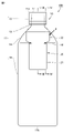
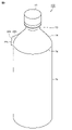
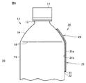
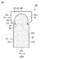
図1は、実施の形態1に係るラベル付き容器の正面図である。図2は、図1に示す矢印IIに沿って見たラベル付き容器の斜視図である。図3は、図1に示すIII-III線に沿ったラベルの断面図である。図4は、図1に示すIV-IV線に沿ったラベルの断面図である。図1から図4を参照して、実施の形態1に係るラベル付き容器100について説明する。
(Embodiment 1)
FIG. 1 is a front view of a labeled container according to Embodiment 1. FIG. 2 is a perspective view of the labeled container taken along arrow II shown in FIG. 1; FIG. FIG. 3 is a cross-sectional view of the label along line III-III shown in FIG. 4 is a cross-sectional view of the label taken along line IV-IV shown in FIG. 1. FIG. A labeled container 100 according to Embodiment 1 will be described with reference to FIGS. 1 to 4. FIG.

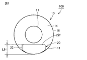
図1に示すように、実施の形態1に係るラベル付き容器100は、被着体としての容器10と、ラベル20とを備える。 As shown in FIG. 1, a labeled container 100 according to Embodiment 1 includes a container 10 as an adherend and a label 20. As shown in FIG.

容器10は、容器本体11と蓋部17とを含む。容器本体11は、高さ方向に平行な軸線方向を有する。容器本体11は、軸線方向において、一端11aおよび他端11bを有する。容器本体11は、口部12、ネック部13、第2部分としての肩部14、第1部分としての胴部15を有する。これら、口部12、ネック部13、肩部14、胴部15は、上記軸線方向に沿って一端11a側から順に連続している。 The container 10 includes a container body 11 and a lid portion 17 . The container body 11 has an axial direction parallel to the height direction. The container body 11 has one end 11a and the other end 11b in the axial direction. The container body 11 has a mouth portion 12, a neck portion 13, a shoulder portion 14 as a second portion, and a body portion 15 as a first portion. The mouth portion 12, the neck portion 13, the shoulder portion 14, and the body portion 15 are continuous from the one end 11a side along the axial direction.

口部12は、容器本体11の一端11a側に位置する。口部12は、胴部15が位置する側とは反対側に向けて開口する。口部12の内側の周長は、略一定となっている。口部12は、蓋部17によって覆われる部分である。 The mouth portion 12 is positioned on the one end 11 a side of the container body 11 . The mouth portion 12 opens toward the side opposite to the side where the body portion 15 is located. The inner peripheral length of the mouth portion 12 is substantially constant. The mouth portion 12 is a portion covered by the lid portion 17 .

胴部15は、容器本体11の他端11b側に位置する。胴部15の外形は、口部12の外形よりも全体的に大きくなっている。胴部15は、容器本体11において周長が最大となる部分を含む。実施の形態1においては、胴部15は、軸線方向に沿って容器本体11の周長が略一定となる場合を例示しているが、これに限定されない。胴部15には、一部が内側に向けて窪む窪み部が設けられていてもよい。また、胴部15には、他端11b側に向かうにつれて一旦周長が大きくなり、最大周長となった部分から容器本体11の他端11bにさらに向かうにつれて周長が小さくなる部分が設けられていてもよい。 The trunk portion 15 is located on the side of the other end 11b of the container body 11 . The outer shape of the trunk portion 15 is larger than the outer shape of the mouth portion 12 as a whole. The trunk portion 15 includes a portion of the container main body 11 having the maximum peripheral length. Embodiment 1 exemplifies the case where the circumference of the container body 11 is substantially constant along the axial direction of the trunk portion 15 , but the present invention is not limited to this. The trunk portion 15 may be provided with a recessed portion that is partially recessed toward the inside. In addition, the trunk portion 15 is provided with a portion whose circumferential length once increases toward the other end 11b, and whose circumferential length decreases further toward the other end 11b of the container body 11 from the maximum circumferential length. may be

肩部14は、胴部15に接続されている。より特定的には、肩部14は、胴部15の上部に接続されている。肩部14は、軸線方向の一方側(口部12側)に向かうにつれて周長が小さくなるように設けられている。肩部14は、軸線方向に平行な断面で見た場合に、軸線方向の一方側に向かうにつれて、内側に向かうように湾曲する形状を有する。肩部14と胴部15との境界には、稜線16が設けられている。 Shoulder 14 is connected to body 15 . More specifically, shoulder 14 is connected to the upper portion of torso 15 . The shoulder portion 14 is provided so that the circumferential length becomes smaller toward one side (the mouth portion 12 side) in the axial direction. The shoulder portion 14 has a shape that curves inward toward one side in the axial direction when viewed in a cross section parallel to the axial direction. A ridgeline 16 is provided at the boundary between the shoulder portion 14 and the body portion 15 .

ネック部13は、口部12と肩部14とを接続する。ネック部13は、軸線方向に平行な断面で見た場合に、略直線状に延在する。ネック部13は、軸線方向の一方側に向かうにつれて、周長が小さくなるように設けられていてもよいし、周長が略一定となるように設けられていてもよい。 Neck portion 13 connects mouth portion 12 and shoulder portion 14 . The neck portion 13 extends substantially linearly when viewed in a cross section parallel to the axial direction. The neck portion 13 may be provided so that the circumferential length becomes smaller toward one side in the axial direction, or may be provided so that the circumferential length is substantially constant.

容器本体11の内部には、たとえば、飲料、調味料、薬液等の液体が収容されている。なお、容器本体11内に収容される内容物は、これらに限定されず、上記口部12から取り出し可能であれば、ゲル状のもの、または粒状のもの等適宜採用することができる。 Inside the container body 11, for example, liquids such as beverages, seasonings, and medicinal solutions are accommodated. Note that the contents contained in the container body 11 are not limited to these, and gel-like or granular contents can be appropriately employed as long as they can be taken out from the mouth portion 12 .

容器本体11は、たとえば、リサイクル可能な、ペットボトル等の樹脂容器、瓶等のガラス製の容器、あるいは、紙製や金属製の容器を採用することができる。 The container main body 11 can employ, for example, a recyclable resin container such as a PET bottle, a glass container such as a bottle, or a paper or metal container.

ラベル20は、容器10の胴部(第1部分)15と肩部14(第2部分)に跨がるように容器10に貼着される。ラベル20は、胴部15に貼着される第1ラベル部21と、肩部14に貼着される第2ラベル部22とを備える。 The label 20 is attached to the container 10 so as to straddle the body portion (first portion) 15 and the shoulder portion 14 (second portion) of the container 10 . The label 20 includes a first label portion 21 attached to the body portion 15 and a second label portion 22 attached to the shoulder portion 14 .

第1ラベル部21は、全体的に胴部15に貼着されている。第2ラベル部22は、部分的に肩部14に貼着されている。より特定的には、図1および図3に示すように、幅方向DR1における第2ラベル部22の中央部が肩部14に接着され、図1、図2および図4に示すように、少なくとも幅方向DR1における第2ラベル部22の両端部(後述する第2端部22c、第3端部22d(図5参照)が肩部14から離れるように、第2ラベル部22は、肩部14に貼着される。このように、第2ラベル部22の周縁の少なくとも一部が、肩部14から離れる(浮き上がる)ことにより、容器10の湾曲形状あるいは凹凸による影響を受けることなく、美麗な貼着状態とすることができる。また、肩部14から浮き上がった部分は掴みやすくなっており、使用後にはラベル20を剥がしやすい。なお、第2ラベル部22は、後述する非接着領域R2(図6参照)あるいは弱接着領域によって、その一部が容器10(特定的には肩部14)に非接着状態あるいは弱接着状態となり、上述のように容器10の湾曲形状あるいは凹凸による影響を受けることを抑制できる。 The first label portion 21 is attached to the body portion 15 as a whole. A second label portion 22 is partially adhered to the shoulder portion 14 . More specifically, as shown in FIGS. 1 and 3, the central portion of the second label portion 22 in the width direction DR1 is adhered to the shoulder portion 14, and as shown in FIGS. The second label portion 22 is positioned on the shoulder portion 14 such that both ends of the second label portion 22 in the width direction DR1 (a second end portion 22c and a third end portion 22d (see FIG. 5) to be described later) are separated from the shoulder portion 14. In this manner, at least a portion of the peripheral edge of the second label portion 22 separates (floats up) from the shoulder portion 14, so that the container 10 is not affected by the curved shape or unevenness of the container 10, and a beautiful label is attached. The portion raised from the shoulder portion 14 is easy to grasp, and the label 20 can be easily peeled off after use. 6) or the weakly adhered region causes a portion thereof to be non-adhered or weakly adhered to the container 10 (particularly the shoulder portion 14), which is affected by the curved shape or unevenness of the container 10 as described above. can be suppressed.

図3および図4に示すように、ラベル20は、基材31と、接着層32と、非接着処理層33とを含む。基材31としては、普通紙、合成紙、蒸着紙、グロス紙、合成樹脂フィルム等を適宜採用することができる。合成樹脂フィルムとしては、たとえば、ポリエチレン、ポリプロピレン、環状オレフィン、ポリエチレンを含む共重合ポリマーなどのポリオレフィン系、ポリエチレンテレフタレートなどのポリエステル系、ポリアミド系、ポリスチレン系などのフィルムを用いることができる。 As shown in FIGS. 3 and 4, the label 20 includes a substrate 31, an adhesive layer 32, and a non-adhesive treatment layer 33. As shown in FIGS. As the substrate 31, plain paper, synthetic paper, metallized paper, gloss paper, synthetic resin film, or the like can be used as appropriate. As the synthetic resin film, for example, polyolefin-based films such as polyethylene, polypropylene, cyclic olefins, and copolymers containing polyethylene, polyester-based films such as polyethylene terephthalate, polyamide-based films, and polystyrene-based films can be used.

基材31は、おもて面31aおよび裏面31bを有する。基材31のおもて面31aには、リサイクルマーク、および/または成分表示等の意匠層が設けられている。意匠層には、商標ロゴ等が含まれていてもよい。なお、意匠層は、おもて面31a側から視認可能である限り、裏面31bに設けられていてもよい。 The base material 31 has a front surface 31a and a back surface 31b. The front surface 31a of the base material 31 is provided with a design layer such as a recycle mark and/or an ingredient display. The design layer may include a trademark logo or the like. The design layer may be provided on the back surface 31b as long as it is visible from the front surface 31a side.

接着層32は、基材31の裏面31bに全体的に設けられている。接着層32には、後述するように、非接着処理層33が部分的に設けられている。なお、上述のように裏面31bに意匠層を設ける場合には、接着層32は、意匠層を覆うように設けられる。また、後述するように、非接着処理層33に代えて、接着層32の接着力を弱める弱接着処理層を設けてもよい。なお、接着層32を部分的に設けずあるいは部分的に減らして、非接着領域R2あるいは弱接着領域を設けてもよい。 The adhesive layer 32 is provided entirely on the rear surface 31 b of the base material 31 . The adhesive layer 32 is partially provided with a non-adhesive treatment layer 33 as described later. When the design layer is provided on the back surface 31b as described above, the adhesive layer 32 is provided so as to cover the design layer. Further, as will be described later, instead of the non-adhesion treatment layer 33, a weak adhesion treatment layer that weakens the adhesion of the adhesion layer 32 may be provided. The non-adhesion region R2 or the weak adhesion region may be provided by partially omitting or partially reducing the adhesion layer 32 .

図5は、実施の形態1に係るラベルをおもて面側から見た平面図である。図6は、実施の形態1に係るラベルを裏面側から見た平面図である。図5および図6を参照して、実施の形態1に係るラベル20の詳細について説明する。 FIG. 5 is a plan view of the label according to Embodiment 1 as viewed from the front side. FIG. 6 is a plan view of the label according to Embodiment 1 as seen from the back side. Details of the label 20 according to the first embodiment will be described with reference to FIGS. 5 and 6. FIG.

図5に示すように、第1ラベル部21は、略矩形形状を有する。第1ラベル部21は、その外形において、上端部21f、下端部21e、一対の側端部21c、21dを含む。 As shown in FIG. 5, the first label portion 21 has a substantially rectangular shape. The first label portion 21 has an outer shape including an upper end portion 21f, a lower end portion 21e, and a pair of side end portions 21c and 21d.

第2ラベル部22は、第1ラベル部21に連接するように設けられている。第2ラベル部22は、第1ラベル部21に接続される接続部22e、当該接続部22eに対して第1ラベル部21が位置する側とは反対側に位置する第1端部22f、幅方向DR1において両端側に位置する第2端部22c、および第3端部22dを有する。第2端部22cは、幅方向DR1の一方側に位置し、第3端部22dは、幅方向DR1の他方側に位置する。 The second label portion 22 is provided so as to be connected to the first label portion 21 . The second label portion 22 includes a connecting portion 22e connected to the first label portion 21, a first end portion 22f positioned opposite to the side on which the first label portion 21 is positioned with respect to the connecting portion 22e, a width It has a second end portion 22c and a third end portion 22d located on both end sides in the direction DR1. Second end 22c is located on one side in width direction DR1, and third end 22d is located on the other side in width direction DR1.

なお、上述の幅方向DR1は、上記接続部22eから第1端部22fに向かう第1方向に交差する方向であり、より特定的には、上記第1方向に直交する方向である。 The width direction DR1 described above is a direction intersecting the first direction from the connection portion 22e to the first end portion 22f, and more specifically, a direction perpendicular to the first direction.

ラベル20には、幅方向DR1における接続部22eの両外側に、一対のくびれ部23が設けられている。これにより、第2ラベル部22を折り曲げて肩部14に接着する際に、折曲部にしわが入ることを抑制することができる。 The label 20 is provided with a pair of constricted portions 23 on both outer sides of the connecting portion 22e in the width direction DR1. As a result, when the second label portion 22 is folded and adhered to the shoulder portion 14, the folded portion can be prevented from being wrinkled.

一対のくびれ部23は、上記一対の第1辺部25と、一対の傾斜部24とによって構成されている。一対の第1辺部25は、上述の第1ラベル部21の上端部21fによって構成されており、幅方向DR1における接続部22eの両端から幅方向DR1の外側に向けて突出する。一対の傾斜部24は、幅方向DR1における接続部22eの両端から第1端部22f側に向かうに連れて幅方向DR1の外側に向かうように傾斜する。 The pair of constricted portions 23 are composed of the pair of first side portions 25 and the pair of inclined portions 24 . The pair of first side portions 25 are formed by the upper end portions 21f of the first label portion 21 described above, and protrude outward in the width direction DR1 from both ends of the connection portion 22e in the width direction DR1. The pair of inclined portions 24 are inclined outward in the width direction DR1 from both ends of the connection portion 22e in the width direction DR1 toward the first end portion 22f.

一対の傾斜部24は、第2端部22cの下端および第3端部22dの下端と、接続部分の両端とを接続する。具体的には、一対の傾斜部24のうち幅方向DR1の一方側に位置する傾斜部24は、第2端部22cの下端(第1ラベル部21側に位置する端部)と、幅方向DR1の一方側に位置する上記接続部22eの端部とを接続する。一対の傾斜部24のうち幅方向DR1の他方側に位置する傾斜部24は、第3端部22dの下端(第1ラベル部21側に位置する端部)と、幅方向DR1の他方側に位置する上記接続部22eの端部とを接続する。 A pair of inclined portions 24 connect the lower ends of the second end portion 22c and the lower ends of the third end portion 22d to both ends of the connection portion. Specifically, of the pair of inclined portions 24, the inclined portion 24 located on one side in the width direction DR1 is located between the lower end of the second end portion 22c (the end portion located on the first label portion 21 side) and the width direction. It is connected to the end of the connecting portion 22e located on one side of DR1. Of the pair of inclined portions 24, the inclined portion 24 located on the other side in the width direction DR1 is located on the other side in the width direction DR1 of the lower end of the third end portion 22d (the end portion located on the first label portion 21 side). It is connected to the end of the connecting portion 22e located above.

一対の傾斜部24と一対の第1辺部25との接続部には、R部26が設けられている。R部26は、幅方向DR1の内側に向けて膨出するように設けられている。R部26が設けられていることにより、一対の傾斜部24と一対の第1辺部25との接続部に応力が作用した際に、当該接続部を起点に亀裂が入ることを抑制することができる。具体的には、たとえば、第2ラベル部22をつまんで、ラベル20を容器10から剥離する際に、ラベル20に亀裂が入ることを抑制することができる。 R portions 26 are provided at connection portions between the pair of inclined portions 24 and the pair of first side portions 25 . The R portion 26 is provided so as to bulge inward in the width direction DR1. By providing the R portion 26, when stress acts on the connecting portion between the pair of inclined portions 24 and the pair of first side portions 25, cracks starting from the connecting portion can be suppressed. can be done. Specifically, for example, when the second label portion 22 is pinched and the label 20 is peeled off from the container 10, cracks in the label 20 can be suppressed.

幅方向DR1において、第1端部22f側に位置する第2ラベル部22の幅は、第1ラベル部21の幅よりも大きくなっている。より特定的には、第2端部22cから第3端部22dまでの幅は、側端部21cから側端部21dまでの幅よりも大きくなっている。 The width of the second label portion 22 located on the first end portion 22f side is larger than the width of the first label portion 21 in the width direction DR1. More specifically, the width from the second end 22c to the third end 22d is greater than the width from the side end 21c to the side end 21d.

上述のように、第2ラベル部22の幅寸法を第1ラベル部21の幅寸法よりも大きくすることで、ラベル20の表示面積を大きく確保することができる。これにより、上述のように、リサイクルマーク、および/または成分表示等の意匠層を適切に設けることができる。また、ラベル20の表示面積を大きくすることで、アイキャッチ性を向上させることもできる。上部が大きく露出しているので、掴みやすく、剥がしやすさも向上させることができる。 As described above, by making the width dimension of the second label portion 22 larger than the width dimension of the first label portion 21, a large display area of the label 20 can be secured. Thereby, as described above, a design layer such as a recycle mark and/or an ingredient display can be appropriately provided. Also, by increasing the display area of the label 20, the eye-catching property can be improved. Since the upper part is largely exposed, it is easy to grasp and can be easily peeled off.

貼着前の状態における具体的なラベル20の寸法としては、第1ラベル部21の下端部21eから第2ラベル部22の第1端部22fまでの長さL1が、たとえば、略70mmである。第2端部22cから第3端部22dまでの幅L2は、たとえば、略40mmである。接続部22eから第1端部22fまでの長さL3は、たとえば、略25mmである。 As for the specific dimensions of the label 20 before sticking, the length L1 from the lower end 21e of the first label portion 21 to the first end 22f of the second label portion 22 is approximately 70 mm, for example. . A width L2 from the second end portion 22c to the third end portion 22d is, for example, approximately 40 mm. A length L3 from the connection portion 22e to the first end portion 22f is, for example, approximately 25 mm.

幅方向DR1に沿った第2端部22cから側端部21cまでの長さL4、および幅方向DR1に沿った第3端部22dから側端部21dまでの長さL5は、略同等であり、たとえば、2mmから5mm程度である。 A length L4 along the width direction DR1 from the second end portion 22c to the side end portion 21c and a length L5 along the width direction DR1 from the third end portion 22d to the side end portion 21d are substantially the same. , for example, on the order of 2 mm to 5 mm.

このような寸法にすることにより、ラベル20のこわさを適切に確保することができる。ラベル20を容器10に貼り付ける際には、第1ラベル部21を胴部15に貼り付けた後に、第2ラベル部22を折り曲げて肩部14に貼り付ける。ラベル20のこわさを一定程度確保することにより、第1ラベル部21を胴部15に貼り付けた後から第2ラベル部22を折り曲げる工程に到達するまでに、ラベル20の姿勢を安定して保つことができる。これにより、第2ラベル部22を安定して肩部14に貼り付けることができる。また、ラベル20のこわさが適切となることにより、第2ラベル部22を折り曲げる際にも、安定して第2ラベル部22を折り曲げることができる。 By using such dimensions, the rigidity of the label 20 can be appropriately ensured. When attaching the label 20 to the container 10 , after attaching the first label portion 21 to the body portion 15 , the second label portion 22 is folded and attached to the shoulder portion 14 . By ensuring the rigidity of the label 20 to a certain degree, the posture of the label 20 is kept stable from the time the first label part 21 is attached to the body part 15 until the process of folding the second label part 22 is reached. be able to. Thereby, the second label portion 22 can be stably attached to the shoulder portion 14 . Also, when the second label portion 22 is folded, the second label portion 22 can be stably folded by the appropriate stiffness of the label 20 .

図6に示すように、ラベル20の裏面側においては、接着層32と、非接着処理層33とが設けられている。接着層32は、上述した基材31の裏面31bに全体的に設けられている。すなわち、接着層32は、上記裏面31bのうち第1ラベル部21に対応する部分および上記裏面31bのうち第2ラベル部22に対応する部分の双方に全体的に設けられている。 As shown in FIG. 6, an adhesive layer 32 and a non-adhesive layer 33 are provided on the back side of the label 20 . The adhesive layer 32 is provided entirely on the rear surface 31b of the substrate 31 described above. That is, the adhesive layer 32 is provided entirely on both the portion of the back surface 31b corresponding to the first label portion 21 and the portion of the back surface 31b corresponding to the second label portion 22 .

非接着処理層33は、接着層32に部分的に設けられている。非接着処理層33は、シリコーン樹脂などの剥離剤を含む液体(例えば紫外線硬化型インキなど)や微粒子を含む塗工液(例えば艶消しインキなど)などの表面処理液を接着層32の所定の範囲に塗布することで形成される。 The non-adhesive treatment layer 33 is partially provided on the adhesive layer 32 . The non-adhesion treatment layer 33 is formed by applying a surface treatment liquid such as a liquid containing a release agent such as silicone resin (for example, ultraviolet curing ink) or a coating liquid containing fine particles (for example, matting ink) to the adhesion layer 32 in a predetermined manner. Formed by applying to an area.

非接着処理層33は、第2ラベル部22の裏面(貼着状態において肩部14に対向する対向面)において、当該裏面の周縁部に沿う部分を含むように設けられている。非接着処理層33は、幅方向DR1において上記裏面の両側に少なくとも設けられている。より特定的には、非接着処理層33は、第2端部22c側、第1端部22f側、および第3端部22d側に設けられている。非接着処理層33は、第2ラベル部22の裏面において、一対の傾斜部24のうち幅方向DR1の一方側に位置する傾斜部24から、時計回りに第2ラベル部22の周縁を沿って一対の傾斜部24のうち幅方向DR1の他方側に位置する傾斜部24に至るまで設けられている。 The non-adhesive layer 33 is provided on the back surface of the second label portion 22 (the surface facing the shoulder portion 14 in the attached state) so as to include a portion along the peripheral edge of the back surface. The non-adhesion treatment layers 33 are provided at least on both sides of the back surface in the width direction DR1. More specifically, the non-adhesion treatment layer 33 is provided on the second end 22c side, the first end 22f side, and the third end 22d side. On the back surface of the second label portion 22, the non-adhesive treatment layer 33 extends clockwise along the periphery of the second label portion 22 from the inclined portion 24 located on one side of the pair of inclined portions 24 in the width direction DR1. It is provided up to the inclined portion 24 positioned on the other side in the width direction DR1 of the pair of inclined portions 24 .

このように接着層32および非接着処理層33が設けられることにより、非接着処理層33から露出する部分の接着層32が、ラベル20の容器10への接着に寄与する接着領域として機能する。第2ラベル部22においては、接着領域R1は、幅方向DR1において第2ラベル部22の裏面の中央部に形成される。 By providing the adhesive layer 32 and the non-adhesive layer 33 in this way, the portion of the adhesive layer 32 exposed from the non-adhesive layer 33 functions as an adhesive region that contributes to the adhesion of the label 20 to the container 10 . In the second label portion 22, the adhesive region R1 is formed in the central portion of the back surface of the second label portion 22 in the width direction DR1.

また、非接着処理層33は、ラベル20を容器10に接着させない非接着領域として機能する。非接着領域R2は、非接着処理層33と同様の位置に設けられており、接着領域R1の周囲に設けられている。より特定的には、非接着領域R2は、第2ラベル部22の裏面の第1端部22f側、第2端部22c側、および第3端部22d側に形成される。なお、第2ラベル部22において、非接着領域R2の面積は、接着領域R1よりも大きくなっている。 Also, the non-adhesion treatment layer 33 functions as a non-adhesion region that does not adhere the label 20 to the container 10 . The non-adhesion region R2 is provided at the same position as the non-adhesion treatment layer 33, and is provided around the adhesion region R1. More specifically, the non-bonded regions R2 are formed on the back surface of the second label portion 22 on the first end portion 22f side, the second end portion 22c side, and the third end portion 22d side. In addition, in the second label portion 22, the area of the non-bonded region R2 is larger than the bonded region R1.

図7は、実施の形態1に係るラベル付き容器の上面図である。図7に示すように、ラベル付き容器100を上方から見た場合には、第1ラベル部21は、胴部の周面に沿って貼り付けられているため見えず、第2ラベル部22が主として見える状態となる。ラベル付き容器100を上方から見た場合に第2ラベル部22が貼着されている側において、肩部14の縁(肩部14と胴部15との稜線16)から第1端部22fまでの最大の長さL6は、3mm以上であることが好ましく、5mm以上であることがより好ましく、10mm以上であることがさらに好ましい。これにより、ラベル付き容器100を上方からラベル20の有無を確認する際に、検査領域を大きく確保することができる。この結果、第1ラベル部21が見えにくい場合であっても、第1ラベル部21と第2ラベル部22とから成るラベル20の有無をより確実に確認することができる。 7 is a top view of the labeled container according to Embodiment 1. FIG. As shown in FIG. 7, when the labeled container 100 is viewed from above, the first label portion 21 is not visible because it is attached along the peripheral surface of the body portion, and the second label portion 22 is not visible. Mainly visible. From the edge of the shoulder portion 14 (the ridge line 16 between the shoulder portion 14 and the body portion 15) to the first end portion 22f on the side where the second label portion 22 is attached when the labeled container 100 is viewed from above. is preferably 3 mm or more, more preferably 5 mm or more, and even more preferably 10 mm or more. This makes it possible to ensure a large inspection area when checking the presence or absence of the label 20 on the labeled container 100 from above. As a result, even if the first label portion 21 is difficult to see, the presence or absence of the label 20 composed of the first label portion 21 and the second label portion 22 can be confirmed more reliably.

加えて、上述のように形成された非接着処理層33によって、幅方向DR1における第2ラベル部22の両端側が容器10の肩部14に接着せずに、肩部14から離れることにより、上方から見た場合に第2ラベル部22の輪郭が明確になる。このような効果は、容器10が丸形のボトルである場合に、より顕著となる。この結果、たとえば、ラベル付き容器100を上方から撮像して、撮像された画像からラベル20の有無を確認する際に、ラベル20の有無の判定が容易になる。 In addition, due to the non-adhesion treatment layer 33 formed as described above, the both end sides of the second label portion 22 in the width direction DR1 are not adhered to the shoulder portion 14 of the container 10, and are separated from the shoulder portion 14, so that The outline of the second label portion 22 becomes clear when viewed from the top. Such an effect becomes more pronounced when the container 10 is a round bottle. As a result, for example, when the labeled container 100 is imaged from above and the presence or absence of the label 20 is confirmed from the captured image, the presence or absence of the label 20 can be easily determined.

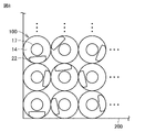
図8は、実施の形態1に係るラベル付き容器を複数個、梱包箱に梱包した状態を示す上面図である。図8を参照して、ラベル20の有無を検査する検査工程について説明する。 FIG. 8 is a top view showing a state in which a plurality of labeled containers according to Embodiment 1 are packed in a packing box. An inspection process for inspecting the presence or absence of the label 20 will be described with reference to FIG.

図8に示すように、ラベル20の有無を検査する場合には、上方側に向けて開放された梱包箱200内に複数のラベル付き容器100を並べて配置し、開放部を介して上方側から複数のラベル付き容器100を撮像して、画像検査にてラベルの有無を確認する。 As shown in FIG. 8, when inspecting the presence or absence of a label 20, a plurality of labeled containers 100 are arranged side by side in a packaging box 200 that is opened upward, and the container is inspected from above through the opening. Images of a plurality of labeled containers 100 are picked up, and presence or absence of labels is confirmed by image inspection.

梱包箱200内に複数のラベル付き容器100を並べて配置する際には、ラベル20が同一方向を向かず、ランダムな方向を向く場合がある。このような場合であっても、上述のように、第2ラベル部22の輪郭が明確となっていることにより、ラベル付き容器100を上方から撮像して、撮像された画像からラベル20の有無を確認する際に、ラベル20の有無の判定が容易になる。 When arranging a plurality of labeled containers 100 side by side in the packing box 200, the labels 20 may not face the same direction but face random directions. Even in such a case, since the outline of the second label portion 22 is clear as described above, the image of the labeled container 100 can be captured from above, and the presence or absence of the label 20 can be determined from the captured image. , it becomes easy to determine whether the label 20 is present or absent.

以上のように、実施の形態1に係るラベル20は、第1ラベル部21と第2ラベル部22とを有することにより表示面積を確保することができる。加えて、第2ラベル部22の裏面において、非接着領域が、第1端部22f側、第2端部22c側、および第3端部22d側に設けられていることにより、被着体に貼着された貼着状態において、上方から見た場合に、上述のように第2ラベル部22の輪郭を明確にすることができる。これにより、上方から見た場合にラベル20の有無を容易に確認することができる。 As described above, the label 20 according to Embodiment 1 can secure a display area by having the first label portion 21 and the second label portion 22 . In addition, on the back surface of the second label portion 22, the non-adhesive regions are provided on the first end portion 22f side, the second end portion 22c side, and the third end portion 22d side. In the pasted state, when viewed from above, the outline of the second label portion 22 can be made clear as described above. Accordingly, the presence or absence of the label 20 can be easily confirmed when viewed from above.

なお、上述においては、上方からラベル付き容器100を撮像してラベル20の有無を確認する場合を例示して説明したが、目視にて上方からラベル20の有無を確認してもよい。この場合においても、第2ラベル部22を確認することにより、ラベル20の有無を容易に判定することができる。 In the above description, the case of confirming the presence or absence of the label 20 by imaging the labeled container 100 from above has been described as an example, but the presence or absence of the label 20 may be confirmed visually from above. Even in this case, the presence or absence of the label 20 can be easily determined by checking the second label portion 22 .

(実施の形態2)
図9は、実施の形態2に係るラベルを裏面側から見た平面図である。図9を参照して、実施の形態2に係るラベル20Aについて説明する。
(Embodiment 2)
FIG. 9 is a plan view of the label according to Embodiment 2 as seen from the back side. A label 20A according to Embodiment 2 will be described with reference to FIG.

図9に示すように、実施の形態2に係るラベル20Aは、実施の形態1に係るラベル20と比較した場合に、第2ラベル部22における非接着処理層33が設けられている領域が相違する。その他の構成については、ほぼ同様である。 As shown in FIG. 9, the label 20A according to Embodiment 2 differs from the label 20 according to Embodiment 1 in the area where the non-adhesive layer 33 is provided in the second label portion 22. do. Other configurations are substantially the same.

ラベル20Aにおいては、非接着処理層33は、第2ラベル部22の裏面の中央部を取り囲むように環状に設けられている。第2ラベル部22の裏面の中央部において、非接着処理層33から接着層32が露出することにより、接着領域R1が、第2ラベル部22の裏面の中央部に形成される。また、非接着領域R2が、上記中央部を取り囲むように形成される。 In the label 20</b>A, the non-adhesive layer 33 is annularly provided so as to surround the central portion of the back surface of the second label portion 22 . By exposing the adhesive layer 32 from the non-adhesive treatment layer 33 in the central portion of the back surface of the second label portion 22 , the adhesive region R1 is formed in the central portion of the back surface of the second label portion 22 . Also, a non-bonded region R2 is formed to surround the central portion.

上述のように構成される場合であっても、実施の形態2に係るラベル20Aは、実施の形態1に係るラベル20とほぼ同様の効果が得られる。加えて、実施の形態1と比較して、非接着領域が拡大し、接着領域が小さくなることにより、第2ラベル部22を肩部14に接着させた際に、第2ラベル部22にしわが形成されることをさらに抑制することができる。 Even in the case of being configured as described above, the label 20A according to the second embodiment can obtain substantially the same effect as the label 20 according to the first embodiment. In addition, as compared with the first embodiment, the non-bonded area is enlarged and the bonded area is decreased. Formation can be further suppressed.

(実施の形態3)
図10は、実施の形態3に係るラベルをおもて面側から見た平面図である。図10を参照して、実施の形態3に係るラベル20Bについて説明する。
(Embodiment 3)
FIG. 10 is a plan view of the label according to Embodiment 3 as viewed from the front side. A label 20B according to Embodiment 3 will be described with reference to FIG.

図10に示すように、実施の形態3に係るラベル20Bは、実施の形態1に係るラベル20と比較した場合に、一対のくびれ部23に代えて、一対の切欠き線27が設けられている点において相違する。その他の構成については、ほぼ同様である。 As shown in FIG. 10, a label 20B according to the third embodiment is provided with a pair of notch lines 27 instead of the pair of constricted portions 23 when compared with the label 20 according to the first embodiment. It is different in that Other configurations are substantially the same.

一対の切欠き線27は、第1ラベル部21の側端部21c、21dから斜め方向に互いに近づくように設けられている。一対の切欠き線27は、一対の傾斜ライン271と一対のカール部272とを有する。 The pair of notch lines 27 are provided so as to approach each other in an oblique direction from the side ends 21c and 21d of the first label portion 21. As shown in FIG. The pair of notch lines 27 has a pair of inclined lines 271 and a pair of curled portions 272 .

一対の傾斜ライン271は、側端部21c、21dから第2ラベル部22の第1端部22f側に向かうに連れて幅方向DR1に互いに近づくように傾斜している。一対の傾斜ライン271は、第2ラベル部22の第2端部22cの下端と第3端部22dの下端とを結ぶ仮想線VLに到達するように延在している。一対の傾斜ライン271の上端位置は、仮想線VLと重なる位置にあってもよいし、仮想線VLよりも第2ラベル部22の第1端部22f側に位置していてもよい。 The pair of inclined lines 271 are inclined so as to approach each other in the width direction DR1 from the side ends 21c and 21d toward the first end 22f of the second label portion 22 . The pair of inclined lines 271 extends to reach a virtual line VL connecting the lower end of the second end portion 22c and the lower end of the third end portion 22d of the second label portion 22 . The upper end positions of the pair of inclined lines 271 may overlap the virtual line VL, or may be positioned closer to the first end 22f of the second label portion 22 than the virtual line VL.

一対のカール部272は、一対の傾斜ライン271の上端に接続されており、幅方向DR1の外側に向かうようにカールする。一対のカール部272が設けられていることにより、第2ラベル部22をつまんで、ラベル20を容器10から剥離する際に、傾斜ライン271からラベルが裂けることを抑制することができる。 The pair of curled portions 272 are connected to the upper ends of the pair of inclined lines 271 and curl outward in the width direction DR1. By providing the pair of curled portions 272 , when the second label portion 22 is pinched and the label 20 is peeled from the container 10 , tearing of the label along the inclined line 271 can be suppressed.

上述のように構成される場合であっても、実施の形態3に係るラベル20Bは、実施の形態1に係るラベル20とほぼ同様の効果が得られる。加えて、貼着状態において、第1ラベル部21のうち一対の傾斜ライン271の外側に位置する部分(一対の傾斜ライン271の外側において、当該傾斜ライン271と上記仮想線VLとの間に位置する略三角形状の部分)が、容器10から浮き上がることにより、アイキャッチ性を高めることもできる。 Even if it is configured as described above, the label 20B according to the third embodiment can obtain substantially the same effect as the label 20 according to the first embodiment. In addition, in the adhered state, the portion of the first label portion 21 located outside the pair of inclined lines 271 (outside the pair of inclined lines 271 and positioned between the inclined line 271 and the virtual line VL). The substantially triangular portion (which is the portion of the container 10) can be lifted from the container 10 to enhance the eye-catching property.

(実施の形態4)
図11は、実施の形態4に係るラベルを裏面側からみた平面図である。図11を参照して、実施の形態4に係るラベル20Cについて説明する。
(Embodiment 4)
FIG. 11 is a plan view of the label according to Embodiment 4 as seen from the back side. A label 20C according to Embodiment 4 will be described with reference to FIG.

図11に示すように、実施の形態4に係るラベル20Cは、実施の形態1に係るラベル20と比較した場合に、主として非接着処理層33が設けられている領域が相違する。その他の構成については、ほぼ同様である。 As shown in FIG. 11, the label 20C according to the fourth embodiment differs from the label 20 according to the first embodiment mainly in the area where the non-adhesive layer 33 is provided. Other configurations are substantially the same.

非接着処理層33は、幅方向DR1における第2ラベル部22の一方の端部側から接続部22eに向かい、さらに幅方向DR1における第2ラベル部22の他方の端部側に向かうように略円弧状(より特定的にはU字状)に設けられている。具体的には、非接着処理層33は、第2端部22c側から、幅方向DR1の一方側に位置する傾斜部24、接続部22e、および幅方向DR1の他方側に位置する傾斜部24を順に通って、第3端部22d側に至るように設けられている。 The non-adhesion treatment layer 33 extends from one end of the second label portion 22 in the width direction DR1 toward the connection portion 22e and further toward the other end of the second label portion 22 in the width direction DR1. It is provided in an arc shape (more specifically, U shape). Specifically, the non-adhesion treatment layer 33 includes, from the second end 22c side, the inclined portion 24 and the connecting portion 22e located on one side in the width direction DR1, and the inclined portion 24 located on the other side in the width direction DR1. through in order to reach the third end 22d side.

これにより、接着領域R1は、略半円形状、略半楕円形状、あるいは略半トラック形状等の略半オーバル形状に形成され、その周囲に非接着領域R2が形成される。接着領域R1は、その外縁の一部が第1端部22fの中央部に沿うように設けられており、他の外縁の周りに非接着領域R2が形成されている。 As a result, the bonding region R1 is formed in a substantially semi-oval shape such as a substantially semi-circular shape, a substantially semi-elliptical shape, or a substantially semi-track shape, and the non-bonding region R2 is formed around it. A portion of the outer edge of the adhesive region R1 is provided along the central portion of the first end portion 22f, and a non-adhesive region R2 is formed around the other outer edge.

また、実施の形態4においては、傾斜部24と第1辺部25とが成す角のうち小さい方の角度は、実施の形態1よりも大きくなっている。貼着前の状態において、接着領域R1の先端(下端)は、第2端部22cの下端と第3端部22dの下端とを結ぶ仮想線VL1に達している。なお、当該接着領域R1の先端は、当該位置に限定されず、当該仮想線VL1よりも接続部22e側に位置していてもよいし、当該仮想線VL1よりも第1端部22f側に位置していてもよい。 Further, in the fourth embodiment, the smaller angle of the angles formed by the inclined portion 24 and the first side portion 25 is larger than in the first embodiment. In the state before sticking, the tip (lower end) of the adhesive region R1 reaches the imaginary line VL1 connecting the lower end of the second end portion 22c and the lower end of the third end portion 22d. Note that the tip of the adhesive region R1 is not limited to this position, and may be positioned closer to the connecting portion 22e than the virtual line VL1, or may be positioned closer to the first end portion 22f than the virtual line VL1. You may have

第1端部22fから接着領域R1の先端までの距離は、当該接着領域R1の先端から接続部22eまでの距離よりも長くてもよい。この場合には、接着領域R1の面積を確保することができ、第2ラベル部22をより確実に肩部14に貼り付けることができる。 The distance from the first end portion 22f to the tip of the adhesion region R1 may be longer than the distance from the tip of the adhesion region R1 to the connecting portion 22e. In this case, the area of the adhesive region R1 can be secured, and the second label portion 22 can be attached to the shoulder portion 14 more reliably.

上記のように構成される場合であっても、実施の形態4に係るラベル20Cは、実施の形態1に係るラベル20とほぼ同様の効果が得られる。 Even if it is configured as described above, the label 20C according to the fourth embodiment can obtain substantially the same effect as the label 20 according to the first embodiment.

(実施の形態5)
図12は、実施の形態5に係るラベルを裏面側からみた平面図である。図12を参照して、実施の形態5に係るラベル20Dについて説明する。
(Embodiment 5)
FIG. 12 is a plan view of the label according to Embodiment 5 as viewed from the back side. A label 20D according to Embodiment 5 will be described with reference to FIG.

実施の形態5に係るラベル20Dは、実施の形態4に係るラベル20Cと比較した場合に、非接着処理層33が設けられている領域が相違する。その他の構成については、ほぼ同様である。 The label 20D according to the fifth embodiment differs from the label 20C according to the fourth embodiment in the area where the non-adhesive layer 33 is provided. Other configurations are substantially the same.

非接着処理層33は、第2ラベル部22側から第1ラベル部21側にはみ出すはみ出し部を含む。当該はみ出し部は、接続部22eの中央部から第1ラベル部21の下端部21eに向けて突出するように設けられている。はみ出し部の下端側は、先細り形状を有する。第1端部22fから接着領域R1の先端までの距離は、接着領域R1の先端からはみ出し部の先端までの距離は、略同程度であってもよい。 The non-adhesion treatment layer 33 includes a protruding portion protruding from the second label portion 22 side to the first label portion 21 side. The protruding portion is provided so as to protrude from the central portion of the connecting portion 22e toward the lower end portion 21e of the first label portion 21. As shown in FIG. The lower end side of the protruding portion has a tapered shape. The distance from the first end portion 22f to the tip of the adhesive region R1 may be substantially the same as the distance from the tip of the adhesive region R1 to the tip of the protruding portion.

上記構成を有する場合であっても実施の形態4に係るラベル20Cとほぼ同様の効果が得られる。また、はみ出し部が設けられることにより、第2ラベル部22を肩部14に貼り付ける際に第2ラベル部22の接続部22e側を第1ラベル部21に対してきれいに湾曲させることができ、しわの形成を抑制できる。 Even with the above configuration, substantially the same effects as those of the label 20C according to the fourth embodiment can be obtained. In addition, since the protruding portion is provided, the connecting portion 22e side of the second label portion 22 can be neatly curved with respect to the first label portion 21 when the second label portion 22 is attached to the shoulder portion 14. It can suppress the formation of wrinkles.

また、第1端部22fから接着領域R1の先端までの距離と接着領域R1の先端からはみ出し部の先端までの距離とを略同程度とすることにより、下端部21eに向かうはみ出し部の長さが長くなりすぎることを抑制できる。このことによっても、上述同様に第2ラベル部22の接続部22e側を第1ラベル部21に対してきれいに湾曲させることができ、しわの形成を抑制できる。 In addition, by making the distance from the first end 22f to the tip of the bonding region R1 and the distance from the tip of the bonding region R1 to the tip of the protruding portion approximately the same, the length of the protruding portion toward the lower end 21e can be suppressed from becoming too long. As a result, the connection portion 22e side of the second label portion 22 can be curved neatly with respect to the first label portion 21 in the same manner as described above, and the formation of wrinkles can be suppressed.

(実施の形態6)
図13は、実施の形態6に係るラベルを裏面側からみた平面図である。図13を参照して、実施の形態6に係るラベル20Eについて説明する。
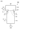
(Embodiment 6)
FIG. 13 is a plan view of the label according to Embodiment 6 as viewed from the back side. A label 20E according to Embodiment 6 will be described with reference to FIG.

図13に示すように、実施の形態6に係るラベル20Eは、実施の形態5に係るラベル20Dと比較した場合に、幅方向DR1における接続部22eの幅が大きくなっており、これにより、はみ出し部の幅が拡大されている点において相違する。その他の構成については、ほぼ同様である。なお、接着領域R1の外縁において第1端部22fに沿う部分の長さは、第1端部22fから接着領域R1の先端までの長さよりも長くなっている。 As shown in FIG. 13, in the label 20E according to the sixth embodiment, when compared with the label 20D according to the fifth embodiment, the width of the connecting portion 22e in the width direction DR1 is larger. The difference is that the width of the portion is enlarged. Other configurations are substantially the same. In addition, the length of the portion along the first end 22f in the outer edge of the bonding region R1 is longer than the length from the first end 22f to the tip of the bonding region R1.

上記構成を有する場合であっても実施の形態5に係るラベル20Cとほぼ同様の効果が得られる。 Even with the above configuration, substantially the same effects as those of the label 20C according to the fifth embodiment can be obtained.

なお、非接着処理層33において、第2ラベル部22側から第1ラベル部21側にはみ出すはみ出し部を省略してもよい。 In addition, in the non-adhesive treatment layer 33, the protruding portion protruding from the second label portion 22 side to the first label portion 21 side may be omitted.

(実施の形態7)
図14は、実施の形態7に係るラベルを裏面側からみた平面図である。図14を参照して、実施の形態7に係るラベル20Fについて説明する。
(Embodiment 7)
FIG. 14 is a plan view of the label according to Embodiment 7 as seen from the back side. A label 20F according to Embodiment 7 will be described with reference to FIG.

図14に示すように、実施の形態7に係るラベル20Fは、実施の形態1と比較した場合に、一対の第1辺部25が下端部21e側に向かうにつれて幅方向DR1の幅が広がるように傾斜している点、および非接着処理層33が設けられている領域が相違する。その他の構成については、ほぼ同様である。 As shown in FIG. 14, in the label 20F according to the seventh embodiment, the width in the width direction DR1 widens as the pair of first side portions 25 goes toward the lower end portion 21e, as compared with the first embodiment. , and the region where the non-adhesive treatment layer 33 is provided are different. Other configurations are substantially the same.

非接着処理層33は、第2ラベル部22において、実施の形態4とほぼ同様に、第2端部22c側から、幅方向DR1の一方側に位置する傾斜部24、接続部22e、および幅方向DR1の他方側に位置する傾斜部24を順に通って、第3端部22d側に至るように設けられている。加えて、非接着処理層33は、接続部22eから第1ラベル部21側にはみ出すはみ出し部を有する。はみ出し部は、接続部22eと一対の第1辺部25の下端を結ぶ線との間に設けられている。なお、はみ出し部は、省略されていてもよい。 In the second label portion 22, the non-adhesive treatment layer 33 includes, in substantially the same manner as in the fourth embodiment, the inclined portion 24, the connecting portion 22e, and the width It is provided so as to reach the third end portion 22d through the inclined portion 24 positioned on the other side in the direction DR1. In addition, the non-adhesion treatment layer 33 has a protruding portion protruding from the connecting portion 22e toward the first label portion 21 side. The protruding portion is provided between the connection portion 22 e and a line connecting the lower ends of the pair of first side portions 25 . Note that the protruding portion may be omitted.

この場合において接着領域R1の外縁において第1端部22fに沿う部分の長さは、第1端部22fから接着領域R1の先端までの長さよりも短くなっている。 In this case, the length of the portion along the first end 22f at the outer edge of the bonding region R1 is shorter than the length from the first end 22f to the tip of the bonding region R1.

このような構成を有する場合においても、実施の形態7に係るラベル20Fは、実施の形態1とほぼ同様の効果が得られる。加えて、上述のように、一対の第1辺部25が傾斜していることにより、接続部22eが、稜線16から高さ方向にずれて第1ラベル部21が胴部15に貼り付けられた場合であっても、第2ラベル部22を肩部14に貼り付ける際に第2ラベル部22を第1ラベル部21に対してきれいに湾曲させることができ、しわの形成を抑制できる。 Even with such a configuration, the label 20F according to the seventh embodiment can obtain substantially the same effects as those of the first embodiment. In addition, as described above, since the pair of first side portions 25 are inclined, the connection portion 22e is shifted in the height direction from the ridge line 16, and the first label portion 21 is attached to the body portion 15. Even in such a case, the second label portion 22 can be neatly curved with respect to the first label portion 21 when the second label portion 22 is attached to the shoulder portion 14, and the formation of wrinkles can be suppressed.

(その他の変形例)
なお、上述した実施の形態1から7においては、容器10が丸形のボトル形状を有し、第1ラベル部21が胴部15に貼着され、第2ラベル部22が肩部14に貼着される場合を例示して説明したが、これに限定されない。容器10は、上面および側面を有する包装箱であってもよく、この場合には、第1ラベル部21が側面に貼着され、第2ラベル部22が上面に貼着されてもよい。容器10が丸形のボトル形状を有する場合には、特に、第2ラベル部22の周縁の少なくとも一部が肩部14から離れることにより、上方から見た場合に第2ラベル部22の輪郭が明確になるという効果をより顕著に発揮させることができる。
(Other modifications)
In Embodiments 1 to 7 described above, the container 10 has a round bottle shape, the first label portion 21 is attached to the body portion 15, and the second label portion 22 is attached to the shoulder portion 14. Although the case where it is worn has been described as an example, it is not limited to this. The container 10 may be a packaging box having a top surface and side surfaces, in which case the first label portion 21 may be attached to the side surfaces and the second label portion 22 may be attached to the top surface. When the container 10 has the shape of a round bottle, in particular, at least a portion of the periphery of the second label portion 22 is away from the shoulder portion 14 so that the contour of the second label portion 22 when viewed from above. The effect of clarification can be exhibited more remarkably.

また、上述した実施の形態1から7においては、非接着処理層33を設けることにより、非接着領域R2を形成する場合を例示して説明したが、これに限定されない。非接着処理層33に代えて、接着層32の接着力を弱くする弱接着処理層を設けてもよい。弱接着処理層は、非接着処理層33を形成する際に用いた上述の表面処理液の量を少なくし、当該表面処理液の厚さを薄くすることにより形成することができる。この場合には、弱接着処理層は、接着領域R1よりも接着力が弱い弱接着領域として機能する。さらに、弱接着処理層を設けずに、非接着領域R2となる部分において接着層32が薄くなっている等によって、接着力が弱くなっていることにより、弱接着領域が設けられてもよい。 Moreover, in Embodiments 1 to 7 described above, the case where the non-adhesion region R2 is formed by providing the non-adhesion treatment layer 33 has been described as an example, but the present invention is not limited to this. Instead of the non-adhesion treatment layer 33, a weak adhesion treatment layer that weakens the adhesion of the adhesion layer 32 may be provided. The weak adhesion treatment layer can be formed by reducing the amount of the surface treatment liquid used to form the non-adhesion treatment layer 33 and by reducing the thickness of the surface treatment liquid. In this case, the weak adhesion treatment layer functions as a weak adhesion region having weaker adhesion than the adhesion region R1. Further, the weak adhesion region may be provided by weakening the adhesion force by thinning the adhesion layer 32 in the non-adhesion region R2 without providing the weak adhesion treatment layer.

また、上述した実施の形態1から7においては、非接着処理層33を設けることにより、非接着領域R2を形成する場合を例示して説明したが、非接着領域R2となる部分に接着層32自体が設けられないことにより、非接着領域R2が設けられてもよい。 Further, in the above-described first to seventh embodiments, the case where the non-adhesive region R2 is formed by providing the non-adhesive treatment layer 33 has been described as an example, but the adhesive layer 32 The non-adhesion region R2 may be provided by not providing itself.

以上、今回発明された実施の形態はすべての点で例示であって制限的なものではない。本発明の範囲は特許請求の範囲によって示され、特許請求の範囲と均等の意味および範囲内でのすべての変更が含まれる。 As described above, the embodiments invented this time are illustrative in all respects and are not restrictive. The scope of the present invention is indicated by the scope of claims, and includes all modifications within the meaning and scope of equivalence to the scope of claims.

10 容器、11 容器本体、11a 一端、11b 他端、12 口部、13 ネック部、14 肩部、15 胴部、16 稜線、17 蓋部、20,20A,20B,20C,20D,20E,20F ラベル、21 第1ラベル部、21c,21d 側端部、21e 下端部、21f 上端部、22 第2ラベル部、22c 第2端部、22d 第3端部、22e 接続部、22f 第1端部、23 くびれ部、24 傾斜部、25 第1辺部、26 R部、27 切欠き線、31 基材、31a おもて面、31b 裏面、32 接着層、33 非接着処理層、100 ラベル付き容器、271 傾斜ライン、272 カール部。 10 Container 11 Container Body 11a One End 11b Other End 12 Mouth 13 Neck 14 Shoulder 15 Body 16 Ridge 17 Lid 20, 20A, 20B, 20C, 20D, 20E, 20F label 21 first label portion 21c, 21d side end portion 21e lower end portion 21f upper end portion 22 second label portion 22c second end portion 22d third end portion 22e connection portion 22f first end portion , 23 constricted portion, 24 inclined portion, 25 first side portion, 26 R portion, 27 notch line, 31 base material, 31a front surface, 31b back surface, 32 adhesive layer, 33 non-adhesive treated layer, 100 labeled container, 271 slant line, 272 curl.

Claims (4)

第1部分と当該第1部分の上部に連設する第2部分とを含む被着体に貼着されるラベルであって、
前記ラベルは、第1部分から第2部分に跨がるように被着体に貼着され、
第1部分に貼着される第1ラベル部と、
前記第1ラベル部に連設するように設けられ、第2部分に貼着される第2ラベル部と、を備え、
前記第2ラベル部は、貼着状態において第2部分に対向する対向面を有し、
前記対向面は、接着領域と、前記接着領域よりも接着力が弱い弱接着領域または非接着領域とを含み、
前記弱接着領域または前記非接着領域は、前記対向面の周縁部の少なくとも一部に沿う部分を含むように設けられている、ラベル。
A label to be attached to an adherend including a first portion and a second portion continuously provided above the first portion,
The label is attached to the adherend so as to extend from the first portion to the second portion,
a first label portion attached to the first portion;
a second label portion provided so as to be continuous with the first label portion and attached to the second portion;
The second label portion has a facing surface facing the second portion in the adhered state,
The facing surface includes an adhesive area and a weakly adhesive area or non-adhesive area having weaker adhesive strength than the adhesive area,
The label, wherein the weakly adhesive area or the non-adhesive area includes a portion along at least a portion of the peripheral edge of the facing surface.
前記弱接着領域または前記非接着領域は、前記接着領域の周囲に設けられている、請求項1に記載のラベル。 2. A label according to claim 1, wherein the weak adhesive area or the non-adhesive area is provided around the adhesive area. 前記第2ラベル部は、前記第1ラベル部に接続される接続部を含み、
前記接続部の両外側に、一対のくびれ部、または一対の切欠き線が設けられている、請求項1または2に記載のラベル。
The second label portion includes a connection portion connected to the first label portion,
3. The label according to claim 1, wherein a pair of constricted portions or a pair of notch lines are provided on both outer sides of said connecting portion.
前記第2ラベル部は、前記第1ラベル部に接続される接続部と、前記接続部に対して前記第1ラベル部が位置する側とは反対側に位置する第1端部を有し、かつ、前記接続部から前記第1端部に向かう方向に交差する幅方向において、両端側に位置する第2端部および第3端部とを有し、
前記接続部の両外側に、一対のくびれ部が設けられており、
前記一対のくびれ部は、前記幅方向における前記接続部の両端に接続された前記第1ラベル部が有する一対の第1辺部と、前記第2端部および前記第3端部と前記幅方向における前記接続部の前記両端とを接続する一対の傾斜部とによって構成されており、
前記一対の傾斜部は、前記幅方向における前記接続部の前記両端から前記第1端部側に向かうに連れて前記幅方向の外側に向かうように傾斜しており、
前記幅方向において、前記第2端部から前記第3端部までの幅は、前記第1ラベル部の幅よりも大きい、請求項1または2に記載のラベル。
The second label portion has a connection portion connected to the first label portion, and a first end located on the opposite side of the connection portion to the side on which the first label portion is located, and having a second end and a third end located on both end sides in a width direction intersecting the direction from the connecting portion toward the first end,
A pair of constricted portions are provided on both outer sides of the connecting portion,
The pair of constricted portions includes a pair of first side portions of the first label portion connected to both ends of the connection portion in the width direction, the second end portion, the third end portion, and the width direction. and a pair of inclined portions connecting the both ends of the connecting portion in
The pair of inclined portions are inclined outward in the width direction from both ends of the connecting portion in the width direction toward the first end,
3. The label according to claim 1, wherein the width from said second end to said third end in said width direction is greater than the width of said first label portion.
JP2021071553A 2021-04-21 2021-04-21 label Active JP7814109B2 (en)

Priority Applications (2)

Application Number Priority Date Filing Date Title
JP2021071553A JP7814109B2 (en) 2021-04-21 2021-04-21 label
JP2025082598A JP2025109877A (en) 2021-04-21 2025-05-16 Labeled container

Applications Claiming Priority (1)

Application Number Priority Date Filing Date Title
JP2021071553A JP7814109B2 (en) 2021-04-21 2021-04-21 label

Related Child Applications (1)

Application Number Title Priority Date Filing Date
JP2025082598A Division JP2025109877A (en) 2021-04-21 2025-05-16 Labeled container

Publications (2)

Publication Number Publication Date
JP2022166380A true JP2022166380A (en) 2022-11-02
JP7814109B2 JP7814109B2 (en) 2026-02-16

Family

ID=83851624

Family Applications (2)

Application Number Title Priority Date Filing Date
JP2021071553A Active JP7814109B2 (en) 2021-04-21 2021-04-21 label
JP2025082598A Pending JP2025109877A (en) 2021-04-21 2025-05-16 Labeled container

Family Applications After (1)

Application Number Title Priority Date Filing Date
JP2025082598A Pending JP2025109877A (en) 2021-04-21 2025-05-16 Labeled container

Country Status (1)

Country Link
JP (2) JP7814109B2 (en)

Cited By (1)

* Cited by examiner, † Cited by third party
Publication number Priority date Publication date Assignee Title
KR20220033025A (en) * 2020-09-08 2022-03-15 가부시키가이샤 다이헨 Welding power supply system

Citations (9)

* Cited by examiner, † Cited by third party
Publication number Priority date Publication date Assignee Title
JPH09188331A (en) * 1996-01-12 1997-07-22 Kanebo Ltd Container
JP2005107110A (en) * 2003-09-30 2005-04-21 Fuji Seal International Inc Tack label
JP2006213376A (en) * 2005-02-04 2006-08-17 Fuji Seal International Inc Packaging box with label
JP2007147902A (en) * 2005-11-25 2007-06-14 Fuji Seal International Inc Campaign label
JP3147481U (en) * 2008-09-29 2009-01-08 常盤薬品工業株式会社 Container sticker
JP2012173673A (en) * 2011-02-24 2012-09-10 Fuji Seal International Inc Pop label
JP2015148681A (en) * 2014-02-05 2015-08-20 株式会社フジシール POP label and labeled container
JP2016064861A (en) * 2014-09-25 2016-04-28 株式会社フジシール Container with label
JP2019002957A (en) * 2017-06-12 2019-01-10 イーデーエム株式会社 Label and container with label

Patent Citations (9)

* Cited by examiner, † Cited by third party
Publication number Priority date Publication date Assignee Title
JPH09188331A (en) * 1996-01-12 1997-07-22 Kanebo Ltd Container
JP2005107110A (en) * 2003-09-30 2005-04-21 Fuji Seal International Inc Tack label
JP2006213376A (en) * 2005-02-04 2006-08-17 Fuji Seal International Inc Packaging box with label
JP2007147902A (en) * 2005-11-25 2007-06-14 Fuji Seal International Inc Campaign label
JP3147481U (en) * 2008-09-29 2009-01-08 常盤薬品工業株式会社 Container sticker
JP2012173673A (en) * 2011-02-24 2012-09-10 Fuji Seal International Inc Pop label
JP2015148681A (en) * 2014-02-05 2015-08-20 株式会社フジシール POP label and labeled container
JP2016064861A (en) * 2014-09-25 2016-04-28 株式会社フジシール Container with label
JP2019002957A (en) * 2017-06-12 2019-01-10 イーデーエム株式会社 Label and container with label

Cited By (1)

* Cited by examiner, † Cited by third party
Publication number Priority date Publication date Assignee Title
KR20220033025A (en) * 2020-09-08 2022-03-15 가부시키가이샤 다이헨 Welding power supply system

Also Published As

Publication number Publication date
JP7814109B2 (en) 2026-02-16
JP2025109877A (en) 2025-07-25

Similar Documents

Publication Publication Date Title
CA2807777C (en) Perforated shrink wrap sleeves and containers
JP6156634B2 (en) Package
US12254791B2 (en) Security label for a multi-part container, use of a security label, system and method for applying a security label for a multi-part container
JP2025109877A (en) Labeled container
JP5458851B2 (en) Seal lid
JP5205106B2 (en) Labeled product
US20220230564A1 (en) Multilayer Label
US20100288721A1 (en) Removable coupon and methods of manufacture
JP2505317Y2 (en) Folding label
JP4913420B2 (en) Package and manufacturing method thereof
JP6031808B2 (en) Packaging container
JP3081307U (en) Wrapping sheet
JP7609647B2 (en) Labels and labeled substrates
JP7566992B2 (en) Packaging
JP7437850B2 (en) Nozzle sealing label and container equipped with the same
JP2024032436A (en) Label and label-inclusive container
JP6346535B2 (en) Integrated package
JP2012126458A (en) Solid preparation package
JP7296127B2 (en) Labels with stickers, strips of labels with stickers, and packages using labels with stickers
JP2019113805A (en) Tack label and packing unit
JP4408352B2 (en) Tape body for attaching trial products etc.
JP2008056247A (en) Heat-shrinkable label, its manufacturing method and plastic bottle
JP2019112104A (en) Opening by bending package body and manufacturing method thereof, surface material of opening by bending package body and opening by bending structure
JP6712154B2 (en) Labeled items and storage labels
JP6955394B2 (en) POP labels and labeled articles

Legal Events

Date Code Title Description
A621 Written request for application examination

Free format text: JAPANESE INTERMEDIATE CODE: A621

Effective date: 20240312

A977 Report on retrieval

Free format text: JAPANESE INTERMEDIATE CODE: A971007

Effective date: 20241129

A131 Notification of reasons for refusal

Free format text: JAPANESE INTERMEDIATE CODE: A131

Effective date: 20241203

A521 Request for written amendment filed

Free format text: JAPANESE INTERMEDIATE CODE: A523

Effective date: 20241223

A131 Notification of reasons for refusal

Free format text: JAPANESE INTERMEDIATE CODE: A131

Effective date: 20250408

A521 Request for written amendment filed

Free format text: JAPANESE INTERMEDIATE CODE: A523

Effective date: 20250516

A02 Decision of refusal

Free format text: JAPANESE INTERMEDIATE CODE: A02

Effective date: 20250826

A521 Request for written amendment filed

Free format text: JAPANESE INTERMEDIATE CODE: A523

Effective date: 20251030

TRDD Decision of grant or rejection written
A01 Written decision to grant a patent or to grant a registration (utility model)

Free format text: JAPANESE INTERMEDIATE CODE: A01

Effective date: 20260127

A61 First payment of annual fees (during grant procedure)

Free format text: JAPANESE INTERMEDIATE CODE: A61

Effective date: 20260203

R150 Certificate of patent or registration of utility model

Ref document number: 7814109

Country of ref document: JP

Free format text: JAPANESE INTERMEDIATE CODE: R150