JP2022166340A - Motor controller and motor control system - Google Patents

Motor controller and motor control system Download PDF

Info

Publication number
JP2022166340A
JP2022166340A JP2019181453A JP2019181453A JP2022166340A JP 2022166340 A JP2022166340 A JP 2022166340A JP 2019181453 A JP2019181453 A JP 2019181453A JP 2019181453 A JP2019181453 A JP 2019181453A JP 2022166340 A JP2022166340 A JP 2022166340A
Authority
JP
Japan
Prior art keywords
motor
motor control
control device
unit
determination
Prior art date
Legal status (The legal status is an assumption and is not a legal conclusion. Google has not performed a legal analysis and makes no representation as to the accuracy of the status listed.)
Pending
Application number
JP2019181453A
Other languages
Japanese (ja)
Inventor
英章 市川
Hideaki Ichikawa
太郎 岸部
Taro Kishibe
英之 岸田
Hideyuki Kishida
Current Assignee (The listed assignees may be inaccurate. Google has not performed a legal analysis and makes no representation or warranty as to the accuracy of the list.)
Panasonic Intellectual Property Management Co Ltd
Original Assignee
Panasonic Intellectual Property Management Co Ltd
Priority date (The priority date is an assumption and is not a legal conclusion. Google has not performed a legal analysis and makes no representation as to the accuracy of the date listed.)
Filing date
Publication date
Application filed by Panasonic Intellectual Property Management Co Ltd filed Critical Panasonic Intellectual Property Management Co Ltd
Priority to JP2019181453A priority Critical patent/JP2022166340A/en
Priority to PCT/JP2020/029263 priority patent/WO2021065185A1/en
Publication of JP2022166340A publication Critical patent/JP2022166340A/en
Pending legal-status Critical Current

Links

Images

Classifications

    • HELECTRICITY
    • H02GENERATION; CONVERSION OR DISTRIBUTION OF ELECTRIC POWER
    • H02PCONTROL OR REGULATION OF ELECTRIC MOTORS, ELECTRIC GENERATORS OR DYNAMO-ELECTRIC CONVERTERS; CONTROLLING TRANSFORMERS, REACTORS OR CHOKE COILS
    • H02P29/00Arrangements for regulating or controlling electric motors, appropriate for both AC and DC motors
    • H02P29/02Providing protection against overload without automatic interruption of supply
    • H02P29/024Detecting a fault condition, e.g. short circuit, locked rotor, open circuit or loss of load
    • HELECTRICITY
    • H02GENERATION; CONVERSION OR DISTRIBUTION OF ELECTRIC POWER
    • H02PCONTROL OR REGULATION OF ELECTRIC MOTORS, ELECTRIC GENERATORS OR DYNAMO-ELECTRIC CONVERTERS; CONTROLLING TRANSFORMERS, REACTORS OR CHOKE COILS
    • H02P5/00Arrangements specially adapted for regulating or controlling the speed or torque of two or more electric motors
    • H02P5/46Arrangements specially adapted for regulating or controlling the speed or torque of two or more electric motors for speed regulation of two or more dynamo-electric motors in relation to one another

Abstract

To provide a motor controller capable of facilitating to quickly take action against unsafe conditions.SOLUTION: A motor controller 1 includes a control unit 2, an input unit 6, and a determination unit 31. The control unit 2 controls a motor 7. The input unit 6 receives detection results of plurality of sensors 9 for detecting the state of the environment in which the load driven by the motor 7 is placed. The determination unit 31 determines whether the environmental conditions are safe or unsafe based on the detection result of the sensor 9 input to the input unit 6.SELECTED DRAWING: Figure 1

Description

本開示は、一般にモータ制御装置及びモータ制御システムに関する。より詳細には、本開示は、機能安全に関する規格に準拠したモータ制御装置及びモータ制御システムに関する。 The present disclosure relates generally to motor controllers and motor control systems. More particularly, the present disclosure relates to motor control devices and motor control systems that comply with standards for functional safety.

特許文献1には、モータ制御システムが開示されている。このモータ制御システムは、モータと、モータ制御装置と、セーフティコントローラと、を備える。モータ制御装置は、モータの駆動状態量に基づいてモータの駆動電力を給電制御する。セーフティコントローラは、モータを減速又は停止すべき所定の条件を満たした際に安全要求信号をモータ制御装置に入力する。モータ制御装置は、セーフティコントローラから安全要求信号が入力された後、モータの駆動状態量が動作監視パターンを越えた場合に、モータを減速停止させる。 Patent Document 1 discloses a motor control system. This motor control system includes a motor, a motor control device, and a safety controller. The motor control device controls power supply to drive the motor based on the drive state quantity of the motor. The safety controller inputs a safety request signal to the motor control device when a predetermined condition for decelerating or stopping the motor is satisfied. The motor controller decelerates and stops the motor when the drive state quantity of the motor exceeds the operation monitoring pattern after the safety request signal is input from the safety controller.

特開2018-182876号公報JP 2018-182876 A

本開示は、セーフティコントローラによりモータ制御装置を管理する場合と比較して、不安全状態に対する措置を速やかに講じやすいモータ制御装置及びモータ制御システムを提供することを目的とする。 An object of the present disclosure is to provide a motor control device and a motor control system that are more likely to promptly take measures against an unsafe state than when the motor control device is managed by a safety controller.

本開示の一態様に係るモータ制御装置は、制御部と、入力部と、判定部と、を備える。前記制御部は、モータを制御する。前記入力部は、前記モータにより駆動される負荷の置かれる環境の状態を検知するセンサの検知結果を受け付ける。前記判定部は、前記入力部に入力された前記センサの検知結果に基づいて、前記環境の状態が安全状態であるか不安全状態であるかを判定する。 A motor control device according to an aspect of the present disclosure includes a control section, an input section, and a determination section. The controller controls the motor. The input unit receives a detection result of a sensor that detects the state of the environment in which the load driven by the motor is placed. The determination unit determines whether the state of the environment is a safe state or an unsafe state based on the detection result of the sensor input to the input unit.

本開示の一態様に係るモータ制御システムは、上記のモータ制御装置を複数備える。前記複数のモータ制御装置のうちの少なくとも1以上のモータ制御装置に、前記センサが接続されている。 A motor control system according to an aspect of the present disclosure includes a plurality of the motor control devices described above. The sensor is connected to at least one or more motor control devices among the plurality of motor control devices.

本開示は、セーフティコントローラによりモータ制御装置を管理する場合と比較して、不安全状態に対する措置を速やかに講じやすい、という利点がある。 The present disclosure has the advantage that it is easier to quickly take measures against an unsafe state compared to the case where a safety controller manages a motor control device.

図1は、本開示の一実施形態に係るモータ制御装置を備えたモータ制御システムの概要を示すブロック図である。FIG. 1 is a block diagram showing an overview of a motor control system including a motor control device according to an embodiment of the present disclosure. 図2は、同上のモータ制御システムの第1動作例を示すシーケンス図である。FIG. 2 is a sequence diagram showing a first operation example of the motor control system; 図3は、同上のモータ制御システムの第2動作例を示すシーケンス図である。FIG. 3 is a sequence diagram showing a second operation example of the motor control system; 図4は、同上のモータ制御システムの第3動作例を示すシーケンス図である。FIG. 4 is a sequence diagram showing a third operation example of the motor control system; 図5は、比較例のモータ制御システムの概要を示すブロック図である。FIG. 5 is a block diagram showing an outline of a motor control system of a comparative example. 図6は、同上のモータ制御システムの動作の一例を示すシーケンス図である。FIG. 6 is a sequence diagram showing an example of the operation of the motor control system; 図7は、本開示の一実施形態の変形例に係るモータ制御装置を備えたモータ制御システムの概要を示すブロック図である。FIG. 7 is a block diagram showing an overview of a motor control system including a motor control device according to a modification of one embodiment of the present disclosure. 図8は、同上のモータ制御システムの動作の一例を示すシーケンス図である。FIG. 8 is a sequence diagram showing an example of the operation of the motor control system;

(1)概要
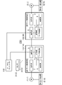
本実施形態のモータ制御装置1(図1参照)は、例えばJIS(Japanese Industrial Standards) C 0508等の日本国の規格、又はIEC(International Electrotechnical Commission) 61508等の国際規格機能安全に関する規格に準拠したモータ制御装置である。本実施形態では、モータ制御装置1は複数(図1では、2つ)存在し、これらのモータ制御装置1がモータ制御システム100を構成している。言い換えれば、モータ制御システム100は、モータ制御装置1を複数備えている。
(1) Overview The motor control device 1 (see FIG. 1) of the present embodiment complies with Japanese standards such as JIS (Japanese Industrial Standards) C 0508, or international standards such as IEC (International Electrotechnical Commission) 61508. It is a standard-compliant motor controller. In this embodiment, there are a plurality of motor control devices 1 (two in FIG. 1), and these motor control devices 1 constitute a motor control system 100 . In other words, the motor control system 100 includes multiple motor control devices 1 .

本実施形態のモータ制御装置1は、図1に示すように、制御部2と、入力部6と、判定部31と、を備えている。本実施形態では、判定部31は、後述するように処理部3の有する機能の一つとして実現される。 The motor control device 1 of this embodiment includes a control section 2, an input section 6, and a determination section 31, as shown in FIG. In this embodiment, the determination unit 31 is implemented as one of the functions of the processing unit 3 as described later.

制御部2は、モータ7を制御する。本実施形態では、制御部2は、モータ制御システム100の上位システムから与えられる制御指令に基づいて、モータ7を制御する。これにより、制御部2は、制御指令にしたがって、モータ7の軸に取り付けられた負荷を制御することになる。本実施形態における負荷は、一例として運搬機械若しくは工作機械等の産業機械、又はロボット等を含み得る。 The control section 2 controls the motor 7 . In this embodiment, the control unit 2 controls the motor 7 based on a control command given from the host system of the motor control system 100 . As a result, the controller 2 controls the load attached to the shaft of the motor 7 according to the control command. The load in this embodiment may include, for example, industrial machines such as transport machines or machine tools, or robots.

入力部6は、センサ9の検知結果を受け付ける。センサ9は、モータ7により駆動される負荷の置かれる環境の状態を検知する。本実施形態における環境は、一例として産業機械又はロボット等が設置される工場を含み得る。センサ9は、例えば工場において産業機械等の周辺に設置される、IEC-61508等の国際規格に準拠した安全機器の一種である。 The input unit 6 receives detection results from the sensor 9 . A sensor 9 detects the state of the environment in which the load driven by the motor 7 is placed. The environment in this embodiment may include, for example, a factory where industrial machines or robots are installed. The sensor 9 is a type of safety equipment that is installed around industrial machines in a factory, for example, and complies with international standards such as IEC-61508.

本実施形態では、複数のモータ制御装置1のうちの少なくとも1以上のモータ制御装置1に、センサ9が接続されている。具体的には、図1に示すように、2つのモータ制御装置1にそれぞれ複数のセンサ9が接続されている。以下の説明では、2つのモータ制御装置1のうちの一方を「第1モータ制御装置11」、他方を「第2モータ制御装置12」ともいう。そして、第1モータ制御装置11には、3つのセンサ9(第1センサ91、第2センサ92、及び第3センサ93)が接続されており、第2モータ制御装置12には、2つのセンサ9(第4センサ94及び第5センサ95)が接続されている。 In this embodiment, the sensor 9 is connected to at least one or more motor control devices 1 out of the plurality of motor control devices 1 . Specifically, as shown in FIG. 1, a plurality of sensors 9 are connected to two motor control devices 1, respectively. In the following description, one of the two motor control devices 1 is also called "first motor control device 11" and the other is called "second motor control device 12". Three sensors 9 (a first sensor 91, a second sensor 92, and a third sensor 93) are connected to the first motor control device 11, and two sensors are connected to the second motor control device 12. 9 (fourth sensor 94 and fifth sensor 95) are connected.

判定部31は、入力部6に入力されたセンサ9の検知結果に基づいて、環境の状態が安全状態であるか不安全状態であるかを判定する。本開示でいう「安全状態」とは、例えば産業機械が設置された領域に人(作業者)が進入していない等、人等に対する許容できないリスクが存在しない状態、言い換えれば、リスクを許容できるまで低減させた状態をいう。本開示でいう「不安全状態」とは、安全状態の逆の状態であって、産業機械が設置された領域に人が進入している等、人等に対する許容できないリスクが存在する状態をいう。 The determination unit 31 determines whether the environmental state is a safe state or an unsafe state based on the detection result of the sensor 9 input to the input unit 6 . The term “safe state” as used in the present disclosure refers to a state in which there is no unacceptable risk to humans, such as a person (worker) not entering the area where the industrial machine is installed. It refers to the state in which it has been reduced to The term “unsafe state” as used in this disclosure refers to a state opposite to a safe state, where there is an unacceptable risk to humans, etc., such as when a person enters an area where industrial machinery is installed. .

上述のように、本実施形態では、モータ制御装置1は、モータ制御装置1に接続されたセンサ9の検知結果に基づいて、環境の状態が安全状態であるか不安全状態であるかを判定することが可能である。つまり、本実施形態では、モータ制御装置1は、従前であればセーフティコントローラSC1(図5参照)が実行していた機能を、セーフティコントローラSC1を介することなく実行することが可能である。このため、本実施形態では、セーフティコントローラSC1によりモータ制御装置1を管理する場合と比較して、不安全状態に対する措置を速やかに講じやすい、という利点がある。 As described above, in the present embodiment, the motor control device 1 determines whether the environmental state is safe or unsafe based on the detection result of the sensor 9 connected to the motor control device 1. It is possible to In other words, in the present embodiment, the motor control device 1 can perform functions that were conventionally performed by the safety controller SC1 (see FIG. 5) without using the safety controller SC1. Therefore, in this embodiment, compared with the case where the motor control device 1 is managed by the safety controller SC1, there is an advantage that it is easier to promptly take measures against an unsafe state.

(2)詳細
以下、本実施形態のモータ制御装置1、及びモータ制御装置1を備えたモータ制御システム100について図1を用いて詳細に説明する。本実施形態では、既に述べたように、モータ制御システム100は、2つのモータ制御装置1(第1モータ制御装置11及び第2モータ制御装置12)を備えている。第1モータ制御装置11及び第2モータ制御装置12の構成は、基本的に同じである。
(2) Details The motor control device 1 of the present embodiment and the motor control system 100 including the motor control device 1 will be described in detail below with reference to FIG. In this embodiment, as already described, the motor control system 100 includes two motor control devices 1 (first motor control device 11 and second motor control device 12). The configurations of the first motor control device 11 and the second motor control device 12 are basically the same.

モータ制御装置1は、制御部2と、処理部3と、取得部4と、通信部5と、入力部6と、を備えている。 The motor control device 1 includes a control section 2 , a processing section 3 , an acquisition section 4 , a communication section 5 and an input section 6 .

取得部4は、モータ7の動作に関するパラメータを取得する。本実施形態では、取得部4は、モータ7に取り付けられた位置検出器8にて検出された物理量を、例えばケーブル等を介して取得する。位置検出器8は、例えばレゾルバ又はロータリエンコーダであって、モータ7の可動子の位置(言い換えれば、モータ7の動作位置)を検出する。つまり、本実施形態では、取得部4が取得するパラメータは、モータ7の動作位置に関する物理量(モータ7の軸の回転角度又は角速度等)である。本実施形態では、第1モータ制御装置11の取得部4は、第1モータ71に取り付けられた第1位置検出器81にて検出された物理量を取得する。また、本実施形態では、第2モータ制御装置12の取得部4は、第2モータ72に取り付けられた第2位置検出器82にて検出された物理量を取得する。 Acquisition unit 4 acquires parameters relating to the operation of motor 7 . In this embodiment, the acquisition unit 4 acquires the physical quantity detected by the position detector 8 attached to the motor 7 via, for example, a cable. The position detector 8 is, for example, a resolver or a rotary encoder, and detects the position of the mover of the motor 7 (in other words, the operating position of the motor 7). That is, in the present embodiment, the parameters acquired by the acquisition unit 4 are physical quantities (rotational angle or angular velocity of the shaft of the motor 7, etc.) relating to the operating position of the motor 7. FIG. In this embodiment, the acquisition unit 4 of the first motor control device 11 acquires physical quantities detected by the first position detector 81 attached to the first motor 71 . Further, in the present embodiment, the acquisition unit 4 of the second motor control device 12 acquires physical quantities detected by the second position detector 82 attached to the second motor 72 .

通信部5は、他のモータ制御装置1との通信を行うための通信インタフェースであって、例えば産業用のイーサネット(登録商標)プロトコルに準拠した有線通信モジュールを有している。通信部5は、例えばLAN(Local Area Network)ケーブルを介して、他のモータ制御装置1の通信部5と通信する。つまり、本実施形態では、複数のモータ制御装置1は、産業用ネットワークに接続されている。本開示でいう「産業用ネットワーク」は、例えばファクトリーオートメーションにおいて用いられるフィールドネットワークであって、工場内に設置された複数の機器間で通信するために用いられる。産業用ネットワークは、一例として、Ethernet/IP(登録商標)、EtherCAT(登録商標)、又はPROFINET(登録商標)等を含み得る。 The communication unit 5 is a communication interface for communicating with another motor control device 1, and has a wired communication module conforming to the industrial Ethernet (registered trademark) protocol, for example. The communication unit 5 communicates with the communication units 5 of other motor control devices 1 via, for example, a LAN (Local Area Network) cable. In other words, in this embodiment, a plurality of motor control devices 1 are connected to an industrial network. An “industrial network” as used in the present disclosure is a field network used, for example, in factory automation, and is used for communication between multiple devices installed in a factory. The industrial network may include Ethernet/IP (registered trademark), EtherCAT (registered trademark), PROFINET (registered trademark), or the like, as an example.

入力部6は、センサ9の検知結果を受け付ける。具体的には、例えば入力部6は、ケーブル等を介してセンサ9から送信される2値信号を受信することにより、センサ9の検知結果を受け付ける。本実施形態では、第1モータ制御装置11には、第1センサ91、第2センサ92、及び第3センサ93が接続されている。したがって、第1モータ制御装置11の入力部6には、第1センサ91の検知結果、第2センサ92の検知結果、及び第3センサ93の検知結果が入力される。また、本実施形態では、第2モータ制御装置12には、第4センサ94及び第5センサ95が接続されている。したがって、第2モータ制御装置12の入力部6には、第4センサ94の検知結果、及び第5センサ95の検知結果が入力される。 The input unit 6 receives detection results from the sensor 9 . Specifically, for example, the input unit 6 receives the detection result of the sensor 9 by receiving a binary signal transmitted from the sensor 9 via a cable or the like. In this embodiment, a first sensor 91 , a second sensor 92 and a third sensor 93 are connected to the first motor control device 11 . Therefore, the detection result of the first sensor 91 , the detection result of the second sensor 92 , and the detection result of the third sensor 93 are input to the input unit 6 of the first motor control device 11 . Further, in the present embodiment, a fourth sensor 94 and a fifth sensor 95 are connected to the second motor control device 12 . Therefore, the detection result of the fourth sensor 94 and the detection result of the fifth sensor 95 are input to the input unit 6 of the second motor control device 12 .

センサ9は、モータ7により駆動される負荷の置かれる環境の状態を検知する。センサ9は、一例として、不安全領域への人の進入を検知するライトカーテン、又は不安全領域における人の存在を検知するレーザスキャナ若しくはマットスイッチ等の安全機器を含み得る。また、センサ9は、一例として、人の自主的な判断により操作される緊急停止スイッチ、又は安全領域と不安全領域とを隔てる扉等が開かれたことを検知するインターロックスイッチ等の安全機器を含み得る。つまり、センサ9は、環境の状態が不安全状態であることを示唆する事象(以下、「不安全事象」という)が発生しているか否かを検知する。本実施形態では、第1センサ91~第5センサ95は、それぞれ上述のいずれかの安全機器により構成されている。 A sensor 9 detects the state of the environment in which the load driven by the motor 7 is placed. Sensors 9 may include, by way of example, safety devices such as light curtains to detect the entry of persons into unsafe areas, or laser scanners or mat switches to detect the presence of persons in unsafe areas. In addition, the sensor 9 is, for example, an emergency stop switch operated by a person's voluntary judgment, or a safety device such as an interlock switch that detects opening of a door or the like separating a safe area and an unsafe area. can include That is, the sensor 9 detects whether or not an event (hereinafter referred to as an “unsafe event”) that suggests that the environment is in an unsafe state has occurred. In this embodiment, each of the first sensor 91 to the fifth sensor 95 is composed of one of the safety devices described above.

本開示でいう「安全領域」は、例えば産業機械等の負荷の稼働中において、負荷が人等に対して及ぼし得る許容できないリスクが発生しない領域である。不安全領域は、例えば産業機械等の負荷の稼働中において、負荷が人等に対して及ぼし得る許容できないリスクが発生し得る領域である。例えば、工場において扉等により隔てられた2つの領域のうち、一方の産業機械が存在する領域が不安全領域に相当し、他方の産業機械が存在しない領域が安全領域に相当する。 The “safe area” referred to in the present disclosure is an area in which an unacceptable risk that the load may pose to people or the like does not occur while the load such as industrial machinery is in operation, for example. An unsafe area is an area in which an unacceptable risk that the load may pose to a person or the like may occur while the load such as an industrial machine is in operation. For example, of two areas separated by a door or the like in a factory, the area where one industrial machine exists corresponds to the unsafe area, and the area where the other industrial machine does not exist corresponds to the safe area.

制御部2は、モータ7の有するコイルに供給する電流を制御することにより、モータ7を制御する。具体的には、例えば制御部2は、三相インバータの有する複数のスイッチング素子をPWM(Pulse Width Modulation)制御することにより、三相インバータからモータ7の有するコイルに供給する交流電流を制御し、モータ7を制御する。また、制御部2は、上位システムから与えられる制御指令と、位置検出器8で検出されたモータ7の動作に関するパラメータと、に基づいてモータ7を制御する。例えば、制御部2は、位置検出器8で検出されるモータ7の軸の回転速度が、制御指令により指示された回転速度に一致するようにモータ7を制御する。本実施形態では、第1モータ制御装置11の制御部2が第1モータ71を制御し、第2モータ制御装置12の制御部2が第2モータ72を制御する。なお、本実施形態では、上位システムとモータ制御装置1との通信に用いるネットワークは、通信部5を介したネットワークと異なっている。 The control unit 2 controls the motor 7 by controlling the current supplied to the coils of the motor 7 . Specifically, for example, the control unit 2 controls the alternating current supplied from the three-phase inverter to the coils of the motor 7 by PWM (Pulse Width Modulation) control of a plurality of switching elements of the three-phase inverter, Control the motor 7. Further, the control unit 2 controls the motor 7 based on a control command given from the host system and parameters related to the operation of the motor 7 detected by the position detector 8 . For example, the control unit 2 controls the motor 7 so that the rotation speed of the shaft of the motor 7 detected by the position detector 8 matches the rotation speed instructed by the control command. In this embodiment, the controller 2 of the first motor controller 11 controls the first motor 71 and the controller 2 of the second motor controller 12 controls the second motor 72 . Note that in this embodiment, the network used for communication between the host system and the motor control device 1 is different from the network via the communication unit 5 .

処理部3は、例えば、コンピュータシステムを含んでいる。コンピュータシステムは、ハードウェアとしてのプロセッサ及びメモリを主構成とする。コンピュータシステムのメモリに記録されたプログラムをプロセッサが実行することによって、処理部3としての機能が実現される。プログラムは、コンピュータシステムのメモリに予め記録されてもよく、電気通信回線を通じて提供されてもよく、コンピュータシステムで読み取り可能なメモリカード、光学ディスク、ハードディスクドライブ等の非一時的記録媒体に記録されて提供されてもよい。処理部3は、所定のプログラムをプロセッサにて実行することにより、判定部31としての機能と、モータ判定部32としての機能と、を実現する。 The processing unit 3 includes, for example, a computer system. A computer system is mainly composed of a processor and a memory as hardware. The function of the processing unit 3 is realized by the processor executing a program recorded in the memory of the computer system. The program may be recorded in advance in the memory of the computer system, may be provided through an electric communication line, or may be recorded in a non-temporary recording medium such as a computer system-readable memory card, optical disk, or hard disk drive. may be provided. The processing unit 3 realizes the function as the determination unit 31 and the function as the motor determination unit 32 by executing a predetermined program in the processor.

判定部31は、入力部6に入力されたセンサ9の検知結果に基づいて、環境の状態が安全状態であるか不安全状態であるかを判定する。例えば、センサ9がライトカーテンである場合、入力部6がセンサ9から不安全領域への人の進入を検知した旨の検知結果を受け付けると、判定部31は、環境が不安全状態にある、と判定する。また、例えば、センサ9が緊急停止スイッチである場合、入力部6がセンサ9から緊急停止スイッチが操作された旨の検知結果を受け付けると、判定部31は、環境が不安全状態にある、と判定する。つまり、判定部31は、入力部6に入力された複数のセンサ9のうちの1以上のセンサ9の検知結果が、環境の状態が不安全状態であることを示唆する結果である場合に、環境の状態が不安全状態である、と判定する。 The determination unit 31 determines whether the environmental state is a safe state or an unsafe state based on the detection result of the sensor 9 input to the input unit 6 . For example, when the sensor 9 is a light curtain, when the input unit 6 receives a detection result indicating that a person has entered an unsafe area from the sensor 9, the determination unit 31 determines that the environment is in an unsafe state. I judge. Further, for example, when the sensor 9 is an emergency stop switch, when the input unit 6 receives the detection result indicating that the emergency stop switch has been operated from the sensor 9, the determination unit 31 determines that the environment is in an unsafe state. judge. That is, when the detection result of one or more sensors 9 out of the plurality of sensors 9 input to the input unit 6 is a result suggesting that the environmental state is unsafe, the determination unit 31 It is determined that the state of the environment is unsafe.

モータ判定部32は、取得部4で取得したパラメータに基づいて、モータ7の動作が正常であるか異常であるかを判定する。例えば、パラメータがモータ7の軸の回転速度である場合、モータ判定部32は、取得部4で取得した回転速度が所定の範囲内に収まっていればモータ7の動作が正常であると判定し、回転速度が所定の範囲を逸脱していればモータ7の動作が異常であると判定する。つまり、モータ判定部32は、取得部4で取得したパラメータが、モータ7の動作が正常である場合に取り得る範囲に収まっているか否かに基づいて、モータ7の動作が正常であるか異常であるかを判定する。 The motor determination unit 32 determines whether the operation of the motor 7 is normal or abnormal based on the parameters acquired by the acquisition unit 4 . For example, when the parameter is the rotation speed of the shaft of the motor 7, the motor determination unit 32 determines that the operation of the motor 7 is normal if the rotation speed acquired by the acquisition unit 4 is within a predetermined range. , the motor 7 is determined to be operating abnormally if the rotational speed deviates from the predetermined range. In other words, the motor determination unit 32 determines whether the operation of the motor 7 is normal or abnormal based on whether the parameter acquired by the acquisition unit 4 falls within a range that can be taken when the operation of the motor 7 is normal. Determine whether or not

本実施形態では、制御部2は、判定部31の判定結果に基づいてモータ7を制御する機能も有する。具体的には、制御部2は、判定部31にて不安全状態と判定されると、モータ7の動作を停止又は制限する。ここでいう「モータの動作を制限する」とは、例えばモータ7の軸の回転速度を減速させることを含み得る。このようにして、本実施形態では、判定部31にて不安全状態と判定されると、モータ7の動作を停止又は制限することにより、環境の状態を不安全状態から安全状態へと移行させる。 In this embodiment, the control section 2 also has a function of controlling the motor 7 based on the determination result of the determination section 31 . Specifically, when the determination unit 31 determines that the state is unsafe, the control unit 2 stops or limits the operation of the motor 7 . "Limiting the operation of the motor" as used herein may include, for example, reducing the rotational speed of the shaft of the motor 7. FIG. In this way, in the present embodiment, when the determining unit 31 determines that the state is unsafe, the operation of the motor 7 is stopped or restricted, thereby shifting the environmental state from the unsafe state to the safe state. .

また、本実施形態では、制御部2は、モータ判定部32の判定結果に基づいてモータ7を制御する機能も有する。具体的には、制御部2は、モータ判定部32にてモータ7に異常があると判定されると、モータ7の動作を停止又は制限する。ここで、判定部31にて安全状態であると判定されている場合でも、モータ7に異常が発生している場合、モータ7が想定外の動作をすることで環境に悪影響を及ぼす可能性がある。したがって、このような場合、環境の状態は不安全状態であると言える。そこで、本実施形態では、モータ判定部32にてモータ7の異常があると判定されると、モータ7の動作を停止又は制限することにより、環境の状態を不安全状態から安全状態へと移行させる。 Further, in this embodiment, the control unit 2 also has a function of controlling the motor 7 based on the determination result of the motor determination unit 32 . Specifically, when the motor determination unit 32 determines that the motor 7 has an abnormality, the control unit 2 stops or limits the operation of the motor 7 . Here, even if the determination unit 31 determines that the state is safe, if an abnormality occurs in the motor 7, there is a possibility that the motor 7 will operate unexpectedly and adversely affect the environment. be. Therefore, in such a case, the state of the environment can be said to be unsafe. Therefore, in this embodiment, when the motor determination unit 32 determines that there is an abnormality in the motor 7, the operation of the motor 7 is stopped or restricted to shift the environmental state from an unsafe state to a safe state. Let

(3)動作
以下、本実施形態のモータ制御装置1及びモータ制御システム100の動作について第1動作例~第3動作例を挙げて説明する。
(3) Operation Hereinafter, the operation of the motor control device 1 and the motor control system 100 of the present embodiment will be described with reference to first to third operation examples.

(3.1)第1動作例
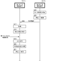
第1動作例における第1モータ制御装置11及び第2モータ制御装置12の動作の流れを図2に示す。第1動作例では、第1モータ制御装置11に接続されている複数のセンサ9のうちのいずれか1つのセンサ9(ここでは、第1センサ91)にて、不安全事象の発生を検知した、と仮定する。
(3.1) First Operation Example FIG. 2 shows the operation flow of the first motor control device 11 and the second motor control device 12 in the first operation example. In the first operation example, one of the plurality of sensors 9 connected to the first motor control device 11 (here, the first sensor 91) detects the occurrence of an unsafe event. ,

まず、第1センサ91から第1モータ制御装置11に検知結果が出力されると、第1モータ制御装置11の入力部6は、第1センサ91からの検知結果の入力を受け付ける(S1)。すると、第1モータ制御装置11の判定部31は、第1センサ91からの検知結果に基づいて、環境の状態が不安全状態にある、と判定する(S2)。判定部31の判定結果を受けて、第1モータ制御装置11の制御部2は、第1モータ71の動作を停止又は制限する(S3)。また、第1モータ制御装置11の処理部3は、判定部31の判定結果を含む判定情報を、通信部5から第2モータ制御装置12の通信部5へ送信する(S4)。 First, when the detection result is output from the first sensor 91 to the first motor control device 11, the input unit 6 of the first motor control device 11 receives the input of the detection result from the first sensor 91 (S1). Then, the determination unit 31 of the first motor control device 11 determines that the environment is in an unsafe state based on the detection result from the first sensor 91 (S2). Upon receiving the determination result of the determination unit 31, the control unit 2 of the first motor control device 11 stops or limits the operation of the first motor 71 (S3). Further, the processing unit 3 of the first motor control device 11 transmits determination information including the determination result of the determination unit 31 from the communication unit 5 to the communication unit 5 of the second motor control device 12 (S4).

第2モータ制御装置12の通信部5は、第1モータ制御装置11から送信された判定情報を受信することで、第1モータ制御装置11の判定部31の判定結果を取得する(S5)。すると、第2モータ制御装置12の判定部31は、この判定結果に基づいて、環境の状態が不安全状態にある、と判定する(S6)。そして、判定部31の判定結果を受けて、第2モータ制御装置12の制御部2は、第2モータ72の動作を停止又は制限する(S7)。つまり、本実施形態では、判定部31は、他のモータ制御装置1(ここでは、第1モータ制御装置11)の判定部31の判定結果に基づいて、モータ7の動作を停止又は制限する機能を有している。 By receiving the determination information transmitted from the first motor control device 11, the communication unit 5 of the second motor control device 12 acquires the determination result of the determination unit 31 of the first motor control device 11 (S5). Then, based on this determination result, the determination unit 31 of the second motor control device 12 determines that the environment is in an unsafe state (S6). Then, upon receiving the determination result of the determination section 31, the control section 2 of the second motor control device 12 stops or limits the operation of the second motor 72 (S7). That is, in the present embodiment, the determination unit 31 has a function of stopping or limiting the operation of the motor 7 based on the determination result of the determination unit 31 of the other motor control device 1 (here, the first motor control device 11). have.

上述のように、第1動作例では、第1モータ制御装置11の処理部3は、判定部31の判定結果を含む判定情報を、通信部5から第2モータ制御装置12の通信部5へ送信する。言い換えれば、通信部5は、判定部31にて不安全状態と判定されると、判定結果を他のモータ制御装置1(ここでは、第2モータ制御装置12)にセーフティコントローラSC1を介さずに送信する。 As described above, in the first operation example, the processing unit 3 of the first motor control device 11 transmits determination information including the determination result of the determination unit 31 from the communication unit 5 to the communication unit 5 of the second motor control device 12. Send. In other words, when the determination unit 31 determines that the state is unsafe, the communication unit 5 transmits the determination result to the other motor control device 1 (here, the second motor control device 12) without passing through the safety controller SC1. Send.

(3.2)第2動作例
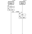
第2動作例における第1モータ制御装置11及び第2モータ制御装置12の動作の流れを図3に示す。第2動作例では、第1モータ制御装置11の制御対象である第1モータ71に何らかの異常が発生した、と仮定する。
(3.2) Second Operation Example FIG. 3 shows the flow of operations of the first motor control device 11 and the second motor control device 12 in the second operation example. In the second operation example, it is assumed that some abnormality has occurred in the first motor 71 controlled by the first motor control device 11 .

まず、第1モータ制御装置11のモータ判定部32は、取得部4で取得したパラメータに基づいて、第1モータ71に異常がある、と判定する(S8)。モータ判定部32の判定結果を受けて、第1モータ制御装置11の制御部2は、第1モータ71の動作を停止又は制限する(S9)。また、第1モータ制御装置11の処理部3は、モータ判定部32の判定結果を含む判定情報を、通信部5から第2モータ制御装置12の通信部5へ送信する(S10)。 First, the motor determination unit 32 of the first motor control device 11 determines that there is an abnormality in the first motor 71 based on the parameters acquired by the acquisition unit 4 (S8). Upon receiving the determination result of the motor determination section 32, the control section 2 of the first motor control device 11 stops or limits the operation of the first motor 71 (S9). Further, the processing unit 3 of the first motor control device 11 transmits determination information including the determination result of the motor determination unit 32 from the communication unit 5 to the communication unit 5 of the second motor control device 12 (S10).

第2モータ制御装置12の通信部5は、第1モータ制御装置11から送信された判定情報を受信することで、第1モータ制御装置11のモータ判定部32の判定結果を取得する(S11)。すると、第2モータ制御装置12の判定部31は、この判定結果に基づいて、環境の状態が不安全状態にある、と判定する(S12)。そして、判定部31の判定結果を受けて、第2モータ制御装置12の制御部2は、第2モータ72の動作を停止又は制限する(S13)。つまり、本実施形態では、モータ判定部32は、他のモータ制御装置1(ここでは、第1モータ制御装置11)のモータ判定部32の判定結果に基づいて、モータ7の動作を停止又は制限する機能を有している。 By receiving the determination information transmitted from the first motor control device 11, the communication unit 5 of the second motor control device 12 acquires the determination result of the motor determination unit 32 of the first motor control device 11 (S11). . Then, based on this determination result, the determination unit 31 of the second motor control device 12 determines that the environment is in an unsafe state (S12). Upon receiving the determination result of the determination unit 31, the control unit 2 of the second motor control device 12 stops or limits the operation of the second motor 72 (S13). That is, in the present embodiment, the motor determination unit 32 stops or limits the operation of the motor 7 based on the determination result of the motor determination unit 32 of the other motor control device 1 (here, the first motor control device 11). It has the function to

上述のように、第2動作例では、第1モータ制御装置11の処理部3は、モータ判定部32の判定結果を含む判定情報を、通信部5から第2モータ制御装置12の通信部5へ送信する。言い換えれば、通信部5は、モータ判定部32にてモータ7が異常であると判定されると、判定結果を他のモータ制御装置1(ここでは、第2モータ制御装置12)にセーフティコントローラSC1を介さずに送信する。 As described above, in the second operation example, the processing unit 3 of the first motor control device 11 transmits determination information including the determination result of the motor determination unit 32 from the communication unit 5 to the communication unit 5 of the second motor control device 12 . Send to In other words, when the motor determination unit 32 determines that the motor 7 is abnormal, the communication unit 5 sends the determination result to the other motor control device 1 (here, the second motor control device 12) via the safety controller SC1. send without going through

(3.3)第3動作例
第3動作例における第1モータ制御装置11及び第2モータ制御装置12の動作の流れを図4に示す。第3動作例では、第2モータ制御装置12の制御対象である第2モータ72に何らかの異常が発生した、と仮定する。その後、第1モータ制御装置11に接続されている複数のセンサ9のうちのいずれか1つのセンサ9(ここでは、第1センサ91)にて、不安全事象の発生を検知した、と仮定する。なお、第2モータ72に異常が発生しただけでは、第1モータ71により駆動される負荷の置かれる環境に影響を及ぼさない、と仮定する。
(3.3) Third Operation Example FIG. 4 shows the operation flow of the first motor control device 11 and the second motor control device 12 in the third operation example. In the third operation example, it is assumed that some abnormality has occurred in the second motor 72 controlled by the second motor control device 12 . After that, it is assumed that any one sensor 9 (here, the first sensor 91) among the plurality of sensors 9 connected to the first motor control device 11 detects the occurrence of an unsafe event. . It is assumed that the environment in which the load driven by the first motor 71 is placed is not affected only by the occurrence of an abnormality in the second motor 72 .

まず、第2モータ制御装置12のモータ判定部32は、取得部4で取得したパラメータに基づいて、第2モータ72に異常がある、と判定する(S14)。モータ判定部32の判定結果を受けて、第2モータ制御装置12の制御部2は、第2モータ72の動作を停止又は制限する(S15)。また、第2モータ制御装置12の処理部3は、モータ判定部32の判定結果を含む判定情報を、通信部5から第1モータ制御装置11の通信部5へ送信する(S16)。 First, the motor determination unit 32 of the second motor control device 12 determines that there is an abnormality in the second motor 72 based on the parameters acquired by the acquisition unit 4 (S14). Upon receiving the determination result of the motor determination section 32, the control section 2 of the second motor control device 12 stops or limits the operation of the second motor 72 (S15). Further, the processing unit 3 of the second motor control device 12 transmits determination information including the determination result of the motor determination unit 32 from the communication unit 5 to the communication unit 5 of the first motor control device 11 (S16).

第1モータ制御装置11の通信部5は、第2モータ制御装置12から送信された判定情報を受信することで、第2モータ制御装置12のモータ判定部32の判定結果を取得する(S17)。すると、第1モータ制御装置11の判定部31は、この判定結果に基づいて、環境の状態が依然として安全状態にある、と判定する(S18)。つまり、第2モータ72に異常が発生した時点では、第2モータ制御装置12では不安全状態にあると判定されるが、第1モータ制御装置11では不安全状態にあるとは判定されない。 By receiving the determination information transmitted from the second motor control device 12, the communication unit 5 of the first motor control device 11 acquires the determination result of the motor determination unit 32 of the second motor control device 12 (S17). . Then, based on the determination result, the determination unit 31 of the first motor control device 11 determines that the environment is still in a safe state (S18). That is, when an abnormality occurs in the second motor 72, the second motor control device 12 determines that it is in an unsafe state, but the first motor control device 11 does not determine that it is in an unsafe state.

その後、第1センサ91から第1モータ制御装置11に対して、不安全事象の発生を示す検知結果が出力されると、第1モータ制御装置11の入力部6は、第1センサ91からの検知結果の入力を受け付ける(S19)。すると、第1モータ制御装置11の判定部31は、第1センサ91からの検知結果に基づいて、環境の状態が不安全状態にある、と判定する(S20)。判定部31の判定結果を受けて、第1モータ制御装置11の制御部2は、第1モータ71の動作を停止又は制限する(S21)。図4に示す例では、第1モータ制御装置11の処理部3は、判定部31の判定結果を含む判定情報を、通信部5から第2モータ制御装置12の通信部5へ送信していないが、送信してもよい。 After that, when the first sensor 91 outputs a detection result indicating the occurrence of an unsafe event to the first motor control device 11, the input unit 6 of the first motor control device 11 receives the signal from the first sensor 91. Input of the detection result is accepted (S19). Then, the determination unit 31 of the first motor control device 11 determines that the environment is in an unsafe state based on the detection result from the first sensor 91 (S20). Upon receiving the determination result of the determination unit 31, the control unit 2 of the first motor control device 11 stops or limits the operation of the first motor 71 (S21). In the example shown in FIG. 4, the processing unit 3 of the first motor control device 11 does not transmit determination information including the determination result of the determination unit 31 from the communication unit 5 to the communication unit 5 of the second motor control device 12. may be sent.

上述のように、第3動作例では、第1モータ制御装置11の判定部31は、第2モータ72の異常の発生のみでは不安全状態にあるとは判定せず、いずれかのセンサ9にて不安全事象の発生が検知されると、初めて不安全状態にある、と判定する。つまり、本実施形態では、モータ制御装置1の判定部31は、他のモータ制御装置1の判定部31の判定結果及び/又はモータ判定部32の判定結果も参照して、環境の状態が安全状態にあるか不安全状態にあるかを判定することも可能である。 As described above, in the third operation example, the determination unit 31 of the first motor control device 11 does not determine that the second motor 72 is in an unsafe state based only on the occurrence of an abnormality in the second motor 72. When the occurrence of an unsafe event is detected by That is, in the present embodiment, the determination unit 31 of the motor control device 1 also refers to the determination result of the determination unit 31 of the other motor control device 1 and/or the determination result of the motor determination unit 32 to determine whether the environmental state is safe. It is also possible to determine whether there is a condition or an unsafe condition.

以下、本実施形態のモータ制御装置1の利点について、比較例のモータ制御システム200との比較を交えて説明する。比較例のモータ制御システム200は、図5に示すように、第1モータ制御装置201と、第2モータ制御装置202と、を備えている。比較例の第1モータ制御装置201及び第2モータ制御装置202は、いずれも判定部31及び通信部5を備えていない点で、本実施形態のモータ制御装置1と相違する。また、比較例の第1モータ制御装置201及び第2モータ制御装置202は、いずれもセーフティコントローラSC1に接続されている点で、本実施形態のモータ制御装置1と相違する。さらに、比較例のモータ制御システム200では、複数のセンサ9は、セーフティコントローラSC1に接続されている。 Advantages of the motor control device 1 of the present embodiment will be described below in comparison with the motor control system 200 of the comparative example. The motor control system 200 of the comparative example includes a first motor control device 201 and a second motor control device 202, as shown in FIG. The first motor control device 201 and the second motor control device 202 of the comparative example are different from the motor control device 1 of the present embodiment in that they do not include the determination unit 31 and the communication unit 5 . Also, the first motor control device 201 and the second motor control device 202 of the comparative example are different from the motor control device 1 of the present embodiment in that they are both connected to the safety controller SC1. Furthermore, in the motor control system 200 of the comparative example, the multiple sensors 9 are connected to the safety controller SC1.

セーフティコントローラSC1は、複数のセンサ9のうちのいずれか1つのセンサ9にて不安全事象の発生が検知されると、環境の状態が不安全状態であると判定し、各モータ制御装置201,202に対して要求情報を送信する機能を有している。要求情報は、モータ7の動作の停止又は制限を要求する指令を含んでいる。また、セーフティコントローラSC1は、いずれかのモータ制御装置201,202から判定情報を取得すると、環境の状態が不安全状態であると判定し、他のモータ制御装置201,202に対して要求情報を送信する機能を有している。 When the occurrence of an unsafe event is detected by any one of the plurality of sensors 9, the safety controller SC1 determines that the environment is in an unsafe state. 202 has a function of transmitting request information. The request information includes a command requesting stopping or limiting the operation of the motor 7 . When the safety controller SC1 acquires determination information from one of the motor control devices 201 and 202, the safety controller SC1 determines that the environmental state is unsafe, and sends request information to the other motor control devices 201 and 202. It has the ability to send.

比較例のモータ制御システム200の動作の流れを図6に示す。比較例の動作例においては、第1モータ制御装置201の制御対象である第1モータ71に何らかの異常が発生した、と仮定する。 FIG. 6 shows the operation flow of the motor control system 200 of the comparative example. In the operation example of the comparative example, it is assumed that some abnormality has occurred in the first motor 71 controlled by the first motor control device 201 .

まず、第1モータ制御装置201は、取得部で取得したパラメータに基づいて、第1モータ71に異常がある、と判定する(S101)。この判定結果を受けて、第1モータ制御装置201は、第1モータ71の動作を停止又は制限する(S102)。また、第1モータ制御装置201は、上記の判定結果を含む判定情報をセーフティコントローラSC1へ送信する(S103)。 First, the first motor control device 201 determines that there is an abnormality in the first motor 71 based on the parameters acquired by the acquisition unit (S101). Upon receiving this determination result, the first motor control device 201 stops or limits the operation of the first motor 71 (S102). Further, the first motor control device 201 transmits determination information including the above determination result to the safety controller SC1 (S103).

セーフティコントローラSC1は、第1モータ制御装置201から送信された判定情報を受信することで、第1モータ制御装置201の判定結果を取得する(S104)。すると、セーフティコントローラSC1は、この判定結果に基づいて、環境の状態が不安全状態にある、と判定する(S105)。そして、セーフティコントローラSC1は、要求情報を第2モータ制御装置202へ送信する(S106)。 The safety controller SC1 acquires the determination result of the first motor control device 201 by receiving the determination information transmitted from the first motor control device 201 (S104). Then, based on this determination result, the safety controller SC1 determines that the environment is in an unsafe state (S105). The safety controller SC1 then transmits the request information to the second motor control device 202 (S106).

第2モータ制御装置12は、セーフティコントローラSC1から要求情報を取得すると(S107)、第2モータ72の動作を停止又は制限する(S108)。 When the second motor control device 12 acquires the request information from the safety controller SC1 (S107), it stops or limits the operation of the second motor 72 (S108).

比較例のモータ制御システム200では、例えば第1モータ制御装置201の制御対象である第1モータ71の異常が発生した場合、環境の状態が不安全状態に移行したことが、セーフティコントローラSC1を介して第2モータ制御装置202に通知される。このため、第2モータ制御装置202においては、第1モータ71の異常が発生した時点から自身の制御対象である第2モータ72の動作を停止又は制限するまでに遅延が生じ得る。 In the motor control system 200 of the comparative example, for example, when an abnormality occurs in the first motor 71 controlled by the first motor control device 201, the fact that the environmental state has shifted to an unsafe state is detected via the safety controller SC1. is notified to the second motor control device 202 . Therefore, in the second motor control device 202, a delay may occur from the time when the abnormality occurs in the first motor 71 until the operation of the second motor 72, which is the control target of the second motor control device 202, is stopped or restricted.

これに対して、本実施形態のモータ制御装置1は、通信部5を備えている。このため、本実施形態では、第2動作例で述べたように、例えば第1モータ制御装置11のモータ判定部32にて第1モータ71が異常であると判定されると、判定結果が第2モータ制御装置12にセーフティコントローラSC1を介さずに送信される。したがって、第2モータ制御装置12においては、第1モータ71の異常が発生した時点から自身の制御対象である第2モータ72の動作を停止又は制限するまでに遅延が生じにくい。つまり、本実施形態では、セーフティコントローラSC1を介して他のモータ制御装置1に判定結果を送信する場合と比較して、他のモータ制御装置1にて判定結果に基づいて不安全状態に対する措置を速やかに講じることができる、という利点がある。 On the other hand, the motor control device 1 of this embodiment includes a communication section 5 . Therefore, in the present embodiment, as described in the second operation example, for example, when the motor determination unit 32 of the first motor control device 11 determines that the first motor 71 is abnormal, the determination result is It is sent to the two-motor control device 12 without going through the safety controller SC1. Therefore, in the second motor control device 12, a delay is less likely to occur from the time when the abnormality occurs in the first motor 71 to the time when the operation of the second motor 72, which is the control target of the second motor control device 12, is stopped or restricted. In other words, in the present embodiment, compared with the case where the determination result is transmitted to the other motor control device 1 via the safety controller SC1, the other motor control device 1 takes measures against the unsafe state based on the determination result. It has the advantage of being able to act quickly.

また、上述のように、比較例のモータ制御システム200では、いずれかのセンサ9にて不安全事象の発生を検知した場合、セーフティコントローラSC1を介して各モータ制御装置201,202へ要求情報が送信される。このため、比較例のモータ制御システム200では、いずれかのセンサ9にて不安全事象の発生を検知してから、各モータ制御装置201,202でモータ7の動作を停止又は制限するまでに遅延が生じ得る。 Further, as described above, in the motor control system 200 of the comparative example, when any of the sensors 9 detects the occurrence of an unsafe event, request information is sent to the motor control devices 201 and 202 via the safety controller SC1. sent. Therefore, in the motor control system 200 of the comparative example, there is a delay from when any of the sensors 9 detects the occurrence of an unsafe event to when the motor control devices 201 and 202 stop or limit the operation of the motor 7. can occur.

これに対して、本実施形態のモータ制御装置1は、判定部31を備えている。このため、本実施形態では、第1動作例で述べたように、例えば第1センサ91にて不安全事象の発生を検知した場合、第1モータ制御装置11の判定部31は、環境の状態が不安全状態である、と判定することができる。したがって、本実施形態では、第1モータ制御装置11は、比較例のモータ制御システム200のようにセーフティコントローラSC1からの要求情報を待ち受けることなく、自身の制御対象である第1モータ71の動作を停止又は制限することが可能である。つまり、本実施形態では、セーフティコントローラSC1によりモータ制御装置1を管理する場合と比較して、不安全状態に対する措置を速やかに講じやすい、という利点がある。 On the other hand, the motor control device 1 of this embodiment includes the determination section 31 . For this reason, in the present embodiment, as described in the first operation example, for example, when the first sensor 91 detects the occurrence of an unsafe event, the determination unit 31 of the first motor control device 11 determines the state of the environment. is in an unsafe state. Therefore, in the present embodiment, the first motor control device 11 does not wait for request information from the safety controller SC1 unlike the motor control system 200 of the comparative example, and operates the first motor 71, which is the control target of itself. It can be stopped or restricted. In other words, this embodiment has the advantage that it is easier to quickly take measures against an unsafe state, compared to the case where the motor control device 1 is managed by the safety controller SC1.

また、比較例のモータ制御システム200では、モータ制御システム200に属するモータ制御装置の数が多くなればなる程、これらを管理するための回路等が増大することから、セーフティコントローラSC1が大型化しやすい。その結果、比較例のモータ制御システム200では、システム全体の大型化を招きやすく、また、コストの増大化も招きやすい。一方、本実施形態では、モータ制御装置1ごとに判定部31及び通信部5を備えている、つまりセーフティコントローラSC1に相当する機能が内蔵されている。このため、本実施形態では、モータ制御システム100に属するモータ制御装置1の数が多くなっても、モータ制御装置1ごとに備えるセーフティコントローラSC1に相当する機能が大型化することはない。その結果、本実施形態では、比較例のモータ制御システム200と比較して、システム全体の小型化を図りやすく、また、コストの低減を図りやすい、という利点がある。 In addition, in the motor control system 200 of the comparative example, as the number of motor control devices belonging to the motor control system 200 increases, the number of circuits for managing them increases, so the safety controller SC1 tends to increase in size. . As a result, the motor control system 200 of the comparative example tends to increase the size of the entire system and increase the cost. On the other hand, in the present embodiment, each motor control device 1 is provided with the determination unit 31 and the communication unit 5, that is, the functions corresponding to the safety controller SC1 are incorporated. Therefore, in this embodiment, even if the number of motor control devices 1 belonging to the motor control system 100 increases, the function corresponding to the safety controller SC1 provided for each motor control device 1 does not increase in size. As a result, in this embodiment, compared with the motor control system 200 of the comparative example, there is an advantage that it is easy to achieve miniaturization of the entire system and it is easy to achieve cost reduction.

また、本実施形態では、モータ制御装置1ごとに通信部5を備えているので、各モータ制御装置1で通信部5を介して情報の共有化を図ることが可能である。このため、センサ9をいずれかのモータ制御装置1に接続すれば、センサ9の検知結果を各モータ制御装置1で共有することができる。このため、本実施形態では、比較例のモータ制御システム200のようにセーフティコントローラSC1の近傍にセンサ9を配置しなくてもよく、センサ9の配置の自由度が向上する、という利点がある。 Further, in the present embodiment, since the communication unit 5 is provided for each motor control device 1 , it is possible for each motor control device 1 to share information via the communication unit 5 . Therefore, by connecting the sensor 9 to any one of the motor control devices 1 , the detection result of the sensor 9 can be shared by each motor control device 1 . Therefore, in this embodiment, unlike the motor control system 200 of the comparative example, there is no need to place the sensor 9 in the vicinity of the safety controller SC1.

さらに、本実施形態では、上述のように各モータ制御装置1で通信部5を介して情報の共有化を図ることが可能であるので、以下のような利点もある。すなわち、モータ制御装置1にて判定部31がそもそも機能しない、又は接続されているセンサ9の異常により環境の状態を判定できない場合、他のモータ制御装置1での判定結果を利用して自身の制御対象であるモータ7の動作を停止又は制限することができる。つまり、本実施形態では、モータ制御システム100に冗長性を持たせることが可能である。 Furthermore, in the present embodiment, as described above, information can be shared among the motor control devices 1 via the communication unit 5, so the following advantages are also obtained. That is, if the determination unit 31 in the motor control device 1 does not function in the first place, or if the state of the environment cannot be determined due to an abnormality in the connected sensor 9, the determination results of the other motor control devices 1 are used to It is possible to stop or limit the operation of the motor 7 to be controlled. That is, in this embodiment, the motor control system 100 can have redundancy.

(4)変形例
上述の実施形態は、本開示の様々な実施形態の一つにすぎない。上述の実施形態は、本開示の目的を達成できれば、設計等に応じて種々の変更が可能である。以下、上述の実施形態の変形例を列挙する。以下に説明する変形例は、適宜組み合わせて適用可能である。
(4) Modifications The embodiment described above is just one of various embodiments of the present disclosure. The above-described embodiments can be modified in various ways according to design and the like as long as the object of the present disclosure can be achieved. Modifications of the above-described embodiment are listed below. Modifications described below can be applied in combination as appropriate.

本開示におけるモータ制御装置1は、例えば処理部3にコンピュータシステムを含んでいる。コンピュータシステムは、ハードウェアとしてのプロセッサ及びメモリを主構成とする。コンピュータシステムのメモリに記録されたプログラムをプロセッサが実行することによって、本開示における処理部3としての機能が実現される。プログラムは、コンピュータシステムのメモリに予め記録されてもよく、電気通信回線を通じて提供されてもよく、コンピュータシステムで読み取り可能なメモリカード、光学ディスク、ハードディスクドライブ等の非一時的記録媒体に記録されて提供されてもよい。コンピュータシステムのプロセッサは、半導体集積回路(IC)又は大規模集積回路(LSI)を含む1ないし複数の電子回路で構成される。ここでいうIC又はLSI等の集積回路は、集積の度合いによって呼び方が異なっており、システムLSI、VLSI(Very Large Scale Integration)、又はULSI(Ultra Large Scale Integration)と呼ばれる集積回路を含む。さらに、LSIの製造後にプログラムされる、FPGA(Field-Programmable Gate Array)、又はLSI内部の接合関係の再構成若しくはLSI内部の回路区画の再構成が可能な論理デバイスについても、プロセッサとして採用することができる。複数の電子回路は、1つのチップに集約されていてもよいし、複数のチップに分散して設けられていてもよい。複数のチップは、1つの装置に集約されていてもよいし、複数の装置に分散して設けられていてもよい。ここでいうコンピュータシステムは、1以上のプロセッサ及び1以上のメモリを有するマイクロコントローラを含む。したがって、マイクロコントローラについても、半導体集積回路又は大規模集積回路を含む1ないし複数の電子回路で構成される。 The motor control device 1 in the present disclosure includes a computer system in the processing section 3, for example. A computer system is mainly composed of a processor and a memory as hardware. The function of the processing unit 3 in the present disclosure is realized by the processor executing a program recorded in the memory of the computer system. The program may be recorded in advance in the memory of the computer system, may be provided through an electric communication line, or may be recorded in a non-temporary recording medium such as a computer system-readable memory card, optical disk, or hard disk drive. may be provided. A processor in a computer system consists of one or more electronic circuits, including semiconductor integrated circuits (ICs) or large scale integrated circuits (LSIs). The integrated circuit such as IC or LSI referred to here is called differently depending on the degree of integration, and includes integrated circuits called system LSI, VLSI (Very Large Scale Integration), or ULSI (Ultra Large Scale Integration). In addition, a field-programmable gate array (FPGA) that is programmed after the LSI is manufactured, or a logic device capable of reconfiguring the bonding relationship inside the LSI or reconfiguring the circuit partitions inside the LSI may also be adopted as the processor. can be done. A plurality of electronic circuits may be integrated into one chip, or may be distributed over a plurality of chips. A plurality of chips may be integrated in one device, or may be distributed in a plurality of devices. A computer system, as used herein, includes a microcontroller having one or more processors and one or more memories. Accordingly, the microcontroller also consists of one or more electronic circuits including semiconductor integrated circuits or large scale integrated circuits.

また、処理部3における複数の機能が、1つの筐体に集約されていることは処理部3に必須の構成ではない。処理部3の構成要素は、複数の筐体に分散して設けられていてもよい。さらに、処理部3の少なくとも一部の機能は、例えば、サーバ装置及びクラウド(クラウドコンピューティング)等によって実現されてもよい。反対に、上述の実施形態のように、処理部3の全ての機能が、1つの筐体に集約されていてもよい。 In addition, it is not an essential configuration of the processing unit 3 that a plurality of functions of the processing unit 3 are integrated into one housing. The constituent elements of the processing unit 3 may be distributed over a plurality of housings. Furthermore, at least part of the functions of the processing unit 3 may be implemented by, for example, a server device and a cloud (cloud computing). Conversely, all functions of the processing unit 3 may be integrated into one housing as in the above-described embodiment.

上述の実施形態では、通信部5は、有線通信モジュールにより他のモータ制御装置1と有線で通信する態様であるが、これに限らず、無線通信モジュールにより他のモータ制御装置1と無線で通信する態様であってもよい。 In the above-described embodiment, the communication unit 5 communicates with the other motor control device 1 by wire using the wire communication module. It may be a mode to do.

上述の実施形態では、上位システムとモータ制御装置1との通信に用いるネットワークは、通信部5を介したネットワークと異なっているが、これに限らない。例えば、上位システムとモータ制御装置1との通信は、通信部5を介したネットワークを用いて行ってもよい。 In the above-described embodiment, the network used for communication between the host system and the motor control device 1 is different from the network via the communication unit 5, but it is not limited to this. For example, communication between the host system and the motor control device 1 may be performed using a network via the communication unit 5 .

上述の実施形態では、通信部5は、他のモータ制御装置1の通信部5とLANケーブルを介して接続されているが、これに限らない。例えば、通信部5は、他のモータ制御装置1の通信部5とI/O線を介して接続されてもよい。ここでいう「I/O線」は、例えばLANケーブルのように通信プロトコルに準拠した通信を行うための通信線ではなく、環境の状態が安全状態であるか不安全状態であるかをハイレベル又はローレベルの2値信号で伝達するための通信線である。 In the above-described embodiment, the communication unit 5 is connected to the communication unit 5 of another motor control device 1 via a LAN cable, but the connection is not limited to this. For example, the communication section 5 may be connected to the communication section 5 of another motor control device 1 via an I/O line. The "I/O line" here is not a communication line for performing communication conforming to a communication protocol, such as a LAN cable. Or, it is a communication line for transmitting a low-level binary signal.

(まとめ)
以上述べたように、第1の態様に係るモータ制御装置(1)は、制御部(2)と、入力部(6)と、判定部(31)と、を備える。制御部(2)は、モータ(7)を制御する。入力部(6)は、モータ(7)により駆動される負荷の置かれる環境の状態を検知するセンサ(9)の検知結果を受け付ける。判定部(31)は、入力部(6)に入力されたセンサ(9)の検知結果に基づいて、環境の状態が安全状態であるか不安全状態であるかを判定する。
(summary)
As described above, the motor control device (1) according to the first aspect includes a control section (2), an input section (6), and a determination section (31). A control unit (2) controls a motor (7). An input unit (6) receives detection results from a sensor (9) that detects the state of the environment in which the load driven by the motor (7) is placed. A determination unit (31) determines whether the environmental state is safe or unsafe based on the detection result of the sensor (9) input to the input unit (6).

この態様によれば、セーフティコントローラ(SC1)によりモータ制御装置(1)を管理する場合と比較して、不安全状態に対する措置を速やかに講じやすい、という利点がある。 According to this aspect, there is an advantage that it is easier to quickly take measures against an unsafe state, compared to the case where the motor control device (1) is managed by the safety controller (SC1).

第2の態様に係るモータ制御装置(1)は、第1の態様において、通信部(5)を更に備える。通信部(5)は、判定部(31)にて不安全状態と判定されると、判定結果を他のモータ制御装置(1)にセーフティコントローラ(SC1)を介さずに送信する。 A motor control device (1) according to a second aspect further comprises a communication section (5) in the first aspect. When the determination unit (31) determines that the state is unsafe, the communication unit (5) transmits the determination result to the other motor control device (1) without going through the safety controller (SC1).

この態様によれば、セーフティコントローラ(SC1)を介して他のモータ制御装置(1)に判定結果を送信する場合と比較して、他のモータ制御装置(1)にて判定結果に基づいて不安全状態に対する措置を速やかに講じることができる、という利点がある。 According to this aspect, in comparison with the case where the determination result is transmitted to the other motor control device (1) via the safety controller (SC1), the other motor control device (1) can detect the failure based on the determination result. This has the advantage that it is possible to quickly take action on safe conditions.

第3の態様に係るモータ制御装置(1)では、第1又は第2の態様において、制御部(2)は、判定部(31)にて不安全状態と判定されると、モータ(7)の動作を停止又は制限する。 In the motor control device (1) according to the third aspect, in the first or second aspect, the control section (2) causes the motor (7) to to stop or limit the operation of

この態様によれば、モータ制御装置(1)の制御対象である負荷の動作を停止又は制限することができ、機能安全を確保することができる、という利点がある。 According to this aspect, it is possible to stop or limit the operation of the load, which is the control target of the motor control device (1), and there is the advantage that the functional safety can be ensured.

第4の態様に係るモータ制御装置(1)では、第1~第3のいずれかの態様において、制御部(2)は、他のモータ制御装置(1)の判定部(31)の判定結果に基づいて、モータ(7)の動作を停止又は制限する機能を有する。 In the motor control device (1) according to the fourth aspect, in any one of the first to third aspects, the control section (2) determines the determination result of the determination section (31) of the other motor control device (1) It has a function to stop or limit the operation of the motor (7) based on.

この態様によれば、何らかの異常により判定部(31)にて安全状態であるか不安全状態であるかを判定できない場合でも、他のモータ制御装置(1)からの判定結果を参照して不安全状態に対する措置を講じることができる、という利点がある。 According to this aspect, even if the determination unit (31) cannot determine whether the state is safe or unsafe due to some abnormality, the determination result from the other motor control device (1) is referred to. It has the advantage of being able to take measures for safe conditions.

第5の態様に係るモータ制御装置(1)は、第1~第4のいずれかの態様において、取得部(4)と、モータ判定部(32)と、を更に備える。取得部(4)は、モータ(7)の動作に関するパラメータを取得する。モータ判定部(32)は、取得部(4)で取得したパラメータに基づいて、モータ(7)の動作が正常であるか異常であるかを判定する。 A motor control device (1) according to a fifth aspect, in any one of the first to fourth aspects, further comprises an acquisition section (4) and a motor determination section (32). An acquisition unit (4) acquires parameters relating to the operation of a motor (7). A motor determination unit (32) determines whether the operation of the motor (7) is normal or abnormal based on the parameters acquired by the acquisition unit (4).

この態様によれば、モータ(7)の動作状態を更に加えることで、環境の状態が安全状態であるか不安全状態であるかをより精度良く判定することができる、という利点がある。 According to this aspect, there is an advantage that it is possible to more accurately determine whether the environmental state is a safe state or an unsafe state by further adding the operation state of the motor (7).

第6の態様に係るモータ制御システム(100)は、第1~第5のいずれかの態様のモータ制御装置(1)を複数備える。複数のモータ制御装置(1)のうちの少なくとも1以上のモータ制御装置(1)に、センサ(9)が接続されている。 A motor control system (100) according to a sixth aspect comprises a plurality of motor control devices (1) according to any one of the first to fifth aspects. A sensor (9) is connected to at least one motor control device (1) among a plurality of motor control devices (1).

この態様によれば、セーフティコントローラ(SC1)によりモータ制御装置(1)を管理する場合と比較して、不安全状態に対する措置を速やかに講じやすい、という利点がある。 According to this aspect, there is an advantage that it is easier to quickly take measures against an unsafe state, compared to the case where the motor control device (1) is managed by the safety controller (SC1).

第2~第5の態様に係る構成については、モータ制御装置(1)に必須の構成ではなく、適宜省略可能である。 The configurations according to the second to fifth aspects are not essential to the motor control device (1), and can be omitted as appropriate.

ところで、上述の実施形態のモータ制御装置1は、判定部31を有しているが、判定部31を有していない態様であってもよい。以下、上述の実施形態の変形例として、判定部31を有していないモータ制御装置1Aを複数(ここでは、第1モータ制御装置11A及び第2モータ制御装置12A)備えたモータ制御システム100Aについて、図7及び図8を用いて説明する。 By the way, although the motor control device 1 of the above-described embodiment has the determination unit 31, the determination unit 31 may not be provided. A motor control system 100A including a plurality of motor control devices 1A (here, a first motor control device 11A and a second motor control device 12A) that does not have a determination unit 31 will be described below as a modified example of the above-described embodiment. , with reference to FIGS. 7 and 8. FIG.

本変形例のモータ制御システム100Aは、図7に示すように、セーフティコントローラSC1を備えている点で、上述の実施形態のモータ制御システム100と相違する。また、本変形例のモータ制御システム100Aでは、複数のセンサ9は、いずれもセーフティコントローラSC1に接続されている。つまり、本変形例では、各モータ制御装置1Aは、入力部6を有していない点で、上述の実施形態のモータ制御装置1と相違する。また、本変形例のモータ制御装置1Aは、既に述べたように判定部31を有していない点で、上述の実施形態のモータ制御装置1と相違する。さらに、本変形例のモータ制御装置1Aは、通信部5を介してセーフティコントローラSC1と通信可能である点で、上述の実施形態のモータ制御装置1と相違する。 A motor control system 100A of this modification differs from the motor control system 100 of the above embodiment in that it includes a safety controller SC1 as shown in FIG. Further, in the motor control system 100A of this modified example, all of the plurality of sensors 9 are connected to the safety controller SC1. In other words, in this modified example, each motor control device 1A is different from the motor control device 1 of the above-described embodiment in that it does not have the input section 6 . Further, the motor control device 1A of this modified example differs from the motor control device 1 of the above-described embodiment in that it does not have the determination unit 31 as already described. Further, the motor control device 1A of this modified example differs from the motor control device 1 of the above-described embodiment in that it can communicate with the safety controller SC1 via the communication unit 5. FIG.

本変形例のモータ制御システム100Aの動作の流れを図8に示す。この動作例においては、第1モータ制御装置11Aの制御対象である第1モータ71に何らかの異常が発生した、と仮定する。 FIG. 8 shows the operation flow of the motor control system 100A of this modified example. In this operation example, it is assumed that some abnormality has occurred in the first motor 71, which is the control target of the first motor control device 11A.

まず、第1モータ制御装置11Aのモータ判定部32は、取得部4で取得したパラメータに基づいて、第1モータ71に異常がある、と判定する(S22)。この判定結果を受けて、第1モータ制御装置11Aは、第1モータ71の動作を停止又は制限する(S23)。また、第1モータ制御装置201は、上記の判定結果を含む判定情報を、通信部5を介してセーフティコントローラSC1ではなく第2モータ制御装置12Aの通信部5へ送信する(S24)。 First, the motor determination unit 32 of the first motor control device 11A determines that there is an abnormality in the first motor 71 based on the parameters acquired by the acquisition unit 4 (S22). In response to this determination result, the first motor control device 11A stops or limits the operation of the first motor 71 (S23). In addition, the first motor control device 201 transmits determination information including the above determination result to the communication section 5 of the second motor control device 12A, not to the safety controller SC1, via the communication section 5 (S24).

第2モータ制御装置12Aの通信部5は、第1モータ制御装置11Aから送信された判定情報を受信することで、第1モータ制御装置11Aのモータ判定部32の判定結果を取得する(S25)。この判定結果を受けて、第2モータ制御装置12Aの制御部2は、第2モータ72の動作を停止又は制限する(S26)。つまり、本変形例では、モータ制御装置1Aは、他のモータ制御装置1Aにてモータ7の異常が発生した場合、セーフティコントローラSC1からの要求情報ではなく、他のモータ制御装置1Aからの判定結果を取得する。したがって、モータ制御装置1Aにおいては、他のモータ制御装置1Aの制御対象であるモータ7の異常が発生した時点から自身の制御対象であるモータ7の動作を停止又は制限するまでに遅延が生じにくい。 The communication unit 5 of the second motor control device 12A receives the determination information transmitted from the first motor control device 11A, thereby obtaining the determination result of the motor determination unit 32 of the first motor control device 11A (S25). . Upon receiving this determination result, the control section 2 of the second motor control device 12A stops or limits the operation of the second motor 72 (S26). In other words, in this modification, when an abnormality occurs in the motor 7 in the other motor control device 1A, the motor control device 1A receives the determination result from the other motor control device 1A instead of the request information from the safety controller SC1. to get Therefore, in the motor control device 1A, it is difficult for a delay to occur from the time when an abnormality occurs in the motor 7 controlled by the other motor control device 1A until the operation of the motor 7 controlled by the motor control device 1A is stopped or limited. .

上述のように、モータ制御装置(1A)は、制御部(2)と、取得部(4)と、モータ判定部(32)と、通信部(5)と、を備える。制御部(2)は、モータ(7)を制御する。取得部(4)は、モータ(7)の動作に関するパラメータを取得する。モータ判定部(32)は、取得部(4)で取得したパラメータに基づいて、モータ(7)の動作が正常であるか異常であるかを判定する。通信部(5)は、モータ判定部(32)にてモータ(7)の動作が異常であると判定されると、判定結果を他のモータ制御装置(1)にセーフティコントローラ(SC1)を介さずに送信する。 As described above, the motor control device (1A) includes a control section (2), an acquisition section (4), a motor determination section (32), and a communication section (5). A control unit (2) controls a motor (7). An acquisition unit (4) acquires parameters relating to the operation of a motor (7). A motor determination unit (32) determines whether the operation of the motor (7) is normal or abnormal based on the parameters acquired by the acquisition unit (4). When the motor determination unit (32) determines that the operation of the motor (7) is abnormal, the communication unit (5) transmits the determination result to the other motor control device (1) via the safety controller (SC1). send without

この態様によれば、セーフティコントローラ(SC1)を介して他のモータ制御装置(1)に判定結果を送信する場合と比較して、他のモータ制御装置(1)にて判定結果に基づいて不安全状態に対する措置を速やかに講じることができる、という利点がある。 According to this aspect, in comparison with the case where the determination result is transmitted to the other motor control device (1) via the safety controller (SC1), the other motor control device (1) can detect the failure based on the determination result. This has the advantage that it is possible to quickly take action on safe conditions.

1 モータ制御装置
2 制御部
31 判定部
32 モータ判定部
4 取得部
5 通信部
6 入力部
7 モータ
9 センサ
100 モータ制御システム
SC1 セーフティコントローラ
REFERENCE SIGNS LIST 1 motor control device 2 control unit 31 determination unit 32 motor determination unit 4 acquisition unit 5 communication unit 6 input unit 7 motor 9 sensor 100 motor control system SC1 safety controller

Claims (6)

モータを制御する制御部と、
前記モータにより駆動される負荷の置かれる環境の状態を検知するセンサの検知結果を受け付ける入力部と、
前記入力部に入力された前記センサの検知結果に基づいて、前記環境の状態が安全状態であるか不安全状態であるかを判定する判定部と、を備える、
モータ制御装置。
a control unit that controls the motor;
an input unit that receives a detection result of a sensor that detects the state of the environment in which the load driven by the motor is placed;
a determination unit that determines whether the state of the environment is a safe state or an unsafe state based on the detection result of the sensor input to the input unit;
motor controller.
前記判定部にて前記不安全状態と判定されると、判定結果を他のモータ制御装置にセーフティコントローラを介さずに送信する通信部を更に備える、
請求項1記載のモータ制御装置。
Further comprising a communication unit that transmits a determination result to another motor control device without going through a safety controller when the determination unit determines that the unsafe state is present.
The motor control device according to claim 1.
前記制御部は、前記判定部にて前記不安全状態と判定されると、前記モータの動作を停止又は制限する、
請求項1又は2に記載のモータ制御装置。
The control unit stops or limits the operation of the motor when the determination unit determines that the unsafe state is established.
The motor control device according to claim 1 or 2.
前記制御部は、他のモータ制御装置の前記判定部の判定結果に基づいて、前記モータの動作を停止又は制限する機能を有する、
請求項1~3のいずれか1項に記載のモータ制御装置。
The control unit has a function of stopping or limiting the operation of the motor based on the determination result of the determination unit of another motor control device.
A motor control device according to any one of claims 1 to 3.
前記モータの動作に関するパラメータを取得する取得部と、
前記取得部で取得した前記パラメータに基づいて、前記モータの動作が正常であるか異常であるかを判定するモータ判定部と、を更に備える、
請求項1~4のいずれか1項に記載のモータ制御装置。
an acquisition unit that acquires parameters related to the operation of the motor;
a motor determination unit that determines whether the operation of the motor is normal or abnormal based on the parameters acquired by the acquisition unit;
A motor control device according to any one of claims 1 to 4.
請求項1~5のいずれか1項に記載のモータ制御装置を複数備え、
前記複数のモータ制御装置のうちの少なくとも1以上のモータ制御装置に、前記センサが接続されている、
モータ制御システム。
A plurality of motor control devices according to any one of claims 1 to 5,
the sensor is connected to at least one or more motor control devices among the plurality of motor control devices;
motor control system.
JP2019181453A 2019-10-01 2019-10-01 Motor controller and motor control system Pending JP2022166340A (en)

Priority Applications (2)

Application Number Priority Date Filing Date Title
JP2019181453A JP2022166340A (en) 2019-10-01 2019-10-01 Motor controller and motor control system
PCT/JP2020/029263 WO2021065185A1 (en) 2019-10-01 2020-07-30 Motor control device, and motor control system

Applications Claiming Priority (1)

Application Number Priority Date Filing Date Title
JP2019181453A JP2022166340A (en) 2019-10-01 2019-10-01 Motor controller and motor control system

Publications (1)

Publication Number Publication Date
JP2022166340A true JP2022166340A (en) 2022-11-02

Family

ID=75336957

Family Applications (1)

Application Number Title Priority Date Filing Date
JP2019181453A Pending JP2022166340A (en) 2019-10-01 2019-10-01 Motor controller and motor control system

Country Status (2)

Country Link
JP (1) JP2022166340A (en)
WO (1) WO2021065185A1 (en)

Family Cites Families (3)

* Cited by examiner, † Cited by third party
Publication number Priority date Publication date Assignee Title
JP2009208158A (en) * 2008-02-29 2009-09-17 Yaskawa Electric Corp Power supply circuit for multi-actuated robot and cutoff method of power supply circuit
JP5855685B2 (en) * 2014-01-30 2016-02-09 ファナック株式会社 Servo motor control device and production system provided with the control device
JP6568039B2 (en) * 2016-10-13 2019-08-28 ファナック株式会社 Motor control device in machine tool having multiple axes

Also Published As

Publication number Publication date
WO2021065185A1 (en) 2021-04-08

Similar Documents

Publication Publication Date Title
US9841142B2 (en) Single-wire industrial safety system with safety device diagnostic communication
EP2372478B1 (en) Motor driving system and motor controller
US9846423B2 (en) Smart taps for a single-wire industrial safety system
EP3037902B1 (en) Diagnostics and enhanced functionality for single-wire safety communication
KR20170095220A (en) Elevator system comprising a safety monitoring system with a master/slave hierarchy
US9563180B2 (en) Configuration-enabled motor drive safety
JP2019161759A (en) Motor drive system
EP3696967B1 (en) Motor control system
JP2012060701A (en) Device for driving a plurality of running fans and failure treatment method thereof
CN105981285A (en) Power conversion device
CN109890571A (en) Industrial robot system including multiple robots and multiple safety sensors
JP2009522116A (en) Device for controlling at least one machine
US10965225B2 (en) Motor control device
JP5619330B1 (en) Safety control system and safety control equipment
JP2022166340A (en) Motor controller and motor control system
CN114467245A (en) Programmable electronic power regulator
EP3260935B1 (en) Smart taps for a single-wire industrial safety system
CN110605712B (en) Robot system and safety control device
EP3260936B1 (en) Single-wire industrial safety system with safety device diagnostic communication
WO2022190547A1 (en) Processing device and method for improving safety function of servo system
KR20200088605A (en) Control system for stage device with double safety circuit
US20210341906A1 (en) Global e-stop in an industrial safety system
JP7392150B2 (en) laser robot system
US10712724B2 (en) Failsafe automation system
JP2024060200A (en) Robot System