JP2022166311A - Body attachment unit for continuous blood glucose measurement - Google Patents
Body attachment unit for continuous blood glucose measurement Download PDFInfo
- Publication number
- JP2022166311A JP2022166311A JP2022134453A JP2022134453A JP2022166311A JP 2022166311 A JP2022166311 A JP 2022166311A JP 2022134453 A JP2022134453 A JP 2022134453A JP 2022134453 A JP2022134453 A JP 2022134453A JP 2022166311 A JP2022166311 A JP 2022166311A
- Authority
- JP
- Japan
- Prior art keywords
- sensor
- attachment unit
- applicator
- user
- blood glucose
- Prior art date
- Legal status (The legal status is an assumption and is not a legal conclusion. Google has not performed a legal analysis and makes no representation as to the accuracy of the status listed.)
- Granted
Links
Images


Classifications
-
- A—HUMAN NECESSITIES
- A61—MEDICAL OR VETERINARY SCIENCE; HYGIENE
- A61B—DIAGNOSIS; SURGERY; IDENTIFICATION
- A61B5/00—Measuring for diagnostic purposes; Identification of persons
- A61B5/15—Devices for taking samples of blood
- A61B5/150007—Details
- A61B5/150206—Construction or design features not otherwise provided for; manufacturing or production; packages; sterilisation of piercing element, piercing device or sampling device
-
- A—HUMAN NECESSITIES
- A61—MEDICAL OR VETERINARY SCIENCE; HYGIENE
- A61B—DIAGNOSIS; SURGERY; IDENTIFICATION
- A61B5/00—Measuring for diagnostic purposes; Identification of persons
- A61B5/0002—Remote monitoring of patients using telemetry, e.g. transmission of vital signals via a communication network
- A61B5/0015—Remote monitoring of patients using telemetry, e.g. transmission of vital signals via a communication network characterised by features of the telemetry system
- A61B5/0024—Remote monitoring of patients using telemetry, e.g. transmission of vital signals via a communication network characterised by features of the telemetry system for multiple sensor units attached to the patient, e.g. using a body or personal area network
-
- A—HUMAN NECESSITIES
- A61—MEDICAL OR VETERINARY SCIENCE; HYGIENE
- A61B—DIAGNOSIS; SURGERY; IDENTIFICATION
- A61B5/00—Measuring for diagnostic purposes; Identification of persons
- A61B5/145—Measuring characteristics of blood in vivo, e.g. gas concentration or pH-value ; Measuring characteristics of body fluids or tissues, e.g. interstitial fluid or cerebral tissue
- A61B5/14532—Measuring characteristics of blood in vivo, e.g. gas concentration or pH-value ; Measuring characteristics of body fluids or tissues, e.g. interstitial fluid or cerebral tissue for measuring glucose, e.g. by tissue impedance measurement
-
- A—HUMAN NECESSITIES
- A61—MEDICAL OR VETERINARY SCIENCE; HYGIENE
- A61B—DIAGNOSIS; SURGERY; IDENTIFICATION
- A61B5/00—Measuring for diagnostic purposes; Identification of persons
- A61B5/15—Devices for taking samples of blood
- A61B5/150007—Details
- A61B5/150206—Construction or design features not otherwise provided for; manufacturing or production; packages; sterilisation of piercing element, piercing device or sampling device
- A61B5/150267—Modular design or construction, i.e. subunits are assembled separately before being joined together or the device comprises interchangeable or detachable modules
-
- A—HUMAN NECESSITIES
- A61—MEDICAL OR VETERINARY SCIENCE; HYGIENE
- A61B—DIAGNOSIS; SURGERY; IDENTIFICATION
- A61B5/00—Measuring for diagnostic purposes; Identification of persons
- A61B5/68—Arrangements of detecting, measuring or recording means, e.g. sensors, in relation to patient
- A61B5/6846—Arrangements of detecting, measuring or recording means, e.g. sensors, in relation to patient specially adapted to be brought in contact with an internal body part, i.e. invasive
- A61B5/6847—Arrangements of detecting, measuring or recording means, e.g. sensors, in relation to patient specially adapted to be brought in contact with an internal body part, i.e. invasive mounted on an invasive device
- A61B5/6848—Needles
-
- A—HUMAN NECESSITIES
- A61—MEDICAL OR VETERINARY SCIENCE; HYGIENE
- A61B—DIAGNOSIS; SURGERY; IDENTIFICATION
- A61B2560/00—Constructional details of operational features of apparatus; Accessories for medical measuring apparatus
- A61B2560/04—Constructional details of apparatus
- A61B2560/0443—Modular apparatus
-
- A—HUMAN NECESSITIES
- A61—MEDICAL OR VETERINARY SCIENCE; HYGIENE
- A61B—DIAGNOSIS; SURGERY; IDENTIFICATION
- A61B2560/00—Constructional details of operational features of apparatus; Accessories for medical measuring apparatus
- A61B2560/06—Accessories for medical measuring apparatus
- A61B2560/063—Devices specially adapted for delivering implantable medical measuring apparatus
-
- A—HUMAN NECESSITIES
- A61—MEDICAL OR VETERINARY SCIENCE; HYGIENE
- A61B—DIAGNOSIS; SURGERY; IDENTIFICATION
- A61B5/00—Measuring for diagnostic purposes; Identification of persons
- A61B5/145—Measuring characteristics of blood in vivo, e.g. gas concentration or pH-value ; Measuring characteristics of body fluids or tissues, e.g. interstitial fluid or cerebral tissue
- A61B5/1468—Measuring characteristics of blood in vivo, e.g. gas concentration or pH-value ; Measuring characteristics of body fluids or tissues, e.g. interstitial fluid or cerebral tissue using chemical or electrochemical methods, e.g. by polarographic means
- A61B5/1486—Measuring characteristics of blood in vivo, e.g. gas concentration or pH-value ; Measuring characteristics of body fluids or tissues, e.g. interstitial fluid or cerebral tissue using chemical or electrochemical methods, e.g. by polarographic means using enzyme electrodes, e.g. with immobilised oxidase
- A61B5/14865—Measuring characteristics of blood in vivo, e.g. gas concentration or pH-value ; Measuring characteristics of body fluids or tissues, e.g. interstitial fluid or cerebral tissue using chemical or electrochemical methods, e.g. by polarographic means using enzyme electrodes, e.g. with immobilised oxidase invasive, e.g. introduced into the body by a catheter or needle or using implanted sensors
Landscapes
- Health & Medical Sciences (AREA)
- Life Sciences & Earth Sciences (AREA)
- Engineering & Computer Science (AREA)
- Physics & Mathematics (AREA)
- Surgery (AREA)
- Public Health (AREA)
- Biomedical Technology (AREA)
- Heart & Thoracic Surgery (AREA)
- Medical Informatics (AREA)
- Molecular Biology (AREA)
- Biophysics (AREA)
- Animal Behavior & Ethology (AREA)
- General Health & Medical Sciences (AREA)
- Pathology (AREA)
- Veterinary Medicine (AREA)
- Emergency Medicine (AREA)
- Optics & Photonics (AREA)
- Manufacturing & Machinery (AREA)
- Hematology (AREA)
- Computer Networks & Wireless Communication (AREA)
- Measurement Of The Respiration, Hearing Ability, Form, And Blood Characteristics Of Living Organisms (AREA)
Abstract
Description
本発明は、連続血糖測定用身体付着ユニットに関するものである。より詳細には、身体付着ユニットをアプリケーター内に組み立てされた状態で製作して別途の付加作業を最小化して単純にアプリケーターを作動させることだけで身体付着ユニットを身体に付着させることができるし、特に、身体付着ユニットに無線通信チップを具備して外部端末機と通信可能にすることで、別途のトランスミッタを連結しなければならない付加作業なしも単純で便利に使用可能で維持管理もより容易に遂行することができるし、身体付着ユニットを身体に付着した以後使用者の操作によって作動開始されるようにすることで、作動開始時点を使用者の必要によって適切な時点で調節することができるし、安定化された状態で作動開始が可能でより正確な血糖測定が可能な連続血糖測定用身体付着ユニットに関するものである。 The present invention relates to a body adhering unit for continuous blood glucose measurement. More specifically, the body-attachment unit is assembled in the applicator to minimize additional work, and the body-attachment unit can be attached to the body simply by operating the applicator. In particular, by equipping the body attachment unit with a wireless communication chip to enable communication with an external terminal, it can be used simply and conveniently without the additional work of connecting a separate transmitter, and maintenance is easier. After attaching the body-attaching unit to the body, the operation is started by the user's operation, so that the operation start time can be adjusted at an appropriate time according to the user's needs. , relates to a body-adherent unit for continuous blood glucose measurement, which can be started in a stabilized state and is capable of more accurate blood glucose measurement.
糖尿病は現代人にたくさん発生される慢性疾患で国内の場合全体人口の5%に該当する200万人以上に至る。 Diabetes is a chronic disease that occurs in many people these days, reaching more than 2 million people, which is 5% of the total population in Korea.
糖尿病は肥満、ストレス、誤った食習慣、先天的遺伝など多様な原因によって膵臓で作られるインシュリンが絶対的に不足であるか、または相対的に不足で血液で糖に対する均衡をすぐ取ってくれることができないことで、血液内に糖成分が絶対的に多くなるようになって発病する。 Diabetes is caused by various factors such as obesity, stress, improper eating habits, and congenital genetics, resulting in an absolute or relative shortage of insulin produced by the pancreas, which quickly balances sugar in the blood. Inability to do so causes the absolute increase in sugar components in the blood, resulting in the onset of disease.
血液内には普通一定濃度の葡萄糖が含有されているし、組織細胞はここでエネルギーを得ている。 Blood normally contains a certain concentration of glucose, and tissue cells obtain energy here.
しかし、葡萄糖が必要以上に増加するようになれば、肝臓や筋肉または脂肪細胞などに適切に貯蔵されることができずに血液内に蓄積され、これにより糖尿病患者は正常人よりずっと高い血糖が維持され、過多な血糖は組織をそのまま通過して小便で排出されることによって身体の各組織に絶対的に必要な糖分は不足になって身体各組織に異常をもたらすようになる。 However, if glucose increases more than necessary, it cannot be properly stored in the liver, muscle, or fat cells, and accumulates in the blood. Excess blood sugar is maintained and is excreted through the tissues as it is and excreted in the urine, so that each body tissue becomes deficient in the amount of sugar that is absolutely necessary for each body tissue, causing abnormalities in each body tissue.
糖尿病は初期にはほとんど自覚症状がないことが特徴であるが、病気が進行されれば糖尿病特有の多飲、多食、多尿、体重減少、全身倦怠、皮膚そうよう症、手と足の傷が治らないで長続きする場合などの特有の症状が現われて、病気がいっそうさらに進行されれば、視力障害、高血圧、腎臓病、中風、歯周疾患、筋肉痙攣及び神経痛、壊疽などで進展する合併症が現われる。 Diabetes is characterized by almost no subjective symptoms in the early stages, but as the disease progresses, diabetes-specific polydipsia, polyphagia, polyuria, weight loss, general malaise, skin eruption, hand and foot pain, etc. Specific symptoms such as long-lasting wounds appear, and if the disease progresses further, visual impairment, hypertension, kidney disease, paralysis, periodontal disease, muscle spasms and neuralgia, gangrene, etc. Complications appear.
このような糖尿病を診断して合併症に進展されないように管理するためには体系的な血糖測定と治療が併行されなければならない。 In order to diagnose such diabetes and manage it so that it does not progress to complications, systematic blood glucose measurement and treatment should be performed at the same time.
糖尿病患者及び糖尿病に進展されなかったが、血液内に正常より多い糖が検出される人々のために多くの医療機器製造業社では家庭で血糖を測定できるように多様な種類の血糖測定器を提供している。 For diabetics and people who have not developed diabetes but who have higher than normal sugar levels in their blood, many medical device manufacturers offer various types of blood glucose meters so that they can measure their blood sugar at home. providing.
血糖測定器は使用者が指端から採血して血糖測定を1回単位で遂行する方式と、使用者のお腹と腕などに付着して血糖測定を連続的に遂行する方式がある。 There are two types of blood glucose meters, one is a method in which the user collects blood from the tip of the user's finger and performs blood glucose measurement once, and the other is a method in which the blood glucose meter is attached to the user's abdomen and arms and continuously performs blood glucose measurement.
糖尿病患者の場合、一般に高血糖と低血糖状態を行き交うようになるが、応急状況は低血糖状態でやって来て、意識を失うか、または糖分供給なしに低血糖状態が長い間持続すれば、命を失うこともある。よって、低血糖状態の即刻な発見は、糖尿病患者に非常に重要であるが間歇的に血糖を測定する採血式血糖測定器ではこれを正確に把握することに限界がある。 Diabetics generally alternate between hyperglycemia and hypoglycemia, but the emergency situation comes with hypoglycemia, and loss of consciousness or prolonged hypoglycemia without sugar supply can be life-threatening. can be lost. Therefore, immediate detection of a hypoglycemic state is very important for a diabetic patient, but there is a limit in accurately grasping this with a blood sampling type blood glucose meter that intermittently measures blood glucose.
最近にはこのような限界を乗り越えるために人体内に挿入されて数分間隔で血糖値を測定する連続血糖測定装置(CGMS:Continuous Glucose Monitoring System)が開発されているし、これを通じて糖尿病患者の管理と応急状況に対する対処を容易に遂行することができる。 Recently, in order to overcome these limitations, a continuous glucose monitoring system (CGMS), which is inserted into the human body and measures the blood glucose level at intervals of several minutes, has been developed. Management and handling of emergency situations can be easily carried out.
また、採血式血糖測定器は糖尿病患者が自分の血糖を検査するために針で痛症に敏感な手先を突いて血液を採取する方式で血糖測定がなされるので、採血過程で苦痛と拒否感を誘発するようになる。このような苦痛と拒否感を最小化するために痛症が相対的に減ったお腹と腕などの部位に針形態のセンサーを挿入した後連続的に血糖を測定する連続血糖測定システムに対する研究開発が遂行されているし、さらにひいては血液を採取しないで血糖を測定する非侵襲血糖測定システム(Non-Invasive Glucose Monitoring System)に対する研究開発も活発に進行されて来た。 In addition, since the blood glucose meter is a method in which a diabetic patient pokes his or her hand, which is sensitive to pain, to take a sample of blood in order to test his/her blood glucose level, there is a sense of pain and rejection during the blood sampling process. will induce In order to minimize such pain and rejection, research and development of a continuous blood glucose measurement system that continuously measures blood glucose after inserting a needle-type sensor into areas such as the abdomen and arms where pain is relatively reduced. has been carried out, and further research and development on a non-invasive glucose monitoring system for measuring blood glucose without collecting blood has been actively carried out.
非侵襲血糖測定システムは過ぎ去った過去40余年間血液を採取しないで血糖を測定するために光学的な方法、電気的な方法、呼気で測定するなどの多様な方式に対する研究が進行されている。シグナス社(Cygnus、Redwoo City、Ca、USA)は逆イオン滲透療法を利用して腕時計形態のGlucowatch G2 Biographerを開発して出市したが、肌刺激問題と検定に対する問題、発汗時機器が止まる問題、高血糖に比べて低血糖をよく認知することができない問題などによって2007年販売が中断された。現在まで多くの無採血血糖測定技術が登場したと報告されているが、正確性が落ちて実用的に使用されることはできない。 For the past 40 years, non-invasive blood glucose measurement systems have been researched into various methods such as optical methods, electrical methods, and exhalation methods to measure blood glucose without collecting blood. Cygnus (Cygnus, Redwoo City, Ca, USA) developed and launched a wristwatch-type Glucowatch G2 Biographer using reverse iontophoresis, but there were skin irritation problems, problems with testing, and problems with the device stopping when sweating. However, sales were suspended in 2007 due to problems such as the difficulty in recognizing hypoglycemia compared to hyperglycemia. Although many non-blood sampling techniques have been reported to date, they cannot be used practically due to their low accuracy.
連続血糖測定装置は身体の肌に付着されて体液を抽出して血糖を測定するセンサーモジュールと、センサーモジュールによって測定された血糖数値を端末機に送るトランスミッタと、伝送を受けた血糖数値を出力する端末機などを含んで構成される。センサーモジュールには皮下脂肪に挿入されて細胞間質液を抽出するように針模様で形成されたセンサープローブなどが具備され、センサーモジュールを身体に付着するために別途のアプリケーターが使用される。 The continuous blood glucose measuring device is a sensor module that is attached to the skin and extracts bodily fluids to measure blood glucose, a transmitter that transmits the blood glucose level measured by the sensor module to a terminal, and outputs the transmitted blood glucose level. It includes a terminal and the like. The sensor module includes a needle-shaped sensor probe inserted into subcutaneous fat to extract interstitial fluid, and a separate applicator is used to attach the sensor module to the body.
このような連続血糖測定装置は製造社ごとに非常に多様な形態で製作されているし、その使用方式も多様になされる。しかし、大部分の連続血糖測定器らは、1回用センサーモジュールをアプリケーターを通じて身体に付着する方式で製作流通されているし、使用者は1回用センサーモジュールの身体付着のためのアプリケーターの作動のために多くの段階の作業を遂行しなければならないし、センサーモジュールを身体に付着した後、針を直接抜き出さなければならないなどさまざまの後続手続きらを遂行しなければならない。 Such continuous blood glucose measuring devices are manufactured in various forms by manufacturers, and are used in various ways. However, most continuous blood glucose meters are manufactured and distributed in such a way that the one-time sensor module is attached to the body through an applicator, and the user operates the applicator to attach the one-time sensor module to the body. Therefore, many steps must be performed, and various follow-up procedures such as attaching the sensor module to the body and directly removing the needle must be performed.
例えば、1回用センサーモジュールの包装をむき出してアプリケーターに正確に挿入しなければならないし、センサーモジュールをアプリケーターに挿入した状態でアプリケーターを作動させてセンサーモジュールを肌に挿入させ、挿入以後には別途の器具を利用してセンサーモジュールの針を肌から直接抜き出すなどの作業らを遂行しなければならないし、血糖測定結果を使用者端末機に送るために別途のトランスミッタをセンサーモジュールに結合させるなどの作業を遂行しなければならない。 For example, the package of the one-time sensor module should be exposed and inserted into the applicator, and the applicator should be operated with the sensor module inserted into the applicator to insert the sensor module into the skin. It is necessary to perform tasks such as extracting the needle of the sensor module directly from the skin using a device such as connecting a separate transmitter to the sensor module to send blood glucose measurement results to the user terminal. work must be done.
したがって、連続血糖測定器を利用して血糖を測定するための作業が非常に煩わしくて不便であるという問題がある。また、センサーモジュール及びトランスミッタの作動開始動作が使用者によってなされなくて血糖測定結果の正確度低下及び装置寿命低下などの原因になる問題がある。 Therefore, there is a problem that the work for measuring blood sugar using a continuous blood sugar meter is very troublesome and inconvenient. In addition, since the sensor module and the transmitter are not started by the user, there is a problem that the accuracy of the blood glucose measurement result is lowered and the service life of the device is shortened.
本発明は、従来技術の問題点を解決するために発明したものであり、本発明の目的は身体付着ユニットをアプリケーター内に組み立てされた状態で製作して別途の付加作業を最小化して単純にアプリケーターを作動させることだけで身体付着ユニットを身体に付着させることができるし、特に、身体付着ユニットに無線通信チップを具備して外部端末機と通信可能にすることで、別途のトランスミッタを連結しなければならない付加作業なしも単純で便利に使用可能で維持管理もより容易に遂行することができる連続血糖測定用身体付着ユニットを提供することである。 The present invention was invented to solve the problems of the prior art, and an object of the present invention is to manufacture a body attachment unit in an assembled state in an applicator, thereby minimizing additional work and simplifying the application. The body-attachment unit can be attached to the body only by operating the applicator, and in particular, the body-attachment unit is equipped with a wireless communication chip to enable communication with an external terminal, thereby connecting a separate transmitter. To provide a body-adhering unit for continuous blood glucose measurement which can be simply and conveniently used without any additional work and which can be easily maintained and managed.
本発明の他の目的は、身体付着ユニットを身体に付着した以後使用者の操作によって作動開始されるようにすることで、作動開始時点を使用者の必要によって適切な時点で調節することができるし、安定化された状態で作動開始が可能でより正確な血糖測定が可能な連続血糖測定用身体付着ユニットを提供することである。 Another object of the present invention is to allow the body attachment unit to be activated by the user's operation after being attached to the body, so that the activation start time can be adjusted at an appropriate time according to the user's needs. It is another object of the present invention to provide a body-adhering unit for continuous blood glucose measurement that can start operation in a stabilized state and can measure blood glucose more accurately.
本発明は、連続血糖測定のためにアプリケーターを通じて身体に挿入付着する連続血糖測定用身体付着ユニットにおいて、底面が肌に付着するように形成されるハウジングと、一端部が前記ハウジングの底面から外部突き出されるように前記ハウジング内部に配置されて前記ハウジングが肌に付着する時一端部は身体に挿入されるセンサー部材と、及び前記ハウジング内部に配置されるPCB基板を含んで、前記センサー部材の他端部が使用者の操作によって前記PCB基板の電気接点に接触することによって作動開始されるように形成されることを特徴とする連続血糖測定用身体付着ユニットを提供する。 The present invention provides a body-adhering unit for continuous blood glucose measurement that is inserted into the body through an applicator for continuous blood glucose measurement, and includes a housing whose bottom surface is formed to adhere to the skin, and one end protruding from the bottom surface of the housing. a sensor member arranged inside the housing so that one end thereof is inserted into the body when the housing is attached to the skin, and a PCB board arranged inside the housing; Provided is a body-adherent unit for continuous blood glucose measurement, characterized in that the ends are formed to be activated by contacting the electrical contacts of the PCB board by user manipulation.
この時、前記PCB基板には別途の外部端末機と無線通信することができる無線通信チップが実装されることができる。 At this time, a wireless communication chip capable of wirelessly communicating with a separate external terminal may be mounted on the PCB board.
また、前記ハウジング内部には前記PCB基板に電源を供給するようにバッテリーが装着されることができる。 Also, a battery may be mounted inside the housing to supply power to the PCB board.
また、前記PCB基板とバッテリーは前記ハウジングの底面に映った面積がお互いに重なり領域なしに独立的に配置され、前記PCB基板には前記バッテリーと電気的に接触連結されるように別途の接触端子が前記バッテリー側で延長形成されることができる。 In addition, the PCB board and the battery are arranged independently of each other so that the areas reflected on the bottom surface of the housing do not overlap each other, and the PCB board is provided with a separate contact terminal so as to be electrically connected to the battery. can be extended on the battery side.
また、前記センサー部材は前記PCB基板の電気接点に接触するように形成されるセンサーボディー部と、及び前記センサーボディー部の一側から折曲される形態で延長形成されて前記ハウジングから外部突き出されて身体に挿入されるセンサープローブ部を含むことができる。 In addition, the sensor member has a sensor body portion formed to contact an electrical contact of the PCB substrate, and is extended from one side of the sensor body portion to protrude from the housing. It can include a sensor probe portion that is inserted into the body through a
また、前記ハウジングには前記センサーボディー部を前記PCB基板の電気接点から一定間隔離隔されるように支持するセンサー支持部が形成されることができる。 Also, the housing may be formed with a sensor supporting part that supports the sensor body part to be spaced apart from the electrical contacts of the PCB board by a predetermined distance.
また、前記ハウジングには前記センサープローブ部を支持ガイドすることができるセンサーガイド部が形成されることができる。 Also, the housing may be formed with a sensor guide part capable of supporting and guiding the sensor probe part.
本発明によれば、身体付着ユニットをアプリケーター内に組み立てされた状態で製作することで、身体付着ユニットを身体に付着するための使用者の付加作業を最小化して単純にアプリケーターを作動させることだけで身体付着ユニットを身体に付着させることができるし、特に、身体付着ユニットに無線通信チップを具備して外部端末機と通信可能にすることで、別途のトランスミッタを連結しなければならない付加作業なしも単純で便利に使用可能で維持管理もより容易に遂行することができる効果がある。 According to the present invention, by fabricating the body-adhesion unit in an assembled state within the applicator, the user's additional work for attaching the body-adhesion unit to the body is minimized by simply actuating the applicator. In particular, the body attachment unit is equipped with a wireless communication chip so that it can communicate with an external terminal, so there is no need to connect a separate transmitter. It is also simple and convenient to use, and maintenance can be performed more easily.
また、身体付着ユニットを身体に付着した以後使用者の操作によって作動開始されるようにすることで、作動開始時点を使用者の必要によって適切な時点で調節することができるし、安定化された状態で作動開始が可能でより正確な血糖測定が可能な効果がある。 In addition, since the operation is started by the user's operation after the body attachment unit is attached to the body, the operation start time can be adjusted at an appropriate time according to the user's needs, and the operation can be stabilized. It has the effect of enabling more accurate blood glucose measurement because it can be activated in any state.
以下、本発明の望ましい実施例を添付された図面らを参照して詳しく説明する。先ず、各図面の構成要素らに参照符号を付け加えるにおいて、同一な構成要素らに対してはたとえ他の図面上に表示されてもできるだけ同一な符号を有するようにしていることに留意しなければならない。また、本発明を説明するにおいて、関連される公知構成または機能に対する具体的な説明が本発明の要旨を濁ごすことがあると判断される場合には、その詳細な説明は略する。 Preferred embodiments of the present invention will now be described in detail with reference to the accompanying drawings. First, in adding reference numerals to constituent elements in each drawing, it should be noted that the same constituent elements are given the same reference numerals as much as possible even if they are displayed on other drawings. not. In addition, in the description of the present invention, if it is determined that a detailed description of related known structures or functions may obscure the gist of the present invention, the detailed description will be omitted.
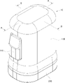
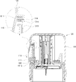
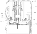
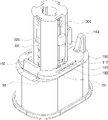
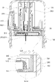
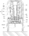
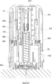
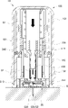
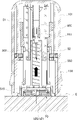
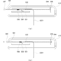
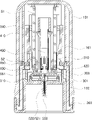
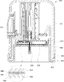
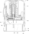
図1は、本発明の一実施例による連続血糖測定装置の外形を概略的に示した斜視図であり、図2は本発明の一実施例による身体付着ユニットの外形を概略的に示した斜視図であり、図3は本発明の一実施例による連続血糖測定装置の構成を概略的に示した分解斜視図であり、図4は図1の"B-B"線に沿って取った断面図であり、図5は図1の"A-A"線に沿って取った断面図である。 FIG. 1 is a perspective view schematically showing the outer shape of a continuous blood glucose measuring device according to one embodiment of the present invention, and FIG. 2 is a perspective view schematically showing the outer shape of a body attachment unit according to one embodiment of the present invention. 3 is an exploded perspective view schematically showing the configuration of a continuous blood glucose measuring device according to an embodiment of the present invention, and FIG. 4 is a cross-sectional view taken along line "BB" of FIG. 5 is a cross-sectional view taken along line "A-A" of FIG. 1; FIG.
本発明の一実施例による連続血糖測定装置は身体付着ユニット20がアプリケーター10内部に組み立てされて一つの単位製品に製作され、連続血糖測定装置の使用時使用者の付加作業が最小化される形態で使用方式が非常に単純な構造である。
The continuous blood glucose measuring device according to one embodiment of the present invention is manufactured as one unit product by assembling the
身体付着ユニット20は、体液を抽出して周期的に血糖を測定できるように身体に付着可能に形成されるが、血糖測定結果を外部端末機(図示せず)などの外部機器に送るように形成される。このような身体付着ユニット20には、一端部が身体に挿入されるセンサー部材520と、外部端末機と無線通信することができるように無線通信チップ(図27参照)540が内部に配置されていて別途のトランスミッタを追加結合する必要もなしに使用可能である。
The body-
アプリケーター10は身体付着ユニット20が内部に結合固定されるように形成され、使用者の操作によって身体付着ユニット20を外部吐出するように作動する。
The
この時、身体付着ユニット20はアプリケーター10内部に挿入された状態で組み立て製作され、使用者の操作によるアプリケーター10の作動によって外部吐出方向に移動して身体に付着するように構成される。
At this time, the
すなわち、本発明の一実施例によるセンサーアプリケーター組立体1は製作段階で、身体付着ユニット20がアプリケーター10内部に挿入された状態でアプリケーター10の作動だけで身体付着ユニット20が肌に付着するように組み立て製作され、この状態で使用者に供給されるので、使用者は身体付着ユニット20を肌に付着するための別途の付加作業なしに単純にアプリケーター10を作動させる作業だけで身体付着ユニット20を肌に付着させることができる。特に、身体付着ユニット20に別途の無線通信チップ540が具備されていて別途のトランスミッタを結合する必要もなくて、より便利に使用することができる。
That is, the
従来の一般的な連続血糖測定装置は、別に包装された身体付着ユニットの包装をむき出した後アプリケーターに正確に挿入し、挿入した以後アプリケーターを作動させて身体付着ユニットを肌に付着させるようになるが、身体付着ユニットをアプリケーターに正確に挿入させる作業が煩わしくて難しいだけでなく、子供や老弱者方々の場合このような作業時身体付着ユニットを汚染させるなどの理由で血糖測定正確度を低下させるなどの問題があった。 In a conventional general continuous blood glucose measuring device, after unpacking a separately packaged body-adhering unit, it is inserted into an applicator. However, it is not only troublesome and difficult to insert the body-adhesive unit into the applicator, but also for children and the elderly, the body-adhesive unit is contaminated during such work, which reduces the accuracy of blood glucose measurement. There were problems such as
本発明の一実施例では製作段階で身体付着ユニット20をアプリケーター10に挿入した状態で製作流通することで、使用者が身体付着ユニット20をむき出してアプリケーター10に挿入する過程などが省略され、単純にアプリケーター10を操作することだけで身体付着ユニット20を肌に付着させることができるので、使用性が画期的に向上し、特に、身体付着ユニット20の汚染などを防止することができて血糖測定正確度を向上させることができる。
In one embodiment of the present invention, the
このように身体付着ユニット20をアプリケーター10に挿入した状態で製作されるので、身体付着ユニット20及びアプリケーター10は再使用が不可能な1回用で使用されることが望ましい。このような再使用不可構造のために本発明の一実施例によるアプリケーター10は内部に挿入された身体付着ユニット20が外部吐出されるように1回作動した以後には身体付着ユニット20の再挿入が不可能になるように形成される。
Since the
すなわち、アプリケーター10は一面が開放された形態で形成されて身体付着ユニット20はアプリケーター10の開放された一面を通じて外部吐出されるように構成されるが、アプリケーター10の最初1回作動を通じて内部の身体付着ユニット20を外部吐出させるようになれば、以後には他の身体付着ユニット20をアプリケーター10に挿入して使用することができないように使用者による身体付着ユニット20の挿入が不可能に構成されることができる。
That is, the
一方、アプリケーター10には身体付着ユニット20がアプリケーター10内部に挿入された状態で外部露出が遮られるように別途の保護キャップ200が分離可能に結合されることができるし、使用者は保護キャップ200を分離した以後のみにアプリケーター10を作動させて身体付着ユニット20を身体に付着させるように構成されることができる。
On the other hand, a separate
この時、身体付着ユニット20の身体接触面には身体付着ユニット20が身体に付着できるように接着テープ560を付着し、接着テープ560の身体接触面には接着テープ560保護のために異形紙561を付着するが、接着テープ560の異形紙561は保護キャップ200をアプリケーター10から分離する過程で接着テープ560から分離除去されるように形成されることができる。
At this time, an
例えば、異形紙561は一側が保護キャップ200に接着されているように構成されることができるし、よって、使用者がアプリケーター10から保護キャップ200を分離すれば、保護キャップ200と共に接着テープ560から分離除去されるようにできる。これによって使用者が保護キャップ200を分離するようになれば、接着テープ560の異形紙561が分離除去されるので、この状態でアプリケーター10を作動させて身体付着ユニット20を身体に付着させることができる。
For example, the
また、アプリケーター10は身体付着ユニット20が内部に挿入された状態では身体付着ユニット20を結合固定して身体付着ユニット20が外部吐出移動した状態では身体付着ユニット20に対する結合固定状態を解除するように形成されることができる。よって、身体付着ユニット20がアプリケーター10の内部に挿入組み立てされた状態では身体付着ユニット20は固定された状態で維持され、アプリケーター10を作動させて身体付着ユニット20を外部吐出して肌に付着するようにした場合にはアプリケーター10と身体付着ユニット20の結合固定状態が解除されるので、この状態でアプリケーター10を分離すれば、身体付着ユニット20と分離して、肌には身体付着ユニット20だけ付着した状態で残っているようになる。
Also, the
一方、本発明の一実施例による身体付着ユニット20は、使用者によって操作される別途のスイッチ手段を通じてセンサー部材520と無線通信チップ540が作動開始されるように形成されることができる。すなわち、アプリケーター10を通じて身体付着ユニット20を身体に挿入付着した以後、使用者は身体付着ユニット20に具備されたスイッチ手段などを通じて身体付着ユニット20が作動開始されるようにできて、このような作動開始時点からセンサー部材520及び無線通信チップ540が作動して身体の血糖を測定して測定結果を外部端末機に送ることができる。この時、使用者によって操作されるスイッチ手段は多様な方式で構成されることができるし、このようなスイッチ手段及び身体付着ユニット20に対する詳細な説明は、図26乃至図37を中心に後述する。
Meanwhile, the
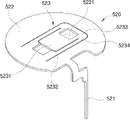
また、身体付着ユニット20は、上部ハウジング512と下部ハウジング511で分離形成されるハウジング510内部にセンサー部材520が配置され、センサー部材520の一端部がハウジング510から外部突き出されて身体に挿入付着するように形成される。センサー部材520は身体に挿入されるセンサープローブ部521と、ハウジング510内部に配置されるセンサーボディー部522で構成されるが、センサープローブ部521とセンサーボディー部522は折曲された形態でそれぞれセンサー部材520の一端部と他端部をなす。
In addition, the
この時、センサー部材520の身体挿入過程が円滑になされるように別途の針部550がハウジング510に分離可能に結合されることができる。針部550はセンサー部材520の一端部が身体に安定的に挿入されるようにセンサー部材520の一端部を囲んでセンサー部材520と共に身体に挿入されるように構成される。
At this time, a
このような針部550は、図2に示されたように身体付着ユニット20のハウジング510を上下貫通する方向に分離可能に装着され、センサー部材520の外部を囲む形態で形成されて上端部には針ヘッド551が形成される。このような針部550は身体付着ユニット20がアプリケーター10によって外部吐出方向に移動すれば、センサー部材520より先に身体に挿入されてセンサー部材520が安定的に肌に挿入されるように補助する。針部550は針ヘッド551を通じてアプリケーター10の針引き出しボディー400と結合され、身体付着ユニット20がアプリケーター10の作動によって身体に挿入付着した以後にはアプリケーター10の針引き出しボディー400によって身体から引き出し除去されるように形成される。
As shown in FIG. 2, the
次に、本発明の一実施例によるアプリケーター10の詳細構成に対してもう少し詳しく見る。
Next, the detailed construction of the
本発明の一実施例によるアプリケーター10は、一側に使用者によって加圧操作されるように加圧ボタン110が装着されるメインケース100と、メインケース100の内部第1位置に結合固定されて加圧ボタン110の操作によって第1位置で結合固定解除されて外部吐出方向である第2位置に直線移動するプランジャーボディー300と、プランジャーボディー300が第1位置から第2位置に直線移動するようにプランジャーボディー300に弾性力を加えるプランジャー弾性スプリング(S1)を含んで構成され、身体付着ユニット20はプランジャーボディー300の一端に結合されてプランジャーボディー300と共に一体で第1位置から第2位置に移動する。
The
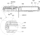
メインケース100の下端部には前述したように内部の身体付着ユニット20を保護するために別途の保護キャップ200が分離可能に結合される。
A separate
保護キャップ200は、図6乃至図8に示されたようにアプリケーター10の外周面を接触する形態で囲んでアプリケーター10の一端部に結合されるように形成される外側カバー部201と、外側カバー部201の一端からアプリケーター10の内側中心方向に延長される延長部202と、延長部202から上向き延長されてアプリケーター10の内部に挿入された身体付着ユニット20の身体接触面を支持する内側支持部203を含んで構成されることができる。この時、内側支持部203の中心部には身体付着ユニット20の身体接触面から下向き突き出されるセンサープローブ521及び針部550を囲むようにセンサー保護部204が局所的に下向き突き出されるように形成されることができる。
As shown in FIGS. 6 to 8, the
したがって、保護キャップ200はアプリケーター10の内部に挿入された身体付着ユニット20の外部露出遮断だけでなく身体付着ユニット20に対する支持機能も遂行し、全体的にアプリケーターの構造的な安全性を向上させる。
Therefore, the
一方、身体付着ユニット20には、図7及び図8に示されたように身体接触面に接着テープ560及び異形紙561を付着し、接着テープ560の異形紙561は保護キャップ200をアプリケーター10から分離する過程で保護キャップ200と共に接着テープ560から分離除去されるように形成される。
On the other hand, the
この時、異形紙561は保護キャップ200の内側支持部203上面に付着することができて、別途の接着部材562を通じて保護キャップ200の内側支持部203に付着することができる。すなわち、図7に示されたように異形紙561によれば、一側には別途の接着部材562が接着され、このような接着部材562は保護キャップ200の内側支持部203上面と異形紙561との間に位置して下面が内側支持部203の上面に接着される。接着部材562の接着力は異形紙561と接着テープ560との間の接着力よりさらに大きく形成される。よって、保護キャップ200をアプリケーター10から分離すれば、接着部材562を通じて保護キャップ200の内側支持部203に接着された異形紙561が共に分離して接着テープ560から分離除去される。
At this time, the shaped
この時、異形紙561には接着部材562の幅と同一な大きさの離隔距離を有する2個の切開線(図示せず)が相互平行に一部区間に形成されることができるし、これによって図8に示されたように保護キャップ200を分離する過程で接着部材562と共に異形紙561が切開線に沿って接着テープ560から先に分離離脱され、以後、保護キャップ200の分離過程がずっと進行されることによって、すなわち、保護キャップ200が図8に示された方向を基準にずっと下向き移動することによって切開線以外部分の異形紙561が牽引されて接着テープ560から分離除去される。このような異形紙分離除去過程を通じて異形紙561の分離除去作業をより円滑で安定的に遂行することができる。
At this time, two cutting lines (not shown) having the same separation distance as the width of the
メインケース100には使用者によって加圧操作されるように加圧ボタン110が装着され、メインケース100内部には加圧ボタン110の加圧操作によって移動するシューテングプレート150が移動可能に結合される。
A
プランジャーボディー300は第1位置でシューテングプレート150とかみ合われて結合固定されてシューテングプレート150の移動によってかみ合い解除されてプランジャー弾性スプリング(S1)の弾性力によって第2位置に移動する。
The
メインケース100は一側に加圧ボタン110が装着される外部ケース101と、外部ケース101の内部に結合されてプランジャーボディー300の直線移動経路をガイドするように形成されるインナーケース102で分離形成されることができるし、シューテングプレート150はインナーケース102に安着支持されて移動することができる。
The
加圧ボタン110は外部ケース101に加圧操作可能に結合されるが、図9に示されたように外部ケース101には加圧ボタン110が加圧操作可能に結合されるようにボタンガイド溝1011が形成される。加圧ボタン110は上端部側に形成されたヒンジ軸112を中心に回動する形態で加圧操作可能に構成され、下端部側にはシューテングプレート150を加圧することができるように加圧ロード111が形成され、一側に加圧ボタン110の分離離脱を防止するために別途の固定ホック113が形成される。
The
このような加圧ボタン110は加圧操作による加圧移動が遮られる安全モードと、加圧操作による加圧移動が可能な加圧待機モード状態でモード変換可能に装着される。
The
加圧ボタン110は安全モード状態でメインケース100の外部表面に沿って一定区間スライド移動して加圧待機モード状態に変換されるように構成されることができる。メインケース100には加圧ボタン110が装着される部位に係止突起1012が形成されることができるし、安全モード状態では加圧ボタン110が係止突起1012にかみ合われて加圧移動が遮られて、安全モード状態で加圧待機モード状態にスライド移動することによって係止突起1012からかみ合い解除されるようにして加圧移動が可能になるようにできる。
The
すなわち、図10に示されたように加圧ボタン110が安全モード状態では外部ケース101の係止突起1012にかみ合われて加圧操作が不可能であり、図11に示されたように加圧ボタン110が加圧待機モード状態で上向き移動すれば、外部ケース101の係止突起1012からかみ合い解除されて加圧操作が可能である。
That is, as shown in FIG. 10, the
このような加圧ボタン110は安全モード状態で加圧待機モード状態にスライド移動すれば、再び安全モード状態に復帰されないように位置固定されるように形成されることができる。
The
このために、加圧ボタン110の一側には固定突起114が形成され、外部ケース101のボタンガイド溝1011の底面には一部区間が切開された形態で弾性変形可能な切開変形部1013が形成され、切開変形部1013は加圧ボタン110が安全モードに位置した状態で固定突起114を挿入収容することができる収容溝1014が形成され、加圧ボタン110が加圧待機モードに移動完了した状態で末端面が固定突起114とかみ合われて加圧ボタン110の復帰移動を拘束するように形成される。
For this purpose, a fixing
このような構造によって加圧ボタン110は加圧待機モード状態にスライド移動した状態のみで使用者による加圧操作が可能であるので、使用者の間違いによる加圧操作を防止して安全な使用ができるようにする。特に、安全モード状態で加圧待機モード状態に変換されれば、再び安全モードに復帰することができないようにすることで、使用者の愼重な操作を誘導することと共に安定的な作動状態を維持させることができる。
Due to this structure, the
加圧ボタン110が加圧待機モード状態に変換されて図12に示されたように加圧操作されれば、加圧ボタン110の加圧ロード111がシューテングプレート150を加圧移動させる。
When the
シューテングプレート150はインナーケース102に安着支持されて加圧ボタン110の加圧操作によってスライド移動可能に結合され、プランジャーボディー300は第1位置でシューテングプレート150とかみ合われてシューテングプレート150の移動によってシューテングプレート150とかみ合い解除されてプランジャー弾性スプリング(S1)の弾性力によって第2位置に移動する。
The
プランジャーボディー300には図12及び図13に示されたようにシューテングプレート150とかみ合われるようにかみ合いホック310が形成され、シューテングプレート150の一側にはプランジャーボディー300のかみ合いホック310とかみ合い結合されることができる係止突出部153が形成され、係止突出部153はシューテングプレート150がスライド移動することによってかみ合いホック310とのかみ合い状態が解除されるように形成される。
12 and 13, the
インナーケース102にはシューテングプレート150のスライド移動経路をガイドするようにガイドレール162が突き出形成され、シューテングプレート150にはガイドレール162が挿入ガイドされるようにガイドスロット151が形成される。また、インナーケース102にはシューテングプレート150を加圧ボタン110の操作によるスライド移動方向と反対方向に弾性支持する弾性部材163が装着される。よって、シューテングプレート150は弾性部材163の弾性力によって加圧ボタン110側に弾性支持されるので、加圧ボタン110を加圧操作しない以上、プランジャーボディー300のかみ合いホック310とのかみ合い状態が安定的に維持される。
A
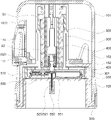
このような構造によって使用者が加圧ボタン110を加圧操作すれば、シューテングプレート150がスライド移動するようになって、これによってプランジャーボディー300とシューテングプレート150とのかみ合い状態が解除されてプランジャーボディー300はプランジャー弾性スプリング(S1)の弾性力によって図15及び図16に示されたように第1位置から第2位置に外部吐出移動する。
With such a structure, when a user presses the
プランジャーボディー300には第2位置への移動範囲を制限できるようにストッパ突起320が形成されることができるし、ストッパ突起320はプランジャーボディー300が第2位置に移動することによってインナーケース102の一側にかみ合われる方式で前記プランジャーボディー300の移動を制限することができる。すなわち、プランジャーボディー300はストッパ突起320によって第2位置までに移動し、その以上の範囲ではメインケース100から外部吐出されない。この時、インナーケース102にはプランジャーボディー300が第2位置に移動した状態でストッパ突起320とかみ合われてストッパ突起320の移動を拘束するようにストッパ固定部1021が形成されることができる。
A
また、プランジャーボディー300の一端部には身体付着ユニット20が挿入収容されるようにセンサー収容部301が形成され、身体付着ユニット20はセンサー収容部301に挿入収容されてプランジャーボディー300と共に第1位置から第2位置に直線移動する。プランジャーボディー300及び身体付着ユニット20が第2位置に直線移動することによって身体付着ユニット20のセンサープローブ521及び針部550が身体に挿入される。
In addition, a
この時、センサー収容部301の縁にはセンサー収容部301に挿入された身体付着ユニット20とかみ合い結合されて身体付着ユニット20を結合固定させることができるセンサー固定ホック330が装着される。身体付着ユニット20の両側端部には身体付着ユニット20がセンサー収容部301に挿入された状態でセンサー固定ホック330とかみ合われるようにかみ合い結合溝5112が形成される。
At this time, a
センサー固定ホック330は回転軸331を中心に弾性回転可能に結合され、プランジャーボディー300が第1位置に位置した状態では、図15に示されたようにセンサー固定ホック330が身体付着ユニット20のかみ合い結合溝5112とかみ合い結合されるように内側方向に加圧されるように弾性支持され、プランジャーボディー300が第2位置に位置した状態では図16に示されたように身体付着ユニット20からアプリケーター10を分離する過程でセンサー固定ホック330が身体付着ユニット20のかみ合い結合溝5112からかみ合い解除されるように構成されることができる。センサー固定ホック330が身体付着ユニット20からかみ合い解除される過程は、回転軸331が拗じれ弾性回転する方式でなされることができる。
The
図示されなかったが、インナーケース102の内側壁面にはセンサー固定ホック330を身体付着ユニット20とかみ合われるように内側方向に加圧し、プランジャーボディー300の第2位置移動状態でセンサー固定ホック330を加圧解除する形態の断面形状を有するホックガイド部(図示せず)が形成されることもできる。すなわち、ホックガイド部はインナーケース102の内側壁面に突き出面及び凹面を有する形態でなされることができるし、突き出面はセンサー固定ホック330を加圧して凹面はセンサー固定ホック330を加圧解除するように形成され、凹面はセンサー固定ホック330がプランジャーボディー300と共に第2位置に移動した状態でセンサー固定ホック330を加圧解除するように形成される。
Although not shown, the inner wall surface of the
一方、本発明では身体付着ユニット20がアプリケーター10に挿入された状態で製作されるので、前述したようにアプリケーター10にまた他の身体付着ユニット20を挿入して再使用することを防止するように構成される。
On the other hand, in the present invention, the
このためにメインケース100にはプランジャーボディー300が第2位置に移動した以後にはプランジャーボディー300が第1位置に復帰移動することを防止する復帰防止手段が具備される。
For this purpose, the
復帰防止手段は図17乃至図19に示されたようにプランジャーボディー300の一側に形成されるかみ合いボディー340と、プランジャーボディー300が第1位置から第2位置に下向き移動完了時プランジャーボディー300のかみ合いボディー340とかみ合い結合されてプランジャーボディー300の復帰移動を防止するようにインナーケース102に形成される復帰防止ホック161を含んで構成されることができる。
As shown in FIGS. 17 to 19, the return preventing means is a meshing
復帰防止ホック161はかみ合いボディー340とかみ合われる過程で弾性復元力が作用してかみ合われるように構成される。もう少し具体的に、復帰防止ホック161はインナーケース102の一側に回転軸1613を中心に弾性回転可能に結合される回動ボディー1611と、回動ボディー1611の内側面に下向き内側方向に傾くように突き出されるホックボディー1612を含む形態で構成されることができる。この時、回転軸1613は弾性材質の材質特性による弾性力が作用してホックボディー1612が内側方向に突き出される方向に回動ボディー1611を弾性支持するように形成される。
The return-preventing
このような復帰防止ホック161によってプランジャーボディー300は、第1位置から第2位置に移動完了時再び第1位置に向けて復帰移動することが防止され、これによってまた他の身体付着ユニット20を使用者が任意に挿入して使用することを防止することができる。
The
復帰防止ホック161の動作状態をよく見れば、図17に示されたようにプランジャーボディー300が第1位置に位置した状態で、加圧ボタン110の操作によって第2位置に移動すれば、図18に示されたようにプランジャーボディー300が第2位置に移動する過程でプランジャーボディー300のかみ合いボディー340によってホックボディー1612が加圧されて復帰防止ホック161が回転軸1613を中心に時計方向(外側方向)に弾性回転するようになる。以後、プランジャーボディー300が図19に示されたように第2位置に移動完了するようになれば、かみ合いボディー340によるホックボディー1612の加圧状態が解除されるので、復帰防止ホック161は回転軸1613を中心に反時計方向(内側方向)に復帰して弾性回転するようになる。このように復帰防止ホック161が弾性復帰回転することによって復帰防止ホック161の下端がプランジャーボディー300のかみ合いボディー340上端とかみ合い結合され、これによってプランジャーボディー300は復帰防止ホック161とかみ合いボディー340とのかみ合い状態によって第1位置に復帰移動が防止される。
If the
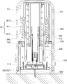
一方、アプリケーター10は身体付着ユニット20が第1位置から第2位置に外部吐出移動完了することと共に身体付着ユニット20の針部550を身体から引き出し除去するように構成され、このためにアプリケーター10はプランジャーボディー300が第1位置から第2位置に移動完了することと共に針部550を上向き移動させて身体から引き出し除去する針引き出し手段(N)を具備することができる。
On the other hand, the
針引き出し手段(N)は、針部550の針ヘッド551と結合されてプランジャーボディー300にかみ合い結合されてプランジャーボディー300と共にインナーケース102に沿って第1位置から第2位置に直線移動する針引き出しボディー400と、針引き出しボディー400が第1位置に向けて上向き移動する方向に針引き出しボディー400に弾性力を加える針引き出し弾性スプリング(S2)を含むことができる。
The needle drawing means (N) is combined with the
針引き出しボディー400はプランジャーボディー300にかみ合い結合されるが、このために針引き出しボディー400には弾性変形可能な別途の弾性ホック410が形成され、弾性ホック410はプランジャーボディー300のホックかみ合い部350にかみ合い結合される方向に弾性偏向される。よって、プランジャーボディー300が加圧ボタン110の操作によって第1位置から第2位置に直線移動すれば、針引き出しボディー400もまたプランジャーボディー300と共に第2位置に直線移動する。
The
この時、インナーケース102には針引き出しボディー400が第2位置に移動することによって弾性ホック410がプランジャーボディー300のホックかみ合い部350からかみ合い解除されるように弾性ホック410を内側方向に加圧する針引き出し加圧部130が形成される。
At this time, the
このような構造によって加圧ボタン110が加圧操作されれば、図19に示されたように針引き出しボディー400はプランジャーボディー300と共に第1位置から第2位置に直線移動し、これと共に針引き出しボディー400の弾性ホック410がインナーケース102の針引き出し加圧部130によって加圧されてホックかみ合い部350とのかみ合い状態が解除されるので、図20に示されたように針引き出しボディー400は針引き出し弾性スプリング(S2)の弾性力によって第1位置に向けて上向き復帰移動するようになる。
With this structure, when the
この時、針引き出しボディー400は一端の針ヘッド結合部420を通じて針部550の針ヘッド551と結合されているので、針引き出しボディー400が上向き復帰移動する過程で針部550が共に移動して身体から引き出し除去される。針ヘッド結合部420は針ヘッド551に形成された結合溝552にかみ合い結合される形態で針引き出しボディー400の下端部に形成される。
At this time, since the needle pull-out
一方、プランジャーボディー300がプランジャー弾性スプリング(S1)の弾性力によって第2位置に移動することによって身体付着ユニット20のセンサープローブ521及び針部550が身体に挿入されるが、針部550の身体挿入過程で挿入抵抗が発生して反力によって針部550が身体挿入方向の反対方向に微細に後退することもある。この場合、センサープローブ521が正常な深さで身体に挿入されないこともあるので、針部550の後退が防止されることが望ましい。このために針引き出しボディー400には針部550が針引き出しボディー400に対して上部側に相対移動しないように針部550の上端を下向き支持する針支持ブロックが結合されることができる。
Meanwhile, when the
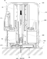
次に、以上で説明したセンサーアプリケーター組立体の使用状態を図21乃至図25を中心に詳しく見る。 Next, the state of use of the sensor applicator assembly described above will be seen in detail, centering on FIGS. 21 to 25. FIG.
図21乃至図25は、本発明の一実施例による連続血糖測定装置の使用状態を動作手順によって段階的に示した図面である。 21 to 25 are diagrams showing step by step how the continuous blood glucose measuring device according to an embodiment of the present invention is used according to the operation procedure.
先ず、図21に示されたようにアプリケーター10の保護キャップ200を分離する。保護キャップ200を分離する過程で身体付着ユニット20の接着テープ560の異形紙561が保護キャップ200と共に分離して接着テープ560から除去される。以後、身体付着ユニット20を付着する身体位置にセンサーアプリケーター組立体を位置させ、この状態で加圧ボタン110を安全モードで加圧待機モード状態に変換した後、加圧ボタン110を加圧操作する。
First, the
加圧ボタン110を加圧操作すれば、シューテングプレート150が移動してプランジャーボディー300とかみ合い状態が解除されるので、図22及び図23に示されたようにプランジャーボディー300がプランジャー弾性スプリング(S1)によって外部吐出される方向に下向き移動し、この過程で身体付着ユニット20の針部550とセンサープローブ521が身体(E)に挿入される。勿論、この時、身体付着ユニット20は底面の接着テープ560によって身体(E)表面に接着される。このようにプランジャーボディー300が外部吐出される方向に移動すれば、図23に示されたようにプランジャーボディー300はインナーケース102の復帰防止ホック161によってかみ合われて再び上昇移動することができない。よって、一度使ったアプリケーター10は再び再使用が不可能である。
When the
プランジャーボディー300が下向き移動すれば、図23に示されたようにセンサー収容部301のセンサー固定ホック330は身体付着ユニット20とのかみ合い結合状態が解除されることがある。また、針引き出しボディー400の弾性ホック410はインナーケース102の針引き出し加圧部130によって内側方向に加圧されてプランジャーボディー300とのかみ合い状態が解除される。
When the
したがって、プランジャーボディー300が下向き移動すれば、これと同時に図24に示されたように針引き出しボディー400が針引き出し弾性スプリング(S2)によって上向き復帰移動するようになる。この時、針引き出しボディー400と共に針部550が上向き移動するようになるので、針部550は身体(E)から引き出し除去される。
Therefore, when the
この状態では、前述したようにセンサー固定ホック330と身体付着ユニット20とのかみ合うことが解除可能な状態であるので、図25に示されたようにアプリケーター10を上向き分離除去することができて、このようにアプリケーター10を分離除去すれば、身体(E)には身体付着ユニット20だけ付着した状態になる。
In this state, the engagement between the
以後、身体付着ユニット20の加圧作動モジュール570などを操作して身体付着ユニット20のセンサー部材520及び無線通信チップ540を作動開始することができるし、これによって身体付着ユニット20による血糖測定結果が別途の外部端末機に伝送される。本発明では身体付着ユニット20にセンサー部材520及び無線通信チップ540がすべて具備されているので、別途のトランスミッタを連結結合するなどの付加作業が不必要である。
After that, the
次に、本発明の一実施例による身体付着ユニット20に対してもう少し詳しく見る。
Looking now a little more closely at the
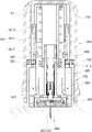
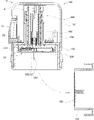
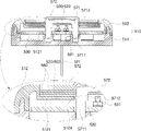
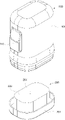
図26は、本発明の一実施例によって身体に付着した身体付着ユニットの外形を概略的に示した斜視図であり、図27は本発明の一実施例による身体付着ユニットの構成を概略的に示した分解斜視図であり、図28は図26の"C-C"線に沿って取った断面図であり、図29は図26の"D-D"線に沿って取った断面図であり、図30は本発明の一実施例による加圧作動モジュールの作動状態を概略的に示した図面である。 FIG. 26 is a perspective view schematically showing the appearance of a body-attached unit attached to a body according to one embodiment of the present invention, and FIG. 27 schematically illustrates the structure of the body-attached unit according to one embodiment of the present invention. 28 is a cross-sectional view taken along line "C-C" of FIG. 26, and FIG. 29 is a cross-sectional view taken along line "D-D" of FIG. FIG. 30 is a diagram schematically showing an operating state of a pressure operating module according to one embodiment of the present invention.
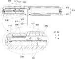
本発明の一実施例による身体付着ユニット20は、底面が肌に付着するように接着テープ560を付着したハウジング510と、一端部がハウジング510の底面から外部突き出されるようにハウジング510内部に配置されてハウジング510が肌に付着する時一端部が身体に挿入されるセンサー部材520と、ハウジング510内部に配置されるPCB基板530を含んで構成される。
The
センサー部材520は一端部が身体に挿入されるように形成されて他端部はPCB基板530に接触できるように形成されるが、他端部にはPCB基板530の電気接点に接触できるようにセンサーボディー部522が形成され、一端部にはセンサーボディー部522の一側から折曲される形態で延長形成されてハウジング510から外部突き出されて身体に挿入されるセンサープローブ部521が形成される。センサーボディー部522は相対的に広い面積を有する形態で形成され、センサープローブ部521は相対的に狭くて長い形態で形成される。
One end of the
ハウジング510は内部収容空間が形成されるように上部ハウジング512と下部ハウジング511で分離形成されることができるし、ハウジング510内部にはセンサーボディー部522をPCB基板530の電気接点531から一定間隔離隔されるように支持するセンサー支持部5121が形成され、また、センサープローブ部521の一部区間を支持しながらガイドすることができるセンサーガイド部(図示せず)が形成される。また、ハウジング510内部にはPCB基板530を一定位置に固定支持するための基板支持部5113が形成されることができる。
The
PCB基板530にはセンサー部材520と電気的に連結されるように電気接点531が形成され、センサー部材520を通じて測定された血糖測定結果を外部端末機に送るように無線通信チップ540が実装される。本発明の一実施例ではこのように無線通信チップ540が身体付着ユニット20の内部に具備されることによって別途のトランスミッタ連結作業なしも外部端末機と容易に通信することができる。
An
また、ハウジング510内部にはPCB基板530に電源を供給するようにバッテリー535が装着されるが、この時、バッテリー535はPCB基板530の一面に実装される形態で配置されるものではなく、PCB基板530とは独立的な領域に配置される。すなわち、PCB基板530とバッテリー535はハウジング510の底面に映った面積がお互いに重なり領域なしに独立的に配置される。このようにPCB基板530とバッテリー535がお互いに独立的な領域に配置されることで、身体付着ユニット20の厚さを減少させることができるし、より小型化することができる。この時、PCB基板530にはバッテリー535と電気的に接触連結されるように別途の接触端子532がバッテリー535側に延長形成されることができる。
Also, a
本発明の一実施例による身体付着ユニット20は、センサー部材520の他端部、すなわち、センサーボディー部522が使用者操作によってPCB基板530の電気接点531に接触するように形成され、このような電気的接触によって身体付着ユニット20が作動開始されるように構成される。すなわち、使用者の操作によるセンサー部材520とPCB基板530の電気的連結によって電源供給がなされることと共にセンサー部材520及び無線通信チップ540などが作動開始されるように構成されることができる。
The
センサー部材520の他端部とPCB基板530との電気接点531を使用者の操作によって接触させるためにハウジング510には使用者の操作によって作動する別途の加圧作動モジュール570が具備されることができる。
In order to bring the
加圧作動モジュール570は、ハウジング510に移動可能に結合されて使用者の加圧力によって加圧方向に移動する移動加圧ボディー571を含むことができるし、移動加圧ボディー571の移動によってセンサー部材520の他端部の少なくとも一部領域が移動加圧ボディー571によって加圧変形されてPCB基板530の電気接点531に接触するように構成されることができる。
The
また、加圧作動モジュール570は、移動加圧ボディー571の外部空間を囲む形態で使用者の加圧操作が可能になるようにハウジング510に外部露出するように結合される軟性材質のボタンカバー572をさらに含むことができるし、ボタンカバー572とハウジング510の結合部位は密封処理されるように構成されることができる。
In addition, the pressurizing
この時、ボタンカバー572とハウジング510結合部位の密封処理方式は、両面テープ580を利用した方式で構成されることができる。例えば、センサー部材520の他端部、すなわち、センサーボディー部522の一面には縁まわりに沿って両面テープ580が接着され、ボタンカバー572の内側面は縁まわりに沿って両面テープ580の打面に接着され、このような両面テープ580によってボタンカバー572の縁まわりが密封処理されるようにできる。この場合、センサーボディー部522の打面にも縁まわりに沿って両面テープ580が接着されることができるし、これを通じてセンサーボディー部522は縁まわりが両面テープ580を利用してセンサー支持部5121に接着固定されることができる。
At this time, the method of sealing the connecting portion of the
このようにセンサーボディー部522の縁まわりが両面テープ580を通じてセンサー支持部5121に接着固定された状態で、図30に示されたようにセンサーボディー部522の中心領域が移動加圧ボディー571によって加圧変形されてPCB基板530の電気接点531に接触されることができる。移動加圧ボディー571は加圧方向に移動するが、ボタンカバー572は軟性材質で両面テープ580によって縁部分がハウジング510に接着されるので、中心領域だけ加圧方向に変形されるだけ縁部分は接着固定されて密封状態が維持される。
While the edge of the
一方、センサーボディー部522が使用者操作によってPCB基板530の電気接点531に接触した以後には安定的な血糖測定のために接触状態が安定的に維持されることが望ましく、このために移動加圧ボディー571は使用者の加圧力によって加圧方向に移動した状態で位置固定されるように形成されることができる。
On the other hand, after the
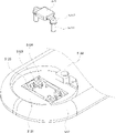
このような移動加圧ボディー571の位置固定のために、図31に示されたように移動加圧ボディー571には移動加圧ボディー571の移動方向に沿って突き出される突き出ガイド部5711が形成され、突き出ガイド部5711の外周面には係止ホック5712が形成されることができる。また、ハウジング510には移動加圧ボディー571が加圧方向に移動した状態で突き出ガイド部5711の係止ホック5712がかみ合い結合されることができるかみ合い突起5124が形成されることができる。移動加圧ボディー571は図30に示されたように係止ホック5712がかみ合い突起5124にかみ合い結合されることによって位置固定されるように構成されることができる。
In order to fix the position of the moving
この時、かみ合い突起5124はハウジング510のセンサー支持部5121に形成されることができるが、ハウジング510のセンサー支持部5121には図31に示されたように移動加圧ボディー571の突き出ガイド部5711を囲む形態のガイド固定部5123が円周方向に沿って離隔されるように少なくとも2個形成され、それぞれのガイド固定部5123にかみ合い突起5124が形成されることができる。また、それぞれのガイド固定部5123は弾性変形する弾性支持部5125によって弾性支持される形態で配置されることができる。
At this time, the engaging
したがって、移動加圧ボディー571が加圧方向に移動する過程でガイド固定部5123が弾性変形して移動加圧ボディー571の移動を円滑にさせて、移動加圧ボディー571の移動が完了すれば、ガイド固定部5123は弾性復帰するようになって係止ホック5712がかみ合い突起5124にかみ合い結合されて、ガイド固定部5123が弾性支持部5125によって弾性支持されるので、係止ホック5712とかみ合い突起5124とのかみ合い結合状態が安定的に維持される。
Therefore, when the moving
一方、センサー部材520は前述したようにセンサーボディー部522とセンサープローブ部521で構成されるが、センサーボディー部522には移動加圧ボディー571の加圧移動によって変形してPCB基板530の電気接点531に接触する加圧変形部523が形成される。
On the other hand, the
加圧変形部523は図32に示されたようにセンサーボディー部522の中心領域に形成された第1切開線5232に沿って切開された形態の第1切開領域5231を含んで、第1切開領域5231が移動加圧ボディー571によって加圧変形されるように形成されることができる。
The pressurized
また、加圧変形部523はセンサーボディー部522の中心領域に第1切開線5232の外郭領域に形成された第2切開線5234に沿って切開された形態の第2切開領域5233をさらに含んで、第1切開領域5231及び第2切開領域5233が移動加圧ボディー571によって加圧変形されるように形成されることができる。
In addition, the
この時、第1切開線5232は閉ループのうちで一部区間が開放された形態で形成され、第2切開線5234は第1切開線5232の開放された区間を外部で囲む閉ループ形態で第1切開線5232の開放された区間と対向される位置に開放された区間を有するように形成される。
At this time, the
このような構造によって移動加圧ボディー571を加圧操作するようになれば、図33の(a)及び(b)に示されたように加圧変形部523の第1切開領域5231が下向き弾性変形され、第1切開領域5231の外郭領域に形成された第2切開領域5233が連続して順次に下向き弾性変形され、これによってPCB基板530の電気接点531と直接接触する第1切開領域5231は相対的に水平状態でPCB基板530の電気接点531と接触するようになるので、センサーボディー部522の電気接点531に対する接触状態をより安定的に維持することができる。
When the moving
一方、PCB基板530にセンサーボディー部522と電気接触する電気接点531はセンサーボディー部522に向けて突き出される形態で複数個形成されるが、複数個の電気接点531のうちで少なくとも何れか一つは、残りより突き出高さがさらに高く形成されることができる。
Meanwhile, a plurality of
例えば、図34に示されたようにPCB基板530に2個の電気接点531が形成された場合、一つの電気接点531の突き出高さが残り電気接点531の突き出高さより高く形成され、これによってセンサーボディー部522との離隔間隔がd1、d2でお互いに異なるように形成される。
For example, when two
このような配置構造を通じて製作及び組み立て公差などの理由で使用者の加圧操作なしもセンサーボディー部522が電気接点531に接触することを防止することができる。
Through this arrangement structure, it is possible to prevent the
もう少し詳しく見れば、本発明の一実施例によるハウジング510内部でセンサー部材520のセンサーボディー部522とPCB基板530の電気接点531がお互いに離隔されるように位置して、使用者の加圧操作によって相互接触するように構成される。しかし、ハウジング510は非常に薄い形態で形成されるので、その内部でセンサーボディー部522と電気接点531との離隔状態を安定的に維持することがとても難しい。特に、製作及び組み立て過程で発生する公差などによってセンサーボディー部522と電気接点531が使用者による加圧操作以前に相互接触状態で製作流通することができる。
In more detail, the
前述したように複数個の電気接点531のうちで少なくとも何れか一つの突き出高さを残り電気接点531より高くすれば、製作及び組み立て公差によってセンサーボディー部522と電気接点531がお互いに接触しても、最も高く突き出された電気接点531だけセンサーボディー部522と接触するようになって、残り電気接点531はセンサーボディー部522と離隔された状態で維持される。これは、最も高く突き出された電気接点531によってセンサーボディー部522を上向き支持する機能が遂行されるためである。この時、複数個の電気接点531は弾性変形可能な形態でPCB基板530から弾性突き出されるように形成されることができるし、このような弾性力によってセンサーボディー部522に対する支持機能及び接触機能を円滑に遂行することができる。
As described above, if the protrusion height of at least one of the
このようにセンサーボディー部522と電気接点531がたとえ接触しても、何れか一つの電気接点531だけ接触するようになれば、身体付着ユニット20の作動が開始されない。すなわち、センサー部材520及び無線通信チップ540などの作動が開始されないし、バッテリー535を通じた電源供給も開始されない。
Even if the
このような作動開始防止機能は複数個の電気接点531がすべてセンサーボディー部522に接触した場合のみに作動開始されるようにPCB基板530のパターン回路を構成するなどの単純な方式を通じて達成されることができる。
Such an operation start prevention function is achieved through a simple method such as configuring the pattern circuit of the
このように複数個の電気接点531がお互いに突き出高さが異なるように形成された場合、加圧作動モジュール570は移動加圧ボディー571の移動距離が複数個の電気接点531のうち突き出高さが最も低い電気接点531とセンサーボディー部522との間の離隔距離以上で形成されなければならないであろう。
When the plurality of
以上では使用者操作によるセンサーボディー部522と電気接点531との接触構造に対して加圧方式で作動する加圧作動モジュール570の構成に対して説明したが、加圧方式以外にも多様な方式で構成されることができるし、以下ではいくつかの例示的な構成らを詳しく見る。
The structure of the
図35乃至図37は、本発明の一実施例による接点連結モジュールの多様な構成を概念的に示した図面である。 35 through 37 are diagrams conceptually showing various configurations of a contact connection module according to an embodiment of the present invention.
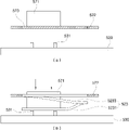
図35乃至図37にはセンサーボディー部522とPCB基板530の電気接点531を接触させることができるように使用者の操作によって作動する接点連結モジュール590が示されるが、このような接点連結モジュール590はセンサーボディー部522とPCB基板530の電気接点531との間で相互接触を遮断するように位置した状態で使用者の操作によって移動して相互接触を遮断解除する方式で作動するように構成されることができる。
FIGS. 35 to 37 show a
もう少し具体的に、PCB基板530の電気接点531はセンサーボディー部522に接触する方向に弾性突き出されるように形成され、接点連結モジュール590がセンサーボディー部522とPCB基板530との電気接点531の相互接触を遮断解除するように作動することによって、PCB基板530の電気接点531が弾性力によって弾性移動してセンサー部材520の他端部に接触するように構成されることができる。
More specifically, the
この時、接点連結モジュール590は、図35に示されたようにハウジング内部でセンサーボディー部522とPCB基板530の電気接点531との間に配置されて使用者の操作によって移動可能に装着される移動プレート591を含んで構成されることができる。
At this time, as shown in FIG. 35, the
図35の(a)に示されたように、移動プレート591がハウジング510内部に挿入された組み立て状態ではセンサーボディー部522と電気接点531との間に位置してセンサーボディー部522と電気接点531との相互接触を遮断し、図35の(b)に示されたように使用者の操作によって移動プレート591をハウジング510から引き出し除去する方向に移動させれば、電気接点531が弾性力によって上向き移動してセンサーボディー部522に接触するようになる。
As shown in FIG. 35(a), in the assembled state where the moving
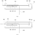
一方、図36に示されたように移動プレート591は、使用者の操作によって第1位置から第2位置に移動可能に装着され、移動プレート591には第1位置で電気接点531をPCB基板530側に加圧して第2位置で電気接点531の加圧状態を解除するように一側に貫通ホール593が形成されることができる。
On the other hand, as shown in FIG. 36, the moving
したがって、図36の(a)に示されたように移動プレート591がハウジング510内部で第1位置に位置した状態では移動プレート591によってセンサーボディー部522と電気接点531の相互接触が遮られて、図36の(b)に示されたように移動プレート591がハウジング510内部で第2位置に移動すれば、移動プレート591の貫通ホール593が電気接点531とセンサーボディー部522との間に位置するので、電気接点531が弾性移動して貫通ホール593を貫通してセンサーボディー部522と接触するようになる。
Therefore, when the moving
この時、移動プレート591には移動プレート591の移動範囲を第1位置から第2位置に制限するようにストッパ部592が形成されることができる。
At this time, a
一方、移動プレート591は第2位置に移動した状態で位置固定されて再び第1位置に復帰移動することができないように形成されることができる。
Meanwhile, the moving
例えば、移動プレート591の一端部には係止ホック594が形成され、ハウジング510内部には移動プレート591が第2位置に移動した状態で係止ホック594とかみ合い結合されることができるかみ合い突起595が形成され、移動プレート591は係止ホック594がかみ合い突起595にかみ合い結合されることによって第2位置で位置固定されることができる。
For example, a
また、図37に示されたように移動プレート591に伝導性材質の接点連結部材596が別に装着される方式で構成されることもできる。これは移動プレート591の貫通ホール593が形成された部位に接点連結部材596が装着される形態で構成されることができるし、移動プレート591の移動時電気接点531とセンサーボディー部522が接点連結部材596によって電気的に連結接触される方式で構成されることができる。
In addition, as shown in FIG. 37, a
以上の説明は、本発明の技術思想を例示的に説明したことに過ぎないものであり、本発明が属する技術分野で通常の知識を有した者なら本発明の本質的な特性から脱しない範囲で多様な修正及び変形が可能であろう。よって、本発明に開示された実施例らは本発明の技術思想を限定するためではなく説明するためのものであり、このような実施例によって本発明の技術思想の範囲が限定されるものではない。本発明の保護範囲は下の請求範囲によって解釈されなければならないし、それと同等な範囲内にあるすべての技術思想は、本発明の権利範囲に含まれるものとして解釈されなければならないであろう。 The above description is merely illustrative of the technical idea of the present invention. Various modifications and variations will be possible. Therefore, the embodiments disclosed in the present invention are not intended to limit the technical idea of the present invention, but to illustrate it, and the scope of the technical idea of the present invention is not limited by such examples. do not have. The protection scope of the present invention shall be construed by the following claims, and all technical ideas within the equivalent scope shall be construed as included in the scope of rights of the present invention.
Claims (8)
センサーボディー部と、
使用者の身体に挿入できるように前記センサーボディー部から延長されるセンサープローブ部と、
使用者の操作によって変形されて前記電気接点に接触するように、前記センサーボディー部に備えられる加圧変形部と、を含むセンサー部材。 In a sensor member, at least one portion of which is inserted into the user's body and another portion of which can contact electrical contacts for electrical connection,
sensor body and
a sensor probe portion extending from the sensor body portion for insertion into a user's body;
a pressure deformation part provided in the sensor body part so as to be deformed by a user's operation and contact the electrical contact.
前記センサーボディー部に形成された第1切開線に沿って切開された第1切開領域を含み、前記第1切開領域が使用者の操作によって変形される請求項1に記載のセンサー部材。 The pressure deformation part is
2. The sensor member of claim 1, further comprising a first incision area cut along a first incision line formed in the sensor body, wherein the first incision area is deformed by a user's operation.
前記センサーボディー部の前記第1切開線の外郭領域に形成された第2切開線に沿って切開された第2切開領域を含み、
前記第2切開領域が使用者の操作によって変形される請求項4に記載のセンサー部材。 The pressure deformation part is
a second incision area incised along a second incision line formed in an outer region of the first incision line of the sensor body;
5. The sensor member of claim 4, wherein the second incision area is deformed by user manipulation.
Applications Claiming Priority (4)
| Application Number | Priority Date | Filing Date | Title |
|---|---|---|---|
| KR10-2018-0089333 | 2018-07-31 | ||
| KR1020180089333A KR102200137B1 (en) | 2018-07-31 | 2018-07-31 | Sensor unit for continuous glucose monitoring system |
| PCT/KR2019/006843 WO2020027426A1 (en) | 2018-07-31 | 2019-06-07 | Body attachment unit for continuous glucose monitoring |
| JP2021503119A JP7132421B2 (en) | 2018-07-31 | 2019-06-07 | Body Adhesive Unit for Continuous Blood Glucose Monitoring |
Related Parent Applications (1)
| Application Number | Title | Priority Date | Filing Date |
|---|---|---|---|
| JP2021503119A Division JP7132421B2 (en) | 2018-07-31 | 2019-06-07 | Body Adhesive Unit for Continuous Blood Glucose Monitoring |
Publications (2)
| Publication Number | Publication Date |
|---|---|
| JP2022166311A true JP2022166311A (en) | 2022-11-01 |
| JP7578655B2 JP7578655B2 (en) | 2024-11-06 |
Family
ID=69231220
Family Applications (2)
| Application Number | Title | Priority Date | Filing Date |
|---|---|---|---|
| JP2021503119A Active JP7132421B2 (en) | 2018-07-31 | 2019-06-07 | Body Adhesive Unit for Continuous Blood Glucose Monitoring |
| JP2022134453A Active JP7578655B2 (en) | 2018-07-31 | 2022-08-25 | Body-worn unit for continuous blood glucose monitoring |
Family Applications Before (1)
| Application Number | Title | Priority Date | Filing Date |
|---|---|---|---|
| JP2021503119A Active JP7132421B2 (en) | 2018-07-31 | 2019-06-07 | Body Adhesive Unit for Continuous Blood Glucose Monitoring |
Country Status (7)
| Country | Link |
|---|---|
| US (2) | US12171550B2 (en) |
| EP (4) | EP4292530B1 (en) |
| JP (2) | JP7132421B2 (en) |
| KR (1) | KR102200137B1 (en) |
| AU (1) | AU2019316453B2 (en) |
| NZ (1) | NZ772746A (en) |
| WO (1) | WO2020027426A1 (en) |
Families Citing this family (10)
| Publication number | Priority date | Publication date | Assignee | Title |
|---|---|---|---|---|
| WO2022147326A1 (en) | 2020-12-31 | 2022-07-07 | Dexcom, Inc. | Reusable applicators for transcutaneous analyte sensors, and associated methods |
| JP7844515B2 (en) * | 2021-06-29 | 2026-04-13 | アイセンス,インコーポレーテッド | Body-attached unit for measuring biological information |
| KR102565316B1 (en) * | 2021-08-05 | 2023-08-10 | 주식회사 아이센스 | Applicator for transcutaneous sensor and applicator assembly |
| KR102566020B1 (en) * | 2021-08-05 | 2023-08-16 | 주식회사 아이센스 | Applicator for transcutaneous sensor and applicator assembly |
| WO2023019453A1 (en) * | 2021-08-18 | 2023-02-23 | Medtrum Technologies Inc. | Intelligent detection device |
| WO2024039239A1 (en) * | 2022-08-19 | 2024-02-22 | 에스디바이오센서 주식회사 | Insertion device assembly for inserting analyte monitoring device |
| CN115844396A (en) * | 2022-12-06 | 2023-03-28 | 江苏鱼跃凯立特生物科技有限公司 | In-vivo blood glucose monitoring device and continuous blood glucose monitor assembly |
| CN115770306B (en) * | 2022-12-06 | 2026-03-27 | 江苏鱼跃凯立特生物科技有限公司 | A sterilization component and sterilization method for a continuous glucose monitor |
| WO2024249941A1 (en) * | 2023-06-02 | 2024-12-05 | Laxmi Therapeutic Devices, Inc. | Applicators for glucose monitors and methods for applying glucose monitors |
| WO2025048431A1 (en) * | 2023-08-25 | 2025-03-06 | 에스디바이오센서 주식회사 | Analyte monitoring device |
Citations (6)
| Publication number | Priority date | Publication date | Assignee | Title |
|---|---|---|---|---|
| JPH0730428U (en) * | 1993-11-16 | 1995-06-06 | オムロン株式会社 | switch |
| US20100198034A1 (en) * | 2009-02-03 | 2010-08-05 | Abbott Diabetes Care Inc. | Compact On-Body Physiological Monitoring Devices and Methods Thereof |
| JP2010538745A (en) * | 2007-09-13 | 2010-12-16 | デックスコム・インコーポレーテッド | Transcutaneous analyte sensor |
| US20170290546A1 (en) * | 2016-04-08 | 2017-10-12 | Medtronic Minimed, Inc. | Analyte sensor |
| WO2018222011A1 (en) * | 2017-06-02 | 2018-12-06 | 주식회사 아이센스 | Sensor applicator assembly for continuous glucose monitoring system |
| JP2022164551A (en) * | 2021-04-15 | 2022-10-27 | 株式会社Jts | building material |
Family Cites Families (13)
| Publication number | Priority date | Publication date | Assignee | Title |
|---|---|---|---|---|
| JP3199522B2 (en) | 1993-07-14 | 2001-08-20 | 旭化成マイクロシステム株式会社 | Digital ΔΣ modulator |
| US6579690B1 (en) * | 1997-12-05 | 2003-06-17 | Therasense, Inc. | Blood analyte monitoring through subcutaneous measurement |
| KR100537334B1 (en) * | 2003-06-12 | 2005-12-19 | 위니아만도 주식회사 | Support structure for button of operation device |
| DE602004016687D1 (en) * | 2003-12-22 | 2008-10-30 | Paul Hadvary | DERIVED SENSOR DEVICE |
| ES2881798T3 (en) | 2010-03-24 | 2021-11-30 | Abbott Diabetes Care Inc | Medical device inserters and medical device insertion and use procedures |
| KR101145668B1 (en) | 2010-11-22 | 2012-05-24 | 전자부품연구원 | The continuous glucose monitoring system |
| US10456064B2 (en) * | 2014-09-03 | 2019-10-29 | Nova Biomedical Corporation | Subcutaneous sensor inserter and method |
| WO2016153313A1 (en) * | 2015-03-25 | 2016-09-29 | Samsung Electronics Co., Ltd. | Wearable electronic device |
| SMT202400475T1 (en) * | 2016-02-05 | 2025-01-14 | Hoffmann La Roche | Medical device for detecting at least one analyte in a body fluid |
| KR101773583B1 (en) * | 2016-06-03 | 2017-09-01 | 주식회사 아이센스 | Applicator for Continuous Glucose Monitoring System |
| AU2017347902B2 (en) * | 2016-10-31 | 2023-02-23 | Dexcom, Inc. | Transcutaneous analyte sensor systems and methods |
| WO2018222009A1 (en) | 2017-06-02 | 2018-12-06 | 주식회사 아이센스 | Sensor applicator assembly for continuous glucose monitoring system |
| KR101891309B1 (en) | 2018-02-23 | 2018-08-23 | 주식회사 티포엘 | Blood glucose sensor insertion device |
-
2018
- 2018-07-31 KR KR1020180089333A patent/KR102200137B1/en active Active
-
2019
- 2019-06-07 EP EP23202549.4A patent/EP4292530B1/en active Active
- 2019-06-07 EP EP19845468.8A patent/EP3831302B1/en active Active
- 2019-06-07 JP JP2021503119A patent/JP7132421B2/en active Active
- 2019-06-07 NZ NZ772746A patent/NZ772746A/en unknown
- 2019-06-07 WO PCT/KR2019/006843 patent/WO2020027426A1/en not_active Ceased
- 2019-06-07 US US17/261,005 patent/US12171550B2/en active Active
- 2019-06-07 EP EP25151260.4A patent/EP4512328A3/en active Pending
- 2019-06-07 EP EP25204144.7A patent/EP4656133A3/en active Pending
- 2019-06-07 AU AU2019316453A patent/AU2019316453B2/en active Active
-
2022
- 2022-08-25 JP JP2022134453A patent/JP7578655B2/en active Active
-
2024
- 2024-08-28 US US18/818,428 patent/US20240415423A1/en active Pending
Patent Citations (6)
| Publication number | Priority date | Publication date | Assignee | Title |
|---|---|---|---|---|
| JPH0730428U (en) * | 1993-11-16 | 1995-06-06 | オムロン株式会社 | switch |
| JP2010538745A (en) * | 2007-09-13 | 2010-12-16 | デックスコム・インコーポレーテッド | Transcutaneous analyte sensor |
| US20100198034A1 (en) * | 2009-02-03 | 2010-08-05 | Abbott Diabetes Care Inc. | Compact On-Body Physiological Monitoring Devices and Methods Thereof |
| US20170290546A1 (en) * | 2016-04-08 | 2017-10-12 | Medtronic Minimed, Inc. | Analyte sensor |
| WO2018222011A1 (en) * | 2017-06-02 | 2018-12-06 | 주식회사 아이센스 | Sensor applicator assembly for continuous glucose monitoring system |
| JP2022164551A (en) * | 2021-04-15 | 2022-10-27 | 株式会社Jts | building material |
Also Published As
| Publication number | Publication date |
|---|---|
| EP4292530A2 (en) | 2023-12-20 |
| EP4656133A2 (en) | 2025-12-03 |
| NZ772746A (en) | 2023-05-26 |
| KR20200013998A (en) | 2020-02-10 |
| EP3831302B1 (en) | 2023-12-27 |
| JP7132421B2 (en) | 2022-09-06 |
| EP3831302A1 (en) | 2021-06-09 |
| EP3831302C0 (en) | 2023-12-27 |
| AU2019316453B2 (en) | 2022-06-16 |
| EP4656133A3 (en) | 2026-02-25 |
| US20240415423A1 (en) | 2024-12-19 |
| EP4292530B1 (en) | 2025-09-24 |
| KR102200137B1 (en) | 2021-01-11 |
| US20210259595A1 (en) | 2021-08-26 |
| JP7578655B2 (en) | 2024-11-06 |
| US12171550B2 (en) | 2024-12-24 |
| EP4512328A2 (en) | 2025-02-26 |
| EP3831302A4 (en) | 2021-09-01 |
| JP2021531868A (en) | 2021-11-25 |
| EP4292530A3 (en) | 2024-02-28 |
| EP4512328A3 (en) | 2025-05-21 |
| AU2019316453A1 (en) | 2021-03-04 |
| WO2020027426A1 (en) | 2020-02-06 |
Similar Documents
| Publication | Publication Date | Title |
|---|---|---|
| JP7139520B2 (en) | Applicator for continuous blood glucose meter | |
| JP7132421B2 (en) | Body Adhesive Unit for Continuous Blood Glucose Monitoring | |
| JP7185075B2 (en) | Applicator for blood glucose meter | |
| KR102222045B1 (en) | Continuous glucose monitoring system | |
| JP7132422B2 (en) | Body Adhesive Unit for Continuous Blood Glucose Monitoring | |
| KR102200138B1 (en) | Continuous glucose monitoring system | |
| JP7161029B2 (en) | continuous blood glucose meter | |
| JP7161037B2 (en) | Blood glucose measurement body-adherent unit | |
| KR102200136B1 (en) | Continuous glucose monitoring system | |
| JP7132423B2 (en) | Body Adhesive Unit for Continuous Blood Glucose Monitoring | |
| JP7086267B2 (en) | Continuous blood glucose measuring device | |
| JP7098816B2 (en) | Body attachment unit for continuous blood glucose measurement | |
| JP2022179730A (en) | Body attachment unit and sensor member | |
| JP2023010823A (en) | Blood glucose measurement body-adherent unit |
Legal Events
| Date | Code | Title | Description |
|---|---|---|---|
| A621 | Written request for application examination |
Free format text: JAPANESE INTERMEDIATE CODE: A621 Effective date: 20220901 |
|
| A977 | Report on retrieval |
Free format text: JAPANESE INTERMEDIATE CODE: A971007 Effective date: 20230809 |
|
| A131 | Notification of reasons for refusal |
Free format text: JAPANESE INTERMEDIATE CODE: A131 Effective date: 20231003 |
|
| A521 | Request for written amendment filed |
Free format text: JAPANESE INTERMEDIATE CODE: A523 Effective date: 20231227 |
|
| A02 | Decision of refusal |
Free format text: JAPANESE INTERMEDIATE CODE: A02 Effective date: 20240312 |
|
| A521 | Request for written amendment filed |
Free format text: JAPANESE INTERMEDIATE CODE: A523 Effective date: 20240712 |
|
| A911 | Transfer to examiner for re-examination before appeal (zenchi) |
Free format text: JAPANESE INTERMEDIATE CODE: A911 Effective date: 20240723 |
|
| TRDD | Decision of grant or rejection written | ||
| A01 | Written decision to grant a patent or to grant a registration (utility model) |
Free format text: JAPANESE INTERMEDIATE CODE: A01 Effective date: 20240924 |
|
| A61 | First payment of annual fees (during grant procedure) |
Free format text: JAPANESE INTERMEDIATE CODE: A61 Effective date: 20241024 |
|
| R150 | Certificate of patent or registration of utility model |
Ref document number: 7578655 Country of ref document: JP Free format text: JAPANESE INTERMEDIATE CODE: R150 |