JP2022158973A - Display device, display module, electronic apparatus, and manufacturing method for display device - Google Patents
Display device, display module, electronic apparatus, and manufacturing method for display device Download PDFInfo
- Publication number
- JP2022158973A JP2022158973A JP2022034216A JP2022034216A JP2022158973A JP 2022158973 A JP2022158973 A JP 2022158973A JP 2022034216 A JP2022034216 A JP 2022034216A JP 2022034216 A JP2022034216 A JP 2022034216A JP 2022158973 A JP2022158973 A JP 2022158973A
- Authority
- JP
- Japan
- Prior art keywords
- layer
- light
- insulating
- insulating layer
- display device
- Prior art date
- Legal status (The legal status is an assumption and is not a legal conclusion. Google has not performed a legal analysis and makes no representation as to the accuracy of the status listed.)
- Pending
Links
- 238000004519 manufacturing process Methods 0.000 title claims description 75
- 238000006243 chemical reaction Methods 0.000 claims abstract description 165
- 238000000034 method Methods 0.000 claims description 190
- 239000000463 material Substances 0.000 claims description 162
- 229920005989 resin Polymers 0.000 claims description 85
- 239000011347 resin Substances 0.000 claims description 85
- 238000002347 injection Methods 0.000 claims description 54
- 239000007924 injection Substances 0.000 claims description 54
- 238000012545 processing Methods 0.000 claims description 43
- 239000002096 quantum dot Substances 0.000 claims description 30
- 230000005525 hole transport Effects 0.000 claims description 19
- 239000011368 organic material Substances 0.000 claims description 19
- 230000008569 process Effects 0.000 claims description 18
- 230000000903 blocking effect Effects 0.000 claims description 16
- 229910010272 inorganic material Inorganic materials 0.000 claims description 15
- 239000011147 inorganic material Substances 0.000 claims description 12
- 239000010410 layer Substances 0.000 description 1926
- 239000010408 film Substances 0.000 description 403
- 230000006870 function Effects 0.000 description 159
- 239000004065 semiconductor Substances 0.000 description 153
- 239000000758 substrate Substances 0.000 description 149
- 238000005401 electroluminescence Methods 0.000 description 108
- 239000011241 protective layer Substances 0.000 description 56
- 239000011701 zinc Substances 0.000 description 55
- 230000003287 optical effect Effects 0.000 description 47
- 229910052751 metal Inorganic materials 0.000 description 44
- 239000000126 substance Substances 0.000 description 41
- 230000015572 biosynthetic process Effects 0.000 description 39
- 238000005755 formation reaction Methods 0.000 description 39
- 239000002184 metal Substances 0.000 description 38
- 239000013078 crystal Substances 0.000 description 35
- 229910052760 oxygen Inorganic materials 0.000 description 33
- QVGXLLKOCUKJST-UHFFFAOYSA-N atomic oxygen Chemical compound [O] QVGXLLKOCUKJST-UHFFFAOYSA-N 0.000 description 32
- 239000001301 oxygen Substances 0.000 description 32
- 238000005530 etching Methods 0.000 description 31
- 239000012535 impurity Substances 0.000 description 31
- XUIMIQQOPSSXEZ-UHFFFAOYSA-N Silicon Chemical compound [Si] XUIMIQQOPSSXEZ-UHFFFAOYSA-N 0.000 description 29
- 229910052710 silicon Inorganic materials 0.000 description 29
- 239000010703 silicon Substances 0.000 description 29
- PXHVJJICTQNCMI-UHFFFAOYSA-N Nickel Chemical compound [Ni] PXHVJJICTQNCMI-UHFFFAOYSA-N 0.000 description 28
- 150000004767 nitrides Chemical class 0.000 description 28
- IJGRMHOSHXDMSA-UHFFFAOYSA-N Atomic nitrogen Chemical compound N#N IJGRMHOSHXDMSA-UHFFFAOYSA-N 0.000 description 25
- -1 etc.) Substances 0.000 description 25
- 229910052738 indium Inorganic materials 0.000 description 25
- TWNQGVIAIRXVLR-UHFFFAOYSA-N oxo(oxoalumanyloxy)alumane Chemical compound O=[Al]O[Al]=O TWNQGVIAIRXVLR-UHFFFAOYSA-N 0.000 description 25
- 239000007789 gas Substances 0.000 description 24
- 229910052733 gallium Inorganic materials 0.000 description 23
- APFVFJFRJDLVQX-UHFFFAOYSA-N indium atom Chemical compound [In] APFVFJFRJDLVQX-UHFFFAOYSA-N 0.000 description 23
- 239000000203 mixture Substances 0.000 description 23
- 229910052782 aluminium Inorganic materials 0.000 description 22
- 238000000231 atomic layer deposition Methods 0.000 description 22
- 239000003086 colorant Substances 0.000 description 22
- XLYOFNOQVPJJNP-UHFFFAOYSA-N water Substances O XLYOFNOQVPJJNP-UHFFFAOYSA-N 0.000 description 22
- GYHNNYVSQQEPJS-UHFFFAOYSA-N Gallium Chemical compound [Ga] GYHNNYVSQQEPJS-UHFFFAOYSA-N 0.000 description 21
- 229910052581 Si3N4 Inorganic materials 0.000 description 21
- XAGFODPZIPBFFR-UHFFFAOYSA-N aluminium Chemical compound [Al] XAGFODPZIPBFFR-UHFFFAOYSA-N 0.000 description 21
- 229910044991 metal oxide Inorganic materials 0.000 description 21
- 150000004706 metal oxides Chemical class 0.000 description 21
- 150000001875 compounds Chemical class 0.000 description 20
- HQVNEWCFYHHQES-UHFFFAOYSA-N silicon nitride Chemical compound N12[Si]34N5[Si]62N3[Si]51N64 HQVNEWCFYHHQES-UHFFFAOYSA-N 0.000 description 20
- XLOMVQKBTHCTTD-UHFFFAOYSA-N Zinc monoxide Chemical compound [Zn]=O XLOMVQKBTHCTTD-UHFFFAOYSA-N 0.000 description 18
- 125000004429 atom Chemical group 0.000 description 18
- 239000003990 capacitor Substances 0.000 description 18
- 238000004891 communication Methods 0.000 description 18
- 239000010949 copper Substances 0.000 description 18
- XEEYBQQBJWHFJM-UHFFFAOYSA-N Iron Chemical compound [Fe] XEEYBQQBJWHFJM-UHFFFAOYSA-N 0.000 description 17
- VYPSYNLAJGMNEJ-UHFFFAOYSA-N Silicium dioxide Chemical compound O=[Si]=O VYPSYNLAJGMNEJ-UHFFFAOYSA-N 0.000 description 17
- 238000004544 sputter deposition Methods 0.000 description 17
- 239000000853 adhesive Substances 0.000 description 16
- 230000001070 adhesive effect Effects 0.000 description 16
- 239000000956 alloy Substances 0.000 description 16
- 230000006378 damage Effects 0.000 description 15
- 229910052739 hydrogen Inorganic materials 0.000 description 15
- 239000001257 hydrogen Substances 0.000 description 15
- 230000032258 transport Effects 0.000 description 15
- 229910052727 yttrium Inorganic materials 0.000 description 15
- 238000001312 dry etching Methods 0.000 description 14
- 239000010936 titanium Substances 0.000 description 14
- 229910052721 tungsten Inorganic materials 0.000 description 14
- 238000007740 vapor deposition Methods 0.000 description 14
- RYGMFSIKBFXOCR-UHFFFAOYSA-N Copper Chemical compound [Cu] RYGMFSIKBFXOCR-UHFFFAOYSA-N 0.000 description 13
- UFHFLCQGNIYNRP-UHFFFAOYSA-N Hydrogen Chemical compound [H][H] UFHFLCQGNIYNRP-UHFFFAOYSA-N 0.000 description 13
- 229910052802 copper Inorganic materials 0.000 description 13
- 229910052759 nickel Inorganic materials 0.000 description 13
- 239000000049 pigment Substances 0.000 description 13
- 239000002356 single layer Substances 0.000 description 13
- 239000010937 tungsten Substances 0.000 description 13
- VWQVUPCCIRVNHF-UHFFFAOYSA-N yttrium atom Chemical compound [Y] VWQVUPCCIRVNHF-UHFFFAOYSA-N 0.000 description 13
- 229910052757 nitrogen Inorganic materials 0.000 description 12
- 229910052814 silicon oxide Inorganic materials 0.000 description 12
- 229910052719 titanium Inorganic materials 0.000 description 12
- WFKWXMTUELFFGS-UHFFFAOYSA-N tungsten Chemical compound [W] WFKWXMTUELFFGS-UHFFFAOYSA-N 0.000 description 12
- 229920000178 Acrylic resin Polymers 0.000 description 11
- 239000004925 Acrylic resin Substances 0.000 description 11
- KDLHZDBZIXYQEI-UHFFFAOYSA-N Palladium Chemical compound [Pd] KDLHZDBZIXYQEI-UHFFFAOYSA-N 0.000 description 11
- ATJFFYVFTNAWJD-UHFFFAOYSA-N Tin Chemical compound [Sn] ATJFFYVFTNAWJD-UHFFFAOYSA-N 0.000 description 11
- RTAQQCXQSZGOHL-UHFFFAOYSA-N Titanium Chemical compound [Ti] RTAQQCXQSZGOHL-UHFFFAOYSA-N 0.000 description 11
- 229910045601 alloy Inorganic materials 0.000 description 11
- 238000005229 chemical vapour deposition Methods 0.000 description 11
- 238000000576 coating method Methods 0.000 description 11
- 238000010894 electron beam technology Methods 0.000 description 11
- 239000003822 epoxy resin Substances 0.000 description 11
- 239000011777 magnesium Substances 0.000 description 11
- 239000007769 metal material Substances 0.000 description 11
- 229910052750 molybdenum Inorganic materials 0.000 description 11
- 229920006122 polyamide resin Polymers 0.000 description 11
- 229920000647 polyepoxide Polymers 0.000 description 11
- 239000010409 thin film Substances 0.000 description 11
- 229910052718 tin Inorganic materials 0.000 description 11
- ZOKXTWBITQBERF-UHFFFAOYSA-N Molybdenum Chemical compound [Mo] ZOKXTWBITQBERF-UHFFFAOYSA-N 0.000 description 10
- 238000002441 X-ray diffraction Methods 0.000 description 10
- 230000004888 barrier function Effects 0.000 description 10
- 238000010586 diagram Methods 0.000 description 10
- 230000000694 effects Effects 0.000 description 10
- 239000011733 molybdenum Substances 0.000 description 10
- 238000001039 wet etching Methods 0.000 description 10
- 229910052725 zinc Inorganic materials 0.000 description 10
- OAICVXFJPJFONN-UHFFFAOYSA-N Phosphorus Chemical compound [P] OAICVXFJPJFONN-UHFFFAOYSA-N 0.000 description 9
- 239000012790 adhesive layer Substances 0.000 description 9
- 238000009792 diffusion process Methods 0.000 description 9
- 238000003384 imaging method Methods 0.000 description 9
- BASFCYQUMIYNBI-UHFFFAOYSA-N platinum Chemical compound [Pt] BASFCYQUMIYNBI-UHFFFAOYSA-N 0.000 description 9
- 229920001721 polyimide Polymers 0.000 description 9
- 239000009719 polyimide resin Substances 0.000 description 9
- 229910052715 tantalum Inorganic materials 0.000 description 9
- 239000011787 zinc oxide Substances 0.000 description 9
- OKTJSMMVPCPJKN-UHFFFAOYSA-N Carbon Chemical compound [C] OKTJSMMVPCPJKN-UHFFFAOYSA-N 0.000 description 8
- FYYHWMGAXLPEAU-UHFFFAOYSA-N Magnesium Chemical compound [Mg] FYYHWMGAXLPEAU-UHFFFAOYSA-N 0.000 description 8
- 239000004372 Polyvinyl alcohol Substances 0.000 description 8
- HCHKCACWOHOZIP-UHFFFAOYSA-N Zinc Chemical compound [Zn] HCHKCACWOHOZIP-UHFFFAOYSA-N 0.000 description 8
- QCWXUUIWCKQGHC-UHFFFAOYSA-N Zirconium Chemical compound [Zr] QCWXUUIWCKQGHC-UHFFFAOYSA-N 0.000 description 8
- 229910052784 alkaline earth metal Inorganic materials 0.000 description 8
- 239000011575 calcium Substances 0.000 description 8
- 239000011651 chromium Substances 0.000 description 8
- PMHQVHHXPFUNSP-UHFFFAOYSA-M copper(1+);methylsulfanylmethane;bromide Chemical compound Br[Cu].CSC PMHQVHHXPFUNSP-UHFFFAOYSA-M 0.000 description 8
- 239000011521 glass Substances 0.000 description 8
- LNEPOXFFQSENCJ-UHFFFAOYSA-N haloperidol Chemical compound C1CC(O)(C=2C=CC(Cl)=CC=2)CCN1CCCC(=O)C1=CC=C(F)C=C1 LNEPOXFFQSENCJ-UHFFFAOYSA-N 0.000 description 8
- 229910001387 inorganic aluminate Inorganic materials 0.000 description 8
- 239000011810 insulating material Substances 0.000 description 8
- 229910052742 iron Inorganic materials 0.000 description 8
- MRELNEQAGSRDBK-UHFFFAOYSA-N lanthanum(3+);oxygen(2-) Chemical compound [O-2].[O-2].[O-2].[La+3].[La+3] MRELNEQAGSRDBK-UHFFFAOYSA-N 0.000 description 8
- 229910052749 magnesium Inorganic materials 0.000 description 8
- PLDDOISOJJCEMH-UHFFFAOYSA-N neodymium(3+);oxygen(2-) Chemical compound [O-2].[O-2].[O-2].[Nd+3].[Nd+3] PLDDOISOJJCEMH-UHFFFAOYSA-N 0.000 description 8
- 150000002894 organic compounds Chemical class 0.000 description 8
- 229920002037 poly(vinyl butyral) polymer Polymers 0.000 description 8
- 229920002451 polyvinyl alcohol Polymers 0.000 description 8
- GUVRBAGPIYLISA-UHFFFAOYSA-N tantalum atom Chemical compound [Ta] GUVRBAGPIYLISA-UHFFFAOYSA-N 0.000 description 8
- 229910052726 zirconium Inorganic materials 0.000 description 8
- BUGBHKTXTAQXES-UHFFFAOYSA-N Selenium Chemical compound [Se] BUGBHKTXTAQXES-UHFFFAOYSA-N 0.000 description 7
- BQCADISMDOOEFD-UHFFFAOYSA-N Silver Chemical compound [Ag] BQCADISMDOOEFD-UHFFFAOYSA-N 0.000 description 7
- 238000010521 absorption reaction Methods 0.000 description 7
- 229910052783 alkali metal Inorganic materials 0.000 description 7
- 229910052796 boron Inorganic materials 0.000 description 7
- 229910052804 chromium Inorganic materials 0.000 description 7
- 230000007547 defect Effects 0.000 description 7
- 230000001747 exhibiting effect Effects 0.000 description 7
- 239000010931 gold Substances 0.000 description 7
- 230000007246 mechanism Effects 0.000 description 7
- 239000005011 phenolic resin Substances 0.000 description 7
- 238000007639 printing Methods 0.000 description 7
- 229910052711 selenium Inorganic materials 0.000 description 7
- 239000011669 selenium Substances 0.000 description 7
- 229910052709 silver Inorganic materials 0.000 description 7
- 239000004332 silver Substances 0.000 description 7
- 238000012546 transfer Methods 0.000 description 7
- 238000001771 vacuum deposition Methods 0.000 description 7
- ZOXJGFHDIHLPTG-UHFFFAOYSA-N Boron Chemical compound [B] ZOXJGFHDIHLPTG-UHFFFAOYSA-N 0.000 description 6
- VYZAMTAEIAYCRO-UHFFFAOYSA-N Chromium Chemical compound [Cr] VYZAMTAEIAYCRO-UHFFFAOYSA-N 0.000 description 6
- KFZMGEQAYNKOFK-UHFFFAOYSA-N Isopropanol Chemical compound CC(C)O KFZMGEQAYNKOFK-UHFFFAOYSA-N 0.000 description 6
- 229910004283 SiO 4 Inorganic materials 0.000 description 6
- 150000001340 alkali metals Chemical class 0.000 description 6
- 150000001342 alkaline earth metals Chemical class 0.000 description 6
- 229920002678 cellulose Polymers 0.000 description 6
- 239000001913 cellulose Substances 0.000 description 6
- 239000011248 coating agent Substances 0.000 description 6
- 239000004020 conductor Substances 0.000 description 6
- 230000007423 decrease Effects 0.000 description 6
- 230000006866 deterioration Effects 0.000 description 6
- 230000005669 field effect Effects 0.000 description 6
- 229910000449 hafnium oxide Inorganic materials 0.000 description 6
- WIHZLLGSGQNAGK-UHFFFAOYSA-N hafnium(4+);oxygen(2-) Chemical compound [O-2].[O-2].[Hf+4] WIHZLLGSGQNAGK-UHFFFAOYSA-N 0.000 description 6
- AMGQUBHHOARCQH-UHFFFAOYSA-N indium;oxotin Chemical compound [In].[Sn]=O AMGQUBHHOARCQH-UHFFFAOYSA-N 0.000 description 6
- 239000007788 liquid Substances 0.000 description 6
- 239000011159 matrix material Substances 0.000 description 6
- 239000004800 polyvinyl chloride Substances 0.000 description 6
- 229920000915 polyvinyl chloride Polymers 0.000 description 6
- 230000001681 protective effect Effects 0.000 description 6
- 239000002904 solvent Substances 0.000 description 6
- 238000004528 spin coating Methods 0.000 description 6
- 229910052684 Cerium Inorganic materials 0.000 description 5
- LFQSCWFLJHTTHZ-UHFFFAOYSA-N Ethanol Chemical compound CCO LFQSCWFLJHTTHZ-UHFFFAOYSA-N 0.000 description 5
- 229910052779 Neodymium Inorganic materials 0.000 description 5
- 229910052785 arsenic Inorganic materials 0.000 description 5
- UMIVXZPTRXBADB-UHFFFAOYSA-N benzocyclobutene Chemical compound C1=CC=C2CCC2=C1 UMIVXZPTRXBADB-UHFFFAOYSA-N 0.000 description 5
- 229910052799 carbon Inorganic materials 0.000 description 5
- 239000000969 carrier Substances 0.000 description 5
- ZMIGMASIKSOYAM-UHFFFAOYSA-N cerium Chemical compound [Ce][Ce][Ce][Ce][Ce][Ce][Ce][Ce][Ce][Ce][Ce][Ce][Ce][Ce][Ce][Ce][Ce][Ce][Ce][Ce][Ce][Ce][Ce][Ce][Ce][Ce][Ce][Ce][Ce][Ce][Ce][Ce][Ce][Ce][Ce][Ce][Ce][Ce] ZMIGMASIKSOYAM-UHFFFAOYSA-N 0.000 description 5
- 229910017052 cobalt Inorganic materials 0.000 description 5
- 239000010941 cobalt Substances 0.000 description 5
- GUTLYIVDDKVIGB-UHFFFAOYSA-N cobalt atom Chemical compound [Co] GUTLYIVDDKVIGB-UHFFFAOYSA-N 0.000 description 5
- 239000002131 composite material Substances 0.000 description 5
- 230000003111 delayed effect Effects 0.000 description 5
- AJNVQOSZGJRYEI-UHFFFAOYSA-N digallium;oxygen(2-) Chemical compound [O-2].[O-2].[O-2].[Ga+3].[Ga+3] AJNVQOSZGJRYEI-UHFFFAOYSA-N 0.000 description 5
- 238000000295 emission spectrum Methods 0.000 description 5
- 235000019441 ethanol Nutrition 0.000 description 5
- 229910001195 gallium oxide Inorganic materials 0.000 description 5
- 229910052732 germanium Inorganic materials 0.000 description 5
- GNPVGFCGXDBREM-UHFFFAOYSA-N germanium atom Chemical compound [Ge] GNPVGFCGXDBREM-UHFFFAOYSA-N 0.000 description 5
- YBMRDBCBODYGJE-UHFFFAOYSA-N germanium oxide Inorganic materials O=[Ge]=O YBMRDBCBODYGJE-UHFFFAOYSA-N 0.000 description 5
- PCHJSUWPFVWCPO-UHFFFAOYSA-N gold Chemical compound [Au] PCHJSUWPFVWCPO-UHFFFAOYSA-N 0.000 description 5
- 229910052737 gold Inorganic materials 0.000 description 5
- 229910052735 hafnium Inorganic materials 0.000 description 5
- VBJZVLUMGGDVMO-UHFFFAOYSA-N hafnium atom Chemical compound [Hf] VBJZVLUMGGDVMO-UHFFFAOYSA-N 0.000 description 5
- 210000003128 head Anatomy 0.000 description 5
- 229910052746 lanthanum Inorganic materials 0.000 description 5
- FZLIPJUXYLNCLC-UHFFFAOYSA-N lanthanum atom Chemical compound [La] FZLIPJUXYLNCLC-UHFFFAOYSA-N 0.000 description 5
- PQXKHYXIUOZZFA-UHFFFAOYSA-M lithium fluoride Chemical compound [Li+].[F-] PQXKHYXIUOZZFA-UHFFFAOYSA-M 0.000 description 5
- 239000011572 manganese Substances 0.000 description 5
- QEFYFXOXNSNQGX-UHFFFAOYSA-N neodymium atom Chemical compound [Nd] QEFYFXOXNSNQGX-UHFFFAOYSA-N 0.000 description 5
- BPUBBGLMJRNUCC-UHFFFAOYSA-N oxygen(2-);tantalum(5+) Chemical compound [O-2].[O-2].[O-2].[O-2].[O-2].[Ta+5].[Ta+5] BPUBBGLMJRNUCC-UHFFFAOYSA-N 0.000 description 5
- RVTZCBVAJQQJTK-UHFFFAOYSA-N oxygen(2-);zirconium(4+) Chemical compound [O-2].[O-2].[Zr+4] RVTZCBVAJQQJTK-UHFFFAOYSA-N 0.000 description 5
- 229910021420 polycrystalline silicon Inorganic materials 0.000 description 5
- 238000007789 sealing Methods 0.000 description 5
- 238000001228 spectrum Methods 0.000 description 5
- 229910001936 tantalum oxide Inorganic materials 0.000 description 5
- 238000002834 transmittance Methods 0.000 description 5
- 229910001928 zirconium oxide Inorganic materials 0.000 description 5
- XKRFYHLGVUSROY-UHFFFAOYSA-N Argon Chemical compound [Ar] XKRFYHLGVUSROY-UHFFFAOYSA-N 0.000 description 4
- 229920002284 Cellulose triacetate Polymers 0.000 description 4
- 229920000089 Cyclic olefin copolymer Polymers 0.000 description 4
- WHXSMMKQMYFTQS-UHFFFAOYSA-N Lithium Chemical compound [Li] WHXSMMKQMYFTQS-UHFFFAOYSA-N 0.000 description 4
- 239000002202 Polyethylene glycol Substances 0.000 description 4
- 239000004373 Pullulan Substances 0.000 description 4
- 229920001218 Pullulan Polymers 0.000 description 4
- NINIDFKCEFEMDL-UHFFFAOYSA-N Sulfur Chemical compound [S] NINIDFKCEFEMDL-UHFFFAOYSA-N 0.000 description 4
- NNLVGZFZQQXQNW-ADJNRHBOSA-N [(2r,3r,4s,5r,6s)-4,5-diacetyloxy-3-[(2s,3r,4s,5r,6r)-3,4,5-triacetyloxy-6-(acetyloxymethyl)oxan-2-yl]oxy-6-[(2r,3r,4s,5r,6s)-4,5,6-triacetyloxy-2-(acetyloxymethyl)oxan-3-yl]oxyoxan-2-yl]methyl acetate Chemical compound O([C@@H]1O[C@@H]([C@H]([C@H](OC(C)=O)[C@H]1OC(C)=O)O[C@H]1[C@@H]([C@@H](OC(C)=O)[C@H](OC(C)=O)[C@@H](COC(C)=O)O1)OC(C)=O)COC(=O)C)[C@@H]1[C@@H](COC(C)=O)O[C@@H](OC(C)=O)[C@H](OC(C)=O)[C@H]1OC(C)=O NNLVGZFZQQXQNW-ADJNRHBOSA-N 0.000 description 4
- RQNWIZPPADIBDY-UHFFFAOYSA-N arsenic atom Chemical compound [As] RQNWIZPPADIBDY-UHFFFAOYSA-N 0.000 description 4
- 239000012298 atmosphere Substances 0.000 description 4
- DQXBYHZEEUGOBF-UHFFFAOYSA-N but-3-enoic acid;ethene Chemical compound C=C.OC(=O)CC=C DQXBYHZEEUGOBF-UHFFFAOYSA-N 0.000 description 4
- XJHCXCQVJFPJIK-UHFFFAOYSA-M caesium fluoride Chemical compound [F-].[Cs+] XJHCXCQVJFPJIK-UHFFFAOYSA-M 0.000 description 4
- 238000000151 deposition Methods 0.000 description 4
- 238000001514 detection method Methods 0.000 description 4
- 239000005038 ethylene vinyl acetate Substances 0.000 description 4
- 239000000284 extract Substances 0.000 description 4
- 238000010438 heat treatment Methods 0.000 description 4
- 150000003949 imides Chemical class 0.000 description 4
- 229910003437 indium oxide Inorganic materials 0.000 description 4
- PJXISJQVUVHSOJ-UHFFFAOYSA-N indium(iii) oxide Chemical compound [O-2].[O-2].[O-2].[In+3].[In+3] PJXISJQVUVHSOJ-UHFFFAOYSA-N 0.000 description 4
- 238000009413 insulation Methods 0.000 description 4
- 239000003446 ligand Substances 0.000 description 4
- 229910052744 lithium Inorganic materials 0.000 description 4
- 238000005259 measurement Methods 0.000 description 4
- 239000002159 nanocrystal Substances 0.000 description 4
- 229910052756 noble gas Inorganic materials 0.000 description 4
- 238000007645 offset printing Methods 0.000 description 4
- SIWVEOZUMHYXCS-UHFFFAOYSA-N oxo(oxoyttriooxy)yttrium Chemical compound O=[Y]O[Y]=O SIWVEOZUMHYXCS-UHFFFAOYSA-N 0.000 description 4
- 229910052763 palladium Inorganic materials 0.000 description 4
- 238000000206 photolithography Methods 0.000 description 4
- 229920002120 photoresistant polymer Polymers 0.000 description 4
- 229910052697 platinum Inorganic materials 0.000 description 4
- 229920001200 poly(ethylene-vinyl acetate) Polymers 0.000 description 4
- 229920001223 polyethylene glycol Polymers 0.000 description 4
- 229920000139 polyethylene terephthalate Polymers 0.000 description 4
- 239000005020 polyethylene terephthalate Substances 0.000 description 4
- 229920001296 polysiloxane Polymers 0.000 description 4
- 229920001343 polytetrafluoroethylene Polymers 0.000 description 4
- 239000004810 polytetrafluoroethylene Substances 0.000 description 4
- 229920000036 polyvinylpyrrolidone Polymers 0.000 description 4
- 239000001267 polyvinylpyrrolidone Substances 0.000 description 4
- 235000013855 polyvinylpyrrolidone Nutrition 0.000 description 4
- 235000019423 pullulan Nutrition 0.000 description 4
- 229910052761 rare earth metal Inorganic materials 0.000 description 4
- 238000009877 rendering Methods 0.000 description 4
- 238000007650 screen-printing Methods 0.000 description 4
- 238000001004 secondary ion mass spectrometry Methods 0.000 description 4
- 229920002050 silicone resin Polymers 0.000 description 4
- 238000005507 spraying Methods 0.000 description 4
- 229910052712 strontium Inorganic materials 0.000 description 4
- 239000011593 sulfur Substances 0.000 description 4
- 229910052717 sulfur Inorganic materials 0.000 description 4
- WGTYBPLFGIVFAS-UHFFFAOYSA-M tetramethylammonium hydroxide Chemical compound [OH-].C[N+](C)(C)C WGTYBPLFGIVFAS-UHFFFAOYSA-M 0.000 description 4
- 229910052720 vanadium Inorganic materials 0.000 description 4
- YVTHLONGBIQYBO-UHFFFAOYSA-N zinc indium(3+) oxygen(2-) Chemical compound [O--].[Zn++].[In+3] YVTHLONGBIQYBO-UHFFFAOYSA-N 0.000 description 4
- XESMNQMWRSEIET-UHFFFAOYSA-N 2,9-dinaphthalen-2-yl-4,7-diphenyl-1,10-phenanthroline Chemical compound C1=CC=CC=C1C1=CC(C=2C=C3C=CC=CC3=CC=2)=NC2=C1C=CC1=C(C=3C=CC=CC=3)C=C(C=3C=C4C=CC=CC4=CC=3)N=C21 XESMNQMWRSEIET-UHFFFAOYSA-N 0.000 description 3
- DHDHJYNTEFLIHY-UHFFFAOYSA-N 4,7-diphenyl-1,10-phenanthroline Chemical compound C1=CC=CC=C1C1=CC=NC2=C1C=CC1=C(C=3C=CC=CC=3)C=CN=C21 DHDHJYNTEFLIHY-UHFFFAOYSA-N 0.000 description 3
- QTBSBXVTEAMEQO-UHFFFAOYSA-N Acetic acid Chemical compound CC(O)=O QTBSBXVTEAMEQO-UHFFFAOYSA-N 0.000 description 3
- MYMOFIZGZYHOMD-UHFFFAOYSA-N Dioxygen Chemical compound O=O MYMOFIZGZYHOMD-UHFFFAOYSA-N 0.000 description 3
- PWHULOQIROXLJO-UHFFFAOYSA-N Manganese Chemical compound [Mn] PWHULOQIROXLJO-UHFFFAOYSA-N 0.000 description 3
- OKKJLVBELUTLKV-UHFFFAOYSA-N Methanol Chemical compound OC OKKJLVBELUTLKV-UHFFFAOYSA-N 0.000 description 3
- MUBZPKHOEPUJKR-UHFFFAOYSA-N Oxalic acid Chemical compound OC(=O)C(O)=O MUBZPKHOEPUJKR-UHFFFAOYSA-N 0.000 description 3
- NRTOMJZYCJJWKI-UHFFFAOYSA-N Titanium nitride Chemical compound [Ti]#N NRTOMJZYCJJWKI-UHFFFAOYSA-N 0.000 description 3
- 229910052769 Ytterbium Inorganic materials 0.000 description 3
- 230000001133 acceleration Effects 0.000 description 3
- 229910021417 amorphous silicon Inorganic materials 0.000 description 3
- 229910052786 argon Inorganic materials 0.000 description 3
- 238000004380 ashing Methods 0.000 description 3
- 229910052788 barium Inorganic materials 0.000 description 3
- 229910052790 beryllium Inorganic materials 0.000 description 3
- ATBAMAFKBVZNFJ-UHFFFAOYSA-N beryllium atom Chemical group [Be] ATBAMAFKBVZNFJ-UHFFFAOYSA-N 0.000 description 3
- 229910052793 cadmium Inorganic materials 0.000 description 3
- BDOSMKKIYDKNTQ-UHFFFAOYSA-N cadmium atom Chemical compound [Cd] BDOSMKKIYDKNTQ-UHFFFAOYSA-N 0.000 description 3
- 230000008859 change Effects 0.000 description 3
- 238000007766 curtain coating Methods 0.000 description 3
- 230000008021 deposition Effects 0.000 description 3
- 238000011161 development Methods 0.000 description 3
- 230000018109 developmental process Effects 0.000 description 3
- 229910001882 dioxygen Inorganic materials 0.000 description 3
- KPUWHANPEXNPJT-UHFFFAOYSA-N disiloxane Chemical class [SiH3]O[SiH3] KPUWHANPEXNPJT-UHFFFAOYSA-N 0.000 description 3
- 239000000428 dust Substances 0.000 description 3
- 238000002149 energy-dispersive X-ray emission spectroscopy Methods 0.000 description 3
- 238000000605 extraction Methods 0.000 description 3
- 238000005247 gettering Methods 0.000 description 3
- 229910021389 graphene Inorganic materials 0.000 description 3
- 238000001341 grazing-angle X-ray diffraction Methods 0.000 description 3
- 229910052736 halogen Inorganic materials 0.000 description 3
- 125000005843 halogen group Chemical group 0.000 description 3
- 238000004770 highest occupied molecular orbital Methods 0.000 description 3
- 239000011261 inert gas Substances 0.000 description 3
- 150000002484 inorganic compounds Chemical class 0.000 description 3
- UQSXHKLRYXJYBZ-UHFFFAOYSA-N iron oxide Inorganic materials [Fe]=O UQSXHKLRYXJYBZ-UHFFFAOYSA-N 0.000 description 3
- 238000004768 lowest unoccupied molecular orbital Methods 0.000 description 3
- 239000000395 magnesium oxide Substances 0.000 description 3
- CPLXHLVBOLITMK-UHFFFAOYSA-N magnesium oxide Inorganic materials [Mg]=O CPLXHLVBOLITMK-UHFFFAOYSA-N 0.000 description 3
- AXZKOIWUVFPNLO-UHFFFAOYSA-N magnesium;oxygen(2-) Chemical compound [O-2].[Mg+2] AXZKOIWUVFPNLO-UHFFFAOYSA-N 0.000 description 3
- 150000002739 metals Chemical class 0.000 description 3
- 229910021421 monocrystalline silicon Inorganic materials 0.000 description 3
- PVADDRMAFCOOPC-UHFFFAOYSA-N oxogermanium Chemical compound [Ge]=O PVADDRMAFCOOPC-UHFFFAOYSA-N 0.000 description 3
- 230000035699 permeability Effects 0.000 description 3
- 229920001568 phenolic resin Polymers 0.000 description 3
- 229910052698 phosphorus Inorganic materials 0.000 description 3
- 239000011574 phosphorus Substances 0.000 description 3
- 238000000623 plasma-assisted chemical vapour deposition Methods 0.000 description 3
- 239000002243 precursor Substances 0.000 description 3
- 238000003672 processing method Methods 0.000 description 3
- 238000004549 pulsed laser deposition Methods 0.000 description 3
- 239000000523 sample Substances 0.000 description 3
- 239000007787 solid Substances 0.000 description 3
- 238000010345 tape casting Methods 0.000 description 3
- JBQYATWDVHIOAR-UHFFFAOYSA-N tellanylidenegermanium Chemical compound [Te]=[Ge] JBQYATWDVHIOAR-UHFFFAOYSA-N 0.000 description 3
- GPPXJZIENCGNKB-UHFFFAOYSA-N vanadium Chemical group [V]#[V] GPPXJZIENCGNKB-UHFFFAOYSA-N 0.000 description 3
- NAWDYIZEMPQZHO-UHFFFAOYSA-N ytterbium Chemical compound [Yb] NAWDYIZEMPQZHO-UHFFFAOYSA-N 0.000 description 3
- OYPRJOBELJOOCE-UHFFFAOYSA-N Calcium Chemical compound [Ca] OYPRJOBELJOOCE-UHFFFAOYSA-N 0.000 description 2
- 229910052693 Europium Inorganic materials 0.000 description 2
- 229910001111 Fine metal Inorganic materials 0.000 description 2
- KRHYYFGTRYWZRS-UHFFFAOYSA-N Fluorane Chemical compound F KRHYYFGTRYWZRS-UHFFFAOYSA-N 0.000 description 2
- 229910052688 Gadolinium Inorganic materials 0.000 description 2
- PEDCQBHIVMGVHV-UHFFFAOYSA-N Glycerine Chemical compound OCC(O)CO PEDCQBHIVMGVHV-UHFFFAOYSA-N 0.000 description 2
- 229910000861 Mg alloy Inorganic materials 0.000 description 2
- 239000004677 Nylon Substances 0.000 description 2
- NBIIXXVUZAFLBC-UHFFFAOYSA-N Phosphoric acid Chemical compound OP(O)(O)=O NBIIXXVUZAFLBC-UHFFFAOYSA-N 0.000 description 2
- 239000004962 Polyamide-imide Substances 0.000 description 2
- 239000004743 Polypropylene Substances 0.000 description 2
- 229920001328 Polyvinylidene chloride Polymers 0.000 description 2
- JUJWROOIHBZHMG-UHFFFAOYSA-N Pyridine Chemical group C1=CC=NC=C1 JUJWROOIHBZHMG-UHFFFAOYSA-N 0.000 description 2
- SMWDFEZZVXVKRB-UHFFFAOYSA-N Quinoline Chemical compound N1=CC=CC2=CC=CC=C21 SMWDFEZZVXVKRB-UHFFFAOYSA-N 0.000 description 2
- NIXOWILDQLNWCW-UHFFFAOYSA-N acrylic acid group Chemical group C(C=C)(=O)O NIXOWILDQLNWCW-UHFFFAOYSA-N 0.000 description 2
- 229920000122 acrylonitrile butadiene styrene Polymers 0.000 description 2
- MWPLVEDNUUSJAV-UHFFFAOYSA-N anthracene Chemical compound C1=CC=CC2=CC3=CC=CC=C3C=C21 MWPLVEDNUUSJAV-UHFFFAOYSA-N 0.000 description 2
- 239000004760 aramid Substances 0.000 description 2
- 150000004982 aromatic amines Chemical class 0.000 description 2
- 229920003235 aromatic polyamide Polymers 0.000 description 2
- XJHABGPPCLHLLV-UHFFFAOYSA-N benzo[de]isoquinoline-1,3-dione Chemical compound C1=CC(C(=O)NC2=O)=C3C2=CC=CC3=C1 XJHABGPPCLHLLV-UHFFFAOYSA-N 0.000 description 2
- WZJYKHNJTSNBHV-UHFFFAOYSA-N benzo[h]quinoline Chemical class C1=CN=C2C3=CC=CC=C3C=CC2=C1 WZJYKHNJTSNBHV-UHFFFAOYSA-N 0.000 description 2
- LWBPNIJBHRISSS-UHFFFAOYSA-L beryllium dichloride Chemical compound Cl[Be]Cl LWBPNIJBHRISSS-UHFFFAOYSA-L 0.000 description 2
- 229910052795 boron group element Inorganic materials 0.000 description 2
- QHIWVLPBUQWDMQ-UHFFFAOYSA-N butyl prop-2-enoate;methyl 2-methylprop-2-enoate;prop-2-enoic acid Chemical compound OC(=O)C=C.COC(=O)C(C)=C.CCCCOC(=O)C=C QHIWVLPBUQWDMQ-UHFFFAOYSA-N 0.000 description 2
- 229910052792 caesium Inorganic materials 0.000 description 2
- TVFDJXOCXUVLDH-UHFFFAOYSA-N caesium atom Chemical compound [Cs] TVFDJXOCXUVLDH-UHFFFAOYSA-N 0.000 description 2
- 229910052791 calcium Inorganic materials 0.000 description 2
- 150000001716 carbazoles Chemical class 0.000 description 2
- 229910052800 carbon group element Inorganic materials 0.000 description 2
- 239000000919 ceramic Substances 0.000 description 2
- 229910052798 chalcogen Inorganic materials 0.000 description 2
- 238000011109 contamination Methods 0.000 description 2
- 229920001577 copolymer Polymers 0.000 description 2
- 238000012937 correction Methods 0.000 description 2
- ZYGHJZDHTFUPRJ-UHFFFAOYSA-N coumarin Chemical compound C1=CC=C2OC(=O)C=CC2=C1 ZYGHJZDHTFUPRJ-UHFFFAOYSA-N 0.000 description 2
- 238000002484 cyclic voltammetry Methods 0.000 description 2
- 150000001925 cycloalkenes Chemical class 0.000 description 2
- 230000002950 deficient Effects 0.000 description 2
- 238000013461 design Methods 0.000 description 2
- 238000003618 dip coating Methods 0.000 description 2
- 238000007598 dipping method Methods 0.000 description 2
- 238000006073 displacement reaction Methods 0.000 description 2
- 238000009826 distribution Methods 0.000 description 2
- 238000001035 drying Methods 0.000 description 2
- 230000005684 electric field Effects 0.000 description 2
- 238000002003 electron diffraction Methods 0.000 description 2
- OGPBJKLSAFTDLK-UHFFFAOYSA-N europium atom Chemical compound [Eu] OGPBJKLSAFTDLK-UHFFFAOYSA-N 0.000 description 2
- 238000001704 evaporation Methods 0.000 description 2
- 230000005281 excited state Effects 0.000 description 2
- 239000007850 fluorescent dye Substances 0.000 description 2
- 230000012447 hatching Effects 0.000 description 2
- 150000002390 heteroarenes Chemical class 0.000 description 2
- 150000002431 hydrogen Chemical class 0.000 description 2
- AMWRITDGCCNYAT-UHFFFAOYSA-L hydroxy(oxo)manganese;manganese Chemical compound [Mn].O[Mn]=O.O[Mn]=O AMWRITDGCCNYAT-UHFFFAOYSA-L 0.000 description 2
- 238000007654 immersion Methods 0.000 description 2
- 229910052741 iridium Inorganic materials 0.000 description 2
- GKOZUEZYRPOHIO-UHFFFAOYSA-N iridium atom Chemical class [Ir] GKOZUEZYRPOHIO-UHFFFAOYSA-N 0.000 description 2
- 235000013980 iron oxide Nutrition 0.000 description 2
- 238000002955 isolation Methods 0.000 description 2
- 239000004973 liquid crystal related substance Substances 0.000 description 2
- SJCKRGFTWFGHGZ-UHFFFAOYSA-N magnesium silver Chemical compound [Mg].[Ag] SJCKRGFTWFGHGZ-UHFFFAOYSA-N 0.000 description 2
- 230000005389 magnetism Effects 0.000 description 2
- 239000002121 nanofiber Substances 0.000 description 2
- 150000002835 noble gases Chemical class 0.000 description 2
- 229920001778 nylon Polymers 0.000 description 2
- 239000012044 organic layer Substances 0.000 description 2
- 239000003960 organic solvent Substances 0.000 description 2
- 125000002524 organometallic group Chemical group 0.000 description 2
- 230000000737 periodic effect Effects 0.000 description 2
- 238000005240 physical vapour deposition Methods 0.000 description 2
- 229910052696 pnictogen Inorganic materials 0.000 description 2
- 229920003229 poly(methyl methacrylate) Polymers 0.000 description 2
- 229920006350 polyacrylonitrile resin Polymers 0.000 description 2
- 229920002312 polyamide-imide Polymers 0.000 description 2
- 239000004417 polycarbonate Substances 0.000 description 2
- 229920000515 polycarbonate Polymers 0.000 description 2
- 229920001225 polyester resin Polymers 0.000 description 2
- 239000004645 polyester resin Substances 0.000 description 2
- 239000011112 polyethylene naphthalate Substances 0.000 description 2
- 239000004926 polymethyl methacrylate Substances 0.000 description 2
- 229920001155 polypropylene Polymers 0.000 description 2
- 229920005591 polysilicon Polymers 0.000 description 2
- 229920005990 polystyrene resin Polymers 0.000 description 2
- 229920005749 polyurethane resin Polymers 0.000 description 2
- 239000005033 polyvinylidene chloride Substances 0.000 description 2
- 230000002265 prevention Effects 0.000 description 2
- 125000006239 protecting group Chemical group 0.000 description 2
- 239000003223 protective agent Substances 0.000 description 2
- 125000003373 pyrazinyl group Chemical group 0.000 description 2
- 150000003222 pyridines Chemical class 0.000 description 2
- 229940083082 pyrimidine derivative acting on arteriolar smooth muscle Drugs 0.000 description 2
- 150000003230 pyrimidines Chemical class 0.000 description 2
- 125000000714 pyrimidinyl group Chemical group 0.000 description 2
- 239000010453 quartz Substances 0.000 description 2
- 150000003252 quinoxalines Chemical class 0.000 description 2
- 230000005855 radiation Effects 0.000 description 2
- 150000002910 rare earth metals Chemical class 0.000 description 2
- 239000005871 repellent Substances 0.000 description 2
- 239000010980 sapphire Substances 0.000 description 2
- 229910052594 sapphire Inorganic materials 0.000 description 2
- 230000035939 shock Effects 0.000 description 2
- 239000000243 solution Substances 0.000 description 2
- 238000003860 storage Methods 0.000 description 2
- CIOAGBVUUVVLOB-UHFFFAOYSA-N strontium atom Chemical compound [Sr] CIOAGBVUUVVLOB-UHFFFAOYSA-N 0.000 description 2
- 238000012916 structural analysis Methods 0.000 description 2
- XSOKHXFFCGXDJZ-UHFFFAOYSA-N telluride(2-) Chemical compound [Te-2] XSOKHXFFCGXDJZ-UHFFFAOYSA-N 0.000 description 2
- 229910052714 tellurium Inorganic materials 0.000 description 2
- PORWMNRCUJJQNO-UHFFFAOYSA-N tellurium atom Chemical compound [Te] PORWMNRCUJJQNO-UHFFFAOYSA-N 0.000 description 2
- 238000002230 thermal chemical vapour deposition Methods 0.000 description 2
- 229920001187 thermosetting polymer Polymers 0.000 description 2
- OGIDPMRJRNCKJF-UHFFFAOYSA-N titanium oxide Inorganic materials [Ti]=O OGIDPMRJRNCKJF-UHFFFAOYSA-N 0.000 description 2
- SKJCKYVIQGBWTN-UHFFFAOYSA-N (4-hydroxyphenyl) methanesulfonate Chemical compound CS(=O)(=O)OC1=CC=C(O)C=C1 SKJCKYVIQGBWTN-UHFFFAOYSA-N 0.000 description 1
- PFNQVRZLDWYSCW-UHFFFAOYSA-N (fluoren-9-ylideneamino) n-naphthalen-1-ylcarbamate Chemical compound C12=CC=CC=C2C2=CC=CC=C2C1=NOC(=O)NC1=CC=CC2=CC=CC=C12 PFNQVRZLDWYSCW-UHFFFAOYSA-N 0.000 description 1
- JYEUMXHLPRZUAT-UHFFFAOYSA-N 1,2,3-triazine Chemical group C1=CN=NN=C1 JYEUMXHLPRZUAT-UHFFFAOYSA-N 0.000 description 1
- BCMCBBGGLRIHSE-UHFFFAOYSA-N 1,3-benzoxazole Chemical compound C1=CC=C2OC=NC2=C1 BCMCBBGGLRIHSE-UHFFFAOYSA-N 0.000 description 1
- IHGSAQHSAGRWNI-UHFFFAOYSA-N 1-(4-bromophenyl)-2,2,2-trifluoroethanone Chemical compound FC(F)(F)C(=O)C1=CC=C(Br)C=C1 IHGSAQHSAGRWNI-UHFFFAOYSA-N 0.000 description 1
- QWENRTYMTSOGBR-UHFFFAOYSA-N 1H-1,2,3-Triazole Chemical group C=1C=NNN=1 QWENRTYMTSOGBR-UHFFFAOYSA-N 0.000 description 1
- AVRPFRMDMNDIDH-UHFFFAOYSA-N 1h-quinazolin-2-one Chemical compound C1=CC=CC2=NC(O)=NC=C21 AVRPFRMDMNDIDH-UHFFFAOYSA-N 0.000 description 1
- KXGFMDJXCMQABM-UHFFFAOYSA-N 2-methoxy-6-methylphenol Chemical compound [CH]OC1=CC=CC([CH])=C1O KXGFMDJXCMQABM-UHFFFAOYSA-N 0.000 description 1
- GOLORTLGFDVFDW-UHFFFAOYSA-N 3-(1h-benzimidazol-2-yl)-7-(diethylamino)chromen-2-one Chemical compound C1=CC=C2NC(C3=CC4=CC=C(C=C4OC3=O)N(CC)CC)=NC2=C1 GOLORTLGFDVFDW-UHFFFAOYSA-N 0.000 description 1
- WUPHOULIZUERAE-UHFFFAOYSA-N 3-(oxolan-2-yl)propanoic acid Chemical compound OC(=O)CCC1CCCO1 WUPHOULIZUERAE-UHFFFAOYSA-N 0.000 description 1
- RGDCMZULZLSZFT-UHFFFAOYSA-N 4-pyridin-2-ylisoindole-1,3-dione Chemical compound O=C1NC(=O)C2=C1C=CC=C2C1=CC=CC=N1 RGDCMZULZLSZFT-UHFFFAOYSA-N 0.000 description 1
- QIHHYQWNYKOHEV-UHFFFAOYSA-N 4-tert-butyl-3-nitrobenzoic acid Chemical compound CC(C)(C)C1=CC=C(C(O)=O)C=C1[N+]([O-])=O QIHHYQWNYKOHEV-UHFFFAOYSA-N 0.000 description 1
- AEJARLYXNFRVLK-UHFFFAOYSA-N 4H-1,2,3-triazole Chemical group C1C=NN=N1 AEJARLYXNFRVLK-UHFFFAOYSA-N 0.000 description 1
- HQQTZCPKNZVLFF-UHFFFAOYSA-N 4h-1,2-benzoxazin-3-one Chemical compound C1=CC=C2ONC(=O)CC2=C1 HQQTZCPKNZVLFF-UHFFFAOYSA-N 0.000 description 1
- JWBHNEZMQMERHA-UHFFFAOYSA-N 5,6,11,12,17,18-hexaazatrinaphthylene Chemical compound C1=CC=C2N=C3C4=NC5=CC=CC=C5N=C4C4=NC5=CC=CC=C5N=C4C3=NC2=C1 JWBHNEZMQMERHA-UHFFFAOYSA-N 0.000 description 1
- MARUHZGHZWCEQU-UHFFFAOYSA-N 5-phenyl-2h-tetrazole Chemical compound C1=CC=CC=C1C1=NNN=N1 MARUHZGHZWCEQU-UHFFFAOYSA-N 0.000 description 1
- 229910001316 Ag alloy Inorganic materials 0.000 description 1
- 229910000838 Al alloy Inorganic materials 0.000 description 1
- 229910018137 Al-Zn Inorganic materials 0.000 description 1
- 229910018573 Al—Zn Inorganic materials 0.000 description 1
- JBRZTFJDHDCESZ-UHFFFAOYSA-N AsGa Chemical compound [As]#[Ga] JBRZTFJDHDCESZ-UHFFFAOYSA-N 0.000 description 1
- 229910052582 BN Inorganic materials 0.000 description 1
- ROFVEXUMMXZLPA-UHFFFAOYSA-N Bipyridyl Chemical class N1=CC=CC=C1C1=CC=CC=N1 ROFVEXUMMXZLPA-UHFFFAOYSA-N 0.000 description 1
- PZNSFCLAULLKQX-UHFFFAOYSA-N Boron nitride Chemical compound N#B PZNSFCLAULLKQX-UHFFFAOYSA-N 0.000 description 1
- 239000007848 Bronsted acid Substances 0.000 description 1
- QPLDLSVMHZLSFG-UHFFFAOYSA-N Copper oxide Chemical compound [Cu]=O QPLDLSVMHZLSFG-UHFFFAOYSA-N 0.000 description 1
- 239000005751 Copper oxide Substances 0.000 description 1
- 229910021594 Copper(II) fluoride Inorganic materials 0.000 description 1
- 229910000881 Cu alloy Inorganic materials 0.000 description 1
- MBMLMWLHJBBADN-UHFFFAOYSA-N Ferrous sulfide Chemical compound [Fe]=S MBMLMWLHJBBADN-UHFFFAOYSA-N 0.000 description 1
- 229910002601 GaN Inorganic materials 0.000 description 1
- 229910005540 GaP Inorganic materials 0.000 description 1
- 229910001218 Gallium arsenide Inorganic materials 0.000 description 1
- JMASRVWKEDWRBT-UHFFFAOYSA-N Gallium nitride Chemical compound [Ga]#N JMASRVWKEDWRBT-UHFFFAOYSA-N 0.000 description 1
- DUKPKQFHJQGTGU-UHFFFAOYSA-N Hexyl salicylic acid Chemical compound CCCCCCOC(=O)C1=CC=CC=C1O DUKPKQFHJQGTGU-UHFFFAOYSA-N 0.000 description 1
- 229910000673 Indium arsenide Inorganic materials 0.000 description 1
- GPXJNWSHGFTCBW-UHFFFAOYSA-N Indium phosphide Chemical compound [In]#P GPXJNWSHGFTCBW-UHFFFAOYSA-N 0.000 description 1
- 229910020440 K2SiF6 Inorganic materials 0.000 description 1
- 229910001477 LaPO4 Inorganic materials 0.000 description 1
- 229910012294 LiPP Inorganic materials 0.000 description 1
- 229910052765 Lutetium Inorganic materials 0.000 description 1
- 229910020068 MgAl Inorganic materials 0.000 description 1
- 229910017857 MgGa Inorganic materials 0.000 description 1
- 229910017639 MgSi Inorganic materials 0.000 description 1
- GRYLNZFGIOXLOG-UHFFFAOYSA-N Nitric acid Chemical compound O[N+]([O-])=O GRYLNZFGIOXLOG-UHFFFAOYSA-N 0.000 description 1
- 229910001252 Pd alloy Inorganic materials 0.000 description 1
- 229910002668 Pd-Cu Inorganic materials 0.000 description 1
- 229920012266 Poly(ether sulfone) PES Polymers 0.000 description 1
- 239000004695 Polyether sulfone Substances 0.000 description 1
- 239000004721 Polyphenylene oxide Substances 0.000 description 1
- 229910052777 Praseodymium Inorganic materials 0.000 description 1
- NRCMAYZCPIVABH-UHFFFAOYSA-N Quinacridone Chemical compound N1C2=CC=CC=C2C(=O)C2=C1C=C1C(=O)C3=CC=CC=C3NC1=C2 NRCMAYZCPIVABH-UHFFFAOYSA-N 0.000 description 1
- 229910008355 Si-Sn Inorganic materials 0.000 description 1
- 229910003564 SiAlON Inorganic materials 0.000 description 1
- 229910006453 Si—Sn Inorganic materials 0.000 description 1
- 229910020994 Sn-Zn Inorganic materials 0.000 description 1
- 229910009069 Sn—Zn Inorganic materials 0.000 description 1
- UCKMPCXJQFINFW-UHFFFAOYSA-N Sulphide Chemical compound [S-2] UCKMPCXJQFINFW-UHFFFAOYSA-N 0.000 description 1
- 150000001217 Terbium Chemical class 0.000 description 1
- 229910052771 Terbium Inorganic materials 0.000 description 1
- FZWLAAWBMGSTSO-UHFFFAOYSA-N Thiazole Chemical group C1=CSC=N1 FZWLAAWBMGSTSO-UHFFFAOYSA-N 0.000 description 1
- GWEVSGVZZGPLCZ-UHFFFAOYSA-N Titan oxide Chemical compound O=[Ti]=O GWEVSGVZZGPLCZ-UHFFFAOYSA-N 0.000 description 1
- 235000005811 Viola adunca Nutrition 0.000 description 1
- 240000009038 Viola odorata Species 0.000 description 1
- 235000013487 Viola odorata Nutrition 0.000 description 1
- 235000002254 Viola papilionacea Nutrition 0.000 description 1
- 244000172533 Viola sororia Species 0.000 description 1
- 229910009372 YVO4 Inorganic materials 0.000 description 1
- 239000005083 Zinc sulfide Substances 0.000 description 1
- DBKNIEBLJMAJHX-UHFFFAOYSA-N [As]#B Chemical compound [As]#B DBKNIEBLJMAJHX-UHFFFAOYSA-N 0.000 description 1
- XHCLAFWTIXFWPH-UHFFFAOYSA-N [O-2].[O-2].[O-2].[O-2].[O-2].[V+5].[V+5] Chemical compound [O-2].[O-2].[O-2].[O-2].[O-2].[V+5].[V+5] XHCLAFWTIXFWPH-UHFFFAOYSA-N 0.000 description 1
- 238000004847 absorption spectroscopy Methods 0.000 description 1
- 230000002776 aggregation Effects 0.000 description 1
- 238000004220 aggregation Methods 0.000 description 1
- 150000001298 alcohols Chemical class 0.000 description 1
- LVQULNGDVIKLPK-UHFFFAOYSA-N aluminium antimonide Chemical compound [Sb]#[Al] LVQULNGDVIKLPK-UHFFFAOYSA-N 0.000 description 1
- MDPILPRLPQYEEN-UHFFFAOYSA-N aluminium arsenide Chemical compound [As]#[Al] MDPILPRLPQYEEN-UHFFFAOYSA-N 0.000 description 1
- 229910000147 aluminium phosphate Inorganic materials 0.000 description 1
- COOGPNLGKIHLSK-UHFFFAOYSA-N aluminium sulfide Chemical compound [Al+3].[Al+3].[S-2].[S-2].[S-2] COOGPNLGKIHLSK-UHFFFAOYSA-N 0.000 description 1
- 238000004458 analytical method Methods 0.000 description 1
- 150000001450 anions Chemical class 0.000 description 1
- 150000001454 anthracenes Chemical class 0.000 description 1
- PYKYMHQGRFAEBM-UHFFFAOYSA-N anthraquinone Natural products CCC(=O)c1c(O)c2C(=O)C3C(C=CC=C3O)C(=O)c2cc1CC(=O)OC PYKYMHQGRFAEBM-UHFFFAOYSA-N 0.000 description 1
- 150000004056 anthraquinones Chemical class 0.000 description 1
- MRPWWVMHWSDJEH-UHFFFAOYSA-N antimony telluride Chemical compound [SbH3+3].[SbH3+3].[TeH2-2].[TeH2-2].[TeH2-2] MRPWWVMHWSDJEH-UHFFFAOYSA-N 0.000 description 1
- 229940027991 antiseptic and disinfectant quinoline derivative Drugs 0.000 description 1
- 239000007864 aqueous solution Substances 0.000 description 1
- 208000003464 asthenopia Diseases 0.000 description 1
- 230000003190 augmentative effect Effects 0.000 description 1
- NWAIGJYBQQYSPW-UHFFFAOYSA-N azanylidyneindigane Chemical compound [In]#N NWAIGJYBQQYSPW-UHFFFAOYSA-N 0.000 description 1
- GPBUGPUPKAGMDK-UHFFFAOYSA-N azanylidynemolybdenum Chemical compound [Mo]#N GPBUGPUPKAGMDK-UHFFFAOYSA-N 0.000 description 1
- 238000007611 bar coating method Methods 0.000 description 1
- DSAJWYNOEDNPEQ-UHFFFAOYSA-N barium atom Chemical compound [Ba] DSAJWYNOEDNPEQ-UHFFFAOYSA-N 0.000 description 1
- CJDPJFRMHVXWPT-UHFFFAOYSA-N barium sulfide Chemical compound [S-2].[Ba+2] CJDPJFRMHVXWPT-UHFFFAOYSA-N 0.000 description 1
- JRPBQTZRNDNNOP-UHFFFAOYSA-N barium titanate Chemical compound [Ba+2].[Ba+2].[O-][Ti]([O-])([O-])[O-] JRPBQTZRNDNNOP-UHFFFAOYSA-N 0.000 description 1
- 229910002113 barium titanate Inorganic materials 0.000 description 1
- RJWLRCHYHHXJLX-UHFFFAOYSA-N barium(2+);selenium(2-) Chemical compound [Se-2].[Ba+2] RJWLRCHYHHXJLX-UHFFFAOYSA-N 0.000 description 1
- 239000002585 base Substances 0.000 description 1
- 239000000981 basic dye Substances 0.000 description 1
- 238000005452 bending Methods 0.000 description 1
- 229910001627 beryllium chloride Inorganic materials 0.000 description 1
- FQDSYGKTHDFFCM-UHFFFAOYSA-N beryllium sulfide Chemical compound S=[Be] FQDSYGKTHDFFCM-UHFFFAOYSA-N 0.000 description 1
- 230000005540 biological transmission Effects 0.000 description 1
- 229910052797 bismuth Inorganic materials 0.000 description 1
- JCXGWMGPZLAOME-UHFFFAOYSA-N bismuth atom Chemical compound [Bi] JCXGWMGPZLAOME-UHFFFAOYSA-N 0.000 description 1
- 210000000988 bone and bone Anatomy 0.000 description 1
- FFBGYFUYJVKRNV-UHFFFAOYSA-N boranylidynephosphane Chemical compound P#B FFBGYFUYJVKRNV-UHFFFAOYSA-N 0.000 description 1
- ODWXUNBKCRECNW-UHFFFAOYSA-M bromocopper(1+) Chemical compound Br[Cu+] ODWXUNBKCRECNW-UHFFFAOYSA-M 0.000 description 1
- YVVVSJAMVJMZRF-UHFFFAOYSA-N c1cncc(c1)-c1cccc(c1)-c1cccc(c1)-c1nc(nc(n1)-c1cccc(c1)-c1cccc(c1)-c1cccnc1)-c1cccc(c1)-c1cccc(c1)-c1cccnc1 Chemical compound c1cncc(c1)-c1cccc(c1)-c1cccc(c1)-c1nc(nc(n1)-c1cccc(c1)-c1cccc(c1)-c1cccnc1)-c1cccc(c1)-c1cccc(c1)-c1cccnc1 YVVVSJAMVJMZRF-UHFFFAOYSA-N 0.000 description 1
- 229910052980 cadmium sulfide Inorganic materials 0.000 description 1
- UHYPYGJEEGLRJD-UHFFFAOYSA-N cadmium(2+);selenium(2-) Chemical compound [Se-2].[Cd+2] UHYPYGJEEGLRJD-UHFFFAOYSA-N 0.000 description 1
- FJDQFPXHSGXQBY-UHFFFAOYSA-L caesium carbonate Chemical compound [Cs+].[Cs+].[O-]C([O-])=O FJDQFPXHSGXQBY-UHFFFAOYSA-L 0.000 description 1
- 229910000024 caesium carbonate Inorganic materials 0.000 description 1
- WUKWITHWXAAZEY-UHFFFAOYSA-L calcium difluoride Chemical compound [F-].[F-].[Ca+2] WUKWITHWXAAZEY-UHFFFAOYSA-L 0.000 description 1
- 229910001634 calcium fluoride Inorganic materials 0.000 description 1
- JGIATAMCQXIDNZ-UHFFFAOYSA-N calcium sulfide Chemical compound [Ca]=S JGIATAMCQXIDNZ-UHFFFAOYSA-N 0.000 description 1
- NNLOHLDVJGPUFR-UHFFFAOYSA-L calcium;3,4,5,6-tetrahydroxy-2-oxohexanoate Chemical compound [Ca+2].OCC(O)C(O)C(O)C(=O)C([O-])=O.OCC(O)C(O)C(O)C(=O)C([O-])=O NNLOHLDVJGPUFR-UHFFFAOYSA-L 0.000 description 1
- QDVBBRPDXBHZFM-UHFFFAOYSA-N calcium;selenium(2-) Chemical compound [Ca+2].[Se-2] QDVBBRPDXBHZFM-UHFFFAOYSA-N 0.000 description 1
- 229910000420 cerium oxide Inorganic materials 0.000 description 1
- 150000004770 chalcogenides Chemical class 0.000 description 1
- 239000007795 chemical reaction product Substances 0.000 description 1
- 229910000428 cobalt oxide Inorganic materials 0.000 description 1
- INPLXZPZQSLHBR-UHFFFAOYSA-N cobalt(2+);sulfide Chemical compound [S-2].[Co+2] INPLXZPZQSLHBR-UHFFFAOYSA-N 0.000 description 1
- IVMYJDGYRUAWML-UHFFFAOYSA-N cobalt(ii) oxide Chemical compound [Co]=O IVMYJDGYRUAWML-UHFFFAOYSA-N 0.000 description 1
- 229910000431 copper oxide Inorganic materials 0.000 description 1
- ORTQZVOHEJQUHG-UHFFFAOYSA-L copper(II) chloride Chemical compound Cl[Cu]Cl ORTQZVOHEJQUHG-UHFFFAOYSA-L 0.000 description 1
- GWFAVIIMQDUCRA-UHFFFAOYSA-L copper(ii) fluoride Chemical compound [F-].[F-].[Cu+2] GWFAVIIMQDUCRA-UHFFFAOYSA-L 0.000 description 1
- GBRBMTNGQBKBQE-UHFFFAOYSA-L copper;diiodide Chemical compound I[Cu]I GBRBMTNGQBKBQE-UHFFFAOYSA-L 0.000 description 1
- 239000011258 core-shell material Substances 0.000 description 1
- 229960000956 coumarin Drugs 0.000 description 1
- 235000001671 coumarin Nutrition 0.000 description 1
- 229910021419 crystalline silicon Inorganic materials 0.000 description 1
- 125000005331 diazinyl group Chemical group N1=NC(=CC=C1)* 0.000 description 1
- 150000004826 dibenzofurans Chemical class 0.000 description 1
- IYYZUPMFVPLQIF-ALWQSETLSA-N dibenzothiophene Chemical class C1=CC=CC=2[34S]C3=C(C=21)C=CC=C3 IYYZUPMFVPLQIF-ALWQSETLSA-N 0.000 description 1
- 238000007607 die coating method Methods 0.000 description 1
- ZZEMEJKDTZOXOI-UHFFFAOYSA-N digallium;selenium(2-) Chemical compound [Ga+3].[Ga+3].[Se-2].[Se-2].[Se-2] ZZEMEJKDTZOXOI-UHFFFAOYSA-N 0.000 description 1
- 229910001873 dinitrogen Inorganic materials 0.000 description 1
- ALKZAGKDWUSJED-UHFFFAOYSA-N dinuclear copper ion Chemical compound [Cu].[Cu] ALKZAGKDWUSJED-UHFFFAOYSA-N 0.000 description 1
- PPSZHCXTGRHULJ-UHFFFAOYSA-N dioxazine Chemical compound O1ON=CC=C1 PPSZHCXTGRHULJ-UHFFFAOYSA-N 0.000 description 1
- 238000007599 discharging Methods 0.000 description 1
- 230000009977 dual effect Effects 0.000 description 1
- 230000005674 electromagnetic induction Effects 0.000 description 1
- 238000002524 electron diffraction data Methods 0.000 description 1
- 125000006575 electron-withdrawing group Chemical group 0.000 description 1
- 238000001962 electrophoresis Methods 0.000 description 1
- 230000005284 excitation Effects 0.000 description 1
- 238000007687 exposure technique Methods 0.000 description 1
- 150000002220 fluorenes Chemical class 0.000 description 1
- 150000002240 furans Chemical class 0.000 description 1
- UIWYJDYFSGRHKR-UHFFFAOYSA-N gadolinium atom Chemical compound [Gd] UIWYJDYFSGRHKR-UHFFFAOYSA-N 0.000 description 1
- VTGARNNDLOTBET-UHFFFAOYSA-N gallium antimonide Chemical compound [Sb]#[Ga] VTGARNNDLOTBET-UHFFFAOYSA-N 0.000 description 1
- HZXMRANICFIONG-UHFFFAOYSA-N gallium phosphide Chemical compound [Ga]#P HZXMRANICFIONG-UHFFFAOYSA-N 0.000 description 1
- BIXHRBFZLLFBFL-UHFFFAOYSA-N germanium nitride Chemical compound N#[Ge]N([Ge]#N)[Ge]#N BIXHRBFZLLFBFL-UHFFFAOYSA-N 0.000 description 1
- GPMBECJIPQBCKI-UHFFFAOYSA-N germanium telluride Chemical compound [Te]=[Ge]=[Te] GPMBECJIPQBCKI-UHFFFAOYSA-N 0.000 description 1
- 230000009477 glass transition Effects 0.000 description 1
- 235000011187 glycerol Nutrition 0.000 description 1
- 150000002367 halogens Chemical class 0.000 description 1
- 125000001072 heteroaryl group Chemical group 0.000 description 1
- 238000002173 high-resolution transmission electron microscopy Methods 0.000 description 1
- 150000002460 imidazoles Chemical class 0.000 description 1
- 125000002883 imidazolyl group Chemical group 0.000 description 1
- 235000019239 indanthrene blue RS Nutrition 0.000 description 1
- UHOKSCJSTAHBSO-UHFFFAOYSA-N indanthrone blue Chemical compound C1=CC=C2C(=O)C3=CC=C4NC5=C6C(=O)C7=CC=CC=C7C(=O)C6=CC=C5NC4=C3C(=O)C2=C1 UHOKSCJSTAHBSO-UHFFFAOYSA-N 0.000 description 1
- WPYVAWXEWQSOGY-UHFFFAOYSA-N indium antimonide Chemical compound [Sb]#[In] WPYVAWXEWQSOGY-UHFFFAOYSA-N 0.000 description 1
- RPQDHPTXJYYUPQ-UHFFFAOYSA-N indium arsenide Chemical compound [In]#[As] RPQDHPTXJYYUPQ-UHFFFAOYSA-N 0.000 description 1
- BDVZHDCXCXJPSO-UHFFFAOYSA-N indium(3+) oxygen(2-) titanium(4+) Chemical compound [O-2].[Ti+4].[In+3] BDVZHDCXCXJPSO-UHFFFAOYSA-N 0.000 description 1
- AKUCEXGLFUSJCD-UHFFFAOYSA-N indium(3+);selenium(2-) Chemical compound [Se-2].[Se-2].[Se-2].[In+3].[In+3] AKUCEXGLFUSJCD-UHFFFAOYSA-N 0.000 description 1
- RSAZYXZUJROYKR-UHFFFAOYSA-N indophenol Chemical compound C1=CC(O)=CC=C1N=C1C=CC(=O)C=C1 RSAZYXZUJROYKR-UHFFFAOYSA-N 0.000 description 1
- 229910052909 inorganic silicate Inorganic materials 0.000 description 1
- 239000012212 insulator Substances 0.000 description 1
- 239000011229 interlayer Substances 0.000 description 1
- 229940079865 intestinal antiinfectives imidazole derivative Drugs 0.000 description 1
- 238000002361 inverse photoelectron spectroscopy Methods 0.000 description 1
- 238000007733 ion plating Methods 0.000 description 1
- 238000010884 ion-beam technique Methods 0.000 description 1
- 150000002500 ions Chemical class 0.000 description 1
- VBMVTYDPPZVILR-UHFFFAOYSA-N iron(2+);oxygen(2-) Chemical class [O-2].[Fe+2] VBMVTYDPPZVILR-UHFFFAOYSA-N 0.000 description 1
- PXZQEOJJUGGUIB-UHFFFAOYSA-N isoindolin-1-one Chemical compound C1=CC=C2C(=O)NCC2=C1 PXZQEOJJUGGUIB-UHFFFAOYSA-N 0.000 description 1
- GWVMLCQWXVFZCN-UHFFFAOYSA-N isoindoline Chemical compound C1=CC=C2CNCC2=C1 GWVMLCQWXVFZCN-UHFFFAOYSA-N 0.000 description 1
- 150000002605 large molecules Chemical class 0.000 description 1
- 239000002346 layers by function Substances 0.000 description 1
- 229910000464 lead oxide Inorganic materials 0.000 description 1
- 229910052981 lead sulfide Inorganic materials 0.000 description 1
- 229940056932 lead sulfide Drugs 0.000 description 1
- 238000007644 letterpress printing Methods 0.000 description 1
- FUJCRWPEOMXPAD-UHFFFAOYSA-N lithium oxide Chemical compound [Li+].[Li+].[O-2] FUJCRWPEOMXPAD-UHFFFAOYSA-N 0.000 description 1
- 229910001947 lithium oxide Inorganic materials 0.000 description 1
- 238000004020 luminiscence type Methods 0.000 description 1
- OHSVLFRHMCKCQY-UHFFFAOYSA-N lutetium atom Chemical compound [Lu] OHSVLFRHMCKCQY-UHFFFAOYSA-N 0.000 description 1
- QENHCSSJTJWZAL-UHFFFAOYSA-N magnesium sulfide Chemical compound [Mg+2].[S-2] QENHCSSJTJWZAL-UHFFFAOYSA-N 0.000 description 1
- AZUPEYZKABXNLR-UHFFFAOYSA-N magnesium;selenium(2-) Chemical compound [Mg+2].[Se-2] AZUPEYZKABXNLR-UHFFFAOYSA-N 0.000 description 1
- 229910052748 manganese Inorganic materials 0.000 description 1
- 238000013507 mapping Methods 0.000 description 1
- 230000008018 melting Effects 0.000 description 1
- 238000002844 melting Methods 0.000 description 1
- VCEXCCILEWFFBG-UHFFFAOYSA-N mercury telluride Chemical compound [Hg]=[Te] VCEXCCILEWFFBG-UHFFFAOYSA-N 0.000 description 1
- 229910052752 metalloid Inorganic materials 0.000 description 1
- 230000004048 modification Effects 0.000 description 1
- 238000012986 modification Methods 0.000 description 1
- CWQXQMHSOZUFJS-UHFFFAOYSA-N molybdenum disulfide Chemical compound S=[Mo]=S CWQXQMHSOZUFJS-UHFFFAOYSA-N 0.000 description 1
- HWJHZLJIIWOTGZ-UHFFFAOYSA-N n-(hydroxymethyl)acetamide Chemical compound CC(=O)NCO HWJHZLJIIWOTGZ-UHFFFAOYSA-N 0.000 description 1
- 150000002790 naphthalenes Chemical class 0.000 description 1
- 230000007935 neutral effect Effects 0.000 description 1
- 229910000480 nickel oxide Inorganic materials 0.000 description 1
- 229910017604 nitric acid Inorganic materials 0.000 description 1
- QGLKJKCYBOYXKC-UHFFFAOYSA-N nonaoxidotritungsten Chemical compound O=[W]1(=O)O[W](=O)(=O)O[W](=O)(=O)O1 QGLKJKCYBOYXKC-UHFFFAOYSA-N 0.000 description 1
- 230000001151 other effect Effects 0.000 description 1
- 150000004866 oxadiazoles Chemical class 0.000 description 1
- 235000006408 oxalic acid Nutrition 0.000 description 1
- 150000007978 oxazole derivatives Chemical class 0.000 description 1
- 125000002971 oxazolyl group Chemical class 0.000 description 1
- 230000003647 oxidation Effects 0.000 description 1
- 238000007254 oxidation reaction Methods 0.000 description 1
- BMMGVYCKOGBVEV-UHFFFAOYSA-N oxo(oxoceriooxy)cerium Chemical compound [Ce]=O.O=[Ce]=O BMMGVYCKOGBVEV-UHFFFAOYSA-N 0.000 description 1
- YEXPOXQUZXUXJW-UHFFFAOYSA-N oxolead Chemical compound [Pb]=O YEXPOXQUZXUXJW-UHFFFAOYSA-N 0.000 description 1
- GNRSAWUEBMWBQH-UHFFFAOYSA-N oxonickel Chemical compound [Ni]=O GNRSAWUEBMWBQH-UHFFFAOYSA-N 0.000 description 1
- 125000004430 oxygen atom Chemical group O* 0.000 description 1
- SOQBVABWOPYFQZ-UHFFFAOYSA-N oxygen(2-);titanium(4+) Chemical class [O-2].[O-2].[Ti+4] SOQBVABWOPYFQZ-UHFFFAOYSA-N 0.000 description 1
- 238000000059 patterning Methods 0.000 description 1
- 230000000149 penetrating effect Effects 0.000 description 1
- 125000002080 perylenyl group Chemical group C1(=CC=C2C=CC=C3C4=CC=CC5=CC=CC(C1=C23)=C45)* 0.000 description 1
- CSHWQDPOILHKBI-UHFFFAOYSA-N peryrene Natural products C1=CC(C2=CC=CC=3C2=C2C=CC=3)=C3C2=CC=CC3=C1 CSHWQDPOILHKBI-UHFFFAOYSA-N 0.000 description 1
- 150000002987 phenanthrenes Chemical class 0.000 description 1
- 150000005041 phenanthrolines Chemical class 0.000 description 1
- 150000005359 phenylpyridines Chemical class 0.000 description 1
- 238000001420 photoelectron spectroscopy Methods 0.000 description 1
- IEQIEDJGQAUEQZ-UHFFFAOYSA-N phthalocyanine Chemical compound N1C(N=C2C3=CC=CC=C3C(N=C3C4=CC=CC=C4C(=N4)N3)=N2)=C(C=CC=C2)C2=C1N=C1C2=CC=CC=C2C4=N1 IEQIEDJGQAUEQZ-UHFFFAOYSA-N 0.000 description 1
- 230000000704 physical effect Effects 0.000 description 1
- 150000003057 platinum Chemical class 0.000 description 1
- 229920000570 polyether Polymers 0.000 description 1
- 229920006393 polyether sulfone Polymers 0.000 description 1
- PUDIUYLPXJFUGB-UHFFFAOYSA-N praseodymium atom Chemical compound [Pr] PUDIUYLPXJFUGB-UHFFFAOYSA-N 0.000 description 1
- DNXIASIHZYFFRO-UHFFFAOYSA-N pyrazoline Chemical compound C1CN=NC1 DNXIASIHZYFFRO-UHFFFAOYSA-N 0.000 description 1
- 150000003220 pyrenes Chemical class 0.000 description 1
- PBMFSQRYOILNGV-UHFFFAOYSA-N pyridazine Chemical group C1=CC=NN=C1 PBMFSQRYOILNGV-UHFFFAOYSA-N 0.000 description 1
- IZMJMCDDWKSTTK-UHFFFAOYSA-N quinoline yellow Chemical compound C1=CC=CC2=NC(C3C(C4=CC=CC=C4C3=O)=O)=CC=C21 IZMJMCDDWKSTTK-UHFFFAOYSA-N 0.000 description 1
- 150000003248 quinolines Chemical class 0.000 description 1
- 125000002943 quinolinyl group Chemical class N1=C(C=CC2=CC=CC=C12)* 0.000 description 1
- 230000009257 reactivity Effects 0.000 description 1
- 230000006798 recombination Effects 0.000 description 1
- WPPDXAHGCGPUPK-UHFFFAOYSA-N red 2 Chemical group C1=CC=CC=C1C(C1=CC=CC=C11)=C(C=2C=3C4=CC=C5C6=CC=C7C8=C(C=9C=CC=CC=9)C9=CC=CC=C9C(C=9C=CC=CC=9)=C8C8=CC=C(C6=C87)C(C=35)=CC=2)C4=C1C1=CC=CC=C1 WPPDXAHGCGPUPK-UHFFFAOYSA-N 0.000 description 1
- 238000005488 sandblasting Methods 0.000 description 1
- OQRNKLRIQBVZHK-UHFFFAOYSA-N selanylideneantimony Chemical compound [Sb]=[Se] OQRNKLRIQBVZHK-UHFFFAOYSA-N 0.000 description 1
- OMEPJWROJCQMMU-UHFFFAOYSA-N selanylidenebismuth;selenium Chemical compound [Se].[Bi]=[Se].[Bi]=[Se] OMEPJWROJCQMMU-UHFFFAOYSA-N 0.000 description 1
- IRPLSAGFWHCJIQ-UHFFFAOYSA-N selanylidenecopper Chemical compound [Se]=[Cu] IRPLSAGFWHCJIQ-UHFFFAOYSA-N 0.000 description 1
- GGYFMLJDMAMTAB-UHFFFAOYSA-N selanylidenelead Chemical compound [Pb]=[Se] GGYFMLJDMAMTAB-UHFFFAOYSA-N 0.000 description 1
- YQMLDSWXEQOSPP-UHFFFAOYSA-N selanylidenemercury Chemical compound [Hg]=[Se] YQMLDSWXEQOSPP-UHFFFAOYSA-N 0.000 description 1
- MFIWAIVSOUGHLI-UHFFFAOYSA-N selenium;tin Chemical compound [Sn]=[Se] MFIWAIVSOUGHLI-UHFFFAOYSA-N 0.000 description 1
- 239000004054 semiconductor nanocrystal Substances 0.000 description 1
- HBMJWWWQQXIZIP-UHFFFAOYSA-N silicon carbide Chemical compound [Si+]#[C-] HBMJWWWQQXIZIP-UHFFFAOYSA-N 0.000 description 1
- 229910010271 silicon carbide Inorganic materials 0.000 description 1
- 150000003384 small molecules Chemical class 0.000 description 1
- 229910000679 solder Inorganic materials 0.000 description 1
- 229910052566 spinel group Inorganic materials 0.000 description 1
- 125000005504 styryl group Chemical group 0.000 description 1
- 238000006467 substitution reaction Methods 0.000 description 1
- YPMOSINXXHVZIL-UHFFFAOYSA-N sulfanylideneantimony Chemical compound [Sb]=S YPMOSINXXHVZIL-UHFFFAOYSA-N 0.000 description 1
- VDNSGQQAZRMTCI-UHFFFAOYSA-N sulfanylidenegermanium Chemical compound [Ge]=S VDNSGQQAZRMTCI-UHFFFAOYSA-N 0.000 description 1
- QXKXDIKCIPXUPL-UHFFFAOYSA-N sulfanylidenemercury Chemical compound [Hg]=S QXKXDIKCIPXUPL-UHFFFAOYSA-N 0.000 description 1
- 150000003457 sulfones Chemical class 0.000 description 1
- 238000010897 surface acoustic wave method Methods 0.000 description 1
- 229940042055 systemic antimycotics triazole derivative Drugs 0.000 description 1
- UCMJLSDIXYLIDJ-UHFFFAOYSA-N tellanylidenebarium Chemical compound [Ba]=[Te] UCMJLSDIXYLIDJ-UHFFFAOYSA-N 0.000 description 1
- PUZSUGPVBHGJRE-UHFFFAOYSA-N tellanylideneberyllium Chemical compound [Te]=[Be] PUZSUGPVBHGJRE-UHFFFAOYSA-N 0.000 description 1
- UFTQLBVSSQWOKD-UHFFFAOYSA-N tellanylidenecalcium Chemical compound [Te]=[Ca] UFTQLBVSSQWOKD-UHFFFAOYSA-N 0.000 description 1
- OCGWQDWYSQAFTO-UHFFFAOYSA-N tellanylidenelead Chemical compound [Pb]=[Te] OCGWQDWYSQAFTO-UHFFFAOYSA-N 0.000 description 1
- GZCRRIHWUXGPOV-UHFFFAOYSA-N terbium atom Chemical compound [Tb] GZCRRIHWUXGPOV-UHFFFAOYSA-N 0.000 description 1
- XPDICGYEJXYUDW-UHFFFAOYSA-N tetraarsenic tetrasulfide Chemical compound S1[As]2S[As]3[As]1S[As]2S3 XPDICGYEJXYUDW-UHFFFAOYSA-N 0.000 description 1
- 230000003685 thermal hair damage Effects 0.000 description 1
- 150000007979 thiazole derivatives Chemical class 0.000 description 1
- ANRHNWWPFJCPAZ-UHFFFAOYSA-M thionine Chemical compound [Cl-].C1=CC(N)=CC2=[S+]C3=CC(N)=CC=C3N=C21 ANRHNWWPFJCPAZ-UHFFFAOYSA-M 0.000 description 1
- 150000003577 thiophenes Chemical class 0.000 description 1
- FRNOGLGSGLTDKL-UHFFFAOYSA-N thulium atom Chemical class [Tm] FRNOGLGSGLTDKL-UHFFFAOYSA-N 0.000 description 1
- WYUZTTNXJUJWQQ-UHFFFAOYSA-N tin telluride Chemical compound [Te]=[Sn] WYUZTTNXJUJWQQ-UHFFFAOYSA-N 0.000 description 1
- AFNRRBXCCXDRPS-UHFFFAOYSA-N tin(ii) sulfide Chemical compound [Sn]=S AFNRRBXCCXDRPS-UHFFFAOYSA-N 0.000 description 1
- 125000005580 triphenylene group Chemical group 0.000 description 1
- AAAQKTZKLRYKHR-UHFFFAOYSA-N triphenylmethane Chemical compound C1=CC=CC=C1C(C=1C=CC=CC=1)C1=CC=CC=C1 AAAQKTZKLRYKHR-UHFFFAOYSA-N 0.000 description 1
- 229910001930 tungsten oxide Inorganic materials 0.000 description 1
- 229910001935 vanadium oxide Inorganic materials 0.000 description 1
- 239000011800 void material Substances 0.000 description 1
- TYHJXGDMRRJCRY-UHFFFAOYSA-N zinc indium(3+) oxygen(2-) tin(4+) Chemical compound [O-2].[Zn+2].[Sn+4].[In+3] TYHJXGDMRRJCRY-UHFFFAOYSA-N 0.000 description 1
- OPCPDIFRZGJVCE-UHFFFAOYSA-N zinc indium(3+) oxygen(2-) titanium(4+) Chemical compound [O-2].[Zn+2].[In+3].[Ti+4] OPCPDIFRZGJVCE-UHFFFAOYSA-N 0.000 description 1
- 229910052984 zinc sulfide Inorganic materials 0.000 description 1
- BNEMLSQAJOPTGK-UHFFFAOYSA-N zinc;dioxido(oxo)tin Chemical compound [Zn+2].[O-][Sn]([O-])=O BNEMLSQAJOPTGK-UHFFFAOYSA-N 0.000 description 1
- DRDVZXDWVBGGMH-UHFFFAOYSA-N zinc;sulfide Chemical compound [S-2].[Zn+2] DRDVZXDWVBGGMH-UHFFFAOYSA-N 0.000 description 1
Images


Classifications
-
- H—ELECTRICITY
- H10—SEMICONDUCTOR DEVICES; ELECTRIC SOLID-STATE DEVICES NOT OTHERWISE PROVIDED FOR
- H10K—ORGANIC ELECTRIC SOLID-STATE DEVICES
- H10K59/00—Integrated devices, or assemblies of multiple devices, comprising at least one organic light-emitting element covered by group H10K50/00
- H10K59/30—Devices specially adapted for multicolour light emission
- H10K59/38—Devices specially adapted for multicolour light emission comprising colour filters or colour changing media [CCM]
-
- H—ELECTRICITY
- H10—SEMICONDUCTOR DEVICES; ELECTRIC SOLID-STATE DEVICES NOT OTHERWISE PROVIDED FOR
- H10K—ORGANIC ELECTRIC SOLID-STATE DEVICES
- H10K59/00—Integrated devices, or assemblies of multiple devices, comprising at least one organic light-emitting element covered by group H10K50/00
- H10K59/10—OLED displays
- H10K59/12—Active-matrix OLED [AMOLED] displays
- H10K59/1201—Manufacture or treatment
-
- H—ELECTRICITY
- H10—SEMICONDUCTOR DEVICES; ELECTRIC SOLID-STATE DEVICES NOT OTHERWISE PROVIDED FOR
- H10K—ORGANIC ELECTRIC SOLID-STATE DEVICES
- H10K59/00—Integrated devices, or assemblies of multiple devices, comprising at least one organic light-emitting element covered by group H10K50/00
- H10K59/10—OLED displays
- H10K59/12—Active-matrix OLED [AMOLED] displays
- H10K59/124—Insulating layers formed between TFT elements and OLED elements
-
- H—ELECTRICITY
- H10—SEMICONDUCTOR DEVICES; ELECTRIC SOLID-STATE DEVICES NOT OTHERWISE PROVIDED FOR
- H10K—ORGANIC ELECTRIC SOLID-STATE DEVICES
- H10K2102/00—Constructional details relating to the organic devices covered by this subclass
- H10K2102/301—Details of OLEDs
- H10K2102/331—Nanoparticles used in non-emissive layers, e.g. in packaging layer
Landscapes
- Engineering & Computer Science (AREA)
- Microelectronics & Electronic Packaging (AREA)
- Devices For Indicating Variable Information By Combining Individual Elements (AREA)
- Manufacturing & Machinery (AREA)
- Electroluminescent Light Sources (AREA)
- Optical Filters (AREA)
Abstract
Description
本発明の一態様は、表示装置、表示モジュール、及び、電子機器に関する。本発明の一態様は、表示装置の作製方法に関する。 One embodiment of the present invention relates to a display device, a display module, and an electronic device. One embodiment of the present invention relates to a method for manufacturing a display device.
なお、本発明の一態様は、上記の技術分野に限定されない。本発明の一態様の技術分野としては、半導体装置、表示装置、発光装置、蓄電装置、記憶装置、電子機器、照明装置、入力装置(例えば、タッチセンサなど)、入出力装置(例えば、タッチパネルなど)、それらの駆動方法、又はそれらの製造方法を一例として挙げることができる。 Note that one embodiment of the present invention is not limited to the above technical field. Technical fields of one embodiment of the present invention include semiconductor devices, display devices, light-emitting devices, power storage devices, memory devices, electronic devices, lighting devices, input devices (e.g., touch sensors), and input/output devices (e.g., touch panels). ), their driving methods, or their manufacturing methods.
近年、スマートフォンなどの携帯電話、タブレット型情報端末、ノート型PC(パーソナルコンピュータ)などの情報端末機器が広く普及している。これらに設けられたディスプレイパネルにおいて、高精細なディスプレイパネルが要求されている。 In recent years, information terminal devices such as mobile phones such as smart phones, tablet information terminals, and notebook PCs (personal computers) have become widespread. High-definition display panels are required for the display panels provided in these devices.
また、ディスプレイパネルに適用可能な表示装置としては、代表的には液晶表示装置、有機EL(Electro Luminescence)素子、発光ダイオード(LED:Light Emitting Diode)等の発光素子(発光デバイスともいう)を備える発光装置、電気泳動方式などにより表示を行う電子ペーパなどが挙げられる。 Display devices applicable to display panels typically include liquid crystal display devices, organic EL (Electro Luminescence) elements, and light-emitting elements (also referred to as light-emitting devices) such as light-emitting diodes (LEDs). A light-emitting device, an electronic paper that performs display by an electrophoresis method, and the like are included.
例えば、有機EL素子(有機ELデバイスともいう)の基本的な構成は、一対の電極間に発光性の有機化合物を含む層を挟持したものである。この素子に電圧を印加することにより、発光性の有機化合物から発光を得ることができる。このような有機EL素子が適用された表示装置は、液晶表示装置等で必要であったバックライトが不要なため、薄型、軽量、高コントラストで且つ低消費電力な表示装置を実現できる。例えば、有機EL素子を用いた表示装置の一例が、特許文献1に記載されている。
For example, the basic configuration of an organic EL element (also referred to as an organic EL device) is one in which a layer containing a light-emitting organic compound is sandwiched between a pair of electrodes. By applying a voltage to this device, light can be obtained from the light-emitting organic compound. A display device to which such an organic EL element is applied does not require a backlight, which is required in a liquid crystal display device or the like. For example,
また、有機EL素子の色変換(波長変換)材料として量子ドットを用いることが、検討されている。量子ドットは、直径数nmの半導体ナノ結晶であり、1×10³個から1×10⁶個程度の原子から構成されている。量子ドットは、電子や正孔、励起子がその内部に閉じ込められた結果、それらのエネルギー状態が離散的となり、また、サイズに依存してエネルギーシフトする。すなわち、同じ物質から構成される量子ドットであっても、サイズによって発光波長が異なるため、用いる量子ドットのサイズを変更することによって容易に発光波長を調整することができる。 In addition, the use of quantum dots as a color conversion (wavelength conversion) material for organic EL devices is being studied. A quantum dot is a semiconductor nanocrystal with a diameter of several nanometers, and is composed of approximately 1×10 3 to 1×10 6 atoms. As a result of confining electrons, holes, and excitons inside quantum dots, their energy states become discrete, and their energy shifts depending on their size. That is, even quantum dots made of the same material have different emission wavelengths depending on their sizes. Therefore, the emission wavelength can be easily adjusted by changing the size of the quantum dots used.
本発明の一態様は、高精細な表示装置を提供することを課題の一つとする。本発明の一態様は、高解像度の表示装置を提供することを課題の一つとする。本発明の一態様は、高開口率の表示装置を提供することを課題の一つとする。本発明の一態様は、大型の表示装置を提供することを課題の一つとする。本発明の一態様は、小型の表示装置を提供することを課題の一つとする。本発明の一態様は、信頼性の高い表示装置を提供することを課題の一つとする。 An object of one embodiment of the present invention is to provide a high-definition display device. An object of one embodiment of the present invention is to provide a high-resolution display device. An object of one embodiment of the present invention is to provide a display device with a high aperture ratio. An object of one embodiment of the present invention is to provide a large-sized display device. An object of one embodiment of the present invention is to provide a small display device. An object of one embodiment of the present invention is to provide a highly reliable display device.
本発明の一態様は、高精細な表示装置の作製方法を提供することを課題の一つとする。本発明の一態様は、高解像度の表示装置の作製方法を提供することを課題の一つとする。本発明の一態様は、高開口率の表示装置の作製方法を提供することを課題の一つとする。本発明の一態様は、大型の表示装置の作製方法を提供することを課題の一つとする。本発明の一態様は、小型の表示装置の作製方法を提供することを課題の一つとする。本発明の一態様は、信頼性の高い表示装置の作製方法を提供することを課題の一つとする。本発明の一態様は、歩留まりの高い表示装置の作製方法を提供することを課題の一つとする。 An object of one embodiment of the present invention is to provide a method for manufacturing a high-definition display device. An object of one embodiment of the present invention is to provide a method for manufacturing a high-resolution display device. An object of one embodiment of the present invention is to provide a method for manufacturing a display device with a high aperture ratio. An object of one embodiment of the present invention is to provide a method for manufacturing a large-sized display device. An object of one embodiment of the present invention is to provide a method for manufacturing a small display device. An object of one embodiment of the present invention is to provide a highly reliable method for manufacturing a display device. An object of one embodiment of the present invention is to provide a method for manufacturing a display device with high yield.
なお、これらの課題の記載は、他の課題の存在を妨げるものではない。本発明の一態様は、必ずしも、これらの課題の全てを解決する必要はないものとする。明細書、図面、請求項の記載から、これら以外の課題を抽出することが可能である。 The description of these problems does not preclude the existence of other problems. One aspect of the present invention does not necessarily have to solve all of these problems. Problems other than these can be extracted from the descriptions of the specification, drawings, and claims.
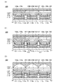
本発明の一態様は、第1の発光デバイスと、第2の発光デバイスと、第1の絶縁層と、第2の絶縁層と、第1の色変換層と、第2の色変換層と、を有し、第1の発光デバイスは、第1の画素電極と、第1の画素電極上の第1の発光層と、第1の発光層上の共通電極と、を有し、第2の発光デバイスは、第2の画素電極と、第2の画素電極上の第2の発光層と、第2の発光層上の共通電極と、を有し、第1の画素電極の端部、及び、第2の画素電極の端部は、それぞれ、第1の絶縁層によって覆われており、第2の絶縁層は、第1の絶縁層上に位置し、第2の絶縁層は、第1の発光層、及び第2の発光層のそれぞれの側面を覆い、第1の色変換層は、第1の発光デバイスに重畳して配置され、第2の色変換層は、第2の発光デバイスに重畳して配置され、第1の発光デバイス、および第2の発光デバイスは、青色光を発する機能を有し、第1の色変換層は、第1の発光デバイスの呈する光を、異なる波長の光へ変換する機能を有し、第2の色変換層は、第2の発光デバイスの呈する光を、異なる波長の光へ変換する機能を有する、表示装置である。 One aspect of the present invention includes a first light-emitting device, a second light-emitting device, a first insulating layer, a second insulating layer, a first color conversion layer, and a second color conversion layer. a first light-emitting device having a first pixel electrode, a first light-emitting layer over the first pixel electrode, a common electrode over the first light-emitting layer; has a second pixel electrode, a second light-emitting layer on the second pixel electrode, a common electrode on the second light-emitting layer, an edge of the first pixel electrode; And the ends of the second pixel electrodes are respectively covered with a first insulating layer, the second insulating layer is located on the first insulating layer, and the second insulating layer is located on the second insulating layer. covering respective sides of the first light-emitting layer and the second light-emitting layer, the first color-converting layer is disposed overlying the first light-emitting device, and the second color-converting layer overlies the second light-emitting device. The first light-emitting device and the second light-emitting device are arranged to overlap the device and have a function of emitting blue light, and the first color conversion layer converts the light emitted by the first light-emitting device into a different color. The second color conversion layer is a display device having a function of converting the light emitted by the second light emitting device into light of a different wavelength.
上記の表示装置は、第3の絶縁層を有し、第2の絶縁層は、無機材料を有し、第3の絶縁層は、有機材料を有し、かつ、第2の絶縁層を介して、第1の発光層、及び第2の発光層のそれぞれの側面、並びに、第1の絶縁層と重なる、ことが好ましい。 The above display device has a third insulating layer, the second insulating layer has an inorganic material, the third insulating layer has an organic material, and It preferably overlaps with each side surface of the first light-emitting layer and the second light-emitting layer and the first insulating layer.
上記の表示装置は、第1の発光デバイスは、第1の発光層と共通電極との間に、共通層を有し、第2の発光デバイスは、第2の発光層と共通電極との間に、共通層を有し、共通層は、正孔注入層、正孔抑止層、正孔輸送層、電子輸送層、電子抑止層、及び電子注入層の少なくとも一つを有する、ことが好ましい。 In the above display device, the first light emitting device has a common layer between the first light emitting layer and the common electrode, and the second light emitting device has a common layer between the second light emitting layer and the common electrode. In addition, it preferably has a common layer, and the common layer has at least one of a hole injection layer, a hole blocking layer, a hole transport layer, an electron transport layer, an electron blocking layer, and an electron injection layer.
上記の表示装置は、第1の発光層は、第2の発光層と、同一の材料を有する、ことが好ましい。 In the above display device, the first light-emitting layer preferably has the same material as the second light-emitting layer.
本発明の他の一態様は、第1の発光デバイスと、第2の発光デバイスと、第1の絶縁層と、第2の絶縁層と、第1の色変換層と、第2の色変換層と、を有し、第1の発光デバイスは、第1の画素電極と、第1の画素電極上の第1の発光ユニットと、第1の発光ユニット上の第1の電荷発生層と、第1の電荷発生層上の第2の発光ユニットと、第2の発光ユニット上の共通電極と、を有し、第2の発光デバイスは、第2の画素電極と、第2の画素電極上の第3の発光ユニットと、第3の発光ユニット上の第2の電荷発生層と、第2の電荷発生層上の第4の発光ユニットと、第4の発光ユニット上の共通電極と、を有し、第1の画素電極の端部、及び、第2の画素電極の端部は、それぞれ、第1の絶縁層によって覆われており、第2の絶縁層は、第1の絶縁層上に位置し、第2の絶縁層は、第1の画素電極、第2の画素電極、第1の電荷発生層、及び第2の電荷発生層のそれぞれの側面を覆い、第1の色変換層は、第1の発光デバイスに重畳して配置され、第2の色変換層は、第2の発光デバイスに重畳して配置され、第1の発光デバイス、第2の発光デバイス、第3の発光ユニット、及び第4の発光ユニットは、青色光を発する機能を有し、第1の色変換層は、第1の発光デバイスの呈する光を、異なる波長の光へ変換する機能を有し、第2の色変換層は、第2の発光デバイスの呈する光を、異なる波長の光へ変換する機能を有する、表示装置である。 Another aspect of the present invention includes a first light emitting device, a second light emitting device, a first insulating layer, a second insulating layer, a first color conversion layer, and a second color conversion. a layer, the first light emitting device comprising: a first pixel electrode; a first light emitting unit on the first pixel electrode; a first charge generation layer on the first light emitting unit; a second light emitting unit on the first charge generation layer and a common electrode on the second light emitting unit, the second light emitting device comprising: a second pixel electrode; a third light emitting unit of, a second charge generating layer on the third light emitting unit, a fourth light emitting unit on the second charge generating layer, and a common electrode on the fourth light emitting unit an end of the first pixel electrode and an end of the second pixel electrode are each covered with a first insulating layer, and the second insulating layer is on the first insulating layer a second insulating layer covering respective sides of the first pixel electrode, the second pixel electrode, the first charge generation layer, and the second charge generation layer; and the first color conversion layer is arranged to overlap the first light emitting device, the second color conversion layer is arranged to overlap the second light emitting device, the first light emitting device, the second light emitting device, and the third light emitting device The unit and the fourth light emitting unit have a function of emitting blue light, the first color conversion layer has a function of converting light emitted by the first light emitting device into light of a different wavelength, The second color conversion layer is a display device having a function of converting light emitted by the second light emitting device into light of a different wavelength.
上記の表示装置は、第3の絶縁層を有し、第2の絶縁層は、無機材料を有し、第3の絶縁層は、有機材料を有し、かつ、第2の絶縁層を介して、第1の電荷発生層、及び第2の電荷発生層のそれぞれの側面、並びに、第1の絶縁層と重なる、ことが好ましい。 The above display device has a third insulating layer, the second insulating layer has an inorganic material, the third insulating layer has an organic material, and It preferably overlaps each side surface of the first charge generation layer and the second charge generation layer and the first insulating layer.
上記の表示装置は、第1の発光デバイスは、第2の発光ユニットと共通電極との間に、共通層を有し、第2の発光デバイスは、第4の発光ユニットと共通電極との間に、共通層を有し、共通層は、正孔注入層、正孔抑止層、正孔輸送層、電子輸送層、電子抑止層、及び電子注入層の少なくとも一つを有する、ことが好ましい。 In the above display device, the first light emitting device has a common layer between the second light emitting unit and the common electrode, and the second light emitting device has a common layer between the fourth light emitting unit and the common electrode. In addition, it preferably has a common layer, and the common layer has at least one of a hole injection layer, a hole blocking layer, a hole transport layer, an electron transport layer, an electron blocking layer, and an electron injection layer.
上記の表示装置は、第1の発光ユニットは、第3の発光ユニットと、同一の材料を有し、第1の電荷発生層は、第2の電荷発生層と、同一の材料を有し、第2の発光ユニットは、第4の発光ユニットと、同一の材料を有する、ことが好ましい。 In the above display device, the first light emitting unit has the same material as the third light emitting unit, the first charge generation layer has the same material as the second charge generation layer, The second light emitting unit preferably comprises the same material as the fourth light emitting unit.
また、上記表示装置は、第1の色変換層および第2の色変換層として、蛍光体又は量子ドットを有することが好ましい。 Moreover, it is preferable that the display device has phosphors or quantum dots as the first color conversion layer and the second color conversion layer.
また、上記の表示装置は、青色光を発する第3の発光デバイスを有し、第3の発光デバイスの呈する光を取り出す機能を有することが好ましい。この場合、表示装置は、第3の発光デバイスの青色光を、色変換層を介さずに取り出す機能を有する。 Moreover, it is preferable that the above display device includes a third light-emitting device that emits blue light and has a function of extracting light emitted by the third light-emitting device. In this case, the display device has a function of extracting blue light from the third light emitting device without going through the color conversion layer.
本発明の一態様は、上記いずれかの構成の表示装置を有し、フレキシブルプリント回路基板(Flexible Printed Circuit、以下、FPCと記す)もしくはTCP(Tape Carrier Package)等のコネクタが取り付けられた表示モジュール、またはCOG(Chip On Glass)方式もしくはCOF(Chip On Film)方式等により集積回路(IC)が実装された表示モジュール等の表示モジュールである。 One aspect of the present invention is a display module having a display device having any one of the above structures and a connector such as a flexible printed circuit (hereinafter referred to as FPC) or TCP (Tape Carrier Package) attached thereto. , or a display module such as a display module in which an integrated circuit (IC) is mounted by a COG (Chip On Glass) method, a COF (Chip On Film) method, or the like.
本発明の一態様は、上記の表示モジュールと、筐体、バッテリ、カメラ、スピーカ、及びマイクのうち少なくとも一つと、を有する電子機器である。 One embodiment of the present invention is an electronic device including the display module described above and at least one of a housing, a battery, a camera, a speaker, and a microphone.
本発明の他の一態様は、絶縁表面上に第1の画素電極、及び第2の画素電極を形成し、第1の画素電極の端部、及び第2の画素電極の端部を覆う、第1の絶縁層を形成し、第1の画素電極、及び第2の画素電極の上に、第1の層を形成し、第1の層上に、第1の犠牲層を形成し、第1の層及び第1の犠牲層を加工して、第1の画素電極上の第2の層と、第2の層上の第2の犠牲層と、第2の画素電極上の第3の層と、第3の層上の第3の犠牲層と、を形成し、少なくとも、第1の絶縁層の上面、第2の層の側面、第3の層の側面、第2の犠牲層の側面及び上面、並びに、第3の犠牲層の側面及び上面を覆う、第1の絶縁膜を形成し、第1の絶縁膜を加工することで、少なくとも、第1の絶縁層の上面、第2の層の側面、及び、第3の層の側面を覆う、第2の絶縁層を形成し、第2の犠牲層及び第3の犠牲層を除去し、第2の層上及び第3の層上に、共通電極を形成し、共通電極上に、第2の層と重畳する第1の色変換層、及び、第3の層と重畳する第2の色変換層を形成する、表示装置の作製方法である。 Another aspect of the present invention is to form a first pixel electrode and a second pixel electrode on an insulating surface, and cover an end of the first pixel electrode and an end of the second pixel electrode. forming a first insulating layer; forming a first layer over the first pixel electrode and the second pixel electrode; forming a first sacrificial layer over the first layer; The first layer and the first sacrificial layer are processed to form a second layer on the first pixel electrode, a second sacrificial layer on the second layer, and a third layer on the second pixel electrode. and a third sacrificial layer on the third layer, wherein at least the top surface of the first insulating layer, the side surface of the second layer, the side surface of the third layer, and the second sacrificial layer. A first insulating film is formed to cover the side surfaces and the top surface and the side surfaces and the top surface of the third sacrificial layer. forming a second insulating layer covering the side surface of the layer and the side surface of the third layer; removing the second sacrificial layer and the third sacrificial layer; forming a common electrode thereon; forming a first color conversion layer overlapping with the second layer and forming a second color conversion layer overlapping with the third layer on the common electrode; It is a manufacturing method.
本発明の他の一態様は、絶縁表面上に第1の画素電極、及び第2の画素電極を形成し、第1の画素電極の端部、及び第2の画素電極の端部を覆う、第1の絶縁層を形成し、第1の画素電極、及び第2の画素電極の上に、第1の層を形成し、第1の層上に、第1の犠牲層を形成し、第1の層及び第1の犠牲層を加工して、第1の画素電極上の第2の層と、第2の層上の第2の犠牲層と、第2の画素電極上の第3の層と、第3の層上の第3の犠牲層と、を形成し、無機材料を用いて、少なくとも、第1の絶縁層の上面、第2の層の側面、第3の層の側面、第2の犠牲層の側面及び上面、並びに、第3の犠牲層の側面及び上面を覆う、第1の絶縁膜を形成し、有機材料を用いて、第1の絶縁膜上に第2の絶縁膜を形成し、第1の絶縁膜及び第2の絶縁膜を加工することで、少なくとも、第1の絶縁層の上面、第2の層の側面、及び、第3の層の側面を覆う、第2の絶縁層と、第2の絶縁層上の第3の絶縁層と、を形成し、第2の犠牲層及び第3の犠牲層を除去し、第2の層上及び第3の層上に、共通電極を形成し、共通電極上に、第2の層と重畳する第1の色変換層、及び、第3の層と重畳する第2の色変換層を形成する、表示装置の作製方法である。 Another aspect of the present invention is to form a first pixel electrode and a second pixel electrode on an insulating surface, and cover an end of the first pixel electrode and an end of the second pixel electrode. forming a first insulating layer; forming a first layer over the first pixel electrode and the second pixel electrode; forming a first sacrificial layer over the first layer; The first layer and the first sacrificial layer are processed to form a second layer on the first pixel electrode, a second sacrificial layer on the second layer, and a third layer on the second pixel electrode. forming a layer and a third sacrificial layer on the third layer, using an inorganic material to form at least the top surface of the first insulating layer, the side surface of the second layer, the side surface of the third layer, forming a first insulating film covering the side and top surfaces of the second sacrificial layer and the side and top surfaces of the third sacrificial layer; using an organic material to form a second insulating film on the first insulating film; forming a film and processing the first insulating film and the second insulating film to cover at least the top surface of the first insulating layer, the side surface of the second layer, and the side surface of the third layer; forming a second insulating layer and a third insulating layer over the second insulating layer; removing the second sacrificial layer and the third sacrificial layer; forming a common electrode thereon; forming a first color conversion layer overlapping with the second layer and forming a second color conversion layer overlapping with the third layer on the common electrode; It is a manufacturing method.
上記の表示装置の作製方法において、有機材料として感光性の樹脂を用いて、第2の絶縁膜を形成する、ことが好ましい。 In the above method for manufacturing a display device, it is preferable to form the second insulating film using a photosensitive resin as the organic material.
上記の表示装置の作製方法において、第1の犠牲層として、第1の犠牲膜と、第1の犠牲膜上の第2の犠牲膜と、を形成し、第2の犠牲膜上に、第1のレジストマスクを形成した後、第1のレジストマスクを用いて、第2の犠牲膜を加工し、第1のレジストマスクを除去し、加工された第2の犠牲膜をマスクに用いて、第1の犠牲膜を加工し、加工された第1の犠牲膜をマスクに用いて、第1の層を加工する、ことが好ましい。 In the above method for manufacturing a display device, a first sacrificial film and a second sacrificial film on the first sacrificial film are formed as the first sacrificial layer, and a second sacrificial film is formed on the second sacrificial film. After forming one resist mask, using the first resist mask, a second sacrificial film is processed, the first resist mask is removed, and the processed second sacrificial film is used as a mask, It is preferable to process the first sacrificial film and process the first layer using the processed first sacrificial film as a mask.
上記の表示装置の作製方法において、第2の犠牲層及び第3の犠牲層を除去した後に、第2の層上及び第3の層上に、第4の層を形成し、第4の層上に、共通電極を形成する、ことが好ましい。 In the above method for manufacturing a display device, after removing the second sacrificial layer and the third sacrificial layer, the fourth layer is formed on the second layer and the third layer, and the fourth layer is formed on the third layer. A common electrode is preferably formed thereon.
本発明の一態様により、高精細な表示装置を提供できる。本発明の一態様により、高解像度の表示装置を提供できる。本発明の一態様により、高開口率の表示装置を提供できる。本発明の一態様により、大型の表示装置を提供できる。本発明の一態様により、小型の表示装置を提供できる。本発明の一態様により、信頼性の高い表示装置を提供できる。 One embodiment of the present invention can provide a high-definition display device. One embodiment of the present invention can provide a high-resolution display device. According to one embodiment of the present invention, a display device with a high aperture ratio can be provided. One embodiment of the present invention can provide a large-sized display device. According to one embodiment of the present invention, a small display device can be provided. One embodiment of the present invention can provide a highly reliable display device.
本発明の一態様により、高精細な表示装置の作製方法を提供できる。本発明の一態様により、高解像度の表示装置の作製方法を提供できる。本発明の一態様により、高開口率の表示装置の作製方法を提供できる。本発明の一態様により、大型の表示装置の作製方法を提供できる。本発明の一態様により、小型の表示装置の作製方法を提供できる。本発明の一態様により、信頼性の高い表示装置の作製方法を提供できる。本発明の一態様により、歩留まりの高い表示装置の作製方法を提供できる。 According to one embodiment of the present invention, a method for manufacturing a high-definition display device can be provided. According to one embodiment of the present invention, a method for manufacturing a high-resolution display device can be provided. According to one embodiment of the present invention, a method for manufacturing a display device with a high aperture ratio can be provided. According to one embodiment of the present invention, a method for manufacturing a large display device can be provided. According to one embodiment of the present invention, a method for manufacturing a small display device can be provided. According to one embodiment of the present invention, a highly reliable method for manufacturing a display device can be provided. According to one embodiment of the present invention, a method for manufacturing a display device with high yield can be provided.
なお、これらの効果の記載は、他の効果の存在を妨げるものではない。本発明の一態様は、必ずしも、これらの効果の全てを有する必要はない。明細書、図面、請求項の記載から、これら以外の効果を抽出することが可能である。 Note that the description of these effects does not preclude the existence of other effects. One aspect of the present invention does not necessarily have all of these effects. Effects other than these can be extracted from the descriptions of the specification, drawings, and claims.
実施の形態について、図面を用いて詳細に説明する。但し、本発明は以下の説明に限定されず、本発明の趣旨及びその範囲から逸脱することなくその形態及び詳細を様々に変更し得ることは当業者であれば容易に理解される。従って、本発明は以下に示す実施の形態の記載内容に限定して解釈されるものではない。 Embodiments will be described in detail with reference to the drawings. However, the present invention is not limited to the following description, and those skilled in the art will easily understand that various changes can be made in form and detail without departing from the spirit and scope of the present invention. Therefore, the present invention should not be construed as being limited to the descriptions of the embodiments shown below.
なお、以下に説明する発明の構成において、同一部分又は同様な機能を有する部分には同一の符号を異なる図面間で共通して用い、その繰り返しの説明は省略する。また、同様の機能を指す場合には、ハッチングパターンを同じくし、特に符号を付さない場合がある。 In the configuration of the invention to be described below, the same reference numerals are used in common for the same parts or parts having similar functions in different drawings, and repeated description thereof will be omitted. Moreover, when referring to similar functions, the same hatching pattern may be used and no particular reference numerals may be attached.
また、図面において示す各構成の、位置、大きさ、範囲などは、理解の簡単のため、実際の位置、大きさ、範囲などを表していない場合がある。このため、開示する発明は、必ずしも、図面に開示された位置、大きさ、範囲などに限定されない。 In addition, the position, size, range, etc. of each configuration shown in the drawings may not represent the actual position, size, range, etc. for ease of understanding. Therefore, the disclosed invention is not necessarily limited to the position, size, range, etc. disclosed in the drawings.
なお、「膜」という言葉と、「層」という言葉とは、場合によっては、又は、状況に応じて、互いに入れ替えることが可能である。例えば、「導電層」という用語を、「導電膜」という用語に変更することが可能である。または、例えば、「絶縁膜」という用語を、「絶縁層」という用語に変更することが可能である。 It should be noted that the terms "film" and "layer" can be interchanged depending on the case or situation. For example, the term "conductive layer" can be changed to the term "conductive film." Alternatively, for example, the term “insulating film” can be changed to the term “insulating layer”.
(実施の形態1)
本実施の形態では、本発明の一態様の表示装置とその作製方法について図1乃至図13を用いて説明する。
(Embodiment 1)
In this embodiment, a display device of one embodiment of the present invention and a manufacturing method thereof will be described with reference to FIGS.
本発明の一態様の表示装置は、表示部に、画素がマトリクス状に配置されており、当該表示部で画像を表示することができる。当該画素は、青色光を発する発光デバイス(発光素子ともいう)と、当該発光デバイスと重畳する色変換層と、を有する。 In the display device of one embodiment of the present invention, pixels are arranged in matrix in the display portion, and an image can be displayed on the display portion. The pixel includes a light-emitting device (also referred to as a light-emitting element) that emits blue light and a color conversion layer that overlaps with the light-emitting device.
なお、本明細書等において、画素とは、例えば、明るさを制御できる要素一つ分を示すものとする。一例としては、一画素とは、一つの色要素を示すものとし、その色要素一つで明るさを表現する。R(赤)G(緑)B(青)の色要素からなるカラー表示装置の場合には、画像の最小単位は、Rの画素とGの画素とBの画素との三画素から構成されるものとする。この場合、RGBのそれぞれの画素は副画素(サブ画素)とも呼ぶことができ、RGBの3つの副画素を併せて画素と呼ぶこともできる。各画素内の副画素において、互いに異なる波長の光へ変換する機能を有する色変換層を用いることで、フルカラー表示を行うことができる。さらに、各画素に用いられる発光デバイスは、同一の材料を用いて形成することができるので、製造工程を簡略化し、製造コストを低減することができる。 Note that in this specification and the like, a pixel indicates, for example, one element whose brightness can be controlled. As an example, one pixel indicates one color element, and the single color element expresses brightness. In the case of a color display device composed of R (red), G (green) and B (blue) color elements, the minimum unit of an image is composed of three pixels: an R pixel, a G pixel, and a B pixel. shall be In this case, each pixel of RGB can also be called a sub-pixel (sub-pixel), and three sub-pixels of RGB can be collectively called a pixel. Full-color display can be performed by using color conversion layers having a function of converting light with different wavelengths in sub-pixels in each pixel. Furthermore, since the light emitting device used for each pixel can be formed using the same material, the manufacturing process can be simplified and the manufacturing cost can be reduced.
発光デバイスとしては、OLED(Organic LED)、QLED(Quantum-dot LED)などのELデバイス(EL素子ともいう)を用いることが好ましい。ELデバイスが有する発光物質としては、蛍光を発する物質(蛍光材料)、燐光を発する物質(燐光材料)、無機化合物(量子ドット材料など)、熱活性化遅延蛍光を示す物質(熱活性化遅延蛍光(Thermally Activated Delayed Fluorescence:TADF)材料)などが挙げられる。また、発光デバイスとして、マイクロLEDなどのLEDを用いることもできる。 As the light-emitting device, an EL device (also referred to as an EL element) such as OLED (Organic LED) or QLED (Quantum-dot LED) is preferably used. Examples of light-emitting substances that EL devices have include substances that emit fluorescence (fluorescent materials), substances that emit phosphorescence (phosphorescence materials), inorganic compounds (quantum dot materials, etc.), and substances that exhibit heat-activated delayed fluorescence (heat-activated delayed fluorescence (Thermally Activated Delayed Fluorescence: TADF) material) and the like. Moreover, LEDs, such as micro LED, can also be used as a light emitting device.
各画素の発光デバイスを、青色発光の有機ELデバイスで形成する場合、各画素において、発光層の塗分けを行う必要がない。よって、発光デバイスに含まれる画素電極以外の層(例えば発光層など)を、各画素で共通にすることができる。しかしながら、発光デバイスに含まれる層には、比較的導電性が高い層もあり、導電性が高い層が各画素で共通で設けられることで、画素間にリーク電流が発生する場合がある。特に、表示装置が高精細化または高開口率化され、画素間の距離が小さくなると、当該リーク電流は無視できない大きさになり、表示装置の表示品位の低下などを引き起こす恐れがある。そこで、本発明の一態様に係る表示装置では、各画素において、発光デバイスの少なくとも一部を島状に形成することで、表示装置の高精細化と高信頼性化を図る。ここで、当該発光デバイスの島状に形成する部分には、発光層を含むものとする。 When the light-emitting device of each pixel is formed of an organic EL device that emits blue light, it is not necessary to separate the light-emitting layers in each pixel. Therefore, a layer other than the pixel electrode included in the light-emitting device (for example, a light-emitting layer) can be shared by each pixel. However, among the layers included in the light-emitting device, there are also layers with relatively high conductivity. Leakage current may occur between pixels when a layer with high conductivity is commonly provided for each pixel. In particular, when a display device has a high definition or a high aperture ratio and the distance between pixels becomes small, the leakage current becomes unignorable, and there is a possibility that the display quality of the display device is deteriorated. Therefore, in a display device according to one embodiment of the present invention, at least part of a light-emitting device in each pixel is formed in an island shape, so that the display device has high definition and high reliability. Here, it is assumed that the island-shaped portion of the light-emitting device includes a light-emitting layer.
なお、本明細書等において、島状とは、同一工程で形成された同一材料を用いた2以上の層が、物理的に分離されている状態であることを示す。例えば、島状の発光層とは、当該発光層と、隣接する発光層とが、物理的に分離されている状態であることを示す。 Note that, in this specification and the like, an island shape indicates a state in which two or more layers using the same material formed in the same step are physically separated. For example, an island-shaped light-emitting layer means that the light-emitting layer is physically separated from an adjacent light-emitting layer.
例えば、メタルマスク(シャドーマスクともいう)を用いた真空蒸着法により、島状の発光層を成膜することができる。しかし、この方法では、メタルマスクの寸法精度、メタルマスクと基板との位置ずれ、メタルマスクのたわみ、及び蒸気の散乱などによる成膜される膜の輪郭の広がりなど、様々な影響により、島状の発光層の形状及び位置に設計からのずれが生じるため、表示装置の高精細化、及び高開口率化が困難である。また、蒸着の際に、層の輪郭がぼやけて、端部の厚さが薄くなることがある。つまり、島状の発光層は場所によって厚さにばらつきが生じることがある。また、大型、高解像度、または高精細な表示装置を作製する場合、メタルマスクの寸法精度の低さ、及び、熱等による変形により、製造歩留まりが低くなる懸念がある。 For example, an island-shaped light-emitting layer can be formed by a vacuum evaporation method using a metal mask (also referred to as a shadow mask). However, in this method, various influences such as the dimensional accuracy of the metal mask, misalignment between the metal mask and the substrate, bending of the metal mask, and broadening of the contour of the film to be formed due to vapor scattering, etc. cause island-like formations. Since the shape and position of the light-emitting layer in (1) deviate from the design, it is difficult to increase the definition and aperture ratio of the display device. Also, during deposition, the layer profile may be blurred and the edge thickness may be reduced. In other words, the thickness of the island-shaped light-emitting layer may vary depending on the location. In addition, when manufacturing a large-sized, high-resolution, or high-definition display device, there is a concern that the manufacturing yield will be low due to low dimensional accuracy of the metal mask and deformation due to heat or the like.
本発明の一態様の表示装置の作製方法では、島状の画素電極(下部電極ともいえる)を形成し、画素電極の端部を覆う絶縁層を形成した後、発光層を含む層(EL層、またはEL層の一部、ということができる)を一面に形成し、EL層上に犠牲層(マスク層ともいう)を形成する。そして、犠牲層上にレジストマスクを形成し、レジストマスクを用いて、EL層と犠牲層を加工することで、島状の画素電極上に島状のEL層を形成する。ここでEL層とは少なくとも発光層を含み、発光ユニットということもできる。 In a method for manufacturing a display device of one embodiment of the present invention, an island-shaped pixel electrode (which can also be called a lower electrode) is formed, an insulating layer covering an end portion of the pixel electrode is formed, and then a layer including a light-emitting layer (an EL layer) is formed. , or part of the EL layer) is formed over the EL layer, and a sacrificial layer (also referred to as a mask layer) is formed over the EL layer. Then, a resist mask is formed over the sacrificial layer, and the EL layer and the sacrificial layer are processed using the resist mask, thereby forming an island-shaped EL layer over the island-shaped pixel electrode. Here, the EL layer includes at least a light-emitting layer and can also be called a light-emitting unit.
このように、本発明の一態様の表示装置の作製方法では、島状のEL層は、メタルマスクのパターンによって形成されるのではなく、EL層を一面に成膜した後に加工することで形成される。したがって、これまで実現が困難であった高精細な表示装置または高開口率の表示装置を実現することができる。また、EL層上に犠牲層を設けることで、表示装置の作製工程中にEL層が受けるダメージを低減し、発光デバイスの信頼性を高めることができる。 As described above, in the method for manufacturing a display device of one embodiment of the present invention, the island-shaped EL layer is not formed by a pattern of a metal mask, but is formed by forming an EL layer over one surface and then processing the EL layer. be done. Therefore, it is possible to realize a high-definition display device or a display device with a high aperture ratio, which has hitherto been difficult to achieve. Further, by providing the sacrificial layer over the EL layer, damage to the EL layer during the manufacturing process of the display device can be reduced, and the reliability of the light-emitting device can be improved.
隣り合う発光デバイスの間隔について、例えばメタルマスクを用いた形成方法では10μm未満にすることは困難であるが、上記方法であれば、8μm以下、6μm以下、4μm以下、3μm以下、2μm以下、または、1μm以下にまで狭めることができる。さらに、例えばLSI向けの露光装置を用いることで、500nm以下、200nm以下、100nm以下、さらには50nm以下にまで間隔を狭めることもできる。これにより、2つの発光デバイス間に存在しうる非発光領域の面積を大幅に縮小することができ、開口率を100%に近づけることが可能となる。例えば、開口率は、50%以上、60%以上、70%以上、80%以上、さらには90%以上であって、100%未満を実現することもできる。 It is difficult to set the distance between adjacent light-emitting devices to less than 10 μm by, for example, a formation method using a metal mask. , can be narrowed down to 1 μm or less. Furthermore, by using an exposure apparatus for LSI, for example, the gap can be narrowed to 500 nm or less, 200 nm or less, 100 nm or less, or even 50 nm or less. As a result, the area of the non-light-emitting region that can exist between the two light-emitting devices can be greatly reduced, and the aperture ratio can be brought close to 100%. For example, the aperture ratio can be 50% or more, 60% or more, 70% or more, 80% or more, or even 90% or more, and less than 100%.
また、EL層自体のパターンについても、メタルマスクを用いた場合に比べて極めて小さくすることができる。また、例えばEL層の作り分けにメタルマスクを用いた場合では、パターンの中央と端で厚さのばらつきが生じるため、パターン全体の面積に対して、発光領域として使用できる有効な面積は小さくなる。一方、上記作製方法では、均一な厚さに成膜した膜を加工することでパターンを形成するため、パターン内で厚さを均一にでき、微細なパターンであっても、そのほぼ全域を発光領域として用いることができる。そのため、高い精細度と高い開口率を兼ね備えた表示装置を作製することができる。 Also, the pattern of the EL layer itself can be made much smaller than when a metal mask is used. In addition, for example, when a metal mask is used to separately fabricate the EL layer, the thickness varies between the center and the edge of the pattern, so the effective area that can be used as the light emitting region is smaller than the area of the entire pattern. . On the other hand, in the above manufacturing method, since the pattern is formed by processing a film formed to have a uniform thickness, the thickness can be made uniform within the pattern, and even if the pattern is fine, almost the entire area of the pattern can emit light. It can be used as a region. Therefore, a display device having both high definition and high aperture ratio can be manufactured.
なお、青色光を発する発光デバイスにおいて、EL層を構成する全ての層を島状に形成する必要はなく、一部の層は同一工程で成膜することができる。本発明の一態様の表示装置の作製方法では、EL層を構成する一部の層を画素ごとに島状に形成した後、犠牲層を除去し、EL層を構成する残りの層(例えば、キャリア注入層など)と、共通電極(上部電極ともいえる)と、を共通して形成することができる。 Note that in a light-emitting device that emits blue light, not all the layers constituting the EL layer need to be island-shaped, and some of the layers can be formed in the same process. In the method for manufacturing a display device of one embodiment of the present invention, after some layers forming the EL layer are formed in an island shape for each pixel, the sacrificial layer is removed, and the remaining layers forming the EL layer (for example, carrier injection layer, etc.) and a common electrode (which can also be called an upper electrode) can be formed in common.
一方で、キャリア注入層は、発光デバイスの中では、比較的導電性が高い層であることが多い。そのため、キャリア注入層が、島状のEL層の側面に接することで、発光デバイスがショートする恐れがある。なお、キャリア注入層を島状に設け、共通電極のみを発光デバイス間で共通して形成する場合についても、共通電極と、島状のEL層の側面、または、画素電極の側面とが接することで、発光デバイスがショートする恐れがある。 On the other hand, carrier injection layers are often relatively highly conductive layers in light emitting devices. Therefore, the light-emitting device may be short-circuited when the carrier injection layer comes into contact with the side surface of the island-shaped EL layer. Note that even in the case where the carrier injection layer is provided in an island shape and only the common electrode is formed in common among the light emitting devices, the common electrode and the side surface of the island-shaped EL layer or the side surface of the pixel electrode should be in contact with each other. and the light-emitting device may short out.
そこで、本発明の一態様の表示装置は、島状のEL層(例えば発光層)の側面を覆う絶縁層と、画素電極の端部を覆う絶縁層と、を有する。これにより、島状のEL層の少なくとも一部の層、及び画素電極が、キャリア注入層または共通電極と接することを抑制できる。したがって、発光デバイスのショートを抑制し、発光デバイスの信頼性を高めることができる。 Therefore, a display device of one embodiment of the present invention includes an insulating layer covering side surfaces of an island-shaped EL layer (eg, a light-emitting layer) and an insulating layer covering end portions of pixel electrodes. This can prevent at least a part of the island-shaped EL layer and the pixel electrode from contacting the carrier injection layer or the common electrode. Therefore, short-circuiting of the light-emitting device can be suppressed, and the reliability of the light-emitting device can be improved.
本発明の一態様の表示装置は、陽極として機能する画素電極と、画素電極上にこの順で設けられた、それぞれ島状の、正孔注入層、正孔輸送層、発光層、及び、電子輸送層と、画素電極の端部を覆う絶縁層と、正孔注入層、正孔輸送層、発光層、及び、電子輸送層のそれぞれの側面を覆うように設けられた絶縁層と、電子輸送層上に設けられた電子注入層と、電子注入層上に設けられ、陰極として機能する共通電極と、を有する。 A display device of one embodiment of the present invention includes a pixel electrode functioning as an anode, and an island-shaped hole-injection layer, a hole-transport layer, a light-emitting layer, and an electron layer provided in this order on the pixel electrode. a transport layer, an insulating layer covering the edge of the pixel electrode, an insulating layer provided to cover each side surface of the hole injection layer, the hole transport layer, the light emitting layer, and the electron transport layer, and the electron transport It has an electron injection layer provided on the layer and a common electrode provided on the electron injection layer and functioning as a cathode.
または、本発明の一態様の表示装置は、陰極として機能する画素電極と、画素電極上にこの順で設けられた、それぞれ島状の、電子注入層、電子輸送層、発光層、及び、正孔輸送層と、画素電極の端部を覆う絶縁層と、電子注入層、電子輸送層、発光層、及び、正孔輸送層のそれぞれの側面を覆うように設けられた絶縁層と、正孔輸送層上に設けられた正孔注入層と、正孔注入層上に設けられ、陽極として機能する共通電極と、を有する。 Alternatively, a display device of one embodiment of the present invention includes a pixel electrode functioning as a cathode, and an island-shaped electron-injection layer, an electron-transport layer, a light-emitting layer, and a positive electrode which are provided in this order over the pixel electrode. a hole-transporting layer, an insulating layer covering the edge of the pixel electrode, an insulating layer provided to cover each side surface of the electron injection layer, the electron-transporting layer, the light-emitting layer, and the hole-transporting layer, and holes It has a hole injection layer provided on the transport layer and a common electrode provided on the hole injection layer and functioning as an anode.
または、本発明の一態様の表示装置は、画素電極と、画素電極上の第1の発光ユニットと、第1の発光ユニット上の中間層(電荷発生層ともいう)と、中間層上の第2の発光ユニットと、画素電極の端部を覆う絶縁層と、第1の発光ユニット、中間層、及び、第2の発光ユニットのそれぞれの側面を覆うように設けられた絶縁層と、第2の発光ユニット上に設けられた共通電極と、を有する。なお、第2の発光ユニットと共通電極との間に、各色の発光デバイスに共通の層が設けられていてもよい。 Alternatively, a display device of one embodiment of the present invention includes a pixel electrode, a first light-emitting unit over the pixel electrode, an intermediate layer (also referred to as a charge generation layer) over the first light-emitting unit, and a first light-emitting layer over the intermediate layer. 2 light-emitting units, an insulating layer covering the edge of the pixel electrode, an insulating layer provided to cover the side surfaces of the first light-emitting unit, the intermediate layer, and the second light-emitting unit; and a common electrode provided on the light emitting unit of the light emitting unit. Note that a layer common to the light emitting devices of each color may be provided between the second light emitting unit and the common electrode.
正孔注入層、電子注入層、または電荷発生層などは、EL層の中では、比較的導電性が高い層であることが多い。本発明の一態様の表示装置では、これらの層の側面が絶縁層で覆われるため、共通電極などと接することを抑制することができる。したがって、発光デバイスのショートを抑制し、発光デバイスの信頼性を高めることができる。 A hole-injection layer, an electron-injection layer, a charge-generating layer, or the like is often a layer having relatively high conductivity among the EL layers. In the display device of one embodiment of the present invention, the side surfaces of these layers are covered with the insulating layer; therefore, contact with a common electrode or the like can be suppressed. Therefore, short-circuiting of the light-emitting device can be suppressed, and the reliability of the light-emitting device can be improved.
また、本発明の一態様の表示装置は、各画素が有する発光デバイスがいずれも青色の光を呈し、色変換層によって異なる波長の光へと変換することで、フルカラー化を達成している。従って、白色の光を呈する発光デバイスを作製する場合と比較して、成膜するEL層の層数や材料の種類を削減することができるため、製造装置及び工程を簡素化して歩留まりを向上させることができる。 In the display device of one embodiment of the present invention, the light-emitting device included in each pixel emits blue light, which is converted into light of different wavelengths by the color conversion layer, thereby achieving full color. Therefore, compared to the case of manufacturing a light-emitting device that emits white light, the number of EL layers to be formed and the types of materials can be reduced, so that the manufacturing apparatus and processes are simplified and the yield is improved. be able to.
このような構成とすることで、精細度または解像度が高く、信頼性の高い、表示装置を作製することができる。例えばペンタイル方式などの特殊な画素配列方式を適用し、疑似的に精細度を高める必要が無く、1つの画素に3つ以上の副画素を用いた配列方法であっても、極めて高精細な表示装置を実現できる。例えば、R、G、Bをそれぞれ一方向に配列させた、いわゆるストライプ配置で、且つ、500ppi以上、1000ppi以上、または2000ppi以上、さらには3000ppi以上、さらには5000ppi以上の精細度の表示装置を実現することができる。 With such a structure, a highly reliable display device with high definition or resolution can be manufactured. For example, by applying a special pixel arrangement method such as the pentile method, there is no need to artificially increase the definition. device can be realized. For example, a display device with a so-called stripe arrangement in which R, G, and B are arranged in one direction and a resolution of 500 ppi or more, 1000 ppi or more, or 2000 ppi or more, further 3000 ppi or more, and furthermore 5000 ppi or more is realized. can do.
色変換層としては、蛍光体、または量子ドット(QD:Quantum Dot)を用いることが好ましい。量子ドットは、発光スペクトルのピーク幅が狭く、色純度のよい発光を得ることができる。これにより、表示装置の表示品位を高めることができる。 As the color conversion layer, it is preferable to use phosphors or quantum dots (QDs). Quantum dots have a narrow peak width in the emission spectrum and can provide light emission with good color purity. Thereby, the display quality of the display device can be improved.
EL層などの側面を覆う絶縁層は、単層構造であってもよく、積層構造であってもよい。特に、2層構造の絶縁層を適用することが好ましい。例えば、絶縁層の1層目は、EL層に接して形成されるため、無機絶縁材料を用いて形成することが好ましい。特に、成膜ダメージが小さい原子層堆積(ALD:Atomic Layer Deposition)法を用いて形成することが好ましい。そのほか、ALD法よりも成膜速度が速い、スパッタリング法、化学気相堆積(CVD:Chemical Vapor Deposition)法、または、プラズマ化学気相堆積(PECVD:Plasma Enhanced CVD)法を用いて無機絶縁層を形成することが好ましい。これにより、信頼性の高い表示装置を生産性高く作製することができる。また、絶縁層の2層目は、1層目の絶縁層に形成された凹部を平坦化するように、有機材料を用いて形成することが好ましい。 An insulating layer that covers the side surfaces of the EL layer or the like may have a single-layer structure or a laminated structure. In particular, it is preferable to apply an insulating layer having a two-layer structure. For example, since the first insulating layer is formed in contact with the EL layer, it is preferably formed using an inorganic insulating material. In particular, it is preferable to use an atomic layer deposition (ALD) method, which causes less film damage. In addition, the inorganic insulating layer is formed using a sputtering method, a chemical vapor deposition (CVD) method, or a plasma enhanced CVD (PECVD) method, which has a higher film formation rate than the ALD method. preferably formed. Accordingly, a highly reliable display device can be manufactured with high productivity. Further, the second insulating layer is preferably formed using an organic material so as to planarize the concave portion formed in the first insulating layer.
例えば、絶縁層の1層目に、ALD法により形成した酸化アルミニウム膜を用い、絶縁層の2層目に、感光性の有機樹脂膜を用いることができる。 For example, an aluminum oxide film formed by an ALD method can be used as the first insulating layer, and a photosensitive organic resin film can be used as the second insulating layer.
また、単層構造の絶縁層を形成してもよい。例えば、無機材料を用いた単層構造の絶縁層を形成することで、当該絶縁層をEL層の保護絶縁層として用いることができる。これにより、表示装置の信頼性を高めることができる。また、例えば、有機材料を用いた単層構造の絶縁層を形成することで、隣り合うEL層の間を当該絶縁層で充填し、平坦化することができる。これにより、EL層及び絶縁層上に形成する共通電極(上部電極)の被覆性を高めることができる。 Alternatively, an insulating layer having a single-layer structure may be formed. For example, by forming an insulating layer having a single-layer structure using an inorganic material, the insulating layer can be used as a protective insulating layer of the EL layer. Thereby, the reliability of the display device can be improved. Further, for example, by forming an insulating layer having a single-layer structure using an organic material, the insulating layer can be filled between adjacent EL layers to planarize the EL layers. Thereby, the coverage of the common electrode (upper electrode) formed over the EL layer and the insulating layer can be improved.
[表示装置の構成例1]
図1(A)及び図1(B)に、本発明の一態様の表示装置を示す。
[Configuration example 1 of display device]
1A and 1B illustrate a display device of one embodiment of the present invention.
図1(A)に表示装置100の上面図を示す。表示装置100は、複数の画素110がマトリクス状に配置された表示部と、表示部の外側の接続部140と、を有する。
FIG. 1A shows a top view of the
図1では、副画素110aと副画素110bは、それぞれ発光デバイス130a、130bに重畳して色変換層129a、129b(以下、まとめて色変換層129と呼ぶ場合がある。)が設けられ、副画素110cは色変換層を有さない構成を有している。例えば、色変換層129aは、青色の光を赤色の光に変換することができ、色変換層129bは青色の光を緑色の光に変換することができる。これによって、副画素110aでは赤色の光が外部に取り出され、副画素110bでは緑色の光が外部に取り出される。色変換層を有さない副画素110cでは、発光デバイス130cが呈した青色の光が取り出される。なお、副画素110a、110b、110cの構成は、赤色(R)、緑色(G)、青色(B)の3色に限られず、例えば副画素110cに色変換層を設けて、黄色(Y)、シアン(C)、及びマゼンタ(M)の3色の副画素などとしてもよい。
In FIG. 1, the sub-pixel 110a and the sub-pixel 110b are provided with
図1(A)では、異なる色の副画素がX方向に並べて配置されており、同じ色の副画素が、Y方向に並べて配置されている例を示す。なお、異なる色の副画素がY方向に並べて配置され、同じ色の副画素が、X方向に並べて配置されていてもよい。 FIG. 1A shows an example in which sub-pixels of different colors are arranged side by side in the X direction and sub-pixels of the same color are arranged side by side in the Y direction. Sub-pixels of different colors may be arranged side by side in the Y direction, and sub-pixels of the same color may be arranged side by side in the X direction.
図1(A)では、上面視で、接続部140が表示部の下側に位置する例を示すが、特に限定されない。接続部140は、上面視で、表示部の上側、右側、左側、下側の少なくとも一箇所に設けられていればよく、表示部の四辺を囲むように設けられていてもよい。また、接続部140は、単数であっても複数であってもよい。
FIG. 1A shows an example in which the
図1(B)に、図1(A)における一点鎖線X1-X2間の断面図を示す。 FIG. 1B shows a cross-sectional view along the dashed-dotted line X1-X2 in FIG. 1A.
図1(B)に示すように、表示装置100は、トランジスタ(図示しない)を含む層101上に、発光デバイス130a、130b、130cが設けられ、これらの発光デバイスを覆うように保護層131、132が設けられている。保護層132上には、色変換層129a、129bが設けられている。さらにその上に、樹脂層122によって基板120が貼り合わされている。また、隣り合う発光デバイスの間の領域には、絶縁層125と、絶縁層125上の絶縁層127と、が設けられている。
As shown in FIG. 1B, in the
本発明の一態様の表示装置は、発光デバイスが形成されている基板とは反対方向に光を射出する上面射出型(トップエミッション型)、発光デバイスが形成されている基板側に光を射出する下面射出型(ボトムエミッション型)、両面に光を射出する両面射出型(デュアルエミッション型)のいずれであってもよい。 A display device of one embodiment of the present invention is a top emission type in which light is emitted in a direction opposite to a substrate over which a light-emitting device is formed, and light is emitted toward a substrate over which a light-emitting device is formed. Either a bottom emission type (bottom emission type) or a double emission type (dual emission type) in which light is emitted from both sides may be used.
層101には、例えば、基板に複数のトランジスタ(図示しない)が設けられ、これらのトランジスタを覆うように絶縁層が設けられた積層構造を適用することができる。層101は、隣り合う発光デバイスの間に凹部を有していてもよい。例えば、層101の最表面に位置する絶縁層に凹部が設けられていてもよい。層101の構成例は、実施の形態3、4で後述する。
For the
発光デバイス130a、130b、130cは、それぞれ、青色(B)の光を発することが好ましい。発光デバイス130a、130b上にそれぞれ異なる色の光に変換する機能を有する色変換層129a、129bを設け、発光デバイス130c上には色変換層を設けない構成とすることで、それぞれ異なる色の光を発する副画素110a、110b、110cを形成することができる。
Each of the
なお、本発明の一態様の表示装置に用いることが可能な発光デバイス130a、130b、130cとしては青色の光を発する発光デバイスに限られず、例えば紫外光を発する発光デバイスを適用することもできる。発光デバイス130a、130b、130cとして紫外光を発する発光デバイスを適用した場合には、発光デバイス130a、130b、130cに重畳して、それぞれ異なる色の光に変換する機能を有する色変換層129を設けるとよい。例えば、色変換層129aとして、紫外光を赤色の波長の光に変換する色変換層を設け、色変換層129bとして、紫外光を緑色の波長の光に変換する色変換層を設け、発光デバイス130c上に、紫外光を青色の波長の光に変換する色変換層を設けることができる。これによって、副画素110aでは赤色の光が外部に取り出され、副画素110bでは緑色の光が外部に取り出され、副画素110cでは青色の光が外部に取り出され、表示装置をフルカラー化することができる。
Note that the light-emitting
発光デバイス130a、130b、130cとしては、OLED、またはQLEDなどのELデバイスを用いることが好ましい。ELデバイスが有する発光物質としては、蛍光を発する物質(蛍光材料)、燐光を発する物質(燐光材料)、無機化合物(量子ドット材料など)、熱活性化遅延蛍光を示す物質(熱活性化遅延蛍光(TADF)材料)などが挙げられる。なお、TADF材料としては、一重項励起状態と三重項励起状態間が熱平衡状態にある材料を用いてもよい。このようなTADF材料は発光寿命(励起寿命)が短くなるため、発光デバイスにおける高輝度領域での効率低下を抑制することができる。
EL devices such as OLEDs or QLEDs are preferably used as the
発光デバイスは、一対の電極間にEL層を有する。本明細書等では、一対の電極の一方を画素電極と記し、他方を共通電極と記すことがある。 A light-emitting device has an EL layer between a pair of electrodes. In this specification and the like, one of a pair of electrodes may be referred to as a pixel electrode and the other may be referred to as a common electrode.
発光デバイスが有する一対の電極のうち、一方の電極は陽極として機能し、他方の電極は陰極として機能する。以下では、画素電極が陽極として機能し、共通電極が陰極として機能する場合を例に挙げて説明する。 Of the pair of electrodes that the light-emitting device has, one electrode functions as an anode and the other electrode functions as a cathode. A case where the pixel electrode functions as an anode and the common electrode functions as a cathode will be described below as an example.
発光デバイス130aは、層101上の画素電極111aと、画素電極111a上の島状の第1の層113aと、島状の第1の層113a上の第5の層114と、第5の層114上の共通電極115と、を有する。発光デバイス130aにおいて、第1の層113a、及び、第5の層114をまとめてEL層と呼ぶことができる。
The light-emitting
本実施の形態の発光デバイスの構成に、特に限定はなく、シングル構造であってもタンデム構造であってもよい。なお、発光デバイスの構成例については、実施の形態2で後述する。
The structure of the light-emitting device of this embodiment is not particularly limited, and may be a single structure or a tandem structure. Note that a configuration example of the light-emitting device will be described later in
発光デバイス130bは、層101上の画素電極111bと、画素電極111b上の島状の第2の層113bと、島状の第2の層113b上の第5の層114と、第5の層114上の共通電極115と、を有する。発光デバイス130bにおいて、第2の層113b、及び、第5の層114をまとめてEL層と呼ぶことができる。
The light-emitting
発光デバイス130cは、層101上の画素電極111cと、画素電極111c上の島状の第3の層113cと、島状の第3の層113c上の第5の層114と、第5の層114上の共通電極115と、を有する。発光デバイス130cにおいて、第3の層113c、及び、第5の層114をまとめてEL層と呼ぶことができる。
The light-emitting
各色の発光デバイスにおいて、共通電極として、同一の膜を共有している。各発光デバイスが共通して有する共通電極は、接続部140に設けられた導電層と電気的に接続される。これにより、各発光デバイスが有する共通電極には、同電位が供給される。
The light emitting devices of each color share the same film as a common electrode. A common electrode that each light emitting device has in common is electrically connected to a conductive layer provided in the connecting
画素電極と共通電極のうち、光を取り出す側の電極には、可視光を透過する導電膜を用いる。また、光を取り出さない側の電極には、可視光を反射する導電膜を用いることが好ましい。 A conductive film that transmits visible light is used for the electrode on the light extraction side of the pixel electrode and the common electrode. A conductive film that reflects visible light is preferably used for the electrode on the side from which light is not extracted.
発光デバイスの一対の電極(画素電極と共通電極)を形成する材料としては、金属、合金、電気伝導性化合物、及びこれらの混合物などを適宜用いることができる。具体的には、インジウムスズ酸化物(In-Sn酸化物、ITOともいう)、In-Si-Sn酸化物(ITSOともいう)、インジウム亜鉛酸化物(In-Zn酸化物)、In-W-Zn酸化物、アルミニウム、ニッケル、及びランタンの合金(Al-Ni-La)等のアルミニウムを含む合金(アルミニウム合金)、及び、銀とパラジウムと銅の合金(Ag-Pd-Cu、APCとも記す)が挙げられる。その他、アルミニウム(Al)、チタン(Ti)、クロム(Cr)、マンガン(Mn)、鉄(Fe)、コバルト(Co)、ニッケル(Ni)、銅(Cu)、ガリウム(Ga)、亜鉛(Zn)、インジウム(In)、スズ(Sn)、モリブデン(Mo)、タンタル(Ta)、タングステン(W)、パラジウム(Pd)、金(Au)、白金(Pt)、銀(Ag)、イットリウム(Y)、ネオジム(Nd)などの金属、及びこれらを適宜組み合わせて含む合金を用いることもできる。その他、上記例示のない元素周期表の第1族または第2族に属する元素(例えば、リチウム(Li)、セシウム(Cs)、カルシウム(Ca)、ストロンチウム(Sr))、ユウロピウム(Eu)、イッテルビウム(Yb)などの希土類金属及びこれらを適宜組み合わせて含む合金、グラフェン等を用いることができる。
As materials for forming the pair of electrodes (pixel electrode and common electrode) of the light-emitting device, metals, alloys, electrically conductive compounds, mixtures thereof, and the like can be appropriately used. Specifically, indium tin oxide (In—Sn oxide, also referred to as ITO), In—Si—Sn oxide (also referred to as ITSO), indium zinc oxide (In—Zn oxide), In—W— Zn oxide, alloys containing aluminum such as alloys of aluminum, nickel, and lanthanum (Al-Ni-La) (aluminum alloys), and alloys of silver, palladium and copper (Ag-Pd-Cu, also referred to as APC) is mentioned. In addition, aluminum (Al), titanium (Ti), chromium (Cr), manganese (Mn), iron (Fe), cobalt (Co), nickel (Ni), copper (Cu), gallium (Ga), zinc (Zn ), indium (In), tin (Sn), molybdenum (Mo), tantalum (Ta), tungsten (W), palladium (Pd), gold (Au), platinum (Pt), silver (Ag), yttrium (Y ), neodymium (Nd), and alloys containing appropriate combinations thereof can also be used. In addition, elements belonging to
発光デバイスには、微小光共振器(マイクロキャビティ)構造が適用されていることが好ましい。したがって、発光デバイスが有する一対の電極の一方は、可視光に対する透過性及び反射性を有する電極(半透過・半反射電極)を有することが好ましく、他方は、可視光に対する反射性を有する電極(反射電極)を有することが好ましい。発光デバイスがマイクロキャビティ構造を有することで、発光層から得られる発光を両電極間で共振させ、発光デバイスから射出される光を強めることができる。 The light-emitting device preferably employs a micro-optical resonator (microcavity) structure. Therefore, one of the pair of electrodes of the light-emitting device preferably has an electrode (semi-transmissive/semi-reflective electrode) that is transparent and reflective to visible light, and the other is an electrode that is reflective to visible light ( reflective electrode). Since the light-emitting device has a microcavity structure, the light emitted from the light-emitting layer can be resonated between both electrodes, and the light emitted from the light-emitting device can be enhanced.
なお、半透過・半反射電極は、反射電極と可視光に対する透過性を有する電極(透明電極ともいう)との積層構造とすることができる。 Note that the semi-transmissive/semi-reflective electrode can have a laminated structure of a reflective electrode and an electrode (also referred to as a transparent electrode) having transparency to visible light.
透明電極の光の透過率は、40%以上とする。例えば、発光デバイスには、可視光(波長400nm以上750nm未満の光)の透過率が40%以上である電極を用いることが好ましい。半透過・半反射電極の可視光の反射率は、10%以上95%以下、好ましくは30%以上80%以下とする。反射電極の可視光の反射率は、40%以上100%以下、好ましくは70%以上100%以下とする。また、これらの電極の抵抗率は、1×10⁻²Ωcm以下が好ましい。 The light transmittance of the transparent electrode is set to 40% or more. For example, the light-emitting device preferably uses an electrode having a transmittance of 40% or more for visible light (light with a wavelength of 400 nm or more and less than 750 nm). The visible light reflectance of the semi-transmissive/semi-reflective electrode is 10% or more and 95% or less, preferably 30% or more and 80% or less. The visible light reflectance of the reflective electrode is 40% or more and 100% or less, preferably 70% or more and 100% or less. Moreover, the resistivity of these electrodes is preferably 1×10 −2 Ωcm or less.
第1の層113a、第2の層113b、及び、第3の層113cは、それぞれ、島状に設けられる。第1の層113a、第2の層113b、及び、第3の層113cは、それぞれ、発光層を有する。第1の層113a、第2の層113b、及び、第3の層113cは、青色の光を発する発光層を有することが好ましい。ここで、島状の第1の層113aと、島状の第2の層113bと、島状の第3の層113cとは、それぞれ同一の材料を有することが好ましい。つまり、島状の第1の層113a、島状の第2の層113b、及び島状の第3の層113cは、それぞれ同じ工程で成膜された膜をパターニングして形成されることが好ましい。
The
発光層は、発光物質を含む層である。発光層は、1種または複数種の発光物質を有することができる。発光物質としては、青色、紫色、青紫色、緑色、黄緑色、黄色、橙色、赤色などの発光色を呈する物質を適宜用いる。また、発光物質として、近赤外光を発する物質を用いることもできる。 A light-emitting layer is a layer containing a light-emitting substance. The emissive layer can have one or more emissive materials. As the light-emitting substance, a substance exhibiting emission colors such as blue, purple, violet, green, yellow-green, yellow, orange, and red is used as appropriate. Alternatively, a substance that emits near-infrared light can be used as the light-emitting substance.
発光物質としては、蛍光材料、燐光材料、TADF材料、量子ドット材料などが挙げられる。 Examples of light-emitting substances include fluorescent materials, phosphorescent materials, TADF materials, and quantum dot materials.
蛍光材料としては、例えば、ピレン誘導体、アントラセン誘導体、トリフェニレン誘導体、フルオレン誘導体、カルバゾール誘導体、ジベンゾチオフェン誘導体、ジベンゾフラン誘導体、ジベンゾキノキサリン誘導体、キノキサリン誘導体、ピリジン誘導体、ピリミジン誘導体、フェナントレン誘導体、ナフタレン誘導体などが挙げられる。 Examples of fluorescent materials include pyrene derivatives, anthracene derivatives, triphenylene derivatives, fluorene derivatives, carbazole derivatives, dibenzothiophene derivatives, dibenzofuran derivatives, dibenzoquinoxaline derivatives, quinoxaline derivatives, pyridine derivatives, pyrimidine derivatives, phenanthrene derivatives, and naphthalene derivatives. be done.
燐光材料としては、例えば、4H-トリアゾール骨格、1H-トリアゾール骨格、イミダゾール骨格、ピリミジン骨格、ピラジン骨格、またはピリジン骨格を有する有機金属錯体(特にイリジウム錯体)、電子吸引基を有するフェニルピリジン誘導体を配位子とする有機金属錯体(特にイリジウム錯体)、白金錯体、希土類金属錯体等が挙げられる。 Examples of phosphorescent materials include organometallic complexes (especially iridium complexes) having a 4H-triazole skeleton, 1H-triazole skeleton, imidazole skeleton, pyrimidine skeleton, pyrazine skeleton, or pyridine skeleton, and phenylpyridine derivatives having an electron-withdrawing group. Organometallic complexes (especially iridium complexes), platinum complexes, rare earth metal complexes, etc., which are used as ligands, can be mentioned.
発光層は、発光物質(ゲスト材料)に加えて、1種または複数種の有機化合物(ホスト材料、アシスト材料等)を有していてもよい。1種または複数種の有機化合物としては、正孔輸送性材料及び電子輸送性材料の一方または双方を用いることができる。また、1種または複数種の有機化合物として、バイポーラ性材料、またはTADF材料を用いてもよい。 The light-emitting layer may contain one or more organic compounds (host material, assist material, etc.) in addition to the light-emitting substance (guest material). One or both of a hole-transporting material and an electron-transporting material can be used as the one or more organic compounds. Bipolar materials or TADF materials may also be used as one or more organic compounds.
発光層は、例えば、燐光材料と、励起錯体を形成しやすい組み合わせである正孔輸送性材料及び電子輸送性材料と、を有することが好ましい。このような構成とすることにより、励起錯体から発光物質(燐光材料)へのエネルギー移動であるExTET(Exciplex-Triplet Energy Transfer)を用いた発光を効率よく得ることができる。発光物質の最も低エネルギー側の吸収帯の波長と重なるような発光を呈する励起錯体を形成するような組み合わせを選択することで、エネルギー移動がスムーズとなり、効率よく発光を得ることができる。この構成により、発光デバイスの高効率、低電圧駆動、長寿命を同時に実現できる。 The light-emitting layer preferably includes, for example, a phosphorescent material and a combination of a hole-transporting material and an electron-transporting material that easily form an exciplex. With such a structure, light emission using ExTET (Exciplex-Triplet Energy Transfer), which is energy transfer from an exciplex to a light-emitting substance (phosphorescent material), can be efficiently obtained. By selecting a combination that forms an exciplex that emits light that overlaps with the wavelength of the absorption band on the lowest energy side of the light-emitting substance, energy transfer becomes smooth and light emission can be efficiently obtained. With this configuration, high efficiency, low-voltage driving, and long life of the light-emitting device can be realized at the same time.
第1の層113a、第2の層113b、及び、第3の層113cは、発光層以外の層として、正孔注入性の高い物質、正孔輸送性の高い物質、正孔ブロック材料、電子輸送性の高い物質、電子注入性の高い物質、電子ブロック材料、またはバイポーラ性の物質(電子輸送性及び正孔輸送性が高い物質)等を含む層をさらに有していてもよい。
The
発光デバイスには低分子系化合物及び高分子系化合物のいずれを用いることもでき、無機化合物を含んでいてもよい。発光デバイスを構成する層は、それぞれ、蒸着法(真空蒸着法を含む)、転写法、印刷法、インクジェット法、塗布法等の方法で形成することができる。 Either a low-molecular-weight compound or a high-molecular-weight compound can be used in the light-emitting device, and an inorganic compound may be included. Each of the layers constituting the light-emitting device can be formed by a vapor deposition method (including a vacuum vapor deposition method), a transfer method, a printing method, an inkjet method, a coating method, or the like.
例えば、第1の層113a、第2の層113b、及び、第3の層113cは、それぞれ、正孔注入層、正孔輸送層、正孔ブロック層、電子ブロック層、電子輸送層、及び電子注入層のうち一つ以上を有していてもよい。
For example, the
EL層のうち、各発光デバイスに共通して形成される層としては、正孔注入層、正孔輸送層、正孔ブロック層(正孔抑止層と呼ぶ場合がある。)、電子ブロック層(電子抑止層と呼ぶ場合がある。)、電子輸送層、及び電子注入層のうち一つ以上を適用することができる。例えば、第5の層114として、キャリア注入層(正孔注入層または電子注入層)を形成してもよい。なお、EL層の全ての層を色ごとに作り分けてもよい。つまり、EL層は、各色に共通して形成される層を有していなくてもよい。
Of the EL layers, layers commonly formed in each light-emitting device include a hole injection layer, a hole transport layer, a hole blocking layer (sometimes referred to as a hole blocking layer), and an electron blocking layer ( may be referred to as an electron blocking layer), an electron transport layer, and an electron injection layer. For example, a carrier injection layer (hole injection layer or electron injection layer) may be formed as the
第1の層113a、第2の層113b、及び、第3の層113cは、それぞれ、発光層と、発光層上のキャリア輸送層を有することが好ましい。これにより、表示装置100の作製工程中に、発光層が最表面に露出することを抑制し、発光層が受けるダメージを低減することができる。これにより、発光デバイスの信頼性を高めることができる。
Each of the
正孔注入層は、陽極から正孔輸送層に正孔を注入する層であり、正孔注入性の高い材料を含む層である。正孔注入性の高い材料としては、芳香族アミン化合物、及び、正孔輸送性材料とアクセプター性材料(電子受容性材料)とを含む複合材料などが挙げられる。 The hole-injecting layer is a layer that injects holes from the anode to the hole-transporting layer, and contains a material with high hole-injecting properties. Examples of highly hole-injecting materials include aromatic amine compounds and composite materials containing a hole-transporting material and an acceptor material (electron-accepting material).
正孔輸送層は、正孔注入層によって、陽極から注入された正孔を発光層に輸送する層である。正孔輸送層は、正孔輸送性材料を含む層である。正孔輸送性材料としては、1×10⁻⁶cm2/Vs以上の正孔移動度を有する物質が好ましい。なお、電子よりも正孔の輸送性の高い物質であれば、これら以外のものも用いることができる。正孔輸送性材料としては、π電子過剰型複素芳香族化合物(例えばカルバゾール誘導体、チオフェン誘導体、フラン誘導体など)、芳香族アミン(芳香族アミン骨格を有する化合物)等の正孔輸送性の高い材料が好ましい。 The hole-transporting layer is a layer that transports holes injected from the anode to the light-emitting layer by means of the hole-injecting layer. A hole-transporting layer is a layer containing a hole-transporting material. A substance having a hole mobility of 1×10 −6 cm 2 /Vs or more is preferable as the hole-transporting material. Note that substances other than these can be used as long as they have a higher hole-transport property than electron-transport property. Examples of hole-transporting materials include π-electron-rich heteroaromatic compounds (e.g., carbazole derivatives, thiophene derivatives, furan derivatives, etc.), aromatic amines (compounds having an aromatic amine skeleton), and other highly hole-transporting materials. is preferred.
電子輸送層は、電子注入層によって、陰極から注入された電子を発光層に輸送する層である。電子輸送層は、電子輸送性材料を含む層である。電子輸送性材料としては、1×10⁻⁶cm2/Vs以上の電子移動度を有する物質が好ましい。なお、正孔よりも電子の輸送性の高い物質であれば、これら以外のものも用いることができる。電子輸送性材料としては、キノリン骨格を有する金属錯体、ベンゾキノリン骨格を有する金属錯体、オキサゾール骨格を有する金属錯体、チアゾール骨格を有する金属錯体等の他、オキサジアゾール誘導体、トリアゾール誘導体、イミダゾール誘導体、オキサゾール誘導体、チアゾール誘導体、フェナントロリン誘導体、キノリン配位子を有するキノリン誘導体、ベンゾキノリン誘導体、キノキサリン誘導体、ジベンゾキノキサリン誘導体、ピリジン誘導体、ビピリジン誘導体、ピリミジン誘導体、その他含窒素複素芳香族化合物を含むπ電子不足型複素芳香族化合物等の電子輸送性の高い材料を用いることができる。 The electron-transporting layer is a layer that transports electrons injected from the cathode to the light-emitting layer by the electron-injecting layer. The electron-transporting layer is a layer containing an electron-transporting material. As the electron-transporting material, a substance having an electron mobility of 1×10 −6 cm 2 /Vs or more is preferable. Note that substances other than these substances can be used as long as they have a higher electron-transport property than hole-transport property. Examples of electron-transporting materials include metal complexes having a quinoline skeleton, metal complexes having a benzoquinoline skeleton, metal complexes having an oxazole skeleton, metal complexes having a thiazole skeleton, oxadiazole derivatives, triazole derivatives, imidazole derivatives, π electron deficient including oxazole derivatives, thiazole derivatives, phenanthroline derivatives, quinoline derivatives with quinoline ligands, benzoquinoline derivatives, quinoxaline derivatives, dibenzoquinoxaline derivatives, pyridine derivatives, bipyridine derivatives, pyrimidine derivatives, and other nitrogen-containing heteroaromatic compounds A material having a high electron transport property such as a type heteroaromatic compound can be used.
また、電子輸送層は、積層構造を有していても良く、また、陽極側から発光層を通過して陰極側に移動するホールをブロックするための正孔ブロック層を発光層に接して有していても良い。 The electron-transporting layer may have a laminated structure, and has a hole-blocking layer in contact with the light-emitting layer for blocking holes from moving from the anode side to the cathode side through the light-emitting layer. It's okay to be
電子注入層は、陰極から電子輸送層に電子を注入する層であり、電子注入性の高い材料を含む層である。電子注入性の高い材料としては、アルカリ金属、アルカリ土類金属、またはそれらの化合物を用いることができる。電子注入性の高い材料としては、電子輸送性材料とドナー性材料(電子供与性材料)とを含む複合材料を用いることもできる。 The electron injection layer is a layer that injects electrons from the cathode into the electron transport layer, and is a layer containing a material with high electron injection properties. Alkali metals, alkaline earth metals, or compounds thereof can be used as materials with high electron injection properties. A composite material containing an electron-transporting material and a donor material (electron-donating material) can also be used as a material with high electron-injecting properties.
電子注入層としては、例えば、リチウム、セシウム、イッテルビウム、フッ化リチウム(LiF)、フッ化セシウム(CsF)、フッ化カルシウム(CaFx、xは任意数)、8-(キノリノラト)リチウム(略称:Liq)、2-(2-ピリジル)フェノラトリチウム(略称:LiPP)、2-(2-ピリジル)-3-ピリジノラトリチウム(略称:LiPPy)、4-フェニル-2-(2-ピリジル)フェノラトリチウム(略称:LiPPP)、リチウム酸化物(LiOx)、炭酸セシウム等のようなアルカリ金属、アルカリ土類金属、またはこれらの化合物を用いることができる。また、電子注入層としては、2以上の積層構造としてもよい。当該積層構造としては、例えば、1層目にフッ化リチウムを用い、2層目にイッテルビウムを設ける構成とすることができる。 Examples of the electron injection layer include lithium, cesium, ytterbium, lithium fluoride (LiF), cesium fluoride (CsF), calcium fluoride (CaF x , where x is an arbitrary number), and 8-(quinolinolato)lithium (abbreviation: Liq), 2-(2-pyridyl)phenoratritium (abbreviation: LiPP), 2-(2-pyridyl)-3-pyridinolatritium (abbreviation: LiPPy), 4-phenyl-2-(2-pyridyl)pheno Alkali metals such as latolithium (abbreviation: LiPPP), lithium oxide (LiO x ), cesium carbonate, alkaline earth metals, or compounds thereof can be used. Also, the electron injection layer may have a laminated structure of two or more layers. As the laminated structure, for example, lithium fluoride can be used for the first layer and ytterbium can be used for the second layer.
または、電子注入層としては、電子輸送性材料を用いてもよい。例えば、非共有電子対を備え、電子不足型複素芳香環を有する化合物を、電子輸送性材料に用いることができる。具体的には、ピリジン環、ジアジン環(ピリミジン環、ピラジン環、ピリダジン環)、トリアジン環の少なくとも一つを有する化合物を用いることができる。 Alternatively, an electron-transporting material may be used as the electron injection layer. For example, a compound having a lone pair of electrons and an electron-deficient heteroaromatic ring can be used as the electron-transporting material. Specifically, a compound having at least one of a pyridine ring, diazine ring (pyrimidine ring, pyrazine ring, pyridazine ring), and triazine ring can be used.
なお、非共有電子対を備える有機化合物の最低空軌道(LUMO:Lowest Unoccupied Molecular Orbital)が、-3.6eV以上-2.3eV以下であると好ましい。また、一般にCV(サイクリックボルタンメトリ)、光電子分光法、光吸収分光法、逆光電子分光法等により、有機化合物の最高被占有軌道(HOMO:Highest Occupied Molecular Orbital)準位及びLUMO準位を見積もることができる。 Note that the lowest unoccupied molecular orbital (LUMO) of the organic compound having an unshared electron pair is preferably −3.6 eV or more and −2.3 eV or less. In general, CV (cyclic voltammetry), photoelectron spectroscopy, optical absorption spectroscopy, inverse photoelectron spectroscopy, etc. are used to determine the highest occupied molecular orbital (HOMO: Highest Occupied Molecular Orbital) level and LUMO level of an organic compound. can be estimated.
例えば、4,7-ジフェニル-1,10-フェナントロリン(略称:BPhen)、2,9-ビス(ナフタレン-2-イル)-4,7-ジフェニル-1,10-フェナントロリン(略称:NBPhen)、ジキノキサリノ[2,3-a:2’,3’-c]フェナジン(略称:HATNA)、2,4,6-トリス[3’-(ピリジン-3-イル)ビフェニル-3-イル]-1,3,5-トリアジン(略称:TmPPPyTz)等を、非共有電子対を備える有機化合物に用いることができる。なお、NBPhenはBPhenと比較して、高いガラス転移温度(Tg)を備え、耐熱性に優れる。 For example, 4,7-diphenyl-1,10-phenanthroline (abbreviation: BPhen), 2,9-bis(naphthalen-2-yl)-4,7-diphenyl-1,10-phenanthroline (abbreviation: NBPhen), diquinoxalino [2,3-a:2′,3′-c]phenazine (abbreviation: HATNA), 2,4,6-tris[3′-(pyridin-3-yl)biphenyl-3-yl]-1,3 , 5-triazine (abbreviation: TmPPPyTz) and the like can be used for organic compounds with a lone pair of electrons. Note that NBPhen has a higher glass transition temperature (Tg) than BPhen and has excellent heat resistance.
また、タンデム構造の発光デバイスを作製する場合、2つの発光ユニットの間に、中間層を設ける。中間層は、一対の電極間に電圧を印加したときに、2つの発光ユニットの一方に電子を注入し、他方に正孔を注入する機能を有する。 Further, when manufacturing a tandem-structured light-emitting device, an intermediate layer is provided between two light-emitting units. The intermediate layer has a function of injecting electrons into one of the two light-emitting units and holes into the other when a voltage is applied between the pair of electrodes.
中間層としては、例えば、リチウムなどの電子注入層に適用可能な材料を好適に用いることができる。また、中間層としては、例えば、正孔注入層に適用可能な材料を好適に用いることができる。また、中間層には、正孔輸送性材料とアクセプター性材料(電子受容性材料)とを含む層を用いることができる。また、中間層には、電子輸送性材料とドナー性材料とを含む層を用いることができる。このような層を有する中間層を形成することにより、発光ユニットが積層された場合における駆動電圧の上昇を抑制することができる。 As the intermediate layer, for example, a material applicable to an electron injection layer, such as lithium, can be suitably used. Moreover, as the intermediate layer, for example, a material applicable to the hole injection layer can be preferably used. In addition, a layer containing a hole-transporting material and an acceptor material (electron-accepting material) can be used for the intermediate layer. A layer containing an electron-transporting material and a donor material can be used for the intermediate layer. By forming an intermediate layer having such a layer, it is possible to suppress an increase in drive voltage when light emitting units are stacked.
画素電極111a、111b、111cのそれぞれの端部は、絶縁層121によって覆われている。
Each end of the
絶縁層121は、無機絶縁膜及び有機絶縁膜の一方または双方を用いた、単層構造または積層構造とすることができる。
The insulating
画素電極の端部を覆う絶縁層121として、無機絶縁膜を用いると、有機絶縁膜を用いる場合よりも、発光デバイスに外部から不純物が混入するのを防ぐ効果を高めることができる。そのため、発光デバイスの信頼性を高めることができる。一方、画素電極の端部を覆う絶縁層121として、有機絶縁膜を用いると、無機絶縁膜を用いる場合よりも、画素電極の端部に対して被覆性良く形成することができる。そのため、発光デバイスのショートを防止できる。具体的には、絶縁層121として、有機絶縁膜を用いると、絶縁層121の形状をテーパー形状などに加工することができる。なお、本明細書等において、テーパー形状とは、構造の側面の少なくとも一部が、基板面または被形成面に対して傾斜して設けられている形状のことを指す。例えば、傾斜した側面と基板面または被形成面とがなす角(テーパー角ともいう)が90度未満である領域を有すると好ましい。
When an inorganic insulating film is used as the insulating
第1の層113a、第2の層113b、及び、第3の層113cのそれぞれの側面は、絶縁層121上に設けられた絶縁層125及び絶縁層127によって覆われている。これにより、第5の層114(または共通電極115)が、第1の層113a、第2の層113b、及び、第3の層113cのいずれかの側面と接することを抑制し、発光デバイスのショートを抑制することができる。
Side surfaces of the
また、第1の層113a、第2の層113b、及び、第3の層113cがタンデム構造を有する場合、これらの層に含まれる、複数の発光ユニット、および中間層のそれぞれの側面も、絶縁層125及び絶縁層127によって覆われる。これにより、第5の層114(または共通電極115)が、複数の発光ユニット、および中間層のいずれかの側面と接することを抑制し、発光デバイスのショートを抑制することができる。
In the case where the
絶縁層125は、第1の層113a、第2の層113b、及び、第3の層113cのそれぞれの側面を覆うことが好ましい。絶縁層125は、第1の層113a、第2の層113b、及び、第3の層113cのそれぞれの側面と接する構成とすることができる。また、絶縁層125の下面が、絶縁層121の上面と接する構成とすることができる。絶縁層125は、無機材料を有する絶縁層とすることが好ましい。
The insulating
絶縁層127は、絶縁層125に形成された凹部を充填するように、絶縁層125上に設けられる。絶縁層127は、絶縁層125を介して、第1の層113a、第2の層113b、及び、第3の層113cのそれぞれの側面と、絶縁層121の上面と、重なる構成とすることができる。絶縁層127は、有機材料を有する絶縁層とすることが好ましい。
The insulating
なお、絶縁層125及び絶縁層127のいずれか一方を設けなくてもよい。例えば、絶縁層125を設けない場合、絶縁層127は、第1の層113a、第2の層113b、及び、第3の層113cのそれぞれの側面と接する構成とすることができる。絶縁層125又は絶縁層127を設けない構成とすることで、表示装置の作製工程数を削減することが可能となる。一方、無機材料を有する絶縁層125を第1の層113a、第2の層113b、第3の層113cのそれぞれの側面に接して設けることで、これらの層への不純物混入の抑制効果を高めることができる。また、絶縁層127を設けることで、第5の層114及び共通電極115の形成面の平坦性を向上させることができる。なお、絶縁層125及び絶縁層127を両方とも設けない構成とすることもできる。
Note that one of the insulating
第5の層114及び共通電極115は、第1の層113a、第2の層113b、第3の層113c、絶縁層125、及び絶縁層127上に設けられる。絶縁層125及び絶縁層127を設ける前の段階では、EL層が設けられる領域と、EL層が設けられない領域(発光デバイス間の領域)と、に起因する段差が生じている。本発明の一態様の表示装置は、絶縁層125及び絶縁層127を有することで当該段差を平坦化させることができ、第5の層114及び共通電極115の被形成面に対する被覆性を向上させることができる。したがって、第5の層114及び共通電極115の段切れによる接続不良を抑制することができる。または、当該段差によって共通電極115が局所的に薄膜化して電気抵抗が上昇することを抑制することができる。
The
なお、本明細書等において、段切れとは、層、膜、又は電極が、被形成面の形状(例えば段差など)に起因して分断されてしまう現象を示す。 Note that in this specification and the like, discontinuity refers to a phenomenon in which a layer, film, or electrode is divided due to the shape of a formation surface (for example, a step).
第5の層114及び共通電極115の形成面の平坦性を向上させるために、絶縁層125の上面及び絶縁層127の上面の高さは、それぞれ、第1の層113a、第2の層113b、及び、第3の層113cの少なくとも一つの上面の高さと一致または概略一致することが好ましい。また、絶縁層127の上面は平坦な形状を有することが好ましく、凸部、凸曲面、凹曲面、または凹部を有していてもよい。
In order to improve the flatness of the surfaces on which the
絶縁層125は、第1の層113a、第2の層113b、及び、第3の層113cのそれぞれの側面と接する領域を有し、第1の層113a、第2の層113b、及び、第3の層113cの保護絶縁層として機能する。絶縁層125を設けることで、第1の層113a、第2の層113b、及び、第3の層113cのそれぞれの側面から内部へ不純物(酸素、水分等)が侵入することを抑制でき、信頼性の高い表示装置とすることができる。
The insulating
断面視において第1の層113a、第2の層113b、及び、第3の層113cのそれぞれの側面と接する領域における絶縁層125の幅(厚さ)が大きいと、第1の層113a、第2の層113b、及び、第3の層113cのそれぞれの隣り合う間隔が大きくなり、開口率が低くなってしまう場合がある。また、絶縁層125の幅(厚さ)が小さいと、第1の層113a、第2の層113b、及び、第3の層113cのそれぞれの側面から内部へ不純物が侵入することを抑制する効果が小さくなってしまう場合がある。第1の層113a、第2の層113b、及び、第3の層113cのそれぞれの側面と接する領域における絶縁層125の幅(厚さ)は、3nm以上200nm以下が好ましく、さらには3nm以上150nm以下が好ましく、さらには5nm以上150nm以下が好ましく、さらには5nm以上100nm以下が好ましく、さらには10nm以上100nm以下が好ましく、さらには10nm以上50nm以下が好ましい。絶縁層125の幅(厚さ)を前述の範囲とすることで、高い開口率を有し、かつ信頼性の高い表示装置とすることができる。
When the width (thickness) of the insulating
絶縁層125は、無機材料を有する絶縁層とすることができる。絶縁層125には、例えば、酸化絶縁膜、窒化絶縁膜、酸化窒化絶縁膜、及び窒化酸化絶縁膜などの無機絶縁膜を用いることができる。絶縁層125は単層構造であってもよく積層構造であってもよい。酸化絶縁膜としては、酸化シリコン膜、酸化アルミニウム膜、酸化マグネシウム膜、インジウムガリウム亜鉛酸化物膜、酸化ガリウム膜、酸化ゲルマニウム膜、酸化イットリウム膜、酸化ジルコニウム膜、酸化ランタン膜、酸化ネオジム膜、酸化ハフニウム膜、及び酸化タンタル膜などが挙げられる。窒化絶縁膜としては、窒化シリコン膜及び窒化アルミニウム膜などが挙げられる。酸化窒化絶縁膜としては、酸化窒化シリコン膜、酸化窒化アルミニウム膜などが挙げられる。窒化酸化絶縁膜としては、窒化酸化シリコン膜、窒化酸化アルミニウム膜などが挙げられる。特に、酸化アルミニウムは、エッチングにおいて、EL層との選択比が高く、後述する絶縁層127の形成において、EL層を保護する機能を有するため、好ましい。特にALD法により形成した酸化アルミニウム膜、酸化ハフニウム膜、酸化シリコン膜、窒化シリコン膜などの無機絶縁膜を絶縁層125に適用することで、ピンホールが少なく、EL層を保護する機能に優れた絶縁層125を形成することができる。また、絶縁層125として、無機材料を用いて積層膜の構成とする場合、酸化アルミニウム膜と、窒化シリコン膜との積層構造などを用いると好適である。
Insulating
なお、本明細書などにおいて、酸化窒化物とは、その組成として、窒素よりも酸素の含有量が多い材料を指し、窒化酸化物とは、その組成として、酸素よりも窒素の含有量が多い材料を指す。例えば、酸化窒化シリコンと記載した場合は、その組成として窒素よりも酸素の含有量が多い材料を指し、窒化酸化シリコンと記載した場合は、その組成として、酸素よりも窒素の含有量が多い材料を示す。 In this specification and the like, oxynitride refers to a material whose composition contains more oxygen than nitrogen, and nitride oxide refers to a material whose composition contains more nitrogen than oxygen. point to the material. For example, silicon oxynitride refers to a material whose composition contains more oxygen than nitrogen, and silicon nitride oxide refers to a material whose composition contains more nitrogen than oxygen. indicates
絶縁層125の形成は、スパッタリング法、CVD法、パルスレーザー堆積(PLD:Pulsed Laser Deposition)法、ALD法などを用いることができる。絶縁層125は、被覆性が良好なALD法を用いて形成することが好ましい。
A sputtering method, a CVD method, a pulsed laser deposition (PLD) method, an ALD method, or the like can be used to form the insulating
絶縁層125上に設けられる絶縁層127は、隣接する発光デバイス間に形成された絶縁層125の凹部を平坦化する機能を有する。換言すると、絶縁層127を有することで共通電極115の形成面の平坦性を向上させる効果を奏する。絶縁層127としては、有機材料を有する絶縁層を好適に用いることができる。例えば、絶縁層127として、アクリル樹脂、ポリイミド樹脂、エポキシ樹脂、イミド樹脂、ポリアミド樹脂、ポリイミドアミド樹脂、シリコーン樹脂、シロキサン樹脂、ベンゾシクロブテン系樹脂、フェノール樹脂、及びこれら樹脂の前駆体等を適用することができる。また、絶縁層127として、ポリビニルアルコール(PVA)、ポリビニルブチラル、ポリビニルピロリドン、ポリエチレングリコール、ポリグリセリン、プルラン、水溶性のセルロース、またはアルコール可溶性のポリアミド樹脂などの有機材料を用いてもよい。また、絶縁層127として、感光性の樹脂を用いることができる。感光性の樹脂としてはフォトレジストを用いてもよい。感光性の樹脂は、ポジ型の材料、またはネガ型の材料を用いることができる。
The insulating
絶縁層127の上面の高さと、第1の層113a、第2の層113b、及び、第3の層113cのいずれかの上面の高さとの差が、例えば、絶縁層127の厚さの0.5倍以下が好ましく、0.3倍以下がより好ましい。また例えば、第1の層113a、第2の層113b、及び、第3の層113cのいずれかの上面が絶縁層127の上面よりも高くなるように、絶縁層127を設けてもよい。また、例えば、絶縁層127の上面が、第1の層113a、第2の層113b、または、第3の層113cが有する発光層の上面よりも高くなるように、絶縁層127を設けてもよい。
The difference between the height of the upper surface of the insulating
なお、絶縁層127を設けることによって、島状に形成されたEL層の少なくとも一部の層が、キャリア注入層または共通電極と接することを抑制することができる。したがって、発光デバイスのショートを抑制し、発光デバイスの信頼性を高めることができる。また、絶縁層127を設けることで、隣り合う島状のEL層の間を埋めることができるため、島状のEL層上に設ける層(キャリア注入層、共通電極など)の被形成面の凹凸を低減し、より平坦にすることができる。したがって、キャリア注入層または共通電極の被形成面に対する被覆性を高めることができる。
Note that the provision of the insulating
また、絶縁層127は、外部引き出し端子部(例えば、後述する表示部の外側の接続部140など)と同時に形成することが可能であるため、製造プロセスを増加させることなく形成することが可能である。また、絶縁層127を設けることによって、膜剥がれを防止する効果を奏する。具体的には、有機層(例えば、正孔注入層、正孔輸送層、発光層、電子輸送層、及び電子注入層の中から選ばれるいずれか一または複数)と、絶縁層125と、を接して設けることができるため、絶縁層127を設けない構成と比較して、有機層と、絶縁層125と、の密着性を高めることができる。
In addition, since the insulating
なお、絶縁層127として、感光性の有機樹脂膜を用い、絶縁層125として、ALD法により形成した酸化アルミニウム膜を用いる構成とすることで、感光性の有機樹脂膜と、EL層の側面とが直接接しない構成とすることができる。例えば、EL層の側面と、感光性の有機樹脂膜とが、直接接する構成の場合、感光性の有機樹脂膜に含まれうる有機溶媒などがEL層の側面にダメージを与える可能性がある。一方で本発明の一態様の構成においては、EL層の側面は、上記ALD法により形成した酸化アルミニウム膜により覆われた構成となるため、感光性の有機樹脂膜に含まれうる有機溶媒がEL層の側面に直接接しない構成とすることができる。
Note that by using a photosensitive organic resin film as the insulating
発光デバイス130a、130b、130c上に保護層131、132を有することが好ましい。保護層131、132を設けることで、発光デバイスの信頼性を高めることができる。
It is preferred to have
保護層131、132の導電性は問わない。保護層131、132としては、絶縁膜、半導体膜、及び、導電膜の少なくとも一種を用いることができる。
The conductivity of the
保護層131、132が無機膜を有することで、共通電極115の酸化を防止する、発光デバイス130a、130b、130cに不純物(水分、酸素など)が入り込むことを抑制する、など、発光デバイスの劣化を抑制し、表示装置の信頼性を高めることができる。
Since the
保護層131、132には、例えば、酸化絶縁膜、窒化絶縁膜、酸化窒化絶縁膜、及び窒化酸化絶縁膜などの無機絶縁膜を用いることができる。酸化絶縁膜としては、酸化シリコン膜、酸化アルミニウム膜、酸化ガリウム膜、酸化ゲルマニウム膜、酸化イットリウム膜、酸化ジルコニウム膜、酸化ランタン膜、酸化ネオジム膜、酸化ハフニウム膜、及び酸化タンタル膜などが挙げられる。窒化絶縁膜としては、窒化シリコン膜及び窒化アルミニウム膜などが挙げられる。酸化窒化絶縁膜としては、酸化窒化シリコン膜、酸化窒化アルミニウム膜などが挙げられる。窒化酸化絶縁膜としては、窒化酸化シリコン膜、窒化酸化アルミニウム膜などが挙げられる。
For the
保護層131、132は、それぞれ、窒化絶縁膜または窒化酸化絶縁膜を有することが好ましく、窒化絶縁膜を有することがより好ましい。
Each of the
また、保護層131、132には、In-Sn酸化物(ITOともいう)、In-Zn酸化物、Ga-Zn酸化物、Al-Zn酸化物、またはインジウムガリウム亜鉛酸化物(In-Ga-Zn酸化物、IGZOともいう)などを含む無機膜を用いることもできる。当該無機膜は、高抵抗であることが好ましく、具体的には、共通電極115よりも高抵抗であることが好ましい。当該無機膜は、さらに窒素を含んでいてもよい。
In addition, the
発光デバイスの発光を、保護層131、132を介して取り出す場合、保護層131、132は、可視光に対する透過性が高いことが好ましい。例えば、ITO、IGZO、及び、酸化アルミニウムは、それぞれ、可視光に対する透過性が高い無機材料であるため、好ましい。
When the light emitted from the light-emitting device is taken out through the
保護層131、132としては、例えば、酸化アルミニウム膜と、酸化アルミニウム膜上の窒化シリコン膜と、の積層構造、または、酸化アルミニウム膜と、酸化アルミニウム膜上のIGZO膜と、の積層構造などを用いることができる。当該積層構造を用いることで、EL層側に入り込む不純物(水、酸素など)を抑制することができる。
As the
さらに、保護層131、132は、有機膜を有していてもよい。例えば、保護層132は、有機膜と無機膜の双方を有していてもよい。
Furthermore, the
保護層131と保護層132とで異なる成膜方法を用いてもよい。具体的には、ALD法を用いて保護層131を形成し、スパッタリング法を用いて保護層132を形成してもよい。
Different deposition methods may be used for the
保護層132上には、色変換層129(色変換層129a、及び色変換層129b)が設けられる。色変換層129aは発光デバイス130aと重なる領域を有し、色変換層129bは発光デバイス130bと重なる領域を有する。色変換層129a、129bは、少なくともそれぞれの発光デバイス130が有する発光層と重なる領域を有する。
A color conversion layer 129 (a
色変換層129は、発光デバイス130が呈する光を、異なる波長の光へ変換する機能を有する。また、色変換層129a及び色変換層129bは、互いに異なる色の光へ変換する機能を有する。例えば、色変換層129aは、発光デバイス130aの呈した青色の光を赤色の光へと変換する機能を有し、色変換層129bは、発光デバイス130bの呈した青色の光を緑色の光へと変換する機能を有する。色変換層を有さない副画素110cでは、発光デバイス130cの呈した青色の光が取り出される。これにより、表示装置100は、フルカラー表示を行うことができる。
The color conversion layer 129 has the function of converting the light emitted by the light emitting device 130 into light of different wavelengths. Further, the
色変換層129としては、蛍光体、量子ドットなどを用いることができる。特に、色変換層129として、量子ドットを用いることが好ましい。量子ドットを用いることで、色変換層129は発光スペクトルの半値幅が狭い、鮮やかな色の光を呈することができる。また、表示装置の色再現性を高めることができる。 A phosphor, a quantum dot, or the like can be used as the color conversion layer 129 . In particular, it is preferable to use quantum dots as the color conversion layer 129 . By using quantum dots, the color conversion layer 129 can exhibit vivid color light with a narrow half width of the emission spectrum. Also, the color reproducibility of the display device can be improved.
量子ドットを構成する材料としては、特に限定は無く、例えば、第14族元素、第15族元素、第16族元素、複数の第14族元素からなる化合物、第4族から第14族に属する元素と第16族元素との化合物、第2族元素と第16族元素との化合物、第13族元素と第15族元素との化合物、第13族元素と第17族元素との化合物、第14族元素と第15族元素との化合物、第11族元素と第17族元素との化合物、酸化鉄類、酸化チタン類、カルコゲナイドスピネル類、各種半導体クラスターなどが挙げられる。
The material constituting the quantum dots is not particularly limited. compounds of elements and Group 16 elements, compounds of
具体的には、セレン化カドミウム、硫化カドミウム、テルル化カドミウム、セレン化亜鉛、酸化亜鉛、硫化亜鉛、テルル化亜鉛、硫化水銀、セレン化水銀、テルル化水銀、砒化インジウム、リン化インジウム、砒化ガリウム、リン化ガリウム、窒化インジウム、窒化ガリウム、アンチモン化インジウム、アンチモン化ガリウム、リン化アルミニウム、砒化アルミニウム、アンチモン化アルミニウム、セレン化鉛、テルル化鉛、硫化鉛、セレン化インジウム、テルル化インジウム、硫化インジウム、セレン化ガリウム、硫化砒素、セレン化砒素、テルル化砒素、硫化アンチモン、セレン化アンチモン、テルル化アンチモン、硫化ビスマス、セレン化ビスマス、テルル化ビスマス、ケイ素、炭化ケイ素、ゲルマニウム、錫、セレン、テルル、ホウ素、炭素、リン、窒化ホウ素、リン化ホウ素、砒化ホウ素、窒化アルミニウム、硫化アルミニウム、硫化バリウム、セレン化バリウム、テルル化バリウム、硫化カルシウム、セレン化カルシウム、テルル化カルシウム、硫化ベリリウム、セレン化ベリリウム、テルル化ベリリウム、硫化マグネシウム、セレン化マグネシウム、硫化ゲルマニウム、セレン化ゲルマニウム、テルル化ゲルマニウム、硫化錫、セレン化錫、テルル化錫、酸化鉛、フッ化銅、塩化銅、臭化銅、ヨウ化銅、酸化銅、セレン化銅、酸化ニッケル、酸化コバルト、硫化コバルト、酸化鉄、硫化鉄、酸化マンガン、硫化モリブデン、酸化バナジウム、酸化タングステン、酸化タンタル、酸化チタン、酸化ジルコニウム、窒化ケイ素、窒化ゲルマニウム、酸化アルミニウム、チタン酸バリウム、セレンと亜鉛とカドミウムの化合物、インジウムと砒素とリンの化合物、カドミウムとセレンと硫黄の化合物、カドミウムとセレンとテルルの化合物、インジウムとガリウムと砒素の化合物、インジウムとガリウムとセレンの化合物、インジウムとセレンと硫黄の化合物、銅とインジウムと硫黄の化合物、及びこれらの組み合わせなどが挙げられる。また、組成が任意の比率で表される、いわゆる合金型量子ドットを用いてもよい。 Specifically, cadmium selenide, cadmium sulfide, cadmium telluride, zinc selenide, zinc oxide, zinc sulfide, zinc telluride, mercury sulfide, mercury selenide, mercury telluride, indium arsenide, indium phosphide, gallium arsenide , gallium phosphide, indium nitride, gallium nitride, indium antimonide, gallium antimonide, aluminum phosphide, aluminum arsenide, aluminum antimonide, lead selenide, lead telluride, lead sulfide, indium selenide, indium telluride, sulfide indium, gallium selenide, arsenic sulfide, arsenic selenide, arsenic telluride, antimony sulfide, antimony selenide, antimony telluride, bismuth sulfide, bismuth selenide, bismuth telluride, silicon, silicon carbide, germanium, tin, selenium, tellurium, boron, carbon, phosphorus, boron nitride, boron phosphide, boron arsenide, aluminum nitride, aluminum sulfide, barium sulfide, barium selenide, barium telluride, calcium sulfide, calcium selenide, calcium telluride, beryllium sulfide, selenium beryllium chloride, beryllium telluride, magnesium sulfide, magnesium selenide, germanium sulfide, germanium selenide, germanium telluride, tin sulfide, tin selenide, tin telluride, lead oxide, copper fluoride, copper chloride, copper bromide, Copper iodide, copper oxide, copper selenide, nickel oxide, cobalt oxide, cobalt sulfide, iron oxide, iron sulfide, manganese oxide, molybdenum sulfide, vanadium oxide, tungsten oxide, tantalum oxide, titanium oxide, zirconium oxide, silicon nitride, germanium nitride, aluminum oxide, barium titanate, compounds of selenium, zinc and cadmium, compounds of indium, arsenic and phosphorus, compounds of cadmium, selenium and sulfur, compounds of cadmium, selenium and tellurium, compounds of indium, gallium and arsenic, Examples include compounds of indium, gallium, and selenium, compounds of indium, selenium, and sulfur, compounds of copper, indium, and sulfur, and combinations thereof. In addition, so-called alloy quantum dots whose composition is represented by an arbitrary ratio may be used.
量子ドットの構造としては、コア型、コア-シェル型、コア-マルチシェル型などが挙げられる。また、量子ドットは、表面原子の割合が高いことから、反応性が高く、凝集が起こりやすい。そのため、量子ドットの表面には保護剤が付着している又は保護基が設けられていることが好ましい。当該保護剤が付着している又は保護基が設けられていることによって、凝集を防ぎ、溶媒への溶解性を高めることができる。また、反応性を低減させ、電気的安定性を向上させることも可能である。 Quantum dot structures include core type, core-shell type, core-multi-shell type, and the like. In addition, since quantum dots have a high proportion of surface atoms, they are highly reactive and tend to aggregate. Therefore, it is preferable that a protecting agent is attached to the surface of the quantum dot or a protecting group is provided. By attaching the protective agent or providing a protective group, aggregation can be prevented and the solubility in a solvent can be increased. It is also possible to reduce reactivity and improve electrical stability.
量子ドットは、サイズが小さくなるに従いバンドギャップが大きくなるため、所望の波長の光が得られるように、そのサイズを適宜調整する。結晶のサイズが小さくなるにつれて、量子ドットの発光は青色側へ、つまり、高エネルギー側へシフトするため、量子ドットのサイズを変更させることにより、紫外領域、可視領域、赤外領域のスペクトルの波長領域にわたって、その発光波長を調整することができる。量子ドットのサイズ(直径)は、例えば、0.5nm以上20nm以下、好ましくは1nm以上10nm以下である。量子ドットはそのサイズ分布が狭いほど、発光スペクトルがより狭線化し、色純度の良好な発光を得ることができる。また、量子ドットの形状は特に限定されず、球状、棒状、円盤状、その他の形状であってもよい。棒状の量子ドットである量子ロッドは、指向性を有する光を呈する機能を有する。 Since the bandgap of quantum dots increases as the size decreases, the size is appropriately adjusted so as to obtain light of a desired wavelength. As the crystal size decreases, the emission of the quantum dots shifts to the blue side, i.e., to the higher energy side. Over a range its emission wavelength can be tuned. The size (diameter) of the quantum dots is, for example, 0.5 nm or more and 20 nm or less, preferably 1 nm or more and 10 nm or less. The narrower the size distribution of the quantum dots, the narrower the emission spectrum and the better the color purity of the emitted light. Further, the shape of the quantum dots is not particularly limited, and may be spherical, rod-like, disk-like, or other shapes. Quantum rods, which are bar-shaped quantum dots, have the function of exhibiting directional light.
また、蛍光体を構成する材料としては、特に限定は無く、無機蛍光体または有機蛍光体を用いることができる。例えば、希土類元素、アルカリ金属元素、アルカリ土類金属元素、その他の金属元素若しくは半金属元素などを用いて構成することができる。また、非金属元素として、例えば酸素、窒素、硫黄、炭素、水素、ハロゲン元素などを含んでいても良い。 Moreover, the material constituting the phosphor is not particularly limited, and an inorganic phosphor or an organic phosphor can be used. For example, it can be configured using rare earth elements, alkali metal elements, alkaline earth metal elements, other metal elements or metalloid elements. Moreover, as nonmetallic elements, for example, oxygen, nitrogen, sulfur, carbon, hydrogen, and halogen elements may be included.
無機蛍光体としては、Eu(ユーロピウム)、Ce(セリウム)、Y(イットリウム)、Al(アルミニウム)、Ba(バリウム)、Mg(マグネシウム)、Ca(カルシウム)、Zr(ジルコニウム)、Tb(テルビウム)、Sr(ストロンチウム)、Lu(ルテチウム)、Pr(プラセオジム)、Gd(ガドリニウム)、Si(ケイ素)等を含むものが挙げられる。 Inorganic phosphors include Eu (europium), Ce (cerium), Y (yttrium), Al (aluminum), Ba (barium), Mg (magnesium), Ca (calcium), Zr (zirconium), and Tb (terbium). , Sr (strontium), Lu (lutetium), Pr (praseodymium), Gd (gadolinium), Si (silicon) and the like.
具体的には、青色蛍光体として、例えば、BaMgAl10O17:Eu2+、CaMgSi2O6:Eu2+、Ba3MgSi2O8:Eu2+、Sr10(PO4)6Cl2:Eu2+などを用いることができる。 Specifically, examples of blue phosphors include BaMgAl 10 O 17 :Eu 2+ , CaMgSi 2 O 6 :Eu 2+ , Ba 3 MgSi 2 O 8 :Eu 2+ , Sr 10 (PO 4 ) 6 Cl 2 :Eu 2+ etc. can be used.
また、緑青又は青緑色蛍光体として、例えば、Sr4Si3O8Cl4:Eu2+、Sr4Al14O24:Eu2+、BaAl8O13:Eu2+、Ba2SiO4:Eu2+、BaZrSi3O9:Eu2+、Ca2YZr2(AlO4)3:Ce3+、Ca2YHf2(AlO4)3:Ce3+、Ca2YZr2(AlO4)3:Ce3+,Tb3+を用いることができる。 Moreover, as a green - blue or blue - green phosphor, for example, Sr4Si3O8Cl4 : Eu2 + , Sr4Al14O24 : Eu2 + , BaAl8O13 : Eu2 + , Ba2SiO4 : Eu2 + , BaZrSi3O9 : Eu2 + , Ca2YZr2 ( AlO4 ) 3 : Ce3 + , Ca2YHf2 ( AlO4 ) 3 : Ce3 + , Ca2YZr2 ( AlO4 ) 3 : Ce3 + , Tb3 + can be used.
また、緑色蛍光体として、例えば、(Ba,Sr)2SiO4:Eu2+、Ca8Mg(SiO4)4Cl2:Eu2+、Ca8Mg(SiO4)4Cl2:Eu2+,Mn2+、BaMgAl10O17:Eu2+,Mn2+、CeMgAl11O19:Mn2+、Y3Al2(AlO4)3:Ce3+、Lu3Al2(AlO4)3:Ce3+、Y3Ga2(AlO4)3:Ce3+、Ca3Sc2Si3O12:Ce3+、CaSc2O4:Ce3+、β-Si3N4:Eu2+、SrSi2O2N2:Eu2+、Ba3Si6O12N2:Eu2+、Sr3Si13Al3O2N21:Eu2+、YTbSi4N6C:Ce3+、SrGa2S4:Eu2+、Ca2LaZr2(AlO4)3:Ce3+、Ca2TbZr2(AlO4)3:Ce3+、Ca2TbZr2(AlO4)3:Ce3+,Pr3+、Zn2SiO4:Mn2+、MgGa2O4:Mn2+、LaPO4:Ce3+,Tb3+、Y2SiO4:Ce3+、CeMgAl11O19:Tb3+、GdMgB5O10:Ce3+,Tb3+を用いることができる。 Further, as green phosphors, for example, (Ba, Sr) 2 SiO 4 :Eu 2+ , Ca 8 Mg(SiO 4 ) 4 Cl 2 :Eu 2+ , Ca 8 Mg(SiO 4 ) 4 Cl 2 :Eu 2+ , Mn 2+ , BaMgAl10O17 :Eu2 + , Mn2 + , CeMgAl11O19 : Mn2 + , Y3Al2 ( AlO4 ) 3 : Ce3 + , Lu3Al2 ( AlO4 ) 3 : Ce3 + , Y3Ga 2 ( AlO4 ) 3 :Ce3 + , Ca3Sc2Si3O12 : Ce3 + , CaSc2O4 : Ce3 + , β - Si3N4 : Eu2 + , SrSi2O2N2 : Eu2 + , Ba3Si6O12N2 : Eu2 + , Sr3Si13Al3O2N21 : Eu2 + , YTbSi4N6C : Ce3 + , SrGa2S4 : Eu2 + , Ca2LaZr2 ( AlO4 ) 3 : Ce 3+ , Ca 2 TbZr 2 (AlO 4 ) 3 : Ce 3+ , Ca 2 TbZr 2 (AlO 4 ) 3 : Ce 3+ , Pr 3+ , Zn 2 SiO 4 : Mn 2+ , MgGa 2 O 4 : Mn 2+ , LaPO4 :Ce3 + , Tb3 + , Y2SiO4 : Ce3 + , CeMgAl11O19 : Tb3 + , GdMgB5O10 : Ce3 + , Tb3 + .
また、黄又は橙色蛍光体として、例えば、(Sr,Ba)2SiO4:Eu2+、(Y,Gd)3Al5O12:Ce3+、α-Ca-SiAlON:Eu2+、Y2Si4N6C:Ce3+、La3Si6N11:Ce3+、Y3MgAl(AlO4)2(SiO4):Ce3+を用いることができる。また、赤色蛍光体としては、例えば、Sr2Si5N8:Eu2+、CaAlSiN3:Eu2+、SrAlSi4N7:Eu2+、CaS:Eu2+、La2O2S:Eu3+、Y3Mg2(AlO4)(SiO4)2:Ce3+、Y2O3:Eu3+、Y2O2S:Eu3+、Y(P,V)O4:Eu3+、YVO4:Eu3+、3.5MgO・0.5MgF2・GeO2:Mn4+、K2SiF6:Mn4+、GdMgB5O10:Ce3+,Mn2+を用いることができる。 Further, as yellow or orange phosphors, for example, (Sr, Ba) 2 SiO 4 :Eu 2+ , (Y, Gd) 3 Al 5 O 12 :Ce 3+ , α-Ca-SiAlON: Eu 2+ , Y 2 Si 4 N 6 C:Ce 3+ , La 3 Si 6 N 11 :Ce 3+ , Y 3 MgAl(AlO 4 ) 2 (SiO 4 ):Ce 3+ can be used. Examples of red phosphors include Sr 2 Si 5 N 8 :Eu 2+ , CaAlSiN 3 :Eu 2+ , SrAlSi 4 N 7 :Eu 2+ , CaS: Eu 2+ , La 2 O 2 S: Eu 3+ , Y 3 Mg2( AlO4 ) ( SiO4) 2 : Ce3 + , Y2O3 : Eu3 + , Y2O2S : Eu3+ , Y ( P,V) O4 : Eu3 + , YVO4 : Eu3+ , 3.5MgO.0.5MgF2.GeO2 : Mn4 + , K2SiF6 : Mn4 + , GdMgB5O10 :Ce3 + , Mn2+ can be used.
また、有機蛍光体としては下記の材料を用いることができる。 Moreover, the following materials can be used as the organic phosphor.
赤色蛍光体としては、ブレンステッド酸等のアニオン、β-ジケトネート、β-ジケトン、又は、芳香族カルボン酸を配位子とする希土類元素イオン錯体が挙げられる。その他、ペリレン系顔料(例えば、ジベンゾ{[f,f’]-4,4’,7,7’-テトラフェニル}ジインデノ[1,2,3-cd:1’,2’,3’-lm]ペリレン)、アントラキノン系顔料、レーキ系顔料、アゾ系顔料、キナクリドン系顔料、アントラセン系顔料、イソインドリン系顔料、イソインドリノン系顔料、フタロシアニン系顔料、トリフェニルメタン系塩基性染料、インダンスロン系顔料、インドフェノール系顔料、シアニン系顔料、または、ジオキサジン系顔料が挙げられる。 Examples of red phosphors include rare earth element ion complexes having anions such as Bronsted acids, β-diketonates, β-diketones, or aromatic carboxylic acids as ligands. In addition, perylene pigments (e.g., dibenzo {[f,f']-4,4',7,7'-tetraphenyl}diindeno[1,2,3-cd:1',2',3'-lm ] perylene), anthraquinone-based pigments, lake-based pigments, azo-based pigments, quinacridone-based pigments, anthracene-based pigments, isoindoline-based pigments, isoindolinone-based pigments, phthalocyanine-based pigments, triphenylmethane-based basic dyes, indanthrone pigments, indophenol pigments, cyanine pigments, or dioxazine pigments.
緑色蛍光体としては、ピリジン-フタルイミド縮合誘導体、ベンゾオキサジノン系、キナゾリノン系、クマリン系、キノフタロン系、ナフタル酸イミド系等の蛍光色素、ヘキシルサリチレートを配位子として有するテルビウム錯体等が挙げられる。 Green phosphors include pyridine-phthalimide condensed derivatives, benzoxazinone-based, quinazolinone-based, coumarin-based, quinophthalone-based, naphthalimide-based fluorescent dyes, and terbium complexes having hexyl salicylate as a ligand. be done.
青色蛍光体としては、ナフタル酸イミド系、ベンゾオキサゾール系、スチリル系、クマリン系、ピラゾリン系、トリアゾール系化合物の蛍光色素、ツリウム錯体等が挙げられる。 Blue phosphors include fluorescent dyes of naphthalimide, benzoxazole, styryl, coumarin, pyrazoline and triazole compounds, and thulium complexes.
なお、上記蛍光体は1種類を単独で用いてもよく、2種類以上を任意の組み合わせ及び比率で併用しても良い。上記の蛍光体を組み合わせることで、白色、シアン、マゼンタ、イエローなど様々な色を呈することができる。 In addition, the said fluorescent substance may be used individually by 1 type, and may use two or more types together by arbitrary combinations and ratios. Various colors such as white, cyan, magenta, and yellow can be exhibited by combining the above phosphors.
ここで、隣接する色変換層129は、互いに重なる領域を有することが好ましい。具体的には、色変換層129の発光デバイス130と重ならない領域において、隣接する色変換層129と重なる領域を有することが好ましい。それぞれ異なる色の光を透過する色変換層129が重なることで、色変換層129が重なる領域において、色変換層129を遮光層として機能させることができる。よって、発光デバイス130が発する光が隣接する副画素に漏れることを抑制できる。例えば、色変換層129aと重なる発光デバイス130aが発する光が、色変換層129bに入射されることを抑制できる。よって、表示装置に表示される画像のコントラストを高めることができ、表示品位の高い表示装置を実現できる。
Here, adjacent color conversion layers 129 preferably have regions that overlap each other. Specifically, it is preferable that a region of the color conversion layer 129 that does not overlap with the light emitting device 130 has a region that overlaps with the adjacent color conversion layer 129 . By overlapping the color conversion layers 129 that transmit light of different colors, the color conversion layers 129 can function as a light shielding layer in the region where the color conversion layers 129 overlap. Therefore, it is possible to suppress leakage of light emitted from the light emitting device 130 to adjacent sub-pixels. For example, light emitted from the
なお、隣接する色変換層129が重なる領域を有さなくてもよい。この場合、色変換層129と、発光デバイス130と、が重ならない領域に、遮光層を設けることが好ましい。遮光層は、例えば基板120の樹脂層122側の面に設けることができる。また、色変換層129を、基板120の樹脂層122側の面に設けてもよい。
It should be noted that the adjacent color conversion layers 129 do not have to overlap with each other. In this case, it is preferable to provide a light shielding layer in a region where the color conversion layer 129 and the light emitting device 130 do not overlap. The light shielding layer can be provided, for example, on the surface of the
また、保護層132上に色変換層129を形成することで、基板120上に色変換層129を形成する場合に比べて、各発光デバイス130と各色変換層129との位置合わせが容易であり、極めて高精細な表示装置を実現できる。
In addition, by forming the color conversion layer 129 on the
本明細書等において、メタルマスク、またはFMM(ファインメタルマスク、高精細なメタルマスク)を用いて作製されるデバイスをMM(メタルマスク)構造のデバイスと呼称する場合がある。また、本明細書等において、メタルマスク、またはFMMを用いることなく作製されるデバイスをMML(メタルマスクレス)構造のデバイスと呼称する場合がある。 In this specification and the like, a device manufactured using a metal mask or FMM (fine metal mask, high-definition metal mask) may be referred to as a device with an MM (metal mask) structure. In this specification and the like, a device manufactured without using a metal mask or FMM may be referred to as a device with an MML (metal maskless) structure.
また、本明細書等において、青色光を発することのできる発光デバイスを青色発光デバイスと呼ぶ場合がある。上記のように、青色発光デバイスは、色変換層(たとえば、量子ドット)と組み合わせることで、フルカラー表示の表示装置を実現することができる。 In this specification and the like, a light-emitting device capable of emitting blue light is sometimes referred to as a blue light-emitting device. As described above, a blue light-emitting device can be combined with a color conversion layer (for example, quantum dots) to realize a full-color display device.
また、発光デバイスは、シングル構造と、タンデム構造とに大別することができる。シングル構造のデバイスは、一対の電極間に1つの発光ユニットを有し、当該発光ユニットは、1以上の発光層を含む構成とすることが好ましい。青色発光を得るには1以上の青色を呈する発光層を有する構成としてもよいし、青色以外の発光を呈する発光層を複数積層させて、発光デバイス全体として青色発光する構成としてもよい。または、1以上の青色を呈する発光層と、複数の青色以外を呈する発光層とを積層させて、発光デバイス全体として青色発光する構成とすることもできる。 Further, light-emitting devices can be broadly classified into a single structure and a tandem structure. A single-structure device preferably has one light-emitting unit between a pair of electrodes, and the light-emitting unit preferably includes one or more light-emitting layers. In order to obtain blue light emission, a structure having one or more light-emitting layers exhibiting blue light may be employed, or a structure in which a plurality of light-emitting layers exhibiting light emission other than blue light is stacked to emit blue light as a whole light-emitting device may be employed. Alternatively, one or more light-emitting layers emitting blue light and a plurality of light-emitting layers emitting light other than blue may be stacked so that the entire light-emitting device emits blue light.
タンデム構造のデバイスは、一対の電極間に複数の発光ユニットを有し、各発光ユニットは、1以上の発光層を含む構成とすることが好ましい。青色発光を得るには、複数の発光ユニットの発光層からの光を合わせて青色発光が得られる構成とすればよい。なお、青色発光が得られる構成については、シングル構造の構成と同様である。なお、タンデム構造のデバイスにおいて、複数の発光ユニットの間には、電荷発生層などの中間層を設けると好適である。 A tandem structure device preferably has a plurality of light-emitting units between a pair of electrodes, and each light-emitting unit includes one or more light-emitting layers. In order to obtain blue light emission, a structure in which blue light emission is obtained by combining light from the light emitting layers of a plurality of light emitting units may be employed. Note that the structure for obtaining blue light emission is the same as the structure of the single structure. In the tandem structure device, it is preferable to provide an intermediate layer such as a charge generation layer between the plurality of light emitting units.
また、上述の青色発光デバイス(シングル構造またはタンデム構造)は、各色の発光デバイスを作り分ける構造(以下、SBS(Side By Side)構造と呼ぶ場合がある。)と比較して、製造プロセスが簡単であるため、製造コストを低くすることができる、又は製造歩留まりを高くすることができるため、好適である。 In addition, the blue light-emitting device (single structure or tandem structure) described above has a simpler manufacturing process than a structure in which light-emitting devices for each color are separately produced (hereinafter sometimes referred to as an SBS (Side By Side) structure). Therefore, the manufacturing cost can be reduced or the manufacturing yield can be increased, which is preferable.
本実施の形態の表示装置は、発光デバイス間の距離を狭くすることができる。具体的には、発光デバイス間の距離、EL層間の距離、または画素電極間の距離を、10μm未満、5μm以下、3μm以下、2μm以下、1μm以下、500nm以下、200nm以下、100nm以下、90nm以下、70nm以下、50nm以下、30nm以下、20nm以下、15nm以下、または10nm以下とすることができる。別言すると、第1の層113aの側面と第2の層113bの側面との間隔、または第2の層113bの側面と第3の層113cの側面との間隔が1μm以下の領域を有し、好ましくは0.5μm(500nm)以下の領域を有し、さらに好ましくは100nm以下の領域を有する。
In the display device of this embodiment mode, the distance between the light-emitting devices can be reduced. Specifically, the distance between light-emitting devices, the distance between EL layers, or the distance between pixel electrodes is less than 10 μm, 5 μm or less, 3 μm or less, 2 μm or less, 1 μm or less, 500 nm or less, 200 nm or less, 100 nm or less, or 90 nm or less. , 70 nm or less, 50 nm or less, 30 nm or less, 20 nm or less, 15 nm or less, or 10 nm or less. In other words, the space between the side surface of the
基板120の樹脂層122側の面には、遮光層を設けてもよい。また、基板120の外側(樹脂層122と反対側の面)には各種光学部材を配置することができる。光学部材としては、偏光板、位相差板、光拡散層(拡散フィルムなど)、反射防止層、及び集光フィルム等が挙げられる。また、基板120の外側には、ゴミの付着を抑制する帯電防止膜、汚れを付着しにくくする撥水性の膜、使用に伴う傷の発生を抑制するハードコート膜、衝撃吸収層等を配置してもよい。
A light shielding layer may be provided on the surface of the
基板120には、ガラス、石英、セラミック、サファイア、樹脂、金属、合金、半導体などを用いることができる。発光デバイスからの光を取り出す側の基板には、該光を透過する材料を用いる。基板120に可撓性を有する材料を用いると、表示装置の可撓性を高めることができる。また、基板120として偏光板を用いてもよい。
Glass, quartz, ceramic, sapphire, resin, metal, alloy, semiconductor, or the like can be used for the
基板120としては、それぞれ、ポリエチレンテレフタレート(PET)、ポリエチレンナフタレート(PEN)等のポリエステル樹脂、ポリアクリロニトリル樹脂、アクリル樹脂、ポリイミド樹脂、ポリメチルメタクリレート樹脂、ポリカーボネート(PC)樹脂、ポリエーテルスルホン(PES)樹脂、ポリアミド樹脂(ナイロン、アラミド等)、ポリシロキサン樹脂、シクロオレフィン樹脂、ポリスチレン樹脂、ポリアミドイミド樹脂、ポリウレタン樹脂、ポリ塩化ビニル樹脂、ポリ塩化ビニリデン樹脂、ポリプロピレン樹脂、ポリテトラフルオロエチレン(PTFE)樹脂、ABS樹脂、セルロースナノファイバー等を用いることができる。基板120に、可撓性を有する程度の厚さのガラスを用いてもよい。
As the
なお、表示装置に円偏光板を重ねる場合、表示装置が有する基板には、光学等方性の高い基板を用いることが好ましい。光学等方性が高い基板は、複屈折が小さい(複屈折量が小さい、ともいえる)。 Note that when a circularly polarizing plate is stacked on a display device, a substrate having high optical isotropy is preferably used as the substrate of the display device. A substrate with high optical isotropy has small birefringence (it can be said that the amount of birefringence is small).
光学等方性が高い基板のリタデーション(位相差)値の絶対値は、30nm以下が好ましく、20nm以下がより好ましく、10nm以下がさらに好ましい。 The absolute value of the retardation (retardation) value of the substrate with high optical isotropy is preferably 30 nm or less, more preferably 20 nm or less, and even more preferably 10 nm or less.
光学等方性が高いフィルムとしては、トリアセチルセルロース(TAC、セルローストリアセテートともいう)フィルム、シクロオレフィンポリマー(COP)フィルム、シクロオレフィンコポリマー(COC)フィルム、及びアクリルフィルム等が挙げられる。 Films with high optical isotropy include triacetylcellulose (TAC, also called cellulose triacetate) films, cycloolefin polymer (COP) films, cycloolefin copolymer (COC) films, and acrylic films.
また、基板としてフィルムを用いる場合、フィルムが吸水することで、表示パネルにしわが発生するなどの形状変化が生じる恐れがある。そのため、基板には、吸水率の低いフィルムを用いることが好ましい。例えば、吸水率が1%以下のフィルムを用いることが好ましく、0.1%以下のフィルムを用いることがより好ましく、0.01%以下のフィルムを用いることがさらに好ましい。 In addition, when a film is used as the substrate, the film may absorb water, which may cause a change in shape such as wrinkling of the display panel. Therefore, it is preferable to use a film having a low water absorption rate as the substrate. For example, it is preferable to use a film with a water absorption of 1% or less, more preferably 0.1% or less, and even more preferably 0.01% or less.
樹脂層122としては、紫外線硬化型等の光硬化型接着剤、反応硬化型接着剤、熱硬化型接着剤、嫌気型接着剤などの各種硬化型接着剤を用いることができる。これら接着剤としてはエポキシ樹脂、アクリル樹脂、シリコーン樹脂、フェノール樹脂、ポリイミド樹脂、イミド樹脂、PVC(ポリビニルクロライド)樹脂、PVB(ポリビニルブチラル)樹脂、EVA(エチレンビニルアセテート)樹脂等が挙げられる。特に、エポキシ樹脂等の透湿性が低い材料が好ましい。また、二液混合型の樹脂を用いてもよい。また、接着シート等を用いてもよい。
As the
トランジスタのゲート電極、ソース電極及びドレイン電極のほか、表示装置を構成する各種配線及び電極などの導電層に用いることのできる材料としては、アルミニウム、チタン、クロム、ニッケル、銅、イットリウム、ジルコニウム、モリブデン、銀、タンタル、及びタングステンなどの金属、並びに、当該金属を主成分とする合金などが挙げられる。これらの材料を含む膜を単層で、または積層構造として用いることができる。 In addition to the gate electrode, source electrode, and drain electrode of a transistor, materials that can be used for conductive layers such as various wirings and electrodes that constitute a display device include aluminum, titanium, chromium, nickel, copper, yttrium, zirconium, and molybdenum. , silver, tantalum, and tungsten, and alloys containing these metals as main components. A film containing these materials can be used as a single layer or as a laminated structure.
また、透光性を有する導電材料としては、酸化インジウム、インジウム錫酸化物、インジウム亜鉛酸化物、酸化亜鉛、ガリウムを含む酸化亜鉛などの導電性酸化物またはグラフェンを用いることができる。または、金、銀、白金、マグネシウム、ニッケル、タングステン、クロム、モリブデン、鉄、コバルト、銅、パラジウム、及びチタンなどの金属材料、または、該金属材料を含む合金材料を用いることができる。または、該金属材料の窒化物(例えば、窒化チタン)などを用いてもよい。なお、金属材料、または、合金材料(またはそれらの窒化物)を用いる場合には、透光性を有する程度に薄くすることが好ましい。また、上記材料の積層膜を導電層として用いることができる。例えば、銀とマグネシウムの合金とインジウムスズ酸化物の積層膜などを用いると、導電性を高めることができるため好ましい。これらは、表示装置を構成する各種配線及び電極などの導電層、及び、発光デバイスが有する導電層(画素電極または共通電極として機能する導電層)にも用いることができる。 As the light-transmitting conductive material, a conductive oxide such as indium oxide, indium tin oxide, indium zinc oxide, zinc oxide, zinc oxide containing gallium, or graphene can be used. Alternatively, metal materials such as gold, silver, platinum, magnesium, nickel, tungsten, chromium, molybdenum, iron, cobalt, copper, palladium, and titanium, or alloy materials containing such metal materials can be used. Alternatively, a nitride of the metal material (eg, titanium nitride) or the like may be used. Note that when a metal material or an alloy material (or a nitride thereof) is used, it is preferably thin enough to have translucency. Alternatively, a stacked film of any of the above materials can be used as the conductive layer. For example, it is preferable to use a laminated film of a silver-magnesium alloy and indium tin oxide, because the conductivity can be increased. These can also be used for conductive layers such as various wirings and electrodes that constitute a display device, and conductive layers (conductive layers functioning as pixel electrodes or common electrodes) of light-emitting devices.
各絶縁層に用いることのできる絶縁材料としては、例えば、アクリル樹脂、エポキシ樹脂などの樹脂、酸化シリコン、酸化窒化シリコン、窒化酸化シリコン、窒化シリコン、酸化アルミニウムなどの無機絶縁材料が挙げられる。 Examples of insulating materials that can be used for each insulating layer include resins such as acrylic resins and epoxy resins, and inorganic insulating materials such as silicon oxide, silicon oxynitride, silicon nitride oxide, silicon nitride, and aluminum oxide.
次に、図2および図3を用いて、表示装置100の断面形状の変形例について説明する。
Next, a modification of the cross-sectional shape of the
図2(A)に示すように、発光デバイス130a、130b、130c上にそれぞれ異なる色の光に変換する機能を有する色変換層129a、129b、129cを設けて、それぞれ異なる色の光を発する副画素110a、110b、110cを形成してもよい。
As shown in FIG. 2A,
例えば、色変換層129aは、発光デバイス130aの呈する青色の光を黄色(Y)の光に変換することができ、色変換層129bは、発光デバイス130bの呈する青色の光をシアン(C)の光に変換することができ、色変換層129cは、発光デバイス130cの呈する青色の光をマゼンタ(M)の光に変換することができる構成とすることができる。なお、これに限られず、副画素110a、110b、110cの構成は、それぞれ、赤色(R)、緑色(G)、青色(B)の3色の構成としてもよい。副画素110cが青色の光を呈する場合、発光デバイス130cからの青色発光を、色変換層129cを介して外部に取り出すことで、色変換層129cを有さない場合よりも、発光スペクトルの半値幅の狭い鮮やかな青色を呈する副画素とすることが可能となる。
For example, the
図2(B)に示すように、表示装置100にマイクロレンズ134を設ける構成にしてもよい。ここで、図2(B)に示す表示装置100は、第1の基板135と、第2の基板136と、を有する。第1の基板135は、層101と、画素電極111a、111b、111cと、第1の層113aと、第2の層113bと、第3の層113cと、第5の層114と、共通電極115と、保護層131、132と、絶縁層121、125、127と、を含む。第2の基板136は、基板120と、色変換層129a、129b、129cと、絶縁層133と、マイクロレンズ134と、を含む。
As shown in FIG. 2B, the
第2の基板136は、基板120を基準にすると、基板120上に色変換層129が設けられ、色変換層129の上に絶縁層133が設けられ、絶縁層133の上にマイクロレンズ134が設けられる。マイクロレンズ134および色変換層129は、対応するいずれかの発光デバイス130と重畳するように配置される。
With respect to the
マイクロレンズ134は、可視光に対して透光性の高い樹脂またはガラスなどを用いればよい。マイクロレンズ134は、副画素ごとに別個に形成されていてもよいし、複数の副画素で一体化されていてもよい。マイクロレンズ134を設けることで、発光デバイス130が発する光を集光し、表示装置100からの光取り出し効率の向上を図ることができる。
The
絶縁層133は、保護層131、132に用いることができる、無機絶縁膜または有機絶縁膜を用いればよい。また、絶縁層133は、平坦化膜として機能することが好ましく、この場合、絶縁層133として有機絶縁膜を用いることが好ましい。また、絶縁層133を設けない構成にしてもよい。
An inorganic insulating film or an organic insulating film which can be used for the
図2(B)に示すように、表示装置100は、第1の基板135と、第2の基板136を、樹脂層122によって、貼り合わせることで、形成することができる。
As shown in FIG. 2B, the
また、図1(B)においては、絶縁層125を設ける構成を示したが、本発明はこれに限られるものではなく、図3(A)に示すように、絶縁層125を設けない構成にしてもよい。このとき、絶縁層127の下面は、絶縁層121の上面に接する。また、絶縁層127には、第1の層113a、第2の層113b、及び第3の層113cに与えるダメージの少ない有機材料を用いることが好ましい。例えば、絶縁層127には、ポリビニルアルコール(PVA)、ポリビニルブチラル、ポリビニルピロリドン、ポリエチレングリコール、ポリグリセリン、プルラン、水溶性のセルロース、またはアルコール可溶性のポリアミド樹脂などの有機材料を用いることが好ましい。
In addition, although FIG. 1B shows a structure in which the insulating
また、図1(B)においては、絶縁層125の上面及び絶縁層127の上面の高さが、それぞれ、第1の層113a、第2の層113b、及び、第3の層113cの少なくとも一つの上面の高さと一致または概略一致する構成を示したが、本発明はこれに限られるものではない。例えば、図3(B)に示すように、絶縁層125の上面及び絶縁層127の上面が、第1の層113aの上面、第2の層113bの上面、及び、第3の層113cの上面より高くなる構成にしてもよい。
Further, in FIG. 1B, the top surface of the insulating
図3(B)に示すように、第1の層113a、第2の層113b、または第3の層113cの上に、第1の犠牲層118、および第2の犠牲層119の一方または両方が形成される場合がある。例えば、第1の層113aの上面、第2の層113bの上面、及び、第3の層113cの上面に、第1の犠牲層118が形成され、第1の犠牲層118の上に第2の犠牲層119が形成される。第1の犠牲層118の一方の側面、および第2の犠牲層119の一方の側面は、絶縁層125に接する。また、第1の犠牲層118の他方の側面、および第2の犠牲層119の他方の側面は、第5の層114に接する。なお、第1の犠牲層118、および第2の犠牲層119は、表示装置100の作製工程において用いられる犠牲層であり、詳細は後述する。
As shown in FIG. 3B, one or both of a first
ここで、第1の犠牲層118の側面、第2の犠牲層119の側面、絶縁層125の側面の一部、及び絶縁層127の側面の一部によって、形成される平面(第5の層114と接する側の面)は、断面視において、テーパー形状を有することが好ましい。当該平面が断面視において、テーパー形状を有することで、第1の犠牲層118、第2の犠牲層119、絶縁層125、及び絶縁層127を覆って形成される第5の層114及び共通電極115を被覆性良く形成し、第5の層114及び共通電極115に段切れなどが発生するのを防ぐことができる。
Here, a plane (fifth layer 114) preferably has a tapered shape in a cross-sectional view. Since the plane has a tapered shape in a cross-sectional view, the
また、図2(B)においては、マイクロレンズ134を基板120側に設ける構成を示したが、本発明はこれに限られるものではない。例えば、図3(C)に示すように、マイクロレンズ134を、層101側に設ける構成にしてもよい。この場合、色変換層129の上に絶縁層133を設け、絶縁層133上にマイクロレンズ134を設ければよい。マイクロレンズ134上に設けられた樹脂層122によって基板120が貼り合わされる。
In addition, although FIG. 2B shows the structure in which the
なお、本発明の一態様の表示装置は、3色の副画素で1つの色を表現する構成に限られない。例えば、R(赤)、G(緑)、B(青)、W(白)の4色の副画素で1つの色を表現する構成を適用してもよい。図4に4種類の副画素で画素を構成する例を示す。 Note that the display device of one embodiment of the present invention is not limited to the structure in which one color is represented by subpixels of three colors. For example, a configuration in which one color is expressed by sub-pixels of four colors of R (red), G (green), B (blue), and W (white) may be applied. FIG. 4 shows an example in which a pixel is composed of four types of sub-pixels.
図4(A)に示すように、画素は副画素を4種類有する構成とすることができる。 As shown in FIG. 4A, a pixel can have four types of sub-pixels.
図4(A)に表示装置100の上面図を示す。表示装置100は、複数の画素110がマトリクス状に配置された表示部と、表示部の外側の接続部140と、を有する。
FIG. 4A shows a top view of the
図4(A)に示す画素110は、副画素110a、110b、110c、110dの、4種類の副画素から構成される。
A
例えば、副画素110a、110b、110c、110dは、それぞれ異なる色の光を発する構成とすることができる。副画素110dも、副画素110a、110b、110cと同様に、青色光を発する発光デバイス130dを有する。例えば、副画素110aは、青色の光を赤色の光に変換することができる色変換層129aを有し、副画素110bは、青色の光を緑色の光に変換することができる色変換層129bを有し、副画素110cは、青色の光を白色の光に変換することができる色変換層129cを有し、副画素110dは色変換層を有さない構成とする。このような構成にすることで、例えば、副画素110a、110b、110cは、それぞれ、赤色、緑色、白色の副画素とすることができ、副画素110dは、青色の副画素とすることができる。
For example, sub-pixels 110a, 110b, 110c, and 110d may be configured to emit different colors of light.
図4(A)では、1つの画素110が2行3列で構成されている例を示す。画素110は、上の行(1行目)に、3つの副画素(副画素110a、110b、110c)を有し、下の行(2行目)に、3つの副画素110dを有する。言い換えると、画素110は、左の列(1列目)に、副画素110a及び副画素110dを有し、中央の列(2列目)に副画素110b及び副画素110dを有し、右の列(3列目)に副画素110c及び副画素110dを有する。図4(A)に示すように、上の行と下の行との副画素の配置を揃える構成とすることで、製造プロセスで生じうるゴミなどを効率よく除去することが可能となる。したがって、表示品位の高い表示装置を提供することができる。
FIG. 4A shows an example in which one
図4(B)に、図4(A)における一点鎖線X3-X4間の断面図を示す。図4(B)に示す構成は、発光デバイス130dを有する点以外は、図1(B)と同様の構成である。したがって、図1(B)と同様の部分については説明を省略する。
FIG. 4B shows a cross-sectional view along the dashed-dotted line X3-X4 in FIG. 4A. The structure shown in FIG. 4B is similar to that in FIG. 1B except that the
図4(B)に示すように、表示装置100は、層101上に、発光デバイス130a、130b、130c、130dが設けられ、これらの発光デバイスを覆うように保護層131、132が設けられている。保護層132上には、樹脂層122によって基板120が貼り合わされている。また、隣り合う発光デバイスの間の領域には、絶縁層125及び絶縁層127が設けられている。絶縁層125及び絶縁層127は絶縁層121上に設けられる。
As shown in FIG. 4B, in the
発光デバイス130a、130b、130c、130dは、青色の光を発する。発光デバイス130aに重畳して色変換層129aが設けられ、発光デバイス130bに重畳して色変換層129bが設けられ、発光デバイス130cに重畳して色変換層129cが設けられる。発光デバイス130dの上には色変換層が設けられない。例えば、色変換層129aが青色の光を赤色(R)の光へ変換し、色変換層129bが青色の光を緑色(G)の光へ変換し、色変換層129cが青色の光を白色(W)の光へ変換する構成にすることで、赤色(R)、緑色(G)、青色(B)、白色(W)の4色の光を発する組み合わせにすることができる。
The
発光デバイス130dは、層101上の画素電極111dと、画素電極111d上の島状の第4の層113dと、島状の第4の層113d上の第5の層114と、第5の層114上の共通電極115と、を有する。発光デバイス130dにおいて、第4の層113d、及び、第5の層114をまとめてEL層と呼ぶことができる。なお、画素電極111dは、画素電極111a、111b、111cと同様の材料を用いればよい。また、第4の層113dは、第1の層113a、第2の層113b、及び第3の層113cと同様の材料を用いればよい。
The light-emitting
画素110が有する3つの副画素110dは、それぞれ独立に発光デバイス130dを有していてもよく、1つの発光デバイス130dを共通して有していてもよい。つまり、画素110は、発光デバイス130dを1つ有していてもよく、3つ有していてもよい。
The three sub-pixels 110d included in the
[画素のレイアウト]
次に、図1(A)及び図4(A)とは異なる画素レイアウトについて説明する。副画素の配列に特に限定はなく、様々な方法を適用することができる。副画素の配列としては、例えば、ストライプ配列、Sストライプ配列、マトリクス配列、デルタ配列、ベイヤー配列、ペンタイル配列などが挙げられる。
[Pixel layout]
Next, a pixel layout different from that of FIGS. 1A and 4A will be described. There is no particular limitation on the arrangement of sub-pixels, and various methods can be applied. The arrangement of sub-pixels includes, for example, a stripe arrangement, an S-stripe arrangement, a matrix arrangement, a delta arrangement, a Bayer arrangement, and a pentile arrangement.
また、副画素の上面形状としては、例えば、三角形、四角形(長方形、正方形を含む)、五角形などの多角形、これら多角形の角が丸い形状、楕円形、または円形などが挙げられる。ここで、副画素の上面形状は、発光デバイスの発光領域の上面形状に相当する。 Examples of top surface shapes of sub-pixels include triangles, quadrilaterals (including rectangles and squares), polygons such as pentagons, shapes with rounded corners, ellipses, and circles. Here, the top surface shape of the sub-pixel corresponds to the top surface shape of the light emitting region of the light emitting device.
図5(A)に示す画素110には、Sストライプ配列が適用されている。図5(A)に示す画素110は、副画素110a、110b、110cの、3つの副画素から構成される。例えば、副画素110aを青色の副画素Bとし、副画素110bを赤色の副画素Rとし、副画素110cを緑色の副画素Gとしてもよい。
An S-stripe arrangement is applied to the
図5(B)に示す画素110は、角が丸い略台形の上面形状を有する副画素110aと、角が丸い略三角形の上面形状を有する副画素110bと、角が丸い略四角形または略六角形の上面形状を有する副画素110cと、を有する。また、副画素110aは、副画素110bよりも発光面積が広い。このように、各副画素の形状及びサイズはそれぞれ独立に決定することができる。例えば、信頼性の高い発光デバイスを有する副画素ほど、サイズを小さくすることができる。例えば、副画素110aを緑色の副画素Gとし、副画素110bを赤色の副画素Rとし、副画素110cを青色の副画素Bとしてもよい。
A
図5(C)に示す画素124a、124bには、ペンタイル配列が適用されている。図5(C)では、副画素110a及び副画素110bを有する画素124aと、副画素110b及び副画素110cを有する画素124bと、が交互に配置されている例を示す。例えば、副画素110aを赤色の副画素Rとし、副画素110bを緑色の副画素Gとし、副画素110cを青色の副画素Bとしてもよい。
A pentile arrangement is applied to the
図5(D)及び図5(E)に示す画素124a、124bは、デルタ配列が適用されている。画素124aは上の行(1行目)に、2つの副画素(副画素110a、110b)を有し、下の行(2行目)に、1つの副画素(副画素110c)を有する。画素124bは上の行(1行目)に、1つの副画素(副画素110c)を有し、下の行(2行目)に、2つの副画素(副画素110a、110b)を有する。例えば、副画素110aを赤色の副画素Rとし、副画素110bを緑色の副画素Gとし、副画素110cを青色の副画素Bとしてもよい。
A delta arrangement is applied to the
図5(D)は、各副画素が、角が丸い略四角形の上面形状を有する例であり、図5(E)は、各副画素が、円形の上面形状を有する例である。 FIG. 5D shows an example in which each sub-pixel has a substantially square top surface shape with rounded corners, and FIG. 5E shows an example in which each sub-pixel has a circular top surface shape.
図5(F)は、各色の副画素がジグザグに配置されている例である。具体的には、上面視において、列方向に並ぶ2つの副画素(例えば、副画素110aと副画素110b、または、副画素110bと副画素110c)の上辺の位置がずれている。例えば、副画素110aを赤色の副画素Rとし、副画素110bを緑色の副画素Gとし、副画素110cを青色の副画素Bとしてもよい。 FIG. 5F is an example in which sub-pixels of each color are arranged in a zigzag pattern. Specifically, when viewed from above, the positions of the upper sides of two sub-pixels (for example, sub-pixel 110a and sub-pixel 110b or sub-pixel 110b and sub-pixel 110c) aligned in the column direction are shifted. For example, the sub-pixel 110a may be a red sub-pixel R, the sub-pixel 110b may be a green sub-pixel G, and the sub-pixel 110c may be a blue sub-pixel B.
フォトリソグラフィ法では、加工するパターンが微細になるほど、光の回折の影響を無視できなくなるため、露光によりフォトマスクのパターンを転写する際に忠実性が損なわれ、レジストマスクを所望の形状に加工することが困難になる。そのため、フォトマスクのパターンが矩形であっても、角が丸まったパターンが形成されやすい。したがって、副画素の上面形状が、多角形の角が丸い形状、楕円形、または円形などになることがある。 In photolithography, the finer the pattern to be processed, the more difficult it is to ignore the effects of light diffraction. becomes difficult. Therefore, even if the photomask pattern is rectangular, a pattern with rounded corners is likely to be formed. Therefore, the top surface shape of the sub-pixel may be a polygonal shape with rounded corners, an elliptical shape, a circular shape, or the like.
さらに、本発明の一態様の表示装置の作製方法では、レジストマスクを用いてEL層を島状に加工する。EL層上に形成したレジスト膜は、EL層の耐熱温度よりも低い温度で硬化する必要がある。そのため、EL層の材料の耐熱温度及びレジスト材料の硬化温度によっては、レジスト膜の硬化が不十分になる場合がある。硬化が不十分なレジスト膜は、加工時に所望の形状から離れた形状をとることがある。その結果、EL層の上面形状が、多角形の角が丸い形状、楕円形、または円形などになることがある。例えば、上面形状が正方形のレジストマスクを形成しようとした場合に、円形の上面形状のレジストマスクが形成され、EL層の上面形状が円形になることがある。 Further, in the method for manufacturing a display device of one embodiment of the present invention, the EL layer is processed into an island shape using a resist mask. The resist film formed on the EL layer needs to be cured at a temperature lower than the heat resistance temperature of the EL layer. Therefore, depending on the heat resistance temperature of the EL layer material and the curing temperature of the resist material, curing of the resist film may be insufficient. A resist film that is insufficiently hardened may take a shape away from the desired shape during processing. As a result, the top surface shape of the EL layer may be a polygon with rounded corners, an ellipse, or a circle. For example, when a resist mask having a square top surface is formed, a resist mask having a circular top surface is formed, and the EL layer may have a circular top surface.
なお、EL層の上面形状を所望の形状とするために、設計パターンと、転写パターンとが、一致するように、あらかじめマスクパターンを補正する技術(OPC(Optical Proximity Correction:光近接効果補正)技術)を用いてもよい。具体的には、OPC技術では、マスクパターン上の図形コーナー部などに補正用のパターンを追加する。 In order to obtain a desired top surface shape of the EL layer, a technique (OPC (Optical Proximity Correction) technique) is used to correct the mask pattern in advance so that the design pattern and the transfer pattern match. ) may be used. Specifically, in the OPC technique, a pattern for correction is added to a corner portion of a figure on a mask pattern.
本発明の一態様の表示装置を備える電子機器は、副画素Wを用いたフラッシュライト機能、及び、副画素Wを用いた照明機能の一方または双方を有することができる。 An electronic device including the display device of one embodiment of the present invention can have one or both of a flashlight function using the subpixel W and a lighting function using the subpixel W.
ここで、副画素Wが発する白色の光は、フラッシュライトまたはストロボライトのように瞬間的な輝度が高い光にしてもよいし、読書灯などのように演色性の高い光にしてもよい。なお、白色の光を読書灯などに用いる場合においては、白色発光の色温度を低くすればよい。例えば、白色の光を、電球色(例えば2500K以上3250K未満)、または温白色(3250K以上3800K未満)とすることで、使用者の目に優しい光源とすることができる。 Here, the white light emitted by the sub-pixel W may be light with high instantaneous brightness such as flash light or strobe light, or light with high color rendering properties such as reading light. Note that when white light is used for a reading lamp or the like, the color temperature of the white light may be lowered. For example, the white light can be a light bulb color (e.g., 2500K or more and less than 3250K) or a warm white color (3250K or more and less than 3800K), so that the light source can be easy on the eyes of the user.
ストロボライト機能は、例えば、短い周期で、発光と非発光とを繰り返す構成で実現することができる。また、フラッシュライト機能は、例えば、電気二重層などの原理を利用して瞬間放電することで、閃光を発生させる構成で実現することができる。 The strobe light function can be realized, for example, by repeating light emission and non-light emission in a short cycle. Also, the flashlight function can be realized by, for example, a configuration that generates a flash of light by instantaneously discharging using the principle of an electric double layer or the like.
例えば、電子機器70にカメラ機能を設ける場合、ストロボライト機能、またはフラッシュライト機能を利用することで、図6(A)に示すように、夜間でも電子機器70で画像を撮影することができる。ここで、電子機器70に備えられた表示装置100は面光源として機能し、被写体に影が生じにくいので、綺麗な画像を撮影することができる。なお、ストロボライト機能、またはフラッシュライト機能は夜間に限られず、使用することができる。電子機器70にストロボライト機能、またはフラッシュライト機能を設ける場合においては、白色発光の色温度を高くすればよい。例えば、電子機器70から射出される光の色温度を、白色(3800K以上4500K未満)、昼白色(4500K以上5500K未満)、あるいは昼光色(5500K以上7100K未満)とすればよい。
For example, when the
また、フラッシュが必要以上に強い光を発することで、本来明るさの強弱がある部分が画像において白一色になってしまう場合がある(いわゆる白飛び)。一方、フラッシュの発光が弱すぎると、暗い部分が画像において黒一色になってしまう場合がある(いわゆる黒潰れ)。これに対して、表示装置が有する受光デバイス(受光素子ともいう)で被写体周囲の明るさを検知することで、副画素が有する発光デバイスが最適な光量に調整できる構成にしてもよい。すなわち、電子機器70は、露出計としての機能を有するともいえる。
In addition, when the flash emits light that is more intense than necessary, there are cases in which portions of the image that originally have varying degrees of brightness become white (so-called blown out highlights). On the other hand, if the flash light emission is too weak, the dark portions of the image may become solid black (so-called black saturation). On the other hand, a light-receiving device (also referred to as a light-receiving element) included in the display device may be used to detect the brightness around the subject, so that the light-emitting device included in the sub-pixel may adjust the amount of light to an optimum level. That is, it can be said that the
また、ストロボライト機能及びフラッシュライト機能は、防犯用途または護身用途などに利用することができる。例えば、図6(B)に示すように、暴漢に向けて電子機器70を発光させることで、暴漢を怯ませることができる。また、暴漢に襲われるなどの非常時において、冷静に対処して、発光範囲の狭い護身用ライトの光を暴漢の顔に向けるのは難しい場合がある。これに対して、電子機器70の表示装置100は面光源であるため、表示装置100の向きが多少ずれていても、表示装置100の発光を暴漢の視野に入れることができる。
Also, the strobe light function and the flash light function can be used for crime prevention or self-defense. For example, as shown in FIG. 6B, the
なお、図6(B)に示すように、電子機器70に備えられた表示装置100を防犯用または護身用のフラッシュライトとして機能させる場合、図6(A)に示す夜間撮影時よりも、輝度を大きくすることが好ましい。また、表示装置100を複数回、間欠的に発光させることで、より暴漢を怯ませやすくすることができる。さらに電子機器70は、周囲に助けを求めるために、比較的音量の大きなブザー音などの音声を発してもよい。暴漢の顔の近くで音声を発することで、光だけでなく音声によっても暴漢を怯ませることができるため好適である。
Note that, as shown in FIG. 6B, when the
また、副画素Wが有する発光デバイスの発光の演色性を高める場合、当該発光デバイスに含まれる発光層の数、または当該発光層に含まれる発光物質の種類を増やすことが好ましい。これにより、より広い波長に強度を有する、ブロードな発光スペクトルを得ることができ、太陽光に近い、より演色性の高い発光を呈することができる。 In order to improve the color rendering of the light emitted from the light-emitting device of the sub-pixel W, it is preferable to increase the number of light-emitting layers included in the light-emitting device or the types of light-emitting substances included in the light-emitting layers. As a result, a broad emission spectrum having intensity over a wider range of wavelengths can be obtained, and light emission close to sunlight and with higher color rendering can be exhibited.
例えば、図6(C)に示すように、演色性の高い発光が可能な電子機器70を読書灯などに用いてもよい。図6(C)では、電子機器70を、支持体72を用いて机74に固定している。このような支持体72を用いることで、電子機器70を読書灯として利用することができる。電子機器70に備えられた表示装置100は面光源として機能するため、対象(図6(C)では本)に陰影ができにくく、且つ対象からの反射光の分布が緩やかであるため光が映り込みにくい。これにより、対象の視認性が向上し、見やすくなる。また、白色発光の発光デバイスの発光スペクトルはブロードであるため、相対的にブルーライトも軽減されている。このため、電子機器70の使用者の眼精疲労などを軽減することができる。
For example, as shown in FIG. 6C, an
なお、支持体72の構成は、図6(C)に示すものに限られるものではない。なるべく可動域が広くなるように、適宜アーム、または可動部などを設ければよい。また、図6(C)において、支持体72は、電子機器70を挟み込む形で把持しているが、本発明はこれに限られるものではない。例えば、磁石、または吸盤などを適宜用いる構成にしてもよい。
Note that the configuration of the
上記の照明用途の発光色としては、特に限定はなく、白色、青色、紫色、青紫色、緑色、黄緑色、黄色、橙色、赤色など、実施者が適宜、最適な発光色を一つまたは複数選択することもできる。 The luminescent color for the above lighting application is not particularly limited, and one or a plurality of optimal luminescent colors such as white, blue, purple, blue-violet, green, yellow-green, yellow, orange, and red can be appropriately selected by the practitioner. You can also choose
本発明の一態様の表示装置は、画素に、受光デバイスを有していてもよい。 A display device of one embodiment of the present invention may include a light-receiving device in a pixel.
[表示装置の作製方法例]
次に、図7乃至図13を用いて表示装置の作製方法例を説明する。図7(A)及び図7(B)は、表示装置の作製方法を示す上面図である。図8(A)乃至図8(C)には、図1(A)における一点鎖線X1-X2間の断面図と、Y1-Y2間の断面図と、を並べて示す。図9乃至図12についても、図8と同様である。図13(A)乃至図13(F)には、絶縁層127とその周辺の断面構造を示す拡大図を示す。
[Example of manufacturing method of display device]
Next, an example of a method for manufacturing a display device is described with reference to FIGS. 7A and 7B are top views showing a method for manufacturing a display device. 8A to 8C show side by side a cross-sectional view taken along the dashed line X1-X2 in FIG. 1A and a cross-sectional view taken along the dashed line Y1-Y2. 9 to 12 are the same as FIG. 8. FIG. FIGS. 13A to 13F are enlarged views showing cross-sectional structures of the insulating
表示装置を構成する薄膜(絶縁膜、半導体膜、及び、導電膜等)は、スパッタリング法、CVD法、真空蒸着法、PLD法、ALD法等を用いて形成することができる。CVD法としては、PECVD法、及び、熱CVD法などがある。また、熱CVD法のひとつに、有機金属化学気相堆積(MOCVD:Metal Organic CVD)法がある。 A thin film (an insulating film, a semiconductor film, a conductive film, or the like) forming a display device can be formed using a sputtering method, a CVD method, a vacuum deposition method, a PLD method, an ALD method, or the like. CVD methods include PECVD and thermal CVD. Also, one of the thermal CVD methods is a metal organic chemical vapor deposition (MOCVD) method.
また、表示装置を構成する薄膜(絶縁膜、半導体膜、及び、導電膜等)は、スピンコート、ディップ、スプレー塗布、インクジェット、ディスペンス、スクリーン印刷、オフセット印刷、ドクターナイフ、スリットコート、ロールコート、カーテンコート、ナイフコート等の方法により形成することができる。 In addition, the thin films (insulating film, semiconductor film, conductive film, etc.) that make up the display device can be applied by spin coating, dipping, spray coating, inkjet, dispensing, screen printing, offset printing, doctor knife, slit coating, roll coating, It can be formed by methods such as curtain coating and knife coating.
特に、発光デバイスの作製には、蒸着法などの真空プロセス、及び、スピンコート法、インクジェット法などの溶液プロセスを用いることができる。蒸着法としては、スパッタ法、イオンプレーティング法、イオンビーム蒸着法、分子線蒸着法、真空蒸着法などの物理蒸着法(PVD法)、及び、化学蒸着法(CVD法)等が挙げられる。特にEL層に含まれる機能層(正孔注入層、正孔輸送層、発光層、電子輸送層、電子注入層、正孔ブロック層、電子ブロック層など)については、蒸着法(真空蒸着法等)、塗布法(ディップコート法、ダイコート法、バーコート法、スピンコート法、スプレーコート法等)、印刷法(インクジェット法、スクリーン(孔版印刷)法、オフセット(平版印刷)法、フレキソ(凸版印刷)法、グラビア法、または、マイクロコンタクト法等)などの方法により形成することができる。 In particular, a vacuum process such as a vapor deposition method and a solution process such as a spin coating method or an inkjet method can be used for manufacturing a light-emitting device. Examples of vapor deposition methods include physical vapor deposition (PVD) such as sputtering, ion plating, ion beam vapor deposition, molecular beam vapor deposition, and vacuum vapor deposition, and chemical vapor deposition (CVD). Especially for the functional layers (hole injection layer, hole transport layer, light emitting layer, electron transport layer, electron injection layer, hole block layer, electron block layer, etc.) included in the EL layer, vapor deposition (vacuum vapor deposition, etc.) ), coating method (dip coating method, die coating method, bar coating method, spin coating method, spray coating method, etc.), printing method (inkjet method, screen (stencil printing) method, offset (lithographic printing) method, flexo (letterpress printing ) method, gravure method, microcontact method, etc.).
また、表示装置を構成する薄膜を加工する際には、フォトリソグラフィ法等を用いることができる。または、ナノインプリント法、サンドブラスト法、リフトオフ法などにより薄膜を加工してもよい。また、メタルマスクなどの遮蔽マスクを用いた成膜方法により、島状の薄膜を直接形成してもよい。 Further, a photolithography method or the like can be used when processing a thin film forming a display device. Alternatively, the thin film may be processed by a nanoimprint method, a sandblast method, a lift-off method, or the like. Alternatively, an island-shaped thin film may be directly formed by a film formation method using a shielding mask such as a metal mask.
フォトリソグラフィ法としては、代表的には以下の2つの方法がある。一つは、加工したい薄膜上にレジストマスクを形成して、エッチング等により当該薄膜を加工し、レジストマスクを除去する方法である。もう一つは、感光性を有する薄膜を成膜した後に、露光、現像を行って、当該薄膜を所望の形状に加工する方法である。 As the photolithography method, there are typically the following two methods. One is a method of forming a resist mask on a thin film to be processed, processing the thin film by etching or the like, and removing the resist mask. The other is a method of forming a photosensitive thin film, then performing exposure and development to process the thin film into a desired shape.
フォトリソグラフィ法において、露光に用いる光は、例えばi線(波長365nm)、g線(波長436nm)、h線(波長405nm)、またはこれらを混合させた光を用いることができる。そのほか、紫外線、KrFレーザ光、またはArFレーザ光等を用いることもできる。また、液浸露光技術により露光を行ってもよい。また、露光に用いる光として、極端紫外光(EUV:Extreme Ultra-Violet)、またはX線を用いてもよい。また、露光に用いる光に換えて、電子ビームを用いることもできる。極端紫外光、X線または電子ビームを用いると、極めて微細な加工が可能となるため好ましい。なお、電子ビームなどのビームを走査することにより露光を行う場合には、フォトマスクは不要である。 In the photolithography method, the light used for exposure can be, for example, i-line (wavelength 365 nm), g-line (wavelength 436 nm), h-line (wavelength 405 nm), or a mixture thereof. In addition, ultraviolet rays, KrF laser light, ArF laser light, or the like can also be used. Moreover, you may expose by a liquid immersion exposure technique. As the light used for exposure, extreme ultraviolet light (EUV: Extreme Ultra-Violet) or X-rays may be used. An electron beam can also be used instead of the light used for exposure. The use of extreme ultraviolet light, X-rays, or electron beams is preferable because extremely fine processing is possible. A photomask is not necessary when exposure is performed by scanning a beam such as an electron beam.
薄膜のエッチングには、ドライエッチング法、ウェットエッチング法、サンドブラスト法などを用いることができる。 A dry etching method, a wet etching method, a sandblasting method, or the like can be used for etching the thin film.
まず、図8(A)に示すように、層101上に、画素電極111a、111b、111c、及び、導電層123を形成する。各画素電極は、表示部に設けられ、導電層123は、接続部140に設けられる。
First,
画素電極111a、111b、111c、及び、導電層123を形成する際に、層101の一部(具体的には、最表面に位置する絶縁層)が加工され、凹部が形成されることがある。
When forming the
次に、画素電極111a、111b、111cの端部及び導電層123の端部を覆う絶縁層121を形成する。これにより、後に形成する膜(第5の層114、または、共通電極115)と、画素電極111a、111b、111cとが接して、発光デバイスがショートすることを抑制できる。
Next, an insulating
そして、画素電極111a、111b、111c、及び、絶縁層121上に、第1の層113Aを形成し、第1の層113A上に第1の犠牲層118Aを形成し、第1の犠牲層118A上に第2の犠牲層119Aを形成する。
Then, a
画素電極として用いることができる材料は上述の通りである。画素電極の形成には、例えば、スパッタリング法または真空蒸着法を用いることができる。また、画素電極の加工には、ウェットエッチング法またはドライエッチング法を用いることができる。画素電極の加工は、異方性エッチングにより行うことが好ましい。 Materials that can be used as the pixel electrode are as described above. For example, a sputtering method or a vacuum deposition method can be used to form the pixel electrode. A wet etching method or a dry etching method can be used for processing the pixel electrode. The processing of the pixel electrodes is preferably performed by anisotropic etching.
絶縁層121は、無機絶縁膜及び有機絶縁膜の一方または双方を用いた、単層構造または積層構造とすることができる。
The insulating
絶縁層121に用いることができる有機絶縁材料としては、例えば、アクリル樹脂、エポキシ樹脂、ポリイミド樹脂、ポリアミド樹脂、ポリイミドアミド樹脂、ポリシロキサン樹脂、ベンゾシクロブテン系樹脂、及びフェノール樹脂等が挙げられる。また、絶縁層121に用いることができる無機絶縁膜としては、保護層131、132に用いることができる無機絶縁膜を用いることができる。
Examples of organic insulating materials that can be used for the insulating
図8(A)に示すように、Y1-Y2間の断面図において、第1の層113Aの接続部140側の端部が、第1の犠牲層118Aの端部よりも内側(表示部側)に位置する。例えば、成膜エリアを規定するためのマスク(ファインメタルマスクと区別して、エリアマスク、またはラフメタルマスクなどともいう)を用いることで、第1の層113Aと、第1の犠牲層118A及び第2の犠牲層119Aとで成膜される領域を変えることができる。本発明の一態様においては、レジストマスクを用いて発光デバイスを形成するが、上述のようにエリアマスクと組み合わせることで、比較的簡単なプロセスにて発光デバイスを作製することができる。
As shown in FIG. 8A, in the cross-sectional view between Y1 and Y2, the end portion of the
第1の層113Aは、後に、第1の層113a、第2の層113b、及び第3の層113cとなる層である。そのため、上述した、第1の層113a、第2の層113b、及び第3の層113cに適用可能な構成を適用できる。第1の層113Aは、蒸着法(真空蒸着法を含む)、転写法、印刷法、インクジェット法、塗布法等の方法で形成することができる。第1の層113Aは、蒸着法を用いて形成することが好ましい。蒸着法を用いた成膜では、プレミックス材料を用いてもよい。なお、本明細書等において、プレミックス材料とは、複数の材料をあらかじめ配合、または混合した複合材料である。
The
第1の犠牲層118A及び第2の犠牲層119Aには、第1の層113Aなどの加工条件に対する耐性の高い膜、具体的には、各種EL層とのエッチングの選択比が大きい膜を用いる。
For the first
第1の犠牲層118A及び第2の犠牲層119Aの形成には、例えば、スパッタリング法、ALD法(熱ALD法、PEALD法)、CVD法、または真空蒸着法を用いることができる。なお、EL層上に接して形成される第1の犠牲層118Aは、第2の犠牲層119Aよりも、EL層へのダメージが少ない形成方法を用いて形成されることが好ましい。例えば、スパッタリング法よりも、ALD法または真空蒸着法を用いて、第1の犠牲層118Aを形成することが好ましい。また、第1の犠牲層118A及び第2の犠牲層119Aは、EL層の耐熱温度よりも低い温度(代表的には、200℃以下、好ましくは100℃以下、さらに好ましくは80℃以下)で形成する。
Sputtering, ALD (thermal ALD, PEALD), CVD, or vacuum deposition, for example, can be used to form the first
第1の犠牲層118A及び第2の犠牲層119Aには、ウェットエッチング法により除去できる膜を用いることが好ましい。ウェットエッチング法を用いることで、ドライエッチング法を用いる場合に比べて、第1の犠牲層118A及び第2の犠牲層119Aの加工時に、第1の層113Aに加わるダメージを低減することができる。
A film that can be removed by a wet etching method is preferably used for the first
また、第1の犠牲層118Aには、第2の犠牲層119Aとのエッチングの選択比の大きい膜を用いることが好ましい。
A film having a high etching selectivity with respect to the second
本実施の形態の表示装置の作製方法における各種犠牲層の加工工程において、EL層を構成する各層(正孔注入層、正孔輸送層、発光層、正孔ブロック層、電子ブロック層、及び、電子輸送層など)が加工されにくいこと、かつ、EL層を構成する各層の加工工程において、各種犠牲層が加工されにくいことが望ましい。犠牲層の材料、加工方法、及び、EL層の加工方法については、これらを考慮して選択することが望ましい。 In the process of processing various sacrificial layers in the manufacturing method of the display device of this embodiment, each layer constituting the EL layer (a hole injection layer, a hole transport layer, a light emitting layer, a hole blocking layer, an electron blocking layer, and It is desirable that the electron transport layer, etc.) is difficult to process, and that various sacrificial layers are difficult to process in the process of processing each layer constituting the EL layer. It is desirable to select the material of the sacrificial layer, the processing method, and the processing method of the EL layer in consideration of these factors.
なお、本実施の形態では、第1の犠牲層118Aと第2の犠牲層119Aの2層構造で犠牲層を形成する例を示すが、犠牲層は単層構造であってもよく、3層以上の積層構造であってもよい。
Note that although an example of forming a sacrificial layer with a two-layer structure of the first
第1の犠牲層118A及び第2の犠牲層119Aとしては、それぞれ、例えば、金属膜、合金膜、金属酸化物膜、半導体膜、無機絶縁膜などの無機膜を用いることができる。
As the first
第1の犠牲層118A及び第2の犠牲層119Aには、例えば金、銀、白金、マグネシウム、ニッケル、タングステン、クロム、モリブデン、鉄、コバルト、銅、パラジウム、チタン、アルミニウム、イットリウム、ジルコニウム、及びタンタルなどの金属材料、または該金属材料を含む合金材料を用いることができる。特に、アルミニウムまたは銀などの低融点材料を用いることが好ましい。第1の犠牲層118A及び第2の犠牲層119Aの一方または双方に紫外光を遮蔽することが可能な金属材料を用いることで、EL層に紫外光が照射されることを抑制でき、EL層の劣化を抑制できるため、好ましい。
For the first
また、第1の犠牲層118A及び第2の犠牲層119Aには、In-Ga-Zn酸化物などの金属酸化物を用いることができる。第1の犠牲層118Aまたは第2の犠牲層119Aとして、例えば、スパッタリング法を用いて、In-Ga-Zn酸化物膜を形成することができる。さらに、酸化インジウム、In-Zn酸化物、In-Sn酸化物、インジウムチタン酸化物(In-Ti酸化物)、インジウムスズ亜鉛酸化物(In-Sn-Zn酸化物)、インジウムチタン亜鉛酸化物(In-Ti-Zn酸化物)、インジウムガリウムスズ亜鉛酸化物(In-Ga-Sn-Zn酸化物)などを用いることができる。またはシリコンを含むインジウムスズ酸化物などを用いることもできる。
A metal oxide such as an In--Ga--Zn oxide can be used for the first
なお、上記ガリウムに代えて元素M(Mは、アルミニウム、シリコン、ホウ素、イットリウム、銅、バナジウム、ベリリウム、チタン、鉄、ニッケル、ゲルマニウム、ジルコニウム、モリブデン、ランタン、セリウム、ネオジム、ハフニウム、タンタル、タングステン、またはマグネシウムから選ばれた一種または複数種)を用いてもよい。特に、Mは、ガリウム、アルミニウム、またはイットリウムから選ばれた一種または複数種とすることが好ましい。 In place of gallium, element M (M is aluminum, silicon, boron, yttrium, copper, vanadium, beryllium, titanium, iron, nickel, germanium, zirconium, molybdenum, lanthanum, cerium, neodymium, hafnium, tantalum, tungsten , or one or more selected from magnesium) may be used. In particular, M is preferably one or more selected from gallium, aluminum, and yttrium.
また、第1の犠牲層118A及び第2の犠牲層119Aとしては、保護層131、132に用いることができる各種無機絶縁膜を用いることができる。特に、酸化絶縁膜は、窒化絶縁膜に比べてEL層との密着性が高く好ましい。例えば、第1の犠牲層118A及び第2の犠牲層119Aには、酸化アルミニウム、酸化ハフニウム、酸化シリコンなどの無機絶縁材料を用いることができる。第1の犠牲層118Aまたは第2の犠牲層119Aとして、例えば、ALD法を用いて、酸化アルミニウム膜を形成することができる。ALD法を用いることで、下地(特にEL層など)へのダメージを低減できるため好ましい。
As the first
例えば、第1の犠牲層118Aとして、ALD法を用いて形成した無機絶縁膜(例えば、酸化アルミニウム膜)を用い、第2の犠牲層119Aとして、スパッタリング法を用いて形成したタングステン膜を用いることができる。または、第2の犠牲層119Aとして、アルミニウム膜またはIn-Ga-Zn酸化物膜を用いてもよい。
For example, as the first
第1の犠牲層118A及び第2の犠牲層119Aとして、少なくとも第1の層113Aの最上部に位置する膜に対して、化学的に安定な溶媒に溶解しうる材料を用いてもよい。特に、水またはアルコールに溶解する材料を、第1の犠牲層118Aまたは第2の犠牲層119Aに好適に用いることができる。このような材料の成膜の際には、水またはアルコールなどの溶媒に溶解させた状態で、湿式の成膜方法で塗布した後に、溶媒を蒸発させるための加熱処理を行うことが好ましい。このとき、減圧雰囲気下での加熱処理を行うことで、低温且つ短時間で溶媒を除去できるため、EL層への熱的なダメージを低減することができ、好ましい。
As the first
第1の犠牲層118A及び第2の犠牲層119Aは、スピンコート、ディップ、スプレー塗布、インクジェット、ディスペンス、スクリーン印刷、オフセット印刷、ドクターナイフ法、スリットコート、ロールコート、カーテンコート、ナイフコートの湿式の成膜方法を用いて形成してもよい。
The first
第1の犠牲層118A及び第2の犠牲層119Aには、ポリビニルアルコール(PVA)、ポリビニルブチラル、ポリビニルピロリドン、ポリエチレングリコール、ポリグリセリン、プルラン、水溶性のセルロース、またはアルコール可溶性のポリアミド樹脂などの有機材料を用いてもよい。
Polyvinyl alcohol (PVA), polyvinyl butyral, polyvinylpyrrolidone, polyethylene glycol, polyglycerin, pullulan, water-soluble cellulose, alcohol-soluble polyamide resin, or the like is used for the first
次に、図8(B)に示すように、第2の犠牲層119A上にレジストマスク190aを形成する。レジストマスクは、感光性の樹脂(フォトレジスト)を塗布し、露光及び現像を行うことで形成することができる。
Next, as shown in FIG. 8B, a resist
レジストマスクは、ポジ型のレジスト材料及びネガ型のレジスト材料のどちらを用いて作製してもよい。 The resist mask may be manufactured using either a positive resist material or a negative resist material.
図7(A)に示すように、レジストマスク190aは、後に副画素110aとなる領域、後に副画素110bとなる領域、及び後に副画素110cとなる領域と重なる位置に設ける。レジストマスク190aとして、1つの副画素110a、副画素110b、または副画素110cに対して、1つの島状のパターンが設けられていることが好ましい。または、レジストマスク190aとして、一列に並ぶ(図7(A)ではY方向に並ぶ)複数の副画素110a、副画素110b、または副画素110cに対して1つの帯状のパターンを形成してもよい。
As shown in FIG. 7A, the resist
なお、レジストマスク190aは、導電層123と重なる位置にも設けることが好ましい。これにより、導電層123が、表示装置の作製工程中にダメージを受けることを抑制できる。
Note that the resist
次に、図8(C)に示すように、レジストマスク190aを用いて、第2の犠牲層119Aの一部を除去し、第2の犠牲層119aを形成する。第2の犠牲層119aは、画素電極111a、111b、111cと重なる領域と、導電層123と重なる領域と、に残存する。
Next, as shown in FIG. 8C, a resist
第2の犠牲層119Aのエッチングの際、第1の犠牲層118Aが当該エッチングにより除去されないように、選択比の高いエッチング条件を用いることが好ましい。また、第2の犠牲層119Aの加工においては、EL層が露出しないため、第1の犠牲層118Aの加工よりも、加工方法の選択の幅は広い。具体的には、第2の犠牲層119Aの加工の際に、エッチングガスに酸素を含むガスを用いた場合でも、EL層の劣化をより抑制することができる。
When etching the second
その後、レジストマスク190aを除去する。例えば、酸素プラズマを用いたアッシングなどによりレジストマスク190aを除去することができる。または、ウェットエッチングにより、レジストマスク190aを除去してもよい。このとき、レジストマスク190aが設けられていない領域においては、第1の犠牲層118Aが最表面に位置し、第1の層113Aは露出していないため、レジストマスク190aの除去工程において、第1の層113Aにダメージが入ることを抑制することができる。また、レジストマスク190aの除去方法の選択の幅を広げることができる。
After that, the resist
次に、図9(A)に示すように、第2の犠牲層119aをハードマスクに用いて、第1の犠牲層118Aの一部を除去し、第1の犠牲層118aを形成する。
Next, as shown in FIG. 9A, the second
第1の犠牲層118A及び第2の犠牲層119Aは、それぞれ、ウェットエッチング法またはドライエッチング法により加工することができる。第1の犠牲層118A及び第2の犠牲層119Aの加工は、異方性エッチングにより行うことが好ましい。
The first
ウェットエッチング法を用いることで、ドライエッチング法を用いる場合に比べて、第1の犠牲層118A及び第2の犠牲層119Aの加工時に、第1の層113Aに加わるダメージを低減することができる。ウェットエッチング法を用いる場合、例えば、現像液、水酸化テトラメチルアンモニウム水溶液(TMAH)、希フッ酸、シュウ酸、リン酸、酢酸、硝酸、またはこれらの混合液体を用いた薬液などを用いることが好ましい。
By using the wet etching method, damage to the
また、ドライエッチング法を用いる場合は、エッチングガスに酸素を含むガスを用いないことで、第1の層113Aの劣化を抑制することができる。ドライエッチング法を用いる場合、例えば、CF4、C4F8、SF6、CHF3、Cl2、H2O、BCl3、またはHeなどの貴ガス(希ガスともいう)を含むガスをエッチングガスに用いることが好ましい。
In the case of using a dry etching method, deterioration of the
例えば、第1の犠牲層118Aとして、ALD法を用いて形成した酸化アルミニウム膜を用いる場合、CHF3とHeを用いて、ドライエッチング法により第1の犠牲層118Aを加工することができる。また、第2の犠牲層119Aとして、スパッタリング法を用いて形成したタングステン膜を用いる場合、CF4とCl2を用いて、ドライエッチング法により第2の犠牲層119Aを加工することができる。
For example, when an aluminum oxide film formed by ALD is used as the first
次に、図9(B)に示すように、第2の犠牲層119a、第1の犠牲層118aをハードマスクに用いて、第1の層113Aの一部を除去し、第1の層113a、第2の層113b、及び第3の層113cを形成する。
Next, as shown in FIG. 9B, the second
これにより、図9(B)に示すように、画素電極111a上に、第1の層113a、第1の犠牲層118a、及び、第2の犠牲層119aの積層構造が残存する。画素電極111b上に、第2の層113b、第1の犠牲層118a、及び、第2の犠牲層119aの積層構造が残存する。画素電極111c上に、第3の層113c、第1の犠牲層118a、及び、第2の犠牲層119aの積層構造が残存する。また、接続部140では、導電層123上に、第1の犠牲層118aと第2の犠牲層119aとの積層構造が残存する。
As a result, as shown in FIG. 9B, a layered structure of the
以上の工程により、第1の層113A、第1の犠牲層118A、及び、第2の犠牲層119Aの、レジストマスク190aと重なっていない領域を除去することができる。
Through the above steps, regions of the
なお、レジストマスク190aを用いて、第1の層113Aの一部を除去する構成にしてもよい。その後、レジストマスク190aを除去してもよい。
Note that part of the
第1の層113Aの加工は、異方性エッチングにより行うことが好ましい。特に、異方性のドライエッチング法を用いることが好ましい。または、ウェットエッチング法を用いてもよい。
The processing of the
ドライエッチング法を用いる場合は、エッチングガスに酸素を含むガスを用いないことで、第1の層113Aの劣化を抑制することができる。
In the case of using a dry etching method, deterioration of the
また、エッチングガスに酸素を含むガスを用いてもよい。エッチングガスが酸素を含むことで、エッチングの速度を速めることができる。したがって、エッチング速度を十分な速さに維持しつつ、低パワーの条件でエッチングを行うことができる。そのため、第1の層113Aに与えるダメージを抑制することができる。さらに、エッチング時に生じる反応生成物の付着などの不具合を抑制することができる。
Alternatively, a gas containing oxygen may be used as the etching gas. When the etching gas contains oxygen, the etching speed can be increased. Therefore, etching can be performed under low power conditions while maintaining a sufficiently high etching rate. Therefore, damage to the
ドライエッチング法を用いる場合、例えば、H2、CF4、C4F8、SF6、CHF3、Cl2、H2O、BCl3、またはHe、Arなどの貴ガス(希ガスともいう)のうち、一種以上を含むガスをエッチングガスに用いることが好ましい。または、これらの一種以上と、酸素を含むガスをエッチングガスに用いることが好ましい。または、酸素ガスをエッチングガスに用いてもよい。具体的には、例えば、H2とArを含むガス、または、CF4とHeを含むガスをエッチングガスに用いることができる。また、例えば、CF4、He、及び酸素を含むガスをエッチングガスに用いることができる。 When a dry etching method is used, for example, H 2 , CF 4 , C 4 F 8 , SF 6 , CHF 3 , Cl 2 , H 2 O, BCl 3 , or noble gases such as He and Ar (also referred to as noble gases) It is preferable to use a gas containing one or more of these as the etching gas. Alternatively, a gas containing one or more of these and oxygen is preferably used as an etching gas. Alternatively, oxygen gas may be used as the etching gas. Specifically, for example, a gas containing H 2 and Ar or a gas containing CF 4 and He can be used as the etching gas. Alternatively, for example, a gas containing CF 4 , He, and oxygen can be used as the etching gas.
なお、第1の層113a、第2の層113b、第3の層113cの側面は、それぞれ、被形成面に対して垂直または概略垂直であることが好ましい。例えば、被形成面と、これらの側面との成す角度を、60度以上90度以下とすることが好ましい。
Note that the side surfaces of the
次に、図9(C)に示すように、絶縁層121、第1の層113a、第2の層113b、第3の層113c、第1の犠牲層118a及び、第2の犠牲層119aを覆うように、絶縁膜125Aを形成する。
Next, as shown in FIG. 9C, an insulating
絶縁膜125Aには、例えば、酸化絶縁膜、窒化絶縁膜、酸化窒化絶縁膜、及び窒化酸化絶縁膜などの無機絶縁膜を用いることができる。酸化絶縁膜としては、酸化シリコン膜、酸化アルミニウム膜、酸化マグネシウム膜、酸化ガリウム膜、酸化ゲルマニウム膜、酸化イットリウム膜、酸化ジルコニウム膜、酸化ランタン膜、酸化ネオジム膜、酸化ハフニウム膜、及び酸化タンタル膜などが挙げられる。窒化絶縁膜としては、窒化シリコン膜及び窒化アルミニウム膜などが挙げられる。酸化窒化絶縁膜としては、酸化窒化シリコン膜、酸化窒化アルミニウム膜などが挙げられる。窒化酸化絶縁膜としては、窒化酸化シリコン膜、窒化酸化アルミニウム膜などが挙げられる。また、インジウムガリウム亜鉛酸化物膜などの金属酸化物膜を用いてもよい。
For the insulating
また、絶縁膜125Aは、水及び酸素の少なくとも一方に対するバリア絶縁膜としての機能を有することが好ましい。または、絶縁膜125Aは、水及び酸素の少なくとも一方の拡散を抑制する機能を有することが好ましい。または、絶縁膜125Aは、水及び酸素の少なくとも一方を捕獲、または固着する(ゲッタリングともいう)機能を有することが好ましい。
Moreover, the insulating
なお、本明細書等において、バリア絶縁膜とは、バリア性を有する絶縁膜のことを示す。また、本明細書等において、バリア性とは、対応する物質の拡散を抑制する機能(透過性が低いともいう)とする。または、対応する物質を、捕獲、または固着する(ゲッタリングともいう)機能とする。 Note that in this specification and the like, a barrier insulating film means an insulating film having a barrier property. In this specification and the like, the term "barrier property" refers to a function of suppressing diffusion of a corresponding substance (also referred to as low permeability). Alternatively, the corresponding substance has a function of capturing or fixing (also called gettering).
絶縁膜125Aが、上述のバリア絶縁膜の機能、またはゲッタリング機能を有することで、外部から各発光デバイスに拡散しうる不純物(代表的には、水または酸素)の侵入を抑制することが可能な構成となる。当該構成とすることで、信頼性の優れた表示装置を提供することができる。
The insulating
次に、図10(A)に示すように、絶縁膜125A上に絶縁膜127Aを形成する。
Next, as shown in FIG. 10A, an insulating film 127A is formed over the insulating
絶縁膜127Aには、有機材料を用いることができる。有機材料としては、例えば、アクリル樹脂、ポリイミド樹脂、エポキシ樹脂、イミド樹脂、ポリアミド樹脂、ポリイミドアミド樹脂、シリコーン樹脂、シロキサン樹脂、ベンゾシクロブテン系樹脂、フェノール樹脂、及びこれら樹脂の前駆体等が挙げられる。また、絶縁膜127Aには、ポリビニルアルコール(PVA)、ポリビニルブチラル、ポリビニルピロリドン、ポリエチレングリコール、ポリグリセリン、プルラン、水溶性のセルロース、またはアルコール可溶性のポリアミド樹脂などの有機材料を用いてもよい。また、絶縁膜127Aには、感光性の樹脂を用いることができる。感光性の樹脂としてはフォトレジストを用いてもよい。感光性の樹脂は、ポジ型の材料、またはネガ型の材料を用いることができる。 An organic material can be used for the insulating film 127A. Examples of organic materials include acrylic resins, polyimide resins, epoxy resins, imide resins, polyamide resins, polyimideamide resins, silicone resins, siloxane resins, benzocyclobutene resins, phenolic resins, and precursors of these resins. be done. For the insulating film 127A, an organic material such as polyvinyl alcohol (PVA), polyvinyl butyral, polyvinylpyrrolidone, polyethylene glycol, polyglycerin, pullulan, water-soluble cellulose, or alcohol-soluble polyamide resin may be used. A photosensitive resin can be used for the insulating film 127A. A photoresist may be used as the photosensitive resin. A positive material or a negative material can be used for the photosensitive resin.
絶縁膜127Aの形成方法に特に限定はなく、例えば、スピンコート、ディップ、スプレー塗布、インクジェット、ディスペンス、スクリーン印刷、オフセット印刷、ドクターナイフ法、スリットコート、ロールコート、カーテンコート、ナイフコートの湿式の成膜方法を用いて形成することができる。特に、スピンコートにより、絶縁膜127Aを形成することが好ましい。 The method for forming the insulating film 127A is not particularly limited, and examples thereof include wet methods such as spin coating, dipping, spray coating, inkjet, dispensing, screen printing, offset printing, doctor knife method, slit coating, roll coating, curtain coating, and knife coating. It can be formed using a film formation method. In particular, it is preferable to form the insulating film 127A by spin coating.
絶縁膜125A及び絶縁膜127Aは、EL層へのダメージが少ない形成方法で成膜されることが好ましい。特に、絶縁膜125Aは、EL層の側面に接して形成されるため、絶縁膜127Aよりも、EL層へのダメージが少ない形成方法で成膜されることが好ましい。また、絶縁膜125A及び絶縁膜127Aは、それぞれ、EL層の耐熱温度よりも低い温度(代表的には、200℃以下、好ましくは100℃以下、さらに好ましくは80℃以下)で形成する。例えば、絶縁膜125Aとして、ALD法を用いて酸化アルミニウム膜を形成することができる。ALD法を用いることで、EL層への成膜ダメージを小さくすることができ、また、被覆性の高い膜を成膜可能なため好ましい。
The insulating
次に、図10(B)に示すように、絶縁膜125A及び絶縁膜127Aを加工することで、絶縁層125及び絶縁層127を形成する。絶縁層127は、絶縁層125の側面と凹部上面に接するように形成される。絶縁層125は、絶縁層121の上面に接して設けられる。さらに、絶縁層125及び絶縁層127は、第1の層113a、第2の層113b、及び、第3の層113cの側面を覆うように設けられることが好ましい。これにより、後に形成する膜がこれらの層の側面と接することを抑制し、発光デバイスがショートすることを抑制できる。また、後の工程において、第1の層113a、第2の層113b、及び、第3の層113cが受けるダメージを抑制することができる。
Next, as shown in FIG. 10B, the insulating
絶縁膜127Aは、例えば、酸素プラズマを用いたアッシングにより加工することが好ましい。 The insulating film 127A is preferably processed by, for example, ashing using oxygen plasma.
絶縁膜125Aは、ドライエッチング法により加工することが好ましい。絶縁膜125Aの加工は、異方性エッチングにより行うことが好ましい。第1の犠牲層118A及び第2の犠牲層119Aを加工する際に用いることができるエッチングガスを用いて、絶縁膜125Aを加工することができる。
The insulating
次に、図10(C)に示すように、第1の犠牲層118a及び、第2の犠牲層119aを除去する。これにより、画素電極111a上では第1の層113aが露出し、画素電極111b上では第2の層113bが露出し、画素電極111c上では第3の層113cが露出し、接続部140では導電層123が露出する。
Next, as shown in FIG. 10C, the first
絶縁層125の上面及び絶縁層127の上面の高さは、それぞれ、第1の層113a、第2の層113b、及び、第3の層113cの少なくとも一つの上面の高さと一致または概略一致することが好ましい。また、絶縁層127の上面は平坦な形状を有することが好ましく、凸部、凸曲面、凹曲面、または凹部を有していてもよい。
The height of the top surface of the insulating
犠牲層の除去工程には、犠牲層の加工工程と同様の方法を用いることができる。特に、ウェットエッチング法を用いることで、ドライエッチング法を用いる場合に比べて、第1の犠牲層118a層及び第2の犠牲層119aを除去する際に、第1の層113a、第2の層113b、及び第3の層113cに加わるダメージを低減することができる。
For the sacrificial layer removing step, the same method as in the sacrificial layer processing step can be used. In particular, by using the wet etching method, when removing the first
第1の犠牲層118aと第2の犠牲層119aは、別々の工程で除去してもよく、同一の工程で除去してもよい。
The first
また、第1の犠牲層118aと第2の犠牲層119aのいずれか一方または双方を、水またはアルコールなどの溶媒に溶解させることで除去してもよい。アルコールとしては、エチルアルコール、メチルアルコール、イソプロピルアルコール(IPA)、またはグリセリンなどが挙げられる。
Alternatively, one or both of the first
第1の犠牲層118aと第2の犠牲層119aを除去した後に、EL層に含まれる水、及びEL層表面に吸着する水を除去するため、乾燥処理を行ってもよい。例えば、不活性ガス雰囲気または減圧雰囲気下における加熱処理を行うことができる。加熱処理は、基板温度として50℃以上200℃以下、好ましくは60℃以上150℃以下、より好ましくは70℃以上120℃以下の温度で行うことができる。減圧雰囲気とすることで、より低温で乾燥が可能であるため好ましい。
After removing the first
次に、図11(A)に示すように、絶縁層125、127、第1の層113a、第2の層113b、第3の層113c、及び導電層123を覆うように、第5の層114を形成する。
Next, as shown in FIG. 11A, a fifth layer is formed so as to cover the insulating
第5の層114として用いることができる材料は上述の通りである。第5の層114は、蒸着法(真空蒸着法を含む)、転写法、印刷法、インクジェット法、塗布法等の方法で形成することができる。また、第5の層114は、プレミックス材料を用いて形成されてもよい。
Materials that can be used for the
ここで、絶縁層125及び絶縁層127が設けられていない場合、第1の層113a、第2の層113b、および第3の層113cの側面と、第5の層114とが接してしまう恐れがある。これらの層の接触により、第5の層114の導電性が高い場合などには、発光デバイスがショートする恐れがある。しかし、本発明の一態様の表示装置では、絶縁層125、127が、第1の層113a、第2の層113b、及び第3の層113cの側面を覆っているため、導電性の高い第5の層114がこれらの層と接することを抑制し、発光デバイスがショートすることを抑制することができる。これにより、発光デバイスの信頼性を高めることができる。
Here, if the insulating
そして、図11(A)に示すように、第5の層114上に共通電極115を形成する。図11(A)に示すように、導電層123と共通電極115とが第5の層114を介して電気的に接続される。
Then, as shown in FIG. 11A, a
共通電極115として用いることができる材料は上述の通りである。共通電極115の形成には、例えば、スパッタリング法または真空蒸着法を用いることができる。または、蒸着法で形成した膜と、スパッタリング法で形成した膜を積層させてもよい。
Materials that can be used for the
その後、共通電極115上に保護層131を形成し、保護層131上に保護層132を形成する。続いて、保護層132上に、色変換層129a、129bを、それぞれ、画素電極111a、111bと重なる領域を有するように形成する。
After that, a
色変換層は、液滴吐出法(例えば、インクジェット法)、塗布法、インプリント法、各種印刷法(スクリーン印刷、オフセット印刷)等を用いて形成することができる。また、量子ドットフィルムなどの色変換フィルムを用いてもよい。 The color conversion layer can be formed using a droplet discharge method (for example, an inkjet method), a coating method, an imprint method, various printing methods (screen printing, offset printing), or the like. Also, a color conversion film such as a quantum dot film may be used.
さらに、樹脂層122を用いて、色変換層129a、129b上に、基板120を貼り合わせることで、図1(B)に示す表示装置100を作製することができる。なお、図2等のように、色変換層129cを、画素電極111cと重なる領域を有するように形成しても良い。
Further, by bonding the
保護層131、132に用いることができる材料及び成膜方法は上述の通りである。保護層131、132の成膜方法としては、真空蒸着法、スパッタリング法、CVD法、及び、ALD法などが挙げられる。保護層131と保護層132は、互いに異なる成膜方法を用いて形成された膜であってもよい。また、保護層131、132は、それぞれ、単層構造であってもよく、積層構造であってもよい。
Materials and film formation methods that can be used for the
なお、共通電極115の成膜の際には、成膜エリアを規定するためのマスク(エリアマスク、ラフメタルマスクなどともいう)を用いてもよい。または、共通電極115の成膜に当該マスクを使用せず、図11(A)に示す工程の後に、図11(B)及び図11(C)に示す共通電極115及び第5の層114の加工工程を行い、その後、保護層131の形成工程に進んでもよい。
Note that a mask for defining a film formation area (also referred to as an area mask, a rough metal mask, or the like) may be used when forming the
図11(B)及び図7(B)に示すように、共通電極115上にレジストマスク190bを形成する。図11(B)のY2側の端部に、レジストマスク190bが設けられていない部分が存在する。図7(B)に示すように、レジストマスク190bは、各副画素及び接続部140と重なる領域に設けられる。つまり、レジストマスク190bが設けられていない領域は、接続部140よりも外側に位置する。
As shown in FIGS. 11B and 7B, a resist
次に、図11(C)に示すように、レジストマスク190bを用いて、共通電極115の一部、及び第5の層114の一部を除去する。以上により、共通電極115及び第5の層114を加工することができる。
Next, as shown in FIG. 11C, part of the
なお、上記のプロセスにおいては、絶縁層127の一部をアッシングなどで消失させて、第2の犠牲層119aなどを露出させる構成(図10(B)参照。)について示したが、本発明はこれに限られるものではない。例えば、図12(A)に示すように、絶縁膜127Aの、画素電極111a、111b、111c、及び導電層123と重なる位置に開口を設けて絶縁層127を形成する構成にしてもよい。例えば、絶縁膜127Aとして、感光性の樹脂を塗布し、露光及び現像を行うことで、画素電極111a、111b、111c、及び導電層123と重なる位置に開口が設けられたパターンを形成することができる。
Note that in the above process, a structure in which part of the insulating
図12(A)に示すように、絶縁層127をパターン形成した後は、上述の図11(A)乃至図11(C)に係る工程と同様の方法で表示装置100を形成することができる。
As shown in FIG. 12A, after the insulating
ただし、この場合、図12(A)に示すように、絶縁層127の上面が、第2の犠牲層119aの上面より高くなる場合がある。これにより、第1の犠牲層118a、及び第2の犠牲層119aを除去する際に、これらの一部が残存する場合がある。よって、図12(B)に示すように、共通電極115の形成後にも、エッチングで除去できなかった、第1の犠牲層118、及び第2の犠牲層119の一方または両方が、第1の層113a、第2の層113b、第3の層113c、または導電層123の上に、形成される場合がある。
However, in this case, as shown in FIG. 12A, the upper surface of the insulating
ここで、第1の犠牲層118の側面、第2の犠牲層119の側面、絶縁層125の側面の一部、及び絶縁層127の側面の一部によって、形成される平面(第5の層114と接する側の面)は、断面視において、テーパー形状を有することが好ましい。当該平面が断面視において、テーパー形状を有することで、第1の犠牲層118、第2の犠牲層119、絶縁層125、及び絶縁層127を覆って形成される第5の層114及び共通電極115を被覆性良く形成し、第5の層114及び共通電極115に段切れなどが発生するのを防ぐことができる。
Here, a plane (fifth layer 114) preferably has a tapered shape in a cross-sectional view. Since the plane has a tapered shape in a cross-sectional view, the
このような方法で表示装置100を形成することで、図3(B)に示す表示装置100を形成することができる。
By forming the
また、図12(C)に示すように、第5の層114を設けず、絶縁層125、127、第1の層113a、第2の層113b、及び、第3の層113cを覆うように、共通電極115を形成してもよい。つまり、それぞれの副画素の発光デバイスにおいて、EL層を構成するすべての層が作り分けられていてもよい。このとき、各発光デバイスのEL層は、全て島状に形成される。
Further, as shown in FIG. 12C, the insulating
ここで、画素電極111a、111b、111cのいずれかと、共通電極115とが接することで、発光デバイスがショートする恐れがある。しかし、本発明の一態様の表示装置では、絶縁層121、125、127が、第1の層113a、第2の層113b、第3の層113c、及び、画素電極111a、111b、111cの側面を覆っているため、共通電極115がこれらの層と接することを抑制し、発光デバイスがショートすることを抑制することができる。これにより、発光デバイスの信頼性を高めることができる。
Here, contact between any of the
また、図11(A)に示す工程で、Y1-Y2間の断面図において、第5の層114の接続部140側の端部が、接続部140よりも内側(表示部側)に位置し、導電層123上に第5の層114を設けない構成にしてもよい(図12(D)参照)。例えば、第5の層114の成膜の際に、成膜エリアを規定するためのマスク(エリアマスク、ラフメタルマスクなどともいう)を用いればよい。この場合、導電層123上に第5の層114が設けられないので、第5の層114を介さずに、導電層123と共通電極115とが電気的に接続される。
Further, in the step shown in FIG. 11A, the end portion of the
図13(A)乃至図13(F)に、絶縁層127とその周辺を含む領域139の断面構造を示す。
13A to 13F show cross-sectional structures of a
図13(A)では、第1の層113aと第2の層113bの厚さが互いに異なる例を示す。絶縁層125の上面の高さは、第1の層113a側では第1の層113aの上面の高さと一致または概略一致しており、第2の層113b側では第2の層113bの上面の高さと一致または概略一致している。そして、絶縁層127の上面は、第1の層113a側が高く、第2の層113b側が低い、なだらかな傾斜を有している。このように、絶縁層125及び絶縁層127の高さは、隣接するEL層の上面の高さと揃っていることが好ましい。または、隣接するEL層のいずれかの上面の高さと揃って、上面が平坦部を有していてもよい。
FIG. 13A shows an example in which the
図13(B)において、絶縁層127の上面は、第1の層113aの上面及び第2の層113bの上面よりも高い領域を有する。また、絶縁層127の上面は、中心に向かって凸状に、なだらかに膨らんだ形状を有する。
In FIG. 13B, the top surface of the insulating
図13(C)において、絶縁層127の上面が第1の層113aの上面及び第2の層113bの上面より高い領域を有する。また、領域139において、表示装置100は、第1の犠牲層118及び第2の犠牲層119の少なくとも一方を有し、絶縁層127の上面が第1の層113aの上面及び第2の層113bの上面より高く、且つ絶縁層125よりも外側に位置する領域を有し、当該領域は第1の犠牲層118及び第2の犠牲層119の少なくとも一方の上に位置する。また、図13(C)では、絶縁層127の上面は、中心に向かって凸状に、なだらかに膨らんだ形状を有し、且つ絶縁層127の上面の中央部には、凹部が形成されている。当該凹部は、中心に向かってなだらかに窪んだ形状を有する。
In FIG. 13C, the top surface of the insulating
図13(D)において、絶縁層127の上面は、第1の層113aの上面及び第2の層113bの上面よりも低い領域を有する。また、絶縁層127の上面は、中心に向かって凹状に、なだらかに窪んだ形状を有する。
In FIG. 13D, the top surface of the insulating
図13(E)において、絶縁層125の上面は、第1の層113aの上面及び第2の層113bの上面よりも高い領域を有する。すなわち、第5の層114の被形成面において、絶縁層125が突出し、凸部を形成している。
In FIG. 13E, the top surface of the insulating
絶縁層125の形成において、例えば、犠牲層の高さと揃うまたは概略揃うように絶縁層125を形成する場合には、図13(E)に示すように、絶縁層125が突出する形状が形成される場合がある。
In the formation of the insulating
図13(F)において、絶縁層125の上面は、第1の層113aの上面及び第2の層113bの上面よりも低い領域を有する。すなわち、第5の層114の被形成面において、絶縁層125が凹部を形成している。
In FIG. 13F, the top surface of the insulating
このように、絶縁層125及び絶縁層127は様々な形状を適用することができる。
Thus, various shapes can be applied to the insulating
以上のように、本実施の形態の表示装置の作製方法では、島状のEL層は、メタルマスクのパターンによって形成されるのではなく、EL層を一面に成膜した後に加工することで形成されるため、島状のEL層を均一の厚さで形成することができる。そのため、高精細な表示装置または高開口率の表示装置を実現することができる。 As described above, in the manufacturing method of the display device of this embodiment mode, the island-shaped EL layer is not formed by the pattern of the metal mask, but is formed by forming the EL layer over one surface and then processing the EL layer. Therefore, the island-shaped EL layer can be formed with a uniform thickness. Therefore, a high-definition display device or a display device with a high aperture ratio can be realized.
青色の発光デバイスを構成する第1の層113a、第2の層113b、第3の層113cは、それぞれ同一の工程で形成することができる。したがって、表示装置の作製工程を簡略化し、製造コストの低減を図ることができる。
The
本発明の一態様の表示装置は、画素電極の端部を覆う絶縁層と、発光層、及びキャリア輸送層のそれぞれの側面を覆う絶縁層と、を有する。当該表示装置の作製工程においては、発光層とキャリア輸送層とが積層された状態でEL層が加工されるため、当該表示装置は、発光層へのダメージが低減された構成である。また、上述の2種類の絶縁層により、画素電極または発光層と、キャリア注入層または共通電極と、が接することが抑制され、発光デバイスがショートすることが抑制された構成である。 A display device of one embodiment of the present invention includes an insulating layer that covers an end portion of a pixel electrode and an insulating layer that covers side surfaces of a light-emitting layer and a carrier-transport layer. In the manufacturing process of the display device, the EL layer is processed while the light-emitting layer and the carrier-transporting layer are stacked, so that the display device has a structure in which damage to the light-emitting layer is reduced. In addition, the above-described two types of insulating layers suppress contact between the pixel electrode or the light-emitting layer and the carrier injection layer or the common electrode, thereby suppressing short-circuiting of the light-emitting device.
本実施の形態は、他の実施の形態と適宜組み合わせることができる。また、本明細書において、1つの実施の形態の中に、複数の構成例が示される場合は、構成例を適宜組み合わせることが可能である。 This embodiment can be appropriately combined with other embodiments. Further, in this specification, when a plurality of configuration examples are shown in one embodiment, the configuration examples can be combined as appropriate.
(実施の形態2)
本実施の形態では、本発明の一態様の表示装置に適用することができる発光デバイスの構成例について図14及び図15を用いて説明する。
(Embodiment 2)
In this embodiment, structural examples of light-emitting devices that can be applied to the display device of one embodiment of the present invention will be described with reference to FIGS.
図14(A)及び図14(B)に示す表示装置500は、青色の光を発する発光デバイス550Bを複数有する。図14では、発光デバイス550Bの上に青色の光を赤色の光に変換する色変換層545R、青色の光を緑色の光に変換する色変換層545Gが設けられる。ここで、色変換層545R、色変換層545Gは、保護層540を介して、発光デバイス550B上に設けられることが好ましい。なお、図14において、色変換層545Gが設けられた発光デバイス550Bに隣接する発光デバイス550Bは色変換層を有さない構成を示したが、本実施の形態はこれに限られず、色変換層545Gに隣接して、青色の光をより半値幅が狭い、鮮やかな青色に変換する色変換層を設けてもよい。
A
図14(A)に示す発光デバイス550Bは、一対の電極(電極501、電極502)の間に、発光ユニット512Bを有する。電極501は、画素電極として機能し、発光デバイス毎に設けられる。電極502は、共通電極として機能し、複数の発光デバイスに共通に設けられる。
A light-emitting
つまり、図14(A)に示す3つの発光デバイス550Bは、それぞれ、1つの発光ユニット(発光ユニット512B)を有する。なお、図14(A)に示す発光デバイス550Bのように、一対の電極間に一つの発光ユニットを有する構成を、本明細書ではシングル構造と呼ぶ。
That is, each of the three light-emitting
図14(A)に示す、発光ユニット512Bは、それぞれ島状の層として形成することができる。つまり、図14(A)に示す発光ユニット512Bは、図1(B)等に示す第1の層113a、第2の層113b、または第3の層113cに相当する。なお、発光デバイス550Bは、発光デバイス130a、発光デバイス130b、または発光デバイス130cに相当する。また、電極501は画素電極111a、画素電極111b、または画素電極111cに相当する。また、電極502は共通電極115に相当する。
Each light-emitting
発光ユニット512Bは、層521、層522、発光層523Q_1、発光層523Q_2、発光層523Q_3、層524等を有する。また、発光デバイス550Bは、発光ユニット512Bと、電極502との間に層525などを有する。
The light-emitting
図14(A)は、発光ユニット512Bが層525を有さず、層525が、各発光デバイス間で共通に設けられている例である。このとき、層525を共通層と呼ぶことができる。このように、複数の発光デバイスに1以上の共通層を設けることで、作製工程を簡略化できるため、製造コストを低減することができる。なお、発光デバイスごとに層525を設けてもよい。つまり、層525が発光ユニット512Bに含まれていてもよい。
FIG. 14A shows an example in which the light-emitting
層521は、例えば正孔注入性の高い物質を含む層(正孔注入層)などを有する。層522は、例えば正孔輸送性の高い物質を含む層(正孔輸送層)などを有する。層524は、例えば電子輸送性の高い物質を含む層(電子輸送層)などを有する。層525は、例えば電子注入性の高い物質を含む層(電子注入層)などを有する。
The
または、層521が電子注入層を有し、層522が電子輸送層を有し、層524が正孔輸送層を有し、層525が正孔注入層を有する構成としてもよい。
Alternatively,
図14(A)においては、層521と、層522と、を分けて明示したがこれに限定されない。例えば、層521が正孔注入層と、正孔輸送層との双方の機能を有する構成とする場合、あるいは層521が電子注入層と、電子輸送層との双方の機能を有する構成とする場合においては、層522を省略してもよい。
Although the
図14(A)に示す発光デバイス550Bにおいて、発光層523Q_1、発光層523Q_2、及び発光層523Q_3に青色の発光を呈する発光層を選択することで、発光デバイス550Bから青色発光を得ることができる。なお、ここでは発光ユニット512Bが3層の発光層を有する例を示すが、発光層の数は問わず、例えば、1層、2層、または4層以上の構成であってもよい。
In the light-emitting
このような、青色発光が可能な発光デバイス550Bの上に、色変換層545R、色変換層545Gを設けることで、画素ごとに赤色発光、緑色発光、または青色発光を行い、フルカラー表示を行うことができる。なお、図14(A)等においては、青色の光を赤色の光へ変換する色変換層545R、青色の光を緑色の光へ変換する色変換層545G、を設け、青色発光を得る画素には色変換層を設けない例について示したが、本発明はこれに限られるものではない。色変換層によって変換される色の可視光は、少なくとも2色以上の互いに異なる色の可視光にすればよく、例えば赤、緑、青、シアン、マゼンタ、または黄などから適宜選択すればよい。
By providing the
よって、層521、層522、層524、層525、発光層523Q_1、発光層523Q_2、および発光層523Q_3は、各色の画素において、同一の構成(材料、膜厚など)にしても、色変換層を適宜設けることで、フルカラー表示を行うことができる。ゆえに、本発明の一態様に係る表示装置は、画素ごとに発光デバイスを作り分ける必要がないので、作製工程を簡略化でき、製造コストを低減することができる。ただし、本発明はこれに限られるものではなく、層521、層522、層524、層525、発光層523Q_1、発光層523Q_2、および発光層523Q_3のいずれか一または複数を、画素によって異なる構成にすることもできる。
Therefore, even if the
図14(B)に示す発光デバイス550Bは、一対の電極(電極501、電極502)の間に、中間層531を介して2つの発光ユニット(発光ユニット512Q_1、発光ユニット512Q_2)が積層された構成を有する。
A light-emitting
また、中間層531は、電極501と電極502との間に電圧を印加したときに、発光ユニット512Q_1及び発光ユニット512Q_2のうち、一方に電子を注入し、他方に正孔を注入する機能を有する。中間層531は、電荷発生層と呼ぶこともできる。
Further, the
中間層531としては、例えば、フッ化リチウムなどの電子注入層に適用可能な材料を好適に用いることができる。また、中間層531としては、例えば、正孔注入層に適用可能な材料を好適に用いることができる。また、中間層531には、正孔輸送性の高い材料(正孔輸送性材料)とアクセプター性材料(電子受容性材料)とを含む層を用いることができる。また、中間層531には、電子輸送性の高い材料(電子輸送性材料)とドナー性材料とを含む層を用いることができる。このような層を有する中間層531を形成することにより、発光ユニットが積層された場合における駆動電圧の上昇を抑制することができる。
As the
発光ユニット512Q_1は、層521、層522、発光層523Q_1、層524等を有する。発光ユニット512Q_2は、層522、発光層523Q_2、層524等を有する。また、発光デバイス550Bは、発光ユニット512Q_2と、電極502との間に層525などを有する。なお、層525を発光ユニット512Q_2の一部とみなすこともできる。
The light-emitting unit 512Q_1 includes
図14(B)に示す発光デバイス550Bにおいて、各発光ユニットが青色の光を呈することで発光デバイス550Bから青色発光を得ることができる。なお、複数の発光ユニットは、同じ発光物質を有していてもよく、異なる発光物質を有していてもよい。
In the light-emitting
図14(B)などに示す発光デバイス550Bのように、複数の発光ユニットが中間層531を介して直列に接続された構成を本明細書ではタンデム構造と呼ぶ。なお、本明細書等においては、タンデム構造として呼称するが、これに限定されず、例えば、タンデム構造をスタック構造と呼んでもよい。なお、タンデム構造とすることで、高輝度発光が可能な発光デバイスとすることができる。また、タンデム構造は、シングル構造と比べて、同じ輝度を得るために必要な電流を低減できるため、表示装置の消費電力を低減し、信頼性を高めることができる。
A structure in which a plurality of light-emitting units are connected in series with an
なお、ここでは発光ユニット512Q_1、512Q_2がそれぞれ1層の発光層を有する例を示すが、各発光ユニットにおける発光層の数は問わない。例えば、発光ユニット512Q_1、512Q_2は、互いに異なる数の発光層を有していてもよい。例えば、一方の発光ユニットは2層の発光層を有し、他方の発光ユニットは1層の発光層を有していてもよい。または、一方の発光ユニットは2層の発光層を有し、他方の発光ユニットは3層以上(具体的には、3層または4層)の発光層を有していてもよい。なお、発光ユニットが2層の発光層を有する構成を2段タンデム構造と、発光ユニットが3層の発光層を有する構成を3段タンデム構造と、発光ユニットが4層の発光層を有する構成を4段タンデム構造と、それぞれ呼称する場合がある。なお、シングル構造の発光ユニットと、タンデム構造(2段タンデム構造、3段タンデム構造、または4段タンデム構造)の発光ユニットと、を組み合わせた発光デバイスとしてもよい。 Although an example in which each of the light-emitting units 512Q_1 and 512Q_2 has one light-emitting layer is shown here, the number of light-emitting layers in each light-emitting unit does not matter. For example, the light emitting units 512Q_1 and 512Q_2 may have different numbers of light emitting layers. For example, one light-emitting unit may have two light-emitting layers and the other light-emitting unit may have one light-emitting layer. Alternatively, one light-emitting unit may have two light-emitting layers, and the other light-emitting unit may have three or more (specifically, three or four) light-emitting layers. A structure in which a light-emitting unit has two light-emitting layers is a two-stage tandem structure, a structure in which a light-emitting unit has three light-emitting layers is a three-stage tandem structure, and a structure in which a light-emitting unit has four light-emitting layers is used. It is sometimes called a four-stage tandem structure. Note that a light-emitting device may be a combination of a light-emitting unit having a single structure and a light-emitting unit having a tandem structure (a two-stage tandem structure, a three-stage tandem structure, or a four-stage tandem structure).
図15(A)に示す表示装置500は、発光デバイス550Bが、3つの発光ユニットを積層した構成を有する場合の例である。図15(A)において、発光デバイス550Bは、発光ユニット512Q_2上にさらに中間層531を介して発光ユニット512Q_3が積層されている。発光ユニット512Q_3は、層522、発光層523Q_3、層524等を有する。発光ユニット512Q_3は、発光ユニット512Q_2と同様の構成を適用することができる。
A
発光デバイスにタンデム構造を適用する場合、発光ユニットの数は特に限定されず、2つ以上とすることができる。 When applying a tandem structure to a light emitting device, the number of light emitting units is not particularly limited, and may be two or more.
図15(B)では、n個の発光ユニット512Q_1から512Q_n(nは2以上の整数)を積層した場合の例を示している。 FIG. 15B shows an example in which n light emitting units 512Q_1 to 512Q_n (n is an integer of 2 or more) are stacked.
このように、発光ユニットの積層数を増やすことにより、同じ電流量で発光デバイスから得られる輝度を、積層数に応じて高めることができる。また、発光ユニットの積層数を増やすことにより、同じ輝度を得るために必要な電流を低減できるため、発光デバイスの消費電力を、積層数に応じて低減することができる。 Thus, by increasing the number of stacked light-emitting units, the luminance obtained from the light-emitting device with the same amount of current can be increased according to the number of stacked layers. Further, by increasing the number of stacked light-emitting units, the current required to obtain the same luminance can be reduced, so the power consumption of the light-emitting device can be reduced according to the number of stacked layers.
なお、表示装置500において、発光層の発光材料は特に限定されない。例えば、図15(B)に示す表示装置500において、発光ユニット512Q_1が有する発光層523Q_1は燐光材料を有し、発光ユニット512Q_2が有する発光層523Q_2は蛍光材料を有する構成とすることができる。または、発光ユニット512Q_1が有する発光層523Q_1は蛍光材料を有し、発光ユニット512Q_2が有する発光層523Q_2は燐光材料を有する構成とすることができる。又は、蛍光発光の発光ユニットが複数積層された構成とすることで表示装置の信頼性を高めることができる。
In addition, in the
なお、発光ユニットの構成については、上記に限定されない。例えば、図15(B)に示す表示装置500において、発光ユニット512Q_1が有する発光層523Q_1はTADF材料を有し、発光ユニット512Q_2が有する発光層523Q_2は蛍光材料、または燐光材料のいずれか一を有する構成としてもよい。このように異なる発光材料を用いる、例えば、信頼性の高い発光材料と、発光効率の高い発光材料と、を組み合わせることで、それぞれの欠点を補い、信頼性、及び発光効率の双方を高めた表示装置とすることができる。
Note that the configuration of the light emitting unit is not limited to the above. For example, in the
なお、本発明の一態様の表示装置は、全ての発光層を蛍光材料とする構成としてもよいし、全ての発光層を燐光材料とする構成としてもよい。 Note that the display device of one embodiment of the present invention may have a structure in which all the light-emitting layers are made of a fluorescent material, or a structure in which all the light-emitting layers are made of a phosphorescent material.
本実施の形態は、他の実施の形態と適宜組み合わせることができる。 This embodiment can be appropriately combined with other embodiments.
(実施の形態3)
本実施の形態では、本発明の一態様の表示装置について図16乃至図18を用いて説明する。
(Embodiment 3)
In this embodiment, a display device of one embodiment of the present invention will be described with reference to FIGS.
本実施の形態の表示装置は、高解像度な表示装置または大型な表示装置とすることができる。したがって、本実施の形態の表示装置は、例えば、テレビジョン装置、デスクトップ型もしくはノート型のパーソナルコンピュータ、コンピュータ用などのモニタ、デジタルサイネージ、パチンコ機などの大型ゲーム機などの比較的大きな画面を備える電子機器の他、デジタルカメラ、デジタルビデオカメラ、デジタルフォトフレーム、携帯電話機、携帯型ゲーム機、携帯情報端末、音響再生装置の表示部に用いることができる。 The display device of this embodiment can be a high-resolution display device or a large-sized display device. Therefore, the display device of the present embodiment includes a relatively large screen such as a television device, a desktop or notebook personal computer, a computer monitor, a digital signage, a large game machine such as a pachinko machine, or the like. In addition to electronic devices, it can be used for display portions of digital cameras, digital video cameras, digital photo frames, mobile phones, portable game machines, personal digital assistants, and sound reproducing devices.
[表示装置100A]
図16に、表示装置100Aの斜視図を示し、図17(A)に、表示装置100Aの断面図を示す。
[
FIG. 16 shows a perspective view of the
表示装置100Aは、基板152と基板151とが貼り合わされた構成を有する。図16では、基板152を破線で明示している。
The
表示装置100Aは、表示部162、接続部140、回路164、配線165等を有する。図16では表示装置100AにIC173及びFPC172が実装されている例を示している。そのため、図16に示す構成は、表示装置100A、IC(集積回路)、及びFPCを有する表示モジュールということもできる。
The
接続部140は、表示部162の外側に設けられる。接続部140は、表示部162の一辺または複数の辺に沿って設けることができる。接続部140は、単数であっても複数であってもよい。図16では、表示部の四辺を囲むように接続部140が設けられている例を示す。接続部140では、発光デバイスの共通電極と、導電層とが電気的に接続されており、共通電極に電位を供給することができる。
The connecting
回路164としては、例えば走査線駆動回路を用いることができる。
As the
配線165は、表示部162及び回路164に信号及び電力を供給する機能を有する。当該信号及び電力は、FPC172を介して外部から、またはIC173から配線165に入力される。
The
図16では、COG方式またはCOF方式等により、基板151にIC173が設けられている例を示す。IC173は、例えば走査線駆動回路または信号線駆動回路などを有するICを適用できる。なお、表示装置100A及び表示モジュールは、ICを設けない構成としてもよい。また、ICを、COF方式等により、FPCに実装してもよい。
FIG. 16 shows an example in which the
図17(A)に、表示装置100Aの、FPC172を含む領域の一部、回路164の一部、表示部162の一部、接続部140の一部、及び、端部を含む領域の一部をそれぞれ切断したときの断面の一例を示す。
FIG. 17A shows part of the region including the
図17(A)に示す表示装置100Aは、基板151と基板152の間に、トランジスタ201、トランジスタ205、発光デバイス130a、130b、130c、及び色変換層129a、129b等を有する。発光デバイス130a、130b、130cは、青色の光を発する。色変換層129a、色変換層129bは、発光デバイス130からの青色の光を互いに異なる波長の光へ変換する機能を有する。
A
ここで、表示装置の画素が、互いに異なる波長の光へ変換する色変換層129a、129bを有する副画素と、色変換層を有さない副画素の3種類有する場合、当該3つの副画素としては、R、G、Bの3色の副画素などがあげられる。または、上記と異なる色の光を呈する副画素の組み合わせとして、黄色(Y)、シアン(C)、及びマゼンタ(M)の3色の副画素などとしてもよい。また、表示装置が副画素を4つ有する場合、当該4つの副画素としては、R、G、B、白色(W)の4色の副画素、R、G、B、Yの4色の副画素などが挙げられる。
Here, when a pixel of a display device has three types of sub-pixels, ie, sub-pixels having
発光デバイス130a、130b、130cは、画素電極とEL層との間に光学調整層126(光学調整層126a、光学調整層126b、光学調整層126c)を有する点以外は、それぞれ、図1(B)に示す積層構造と同様の構造を有する。図17(A)に示す表示装置100Aは、図1(B)に示す表示装置100とは異なり、発光デバイス130aが光学調整層126aを有し、発光デバイス130bが光学調整層126bを有し、発光デバイス130cが光学調整層126cを有する。発光デバイスの詳細は実施の形態1を参照できる。
The light-emitting
また図17(A)に示すように、各発光デバイス130に備わる光学調整層126は、発光デバイスごとに異なる厚みを有することが好ましい。例えば発光デバイス130aからの青色光が赤色の光に変換され、発光デバイス130bからの青色光が緑色の光に変換され、発光デバイス130cからの青色光が他の色の光に変換されない場合、3つの光学調整層126のうち、光学調整層126aの厚さを最も厚くし、光学調整層126bの厚さを光学調整層126aの厚さよりも薄くし、光学調整層126cの厚さを最も薄くすればよい。このようにして、それぞれの発光デバイスにおける光学距離(光路長)を変化させることができる。
Also, as shown in FIG. 17A, the optical adjustment layer 126 provided in each light emitting device 130 preferably has a different thickness for each light emitting device. For example, if blue light from light emitting
3つの発光デバイスのうち、色変換層129aと重なる発光デバイス130aは最も光路長が長いため、最も長波長の光(例えば赤色の光)が強められた光を射出する。一方、発光デバイス130cは、最も光路長が短いため、最も短波長の光(例えば青色の光)が強められた光を射出する。色変換層129bと重なる発光デバイス130bは、その中間の波長の光(例えば緑色の光)が強められた光を射出する。
Among the three light emitting devices, the
このような構成とすることで、異なる色の副画素毎に、発光デバイス130が有する発光層を作り分ける必要がなく、同じ構成の発光デバイスを用いて、色再現性の高いカラー表示を行うことができる。 With such a configuration, it is not necessary to separately prepare a light-emitting layer of the light-emitting device 130 for each sub-pixel of a different color, and color display with high color reproducibility can be performed using light-emitting devices having the same configuration. can be done.
また、第1の層113a、第2の層113b、第3の層113c、及び、絶縁層125、127上に、第5の層114が設けられ、第5の層114上に共通電極115が設けられている。また、発光デバイス130a、130b、130c上にはそれぞれ、保護層131が設けられている。保護層131上には保護層132が設けられている。
A
保護層132と基板152は接着層142を介して接着されている。発光デバイスの封止には、固体封止構造または中空封止構造などが適用できる。図17(A)では、基板152と基板151との間の空間が、接着層142で充填されており、固体封止構造が適用されている。または、当該空間を不活性ガス(窒素またはアルゴンなど)で充填し、中空封止構造を適用してもよい。このとき、接着層142は、発光デバイスと重ならないように設けられていてもよい。また、当該空間を、枠状に設けられた接着層142とは異なる樹脂で充填してもよい。
The
画素電極111a、111b、111cは、それぞれ、絶縁層214に設けられた開口を介して、トランジスタ205が有する導電層222bと接続されている。
The
画素電極111a、111b、111c及び光学調整層126a、126b、126cの端部は、それぞれ、絶縁層121aによって覆われており、絶縁層121aは絶縁層121bによって覆われている。画素電極111a、111b、111cは可視光を反射する材料を含み、共通電極115は可視光を透過する材料を含む。
Edges of the
画素電極111a、111b、111cの端部を覆う絶縁層としては、無機絶縁膜及び有機絶縁膜の一方または双方を用いた、単層構造または積層構造とすることができる。本実施の形態では、有機絶縁膜を用いて絶縁層121aを形成し、無機絶縁膜を用いて絶縁層121bを形成する例を示す。
The insulating layer covering the end portions of the
絶縁層121aに用いることができる有機絶縁材料としては、例えば、アクリル樹脂、エポキシ樹脂、ポリイミド樹脂、ポリアミド樹脂、ポリイミドアミド樹脂、ポリシロキサン樹脂、ベンゾシクロブテン系樹脂、及びフェノール樹脂等が挙げられる。また、絶縁層121bに用いることができる無機絶縁膜としては、保護層131、132に用いることができる無機絶縁膜を用いることができる。
Examples of organic insulating materials that can be used for the insulating
画素電極111a、111b、111cの端部を覆う絶縁層として、無機絶縁膜を用いると、有機絶縁膜を用いる場合に比べて、外部から発光デバイスに不純物が入りにくく、発光デバイスの信頼性を高めることができる。画素電極111a、111b、111cの端部を覆う絶縁層として、有機絶縁膜を用いると、無機絶縁膜を用いる場合に比べて、段差被覆性が高く、画素電極111a、111b、111cの形状の影響を受けにくい。そのため、発光デバイスのショートを防止できる。具体的には、絶縁層121aとして、有機絶縁膜を用いると、絶縁層121aの形状をテーパー形状などに加工することができる。
When an inorganic insulating film is used as the insulating layer that covers the ends of the
絶縁層121a、121bのように、画素電極111a、111b、111cの端部を覆う絶縁層を、有機絶縁膜と無機絶縁膜を用いた2層構造とすることで、発光デバイスの信頼性をより高くすることができ好ましい。
The reliability of the light-emitting device is further improved by forming the insulating layers covering the ends of the
接続部140においては、絶縁層214上に導電層123が設けられている。導電層123は、画素電極111a、111b、111cと同一の導電膜を加工して得られた導電膜と、光学調整層126a、126b、126cと同一の導電膜を加工して得られた導電膜と、の積層構造である例を示す。導電層123の端部は、絶縁層121a、絶縁層121b、絶縁層125、及び、絶縁層127によって覆われている。また、導電層123上には第5の層114が設けられ、第5の層114上には共通電極115が設けられている。導電層123と共通電極115は第5の層114を介して電気的に接続される。なお、接続部140には、第5の層114が形成されていなくてもよい。この場合、導電層123と共通電極115とが直接接して電気的に接続される。
A
表示装置100Aは、トップエミッション型である。発光デバイスが発する光は、基板152側に射出される。基板152には、可視光に対する透過性が高い材料を用いることが好ましい。
The
基板151から絶縁層214までの積層構造が、実施の形態1における層101に相当する。
A laminated structure from the
トランジスタ201及びトランジスタ205は、いずれも基板151上に形成されている。これらのトランジスタは、同一の材料及び同一の工程により作製することができる。
Both the
基板151上には、絶縁層211、絶縁層213、絶縁層215、及び絶縁層214がこの順で設けられている。絶縁層211は、その一部が各トランジスタのゲート絶縁層として機能する。絶縁層213は、その一部が各トランジスタのゲート絶縁層として機能する。絶縁層215は、トランジスタを覆って設けられる。絶縁層214は、トランジスタを覆って設けられ、平坦化層としての機能を有する。なお、ゲート絶縁層の数及びトランジスタを覆う絶縁層の数は限定されず、それぞれ単層であっても2層以上であってもよい。
An insulating
トランジスタを覆う絶縁層の少なくとも一層に、水及び水素などの不純物が拡散しにくい材料を用いることが好ましい。これにより、絶縁層をバリア層として機能させることができる。このような構成とすることで、トランジスタに外部から不純物が拡散することを効果的に抑制でき、表示装置の信頼性を高めることができる。 A material into which impurities such as water and hydrogen are difficult to diffuse is preferably used for at least one insulating layer that covers the transistor. This allows the insulating layer to function as a barrier layer. With such a structure, diffusion of impurities from the outside into the transistor can be effectively suppressed, and the reliability of the display device can be improved.
絶縁層211、絶縁層213、及び絶縁層215としては、それぞれ、無機絶縁膜を用いることが好ましい。無機絶縁膜としては、例えば、窒化シリコン膜、酸化窒化シリコン膜、酸化シリコン膜、窒化酸化シリコン膜、酸化アルミニウム膜、窒化アルミニウム膜などを用いることができる。また、酸化ハフニウム膜、酸化イットリウム膜、酸化ジルコニウム膜、酸化ガリウム膜、酸化タンタル膜、酸化マグネシウム膜、酸化ランタン膜、酸化セリウム膜、及び酸化ネオジム膜等を用いてもよい。また、上述の絶縁膜を2以上積層して用いてもよい。
An inorganic insulating film is preferably used for each of the insulating
ここで、有機絶縁膜は、無機絶縁膜に比べてバリア性が低いことが多い。そのため、有機絶縁膜は、表示装置100Aの端部近傍に開口を有することが好ましい。これにより、表示装置100Aの端部から有機絶縁膜を介して不純物が入り込むことを抑制することができる。または、有機絶縁膜の端部が表示装置100Aの端部よりも内側にくるように有機絶縁膜を形成し、表示装置100Aの端部に有機絶縁膜が露出しないようにしてもよい。
Here, organic insulating films often have lower barrier properties than inorganic insulating films. Therefore, the organic insulating film preferably has openings near the ends of the
平坦化層として機能する絶縁層214には、有機絶縁膜が好適である。有機絶縁膜に用いることができる材料としては、アクリル樹脂、ポリイミド樹脂、エポキシ樹脂、ポリアミド樹脂、ポリイミドアミド樹脂、シロキサン樹脂、ベンゾシクロブテン系樹脂、フェノール樹脂、及びこれら樹脂の前駆体等が挙げられる。また、絶縁層214を、有機絶縁膜と、無機絶縁膜との積層構造にしてもよい。絶縁層214の最表層は、エッチング保護膜としての機能を有することが好ましい。これにより、画素電極111aまたは光学調整層126aなどの加工時に、絶縁層214に凹部が形成されることを抑制することができる。または、絶縁層214には、画素電極111aまたは光学調整層126aなどの加工時に、凹部が設けられてもよい。
An organic insulating film is suitable for the insulating
トランジスタ201及びトランジスタ205は、ゲート電極として機能する導電層221、ゲート絶縁層として機能する絶縁層211、ソース電極及びドレイン電極として機能する導電層222a及び導電層222b、半導体層231、ゲート絶縁層として機能する絶縁層213、並びに、ゲート電極として機能する導電層223を有する。ここでは、同一の導電膜を加工して得られる複数の層に、同じハッチングパターンを付している。絶縁層211は、導電層221と半導体層231との間に位置する。絶縁層213は、導電層223と半導体層231との間に位置する。
The
本実施の形態の表示装置が有するトランジスタの構造は特に限定されない。例えば、プレーナ型のトランジスタ、スタガ型のトランジスタ、逆スタガ型のトランジスタ等を用いることができる。また、トップゲート型またはボトムゲート型のいずれのトランジスタ構造としてもよい。または、チャネルが形成される半導体層の上下にゲート電極が設けられていてもよい。 There is no particular limitation on the structure of the transistor included in the display device of this embodiment. For example, a planar transistor, a staggered transistor, an inverted staggered transistor, or the like can be used. Further, the transistor structure may be either a top-gate type or a bottom-gate type. Alternatively, gate electrodes may be provided above and below a semiconductor layer in which a channel is formed.
トランジスタ201及びトランジスタ205には、チャネルが形成される半導体層を2つのゲート電極で挟持する構成が適用されている。2つのゲート電極を接続し、これらに同一の信号を供給することによりトランジスタを駆動してもよい。または、2つのゲート電極のうち、一方に閾値電圧を制御するための電位を与え、他方に駆動のための電位を与えることで、トランジスタの閾値電圧を制御してもよい。
A structure in which a semiconductor layer in which a channel is formed is sandwiched between two gate electrodes is applied to the
トランジスタに用いる半導体材料の結晶性についても特に限定されず、非晶質半導体、結晶性を有する半導体(微結晶半導体、多結晶半導体、単結晶半導体、または一部に結晶領域を有する半導体)のいずれを用いてもよい。結晶性を有する半導体を用いると、トランジスタ特性の劣化を抑制できるため好ましい。 Crystallinity of a semiconductor material used for a transistor is not particularly limited, either an amorphous semiconductor or a semiconductor having crystallinity (a microcrystalline semiconductor, a polycrystalline semiconductor, a single crystal semiconductor, or a semiconductor partially including a crystal region). may be used. It is preferable to use a crystalline semiconductor because deterioration of transistor characteristics can be suppressed.
トランジスタの半導体層は、金属酸化物(酸化物半導体ともいう)を有することが好ましい。つまり、本実施の形態の表示装置は、金属酸化物をチャネル形成領域に用いたトランジスタ(以下、OSトランジスタ)を用いることが好ましい。または、トランジスタの半導体層は、シリコンを有していてもよい。シリコンとしては、アモルファスシリコン、結晶性のシリコン(低温ポリシリコン、単結晶シリコンなど)などが挙げられる。 A semiconductor layer of a transistor preferably includes a metal oxide (also referred to as an oxide semiconductor). In other words, the display device of this embodiment preferably uses a transistor including a metal oxide for a channel formation region (hereinafter referred to as an OS transistor). Alternatively, the semiconductor layer of the transistor may comprise silicon. Examples of silicon include amorphous silicon and crystalline silicon (low-temperature polysilicon, monocrystalline silicon, etc.).
半導体層は、例えば、インジウムと、M(Mは、ガリウム、アルミニウム、シリコン、ホウ素、イットリウム、スズ、銅、バナジウム、ベリリウム、チタン、鉄、ニッケル、ゲルマニウム、ジルコニウム、モリブデン、ランタン、セリウム、ネオジム、ハフニウム、タンタル、タングステン、及びマグネシウムから選ばれた一種または複数種)と、亜鉛と、を有することが好ましい。特に、Mは、アルミニウム、ガリウム、イットリウム、及びスズから選ばれた一種または複数種であることが好ましい。 The semiconductor layer includes, for example, indium and M (M is gallium, aluminum, silicon, boron, yttrium, tin, copper, vanadium, beryllium, titanium, iron, nickel, germanium, zirconium, molybdenum, lanthanum, cerium, neodymium, one or more selected from hafnium, tantalum, tungsten, and magnesium) and zinc. In particular, M is preferably one or more selected from aluminum, gallium, yttrium, and tin.
特に、半導体層として、インジウム(In)、ガリウム(Ga)、及び亜鉛(Zn)を含む酸化物(IGZOとも記す)を用いることが好ましい。 In particular, an oxide containing indium (In), gallium (Ga), and zinc (Zn) (also referred to as IGZO) is preferably used for the semiconductor layer.
半導体層がIn-M-Zn酸化物の場合、当該In-M-Zn酸化物におけるInの原子数比はMの原子数比以上であることが好ましい。このようなIn-M-Zn酸化物の金属元素の原子数比として、In:M:Zn=1:1:1またはその近傍の組成、In:M:Zn=1:1:1.2またはその近傍の組成、In:M:Zn=2:1:3またはその近傍の組成、In:M:Zn=3:1:2またはその近傍の組成、In:M:Zn=4:2:3またはその近傍の組成、In:M:Zn=4:2:4.1またはその近傍の組成、In:M:Zn=5:1:3またはその近傍の組成、In:M:Zn=5:1:6またはその近傍の組成、In:M:Zn=5:1:7またはその近傍の組成、In:M:Zn=5:1:8またはその近傍の組成、In:M:Zn=6:1:6またはその近傍の組成、In:M:Zn=5:2:5またはその近傍の組成、等が挙げられる。なお、近傍の組成とは、所望の原子数比の±30%の範囲を含む。 When the semiconductor layer is an In--M--Zn oxide, the atomic ratio of In in the In--M--Zn oxide is preferably equal to or higher than the atomic ratio of M. The atomic number ratio of the metal elements of such In-M-Zn oxide is In:M:Zn=1:1:1 or a composition in the vicinity thereof, In:M:Zn=1:1:1.2 or In:M:Zn=2:1:3 or its neighboring composition In:M:Zn=3:1:2 or its neighboring composition In:M:Zn=4:2:3 or a composition in the vicinity thereof, In:M:Zn=4:2:4.1 or a composition in the vicinity thereof, In:M:Zn=5:1:3 or a composition in the vicinity thereof, In:M:Zn=5: 1:6 or thereabouts, In:M:Zn=5:1:7 or thereabouts, In:M:Zn=5:1:8 or thereabouts, In:M:Zn=6 :1:6 or a composition in the vicinity thereof, In:M:Zn=5:2:5 or a composition in the vicinity thereof, and the like. It should be noted that the neighboring composition includes a range of ±30% of the desired atomic number ratio.
例えば、原子数比がIn:Ga:Zn=4:2:3またはその近傍の組成と記載する場合、Inの原子数比を4としたとき、Gaの原子数比が1以上3以下であり、Znの原子数比が2以上4以下である場合を含む。また、原子数比がIn:Ga:Zn=5:1:6またはその近傍の組成と記載する場合、Inの原子数比を5としたときに、Gaの原子数比が0.1より大きく2以下であり、Znの原子数比が5以上7以下である場合を含む。また、原子数比がIn:Ga:Zn=1:1:1またはその近傍の組成と記載する場合、Inの原子数比を1としたときに、Gaの原子数比が0.1より大きく2以下であり、Znの原子数比が0.1より大きく2以下である場合を含む。 For example, when the atomic ratio of In:Ga:Zn=4:2:3 or a composition in the vicinity thereof is described, when the atomic ratio of In is 4, the atomic ratio of Ga is 1 or more and 3 or less. , and Zn having an atomic ratio of 2 or more and 4 or less. Further, when the atomic ratio of In:Ga:Zn=5:1:6 or a composition in the vicinity thereof is described, when the atomic ratio of In is 5, the atomic ratio of Ga is greater than 0.1. 2 or less, including the case where the atomic number ratio of Zn is 5 or more and 7 or less. Further, when the atomic ratio of In:Ga:Zn=1:1:1 or a composition in the vicinity thereof is described, when the atomic ratio of In is 1, the atomic ratio of Ga is greater than 0.1. 2 or less, including the case where the atomic number ratio of Zn is greater than 0.1 and 2 or less.
回路164が有するトランジスタと、表示部162が有するトランジスタは、同じ構造であってもよく、異なる構造であってもよい。回路164が有する複数のトランジスタの構造は、全て同じであってもよく、2種類以上あってもよい。同様に、表示部162が有する複数のトランジスタの構造は、全て同じであってもよく、2種類以上あってもよい。
The transistors included in the
図17(B)及び図17(C)に、トランジスタの他の構成例を示す。 17B and 17C show other structural examples of the transistor.
トランジスタ209及びトランジスタ210は、ゲート電極として機能する導電層221、ゲート絶縁層として機能する絶縁層211、チャネル形成領域231i及び一対の低抵抗領域231nを有する半導体層231、一対の低抵抗領域231nの一方と接続する導電層222a、一対の低抵抗領域231nの他方と接続する導電層222b、ゲート絶縁層として機能する絶縁層225、ゲート電極として機能する導電層223、並びに、導電層223を覆う絶縁層215を有する。絶縁層211は、導電層221とチャネル形成領域231iとの間に位置する。絶縁層225は、少なくとも導電層223とチャネル形成領域231iとの間に位置する。さらに、トランジスタを覆う絶縁層218を設けてもよい。
The
図17(B)に示すトランジスタ209では、絶縁層225が半導体層231の上面及び側面を覆う例を示す。導電層222a及び導電層222bは、それぞれ、絶縁層225及び絶縁層215に設けられた開口を介して低抵抗領域231nと接続される。導電層222a及び導電層222bのうち、一方はソース電極として機能し、他方はドレイン電極として機能する。
The
一方、図17(C)に示すトランジスタ210では、絶縁層225は、半導体層231のチャネル形成領域231iと重なり、低抵抗領域231nとは重ならない。例えば、導電層223をマスクとして絶縁層225を加工することで、図17(C)に示す構造を作製できる。図17(C)では、絶縁層225及び導電層223を覆って絶縁層215が設けられ、絶縁層215の開口を介して、導電層222a及び導電層222bがそれぞれ低抵抗領域231nと接続されている。
On the other hand, in the
図17(A)において、基板151の、基板152が重ならない領域には、接続部204が設けられている。接続部204では、配線165が導電層166及び接続層242を介してFPC172と電気的に接続されている。導電層166は、画素電極111a、111b、111cと同一の導電膜を加工して得られた導電膜と、光学調整層126a、126b、126cと同一の導電膜を加工して得られた導電膜と、の積層構造である例を示す。接続部204の上面では、導電層166が露出している。これにより、接続部204とFPC172とを接続層242を介して電気的に接続することができる。
In FIG. 17A, a connecting
基板152の基板151側の面には、遮光層117を設けることが好ましい。遮光層117は、隣り合う発光デバイスの間、接続部140、及び、回路164などに設けることができる。また、基板152の基板151側の面に、色変換層129a、129bを設けてもよい。図17(A)では、基板152を基準としてみたときに、色変換層129a、129bが遮光層117の一部を覆うように設けられている。
A
また、基板152の外側には各種光学部材を配置することができる。光学部材としては、偏光板、位相差板、光拡散層(拡散フィルムなど)、反射防止層、及び集光フィルム等が挙げられる。また、基板152の外側には、ゴミの付着を抑制する帯電防止膜、汚れを付着しにくくする撥水性の膜、使用に伴う傷の発生を抑制するハードコート膜、衝撃吸収層等を配置してもよい。
Also, various optical members can be arranged outside the
発光デバイスを覆う保護層131及び保護層132を設けることで、発光デバイスに水などの不純物が入り込むことを抑制し、発光デバイスの信頼性を高めることができる。
By providing the
基板151及び基板152には、それぞれ、ガラス、石英、セラミック、サファイア、樹脂、金属、合金、半導体などを用いることができる。発光デバイスからの光を取り出す側の基板には、該光を透過する材料を用いる。基板151及び基板152に可撓性を有する材料を用いると、表示装置の可撓性を高めることができる。また、基板151または基板152として偏光板を用いてもよい。
Glass, quartz, ceramic, sapphire, resin, metal, alloy, semiconductor, or the like can be used for the
基板151及び基板152としては、それぞれ、ポリエチレンテレフタレート(PET)、ポリエチレンナフタレート(PEN)等のポリエステル樹脂、ポリアクリロニトリル樹脂、アクリル樹脂、ポリイミド樹脂、ポリメチルメタクリレート樹脂、ポリカーボネート(PC)樹脂、ポリエーテルスルホン(PES)樹脂、ポリアミド樹脂(ナイロン、アラミド等)、ポリシロキサン樹脂、シクロオレフィン樹脂、ポリスチレン樹脂、ポリアミドイミド樹脂、ポリウレタン樹脂、ポリ塩化ビニル樹脂、ポリ塩化ビニリデン樹脂、ポリプロピレン樹脂、ポリテトラフルオロエチレン(PTFE)樹脂、ABS樹脂、セルロースナノファイバー等を用いることができる。基板151及び基板152の一方または双方に、可撓性を有する程度の厚さのガラスを用いてもよい。
As the
なお、表示装置に円偏光板を重ねる場合、表示装置が有する基板には、光学等方性の高い基板を用いることが好ましい。光学等方性が高い基板は、複屈折が小さい(複屈折量が小さい、ともいえる)。 Note that when a circularly polarizing plate is stacked on a display device, a substrate having high optical isotropy is preferably used as the substrate of the display device. A substrate with high optical isotropy has small birefringence (it can be said that the amount of birefringence is small).
光学等方性が高い基板のリタデーション(位相差)値の絶対値は、30nm以下が好ましく、20nm以下がより好ましく、10nm以下がさらに好ましい。 The absolute value of the retardation (retardation) value of the substrate with high optical isotropy is preferably 30 nm or less, more preferably 20 nm or less, and even more preferably 10 nm or less.
光学等方性が高いフィルムとしては、トリアセチルセルロース(TAC、セルローストリアセテートともいう)フィルム、シクロオレフィンポリマー(COP)フィルム、シクロオレフィンコポリマー(COC)フィルム、及びアクリルフィルム等が挙げられる。 Films with high optical isotropy include triacetylcellulose (TAC, also called cellulose triacetate) films, cycloolefin polymer (COP) films, cycloolefin copolymer (COC) films, and acrylic films.
また、基板としてフィルムを用いる場合、フィルムが吸水することで、表示パネルにしわが発生するなどの形状変化が生じる恐れがある。そのため、基板には、吸水率の低いフィルムを用いることが好ましい。例えば、吸水率が1%以下のフィルムを用いることが好ましく、0.1%以下のフィルムを用いることがより好ましく、0.01%以下のフィルムを用いることがさらに好ましい。 In addition, when a film is used as the substrate, the film may absorb water, which may cause a change in shape such as wrinkling of the display panel. Therefore, it is preferable to use a film having a low water absorption rate as the substrate. For example, it is preferable to use a film with a water absorption of 1% or less, more preferably 0.1% or less, and even more preferably 0.01% or less.
接着層142としては、紫外線硬化型等の光硬化型接着剤、反応硬化型接着剤、熱硬化型接着剤、嫌気型接着剤などの各種硬化型接着剤を用いることができる。これら接着剤としてはエポキシ樹脂、アクリル樹脂、シリコーン樹脂、フェノール樹脂、ポリイミド樹脂、イミド樹脂、PVC(ポリビニルクロライド)樹脂、PVB(ポリビニルブチラル)樹脂、EVA(エチレンビニルアセテート)樹脂等が挙げられる。特に、エポキシ樹脂等の透湿性が低い材料が好ましい。また、二液混合型の樹脂を用いてもよい。また、接着シート等を用いてもよい。
As the
接続層242としては、異方性導電フィルム(ACF:Anisotropic Conductive Film)、異方性導電ペースト(ACP:Anisotropic Conductive Paste)などを用いることができる。
As the
トランジスタのゲート電極、ソース電極及びドレイン電極のほか、表示装置を構成する各種配線及び電極などの導電層に用いることのできる材料としては、アルミニウム、チタン、クロム、ニッケル、銅、イットリウム、ジルコニウム、モリブデン、銀、タンタル、及びタングステンなどの金属、並びに、当該金属を主成分とする合金などが挙げられる。これらの材料を含む膜を単層で、または積層構造として用いることができる。 In addition to the gate electrode, source electrode, and drain electrode of a transistor, materials that can be used for conductive layers such as various wirings and electrodes that constitute a display device include aluminum, titanium, chromium, nickel, copper, yttrium, zirconium, and molybdenum. , silver, tantalum, and tungsten, and alloys containing these metals as main components. A film containing these materials can be used as a single layer or as a laminated structure.
また、透光性を有する導電材料としては、酸化インジウム、インジウム錫酸化物、インジウム亜鉛酸化物、酸化亜鉛、ガリウムを含む酸化亜鉛などの導電性酸化物またはグラフェンを用いることができる。または、金、銀、白金、マグネシウム、ニッケル、タングステン、クロム、モリブデン、鉄、コバルト、銅、パラジウム、及びチタンなどの金属材料、または、該金属材料を含む合金材料を用いることができる。または、該金属材料の窒化物(例えば、窒化チタン)などを用いてもよい。なお、金属材料、または、合金材料(またはそれらの窒化物)を用いる場合には、透光性を有する程度に薄くすることが好ましい。また、上記材料の積層膜を導電層として用いることができる。例えば、銀とマグネシウムの合金とインジウムスズ酸化物の積層膜などを用いると、導電性を高めることができるため好ましい。これらは、表示装置を構成する各種配線及び電極などの導電層、及び、発光デバイスが有する導電層(画素電極または共通電極として機能する導電層)にも用いることができる。 As the light-transmitting conductive material, a conductive oxide such as indium oxide, indium tin oxide, indium zinc oxide, zinc oxide, zinc oxide containing gallium, or graphene can be used. Alternatively, metal materials such as gold, silver, platinum, magnesium, nickel, tungsten, chromium, molybdenum, iron, cobalt, copper, palladium, and titanium, or alloy materials containing such metal materials can be used. Alternatively, a nitride of the metal material (eg, titanium nitride) or the like may be used. Note that when a metal material or an alloy material (or a nitride thereof) is used, it is preferably thin enough to have translucency. Alternatively, a stacked film of any of the above materials can be used as the conductive layer. For example, it is preferable to use a laminated film of a silver-magnesium alloy and indium tin oxide, because the conductivity can be increased. These can also be used for conductive layers such as various wirings and electrodes that constitute a display device, and conductive layers (conductive layers functioning as pixel electrodes or common electrodes) of light-emitting devices.
各絶縁層に用いることのできる絶縁材料としては、例えば、アクリル樹脂、エポキシ樹脂などの樹脂、酸化シリコン、酸化窒化シリコン、窒化酸化シリコン、窒化シリコン、酸化アルミニウムなどの無機絶縁材料が挙げられる。 Examples of insulating materials that can be used for each insulating layer include resins such as acrylic resins and epoxy resins, and inorganic insulating materials such as silicon oxide, silicon oxynitride, silicon nitride oxide, silicon nitride, and aluminum oxide.
[表示装置100B]
図18に示す表示装置100Bは、ボトムエミッション型である点で、表示装置100Aと主に相違する。なお、表示装置100Aと同様の部分については説明を省略する。
[
A
発光デバイスが発する光は、基板151側に射出される。基板151には、可視光に対する透過性が高い材料を用いることが好ましい。一方、基板152に用いる材料の透光性は問わない。
Light emitted by the light emitting device is emitted to the
また、表示装置100Bは、画素電極111a、111b、111c及び光学調整層126a、126b、126cが可視光を透過する材料を含み、共通電極115が可視光を反射する材料を含む。ここで、画素電極111a、111b、111c及び光学調整層126a、126b、126cと同一の導電膜を加工して得られる、導電層166も可視光を透過する材料を含む。
In the
基板151とトランジスタ201との間、基板151とトランジスタ205との間には、それぞれ、遮光層117を形成することが好ましい。図18では、基板151上に遮光層117が設けられ、遮光層117上に絶縁層153が設けられ、絶縁層153上にトランジスタ201、205などが設けられている例を示す。
A light-
さらに、表示装置100Bでは、色変換層129a、129bが、絶縁層215と絶縁層214の間に設けられている。色変換層129a、129bは、端部が遮光層117と重畳することが好ましい。
Further, in the
本実施の形態は、他の実施の形態と適宜組み合わせることができる。 This embodiment can be appropriately combined with other embodiments.
(実施の形態4)
本実施の形態では、本発明の一態様の表示装置について図19乃至図24を用いて説明する。
(Embodiment 4)
In this embodiment, a display device of one embodiment of the present invention will be described with reference to FIGS.
本実施の形態の表示装置は、高精細な表示装置とすることができる。したがって、本実施の形態の表示装置は、例えば、腕時計型、ブレスレット型などの情報端末機(ウェアラブル機器)、並びに、ヘッドマウントディスプレイなどのVR(Virtual Reality)向け機器、メガネ型のAR(Augmented Reality)向け機器など、頭部に装着可能なウェアラブル機器の表示部に用いることができる。 The display device of this embodiment can be a high-definition display device. Therefore, the display device of the present embodiment is applicable to, for example, information terminals (wearable devices) such as a wristwatch type and a bracelet type, devices for VR (Virtual Reality) such as a head-mounted display, and glasses type AR (Augmented Reality). ), it can be used for the display part of wearable equipment that can be worn on the head.
[表示モジュール]
図19(A)に、表示モジュール280の斜視図を示す。表示モジュール280は、表示装置100Cと、FPC290と、を有する。なお、表示モジュール280が有する表示装置は表示装置100Cに限られず、後述する表示装置100D乃至表示装置100Gのいずれかであってもよい。
[Display module]
FIG. 19A shows a perspective view of the
表示モジュール280は、基板291及び基板292を有する。表示モジュール280は、表示部281を有する。表示部281は、表示モジュール280における画像を表示する領域であり、後述する画素部284に設けられる各画素からの光を視認できる領域である。
The
図19(B)に、基板291側の構成を模式的に示した斜視図を示している。基板291上には、回路部282と、回路部282上の画素回路部283と、画素回路部283上の画素部284と、が積層されている。また、基板291上の画素部284と重ならない部分に、FPC290と接続するための端子部285が設けられている。端子部285と回路部282とは、複数の配線により構成される配線部286により電気的に接続されている。
FIG. 19B shows a perspective view schematically showing the structure on the
画素部284は、周期的に配列した複数の画素284aを有する。図19(B)の右側に、1つの画素284aの拡大図を示している。画素284aは、副画素110a、副画素110b、及び副画素110cを有する。副画素110a、副画素110b、及び副画素110c並びにその周囲の構成に関しては、先の実施の形態を参酌することができる。複数の副画素は、図19(B)に示すようにストライプ配列で配置することができる。また、デルタ配列、または、ペンタイル配列など様々な発光デバイスの配列方法を適用することができる。
The
画素回路部283は、周期的に配列した複数の画素回路283aを有する。
The
1つの画素回路283aは、1つの画素284aが有する3つの発光デバイスの発光を制御する回路である。1つの画素回路283aは、1つの発光デバイスの発光を制御する回路が3つ設けられる構成としてもよい。例えば、画素回路283aは、1つの発光デバイスにつき、1つの選択トランジスタと、1つの電流制御用トランジスタ(駆動トランジスタ)と、容量素子と、を少なくとも有する構成とすることができる。このとき、選択トランジスタのゲート電極にはゲート信号が、ソース電極またはドレイン電極の一方にはソース信号が、それぞれ入力される。これにより、アクティブマトリクス型の表示装置が実現されている。
One
回路部282は、画素回路部283の各画素回路283aを駆動する回路を有する。例えば、ゲート線駆動回路、及び、ソース線駆動回路の一方または双方を有することが好ましい。このほか、演算回路、メモリ回路、及び電源回路等の少なくとも一つを有していてもよい。
The
FPC290は、外部から回路部282にビデオ信号または電源電位等を供給するための配線として機能する。また、FPC290上にICが実装されていてもよい。
The
表示モジュール280は、画素部284の下側に画素回路部283及び回路部282の一方または双方が積層された構成とすることができるため、表示部281の開口率(有効表示面積比)を極めて高くすることができる。例えば表示部281の開口率は、40%以上100%未満、好ましくは50%以上95%以下、より好ましくは60%以上95%以下とすることができる。また、画素284aを極めて高密度に配置することが可能で、表示部281の精細度を極めて高くすることができる。例えば、表示部281には、2000ppi以上、好ましくは3000ppi以上、より好ましくは5000ppi以上、さらに好ましくは6000ppi以上であって、20000ppi以下、または30000ppi以下の精細度で、画素284aが配置されることが好ましい。
Since the
このような表示モジュール280は、極めて高精細であることから、ヘッドマウントディスプレイなどのVR向け機器、またはメガネ型のAR向け機器に好適に用いることができる。例えば、レンズを通して表示モジュール280の表示部を視認する構成の場合であっても、表示モジュール280は極めて高精細な表示部281を有するためにレンズで表示部を拡大しても画素が視認されず、没入感の高い表示を行うことができる。また、表示モジュール280はこれに限られず、比較的小型の表示部を有する電子機器に好適に用いることができる。例えば腕時計などの装着型の電子機器の表示部に好適に用いることができる。
Since such a
[表示装置100C]
図20に示す表示装置100Cは、基板301、副画素110a、110b、110c、容量240、及び、トランジスタ310を有する。副画素110aは発光デバイス130aおよび色変換層129aを有し、副画素110bは発光デバイス130bおよび色変換層129bを有し、副画素110cは発光デバイス130cを有し、色変換層は設けない構成とする。ただし、副画素110cにおいて発光デバイス130cと重なる色変換層を設けてもよい。
[
A
基板301は、図19(A)及び図19(B)における基板291に相当する。基板301から絶縁層255bまでの積層構造が、実施の形態1における層101に相当する。
The
トランジスタ310は、基板301にチャネル形成領域を有するトランジスタである。基板301としては、例えば単結晶シリコン基板などの半導体基板を用いることができる。トランジスタ310は、基板301の一部、導電層311、低抵抗領域312、絶縁層313、及び、絶縁層314を有する。導電層311は、ゲート電極として機能する。絶縁層313は、基板301と導電層311の間に位置し、ゲート絶縁層として機能する。低抵抗領域312は、基板301に不純物がドープされた領域であり、ソースまたはドレインの一方として機能する。絶縁層314は、導電層311の側面を覆って設けられ、絶縁層として機能する。
A
また、基板301に埋め込まれるように、隣接する2つのトランジスタ310の間に素子分離層315が設けられている。
A
また、トランジスタ310を覆って絶縁層261が設けられ、絶縁層261上に容量240が設けられている。
An insulating
容量240は、導電層241と、導電層245と、これらの間に位置する絶縁層243を有する。導電層241は容量240の一方の電極として機能し、導電層245は容量240の他方の電極として機能し、絶縁層243は容量240の誘電体として機能する。
The
導電層241は絶縁層261上に設けられ、絶縁層254に埋め込まれている。導電層241は、絶縁層261に埋め込まれたプラグ271によってトランジスタ310のソースまたはドレインの一方と電気的に接続されている。絶縁層243は導電層241を覆って設けられる。導電層245は、絶縁層243を介して導電層241と重なる領域に設けられている。
The
容量240を覆って、絶縁層255aが設けられ、絶縁層255a上に絶縁層255bが設けられ、絶縁層255b上に発光デバイス130a、130b、130c等が設けられている。本実施の形態では、発光デバイス130a、130b、130cが、図1(B)に示す積層構造を有する例を示す。画素電極111a、111b、111cの側面は、それぞれ、絶縁層121によって覆われている。また、第1の層113a、第2の層113b、及び、第3の層113cの側面は、それぞれ、絶縁層125、127によって覆われている。第1の層113a、第2の層113b、第3の層113c、及び、絶縁層125、127上に、第5の層114が設けられ、第5の層114上に共通電極115が設けられている。また、発光デバイス130a、130b、130c上には保護層131が設けられている。保護層131上には保護層132が設けられており、保護層132上には、色変換層129a、129bが設けられている。色変換層129a、129b上には、樹脂層122によって基板120が貼り合わされている。発光デバイスから基板120までの構成要素についての詳細は、実施の形態1を参照することができる。基板120は、図19(A)における基板292に相当する。
An insulating
絶縁層255a、255bとしては、それぞれ、酸化絶縁膜、窒化絶縁膜、酸化窒化絶縁膜、及び窒化酸化絶縁膜などの各種無機絶縁膜を好適に用いることができる。絶縁層255aとしては、酸化シリコン膜、酸化窒化シリコン膜、酸化アルミニウム膜などの酸化絶縁膜または酸化窒化絶縁膜を用いることが好ましい。絶縁層255bとしては、窒化シリコン膜、窒化酸化シリコン膜などの窒化絶縁膜または窒化酸化絶縁膜を用いることが好ましい。より具体的には、絶縁層255aとして酸化シリコン膜を用い、絶縁層255bとして窒化シリコン膜を用いることが好ましい。絶縁層255bは、エッチング保護膜としての機能を有することが好ましい。または、絶縁層255aとして、窒化絶縁膜または窒化酸化絶縁膜を用い、絶縁層255bとして、酸化絶縁膜または酸化窒化絶縁膜を用いてもよい。本実施の形態では、絶縁層255bに凹部が設けられていない例を示すが、絶縁層255bに凹部が設けられていてもよい。
As the insulating
発光デバイスの画素電極は、絶縁層255a、255bに埋め込まれたプラグ256、絶縁層254に埋め込まれた導電層241、及び、絶縁層261に埋め込まれたプラグ271によってトランジスタ310のソースまたはドレインの一方と電気的に接続されている。絶縁層255bの上面の高さと、プラグ256の上面の高さは、一致または概略一致している。プラグには各種導電材料を用いることができる。
The pixel electrode of the light emitting device is connected to one of the source or drain of
[表示装置100D]
図21に示す表示装置100Dは、トランジスタの構成が異なる点で、表示装置100Cと主に相違する。なお、表示装置100Cと同様の部分については説明を省略することがある。
[
A
トランジスタ320は、チャネルが形成される半導体層に、金属酸化物(酸化物半導体ともいう)が適用されたトランジスタ(OSトランジスタ)である。
The
トランジスタ320は、半導体層321、絶縁層323、導電層324、一対の導電層325、絶縁層326、及び、導電層327を有する。
The
基板331は、図19(A)及び図19(B)における基板291に相当する。基板331から絶縁層255bまでの積層構造が、実施の形態1における層101に相当する。基板331としては、絶縁性基板または半導体基板を用いることができる。
The
基板331上に、絶縁層332が設けられている。絶縁層332は、基板331から水または水素などの不純物がトランジスタ320に拡散すること、及び半導体層321から絶縁層332側に酸素が脱離することを防ぐバリア層として機能する。絶縁層332としては、例えば酸化アルミニウム膜、酸化ハフニウム膜、窒化シリコン膜などの、酸化シリコン膜よりも水素または酸素が拡散しにくい膜を用いることが好ましい。
An insulating
絶縁層332上に導電層327が設けられ、導電層327を覆って絶縁層326が設けられている。導電層327は、トランジスタ320の第1のゲート電極として機能し、絶縁層326の一部は、第1のゲート絶縁層として機能する。絶縁層326の少なくとも半導体層321と接する部分には、酸化シリコン膜等の酸化物絶縁膜を用いることが好ましい。絶縁層326の上面は、平坦化されていることが好ましい。
A
半導体層321は、絶縁層326上に設けられる。半導体層321は、半導体特性を有する金属酸化物(酸化物半導体ともいう)膜を有することが好ましい。半導体層321に好適に用いることのできる材料の詳細については後述する。
The
一対の導電層325は、半導体層321上に接して設けられ、ソース電極及びドレイン電極として機能する。
A pair of
また、一対の導電層325の上面及び側面、並びに半導体層321の側面等を覆って絶縁層328が設けられ、絶縁層328上に絶縁層264が設けられている。絶縁層328は、半導体層321に絶縁層264等から水または水素などの不純物が拡散すること、及び半導体層321から酸素が脱離することを防ぐバリア層として機能する。絶縁層328としては、上記絶縁層332と同様の絶縁膜を用いることができる。
An insulating
絶縁層328及び絶縁層264に、半導体層321に達する開口が設けられている。当該開口の内部において、絶縁層264、絶縁層328、及び導電層325の側面、並びに半導体層321の上面に接する絶縁層323と、導電層324とが埋め込まれている。導電層324は、第2のゲート電極として機能し、絶縁層323は第2のゲート絶縁層として機能する。
An opening reaching the
導電層324の上面、絶縁層323の上面、及び絶縁層264の上面は、それぞれ高さが一致または概略一致するように平坦化処理され、これらを覆って絶縁層329及び絶縁層265が設けられている。
The top surface of the
絶縁層264及び絶縁層265は、層間絶縁層として機能する。絶縁層329は、トランジスタ320に絶縁層265等から水または水素などの不純物が拡散することを防ぐバリア層として機能する。絶縁層329としては、上記絶縁層328及び絶縁層332と同様の絶縁膜を用いることができる。
The insulating
一対の導電層325の一方と電気的に接続するプラグ274は、絶縁層265、絶縁層329、及び絶縁層264に埋め込まれるように設けられている。ここで、プラグ274は、絶縁層265、絶縁層329、絶縁層264、及び絶縁層328のそれぞれの開口の側面、及び導電層325の上面の一部を覆う導電層274aと、導電層274aの上面に接する導電層274bとを有することが好ましい。このとき、導電層274aとして、水素及び酸素が拡散しにくい導電材料を用いることが好ましい。
A
表示装置100Dにおける、絶縁層254から基板120までの構成は、表示装置100Cと同様である。
The configuration from the insulating
[表示装置100E]
図22に示す表示装置100Eは、基板301にチャネルが形成されるトランジスタ310と、チャネルが形成される半導体層に金属酸化物を含むトランジスタ320とが積層された構成を有する。なお、表示装置100C、100Dと同様の部分については説明を省略することがある。
[
A
トランジスタ310を覆って絶縁層261が設けられ、絶縁層261上に導電層251が設けられている。また導電層251を覆って絶縁層262が設けられ、絶縁層262上に導電層252が設けられている。導電層251及び導電層252は、それぞれ配線として機能する。また、導電層252を覆って絶縁層263及び絶縁層332が設けられ、絶縁層332上にトランジスタ320が設けられている。また、トランジスタ320を覆って絶縁層265が設けられ、絶縁層265上に容量240が設けられている。容量240とトランジスタ320とは、プラグ274により電気的に接続されている。
An insulating
トランジスタ320は、画素回路を構成するトランジスタとして用いることができる。また、トランジスタ310は、画素回路を構成するトランジスタ、または当該画素回路を駆動するための駆動回路(ゲート線駆動回路、ソース線駆動回路)を構成するトランジスタとして用いることができる。また、トランジスタ310及びトランジスタ320は、演算回路または記憶回路などの各種回路を構成するトランジスタとして用いることができる。
The
このような構成とすることで、発光デバイスの直下に画素回路だけでなく駆動回路等を形成することができるため、表示領域の周辺に駆動回路を設ける場合に比べて、表示装置を小型化することが可能となる。 With such a structure, not only the pixel circuit but also the driver circuit and the like can be formed directly under the light-emitting device, so that the size of the display device can be reduced compared to the case where the driver circuit is provided around the display region. becomes possible.
[表示装置100F]
図23に示す表示装置100Fは、それぞれ半導体基板にチャネルが形成されるトランジスタ310Aと、トランジスタ310Bとが積層された構成を有する。
[
A
表示装置100Fは、トランジスタ310B、容量240および各発光デバイスが設けられた基板301Bと、トランジスタ310Aが設けられた基板301Aとが、貼り合された構成を有する。
The
ここで、基板301Bの下面に絶縁層345を設けることが好ましい。また、基板301A上に設けられた絶縁層261の上に絶縁層346を設けることが好ましい。絶縁層345、346は、保護層として機能する絶縁層であり、基板301Bおよび基板301Aに不純物が拡散するのを抑制することができる。絶縁層345、346としては、保護層131、132、または図22で示した絶縁層332に用いることができる無機絶縁膜を用いることができる。
Here, it is preferable to provide an
基板301Bには、基板301Bおよび絶縁層345を貫通するプラグ343が設けられる。ここで、プラグ343の側面を覆って絶縁層344を設けることが好ましい。絶縁層344は、保護層として機能する絶縁層であり、基板301Bに不純物が拡散するのを抑制することができる。絶縁層344としては、保護層131、132、または図22で示した絶縁層332に用いることができる無機絶縁膜を用いることができる。
また、基板301Bの裏面(基板120側とは反対側の表面)側、絶縁層345の下に、導電層342が設けられる。導電層342は、絶縁層335に埋め込まれるように設けられることが好ましい。また、導電層342と絶縁層335の下面は平坦化されていることが好ましい。ここで、導電層342はプラグ343と電気的に接続されている。
In addition, a
一方、基板301Aには、絶縁層346上に導電層341が設けられている。導電層341は、絶縁層336に埋め込まれるように設けられることが好ましい。また、導電層341と絶縁層336の上面は平坦化されていることが好ましい。
On the other hand, the
導電層341と、導電層342とが接合されることで、基板301Aと基板301Bとが電気的に接続される。ここで、導電層342と絶縁層335で形成される面と、導電層341と絶縁層336で形成される面の平坦性を向上させておくことで、導電層341と導電層342の貼り合わせを良好にすることができる。
By bonding the
導電層341および導電層342としては、同じ導電材料を用いることが好ましい。例えば、Al、Cr、Cu、Ta、Ti、Mo、Wから選ばれた元素を含む金属膜、又は上述した元素を成分とする金属窒化物膜(窒化チタン膜、窒化モリブデン膜、窒化タングステン膜)等を用いることができる。特に、導電層341および導電層342に、銅を用いることが好ましい。これにより、Cu-Cu(カッパー・カッパー)直接接合技術(Cu(銅)のパッド同士を接続することで電気的導通を図る技術)を適用することができる。
The same conductive material is preferably used for the
[表示装置100G]
図23では、導電層341と導電層342の接合にCu-Cu直接接合技術を用いる例について示したが、本発明はこれに限られるものではない。図24に示すように、表示装置100Gにおいて、導電層341と導電層342を、バンプ347を介して接合する構成にしてもよい。
[
Although FIG. 23 shows an example in which the Cu--Cu direct bonding technique is used to bond the
図24に示すように、導電層341と導電層342の間にバンプ347を設けることで、導電層341と導電層342を電気的に接続することができる。バンプ347は、例えば、金(Au)、ニッケル(Ni)、インジウム(In)、錫(Sn)などを含む導電材料を用いて形成することができる。また例えば、バンプ347として半田を用いる場合がある。また、絶縁層345と絶縁層346の間に、接着層348を設けてもよい。また、バンプ347を設ける場合、図23で示した絶縁層335及び絶縁層336を設けない構成にしてもよい。
As shown in FIG. 24, by providing
本実施の形態は、他の実施の形態と適宜組み合わせることができる。 This embodiment can be appropriately combined with other embodiments.
(実施の形態5)
本実施の形態では、本発明の一態様の表示装置に適用することのできるトランジスタの構成例について説明する。特に、チャネルが形成される半導体にシリコンを含むトランジスタを用いる場合について説明する。
(Embodiment 5)
In this embodiment, a structure example of a transistor that can be applied to a display device of one embodiment of the present invention will be described. In particular, the case of using a transistor containing silicon as a semiconductor in which a channel is formed will be described.
本発明の一態様は、発光デバイスと、画素回路と、を有する表示装置である。表示装置は、例えば、青色の光を呈する発光デバイスと、発光デバイスからの光の波長を変換する機能を有する色変換層とを備え、それぞれ赤色(R)、緑色(G)、または青色(B)の光を発する3種類の副画素を有することで、フルカラーの表示装置を実現できる。 One embodiment of the present invention is a display device including a light-emitting device and a pixel circuit. A display device includes, for example, a light-emitting device that emits blue light and a color conversion layer that has a function of converting the wavelength of light emitted from the light-emitting device to emit red (R), green (G), or blue (B ), a full-color display device can be realized.
発光デバイスを駆動する画素回路に含まれるトランジスタの全てに、チャネルが形成される半導体層にシリコンを有するトランジスタを用いることが好ましい。シリコンとしては、単結晶シリコン、多結晶シリコン、非晶質シリコンなどが挙げられる。特に、半導体層に低温ポリシリコン(LTPS(Low Temperature Poly Silicon))を有するトランジスタ(以下、LTPSトランジスタともいう)を用いることが好ましい。LTPSトランジスタは、電界効果移動度が高く、周波数特性が良好である。 It is preferable to use a transistor including silicon in a semiconductor layer in which a channel is formed for all transistors included in a pixel circuit that drives a light-emitting device. Examples of silicon include monocrystalline silicon, polycrystalline silicon, and amorphous silicon. In particular, a transistor including low temperature polysilicon (LTPS) in a semiconductor layer (hereinafter also referred to as an LTPS transistor) is preferably used. The LTPS transistor has high field effect mobility and good frequency characteristics.
LTPSトランジスタなどのシリコンを用いたトランジスタを適用することで、高周波数で駆動する必要のある回路(例えばソースドライバ回路)を表示部と同一基板上に作り込むことができる。これにより、表示装置に実装される外部回路を簡略化でき、部品コスト及び実装コストを削減することができる。 By using a transistor using silicon such as an LTPS transistor, a circuit that needs to be driven at a high frequency (for example, a source driver circuit) can be formed over the same substrate as the display portion. This makes it possible to simplify the external circuit mounted on the display device and reduce the component cost and the mounting cost.
また、画素回路に含まれるトランジスタの少なくとも一に、チャネルが形成される半導体に金属酸化物(以下、酸化物半導体ともいう)を有するトランジスタ(以下、OSトランジスタともいう)を用いることが好ましい。OSトランジスタは、非晶質シリコンと比較して電界効果移動度が極めて高い。また、OSトランジスタは、オフ状態におけるソース-ドレイン間のリーク電流(以下、オフ電流ともいう)が著しく小さく、当該トランジスタと直列に接続された容量に蓄積した電荷を長期間に亘って保持することが可能である。また、OSトランジスタを適用することで、表示装置の消費電力を低減することができる。 At least one of the transistors included in the pixel circuit is preferably a transistor including a metal oxide (hereinafter also referred to as an oxide semiconductor) as a semiconductor in which a channel is formed (hereinafter also referred to as an OS transistor). OS transistors have extremely high field effect mobility compared to amorphous silicon. In addition, an OS transistor has extremely low source-drain leakage current (hereinafter also referred to as an off-state current) in an off state, and can retain charge accumulated in a capacitor connected in series with the transistor for a long time. is possible. Further, by using the OS transistor, power consumption of the display device can be reduced.
画素回路に含まれるトランジスタの一部に、LTPSトランジスタを用い、他の一部にOSトランジスタを用いることで、消費電力が低く、駆動能力の高い表示装置を実現することができる。また、LTPSトランジスタと、OSトランジスタとを、組み合わせる構成をLTPOと呼称する場合がある。なお、より好適な例としては、配線間の導通、非導通を制御するためのスイッチとして機能するトランジスタなどにOSトランジスタを適用し、電流を制御するトランジスタなどにLTPSトランジスタを適用することが好ましい。 By using LTPS transistors for part of the transistors included in the pixel circuit and using OS transistors for the other part, a display device with low power consumption and high driving capability can be realized. A structure in which an LTPS transistor and an OS transistor are combined is sometimes called an LTPO. Note that as a more preferable example, an OS transistor is preferably used as a transistor that functions as a switch for controlling conduction/non-conduction between wirings, and an LTPS transistor is preferably used as a transistor that controls current.
例えば、画素回路に設けられるトランジスタの一は、発光デバイスに流れる電流を制御するためのトランジスタとして機能し、駆動トランジスタとも呼ぶことができる。駆動トランジスタのソース及びドレインの一方は、発光デバイスの画素電極と電気的に接続される。当該駆動トランジスタには、LTPSトランジスタを用いることが好ましい。これにより、画素回路において発光デバイスに流れる電流を大きくできる。 For example, one of the transistors provided in the pixel circuit functions as a transistor for controlling current flowing through the light emitting device and can also be called a driving transistor. One of the source and drain of the driving transistor is electrically connected to the pixel electrode of the light emitting device. An LTPS transistor is preferably used as the driving transistor. This makes it possible to increase the current flowing through the light emitting device in the pixel circuit.
一方、画素回路に設けられるトランジスタの他の一は、画素の選択、非選択を制御するためのスイッチとして機能し、選択トランジスタとも呼ぶことができる。選択トランジスタのゲートはゲート線と電気的に接続され、ソース及びドレインの一方は、ソース線(信号線)と電気的に接続される。選択トランジスタには、OSトランジスタを適用することが好ましい。これにより、フレーム周波数を著しく小さく(例えば1fps以下)しても、画素の階調を維持することができるため、静止画を表示する際にドライバを停止することで、消費電力を低減することができる。 On the other hand, the other transistor provided in the pixel circuit functions as a switch for controlling selection/non-selection of the pixel and can also be called a selection transistor. The gate of the selection transistor is electrically connected to the gate line, and one of the source and the drain is electrically connected to the source line (signal line). An OS transistor is preferably used as the selection transistor. As a result, even if the frame frequency is significantly reduced (for example, 1 fps or less), the gradation of pixels can be maintained, so power consumption can be reduced by stopping the driver when displaying a still image. can.
以下では、より具体的な構成例について、図面を参照して説明する。 A more specific configuration example will be described below with reference to the drawings.
[表示装置の構成例2]
図25(A)に、表示装置10のブロック図を示す。表示装置10は、表示部11、駆動回路部12、駆動回路部13などを有する。
[Configuration example 2 of display device]
FIG. 25A shows a block diagram of the
表示部11は、マトリクス状に配置された複数の画素30を有する。画素30は、副画素21R、副画素21G、及び副画素21Bを有する。副画素21R、副画素21G、及び副画素21Bは、それぞれ表示デバイスとして機能する発光デバイスと、色変換層を有する。
The
画素30は、配線GL、配線SLR、配線SLG、及び配線SLBと電気的に接続されている。配線SLR、配線SLG、及び配線SLBは、それぞれ駆動回路部12と電気的に接続されている。配線GLは、駆動回路部13と電気的に接続されている。駆動回路部12は、ソース線駆動回路(ソースドライバともいう)として機能し、駆動回路部13は、ゲート線駆動回路(ゲートドライバともいう)として機能する。配線GLは、ゲート線として機能し、配線SLR、配線SLG、及び配線SLBは、それぞれソース線として機能する。
The
副画素21Rは、青色の光を呈する発光デバイスと、青色の光を赤色の波長の光へ変換させる色変換層を有する。副画素21Gは、青色の光を呈する発光デバイスと、青色の光を緑色の波長の光へ変換させる色変換層を有する。副画素21Bは、青色の光を呈する発光デバイスと青色の光をより鮮やかな青色へと変換する色変換層とを有する。これにより、表示装置10はフルカラーの表示を行うことができる。なお、副画素21Bは色変換層を有さない構成としてもよい。または、画素30は、他の色の光を呈する副画素を有していてもよい。例えば画素30は、上記3つの副画素に加えて、白色の光を呈する副画素、または黄色の光を呈する副画素などを有していてもよい。
The sub-pixel 21R has a light-emitting device that emits blue light and a color conversion layer that converts blue light into red wavelength light. The sub-pixel 21G has a light-emitting device that emits blue light and a color conversion layer that converts blue light into green wavelength light. The sub-pixel 21B has a light-emitting device that emits blue light and a color conversion layer that converts the blue light into a brighter blue. Accordingly, the
配線GLは、行方向(配線GLの延伸方向)に配列する副画素21R、副画素21G、及び副画素21Bと電気的に接続されている。配線SLR、配線SLG、及び配線SLBは、それぞれ、列方向(配線SLR等の延伸方向)に配列する副画素21R、副画素21G、または副画素21B(いずれも図示しない)と電気的に接続されている。 The wiring GL is electrically connected to the sub-pixels 21R, 21G, and 21B arranged in the row direction (the extending direction of the wiring GL). The wiring SLR, the wiring SLG, and the wiring SLB are electrically connected to the subpixels 21R, 21G, and 21B (none of which is shown) arranged in the column direction (the direction in which the wiring SLR and the like extend). ing.
〔画素回路の構成例〕
図25(B)に、上記副画素21R、副画素21G、及び副画素21Bに適用することのできる画素21の回路図の一例を示す。画素21は、トランジスタM1、トランジスタM2、トランジスタM3、容量C1、及び発光デバイスELを有する。また、画素21には、配線GL及び配線SLが電気的に接続される。配線SLは、図25(A)で示した配線SLR、配線SLG、及び配線SLBのうちのいずれかに対応する。
[Configuration example of pixel circuit]
FIG. 25B shows an example of a circuit diagram of the
トランジスタM1は、ゲートが配線GLと電気的に接続され、ソース及びドレインの一方が配線SLと電気的に接続され、他方が容量C1の一方の電極、及びトランジスタM2のゲートと電気的に接続される。トランジスタM2は、ソース及びドレインの一方が配線ALと電気的に接続され、ソース及びドレインの他方が発光デバイスELの一方の電極、容量C1の他方の電極、及びトランジスタM3のソース及びドレインの一方と電気的に接続される。トランジスタM3は、ゲートが配線GLと電気的に接続され、ソース及びドレインの他方が配線RLと電気的に接続される。発光デバイスELは、他方の電極が配線CLと電気的に接続される。 The transistor M1 has a gate electrically connected to the wiring GL, one of its source and drain electrically connected to the wiring SL, and the other electrically connected to one electrode of the capacitor C1 and the gate of the transistor M2. be. The transistor M2 has one of its source and drain electrically connected to the wiring AL, and the other of its source and drain connected to one electrode of the light-emitting device EL, the other electrode of the capacitor C1, and one of the source and drain of the transistor M3. electrically connected. The transistor M3 has a gate electrically connected to the wiring GL and the other of its source and drain electrically connected to the wiring RL. The other electrode of the light emitting device EL is electrically connected to the wiring CL.
配線SLには、データ電位Dが与えられる。配線GLには、選択信号が与えられる。当該選択信号には、トランジスタM1及びトランジスタM3を導通状態とする電位と、非導通状態とする電位が含まれる。 A data potential D is applied to the wiring SL. A selection signal is applied to the wiring GL. The selection signal includes a potential to turn on the transistor M1 and the transistor M3 and a potential to turn off the transistor M1 and M3.
配線RLには、リセット電位が与えられる。配線ALには、アノード電位が与えられる。配線CLには、カソード電位が与えられる。画素21において、アノード電位はカソード電位よりも高い電位とする。また、配線RLに与えられるリセット電位は、リセット電位とカソード電位との電位差が、発光デバイスELのしきい値電圧よりも小さくなるような電位とすることができる。リセット電位は、カソード電位よりも高い電位、カソード電位と同じ電位、または、カソード電位よりも低い電位とすることができる。
A reset potential is applied to the wiring RL. An anode potential is applied to the wiring AL. A cathode potential is applied to the wiring CL. In the
トランジスタM1及びトランジスタM3は、スイッチとして機能する。トランジスタM2は、発光デバイスELに流れる電流を制御するためのトランジスタとして機能する。例えば、トランジスタM1は選択トランジスタとして機能し、トランジスタM2は、駆動トランジスタとして機能するともいえる。 Transistor M1 and transistor M3 function as switches. The transistor M2 functions as a transistor for controlling the current flowing through the light emitting device EL. For example, it can be said that the transistor M1 functions as a selection transistor and the transistor M2 functions as a driving transistor.
ここで、トランジスタM1乃至トランジスタM3の全てに、LTPSトランジスタを適用することが好ましい。または、トランジスタM1及びトランジスタM3にOSトランジスタを適用し、トランジスタM2にLTPSトランジスタを適用することが好ましい。 Here, LTPS transistors are preferably used for all of the transistors M1 to M3. Alternatively, it is preferable to use an OS transistor for the transistors M1 and M3 and an LTPS transistor for the transistor M2.
または、トランジスタM1乃至トランジスタM3のすべてに、OSトランジスタを適用してもよい。このとき、図25(A)に示す表示装置10において、駆動回路部12が有する複数のトランジスタ、及び駆動回路部13が有する複数のトランジスタのうち、一以上にLTPSトランジスタを適用し、他のトランジスタにOSトランジスタを適用する構成とすることができる。例えば、表示部11に設けられるトランジスタにはOSトランジスタを適用し、駆動回路部12及び駆動回路部13に設けられるトランジスタにはLTPSトランジスタを適用することもできる。
Alternatively, all of the transistors M1 to M3 may be OS transistors. At this time, in the
OSトランジスタとしては、チャネルが形成される半導体層に酸化物半導体を用いたトランジスタを用いることができる。半導体層は、例えば、インジウムと、M(Mは、ガリウム、アルミニウム、シリコン、ホウ素、イットリウム、スズ、銅、バナジウム、ベリリウム、チタン、鉄、ニッケル、ゲルマニウム、ジルコニウム、モリブデン、ランタン、セリウム、ネオジム、ハフニウム、タンタル、タングステン、及びマグネシウムから選ばれた一種または複数種)と、亜鉛と、を有することが好ましい。特に、Mは、アルミニウム、ガリウム、イットリウム、及びスズから選ばれた一種または複数種であることが好ましい。特に、OSトランジスタの半導体層として、インジウム、ガリウム、及び亜鉛を含む酸化物(IGZOとも記す)を用いることが好ましい。または、インジウム、スズ、及び亜鉛を含む酸化物を用いることが好ましい。または、インジウム、ガリウム、スズ、及び亜鉛を含む酸化物を用いることが好ましい。 As the OS transistor, a transistor including an oxide semiconductor for a semiconductor layer in which a channel is formed can be used. The semiconductor layer includes, for example, indium and M (M is gallium, aluminum, silicon, boron, yttrium, tin, copper, vanadium, beryllium, titanium, iron, nickel, germanium, zirconium, molybdenum, lanthanum, cerium, neodymium, one or more selected from hafnium, tantalum, tungsten, and magnesium) and zinc. In particular, M is preferably one or more selected from aluminum, gallium, yttrium, and tin. In particular, an oxide containing indium, gallium, and zinc (also referred to as IGZO) is preferably used for the semiconductor layer of the OS transistor. Alternatively, an oxide containing indium, tin, and zinc is preferably used. Alternatively, oxides containing indium, gallium, tin, and zinc are preferably used.
シリコンよりもバンドギャップが広く、かつキャリア密度の小さい酸化物半導体を用いたトランジスタは、極めて小さいオフ電流を実現することができる。そのため、その小さいオフ電流により、トランジスタと直列に接続された容量に蓄積した電荷を長期間に亘って保持することが可能である。そのため、特に容量C1に直列に接続されるトランジスタM1及びトランジスタM3には、それぞれ、酸化物半導体が適用されたトランジスタを用いることが好ましい。トランジスタM1及びトランジスタM3として酸化物半導体を有するトランジスタを適用することで、容量C1に保持される電荷が、トランジスタM1またはトランジスタM3を介してリークすることを防ぐことができる。また、容量C1に保持される電荷を長時間に亘って保持できるため、画素21のデータを書き換えることなく、静止画を長期間に亘って表示することが可能となる。
A transistor including an oxide semiconductor, which has a wider bandgap and a lower carrier density than silicon, can achieve extremely low off-state current. Therefore, with the small off-state current, charge accumulated in the capacitor connected in series with the transistor can be held for a long time. Therefore, it is preferable to use a transistor including an oxide semiconductor, particularly for the transistor M1 and the transistor M3 which are connected in series to the capacitor C1. By using a transistor including an oxide semiconductor as the transistor M1 and the transistor M3, electric charge held in the capacitor C1 can be prevented from leaking through the transistor M1 or the transistor M3. Further, since the charge held in the capacitor C1 can be held for a long time, a still image can be displayed for a long time without rewriting the data of the
なお、図25(B)において、全てのトランジスタをnチャネル型のトランジスタとして表記しているが、pチャネル型のトランジスタを用いることもできる。 Note that although all the transistors are n-channel transistors in FIG. 25B, p-channel transistors can also be used.
また、画素21が有する各トランジスタは、同一基板上に並べて形成されることが好ましい。
Further, each transistor included in the
画素21が有するトランジスタとして、半導体層を介して重なる一対のゲートを有するトランジスタを適用することができる。
As the transistor included in the
一対のゲートを有するトランジスタにおいて、一対のゲートが互いに電気的に接続され、同じ電位が与えられる構成とすることで、トランジスタのオン電流が高まること、及び飽和特性が向上するといった利点がある。また、一対のゲートの一方に、トランジスタのしきい値電圧を制御する電位を与えてもよい。また、一対のゲートの一方に、定電位を与えることで、トランジスタの電気特性の安定性を向上させることができる。例えば、トランジスタの一方のゲートを、定電位が与えられる配線と電気的に接続する構成としてもよいし、自身のソースまたはドレインと電気的に接続する構成としてもよい。 In a transistor having a pair of gates, a structure in which the pair of gates are electrically connected to each other and supplied with the same potential is advantageous in that the on-state current of the transistor is increased and the saturation characteristics are improved. Alternatively, a potential for controlling the threshold voltage of the transistor may be applied to one of the pair of gates. Further, by applying a constant potential to one of the pair of gates, the stability of the electrical characteristics of the transistor can be improved. For example, one gate of the transistor may be electrically connected to a wiring to which a constant potential is applied, or may be electrically connected to its own source or drain.
図25(C)に示す画素21は、トランジスタM1及びトランジスタM3に、一対のゲートを有するトランジスタを適用した場合の例である。トランジスタM1及びトランジスタM3は、それぞれ一対のゲートが電気的に接続されている。このような構成とすることで、画素21へのデータの書き込み期間を短縮することができる。
A
図25(D)に示す画素21は、トランジスタM1及びトランジスタM3に加えて、トランジスタM2にも、一対のゲートを有するトランジスタを適用した例である。トランジスタM2は、一対のゲートが電気的に接続されている。トランジスタM2に、このようなトランジスタを適用することで、飽和特性が向上するため、発光デバイスELの発光輝度の制御が容易となり、表示品位を高めることができる。
A
[トランジスタの構成例]
以下では、上記表示装置に適用することのできるトランジスタの断面構成例について説明する。
[Transistor configuration example]
An example of a cross-sectional structure of a transistor that can be applied to the display device will be described below.
〔構成例1〕
図26(A)は、トランジスタ410を含む断面図である。
[Configuration example 1]
FIG. 26A is a cross-sectional view including the
トランジスタ410は、基板401上に設けられ、半導体層に多結晶シリコンを適用したトランジスタである。例えばトランジスタ410は、図25で示した画素21のトランジスタM2に対応する。すなわち、図26(A)は、トランジスタ410のソース電極及びドレイン電極の一方が、発光デバイスの導電層431と電気的に接続されている例である。
A
トランジスタ410は、半導体層411、絶縁層412、導電層413等を有する。半導体層411は、チャネル形成領域411i及び低抵抗領域411nを有する。半導体層411は、シリコンを有する。半導体層411は、多結晶シリコンを有することが好ましい。絶縁層412の一部は、ゲート絶縁層として機能する。導電層413は、ゲート電極として機能する。
The
なお、半導体層411は、半導体特性を示す金属酸化物(酸化物半導体ともいう)を含む構成とすることもできる。このとき、トランジスタ410は、OSトランジスタと呼ぶことができる。
Note that the
低抵抗領域411nは、不純物元素を含む領域である。例えばトランジスタ410をnチャネル型のトランジスタとする場合には、低抵抗領域411nにリン、ヒ素などを添加すればよい。一方、pチャネル型のトランジスタとする場合には、低抵抗領域411nにホウ素、アルミニウムなどを添加すればよい。また、トランジスタ410のしきい値電圧を制御するため、チャネル形成領域411iに、上述した不純物が添加されていてもよい。
The
基板401上に、絶縁層421が設けられている。半導体層411は、絶縁層421上に設けられている。絶縁層412は、半導体層411及び絶縁層421を覆って設けられている。導電層413は、絶縁層412上の、半導体層411と重なる位置に設けられている。
An insulating
また、導電層413及び絶縁層412を覆って絶縁層422が設けられる。絶縁層422上には、導電層414a及び導電層414bが設けられる。導電層414a及び導電層414bは、絶縁層422及び絶縁層412に設けられた開口部において、低抵抗領域411nと電気的に接続されている。導電層414aの一部は、ソース電極及びドレイン電極の一方として機能し、導電層414bの一部は、ソース電極及びドレイン電極の他方として機能する。また、導電層414a、導電層414b、及び絶縁層422を覆って、絶縁層423が設けられている。
An insulating
絶縁層423上には、画素電極として機能する導電層431が設けられる。導電層431は、絶縁層423上に設けられ、絶縁層423に設けられた開口において、導電層414bと電気的に接続されている。ここでは省略するが、導電層431上には、EL層及び共通電極を積層することができる。
A
〔構成例2〕
図26(B)には、一対のゲート電極を有するトランジスタ410aを示す。図26(B)に示すトランジスタ410aは、導電層415、及び絶縁層416を有する点で、図26(A)と主に相違している。
[Configuration example 2]
FIG. 26B shows a
導電層415は、絶縁層421上に設けられている。また、導電層415及び絶縁層421を覆って、絶縁層416が設けられている。半導体層411は、少なくともチャネル形成領域411iが、絶縁層416を介して導電層415と重なるように設けられている。
The
図26(B)に示すトランジスタ410aにおいて、導電層413が第1のゲート電極として機能し、導電層415の一部が第2のゲート電極として機能する。またこのとき、絶縁層412の一部が第1のゲート絶縁層として機能し、絶縁層416の一部が第2のゲート絶縁層として機能する。
In the
ここで、第1のゲート電極と、第2のゲート電極とを電気的に接続する場合、図示しない領域において、絶縁層412及び絶縁層416に設けられた開口部を介して導電層413と導電層415とを電気的に接続すればよい。また、第2のゲート電極と、ソース電極またはドレイン電極とを電気的に接続する場合、図示しない領域において、絶縁層422、絶縁層412、及び絶縁層416に設けられた開口部を介して、導電層414aまたは導電層414bと、導電層415とを電気的に接続すればよい。
Here, when the first gate electrode and the second gate electrode are electrically connected, the
画素21を構成するトランジスタの全てに、LTPSトランジスタを適用する場合、図26(A)で例示したトランジスタ410、または図26(B)で例示したトランジスタ410aを適用することができる。このとき、画素21を構成する全てのトランジスタに、トランジスタ410aを用いてもよいし、全てのトランジスタにトランジスタ410を適用してもよいし、トランジスタ410aと、トランジスタ410とを組み合わせて用いてもよい。
When LTPS transistors are used for all the transistors forming the
〔構成例3〕
以下では、半導体層にシリコンが適用されたトランジスタと、半導体層に金属酸化物が適用されたトランジスタの両方を有する構成の例について説明する。
[Configuration example 3]
An example of a structure including both a transistor whose semiconductor layer is made of silicon and a transistor whose semiconductor layer is made of metal oxide will be described below.
図26(C)に、トランジスタ410a及びトランジスタ450を含む、断面概略図を示している。
FIG. 26C shows a schematic cross-sectional view including the
トランジスタ410aについては、上記構成例2を援用できる。なお、ここではトランジスタ410aを用いる例を示したが、トランジスタ410とトランジスタ450とを有する構成としてもよいし、トランジスタ410、トランジスタ410a、トランジスタ450の全てを有する構成としてもよい。
Structure Example 2 can be used for the
トランジスタ450は、半導体層に金属酸化物を適用したトランジスタである。図26(C)に示す構成は、例えばトランジスタ450が図25で示した画素21のトランジスタM1に対応し、トランジスタ410aがトランジスタM2に対応する例である。すなわち、図26(C)は、トランジスタ410aのソース電極及びドレイン電極の一方が、導電層431と電気的に接続されている例である。
A
また、図26(C)には、トランジスタ450が一対のゲート電極を有する例を示している。
FIG. 26C shows an example in which the
トランジスタ450は、導電層455、絶縁層422、半導体層451、絶縁層452、導電層453等を有する。導電層453は、トランジスタ450の第1のゲート電極として機能し、導電層455の一部は、トランジスタ450の第2のゲート電極として機能する。このとき、絶縁層452の一部はトランジスタ450の第1のゲート絶縁層として機能し、絶縁層422の一部は、トランジスタ450の第2のゲート絶縁層として機能する。
The
導電層455は、絶縁層412上に設けられている。絶縁層422は、導電層455を覆って設けられている。半導体層451は、絶縁層422上に設けられている。絶縁層452は、半導体層451及び絶縁層422を覆って設けられている。導電層453は、絶縁層452上に設けられ、半導体層451及び導電層455と重なる領域を有する。
A
また、絶縁層426が絶縁層452及び導電層453を覆って設けられている。絶縁層426上には、導電層454a及び導電層454bが設けられる。導電層454a及び導電層454bは、絶縁層426及び絶縁層452に設けられた開口部において、半導体層451と電気的に接続されている。導電層454aの一部は、ソース電極及びドレイン電極の一方として機能し、導電層454bの一部は、ソース電極及びドレイン電極の他方として機能する。また、導電層454a、導電層454b、及び絶縁層426を覆って、絶縁層423が設けられている。
An insulating
ここで、トランジスタ410aと電気的に接続する導電層414a及び導電層414bは、導電層454a及び導電層454bと、同一の導電膜を加工して形成することが好ましい。図26(C)では、導電層414a、導電層414b、導電層454a、及び導電層454bが、同一面上に(すなわち絶縁層426の上面に接して)形成され、且つ、同一の金属元素を含む構成を示している。このとき、導電層414a及び導電層414bは、絶縁層426、絶縁層452、絶縁層422、及び絶縁層412に設けられた開口を介して、低抵抗領域411nと電気的に接続する。これにより、作製工程を簡略化できるため好ましい。
Here, the
また、トランジスタ410aの第1のゲート電極として機能する導電層413と、トランジスタ450の第2のゲート電極として機能する導電層455とは、同一の導電膜を加工して形成することが好ましい。図26(C)では、導電層413と導電層455とが、同一面上に(すなわち絶縁層412の上面に接して)形成され、且つ、同一の金属元素を含む構成を示している。これにより、作製工程を簡略化できるため好ましい。
The
図26(C)では、トランジスタ450の第1のゲート絶縁層として機能する絶縁層452が、半導体層451の端部を覆う構成としたが、図26(D)に示すトランジスタ450aのように、絶縁層452が、導電層453と上面形状が一致または概略一致するように加工されていてもよい。
In FIG. 26C, the insulating
なお、本明細書等において「上面形状が概略一致」とは、積層した層と層との間で少なくとも輪郭の一部が重なることをいう。例えば、上層と下層とが、同一のマスクパターン、または一部が同一のマスクパターンにより加工された場合を含む。ただし、厳密には輪郭が重なり合わず、上層が下層の内側に位置すること、または、上層が下層の外側に位置することもあり、この場合も「上面形状が概略一致」という。 Note that in this specification and the like, the phrase “the upper surface shapes are approximately the same” means that at least part of the contours of the stacked layers overlap. For example, the upper layer and the lower layer may be processed with the same mask pattern or partially with the same mask pattern. Strictly speaking, however, the contours do not overlap, and the upper layer may be located inside the lower layer, or the upper layer may be located outside the lower layer.
なお、ここではトランジスタ410aが、図25で示したトランジスタM2に対応し、画素電極と電気的に接続する例を示したが、これに限られない。例えば、トランジスタ450またはトランジスタ450aが、トランジスタM2に対応する構成としてもよい。このとき、トランジスタ410aは、トランジスタM1、トランジスタM3、またはその他のトランジスタに対応する。
Note that although an example in which the
本実施の形態は、他の実施の形態と適宜組み合わせることができる。 This embodiment can be appropriately combined with other embodiments.
(実施の形態6)
本実施の形態では、上記の実施の形態で説明したOSトランジスタに用いることができる金属酸化物(酸化物半導体ともいう)について説明する。
(Embodiment 6)
In this embodiment, a metal oxide (also referred to as an oxide semiconductor) that can be used for the OS transistor described in the above embodiment will be described.
金属酸化物は、少なくともインジウムまたは亜鉛を含むことが好ましい。特にインジウム及び亜鉛を含むことが好ましい。また、それらに加えて、アルミニウム、ガリウム、イットリウム、スズなどが含まれていることが好ましい。また、ホウ素、シリコン、チタン、鉄、ニッケル、ゲルマニウム、ジルコニウム、モリブデン、ランタン、セリウム、ネオジム、ハフニウム、タンタル、タングステン、マグネシウム、コバルトなどから選ばれた一種、または複数種が含まれていてもよい。 The metal oxide preferably contains at least indium or zinc. In particular, it preferably contains indium and zinc. In addition to these, aluminum, gallium, yttrium, tin and the like are preferably contained. In addition, one or more selected from boron, silicon, titanium, iron, nickel, germanium, zirconium, molybdenum, lanthanum, cerium, neodymium, hafnium, tantalum, tungsten, magnesium, cobalt, etc. may be contained. .
また、金属酸化物は、スパッタリング法、MOCVD法などのCVD法、または、ALD法などにより形成することができる。 Also, the metal oxide can be formed by a sputtering method, a CVD method such as an MOCVD method, an ALD method, or the like.
<結晶構造の分類>
酸化物半導体の結晶構造としては、アモルファス(completely amorphousを含む)、CAAC(C-Axis-Aligned Crystalline)、nc(nanocrystalline)、CAC(Cloud-Aligned Composite)、単結晶(single crystal)、及び多結晶(poly crystal)等が挙げられる。
<Classification of crystal structure>
Crystal structures of oxide semiconductors include amorphous (including completely amorphous), CAAC (C-Axis-Aligned Crystalline), nc (nanocrystalline), CAC (Cloud-Aligned Composite), single crystal, and polycrystal. (poly crystal) and the like.
なお、膜または基板の結晶構造は、X線回折(XRD:X-Ray Diffraction)スペクトルを用いて評価することができる。例えば、GIXD(Grazing-Incidence XRD)測定で得られるXRDスペクトルを用いて評価することができる。なお、GIXD法は、薄膜法またはSeemann-Bohlin法ともいう。 Note that the crystal structure of the film or substrate can be evaluated using an X-ray diffraction (XRD) spectrum. For example, it can be evaluated using an XRD spectrum obtained by GIXD (Grazing-Incidence XRD) measurement. The GIXD method is also called the thin film method or the Seemann-Bohlin method.
例えば、石英ガラス基板では、XRDスペクトルのピークの形状がほぼ左右対称である。一方で、結晶構造を有するIGZO膜では、XRDスペクトルのピークの形状が左右非対称である。XRDスペクトルのピークの形状が左右非対称であることは、膜中または基板中の結晶の存在を明示している。別言すると、XRDスペクトルのピークの形状が左右対称でないと、膜または基板は非晶質状態であるとは言えない。 For example, in a quartz glass substrate, the peak shape of the XRD spectrum is almost symmetrical. On the other hand, in an IGZO film having a crystalline structure, the peak shape of the XRD spectrum is left-right asymmetric. The asymmetric shape of the peaks in the XRD spectra demonstrates the presence of crystals in the film or substrate. In other words, the film or substrate cannot be said to be in an amorphous state unless the shape of the peaks in the XRD spectrum is symmetrical.
また、膜または基板の結晶構造は、極微電子線回折法(NBED:Nano Beam Electron Diffraction)によって観察される回折パターン(極微電子線回折パターンともいう)にて評価することができる。例えば、石英ガラス基板の回折パターンでは、ハローが観察され、石英ガラスは、非晶質状態であることが確認できる。また、室温成膜したIGZO膜の回折パターンでは、ハローではなく、スポット状のパターンが観察される。このため、室温成膜したIGZO膜は、結晶状態でもなく、非晶質状態でもない、中間状態であり、非晶質状態であると結論することはできないと推定される。 In addition, the crystal structure of the film or substrate can be evaluated by a diffraction pattern (also referred to as a nanobeam electron diffraction pattern) observed by nano beam electron diffraction (NBED). For example, a halo is observed in the diffraction pattern of a quartz glass substrate, and it can be confirmed that the quartz glass is in an amorphous state. Also, in the diffraction pattern of the IGZO film formed at room temperature, a spot-like pattern is observed instead of a halo. Therefore, it is presumed that the IGZO film deposited at room temperature is neither crystalline nor amorphous, but in an intermediate state and cannot be concluded to be in an amorphous state.
<<酸化物半導体の構造>>
なお、酸化物半導体は、構造に着目した場合、上記とは異なる分類となる場合がある。例えば、酸化物半導体は、単結晶酸化物半導体と、それ以外の非単結晶酸化物半導体と、に分けられる。非単結晶酸化物半導体としては、例えば、上述のCAAC-OS、及びnc-OSがある。また、非単結晶酸化物半導体には、多結晶酸化物半導体、擬似非晶質酸化物半導体(a-like OS:amorphous-like oxide semiconductor)、非晶質酸化物半導体、などが含まれる。
<<Structure of Oxide Semiconductor>>
Note that oxide semiconductors may be classified differently from the above when their structures are focused. For example, oxide semiconductors are classified into single-crystal oxide semiconductors and non-single-crystal oxide semiconductors. Non-single-crystal oxide semiconductors include, for example, the above CAAC-OS and nc-OS. Non-single-crystal oxide semiconductors include polycrystalline oxide semiconductors, amorphous-like oxide semiconductors (a-like OS), amorphous oxide semiconductors, and the like.
ここで、上述のCAAC-OS、nc-OS、及びa-like OSの詳細について、説明を行う。 Details of the CAAC-OS, nc-OS, and a-like OS described above will now be described.
[CAAC-OS]
CAAC-OSは、複数の結晶領域を有し、当該複数の結晶領域はc軸が特定の方向に配向している酸化物半導体である。なお、特定の方向とは、CAAC-OS膜の厚さ方向、CAAC-OS膜の被形成面の法線方向、またはCAAC-OS膜の表面の法線方向である。また、結晶領域とは、原子配列に周期性を有する領域である。なお、原子配列を格子配列とみなすと、結晶領域とは、格子配列の揃った領域でもある。さらに、CAAC-OSは、a-b面方向において複数の結晶領域が連結する領域を有し、当該領域は歪みを有する場合がある。なお、歪みとは、複数の結晶領域が連結する領域において、格子配列の揃った領域と、別の格子配列の揃った領域と、の間で格子配列の向きが変化している箇所を指す。つまり、CAAC-OSは、c軸配向し、a-b面方向には明らかな配向をしていない酸化物半導体である。
[CAAC-OS]
A CAAC-OS is an oxide semiconductor that includes a plurality of crystal regions, and the c-axes of the plurality of crystal regions are oriented in a specific direction. Note that the specific direction is the thickness direction of the CAAC-OS film, the normal direction to the formation surface of the CAAC-OS film, or the normal direction to the surface of the CAAC-OS film. A crystalline region is a region having periodicity in atomic arrangement. If the atomic arrangement is regarded as a lattice arrangement, the crystalline region is also a region with a uniform lattice arrangement. Furthermore, CAAC-OS has a region where a plurality of crystal regions are connected in the ab plane direction, and the region may have strain. The strain refers to a portion where the orientation of the lattice arrangement changes between a region with a uniform lattice arrangement and another region with a uniform lattice arrangement in a region where a plurality of crystal regions are connected. That is, CAAC-OS is an oxide semiconductor that is c-axis oriented and has no clear orientation in the ab plane direction.
なお、上記複数の結晶領域のそれぞれは、1つまたは複数の微小な結晶(最大径が10nm未満である結晶)で構成される。結晶領域が1つの微小な結晶で構成されている場合、当該結晶領域の最大径は10nm未満となる。また、結晶領域が多数の微小な結晶で構成されている場合、当該結晶領域の大きさは、数十nm程度となる場合がある。 Note that each of the plurality of crystal regions is composed of one or a plurality of minute crystals (crystals having a maximum diameter of less than 10 nm). When the crystalline region is composed of one minute crystal, the maximum diameter of the crystalline region is less than 10 nm. Moreover, when a crystal region is composed of a large number of microscopic crystals, the size of the crystal region may be about several tens of nanometers.
また、In-M-Zn酸化物(元素Mは、アルミニウム、ガリウム、イットリウム、スズ、チタンなどから選ばれた一種、または複数種)において、CAAC-OSは、インジウム(In)、及び酸素を有する層(以下、In層)と、元素M、亜鉛(Zn)、及び酸素を有する層(以下、(M,Zn)層)とが積層した、層状の結晶構造(層状構造ともいう)を有する傾向がある。なお、インジウムと元素Mは、互いに置換可能である。よって、(M,Zn)層にはインジウムが含まれる場合がある。また、In層には元素Mが含まれる場合がある。なお、In層にはZnが含まれる場合もある。当該層状構造は、例えば、高分解能TEM(Transmission Electron Microscope)像において、格子像として観察される。 In the In-M-Zn oxide (element M is one or more selected from aluminum, gallium, yttrium, tin, titanium, etc.), CAAC-OS contains indium (In) and oxygen. A tendency to have a layered crystal structure (also referred to as a layered structure) in which a layer (hereinafter referred to as an In layer) and a layer containing the element M, zinc (Zn), and oxygen (hereinafter referred to as a (M, Zn) layer) are stacked. There is Note that indium and the element M can be substituted with each other. Therefore, the (M, Zn) layer may contain indium. In some cases, the In layer contains the element M. Note that the In layer may contain Zn. The layered structure is observed as a lattice image in, for example, a high-resolution TEM (Transmission Electron Microscope) image.
CAAC-OS膜に対し、例えば、XRD装置を用いて構造解析を行うと、θ/2θスキャンを用いたOut-of-plane XRD測定では、c軸配向を示すピークが2θ=31°またはその近傍に検出される。なお、c軸配向を示すピークの位置(2θの値)は、CAAC-OSを構成する金属元素の種類、組成などにより変動する場合がある。 When structural analysis is performed on the CAAC-OS film using, for example, an XRD device, out-of-plane XRD measurement using a θ/2θ scan shows that the peak indicating the c-axis orientation is at or near 2θ=31°. detected at The position of the peak indicating the c-axis orientation (value of 2θ) may vary depending on the type and composition of the metal elements forming the CAAC-OS.
また、例えば、CAAC-OS膜の電子線回折パターンにおいて、複数の輝点(スポット)が観測される。なお、あるスポットと別のスポットとは、試料を透過した入射電子線のスポット(ダイレクトスポットともいう)を対称中心として、点対称の位置に観測される。 Also, for example, a plurality of bright points (spots) are observed in the electron beam diffraction pattern of the CAAC-OS film. A certain spot and another spot are observed at point-symmetrical positions with respect to the spot of the incident electron beam that has passed through the sample (also referred to as a direct spot) as the center of symmetry.
上記特定の方向から結晶領域を観察した場合、当該結晶領域内の格子配列は、六方格子を基本とするが、単位格子は正六角形とは限らず、非正六角形である場合がある。また、上記歪みにおいて、五角形、七角形などの格子配列を有する場合がある。なお、CAAC-OSにおいて、歪み近傍においても、明確な結晶粒界(グレインバウンダリー)を確認することはできない。即ち、格子配列の歪みによって、結晶粒界の形成が抑制されていることがわかる。これは、CAAC-OSが、a-b面方向において酸素原子の配列が稠密でないこと、金属原子が置換することで原子間の結合距離が変化することなどによって、歪みを許容することができるためと考えられる。 When the crystal region is observed from the above specific direction, the lattice arrangement in the crystal region is basically a hexagonal lattice, but the unit lattice is not always regular hexagon and may be non-regular hexagon. Moreover, the distortion may have a lattice arrangement such as a pentagon or a heptagon. In CAAC-OS, it is not possible to confirm a clear crystal grain boundary even in the vicinity of the strain. That is, it can be seen that the distortion of the lattice arrangement suppresses the formation of grain boundaries. This is because CAAC-OS can tolerate strain due to the fact that the arrangement of oxygen atoms is not dense in the ab plane direction, and the bond distance between atoms changes due to the substitution of metal atoms. it is conceivable that.
なお、明確な結晶粒界が確認される結晶構造は、いわゆる多結晶(polycrystal)と呼ばれる。結晶粒界は、再結合中心となり、キャリアが捕獲されトランジスタのオン電流の低下、電界効果移動度の低下などを引き起こす可能性が高い。よって、明確な結晶粒界が確認されないCAAC-OSは、トランジスタの半導体層に好適な結晶構造を有する結晶性の酸化物の一つである。なお、CAAC-OSを構成するには、Znを有する構成が好ましい。例えば、In-Zn酸化物、及びIn-Ga-Zn酸化物は、In酸化物よりも結晶粒界の発生を抑制できるため好適である。 A crystal structure in which clear grain boundaries are confirmed is called a so-called polycrystal. A grain boundary becomes a recombination center, traps carriers, and is highly likely to cause a decrease in on-current of a transistor, a decrease in field-effect mobility, and the like. Therefore, CAAC-OS in which no clear grain boundaries are confirmed is one of crystalline oxides having a crystal structure suitable for a semiconductor layer of a transistor. Note that a configuration containing Zn is preferable for configuring the CAAC-OS. For example, In--Zn oxide and In--Ga--Zn oxide are preferable because they can suppress generation of grain boundaries more than In oxide.
CAAC-OSは、結晶性が高く、明確な結晶粒界が確認されない酸化物半導体である。よって、CAAC-OSは、結晶粒界に起因する電子移動度の低下が起こりにくいといえる。また、酸化物半導体の結晶性は不純物の混入、欠陥の生成などによって低下する場合があるため、CAAC-OSは不純物及び欠陥(酸素欠損など)の少ない酸化物半導体ともいえる。従って、CAAC-OSを有する酸化物半導体は、物理的性質が安定する。そのため、CAAC-OSを有する酸化物半導体は熱に強く、信頼性が高い。また、CAAC-OSは、製造工程における高い温度(所謂サーマルバジェット)に対しても安定である。従って、OSトランジスタにCAAC-OSを用いると、製造工程の自由度を広げることが可能となる。 CAAC-OS is an oxide semiconductor with high crystallinity and no clear grain boundaries. Therefore, it can be said that the CAAC-OS is less prone to decrease in electron mobility due to grain boundaries. In addition, since the crystallinity of an oxide semiconductor may be deteriorated by contamination of impurities, generation of defects, or the like, CAAC-OS can be said to be an oxide semiconductor with few impurities and defects (such as oxygen vacancies). Therefore, an oxide semiconductor including CAAC-OS has stable physical properties. Therefore, an oxide semiconductor including CAAC-OS is resistant to heat and has high reliability. CAAC-OS is also stable against high temperatures (so-called thermal budget) in the manufacturing process. Therefore, using the CAAC-OS for the OS transistor makes it possible to expand the degree of freedom in the manufacturing process.
[nc-OS]
nc-OSは、微小な領域(例えば、1nm以上10nm以下の領域、特に1nm以上3nm以下の領域)において原子配列に周期性を有する。別言すると、nc-OSは、微小な結晶を有する。なお、当該微小な結晶の大きさは、例えば、1nm以上10nm以下、特に1nm以上3nm以下であることから、当該微小な結晶をナノ結晶ともいう。また、nc-OSは、異なるナノ結晶間で結晶方位に規則性が見られない。そのため、膜全体で配向性が見られない。従って、nc-OSは、分析方法によっては、a-like OSまたは非晶質酸化物半導体と区別が付かない場合がある。例えば、nc-OS膜に対し、XRD装置を用いて構造解析を行うと、θ/2θスキャンを用いたOut-of-plane XRD測定では、結晶性を示すピークが検出されない。また、nc-OS膜に対し、ナノ結晶よりも大きいプローブ径(例えば50nm以上)の電子線を用いる電子線回折(制限視野電子線回折ともいう。)を行うと、ハローパターンのような回折パターンが観測される。一方、nc-OS膜に対し、ナノ結晶の大きさと近いかナノ結晶より小さいプローブ径(例えば1nm以上30nm以下)の電子線を用いる電子線回折(ナノビーム電子線回折ともいう。)を行うと、ダイレクトスポットを中心とするリング状の領域内に複数のスポットが観測される電子線回折パターンが取得される場合がある。
[nc-OS]
The nc-OS has periodic atomic arrangement in a minute region (eg, a region of 1 nm to 10 nm, particularly a region of 1 nm to 3 nm). In other words, the nc-OS has minute crystals. In addition, since the size of the minute crystal is, for example, 1 nm or more and 10 nm or less, particularly 1 nm or more and 3 nm or less, the minute crystal is also called a nanocrystal. Also, nc-OS shows no regularity in crystal orientation between different nanocrystals. Therefore, no orientation is observed in the entire film. Therefore, an nc-OS may be indistinguishable from an a-like OS or an amorphous oxide semiconductor depending on the analytical method. For example, when an nc-OS film is subjected to structural analysis using an XRD apparatus, out-of-plane XRD measurement using θ/2θ scanning does not detect a peak indicating crystallinity. Further, when an nc-OS film is subjected to electron beam diffraction (also referred to as selected area electron beam diffraction) using an electron beam with a probe diameter larger than that of nanocrystals (for example, 50 nm or more), a diffraction pattern such as a halo pattern is obtained. is observed. On the other hand, when an nc-OS film is subjected to electron beam diffraction (also referred to as nanobeam electron diffraction) using an electron beam with a probe diameter close to or smaller than the nanocrystal size (for example, 1 nm or more and 30 nm or less), In some cases, an electron beam diffraction pattern is obtained in which a plurality of spots are observed within a ring-shaped area centered on the direct spot.
[a-like OS]
a-like OSは、nc-OSと非晶質酸化物半導体との間の構造を有する酸化物半導体である。a-like OSは、鬆または低密度領域を有する。即ち、a-like OSは、nc-OS及びCAAC-OSと比べて、結晶性が低い。また、a-like OSは、nc-OS及びCAAC-OSと比べて、膜中の水素濃度が高い。
[a-like OS]
An a-like OS is an oxide semiconductor having a structure between an nc-OS and an amorphous oxide semiconductor. An a-like OS has void or low density regions. That is, a-like OS has lower crystallinity than nc-OS and CAAC-OS. In addition, the a-like OS has a higher hydrogen concentration in the film than the nc-OS and the CAAC-OS.
<<酸化物半導体の構成>>
次に、上述のCAC-OSの詳細について、説明を行う。なお、CAC-OSは材料構成に関する。
<<Structure of Oxide Semiconductor>>
Next, the details of the above CAC-OS will be explained. Note that CAC-OS relates to material composition.
[CAC-OS]
CAC-OSとは、例えば、金属酸化物を構成する元素が、0.5nm以上10nm以下、好ましくは、1nm以上3nm以下、またはその近傍のサイズで偏在した材料の一構成である。なお、以下では、金属酸化物において、一つまたは複数の金属元素が偏在し、該金属元素を有する領域が、0.5nm以上10nm以下、好ましくは、1nm以上3nm以下、またはその近傍のサイズで混合した状態をモザイク状、またはパッチ状ともいう。
[CAC-OS]
A CAC-OS is, for example, one structure of a material in which elements constituting a metal oxide are unevenly distributed with a size of 0.5 nm or more and 10 nm or less, preferably 1 nm or more and 3 nm or less, or in the vicinity thereof. In the following, in the metal oxide, one or more metal elements are unevenly distributed, and the region having the metal element has a size of 0.5 nm or more and 10 nm or less, preferably 1 nm or more and 3 nm or less, or a size in the vicinity thereof. The mixed state is also called mosaic or patch.
さらに、CAC-OSとは、第1の領域と、第2の領域と、に材料が分離することでモザイク状となり、当該第1の領域が、膜中に分布した構成(以下、クラウド状ともいう。)である。つまり、CAC-OSは、当該第1の領域と、当該第2の領域とが、混合している構成を有する複合金属酸化物である。 Furthermore, the CAC-OS is a structure in which the material is separated into a first region and a second region, resulting in a mosaic shape, and the first region is distributed in the film (hereinafter, also referred to as a cloud shape). ). That is, CAC-OS is a composite metal oxide having a structure in which the first region and the second region are mixed.
ここで、In-Ga-Zn酸化物におけるCAC-OSを構成する金属元素に対するIn、Ga、及びZnの原子数比のそれぞれを、[In]、[Ga]、及び[Zn]と表記する。例えば、In-Ga-Zn酸化物におけるCAC-OSにおいて、第1の領域は、[In]が、CAC-OS膜の組成における[In]よりも大きい領域である。また、第2の領域は、[Ga]が、CAC-OS膜の組成における[Ga]よりも大きい領域である。または、例えば、第1の領域は、[In]が、第2の領域における[In]よりも大きく、且つ、[Ga]が、第2の領域における[Ga]よりも小さい領域である。また、第2の領域は、[Ga]が、第1の領域における[Ga]よりも大きく、且つ、[In]が、第1の領域における[In]よりも小さい領域である。 Here, the atomic ratios of In, Ga, and Zn to the metal elements constituting the CAC-OS in the In—Ga—Zn oxide are represented by [In], [Ga], and [Zn], respectively. For example, in CAC-OS in In--Ga--Zn oxide, the first region is a region where [In] is greater than [In] in the composition of the CAC-OS film. The second region is a region where [Ga] is larger than [Ga] in the composition of the CAC-OS film. Alternatively, for example, the first region is a region in which [In] is larger than [In] in the second region and [Ga] is smaller than [Ga] in the second region. The second region is a region in which [Ga] is larger than [Ga] in the first region and [In] is smaller than [In] in the first region.
具体的には、上記第1の領域は、インジウム酸化物、インジウム亜鉛酸化物などが主成分である領域である。また、上記第2の領域は、ガリウム酸化物、ガリウム亜鉛酸化物などが主成分である領域である。つまり、上記第1の領域を、Inを主成分とする領域と言い換えることができる。また、上記第2の領域を、Gaを主成分とする領域と言い換えることができる。 Specifically, the first region is a region containing indium oxide, indium zinc oxide, or the like as a main component. The second region is a region containing gallium oxide, gallium zinc oxide, or the like as a main component. That is, the first region can be rephrased as a region containing In as a main component. Also, the second region can be rephrased as a region containing Ga as a main component.
なお、上記第1の領域と、上記第2の領域とは、明確な境界が観察できない場合がある。 In some cases, a clear boundary cannot be observed between the first region and the second region.
また、In-Ga-Zn酸化物におけるCAC-OSとは、In、Ga、Zn、及びOを含む材料構成において、一部にGaを主成分とする領域と、一部にInを主成分とする領域とが、それぞれモザイク状であり、これらの領域がランダムに存在している構成をいう。よって、CAC-OSは、金属元素が不均一に分布した構造を有していると推測される。 In addition, CAC-OS in In--Ga--Zn oxide means a region containing Ga as a main component and a region containing In as a main component in a material structure containing In, Ga, Zn, and O. Each region is a mosaic, and refers to a configuration in which these regions exist randomly. Therefore, CAC-OS is presumed to have a structure in which metal elements are unevenly distributed.
CAC-OSは、例えば基板を加熱しない条件で、スパッタリング法により形成することができる。また、CAC-OSをスパッタリング法で形成する場合、成膜ガスとして、不活性ガス(代表的にはアルゴン)、酸素ガス、及び窒素ガスの中から選ばれたいずれか一つまたは複数を用いればよい。また、成膜時の成膜ガスの総流量に対する酸素ガスの流量比は低いほど好ましく、例えば、成膜時の成膜ガスの総流量に対する酸素ガスの流量比を0%以上30%未満、好ましくは0%以上10%以下とすることが好ましい。 A CAC-OS can be formed by a sputtering method, for example, under the condition that the substrate is not heated. Further, when the CAC-OS is formed by a sputtering method, any one or more selected from inert gas (typically argon), oxygen gas, and nitrogen gas may be used as the film forming gas. good. In addition, the lower the flow rate ratio of the oxygen gas to the total flow rate of the film formation gas during film formation, the better. is preferably 0% or more and 10% or less.
また、例えば、In-Ga-Zn酸化物におけるCAC-OSでは、エネルギー分散型X線分光法(EDX:Energy Dispersive X-ray spectroscopy)を用いて取得したEDXマッピングにより、Inを主成分とする領域(第1の領域)と、Gaを主成分とする領域(第2の領域)とが、偏在し、混合している構造を有することが確認できる。 Further, for example, in the CAC-OS in In-Ga-Zn oxide, a region containing In as a main component is identified by EDX mapping obtained using energy dispersive X-ray spectroscopy (EDX). It can be confirmed that the (first region) and the region (second region) containing Ga as the main component are unevenly distributed and have a mixed structure.
ここで、第1の領域は、第2の領域と比較して、導電性が高い領域である。つまり、第1の領域を、キャリアが流れることにより、金属酸化物としての導電性が発現する。従って、第1の領域が、金属酸化物中にクラウド状に分布することで、高い電界効果移動度(μ)を実現できる。 Here, the first region is a region with higher conductivity than the second region. That is, when carriers flow through the first region, conductivity as a metal oxide is developed. Therefore, a high field effect mobility (μ) can be realized by distributing the first region in the form of a cloud in the metal oxide.
一方、第2の領域は、第1の領域と比較して、絶縁性が高い領域である。つまり、第2の領域が、金属酸化物中に分布することで、リーク電流を抑制することができる。 On the other hand, the second region is a region with higher insulation than the first region. In other words, the leakage current can be suppressed by distributing the second region in the metal oxide.
従って、CAC-OSをトランジスタに用いる場合、第1の領域に起因する導電性と、第2の領域に起因する絶縁性とが、相補的に作用することにより、スイッチングさせる機能(On/Offさせる機能)をCAC-OSに付与することができる。つまり、CAC-OSとは、材料の一部では導電性の機能と、材料の一部では絶縁性の機能とを有し、材料の全体では半導体としての機能を有する。導電性の機能と絶縁性の機能とを分離させることで、双方の機能を最大限に高めることができる。よって、CAC-OSをトランジスタに用いることで、高いオン電流(Ion)、高い電界効果移動度(μ)、低いリーク電流、及び良好なスイッチング動作を実現することができる。 Therefore, when the CAC-OS is used for a transistor, the conductivity caused by the first region and the insulation caused by the second region act complementarily to provide a switching function (on/off). functions) can be given to the CAC-OS. In other words, the CAC-OS has a conductive function in part of the material, an insulating function in a part of the material, and a semiconductor function in the whole material. By separating the conductive and insulating functions, both functions can be maximized. Therefore, by using a CAC-OS for a transistor, high on-state current (I on ), high field-effect mobility (μ), low leakage current, and good switching operation can be achieved.
また、CAC-OSを用いたトランジスタは、信頼性が高い。従って、CAC-OSは、表示装置をはじめとするさまざまな半導体装置に最適である。 Further, a transistor using a CAC-OS has high reliability. Therefore, CAC-OS is most suitable for various semiconductor devices including display devices.
酸化物半導体は、多様な構造をとり、それぞれが異なる特性を有する。本発明の一態様の酸化物半導体は、非晶質酸化物半導体、多結晶酸化物半導体、a-like OS、CAC-OS、nc-OS、CAAC-OSのうち、二種以上を有していてもよい。 Oxide semiconductors have various structures and each has different characteristics. An oxide semiconductor of one embodiment of the present invention includes two or more of an amorphous oxide semiconductor, a polycrystalline oxide semiconductor, an a-like OS, a CAC-OS, an nc-OS, and a CAAC-OS. may
<酸化物半導体を有するトランジスタ>
続いて、上記酸化物半導体をトランジスタに用いる場合について説明する。
<Transistor including oxide semiconductor>
Next, the case where the above oxide semiconductor is used for a transistor is described.
上記酸化物半導体をトランジスタに用いることで、高い電界効果移動度のトランジスタを実現することができる。また、信頼性の高いトランジスタを実現することができる。 By using the above oxide semiconductor for a transistor, a transistor with high field-effect mobility can be realized. Further, a highly reliable transistor can be realized.
トランジスタには、キャリア濃度の低い酸化物半導体を用いることが好ましい。例えば、酸化物半導体のキャリア濃度は1×1017cm-3以下、好ましくは1×1015cm-3以下、さらに好ましくは1×1013cm-3以下、より好ましくは1×1011cm-3以下、さらに好ましくは1×1010cm-3未満であり、1×10⁻⁹cm-3以上である。なお、酸化物半導体膜のキャリア濃度を低くする場合においては、酸化物半導体膜中の不純物濃度を低くし、欠陥準位密度を低くすればよい。本明細書等において、不純物濃度が低く、欠陥準位密度の低いことを高純度真性または実質的に高純度真性と言う。なお、キャリア濃度の低い酸化物半導体を、高純度真性または実質的に高純度真性な酸化物半導体と呼ぶ場合がある。 An oxide semiconductor with low carrier concentration is preferably used for a transistor. For example, the carrier concentration of the oxide semiconductor is 1×10 17 cm −3 or less, preferably 1×10 15 cm −3 or less, more preferably 1×10 13 cm −3 or less, and more preferably 1×10 11 cm −3 or less. 3 or less, more preferably less than 1×10 10 cm −3 and 1×10 −9 cm −3 or more. Note that in the case of lowering the carrier concentration of the oxide semiconductor film, the impurity concentration in the oxide semiconductor film may be lowered to lower the defect level density. In this specification and the like, a low impurity concentration and a low defect level density are referred to as high-purity intrinsic or substantially high-purity intrinsic. Note that an oxide semiconductor with a low carrier concentration is sometimes referred to as a highly purified intrinsic or substantially highly purified intrinsic oxide semiconductor.
また、高純度真性または実質的に高純度真性である酸化物半導体膜は、欠陥準位密度が低いため、トラップ準位密度も低くなる場合がある。 Further, since a highly purified intrinsic or substantially highly purified intrinsic oxide semiconductor film has a low defect level density, the trap level density may also be low.
また、酸化物半導体のトラップ準位に捕獲された電荷は、消失するまでに要する時間が長く、あたかも固定電荷のように振る舞うことがある。そのため、トラップ準位密度の高い酸化物半導体にチャネル形成領域が形成されるトランジスタは、電気特性が不安定となる場合がある。 In addition, the charge trapped in the trap level of the oxide semiconductor takes a long time to disappear and may behave like a fixed charge. Therefore, a transistor whose channel formation region is formed in an oxide semiconductor with a high trap level density might have unstable electrical characteristics.
従って、トランジスタの電気特性を安定にするためには、酸化物半導体中の不純物濃度を低減することが有効である。また、酸化物半導体中の不純物濃度を低減するためには、近接する膜中の不純物濃度も低減することが好ましい。不純物としては、水素、窒素、アルカリ金属、アルカリ土類金属、鉄、ニッケル、シリコン等がある。 Therefore, it is effective to reduce the impurity concentration in the oxide semiconductor in order to stabilize the electrical characteristics of the transistor. In order to reduce the impurity concentration in the oxide semiconductor, it is preferable to also reduce the impurity concentration in adjacent films. Impurities include hydrogen, nitrogen, alkali metals, alkaline earth metals, iron, nickel, silicon, and the like.
<不純物>
ここで、酸化物半導体中における各不純物の影響について説明する。
<Impurities>
Here, the influence of each impurity in the oxide semiconductor is described.
酸化物半導体において、第14族元素の一つであるシリコンまたは炭素が含まれると、酸化物半導体において欠陥準位が形成される。このため、酸化物半導体におけるシリコンまたは炭素の濃度と、酸化物半導体との界面近傍のシリコンまたは炭素の濃度(二次イオン質量分析法(SIMS:Secondary Ion Mass Spectrometry)により得られる濃度)を、2×10¹⁸atoms/cm3以下、好ましくは2×1017atoms/cm3以下とする。 When an oxide semiconductor contains silicon or carbon, which is one of Group 14 elements, a defect level is formed in the oxide semiconductor. Therefore, the concentration of silicon or carbon in the oxide semiconductor and the concentration of silicon or carbon in the vicinity of the interface with the oxide semiconductor (concentration obtained by secondary ion mass spectrometry (SIMS)) are 2 ×10 18 atoms/cm 3 or less, preferably 2 × 10 17 atoms/cm 3 or less.
また、酸化物半導体にアルカリ金属またはアルカリ土類金属が含まれると、欠陥準位を形成し、キャリアを生成する場合がある。従って、アルカリ金属またはアルカリ土類金属が含まれている酸化物半導体を用いたトランジスタはノーマリーオン特性となりやすい。このため、SIMSにより得られる酸化物半導体中のアルカリ金属またはアルカリ土類金属の濃度を、1×10¹⁸atoms/cm3以下、好ましくは2×1016atoms/cm3以下にする。 Further, when an oxide semiconductor contains an alkali metal or an alkaline earth metal, a defect level may be formed to generate carriers. Therefore, a transistor using an oxide semiconductor containing an alkali metal or an alkaline earth metal is likely to have normally-on characteristics. Therefore, the concentration of alkali metal or alkaline earth metal in the oxide semiconductor obtained by SIMS is set to 1×10 18 atoms/cm 3 or less, preferably 2×10 16 atoms/cm 3 or less.
また、酸化物半導体において、窒素が含まれると、キャリアである電子が生じ、キャリア濃度が増加し、n型化しやすい。この結果、窒素が含まれている酸化物半導体を半導体に用いたトランジスタはノーマリーオン特性となりやすい。または、酸化物半導体において、窒素が含まれると、トラップ準位が形成される場合がある。この結果、トランジスタの電気特性が不安定となる場合がある。このため、SIMSにより得られる酸化物半導体中の窒素濃度を、5×10¹⁹atoms/cm3未満、好ましくは5×1018atoms/cm3以下、より好ましくは1×1018atoms/cm3以下、さらに好ましくは5×1017atoms/cm3以下にする。 In addition, when an oxide semiconductor contains nitrogen, electrons as carriers are generated, the carrier concentration increases, and the oxide semiconductor tends to be n-type. As a result, a transistor including an oxide semiconductor containing nitrogen as a semiconductor tends to have normally-on characteristics. Alternatively, when an oxide semiconductor contains nitrogen, a trap level may be formed. As a result, the electrical characteristics of the transistor may become unstable. Therefore, the nitrogen concentration in the oxide semiconductor obtained by SIMS is less than 5×10 19 atoms/cm 3 , preferably 5×10 18 atoms/cm 3 or less, more preferably 1×10 18 atoms/cm 3 or less. , more preferably 5×10 17 atoms/cm 3 or less.
また、酸化物半導体に含まれる水素は、金属原子と結合する酸素と反応して水になるため、酸素欠損を形成する場合がある。該酸素欠損に水素が入ることで、キャリアである電子が生成される場合がある。また、水素の一部が金属原子と結合する酸素と結合して、キャリアである電子を生成することがある。従って、水素が含まれている酸化物半導体を用いたトランジスタはノーマリーオン特性となりやすい。このため、酸化物半導体中の水素はできる限り低減されていることが好ましい。具体的には、酸化物半導体において、SIMSにより得られる水素濃度を、1×10²⁰atoms/cm3未満、好ましくは1×1019atoms/cm3未満、より好ましくは5×1018atoms/cm3未満、さらに好ましくは1×1018atoms/cm3未満にする。 Further, hydrogen contained in the oxide semiconductor reacts with oxygen that bonds to a metal atom to form water, which may cause oxygen vacancies. When hydrogen enters the oxygen vacancies, electrons, which are carriers, may be generated. In addition, part of hydrogen may bond with oxygen that bonds with a metal atom to generate an electron, which is a carrier. Therefore, a transistor including an oxide semiconductor containing hydrogen is likely to have normally-on characteristics. Therefore, hydrogen in the oxide semiconductor is preferably reduced as much as possible. Specifically, in the oxide semiconductor, the hydrogen concentration obtained by SIMS is less than 1×10 20 atoms/cm 3 , preferably less than 1×10 19 atoms/cm 3 , more preferably less than 5×10 18 atoms/cm. Less than 3 , more preferably less than 1×10 18 atoms/cm 3 .
不純物が十分に低減された酸化物半導体をトランジスタのチャネル形成領域に用いることで、安定した電気特性を付与することができる。 By using an oxide semiconductor in which impurities are sufficiently reduced for a channel formation region of a transistor, stable electrical characteristics can be imparted.
本実施の形態は、他の実施の形態と適宜組み合わせることができる。 This embodiment can be appropriately combined with other embodiments.
(実施の形態7)
本実施の形態では、本発明の一態様の電子機器について、図27乃至図31を用いて説明する。
(Embodiment 7)
In this embodiment, an electronic device of one embodiment of the present invention will be described with reference to FIGS.
本実施の形態の電子機器は、表示部に本発明の一態様の表示装置を有する。本発明の一態様の表示装置は、高精細化及び高解像度化が容易である。したがって、様々な電子機器の表示部に用いることができる。 The electronic devices of this embodiment each include the display device of one embodiment of the present invention in a display portion. The display device of one embodiment of the present invention can easily have high definition and high resolution. Therefore, it can be used for display portions of various electronic devices.
電子機器としては、例えば、テレビジョン装置、デスクトップ型もしくはノート型のパーソナルコンピュータ、コンピュータ用などのモニタ、デジタルサイネージ、パチンコ機などの大型ゲーム機などの比較的大きな画面を備える電子機器の他、デジタルカメラ、デジタルビデオカメラ、デジタルフォトフレーム、携帯電話機、携帯型ゲーム機、携帯情報端末、音響再生装置、などが挙げられる。 Examples of electronic devices include televisions, desktop or notebook personal computers, monitors for computers, digital signage, large game machines such as pachinko machines, and other electronic devices with relatively large screens. Examples include cameras, digital video cameras, digital photo frames, mobile phones, mobile game machines, mobile information terminals, and sound reproducing devices.
特に、本発明の一態様の表示装置は、精細度を高めることが可能なため、比較的小さな表示部を有する電子機器に好適に用いることができる。このような電子機器としては、例えば、腕時計型及びブレスレット型の情報端末機(ウェアラブル機器)、並びに、ヘッドマウントディスプレイなどのVR向け機器、メガネ型のAR向け機器、及び、MR(Mixed Reality)向け機器など、頭部に装着可能なウェアラブル機器等が挙げられる。 In particular, since the display device of one embodiment of the present invention can have high definition, it can be suitably used for an electronic device having a relatively small display portion. Such electronic devices include, for example, wristwatch-type and bracelet-type information terminals (wearable devices), VR devices such as head-mounted displays, glasses-type AR devices, and MR (Mixed Reality) devices. A wearable device that can be worn on the head, such as a device, is exemplified.
本発明の一態様の表示装置は、HD(画素数1280×720)、FHD(画素数1920×1080)、WQHD(画素数2560×1440)、WQXGA(画素数2560×1600)、4K(画素数3840×2160)、8K(画素数7680×4320)といった極めて高い解像度を有していることが好ましい。特に4K、8K、またはそれ以上の解像度とすることが好ましい。また、本発明の一態様の表示装置における画素密度(精細度)は、100ppi以上が好ましく、300ppi以上が好ましく、500ppi以上がより好ましく、1000ppi以上がより好ましく、2000ppi以上がより好ましく、3000ppi以上がより好ましく、5000ppi以上がより好ましく、7000ppi以上がさらに好ましい。このように高い解像度及び高い精細度の一方または双方を有する表示装置を用いることで、臨場感及び奥行き感などをより高めることが可能となる。また、本発明の一態様の表示装置の画面比率(アスペクト比)については、特に限定はない。例えば、表示装置は、1:1(正方形)、4:3、16:9、16:10など様々な画面比率に対応することができる。 A display device of one embodiment of the present invention includes HD (1280×720 pixels), FHD (1920×1080 pixels), WQHD (2560×1440 pixels), WQXGA (2560×1600 pixels), 4K (2560×1600 pixels), 3840×2160) and 8K (7680×4320 pixels). In particular, it is preferable to set the resolution to 4K, 8K, or higher. Further, the pixel density (definition) of the display device of one embodiment of the present invention is preferably 100 ppi or more, preferably 300 ppi or more, more preferably 500 ppi or more, more preferably 1000 ppi or more, more preferably 2000 ppi or more, and 3000 ppi or more. More preferably, it is 5000 ppi or more, and even more preferably 7000 ppi or more. By using a display device having one or both of high resolution and high definition in this way, it is possible to further enhance a sense of realism, a sense of depth, and the like. Further, there is no particular limitation on the screen ratio (aspect ratio) of the display device of one embodiment of the present invention. For example, the display device can support various screen ratios such as 1:1 (square), 4:3, 16:9, 16:10.
本実施の形態の電子機器は、センサ(力、変位、位置、速度、加速度、角速度、回転数、距離、光、液、磁気、温度、化学物質、音声、時間、硬度、電場、電流、電圧、電力、放射線、流量、湿度、傾度、振動、においまたは赤外線を測定する機能を含むもの)を有していてもよい。 The electronic device of this embodiment includes sensors (force, displacement, position, velocity, acceleration, angular velocity, number of revolutions, distance, light, liquid, magnetism, temperature, chemical substance, sound, time, hardness, electric field, current, voltage , power, radiation, flow, humidity, gradient, vibration, odor or infrared).
本実施の形態の電子機器は、様々な機能を有することができる。例えば、様々な情報(静止画、動画、テキスト画像など)を表示部に表示する機能、タッチパネル機能、カレンダー、日付または時刻などを表示する機能、様々なソフトウェア(プログラム)を実行する機能、無線通信機能、記録媒体に記録されているプログラムまたはデータを読み出す機能等を有することができる。 The electronic device of this embodiment can have various functions. For example, functions to display various information (still images, moving images, text images, etc.) on the display, touch panel functions, functions to display calendars, dates or times, functions to execute various software (programs), wireless communication function, a function of reading a program or data recorded on a recording medium, and the like.
図27(A)、図27(B)及び図28(A)、図28(B)を用いて、頭部に装着可能なウェアラブル機器の一例を説明する。これらウェアラブル機器は、ARのコンテンツを表示する機能、及びVRのコンテンツを表示する機能の一方または双方を有する。なお、これらウェアラブル機器は、AR、VRの他に、SR(Substitutional Reality)またはMRのコンテンツを表示する機能を有していてもよい。電子機器が、AR、VR、SR、MRなどのコンテンツを表示する機能を有することで、使用者の没入感を高めることが可能となる。 An example of a wearable device that can be worn on the head will be described with reference to FIGS. These wearable devices have one or both of the function of displaying AR content and the function of displaying VR content. These wearable devices may have a function of displaying content of SR (Substitutional Reality) or MR in addition to AR and VR. When the electronic device has a function of displaying content such as AR, VR, SR, and MR, it is possible to enhance the immersive feeling of the user.
図27(A)に示す電子機器700A、及び、図27(B)に示す電子機器700Bは、それぞれ、一対の表示パネル751と、一対の筐体721と、通信部(図示しない)と、一対の装着部723と、制御部(図示しない)と、撮像部(図示しない)と、一対の光学部材753と、フレーム757と、一対の鼻パッド758と、を有する。
An
表示パネル751には、本発明の一態様の表示装置を適用することができる。したがって極めて精細度の高い表示が可能な電子機器とすることができる。
The display device of one embodiment of the present invention can be applied to the
電子機器700A、及び、電子機器700Bは、それぞれ、光学部材753の表示領域756に、表示パネル751で表示した画像を投影することができる。光学部材753は透光性を有するため、使用者は光学部材753を通して視認される透過像に重ねて、表示領域756に表示された画像を見ることができる。したがって、電子機器700A、及び、電子機器700Bは、それぞれ、AR表示が可能な電子機器である。
Each of the
電子機器700A、及び、電子機器700Bには、撮像部として、前方を撮像することのできるカメラが設けられていてもよい。また、電子機器700A、及び、電子機器700Bは、それぞれ、ジャイロセンサなどの加速度センサを備えることで、使用者の頭部の向きを検知して、その向きに応じた画像を表示領域756に表示することもできる。
The
通信部は無線通信機を有し、当該無線通信機により映像信号等を供給することができる。なお、無線通信機に代えて、または無線通信機に加えて、映像信号及び電源電位が供給されるケーブルを接続可能なコネクタを備えていてもよい。 The communication unit has a wireless communication device, and can supply a video signal or the like by the wireless communication device. Instead of or in addition to the wireless communication device, a connector to which a cable to which a video signal and a power supply potential are supplied may be provided.
また、電子機器700A、及び、電子機器700Bには、バッテリが設けられており、無線及び有線の一方または双方によって充電することができる。
In addition, the
筐体721には、タッチセンサモジュールが設けられていてもよい。タッチセンサモジュールは、筐体721の外側の面がタッチされることを検出する機能を有する。タッチセンサモジュールにより、使用者のタップ操作またはスライド操作などを検出し、様々な処理を実行することができる。例えば、タップ操作によって動画の一時停止または再開などの処理を実行することが可能となり、スライド操作により、早送りまたは早戻しの処理を実行することなどが可能となる。また、2つの筐体721のそれぞれにタッチセンサモジュールを設けることで、操作の幅を広げることができる。
The
タッチセンサモジュールとしては、様々なタッチセンサを適用することができる。例えば、静電容量方式、抵抗膜方式、赤外線方式、電磁誘導方式、表面弾性波方式、光学方式等、種々の方式を採用することができる。特に、静電容量方式または光学方式のセンサを、タッチセンサモジュールに適用することが好ましい。 Various touch sensors can be applied as the touch sensor module. For example, various methods such as a capacitance method, a resistive film method, an infrared method, an electromagnetic induction method, a surface acoustic wave method, and an optical method can be adopted. In particular, it is preferable to apply a capacitive or optical sensor to the touch sensor module.
光学方式のタッチセンサを用いる場合には、受光デバイスとして、光電変換デバイス(光電変換素子ともいう)を用いることができる。光電変換デバイスの活性層には、無機半導体及び有機半導体の一方または双方を用いることができる。 In the case of using an optical touch sensor, a photoelectric conversion device (also referred to as a photoelectric conversion element) can be used as the light receiving device. One or both of an inorganic semiconductor and an organic semiconductor can be used for the active layer of the photoelectric conversion device.
図28(A)に示す電子機器800A、及び、図28(B)に示す電子機器800Bは、それぞれ、一対の表示部820と、筐体821と、通信部822と、一対の装着部823と、制御部824と、一対の撮像部825と、一対のレンズ832と、を有する。
表示部820には、本発明の一態様の表示装置を適用することができる。したがって極めて精細度の高い表示が可能な電子機器とすることができる。これにより、使用者に高い没入感を感じさせることができる。
The display device of one embodiment of the present invention can be applied to the
表示部820は、筐体821の内部の、レンズ832を通して視認できる位置に設けられる。また、一対の表示部820に異なる画像を表示させることで、視差を用いた3次元表示を行うこともできる。
The
電子機器800A、及び、電子機器800Bは、それぞれ、VR向けの電子機器ということができる。電子機器800Aまたは電子機器800Bを装着した使用者は、レンズ832を通して、表示部820に表示される画像を視認することができる。
Each of the
電子機器800A、及び、電子機器800Bは、それぞれ、レンズ832及び表示部820が、使用者の目の位置に応じて最適な位置となるように、これらの左右の位置を調整可能な機構を有していることが好ましい。また、レンズ832と表示部820との距離を変えることで、ピントを調整する機構を有していることが好ましい。
The
装着部823により、使用者は電子機器800Aまたは電子機器800Bを頭部に装着することができる。なお、図28(A)などにおいては、メガネのつる(ジョイント、テンプルなどともいう)のような形状として例示しているがこれに限定されない。装着部823は、使用者が装着できればよく、例えば、ヘルメット型またはバンド型の形状としてもよい。
Mounting
撮像部825は、外部の情報を取得する機能を有する。撮像部825が取得したデータは、表示部820に出力することができる。撮像部825には、イメージセンサを用いることができる。また、望遠、広角などの複数の画角に対応可能なように複数のカメラを設けてもよい。
The
なお、ここでは撮像部825を有する例を示したが、対象物の距離を測定することのできる測距センサ(以下、検知部ともよぶ)を設ければよい。すなわち、撮像部825は、検知部の一態様である。検知部としては、例えばイメージセンサ、または、ライダー(LIDAR:Light Detection And Ranging)などの距離画像センサを用いることができる。カメラによって得られた画像と、距離画像センサによって得られた画像とを用いることにより、より多くの情報を取得し、より高精度なジェスチャー操作を可能とすることができる。
Note that although an example including the
電子機器800Aは、骨伝導イヤフォンとして機能する振動機構を有していてもよい。例えば、表示部820、筐体821、及び装着部823のいずれか一または複数に、当該振動機構を有する構成を適用することができる。これにより、別途、ヘッドフォン、イヤフォン、またはスピーカなどの音響機器を必要とせず、電子機器800Aを装着しただけで映像と音声を楽しむことができる。
The
電子機器800A、及び、電子機器800Bは、それぞれ、入力端子を有していてもよい。入力端子には映像出力機器等からの映像信号、及び、電子機器内に設けられるバッテリを充電するための電力等を供給するケーブルを接続することができる。
Each of the
本発明の一態様の電子機器は、イヤフォン750と無線通信を行う機能を有していてもよい。イヤフォン750は、通信部(図示しない)を有し、無線通信機能を有する。イヤフォン750は、無線通信機能により、電子機器から情報(例えば音声データ)を受信することができる。例えば、図27(A)に示す電子機器700Aは、無線通信機能によって、イヤフォン750に情報を送信する機能を有する。また、例えば、図28(A)に示す電子機器800Aは、無線通信機能によって、イヤフォン750に情報を送信する機能を有する。
An electronic device of one embodiment of the present invention may have a function of wirelessly communicating with the
また、電子機器がイヤフォン部を有していてもよい。図27(B)に示す電子機器700Bは、イヤフォン部727を有する。例えば、イヤフォン部727と制御部とは、互いに有線接続されている構成とすることができる。イヤフォン部727と制御部とをつなぐ配線の一部は、筐体721または装着部723の内部に配置されていてもよい。
Also, the electronic device may have an earphone section. An
同様に、図28(B)に示す電子機器800Bは、イヤフォン部827を有する。例えば、イヤフォン部827と制御部824とは、互いに有線接続されている構成とすることができる。イヤフォン部827と制御部824とをつなぐ配線の一部は、筐体821または装着部823の内部に配置されていてもよい。また、イヤフォン部827と装着部823とがマグネットを有していてもよい。これにより、イヤフォン部827を装着部823に磁力によって固定することができ、収納が容易となり好ましい。
Similarly,
なお、電子機器は、イヤフォンまたはヘッドフォンなどを接続することができる音声出力端子を有していてもよい。また、電子機器は、音声入力端子及び音声入力機構の一方または双方を有していてもよい。音声入力機構としては、例えば、マイクなどの集音装置を用いることができる。電子機器が音声入力機構を有することで、電子機器に、いわゆるヘッドセットとしての機能を付与してもよい。 Note that the electronic device may have an audio output terminal to which earphones, headphones, or the like can be connected. Also, the electronic device may have one or both of an audio input terminal and an audio input mechanism. As the voice input mechanism, for example, a sound collecting device such as a microphone can be used. By providing the electronic device with a voice input mechanism, the electronic device may function as a so-called headset.
このように、本発明の一態様の電子機器としては、メガネ型(電子機器700A、及び、電子機器700Bなど)と、ゴーグル型(電子機器800A、及び、電子機器800Bなど)と、のどちらも好適である。
As described above, the electronic device of one embodiment of the present invention includes both glasses type (
また、本発明の一態様の電子機器は、有線または無線によって、イヤフォンに情報を送信することができる。 Further, the electronic device of one embodiment of the present invention can transmit information to the earphone by wire or wirelessly.
図29(A)に示す電子機器6500は、スマートフォンとして用いることのできる携帯情報端末機である。
An
電子機器6500は、筐体6501、表示部6502、電源ボタン6503、ボタン6504、スピーカ6505、マイク6506、カメラ6507、及び光源6508等を有する。表示部6502はタッチパネル機能を備える。
An
表示部6502に、本発明の一態様の表示装置を適用することができる。
The display device of one embodiment of the present invention can be applied to the
図29(B)は、筐体6501のマイク6506側の端部を含む断面概略図である。
FIG. 29B is a schematic cross-sectional view including the end of the
筐体6501の表示面側には透光性を有する保護部材6510が設けられ、筐体6501と保護部材6510に囲まれた空間内に、表示パネル6511、光学部材6512、タッチセンサパネル6513、プリント基板6517、バッテリ6518等が配置されている。
A light-transmitting
保護部材6510には、表示パネル6511、光学部材6512、及びタッチセンサパネル6513が接着層(図示しない)により固定されている。
A
表示部6502よりも外側の領域において、表示パネル6511の一部が折り返されており、当該折り返された部分にFPC6515が接続されている。FPC6515には、IC6516が実装されている。FPC6515は、プリント基板6517に設けられた端子に接続されている。
A portion of the
表示パネル6511には本発明の一態様の表示装置を適用することができる。そのため、極めて軽量な電子機器を実現できる。また、表示パネル6511が極めて薄いため、電子機器の厚さを抑えつつ、大容量のバッテリ6518を搭載することもできる。また、表示パネル6511の一部を折り返して、画素部の裏側にFPC6515との接続部を配置することにより、狭額縁の電子機器を実現できる。
The display device of one embodiment of the present invention can be applied to the
図30(A)にテレビジョン装置の一例を示す。テレビジョン装置7100は、筐体7101に表示部7000が組み込まれている。ここでは、スタンド7103により筐体7101を支持した構成を示している。
FIG. 30A shows an example of a television set. A
表示部7000に、本発明の一態様の表示装置を適用することができる。
The display device of one embodiment of the present invention can be applied to the
図30(A)に示すテレビジョン装置7100の操作は、筐体7101が備える操作スイッチ、及び、別体のリモコン操作機7111により行うことができる。または、表示部7000にタッチセンサを備えていてもよく、指等で表示部7000に触れることでテレビジョン装置7100を操作してもよい。リモコン操作機7111は、当該リモコン操作機7111から出力する情報を表示する表示部を有していてもよい。リモコン操作機7111が備える操作キーまたはタッチパネルにより、チャンネル及び音量の操作を行うことができ、表示部7000に表示される映像を操作することができる。
The
なお、テレビジョン装置7100は、受信機及びモデムなどを備えた構成とする。受信機により一般のテレビ放送の受信を行うことができる。また、モデムを介して有線または無線による通信ネットワークに接続することにより、一方向(送信者から受信者)または双方向(送信者と受信者間、あるいは受信者間同士など)の情報通信を行うことも可能である。
Note that the
図30(B)に、ノート型パーソナルコンピュータの一例を示す。ノート型パーソナルコンピュータ7200は、筐体7211、キーボード7212、ポインティングデバイス7213、外部接続ポート7214等を有する。筐体7211に、表示部7000が組み込まれている。
FIG. 30B shows an example of a notebook personal computer. A notebook
表示部7000に、本発明の一態様の表示装置を適用することができる。
The display device of one embodiment of the present invention can be applied to the
図30(C)、図30(D)に、デジタルサイネージの一例を示す。 An example of digital signage is shown in FIG. 30(C) and FIG. 30(D).
図30(C)に示すデジタルサイネージ7300は、筐体7301、表示部7000、及びスピーカ7303等を有する。さらに、LEDランプ、操作キー(電源スイッチ、または操作スイッチを含む)、接続端子、各種センサ、マイクロフォン等を有することができる。
A
図30(D)は円柱状の柱7401に取り付けられたデジタルサイネージ7400である。デジタルサイネージ7400は、柱7401の曲面に沿って設けられた表示部7000を有する。
FIG. 30D shows a
図30(C)、図30(D)において、表示部7000に、本発明の一態様の表示装置を適用することができる。
The display device of one embodiment of the present invention can be applied to the
表示部7000が広いほど、一度に提供できる情報量を増やすことができる。また、表示部7000が広いほど、人の目につきやすく、例えば、広告の宣伝効果を高めることができる。
As the
表示部7000にタッチパネルを適用することで、表示部7000に画像または動画を表示するだけでなく、使用者が直感的に操作することができ、好ましい。また、路線情報もしくは交通情報などの情報を提供するための用途に用いる場合には、直感的な操作によりユーザビリティを高めることができる。
By applying a touch panel to the
また、図30(C)、図30(D)に示すように、デジタルサイネージ7300またはデジタルサイネージ7400は、使用者が所持するスマートフォン等の情報端末機7311または情報端末機7411と無線通信により連携可能であることが好ましい。例えば、表示部7000に表示される広告の情報を、情報端末機7311または情報端末機7411の画面に表示させることができる。また、情報端末機7311または情報端末機7411を操作することで、表示部7000の表示を切り替えることができる。
In addition, as shown in FIGS. 30(C) and 30(D), the
また、デジタルサイネージ7300またはデジタルサイネージ7400に、情報端末機7311または情報端末機7411の画面を操作手段(コントローラ)としたゲームを実行させることもできる。これにより、不特定多数の使用者が同時にゲームに参加し、楽しむことができる。
Also, the
図31(A)乃至図31(G)に示す電子機器は、筐体9000、表示部9001、スピーカ9003、操作キー9005(電源スイッチ、または操作スイッチを含む)、接続端子9006、センサ9007(力、変位、位置、速度、加速度、角速度、回転数、距離、光、液、磁気、温度、化学物質、音声、時間、硬度、電場、電流、電圧、電力、放射線、流量、湿度、傾度、振動、においまたは赤外線を測定する機能を含むもの)、マイクロフォン9008、等を有する。
The electronic device shown in FIGS. 31A to 31G includes a
図31(A)乃至図31(G)において、表示部9001に、本発明の一態様の表示装置を適用することができる。
The display device of one embodiment of the present invention can be applied to the
図31(A)乃至図31(G)に示す電子機器は、様々な機能を有する。例えば、様々な情報(静止画、動画、テキスト画像など)を表示部に表示する機能、タッチパネル機能、カレンダー、日付または時刻などを表示する機能、様々なソフトウェア(プログラム)によって処理を制御する機能、無線通信機能、記録媒体に記録されているプログラムまたはデータを読み出して処理する機能、等を有することができる。なお、電子機器の機能はこれらに限られず、様々な機能を有することができる。電子機器は、複数の表示部を有していてもよい。また、電子機器にカメラ等を設け、静止画または動画を撮影し、記録媒体(外部またはカメラに内蔵)に保存する機能、撮影した画像を表示部に表示する機能、等を有していてもよい。 Electronic devices illustrated in FIGS. 31A to 31G have various functions. For example, a function to display various information (still images, moving images, text images, etc.) on the display unit, a touch panel function, a calendar, a function to display the date or time, a function to control processing by various software (programs), It can have a wireless communication function, a function of reading and processing programs or data recorded on a recording medium, and the like. Note that the functions of the electronic device are not limited to these, and can have various functions. The electronic device may have a plurality of display units. In addition, even if the electronic device is equipped with a camera, etc., and has the function of capturing still images or moving images and storing them in a recording medium (external or built into the camera), or the function of displaying the captured image on the display unit, etc. good.
図31(A)乃至図31(G)に示す電子機器の詳細について、以下説明を行う。 Details of the electronic devices illustrated in FIGS. 31A to 31G are described below.
図31(A)は、携帯情報端末9101を示す斜視図である。携帯情報端末9101は、例えばスマートフォンとして用いることができる。なお、携帯情報端末9101は、スピーカ9003、接続端子9006、センサ9007等を設けてもよい。また、携帯情報端末9101は、文字及び画像情報をその複数の面に表示することができる。図31(A)では3つのアイコン9050を表示した例を示している。また、破線の矩形で示す情報9051を表示部9001の他の面に表示することもできる。情報9051の一例としては、電子メール、SNS、電話などの着信の通知、電子メールまたはSNSなどの題名、送信者名、日時、時刻、バッテリの残量、電波強度などがある。または、情報9051が表示されている位置にはアイコン9050などを表示してもよい。
FIG. 31A is a perspective view showing a
図31(B)は、携帯情報端末9102を示す斜視図である。携帯情報端末9102は、表示部9001の3面以上に情報を表示する機能を有する。ここでは、情報9052、情報9053、情報9054がそれぞれ異なる面に表示されている例を示す。例えば使用者は、洋服の胸ポケットに携帯情報端末9102を収納した状態で、携帯情報端末9102の上方から観察できる位置に表示された情報9053を確認することもできる。使用者は、携帯情報端末9102をポケットから取り出すことなく表示を確認し、例えば電話を受けるか否かを判断できる。
FIG. 31B is a perspective view showing a
図31(C)は、タブレット端末9103を示す斜視図である。タブレット端末9103は、一例として、移動電話、電子メール、文章閲覧及び作成、音楽再生、インターネット通信、コンピュータゲーム等の種々のアプリケーションの実行が可能である。タブレット端末9103は、筐体9000の正面に表示部9001、カメラ9002、マイクロフォン9008、スピーカ9003を有し、筐体9000の左側面には操作用のボタンとしての操作キー9005、底面には接続端子9006を有する。
FIG. 31C is a perspective view showing the
図31(D)は、腕時計型の携帯情報端末9200を示す斜視図である。携帯情報端末9200は、例えばスマートウォッチ(登録商標)として用いることができる。また、表示部9001はその表示面が湾曲して設けられ、湾曲した表示面に沿って表示を行うことができる。また、携帯情報端末9200は、例えば無線通信可能なヘッドセットと相互通信することによって、ハンズフリーで通話することもできる。また、携帯情報端末9200は、接続端子9006により、他の情報端末と相互にデータ伝送を行うこと、及び、充電を行うこともできる。なお、充電動作は無線給電により行ってもよい。
FIG. 31D is a perspective view showing a wristwatch-type
図31(E)乃至図31(G)は、折り畳み可能な携帯情報端末9201を示す斜視図である。また、図31(E)は携帯情報端末9201を展開した状態、図31(G)は折り畳んだ状態、図31(F)は図31(E)と図31(G)の一方から他方に変化する途中の状態の斜視図である。携帯情報端末9201は、折り畳んだ状態では可搬性に優れ、展開した状態では継ぎ目のない広い表示領域により表示の一覧性に優れる。携帯情報端末9201が有する表示部9001は、ヒンジ9055によって連結された3つの筐体9000に支持されている。例えば、表示部9001は、曲率半径0.1mm以上150mm以下で曲げることができる。
31E to 31G are perspective views showing a foldable personal
本実施の形態は、他の実施の形態と適宜組み合わせることができる。 This embodiment can be appropriately combined with other embodiments.
AL 配線
CL 配線
GL 配線
RL 配線
SL 配線
SLB 配線
SLG 配線
SLR 配線
10 表示装置
11 表示部
12 駆動回路部
13 駆動回路部
21 画素
21R 副画素
21G 副画素
21B 副画素
30 画素
70 電子機器
72 支持体
74 机
100 表示装置
100A 表示装置
100B 表示装置
100C 表示装置
100D 表示装置
100E 表示装置
100F 表示装置
100G 表示装置
101 層
110 画素
110a 副画素
110b 副画素
110c 副画素
110d 副画素
111a 画素電極
111b 画素電極
111c 画素電極
111d 画素電極
113a 第1の層
113A 第1の層
113b 第2の層
113c 第3の層
113d 第4の層
114 第5の層
115 共通電極
117 遮光層
118 第1の犠牲層
118a 第1の犠牲層
118A 第1の犠牲層
119 第2の犠牲層
119a 第2の犠牲層
119A 第2の犠牲層
120 基板
121 絶縁層
121a 絶縁層
121b 絶縁層
122 樹脂層
123 導電層
124a 画素
124b 画素
125 絶縁層
125A 絶縁膜
126 光学調整層
126a 光学調整層
126b 光学調整層
126c 光学調整層
127 絶縁層
127A 絶縁膜
129 色変換層
129a 色変換層
129b 色変換層
129c 色変換層
130 発光デバイス
130a 発光デバイス
130b 発光デバイス
130c 発光デバイス
130d 発光デバイス
131 保護層
132 保護層
133 絶縁層
134 マイクロレンズ
135 第1の基板
136 第2の基板
139 領域
140 接続部
142 接着層
151 基板
152 基板
153 絶縁層
162 表示部
164 回路
165 配線
166 導電層
172 FPC
173 IC
190a レジストマスク
190b レジストマスク
201 トランジスタ
204 接続部
205 トランジスタ
209 トランジスタ
210 トランジスタ
211 絶縁層
213 絶縁層
214 絶縁層
215 絶縁層
218 絶縁層
221 導電層
222a 導電層
222b 導電層
223 導電層
225 絶縁層
231 半導体層
231i チャネル形成領域
231n 低抵抗領域
240 容量
241 導電層
242 接続層
243 絶縁層
245 導電層
251 導電層
252 導電層
254 絶縁層
255a 絶縁層
255b 絶縁層
256 プラグ
261 絶縁層
262 絶縁層
263 絶縁層
264 絶縁層
265 絶縁層
271 プラグ
274 プラグ
274a 導電層
274b 導電層
280 表示モジュール
281 表示部
282 回路部
283 画素回路部
283a 画素回路
284 画素部
284a 画素
285 端子部
286 配線部
290 FPC
291 基板
292 基板
301 基板
301A 基板
301B 基板
310 トランジスタ
310A トランジスタ
310B トランジスタ
311 導電層
312 低抵抗領域
313 絶縁層
314 絶縁層
315 素子分離層
320 トランジスタ
321 半導体層
323 絶縁層
324 導電層
325 導電層
326 絶縁層
327 導電層
328 絶縁層
329 絶縁層
331 基板
332 絶縁層
335 絶縁層
336 絶縁層
341 導電層
342 導電層
343 プラグ
344 絶縁層
345 絶縁層
346 絶縁層
347 バンプ
348 接着層
401 基板
410 トランジスタ
410a トランジスタ
411 半導体層
411i チャネル形成領域
411n 低抵抗領域
412 絶縁層
413 導電層
414a 導電層
414b 導電層
415 導電層
416 絶縁層
421 絶縁層
422 絶縁層
423 絶縁層
426 絶縁層
431 導電層
450 トランジスタ
450a トランジスタ
451 半導体層
452 絶縁層
453 導電層
454a 導電層
454b 導電層
455 導電層
500 表示装置
501 電極
502 電極
512Q_1 発光ユニット
512Q_2 発光ユニット
512Q_3 発光ユニット
512B 発光ユニット
521 層
522 層
523Q_1 発光層
523Q_2 発光層
523Q_3 発光層
524 層
525 層
531 中間層
540 保護層
545G 色変換層
545R 色変換層
550B 発光デバイス
700A 電子機器
700B 電子機器
721 筐体
723 装着部
727 イヤフォン部
750 イヤフォン
751 表示パネル
753 光学部材
756 表示領域
757 フレーム
758 鼻パッド
800A 電子機器
800B 電子機器
820 表示部
821 筐体
822 通信部
823 装着部
824 制御部
825 撮像部
827 イヤフォン部
832 レンズ
6500 電子機器
6501 筐体
6502 表示部
6503 電源ボタン
6504 ボタン
6505 スピーカ
6506 マイク
6507 カメラ
6508 光源
6510 保護部材
6511 表示パネル
6512 光学部材
6513 タッチセンサパネル
6515 FPC
6516 IC
6517 プリント基板
6518 バッテリ
7000 表示部
7100 テレビジョン装置
7101 筐体
7103 スタンド
7111 リモコン操作機
7200 ノート型パーソナルコンピュータ
7211 筐体
7212 キーボード
7213 ポインティングデバイス
7214 外部接続ポート
7300 デジタルサイネージ
7301 筐体
7303 スピーカ
7311 情報端末機
7400 デジタルサイネージ
7401 柱
7411 情報端末機
9000 筐体
9001 表示部
9002 カメラ
9003 スピーカ
9005 操作キー
9006 接続端子
9007 センサ
9008 マイクロフォン
9050 アイコン
9051 情報
9052 情報
9053 情報
9054 情報
9055 ヒンジ
9101 携帯情報端末
9102 携帯情報端末
9103 タブレット端末
9200 携帯情報端末
9201 携帯情報端末
AL wiring CL wiring GL wiring RL wiring SL wiring SLB wiring SLG wiring SLR wiring 10 display device 11 display section 12 drive circuit section 13 drive circuit section 21 pixel 21R sub-pixel 21G sub-pixel 21B sub-pixel 30 pixel 70 electronic device 72 support 74 Desk 100 Display device 100A Display device 100B Display device 100C Display device 100D Display device 100E Display device 100F Display device 100G Display device 101 Layer 110 Pixel 110a Sub-pixel 110b Sub-pixel 110c Sub-pixel 110d Sub-pixel 111a Pixel electrode 111b Pixel electrode 111c Pixel electrode 111d pixel electrode 113a first layer 113A first layer 113b second layer 113c third layer 113d fourth layer 114 fifth layer 115 common electrode 117 light shielding layer 118 first sacrificial layer 118a first sacrificial layer Layer 118A First sacrificial layer 119 Second sacrificial layer 119a Second sacrificial layer 119A Second sacrificial layer 120 Substrate 121 Insulating layer 121a Insulating layer 121b Insulating layer 122 Resin layer 123 Conductive layer 124a Pixel 124b Pixel 125 Insulating layer 125A Insulating film 126 Optical adjustment layer 126a Optical adjustment layer 126b Optical adjustment layer 126c Optical adjustment layer 127 Insulation layer 127A Insulation film 129 Color conversion layer 129a Color conversion layer 129b Color conversion layer 129c Color conversion layer 130 Light emitting device 130a Light emitting device 130b Light emitting device 130c Light-emitting device 130d Light-emitting device 131 Protective layer 132 Protective layer 133 Insulating layer 134 Microlens 135 First substrate 136 Second substrate 139 Region 140 Connecting portion 142 Adhesive layer 151 Substrate 152 Substrate 153 Insulating layer 162 Display portion 164 Circuit 165 Wiring 166 Conductive layer 172 FPC
173 IC
190a resist
291 substrate 292 substrate 301 substrate 301A substrate 301B substrate 310 transistor 310A transistor 310B transistor 311 conductive layer 312 low resistance region 313 insulating layer 314 insulating layer 315 element isolation layer 320 transistor 321 semiconductor layer 323 insulating layer 324 conductive layer 325 conductive layer 326 insulating layer 327 conductive layer 328 insulating layer 329 insulating layer 331 substrate 332 insulating layer 335 insulating layer 336 insulating layer 341 conductive layer 342 conductive layer 343 plug 344 insulating layer 345 insulating layer 346 insulating layer 347 bump 348 adhesive layer 401 substrate 410 transistor 410a transistor 411 semiconductor Layer 411i Channel formation region 411n Low resistance region 412 Insulating layer 413 Conductive layer 414a Conductive layer 414b Conductive layer 415 Conductive layer 416 Insulating layer 421 Insulating layer 422 Insulating layer 423 Insulating layer 426 Insulating layer 431 Conductive layer 450 Transistor 450a Transistor 451 Semiconductor layer 452 Insulating layer 453 Conductive layer 454a Conductive layer 454b Conductive layer 455 Conductive layer 500 Display device 501 Electrode 502 Electrode 512Q_1 Light-emitting unit 512Q_2 Light-emitting unit 512Q_3 Light-emitting unit 512B Light-emitting unit 521 Layer 522 Layer 523Q_1 Light-emitting layer 523Q_2 Light-emitting layer 523Q_3 Light-emitting layer 524 Layer 525 Layer 531 Intermediate layer 540 Protective layer 545G Color conversion layer 545R Color conversion layer 550B Light emitting device 700A Electronic device 700B Electronic device 721 Housing 723 Mounting part 727 Earphone part 750 Earphone 751 Display panel 753 Optical member 756 Display area 757 Frame 758 Nose pad 800A Electronics Device 800B Electronic device 820 Display unit 821 Housing 822 Communication unit 823 Mounting unit 824 Control unit 825 Imaging unit 827 Earphone unit 832 Lens 6500 Electronic device 6501 Housing 6502 Display unit 6503 Power button 6504 Button 6505 Speaker 6506 Microphone 6507 Camera 6508 Light source 6510 Protective member 6511 Display panel 6512 Optical member 6513 Touch sensor panel 6515 FPC
6516 IC
6517 printed
Claims (18)
前記第1の発光デバイスは、第1の画素電極と、前記第1の画素電極上の第1の発光層と、前記第1の発光層上の共通電極と、を有し、
前記第2の発光デバイスは、第2の画素電極と、前記第2の画素電極上の第2の発光層と、前記第2の発光層上の前記共通電極と、を有し、
前記第1の画素電極の端部、及び、前記第2の画素電極の端部は、それぞれ、前記第1の絶縁層によって覆われており、
前記第2の絶縁層は、前記第1の絶縁層上に位置し、
前記第2の絶縁層は、前記第1の発光層、及び前記第2の発光層のそれぞれの側面を覆い、
前記第1の色変換層は、前記第1の発光デバイスに重畳して配置され、
前記第2の色変換層は、前記第2の発光デバイスに重畳して配置され、
前記第1の発光デバイス、及び、前記第2の発光デバイスは、青色光を発する機能を有し、
前記第1の色変換層は、前記第1の発光デバイスの呈する光を、異なる波長の光へ変換する機能を有し、
前記第2の色変換層は、前記第2の発光デバイスの呈する光を、異なる波長の光へ変換する機能を有する、
表示装置。 a first light emitting device, a second light emitting device, a first insulating layer, a second insulating layer, a first color conversion layer, and a second color conversion layer;
the first light-emitting device having a first pixel electrode, a first light-emitting layer on the first pixel electrode, and a common electrode on the first light-emitting layer;
the second light-emitting device having a second pixel electrode, a second light-emitting layer on the second pixel electrode, and the common electrode on the second light-emitting layer;
an end portion of the first pixel electrode and an end portion of the second pixel electrode are each covered with the first insulating layer;
the second insulating layer is located on the first insulating layer;
the second insulating layer covers respective sides of the first light-emitting layer and the second light-emitting layer;
the first color conversion layer is arranged to overlap the first light emitting device;
the second color conversion layer is arranged to overlap the second light emitting device;
The first light emitting device and the second light emitting device have a function of emitting blue light,
The first color conversion layer has a function of converting light emitted by the first light emitting device into light of a different wavelength,
The second color conversion layer has a function of converting light emitted by the second light emitting device into light of a different wavelength,
display device.
第3の絶縁層を有し、
前記第2の絶縁層は、無機材料を有し、
前記第3の絶縁層は、有機材料を有し、かつ、前記第2の絶縁層を介して、前記第1の発光層、及び前記第2の発光層のそれぞれの側面、並びに、前記第1の絶縁層と重なる、表示装置。 In claim 1,
having a third insulating layer;
The second insulating layer has an inorganic material,
The third insulating layer contains an organic material, and through the second insulating layer, each side surface of the first light-emitting layer and the second light-emitting layer, and the first light-emitting layer. display device, which overlaps with the insulating layer of
前記第1の発光デバイスは、前記第1の発光層と前記共通電極との間に、共通層を有し、
前記第2の発光デバイスは、前記第2の発光層と前記共通電極との間に、前記共通層を有し、
前記共通層は、正孔注入層、正孔抑止層、正孔輸送層、電子輸送層、電子抑止層、及び電子注入層の少なくとも一つを有する、表示装置。 In claim 1 or claim 2,
the first light emitting device having a common layer between the first light emitting layer and the common electrode;
the second light-emitting device has the common layer between the second light-emitting layer and the common electrode;
The display device, wherein the common layer has at least one of a hole injection layer, a hole blocking layer, a hole transport layer, an electron transport layer, an electron blocking layer, and an electron injection layer.
前記第1の発光層は、前記第2の発光層と、同一の材料を有する、表示装置。 In any one of claims 1 to 3,
The display device, wherein the first light-emitting layer has the same material as the second light-emitting layer.
前記第1の発光デバイスは、第1の画素電極と、前記第1の画素電極上の第1の発光ユニットと、前記第1の発光ユニット上の第1の電荷発生層と、前記第1の電荷発生層上の第2の発光ユニットと、前記第2の発光ユニット上の共通電極と、を有し、
前記第2の発光デバイスは、第2の画素電極と、前記第2の画素電極上の第3の発光ユニットと、前記第3の発光ユニット上の第2の電荷発生層と、前記第2の電荷発生層上の第4の発光ユニットと、前記第4の発光ユニット上の前記共通電極と、を有し、
前記第1の画素電極の端部、及び、前記第2の画素電極の端部は、それぞれ、前記第1の絶縁層によって覆われており、
前記第2の絶縁層は、前記第1の絶縁層上に位置し、
前記第2の絶縁層は、前記第1の画素電極、前記第2の画素電極、前記第1の電荷発生層、及び前記第2の電荷発生層のそれぞれの側面を覆い、
前記第1の色変換層は、前記第1の発光デバイスに重畳して配置され、
前記第2の色変換層は、前記第2の発光デバイスに重畳して配置され、
前記第1の発光ユニット、前記第2の発光ユニット、前記第3の発光ユニット、及び、前記第4の発光ユニットは、青色光を発する機能を有し、
前記第1の色変換層は、前記第1の発光デバイスの呈する光を、異なる波長の光へ変換する機能を有し、
前記第2の色変換層は、前記第2の発光デバイスの呈する光を、異なる波長の光へ変換する機能を有する、
表示装置。 a first light emitting device, a second light emitting device, a first insulating layer, a second insulating layer, a first color conversion layer, and a second color conversion layer;
The first light emitting device includes: a first pixel electrode; a first light emitting unit on the first pixel electrode; a first charge generation layer on the first light emitting unit; a second light emitting unit on the charge generating layer and a common electrode on the second light emitting unit;
The second light-emitting device includes: a second pixel electrode; a third light-emitting unit on the second pixel electrode; a second charge generation layer on the third light-emitting unit; a fourth light emitting unit on a charge generation layer; and the common electrode on the fourth light emitting unit;
an end portion of the first pixel electrode and an end portion of the second pixel electrode are each covered with the first insulating layer;
the second insulating layer is located on the first insulating layer;
the second insulating layer covers respective side surfaces of the first pixel electrode, the second pixel electrode, the first charge generation layer, and the second charge generation layer;
the first color conversion layer is arranged to overlap the first light emitting device;
the second color conversion layer is arranged to overlap the second light emitting device;
The first light emitting unit, the second light emitting unit, the third light emitting unit, and the fourth light emitting unit have a function of emitting blue light,
The first color conversion layer has a function of converting light emitted by the first light emitting device into light of a different wavelength,
The second color conversion layer has a function of converting light emitted by the second light emitting device into light of a different wavelength,
display device.
第3の絶縁層を有し、
前記第2の絶縁層は、無機材料を有し、
前記第3の絶縁層は、有機材料を有し、かつ、前記第2の絶縁層を介して、前記第1の電荷発生層、及び前記第2の電荷発生層のそれぞれの側面、並びに、前記第1の絶縁層と重なる、表示装置。 In claim 5,
having a third insulating layer;
The second insulating layer has an inorganic material,
The third insulating layer contains an organic material, and through the second insulating layer, the respective side surfaces of the first charge generation layer and the second charge generation layer, and the A display device overlying the first insulating layer.
前記第1の発光デバイスは、前記第2の発光ユニットと前記共通電極との間に、共通層を有し、
前記第2の発光デバイスは、前記第4の発光ユニットと前記共通電極との間に、前記共通層を有し、
前記共通層は、正孔注入層、正孔抑止層、正孔輸送層、電子輸送層、電子抑止層、及び電子注入層の少なくとも一つを有する、表示装置。 In claim 5 or claim 6,
the first light emitting device having a common layer between the second light emitting unit and the common electrode;
the second light emitting device has the common layer between the fourth light emitting unit and the common electrode;
The display device, wherein the common layer has at least one of a hole injection layer, a hole blocking layer, a hole transport layer, an electron transport layer, an electron blocking layer, and an electron injection layer.
前記第1の発光ユニットは、前記第3の発光ユニットと、同一の材料を有し、
前記第1の電荷発生層は、前記第2の電荷発生層と、同一の材料を有し、
前記第2の発光ユニットは、前記第4の発光ユニットと、同一の材料を有する、表示装置。 In any one of claims 5 to 7,
the first light emitting unit has the same material as the third light emitting unit;
The first charge generation layer has the same material as the second charge generation layer,
The display device, wherein the second light emitting unit has the same material as the fourth light emitting unit.
前記第1の色変換層および前記第2の色変換層は、量子ドットを有する、表示装置。 In any one of claims 1 to 8,
The display device, wherein the first color conversion layer and the second color conversion layer have quantum dots.
前記第1の色変換層および前記第2の色変換層は、蛍光体を有する、表示装置。 In any one of claims 1 to 8,
The display device, wherein the first color conversion layer and the second color conversion layer have phosphors.
青色光を発する第3の発光デバイスを有し、
前記第3の発光デバイスの呈する光を取り出す機能を有する、表示装置。 In any one of claims 1 to 10,
having a third light emitting device that emits blue light;
A display device having a function of extracting light exhibited by the third light emitting device.
コネクタ及び集積回路のうち少なくとも一方と、を有する、表示モジュール。 a display device according to any one of claims 1 to 11;
and at least one of a connector and an integrated circuit.
筐体、バッテリ、カメラ、スピーカ、及びマイクのうち少なくとも一つと、を有する、電子機器。 a display module according to claim 12;
An electronic device comprising at least one of a housing, a battery, a camera, a speaker, and a microphone.
前記第1の画素電極の端部、及び前記第2の画素電極の端部を覆う、第1の絶縁層を形成し、
前記第1の画素電極、及び前記第2の画素電極の上に、第1の層を形成し、
前記第1の層上に、第1の犠牲層を形成し、
前記第1の層及び前記第1の犠牲層を加工して、前記第1の画素電極上の第2の層と、前記第2の層上の第2の犠牲層と、前記第2の画素電極上の第3の層と、前記第3の層上の第3の犠牲層と、を形成し、
少なくとも、前記第1の絶縁層の上面、前記第2の層の側面、前記第3の層の側面、前記第2の犠牲層の側面及び上面、並びに、前記第3の犠牲層の側面及び上面を覆う、第1の絶縁膜を形成し、
前記第1の絶縁膜を加工することで、少なくとも、前記第1の絶縁層の上面、前記第2の層の側面、及び、前記第3の層の側面を覆う、第2の絶縁層を形成し、
前記第2の犠牲層及び前記第3の犠牲層を除去し、
前記第2の層上及び前記第3の層上に、共通電極を形成し、
前記共通電極上に、前記第2の層と重畳する第1の色変換層、及び、前記第3の層と重畳する第2の色変換層を形成する、
表示装置の作製方法。 forming a first pixel electrode and a second pixel electrode on the insulating surface;
forming a first insulating layer covering an edge of the first pixel electrode and an edge of the second pixel electrode;
forming a first layer on the first pixel electrode and the second pixel electrode;
forming a first sacrificial layer on the first layer;
processing the first layer and the first sacrificial layer to form a second layer on the first pixel electrode, a second sacrificial layer on the second layer, and the second pixel; forming a third layer over the electrode and a third sacrificial layer over the third layer;
At least the top surface of the first insulating layer, the side surface of the second layer, the side surface of the third layer, the side surface and top surface of the second sacrificial layer, and the side surface and top surface of the third sacrificial layer forming a first insulating film covering the
forming a second insulating layer covering at least the top surface of the first insulating layer, the side surface of the second layer, and the side surface of the third layer by processing the first insulating film; death,
removing the second sacrificial layer and the third sacrificial layer;
forming a common electrode on the second layer and on the third layer;
forming a first color conversion layer overlapping with the second layer and a second color conversion layer overlapping with the third layer on the common electrode;
A method for manufacturing a display device.
前記第1の画素電極の端部、及び前記第2の画素電極の端部を覆う、第1の絶縁層を形成し、
前記第1の画素電極、及び前記第2の画素電極の上に、第1の層を形成し、
前記第1の層上に、第1の犠牲層を形成し、
前記第1の層及び前記第1の犠牲層を加工して、前記第1の画素電極上の第2の層と、前記第2の層上の第2の犠牲層と、前記第2の画素電極上の第3の層と、前記第3の層上の第3の犠牲層と、を形成し、
無機材料を用いて、少なくとも、前記第1の絶縁層の上面、前記第2の層の側面、前記第3の層の側面、前記第2の犠牲層の側面及び上面、並びに、前記第3の犠牲層の側面及び上面を覆う、第1の絶縁膜を形成し、
有機材料を用いて、前記第1の絶縁膜上に第2の絶縁膜を形成し、
前記第1の絶縁膜及び前記第2の絶縁膜を加工することで、少なくとも、前記第1の絶縁層の上面、前記第2の層の側面、及び、前記第3の層の側面を覆う、第2の絶縁層と、前記第2の絶縁層上の第3の絶縁層と、を形成し、
前記第2の犠牲層及び前記第3の犠牲層を除去し、
前記第2の層上及び前記第3の層上に、共通電極を形成し、
前記共通電極上に、前記第2の層と重畳する第1の色変換層、及び、前記第3の層と重畳する第2の色変換層を形成する、
表示装置の作製方法。 forming a first pixel electrode and a second pixel electrode on the insulating surface;
forming a first insulating layer covering an edge of the first pixel electrode and an edge of the second pixel electrode;
forming a first layer on the first pixel electrode and the second pixel electrode;
forming a first sacrificial layer on the first layer;
processing the first layer and the first sacrificial layer to form a second layer on the first pixel electrode, a second sacrificial layer on the second layer, and the second pixel; forming a third layer over the electrode and a third sacrificial layer over the third layer;
At least the upper surface of the first insulating layer, the side surface of the second layer, the side surface of the third layer, the side surfaces and the upper surface of the second sacrificial layer, and the third insulating layer are formed using an inorganic material. forming a first insulating film covering the side and top surfaces of the sacrificial layer;
forming a second insulating film on the first insulating film using an organic material;
By processing the first insulating film and the second insulating film, at least the upper surface of the first insulating layer, the side surface of the second layer, and the side surface of the third layer are covered. forming a second insulating layer and a third insulating layer on the second insulating layer;
removing the second sacrificial layer and the third sacrificial layer;
forming a common electrode on the second layer and on the third layer;
forming a first color conversion layer overlapping with the second layer and a second color conversion layer overlapping with the third layer on the common electrode;
A method for manufacturing a display device.
前記有機材料として感光性の樹脂を用いて、前記第2の絶縁膜を形成する、表示装置の作製方法。 In claim 15,
A method of manufacturing a display device, wherein the second insulating film is formed using a photosensitive resin as the organic material.
前記第1の犠牲層として、第1の犠牲膜と、前記第1の犠牲膜上の第2の犠牲膜と、を形成し、
前記第2の犠牲膜上に、第1のレジストマスクを形成した後、前記第1のレジストマスクを用いて、前記第2の犠牲膜を加工し、
前記第1のレジストマスクを除去し、
前記加工された第2の犠牲膜をマスクに用いて、前記第1の犠牲膜を加工し、
前記加工された第1の犠牲膜をマスクに用いて、前記第1の層を加工する、表示装置の作製方法。 In any one of claims 14 to 16,
forming a first sacrificial film and a second sacrificial film on the first sacrificial film as the first sacrificial layer;
forming a first resist mask on the second sacrificial film, and then processing the second sacrificial film using the first resist mask;
removing the first resist mask;
using the processed second sacrificial film as a mask to process the first sacrificial film;
A method of manufacturing a display device, wherein the first layer is processed using the processed first sacrificial film as a mask.
前記第2の犠牲層及び前記第3の犠牲層を除去した後に、前記第2の層上及び前記第3の層上に、第4の層を形成し、
前記第4の層上に、前記共通電極を形成する、表示装置の作製方法。 In any one of claims 14 to 16,
forming a fourth layer on the second layer and the third layer after removing the second sacrificial layer and the third sacrificial layer;
A method of manufacturing a display device, wherein the common electrode is formed on the fourth layer.
Applications Claiming Priority (2)
| Application Number | Priority Date | Filing Date | Title |
|---|---|---|---|
| JP2021059371 | 2021-03-31 | ||
| JP2021059371 | 2021-03-31 |
Publications (1)
| Publication Number | Publication Date |
|---|---|
| JP2022158973A true JP2022158973A (en) | 2022-10-17 |
Family
ID=83448315
Family Applications (1)
| Application Number | Title | Priority Date | Filing Date |
|---|---|---|---|
| JP2022034216A Pending JP2022158973A (en) | 2021-03-31 | 2022-03-07 | Display device, display module, electronic apparatus, and manufacturing method for display device |
Country Status (2)
| Country | Link |
|---|---|
| US (1) | US20220320184A1 (en) |
| JP (1) | JP2022158973A (en) |
-
2022
- 2022-03-03 US US17/685,821 patent/US20220320184A1/en active Pending
- 2022-03-07 JP JP2022034216A patent/JP2022158973A/en active Pending
Also Published As
| Publication number | Publication date |
|---|---|
| US20220320184A1 (en) | 2022-10-06 |
Similar Documents
| Publication | Publication Date | Title |
|---|---|---|
| JP2022176125A (en) | Display device, display module, electronic apparatus and manufacturing method of display device | |
| WO2022208231A1 (en) | Display apparatus | |
| WO2022229775A1 (en) | Display device | |
| JP2022158973A (en) | Display device, display module, electronic apparatus, and manufacturing method for display device | |
| WO2022200914A1 (en) | Display device, display module, electronic appliance, and method for manufacturing display device | |
| WO2022189878A1 (en) | Display apparatus, display module, electronic instrument, and method for producing display apparatus | |
| WO2023281344A1 (en) | Display device | |
| WO2022189882A1 (en) | Display apparatus, display module, electronic equipment, and method for producing display apparatus | |
| WO2022189883A1 (en) | Display apparatus, display module, electronic instrument, and method for producing display apparatus | |
| WO2022248962A1 (en) | Display device, display module, and electronic apparatus | |
| WO2023100022A1 (en) | Display device and method for producing display device | |
| WO2022180482A1 (en) | Display device, display module, electronic apparatus, and method for manufacturing display device | |
| WO2022185150A1 (en) | Display apparatus, display module, electronic equipment, and method for manufacturing display apparatus | |
| WO2022263964A1 (en) | Display device | |
| WO2022180468A1 (en) | Display apparatus, display module, electronic instrument, and method for producing display apparatus | |
| WO2023281352A1 (en) | Display device, method for producing display device, display module, and electronic device | |
| WO2022185149A1 (en) | Display device, display module, electronic device, and method for fabricating display device | |
| WO2022214904A1 (en) | Display device | |
| WO2022259077A1 (en) | Display device, display module, electronic device, and method for producing display device | |
| WO2023126749A1 (en) | Display device, display module, and electronic apparatus | |
| WO2023275653A1 (en) | Display device and method for producing display device | |
| WO2023067437A1 (en) | Display device | |
| WO2023073481A1 (en) | Display device and method for producing display device | |
| WO2022224073A1 (en) | Display device and method for manufacturing display device | |
| WO2022224080A1 (en) | Display device, display module, electronic apparatus, and method for producing display device |