JP2022102403A - Blower - Google Patents

Blower Download PDF

Info

Publication number
JP2022102403A
JP2022102403A JP2020217108A JP2020217108A JP2022102403A JP 2022102403 A JP2022102403 A JP 2022102403A JP 2020217108 A JP2020217108 A JP 2020217108A JP 2020217108 A JP2020217108 A JP 2020217108A JP 2022102403 A JP2022102403 A JP 2022102403A
Authority
JP
Japan
Prior art keywords
case
flange
engaging portion
protrusion
recess
Prior art date
Legal status (The legal status is an assumption and is not a legal conclusion. Google has not performed a legal analysis and makes no representation as to the accuracy of the status listed.)
Pending
Application number
JP2020217108A
Other languages
Japanese (ja)
Inventor
恭佑 笹生
Kyosuke Saso
雅俊 大林
Masatoshi Obayashi
佑希 中田
Yuki Nakata
俊哉 内田
Toshiya Uchida
Current Assignee (The listed assignees may be inaccurate. Google has not performed a legal analysis and makes no representation or warranty as to the accuracy of the list.)
Nidec Copal Electronics Corp
Original Assignee
Nidec Copal Electronics Corp
Priority date (The priority date is an assumption and is not a legal conclusion. Google has not performed a legal analysis and makes no representation as to the accuracy of the date listed.)
Filing date
Publication date
Application filed by Nidec Copal Electronics Corp filed Critical Nidec Copal Electronics Corp
Priority to JP2020217108A priority Critical patent/JP2022102403A/en
Priority to PCT/JP2021/037116 priority patent/WO2022137726A1/en
Publication of JP2022102403A publication Critical patent/JP2022102403A/en
Pending legal-status Critical Current

Links

Images

Classifications

    • F—MECHANICAL ENGINEERING; LIGHTING; HEATING; WEAPONS; BLASTING
    • F04—POSITIVE - DISPLACEMENT MACHINES FOR LIQUIDS; PUMPS FOR LIQUIDS OR ELASTIC FLUIDS
    • F04D—NON-POSITIVE-DISPLACEMENT PUMPS
    • F04D25/00—Pumping installations or systems
    • F04D25/16—Combinations of two or more pumps ; Producing two or more separate gas flows
    • F—MECHANICAL ENGINEERING; LIGHTING; HEATING; WEAPONS; BLASTING
    • F04—POSITIVE - DISPLACEMENT MACHINES FOR LIQUIDS; PUMPS FOR LIQUIDS OR ELASTIC FLUIDS
    • F04D—NON-POSITIVE-DISPLACEMENT PUMPS
    • F04D29/00—Details, component parts, or accessories
    • F04D29/40—Casings; Connections of working fluid
    • F04D29/52—Casings; Connections of working fluid for axial pumps
    • F—MECHANICAL ENGINEERING; LIGHTING; HEATING; WEAPONS; BLASTING
    • F04—POSITIVE - DISPLACEMENT MACHINES FOR LIQUIDS; PUMPS FOR LIQUIDS OR ELASTIC FLUIDS
    • F04D—NON-POSITIVE-DISPLACEMENT PUMPS
    • F04D29/00—Details, component parts, or accessories
    • F04D29/60—Mounting; Assembling; Disassembling
    • F04D29/64—Mounting; Assembling; Disassembling of axial pumps

Landscapes

  • Engineering & Computer Science (AREA)
  • Mechanical Engineering (AREA)
  • General Engineering & Computer Science (AREA)
  • Structures Of Non-Positive Displacement Pumps (AREA)

Abstract

To provide a blower capable of surely connecting a plurality of blowers without requiring a strong force.SOLUTION: A first case 21 includes a first flange 25. A second case 31 has a second flange 35, and is connected to the first case by the second flange coming into contact with the first flange of the first case. A first engagement part 27 is provided at the first flange, and a second engagement part 28 is provided at the first flange, and separated in the rotation direction with respect to a shaft center of the first case from the first engagement part. A third engagement part 37 engaged with the first engagement part is provided at the second flange. A fourth engagement part 38 having elasticity is arranged at the second flange, and separated in the rotation direction with respect to the shaft center from the third engagement part, and one end part is provided at the second flange and the other end part is engaged with the second engagement part.SELECTED DRAWING: Figure 2

Description

本発明の実施形態は、例えば軸流ファンを含む送風機に関する。 Embodiments of the present invention relate to, for example, a blower including an axial fan.

例えば第1の単体軸流送風機と第2の単体軸流送風機とが結合構造を介して連結された送風機が開発されている(例えば特許文献1参照)。第1の単体軸流送風機は、例えば4つの第1の嵌合溝と、4つの第2の嵌合溝とを有し、第2の単体軸流送風機は、第1の嵌合溝にそれぞれ嵌合可能なフックと、第2の嵌合溝に嵌合可能な突起とを有している。第1の嵌合溝にフックが挿入され、第2の嵌合溝に突起が挿入されることにより、第2の単体軸流送風機が第1の単体軸流送風機の軸心に沿った方向と、軸心を中心として回転する方向に対して連結状態が保持される。 For example, a blower in which a first single shaft blower and a second single shaft blower are connected via a coupling structure has been developed (see, for example, Patent Document 1). The first single shaft blower has, for example, four first fitting grooves and four second fitting grooves, and the second single shaft blower has four fitting grooves, respectively. It has a hook that can be fitted and a protrusion that can be fitted into the second fitting groove. By inserting the hook into the first fitting groove and inserting the protrusion into the second fitting groove, the second single shaft blower is oriented in the direction along the axis of the first single shaft blower. , The connected state is maintained in the direction of rotation about the axis.

特許第3959359号公報Japanese Patent No. 3959359

上記2つの送風機を連結する際、フックや突起が弾性変形することで溝に嵌合される。したがって、フックや突起を弾性変形させるために強い力が必要であった。
本実施形態は、強い力を必要とせずに複数の送風機を確実に連結することが可能な送風機を提供する。
When connecting the above two blowers, the hooks and protrusions are elastically deformed and fitted into the groove. Therefore, a strong force was required to elastically deform the hooks and protrusions.
The present embodiment provides a blower capable of reliably connecting a plurality of blowers without requiring a strong force.

本実施形態の送風機は、第1フランジを有する第1ケースと、第2フランジを有し、前記第2フランジを前記第1ケースの第1フランジに接触させて前記第1ケースに連結される第2ケースと、前記第1ケースの前記第1フランジに設けられた第1係合部と、前記第1ケースの前記第1フランジに前記第1係合部から前記第1ケースの軸心に対して回転方向に離間して設けられた第2係合部と、前記第2ケースの前記第2フランジに設けられ、前記第1ケースの前記第1係合部に係合される第3係合部と、前記第2ケースの前記第2フランジに前記第3係合部から前記第2ケースの軸心に対して回転方向に離間して配置され、一端部が前記第2フランジに設けられ、他端部が第1ケースの前記第2係合部に係合される弾性を有する第4係合部と、を具備する。 The blower of the present embodiment has a first case having a first flange and a second flange, and the second flange is brought into contact with the first flange of the first case and connected to the first case. Two cases, a first engaging portion provided on the first flange of the first case, and the first flange of the first case from the first engaging portion to the axis of the first case. A third engagement portion provided on the second flange of the second case and engaged with the first engagement portion of the first case. The portion and the second flange of the second case are arranged apart from the third engaging portion in the rotational direction with respect to the axial center of the second case, and one end portion is provided on the second flange. The other end is provided with a fourth engaging portion having elasticity to be engaged with the second engaging portion of the first case.

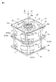
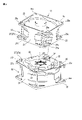
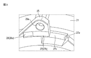
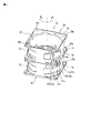
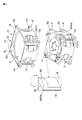
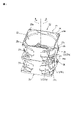
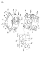
第1実施形態に係る送風機を示す斜視図。The perspective view which shows the blower which concerns on 1st Embodiment. 図1の主要部を分解して示す斜視図。The perspective view which shows the main part of FIG. 1 by disassembling. 図1に示す第1ケースの主要部を拡大して示す斜視図。The perspective view which shows the main part of the 1st case shown in FIG. 1 enlarged. 図1に示す第2ケースの主要部を拡大して示す斜視図。The perspective view which shows the main part of the 2nd case shown in FIG. 1 enlarged. 第2実施形態に係る送風機を示す斜視図。The perspective view which shows the blower which concerns on 2nd Embodiment. 図5の主要部を分解して示す斜視図。The perspective view which shows the main part of FIG. 5 by disassembling. 第3実施形態に係る送風機を示す斜視図。The perspective view which shows the blower which concerns on 3rd Embodiment. 図7の主要部を分解して示す斜視図。The perspective view which shows the main part of FIG. 7 by disassembling.

以下、実施の形態について、図面を参照して説明する。図面において、同一部分には、同一符号を付している。
図1、図2は、本実施形態に係る送風機の一例を示している。
送風機10は、第1送風機20と第2送風機30が連結して配置されている。第1送風機20及び第2送風機30は、いずれも軸流ファンであり、これらは同一方向に送風するように配置されている。第1送風機20は、円筒形の第1ケース21を具備し、第1ケース21は、吸気口又は排気口としての第1開口部22を有している。第2送風機30も、円筒形の第2ケース31を具備し、第2ケース31も、吸気口又は排気口としての第2開口部32を有している。
Hereinafter, embodiments will be described with reference to the drawings. In the drawings, the same parts are designated by the same reference numerals.
1 and 2 show an example of a blower according to the present embodiment.
In the blower 10, the first blower 20 and the second blower 30 are connected and arranged. The first blower 20 and the second blower 30 are both axial flow fans, and they are arranged so as to blow air in the same direction. The first blower 20 includes a cylindrical first case 21, and the first case 21 has a first opening 22 as an intake port or an exhaust port. The second blower 30 also includes a cylindrical second case 31, and the second case 31 also has a second opening 32 as an intake or exhaust port.

第1ケース21及び第2ケース31、又は第2ケース31は、高剛性材料、例えばPBT(ポリブチレンテレフタレート)繊維強化樹脂、PPS(ポリフェニレンサルファイド)繊維強化樹脂、又はアルミ合金により構成される。しかし、別の材料を適用することも可能である。 The first case 21, the second case 31, or the second case 31 are composed of a highly rigid material, for example, a PBT (polybutylene terephthalate) fiber reinforced resin, a PPS (polyphenylene sulfide) fiber reinforced resin, or an aluminum alloy. However, it is possible to apply different materials.

第1ケース21の第1開口部22の内部には、第1インペラ23と、第1インペラ23を駆動する第1モータ24が設けられている。図1において、第1モータ24のシャフトのみが示されている。 Inside the first opening 22 of the first case 21, a first impeller 23 and a first motor 24 for driving the first impeller 23 are provided. In FIG. 1, only the shaft of the first motor 24 is shown.

第2ケース31の第2開口部32の内部には、第2インペラ33と、第2インペラ33を駆動する第2モータ34が設けられている。図2において、第2モータは、図示されていない。 Inside the second opening 32 of the second case 31, a second impeller 33 and a second motor 34 for driving the second impeller 33 are provided. In FIG. 2, the second motor is not shown.

第1ケース21の軸心(図2に破線で示す)に沿った方向の両端部、すなわち、第1開口部22の両端部且つその周囲には、例えば四角形状の第1フランジ25と第2フランジ26が設けられている。 At both ends in the direction along the axis of the first case 21 (indicated by a broken line in FIG. 2), that is, at both ends of the first opening 22 and around it, for example, a square first flange 25 and a second flange 25. A flange 26 is provided.

第2ケース31の軸心に沿った方向の両端部、すなわち、第2開口部32の両端部且つその周囲には、例えば四角形状の第3フランジ35と、第4フランジ36が設けられている。 For example, a square third flange 35 and a fourth flange 36 are provided at both ends of the second case 31 in the direction along the axis, that is, at both ends of the second opening 32 and around the two ends thereof. ..

第1フランジ25、第2フランジ26、第3フランジ35、第4フランジ36のそれぞれの四隅には、穴25a、26a、35a、36aがそれぞれ設けられている。 Holes 25a, 26a, 35a, 36a are provided at the four corners of the first flange 25, the second flange 26, the third flange 35, and the fourth flange 36, respectively.

第1送風機20と第2送風機30とを連結する場合、第1ケース21の第1フランジ25と第2ケース31の第3フランジ35が接触され、第1ケース21と第2ケース31がこれらの中心を通る軸に対して相対的に回転される。第1ケース21と第2ケース31は、連結状態を保持するため、第1ケース21は、複数の第1係合部27と複数の第2係合部28を具備し、第2ケース31は、複数の第3係合部37と複数の第4係合部38を具備している。第3係合部37のそれぞれは、第1係合部27のそれぞれに係合可能であり、第4係合部38のそれぞれは、第2係合部のそれぞれに係合可能とされている。 When connecting the first blower 20 and the second blower 30, the first flange 25 of the first case 21 and the third flange 35 of the second case 31 are in contact with each other, and the first case 21 and the second case 31 are in contact with each other. It is rotated relative to the axis passing through the center. Since the first case 21 and the second case 31 maintain the connected state, the first case 21 includes a plurality of first engaging portions 27 and a plurality of second engaging portions 28, and the second case 31 has a plurality of second engaging portions 28. , A plurality of third engaging portions 37 and a plurality of fourth engaging portions 38 are provided. Each of the third engaging portions 37 is engageable with each of the first engaging portions 27, and each of the fourth engaging portions 38 is engageable with each of the second engaging portions. ..

第1ケース21に設けられた複数の第1係合部27は、第1フランジ25の各穴25aの近傍に設けられた切欠き27aに含まれている。切欠き27aは、第1フランジ25の側面から第1ケース21の側面に亘り、且つ第1ケース21の中心を通る軸の周囲に沿って設けられている。 The plurality of first engaging portions 27 provided in the first case 21 are included in the notches 27a provided in the vicinity of the respective holes 25a of the first flange 25. The notch 27a is provided from the side surface of the first flange 25 to the side surface of the first case 21 and along the circumference of the axis passing through the center of the first case 21.

具体的には、図2、図3に示すように、切欠き27aは、第1凹部27bと第3凹部27c(第2凹部は後述する)を含んでいる。第1凹部27bは、穴25aの近傍で、第1ケース21が軸を中心として図示矢印A方向に向かって開いており、第3係合部37が進入可能とされている。第3凹部27cは、第1凹部27bと連続し、第1ケース21の側面に沿って設けられている。 Specifically, as shown in FIGS. 2 and 3, the notch 27a includes a first recess 27b and a third recess 27c (the second recess will be described later). In the first recess 27b, in the vicinity of the hole 25a, the first case 21 opens in the direction of the arrow A in the drawing centering on the axis, and the third engaging portion 37 can enter. The third recess 27c is continuous with the first recess 27b and is provided along the side surface of the first case 21.

図3に示すように、第1ケース21の複数の第2係合部28は、第1フランジ25の第3フランジ35と対向する面(裏面とも言う)に設けられている。第2係合部28は、第1フランジ25の各穴25aの近傍に設けられたほぼ矩形状の第2凹部28aであり、第2凹部28aは、第1ケース21の回転方向に沿って設けられている。第2凹部28aは、第2ケース31の第4係合部38と係合可能であり、第4係合部38が進入可能な幅と、長さと、深さを有している。 As shown in FIG. 3, a plurality of second engaging portions 28 of the first case 21 are provided on a surface (also referred to as a back surface) of the first flange 25 facing the third flange 35. The second engaging portion 28 is a substantially rectangular second recess 28a provided in the vicinity of each hole 25a of the first flange 25, and the second recess 28a is provided along the rotation direction of the first case 21. Has been done. The second recess 28a is engageable with the fourth engaging portion 38 of the second case 31, and has a width, length, and depth that the fourth engaging portion 38 can enter.

図4に示すように、第2ケース31の複数の第3係合部37は、第3フランジ35の第1フランジ25と対向する面(表面とも言う)に設けられている。第3係合部37は、所謂フック37aである。フック37aは、柱部37bと頭部37cを有している。柱部37bは、第3フランジ35の表面に対して垂直に設けられ、頭部37cは、第3フランジ35の表面とほぼ平行で、第3フランジ35の外側に向けて設けられている。フック37aの柱部37bの幅と厚みは、第1フランジ25の第1凹部27bの幅、及び奥行きとほぼ等しく、柱部37bの長さは、第1フランジ25の厚みとほぼ等しい。このため、フック37aの柱部37bが第1フランジ25の第1凹部27b内に収容された状態において、フック37aの頭部37cが第1フランジ25の表面に係合され、第1ケース21と第2ケース31は、軸心に沿った方向にロックされる。 As shown in FIG. 4, a plurality of third engaging portions 37 of the second case 31 are provided on a surface (also referred to as a surface) of the third flange 35 facing the first flange 25. The third engaging portion 37 is a so-called hook 37a. The hook 37a has a pillar portion 37b and a head portion 37c. The pillar portion 37b is provided perpendicular to the surface of the third flange 35, and the head portion 37c is provided so as to be substantially parallel to the surface of the third flange 35 and toward the outside of the third flange 35. The width and thickness of the pillar portion 37b of the hook 37a are substantially equal to the width and depth of the first recess 27b of the first flange 25, and the length of the pillar portion 37b is substantially equal to the thickness of the first flange 25. Therefore, in a state where the pillar portion 37b of the hook 37a is housed in the first concave portion 27b of the first flange 25, the head portion 37c of the hook 37a is engaged with the surface of the first flange 25 to be engaged with the first case 21. The second case 31 is locked in the direction along the axis.

また、フック37aの頭部37cは、第3フランジ35と対向する面の一部に傾斜部37dを有している。傾斜部37dは、第2ケース31の回転方向一方(図1に示す矢印B)側に向かうに従って、頭部37cの厚みが薄くなるように傾斜されている。このため、第1ケース21と第2ケース31とを連結する際、第1ケース21の第1フランジ25がフック37aに対して移動し易くされている。 Further, the head portion 37c of the hook 37a has an inclined portion 37d on a part of the surface facing the third flange 35. The inclined portion 37d is inclined so that the thickness of the head 37c becomes thinner toward one side (arrow B in FIG. 1) in the rotation direction of the second case 31. Therefore, when connecting the first case 21 and the second case 31, the first flange 25 of the first case 21 is easily moved with respect to the hook 37a.

図4に示すように、第2ケース31に設けられた複数の第4係合部38は、第3フランジ35の一部に設けられた弾性を有する突起38aであり、所謂片持ち梁である。具体的には、突起38aの一端部は、第3フランジ35に一体的に設けられ、他端部は、第3フランジ35の厚み方向(図示矢印C、D方向)に回転するように変形可能とされている。このため、突起38aは、ほぼL字型の切り込み38bを隔てて、第3フランジ35に設けられる。突起38aは、第2ケース31の周囲に沿って配置され、突起38aの長さは、第2係合部28としての第2凹部28aの長さにほぼ等しい。 As shown in FIG. 4, the plurality of fourth engaging portions 38 provided in the second case 31 are elastic protrusions 38a provided in a part of the third flange 35, and are so-called cantilever beams. .. Specifically, one end of the protrusion 38a is integrally provided on the third flange 35, and the other end can be deformed so as to rotate in the thickness direction (arrows C and D in the figure) of the third flange 35. It is said that. Therefore, the protrusion 38a is provided on the third flange 35 with a substantially L-shaped notch 38b in between. The protrusion 38a is arranged along the periphery of the second case 31, and the length of the protrusion 38a is substantially equal to the length of the second recess 28a as the second engaging portion 28.

突起38aの厚みは、一端部(第1フランジ25の進入側)から他端部に次第に増加されており、他端部は、第3フランジ35の表面より高く、第3フランジ35の表面から突出されている。このため、突起38aの表面は、一端部から他端部に高くなるよう傾斜されており、突起38aは、一端部と他端部との間に傾斜部38cを有している。 The thickness of the protrusion 38a is gradually increased from one end (the entry side of the first flange 25) to the other end, and the other end is higher than the surface of the third flange 35 and protrudes from the surface of the third flange 35. Has been done. Therefore, the surface of the protrusion 38a is inclined so as to be high from one end to the other end, and the protrusion 38a has an inclined portion 38c between one end and the other end.

突起38aの一端部の厚みと他端部の厚みの差は、第3フランジ35の表面からの突出量にほぼ等しく、第2凹部28aの深さにほぼ等しくされている。このため、突起38aは、第2凹部28a内に進入した状態において、他端部が第2凹部28aの側面に係合され、第1ケース21と第2ケース31は、軸心に対して回転する方向にロックされる。 The difference between the thickness of one end and the thickness of the other end of the protrusion 38a is substantially equal to the amount of protrusion from the surface of the third flange 35 and substantially equal to the depth of the second recess 28a. Therefore, in a state where the protrusion 38a has entered the second recess 28a, the other end thereof is engaged with the side surface of the second recess 28a, and the first case 21 and the second case 31 rotate with respect to the axis. Locked in the direction of

上記構成において、第1ケース21を第2ケース31に連結する場合、第1ケース21の第1フランジ25と第2ケース31の第3フランジ35が接触され、第1ケース21の第1フランジ25に設けられた複数の切欠き27aのそれぞれに第2ケース31の第3フランジ35に設けられた複数のフック37aのそれぞれが挿入される。この時、第3フランジ35の突起38aは、第1フランジ25の裏面に接触され、その弾性に抗して図示矢印C方向に変形される。 In the above configuration, when the first case 21 is connected to the second case 31, the first flange 25 of the first case 21 and the third flange 35 of the second case 31 are brought into contact with each other, and the first flange 25 of the first case 21 is contacted. Each of the plurality of hooks 37a provided on the third flange 35 of the second case 31 is inserted into each of the plurality of notches 27a provided in the second case 31. At this time, the protrusion 38a of the third flange 35 is in contact with the back surface of the first flange 25 and is deformed in the direction of arrow C in the drawing against the elasticity thereof.

この状態において、第1ケース21を第2ケース31に対して、図1、図2に示す矢印A方向に回転すると、第2ケース31のフック37aが第1ケースの第3凹部27cから第1凹部27b内に進入し、フック37aの頭部37cが第1ケース21の第1フランジ25の表面に係合される。 In this state, when the first case 21 is rotated with respect to the second case 31 in the direction of the arrow A shown in FIGS. 1 and 2, the hook 37a of the second case 31 is first from the third recess 27c of the first case. It enters the recess 27b and the head 37c of the hook 37a is engaged with the surface of the first flange 25 of the first case 21.

一方、第1ケース21が第2ケース31に対して、図1、図2に示す矢印A方向に回転されると、突起38aは、第1フランジ25をスライドする。突起38aが第1ケース21の第2凹部28a内に到達すると、突起38aは、傾斜部38cが第2凹部28aの縁に接触した状態で、その弾性により先端部が矢印D方向に変形し、突起38aが第2凹部28a内に進入する。このため、突起38aと第2凹部28aとが係合され、第1ケース21と第2ケース31は、軸心に対して回転する方向に対してロックされる。 On the other hand, when the first case 21 is rotated in the direction of the arrow A shown in FIGS. 1 and 2 with respect to the second case 31, the protrusion 38a slides on the first flange 25. When the protrusion 38a reaches the inside of the second recess 28a of the first case 21, the tip of the protrusion 38a is deformed in the arrow D direction due to its elasticity while the inclined portion 38c is in contact with the edge of the second recess 28a. The protrusion 38a enters the second recess 28a. Therefore, the protrusion 38a and the second recess 28a are engaged with each other, and the first case 21 and the second case 31 are locked in the direction of rotation with respect to the axis.

このようにして、第1ケース21と第2ケース31は、第1係合部27、第2係合部28、第3係合部37、第4係合部38により、第1ケース21と第2ケース31の軸心に沿った方向と軸心に対して回転する方向に対してロックされる。 In this way, the first case 21 and the second case 31 are combined with the first case 21 by the first engaging portion 27, the second engaging portion 28, the third engaging portion 37, and the fourth engaging portion 38. It is locked in the direction along the axis of the second case 31 and in the direction of rotation with respect to the axis.

一方、第1ケース21と第2ケース31が連結された状態から、第1ケース21と第2ケース31を分離する場合、第2ケース31の突起38aをその弾性に抗して、図4に示す矢印C方向に変形させ、突起38aと第2凹部28aとの係合状態が解除される。この後、第1ケース21を第2ケース31に対して、図1、図2に示す矢印B方向に回転すると、突起38aは、傾斜部38cが第2凹部28aの縁により図示矢印C方向に変形しながら第2凹部28aから抜ける。突起38aが第2凹部28aから抜けると、フック37aと第1凹部27b(第1フランジ25)との係合状態が解除され、第1ケース21を第2ケース31から分離することができる。 On the other hand, when the first case 21 and the second case 31 are separated from the state where the first case 21 and the second case 31 are connected, the protrusion 38a of the second case 31 resists its elasticity and is shown in FIG. By deforming in the direction of the arrow C shown, the engagement state between the protrusion 38a and the second recess 28a is released. After that, when the first case 21 is rotated with respect to the second case 31 in the direction of the arrow B shown in FIGS. 1 and 2, the protrusion 38a has the inclined portion 38c in the direction of the arrow C shown by the edge of the second recess 28a. It comes out of the second recess 28a while being deformed. When the protrusion 38a comes out of the second recess 28a, the engagement state between the hook 37a and the first recess 27b (first flange 25) is released, and the first case 21 can be separated from the second case 31.

(第1実施形態の効果)
上記第1実施形態によれば、第1ケース21と第2ケース31は、第1係合部27、第2係合部28、第3係合部37、第4係合部38により、第1ケース21と第2ケース31の軸心に沿った方向と軸心に対して回転する方向に対してロックすることが可能であり、第4係合部38としての突起38aが回転するように変形することにより第2凹部28aに係合される。このため、強い力を必要とせずに第1ケース21と第2ケース31とを連結することができ、且つ、第1乃至第4係合部により、連結状態を確実に保持することができる。
(Effect of the first embodiment)
According to the first embodiment, the first case 21 and the second case 31 are formed by the first engaging portion 27, the second engaging portion 28, the third engaging portion 37, and the fourth engaging portion 38. It is possible to lock in the direction along the axis of the first case 21 and the second case 31 and in the direction of rotation with respect to the axis, so that the protrusion 38a as the fourth engaging portion 38 rotates. By deforming, it is engaged with the second recess 28a. Therefore, the first case 21 and the second case 31 can be connected without requiring a strong force, and the connected state can be reliably maintained by the first to fourth engaging portions.

しかも、突起38aは、傾斜部38cを有しており、突起38aと第2凹部28aを係合するとき、及び突起38aと第2凹部28aとの係合を解除するとき、突起38aの弾性により傾斜部38cが第2凹部28aの縁に接触して移動する。したがって、突起38aの弾性を利用して、突起38aを変形させることができるため、第1ケース21と第2ケース31とを連結したり、分離したりする際の操作力を低減することが可能である。 Moreover, the protrusion 38a has an inclined portion 38c, and when the protrusion 38a and the second recess 28a are engaged with each other and when the protrusion 38a and the second recess 28a are disengaged, the elasticity of the protrusion 38a causes the protrusion 38a to have an inclined portion 38c. The inclined portion 38c comes into contact with the edge of the second recess 28a and moves. Therefore, since the protrusion 38a can be deformed by utilizing the elasticity of the protrusion 38a, it is possible to reduce the operating force when connecting or separating the first case 21 and the second case 31. Is.

さらに、第4係合部38としての、突起38aは、一端部が第3フランジ35に設けられた片持ち梁であるため、突起38aをその弾性に抗して変形させることにより、突起38aと第2凹部28aとの係合状態を容易に解除することが可能である。したがって、第1送風機20と第2送風機30を必要に応じて連結したり分離したりすることが可能である。 Further, since the protrusion 38a as the fourth engaging portion 38 is a cantilever beam whose one end is provided on the third flange 35, the protrusion 38a is deformed against its elasticity to form a protrusion 38a. The engagement state with the second recess 28a can be easily released. Therefore, the first blower 20 and the second blower 30 can be connected or separated as needed.

尚、第1実施形態において、2つの送風機を連結する場合について説明したが、上記の連結構造を利用することにより、3つ以上の送風機を連結することも可能である。 Although the case of connecting two blowers has been described in the first embodiment, it is also possible to connect three or more blowers by using the above-mentioned connecting structure.

(第2実施形態)
図5、図6は、第2実施形態を示している。第2実施形態は、第2係合部41と第4係合部42の構成が第1実施形態と異なっている。
第2実施形態において、第2係合部41は、切欠き27a内の第3凹部27cであり、第4係合部42は、第3フランジ35の表面に設けられた弾性を有する突起42aである。
(Second Embodiment)
5 and 6 show a second embodiment. In the second embodiment, the configurations of the second engaging portion 41 and the fourth engaging portion 42 are different from those in the first embodiment.
In the second embodiment, the second engaging portion 41 is a third recess 27c in the notch 27a, and the fourth engaging portion 42 is an elastic protrusion 42a provided on the surface of the third flange 35. be.

図6に示すように、突起42aは、第3フランジ35の表面において、フック37aから第1ケース21の回転方向(図示矢印A方向)に所定距離離れて配置される。具体的には、フック37aと突起42aは、第1ケース21に設けられた第3凹部27cの第1ケース21の周囲に沿った長さと同一の範囲内に配置される。 As shown in FIG. 6, the protrusion 42a is arranged on the surface of the third flange 35 at a predetermined distance from the hook 37a in the rotation direction of the first case 21 (direction of arrow A in the drawing). Specifically, the hook 37a and the protrusion 42a are arranged within the same range as the length along the circumference of the first case 21 of the third recess 27c provided in the first case 21.

突起42aは、柱部42bと頭部42cを含んでいる。柱部42bは、第3フランジ35の表面に垂直に設けられ、突起42aの高さ(長さ)は、第1ケース21の第3凹部27cの高さの範囲内とされている。柱部42bは、頭部42cが図示矢印E、F方向に回転するように変形可能となるよう弾性を有している。 The protrusion 42a includes a pillar portion 42b and a head portion 42c. The pillar portion 42b is provided perpendicular to the surface of the third flange 35, and the height (length) of the protrusion 42a is within the height range of the third recess 27c of the first case 21. The pillar portion 42b has elasticity so that the head portion 42c can be deformed so as to rotate in the directions of arrows E and F in the figure.

突起42aの頭部42cは、第3フランジ35の表面とほぼ平行で、第3フランジ35の内側(第1ケース21の側面)に向けて突出されている。頭部42cの軸と交差する方向の厚みは、第1ケース21の第3凹部27cの深さ(軸と交差する方向の奥行)より大きく、頭部42cの先端が第3凹部27c内に進入可能とされている。 The head portion 42c of the protrusion 42a is substantially parallel to the surface of the third flange 35 and protrudes toward the inside of the third flange 35 (the side surface of the first case 21). The thickness of the head 42c in the direction intersecting the axis is larger than the depth of the third recess 27c of the first case 21 (depth in the direction intersecting the axis), and the tip of the head 42c enters the third recess 27c. It is possible.

頭部42cは、第1ケース21の側面と対向する側面の一部に傾斜部42dを有している。傾斜部42dは、第2ケース31の回転方向の一方(矢印B)側に向かうに従って、頭部37cの厚みが薄くなるように傾斜されている。このため、第1ケース21と第2ケース31とを連結する際、第1ケース21の側面に対して移動し易くされている。 The head 42c has an inclined portion 42d on a part of the side surface facing the side surface of the first case 21. The inclined portion 42d is inclined so that the thickness of the head 37c becomes thinner toward one side (arrow B) of the rotation direction of the second case 31. Therefore, when connecting the first case 21 and the second case 31, it is easy to move with respect to the side surface of the first case 21.

上記構成において、第1ケース21を第2ケース31に連結する場合、第1ケース21の第1フランジ25と第2ケース31の第3フランジ35が接触され、第1ケース21の第1フランジ25に設けられた複数の切欠き27aに第2ケース31の第3フランジ35に設けられた複数のフック37aのそれぞれが挿入される。さらに、突起42aの頭部42cが第1ケース21の側面に接触され、柱部42bは、その弾性に抗して図示矢印E方向に変形される。 In the above configuration, when the first case 21 is connected to the second case 31, the first flange 25 of the first case 21 and the third flange 35 of the second case 31 are brought into contact with each other, and the first flange 25 of the first case 21 is contacted. Each of the plurality of hooks 37a provided on the third flange 35 of the second case 31 is inserted into the plurality of notches 27a provided in the second case 31. Further, the head portion 42c of the protrusion 42a is brought into contact with the side surface of the first case 21, and the pillar portion 42b is deformed in the direction of the arrow E shown in the figure against its elasticity.

この状態において、第1ケース21を第2ケース31に対して、図示矢印A方向に回転すると、第2ケース31のフック37aが第1ケースの第3凹部27cから第1凹部27b内に進入し、図5に示すように、フック37aの頭部37cが第1ケース21の第1フランジ25の表面に係合される。 In this state, when the first case 21 is rotated with respect to the second case 31 in the direction of the arrow A in the drawing, the hook 37a of the second case 31 enters the first recess 27b from the third recess 27c of the first case. , As shown in FIG. 5, the head 37c of the hook 37a is engaged with the surface of the first flange 25 of the first case 21.

一方、第1ケース21の側面に頭部42cが当接された第2ケース31の突起42aは、第1ケース21が第2ケース31に対して、図示矢印A方向に回転されると、第1ケース21の側面をスライドする。 On the other hand, the protrusion 42a of the second case 31 in which the head 42c is in contact with the side surface of the first case 21 becomes the second when the first case 21 is rotated with respect to the second case 31 in the direction of the arrow A in the drawing. 1 Slide the side surface of the case 21.

この状態において、突起42aが第1ケース21の第2係合部28としての第3凹部27c内に到達すると、突起42aはその弾性により先端部が矢印F方向に変形し、突起42aが第3凹部27c内に進入する。このため、図5に示すように、突起42aと第3凹部27cとが係合され、第1ケース21と第2ケース31は、軸心に対して回転する方向に対してロックされる。 In this state, when the protrusion 42a reaches the inside of the third recess 27c as the second engaging portion 28 of the first case 21, the tip of the protrusion 42a is deformed in the arrow F direction due to its elasticity, and the protrusion 42a is the third. It enters the recess 27c. Therefore, as shown in FIG. 5, the protrusion 42a and the third recess 27c are engaged with each other, and the first case 21 and the second case 31 are locked in the direction of rotation with respect to the axis.

このようにして、第1ケース21と第2ケース31は、第1係合部27、第2係合部41、第3係合部37、第4係合部42により、第1ケース21と第2ケース31の軸心に沿った方向と軸心に対して回転する方向に対してロックされる。 In this way, the first case 21 and the second case 31 are combined with the first case 21 by the first engaging portion 27, the second engaging portion 41, the third engaging portion 37, and the fourth engaging portion 42. It is locked in the direction along the axis of the second case 31 and in the direction of rotation with respect to the axis.

一方、第1ケース21と第2ケース31が連結された状態から、第1ケース21と第2ケース31を分離する場合、第2ケース31の突起42aをその弾性に抗して、図6に示す矢印E方向に変形させ、突起42aと第3凹部27cとの係合状態を解除する。この後、第1ケース21を第2ケース31に対して、図示矢印B方向に回転すると、フック37aと第3凹部27c(第1フランジ25)との係合状態が解除され、第1ケース21を第2ケース31から分離することができる。 On the other hand, when the first case 21 and the second case 31 are separated from the state where the first case 21 and the second case 31 are connected, the protrusion 42a of the second case 31 resists its elasticity and is shown in FIG. It is deformed in the direction of the arrow E shown to release the engagement state between the protrusion 42a and the third recess 27c. After that, when the first case 21 is rotated with respect to the second case 31 in the direction of the arrow B in the drawing, the engagement state between the hook 37a and the third recess 27c (first flange 25) is released, and the first case 21 is released. Can be separated from the second case 31.

(第2実施形態の効果)
第2実施形態によっても、第1実施形態と同様の効果を得ることができる。しかも、第4係合部42としての突起42aが第3係合部37としてのフック37aと同一の面に設けられているため、第1ケース21と第2ケース31の連結作業及び分離作業を容易に行うことができる
さらに、突起42aは、傾斜部42dを有しており、突起42aと第3凹部27cを係合するとき、及び突起42aと第3凹部27cとの係合を解除するとき、突起42aの弾性により傾斜部42dが第3凹部27cの縁に接触して移動する。したがって、突起42aの弾性を利用して、突起42aを変形させることができるため、第1ケース21と第2ケース31とを連結したり、分離したりする際の操作力を低減することが可能である。
(Effect of the second embodiment)
The same effect as that of the first embodiment can be obtained by the second embodiment as well. Moreover, since the protrusion 42a as the fourth engaging portion 42 is provided on the same surface as the hook 37a as the third engaging portion 37, the first case 21 and the second case 31 can be connected and separated. Further, the protrusion 42a has an inclined portion 42d, and when the protrusion 42a and the third recess 27c are engaged with each other and when the protrusion 42a and the third recess 27c are disengaged from each other. Due to the elasticity of the protrusion 42a, the inclined portion 42d moves in contact with the edge of the third recess 27c. Therefore, since the protrusion 42a can be deformed by utilizing the elasticity of the protrusion 42a, it is possible to reduce the operating force when connecting or separating the first case 21 and the second case 31. Is.

(第3実施形態)
図7、図8は、第3実施形態を示している。第3実施形態は、第4係合部51の構成が第2実施形態と異なっている。
第3実施形態において、第4係合部51は、第3係合部37としてのフック37aに設けられている。
(Third Embodiment)
7 and 8 show a third embodiment. In the third embodiment, the configuration of the fourth engaging portion 51 is different from that in the second embodiment.
In the third embodiment, the fourth engaging portion 51 is provided on the hook 37a as the third engaging portion 37.

図8に示すように、第4係合部51は、弾性を有する突起37eであり、突起37eは、アーム37fと頭部37gを含んでいる。アーム37fは、第3フランジ35の表面と平行に設けられ、その一端部は、フック37aの側面に一体的に設けられ、頭部37gを含む他端部は、第1ケース21の回転方向(図示矢印A方向)に延出されている。 As shown in FIG. 8, the fourth engaging portion 51 is a protrusion 37e having elasticity, and the protrusion 37e includes an arm 37f and a head 37g. The arm 37f is provided parallel to the surface of the third flange 35, one end thereof is integrally provided on the side surface of the hook 37a, and the other end including the head 37g is the rotation direction of the first case 21 ( It extends in the direction of arrow A in the figure).

フック37aを含む突起37eの長さは、第1ケース21の第3凹部27cの長さとほぼ一致されており、フック37aと突起37eは、第3凹部27c内に収容可能とされている。アーム37fの厚みは、頭部37gの厚みより薄く、弾力を有している。このため、頭部37gは、図示矢印G、H方向に回転するように変形可能とされている。 The length of the protrusion 37e including the hook 37a is substantially the same as the length of the third recess 27c of the first case 21, and the hook 37a and the protrusion 37e can be accommodated in the third recess 27c. The thickness of the arm 37f is thinner than the thickness of the head 37g and has elasticity. Therefore, the head 37g is deformable so as to rotate in the directions of the arrows G and H in the figure.

頭部37gの第1ケース21の側面と対向する面には傾斜部37hが設けられている。傾斜部37hは、第2ケース31の回転方向一方(矢印B)側に向かうに従って、頭部37cの厚みが薄くなるように傾斜されている。このため、第1ケース21と第2ケース31とを連結する際、第1ケース21の側面に対して移動し易くされている。 An inclined portion 37h is provided on the surface of the head 37g facing the side surface of the first case 21. The inclined portion 37h is inclined so that the thickness of the head 37c becomes thinner toward one side (arrow B) in the rotation direction of the second case 31. Therefore, when connecting the first case 21 and the second case 31, it is easy to move with respect to the side surface of the first case 21.

上記構成において、第1ケース21を第2ケース31に連結する場合、第1ケース21の第1フランジ25と第2ケース31の第3フランジ35が接触され、第1ケース21の第1フランジ25に設けられた複数の切欠き27aのそれぞれに第2ケース31の第3フランジ35に設けられたフック37aのそれぞれが挿入される。さらに、突起37eの頭部37gは、第1ケース21の側面に接触され、アーム37fはその弾性に抗して図示矢印H方向に変形される。 In the above configuration, when the first case 21 is connected to the second case 31, the first flange 25 of the first case 21 and the third flange 35 of the second case 31 are brought into contact with each other, and the first flange 25 of the first case 21 is contacted. Each of the hooks 37a provided on the third flange 35 of the second case 31 is inserted into each of the plurality of notches 27a provided in the second case 31. Further, the head 37g of the protrusion 37e is in contact with the side surface of the first case 21, and the arm 37f is deformed in the direction of arrow H in the figure against its elasticity.

この状態において、第1ケース21を第2ケース31に対して、図示矢印A方向に回転すると、第2ケース31のフック37aが第1ケースの第3凹部27cから第1凹部27b内に進入し、図7に示すように、フック37aの頭部37cが第1ケース21の第1フランジ25の表面に係合される。 In this state, when the first case 21 is rotated with respect to the second case 31 in the direction of the arrow A in the drawing, the hook 37a of the second case 31 enters the first recess 27b from the third recess 27c of the first case. , As shown in FIG. 7, the head 37c of the hook 37a is engaged with the surface of the first flange 25 of the first case 21.

一方、第1ケース21の側面に頭部37gが接触された第2ケース31の突起37eは、第1ケース21が第2ケース31に対して、図示矢印A方向に回転されると、第1ケース21の側面をスライドされる。頭部37gが第1ケース21の第3凹部27cに到達すると、突起37eはその弾性により先端部が矢印G方向に変形され、突起37eが第3凹部27c内に進入する。このため、図7に示すように、突起37eと第3凹部27cとが係合され、第1ケース21と第2ケース31は、軸心に対して回転する方向に対してロックされる。 On the other hand, the protrusion 37e of the second case 31 in which the head 37g is in contact with the side surface of the first case 21 is the first when the first case 21 is rotated in the direction of the arrow A in the drawing with respect to the second case 31. The side surface of the case 21 is slid. When the head 37g reaches the third recess 27c of the first case 21, the tip of the protrusion 37e is deformed in the direction of the arrow G due to its elasticity, and the protrusion 37e enters the third recess 27c. Therefore, as shown in FIG. 7, the protrusion 37e and the third recess 27c are engaged with each other, and the first case 21 and the second case 31 are locked in the direction of rotation with respect to the axis.

このようにして、第1ケース21と第2ケース31は、第1係合部27、第2係合部41、第3係合部37、第4係合部51により、第1ケース21と第2ケース31の軸心に沿った方向と軸心に対して回転する方向に対してロックされる。 In this way, the first case 21 and the second case 31 are combined with the first case 21 by the first engaging portion 27, the second engaging portion 41, the third engaging portion 37, and the fourth engaging portion 51. It is locked in the direction along the axis of the second case 31 and in the direction of rotation with respect to the axis.

一方、第1ケース21と第2ケース31が連結された状態から、第1ケース21と第2ケース31を分離する場合、第2ケース31の突起37eをその弾性に抗して、図8に示す矢印H方向に変形させ、突起37eと第3凹部27cとの係合状態を解除する。この後、第1ケース21を第2ケース31に対して、図示矢印B方向に回転すると、フック37aと第3凹部27c(第1フランジ25)との係合状態が解除され、第1ケース21を第2ケース31から分離することができる。 On the other hand, when the first case 21 and the second case 31 are separated from the state where the first case 21 and the second case 31 are connected, the protrusion 37e of the second case 31 resists its elasticity and is shown in FIG. It is deformed in the direction of the arrow H shown to release the engagement state between the protrusion 37e and the third recess 27c. After that, when the first case 21 is rotated with respect to the second case 31 in the direction of the arrow B in the drawing, the engagement state between the hook 37a and the third recess 27c (first flange 25) is released, and the first case 21 is released. Can be separated from the second case 31.

(第3実施形態の効果)
第3実施形態によっても、第1実施形態及び第2実施形態と同様の効果を得ることができる。しかも、第3実施形態によれば、第4係合部51としての突起37eは、第3係合部37としてのフック37aに一体的に設けられている。このため、第1ケース21と第2ケース31を連結する際、各係合部の位置合わせを容易化することができ、作業工数を低減することが可能である。
(Effect of the third embodiment)
The third embodiment can also obtain the same effects as those of the first embodiment and the second embodiment. Moreover, according to the third embodiment, the protrusion 37e as the fourth engaging portion 51 is integrally provided on the hook 37a as the third engaging portion 37. Therefore, when connecting the first case 21 and the second case 31, it is possible to facilitate the alignment of each engaging portion and reduce the work man-hours.

さらに、突起37eは、傾斜部37hを有しており、突起37eと第3凹部27cを係合するとき、及び突起37eと第3凹部27cとの係合を解除するとき、突起37eの弾性により傾斜部37hが第3凹部27cの縁に接触して移動する。したがって、突起37eの弾性を利用して、突起37eを変形させることができるため、第1ケース21と第2ケース31とを連結したり、分離したりする際の操作力を低減することが可能である。 Further, the protrusion 37e has an inclined portion 37h, and when the protrusion 37e and the third recess 27c are engaged with each other and when the protrusion 37e and the third recess 27c are disengaged, the elasticity of the protrusion 37e causes the protrusion 37e to have an inclined portion 37h. The inclined portion 37h comes into contact with the edge of the third recess 27c and moves. Therefore, since the protrusion 37e can be deformed by utilizing the elasticity of the protrusion 37e, it is possible to reduce the operating force when connecting or separating the first case 21 and the second case 31. Is.

その他、本発明は上記各実施形態そのままに限定されるものではなく、実施段階ではその要旨を逸脱しない範囲で構成要素を変形して具体化できる。また、上記各実施形態に開示されている複数の構成要素の適宜な組み合わせにより、種々の発明を形成できる。例えば、実施形態に示される全構成要素から幾つかの構成要素を削除してもよい。さらに、異なる実施形態にわたる構成要素を適宜組み合わせてもよい。 In addition, the present invention is not limited to each of the above embodiments as it is, and at the implementation stage, the components can be modified and embodied within a range that does not deviate from the gist thereof. In addition, various inventions can be formed by an appropriate combination of the plurality of components disclosed in each of the above embodiments. For example, some components may be removed from all the components shown in the embodiments. In addition, components across different embodiments may be combined as appropriate.

10…送風機、20…第1送風機、30…第2送風機、21…第1ケース、31…第2ケース、25…第1フランジ、26…第2フランジ、35…第3フランジ、36…第4フランジ、27…第1係合部、27a…切欠き、27b…第1凹部、27c…第3凹部、28、41…第2係合部、28a…第2凹部、37…第3係合部、37a…フック、37b…柱部、37c…頭部、37d…傾斜部、37e…突起、37f…アーム、37g…頭部、37h…傾斜部、38、42、51…第4係合部、38a…突起、42a…突起、42b…柱部、42c…頭部、42d…傾斜部。 10 ... Blower, 20 ... 1st blower, 30 ... 2nd blower, 21 ... 1st case, 31 ... 2nd case, 25 ... 1st flange, 26 ... 2nd flange, 35 ... 3rd flange, 36 ... 4th Flange, 27 ... 1st engaging portion, 27a ... notch, 27b ... 1st recess, 27c ... 3rd recess, 28, 41 ... 2nd engaging portion, 28a ... 2nd recess, 37 ... 3rd engaging portion , 37a ... Hook, 37b ... Pillar, 37c ... Head, 37d ... Inclined, 37e ... Protrusion, 37f ... Arm, 37g ... Head, 37h ... Inclined, 38, 42, 51 ... Fourth engaging portion, 38a ... protrusion, 42a ... protrusion, 42b ... pillar portion, 42c ... head, 42d ... inclined portion.

Claims (10)

第1フランジを有する第1ケースと、
第2フランジを有し、前記第2フランジを前記第1ケースの第1フランジに接触させて前記第1ケースに連結される第2ケースと、
前記第1ケースの前記第1フランジに設けられた第1係合部と、
前記第1ケースの前記第1フランジに前記第1係合部から前記第1ケースの軸心に対して回転方向に離間して設けられた第2係合部と、
前記第2ケースの前記第2フランジに設けられ、前記第1ケースの前記第1係合部に係合される第3係合部と、
前記第2ケースの前記第2フランジに前記第3係合部から前記第2ケースの軸心に対して回転方向に離間して配置され、一端部が前記第2フランジに設けられ、他端部が第1ケースの前記第2係合部に係合される弾性を有する第4係合部と、
を具備することを特徴とする送風機。
The first case with the first flange and
A second case having a second flange and having the second flange in contact with the first flange of the first case and connected to the first case.
With the first engaging portion provided on the first flange of the first case,
A second engaging portion provided on the first flange of the first case at a distance from the first engaging portion in the rotational direction with respect to the axial center of the first case.
A third engaging portion provided on the second flange of the second case and engaged with the first engaging portion of the first case, and a third engaging portion.
The second flange of the second case is arranged apart from the third engaging portion in the rotational direction with respect to the axis of the second case, one end thereof is provided on the second flange, and the other end portion is provided. With a fourth engaging portion having elasticity to be engaged with the second engaging portion of the first case,
A blower characterized by being equipped with.
前記第1係合部は、前記第1フランジの周囲に設けられた第1凹部であり、
前記第2係合部は、前記第1フランジの前記第2フランジと対向する面に設けられた第2凹部であり、
前記第3係合部は、前記第2フランジの前記第1フランジと対向する表面に垂直に設けられたフックであり、
前記第4係合部は、一端部が前記第2フランジと一体的に設けられた突起であり、前記突起の他端部は、前記第2フランジに対して前記第2ケースの前記軸心と平行な方向に変形可能であることを特徴とする請求項1記載の送風機。
The first engaging portion is a first recess provided around the first flange.
The second engaging portion is a second recess provided on a surface of the first flange facing the second flange.
The third engaging portion is a hook provided perpendicular to the surface of the second flange facing the first flange.
The fourth engaging portion is a protrusion whose one end is integrally provided with the second flange, and the other end of the protrusion is the axial center of the second case with respect to the second flange. The blower according to claim 1, wherein the blower can be deformed in a parallel direction.
前記第1係合部は、前記第1フランジの周囲に設けられた第1凹部であり、
前記第2係合部は、前記第1フランジの周囲に前記第1凹部と連続的に設けられた第3凹部であり、
前記第3係合部は、前記第2フランジの前記第1フランジと対向する表面に垂直に設けられたフックであり、
前記第4係合部は、前記第2フランジの前記第1フランジと対向する表面に垂直に設けられ、前記フックより厚みが薄く、前記第3凹部に係合可能な突起であることを特徴とする請求項1記載の送風機。
The first engaging portion is a first recess provided around the first flange.
The second engaging portion is a third recess provided continuously with the first recess around the first flange.
The third engaging portion is a hook provided perpendicular to the surface of the second flange facing the first flange.
The fourth engaging portion is provided perpendicular to the surface of the second flange facing the first flange, is thinner than the hook, and is a protrusion capable of engaging with the third recess. The blower according to claim 1.
前記第1係合部は、前記第1フランジの周囲に設けられた第1凹部であり、
前記第2係合部は、前記第1フランジの周囲に前記第1凹部と連続的に設けられた第3凹部であり、
前記第3係合部は、前記第2フランジの前記第1フランジと対向する表面と垂直に設けられたフックであり、
前記第4係合部は、前記第2フランジと平行で、一端部が前記第3係合部と一体的に設けられ、他端部が前記第3凹部に係合可能な突起であることを特徴とする請求項1記載の送風機。
The first engaging portion is a first recess provided around the first flange.
The second engaging portion is a third recess provided continuously with the first recess around the first flange.
The third engaging portion is a hook provided perpendicular to the surface of the second flange facing the first flange.
The fourth engaging portion is parallel to the second flange, one end thereof is provided integrally with the third engaging portion, and the other end portion is a protrusion capable of engaging with the third concave portion. The blower according to claim 1.
前記フックは、一端部が前記第2フランジに一体的に設けられた柱部と、前記柱部の他端部に前記第1ケースの側面と反対側に突出して設けられた頭部を具備し、前記頭部は、前記第2フランジと対向する面に傾斜部を有することを特徴とする請求項2乃至4のいずれか1つに記載の送風機。 The hook includes a pillar portion whose one end is integrally provided on the second flange, and a head provided on the other end of the pillar portion so as to project from the side surface of the first case. The blower according to any one of claims 2 to 4, wherein the head portion has an inclined portion on a surface facing the second flange. 前記突起は、一端部が前記第2フランジに設けられ、他端部が前記第2フランジの表面より高く、前記一端部と前記他端部の間に傾斜部を有することを特徴とする請求項2記載の送風機。 The invention is characterized in that one end thereof is provided on the second flange, the other end portion is higher than the surface of the second flange, and the protrusion has an inclined portion between the one end portion and the other end portion. 2 The blower described. 前記突起は、L字型の切り込みを隔てて前記第2フランジに設けられることを特徴とする請求項2記載の送風機。 The blower according to claim 2, wherein the protrusion is provided on the second flange across an L-shaped notch. 前記突起は、一端部が前記第2フランジに設けられた柱部と、前記柱部の他端部に前記第1ケースの側面側に突出して設けられた頭部を具備し、前記頭部は、前記第1ケースと対向する側面に傾斜部を有することを特徴とする請求項3記載の送風機。 The protrusion comprises a pillar portion having one end provided on the second flange and a head provided on the other end of the pillar portion so as to project toward the side surface of the first case. The blower according to claim 3, further comprising an inclined portion on a side surface facing the first case. 前記突起は、前記第2フランジと平行で、一端部が前記第3係合部の側面に設けられたアームと、前記アームの他端部に前記第1ケースの側面側に突出して設けられた頭部を具備し、前記頭部は、前記第1ケースと対向する側面に傾斜部を有することを特徴とする請求項4記載の送風機。 The protrusions are parallel to the second flange, and one end thereof is provided on an arm provided on the side surface of the third engaging portion, and the other end portion of the arm is provided so as to project toward the side surface side of the first case. The blower according to claim 4, further comprising a head, wherein the head has an inclined portion on a side surface facing the first case. 前記第1ケース及び第2ケース、又は第2ケースは、PBT(ポリブチレンテレフタレート)繊維強化樹脂、PPS(ポリフェニレンサルファイド)繊維強化樹脂、及びアルミ合金の1つにより形成される請求項1記載の送風機。 The blower according to claim 1, wherein the first case and the second case, or the second case, are formed of one of a PBT (polybutylene terephthalate) fiber reinforced resin, a PPS (polyphenylene sulfide) fiber reinforced resin, and an aluminum alloy. ..
JP2020217108A 2020-12-25 2020-12-25 Blower Pending JP2022102403A (en)

Priority Applications (2)

Application Number Priority Date Filing Date Title
JP2020217108A JP2022102403A (en) 2020-12-25 2020-12-25 Blower
PCT/JP2021/037116 WO2022137726A1 (en) 2020-12-25 2021-10-07 Blower

Applications Claiming Priority (1)

Application Number Priority Date Filing Date Title
JP2020217108A JP2022102403A (en) 2020-12-25 2020-12-25 Blower

Publications (1)

Publication Number Publication Date
JP2022102403A true JP2022102403A (en) 2022-07-07

Family

ID=82158948

Family Applications (1)

Application Number Title Priority Date Filing Date
JP2020217108A Pending JP2022102403A (en) 2020-12-25 2020-12-25 Blower

Country Status (2)

Country Link
JP (1) JP2022102403A (en)
WO (1) WO2022137726A1 (en)

Cited By (1)

* Cited by examiner, † Cited by third party
Publication number Priority date Publication date Assignee Title
JP2024061163A (en) * 2022-10-21 2024-05-07 ニデック株式会社 Blower device and manufacturing method thereof

Family Cites Families (3)

* Cited by examiner, † Cited by third party
Publication number Priority date Publication date Assignee Title
JP3959359B2 (en) * 2003-03-13 2007-08-15 山洋電気株式会社 Counter-rotating axial fan
TWI390116B (en) * 2008-02-26 2013-03-21 日本電產股份有限公司 A shaft fan unit connected in series and a frame of an axial fan unit connected in series
JP5146911B2 (en) * 2008-05-19 2013-02-20 日本電産株式会社 Axial fan

Cited By (1)

* Cited by examiner, † Cited by third party
Publication number Priority date Publication date Assignee Title
JP2024061163A (en) * 2022-10-21 2024-05-07 ニデック株式会社 Blower device and manufacturing method thereof

Also Published As

Publication number Publication date
WO2022137726A1 (en) 2022-06-30

Similar Documents

Publication Publication Date Title
US8591160B2 (en) Clip
JP2006002762A (en) Blower
CN107850100B (en) Fastener
JP4733709B2 (en) Rotor axial segment in turbine rotor
US6843638B2 (en) Vane radial mounting apparatus
CN101520056B (en) Fan frame and fan unit
JP5906155B2 (en) Driver device and motor device
WO2009157488A1 (en) Clip
WO2018147330A1 (en) Fan unit
JP2009228675A (en) Serial axial flow fan
JP5855971B2 (en) Bumper fixing clip
JP2009250237A (en) Turbine blade retention system and method
JP2008032205A (en) clip
WO2022137726A1 (en) Blower
JP2012041900A (en) Fastening structure of intake system component
JP6310644B2 (en) Fastener member, fastener structure, and support
JP2020008089A (en) Member mounting structure
JP7037929B2 (en) Turbine blade and locking set
JP6091072B2 (en) Rotating body and impeller
JP5380323B2 (en) Turbine blades and steam turbines
US12060905B2 (en) Fasteners
JP2009264343A (en) Axial flow fan unit
US11193500B2 (en) Blower device
CN111313592B (en) a motor
TWM669234U (en) Fan module