JP2022099033A - Sheet loading device, recording device, control method, and program - Google Patents
Sheet loading device, recording device, control method, and program Download PDFInfo
- Publication number
- JP2022099033A JP2022099033A JP2020212773A JP2020212773A JP2022099033A JP 2022099033 A JP2022099033 A JP 2022099033A JP 2020212773 A JP2020212773 A JP 2020212773A JP 2020212773 A JP2020212773 A JP 2020212773A JP 2022099033 A JP2022099033 A JP 2022099033A
- Authority
- JP
- Japan
- Prior art keywords
- sheet
- recording
- recording device
- unit
- sheets
- Prior art date
- Legal status (The legal status is an assumption and is not a legal conclusion. Google has not performed a legal analysis and makes no representation as to the accuracy of the status listed.)
- Pending
Links
- 238000000034 method Methods 0.000 title claims description 21
- 238000001514 detection method Methods 0.000 claims abstract description 48
- 238000007599 discharging Methods 0.000 claims abstract description 23
- 238000012840 feeding operation Methods 0.000 claims abstract description 11
- 230000008569 process Effects 0.000 claims description 10
- 238000011144 upstream manufacturing Methods 0.000 claims description 3
- 230000006866 deterioration Effects 0.000 abstract 1
- 238000001035 drying Methods 0.000 description 9
- 238000004804 winding Methods 0.000 description 9
- 238000007689 inspection Methods 0.000 description 7
- 238000012546 transfer Methods 0.000 description 7
- 238000012937 correction Methods 0.000 description 6
- 238000012545 processing Methods 0.000 description 6
- 238000010586 diagram Methods 0.000 description 5
- 239000003086 colorant Substances 0.000 description 3
- 238000004891 communication Methods 0.000 description 3
- 230000006870 function Effects 0.000 description 3
- 239000007788 liquid Substances 0.000 description 3
- 230000004044 response Effects 0.000 description 3
- 230000001133 acceleration Effects 0.000 description 2
- 238000012986 modification Methods 0.000 description 2
- 230000004048 modification Effects 0.000 description 2
- 230000006399 behavior Effects 0.000 description 1
- 239000000919 ceramic Substances 0.000 description 1
- 230000015271 coagulation Effects 0.000 description 1
- 238000005345 coagulation Methods 0.000 description 1
- 238000007796 conventional method Methods 0.000 description 1
- 238000005520 cutting process Methods 0.000 description 1
- 239000004744 fabric Substances 0.000 description 1
- 239000011521 glass Substances 0.000 description 1
- 230000005484 gravity Effects 0.000 description 1
- 239000010985 leather Substances 0.000 description 1
- 239000000463 material Substances 0.000 description 1
- 239000002184 metal Substances 0.000 description 1
- 239000002985 plastic film Substances 0.000 description 1
- 229920006255 plastic film Polymers 0.000 description 1
- 238000003825 pressing Methods 0.000 description 1
- 230000007723 transport mechanism Effects 0.000 description 1
- 239000002023 wood Substances 0.000 description 1
Images


Classifications
-
- B—PERFORMING OPERATIONS; TRANSPORTING
- B41—PRINTING; LINING MACHINES; TYPEWRITERS; STAMPS
- B41J—TYPEWRITERS; SELECTIVE PRINTING MECHANISMS, i.e. MECHANISMS PRINTING OTHERWISE THAN FROM A FORME; CORRECTION OF TYPOGRAPHICAL ERRORS
- B41J13/00—Devices or arrangements of selective printing mechanisms, e.g. ink-jet printers or thermal printers, specially adapted for supporting or handling copy material in short lengths, e.g. sheets
- B41J13/0009—Devices or arrangements of selective printing mechanisms, e.g. ink-jet printers or thermal printers, specially adapted for supporting or handling copy material in short lengths, e.g. sheets control of the transport of the copy material
- B41J13/0045—Devices or arrangements of selective printing mechanisms, e.g. ink-jet printers or thermal printers, specially adapted for supporting or handling copy material in short lengths, e.g. sheets control of the transport of the copy material concerning sheet refeed sections of automatic paper handling systems, e.g. intermediate stackers
-
- B—PERFORMING OPERATIONS; TRANSPORTING
- B65—CONVEYING; PACKING; STORING; HANDLING THIN OR FILAMENTARY MATERIAL
- B65H—HANDLING THIN OR FILAMENTARY MATERIAL, e.g. SHEETS, WEBS, CABLES
- B65H31/00—Pile receivers
- B65H31/02—Pile receivers with stationary end support against which pile accumulates
-
- B—PERFORMING OPERATIONS; TRANSPORTING
- B65—CONVEYING; PACKING; STORING; HANDLING THIN OR FILAMENTARY MATERIAL
- B65H—HANDLING THIN OR FILAMENTARY MATERIAL, e.g. SHEETS, WEBS, CABLES
- B65H31/00—Pile receivers
- B65H31/30—Arrangements for removing completed piles
- B65H31/3054—Arrangements for removing completed piles by moving the surface supporting the lowermost article of the pile, e.g. by using belts or rollers
-
- B—PERFORMING OPERATIONS; TRANSPORTING
- B65—CONVEYING; PACKING; STORING; HANDLING THIN OR FILAMENTARY MATERIAL
- B65H—HANDLING THIN OR FILAMENTARY MATERIAL, e.g. SHEETS, WEBS, CABLES
- B65H33/00—Forming counted batches in delivery pile or stream of articles
- B65H33/16—Forming counted batches in delivery pile or stream of articles by depositing articles in batches on moving supports
-
- B—PERFORMING OPERATIONS; TRANSPORTING
- B65—CONVEYING; PACKING; STORING; HANDLING THIN OR FILAMENTARY MATERIAL
- B65H—HANDLING THIN OR FILAMENTARY MATERIAL, e.g. SHEETS, WEBS, CABLES
- B65H43/00—Use of control, checking, or safety devices, e.g. automatic devices comprising an element for sensing a variable
- B65H43/06—Use of control, checking, or safety devices, e.g. automatic devices comprising an element for sensing a variable detecting, or responding to, completion of pile
-
- B—PERFORMING OPERATIONS; TRANSPORTING
- B65—CONVEYING; PACKING; STORING; HANDLING THIN OR FILAMENTARY MATERIAL
- B65H—HANDLING THIN OR FILAMENTARY MATERIAL, e.g. SHEETS, WEBS, CABLES
- B65H2301/00—Handling processes for sheets or webs
- B65H2301/40—Type of handling process
- B65H2301/42—Piling, depiling, handling piles
- B65H2301/421—Forming a pile
- B65H2301/4212—Forming a pile of articles substantially horizontal
-
- B—PERFORMING OPERATIONS; TRANSPORTING
- B65—CONVEYING; PACKING; STORING; HANDLING THIN OR FILAMENTARY MATERIAL
- B65H—HANDLING THIN OR FILAMENTARY MATERIAL, e.g. SHEETS, WEBS, CABLES
- B65H2301/00—Handling processes for sheets or webs
- B65H2301/40—Type of handling process
- B65H2301/42—Piling, depiling, handling piles
- B65H2301/421—Forming a pile
- B65H2301/4219—Forming a pile forming a pile in which articles are offset from each other, e.g. forming stepped pile
- B65H2301/42194—Forming a pile forming a pile in which articles are offset from each other, e.g. forming stepped pile forming a pile in which articles are offset from each other in the delivery direction
-
- B—PERFORMING OPERATIONS; TRANSPORTING
- B65—CONVEYING; PACKING; STORING; HANDLING THIN OR FILAMENTARY MATERIAL
- B65H—HANDLING THIN OR FILAMENTARY MATERIAL, e.g. SHEETS, WEBS, CABLES
- B65H2405/00—Parts for holding the handled material
- B65H2405/10—Cassettes, holders, bins, decks, trays, supports or magazines for sheets stacked substantially horizontally
- B65H2405/11—Parts and details thereof
- B65H2405/111—Bottom
- B65H2405/1115—Bottom with surface inclined, e.g. in width-wise direction
- B65H2405/11151—Bottom with surface inclined, e.g. in width-wise direction with surface inclined upwardly in transport direction
-
- B—PERFORMING OPERATIONS; TRANSPORTING
- B65—CONVEYING; PACKING; STORING; HANDLING THIN OR FILAMENTARY MATERIAL
- B65H—HANDLING THIN OR FILAMENTARY MATERIAL, e.g. SHEETS, WEBS, CABLES
- B65H2511/00—Dimensions; Position; Numbers; Identification; Occurrences
- B65H2511/20—Location in space
- B65H2511/22—Distance
-
- B—PERFORMING OPERATIONS; TRANSPORTING
- B65—CONVEYING; PACKING; STORING; HANDLING THIN OR FILAMENTARY MATERIAL
- B65H—HANDLING THIN OR FILAMENTARY MATERIAL, e.g. SHEETS, WEBS, CABLES
- B65H2511/00—Dimensions; Position; Numbers; Identification; Occurrences
- B65H2511/50—Occurence
- B65H2511/51—Presence
-
- B—PERFORMING OPERATIONS; TRANSPORTING
- B65—CONVEYING; PACKING; STORING; HANDLING THIN OR FILAMENTARY MATERIAL
- B65H—HANDLING THIN OR FILAMENTARY MATERIAL, e.g. SHEETS, WEBS, CABLES
- B65H2513/00—Dynamic entities; Timing aspects
- B65H2513/50—Timing
- B65H2513/51—Sequence of process
-
- B—PERFORMING OPERATIONS; TRANSPORTING
- B65—CONVEYING; PACKING; STORING; HANDLING THIN OR FILAMENTARY MATERIAL
- B65H—HANDLING THIN OR FILAMENTARY MATERIAL, e.g. SHEETS, WEBS, CABLES
- B65H2513/00—Dynamic entities; Timing aspects
- B65H2513/50—Timing
- B65H2513/52—Age; Duration; Life time or chronology of event
-
- B—PERFORMING OPERATIONS; TRANSPORTING
- B65—CONVEYING; PACKING; STORING; HANDLING THIN OR FILAMENTARY MATERIAL
- B65H—HANDLING THIN OR FILAMENTARY MATERIAL, e.g. SHEETS, WEBS, CABLES
- B65H2801/00—Application field
- B65H2801/03—Image reproduction devices
- B65H2801/06—Office-type machines, e.g. photocopiers
Abstract
Description
本発明は、シート積載装置、記録装置、制御方法及びプログラムに関する。 The present invention relates to a seat loading device, a recording device, a control method and a program.
従来、記録がなされて装置筐体から排出されたシートを積載するシート積載装置を備えた記録装置が知られている。特許文献1には、シート積載部としてのコンベアに、積載されたシート束を保持するグリップ部が所定の間隔で設けられることが開示されている。また、積載されたシート束の視認性を向上の観点から、ジョブごとのシート束をグリップ部で保持してコンベアを所定量移動させることが開示されている。
Conventionally, a recording device including a sheet loading device for loading a sheet that has been recorded and discharged from the device housing is known.
上記従来技術では、グリップ部同士の間隔が決まっているため、グリップ部同士の間隔に対して排出されるシートが短い場合、隣接するシート束同士の間隔が広くなってしまい、積載部の積載量が低下することがある。一方、グリップ部同士の間隔に対して排出されるシートが長い場合、隣接するシート束同士が重なってしまい、シート束の取り出しの作業性が低下することがある。 In the above-mentioned conventional technique, since the distance between the grip parts is fixed, if the sheets discharged are short with respect to the distance between the grip parts, the distance between adjacent sheet bundles becomes wide, and the load capacity of the loading part is widened. May decrease. On the other hand, if the sheets to be discharged are long with respect to the distance between the grip portions, the adjacent sheet bundles may overlap each other, which may reduce the workability of taking out the sheet bundles.
本発明は、シート束の取り出しの作業性の低下を抑制しつつ、シートをより多く積載することができる技術を提供する。 The present invention provides a technique capable of loading a larger number of sheets while suppressing a decrease in workability of taking out a bundle of sheets.
本発明の一側面によれば、
記録装置から排出されたシートの積載、及び積載したシートの搬送を行うコンベア部と、
前記記録装置がシートを排出中であるか否かを検知する検知手段と、
前記記録装置から排出されているシートの積載スペースを前記コンベア部上に確保するように、前記記録装置がシートを排出中であることを前記検知手段が検知している期間に対応して、前記コンベア部の送り動作を制御する制御手段と、を備える、
ことを特徴とするシート積載装置が提供される。
According to one aspect of the invention
A conveyor unit that loads the sheets discharged from the recording device and conveys the loaded sheets.
A detection means for detecting whether or not the recording device is ejecting a sheet,
The above-mentioned period corresponding to the period during which the detection means has detected that the recording device is discharging the sheets so as to secure a loading space for the sheets discharged from the recording device on the conveyor unit. A control means for controlling the feeding operation of the conveyor unit is provided.
A seat loading device characterized by this is provided.
本発明によれば、シート束の取り出しの作業性の低下を抑制しつつ、シートをより多く積載することができる。 According to the present invention, a larger number of sheets can be loaded while suppressing a decrease in workability for taking out a bundle of sheets.
以下、添付図面を参照して実施形態を詳しく説明する。なお、以下の実施形態は特許請求の範囲に係る発明を限定するものではない。実施形態には複数の特徴が記載されているが、これらの複数の特徴の全てが発明に必須のものとは限らず、また、複数の特徴は任意に組み合わせられてもよい。さらに、添付図面においては、同一若しくは同様の構成に同一の参照番号を付し、重複した説明は省略する。 Hereinafter, embodiments will be described in detail with reference to the accompanying drawings. The following embodiments do not limit the invention according to the claims. Although a plurality of features are described in the embodiment, not all of the plurality of features are essential for the invention, and the plurality of features may be arbitrarily combined. Further, in the attached drawings, the same or similar configurations are given the same reference numbers, and duplicate explanations are omitted.
なお、この明細書において、「記録」(「プリント」という場合もある)とは、文字、図形等有意の情報を形成する場合のみならず、有意無意を問わない。また人間が視覚で知覚し得るように顕在化したものであるか否かを問わず、広く記録媒体上に画像、模様、パターン等を形成する、または媒体の加工を行う場合も表すものとする。 In this specification, "record" (sometimes referred to as "print") is not limited to the case of forming significant information such as characters and figures, and may be significant or unintentional. It also refers to the case where an image, pattern, pattern, etc. is widely formed on a recording medium or the medium is processed, regardless of whether or not it is manifested so that it can be visually perceived by humans. ..
また、「記録媒体」とは、一般的な記録装置で用いられる紙のみならず、広く、布、プラスチック・フィルム、金属板、ガラス、セラミックス、木材、皮革等、インクを受容可能なものも表すものとする。 The term "recording medium" refers not only to paper used in general recording equipment, but also to a wide range of materials such as cloth, plastic film, metal plate, glass, ceramics, wood, and leather that can accept ink. It shall be.
さらに、「インク」(「液体」と言う場合もある)とは、上記「記録(プリント)」の定義と同様広く解釈されるべきものである。従って、記録媒体上に付与されることによって、画像、模様、パターン等の形成または記録媒体の加工、或いはインクの処理(例えば記録媒体に付与されるインク中の色剤の凝固または不溶化)に供され得る液体を表すものとする。 Furthermore, "ink" (sometimes referred to as "liquid") should be broadly construed as in the definition of "print" above. Therefore, by being applied onto the recording medium, it is used for forming images, patterns, patterns, etc., processing the recording medium, or processing ink (for example, coagulation or insolubilization of the colorant in the ink applied to the recording medium). It shall represent a liquid that can be produced.
またさらに、「ノズル」とは、特にことわらない限り吐出口ないしこれに連通する液路およびインク吐出に利用されるエネルギーを発生する素子を総括して言うものとする。 Further, the term "nozzle" is used as a general term for the ejection port, the liquid passage communicating with the ejection port, and the element for generating energy used for ink ejection, unless otherwise specified.
<記録システムの概要>
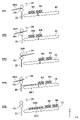
図1は、一実施形態に係る記録システムSYの内部構造を模式的に示す図である。本実施形態の記録システムSYは、ロール状に巻かれた連続シートを使用し、片面プリント及び両面プリントの両方に対応可能なインクジェット方式の高速ラインプリンタである。記録システムSYは、例えば、プリントラボ等における大量のプリントの分野に使用され得る。
<Overview of recording system>
FIG. 1 is a diagram schematically showing an internal structure of a recording system SY according to an embodiment. The recording system SY of the present embodiment is an inkjet high-speed line printer capable of both single-sided printing and double-sided printing by using a continuous sheet wound in a roll shape. The recording system SY can be used, for example, in the field of mass printing in print laboratories and the like.
記録システムSYは、記録装置100及びシート積載装置200を含む。記録装置100は、シート供給部1、デカール部2、斜行矯正部3、記録部4、検査部5、カッタ部6、情報記録部7、乾燥部8、巻取部9、排出部10、及び制御部13を備える。シートは、図中の実線で示したシート搬送経路に沿ってローラ対、ベルト及びこれらを駆動するモータ等を含む搬送機構で搬送され、各ユニットで処理がなされる。
The recording system SY includes a
シート供給部1は、ロール状に巻かれた連続シート(ロールシート)を収納するとともに、収納された連続シートを引き出して搬送経路に供給するユニットである。本実施形態では、シート供給部1は、2つのロールR1、R2を収納することが可能であり、択一的にシートを引き出して供給する構成となっている。なお、シート供給部1が収納可能なロールは2つであることに限定はされず、シート供給部1が1つ、あるいは3つ以上のロールを収納する構成も採用可能である。
The
デカール部2は、シート供給部1から供給されたシートのカール(反り)を軽減させるユニットである。本実施形態では、デカール部2は、1つの駆動ローラに対して2つのピンチローラを用いて、カールの逆向きの反りを与えるようにシートを湾曲させてしごくことでカールを軽減させる。
The
斜行矯正部3は、デカール部2を通過したシートの斜行(本来の進行方向に対する傾き)を矯正するユニットである。例えば、斜行矯正部3は、シートの搬送方向に交差する幅方向の両端部のうち基準となる側のシート端部をガイド部材に押し付けることにより、シートの斜行を矯正する。
The
記録部4は、搬送されるシートに対して画像を記録するユニットである。例えば、記録部4は、記録ヘッドユニット14と、シートを搬送する複数の搬送部材としての搬送ローラを含む。
The
本実施形態の記録ヘッドユニット14は、複数の記録ヘッドを含み、各記録ヘッドには、使用が想定されるシートの最大幅をカバーする範囲でインクジェット方式のノズル列が形成されている。本実施形態では、複数の記録ヘッドが、搬送方向に沿って平行に並べられている。一例として、記録ヘッドユニット14は、C(シアン)、M(マゼンタ)、Y(イエロー)、LC(ライトシアン)、LM(ライトマゼンタ)、G(グレー)、K(ブラック)の7色に対応した7つの記録ヘッドを含む。なお、インクの色数及び記録ヘッドの数は7つには限定はされず、適宜変更されてもよい。
The
記録ヘッドのインクの吐出方式としては、発熱素子を用いた方式、ピエゾ素子を用いた方式、静電素子を用いた方式、MEMS素子を用いた方式等を採用することができる。各色のインクは、例えば、インクタンクからそれぞれインクチューブを介して記録ヘッドユニット14に供給される。
As the ink ejection method of the recording head, a method using a heat generating element, a method using a piezo element, a method using an electrostatic element, a method using a MEMS element, or the like can be adopted. The ink of each color is supplied from the ink tank to the
検査部5は、記録部4でシートに記録された検査パターンや画像を光学的に読み取ることにより、記録ヘッドのノズルの状態、シート搬送状態、画像位置等を検査するユニットである。カッタ部6は、記録後のシートを所定長さにカットする機械的なカッタを備えたユニットである。情報記録部7は、カットされたシートの裏面に記録のシリアル番号や日付などの記録情報を記録するユニットである。乾燥部8は、記録部4で記録されたシートを加熱して、付与されたインクを短時間に乾燥させるユニットである。検査部5、カッタ部6、情報記録部7、乾燥部8はそれぞれ、シートを次工程に送り出すための搬送ベルト又は搬送ローラを含み得る。
The
巻取部9は、両面記録を行う際に表面記録が終了した連続シートを一時的に巻き取るユニットである。巻取部9はシートを巻き取るための回転する巻取ドラムを備えている。両面記録時の巻取部9の具体的な動作は後述する。 The winding unit 9 is a unit that temporarily winds a continuous sheet for which surface recording has been completed when performing double-sided recording. The take-up unit 9 includes a rotating take-up drum for taking up the sheet. The specific operation of the take-up unit 9 during double-sided recording will be described later.
排出部10は、カッタ部6でカットされ乾燥部8で乾燥させられたシートを搬送して記録装置100から排出し、シート積載装置200にシートを受け渡すためのユニットである。排出部10の具体的な構成については後述する。
The
制御部13は、記録装置100の各部の制御を司るユニットである。制御部13は、例えば、CPUに代表されるプロセッサ、RAM、ROM等のメモリ、I/Oインターフェース又は通信インターフェース等の各種インターフェースを含むコントローラ15及び電源を含み得る。
The
コントローラ15は、受け付けた指示に基づいて記録装置100の動作を制御する。例えば、コントローラ15は、記録装置100の筐体に設けられた操作パネル等の操作部が受け付けるユーザからの指示をI/Oインターフェースを介して取得し、その内容に基づいて記録装置100の動作を制御する。また例えば、コントローラ15は、通信インターフェースを介して接続されるホストコンピュータ等の外部機器16から受信した指示に基づいて制御される。
The
シート積載装置200は、記録装置100の排出部10から排出されたシートを積載する。シート積載装置200は、記録装置100に対して着脱可能に構成されてもよい。例えば、記録装置100に備え付けられていた排紙トレイを取り外し、シート積載装置200を排出部10にアドオンしてもよい。なお、シート積載装置200の具体的な構成については後述する。
The
<記録システムの動作例>
次に、記録システムSYの記録時の基本動作について説明する。以下、片面記録及び両面記録のそれぞれの動作について説明する。
<Operation example of recording system>
Next, the basic operation at the time of recording of the recording system SY will be described. Hereinafter, each operation of single-sided recording and double-sided recording will be described.
図2は、片面記録時の記録システムSYの動作を説明するための図である。図2では、搬送経路上のシートが太い実線で示されている。シート供給部1から搬送経路上に供給され、デカール部2、斜行矯正部3でそれぞれ処理されたシートは、記録部4において表面に記録がなされる。記録部4で記録がなされたシートは、検査部5を通過した後、カッタ部6において予め設定されている所定の単位長さ毎にカットされる。次に、情報記録部7において、必要に応じてカットシートの裏面に記録情報が記録される。そして、カットシートは一枚ずつ乾燥部8に搬送されてインクの乾燥が行なわれる。その後、排出部10から記録装置100の外部に排出されて、シート積載装置200に順次積載されていく。
FIG. 2 is a diagram for explaining the operation of the recording system SY at the time of single-sided recording. In FIG. 2, the sheet on the transport path is shown by a thick solid line. The sheet supplied from the
図3は、両面記録時の記録システムSYの動作を説明するための図である。両面記録では、表面記録シーケンスに次いで裏面記録シーケンスが実行される。図3では、表面記録シーケンスにより巻取部9へと搬送されている連続シートが太い実線で示されている。 FIG. 3 is a diagram for explaining the operation of the recording system SY at the time of double-sided recording. In double-sided recording, the backside recording sequence is executed after the frontside recording sequence. In FIG. 3, the continuous sheet conveyed to the winding unit 9 by the surface recording sequence is shown by a thick solid line.
最初の表面記録シーケンスにおいて、シート供給部1から検査部5までの各ユニットでの動作は上述の片面記録の動作と同じであるが、カッタ部6ではカット動作が行われずに、連続シートのまま乾燥部8に搬送される。乾燥部8での表面のインク乾燥の後、連続シートは排出部10の側の経路ではなく、巻取部9の側の経路に導入される。導入されたシートは、順方向(図面では反時計回り方向)に回転する巻取部9の巻取ドラムに巻き取られていく。記録部4において、予定された表面の記録が全て終了すると、カッタ部6において連続シートの記録領域の後端がカットされる。カット位置を基準に、搬送方向下流側(記録された側)の連続シートは乾燥部8を経て巻取部9でシート後端(カット位置)まで全て巻き取られる。一方、カット位置よりも搬送方向上流側の連続シートは、シート先端(カット位置)がデカール部2に残らないように、シート供給部1に巻き戻される。
In the first surface recording sequence, the operation of each unit from the
以上の表面記録シーケンスの後に、裏面記録シーケンスが実行される。図3では、裏面記録シーケンス時の連続シートの搬送経路のうち、巻取部9からデカール部2までの部分が太い破線で示されている。巻取部9の巻取ドラムが巻き取り時とは逆方向(図面では時計回り方向)に回転する。すると、巻き取られたシートの端部が連続シートの表裏が反転した状態でデカール部2に送り込まれる。なお、このときデカール部2に送り込まれるシートの先端は、巻き取り時のシート後端である。つまり、表面記録時と裏面記録時とでシートの先端と後端とが入れ替わる。デカール部2では表面記録時とは逆向きのカール矯正がなされる。これは、巻取ドラムに巻かれたシートは、シート供給部1でのロールとは表裏反転して巻かれ、逆向きのカールとなっているためである。その後は、斜行矯正部3を経て、記録部4で連続シートの裏面に記録が行なわれる。記録されたシートは検査部5を経て、カッタ部6において予め設定されている所定の単位長さ毎にカットされる。カットシートは両面に記録されているので、情報記録部7での記録はなされない。カットシートは一枚ずつ乾燥部8に搬送され、排出部10から記録装置100の外部に搬出されシート積載装置200に順次積載されていく。
After the above front side recording sequence, the back side recording sequence is executed. In FIG. 3, of the continuous sheet transport paths during the backside recording sequence, the portion from the winding portion 9 to the
<排出部及びシート積載装置の構成>
図4は、排出部10及びシート積載装置200周辺の構成を説明する図である。
<Structure of discharge unit and sheet loading device>
FIG. 4 is a diagram illustrating the configuration around the
排出部10は、搬送方向最下流に排出ローラ101を含む。排出ローラ101は、例えば不図示のモータにより回転する。排出ローラ101により、記録装置100の筐体に形成された排出開口102からシートが排出される。
The
シート積載装置200は、コンベア部23、シート検知センサ24及びコンベア制御部26を含む。
The
コンベア部23は、記録装置100の排出部10から排出されたシートの積載、及び積載したシートの搬送を行う。コンベア部23は、排出部10の排出開口102の下方(-Z方向)に設けられている。コンベア部23は、コンベアベルト231及びコンベア駆動ローラ232を含む。
The
コンベアベルト231は、シートの積載面を形成する無端状のベルトである。本実施形態では、シートの積載面が、排出開口102の下方において記録装置100に近接した位置からX方向及びZ方向に延びるように形成されている。換言すれば、コンベアベルト231により形成されるシートの積載面が、コンベアベルト231に積載されたシートの搬送方向下流に向かうに従って上方に向かうように傾斜している。この傾斜は、後述するように、コンベアベルト231に積載されたシートを整列部22により整列させるために設けられている。なお、この傾斜は、整列部22によるシートの積載整列性と、後述する送り動作実行時のシートの積載整列性を考慮して、例えば角度が5~30度に設定されてもよい。
The
また、コンベアベルト231により形成されるシート積載面の搬送方向の長さは、例えば、記録装置100が排出可能な最大シート長さよりも長くなるように設定されてもよい。
Further, the length of the sheet loading surface formed by the
ここで、本実施形態では、記録装置100の外装部材の一部がコンベア部23に積載されたシートを整列させる整列部22として機能している。具体的には、記録装置100から排出されたシートがシート積載面の傾斜により記録装置100側に移動し、シートの排出方向上流側の端部が整列部22に当接することで、コンベア部23に積載されたシートが整列する。しかしながら、整列部22は、記録装置100の外装部材とは別に設けられた部材であってもよい。例えば、シート積載装置200は、シート積載面の傾斜によるシートの移動を規制する部材を含んでもよい。
Here, in the present embodiment, a part of the exterior member of the
シート検知センサ24は、記録装置100がシートの排出中であるか否かを検知する。本実施形態では、シート検知センサ24は、排出ローラ101の排出方向下流に位置する。本実施形態では、シート検知センサ24は、排出ローラ101から排出されたシートがシート検知センサ24の検知位置上に存在している場合はオンになり、検知位置上にシートが存在しない場合はオフになる。つまり、シートが排出ローラ101にニップされて排出中のときはオンになり、シートが排出ローラ101のニップから離れてシートが排出されていないときはオフになる。なお、シート検知センサ24としては、光電センサ、レーザセンサ、超音波センサ、静電容量センサなどの周知のセンサを適宜採用可能である。
The
コンベア駆動ローラ232は、不図示のコンベア駆動モータにより、コンベアベルト231を駆動する。
The
コンベア制御部26は、コンベア駆動ローラ232の駆動を制御することで、コンベア部23の送り動作を制御する。例えば、コンベア制御部26は、CPUに代表されるプロセッサ、RAM、ROM等のメモリ、I/Oインターフェース又は通信インターフェース等の各種インターフェースを含むコントローラ及び電源を含み得る。
The
コンベア制御部26は、排出部10から排出されるシートの速度情報、排出部10から排出される同一記録ジョブのシートの排出間隔情報、又はシート検知センサ24からの情報等に基づいて、コンベア駆動ローラ232の駆動を制御する。例えば、コンベア制御部26は、シートの速度情報及びシートの排出間隔情報を、シート積載装置200に設けられる不図示の操作部によりユーザの入力を受け付けることで取得する。また例えば、コンベア制御部26は、シートの速度情報及びシートの排出間隔情報を、記録装置100の制御部13から受信することで取得する。コンベア制御部26が記録装置100から受信するシートの速度情報は、設定値であってもよいし、排出ローラ101に設けられたエンコーダ等の測定値であってもよい。
The
また、記録ジョブは、例えば、記録装置100に記録処理を実行させるための命令や画像データ、設定情報等を含むデータであってもよい。記録装置100は、同一の記録ジョブに基づいて、1枚以上のカットシートを排出部10から排出し得る。
Further, the recording job may be data including, for example, an instruction for causing the
また、本実施形態では、コンベア制御部26は、シート検知センサ24からの情報の情報として、シート検知センサ24の検知結果に基づく記録ジョブの実行状態(ジョブ状態)を管理している。例えば、コンベア制御部26のCPUは、シート検知センサ24の検知結果からジョブ状態を判断し、判断結果をジョブ状態としてコンベア制御部26のメモリに記憶する。本実施形態では、後述する図5のフローチャートにより、ジョブ状態が、記録ジョブの実行中であることを示す「継続」、記録ジョブが実行されていないことを示す「終了」のいずれであるかが判断される。なお、コンベア制御部26が管理するジョブ状態は、あくまでシート検知センサ24の検知結果に基づいてコンベア制御部26が判断したものであり、記録装置100の制御部13による処理における記録ジョブの実行状態とは一致しない場合もあり得る。
Further, in the present embodiment, the
次に、シート積載装置200にシートが積載される際の、シートの挙動について説明する。
Next, the behavior of the seat when the seat is loaded on the
排出ローラ101から排出されたシートは、重力でコンベアベルト231に落下する。コンベアベルト231に落下したシートは、コンベアベルト231のシート積載面の傾きにより記録装置100側に移動して、シートの端部が整列部22に突き当たり、停止する。このような動きで、排出ローラ101から排出されたシートは、コンベア制御部26によりコンベア部23が動作するまで、順次コンベアベルト231上に整列して積載されていく。
The sheet discharged from the
コンベア制御部26は、例えば同一の記録ジョブに基づく記録装置100からのシートの排出が終了すると、コンベア部23の送り動作を実行する。このとき、コンベア制御部26は、コンベアベルト231に積載されたシート束の積載整列性を崩さないよう、コンベアベルト231の加減速をコントロールして送り動作を行う。この送り動作により、次の記録ジョブに基づいて記録装置100からシートが排出された場合のシートの積載スペースを確保することができる。そして、次の記録ジョブに基づき排出されたシートがコンベアベルト231に積載されることで、コンベアベルト231に複数のシート束が整列されて積載される(図6参照)。
For example, when the
ところで、前述したコンベア部23の送り動作において、次に記録装置100から排出されるシートの長さに対して送り量が大きいと、シート束同士の間隔が大きくなり、シート積載装置200のシートの積載量が低下してしまう場合がある。一方で、次に記録装置100から排出されるシートの長さに対して送り量が小さいと、隣接するシート束同士が重なってしまい、シート束の取り出しの作業性が低下してしまうことがある。そこで、本実施形態では、コンベア制御部26は、以下の制御により、コンベア部23の送り量を制御している。
By the way, in the feeding operation of the
<制御例>
図5(a)は、シート積載装置200の制御例を示すフローチャートである。本フローチャートは、例えば、コンベア制御部26のCPUが、ROMに記憶されたプログラムをRAMに読み出して実行することにより実現される。
<Control example>
FIG. 5A is a flowchart showing a control example of the
また、図6は、シート積載装置200の動作例を示す図であり、図5(a)のフローチャートが実行された場合の動作例を示している。図6では、コンベア部23に既に2つのシート束が積載された状態において、後続のシートSH1、シートSH2が記録装置100から排出される場合のシート積載装置200の動作例が示されている。なお、以下の説明では、シートSH1,シートSH2は、コンベア部23に積載されている図6の状態ST1等で示す左側のシート束が排出された際の記録ジョブの次の記録ジョブに基づいて排出されるシートであるものとして説明する。よって、図6の状態ST1では、ジョブ状態は「終了」である。
Further, FIG. 6 is a diagram showing an operation example of the
ステップS1(以下、単にS1と表記し、他のステップについても同様とする)で、コンベア制御部26は、ジョブ状態を確認し、ジョブ状態が「終了」であればS2に進み、「継続」であればS3に進む。例えば、コンベア制御部26は、メモリに記憶されているジョブ状態についての情報を読み出して確認を行う。図6の例では、前述したように状態ST1におけるジョブ状態は「終了」なので、コンベア制御部26はS2に進む。
In step S1 (hereinafter, simply referred to as S1 and the same applies to other steps), the
S2で、コンベア制御部26は、コンベア送り処理を実行する。ジョブ状態が「終了」の場合、コンベアベルト231に積載されているシートが排出された際の記録ジョブは終了しているため、次に排出部10から排出されるシートは次の記録ジョブに基づく1枚目のシートである。一方、ジョブ状態が「継続」の場合、次に排出部10から排出されるシートは現在継続中の記録ジョブに基づく2枚目以降のシートである。よって、本実施形態では、S1での分岐により、同一記録ジョブの1枚目のシートの排出に対してはコンベア送り処理が実行されるが、同一記録ジョブの2枚目以降のシートの排出に対してはコンベ送り処理が実行されない。
In S2, the
図5(b)は、シート積載装置200の制御例を示すフローチャートであり、図5(a)のS2の具体的な処理例を示している。
FIG. 5B is a flowchart showing a control example of the
S201で、コンベア制御部26は、排出部10からシートの排出が開始されたか否かを確認し、開始されている場合はS202に進み、開始されていない場合はS201に戻る。例えば、図6の状態ST1はシート検知センサ24によりシートSH1が検知される前の状態のため、コンベア制御部26はシート排出が開始されていないと判断する(S201:No)。一方、図6の状態ST2まで排出ローラ101によるシートの搬送が進むと、シートSH1の先端がシート検知センサ24により検知されるため、コンベア制御部26はシート排出が開始されたと判断する(S201:Yes)。
In S201, the
S202で、コンベア制御部26は、コンベア制御部26のメモリに記憶されているジョブ状態を「継続」に更新する。S203で、コンベア制御部26は、コンベア部23の送り動作を開始する。具体的には、コンベア制御部26は、コンベア駆動ローラ232によってコンベアベルト231を駆動する。これにより、コンベアベルト231に積載されたシートSHの束がコンベアベルト231の搬送方向の下流(図6中の左側)に移動する。よって、コンベアベルト231の記録装置100に近接する領域に排出中のシートSH2の積載スペースが形成される(図6の状態ST3)。
In S202, the
ここで、コンベア部23の加速度は、コンベア部23に積載されたシート束の整列性が崩れない値に設定され得る。また、コンベア部23の搬送速度は、排出部10のシート排出速度に対応して設定され得る。例えば、コンベア部23の搬送速度は、排出部10のシート排出速度と同じ速度であってもよい。また例えば、コンベア部23の搬送速度は、排出部10のシート排出速度±5~30%以内の値となるように設定されてもよい。つまり、コンベア部23の搬送速度は、シートの記録装置100からの排出速度に近い値に設定されてもよい。これにより、記録装置100からのシートの排出期間に対応してコンベア部23を動作させた場合に、コンベア部23の送り量を排出されたシートの長さに近づけることができる。
Here, the acceleration of the
S204で、コンベア制御部26は、シートの排出が終了したか否かを確認し、終了していればS205に進み、終了していない、すなわちシートの排出が継続中であればS204に戻る。コンベア制御部26は、シート検知センサ24の検知結果がオンからオフに切り替わったことに基づいて、シートの排出が終了したと判断してもよい。
In S204, the
コンベア制御部26は、S205で所定時間待機した後、S206でコンベア部23の送り動作を終了し、図5(b)のフローチャートを終了する。ここで、コンベア部23の減速は、コンベア部23に積載されたシート束の整列性が崩れない値に設定され得る。
After waiting for a predetermined time in S205, the
このように、コンベア制御部26は、シートSH1がシート検知センサ24により検知され続けている間、すなわち記録装置100のシートの排出中はコンベア部23の送り動作を継続する。一方、コンベア制御部26は、シートSH1がシート検知センサ24により検知されなくなったことに対応して、すなわち記録装置100がシートの排出を終了したことに対応して、コンベア部23の送り動作を終了する。つまり、コンベア部23の送り動作は、記録装置100がシートを排出中であることをシート検知センサ24が検知している期間に対応して実行される。これにより、記録装置100から排出されるシートの積載スペースが、記録装置100がシートを排出中であることをシート検知センサ24が検知している期間に対応して、コンベアベルト231のシートの積載面上(コンベア部上)に確保される。
In this way, the
図5(a)に戻る。S3で、コンベア制御部26は、ジョブ状態判断処理を実行する。図5(c)は、シート積載装置200の制御例を示すフローチャートであり、S3の具体的な処理例を示している。
Return to FIG. 5 (a). In S3, the
S301で、コンベア制御部26は、排出部10によるシートの非排出期間が閾値以上であればS302に進み、閾値未満であればフローチャートを終了する。さらに言えば、コンベア制御部26は、排出部10によりシートが排出中である場合、又は、最後に排出されたシートの排出が完了してからの経過時間が閾値未満の場合にはフローチャートを終了する。
In S301, the
ここで、図7は、排出部10における、複数のジョブが実行される際のシート搬送の動作例を模式的に示している。ジョブ1では、複数の同一サイズのシートが、所定の隙間Aをあけて順次搬送される。ジョブ2では、ジョブ1のシートサイズとは異なるがジョブ内では同一サイズのシートが、所定の隙間Aをあけて順次搬送される。また、ジョブ1に基づく記録処理における最後のシートと、ジョブ2に基づく記録処理における最初のシートが、隙間Bをあけて搬送される。本実施形態では、「異なるジョブ間のシート隙間B>同一ジョブ内のシート隙間A」の関係となるよう設定されている。このため、シート検知センサ24のオフ時間、すなわち排出部10によるシートの非排出期間は、同一ジョブ内でのシート間よりも、異なるジョブのシート間の方が長くなる。よって、コンベア制御部26は、シート検知センサ24に基づくシートの非排出期間から、ジョブが継続中であるか終了したかを判断することができる。
Here, FIG. 7 schematically shows an operation example of sheet transfer in the
図5(c)に戻る。例えば、シート間の隙間が隙間Aである場合のシートの非排出期間が期間TA[sec]、シート間の隙間が隙間Bである場合のシートの非排出期間が期間TB[sec]である場合、S301の閾値は、期間TAから期間TBの間の値に設定されてもよい。 Return to FIG. 5 (c). For example, when the gap between the sheets is the gap A, the non-discharge period of the sheet is the period TA [sec], and when the gap between the sheets is the gap B, the non-discharge period of the sheet is the period TB [sec]. , S301 may be set to a value between period TA and period TB.
S302で、コンベア制御部26は、メモリに記憶されているジョブ状態を「終了」に更新し、図5(c)フローチャートを終了する。
In S302, the
図5(a)に戻る。S4で、コンベア制御部26は、ジョブ状態を確認し、ジョブ状態が「終了」であればS5に進み、「継続」であればフローチャートを終了する。例えば、コンベア制御部26は、メモリに記憶されているジョブ状態についての情報を読み出して確認を行う。
Return to FIG. 5 (a). In S4, the
S5で、コンベア制御部26は、コンベア間欠送りを実行する。具体的には、コンベア制御部26は、コンベア部23に積載されたシートが所定量搬送されるように、コンベア駆動ローラ232によりコンベアベルト231を所定量駆動する。この動作は、例えば異なるジョブのシート束間にバッファを設けるために実行される(図6の状態ST5)。
In S5, the
以上説明したように、本実施形態によれば、記録装置100がシートを排出中であることをシート検知センサ24が検知している期間に対応してコンベア部23の送り動作が実行される(S201~S206)。よって、検出されるシートのシート長に応じた積載スペースがコンベアベルト231上に確保される。したがって、シート束の重なりによる取り出しの作業性の低下を抑制することができる。また、異なるシート長のシートが排出されるジョブが連続して行われる場合であっても、シート束間を適切に制御することができる。よって、異なるシート長のシート束をコンベアベルト231により多く積載することができる。
As described above, according to the present embodiment, the feeding operation of the
また、本実施形態によれば、コンベア部23の搬送期間は、シート検知センサ24により記録装置100からシートが排出中であることが検知されている期間に対応して決定される。また、コンベア部23の搬送速度が、排出部10のシート排出速度に対応して設定され得る。よって、シートの排出期間及び排出部10のシートの排出速度に基づきコンベア部23の送り量が設定される。したがって、コンベア部23の送り量を排出されるシートの長さに対応した量とすることができる。より具体的には、コンベア部23の送り量が、シートの記録装置100からの排出期間(時間)×シートの排出速度に基づいて設定されるので、コンベア部23の送り量をシートの長さに近づけることができる。よって、コンベア部23に積載されるシート束同士の間隔を近づけることができ、コンベア部23のシートの積載量を向上することができる。
Further, according to the present embodiment, the transport period of the
また、本実施形態によれば、コンベア制御部26は、シート検知センサ24の検知結果に基づいて、シート長に対応したシートの積載スペースを確保している。したがって、シート積載装置200が記録装置100に対してアドオンされるような場合に、コンベア制御部26は記録装置100の制御部13からシートの長さ等の情報を受け取る必要がない。したがって、コンベア制御部26はより簡易な態様でコンベア部23の動作を制御することができる。
Further, according to the present embodiment, the
<他の実施形態>
上記実施形態では、記録装置100がシートを排出中であるか否かを、シート検知センサ24により検知しているが、他の態様により記録装置100がシートを排出中であるか否かが検知されてもよい。例えば、記録装置100がシートを排出中であるか否かが、排出部10の排出ローラ101の駆動情報に基づいて検知されてもよい。排出ローラ101の駆動情報は、排出ローラ101の駆動電流値又は排出ローラ101に回転速度を測定可能なエンコーダの検知結果等であってもよい。例えば、コンベア制御部26は、制御部13から排出ローラ101の駆動情報を取得し、排出ローラ101が駆動中である期間、すなわち記録装置100がシートを排出中である期間に対応して、コンベア部23の送り動作を制御してもよい。
<Other embodiments>
In the above embodiment, whether or not the
また、上記実施形態では、記録装置100とシート積載装置200により記録システムSYが構成されるが、記録装置の一部としてシート積載装置が設けられていてもよい。この場合、コンベア制御部26が設けられずに、記録装置100の制御部13がコンベア部23の動作を制御してもよい。
Further, in the above embodiment, the recording system SY is configured by the
また、上記実施形態の説明では、1つの記録装置100と1つのシート積載装置200の組み合わせについて述べたが、1つの記録装置100に排出部10が複数ある場合、シート積載装置200が複数設けられてもよい。この場合、複数のシート積載装置200に、シートを整列して積載することができる。
Further, in the description of the above embodiment, the combination of one
また、上記実施形態の説明では、1つの記録装置100と1つのシート積載装置200の組み合わせについて述べたが、複数の記録装置100と複数のシート積載装置200が設けられてもよい。この場合、複数のシート積載装置200のコンベアを延伸し、コンベアの終着点を一か所に集約するように複数のシート積載装置200が配置されてもよい。これにより、整列して積載されたシートが一か所に集まることになる。結果として、複数の記録装置100から排出されたシートを後工程に簡易に進めることができる。
Further, in the description of the above embodiment, the combination of one
本発明は、上述の実施形態の1以上の機能を実現するプログラムを、ネットワーク又は記憶媒体を介してシステム又は装置に供給し、そのシステム又は装置のコンピュータにおける1つ以上のプロセッサがプログラムを読出し実行する処理でも実現可能である。また、1以上の機能を実現する回路(例えば、ASIC)によっても実現可能である。 The present invention supplies a program that realizes one or more functions of the above-described embodiment to a system or device via a network or storage medium, and one or more processors in the computer of the system or device reads and executes the program. It can also be realized by the processing to be performed. It can also be realized by a circuit (for example, ASIC) that realizes one or more functions.
発明は上記実施形態に制限されるものではなく、発明の精神及び範囲から離脱することなく、様々な変更及び変形が可能である。従って、発明の範囲を公にするために請求項を添付する。 The invention is not limited to the above embodiment, and various modifications and modifications can be made without departing from the spirit and scope of the invention. Therefore, a claim is attached to publicize the scope of the invention.
23 コンベア部、24 シート検知センサ、26 コンベア制御部、100 記録装置、200 シート積載装置、SY 記録システム 23 Conveyor section, 24 sheet detection sensor, 26 conveyor control section, 100 recording device, 200 sheet loading device, SY recording system
Claims (14)
前記記録装置がシートを排出中であるか否かを検知する検知手段と、
前記記録装置から排出されているシートの積載スペースを前記コンベア部上に確保するように、前記記録装置がシートを排出中であることを前記検知手段が検知している期間に対応して、前記コンベア部の送り動作を制御する制御手段と、を備える、
ことを特徴とするシート積載装置。 A conveyor unit that loads the sheets discharged from the recording device and conveys the loaded sheets.
A detection means for detecting whether or not the recording device is ejecting a sheet,
The above-mentioned period corresponding to the period during which the detection means has detected that the recording device is discharging the sheets so as to secure a loading space for the sheets discharged from the recording device on the conveyor unit. A control means for controlling the feeding operation of the conveyor unit is provided.
A seat loading device characterized by that.
前記制御手段は、同一の記録ジョブにより複数のシートが前記記録装置から排出される場合には、前記記録装置が2枚目以降のシートの排出中であることを前記検知手段が検知しても、前記コンベア部の送り動作を実行しない、
ことを特徴とするシート積載装置。 The sheet loading device according to claim 1.
When a plurality of sheets are ejected from the recording device by the same recording job, the control means may detect that the recording apparatus is ejecting the second and subsequent sheets. , Do not execute the feed operation of the conveyor unit,
A seat loading device characterized by that.
前記検知手段の検知結果に基づいて、同一の記録ジョブに基づく前記記録装置からのシートの排出が継続中であるか終了したかを判断する判断手段をさらに備える、
ことを特徴とするシート積載装置。 The sheet loading device according to claim 1 or 2.
Further provided with a determination means for determining whether or not the ejection of the sheet from the recording device based on the same recording job is ongoing or completed based on the detection result of the detection means.
A seat loading device characterized by that.
前記記録装置がシートを排出中でないことを前記検知手段が検知している期間の長さに基づいて、同一の記録ジョブに基づく前記記録装置からのシートの排出が継続中であるか終了したかを判断する判断手段をさらに備える、
ことを特徴とするシート積載装置。 The sheet loading device according to claim 1 or 2.
Whether the sheet ejection from the recording device based on the same recording job is ongoing or terminated based on the length of the period during which the detection means has detected that the recording device is not ejecting the sheet. Further equipped with a judgment means to judge
A seat loading device characterized by that.
前記制御手段は、前記判断手段により同一の記録ジョブに基づく前記記録装置からのシートの排出が終了したと判断された場合には、前記記録装置が後続のシートの排出中であることを前記検知手段が検知している期間に対応して、前記コンベア部の送り動作を実行する、
ことを特徴とするシート積載装置。 The sheet loading device according to claim 3 or 4.
When the control means determines by the determination means that the ejection of the sheet from the recording device based on the same recording job is completed, the control means detects that the recording apparatus is ejecting a subsequent sheet. The feed operation of the conveyor unit is executed according to the period detected by the means.
A seat loading device characterized by that.
前記制御手段は、前記判断手段により同一の記録ジョブに基づく前記記録装置からのシートの排出が継続していると判断された場合には、前記記録装置が後続のシートの排出中であることを前記検知手段が検知しても、前記コンベア部の送り動作を実行しない、
ことを特徴とするシート積載装置。 The sheet loading device according to any one of claims 3 to 5.
When the control means determines by the determination means that the sheet is continuously ejected from the recording device based on the same recording job, the control means indicates that the recording device is ejecting a subsequent sheet. Even if the detection means detects it, the feed operation of the conveyor unit is not executed.
A seat loading device characterized by that.
前記制御手段は、前記記録装置のシートの排出速度に基づく前記コンベア部の搬送速度で、前記コンベア部の送り動作を実行する、
ことを特徴とするシート積載装置。 The sheet loading device according to any one of claims 1 to 6.
The control means executes the feeding operation of the conveyor unit at the transport speed of the conveyor unit based on the discharge speed of the sheet of the recording device.
A seat loading device characterized by that.
前記制御手段は、前記記録装置のシートの排出速度及び前記検知手段によりシートが排出中であることが検知されている期間に基づく送り量で前記コンベア部の送り動作を実行する、
ことを特徴とするシート積載装置。 The sheet loading device according to claim 1.
The control means executes the feed operation of the conveyor unit with a feed amount based on the discharge speed of the sheet of the recording device and the period during which the sheet is detected to be being discharged by the detection means.
A seat loading device characterized by that.
前記制御手段は、前記判断手段により同一の記録ジョブに基づく前記記録装置からのシートの排出が終了したと判断された場合に、前記コンベア部に積載されたシートが所定量搬送されるように、前記コンベア部の送り動作を実行する、
ことを特徴とするシート積載装置。 The sheet loading device according to claim 3 or 4.
When the control means determines by the determination means that the ejection of the sheet from the recording device based on the same recording job is completed, the control means conveys a predetermined amount of the sheet loaded on the conveyor unit. Executing the feed operation of the conveyor unit,
A seat loading device characterized by that.
前記コンベア部のシートの積載面が、前記コンベア部に積載されたシートの搬送方向下流に向かうに従って上方に向かうように傾斜する、
ことを特徴とするシート積載装置。 The sheet loading device according to any one of claims 1 to 9.
The loading surface of the sheet loaded on the conveyor section is inclined upward toward the downstream in the transport direction of the sheet loaded on the conveyor section.
A seat loading device characterized by that.
前記コンベア部の前記積載面よりも前記記録装置の側に設けられ、前記記録装置から排出されたシートを整列させる整列部に、前記記録装置から排出されたシートの排出方向上流側の端部が当接することにより、前記コンベア部に積載されたシートが整列する、
ことを特徴とするシート積載装置。 The sheet loading device according to claim 10.
An end portion of the sheet discharged from the recording device on the upstream side in the discharge direction is provided at an aligning portion provided on the side of the recording device with respect to the loading surface of the conveyor unit to align the sheets discharged from the recording device. By abutting, the sheets loaded on the conveyor section are aligned.
A seat loading device characterized by that.
前記記録手段により記録がなされたシートを排出する排出手段と、
記録装置から排出されたシートの積載、及び積載したシートの搬送を行うコンベア部と、
前記記録装置がシートを排出中であるか否かを検知する検知手段と、
前記記録装置から排出されているシートの積載スペースを前記コンベア部上に確保するように、前記記録装置がシートを排出中であることを前記検知手段が検知している期間に対応して、前記コンベア部の送り動作を制御する制御手段と、を備える、
ことを特徴とする記録装置。 A recording means for recording on a sheet,
A discharge means for discharging the sheet recorded by the recording means, and a discharge means.
A conveyor unit that loads the sheets discharged from the recording device and conveys the loaded sheets.
A detection means for detecting whether or not the recording device is ejecting a sheet,
The above-mentioned period corresponding to the period during which the detection means has detected that the recording device is discharging the sheets so as to secure a loading space for the sheets discharged from the recording device on the conveyor unit. A control means for controlling the feeding operation of the conveyor unit is provided.
A recording device characterized by that.
前記記録装置からシートが排出されているか否かを検知する検知手段と、を備えたシート積載装置の制御方法であって、
前記記録装置から排出されているシートの積載スペースを前記コンベア部上に確保するように、前記記録装置がシートを排出中であることを前記検知手段が検知している期間に対応して、前記コンベア部の送り動作を制御する制御工程、を含む、
ことを特徴とする制御方法。 A conveyor unit that loads the sheets discharged from the recording device and conveys the loaded sheets.
It is a control method of a sheet loading device provided with a detection means for detecting whether or not a sheet is ejected from the recording device.
The detection means corresponds to the period during which the recording device is detecting that the sheet is being discharged so as to secure a loading space for the sheet discharged from the recording device on the conveyor unit. Including a control process for controlling the feed operation of the conveyor unit,
A control method characterized by that.
Priority Applications (3)
| Application Number | Priority Date | Filing Date | Title |
|---|---|---|---|
| JP2020212773A JP2022099033A (en) | 2020-12-22 | 2020-12-22 | Sheet loading device, recording device, control method, and program |
| EP21214410.9A EP4043376A3 (en) | 2020-12-22 | 2021-12-14 | Sheet stacking apparatus, printing apparatus, control method, and program |
| US17/552,585 US11926150B2 (en) | 2020-12-22 | 2021-12-16 | Sheet stacking apparatus, printing apparatus, control method, and storage medium |
Applications Claiming Priority (1)
| Application Number | Priority Date | Filing Date | Title |
|---|---|---|---|
| JP2020212773A JP2022099033A (en) | 2020-12-22 | 2020-12-22 | Sheet loading device, recording device, control method, and program |
Publications (2)
| Publication Number | Publication Date |
|---|---|
| JP2022099033A true JP2022099033A (en) | 2022-07-04 |
| JP2022099033A5 JP2022099033A5 (en) | 2024-01-05 |
Family
ID=79024323
Family Applications (1)
| Application Number | Title | Priority Date | Filing Date |
|---|---|---|---|
| JP2020212773A Pending JP2022099033A (en) | 2020-12-22 | 2020-12-22 | Sheet loading device, recording device, control method, and program |
Country Status (3)
| Country | Link |
|---|---|
| US (1) | US11926150B2 (en) |
| EP (1) | EP4043376A3 (en) |
| JP (1) | JP2022099033A (en) |
Family Cites Families (10)
| Publication number | Priority date | Publication date | Assignee | Title |
|---|---|---|---|---|
| US1693632A (en) * | 1924-05-06 | 1928-12-04 | R Hoe And Co Inc | Delivery mechanism |
| US3724640A (en) * | 1970-03-23 | 1973-04-03 | Licentia Gmbh | Device for forming stacks from a flow of consecutively furnished flat items |
| US3752043A (en) * | 1970-05-29 | 1973-08-14 | Licentia Gmbh | Stack forming apparatus |
| DE4333575A1 (en) * | 1993-10-01 | 1995-04-06 | Boewe Systec Ag | Method and device for forming and moving stacks from printed sheets, in particular documents |
| JP3592866B2 (en) * | 1996-12-05 | 2004-11-24 | 富士写真フイルム株式会社 | Photosensitive material sorting method and apparatus |
| US20040173958A1 (en) * | 2003-03-04 | 2004-09-09 | Quad/Graphics, Inc. | Method of delivering a printed product to a binding or mailing line |
| JP4497310B2 (en) * | 2005-07-01 | 2010-07-07 | ノーリツ鋼機株式会社 | Image processing device |
| CH703953A1 (en) * | 2010-10-15 | 2012-04-30 | Ferag Ag | Method for operating a processing plant to be in any product units with different characteristics processing. |
| US8833758B2 (en) * | 2011-09-09 | 2014-09-16 | Vits America, Inc. | Stacker |
| JP2013249161A (en) | 2012-05-31 | 2013-12-12 | Canon Inc | Sheet loading device and image forming apparatus |
-
2020
- 2020-12-22 JP JP2020212773A patent/JP2022099033A/en active Pending
-
2021
- 2021-12-14 EP EP21214410.9A patent/EP4043376A3/en active Pending
- 2021-12-16 US US17/552,585 patent/US11926150B2/en active Active
Also Published As
| Publication number | Publication date |
|---|---|
| EP4043376A3 (en) | 2022-11-30 |
| US11926150B2 (en) | 2024-03-12 |
| US20220194105A1 (en) | 2022-06-23 |
| EP4043376A2 (en) | 2022-08-17 |
Similar Documents
| Publication | Publication Date | Title |
|---|---|---|
| US9358812B2 (en) | Printing apparatus for detecting and avoiding unprintable regions on recording mediums | |
| JP6094349B2 (en) | Droplet ejection apparatus and program | |
| JP6460715B2 (en) | Control device, control method and program | |
| JP5917084B2 (en) | Recording apparatus, control method, and program | |
| JP5631117B2 (en) | Recording apparatus, detection method, and detection apparatus | |
| WO2005087636A1 (en) | Image forming device | |
| JP5911256B2 (en) | Printing apparatus and inspection method | |
| JP4991889B2 (en) | Printing apparatus and printing apparatus control method | |
| JP2022099033A (en) | Sheet loading device, recording device, control method, and program | |
| US9162490B2 (en) | Sheet supply apparatus and printing apparatus | |
| JP5921070B2 (en) | Control apparatus and control method | |
| JP5720317B2 (en) | printer | |
| JP2018051962A (en) | Printer | |
| JP2004224057A (en) | Ink jet recording device | |
| JP2011230386A (en) | Printer | |
| JP6408782B2 (en) | Recording apparatus and recording method | |
| JP4496814B2 (en) | Printer and printing method | |
| JP7415435B2 (en) | inkjet recording device | |
| JP5921735B2 (en) | Printing device | |
| JP2015187018A (en) | Recording device and discharge method of recording medium of the device | |
| JP2023174058A (en) | Image formation apparatus | |
| JP2021066131A (en) | Inkjet recording apparatus | |
| JP2021066130A (en) | Inkjet recording apparatus | |
| JP6004813B2 (en) | Control method of printing apparatus, continuous sheet and printing apparatus | |
| JPH1035919A (en) | Sheet feeding device and recording device |
Legal Events
| Date | Code | Title | Description |
|---|---|---|---|
| RD02 | Notification of acceptance of power of attorney |
Free format text: JAPANESE INTERMEDIATE CODE: A7422 Effective date: 20210103 |
|
| A521 | Request for written amendment filed |
Free format text: JAPANESE INTERMEDIATE CODE: A523 Effective date: 20210113 |
|
| RD04 | Notification of resignation of power of attorney |
Free format text: JAPANESE INTERMEDIATE CODE: A7424 Effective date: 20210316 |
|
| A521 | Request for written amendment filed |
Free format text: JAPANESE INTERMEDIATE CODE: A523 Effective date: 20231221 |
|
| A621 | Written request for application examination |
Free format text: JAPANESE INTERMEDIATE CODE: A621 Effective date: 20231221 |