JP2022092094A - Worm reduction gear - Google Patents
Worm reduction gear Download PDFInfo
- Publication number
- JP2022092094A JP2022092094A JP2020204662A JP2020204662A JP2022092094A JP 2022092094 A JP2022092094 A JP 2022092094A JP 2020204662 A JP2020204662 A JP 2020204662A JP 2020204662 A JP2020204662 A JP 2020204662A JP 2022092094 A JP2022092094 A JP 2022092094A
- Authority
- JP
- Japan
- Prior art keywords
- outer ring
- housing
- gear housing
- convex portion
- axial
- Prior art date
- Legal status (The legal status is an assumption and is not a legal conclusion. Google has not performed a legal analysis and makes no representation as to the accuracy of the status listed.)
- Pending
Links
- 238000005096 rolling process Methods 0.000 claims abstract description 46
- 229920003002 synthetic resin Polymers 0.000 claims abstract description 25
- 239000000057 synthetic resin Substances 0.000 claims abstract description 25
- 230000002093 peripheral effect Effects 0.000 claims description 44
- 239000003638 chemical reducing agent Substances 0.000 claims description 37
- 230000007423 decrease Effects 0.000 claims description 11
- 238000002347 injection Methods 0.000 abstract 1
- 239000007924 injection Substances 0.000 abstract 1
- 239000000243 solution Substances 0.000 abstract 1
- 239000000835 fiber Substances 0.000 description 8
- 238000010586 diagram Methods 0.000 description 7
- 229910052751 metal Inorganic materials 0.000 description 7
- 239000002184 metal Substances 0.000 description 7
- 229920005989 resin Polymers 0.000 description 7
- 239000011347 resin Substances 0.000 description 7
- 238000009434 installation Methods 0.000 description 6
- 238000005192 partition Methods 0.000 description 6
- 239000004734 Polyphenylene sulfide Substances 0.000 description 5
- 229920000069 polyphenylene sulfide Polymers 0.000 description 5
- XEEYBQQBJWHFJM-UHFFFAOYSA-N Iron Chemical compound [Fe] XEEYBQQBJWHFJM-UHFFFAOYSA-N 0.000 description 4
- 238000013459 approach Methods 0.000 description 4
- 238000006243 chemical reaction Methods 0.000 description 4
- 238000006073 displacement reaction Methods 0.000 description 4
- 230000000694 effects Effects 0.000 description 4
- 239000003365 glass fiber Substances 0.000 description 4
- 239000012779 reinforcing material Substances 0.000 description 4
- 229920000049 Carbon (fiber) Polymers 0.000 description 3
- 229910000831 Steel Inorganic materials 0.000 description 3
- 239000004917 carbon fiber Substances 0.000 description 3
- 230000008878 coupling Effects 0.000 description 3
- 238000010168 coupling process Methods 0.000 description 3
- 238000005859 coupling reaction Methods 0.000 description 3
- 238000001746 injection moulding Methods 0.000 description 3
- VNWKTOKETHGBQD-UHFFFAOYSA-N methane Chemical compound C VNWKTOKETHGBQD-UHFFFAOYSA-N 0.000 description 3
- 239000004033 plastic Substances 0.000 description 3
- 239000010959 steel Substances 0.000 description 3
- 229920005992 thermoplastic resin Polymers 0.000 description 3
- 229910000838 Al alloy Inorganic materials 0.000 description 2
- 239000004696 Poly ether ether ketone Substances 0.000 description 2
- 229910045601 alloy Inorganic materials 0.000 description 2
- 239000000956 alloy Substances 0.000 description 2
- 238000005520 cutting process Methods 0.000 description 2
- 229910052742 iron Inorganic materials 0.000 description 2
- 238000004519 manufacturing process Methods 0.000 description 2
- 239000000463 material Substances 0.000 description 2
- 238000000465 moulding Methods 0.000 description 2
- 229920002530 polyetherether ketone Polymers 0.000 description 2
- 230000003014 reinforcing effect Effects 0.000 description 2
- 239000004575 stone Substances 0.000 description 2
- 239000013585 weight reducing agent Substances 0.000 description 2
- ZOXJGFHDIHLPTG-UHFFFAOYSA-N Boron Chemical compound [B] ZOXJGFHDIHLPTG-UHFFFAOYSA-N 0.000 description 1
- 229910001018 Cast iron Inorganic materials 0.000 description 1
- 229910000640 Fe alloy Inorganic materials 0.000 description 1
- 229920007278 PPS GF40 Polymers 0.000 description 1
- 229920006980 PPS-CF Polymers 0.000 description 1
- 229920006917 PPS-GF40 Polymers 0.000 description 1
- 241000269978 Pleuronectiformes Species 0.000 description 1
- 239000004642 Polyimide Substances 0.000 description 1
- 238000010521 absorption reaction Methods 0.000 description 1
- 229910052782 aluminium Inorganic materials 0.000 description 1
- XAGFODPZIPBFFR-UHFFFAOYSA-N aluminium Chemical compound [Al] XAGFODPZIPBFFR-UHFFFAOYSA-N 0.000 description 1
- PNEYBMLMFCGWSK-UHFFFAOYSA-N aluminium oxide Inorganic materials [O-2].[O-2].[O-2].[Al+3].[Al+3] PNEYBMLMFCGWSK-UHFFFAOYSA-N 0.000 description 1
- 239000004760 aramid Substances 0.000 description 1
- 229920003235 aromatic polyamide Polymers 0.000 description 1
- 125000003118 aryl group Chemical group 0.000 description 1
- 230000005540 biological transmission Effects 0.000 description 1
- 230000015572 biosynthetic process Effects 0.000 description 1
- 229910052796 boron Inorganic materials 0.000 description 1
- 239000000919 ceramic Substances 0.000 description 1
- 230000009977 dual effect Effects 0.000 description 1
- 239000000428 dust Substances 0.000 description 1
- 239000000446 fuel Substances 0.000 description 1
- 239000012784 inorganic fiber Substances 0.000 description 1
- 229910001234 light alloy Inorganic materials 0.000 description 1
- 239000004973 liquid crystal related substance Substances 0.000 description 1
- 239000000314 lubricant Substances 0.000 description 1
- 238000003754 machining Methods 0.000 description 1
- 238000000034 method Methods 0.000 description 1
- 229920006122 polyamide resin Polymers 0.000 description 1
- 229920000728 polyester Polymers 0.000 description 1
- 229920001721 polyimide Polymers 0.000 description 1
- 230000001105 regulatory effect Effects 0.000 description 1
- HBMJWWWQQXIZIP-UHFFFAOYSA-N silicon carbide Chemical compound [Si+]#[C-] HBMJWWWQQXIZIP-UHFFFAOYSA-N 0.000 description 1
- 229910010271 silicon carbide Inorganic materials 0.000 description 1
- 239000010935 stainless steel Substances 0.000 description 1
- 229910001220 stainless steel Inorganic materials 0.000 description 1
- 229920006230 thermoplastic polyester resin Polymers 0.000 description 1
- 229920006259 thermoplastic polyimide Polymers 0.000 description 1
- XLYOFNOQVPJJNP-UHFFFAOYSA-N water Substances O XLYOFNOQVPJJNP-UHFFFAOYSA-N 0.000 description 1
Images


Abstract
Description
本発明は、ウォーム減速機に関する。 The present invention relates to a worm reducer.
自動車のステアリング装置では、運転者の操作によりステアリングホイールを回転させると、ステアリングホイールの回転は、ステアリングシャフトや中間シャフトを介して、ステアリングギヤユニットのピニオンシャフトに伝達され、ステアリングギヤユニットのラック軸の直線運動に変換される。これにより、1対のタイロッドが押し引きされ、1対の操舵輪にステアリングホイールの操作量に応じた舵角が付与される。 In an automobile steering device, when the steering wheel is rotated by the driver's operation, the rotation of the steering wheel is transmitted to the pinion shaft of the steering gear unit via the steering shaft and the intermediate shaft, and the rotation of the rack shaft of the steering gear unit is transmitted. Converted to linear motion. As a result, the pair of tie rods is pushed and pulled, and the pair of steering wheels are given a steering angle according to the amount of operation of the steering wheel.
また、近年、電動モータを補助動力源として、運転者がステアリングホイールを操作するのに要する力を軽減する、電動パワーステアリング装置が広く普及している。電動パワーステアリング装置は、電動モータのトルクを増大させるための減速機として、大きな減速比が得られるウォーム減速機を備える。 Further, in recent years, an electric power steering device that uses an electric motor as an auxiliary power source to reduce the force required for the driver to operate the steering wheel has become widespread. The electric power steering device includes a worm reducer that can obtain a large reduction ratio as a reducer for increasing the torque of the electric motor.
ウォーム減速機は、ギヤハウジングと、ギヤハウジングに回転自在に支持されて、外周面にホイール歯を有するウォームホイールと、ギヤハウジングに回転自在に支持されて、外周面にホイール歯と噛合するウォーム歯を有するウォームとを備える。電動モータのトルクは、ウォームを介してウォームホイールに伝達されることにより増大されてから、ステアリングシャフトやピニオンシャフトまたはラック軸などの操舵力伝達部材に補助動力として付与される。これにより、運転者がステアリングホイールを操作するのに要する力が軽減される。 The worm reducer is a worm wheel that is rotatably supported by the gear housing and has wheel teeth on the outer peripheral surface, and worm teeth that are rotatably supported by the gear housing and mesh with the wheel teeth on the outer peripheral surface. With a worm that has. The torque of the electric motor is increased by being transmitted to the worm wheel via the worm, and then is applied as auxiliary power to the steering force transmission member such as the steering shaft, the pinion shaft, or the rack shaft. This reduces the force required for the driver to operate the steering wheel.
また、特開2016-117426号公報(特許文献1)などに記載されて従来から知られているように、ウォーム減速機を構成するウォームホイールは、ギヤハウジングに対し、転がり軸受を用いて回転自在に支持されている。このような転がり軸受には、大きな軸方向荷重、具体的には、ウォームホイールに作用するギヤ反力に基づく軸方向荷重や、二次衝突時にステアリングホイール側から入力される軸方向荷重や、車輪が縁石に乗り上げた場合などに車輪側から入力される軸方向荷重が加わる。このため、転がり軸受が、ギヤハウジングに対して軸方向に変位することを防止するために、止め輪(スナップリング)が用いられている。具体的には、ギヤハウジングの内周面に備えられた係止溝に対して、止め輪の外周縁部を係止する。そして、ギヤハウジングの内周面に内嵌した転がり軸受を構成する外輪を、止め輪のうちで係止溝から径方向内側に突出した部分と、ギヤハウジングの内周面に備えられた段差面との間で軸方向に挟持することにより、転がり軸受が軸方向に変位することを防止している。 Further, as described in Japanese Patent Application Laid-Open No. 2016-117426 (Patent Document 1) and the like, the worm wheel constituting the worm reducer is rotatable with respect to the gear housing by using a rolling bearing. Is supported by. Such rolling bearings have a large axial load, specifically, an axial load based on the gear reaction force acting on the worm wheel, an axial load input from the steering wheel side at the time of a secondary collision, and a wheel. Axial load input from the wheel side is applied when the wheel rides on a rim stone. Therefore, a retaining ring (snap ring) is used to prevent the rolling bearing from being displaced in the axial direction with respect to the gear housing. Specifically, the outer peripheral edge of the retaining ring is locked to the locking groove provided on the inner peripheral surface of the gear housing. Then, the outer ring constituting the rolling bearing internally fitted to the inner peripheral surface of the gear housing is provided on the inner peripheral surface of the gear housing and the portion of the retaining ring that protrudes radially inward from the locking groove. By sandwiching the rolling bearing in the axial direction, the rolling bearing is prevented from being displaced in the axial direction.
近年、自動車の低燃費化に対する要求が高まっており、自動車の構成部品のさらなる軽量化が進められている。このような事情に鑑みて、ウォーム減速機を構成するギヤハウジングを、鉄系合金やアルミニウム合金などの金属ではなく、合成樹脂により構成することが考えられている。 In recent years, there has been an increasing demand for low fuel consumption of automobiles, and further weight reduction of automobile components is being promoted. In view of such circumstances, it is considered that the gear housing constituting the worm reducer is made of synthetic resin instead of metal such as iron alloy or aluminum alloy.
ところが、ギヤハウジングを合成樹脂により構成した場合には、金属製の止め輪から係止溝に加わる軸方向荷重および径方向外向荷重(反力)により、係止溝にクリープ変形が生じる可能性がある。このため、係止溝と止め輪との間にがたつきが発生し、転がり軸受の軸方向の変位を十分に防止できなくなる可能性がある。 However, when the gear housing is made of synthetic resin, creep deformation may occur in the locking groove due to the axial load and radial outward load (reaction force) applied to the locking groove from the metal retaining ring. be. For this reason, rattling may occur between the locking groove and the retaining ring, and it may not be possible to sufficiently prevent the axial displacement of the rolling bearing.
本発明は、合成樹脂により構成されたギヤハウジングに対して転がり軸受を構成する外輪が変位することを有効に防止できるウォーム減速機を提供することを目的とする。 It is an object of the present invention to provide a worm reducer capable of effectively preventing the outer ring constituting the rolling bearing from being displaced with respect to the gear housing made of synthetic resin.
本発明の一態様のウォーム減速機は、ギヤハウジングと、前記ギヤハウジングに支持された静止輪である外輪を有し、前記ギヤハウジングに対してウォームホイールを回転自在に支持するために用いられる、転がり軸受とを備える。
前記外輪は、外周面に外輪係合部を有する。
前記ギヤハウジングは、前記外輪をインサート部品とする合成樹脂の射出成形品であって、前記ギヤハウジングと前記外輪とが該外輪の軸方向および周方向に関して相対変位することを阻止するように前記外輪係合部と係合するハウジング係合部を有する。
The worm reducer of one aspect of the present invention has a gear housing and an outer ring which is a stationary wheel supported by the gear housing, and is used to rotatably support the worm wheel with respect to the gear housing. It is equipped with a rolling bearing.
The outer ring has an outer ring engaging portion on the outer peripheral surface.
The gear housing is an injection-molded product made of a synthetic resin having the outer ring as an insert component, and the outer ring is prevented from being displaced relative to each other with respect to the axial direction and the circumferential direction of the outer ring. It has a housing engaging portion that engages with the engaging portion.
本発明の一態様のウォーム減速機では、前記外輪係合部は、径方向内側に凹入しかつ周方向に伸長した外輪凹部により構成されている。
前記外輪凹部の底部は、周方向に関する凹凸形状を有するローレット部により構成されている。
前記ハウジング係合部は、前記外輪凹部の内側に入り込んだハウジング凸部により構成されており、該ハウジング凸部が前記外輪凹部と凹凸係合し、かつ、該ハウジング凸部の径方向先端部が前記ローレット部と凹凸係合している。
In the worm reducer of one aspect of the present invention, the outer ring engaging portion is composed of an outer ring recess that is recessed inward in the radial direction and extends in the circumferential direction.
The bottom of the outer ring recess is composed of a knurled portion having an uneven shape in the circumferential direction.
The housing engaging portion is composed of a housing convex portion that has entered the inside of the outer ring concave portion, the housing convex portion is unevenly engaged with the outer ring concave portion, and the radial tip portion of the housing convex portion is formed. It is unevenly engaged with the knurled portion.
本発明の一態様のウォーム減速機では、前記外輪は、内周面に深溝型の外輪軌道を有する。
前記外輪凹部の全体が、前記外輪軌道の軸方向中央部に対して軸方向にずれた位置に配置されている。
In the worm reducer of one aspect of the present invention, the outer ring has a deep groove type outer ring track on the inner peripheral surface.
The entire outer ring recess is arranged at a position displaced in the axial direction with respect to the axial center portion of the outer ring track.
本発明の一態様のウォーム減速機では、前記外輪凹部のうちで前記ローレット部よりも径方向外側に位置する部分は、径方向内側に向かうにしたがって軸方向幅が小さくなる形状を有する傾斜凹部により構成されている。 In the worm reducer according to one aspect of the present invention, the portion of the outer ring recess located radially outside the knurled portion is formed by an inclined recess having a shape in which the axial width decreases toward the radial inside. It is configured.
本発明の一態様のウォーム減速機では、前記外輪係合部は、径方向外側に突出しかつ周方向に伸長した外輪凸部により構成されている。
前記外輪凸部の径方向先端部は、周方向に関する凹凸形状を有するローレット部により構成されている。
前記ハウジング係合部は、前記外輪凸部をその内側に入り込ませたハウジング凹部により構成されており、該ハウジング凹部が前記外輪凸部と凹凸係合し、かつ、該ハウジング凹部の底部が前記ローレット部と凹凸係合している。
In the worm reducer of one aspect of the present invention, the outer ring engaging portion is composed of an outer ring convex portion that protrudes outward in the radial direction and extends in the circumferential direction.
The radial tip portion of the outer ring convex portion is composed of a knurled portion having an uneven shape in the circumferential direction.
The housing engaging portion is composed of a housing concave portion in which the outer ring convex portion is inserted into the inside thereof, the housing concave portion is unevenly engaged with the outer ring convex portion, and the bottom portion of the housing concave portion is the knurled portion. It is unevenly engaged with the part.
本発明の一態様のウォーム減速機では、前記外輪凸部のうちで前記ローレット部よりも径方向内側に位置する部分は、径方向外側に向かうにしたがって軸方向幅が小さくなる形状を有する傾斜凸部により構成されている。 In the worm reducer according to one aspect of the present invention, the portion of the outer ring convex portion located radially inside the knurled portion has an inclined convex shape in which the axial width decreases toward the radial outer side. It is composed of parts.
本発明の一態様のウォーム減速機では、前記外輪係合部が、前記外輪の外周面の全周にわたり備えられている。 In the worm reducer of one aspect of the present invention, the outer ring engaging portion is provided over the entire circumference of the outer peripheral surface of the outer ring.
本発明の一態様のウォーム減速機では、前記外輪係合部が、前記外輪の外周面の全周にわたりつながっておらず、前記外輪係合部の周方向側面と前記ハウジング係合部の周方向側面とが係合している。この場合に、本発明の一態様のウォーム減速機では、前記外輪係合部が、前記外輪の外周面の周方向に離隔した複数箇所に備えられている。 In the worm reducer of one aspect of the present invention, the outer ring engaging portion is not connected over the entire circumference of the outer peripheral surface of the outer ring, and the circumferential side surface of the outer ring engaging portion and the circumferential direction of the housing engaging portion. The sides are engaged. In this case, in the worm reducer according to one aspect of the present invention, the outer ring engaging portions are provided at a plurality of locations separated in the circumferential direction of the outer peripheral surface of the outer ring.
本発明の一態様のウォーム減速機では、前記ギヤハウジングは、前記外輪の軸方向両側の側面のうちの少なくともいずれか一方の側面に接触する抑え面を有する。 In the worm reducer of one aspect of the present invention, the gear housing has a holding surface that contacts at least one of the side surfaces of the outer ring on both sides in the axial direction.
本発明の一態様のウォーム減速機は、電動パワーステアリング装置に組み込まれる。 The worm reducer of one aspect of the present invention is incorporated in an electric power steering device.
本発明の一態様によれば、合成樹脂により構成されたギヤハウジングに対して転がり軸受を構成する外輪が軸方向および周方向の両方に関して変位することを有効に防止できるウォーム減速機を提供できる。 According to one aspect of the present invention, it is possible to provide a worm reducer that can effectively prevent the outer ring constituting the rolling bearing from being displaced in both the axial direction and the circumferential direction with respect to the gear housing made of synthetic resin.
[実施の形態の第1例]
本発明の実施の形態の第1例について、図1~図6を用いて説明する。
[First example of the embodiment]
A first example of the embodiment of the present invention will be described with reference to FIGS. 1 to 6.
本例は、本発明のウォーム減速機を、自動車の電動パワーステアリング装置に組み込んだ例である。なお、電動パワーステアリング装置に関する以下の説明中、前後方向は、自動車の前後方向をいう。 This example is an example in which the worm reducer of the present invention is incorporated into an electric power steering device of an automobile. In the following description of the electric power steering device, the front-rear direction refers to the front-rear direction of the automobile.
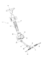
本例の電動パワーステアリング装置1は、コラムアシストタイプの電動パワーステアリング装置であり、ステアリングホイール2と、ステアリングシャフト3と、ステアリングコラム4と、1対の自在継手5a、5bと、中間シャフト6と、ステアリングギヤユニット7と、1対のタイロッド8と、電動アシスト装置9とを備える。
The electric power steering device 1 of this example is a column assist type electric power steering device, and includes a
ステアリングホイール2は、ステアリングコラム4の内側に回転自在に支持されたステアリングシャフト3の後側の端部に固定されている。ステアリングシャフト3の前側の端部は、ステアリングコラム4の前側の端部に固定されたハウジングケース10の内側に挿入されており、トーションバー11を介して、出力シャフト12に連結されている。
The
出力シャフト12の回転は、1対の自在継手5a、5bおよび中間シャフト6を介して、ステアリングギヤユニット7のピニオンシャフト13に伝達される。そして、ピニオンシャフト13の回転を、図示しないラック軸の直線運動に変換することで、1対のタイロッド8を押し引きし、操舵輪に舵角を付与する。
The rotation of the
電動アシスト装置9は、運転者がステアリングホイール2を操作するのに要する力を軽減するための補助トルクを発生させる装置であり、トルクセンサ14と、図示しないECUと、電動モータ15と、ウォーム減速機16とを備える。
The
トルクセンサ14は、出力シャフト12の周囲に配置されており、トーションバー11の捩れ方向および捩れ量を検出する。ECUは、トルクセンサ14により検出されたトーションバー11の捩れ方向および捩れ量に基づき算出した操舵トルクに関する情報、および、図示しない車速センサにより測定される車速に関する情報などに基づいて、補助トルクを決定する。電動モータ15は、ハウジングケース10に固定されており、ECUによって通電方向および通電量が制御されている。ウォーム減速機16は、電動モータ15のトルクを増大して出力シャフト12に伝達する。この結果、出力シャフト12に補助トルクが付与されるため、運転者によってステアリングホイール2に加えられた力よりも大きな力で、1対のタイロッド8を押し引きすることが可能になる。
The
以下、ウォーム減速機16の具体的な構成について説明する。
Hereinafter, a specific configuration of the
ウォーム減速機16は、図2に示すように、ギヤハウジング21と、転がり軸受19とを備える。転がり軸受19は、ギヤハウジング21に支持された静止輪である外輪35を有し、ギヤハウジング21に対してウォームホイール18を回転自在に支持するために用いられる。
As shown in FIG. 2, the
本例では、このようなウォーム減速機16は、ハウジングケース10と、図示しないウォームと、ウォームホイール18と、出力シャフト12と、1対の転がり軸受19、20とを備える。
In this example, such a
ハウジングケース10は、前側に配置されたギヤハウジング21と、後側に配置されたカバーハウジング22と、前後方向に関してギヤハウジング21とカバーハウジング22との間に配置された中間プレート23とを、複数本(図示の例では2本)のボルト24により前後方向に結合してなる。
The
ギヤハウジング21は、合成樹脂の射出成形品である。このようなギヤハウジング21は、ウォームホイール収容部25と、ウォーム収容部26と、ピボット部27を備える。
The
ウォームホイール収容部25は、出力シャフト12と同軸に配置された略円筒状の筒状部28と、筒状部28の前側の端部から径方向内側に向けて折れ曲がった略中空円形板状の側板部29と、側板部29の径方向内側の端部に接続され、かつ、筒状部28と同軸に配置された略円筒状の支持筒部30とを備える。また、ウォームホイール収容部25は、筒状部28の後側の端部の直径方向反対側となる2箇所から径方向外側に向けて突出した結合フランジ31を備える。結合フランジ31のそれぞれは、ボルト24を螺合するためのねじ孔32を有する。さらに、ウォームホイール収容部25は、側板部29の後側の側面と支持筒部30の外周面とに掛け渡された補強用のリブ64を、周方向複数箇所に備える。図2および図3に示すように、リブ64のそれぞれは、軸方向前側に向かうにしたがって支持筒部30の外周面からの径方向高さが徐々に大きくなる三角板形状を有する。
The worm
ウォーム収容部26は、全体を略円筒状に構成されたもので、ウォームホイール収容部25の外周縁部の周方向一部に接続されている。ウォーム収容部26の内側空間は、ウォームホイール収容部25の内側空間に連通している。ウォーム収容部26の中心軸は、ウォームホイール収容部25の中心軸に対し捩れの位置にある。
The
ピボット部27は、ハウジングケース10を車体に対し、車体の幅方向に配置された枢軸を中心とする揺動変位を可能に片持ち支持する部位である。ピボット部27の基端部は、ウォームホイール収容部25の外周縁部の周方向一部に接続されており、前側に向けて伸長している。
The
本例の構造では、ギヤハウジング21を構成する合成樹脂として、熱可塑性樹脂材料を好ましく使用できる。
In the structure of this example, a thermoplastic resin material can be preferably used as the synthetic resin constituting the
この場合に、熱可塑性樹脂(ベース樹脂)としては、たとえば、ポリフェニレンサルファイド樹脂(PPS)、ポリアミド系樹脂、熱可塑性ポリイミド、ポリエーテルエーテルケトン(PEEK)、熱可塑性ポリエステル樹脂(PET、PBT)などを使用することができる。ポリフェニレンサルファイド樹脂(PPS)は、吸水による寸法変化が少ない点で、好ましく使用できる。 In this case, examples of the thermoplastic resin (base resin) include polyphenylene sulfide resin (PPS), polyamide resin, thermoplastic polyimide, polyetheretherketone (PEEK), and thermoplastic polyester resin (PET, PBT). Can be used. Polyphenylene sulfide resin (PPS) can be preferably used because there is little dimensional change due to water absorption.
また、ベース樹脂に含有させる強化材としては、たとえば、ガラス繊維、炭素繊維、炭化ケイ素繊維、アルミナ繊維、ボロン繊維、金属繊維(金属の種類はステンレス、鉄、アルミニウム)などの無機繊維や、アラミド繊維、芳香族ポリイミド繊維、液晶ポリエステル繊維などの有機繊維を含有することができる。これらの強化材の中では、良好な補強性が得られることから、ガラス繊維および炭素繊維を好ましく使用できる。具体的には、ポリフェニレンサルファイド樹脂をベース樹脂とした場合に、ガラス繊維を10%含有したもの(PPS-GF10%)や、ガラス繊維を40%含有したもの(PPS-GF40%)、炭素繊維を30%含有したもの(PPS-CF30%)などを使用できる。ベース樹脂に含有する強化材の含有量は、10質量%以上50質量%以下に規制することが好ましい。なお、強化材を省略(含有しないように)することもできる。
Examples of the reinforcing material contained in the base resin include inorganic fibers such as glass fiber, carbon fiber, silicon carbide fiber, alumina fiber, boron fiber, and metal fiber (metal types are stainless steel, iron, and aluminum), and aramid. It can contain organic fibers such as fibers, aromatic polyimide fibers, and liquid crystal polyester fibers. Among these reinforcing materials, glass fiber and carbon fiber can be preferably used because good reinforcing property can be obtained. Specifically, when polyphenylene sulfide resin is used as the base resin, those containing 10% glass fiber (PPS-GF10%), those containing 40% glass fiber (PPS-GF40%), and carbon fiber are used. Those containing 30% (PPS-
カバーハウジング22および中間プレート23のそれぞれは、鉄系合金の鋳造品、アルミニウム合金などの軽合金のダイキャスト成形品、合成樹脂の射出成形品などである。カバーハウジング22および中間プレート23のそれぞれを合成樹脂により構成する場合には、該合成樹脂として、上述したような熱可塑性樹脂材料を好ましく使用できる。カバーハウジング22および中間プレート23のそれぞれは、径方向外側の端部に、ボルト24を挿通するための通孔33、34を有する。本例では、トルクセンサ14は、出力シャフト12の後側の端部の周囲で、軸方向に関してカバーハウジング22と中間プレート23との間に配置されている。
Each of the
前記ウォームは、ウォーム収容部26の内側に、図示しない転がり軸受により回転自在に支持されている。前記ウォームの基端部は、電動モータ15の出力軸に対し、トルク伝達可能に結合されている。
The worm is rotatably supported inside the
ウォームホイール18は、ウォームホイール収容部25の内側に配置され、かつ、出力シャフト12の軸方向中間部に外嵌固定されている。また、この状態で、ウォームホイール18は、外周面に備えられたホイール歯17を、前記ウォームの外周面に備えられたウォーム歯に噛合させている。このため、電動モータ15のトルクは、前記ウォームを介してウォームホイール18に伝達されることにより増大されてから、出力シャフト12に補助トルクとして付与される。
The
出力シャフト12は、1対の転がり軸受19、20により、ハウジングケース10の内側に回転自在に支持されている。具体的には、出力シャフト12のうち、ウォームホイール18の前側に隣接する部分は、転がり軸受19により、ギヤハウジング21を構成する支持筒部30に対して回転自在に支持されている。また、出力シャフト12のうち、ウォームホイール18の後側に隣接する部分は、転がり軸受20により、中間プレート23の径方向内側の端部に対して回転自在に支持されている。
The
本例では、転がり軸受19は、深溝型の玉軸受であり、図4に示すように、外輪35と、内輪36と、複数個の玉37と、シールリング38とを備える。なお、本発明を実施する場合、転がり軸受は、深溝型の玉軸受に限定されず、各種の転がり軸受を採用することができる。
In this example, the rolling
外輪35は、軸受鋼などの硬質金属により全体を円環状に構成されている。外輪35は、内周面の軸方向中間部に円弧形の断面形状を有する深溝型の外輪軌道39を全周にわたり備え、かつ、内周面の軸方向両側の端部のそれぞれにシールリング38の径方向外側の端部を係止可能な係止溝40を全周にわたり備える。外輪35は、ギヤハウジング21を構成する支持筒部30の径方向内側に支持固定されている。
The
内輪36は、軸受鋼などの硬質金属により全体を円環状に構成されている。内輪36は、外周面の軸方向中間部に円弧形の断面形状を有する深溝型の内輪軌道41を全周にわたり備え、かつ、外周面の軸方向両側の端部のそれぞれにシール摺接溝42を全周にわたり備える。内輪36は、出力シャフト12の軸方向中間部に締り嵌め、すなわち圧入により外嵌固定されている。
The
なお、内輪36は、出力シャフト12の軸方向中間部に、隙間嵌めにより外嵌することもできる。この場合には、たとえば、出力シャフトの外周面に備えられた係止溝に対して、止め輪の内周縁部を係止することにより、該止め輪のうちで前記係止溝から径方向外側に突出した部分と、出力シャフトに外嵌固定されたウォームホイール18の径方向内側の端部との間で、内輪36を軸方向に挟持することができる。これにより、内輪36と出力シャフト12とが軸方向に相対変位することを防止できる。
The
複数個の玉37のそれぞれは、軸受鋼などの鉄系合金またはセラミックスにより構成されており、外輪軌道39と内輪軌道41との間に配置され、かつ、図示しない保持器により転動自在に保持されている。
Each of the plurality of
シールリング38は、外輪35の内周面と内輪36の外周面との間に存在する転動体設置空間43の前側の端部開口を塞いでいる。このために、シールリング38は、径方向外側の端部を、外輪35の前側の係止溝40に係止されており、かつ、径方向内側の端部に備えられたシールリップの先端部を、内輪36の前側のシール摺接溝42の内面に全周にわたり摺接させている。
The
一方、本例の構造では、転動体設置空間43の後側の端部開口はシールリングにより塞がれておらず、転動体設置空間43とギヤハウジング21の内側空間とが連通している。シールリング38は、転動体設置空間43およびギヤハウジング21の内側空間に存在する潤滑剤が外部に漏洩すること、および、外部から塵芥などの異物が転動体設置空間43およびギヤハウジング21の内側空間に侵入することを防止している。
On the other hand, in the structure of this example, the rear end opening of the rolling element installation space 43 is not closed by the seal ring, and the rolling element installation space 43 and the inner space of the
特に、本例の構造では、外輪35は、外周面に外輪係合部(44)を有する。また、ギヤハウジング21は、外輪35をインサート部品とする合成樹脂の射出成形品であって、ギヤハウジング21と外輪35とが該外輪35の軸方向および周方向に関して相対変位することを阻止するように前記外輪係合部と係合するハウジング係合部(47)を有する。
In particular, in the structure of this example, the
本例では、前記外輪係合部は、径方向内側に凹入し、かつ、周方向に伸長した外輪凹部44により構成されている。本例では、外輪凹部44の全体が、外輪軌道39の軸方向中央部に対して軸方向にずれた位置に配置されており、より具体的には、外輪軌道39の軸方向中央部に対して前側にずれた位置に配置されている。なお、図4において、鎖線αは、外輪35の中心軸に直交し、かつ、外輪軌道39の軸方向中央部を通過する仮想直線を表している。本例では、外輪凹部44は、外輪35の外周面の全周にわたり備えられている。なお、本発明を実施する場合、外輪凹部の全体を、外輪の外周面のうち、外輪軌道の軸方向中央部に対して後ろにずれた位置に配置することもできる。なお、外輪凹部44の軸方向幅および径方向深さ、並びに、軸方向の配置箇所については、後述するハウジング凸部47との係合により、外輪35の軸方向の変位が阻止される限りにおいて、かつ、外輪35の剛性が確保される限りにおいて、任意に決定することができる。たとえば、外輪凹部44については、軸方向幅を1.12mm以下とし、径方向深さを0.4mm以上とすることができる。
In this example, the outer ring engaging portion is composed of an
外輪凹部44の底部は、周方向に関する凹凸形状を有するローレット部45により構成されている。本例では、ローレット部45は、図5に示すように、凹部および凸部の形成方向が軸方向である平目構造を有する。ただし、本発明を実施する場合、ローレット部は、凹部および凸部の形成方向が軸方向に対して傾斜しかつ交差した綾目構造を有することもできる。
The bottom of the
本例では、外輪凹部44のうちでローレット部45よりも径方向外側に位置する部分は、径方向内側に向かうにしたがって軸方向幅が小さくなる形状を有する傾斜凹部61により構成されている。図示の例では、傾斜凹部61の軸方向両側の側面46のそれぞれは、径方向内側に向かうにしたがって外輪凹部44の軸方向中央側に近づくような形状を有する。より具体的には、傾斜凹部61の軸方向両側の側面46のそれぞれは、S字形の断面形状を有する。ただし、傾斜凹部の軸方向両側の側面のそれぞれは、直線状の断面形状を有すること、すなわち、円すい面により構成することもできる。
In this example, the portion of the
なお、本発明を実施する場合は、傾斜凹部の軸方向一方側の側面を、外輪の中心軸に対して直交する平坦面により構成し、かつ、傾斜凹部の軸方向他方側の側面を、径方向内側に向かうにしたがって外輪凹部の軸方向中央側に近づくような形状を有する面により構成することもできる。また、傾斜凹部の軸方向両側の側面のそれぞれを、外輪の中心軸に対して直交する平坦面により構成することもできる。さらに、本発明を実施する場合には、外輪凹部のうちでローレット部よりも径方向外側に位置する部分を、径方向内側に向かうにしたがって軸方向幅が大きくなる形状を有する傾斜凹部より構成することもできる。 In the case of carrying out the present invention, the side surface of the inclined recess on one side in the axial direction is formed of a flat surface orthogonal to the central axis of the outer ring, and the side surface of the inclined recess on the other side in the axial direction has a diameter. It can also be configured by a surface having a shape that approaches the axial center side of the outer ring recess toward the inside in the direction. Further, each of the side surfaces of the inclined recess on both sides in the axial direction may be formed of a flat surface orthogonal to the central axis of the outer ring. Further, when the present invention is carried out, the portion of the outer ring recess located radially outside the knurled portion is composed of an inclined recess having a shape in which the axial width increases toward the inside in the radial direction. You can also do it.
また、本例の構造では、外輪凹部44の底部(ローレット部45)の全体が、外輪35の前側の係止溝40に対して軸方向にずれた位置に配置されており、より具体的には、該係止溝40に対して後側にずれた位置に配置されている。
Further, in the structure of this example, the entire bottom portion (knurled portion 45) of the
なお、外輪凹部44は、たとえば、底部が円筒面により構成され、かつ、径方向内側に向かうにしたがって軸方向幅が小さくなる形状を有する周方向溝を切削加工により形成する工程と、該周方向溝の底部にローレット部45を転造加工により形成する工程とに分けて、形成することができる。
The
本例では、前記ハウジング係合部は、外輪凹部44の内側に入り込んだハウジング凸部47により構成されており、ハウジング凸部47が外輪凹部44と凹凸係合し、かつ、ハウジング凸部47の径方向内側の端部である径方向先端部がローレット部45と凹凸係合している。
In this example, the housing engaging portion is composed of a housing
すなわち、ハウジング凸部47は、ギヤハウジング21を合成樹脂の射出成形により造る際に、外輪凹部44の内側に入り込んだ、該合成樹脂の一部により構成されており、外輪凹部44の内側全体を埋めている。このため、ハウジング凸部47は、外輪凹部44の内面(表面)形状に合致する外面(表面)形状を有する。また、このようなハウジング凸部47は、径方向先端部に、ローレット部45を構成する凹部の内側全体を埋める凸部48を有する。以上の構成により、ハウジング凸部47が外輪凹部44と凹凸係合し、かつ、ハウジング凸部47の径方向先端部が、ローレット部45と凹凸係合している。
That is, the housing
さらに、本例では、ギヤハウジング21は、外輪35の前側の側面に接触する抑え面49を有する。すなわち、本例では、ギヤハウジング21は、支持筒部30の前側の端部に、径方向内側に突出した内向鍔部50を全周にわたり有する。抑え面49は、内向鍔部50の後側の側面を構成しており、外輪35の前側の側面に接触している。
Further, in this example, the
本例では、上述のようなギヤハウジング21を、外輪35をインサート部品とする合成樹脂の射出成形により製造する際には、予め、転がり軸受19を組み立てておく。そして、図6に示すように、ダミーの出力シャフトである支持軸51に、転がり軸受19の内輪36を外嵌した状態で、軸方向片側(前側)の金型素子52aと軸方向他側(後側)の金型素子52bとを含む複数の金型素子を組み合わせてなる金型53の内側に、転がり軸受19の外輪35をセットする。この状態で、金型53と外輪35との間に形成されたキャビティ54内に、ノズル55を通じて溶融状態の合成樹脂を注入した後、キャビティ54内で該合成樹脂を冷却固化させることにより、ギヤハウジング21を成形する。本例では、このようなギヤハウジング21の成形に伴い、外輪凹部44に係合するハウジング凸部47、および、外輪35の前側の側面に接触する抑え面49が形成される。ギヤハウジング21の成形後は、内輪36の内側から支持軸51を抜き取り、かつ、金型53を開放することで、金型53の内側から、外輪35と一体化されたギヤハウジング21を取り出す。
In this example, when the
上述したような本例の構造によれば、合成樹脂により構成されたギヤハウジング21に対して転がり軸受19を構成する外輪35が軸方向および周方向の両方に関して変位することを有効に防止できる。
According to the structure of this example as described above, it is possible to effectively prevent the
すなわち、本例の構造では、外輪35の外周面に備えられた、周方向に伸長する外輪凹部44に、ギヤハウジング21に備えられたハウジング凸部47が係合している。このため、転がり軸受19に大きな軸方向荷重、具体的には、ウォームホイール18に作用するギヤ反力に基づく軸方向荷重や、二次衝突時にステアリングホイール2側、すなわち後側から入力される軸方向荷重や、車輪が縁石に乗り上げた場合などに車輪側、すなわち前側から入力される軸方向荷重が加わった場合でも、ギヤハウジング21に対して外輪35が軸方向に変位することを有効に防止できる。
That is, in the structure of this example, the housing
また、本例の構造では、外輪凹部44の底部に備えられた、周方向に関する凹凸形状を有するローレット部45に、ハウジング凸部47の径方向先端部が凹凸係合している。このため、転がり軸受19に加わる回転方向荷重により、ギヤハウジング21に対して外輪35が周方向に変位する、すなわちクリープ回転することを有効に防止できる。
Further, in the structure of this example, the radial tip portion of the housing
また、本例の構造では、外輪35の外周面に備えられた外輪凹部44の全体が、外輪軌道39の軸方向中央部に対して軸方向にずれた位置に配置されている。このため、外輪35全体の径方向の肉厚を小さく抑えられる。すなわち、深溝玉軸受である転がり軸受19の外輪35には、剛性確保の観点から、外輪軌道39の最深部であり、かつ、外輪軌道39のうちで玉37が転がり接触する部分である、外輪軌道39の軸方向中央部と同じ軸方向位置において、所定以上の径方向の肉厚が要求される。このため、外輪軌道39の軸方向中央部と同じ軸方向位置に外輪凹部44を配置する場合には、該軸方向位置における肉厚を所定以上確保するために、外輪全体の径方向の肉厚を大きくする必要がある。これに対し、本例の構造では、外輪凹部44の全体が、外輪軌道39の軸方向中央部に対して軸方向にずれた位置に配置されている。このため、外輪軌道39の軸方向中央部と同じ軸方向位置において所定以上の径方向の肉厚を確保する場合でも、外輪35全体の径方向の肉厚を小さく抑えられる。
Further, in the structure of this example, the entire
また、転がり軸受19には、二次衝突によってステアリングホイール2側から入力される軸方向荷重よりも、車輪側から入力される軸方向荷重の方が、加わる頻度が高い。この点に関して、本例の構造では、外輪35の外周面に備えられた外輪凹部44は、外輪軌道39の軸方向中央部に対して前側にずれた位置に配置されている。このため、ギヤハウジング21に対する外輪35の前側の支持剛性を確保しやすい。すなわち、本例の構造では、ギヤハウジング21のうち、外輪35を内嵌した部分は、外輪軌道39の軸方向中央部よりも前側にずれた箇所(すなわち、径方向外側に側板部29やリブ64の径方向高さが大きい部分が存在する箇所)で、外輪軌道39の軸方向中央部よりも後側にずれた箇所(すなわち、径方向外側にリブ64の径方向高さが小さい部分が存在する箇所)よりも、剛性が高い。そして、本例の構造では、このようなギヤハウジング21の剛性が高い軸方向箇所において、外輪凹部44とハウジング凸部47とを係合させている。このため、ギヤハウジング21に対する外輪35の前側の支持剛性を確保しやすい。
Further, the axial load input from the wheel side is more frequently applied to the rolling
また、本例の構造では、外輪凹部44のうちでローレット部45よりも径方向外側に位置する部分を構成する傾斜凹部61は、径方向内側に向かうにしたがって軸方向幅が小さくなる形状を有する。このため、外輪凹部44を形成するための溝加工を行いやすい。また、ギヤハウジング21を射出成形する際に、外輪凹部44の内側全体に溶融した合成樹脂が入り込みやすくなり、ハウジング凸部47の成形性を確保しやすくなる。
Further, in the structure of this example, the
また、本例の構造では、外輪凹部44の底部(ローレット部45)の全体が、外輪35の前側の係止溝40に対して軸方向にずれた位置に配置されている。このため、外輪35のうちで前側の係止溝40と同じ軸方向位置の肉厚を確保することが容易となる。
Further, in the structure of this example, the entire bottom portion (knurled portion 45) of the
また、本例の構造では、ギヤハウジング21に備えられた抑え面49が、外輪35の前側の側面に接触している。このため、二次衝突時にステアリングホイール2側から入力される軸方向荷重が加わった場合でも、ギヤハウジング21に対して外輪35が軸方向に関して前側に変位することを、より有効に防止できる。
Further, in the structure of this example, the holding
また、本例の構造では、ギヤハウジング21に対して外輪35が軸方向に変位することを防止するために、ギヤハウジング21に備えられた係止溝に係止される金属製の止め輪を使用しない。このため、止め輪から係止溝に加わる軸方向荷重および径方向外向荷重(反力)により、係止溝にクリープ変形が生じて、係止溝と止め輪との間にがたつきが発生し、外輪35の軸方向の変位を十分に防止できなくなるといった不都合が生じることはない。また、止め輪を使用しないため、その分、部品点数および組み付け工数を減らして製造コストを抑えられる。
Further, in the structure of this example, in order to prevent the
[実施の形態の第2例]
本発明の実施の形態の第2例について、図7を用いて説明する。
[Second example of the embodiment]
A second example of the embodiment of the present invention will be described with reference to FIG. 7.
本例では、転がり軸受19を構成する外輪35aは、外周面のうち、外輪軌道39の軸方向中央部に対して前側にずれた位置だけでなく、外輪軌道39の軸方向中央部に対して後側にずれた位置にも、外輪凹部44を有する。そして、これら2つの外輪凹部44のそれぞれに、ギヤハウジング21に備えられたハウジング凸部47が係合している。このように本例の構造では、外輪凹部44とハウジング凸部47との係合部が2つ備えられているため、実施の形態の第1例の構造に比べて、ギヤハウジング21に対して外輪35aが軸方向および周方向に変位することを、より有効に防止できる。
In this example, the
本例の構造では、前側の外輪凹部44の軸方向幅と、後側の外輪凹部44の軸方向幅とは、互いに等しいが、本発明を実施する場合には、図8に示した実施の形態の第2例の変形例のように、外輪35bにおいて、前側の外輪凹部44(およびハウジング凸部47)の軸方向幅と、後側の外輪凹部44a(およびハウジング凸部47a)の軸方向幅とを、互いに異ならせることもできる。なお、図8に示した変形例では、前側の外輪凹部44の軸方向幅が、後側の外輪凹部44aの軸方向幅よりも大きくなっているが、本発明を実施する場合には、後側の外輪凹部の軸方向幅を、前側の外輪凹部の軸方向幅よりも大きくすることもできる。さらに、本発明を実施する場合には、前側の外輪凹部の深さと、後側の外輪凹部の深さとを、互いに異ならせることもできる。
その他の構成及び作用効果は、実施の形態の第1例と同じである。
In the structure of this example, the axial width of the
Other configurations and effects are the same as in the first embodiment.
[実施の形態の第3例]
本発明の実施の形態の第3例について、図9を用いて説明する。
[Third example of the embodiment]
A third example of the embodiment of the present invention will be described with reference to FIG.
本例では、ギヤハウジング21は、外輪35の前側の側面に接触する抑え面49に加えて、外輪35の後側の側面に接触する抑え面49aを有する。すなわち、本例では、ギヤハウジング21は、支持筒部30の後側の端部に、径方向内側に突出した内向鍔部50aを全周にわたり有する。抑え面49aは、内向鍔部50aの前側の側面を構成しており、外輪35の後側の側面に接触している。このため、本例の構造では、車輪側から入力される軸方向荷重が加わった場合でも、ギヤハウジング21に対して外輪35が軸方向に関して後側に変位することを、より有効に防止できる。
その他の構成及び作用効果は、実施の形態の第1例と同じである。
In this example, the
Other configurations and effects are the same as in the first embodiment.
[実施の形態の第4例]
本発明の実施の形態の第4例について、図10を用いて説明する。
[Fourth Example of Embodiment]
A fourth example of the embodiment of the present invention will be described with reference to FIG.
本例の構造では、外輪凹部44bは、全周にわたりつながっておらず、外輪35cの外周面の周方向に離隔した複数箇所(図示の例では、周方向等間隔となる複数箇所)に備えられている。すなわち、本例の構造では、外輪35cにおいて、周方向に隣り合う2つの外輪凹部44bの間に、径方向内側に向けて凹んでいない仕切り部63が存在している。そして、外輪凹部44bのそれぞれに、図示しないギヤハウジングのハウジング凸部が係合している。このような本例の構造では、外輪凹部44bの内面を構成する周方向側面、すなわち仕切り部63の周方向側面と、ハウジング凸部の周方向側面とが、係合している。このため、ギヤハウジングに対して外輪35cが周方向に変位することを、より効果的に防止できる。なお、本発明を実施する場合で、外輪に仕切り部を設ける場合、仕切り部の数は、任意の数(1個以上)とすることができる。また、仕切り部および外輪凹部の数、周方向長さ、軸方向幅などは、塑性加工や転造加工などの加工が可能である範囲で任意に決定することができる。
その他の構成及び作用効果は、実施の形態の第1例と同じである。
In the structure of this example, the outer ring recesses 44b are not connected over the entire circumference, and are provided at a plurality of locations separated in the circumferential direction of the outer peripheral surface of the
Other configurations and effects are the same as in the first embodiment.
[実施の形態の第5例]
本発明の実施の形態の第5例について、図11を用いて説明する。
[Fifth Example of Embodiment]
A fifth example of the embodiment of the present invention will be described with reference to FIG.
本例では、外輪35dの外周面に備えられた外輪係合部は、径方向外側に突出し、かつ、周方向に伸長した外輪凸部56により構成されている。本例では、外輪凸部56の全体が、外輪軌道39の軸方向中央部に対して軸方向にずれた位置に配置されており、より具体的には、外輪軌道39の軸方向中央部に対して前側にずれた位置に配置されている。本例では、外輪凸部56は、外輪35dの外周面の全周にわたり備えられている。なお、外輪凸部56の軸方向幅および径方向高さ、並びに、軸方向の配置箇所については、後述するハウジング凹部59との係合により、外輪35dの軸方向の変位が阻止される限りにおいて、かつ、外輪35dの剛性が確保される限りにおいて、任意に決定することができる。なお、外輪凸部56の軸方向幅および径方向高さは、大きいほど、ギヤハウジング21に対する外輪35dの支持剛性を確保しやすくなる。
In this example, the outer ring engaging portion provided on the outer peripheral surface of the
外輪凸部56の径方向先端部は、周方向に関する凹凸形状を有するローレット部57により構成されている。本例では、ローレット部57は、凹部および凸部の形成方向が軸方向である平目構造を有する。ただし、本発明を実施する場合、ローレット部は、凹部および凸部の形成方向が軸方向に対して傾斜しかつ交差した綾目構造を有することもできる。
The radial tip portion of the outer ring
本例では、外輪凸部56のうちでローレット部57よりも径方向内側に位置する部分は、径方向外側に向かうにしたがって軸方向幅が小さくなる形状を有する傾斜凸部62により構成されている。図示の例では、傾斜凸部62の軸方向両側の側面58のそれぞれは、径方向外側に向かうにしたがって外輪凸部56の軸方向中央側に近づくような形状を有する。より具体的には、傾斜凸部62の軸方向両側の側面58のそれぞれは、S字形の断面形状を有する。ただし、傾斜凸部の軸方向両側の側面のそれぞれは、直線状の断面形状を有すること、すなわち、円すい面により構成することもできる。
In this example, the portion of the outer ring
なお、本発明を実施する場合は、傾斜凸部の軸方向一方側の側面を、外輪の中心軸に対して直交する平坦面により構成し、かつ、傾斜凸部の軸方向他方側の側面を、径方向外側に向かうにしたがって外輪凸部の軸方向中央側に近づくような形状を有する面により構成することもできる。また、傾斜凸部の軸方向両側の側面のそれぞれを、外輪の中心軸に対して直交する平坦面により構成することもできる。さらに、本発明を実施する場合には、外輪凸部のうちでローレット部よりも径方向内側に位置する部分を、径方向外側に向かうにしたがって軸方向幅が大きくなる形状を有する傾斜凸部より構成することもできる。 In the case of carrying out the present invention, the side surface of the inclined convex portion on one side in the axial direction is formed by a flat surface orthogonal to the central axis of the outer ring, and the side surface of the inclined convex portion on the other side in the axial direction is formed. It can also be configured by a surface having a shape that approaches the axial center side of the outer ring convex portion toward the outer side in the radial direction. Further, each of the side surfaces of the inclined convex portion on both sides in the axial direction may be formed of a flat surface orthogonal to the central axis of the outer ring. Further, in the case of carrying out the present invention, the portion of the outer ring convex portion located on the inner side in the radial direction from the knurled portion is more than the inclined convex portion having a shape in which the axial width increases toward the outer side in the radial direction. It can also be configured.
なお、外輪凸部56は、たとえば、外周面が円筒面により構成され、かつ、径方向外側に向かうにしたがって軸方向幅が小さくなる形状を有する周方向凸部を切削加工または転造加工などの塑性加工により形成する工程と、該周方向凸部の径方向先端部にローレット部57を転造加工により形成する工程とに分けて、形成することができる。あるいは、外輪凸部56の全体を、切削加工または転造加工などの塑性加工により形成することができる。
In the outer ring
本例では、ギヤハウジング21に備えられたハウジング係合部は、外輪凸部56をその内側に入り込ませたハウジング凹部59により構成されており、ハウジング凹部59が外輪凸部56と凹凸係合し、かつ、ハウジング凹部59の底部がローレット部57と凹凸係合している。
In this example, the housing engaging portion provided in the
すなわち、ハウジング凹部59は、外輪凸部56の外面(表面)全体を覆っている。このため、ハウジング凹部59は、外輪凸部56の外面形状に合致する内面(表面)形状を有する。また、このようなハウジング凹部59は、底部に、ローレット部57を構成する凹部の内側全体を埋める凸部60を有する。以上のような構成により、ハウジング凹部59が外輪凸部56と凹凸係合し、かつ、ハウジング凹部59の底部が、ローレット部57と凹凸係合している。
That is, the
上述したような本例の構造でも、合成樹脂により構成されたギヤハウジング21に対して転がり軸受19を構成する外輪35dが変位することを有効に防止できる。
Even with the structure of this example as described above, it is possible to effectively prevent the
すなわち、本例の構造では、外輪35dの外周面に備えられた、周方向に伸長する外輪凸部56に、ギヤハウジング21に備えられたハウジング凹部59が係合している。このため、ギヤハウジング21に対して外輪35dが軸方向に変位することを有効に防止できる。
That is, in the structure of this example, the
また、本例の構造では、外輪凸部56の径方向先端部に備えられた、周方向に関する凹凸形状を有するローレット部57に、ハウジング凹部59の底部が凹凸係合している。このため、ギヤハウジング21に対して外輪35dが周方向に変位することを有効に防止できる。
Further, in the structure of this example, the bottom portion of the
また、本例の構造では、外輪凸部56のうちでローレット部57よりも径方向内側に位置する部分である傾斜凸部62は、径方向外側に向かうにしたがって軸方向幅が小さくなる形状を有する。このため、外輪凸部56を形成するための加工を行いやすい。また、ギヤハウジング21を射出成形する際に、外輪凸部56の表面全体が溶融した合成樹脂によって覆いやすくなり、ハウジング凹部59の成形性を確保しやすくなる。なお、本発明を実施する場合で、外輪凸部のうちでローレット部よりも径方向内側に位置する部分を、径方向外側に向かうにしたがって軸方向幅が大きくなる形状を有する傾斜凸部より構成する場合には、外輪凸部がギヤハウジング21を構成する合成樹脂に噛み込む構造となるため、ギヤハウジング21に対する外輪凸部の結合強度を確保しやすくなる。
Further, in the structure of this example, the inclined
なお、本例の構造では、外輪35dの外周面において、外輪凸部56を、外輪軌道39の軸方向中央部に対して軸方向にずれた位置に配置している。ただし、外輪の外周面に外輪凹部を形成する場合と異なり、外輪の外周面に外輪凸部を形成する場合には、外輪凸部の形成に伴って外輪の径方向の肉厚が減少することがない。このため、本発明を実施する場合には、図12に示した実施の形態の第5例の変形例のように、外輪35eの外周面において、外輪凸部56を、外輪軌道39の軸方向中央部と同じ軸方向位置に形成することもできる。また、本発明を実施する場合、周方向に伸長する外輪凸部は、全周にわたりつながっていなくてもよい。すなわち、周方向の少なくとも1箇所に、外輪凸部が設けられていない部分である切り欠き部を存在させることもできる。そして、このような切り欠き部にギヤハウジングを構成する合成樹脂を周方向に係合させることで、ギヤハウジングに対する外輪の回転をより有効に防止することもできる。
その他の構成及び作用効果は、実施の形態の第1例と同じである。
In the structure of this example, the outer ring
Other configurations and effects are the same as in the first embodiment.
本発明を実施する場合には、実施の形態の各例の構造を、矛盾が生じない範囲で、適宜組み合わせて実施することができる。 When the present invention is carried out, the structures of the examples of the embodiments can be appropriately combined and carried out within a range that does not cause a contradiction.
本発明のウォーム減速機は、コラムアシスト型の電動パワーステアリング装置に限らず、たとえば、ピニオンアシスト型、ラックアシスト型、デュアルピニオン型などの各種構造の電動パワーステアリング装置に組み込むことができるほか、ステアバイワイヤ方式のステアリング装置に組み込んで、これらの装置の軽量化に資することができる。 The worm reducer of the present invention is not limited to the column assist type electric power steering device, but can be incorporated into, for example, an electric power steering device having various structures such as a pinion assist type, a rack assist type, and a dual pinion type, and also steer. It can be incorporated into a by-wire steering device to contribute to the weight reduction of these devices.
1 電動パワーステアリング装置
2 ステアリングホイール
3 ステアリングシャフト
4 ステアリングコラム
5a、5b 自在継手
6 中間シャフト
7 ステアリングギヤユニット
8 タイロッド
9 電動アシスト装置
10 ハウジングケース
11 トーションバー
12 出力シャフト
13 ピニオンシャフト
14 トルクセンサ
15 電動モータ
16 ウォーム減速機
17 ホイール歯
18 ウォームホイール
19 転がり軸受
20 転がり軸受
21 ギヤハウジング
22 カバーハウジング
23 中間プレート
24 ボルト
25 ウォームホイール収容部
26 ウォーム収容部
27 ピボット部
28 筒状部
29 側板部
30 支持筒部
31 結合フランジ
32 ねじ孔
33 通孔
34 通孔
35、35a、35b、35c、35d、35e 外輪
36 内輪
37 玉
38 シールリング
39 外輪軌道
40 係止溝
41 内輪軌道
42 シール摺接溝
43 転動体設置空間
44、44a、44b 外輪凹部
45 ローレット部
46 側面
47、47a、47b ハウジング凸部
48 凸部
49、49a 抑え面
50、50a 内向鍔部
51 支持軸
52a、52b 金型素子
53 金型
54 キャビティ
55 ノズル
56 外輪凸部
57 ローレット部
58 側面
59 ハウジング凹部
60 凸部
61 傾斜凹部
62 傾斜凸部
63 仕切り部
64 リブ
1 Electric
Claims (10)
前記ギヤハウジングに支持された静止輪である外輪を有し、前記ギヤハウジングに対してウォームホイールを回転自在に支持するために用いられる、転がり軸受と、を備え、
前記外輪は、外周面に外輪係合部を有し、
前記ギヤハウジングは、前記外輪をインサート部品とする合成樹脂の射出成形品であって、前記ギヤハウジングと前記外輪とが該外輪の軸方向および周方向に関して相対変位することを阻止するように前記外輪係合部と係合するハウジング係合部を有する、
ウォーム減速機。 With the gear housing
It has an outer ring, which is a stationary wheel supported by the gear housing, and includes a rolling bearing, which is used to rotatably support the worm wheel with respect to the gear housing.
The outer ring has an outer ring engaging portion on the outer peripheral surface and has an outer ring engaging portion.
The gear housing is an injection-molded product made of a synthetic resin having the outer ring as an insert component, and the outer ring is prevented from being displaced relative to each other with respect to the axial direction and the circumferential direction of the outer ring. Has a housing engaging portion that engages the engaging portion,
Warm reducer.
前記外輪凹部の底部は、周方向に関する凹凸形状を有するローレット部により構成されており、
前記ハウジング係合部は、前記外輪凹部の内側に入り込んだハウジング凸部により構成されており、該ハウジング凸部が前記外輪凹部と凹凸係合し、かつ、該ハウジング凸部の径方向先端部が前記ローレット部と凹凸係合している、
請求項1に記載のウォーム減速機。 The outer ring engaging portion is composed of an outer ring recess that is recessed inward in the radial direction and extends in the circumferential direction.
The bottom of the outer ring recess is composed of a knurled portion having an uneven shape in the circumferential direction.
The housing engaging portion is composed of a housing convex portion that has entered the inside of the outer ring concave portion, the housing convex portion is unevenly engaged with the outer ring concave portion, and the radial tip portion of the housing convex portion is formed. Concavo-convex engagement with the knurled portion,
The worm reducer according to claim 1.
前記外輪凹部の全体が、前記外輪軌道の軸方向中央部に対して軸方向にずれた位置に配置されている、
請求項2に記載のウォーム減速機。 The outer ring has a deep groove type outer ring track on the inner peripheral surface.
The entire outer ring recess is arranged at a position displaced in the axial direction with respect to the axial center portion of the outer ring track.
The worm reducer according to claim 2.
請求項2または3に記載のウォーム減速機。 The portion of the outer ring recess located radially outside the knurled portion is composed of an inclined recess having a shape in which the axial width decreases toward the inside in the radial direction.
The worm reducer according to claim 2 or 3.
前記外輪凸部の径方向先端部は、周方向に関する凹凸形状を有するローレット部により構成されており、
前記ハウジング係合部は、前記外輪凸部をその内側に入り込ませたハウジング凹部により構成されており、該ハウジング凹部が前記外輪凸部と凹凸係合し、かつ、該ハウジング凹部の底部が前記ローレット部と凹凸係合している、
請求項1に記載のウォーム減速機。 The outer ring engaging portion is composed of an outer ring convex portion that protrudes outward in the radial direction and extends in the circumferential direction.
The radial tip portion of the outer ring convex portion is composed of a knurled portion having an uneven shape in the circumferential direction.
The housing engaging portion is composed of a housing concave portion in which the outer ring convex portion is inserted into the inside thereof, the housing concave portion is unevenly engaged with the outer ring convex portion, and the bottom portion of the housing concave portion is the knurled portion. Unevenly engaged with the part,
The worm reducer according to claim 1.
請求項5に記載のウォーム減速機。 The portion of the outer ring convex portion located radially inside the knurled portion is composed of an inclined convex portion having a shape in which the axial width decreases toward the radial outer side.
The worm reducer according to claim 5.
請求項1~6のうちのいずれかに記載のウォーム減速機。 The outer ring engaging portion is provided over the entire circumference of the outer peripheral surface of the outer ring.
The worm reducer according to any one of claims 1 to 6.
請求項1~6のうちのいずれかに記載のウォーム減速機。 The outer ring engaging portion is not connected over the entire circumference of the outer peripheral surface of the outer ring, and the circumferential side surface of the outer ring engaging portion and the circumferential side surface of the housing engaging portion are engaged.
The worm reducer according to any one of claims 1 to 6.
請求項1~8のうちのいずれかに記載のウォーム減速機。 The gear housing has a holding surface that contacts at least one of the side surfaces of the outer ring on both sides in the axial direction.
The worm reducer according to any one of claims 1 to 8.
請求項1~9のうちのいずれかに記載のウォーム減速機。 Built into the electric power steering system,
The worm reducer according to any one of claims 1 to 9.
Priority Applications (1)
| Application Number | Priority Date | Filing Date | Title |
|---|---|---|---|
| JP2020204662A JP2022092094A (en) | 2020-12-10 | 2020-12-10 | Worm reduction gear |
Applications Claiming Priority (1)
| Application Number | Priority Date | Filing Date | Title |
|---|---|---|---|
| JP2020204662A JP2022092094A (en) | 2020-12-10 | 2020-12-10 | Worm reduction gear |
Publications (2)
| Publication Number | Publication Date |
|---|---|
| JP2022092094A true JP2022092094A (en) | 2022-06-22 |
| JP2022092094A5 JP2022092094A5 (en) | 2023-10-30 |
Family
ID=82067929
Family Applications (1)
| Application Number | Title | Priority Date | Filing Date |
|---|---|---|---|
| JP2020204662A Pending JP2022092094A (en) | 2020-12-10 | 2020-12-10 | Worm reduction gear |
Country Status (1)
| Country | Link |
|---|---|
| JP (1) | JP2022092094A (en) |
-
2020
- 2020-12-10 JP JP2020204662A patent/JP2022092094A/en active Pending
Similar Documents
| Publication | Publication Date | Title |
|---|---|---|
| CN107031710B (en) | Speed reducer of electric power steering apparatus | |
| US8327971B2 (en) | Reducer of electric power steering apparatus | |
| JP5234314B2 (en) | Vehicle steering system | |
| JP4365420B2 (en) | Support yoke automatic gap compensator for rack and pinion type steering device | |
| US20120067151A1 (en) | Worm drive | |
| US20080236933A1 (en) | Vehicle steering system | |
| JP4482802B2 (en) | Worm wheel and electric power steering device | |
| US20200332878A1 (en) | Steering Gear and Method for Producing the Steering Gear | |
| JP2022092094A (en) | Worm reduction gear | |
| JP2005319922A (en) | Power steering device | |
| EP1970290B1 (en) | Center take-off rack-and-pinion steering apparatus | |
| JP2008080991A (en) | Column hole cover | |
| EP3816480B1 (en) | Ball screw nut, electric power steering device , and method for manufacturing ball screw nut | |
| JP2019202596A (en) | Worm reduction gear | |
| US7128183B2 (en) | Electric power steering apparatus | |
| JP3799267B2 (en) | Electric power steering device | |
| JP2006312965A (en) | Spherical sliding bearing and bearing unit | |
| JP2011255818A (en) | Electric power steering device | |
| JP2009208691A (en) | Electric power steering device | |
| JP5234313B2 (en) | Vehicle steering system | |
| KR101189304B1 (en) | The Rack Bar Supporting Device | |
| JP7283319B2 (en) | Worm wheel unit and manufacturing method thereof, worm reduction gear | |
| JP5110362B2 (en) | Transmission ratio variable mechanism and vehicle steering apparatus including the same | |
| JP5110361B2 (en) | Transmission ratio variable mechanism and vehicle steering apparatus including the same | |
| WO2022269986A1 (en) | Steering device |
Legal Events
| Date | Code | Title | Description |
|---|---|---|---|
| A711 | Notification of change in applicant |
Free format text: JAPANESE INTERMEDIATE CODE: A712 Effective date: 20230928 |
|
| A521 | Request for written amendment filed |
Free format text: JAPANESE INTERMEDIATE CODE: A523 Effective date: 20231006 |
|
| A621 | Written request for application examination |
Free format text: JAPANESE INTERMEDIATE CODE: A621 Effective date: 20231006 |
|
| A521 | Request for written amendment filed |
Free format text: JAPANESE INTERMEDIATE CODE: A523 Effective date: 20231011 |
|
| A521 | Request for written amendment filed |
Free format text: JAPANESE INTERMEDIATE CODE: A821 Effective date: 20230928 |
|
| A977 | Report on retrieval |
Free format text: JAPANESE INTERMEDIATE CODE: A971007 Effective date: 20240315 |
|
| A131 | Notification of reasons for refusal |
Free format text: JAPANESE INTERMEDIATE CODE: A131 Effective date: 20240402 |