JP2022079110A - Sterilization system, sterilizer, control device, control method and control program - Google Patents
Sterilization system, sterilizer, control device, control method and control program Download PDFInfo
- Publication number
- JP2022079110A JP2022079110A JP2020190086A JP2020190086A JP2022079110A JP 2022079110 A JP2022079110 A JP 2022079110A JP 2020190086 A JP2020190086 A JP 2020190086A JP 2020190086 A JP2020190086 A JP 2020190086A JP 2022079110 A JP2022079110 A JP 2022079110A
- Authority
- JP
- Japan
- Prior art keywords
- unit
- light source
- angle adjusting
- sensor unit
- irradiation
- Prior art date
- Legal status (The legal status is an assumption and is not a legal conclusion. Google has not performed a legal analysis and makes no representation as to the accuracy of the status listed.)
- Granted
Links
Images




Classifications
-
- A—HUMAN NECESSITIES
- A61—MEDICAL OR VETERINARY SCIENCE; HYGIENE
- A61L—METHODS OR APPARATUS FOR STERILISING MATERIALS OR OBJECTS IN GENERAL; DISINFECTION, STERILISATION OR DEODORISATION OF AIR; CHEMICAL ASPECTS OF BANDAGES, DRESSINGS, ABSORBENT PADS OR SURGICAL ARTICLES; MATERIALS FOR BANDAGES, DRESSINGS, ABSORBENT PADS OR SURGICAL ARTICLES
- A61L2/00—Disinfection or sterilisation of materials or objects, in general; Accessories therefor
- A61L2/02—Disinfection or sterilisation of materials or objects, in general; Accessories therefor using physical processes
- A61L2/08—Radiation
- A61L2/10—Ultraviolet [UV] radiation
-
- A—HUMAN NECESSITIES
- A61—MEDICAL OR VETERINARY SCIENCE; HYGIENE
- A61L—METHODS OR APPARATUS FOR STERILISING MATERIALS OR OBJECTS IN GENERAL; DISINFECTION, STERILISATION OR DEODORISATION OF AIR; CHEMICAL ASPECTS OF BANDAGES, DRESSINGS, ABSORBENT PADS OR SURGICAL ARTICLES; MATERIALS FOR BANDAGES, DRESSINGS, ABSORBENT PADS OR SURGICAL ARTICLES
- A61L2/00—Disinfection or sterilisation of materials or objects, in general; Accessories therefor
- A61L2/24—Apparatus using programmed or automatic operation
-
- A—HUMAN NECESSITIES
- A61—MEDICAL OR VETERINARY SCIENCE; HYGIENE
- A61L—METHODS OR APPARATUS FOR STERILISING MATERIALS OR OBJECTS IN GENERAL; DISINFECTION, STERILISATION OR DEODORISATION OF AIR; CHEMICAL ASPECTS OF BANDAGES, DRESSINGS, ABSORBENT PADS OR SURGICAL ARTICLES; MATERIALS FOR BANDAGES, DRESSINGS, ABSORBENT PADS OR SURGICAL ARTICLES
- A61L9/00—Disinfection, sterilisation or deodorisation of air
- A61L9/16—Disinfection, sterilisation or deodorisation of air using physical phenomena
- A61L9/18—Radiation
- A61L9/20—Ultraviolet radiation
-
- H—ELECTRICITY
- H05—ELECTRIC TECHNIQUES NOT OTHERWISE PROVIDED FOR
- H05B—ELECTRIC HEATING; ELECTRIC LIGHT SOURCES NOT OTHERWISE PROVIDED FOR; CIRCUIT ARRANGEMENTS FOR ELECTRIC LIGHT SOURCES, IN GENERAL
- H05B47/00—Circuit arrangements for operating light sources in general, i.e. where the type of light source is not relevant
- H05B47/10—Controlling the light source
- H05B47/105—Controlling the light source in response to determined parameters
- H05B47/115—Controlling the light source in response to determined parameters by determining the presence or movement of objects or living beings
-
- A—HUMAN NECESSITIES
- A61—MEDICAL OR VETERINARY SCIENCE; HYGIENE
- A61L—METHODS OR APPARATUS FOR STERILISING MATERIALS OR OBJECTS IN GENERAL; DISINFECTION, STERILISATION OR DEODORISATION OF AIR; CHEMICAL ASPECTS OF BANDAGES, DRESSINGS, ABSORBENT PADS OR SURGICAL ARTICLES; MATERIALS FOR BANDAGES, DRESSINGS, ABSORBENT PADS OR SURGICAL ARTICLES
- A61L2103/00—Materials or objects being the target of disinfection or sterilisation
- A61L2103/75—Room floors or walls
-
- A—HUMAN NECESSITIES
- A61—MEDICAL OR VETERINARY SCIENCE; HYGIENE
- A61L—METHODS OR APPARATUS FOR STERILISING MATERIALS OR OBJECTS IN GENERAL; DISINFECTION, STERILISATION OR DEODORISATION OF AIR; CHEMICAL ASPECTS OF BANDAGES, DRESSINGS, ABSORBENT PADS OR SURGICAL ARTICLES; MATERIALS FOR BANDAGES, DRESSINGS, ABSORBENT PADS OR SURGICAL ARTICLES
- A61L2202/00—Aspects relating to methods or apparatus for disinfecting or sterilising materials or objects
- A61L2202/10—Apparatus features
- A61L2202/14—Means for controlling sterilisation processes, data processing, presentation and storage means, e.g. sensors, controllers, programs
-
- A—HUMAN NECESSITIES
- A61—MEDICAL OR VETERINARY SCIENCE; HYGIENE
- A61L—METHODS OR APPARATUS FOR STERILISING MATERIALS OR OBJECTS IN GENERAL; DISINFECTION, STERILISATION OR DEODORISATION OF AIR; CHEMICAL ASPECTS OF BANDAGES, DRESSINGS, ABSORBENT PADS OR SURGICAL ARTICLES; MATERIALS FOR BANDAGES, DRESSINGS, ABSORBENT PADS OR SURGICAL ARTICLES
- A61L2209/00—Aspects relating to disinfection, sterilisation or deodorisation of air
- A61L2209/10—Apparatus features
- A61L2209/11—Apparatus for controlling air treatment
-
- A—HUMAN NECESSITIES
- A61—MEDICAL OR VETERINARY SCIENCE; HYGIENE
- A61L—METHODS OR APPARATUS FOR STERILISING MATERIALS OR OBJECTS IN GENERAL; DISINFECTION, STERILISATION OR DEODORISATION OF AIR; CHEMICAL ASPECTS OF BANDAGES, DRESSINGS, ABSORBENT PADS OR SURGICAL ARTICLES; MATERIALS FOR BANDAGES, DRESSINGS, ABSORBENT PADS OR SURGICAL ARTICLES
- A61L2209/00—Aspects relating to disinfection, sterilisation or deodorisation of air
- A61L2209/10—Apparatus features
- A61L2209/11—Apparatus for controlling air treatment
- A61L2209/111—Sensor means, e.g. motion, brightness, scent, contaminant sensors
-
- F—MECHANICAL ENGINEERING; LIGHTING; HEATING; WEAPONS; BLASTING
- F24—HEATING; RANGES; VENTILATING
- F24F—AIR-CONDITIONING; AIR-HUMIDIFICATION; VENTILATION; USE OF AIR CURRENTS FOR SCREENING
- F24F2120/00—Control inputs relating to users or occupants
-
- F—MECHANICAL ENGINEERING; LIGHTING; HEATING; WEAPONS; BLASTING
- F24—HEATING; RANGES; VENTILATING
- F24F—AIR-CONDITIONING; AIR-HUMIDIFICATION; VENTILATION; USE OF AIR CURRENTS FOR SCREENING
- F24F8/00—Treatment, e.g. purification, of air supplied to human living or working spaces otherwise than by heating, cooling, humidifying or drying
- F24F8/20—Treatment, e.g. purification, of air supplied to human living or working spaces otherwise than by heating, cooling, humidifying or drying by sterilisation
- F24F8/22—Treatment, e.g. purification, of air supplied to human living or working spaces otherwise than by heating, cooling, humidifying or drying by sterilisation using UV light
Landscapes
- Health & Medical Sciences (AREA)
- Epidemiology (AREA)
- Life Sciences & Earth Sciences (AREA)
- Animal Behavior & Ethology (AREA)
- General Health & Medical Sciences (AREA)
- Public Health (AREA)
- Veterinary Medicine (AREA)
- Apparatus For Disinfection Or Sterilisation (AREA)
- Disinfection, Sterilisation Or Deodorisation Of Air (AREA)
Abstract
【課題】人体等に対する安全性を高めること。【解決手段】実施形態の殺菌システムは、光源部と、水平角度調整部および/または垂直角度調整部と、第1センサ部と、第2センサ部と、制御装置とを備える。前記光源部は、放射状の紫外線を照射する。前記水平角度調整部は、前記光源部を水平方向に対して回動することで、前記光源部の水平角度を調整する。前記垂直角度調整部は、前記光源部を垂直方向に対して回動することで、前記光源部の垂直角度を調整する。前記第1センサ部は、体温を有する物体を検知する。前記第2センサ部は、物体の近接を検知する。前記制御装置は、水平角度および/または垂直角度を含む設定情報を読み出して前記水平角度調整部および/または前記垂直角度調整部の回動を制御し、前記第1センサ部および前記第2センサ部の検知状態に応じて前記光源部による紫外線の照射を制御する。【選択図】図1An object of the present invention is to enhance safety for the human body. A sterilization system according to an embodiment includes a light source section, a horizontal angle adjustment section and/or a vertical angle adjustment section, a first sensor section, a second sensor section, and a control device. The light source unit emits radial ultraviolet rays. The horizontal angle adjustment section adjusts the horizontal angle of the light source section by rotating the light source section in a horizontal direction. The vertical angle adjustment section adjusts the vertical angle of the light source section by rotating the light source section in a vertical direction. The first sensor unit detects an object having body temperature. The second sensor unit detects proximity of an object. The control device reads setting information including a horizontal angle and/or a vertical angle, controls rotation of the horizontal angle adjustment section and/or the vertical angle adjustment section, and controls the rotation of the first sensor section and the second sensor section. is controlled according to the detection state of the light source unit. [Selection drawing] Fig. 1
Description
本発明は、殺菌システム、殺菌装置、制御装置、制御方法および制御プログラムに関する。 The present invention relates to a sterilization system, a sterilizer, a control device, a control method and a control program.
紫外線の照射による殺菌ないしは除染が従来から行われている(例えば、特許文献1~4等を参照)。 Sterilization or decontamination by irradiation with ultraviolet rays has been conventionally performed (see, for example, Patent Documents 1 to 4 and the like).
しかしながら、紫外線は人体等に与える影響が大きく、人体等に有害であることから、人が出入りする空間における紫外線の照射には安全性の確保が求められる。なお、人体に対する安全性が確認されている波長の紫外線も存在するが、安全に照射できる時間や距離が規定されており、規定を超える照射は有害である。 However, since ultraviolet rays have a large effect on the human body and are harmful to the human body and the like, it is required to ensure safety when irradiating the ultraviolet rays in a space where people enter and exit. Although there are ultraviolet rays with wavelengths that have been confirmed to be safe for the human body, the time and distance at which they can be safely irradiated are specified, and irradiation exceeding the specified time is harmful.
本発明は、上記に鑑みてなされたものであって、人体等に対する安全性を高めることができる殺菌システム、殺菌装置、制御装置、制御方法および制御プログラムを提供することを目的とする。 The present invention has been made in view of the above, and an object of the present invention is to provide a sterilization system, a sterilization device, a control device, a control method, and a control program capable of enhancing safety for a human body or the like.
上述した課題を解決し、目的を達成するために、本発明の一態様に係る殺菌装置は、光源部と、水平角度調整部および/または垂直角度調整部と、第1センサ部と、第2センサ部と、制御装置とを備える。前記光源部は、放射状の紫外線を照射する。前記水平角度調整部は、前記光源部を水平方向に対して回動することで、前記光源部の水平角度を調整する。前記垂直角度調整部は、前記光源部を垂直方向に対して回動することで、前記光源部の垂直角度を調整する。前記第1センサ部は、体温を有する物体を検知する。前記第2センサ部は、物体の近接を検知する。前記制御装置は、水平角度および/または垂直角度を含む設定情報を読み出して前記水平角度調整部および/または前記垂直角度調整部の回動を制御し、前記第1センサ部および前記第2センサ部の検知状態に応じて前記光源部による紫外線の照射を制御する。 In order to solve the above-mentioned problems and achieve the object, the sterilizer according to one aspect of the present invention includes a light source unit, a horizontal angle adjusting unit and / or a vertical angle adjusting unit, a first sensor unit, and a second sensor unit. It includes a sensor unit and a control device. The light source unit irradiates radial ultraviolet rays. The horizontal angle adjusting unit adjusts the horizontal angle of the light source unit by rotating the light source unit in the horizontal direction. The vertical angle adjusting unit adjusts the vertical angle of the light source unit by rotating the light source unit in the vertical direction. The first sensor unit detects an object having a body temperature. The second sensor unit detects the proximity of an object. The control device reads setting information including a horizontal angle and / or a vertical angle to control the rotation of the horizontal angle adjusting unit and / or the vertical angle adjusting unit, and controls the rotation of the horizontal angle adjusting unit and / or the vertical angle adjusting unit, and controls the rotation of the first sensor unit and the second sensor unit. The irradiation of ultraviolet rays by the light source unit is controlled according to the detection state of.
本発明の一態様に係る殺菌システムは、人体等に対する安全性を高めることができる。 The sterilization system according to one aspect of the present invention can enhance the safety to the human body and the like.
以下、実施形態に係る殺菌システム、殺菌装置、制御装置、制御方法および制御プログラムについて図面を参照して説明する。なお、この実施形態によりこの発明が限定されるものではない。また、図面における各要素の寸法の関係、各要素の比率などは、現実と異なる場合がある。図面の相互間においても、互いの寸法の関係や比率が異なる部分が含まれている場合がある。また、1つの実施形態や変形例に記載された内容は、原則として他の実施形態や変形例にも同様に適用される。 Hereinafter, the sterilization system, the sterilizer, the control device, the control method, and the control program according to the embodiment will be described with reference to the drawings. The present invention is not limited to this embodiment. In addition, the relationship between the dimensions of each element in the drawing, the ratio of each element, etc. may differ from the reality. Even between the drawings, there may be parts where the relationship and ratio of the dimensions are different from each other. Further, in principle, the contents described in one embodiment or modification are similarly applied to other embodiments or modifications.
<装置構成、システム構成>
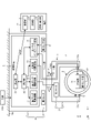
図1は、一実施形態に係る殺菌装置1等の構成例を示すブロック図である。図1において、殺菌装置1は、例えば天井を構成する天井壁100にベース部41が取り付けられており、光源部21を有する本体部2と、本体部2を回動可能に支持する垂直角度調整部3および水平角度調整部4と、制御装置5とを備えている。
<Device configuration, system configuration>
FIG. 1 is a block diagram showing a configuration example of the sterilizer 1 and the like according to the embodiment. In FIG. 1, in the sterilizer 1, for example, a
なお、図1におけるX方向は水平方向であり、殺菌装置1の前後方向である。Y方向は水平方向であり、殺菌装置1の幅方向である。Z方向は水平方向と直交する垂直方向であり、殺菌装置1の上下方向である。なお、本実施形態においては、Z方向が殺菌対象空間Sの鉛直方向と平行であるが、これに限定されるものではなく、Z方向が鉛直方向に対して傾斜、あるいはZ方向が鉛直方向と直交する方向と平行であってもよい。 The X direction in FIG. 1 is a horizontal direction, which is a front-back direction of the sterilizer 1. The Y direction is the horizontal direction and is the width direction of the sterilizer 1. The Z direction is a vertical direction orthogonal to the horizontal direction, and is a vertical direction of the sterilizer 1. In the present embodiment, the Z direction is parallel to the vertical direction of the space S to be sterilized, but the present invention is not limited to this, and the Z direction is inclined with respect to the vertical direction, or the Z direction is the vertical direction. It may be parallel to the orthogonal direction.
制御装置5は、殺菌装置1において制御を行う部分である。制御装置5は、光源部21、垂直角度調整部3および水平角度調整部4を制御するものであり、ベース部41の内部空間に収容されている。制御装置5は、通信部51、制御部52、光源部駆動回路53、第1モータ駆動回路54、第2モータ駆動回路55、センサ部インタフェース回路56を有する。制御装置5は、電源200から供給された電力に基づき、光源部21による紫外線の点灯・消灯、照射強度の調整、垂直角度調整部3による光源部21の垂直角度の調整、水平角度調整部4による光源部21の水平角度の調整などを行う。なお、制御装置5のハードウェア構成は、一般的な制御装置のハードウェア構成と同様であり、詳細については後述する。また、電源200は、商業電源、発電機、バッテリなどである。
The
通信部51は、ユーザーが所持する端末10との間で情報を送受信するものであり、例えば、端末10からの操作情報を受信したり、殺菌装置1の状態、光源部21の照射状態(例えば、点灯・消灯、照射強度)、光源部21の姿勢状態(例えば、垂直角度および水平角度)を端末10に送信したりするものである。通信部51は、例えば、Wi-Fi(登録商標)やBluetooth(登録商標)等の近距離無線通信を行うものである。
The communication unit 51 transmits and receives information to and from the
制御部52は、光源部21に対する照射制御、第1モータ32に対する駆動制御および第2モータ42に対する駆動制御などを行うものである。ここで、照射制御には、光源部21の点灯・消灯制御、照射強度制御などが含まれる。
The
光源部駆動回路53は、光源部21と制御部52とのインタフェースとなり、制御部52からの光源部21に対する照射制御信号に基づき、光源部21に電力を供給するものである。光源部駆動回路53は、光源部21が紫外線の照射強度を変更できるタイプである場合、照射強度の調整も行う。また、光源部駆動回路53は、光源部21が照射する紫外線の波長を変更(切替)できるタイプである場合、波長の変更(切替)も行う。光源部駆動回路53は、制御部52および光源部21と電気的に接続されている。なお、光源部駆動回路53は、制御装置5が有しているがこれに限定されるものではなく、光源部21が有していてもよい。また、光源部21が異なる波長領域の光源が組み合わされた光源であった場合、それぞれの光源の照射強度を調整できるように調整を行う。
The light source
第1モータ駆動回路54は、第1モータ32と制御部52とのインタフェースとなり、制御部52からの第1モータ32に対する駆動制御信号に基づき、第1モータ32に対して駆動電力を供給することで、光源部21を垂直方向において回動させるものである。第1モータ駆動回路54は、制御部52および第1モータ32と電気的に接続されている。なお、第1モータ駆動回路54は、制御装置5が有しているがこれに限定されるものではなく、第1モータ32が有していてもよい。
The first
第2モータ駆動回路55は、第2モータ42と制御部52とのインタフェースとなり、制御部52からの第2モータ42に対する駆動制御信号に基づき、第2モータ42に対して駆動電力を供給することで、光源部21を水平方向において回動させるものである。第2モータ駆動回路55は、制御部52および第2モータ42と電気的に接続されている。なお、第2モータ駆動回路55は、制御装置5が有しているがこれに限定されるものではなく、第2モータ42が有していてもよい。
The second
センサ部インタフェース回路56は、ベース部41側に設けられた第1センサ部61と、光源部21側に設けられた第2センサ部62とのインタフェースとなり、第1センサ部61および第2センサ部62の検知信号を制御部52に伝える。第1センサ部61は、所定距離内(例えば、7m以内)の体温を有する物体を検知する焦電型赤外線センサであり、光源部21による紫外線の照射可能範囲を一望するベース部41側の固定位置に配置されている。なお、第1センサ部61は、紫外線の照射対象となるエリアの物体を検知できる位置に配置されれば、ベース部41とは異なる位置でもかまわない。また、紫外線の照射対象となるエリアの物体を検知できる位置に配置されれば、殺菌装置1とは別体として殺菌装置1の近傍に設けられても構わない。その場合、別体の第1センサ部61は、殺菌装置1と有線または無線を介して検知信号を制御部52に伝える。第2センサ部62は、物体(体温を有する物体に限られない)の近接(例えば、30cm以内の近接)を検知する近接センサであり、光源部21とともに紫外線の照射方向を向く可動位置に配置されている。
The sensor
端末10は、ユーザーが操作することで殺菌装置1を操作するものであるとともに、ユーザーが殺菌装置1の状態を把握するものである。端末10は、通信部11と、制御部12と、操作・表示部13とを有する。なお、端末10は、殺菌装置1用の専用端末であってもよいし、スマートフォン、タブレット、ノートパソコンなどの汎用端末であってもよい。また、端末10のハードウェア構成は、一般的な端末のハードウェア構成と同様であり、詳細については後述する。
The terminal 10 operates the sterilizer 1 by being operated by the user, and the user grasps the state of the sterilizer 1. The terminal 10 has a
通信部11は、制御装置5との間で情報を送受信するものである。通信部11は、例えば、Wi-Fi(登録商標)やBluetooth(登録商標)等の近距離無線通信を行うものである。なお、情報の送受信は無線に限られるものではなく、有線によるものであってもよい。
The
制御部12は、端末10を制御するものであり、少なくとも操作・表示部13に対するユーザーの操作に基づいて、操作情報を通信部11に出力するものである。制御部12は、操作・表示部13による表示も制御する。制御部12は、通信部11および操作・表示部13と電気的に接続されている。なお、制御部12は、自装置側の通信部11および殺菌装置1側の通信部51を介して接続された制御部52の処理の一部を代行することができる。
The control unit 12 controls the terminal 10 and outputs operation information to the
操作・表示部13は、端末10における一般的な操作および表示のほかに、殺菌装置1を遠隔操作する際に用いられるものである。操作・表示部13は、図示はしないが例えば、紫外線の点灯・消灯に対応するスイッチ、照射強度に対応するスイッチ、光源部21の垂直角度の調整に対応するスイッチ、光源部21の水平角度の調整に対応するスイッチなどが含まれる。なお、スイッチは、通電・非通電や抵抗変化などの機械式のスイッチであっても、タッチパネルなどの電気式のスイッチであってもよい。
The operation /
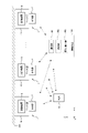
図2は、複数の殺菌装置1等が含まれる場合の構成例を示す図である。図2において、例えば天井を構成する天井壁100に複数の殺菌装置1が取り付けられている。各殺菌装置1の制御装置5は、それぞれが対等な関係で制御を行うか、いずれかがマスターとなって統括的に制御を行う。また、殺菌装置1の制御装置5とは別に、統括制御用の制御装置500が設けられるものであってもよい。制御装置500は、通信部501と、制御部502と、操作・表示部503とを備えている。
FIG. 2 is a diagram showing a configuration example when a plurality of sterilizers 1 and the like are included. In FIG. 2, for example, a plurality of sterilizers 1 are attached to a
通信部501は、各殺菌装置1の制御装置5との間で情報を送受信するものである。通信部501は、例えば、Wi-Fi(登録商標)やBluetooth(登録商標)等の近距離無線通信を行うものである。なお、情報の送受信は無線に限られるものではなく、有線によるものであってもよい。
The
制御部502は、制御装置500を制御するものであり、少なくとも操作・表示部503に対するユーザーの操作または予め設定された情報に基づいて、操作情報を通信部501に出力するものである。制御部502は、通信部501および操作・表示部503と電気的に接続されている。
The
操作・表示部503は、制御装置500における一般的な操作および表示のほかに、各殺菌装置1を遠隔操作する際に用いられるものである。操作・表示部503は、図示はしないが例えば、紫外線の点灯・消灯に対応するスイッチ、照射強度に対応するスイッチ、光源部21の垂直角度の調整に対応するスイッチ、光源部21の水平角度の調整に対応するスイッチ、各種自動動作の設定のためのスイッチなどが含まれる。なお、スイッチは、通電・非通電や抵抗変化などの機械式のスイッチであっても、タッチパネルなどの電気式のスイッチであってもよい。
The operation /
端末10は、各殺菌装置1の制御装置5との間、マスターに設定された制御装置5との間、または、制御装置500との間で通信を行い、ユーザーによる各種の操作や、状態の確認に対応する。端末10は、制御装置500とともに、または、制御装置500に代わって、個々の殺菌装置1を制御することができる。
The terminal 10 communicates with the
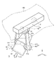
図3は、殺菌装置1の一例(殺菌装置1A)の機械的な構成例を示す斜視図である。殺菌装置1Aは、図3に示されるように、紫外線UVを殺菌対象空間Sに照射するものである。殺菌装置1Aは、殺菌対象空間Sの一部を構成する壁、本実施形態では天井を構成する天井壁100に取り付けられている。具体的には、殺菌装置1Aは、天井壁100から殺菌対象空間Sに突出した状態で天井壁100に対して、図示しないレール等を介して取り付けられている。殺菌装置1Aは、光源部21が取り付けられる本体部2と、垂直角度調整部3と、水平角度調整部4と、制御装置5とを備える。
FIG. 3 is a perspective view showing a mechanical configuration example of an example of the sterilizer 1 (
本体部2は、光源部21が取り付けられるものである。本体部2は、略円筒形状に形成されており、軸方向のうち、殺菌対象空間S側に開口22が形成され、殺菌対象空間Sと反対側が閉塞されている。本体部2は、図示しない支持軸を介して、垂直角度調整部3に対して回転自在に支持されている。
The
光源部21は、放射状の紫外線UVを殺菌対象空間Sに対して照射するものである。光源部21は、本体部2の内部空間のうち、本体部2の軸方向において開口22と対向した位置に取り付けられている。光源部21は、開口22を介して紫外線UVを殺菌対象空間Sに照射する。ここで、光源部21が殺菌対象空間Sに照射する紫外線UVは、可視光線とは異なる波長の電磁波である。また、放射状の紫外線UVは、光源から出射する紫外線が放射状であってもよいし、光源から出射する紫外線UVは直線状であって、図示しないレンズにより実現してもよい。
The
また、光源部21は、1つの波長領域の紫外線UVを照射する光源に限られず、波長領域の異なる紫外線UVを切り替えられるものであってもよい。また、光源部21は、紫外線UVを照射する光源と、紫外線UVとは異なる波長領域の電磁波、例えば、可視光線、赤外線を照射する光源とが組み合わされたものでもよい。また、光源部21は、1つの波長領域の紫外線を照射する光源と、それとは異なる波長領域の紫外線を照射する光源とが組み合わされたものであってもよい。
Further, the
垂直角度調整部3は、光源部21を垂直方向Zにおいて回動することで、垂直角度を調整、すなわちチルト方向Tを調整する。垂直角度調整部3は、アーム部31と、第1モータ32とを有する。アーム部31は、本体部2を垂直方向Zに回動可能に支持するものである。アーム部31は、下方向に開口するU字状に形成されており、開口を形成する両先端部31a、31aにおいて、本体部2が両先端部31a、31aの対向方向周りに回転自在に支持されている。第1モータ32は、垂直アクチュエータであり、本体部2をアーム部31に対して回動させるものである。第1モータ32は、アーム部31に取り付けられており、図示しない駆動機構を介して、支持軸周り、すなわち対向方向周りに本体部2を回動させるものである。本実施形態における光源部21は、第1モータ32により、下方向を0度とした場合に、例えば、±90度の範囲で揺動させる。垂直角度調整部3は、図示しない支持軸を介して、水平角度調整部4に対して回転自在に支持されている。
The vertical
水平角度調整部4は、光源部21を水平方向(前後方向X、幅方向Y)において回動することで、水平角度を調整、すなわちパン方向Pを調整する。水平角度調整部4は、ベース部41と、第2モータ42とを有する。ベース部41は、アーム部31を介して本体部2を水平方向に回動可能に支持するものである。ベース部41は、天井壁100に取り付けられており、前後方向を長手方向として立方体状に形成されており、アーム部31の上方向側の先端部31bにおいてアーム部31が垂直方向Z周りに回転自在に支持されている。第2モータ42は、水平アクチュエータであり、アーム部31をベース部41に対して回動させるものである。第2モータ42は、ベース部41に取り付けられており、図示しない駆動機構を介して、支持軸周り、すなわち垂直方向周りにアーム部31を回動させることで、本体部2を回動させるものである。本実施形態における光源部21は、第2モータ42により、水平方向のうち、任意の方向を0度とした場合に、例えば、±180度の範囲で揺動させる。
The horizontal
なお、上記の説明においては、各アクチュエータをモータとしたが、これに限定されるものではなく、液圧式シリンダ、気圧式シリンダなどであってもよい。 In the above description, each actuator is a motor, but the present invention is not limited to this, and a hydraulic cylinder, a barometric cylinder, or the like may be used.
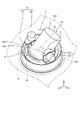
図4は、殺菌装置1の他の例(殺菌装置1B)の機械的な構成例を示す斜視図である。図4において、殺菌装置1Bは、天井壁100に対する取り付け状態の点で、前述の殺菌装置1Aと異なる。殺菌装置1Bの基本的構成は、殺菌装置1Aの基本的構成と同一、またはほぼ同一であるので、同一符号についてはその説明を省略あるいは簡略化する。
FIG. 4 is a perspective view showing a mechanical configuration example of another example of the sterilizer 1 (
殺菌装置1Bは、図4に示されるように、紫外線UVを殺菌対象空間Sに照射するものである。殺菌装置1Bは、殺菌対象空間Sの一部を構成する天井壁100に取り付けられている。具体的には、殺菌装置1Aは、天井壁100から殺菌対象空間S側と反対側に突出、すなわち天井壁100に埋設した状態で天井壁100に取り付けられている。天井壁100には、開口101が形成されており、殺菌装置1B、特に本体部2の開口22が開口101を介して、殺菌対象空間Sに露出して取り付けらえている。殺菌装置1Bは、光源部21を取り付けられる本体部2と、垂直角度調整部3と、水平角度調整部4と、制御装置5とを備える。
As shown in FIG. 4, the
本体部2は、放射状の紫外線UVを殺菌対象空間Sに対して照射する光源部21が取り付けられるものである。本体部2は、略円筒形状に形成されており、軸方向のうち、殺菌対象空間S側に開口22が形成され、殺菌対象空間S側と反対側が閉塞されている。本体部2は、図示しない支持軸を介して、垂直角度調整部3に対して回転自在に支持されている。
The
垂直角度調整部3は、光源部21を垂直方向Zにおいて回動することで、垂直角度を調整、すなわちチルト方向Tを調整する。垂直角度調整部3は、サブ枠部33と、第1モータ32とを有する。サブ枠部33は、本体部2を垂直方向Zに回動可能に支持するものである。サブ枠部33は、上下方向を軸とする円筒形状に形成され、上下方向に開口を介して外部連通する内部空間33aが形成されている。サブ枠部33は、内部空間33aにおいて、本体部2が水平方向周りに回動自在に支持されている。つまり、サブ枠部33は、本体部2の少なくとも一部が内部空間33aに収容され、かつ本体部2を垂直方向に回動可能に支持する。第1モータ32は、サブ枠部33に取り付けられており、図示しない駆動機構を介して、支持軸周り、すなわち対向方向周りに本体部2を回動させるものである。本実施形態における光源部21は、第1モータ32により、下方向を0度とした場合に、例えば、-35度~+45度の範囲で揺動させる。
The vertical
水平角度調整部4は、光源部21を水平方向(前後方向X、幅方向Y)において回動することで、水平角度を調整、すなわちパン方向Pを調整する。水平角度調整部4は、ベース枠部43と、第2モータ42とを有する。ベース枠部43は、サブ枠部33を介して本体部2を水平方向に回動可能に支持するものである。ベース枠部43は、上下方向において開口101と対向して天井壁100に取り付けられており、上下方向を軸とする円筒形状に形成され、上下方向に開口を介して外部連通する内部空間43aが形成されている。ベース枠部43は、内部空間43aにおいて、本体部2が垂直方向周りに回動自在に支持されている。つまり、ベース枠部43は、サブ枠部33の少なくとも一部が内部空間43aに収容され、かつサブ枠部33を垂直方向に回動可能に支持する。本実施形態における光源部21は、第2モータ42により、水平方向のうち、任意の方向を0度とした場合に、例えば、+355度の範囲で揺動させる。
The horizontal
なお、上記の説明においては、各アクチュエータをモータとしたが、これに限定されるものではなく、液圧式シリンダ、気圧式シリンダなどであってもよい。 In the above description, each actuator is a motor, but the present invention is not limited to this, and a hydraulic cylinder, a barometric cylinder, or the like may be used.
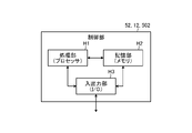
図5は、制御装置5の制御部52、端末10の制御部12、または、制御装置500の制御部502のハードウェア構成例を示す図である。図5において、制御部52、12、502は、一般的なコンピュータの構成を有しており、処理部(プロセッサ)H1と、記憶部(メモリ)H2と、入出力部(I/O:Input Output)H3とを備えている。記憶部H2には、ROM(Read Only Memory)、RAM(Random Access Memory)、NV-RAM(Nonvolatile-RAM)、SSD(Solid State Drive)、HDD(Hard Disk Drive)等が含まれる。
FIG. 5 is a diagram showing a hardware configuration example of the
処理部H1は、記憶部H2に記憶されたプログラムに従い、記憶部H2に記憶されたデータまたは入出力部H3から入力されたデータに基づいて処理を行う。処理により得られたデータは、入出力部H3から出力される。 The processing unit H1 performs processing based on the data stored in the storage unit H2 or the data input from the input / output unit H3 according to the program stored in the storage unit H2. The data obtained by the processing is output from the input / output unit H3.
図6は、制御装置5の制御部52、端末10の制御部12、または、制御装置500の制御部502の機能構成例を示す図である。図6において、制御部52、12、502は、照射位置設定部C1と、照射位置制御部C2と、照射制御部C3とを備えている。
FIG. 6 is a diagram showing a functional configuration example of the
照射位置設定部C1は、殺菌のために紫外線を照射する位置または範囲(複数の位置等により範囲を特定)の設定を行う機能を有する。照射位置制御部C2は、設定情報に基づいて殺菌装置1の垂直角度調整部3および水平角度調整部4を制御し、紫外線を照射する位置を制御する機能を有する。照射制御部C3は、設定情報や第1センサ部61および第2センサ部62の検知信号に基づいて紫外線の点灯・消灯、強度変更(光源により強度が変更できる場合とできない場合とがある)または波長変更(人体に照射可能な波長と、人体に照射はできないが殺菌効果の高い波長との切り替えが可能)を行う機能を有する。
The irradiation position setting unit C1 has a function of setting a position or a range (a range is specified by a plurality of positions or the like) to irradiate ultraviolet rays for sterilization. The irradiation position control unit C2 has a function of controlling the vertical
<ユーザーによるリアルタイムでの操作>
図1~図6において、ユーザーは、端末10等を操作することで、殺菌装置1(1A、1B)の状態、光源部21の照射状態、光源部21の姿勢状態を変更する。例えば、制御装置5は、ユーザーが端末10を操作することで、光源部21を点灯する場合に、点灯に対応する操作情報に対応する照射制御信号に基づき、光源部駆動回路53を介して、光源部21を点灯する。殺菌装置1は、光源部21が点灯されることで、放射状の紫外線UVが殺菌対象空間Sに照射され、殺菌対象空間Sの空気および殺菌対象空間Sに存在する物体を紫外線UVにより殺菌する。また、制御装置5は、ユーザーが端末10を操作することで、殺菌対象空間Sにおける紫外線UVの照射範囲を垂直方向において変更する場合に、垂直角度の調整に対応する操作情報に対応する第1モータ32に対する駆動制御信号に基づき、第1モータ駆動回路54を介して、第1モータ32を駆動し、光源部21を垂直方向に回動させる。また、制御装置5は、ユーザーが端末10を操作することで、殺菌対象空間Sにおける紫外線UVの照射範囲を水平方向において変更する場合に、水平角度の調整に対応する操作情報に対応する第2モータ42に対する駆動制御信号に基づき、第2モータ駆動回路55を介して、第2モータ42を駆動し、光源部21を水平方向に回動させる。つまり、ユーザーが殺菌対象空間Sに存在する物体を殺菌したい場合は、光源部21を垂直方向および水平方向に回動させることで、光源部21の紫外線UVの照射範囲を物体にまで移動させて、殺菌を行う。
<Real-time operation by the user>
In FIGS. 1 to 6, the user operates the terminal 10 or the like to change the state of the sterilizer 1 (1A, 1B), the irradiation state of the
なお、ユーザーによるリアルタイムでの操作においても、後述する照射の自動的な停止(第1センサ部61が体温を有する物体を検知した方向に第2センサ部62が物体の近接を検知した場合、または第2センサ部62が物体の近接を検知した場合に、光源部21による紫外線の照射を停止)を行うようにしてもよい。
Even in the real-time operation by the user, the irradiation is automatically stopped, which will be described later (when the
<設定された位置に基づく自動照射(照射時間固定)>
図7は、制御装置5の制御部52、端末10の制御部12、または、制御装置500の制御部502に保持される設定情報のデータ構造例を示す図である。図7において、設定情報は、水平角度と垂直角度との組を複数含んでいる。水平角度と垂直角度との組は、1つの位置に対応する照射方向を示している。水平角度は、水平角度調整部4(図1)によって制御の対象となる角度(パン)である。垂直角度は、垂直角度調整部3(図1)によって制御の対象となる角度(チルト)である。また、設定情報には、各位置に共通の照射時間が含まれている。
<Automatic irradiation based on the set position (fixed irradiation time)>
FIG. 7 is a diagram showing an example of a data structure of setting information held in the
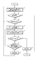
図8は、制御装置5の制御部52、端末10の制御部12、または、制御装置500の制御部502による制御例を示すフローチャートである。図8において、制御部52等は、処理を開始すると、次の設定情報(最初は先頭の設定情報)の読み出しを行う(ステップS1)。なお、後述する照射方向の変更により照射済となった照射方向はスキップする。また、照射方向の変更により照射が未完了の照射方向については、未処理として再び読み出されるようにしてもよい。
FIG. 8 is a flowchart showing a control example by the
次いで、制御部52等は、設定情報があって読み出せたか否か判断する(ステップS2)。制御部52等は、設定情報がない場合または未処理の照射方向が読み出せなかったと判断した場合(ステップS2のNo)、処理を終了する。
Next, the
制御部52等は、設定情報が読み出せたと判断した場合(ステップS2のYes)、続いて、設定情報に矛盾がない等により適正であるか否か判断する(ステップS3)。制御部52等は、読み出した設定情報が適正でないと判断した場合(ステップS3のNo)、次の設定情報の読み出し(ステップS1)に移行する。
When the
制御部52等は、読み出した設定情報が適正であると判断した場合(ステップS3のYes)、読み出した設定情報に従って紫外線の照射を開始する(ステップS4)。すなわち、設定情報(図7)に含まれる水平角度および垂直角度に光源部21の光軸を向けて紫外線の照射を行う。
When the
次いで、制御部52等は、第1センサ部61および第2センサ部62の検知状態に応じた処理を行う(ステップS5)。この処理の詳細については後述する。
Next, the
次いで、制御部52等は、ユーザーからの終了指示等による終了条件を満たすか否か判断し(ステップS6)、終了条件を満たさないと判断した場合(ステップS6のNo)、続いて、設定情報(図7)に含まれる共通の照射時間を経過したか否か判断する(ステップS7)。制御部52等は、共通の照射時間を経過していないと判断した場合(ステップS7のNo)、第1センサ部61および第2センサ部62の検知状態に応じた処理(ステップS5)に移行する。なお、途中で照射方向を変更した場合は、照射時間をはじめから再カウントする。
Next, the
制御部52等は、共通の照射時間を経過したと判断した場合(ステップS7のYes)、紫外線の照射を停止し(ステップS8)、次の設定情報の読み出し(ステップS1)に移行する。
When the
制御部52等は、終了条件の判断(ステップS6)において、終了条件を満たしたと判断した場合(ステップS6のYes)、紫外線の照射を終了し(ステップS9)、処理を終了する。
When the
図9は、図8におけるステップS5の処理例を示すフローチャートである。図9において、制御部52等は、処理を開始すると、第1センサ部61および第2センサ部62の検知状態を取得し(ステップS501)、状態判断を行う(ステップS502)。
FIG. 9 is a flowchart showing a processing example of step S5 in FIG. In FIG. 9, when the processing is started, the
ここで、状態判断(ステップS502)において状態が、第1センサ部61が人等を検知した方向に第2センサ部62が物体の近接(例えば、30cm以内の近接)を検知していた場合、制御部52等は、紫外線の照射を停止する(ステップS503)。なお、第2センサ部62に近接する位置に人等の体温を有する物体以外が入ることがない環境下(什器備品等が第2センサ部62に近接する位置に配置されていない場合等)では、第1センサ部61の検知状態によらず、第2センサ部62が物体の近接を検知した場合に、人等の体温を有する物体が近接したものとして、紫外線の照射を停止(ステップS503)するものとしてよい。
Here, in the state determination (step S502), when the state is that the
次いで、制御部52等は、アラームを発生し(ステップS504)、処理を終了する。アラームは、管理者等のユーザーに対し、紫外線照射による殺菌動作が停止したことを伝えるものである。
Next, the
人等が殺菌装置1の光源部21から30cm以内に近接した場合、そのままでは細胞破壊等の被害が発生するが、即座に紫外線の照射が停止されるため、被害を未然に防ぐことができ、安全性を確保することができる。
If a person or the like is close to the
一方、状態判断(ステップS502)において状態が、第1センサ部61が人等を検知した方向に第2センサ部62が向いているが、第2センサ部62は物体の近接を非検知(検知していない)の場合、制御部52等は、第1センサ部61が人等を検知していない領域に対応する照射方向を取得する(ステップS505)。人等を検知していない領域に対応する照射方向とは、人等が検知されない、ある程度の範囲を持つ領域の中心を向く方向である。
On the other hand, in the state determination (step S502), the
制御部52等は、第1センサ部61が人等を検知していない領域に対応する照射方向を取得できた場合(ステップS506のYes)、紫外線の照射を行った状態で、紫外線の照射方向を取得された方向に変更し(ステップS507)、処理を終了する。
When the
人等が紫外線の照射方向に存在していても、即座に停止するほどの近距離でない場合は、短時間の照射であれば安全性に問題がないため、照射を続けながら人等の存在しない方向に照射方向を変更することで、殺菌動作を継続しつつ安全性を確保することができる。 Even if a person or the like is present in the irradiation direction of ultraviolet rays, if the distance is not short enough to stop immediately, there is no problem in safety if the irradiation is performed for a short time, so there is no person or the like while continuing the irradiation. By changing the irradiation direction in the direction, safety can be ensured while continuing the sterilization operation.
また、制御部52等は、第1センサ部61が人等を検知していない領域に対応する照射方向を取得できなかった場合(ステップS506のNo)、紫外線の照射を停止し(ステップS508)、アラームを発生し(ステップS509)、処理を終了する。
Further, when the
一方、状態判断(ステップS502)において状態がその他の場合、制御部52等は処理を終了する。
On the other hand, if the state is other in the state determination (step S502), the
図10は、紫外線の照射対象となるエリアの例を示す平面図である。なお、図10においては、円形の領域が4個の扇状のエリアA~Dに分割され、中心の天井部分に殺菌装置1が設置されているものとしている。 FIG. 10 is a plan view showing an example of an area to be irradiated with ultraviolet rays. In FIG. 10, it is assumed that the circular region is divided into four fan-shaped areas A to D, and the sterilizer 1 is installed in the central ceiling portion.
図10において、例えば、エリアAに紫外線の照射が行われている最中にエリアAに人等が入ってきて、いきなり殺菌装置1に近接してしまった場合には、紫外線の照射が即座に停止され、アラームが発生される(図9のステップS503、S504)。 In FIG. 10, for example, when a person or the like enters the area A while the area A is being irradiated with ultraviolet rays and suddenly approaches the sterilizer 1, the irradiation of the ultraviolet rays is immediate. It is stopped and an alarm is generated (steps S503 and S504 in FIG. 9).
しかし、エリアAに紫外線の照射が行われている最中にエリアAに人等が入ってきても、殺菌装置1に近接するまでいかない場合には、人等が存在せず、エリアAから隔絶された例えばエリアCに照射方向が変更される(図9のステップS505~S507)。仮に、エリアCにも人等が存在する場合、照射方向を変更する先がないものとして、紫外線の照射が停止され、アラームが発生される(図9のステップS508、S509)。なお、エリアAに隣接するエリアBとエリアDは、人等が存在しなくても、エリアAにいる人等への影響を考慮して照射方向の変更先としなかったが、エリアAにいる人等への影響がない場合には、人等が存在しないエリアBまたはエリアDに紫外線の照射方向が変更されるようにしてもよい。 However, even if a person or the like enters the area A while the area A is being irradiated with ultraviolet rays, if the person or the like does not come close to the sterilizer 1, the person or the like does not exist and the area A is used. The irradiation direction is changed to the isolated area C, for example (steps S505 to S507 in FIG. 9). If there is a person or the like in Area C, the irradiation of ultraviolet rays is stopped and an alarm is generated, assuming that there is no place to change the irradiation direction (steps S508 and S509 in FIG. 9). In addition, area B and area D adjacent to area A were not changed to the irradiation direction in consideration of the influence on people in area A even if there were no people, but they are in area A. If there is no influence on people or the like, the irradiation direction of the ultraviolet rays may be changed to the area B or the area D in which the people or the like do not exist.
また、変更先の照射方向を選択する際に、距離センサ等により存在する人等との距離を取得できる場合、存在する人等との距離ができるだけ離れた照射方向を選択することができる。 Further, when selecting the irradiation direction of the change destination, if the distance to the existing person or the like can be acquired by the distance sensor or the like, the irradiation direction as far as possible from the existing person or the like can be selected.
図11は、図8におけるステップS5の他の処理例を示すフローチャートである。図11において、制御部52等は、処理を開始すると、第1センサ部61および第2センサ部62の検知状態を取得し(ステップS511)、状態判断を行う(ステップS512)。
FIG. 11 is a flowchart showing another processing example of step S5 in FIG. In FIG. 11, when the processing is started, the
ここで、状態判断(ステップS512)において状態が、第1センサ部61が人等を検知した方向に第2センサ部62が物体の近接(例えば、30cm以内の近接)を検知していた場合、制御部52等は、紫外線の照射を停止する(ステップS513)。なお、第2センサ部62に近接する位置に人等の体温を有する物体以外が入ることがない環境下では、第1センサ部61の検知状態によらず、第2センサ部62が物体の近接を検知した場合に、人等の体温を有する物体が近接したものとして、紫外線の照射を停止(ステップS513)するものとしてよい。
Here, when the state in the state determination (step S512) is that the
次いで、制御部52等は、第1センサ部61が人等を検知していない領域に対応する照射方向を取得する(ステップS514)。次いで、制御部52等は、第1センサ部61が人等を検知していない領域に対応する照射方向を取得できた場合(ステップS515のYes)、紫外線の照射方向を取得された方向に変更し(ステップS516)、紫外線の照射を再開し(ステップS517)、処理を終了する。
Next, the
安全性の確保の観点から人等の近接の検知に応じて紫外線の照射を停止したが、その他の人等の存在しない領域については、紫外線の照射を再開しても問題がないため、殺菌動作を再開して継続できるようにしている。 From the viewpoint of ensuring safety, the irradiation of ultraviolet rays was stopped in response to the detection of the proximity of people, etc., but in areas where other people, etc. do not exist, there is no problem even if the irradiation of ultraviolet rays is resumed, so sterilization operation is performed. Is restarted so that it can be continued.
また、制御部52等は、第1センサ部61が人等を検知していない領域に対応する照射方向を取得できなかった場合(ステップS515のNo)、アラームを発生し(ステップS518)、処理を終了する。
Further, when the
一方、状態判断(ステップS512)において状態が、第1センサ部61が人等を検知した方向に第2センサ部62が向いているが、第2センサ部62は物体の近接を非検知(検知していない)の場合、制御部52等は、第1センサ部61が人等を検知していない領域に対応する照射方向を取得する(ステップS519)。制御部52等は、第1センサ部61が人等を検知していない領域に対応する照射方向を取得できた場合(ステップS520のYes)、紫外線の照射を行った状態で、紫外線の照射方向を取得された方向に変更し(ステップS521)、処理を終了する。
On the other hand, in the state determination (step S512), the
また、制御部52等は、第1センサ部61が人等を検知していない領域に対応する照射方向を取得できなかった場合(ステップS520のNo)、紫外線の照射を停止し(ステップS522)、アラームを発生し(ステップS523)、処理を終了する。
Further, when the
一方、状態判断(ステップS512)において状態がその他の場合、制御部52等は処理を終了する。
On the other hand, if the state is other in the state determination (step S512), the
なお、図7の設定情報に基づく動作例について説明したが、設定情報としては他にも種々のパターンがある。例えば、水平角度および垂直角度とともに照射時間が設定される場合、照射方向ごとに設定された照射時間に基づいて紫外線の照射が行われる。 Although an operation example based on the setting information in FIG. 7 has been described, there are various other patterns as the setting information. For example, when the irradiation time is set together with the horizontal angle and the vertical angle, the irradiation of ultraviolet rays is performed based on the irradiation time set for each irradiation direction.
また、紫外線の照射強度が変更でき、水平角度および垂直角度とともに照射強度が設定される場合、照射方向ごとに設定された照射強度に基づいて紫外線の照射(照射時間は一定)が行われる。また、紫外線の照射強度が変更でき、水平角度および垂直角度とともに照射時間および照射強度が設定される場合、照射方向ごとに設定された照射時間および照射強度に基づいて紫外線の照射が行われる。 Further, when the irradiation intensity of ultraviolet rays can be changed and the irradiation intensity is set together with the horizontal angle and the vertical angle, the irradiation of ultraviolet rays (the irradiation time is constant) is performed based on the irradiation intensity set for each irradiation direction. Further, when the irradiation intensity of ultraviolet rays can be changed and the irradiation time and irradiation intensity are set together with the horizontal angle and the vertical angle, the irradiation of ultraviolet rays is performed based on the irradiation time and irradiation intensity set for each irradiation direction.
また、紫外線の波長が変更でき、水平角度および垂直角度とともに、更には照射時間や照射強度とともに、波長が設定される場合、設定された波長等に基づいて紫外線の照射が行われる。 Further, the wavelength of the ultraviolet ray can be changed, and when the wavelength is set together with the horizontal angle and the vertical angle, as well as the irradiation time and the irradiation intensity, the ultraviolet ray is irradiated based on the set wavelength and the like.
また、殺菌の対象物との距離を距離センサ等により取得でき、水平角度および垂直角度とともに、更には照射時間や照射強度や波長とともに、距離が設定される場合、設定された距離に応じた照射時間や照射強度や波長に基づいて紫外線の照射が行われる。 In addition, the distance to the object to be sterilized can be obtained by a distance sensor or the like, and when the distance is set along with the horizontal angle and vertical angle, as well as the irradiation time, irradiation intensity, and wavelength, irradiation according to the set distance. Ultraviolet irradiation is performed based on the time, irradiation intensity, and wavelength.
更には、個々の水平角度および垂直角度による照射方向ではなく、複数の照射方向による範囲が設定される場合、設定された範囲について紫外線の照射が行われる。この場合も、照射時間、照射強度、波長、距離等と組み合わせることができる。 Furthermore, when a range is set according to a plurality of irradiation directions instead of the irradiation directions according to the individual horizontal angles and vertical angles, the irradiation of ultraviolet rays is performed for the set range. In this case as well, it can be combined with the irradiation time, irradiation intensity, wavelength, distance and the like.
以上、本発明の実施形態について説明したが、本発明は上記実施形態に限定されるものではなく、その趣旨を逸脱しない限りにおいて種々の変更が可能である。 Although the embodiment of the present invention has been described above, the present invention is not limited to the above embodiment, and various modifications can be made without departing from the spirit of the present invention.
以上のように、実施形態に係る殺菌システムは、放射状の紫外線を照射する光源部と、光源部を水平方向に対して回動することで、光源部の水平角度を調整する水平角度調整部および/または、光源部を垂直方向に対して回動することで、光源部の垂直角度を調整する垂直角度調整部と、体温を有する物体を検知する第1センサ部と、物体の近接を検知する第2センサ部と、水平角度および/または垂直角度を含む設定情報を読み出して水平角度調整部および/または垂直角度調整部の回動を制御し、第1センサ部および第2センサ部の検知状態に応じて光源部による紫外線の照射を制御する制御装置とを備える。これにより、人体等に対する安全性を高めることができる。 As described above, the sterilization system according to the embodiment includes a light source unit that irradiates radial ultraviolet rays, a horizontal angle adjustment unit that adjusts the horizontal angle of the light source unit by rotating the light source unit in the horizontal direction, and a horizontal angle adjustment unit. / Or, by rotating the light source unit in the vertical direction, the vertical angle adjustment unit that adjusts the vertical angle of the light source unit, the first sensor unit that detects an object having a body temperature, and the proximity of the object are detected. The second sensor unit and the setting information including the horizontal angle and / or the vertical angle are read out to control the rotation of the horizontal angle adjustment unit and / or the vertical angle adjustment unit, and the detection state of the first sensor unit and the second sensor unit. It is provided with a control device for controlling the irradiation of ultraviolet rays by the light source unit according to the above. This makes it possible to enhance the safety of the human body and the like.
また、第1センサ部は焦電型赤外線センサであり、第2センサ部は近接センサである。これにより、人体等の存在を適切に把握することができる。 The first sensor unit is a pyroelectric infrared sensor, and the second sensor unit is a proximity sensor. This makes it possible to properly grasp the existence of the human body and the like.
また、第1センサ部は紫外線の照射可能範囲を一望する固定位置に配置され、第2センサ部は光源部とともに紫外線の照射方向を向く可動位置に配置される。これにより、人体等の存在を適切に把握することができる。 Further, the first sensor unit is arranged at a fixed position overlooking the ultraviolet irradiation range, and the second sensor unit is arranged at a movable position facing the ultraviolet irradiation direction together with the light source unit. This makes it possible to properly grasp the existence of the human body and the like.
また、制御装置は、第1センサ部が体温を有する物体を検知した方向に第2センサ部が物体の近接を検知した場合、または第2センサ部が物体の近接を検知した場合に、光源部による紫外線の照射を停止する。これにより、人体等に対する安全性を高めることができる。 Further, in the control device, when the second sensor unit detects the proximity of the object in the direction in which the first sensor unit detects the object having the body temperature, or when the second sensor unit detects the proximity of the object, the light source unit. Stops the irradiation of ultraviolet rays. This makes it possible to enhance the safety of the human body and the like.
また、制御装置は、紫外線の照射を停止した後、第1センサ部が体温を有する物体を検知していない領域に対応する方向を取得し、その方向に水平角度調整部および/または垂直角度調整部の回動を制御して光源部による紫外線の照射を再開する。これにより、殺菌動作を継続しつつ安全性を確保することができる。 Further, after stopping the irradiation of ultraviolet rays, the control device acquires the direction corresponding to the region where the first sensor unit does not detect the object having the body temperature, and the horizontal angle adjusting unit and / or the vertical angle adjusting in that direction. The rotation of the unit is controlled to restart the irradiation of ultraviolet rays by the light source unit. As a result, safety can be ensured while continuing the sterilization operation.
また、制御装置は、第1センサ部が体温を有する物体を検知した方向に第2センサ部が物体の近接を検知しなかった場合に、第1センサ部が体温を有する物体を検知していない領域に対応する方向を取得し、その方向に水平角度調整部および/または垂直角度調整部の回動を制御して光源部による紫外線の照射方向を変更する。これにより、殺菌動作を継続しつつ安全性を確保することができる。 Further, the control device does not detect the object having the body temperature when the second sensor unit does not detect the proximity of the object in the direction in which the first sensor unit detects the object having the body temperature. The direction corresponding to the region is acquired, and the rotation of the horizontal angle adjusting unit and / or the vertical angle adjusting unit is controlled in that direction to change the irradiation direction of ultraviolet rays by the light source unit. As a result, safety can be ensured while continuing the sterilization operation.
また、上記実施の形態により本発明が限定されるものではない。上述した各構成要素を適宜組み合わせて構成したものも本発明に含まれる。また、さらなる効果や変形例は、当業者によって容易に導き出すことができる。よって、本発明のより広範な態様は、上記の実施の形態に限定されるものではなく、様々な変更が可能である。 Further, the present invention is not limited to the above embodiments. The present invention also includes a configuration in which the above-mentioned components are appropriately combined. Further, further effects and modifications can be easily derived by those skilled in the art. Therefore, the broader aspect of the present invention is not limited to the above-described embodiment, and various modifications can be made.
1、1A、1B 殺菌装置,21 光源部,3 垂直角度調整部,4 水平角度調整部,5 制御装置,51 通信部,52 制御部,53 光源部駆動回路,54 第1モータ駆動回路,55 第2モータ駆動回路,56 センサ部インタフェース回路,10 端末,500 制御装置,C1 照射位置設定部,C2 照射位置制御部,C3 照射制御部 1, 1A, 1B sterilizer, 21 light source unit, 3 vertical angle adjustment unit, 4 horizontal angle adjustment unit, 5 control device, 51 communication unit, 52 control unit, 53 light source unit drive circuit, 54 first motor drive circuit, 55 2nd motor drive circuit, 56 sensor unit interface circuit, 10 terminals, 500 control device, C1 irradiation position setting unit, C2 irradiation position control unit, C3 irradiation control unit
Claims (10)
前記光源部を水平方向に対して回動することで、前記光源部の水平角度を調整する水平角度調整部および/または、
前記光源部を垂直方向に対して回動することで、前記光源部の垂直角度を調整する垂直角度調整部と、
体温を有する物体を検知する第1センサ部と、
物体の近接を検知する第2センサ部と、
水平角度および/または垂直角度を含む設定情報を読み出して前記水平角度調整部および/または前記垂直角度調整部の回動を制御し、前記第1センサ部および前記第2センサ部の検知状態に応じて前記光源部による紫外線の照射を制御する制御装置と、
を備える殺菌システム。 A light source that irradiates radial ultraviolet rays, and
A horizontal angle adjusting unit and / or a horizontal angle adjusting unit that adjusts the horizontal angle of the light source unit by rotating the light source unit in the horizontal direction.
A vertical angle adjusting unit that adjusts the vertical angle of the light source unit by rotating the light source unit in the vertical direction.
The first sensor unit that detects an object with body temperature,
The second sensor unit that detects the proximity of an object,
The setting information including the horizontal angle and / or the vertical angle is read out to control the rotation of the horizontal angle adjusting unit and / or the vertical angle adjusting unit, and according to the detection state of the first sensor unit and the second sensor unit. A control device that controls the irradiation of ultraviolet rays by the light source unit,
Sterilization system equipped with.
前記第2センサ部は近接センサである、
請求項1に記載の殺菌システム。 The first sensor unit is a pyroelectric infrared sensor.
The second sensor unit is a proximity sensor.
The sterilization system according to claim 1.
前記第2センサ部は前記光源部とともに紫外線の照射方向を向く可動位置に配置される、
請求項1または2に記載の殺菌システム。 The first sensor unit is arranged at a fixed position overlooking the range in which ultraviolet rays can be irradiated.
The second sensor unit is arranged together with the light source unit at a movable position facing the irradiation direction of ultraviolet rays.
The sterilization system according to claim 1 or 2.
請求項1~3のいずれか一つに記載の殺菌システム。 The control device detects the proximity of an object in the direction in which the first sensor unit detects an object having a body temperature, or when the second sensor unit detects the proximity of an object. Stop the irradiation of ultraviolet rays by the light source unit,
The sterilization system according to any one of claims 1 to 3.
請求項4に記載の殺菌システム。 After stopping the irradiation of ultraviolet rays, the control device acquires a direction corresponding to a region in which the first sensor unit does not detect an object having a body temperature, and the horizontal angle adjusting unit and / or the vertical direction in that direction. By controlling the rotation of the angle adjusting unit, the irradiation of ultraviolet rays by the light source unit is restarted.
The sterilization system according to claim 4.
請求項1~5のいずれか一つに記載の殺菌システム。 In the control device, when the second sensor unit does not detect the proximity of the object in the direction in which the first sensor unit detects the object having the body temperature, the first sensor unit detects the object having the body temperature. The direction corresponding to the non-existing area is acquired, and the rotation of the horizontal angle adjusting portion and / or the vertical angle adjusting portion is controlled in that direction to change the irradiation direction of ultraviolet rays by the light source unit.
The sterilization system according to any one of claims 1 to 5.
前記光源部を水平方向に対して回動することで、前記光源部の水平角度を調整する水平角度調整部および/または、
前記光源部を垂直方向に対して回動することで、前記光源部の垂直角度を調整する垂直角度調整部と、
体温を有する物体を検知する第1センサ部と、
物体の近接を検知する第2センサ部と、
水平角度および/または垂直角度を含む設定情報を読み出して前記水平角度調整部および/または前記垂直角度調整部の回動を制御し、前記第1センサ部および前記第2センサ部の検知状態を参照して前記光源部による紫外線の照射を制御する制御装置と、
を備える殺菌装置。 A light source that irradiates radial ultraviolet rays, and
A horizontal angle adjusting unit and / or a horizontal angle adjusting unit that adjusts the horizontal angle of the light source unit by rotating the light source unit in the horizontal direction.
A vertical angle adjusting unit that adjusts the vertical angle of the light source unit by rotating the light source unit in the vertical direction.
The first sensor unit that detects an object with body temperature,
The second sensor unit that detects the proximity of an object,
The setting information including the horizontal angle and / or the vertical angle is read out to control the rotation of the horizontal angle adjusting unit and / or the vertical angle adjusting unit, and the detection state of the first sensor unit and the second sensor unit is referred to. A control device that controls the irradiation of ultraviolet rays by the light source unit,
A sterilizer equipped with.
前記光源部を水平方向に対して回動することで、前記光源部の水平角度を調整する水平角度調整部および/または、
前記光源部を垂直方向に対して回動することで、前記光源部の垂直角度を調整する垂直角度調整部と、
体温を有する物体を検知する第1センサ部と、
物体の近接を検知する第2センサ部と、
に対し、
水平角度および/または垂直角度を含む設定情報を読み出して前記水平角度調整部および/または前記垂直角度調整部の回動を制御し、前記第1センサ部および前記第2センサ部の検知状態を参照して前記光源部による紫外線の照射を制御する、
制御装置。 A light source that irradiates radial ultraviolet rays, and
A horizontal angle adjusting unit and / or a horizontal angle adjusting unit that adjusts the horizontal angle of the light source unit by rotating the light source unit in the horizontal direction.
A vertical angle adjusting unit that adjusts the vertical angle of the light source unit by rotating the light source unit in the vertical direction.
The first sensor unit that detects an object with body temperature,
The second sensor unit that detects the proximity of an object,
On the other hand
The setting information including the horizontal angle and / or the vertical angle is read out to control the rotation of the horizontal angle adjusting unit and / or the vertical angle adjusting unit, and the detection state of the first sensor unit and the second sensor unit is referred to. Then, the irradiation of ultraviolet rays by the light source unit is controlled.
Control device.
前記光源部を水平方向に対して回動することで、前記光源部の水平角度を調整する水平角度調整部および/または、
前記光源部を垂直方向に対して回動することで、前記光源部の垂直角度を調整する垂直角度調整部と、
体温を有する物体を検知する第1センサ部と、
物体の近接を検知する第2センサ部と、
に対し、
水平角度および/または垂直角度を含む設定情報を読み出して前記水平角度調整部および/または前記垂直角度調整部の回動を制御し、前記第1センサ部および前記第2センサ部の検知状態を参照して前記光源部による紫外線の照射を制御する処理をコンピュータが行う、
制御方法。 A light source that irradiates radial ultraviolet rays, and
A horizontal angle adjusting unit and / or a horizontal angle adjusting unit that adjusts the horizontal angle of the light source unit by rotating the light source unit in the horizontal direction.
A vertical angle adjusting unit that adjusts the vertical angle of the light source unit by rotating the light source unit in the vertical direction.
The first sensor unit that detects an object with body temperature,
The second sensor unit that detects the proximity of an object,
On the other hand
The setting information including the horizontal angle and / or the vertical angle is read out to control the rotation of the horizontal angle adjusting unit and / or the vertical angle adjusting unit, and the detection state of the first sensor unit and the second sensor unit is referred to. Then, the computer performs a process of controlling the irradiation of ultraviolet rays by the light source unit.
Control method.
前記光源部を水平方向に対して回動することで、前記光源部の水平角度を調整する水平角度調整部および/または、
前記光源部を垂直方向に対して回動することで、前記光源部の垂直角度を調整する垂直角度調整部と、
体温を有する物体を検知する第1センサ部と、
物体の近接を検知する第2センサ部と、
に対し、
水平角度および/または垂直角度を含む設定情報を読み出して前記水平角度調整部および/または前記垂直角度調整部の回動を制御し、前記第1センサ部および前記第2センサ部の検知状態を参照して前記光源部による紫外線の照射を制御する処理をコンピュータに実行させる、
制御プログラム。 A light source that irradiates radial ultraviolet rays, and
A horizontal angle adjusting unit and / or a horizontal angle adjusting unit that adjusts the horizontal angle of the light source unit by rotating the light source unit in the horizontal direction.
A vertical angle adjusting unit that adjusts the vertical angle of the light source unit by rotating the light source unit in the vertical direction.
The first sensor unit that detects an object with body temperature,
The second sensor unit that detects the proximity of an object,
On the other hand
The setting information including the horizontal angle and / or the vertical angle is read out to control the rotation of the horizontal angle adjusting unit and / or the vertical angle adjusting unit, and the detection state of the first sensor unit and the second sensor unit is referred to. Then, the computer is made to execute the process of controlling the irradiation of the ultraviolet rays by the light source unit.
Control program.
Priority Applications (6)
| Application Number | Priority Date | Filing Date | Title |
|---|---|---|---|
| JP2020190086A JP7232231B2 (en) | 2020-11-16 | 2020-11-16 | Sterilization system, sterilization device, control device, control method and control program |
| PCT/JP2021/023723 WO2022102162A1 (en) | 2020-11-16 | 2021-06-23 | Sterilization system, sterilization device, control device, control method, and control program |
| CN202180076780.6A CN116457033A (en) | 2020-11-16 | 2021-06-23 | Sterilization system, sterilization device, control method, and control program |
| US18/252,940 US20240009334A1 (en) | 2020-11-16 | 2021-06-23 | Sterilization system, controller, and control method |
| EP21891410.9A EP4245323A1 (en) | 2020-11-16 | 2021-06-23 | Sterilization system, sterilization device, control device, control method, and control program |
| JP2023023278A JP7526301B2 (en) | 2020-11-16 | 2023-02-17 | Sterilization system, sterilization device, control device, control method, and control program |
Applications Claiming Priority (1)
| Application Number | Priority Date | Filing Date | Title |
|---|---|---|---|
| JP2020190086A JP7232231B2 (en) | 2020-11-16 | 2020-11-16 | Sterilization system, sterilization device, control device, control method and control program |
Related Child Applications (1)
| Application Number | Title | Priority Date | Filing Date |
|---|---|---|---|
| JP2023023278A Division JP7526301B2 (en) | 2020-11-16 | 2023-02-17 | Sterilization system, sterilization device, control device, control method, and control program |
Publications (3)
| Publication Number | Publication Date |
|---|---|
| JP2022079110A true JP2022079110A (en) | 2022-05-26 |
| JP2022079110A5 JP2022079110A5 (en) | 2022-12-09 |
| JP7232231B2 JP7232231B2 (en) | 2023-03-02 |
Family
ID=81601009
Family Applications (2)
| Application Number | Title | Priority Date | Filing Date |
|---|---|---|---|
| JP2020190086A Active JP7232231B2 (en) | 2020-11-16 | 2020-11-16 | Sterilization system, sterilization device, control device, control method and control program |
| JP2023023278A Active JP7526301B2 (en) | 2020-11-16 | 2023-02-17 | Sterilization system, sterilization device, control device, control method, and control program |
Family Applications After (1)
| Application Number | Title | Priority Date | Filing Date |
|---|---|---|---|
| JP2023023278A Active JP7526301B2 (en) | 2020-11-16 | 2023-02-17 | Sterilization system, sterilization device, control device, control method, and control program |
Country Status (5)
| Country | Link |
|---|---|
| US (1) | US20240009334A1 (en) |
| EP (1) | EP4245323A1 (en) |
| JP (2) | JP7232231B2 (en) |
| CN (1) | CN116457033A (en) |
| WO (1) | WO2022102162A1 (en) |
Families Citing this family (1)
| Publication number | Priority date | Publication date | Assignee | Title |
|---|---|---|---|---|
| JP7644336B2 (en) | 2021-03-19 | 2025-03-12 | 愛知製鋼株式会社 | Powder for magnetic cores, its manufacturing method and powder magnetic cores |
Citations (4)
| Publication number | Priority date | Publication date | Assignee | Title |
|---|---|---|---|---|
| US20170246329A1 (en) * | 2016-02-25 | 2017-08-31 | Ralph Birchard Lloyd | System and Method for Disinfecting an Occupied Environment Using Direction Controlled Germicidal Radiation |
| JP2017528258A (en) * | 2014-09-23 | 2017-09-28 | デイライト メディカル,インク. | Indoor decontamination apparatus and method |
| JP2020504371A (en) * | 2016-12-07 | 2020-02-06 | ノースラップ,チャールズ | Thing machine system and method |
| US20200101183A1 (en) * | 2018-10-02 | 2020-04-02 | ShenZhen Kaiyan Medical Equipment Co, LTD | System and method for sterilization using ultra-violet illumination |
Family Cites Families (10)
| Publication number | Priority date | Publication date | Assignee | Title |
|---|---|---|---|---|
| JP2005168858A (en) * | 2003-12-12 | 2005-06-30 | Keishin Aoki | Portable mildew-proof device |
| JP5197550B2 (en) | 2009-11-09 | 2013-05-15 | 株式会社ミウラ | UV sterilizer |
| WO2015168768A1 (en) * | 2014-05-05 | 2015-11-12 | Sanuvox Technologies Inc. | Room decontamination system, method and controller |
| JP2015221085A (en) * | 2014-05-22 | 2015-12-10 | 有限会社甲陽樹脂 | Sterilization device for game machine |
| US9750832B2 (en) * | 2015-01-26 | 2017-09-05 | E & C Manufacturing, LLC | Ultraviolet and misting disinfecting unit |
| EP3290058A1 (en) * | 2016-09-02 | 2018-03-07 | BrainLit AB | A light control system and a method for exposing a subportion of a space with light within a predetermined spectral range at a predetermined threshold intensity |
| US10918748B2 (en) | 2016-09-08 | 2021-02-16 | The Boeing Company | Deployable ultraviolet light sanitizing systems and methods |
| JP6931230B2 (en) | 2017-02-13 | 2021-09-01 | エアロシールド株式会社 | Indoor sterilizer |
| US12311070B2 (en) * | 2020-05-08 | 2025-05-27 | Robust AI, Inc. | Robotic social interaction |
| CN111821478B (en) * | 2020-06-30 | 2024-06-07 | 广州市莱帝亚照明股份有限公司 | Indoor sterilization system |
-
2020
- 2020-11-16 JP JP2020190086A patent/JP7232231B2/en active Active
-
2021
- 2021-06-23 CN CN202180076780.6A patent/CN116457033A/en not_active Withdrawn
- 2021-06-23 EP EP21891410.9A patent/EP4245323A1/en not_active Withdrawn
- 2021-06-23 US US18/252,940 patent/US20240009334A1/en active Pending
- 2021-06-23 WO PCT/JP2021/023723 patent/WO2022102162A1/en not_active Ceased
-
2023
- 2023-02-17 JP JP2023023278A patent/JP7526301B2/en active Active
Patent Citations (4)
| Publication number | Priority date | Publication date | Assignee | Title |
|---|---|---|---|---|
| JP2017528258A (en) * | 2014-09-23 | 2017-09-28 | デイライト メディカル,インク. | Indoor decontamination apparatus and method |
| US20170246329A1 (en) * | 2016-02-25 | 2017-08-31 | Ralph Birchard Lloyd | System and Method for Disinfecting an Occupied Environment Using Direction Controlled Germicidal Radiation |
| JP2020504371A (en) * | 2016-12-07 | 2020-02-06 | ノースラップ,チャールズ | Thing machine system and method |
| US20200101183A1 (en) * | 2018-10-02 | 2020-04-02 | ShenZhen Kaiyan Medical Equipment Co, LTD | System and method for sterilization using ultra-violet illumination |
Also Published As
| Publication number | Publication date |
|---|---|
| JP7232231B2 (en) | 2023-03-02 |
| US20240009334A1 (en) | 2024-01-11 |
| JP7526301B2 (en) | 2024-07-31 |
| CN116457033A (en) | 2023-07-18 |
| EP4245323A1 (en) | 2023-09-20 |
| WO2022102162A1 (en) | 2022-05-19 |
| JP2023057149A (en) | 2023-04-20 |
Similar Documents
| Publication | Publication Date | Title |
|---|---|---|
| JP6339171B2 (en) | Partner snoring function for adjustable bed foundation | |
| US9370600B1 (en) | Ultraviolet light germicidal sanitizing system ulitilizing various room sanitizing modes | |
| US8519361B2 (en) | System and method for germicidal sanitizing of an elevator or other enclosed structure | |
| EP3237857B1 (en) | Ultraviolet light germicidal sanitizing system | |
| CN109641075A (en) | Optimizing Control System and space subdivision is exposed to the predetermined threshold intensity in predetermined spectral region light method | |
| JP5055276B2 (en) | Hospital operating room lighting apparatus and method of using operating room light | |
| WO2022102162A1 (en) | Sterilization system, sterilization device, control device, control method, and control program | |
| WO2022054368A1 (en) | Sterilization system, sterilizer, controller, control method, and control program | |
| WO2022054370A1 (en) | Sterilization system, sterilization device, control device, control method, and control program | |
| WO2022024587A1 (en) | Sterilization device | |
| US11439717B1 (en) | UV sanitizing device | |
| JP2022037640A (en) | Ultraviolet irradiation system | |
| US20220331473A1 (en) | Uv sanitation systems and methods | |
| WO2023157554A1 (en) | Sterilization system, sterilization device, and control method | |
| JP7237901B2 (en) | Sterilization system, sterilization device, control device, control method and control program | |
| JP2022138101A (en) | Apparatus for inactivating bacteria or viruses, and system for inactivating bacteria or viruses | |
| WO2024009666A1 (en) | Sterilization system, sterilization device, and control method | |
| WO2022190672A1 (en) | Apparatus for inactivating bacteria or viruses, and system for inactivating bacteria or viruses | |
| US20230114401A1 (en) | Method and disinfection system for disinfecting a closed space or surface including wall-mounted uv radiation delivery and monitoring apparatus | |
| JP2025073992A5 (en) | ||
| JP2022018975A (en) | Ultraviolet irradiator, ultraviolet irradiation controller, ultraviolet irradiation system |
Legal Events
| Date | Code | Title | Description |
|---|---|---|---|
| A521 | Request for written amendment filed |
Free format text: JAPANESE INTERMEDIATE CODE: A523 Effective date: 20221201 |
|
| A621 | Written request for application examination |
Free format text: JAPANESE INTERMEDIATE CODE: A621 Effective date: 20221201 |
|
| A871 | Explanation of circumstances concerning accelerated examination |
Free format text: JAPANESE INTERMEDIATE CODE: A871 Effective date: 20221201 |
|
| TRDD | Decision of grant or rejection written | ||
| A01 | Written decision to grant a patent or to grant a registration (utility model) |
Free format text: JAPANESE INTERMEDIATE CODE: A01 Effective date: 20230124 |
|
| A61 | First payment of annual fees (during grant procedure) |
Free format text: JAPANESE INTERMEDIATE CODE: A61 Effective date: 20230217 |
|
| R150 | Certificate of patent or registration of utility model |
Ref document number: 7232231 Country of ref document: JP Free format text: JAPANESE INTERMEDIATE CODE: R150 |