以下、本発明の実施形態に係る遊技機について図を参照しつつ説明する。尚、以下の説明において、パチンコ遊技機の各部の方向を説明する場合は、そのパチンコ遊技機と正対して遊技を行う遊技状態の遊技者から見た方向を基準とする。具体的には、パチンコ遊技機の各部の左右方向及び上下方向は、遊技者から見た左右方向及び上下方向とする。また、遊技者に近づく方向を前方(手前側)とし、遊技者から遠ざかる方向を後方とする。また、遊技状態の遊技者とは、例えば、パチンコ遊技機1の前に設置された椅子に座り、後述するハンドル4を右手で操作している遊技者の状態をいう。
Hereinafter, the gaming machine according to the embodiment of the present invention will be described with reference to the drawings. In the following description, when the direction of each part of the pachinko gaming machine is explained, the direction seen from the player in the gaming state who plays the game facing the pachinko gaming machine is used as a reference. Specifically, the left-right direction and the up-down direction of each part of the pachinko gaming machine are the left-right direction and the up-down direction as seen from the player. Further, the direction approaching the player is the front side (front side), and the direction away from the player is the rear side. Further, the player in the gaming state means, for example, the state of a player sitting on a chair installed in front of the pachinko gaming machine 1 and operating the handle 4 described later with his right hand.
[パチンコ遊技機の主要構成]
図1は、パチンコ遊技機1の正面図である。図2は、パチンコ遊技機1の断面を模式的に示している。図1及び図2に示すように、パチンコ遊技機1は、遊技機枠16を備える。遊技機枠16は、前方側から順に、前面枠16a、中枠16b、外枠16cによって構成される。前面枠16aは、外枠16cの一端(例えば、左端)に回動可能に軸支されており、中枠16b及び外枠16cに対して前方側に回動可能となっている。また、中枠16bは、前面枠16aと同様に、外枠16cの一端(例えば、左端)に回動可能に軸支されており、外枠16cに対して前方側に回動可能となっている。中枠16bの裏側には、後述する箱部材18が取り付けられている。
[Main configuration of pachinko gaming machines]
FIG. 1 is a front view of the pachinko gaming machine 1. FIG. 2 schematically shows a cross section of the pachinko gaming machine 1. As shown in FIGS. 1 and 2, the pachinko gaming machine 1 includes a gaming machine frame 16. The gaming machine frame 16 is composed of a front frame 16a, a middle frame 16b, and an outer frame 16c in order from the front side. The front frame 16a is rotatably supported by one end (for example, the left end) of the outer frame 16c, and is rotatable forward with respect to the middle frame 16b and the outer frame 16c. Further, the middle frame 16b is rotatably supported by one end (for example, the left end) of the outer frame 16c like the front frame 16a, and is rotatable forward with respect to the outer frame 16c. There is. A box member 18, which will be described later, is attached to the back side of the middle frame 16b.
前面枠16aは、ハンドル4と、打球供給皿(上皿ともいう)24と、余剰球受皿(下皿ともいう)25と、演出レバー6と、スピーカ8,8と、演出ボタン9と、左サイドランプ23aと、右サイドランプ23bとを備えている。ハンドル4は、前面枠16aのうち右下に設けられている。ハンドル4は、タッチスイッチ92(図3)と、発射レバー4aと、発射停止ボタン4bとを備えている。タッチスイッチ92は、遊技者がハンドル4に触れたことを示す信号を出力するものであり、ハンドル4を握った遊技者の右手が触れる部分に配置されている。発射レバー4aは、遊技球の発射強度を調整するためのものであり、ハンドル4に回動可能に設けられている。発射停止ボタン4bは、遊技球が発射されているときに遊技球の発射を停止するためのものであり、ハンドル4を握った右手の親指により操作可能な位置に設けられている。
The front frame 16a includes a handle 4, a hitting ball supply plate (also referred to as an upper plate) 24, a surplus ball receiving plate (also referred to as a lower plate) 25, an effect lever 6, speakers 8 and 8, an effect button 9, and a left. It includes a side lamp 23a and a right side lamp 23b. The handle 4 is provided at the lower right of the front frame 16a. The handle 4 includes a touch switch 92 (FIG. 3), a firing lever 4a, and a firing stop button 4b. The touch switch 92 outputs a signal indicating that the player has touched the handle 4, and is arranged at a portion touched by the right hand of the player holding the handle 4. The firing lever 4a is for adjusting the firing strength of the game ball, and is rotatably provided on the handle 4. The launch stop button 4b is for stopping the launch of the game ball when the game ball is being launched, and is provided at a position that can be operated by the thumb of the right hand holding the handle 4.
打球供給皿(上皿ともいう)24は、前面枠16aのうち中央下側に設けられている。打球供給皿24は、発射装置90(図3)に供給する遊技球を貯留するためのものである。打球供給皿24は、貸球払出装置80(図3)及び賞球払出装置400(図3)から払出された遊技球を貯留する。余剰球受皿(下皿ともいう)25は、前面枠16aのうち打球供給皿24の下方に設けられている。余剰球受皿25は、打球供給皿24の貯留可能数を超えた遊技球を貯留する。
The hitting ball supply plate (also referred to as an upper plate) 24 is provided on the lower center side of the front frame 16a. The hit ball supply plate 24 is for storing the game balls to be supplied to the launching device 90 (FIG. 3). The hit ball supply plate 24 stores the game balls paid out from the ball rental payout device 80 (FIG. 3) and the prize ball payout device 400 (FIG. 3). The surplus ball tray (also referred to as a lower plate) 25 is provided below the hit ball supply plate 24 in the front frame 16a. The surplus ball tray 25 stores game balls that exceed the number that can be stored in the hit ball supply plate 24.
演出ボタン9は、例えば、プッシュオン式のボタンスイッチである。演出ボタン9は、打球供給皿24の上方を覆おうカバーに設けられている。演出ボタン9には、演出ボタンランプ9c(図4)が内蔵されている。パチンコ遊技機1は、演出ボタン9に対する操作入力に応じた演出を行う。
The effect button 9 is, for example, a push-on type button switch. The effect button 9 is provided on a cover that covers the upper part of the ball hitting plate 24. The effect button 9 has a built-in effect button lamp 9c (FIG. 4). The pachinko gaming machine 1 performs an effect according to an operation input to the effect button 9.
また、前面枠16aのうち余剰球受皿25の左方、つまり、前面枠16aのうち下側の左端寄りには、演出レバー6が設けられている。遊技者は、演出レバー6を握って操作することで、演出レバー6を回動させたり、前後に移動させたりできる。パチンコ遊技機1は、演出レバー6に対する操作入力に応じた演出を行う。また、前面枠16aのうち、左側には左サイドランプ23aが設けられており、右側には右サイドランプ23bが設けられている。また、スピーカ8は、前面枠16aのうち上部の左右の隅部にそれぞれ設けられている。これらの左サイドランプ23a、右サイドランプ23b、スピーカ8は、遊技上の演出効果を高めるために駆動される。
Further, the effect lever 6 is provided on the left side of the surplus ball tray 25 in the front frame 16a, that is, on the lower left end side of the front frame 16a. The player can rotate the effect lever 6 or move it back and forth by grasping and operating the effect lever 6. The pachinko gaming machine 1 performs an effect according to an operation input to the effect lever 6. Further, in the front frame 16a, the left side lamp 23a is provided on the left side, and the right side lamp 23b is provided on the right side. Further, the speakers 8 are provided at the upper left and right corners of the front frame 16a, respectively. These left side lamps 23a, right side lamps 23b, and speakers 8 are driven in order to enhance the effect on the game.
また、パチンコ遊技機1は、遊技盤2と、ガラス板5と、演出表示装置7とを備える。遊技盤2は、例えば、中枠16bの前面部分に設けられ、つまり、遊技状態の遊技者の顔と略正対する位置に配置されている。箱部材18は、中央部分を後方側に向けて膨出した箱形形状をなし、正面から見た場合に上下方向に長い長方形形状をなしている。箱部材18は、前後方向において所定の厚みを有しており、前面を開口させた有底の箱形形状をなしている。尚、箱部材18の周囲には、遊技球を貯留し、遊技によって所定の払出条件が成立するとその遊技球を払い出す球受け払出機構(図示略)が設けられている。演出表示装置7は、箱部材18の底部に配置されている。
Further, the pachinko gaming machine 1 includes a gaming board 2, a glass plate 5, and an effect display device 7. The game board 2 is provided, for example, on the front portion of the middle frame 16b, that is, is arranged at a position substantially facing the face of the player in the game state. The box member 18 has a box shape in which the central portion bulges toward the rear side, and has a rectangular shape that is long in the vertical direction when viewed from the front. The box member 18 has a predetermined thickness in the front-rear direction, and has a bottomed box shape with an open front surface. A ball receiving / paying mechanism (not shown) is provided around the box member 18 for storing game balls and paying out the game balls when a predetermined payout condition is satisfied by the game. The effect display device 7 is arranged at the bottom of the box member 18.
遊技盤2は、固定入賞装置10と、第1大入賞装置30と、第2大入賞装置40と、ゲート12と、普通可変入賞装置(電チューともいう)20と、一般入賞口13と、表示器類50と、誘導部材17とを備える。遊技盤2は、例えば、透明の樹脂等により形成されており、後面側に配置された演出表示装置7や後述するユニット装置15等を前面から視認可能となっている。尚、図1は、図面が煩雑となるのを避けるため、透明の遊技盤2を白く塗りつぶして図示している。また、遊技盤2は、その一部又は全部が不透明の部材でも良い。
The game board 2 includes a fixed winning device 10, a first big winning device 30, a second big winning device 40, a gate 12, a normal variable winning device (also referred to as an electric chew) 20, a general winning opening 13. A display 50 and a guide member 17 are provided. The game board 2 is formed of, for example, a transparent resin or the like, and the effect display device 7 arranged on the rear surface side, the unit device 15 described later, and the like can be visually recognized from the front surface. Note that FIG. 1 shows the transparent game board 2 painted in white in order to avoid complicating the drawings. Further, the game board 2 may be a member whose part or whole is opaque.
遊技盤2の複数箇所には、盤ランプ2a(図4)が設けられている。また、遊技盤2の盤面には、遊技球の流下方向を変化させるための複数の遊技釘(図示略)が打ち込まれている。遊技盤2の盤面の前方は、透明のガラス板5によって覆われている。また、遊技盤2は、前方から見た場合に、演出表示装置7を取り囲む形状をなしている。遊技盤2の中央には、演出表示装置7の前方の位置に合わせて形成された貫通孔2bが形成されている。演出表示装置7の画面は、この遊技盤2の貫通孔2bから前面へ露出している。演出表示装置7の周囲には、後述するユニット装置15が設けられている。遊技盤2の盤面には、遊技球が流下(転動)する遊技領域3が形成されている。遊技領域3は、遊技者から見て演出表示装置7の画面の左方に位置する左遊技領域3aと、演出表示装置7の画面の右方に位置する右遊技領域3bとを有する。
Board lamps 2a (FIG. 4) are provided at a plurality of locations on the game board 2. Further, a plurality of game nails (not shown) for changing the flow direction of the game ball are driven into the board surface of the game board 2. The front surface of the game board 2 is covered with a transparent glass plate 5. Further, the game board 2 has a shape that surrounds the effect display device 7 when viewed from the front. In the center of the game board 2, a through hole 2b formed in accordance with the position in front of the effect display device 7 is formed. The screen of the effect display device 7 is exposed to the front from the through hole 2b of the game board 2. A unit device 15, which will be described later, is provided around the effect display device 7. On the board surface of the game board 2, a game area 3 in which the game ball flows down (rolls) is formed. The game area 3 has a left game area 3a located on the left side of the screen of the effect display device 7 and a right game area 3b located on the right side of the screen of the effect display device 7 when viewed from the player.
また、固定入賞装置10は、遊技盤2のうち下側の略中央に配置されている。固定入賞装置10は、遊技球が1個ずつ入賞(入球)可能な第1始動口11を有する。ゲート12は、右遊技領域3bに配置されており、右遊技領域3bを流下する遊技球が通過可能に構成されている。普通可変入賞装置20は、右遊技領域3bのうちゲート12の下方に配置されている。普通可変入賞装置20の可動部材(図示略)は、例えば、前後方向へ変位可能に構成されており、普通可変入賞装置20の第2始動口(図示略)を開閉する。第1大入賞装置30は、遊技盤2のうち固定入賞装置10の右方に配置されており、第2大入賞装置40は、第1大入賞装置30の上側に配置されている。第1大入賞装置30は、第1大入賞口を開閉する第1開閉部材(図示略)を備えており、第2大入賞装置40は、第2大入賞口を開閉する第2開閉部材(図示略)を備える。第2大入賞装置40の内部には、第2大入賞口に入賞した遊技球が通過可能な領域である特定領域(図示略)及び非特定領域(図示略)が形成されている。また、第2大入賞装置40の内部には、第2大入賞口に入賞した遊技球を特定領域または非特定領域に振り分ける振分部材(図示略)と、この振分部材を駆動する振分部材ソレノイド42d(図3)とが設けられている。
Further, the fixed winning device 10 is arranged at substantially the center of the lower side of the game board 2. The fixed winning device 10 has a first starting port 11 capable of winning (winning) one game ball at a time. The gate 12 is arranged in the right game area 3b, and is configured to allow a game ball flowing down the right game area 3b to pass through. The ordinary variable winning device 20 is arranged below the gate 12 in the right game area 3b. The movable member (not shown) of the ordinary variable winning device 20 is configured to be displaceable in the front-rear direction, for example, and opens and closes the second starting port (not shown) of the ordinary variable winning device 20. The first big prize device 30 is arranged on the right side of the fixed prize device 10 in the game board 2, and the second big prize device 40 is arranged on the upper side of the first big prize device 30. The first prize-winning device 30 includes a first opening / closing member (not shown) for opening / closing the first prize opening, and the second prize-winning device 40 has a second opening / closing member (not shown) for opening / closing the second prize opening. (Not shown). Inside the second prize-winning device 40, a specific region (not shown) and a non-specific region (not shown), which are regions through which the game ball won in the second prize-winning opening can pass, are formed. Further, inside the second prize-winning device 40, a distribution member (not shown) that distributes the game ball winning in the second prize-winning opening to a specific area or a non-specific area, and a distribution member that drives the distribution member. A member solenoid 42d (FIG. 3) is provided.
表示器類50は、遊技盤2のうち遊技領域3の外側であって第1大入賞装置30の下方に設けられている。表示器類50は、第1特別図柄(第1特図ともいう)を変動表示する第1特別図柄表示器と、第2特別図柄(第2特図ともいう)を変動表示する第2特別図柄表示器と、普通図柄(普図ともいう)を変動表示する普通図柄表示器とを備える。さらに、表示器類50は、第1特別図柄表示器の作動保留の記憶数を表示する第1特図保留表示器と、第2特別図柄表示器の作動保留の記憶数を表示する第2特図保留表示器と、普通図柄表示器の作動保留の記憶数を表示する普図保留表示器とを備える。以下、第1特別図柄及び第2特別図柄に共通の事項を説明する場合は、単に特別図柄という。また、第1特別図柄表示器及び第2特別図柄表示器に共通の事項を説明する場合は、単に特別図柄表示器という。
The indicators 50 are provided outside the game area 3 of the game board 2 and below the first large winning device 30. The indicators 50 include a first special symbol display that variablely displays the first special symbol (also referred to as the first special symbol) and a second special symbol that variablely displays the second special symbol (also referred to as the second special symbol). It is provided with a display and a normal symbol display that variablely displays a normal symbol (also referred to as a normal pattern). Further, the indicators 50 include a first special symbol hold indicator that displays the number of stored operation hold of the first special symbol display, and a second special symbol that displays the number of stored operation hold of the second special symbol display. It is provided with a figure hold indicator and a normal figure hold indicator that displays the number of stored operation hold of the normal symbol display. Hereinafter, when the matters common to the first special symbol and the second special symbol are explained, they are simply referred to as special symbols. Further, when explaining matters common to the first special symbol display and the second special symbol display, it is simply referred to as a special symbol display.
本実施形態では、表示器類50の第1及び第2特別図柄表示器は、複数(例えば、8個)のLEDを点灯又は消灯させ特別図柄を表示する。また、普通図柄表示器は、複数(例えば、2個)のLEDを点灯又は消灯させ普通図柄を表示する。遊技球がゲート12を通過すると、当たりか否かを判定する普通図柄の抽選が実行され、普通図柄表示器が普通図柄を変動表示する。そして、普通図柄表示器は、普通図柄の変動表示を開始してから所定時間経過後に、普通図柄の抽選結果に対応する普通図柄を確定表示する。普通図柄表示器が確定表示した普通図柄が、当たりを示す普通図柄であった場合は、普通可変入賞装置20が作動して可動部材が開閉し、第2始動口が開閉する。
In the present embodiment, the first and second special symbol indicators of the indicators 50 turn on or off a plurality of (for example, eight) LEDs to display the special symbols. Further, the normal symbol display turns on or off a plurality of (for example, two) LEDs to display the normal symbol. When the game ball passes through the gate 12, a lottery for a normal symbol for determining whether or not it is a hit is executed, and the normal symbol display displays the normal symbol in a variable manner. Then, the normal symbol display confirms and displays the normal symbol corresponding to the lottery result of the normal symbol after a predetermined time has elapsed from the start of the variable display of the normal symbol. When the normal symbol confirmed and displayed by the normal symbol display is a normal symbol indicating a hit, the normal variable winning device 20 operates to open and close the movable member, and the second starting port opens and closes.
また、遊技球が第1始動口11に入賞すると大当たりか否かを判定する大当たり判定が実行され、第1特別図柄表示器が第1特別図柄を変動表示する。第1特別図柄表示器は、第1特別図柄の変動表示を開始してから所定時間経過後に、大当たり判定の結果に対応する第1特別図柄を確定表示する。ここで、確定表示された第1特別図柄が、大当たりを示す特別図柄であった場合は、大当たりが発生し、第1大入賞装置30が作動して第1開閉部材が開閉し、第1大入賞口が開閉する。表示器類50の第1特別図柄表示器が第1特別図柄を変動表示しているときに遊技球が第1始動口11に入賞したときは、その入賞を契機とする第1特別図柄表示器の作動が保留され、その作動保留の数を示す記憶数が第1特図保留表示器によって表示される。以下、第1特別図柄表示器の作動保留の記憶数を第1特図保留数という。
Further, when the game ball wins the first starting port 11, a jackpot determination for determining whether or not it is a jackpot is executed, and the first special symbol display variablely displays the first special symbol. The first special symbol display confirms and displays the first special symbol corresponding to the result of the jackpot determination after a predetermined time has elapsed from the start of the variable display of the first special symbol. Here, if the first special symbol that is confirmed and displayed is a special symbol indicating a big hit, a big hit occurs, the first big prize device 30 operates, the first opening / closing member opens and closes, and the first big hit. The winning opening opens and closes. If the game ball wins a prize in the first starting port 11 while the first special symbol display of the indicators 50 is variablely displaying the first special symbol, the first special symbol display triggered by the winning is used. The operation of is suspended, and the storage number indicating the number of operation suspensions is displayed by the first special figure reservation indicator. Hereinafter, the number of stored operation hold of the first special symbol display is referred to as the first special symbol hold number.
また、遊技球が普通可変入賞装置20の第2始動口に入賞すると大当たり判定が実行され、表示器類50の第2特別図柄表示器が第2特別図柄を変動表示する。そして、第2特別図柄表示器は、第2特別図柄の変動表示を開始してから所定時間経過後に、大当たり判定の結果に対応する第2特別図柄を確定表示する。ここで、確定表示された第2特別図柄が、大当たりを示す特別図柄であった場合は、大当たりが発生し、第2大入賞装置40が作動して第2開閉部材が開閉し、第2大入賞口が開閉する。第2特別図柄表示器が第2特別図柄を変動表示しているときに遊技球が普通可変入賞装置20の第2始動口に入賞したときは、その入賞を契機とする第2特別図柄表示器の作動が保留され、その作動保留の数を示す記憶数が第2特図保留表示器によって表示される。以下、第2特別図柄表示器の作動保留の記憶数を第2特図保留数という。また、第1特図保留数及び第2特図保留数に共通の事項を説明する場合は、単に特図保留数という。また、大入賞口が開口してから閉口するまでに要する期間を大入賞口の開口期間といい、大入賞口が開口してから次回開口するまでの期間をラウンドという。また、最初のラウンドから最終ラウンドが終了するまでの遊技を大当たり遊技という。また、大当たり判定において大当たりと判定された場合は、大当たりの種類が抽選により決定される。大当たりの種類によって、開閉する大入賞口(第1大入賞口及び第2大入賞口の一方または両方)、大入賞口の開口期間、実行可能な最大ラウンド数などが異なる。
Further, when the game ball wins a prize in the second starting port of the normal variable winning device 20, the jackpot determination is executed, and the second special symbol display of the indicators 50 variablely displays the second special symbol. Then, the second special symbol display confirms and displays the second special symbol corresponding to the result of the jackpot determination after a predetermined time has elapsed from the start of the variable display of the second special symbol. Here, if the second special symbol that is confirmed and displayed is a special symbol indicating a big hit, a big hit occurs, the second big prize device 40 operates, the second opening / closing member opens and closes, and the second big hit. The winning opening opens and closes. When the game ball wins a prize in the second starting port of the normal variable winning device 20 while the second special symbol display is displaying the second special symbol in a variable manner, the second special symbol display triggered by the winning. The operation of is suspended, and the storage number indicating the number of the operation suspension is displayed by the second special figure reservation indicator. Hereinafter, the number of stored operation hold of the second special symbol display is referred to as the second special symbol hold number. In addition, when explaining matters common to the first special figure reservation number and the second special figure reservation number, it is simply referred to as the special figure reservation number. In addition, the period required from the opening of the big winning opening to the closing is called the opening period of the big winning opening, and the period from the opening of the big winning opening to the next opening is called the round. The game from the first round to the end of the final round is called a jackpot game. If the jackpot is determined to be a jackpot, the type of jackpot is determined by lottery. Depending on the type of jackpot, the opening and closing of the big winning opening (one or both of the first big winning opening and the second big winning opening), the opening period of the big winning opening, the maximum number of rounds that can be performed, and the like differ.
パチンコ遊技機1には、大当たり判定において大当たりと判定される確率(以下、大当たり確率という)として、通常確率と、通常確率よりも高い高確率とが設定されている。以下、大当たり確率が通常確率に設定されている遊技状態を通常確率状態といい、大当たり確率が高確率に設定されている遊技状態を高確率状態という。パチンコ遊技機1では、大当たり遊技中に第2大入賞装置40の第2大入賞口に入賞した遊技球が、前述した特定領域を通過(V入賞)すると、大当たり遊技が終了した後の遊技状態が高確率状態に移行する。つまり、本実施形態のパチンコ遊技機1は、いわゆるV確機と呼ばれる機種である。
In the pachinko gaming machine 1, a normal probability and a high probability higher than the normal probability are set as the probability of being determined to be a big hit in the big hit determination (hereinafter referred to as the big hit probability). Hereinafter, the gaming state in which the jackpot probability is set to the normal probability is referred to as a normal probability state, and the gaming state in which the jackpot probability is set to a high probability is referred to as a high probability state. In the pachinko gaming machine 1, when the game ball that has won the second big winning opening of the second big winning device 40 during the big hit game passes through the above-mentioned specific area (V winning), the gaming state after the big hit game is completed. Moves to a high probability state. That is, the pachinko gaming machine 1 of the present embodiment is a so-called V probability machine.
一般入賞口13は、遊技盤2のうち固定入賞装置10の左方に配置されている。誘導部材17は、遊技盤2の周囲に沿って配置されている。誘導部材17は、発射装置90(図3)によって発射された遊技球を遊技領域3に案内する。遊技盤2の下部中央には、どこにも入賞しなかった遊技球を排出するためのアウト口19が開口している。演出表示装置7は、演出画像、メッセージ画像、デモンストレーション画像などの動画像及び静止画像を表示する。演出表示装置7は、演出画像として、演出図柄を特別図柄の変動表示と同期させて変動表示する。本実施形態では、演出図柄は、例えば、1~9の算用数字を表した図柄である。本実施形態では、演出表示装置7が演出図柄を変動表示する領域として、左から順に、左演出図柄表示領域、中演出図柄表示領域、右演出図柄表示領域が設定されている。左演出図柄表示領域では左演出図柄9Lが、中演出図柄表示領域では中演出図柄9Cが、右演出図柄表示領域では右演出図柄9Rがそれぞれ変動表示される。以下、左演出図柄表示領域、中演出図柄表示領域及び右演出図柄表示領域に共通の事項を説明する場合は、単に演出図柄表示領域という。
The general winning opening 13 is arranged on the left side of the fixed winning device 10 in the game board 2. The guide member 17 is arranged along the periphery of the game board 2. The guiding member 17 guides the game ball launched by the launching device 90 (FIG. 3) to the game area 3. At the center of the lower part of the game board 2, an out port 19 for discharging a game ball that has not won a prize is opened. The effect display device 7 displays moving images such as effect images, message images, and demonstration images, and still images. The effect display device 7 variablely displays the effect symbol as the effect image in synchronization with the variable display of the special symbol. In the present embodiment, the effect symbol is, for example, a symbol representing an arithmetic numeral from 1 to 9. In the present embodiment, a left effect symbol display area, a middle effect symbol display area, and a right effect symbol display area are set in order from the left as an area in which the effect display device 7 variablely displays the effect symbol. The left effect symbol 9L is displayed in the left effect symbol display area, the middle effect symbol 9C is displayed in the middle effect symbol display area, and the right effect symbol 9R is displayed in the right effect symbol display area. Hereinafter, when items common to the left effect symbol display area, the middle effect symbol display area, and the right effect symbol display area are described, they are simply referred to as the effect symbol display area.
本実施形態の各演出図柄の主な変動パターンは、例えば、演出図柄が表す数字が昇順となるように画面の上から下に移動する変動パターン、つまり、縦方向にスクロールする変動パターンである。演出表示装置7は、例えば、液晶表示装置である。尚、演出表示装置7として、有機EL表示装置、ドットマトリクスLEDを使った表示装置などを用いることもできる。演出表示装置7は、各演出図柄を特別図柄の変動表示と同期させて変動表示し、特別図柄が確定表示されると同時に各演出図柄を確定表示し、大当たり判定結果を表示する。
The main variation pattern of each effect symbol of the present embodiment is, for example, a variation pattern that moves from the top to the bottom of the screen so that the numbers represented by the effect symbols are in ascending order, that is, a variation pattern that scrolls in the vertical direction. The effect display device 7 is, for example, a liquid crystal display device. As the effect display device 7, an organic EL display device, a display device using a dot matrix LED, or the like can also be used. The effect display device 7 variablely displays each effect symbol in synchronization with the variable display of the special symbol, confirms and displays each effect symbol at the same time as the special symbol is confirmed and displays, and displays the jackpot determination result.
以下、演出表示装置7が特別図柄と同期させて変動表示する演出図柄及び他の画像などから成る画像を変動演出パターンという。変動演出パターンは、特図の変動パターンの変動表示と同期して変動表示され、特別図柄表示器の作動保留が発生した場合は、演出表示装置7の作動も保留される。演出表示装置7には、第1演出保留表示領域51Bと、第2演出保留表示領域52Bとが設定されている。遊技者は、第1演出保留表示領域51Bに表示される演出保留画像を見ることにより、第1特図保留数を知ることができるとともに、第2演出保留表示領域52Bに表示される演出保留画像を見ることにより、第2特図保留数を知ることができる。
Hereinafter, an image composed of an effect symbol and other images that are variablely displayed by the effect display device 7 in synchronization with the special symbol is referred to as a variable effect pattern. The variation effect pattern is varied and displayed in synchronization with the variation display of the variation pattern of the special symbol, and when the operation suspension of the special symbol display occurs, the operation of the effect display device 7 is also suspended. The effect display device 7 is set with a first effect hold display area 51B and a second effect hold display area 52B. The player can know the number of the first special figure hold by looking at the effect hold image displayed in the first effect hold display area 51B, and the effect hold image displayed in the second effect hold display area 52B. By looking at, the number of the second special figure reserved can be known.
[パチンコ遊技機の主な電気的構成]
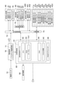
次に、パチンコ遊技機1の主な電気的構成について図3及び図4を参照しつつ説明する。パチンコ遊技機1は、主制御基板60(図3)と、払出制御基板73(図3)と、サブ制御基板100(図4)と、画像制御基板300(図4)とを備えている。これらの主制御基板60、サブ制御基板100等は、例えば、箱部材18の後面に基板カバー18aによって固定されている(図2参照)。図3に示すように、主制御基板60には、遊技制御用ワンチップマイコン(以下、遊技制御用マイコンという)61が実装されている。遊技制御用マイコン61は、CPU62と、ROM63と、RAM64と、入出力回路65とを備えている。CPU62は、入賞の検出、大当たり判定、各種乱数の更新などを実行する。ROM63には、CPU62が実行するコンピュータプログラムの他に、大当たり判定テーブル、リーチ判定テーブル、特図変動パターン選択テーブル、大当たり種別判定テーブルなどの各種のテーブルTA1が記憶されている。遊技制御用マイコン61は、大当たり乱数、大当たり種別乱数、リーチ乱数、変動パターン乱数など、各種の判定(抽選)にて使用する乱数を発生する。
[Main electrical components of pachinko machines]
Next, the main electrical configurations of the pachinko gaming machine 1 will be described with reference to FIGS. 3 and 4. The pachinko gaming machine 1 includes a main control board 60 (FIG. 3), a payout control board 73 (FIG. 3), a sub control board 100 (FIG. 4), and an image control board 300 (FIG. 4). The main control board 60, the sub control board 100, and the like are fixed to the rear surface of the box member 18 by a board cover 18a (see FIG. 2). As shown in FIG. 3, a game control one-chip microcomputer (hereinafter referred to as a game control microcomputer) 61 is mounted on the main control board 60. The game control microcomputer 61 includes a CPU 62, a ROM 63, a RAM 64, and an input / output circuit 65. The CPU 62 executes winning prize detection, jackpot determination, update of various random numbers, and the like. In addition to the computer program executed by the CPU 62, the ROM 63 stores various tables TA1 such as a jackpot determination table, a reach determination table, a special figure variation pattern selection table, and a jackpot type determination table. The game control microcomputer 61 generates random numbers used in various determinations (lottery) such as big hit random numbers, big hit type random numbers, reach random numbers, and fluctuation pattern random numbers.
RAM64は、CPU62がコンピュータプログラムを実行するときのワークメモリなどとして使用される。RAM64には、遊技球が第1始動口11(図1)に入賞したことに起因して遊技制御用マイコン61が取得した大当たり乱数、大当たり種別乱数、リーチ乱数及び変動パターン乱数が記憶される。表示器類50の第1特別図柄表示器が第1特別図柄を変動表示しているときに遊技球が第1始動口11に入賞したときは、その入賞に起因する第1特別図柄の変動表示は一旦保留(作動保留)され、その入賞に起因して取得された大当たり乱数などはRAM64に記憶される。同様に、RAM64には、遊技球が普通可変入賞装置20の第2始動口に入賞したことに起因して遊技制御用マイコン61が取得した大当たり乱数、大当たり種別乱数、リーチ乱数及び変動パターン乱数が記憶される。また、RAM64には、遊技球がゲート12(図1)を通過したことに起因して遊技制御用マイコン61が取得した普通当たり乱数(普通図柄が当たりか否かを判定(抽選)するための乱数)が記憶される。表示器類50の普通図柄表示器が普通図柄を変動表示しているときに遊技球がゲート12を通過したときは、その通過に起因する普通図柄表示器の作動は一旦保留(作動保留)され、その通過に起因して取得された普通当たり乱数はRAM64に記憶される。
The RAM 64 is used as a work memory or the like when the CPU 62 executes a computer program. The RAM 64 stores a jackpot random number, a jackpot type random number, a reach random number, and a variation pattern random number acquired by the game control microcomputer 61 due to the game ball winning a prize in the first starting port 11 (FIG. 1). If the game ball wins a prize in the first starting port 11 while the first special symbol display of the indicators 50 is displaying the first special symbol in a variable manner, the variable display of the first special symbol due to the winning is displayed. Is temporarily held (suspended for operation), and the jackpot random numbers and the like acquired due to the winning are stored in the RAM 64. Similarly, the RAM 64 contains a jackpot random number, a jackpot type random number, a reach random number, and a variation pattern random number acquired by the game control microcomputer 61 due to the game ball winning a prize in the second starting port of the normally variable winning device 20. It will be remembered. Further, the RAM 64 is used to determine (lottery) whether or not the normal hit random number (normal symbol is hit or not) acquired by the game control microcomputer 61 due to the game ball passing through the gate 12 (FIG. 1). Random number) is stored. When the game ball passes through the gate 12 while the normal symbol display of the indicators 50 is displaying the normal symbol in a variable manner, the operation of the normal symbol display due to the passage is temporarily suspended (operation suspended). , The normal hit random number acquired due to the passage is stored in the RAM 64.
また、入出力回路65は、主制御基板60に接続された各基板などとの間でデータの送信又は受信を行う。また、主制御基板60には、RAMクリアスイッチ66が搭載されている。パチンコ遊技機1は、RAMクリアスイッチ66が押下された状態で起動すると、RAM64及びサブ制御基板100のRAM120(図4)を初期化する。また、主制御基板60には、表示器類50が電気的に接続されている。さらに、主制御基板60には、中継基板74を介して第1始動口センサ11aと、第2始動口センサ22aと、ゲートセンサ12aと、第1大入賞口センサ32aと、第2大入賞口センサ42aと、特定領域センサ42bと、非特定領域センサ42cと、一般入賞口センサ13aと、電チューソレノイド20aと、第1大入賞口ソレノイド30aと、第2大入賞口ソレノイド40aと、振分部材ソレノイド42dとが電気的に接続されている。
Further, the input / output circuit 65 transmits or receives data to and from each board connected to the main control board 60. Further, the RAM clear switch 66 is mounted on the main control board 60. When the pachinko gaming machine 1 is started in a state where the RAM clear switch 66 is pressed, the RAM 64 and the RAM 120 (FIG. 4) of the sub control board 100 are initialized. Further, the indicators 50 are electrically connected to the main control board 60. Further, the main control board 60 has a first start port sensor 11a, a second start port sensor 22a, a gate sensor 12a, a first large winning opening sensor 32a, and a second large winning opening via the relay board 74. The sensor 42a, the specific area sensor 42b, the non-specific area sensor 42c, the general winning opening sensor 13a, the electric chew solenoid 20a, the first special winning opening solenoid 30a, the second major winning opening solenoid 40a, and the distribution. The member solenoid 42d is electrically connected to the member solenoid 42d.
第1始動口センサ11aは、第1始動口11(図1)の直下に設けられており、遊技球が第1始動口11に入賞したことを示す信号を主制御基板60へ出力する。第2始動口センサ22aは、普通可変入賞装置20の第2始動口の直下に設けられており、遊技球が第2始動口に入賞したことを示す信号を主制御基板60へ出力する。ゲートセンサ12aは、ゲート12(図1)のうち遊技球の通過領域に設けられており、遊技球がゲート12を通過したことを示す信号を主制御基板60へ出力する。第1大入賞口センサ32aは、第1大入賞装置30の第1大入賞口の直下に設けられており、遊技球が第1大入賞口に入賞したことを示す信号を主制御基板60へ出力する。第2大入賞口センサ42aは、第2大入賞装置40の第2大入賞口の直下に設けられており、遊技球が第2大入賞口に入賞したことを示す信号を主制御基板60へ出力する。特定領域センサ42bは、第2大入賞装置40の第2大入賞口の内部の特定領域内に設けられており、遊技球が特定領域を通過したことを示す信号を主制御基板60へ出力する。非特定領域センサ42cは、第2大入賞装置40の第2大入賞口の内部の非特定領域に設けられており、遊技球が非特定領域を通過したことを示す信号を主制御基板60へ出力する。一般入賞口センサ13aは、一般入賞口13(図1)の直下に設けられており、遊技球が一般入賞口13に入賞したことを示す信号を主制御基板60へ出力する。
The first starting port sensor 11a is provided directly below the first starting port 11 (FIG. 1), and outputs a signal indicating that the game ball has won the first starting port 11 to the main control board 60. The second starting port sensor 22a is normally provided immediately below the second starting port of the variable winning device 20, and outputs a signal indicating that the game ball has won a prize in the second starting port to the main control board 60. The gate sensor 12a is provided in the passage region of the game ball in the gate 12 (FIG. 1), and outputs a signal indicating that the game ball has passed through the gate 12 to the main control board 60. The first large winning opening sensor 32a is provided directly below the first large winning opening of the first large winning device 30, and sends a signal indicating that the game ball has won the first large winning opening to the main control board 60. Output. The second major winning opening sensor 42a is provided directly below the second major winning opening of the second major winning device 40, and sends a signal indicating that the game ball has won the second major winning opening to the main control board 60. Output. The specific area sensor 42b is provided in a specific area inside the second large winning opening of the second large winning device 40, and outputs a signal indicating that the game ball has passed through the specific area to the main control board 60. .. The non-specific area sensor 42c is provided in a non-specific area inside the second large winning opening of the second large winning device 40, and sends a signal indicating that the game ball has passed through the non-specific area to the main control board 60. Output. The general winning opening sensor 13a is provided directly below the general winning opening 13 (FIG. 1), and outputs a signal indicating that the game ball has won the general winning opening 13 to the main control board 60.
また、図4に示すように、サブ制御基板100には、アウト口センサ19aが電気的に接続されている。アウト口センサ19aは、アウト口19(図1)の直下に設けられており、遊技球がアウト口19に入球したことを示す信号をサブ制御基板100へ出力する。これにより、サブ制御基板100(演出制御用マイコン101)は、アウト口センサ19aから出力される信号に基づいて、アウト口19に入球して消費された遊技球の数を計測できる。
Further, as shown in FIG. 4, the out port sensor 19a is electrically connected to the sub control board 100. The out port sensor 19a is provided directly below the out port 19 (FIG. 1), and outputs a signal indicating that the game ball has entered the out port 19 to the sub control board 100. As a result, the sub control board 100 (microcomputer 101 for effect control) can measure the number of game balls that have entered and consumed the out port 19 based on the signal output from the out port sensor 19a.
図3に戻り、電チューソレノイド20aは、普通可変入賞装置20の可動部材を開閉駆動する。第1大入賞口ソレノイド30aは、第1大入賞装置30の第1開閉部材を開閉駆動する。第2大入賞口ソレノイド40aは、第2大入賞装置40の第2開閉部材を開閉駆動する。振分部材ソレノイド42dは、第2大入賞装置40の内部に設けられた振分部材を駆動する。
Returning to FIG. 3, the electric chew solenoid 20a normally drives the movable member of the variable winning device 20 to open and close. The first prize-winning port solenoid 30a opens and closes and drives the first opening and closing member of the first prize-winning device 30. The second prize-winning port solenoid 40a opens and closes and drives the second opening and closing member of the second prize-winning device 40. The distribution member solenoid 42d drives a distribution member provided inside the second prize-winning device 40.
また、主制御基板60には、払出制御基板73を介して貸球払出装置80と、カードユニット76と、賞球払出装置400とが電気的に接続されている。カードユニット76は、パチンコ遊技機1に隣接して設けられており、プリペイドカードに対して残高の読取りや書き込みなどを行う。貸球払出装置80は、球貸モータ81と、球貸センサ82とを備えている。球貸モータ81は、貸球としての遊技球を払出す部材を駆動し、球貸センサ82は、その部材によって遊技球が払出されたことを示す信号を、払出制御基板73を介して主制御基板60へ出力する。遊技制御用マイコン61は、払出制御基板73から出力される信号に基づいて、貸球払出装置80が払出した貸球数を計数する。カードユニット76に挿入されたプリペイドカードに、払出可能な最小残高以上の残高が記録されているときに、球貸ボタン(図示略)が操作されると、貸球払出装置80が作動し、最小単位個数の貸球が打球供給皿24に払出される。
Further, the ball rental payout device 80, the card unit 76, and the prize ball payout device 400 are electrically connected to the main control board 60 via the payout control board 73. The card unit 76 is provided adjacent to the pachinko gaming machine 1, and reads or writes the balance to the prepaid card. The ball lending device 80 includes a ball lending motor 81 and a ball lending sensor 82. The ball lending motor 81 drives a member for paying out the game ball as a lending ball, and the ball lending sensor 82 mainly controls a signal indicating that the game ball has been paid out by the member via the payout control board 73. Output to the board 60. The game control microcomputer 61 counts the number of balls rented by the ball renting device 80 based on the signal output from the payout control board 73. When the ball lending button (not shown) is operated when the balance equal to or greater than the minimum balance that can be paid out is recorded on the prepaid card inserted in the card unit 76, the ball lending payout device 80 is activated and the minimum balance is recorded. A unit number of rented balls is paid out to the hit ball supply plate 24.
賞球払出装置400は、賞球モータ401と、賞球センサ402とを備えている。賞球モータ401は、賞球としての遊技球を払出す部材を駆動し、賞球センサ402は、その部材によって遊技球が払出されたことを示す信号を、払出制御基板73を介して主制御基板60へ出力する。遊技制御用マイコン61は、払出制御基板73から出力される信号に基づいて、賞球払出装置400が払出した賞球数を計数する。
The prize ball payout device 400 includes a prize ball motor 401 and a prize ball sensor 402. The prize ball motor 401 drives a member for paying out the game ball as a prize ball, and the prize ball sensor 402 mainly controls a signal indicating that the game ball has been paid out by the member via the payout control board 73. Output to the board 60. The game control microcomputer 61 counts the number of prize balls paid out by the prize ball payout device 400 based on the signal output from the payout control board 73.
また、主制御基板60には、払出制御基板73、発射制御回路75を介して発射装置90が電気的に接続されている。発射装置90は、発射モータ91と、タッチスイッチ92と、発射ボリューム93と、発射口センサ94を備えている。発射モータ91は、遊技球を打撃して発射する打撃槌(図示略)を駆動する。タッチスイッチ92は、遊技者がハンドル4に触れたことを示す信号を出力する。発射ボリューム93は、発射レバー4a(図1)の回転量に応じて、上記打撃槌が遊技球を打撃する強度を調節する。発射口センサ94は、誘導部材17(図1)に設けられている。発射口センサ94は、誘導部材17から遊技領域3へ遊技球が入球されたこと、即ち、発射装置90によって発射された遊技球が遊技領域3内に入ったことを示す信号を主制御基板60へ出力する。これにより、主制御基板60は、発射口センサ94から出力される信号に基づいて、発射装置90により発射され遊技領域3内で消費された遊技球の数を計測できる。
Further, the launching device 90 is electrically connected to the main control board 60 via the payout control board 73 and the launch control circuit 75. The launch device 90 includes a launch motor 91, a touch switch 92, a launch volume 93, and a launch port sensor 94. The launch motor 91 drives a striking mallet (not shown) that strikes and launches a game ball. The touch switch 92 outputs a signal indicating that the player has touched the handle 4. The firing volume 93 adjusts the strength with which the hitting mallet hits the game ball according to the amount of rotation of the firing lever 4a (FIG. 1). The launch port sensor 94 is provided on the guidance member 17 (FIG. 1). The launch port sensor 94 sends a signal indicating that the game ball has entered the game area 3 from the guide member 17, that is, the game ball launched by the launch device 90 has entered the game area 3. Output to 60. As a result, the main control board 60 can measure the number of game balls launched by the launching device 90 and consumed in the gaming area 3 based on the signal output from the launch port sensor 94.
また、パチンコ遊技機1は、電源基板70を備えている。電源基板70は、主制御基板60及び払出制御基板73に電力を供給する。また、電源基板70は、払出制御基板73に電気的に接続された各装置に対して、払出制御基板73を介して電力を供給する。また、電源基板70は、中継基板74に電気的に接続された各センサ及びソレノイドに対して、主制御基板60から中継基板74を介して電力を供給する。また、電源基板70は、主制御基板60に電気的に接続された表示器類50に対して、主制御基板60を介して電力を供給する。また、電源基板70は、サブ制御基板100に対して電力を供給する(図3、図4の「B」)。電源基板70には、バックアップ電源回路71が設けられている。バックアップ電源回路71は、パチンコ遊技機1に対して外部から電力が供給されていない場合に、主制御基板60のRAM64やサブ制御基板100のRTC124などに対して情報の保持に必要な電力を供給する。バックアップ電源回路71としては、コンデンサや内臓電池(ボタン電池等)を含む回路を採用することができる。電源基板70には、電源基板70へ電力を供給する主電源をオンオフするための電源スイッチ72が電気的に接続されている。
Further, the pachinko gaming machine 1 includes a power supply board 70. The power supply board 70 supplies electric power to the main control board 60 and the payout control board 73. Further, the power supply board 70 supplies electric power to each device electrically connected to the payout control board 73 via the payout control board 73. Further, the power supply board 70 supplies electric power from the main control board 60 to each sensor and solenoid electrically connected to the relay board 74 via the relay board 74. Further, the power supply board 70 supplies electric power to the indicators 50 electrically connected to the main control board 60 via the main control board 60. Further, the power supply board 70 supplies electric power to the sub control board 100 (“B” in FIGS. 3 and 4). The power supply board 70 is provided with a backup power supply circuit 71. The backup power supply circuit 71 supplies power necessary for holding information to the RAM 64 of the main control board 60, the RTC 124 of the sub control board 100, and the like when power is not supplied to the pachinko gaming machine 1 from the outside. do. As the backup power supply circuit 71, a circuit including a capacitor and a built-in battery (button battery or the like) can be adopted. A power switch 72 for turning on / off the main power supply for supplying electric power to the power supply board 70 is electrically connected to the power supply board 70.
また、主制御基板60は、サブ制御基板100(図4)に対して各種コマンドを送信する(図3、図4の「A」)。主制御基板60は、コマンドをサブ制御基板100へ送信することはできるが、サブ制御基板100は、主制御基板60へコマンドを送信することができない。つまり、主制御基板60とサブ制御基板100との通信は、主制御基板60からサブ制御基板100へ送信することのみが可能な単方向通信となっている。
Further, the main control board 60 transmits various commands to the sub control board 100 (FIG. 4) (“A” in FIGS. 3 and 4). The main control board 60 can send commands to the sub control board 100, but the sub control board 100 cannot send commands to the main control board 60. That is, the communication between the main control board 60 and the sub control board 100 is unidirectional communication that can only be transmitted from the main control board 60 to the sub control board 100.
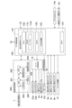
図4に示すように、サブ制御基板100には、演出制御用ワンチップマイコン(以下、演出制御用マイコンという)101が実装されている。演出制御用マイコン101は、CPU102と、ROM110と、RAM120と、入出力回路103とを備えている。CPU102は、遊技に伴って演出を制御する。ROM110には、CPU102が演出を制御するためのコンピュータプログラムの他に、変動演出パターン選択テーブルなどの各種のテーブルTA4が記憶されている。RAM120は、CPU102がコンピュータプログラムを実行するときのワークメモリとして使用される。
As shown in FIG. 4, a one-chip microcomputer for effect control (hereinafter referred to as an effect control microcomputer) 101 is mounted on the sub control board 100. The effect control microcomputer 101 includes a CPU 102, a ROM 110, a RAM 120, and an input / output circuit 103. The CPU 102 controls the effect as the game is played. In addition to the computer program for the CPU 102 to control the effect, the ROM 110 stores various tables TA4 such as a variable effect pattern selection table. The RAM 120 is used as a work memory when the CPU 102 executes a computer program.
RAM120は、主制御基板60から出力される第1始動入賞コマンドなどを記憶する。第1始動入賞コマンドは、遊技球が第1始動口11に入賞したことを契機として、遊技制御用マイコン61が取得した大当たり乱数、大当たり種別乱数、変動パターン乱数及びリーチ乱数を含むコマンドである。また、RAM120は、主制御基板60から出力される第2始動入賞コマンドなどを記憶する。第2始動入賞コマンドは、遊技球が普通可変入賞装置20の第2始動口に入賞したことを契機として、遊技制御用マイコン61が取得した大当たり乱数、大当たり種別乱数、変動パターン乱数及びリーチ乱数を含むコマンドである。入出力回路103は、サブ制御基板100に接続された各基板などとの間でデータの送信または受信を行う。
The RAM 120 stores a first start winning command and the like output from the main control board 60. The first start winning command is a command including a jackpot random number, a jackpot type random number, a variation pattern random number, and a reach random number acquired by the game control microcomputer 61 when the game ball wins a prize in the first starting port 11. Further, the RAM 120 stores a second start winning command and the like output from the main control board 60. The second start winning command uses the jackpot random number, the jackpot type random number, the variation pattern random number, and the reach random number acquired by the game control microcomputer 61 when the game ball wins the second starting port of the normal variable winning device 20. The command to include. The input / output circuit 103 transmits or receives data to and from each board connected to the sub control board 100.
図4に示すように、サブ制御基板100には、画像制御基板300が電気的に接続されている。画像制御基板300には、画像制御用CPU302と、VDP(Video Display Processor)301と、制御用ROM303と、制御用RAM304と、CGROM(Character Generator Read Only Memory)305と、VRAM(Video Random Access Memory)306とが実装されている。画像制御用CPU302は、変動演出パターン、ボタン演出画像及び予告演出画像などの演出画像を表示するよう演出表示装置7を制御する。制御用ROM303には、画像制御用CPU302が演出表示装置7を制御するためのコンピュータプログラムが記憶されている。制御用RAM304は、画像制御用CPU302がコンピュータプログラムを実行するときのワークメモリとして使用される。CGROM305には、演出表示装置7が画像を表示するための画像データ(演出画像などの画像データ)が記憶されている。VDP301は、例えば、画像制御用CPU302によって作成されるディスプレイリストに従って、CGROM305から画像データを読み出し、その読出した画像データをVRAM306内の展開領域に展開する。そして、VDP301は、VRAM306内に展開した画像データを合成し、その合成した画像データをVRAM306内のフレームバッファに記憶する。そして、VDP301は、VRAM306内のフレームバッファに記憶した画像データをRGB信号に変換して演出表示装置7に出力する。これにより、演出表示装置7は演出画像を表示する。
As shown in FIG. 4, the image control board 300 is electrically connected to the sub control board 100. The image control board 300 includes a CPU 302 for image control, a VDP (Video Display Processor) 301, a ROM 303 for control, a RAM 304 for control, a CGROM (Character Generator Read Only Memory) 305, and a VRAM (Video Random Access). 306 and are mounted. The image control CPU 302 controls the effect display device 7 to display an effect image such as a variable effect pattern, a button effect image, and a preview effect image. The control ROM 303 stores a computer program for the image control CPU 302 to control the effect display device 7. The control RAM 304 is used as a work memory when the image control CPU 302 executes a computer program. The CGROM 305 stores image data (image data such as an effect image) for the effect display device 7 to display an image. For example, the VDP 301 reads image data from the CGROM 305 according to a display list created by the image control CPU 302, and expands the read image data into a development area in the VRAM 306. Then, the VDP 301 synthesizes the image data expanded in the VRAM 306, and stores the synthesized image data in the frame buffer in the VRAM 306. Then, the VDP 301 converts the image data stored in the frame buffer in the VRAM 306 into an RGB signal and outputs the image data to the effect display device 7. As a result, the effect display device 7 displays the effect image.
また、サブ制御基板100には、ランプ制御基板79を介して左サイドランプ23a、右サイドランプ23b、盤ランプ2a、演出ボタンランプ9cが電気的に接続されている。演出制御用マイコン101は、ROM110に記憶されているデータを用いて各ランプの発光態様を決める発光パターンデータを作成し、その発光パターンデータをランプ制御基板79に送信する。そして、ランプ制御基板79は、受信した発光パターンデータに従って各ランプの発光制御を行う。
Further, the left side lamp 23a, the right side lamp 23b, the panel lamp 2a, and the effect button lamp 9c are electrically connected to the sub control board 100 via the lamp control board 79. The effect control microcomputer 101 creates light emission pattern data that determines the light emission mode of each lamp using the data stored in the ROM 110, and transmits the light emission pattern data to the lamp control board 79. Then, the lamp control board 79 controls the light emission of each lamp according to the received light emission pattern data.
サブ制御基板100には、音声制御基板78を介して各スピーカ8が電気的に接続されている。音声制御基板78には、音声制御用CPU(図示略)と、音声データROM(図示略)と、音声合成回路(図示略)と、アンプ(図示略)とが搭載されている。音声データROMには、各スピーカ8が音楽や効果音などの音を出力するための音声データが記憶されている。音声制御用CPUは、サブ制御基板100から受信したコマンドに基づいて音声データROMから音声データを読出し、その読出した音声データを音声合成回路に出力する。音声合成回路は、入力した音声データを合成するとともに、その合成した合成音声データをアナログの音声信号に変換してアンプに出力する。アンプは、入力した音声信号を増幅して各スピーカ8に出力する。そして、各スピーカ8は、入力した音声信号により示される音を出力する。
Each speaker 8 is electrically connected to the sub control board 100 via the voice control board 78. A voice control CPU (not shown), a voice data ROM (not shown), a voice synthesis circuit (not shown), and an amplifier (not shown) are mounted on the voice control board 78. The voice data ROM stores voice data for each speaker 8 to output sounds such as music and sound effects. The voice control CPU reads voice data from the voice data ROM based on the command received from the sub control board 100, and outputs the read voice data to the voice synthesis circuit. The voice synthesis circuit synthesizes the input voice data, converts the synthesized voice data into an analog voice signal, and outputs the synthesized voice data to the amplifier. The amplifier amplifies the input audio signal and outputs it to each speaker 8. Then, each speaker 8 outputs the sound indicated by the input audio signal.
また、サブ制御基板100には、演出ボタン検出スイッチ9aと、演出レバー検出スイッチ6j、操作ボタン検出スイッチ6kが電気的に接続されている。演出ボタン検出スイッチ9aは、演出ボタン9が押圧操作されたことを示す信号をサブ制御基板100に出力する。演出レバー検出スイッチ6jは、演出レバー6が押込操作された、あるいは回動操作されたことを示す信号をサブ制御基板100に出力する。操作ボタン検出スイッチ6kは、打球供給皿24に設けられた操作ボタン(図示略)を操作されたことを示す信号をサブ制御基板100に出力する。また、サブ制御基板100には、演出レバー駆動モータ6dが電気的に接続されている。演出レバー駆動モータ6dは、演出レバー6を振動、回動、スライド移動等させる部材である。演出制御用マイコン101は、演出に合わせて演出レバー6を回動等させる。
Further, the effect button detection switch 9a, the effect lever detection switch 6j, and the operation button detection switch 6k are electrically connected to the sub control board 100. The effect button detection switch 9a outputs a signal indicating that the effect button 9 has been pressed to the sub-control board 100. The effect lever detection switch 6j outputs a signal indicating that the effect lever 6 has been pushed or rotated to the sub-control board 100. The operation button detection switch 6k outputs a signal indicating that the operation button (not shown) provided on the ball hitting plate 24 has been operated to the sub control board 100. Further, the effect lever drive motor 6d is electrically connected to the sub control board 100. The effect lever drive motor 6d is a member that vibrates, rotates, slides, and the like the effect lever 6. The effect control microcomputer 101 rotates the effect lever 6 or the like in accordance with the effect.
また、サブ制御基板100には、リアルタイムクロック(RTC)124が実装されている。RTC124は、現時点の日時(日付及び時刻)を計測するものである。RTC124は、例えば、外部の電源装置からパチンコ遊技機1へ電力が供給されているときにはその電力によって動作し、外部の電源装置から電力が供給されていないときには、電源基板70が備えるバックアップ電源回路71から供給される電力によって動作する。このため、RTC124は、パチンコ遊技機1の電源が投入されていないときにも現在の日時を計測することが可能である。尚、RTC124へ電力を供給するバックアップ電源回路をサブ制御基板100に設けてもよい。
A real-time clock (RTC) 124 is mounted on the sub-control board 100. The RTC124 measures the current date and time (date and time). For example, the RTC 124 operates by the electric power when the electric power is supplied from the external power supply device to the pachinko gaming machine 1, and when the electric power is not supplied from the external power supply device, the backup power supply circuit 71 included in the power supply board 70 is provided. It operates by the power supplied from. Therefore, the RTC 124 can measure the current date and time even when the power of the pachinko gaming machine 1 is not turned on. A backup power supply circuit that supplies power to the RTC 124 may be provided on the sub control board 100.
また、サブ制御基板100には、ユニット装置15が接続されている。サブ制御基板100は、後述するユニット装置15の第1及び第2発光手段171a,171b(図14)の点灯状態(点灯の有無、光の明るさなど)を制御することで、ユニット装置15による演出態様を変更することができる。演出制御用マイコン101は、遊技状態(演出の内容)に応じてユニット装置15の点灯状態を変更する。例えば、演出制御用マイコン101は、ROM110に記憶されているデータを用いて第1及び第2発光手段171a,171bの点灯状態を決める点灯パターンデータを作成し、その点灯パターンデータに従って第1及び第2発光手段171a,171bの点灯制御を行う。
Further, the unit device 15 is connected to the sub control board 100. The sub-control board 100 depends on the unit device 15 by controlling the lighting state (whether or not the light is lit, the brightness of the light, etc.) of the first and second light emitting means 171a and 171b (FIG. 14) of the unit device 15 described later. The production mode can be changed. The effect control microcomputer 101 changes the lighting state of the unit device 15 according to the game state (contents of the effect). For example, the effect control microcomputer 101 creates lighting pattern data for determining the lighting states of the first and second light emitting means 171a and 171b using the data stored in the ROM 110, and the first and first light emitting means according to the lighting pattern data. 2 Lighting control of the light emitting means 171a and 171b is performed.
[ユニット装置15の構成]
次に、ユニット装置15の構成について説明する。図5に示すように、ユニット装置15は、箱形形状の箱部材18に収容されている。ユニット装置15は、右側ユニット131、上側ユニット132、下側ユニット133、及び左側ユニット134の4つのユニットを備えている。以下の説明では、右側ユニット131、上側ユニット132、下側ユニット133、及び左側ユニット134のうち、少なくとも2つのユニットをまとめて説明する場合、単に「ユニット131~134」のようにユニットと総称して説明する。
[Configuration of unit device 15]
Next, the configuration of the unit device 15 will be described. As shown in FIG. 5, the unit device 15 is housed in a box-shaped box member 18. The unit device 15 includes four units, a right side unit 131, an upper unit 132, a lower unit 133, and a left side unit 134. In the following description, when at least two units of the right side unit 131, the upper unit 132, the lower unit 133, and the left side unit 134 are collectively described, they are collectively referred to as units such as "units 131 to 134". I will explain.
箱部材18は、有底の四角形の箱形形状をなし、前面側に四角形をなす開口18bを有し、その開口18bを構成する4辺のそれぞれに側壁18cを有する。4つのユニット131~134は、4つの側壁18cのそれぞれに、第1螺合部材137によって固定されている。
The box member 18 has a bottomed quadrangular box shape, has a quadrangular opening 18b on the front side, and has side walls 18c on each of the four sides constituting the opening 18b. The four units 131 to 134 are fixed to each of the four side walls 18c by a first screwing member 137.
図6は、右側ユニット131の正面図である。図6に示すように、右側ユニット131は、取付部材141と、第1装飾部材143と、第2装飾部材144と、第3掃拭部材145とを備えている。取付部材141は、例えば、プラスチック製(樹脂製)の成型物によって構成されている。取付部材141は、左右方向において所定の幅を有し、上下方向に長い板状に形成されている。取付部材141は、上下方向における両端のそれぞれを、他のユニットと連結される。例えば、取付部材141の上端は、上側ユニット132の右側端部と、第2螺合部材139によって固定されている。第2螺合部材139は、例えば、ネジである。これにより、右側ユニット131は、上側ユニット132と連結される。また、取付部材141の下端は、下側ユニット133の右端端部と、第2螺合部材139によって固定されている。これにより、右側ユニット131は、下側ユニット133と連結される。同様に、各ユニット131~134の各々は、上下方向、左右方向の端部を、他のユニットと第2螺合部材139によって連結されている。これにより、ユニット装置15は、演出表示装置7を囲むように、ユニット装置15の側壁18cに沿った枠状の部材を構成している。尚、各ユニット131~134を連結する部材は、ネジに限らず、ボルト、ナット等を用いても良い。
FIG. 6 is a front view of the right side unit 131. As shown in FIG. 6, the right side unit 131 includes a mounting member 141, a first decorative member 143, a second decorative member 144, and a third wiping member 145. The mounting member 141 is made of, for example, a molded product made of plastic (resin). The mounting member 141 has a predetermined width in the left-right direction and is formed in a long plate shape in the up-down direction. Each of both ends of the mounting member 141 in the vertical direction is connected to another unit. For example, the upper end of the mounting member 141 is fixed to the right end portion of the upper unit 132 by the second screwing member 139. The second screwing member 139 is, for example, a screw. As a result, the right side unit 131 is connected to the upper side unit 132. Further, the lower end of the mounting member 141 is fixed to the right end portion of the lower unit 133 by the second screwing member 139. As a result, the right side unit 131 is connected to the lower unit 133. Similarly, each of the units 131 to 134 has its end portions in the vertical direction and the horizontal direction connected to the other unit by the second screwing member 139. As a result, the unit device 15 constitutes a frame-shaped member along the side wall 18c of the unit device 15 so as to surround the effect display device 7. The members connecting the units 131 to 134 are not limited to screws, and bolts, nuts, and the like may be used.
右側ユニット131は、後面側に設けられた発光手段により、第1装飾部材143、第2装飾部材144、第3掃拭部材145を発光させる。右側ユニット131の詳細については、後述する。また、図5に示すように、上側ユニット132は、前後方向に並んで配置される複数の透明板147を備えている。各透明板147は、例えば、透明のアクリル板であり、上下方向における長さが、例えば、前側から後側に向かうに従って、徐々に長くなっている。前後方向で隣り合う2つの透明板147は、後ろ側の透明板147が、前側の透明板147の下端から下方へ突出している。上側ユニット132は、その上部に設けられた基板(図示略)に実装されたLEDから複数の透明板147のそれぞれに光を発光することで、各透明板147を発光させる。尚、図5は、透明板147の奥側に配置された部材を透過的に図示している。
The right side unit 131 causes the first decorative member 143, the second decorative member 144, and the third wiping member 145 to emit light by the light emitting means provided on the rear surface side. The details of the right side unit 131 will be described later. Further, as shown in FIG. 5, the upper unit 132 includes a plurality of transparent plates 147 arranged side by side in the front-rear direction. Each transparent plate 147 is, for example, a transparent acrylic plate, and the length in the vertical direction gradually increases from the front side to the rear side, for example. In the two transparent plates 147 adjacent to each other in the front-rear direction, the transparent plate 147 on the rear side projects downward from the lower end of the transparent plate 147 on the front side. The upper unit 132 emits light from an LED mounted on a substrate (not shown) provided above the transparent plate 147 to each of the plurality of transparent plates 147, thereby causing each transparent plate 147 to emit light. Note that FIG. 5 transparently shows the members arranged on the back side of the transparent plate 147.
同様に、下側ユニット133は、複数の透明板148を備えている。各透明板148は、例えば、透明のアクリル板であり、上下方向における長さが、前側から後側に向かうに従って、徐々に長くなっている。従って、下側ユニット133の透明板148は、上側ユニット132の透明板147と上下方向で対象な構造となっている。下側ユニット133は、その下部に設けられた基板(図示略)に実装されたLEDから複数の透明板148のそれぞれに光を発光することで、各透明板148を発光させる。
Similarly, the lower unit 133 includes a plurality of transparent plates 148. Each transparent plate 148 is, for example, a transparent acrylic plate, and its length in the vertical direction gradually increases from the front side to the rear side. Therefore, the transparent plate 148 of the lower unit 133 has a structure that is vertically symmetrical with the transparent plate 147 of the upper unit 132. The lower unit 133 emits light from an LED mounted on a substrate (not shown) provided below the transparent plate 148 to each of the plurality of transparent plates 148, thereby causing each transparent plate 148 to emit light.
また、左側ユニット134は、人型の装飾部材149を有している。装飾部材149は、例えば、人が立っている状態を立体的に表した部材である。装飾部材149は、例えば、左手を隠した状態となっている。パチンコ遊技機1は、例えば、演出表示装置7に左手を写し出し、写し出した左手を動かすことで、あたかも装飾部材149の人が動いているように見せることができる。従って、パチンコ遊技機1は、ユニット装置15に設けられた装飾部材と連係した映像を演出表示装置7に写し出すことで、装飾部材を活かした演出を行うことができる。
Further, the left side unit 134 has a human-shaped decorative member 149. The decorative member 149 is, for example, a member that three-dimensionally represents a state in which a person is standing. The decorative member 149 is, for example, in a state where the left hand is hidden. The pachinko gaming machine 1 can make it appear as if the person of the decorative member 149 is moving by projecting the left hand on the effect display device 7 and moving the projected left hand, for example. Therefore, the pachinko gaming machine 1 can perform an effect utilizing the decorative member by projecting an image linked to the decorative member provided on the unit device 15 on the effect display device 7.
上記したように、ユニット装置15は、機能の異なる複数のユニット131~134を第2螺合部材139で互いに連結して構成されている。そして、各ユニット131~134は、第1螺合部材137によって箱部材18に着脱可能となっている。また、箱部材18には、演出表示装置7や各種の制御基板(サブ制御基板100など)が取り付け可能となっている(図2参照)。このような構成では、箱部材18を共通の部材として、箱部材18に取り付ける各ユニット131~134、演出表示装置7、サブ制御基板100等を交換することで、種類の異なる(別機種の)パチンコ遊技機1にも対応することができる。換言すれば、箱部材18に対して装着するユニット131~134を自由に組み合わせて、新しいパチンコ遊技機1を構成することができる。例えば、種類の異なるパチンコ遊技機1に必要な箱部材18を、同一の成形金型で製造できる。また、箱部材18を再利用することができ、パチンコ遊技機1の製造コストの低減を図ることができる。
As described above, the unit device 15 is configured by connecting a plurality of units 131 to 134 having different functions to each other by a second screwing member 139. Each unit 131 to 134 can be attached to and detached from the box member 18 by the first screwing member 137. Further, the effect display device 7 and various control boards (sub-control board 100, etc.) can be attached to the box member 18 (see FIG. 2). In such a configuration, the box member 18 is used as a common member, and the units 131 to 134 attached to the box member 18, the effect display device 7, the sub control board 100, and the like are exchanged, so that different types (of different models) are exchanged. It can also be used for the pachinko gaming machine 1. In other words, the new pachinko gaming machine 1 can be configured by freely combining the units 131 to 134 mounted on the box member 18. For example, the box member 18 required for different types of pachinko gaming machines 1 can be manufactured with the same molding die. Further, the box member 18 can be reused, and the manufacturing cost of the pachinko gaming machine 1 can be reduced.
図6及び図7に示すように、右側ユニット131は、上下方向の間に第3掃拭部材145を挟んで、上側に第1装飾部材143が配置され、下側に第2装飾部材144が配置されている。第3掃拭部材145は、前方側へ膨らんだ中空形状をなしており、略板状の取付部材141の前面側に設けられている。第3掃拭部材145は、上下方向における取付部材141の略中央部に形成されている。第3掃拭部材145は、球体の略1/4程度の形状をなしており、図6の正面から見た場合には円形の左半分の半円形状をなし、図7の左側から見た場合には前側半分の半円形状をなしている。第3掃拭部材145の表面には、様々な装飾が施されている。例えば、第3掃拭部材145には、爆弾を模擬した装飾が施されており、後述するように演出表示装置7の表示と連動することで爆弾を用いた演出を実行できる。第3掃拭部材145は、後述する取付部材141の後方に配置された基板171の第2発光手段171bから発光された光を、内周面で受光して発光する。
As shown in FIGS. 6 and 7, in the right side unit 131, the first decorative member 143 is arranged on the upper side and the second decorative member 144 is arranged on the lower side with the third wiping member 145 sandwiched between them in the vertical direction. Have been placed. The third wiping member 145 has a hollow shape bulging toward the front side, and is provided on the front surface side of the substantially plate-shaped mounting member 141. The third wiping member 145 is formed at a substantially central portion of the mounting member 141 in the vertical direction. The third wiping member 145 has a shape of about 1/4 of a sphere, has a semicircular shape on the left half of a circle when viewed from the front of FIG. 6, and is viewed from the left side of FIG. In some cases, it has a semicircular shape on the front half. Various decorations are applied to the surface of the third wiping member 145. For example, the third wiping member 145 is decorated to imitate a bomb, and as will be described later, an effect using the bomb can be executed by interlocking with the display of the effect display device 7. The third wiping member 145 receives the light emitted from the second light emitting means 171b of the substrate 171 arranged behind the mounting member 141, which will be described later, on the inner peripheral surface and emits light.
第1装飾部材143は、第1透明部材151、第2透明部材152、第1反射部材153、及び第2反射部材154を備えている。第1装飾部材143は、前方から見た場合に、第2透明部材152の一部(取付部材141に取り付けられた基端部側)に、第1透明部材151が重なるように配置されている。例えば、後方側の第2反射部材154の前方に、第1反射部材153が位置するように配置されている。同様に、第2装飾部材144は、第1透明部材161、第2透明部材162、第1反射部材163、及び第2反射部材164を備えている。第2装飾部材144は、前方から見た場合に、第2透明部材162の一部(取付部材141に取り付けられた基端部側)に、第1透明部材161が重なるように配置されている。第2装飾部材144は、第1及び第2透明部材161,162の外周形状など、第1装飾部材143と一部の形状が異なっている。しかしながら、第2装飾部材144は、第1装飾部材143と同様の構造となっており、第3掃拭部材145を間に挟んで、上下方向において第1装飾部材143と対象な構造となっている。このため、以下の説明では、主に、第1装飾部材143について説明し、第2装飾部材144についての説明を適宜省略する。
The first decorative member 143 includes a first transparent member 151, a second transparent member 152, a first reflective member 153, and a second reflective member 154. The first decorative member 143 is arranged so that the first transparent member 151 overlaps a part of the second transparent member 152 (the base end side attached to the mounting member 141) when viewed from the front. .. For example, the first reflective member 153 is arranged in front of the second reflective member 154 on the rear side. Similarly, the second decorative member 144 includes a first transparent member 161, a second transparent member 162, a first reflective member 163, and a second reflective member 164. The second decorative member 144 is arranged so that the first transparent member 161 overlaps a part of the second transparent member 162 (the base end side attached to the mounting member 141) when viewed from the front. .. The second decorative member 144 is partially different in shape from the first decorative member 143, such as the outer peripheral shapes of the first and second transparent members 161, 162. However, the second decorative member 144 has the same structure as the first decorative member 143, and has a structure symmetrical to the first decorative member 143 in the vertical direction with the third wiping member 145 sandwiched between them. There is. Therefore, in the following description, the first decorative member 143 will be mainly described, and the description of the second decorative member 144 will be omitted as appropriate.
図8~図11に示すように、第1装飾部材143の第1透明部材151は、透明の部材で板状に形成され、基端部151aを取付部材141に取り付けられ、基端部151aに対して先端部151bを所定の角度へ湾曲させた形状をなしている。同様に、第2透明部材152は、透明の部材で板状に形成され、基端部152aを取付部材141に取り付けられ、基端部152aに対して先端部152bを所定の角度へ湾曲させた形状をなしている。
As shown in FIGS. 8 to 11, the first transparent member 151 of the first decorative member 143 is formed of a transparent member in a plate shape, the base end portion 151a is attached to the mounting member 141, and the base end portion 151a is attached to the base end portion 151a. On the other hand, the tip portion 151b is curved to a predetermined angle. Similarly, the second transparent member 152 is formed of a transparent member in a plate shape, the base end portion 152a is attached to the mounting member 141, and the tip end portion 152b is curved at a predetermined angle with respect to the base end portion 152a. It has a shape.
第1及び第2透明部材151,152は、例えば、透明のアクリル板で形成されている。尚、第1及び第2透明部材151,152の材料は、アクリルに限らず、例えば、ポリエチレンテレフタレート(PET)でも良い。また、図6~図11は、図面が煩雑となるのを避けるため、透明の第1及び第2透明部材151,152を白色に塗りつぶして図示している。また、第1及び第2透明部材151,152は、一部が透明、あるいは透明でない部材でも良い。
The first and second transparent members 151 and 152 are formed of, for example, a transparent acrylic plate. The materials of the first and second transparent members 151 and 152 are not limited to acrylic, and may be, for example, polyethylene terephthalate (PET). Further, FIGS. 6 to 11 show the transparent first and second transparent members 151 and 152 painted in white in order to avoid complicating the drawings. Further, the first and second transparent members 151 and 152 may be partially transparent or non-transparent members.
第1透明部材151の基端部151aには、第1反射部材153が取り付けられている。また、第2透明部材152の基端部152aには、第2反射部材154が取り付けられている。一対の第1透明部材151及び第1反射部材153と、一対の第2透明部材152及び第2反射部材154とは、同様の構造となっている。このため、以下の説明では、主に、第1透明部材151及び第1反射部材153について説明し、第2透明部材152及び第2反射部材154についての説明を適宜省略する。
A first reflective member 153 is attached to a base end portion 151a of the first transparent member 151. Further, a second reflective member 154 is attached to the base end portion 152a of the second transparent member 152. The pair of the first transparent member 151 and the first reflective member 153 and the pair of the second transparent member 152 and the second reflective member 154 have the same structure. Therefore, in the following description, the first transparent member 151 and the first reflective member 153 will be mainly described, and the description of the second transparent member 152 and the second reflective member 154 will be omitted as appropriate.
図12に示すように、右側ユニット131の後方側の後面141bには、基板171が取り付けられている。基板171は、例えば、サブ制御基板100に電気的に接続されており、サブ制御基板100によって制御される。基板171の後方には、保護カバー173が取り付けられている。保護カバー173は、例えば、透明のアクリル板で形成され、ネジ175によって取付部材141の後面141bに取り付けられている。
As shown in FIG. 12, the substrate 171 is attached to the rear surface 141b on the rear side of the right side unit 131. The board 171 is electrically connected to, for example, the sub control board 100 and is controlled by the sub control board 100. A protective cover 173 is attached to the rear of the board 171. The protective cover 173 is formed of, for example, a transparent acrylic plate, and is attached to the rear surface 141b of the attachment member 141 by screws 175.
図13は、右側ユニット131を左側の後方から見た斜視図であり、基板171及び保護カバー173を取り外した状態を示している。図9及び図13に示すように、取付部材141には、第1装飾部材143の第1及び第2透明部材151,152、及び第2装飾部材144の第1及び第2透明部材161,162の基端部(基端部151a,152aなど)を取り付ける位置に貫通孔141aが形成されている。貫通孔141aは、例えば、1つの基端部(基端部151a,152aなど)に対応して2つ形成されている。
FIG. 13 is a perspective view of the right side unit 131 as viewed from the rear on the left side, and shows a state in which the substrate 171 and the protective cover 173 are removed. As shown in FIGS. 9 and 13, the mounting member 141 includes the first and second transparent members 151 and 152 of the first decorative member 143, and the first and second transparent members 161, 162 of the second decorative member 144. A through hole 141a is formed at a position where the base end portion (base end portion 151a, 152a, etc.) is attached. Two through holes 141a are formed, for example, corresponding to one proximal end portion (base end portions 151a, 152a, etc.).
例えば、基端部151aを取り付ける位置に形成された一対の貫通孔141aは、第3掃拭部材145における円弧形状の外周に沿うように、周方向に並んで配置されている。貫通孔141aは、取付部材141の平面視において、第3掃拭部材145の外周に沿うように延設された長方形の穴である。
For example, the pair of through holes 141a formed at the position where the base end portion 151a is attached are arranged side by side in the circumferential direction along the outer circumference of the arc shape in the third wiping member 145. The through hole 141a is a rectangular hole extending along the outer periphery of the third wiping member 145 in the plan view of the mounting member 141.
また、図9~図11に示すように、第1透明部材151の基端部151aは、第3掃拭部材145の外周に沿うように円弧形状に湾曲した形状をなしている。以下の説明では、説明の便宜上、第3掃拭部材145の外周に沿うように基端部151aを湾曲させて延設する方向を、第1透明部材151の幅方向と称する(図9参照)。基端部151aには、一対の貫通孔141aの各々に挿入される一対の凸部151cが形成されている。一対の凸部151cの各々は、貫通孔141aに合わせた形状や大きさで形成され、基端部151aの後面から後方へ突出した形状をなしている。一対の凸部151c及び一対の貫通孔141aは、基端部151aの幅方向において、所定の間隔を間に設けて配置されている。また、貫通孔141aは、基端部151aの幅方向に長い長方形形状をなしている。第1透明部材151は、一対の基端部151aの各々を、一対の貫通孔141aに挿入させた状態で取付部材141に固定されている。一対の基端部151aの各々は、取付部材141の後方へ先端を突出させた状態となっている(図13参照)。
Further, as shown in FIGS. 9 to 11, the base end portion 151a of the first transparent member 151 has a shape curved in an arc shape along the outer circumference of the third wiping member 145. In the following description, for convenience of explanation, the direction in which the base end portion 151a is curved and extended along the outer circumference of the third wiping member 145 is referred to as the width direction of the first transparent member 151 (see FIG. 9). .. A pair of convex portions 151c to be inserted into each of the pair of through holes 141a are formed in the base end portion 151a. Each of the pair of convex portions 151c is formed in a shape and size suitable for the through hole 141a, and has a shape protruding rearward from the rear surface of the proximal end portion 151a. The pair of convex portions 151c and the pair of through holes 141a are arranged so as to be spaced apart from each other in the width direction of the base end portion 151a. Further, the through hole 141a has a rectangular shape long in the width direction of the base end portion 151a. The first transparent member 151 is fixed to the mounting member 141 in a state where each of the pair of base end portions 151a is inserted into the pair of through holes 141a. Each of the pair of base end portions 151a is in a state in which the tip thereof protrudes rearward of the mounting member 141 (see FIG. 13).
第1反射部材153は、基端部151aの幅方向に沿って湾曲した形状をなしている。第1反射部材153は、例えば、樹脂を成形して形成されている。第1反射部材153の前面153a(遊技者側の面)には、三角形、丸、円などを組み合わせて立体的な凹凸形状が形成された装飾が施されている。第1反射部材153の前面153a及び後面153bは、例えば、メッキ加工が施されている。例えば、前面153a及び後面153bの前面には、金メッキ加工が施され、光を反射する加工が施されている。尚、前面153a及び後面153bのどちらか一面に、メッキ加工を施しても良い。また、前面153a及び後面153bの両面に、メッキ加工を施さなくとも良い。また、前面153a及び後面153bに、メッキ加工以外の鏡面加工などの反射率を高める加工を施しても良い。
The first reflective member 153 has a curved shape along the width direction of the proximal end portion 151a. The first reflective member 153 is formed, for example, by molding a resin. The front surface 153a (the surface on the player side) of the first reflective member 153 is decorated with a three-dimensional uneven shape formed by combining triangles, circles, circles, and the like. The front surface 153a and the rear surface 153b of the first reflective member 153 are, for example, plated. For example, the front surfaces of the front surface 153a and the rear surface 153b are gold-plated and light-reflecting. Either one of the front surface 153a and the rear surface 153b may be plated. Further, it is not necessary to perform plating on both the front surface 153a and the rear surface 153b. Further, the front surface 153a and the rear surface 153b may be subjected to a process for increasing the reflectance such as a mirror surface process other than the plating process.
幅方向における第1反射部材153の中央部には、ネジ177を螺合するメスネジを形成された被螺合部153cが形成されている。また、第1反射部材153には、係合突起153dが形成されている。
At the center of the first reflective member 153 in the width direction, a screwed portion 153c formed with a female screw for screwing the screw 177 is formed. Further, an engaging projection 153d is formed on the first reflective member 153.
一方、第1透明部材151の基端部151aには、被螺合部153cの位置に合わせて切り欠かれた切り欠き部151dが形成されている。また、基端部151aには、係合突起153dを挿入可能な貫通孔151eが形成されている。第1反射部材153は、被螺合部153cを切り欠き部151dに嵌め込み、係合突起153dを貫通孔151eに挿入することで、第1透明部材151に対する位置ズレを抑制される。そして、第1反射部材153は、被螺合部153cを切り欠き部151dに嵌め込み、係合突起153dを貫通孔151eに挿入した状態で、取付部材141の後面141b側から挿入したネジ177によって固定されている。第1透明部材151は、基端部151aを貫通孔141aに挿入した状態で、前後方向において第1反射部材153と取付部材141によって挟まれて位置を固定される。
On the other hand, the base end portion 151a of the first transparent member 151 is formed with a notched portion 151d cut out according to the position of the screwed portion 153c. Further, a through hole 151e into which the engagement projection 153d can be inserted is formed in the base end portion 151a. In the first reflective member 153, the screwed portion 153c is fitted into the notch portion 151d, and the engaging projection 153d is inserted into the through hole 151e, so that the positional deviation with respect to the first transparent member 151 is suppressed. Then, the first reflective member 153 is fixed by a screw 177 inserted from the rear surface 141b side of the mounting member 141 in a state where the screwed portion 153c is fitted into the notch portion 151d and the engaging protrusion 153d is inserted into the through hole 151e. Has been done. The position of the first transparent member 151 is fixed by being sandwiched between the first reflective member 153 and the mounting member 141 in the front-rear direction with the base end portion 151a inserted into the through hole 141a.
また、図13及び図14に示すように、基板171には、第1発光手段171aと、第2発光手段171bとが実装されている。第1及び第2発光手段171a,171bは、例えば、LEDであり、演出制御用マイコン101によって点灯を制御される。尚、本願の発光手段は、LEDに限らず、ハロゲンランプ等の他の発光手段でも良い。
Further, as shown in FIGS. 13 and 14, the first light emitting means 171a and the second light emitting means 171b are mounted on the substrate 171. The first and second light emitting means 171a and 171b are, for example, LEDs, and their lighting is controlled by the effect control microcomputer 101. The light emitting means of the present application is not limited to the LED, and other light emitting means such as a halogen lamp may be used.
第2発光手段171bは、第3掃拭部材145を発光させる光源である。取付部材141には、第3掃拭部材145の位置に合わせて複数の貫通孔141dが形成されている。第2発光手段171bは、この複数の貫通孔141dの各々の位置に合わせて、基板171の上に複数個実装されている。取付部材141は、例えば、非透明(有色)の部材で形成されており、凸部151cを挿入する貫通孔141aや貫通孔141dなどの穴を通じて、基板171の第1及び第2発光手段171a,171bから発光された光を前面側へ照射する。複数の第2発光手段171bの各々から発光された光は、各貫通孔141dを通じて第3掃拭部材145内に照射され、第3掃拭部材145内で反射等する。これにより、演出制御用マイコン101は、複数の第2発光手段171bの点灯状態を制御することで、第3掃拭部材145に装飾された部材等の点灯状態を変更することができる。
The second light emitting means 171b is a light source that causes the third wiping member 145 to emit light. A plurality of through holes 141d are formed in the mounting member 141 according to the position of the third wiping member 145. A plurality of the second light emitting means 171b are mounted on the substrate 171 according to the positions of the plurality of through holes 141d. The mounting member 141 is formed of, for example, a non-transparent (colored) member, and the first and second light emitting means 171a of the substrate 171 are formed through holes such as the through hole 141a and the through hole 141d into which the convex portion 151c is inserted. The light emitted from 171b is irradiated to the front side. The light emitted from each of the plurality of second light emitting means 171b is irradiated into the third wiping member 145 through each through hole 141d, and is reflected or the like in the third wiping member 145. As a result, the effect control microcomputer 101 can change the lighting state of the member or the like decorated on the third wiping member 145 by controlling the lighting state of the plurality of second light emitting means 171b.
また、第1発光手段171aは、第1装飾部材143の第1及び第2透明部材151,152、第2装飾部材144の第1及び第2透明部材161,162の基端部(基端部151a,152aなど)の位置に合わせて、基板171の上に複数個実装されている。例えば、第1発光手段171aは、1つの凸部151cに対して2つ、即ち、1つの基端部151aに対して合計4つ設けられている。4つの第1発光手段171aは、図14に示すように、基端部151aの幅方向に沿って、且つ凸部151cの位置に合わせて並んで円弧上に配置されている(図14の破線参照)。
Further, the first light emitting means 171a is a base end portion (base end portion) of the first and second transparent members 151 and 152 of the first decorative member 143 and the first and second transparent members 161 and 162 of the second decorative member 144. A plurality of them are mounted on the substrate 171 according to the positions of 151a, 152a, etc.). For example, two first light emitting means 171a are provided for one convex portion 151c, that is, a total of four for one base end portion 151a. As shown in FIG. 14, the four first light emitting means 171a are arranged in an arc along the width direction of the base end portion 151a and in line with the position of the convex portion 151c (broken line in FIG. 14). reference).
図7に第1発光手段171aから発光した光の進行方向179の一例を示している。尚、図7の進行方向179は、第2透明部材152内を通過する光の進行方向を示しているが、第1透明部材151内を通過する光の進行方向についても同様である。4つの第1発光手段171aは、一対の基端部151aに対して光を発光する。第1発光手段171aから発光された光は、例えば、前後方向に沿って貫通孔141aを通じて前方へ伝達される。第1反射部材153は、第1発光手段171aから発光された光の進行方向179(この場合、前後方向)において、基端部151aを間に挟んで反対側(前面側)に配置されている。各第1発光手段171aから発光した光は、凸部151cを通じて基端部151a内を通過し第1反射部材153によって反射させられ、進行方向179を変更され、第1透明部材151の先端部151bへと伝達される。演出制御用マイコン101は、第1発光手段171aの点灯状態を制御することで、第1装飾部材143及び第2装飾部材144の点灯状態を変更する。
FIG. 7 shows an example of the traveling direction 179 of the light emitted from the first light emitting means 171a. The traveling direction 179 in FIG. 7 indicates the traveling direction of the light passing through the second transparent member 152, but the same applies to the traveling direction of the light passing through the first transparent member 151. The four first light emitting means 171a emit light to a pair of base end portions 151a. The light emitted from the first light emitting means 171a is transmitted forward, for example, through the through hole 141a along the front-rear direction. The first reflecting member 153 is arranged on the opposite side (front side) with the base end portion 151a interposed therebetween in the traveling direction 179 (in this case, the front-rear direction) of the light emitted from the first light emitting means 171a. .. The light emitted from each of the first light emitting means 171a passes through the base end portion 151a through the convex portion 151c and is reflected by the first reflecting member 153 to change the traveling direction 179, and the tip portion 151b of the first transparent member 151b. Is transmitted to. The effect control microcomputer 101 changes the lighting state of the first decorative member 143 and the second decorative member 144 by controlling the lighting state of the first light emitting means 171a.
また、図7~図11に示すように、第1透明部材151の基端部151aは、例えば、前後方向に沿った板形状をなし、幅方向へ(第3掃拭部材145の外周形状に沿うように)湾曲した形状をなしている。第1透明部材151は、基端部151aの前端部151fにおいて所定の角度で湾曲している。例えば、第1透明部材151は、基端部151aの前端部151fから先端部151b側を、上方且つ前方側へと傾斜させている。第1透明部材151は、前端部151fで湾曲した部分よりも先端部151b側に湾曲面151gを有する。
Further, as shown in FIGS. 7 to 11, the base end portion 151a of the first transparent member 151 has, for example, a plate shape along the front-rear direction and is in the width direction (in the outer peripheral shape of the third wiping member 145). It has a curved shape (along). The first transparent member 151 is curved at a predetermined angle at the front end portion 151f of the base end portion 151a. For example, the first transparent member 151 is inclined upward and forward from the front end portion 151f of the base end portion 151a to the tip end portion 151b side. The first transparent member 151 has a curved surface 151g on the tip end portion 151b side with respect to the portion curved at the front end portion 151f.
湾曲面151gは、幅方向における外縁(外側)よりも内側を取付部材141側(後方側)へ湾曲させた形状をなしている。湾曲面151gは、例えば、所定の曲率で、取付部材141側へ突出するように湾曲して形成されている。第1反射部材153は、この湾曲した基端部151a及び湾曲面151gに沿った形状をなしている。第1反射部材153は、基端部151aに沿った部分と、前端部151f付近の湾曲面151gに沿った部分とで構成されている。第1反射部材153の後面153bは、基端部151a及び湾曲面151gの前面151hに沿って形成されている。第1反射部材153は、第1透明部材151の形状に沿って湾曲した形状で形成され、後面153bを基端部151a及び湾曲面151gの前面151hに面接触させた状態で取付部材141に固定されている。また、第1反射部材153の後面153bには、第1反射部材153の成形に必要な部材の量を減らすための肉抜き部153eが形成されている(図11参照)。肉抜き部153eは、後面153bを前面151h側へ凹設して形成されている。尚、第1反射部材153は、肉抜き部153eを備えず、後面153bをフラットな面で形成された構成でも良い。
The curved surface 151g has a shape in which the inner side of the outer edge (outer side) in the width direction is curved toward the mounting member 141 side (rear side). The curved surface 151g is formed by being curved so as to project toward the mounting member 141 with a predetermined curvature, for example. The first reflective member 153 has a shape along the curved base end portion 151a and the curved surface 151g. The first reflective member 153 is composed of a portion along the base end portion 151a and a portion along the curved surface 151g near the front end portion 151f. The rear surface 153b of the first reflective member 153 is formed along the front end portion 151a and the front surface 151h of the curved surface 151g. The first reflective member 153 is formed in a curved shape along the shape of the first transparent member 151, and is fixed to the mounting member 141 in a state where the rear surface 153b is in surface contact with the base end portion 151a and the front surface 151h of the curved surface 151g. Has been done. Further, on the rear surface 153b of the first reflective member 153, a lightening portion 153e for reducing the amount of the member required for molding the first reflective member 153 is formed (see FIG. 11). The lightening portion 153e is formed by recessing the rear surface 153b toward the front surface 151h. The first reflective member 153 may not be provided with the lightening portion 153e, and the rear surface 153b may be formed of a flat surface.
また、湾曲面151gは、基端部151aの前端部151fから、上方且つ前方側へと傾斜しており、傾斜した先端に先端部151bが形成されている。湾曲面151gは、基端部151a側から先端部151bに向かうに従って、取付部材141との間の距離(前後方向における距離)が徐々に長くなるように、傾斜した形状で形成されている。
Further, the curved surface 151g is inclined upward and forward from the front end portion 151f of the base end portion 151a, and the tip portion 151b is formed at the inclined tip. The curved surface 151g is formed in an inclined shape so that the distance (distance in the front-rear direction) from the mounting member 141 gradually increases from the base end portion 151a side toward the tip end portion 151b.
また、先端部151bを含む湾曲面151gの外周は、三角形に尖ったり、円弧状に切り欠かれたりした不規則な形状をなしている。従って、湾曲面151gの外周形状は、基端部151aから伝達された光を様々な方向へ拡散させる形状となっている。尚、湾曲面151gの外周形状は、矩形や一定の曲率の半円形状等でも良い。
Further, the outer circumference of the curved surface 151g including the tip portion 151b has an irregular shape such as a triangular point or a notch in an arc shape. Therefore, the outer peripheral shape of the curved surface 151g is a shape that diffuses the light transmitted from the base end portion 151a in various directions. The outer peripheral shape of the curved surface 151 g may be a rectangle, a semicircular shape having a constant curvature, or the like.
また、先端部151bを含む湾曲面151gの外周端の全周に、エッジ面151jが形成されている。エッジ面151jは、湾曲面151gの先端の後面に形成され、湾曲面151gの内側から外側に向かうに従って、湾曲面151gの厚みを薄くするように傾斜した面で形成されている。湾曲面151gは、外周端にエッジ面151jを形成されることで、外周端が尖った形状となっている。従って、湾曲面151gの外周形状は、基端部151aから伝達された光をエッジ面151jで反射等させる形状となっている。尚、湾曲面151gは、エッジ面151jを外周端の一部に備えても良く、エッジ面151jを備えなくとも良い。
Further, an edge surface 151j is formed on the entire circumference of the outer peripheral end of the curved surface 151g including the tip portion 151b. The edge surface 151j is formed on the rear surface of the tip of the curved surface 151g, and is formed as an inclined surface so as to reduce the thickness of the curved surface 151g from the inside to the outside of the curved surface 151g. The curved surface 151g has an edge surface 151j formed at the outer peripheral end, so that the outer peripheral end has a sharp shape. Therefore, the outer peripheral shape of the curved surface 151g is such that the light transmitted from the base end portion 151a is reflected by the edge surface 151j. The curved surface 151g may have an edge surface 151j on a part of the outer peripheral end, or may not have an edge surface 151j.
また、本実施形態の第1装飾部材143は、第1透明部材151及び第1反射部材153、第2透明部材152及び第2反射部材154を有し、透明部材及び反射部材を2組み有している。図7及び図8に示すように、一方の組みの第1透明部材151及び第1反射部材153は、前後方向において、他の組の第2透明部材152及び第2反射部材154と重なる前側の位置に配置されている。換言すれば、一方の組みの第1透明部材151及び第1反射部材153は、第1発光手段171aから発光された光の進行方向179(前後方向)において、他の組の第2透明部材152及び第2反射部材154と重なるように配置される。
Further, the first decorative member 143 of the present embodiment has a first transparent member 151 and a first reflective member 153, a second transparent member 152 and a second reflective member 154, and has two sets of the transparent member and the reflective member. ing. As shown in FIGS. 7 and 8, one set of the first transparent member 151 and the first reflective member 153 is on the front side overlapping with the other set of the second transparent member 152 and the second reflective member 154 in the front-rear direction. It is placed in a position. In other words, one set of the first transparent member 151 and the first reflective member 153 is the second set of the second transparent member 152 in the traveling direction 179 (front-back direction) of the light emitted from the first light emitting means 171a. And is arranged so as to overlap with the second reflective member 154.
また、図7から図9に示すように、第1透明部材151の基端部151aと、第2透明部材152の基端部152aとは、近接した位置に配置されている。一方で、後方側の第2透明部材152の湾曲面152gは、前方側の第1透明部材151の湾曲面151gよりも外側へ(上方向や左右方向の外側へ)広がっている。換言すれば、遊技者から見た場合に、第2透明部材152は、第1透明部材151の後ろ側から第1透明部材151の外側まで広がる大きさで形成されている。これにより、第1透明部材151や第2透明部材152の個別の点灯演出だけでなく、第1及び第2透明部材151,152を重ねて点灯させた趣向姓の高い点灯演出を実行できる。
Further, as shown in FIGS. 7 to 9, the base end portion 151a of the first transparent member 151 and the base end portion 152a of the second transparent member 152 are arranged at close positions. On the other hand, the curved surface 152 g of the second transparent member 152 on the rear side extends outward (outward in the upward or left-right direction) from the curved surface 151 g of the first transparent member 151 on the front side. In other words, when viewed from the player, the second transparent member 152 is formed in a size extending from the rear side of the first transparent member 151 to the outside of the first transparent member 151. As a result, it is possible to execute not only the individual lighting effects of the first transparent member 151 and the second transparent member 152, but also the lighting effects having a high taste of lighting the first and second transparent members 151 and 152 in an overlapping manner.
さらに、右側ユニット131の第1装飾部材143は、第3掃拭部材145を間に挟んで第2装飾部材144とは反対側に配置されている。図6に示すように、第1装飾部材143の第1及び第2透明部材151,152は、前方の遊技者から見た場合に、球体形状の第3掃拭部材145の半径方向に沿って、半径方向の外側へと広がるように配置されている。同様に、第2装飾部材144の第1及び第2透明部材161,162は、前方の遊技者から見た場合に、球体形状の第3掃拭部材145の半径方向に沿って、半径方向の外側へと広がるように配置されている。このような第3掃拭部材145を間に挟んだ対象な構造によって、第1装飾部材143、第2装飾部材144、第3掃拭部材145を連係させて点灯等させることで、今までにない趣向姓の高い演出を実行できる。例えば、第1装飾部材143、第2装飾部材144の点滅に合わせて第3掃拭部材145を点滅させることで、球形の第3掃拭部材145を爆弾に見立てて、爆弾が爆発したような演出を行うことができる。
Further, the first decorative member 143 of the right side unit 131 is arranged on the opposite side of the second decorative member 144 with the third wiping member 145 in between. As shown in FIG. 6, the first and second transparent members 151 and 152 of the first decorative member 143 are along the radial direction of the spherical third wiping member 145 when viewed from the front player. , Arranged to extend outward in the radial direction. Similarly, the first and second transparent members 161, 162 of the second decorative member 144 are radially along the radial direction of the spherical third sweeping member 145 when viewed from the front player. It is arranged so as to spread outward. By linking the first decorative member 143, the second decorative member 144, and the third wiping member 145 with such a target structure sandwiching the third wiping member 145, the lighting and the like have been achieved so far. It is possible to perform a production with a high surname. For example, by blinking the third wiping member 145 in accordance with the blinking of the first decorative member 143 and the second decorative member 144, the spherical third wiping member 145 is regarded as a bomb, and the bomb explodes. You can produce.
(演出の一態様)
次に、ユニット装置15を用いた演出の一態様について説明する。図15は、演出図柄の変動表示中における演出表示装置7の表示例を示している。図15は、例えば、リーチ演出が実行される際の状態を示している。
(One aspect of production)
Next, one aspect of the effect using the unit device 15 will be described. FIG. 15 shows a display example of the effect display device 7 during the variable display of the effect symbol. FIG. 15 shows, for example, a state when the reach effect is executed.
例えば、演出制御用マイコン101は、第1始動口11への遊技球の入賞に応じて左演出図柄9L、中演出図柄9C、右演出図柄9Rの変動を開始する。演出制御用マイコン101は、リーチ予告演出等を実行した後、左演出図柄9L及び右演出図柄9Rを同じ数字の図柄で確定表示して、リーチ状態とする。演出制御用マイコン101は、例えば、左演出図柄9Lと右演出図柄9Rとに「7」の演出図柄を停止させ、演出図柄がリーチ状態であること(リーチが確定したこと)を演出表示装置7に表示させる。また、演出制御用マイコン101は、例えば、演出図柄を演出表示装置7の隅に移動させ、リーチ演出を見え易い状態とする。
For example, the effect control microcomputer 101 starts to change the left effect symbol 9L, the middle effect symbol 9C, and the right effect symbol 9R according to the winning of the game ball to the first starting port 11. After executing the reach advance notice effect and the like, the effect control microcomputer 101 confirmably displays the left effect symbol 9L and the right effect symbol 9R with the same numbered symbols to bring them into the reach state. For example, the effect control microcomputer 101 stops the effect symbol of "7" on the left effect symbol 9L and the right effect symbol 9R, and indicates that the effect symbol is in the reach state (reach is confirmed). To display. Further, the effect control microcomputer 101 moves, for example, the effect symbol to the corner of the effect display device 7 to make the reach effect easy to see.
そして、演出制御用マイコン101は、例えば、左側ユニット134の人の装飾部材149の位置に合わせて左腕を模擬した模擬アイコン181を演出表示装置7に表示する。演出制御用マイコン101は、例えば、模擬アイコン181の左腕に、たいまつ等の火を付ける部材を持たせた画像を演出表示装置7に表示する。また、演出制御用マイコン101は、右側ユニット131の爆弾を模擬した第3掃拭部材145から、爆弾の導火線を模擬した模擬アイコン183を演出表示装置7に表示する。
Then, the effect control microcomputer 101 displays, for example, a simulated icon 181 simulating the left arm in accordance with the position of the human decorative member 149 of the left side unit 134 on the effect display device 7. The effect control microcomputer 101 displays, for example, an image on the effect display device 7 in which the left arm of the simulated icon 181 is provided with a member for igniting a torch or the like. Further, the effect control microcomputer 101 displays a simulated icon 183 simulating the fuse of the bomb on the effect display device 7 from the third wiping member 145 simulating the bomb of the right side unit 131.
演出制御用マイコン101は、例えば、模擬アイコン181を動かして模擬アイコン183の先端に火を付けさせ、模擬アイコン183の導火線が徐々に燃えて短くなるような画像を演出表示装置7に表示する。そして、演出制御用マイコン101は、模擬アイコン183が燃え尽きて、火が第3掃拭部材145に到達したタイミングに合わせて、第1装飾部材143、第3掃拭部材145、第2装飾部材144を点灯・点滅等させ、爆弾が爆発したような演出を実行する。
For example, the effect control microcomputer 101 moves the simulated icon 181 to ignite the tip of the simulated icon 183, and displays an image on the effect display device 7 such that the fuse of the simulated icon 183 gradually burns and shortens. Then, in the effect control microcomputer 101, the first decorative member 143, the third cleaning member 145, and the second decorative member 144 are set in accordance with the timing when the simulated icon 183 is burned out and the fire reaches the third cleaning member 145. Is lit / blinking, etc. to perform the effect of exploding a bomb.
例えば、演出制御用マイコン101は、「ドカーン」などの爆発したような効果音をスピーカ8から放音させつつ、前面側の第1透明部材151,161と、後ろ側の第2透明部材152,162を交互に点灯させるように第1発光手段171aを制御しても良い。また、この爆発演出に合わせて、演出制御用マイコン101は、第2発光手段171bを制御し、第3掃拭部材145を点滅等させても良い。演出制御用マイコン101は、例えば、大当たり判定が当たりの場合、上記した爆発演出を実行した後、中演出図柄9Cに「7」の演出図柄を停止させ、大当たりであることを報知した後、大当たり遊技を行う。また、演出制御用マイコン101は、大当たり判定がはずれの場合、爆発する演出を実行せずに、例えば、模擬アイコン183が燃え尽きて、火が第3掃拭部材145に到達したタイミングで、「不発」などの文字を演出表示装置7に表示しても良い。これにより、模擬アイコン181,183を表示し、ユニット装置15を点滅等させることで、大当たりの確定を遊技者に期待させることができ、遊技の趣向性を向上できる。さらに、演出表示装置7の表示と上側ユニット132の点滅等を連動させることで、遊技者にとって有利な遊技(大当たり遊技など)に対する期待感をより高めることができ遊技の趣向性を向上できる。従って、本実施形態の演出制御用マイコン101は、演出表示装置7に表示した演出内容の結果・進行具合や遊技者にとって有利な特典(大当たり、時短遊技など)を付与するか否かの結果に応じて、第1透明部材151,161、第2透明部材152,162を、一定の周期等で交互に点灯させるなど、第1透明部材151,161等の点灯状態を制御しても良い。
For example, the effect control microcomputer 101 emits an explosive sound effect such as “Dokhan” from the speaker 8, while the first transparent member 151, 161 on the front side and the second transparent member 152 on the rear side. The first light emitting means 171a may be controlled so as to light 162 alternately. Further, the effect control microcomputer 101 may control the second light emitting means 171b and make the third wiping member 145 blink or the like in accordance with the explosion effect. For example, when the jackpot determination is a hit, the effect control microcomputer 101 executes the above-mentioned explosion effect, stops the effect symbol of "7" to the middle effect symbol 9C, notifies that it is a jackpot, and then makes a jackpot. Play a game. Further, when the jackpot determination is missed, the effect control microcomputer 101 does not execute the effect of exploding, for example, at the timing when the simulated icon 183 burns out and the fire reaches the third wiping member 145, "unexploded". May be displayed on the effect display device 7. As a result, by displaying the simulated icons 181 and 183 and blinking the unit device 15 or the like, the player can be expected to confirm the jackpot, and the taste of the game can be improved. Further, by interlocking the display of the effect display device 7 with the blinking of the upper unit 132, the expectation for a game (big hit game, etc.) that is advantageous to the player can be further increased, and the taste of the game can be improved. Therefore, the effect control microcomputer 101 of the present embodiment determines the result / progress of the effect content displayed on the effect display device 7 and the result of whether or not to give a privilege (big hit, time saving game, etc.) advantageous to the player. Accordingly, the lighting state of the first transparent members 151, 161 may be controlled by alternately lighting the first transparent members 151, 161 and the second transparent members 152, 162 at a fixed cycle or the like.
上記したユニット装置15を用いた演出は、一例である。例えば、右側ユニット131に加え、上側ユニット132の透明板147や下側ユニット133の透明板148を点灯等させて、爆発演出を実行しても良い。演出制御用マイコン101は、導火線の模擬アイコン183が短くなるに従って、透明板147,148のそれぞれを前側から後ろ側へ順番に点灯させても良い。また、演出制御用マイコン101は、爆発による第3掃拭部材145の点滅に合わせて透明板147,148を点滅させても良い。また、演出制御用マイコン101は、1つの第1透明部材151に対応する4つの第1発光手段171a(図14参照)を、例えば、順番に点灯させたり、2つずつ点灯させたりしても良い。また、演出制御用マイコン101は、複数の第1発光手段171aや第2発光手段171bの光の強弱を調整して、演出を実行しても良い。
The effect using the unit device 15 described above is an example. For example, in addition to the right side unit 131, the transparent plate 147 of the upper unit 132 and the transparent plate 148 of the lower unit 133 may be turned on to perform an explosion effect. The effect control microcomputer 101 may light each of the transparent plates 147 and 148 in order from the front side to the rear side as the simulated icon 183 of the fuse becomes shorter. Further, the effect control microcomputer 101 may blink the transparent plates 147 and 148 in accordance with the blinking of the third wiping member 145 due to the explosion. Further, the effect control microcomputer 101 may turn on the four first light emitting means 171a (see FIG. 14) corresponding to one first transparent member 151 in order or two by two, for example. good. Further, the effect control microcomputer 101 may perform the effect by adjusting the intensity of the light of the plurality of first light emitting means 171a and the second light emitting means 171b.
また、演出制御用マイコン101は、上記したユニット装置15を使用した演出を、演出図柄を確定させるタイミング以外で実行しても良い。例えば、演出制御用マイコン101は、ユニット装置15を使用した演出を、リーチ前の予告演出のタイミング、一度確定したはずれ図柄を再変動させるタイミング、リーチをより信頼度の高いリーチへ発展させるタイミング、大当たり遊技中に大当たりの種類(大当たり遊技が終了した後の遊技状態が高確率状態に移行するか否かなど)を報知するタイミングなどに実行しても良い。
Further, the effect control microcomputer 101 may execute the effect using the unit device 15 described above at a timing other than the timing for determining the effect symbol. For example, the effect control microcomputer 101 performs an effect using the unit device 15 at the timing of the advance notice effect before the reach, the timing of re-variating the missed symbol once confirmed, and the timing of developing the reach into a more reliable reach. It may be executed at the timing of notifying the type of jackpot (whether or not the gaming state after the jackpot game ends shifts to the high probability state, etc.) during the jackpot game.
因みに、第1発光手段171aは、発光手段の一例である。前面153aは、反射部材表面の一例である。後面153bは、反射部材裏面の一例である。前面151hは、透明部材表面の一例である。演出表示装置7は、表示手段の一例である。ユニット131~134は、ユニット部材の一例である。
Incidentally, the first light emitting means 171a is an example of the light emitting means. The front surface 153a is an example of the surface of the reflective member. The rear surface 153b is an example of the back surface of the reflective member. The front surface 151h is an example of the surface of the transparent member. The effect display device 7 is an example of display means. Units 131 to 134 are examples of unit members.
[実施形態の効果]
(1)上述した実施形態のパチンコ遊技機1は、取付部材141と、透明の部材で板状に形成され、基端部151aを取付部材141に取り付けられ、基端部151aに対して先端部151b側を所定の角度へ湾曲させた第1透明部材151と、第1透明部材151の基端部151aに対して光を発光する第1発光手段171aと、第1発光手段171aから発光された光の進行方向179において、基端部151aを間に挟んで反対側に配置され、第1透明部材151の先端部151b側へ光を反射させる第1反射部材153と、を備えている。
[Effect of embodiment]
(1) The pachinko gaming machine 1 of the above-described embodiment is formed in a plate shape by a mounting member 141 and a transparent member, the base end portion 151a is mounted on the mounting member 141, and the tip end portion with respect to the base end portion 151a. Light was emitted from the first transparent member 151 having the 151b side curved to a predetermined angle, the first light emitting means 171a that emits light to the base end portion 151a of the first transparent member 151, and the first light emitting means 171a. In the traveling direction of light 179, a first reflecting member 153, which is arranged on the opposite side with a base end portion 151a interposed therebetween and reflects light toward the tip end portion 151b side of the first transparent member 151, is provided.
これによれば、基板171の前面に実装された複数の第1発光手段171aは、第1透明部材151の2つの基端部151aの各々に対して光を発光する。第1反射部材153は、複数の第1発光手段171aの各々から発光された光の進行方向179、例えば、前後方向に沿った進行方向179において、基端部151aを間に挟んで反対側(前方)に配置される。これにより、第1発光手段171aから発光した光が、第1透明部材151の湾曲部分において外部へ漏れるのを第1反射部材153によって抑制することができる。具体的には、例えば、進行方向179に沿って前方へと進む光は、基端部151aの後端から入射して前端部151fまで進行し、前端部151fから外部へ漏れようとするが、金メッキされた第1反射部材153の後面153bで反射する。第1反射部材153は、光の進行方向179を、第1透明部材151の先端部151b側へと変更する。従って、基端部151aに照射した光を先端部151bへと伝達することができ、湾曲部分よりも先端部151b側の発光量を増加させることができる。換言すれば、第1透明部材151の基端部151aに光を照射するだけ、湾曲等した複雑な形状の第1透明部材151を、第1反射部材153の反射によって先端部151bまで光らせることができる。
According to this, the plurality of first light emitting means 171a mounted on the front surface of the substrate 171 emit light to each of the two base end portions 151a of the first transparent member 151. The first reflecting member 153 is located on the opposite side (with a base end portion 151a in between) in the traveling direction 179 of the light emitted from each of the plurality of first light emitting means 171a, for example, in the traveling direction 179 along the front-rear direction. Placed in front). Thereby, the light emitted from the first light emitting means 171a can be suppressed from leaking to the outside in the curved portion of the first transparent member 151 by the first reflecting member 153. Specifically, for example, light traveling forward along the traveling direction 179 enters from the rear end of the base end portion 151a, travels to the front end portion 151f, and tries to leak to the outside from the front end portion 151f. It is reflected by the rear surface 153b of the first reflective member 153 plated with gold. The first reflective member 153 changes the traveling direction of light 179 to the tip portion 151b side of the first transparent member 151. Therefore, the light radiated to the base end portion 151a can be transmitted to the tip portion 151b, and the amount of light emitted on the tip portion 151b side of the curved portion can be increased. In other words, by simply irradiating the base end portion 151a of the first transparent member 151 with light, the first transparent member 151 having a complicated shape such as a curve can be illuminated to the tip portion 151b by the reflection of the first reflective member 153. can.
(2)また、第1透明部材151は、基端部151aから先端部151bに向かうに従って、取付部材141との間の前後方向における距離が徐々に長くなるように、基端部151aの前端部151fから先端部151bに向けて傾斜した形状で形成されている(図7参照)。これによれば、第1反射部材153の反射角度と、第1透明部材151の傾きとを調整し、第1透明部材151の先端部151bまでより確実に光を伝達させることができる。
(2) Further, the first transparent member 151 has a front end portion of the base end portion 151a so that the distance between the first transparent member 151 and the mounting member 141 in the front-rear direction gradually increases from the base end portion 151a toward the tip end portion 151b. It is formed in a shape inclined from 151f toward the tip portion 151b (see FIG. 7). According to this, the reflection angle of the first reflective member 153 and the inclination of the first transparent member 151 can be adjusted, and light can be more reliably transmitted to the tip portion 151b of the first transparent member 151.
(3)また、第1反射部材153は、第1透明部材151の基端部151aや前端部151f付近の湾曲面151gの形状に沿って湾曲した形状で形成されている。第1反射部材153は、第1透明部材151に面した後面153bを、第1透明部材151の基端部151aや湾曲面151gの前面151hに面接触させた状態で取付部材141に取り付けられている。
(3) Further, the first reflective member 153 is formed in a curved shape along the shape of the curved surface 151 g near the base end portion 151a and the front end portion 151f of the first transparent member 151. The first reflective member 153 is attached to the mounting member 141 in a state where the rear surface 153b facing the first transparent member 151 is in surface contact with the base end portion 151a of the first transparent member 151 and the front surface 151h of the curved surface 151g. There is.
これによれば、第1反射部材153を第1透明部材151に沿った形状とし、第1透明部材151に密着させることで、第1透明部材151から外部に漏れようとする光を、より多く漏らすことなく先端部151b側へ反射させることができる。
According to this, the first reflective member 153 has a shape along the first transparent member 151 and is brought into close contact with the first transparent member 151 to increase the amount of light leaking from the first transparent member 151 to the outside. It can be reflected to the tip portion 151b side without leaking.
(4)また、取付部材141は、第1発光手段171aから発光された光を通過させる貫通孔141aを有する(図9参照)。第1透明部材151は、貫通孔141aに挿入される凸部151cを基端部151aに有する。第1発光手段171aは、取付部材141の後面141bに基板171を固定した状態では、貫通孔141aに挿入された凸部151cに向かって光を発光する位置に固定されている。
(4) Further, the mounting member 141 has a through hole 141a through which the light emitted from the first light emitting means 171a is passed (see FIG. 9). The first transparent member 151 has a convex portion 151c inserted into the through hole 141a at the base end portion 151a. The first light emitting means 171a is fixed at a position where light is emitted toward the convex portion 151c inserted into the through hole 141a in a state where the substrate 171 is fixed to the rear surface 141b of the mounting member 141.
これによれば、貫通孔141aに挿入された凸部151cに光を照射し、光を凸部151c内で伝達することで、取付部材141の後面141bから前面へ、貫通孔141aを介して光を伝達することができる。そして、基端部151aで受光した光を第1反射部材153によって反射させることができる。
According to this, by irradiating the convex portion 151c inserted in the through hole 141a with light and transmitting the light in the convex portion 151c, the light is transmitted from the rear surface 141b of the mounting member 141 to the front surface through the through hole 141a. Can be transmitted. Then, the light received by the base end portion 151a can be reflected by the first reflecting member 153.
(5)また、第1透明部材151は、前端部151fの湾曲した部分よりも先端部151b側において、幅方向における外側よりも内側を取付部材141側へ湾曲させた湾曲面151gを有する。これによれば、第1反射部材153で反射させた光を湾曲面151gで伝達させることで、伝達させる光の態様に変化を加えることができる。例えば、湾曲面151gに光を通過させることで、湾曲面151gを複雑に発光させ、趣向姓の高い演出を実行できる。
(5) Further, the first transparent member 151 has a curved surface 151g in which the inner side of the front end portion 151f is curved toward the mounting member 141 rather than the outer side in the width direction on the tip portion 151b side of the curved portion. According to this, by transmitting the light reflected by the first reflecting member 153 on the curved surface 151g, it is possible to change the mode of the transmitted light. For example, by passing light through the curved surface 151g, the curved surface 151g can be made to emit light in a complicated manner, and it is possible to perform an effect with a high taste.
(6)また、第1反射部材153は、第1透明部材151に面した後面153b、及び後面153bとは反対側の前面153aの両面に、金メッキが施されている。これによれば、前面153aにメッキを施すことで、遊技者から見た場合の第1反射部材153の見栄えを良くすることができる。また、後面153bにメッキを施すことで、基端部151aを伝達してきた光を、高い反射率で先端部151b側へ反射させることができる。さらに、本実施形態では、後方側の第2反射部材154の前方に、第1透明部材151や第1反射部材153が位置するように配置されている。このため、第1反射部材153の後面153bで反射した光の一部が、金メッキされた第2反射部材154の前面で第1透明部材151側へ反射する。従って、湾曲部分で第1透明部材151から外部へ漏れる光を第1透明部材151へ戻すことができる。従って、後方側の第2反射部材154の前面のメッキは、装飾としての機能だけでなく、反射部材としての機能も発揮する。
(6) Further, the first reflective member 153 is gold-plated on both sides of the rear surface 153b facing the first transparent member 151 and the front surface 153a opposite to the rear surface 153b. According to this, by plating the front surface 153a, it is possible to improve the appearance of the first reflective member 153 when viewed from the player. Further, by plating the rear surface 153b, the light transmitted through the base end portion 151a can be reflected to the front end portion 151b side with high reflectance. Further, in the present embodiment, the first transparent member 151 and the first reflective member 153 are arranged in front of the second reflective member 154 on the rear side. Therefore, a part of the light reflected by the rear surface 153b of the first reflecting member 153 is reflected to the first transparent member 151 side on the front surface of the gold-plated second reflecting member 154. Therefore, the light leaking to the outside from the first transparent member 151 at the curved portion can be returned to the first transparent member 151. Therefore, the plating on the front surface of the second reflective member 154 on the rear side exhibits not only a function as a decoration but also a function as a reflective member.
(7)また、第1透明部材151材及び第1反射部材153が、第1発光手段171aから発光された光の進行方向179において、後方側の第2透明部材152及び第2反射部材154と重なるように配置されている。これによれば、2つの透明部材を重ねて光らせることで、趣向姓の高い演出を実行することができる。
(7) Further, the first transparent member 151 material and the first reflective member 153 together with the second transparent member 152 and the second reflective member 154 on the rear side in the traveling direction 179 of the light emitted from the first light emitting means 171a. They are arranged so that they overlap. According to this, by overlapping and shining the two transparent members, it is possible to perform a production with a high taste.
(8)また、演出表示装置7は、開口18bを有する箱形形状の箱部材18に取り付けられている。箱部材18は、中枠16bの後面側に取り付けられている。ユニット装置15の4つのユニット131~134は、演出表示装置7を囲むように、箱部材18の4辺(側壁18c)の各々に着脱可能に設けられ、互いに連結されている。取付部材141、第1透明部材151、第1発光手段171a、及び第1反射部材153の組み合わせは、右側ユニット131に設けられる。
(8) Further, the effect display device 7 is attached to a box-shaped box member 18 having an opening 18b. The box member 18 is attached to the rear surface side of the middle frame 16b. The four units 131 to 134 of the unit device 15 are detachably provided on each of the four sides (side wall 18c) of the box member 18 so as to surround the effect display device 7, and are connected to each other. The combination of the mounting member 141, the first transparent member 151, the first light emitting means 171a, and the first reflecting member 153 is provided on the right side unit 131.
これによれば、複数のユニット131~134の種類を組み合わせることで、様々な種類の遊技機を構成することができる。また、箱部材18等を共通の部材として使用することができ、種類の異なるパチンコ遊技機1で同じ箱部材18を使用することができる。パチンコ遊技機1の製造コストを低減することができる。
According to this, various types of gaming machines can be configured by combining the types of a plurality of units 131 to 134. Further, the box member 18 and the like can be used as a common member, and the same box member 18 can be used in different types of pachinko gaming machines 1. The manufacturing cost of the pachinko gaming machine 1 can be reduced.
〈他の実施形態〉
(1)上記実施形態において、第1透明部材151は、基端部151aの前端部151fから先端部151bに向かうに従って、取付部材141との前後方向の距離を長くするように傾斜した形状であったが、傾斜していない形状でも良い。第1透明部材151は、例えば、前端部151fで90度に曲がった形状や、前端部151fから先端部151bに向かうに従って取付部材141に近づく形状でも良い。
(2)また、右側ユニット131は、透明部材と反射部材との組み合わせを4組備えたが、1組だけ、例えば、第1透明部材151と第1反射部材153だけ備える構成でも良い。
(3)また、本願の発光手段は、LEDに限らず、ハロゲンランプ等の他の発光する手段でも良い。
(4)また、本願の透明部材は、透明のアクリル板に限らず、有色(半透明など)の光透過性を有する板でも良い。
<Other embodiments>
(1) In the above embodiment, the first transparent member 151 has a shape inclined so as to increase the distance in the front-rear direction from the mounting member 141 from the front end portion 151f of the base end portion 151a toward the tip end portion 151b. However, the shape may not be inclined. The first transparent member 151 may have, for example, a shape bent at 90 degrees at the front end portion 151f or a shape approaching the mounting member 141 from the front end portion 151f toward the tip portion 151b.
(2) Further, although the right side unit 131 includes four sets of combinations of the transparent member and the reflective member, it may be configured to include only one set, for example, only the first transparent member 151 and the first reflective member 153.
(3) Further, the light emitting means of the present application is not limited to the LED, and other light emitting means such as a halogen lamp may be used.
(4) Further, the transparent member of the present application is not limited to a transparent acrylic plate, but may be a plate having colored (semi-transparent or the like) light transmission.
(5)また、第1反射部材153は、第1透明部材151に面接触しない形状でも良い。例えば、第1反射部材153と第1透明部材151との前後方向における間に、隙間を設けても良い。
(6)また、第1透明部材151は、取付部材141の貫通孔141aに挿入される凸部151cを備えなくとも良い。例えば、第1発光手段171aは、貫通孔141aを通じて前方へ光を照射しても良い。そして、第1透明部材151は、貫通孔141aから前方に照射された光を基端部151aで受光しても良い。
(7)また、第1透明部材151は、前端部151fと先端部151bとの間に湾曲面151gを備えなくとも良い。例えば、第1透明部材151は、前端部151fと湾曲面151gとを平面で接続した形状でも良い。また、第1透明部材151は、外周にエッジ面151jを備えなくとも良い。また、第1透明部材151の外周形状は、例えば、円形や矩形でも良く、先端を丸めた形状でも良い。
(5) Further, the first reflective member 153 may have a shape that does not come into surface contact with the first transparent member 151. For example, a gap may be provided between the first reflective member 153 and the first transparent member 151 in the front-rear direction.
(6) Further, the first transparent member 151 does not have to include the convex portion 151c to be inserted into the through hole 141a of the mounting member 141. For example, the first light emitting means 171a may irradiate light forward through the through hole 141a. Then, the first transparent member 151 may receive the light radiated forward from the through hole 141a at the base end portion 151a.
(7) Further, the first transparent member 151 does not have to have a curved surface 151 g between the front end portion 151f and the tip portion 151b. For example, the first transparent member 151 may have a shape in which the front end portion 151f and the curved surface 151g are connected by a plane. Further, the first transparent member 151 does not have to be provided with an edge surface 151j on the outer periphery. Further, the outer peripheral shape of the first transparent member 151 may be, for example, a circular shape or a rectangular shape, or may be a shape with a rounded tip.
(8)第1透明部材151材及び第1反射部材153と、第2透明部材152及び第2反射部材154を、進行方向179(前後方向)で重なるように配置したが、離間した位置に配置しても良い。
(9)表示手段は、液晶に限らず、有機EL等の他の表示手段でも良い。また、パチンコ遊技機1は、表示手段を備えなくとも良い。
(10)ユニット装置15は、4つのユニット131~134のうち、右側ユニット131だけを備える構成でも良い。
(11)第1反射部材153は、メッキ加工を施されていない不透明な部材でも良い。また、第1反射部材153は、前面153aだけメッキ加工された部材でも良い。
(8) The first transparent member 151 material and the first reflective member 153, and the second transparent member 152 and the second reflective member 154 are arranged so as to overlap each other in the traveling direction 179 (front-rear direction), but are arranged at separated positions. You may.
(9) The display means is not limited to the liquid crystal display, and other display means such as an organic EL may be used. Further, the pachinko gaming machine 1 does not have to be provided with display means.
(10) The unit device 15 may be configured to include only the right side unit 131 among the four units 131 to 134.
(11) The first reflective member 153 may be an opaque member that has not been plated. Further, the first reflective member 153 may be a member plated only on the front surface 153a.
(12)本発明の遊技機は、所謂、V確機に限らない。例えば、本発明は、大当たり抽選のときに、大当たり遊技終了後の遊技状態が確変遊技状態に移行することが約束された大当たり(いわゆる確変大当たり)であるか、あるいは、確変遊技状態に移行しない大当たり(いわゆる通常大当たり)であるかを抽選するパチンコ遊技機にも適用することができる。また、本発明は、ST(スペシャルタイム)の期間、高確率状態に制御される所謂「ST機」にも適用できる。
(13)本発明は、スロットマシン(パチスロ遊技機)などにも適用することができる。
(12) The gaming machine of the present invention is not limited to the so-called V probability machine. For example, the present invention is a jackpot (so-called probabilistic jackpot) in which the gaming state after the end of the jackpot game is promised to shift to the probabilistic gaming state at the time of the jackpot lottery, or a jackpot that does not shift to the probabilistic gaming state. It can also be applied to pachinko gaming machines that draw lots for whether it is a (so-called normal jackpot). The present invention can also be applied to a so-called "ST machine" controlled to a high probability state during the ST (special time) period.
(13) The present invention can also be applied to slot machines (pachislot gaming machines) and the like.
上記実施形態から導き出される技術的思想を下記に記載する。
(イ)2組の前記透明部材及び前記反射部材は、
光の前記進行方向において、一方の組の前記反射部材と、他の組の前記反射部材とが重なる位置に配置されており、一方の組の前記反射部材で反射した光が、他の組の前記反射部材で反射される、請求項7に記載の遊技機。
The technical ideas derived from the above embodiments are described below.
(B) The two sets of the transparent member and the reflective member are
In the traveling direction of light, one set of the reflective members and the other set of the reflective members are arranged at overlapping positions, and the light reflected by one set of the reflective members is the other set of the reflective members. The gaming machine according to claim 7, which is reflected by the reflective member.
これによれば、一方の反射部材で反射した光の一部が、他方の反射部材で透明部材側へ反射する。従って、湾曲部分で透明部材から外部へ漏れる光を透明部材へ集めることができる。
According to this, a part of the light reflected by one reflecting member is reflected to the transparent member side by the other reflecting member. Therefore, the light leaking from the transparent member to the outside at the curved portion can be collected on the transparent member.
[本明細書に開示されている発明]
前述した実施形態には、以下の発明が開示されている。以下の説明では、実施形態における対応する構成の名称や表現、図面に使用した符号を参考のためにかっこ書きで付記している。ただし、各発明の構成要素はこの付記に限定されるものではない。
[Invention disclosed in the present specification]
The following inventions are disclosed in the above-described embodiments. In the following description, the names and expressions of the corresponding configurations in the embodiments and the reference numerals used in the drawings are added in parentheses for reference. However, the components of each invention are not limited to this appendix.
(発明1)
取付部材(141)と、
透明の部材で板状に形成され、基端部(151a)を前記取付部材に取り付けられ、前記基端部に対して先端部(151b)側を所定の角度へ湾曲させた透明部材(151)と、
前記透明部材の前記基端部に対して光を発光する発光手段(171a)と、
前記発光手段から発光された光の進行方向において、前記基端部を間に挟んで反対側に配置され、前記透明部材の前記先端部へ光を反射させる反射部材(153)と、
を備える遊技機(1)。
(Invention 1)
Mounting member (141) and
A transparent member (151) formed of a transparent member in a plate shape, the base end portion (151a) is attached to the mounting member, and the tip end portion (151b) side is curved to a predetermined angle with respect to the base end portion. When,
A light emitting means (171a) that emits light to the base end portion of the transparent member, and a light emitting means (171a).
A reflective member (153) arranged on the opposite side of the base end portion in the traveling direction of the light emitted from the light emitting means and reflecting the light to the tip portion of the transparent member.
A gaming machine (1).
これによれば、発光手段は、透明部材の基端部に対して光を発光する。反射部材は、発光手段から発光された光の進行方向において、基端部を間に挟んで反対側に配置される。これにより、発光手段から発光した光が、透明部材の湾曲部分において外部へ漏れるのを反射部材によって抑制することができる。そして、反射部材は、発光手段から受光した光の進行方向を、透明部材の先端側へと変更する。従って、基端部に照射した光を透明部材の先端部側へと伝達することができ、湾曲部分よりも先端部側の発光量を増加させることができる。
According to this, the light emitting means emits light to the base end portion of the transparent member. The reflective member is arranged on the opposite side with the proximal end portion interposed therebetween in the traveling direction of the light emitted from the light emitting means. Thereby, the light emitted from the light emitting means can be suppressed from leaking to the outside in the curved portion of the transparent member by the reflecting member. Then, the reflective member changes the traveling direction of the light received from the light emitting means to the tip end side of the transparent member. Therefore, the light radiated to the base end portion can be transmitted to the tip end portion side of the transparent member, and the amount of light emitted from the tip end portion side can be increased more than the curved portion.
(発明2)
前記透明部材(151)は、
前記基端部(151a)から前記先端部(151b)に向かうに従って、前記取付部材との間の距離が徐々に長くなるように、前記基端部から前記先端部に向けて傾斜した形状で形成される、発明1に記載の遊技機。
(Invention 2)
The transparent member (151) is
Formed in an inclined shape from the base end portion toward the tip end portion so that the distance between the base end portion (151a) and the tip end portion (151b) gradually increases. The gaming machine according to the invention 1.
これによれば、反射部材の反射角度と、透明部材の傾きとを調整し、透明部材の先端部までより確実に光を伝達させることができる。
According to this, the reflection angle of the reflective member and the inclination of the transparent member can be adjusted, and light can be more reliably transmitted to the tip of the transparent member.
(発明3)
前記反射部材(153)は、
前記透明部材(151)の形状に沿って湾曲した形状で形成され、前記透明部材に面した反射部材裏面(153b)を前記透明部材の透明部材表面(151h)に面接触させた状態で前記取付部材に取り付けられる、発明1又は発明2に記載の遊技機。
(Invention 3)
The reflective member (153) is
The mounting is formed in a curved shape along the shape of the transparent member (151), and the back surface of the reflective member (153b) facing the transparent member is in surface contact with the surface of the transparent member (151h) of the transparent member. The gaming machine according to Invention 1 or Invention 2, which is attached to a member.
これによれば、反射部材を透明部材に沿った形状とし、透明部材に密着させることで、透明部材から外部に漏れようとする光を、より多く漏らすことなく先端部側へ反射させることができる。
According to this, the reflective member has a shape along the transparent member and is brought into close contact with the transparent member, so that the light that is about to leak from the transparent member to the outside can be reflected to the tip side without leaking more. ..
(発明4)
前記取付部材(141)は、
前記発光手段(171a)から発光された光を通過させる貫通孔(141a)を有し、
前記透明部材(151)は、
前記貫通孔に挿入される凸部(151c)を前記基端部に有し、
前記発光手段は、
前記貫通孔に挿入された前記凸部に向かって光を発光する、発明1から発明3の何れか1項に記載の遊技機。
(Invention 4)
The mounting member (141) is
It has a through hole (141a) through which the light emitted from the light emitting means (171a) is passed.
The transparent member (151) is
The base end portion has a convex portion (151c) to be inserted into the through hole.
The light emitting means
The gaming machine according to any one of Inventions 1 to 3, which emits light toward the convex portion inserted into the through hole.
これによれば、貫通孔に挿入された凸部に光を照射し、光を凸部内で伝達することで、取付部材の後面から前面へ、貫通孔を介して光を伝達することができる。そして、基端部で受光した光を反射部材によって反射させることができる。
According to this, by irradiating the convex portion inserted in the through hole with light and transmitting the light in the convex portion, the light can be transmitted from the rear surface to the front surface of the mounting member through the through hole. Then, the light received at the base end portion can be reflected by the reflecting member.
(発明5)
前記透明部材(151)は、
湾曲した部分よりも前記先端部(151b)側において、外縁よりも内側を前記取付部材側へ湾曲させた湾曲面(151g)を有する、発明1から発明4の何れかに記載の遊技機。
(Invention 5)
The transparent member (151) is
The gaming machine according to any one of Inventions 1 to 4, which has a curved surface (151 g) in which the inside of the outer edge is curved toward the mounting member on the tip (151b) side of the curved portion.
これによれば、反射部材で反射させた光を湾曲面で伝達させることで、伝達させる光の態様に変化を加えることができる。例えば、湾曲面に光を通過させることで、湾曲面を複雑に発光させ、趣向姓の高い演出を実行できる。
According to this, by transmitting the light reflected by the reflecting member on the curved surface, it is possible to change the mode of the transmitted light. For example, by passing light through a curved surface, the curved surface can be made to emit light in a complicated manner, and it is possible to perform an effect with a high taste.
(発明6)
前記反射部材(153)は、
前記透明部材(151)に面した反射部材裏面(153b)、及び前記反射部材裏面とは反対側の反射部材表面(153a)の両面に、メッキが施されている、発明1から発明5の何れか1項に記載の遊技機。
(Invention 6)
The reflective member (153) is
Any of Inventions 1 to 5, wherein both sides of the back surface of the reflective member (153b) facing the transparent member (151) and the front surface of the reflective member (153a) opposite to the back surface of the reflective member are plated. The gaming machine described in item 1.
これによれば、反射部材表面にメッキを施すことで、遊技者から見た場合の反射部材の見栄えを良くすることができる。また、反射部材裏面にメッキを施すことで、基端部を伝達してきた光を、高い反射率で先端部側へ反射させることができる。
According to this, by plating the surface of the reflective member, it is possible to improve the appearance of the reflective member when viewed from the player. Further, by plating the back surface of the reflective member, the light transmitted through the base end portion can be reflected to the tip portion side with high reflectance.
(発明7)
前記透明部材(151)及び前記反射部材(153)を、2組み有し、
一方の組みの前記透明部材及び前記反射部材が、
前記発光手段(171a)から発光された光の進行方向において、他の組みの前記透明部材(152)及び前記反射部材(154)と重なるように配置される、発明1から発明6の何れか1項に記載の遊技機。
(Invention 7)
It has two sets of the transparent member (151) and the reflective member (153).
One set of the transparent member and the reflective member
Any one of Inventions 1 to 6, which is arranged so as to overlap the transparent member (152) and the reflection member (154) of another set in the traveling direction of the light emitted from the light emitting means (171a). The gaming machine described in the section.
これによれば、2つの透明部材を重ねて光らせることで、趣向姓の高い演出を実行することができる。
According to this, by overlapping and shining the two transparent members, it is possible to perform a production with a high taste.
(発明8)
遊技に応じた表示を行なう表示手段(7)と、
前記表示手段が取り付けられ、開口(18b)を有する箱形形状の箱部材(18)と、
前記箱部材が後面側に取り付けられた中枠(16b)と、
前記表示手段を囲むように、前記箱部材の4辺の各々に着脱可能に設けられ、互いに連結される4つのユニット部材(131~134)と、
を備え、
前記取付部材、前記透明部材、前記発光手段、及び前記反射部材の組み合わせが、
4つの前記ユニット部材のうち、少なくとも1つの前記ユニット部材に設けられる、発明1から発明7の何れか1項に記載の遊技機。
(Invention 8)
Display means (7) that displays according to the game,
A box-shaped box member (18) to which the display means is attached and having an opening (18b),
The middle frame (16b) to which the box member is attached to the rear surface side and
Four unit members (131 to 134) that are detachably provided on each of the four sides of the box member and are connected to each other so as to surround the display means.
Equipped with
The combination of the mounting member, the transparent member, the light emitting means, and the reflecting member
The gaming machine according to any one of Inventions 1 to 7, which is provided on at least one of the four unit members.
これによれば、複数のユニット部材の種類を組み合わせることで、様々な種類の遊技機を構成することができる。また、箱部材等を共通の部材として使用することができ、種類の異なるパチンコ遊技機で同じ箱部材を使用することができる。パチンコ遊技機の製造コストを低減することができる。
According to this, various types of gaming machines can be configured by combining the types of a plurality of unit members. Further, the box member or the like can be used as a common member, and the same box member can be used in different types of pachinko gaming machines. The manufacturing cost of pachinko gaming machines can be reduced.