JP2022040192A - Battery power generator - Google Patents
Battery power generator Download PDFInfo
- Publication number
- JP2022040192A JP2022040192A JP2022000002A JP2022000002A JP2022040192A JP 2022040192 A JP2022040192 A JP 2022040192A JP 2022000002 A JP2022000002 A JP 2022000002A JP 2022000002 A JP2022000002 A JP 2022000002A JP 2022040192 A JP2022040192 A JP 2022040192A
- Authority
- JP
- Japan
- Prior art keywords
- power
- power generation
- storage unit
- battery
- solid electrolyte
- Prior art date
- Legal status (The legal status is an assumption and is not a legal conclusion. Google has not performed a legal analysis and makes no representation as to the accuracy of the status listed.)
- Pending
Links
Images
Classifications
-
- Y—GENERAL TAGGING OF NEW TECHNOLOGICAL DEVELOPMENTS; GENERAL TAGGING OF CROSS-SECTIONAL TECHNOLOGIES SPANNING OVER SEVERAL SECTIONS OF THE IPC; TECHNICAL SUBJECTS COVERED BY FORMER USPC CROSS-REFERENCE ART COLLECTIONS [XRACs] AND DIGESTS
- Y02—TECHNOLOGIES OR APPLICATIONS FOR MITIGATION OR ADAPTATION AGAINST CLIMATE CHANGE
- Y02E—REDUCTION OF GREENHOUSE GAS [GHG] EMISSIONS, RELATED TO ENERGY GENERATION, TRANSMISSION OR DISTRIBUTION
- Y02E60/00—Enabling technologies; Technologies with a potential or indirect contribution to GHG emissions mitigation
- Y02E60/10—Energy storage using batteries
Landscapes
- Charge And Discharge Circuits For Batteries Or The Like (AREA)
- Secondary Cells (AREA)
- Battery Mounting, Suspending (AREA)
Abstract
【課題】電池の力で発電する発電装置を提供する。【解決手段】電池力発電装置1は蓄電部2と発電部3と電力供給制御部4とを有する。蓄電部2は単電池2aを複数個積層した積層電池LBである。発電部3は積層電池LBの積層方向Xへの膨張により圧縮されて発電する。発電部3は積層電池LBの積層方向Xへの収縮により当該圧縮が解かれて発電する。電力供給制御部4は、蓄電部2の充電時には、発電部3が発電した電力を蓄電部2に供給する。電力供給制御部4は、蓄電部2の放電時には、発電部3が発電した電力を外部の供給対象に供給する。単電池2aは正電極12aと負電極12bと混成電解質層12dとを有する。混成電解質層12dは固体電解質層12eと半固体電解質層12f、12gとを含む。固体電解質層12eは固体材料のみからなる電解質層である。半固体電解質層12f、12gは電解液をゲル化した電解質からなる電解質層である。【選択図】図3PROBLEM TO BE SOLVED: To provide a power generation device for generating electricity by the power of a battery. A battery-powered power generation device 1 has a power storage unit 2, a power generation unit 3, and a power supply control unit 4. The power storage unit 2 is a laminated battery LB in which a plurality of cell cells 2a are laminated. The power generation unit 3 is compressed by expansion of the laminated battery LB in the stacking direction X to generate power. The power generation unit 3 generates power by releasing the compression due to the shrinkage of the laminated battery LB in the stacking direction X. When charging the power storage unit 2, the power supply control unit 4 supplies the power generated by the power generation unit 3 to the power storage unit 2. When the power storage unit 2 is discharged, the power supply control unit 4 supplies the power generated by the power generation unit 3 to an external supply target. The cell 2a has a positive electrode 12a, a negative electrode 12b, and a hybrid electrolyte layer 12d. The hybrid electrolyte layer 12d includes a solid electrolyte layer 12e and semi-solid electrolyte layers 12f and 12g. The solid electrolyte layer 12e is an electrolyte layer made of only a solid material. The semi-solid electrolyte layers 12f and 12g are electrolyte layers made of an electrolyte obtained by gelling an electrolytic solution. [Selection diagram] Fig. 3
Description
本発明は発電技術の分野に属する。 The present invention belongs to the field of power generation technology.
車両の振動などを利用して発電する技術は公知である(特許文献1)。 A technique for generating electricity by utilizing vibration of a vehicle is known (Patent Document 1).
本発明は電池の力を利用して発電する技術を提供する。 The present invention provides a technique for generating electricity by utilizing the power of a battery.
一実施形態の電池力発電装置は、充放電に伴い膨張収縮する電池と、前記電池の膨張時に圧縮されて発電し、前記電池の収縮時に膨張し発電する発電体と、を有する。 The battery-powered power generation device of one embodiment includes a battery that expands and contracts with charging and discharging, and a power generator that is compressed and generates power when the battery expands and expands and generates power when the battery contracts.
本発明によれば、充放電に伴い膨張収縮する電池の力を利用して発電をすることができる。 According to the present invention, power can be generated by utilizing the power of a battery that expands and contracts with charging and discharging.
本発明の実施形態について図面を参照して説明する。 An embodiment of the present invention will be described with reference to the drawings.
[第1実施形態]
[構成]
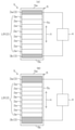
図1に示すように、第1実施形態の電池力発電装置1は蓄電部2と発電部3と電力供給制御部4とを有する。電池力発電装置1は、蓄電部2に蓄えた電力を外部の電力供給対象に供給し得る。電池力発電装置1は、車両等移動体に搭載される蓄電池として使用可能である。電池力発電装置1は、定置型の蓄電池としても使用可能である。
[First Embodiment]
[Constitution]
As shown in FIG. 1, the battery-powered power generation device 1 of the first embodiment has a
蓄電部2は、単電池2aを複数個積層した積層電池(組電池)LBである。隣接する単電池2a同士は互いに直列に接続されている。
The
発電部3は、第1発電体3a及び第2発電体3bを含む。第1発電体3aは、積層電池LBの積層方向Xにおける一端に設けられている。第2発電体3bは、積層電池LBの積層方向Xにおける他端に設けられている。第1発電体3a及び第2発電体3bは、それぞれ圧電素子を有して構成される。発電部3は、積層電池LBの積層方向Xへの膨張により圧縮されて発電する。発電部3は、積層電池LBの積層方向Xへの収縮により当該圧縮が解かれて発電する。
The
蓄電部2及び発電部3は、拘束体5により拘束されている。拘束体5は、蓄電部2及び発電部3を積層方向Xの両側から挟む一対のエンドプレート部5a、5bと、両エンドプレート部5a、5bを互いに接続し固定する連結部5cと、を有する。両エンドプレート部5a、5b間の距離は、厳密な意味ではなく一定である。
The
電力供給制御部4は、蓄電部2の充電時には、発電部3が発電した電力を蓄電部2に供給する。電力供給制御部4は、蓄電部2の放電時には、発電部3が発電した電力を外部の供給対象に供給する。電力供給制御部4は、例えば全波整流回路を含んで構成される。
When charging the
[作用]
電池力発電装置1は、外部の電力供給源からの電力を蓄電部2に蓄電(充電)し、蓄電部2の電力を外部の電力供給対象へ供給(放電)し得る。
[Action]
The battery-powered power generation device 1 can store (charge) the power from the external power supply source in the
蓄電部2は、充電時には積層方向Xに膨張し(図1(A))、放電時には積層方向Xに収縮する(図1(B))。
The
電池力発電装置1は、充放電に伴い膨張収縮する蓄電部2の力を利用して発電する。
The battery-powered power generation device 1 generates power by utilizing the power of the
すなわち、電池力発電装置1は、充電時には、蓄電部2が積層方向Xに膨張し、それに伴って発電部3が圧縮されることにより発電する。充電時に発電部3が発電した電力は、蓄電部2に充電される。
That is, in the battery-powered power generation device 1, when charging, the
そして、電池力発電装置1は、放電時には、蓄電部2が積層方向Xに収縮し、それに伴って発電部3の圧縮が解かれ、発電部3が膨張する(圧縮前の状態に戻る)ことにより発電する。充放電に発電部3が発電した電力は、外部の供給対象に供給される。
When the battery-powered power generation device 1 is discharged, the
[効果]
電池力発電装置1によれば、放電時には、蓄電部2の電力を外部の電力供給対象へ供給するのみならず、発電部3が発電した電力も外部の供給対象に供給することができるので、蓄電池としての出力性能を向上できる。
[effect]
According to the battery-powered power generation device 1, at the time of discharging, not only the electric power of the
電池力発電装置1によれば、充電時には、外部の電力供給源からの電力を蓄電部2に充電するのみならず、発電部3が発電した電力を蓄電部2に充電することができるので、蓄電池としての充電性能を向上できる。
According to the battery-powered power generation device 1, at the time of charging, not only the
[第2実施形態]
以下の説明では、既に説明した構成要素と共通する構成要素については同符号を付して、その説明を適宜省略する。
[Second Embodiment]
In the following description, the components common to the components already described will be designated by the same reference numerals, and the description thereof will be omitted as appropriate.
[構成]
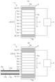
図2に示すように、第2実施形態の電池力発電装置11は蓄電部2と発電部3と電力供給制御部4とを有する。
[Constitution]
As shown in FIG. 2, the battery-powered
蓄電部2は、単電池2aを複数個積層した積層電池(組電池)LBである。
The
蓄電部2及び発電部3は、拘束体5により拘束されている。
The
単電池2aは、正電極12aと、負電極12bと、半固体電解質層12cと、を有する。
The
正電極12aは、正極層と正極集電体とを含む。正極層は、正極集電体と半固体電解質層12cとの間に介在する。
The
負電極12bは、負極層と負極集電体とを含む。負極層は、負極集電体と半固体電解質層12cとの間に介在する。
The
半固体電解質層12cは、電解液をゲル化剤で半固体化(ゲル化)した電解質からなる電解質層である。
The
[作用]
蓄電部2は、拘束体5で拘束されているが、発電部3が膨張収縮する範囲で積層方向Xに膨張収縮し得る。
単電池2aの内部では、正電極12a及び負電極12bのうちの少なくとも一方が積層方向Xに膨張収縮する。それに伴い、半固体電解質層12cは、正電極12a及び負電極12bとの接触を保ちつつ積層方向Xに膨張収縮する。
[Action]
Although the
Inside the
[効果]
電池力発電装置11によれば、半固体電解質層12cは、正電極12a及び負電極12bとの接触を保ちつつ積層方向Xに膨張収縮するので、蓄電池としての出力性能を比較的に向上できる。比較的とは、半固体電解質層12cに代えて固体電解質層(固体材料のみからなる電解質層)を使用した場合と比較してという意味である。すなわち、固体電解質層の場合、放電時に、例えば、正電極12aの収縮により、正極活物質と固体電解質との接点を維持することができず出力特性が低下してしまうことがあるが、半固体電解質層12cを使用することで正極活物質と電解質との接点を維持し、蓄電池としての出力特性の低下を抑制し得る。
その他の効果は第1実施形態と同様である。
[effect]
According to the battery-powered
Other effects are the same as in the first embodiment.
[第3実施形態] [Third Embodiment]
[構成]
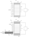
図3に示すように、第3実施形態の電池力発電装置21は蓄電部2と発電部3と電力供給制御部4とを有する。
[Constitution]
As shown in FIG. 3, the battery-powered
蓄電部2は、単電池2aを複数個積層した積層電池(組電池)LBである。
The
蓄電部2及び発電部3は、拘束体5により拘束されている。
The
単電池2aは、正電極12aと、負電極12bと、混成電解質層12dと、を有する。
The
正電極12aは、正極層と正極集電体とを含む。正極層は、正極集電体と混成電解質層12dとの間に介在する。
The
負電極12bは、負極層と負極集電体とを含む。負極層は、負極集電体と混成電解質層12dとの間に介在する。
The
混成電解質層12dは、固体電解質層12eと一対の半固体電解質層12f、12gとを含む。
The
固体電解質層12eは、固体材料のみからなる電解質層である。
The
半固体電解質層12f、12gは、電解液をゲル化剤で半固体化(ゲル化)した電解質からなる電解質層である。 The semi-solid electrolyte layers 12f and 12g are electrolyte layers made of an electrolyte obtained by semi-solidifying (gelling) an electrolytic solution with a gelling agent.
一方の半固体電解質層12fは、正電極12aと固体電解質層12eとの間に介在する。
One
他方の半固体電解質層12gは、負電極12bと固体電解質層12eとの間に介在する。
[作用]
蓄電部2は、拘束体5で拘束されているが、発電部3が膨張収縮する範囲で積層方向Xに膨張収縮し得る。
単電池2a内部では、正電極12a及び負電極12bのうちの少なくとも一方が積層方向Xに膨張収縮する。それに伴い、半固体電解質層12f、12gは、正電極12a及び負電極12bとの接触を保ちつつ積層方向Xに膨張収縮する。
The other
[Action]
Although the
Inside the
[効果]
電池力発電装置21によれば、半固体電解質層12f、12gは、正電極12a及び負電極12bとの接触を保ちつつ積層方向Xに膨張収縮するので、蓄電池としての出力性能を比較的に向上できる。比較的にとは、混成電解質層12dに代えて固体電解質層のみを使用した場合と比較してという意味である。すなわち、固体電解質層のみの場合、放電時に、例えば、正電極12aの収縮により、正極活物質と固体電解質との接点を維持することができず出力特性が低下してしまうことがあるが、混成電解質層12dすなわち固体電解質層12eと半固体電解質層12f、12gとを含む電解質層を使用することで正極活物質と電解質との接点を維持し、蓄電池としての出力特性の低下を抑制し得る。
その他の効果は第1実施形態と同様である。
[effect]
According to the battery-powered
Other effects are the same as in the first embodiment.
本発明は上記実施形態に限定されない。例えば、上記実施形態では、発電部3は第1発電体3a及び第2発電体3bを含んでいるが、第1発電体3a及び第2発電体3bのうちの一方は省略可能である。
The present invention is not limited to the above embodiment. For example, in the above embodiment, the
この明細書は少なくとも以下の構成を開示するものである。
膨張したり収縮したりする物体と、前記物体の膨張時に圧縮されて発電し、前記物体の収縮時に膨張し発電する発電体と、を有する発電装置。
この構成によれば、膨張したり収縮したりする物体の力を利用して発電をすることができる。
This specification discloses at least the following constitutions.
A power generation device having an object that expands or contracts, and a power generator that is compressed and generates power when the object expands and expands and generates power when the object contracts.
According to this configuration, power can be generated by utilizing the force of an object that expands or contracts.
充放電に伴い膨張収縮する蓄電部と、前記蓄電部の膨張時に圧縮されて発電し、前記蓄電部の収縮時に膨張し発電する発電部と、を有する電池力発電装置。
この構成によれば、充放電に伴い膨張収縮する蓄電部の力を利用して発電をすることができる。
A battery-powered power generation device having a power storage unit that expands and contracts with charging and discharging, and a power generation unit that is compressed and generates power when the power storage unit expands and expands and generates power when the power storage unit contracts.
According to this configuration, power can be generated by utilizing the force of the power storage unit that expands and contracts with charging and discharging.
充放電に伴い膨張収縮する蓄電部と、前記蓄電部の膨張時に圧縮されて発電し、前記蓄電部の収縮時に膨張し発電する発電部と、を有し、
前記蓄電部は、複数個の単電池を積層した積層電池(組電池)であり、
前記発電部は、前記積層電池の積層方向の膨張により圧縮されて発電し、前記積層電池の積層方向の収縮により当該圧縮が解かれて発電する、電池力発電装置。
この構成によれば、充放電に伴い膨張収縮する蓄電部の力を利用して発電をすることができる。
It has a power storage unit that expands and contracts with charging and discharging, and a power generation unit that is compressed and generates power when the power storage unit expands and expands and generates power when the power storage unit contracts.
The power storage unit is a laminated battery (combined battery) in which a plurality of single batteries are laminated.
The power generation unit is a battery-powered power generation device that is compressed by expansion of the laminated battery in the stacking direction to generate power, and is released by contraction of the laminated battery in the stacking direction to generate power.
According to this configuration, power can be generated by utilizing the force of the power storage unit that expands and contracts with charging and discharging.
充放電に伴い膨張収縮する蓄電部と、
前記蓄電部の膨張時に圧縮されて発電し、前記蓄電部の収縮時に膨張し発電する発電部と、
前記蓄電部の充電時には、前記発電部が発電した電力を前記蓄電部に供給し、前記蓄電部の放電時には、前記発電部が発電した電力を外部の供給対象に供給するための電力供給制御部と、を有する、電池力発電装置。
この構成によれば、放電時には、蓄電部の電力を外部の電力供給対象へ供給するのみならず、発電部が発電した電力も外部の供給対象に供給することができるので、蓄電池としての出力性能を向上できる。そして、充電時には、外部の電力供給源からの電力を蓄電部に充電するのみならず、発電部が発電した電力を蓄電部に充電することができるので、蓄電池としての充電性能を向上できる。
A storage unit that expands and contracts with charging and discharging,
A power generation unit that is compressed to generate electricity when the power storage unit expands and expands to generate power when the power storage unit contracts.
When charging the power storage unit, the power generated by the power generation unit is supplied to the power storage unit, and when the power storage unit is discharged, the power supply control unit for supplying the power generated by the power generation unit to an external supply target. And, with a battery-powered power generator.
According to this configuration, at the time of discharging, not only the electric power of the storage unit can be supplied to the external power supply target, but also the electric power generated by the power generation unit can be supplied to the external supply target, so that the output performance as a storage battery can be obtained. Can be improved. At the time of charging, not only the power storage unit is charged with the electric power from the external power supply source, but also the power generation unit can be charged with the power generation unit, so that the charging performance as a storage battery can be improved.
充放電に伴い膨張収縮する蓄電部と、前記蓄電部の膨張時に圧縮されて発電し、前記蓄電部の収縮時に膨張し発電する発電部と、を有し、
前記蓄電部の電解質層は、半固体電解質を含む、電池力発電装置。
この構成によれば、蓄電部の電解質層が固体電解質のみからなる場合と比較して、電極活物質と電解質との接点を安定に維持し得るので、蓄電池としての出力性能を向上できる。
It has a power storage unit that expands and contracts with charging and discharging, and a power generation unit that is compressed and generates power when the power storage unit expands and expands and generates power when the power storage unit contracts.
The electrolyte layer of the power storage unit is a battery-powered power generation device containing a semi-solid electrolyte.
According to this configuration, the contact point between the electrode active material and the electrolyte can be stably maintained as compared with the case where the electrolyte layer of the power storage unit is composed of only the solid electrolyte, so that the output performance as a storage battery can be improved.
充放電に伴い膨張収縮する蓄電部と、前記蓄電部の膨張時に圧縮されて発電し、前記蓄電部の収縮時に膨張し発電する発電部と、を有し、
前記蓄電部の電解質層は、固体電解質と半固体電解質とを含む、電池力発電装置。
この構成によれば、蓄電部の電解質層が固体電解質のみからなる場合と比較して、電極活物質と電解質との接点を安定に維持し得るので、蓄電池としての出力性能を向上できる。
It has a power storage unit that expands and contracts with charging and discharging, and a power generation unit that is compressed and generates power when the power storage unit expands and expands and generates power when the power storage unit contracts.
The electrolyte layer of the power storage unit is a battery-powered power generation device including a solid electrolyte and a semi-solid electrolyte.
According to this configuration, the contact point between the electrode active material and the electrolyte can be stably maintained as compared with the case where the electrolyte layer of the power storage unit is composed of only the solid electrolyte, so that the output performance as a storage battery can be improved.
固体電解質と半固体電解質とを含む電解質層を有する蓄電池。
この構成によれば、電解質層が固体電解質のみからなる蓄電池と比較して、電極活物質と電解質との接点を安定に維持し得るので、蓄電池の出力性能を向上できる。
A storage battery having an electrolyte layer containing a solid electrolyte and a semi-solid electrolyte.
According to this configuration, the contact point between the electrode active material and the electrolyte can be stably maintained as compared with the storage battery in which the electrolyte layer is composed of only the solid electrolyte, so that the output performance of the storage battery can be improved.
1 電池力発電装置
2 蓄電部
2a 単電池(蓄電池)
3 発電部
3a 第1発電体
3b 第2発電体
4 電力供給制御部
5 拘束体
5a エンドプレート部
5b エンドプレート部
5c 連結部
11 電池力発電装置
12c 半固体電解質層
12d 混成電解質層
12e 固体電解質層
12f 半固体電解質層
12g 半固体電解質層
21 電池力発電装置
LB 積層電池(組電池)
X 積層方向
1 Battery-powered
3
X Stacking direction
Claims (6)
前記蓄電部の膨張時に圧縮されて発電し、前記蓄電部の収縮時に膨張し発電する発電部と、を有する電池力発電装置。 A storage unit that expands and contracts with charging and discharging,
A battery-powered power generation device comprising a power generation unit that is compressed to generate power when the power storage unit expands and expands to generate power when the power storage unit contracts.
前記発電部は、前記積層電池の積層方向の膨張により圧縮されて発電し、前記積層電池の積層方向の収縮により当該圧縮が解かれて発電する、請求項1の電池力発電装置。 The power storage unit is a laminated battery in which a plurality of single batteries are laminated.
The battery-powered power generation device according to claim 1, wherein the power generation unit is compressed by expansion in the stacking direction of the laminated batteries to generate power, and the compression is released by contraction in the stacking direction of the laminated batteries to generate power.
前記蓄電部の放電時には、前記発電部が発電した電力を外部の供給対象に供給するための電力供給制御部を有する、請求項2の電池力発電装置。 At the time of charging the power storage unit, the electric power generated by the power generation unit is supplied to the power storage unit.
The battery-powered power generation device according to claim 2, further comprising a power supply control unit for supplying the power generated by the power generation unit to an external supply target when the power storage unit is discharged.
Priority Applications (1)
| Application Number | Priority Date | Filing Date | Title |
|---|---|---|---|
| JP2022000002A JP2022040192A (en) | 2022-01-01 | 2022-01-01 | Battery power generator |
Applications Claiming Priority (1)
| Application Number | Priority Date | Filing Date | Title |
|---|---|---|---|
| JP2022000002A JP2022040192A (en) | 2022-01-01 | 2022-01-01 | Battery power generator |
Publications (1)
| Publication Number | Publication Date |
|---|---|
| JP2022040192A true JP2022040192A (en) | 2022-03-10 |
Family
ID=80498819
Family Applications (1)
| Application Number | Title | Priority Date | Filing Date |
|---|---|---|---|
| JP2022000002A Pending JP2022040192A (en) | 2022-01-01 | 2022-01-01 | Battery power generator |
Country Status (1)
| Country | Link |
|---|---|
| JP (1) | JP2022040192A (en) |
-
2022
- 2022-01-01 JP JP2022000002A patent/JP2022040192A/en active Pending
Similar Documents
| Publication | Publication Date | Title |
|---|---|---|
| KR101815287B1 (en) | Hybrid power system for unmanned aerial vehicle | |
| US9018909B2 (en) | Battery pack | |
| JP4377565B2 (en) | Plate battery connection structure | |
| KR20140064418A (en) | Secondary battery module | |
| US20150017504A1 (en) | Battery unit, battery module, power storage system, electronic device, power system, and electric vehicle | |
| JPH09503333A (en) | Rechargeable battery cell with integrated vibrating means | |
| WO2020194937A1 (en) | Power supply device, and electric vehicle and electrical storage device each equipped with same | |
| US20140255762A1 (en) | Secondary battery including plurality of electrode assemblies | |
| KR20150049959A (en) | Battery pack assembly can absorb the external shock | |
| JP2013200940A (en) | Power storage device | |
| CN113632300A (en) | Power supply device, electric vehicle using the same, and power storage device | |
| JP7022308B2 (en) | Battery module | |
| JP2010108751A (en) | Battery | |
| JP2009231042A (en) | Electricity storage device and vehicle | |
| WO2020261727A1 (en) | Power supply device, electric vehicle comprising said power supply device, and power storage device | |
| KR20190082180A (en) | Secondary Battery Module | |
| JP6648561B2 (en) | Power system | |
| CN115023849A (en) | Power supply device, and electrically powered vehicle and power storage device using same | |
| JP2020074320A (en) | Stacked storage battery and storage battery system including the same | |
| WO2020262085A1 (en) | Power source device, electric vehicle equipped with said power source device, and power storage device | |
| JP6754111B2 (en) | Stacked storage battery and storage battery system using it | |
| Thangavelautham et al. | Hybrid fuel cell power for long duration robot missions in field environments | |
| CN107611527B (en) | Fuel cell and lithium ion battery composite power supply device | |
| KR20200056376A (en) | Secondary Battery Module | |
| JP7003888B2 (en) | Battery module |
Legal Events
| Date | Code | Title | Description |
|---|---|---|---|
| A521 | Request for written amendment filed |
Free format text: JAPANESE INTERMEDIATE CODE: A523 Effective date: 20220111 |