JP2022029250A - Descending window opening and closing auxiliary tool - Google Patents
Descending window opening and closing auxiliary tool Download PDFInfo
- Publication number
- JP2022029250A JP2022029250A JP2020132490A JP2020132490A JP2022029250A JP 2022029250 A JP2022029250 A JP 2022029250A JP 2020132490 A JP2020132490 A JP 2020132490A JP 2020132490 A JP2020132490 A JP 2020132490A JP 2022029250 A JP2022029250 A JP 2022029250A
- Authority
- JP
- Japan
- Prior art keywords
- spring
- descending window
- gear
- arm
- compression spring
- Prior art date
- Legal status (The legal status is an assumption and is not a legal conclusion. Google has not performed a legal analysis and makes no representation as to the accuracy of the status listed.)
- Granted
Links
Images


Classifications
-
- Y—GENERAL TAGGING OF NEW TECHNOLOGICAL DEVELOPMENTS; GENERAL TAGGING OF CROSS-SECTIONAL TECHNOLOGIES SPANNING OVER SEVERAL SECTIONS OF THE IPC; TECHNICAL SUBJECTS COVERED BY FORMER USPC CROSS-REFERENCE ART COLLECTIONS [XRACs] AND DIGESTS
- Y02—TECHNOLOGIES OR APPLICATIONS FOR MITIGATION OR ADAPTATION AGAINST CLIMATE CHANGE
- Y02T—CLIMATE CHANGE MITIGATION TECHNOLOGIES RELATED TO TRANSPORTATION
- Y02T30/00—Transportation of goods or passengers via railways, e.g. energy recovery or reducing air resistance
Abstract
Description
本発明は、鉄道車両の窓の開閉機構に関するものであり、特に、通勤用途に適した近郊型車両において、側下降窓の開閉操作を容易にするための下降窓開閉補助具に関する。 The present invention relates to a window opening / closing mechanism of a railroad vehicle, and more particularly to a descending window opening / closing assisting tool for facilitating an opening / closing operation of a side descending window in a suburban vehicle suitable for commuting.
鉄道車両の下降窓の昇降機構に対して用いられるバランサ(釣合装置)としては、主に2種類のタイプのものが知られている。 There are mainly two types of balancers (balancers) used for the elevating mechanism of the descending window of a railway vehicle.
一つは、下降窓を閉方向(上向き)に付勢する揺動アームを用いた揺動アーム式(シュリーレン式とも呼ばれる。)のバランサであり、もう一つは、スパイラル式のバランサである。スパイラル式は軽量窓(単板ガラス構造)にしか対応できないが、揺動アーム式はスパイラル式と比較して質量の大きい昇降窓にも対応可能である。 One is a swing arm type (also called a Schlieren type) balancer using a swing arm that urges the descending window in the closed direction (upward), and the other is a spiral type balancer. The spiral type can only be used for lightweight windows (single plate glass structure), but the swing arm type can also be used for elevating windows, which have a larger mass than the spiral type.
揺動アーム式のバランサは、リンク機構と複数本のバネを用いて構成される。ところで、複層ガラス構造による1000mm幅の窓の質量は約30kgになり、乗客が補助無しで容易に持ち上げられるものではない。この高重量の窓を揺動アーム式のバランサで支える場合、20~24本のバネが必要となる。揺動アーム式の機構では、窓の質量と操作力とを考慮して補助に必要なバネの本数を変更できる構造となっている。このような揺動アーム式のバランサの構成については、特許文献1に開示されている。
The swing arm type balancer is configured by using a link mechanism and a plurality of springs. By the way, the mass of a 1000 mm wide window due to the double glazing structure is about 30 kg, and passengers cannot easily lift it without assistance. When supporting this heavy window with a swing arm type balancer, 20 to 24 springs are required. The swing arm type mechanism has a structure in which the number of springs required for assistance can be changed in consideration of the mass of the window and the operating force. The configuration of such a swing arm type balancer is disclosed in
一方、スパイラル式のバランサは、窓一つに対して両側に設置される2本のスパイラルバネのねじり量に応じて生じる反発力によって窓の開閉操作を補助する構造となっている。このようなスパイラル式のバランサの構成については、特許文献2に開示されている。
On the other hand, the spiral balancer has a structure that assists the opening and closing operation of the window by the repulsive force generated according to the twist amount of the two spiral springs installed on both sides of one window. The configuration of such a spiral balancer is disclosed in
近年では、ダブルスキン構造を有するアルミニウム合金製の構体が主流となっており、従来のステンレス鋼を用いたシングルスキン構造の構体よりも窓の下の空間が狭くなっていることが多い。これに対して、揺動アーム式のバランサでは、複数のバネを使用し複雑なリンク機構を用いていることから装置の厚みが大きくなる。よって、たとえば、ダブルスキン構造において、一定の客室空間を確保するためには、側構体の一部を切り欠くといった対応が必要になる。場合によっては、十分な設置スペースを確保できないために、適用できない車種もある。また、一部が切り欠かれた側構体には、補強を入れるなどの対策が必要となる。さらに、バネ本数が多いならびに複雑なリンク構成では、メンテナンスに時間を要する上に、装置の重量が増大してしまう。 In recent years, an aluminum alloy structure having a double-skin structure has become the mainstream, and the space under the window is often narrower than that of a conventional single-skin structure using stainless steel. On the other hand, in the swing arm type balancer, since a plurality of springs are used and a complicated link mechanism is used, the thickness of the device becomes large. Therefore, for example, in the double-skin structure, in order to secure a certain guest room space, it is necessary to cut out a part of the side structure. In some cases, it may not be applicable to some models because sufficient installation space cannot be secured. In addition, it is necessary to take measures such as adding reinforcement to the side structure that is partially cut out. Further, in a link configuration having a large number of springs and a complicated link configuration, maintenance is required and the weight of the device is increased.
また、スパイラル式のバランサでは、比較的バネの反発力が小さいので、上で述べたように軽量窓にしか適用できない。そして、設置の際の調整は一つの窓に対して同時に2人で行う必要があり、揺動アーム式の倍の作業時間を要する。取り付け後の再調整では、カーテンを収納するカーテンキセや、カーテン下端の横棒をガイドする溝が形成されたカーテン溝島などを取り外さなければならないため、復旧に時間を要する。 In addition, since the repulsive force of the spring is relatively small in the spiral type balancer, it can be applied only to lightweight windows as described above. Further, the adjustment at the time of installation needs to be performed by two people at the same time for one window, which requires twice the working time of the swing arm type. In the readjustment after installation, it takes time to recover because it is necessary to remove the curtain squeeze for storing the curtain and the curtain groove island where the groove for guiding the horizontal bar at the lower end of the curtain is formed.
上述の揺動アーム式及びスパイラル式の何れのバランサにおいても、閉状態と全開状態との間でバネの抵抗力に大きな差が生じるので、スムーズに開閉操作を行うことが難しい。 In any of the above-mentioned swing arm type and spiral type balancers, there is a large difference in the resistance force of the spring between the closed state and the fully open state, so that it is difficult to smoothly open and close the balancer.
そこで、本発明は、コンパクトな構造でありながら閉状態から全開状態にかけて生じるバネの反発力に基づく負荷の急激な上昇を低減させることにより、スムーズな開閉操作を可能にし、且つ、設置を容易にする下降窓開閉補助具を提供することを目的とする。 Therefore, the present invention enables smooth opening / closing operation and facilitates installation by reducing a rapid increase in load due to the repulsive force of the spring generated from the closed state to the fully open state despite the compact structure. It is an object of the present invention to provide a descending window opening / closing assisting tool.
上記目的を達成するために、本発明の下降窓開閉補助具は、鉄道車両の下降窓の開閉操作を補助する下降窓開閉補助具であって、前記下降窓の下方に配置される本体と、一端が前記下降窓の下方で上下に旋回できるように、他端が前記本体に軸支されているアームと、前記アームを旋回させる回転運動を往復運動に変換する変換部と、前記下降窓を持ち上げる向きに前記アームを旋回させるように、前記変換部の往復運動を付勢する付勢バネと、前記付勢バネに直列に配置され、内蔵するバネ材を圧縮状態で保持するストッパーが圧縮方向へのみ可動となっているバネユニットとを備えたことを特徴とする。 In order to achieve the above object, the descending window opening / closing assisting tool of the present invention is a descending window opening / closing assisting tool that assists the opening / closing operation of the descending window of a railroad vehicle, and has a main body arranged below the descending window and a main body. An arm whose other end is pivotally supported by the main body so that one end can swivel up and down below the descending window, a conversion unit that converts a rotational motion that swivels the arm into a reciprocating motion, and the descending window. An urging spring that urges the reciprocating motion of the conversion unit and a stopper that is arranged in series with the urging spring and holds the built-in spring material in a compressed state so as to rotate the arm in the lifting direction are in the compression direction. It is characterized by having a spring unit that is movable only to the window.
また、本発明の下降窓開閉補助具は、上記構成に加えて、前記変換部が、前記アームの旋回中心に取り付けられたギアと、前記ギアの回転運動を往復運動に変換するラックとを備えたことを特徴とする。 Further, in addition to the above configuration, the descending window opening / closing assisting tool of the present invention includes a gear in which the conversion unit is attached to the turning center of the arm, and a rack that converts the rotational motion of the gear into a reciprocating motion. It is characterized by that.
また、本発明の下降窓開閉補助具は、上記構成に加えて、前記変換部が、前記ギアと前記ラックとの間に、前記ギアの回転を減速させる中間ギアを備えていることを特徴とする。 Further, the descending window opening / closing assisting tool of the present invention is characterized in that, in addition to the above configuration, the conversion unit includes an intermediate gear for decelerating the rotation of the gear between the gear and the rack. do.
また、本発明の下降窓開閉補助具は、上記構成に加えて、前記変換部の前記付勢バネが、前記ラックの往復運動を付勢する圧縮バネであることを特徴とする。 Further, the descending window opening / closing assisting tool of the present invention is characterized in that, in addition to the above configuration, the urging spring of the conversion unit is a compression spring that urges the reciprocating motion of the rack.
また、本発明の下降窓開閉補助具は、上記構成に加えて、前記変換部が、前記アームの旋回中心に取り付けられたギアと、前記ギアの回転力を、連接棒を介して前記バネユニットの伸縮方向に沿った往復運動に変換するクランク部とを備えたことを特徴とする。 Further, in the descending window opening / closing assisting tool of the present invention, in addition to the above configuration, the conversion unit transfers the gear attached to the turning center of the arm and the rotational force of the gear to the spring unit via the connecting rod. It is characterized by having a crank portion that converts the reciprocating motion along the expansion / contraction direction of the connecting rod.
以上のように、本発明によれば、下降窓の下方に配置された本体に対して旋回可能にアームが軸支されているので、旋回するアームが下降窓を下方から持ち上げることができる。 As described above, according to the present invention, since the arm is pivotally supported with respect to the main body arranged below the descending window, the swivel arm can lift the descending window from below.
アームの旋回による回転運動は変換部で往復運動に変換される。この往復運動は、アームが下降窓を持ち上げるように付勢されているので、開閉操作において、この付勢に基づく力が担う分だけ下降窓の重量が軽減される。 The rotational motion due to the turning of the arm is converted into a reciprocating motion by the conversion unit. In this reciprocating motion, the arm is urged to lift the descending window, so that the weight of the descending window is reduced by the amount of the force based on this urging in the opening / closing operation.
付勢バネと直列に配置されるバネユニットは、内蔵されるバネ材が圧縮状態で保持されている。このバネ材を保持しているストッパーは圧縮方向へのみ可動となっているので、付勢バネの力が内蔵バネの力を越えると、付勢バネ及び内蔵バネは直列の合成バネとして作用する。すなわち、アームに作用する力が、付勢バネ単独から合成バネに移行する際に、全体のバネ定数が低下する。これにより、付勢に基づく力の変化が緩和され、スムーズな操作感が得られる。 In the spring unit arranged in series with the urging spring, the built-in spring material is held in a compressed state. Since the stopper holding this spring material is movable only in the compression direction, when the force of the urging spring exceeds the force of the built-in spring, the urging spring and the built-in spring act as a series synthetic spring. That is, when the force acting on the arm shifts from the urging spring alone to the synthetic spring, the overall spring constant decreases. As a result, the change in force based on the urging is alleviated, and a smooth operation feeling can be obtained.
また、本発明によれば、上記効果に加えて、ギアとラックを用いて変換部が構成されているので、スムーズな操作感を得ることができる上に、変換部を含む本体を薄型に形成す
ることができる。
Further, according to the present invention, in addition to the above effects, since the conversion unit is configured by using gears and racks, a smooth operation feeling can be obtained and the main body including the conversion unit is formed thin. can do.
また、本発明によれば、上記効果に加えて、ギアの回転を減速させてラックへ伝達されるので、アームの動きに対してラックの往復運動を小さい範囲に設定することができる。これにより、付勢バネ及びバネユニットによる力の特性のうち、変化の緩やかな領域が狭小な範囲であっても有効に利用することができる。 Further, according to the present invention, in addition to the above effect, the rotation of the gear is decelerated and transmitted to the rack, so that the reciprocating motion of the rack can be set in a small range with respect to the movement of the arm. As a result, among the characteristics of the force due to the urging spring and the spring unit, even if the region where the change is gradual is a narrow range, it can be effectively used.
また、本発明によれば、上記効果に加えて、圧縮バネを用いると簡易な構成により耐久性の高い設計が容易になる。 Further, according to the present invention, in addition to the above effects, the use of a compression spring facilitates a highly durable design due to a simple configuration.
また、本発明によれば、上記効果に加えて、変換部がクランク機構により構成されているので、ギアのみの構成と比較して往復動作における衝撃を低減できる。また、クランク部の連接棒の位相とバネユニットの位置との関係における力の変化を利用して、下降窓の開閉位置に対する荷重の変化を調整することが可能となる。 Further, according to the present invention, in addition to the above effects, since the conversion unit is configured by the crank mechanism, the impact in the reciprocating operation can be reduced as compared with the configuration of only the gear. Further, it is possible to adjust the change in the load with respect to the opening / closing position of the descending window by utilizing the change in the force in the relationship between the phase of the connecting rod of the crank portion and the position of the spring unit.
以下、本発明の実施の形態に係る下降窓開閉補助具について図を用いて説明する。 Hereinafter, the descending window opening / closing assisting tool according to the embodiment of the present invention will be described with reference to the drawings.
(第1の実施の形態)
図1は、本発明の第1の実施の形態に係る下降窓開閉補助具1を表している。図1(a)は全体斜視図、図1(b)は内部構造を確認できるように、後述する本体2の一部を破断させた斜視図である。
(First Embodiment)
FIG. 1 represents a descending window opening / closing assisting
図1に示すように、下降窓開閉補助具1は、本体2と、この本体2に対して旋回可能に一端が軸支されたアーム4を備えている。アーム4の先端には、回転自在にローラ4aが設けられている。アーム4の旋回中心となる軸は、本体2内のギア12に接続されている。このギア12の回転力に基づく動力は、中間ギア16を介してラック14に伝達されるように構成されている。中間ギア16は、ギア12側の動きを下歯車16bで受け、速度を減じて上歯車16aに伝達する減速ギアである。中間ギア16の動力は水平方向に延びるように配置されたラック14に伝達される。本実施の形態に係る構成では、中間ギア16によってギア12の回転による動きをほぼ半減させてラック14に伝達することができる。
As shown in FIG. 1, the descending window opening / closing assisting
ラック14の一端側には、バネユニット8が配置されている。このバネユニット8には、バネ材として圧縮バネ8bが内蔵されている。圧縮バネ8bは圧縮状態で一端をストッパー8aによって封止されている。圧縮バネ8bの内側にはボルト状のガイド8cが貫通して配置されており、このガイド8cに沿ってスライド可能にストッパー8aが設けられている。ストッパー8aはガイド8cの頭部により規制され、圧縮バネ8bの伸長を阻止している。ガイド8cの先端はラック14に螺合されており、圧縮バネ8bの圧縮の程度はガイド8cのねじ込み量によって調節される。圧縮状態で収容されている圧縮バネ8b
の反発力を越える力を外側からストッパー8aに加えると、ストッパー8aがラック14側へ押し込まれるように構成されている。
A
When a force exceeding the repulsive force of the above is applied to the
ストッパー8aに一端を当接させるようにして圧縮バネ6がバネユニット8(の圧縮バネ8b)と直列に配置されている。圧縮バネ6の他端側は、調節部20によって封止されている。調節部20は、固定壁22と可動壁24とを有している。頭部を圧縮バネ6側に配置したボルト状の調節軸26が、固定壁22及び可動壁24を貫通して配置されている。本体2の外側に突出した調節軸26の端部を把持して回すと、固定壁22の位置を基準として可動壁24と共に調節軸26の頭部がスライドする。これにより圧縮バネ6の圧縮の程度を調節することができる。調節された調節軸26は、外側の固定ナット28によって固定される。
The
図2は、下降窓開閉補助具1の使用状態を示す正面図である。図1に示した下降窓開閉補助具1が側構体100の下降窓101の下方空間に設けられている。旋回するアーム4の先端にはローラ4aが設けられており、このローラ4aを下降窓101の下端に当接させるようにして持ち上げて、下降窓101を支える構成となっている。下降窓101に対して持ち上げる向きにアーム4から付勢が作用しており、下降窓101の重量を軽減するように設定されている。
FIG. 2 is a front view showing a usage state of the descending window opening /
本体2は、図1に示したようにギア類をケースで囲むだけの、シンプルな薄型構造となっている。中間ギア16についてもギア比の異なる歯を一体的に形成した構造とし、厚さの低減に寄与している。これにより、近年のダブルスキン構造によるアルミニウム合金製の構体内の限られたスペースにも、構体に切り欠きを形成することなく収容できる。
As shown in FIG. 1, the
図3は、本体2の内部の動作を表している。図3(a)は下降窓の閉状態、図3(b)は開状態を示している。ローラを含むアーム4の先端側は、説明の便宜のため図示を省略している。
FIG. 3 shows the internal operation of the
まず、図3(a)を参照して、力の伝達経路を辿りながら各構成の動きを見ていく。アーム4が上方(閉方向)へ旋回する向きは図中に矢印A1で示している。上方へアーム4が旋回するときのギア12の回転方向は矢印A2の向きとなる。さらに、このときギア12の回転を伝達する中間ギア16の回転の向きは、矢印A3の向きになる。これにより、ラック14は矢印A4の向きに直線運動を行う。同様に、図3(b)には、開方向に対する各構成の動きを矢印B1からB4(それぞれが矢印A1からA4に対して逆向き)で表している。
First, with reference to FIG. 3A, the movement of each configuration will be observed while following the force transmission path. The direction in which the
図3(a)と図3(b)とを比較すると分かるように、図3(a)の閉状態では、バネユニット8のストッパー8aはガイド8cの左端に位置しているが、図3(b)の開状態では、ストッパー8aはガイド8cの左端から離れてラック14側に押し込まれている。図3(a)の状態から図3(b)の状態になるとき、ラック14の開方向移動量は距離D1となる。このとき、バネユニット8のガイド8cの左端からストッパー8aは距離D2だけ離れている。
As can be seen by comparing FIG. 3A and FIG. 3B, in the closed state of FIG. 3A, the
本実施の形態に係る構成では、バネユニット8の圧縮バネ8bの初期状態の弾性反発力は、閉状態における圧縮バネ6の弾性反発力よりも大きくなるように設定されている。すなわち、ストッパー8aがガイド8cの左端を離れるまでは、実質的に、圧縮バネ6の弾性反発力だけが、アーム4を下降窓101(図2参照)の閉方向へ旋回させるための付勢として作用している。しかし、アーム4の開方向への旋回角度がある領域を越えると、圧縮バネ6の弾性反発力がバネユニット8の圧縮バネ8bの弾性反発力を上回り、ストッパー8aがガイド8cの左端から離れる。このとき、圧縮バネ6と圧縮バネ8bとが直列に
合成された合成バネとして作用している。したがって、見かけ上のバネ定数は、圧縮バネ6のバネ定数K1から合成バネのバネ定数K2へと変化する。一般に、バネを直列に接続するとバネ定数は低下する。このため、合成バネのバネ定数K2は、圧縮バネ6単独のバネ定数K1より小さい。この合成バネが作用する動作領域で開閉操作を行えるように設定すると、圧縮バネ6単独による弾性反発力よりも変化が緩やかであるため、利用者はスムーズな操作感で開閉操作を行うことができる。
In the configuration according to the present embodiment, the elastic repulsive force of the
ここで、下降窓開閉補助具1のバネ特性を参照しながら動作説明を行う。
Here, the operation will be described with reference to the spring characteristics of the descending window opening /
図4は、本体2に用いられている圧縮バネ6、8bの特性を表した図である。図4の縦軸はバネ反力(荷重)を表し、横軸は下降窓の開度の拡大に伴って増大するラック14の開方向移動量を表している。
FIG. 4 is a diagram showing the characteristics of the compression springs 6 and 8b used in the
ラック14の開方向移動量が小さい領域から大きい領域にかけて直線の傾きが変化しているのが見て取れる。下降窓の開度が大きくなるほど、バネ反力が大きくなるのが分かる。開方向移動量が小さい領域は、圧縮バネ6のみが付勢を生じている領域であって、圧縮バネ6のばね定数K1の特性だけが表れている。一方、開方向移動量が大きい領域は、図3を用いて上述した合成バネの付勢が作用している領域である。図3(b)に示したように、バネユニット8のストッパー8aがガイド8cの左端から離れる程度に圧縮バネ6の力が増大した状態がこの領域に相当する。合成バネのバネ定数はK2であり、圧縮バネ6のバネ定数K1よりも小さい。したがって、バネ定数K2の領域では、バネ特性の傾きも緩やかになっている。
It can be seen that the slope of the straight line changes from the region where the amount of movement in the opening direction of the
釣り合い位置Bは、このバネ定数K2の領域にあり、アーム4の旋回位置がほぼ水平になった状態で釣り合うように設定されている。なお、具体的には、質量30kgの窓を7kg重程度の力で閉じることができるような設定となっている。
The equilibrium position B is in the region of the spring constant K2, and is set so as to be balanced in a state where the turning position of the
ところで、本実施の形態にかかる構成では、ギア12の動きは中間ギア16によって減速されてラック14に伝達されることは上述した。これにより、アーム4の動作に対するラック14の可動域は小さく抑えられる。すなわち、図4に示したラック14の開方向移動量L1からL2のような狭い範囲にラック14の可動域Rを収めるように設定すると、付勢が緩やかに変化する領域を利用することができる。これにより、利用者は開度に関わらず荷重変化の少ないスムーズな操作が可能となる。
By the way, in the configuration according to the present embodiment, it has been described above that the movement of the
以上のように、本発明の下降窓開閉補助具では、下降窓を閉じる向きに付勢を与えるバネ機構として、予め圧縮したバネユニットを含む直列配置の合成バネが用いられている。このようにバネ機構の一部をユニット化することにより、比較的自然長の長いバネ材を短くした状態で取り扱うことができるので、組立作業やメンテナンス時の調整作業が容易になるという利点がある。よって、比較的バネ定数の小さいバネ材を、バネ反力の高い状態で利用しやすい。すなわち、バネユニット8に比較的バネ定数の小さい圧縮バネ8bを用いた上で、この圧縮バネ8bと圧縮バネ6とを直列に配置して合成バネとして作用させることによりさらに全体のバネ定数を小さくすることができる。これにより、省スペースであってもバネ定数の小さいバネ材から十分な力を得ることが可能となる。
As described above, in the descending window opening / closing assisting tool of the present invention, a synthetic spring arranged in series including a precompressed spring unit is used as a spring mechanism for urging the descending window in the closing direction. By unitizing a part of the spring mechanism in this way, it is possible to handle the spring material with a relatively long natural length in a short state, which has the advantage of facilitating assembly work and adjustment work during maintenance. .. Therefore, it is easy to use a spring material having a relatively small spring constant in a state where the spring reaction force is high. That is, after using a
これに加えて、アーム4の回転による動きを縮小して伝達し、ラック14に繋がる圧縮バネ6及び圧縮バネ8bの作用範囲を小さく抑えるために中間ギア16が採用されている。このように構成されているので、全体のバネ特性において、ラックの開放移動量が比較的小さい範囲を選択して設定することができる(図4の可動域R)。すなわち、シュリーレン式の構成のように複雑なリンク機構を用いることなく、変動の少ない作用範囲を上述の調節部20によって選択することができるので、下降窓の開閉操作をスムーズに行うこ
とができる。さらに、バネ反力の変動を緩やかに設定できることを利用して、開閉途中の下降窓を任意の場所で停止させるフリーストップに近い状態を実現することも可能である。
In addition to this, an
(第2の実施の形態)
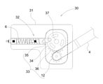
図5は、本発明の第2の実施の形態に係る下降窓開閉補助具30を示す図である。ここでは、第1の実施の形態において示した下降窓開閉補助具1と同一の構成については、同一の符号を用いて説明することとする。また、図5は図3の説明と同様に、本体31内部の構造が分かりやすいように、正面側の一部を切り欠いて表しており、アーム4の先端の構造は図示を省略している。
(Second embodiment)
FIG. 5 is a diagram showing a descending window opening /
アーム4によって下降窓101(図2参照)の開閉に基づく外力が入力され、このアーム4の旋回力を往復運動に変換して圧縮バネ6で受けるという概略の構成は、第1の実施の形態に示した下降窓開閉補助具1と共通である。しかし、回転力を往復運動に変換する変換部33の構成が異なっている。以下では、この変換部33を中心に説明を行う。
The schematic configuration in which an external force based on the opening and closing of the descending window 101 (see FIG. 2) is input by the
図1の下降窓開閉補助具1と異なり、変換部33は、ギア12とラック14の構成ではなく、ギア12とクランク部34によって構成されている。クランク部34には、アーム4の旋回中心に設けられたギア12と噛み合う円弧状ギア部36を有している。そして、クランク部34の回転中心からの距離が円弧状ギア部36よりも近い位置に連接棒35の一端が接続されている。この連接棒35の他端は図1のバネユニット8に相当するバネユニット32に連結されている。このように構成されているので、ギア12から伝達される回転力は、クランク部34及び連接棒35を介して往復運動に変換され、バネユニット32に伝達される。なお、上述のように、円弧状ギア部36の方が、連接棒35の連結位置よりもクランク部34のクランクシャフト37から遠い位置に設けられているので、ギア12から伝達される回転運動を減速させる作用が生じる。すなわち、第1の実施の形態に示した中間ギア16によるギア比による減速作用は、連接棒35の取り付け位置によって調節することができる。
Unlike the descending window opening /
バネユニット32については、連接棒35が回転自在に連結できるように構成されている以外は、第1の実施の形態の構成と実質的に同一である。
The
下降窓101の開放に伴って旋回するアーム4により回転力が入力され、それに応じて徐々に連接棒35がバネユニット32を押し込む。これにより、バネユニット32の圧縮バネ32bの強度をもう一方の圧縮バネ6の力が越える時点で両者が合成バネとして作用する。
A rotational force is input by the
なお、変換部33としてクランク機構を用いる場合、ギアとラックの組み合わせによる変換機構とは異なり、回転の位相に対する連接棒35の連結位置を調節することによって、往復運動側にピークとなるポイントを設定することができる。これにより、窓の開閉に伴う操作感を様々に設定することも可能である。
When the crank mechanism is used as the
<変形例>
図6は、図5の下降窓開閉補助具30の変形例である下降窓開閉補助具40を示す図である。図5の場合と同様に、第1の実施の形態において示した下降窓開閉補助具1と同一の構成については、同一の符号を用いて説明することとする。また、本体内部の構造が分かりやすいようにする図示の形態も同様である。
<Modification example>
FIG. 6 is a diagram showing a descending window opening /
第1の実施の形態と比べて、アーム4、ギア12および圧縮バネ6については同様の構成であるが、変換部43の構成が異なっている。図6の変換部43はカム機構によって構
成されている。
Compared with the first embodiment, the
本体41内には、ギア12と同一平面内に板カム44が設けられている。この板カム44の縁の一部には、図5のクランク部34の円弧状ギア部36と同様の円弧状ギア部46が形成されている。そして、カムシャフト47からの半径が変化してカム作用が得られる位置に、バネユニット42に設けられた従動節45が当接するように構成されている。このように構成されているので、アーム4の旋回によって入力された回転力は、ギア12を介してカムを回転させ、カム機構によってバネユニット42の往復運動に変換される。
A
図6のようなカム機構によっても、図5のクランク機構を利用した変換部33と同様に、往復運動のピーク位置を設定することが可能である。
With the cam mechanism as shown in FIG. 6, it is possible to set the peak position of the reciprocating motion as in the
以上に述べてきたような構成は本発明の一例であり、さらに以下のような変形例も含まれる。 The configuration as described above is an example of the present invention, and further includes the following modifications.
(1)上記の第1の実施の形態では、変換部を構成するラックが直線状に形成された例を示した。しかし、スムーズな往復運動が可能な構成であれば、円弧状のラックでも構わない。 (1) In the first embodiment described above, an example is shown in which the racks constituting the conversion unit are formed in a straight line. However, an arc-shaped rack may be used as long as it is configured to allow smooth reciprocating motion.
(2)上記の第1の実施の形態では、ギアとラックとの間に中間ギアを設けた構成を例として示した。しかし、スムーズに回転運動を往復運動に変換できる構成であれば、中間ギアを用いなくても構わない。 (2) In the first embodiment described above, a configuration in which an intermediate gear is provided between the gear and the rack is shown as an example. However, if the configuration is such that the rotational motion can be smoothly converted into the reciprocating motion, the intermediate gear may not be used.
(3)上記の第1の実施の形態では、ギアの回転を減速させる中間ギアが1枚で構成されている例を示した。しかし、複数枚を組み合わせた中間ギアを用いても構わない。 (3) In the first embodiment described above, an example is shown in which an intermediate gear for decelerating the rotation of the gear is composed of one piece. However, an intermediate gear in which a plurality of pieces are combined may be used.
(4)上記の第1の実施の形態では、変換部の付勢バネとしてコイル状の圧縮バネを用いた構成を例として示した。しかし、板バネ等の付勢バネに置き換えることも可能である。 (4) In the first embodiment described above, a configuration using a coiled compression spring as an urging spring of the conversion unit is shown as an example. However, it is also possible to replace it with an urging spring such as a leaf spring.
(5)上記の実施の形態では、バネユニットが変換部に直結する構成を例として示した。しかし、圧縮バネをバネユニットと変換部との間に設ける構成でも構わない。 (5) In the above embodiment, a configuration in which the spring unit is directly connected to the conversion unit is shown as an example. However, a configuration in which a compression spring is provided between the spring unit and the conversion unit may be used.
(6)上記の実施の形態では、1つのバネユニットを用いてバネ機構を構成する例を示した。しかし、圧縮バネ及びバネユニットからなる直列のバネ機構を少なくとも1つ含んでいれば、バネユニットは複数ユニットで置き換えることも可能である。また、単一又は複数のバネユニットと圧縮バネとを直列に組み合わせたバネ機構を少なくとも1つ含んだ並列の構成でも構わない。 (6) In the above embodiment, an example in which a spring mechanism is configured by using one spring unit is shown. However, the spring unit can be replaced with a plurality of units as long as it includes at least one series spring mechanism including a compression spring and a spring unit. Further, a parallel configuration including at least one spring mechanism in which a single or a plurality of spring units and a compression spring are combined in series may be used.
本発明の下降窓開閉補助具は、コンパクトな設計でありながら、高重量の下降窓を力の変化が緩やかな操作感で操作することができるので、鉄道車両に限らず、広く、車両用の昇降窓や開閉扉において有用である。 Although the descending window opening / closing assisting tool of the present invention has a compact design, it can operate a heavy descending window with a gradual change in force, so that it can be widely used not only for railway vehicles but also for vehicles. It is useful for elevating windows and open / close doors.
1 下降窓開閉補助具
2 本体
4 アーム
4a ローラ
6 圧縮バネ(付勢バネ)
8 バネユニット
8a ストッパー
8b 圧縮バネ(バネ材)
8c ガイド
10 変換部
12 ギア
14 ラック
16 中間ギア
16a 上歯車
16b 下歯車
20 調節部
22 固定壁
24 可動壁
26 調節軸
28 固定ナット
30 下降窓開閉補助具
31 本体
32 バネユニット
32a ストッパー
32b 圧縮バネ
32c スライダー
32d ガイド
33 変換部
34 クランク部
35 連接棒
36 円弧状ギア部
37 クランクシャフト
40 下降窓開閉補助具
41 本体
42 バネユニット
42a ストッパー
42b 圧縮バネ
42c スライダー
42d ガイド
43 変換部
44 板カム
45 従動節
46 円弧状ギア部
47 カムシャフト
100 側構体
101 下降窓
P 釣合い位置
R 可動域
K1、K2 バネ定数
1 Down window opening /
8
Claims (5)
前記下降窓の下方に配置される本体と、
一端が前記下降窓の下方で上下に旋回できるように、他端が前記本体に軸支されているアームと、
前記アームを旋回させる回転運動を往復運動に変換する変換部と、
前記下降窓を持ち上げる向きに前記アームを旋回させるように、前記変換部の往復運動を付勢する付勢バネと、
前記付勢バネに直列に配置され、内蔵するバネ材を圧縮状態で保持するストッパーが圧縮方向へのみ可動となっているバネユニットと
を備えたことを特徴とする下降窓開閉補助具。 It is a descending window opening / closing assisting tool that assists the opening / closing operation of the descending window of a railway vehicle.
The main body arranged below the descending window and
An arm whose other end is pivotally supported by the main body so that one end can swivel up and down below the descending window.
A conversion unit that converts the rotary motion that turns the arm into a reciprocating motion,
An urging spring that urges the reciprocating motion of the conversion unit so that the arm is swiveled in a direction that lifts the descending window.
A descending window opening / closing assisting tool provided with a spring unit that is arranged in series with the urging spring and has a stopper that holds the built-in spring material in a compressed state and is movable only in the compression direction.
前記アームの旋回中心に取り付けられたギアと、
前記ギアの回転運動を往復運動に変換するラックと
を備えたことを特徴とする請求項1に記載の下降窓開閉補助具。 The conversion unit
The gear attached to the turning center of the arm and
The descending window opening / closing assisting tool according to claim 1, further comprising a rack that converts the rotational motion of the gear into a reciprocating motion.
前記アームの旋回中心に取り付けられたギアと、
前記ギアの回転力を、連接棒を介して前記バネユニットの伸縮方向に沿った往復運動に変換するクランク部と
を備えたことを特徴とする請求項1に記載の下降窓開閉補助具。 The conversion unit
The gear attached to the turning center of the arm and
The descending window opening / closing assisting tool according to claim 1, further comprising a crank portion that converts the rotational force of the gear into a reciprocating motion along the expansion / contraction direction of the spring unit via a connecting rod.
Priority Applications (1)
| Application Number | Priority Date | Filing Date | Title |
|---|---|---|---|
| JP2020132490A JP7183220B2 (en) | 2020-08-04 | 2020-08-04 | Lowering window opening and closing aid |
Applications Claiming Priority (1)
| Application Number | Priority Date | Filing Date | Title |
|---|---|---|---|
| JP2020132490A JP7183220B2 (en) | 2020-08-04 | 2020-08-04 | Lowering window opening and closing aid |
Publications (2)
| Publication Number | Publication Date |
|---|---|
| JP2022029250A true JP2022029250A (en) | 2022-02-17 |
| JP7183220B2 JP7183220B2 (en) | 2022-12-05 |
Family
ID=80271313
Family Applications (1)
| Application Number | Title | Priority Date | Filing Date |
|---|---|---|---|
| JP2020132490A Active JP7183220B2 (en) | 2020-08-04 | 2020-08-04 | Lowering window opening and closing aid |
Country Status (1)
| Country | Link |
|---|---|
| JP (1) | JP7183220B2 (en) |
Citations (4)
| Publication number | Priority date | Publication date | Assignee | Title |
|---|---|---|---|---|
| JPH029697U (en) * | 1988-06-27 | 1990-01-22 | ||
| JPH04277284A (en) * | 1991-03-05 | 1992-10-02 | Yamazaki Sangyo Kk | Damper mechanism |
| JP2004324058A (en) * | 2003-04-21 | 2004-11-18 | Zenji Tsuchikawa | Door closer |
| JP2011088467A (en) * | 2009-10-20 | 2011-05-06 | Kinki Sharyo Co Ltd | Window opening/closing device of cab in railroad vehicle |
Family Cites Families (1)
| Publication number | Priority date | Publication date | Assignee | Title |
|---|---|---|---|---|
| JP4277284B2 (en) | 2002-05-24 | 2009-06-10 | 日立金属株式会社 | Method for manufacturing minute body and minute body |
-
2020
- 2020-08-04 JP JP2020132490A patent/JP7183220B2/en active Active
Patent Citations (4)
| Publication number | Priority date | Publication date | Assignee | Title |
|---|---|---|---|---|
| JPH029697U (en) * | 1988-06-27 | 1990-01-22 | ||
| JPH04277284A (en) * | 1991-03-05 | 1992-10-02 | Yamazaki Sangyo Kk | Damper mechanism |
| JP2004324058A (en) * | 2003-04-21 | 2004-11-18 | Zenji Tsuchikawa | Door closer |
| JP2011088467A (en) * | 2009-10-20 | 2011-05-06 | Kinki Sharyo Co Ltd | Window opening/closing device of cab in railroad vehicle |
Also Published As
| Publication number | Publication date |
|---|---|
| JP7183220B2 (en) | 2022-12-05 |
Similar Documents
| Publication | Publication Date | Title |
|---|---|---|
| JP5113716B2 (en) | Drive mechanism for drive arm mounted so as to be pivotable | |
| JP5379144B2 (en) | Actuating mechanism for the pivoting actuating arm | |
| EP3575532B1 (en) | Lifting system for leaves of furniture | |
| US4744125A (en) | Door closer transmission including an eccentric pinion | |
| JP2017515018A (en) | Furniture flap door drive | |
| US10487554B2 (en) | Actuator for movable furniture parts | |
| JP2008506054A5 (en) | ||
| CN206053634U (en) | The regulation optimization mechanism of furniture tilt-up door | |
| EP0734484B1 (en) | Device for controlling the movement of a wing | |
| JP2022029250A (en) | Descending window opening and closing auxiliary tool | |
| CN112796600A (en) | Hinge auxiliary device of furniture folding door | |
| TW202221217A (en) | Hinge for furniture | |
| CN109372368A (en) | A kind of adjustable damping closing structure of imbedded hinge | |
| US1747587A (en) | Window-regulating mechanism | |
| CN215255485U (en) | Hinge auxiliary device of furniture folding door | |
| CN117328755A (en) | Hinge | |
| CN215485430U (en) | Novel hidden hydraulic pressure hinge | |
| CN117328754A (en) | Single tooth hinge | |
| CN216949983U (en) | Hidden hydraulic hinge | |
| KR102010371B1 (en) | dampener of a sliding type windows and doors | |
| JP3072499B2 (en) | Overhead door | |
| WO2023237414A1 (en) | Lifting system for furniture doors as well as support and lifting assembly for furniture doors comprising said lifting system | |
| CN113738205A (en) | Hinge structure and refrigerator | |
| CN113738210A (en) | Hinge structure and refrigerator | |
| JPS6348872U (en) |
Legal Events
| Date | Code | Title | Description |
|---|---|---|---|
| A621 | Written request for application examination |
Free format text: JAPANESE INTERMEDIATE CODE: A621 Effective date: 20220228 |
|
| TRDD | Decision of grant or rejection written | ||
| A01 | Written decision to grant a patent or to grant a registration (utility model) |
Free format text: JAPANESE INTERMEDIATE CODE: A01 Effective date: 20221115 |
|
| A977 | Report on retrieval |
Free format text: JAPANESE INTERMEDIATE CODE: A971007 Effective date: 20221116 |
|
| A61 | First payment of annual fees (during grant procedure) |
Free format text: JAPANESE INTERMEDIATE CODE: A61 Effective date: 20221122 |
|
| R150 | Certificate of patent or registration of utility model |
Ref document number: 7183220 Country of ref document: JP Free format text: JAPANESE INTERMEDIATE CODE: R150 |