JP2022020548A - Member connecting structure and screwed tubular member - Google Patents
Member connecting structure and screwed tubular member Download PDFInfo
- Publication number
- JP2022020548A JP2022020548A JP2021040866A JP2021040866A JP2022020548A JP 2022020548 A JP2022020548 A JP 2022020548A JP 2021040866 A JP2021040866 A JP 2021040866A JP 2021040866 A JP2021040866 A JP 2021040866A JP 2022020548 A JP2022020548 A JP 2022020548A
- Authority
- JP
- Japan
- Prior art keywords
- threaded portion
- female
- male
- thread
- male threaded
- Prior art date
- Legal status (The legal status is an assumption and is not a legal conclusion. Google has not performed a legal analysis and makes no representation as to the accuracy of the status listed.)
- Pending
Links
- 230000002093 peripheral effect Effects 0.000 claims description 109
- 230000004323 axial length Effects 0.000 claims description 44
- 238000007789 sealing Methods 0.000 claims description 28
- 230000000116 mitigating effect Effects 0.000 claims description 27
- 239000003129 oil well Substances 0.000 claims description 7
- 238000010276 construction Methods 0.000 claims 3
- 230000003247 decreasing effect Effects 0.000 claims 1
- 239000012530 fluid Substances 0.000 abstract description 11
- 238000005065 mining Methods 0.000 abstract description 7
- 238000005516 engineering process Methods 0.000 abstract 1
- 239000011295 pitch Substances 0.000 description 31
- 229910000831 Steel Inorganic materials 0.000 description 23
- 239000010959 steel Substances 0.000 description 23
- 238000012360 testing method Methods 0.000 description 19
- -1 polyethylene Polymers 0.000 description 12
- 238000003780 insertion Methods 0.000 description 9
- 230000037431 insertion Effects 0.000 description 9
- 238000010008 shearing Methods 0.000 description 8
- 238000012669 compression test Methods 0.000 description 7
- 239000000463 material Substances 0.000 description 7
- 238000009864 tensile test Methods 0.000 description 7
- XLYOFNOQVPJJNP-UHFFFAOYSA-N water Substances O XLYOFNOQVPJJNP-UHFFFAOYSA-N 0.000 description 7
- 230000007423 decrease Effects 0.000 description 5
- 239000004698 Polyethylene Substances 0.000 description 4
- 238000010586 diagram Methods 0.000 description 4
- 229920000573 polyethylene Polymers 0.000 description 4
- 229910000975 Carbon steel Inorganic materials 0.000 description 3
- RYGMFSIKBFXOCR-UHFFFAOYSA-N Copper Chemical compound [Cu] RYGMFSIKBFXOCR-UHFFFAOYSA-N 0.000 description 3
- BZHJMEDXRYGGRV-UHFFFAOYSA-N Vinyl chloride Chemical compound ClC=C BZHJMEDXRYGGRV-UHFFFAOYSA-N 0.000 description 3
- 239000000853 adhesive Substances 0.000 description 3
- 230000001070 adhesive effect Effects 0.000 description 3
- 238000005452 bending Methods 0.000 description 3
- 239000010962 carbon steel Substances 0.000 description 3
- 229910052802 copper Inorganic materials 0.000 description 3
- 239000010949 copper Substances 0.000 description 3
- 239000007789 gas Substances 0.000 description 3
- 239000003921 oil Substances 0.000 description 3
- 229920005989 resin Polymers 0.000 description 3
- 239000011347 resin Substances 0.000 description 3
- 229920005992 thermoplastic resin Polymers 0.000 description 3
- 238000003466 welding Methods 0.000 description 3
- 229910001018 Cast iron Inorganic materials 0.000 description 2
- 239000004743 Polypropylene Substances 0.000 description 2
- 238000004891 communication Methods 0.000 description 2
- 230000006835 compression Effects 0.000 description 2
- 238000007906 compression Methods 0.000 description 2
- 239000010779 crude oil Substances 0.000 description 2
- 229920006351 engineering plastic Polymers 0.000 description 2
- 239000003365 glass fiber Substances 0.000 description 2
- 239000007788 liquid Substances 0.000 description 2
- 239000002184 metal Substances 0.000 description 2
- 229910052751 metal Inorganic materials 0.000 description 2
- VNWKTOKETHGBQD-UHFFFAOYSA-N methane Chemical compound C VNWKTOKETHGBQD-UHFFFAOYSA-N 0.000 description 2
- 229920003023 plastic Polymers 0.000 description 2
- 239000004033 plastic Substances 0.000 description 2
- 229920000139 polyethylene terephthalate Polymers 0.000 description 2
- 239000005020 polyethylene terephthalate Substances 0.000 description 2
- 229920001155 polypropylene Polymers 0.000 description 2
- 239000004810 polytetrafluoroethylene Substances 0.000 description 2
- 229920001343 polytetrafluoroethylene Polymers 0.000 description 2
- 239000000843 powder Substances 0.000 description 2
- 239000003566 sealing material Substances 0.000 description 2
- 238000009751 slip forming Methods 0.000 description 2
- 239000007787 solid Substances 0.000 description 2
- 239000004925 Acrylic resin Substances 0.000 description 1
- 229920000178 Acrylic resin Polymers 0.000 description 1
- VEXZGXHMUGYJMC-UHFFFAOYSA-M Chloride anion Chemical compound [Cl-] VEXZGXHMUGYJMC-UHFFFAOYSA-M 0.000 description 1
- 229910001141 Ductile iron Inorganic materials 0.000 description 1
- 239000004593 Epoxy Substances 0.000 description 1
- 229920000106 Liquid crystal polymer Polymers 0.000 description 1
- 239000004977 Liquid-crystal polymers (LCPs) Substances 0.000 description 1
- 239000004677 Nylon Substances 0.000 description 1
- 239000004696 Poly ether ether ketone Substances 0.000 description 1
- 229930182556 Polyacetal Natural products 0.000 description 1
- 239000004952 Polyamide Substances 0.000 description 1
- 239000004962 Polyamide-imide Substances 0.000 description 1
- 239000004695 Polyether sulfone Substances 0.000 description 1
- 229920000265 Polyparaphenylene Polymers 0.000 description 1
- 239000004793 Polystyrene Substances 0.000 description 1
- 229920001328 Polyvinylidene chloride Polymers 0.000 description 1
- UCKMPCXJQFINFW-UHFFFAOYSA-N Sulphide Chemical compound [S-2] UCKMPCXJQFINFW-UHFFFAOYSA-N 0.000 description 1
- XECAHXYUAAWDEL-UHFFFAOYSA-N acrylonitrile butadiene styrene Chemical compound C=CC=C.C=CC#N.C=CC1=CC=CC=C1 XECAHXYUAAWDEL-UHFFFAOYSA-N 0.000 description 1
- 239000004676 acrylonitrile butadiene styrene Substances 0.000 description 1
- 229920000122 acrylonitrile butadiene styrene Polymers 0.000 description 1
- 238000013459 approach Methods 0.000 description 1
- 238000009412 basement excavation Methods 0.000 description 1
- 230000005540 biological transmission Effects 0.000 description 1
- 230000015572 biosynthetic process Effects 0.000 description 1
- QHIWVLPBUQWDMQ-UHFFFAOYSA-N butyl prop-2-enoate;methyl 2-methylprop-2-enoate;prop-2-enoic acid Chemical compound OC(=O)C=C.COC(=O)C(C)=C.CCCCOC(=O)C=C QHIWVLPBUQWDMQ-UHFFFAOYSA-N 0.000 description 1
- 125000004122 cyclic group Chemical group 0.000 description 1
- 238000013461 design Methods 0.000 description 1
- 238000006073 displacement reaction Methods 0.000 description 1
- 230000005489 elastic deformation Effects 0.000 description 1
- 238000011156 evaluation Methods 0.000 description 1
- 229920001903 high density polyethylene Polymers 0.000 description 1
- 239000004700 high-density polyethylene Substances 0.000 description 1
- 239000010720 hydraulic oil Substances 0.000 description 1
- 230000002452 interceptive effect Effects 0.000 description 1
- 230000007774 longterm Effects 0.000 description 1
- 229920001684 low density polyethylene Polymers 0.000 description 1
- 239000004702 low-density polyethylene Substances 0.000 description 1
- 230000013011 mating Effects 0.000 description 1
- 238000005259 measurement Methods 0.000 description 1
- 229920001179 medium density polyethylene Polymers 0.000 description 1
- 239000004701 medium-density polyethylene Substances 0.000 description 1
- 239000003345 natural gas Substances 0.000 description 1
- 229920001778 nylon Polymers 0.000 description 1
- 229920002492 poly(sulfone) Polymers 0.000 description 1
- 229920002647 polyamide Polymers 0.000 description 1
- 229920002312 polyamide-imide Polymers 0.000 description 1
- 229920001230 polyarylate Polymers 0.000 description 1
- 229920001707 polybutylene terephthalate Polymers 0.000 description 1
- 239000004417 polycarbonate Substances 0.000 description 1
- 229920000515 polycarbonate Polymers 0.000 description 1
- 229920006393 polyether sulfone Polymers 0.000 description 1
- 229920002530 polyetherether ketone Polymers 0.000 description 1
- 229920000098 polyolefin Polymers 0.000 description 1
- 229920006324 polyoxymethylene Polymers 0.000 description 1
- 229920001955 polyphenylene ether Polymers 0.000 description 1
- 229920002223 polystyrene Polymers 0.000 description 1
- 239000004814 polyurethane Substances 0.000 description 1
- 229920002635 polyurethane Polymers 0.000 description 1
- 239000011118 polyvinyl acetate Substances 0.000 description 1
- 229920002689 polyvinyl acetate Polymers 0.000 description 1
- 239000004800 polyvinyl chloride Substances 0.000 description 1
- 229920000915 polyvinyl chloride Polymers 0.000 description 1
- 239000005033 polyvinylidene chloride Substances 0.000 description 1
- 230000002265 prevention Effects 0.000 description 1
- 238000012545 processing Methods 0.000 description 1
- 230000001105 regulatory effect Effects 0.000 description 1
- 238000011160 research Methods 0.000 description 1
- 239000010935 stainless steel Substances 0.000 description 1
- 229910001220 stainless steel Inorganic materials 0.000 description 1
- 239000000126 substance Substances 0.000 description 1
- 229920002725 thermoplastic elastomer Polymers 0.000 description 1
- 229920006259 thermoplastic polyimide Polymers 0.000 description 1
- 238000012546 transfer Methods 0.000 description 1
- 238000009423 ventilation Methods 0.000 description 1
- 125000000391 vinyl group Chemical group [H]C([*])=C([H])[H] 0.000 description 1
- 229920002554 vinyl polymer Polymers 0.000 description 1
Images


Abstract
Description
本発明は、部材連結構造及びねじ付管状部材に関するものである。 The present invention relates to a member connecting structure and a threaded tubular member.
一般的に支柱、パイプ、管等の中空の棒形状の部材を軸方向に複数連結して利用することが知られており、その連結するための手段として、接着剤や溶接等によって両部材を接合して連結すること、別部材(スリーブや管ねじ継手等)によって両部材を連結することが知られている。 It is generally known that a plurality of hollow rod-shaped members such as columns, pipes, and pipes are connected in the axial direction and used, and as a means for connecting the members, both members are connected by an adhesive or welding. It is known to join and connect, and to connect both members by another member (sleeve, pipe thread joint, etc.).
例えば、外周にねじ山を有した雄型の接合端部を備える一方の鋼管と、内周にねじ山を有して雄型の接合端部と螺合する雌型の接合端部を備えた他方の鋼管とを、互いの接合端部を螺合させて接合した構造において、雌型の接合端部が備える、当該雌型の接合端部の外周面から内周面に至る貫通孔に対し、先端部に凹凸形状を有するボルトを螺合させ、先端部を雄型の接合端部の外周面に押圧することで、鋼管接合のゆるみ防止構造を成すものが知られている(特許文献1参照)。 For example, one steel pipe having a male-shaped joint end having a thread on the outer circumference and a female joint end having a thread on the inner circumference and screwing with the male-shaped joint end were provided. In a structure in which the other steel pipe is joined by screwing the joint ends of each other, the through hole from the outer peripheral surface to the inner peripheral surface of the joint end of the female mold provided by the joint end of the female mold. It is known that a bolt having an uneven shape is screwed into the tip portion and the tip portion is pressed against the outer peripheral surface of the male joint end portion to form a loosening prevention structure for the steel pipe joint (Patent Document 1). reference).
また、鋼管の端部にフランジを設け、フランジ同士を突き合わせてフランジ孔にボルトを通すことでナットを締結し、鋼管同士を接合するものが知られている(特許文献2参照)。このようなフランジ付き鋼管は、通常、鋼管の設計圧力を基準に、フランジの形状、ボルトの本数等が決められる。即ち、常時作用する内圧に対して強度を確保し、漏れが生じないようにフランジ接合面に十分な面圧が働くように設計されている。 Further, it is known that a flange is provided at an end of a steel pipe, the flanges are butted against each other, and a bolt is passed through a flange hole to fasten a nut to join the steel pipes (see Patent Document 2). In such a steel pipe with a flange, the shape of the flange, the number of bolts, and the like are usually determined based on the design pressure of the steel pipe. That is, it is designed so that the strength is secured against the internal pressure that always acts and a sufficient surface pressure acts on the flange joint surface so that leakage does not occur.
また、液体圧シリンダにおいて、シリンダチューブの一端にシリンダボトムを結合し、他端にシリンダヘッドを結合したものが知られており(特許文献3参照)、この液体圧シリンダは、強度を高めるためにシリンダチューブ、シリンダボトム及びシリンダヘッドにフランジを設けてフランジ同士を突き合わせてボルトでシリンダチューブに対してシリンダボトム及びシリンダヘッドを固定している。 Further, in a hydraulic cylinder, a cylinder bottom is connected to one end of a cylinder tube and a cylinder head is connected to the other end (see Patent Document 3), and this hydraulic cylinder is used to increase the strength. Flange is provided on the cylinder tube, the cylinder bottom and the cylinder head, the flanges are abutted against each other, and the cylinder bottom and the cylinder head are fixed to the cylinder tube with bolts.
しかしながら、溶接によって部材同士を連結する場合、時間が掛かって作業性が悪化してしまう。また接着剤などを用いて部材を接続する場合、接着剤の長期耐久性がねじ継手と比べて高くないことや温度変化による剥離等が発生し得るという問題がある。
また、特許文献1のような管に形成した雄ねじ又は雌ねじストレートねじであるとき、管の軸方向の強度は全断面強度の最大でも五割未満程度しか得ることができないという問題がある。ストレートねじをテーパねじにすれば管の軸方向の強度を向上させることができるが、それでも管の軸方向の強度は管の全断面強度の約七割程度しか得られないという実状がある。
そこで、一般的なねじ継手を介して管同士を接続すれば、全断面強度に相当する強度を得ることができるが、ねじ継手は管よりも大径であってねじ継手を配した箇所が大型化する。そのため、ねじ継手を介して接続させた管を地中に配するときに穴の大型化等の作業に手間がかかってしまう。
なお、管内に流体が通過する場合において、特許文献1のように管同士を直接螺合して接続したときは、管同士の面接触や、ねじ継手が両管に対して面接触していることで管に流体漏洩を防ぐシール性を確保し、また溶接で管同士を接合した場合においても、接合によってシール性を確保している。しかしながら、管が高温下で膨張したり、高負荷を受けて曲げや伸び等の変形が生じたり、接合箇所にクラックが発生したりしたときに、管と管との間に間隙が生じてシール性を失ってしまうという問題がある。
However, when the members are connected to each other by welding, it takes time and the workability deteriorates. Further, when connecting members using an adhesive or the like, there are problems that the long-term durability of the adhesive is not higher than that of a threaded joint and that peeling or the like may occur due to a temperature change.
Further, in the case of a male thread or a female thread straight thread formed on a tube as in
Therefore, if pipes are connected to each other via a general threaded joint, strength equivalent to the total cross-sectional strength can be obtained, but the threaded joint has a larger diameter than the pipe and the place where the threaded joint is arranged is large. To become. Therefore, when arranging the pipes connected via the threaded joints in the ground, it takes time and effort to increase the size of the holes.
When the fluid passes through the pipes and the pipes are directly screwed and connected as in
また、特許文献2のフランジ付き鋼管同士を接合する場合、内圧以外に軸力や曲げといった外力が作用することも珍しくはない。内圧に対して十分な強度を有するフランジでも、外力が作用する環境ではフランジにモーメントが作用して変形し、フランジ接合面に面圧が働くなり漏れが生じるという問題がある。また、このようなフランジの変形を防止するためにフランジを大型化させなくてはならないという問題がある。また、フランジを有する鋼管同士を配列して保管するに当たってはより大きな保管場所を必要とするという問題がある。
また、特許文献3のように液体圧シリンダにフランジを設ける場合においても、フランジを設けることで液体圧シリンダ全体が大型化し、重量増にもなってしまうという問題がある。
なお、上述した各特許文献は、管の接続に関するものであるが、同様の手段によって接続された支柱等においても同様の問題が発生し得る。
Further, when joining steel pipes with flanges of
Further, even when a flange is provided on the hydraulic pressure cylinder as in Patent Document 3, there is a problem that the provision of the flange increases the size and weight of the entire liquid pressure cylinder.
Although the above-mentioned patent documents relate to the connection of pipes, the same problem may occur in columns and the like connected by the same means.
本発明は、上記問題点に鑑みて本発明者の鋭意研究により成されたものであり、簡易な構造によって、大型化させず、部材の内外径内に納め且つ従来技術の限界を著しく上回る強度を有するようにねじ付管状部材同士を接続する手段を提供することを目的とする。
また、高温下や高負荷等を受ける環境下でも高いシール性を維持するシール構造を成すための手段を提供することを目的とする。
The present invention has been made by the inventor's diligent research in view of the above problems, and has a simple structure, does not increase in size, fits within the inner and outer diameters of the member, and has a strength significantly exceeding the limit of the prior art. It is an object of the present invention to provide a means for connecting screwed tubular members to each other so as to have.
Another object of the present invention is to provide a means for forming a sealing structure that maintains high sealing performance even in an environment subject to high temperature or high load.
本発明の部材連結構造は、非油井管である管状部材の部材連結構造であって、外周面に雄ねじ部を有する第一部材と、内周面に上記雄ねじ部に螺合する雌ねじ部を有し、上記第一部材に接続し得る第二部材と、を具え、上記雄ねじ部は、径が所定の大きさの第一雄ねじ部と、該第一雄ねじ部よりも一端部側に配されて該一端側に向って徐々に縮径する略テーパ状の第二雄ねじ部とからなり、上記雌ねじ部は、開口端側に配されて所定の大きさの径を有する第一雌ねじ部と、該第一雌ねじ部側から奥側に向けて徐々に縮径する略テーパ状の第二雌ねじ部とからなり、上記第一雄ねじ部が上記第一雌ねじ部に、上記第二雄ねじ部が上記第二雌ねじ部にそれぞれ螺合し、上記第一部材と上記第二部材とが連結することを特徴とする。 The member connecting structure of the present invention is a member connecting structure of a tubular member which is a non-oil pipe, and has a first member having a male threaded portion on an outer peripheral surface and a female threaded portion screwed to the male threaded portion on an inner peripheral surface. A second member that can be connected to the first member is provided, and the male threaded portion is arranged on the one end side of the first male threaded portion having a predetermined diameter and the first male threaded portion. The female threaded portion is composed of a substantially tapered second male threaded portion whose diameter is gradually reduced toward one end side, and the female threaded portion is a first female threaded portion arranged on the open end side and having a diameter of a predetermined size. It consists of a substantially tapered second female threaded portion whose diameter gradually decreases from the first female threaded portion side to the inner side, and the first female threaded portion is the first female threaded portion and the second male threaded portion is the second female threaded portion. It is characterized in that the first member and the second member are connected to each other by being screwed into the female threaded portion.
本発明の部材連結構造は、前記第二雄ねじ部の径が、前記第一雄ねじ部の径以下であり、前記第二雌ねじ部の径は、前記第一雌ねじ部の径以上であることを特徴とする。 The member connecting structure of the present invention is characterized in that the diameter of the second male threaded portion is equal to or less than the diameter of the first male threaded portion, and the diameter of the second female threaded portion is equal to or larger than the diameter of the first female threaded portion. And.
本発明の部材連結構造は、前記第一雄ねじ部及び/又は前記第二雄ねじ部のねじ山形状が、略鋸刃形状を成し、前記第一雌ねじ部及び/又は前記第二雌ねじ部のねじ山形状が、略鋸刃形状を成すことを特徴とする。 In the member connecting structure of the present invention, the thread shape of the first male threaded portion and / or the second male threaded portion has a substantially saw blade shape, and the first female threaded portion and / or the second female threaded portion is threaded. The mountain shape is characterized by forming a substantially saw blade shape.
本発明の部材連結構造は、前記第一雄ねじ部及び/又は前記第二雄ねじ部のねじ山形状が、前記第一部材と前記第二部材とを連結状態から軸方向に沿って引き離す向きに引張したときに圧力を受けるフランク面のフランク角が前記第一部材の軸心に対して直角以下であることを特徴とする。 In the member connecting structure of the present invention, the thread shape of the first male threaded portion and / or the second male threaded portion pulls the first member and the second member apart from the connected state along the axial direction. It is characterized in that the flank angle of the flank surface that receives the pressure is not more than a right angle to the axis of the first member.
本発明の部材連結構造は、前記第一雌ねじ部及び/又は前記第二雌ねじ部のねじ山形状が、前記第一部材と前記第二部材とを連結状態から軸方向に沿って引き離す向きに引張したときに圧力を受けるフランク面のフランク角が前記第二部材の軸心に対して直角以下であることを特徴とする。 In the member connecting structure of the present invention, the thread shape of the first female threaded portion and / or the second female threaded portion is pulled in a direction in which the first member and the second member are separated from the connected state along the axial direction. It is characterized in that the flank angle of the flank surface that receives the pressure when the pressure is applied is equal to or less than a right angle to the axis of the second member.
本発明の部材連結構造は、前記第一雄ねじ部と前記第二雄ねじ部が、互いにねじ山のピッチが等しいことを特徴とする。 The member connecting structure of the present invention is characterized in that the first male threaded portion and the second male threaded portion have the same thread pitch.
本発明の部材連結構造は、前記第一雌ねじ部と前記第二雌ねじ部が、互いにねじ山のピッチが等しいことを特徴とする。 The member connecting structure of the present invention is characterized in that the first female threaded portion and the second female threaded portion have the same thread pitch.
本発明の部材連結構造は、前記雄ねじ部のねじ山のピッチと前記雌ねじ部のねじ山のピッチとが等しいことを特徴とする。 The member connecting structure of the present invention is characterized in that the pitch of the thread of the male thread portion and the pitch of the thread of the female thread portion are equal to each other.
本発明の部材連結構造は、前記雄ねじ部が、前記第一雄ねじ部側から前記第二雄ねじ部側に向けて徐々にねじ山のピッチが小さく、前記雌ねじ部は、前記第一雌ねじ部側から前記第二雌ねじ部側に向けて徐々にねじ山のピッチが小さくなることを特徴とする。 In the member connecting structure of the present invention, the thread pitch of the male threaded portion gradually decreases from the first male threaded portion side to the second male threaded portion side, and the female threaded portion is from the first female threaded portion side. It is characterized in that the pitch of the thread gradually decreases toward the second female thread portion side.
本発明の部材連結構造は、前記第一部材の前記第二部材に対して非係合な領域の外径が、前記第二部材の外径と略等しいことを特徴とする。 The member connecting structure of the present invention is characterized in that the outer diameter of the region of the first member that is not engaged with the second member is substantially equal to the outer diameter of the second member.
本発明の部材連結構造は、前記第一部材と前記第二部材が中空構造を有し、前記第一部材の中空の内径が、前記第二部材の前記第一部材に対して非係合な領域の内径と略等しいことを特徴とする。 In the member connecting structure of the present invention, the first member and the second member have a hollow structure, and the hollow inner diameter of the first member is not engaged with the first member of the second member. It is characterized in that it is substantially equal to the inner diameter of the region.
本発明の部材連結構造は、前記第二雄ねじ部が前記第一雄ねじ部よりも軸方向に沿う領域が長いことを特徴とする。 The member connecting structure of the present invention is characterized in that the second male threaded portion has a longer region along the axial direction than the first male threaded portion.
本発明の部材連結構造は、前記第二雌ねじ部が前記第一雌ねじ部よりも軸方向に沿う領域が長いことを特徴とする。 The member connecting structure of the present invention is characterized in that the second female threaded portion has a longer region along the axial direction than the first female threaded portion.
本発明の部材連結構造は、前記雄ねじ部が前記第二雄ねじ部よりも前記一端側に配され、径が所定の大きさの第三雄ねじ部を有し、前記雌ねじ部は、前記第二雌ねじ部よりも前記奥側に配され、所定の大きさの径を有する第三雌ねじ部を有し、前記第三雄ねじ部が前記第三雌ねじ部に螺合し得ることを特徴とする。 In the member connecting structure of the present invention, the male threaded portion is arranged on one end side of the second male threaded portion and has a third male threaded portion having a predetermined diameter, and the female threaded portion is the second female threaded portion. It is characterized in that it has a third female threaded portion which is arranged on the inner side of the portion and has a diameter of a predetermined size, and the third male threaded portion can be screwed into the third female threaded portion.
本発明の部材連結構造は、前記第三雄ねじ部が有効径が前記第二雄ねじ部以上で且つストレートねじ形状を有し、前記第三雌ねじ部は、有効径が前記第二雌ねじ部以上で且つストレートねじ形状を有することを特徴とする。 In the member connecting structure of the present invention, the third male threaded portion has an effective diameter equal to or larger than the second male threaded portion and has a straight thread shape, and the third female threaded portion has an effective diameter equal to or larger than the second female threaded portion. It is characterized by having a straight screw shape.
本発明の部材連結構造は、前記第二雄ねじ部が前記第一雄ねじ部及び/又は前記第三雄ねじ部よりも軸方向に沿う領域が長いことを特徴とする。 The member connecting structure of the present invention is characterized in that the second male threaded portion has a longer region along the axial direction than the first male threaded portion and / or the third male threaded portion.
本発明の部材連結構造は、前記第二雄ねじ部が前記第一雄ねじ部及び/又は前記第三雄ねじ部よりも軸方向に沿う領域が短いことを特徴とする。 The member connecting structure of the present invention is characterized in that the region along the axial direction of the second male threaded portion is shorter than that of the first male threaded portion and / or the third male threaded portion.
本発明の部材連結構造は、前記第二雌ねじ部が前記第一雌ねじ部及び/又は前記第三雌ねじ部よりも軸方向に沿う領域が長いことを特徴とする。 The member connecting structure of the present invention is characterized in that the second female threaded portion has a longer region along the axial direction than the first female threaded portion and / or the third female threaded portion.
本発明の部材連結構造は、前記第二雌ねじ部が前記第一雌ねじ部及び/又は前記第三雌ねじ部よりも軸方向に沿う領域が短いことを特徴とする。 The member connecting structure of the present invention is characterized in that the region along the axial direction of the second female threaded portion is shorter than that of the first female threaded portion and / or the third female threaded portion.
本発明の部材連結構造は、前記雄ねじ部が径方向に仮想的に分割された、前記第一雄ねじ部を含んだ第一の円環領域と、前記第二雄ねじ部を含んだ第二の円環領域と、前記第三雄ねじ部を含んだ第三の円環領域とを有し、上記第一の円環領域の面積は、前記第一部材の横断面における全断面積の三分の一以下であり、上記第二の円環領域の面積は、前記第一部材の横断面における全断面積の三分の一以上であり、上記第三の円環領域の面積は、前記第一部材の横断面における全断面積の三分の一以下であり、前記雌ねじ部は、径方向に仮想的に分割された、前記第一雌ねじ部を含んだ第四の円環領域と、前記第二雌ねじ部を含んだ第五の円環領域と、前記第三雌ねじ部を含んだ第六の円環領域とを有し、上記第四の円環領域の面積は、前記第二部材の横断面における全断面積の三分の一以下であり、上記第五の円環領域の面積は、前記第二部材の横断面における全断面積の三分の一以上であり、上記第六の円環領域の面積は、前記第二部材の横断面における全断面積の三分の一以下であることを特徴とする。 In the member connecting structure of the present invention, the first male threaded portion is virtually divided in the radial direction, and the first annular region including the first male threaded portion and the second circular portion including the second male threaded portion are included. It has a ring region and a third annular region including the third male screw portion, and the area of the first annular region is one-third of the total cross-sectional area in the cross section of the first member. The area of the second annular region is one-third or more of the total cross-sectional area in the cross section of the first member, and the area of the third annular region is the first member. It is less than one-third of the total cross-sectional area in the cross section of the above, and the female thread portion is a fourth annular region including the first female thread portion, which is virtually divided in the radial direction, and the second female thread portion. It has a fifth annular region including a female thread portion and a sixth annular region including the third female thread portion, and the area of the fourth annular region is a cross section of the second member. The area of the fifth annular region is one-third or more of the total cross-sectional area in the cross section of the second member, and the area of the fifth annular region is one-third or more of the total cross-sectional area in the above-mentioned sixth annular region. The area of the region is characterized in that it is one-third or less of the total cross-sectional area in the cross section of the second member.
本発明の部材連結構造は、前記第一雄ねじ部及び/又は前記第三雄ねじ部が、対称形状のねじ山を有し、前記第一雌ねじ部が前記第一雄ねじ部のねじ山に対応したねじ山形状を有し、前記第三雌ねじ部が前記第三雄ねじ部のねじ山に対応したねじ山形状を有することを特徴とする。 In the member connecting structure of the present invention, the first male threaded portion and / or the third male threaded portion has a thread having a symmetrical shape, and the first female threaded portion corresponds to the thread of the first male threaded portion. It has a thread shape, and the third female thread portion has a thread shape corresponding to the thread of the third male thread portion.
本発明の部材連結構造は、前記第一部材の先端部の外周面と前記第二部材の前記雌ねじ部の基端側の内周面との間、及び/又は前記第一部材の前記雄ねじ部の基端側の外周面と前記第二部材の前記先端部の内周面との間に、密封構造を設けることを特徴とする。 In the member connecting structure of the present invention, the outer peripheral surface of the tip end portion of the first member and the inner peripheral surface of the second member on the proximal end side of the female threaded portion and / or the male threaded portion of the first member. It is characterized in that a sealing structure is provided between the outer peripheral surface of the base end side and the inner peripheral surface of the tip end portion of the second member.
本発明の部材連結構造は、前記第一部材の先端部の外周面と前記第二部材の前記雌ねじ部の奥側の内周面との間、及び/又は前記第一部材の前記雄ねじ部の基端側の外周面と前記第二部材の前記開口部の内周面との間に、密封構造を設け、上記密封構造の内、前記第一部材の先端部の外周面は、軸方向長さが前記第二部材の第三雌ねじ部の軸方向長さ未満に設定、及び/又は前記第一部材の前記雄ねじ部の基端側の外周面は、軸方向長さが前記第二部材の前記開口側の内周面の軸方向長さ未満に設定することを特徴とする。 The member connecting structure of the present invention is between the outer peripheral surface of the tip end portion of the first member and the inner peripheral surface on the inner peripheral side of the female threaded portion of the second member, and / or the male threaded portion of the first member. A sealing structure is provided between the outer peripheral surface on the proximal end side and the inner peripheral surface of the opening of the second member, and the outer peripheral surface of the tip end portion of the first member in the sealing structure is axially long. The length of the outer peripheral surface of the first member on the proximal end side of the male threaded portion is set to be less than the axial length of the third female threaded portion of the second member, and / or the axial length of the second member is set. It is characterized in that it is set to be less than the axial length of the inner peripheral surface on the opening side.
本発明のねじ付管状部材は、非油井管であるねじ付管状部材において、中空構造で且つ外周面に雄ねじ部を有し、該雄ねじ部は、径が所定の大きさの第一雄ねじ部と、上記第一雄ねじ部よりも一端部側に配されて該一端側に向って徐々に縮径する略テーパ状の第二雄ねじ部とからなり、上記雄ねじ部が、内周面に雌ねじ部を有する他部材に螺合することを特徴とする。 The threaded tubular member of the present invention is a threaded tubular member which is a non-oil pipe, and has a hollow structure and has a male threaded portion on the outer peripheral surface, and the male threaded portion has a first male threaded portion having a predetermined diameter. It consists of a substantially tapered second male threaded portion that is arranged on one end side of the first male threaded portion and gradually reduces in diameter toward the one end side, and the male threaded portion has a female threaded portion on the inner peripheral surface. It is characterized by being screwed into another member having.
本発明のねじ付管状部材は、前記第二雄ねじ部の径が前記第一雄ねじ部の径以下であることを特徴とする。 The threaded tubular member of the present invention is characterized in that the diameter of the second male threaded portion is equal to or smaller than the diameter of the first male threaded portion.
本発明のねじ付管状部材は、前記第一雄ねじ部及び/又は前記第二雄ねじ部のねじ山形状が、略鋸刃形状を成すことを特徴とする。 The threaded tubular member of the present invention is characterized in that the thread shape of the first male threaded portion and / or the second male threaded portion has a substantially saw blade shape.
本発明のねじ付管状部材は、前記第一雄ねじ部及び/又は前記第二雄ねじ部のねじ山形状が、前記ねじ付部材を前記他部材に螺合させた状態から軸方向に引き離す向きに引張したときに圧力を受けるフランク面のフランク角が前記ねじ付部材の軸心に対して直角以上であることを特徴とする。 In the threaded tubular member of the present invention, the thread shape of the first male threaded portion and / or the second male threaded portion is pulled in a direction in which the threaded member is axially separated from the state in which the threaded member is screwed into the other member. It is characterized in that the flank angle of the flank surface that receives pressure at the time of the screwing is equal to or more than a right angle to the axis of the threaded member.
本発明のねじ付管状部材は、前記第二雄ねじ部が、前記第一雄ねじ部よりも軸方向に沿う領域が長いことを特徴とする。 The threaded tubular member of the present invention is characterized in that the second male threaded portion has a longer region along the axial direction than the first male threaded portion.
本発明のねじ付管状部材は、前記雄ねじ部が、前記第二雄ねじ部よりも前記一端側に配され、径が所定の大きさの第三雄ねじ部を有することを特徴とする。 The threaded tubular member of the present invention is characterized in that the male threaded portion is arranged on one end side of the second male threaded portion and has a third male threaded portion having a diameter of a predetermined size.
本発明のねじ付管状部材は、前記第三雄ねじ部が、有効径が前記第二雄ねじ部以上で且つストレートねじ形状を有することを特徴とする。 The threaded tubular member of the present invention is characterized in that the third male threaded portion has an effective diameter equal to or larger than the second male threaded portion and has a straight threaded shape.
本発明のねじ付管状部材は、前記第二雄ねじ部が、前記第一雄ねじ部及び/又は前記第三雄ねじ部よりも軸方向に沿う領域が長いことを特徴とする。 The threaded tubular member of the present invention is characterized in that the second male threaded portion has a longer region along the axial direction than the first male threaded portion and / or the third male threaded portion.
本発明のねじ付管状部材は、前記第二雄ねじ部が、前記第一雄ねじ部及び/又は前記第三雄ねじ部よりも軸方向に沿う領域が短いことを特徴とする。 The threaded tubular member of the present invention is characterized in that the second male threaded portion has a shorter region along the axial direction than the first male threaded portion and / or the third male threaded portion.
本発明のねじ付管状部材は、前記雄ねじ部が径方向に仮想的に分割された、前記第一雄ねじ部を含んだ第一の円環領域と、前記第二雄ねじ部を含んだ第二の円環領域と、前記第三雄ねじ部を含んだ第三の円環領域とを有し、上記第一の円環領域の面積は、前記第一部材の横断面における全断面積の三分の一以下であり、上記第二の円環領域の面積は、前記第一部材の横断面における全断面積の三分の一以上であり、上記第三の円環領域の面積は、前記第一部材の横断面における全断面積の三分の一以下であることを特徴とする。 In the threaded tubular member of the present invention, the male threaded portion is virtually divided in the radial direction, and the first annular region including the first male threaded portion and the second male threaded portion including the second male threaded portion are included. It has an annular region and a third annular region including the third male thread portion, and the area of the first annular region is one-third of the total cross-sectional area in the cross section of the first member. The area of the second annular region is one or less, the area of the second annular region is one-third or more of the total cross-sectional area in the cross section of the first member, and the area of the third annular region is the first. It is characterized in that it is less than one-third of the total cross-sectional area in the cross section of the member.
本発明のねじ付管状部材は、前記第一雄ねじ部と前記第三雄ねじ部が、対称形状のねじ山を有することを特徴とする。 The threaded tubular member of the present invention is characterized in that the first male threaded portion and the third male threaded portion have a thread having a symmetrical shape.
本発明のねじ付管状部材は、前記雄ねじ部の先端側及び/又は基端側に、前記雄ねじ部を他部材の雌ねじ部に嵌め合わせたときに前記他部材の内周面に略全周で密着し得る外周面を設けることを特徴とする。 The threaded tubular member of the present invention has substantially the entire circumference on the inner peripheral surface of the other member when the male threaded portion is fitted to the female threaded portion of the other member on the tip end side and / or the proximal end side of the male threaded portion. It is characterized in that an outer peripheral surface that can be in close contact is provided.
本発明のねじ付管状部材は、前記雄ねじ部の先端側及び/又は基端側に、前記雄ねじ部を他部材の雌ねじ部に嵌め合わせたときに前記他部材の内周面に略全周で密着し得る外周面を設け、前記雄ねじ部の先端側の上記外周面は、軸方向長さが前記第三雄ねじ部の軸方向長さ未満に設定、及び/又は前記雄ねじ部の基端側の外周面は、軸方向長さが前記第一雄ねじ部の軸方向長さ未満に設定することを特徴とする。 The threaded tubular member of the present invention has substantially the entire circumference on the inner peripheral surface of the other member when the male threaded portion is fitted to the female threaded portion of the other member on the tip end side and / or the proximal end side of the male threaded portion. An outer peripheral surface that can be brought into close contact is provided, and the axial length of the outer peripheral surface on the tip end side of the male screw portion is set to be less than the axial length of the third male screw portion, and / or on the base end side of the male screw portion. The outer peripheral surface is characterized in that the axial length is set to be less than the axial length of the first male threaded portion.
本発明のねじ付管状部材は、非油井管であるねじ付管状部材において、中空構造で且つ内周面に雌ねじ部を有し、該雌ねじ部は、開口端側に所定の大きさの径を有する第一雌ねじ部と、該第一雌ねじ部から離間する向きに沿って徐々に拡径する略テーパ状の第二雌ねじ部とからなり、上記雌ねじ部が外周面に雄ねじ部を有する他部材に螺合することを特徴とする。 The threaded tubular member of the present invention is a threaded tubular member which is a non-oil pipe, and has a hollow structure and has a female threaded portion on the inner peripheral surface, and the female threaded portion has a diameter of a predetermined size on the opening end side. It consists of a first female threaded portion having a second female threaded portion having a substantially tapered shape that gradually expands in diameter along a direction away from the first female threaded portion, and the female threaded portion is a member having a male threaded portion on the outer peripheral surface. It is characterized by screwing.
本発明のねじ付管状部材は、前記第二雌ねじ部の径は、前記第一雌ねじ部の径以上であることを特徴とする。 The threaded tubular member of the present invention is characterized in that the diameter of the second female threaded portion is equal to or larger than the diameter of the first female threaded portion.
本発明のねじ付管状部材は、前記第一雌ねじ部及び/又は前記第二雌ねじ部のねじ山形状が、略鋸刃形状を成すことを特徴とする。 The threaded tubular member of the present invention is characterized in that the thread shape of the first female thread portion and / or the second female thread portion has a substantially saw blade shape.
本発明のねじ付管状部材は、前記第一雌ねじ部及び/又は前記第二雌ねじ部のねじ山形状は、前記ねじ付部材を前記他部材に螺合させた状態から軸方向に沿って引き離す向きに引張したときに圧力を受けるフランク面のフランク角が前記ねじ付部材の軸心に対して直角以上であることを特徴とする。 In the threaded tubular member of the present invention, the thread shape of the first female threaded portion and / or the second female threaded portion is oriented so as to separate the threaded member from the state of being screwed into the other member in the axial direction. The flank angle of the flank surface that receives pressure when pulled to is not more than a right angle to the axis of the threaded member.
本発明のねじ付管状部材は、前記第二雌ねじ部が、前記第一雌ねじ部よりも軸方向に沿った領域が長いことを特徴とする。 The threaded tubular member of the present invention is characterized in that the second female threaded portion has a longer region along the axial direction than the first female threaded portion.
本発明のねじ付管状部材は、前記雌ねじ部が、前記第二雌ねじ部よりも前記開口端側に配され、所定の大きさの径を有する第三雌ねじ部を有することを特徴とする The threaded tubular member of the present invention is characterized in that the female threaded portion is arranged closer to the opening end side than the second female threaded portion and has a third female threaded portion having a diameter of a predetermined size.
本発明のねじ付管状部材は、前記第三雌ねじ部が、有効径が前記第二雌ねじ部以上で且つストレートねじ形状を有することを特徴とする。 The threaded tubular member of the present invention is characterized in that the third female thread portion has an effective diameter equal to or larger than the second female thread portion and has a straight thread shape.
本発明のねじ付管状部材は、前記第二雌ねじ部が、前記第一雌ねじ部及び/又は前記第三雌ねじ部よりも軸方向に沿う領域が長いことを特徴とする。 The threaded tubular member of the present invention is characterized in that the second female threaded portion has a longer region along the axial direction than the first female threaded portion and / or the third female threaded portion.
本発明のねじ付管状部材は、前記第二雌ねじ部が、前記第一雌ねじ部及び/又は前記第三雌ねじ部よりも軸方向に沿う領域が短いことを特徴とする。 The threaded tubular member of the present invention is characterized in that the second female threaded portion has a shorter region along the axial direction than the first female threaded portion and / or the third female threaded portion.
本発明のねじ付管状部材は、前記雌ねじ部が、径方向に仮想的に分割された、前記第一雌ねじ部を含んだ第四の円環領域と、前記第二雌ねじ部を含んだ第五の円環領域と、前記第三雌ねじ部を含んだ第六の円環領域とを有し、上記第四の円環領域の面積は、前記第二部材の横断面における全断面積の三分の一以下であり、上記第五の円環領域の面積は、前記第二部材の横断面における全断面積の三分の一以上であり、上記第六の円環領域の面積は、前記第二部材の横断面における全断面積の三分の一以下であることを特徴とする。 In the threaded tubular member of the present invention, the female threaded portion is virtually divided in the radial direction, and the fourth annular region including the first female threaded portion and the fifth female threaded portion including the second female threaded portion are included. Has a sixth annular region including the third female thread portion, and the area of the fourth annular region is three-thirds of the total cross-sectional area in the cross section of the second member. The area of the fifth annular region is one-third or more of the total cross-sectional area in the cross section of the second member, and the area of the sixth annular region is the first. (2) It is characterized in that it is less than one-third of the total cross-sectional area in the cross section of the member.
本発明のねじ付管状部材は、前記第一雌ねじ部と前記第三雌ねじ部が、対称形状のねじ山を有することを特徴とする。 The threaded tubular member of the present invention is characterized in that the first female threaded portion and the third female threaded portion have threads having a symmetrical shape.
本発明のねじ付管状部材は、前記雌ねじ部の開口側及び/又は奥側に、前記雌ねじ部を前記他部材の雄ねじ部に嵌め合わせたときに、前記他部材の外周面に略全周で密着し得る内周面を設けることを特徴とする。 The threaded tubular member of the present invention has substantially the entire circumference on the outer peripheral surface of the other member when the female threaded portion is fitted to the male threaded portion of the other member on the opening side and / or the back side of the female threaded portion. It is characterized by providing an inner peripheral surface that can be in close contact with the inner peripheral surface.
本発明のねじ付管状部材は、前記雌ねじ部の開口側及び/又は奥側に、前記雌ねじ部を前記他部材の雄ねじ部に嵌め合わせたときに、前記他部材の外周面に略全周で密着し得る内周面を設け、前記雌ねじ部の開口側の上記内周面の軸方向長さは、前記第三雌ねじ部の軸方向長さ未満に設定、及び/又は前記雌ねじ部の奥側の上記内周面の軸方向長さは、前記第一雌ねじ部の軸方向長さ未満に設定されることを特徴とする。 The threaded tubular member of the present invention has substantially the entire circumference on the outer peripheral surface of the other member when the female threaded portion is fitted to the male threaded portion of the other member on the opening side and / or the back side of the female threaded portion. An inner peripheral surface that can be in close contact is provided, and the axial length of the inner peripheral surface on the opening side of the female screw portion is set to be less than the axial length of the third female screw portion, and / or the inner side of the female screw portion. The axial length of the inner peripheral surface of the above is set to be less than the axial length of the first female thread portion.
本発明の部材連結構造は、前記第二雄ねじ部及び前記第二雌ねじ部が半径方向に干渉し、前記第二雄ねじ部及び前記第二雌ねじ部の内、一方が半径方向に弾性変形及び/又は塑性変形可能に構成され、前記雄ねじ部は、前記第一雄ねじ部と前記第二雄ねじ部との境界領域に、干渉緩和部を有することを特徴とする。 In the member connecting structure of the present invention, the second male threaded portion and the second female threaded portion interfere with each other in the radial direction, and one of the second male threaded portion and the second female threaded portion is elastically deformed in the radial direction and / or It is configured to be plastically deformable, and the male threaded portion is characterized by having an interference mitigating portion in a boundary region between the first male threaded portion and the second male threaded portion.
本発明の部材連結構造は、前記第二雄ねじ部及び前記第二雌ねじ部が半径方向に干渉し、前記第二雄ねじ部及び前記第二雌ねじ部の内、一方が半径方向に弾性変形及び/又は塑性変形可能に構成され、前記雌ねじ部は、前記第二雌ねじ部と前記第三雌ねじ部との境界領域に、干渉緩和部を有することを特徴とする。 In the member connecting structure of the present invention, the second male threaded portion and the second female threaded portion interfere with each other in the radial direction, and one of the second male threaded portion and the second female threaded portion is elastically deformed in the radial direction and / or It is configured to be plastically deformable, and the female threaded portion is characterized by having an interference mitigating portion in a boundary region between the second female threaded portion and the third female threaded portion.
本発明のねじ付管状部材は、前記雄ねじ部が、前記第一雄ねじ部と前記第二雄ねじ部との境界領域に干渉緩和部を有することを特徴とする。 The threaded tubular member of the present invention is characterized in that the male threaded portion has an interference mitigating portion in a boundary region between the first male threaded portion and the second male threaded portion.
本発明のねじ付管状部材は、前記雌ねじ部が、前記第二雌ねじ部と前記第三雌ねじ部との境界領域に、干渉緩和部を有することを特徴とする。 The threaded tubular member of the present invention is characterized in that the female threaded portion has an interference mitigating portion in a boundary region between the second female threaded portion and the third female threaded portion.
本発明によれば、簡易な構造によって、大型化させず、部材の内外径内に納め且つ従来技術の限界を著しく上回る強度を有するようにねじ付管状部材同士を接続することができる。
また、高温下や高負荷等を受ける環境下でも高いシール性を維持するシール構造を成すことができる。
According to the present invention, it is possible to connect the threaded tubular members to each other so as to fit within the inner and outer diameters of the members and to have a strength significantly exceeding the limit of the prior art without increasing the size by a simple structure.
In addition, it is possible to form a sealing structure that maintains high sealing performance even in an environment subject to high temperature or high load.
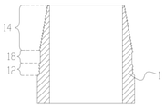
以下に本発明のねじ付管(ねじ付部材)の連結構造の実施形態を、図面を参照して説明する。図1は第一の実施形態の部材連結構造を有して互いに連結し得る二本のねじ付管1、1Aを示す斜視図、図2は第一の実施形態のねじ付管1、1Aを示す断面図である。なお、図1、2においては、ねじ付管1、1A同士を連結するための要部を示し、全体を示すものではない。即ち、図1、2は、ねじ付管1の雄ねじ部が形成された一端部と、ねじ付管1Aの雌ねじ部が形成された一端部を示している。またねじ付管1、1Aは、接続したときにおいても、外径の大きさが略一様となるように、後述する雄ねじ部の外径及び雌ねじ部の内径が設定される。
Hereinafter, embodiments of the connecting structure of the threaded pipe (threaded member) of the present invention will be described with reference to the drawings. FIG. 1 is a perspective view showing two threaded
ねじ付管1、1Aは、金属製のねじ付管状部材であって、例えば、外径の大きさが略一様で且つ流体を移送可能に軸方向に貫通孔2を有した、中空構造を有する所謂鋼管等である。従って、ねじ付管1、1Aは、油井、ガス井等の採掘現場における採掘資源性流体の井戸に使用される物、即ち、油井管を除く非採掘資源性流体(空気、水、非採掘性天然ガス、油圧油等)の使途に限定して使用される物、即ち、非油井管に限定して適用される物である。従って非採掘資源性流体の収容及び/又は流動させ得る様に使用される物であり、ねじ付管1、1Aは、例えば、水道管、ボイラー管等として使用し得る。
The threaded
ねじ付管1は、外径が縮径した一端部を有し、該一端部の外周面に雄ねじ部10を有する。雄ねじ部10は、雄ねじの外径が略一定のストレートねじを有する第一雄ねじ部12と、第一雄ねじ部12よりも一端部側に配されて雄ねじの外径が徐々に縮径する、所謂テーパねじを有する第二雄ねじ部14とを有する。また、第一雄ねじ部12に比して第二雄ねじ部14は、軸方向に沿う領域を長く設定する。
The threaded
第二雄ねじ部14には、一端部に向けて、雄ねじの外径が徐々に小さくなるようにねじ山が形成される。具体的に、第二雄ねじ部14のねじ山は、第一雄ねじ部12のねじ山と同一ピッチで且つ一端側に向けて徐々に外径及び山高さが小さくなるように形成される。なお、第一雄ねじ部12のねじ山と第二雄ねじ部14のねじ山とは、同一ピッチで連続的に形成されるが、これに限定されず、どちらか一方に比して他方のピッチを大きく又は小さく設定してもよく、徐々にピッチを変更するように構成してもよい。
A thread is formed in the second
ねじ付管1Aは、一端部の内周面が拡径し、該内周面に雌ねじ部20を有する。雌ねじ部20は、第一雌ねじ部22と第二雌ねじ部24とを有し、第一雌ねじ部22が第二雌ねじ部24よりも一端側に位置している。また、第一雌ねじ部22に比して第二雌ねじ部24は、軸方向に沿う領域を長く設定する。
The threaded
第一雌ねじ部22は、雌ねじの径が略一定のストレートねじを有する。第二雌ねじ部24は、雌ねじの径が徐々に変化するテーパねじを有する。具体的に、第二雌ねじ部24には、一端側(即ち、第一雌ねじ部22側)に向けて、雌ねじの内径が徐々に大きくなるようにねじ山が形成される。また、第二雌ねじ部24のねじ山は、第一雌ねじ部22のねじ山と同一ピッチに設定される。結果、雌ねじ部20のねじ山は、第一雌ねじ部22においてストレートねじを成すように形成され、第二雌ねじ部24において第一雌ねじ部22(一端)側から内径が漸次縮径していくテーパねじを成すように形成される。
The first
なお、第一雌ねじ部22のねじ山と第二雌ねじ部24のねじ山とは、同一ピッチで連続的に形成されるが、これに限定されず、どちらか一方に比して他方のピッチを大きく又は小さく設定してもよく、徐々にピッチを変更するように構成してもよい。
The thread of the first
また、雄ねじ部10、雌ねじ部20のねじ山形状は、特に限定されるものではないが、例えば鋸刃形状としてもよい。ここで図4は雄ねじ部10のねじ山形状を示す図であり、図4に示すようにねじ山形状は、ねじ付管1、1A同士を螺合させ、接続した状態から両ねじ付管1、1Aを軸方向に引き離す向きに引張したときに圧力を受けるねじ山のフランク面4のフランク角θがねじ付管1の軸心に対して略直角とする。なお、ここでフランク角θは、三角形様のねじ山断面における外角を示すものとする。
The thread shape of the male threaded
なお、雌ねじ部20のねじ山形状は、雄ねじ部10と同様に設定する。即ち、雌ねじ部20において、雄ねじ部10のフランク面4に当接するフランク面のフランク角を、雄ねじ部10と同様のフランク角θに設定する。勿論、雄ねじ部10、雌ねじ部20は、互いのフランク面が略全面で当接するようにすれば、フランク角を直角以外の角度にしてもよく、例えば、雄ねじ部10におけるフランク角θを直角を超える角度に設定してもよく、逆にフランク角θを図5に示すような直角を下回る、所謂反し状に設定してもよい。
The thread shape of the female threaded
ねじ付管1、1A同士の接続は、雄ねじ部10と雌ねじ部20との螺合により行う。具体的には、ねじ付管1の一端部をねじ付管1Aの一端部側の内周面内に挿入する。このとき、先ずねじ付管1の先端側に存する第二雄ねじ部14をねじ付管1Aの開口側の第一雌ねじ部22によって囲まれる内周面を通過させ、図3(a)に示す第一雄ねじ部12を第一雌ねじ部22に螺合可能な位置にねじ付管1を配置する。次に第一雄ねじ部12を第一雌ねじ部22に螺合するように、ねじ付管1をねじ付管1Aに対しねじの締め付け方向に回転させる。
The threaded
これにより、ねじ付管1は、第二雄ねじ部14が第二雌ねじ部24に螺合可能な位置まで徐々に変位し、更に回転することによって図3(b)に示すように第二雄ねじ部14の雄ねじと第二雌ねじ部24の雌ねじとが螺合した状態となる。
As a result, in the threaded
従って、ねじ付管1、1Aは、雄ねじ部10と雌ねじ部20とが螺合した状態で接続される。即ち、第一雄ねじ部12が第一雌ねじ部22に螺合し、第二雄ねじ部14が第二雌ねじ部24に螺合した状態で接続される。また、雄ねじ部10と雌ねじ部20とを嵌め合わせたときにおいて、軸方向に並ぶ雄ねじ部10のねじ山の頂部を結んだ仮想線と、軸方向に並ぶ雌ねじ部20のねじ山の頂部を結んだ仮想線とが平行となる。即ち、第一雄ねじ部12における仮想線と第一雌ねじ部22における仮想線とが平行で、且つ第二雄ねじ部14における仮想線と第二雌ねじ部24における仮想線とが平行となる。
Therefore, the threaded
ここで、接続されたねじ付管1、1Aの軸方向の強度は、第一雄ねじ部12と第一雌ねじ部22が螺合する箇所、第二雄ねじ部14と第二雌ねじ部24が螺合する箇所で異なる。
Here, the axial strength of the connected threaded
先ず、ねじ付管1の第一雄ねじ部12においては、ねじ山の始点近傍の管の肉厚が最も薄い箇所、即ち、図6の位置P1辺りに荷重が集中する。従って、第一雄ねじ部12における強度は、位置P1の強度に依存し、全断面強度に対する位置P1での強度の割合が、全断面積に対する位置P1での断面積の割合に略相当する。例えば、位置P0での全断面積に対し、位置P1での断面積の割合が約九割であれば、強度は全断面強度の約九割となる。
First, in the first male threaded
ねじ付管1の第二雄ねじ部14は、先端に向けて外径が変化するテーパねじを有するため、ねじ付管1Aの第二雌ねじ部24のねじ山に対し、ねじが有効に掛かっている区間において略隙間無く螺合する。即ち、ねじ掛り有効長さに応じた、ねじ山の剪断断面積に係る剪断強度に相当し、第二雄ねじ部14においては、ねじ掛り有効長さにおいてねじ山に負荷が分散され、結果、ねじ掛り有効長さが最大となるように第二雄ねじ部14を設定した場合に全断面強度の約七割の強度が得られる。
Since the second male threaded
なお、ねじ付管1Aの第一雌ねじ部22、第二雌ねじ部24においても、ねじ付管1の第一雄ねじ部12、第二雄ねじ部14と略同様に強度が決まる。即ち、第一雌ねじ部22は、ねじ山の始点近傍の肉厚が最も薄い箇所(図6における位置P3)に荷重が集中する。従って、第一雌ねじ部22における強度は、肉厚が最も薄い位置P3での断面積の全断面積(図6における位置P4での断面積)に対する割合と、全断面強度とによって決まる。また、第二雌ねじ部24は、テーパねじを有することから最大で全断面強度の約七割の強度が得られる。
The strength of the first female threaded
雄ねじ部10、雌ねじ部20は、上記のようにストレートねじを配した領域、テーパねじを配した領域とで強度が異なることから、その全体の引張強度が各領域での引張強度の総和で決まる。具体的に、雄ねじ部10の引張強度は、第一雄ねじ部12の引張強度と第二雄ねじ部14の引張強度の和で決まり、上記の例のように第一雄ねじ部12領域の引張強度が全断面の引張強度の約一割で、第二雄ねじ部14領域の引張強度が全断面の引張強度の約七割であれば、全体の引張強度は全断面の引張強度の約八割となる。なお、雌ねじ部20においても、第一雌ねじ部22領域の引張強度と第二雌ねじ部24領域の引張強度との和が全体の引張強度となる。
Since the strengths of the
以上、説明したように、ねじ付管1、1Aにそれぞれ雄ねじ部と雌ねじ部とを設け、第一雄ねじ部及び第一雌ねじ部のストレートねじ同士が螺合し、また第二雄ねじ部及び第二雌ねじ部のテーパねじ同士が螺合することで、単にストレートねじで雄ねじと雌ねじとを螺合した場合、或いはテーパねじ同士で雄ねじと雌ねじとを螺合した場合よりも軸方向の強度を向上させることができる。
As described above, the threaded
なお、上述した実施形態において、雄ねじ部10を、ねじ付管1の中途部から一端部に向って第一雄ねじ部12、第二雄ねじ部14の順に配して成るように形成したが、図7に示すように中途部から一端部に向けて順に第一雄ねじ部12、第二雄ねじ部14、ストレートねじを有する第三雄ねじ部16を配して成るように形成してもよい。
In the above-described embodiment, the male threaded
また、雌ねじ部20は、ねじ付管1Aの一端から順に第一雌ねじ部22、第二雌ねじ部24を配したが、図7に示すように一端から順に第一雌ねじ部22、第二雌ねじ部24、ストレートねじを有する第三雌ねじ部26を配して成るように形成してもよい。
Further, in the female threaded
また、一般的にねじ付管同士を接続する際に強度を向上させるために、別体の継手を介して管の接続を行っているが、継手の外径がねじ付管よりも大径であるため、このようなねじ付管を設置するためには、継手に合わせて大径の井戸、穴等を設けていた。しかしながら、本発明のねじ付管によれば、軸方向に非常に高い強度を有しながら、管の外径の大型化を抑えることができるので、井戸、穴等の掘削にかかる作業手間を低減させると共に、掘削の低コスト化を図ることができる。 Also, in general, in order to improve the strength when connecting threaded pipes, the pipes are connected via a separate joint, but the outer diameter of the joint is larger than that of the threaded pipe. Therefore, in order to install such a threaded pipe, a large-diameter well, a hole, or the like was provided according to the joint. However, according to the threaded pipe of the present invention, it is possible to suppress an increase in the outer diameter of the pipe while having a very high strength in the axial direction, so that the labor required for excavating a well, a hole, etc. is reduced. At the same time, it is possible to reduce the cost of excavation.
また、接続されたねじ付管1、1Aは、第一雄ねじ部及び第一雌ねじ部のストレートねじ同士が螺合し、また第二雄ねじ部及び第二雌ねじ部のテーパねじ同士が螺合するので、フランジ付き鋼管同士の接続と比較して径方向に張り出したフランジを設けることなく、軸方向の強度を向上することができる。また、フランジを省くことにより、ねじ付管1、1Aの大型化を抑え、配設に必要なスペースを小さくすることができ、省スペース化を図ることができる。また、ねじ付管1、1Aを配列して保管する場合においても、保管場所の省スペース化を図ることができる。
また、フランジ接合面に隙間が生じることによる流体の漏れが発生し得ないことから、より安定した流体の移送を行うことができる。
Further, in the connected threaded
In addition, since fluid leakage cannot occur due to the formation of a gap in the flange joint surface, more stable fluid transfer can be performed.
なお、上述した実施形態において、第二雄ねじ部14及び第二雌ねじ部24のテーパねじのテーパ形状は、適宜設定し得る。例えば、図8(a)に示す雄ねじ部10の断面形状において、第二雄ねじ部14の各ねじ山の先端を繋いだ仮想線が直線状で且つ所定の勾配で傾斜したテーパ形状に設定し得、また、図8(b)に示す第二雄ねじ部14の各ねじ山の先端を繋いだ仮想線が曲線状に傾斜したテーパ形状に設定し得る。また、図8(c)に示す第二雌ねじ部14の各ねじ山の先端及び/又は谷部を軸方向に沿って繋いだ仮想線がタンジェント曲線様の曲線形状に設定することも可能である。勿論、雌ねじ部20の第二雌ねじ部24においてもテーパねじは、上記と同様に所定の勾配で傾斜したテーパ形状に設定し得、また曲線状に傾斜したテーパ形状に設定し得る。
In the above-described embodiment, the tapered shape of the tapered screw of the second male threaded
また、上述した実施形態において、第一雄ねじ部12及び第二雄ねじ部14に亘って連続するねじ山を設けたが、これに限定されるものではなく、第一雄ねじ部12のねじ山と、第二雄ねじ部14のねじ山とを別々に形成してもよい。また、図9に示すように第一雄ねじ部12と第二雄ねじ部14との間に非ねじ部18を設けてもよい。非ねじ部18は、少なくとも第一雄ねじ部12のねじ山の谷径以下となるように外径が設定される。即ち、非ねじ部18は、雄ねじ部10と雌ねじ部20とを螺合する際に、雌ねじ部20のねじ山に干渉せず螺合を妨げない外径に設定される。また、非ねじ部18は、軸方向に沿って外径が一定であることが望ましい。
Further, in the above-described embodiment, a continuous thread is provided over the first
また、雄ねじ部10に非ねじ部18を配した場合、同様に雌ねじ部20にも非ねじ部を配してもよい。また非ねじ部18にメタルシール構造を設けたり、Oリング、Dリング、ガスケット等のシール材を装着してもよい。雄ねじ部10と雌ねじ部20との間にシール材を介在させれば、より気密性が向上して管内に流れる流体の漏洩防止等を図ることができる。
Further, when the
また、雄ねじ部10、雌ねじ部20のねじ山形状は、鋸刃形状に限定するものではなく、適宜設定し得、例えば、図10(a)に示す三角ねじ状、図10(b)に示す丸ねじ状、図10(c)に示す角ねじ状、図10(d)に示す台形ねじ状等があり得る。また、図11(a)に示すようにねじ山の先端面を広く形成した鋸刃形状や、図11(b)に示すようにねじ山の先端面を広く形成した反し状等があり得る。また、図11(c)に示すように、ねじ山の先端面やねじの谷部が曲面状の鋸刃形状や、図11(d)に示すようにねじ山の先端面やねじの谷部が曲面状の反し状であってもよい。
なお、雄ねじ部10において、第一雄ねじ部と第二雄ねじ部とでねじ山形状を異ならせてもよく、例えば、ストレートねじである第一雄ねじ部のねじ山を三角ねじ状、テーパねじである第二雄ねじ部のねじ山を鋸刃形状等のように設定することもできる。また、図7に示すような第一雄ねじ部乃至第三雄ねじ部を有する雄ねじ部においても同様であって、第一雄ねじ部のねじ山を三角ねじ状、第二雄ねじ部のねじ山を鋸刃形状、第三雄ねじ部のねじ山を丸ねじ形状等のように設定することもできる。
Further, the thread shape of the male threaded
In the male threaded
また、雄ねじ部10の外径と雌ねじ部20の内径は、適宜設定し得る。従って雄ねじ部10と雌ねじ部20との間で密封性を向上させるべく雄ねじ部10の外径及び/又は雌ねじ部20の内径を設定してもよい。即ち、第二雄ねじ部14が第二雌ねじ部24を内側から外側に向かって押圧し、第二雄ねじ部14及び第二雌ねじ部24の少なくとも一方を弾性変形及び/又は塑性変形させて密封性を向上させてもよい。
Further, the outer diameter of the
例えば、完全に螺合させた状態において、雌ねじ部20が径方向外側にやや拡がり得るように、第二雄ねじ部14の最大外径(若しくは最大有効径)を第二雌ねじ部24の最大内径(若しくは最大有効径)よりも大きく設定、及び/又は第二雄ねじ部14の最小外径(若しくは最小有効径)を第二雌ねじ部24の最小内径(若しくは最小有効径)よりも大きく設定する。これによれば、第二雄ねじ部14と第二雌ねじ部24とが少なくとも一部で径方向に干渉し得、雄ねじ部10と雌ねじ部20とを螺合させていく際に、雌ねじ部20が弾性変形及び/又は塑性変形しながら拡径して、その結果として雄ねじ部10と雌ねじ部20とが密着して密封性が向上する。
勿論、第二雄ねじ部14が径方向内側に弾性変形及び/又は塑性変形するように、第二雄ねじ部14の外径に対する第二雌ねじ部24の内径の大きさを設定してもよい。また、上記で第二雄ねじ部14の外径、第二雌ねじ部24の内径を設定するものとして説明したが、更に第二雄ねじ部14及び/又は第二雌ねじ部24における管の厚みを設定するようにしてもよい。
For example, the maximum outer diameter (or maximum effective diameter) of the second male threaded
Of course, the size of the inner diameter of the second female threaded
また、第二雄ねじ部14と第二雌ねじ部24とを干渉させる構成にした場合、正規の位置まで互いを螺合させる(最奥までねじ込む)とき、第一雄ねじ部12における第二雄ねじ部14近傍のねじ山の先端が、第二雌ねじ部24の第一雌ねじ部22側端部付近のねじ谷部よりも半径方向外側に位置し干渉する。この干渉した状態では、それ以上の螺合が不可となる。従って、第一雄ねじ部12における、第二雌ねじ部24に干渉する端部領域を縮径させ、干渉量を減少乃至皆無とするように構成する。
縮径させる長さは、第一雄ねじ部12の端部と第二雌ねじ部24との干渉長さ以上の長さとすることが好ましい。また、第一雄ねじ部12の端部領域に、段状、テーパ状、曲線状、無ねじ状等の種々の形状を設けて縮径させる。
Further, when the second male threaded
The length to be reduced is preferably a length equal to or longer than the interference length between the end portion of the first male threaded
具体的に第一雄ねじ部12が第二雌ねじ部24に軸方向に干渉し得るので、そのような干渉を避けるために第一雄ねじ部12と第二雄ねじ部14との外向きに凸(即ち、半径方向外向きに凸)状の境界領域に図21に示すような干渉緩和部13を設ける。
例えば、干渉緩和部13の各ねじ山の先端を結んだ仮想線13a(図21参照)は、第一雄ねじ部12の各ねじ山の先端を結んだ直線状の仮想線12a及び第二雄ねじ部14の各ねじ山の先端を結んだテーパ状の仮想線14aよりも、軸心側に寄った曲線状を成し、該曲線に沿うようにねじ山の高さや位置を定める。また、干渉緩和部13における最大となる半径r(図21参照)は、第二雌ねじ部24の最小内径以下である。
従って、干渉緩和部13を設けることで、第一雄ねじ部12と第二雌ねじ部24との干渉を緩和乃至避けることができる。また、干渉緩和部13は、第二雌ねじ部24への干渉を緩和乃至避けるような面形状を有してもよいが、第一雌ねじ部22及び/又は第二雌ねじ部24に螺合し得るようなねじ山を具える形状を有してもよい。
Specifically, since the first male threaded
For example, the virtual line 13a (see FIG. 21) connecting the tips of the threads of the
Therefore, by providing the
なお、雄ねじ部10が、ねじ付管1の中途部から一端部に向かってストレートねじの第一雄ねじ部12、テーパねじの第二雄ねじ部14を有する形状として説明したが、勿論、図22に示すように中途部から一端部に向かって第二雄ねじ部14、第一雄ねじ部12を有する形状であってもよいことは言うまでもない。その場合、雄ねじ部10に螺合し得る雌ねじ部20は、図22に示す一端から奥に向かって第二雌ねじ部24、第一雌ねじ部22を有する形状となる。また、雄ねじ部10は、第二雄ねじ部14よりも中途部側に環状を成し、ねじ付管1Aの内周面に全周に亘って密着し得るシール部19を設けてもよい。
The male threaded
また、図22のねじ付管1、1Aにおいて、第二雄ねじ部14と第二雌ねじ部24とを干渉させる構成とし、且つ正規の位置まで互いを螺合させる(最奥までねじ込む)とき、第一雌ねじ部22における第二雌ねじ部24側端部付近に、第二雄ねじ部14の第一雄ねじ部12側端部が干渉する。従って、第一雌ねじ部22における、第二雄ねじ部14に干渉する端部領域を拡径させ、干渉量を減少乃至皆無とするように構成する。
拡径させる長さは、第一雌ねじ部22の端部と第二雄ねじ部14との干渉長さ以上の長さとすることが好ましい。また、第一雌ねじ部22の端部領域に、段状、テーパ状、曲線状、無ねじ状等の種々の形状を設けて拡径させる。
Further, in the threaded
The length to be expanded is preferably a length equal to or longer than the interference length between the end portion of the first
具体的に第一雌ねじ部22と第二雌ねじ部24との外向きに凸(即ち、半径方向内向きに凸)状の境界領域に干渉緩和部23(図23参照)を設ける。例えば、干渉緩和部23の各ねじ山の先端を結んだ仮想線23a(図23参照)は、第一雌ねじ部22の各ねじ山の先端を結んだ仮想線22aと、第二雌ねじ部24の各ねじ山の先端を結んだテーパ状の仮想線24aよりも、外側に位置する曲線状を成し、該曲線に沿うようにねじ山の高さや位置を定める。また、干渉緩和部23における最大となる半径R(図23参照)は、第二雄ねじ部14の最小外径以上である。干渉緩和部23を設けることで、第一雌ねじ部22と第二雄ねじ部14との干渉を緩和乃至避けることができる。また、干渉緩和部23は、第二雄ねじ部14への干渉を緩和乃至避けるような面形状を有してもよいが、第一雄ねじ部12及び/又は第二雄ねじ部14に螺合し得るようなねじ山を具える形状を有してもよい。
Specifically, an interference mitigation portion 23 (see FIG. 23) is provided in an outwardly convex (that is, radially inwardly convex) boundary region between the first
また、雄ねじ部10と雌ねじ部20との間に密封構造を配するために、図12に示すようにねじ付管1の雄ねじ部10の先端部の外周面30を、ねじ付管1Aの雌ねじ部20の基端側の内周面40に密着させるようにしてもよい。即ち、ねじ付管1Aとねじ付管1との挿入向きにおける、雄ねじ部10の挿入向き前方側に位置する外周面30を、ねじ付管1Aの挿入向き後方側に位置する内周面40に密着させてもよい。
その場合、外周面30における外径が、内周面40における内径よりも僅かに大きくなるように設定する。従って、雄ねじ部10と雌ねじ部20とを嵌め合わせたときに、外周面30が内周面40を外側に押圧或いは内周面40が外周面30を内側に押圧するように弾性力が作用する。結果、外周面30と内周面40が全周で密着して密封性能を発揮する。
Further, in order to arrange a sealing structure between the male threaded
In that case, the outer diameter of the outer
また、ねじ付管1の雄ねじ部10の基端側の外周面32を、ねじ付管1Aの雌ねじ部20の先端側の内周面42に密着させるようにしてもよい。その場合、外周面32における外径が、内周面42における内径よりも僅かに大きくなるように設定する。
このようにしても、雄ねじ部10と雌ねじ部20とを嵌め合わせたときに、外周面32が内周面42を外側に押圧或いは内周面42が外周面32を内側に押圧するように弾性力が作用し、外周面32と内周面42が全周で密着して密封性能を発揮する。なお、外周面30、32及び内周面40、42は、雄ねじ部10及び雌ねじ部20の軸心に対して傾斜させた傾斜面であってもよい。
Further, the outer
Even in this way, when the
次に、他の構成に係るねじ付管について説明する。図13は雄ねじ部を有するねじ付管の他の構成例を示すものであり、(a)は断面図、(b)は円環領域A~Cを示す図である。ねじ付管300は、ねじ付管400に接続される先端側から順に第一シール部310、雄ねじ部320、第二シール部330を配設する。また、ねじ付管300は、ねじ付管400に対する挿入深さを規制する先端部300aを有する。
Next, a threaded pipe according to another configuration will be described. 13A and 13B show another configuration example of a threaded tube having a male threaded portion, FIG. 13A is a cross-sectional view, and FIG. 13B is a diagram showing annular regions A to C. The threaded
第一シール部310は、図14に示すように、外周面の周方向全周に延在し且つ径方向外側に突出する環状凸部312を少なくとも一つ以上、好ましくは複数有する。また、第一シール部310は、環状凸部312を軸方向に並列させることで、環状凸部312間に環状凸部312に対し相対的に凹形状を成す環状凹部314を画成する。なお、環状凸部312の突出長さは、少なくとも後述する第一雄ねじ部322と第一雌ねじ部422(図15参照)との螺合を妨げず且つ第一無ねじ部410(図15参照)の内周面に密着(或いは僅かに干渉)可能な長さとする。
As shown in FIG. 14, the
雄ねじ部320は、基端側から順にストレートねじの第一雄ねじ部322、テーパねじの第二雄ねじ部324、ストレートねじの第三雄ねじ部326を配して成り、第二雄ねじ部324は、有効径が第一雄ねじ部322の有効径以下であり、第三雄ねじ部326は、有効径が第二雄ねじ部の有効径以下である。第二雄ねじ部324の有効径は、先端側よりも基端側の方が大きい。なお、ここでは第二雄ねじ部324の最大有効径が第一雄ねじ部322の有効径に略相当し、最小有効径が第三雄ねじ部326の有効径に略相当するように、第一雄ねじ部322乃至第三雄ねじ部326のねじ山が一連の螺旋状を成しているものとする。
The male threaded
ねじ付管300は、第一雄ねじ部322乃至第三雄ねじ部326の何れかを含んだ、軸方向視で径方向に三分割された同心の円環領域A(第一の円環領域)、円環領域B(第二の円環領域)、円環領域C(第三の円環領域)を有する。図13(b)に示すように、ねじ付管300の外周面から第一雄ねじ部322の有効径部分までの径方向の領域を円環領域Aとする。また、第二雄ねじ部324の最大有効径部分(即ち、第一雄ねじ部322の有効径部分)から第二雄ねじ部324の最小有効径部分までの径方向の領域を円環領域Bとする。また、第三雄ねじ部326の有効径部分(即ち、第二雄ねじ部324の最小有効径部分)からねじ付管300の内周面までの径方向の領域を円環領域Cとする。
The threaded
円環領域Aの面積は、ねじ付管300の横断面における全断面積の三分の一以下に設定する。また横断面領域Bの面積は、ねじ付管300の横断面における全断面積の三分の一以上に設定する。また横断面領域Cの面積は、ねじ付管300の横断面における全断面積の三分の一以下に設定する。
The area of the annular region A is set to be one-third or less of the total cross-sectional area of the threaded
第一雄ねじ部322は、第一雌ねじ部422と螺合して嵌め合わされるねじ山全域の剪断面積が、円環領域Aの面積に3の平方根を乗じた大きさ以上となるように、ねじ領域の形状等を設定する。従って、ねじ山の有効径部位で螺旋状に一連に剪断して成る第一雄ねじ部322のねじ山の総剪断面積が円環領域Aの面積の3の平方根倍以上となるように、ねじ掛り有効長さ、ねじ山の数、ピッチ等を設定する。
The first
また、第二雄ねじ部324は、第二雌ねじ部424と螺合して嵌め合わされるねじ山全域の剪断面積が、円環領域Bの面積に3の平方根を乗じた大きさ以上となるように、ねじ領域の形状等を設定する。従って、ねじ山の有効径部位で螺旋状に一連に剪断して成る第二雄ねじ部324のねじ山の総剪断面積が円環領域Bの面積の3の平方根倍以上となるように、ねじ掛り有効長さ、ねじ山の数、ピッチ等を設定する。
Further, in the second male threaded
また、第三雄ねじ部326は、第三雌ねじ部426と螺合して嵌め合わされるねじ山全域の剪断面積が、円環領域Cの面積に3の平方根を乗じた大きさ以上となるように、ねじ領域の形状等を設定する。従って、ねじ山の有効径部位で螺旋状に一連に剪断して成る第三雄ねじ部326のねじ山の総剪断面積が円環領域Cの面積の3の平方根倍以上となるように、ねじ掛り有効長さ、ねじ山の数、ピッチ等を設定する。
Further, in the third male threaded
第二シール部330は、第一シール部310と同様に環状凸部332を一つ以上好ましくは複数有し、環状凸部332間に環状凹部334を画成している。また環状凸部332の突出長さは、第二無ねじ部430(図15参照)の内周面に密着(或いは僅かに干渉)可能な長さとする。
Like the
先端部300aは、ねじ付管400に当接し深さ方向の位置を規制し得る形状、好ましくは更に挿入し易くする誘い込み可能な形状を有するものであれば尚よく、例えば、図14に示すように第一シール部310の先端を面取り加工することで形成することができる。またねじ付管400に当接し深さ方向の位置を規制し得る規制手段としての基端部300bを先端部300aに代えて或いは先端部300aと共に第二シール部330の基端側に形成してもよい。
It is even more preferable that the
また、図15は雌ねじ部を有するねじ付管の他の構成例を示し、(a)は断面図、(b)は円環領域D~Fを示す図である。ねじ付管400は、第一無ねじ部410、雌ねじ部420、第二無ねじ部430を有する。ねじ付管400は、ねじ付管300に接続したとき、第一無ねじ部410が第一シール部310に対応し、第二無ねじ部430が第二シール部330に対応する。
15A and 15B show another configuration example of a threaded tube having a female threaded portion, FIG. 15A is a cross-sectional view, and FIG. 15B is a diagram showing annular regions D to F. The threaded
また、ねじ付管400は、ねじ付管300の挿入を規制する受部400aを有し、受部400aは、先端部300a(或いは基端部300b)に対応する箇所に配設される。第一無ねじ部410は、軸方向にわたり内径が一定の円周形状の内周面を有し、当該内径が後述す第三雌ねじ部426の山径未満に設定されている。また第二無ねじ部430は、軸方向にわたり内径が一定の円周形状の内周面を有し、当該内径が後述する第一雌ねじ部422の谷径以上に設定されている。
Further, the threaded
雌ねじ部420は、被挿入端側から順にストレートねじの第一雌ねじ部422、テーパねじの第二雌ねじ部424、ストレートねじの第三雌ねじ部426を配して成る。第二雌ねじ部424は、少なくとも最小有効径が第一雌ねじ部422の有効径以上で、第三雌ねじ部426は、有効径が第二雌ねじ部424の最大有効径以上であり、第一雌ねじ部422は、第一雄ねじ部322と螺合し、第二雌ねじ部424は、第二雄ねじ部324と螺合し、第三雌ねじ部426は、第三雄ねじ部326と螺合する。
The female threaded
ねじ付管400は、第一雌ねじ部422乃至第三雌ねじ部426の何れかを含んだ、軸方向視で径方向に三分割された同心の円環領域D(第四の円環領域)、円環領域E(第五の円環領域)、円環領域F(第六の円環領域)を有する。図15(b)に示すように、ねじ付管400の外周面から第一雌ねじ部422の有効径部分までの径方向の領域を円環領域Dとする。また、第二雌ねじ部424の最大有効径部分(即ち、第一雌ねじ部422の有効径部分)から第二雌ねじ部424の最小有効径部分までの径方向の領域を円環領域Eとする。また、第三雌ねじ部426の有効径部分(即ち、第二雌ねじ部424の最小有効径部分)からねじ付管400の素管部分の内周面までの径方向の領域を円環領域Fとする。
The threaded
円環領域Dの面積は、ねじ付管400の横断面における全断面積の三分の一以下に設定する。また横断面領域Eの面積は、ねじ付管400の横断面における全断面積の三分の一以上に設定する。また横断面領域Fの面積は、ねじ付管400の横断面における全断面積の三分の一以下に設定する。なお、ここでは、円環領域Dが円環領域Aに略相当する面積を有し、円環領域Eが円環領域Bに略相当する面積を有し、円環領域Fが円環領域Cに略相当する面積を有するものとする。
The area of the annular region D is set to be one-third or less of the total cross-sectional area of the threaded
第一雌ねじ部422は、第一雄ねじ部322と螺合して嵌め合わされるねじ山全域の剪断面積が、円環領域Dの面積に3の平方根を乗じた大きさ以上となるように、ねじ領域の形状等を設定する。即ち、ねじ山の有効径部位で螺旋状に一連に剪断して成る第一雌ねじ部422のねじ山の総剪断面積が円環領域Dの面積の3の平方根倍以上となるように、ねじ掛り有効長さ、ねじ山の数、ピッチ等を設定する。ここでは第一雌ねじ部422のねじ領域の形状を、第一雄ねじ部322のねじ掛り有効長さ、ねじ山の数、ピッチに対応するように設定することで、上記条件を満たしている。
The first
また、第二雌ねじ部424は、第二雄ねじ部324と螺合して嵌め合わされるねじ山全域の剪断面積が、円環領域Eの面積に3の平方根を乗じた大きさ以上となるように、ねじ領域の形状等を設定する。即ち、ねじ山の有効径部位で螺旋状に一連に剪断して成る第二雌ねじ部424のねじ山の総剪断面積が円環領域Eの面積の3の平方根倍以上となるように、ねじ掛り有効長さ、ねじ山の数、ピッチ等を設定する。ここでは第二雌ねじ部424のねじ領域の形状を、第二雄ねじ部324のねじ掛り有効長さ、ねじ山の数、ピッチに対応するように設定することで、上記条件を満たしている。
Further, in the second
また、第三雌ねじ部426は、第三雄ねじ部326と螺合して嵌め合わされるねじ山全域の剪断面積が、円環領域Fの面積に3の平方根を乗じた大きさ以上となるように、ねじ領域の形状等を設定する。即ち、ねじ山の有効径部位で螺旋状に一連に剪断して成る第三雌ねじ部426のねじ山の総剪断面積が円環領域Fの面積の3の平方根倍以上となるように、ねじ掛り有効長さ、ねじ山の数、ピッチ等を設定する。ここでは第三雌ねじ部426のねじ領域の形状を、第三雄ねじ部326のねじ掛り有効長さ、ねじ山の数、ピッチに対応するように設定することで、上記条件を満たしている。
Further, in the third
なお、第一無ねじ部410と第一シール部310とは、互いの軸方向長さが略等しいが、第一無ねじ部410の方が長くなるように設定される。雌ねじ部420と雄ねじ部320とは、互いの軸方向長さが略等しい。第二無ねじ部430と第二シール部330とは、互いの軸方向長さが略等しいが第二無ねじ部430の方が長くなるように設定される。
The
第一シール部310は、雄ねじ部320と雌ねじ部420とが螺合する前に第一無ねじ部410に係合しないように、軸方向長さを設定することが好ましい。具体的には、図18(a)に示す第一シール部310の軸方向長さをL1、第一シール部310と軸方向に隣接する第三雄ねじ部326の軸方向長さをL2としたとき、L1<L2を満たすように各軸方向長さを設定することが望ましい。同様に第二シール部330は、雄ねじ部320と雌ねじ部420とが螺合する前に第二無ねじ部430に係合しないように、軸方向長さを設定することが好ましい。具体的には、図18(a)に示す第二シール部330の軸方向長さをL3、第二シール部330と軸方向に隣接する第一雄ねじ部322の軸方向長さをL4としたとき、L3<L4を満たすように各軸方向長さを設定することが望ましい。
It is preferable to set the axial length of the
上記第一シール部310と第二シール部330の軸方向長さに対応するように、第一無ねじ部410と第二無ねじ部430の各軸方向長さについても同様に設定することが好ましい。具体的には、図18(b)に示す第一無ねじ部410の軸方向長さをL1´、第一無ねじ部410と軸方向に隣接する第三雌ねじ部426の軸方向長さをL2´としたとき、L1´<L2´を満たすように各軸方向長さを設定することが望ましい。第二無ねじ部430の軸方向長さをL3´、第二無ねじ部430と軸方向に隣接する第一雌ねじ部422の軸方向長さをL4´としたとき、L3´<L4´を満たすように各軸方向長さを設定することが望ましい。
上記のように各部の軸方向長さを設定すれば、雄ねじ部320と雌ねじ部420とが螺合し始めてから、締め込み完了までの間に、第一シール部310と第一無ねじ部410(及び第二シール部330と第二無ねじ部430)が係合してシーリング構造を成すことが出来る。
The axial lengths of the
If the axial length of each part is set as described above, the
このようなねじ付管300、400によれば、ねじ付管300をねじ付管400に挿入して回転すると、各雄ねじ部322乃至326が各雌ねじ部422乃至426に螺合する。また、第一シール部310が第一無ねじ部410に圧入され、環状凸部312が第一無ねじ部410の内周面に密着する。また、第二シール部330が第二無ねじ部430に圧入され、環状凸部332が第二無ねじ部430の内周面に密着する。
また、ねじ付管300の先端部300aがねじ付管400の受部400aに係合又は当接するように構成することも可能であり、こうすることで各雄ねじ部322乃至326と各雌ねじ部422乃至426との必要以上の締め込みを抑止する。
According to such threaded
Further, it is also possible to configure the
また、環状凸部312が第一無ねじ部410、環状凸部332が第二無ねじ部430にそれぞれ密着し、環状凸部312、332が第一無ねじ部410又は第二無ねじ部430に圧接するため、ねじ付管300、400の引張、圧縮等の入力によるねじ付管300及びねじ付管400との相対変位を伴う状況下においても対応可能なシール構造を成すと共に、ねじ付管300、400の曲げ等の変形にも追従可能な、高い密封性能を有するシール構造を成すことができる。
Further, the annular
更に、環状凹部314にシーリング構造を持たせるようにしてもよい。具体的には所定温度以上で軟化膨張する固脂(後で詳述する)を環状凹部314内に収容させ、ポリエチレンやポリプロピレン等の樹脂リングを環状凹部314に嵌着及び/又は埋設させシーリング構造を構成することができ、これによって更に密封性能を向上させることができる。
Further, the
また、上述したように、第一雄ねじ部322は、ねじ山全域の総断面積が円環領域Aの面積に3の平方根を乗じた大きさ以上となるようにねじ領域の形状等を設定したので、円環領域Aの面積に相当する素管の引張強度よりも高い剪断強度を有する。同様に、第二雄ねじ部324は、円環領域Bの面積に相当する素管の引張強度よりも高い剪断強度を有し、また第三雄ねじ部326は、円環領域Cの面積に相当する素管の引張強度よりも高い剪断強度を有する。
従って、雄ねじ部320全体は、ねじ付管300における雄ねじ部320が形成されていない領域での引張強度よりも高い剪断強度を有することとなり、雌ねじ部420と螺合した状態で両ねじ付管300、400を軸方向に沿って互いを離間させる向きに引張ったときに、ねじ付管300の軸破断が生じるよりも先に雄ねじ部320が剪断破壊することを防止することが出来る。
Further, as described above, the shape of the threaded region of the first male threaded
Therefore, the entire male threaded
これと同様にして、第一雌ねじ部422は、ねじ山全域の総断面積が円環領域Dの面積に3の平方根を乗じた大きさ以上となるようにねじ領域の形状等を設定したので、円環領域Dの面積に相当する素管の引張強度よりも高い剪断強度を有する。同様に、第二雌ねじ部424は、円環領域Eの面積に相当する素管の引張強度よりも高い剪断強度を有し、また第三雌ねじ部426は、円環領域Fの面積に相当する素管の引張強度よりも高い剪断強度を有する。
In the same manner as this, the shape of the threaded region and the like of the first female threaded
従って、雌ねじ部420全体は、ねじ付管400における雌ねじ部420が形成されていない領域での引張強度よりも高い剪断強度を有することとなり、雄ねじ部320と螺合した状態で両ねじ付管300、400を軸方向に沿って互いに離間させる向きに引張ったときに、ねじ付管400の軸破断が生じるよりも先に雌ねじ部420が剪断破壊することを防止することが出来る。
Therefore, the entire female threaded
上記の通り、雄ねじ部320及び雌ねじ部420の剪断強度は、各ねじ付管300、400のねじ部が形成されていない領域での引張強度よりも高く、ねじ付管300、400同士を接続した状態で互いを離間させる向きに引張力を付加したとき、ねじ山の剪断よりも先に確実にねじ付管300、400の何れかを軸破断させることができる。
As described above, the shear strength of the male threaded
第一雄ねじ部322、第二雄ねじ部324、第三雄ねじ部326又は第一雌ねじ部422、第二雌ねじ部424、第三雌ねじ部426それぞれの引張強度は、対象とする雄ねじ部又は雌ねじ部の互いに螺合する嵌合い領域における略有効径部位をねじ山に沿って螺旋状に一連に剪断した際の総剪断面積aと、当該対象とする雄ねじ部の有効径部位における横断面の断面積bと、当該対象とする雌ねじ部の有効径部位における横断面の断面積cとの何れか最も引張強度が小さいものとなる。但し、a≧√3・b∧a≧√3・cの関係に設定することができ、この場合対象とする雄ねじ部又は雌ねじ部の引張強度は、b及び/又はcに材料の単位面積当たりの引張強度を乗じたものとして算出可能である。
The tensile strength of each of the first male threaded
また、第二雄ねじ部の螺進向きの前後に第一雄ねじ部、第三雄ねじ部を配し、第二雌ねじ部の螺進向きの前後に第一雌ねじ部、第三雌ねじ部を配したことで、雄ねじ部及び雌ねじ部は、螺旋状のねじ領域全体で螺合する。これによって従来の所謂フラッシュジョイントと呼ばれる継手で存在していたテーパねじ部の先端側と基端側とにねじの無掛部が形成されてしまうことが無く、無掛部の存在による強度低下を防止し、結果、ねじ付管同士を強固に接続することができる。 In addition, the first male threaded part and the third male threaded part are arranged before and after the second male threaded portion in the spiraling direction, and the first female threaded portion and the third female threaded portion are arranged before and after the spiraling direction of the second female threaded portion. Then, the male threaded portion and the female threaded portion are screwed together in the entire spiral threaded region. As a result, the threadless portion is not formed on the tip end side and the base end side of the tapered threaded portion that existed in the conventional so-called flush joint, and the strength is reduced due to the presence of the hooked portion. As a result, the threaded pipes can be firmly connected to each other.
また、上述した構造によるねじ付管300、400によれば、雄ねじ部320と雌ねじ部420とを螺合させ締め込んだときに接続部分を高強度化させることができる。ここで引張強度の評価において、ねじ付管300、400の素管部分の降伏強度に対する接合部分の引張強度の割合である接合部分の降伏率という基準を考えることができる。接合部分の降伏率は、{接合部分の破壊強度}/{素管部分の全断面降伏強度}で示すことができる。
Further, according to the threaded
例えば、強度区分がボルトの強度区分でいうところの10.9相当の鋼材料を用い、接合部分の断面積がS1(mm2)、素管部分の断面積がS0(mm2)の場合には、降伏率を式(1)のように示すことができる。
[式1]

断面積S1は、上記した雄ねじ部320の断面積或いは雌ねじ部420の断面積によって定まる。即ち、雄ねじ部320は、図13に示すねじ付管300の内径から第一雄ねじ部322の有効径までの範囲が断面積の大きさに影響する。雌ねじ部420は、図15に示すねじ付管400の外形から第三雌ねじ部426の有効径までの範囲が断面積の大きさに影響する。
従って、雄ねじ部320は、第一雄ねじ部322を拡径するように設定し、雌ねじ部420は、第三雌ねじ部426を縮径するように設定し、例えば、断面積S1が断面積S0の8割程度の大きさとなるように設定した場合、式1の断面積S1を断面積S0×0.8と表すことができる。
式1に各値を代入した式2を示す。
[式2]

また、降伏強度の引張強さに対する比率が低い材料を選択する程、より高い降伏率を得ることが出来る。例えば、降伏強度の引張強さに対する比率が70パーセントの材料を選定した場合であって、断面積S1が断面積S0の8割程度の大きさとした場合、約114パーセントの降伏率を得られる。
For example, using a steel material whose strength classification is equivalent to 10.9 in the strength classification of bolts, the cross-sectional area of the joint portion is S 1 (mm 2 ) and the cross-sectional area of the raw pipe portion is S 0 (mm 2 ). In that case, the yield rate can be expressed as in the equation (1).
[Equation 1]
The cross-sectional area S 1 is determined by the cross-sectional area of the male threaded
Therefore, the male threaded
[Equation 2]
Further, the higher the yield rate can be obtained, the lower the ratio of the yield strength to the tensile strength is selected. For example, when a material having a yield strength ratio to the tensile strength of 70% is selected and the cross-sectional area S1 is about 80% of the cross - sectional area S0 , a yield rate of about 114% is obtained. Be done.
また、降伏強度の引張強度に対する比率が高い材料を選定した場合であっても、断面積S1を断面積S0に近づける程、降伏率の高いねじ付管300、400を得ることが可能となる。勿論、現実的には加工精度の問題や第一雌ねじ部422や第二無ねじ部430、或いは第三雄ねじ部326や第一シール部310の最薄肉部の強度の問題等があって一定厚以下にすることが好ましくないということがあることを考慮する必要がある。
また、例えば、引張強度が965(N/mm2)で且つ降伏強度が862(N/mm2)の材料(降伏強度の引張強さに対する比率が約89パーセントの材料)で製造したねじ付管において、素管部分が外径400mm、肉厚19mmであって且つ第一雌ねじ部422や第二無ねじ部430、或いは第三雄ねじ部326や第一シール部310の最薄肉部を1.4mmとなるよう設定した場合、式1によれば約103パーセントの降伏率を得ることが出来る。なお、従来は、同一材料によって製造されるねじ付管の降伏率が凡そ七割である。このことから本発明による雄ねじ部320と雌ねじ部420との螺合、即ち、ストレートねじ同士を螺合させると共にテーパねじ同士を螺合させることで、より肉厚を薄く設定することが出来るようになり、従来のねじ付管と比較して非常に高い降伏率が得られる。
Further, even when a material having a high ratio of yield strength to tensile strength is selected, it is possible to obtain screwed
Further, for example, a threaded tube manufactured of a material having a tensile strength of 965 (N / mm 2 ) and a yield strength of 862 (N / mm 2 ) (a material in which the ratio of the yield strength to the tensile strength is about 89%). The raw pipe portion has an outer diameter of 400 mm and a wall thickness of 19 mm, and the thinnest portion of the first
なお、雄ねじ部320のねじ山形状は、第一雄ねじ部322、第二雄ねじ部324、第三雄ねじ部326で各々変えるようにしてもよく、また全て同様の形状にしてもよい。例えば、各雄ねじ部322乃至326で鋸刃形状のねじ山を有してもよく、ストレートねじ形状の第一雄ねじ部322と第三雄ねじ部326とのねじ山が、三角ねじや台形ねじ等の対称形状の山形状を有するものとし、テーパねじ形状の第二雄ねじ部324のねじ山が、鋸刃形状を有するものとすることができる。なお、雌ねじ部420は、雄ねじ部320に螺合することから、各雌ねじ部422乃至426のねじ山形状は、各雄ねじ部322乃至326のねじ山形状に対応した形状とすると共に、基本的にピッチを同一とすることが好ましい。
The thread shape of the male threaded
ここで、図20は、二種類のねじ山形状に対応するねじ付管300とねじ付管400とを互いに螺合して連結させた部材連結構造の試験体の引張強度、圧縮強度を示す図である。部材連結構造は、雄ねじ部320のねじ山形状とこれに対応する雌ねじ部420のねじ山形によって破壊強度に影響を受ける。
具体的にねじ付管300は、上述の円環領域A、円環領域B、円環領域Cを有し、ねじ付管400は、上述の円環領域D、円環領域E、円環領域Fを有し、これらが螺合、連結して試験体が成る。更に、円環領域Aの面積をねじ付管300の横断面における全断面積の三分の一以下とし、第一雄ねじ部322がねじ山の総剪断面積が円環領域Aの面積の3の平方根倍以上となるように、ねじ掛り有効長さ、ねじ山の数、ピッチ等を設定する。
また横断面領域Bの面積をねじ付管300の横断面における全断面積の三分の一以上とし、第二雄ねじ部324がねじ山の総剪断面積が円環領域Bの面積の3の平方根倍以上となるように、ねじ掛り有効長さ、ねじ山の数、ピッチ等を設定する。
また横断面領域Cの面積をねじ付管300の横断面における全断面積の三分の一以下とし、第三雄ねじ部326がねじ山の総剪断面積が円環領域Cの面積の3の平方根倍以上となるように、ねじ掛り有効長さ、ねじ山の数、ピッチ等を設定する。
また、円環領域Dの面積は、ねじ付管400の横断面における全断面積の三分の一以下に設定する。また横断面領域Eの面積は、ねじ付管400の横断面における全断面積の三分の一以上に設定する。また横断面領域Fの面積は、ねじ付管400の横断面における全断面積の三分の一以下に設定する。円環領域Dが円環領域Aに略相当する面積を有し、円環領域Eが円環領域Bに略相当する面積を有し、円環領域Fが円環領域Cに略相当する面積を有するものとする。
Here, FIG. 20 is a diagram showing the tensile strength and compressive strength of a test piece having a member connecting structure in which a threaded
Specifically, the threaded
Further, the area of the cross section region B is set to one-third or more of the total cross-sectional area in the cross section of the threaded
Further, the area of the cross section region C is set to one-third or less of the total cross-sectional area in the cross section of the threaded
Further, the area of the annular region D is set to be one-third or less of the total cross-sectional area in the cross section of the threaded
上記構成のねじ付管300、400において、二種類の試験体を用意し、それぞれ異なるねじ山形状を設定し、引張試験及び圧縮試験を行った結果を図20に示す。なお、それぞれの試験体のねじ掛り有効長さ、ねじ山の数、ピッチ等は互いに等しく設定した。
ここでねじ山形状は、一方を鋸刃形状でねじ山角度を60°とし、他方を断面が対称形状な三角ねじ山でねじ山角度を70°とした。図20において、破線は、ねじ山角度70°の部材連結体(試験体)の引張試験の結果を示す。一点鎖線は、鋸刃形状でねじ山角度60°の部材連結体(試験体)の引張試験の結果を示す。実線は、鋸刃形状でねじ山角度60°の部材連結体(試験体)の圧縮試験の結果を示す。二点鎖線は、ねじ山角度70°の部材連結体(試験体)の圧縮試験の結果を示す。
In the threaded
Here, as for the thread shape, one is a saw blade shape and the thread angle is 60 °, and the other is a triangular thread having a symmetrical cross section and a thread angle of 70 °. In FIG. 20, the broken line shows the result of the tensile test of the member connecting body (test body) having a thread angle of 70 °. The alternate long and short dash line shows the result of a tensile test of a member connecting body (test piece) having a saw blade shape and a thread angle of 60 °. The solid line shows the result of the compression test of the member connecting body (test piece) having a saw blade shape and a thread angle of 60 °. The two-dot chain line shows the result of the compression test of the member connecting body (test piece) having a thread angle of 70 °.
引張試験では、部材連結体(試験体)を成すねじ付管300とねじ付管400とを治具を介してそれぞれ試験機に装着し、更に雄ねじ部320と雌ねじ部420を互いに螺合させた状態で部材連結体が破断するまで引張させた。
また、圧縮試験では、部材連結体(試験体)を成すねじ付管300とねじ付管400とを予め互いに螺合した状態で、治具を介して試験機に装着し、圧壊するまで圧縮させた。
In the tensile test, the threaded
Further, in the compression test, the threaded
図20の破線及び実線を比較、即ち圧縮試験結果を比較した場合は鋸刃形状でねじ山角度60°のねじ山を有する部材連結体(試験体)よりも、ねじ山角度70°の断面視で対称形状のねじ山を有する部材連結体(試験体)の方が、圧縮強度が高い結果となった。
他方、図20の一点鎖線及び二点鎖線を比較、即ち、引張試験結果を比較した場合はねじ山角度70°のねじ山を有する部材連結体(試験体)よりも、鋸刃形状でねじ山角度60°のねじ山を有する部材連結体(試験体)の方が、引張強度が高い結果となった。このような圧縮試験の結果と引張試験の結果から、圧縮に強いねじ山形状と引張に強いねじ山形状とが異なるといえる。
従って、部材連結体(試験体)の使用箇所に応じてねじ山形状を適宜設定することが望ましく、例えば、引張応力を受け易い環境に配設される部材連結体(試験体)は、鋸刃形状のねじ山を有するものであることが好ましい。また圧縮応力を受け易い環境に配設される部材連結体(試験体)は、ねじ山角度70°の断面視で対称形状のねじ山を有するものであることが好ましい。或いは、引張応力と圧縮応力の両方を受け易い環境や、使途に配設される場合には断面が対称形状のねじ山より好ましくは、ねじ山角度70°の断面視で対称形状のねじ山を有する部材連結体を選択することが好ましい。
When comparing the broken lines and solid lines in FIG. 20, that is, when comparing the compression test results, a cross-sectional view of a thread angle of 70 ° is compared with a member connecting body (test piece) having a saw blade shape and a thread with a thread angle of 60 °. The result was that the member connecting body (test piece) having a thread with a symmetrical shape had higher compressive strength.
On the other hand, when comparing the one-dot chain line and the two-dot chain line in FIG. 20, that is, when comparing the tensile test results, the thread has a thread blade shape rather than the member connecting body (test piece) having a thread with a thread angle of 70 °. The result was that the member connecting body (test piece) having a thread with an angle of 60 ° had higher tensile strength. From the results of the compression test and the tensile test, it can be said that the thread shape that is strong against compression and the thread shape that is strong against tension are different.
Therefore, it is desirable to appropriately set the thread shape according to the place where the member connecting body (test body) is used. For example, the member connecting body (test body) arranged in an environment susceptible to tensile stress has a saw blade. It preferably has a thread of shape. Further, the member connecting body (test body) arranged in an environment susceptible to compressive stress preferably has a thread having a symmetrical shape in a cross-sectional view with a thread angle of 70 °. Alternatively, in an environment susceptible to both tensile stress and compressive stress, or when arranged for use, a thread having a symmetric cross section is preferable to a thread having a symmetric cross section. It is preferable to select a member connecting body to have.
また、各シール部310、330の外周に環状凸部312、332と環状凹部314、334を設けたが、ねじ付管400側に環状凸部と環状凹部を設けてもよい。即ち、各無ねじ部410、430の内周面に環状凸部と環状凹部とを形成し、各シール部310、330の外周面に環状凸部を密着させてもよい。この場合、各シール部はその外周を円周面状又は略円錐周面状とすることができる。
Further, although the
また、ねじ付管300の先端側及び基端側に第一シール部310、第二シール部330を設けたが、先端側又は基端側の何れか一方のみにシール部を設けるようにしてもよい。即ち、図16(a)に示すようにねじ付管300の先端側にのみシール部310を設けるようにしてもよく、図16(b)に示すようにねじ付管300における雄ねじ部320の基端側にのみシール部330を設けるようにしてもよい。これらの場合においては、ねじ付管400は、シール部に対応する箇所にだけ無ねじ部を形成しておけばよい。即ち、雌ねじ部の一端側又は他端側の何れか一方にのみ無ねじ部を形成すればよい。
Further, although the
また、ねじ付管300のねじ付管400に対する挿入を規制する先端部300aの形状は、適宜設定し得る。例えば、先端部300aは、図17(a)に示すように、軸直交方向に対して例えば45°未満の浅い角度で傾斜したものであってもよく、また、図17(b)に示すように曲面状に形成されたもの、即ちねじ付管300の先端部を丸く面取りすることによって形成されたものであってもよい。また、図17(c)に示すように角部が直角形状であるねじ付管300の端面を先端部300aとしてもよい。なお、先端部300aが傾斜面又は曲面形状であると、傾斜する先端部300aを介して受部400aに径方向外向きに荷重が集中し得、ねじ付管400を拡径させる虞がある。そこで先端部300aをねじ付管300の端面を含む広範囲で受部400aに面接触するようにすれば、その分荷重が分散して受部400aに径方向外向きの荷重が作用することを抑止できる。
勿論、ねじ付管300の雄ねじ部320の基端側に位置する基端部300bの形状も同様に適宜設定し得るものである。また、受部400aの形状は、先端部300a又は基端部300bの形状に対応するように設定することができる。
Further, the shape of the
Of course, the shape of the proximal end portion 300b located on the proximal end side of the male threaded
また、先端部300a又は基端部300bを設ける以外の手段によって、ねじ付管400に対するねじ付管300の挿入を規制してもよい。例えば、雄ねじ部320と雌ねじ部420の何れか一方、又は両方のねじ山の終端のピッチを短く設定する。即ち、雄ねじ部320の基端側の一部のねじ山と雌ねじ部420の挿入方向奥側の一部のねじ山との少なくとも一方の、ピッチを短くする。これによって雄ねじ部320と雌ねじ部420とを螺合させたときに、ピッチが短くなっている箇所で螺進を規制する制動構造をもたせることができる。勿論この場合には、先端部300aと受部400aとを互いに接触させる必要はないが、あえて接触させて荷重を制動構造との間で分散させてもよい。
Further, the insertion of the threaded
また、雄ねじ部320と雌ねじ部420との間で密封性を向上させるべく雄ねじ部320の外径及び/又は雌ねじ部420の内径を設定してもよい。即ち、雄ねじ部320の内、テーパねじの第二雄ねじ部324がテーパねじの第二雌ねじ部424を内側から外側に向かって押圧し、第二雄ねじ部324及び第二雌ねじ部424の少なくとも一方を弾性変形及び/又は塑性変形させて密封性を向上させてもよい。
Further, the outer diameter of the male threaded
例えば、完全に螺合させた状態において、雌ねじ部420が径方向外側にやや拡がり得るように、第二雄ねじ部324の最大外径(若しくは最大有効径)を第二雌ねじ部424の最大内径(若しくは最大有効径)よりも大きく設定、及び/又は第二雄ねじ部324の最小外径(若しくは最小有効径)を第二雌ねじ部424の最小内径(若しくは最小有効径)よりも大きく設定する。これによれば、第二雄ねじ部324と第二雌ねじ部424とが少なくとも一部で径方向に干渉し得、雄ねじ部320と雌ねじ部420とを螺合させていく際に、雌ねじ部420が弾性変形及び/又は塑性変形しながら拡径して、その結果として雄ねじ部320と雌ねじ部420とが密着して密封性が向上する。
For example, the maximum outer diameter (or maximum effective diameter) of the second male threaded
勿論、第二雄ねじ部324が径方向内側に弾性変形及び/又は塑性変形するように、第二雄ねじ部324の外径に対する第二雌ねじ部424の内径の大きさを設定してもよい。また、上記で第二雄ねじ部14の外径、第二雌ねじ部24の内径を設定するものとして説明したが、更に第二雄ねじ部324及び/又は第二雌ねじ部424における管の厚みを設定するようにしてもよい。
なお、第二雄ねじ部324と第二雌ねじ部424とを干渉させる構成にした場合、第一雄ねじ部322と第二雄ねじ部324との間に第一の干渉緩和部323(図24(a)参照)、第二雌ねじ部424と第三雌ねじ部426との間に第二の干渉緩和部425(図24(b)参照)を設けてもよい。
Of course, the size of the inner diameter of the second female threaded
When the second male threaded
第一の干渉緩和部323は、第一雄ねじ部322と第二雄ねじ部324との外向きに凸(半径方向外向きに凸)状の境界領域に配され、第二雌ねじ部424に対し、軸方向に干渉しないように、例えば段状、テーパ状、曲線状等に形成すること、或いは無ねじ領域を形成することによって構成される。また、第二の干渉緩和部425は、第二雌ねじ部424と第三雌ねじ部426との外向きに凸(半径方向内向きに凸)状の境界領域に配され、第三雄ねじ部324に対し、軸方向に干渉しないように、例えば段状、テーパ状、曲線状等に形成すること、或いは無ねじ領域を形成することによって構成される。
The first
両干渉緩和部323、425を設けることで、第一雄ねじ部322と第二雌ねじ部424との干渉を避けると共に、第三雌ねじ部426と第二雄ねじ部324との干渉を避けることができる。
また、第一の干渉緩和部323及び/又は第二の干渉緩和部425は、第二雌ねじ部424(或いは第二雄ねじ部324)への干渉の緩和乃至避けるような面形状を有してもよいが、第一の干渉緩和部323は、第二雌ねじ部424に螺合し得るようにねじ山を具えてもよく、また同様に第二の干渉緩和部426は、第二雄ねじ部324に螺合し得るように、ねじ山を具えてもよい。
By providing both
Further, even if the first
また、固脂としては、例えば、熱可塑性樹脂や、その熱可塑性樹脂を混合したガラス繊維強化樹脂や熱可塑性エラストマー等もあり得る。熱可塑性樹脂としては、例えば汎用プラスチック(ポリエチレン、高密度ポリエチレン、中密度ポリエチレン、低密度ポリエチレン、ポリプロピレン、ポリ塩化ビニル、ポリ塩化ビニリデン、ポリスチレン、ポリ酢酸ビニル、ポリウレタン、ポリテトラフルオロエチレン、アクリロニトリルブタジエンスチレン樹脂、AS樹脂、アクリル樹脂等)、エンジニアリングプラスチック(ポリアミド、ナイロン、ポリアセタール、ポリカーボネート、変性ポリフェニレンエーテル、ポリエチレンテレフタレート、グラスファイバー強化ポリエチレンテレフタレート、ポリブチレンテレフタレート、環状ポリオレフィン等)、スーパーエンジニアリングプラスチック(ポリフェニレンスルファイド、ポリテトラフロロエチレン、ポリサルフォン、ポリエーテルサルフォン、非晶ポリアリレート、液晶ポリマー、ポリエーテルエーテルケトン、熱可塑性ポリイミド、ポリアミドイミド等)等が適用し得て、適用温度や熱膨張率や所要の耐薬品性等によって選定する。 Further, as the solid fat, for example, a thermoplastic resin, a glass fiber reinforced resin mixed with the thermoplastic resin, a thermoplastic elastomer, or the like can be used. Examples of the thermoplastic resin include general-purpose plastics (polyethylene, high-density polyethylene, medium-density polyethylene, low-density polyethylene, polypropylene, polyvinyl chloride, polyvinylidene chloride, polystyrene, polyvinyl acetate, polyurethane, polytetrafluoroethylene, and acrylonitrile butadiene styrene. Resins, AS resins, acrylic resins, etc.), engineering plastics (polyamide, nylon, polyacetal, polycarbonate, modified polyphenylene ether, polyethylene terephthalate, glass fiber reinforced polyethylene terephthalate, polybutylene terephthalate, cyclic polyolefin, etc.), super engineering plastics (polyphenylen sulphide) , Polytetrafluoroethylene, polysulfone, polyether sulfone, amorphous polyarylate, liquid crystal polymer, polyether ether ketone, thermoplastic polyimide, polyamideimide, etc.) can be applied, and the application temperature, thermal expansion rate, and required Select according to chemical resistance, etc.
ねじ付管は、油井管を除く、鋼管(配管用炭素鋼綱管、圧力配管用炭素綱鋼管、水配管用亜鉛めっき鋼管、配管用アーク溶接炭素綱鋼管等)、ライニング鋼管(水道用硬質塩化ビニルライニング鋼管、水道用耐熱性硬質塩化ビニルライニング鋼管、消火用硬質塩化ビニル外面被覆鋼管、排水用硬質塩化ビニルライニング鋼管、水道用ポリエチレン粉体ライニング鋼管、排水用タールエポキシ塗装鋼管、ポリエチレン被覆鋼管等)、鋳鉄管(ダクタイル鋳鉄管、排水用鋳鉄管等)、銅管(配管用銅管、被覆銅管等)、SUS鋼管(一般配管用ステンレス鋼管)、鉛管(排水、通気用鉛管、排水鉛管等)等であってもよい。
また、ねじ付管の使用場所や、用途は原油採掘現場等での使用並びに原油採掘用途等を除けば特に限定されるものではなく、例えば地中に埋設して使用されるものであっても、屋内や屋外で使用されるものであってもよい。またねじ付管は、液体、気体、粉体などの流体を輸送するために用いるものであってもよく、送電線や電信信号の通信に用いる通信線の配管に用いるものであってもよい。即ち、ボイラー管、水道管、排水管、ガス管、消火用配管、エアー配管、計測用配管、電気設備用配管、電線管等であってもよい。
また、ねじ付部材は、シリンダに適用してもよく、具体的には、図19に示すように、シリンダチューブ500の両端に雄ねじ部320を設けて、シリンダボトム510及びシリンダヘッド520に雌ねじ部420を設けるようにすればよい。このようにすれば、フランジを設けることなく、ピストン530の摺動に伴って生じる応力に十分に耐える高強度を有しながら、更に小型化、軽量化させたシリンダを設けることができる。
Threaded pipes are steel pipes (carbon steel pipes for piping, carbon steel pipes for pressure pipes, zinc-plated steel pipes for water pipes, arc-welded carbon steel pipes for pipes, etc.) and lining steel pipes (hard chloride for water pipes, etc.), excluding oil well pipes. Vinyl lining steel pipe, heat resistant hard vinyl chloride lining steel pipe for water supply, hard vinyl chloride outer surface coated steel pipe for fire extinguishing, hard vinyl chloride lining steel pipe for drainage, polyethylene powder lining steel pipe for water supply, tar epoxy coated steel pipe for drainage, polyethylene coated steel pipe, etc. ), Cast iron pipes (ductile cast iron pipes, cast iron pipes for drainage, etc.), copper pipes (copper pipes for piping, coated copper pipes, etc.), SUS steel pipes (stainless steel pipes for general piping), lead pipes (drainage, lead pipes for ventilation, drainage lead pipes, etc.) Etc.) etc.
Further, the place of use and the use of the threaded pipe are not particularly limited except for the use at the crude oil mining site and the crude oil mining use, and even if the pipe is buried in the ground, for example, it is used. , May be used indoors or outdoors. Further, the threaded pipe may be used for transporting a fluid such as a liquid, a gas, or a powder, or may be used for piping a transmission line or a communication line used for communication of a telegraph signal. That is, it may be a boiler pipe, a water pipe, a drain pipe, a gas pipe, a fire extinguishing pipe, an air pipe, a measurement pipe, an electric equipment pipe, an electric wire pipe, or the like.
Further, the threaded member may be applied to the cylinder. Specifically, as shown in FIG. 19, male threaded
1,1A…ねじ付管 2…貫通孔 10…雄ねじ部 12…第一雄ねじ部 14…第二雄ねじ部 16…第三雄ねじ部 18…非ねじ部 20…雌ねじ部 22…第一雌ねじ部 24…第二雌ねじ部 26…第三雌ねじ部 300,400…ねじ付管 310…第一シール部 312…環状凸部 314…環状凹部 320…雄ねじ部 322…第一雄ねじ部 324…第二雄ねじ部 326…第三雄ねじ部 330…第二シール部 410…第一無ねじ部 420…雌ねじ部 422…第一雌ねじ部 424…第二雌ねじ部 426…第三雌ねじ部 430…第二無ねじ部。
1,1A ... Threaded
Claims (53)
外周面に雄ねじ部を有する第一部材と、
内周面に上記雄ねじ部に螺合する雌ねじ部を有し、上記第一部材に接続し得る第二部材と、を具え、
上記雄ねじ部は、径が所定の大きさの第一雄ねじ部と、該第一雄ねじ部よりも一端部側に配されて該一端側に向って徐々に縮径する略テーパ状の第二雄ねじ部とからなり、
上記雌ねじ部は、開口端側に配されて所定の大きさの径を有する第一雌ねじ部と、該第一雌ねじ部側から奥側に向けて徐々に縮径する略テーパ状の第二雌ねじ部とからなり、
上記第一雄ねじ部が上記第一雌ねじ部に、上記第二雄ねじ部が上記第二雌ねじ部にそれぞれ螺合し、上記第一部材と上記第二部材とが連結することを特徴とする部材連結構造。 It is a member connection structure of a tubular member that is a non-oil well pipe.
The first member having a male thread on the outer peripheral surface,
It has a female threaded portion that is screwed into the male threaded portion on the inner peripheral surface, and has a second member that can be connected to the first member.
The male threaded portion has a first male threaded portion having a predetermined diameter and a substantially tapered second male threaded portion that is arranged on one end side of the first male threaded portion and gradually reduces in diameter toward the one end side. It consists of a department
The female thread portion is a first female thread portion arranged on the end side of the opening and having a diameter of a predetermined size, and a substantially tapered second female thread portion whose diameter is gradually reduced from the first female thread portion side to the inner side. It consists of a department
The member connection is characterized in that the first male threaded portion is screwed into the first female threaded portion and the second male threaded portion is screwed into the second female threaded portion, and the first member and the second member are connected to each other. Construction.
前記第二雌ねじ部の径は、前記第一雌ねじ部の径以上であることを特徴とする請求項1記載の部材連結構造。 The diameter of the second male threaded portion is equal to or smaller than the diameter of the first male threaded portion.
The member connecting structure according to claim 1, wherein the diameter of the second female thread portion is equal to or larger than the diameter of the first female thread portion.
前記第一雌ねじ部及び/又は前記第二雌ねじ部のねじ山形状が、略鋸刃形状を成すことを特徴とする請求項1又は2記載の部材連結構造。 The thread shape of the first male threaded portion and / or the second male threaded portion forms a substantially saw blade shape.
The member connecting structure according to claim 1 or 2, wherein the thread shape of the first female thread portion and / or the second female thread portion has a substantially saw blade shape.
前記雌ねじ部は、前記第一雌ねじ部側から前記第二雌ねじ部側に向けて徐々にねじ山のピッチが小さくなることを特徴とする請求項1乃至6の何れかに記載の部材連結構造。 In the male threaded portion, the pitch of the thread is gradually reduced from the first male threaded portion side toward the second male threaded portion side.
The member connecting structure according to any one of claims 1 to 6, wherein the female threaded portion has a thread pitch gradually decreasing from the first female threaded portion side to the second female threaded portion side.
前記第一部材の中空の内径が、前記第二部材の前記第一部材に対して非係合な領域の内径と略等しいことを特徴とする請求項1乃至10の何れかに記載の部材連結構造。 The first member and the second member have a hollow structure and have a hollow structure.
The member connection according to any one of claims 1 to 10, wherein the hollow inner diameter of the first member is substantially equal to the inner diameter of the region of the second member that is not engaged with the first member. Construction.
前記雌ねじ部は、前記第二雌ねじ部よりも前記奥側に配され、所定の大きさの径を有する第三雌ねじ部を有し、
前記第三雄ねじ部が前記第三雌ねじ部に螺合し得ることを特徴とする請求項1乃至13の何れかに記載の部材連結構造。 The male threaded portion has a third male threaded portion having a diameter of a predetermined size and is arranged on one end side of the second male threaded portion.
The female threaded portion has a third female threaded portion which is arranged on the inner side of the second female threaded portion and has a diameter of a predetermined size.
The member connecting structure according to any one of claims 1 to 13, wherein the third male threaded portion can be screwed into the third female threaded portion.
前記第三雌ねじ部は、有効径が前記第二雌ねじ部以上で且つストレートねじ形状を有することを特徴とする請求項14記載の部材連結構造。 The third male threaded portion has an effective diameter larger than that of the second male threaded portion and has a straight thread shape.
The member connecting structure according to claim 14, wherein the third female thread portion has an effective diameter equal to or larger than that of the second female thread portion and has a straight thread shape.
上記第一の円環領域の面積は、前記第一部材の横断面における全断面積の三分の一以下であり、
上記第二の円環領域の面積は、前記第一部材の横断面における全断面積の三分の一以上であり、
上記第三の円環領域の面積は、前記第一部材の横断面における全断面積の三分の一以下であり、
前記雌ねじ部は、径方向に仮想的に分割された、前記第一雌ねじ部を含んだ第四の円環領域と、前記第二雌ねじ部を含んだ第五の円環領域と、前記第三雌ねじ部を含んだ第六の円環領域とを有し、
上記第四の円環領域の面積は、前記第二部材の横断面における全断面積の三分の一以下であり、
上記第五の円環領域の面積は、前記第二部材の横断面における全断面積の三分の一以上であり、
上記第六の円環領域の面積は、前記第二部材の横断面における全断面積の三分の一以下であることを特徴とする請求項14乃至19の何れかに記載の部材連結構造。 The male threaded portion includes a first annular region including the first male threaded portion, a second annular region including the second male threaded portion, and the third, which are virtually divided in the radial direction. It has a third annulus region including a male thread and
The area of the first annulus region is less than one-third of the total cross-sectional area in the cross section of the first member.
The area of the second annulus region is one-third or more of the total cross-sectional area in the cross section of the first member.
The area of the third annulus region is less than one-third of the total cross-sectional area in the cross section of the first member.
The female threaded portion includes a fourth annular region including the first female threaded portion, a fifth annular region including the second female threaded portion, and the third, which are virtually divided in the radial direction. Has a sixth annulus region including a female thread
The area of the fourth annulus region is less than one-third of the total cross-sectional area in the cross section of the second member.
The area of the fifth annulus region is one-third or more of the total cross-sectional area in the cross section of the second member.
The member connecting structure according to any one of claims 14 to 19, wherein the area of the sixth annular region is one-third or less of the total cross-sectional area in the cross section of the second member.
前記第一雌ねじ部が前記第一雄ねじ部のねじ山に対応したねじ山形状を有し、前記第三雌ねじ部が前記第三雄ねじ部のねじ山に対応したねじ山形状を有することを特徴とする請求項14乃至20の何れかに記載の部材連結構造。 The first male threaded portion and / or the third male threaded portion has a thread having a symmetrical shape.
The first female thread portion has a thread shape corresponding to the thread of the first male thread portion, and the third female thread portion has a thread shape corresponding to the thread of the third male thread portion. The member connecting structure according to any one of claims 14 to 20.
上記密封構造の内、前記第一部材の先端部の外周面は、軸方向長さが前記第二部材の第三雌ねじ部の軸方向長さ未満に設定、及び/又は前記第一部材の前記雄ねじ部の基端側の外周面は、軸方向長さが前記第二部材の前記開口側の内周面の軸方向長さ未満に設定することを特徴とする請求項14乃至21の何れかに記載の部材連結構造。 Between the outer peripheral surface of the tip end portion of the first member and the inner peripheral surface on the inner peripheral side of the female threaded portion of the second member, and / or the outer peripheral surface of the first member on the proximal end side of the male threaded portion and the said. A sealing structure is provided between the second member and the inner peripheral surface of the opening.
In the sealed structure, the outer peripheral surface of the tip end portion of the first member is set so that the axial length is less than the axial length of the third female thread portion of the second member, and / or the first member. Any of claims 14 to 21, wherein the outer peripheral surface on the base end side of the male screw portion is set so that the axial length is less than the axial length of the inner peripheral surface on the opening side of the second member. The member connection structure described in 1.
中空構造で且つ外周面に雄ねじ部を有し、
該雄ねじ部は、径が所定の大きさの第一雄ねじ部と、上記第一雄ねじ部よりも一端部側に配されて該一端側に向って徐々に縮径する略テーパ状の第二雄ねじ部とからなり、
上記雄ねじ部が、内周面に雌ねじ部を有する他部材に螺合することを特徴とするねじ付管状部材。 In a threaded tubular member that is a non-oil well pipe
It has a hollow structure and has a male thread on the outer peripheral surface.
The male threaded portion has a first male threaded portion having a predetermined diameter and a substantially tapered second male threaded portion that is arranged on one end side of the first male threaded portion and gradually reduces in diameter toward the one end side. It consists of a department
A tubular member with a thread, wherein the male threaded portion is screwed into another member having a female threaded portion on an inner peripheral surface.
上記第一の円環領域の面積は、前記第一部材の横断面における全断面積の三分の一以下であり、
上記第二の円環領域の面積は、前記第一部材の横断面における全断面積の三分の一以上であり、
上記第三の円環領域の面積は、前記第一部材の横断面における全断面積の三分の一以下であることを特徴とする請求項29乃至32の何れかに記載のねじ付管状部材。 The male threaded portion includes a first annular region including the first male threaded portion, a second annular region including the second male threaded portion, and the third, which are virtually divided in the radial direction. It has a third annulus region including a male thread and
The area of the first annulus region is less than one-third of the total cross-sectional area in the cross section of the first member.
The area of the second annulus region is one-third or more of the total cross-sectional area in the cross section of the first member.
The threaded tubular member according to any one of claims 29 to 32, wherein the area of the third annular region is one-third or less of the total cross-sectional area in the cross section of the first member. ..
前記雄ねじ部の先端側の上記外周面は、軸方向長さが前記第三雄ねじ部の軸方向長さ未満に設定、及び/又は前記雄ねじ部の基端側の外周面は、軸方向長さが前記第一雄ねじ部の軸方向長さ未満に設定することを特徴とする請求項29乃至34の何れかに記載のねじ付管状部材。 On the tip end side and / or the base end side of the male threaded portion, an outer peripheral surface that can be brought into close contact with the inner peripheral surface of the other member almost all around when the male threaded portion is fitted to the female threaded portion of the other member is provided.
The outer peripheral surface on the tip end side of the male threaded portion has an axial length set to be less than the axial length of the third male threaded portion, and / or the outer peripheral surface on the proximal end side of the male threaded portion has an axial length. The threaded tubular member according to any one of claims 29 to 34, wherein the first male threaded portion is set to be less than the axial length.
中空構造で且つ内周面に雌ねじ部を有し、
該雌ねじ部は、開口端側に所定の大きさの径を有する第一雌ねじ部と、該第一雌ねじ部から離間する向きに沿って徐々に拡径する略テーパ状の第二雌ねじ部とからなり、
上記雌ねじ部が外周面に雄ねじ部を有する他部材に螺合することを特徴とするねじ付管状部材。 In a threaded tubular member that is a non-oil well pipe
It has a hollow structure and has a female thread on the inner peripheral surface.
The female threaded portion is composed of a first female threaded portion having a diameter of a predetermined size on the end side of the opening and a substantially tapered second female threaded portion whose diameter gradually increases along a direction away from the first female threaded portion. Become,
A tubular member with a thread, wherein the female threaded portion is screwed into another member having a male threaded portion on an outer peripheral surface.
上記第四の円環領域の面積は、前記第二部材の横断面における全断面積の三分の一以下であり、
上記第五の円環領域の面積は、前記第二部材の横断面における全断面積の三分の一以上であり、
上記第六の円環領域の面積は、前記第二部材の横断面における全断面積の三分の一以下であることを特徴とする請求項42乃至45の何れかに記載のねじ付管状部材。 The female threaded portion includes a fourth annular region including the first female threaded portion, a fifth annular region including the second female threaded portion, and the third, which are virtually divided in the radial direction. Has a sixth annulus region including a female thread
The area of the fourth annulus region is less than one-third of the total cross-sectional area in the cross section of the second member.
The area of the fifth annulus region is one-third or more of the total cross-sectional area in the cross section of the second member.
The threaded tubular member according to any one of claims 42 to 45, wherein the area of the sixth annular region is one-third or less of the total cross-sectional area in the cross section of the second member. ..
前記雌ねじ部の開口側の上記内周面の軸方向長さは、前記第三雌ねじ部の軸方向長さ未満に設定、及び/又は前記雌ねじ部の奥側の上記内周面の軸方向長さは、前記第一雌ねじ部の軸方向長さ未満に設定されることを特徴とする請求項42乃至47の何れかに記載のねじ付管状部材。 On the opening side and / or the back side of the female threaded portion, an inner peripheral surface that can be brought into close contact with the outer peripheral surface of the other member on substantially the entire circumference when the female threaded portion is fitted to the male threaded portion of the other member is provided.
The axial length of the inner peripheral surface on the opening side of the female threaded portion is set to be less than the axial length of the third female threaded portion, and / or the axial length of the inner peripheral surface on the inner side of the female threaded portion. The threaded tubular member according to any one of claims 42 to 47, wherein the first female thread portion is set to have a length less than the axial length.
前記雄ねじ部は、前記第一雄ねじ部と前記第二雄ねじ部との境界領域に、干渉緩和部を有することを特徴とする請求項1乃至23の何れかに記載の部材連結構造。 The second male threaded portion and the second female threaded portion interfere with each other in the radial direction, and one of the second male threaded portion and the second female threaded portion is configured to be elastically deformable and / or plastically deformable in the radial direction.
The member connecting structure according to any one of claims 1 to 23, wherein the male threaded portion has an interference mitigating portion in a boundary region between the first male threaded portion and the second male threaded portion.
前記雌ねじ部は、前記第二雌ねじ部と前記第三雌ねじ部との境界領域に、干渉緩和部を有することを特徴とする請求項14乃至21の何れかに記載の部材連結構造。 The second male threaded portion and the second female threaded portion interfere with each other in the radial direction, and one of the second male threaded portion and the second female threaded portion is configured to be elastically deformable and / or plastically deformable in the radial direction.
The member connecting structure according to any one of claims 14 to 21, wherein the female threaded portion has an interference mitigating portion in a boundary region between the second female threaded portion and the third female threaded portion.
Applications Claiming Priority (15)
| Application Number | Priority Date | Filing Date | Title |
|---|---|---|---|
| JP2020056905 | 2020-03-26 | ||
| JP2020056905 | 2020-03-26 | ||
| JP2020128988 | 2020-07-30 | ||
| JP2020128988 | 2020-07-30 | ||
| JP2020137153 | 2020-08-14 | ||
| JP2020137153 | 2020-08-14 | ||
| JP2020214705 | 2020-12-24 | ||
| JP2020215878 | 2020-12-24 | ||
| JP2020215878 | 2020-12-24 | ||
| JP2020214705 | 2020-12-24 | ||
| JP2021003833 | 2021-01-13 | ||
| JP2021003833 | 2021-01-13 | ||
| JP2021027058 | 2021-02-24 | ||
| JP2021027058 | 2021-02-24 | ||
| JP2021040863A JP2022008001A (en) | 2020-03-26 | 2021-03-12 | Member connection structure and member with screw |
Related Parent Applications (1)
| Application Number | Title | Priority Date | Filing Date |
|---|---|---|---|
| JP2021040863A Division JP2022008001A (en) | 2020-03-26 | 2021-03-12 | Member connection structure and member with screw |
Publications (1)
| Publication Number | Publication Date |
|---|---|
| JP2022020548A true JP2022020548A (en) | 2022-02-01 |
Family
ID=87575214
Family Applications (2)
| Application Number | Title | Priority Date | Filing Date |
|---|---|---|---|
| JP2021040866A Pending JP2022020548A (en) | 2020-03-26 | 2021-03-12 | Member connecting structure and screwed tubular member |
| JP2021040867A Pending JP2022008003A (en) | 2020-03-26 | 2021-03-12 | Oil well pipe connection structure, and oil well pipe |
Family Applications After (1)
| Application Number | Title | Priority Date | Filing Date |
|---|---|---|---|
| JP2021040867A Pending JP2022008003A (en) | 2020-03-26 | 2021-03-12 | Oil well pipe connection structure, and oil well pipe |
Country Status (1)
| Country | Link |
|---|---|
| JP (2) | JP2022020548A (en) |
Families Citing this family (1)
| Publication number | Priority date | Publication date | Assignee | Title |
|---|---|---|---|---|
| WO2023238864A1 (en) * | 2022-06-07 | 2023-12-14 | 日本製鉄株式会社 | Threaded joint for steel pipe |
-
2021
- 2021-03-12 JP JP2021040866A patent/JP2022020548A/en active Pending
- 2021-03-12 JP JP2021040867A patent/JP2022008003A/en active Pending
Also Published As
| Publication number | Publication date |
|---|---|
| JP2022008003A (en) | 2022-01-13 |
Similar Documents
| Publication | Publication Date | Title |
|---|---|---|
| JP5530352B2 (en) | Screw joint with elastic seal ring | |
| JP4406512B2 (en) | Screw shape with multifaceted flank | |
| RU2306473C2 (en) | Pipe threaded joint | |
| JP4087798B2 (en) | Threaded connection structure, especially for radially plastically expandable conduits | |
| AU2007210216B2 (en) | Threaded pipe connection | |
| US11493154B2 (en) | Threaded connection including an intermediate shoulder | |
| WO2003093716A1 (en) | Threaded pipe joint | |
| MX2011004112A (en) | Threaded joint for steel pipes. | |
| JPH02243897A (en) | Airtight metallic pipe joint | |
| MX2012005796A (en) | Threaded connection. | |
| MX2008012234A (en) | Tubular threaded joint. | |
| JP4860655B2 (en) | Dissimilar pipe joint | |
| JP6683738B2 (en) | Threaded joint for steel pipe | |
| BR112017004887B1 (en) | connector system | |
| RU2722195C2 (en) | Tubular element with screw stop | |
| JP2022020548A (en) | Member connecting structure and screwed tubular member | |
| JPWO2002075195A1 (en) | Manufacturing method of threaded joint for oil country tubular goods | |
| JP2022008001A (en) | Member connection structure and member with screw | |
| JP7352738B2 (en) | Threaded joints for steel pipes | |
| US20210301600A1 (en) | Oil well pipe connection structure and oil well pipe | |
| KR101616353B1 (en) | Joint structure for connecting pipe | |
| US20220341518A1 (en) | Threaded connection including and intermediate shoulder | |
| JP2020514633A (en) | Threaded connection for tubular members | |
| JP2001082644A (en) | Manufacture of screw joint for oil well pipe | |
| EP0163958A1 (en) | Corrosion-resistant pipe coupling structures |
Legal Events
| Date | Code | Title | Description |
|---|---|---|---|
| A711 | Notification of change in applicant |
Free format text: JAPANESE INTERMEDIATE CODE: A711 Effective date: 20210312 |
|
| A711 | Notification of change in applicant |
Free format text: JAPANESE INTERMEDIATE CODE: A711 Effective date: 20210315 |
|
| A521 | Request for written amendment filed |
Free format text: JAPANESE INTERMEDIATE CODE: A821 Effective date: 20210316 |
|
| A521 | Request for written amendment filed |
Free format text: JAPANESE INTERMEDIATE CODE: A523 Effective date: 20210917 |
|
| A621 | Written request for application examination |
Free format text: JAPANESE INTERMEDIATE CODE: A621 Effective date: 20240311 |