JP2022018593A - Connection plate of stator of rotary electric machine, stator of rotary electric machine, rotary electric machine, manufacturing method of connection plate of stator of rotary electric machine, manufacturing method of stator of rotary electric machine, and manufacturing method of rotary electric machine - Google Patents
Connection plate of stator of rotary electric machine, stator of rotary electric machine, rotary electric machine, manufacturing method of connection plate of stator of rotary electric machine, manufacturing method of stator of rotary electric machine, and manufacturing method of rotary electric machine Download PDFInfo
- Publication number
- JP2022018593A JP2022018593A JP2020121800A JP2020121800A JP2022018593A JP 2022018593 A JP2022018593 A JP 2022018593A JP 2020121800 A JP2020121800 A JP 2020121800A JP 2020121800 A JP2020121800 A JP 2020121800A JP 2022018593 A JP2022018593 A JP 2022018593A
- Authority
- JP
- Japan
- Prior art keywords
- electric machine
- rotary electric
- stator
- connection plate
- manufacturing
- Prior art date
- Legal status (The legal status is an assumption and is not a legal conclusion. Google has not performed a legal analysis and makes no representation as to the accuracy of the status listed.)
- Granted
Links
- 238000004519 manufacturing process Methods 0.000 title claims abstract description 51
- NJPPVKZQTLUDBO-UHFFFAOYSA-N novaluron Chemical compound C1=C(Cl)C(OC(F)(F)C(OC(F)(F)F)F)=CC=C1NC(=O)NC(=O)C1=C(F)C=CC=C1F NJPPVKZQTLUDBO-UHFFFAOYSA-N 0.000 claims abstract description 46
- 239000004020 conductor Substances 0.000 claims description 67
- 239000012212 insulator Substances 0.000 claims description 30
- 238000000034 method Methods 0.000 claims description 29
- 238000004804 winding Methods 0.000 claims description 26
- 230000002093 peripheral effect Effects 0.000 claims description 25
- 238000005520 cutting process Methods 0.000 claims description 8
- 238000003466 welding Methods 0.000 claims description 8
- 239000011347 resin Substances 0.000 claims description 5
- 229920005989 resin Polymers 0.000 claims description 5
- 239000000853 adhesive Substances 0.000 claims description 4
- 230000001070 adhesive effect Effects 0.000 claims description 4
- 230000000149 penetrating effect Effects 0.000 claims description 2
- 238000010586 diagram Methods 0.000 description 6
- 230000007935 neutral effect Effects 0.000 description 6
- 239000011248 coating agent Substances 0.000 description 4
- 238000000576 coating method Methods 0.000 description 4
- 239000011810 insulating material Substances 0.000 description 3
- 238000009413 insulation Methods 0.000 description 3
- 238000000465 moulding Methods 0.000 description 3
- XEEYBQQBJWHFJM-UHFFFAOYSA-N Iron Chemical group [Fe] XEEYBQQBJWHFJM-UHFFFAOYSA-N 0.000 description 2
- 239000000758 substrate Substances 0.000 description 2
- 229910000831 Steel Inorganic materials 0.000 description 1
- 238000005452 bending Methods 0.000 description 1
- 230000015572 biosynthetic process Effects 0.000 description 1
- 230000000694 effects Effects 0.000 description 1
- 230000002452 interceptive effect Effects 0.000 description 1
- 238000010030 laminating Methods 0.000 description 1
- 239000010959 steel Substances 0.000 description 1
Images


Abstract
Description
本願は、回転電機のステータの結線板、回転電機のステータ、回転電機、回転電機のステータの結線板の製造方法、回転電機のステータの製造方法および回転電機の製造方法に関するものである。 The present application relates to a method for manufacturing a connection plate for a stator of a rotary electric machine, a stator for a rotary electric machine, a rotary electric machine, a method for manufacturing a connection plate for a stator of a rotary electric machine, a method for manufacturing a stator of a rotary electric machine, and a method for manufacturing a rotary electric machine.
従来、ロータ及びステータと、ステータの巻線の端部を所定の結線パターンで結線処理する結線基板と、を有する回転電機の製造方法であって、結線基板は、導電性の導体を渦巻状に成型する第1工程と、渦巻状に成型した導体の表面の少なくとも一部を絶縁材で被覆する第2工程と、絶縁材で被覆した導体を所定の円周方向位置で分断する第3工程と、を有する製造工程により製造される回転電機の製造方法が提案されている(例えば、特許文献1参照)。 Conventionally, it is a method of manufacturing a rotary electric machine having a rotor and a stator, and a connection substrate in which an end portion of a winding of the stator is connected in a predetermined connection pattern. The connection substrate has a conductive conductor in a spiral shape. The first step of molding, the second step of covering at least a part of the surface of the spirally molded conductor with an insulating material, and the third step of dividing the conductor covered with the insulating material at a predetermined circumferential position. A method for manufacturing a rotary electric machine manufactured by a manufacturing process having the above has been proposed (see, for example, Patent Document 1).
特許文献1に記載の回転電機のステータの結線板、回転電機のステータ、回転電機、回転電機のステータの結線板の製造方法、回転電機のステータの製造方法および回転電機の製造方法では、導体を渦巻き状に成型し一部を絶縁材で覆った後、導体を円周方向の位置で切断する。導体には貫通孔が設けられており、ステータの巻き線端末を貫通孔に挿入し、導体と半田付けをして結線している。 In the method of manufacturing the connection plate of the stator of the rotary electric machine, the stator of the rotary electric machine, the rotary electric machine, the connection plate of the stator of the rotary electric machine, the method of manufacturing the stator of the rotary electric machine, and the method of manufacturing the stator of the rotary electric machine described in Patent Document 1, the conductor is used. After molding into a spiral shape and covering a part with an insulating material, the conductor is cut at a position in the circumferential direction. The conductor is provided with a through hole, and the winding end of the stator is inserted into the through hole and soldered to the conductor for connection.
特許文献1に記載の渦巻き状に成形した導体は、ステータの軸方向に垂直な同一平面上に導体が配置されるため、隣合う導体の絶縁距離を確保するためには、コイルを径方向に大きくする必要があるので回転電機の外径が大きくなるという課題があった。 In the spirally formed conductor described in Patent Document 1, the conductors are arranged on the same plane perpendicular to the axial direction of the stator. Therefore, in order to secure the insulation distance between the adjacent conductors, the coils are arranged in the radial direction. Since it is necessary to increase the size, there is a problem that the outer diameter of the rotary electric machine becomes large.
本願は、上記のような課題を解決するための技術を開示するものであり、回転電機の外径を小さくし、回転電機を小型化できる回転電機のステータの結線板、回転電機のステータ、回転電機、回転電機のステータの結線板の製造方法、回転電機のステータの製造方法および回転電機の製造方法を提供することを目的とする。 The present application discloses a technique for solving the above-mentioned problems, and is capable of reducing the outer diameter of the rotary electric machine and reducing the size of the rotary electric machine. It is an object of the present invention to provide a method for manufacturing a wire connection plate for an electric machine and a stator of a rotary electric machine, a method for manufacturing a stator for a rotary electric machine, and a method for manufacturing a rotary electric machine.
本願に開示される回転電機のステータの結線板は、
回転電機のステータのティース部に巻回された複数のコイルの端末線同士を接続する接続線を備える回転電機のステータの結線板であって、
周方向に複数に分割された台座部と、
周方向に隣合う前記台座部同士を連結する連結部とを備え、
前記台座部には周方向に平行に、前記接続線を案内する複数の案内溝が設けられ、
各前記案内溝の底の軸方向の位置は、径方向の外側から内側に向かって、順に高くなっているものである。
また、本願に開示される回転電機のステータは、
前記回転電機のステータの結線板を備え、
周方向に分割された分割コアと、前記分割コアの軸方向両端面に装着されたインシュレータと、前記インシュレータを介して前記分割コアのティース部に巻回された前記コイルとを有する複数のコイル巻装体を備え、
前記インシュレータは、前記分割コアのヨーク部の軸方向端面を覆う外鍔部と、前記ティース部の径方向内側先端部の軸方向端面を覆う内鍔と、前記ティース部の軸方向の端面を覆うティース端面被覆部とを備え、
前記結線板は、前記内鍔の端面と、前記外鍔部の軸方向の端面の径方向の内側の縁の上に、径方向に位置決めされて配置されているものである。
また、本願に開示される回転電機は、
回転電機のステータと、
前記ステータの内周面に外周面を対向させて回転可能に支持されたロータとを備えるものである。
また、本願に開示される回転電機のステータの結線板の製造方法は、
1本の導体を、全ての前記台座部の、一番外側又は一番内側の前記案内溝の中に配置し、
引き続き、前記導体を、既に前記導体を配置した前記案内溝の径方向に隣合う、全ての前記台座部の前記案内溝に配置する導体配置工程と、
1本の前記導体を隣合う前記台座部の間で切断する切断工程とを備えるものである。
また、本願に開示される回転電機のステータの製造方法は、
前記結線板を、円環状に配置した複数の前記コイル巻装体の上に配置する結線板配置工程と、
前記端末線を、溶接対象となる前記接続線の軸方向の上方に配置する端末線配置工程と、
第1電極を、溶接対象の前記接続線の軸方向の下に差し込み、
第2電極を、溶接対象となる前記端末線の軸方向の上方から、前記第1電極の上面との間に、溶接対象となる前記接続線および前記端末線を、軸方向に挟むように下ろして前記端末線と前記接続線とを溶接する接続工程とを備えるものである。
また、本願に開示される回転電機の製造方法は、
前記ステータの内周面に、ロータの外周面を対向させて前記ロータを回転可能に配置するものである。
The connection plate of the stator of the rotary electric machine disclosed in the present application is
It is a connection plate of the stator of a rotary electric machine provided with a connection wire for connecting the terminal wires of a plurality of coils wound around the teeth portion of the stator of the rotary electric machine.
The pedestal part divided into multiple parts in the circumferential direction,
It is equipped with a connecting portion that connects the pedestals adjacent to each other in the circumferential direction.
The pedestal portion is provided with a plurality of guide grooves for guiding the connection line in parallel with the circumferential direction.
The axial position of the bottom of each guide groove is higher in order from the outer side to the inner side in the radial direction.
Further, the stator of the rotary electric machine disclosed in the present application is
A connection plate for the stator of the rotary electric machine is provided.
A plurality of coil windings having a split core divided in the circumferential direction, insulators mounted on both end faces in the axial direction of the split core, and the coil wound around the teeth portion of the split core via the insulator. Equipped with a body,
The insulator covers an outer flange portion that covers the axial end surface of the yoke portion of the split core, an inner flange portion that covers the axial end surface of the radial inner tip portion of the tooth portion, and an axial end surface of the tooth portion. Equipped with a tooth end face covering
The connection plate is positioned and arranged radially on the end surface of the inner flange and the radial inner edge of the axial end surface of the outer flange portion.
Further, the rotary electric machine disclosed in the present application is a rotary electric machine.
With the stator of the rotary electric machine,
The rotor is provided with a rotor rotatably supported so that the outer peripheral surface faces the inner peripheral surface of the stator.
Further, the method for manufacturing the connection plate of the stator of the rotary electric machine disclosed in the present application is described.
One conductor is placed in the outermost or innermost guide groove of all the pedestals.
Subsequently, a conductor arranging step of arranging the conductor in the guide grooves of all the pedestals adjacent to each other in the radial direction of the guide groove in which the conductor is already arranged,
It includes a cutting step of cutting one conductor between adjacent pedestals.
Further, the method for manufacturing a stator of a rotary electric machine disclosed in the present application is as follows.
A wiring plate arranging step of arranging the wiring plate on a plurality of the coil winding bodies arranged in an annular shape, and
A terminal line arranging step of arranging the terminal line above the connecting line to be welded in the axial direction,
The first electrode is inserted below the axial direction of the connecting wire to be welded.
The second electrode is lowered from above the terminal wire to be welded in the axial direction so as to sandwich the connecting wire and the terminal wire to be welded in the axial direction between the upper surface of the first electrode and the connecting wire to be welded. The terminal wire and the connecting wire are welded together.
Further, the method for manufacturing a rotary electric machine disclosed in the present application is as follows.
The rotor is rotatably arranged so that the outer peripheral surface of the rotor faces the inner peripheral surface of the stator.
本願に開示される回転電機のステータの結線板、回転電機のステータ、回転電機、回転電機のステータの結線板の製造方法、回転電機のステータの製造方法および回転電機の製造方法によれば、回転電機の外径を小さくし、回転電機を小型化できる。 According to the method of manufacturing the connection plate of the stator of the rotary electric machine, the stator of the rotary electric machine, the rotary electric machine, the connection plate of the stator of the rotary electric machine, the method of manufacturing the stator of the rotary electric machine, and the method of manufacturing the rotary electric machine disclosed in the present application. The outer diameter of the electric machine can be reduced and the rotary electric machine can be made smaller.
実施の形態1.
以下、実施の形態1による回転電機のステータの結線板、回転電機のステータ、回転電機、回転電機のステータの結線板の製造方法、回転電機のステータの製造方法および回転電機の製造方法を図を用いて説明する。
本明細書で、特に断り無く「軸方向」、「周方向」、「径方向」、「内側」、「外側」、「内周面」、「外周面」というときは、それぞれ、ステータの「軸方向」、「周方向」、「径方向」、「内側」、「外側」、「内周面」、「外周面」をいうものとする。また、この明細書で、特に断り無く「上」、「下」に言及するときは、基準となる場所において、軸方向に垂直な面を想定し、その面を境界としてステータの中心点が含まれる側を「下」、その反対を「上」とする。また、高さの高低を比較する場合は、ステータの中心からの距離が長い方を「高い」とする。なお、以下の説明では、分割積層コアを用いて説明するが、一体型の分割コアを用いてもよい。
Embodiment 1.
Hereinafter, the method of manufacturing the connection plate of the stator of the rotary electric machine, the stator of the rotary electric machine, the rotary electric machine, the method of manufacturing the connection plate of the stator of the rotary electric machine, the method of manufacturing the stator of the rotary electric machine, and the method of manufacturing the rotary electric machine according to the first embodiment are shown. It will be explained using.
In the present specification, the terms "axial direction", "circumferential direction", "diametrical direction", "inner side", "outer side", "inner peripheral surface", and "outer peripheral surface" are used without particular notice, respectively. It means "axial direction", "circumferential direction", "diametrical direction", "inside", "outside", "inner peripheral surface", and "outer peripheral surface". In addition, when referring to "upper" and "lower" in this specification without particular notice, a plane perpendicular to the axial direction is assumed at a reference place, and the center point of the stator is included with that plane as a boundary. The side to be used is "bottom" and the opposite is "top". When comparing the heights, the one with the longer distance from the center of the stator is regarded as "higher". In the following description, the split laminated core will be used, but an integrated split core may be used.
図1は、実施の形態1による回転電機100の概略構成を示す断面模式図である。
図2は、ステータ10を構成する分割積層コア11の斜視図である。
図3Aは、分割積層コア11に装着する絶縁部材としての結線側インシュレータ13の斜視図である。
図3Bは、分割積層コア11に装着する絶縁部材としての結線側インシュレータ13の平面図である。
図3Cは、分割積層コア11に装着する絶縁部材としての反結線側インシュレータ14の斜視図である。
図4は、コイル巻装体11Aの斜視図である。
FIG. 1 is a schematic cross-sectional view showing a schematic configuration of the rotary
FIG. 2 is a perspective view of the split laminated
FIG. 3A is a perspective view of the
FIG. 3B is a plan view of the
FIG. 3C is a perspective view of the
FIG. 4 is a perspective view of the
図1に示すように、回転電機100は、ステータ10と、ステータ10の内周面に外周面を対向させて回転可能に支持されたロータ30と、ステータ10を収納するフレーム60とを備える。ロータ30は、複数の永久磁石を備える。ステータ10は、環状に組み合わせた複数のコイル巻装体11A(図4参照)とコイル巻装体11Aが備えるコイル12の端末線12t同士を接続する接続線15等を案内する結線板17(図1参照)と、ロータ30を保持する反結線側ブラケット50aと結線側ブラケット50bと、電源コネクタ40とを備える。環状に組み合わされた複数のコイル巻装体11Aは、フレーム60に圧入または焼き嵌めされている。なお、以下の説明で使用する「導体W」は、複数の接続線15に切断前の導体を指す。すなわち、導体Wを複数に切断した物が、個々の接続線15となる。
As shown in FIG. 1, the rotary
図2、図4に示すように、コイル巻装体11Aは、分割積層コア11と、分割積層コア11の軸方向Zの結線側の一端面11s1に装着する結線側インシュレータ13と、分割積層コア11の軸方向Zの他端面11s2(結線部がない側)に装着する反結線側インシュレータ14と、分割積層コア11に巻回されたコイル12とを備える。
As shown in FIGS. 2 and 4, the
分割積層コア11は、磁性鋼板からなる鉄心片11pを、軸方向Zに複数枚積層して形成されている。分割積層コア11は、ステータ10の周方向Yに延びるヨーク部11aと、ヨーク部11aの内周面から径方向Xの内側に突出するティース部11bと、ティース部11bの径方向Xの内側先端からそれぞれ周方向Yの反対側に突出するシュー部11cとからなる。
The divided
以下の説明において、結線側インシュレータ13および反結線側インシュレータ14の双方について言及するときは、インシュレータ13、14と表記する。
図3および図4に示すように、結線側インシュレータ13と、反結線側インシュレータ14とは、一部の形状が異なる。
In the following description, when both the
As shown in FIGS. 3 and 4, the
まず、インシュレータ13、14に共通する構成について説明する。
インシュレータ13、14は、外鍔部13a、14aと、内鍔部13c、14cと、ティース端面被覆部13b、14bとを備える。
First, the configuration common to the
The
外鍔部13a、14aは、ヨーク部11aの軸方向Zの端面11asを覆い、かつ、軸方向Zの上方に突出する。内鍔部13c、14cは、ティース部11bの径方向Xの内側先端部の軸方向Zの端面11binsと、シュー部11cの軸方向Zの端面11csとを覆い、かつ、軸方向Zの上方に突出する。ティース端面被覆部13b、14bは、それぞれ、ティース部11bの軸方向Zの端面11bsを覆う。
The
結線側インシュレータ13の外鍔部13aには、周方向Yの一端部に軸方向Zの上方に突出する第1突起13p1と、周方向Yの中央部に、軸方向Zの上方に突出する第2突起13p2とを備える。そして、第1突起13p1と第2突起13p2との間に、コイル12の端末線12tを径方向Xの外側に引き出すための、溝13dが形成されている。
The
溝13dから、径方向Xの外側に引き出された端末線12tは、周方向Yの第2突起13p2側に折り曲げられ、外鍔部13aの軸方向Zの端面上かつ、第2突起13p2の径方向Xの外側を引き回された後、軸方向Zの上方に折り曲げられている。
The
図3A、図3Bに示すように、外鍔部13aと内鍔部13cの軸方向Zの高さは同じである。また、外鍔部13aの第1突起13p1と第2突起13p2の径方向Xの内側にはスペースが空いている。したがって、外鍔部13aの軸方向Zの端面13asの径方向Xの内側の縁13fは、周方向Yに面一である。内鍔部13cの軸方向Zの端面13csと、外鍔部13aの上述の縁13fの上に、第1突起13p1および第2突起13p2に外周面を位置決めされて、後述する結線板17が配置される。
As shown in FIGS. 3A and 3B, the heights of the
コイル12は、インシュレータ13、14を介して分割積層コア11のティース部11bの周囲に巻回されている。ティース部11bの周方向Yの側面と、巻回されるコイル12との間には、図示しないシート状絶縁部材が配置される。
The
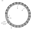
図5Aは、結線板17の平面図である。
図5Bは、結線板17の側面図である。
図5Cは、結線板17の斜視図である。
結線板17は、コイル巻装体11Aに巻回されたコイル12の各端末線12t同士を接続し、三相交流のU、V、W相のコイル群を形成し、更にこれらを中性点に接続する複数の接続線15を案内し、接続線15をさらに電源コネクタ40へ接続する接続線16に接続するために使用する。
FIG. 5A is a plan view of the
FIG. 5B is a side view of the
FIG. 5C is a perspective view of the
The
結線板17は、周方向Yに複数に分割された絶縁体からなる台座部17Aと、周方向Yに隣合う台座部17A同士を連結する絶縁体からなる連結部17Bと、複数の接続線15を備える。連結部17Bは、隣合う台座部17Aの径方向Xの内側端部、かつ、軸方向Zの上端部同士を連結している。
The
台座部17Aの上端面17Asは、径方向Xの内側部分の軸方向Zの高さが、径方向Xの外側部分の軸方向Zの高さよりも高く設定されている。そして、台座部17Aには周方向Yに平行に、複数の接続線15を案内する複数の案内溝17aが設けられている。
In the upper end surface 17As of the
したがって、各案内溝17aの底17adの軸方向Zの位置は、径方向Xの外側から内側に向かって、順に高くなる構造になっている。また、同じ径方向Xの位置に存在する、各台座部17Aの案内溝17aの軸方向Zの位置は、軸方向Zに垂直な同一平面上にある。
Therefore, the position of the bottom 17ad of each
図5A~図5Cに示すように、隣合う台座部17Aの間には空間R1が存在する。この空間R1は、三相交流のU、V、W相のコイル群を形成し、更にこれらを中性点に接続する複数の接続線15を作る過程において、導体Wを切断するために使用する。
As shown in FIGS. 5A to 5C, a space R1 exists between
図5B、図5Cに示すように、結線板17を径方向Xに見た側面図において、連結部17Bの軸方向Zの下には、径方向Xに貫通する空間R2が存在する。空間R2は、接続線15の溶接時に、ステータ10の内側から、溶接用の電極を、結線板17の下部へ挿入するために使用する。
As shown in FIGS. 5B and 5C, in the side view of the
また、連結部17Bの径方向Xの外周面17Boutは、台座部17Aの最も径方向Xの内側に存在する案内溝17aの内側側面17ainよりも径方向Xの内側に凹んでいる。これは、接続線15の溶接時に、軸方向Zの上方から接続線15に接触する電極が連結部17Bに干渉することを防止するための構造である。
Further, the outer peripheral surface 17Bout of the connecting
1つの台座部17Aの内壁の軸方向Zの上方端部には、係止部17kが設けられている。係止部17kは、予め螺旋状に形成された導体Wを、径方向Xに複数形成された案内溝17aに配置する際に、その巻き始め端部Sを係止するために使用する。なお、係止部17kを設けた台座部17Aには、案内溝17aを設けていない。また、以下の説明では係止部17kは、径方向Xの内側に設けているが、外側に設けてもよい。
A locking
図6は、接続線15の形成工程および、結線板17とコイル12との接続工程を示すフローチャートである。
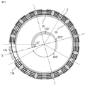
図7は、結線板17の台座部17A上に、導体Wを固定した状態を示す平面図である。
まず、1本の導体Wの巻き始め端部Sを係止部17kに固定する。ここで、予め螺旋状に形成された1本の導体Wを接線板17上に配置すると、3周ある導体Wの内側から1周目部分は、周方向Yに時計回りに隣の台座部17Aから始めて、径方向Xの最も内側の案内溝17aの中に周方向Yに平行に(ステータ10と同心に)収納される。導体Wのうち、最も内側の1周目の案内溝17aに配置される1周目部分は、ステータ10の軸心に対して同心に配置される。
FIG. 6 is a flowchart showing a process of forming the
FIG. 7 is a plan view showing a state in which the conductor W is fixed on the
First, the winding start end portion S of one conductor W is fixed to the locking
係止部17kを備える台座部17Aには、案内溝17aが存在しないので、この台座部17Aの上で、導体Wの2周目となる部分が径方向Xに位置を変える。そして、1周目部分と同様に、導体Wの内側から2周目部分は、係止部17kを備える台座部17A以外の全ての台座部17Aの、径方向Xの内側から2番目の案内溝17aの中に周方向Yに平行に収納される。導体Wの内側から3周目部分は、同様に、径方向Xの内側から3番目の案内溝17aの中に周方向Yに平行に収納される。なお、厳密には、最後の3周目部分は、係止部17kの存在する台座部17Aから2つ手前の台座部17Aまで配置される(ST001:導体配置工程)。
Since the
このように、1本の導体Wを複数の台座部17Aに配置した後、台座部17Aと導体Wとに接着剤19を塗布して、導体Wを台座部17Aに接着、固定する(ST002:導体固定工程)。
In this way, after arranging one conductor W on the plurality of
図8は、台座部17Aに固定後の導体Wを切断し、複数の接続線15を形成した状態を示す図である。
図9は、実施の形態1によるコイル12の結線図である。
図10は、円環状に配置した複数のコイル巻装体11Aを、フレーム60に嵌合した状態を示す斜視図である。
FIG. 8 is a diagram showing a state in which the conductor W after being fixed to the
FIG. 9 is a wiring diagram of the
FIG. 10 is a perspective view showing a state in which a plurality of
図9に示すように、本実施の形態では、各相の2個のコイル12が並列接続され、3相Y結線されている。そこで、三相交流のU、V、W相のコイル群を形成し、更にこれらを中性点に接続する複数の接続線15を作るために、図7のように導体Wを台座部17Aに固定した後、結線板17の隣合う台座部17A間の空間R1にパンチのダイを挿入し、パンチで導体Wを軸方向Zの上から打ち抜いて切断する(ST003:導体切断工程)。このとき、3周ある導体Wの最も内側の1周目部分は、図8に示すように、係止部17kから時計回りに15°165°345°の位置で切断する。このように、全ての切断部Cは、周方向Yに隣合う2つの台座部17Aの間に設ける。
As shown in FIG. 9, in the present embodiment, the two
また、導体Wの内側から2周目部分は、係止部17kから時計回りに45°、285°の位置で切断する。同様に、導体Wの最も外側の3周目部分は、係止部17kから時計回りに135°、315°の位置で切断する。導体Wを台座部17Aに固定した後、このように切断することによって、U、V、W相のコイル群を形成し、更にこれらを中性点に接続する複数の接続線15を備える結線板17を得る。
Further, the second peripheral portion from the inside of the conductor W is cut at a position of 45 ° and 285 ° clockwise from the locking
次に、完成した結線板17を、円環状に配置した複数のコイル巻装体11Aの上に配置する(ST004:結線板配置工程)。結線板17は、結線側インシュレータ13の内鍔部13cの軸方向Zの端面13csと、外鍔部13aの軸方向Zの端面13asの径方向Xの内側の縁13f上に配置される。
Next, the completed
なお、結線板配置工程と、次に説明する接続線15と、コイル巻装体11Aのコイル12の端末線12tとの結線は、複数のコイル巻装体11Aが、図10に示すようにフレーム60に嵌合された状態で行われる。
The connection between the connection plate arrangement step, the
図11は、結線板17とコイル巻装体11Aの溶接前の要部断面図である。
次に、各コイル12の端末線12tの被膜を剥離し、端末線12tを結線側インシュレータ13の第2突起13p2の外周面に沿って引き回して軸方向Zの上方へ折り曲げ、更に径方向Xの内側に折り曲げて、結線板17の接続線15の被膜を剥離した部分の上に配置する。すなわち、図11に示すように、端末線12tは、図10の状態から、先端が径方向Xの内側に折り曲げられて溶接対象となる接続線15の軸方向Zの上方に配置される(ST005:端末線配置工程)。同様に、全てのコイル巻装体11Aの端末線12tを引き回し、結線板17の接続線15上に配置する。
FIG. 11 is a cross-sectional view of a main part of the
Next, the coating film of the
次に、第1電極70inを径方向Xの内側から、上述の空間R2の中を通して溶接対象の接続線15の軸方向Zの下に差し込む。次に、第2電極70uを、溶接対象となる端末線12tの軸方向Zの上方から、第1電極70inの上面との間に、溶接対象となる接続線15および端末線12tを、軸方向Zに挟むように下ろして双方を溶接する(ST006:接続工程)。
Next, the first electrode 70in is inserted from the inside of the radial direction X through the space R2 described above and below the axial direction Z of the
同様に、U、V、W相の接続線15に電源コネクタ40から電流を供給するための接続線16の端末の被覆を剥離した後、接続線15の被膜を剥離した部分の上に配置して溶接する。なお、本実施の形態では、溶接としたが、結線部材を用い、空間R1、R2に治具を挿入して結線してもよい。
Similarly, after stripping the coating of the terminal of the connecting
図12は、モールドしたステータ10の斜視図である。
全ての端末線12tを結線板17の接続線15に溶接した後、ステータ10を絶縁樹脂90でモールドして各溶接部を絶縁する。絶縁樹脂でモールドすることによって、振動により溶接部が破断することも防止できる。
FIG. 12 is a perspective view of the molded
After all the
従来の結線板では、渦巻状の導体が、軸方向Zに垂直な同一平面上に配置されていたため、導体の上端部が、軸方向Zに同じ高さであった。このため、結線のためにステータのコイルの端末線をステータの外側から引き回して溶接する際に、溶接する接続線以外の接続線に干渉し、溶接できなかった。 In the conventional wiring plate, since the spiral conductors are arranged on the same plane perpendicular to the axial direction Z, the upper end portion of the conductor is at the same height in the axial direction Z. Therefore, when the terminal wire of the coil of the stator is routed from the outside of the stator for welding, it interferes with the connecting wire other than the connecting wire to be welded, and welding cannot be performed.
一方、本実施の形態1による回転電機のステータの結線板、回転電機のステータ、回転電機、回転電機のステータの結線板の製造方法、回転電機のステータの製造方法および回転電機の製造方法によれば、コイル12の端末線12tを接続する接続線15は、径方向Xの内側ほど軸方向Zの高さが高くなっているので、接続線15とコイル12の端末線12tとを溶接する際に、ステータ10の内側から挿入される第1電極70inが、他の接続線15に干渉することがなく、双方の溶接が可能となる。
On the other hand, according to the first embodiment, the method of manufacturing the connection plate of the stator of the rotary electric machine, the stator of the rotary electric machine, the rotary electric machine, the connection plate of the stator of the rotary electric machine, the method of manufacturing the stator of the rotary electric machine, and the method of manufacturing the rotary electric machine. For example, since the connecting
また、図11に示すように導体Wを、軸方向Zにずらして、配置することによって、径方向Xに隣合う導体W間の距離が大きくなり、導体Wを平面状に成形するよりも導体W間の絶縁距離を長く確保しつつ径方向Xの間隔は縮めることができるので、ステータ10の径を小さくすることができ、回転電機100の小型化が可能である。
Further, as shown in FIG. 11, by arranging the conductor W by shifting it in the axial direction Z, the distance between the conductors W adjacent to each other in the radial direction X becomes large, and the conductor W is more than formed into a plane. Since the distance in the radial direction X can be shortened while ensuring a long insulation distance between Ws, the diameter of the
また、絶縁樹脂を用いて台座部17A、連結部17Bを形成できるので製造の自由度および搬送性が高く、結線板の組立の効率を向上できる。なお、台座部17Aの案内溝17aの溝の深さは、図11に示すように導体Wが崩れずに収納できればよい。
Further, since the
実施の形態2.
以下、実施の形態2による回転電機のステータの結線板、回転電機のステータ、回転電機、回転電機のステータの結線板の製造方法、回転電機のステータの製造方法および回転電機の製造方法を図を用いて、実施の形態1と異なる部分を中心に説明する。
図13は、結線板217の台座部217A上に、導体Wを固定した状態を示す平面図である。
図14は、台座部217Aに固定後の導体Wを切断し、複数の接続線15を形成した状態を示す図である。
図15は、実施の形態2によるコイル12の結線図である。
Embodiment 2.
Hereinafter, the method of manufacturing the connection plate of the stator of the rotary electric machine, the stator of the rotary electric machine, the rotary electric machine, the method of manufacturing the connection plate of the stator of the rotary electric machine, the method of manufacturing the stator of the rotary electric machine, and the method of manufacturing the rotary electric machine according to the second embodiment are shown. The part different from the first embodiment will be mainly described.
FIG. 13 is a plan view showing a state in which the conductor W is fixed on the
FIG. 14 is a diagram showing a state in which the conductor W after being fixed to the
FIG. 15 is a wiring diagram of the
実施の形態1の結線板17と本実施の形態の結線板217とは、台座部17Aに固定する導体Wの巻き数が異なる。すなわち、実施の形態1では、導体Wは約3周分巻かれていたが、本実地の形態2では、約4周分巻かれている。したがって、台座部217Aに形成される案内溝217aの数も4本となる。
The number of turns of the conductor W fixed to the
本実施の形態では、U、V、W相のコイル群を形成する接続線15と、中性点を形成する接続線15と、電源からの給電線を接続する部分の被膜を中間で剥離している。実施の形態1と同様に、1本の導体Wが軸方向Zの高さ違い、かつ、径方向Xの径違いに4重に並んでおり、軸方向Zの高さの違う部分を繋ぐ部分が存在する。
In the present embodiment, the coating film of the portion connecting the connecting
図13に示すように導体Wを台座部217Aに配置し、接着剤19によって固定した後、実施の形態1と同様に、ダイとパンチで導体Wを打ち抜いて切断する。4周ある導体Wの最も内側の1周目部分は、係止部17kから時計回りに15°、135°、225、°345°の位置で切断する。
As shown in FIG. 13, the conductor W is arranged on the
また、内側から2周目部分は、係止部17kから時計回りに15°、225°の位置で切断する。同様に、内側から3週目部分は、係止部17kから時計回りに135°、345°の位置で切断する。そして最も外側の4周目部分は、係止部17kから時計回りに15°の位置で切断する。そして、U、V、W相のコイル群を形成し、更にこれらを中性点に接続する複数の接続線15を備える結線板217を得る。
Further, the second lap portion from the inside is cut at a position of 15 ° and 225 ° clockwise from the locking
次に、完成した結線板217を、円環状に配置した複数のコイル巻装体11Aの上に配置する。結線板217は、結線側インシュレータ13の内鍔部13cの軸方向Zの端面13csと、外鍔部13aの軸方向Zの端面13asの径方向Xの内側の縁13f上に配置される。以降の工程は、実施の形態1と同様である。
Next, the completed
実施の形態2による回転電機のステータの結線板、回転電機のステータ、回転電機、回転電機のステータの結線板の製造方法、回転電機のステータの製造方法および回転電機の製造方法によれば、実施の形態1の回転電機のステータの結線板、回転電機のステータ、回転電機、回転電機のステータの結線板の製造方法、回転電機のステータの製造方法および回転電機の製造方法と同様の効果を奏する。 According to the second embodiment, the method of manufacturing the connection plate of the stator of the rotary electric machine, the stator of the rotary electric machine, the rotary electric machine, the connection plate of the stator of the rotary electric machine, the method of manufacturing the stator of the rotary electric machine, and the method of manufacturing the rotary electric machine. The same effect as that of the method for manufacturing the connection plate of the stator of the rotary electric machine, the stator of the rotary electric machine, the rotary electric machine, the connection plate of the stator of the rotary electric machine, the method of manufacturing the stator of the rotary electric machine, and the method of manufacturing the stator of the rotary electric machine of Form 1 is obtained. ..
本願は、様々な例示的な実施の形態及び実施例が記載されているが、1つ、または複数の実施の形態に記載された様々な特徴、態様、及び機能は特定の実施の形態の適用に限られるのではなく、単独で、または様々な組み合わせで実施の形態に適用可能である。
従って、例示されていない無数の変形例が、本願に開示される技術の範囲内において想定される。例えば、少なくとも1つの構成要素を変形する場合、追加する場合または省略する場合、さらには、少なくとも1つの構成要素を抽出し、他の実施の形態の構成要素と組み合わせる場合が含まれるものとする。
Although the present application describes various exemplary embodiments and examples, the various features, embodiments, and functions described in one or more embodiments are applications of a particular embodiment. It is not limited to, but can be applied to embodiments alone or in various combinations.
Therefore, innumerable variations not exemplified are envisioned within the scope of the techniques disclosed in the present application. For example, it is assumed that at least one component is modified, added or omitted, and further, at least one component is extracted and combined with the components of other embodiments.
100 回転電機、10 ステータ、11 分割積層コア、11a ヨーク部、
11A コイル巻装体、11as 端面、11b ティース部、11bins 端面、
11bs 端面、11c シュー部、11cs,13cs,13as 端面、
11p 鉄心片、11s1 一端面、11s2 他端面、12 コイル、
12t 端末線、13 結線側インシュレータ、14 反結線側インシュレータ、
13a,14a 外鍔部、13b,14b ティース端面被覆部、
13c,14c 内鍔部、13d 溝、13f 縁、13p1 第1突起、
13p2 第2突起、15,16 接続線、17,217 結線板、
17a,217a 案内溝、17A,217A 台座部、17ain 内側側面、
17As 上端面、17B 連結部、17Bout 外周面、17k 係止部、
19 接着剤、30 ロータ、40 電源コネクタ、50a 反結線側ブラケット、
50b 結線側ブラケット、60 フレーム、70in 第1電極、70u 第2電極、
90 絶縁樹脂、C 切断部、R1,R2 空間、S 端部、W 導体、X 径方向、
Y 周方向、Z 軸方向。
100 rotary electric machine, 10 stator, 11 split laminated core, 11a yoke part,
11A coil winding body, 11as end face, 11b teeth part, 11bins end face,
11bs end face, 11c shoe part, 11cs, 13cs, 13as end face,
11p iron core piece, 11s1 one end surface, 11s2 other end surface, 12 coils,
12t terminal line, 13 connection side insulator, 14 non-connection side insulator,
13a, 14a outer collar, 13b, 14b tooth end face covering,
13c, 14c inner collar, 13d groove, 13f edge, 13p1 first protrusion,
13p2 2nd protrusion, 15,16 connection line, 17,217 connection plate,
17a, 217a guide groove, 17A, 217A pedestal, 17ain inner side surface,
17As upper end surface, 17B connecting part, 17Bout outer peripheral surface, 17k locking part,
19 Adhesive, 30 Rotor, 40 Power Connector, 50a Anti-Connecting Bracket,
50b connection side bracket, 60 frame, 70in 1st electrode, 70u 2nd electrode,
90 Insulation resin, C cut part, R1, R2 space, S end part, W conductor, X radial direction,
Y circumferential direction, Z axis direction.
Claims (12)
周方向に複数に分割された台座部と、
周方向に隣合う前記台座部同士を連結する連結部とを備え、
前記台座部には周方向に平行に、前記接続線を案内する複数の案内溝が設けられ、
各前記案内溝の底の軸方向の位置は、径方向の外側から内側に向かって、順に高くなっている回転電機のステータの結線板。 It is a connection plate of the stator of a rotary electric machine provided with a connection wire for connecting the terminal wires of a plurality of coils wound around the teeth portion of the stator of the rotary electric machine.
The pedestal part divided into multiple parts in the circumferential direction,
It is equipped with a connecting portion that connects the pedestals adjacent to each other in the circumferential direction.
The pedestal portion is provided with a plurality of guide grooves for guiding the connection line in parallel with the circumferential direction.
The axial position of the bottom of each guide groove is the connection plate of the stator of the rotary electric machine, which increases in order from the outside to the inside in the radial direction.
周方向に分割された分割コアと、前記分割コアの軸方向両端面に装着されたインシュレータと、前記インシュレータを介して前記分割コアのティース部に巻回された前記コイルとを有する複数のコイル巻装体を備え、
前記インシュレータは、前記分割コアのヨーク部の軸方向端面を覆う外鍔部と、前記ティース部の径方向内側先端部の軸方向端面を覆う内鍔と、前記ティース部の軸方向の端面を覆うティース端面被覆部とを備え、
前記結線板は、前記内鍔の端面と、前記外鍔部の軸方向の端面の径方向の内側の縁の上に、径方向に位置決めされて配置されている回転電機のステータ。 The connection plate of the stator of the rotary electric machine according to any one of claims 1 to 6 is provided.
A plurality of coil windings having a split core divided in the circumferential direction, insulators mounted on both end faces in the axial direction of the split core, and the coil wound around the teeth portion of the split core via the insulator. Equipped with a body,
The insulator covers an outer flange portion that covers the axial end surface of the yoke portion of the split core, an inner flange portion that covers the axial end surface of the radial inner tip portion of the tooth portion, and an axial end surface of the tooth portion. Equipped with a tooth end face covering
The connection plate is a stator of a rotary electric machine that is positioned and arranged radially on the end surface of the inner flange and the radial inner edge of the axial end surface of the outer flange portion.
前記ステータの内周面に外周面を対向させて回転可能に支持されたロータとを備える回転電機。 The stator of the rotary electric machine according to claim 7 or 8,
A rotary electric machine provided with a rotor rotatably supported by facing the outer peripheral surface to the inner peripheral surface of the stator.
1本の導体を、全ての前記台座部の、一番外側又は一番内側の前記案内溝の中に配置し、
引き続き、前記導体を、既に前記導体を配置した前記案内溝の径方向に隣合う、全ての前記台座部の前記案内溝に配置する導体配置工程と、
1本の前記導体を隣合う前記台座部の間で切断する切断工程とを備える回転電機のステータの結線板の製造方法。 The method for manufacturing a connection plate for a stator of a rotary electric machine according to any one of claims 1 to 6.
One conductor is placed in the outermost or innermost guide groove of all the pedestals.
Subsequently, a conductor arranging step of arranging the conductor in the guide grooves of all the pedestals adjacent to each other in the radial direction of the guide groove in which the conductor is already arranged,
A method for manufacturing a connection plate for a stator of a rotary electric machine, comprising a cutting step of cutting one conductor between adjacent pedestals.
前記結線板を、円環状に配置した複数の前記コイル巻装体の上に配置する結線板配置工程と、
前記端末線を、溶接対象となる前記接続線の軸方向の上方に配置する端末線配置工程と、
第1電極を、溶接対象の前記接続線の軸方向の下に差し込み、
第2電極を、溶接対象となる前記端末線の軸方向の上方から、前記第1電極の上面との間に、溶接対象となる前記接続線および前記端末線を、軸方向に挟むように下ろして前記端末線と前記接続線とを溶接する接続工程とを備える回転電機のステータの製造方法。 The method for manufacturing a rotary electric machine stator according to claim 7 or 8, wherein the connection plate for the rotary electric machine stator manufactured by using the method for manufacturing the connection plate for the rotary electric machine stator according to claim 10 is used. ,
A wiring plate arranging step of arranging the wiring plate on a plurality of the coil winding bodies arranged in an annular shape, and
A terminal line arranging step of arranging the terminal line above the connecting line to be welded in the axial direction,
The first electrode is inserted below the axial direction of the connecting wire to be welded.
The second electrode is lowered from above the terminal wire to be welded in the axial direction so as to sandwich the connecting wire and the terminal wire to be welded in the axial direction between the upper surface of the first electrode and the connecting wire to be welded. A method for manufacturing a stator of a rotary electric machine, comprising a connection step of welding the terminal wire and the connection wire.
前記ステータの内周面に、ロータの外周面を対向させて前記ロータを回転可能に配置する回転電機の製造方法。 A method for manufacturing a rotary electric machine using a rotary electric machine stator manufactured by using the method for manufacturing a rotary electric machine stator according to claim 11.
A method for manufacturing a rotary electric machine in which the rotor is rotatably arranged so that the outer peripheral surface of the rotor faces the inner peripheral surface of the stator.
Priority Applications (1)
| Application Number | Priority Date | Filing Date | Title |
|---|---|---|---|
| JP2020121800A JP7433153B2 (en) | 2020-07-16 | 2020-07-16 | A stator connection plate for a rotating electric machine, a stator for a rotating electric machine, a rotating electric machine, a method for manufacturing a connection plate for a stator for a rotating electric machine, a method for manufacturing a stator for a rotating electric machine, and a method for manufacturing a rotating electric machine |
Applications Claiming Priority (1)
| Application Number | Priority Date | Filing Date | Title |
|---|---|---|---|
| JP2020121800A JP7433153B2 (en) | 2020-07-16 | 2020-07-16 | A stator connection plate for a rotating electric machine, a stator for a rotating electric machine, a rotating electric machine, a method for manufacturing a connection plate for a stator for a rotating electric machine, a method for manufacturing a stator for a rotating electric machine, and a method for manufacturing a rotating electric machine |
Publications (2)
| Publication Number | Publication Date |
|---|---|
| JP2022018593A true JP2022018593A (en) | 2022-01-27 |
| JP7433153B2 JP7433153B2 (en) | 2024-02-19 |
Family
ID=80203416
Family Applications (1)
| Application Number | Title | Priority Date | Filing Date |
|---|---|---|---|
| JP2020121800A Active JP7433153B2 (en) | 2020-07-16 | 2020-07-16 | A stator connection plate for a rotating electric machine, a stator for a rotating electric machine, a rotating electric machine, a method for manufacturing a connection plate for a stator for a rotating electric machine, a method for manufacturing a stator for a rotating electric machine, and a method for manufacturing a rotating electric machine |
Country Status (1)
| Country | Link |
|---|---|
| JP (1) | JP7433153B2 (en) |
Family Cites Families (6)
| Publication number | Priority date | Publication date | Assignee | Title |
|---|---|---|---|---|
| DE10318816B4 (en) | 2003-04-17 | 2007-06-28 | Minebea Co., Ltd. | Stator with wiring structure for stator windings |
| JP2012228007A (en) | 2011-04-15 | 2012-11-15 | Asmo Co Ltd | Bus bar device, stator, motor and manufacturing method of stator |
| JP2012244839A (en) | 2011-05-23 | 2012-12-10 | Toyota Motor Corp | Stator for rotating electric machine |
| JP5348199B2 (en) | 2011-08-05 | 2013-11-20 | 株式会社安川電機 | Manufacturing method of rotating electrical machine and manufacturing method of wiring board of rotating electrical machine |
| WO2018168090A1 (en) | 2017-03-14 | 2018-09-20 | 日本電産株式会社 | Stator, motor, and electric power steering device |
| WO2018179790A1 (en) | 2017-03-31 | 2018-10-04 | 日本電産株式会社 | Busbar unit and motor provided with same |
-
2020
- 2020-07-16 JP JP2020121800A patent/JP7433153B2/en active Active
Also Published As
| Publication number | Publication date |
|---|---|
| JP7433153B2 (en) | 2024-02-19 |
Similar Documents
| Publication | Publication Date | Title |
|---|---|---|
| JP5028869B2 (en) | Brushless motor | |
| JP5306411B2 (en) | Rotating electric machine | |
| JP4710047B2 (en) | Variable reluctance angle detector | |
| JP5217117B2 (en) | Brushless motor | |
| JP5140389B2 (en) | Stator for rotating electric machine and rotating electric machine using the same | |
| KR20080021678A (en) | Armature for rotary electric motor, rotary electric motor, and method of producing the rotary electric motor | |
| JP2009106003A (en) | Rotary electric machine | |
| JP6979464B2 (en) | Rotating machine stator | |
| JP5232547B2 (en) | Rotating electric machine | |
| US11469637B2 (en) | Stator comprising an insulator having a restriction portion and covering a tooth | |
| WO2020174817A1 (en) | Dynamo-electric machine stator, dynamo-electric machine, method for manufacturing dynamo-electric machine stator, and method for manufacturing dynamo-electric machine | |
| US20080024032A1 (en) | Motor Stator | |
| JP5181627B2 (en) | Rotating electric machine and method of manufacturing rotating electric machine | |
| JP7433153B2 (en) | A stator connection plate for a rotating electric machine, a stator for a rotating electric machine, a rotating electric machine, a method for manufacturing a connection plate for a stator for a rotating electric machine, a method for manufacturing a stator for a rotating electric machine, and a method for manufacturing a rotating electric machine | |
| US11418082B2 (en) | Stator used for motor and method for manufacturing said stator | |
| JP6080964B2 (en) | Rotating electric machine stator | |
| CN102916515B (en) | Rotating electrical machine, wire connecting substrate of rotating electrical machine, manufacturing method of rotating electrical machine, and manufacturing method of wire connecting substrate of rotating electrical machine | |
| US11784528B2 (en) | Winding pattern and arrangement for a motor armature | |
| JP7433176B2 (en) | Rotating electric machine stator wiring board, rotating electric machine stator, and rotating electric machine | |
| JP7050239B2 (en) | Stator, motor | |
| WO2021255838A1 (en) | Electric motor stator and electric motor | |
| WO2021182052A1 (en) | Alternating-current motor | |
| US10916987B2 (en) | Stator, associated electric motor and associated method | |
| US20220302787A1 (en) | Stator and method for manufacturing stator | |
| WO2022038999A1 (en) | Stator and electric motor provided with same |
Legal Events
| Date | Code | Title | Description |
|---|---|---|---|
| A621 | Written request for application examination |
Free format text: JAPANESE INTERMEDIATE CODE: A621 Effective date: 20230314 |
|
| A977 | Report on retrieval |
Free format text: JAPANESE INTERMEDIATE CODE: A971007 Effective date: 20231122 |
|
| A131 | Notification of reasons for refusal |
Free format text: JAPANESE INTERMEDIATE CODE: A131 Effective date: 20231205 |
|
| A521 | Request for written amendment filed |
Free format text: JAPANESE INTERMEDIATE CODE: A523 Effective date: 20231212 |
|
| TRDD | Decision of grant or rejection written | ||
| A01 | Written decision to grant a patent or to grant a registration (utility model) |
Free format text: JAPANESE INTERMEDIATE CODE: A01 Effective date: 20240109 |
|
| A61 | First payment of annual fees (during grant procedure) |
Free format text: JAPANESE INTERMEDIATE CODE: A61 Effective date: 20240206 |
|
| R151 | Written notification of patent or utility model registration |
Ref document number: 7433153 Country of ref document: JP Free format text: JAPANESE INTERMEDIATE CODE: R151 |