JP2022018027A - Electrode cutting device and manufacturing device of laminated cell - Google Patents
Electrode cutting device and manufacturing device of laminated cell Download PDFInfo
- Publication number
- JP2022018027A JP2022018027A JP2020120962A JP2020120962A JP2022018027A JP 2022018027 A JP2022018027 A JP 2022018027A JP 2020120962 A JP2020120962 A JP 2020120962A JP 2020120962 A JP2020120962 A JP 2020120962A JP 2022018027 A JP2022018027 A JP 2022018027A
- Authority
- JP
- Japan
- Prior art keywords
- conductive sheet
- electrode plate
- separator
- cutting
- laminated
- Prior art date
- Legal status (The legal status is an assumption and is not a legal conclusion. Google has not performed a legal analysis and makes no representation as to the accuracy of the status listed.)
- Pending
Links
- 238000005520 cutting process Methods 0.000 title claims abstract description 152
- 238000004519 manufacturing process Methods 0.000 title claims abstract description 67
- 230000032258 transport Effects 0.000 claims description 187
- 238000012546 transfer Methods 0.000 claims description 58
- 238000003708 edge detection Methods 0.000 claims description 19
- 238000011144 upstream manufacturing Methods 0.000 claims description 13
- 210000000078 claw Anatomy 0.000 description 44
- 238000012790 confirmation Methods 0.000 description 34
- 238000000034 method Methods 0.000 description 24
- 238000003384 imaging method Methods 0.000 description 23
- 238000010030 laminating Methods 0.000 description 16
- 238000010586 diagram Methods 0.000 description 14
- 230000008569 process Effects 0.000 description 14
- 238000012545 processing Methods 0.000 description 14
- 238000000926 separation method Methods 0.000 description 14
- 238000003860 storage Methods 0.000 description 11
- 238000001514 detection method Methods 0.000 description 9
- 229910052782 aluminium Inorganic materials 0.000 description 8
- XAGFODPZIPBFFR-UHFFFAOYSA-N aluminium Chemical compound [Al] XAGFODPZIPBFFR-UHFFFAOYSA-N 0.000 description 8
- 239000011888 foil Substances 0.000 description 8
- 239000000463 material Substances 0.000 description 8
- 238000005452 bending Methods 0.000 description 7
- 238000003475 lamination Methods 0.000 description 6
- 230000008859 change Effects 0.000 description 5
- 238000013459 approach Methods 0.000 description 4
- 238000000605 extraction Methods 0.000 description 4
- 230000002093 peripheral effect Effects 0.000 description 4
- 239000011149 active material Substances 0.000 description 3
- 230000007246 mechanism Effects 0.000 description 3
- 229910052751 metal Inorganic materials 0.000 description 3
- 239000002184 metal Substances 0.000 description 3
- 238000004804 winding Methods 0.000 description 3
- 230000004323 axial length Effects 0.000 description 2
- 239000004020 conductor Substances 0.000 description 2
- 230000006866 deterioration Effects 0.000 description 2
- 239000008151 electrolyte solution Substances 0.000 description 2
- 230000007257 malfunction Effects 0.000 description 2
- 206010040954 Skin wrinkling Diseases 0.000 description 1
- 229910001315 Tool steel Inorganic materials 0.000 description 1
- 239000000919 ceramic Substances 0.000 description 1
- 230000008878 coupling Effects 0.000 description 1
- 238000010168 coupling process Methods 0.000 description 1
- 238000005859 coupling reaction Methods 0.000 description 1
- 230000000694 effects Effects 0.000 description 1
- 150000002500 ions Chemical class 0.000 description 1
- 238000009940 knitting Methods 0.000 description 1
- 238000003698 laser cutting Methods 0.000 description 1
- 238000012423 maintenance Methods 0.000 description 1
- 238000005259 measurement Methods 0.000 description 1
- 239000000203 mixture Substances 0.000 description 1
- TWNQGVIAIRXVLR-UHFFFAOYSA-N oxo(oxoalumanyloxy)alumane Chemical compound O=[Al]O[Al]=O TWNQGVIAIRXVLR-UHFFFAOYSA-N 0.000 description 1
- 239000011148 porous material Substances 0.000 description 1
- 239000004065 semiconductor Substances 0.000 description 1
- 238000001179 sorption measurement Methods 0.000 description 1
- 239000000126 substance Substances 0.000 description 1
Images


Classifications
-
- H—ELECTRICITY
- H01—ELECTRIC ELEMENTS
- H01M—PROCESSES OR MEANS, e.g. BATTERIES, FOR THE DIRECT CONVERSION OF CHEMICAL ENERGY INTO ELECTRICAL ENERGY
- H01M10/00—Secondary cells; Manufacture thereof
- H01M10/04—Construction or manufacture in general
- H01M10/0404—Machines for assembling batteries
-
- B—PERFORMING OPERATIONS; TRANSPORTING
- B26—HAND CUTTING TOOLS; CUTTING; SEVERING
- B26D—CUTTING; DETAILS COMMON TO MACHINES FOR PERFORATING, PUNCHING, CUTTING-OUT, STAMPING-OUT OR SEVERING
- B26D1/00—Cutting through work characterised by the nature or movement of the cutting member or particular materials not otherwise provided for; Apparatus or machines therefor; Cutting members therefor
- B26D1/01—Cutting through work characterised by the nature or movement of the cutting member or particular materials not otherwise provided for; Apparatus or machines therefor; Cutting members therefor involving a cutting member which does not travel with the work
- B26D1/12—Cutting through work characterised by the nature or movement of the cutting member or particular materials not otherwise provided for; Apparatus or machines therefor; Cutting members therefor involving a cutting member which does not travel with the work having a cutting member moving about an axis
- B26D1/14—Cutting through work characterised by the nature or movement of the cutting member or particular materials not otherwise provided for; Apparatus or machines therefor; Cutting members therefor involving a cutting member which does not travel with the work having a cutting member moving about an axis with a circular cutting member, e.g. disc cutter
- B26D1/20—Cutting through work characterised by the nature or movement of the cutting member or particular materials not otherwise provided for; Apparatus or machines therefor; Cutting members therefor involving a cutting member which does not travel with the work having a cutting member moving about an axis with a circular cutting member, e.g. disc cutter coacting with a fixed member
-
- B—PERFORMING OPERATIONS; TRANSPORTING
- B26—HAND CUTTING TOOLS; CUTTING; SEVERING
- B26D—CUTTING; DETAILS COMMON TO MACHINES FOR PERFORATING, PUNCHING, CUTTING-OUT, STAMPING-OUT OR SEVERING
- B26D5/00—Arrangements for operating and controlling machines or devices for cutting, cutting-out, stamping-out, punching, perforating, or severing by means other than cutting
- B26D5/20—Arrangements for operating and controlling machines or devices for cutting, cutting-out, stamping-out, punching, perforating, or severing by means other than cutting with interrelated action between the cutting member and work feed
- B26D5/30—Arrangements for operating and controlling machines or devices for cutting, cutting-out, stamping-out, punching, perforating, or severing by means other than cutting with interrelated action between the cutting member and work feed having the cutting member controlled by scanning a record carrier
- B26D5/34—Arrangements for operating and controlling machines or devices for cutting, cutting-out, stamping-out, punching, perforating, or severing by means other than cutting with interrelated action between the cutting member and work feed having the cutting member controlled by scanning a record carrier scanning being effected by a photosensitive device
-
- B—PERFORMING OPERATIONS; TRANSPORTING
- B26—HAND CUTTING TOOLS; CUTTING; SEVERING
- B26D—CUTTING; DETAILS COMMON TO MACHINES FOR PERFORATING, PUNCHING, CUTTING-OUT, STAMPING-OUT OR SEVERING
- B26D7/00—Details of apparatus for cutting, cutting-out, stamping-out, punching, perforating, or severing by means other than cutting
- B26D7/08—Means for treating work or cutting member to facilitate cutting
- B26D7/14—Means for treating work or cutting member to facilitate cutting by tensioning the work
-
- B—PERFORMING OPERATIONS; TRANSPORTING
- B26—HAND CUTTING TOOLS; CUTTING; SEVERING
- B26F—PERFORATING; PUNCHING; CUTTING-OUT; STAMPING-OUT; SEVERING BY MEANS OTHER THAN CUTTING
- B26F1/00—Perforating; Punching; Cutting-out; Stamping-out; Apparatus therefor
- B26F1/02—Perforating by punching, e.g. with relatively-reciprocating punch and bed
- B26F1/12—Perforating by punching, e.g. with relatively-reciprocating punch and bed to notch margins of work
-
- H—ELECTRICITY
- H01—ELECTRIC ELEMENTS
- H01M—PROCESSES OR MEANS, e.g. BATTERIES, FOR THE DIRECT CONVERSION OF CHEMICAL ENERGY INTO ELECTRICAL ENERGY
- H01M10/00—Secondary cells; Manufacture thereof
- H01M10/04—Construction or manufacture in general
-
- H—ELECTRICITY
- H01—ELECTRIC ELEMENTS
- H01M—PROCESSES OR MEANS, e.g. BATTERIES, FOR THE DIRECT CONVERSION OF CHEMICAL ENERGY INTO ELECTRICAL ENERGY
- H01M10/00—Secondary cells; Manufacture thereof
- H01M10/04—Construction or manufacture in general
- H01M10/0459—Cells or batteries with folded separator between plate-like electrodes
-
- H—ELECTRICITY
- H01—ELECTRIC ELEMENTS
- H01M—PROCESSES OR MEANS, e.g. BATTERIES, FOR THE DIRECT CONVERSION OF CHEMICAL ENERGY INTO ELECTRICAL ENERGY
- H01M10/00—Secondary cells; Manufacture thereof
- H01M10/05—Accumulators with non-aqueous electrolyte
- H01M10/058—Construction or manufacture
- H01M10/0583—Construction or manufacture of accumulators with folded construction elements except wound ones, i.e. folded positive or negative electrodes or separators, e.g. with "Z"-shaped electrodes or separators
-
- H—ELECTRICITY
- H01—ELECTRIC ELEMENTS
- H01M—PROCESSES OR MEANS, e.g. BATTERIES, FOR THE DIRECT CONVERSION OF CHEMICAL ENERGY INTO ELECTRICAL ENERGY
- H01M4/00—Electrodes
- H01M4/02—Electrodes composed of, or comprising, active material
- H01M4/04—Processes of manufacture in general
-
- H—ELECTRICITY
- H01—ELECTRIC ELEMENTS
- H01M—PROCESSES OR MEANS, e.g. BATTERIES, FOR THE DIRECT CONVERSION OF CHEMICAL ENERGY INTO ELECTRICAL ENERGY
- H01M50/00—Constructional details or processes of manufacture of the non-active parts of electrochemical cells other than fuel cells, e.g. hybrid cells
- H01M50/40—Separators; Membranes; Diaphragms; Spacing elements inside cells
- H01M50/403—Manufacturing processes of separators, membranes or diaphragms
- H01M50/406—Moulding; Embossing; Cutting
-
- Y—GENERAL TAGGING OF NEW TECHNOLOGICAL DEVELOPMENTS; GENERAL TAGGING OF CROSS-SECTIONAL TECHNOLOGIES SPANNING OVER SEVERAL SECTIONS OF THE IPC; TECHNICAL SUBJECTS COVERED BY FORMER USPC CROSS-REFERENCE ART COLLECTIONS [XRACs] AND DIGESTS
- Y02—TECHNOLOGIES OR APPLICATIONS FOR MITIGATION OR ADAPTATION AGAINST CLIMATE CHANGE
- Y02E—REDUCTION OF GREENHOUSE GAS [GHG] EMISSIONS, RELATED TO ENERGY GENERATION, TRANSMISSION OR DISTRIBUTION
- Y02E60/00—Enabling technologies; Technologies with a potential or indirect contribution to GHG emissions mitigation
- Y02E60/10—Energy storage using batteries
-
- Y—GENERAL TAGGING OF NEW TECHNOLOGICAL DEVELOPMENTS; GENERAL TAGGING OF CROSS-SECTIONAL TECHNOLOGIES SPANNING OVER SEVERAL SECTIONS OF THE IPC; TECHNICAL SUBJECTS COVERED BY FORMER USPC CROSS-REFERENCE ART COLLECTIONS [XRACs] AND DIGESTS
- Y02—TECHNOLOGIES OR APPLICATIONS FOR MITIGATION OR ADAPTATION AGAINST CLIMATE CHANGE
- Y02P—CLIMATE CHANGE MITIGATION TECHNOLOGIES IN THE PRODUCTION OR PROCESSING OF GOODS
- Y02P70/00—Climate change mitigation technologies in the production process for final industrial or consumer products
- Y02P70/50—Manufacturing or production processes characterised by the final manufactured product
Abstract
Description
本発明は、電極切断装置、および、積層セルの製造装置に関する。 The present invention relates to an electrode cutting device and a laminated cell manufacturing device.
自動車用電池、電子機器用電池等の各種電池として、セパレータを挟んで負極板と正極板とを交互に積層した積層型電池が広く採用されている。特開2014-165055号公報に記載の構成では、正極板移載ヘッドおよび負極板移載ヘッドで交互にセパレータを押して、ジグザグに折り曲げつつ、正極板移載ヘッドから折り曲げたセパレータに正極板を、負極板移載ヘッドから折り曲げたセパレータに負極板をそれぞれ移載して、正極板および負極板がセパレータを介して交互に配置される。 As various batteries such as batteries for automobiles and batteries for electronic devices, laminated batteries in which negative electrode plates and positive electrode plates are alternately laminated with a separator sandwiched between them are widely adopted. In the configuration described in Japanese Patent Application Laid-Open No. 2014-16555, the positive electrode plate is alternately pushed by the positive electrode plate transfer head and the negative electrode plate transfer head, and the positive electrode plate is bent in a zigzag manner, and the positive electrode plate is attached to the separator bent from the positive electrode plate transfer head. The negative electrode plate is transferred from the negative electrode plate transfer head to the bent separator, and the positive electrode plate and the negative electrode plate are alternately arranged via the separator.
導電板を切断して、高い形状精度の正極板および負極板を形成する場合、金型を用いると、高精度の金型を用いる必要がある。また、一定量製造した後に金型の交換が必要である。また、レーザーで切断することも可能であるが、切断時の金属板の編成や微細物の飛散があり、精度の高い正極板および負極板を得ることが困難になる虞がある。 When a positive electrode plate and a negative electrode plate having high shape accuracy are formed by cutting a conductive plate, it is necessary to use a high precision mold when using a mold. In addition, it is necessary to replace the mold after manufacturing a certain amount. It is also possible to cut with a laser, but there is a risk that it will be difficult to obtain a high-precision positive electrode plate and negative electrode plate due to the knitting of the metal plate and the scattering of fine substances at the time of cutting.
そこで、本発明は、簡単な構成で、安定して高品質に電極を切断できる電極切断装置、および、簡単な構成で、安定して高品質な積層セルを製造できる積層セルの製造装置を提供することを目的とする。 Therefore, the present invention provides an electrode cutting device capable of stably cutting electrodes with high quality with a simple configuration, and a laminated cell manufacturing device capable of stably manufacturing high quality laminated cells with a simple configuration. The purpose is to do.
上記目的を達成するために本発明の電極切断装置は、前記導電シートの搬送方向と交差する方向に延びる固定切り刃を有する固定刃と、円板状であって径方向外縁に回転切り刃を有する回転刃と、を備え、前記回転刃を回転させつつ前記固定刃に沿って移動させる。 In order to achieve the above object, the electrode cutting device of the present invention has a fixed blade having a fixed cutting blade extending in a direction intersecting the transport direction of the conductive sheet, and a disc-shaped rotary cutting blade on the outer edge in the radial direction. The rotary blade is provided with a rotary blade, and the rotary blade is rotated and moved along the fixed blade.
このように構成することで、回転刃の回転切り刃を固定刃の固定切り刃に対して、一定の精度とすることで、導電シートを切断可能である。これにより、電極切断部を簡略化できる。また、固定刃または回転刃を交換する場合も、取り付け時の精度を一定の精度とすればよく、交換も容易である。このような簡単な構成であるにもかかわらず安定して高品質に電極を切断できる。 With this configuration, the conductive sheet can be cut by setting the rotary cutting edge of the rotary blade to a certain accuracy with respect to the fixed cutting edge of the fixed blade. This makes it possible to simplify the electrode cutting portion. Further, when the fixed blade or the rotary blade is replaced, the accuracy at the time of mounting may be set to a certain accuracy, and the replacement is easy. Despite such a simple configuration, the electrodes can be cut stably and with high quality.
上記構成において、前記回転刃は、前記固定刃との接触を維持した状態で、回転しつつ前記固定刃に沿って移動する。 In the above configuration, the rotary blade moves along the fixed blade while rotating while maintaining contact with the fixed blade.
上記構成において、前記回転刃には、前記固定刃に向けて押す力が付与される。 In the above configuration, the rotary blade is given a pushing force toward the fixed blade.
上記構成において、前記固定刃に対する前記回転刃の送り量および回転刃の回転速度が可変である。 In the above configuration, the feed amount of the rotary blade and the rotation speed of the rotary blade with respect to the fixed blade are variable.
上記構成において、前記導電シートの切断完了時において、前記回転刃を空転させており、設定された切断回数毎に前記回転刃の空転時の回転角度が可変である。 In the above configuration, the rotary blade is idled when the cutting of the conductive sheet is completed, and the rotation angle of the rotary blade when idling is variable for each set number of cuttings.
上記構成において、前記導電シートの搬送方向において、前記回転刃と前記固定刃に対し、上流側に配置された第1搬送ローラ部と、下流側に配置された第2搬送ローラ部と、をさらに有する。前記第1搬送ローラ部および前記第2搬送ローラ部は、ともに前記導電シート厚み方向につかみ、搬送中の前記導電シートに対して搬送方向に一定の張力を付与している。前記回転刃と前記固定刃とにより前記導電シートを切断するときに、前記導電シートの搬送を停止するとともに、前記導電シートの前記第1搬送ローラ部と前記第2搬送ローラ部との間の部分の張力を搬送時の張力に対して変化させる。 In the above configuration, in the transport direction of the conductive sheet, the first transport roller portion arranged on the upstream side and the second transport roller portion arranged on the downstream side with respect to the rotary blade and the fixed blade are further provided. Have. Both the first transport roller section and the second transport roller section are grasped in the thickness direction of the conductive sheet and apply a constant tension to the conductive sheet being transported in the transport direction. When the conductive sheet is cut by the rotary blade and the fixed blade, the transfer of the conductive sheet is stopped, and the portion between the first transfer roller portion and the second transfer roller portion of the conductive sheet. The tension of is changed with respect to the tension at the time of transportation.
上記構成において、前記導電シートの切断時において、前記第1搬送ローラ部が停止して一定時間経過した後、前記第2搬送ローラ部が停止する。 In the above configuration, when the conductive sheet is cut, the first transport roller portion is stopped and a certain period of time elapses, and then the second transport roller portion is stopped.
上記構成において、前記導電シートの切断時において、前記第1搬送ローラ部および前記第2搬送ローラ部がともに停止した後、前記第2搬送ローラ部を前記導電シートの搬送方向と逆方向に一定量回転する。 In the above configuration, when the conductive sheet is cut, after both the first transport roller portion and the second transport roller portion are stopped, the second transport roller portion is moved by a fixed amount in the direction opposite to the transport direction of the conductive sheet. Rotate.
上記構成において、前記導電シートの幅方向の両端に前記電極切断部で切断する部分を支持するための切り欠きを形成する切り欠き形成部をさらに有し、前記切り欠き形成部は、前記導電シートに切り欠きを形成するとともに幅方向に移動可能な切り欠き金型と、前記導電シートの搬送方向において前記切り欠き金型の上流側に配置されて前記導電シートの幅方向のエッジを検知するエッジ検知部と、を有する。そして、前記切り欠き金型が、前記エッジ検知部にて検知された前記導電シートの前記エッジに基づいて、前記導電シートの幅方向の前記エッジに正確に形成されるように移動される。 In the above configuration, the conductive sheet further has notch forming portions for forming notches for supporting the portions to be cut by the electrode cutting portions at both ends in the width direction, and the notch forming portions are the conductive sheet. A notch mold that can move in the width direction while forming a notch, and an edge that is arranged on the upstream side of the notch mold in the transport direction of the conductive sheet and detects an edge in the width direction of the conductive sheet. It has a detection unit and. Then, the notch mold is moved so as to be accurately formed on the edge in the width direction of the conductive sheet based on the edge of the conductive sheet detected by the edge detection unit.
上記目的を達成するために本発明の積層セルの製造装置は、蛇腹状に折り曲げたセパレータの谷折り部分に負極板となる電極板および正極板となる電極板を交互に配置して積層した積層セルを製造する。積層セルの製造装置は、テープ状の前記セパレータを供給するセパレータローラを有するセパレータ供給部と、前記セパレータローラから供給された前記セパレータを蛇腹状に折り曲げる折り曲げ部と、前記折り曲げ部にて蛇腹状に折り曲げられた前記セパレータに前記負極板および前記正極板を交互に供給する電極供給部と、を有する。前記電極供給部は、2個の電極板供給部を有する。一方の前記電極板供給部は、前記一方側に配置されて前記負極板となる電極板を供給し、他方の前記電極板供給部は、前記他方側に配置されて前記正極板となる前記電極板を供給する。各電極板供給部は、前記導電シートを一定の長さ毎に切断して前記電極板を作製する電極切断部を有する。前記電極切断部は、前記導電シートの搬送方向と交差する方向に延びる固定切り刃を有する固定刃と、円板状であって径方向外縁に回転切り刃を有する回転刃と、前記回転刃を回転させつつ接触前記固定切り刃に沿って移動させる回転刃移動部と、を有する。 In order to achieve the above object, in the laminated cell manufacturing apparatus of the present invention, the electrode plates to be the negative electrode plates and the electrode plates to be the positive electrode plates are alternately arranged and laminated in the valley fold portion of the separator bent in a bellows shape. Manufacture cells. The stacking cell manufacturing apparatus has a separator supply unit having a separator roller that supplies the tape-shaped separator, a bent portion that bends the separator supplied from the separator roller in a bellows shape, and a bellows shape at the bent portion. The bent separator is provided with a negative electrode plate and an electrode supply unit that alternately supplies the positive electrode plate. The electrode supply unit has two electrode plate supply units. One of the electrode plate supply units is arranged on one side to supply an electrode plate to be the negative electrode plate, and the other electrode plate supply unit is arranged on the other side to be the positive electrode plate. Supply the board. Each electrode plate supply unit has an electrode cutting unit for producing the electrode plate by cutting the conductive sheet at regular length intervals. The electrode cutting portion includes a fixed blade having a fixed cutting blade extending in a direction intersecting the transport direction of the conductive sheet, a rotary blade having a disc shape and having a rotary cutting blade on the radial outer edge, and the rotary blade. It has a rotary blade moving portion that moves along the fixed cutting edge in contact while rotating.
この構成によると、回転刃を回転させつつ移動させることで導電シートを切断する。回転刃の回転切り刃を固定刃の固定切り刃に対して、一定の精度とすることで、導電シートを切断可能である。これにより、電極切断部を簡略化できる。また、固定刃または回転刃を交換する場合も、取り付け時の精度を一定の精度であればよく、交換も容易である。このような簡単な構成であるにもかかわらず安定して高品質な積層セルを製造できる。 According to this configuration, the conductive sheet is cut by moving the rotary blade while rotating it. The conductive sheet can be cut by setting the rotary cutting edge of the rotary blade to a certain accuracy with respect to the fixed cutting edge of the fixed blade. This makes it possible to simplify the electrode cutting portion. Further, when the fixed blade or the rotary blade is replaced, the accuracy at the time of mounting may be constant as long as the accuracy is constant, and the replacement is easy. Despite such a simple configuration, stable and high-quality laminated cells can be manufactured.
上記構成において、前記回転刃移動部は、前記回転切り刃と前記固定切り刃との接触を維持した状態で、前記回転刃を回転させつつ前記固定切り刃に沿って移動させる。 In the above configuration, the rotary blade moving portion moves along the fixed cutting blade while rotating the rotary blade while maintaining contact between the rotary cutting blade and the fixed cutting blade.
上記構成において、前記回転刃を前記固定刃に向けて押す力を付勢する付勢部をさらに有する。 In the above configuration, it further has an urging portion that urges a force that pushes the rotary blade toward the fixed blade.
上記構成において、前記固定刃に対する前記回転刃の送り量および前記回転刃の回転速度が可変である。 In the above configuration, the feed amount of the rotary blade and the rotation speed of the rotary blade with respect to the fixed blade are variable.
上記構成において、前記導電シートの切断完了時において、前記回転刃を空転させており、設定された切断回数毎に前記回転刃の空転時の回転角度が可変である。 In the above configuration, the rotary blade is idled when the cutting of the conductive sheet is completed, and the rotation angle of the rotary blade when idling is variable for each set number of cuttings.
上記構成において、前記電極切断部は、前記導電シートの搬送方向において前記電極切断部の上流側に配置された第1搬送ローラ部と、前記電極切断部の下流側に配置された第2搬送ローラ部とを有する。前記第1搬送ローラ部および前記第2搬送ローラ部は、ともに前記導電シートを厚み方向に掴み、搬送中の前記導電シートに対して搬送方向に一定の張力を付与している。前記電極切断部は、前記導電シートを切断するときに前記導電シートの搬送を停止するとともに、前記導電シートの前記第1搬送ローラ部と前記第2搬送ローラ部との間の部分の張力を搬送時の張力に対して変化させる。 In the above configuration, the electrode cutting portion includes a first transport roller portion arranged on the upstream side of the electrode cutting portion and a second transport roller arranged on the downstream side of the electrode cutting portion in the transport direction of the conductive sheet. Has a part. Both the first transport roller section and the second transport roller section grip the conductive sheet in the thickness direction and apply a constant tension to the conductive sheet being transported in the transport direction. The electrode cutting portion stops the transport of the conductive sheet when the conductive sheet is cut, and at the same time, transports the tension of the portion of the conductive sheet between the first transport roller portion and the second transport roller portion. Change with respect to the tension of time.
上記構成において、前記導電シートの切断時において、前記電極切断部は、前記第1搬送ローラ部を停止して一定時間経過した後に前記第2搬送ローラ部を停止する。 In the above configuration, when the conductive sheet is cut, the electrode cutting portion stops the first transport roller portion and then stops the second transport roller portion after a certain period of time has elapsed.
上記構成において、前記導電シートの切断時において、前記電極切断部は、前記第1搬送ローラ部および前記第2搬送ローラ部がともに停止した後、前記第2搬送ローラ部を前記導電シートの搬送方向と逆方向に一定量回転させる。 In the above configuration, at the time of cutting the conductive sheet, in the electrode cutting portion, after both the first transport roller portion and the second transport roller portion are stopped, the second transport roller portion is moved in the transport direction of the conductive sheet. Rotate a certain amount in the opposite direction.
上記構成において、前記導電シートの幅方向の両端に前記電極切断部で切断する部分を支持するための切り欠きを形成する切り欠き形成部をさらに有し、前記切り欠き形成部は、前記導電シートに切り欠きを形成するとともに幅方向に移動可能な切り欠き金型と、前記導電シートの搬送方向において前記切り欠き金型の上流側に配置されて前記導電シートの幅方向のエッジを検知するエッジ検知部と、を有し、前記切り欠き金型が、前記エッジ検知部にて検知された前記導電シートの前記エッジに基づいて、前記導電シートの幅方向の前記エッジに正確に形成されるように移動される。 In the above configuration, the conductive sheet is further provided with notches forming portions for forming notches for supporting the portions to be cut by the electrode cutting portions at both ends in the width direction, and the notch forming portions are the conductive sheets. A notch mold that can move in the width direction while forming a notch, and an edge that is arranged on the upstream side of the notch mold in the transport direction of the conductive sheet and detects an edge in the width direction of the conductive sheet. It has a detection unit, and the notch mold is accurately formed on the edge in the width direction of the conductive sheet based on the edge of the conductive sheet detected by the edge detection unit. Will be moved to.
本発明によると、簡単な構成で、安定して高品質に電極を切断できる電極切断装置、および、簡単な構成で、安定して高品質な積層セルを製造できる積層セルの製造装置、を提供することができる。 According to the present invention, there is provided an electrode cutting device capable of stably cutting electrodes with high quality with a simple configuration, and a laminated cell manufacturing device capable of stably manufacturing high quality laminated cells with a simple configuration. can do.
以下に本発明の実施形態について図面を参照して説明する。 Hereinafter, embodiments of the present invention will be described with reference to the drawings.
<積層セルの製造装置100>
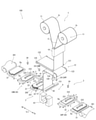
図1は、本発明にかかる積層セルの製造装置100の概略配置図である。図2は、積層セルの製造装置100の機能ブロック図である。なお、本実施形態の積層セルの製造装置100では、図1に示す積層セルの製造装置100において、積層テーブル21の移動方向Tr1を矢印にて示す。
<
FIG. 1 is a schematic layout diagram of a laminated
積層テーブル21の移動方向Tr1において、後述のローラ対131よりも左側を一方側Op、右側を他方側Tpとする。積層テーブル21は、一方側Opと他方側Tpとの間を、例えば、直線的に往復移動する。積層テーブル21が一方側Opと他方側Tpとの間を移動することで、セパレータSが蛇腹状に折り曲げられる。例えば、移動方向Tr1は、ローラ対131から供給されたセパレータSの厚み方向ということも可能である。ここで、蛇腹状とは、テープ状のシートを一定の範囲の幅で折り曲げて重ね合わせた形状であり、つづら折りとも呼ばれる形状である。
In the moving direction Tr1 of the laminated table 21, the left side of the
積層セルの製造装置100は、セパレータロールSrから供給されるテープ状のセパレータSを蛇腹状に折り曲げるとともに、蛇腹状に折り曲げられたセパレータSの谷折り部分に負極板200および正極板300を交互に配置して積層セル400(図3参照)を形成する。積層セル400は、積層型電池Bpに用いられる(図3参照)。以下、積層される前の電極を電極板Epとして説明する。
The laminated
<積層型電池Bp>
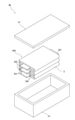
ここで、積層型電池Bpの一例について図面を参照して説明する。図3は、積層型電池Bpの概略を示す分解斜視図である。図3に示すように、積層型電池Bpは、ケースCsと、積層セル400とを有する。ケースCsは、例えば、上部が開口した略直方体形状であり、上部の開口を蓋Ctにて閉じられる。積層型電池Bpでは、積層セル400がケースCsの内部に電解液とともに収容される。そして、蓋Ctを閉じるとともに、電解液が漏れないように封止する。
<Stacked battery Bp>
Here, an example of the laminated battery Bp will be described with reference to the drawings. FIG. 3 is an exploded perspective view showing an outline of the laminated battery Bp. As shown in FIG. 3, the laminated battery Bp has a case Cs and a
積層セル400は、負極板200と、正極板300と、セパレータSとを有する。セパレータSは、絶縁性を有するとともに、イオンが透過可能な材料で形成される。そして、セパレータSは、蛇腹状に折り曲げられる。セパレータSの谷折り部分に、負極板200および正極板300が交互に配置されることで、積層セル400が形成される。なお、図3に示す積層セル400では、3個の負極板200と2個の正極板300を積層した構成としているが、実際の積層数は、これに限定されない。
The
負極板200は、導電性材料で形成された平面視長方形状の平板である。負極板200は、1対の短辺の一方から突出した端子部201を有する。また、正極板300は、負極板200と同様、導電性材料で形成された平面視長方形状の平板である。正極板300は、一対の短辺の一方から突出した端子部301を有する。なお、積層セル400では、負極板200および正極板300は、端子部201および端子部301が、例えば、それぞれ反対側に突出するように重ねられる。なお、図示を省略しているが、負極板200の端子部201同士が電気的に接続され、正極板300の端子部301同士が電気的に接続される。端子部の接続はこれに限定されない。
The
図3に示すように、負極板200の短辺は、正極板300の短辺よりも長い。そして、平面視において、負極板200は正極板300を覆うように配置される。そして、積層方向の両端は、いずれも負極板200となるように積層される。なお、図3に示す構成は一例であり、積層方向の両端またはいずれか一端が正極板300となる構成もある。そして、両端の外側にセパレータSが配置される。図3に示す積層型電池Bpでは、負極板200および正極板300は、平面視長方形状としているが、平面視正方形状、多角形状等、長方形状以外の形状であってもよい。なお、積層セル400の出力電力は、負極板200および正極板300の面積、積層枚数によって決まる。換言すると、積層型電池Bpに要求される容量等に応じて、負極板200および正極板300の面積および積層枚数が決定される。
As shown in FIG. 3, the short side of the
積層セルの製造装置100は以上示したような積層セル400を製造する。次に、積層セルの製造装置100の詳細について説明する。図1、図2に示すように、積層セルの製造装置100は、セパレータ供給部1と、折り曲げ部2と、電極供給部3と、積層セル分離部4と、制御部5(図2参照)とを有する。積層セルの製造装置100は、制御部5によって制御される。
The laminated
<制御部5>
制御部5は、例えば、処理回路51と、記憶回路52とを有する。処理回路51は、各種情報を処理する回路であり、CPU、MPU等の演算回路を有する。また、処理回路51は、処理結果に基づいて、積層セルの製造装置100の各部の駆動を制御する。
<
The
記憶回路52は、ROM、RAM等の半導体メモリー、フラッシュメモリー等の可搬性を有するメモリーおよびハードディスク等の記憶媒体を含むまたは接続される回路である。記憶回路52で、制御プログラムまたは処理プログラム等の各種プログラムを記憶しておき、必要に応じて処理に対応したプログラムを呼び出すとともに処理回路51でプログラムを動作させて、処理を行うようにしてもよい。
The
<セパレータ供給部1>
図1に示すように、セパレータ供給部1は、セパレータロールSrから引き出されたテープ状のセパレータSを折り曲げ部2に供給する。セパレータ供給部1は、セパレータロール取付部11と、セパレータ搬送部12と、セパレータローラ13と、連結部14とを有する。
<
As shown in FIG. 1, the
<セパレータロール取付部11>
セパレータロール取付部11は、セパレータロールSrが回転可能に取り付けられる。図1に示すように積層セルの製造装置100は、例えば、2個のセパレータロール取付部11を有する。2個のセパレータロール取付部11には、それぞれ、独立したセパレータロールSrが取り付けられる。セパレータロールSrは回転可能であり、セパレータロールSrからセパレータSが引き出される。
<Separator
The separator roll Sr is rotatably mounted on the separator
各セパレータロール取付部11は、取り付けられたセパレータロールSrの残量を検知するセパレータ残量検知部111(図2参照)を有する。セパレータロールSrは、セパレータSを巻き付けて形成されている。そのため、セパレータSが引き出されることで、セパレータロールSrの半径が小さくなる。セパレータ残量検知部111では、セパレータロールSrの半径を検知してセパレータロールSrの残量を検知する。なお、セパレータロールSrの残量検知方法は、一例であり、これに限定されない。
Each separator
<セパレータ搬送部12>
セパレータ搬送部12は、セパレータSをセパレータローラ13に搬送する。セパレータ搬送部12は、搬送ローラ121と、搬送経路調整部122(図2参照)と、トラクションローラ123と、張力測定部124と、を有する。
<
The
搬送ローラ121は、回転可能に設けられたローラであり、外周面にテープ状のセパレータSが接触する。搬送ローラ121は、セパレータSの搬送をガイドする。積層セルの製造装置100において、セパレータSは、搬送ローラ121の外周面に接触することで、搬送方向が屈曲している。搬送ローラ121は、セパレータSが直線状に搬送されている部分でセパレータSと接触してガイドしてもよい。なお、本実施形態の積層セルの製造装置100では、1個の搬送ローラ121を有するものを例に説明しているが、複数個の搬送ローラ121を有してもよい。
The
搬送経路調整部122は、回転可能であるとともに移動可能な可動ローラ125を有する。可動ローラ125は、搬送ローラ121に対して接近または離間可能に配置される。可動ローラ125の回転軸は、搬送ローラ121の回転軸と平行である。可動ローラ125が搬送ローラ121から離間するほど、セパレータSの引き出し長さが長くなり、逆方向に移動することで、セパレータSの引き出し長さが短くなる。つまり、可動ローラ125の位置によって、セパレータ搬送部12におけるセパレータ搬送ルート、換言すると、搬送距離が変化する。搬送経路調整部122は、制御部5からの指示に従って可動ローラ125を搬送ローラ121に対して接近または離間するように移動させる。
The transport
図1に示すように、積層セルの製造装置100において、セパレータSは、可動ローラ125で折り返してトラクションローラ123に送られる。トラクションローラ123は、回転可能に配置されたローラである。トラクションローラ123は、不図示の駆動部を有しており、制御部5からの指示に基づいて回転制御される。
As shown in FIG. 1, in the laminated
トラクションローラ123は、外周面でセパレータSを、例えば、吸引している。そのため、トラクションローラ123は、搬送ローラ121、搬送経路調整部122に比べてセパレータSとの摩擦力が高い。トラクションローラ123は、回転速度によって、セパレータSの搬送方向において、トラクションローラ123よりも上流側および下流側の張力を変更可能である。換言すると、トラクションローラ123は、セパレータSに対して、上流側と下流側とで別の張力を作用させることができる。
The
本実施形態の積層セルの製造装置100において、トラクションローラ123は、1個のローラを用いているが、これに限定されず、例えば、回転軸を平行とした2個のローラの外周面を接触させ、接触した部分(ニップ部分)でセパレータSを掴むような構成であってもよい。
In the laminated
セパレータSは、トラクションローラ123で折り返して張力測定部124に送られる。張力測定部124は、セパレータSの張力を測定する。張力測定部124で測定された張力は、制御部5に送られる。張力測定部124は、例えば、ロードセルを挙げることができるが、これに限定されない。セパレータSの張力を正確かつ迅速に測定できる構成を広く採用することができる。セパレータSは、張力測定部124で曲げられて、下方に配置されたセパレータローラ13に送られる。セパレータ搬送部12は、張力測定部124からセパレータローラ13までの間に配置されたエッジ検知部126を有する。エッジ検知部126は、セパレータSの幅方向のエッジを検知する。エッジ検知部126は、例えば、セパレータSの蛇行、幅のばらつき等を検知することができる。
The separator S is folded back by the
<セパレータローラ13>
セパレータローラ13は、セパレータSをセパレータ供給部1から折り曲げ部2に供給する。セパレータローラ13は、ローラ対131を有する。ローラ対131は、回転軸が平行である2個のローラを有する。
<
The
セパレータローラ13は、制御部5からの指示に基づいて、ローラ対131を折り曲げ部2の積層テーブル21が移動方向Tr1に移動するときに、折り曲げ部2の邪魔にならないように上方に移動される。ローラ対131の上下方向の移動の詳細は後述する。
The
<連結部14>
積層セルの製造装置100では、2個のセパレータロール取付部11に取り付けられた2個のセパレータロールSrから交互にセパレータSが引き出される。両方のセパレータロールSrそれぞれから引き出されたセパレータSの搬送方向の先端は連結部14に保持されている。そして、連結部14は、一方のセパレータロールSrからのセパレータSをセパレータ搬送部12に送る。
<Connecting
In the laminated
連結部14は、制御部5に接続されており、制御部5からの指示に従って動作する。連結部14は、一方のセパレータロールSrの残量が一定量よりも少なくなると、他方のセパレータロールSrから引き出されているセパレータSを、一方のセパレータロールSrからのセパレータSの搬送方向後方の端部に連結する。なお、一方側のセパレータロールSrから他方側のセパレータロールSrに切り替えてセパレータSを引き出すようにした後、一方側のセパレータロール取付部11にセパレータロールSrを取り付ける。このようにすることで、連結部14では、2個のセパレータロールSrの残量によって自動的に連結するため、セパレータロールSrを交換する際に停止する時間を減らすことができる。
The connecting
連結部14の構成については、従来周知のテープ状の部材を繋ぐ装置と同じ構成を採用することが可能である。そのため、連結部14の詳細な構成については省略する。また、連結部14でセパレータSを連結するときの積層セルの製造装置100の動作については、後述する。
As for the configuration of the connecting
セパレータ供給部1は、以上示した構成を有する。セパレータSは、セパレータ供給部1から折り曲げ部2に供給される。次に、折り曲げ部2の詳細について説明する。
The
<折り曲げ部2>
図4は、折り曲げ部2を拡大した斜視図である。図4に示す積層テーブル21では、積層が完了する前の積層体500を示すとともに、セパレータSの図示を省略している。
<
FIG. 4 is an enlarged perspective view of the
図1に示すように、折り曲げ部2は、セパレータローラ13から供給されたセパレータSを蛇腹状に折り曲げる。積層セルの製造装置100において、折り曲げ部2は、セパレータローラ13のローラ対131に対し、水平もしくは下方に配置される。折り曲げ部2は、積層テーブル21と、第1爪部22と、第2爪部23と、を有する。さらに、確認用撮像部24を有してもよい。
As shown in FIG. 1, the
<積層テーブル21>
積層テーブル21は、平面視長方形状である。積層テーブル21は、制御部5にて制御される積層テーブル移動部211(図2参照)にて往復移動される。正面視において、積層テーブル21はセパレータローラ13のローラ対131よりも一方側Opの第1位置P1(後述の図8等参照)と他方側Tpの第2位置P2(後述の図16等参照)との間を往復移動する。
<Laminate table 21>
The laminated table 21 has a rectangular shape in a plan view. The laminated table 21 is reciprocated by the laminated table moving unit 211 (see FIG. 2) controlled by the
また、後述する第1爪部22および第2爪部23により、積層テーブル21の上面では、セパレータSが保持される。さらには、積層テーブル21の上面に複数の孔(不図示)を設け、孔から空気を吸引することで、セパレータSを吸着(真空吸着)するようにしてもよい。なお、孔を形成した構成と同様に、メッシュ、ポーラス等の隙間を有する材料で形成されていてもよい。以上のような構成により、積層テーブル21は、セパレータSを保持する。
Further, the separator S is held on the upper surface of the laminated table 21 by the
積層テーブル21は、第1位置P1に移動したときに蛇腹状に折り曲げられたセパレータSの上部に、電極供給部3から供給される電極板Epが載置される。電極板Epは、積層セル400において、負極板200または正極板300として用いられる。積層テーブル21の上部には、積層テーブル21が第1位置P1にあるときに電極板Epが負極板200として載置され(図8参照)、第2位置P2にあるときに電極板Epが正極板300として載置される(図16参照)。
In the laminated table 21, the electrode plate Ep supplied from the
電極板Epは、アルミニウム等の導電性を有する金属を含んで形成される。また、電極板Epは、平面視長方形状であり、一方の短辺から長手方向に沿って外側に突出する突出部Epmを有する(図8等参照)。突出部Epmは、負極板200の端子部201となる部分であり、正極板300の端子部301となる部分である。積層テーブル21が往復移動を繰り返す毎に、負極板200および正極板300が積層される。
The electrode plate Ep is formed by containing a conductive metal such as aluminum. Further, the electrode plate Ep has a rectangular shape in a plan view and has a protruding portion Epm protruding outward along the longitudinal direction from one short side (see FIG. 8 and the like). The protruding portion Epm is a portion that becomes the
積層テーブル21は、上下にも移動可能である。積層テーブルは、負極板200または正極板300が積層される毎に、電極板Epの厚みだけ下方に移動する。これにより、積層テーブル21の上部に載置される積層途中の積層体500の上面は、常に一定の高さとすることができる。これにより、後述する第2搬送部332により電極板Epを精度よく搬送することが可能である。
The laminated table 21 can also be moved up and down. The laminating table moves downward by the thickness of the electrode plate Ep each time the
<第1爪部22および第2爪部23>
図4に示すように、第1爪部22および第2爪部23は、積層テーブル21の上方に配置される。第1爪部22は、第1位置P1において積層テーブル21の上部で蛇腹状に折り曲げられたセパレータSの上部に載置された負極板200の上面の他方側Tpの隅部を押える。第1爪部22は、制御部5によって移動制御されており、上下方向および移動方向と直交する水平方向に移動される。なお、積層セルの製造装置100では、第1爪部22は、積層テーブル21の長手方向に対をなして配置されるが、これに限定されない。
<
As shown in FIG. 4, the
第2爪部23は、第2位置P2において積層テーブル21の上部で蛇腹状に折り曲げられたセパレータSの上部に載置された正極板300の上面の一方側Opの隅部を押える。第2爪部23は、制御部5によって移動制御されており、上下方向および移動方向と直交する水平方向に移動される。なお、積層セルの製造装置100では、第2爪部23は、積層テーブル21の長手方向に対をなして配置されるが、これに限定されない。
The
第1爪部22は、第2爪部23が正極板300を押えた後、積層体500から水平方向に移動し、平面視において、積層テーブル21上に載置した電極板Epと重ならない退避位置に移動する。なお、第1爪部22の退避位置は負極板200となる電極板Epを載置する際に邪魔にならない位置を広く採用することができるが、その後、負極板200を押えることが必要であることからため、例えば積層テーブル21の近傍とすると好ましい。
After the
また、第2爪部23は、第1爪部22が負極板200を押えた後、積層体500から水平方向に移動し、平面視において、積層テーブル21上に配置した電極板Epと重ならない退避位置に移動する。なお、第2爪部23の退避位置は正極板300となる電極板Epの載置の邪魔にならない位置を広く採用することができるが、その後、正極板300を押えるため、積層テーブル21の近傍とすることが好ましい。
Further, the
<確認用撮像部24>
確認用撮像部24は、積層テーブル21に載置された負極板200または正極板300を撮像する。確認用撮像部24は、第1位置P1にある積層テーブル21の上方および第2位置P2にある積層テーブル21の上方の両方に配置される。なお、必要に応じて、第1位置P1の上方にあるものを確認用撮像部24N、第2位置P2の上方にあるものを確認用撮像部24Pとして区別する(図1等参照)。
<
The
本実施形態にかかる積層セルの製造装置100では、セパレータローラ13が水平方向固定で、積層テーブル21が移動することで、セパレータSを蛇腹状に折り曲げるとともに、負極板200および正極板300を積層する。そのため、従来のセパレータローラ13を移動させる場合に比べて、セパレータローラ13が撮像の邪魔になりにくく、好ましい。
In the laminated
また、確認用撮像部24Nは、第1位置P1の上方に固定され、確認用撮像部24Pは、第2位置P2の上方に固定される。そのため、確認用撮像部24Nおよび確認用撮像部24Pの画角が固定となり、確認用撮像部24Nおよび確認用撮像部24Pによる確認用撮像データImg(後述の図14)を一定の形状および大きさで撮像することができる。これにより、確認用撮像データImgによる確認作業の精度を高めることが可能である。
Further, the confirmation
<電極供給部3>
次に電極供給部3の詳細について図面を参照して説明する。図5は、電極供給部3の概略配置図である。図6は、切り欠き形成部37の斜視図である。図7は、電極切断部36の斜視図である。図1に示すように、積層セルの製造装置100において、電極供給部3は、例えば、2個の電極板供給部30を有する。2個の電極板供給部30は、移動方向Tr1において一方側Opおよび他方側Tpにそれぞれ配置される。一方側Opに配置される電極板供給部30は、積層されて負極板200として用いられる電極板Epを供給する。他方側Tpに配置される電極板供給部30は、積層されて正極板300として用いられる電極板Epを供給する。なお、必要に応じ、負極板200となる電極板Epを供給する方を電極板供給部30Nとし、正極板300となる電極板Epを供給する方を電極板供給部30Pとして区別する。
<
Next, the details of the
電極板供給部30Nと電極板供給部30Pとは、電極板Epを形成する前の導電シートShが異なる。具体的には、導電シートShを構成する材料が異なるとともに、突出部Shmの向きや形状が異なる。これ以外の点については、電極板供給部30Nおよび電極板供給部30Pは、実質上同じ構成を有する。そのため、図5では、電極板供給部30Nを図示するとともに、電極板供給部30Nを基準に説明する。また、図6および図7も電極板供給部30Nに配置される切り欠き形成部37および電極切断部36を示している。
The electrode
図5、図6、図7は、電極板供給部30Nまたはその一部を示している。電極板供給部30Nを搬送される導電シートShは、幅方向の一方側に、例えば、端子部201となる突出部Shmを有する。突出部Shmは、予め導電シートShに形成されていてもよいし、電極供給部3で形成してもよい。ここでは、予め導電シートShに形成されているものとする。
5, FIG. 6 and FIG. 7 show the electrode
図5に一例として例示すように、電極板供給部30Nは、待機テーブル31と、位置調整テーブル32と、搬送部33と、調整用撮像部34と、導電シート搬送部35と、電極切断部36と、切り欠き形成部37と、搬送コンベヤ381と、クリーナ382と、を有する。電極板供給部30Nでは、導電シートShをロール状に巻き付けて形成した導電シートロールShrから引き出される導電シートShを所定の長さに切断して、電極板Epを作製する。そして、電極板Epを積層テーブル21に供給する。
As shown as an example in FIG. 5, the electrode
なお、待機テーブル31を設けずに、搬送コンベヤ381の、位置調整テーブル32側の終端部分を待機テーブルとして兼用する構成としても構わない。また、位置調整テーブル32や、切り欠き形成部37や、クリーナ382、等を有しない構成としても構わない。
It should be noted that the standby table 31 may not be provided, and the terminal portion of the
また、位置調整テーブル32を有しない構成の場合、待機テーブル31(搬送コンベヤ381の終端部分を兼用する構成も含む)から積層テーブル21へ移載する途中の過程において電極板Epの位置を調整し、調整終了後、積層テーブル21上に載置するようにしてもよい。 Further, in the case of the configuration without the position adjustment table 32, the position of the electrode plate Ep is adjusted in the process of transferring from the standby table 31 (including the configuration that also serves as the terminal portion of the conveyor 381) to the stacking table 21. After the adjustment is completed, it may be placed on the laminated table 21.
<導電シート搬送部35>
導電シート搬送部35は、導電シートロール取付部351を有する。なお、図5では、2ロールの例を示しているが1ロールであってもよい。電極板供給部30Nは、2個の導電シートロール取付部351を有しており、それぞれ、導電シートロールShrが取り付けられている。導電シート搬送部35では、一方の導電シートロール取付部351に取り付けられた一方の導電シートロールShrから導電シートShが引き出して、搬送する。そして、一方の導電シートロールShrの残量が一定以下になると、自動的に他方の導電シートロール取付部351に取り付けられた他方の導電シートロールShrから導電シートShを引き出す。これにより、導電シートロールShrの取り付けのために、電極板供給部30Nを停止しなくてもよく、積層セル400の製造に要する時間を短くできる。
<Conductive
The conductive
導電シート搬送部35は、導電シートロールShrから引き出された導電シートShを搬送するためのローラを複数個備えている。導電シート搬送部35によって搬送された導電シートShが電極切断部36で切断される電極板Epが形成される。電極切断部36では、導電シートShの幅方向の両側に設けられた切り欠きNtを基準に導電シートShを切断する。そのため、導電シート搬送部35において、電極切断部36の上流側に切り欠き形成部37が配置される。
The conductive
<切り欠き形成部37>
切り欠き形成部37は、搬送された導電シートShの幅方向の両側に切り欠きNtを形成する。切り欠き形成部37としては一般的な切断方法で箔を切断する構成、例えば、図5に例示するような、切り欠き金型371と、エッジ検知部372と、金型移動部373(図2参照)とを有する構成を挙げることができる。また、これ以外の構成を採用してもよく、例えば、レーザー切断による構成等を広く採用することができる。
<Cut forming
The
図6に示すように、切り欠き金型371は、ダイ374と、パンチ375とを有する。ダイ374は、パンチ375が嵌合する凹部を有しており、ワークである導電シートShの側部がダイ374と上下に重なっている状態で、パンチ375を凹部に嵌入させることで、切り欠きを形成する。ダイ374には、導電シートShの幅方向に並んで2個の凹部を有する。そして、パンチ375は、各凹部に嵌合可能なように、幅方向に対をなして配置される。
As shown in FIG. 6, the notch die 371 has a
切り欠き金型371は、搬送される導電シートShの幅方向に移動可能である。つまり、切り欠き金型371は、導電シートShの側部に対して、位置決め可能となっている。切り欠き金型371は、ダイ374が共通で、2個のパンチ375が一体的に導電シートShの幅方向に移動するように形成されているが、これに限定されず、ダイ374が幅方向に独立し、それぞれ、独立して移動するようにしてもよい。
The
エッジ検知部372は、導電シートShの搬送方向において、切り欠き金型371よりも上流側に配置される。エッジ検知部372は、導電シートShの側端部(エッジ)を検知する。そして、エッジの情報を制御部5に送る。なお、エッジ検知部372として、画像を撮像する構成を挙げることができるがこれに限定されず、導電シートShのエッジを精度よく検知できる方法を広く採用することができる。
The
金型移動部373は、制御部5と接続されており、切り欠き金型371を導電シートShの幅方向に移動させることができる。制御部5は、エッジ検知部372から送られてきた導電シートShの搬送方向の上流側のエッジの情報に基づいて、切り欠きNtが導電シートShの規定の位置に形成されるように、切り欠き金型371を移動させる。
The
切り欠き形成部37を上述のように形成することで、導電シート搬送部35で搬送される導電シートShが蛇行した場合でも、導電シートShのエッジに適切な切り欠きを形成することが可能である。
By forming the
エッジ検知部372は、導電シートShの幅方向一方側のエッジを検知する構成であるが、これに限定されず、両方のエッジを検知するようにしてもよい。エッジ検知部372が導電シートShの両方のエッジを検知する構成とする場合、切り欠き金型371は、両方のエッジで独立して幅方向に移動することが好ましい。このようにすることで、導電シートShの幅がばらついた場合であっても、導電シートShのエッジに適切な切り欠きを形成することが可能である。
The
切り欠き形成部37でエッジに切り欠きが形成された導電シートShは、電極切断部36に送られる。
The conductive sheet Sh having a notch formed at the edge of the
<電極切断部36>
図7に示すように、電極切断部36は、固定刃361と、回転刃362と、回転刃移動部363(図2参照)と、第1搬送ローラ部364と、第2搬送ローラ部365とを有する。
<
As shown in FIG. 7, the
電極切断部36に搬送され導電シートShは、第1搬送ローラ部364および第2搬送ローラ部365によって搬送される。図7に一例として例示すように、第1搬送ローラ部364は、導電シートShの下方に配置されて、軸方向の長さが導電シートShの幅よりも長い下部ローラ3641と、下部ローラ3641の上方に配置されて、導電シートShの幅方向に3個並んで配置された上部ローラ3642とを有する。
The conductive sheet Sh that is conveyed to the
第1搬送ローラ部364は、下部ローラ3641と上部ローラ3642とで、導電シートShを掴む。そして、第1搬送ローラ部364は、制御部5に接続されており、不図示の駆動部によって回転される。なお、第1搬送ローラ部364は、3個の上部ローラ3642を備えるが、これに限定されない。導電シートShを強く掴むことができる構成を広く採用することができる。
The first
第2搬送ローラ部365は、導電シートShの下方に配置されて、軸方向の長さが導電シートShの幅よりも長い下部ローラ3651と、下部ローラ3651の上方に配置されて、導電シートShの幅方向に3個並んで配置された上部ローラ3652とを有する。
The second
第2搬送ローラ部365の各ローラ部は、下部ローラ3651と上部ローラ3652とで、導電シートShを掴む。そして、第2搬送ローラ部365は、制御部5に接続されており、不図示の駆動部によって回転される。
Each roller portion of the second
また、第2搬送ローラ部365の下流側には、3個の搬送ローラ部366、367、368を有する。各搬送ローラ部366、367、368は、第2搬送ローラ部365と同じ構成を有する。
Further, on the downstream side of the second
本実施形態の積層セルの製造装置100では、電極板供給部30(30N、30P)で導電シートShを切断して、電極板Epを作製し、積層体500に供給している。作業者は、電極板Epよりも搬送、取り付けが容易な導電シートロールShrを取り扱うため、作業性が高い。
In the laminated
<固定刃361、回転刃362および回転刃移動部363>
第1搬送ローラ部364と第2搬送ローラ部365との間には、固定刃361および回転刃362が配置される。固定刃361は、下部ローラ3641と下部ローラ3651との間に配置される。固定刃361は、例えば、工具鋼、超硬合金等の高硬度の材料によって形成される。電極切断部36において、固定刃361は、直方体形状であり、稜線の1つが、固定切り刃3611である。導電シートShは、固定切り刃3611の上方に搬送される。
<
A fixed
回転刃362は、固定刃361と同様、高硬度の材料によって形成される。回転刃362は、固定刃361と同じ材料であってもよいし、異なる材料であってもよい。回転刃362は、円板状であり、外縁部に回転切り刃3621が形成される。
The
回転刃移動部363は、回転刃362を回転させつつ、固定刃361に沿って移動可能である。回転刃移動部363は、回転切り刃3621が固定切り刃3611と接触させた状態で、回転刃362を回転させつつ固定刃361に沿って移動させることで搬送された導電シートShを切断できる。なお、回転刃362を固定刃361に向けて付勢するばね等の付勢部を設けて、固定切り刃3611と回転切り刃3621とを確実に接触させるようにしてもよい。
The rotary
回転刃移動部363は、制御部5の指示に従って動作する。電極切断部36では、不図示の検知部により導電シートShのエッジに形成された切り欠きを検知する。そして、制御部5は、検知部が切り欠きを検知したとき、回転刃移動部363に指示を送り、回転刃362を駆動させるとともに移動させて、切り欠きを繋ぐように導電シートShを切断する。電極切断部36において、導電シートShが切断されることで、電極板Epが形成される。
The rotary
回転刃362は、円板状であるため、簡単な構成であるとともに、回転切り刃3621の形状の精度を簡単に高めることが可能である。また、回転刃362の回転切り刃3621を固定刃361の固定切り刃3611に接触させつつ回転させる構成とすれば、固定切り刃3611と回転切り刃3621との組み合わせの精度が多少ばらついても切断の精度を高めることが可能である。
Since the
また、接触させることで「刃」の摩耗が問題となる場合には、回転刃362の回転切り刃3621と固定刃361の固定切り刃3611との間に微小な間隙を設けた非接触状態(以下、近接あるいは近接状態と称する場合がある)とした上で切断する、という構成も可能である。なお、固定刃361に対する回転刃362の送り量に対し回転刃362の回転速度を変化させることで、切れ味を変化させることができる。そのため、「刃」の摩耗が問題となる場合に好適である。
Further, when the wear of the "blade" becomes a problem due to the contact, a non-contact state in which a minute gap is provided between the rotary cutting blade 3621 of the
例えば、導電シートShは、金属箔(ここでは、アルミニウム箔)だけの部分、アルミニウム箔に絶縁層(例えば、酸化アルミニウムなどのセラミックス)が塗工されている部分、アルミニウム箔に活物質が塗工されている部分等を有する。導電シートShを切断する際、切断終端部において、アルミニウム箔と活物質の剥離が発生しやすい。そこで、電極切断部36では、導電シートShにおける切断箇所によって回転刃362の回転数を調整している。例えば、終端部をカットする場合には回転数を落としてカットする。これにより、アルミニウム箔と活物質の剥離の発生が抑制される。
For example, the conductive sheet Sh has a portion of only a metal foil (here, an aluminum foil), a portion of the aluminum foil coated with an insulating layer (for example, ceramics such as aluminum oxide), and a portion of the aluminum foil coated with an active material. It has a part that has been made. When cutting the conductive sheet Sh, peeling of the aluminum foil and the active material is likely to occur at the cutting end portion. Therefore, in the
また、電極切断部36では、固定刃361が直線刃で、回転刃362が固定刃361の一端から他端に向けて回転しつつ移動する(往路)ときに導電シートShを切断し、その後、回転刃362が固定刃361の他端から一端に向けて回転しつつ移動して戻る(復路)ときにも切断する場合がある。
Further, in the
往路および復路で回転刃362が回転しつつ移動する場合、回転刃362の回転切り刃3621の同じ箇所が、常に、固定刃361の固定切り刃3611と接触または近接する。そして、導電シートShは、固定刃361に対して同じまたは略同じ位置に送られる。そのため、導電シートShは、回転切り刃3621の同じ箇所で切断される。
When the
このような構成の電極切断部36において、回転刃362が、例えば、固定刃361の一端および他端の少なくとも一方にあるとき、回転刃362を空転させるように、制御部5が回転刃移動部363を制御してもよい。このように制御することで、導電シートShを切断するごとに、回転刃362の回転切り刃3621の異なる箇所が固定刃361の固定切り刃3611に対して接触または近接するように調整することが可能である。
In the
以上のような制御を行うことで、毎回、回転刃362の回転切り刃3621の異なる箇所で、導電シートShを切断することができる。その結果、導電シートShを切断するときには、絶縁層と接触または近接して、切断する部分を毎回異なる部分とすることができ、回転切り刃3621の一部が集中して摩耗することを抑制できる。また、アルミニウム箔と接触または近接して、切断する部分を毎回異なる部分とすることができ、アルミニウム凝着することを抑制することが可能である。これらのことにより、回転刃362の劣化を抑制し、ひいては、回転刃362を長寿命化することができる。
By performing the above control, the conductive sheet Sh can be cut at different points of the rotary cutting edge 3621 of the
なお、回転刃362を空転させるときの回転角度は、360°の倍数以外の角度である。このようにすることで、回転刃362の回転切り刃3621の固定刃361の固定切り刃3611と接触または近接する箇所がばらつくため、摩耗の集中や凝着を抑制する効果を高めることができ、回転刃362のさらなる長寿命化が可能である。また、回転刃362の空転は、導電シートShを切断する毎に行ってもよいし、複数回切断する毎に行ってもよい。さらに、予め設定された切断回数毎に回転刃362の空転時の回転角度を変更してもよい。
The rotation angle when the
電極切断部36では、導電シートShを停止させた状態で導電シートShを切断する。ここで、導電シートShの張力が高いと、回転刃362が接触した途端にそこを起点に導電シートShが裂けてしまう場合がある。また、裂けるほどの張力ではない場合であっても、一定以上の張力が作用している場合には、切断時の張力によって電極板Epの形状が不安定になりやすい。
The
そこで、制御部5は、電極切断部36で導電シートShの搬送を停止するときに、第1搬送ローラ部364の動作を停止させた後、第2搬送ローラ部365を停止させる。このようにすることで、導電シートShの第1搬送ローラ部364と第2搬送ローラ部365との間の部分に張力を適度に発生させることができるので、形状を安定させることができる。さらに説明すると、第1搬送ローラ部364にて導電シートShが押し出されるように搬送されることにより発生する導電シートShの「たわみ」を抑制できる。
Therefore, when the
また、制御部5が、第1搬送ローラ部364と第2搬送ローラ部365とを同時に停止させたのち、第2搬送ローラ部365を搬送方向と逆方向に回転させてもよい。このようにすることで、導電シートShの第1搬送ローラ部364と第2搬送ローラ部365との間の部分の張力を適度に緩和させることができる。
Further, the
すなわち、制御部5が、このように第1搬送ローラ部364および第2搬送ローラ部365を制御することで、導電シートShの第1搬送ローラ部364と第2搬送ローラ部365との間の部分の張力を適度に調整することができる。以上によって、切断後の電極板Epの形状が不安定になるといった不具合や、導電シートShが裂けるといった不具合、の発生を低減することが可能である。
That is, by controlling the first
電極切断部36において、導電シートShが固定刃361および回転刃362によって切断されることで電極板Epが形成される。電極切断部36では、第2搬送ローラ部365の下流側の、例えば、3個の搬送ローラ部366、367、368によって搬送される。そして、電極切断部36の導電シートShの搬送方向の下流側には、搬送コンベヤ381が配置される。電極板Epは、搬送コンベヤ381によって、待機テーブル31の上部に供給される。
In the
搬送コンベヤ381は、一定速度(一定の間欠動作による搬送、一定の間欠動作を挟んでの一定速度での搬送、も含む)で移動している。そして、制御部5は、第2搬送ローラ部365、搬送ローラ部366、367、368の回転を制御して、電極板Epを搬送コンベヤ381の移動速度と同じ速度にして、搬送コンベヤ381に送る。
The
搬送コンベヤ381はクリーナ382と対向する。搬送コンベヤ381にて搬送される電極板Epは、クリーナ382によってクリーニングされる。なお、クリーナ382としては、例えば、気流またはガスを吹き付けて、表面の異物、汚れ等を吹き飛ばす構成を挙げることができるが、これに限定されない。電極板Epをクリーニングできる構成を広く採用することができる。クリーナ382でクリーニングされた電極板Epは、待機テーブル31に載置される。なお、クリーナ382を備えない構成であってもよい。
The
<待機テーブル31>
図8は、待機テーブル31および位置調整テーブル32の配置を示す斜視図である。図8に示すように、待機テーブル31は、上面に電極板Epを積載可能である。待機テーブル31に積載された電極板Epは、搬送部33の第1搬送部331に保持されて、位置調整テーブル32に送られる。待機テーブル31は、上面に載置された電極板Epの数によって、積載された電極板Epの上面が常に一定の位置に配置されるように上下方向に移動可能としてもよい。例えば、搬送コンベヤ381から電極板Epが供給されたときには、電極板Epの厚み分、下方に移動し、第1搬送部331によって搬送されたときには電極板Epの厚み分、上方に移動する。なお、上記で示した、待機テーブル31の上下方向の移動は、一例でありこれに限定されない。
<Waiting table 31>
FIG. 8 is a perspective view showing the arrangement of the standby table 31 and the position adjustment table 32. As shown in FIG. 8, the standby table 31 can be loaded with the electrode plate Ep on the upper surface. The electrode plate Ep loaded on the standby table 31 is held by the
また、待機テーブル31を設けずに、搬送コンベヤ381の、位置調整テーブル32側の終端部分を待機テーブルの代用として使用する構成としてもよい。この場合、搬送コンベヤ381上の、位置調整テーブル32側の終端部分に位置する電極板Epを搬送部33の第2搬送部332保持して、位置調整テーブル32に送る。
Further, the standby table 31 may not be provided, and the terminal portion of the
<位置調整テーブル32および調整用撮像部34>
電極板Epは、搬送コンベヤ381から待機テーブル31に送られる。そのため、待機テーブル31に載置された電極板Epの待機テーブル31に対する位置は、ばらつく場合が多い。そのため、電極板供給部30Nにおいて、電極板Epは、一端、位置調整テーブル32に載置され、位置調整テーブル32で位置調整を行った後、積層テーブル21に送られる。しかしながら、位置調整は位置調整テーブル32で行うことに限定されず、他の手段または方法で位置調整を行ってもよい。
<Position adjustment table 32 and
The electrode plate Ep is sent from the
位置調整テーブルを32有しない構成として、例えば、以下のような構成を挙げることができる。すなわち、待機テーブル31(搬送コンベヤ381の終端部分が兼用する構成も含む。以下、同じ。)と、待機テーブル31に載置された電極板Epを撮像する調整用撮像部34と、を有する。そして、待機テーブル31から積層テーブル21へ電極板Epを移載するとき、制御部5が、調整用撮像部34からの、待機テーブル31に載置された電極板Epの撮像データに基づいて、電極板EpがセパレータSに対して規定位置に供給されるように、電極板Epの位置を調整し、調整終了後、積層テーブル21上に電極板Epを載置する構成を挙げることができる。
As a configuration having no 32 position adjustment tables, for example, the following configuration can be mentioned. That is, it has a standby table 31 (including a configuration in which the terminal portion of the
また、上述の構成に、積層テーブル21に載置された電極板Epを撮像する確認用撮像部24をさらに有し、確認用撮像部24からの、積層テーブル21に載置された電極板Epの撮像データに基づいて、制御部5が、電極板Epの位置調整(微調整)をさらに行う、という構成であってもよい。以上のような構成とすることで、電極板Epの位置調整の処理をより高速に行うことが可能となる。
Further, the above-mentioned configuration further includes a
位置調整テーブル32は、それ自体、セパレータSの搬送方向に沿うx方向、セパレータSの幅方向であるy方向、セパレータSの法線を中心とする円周方向であるθ方向に移動可能である。そして、位置調整テーブル32が移動することで、位置調整テーブル32上に載置された電極板Epの位置が調整される。位置調整テーブル32が移動するときに電極板Epがずれると位置調整が行われにくい。そのため、位置調整テーブル32では、電極板Epを保持する保持機構を有していてもよい。 The position adjustment table 32 itself can move in the x direction along the transport direction of the separator S, the y direction which is the width direction of the separator S, and the θ direction which is the circumferential direction about the normal line of the separator S. .. Then, by moving the position adjustment table 32, the position of the electrode plate Ep placed on the position adjustment table 32 is adjusted. If the electrode plate Ep shifts when the position adjustment table 32 moves, it is difficult to adjust the position. Therefore, the position adjustment table 32 may have a holding mechanism for holding the electrode plate Ep.
保持機構としては、例えば、空気を吸引することで吸着(真空吸着)する構造を挙げることができるが、これに限定されない。位置調整テーブル32において、電極板Epの位置が調整される。そのため、位置調整テーブル32には、1枚ずつ電極板Epが載置されるように制御される。 Examples of the holding mechanism include, but are not limited to, a structure of suction (vacuum suction) by sucking air. In the position adjustment table 32, the position of the electrode plate Ep is adjusted. Therefore, the position adjustment table 32 is controlled so that the electrode plates Ep are placed one by one.
電極板Epの位置調整は、位置調整テーブル32から第1位置P1にある積層テーブル21に電極板Epを搬送する第2搬送部332に対して行われる。電極板Epの位置調整を行う場合、位置調整テーブル32の上方に配置された調整用撮像部34にて撮像される撮像データに基づいて行われる。調整用撮像部34は、位置調整テーブル32に載置されている電極板Epを撮像して撮像データを制御部5に送る。位置調整を容易にするために、調整用撮像部34は、電極板Epの法線方向上方から法線方向に撮像できる位置に配置されることが好ましい。
The position adjustment of the electrode plate Ep is performed on the
調整用撮像部34で撮像された撮像データは、制御部5に送られ、制御部5の処理回路51で画像処理される。そして、処理回路51は、適切な電極板Epの位置と撮像データの電極板Epの位置のずれに基づいて、位置調整テーブル32の移動量を算出する。制御部5は、算出された移動量に基づいて、位置調整テーブル32を移動させることで電極板Epの位置調整を行う。電極板Epの位置調整の詳細については後述する。
The image pickup data captured by the adjustment
<搬送部33>
搬送部33は、電極板Epを第1位置P1にある積層テーブル21に搬送する。搬送部33は、第1搬送部331と、第2搬送部332と、連結アーム333とを有する。第1搬送部331は、待機テーブル31に搬送されて蓄積されている電極板Epを位置調整テーブル32に搬送する。第2搬送部332は、位置調整テーブル32で位置調整された電極板Epを第1位置P1にある積層テーブル21の上部に搬送する。
<
The
第1搬送部331および第2搬送部332とは、同じ構成である。第1搬送部331および第2搬送部332は、下面に電極板Epと接触するとともに、電極板Epを保持することができる。第1搬送部331および第2搬送部332は、例えば、下面に吸着部を有し、吸着(真空吸着)にて電極板Epを保持するものを挙げることができるが、これに限定されない。
The
<積層セル分離部4>
図9は、積層セル分離部4の配置図である。積層セル分離部4は、積層テーブル21上で積層が完了した積層セル400とセパレータ供給部1から供給されるテープ状のセパレータSとを分離する。分離された積層セル400は取り出される。
<Laminate
FIG. 9 is a layout diagram of the laminated
図1、図3、図9に示すように、積層セル分離部4は、セパレータ保持部41と、セパレータ切断部42と、積層セル取出部43(図1参照)と、を有する。セパレータ保持部41は、一方側Opの待機位置Esと、他方側Tpの保持位置Ccとの間を、セパレータローラ13の下方を通過する円弧上の軌道SSに沿って移動可能である。なお、セパレータ保持部41としては、例えば、不図示の円弧状のガイドに沿って移動するものを挙げることができるが、これに限定されない。
As shown in FIGS. 1, 3, and 9, the laminated
セパレータ保持部41の軌道SSは、保持しているセパレータSに対して規定を超える張力を発生させずに移動可能であれば、円弧状に限定されず、楕円弧状、双曲線状、直線状等の移動経路であってもよい。上述のように、セパレータSは、セパレータ保持部41で保持された状態で切断されるので、セパレータSの切断後の端部は、セパレータ保持部41によって待機位置Esに待機させた状態とすることが可能となる。
The trajectory SS of the
図9に例示するように、待機位置Esは、セパレータ保持部41が積層体500の積層を邪魔しない位置である。詳しくは、ローラ対131の上下移動時に干渉せず、確認用撮像部24による撮像の画角から外れた位置である。
As illustrated in FIG. 9, the standby position Es is a position where the
そして、セパレータ保持部41は、保持位置Ccに移動したとき、第2位置P2にある積層テーブル21上の積層セル400につながるセパレータSの下面を保持する。セパレータ保持部41は、セパレータSと接触する面で、セパレータSを吸着(真空吸着)することができる構成である。なお、セパレータ保持部41のセパレータSの保持は、吸着(真空吸着)に限定されず、セパレータSの変形、破損等させることなく保持することができる保持方法を広く採用できる。
Then, when the
セパレータ切断部42は、他方側Tpに配置される。セパレータ切断部42は、セパレータSのセパレータ保持部41で保持されている部分と第2位置P2にある積層テーブル21上の積層セル400までの間の部分を切断可能である。なお、セパレータ切断部42は、セパレータSを搬送方向に分離可能な切断工具を広く採用することができる。
The
積層セル分離部4は、セパレータ保持部41およびセパレータ切断部42を駆動する。積層セル分離部4は、制御部5からの指示に従って動作し、積層セル400の積層が完了した後、セパレータ保持部41がセパレータSを保持したときのみ、セパレータ切断部42を動作させてセパレータSを切断する動作を行う。
The laminated
積層セル取出部43は、他方側Tpに配置される。セパレータ切断部42にてセパレータSを切断した後、第2位置P2にある積層テーブル21から積層セル400を取り出す。積層セル取出部43は、セパレータSの幅方向、すなわち、y方向に積層セル400を取り出す。積層セル取出部43は、積層セル400の端子部201、301が突出しない辺を保持する形状である。しかしながら、これに限定されず、例えば、積層セル400を上方から掴むようなグラブ状であってもよい。
The laminated cell take-out
本実施形態にかかる積層セルの製造装置100は以上示した構造を有する。次に、積層セルの製造装置100の動作について図面を参照して説明する。
The laminated
<電極板Epの位置調整>
まず、待機テーブル31に蓄積された電極板Epを第1位置P1にある積層テーブル21に搬送する搬送動作について図面を参照して説明する。図10は、電極板Epの位置調整の動作を示すフローチャートである。図11は、第1搬送部331が待機テーブル31の電極板Epを保持した状態を示す斜視図である。図12は、位置調整テーブル32の上面に電極板Epを配置した直後の斜視図である。図13は、第1搬送部331が待機テーブル31の電極板を取りに移動している状態を示す斜視図である。
<Position adjustment of electrode plate Ep>
First, the transport operation of transporting the electrode plate Ep accumulated in the standby table 31 to the laminated table 21 at the first position P1 will be described with reference to the drawings. FIG. 10 is a flowchart showing the operation of adjusting the position of the electrode plate Ep. FIG. 11 is a perspective view showing a state in which the
図11に示すように、第1搬送部331で待機テーブル31に蓄積された電極板Epを吸着する。図11では、第2搬送部332が位置調整テーブル32の上部に載置された電極板Epを吸着しているが、これについては後述する。
As shown in FIG. 11, the
図8に示すように、搬送部33は、第1搬送部331で保持した電極板Epを、位置調整テーブル32の上面に載置する。調整用撮像部34は位置調整テーブル32に電極板Epが載置された直後に、位置調整テーブル32に載置された電極板Epを撮像し、制御部は、第1撮像データを取得する(図10、ステップS101)。
As shown in FIG. 8, the
制御部5は、第1搬送部331が待機テーブル31に移動するまでの間に、画像処理を行うとともに第1撮像データの電極板Epの位置、エッジ検知部126からのセパレータSのエッジの情報等から適切な電極板Epに対する位置のずれを算出する。そして、制御部5は、算出結果に基づいて、位置調整テーブル32を移動する第1位置調整処理を行う(ステップS102)。図12に示すように、第1位置調整処理では、位置調整テーブル32の回転方向(θ方向)の移動を行う。本実施形態に示す電極板Epのように、長尺の電極板Epの場合、回転方向にずれが発生すると、長手方向の端部のずれが大きくなる。そのため、1回目の調整である第1位置調整処理には、θ方向のずれを調整する。
The
そして、第1位置調整が終了した後、第2搬送部332が位置調整テーブル32上の電極板Epを保持するまでの間(図13参照)、調整用撮像部34は、位置調整テーブル32の上部に載置された電極板Epを撮像する。制御部5は、調整用撮像部34より第2撮像データを取得する(ステップS103)。制御部5は、第2搬送部332が位置調整テーブル32に移動するまでの間に、画像処理を行うとともに第2撮像データの電極板Epの位置、エッジ検知部126からのセパレータSのエッジの情報等から適切な電極板Epに対する位置のずれを算出する。そして、制御部5は、算出結果に基づいて、位置調整テーブル32を移動する第2位置調整処理を行う(ステップS104)。
Then, after the first position adjustment is completed, until the
図13に示すように、第2位置調整処理では、位置調整テーブル32を電極板Epの横方向(x方向)および縦方向(y方向)に移動する。上述したとおり、第1位置調整処理において、位置調整テーブル32をθ方向に移動し、第2位置調整処理において、x方向およびy方向に移動しているが、これに限定されない。 As shown in FIG. 13, in the second position adjustment process, the position adjustment table 32 is moved in the lateral direction (x direction) and the vertical direction (y direction) of the electrode plate Ep. As described above, in the first position adjustment process, the position adjustment table 32 is moved in the θ direction, and in the second position adjustment process, it is moved in the x direction and the y direction, but the present invention is not limited to this.
第1位置調整処理および第2位置調整処理を行うことで、位置調整テーブル32の上部に載置された電極板Epが積層テーブル21に載置するための適切な位置に位置決めされる。そして、図11に示すように、位置調整テーブル32上で、θ方向、x方向およびy方向の位置調整された電極板Epは、第2搬送部332に吸着される。調整用撮像部34は、第2搬送部332が電極板Epを吸着したときに、電極板Epを含む位置調整テーブル32を撮像する。制御部5は、調整用撮像部34より、最終調整用撮像データを取得する(ステップS105)。
By performing the first position adjustment process and the second position adjustment process, the electrode plate Ep placed on the upper part of the position adjustment table 32 is positioned at an appropriate position for mounting on the laminated table 21. Then, as shown in FIG. 11, the electrode plate Ep whose positions have been adjusted in the θ direction, the x direction, and the y direction on the position adjustment table 32 is attracted to the
制御部5は、最終調整用撮像データから、電極板Epの最終位置を確認する(ステップS105)。なお、最終位置は、第2搬送部332によって保持された電極板Epの位置であり、位置調整テーブル32での位置調整はできない。そのため、制御部5は、最終位置が適正な位置であるか否か確認する(ステップS106)。
The
最終位置が適正な位置である場合(ステップS106でYesの場合)、制御部5は、図8に示すように、搬送部33を動作させ第2搬送部332が保持した電極板Epの第1位置P1にある積層テーブル21の上部に配置される積層中の積層体500の上部への搬送を行う(ステップS107)。最終位置が適正な位置でない場合(ステップS106でNoの場合)、制御部5は、第2搬送部332が保持した電極板Epを廃棄する(ステップS108)。電極板Epの破棄は、例えば、位置調整テーブル32と第1位置P1の積層テーブル21の間に落下させることで廃棄させてもよいし、別途、廃棄用の機構を備えてもよい。
When the final position is an appropriate position (Yes in step S106), the
なお、本実施形態では、電極板Epのずれが発生する場合を例に説明したが、これに限定されない。例えば、電極板Epの形状、大きさのばらつきが発生した場合にも、電極板Epを廃棄するようにしてもよい。このようにすることで、製造される積層セル400の性能のばらつきを抑制することができる。換言すると、積層セル400の歩留まりの低下を抑制できる。
In this embodiment, the case where the electrode plate Ep is displaced has been described as an example, but the present invention is not limited to this. For example, even when the shape and size of the electrode plate Ep vary, the electrode plate Ep may be discarded. By doing so, it is possible to suppress variations in the performance of the manufactured
<積層体500の積層状態の確認>
上述のように電極板Epの位置を調整した場合であっても、第2搬送部332で電極板Epを積層体500の上部に載置したときにずれる場合もある。そのため、積層セルの製造装置100では、現在積層中の積層体500の上部に載置された電極板Epの積層体500に対する位置を、確認用撮像部24(24N)を設けることにより確認する場合もある。以下に、電極板Epの位置の確認の手順について図面を参照して説明する。図14は、電極板Epの積層体500に対する位置を確認する手順を示すフローチャートである。図15は、確認用撮像部24Nで撮像した確認用撮像データImgを示す図である。
<Confirmation of the laminated state of the
Even when the position of the electrode plate Ep is adjusted as described above, the electrode plate Ep may be displaced when the electrode plate Ep is placed on the upper portion of the
図8に示すように、第2搬送部332が保持した電極板Epは第1位置P1にある積層テーブル21の上部に配置された積層体500の上部に配置される。このとき、確認用撮像部24Nが、積層体500の上部を撮像する。制御部5は、確認用撮像部24Nから確認用撮像データImgを取得する(ステップS201)。そして制御部5は、確認用撮像データImgを画像処理し、最上部に配置されている電極板Epの4個の隅部Agの位置を取得する。(ステップS202)。
As shown in FIG. 8, the electrode plate Ep held by the
折り曲げ部2では、電極板Epが載置されるとすぐに、第1爪部22で電極板Epの上部を押える。そのため、図15に示すように、確認用撮像部24Nで電極板Epを撮像するとき、電極板Epの他方側Tpの隅部Agを直接認識することができない。そのため、制御部5は、確認用撮像データImgにおいて、電極板Epの短辺および長辺の第1爪部22の近くの検出部分Cp(4か所)の位置を確認し、そのデータから隅部Agの位置を演算にて取得する。
In the
また、電極板Epは、第2爪部23の上部に配置される。そのため、電極板Epが傾いているため、電極板Epの一方側Opの隅部Agは、認識できるが、正確な位置ではない場合がある。そこで、位置調整テーブル32で取得したxy方向の製品寸法のデータと検出部分Cpの検出による他方側Tpの2か所の隅部Agのデータとから、正規の隅部の位置を算出する。
Further, the electrode plate Ep is arranged on the upper part of the
制御部5は、電極板Epの4個の隅部Agが適正な位置にあるか否か確認する(ステップS203)。隅部Agの少なくとも一つが適正な位置にない場合(ステップS203でNoの場合)、現在積層中の積層体500を廃棄する(ステップS205)。
The
電極板Epの4個の隅部Agが適正な位置にある場合(ステップS203でYesの場合)、四隅の情報を記憶回路52に記憶する(ステップS204)。その後、制御部5は、積層セル400が完成したか否か確認する(ステップS206)。積層セル400が完成していない場合(ステップS206でNoの場合)、制御部5は、積層を継続する(ステップS207)。なお、積層を継続した後、ステップS201に戻り、積層状態の確認を継続する。また、積層セル400が完成した場合(ステップS206でYesの場合)、制御部5は、積層セル取出部43を動作させ積層セル400を取り出す(ステップS208)。
When the four corners Ag of the electrode plate Ep are in appropriate positions (Yes in step S203), the information on the four corners is stored in the storage circuit 52 (step S204). After that, the
上述のとおり、電極板Epは、積層体500において、負極板200および正極板300として用いられる。積層セル400では、平面視において、正極板300は、負極板200よりも内側に配置される等の決まりがある。そのため、正極板300となる電極板Epの隅部Agの一部が負極板200の隅部Agよりも外側にある場合、適正な位置にないと判断する。また、負極板200となる電極板Epの隅部Agが決められた位置よりも外側にあると、セパレータSを蛇腹状に折り曲げるときに電極板Epを折り曲げてしまう。そのため、上述のように電極板Epを配置するごとに、電極板Epの位置が適正な位置であるか確認することで、製造された積層セル400の性能のばらつきを抑制することが可能である。
As described above, the electrode plate Ep is used as the
<折り曲げ部2および電極供給部3による積層動作>
積層セルの製造装置100では、折り曲げ部2でセパレータSを蛇腹状に折り曲げつつ谷折り部分に負極板200および正極板300を配置して、積層セル400を製造する。ここで、折り曲げ部2の動作について図面を参照して説明する。図16は、積層テーブル21が第2位置P2にある状態を示す図である。図17は、正極板300が上部に載置されて第2爪部23で押えられた状態を示す図である。図18は、積層テーブル21が一方側Opに移動している状態を示す図である。図19は、積層テーブル21がさらに一方側Opに移動している状態を示す図である。図20は、積層テーブル21が第1位置P1にある状態を示す図である。図21は、負極板200が上部に載置されて第1爪部22で押えられた状態を示す図である。
<Laminating operation by the
In the laminated
図16に示すように、積層テーブル21が第2位置P2にあるとき、負極板200は第1爪部22で押えられている。そして、第1爪部22でセパレータSが折り返される。上下方向において、ローラ対131が積層テーブル21の近くに配置されている。そのため、第1爪部22で折り返したセパレータSの傾斜角度を小さくすることが可能である。なお、ローラ対131の位置によっては、折り返したセパレータSを水平または略水平にすることができる。これにより、折り返したセパレータSの上部に、正極板300となる電極板Epを簡単かつ正確に配置することが可能である(図17参照)。
As shown in FIG. 16, when the laminated table 21 is in the second position P2, the
また、上下方向において、ローラ対131を積層テーブル21の近くに配置することで、折り返したセパレータSを水平または略水平とすることができる。そのため、積層テーブル21の往復移動の距離が短くなり、積層セル400の製造のタクトタイムを短くすることができる。
Further, by arranging the
そして、電極板Epが正極板300として上部に配置された後、第2爪部23で押さえてから、第1爪部22を、y方向およびz方向(x方向およびy方向と直交する方向)に移動させる。これにより、第1爪部22が、負極板200とセパレータSとの間から引き抜かれる(図17参照)。
Then, after the electrode plate Ep is arranged on the upper portion as the
正極板300を載置することで、積層体500の積層方向の高さが高くなる。電極供給部3の搬送部33で電極板Epを積層体500に精度よく搬送するため、積層テーブル21は、正極板300の厚み分下方に移動する(図18参照)。
By placing the
そして、制御部5は、セパレータローラ13を制御してローラ対131を上方に移動させる。これにより、ローラ対131が、積層テーブル21および第1爪部22、第2爪部23と干渉しない位置に移動する。この状態で、積層テーブル21が一方側Opに移動する(図18参照)。積層テーブル21がローラ対131の下部を通過できる。
Then, the
また、積層テーブル21がローラ対131に接近するときローラ対131の接触部と積層体500までのセパレータSの長さが短くなる。セパレータ搬送部12において、セパレータロールSrからセパレータSを引き出すことはできるが、戻すことはできない。そこで、制御部5は、搬送経路調整部122を制御し、可動ローラ125を搬送ローラ121から離れる方向に移動させて、セパレータSの経路の長さを調整する。
Further, when the laminated table 21 approaches the
また、セパレータSは、薄く形成されていることが多く、張力が小さくなると、各ローラから離れてしまう場合があり、その結果、しわが寄ったり、ねじれたりする虞がある。また、張力が強くなりすぎると、セパレータSが裂けたり、延びたりする虞がある。そのため、制御部5は、トラクションローラ123の回転速度を調整して、セパレータSの張力が一定の範囲に収まるように調整する。
Further, the separator S is often formed thin, and when the tension becomes small, the separator S may be separated from each roller, and as a result, there is a risk of wrinkling or twisting. Further, if the tension becomes too strong, the separator S may be torn or stretched. Therefore, the
制御部5は、可動ローラ125の位置およびトラクションローラ123の回転速度を制御している。搬送経路調整部122およびトラクションローラ123が搬送調整部であり、可動ローラ125の位置およびトラクションローラ123の回転速度が制御条件である。制御条件は、予め記憶回路52に記憶されている。制御部5は、記憶回路52から制御条件を呼び出し、制御条件に基づいて、搬送経路調整部122およびトラクションローラ123を制御する。なお、制御部5が、制御条件で制御することで、セパレータSの張力が一定の範囲に収まるように制御される。
The
そして、第2爪部23が、ローラ対131の下方を越えて一方側Opに移動することで、セパレータSは、第2爪部23で折り曲げられる。これにより、積層体500の上部に配置された正極板300でセパレータSが折り返される(図19参照)。
Then, the
積層テーブル21がさらに一方側Opに移動することで、ローラ対131のニップ部と積層体500までのセパレータSの長さが長くなる。このとき、制御部5は、可動ローラ125を搬送ローラ121に接近するように移動させるとともにトラクションローラ123の回転速度を調整する。このとき、セパレータロールSrから引き出されるセパレータSは、予め決められた速度で搬送されるとともに、張力が一定の範囲に収まるように送られる。
By further moving the laminated table 21 to one side Op, the length of the nip portion of the
また、積層テーブル21がローラ対131を通過した後、ローラ対131は、下方に移動する。これにより、積層テーブル21が第1位置P1にあるときも積層体500の第2爪部23で折り返したセパレータSが水平または略水平となる(図20参照)。そして、第1位置P1に到着した積層テーブル21の上部に配置された積層体500の上部に負極板200となる電極板Epが搬送される。
Further, after the laminated table 21 passes through the
負極板200となる電極板Epが積層体500の上面のセパレータSの上部に配置され、第1爪部22が負極板200の他方側Tpの隅部を押えた後、第2爪部23がy方向およびz方向に引き抜かれる(図21)。
The electrode plate Ep to be the
以上のような手順を繰り返すことで、セパレータSを蛇腹状に折り曲げる(つづら折り)とともに、負極板200および正極板300を谷折り部分に交互に配置した、積層セル400を形成することができる。このように、ローラ対131を積層テーブル21の移動に同期して上下に移動させることで、積層体500の上部のセパレータSの傾斜を小さくでき、積層テーブル21の移動量を抑えることができる。
By repeating the above procedure, the separator S can be bent in a bellows shape (spin turn), and the
<セパレータSの張力制御>
上述のとおり、セパレータSは、張力が一定の範囲に収まっていることが好ましい。上述のとおり、積層セルの製造装置100では、予め与えられた制御条件に基づいて制御することで、セパレータSが一定の速度で搬送されるときの張力を一定の範囲に収まるようにしている。積層セルの製造装置100では、個体差、セパレータSの組成のばらつきがある場合があり、同じ制御条件で制御しても、張力がばらつく場合がある。そこで、制御部5は、積層セルの製造装置100で、制御条件を取得する学習モードを備えていてもよい。
<Tension control of separator S>
As described above, it is preferable that the tension of the separator S is within a certain range. As described above, in the laminated
以下に学習モードについて、図面を参照して説明する。図22は、学習モードにおける動作を示すフローチャートである。 The learning mode will be described below with reference to the drawings. FIG. 22 is a flowchart showing the operation in the learning mode.
制御部5は、予め与えられている初期制御条件Cnpを記憶回路52から呼び出す(ステップS301)。初期制御条件Cnpは、上述の制御条件と同様、可動ローラ125の位置およびトラクションローラ123の回転速度を決定する条件である。初期制御条件Cnpは、予め備えられたものであってもよいし、それまでに積層セルの製造装置100を動作させたことがある場合、保存されている制御条件を初期制御条件Cnpとしてもよい。初期制御条件Cnpは、セパレータSの張力が高くなりすぎない条件であることが好ましい。
The
そして、制御部5は、セパレータSを搬送速度Vtで搬送させる(ステップS302)。なお、制御部5は、セパレータ供給部1を制御して、搬送速度を段階的に変化させることが可能である。学習モード開始時には、搬送速度Vtとして、段階的に設定された搬送速度の最も遅い速度とする。
Then, the
制御部5は、初期制御条件Cnpを変更する(ステップS303)。例えば、可動ローラ125の位置を調整したり、トラクションローラ123の回転速度を調整したりする。このとき、張力測定部124でセパレータSの張力Tsを測定する(ステップS304)。
The
制御部5は、張力測定部124からの張力Tsと張力が決められた範囲に収まるか否か確認する(ステップS305)。張力Tsが決められた範囲に収まらない場合(ステップS305でNoの場合)、制御部5は、初期制御条件Cnpの変更のステップ(ステップS303)に戻り、初期制御条件Cnpを変更する。
The
張力Tsが決められた範囲に収まっている場合(ステップS305でYesの場合)、制御部5は、現在の搬送速度Vtが予め決められた搬送速度Vshであるか否か判断する(ステップS306)。なお、搬送速度は、段階的に変更されるものであるため、搬送速度Vtを変更することで予め決められた搬送速度Vshになる。しかしながら、搬送速度が連続的に変化する場合、ステップS305で、搬送速度Vtが搬送速度Vshを越えたか否かで判断するようにしてもよい。
When the tension Ts is within the predetermined range (Yes in step S305), the
搬送速度Vtが予め決められた搬送速度Vshではない場合(ステップS306でNoの場合)、制御部5は、搬送速度Vtを1段階速くし(ステップS307)、新たな搬送速度Vtで動作を再開する(ステップS302)。
When the transfer speed Vt is not a predetermined transfer speed Vsh (No in step S306), the
搬送速度Vtが予め決められた搬送速度Vshとなった場合(ステップS306でYesの場合)、制御部5は、現在の初期制御条件Cnpを制御条件Cntとする(ステップS308)。そして、制御部5は、新たな制御条件Cntを記憶回路52に記憶する(ステップS309)。
When the transfer speed Vt becomes a predetermined transfer speed Vsh (Yes in step S306), the
このように、制御部5が、学習モードを有する場合、積層セルの製造装置100毎に最適化された制御条件Cntを用いることができ、積層セル400の精度の低下を抑制することができる。
As described above, when the
なお、学習モードは、積層セルの製造装置100の出荷時に行うものであってもよいし、セパレータロールSrを交換したとき、搬送ローラ121等の部材を交換したときに行うようにしてもよい。また、積層セルの製造装置100の歩留まりが低下したときに、行うようにしてもよい。学習モードは、使用者が容易に行うことができるようにしてもよいし、メンテナンスを行うことができる作業者のみが行うことができるようにしてもよい。
The learning mode may be performed at the time of shipment of the laminated
セパレータSの張力制御の他の例について図面を参照して説明する。図23は、セパレータSの張力制御を示すフローチャートである。 Another example of tension control of the separator S will be described with reference to the drawings. FIG. 23 is a flowchart showing the tension control of the separator S.
図23に示す張力制御において、制御部5は、所定のタイミング(例えば、一定期間、一定長さのセパレータSを供給する等)ごとに張力測定部124からの張力Tsを取得する(ステップS401)。制御部5は、取得した張力Tsを時系列に記憶回路52に記憶する(ステップS402)。制御部5は、張力Tsを記憶するとともに、直近一定回数分の張力Tsを呼び出す(ステップS403)。制御部5は、呼び出した張力Tsのデータをもとに基準値Sthを算出する(ステップS404)。基準値Sthとしては、相加平均、標準偏差、移動平均等を挙げることができるがこれに限定されない。
In the tension control shown in FIG. 23, the
制御部5は、基準値Sthが所定範囲の最大値St1よりも小さいかどうか確認する(ステップS405)、基準値Sthが最大値St1よりも大きい場合(ステップS405でNoの場合)、制御部5は、基準値Sthが小さくなるように制御条件Cntを変更する(ステップS406)。そして、制御部5は、ステップS401に戻り、張力Tsを取得する。
The
基準値Sthが最大値St1よりも小さい場合(ステップS405でYesの場合)、制御部5は基準値Sthが所定範囲の最小値St2よりも大きいかどうか確認する(ステップS407)。
When the reference value Sth is smaller than the maximum value St1 (Yes in step S405), the
基準値Sthが最小値St2よりも大きい場合(ステップS407でYesの場合)、制御部5は、制御条件を変えずステップS401に戻り、張力Tsを取得する。基準値Sthが最小値St2以下の場合(ステップS407でNoの場合)、制御部5は、基準値Sthが大きくなるように制御条件Cntを変更する(ステップS408)。そして、制御部5は、ステップS401に戻り、張力Tsを取得する。
When the reference value Sth is larger than the minimum value St2 (Yes in step S407), the
このように、制御部5が実測の張力Tsに基づいて制御条件を変更する構成とすることで、積層セルの製造装置100で安定して積層セルを製造することができる。また、1つのセパレータロールSrであっても巻き始めと巻き終わりとで、性状が異なる場合がある。実測の張力Tsに基づいて張力制御を行うことで、セパレータロールSrの性状の変化にも対応が可能である。
In this way, by configuring the
セパレータSの張力制御のさらに他の例について図面を参照して説明する。図24は、セパレータSの張力制御を示すフローチャートである。 Still another example of tension control of the separator S will be described with reference to the drawings. FIG. 24 is a flowchart showing tension control of the separator S.
図24に示す張力制御において、制御部5は、所定のタイミング(例えば、一定期間、一定長さのセパレータSを供給する等)ごとに張力測定部124からの張力Tsを取得する(ステップS501)。
In the tension control shown in FIG. 24, the
制御部5は、張力Tsが所定範囲の最大値T1よりも小さいかどうか確認する(ステップS502)、張力Tsが最大値T1よりも大きい場合(ステップS502でNoの場合)、制御部5は、張力Tsが小さくなるように制御条件Cntを変更する(ステップS503)。そして、制御部5は、ステップS501に戻り、張力Tsを取得する。
The
張力Tsが最大値T1よりも小さい場合(ステップS502でYesの場合)、制御部5は張力Tsが所定範囲の最小値T2よりも大きいかどうか確認する(ステップS504)。
When the tension Ts is smaller than the maximum value T1 (Yes in step S502), the
張力Tsが最小値T2よりも大きい場合(ステップS504でYesの場合)、制御部5は、制御条件を変えずステップS501に戻り、張力Tsを取得する。張力Tsが最小値T2以下の場合(ステップ504でNoの場合)、制御部5は、張力Tsが大きくなるように制御条件Cntを変更する(ステップS505)。そして、制御部5は、ステップS501に戻り、張力Tsを取得する。
When the tension Ts is larger than the minimum value T2 (Yes in step S504), the
制御部5は現在測定した張力Tsを用いてリアルタイム制御を行っている。このようなリアルタイム制御を行うことで、装置の不具合、セパレータSの突発的な変化に迅速に対応することが可能である。
The
<積層セルの分離処理>
積層が完了した積層セル400を搬送されてくるセパレータSから分離する分離処理について図面を参照して説明する。図25は、積層セル400の分離処理を示すフローチャートである。図26は、切断後のセパレータ保持部41の移動状態を示す図である。図27は、セパレータ保持部41から積層テーブル21にセパレータSを受け渡した状態を示す図である。図28は、第1位置P1まで移動した積層テーブル21を示す図である。
<Separation process of stacked cells>
The separation process for separating the
以上に示した、積層セルの製造装置100において、積層テーブル21の移動によって、積層セル400が製造され、積層セル400は、最も下および最も上が、負極板200であり、そして、積層セル400では、最も下の負極板200の下および最も上の負極板200の上にセパレータSが配置されるように積層される構成を例示しているが、積層の態様はこれに限定されない。
In the laminated
また、図9にて例示した構成では、積層テーブル21が第2位置P2にあるときに負極板200の上方にセパレータSが配置される。そのため、積層セル400が完成したとき、積層テーブル21が第2位置P2にあるときに積層セル400の積層が完了するが、積層の態様はこれに限定されない。
Further, in the configuration exemplified in FIG. 9, the separator S is arranged above the
制御部5は、積層テーブル21が第2位置P2にあるとき、積層体500の積層が完了したか確認する(ステップS601)。積層体500の積層の終了は、例えば、積層テーブル21の移動方向の往復回数、セパレータSの搬送長さ等に基づいて確認することができるがこれに限定されない。積層体500の積層が完了していない場合(ステップS601でNoの場合)、制御部5は、積層体500の積層が完了するまで積層体500の積層を監視する(ステップS601を繰り返す)。
When the stacking table 21 is at the second position P2, the
積層体500の積層が完了したとき(ステップS601でYesの場合)、制御部5は、積層セル分離部4に指示を送り、セパレータ保持部41を保持位置Ccに移動させる。図9に示すように、セパレータ保持部41が、セパレータSのローラ対131と積層体500との間の部分の底面を吸着して保持する(ステップS602)。
When the stacking of the
セパレータ保持部41がセパレータSを保持しているとき、セパレータSのセパレータ保持部41と積層体500との間の部分の張力は一定の範囲を保っている。この状態で制御部5は、積層セル分離部4に指示を送り、セパレータ切断部42を駆動することで、セパレータ保持部41と積層テーブル21との間で、セパレータSをカットさせる(ステップS603)。なお、「セパレータ保持部41と積層テーブル21との間」とは、「セパレータ保持部41上」も含む。そのため、「セパレータ保持部41と積層テーブル21との間でカットされる」とは、「セパレータ保持部41上でカットされる」も含まれる。
When the
図26に示すように、制御部5は、積層セル分離部4に指示を送り、セパレータ保持部41を一方側Opに移動させる(ステップS604)。また、図26に示すように、積層テーブル21が一方側Opに移動可能なように、ローラ対131を上方に移動させる。セパレータ保持部41は、積層テーブル21が一方側Opに移動したとき、積層テーブル21とセパレータSとが接触できるような位置に配置される。
As shown in FIG. 26, the
制御部5は、積層セル取出部43を駆動して積層テーブル21上の積層セル400を取り出す(ステップS605)。積層セル400が取り出された後、制御部5は、積層テーブル21を一方側Opに移動させる。そして、セパレータ保持部41から積層テーブル21にセパレータSを受け渡す(ステップS606)。そして、図28に示すように、積層テーブル21が第1位置P1に移動するときに、制御部5は、積層セル分離部4に指示を送り、セパレータ保持部41を待機位置Esに移動させる(ステップS607)。
The
以上のように、セパレータ保持部41でセパレータSを保持するためセパレータSを確実に切断することができる。また、薄手のセパレータSを用いる場合であっても、切断後のセパレータSの先端をセパレータ保持部41で保持するため、切断後のセパレータSの先端の動きをコントールでき、確実に積層テーブル21に受け渡すことができる。
As described above, since the separator S is held by the
<セパレータSの自動連結>
セパレータ供給部1では、2個のセパレータロールSrから引き出されるセパレータSが連結部14に供給されている。そして、一方のセパレータロールSrの残量が少なくなると、連結部14で一方のセパレータロールSrから引き出されるセパレータSの後端に他方のセパレータロールSrから引き出されたセパレータSの前端を連結する。
<Automatic connection of separator S>
In the
積層型電池Bpにおいて、セパレータSのつなぎ目が、積層セル400に含まれると、積層セル400の不具合の原因になる虞があり、つなぎ目は、積層セル400に含まれないことが好ましい。そのため、積層セルの製造装置100では、セパレータSを連結したときのつなぎ目が積層セル400に含まれないように連結する方法を採用している。以下に、セパレータSの連結について図面を参照して説明する。図29は、セパレータSの連結動作を示すフローチャートである。
In the laminated battery Bp, if the joint of the separator S is included in the
制御部5は、セパレータ残量検知部111からセパレータSの残量を検知している。制御部5は、セパレータ残量検知部111から、現在、セパレータSが引き出されているセパレータロールSrの残量が一定量を切ったか否か確認する(ステップS701)。セパレータロールSrの残量が一定量以上の場合(ステップS701でNoの場合)、セパレータロールSrの残量を取得する(ステップS701を繰り返す)。
The
セパレータロールSrの残量が一定量を切った場合(ステップS701でYesの場合)、制御部5は、積層体500の現在の積層数を取得する(ステップS702)。そして、制御部5は、積層セル400を完成させるために必要なセパレータSの長さを算出する(ステップS703)。
When the remaining amount of the separator roll Sr is less than a certain amount (Yes in step S701), the
制御部5は、積層セル400の完成に必要なセパレータSの長さが積層体500から連結部14までの経路よりも長いか否か確認する(ステップS704)。積層セル400の完成に必要なセパレータSの長さが積層体500から連結部14までの経路よりも長い場合(ステップS704でYesの場合)、ステップS702に戻る。
The
積層セル400の完成に必要なセパレータSの長さが積層体500から連結部14までの経路よりも短い場合(ステップS704でNoの場合)、制御部5は、連結部14に指示を送り、現在、搬送されているセパレータSを切断させ、残りのセパレータロールSrから引き出されたセパレータSを連結する(ステップS705)。
When the length of the separator S required to complete the
制御部5は、積層セル400が完成し、積層セル400が取り出されたか否か確認する(ステップS706)。制御部5は、積層セル400が取り出されるまで待機する(ステップs706でNoの場合ステップS706を繰り返す)。積層セル400が取り出された場合(ステップS706でYesの場合)、制御部5は電極供給部3を停止させ、セパレータ供給部1と折り曲げ部2を駆動させてセパレータSだけを蛇腹状に折り曲げた折曲体を作製する(ステップS707)。
The
制御部5は、積層テーブル21が1往復するごとに、セパレータSのつなぎ目が折曲体に含まれたか否か長さで管理する(ステップS708)。制御部5は、セパレータSのつなぎ目が折曲体に含まれるまで待機する(ステップS708でNoの場合ステップS708を繰り返す)。そして、つなぎ目が折曲体に含まれた場合(ステップS708でYesの場合)、制御部5は、積層セル分離部4に指示を送り、セパレータSをカットする(ステップS709)。そして、積層テーブル21状の折曲体を廃棄する(ステップS710)。
The
以上のようにセパレータSを繋ぐことで、セパレータSが引き出されるセパレータロールSrを確実に切り替えることができるとともに、積層セル400の精度を維持することが可能である。
By connecting the separator S as described above, the separator roll Sr from which the separator S is drawn can be reliably switched, and the accuracy of the
以上、本発明の実施形態について説明したが、本発明はこの内容に限定されるものではない。また本発明の実施形態は、発明の趣旨を逸脱しない限り、種々の改変を加えることが可能である。 Although the embodiments of the present invention have been described above, the present invention is not limited to this content. Further, the embodiments of the present invention can be modified in various ways as long as they do not deviate from the gist of the invention.
100 製造装置
200 負極板
201 端子部
300 正極板
301 端子部
400 積層セル
500 積層体
1 セパレータ供給部
2 折り曲げ部
3 電極供給部
4 積層セル分離部
5 制御部
11 セパレータロール取付部
111 セパレータ残量検知部
12 セパレータ搬送部
121 搬送ローラ
122 搬送経路調整部
123 トラクションローラ
124 張力測定部
125 可動ローラ
13 セパレータローラ
131 ローラ対
14 連結部
21 積層テーブル
211 積層テーブル移動部
22 第1爪部
23 第2爪部
24 確認用撮像部
24N 確認用撮像部
24P 確認用撮像部
30 電極板供給部
30N 電極板供給部
30P 電極板供給部
31 待機テーブル
32 位置調整テーブル
33 搬送部
331 第1搬送部
332 第2搬送部
333 連結アーム
34 調整用撮像部
35 導電シート搬送部
351 導電シートロール取付部
36 電極切断部
361 固定刃
3611 固定切り刃
362 回転刃
3621 回転切り刃
363 回転刃移動部
364 第1搬送ローラ部
3641 下部ローラ
3642 上部ローラ
365 第2搬送ローラ部
3651 下部ローラ
3652 上部ローラ
366、367、368 搬送ローラ部
37 切り欠き形成部
371 切り欠き金型
372 エッジ検知部
373 金型移動部
374 ダイ
375 パンチ
381 搬送コンベヤ
382 クリーナ
41 セパレータ保持部
42 セパレータ切断部
43 積層セル取出部
51 処理回路
52 記憶回路
Ag 隅部
Bp 積層型電池
Cc 保持位置
Cnp 初期制御条件
Cnt 制御条件
Cp 検出部分
Cs ケース
Ct 蓋
Ep 電極板
Epm 突出部
Es 待機位置
Nt 切り欠き
Op 一方側
P1 第1位置
P2 第2位置
100 Manufacturing equipment 200 Negative electrode plate 201 Terminal part 300 Positive electrode plate 301 Terminal part 400 Laminated cell 500 Laminated body 1 Separator supply part 2 Bending part 3 Electrode supply part 4 Laminated cell separation part 5 Control part 11 Separator roll mounting part 111 Separator remaining amount detection 12 Separator transport section 121 Transport roller 122 Transport path adjustment section 123 Traction roller 124 Tension measurement section 125 Movable roller 13 Separator roller 131 Roller pair 14 Connecting section 21 Laminating table 211 Laminating table moving section 22 1st claw section 23 2nd claw section 24 Confirmation image pickup unit 24N Confirmation image pickup unit 24P Confirmation image pickup unit 30 Electrode plate supply unit 30N Electrode plate supply unit 30P Electrode plate supply unit 31 Standby table 32 Position adjustment table 33 Transfer unit 331 First transport unit 332 Second transport unit 333 Coupling arm 34 Adjustment imaging unit 35 Conductive sheet transfer unit 351 Conductive sheet roll mounting unit 36 Electrode cutting unit 361 Fixed blade 3611 Fixed cutting blade 362 Rotating blade 3621 Rotating cutting blade 363 Rotating blade moving unit 364 First transport roller unit 3641 Lower part Roller 3642 Upper roller 365 Second transfer roller part 3651 Lower roller 3652 Upper roller 366, 376, 368 Transfer roller part 37 Notch forming part 371 Notch mold 372 Edge detection part 373 Mold moving part 374 Die 375 Punch 381 Conveyance conveyor 382 Cleaner 41 Separator holding part 42 Separator cutting part 43 Laminated cell take-out part 51 Processing circuit 52 Storage circuit Ag Corner part Bp Laminated battery Cc Holding position Cnp Initial control condition Cnt Control condition Cp Detection part Cs Case Ct Lid Ep Electrode plate Epm Part Es Standby position Nt Notch Op One side P1 1st position P2 2nd position
Claims (18)
前記導電シートの搬送方向と交差する方向に延びる固定切り刃を有する固定刃と、
円板状であって径方向外縁に回転切り刃を有する回転刃と、を備え、
前記回転刃が、回転しつつ前記固定刃に沿って移動する電極切断装置。 An electrode cutting device that cuts a conductive sheet at regular lengths to produce an electrode plate.
A fixed blade having a fixed cutting edge extending in a direction intersecting the transport direction of the conductive sheet,
It is equipped with a rotary blade that is disk-shaped and has a rotary cutting blade on the outer edge in the radial direction.
An electrode cutting device in which the rotary blade moves along the fixed blade while rotating.
設定された切断回数毎に前記回転刃の空転時の回転角度が可変である請求項1から請求項4のいずれかに記載の電極切断装置。 When the cutting of the conductive sheet is completed, the rotary blade is idled.
The electrode cutting device according to any one of claims 1 to 4, wherein the rotation angle of the rotary blade when idling is variable for each set number of cutting times.
前記第1搬送ローラ部および前記第2搬送ローラ部は、ともに前記導電シート厚み方向につかみ、搬送中の前記導電シートに対して搬送方向に一定の張力を付与しており、
前記回転刃と前記固定刃とにより前記導電シートを切断するときに、前記導電シートの搬送を停止するとともに、前記導電シートの前記第1搬送ローラ部と前記第2搬送ローラ部との間の部分の張力を搬送時の張力に対して変化させる請求項1から請求項5のいずれかに記載の電極切断装置。 Further, in the transport direction of the conductive sheet, the rotary blade and the fixed blade are further provided with a first transport roller portion arranged on the upstream side and a second transport roller portion arranged on the downstream side.
Both the first transport roller section and the second transport roller section are grasped in the thickness direction of the conductive sheet and apply a constant tension to the conductive sheet being transported in the transport direction.
When the conductive sheet is cut by the rotary blade and the fixed blade, the transfer of the conductive sheet is stopped, and the portion between the first transfer roller portion and the second transfer roller portion of the conductive sheet. The electrode cutting device according to any one of claims 1 to 5, wherein the tension of the above is changed with respect to the tension during transportation.
前記切り欠き形成部は、
前記導電シートに切り欠きを形成するとともに幅方向に移動可能な切り欠き金型と、
前記導電シートの搬送方向において前記切り欠き金型の上流側に配置されて前記導電シートの幅方向のエッジを検知するエッジ検知部と、を有し、
前記切り欠き金型が、前記エッジ検知部にて検知された前記導電シートの前記エッジに基づいて、前記導電シートの幅方向の前記エッジに正確に形成されるように移動される請求項1から請求項8のいずれかに記載の電極切断装置。 The conductive sheet further has notch forming portions at both ends in the width direction to form notches for supporting the portions to be cut by the electrode cutting portions.
The notch forming portion is
A notch mold that can move in the width direction while forming a notch in the conductive sheet,
It has an edge detection unit, which is arranged on the upstream side of the notch mold in the transport direction of the conductive sheet and detects an edge in the width direction of the conductive sheet.
From claim 1, the notch mold is moved so as to be accurately formed on the edge in the width direction of the conductive sheet based on the edge of the conductive sheet detected by the edge detection unit. The electrode cutting device according to any one of claims 8.
テープ状の前記セパレータを供給するセパレータローラを有するセパレータ供給部と、
前記セパレータローラから供給された前記セパレータを蛇腹状に折り曲げる折り曲げ部と、
前記折り曲げ部にて蛇腹状に折り曲げられた前記セパレータに前記負極板および前記正極板を交互に供給する電極供給部と、
を有し、
前記電極供給部は、2個の電極板供給部を有し、
一方の前記電極板供給部は、前記一方側に配置されて前記負極板となる電極板を供給し、他方の前記電極板供給部は、前記他方側に配置されて前記正極板となる前記電極板を供給し、
各電極板供給部は、
前記導電シートを一定の長さ毎に切断して前記電極板を作製する電極切断部を有し、
前記電極切断部は、
前記導電シートの搬送方向と交差する方向に延びる固定切り刃を有する固定刃と、
円板状であって径方向外縁に回転切り刃を有する回転刃と、
前記回転刃を回転させつつ接触前記固定切り刃に沿って移動させる回転刃移動部と、を有する積層セルの製造装置。 It is a laminated cell manufacturing apparatus for manufacturing a laminated cell in which an electrode plate to be a negative electrode plate and an electrode plate to be a positive electrode plate are alternately arranged and laminated in a valley-folded portion of a separator bent in a bellows shape.
A separator supply unit having a separator roller that supplies the tape-shaped separator,
A bent portion that bends the separator supplied from the separator roller in a bellows shape, and
An electrode supply unit that alternately supplies the negative electrode plate and the positive electrode plate to the separator bent in a bellows shape at the bent portion.
Have,
The electrode supply unit has two electrode plate supply units.
One of the electrode plate supply units is arranged on one side to supply an electrode plate to be the negative electrode plate, and the other electrode plate supply unit is arranged on the other side to be the positive electrode plate. Supply the board,
Each electrode plate supply part is
It has an electrode cutting portion for producing the electrode plate by cutting the conductive sheet at regular length intervals.
The electrode cut portion is
A fixed blade having a fixed cutting edge extending in a direction intersecting the transport direction of the conductive sheet,
A rotary blade that is disk-shaped and has a rotary cutting edge on the outer edge in the radial direction,
A device for manufacturing a laminated cell having a rotary blade moving portion that moves the rotary blade along the fixed cutting edge in contact with the rotary blade while rotating the rotary blade.
設定された切断回数毎に前記回転刃の空転時の回転角度が可変である請求項10から請求項13のいずれかに記載の積層セルの製造装置。 When the cutting of the conductive sheet is completed, the rotary blade is idled.
The laminated cell manufacturing apparatus according to any one of claims 10 to 13, wherein the rotation angle of the rotary blade when idling is variable for each set number of cuttings.
前記導電シートの搬送方向において前記電極切断部の上流側に配置された第1搬送ローラ部と、前記電極切断部の下流側に配置された第2搬送ローラ部とを有し、
前記第1搬送ローラ部および前記第2搬送ローラ部は、ともに前記導電シートを厚み方向に掴み、搬送中の前記導電シートに対して搬送方向に一定の張力を付与しており、
前記電極切断部は、前記導電シートを切断するときに前記導電シートの搬送を停止するとともに、前記導電シートの前記第1搬送ローラ部と前記第2搬送ローラ部との間の部分の張力を搬送時の張力に対して変化させる請求項10から請求項14のいずれか記載の積層セルの製造装置。 The electrode cut portion is
It has a first transport roller portion arranged on the upstream side of the electrode cutting portion and a second transport roller portion arranged on the downstream side of the electrode cutting portion in the transport direction of the conductive sheet.
Both the first transport roller section and the second transport roller section grip the conductive sheet in the thickness direction and apply a constant tension to the conductive sheet being transported in the transport direction.
The electrode cutting portion stops the transport of the conductive sheet when the conductive sheet is cut, and at the same time, transports the tension of the portion of the conductive sheet between the first transport roller portion and the second transport roller portion. The apparatus for manufacturing a laminated cell according to any one of claims 10 to 14, which is changed with respect to the tension of time.
前記切り欠き形成部は、
前記導電シートに切り欠きを形成するとともに幅方向に移動可能な切り欠き金型と、
前記導電シートの搬送方向において前記切り欠き金型の上流側に配置されて前記導電シートの幅方向のエッジを検知するエッジ検知部と、を有し、
前記切り欠き金型が、前記エッジ検知部にて検知された前記導電シートの前記エッジに基づいて、前記導電シートの幅方向の前記エッジに正確に形成されるように移動される請求項10から請求項17のいずれかに記載の積層セルの製造装置。 The conductive sheet further has notch forming portions at both ends in the width direction to form notches for supporting the portions to be cut by the electrode cutting portions.
The notch forming portion is
A notch mold that can move in the width direction while forming a notch in the conductive sheet,
It has an edge detection unit, which is arranged on the upstream side of the notch mold in the transport direction of the conductive sheet and detects an edge in the width direction of the conductive sheet.
From claim 10, the notch mold is moved so as to be accurately formed on the edge in the width direction of the conductive sheet based on the edge of the conductive sheet detected by the edge detection unit. The apparatus for manufacturing a laminated cell according to any one of claims 17.
Priority Applications (3)
| Application Number | Priority Date | Filing Date | Title |
|---|---|---|---|
| JP2020120962A JP2022018027A (en) | 2020-07-14 | 2020-07-14 | Electrode cutting device and manufacturing device of laminated cell |
| US18/004,846 US20230261240A1 (en) | 2020-07-14 | 2021-07-13 | Electrode cutting device and stacked cell manufacturing device |
| PCT/JP2021/026229 WO2022014559A1 (en) | 2020-07-14 | 2021-07-13 | Electrode cutting device, and device for manufacturing stacked cell |
Applications Claiming Priority (1)
| Application Number | Priority Date | Filing Date | Title |
|---|---|---|---|
| JP2020120962A JP2022018027A (en) | 2020-07-14 | 2020-07-14 | Electrode cutting device and manufacturing device of laminated cell |
Publications (1)
| Publication Number | Publication Date |
|---|---|
| JP2022018027A true JP2022018027A (en) | 2022-01-26 |
Family
ID=79555522
Family Applications (1)
| Application Number | Title | Priority Date | Filing Date |
|---|---|---|---|
| JP2020120962A Pending JP2022018027A (en) | 2020-07-14 | 2020-07-14 | Electrode cutting device and manufacturing device of laminated cell |
Country Status (3)
| Country | Link |
|---|---|
| US (1) | US20230261240A1 (en) |
| JP (1) | JP2022018027A (en) |
| WO (1) | WO2022014559A1 (en) |
Cited By (1)
| Publication number | Priority date | Publication date | Assignee | Title |
|---|---|---|---|---|
| CN115464411A (en) * | 2022-11-14 | 2022-12-13 | 四川中哲新材料科技有限公司 | Sodium ion battery pole piece slicing device and processing method thereof |
Family Cites Families (8)
| Publication number | Priority date | Publication date | Assignee | Title |
|---|---|---|---|---|
| JP2570047B2 (en) * | 1992-02-13 | 1997-01-08 | 富士通株式会社 | Tension applying mechanism |
| JP2003080494A (en) * | 2001-09-11 | 2003-03-18 | Matsushita Electric Works Ltd | Processing method and processing apparatus for copper foil with resin |
| KR101326628B1 (en) * | 2010-12-02 | 2013-11-07 | 주식회사 엘지화학 | Novel Device for Notching and Secondary Battery Manufactured Using the Same |
| JP2014161968A (en) * | 2013-02-26 | 2014-09-08 | Mitsubishi Heavy Ind Ltd | Cutting device |
| JP2016001575A (en) * | 2014-06-12 | 2016-01-07 | 株式会社デンソー | Method for manufacturing electrode |
| KR102273773B1 (en) * | 2014-09-04 | 2021-07-06 | 삼성에스디아이 주식회사 | Rolling device for secondary battery and rolling method for the same |
| JP6632823B2 (en) * | 2015-07-03 | 2020-01-22 | 株式会社京都製作所 | Stacked battery manufacturing equipment |
| CN210452914U (en) * | 2019-06-27 | 2020-05-05 | 宁德领一智能装备有限公司 | Flying cutting mechanism for pole piece of lithium ion power battery |
-
2020
- 2020-07-14 JP JP2020120962A patent/JP2022018027A/en active Pending
-
2021
- 2021-07-13 WO PCT/JP2021/026229 patent/WO2022014559A1/en active Application Filing
- 2021-07-13 US US18/004,846 patent/US20230261240A1/en active Pending
Cited By (2)
| Publication number | Priority date | Publication date | Assignee | Title |
|---|---|---|---|---|
| CN115464411A (en) * | 2022-11-14 | 2022-12-13 | 四川中哲新材料科技有限公司 | Sodium ion battery pole piece slicing device and processing method thereof |
| CN115464411B (en) * | 2022-11-14 | 2023-01-20 | 四川中哲新材料科技有限公司 | Sodium ion battery pole piece slicing device and processing method thereof |
Also Published As
| Publication number | Publication date |
|---|---|
| WO2022014559A1 (en) | 2022-01-20 |
| US20230261240A1 (en) | 2023-08-17 |
Similar Documents
| Publication | Publication Date | Title |
|---|---|---|
| WO2022014583A1 (en) | Method for manufacturing stack cell | |
| JP5521861B2 (en) | Electrode laminator | |
| EP3826085A1 (en) | Secondary battery electrode production system | |
| JP5521839B2 (en) | Electrode laminator | |
| RU2556034C2 (en) | Position determination device and method | |
| JP6888645B2 (en) | Transfer device and transfer method | |
| EP2903072B1 (en) | Sheet material adhesive agent application method | |
| WO2022014559A1 (en) | Electrode cutting device, and device for manufacturing stacked cell | |
| WO2022014551A1 (en) | Stacked cell manufacturing device | |
| CN112421084A (en) | Laminating device for membrane electrode | |
| WO2022014590A1 (en) | Production method for laminate cell | |
| US11274002B2 (en) | Placement method | |
| KR102603777B1 (en) | Stacking device and stacking method | |
| JP7081192B2 (en) | Equipment for manufacturing laminated electrode bodies | |
| JP6972822B2 (en) | Electrode transfer device | |
| JP2016015199A (en) | Processing device for surplus separator in electrode laminate of secondary battery | |
| JP2018063752A (en) | Laminated battery manufacturing apparatus | |
| JP6605351B2 (en) | Electrode manufacturing equipment | |
| JP6795100B2 (en) | Electrode manufacturing equipment | |
| JP7119410B2 (en) | Laminated electrode assembly manufacturing equipment | |
| JP2018081776A (en) | Laminate battery manufacturing device | |
| JP2007099467A (en) | Sheet cutting method and sheet cutting device | |
| JP6776786B2 (en) | Laminated battery manufacturing equipment | |
| JPH11174629A (en) | Method for installing light-shielding material to photosensitive material and apparatus therefor | |
| JPH07267460A (en) | Work stacking device |
Legal Events
| Date | Code | Title | Description |
|---|---|---|---|
| A621 | Written request for application examination |
Free format text: JAPANESE INTERMEDIATE CODE: A621 Effective date: 20230508 |