JP2022017357A - System and method for picking item - Google Patents
System and method for picking item Download PDFInfo
- Publication number
- JP2022017357A JP2022017357A JP2021171619A JP2021171619A JP2022017357A JP 2022017357 A JP2022017357 A JP 2022017357A JP 2021171619 A JP2021171619 A JP 2021171619A JP 2021171619 A JP2021171619 A JP 2021171619A JP 2022017357 A JP2022017357 A JP 2022017357A
- Authority
- JP
- Japan
- Prior art keywords
- container
- storage
- storage container
- picking
- presentation
- Prior art date
- Legal status (The legal status is an assumption and is not a legal conclusion. Google has not performed a legal analysis and makes no representation as to the accuracy of the status listed.)
- Granted
Links
- 238000000034 method Methods 0.000 title claims abstract description 24
- 238000003860 storage Methods 0.000 claims abstract description 499
- 230000007246 mechanism Effects 0.000 claims description 30
- 238000012546 transfer Methods 0.000 claims description 27
- 230000005484 gravity Effects 0.000 claims description 12
- 230000004913 activation Effects 0.000 claims description 2
- 239000000463 material Substances 0.000 description 8
- 230000009194 climbing Effects 0.000 description 7
- 230000008569 process Effects 0.000 description 5
- 230000006698 induction Effects 0.000 description 4
- 230000008901 benefit Effects 0.000 description 3
- 230000001939 inductive effect Effects 0.000 description 3
- 238000004519 manufacturing process Methods 0.000 description 3
- 230000002441 reversible effect Effects 0.000 description 3
- 230000008859 change Effects 0.000 description 2
- 230000001934 delay Effects 0.000 description 2
- 238000005096 rolling process Methods 0.000 description 2
- 238000013459 approach Methods 0.000 description 1
- 230000004888 barrier function Effects 0.000 description 1
- 230000009286 beneficial effect Effects 0.000 description 1
- 230000015572 biosynthetic process Effects 0.000 description 1
- 238000004140 cleaning Methods 0.000 description 1
- 238000004891 communication Methods 0.000 description 1
- 230000003111 delayed effect Effects 0.000 description 1
- 238000013461 design Methods 0.000 description 1
- 238000010586 diagram Methods 0.000 description 1
- 230000000694 effects Effects 0.000 description 1
- 238000005516 engineering process Methods 0.000 description 1
- 238000001125 extrusion Methods 0.000 description 1
- 230000007774 longterm Effects 0.000 description 1
- 239000002184 metal Substances 0.000 description 1
- 238000012986 modification Methods 0.000 description 1
- 230000004048 modification Effects 0.000 description 1
- 238000012856 packing Methods 0.000 description 1
- 230000002093 peripheral effect Effects 0.000 description 1
- 230000001932 seasonal effect Effects 0.000 description 1
- 238000003786 synthesis reaction Methods 0.000 description 1
- 230000007306 turnover Effects 0.000 description 1
Images


Classifications
-
- B—PERFORMING OPERATIONS; TRANSPORTING
- B65—CONVEYING; PACKING; STORING; HANDLING THIN OR FILAMENTARY MATERIAL
- B65G—TRANSPORT OR STORAGE DEVICES, e.g. CONVEYORS FOR LOADING OR TIPPING, SHOP CONVEYOR SYSTEMS OR PNEUMATIC TUBE CONVEYORS
- B65G1/00—Storing articles, individually or in orderly arrangement, in warehouses or magazines
- B65G1/02—Storage devices
- B65G1/04—Storage devices mechanical
- B65G1/0492—Storage devices mechanical with cars adapted to travel in storage aisles
-
- B—PERFORMING OPERATIONS; TRANSPORTING
- B65—CONVEYING; PACKING; STORING; HANDLING THIN OR FILAMENTARY MATERIAL
- B65G—TRANSPORT OR STORAGE DEVICES, e.g. CONVEYORS FOR LOADING OR TIPPING, SHOP CONVEYOR SYSTEMS OR PNEUMATIC TUBE CONVEYORS
- B65G1/00—Storing articles, individually or in orderly arrangement, in warehouses or magazines
- B65G1/02—Storage devices
- B65G1/04—Storage devices mechanical
- B65G1/0464—Storage devices mechanical with access from above
-
- B—PERFORMING OPERATIONS; TRANSPORTING
- B65—CONVEYING; PACKING; STORING; HANDLING THIN OR FILAMENTARY MATERIAL
- B65G—TRANSPORT OR STORAGE DEVICES, e.g. CONVEYORS FOR LOADING OR TIPPING, SHOP CONVEYOR SYSTEMS OR PNEUMATIC TUBE CONVEYORS
- B65G1/00—Storing articles, individually or in orderly arrangement, in warehouses or magazines
- B65G1/02—Storage devices
- B65G1/04—Storage devices mechanical
- B65G1/0407—Storage devices mechanical using stacker cranes
- B65G1/0414—Storage devices mechanical using stacker cranes provided with satellite cars adapted to travel in storage racks
-
- B—PERFORMING OPERATIONS; TRANSPORTING
- B65—CONVEYING; PACKING; STORING; HANDLING THIN OR FILAMENTARY MATERIAL
- B65G—TRANSPORT OR STORAGE DEVICES, e.g. CONVEYORS FOR LOADING OR TIPPING, SHOP CONVEYOR SYSTEMS OR PNEUMATIC TUBE CONVEYORS
- B65G1/00—Storing articles, individually or in orderly arrangement, in warehouses or magazines
- B65G1/02—Storage devices
- B65G1/04—Storage devices mechanical
- B65G1/0478—Storage devices mechanical for matrix-arrangements
-
- B—PERFORMING OPERATIONS; TRANSPORTING
- B65—CONVEYING; PACKING; STORING; HANDLING THIN OR FILAMENTARY MATERIAL
- B65G—TRANSPORT OR STORAGE DEVICES, e.g. CONVEYORS FOR LOADING OR TIPPING, SHOP CONVEYOR SYSTEMS OR PNEUMATIC TUBE CONVEYORS
- B65G1/00—Storing articles, individually or in orderly arrangement, in warehouses or magazines
- B65G1/02—Storage devices
- B65G1/04—Storage devices mechanical
- B65G1/0485—Check-in, check-out devices
-
- B—PERFORMING OPERATIONS; TRANSPORTING
- B65—CONVEYING; PACKING; STORING; HANDLING THIN OR FILAMENTARY MATERIAL
- B65G—TRANSPORT OR STORAGE DEVICES, e.g. CONVEYORS FOR LOADING OR TIPPING, SHOP CONVEYOR SYSTEMS OR PNEUMATIC TUBE CONVEYORS
- B65G1/00—Storing articles, individually or in orderly arrangement, in warehouses or magazines
- B65G1/02—Storage devices
- B65G1/04—Storage devices mechanical
- B65G1/06—Storage devices mechanical with means for presenting articles for removal at predetermined position or level
- B65G1/065—Storage devices mechanical with means for presenting articles for removal at predetermined position or level with self propelled cars
-
- B—PERFORMING OPERATIONS; TRANSPORTING
- B65—CONVEYING; PACKING; STORING; HANDLING THIN OR FILAMENTARY MATERIAL
- B65G—TRANSPORT OR STORAGE DEVICES, e.g. CONVEYORS FOR LOADING OR TIPPING, SHOP CONVEYOR SYSTEMS OR PNEUMATIC TUBE CONVEYORS
- B65G1/00—Storing articles, individually or in orderly arrangement, in warehouses or magazines
- B65G1/02—Storage devices
- B65G1/04—Storage devices mechanical
- B65G1/137—Storage devices mechanical with arrangements or automatic control means for selecting which articles are to be removed
- B65G1/1373—Storage devices mechanical with arrangements or automatic control means for selecting which articles are to be removed for fulfilling orders in warehouses
-
- B—PERFORMING OPERATIONS; TRANSPORTING
- B65—CONVEYING; PACKING; STORING; HANDLING THIN OR FILAMENTARY MATERIAL
- B65G—TRANSPORT OR STORAGE DEVICES, e.g. CONVEYORS FOR LOADING OR TIPPING, SHOP CONVEYOR SYSTEMS OR PNEUMATIC TUBE CONVEYORS
- B65G2201/00—Indexing codes relating to handling devices, e.g. conveyors, characterised by the type of product or load being conveyed or handled
- B65G2201/02—Articles
- B65G2201/0235—Containers
Abstract
Description
本発明は、保管システムからアイテムをピッキングするためのシステム及び方法に関する。排他的ではないが、より具体的には、本発明は、オンライン小売環境において顧客注文を履行するためにアイテムをピッキングするためのシステム及び方法に関し、前記注文ピッキングシステムは、アイテム提示システム及びデバイスを含む。 The present invention relates to a system and method for picking items from a storage system. Although not exclusive, more specifically, the present invention relates to a system and method for picking an item to fulfill a customer order in an online retail environment, wherein the order picking system comprises an item presentation system and a device. include.
いくつかの商用及び工業用の活動は、広大な数の異なる在庫アイテムの保管及び取り出しを可能にするシステムを必要としている。 Some commercial and industrial activities require systems that allow the storage and retrieval of vast numbers of different inventory items.
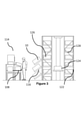
履行センターの1つの既知の形態では、図1に示すように、「ゾーンピッキング」又は「ピッキングアンドパス」と呼ばれる履行システムが使用される。このようなシステムでは、顧客の注文を履行するために必要とされるアイテム及び在庫は、保管容器又は容コンテナ中に位置付けられ、保管容器又はコンテナは通路に沿って配置される。保管容器又はコンテナから通路の反対側には、コンベヤシステムが位置付けられ、コンベヤシステムは顧客配送容器又はコンテナを運ぶ。コンベヤシステムは、ステーションコンベヤを介して、ピッキングステーションを通してバックラインコンベヤ上を移動する配送容器又はコンテナの一部を通過させるように配置され、顧客によって注文されたアイテムは、作業者によって保管容器又はコンテナから顧客配送容器又はコンテナに移送される。顧客配送コンテナがコンベヤシステム上のピッキングステーションに位置付けられとき、それは一時停止され、オペレータは保管容器又はコンテナから必要なアイテムを選択し、それを顧客配送容器又はコンテナに置く。 In one known form of fulfillment center, a fulfillment system called "zone picking" or "picking and pass" is used, as shown in FIG. In such a system, the items and inventories required to fulfill the customer's order are located in the storage container or container, and the storage container or container is placed along the aisle. A conveyor system is located on the opposite side of the passage from the storage container or container, which carries the customer delivery container or container. The conveyor system is arranged to pass through a station conveyor through a portion of a delivery container or container that travels on a backline conveyor through a picking station, and items ordered by a customer are stored by a worker in a storage container or container. Is transferred to the customer delivery container or container. When the customer delivery container is positioned at the picking station on the conveyor system, it is suspended and the operator selects the required item from the storage container or container and places it in the customer delivery container or container.
オンライン食料雑貨小売のような特定の市場部門では、この既知の形態の動作は、顧客注文を履行するために、多くのピッキング通路、多くのピッキングステーション、及び多くのオペレータを必要とすることがあり、したがって、大きな初期支出を必要とすることが理解されるだろう。さらに、インフラストラクチャの設計及びロケーションが最初から固定されているので、このようなシステムの拡張は困難である。 In certain market sectors such as online grocery retail, this known form of operation may require many picking aisles, many picking stations, and many operators to fulfill customer orders. Therefore, it will be understood that it requires a large initial expenditure. Moreover, since the infrastructure design and location are fixed from the beginning, it is difficult to scale such a system.
複数の製品ラインのアイテムの保管及び取り出しのためのさらなる既知のタイプのシステムでは、アイテムは、再び保管容器またコンテナ中に位置付けられる。しかしながら、別の既知のシステムでは、容器又はコンテナは、互いの上に積み重ねて配置され、スタックは列で配置される。保管容器又はコンテナは、上方からアクセスされ、荷積み取り扱いデバイスによってスタックから取り出される。 In a further known type of system for storing and retrieving items from multiple product lines, the items are repositioned in the storage container or container. However, in another known system, the containers or containers are stacked on top of each other and the stacks are arranged in rows. The storage container or container is accessed from above and removed from the stack by a loading handling device.
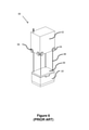
EP3030504B1(Ocado Innovation Limited)は、その内容が参照によってここに組み込まれており、コンテナのスタックがフレーム構造内に配置されているシステムを説明している。このタイプのシステムは、添付の図面の図5と6において概略的に図示されている。ロボット荷積み取り扱いデバイスは、軌道のシステム上で制御可能に移動され、軌道は、コンテナのスタックの上方に位置する格子を形成する。EP3030504B1で説明されているロボットピッキングシステムでは、格子は、軌道によって規定された一連の格子空間を備え、コンテナの各スタックは、単一の格子空間の占有面積内に位置付けられている。使用する際、ロボット荷積みハンドラは、スタックの上方の軌道上を進み、コンテナの予め定められたスタックの上方に制御可能に位置付けられる。適切な位置で、あるポジションでリフト機構が下降すると、その一部であるグリッパデバイスがコンテナを係合し、前記容器又はコンテナを、スタックから荷積み取り扱いデバイス内の空洞に持ち上げる。この特定のシステムでは、ロボット荷積み取り扱いデバイスの断面は、単一の格子空間のエリアに実質的に一致する。さらに、軌道及びロボット荷積み取り扱いデバイスは、2つの荷積み取り扱いデバイスが隣接する格子空間を占有し、動作時にいずれかの方向に互いに通過するように構成される。 EP3030504B1 (Ocado Innovation Limited) describes a system in which its contents are incorporated here by reference and the stack of containers is arranged within a frame structure. This type of system is schematically illustrated in FIGS. 5 and 6 of the accompanying drawings. The robot loading handling device is moved in a controllable manner on the system of orbits, and the orbits form a grid located above the stack of containers. In the robot picking system described in EP3030504B1, the grid comprises a series of grid spaces defined by orbits, and each stack of containers is located within the occupied area of a single grid space. When used, the robot loading handler travels in orbit above the stack and is controllably positioned above the predetermined stack of containers. At the appropriate position, when the lift mechanism descends at a position, the gripper device that is part of it engages the container and lifts the container or container from the stack into a cavity within the loading handling device. In this particular system, the cross section of the robot loading and handling device substantially matches an area of a single grid space. In addition, the orbital and robotic loading and handling devices are configured such that the two loading and handling devices occupy adjacent grid spaces and pass through each other in either direction during operation.
ロボット荷積み取り扱いデバイスの他の形態は、例えば、ノルウェー特許番号NO317366B1(Autostore AS)に説明されており、その内容は参照によってここに組み込まれ、開示されるカンチレバータイプの荷積み取り扱いデバイスは、動作時に2つの格子空間を占有する。特定の実施形態を参照して以下でより詳細に説明する本発明の文脈において、上述の2つの例の代わりに、任意の形態又は構成の荷積み取り扱いデバイスを使用することができることが理解されるだろう。 Other forms of the robotic loading and handling device are described, for example, in Norwegian patent number NO317366B1 (Autostore AS), the contents of which are incorporated herein by reference and the cantilever type loading and handling device disclosed is operational. Sometimes it occupies two grid spaces. It is understood that in the context of the invention, which is described in more detail below with reference to a particular embodiment, a loading handling device of any form or configuration can be used instead of the two examples described above. right.
このような保管システムは、保管エリアとピッキングエリアとの間の通路の必要性を除去し、所定の容積について履行センターにおける製品又はアイテムのより高い密度の保管も可能にする。 Such a storage system eliminates the need for aisles between the storage area and the picking area and also allows for higher density storage of products or items in the fulfillment center for a given volume.
上述の既知の格子ベースのロボットピッキングシステムでは、スタックから持ち上げられている保管容器又はコンテナは、顧客注文を履行するのに必要な在庫アイテムを含むことができる。いったん荷積み取り扱いデバイスによって持ち上げられると、保管容器又はコンテナは、荷積み取り扱いデバイスによって、ピッキングステーションの上方又は隣接する出力ポートに、又は、ピッキングステーション自体に配送される。ピッキングステーションでは、必要とされる1つ以上の在庫アイテムは、保管容器又はコンテナから手動で又はロボットで取り出され、配送コンテナ中に配置されてもよく、配送コンテナは顧客注文の一部を形成し、適切な時間に発送のために充填される。 In the known grid-based robot picking system described above, the storage container or container lifted from the stack can contain the inventory items needed to fulfill the customer order. Once lifted by the loading handling device, the storage container or container is delivered by the loading handling device to an output port above or adjacent to the picking station, or to the picking station itself. At the picking station, one or more inventory items required may be manually or robotically removed from the storage container or container and placed in the delivery container, which forms part of the customer order. , Filled for shipping at the right time.
このような注文は、複数の配送コンテナを含むことができ、必要とされる配送コンテナの数は、注文されるアイテム又は製品の数によって規定されることが理解されるだろう。したがって、多数の容器又はコンテナをスタック内の保管ポジションからピッキングステーションに移動させる必要があるかもしれない。 It will be appreciated that such an order can include multiple shipping containers and the number of shipping containers required is dictated by the number of items or products ordered. Therefore, it may be necessary to move a large number of containers or containers from storage positions in the stack to the picking station.
有利なことに、格子ベースのピッキングシステムのモジュールの性質は、全体的なピッキング及び保管システムが段階的に構築され、必要に応じて拡張されることを可能にし、それによって、必要に応じて設備投資及びコストを広げる。 Advantageously, the modular nature of the grid-based picking system allows the overall picking and storage system to be built in stages and expanded as needed, thereby providing equipment as needed. Increase investment and costs.
しかしながら、保管容器又はコンテナをピッキングステーションに移動させ、その後、手動であるかロボット制御であるかにかかわらず、前記保管容器又はコンテナから在庫アイテムを配送容器又はコンテナにピッキングすることは、時には遅延することがあることが理解されるだろう。ピッキングステーションにおけるこのような遅延は、システムの出力ポート又はピッキングステーションでの荷積み取り扱いデバイスの混雑を引き起こすかもしれず、アセンブリ、したがって顧客注文の発送の遅延を引き起こすことがある。 However, moving a storage container or container to a picking station and then picking inventory items from the storage container or container into a delivery container or container, whether manually or robotically controlled, is sometimes delayed. It will be understood that there are things. Such delays at the picking station may cause congestion of the system's output ports or loading handling devices at the picking station, and may cause delays in the assembly, and thus the shipment of customer orders.
これは、各在庫アイテムを必要に応じて保管容器又はコンテナ内でピッキングステーションに配送しなければならず、頻繁に必要とされるアイテムをピッキングステーションに保持する能力がないという、このようなシステムの欠点である。 This is because each inventory item must be delivered to the picking station in a storage container or container as needed, and there is no ability to hold frequently needed items in the picking station. It is a drawback.
さらに、格子ベースのシステムにおけるピッキングステーションの数は、ピッキングステーションの占有面積に利用可能な空間によって制限される。この結果、頻繁に必要とされるアイテム及び製品は、ロボット荷積みハンドラによって何度も移送される必要があり、それによって、必要とされる荷積みハンドラの移動が増大し、さらに、出力ポートにおける混雑が増大する。 Moreover, the number of picking stations in a grid-based system is limited by the space available for the picking station's occupied area. As a result, frequently needed items and products need to be transported multiple times by the robot loading handler, which increases the movement of the required loading handler and also at the output port. Increased congestion.
さらに、このような格子ベースのシステムは、すべての在庫アイテムがピッキングするのに利用可能であるようにするために、保管容器又はコンテナに配置されることを必要とする。これは、システムを、コンテナ又は容器に配置できる在庫アイテムに限定し、ピッキングシステム又は方法の一部として実行される追加の開梱ステップを必要とする。 In addition, such grid-based systems need to be placed in storage containers or containers so that all inventory items are available for picking. This limits the system to containers or inventory items that can be placed in containers and requires additional unpacking steps performed as part of the picking system or method.
上述した既知のタイプの保管及びピッキングシステムの両方は、保管容器又はコンテナ及び配送コンテナの移動及びロケーション、在庫の移動及びロケーション、並びに、システム中の任意の所定の点で必要とされる作業者のロケーション及び数を制御するように作用するコンピュータユーティリティの制御下で動作することが理解されるだろう。さらに、格子ベースのシステムでは、コンピュータユーティリティは、荷積み取り扱いデバイスの移動及びロケーションを制御し、荷積み取り扱いデバイスと注文ピッキングシステムとの間の通信を制御することができる。 Both of the known types of storage and picking systems described above are required for storage or container and delivery container movement and location, inventory movement and location, and at any given point in the system. It will be appreciated that it operates under the control of computer utilities that act to control location and number. Further, in a grid-based system, computer utilities can control the movement and location of the loading handling device and control the communication between the loading handling device and the order picking system.
上述した既知のシステムを考慮すると、特に、労働が比較的安価であり、頻繁に注文される又は「高速移動する」アイテムが集中している場合、格子ベースの保管及びピッキングシステムを従来の「ゾーンピッキング」又は「ピッキングアンドパス」コンベヤベースのピッキングシステムと組み合わせることが有益かもしれない。 Considering the known systems mentioned above, grid-based storage and picking systems are traditionally "zoned", especially if the labor is relatively cheap and the items that are frequently ordered or "fast-moving" are concentrated. It may be beneficial to combine it with a "picking" or "picking and pass" conveyor-based picking system.
本発明にしたがうと、保管庫からアイテムをピッキングするためのシステムが提供され、システムは、格子ベースの保管システムを含み、保管システムは、一連の保管コンテナを含み、保管コンテナは、保管されるアイテムを含み、保管コンテナは、フレームワーク内にスタック中に位置付けられ、その中でフレームワークの一部は、出力列を含み、前記出力列には、複数の提示ポジションが設けられ、保管コンテナは、スタック内の保管ポジションから、出力列を介してスタックから離れた前記提示ポジションに移動可能であり、前記提示ポジションは、保管システムの少なくとも1つの面上に複数の保管コンテナを位置付けるように配置され、提示ポジションは、前記保管コンテナ中に保管されたアイテムが,アイテムピッカーにアクセス可能であるように配置される。 According to the present invention, a system for picking items from a storage is provided, the system includes a grid-based storage system, the storage system includes a series of storage containers, and the storage container is the item to be stored. The storage container is located in the stack within the framework, in which a part of the framework contains an output column, the output column is provided with multiple presentation positions, and the storage container is It is possible to move from a storage position in the stack to the presentation position away from the stack via an output column, the presentation position being arranged to position multiple storage containers on at least one surface of the storage system. The presentation position is arranged so that the items stored in the storage container can be accessed by the item picker.
本発明にしたがうと、このようなピッキングシステムを使用して保管システムからアイテムをピッキングする方法がさらに提供される。 According to the present invention, further methods are provided for picking items from a storage system using such a picking system.
このようにして、本発明は、従来技術の問題を克服し、顧客注文を蓄積することができるスピードを向上させる一方で、全体的なコストを削減し、顧客履行センター、又は、アイテムが保管され、前記アイテムへのアクセスが定期的に必要とされる他の産業シナリオの効率性を改善するシステム及び方法を提供する。 In this way, the invention overcomes the problems of the prior art and improves the speed at which customer orders can be accumulated, while reducing overall costs and storing customer fulfillment centers or items. , Provide systems and methods to improve the efficiency of other industrial scenarios where access to said items is required on a regular basis.
添付の図を参照して、本発明を説明する。 The present invention will be described with reference to the accompanying figures.
以下の説明では、「保管容器10」は、在庫アイテムの保管のために意図されたコンテナ、容器、又は、トートを示すために使用され、「配送コンテナDT」は、オンライン小売環境又は別の方法で、顧客によってなされた注文を履行するために充填されることを意図したコンテナ、容器、又は、トートを示すために使用される。この専門用語は、本文献内においては参照及び説明を容易にするために使用されることが理解されるだろう。しかしながら、保管容器10及び配送コンテナDTは、同一の形状及び構成のものであってもよいことに留意されたい。さらに、配送コンテナDTは、保管システム又はその任意部分内の容器10内に保管されてもよい。コンテナのカテゴリを規定するのは、実際のサイズ、形状、又は、構成の何らかの変化よりもむしろ、容器、コンテナ、又はトートの機能である。
In the following description, "
図1から図4を参照して以下に説明する注文ピッキングシステムの1つの形態では、多くのピッキング通路100を顧客履行センター(CFC)と呼ばれることが多い大型倉庫環境に配置することができるが、本説明を容易にするために、単一のピッキング通路100を以下に説明し、図1から4に図示する。ピッキング通路100の数は、倉庫建物又はCFCのサイズによってのみ制限され、ピッキング通路100は、多くのフロアにわたって、多くの異なる形式及び配置で配置することができることが理解されるだろう。以下に説明するピッキング通路100の1つの例は、典型的な形態のものであるが、単なる例として説明するものであり、限定的なものとみなすべきではない。
In one form of the order picking system described below with reference to FIGS. 1 to 4, many picking
図1に示されるように、ゾーンピッキング履行システムの1つの形態は、ピッキング通路100を備え、ピッキング通路100は、一方の側で製品又はアイテム保管エリア102によって境界付けられ、他方の側で注文アセンブリエリア104によって境界付けられる。注文アセンブリエリア104及び保管エリア102の両方は、実質的にピッキング通路100の長さに沿って両側に伸長する。
As shown in FIG. 1, one form of a zone picking fulfillment system comprises a picking
注文アセンブリエリア104は、ピッキング通路100に沿って進む2つの平行なコンベヤ又はコンベヤの部分106、108、第1の「バックライン」コンベヤ106、並びに、第2の「ステーション」コンベヤセグメント108a及び108bを備える。バックラインコンベヤ106は、一連の分岐110及び合流112によってステーションコンベヤ部分108a及び108bにリンクされる。
The
ピッキング通路100は、ピッキング通路100の長さに沿って間隔を置いて位置付けられている一連のピッキングステーション114をさらに備え、ピッキングステーション114は、ステーションコンベヤ部分108a及び108bがピッキングステーション114a及び114bを通過するように位置付けられている。
The picking
ピッキング通路100の保管エリア102は、一連の保管容器又はコンテナ10の提示ポジション116を備え、提示ポジションは、適切な保管容器中又は上に容器又はコンテナ10又は他の形態の製品、在庫又はアイテムが格納されるとき、ピッキング通路100の長さに沿って伸長する「ピッキング面」118を生成する。ピッキング面118は、ピッキングすべきアイテム(図示せず)をピッキング通路100中に存在する作業者120に提示するように位置付けられた複数層の保管容器又は容器10を含む。
The
使用する際、配送コンテナDTは、CFCの周りを移動して、注文の一部として顧客によって以前に注文された在庫アイテム又は製品をその中に入れる。所定の配送コンテナDTのケースでは、特定のピッキング通路100の保管エリア102が所定の顧客注文及び所定の配送コンテナDTに必要なアイテムを含むとき、制御ユーティリティ(図示せず)が前記配送コンテナDTをその通路100にルーティングすると、これは上述のピッキング通路100に入る。配送コンテナDTは、CFC又はインフラストラクチャ中のあらゆるピッキング通路を通ってルーティングされてもよく、又は、配送コンテナDTが、アイテムがその中でピッキングされることになるピッキング通路100を通ってのみルーティングされることを可能にするコンベヤ接続がCFC内に存在してもよいことが理解されるだろう。
When used, the delivery container DT travels around the CFC to contain an inventory item or product previously ordered by the customer as part of the order. In the case of a given delivery container DT, when the
配送コンテナDTがバックラインコンベヤ106に沿って通過すると、ピッキングステーション114aの領域中の保管エリア102が所定の配送コンテナDTに関係付けられた所定の顧客注文において必要とされる製品又はアイテムを含む場合、配送コンテナDTは、分岐110を介してステーションコンベヤ108aに分岐されてもよい。ピッキングステーション114aの領域中の保管エリア102が、その所定の配送コンテナDTに対して必要なアイテム又は製品を含まない場合、配送コンテナDTは、バックラインコンベヤ106に沿って進むことによってピッキングステーション114aを迂回するだろう。
When the delivery container DT passes along the
ピッキングステーション114aに到着すると、配送コンテナDTは、コンピュータ制御ユーティリティ(図示せず)の制御下で制御停止する。ピッキングステーション114aに保持されている間に、作業者120は、保管エリア102中に位置付けられている識別された保管コンテナ又は容器10から必要な在庫アイテム又は製品をピッキングして配送コンテナDTに入れるだろう。保管容器10は、任意の適切な方法によって識別されるだろう。例えば、ライトは、適切な提示ポジション116でアクティブ化されてもよい。代替的に、ピッキングステーション114におけるディスプレイがロケーション情報を提供してもよい。
Upon arriving at the picking
いったん必要とされるアイテムが配送コンテナDTにピッキングされると、配送コンテナDTは、コンピュータ制御ユーティリティ(図示せず)の制御下で、ステーションコンベヤ部分108a及び合流112を介して、バックラインコンベヤ106上に自動的に動かされる。次に、配送コンテナDTは、CFCの周りを移動し続け、コンピュータ制御ユーティリティ(図示せず)によって、CFC内の任意のピッキング通路100中の必要とされるピッキングステーション114にルーティングされる。
Once the required item is picked into the delivery container DT, the delivery container DT is on the
上記はゾーンピッキングシステムの1つの形態であり、上記システムに対して可能な多くのバリエーション及び修正が存在することが理解されるだろう。例えば、配送コンテナDTは、バックラインコンベヤ106に、及び、バックラインコンベヤ106から、手動で押されてもよく、又は、手動でピッキングステーション114間を移動してもよい。
It will be appreciated that the above is one form of a zone picking system and there are many possible variations and modifications to the system. For example, the delivery container DT may be manually pushed to and from the
別の例では、別個のバックラインコンベヤ106が設けられていないことから、すべての配送コンテナDTはステーションコンベヤ108のみに沿って通過し、したがってすべてのピッキングステーション114を通過する。さらに、配送コンテナDTは、ピッキングステーション114で自動的に停止してもよく、又は、そこを通って移動し続けてもよく、配送コンテナDTが移動している間に、作業者はそこへアイテムをピッキングする。さらに、配送コンテナDTが完全なピッキング通路100を迂回し、関連する配送コンテナDTにピッキングする必要があるアイテムがある通路100のみを通してルーティングされることが可能であることが理解されるだろう。
In another example, since no
1つのさらなる例では、コンベヤシステム106、108は、コンピュータ制御ユーティリティの制御下でアイテムロケーションを表示するコンピュータデバイスによって誘導され、ピッキング面118に沿って必要とされる保管ロケーション116に移動する作業者によってCFC環境の周りで押される、トロリーの手動システムによって完全に置き換えられる。コンピュータデバイスは、ハンドヘルドであってもよく、又は、トロリーに据え付けられてもよい。
In one further example, the
図3及び図4により詳細に示す保管エリア102は、クレーンデバイス124によって保管容器10が配置されるフレームワーク122を備える。フレームワークは、ピッキング通路100の長さに沿ってピッキング面118を形成するように保管容器又は容器10が配置される提示ポジション116を備える。フレームワーク122はさらに、保管容器10が位置付けられている、提示ポジション116のすぐ後ろの保管ロケーション126(時には事前ピッキングポジションと呼ばれる)を含む。保管ロケーション126は、一般的に、ピッキング面118中における提示ポジション116中の保管容器10と同じ在庫アイテムをその中に有する保管容器10を含む。しかしながら、これはそうである必要はない。
The
残りの保管ポジション128は、その中に他の在庫アイテムを有する保管容器10を含む。在庫アイテムは、高速で移動する商品のケースでは、提示ポジション116及び保管ロケーション126における保管容器10中のものと同じタイプのものであるか、又は、提示ポジション116における保管容器10をより少ない頻度で交換することのみが必要とされるかもしれない他のより低速で移動する在庫アイテムのいずれかであることが理解されるだろう。
The remaining
使用する際、いったん任意の所定の提示ポジション116における保管容器10が空になると、例えば、作業者120が提示ポジション116における保管容器10から最後の在庫アイテムをピッキングするとき、作業者120は、空の保管容器10を代替遠隔ロケーションに除去し、すぐ後ろの事前ピッキング保管ポジション126中に位置付けられている保管容器10が、提示ポジション116に移動される。クレーンデバイス124は、次いで、空の事前ピッキング保管ポジション126を、必要とされる在庫アイテムをその中に有するさらなる保管容器10で満たす。
When in use, once the
事前ピッキングポジション126における保管容器10は、例えば、作業者120が保管コンテナ10を引っ張ることによって手動で、又は、駆動されるかもしくは重力下で動作するコンベヤによって自動的に、提示ポジション116に移動されてもよいことが理解されるだろう。保管容器10を事前ピッキングポジション126から提示ポジション116に移動させる多くの方法があることが理解されるだろう。事前ピッキング保管ポジション126における保管容器又は容器10は、提示ポジション116における保管容器10中に位置付けられている同じタイプの在庫アイテムを含むことができることも理解されるだろう。しかしながら、コンピュータ制御ユーティリティは、将来の注文のために、代替在庫アイテムを含む保管容器10を提示ポジション116により適切に位置付けることができると決定し、適切な保管容器10を保管ポジション126に事前に配置することによって事前にこれに備えることができる。
The
このようにして、作業者120に提示されるアイテムは、経時的に動的に変化してもよく、将来の注文又は季節的変化のような他の外部影響の知識によって管理されてもよい。
In this way, the items presented to
上述のゾーンピッキングシステムの欠点は、保管エリアが単一の障害点になることがあることである。任意の所定のピッキング通路100におけるクレーンデバイス124が故障した場合、前記ピッキング通路100の使用に影響を及ぼす。これは、例えば、ピッキング通路100の使用を、既にピッキング面118にある保管容器10に残っているアイテムのみに制限することがある。クレーンデバイス124の長期の不活動は、CFC環境全体に問題を引き起こすことがあり、極端なケースでは、顧客の注文が不完全になることがある。
The disadvantage of the zone picking system described above is that the storage area can be a single point of failure. If the
上述のピッキング通路100の保管エリアに関するさらなる問題は、1つのピッキング通路100における1つのクレーンデバイス124が過負荷にならないことを保証するために、保管エリア102内のロケーションに保管されているアイテム及び製品の回転の速度を制御する必要があることである。
A further problem with the storage area of the picking
以下の説明では、上述の典型的なシステム及び本発明の実施形態に共通する特徴は、同じ参照番号を使用して識別されるだろう。 In the following description, features common to the typical systems described above and embodiments of the invention will be identified using the same reference number.
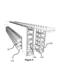
図5、図6、図及び図7を参照して、積み重ね可能な保管容器10が互いの上に積み重ねられてスタック12を形成する本発明の1つの形態を説明する。スタック12は、倉庫環境又は製造環境中のフレーム構造14中に配置される。
With reference to FIGS. 5, 6, and 7, one embodiment of the present invention in which
図5は、フレーム構造14の概略斜視図である。各容器10は、典型的には複数の製品又は在庫アイテム28を保持し、容器10内の在庫アイテムは、同一であってもよく、又は、ピッキング通路100が置く用途に応じて異なる製品タイプのものであってもよい。さらに、容器10は、複数の異なる在庫アイテム28を収容するように物理的に小区分されてもよい。
FIG. 5 is a schematic perspective view of the
フレーム構造14は、水平の部材18、20をサポートしている複数の直立部材16を備えている。直立部材16によりサポートされた複数の水平格子構造を形成するために、平行水平部材18の第1のセットが平行水平部材20の第2のセットに対して垂直に配置されている。部材16、18、20は、典型的には金属から製造される。保管容器10は、フレーム構造14の部材16、18、20の間で積み重ねられているので、フレーム構造14は、保管容器10のスタック12の水平移動に対してガードし、保管容器10の垂直の移動を誘導する。
The
フレーム構造14の最上レベルは、スタック12の最上部に渡る格子パターン22で配置されているレール22を含んでいる。さらに、図6を参照すると、レール22は、複数のロボット荷積み取り扱いデバイス30をサポートしている。平行なレール22の第1のセット22aは、フレーム構造14の最上部に渡って、第1の方向(X)における荷積み取り扱いデバイス30の移動を誘導し、平行なレール22の第2のセット22bは、第1のセット22aに対して直角に配置され、第1の方向に対して直角な第2の方向(Y)において、荷積み取り扱いデバイス30の移動を誘導する。このようにして、レール22は、X-Y平面における、2次元での荷積み取り扱いデバイス30の移動を可能にするので、荷積み取り扱いデバイス30は、スタック12のうちのいずれか上のポジションに移動できる。
The top level of the
各荷積み取り扱いデバイス30は、スタック12の上方においてフレーム構造14のレール22上でX方向及びY方向に移動するように配置された車両32を備える。車両32の前方の一対のホイール34及び車両32の後方の一対のホイール34からなるホイールの第1のセット34が、レール22の第1のセット22aの2つの隣接し合うレールに係合するように配置される。同様に、車両32の各側面のホイール36の対からなる、ホイール36の第2のセットは、レール22の第2のセット22bの2つの隣接するレールに係合するように配置されている。ホイール34、36の各セットを、持ち上げて、下げることができるので、ホイールの第1のセット34、又は、ホイールの第2のセット36のいずれかは、どの時点においても、レール22a、22bのそれぞれのセットに係合される。
Each
ホイール34の第1のセットがレール22aの第1のセットに係合され、ホイールの第2のセット36がレール22から完全に持ち上げられているとき、車両32中に収納されている駆動機構(図示せず)を介して、荷積み取り扱いデバイス30をX方向に移動させるために、ホイール34を駆動することができる。Y方向に荷積み取り扱いデバイス30を移動させるために、ホイールの第1のセット34は、レール22から完全に持ち上げられて、ホイールの第2のセット36は、レール22aの第2のセットとの係合の中に下げられる。その後、駆動機構を使用してホイールの第2のセット36を駆動し、Y方向への移動を達成することができる。
When the first set of
このようにして、1つ以上のロボット荷積み取り扱いデバイス30が、集中制御ユーティリティ(図示せず)の制御下で、図4に示すようなフレーム構造体14上でスタック12の最上面の周囲を移動することが可能となる。各ロボット荷積み取り扱いデバイス30には、必要とされる製品にアクセスするためにスタック12から1つ以上の容器10を持ち上げるためのリフト手段38が設けられる。
In this way, one or more robot
車両32の本体は、空洞40を備え、空洞40は、容器10を保持することが可能なサイズのものである。リフト手段38は、好ましくは、ウィンチ手段及び保管容器グリッパアセンブリ39を備える。リフト手段38は、スタック12から車両32の本体における空洞40内へと保管容器10を持ち上げる。
The main body of the
このようにして、格子ベースの保管システム上で複数のロボット荷積み取り扱いデバイス30を使用して、どの時点においても、格子及びスタック12における複数のロケーションから複数の製品にアクセスすることが可能になる。
In this way, a plurality of robot loading and
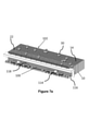
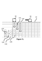
本発明の1つの形態にしたがう注文ピッキングシステムの第1の実施形態を、図7a、図7b、及び図7cに示す。図7aに見られるように、第1の実施形態は、ピッキング通路100を備え、保管エリア102は、ピッキング面118を生成するように保管容器10が位置付けられる提示ポジション116を備える。
A first embodiment of an order picking system according to one embodiment of the present invention is shown in FIGS. 7a, 7b, and 7c. As seen in FIG. 7a, the first embodiment comprises a picking
本発明の1つの形態にしたがう注文ピッキングシステムの1つの文脈において、図7a、図7b及び図7cを参照すると、ロボット荷積み取り扱いデバイス30は、顧客注文をその中にピッキングするために必要とされる在庫アイテム28を含む保管容器10をスタック12から取り出す。荷積み取り扱いデバイス30は、図7bでより詳細に示すように、前記必要とされる保管容器10を出力ポート130に移送する。出力ポート130において、保管容器10は、荷積み取り扱いデバイス30によって、事前ピッキングポジション126にある着陸部分132まで下げられる。
In one context of an order picking system according to one embodiment of the invention, with reference to FIGS. 7a, 7b and 7c, a robot
図7bに示されるように、保管容器10が下げられる事前ピッキングポジション126は、保管容器10が最終的に定められる提示ポジション116に依存する。典型的には、ピッキング面118に沿って列状配置で実質的に位置付けられている3つの提示ポジション116があるが、これは保管容器10のサイズに依存し、保管容器10が大きいほどピッキング面118上の提示ポジション116が少なくなり、保管容器10が小さいほど結果としてピッキング面118上の提示ポジション116の数が多くなることが理解されるだろう。さらに、提示ポジション116の配置は、降ろすロケーション及び着陸部分132の配置に依存してもよい。ピッキングシステムの特定の文脈において、ピッキング通路100における、保管容器10の必要とされるスループットを達成するのに適切な提示ポジション116の任意の適切な配置を想定することができる。
As shown in FIG. 7b, the
図7bにより詳細に示されるように、提示ポジション116のための事前ピッキングポジション126が、代替的な荷積み取り扱いデバイス30によって他の事前ピッキングポジション126に下げられる保管容器10に影響を及ぼさないようにするために、交互になっている事前ピッキングポジション126のセットが必要とされるかもしれない。有利なことに、これは、「より速く移動する」在庫アイテム28、すなわち、顧客によってより頻繁に注文されるもの、又は、顧客が典型的に複数を注文するものが、提示ポジション116中の保管容器10が空であるときに迅速な交換を可能にするために、継続的かつ定期的に事前ピッキングポジション126に配置されることを確実にすることができる。前述したように、同じアイテム又は製品が、事前ピッキングポジション126中の保管コンテナ10のそれぞれにある必要はない。
As shown in detail in FIG. 7b, the
図8aの簡略化された側面図により詳細に示されるように、各事前ピッキングポジション126は、荷積み取り扱いデバイス30が保管容器10を降ろす着陸部分132を備える。着陸部分132は、ピッキング通路100における作業者120によって必要とされるときに、実質的に横方向に、制御された方法で、落下ポジションから提示ポジション116に向けて保管容器10を移動させる手段として作用するデバイスを備える。当業者がこの目的を達成できる多くの方法が存在し、以下の例は限定的であると見なされるべきではなく、任意の好適な形態の機構が、この機能を満たすために使用されてもよいことが理解されるだろう。
As shown in detail by the simplified side view of FIG. 8a, each
移動デバイスの1つの形態は、図7bに示すように、着陸部分132に位置付けられた駆動ローラコンベヤセクション133を含むことができる。駆動コンベヤ133は、ドライバをアクティブ化すると、着陸部分132上の適切な位置にある任意の保管容器10が、駆動コンベヤセクション133の制御下で、次の事前ピッキング保管ポジション126に又は提示ポジション116に移動するように動力供給される一連のローラを備えることができる。
One embodiment of the mobile device can include a drive roller conveyor section 133 located at the
コンベヤセクション133は、モータ又は任意の他の適切な形態のドライバによって駆動されてもよいが、作業者120の制御下で、レバー、クランク、又は他の機械的デバイスによって、手動でアクティブ化されてもよいことが理解されるだろう。
Conveyor section 133 may be driven by a motor or any other suitable form of driver, but is manually activated by levers, cranks, or other mechanical devices under the control of
コンベヤセクション133は、容器止め具(図示せず)をさらに備えることができる。容器止め具は、保管容器10が着陸部分132から事前ピッキングポジション126又は提示ポジション116に移動するのを防止するように作用する。容器止め具は、コンピュータ制御ユーティリティの制御下にあってもよく、それによって、システムが、提示ポジション116における以前に枯渇した保管容器10が作業者によって移動されたときにのみ、提示ポジション116への保管容器10の移動を制御することを可能にする。
Conveyor section 133 may further comprise a container stopper (not shown). The container stopper acts to prevent the
各出力ポート130は、格子ベースの保管エリア102中の軌道又はレール22によって規定される格子空間を備える。出力ポート130の下には、保管容器10のスタック12が格納されていない保管エリア102の列があり、この列は、列131として機能し、その下に、荷積み取り扱いデバイス30は、ピッキング面118に配送されることが必要な1つ又は各保管容器10を降ろす。出力列131は、出力列131におけるリフトデバイス38及び/又は保管容器グリッパアセンブリ39の有無を検出するセンサ手段(図示せず)をさらに有する。出力列は、着陸部分132上の保管容器10の有無を検出するために、着陸部分132の近傍にセンサ手段(図示せず)をさらに備える。
Each
使用する際、図7a、図7b及び図7cのシステムは以下のように動作する。ロボット荷積み取り扱いデバイス30は、保管容器10のスタック12の上方のポジションに制御可能に移動され、その中で、最上部の保管容器10は、オンライン小売環境において顧客注文へとピッキングする必要があるアイテムを含む。ロボット荷積み取り扱いデバイス30は、リフトデバイス38を降ろし、保管容器10のグリッパアセンブリ39は、スタック12の最上部のポジションにある保管容器10を係合する。リフト機構38は、引き寄せられ、保管容器10は、スタック12から上方に移動され、ロボット荷積み取り扱いデバイス30の本体32の空洞に持ち上げられる。
When used, the systems of FIGS. 7a, 7b and 7c operate as follows. The robot
保管容器10が完全に本体32内に入ると、ロボット荷積み取り扱いデバイス30は、コンピュータ制御ユーティリティの制御下で出力ポート130に移動する。出力ポート130において、出力列131の上方にいったん位置付けられると、ロボット荷積み取り扱いデバイス30は、保管容器10を降ろし、保管容器10の持ち上げプロセスを実質的に逆転させ、着陸部分132上に位置付けられるまで、リフトデバイス38は保管容器10を降ろす。着陸部分132の近傍にある出力列131中のセンサ(図示せず)は、着陸部分132上の保管容器10の存在を検出し、容器グリッパ39は保管容器10から解放される。いったん解放されると、容器グリッパ39は、荷積み取り扱いデバイス30の本体32に引き寄せられる。容器グリッパ39の移動は、出力列131中のさらなるセンサ(図示せず)によって監視され、荷積み取り扱いデバイス30が保管容器10から完全に解放されることを確実にする。保管容器10が着陸部分132上で検出され、容器グリッパ39が保管容器10から解放されていると検出される場合、コンピュータ制御ユーティリティは、駆動コンベヤセクション133を駆動して、保管容器10を、保管容器10が配置された出力列131に依存して、提示ポジション116又はさらなる事前ピッキング保管ポジション126に移動させるように作用することができる。
When the
駆動ローラコンベヤセクション133は、コンピュータ制御ユーティリティ(図示せず)の制御下にあり、コンベヤセクション133は、保管容器10が着陸部分132上の適切な位置にあるときにのみ動力供給されることが理解されるだろう。容器止め具は、次の保管容器10のポジション116、126が保管容器10を自由に受け入れる前に、保管容器10の移動を防止するように作用する。
It is understood that the drive roller conveyor section 133 is under the control of a computer control utility (not shown) and the conveyor section 133 is powered only when the
必要とされる保管容器10がピッキング面118の必要とされる提示ポジション116にあると、作業者120は、そこから、ピッキング通路100中のピッキングステーション114aにおいてステーションコンベヤ108a上に存在する配送コンテナDTにアイテムをピッキングすることができる。ピッキングされたアイテムを含む配送コンテナDTは、次に、ステーションコンベヤ108aに沿って移動し、合流112を介してバックラインコンベヤ106に合流することができる。次に、前記配送コンテナDTは、コンベヤ接続部(図示せず)を介して他のピッキング通路100に移動し、CFC内の他のピッキングステーション114に進む。
When the required
いったん顧客の注文又は顧客の注文の一部を満たす必要とされるアイテムがそこでピッキングされると、配送コンテナDTは、コンピュータ制御ユーティリティの制御下で、顧客への荷積みをし、発送するための発送エリア(図示せず)にルーティングされる。 Once an item that is required to fill a customer's order or part of a customer's order is picked there, the shipping container DT is for loading and shipping to the customer under the control of a computer controlled utility. Routed to the shipping area (not shown).
提示ポジション116は、「事前取り出し」ポジション126から保管容器10によって補充されない限り、常に保管容器10を含むことが理解されるだろう。しかしながら、在庫アイテム又は製品を含む保管容器10を作業者120によって空にされた保管容器10と交換するために、空の保管容器10は、作業者120によって手動で取り出されなければならない。空の保管容器10は、さらなる作業者120によって手動で収集され、保管エリアの入力ポート(図示せず)に移動されてもよく、そこで、さらなる在庫アイテム又は製品をその中に手動又はロボットで配置できる。
It will be appreciated that the
代替的に、いったん在庫アイテム又は製品が枯渇すると、提示ロケーション116から取り出された保管容器10は、遠隔ロケーションへと取り出すためにステーションコンベヤ108及び/又はバックラインコンベヤ106上に配置され、そこで保管容器10は、補充又は他の使用のために保管エリア102に戻される。本発明のさらなる形態では、空の保管容器10を前記遠隔収集点(図示せず)へと取り出すために、例えば、ステーション108及び/又はバックラインコンベヤ106の上方に、或いは、ピッキング面118の上方に、さらなるコンベヤを位置付けることができる。
Alternatively, once the inventory item or product is depleted, the
しかしながら、保管容器10がシステム内に捕捉されたままであることは、このような格子ベースの注文ピッキング及び保管システムの利点である。損傷が引き起こされる可能性があるか、又は洗浄が必要とされる可能性があるので、保管容器10の手動移動は回避される必要があるかもしれない。
However, it is an advantage of such a grid-based order picking and storage system that the
したがって、本発明の第1の実施形態の別の態様では、ピッキング面118には、保管エリア102への入力ロケーションが設けられる。入力ロケーションは、ピッキング面118中に空の提示ロケーション116を含み、ここで、作業者120は、空の保管容器10を提示ポジション116から空の事前ピッキングポジション126に、そして再び着陸部分132に移動させるように作用する移動デバイス上に、空の保管容器10を配置することができる。空の保管容器10が着陸部分132上の適切な位置にあると、ロボット荷積み取り扱いデバイス30をコンピュータ制御ユーティリティの制御下で移動させて、空の保管容器10をピックアップし、前記容器10を荷積み取り扱いデバイス30の本体に引き寄せることができる。その後、荷積み取り扱いデバイス30は、空の保管容器10が必要とされるポジションに移動されてもよく、又は、在庫アイテム又は製品で補充されてもよい。
Therefore, in another aspect of the first embodiment of the present invention, the picking
これは、在庫アイテム又は製品を含む保管容器10を提示ポジション116にルーティングする逆のプロセスであることが理解されるだろう。しかしながら、ピッキング面118中の提示ポジション116における各保管容器10内に在庫アイテム又は製品の数を考慮すると、空の保管コンテナ10のより遅い回転があるだろう。したがって、ピッキング通路100の長さに沿って必要とされる逆入力提示ポジションは少なくなるだろう。30の出力提示ポジション116ごとに、わずか1つの入力提示ポジションがあってもよい。
It will be appreciated that this is the reverse process of routing the
発明の第1の実施形態のさらなる形態では、ピッキングステーション114に位置付けられている配送コンテナDTは、いったん必要とされるアイテムがその中でピッキングされると、保管エリアに入れられてもよい。逆提示ポジション116を介して空の保管容器10を保管エリアに戻すことができるのと同じ方法で、配送コンテナDTを保管容器10に配置し、後の顧客の完全な注文のアセンブリのために保管エリアに入れることができる。このようにして、顧客注文は、部分的にピッキングされ、スタック12中の保管容器10内の配送コンテナDT内の保管エリアに保管されてもよい。
In a further embodiment of the first embodiment of the invention, the delivery container DT located at the picking
移動コンベヤセクション133は、駆動ローラコンベヤセクション133を備える必要はないが、駆動ベルトコンベヤを備えてもよいことが当業者には明らかだろう。注文ピッキング及び保管システムにおけるコンピュータ制御ユーティリティの制御下で、保管容器10を移動させることができる、他の何らかの適切な形態の駆動コンベヤを使用することができることが理解されるだろう。
It will be apparent to those skilled in the art that the mobile conveyor section 133 does not need to include the drive roller conveyor section 133, but may include a drive belt conveyor. It will be appreciated that some other suitable form of drive conveyor capable of moving the
本発明の第1の実施形態のさらなる形態では、図7cに示すように、ピッキング通路100は、コンベヤ106、108及びピッキングステーション114の配置の代わりに、ピッキング通路100に沿ってトロリー134を移動させる作業者120を含む。トロリー134は、ピッキング面118の前のピッキング通路100に沿って作業者によって移動させることができる複数の配送コンテナDTを備える。本発明の実施形態のこの形態では、作業者120にはコンピュータ制御ディスプレイ及びスキャンデバイスが提供され、デバイスは、所定の顧客注文に関連するアイテムロケーション情報及び予め定められた配送コンテナDTポジション情報を含む。
In a further embodiment of the first embodiment of the invention, as shown in FIG. 7c, the picking
コンピュータ及び/又はスキャナは、目的に適した任意の適切な形態又は構成であってもよく、ここで説明されるようなこのようなシステムでの実現のために、当業者に知られているであろうこのようなデバイスは多くの形態であることが理解されるだろう。コンピュータデバイスは、据え付けられているトロリーであってもよく、音声合成及び音声認識テクノロジーを使用してもよいが、このように構成される必要はなく、目的のための任意の適切な構成が想定されてもよい。 Computers and / or scanners may be in any suitable form or configuration suitable for the purpose and are known to those of skill in the art for implementation in such systems as described herein. It will be understood that such devices will be in many forms. The computer device may be an installed trolley or may use speech synthesis and speech recognition technology, but it does not have to be configured this way and any suitable configuration for the purpose is assumed. May be done.
使用する際、作業者120は、コンピュータ制御装置によって命令されるようにアイテムが必要とされる提示ポジション116に隣接してトロリー134を配置する。各作業者120は、適切な提示ポジション116にある保管コンテナ10からアイテムをピッキングし、アイテムをスキャンし、アイテムをトロリー134上の配送コンテナDTに配置する。作業者はまた、正しいアイテムが正しい配送コンテナDT内にあることを確実にするために、スキャンされたアイテムを予め定められた配送コンテナDT内に配置する際に配送コンテナDTをスキャンすることを要求されるかもしれない。
When in use, the
次に、作業者120は、ピッキング通路100に沿って移動し、所定のピッキング通路100から必要とされるすべてのアイテムがトロリー134上の適切な配送コンテナDTにピッキングされるまで、プロセスを繰り返す。その後、作業者120は、CFC内の他のピッキング通路100に進み、必要に応じてそこを通って移動することができる。トロリー134上の配送コンテナDTを含む顧客注文の部分を履行するために、必要とされるすべてのアイテムがピッキングされると、荷降ろしし、顧客への移送に進めるために発送するようにトロリー134は、移動される。
The
代替的に、完成した配送コンテナDTは、保管容器10に配置され、将来のピッキング、所定の注文のための他の関連する配送コンテナDTとの組み合わせ、又は発送のために、格子ベースの保管エリア102に配置されてもよい。入れ子にされた保管容器10及び配送コンテナDTは、上述のコンベヤ手段のいずれかを介して、システム中の手動、自動、又はロボット交換のために、遠隔ロケーションにルーティングされてもよい。
Alternatively, the completed shipping container DT is placed in
任意の所定のCFC動作において、コンベヤピッキング通路100及びトロリー134ピッキング通路及び作業者120の組み合わせを使用して、顧客注文のすべて又は一部を履行することができることが理解されるだろう。
It will be appreciated that in any given CFC operation, the combination of the
本発明の第1の実施形態では、格子ベースの保管エリア102を使用することにより、すべてのピッキング通路100におけるすべての提示ポジション116を常にサービス提供することができることが理解されるだろう。荷積み取り扱いデバイス30の故障は、クレーンデバイス124によって現在サービス提供されている典型的な保管エリア102とは異なり、システムの動作を停止させない。
It will be appreciated that in the first embodiment of the invention, by using the grid-based
図8a、図8b及び図8cを参照して、本発明の第2の実施形態を説明する。本発明の序文及び第1の実施形態の両方において上述したシステムにおいて参照されるアイテムは、同じ参照番号を保持する。 A second embodiment of the present invention will be described with reference to FIGS. 8a, 8b and 8c. Items referenced in the system described above in both the preface of the invention and the first embodiment retain the same reference number.
図8aは、CFCのピッキング通路100に位置付けられている保管エリア102の代替形態の概略斜視図を示す。コンベヤ106、108、ピッキングステーション114、及び注文アセンブリエリアは、図7a及び図7bを参照して説明したようなものであり、又は代替的に、図7cのトロリーピッキングソリューションを想定することができる。
FIG. 8a shows a schematic perspective view of an alternative form of the
第2の実施形態の保管エリア102は、格子ベースのタイプのままであり、フレームワーク14内に位置付けられている保管容器10のスタック12を備え、フレームワーク14は、スタック12の上に位置付けられている格子構造を支持する直立材16を備える。荷積み取り扱いデバイス30は、フレームワーク14の格子構造上に据え付けられた軌道22上で動作する。格子構造は、保管容器10のスタック12の占有面積が適合する格子空間を規定する。
The
第1の実施形態と同様に、フレームワーク14は、多数の出力ポート130及び出力列131をさらに規定し、荷積み取り扱いデバイス30のリフトデバイス38及び容器グリッパデバイス39によって保管容器10を出力ポート及び出力列の下方に降ろすことができる。
Similar to the first embodiment, the
本発明の第2の実施形態では、出力列131は、再び、一連の着陸部分132を含む。しかしながら、本発明の第2の実施形態では、着陸部分132は、ローラコンベヤセクション233を含む。第2の実施形態のローラコンベヤセクション233は、動力供給も駆動もされない。ローラコンベヤ233は、下部構造236に据え付けられた一連のローラ234を備える。ローラは、下部構造234中に位置付けられるとき、自由に回転する。
In a second embodiment of the invention, the
図8a及び図8b中に見られるように、所定の提示ポジション116に関係付けられている各出力ポート130及び出力列131は、異なる数のローラ下部構造236を備え、この場合も、交互になっている数の着陸ポジション132が、ピッキング面118において必要とされる提示ポジション116の数によって規定される。着陸部分132及び出力ポート130及び列131の具体的な数は、本例に示され、説明されるものとは異なってもよい。
As seen in FIGS. 8a and 8b, each
着陸部分132の下部構造236は、本発明の第1の実施形態を参照して前述したものと同様の方法で、出力列131内に位置付けられる。そのまま出力列131内にあるとき、下部構造236を備える各着陸部分132は、そこに位置付けられている保管容器10がないとき、保管エリア102のフレームワーク14の直立材を参照して実質的に水平なポジションに位置付けられる。図8bに示すように、保管容器10のない最上部の着陸部分132は、出力列131内に、前記列131の直立材に対して、実質的に水平な方法で位置付けられた下部構造236を備える。
The
図8bの残りの着陸部分132は、下部構造236のローラ上に位置付けられている保管容器10を備えることに留意されたい。しかしながら、その上に保管容器を有する、占有された下部構造236は、水平に対して傾斜している。図面では縮尺通りではないが、角度は水平から5度であってもよいが、必要とされる目的に適した任意の角度が使用されてもよいことが理解されるだろう。
Note that the remaining
下部構造236は、下部構造236のベースに実質的に垂直に前記下部構造236上に据え付けられた2つの誘導直立材238をさらに備える。誘導直立材238は、下部構造236の短辺の2つの角から上方に、保管エリア102の出力列131中のフレームワーク14のフレームワーク直立材14に実質的に平行に伸長する。誘導直立材238は、その上に降ろされた保管容器10を誘導するように、着陸部分132の下部構造236上に位置付けられる。誘導直立材238は、下部構造から上方に伸長し、システムで使用する際に保管容器10の高さよりも高くなるようにサイズ決めされる。
The
着陸部分132の下部構造236は、出力列131内で枢動可能に据え付けられている。このようにして、着陸部分は、予め定められた角度だけ提示ポジション116に向かって下方に自由に傾く。
The
各着陸部分132には、保管容器10止め具デバイス240が設けられている。容器止め具デバイス240は、下部構造236に据え付けられたローラの下で、着陸部分132及び提示部分116のそれぞれに回転可能に据え付けられる。容器止め具デバイスは、下部構造236に据え付けられたローラ間に突出することができる実質的に垂直に伸長する部材242を備えることができる。容器止め具デバイス240は、垂直に伸長する部材242に接続されたローラの下に長手方向に伸長する部分(図示せず)をさらに備えることができ、長手方向に伸長する部分は、下部構造236に枢動可能に据え付けられる。本実施形態では、容器止め具240は実質的にL字形である。下部構造236に据え付けられたローラベッド中のローラのうちの1つ(図示せず)は、下部構造236中にばねで留められ、ローラのベッド上の保管容器10の存在によって押し下げられるとき、ローラの下の容器止め具デバイス240の長手方向に伸長する部分に影響を及ぼすように作用する。容器止め具デバイス240は、垂直に伸長する部材242がローラを通って突出する第1のポジションから、垂直に伸長する部材242がローラの最上面の下にある第2のポジションまで移動することができる。ローラにおける小さな動きが、垂直に伸長する部分242のより大きな動きに拡大されるような機械的利点があってもよい。ローラ上の保管容器10の力の下でのばねが据え付けられたローラの移動は、垂直伸長部分242がローラを通して突出するように、長手方向伸長部材を枢動させる。
Each landing
使用する際、図8a、図8b及び図8cを参照すると、本発明の第1の実施形態を参照して上述したように、保管容器10が出力ポート130に移送される。保管容器10は、荷積み取り扱いデバイス30のリフト手段38によって出力列131の下方に降ろされる。保管容器10が着陸ポジション132に近づくと、保管容器10は下部構造236の誘導直立材238を係合することを開始する。リフト手段238は、保管容器10が下部構造236に回転可能に据え付けられたローラ上の適切な位置にくるまで、保管容器10を降ろし続ける。いったんこの位置にくると、リフトデバイス38のグリッパアセンブリ39は、保管容器10から解放され、荷積み取り扱いデバイス30に引き寄せられる。
In use, with reference to FIGS. 8a, 8b and 8c, the
グリッパデバイス39が解放され、上方に移動すると、グリッパデバイスは誘導直立材238の最上部を通過する。いったんグリッパデバイス39が誘導直立材238のこの最上部を通過すると、下部構造236は、実質的に水平なポジションから提示ポジション116に向けて下方に自由に枢動する。
When the
下部構造236内に据え付けられたローラが自由に回転すると、保管容器10は、重力下の保管容器10の重量の下で、提示ポジション116に向かって移動する。
When the rollers installed in the
図8bの最上部の着陸ポジション232及び提示ポジション116のケースでは、保管容器10がそのまま着陸部分132の下部構造236上にあり、荷積み取り扱いデバイス30のグリッパデバイス39が後退すると、下部構造236は提示ポジション116に隣接する端部で下方に傾き、保管容器10は重力下で提示ポジション116に移動する。
In the case of the
この例では、ピッキング面118の最上部の提示ポジション116に保管容器がないので、容器止め具デバイス240は動作せず、保管容器は、ローラ上で、事前ピッキングポジション126の着陸ポジション132から提示ポジション116aまで自由に前方に転がる。
In this example, since there is no storage container at the
図8bの事前ピッキングポジション126中の保管容器10の第2の層を参照すると、提示ポジション116中の保管容器10の存在は、容器止め具デバイス240をアクティブ化させるように作用する。
Referring to the second layer of the
提示部分116のローラ上の保管容器10の力の下にばねで留められたローラの移動は、ローラの下の長手方向に伸長する部材を枢動させ、容器止め具デバイス240の垂直に伸長する部材242が、第1の事前ピッキングポジション126bに隣接するローラベッド上のポジションにおいてローラを通して突出し、それによって、保管容器10b’が、重力下で提示ポジション116bの保管容器10中に転がることを防止する。同様な方法で、事前ピッキングポジション126b中の保管容器10b’の存在は、事前ピッキングポジション126bにおけるローラコンベヤセクションの下部構造236中の容器止め具240をアクティブ化させる。アクティブ化された容器止め具240は、保管容器10b’’が重力下で着陸部分132bから事前ピッキングポジション126bにある保管容器10b’へ転がることを防止する。
The movement of the rollers springed under the force of the
上記から、また図8b及び図8cを参照すると、任意のローラコンベヤセクション133上の保管容器10の存在が容器止め具デバイス240をアクティブ化させ、システム中の次の保管容器10が重力下でシステム内の次のポジションに移動することを防止することが理解されるだろう。
From the above, and also with reference to FIGS. 8b and 8c, the presence of a
容器止め具デバイス240によって停止されている事前ピッキング保管容器10がない場合に、提示ポジション116中の保管容器10を手動で取り出すことは過剰な力を必要とすることがあるので、容器止め具デバイス240をこのように使用する必要があることが理解されるだろう。さらに、提示ポジション116にある保管容器10を取り出すと、停止していない任意の保管容器10は重力下で急速に移動することがあり、作業者120又は保管容器10内のアイテム及び製品に被害又は損害を引き起こすことがある。
Manual removal of the
図8b及び図8cを参照して上述した容器止め具デバイス240は、使用することができる容器止め具機構の1つの形態にすぎず、他の何らかの機械的、電気機械的、磁気的、又は、重力送りローラコンベヤセクション上の容器の移動を停止することができる他の何らかの適切な形態の容器止め具デバイスを使用することができることが理解されるだろう。
The
本発明の第2の実施形態の利点は、保管容器10を荷積み取り扱いデバイス30によって配置された点から提示ポジション116まで移動させるシステムが動力を必要とせず、比較的単純で効果的な機械システムであることである。これは、システムの複雑性をなくし、コンピュータ制御ユーティリティがピッキング面118に向けた保管容器10の正確な移動を制御する必要をなくす。
An advantage of the second embodiment of the present invention is that the system for moving the
上述の第1の実施形態と同様に、空の保管容器10は、提示ポジション116に供給される保管容器10に関して上述したものと同じ方法で作用する特別に構成された提示ポジション116において、システムに入力されてもよいことが理解されるだろう。一方、機械的システムも考えられる。第1の実施形態を参照して説明した方法で、入力ポジションに動力供給することも可能である。この場合も、出力提示ポジション116の数と比較して、より少ない入力ポジションが必要とされる。
Similar to the first embodiment described above, the
この場合も、コンベヤベースの注文アセンブリエリア104は、第1の実施形態の図7cを参照して説明したトロリー134ピッキングソリューションと置き換えることができ、トロリーピッキング通路の使用は上述したままであることが理解されるだろう。
Again, the conveyor-based
図8dを参照して、本発明の第3の実施形態を説明する。本発明のプリアンブル並びに第1及び第2の実施形態の両方において上述したシステムにおいて参照されるアイテムは、同じ参照番号を保持する。 A third embodiment of the present invention will be described with reference to FIG. 8d. The items referenced in the system described above in both the preambles of the invention and the first and second embodiments retain the same reference number.
本発明の第3の実施形態は、出力列331の代替形態及びその動作方法を含む。
A third embodiment of the present invention includes an alternative form of the
第3の実施形態の出力列331は、容器リフトデバイス300を備える。容器リフトデバイス300は、出力列331内で動作可能であり、ピッキング通路100のすべての提示ポジション116にサービス提供する。
The
容器リフトデバイス300は、動力付きコンベヤ304のセクションを含む着陸部分332を含む。容器リフトデバイス300は、コンピュータ制御ユーティリティ(図示せず)の制御下で、出力列331を上下に移動する。容器リフトデバイス300は、荷積み取り扱いデバイス30によって配送される保管容器10を収容し、前記保管容器10をピッキング通路100の保管エリア102のピッキング面118の提示ポジション116に移送することができる任意の適切な形態のリフトデバイスを備えることができる。
The vessel lift device 300 includes a
使用する際、荷積み取り扱いデバイス30は、出力ポート30を通して出力列331内に保管容器10を降ろす。容器リフトデバイス300は、荷積み取り扱いデバイス30によって降ろされる保管容器10に対応するように、列内で上方に移動されてもよい。
When in use, the
保管容器10は、リフトデバイス300の着陸部分332上に配置され、リフト手段38の容器グリッパ39は、保管容器10から解放され、荷積み取り扱いデバイス30の本体32内に後退される。
The
保管容器10がそのまま容器リフトデバイス300の着陸部分332上にあると、容器リフトデバイス300は、CFC中のピッキング通路100のピッキング面118の提示ポジション116に隣接するように移動される。容器リフトデバイス300の着陸部分332の駆動ローラコンベヤは、保管容器10を容器リフトデバイス300から提示ポジション116に駆動するようにアクティブ化される。保管容器10がそのまま提示ポジション116にあると、容器リフトデバイス300は、別の保管容器10を収容するために、出力列331の最上部に移動することができる。
When the
このようにして、単一の容器リフトデバイス300は、ピッキング面118の各出力列331において動作可能であり、単一の障害点を回避するが、事前ピッキングポジション126を有するより少ない保管空間を無駄にする。
In this way, the single container lift device 300 is operable in each
第3の実施形態のこのケースでは、単一の出力列331が、列331の両側に1つの、2つのピッキング通路の提示ポジション116にサービス提供することができることが理解されるだろう。さらに、単一の出力列が複数のレベルのピッキング通路100にサービス提供することも可能である。例えば、本発明の第3の実施形態の1つの形態では、2つのピッキング通路100が1階に位置付けられ、2つのピッキング通路100が真上の中2階に位置付けられている。
In this case of the third embodiment, it will be appreciated that a
格子ベースの保管システムは、1階に位置付けられてもよいが、多くの階にわたって上方に伸長することが理解されるだろう。このケースでは、単一の出力列331が、1階と中2階の両方の提示ポジション116にサービス提供することができ、システムは、各フロアにピッキング面118を有する。容器リフトデバイス300は、提示ポジション116をそこ有する任意の出力列331において必要とされることが理解されるだろう。
The grid-based storage system may be located on the first floor, but it will be appreciated that it extends upwards over many floors. In this case, a
図8e及び図8fを参照する本発明の別の形態では、上述したように各出力列331中に存在する容器リフトデバイス300は、一連のシャトルデバイス310に置き換えられる。各シャトルデバイス310は、フレーム340の周りを移動可能であり、フレーム340は、図8fに示すように、出力列331の直立材の間に挿入される。
In another embodiment of the invention with reference to FIGS. 8e and 8f, the container lift device 300 present in each
フレーム340は、2つの軌道を備え、各軌道は、実質的に水平であり、出力列331のベースに沿って長手方向に伸長する第1の部分342と、実質的に水平であり、荷積み取り扱いデバイス30が動作可能であるレール又は軌道の下側に沿って長手方向に伸長する第2の部分344とを備える。
The
第1及び第2の軌道セクション342及び344は、複数の実質的に垂直に伸長する軌道セクション346によってリンクされ、実質的に垂直に伸長する軌道セクション346の数は、出力列331中の直立材の数に一致する。このようにして、実質的に垂直な軌道セクション346のピッチは、出力列331の直立材のピッチと実質的に一致する。フレーム340は、シャトルデバイス310が進むことができるフレームワークを生成するように、出力列331の直立材の間に配置される。
The first and second
各シャトルデバイス310は車両ベース312を備え、ベース312はコンベヤ333のセクションを運ぶ。各シャトルデバイス310は、ホイール又は他の何らかの適切な形態の移動機構をさらに備え、ホイール又は移動機構は、フレーム340の軌道342、344、346内又は上でさらに捕捉されて移動可能であるように適合される。
Each
フレーム340の軌道部分342、344及び軌道セクション346は、長手方向に伸長する溝付き押出部材を備えてもよく、ホイール又は移動手段は、溝付き押出部材中で捕捉される歯車機構又はホイール機構を備える。
The
しかしながら、この目的を達成する、当業者に知られている多くの方法があることが理解されるだろう。例えば、軌道は溝付きでなくてもよいが、C字形の断面のものであってもよく、捕捉ホイール機構はC字形の遠位端によって定位置に保持される。 However, it will be appreciated that there are many methods known to those of skill in the art to achieve this goal. For example, the track does not have to be grooved, but may have a C-shaped cross section, and the capture wheel mechanism is held in place by the distal end of the C-shape.
実質的に垂直に伸長する軌道セクション346と実質的に水平な長手方向に伸長する軌道セクション342、344との間の接合部(図示せず)は、シャトルデバイス340のホイール又は移動手段が、軌道346の実質的に垂直に伸長するセクションから軌道342、344の実質的に水平に伸長する部分に移動することを可能にするように適合される。
The junction (not shown) between the substantially vertically extending
このようにして、シャトルデバイスは、軌道部分342上の保管エリア102の出力列331のベースに沿って通過し、出力列331内の軌道セクション346上を上方に、最上部の軌道部分344に沿って移動することができる。
In this way, the shuttle device passes along the base of the
フレーム340の性質は、シャトルデバイス340が、軌道346の実質的に垂直なセクション上に位置付けられて動作可能なシャトルデバイス340の下に実質的に水平な長手方向に伸長する軌道342に沿って通過することが可能であるので、複数のシャトルデバイスがいつでもフレーム上で動作可能であることを可能にすることが理解されるだろう。
The nature of the
使用する際、出力列331の最上部に位置付けられた荷積み取り扱いデバイス30は、所定の出力列331に関係付けられている提示ポジション116に必要とされる保管容器10をシャトルデバイス310上に降ろす。保管容器10がシャトルデバイス310上にそのまま置かれると、荷積み取り扱いデバイス30のグリッパ機構39及びリフトデバイス38は保管容器10から解放され、荷積み取り扱いデバイス30中に後退又は引き寄せられる。
When in use, the
いったん保管容器10がグリッパデバイス39から解放され、グリッパデバイス39及びリフト手段38が出力列331から離れると、シャトルデバイス310は、出力列331内の軌道346のセクション上で実質的に垂直方向に移動し、コンピュータ制御ユーティリティの制御下で、保管容器10が以前に取り出された保管容器10を交換する必要がある提示ポジション116に対応するレベルで一時停止する。
Once the
適切な位置で、シャトルデバイス310上のコンベヤ333がアクティブ化され、保管容器10がデバイスから空の提示ポジション116に移動する。
At the appropriate location, the
保管容器10が提示ポジション116の適切な位置にくると、シャトルデバイス310は、次の保管容器10を収容するように再位置付けされてもよい。補充を必要とするかもしれない次の提示ポジション116は、同じ出力列331に関係付けられてもよく、又は、ピッキング面118中の異なるポジションに位置付けられている代替出力列331に関係付けられてもよいことが理解されるだろう。
Once the
提示ポジション116が同じ出力列中にある場合には、シャトルデバイス310及びクライミング手段316は、上述の方法で作用して、必要とされる保管容器10を収容し、それを必要とされるポジション116に移動させる。
When the
配送された保管容器10によって充填される提示ポジション116が異なる出力列331にある場合、シャトルデバイス310は、他のシャトルデバイスのポジション及び充填される提示ポジション116のロケーションに依存して、上方向又は下方向のいずれかに軌道セクション346上を移動する。実質的に水平に伸長する軌道部分342、344のいずれかに到達すると、シャトルデバイス310のホイール又は移動機構は、軌道342、344の関連部分に係合し、コンピュータ制御ユーティリティの制御下で、保管容器10がそこに配送されることを要求する提示ポジション116に関係付けられた出力列331のベースに移動される。必要とされる出力列331のベースにおける適切な位置で、シャトルデバイス310は軌道セクション346を係合し、シャトルデバイス310は出力列331に移動される。上述したような、保管容器10を収容し、前記容器10を提示ポジション116に移送する手順が繰り返される。
If the
シャトルデバイス310は、本発明の前述の実施形態及び形態のすべてと共通のコンピュータ制御ユーティリティによって制御されることが理解されるだろう。
It will be appreciated that the
本発明のさらに別の形態では、本実施形態の文脈で、図8g及び図8hに示すように、図8dの容器リフトデバイス300は、やはりシャトルデバイス310に置き換えられる。シャトルデバイス310は、車両ベース312を備え、ベース312は、駆動コンベヤ333のセクションを運ぶ。シャトルデバイス310は、保管エリア102のベースにおいてピッキング面118に対して実質的に平行に進む実質的に水平な長手方向に伸長するレール又は軌道313上に据え付けられ、長手方向に伸長するレール又は軌道313は、格子ベースの保管エリア102の出力列331の境界を定める直立材16のベースの下を通る。
In yet another embodiment of the invention, in the context of this embodiment, the container lift device 300 of FIG. 8d is also replaced by the
シャトルデバイス310は、長手方向に伸長するレール又は軌道に沿って両方向のシャトルデバイス310の移動を可能にするように適合されている、ホイール314、又は他の何らかの適切な形態の移動手段をさらに備える。
The
シャトルデバイス310は、シャトルデバイス310が出力列331を上昇できるように適合されたクライミング手段316をさらに備える。クライミング手段316は、実質的に垂直方向にシャトルデバイス310が出力列331を上下に移動することを可能にし、シャトルデバイスが提示ポジション116に対応する出力列331内のポジションで一時停止することを可能にする任意の適切な形態をとることができる。
The
クライミング手段316は、シャトルデバイス310と統合されてもよく、又は、シャトルデバイス310が操作される別個に機能するリフトデバイスの形態をとってもよく、別個のリフトデバイスは、出力列331を上下に進み、提示ポジション116で一時停止することが理解されるだろう。
The climbing means 316 may be integrated with the
使用する際、シャトルデバイス310は、コンピュータ制御ユーティリティの制御下で、長手方向に伸長するレール又は軌道に沿って出力列331のベースまで移動される。所望の出力列331のベースにおける適切な位置で、クライミング手段は出力列331の直立材を係合し、コンピュータ制御ユーティリティの制御下で上方向に移動する。
When in use, the
図8e及び図8fのシステムを参照して上述したように、出力列331の最上部に位置付けられた荷積み取り扱いデバイス30は、所定の出力列331に関係付けられた提示ポジション116に必要とされる保管容器10をシャトルデバイス310上に降ろす。その後、荷積み取り扱いデバイス30のグリッパ機構39とリフトデバイス38とが解放され、荷積み取り扱いデバイス30内に後退されるか、又は引き寄せられる。保管容器30がグリッパデバイス39から解放されると、シャトルデバイス310は、垂直方向下方に移動し、コンピュータ制御ユーティリティの制御下で、保管容器10が以前に取り出された保管容器10を交換する必要がある提示ポジション116に対応するレベルで一時停止する。
As described above with reference to the systems of FIGS. 8e and 8f, the
適切な位置で、シャトルデバイス310上のコンベヤがアクティブ化され、保管容器10がデバイスから空の提示ポジション116に移動する。保管容器10が提示ポジション116の適切な位置にくると、シャトルデバイス310は、次の保管容器10を収容するように位置付けられることができる。
At the appropriate location, the conveyor on the
補充を必要とする次の提示ポジション116は、同じ出力列331に関係付けられてもよく、又は、ピッキング面118内の異なるポジションに位置付けられた代替出力列331に関係付けられてもよいことが理解されるだろう。
The
配送された保管容器10によって充填される提示ポジション116が同じ出力列にある場合、シャトルデバイス310及びクライミング手段316は、必要とされる保管容器10を収容し、それを必要とされるポジション116に移動させるように上述した方法で作用する。
If the
配送された保管容器10によって充填される提示ポジション116が異なる出力列331にある場合、シャトルデバイス310は、クライミング手段316を介して出力列331のベースに向かって下方向に移動される。出力列331のベースにおいて、シャトルデバイス310は、長手方向に伸長するレール又は軌道313を係合し、コンピュータ制御ユーティリティの制御下で、保管容器10がそこに配送されることを必要とする提示ポジション116に関係付けられた出力列331のベースに移動される。必要とされる出力列331のベースにおける適切な位置で、シャトルデバイス310は出力列331の直立材を係合し、上記の手順が繰り返される。
If the
図8d、図8e、図8f、図8g、及び図8hのうちのいずれかを参照して説明した実施形態では、シャトルデバイス310上のコンベヤ333は、駆動ローラコンベヤ又は駆動ベルトコンベヤであってもよく、任意の適切な手段によって動力供給されてもよいことを理解されるだろう。
In the embodiment described with reference to any one of FIGS. 8d, 8e, 8f, 8g, and 8h, the
図8d、図8e、図8f、図8g及び図8hを参照して説明した実施形態のうちのいずれかで説明した方法で、シャトルデバイス310を使用することにより、複数の列を単一のシャトルデバイス310によってサービス提供することが可能になる。
A single shuttle for multiple rows by using the
図8e、図8f、図8g及び図8hに示すように、複数のシャトルデバイス310は、1つのシャトルデバイス310が出力列331内の適切な位置にあるシャトルデバイス310の下を通過することができるように、長手方向に伸長するレール又は軌道上で動作することができることが理解されるだろう。
As shown in FIGS. 8e, 8f, 8g and 8h, the plurality of
さらに、長手方向に伸長するレール又は軌道318は、出力列331の最上部において、保管エリア302のベースにおけるレール又は軌道313に実質的に平行に、ピッキング面118の長さを進んでもよいことが理解されるだろう。出力列331のベースには単一のレール又は軌道313のみが必要とされるが、出力列の最上部には、シャトルデバイス310及びそれらが進むレール又は軌道318が荷積み取り扱いデバイス30の動作及び保管容器10の移動に影響を及ぼさないように、一対のレール又は軌道318が必要とされることに留意されたい。
Further, the longitudinally extending rail or track 318 may travel the length of the picking
このようにして、シャトルデバイス310は、出力列331を上下に通過し、並びに、前記出力列331の最上部にわたり、荷積み取り扱いデバイス30が動作可能な表面のレベルより下を、及び、前記表面の下側に沿って、さらなる出力列331へと、1つの出力列331を上方に通過し、前記出力列331を下方に通過することが可能である。これを達成するために、シャトルデバイス310は、底部の長手方向に伸長するレール又は軌道313、出力列331の直立材、及び出力列331の上部に沿って長手方向に進むレール又は軌道318と係合するように適合された少なくとも1つの保持機構を備えることが理解されるだろう。
In this way, the
図8e及び図8fを参照して上述したように、前記レール又は軌道313、318は、長手方向に伸長する溝付き押出部材を備えてもよく、保持機構は、出力列の実質的に垂直に伸長する直立材と実質的に水平なレール又は軌道313、318との間の受け渡し点まで、溝付き伸長部材内に捕捉される歯車機構又はホイール機構を備える。しかしながら、この目的を達成する当業者に知られている多くの方法があることが理解されるだろう。例えば、軌道又はレール313、318は、溝付きでなくてもよいが、C字形の断面であってもよく、捕捉ホイール機構は、C字形の遠位端によって定位置に保持される。
As described above with reference to FIGS. 8e and 8f, the rails or tracks 313, 318 may include longitudinally extending grooved extrusion members, the holding mechanism being substantially vertical to the output train. It comprises a gear mechanism or wheel mechanism that is trapped within the grooved extension member up to the transfer point between the elongating member and the substantially horizontal rail or track 313,318. However, it will be appreciated that there are many methods known to those of skill in the art to achieve this goal. For example, the track or
このようにして、ピッキング面118中の出力列331の数よりも少ない数のシャトルデバイス310が必要とされる。例えば、1つのシャトルデバイスが10以上の出力列331をカバーすることが可能である。しかしながら、必要とされるシャトルデバイス310の数は、提示ポジション116における保管容器10の回転率に依存する。
In this way, a smaller number of
図8g及び図8hを参照して説明した実施形態のさらに修正し、簡略化した形態では、長手方向に伸長するレール又は軌道313は、複数のシャトルデバイス310を運び、シャトルデバイス310は、ピッキング面118に実質的に平行に伸長する、出力列331のベースに沿った軌道313に沿って移動可能である。シャトルデバイス310は、リフトデバイスと容器収容部分132とを備え、容器収容部分132は移送手段をさらに備える。
In a further modified and simplified embodiment of the embodiments described with reference to FIGS. 8g and 8h, a longitudinally extending rail or track 313 carries a plurality of
使用する際、保管容器10は、荷積み取り扱いデバイス30によって容器収容部分132上に降ろされる。シャトルデバイス310は、コンピュータ制御ユーティリティの制御下で、軌道313に沿って、保管容器116をその上に置くことを必要とする提示部分116に関係付けられている出力列のベースまで移動される。関連する出力列131、331のベースに適切な位置で、リフトデバイスがアクティブ化され、保管容器10の収容部分132を予め定められた提示ポジション116のレベルまで持ち上げる。保管容器10が出力列131内の必要なレベルになると、移送手段がアクティブ化され、保管容器10を容器収容部分から提示ポジション116又は事前ピッキング保管ポジション126又は追加の保管ポジション128に移動させる。
Upon use, the
移送手段は、説明した機能を満たす任意の適切な形態であってもよく、本発明の他の実施形態又はその形態のうちのいずれかを参照して上述した移送機構のうちのいずれかの形態であってもよいことが理解されるだろう。 The transfer means may be in any suitable form that fulfills the functions described and is any form of the transfer mechanism described above with reference to any of the other embodiments of the invention or embodiments thereof. It will be understood that it may be.
上記の結果を達成する多くの方法があり、目的を達成するための任意の適切な機構を想定できることは、当業者には明らかであろう。 It will be apparent to those skilled in the art that there are many ways to achieve the above results and any suitable mechanism for achieving the objective can be envisioned.
有利には、図7及び図8のすべての実施形態を参照すると、単一のシャトルデバイス310又は容器リフトデバイス300が故障したケースでは、そのまま引き継ぐことができる他のシャトルデバイス310又は容器リフトデバイス300があるだろう。加えて、上述した簡略化された実施形態を参照すると、機能しているシャトルデバイス310によって、故障したシャトルデバイス310を通路から押し出す又は引き出すことが可能である。このようにして、ピッキング面118中の提示ポジション116を補充する際の単一の障害点はない。
Advantageously, referring to all embodiments of FIGS. 7 and 8, if a
この実施形態の代替形態では、先の実施形態を参照して説明した保管ロケーション126を、容器リフトデバイス300と提示ポジション116との間に配置することができる。このような追加の保管ポジション126を、容器リフトデバイス300の片側又は両側に設けることができる。
In an alternative embodiment of this embodiment, the
本発明のさらなる形態を、図9、10及び11に示す。本発明のプリアンブル並びに第1及び第2の実施形態の両方において上述したシステムで参照されるアイテムは、同じ参照番号を保持する。本発明のこれらの形態は、オンライン小売環境における大規模なCFCオペレーションにおいて最大の柔軟性を提供するために、上記の実施形態のいずれか又はすべて、及びそこで参照されるすべての代替と組み合わせることができることが理解されるだろう。 Further embodiments of the present invention are shown in FIGS. 9, 10 and 11. The items referenced in the system described above in both the preambles of the invention and the first and second embodiments retain the same reference number. These embodiments of the invention may be combined with any or all of the above embodiments and all alternatives referenced therein to provide maximum flexibility in large-scale CFC operations in an online retail environment. You will understand that you can.
図9は、格子ベースの保管エリア102内に位置付けられているピッキング通路100を備える本発明のさらなる形態を示す。本発明のこの形態では、保管エリア102は、ピッキング通路100の両側に別個のエリア402a及び402bを備える。
FIG. 9 shows a further embodiment of the invention comprising a picking
保管エリア402は、他のすべての点において、上述の実施形態のいずれかに説明されている。 The storage area 402 is described in any of the above embodiments in all other respects.
保管エリア402aは、パレットサイズの保管が可能な保管エリアを含む。荷積み取り扱いデバイス400は、ピッキング通路100に隣接した予め定められた標準サイズのパレットをピックアップし、移動させ、配置することができるようにサイズ化され、構成されている。より大きなアイテム、又はサプライヤーによって大量にパレットでCFCに配送されるアイテムは、特別に構成された格子ベースのシステム402a内に保管される。
The
使用する際、保管エリア402b内に保管されているピッキングステーション114で必要とされるアイテムは、上述の方法のうちのいずれかで提示ポジション116に配送された、関連する提示部分116からピッキングされる。
When used, the items required by the picking
使用する際、保管エリア402aのパレットセクション中に保管されたアイテムは、提示部分116がないことを除いて、保管エリア402bと同様に取り扱われる。パレット上に配置されたアイテム又は製品は、ピッキング通路100に直接配送され、ピッキングステーション114の反対側の作業者120は、パレットを分解し、パレットから注文アセンブリエリア104における一時保管エリア(図示せず)にアイテムをピッキングすることができる。ピッキングステーションにおけるこのような一時的ロケーションは、2016年12月5日付けの特許番号GB2,524,383(Ocado Innovation Limited)に説明されており、参照によってその全体がここに組み込まれている。
When used, items stored in the pallet section of
有利なことに、パレットサイズの格子ベースの保管システム及び保管エリア402aの使用は、パレット上のアイテム及び製品を分解し、これらを保管容器10及びシステム102に入れるために必要とされる長いデカントプロセス(decant process)なく、アイテムを保管し、アクセスすることを可能にする。しかしながら、すべてのアイテムがパレット上に配送されるわけではないので、両方のシステムが必要とされ、上記の方法で有利に組み合わせることができる。
Advantageously, the use of a pallet-sized grid-based storage system and
図10は、格子ベースの保管エリア102内に位置付けられているピッキング通路100を備える本発明のさらなる形態を示す。本発明のこの形態では、保管エリア102は、別個のエリア502、502a、及び502bを備え、各別個のエリアは、ディバイダ又はクラッシュバリア504によって分離された格子ベースの保管システムの別個のエリアを備える。本発明のこの形態では、別個のエリア502、502a及び502bは、異なるサイズの保管容器10、10a及び10bを含む。図10を参照すると、注文ピッキングシステムは、前述の実施形態を参照して上述したのと全く同じ方法で動作する。違いは、提示ポジションが、異なる別個のサイズの保管容器10を収容するようにサイズ化されていることだけである。ここで説明する例では、3つのサイズの保管容器10、10a、10bがあることが理解されるだろう。保管容器10は、上述のものと同様のサイズの容器であり、保管容器10bは、整数個の保管容器10のサイズの断面エリアを有する占有面積を有し、保管容器10bは、保管コンテナ10と同じ占有面積を有するが、より高い。この場合も、これらは、使用することができる保管容器10のサイズのうちのいくつかにすぎないが、本発明のこの形態はこれらのサイズに限定されないことが理解されるだろう。
FIG. 10 shows a further embodiment of the invention comprising a picking
複数の異なるサイズのロボット荷積みハンドラ及び保管容器10を有するこの形態の保管システムは、2017年2月8日付けの英国特許番号GB2,528,573B1(Ocado Innovation Limited)に説明されており、その内容は参照によってその全体がここに組み込まれている。
This form of storage system with a plurality of different sized robot loading handlers and
他のすべての点において、注文ピッキングシステム、特に注文ピッキングシステム内の保管エリア502は、本発明の他の実施形態を参照して上述したものと実質的に同じ方法で動作する。
In all other respects, the order picking system, in particular the
図11は、異なるレベルの複数のピッキング通路100が単一の格子ベースの保管システムを介してサービス提供される、本発明のさらなる形態を示す。この場合も、注文ピッキングシステムは、上記の実施形態を参照して説明したのと同じ方法で動作し、前述の代替例及び他の例を含むことができる。
FIG. 11 shows a further embodiment of the invention in which multiple picking
しかしながら、ロボット荷積みハンドラ30が保管容器10を複数のレベルの着陸ポジション132に配置することを可能にするために、第1のレベルの提示ポジション616を第2のレベルの提示ポジション616’に対してずらすことが必要である。
However, in order to allow the
図12及び図13は、本発明のさらなる形態を示しており、格子ベースの保管システムには、コンベヤベースのピッキング通路100が設けられている。本発明のこれらの形態では、格子ベースの保管システムピッキングステーション714は、CFC環境内に設けられる。これを考慮して、図12は、ピッキング通路100を含むゾーンピッキングエリアが格子ベースの保管システムの1つの面上に配置された注文ピッキングシステムを示す。
12 and 13 show a further embodiment of the invention, where the grid-based storage system is provided with a conveyor-based
ゾーンピッキング、ピッキング通路100、及び格子ベースの保管システム102の組み合わせは、上で詳細に説明したように、高速で移動する製品及びアイテムをゾーンピッキングエリア内で取り扱うことを可能にし、低速で移動するアイテムをピッキングステーション714における注文アセンブリエリア中で取り扱うことを可能にする。本発明の1つの形態にしたがうピッキングステーション714では、顧客注文に必要とされるアイテムを含む保管容器10と、特定の顧客注文に指定された配送コンテナDTとが、ピッキングステーション714に配置される。保管容器10から必要とされるアイテム(又は複数のアイテム)は、保管容器10から配送コンテナDTへとピッキングされ、保管容器10は、荷積み取り扱いデバイス30によって取り出され、保管エリア102中のスタック12に戻される。配送コンテナDTは、同じ顧客注文に必要とされるすべてのアイテムが、荷積み取り扱いデバイスが配送した保管容器10から配送コンテナDTに移送されるまで、ピッキングステーション714に留まり他のアイテムを待つことができる。
The combination of zone picking, picking
本発明のさまざまな実施形態を参照して上述した方法で取り扱われる、より速く移動するアイテムは、ゾーンピッキング通路100で配送コンテナDTにピッキングされる。次に、配送コンテナDTは、上述したように、保管容器10に配置され、保管システムに入力され、複数の配送コンテナDTにわたってアセンブリするときの顧客注文全体は、要求された配送ルートのために準備して分類された配送エリアへの単一の移動での出力のために保管システム内で順序付けられる。
Faster moving items, handled in the manner described above with reference to various embodiments of the invention, are picked into the delivery container DT at the
空の保管容器10、又は配送コンテナDTを含む保管容器10、又は配送コンテナDT及び袋52を含む保管容器はすべて、保管エリア102内のスタック12内に保管することができることが理解されるだろう。したがって、このようなコンテナ又はこれらの組み合わせを入れるための適切な手段が、上記のように使用されてもよい。代替的に、他の形態の入力方法が当業者に明らかだろう。
It will be appreciated that the
図13は、格子ベースシステムを有するゾーンピッキングシステムのさらなる配置を示す。本発明のこの形態では、格子ベースシステムのピッキングステーション714は、ゾーンピッキング通路に隣接してシステム内に配置される。このようにして、ゾーンピッキングエリアで取り扱われる、より速く移動するアイテム及び製品は、格子ベースのピッキングステーションで取り扱われる、より遅く移動するアイテムと統合されてもよい。単一の作業者120は、両方のエリアからピッキングすることができる。代替的に、複数の作業者が単一のピッキングエリアで作業して、ピッキングステーション714で一連の配送コンテナDTに単一の顧客注文をアセンブリすることができ、配送コンテナDTは保管容器10に保管され、必要な時間に順序付け及び発送のために保管システムに入力される。
FIG. 13 shows a further arrangement of a zone picking system with a grid-based system. In this embodiment of the invention, the picking
任意の所定の保管システム中に多数の容器10が存在してもよいことと、多数のそれぞれ異なるアイテムがスタック12における容器10中に保管され、各容器10が単一のスタック12内に異なるカテゴリの在庫アイテム28を含んでもよいこととが理解されるだろう。
A large number of
配送コンテナDTは、顧客への移送を進めるための実際の配送コンテナであってもよく、又は例えば代替的な履行センターのような他への配送のために定められた「後でピッキングする」アイテムを有する容器又はコンテナ10であってもよいことに留意されたい。配送コンテナDTという用語は、配送コンテナDTから容器10を区別するために使用される。
The delivery container DT may be the actual delivery container to facilitate the transfer to the customer, or a "pick later" item defined for delivery to another, such as an alternative fulfillment center. It should be noted that it may be a container or
また、主要保管システムのスタック12中であろうと又はわずかなロボットピッキングエリア中であろうと、ロボット荷積み取り扱いデバイスがすべての容器又はコンテナの移動を取り扱うことができることを確実するために、格子ベースのシステム内に保管されるとき、配送コンテナDTは、容器10内に含まれてもよいことが理解されるだろう。
It is also grid-based to ensure that the robot loading handling device can handle all containers or container movements, whether in the
さらに、本発明の上述の実施形態のうちのいずれか、並びにそのすべての形態及びバリエーションで使用されるコンテナ、容器、又はトートは、2つの類似したコンテナを互いに対して180度回転させると、それに応じてコンテナの積み重ね又は入れ子になる能力が変化する、180度「積み重ね及び入れ子」の構成であってもよい。 In addition, the container, container, or tote used in any of the above embodiments of the invention, as well as all embodiments and variations thereof, can be obtained by rotating two similar containers 180 degrees with respect to each other. It may be a 180 degree "stack and nest" configuration in which the ability to stack or nest containers varies accordingly.
加えて、本発明の実施形態及びそのすべての形態は、上部が開放されたコンテナ、容器又はトートの使用に基づいて説明した。しかしながら、コンテナ、容器、又はトートの任意の適切な形態が使用されてもよいことが認識されるだろう。例えば、コンテナ、容器又はトートには、蓋(ヒンジ式又はその他)、側部開口パネル、又は端部開口パネル、又は説明された目的に適した他の何らかの形態が設けられてもよい。 In addition, embodiments of the invention and all embodiments thereof have been described based on the use of open top containers, containers or totes. However, it will be appreciated that any suitable form of container, container, or tote may be used. For example, the container, container or tote may be provided with a lid (hinge or otherwise), a side opening panel, or an end opening panel, or any other form suitable for the purposes described.
さらに、保管容器10は、添付の図面に示す構成である必要はないことが理解されるだろう。保管容器10は、長方形の占有面積又は正方形の占有面積であってもよい。さらに、保管容器10は、容器10の充填密度を高めるために、短い縁を先頭にして提示ポジション116に示されている。しかしながら、長い縁を先にした構成も同様に可能である。
Further, it will be appreciated that the
上述の荷積み取り扱いデバイスは、特定の実施形態及び参照した図面において詳細に説明した形態であってもよいことが理解されるだろう。しかしながら、空洞を備える荷積み取り扱いデバイス、カンチレバーコンフィギュレーシの荷積み取り扱いデバイス、シャトル、ガントリークレーン、又は説明した機能に適した他の何らかの形態の荷積み取り扱いデバイスを含んでいてもよいがこれらに限定されない、任意の形態の荷積み取り扱いデバイスが使用されてもよい。 It will be appreciated that the loading handling device described above may be in the form described in detail in the particular embodiment and the referenced drawings. However, it may include, but is limited to, a loading handling device with a cavity, a loading handling device in a cantilever configuration, a shuttle, a gantry crane, or any other form of loading handling device suitable for the described function. Any form of loading handling device that is not used may be used.
さらに、上述の実施形態の多くが、遠隔の又は別個のロボットピッキングエリアを参照として説明されるが、主要保管システムは、従来のピッキング及び保管システムとして同時に機能するようなロボットピッキングエリアとして使用されることが可能であることが理解されるだろう。 Further, while many of the above embodiments are described with reference to remote or separate robot picking areas, the primary storage system is used as a robot picking area that simultaneously functions as a conventional picking and storage system. It will be understood that it is possible.
上述のすべての実施形態において、保管容器10から配送コンテナDTへのアイテムのピッキングは、作業者によって手動で行われてもよく、又は、適切に制御されたロボットピッキングデバイスによってロボットで行われてもよい。
In all of the above embodiments, picking of items from the
さらに、上述したピッキング動作は、顧客注文のピッキングに適用する必要があるだけでなく、ピッキング動作は、CFC階層内のより小さなCFCへの前方移送のための配送コンテナDT、或いは他の形態のコンテナ、容器、又はトートのピッキングの一部、或いは供給又は配送ネットワークの一部であることが理解されるだろう。 Moreover, not only the picking behavior described above needs to be applied to picking customer orders, but the picking behavior is a delivery container DT for forward transfer to a smaller CFC within the CFC hierarchy, or other form of container. It will be understood that it is part of a container, or tote picking, or part of a supply or delivery network.
さらに、上記のシステムは、オンライン小売事業、特にオンライン食料品小売業内での注文ピッキングに関して説明してきたが、システムは、他の注文ピッキングシステムにおいても使用できることが理解されるだろう。例えば、一般的な商品アイテムのピッキングが想定される。さらに、説明したシステムは、例えば、自動車又は車両組立ラインにおいて、多数の部品に定期的にアクセスすることを必要とする他の製造環境において使用されることができる。 In addition, although the above system has described order picking within the online retail business, especially the online grocery retail business, it will be appreciated that the system can also be used with other order picking systems. For example, picking of general merchandise items is assumed. Further, the described system can be used in other manufacturing environments that require regular access to a large number of parts, for example in an automobile or vehicle assembly line.
さらに、上記のシステムは、オンライン小売事業、特にオンライン食料品小売業内での注文ピッキングに関して説明してきたが、システムは、他の注文ピッキングシステムにおいても使用できることが理解されるだろう。例えば、一般的な商品アイテムのピッキングが想定される。さらに、説明したシステムは、例えば、自動車又は車両組立ラインにおいて、多数の部品に定期的にアクセスすることを必要とする他の製造環境において使用されることができる。
以下に、本願出願の当初の特許請求の範囲に記載された発明を付記する。
[1] 保管庫からアイテムをピッキングするためのシステムであって、
前記システムは、格子ベースの保管システム102、103を含み、
前記保管システムは、一連の保管コンテナ10を含み、
前記保管コンテナ10は、保管されるアイテムを含み、
前記保管コンテナ10は、フレームワーク14内のスタック12に位置付けられ、その中で前記フレームワーク14の一部分は、少なくとも1つの出力列131を含み、
前記又は各出力列は、前記保管システムから移動された少なくとも1つの保管コンテナ10を収容するように適合され、前記出力列131のうちの1つには複数の提示ポジションが設けられ、
前記保管コンテナ10は、前記スタック12内の保管ポジションから、前記又は各出力列131を介して前記スタック12から離れた前記提示ポジション116に移動可能であり、
前記提示ポジション116は、前記保管システムの少なくとも1つの面上に複数の保管コンテナ10を位置付けるように配置され、
前記提示ポジション116は、前記保管コンテナ10中に保管されたアイテムが、アイテムピッカーにアクセス可能であるように配置される、システム。
[2] 前記システムは、レール又は軌道22上で動作可能な少なくとも1つの荷積み取り扱いデバイス30をさらに含み、
前記レール又は軌道22は、前記フレームワーク14の実質的な水平部材上に配置され、
前記又は各荷積み取り扱いデバイス30は、スタック12から前記保管コンテナ10を持ち上げるように少なくとも1つの保管コンテナ10を係合するリフト機構38、39を含み、
前記荷積み取り扱いデバイス30は、保管コンテナ10のスタック12の上の第1のポジションから出力列131、331の上の第2のポジションへ前記荷積み取り扱いデバイス30を駆動する駆動手段をさらに含む、[1]に記載のシステム。
[3] 前記システムは、複数の出力列131、331を含み、
前記出力列131、331は、複数の関係付けられている提示ポジション116を規定し、
前記複数の出力列131に関係付けられている提示ポジション116は、ともに、前記保管システムの少なくとも1つの面上の提示ポジション116の配列を規定する、[1]又は[2]に記載のシステム。
[4] 前記出力列131、331は、荷積み取り扱いデバイス30に配送された保管コンテナ10を前記出力列131に関係付けられている提示ポジション116に移送するための移送手段をさらに含む、[1]から[3]のうちのいずれか1項に記載のシステム。
[5] 前記移送手段は、容器リフトデバイス300を含み、
前記容器リフトデバイス300は、提示ポジション116に対応するポジション間の出力列131、331内で移動可能である、[4]に記載のシステム。
[6] 前記容器リフトデバイス300は、保管容器10収容部分132を含み、
前記容器リフトデバイス300は、前記収容部分132上に位置付けられている保管容器10を、前記保管システムの1つの面上の提示ポジション116の配列内の予め定められた提示ポジション116に移送するように適合されたコンベヤ手段をさらに含む、[5]に記載のシステム。
[7] 前記移送手段は、少なくとも1つのシャトルデバイス310を運ぶフレーム340を含み、
前記フレーム340は、前記複数の出力列131内に配置される、[4]に記載のシステム。
[8] 前記フレーム340は、前記又は各シャトルデバイス310が移動可能な軌道342、344、346を含み、
前記又は各シャトルデバイス310は、前記軌道342、344、346の周りを、前記保管システムの1つの面上の前記提示ポジション116の配列内の提示ポジション116に対応する前記出力列131内のポジションまで移動可能である、[7]に記載のシステム。
[9] 前記出力列131、331は、保管容器10が前記保管容器10収容部分132上に位置付けられてない限り、移送手段のアクティブ化を防止するように、前記出力列131、331中の保管容器10の存在を検出するためのセンサ手段をさらに含む、[1]から[8]のうちのいずれか1項に記載のシステム。
[10] 前記列131は、事前ピッキングポジションをさらに含み、
前記提示ポジション116から取り出されている保管コンテナ10上のさらなる移送手段によって、前記事前ピッキングポジションに位置付けられている保管コンテナ10が前記提示ポジション116に移送され、それによって、必要に応じて、前記提示ポジション116に保管コンテナ10を補充する、[3]から[9]のうちのいずれか1項に記載のシステム。
[11] 前記移送手段はコンベヤ手段を含む、[4]から[10]のうちのいずれか1項に記載のシステム。
[12] 前記コンベヤ手段は、ローラコンベヤ又はベルトコンベヤを含む、[11]に記載のシステム。
[13] 前記コンベヤ手段は駆動される、[11]又は[12]に記載のシステム。
[14] 前記移送手段は、重力送りコンベヤ機構を含む、[4]に記載のシステム。
[15] 前記重力送りコンベヤ機構は、容器収容部分132を含み、
前記容器収容部分は、複数の回転可能に据え付けられたローラを含み、
前記容器収容部分132が前記出力列131上の点の周りを回転するとき、前記ローラは、前記保管コンテナ10の重量の下で、出力列132内の隣接する保管ポジション126に前記容器収容部分132上の保管容器を移送するように作用する、[14]に記載のシステム。
[16] アイテムピッキングシステムは、注文アセンブリ部分104をさらに含む、[1]から[15]のうちのいずれか1項に記載のシステム。
[17] 注文アセンブリ部分104は、配送コンテナDTを運ぶコンベヤシステム106、108を含み、そこに前記提示ポジション116中の前記保管容器10からアイテムがピッキングされる、[15]に記載のシステム。
[18] 注文アセンブリ部分は、配送コンテナDTを運ぶトロリーを含み、そこに前記提示ポジション116中の前記保管容器10からアイテムがピッキングされる、[15]に記載のシステム。
[19] 提示ポジション116の所定の配列には、関係付けられている注文アセンブリ部分104が設けられている、[15]から[17]のうちのいずれか1項に記載のシステム。
[20] 複数の注文アセンブリ部分104は、提示ポジション116の所定の配列118に関係付けられている、[18]に記載のシステム。
[21] 前記注文アセンブリ部分104は、保管システムの多数のレベルにわたって位置付けられている、[15]から[19]のうちのいずれか1項に記載のシステム。
[22] 提示ポジション116から取り出された保管コンテナ10は、前記保管コンテナ10を保管エリア102に戻すように前記保管コンテナ10上で作用する移送手段を介して前記保管エリアに戻される、[1]から[21]のうちのいずれか1項に記載のシステム。
[23] 提示ポジション116から取り出された保管コンテナ10は、作業者によって手動で収集され、前記提示ポジション116から離れたロケーションの前記保管エリアに戻される、[1]から[20]のうちのいずれか1項に記載のシステム。
[24] 前記出力列は止め具手段240をさらに含み、
前記止め具手段は、出力列131中の保管ポジション126から提示ポジション116への、又は、保管ポジション128から出力列131、331内の保管ポジション126への、保管容器10の移動を防止するように適合されている、[1]から[23]のうちのいずれか1項に記載のシステム。
[25] 前記止め具手段240は、前記容器収容部分132中のコンベヤ手段の下方に据え付けられた、実質的にL字形の枢動可能に据え付けられた部材を含み、前記容器収容部分132上の前記保管コンテナ10の存在は、前記L字形部材の遠位端が前記容器収容部分を通って突出し、前記保管容器10の隣接ポジション126、116への移送を防止するように、前記部材を枢動させるように作用する、[24]に記載のシステム。
[26] 前記荷積み取り扱いデバイスは、空洞を備え、
前記空洞は、保管コンテナ10を収容するように適合されている、[2]から[25]のうちのいずれか1項に記載のシステム。
[27] 前記荷積み取り扱いデバイス30は、前記格子ベースの保管システム中の単一の格子空間の占有面積を占有する、[26]に記載のシステム。
[28] 前記荷積み取り扱いデバイスは、カンチレバー形状の本体を備える、[2]から[25]のうちのいずれか1項に記載のシステム。
[29] 前記格子ベースの保管システムの前記保管エリアは、複数のサイズの保管コンテナ10を保管するように適合されている、[1]から[28]のうちのいずれか1項に記載の注文ピッキングシステム。
[30] 前記保管システムは、前記保管システム内に保管されたサイズの保管コンテナを提示するように適合された提示ポジションを含む、[29]に記載の注文ピッキングシステム。
[31] 前記保管エリアは、パレットを含むコンテナ10を保管するように適合された格子ベースの保管システムを含む、[28]に記載の注文ピッキングシステム。
[32] ピッキングされるアイテムは、提示ポジション116中の保管コンテナ10からピッキングされてもよく、又は、前記格子ベースの保管システムに関係付けられている注文アセンブリエリア714からピッキングされてもよく、
提示ポジション116における保管コンテナ10中の前記アイテムは、オンライン小売システムの文脈において頻繁にピッキングされるアイテムを含む、[1]から[31]のうちのいずれか1項に記載の注文ピッキングシステム。
[33] 前記システムには、前記システム内の保管コンテナ10の前記ポジション及び移動を制御するためのコンピュータ制御ユーティリティが設けられる、[1]から[32]のうちのいずれか1項に記載の注文ピッキングシステム又は保管システムからアイテムをピッキングするシステム。
[34] ピッキングされる前記アイテムは、ロボット又は手動で保管コンテナ10から配送コンテナDTにピッキングされる、[1]から[33]のうちのいずれか1項に記載のシステム。
[35] 前記配送コンテナDTは、保管コンテナ10内に保管されている、[1]から[34]のうちのいずれか1項に記載のシステム。
[36] 前記保管エリアは、ピッキングされるアイテムを含む保管コンテナ、並びに或いは、配送コンテナDT、並びに或いは、配送コンテナDTを含む保管コンテナ10、並びに或いは、部分的に又は完全にピッキングされる顧客注文を含む配送コンテナDTを含む、[1]から[35]のうちのいずれか1項に記載のシステム。
[37] 方法であって、
[1]から[36]のうちのいずれか1項に記載のアイテムピッキングシステム内のオンライン小売システムにおいてアイテムをピッキングする方法。
In addition, although the above system has described order picking within the online retail business, especially the online grocery retail business, it will be appreciated that the system can also be used with other order picking systems. For example, picking of general merchandise items is assumed. Further, the described system can be used in other manufacturing environments that require regular access to a large number of parts, for example in an automobile or vehicle assembly line.
The inventions described in the original claims of the present application are described below.
[1] A system for picking items from the vault.
The system includes grid-based
The storage system includes a series of
The
The
The or each output column is adapted to accommodate at least one
The
The
The
[2] The system further comprises at least one
The rail or
The or each
The
[3] The system includes a plurality of
The
The system according to [1] or [2], wherein the presentation positions 116 associated with the plurality of
[4] The
[5] The transport means includes a container lift device 300.
The system according to [4], wherein the container lift device 300 is movable within
[6] The container lift device 300 includes a
The container lift device 300 is such that the
[7] The transport means includes a
The system according to [4], wherein the
[8] The
The or each
[9] The
[10] The
Further transfer means on the
[11] The system according to any one of [4] to [10], wherein the transfer means includes a conveyor means.
[12] The system according to [11], wherein the conveyor means includes a roller conveyor or a belt conveyor.
[13] The system according to [11] or [12], wherein the conveyor means is driven.
[14] The system according to [4], wherein the transfer means includes a gravity feed conveyor mechanism.
[15] The gravity feed conveyor mechanism includes a
The container housing portion comprises a plurality of rotatably mounted rollers.
As the
[16] The system according to any one of [1] to [15], wherein the item picking system further includes an
[17] The system according to [15], wherein the
[18] The system according to [15], wherein the order assembly portion includes a trolley carrying a delivery container DT into which items are picked from the
[19] The system according to any one of [15] to [17], wherein the predetermined array of
[20] The system according to [18], wherein the plurality of
[21] The system according to any one of [15] to [19], wherein the
[22] The
[23] Any of [1] to [20], the
[24] The output train further includes a stopper means 240.
The stopper means prevents the
[25] The stopper means 240 includes a substantially L-shaped pivotally mounted member installed below the conveyor means in the
[26] The loading handling device comprises a cavity and is provided.
The system according to any one of [2] to [25], wherein the cavity is adapted to accommodate a
[27] The system according to [26], wherein the
[28] The system according to any one of [2] to [25], wherein the loading handling device includes a cantilever-shaped main body.
[29] The order according to any one of [1] to [28], wherein the storage area of the grid-based storage system is adapted to store
[30] The order picking system according to [29], wherein the storage system includes a presentation position adapted to present a storage container of a size stored in the storage system.
[31] The order picking system according to [28], wherein the storage area includes a grid-based storage system adapted to store the
[32] The picked item may be picked from the
The order picking system according to any one of [1] to [31], wherein the item in the
[33] The order according to any one of [1] to [32], wherein the system is provided with a computer control utility for controlling the position and movement of the
[34] The system according to any one of [1] to [33], wherein the picked item is picked from the
[35] The system according to any one of [1] to [34], wherein the delivery container DT is stored in the
[36] The storage area is a storage container containing items to be picked, and / or a delivery container DT, and / or a
[37] The method,
A method of picking an item in an online retail system in the item picking system according to any one of [1] to [36].
Claims (37)
前記システムは、格子ベースの保管システム102、103を含み、
前記保管システムは、一連の保管コンテナ10を含み、
前記保管コンテナ10は、保管されるアイテムを含み、
前記保管コンテナ10は、フレームワーク14内のスタック12に位置付けられ、その中で前記フレームワーク14の一部分は、少なくとも1つの出力列131を含み、
前記又は各出力列は、前記保管システムから移動された少なくとも1つの保管コンテナ10を収容するように適合され、前記出力列131のうちの1つには複数の提示ポジションが設けられ、
前記保管コンテナ10は、前記スタック12内の保管ポジションから、前記又は各出力列131を介して前記スタック12から離れた前記提示ポジション116に移動可能であり、
前記提示ポジション116は、前記保管システムの少なくとも1つの面上に複数の保管コンテナ10を位置付けるように配置され、
前記提示ポジション116は、前記保管コンテナ10中に保管されたアイテムが、アイテムピッカーにアクセス可能であるように配置される、システム。 A system for picking items from the vault,
The system includes grid-based storage systems 102, 103.
The storage system includes a series of storage containers 10.
The storage container 10 contains items to be stored.
The storage container 10 is located in a stack 12 within the framework 14, wherein a portion of the framework 14 includes at least one output column 131.
The or each output column is adapted to accommodate at least one storage container 10 moved from the storage system, and one of the output columns 131 is provided with a plurality of presentation positions.
The storage container 10 is movable from the storage position in the stack 12 to the presentation position 116 away from the stack 12 via the or each output column 131.
The presentation position 116 is arranged so as to position the plurality of storage containers 10 on at least one surface of the storage system.
The presentation position 116 is a system in which items stored in the storage container 10 are arranged so that they can access the item picker.
前記レール又は軌道22は、前記フレームワーク14の実質的な水平部材上に配置され、
前記又は各荷積み取り扱いデバイス30は、スタック12から前記保管コンテナ10を持ち上げるように少なくとも1つの保管コンテナ10を係合するリフト機構38、39を含み、
前記荷積み取り扱いデバイス30は、保管コンテナ10のスタック12の上の第1のポジションから出力列131、331の上の第2のポジションへ前記荷積み取り扱いデバイス30を駆動する駆動手段をさらに含む、請求項1に記載のシステム。 The system further comprises at least one loading handling device 30 capable of operating on rails or tracks 22.
The rail or track 22 is placed on a substantially horizontal member of the framework 14.
The or each loading handling device 30 includes lift mechanisms 38, 39 that engage at least one storage container 10 to lift the storage container 10 from the stack 12.
The loading handling device 30 further includes driving means for driving the loading handling device 30 from a first position on the stack 12 of the storage container 10 to a second position above the output columns 131, 331. The system according to claim 1.
前記出力列131、331は、複数の関係付けられている提示ポジション116を規定し、
前記複数の出力列131に関係付けられている提示ポジション116は、ともに、前記保管システムの少なくとも1つの面上の提示ポジション116の配列を規定する、請求項1又は2に記載のシステム。 The system includes a plurality of output columns 131, 331.
The output columns 131, 331 define a plurality of related presentation positions 116.
The system of claim 1 or 2, wherein the presentation positions 116 associated with the plurality of output columns 131 both define an array of presentation positions 116 on at least one surface of the storage system.
前記容器リフトデバイス300は、提示ポジション116に対応するポジション間の出力列131、331内で移動可能である、請求項4に記載のシステム。 The transfer means includes a container lift device 300.
The system of claim 4, wherein the container lift device 300 is movable within output columns 131, 331 between positions corresponding to the presented position 116.
前記容器リフトデバイス300は、前記収容部分132上に位置付けられている保管容器10を、前記保管システムの1つの面上の提示ポジション116の配列内の予め定められた提示ポジション116に移送するように適合されたコンベヤ手段をさらに含む、請求項5に記載のシステム。 The container lift device 300 includes a storage container 10 accommodating portion 132.
The container lift device 300 is such that the storage container 10 located on the containment portion 132 is transferred to a predetermined presentation position 116 within an array of presentation positions 116 on one surface of the storage system. The system of claim 5, further comprising a adapted conveyor means.
前記フレーム340は、前記複数の出力列131内に配置される、請求項4に記載のシステム。 The transport means includes a frame 340 carrying at least one shuttle device 310.
The system according to claim 4, wherein the frame 340 is arranged in the plurality of output columns 131.
前記又は各シャトルデバイス310は、前記軌道342、344、346の周りを、前記保管システムの1つの面上の前記提示ポジション116の配列内の提示ポジション116に対応する前記出力列131内のポジションまで移動可能である、請求項7に記載のシステム。 The frame 340 includes trajectories 342, 344, 346 in which the or shuttle device 310 can move.
The or each shuttle device 310 is around the track 342, 344, 346 to a position in the output row 131 corresponding to the presentation position 116 in the array of presentation positions 116 on one surface of the storage system. The system according to claim 7, which is movable.
前記提示ポジション116から取り出されている保管コンテナ10上のさらなる移送手段によって、前記事前ピッキングポジションに位置付けられている保管コンテナ10が前記提示ポジション116に移送され、それによって、必要に応じて、前記提示ポジション116に保管コンテナ10を補充する、請求項3から9のうちのいずれか1項に記載のシステム。 The row 131 further includes a pre-picking position.
Further transfer means on the storage container 10 taken out of the presentation position 116 transfers the storage container 10 located in the pre-picking position to the presentation position 116, thereby, if necessary. The system according to any one of claims 3 to 9, wherein the presentation position 116 is replenished with the storage container 10.
前記容器収容部分は、複数の回転可能に据え付けられたローラを含み、
前記容器収容部分132が前記出力列131上の点の周りを回転するとき、前記ローラは、前記保管コンテナ10の重量の下で、出力列132内の隣接する保管ポジション126に前記容器収容部分132上の保管容器を移送するように作用する、請求項14に記載のシステム。 The gravity feed conveyor mechanism includes a container accommodating portion 132.
The container housing portion comprises a plurality of rotatably mounted rollers.
As the container housing portion 132 rotates around a point on the output row 131, the roller is placed in an adjacent storage position 126 in the output row 132 under the weight of the storage container 10. 14. The system of claim 14, which acts to transfer the storage container above.
前記止め具手段は、出力列131中の保管ポジション126から提示ポジション116への、又は、保管ポジション128から出力列131、331内の保管ポジション126への、保管容器10の移動を防止するように適合されている、請求項1から23のうちのいずれか1項に記載のシステム。 The output train further includes a stopper means 240, which further comprises a stopper means 240.
The stopper means prevents the storage container 10 from moving from the storage position 126 in the output row 131 to the presentation position 116, or from the storage position 128 to the storage position 126 in the output row 131, 331. The system according to any one of claims 1 to 23, which is adapted.
前記空洞は、保管コンテナ10を収容するように適合されている、請求項2から25のうちのいずれか1項に記載のシステム。 The loading handling device comprises a cavity and
The system according to any one of claims 2 to 25, wherein the cavity is adapted to accommodate a storage container 10.
提示ポジション116における保管コンテナ10中の前記アイテムは、オンライン小売システムの文脈において頻繁にピッキングされるアイテムを含む、請求項1から31のうちのいずれか1項に記載の注文ピッキングシステム。 The picked item may be picked from the storage container 10 in the presentation position 116, or may be picked from the order assembly area 714 associated with the grid-based storage system.
The order picking system according to any one of claims 1 to 31, wherein the item in the storage container 10 at the presentation position 116 includes an item that is frequently picked in the context of an online retail system.
請求項1から36のうちのいずれか1項に記載のアイテムピッキングシステム内のオンライン小売システムにおいてアイテムをピッキングする方法。 It ’s a method,
A method of picking an item in an online retail system within the item picking system according to any one of claims 1 to 36.
Priority Applications (1)
| Application Number | Priority Date | Filing Date | Title |
|---|---|---|---|
| JP2023205956A JP2024023559A (en) | 2018-01-22 | 2023-12-06 | System and method for picking items |
Applications Claiming Priority (6)
| Application Number | Priority Date | Filing Date | Title |
|---|---|---|---|
| GB1800961.3 | 2018-01-22 | ||
| GBGB1800961.3A GB201800961D0 (en) | 2018-01-22 | 2018-01-22 | System and method for order picking |
| GB1801263.3 | 2018-01-25 | ||
| GBGB1801263.3A GB201801263D0 (en) | 2018-01-22 | 2018-01-25 | System and method for picking items |
| JP2020540412A JP6965457B2 (en) | 2018-01-22 | 2019-01-22 | Systems and methods for picking items |
| PCT/EP2019/051528 WO2019141877A1 (en) | 2018-01-22 | 2019-01-22 | System and method for picking items |
Related Parent Applications (1)
| Application Number | Title | Priority Date | Filing Date |
|---|---|---|---|
| JP2020540412A Division JP6965457B2 (en) | 2018-01-22 | 2019-01-22 | Systems and methods for picking items |
Related Child Applications (1)
| Application Number | Title | Priority Date | Filing Date |
|---|---|---|---|
| JP2023205956A Division JP2024023559A (en) | 2018-01-22 | 2023-12-06 | System and method for picking items |
Publications (2)
| Publication Number | Publication Date |
|---|---|
| JP2022017357A true JP2022017357A (en) | 2022-01-25 |
| JP7399924B2 JP7399924B2 (en) | 2023-12-18 |
Family
ID=61283500
Family Applications (3)
| Application Number | Title | Priority Date | Filing Date |
|---|---|---|---|
| JP2020540412A Active JP6965457B2 (en) | 2018-01-22 | 2019-01-22 | Systems and methods for picking items |
| JP2021171619A Active JP7399924B2 (en) | 2018-01-22 | 2021-10-20 | System and method for picking items |
| JP2023205956A Pending JP2024023559A (en) | 2018-01-22 | 2023-12-06 | System and method for picking items |
Family Applications Before (1)
| Application Number | Title | Priority Date | Filing Date |
|---|---|---|---|
| JP2020540412A Active JP6965457B2 (en) | 2018-01-22 | 2019-01-22 | Systems and methods for picking items |
Family Applications After (1)
| Application Number | Title | Priority Date | Filing Date |
|---|---|---|---|
| JP2023205956A Pending JP2024023559A (en) | 2018-01-22 | 2023-12-06 | System and method for picking items |
Country Status (9)
| Country | Link |
|---|---|
| US (2) | US11794994B2 (en) |
| EP (1) | EP3743362A1 (en) |
| JP (3) | JP6965457B2 (en) |
| KR (2) | KR20220123349A (en) |
| CN (1) | CN111655598A (en) |
| AU (2) | AU2019209922C1 (en) |
| CA (1) | CA3086314C (en) |
| GB (3) | GB201800961D0 (en) |
| WO (1) | WO2019141877A1 (en) |
Families Citing this family (23)
| Publication number | Priority date | Publication date | Assignee | Title |
|---|---|---|---|---|
| US11858738B2 (en) | 2013-08-09 | 2024-01-02 | Ocado Innovation Limited | Apparatus for retrieving units from a storage system |
| PL3807180T3 (en) | 2018-06-12 | 2024-01-03 | Autostore Technology AS | Container accessing station with lifting device |
| CN114604545A (en) | 2018-06-12 | 2022-06-10 | 自动存储科技股份有限公司 | Remotely operated transport vehicle |
| WO2019238659A2 (en) * | 2018-06-12 | 2019-12-19 | Autostore Technology AS | Express bin lift for automated storagage system |
| DE102018214214A1 (en) * | 2018-08-22 | 2020-02-27 | Gebhardt Fördertechnik GmbH | Storage system for storing containers |
| DE102018218906A1 (en) * | 2018-11-06 | 2020-05-07 | Gebhardt Fördertechnik GmbH | Storage system for storing containers |
| NO346306B1 (en) * | 2019-08-22 | 2022-05-30 | Autostore Tech As | A delivery system, an automated storage and retrieval system and a method of transporting a container |
| US20210349067A1 (en) * | 2019-10-17 | 2021-11-11 | Design West Technologies, Inc. | CBRNE Sensors And System For Monitoring And Deploying Same |
| GB2590069A (en) * | 2019-11-21 | 2021-06-23 | Moffett Automated Storage Ltd | Automated storage and retrieval system |
| NO345828B1 (en) * | 2020-02-18 | 2021-08-30 | Autostore Tech As | Conveyor system and method of using same |
| GB202003054D0 (en) * | 2020-03-03 | 2020-04-15 | Ocado Innovation Ltd | A grid framework structure |
| GB202003047D0 (en) * | 2020-03-03 | 2020-04-15 | Ocado Innovation Ltd | A grid framework structure |
| GB202003056D0 (en) * | 2020-03-03 | 2020-04-15 | Ocado Innovation Ltd | A grid frame work structure |
| FR3107892B1 (en) * | 2020-03-04 | 2022-05-20 | Scallog | System and method for transferring containers in a bonded warehouse |
| NO20200391A1 (en) * | 2020-03-31 | 2021-10-01 | Autostore Tech As | Automated storage and retrieval system |
| GB202008129D0 (en) * | 2020-05-29 | 2020-07-15 | Ocado Innovation Ltd | Multi-function inventory handling station assembly |
| JP7279699B2 (en) * | 2020-11-13 | 2023-05-23 | 村田機械株式会社 | picking system |
| GB202105316D0 (en) * | 2021-04-14 | 2021-05-26 | Ocado Innovation Ltd | An automated load handling system |
| GB202107884D0 (en) * | 2021-06-02 | 2021-07-14 | Ocado Innovation Ltd | A grid framework structure |
| GB202107894D0 (en) * | 2021-06-02 | 2021-07-14 | Ocado Innovation Ltd | A storage and retrieval system |
| NO20211445A1 (en) * | 2021-11-30 | 2023-05-31 | Autostore Tech As | Method for transporting a product item to an access station |
| CN114394361B (en) * | 2022-01-04 | 2023-11-24 | 大唐互联科技(武汉)有限公司 | Automatic picking and carrying system of flexible group dish based on freezer |
| GB2616910B (en) * | 2022-03-25 | 2024-04-17 | Ocado Innovation Ltd | Inventory handling station assembly |
Citations (6)
| Publication number | Priority date | Publication date | Assignee | Title |
|---|---|---|---|---|
| JPH05278808A (en) * | 1992-04-03 | 1993-10-26 | Nkk Corp | Automatic high rise warehouse |
| JP2008050064A (en) * | 2006-08-22 | 2008-03-06 | Toa Holdings Inc | Drawing unit of component shelf in picking system |
| WO2016198467A1 (en) * | 2015-06-08 | 2016-12-15 | Ocado Innovation Limited | Object storage, handling, and retrieving system and method |
| JP2017522245A (en) * | 2014-06-25 | 2017-08-10 | オカド・イノベーション・リミテッド | Robot object handling system, device and method |
| WO2017211596A1 (en) * | 2016-06-10 | 2017-12-14 | Autostore Technology AS | Storage system comprising drawer device |
| WO2017211640A1 (en) * | 2016-06-06 | 2017-12-14 | Autostore Technology AS | Storage system with abovehead vehicle and commissioning station |
Family Cites Families (15)
| Publication number | Priority date | Publication date | Assignee | Title |
|---|---|---|---|---|
| JPH0348084Y2 (en) | 1987-03-31 | 1991-10-15 | ||
| JPH1159814A (en) * | 1997-08-12 | 1999-03-02 | Kobe Steel Ltd | Automatic picking system |
| NO317366B1 (en) | 1999-07-01 | 2004-10-18 | Autostore As | Storage system with remote controlled wagons with two wheelsets and lifting device for operation on rails arranged in cross over columns of storage units separated by vertical profile posts |
| JP2007210773A (en) * | 2006-02-10 | 2007-08-23 | Itoki Corp | Cargo storage and treatment facility |
| AT508269A1 (en) * | 2009-05-28 | 2010-12-15 | Tgw Mechanics Gmbh | order picking |
| AT511141A1 (en) * | 2011-02-03 | 2012-09-15 | Tgw Logistics Group Gmbh | METHOD AND APPENDIX FOR PICKING ARTICLES |
| WO2013155107A1 (en) | 2012-04-09 | 2013-10-17 | Opex Corporation | Method and apparatus for sorting or retrieving items |
| GB201314313D0 (en) | 2013-08-09 | 2013-09-25 | Ocado Ltd | Apparatus for retrieving units from a storage system |
| WO2016007940A1 (en) * | 2014-07-11 | 2016-01-14 | Dematic Corp. | Picking station with automated warehouse |
| US10521767B2 (en) * | 2015-01-16 | 2019-12-31 | Symbotic, LLC | Storage and retrieval system |
| US11142398B2 (en) * | 2015-06-02 | 2021-10-12 | Alert Innovation Inc. | Order fulfillment system |
| IL244096A0 (en) * | 2015-08-09 | 2016-07-31 | Israel Aerospace Industries Ltd | Grip for moving an article |
| EP3402611B1 (en) * | 2016-01-11 | 2023-07-05 | Opex Corporation | Sorting apparatus |
| US10029851B1 (en) * | 2016-09-16 | 2018-07-24 | Amazon Technologies, Inc. | Routing based on automation capabilities in inventory system |
| WO2018170277A1 (en) * | 2017-03-15 | 2018-09-20 | Berkshire Grey, Inc. | Systems and methods for storing, retrieving and processing objects including stackable semicircular towers |
-
2018
- 2018-01-22 GB GBGB1800961.3A patent/GB201800961D0/en not_active Ceased
- 2018-01-25 GB GBGB1801263.3A patent/GB201801263D0/en not_active Ceased
-
2019
- 2019-01-22 EP EP19701348.5A patent/EP3743362A1/en active Pending
- 2019-01-22 JP JP2020540412A patent/JP6965457B2/en active Active
- 2019-01-22 KR KR1020227029802A patent/KR20220123349A/en not_active Application Discontinuation
- 2019-01-22 GB GB1900895.2A patent/GB2571827A/en not_active Withdrawn
- 2019-01-22 KR KR1020207023898A patent/KR102439196B1/en active IP Right Grant
- 2019-01-22 US US16/964,011 patent/US11794994B2/en active Active
- 2019-01-22 CN CN201980009439.1A patent/CN111655598A/en active Pending
- 2019-01-22 CA CA3086314A patent/CA3086314C/en active Active
- 2019-01-22 WO PCT/EP2019/051528 patent/WO2019141877A1/en unknown
- 2019-01-22 AU AU2019209922A patent/AU2019209922C1/en active Active
-
2021
- 2021-10-20 JP JP2021171619A patent/JP7399924B2/en active Active
- 2021-12-09 AU AU2021282526A patent/AU2021282526B2/en active Active
-
2023
- 2023-09-21 US US18/471,409 patent/US20240010423A1/en active Pending
- 2023-12-06 JP JP2023205956A patent/JP2024023559A/en active Pending
Patent Citations (6)
| Publication number | Priority date | Publication date | Assignee | Title |
|---|---|---|---|---|
| JPH05278808A (en) * | 1992-04-03 | 1993-10-26 | Nkk Corp | Automatic high rise warehouse |
| JP2008050064A (en) * | 2006-08-22 | 2008-03-06 | Toa Holdings Inc | Drawing unit of component shelf in picking system |
| JP2017522245A (en) * | 2014-06-25 | 2017-08-10 | オカド・イノベーション・リミテッド | Robot object handling system, device and method |
| WO2016198467A1 (en) * | 2015-06-08 | 2016-12-15 | Ocado Innovation Limited | Object storage, handling, and retrieving system and method |
| WO2017211640A1 (en) * | 2016-06-06 | 2017-12-14 | Autostore Technology AS | Storage system with abovehead vehicle and commissioning station |
| WO2017211596A1 (en) * | 2016-06-10 | 2017-12-14 | Autostore Technology AS | Storage system comprising drawer device |
Also Published As
| Publication number | Publication date |
|---|---|
| KR102439196B1 (en) | 2022-08-31 |
| US11794994B2 (en) | 2023-10-24 |
| GB201900895D0 (en) | 2019-03-13 |
| GB2571827A (en) | 2019-09-11 |
| US20210032026A1 (en) | 2021-02-04 |
| US20240010423A1 (en) | 2024-01-11 |
| AU2019209922C1 (en) | 2022-01-13 |
| AU2021282526A1 (en) | 2022-01-06 |
| JP2024023559A (en) | 2024-02-21 |
| GB201801263D0 (en) | 2018-03-14 |
| JP6965457B2 (en) | 2021-11-10 |
| KR20200106549A (en) | 2020-09-14 |
| AU2019209922B2 (en) | 2021-09-09 |
| GB201800961D0 (en) | 2018-03-07 |
| AU2019209922A1 (en) | 2020-06-11 |
| WO2019141877A1 (en) | 2019-07-25 |
| CA3086314C (en) | 2024-02-20 |
| CN111655598A (en) | 2020-09-11 |
| AU2021282526B2 (en) | 2024-02-01 |
| JP7399924B2 (en) | 2023-12-18 |
| EP3743362A1 (en) | 2020-12-02 |
| KR20220123349A (en) | 2022-09-06 |
| JP2021510661A (en) | 2021-04-30 |
| CA3086314A1 (en) | 2019-07-25 |
Similar Documents
| Publication | Publication Date | Title |
|---|---|---|
| JP6965457B2 (en) | Systems and methods for picking items | |
| JP7225310B2 (en) | Goods storage, handling and recovery systems and methods | |
| AU2019280272B2 (en) | Improved storage and retrieval systems | |
| KR102538516B1 (en) | System and method for picking items | |
| JP2019127347A (en) | Case transfer system and case transfer method | |
| US20240067449A1 (en) | Matrix-picking |
Legal Events
| Date | Code | Title | Description |
|---|---|---|---|
| A521 | Request for written amendment filed |
Free format text: JAPANESE INTERMEDIATE CODE: A523 Effective date: 20211115 |
|
| A621 | Written request for application examination |
Free format text: JAPANESE INTERMEDIATE CODE: A621 Effective date: 20220121 |
|
| RD02 | Notification of acceptance of power of attorney |
Free format text: JAPANESE INTERMEDIATE CODE: A7422 Effective date: 20230104 |
|
| A977 | Report on retrieval |
Free format text: JAPANESE INTERMEDIATE CODE: A971007 Effective date: 20230217 |
|
| A131 | Notification of reasons for refusal |
Free format text: JAPANESE INTERMEDIATE CODE: A131 Effective date: 20230307 |
|
| A521 | Request for written amendment filed |
Free format text: JAPANESE INTERMEDIATE CODE: A523 Effective date: 20230517 |
|
| A131 | Notification of reasons for refusal |
Free format text: JAPANESE INTERMEDIATE CODE: A131 Effective date: 20230808 |
|
| A521 | Request for written amendment filed |
Free format text: JAPANESE INTERMEDIATE CODE: A523 Effective date: 20231024 |
|
| TRDD | Decision of grant or rejection written | ||
| A01 | Written decision to grant a patent or to grant a registration (utility model) |
Free format text: JAPANESE INTERMEDIATE CODE: A01 Effective date: 20231107 |
|
| A61 | First payment of annual fees (during grant procedure) |
Free format text: JAPANESE INTERMEDIATE CODE: A61 Effective date: 20231206 |
|
| R150 | Certificate of patent or registration of utility model |
Ref document number: 7399924 Country of ref document: JP Free format text: JAPANESE INTERMEDIATE CODE: R150 |