JP2022013884A - Easily accessible patch panel - Google Patents
Easily accessible patch panel Download PDFInfo
- Publication number
- JP2022013884A JP2022013884A JP2021108911A JP2021108911A JP2022013884A JP 2022013884 A JP2022013884 A JP 2022013884A JP 2021108911 A JP2021108911 A JP 2021108911A JP 2021108911 A JP2021108911 A JP 2021108911A JP 2022013884 A JP2022013884 A JP 2022013884A
- Authority
- JP
- Japan
- Prior art keywords
- port
- tray
- patch panel
- cable
- assembly
- Prior art date
- Legal status (The legal status is an assumption and is not a legal conclusion. Google has not performed a legal analysis and makes no representation as to the accuracy of the status listed.)
- Pending
Links
- 230000000712 assembly Effects 0.000 claims abstract description 89
- 238000000429 assembly Methods 0.000 claims abstract description 89
- 230000000149 penetrating effect Effects 0.000 claims description 4
- 230000000452 restraining effect Effects 0.000 claims description 2
- 230000000644 propagated effect Effects 0.000 claims 1
- 230000007246 mechanism Effects 0.000 description 16
- 230000007935 neutral effect Effects 0.000 description 11
- 239000000835 fiber Substances 0.000 description 6
- 230000002452 interceptive effect Effects 0.000 description 4
- 238000013461 design Methods 0.000 description 3
- 238000010586 diagram Methods 0.000 description 3
- 238000006073 displacement reaction Methods 0.000 description 3
- 238000005452 bending Methods 0.000 description 2
- 230000002457 bidirectional effect Effects 0.000 description 2
- 230000008859 change Effects 0.000 description 2
- 230000005540 biological transmission Effects 0.000 description 1
- 238000004891 communication Methods 0.000 description 1
- 230000000694 effects Effects 0.000 description 1
- 238000005516 engineering process Methods 0.000 description 1
- 238000005530 etching Methods 0.000 description 1
- 238000003780 insertion Methods 0.000 description 1
- 230000037431 insertion Effects 0.000 description 1
- 238000012423 maintenance Methods 0.000 description 1
- 239000000463 material Substances 0.000 description 1
- 239000002184 metal Substances 0.000 description 1
- 238000000034 method Methods 0.000 description 1
- 238000012986 modification Methods 0.000 description 1
- 230000004048 modification Effects 0.000 description 1
- 230000003287 optical effect Effects 0.000 description 1
- 230000008569 process Effects 0.000 description 1
- 230000004044 response Effects 0.000 description 1
- 125000006850 spacer group Chemical group 0.000 description 1
- 238000012360 testing method Methods 0.000 description 1
- 238000013519 translation Methods 0.000 description 1
Images


Classifications
-
- G—PHYSICS
- G02—OPTICS
- G02B—OPTICAL ELEMENTS, SYSTEMS OR APPARATUS
- G02B6/00—Light guides; Structural details of arrangements comprising light guides and other optical elements, e.g. couplings
- G02B6/44—Mechanical structures for providing tensile strength and external protection for fibres, e.g. optical transmission cables
- G02B6/4439—Auxiliary devices
- G02B6/444—Systems or boxes with surplus lengths
- G02B6/4452—Distribution frames
-
- H—ELECTRICITY
- H04—ELECTRIC COMMUNICATION TECHNIQUE
- H04Q—SELECTING
- H04Q1/00—Details of selecting apparatus or arrangements
- H04Q1/02—Constructional details
- H04Q1/13—Patch panels for monitoring, interconnecting or testing circuits, e.g. patch bay, patch field or jack field; Patching modules
- H04Q1/133—Patch panels for monitoring, interconnecting or testing circuits, e.g. patch bay, patch field or jack field; Patching modules being slidable
-
- H—ELECTRICITY
- H01—ELECTRIC ELEMENTS
- H01R—ELECTRICALLY-CONDUCTIVE CONNECTIONS; STRUCTURAL ASSOCIATIONS OF A PLURALITY OF MUTUALLY-INSULATED ELECTRICAL CONNECTING ELEMENTS; COUPLING DEVICES; CURRENT COLLECTORS
- H01R13/00—Details of coupling devices of the kinds covered by groups H01R12/70 or H01R24/00 - H01R33/00
- H01R13/40—Securing contact members in or to a base or case; Insulating of contact members
-
- G—PHYSICS
- G02—OPTICS
- G02B—OPTICAL ELEMENTS, SYSTEMS OR APPARATUS
- G02B6/00—Light guides; Structural details of arrangements comprising light guides and other optical elements, e.g. couplings
- G02B6/24—Coupling light guides
- G02B6/36—Mechanical coupling means
- G02B6/38—Mechanical coupling means having fibre to fibre mating means
- G02B6/3807—Dismountable connectors, i.e. comprising plugs
- G02B6/3897—Connectors fixed to housings, casing, frames or circuit boards
-
- H—ELECTRICITY
- H01—ELECTRIC ELEMENTS
- H01R—ELECTRICALLY-CONDUCTIVE CONNECTIONS; STRUCTURAL ASSOCIATIONS OF A PLURALITY OF MUTUALLY-INSULATED ELECTRICAL CONNECTING ELEMENTS; COUPLING DEVICES; CURRENT COLLECTORS
- H01R13/00—Details of coupling devices of the kinds covered by groups H01R12/70 or H01R24/00 - H01R33/00
- H01R13/02—Contact members
-
- H—ELECTRICITY
- H01—ELECTRIC ELEMENTS
- H01R—ELECTRICALLY-CONDUCTIVE CONNECTIONS; STRUCTURAL ASSOCIATIONS OF A PLURALITY OF MUTUALLY-INSULATED ELECTRICAL CONNECTING ELEMENTS; COUPLING DEVICES; CURRENT COLLECTORS
- H01R24/00—Two-part coupling devices, or either of their cooperating parts, characterised by their overall structure
- H01R24/60—Contacts spaced along planar side wall transverse to longitudinal axis of engagement
- H01R24/62—Sliding engagements with one side only, e.g. modular jack coupling devices
- H01R24/64—Sliding engagements with one side only, e.g. modular jack coupling devices for high frequency, e.g. RJ 45
-
- H—ELECTRICITY
- H01—ELECTRIC ELEMENTS
- H01R—ELECTRICALLY-CONDUCTIVE CONNECTIONS; STRUCTURAL ASSOCIATIONS OF A PLURALITY OF MUTUALLY-INSULATED ELECTRICAL CONNECTING ELEMENTS; COUPLING DEVICES; CURRENT COLLECTORS
- H01R35/00—Flexible or turnable line connectors, i.e. the rotation angle being limited
-
- H—ELECTRICITY
- H01—ELECTRIC ELEMENTS
- H01R—ELECTRICALLY-CONDUCTIVE CONNECTIONS; STRUCTURAL ASSOCIATIONS OF A PLURALITY OF MUTUALLY-INSULATED ELECTRICAL CONNECTING ELEMENTS; COUPLING DEVICES; CURRENT COLLECTORS
- H01R9/00—Structural associations of a plurality of mutually-insulated electrical connecting elements, e.g. terminal strips or terminal blocks; Terminals or binding posts mounted upon a base or in a case; Bases therefor
- H01R9/22—Bases, e.g. strip, block, panel
- H01R9/24—Terminal blocks
-
- H—ELECTRICITY
- H04—ELECTRIC COMMUNICATION TECHNIQUE
- H04Q—SELECTING
- H04Q1/00—Details of selecting apparatus or arrangements
- H04Q1/02—Constructional details
- H04Q1/04—Frames or mounting racks for selector switches; Accessories therefor, e.g. frame cover
-
- G—PHYSICS
- G02—OPTICS
- G02B—OPTICAL ELEMENTS, SYSTEMS OR APPARATUS
- G02B6/00—Light guides; Structural details of arrangements comprising light guides and other optical elements, e.g. couplings
- G02B6/24—Coupling light guides
- G02B6/36—Mechanical coupling means
- G02B6/38—Mechanical coupling means having fibre to fibre mating means
- G02B6/3807—Dismountable connectors, i.e. comprising plugs
- G02B6/381—Dismountable connectors, i.e. comprising plugs of the ferrule type, e.g. fibre ends embedded in ferrules, connecting a pair of fibres
- G02B6/3825—Dismountable connectors, i.e. comprising plugs of the ferrule type, e.g. fibre ends embedded in ferrules, connecting a pair of fibres with an intermediate part, e.g. adapter, receptacle, linking two plugs
-
- H—ELECTRICITY
- H01—ELECTRIC ELEMENTS
- H01R—ELECTRICALLY-CONDUCTIVE CONNECTIONS; STRUCTURAL ASSOCIATIONS OF A PLURALITY OF MUTUALLY-INSULATED ELECTRICAL CONNECTING ELEMENTS; COUPLING DEVICES; CURRENT COLLECTORS
- H01R2201/00—Connectors or connections adapted for particular applications
- H01R2201/04—Connectors or connections adapted for particular applications for network, e.g. LAN connectors
-
- H—ELECTRICITY
- H04—ELECTRIC COMMUNICATION TECHNIQUE
- H04Q—SELECTING
- H04Q2213/00—Indexing scheme relating to selecting arrangements in general and for multiplex systems
- H04Q2213/003—Constructional details
Abstract
Description
パッチパネルは、回路を監視、相互接続、及び試験するためにネットワークシステムに広く用いられている。パッチパネルは、一般的に、光ファイバケーブルのような通信回線を受け入れるように適合された接続ポートの両側差込式アレイ(two-sided array)から構成されている。接続ポートは、それ自体を両側差込式として、任意の接続ポートの片側に挿入されたケーブルを、同一の接続ポートの反対側に挿入されたケーブルに通信可能に連結することができる。 Patch panels are widely used in network systems to monitor, interconnect, and test circuits. Patch panels generally consist of a two-sided array of connection ports adapted to accept communication lines such as fiber optic cables. The connection port itself can be plugged in on both sides, allowing a cable inserted on one side of any connection port to be communicably connected to a cable inserted on the other side of the same connection port.
空間を節約するために、パッチパネルの大きさはだんだん縮小されてきている。しかし、パッチパネルの大きさが縮小されると、パッチパネルの保守及びケーブル接続の管理もますます困難になる。ケーブルは、手動のラッチ機構によって着脱されるので、ユーザーは、ケーブルを対応する接続ポートに対してラッチ又はラッチ解除するために、ラッチ機構にアクセス可能でなければならない。 To save space, patch panels are getting smaller and smaller. However, as the size of the patch panel is reduced, maintenance of the patch panel and management of cable connections become more difficult. Since the cable is attached and detached by a manual latching mechanism, the user must have access to the latching mechanism in order to latch or unlatch the cable to the corresponding connection port.
ケーブル接続部をよりアクセスし易くするために、パッチパネルは、摺動トレイを備えるように設計されることがある。接続ポートが摺動トレイ内に組み込まれるので、トレイを引き出すと、接続ポートもトレイと一緒に引き出される。摺動トレイは、接続ポートへの一層容易なアクセスを可能にする。何故なら、単一のポート列が一度にアレイから引き出されるので、そのすぐ上及びすぐ下の接続ポートの列は、引き出されたトレイの接続ポートの列へのアクセスにもはや干渉しないからである。 To make the cable connection more accessible, the patch panel may be designed to include a sliding tray. Since the connection port is built into the sliding tray, when the tray is pulled out, the connection port is also pulled out together with the tray. Sliding trays allow for easier access to connecting ports. This is because a single row of ports is pulled out of the array at once, so the rows of connection ports just above and just below it no longer interfere with access to the rows of connection ports in the drawn tray.
摺動トレイ設計のトレードオフの1つは、接続ポートに接続されたケーブルを、摺動トレイと共に内側及び外側に移動させるために過度に長くしなければならないことであり、これは摺動トレイの移動に伴うケーブルの引っ張りによってケーブルに生じる望ましくない曲げ応力を回避するためである。ケーブルのこの過度の長さは、特に接続ポートから延在する長いケーブルを配線するための空間が制限される高密度パッチパネル構成では、接続ポートへのアクセスをより困難にする可能性がある。加えて、ケーブルは、長くなるほど互いに絡まりやすくなる。 One of the trade-offs in sliding tray design is that the cable connected to the connection port must be overly long to move in and out with the sliding tray, which is the sliding tray's. This is to avoid unwanted bending stresses on the cable due to the pulling of the cable during movement. This excessive length of cable can make access to the connection port more difficult, especially in high-density patch panel configurations where space is limited for wiring long cables that extend from the connection port. In addition, the longer the cables, the more likely they are to get entangled with each other.
最終的に、ケーブルを手動によってラッチ及びラッチ解除するためのケーブル接続部へのアクセスは、パッチパネルの重要な機能であるが、可能な限り短くかつ弛みのないケーブルをもたらすこともパッチパネルの重要な機能である。しかし、これらの機能の間にはトレードオフが存在する。何故なら、接続ポートの列を引き出してよりアクセスし易くするためには、ケーブルを弛ませる必要があるからである。 Ultimately, access to cable connections for manually latching and unlatching cables is an important feature of patch panels, but it is also important for patch panels to bring cables as short and tight as possible. It is a function. However, there are trade-offs between these features. This is because the cables need to be loosened in order to pull out a row of connection ports for better access.
従って、パッチパネルのコネクタから延在するケーブルの長さを最小限に抑えながら、パッチパネルのコネクタへのケーブル接続部へのアクセスを容易にするための改良されたパッチパネルが望まれている。 Therefore, an improved patch panel is desired to facilitate access to the cable connection to the patch panel connector while minimizing the length of the cable extending from the patch panel connector.
本開示は、接続されたケーブルの弛みを可能な限り少なくしながらケーブル接続ポートへの改良されたアクセスを可能にするパッチパネル及びパッチパネルラックに関する。 The present disclosure relates to patch panels and patch panel racks that allow improved access to cable connection ports while minimizing slack in connected cables.
一態様によれば、パッチパネルは、フレームと、フレームに支持されて第1の方向に積み重ねられた複数のトレイとを備え、トレイの各々は、ケーブル接続端子のそれぞれの対を受け入れるように構成され、ケーブル接続端子の各対において、対のケーブル接続端子は、該対の端子が互いに通信可能に連結されるとともに、第1の軸の方向において互いから離れて外方に延びるように構成され、複数のトレイの各トレイは、複数のトレイの他のトレイと平行又は実質的に平行に第1の軸から角度ずれした第2の軸の方向に摺動することによって、フレーム内において1つ又は複数のガイドに沿ってトレイ・イン位置と少なくとも1つのトレイ・アウト位置との間で摺動するように適合され、トレイは、トレイ・イン位置とトレイ・アウト位置との間で摺動した時に100mm未満変位され、複数のトレイの1つ又は複数のトレイは、トレイの摺動に用いられるように構成された少なくとも1つのハンドルを備えている。 According to one aspect, the patch panel comprises a frame and a plurality of trays supported by the frame and stacked in a first direction, each of which is configured to accept a pair of cable connection terminals. In each pair of cable connection terminals, the pair of cable connection terminals is configured such that the pair of terminals are communicably connected to each other and extend outwardly away from each other in the direction of the first axis. Each tray of the plurality of trays is one in the frame by sliding in the direction of the second axis, which is angled from the first axis in parallel or substantially parallel to the other trays of the plurality of trays. Or adapted to slide between the tray-in position and at least one tray-out position along multiple guides, and the tray slides between the tray-in position and the tray-out position. Displaced less than 100 mm, one or more of the trays comprises at least one handle configured to be used for sliding the trays.
一態様によれば、パッチパネルは、フレームと、フレームによって支持されて第1の方向に積み重ねられた複数のトレイ対とを備え、複数のトレイ対の各々は、それぞれの対のケーブル接続端子を受け入れるように構成され、トレイ対に受け入れられた各対のケーブル接続端子において、第1のケーブル接続端子は、トレイ対の第1のトレイに受け入れられ、第2のケーブル接続端子は、トレイ対の第2のトレイに受け入れられ、第1のケーブル接続端子及び第2のケーブル接続端子は、中間ケーブルによって通信可能に互いに連結され、第1の軸の方向において互いから離れて外方に向かって延在するように構成され、トレイ対の第1のトレイは、トレイ対の第2のトレイが移動しない状態において、複数のトレイ対の他のトレイ対のトレイに対して平行又は実質的に平行に摺動することによって、第1のトレイ・イン位置と少なくとも1つの第1のトレイ・アウト位置との間で摺動するように適合されている。 According to one aspect, the patch panel comprises a frame and a plurality of tray pairs supported by the frame and stacked in a first direction, each of the plurality of tray pairs having a cable connection terminal for each pair. In each pair of cable connection terminals configured to accept and accepted in the tray pair, the first cable connection terminal is received in the first tray of the tray pair and the second cable connection terminal is in the tray pair. Accepted in the second tray, the first cable connection terminal and the second cable connection terminal are communicably connected to each other by an intermediate cable and extend outward away from each other in the direction of the first axis. The first tray of the tray pair is configured to be present and is parallel or substantially parallel to the trays of the other tray pairs of the plurality of tray pairs in a state where the second tray of the tray pair does not move. By sliding, it is adapted to slide between the first tray-in position and at least one first tray-out position.
一態様によれば、ラッチパネルは、少なくとも1つのパッチパネルサブアセンブリを備え、パッチパネルサブアセンブリは、少なくとも1つの取付プレートと複数のポートアセンブリとを備え、少なくとも1つの取付プレートは、各ポートアセンブリが個別に取付プレートの表面と平行な方向に沿って移動することができ、かつ取付プレートの表面と直交する軸を中心として回転することができるように、ポートアセンブリを取り付けるように構成されている。 According to one aspect, the latch panel comprises at least one patch panel subassembly, the patch panel subassembly comprises at least one mounting plate and a plurality of port assemblies, and the at least one mounting plate comprises each port assembly. Is configured to mount the port assembly so that it can move individually along a direction parallel to the surface of the mounting plate and can rotate about an axis orthogonal to the surface of the mounting plate. ..
一態様によれば、パッチパネルは、複数のポートアセンブリを備え、複数のポートアセンブリは個別に回転可能であって、複数のポートアセンブリのいずれか1つのポートアセンブリの前側ポートの中心及び1つのポートアセンブリの対応する後側ポートの中心を貫通する軸が、他の1つのポートアセンブリの前側ポートの中心及び他の1つのポートアセンブリの対応する後側ポートの中心を貫通する軸と非平行となるように位置決め可能である。 According to one aspect, the patch panel comprises a plurality of port assemblies, the plurality of port assemblies being individually rotatable, the center of the front port of any one of the plurality of port assemblies and one port. The axis penetrating the center of the corresponding rear port of the assembly is non-parallel to the axis penetrating the center of the front port of the other port assembly and the center of the corresponding rear port of the other port assembly. It can be positioned as such.
一態様によれば、パッチパネルは、空間内に配置された複数のポートアセンブリを備え、空間の1つの寸法は、ポートアセンブリの深さ寸法の2倍よりも小さく、ポートアセンブリは、空間内において個別に移動可能及び回転可能である。 According to one aspect, the patch panel comprises a plurality of port assemblies arranged in space, one dimension of the space is less than twice the depth dimension of the port assembly, and the port assembly is in space. It can be moved and rotated individually.
一態様によれば、パッチパネルは、空間内に配置された複数のポートアセンブリを備え、空間の1つの寸法は、ポートアセンブリの深さ寸法の2倍よりも小さく、ポートアセンブリは、空間内において個別に移動可能及び回転可能であり、複数のポートアセンブリの1つのポートアセンブリのポートと複数のポートアセンブリの他の1つのポートアセンブリのポートとの間の距離は、1つのポートアセンブリ及び他の1つのポートアセンブリの一方又は両方を移動させることによって、変化させることが可能である。 According to one aspect, the patch panel comprises a plurality of port assemblies arranged in space, one dimension of the space is less than twice the depth dimension of the port assembly, and the port assembly is in space. It is individually movable and rotatable, and the distance between the port of one port assembly of multiple port assemblies and the port of another port assembly of multiple port assemblies is one port assembly and one other. It can be changed by moving one or both of the two port assemblies.
一態様によれば、パッチパネルは、少なくとも1つの取付手段に関連付けられた複数のポートアセンブリを備え、複数のポートアセンブリの各々は、少なくとも1つの取付手段との接触を保ちながら回転可能及び移動可能(並進可能)(translatable)である。 According to one aspect, the patch panel comprises a plurality of port assemblies associated with at least one mounting means, each of which is rotatable and movable while maintaining contact with at least one mounting means. (Translation is possible) (translatable).
一態様によれば、複数のポートアセンブリは、細長の空間内に固定され、空間の長軸が第1の方向を画定し、ポートアセンブリは、少なくとも1つの前側ポート及び1つの後側ポートを有し、前側ポートに第1のケーブル接続端子を受け入れると共に後側ポートに第2のケーブル接続端子を受け入れ、第1のケーブル接続端子と第2のケーブル接続端子との間にエネルギー伝搬接続をもたらすように構成され、前側ポート及び後側ポートの相対位置は、第2の方向を画定し、第1の方向と第2の方向との間の角度は、30°から90°の範囲内において調整可能であり、ポートアセンブリは、少なくとも第1の方向において移動可能である。 According to one aspect, the plurality of port assemblies are fixed in an elongated space, the long axis of the space defines a first direction, and the port assembly has at least one front port and one rear port. Then, accept the first cable connection terminal in the front port and the second cable connection terminal in the rear port to provide an energy propagation connection between the first cable connection terminal and the second cable connection terminal. The relative positions of the front and rear ports define the second direction, and the angle between the first and second directions is adjustable within the range of 30 ° to 90 °. And the port assembly is movable in at least the first direction.
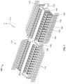
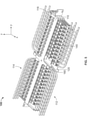
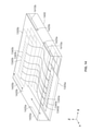
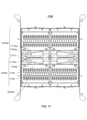
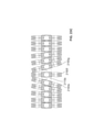
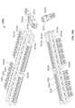
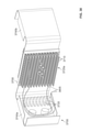
図1,2,3は、種々の角度から見たパッチパネル100を示している。図1は、パッチパネルの斜視図である。図2は、パッチパネルの上面図である。図3は、パッチパネルの正面図である。図1-3の各々には、相対的な視点の関係を明瞭にするために、座標空間キー[x、y、z]が付されている。
FIGS. 1, 2 and 3 show the
パッチパネル100は、フレーム110を備えている。フレーム110は、x軸方向にフレーム深さ、y軸方向にフレーム幅、及びz軸方向にフレーム高さを有するフレーム110を備え得るる。フレーム110は、金属又は厚肉プラスチックのような頑丈な支持材料によって作製され得る。
The
パッチパネル100は、複数のトレイ120を更に備えている。これらのトレイ120は、フレーム110によって支持され、フレーム高さ方向において垂直に積み重ねられている。この例では、トレイ120は、互いの上に直接置かれることがなく又は互いに直接接触することがないので、任意の1つのトレイを他のトレイを移動させたり他のトレイに接触することなくパッチパネル100のアレイから引き出すことができる。この例では、トレイが3段に積み重ねられているが、他の例では、トレイが3段よりも多いか又は少ない段数に積み重ねられていてもよい。加えて、この例では、2つのトレイ段が互いに隣接して配置されているが、他の例では、1つのみのトレイ段であってもよいし、3つ以上のトレイ段が互いに隣接していてもよい。
The
トレイ120の各々は、互いに実質的に同じであってもよい。明瞭にするために、以下の記載では、垂直方向のトレイ段の中央に位置する単一トレイ120の構造及び機能について説明するが、同じ構造及び機能が垂直方向のトレイ段の各トレイに適用されてもよいことを理解されたい。
Each of the
トレイ120は、フレーム110の内側に配置されている。フレーム110は、フレーム深さ方向に沿って第1の側112及び反対の第2の側114の各々において開いており、これによって、フレーム110の両側からトレイにアクセスすることができる。
The
複数の接続ポート130が、トレイ120に接続されている。この例では、トレイは、フレーム幅方向に一列に並んだ12個の接続ポート130の列を備えているが、他の例では、12個よりも多いか又は少ない数の接続ポートが含まれていてもよい。接続ポートは、両側差込式であり、フレーム110の両側112,114からケーブル接続端子140を受け入れるように構成されている。
A plurality of
複数の接続ポート130及び複数のケーブル接続端子140は、それぞれ互いに実質的に同じであってもよい。明瞭にするために、以下の記載では、単一の接続ポート130及び単一のケーブル接続端子140の構造及び機能について説明するが、同じ構造及び機能がトレイに含まれる接続ポート及び接続端子の各々に適用されてもよいことを理解されたい。
The plurality of
ケーブル接続端子140は、剛性ハウジング142を備えている。剛性ハウジング142は、ケーブル150に取り付けられ、ケーブル150を部分的に収容するように構成されている。剛性ハウジング142は、接続ポート130の開口内に嵌合するように適合されている。この例では、接続ポート130の両側内へケーブル接続端子を嵌合することによって、それぞれのケーブル接続端子内に収容されたケーブルを互いに通信可能に連結することができる。
The
ケーブル接続端子140は、ラッチ解除機構144又はより一般的にラッチも備えている。ラッチ解除機構144は、剛性ハウジング142の外面に設けられている。ラッチ解除機構144は、接続ポート130の内面の凹縁に係合するように適合された押圧可能なフィンガーであるとよい。ラッチ解除機構144が係合されると、ラッチ解除機構144は、ケーブル接続端子140が接続ポート130から外れるのを防ぐことができる。ラッチ解除機構144は、手動によって、例えば、ユーザーがラッチ解除機構144を押し込むか、引っ張るか、又は捩じることによって解除することができる。同様の効果を達成するために、ネジ、ボルト、バネ、又は他の周知のケーブル係止装置及び機構が用いられてもよい。更に、他の例では、ラッチは、接続ポート自体に設けられ、接続ポートのラッチを解除することによって、接続ポート内に挿入されたケーブル接続端子を離脱させるようになっていてもよい。
The
ケーブル接続端子140は、剛性ハウジング142とケーブル150の露出した非収容部分との間に配置された柔軟ブーツ146を更に備えている。ブーツは、ケーブル接続端子140の耐久性を向上させるとともに、ケーブル150がパッチパネル100から離脱されないことを確実にするために、柔軟であるとよい。ブーツは、応力を緩和し、ケーブル150が鋭く屈曲するのを防ぐことになる。このような鋭利な屈曲は、内部のファイバを破壊し、その結果として、伝送損失をもたらす可能性がある。
The
接続ポート130の両側のケーブル接続端子140は、接続ポート130内に挿入されると、接続ポート130から第1の軸に沿って離れる方に延びる。図1-3の例では、第1の軸は、フレームの深さ方向xと同じである。しかし、他の例では、第1の軸は、フレーム深さ方向から角度ずれしていてもよく、この場合、ケーブル接続端子は、フレーム深さ方向に対してある角度で接続ポートに入ることになる。
When inserted into the
トレイ120に戻ると、このトレイは、フレーム110の片側又は両側においてガイド116によって支持されるようになっている。ガイド116は、第1の軸から角度ずれした第2の軸に沿って延在している。第2の軸x’は、図2に示されており、フレーム深さ方向xから角度ずれしている。しかし、第1の軸自体がフレーム深さ方向xから角度ずれしている例では、第2の軸は、フレームの深さ方向と同じ方向であってもよい。
Returning to the
トレイ120は、ガイド116に沿って摺動するように適合されているとよく、これによって、トレイは、軸x’のいずれの方向にも移動することが可能になる。これは、図2の上面図に顕著に示されている。ここでは、トレイ120は、トレイの側縁がx’軸方向に延在してフレーム深さ方向xから角度ずれした方向x’に沿って摺動可能となるように平行四辺形に形作られている。フレーム110の側縁(及び必然的にフレームのガイド116)が、ケーブル接続端子140が延在する方向とは対照的にトレイ120の側縁と同じ方向に延在していることが、図2から更に分かる。以下に更に詳細に説明するように、フレーム110、ガイド116、及びトレイ120の角度付けは、パッチパネルフレームの内部からケーブル接続端子140がパッチパネル100の完全に外にある位置までトレイを引っ張ることなく、ケーブル接続端子140のラッチ解除機構144にアクセスすることを可能にするために、重要である。
The
図示されるこの例のケーブル接続端子140は、(MTPケーブルとも呼ばれる)マルチファイバ・プッシュオン(MPO)ケーブル端子であり、端子に接続されたケーブル150は、マルチファイバケーブルである。MPOケーブル端子の例では、接続ポートは、ポートの内面に取り付けられたフックを備え、ケーブル接続端子は、フックによって固定されるように構成された対応するラッチを備えている。ラッチをフックに固定すると、その結果として、ケーブル接続端子は、パッチパネル接続ポートに動作可能に接続されることになる。接続ポートは、ラッチがフックから引き出された時にラッチを解除するように更に構成されている。他の例では、他の形式のケーブル及び端子が用いられてもよい。例えば、周知のいかなるファイバケーブル(例えば、単芯ファイバケーブル)及びケーブルをポートに脱着させるためのラッチ又は他の機構を有する周知のいかなるコネクタ(例えば、SCコネクタ)であっても、本開示によって設計されたパッチパネルに対応可能である。
The
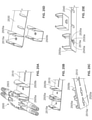
図4は、例示的なトレイ120の斜視図であり、該トレイの構造をより詳細に示している。トレイ120は、表面を画定する表面部410を備えている。表面は、フレーム幅方向及びフレーム深さ方向における平面とすることができる。垂直部材420が、フレーム高さ方向において表面から垂直に延在し、トレイ120の第1の側112を第2の側114から分離している。垂直部材420は、表面部410の幅全体又はほぼ幅全体にわたって配置され、表面部410の幅を横切って単一列に並ぶ開口430を備えている。各開口430は、それぞれの両側差込式接続ポート130によって占有され、これによって、接続ポート130の第1の側がトレイ120の第1の側112に配置され、接続ポート130の第2の側がトレイ120の第2の側に配置されることになる。図4の例では、垂直部材420が上方に延在し、接続ポート130が表面部410の上に配置されているが、他の例では、垂直部材が下方に延在し、接続ポートが表面部の下に配置されるようになっていてもよい。
FIG. 4 is a perspective view of an
図1-3の各々において、パッチパネル100のトレイ120の全てがトレイ・イン位置にある。ケーブル接続端子140の各列は、フレーム高さ方向において垂直に互いに真っすぐに並んでいる。トレイ・イン位置は、概して、トレイの格納に適しており、ケーブル接続端子140の各々にアクセスすることができず、このような位置では、これらの端子は、パッチパネル100から容易に離脱可能とはなっていない。
In each of FIGS. 1-3, all of the
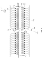
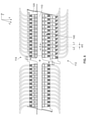
図5,6,7は、種々の角度から見たトレイ・アウト位置にあるトレイ120を有するパッチパネル100を示している。図5は、パッチパネルの斜視図である。図6は、パッチパネルの上面図である。図7は、パッチパネルの正面図である。図5-7の各々には、相対的な視点間の関係を明瞭にするために、座標空間キー[x,y,z]が付されている。
Figures 5, 6 and 7 show a
以下に説明するように、トレイ・アウト位置は、引き出されたトレイ120のすぐ上及びすぐ下のトレイがトレイ・イン位置にまだ位置しているか又は引き出されたトレイと垂直方向において真っすぐに並んでいないという条件下において、概して、引き出されたトレイのケーブル接続端子140へのアクセスに適したトレイの位置である。トレイ120の引出しは、トレイ120を第1の側112から引っ張り出すか又は押し出すことによって、又はトレイ120を第2の側から引っ張り出すか又は押し出すことによって、行われるとよい。トレイ120は、トレイ・イン位置とトレイ・アウト位置との間を移動するためにガイド116に沿って滑動、転動、又は他の形態で摺動するように適合されているとよい。
As described below, the tray-out position is such that the trays just above and below the drawn
トレイ120は、トレイ120の両側縁が延びる第2の軸(例えば、図6のx’)と平行な軸に沿ってトレイ120の表面と平行にトレイ・イン位置からトレイ・アウト位置に摺動する。ここで、第2の軸は、第1の軸(例えば、図6のx)から角度ずれしている。その結果、引き出されたトレイのケーブル接続端子は、トレイ・イン位置におけるそれらの位置に対して横方向に変位している。換言すれば、任意のケーブル接続端子は、トレイ・イン位置にある時、第1の軸の方向において第1の線に沿って延在していると見なされ、トレイ・アウト位置にある時、第1の軸の方向において平行に位置ずれした第2の線に沿って延在していると見なされる。トレイがトレイ・アウト位置にある時、第1の線と第2の線との間の距離は、d/2である。この値は、互いに隣接するケーブル接続端子間の距離dの半分である。
The
特に、図5-7の例では、トレイ120は、フレーム深さ方向に対して斜めに摺動するように適合されている。その結果、トレイがトレイ・イン位置からトレイ・アウト位置に移動すると、ケーブル接続端子は、フレーム幅方向及びフレーム深さ方向の各々において変位する。加えて、トレイがトレイ・アウト位置に達すると、引き出されたトレイ120のケーブル接続端子140は、引き出されたトレイ120のすぐ上及びすぐ下のトレイのケーブル接続端子に対してフレーム幅方向において横方向にずらされる。トレイをトレイ・イン位置からトレイ・アウト位置に移行させるために、トレイは、トレイがそのケーブル接続端子へのアクセス可能な位置に配置されるのに必要な最小距離だけ、トレイ・イン位置から第2の軸と平行な軸に沿った方向に摺動されることになる。従って、トレイ・アウト位置において、トレイのケーブル接続端子にアクセスすることができ、これによって、ケーブル接続端子へのアクセスのために、トレイをパッチパネルの外までガイドに沿って更なる距離にわたって摺動させる必要がない。トレイ・アウト位置において、横方向の位置ずれは、互いに隣接するケーブル接続端子間の横方向の距離(d)の半分(d/2)である。
In particular, in the example of FIG. 5-7, the
従って、図6,7の各々に示されるように、トレイ120がトレイ・アウト位置に達すると、引き出されたトレイ120のケーブル接続端子140は、横方向において、すぐ上及びすぐ下のトレイのケーブル接続端子間の間隙の上及び下に配置されることになる。これによって、引き出されたトレイ120のケーブル接続端子140へのアクセスが可能になる。
Therefore, as shown in each of FIGS. It will be placed above and below the gap between the connection terminals. This allows access to the
トレイ・アウト位置にある引き出されたトレイ120のケーブル接続端子140がすぐ上及びすぐ下の間隙を通してアクセスすることができるので、トレイ120をそれほど遠くまで引き出す必要がない。特に、トレイ・イン位置とトレイ・アウト位置との間のトレイの変位は、第1の軸の方向におけるケーブル接続端子の長さより短くてもよい。例えば、各ケーブル接続端子の長さが100mmである場合、トレイ・イン位置とトレイ・アウト位置との間の変位は、100mm未満の長さであってもよく、いくつかの例では、50mm以下であってもよい。
The
一例では、図1-7の例に示されるフレーム110は、約400mmから約500mmの幅を有し、各トレイ120は、約200mmから250mmの幅を有している。12個のケーブル接続端子140は、(ケーブル接続端子自体の幅を含めて)約15mmから約25mmの間隔で互いに離間している。この間隔は、異なる数のケーブル接続端子を有するトレイであっても同一又は同様とすることができる。フレームの高さは、約40mmから約45mmの間である。これは、各トレイが15mm未満の間隙によって互いに分離されていることを意味している。これが、ユーザーがトレイ120をトレイ・アウト位置に移動させることなくケーブル接続端子140のラッチにアクセスすることを困難にしている。
In one example, the
一般的に、トレイ120は、2つのトレイ・アウト位置、すなわち、トレイ120の第1の側112におけるケーブル接続端子がアクセス可能となる第1のトレイ・アウト位置、及びトレイ120の第2の側114におけるケーブル接続端子がアクセス可能となる第2のトレイ・アウト位置を有している。トレイは、トレイが摺動する方向(例えば、前方向又は後方向)に応じて、トレイ・イン位置から2つのトレイ・アウト位置のいずれかに摺動することになる。いずれにしても、トレイの位置は、トレイのそれぞれの側におけるケーブル接続端子をよりアクセスし易くするために、第1の軸から角度ずれした第2の軸の方向に移動されるとよい(例えば図5-7の場合、フレーム深さ方向及びフレーム幅方向の両方に移動する)。
Generally, the
パッチパネルは、その機能及び作動並びにケーブル接続端子のアクセス性を向上するための追加的な特徴を備え得る。図8は、図4のトレイ120の底面810の斜視図である。図8から分かるように、トレイ120の表面部410は、フレーム幅方向に延在する1対の長孔状開口812,814を備えている。第1の開口812は、トレイ120の第1の側112のケーブル接続端子の剛性ハウジングの真下に位置している。第2の開口814は、トレイ120の第2の側114のケーブル接続端子の剛性ハウジングの真下に位置している。
Patch panels may have additional features to improve their functionality and operation as well as the accessibility of cable connection terminals. FIG. 8 is a perspective view of the
図8の例では、第2の開口814は、垂直部材420がフレーム高さ方向において第2の開口814の内縁824と垂直方向に真っすぐに並ぶのに十分な大きさに形成されている。しかし、他の例では、第2の開口は、該開口がケーブル接続端子の剛性ハウジングにおけるラッチ又は他の脱着機構へのアクセスを可能にするのに十分な大きさを保っている限り、より小さくてもよい。
In the example of FIG. 8, the
加えて、図8の例では、開口812,814は、ケーブル接続端子の剛性ハウジングの下に位置している。しかし、脱着機構が接続ポートのような他の箇所に配置される例では、トレイ表面のこれらの開口は、それぞれの脱着機構に対して適切に並ぶように、異なる位置に配置されてもよい。図8の例では、ケーブル接続端子140を接続ポート130から容易にラッチ解除することを可能にするために、開口812は、意図的にラッチ解除機構144と並んでいる。
In addition, in the example of FIG. 8, the
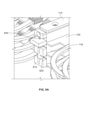
図1,3,5,7は、トレイが誤ってフレームから滑り落ちるのを防ぐように構成された機械的ストッパー160も示している。機械的ストッパーの拡大図が、図9A,9Bの各々に示されている。
Figures 1, 3, 5 and 7 also show a
機械的ストッパー160は、フレーム110の外面に取り付けられ、フレームからフレームの深さ方向に延在している。機械的ストッパー160は、フレーム幅方向においてストッパーの本体に形成された1つ又は複数のノッチ920を備えている。これらのノッチ920の位置において、フレーム幅方向における機械的ストッパー160の幅は、ノッチの上及び下のストッパ160の部分よりも短くなっている。これに関して、機械的ストッパー160は、フレーム幅方向においてトレイ120の少なくとも一部と重なる全幅を有している。しかし、ノッチの位置における機械的ストッパー160の幅は、フレーム幅方向においてトレイ120と重ならない。
The
図9Aにおいて、機械的ストッパー160は、ロック位置にある。ノッチ920は、垂直方向においてフレーム110のガイド116と位置ずれしており、これによって、各トレイ120がトレイ・イン位置とトレイ・アウト位置との間で摺動するのを阻止することになる。図9Bにおいて、機械的ストッパー160は、ロック解除位置にある。ノッチは、フレーム高さ方向においてフレーム110のガイド116と垂直方向の位置が整合し、トレイ120の各々は、トレイ・イン位置とトレイ・アウト位置との間で自由に摺動することが可能になる。
In FIG. 9A, the
図9A,9Bの例では、機械的ストッパー160をロック位置とロック解除位置との間で移動させることは、機械的ストッパー160をフレーム高さ方向において垂直に変位させることを含んでいる。機械的ストッパー160は、付勢バネ930のような付勢要素によってロック位置に付勢されている。付勢バネ930は、フレーム高さ方向において機械的ストッパー160に垂直に力を加えるものである。付勢バネ930は、押圧可能となるように構成され、これによって、反対の力(図9の例では、上向き力)が付勢バネ930を圧縮し、ノッチ920がフレーム110内の1つ又は複数のトレイ120と真っすぐに並ぶまで、機械的ストッパー160を付勢バネ力の軸に沿って変位させることになる。
In the examples of FIGS. 9A, 9B, moving the
加えて、トレイ120は、トレイ・アウト位置に引き出された時にフレーム高さ方向において機械的ストッパー160と重なるが、トレイ・イン位置においてフレーム高さ方向において機械的ストッパー160と重ならないように構成することができる。トレイ・アウト位置にあるトレイ120は、この重なりによって、機械的ストッパー160が付勢されたロック位置に戻るのを妨げることができる。従って、機械的ストッパー160は、トレイ120がトレイ・イン位置に戻されてフレーム深さ方向において機械的ストッパーともはや重ならなくなった後でのみ、ロック位置に戻り、これによって、付勢バネ930が解放され機械的ストッパー160をロック位置に付勢することになる。
In addition, the
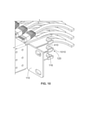
図4,8は、トレイをフレームに係留するように構成されたアンカー部材も示している。アンカー部材の拡大図は、図10に示されている。アンカー1010は、トレイ表面部410からフレーム幅方向に延在するトレイ表面部410の縁に取り付けられている。アンカー1010は、トレイ表面部410の厚さよりも大きいフレーム高さ方向の高さを有している。加えて、フレーム110内のガイド116は、スロットであってもよい。各スロットの幅は、トレイ表面部410の厚さと等しいか又はそれよりも大きいがアンカー1010の高さよりは小さい。これに関して、トレイ120は、x’軸に沿って、従って、スロット116に沿って前後に摺動することができるが、アンカーによって、トレイ120が回転すること又はフレーム幅方向においてフレーム110の外まで横方向に摺動することが阻止されることになる。
FIGS. 4 and 8 also show anchor members configured to moor the tray to the frame. An enlarged view of the anchor member is shown in FIG. The
両側差込式接続ポートと前後に引出し可能なトレイとを有するパッチパネルの場合、機械的ストッパー及びアンカーは、パッチパネルの両側に設けられているとよい。例えば、フレームの第1の側における第1の機械的ストッパーは、トレイが第1の側の方向に引き出されるのを阻止し、フレームの第2の側の第2の機械的ストッパーは、トレイが第2の側の方向に引き出されるのを阻止するとよい。同様に、各トレイ表面は、2つのアンカーを備えているとよく、この場合、一方のアンカーは、トレイの一方の側が引き出される時に側方摺動を防ぐために第1の側に設けられ、他のアンカーは、トレイの他の側が引き出される時に側方摺動を防ぐためにトレイの他の側に設けられているとよい。 For patch panels with double-sided plug-in connection ports and trays that can be pulled back and forth, mechanical stoppers and anchors may be provided on both sides of the patch panel. For example, a first mechanical stopper on the first side of the frame prevents the tray from being pulled out in the direction of the first side, and a second mechanical stopper on the second side of the frame allows the tray to be pulled out. It is good to prevent it from being pulled out in the direction of the second side. Similarly, each tray surface may be provided with two anchors, in which case one anchor is provided on the first side to prevent lateral sliding when one side of the tray is pulled out and the other. Anchors may be provided on the other side of the tray to prevent lateral sliding when the other side of the tray is pulled out.
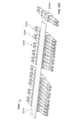
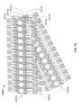
図11は、本開示によるパッチパネル1100の代替的な実施形態を示している。前述の実施形態と同様、図11のパッチパネル1100は、フレーム、トレイ、接続ポート(前述の図示された例におけるのと同様、図11の例では72ポート)、及びケーブルを接続ポートに接続するためのケーブル接続端子を備えている。図11のパッチパネル1100は、各トレイが回転されると共に引き出されるように構成されている点において異なっている。
FIG. 11 shows an alternative embodiment of the
フレーム1110は、フレーム高さ方向において垂直に延在するポスト1118を備えている。場合によっては、ポスト1118は、フレーム1110の側壁に近接して配置されているとよい。トレイ1120の各々は、トレイ1120の表面部にエッチングによって形成された細長のスロット1122も備えている。細長のスロット1122は、ポスト1118がスロット1122内に挿入されるように適合されている。これによって、トレイ1120は、スロット1122内の枢動点(例えば、ポスト1118)を中心として回転し、スロットの延びる方向に摺動することが可能になる。これに関して、スロット1122の幅は、トレイ1120がポスト1118に手際よく取り付けられてポスト1118に対して摺動することを可能にするために、ポスト1118の幅と略等しいか又はポスト1118の幅よりもいくらか広いとよい。場合によっては、スロット1122は、L字状であってもよい。
The
ポスト1118は、トレイの重量を支持するプラットフォーム又はスペーサーのような支持特徴部を更に備え、フレーム1110によって受け入れられるトレイ1120を垂直方向において互いに離間させ、互いに隣接するトレイ同士の干渉を回避することができる。
フレーム1110は、ポスト1118に近接して配置されるシャフト(図示せず)又は他のケーブル配線部を更に備えていてもよい。パッチパネル1100からの1つ又は複数のケーブル1119は、シャフトを通して配線される。これによって、所定のケーブル1119に対して、トレイ1120がポスト1118を中心として回転する時、ケーブル接続端子からシャフトまでの距離が著しく変化しない。加えて、トレイ1120が短い距離(例えば、100mm未満、具体的には、約50mm)しか内外に摺動しないので、トレイ1120の変位がケーブル接続端子からシャフトまでの距離に著しく影響を与えることもない。
The
操作に際して、図11のフレーム1110内のトレイをトレイ・イン位置からトレイ・アウト位置に移動させることによって、ポスト1118を中心とするトレイの回転と、スロット1122の延びる方向におけるトレイ表面によって画定された平面に沿ったトレイの移動との両方が生じる。トレイを回転させる目的は、回転されたトレイのケーブル接続端子を、そのすぐ上及びすぐ下のトレイのケーブル接続端子と垂直方向において真っすぐに並ばないように、移動させることにある。トレイを移動させる目的は、ポスト1118に最も近いケーブル接続端子に対して追加的なクリアランス及びアクセス性をもたらすことにある(何故なら、これらの端子の回転は、ポスト1118からより遠い端子の回転よりもわずかな位置変更しかもたらさないからである)。
By moving the tray in
回転可能な複数のトレイは、対応する接続ポートの両側のケーブル接続端子へのアクセスを可能にするために、互いに反対の方向に回転するように構成されている。積み重ねられたトレイの各々は、枢動点(例えば、ポスト)を中心として回転すると共に細長のスロットの長軸に沿って移動するように構成されている。例えば、図11に示されるように、第1のトレイ1141は、1つの方向に回転した状態で示され、第2のトレイ1142は、反対の第2の方向に回転した状態で示されている。また、第1のトレイ1141は、細長のスロットに沿っても移動しているが、第2のトレイ1142は、細長のスロットに沿って移動していないことに留意されたい。
The rotatable trays are configured to rotate in opposite directions to allow access to the cabling terminals on either side of the corresponding connection port. Each of the stacked trays is configured to rotate about a pivot point (eg, a post) and move along the long axis of the elongated slot. For example, as shown in FIG. 11, the
図11から分かるように、トレイ1120の細長のスロット1120は、フレーム1110の幅を超えて突出するトレイ表面部の延長部に形成されている。これによって、トレイ1120がポスト1118を中心として回転することを可能にすると共に、ポスト1118が、トレイ表面部のごくわずかな部分をフレーム幅方向においてポスト1118の反対側に残しながら、フレーム幅方向においてフレーム1110の縁の近くに形成されることが可能になる。
As can be seen from FIG. 11, the
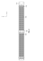
図12を参照すると、一実施形態によるパッチパネルトレイ1200の斜視図が示されている。パッチパネルトレイ1200は、トレイ1200が1つ又は複数のハンドル1205を備えることを除けば、各トレイ120と同様である。図には、2つのハンドル1205が示されている。一方のハンドル1205は、トレイの第1の側112に配置され、他方のハンドル1205は、トレイの第2の側114に配置されている。しかし、トレイ1200は、例えば、トレイの第1の側112に単一ハンドルを有するように構成されてもよいし、又は3つ以上のハンドルを有するように構成されてもよいことに留意されたい。いずれにしても、ハンドルは、ユーザーにトレイ1200を掴むための場所をもたらすことによって、トレイ1200をトレイ・イン位置及びトレイ・アウト位置に配置することを容易にする。トレイ1200と同じようにそれぞれ構成された多数のトレイが、例えば、代替的な実施形態を達成するために、図1-10の実施形態における多数のトレイ120に代わって用いられてもよい。トレイ120におけるのと同様、トレイ1200においても、垂直部材420がフレーム高さ方向において表面部から垂直に延び、トレイ1200の第1の側112を第2の側114から分離している。垂直部材420は、表面部410の全幅又はほぼ全幅にわたって延在し、表面部410の幅を横切って単一列に並んだ開口430を備えている。各開口430は、それぞれ両側差込式接続ポート130によって占有されることになる。具体的には、接続ポート130の第1の側がトレイ120の第1の側112に配置され、接続ポート130の第2の側がトレイ120の第2の側に配置される。一構成では、垂直部材420は、上方に延び、接続ポート130が表面部410の上方に配置されるが、他の例では、垂直部材が下方に延び、接続ポートが表面部の下に配置されてもよい。
Referring to FIG. 12, a perspective view of the
図13を参照すると、一実施形態によるパッチパネル構成の斜視図が示されている。この構成では、トレイ1305a,1305b,1310a,1310b,1315a,1315bが対で配置されている。例えば、トレイ1305a,1350bが対を形成している。各トレイ対は、関連する多数の中間ケーブル又は「ジャンパー(jumper)」ケーブルを有している。しかし、図13は、図示を明瞭にするために、トレイ対1305a,1305bに関連する中間ケーブル1320のみを示している。更に、各対を形成する2つのトレイは、同一平面上又は実質的に同一平面上にあり、このようなトレイを接続するケーブルは、支持体によってトレイの平面内又は実質的に平面内に保持されている。例えば、トレイ1305a,1305bは、XY平面と平行な同一平面内にあり、ケーブル1320は、支持体1330によってトレイ1305a,1305bの平面内に保持されている。支持体1330は、例えば、トレイ1305a,1305b及びケーブル1320を取り囲む筐体上に取りつけられている。
Referring to FIG. 13, a perspective view of the patch panel configuration according to one embodiment is shown. In this configuration,
トレイ1305a-1315bの各々は、複数のポートを備えている。例えば、トレイ1305aは、ポート1340aを備え、トレイ1305bは、ポート1340bを備えている。ポート1340a,1340bの各々は、外部ケーブル1320に連結するための1つ又は複数の接続端子を受け入れるようになっている。更に、ケーブル1320は、それら自体、それぞれの接続端子によってポートに連結される。従って、一実施形態では、ケーブル1320の各々は、ケーブル、例えば、ケーブル1322の第1の端1320aに接続端子を有し、ケーブル、例えば、ケーブル1322の第2の端1320bに接続端子を有し、第1の端1320aにおける接続端子は、ポート1340aの1つに接続され、第2の端1320bにおける接続端子は、ポート1340bの対応する1つに連結されている。次いで、外部ケーブルの対、例えば、ケーブル1350,1355が、それぞれ複数のケーブル1320のうちの1つを介して、例えば、複数のポート1340aのうちの1つ及び対応する1つのポート1340bを介して、互いに連結されることになる。
Each of the
図13の配置では、ケーブル1350に取り付けられた接続端子は、トレイ1305aをY方向に沿ってトレイ・アウト位置に移動させることによって、ケーブル1355を妨げることなく容易にアクセス可能になる。すなわち、中間ケーブル1320は、トレイ1305aの移動を吸収するのに十分な長さを有しており、このような移動の結果として著しく大きな力をケーブル1355又はトレイ1305bに与えることがない。同様に、ケーブル1355に取り付けられた接続端子は、トレイ1305bをY方向と反対の方向に沿ってトレイ・アウト位置に移動させることによって、ケーブル1350又はトレイ1305aを妨げることなく容易にアクセス可能になる。
In the arrangement of FIG. 13, the connection terminals attached to the
図14は、筐体1400内に配置された状態にある図13のパッチパネル構成の斜視図である。筐体は、トレイ1305a-1315bの全てを収容し、トレイ・イン位置とトレイ・アウト位置との間の移動中にトレイを案内するための1つ又は複数のガイド、例えば、ガイド1405a,1405b,1410a,1410bを備えることができる。例えば、トレイ1305aは、ガイド1405a,1410aによってトレイ・イン位置とトレイ・アウト位置との間で案内される。加えて、これらのガイドは、それぞれのストッパ、例えば、ストッパ1420a,1420b,1425a,1425bに関連付けられている。ストッパは、設計によって決められたトレイ・イン位置を越えるトレイの移動を制限するために設けられている。例えば、ストッパ1420a,1425aは、トレイ1305aが設計によって決められたトレイ・イン位置を越えて移動するのを防ぐようになっている。
FIG. 14 is a perspective view of the patch panel configuration of FIG. 13 in a state of being arranged in the
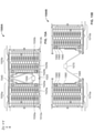
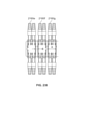
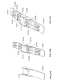
図15A,15Bは、並置構成にある2つのトレイ対パッチパネル配置1500A,1500Bを示している。トレイ対パッチパネル配置1500Aは、トレイ・イン位置にあるトレイ1505a,1505bを有し、トレイ対パッチパネル配置1500Bは、トレイ・イン位置にあるトレイ1510a及びトレイ・アウト位置にあるトレイ1510bを有している。2つのトレイ対パッチパネル配置1500A,1500Bは、フレーム(図示せず)内に含まれている。フレームは、パネル筐体(図示せず)と一体であってもよいし、パネル筐体に取り付けられていてもよいし、又はパネル筐体から独立していてもよい。配置1500A,1500Bの各々は、他の対の配置と共に、フレームによって支持され、第1の方向、例えば、Z方向に積み重ねられている。更に、配置1500A,1500Bの各々は、ケーブル接続端子のそれぞれの対を受け入れるように構成され、これによって、この配置によって受け入れられるケーブル接続端子の各対において、第1のケーブル接続端子トレイ対の第1のトレイによって受け入れられ、第2のケーブル接続端子がトレイ対の第2のトレイによって受け入れられ、第1のケーブル接続端子及び第2のケーブル接続端子は、これらのケーブル端子が第1の軸の方向において互いから外方に延びるように、中間ケーブルによって互いに通信可能に連結されるように構成されている。例えば、配置1500Aは、第1のケーブル接続端子1512aをトレイ1505aのポートに受け入れ、第2のケーブル接続端子1512bをトレイ1505bのポートに受け入れるように構成され、ケーブル接続端子1512a,1512bは、ケーブル接続端子1512a,1512bがY軸に沿って互いから外方に延びるように、中間ケーブル1520によって互いに通信可能に連結されるように構成されている。
FIGS. 15A and 15B show two tray-to-
図15A,15Bの実施形態では、第1のケーブル接続端子、例えば、第1のケーブル接続端子1512aは、トレイ1505aのそれぞれのポート、例えば、ポート1525aに連結され、第2のケーブル接続端子、例えば、第2のケーブル接続端子1512bは、トレイ1505bのそれぞれのポート、例えば、ポート1525bに連結されている。また、各中間ケーブルの第1の端、例えば、ケーブル1520の端1520aは、第1の中間ケーブル接続端子、例えば、第1の中間ケーブル接続端子1530aに連結され、この中間ケーブル接続端子1530aは、トレイ1505aのそれぞれのポート、例えば、ポート1525aに連結される。各中間ケーブルの第2の端、例えば、ケーブル1520の端1520bは、第2の中間ケーブル接続端子、例えば、第2の中間ケーブル接続端子1530bに連結され、この中間ケーブル接続端子1530bは、トレイ1505bのそれぞれのポート、例えば、ポート1525bに連結される。このようにして、第1のケーブル接続端子の1つに接続されたケーブルは、中間ケーブルを介して第2のケーブル接続端子の1つに接続されたケーブルに連結される。例えば、第1のケーブル接続端子1512aに連結されたケーブルは、第1のケーブル接続端子1512a、ポート1525a、第1の中間ケーブル接続端子1530a、中間ケーブル1520、第2の中間ケーブル接続端子1530b、ポート1525b、及び第2のケーブル接続端子1512bによって、第2のケーブル接続端子1512bに接続されたケーブルに連結される。
In the embodiments of FIGS. 15A, 15B, the first cable connection terminal, eg, the first
図15A、15Bの実施形態の中間ケーブル1520の一部は、ケーブルジャケット1540内に配置されている。ジャケット1540は、トレイ1505aとトレイ1505bとの間の空間における中間ケーブル1520の調整された位置決めを容易にするものである。更に、ジャケットは、ジャケットを拘束して中間ケーブルを少なくとも一つの方向に拘束する支持体1550によって保持されている。
A part of the
ここで図15Bを参照すると、トレイ対パッチパネル配置1500Bが示されている。この配置では、トレイ1510aがトレイ・イン位置にあり、トレイ1510bがトレイ・アウト位置にある。配置1500Bは、X軸に関連する配向を除けば、配置1500Aと同じである。X軸に沿って、配置1500Bは、配置1500Aと鏡面対称である。図15Bから分かるように、トレイ1510bのトレイ・アウト位置への移動は、中間ケーブル1560の弛みにより、トレイ1510aに著しく大きな力を加えることがない。すなわち、トレイ1510bがY方向に移動すると、中間ケーブル1560及び関連するジャケット1565がこのような移動を吸収する。更に、支持体1570が、Z方向に沿ってケーブル1560及びジャケット1565を支持している。支持体1570は、ケーブル1560及びジャケット1565を保持してXY平面内において自由に移動するが、Z軸に沿って移動せず、これによって、ケーブル1560及びジャケット1565は、XY平面内において自由に移動するが、Z軸に沿った移動を制限されることになる。
Here, with reference to FIG. 15B, a tray-to-
配置1500Bは、他のトレイ対配置と共に第1の方向、例えば、Z方向に積み重ねられていてもよい。このような構成では、トレイ1510bは、トレイ1510aが静止している間に、他のトレイ対構成のトレイと平行に又は実質的に平行に摺動することによって、第1のトレイ・イン位置と少なくとも1つの第1のトレイ・アウト位置との間で摺動するように適合されているとよい。
The
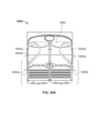
ここで図16A-16Fを参照すると、一実施形態によるトレイ対パッチパネル1600の斜視図が示されている。図16Aは、パッチパネル1600の筐体1605を示している。筐体は、上面1610、ケーブルハンガー1615、及びドア1620を備えている。ケーブルハンガー1615は、パッチパネルに対して出入りするケーブルを固定するために設けられている。ドア1620は、筐体1605内において摺動可能なトレイを固定するために設けられ、トレイが筐体1605から外方に摺動することを可能にするために開くようになっている。
Here, with reference to FIGS. 16A-16F, a perspective view of the tray-to-
図16Bは、上面1610を含む部分が取り外された図16Aのパッチパネルを示している。パッチパネルは、第1のトレイ対パッチパネル配置1625A及び第2のトレイ対パッチパネル配置1625Bを備えている。1つの可能な実施形態では、配置1625A,1625Bは、それぞれ、(図15A,15Bに示されるような)配置1500A,1500Bの形態を取ることができる。いずれにしても、配置1625Aは、第1のトレイ1630a、第2のトレイ1630b、及びケーブルジャケット1635を通る中間ケーブル(図示せず)を備えている。同様に、配置1625Bは、第1のトレイ1640a、第2のトレイ1640b、及びケーブルジャケット1645を通る中間ケーブル(図示せず)を備えている。加えて、トレイ1630a,1630b,1640a,1640bの各々は、トレイの操作を容易にするためのハンドル、例えば、ハンドル1650を備えている。図16Bから分かるように、パッチパネルは、側壁1660,1665及び中間壁1670を備えている。壁1660,1665,1670は、対応するガイド、例えば、側壁1660上の複数のガイド1675を有している。ガイド1675は、トレイ・イン位置とトレイ・アウト位置との間のパッチパネルのトレイ、例えば、トレイ1630a,1630bの移動を案内するものである。図16Bでは、2つのトレイ対パッチパネル配置のみが示されているが、図のパッチパネルは、3層に重ねられて各層において2つのトレイ対配置が並置される6つのトレイ対パッチパネル配置を備えるように構成されている。これらの層は、各層がガイド1675の1つに対応するように、配置1625A,1625Bから筐体の頂部に向かって上向きに重ねられている。
FIG. 16B shows the patch panel of FIG. 16A with the portion including the
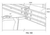
図16Cは、図16Bのレイアウトの代替例を示している。図16Cから分かるように、中間壁1670は、ガイド1680a,1680b,1680cを備えている。ガイド1680a,1680b,1680cの各々は、2つのトレイ対配置の1つの層に対応している。具体的には、例えば、ガイド1680aは、配置1625Aのトレイ1630a,1630bのためのガイドに対応する。図16Cから更に分かるように、ケーブルジャケットの各々、例えば、ケーブルジャケット1635は、それぞれの対の支持体、例えば、支持体1685a,1685bによって支持されている。支持体は、ケーブルジャケット及びジャケット内の中間ケーブルが筐体1605の上下方向と直交する方向において移動することを許容しながら、ケーブルジャケット及びケーブルが筐体1605の上下方向に沿って移動することを拘束する。図16Cは、側壁1665上の中心ストッパー1690も示している。中心ストッパー1690は、ガイド1677によって案内されるトレイ、例えば、トレイ1640aが筐体1605に向かって移動する時に該トレイ1640aの移動を制限するために設けられている。図16Dは、側壁1660上の中心ストッパ1695の詳細図を示している。
FIG. 16C shows an alternative example of the layout of FIG. 16B. As can be seen from FIG. 16C, the
図16Eは、図16B,16Cのレイアウトの代替例を示している。図16Eにおいて、トレイ1640bが図の左下部分に見えている。トレイ1640bは、図16Fにおいて単独で示されている。図16Fから分かるように、トレイ1640bは、複数のポート1640b’’を露出させるために開くようになっている蓋1640b’を備えている。一実施形態では、ポート1640b’’の各々は、(図15Aに示される)ポート1525aと同じであってもよい。
FIG. 16E shows an alternative example of the layout of FIGS. 16B and 16C. In FIG. 16E, the
図17は、他の実施形態によるトレイ対パッチパネル構成1700の上面図である。図17の構成は、中間ケーブル管理を除けば、図16A-16Fに関連して説明した実施形態と同様である。図17の実施形態は、トレイ対の一方の移動がトレイ対の他方のケーブル接続部に干渉するおそれを更に低減する。例えば、この実施形態は、トレイ1640bの図示されたトレイ・イン位置からトレイ・アウト位置(図示せず)への移動がトレイ1640aのケーブル接続部に干渉するおそれを更に低減させるケーブル管理を特徴とする。更に具体的には、トレイ1640bの接続端子をトレイ1640aの接続端子に連結する中間ケーブルは、ケーブルジャケット1705を通って配線されている。ケーブルジャケット1705は、スリーブ1715a,1715bによってパッチパネル構成の壁1710に固定されている。従って、トレイ1640a,1640bのいずれか又は両方が移動する時、トレイ1640a,1640bから最も遠いジャケット及びケーブル部分は移動せず、これによって、トレイ1640a,1640bの移動を互いに遮断することができる。加えて、図17の実施形態は、ケーブルジャケット1705を支持する枢動支持体1720a,1720bを備えているので、ジャケットは、パッチパネル構成1700の床1735と平行又は実質的に平行の方向に移動することができるが、床1735と直交又は実質的に直交する方向に移動することができない。
FIG. 17 is a top view of the tray-to-
図18は、一実施形態によるトレイ対パッチパネル構成1800の上面図である。ここでは、全てのケーブルアクセスがパッチパネルの前側から行われるようになっている。図18の構成は、ケーブル接続端子1810aを有する第1のトレイ1805aと、ケーブル接続端子1810bを有する第2のトレイ1805bとを備えている。トレイ1805a,1805bは、両方の端子1810a,1810bが構成1800の同じ側、例えば、構成1800の前側1820に面するように配置されている。端子1810aのそれぞれに接続されたケーブルは、トレイ1805aのポート1825a、中間ケーブル接続端子1830a、中間ケーブル1835、中間ケーブル接続端子1830b、及びトレイ1805bのポート1825bを介して端子1810bのそれぞれに接続されたケーブルに通信可能に連結されている。図18の実施形態によれば、トレイ1805a,1805bの各々は、他のトレイを妨げることなく、図示されたトレイ・イン位置からトレイ・アウト位置に移動することが可能になる。図示される実施形態では、トレイ1805a又は1805bのいずれかをトレイ・アウト位置に移動させることは、トレイ1805a又は1805bをY方向に沿って移動させることを含んでいる。
FIG. 18 is a top view of the tray-to-
トレイ1805a又は1805bの移動が他のトレイ上のケーブル接続部に干渉するおそれを低減するために、中間ケーブル1835は、ケーブルジャケット1840a,1840bを通って配線されている。ケーブルジャケット1840a,1840bは、それぞれのスリーブ1850a,1850bによってパッチパネル構成1800の壁1845に固定されている。従って、トレイ1805a,1805bのいずれか又は両方がジャケット1840a,1840bを移動させる時、トレイから最も遠いケーブル部分が移動せず、これによって、トレイ1805a,1805bの移動を互いに遮断することができる。加えて、図18の実施形態は、ケーブルジャケット1840a,1840bをそれぞれ支持する枢動支持体1855a,1855bを備えているので、ジャケットは、パッチパネル構成1800の床1860と平行又は実質的に平行の方向に移動することができるが、床1860と直交又は実質的に直交する方向に移動することができできない。
図19Aは、トレイ1805bがトレイ・アウト位置にある図18Aのトレイ対パッチパネルの上面図である。図から分かるように、枢動支持体1855bは、ケーブルジャケット1840bを床1860に平行又は実質的に平行な方向に支持しながら、トレイ1805bのトレイ・アウト位置及びケーブルジャケット1840bの付随的な位置に対応するように枢動されている。図から更に分かるように、トレイ1805bがトレイ・アウト位置にある時、ケーブルジャケット1840bは、スリーブ1850bによって壁1845に固定された状態にある。
FIG. 19A is a top view of the tray-to-patch panel of FIG. 18A with the
図19Bは、トレイ1640cがトレイ・アウト位置にある図17のトレイ対パッチパネルの上面図である。図から分かるように、枢動支持体1720cが、ケーブルジャケット1707をパッチパネル構成1700の床1735と平行又は実質的に平行な方向に支持しながら、トレイ1640cのトレイ・アウト位置及びケーブルジャケット1707の付随的な位置に対応するように枢動されている。図から更に分かるように、トレイ1640cがトレイ・アウト位置にある時、ケーブルジャケット1707は、スリーブ1715cによって壁1710に固定された状態にある。
FIG. 19B is a top view of the tray-to-patch panel of FIG. 17 with the
図20Aは、トレイ1805a,1805bの両方がトレイ・アウト位置にある図18のトレイ対パッチパネルの上面図である。図から分かるように、枢動支持体1855a,1855bが、それぞれ、ケーブルジャケット1840a,1840bを床1860と平行又は実質的に平行な方向に支持しながら、トレイ1805a,1805bのトレイ・アウト位置にそれぞれ対応するように枢動されている。
FIG. 20A is a top view of the tray-to-patch panel of FIG. 18 with both
図20Bは、トレイ1640c,1640dの両方がトレイ・アウト位置にある図17のトレイ対パッチパネルの上面図である。図から分かるように、枢動支持体1720c,1720dが、それぞれ、ケーブルジャケット1707,1708を床1735と平行又は実質的に平行な方向に支持しながら、トレイ1640c,1640dのトレイ・アウト位置にそれぞれ対応するように枢動されている。
FIG. 20B is a top view of the tray-to-patch panel of FIG. 17 with both
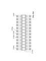
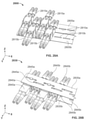
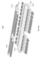
図21は、一実施形態によるラックマウントパッチパネルユニット2100の斜視図である。ユニット2100は、第1の方向、すなわち、図のZ方向に積み重ねられた3つのパッチパネルサブアセンブリ2105a,2105b,及び2105cを備えている。各パッチパネルサブアセンブリは、本開示の取付手段の1形式である少なくとも1つの取付プレートと、複数のポートアセンブリとを備えている。例えば、サブアセンブリ2105aは、複数のポートアセンブリ2110a,2110b,・・・,2110nと、取付プレート(mounting plate)2115aを備えている。取付プレート2115aは、各ポートアセンブリが個別に取付プレートの表面と平行な方向、すなわち、図のX方向と平行な方向に沿って移動(並進)(translate)することができ、かつ取付プレートの表面と直交する軸、すなわち、図のZ方向の軸を中心として回転することができるように、ポートアセンブリ2110a-2110nを取り付けるように構成されている。ポートアセンブリ、例えば、ポートアセンブリ2110a-2110nは、取付プレート、例えば、取付プレート2115aとの接触を保ちながら、移動可能及び回転可能である。
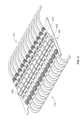
FIG. 21 is a perspective view of the rack mount
ラックマウントパッチパネルユニット2100は、フレーム2120及びケーブル支持体2125も備えている。フレーム2120は、取付プレート、例えば、取付プレート2115aをユニット2100内に固定するために及びユニット2100を取付具2130a,2130bを介してラック(図示せず)に固定するために用いられる。ケーブル支持体2125は、ポートアセンブリ、例えば、ポートアセンブリ2110a-2110nに接続されたケーブルをZ方向に支持するために用いられる。
The rack mount
図21の構成において、ポートアセンブリ、例えば、ポートアセンブリ2110a-2110nは、図の例に示されるように、共通の深さ寸法2132を有している。深さ寸法2132は、ポートアセンブリが配置される空間2101の1つの寸法、図を参照すれば、空間のY寸法を画定している。従って、空間のY寸法は、全てのポートアセンブリを深さ方向がY方向に延在するように並べた時、深さ寸法2132と等しい。ポートアセンブリの方位と関係なく、空間2101の深さ(空間のY寸法)は、ポートアセンブリの深さ寸法2132の2倍よりも小さい。
In the configuration of FIG. 21, the port assembly, eg, the
以下、ラックユニット2100の要素について更に詳細に説明する。いずれの場合も、ユニット2100は、3つのサブアセンブリに制限されないこと、及びユニット2100は、1つのサブアセンブリ、2つのサブアセンブリ、又は3つを超えるサブアセンブリを用いてもよいことに留意されたい。更に、ユニット2100は、ケーブル支持体2125を備えていなくてもよいし、又は異なる構成のケーブル支持体を備えていてもよい。更に、ユニット2100は、フレーム2120と異なる構成を有するフレームを備えていてもよい。
Hereinafter, the elements of the
説明を明瞭にするために、ポートアセンブリ、例えば、ポートアセンブリ2110aは、ケーブル接続端子、例えば、ケーブル接続端子2135a,2140a,2145a,2150aが該アセンブリ内に挿入された状態で示されていることに更に留意されたい。ケーブル接続端子は、それぞれのケーブル(図示せず)に関連付けられ、各ポートアセンブリは、該アセンブリの一方の側のケーブル接続端子を該アセンブリの他方の側のケーブル接続端子に通信可能に連結し、これによって、2つのケーブル接続端子に対応するケーブルが互いに通信可能に連結されることになる。例えば、ポートアセンブリ2110aは、ケーブル接続端子2135aをケーブル接続端子2145aに通信可能に連結している。更に、ポートアセンブリは、各側に2つのケーブル接続端子を収容するものとして示されているが、実施形態がこのようなアセンブリに限定されないことに留意されたい。例えば、ポートアセンブリは、各側に1つのケーブル接続端子、又は各側に3つ以上のケーブル接続端子を収容するようになっていてもよい。
For clarity, the port assembly, eg, the
ポートアセンブリは、細長の空間内に固定されてもよい。例えば、図21のポートアセンブリは、X方向(長手方向)に延在する空間2101内に固定されている。長手方向は、第1の方向と呼ばれることがある。各ポートアセンブリは、ケーブル端子アセンブリを受け入れるための少なくとも1対の前側及び後側ポート又はインターフェイスを備えている。例えば、ポートアセンブリ2110aは、ケーブル接続端子2135a,2140aをそれぞれ受け入れるための前側ポート2137,2139を備え、ケーブル接続端子2145a,2150aをそれぞれ受け入れるための後側ポート2142,2144を備えている。ポート2137,2142は、ケーブル接続端子2135a,2145a間のエネルギー伝搬接続を行い、ポート2139,2144は、ケーブル接続端子2140a,2150a間のエネルギー伝搬接続を行う。更に、前側ポート2137から後側ポート2142への相対位置及び前側ポート2139から後側ポート2144への相対位置は、第2の方向を画定する。第1の方向と第2の方向との間の角度は、ポートアセンブリ2110aがどれほど回転されたかに応じて、30°から90°の間にあるとよい。更に、ポートアセンブリ2110aは、少なくとも第1の方向に沿って移動することができる。特に、第1の方向と第2の方向との間の角度、具体的には、30°から90°の間の角度は、少なくとも第1の方向に沿ってポートアセンブリを移動させる特性として、図21の全てのポートアセンブリに適用可能である。
The port assembly may be fixed in an elongated space. For example, the port assembly of FIG. 21 is fixed in
加えて、図21のパッチパネルサブアセンブリのいずれか1つ、例えば、サブアセンブリ2105aに関して、複数のポートアセンブリ、例えば、ポートアセンブリ2110a-2110nが、取付手段、例えば、取付プレート2115aの表面と平行な方向に沿って個別に移動可能であることに留意されたい。更に、ポートアセンブリが個別に移動可能であるため、1つのポートアセンブリのポートと他の1つのポートアセンブリのポートとの間の距離は、1つのポートアセンブリ及び他の1つのポートアセンブリの一方又は両方を移動させることによって変更可能である。更に、図21のポートアセンブリが個別に回転可能であることに留意されたい。具体的には、ポートアセンブリのいずれか1つ、例えば、ポートアセンブリ2152に関して、該ポートアセンブリの前側ポートの中心及び該ポートアセンブリの対応する後側ポートの中心を貫通する軸、例えば、軸2154は、ポートアセンブリの他の1つ、例えば、ポートアセンブリ2156の前側ポートの中心及び該ポートアセンブリの対応する後側ポートの中心を貫通する軸、例えば、軸2158と平行にならないように位置決め可能である。
In addition, with respect to any one of the patch panel subassemblies in FIG. 21, eg,
ここで図22Aを参照すると、図21のラックマウントパッチパネルユニット2100の一部の斜視図が示されている。図示されるポートアセンブリは、中立位置にある。例えば、サブアセンブリ2105bのポート2160a-2160lは、それらの長軸が互いに平行となるように取付プレート2115bに沿って互いに均一に離間している。図22Bは、図22Aに示されるポートアセンブリの内の選択されたものをいかにそれらの中立位置から移動させ、ポートアセンブリ2160fへの容易なアクセスを可能にするかを示している。図22Bから分かるように、ポートアセンブリ2160eは、-X方向に移動されると共に+Z方向から見た時に時計回りに回転され、ポートアセンブリ2160gは、+X方向に移動されると共に+Z方向から見た時に反時計回りに回転されている。
Here, with reference to FIG. 22A, a perspective view of a part of the rack mount
図23Aは、図22Aのポートアセンブリ2160a-2160lの平面図である。この図は、ポートアセンブリ2160a-2160lがそれらの中立位置にある時、取付プレート2115bの長手方向に沿ったポートアセンブリ2160a-2160lの均一な間隔を示している。
23A is a plan view of the
図23Bは、図23Aのポートアセンブリ2160e,2160f,2160gの平面図である。この図は、ポートアセンブリ2160gの幅寸法Aを示している。但し、ポートアセンブリ2160a-2160lの各々は、同じ幅を有しているので、幅寸法Aは、ポートアセンブリ2160a-2160lに共通である。更に、図23Bは、ポートアセンブリ2160e,2160f間の間隔距離Bを示している。但し、ポートアセンブリ2160a-2160lがそれらの中立位置にある時、ポートアセンブリ2160a-2160lの任意の互いに隣接する2つのポートアセンブリ間の間隔距離は、Bである。いくつかの実施形態では、間隔距離Bは、幅寸法Aの約2%から約20%の範囲内にある。
23B is a plan view of the
図23Cは、図22Bの中央列の平面図である。この図は、ポートアセンブリ2160fへの容易なアクセスを可能にするために、ポートアセンブリ2160a-2160lがいかに配置されるかを示している。図から分かるように、ポートアセンブリ2160a-2160e及び2160g-2160lは、それらの中立位置から移動されており、ポートアセンブリ2160a-2160lは、もはや、間隔距離Bを隔てて互いに離間されていない。
23C is a plan view of the central row of FIG. 22B. This figure shows how the
ここで図24A-24Fを参照すると、実施形態によるパッチパネルサブアセンブリに用いられる取付プレート(mounting plate)2400-2425の斜視図が示されている。取付プレート2400-2425の各々は、それぞれのポートアセンブリを取り付けるための多数の開口を備えている。例えば、取付プレート2420は、多数の開口2420a-2420lを備えている。取付プレート2420のような取付プレートは、図21-23Cの構成に用いられるが、この説明に照らせば、図21-23Cの構成に関していずれの取付プレート2400,2405,2410,2415,又は2425がどのように用いられるかが明らかである。
Here, with reference to FIGS. 24A-24F, a perspective view of mounting plate 2400-2425 used in the patch panel subassembly according to the embodiment is shown. Each of the mounting plates 2400-2425 has a large number of openings for mounting the respective port assemblies. For example, the mounting
一般的に、ポートアセンブリに関し、ポートアセンブリが単一部品の形態をとる一体化アセンブリの構成と、ポートアセンブリがポートホルダー内に固定されたポートの形態を取る2部品アセンブリの構成とが可能であることに留意されたい。2部品アセンブリの例が、図25Aに示されている。 In general, for port assemblies, it is possible to configure an integrated assembly in which the port assembly takes the form of a single part, or a two-part assembly in which the port assembly takes the form of a port fixed within a port holder. Please note that. An example of a two-part assembly is shown in FIG. 25A.
図25A-25Cは、取付プレート2510に固定されたポートアセンブリ2500及びポートホルダー2505a,2505bの詳細な例を示す部分斜視図である。図示されるように、ポートアセンブリ2500は、ポート2503及びポートホルダー2505aを備える2部品アセンブリである。ポートアセンブリ2500は、係合部材2515aを介して取付プレート2510に固定されている。係合部材2515aは、取付プレート2510の多数の開口の1つである開口2520aに係合するものである。係合部材2515aは、開口2520aに沿って移動することができ、開口2520a内において回転することができ、これによって、ポートアセンブリ2500の全体が開口2520aに沿って移動し、かつ開口2520a内において回転することを可能にする。
25A-25C are partial perspective views showing detailed examples of the
図25D,25Eは、取付プレート2530に固定されるポートホルダー2505aを示している。取付プレート2530は、取付プレート2530がポートホルダーの挿入を容易にするために取付プレート2530の縁と交差する複数の開口を備えるという点において、取付プレート2510と異なっている。例えば、取付プレート2530は、開口2530aを取付プレート2530の縁2540に接続する狭小部分2535aを有する開口2530aを備えている。ポートホルダー2505aは、ポートホルダー2505aのネック2545aを狭小部分2535aを通して移動させることによって、取付プレート2530に容易に固定されることになる。
25D and 25E show the
ここで図26A-26Eを参照すると、実施形態によるポートホルダー2600a-2600eの斜視図が示されている。ポートホルダー2600a-2600eの各々において、ホルダーは、単独の状態でかつポートアセンブリを形成するためポートに係合した状態で示されている。更に、ポートホルダー2600a-2600eの各々において、2つの図、すなわち、上側から見た図と下側から見た図が示されている。例えば、ポートホルダー2600aは、単独の状態でかつポートアセンブリ2610aを形成するためにポート2605aと係合した状態で示されている。
Here, with reference to FIGS. 26A-26E, a perspective view of the
図26Fは、実施形態によるポートホルダー2600fの斜視図である。ポートホルダー2600fは、対応するポートへのポートホルダー2600fのより強固な連結をもたらすために、該ポートを包囲するように構成されている。図示される実施形態では、ポートホルダー2600fは、上部分2605fを備える点を除けば、図26Dのポートホルダー2600dと同様の形態にある。
FIG. 26F is a perspective view of the
いくつかの実施形態では、ポートアセンブリは、ラベルタブを備えている。図27A-27Cは、実施形態によるラベルタブを備えるポートホルダー及びポートアセンブリの斜視図である。図27A-27Cの実施形態では、ラベルタブは、単一部品ポートアセンブリの一部であってもよいし、又は2部品ポートアセンブリの一部であってもよい。説明を簡潔にするために、2部品構成のみについて説明する。図27Aは、ラベルタブ2705を有するポートホルダー2700を示している。図27Bは、ポートアセンブリ2715を形成するためにポート2710がポートホルダー2700内に固定されているポートホルダー2700を示している。タブ2705は、例えば、インクによってタブ2705に書き込むことによって、ポート2710の第1のインターフェイス2725aに受け入れられたケーブル接続端子2720a,2720bを識別するために用いられ得る区域をもたらす。図27Cは、2つのラベルタブ2735a,2735bを有するポートホルダー2730を示している。ポートアセンブリ2740を形成するために、ポート2710がポートホルダー2730内に固定されている。タブ2735aは、例えば、インクによってタブ2735aに書き込むことによってポート2710の第1のインターフェイス2725aに受け入れられたケーブル接続端子2720a,2720bを識別するために用いられる区域をもたらし、タブ2735bは、例えば、インクによってタブ2735bに書き込むことによってポート2710の第2のインターフェイス2725bに受け入れられたケーブル接続端子2720c,2720dを識別するために用いられる区域をもたらす。
In some embodiments, the port assembly comprises a label tab. 27A-27C are perspective views of a port holder and port assembly with label tabs according to embodiments. In the embodiment of FIGS. 27A-27C, the label tab may be part of a single part port assembly or part of a two part port assembly. For the sake of brevity, only the two-part configuration will be described. FIG. 27A shows a
ここで図28A,28B,29を参照すると、実施形態によるポートアセンブリ及び取付プレートの配置の斜視図が示されている。図28Aは、パッチパネルサブアセンブリの一部2800を示している。サブアセンブリは、同一平面上に位置するように互いに隣接して配置された2つの取付プレート2805a,2805bを備えている。取付プレート2805aは、複数の開口2810aを備え、取付プレート2805bは、複数の開口2810bを備えている。取付プレート2805aは、取付プレート2805aのX方向に沿って第1の開口から始まる1つ置きの開口2810aを介してポートアセンブリ2815aを固定するために用いられ、取付プレート2805bは、取付プレート2805bのX方向に沿って第2の開口から始まる1つ置きの開口2810bを介してポートアセンブリ2815bを固定するために用いられる。これによって、ポートアセンブリ2815a,2815bは、Y方向に関して千鳥状の形態で配列されることになる。また、ポートアセンブリ2815a,2815bの各々は、取り付けられると、移動可能及び回転可能である。
Here, with reference to FIGS. 28A, 28B, 29, a perspective view of the arrangement of the port assembly and the mounting plate according to the embodiment is shown. FIG. 28A shows a
図28Bは、パッチパネルサブアセンブリの一部2830を示している。サブアセンブリは、Z方向において互いに上下に配置された2つの取付プレート2835a,2835bを備え、取付プレート2835a,2835b間に複数のポートアセンブリ2840a,2840bが配置されている。取付プレート2835aは、取付プレート2835aのX方向に沿って第1の開口から始まる1つ置きの開口2845aを介してポートアセンブリ2840aを固定するための複数の開口2845aを備え、取付プレート2835bは、取付プレート2835bのX方向に沿って第2の開口から始まる1つ置きの開口2845bを介してポートアセンブリ2840bを固定するための複数の開口2845bを備えている。開口2845a,2845bの配置は、Y方向に関してサブアセンブリ2840a,2840bの千鳥状の形態をもたらす。また、ポートアセンブリ2840a,2840bの各々は、取り付けられると、移動可能及び回転可能である。
FIG. 28B shows a
図29は、パッチパネルサブアセンブリの一部2850を示している。図29の構成は、図28Bの構成の取付プレート2835a,2845bに代わって取付プレート2855a,2855bが用いられることを除けば、図28Bの構成と同様である。
FIG. 29 shows a
図30は、図29の配置の輪郭図である。図から分かるように、ポートアセンブリは、中立位置にある時、幅寸法A及び間隔距離Bを有している。 FIG. 30 is a contour view of the arrangement of FIG. 29. As can be seen from the figure, the port assembly has a width dimension A and a spacing distance B when in the neutral position.
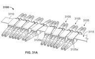
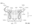
ここで図31Aを参照すると、一実施形態によるポートアセンブリ3105及び取付プレート3110の配置3100の斜視図が示されている。配置3100は、パッチパネルサブアセンブリのポートとして用いられる。配置3100のポートアセンブリ3105は、取付プレート3110の表面3115に沿って移動することができると共に取付プレート3110の表面3115と直交する方向において回転することができるように、取り付けられている。ポートアセンブリ3105は、2部品ポートアセンブリである。例えば、ポートアセンブリ3105は、ポートホルダー3120a及びポート3125aを備えている。図31Aの実施形態は、2部品アセンブリに制限されないことに留意されたい。
Here, with reference to FIG. 31A, a perspective view of the
図31Bは、図31Aの実施形態のポートホルダー3120aの斜視図である。図31Bから分かるように、ポートホルダー3120aは、ポートホルダー3120aを取付プレート3110に移動可能かつ回転可能となるように固定するための開口3130aを備えている。ポートホルダー3120aが取り付けられた時に移動及び回転することを可能にするために、開口3130aは、少なくとも1つの寸法、具体的には、図31Bの実施形態におけるY寸法において取付プレートよりも大きくなっている。
31B is a perspective view of the
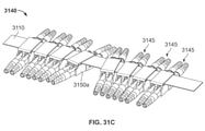
図31Cは、一実施形態によるポートアセンブリ3145及び取付プレート3110の配置3140の斜視図である。図31Cの配置3140は、配置3140が異なる形式のポートホルダーを備えることを除けば、図31Aの配置3100と同様である。例えば、配置3140は、ポートホルダー3120aに代わってポートホルダー3150aを備えている。
FIG. 31C is a perspective view of the
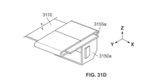
図31Dは、図31Cの実施形態のポートホルダー3150aの斜視図を示している。ポートホルダー3150aは、ポートホルダー3150aを取付プレート3110に移動可能及び回転可能となるように固定するための開口3155aを備えている。ポートホルダー3150aが取り付けられた時に移動及び回転することを可能にするために、開口3155aは、少なくとも1つの寸法、具体的には、図31Dの実施形態におけるY寸法において取付プレートよりも大きくなっている。
31D shows a perspective view of the
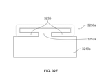
図32Aは、一実施形態によるポートアセンブリ3205及び取付プレート3210の配置3200の斜視図である。配置3200は、パッチパネルサブアセンブリのポートとして用いられる。配置3200のポートアセンブリ3205は、取付プレート3210の表面3215に沿って移動することができると共に取付プレート3210の表面3215と直交する方向において回転することができるように、取り付けられている。図示される構成では、ポートアセンブリ3205は、取付プレート3210の長軸と平行な方向に移動することができる。また、ポートアセンブリ3205は、2部品ポートアセンブリである。例えば、ポートアセンブリ3205aは、ポートホルダー3220a及びポート3225aを備えている。図32Aの実施形態は、2部品アセンブリに制限されないことに留意されたい。
FIG. 32A is a perspective view of the
図32Bは、図32Aの実施形態の一部の詳細図であり、図32Aの実施形態のポートホルダー3220aの単独図を含んでいる。図32Bから分かるように、ポートホルダー3220aは、円形係合部材3230aを備えている。円形係合部材3230aは、ポートホルダー3220aを取付プレート3210内に移動可能及び回転可能となるように固定するための狭小部分3232aを備えている。図32Bから更に分かるように、取付プレート3210は、拘束部分3235を備えるように形成されている。拘束部分3235は、取付け時に、ポートアセンブリの移動及び回転を可能にしながら、係合部材、例えば、係合部材3230aを介してポートアセンブリ3205に係合するようになっている。拘束部分3235は、係合部材、例えば、係合部材3230aと係合し、ポートアセンブリの移動を一方向に沿った移動、具体的には、図32Bの構成における取付プレート3210の長軸に沿った移動に拘束する。
32B is a partial detail view of the embodiment of FIG. 32A and includes a single view of the
図32Cは、一実施形態によるポートアセンブリ3245及び取付プレート3210の配置3240の斜視図である。図32Cの配置3240は、配置3240が異なる形式のポートホルダーを備えることを除けば、図32Aの配置3200と同様である。例えば、配置3240は、ポートホルダー3220aに代わってポートホルダー3240aを備えている。
FIG. 32C is a perspective view of the
図32Dは、図32Cの実施形態の一部の詳細図であり、図32Cの実施形態のポートホルダー3240aの単独図を含んでいる。ポートホルダー3240aは、円形係合部材3250aを備えている。円形係合部材3250aは、ポートホルダー3240aを取付プレート3210内に移動可能及び回転可能となるように固定するための狭小部分3252aを備えている。開口3155aはポートホルダー3150aを取付プレート3110に移動可能及び回転可能に固定するためのものである。
32D is a partial detail view of the embodiment of FIG. 32C and includes a single view of the
図32Eは、図32Dの一部の拡大図である。 32E is an enlarged view of a part of FIG. 32D.
図32Fは、図32Eの取付プレート3210に係合された図32Eのポートホルダー3240aの輪郭図である。
32F is a contour view of the
図33A-34Cは、図32Cに示される配置と同様の配置を備えるパッチパネルアセンブリの斜視図である。図33Aは、2つのパッチパネルサブアセンブリ3305a,3305bを備えるパッチパネルアセンブリ3300の2つの図を示している。サブアセンブリ3305aは、取付プレート3310a及びポートアセンブリ3315aを備えている。サブアセンブリ3305bは、取付プレート3310b及びポートアセンブリ3315bを備えている。パネルアセンブリ3300は、パッチパネルサブアセンブリ3305a,3305bを第1の筐体部分3320に取り付けることによって、又は取付プレート3310a,3310bを第1の筐体部分3320の一体部分として備えることによって得られる。いずれにしても、ポートアセンブリ3315aは、中間ケーブル3325によってポートアセンブリ3315bに連結される。更に、光回路、電子回路、又はその両方が、中間ケーブル3325を通る信号を処理するために、アセンブリ3300の回路区域3330に含まれている。加えて、第2の筐体部分3335が、中間ケーブル3325及び回路区域3330の保護を助長するために、第1の筐体部分3320に取り付けられている。
33A-34C are perspective views of a patch panel assembly having an arrangement similar to that shown in FIG. 32C. FIG. 33A shows two diagrams of a
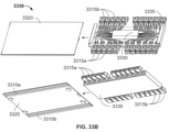
図33Bは、パッチパネルアセンブリ3350の2つの図を示している。アセンブリ3350は、2つのアセンブリがいかに一緒に配置されるかを示すことを除けば、図33Aのアセンブリ3300と同様である。アセンブリ3350を得るために、ポートアセンブリ3315a,3315b及び回路区域3330は、第2の筐体部分3335に固定され、次いで、取付プレート3310a,3310bを備える第1の筐体部分3320が、ポートアセンブリ3315a,3315b上を摺動され、ポートアセンブリ3315a,3315bに係合するようになっている。
FIG. 33B shows two figures of the
図33Cは、完成した形態にあるパッチパネルアセンブリ3300の2つの図を示している。完成した形態にあるパッチパネルアセンブリ3350は、パッチパネルアセンブリ3300と同じように見えることに留意されたい。
FIG. 33C shows two figures of the
図34Aは、パッチパネル配置3405a,3405b,3405cがそれぞれのパッチパネルフレーム部分3410a,3410b,及び3410cに取り付けられたパッチパネルアセンブリ3400を示している。パッチパネル配置3405a,3405b,3405cの各々は、図32Cに示されるパッチパネル配置と同様である。フレーム部分3410a,3410b,3410cは、単一フレームの一部であってもよい。いずれにしても、パッチパネル配置3405a,3405b,3405cは、それぞれ、フレーム部分3410a,3410b,及び3410c上を摺動するように構成されている。図34Aにおいて、パッチパネル配置3405bは、前方に摺動した位置で示され、パッチパネル配置3405a,3405cは、中立位置で示されている。
FIG. 34A shows a
図34Bは、パッチパネル配置3420a,3420bがそれぞれのパッチパネルフレーム部分3425a,3425bに取り付けられたパッチパネルアセンブリ3415を示している。フレーム部分は、それぞれ、枢軸3430a,3430bを中心として回転するように構成されている。フレーム部分3425a,3425bは、単一フレームの一部であってもよい。
FIG. 34B shows a
図34Cは、パッチパネル配置3445a,3445bがそれぞれのパッチパネルフレーム部分3450a,3450bに取り付けられたパッチパネルアセンブリ3440を示している。フレーム部分は、それぞれ、枢軸3455a,3455bを中心として回転するように構成されている。フレーム部分3450a,3450bは、単一フレームの一部であってもよい。
FIG. 34C shows a
図34A-34Cの構成に関して、この説明の図によれば、図32Cの配置以外の本開示のパッチパネル配置が図34A-34Cの構成に用いられてもよいことが明らかであろう。 With respect to the configuration of FIGS. 34A-34C, it will be clear from the figures in this description that the patch panel arrangements of the present disclosure other than the arrangement of FIG. 32C may be used for the configuration of FIGS. 34A-34C.
図35Aは、一実施形態によるポートアセンブリ3505及び取付プレート3510a,3510bの配置3500の斜視図を示している。ポートアセンブリ3505は、各々、2つの係合部分を備え、取付プレート3510a,3510bの両方に係合される。ポートアセンブリ3505は、取り付けられると、取付プレート3510a,3510bの表面、例えば、表面3512bに沿って移動され、表面、例えば、表面3512bと直交する軸を中心として回転されるようになっている。例えば、ポートアセンブリ3515は、取付プレート3510a,3510bにそれぞれ係合するための係合部分3520a,3520bを備えている。図から分かるように、取付プレート3510aは、ポートアセンブリ3505と係合するためにその長軸に沿って延在する長孔3525aを有するように形成され、取付プレート3510bは、ポートアセンブリ3505と係合するためにその長軸に沿って延在する長孔3525bを有するように形成されている。
FIG. 35A shows a perspective view of the
図35Bは、一実施形態によるポートアセンブリ3535及び取付プレート3540a,3540bの配置3530の斜視図である。ポートアセンブリ3535は、各々、係合部分を備え、取付プレート3540a,3540bの両方によって係合される。ポートアセンブリ3535は、取り付けられると、取付プレート3540a,3540bの表面、例えば、表面3512bに沿って移動され、表面、例えば、表面3512bと直交する軸を中心として回転するようになっている。例えば、ポートアセンブリ3545は、係合部分3550を介して取付プレート3540aに係合し、取付プレート3540bに当接することによって取付プレート3540bに係合する。図から分かるように、取付プレート3540aは、ポートアセンブリ3535と係合するためにその長軸に沿って延在する長孔3555aを有するように形成されている。
FIG. 35B is a perspective view of the
図35Cは、図35Aに示されるような配置3565a,3565b,3565cを3つ備えるパッチパネルアセンブリ3560の斜視図である。これらの配置は、上下に積み重ねられている。アセンブリ3560は、フレーム片3570a,3570bを備えている。フレーム片3570a,3570bは、配置3565a,3565b,3656cを適所に保持し、配置3565a,3565b,3656cの取付プレートの各々をまとめる働きをする。
35C is a perspective view of a
図35Dは、図35Bに示されるような配置3580を備えるパッチパネルアセンブリ3575の斜視図である。アセンブリ3575は、配置3580を保持して取付プレート3590をまとめる働きをするフレーム3585を備えている。
35D is a perspective view of a
図36は、一実施形態によるラックマウントパッチパネルユニット3600の一部の斜視図である。図36の構成は、3つのパッチパネルサブアセンブリ3605a,3605b,3605cを備えている。サブアセンブリ3605a,3605b,3605cは、それぞれの取付プレート3610a,3610b,3610cを備え、これらの取付プレートは、それぞれの枢動孔3615a,3615b,3615cを備えている。サブアセンブリ3605a,3605b,3605cは、軸部材(図示せず)が枢動孔3615a,3615b,3615cを貫通するように、フレーム(図示せず)内に取り付けられている。これによって、サブアセンブリ3605a,3605b,3605cは、軸部材を中心として個別に回転することができる。図において、サブアセンブリ3605bは、サブアセンブリ3605a,3605cに対して約30°反時計方向に回転されている。
FIG. 36 is a perspective view of a part of the rack mount
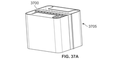
図37Aは、完全に閉じた状態にある一実施形態によるパッチパネル3700及び筐体3705の斜視図である。
FIG. 37A is a perspective view of the
図37Bは、完全に開いた状態にある一実施形態によるパッチパネル3700及び筐体3705の斜視図である。図から分かるように、パッチパネル3700は、図21に示されるものと同じように配置された多数のポートアセンブリ3710を備えている。しかし、この説明を検討すれば、図21の配置以外の本開示のパッチパネル配置が図37Bの構成に用いられてもよいことが明らかであろう。いずれにしても、図37Bの構成では、パッチパネル3700は、第1の方向、すなわち、Z方向に上下に積み重ねられた多数のパッチパネルサブアセンブリ3730として形成されている。
FIG. 37B is a perspective view of the
図から更に分かるように、筐体3705は、第1のヒンジ付き部分3715a及び第2のヒンジ付き部分3715bを備えている。ヒンジ付き部分3715aは、多数のケーブルハンガー3720を備え、ポートアセンブリ3710の第1の側3725aを露出させるように開くことができる。ヒンジ付き部分3715bは、多数のケーブルハンガー(図示せず)を備え、ポートアセンブリ3710の第2の側3725bを露出させるように開くことができる。第1のヒンジ付き部分3715aのための第1のヒンジ3735aは、第1の方向と平行又は実質的に平行な回転軸を有し、第2のヒンジ付き部分3715bの第2のヒンジ3735bは、第1の方向と平行又は実質的に平行な回転軸を有している。第1のヒンジ3715a及び第2のヒンジ3715bは、X方向に関してパッチパネル3700の同じ側に配置されている。
As can be further seen from the figure, the
いくつかの実施形態では、筐体3705は、2つのヒンジ付き部分に代わって、単一のヒンジ付き部分又は2つよりも多い数のヒンジ付き部分を備えてもよいことに留意されたい。また、ケーブルハンガーは、任意のヒンジ付き部分に含まれていなくてもよいし、全てのヒンジ付き部分よりも少ないヒンジ付き部分に含まれていてもよいことにも留意されたい。更に、任意のヒンジ付き部分は、ポートアセンブリの側面全体を露出させるのではなく、ポートアセンブリの側面の一部のみを露出させるように開くことができることに留意されたい。
Note that in some embodiments, the
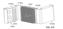
図37Cは、完全に開いた状態にある一実施形態によるパッチパネル3700及び筐体3705の斜視図である。図37Cの実施形態は、第1のヒンジ付き部分3740a及び第2のヒンジ付き部分3740bを備えている。第1のヒンジ付き部分3740aのための第1のヒンジ3745aは、第1の方向と平行又は実質的に平行な回転軸を有し、第2のヒンジ付き部分3740bのための第2のヒンジ3745bも、第1の方向と平行又は実質的に平行な回転軸を有している。第1のヒンジ3745a及び第2のヒンジ3745bは、X方向に関して、パッチパネル3700の両側に配置されている。
FIG. 37C is a perspective view of the
図38は、ケーブルの取り回しの例を示す完全に開いた状態にある図37Cのパッチパネル3700及び筐体3705の斜視図である。図から分かるように、ポートアセンブリ3710の第1の側3725aに連結されたケーブル3805は、ヒンジ付き部分3740a上のケーブルハンガー3720によって取り回されている。
FIG. 38 is a perspective view of the
図39は、ケーブルの取り回しの例を示す完全に開いた状態にある一実施形態によるパッチパネル3700及び筐体3705の斜視図である。図39の実施形態では、筐体3705は、第1のヒンジ付き部分3905a及び第2のヒンジ付き部分3905bを備えている。ヒンジ付き部分3905aは、複数のケーブルハンガー3910aを備え、ポートアセンブリ3710の第1の側3725aを露出させるように開くことができる。ヒンジ付き部分3905bは、複数のケーブルハンガー(図示せず)を含み、ポートアセンブリ3710の第2の側3725bを露出させるように開くことができる。第1のヒンジ付き部分3905aのための第1のヒンジ3915aは、第1の方向(Z方向)と直交又は実質的に直交する回転軸、図39の実施形態では、Y方向と平行な回転軸を有している。第2のヒンジ付き部分3905bのための第2のヒンジ3915bは、第1の方向と平行又は実質的に平行な回転軸を有している。図から分かるように、ポートアセンブリ3710の第1の側3725aに連結されたケーブル3750は、ヒンジ付き部分3905a上のケーブルハンガー3910aによって配線されている。
FIG. 39 is a perspective view of the
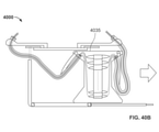
図40Aは、双方向摺動トレイ4005を有するパッチパネル構成4000の平面図であり、トレイ4005は、中立位置にある。トレイ4005は、X方向と平行に摺動するように作動可能であり、トレイ上に1つ又は複数のパッチパネルサブアセンブリ4010が取り付けられている。トレイ4005上に取り付けることができるパッチパネルサブアセンブリの形式の1つは、図32Cに示される形式のパッチパネルサブアセンブリである。しかし、構成4000は、図32Cに示される形式のサブアセンブリに制限されるものではない。
FIG. 40A is a plan view of the
パッチパネル構成4000は、パッチパネルサブアセンブリ4010の第1の側4020aから延在する1つ又は複数のケーブル4017aを包囲するための第1のケーブルジャケット4015aと、摺動トレイ4005の摺動方向と直交する方向(図40AのZ方向)において第1のケーブルジャケット4015aを支持し、第1のケーブルジャケット4015aが摺動トレイが摺動する面と平行又は実質的に平行な面(図40AのXY面)において移動することを可能にするための第1の支持体4025aと、第1のケーブルジャケット4015aの一端を位置決めするための第1のケーブルハンガー4030aと、パッチパネルアセンブリ4010の第2の側4020bから延在する1つ又は複数のケーブル4017bを包囲するための第2のケーブルジャケット4015bと、摺動トレイの摺動方向と直交する方向(図40AのZ方向)において第2のケーブルジャケット4015bを支持し、第2のケーブルジャケット4015bが摺動トレイが摺動する面と平行又は実質的に平行な面(図40AのXY面)において移動することを可能にするための第2の支持体4025bと、第2のケーブルジャケット4015bの一端を位置決めするための第2のケーブルハンガー4030bとを更に備えている。
The
図40Bは、トレイ4035がトレイ・アウト位置にある図40Aのパッチパネル構成4000の平面図である。
40B is a plan view of the
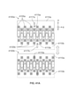
図41Aは、一実施形態による2つの異なる位置4100a,4100bにあるポートアセンブリ及び取付プレートの配置を示している。この配置は、第1の取付プレート4110aに取り付けられた複数の第1のポートアセンブリ4105a、及び第2の取付プレート4110bに取り付けられた複数の第2のポートアセンブリ4105bを備えている。第1の取付プレート4110aは、トレイ、フレーム、又は筐体(図示せず)上の第1のガイドピン4115aによって案内される移動方向に沿って移動することができる。第1のガイドピン4115aは、取付プレート4110aの第1の長孔4117aに係合され、これによって、取付プレート4110aは、第1の長孔4117aの長軸と平行な方向にのみ移動することができる。第2の取付プレート4110bは、第2のガイドピン4115b及び第2の長孔4117bに従って移動することができる。位置4100bでは、位置4100aと比較して、取付プレート4110b及びポートアセンブリ4105bは、Y方向に沿って取付プレート4110a及びポートアセンブリ4105aに近づけられている。
FIG. 41A shows the arrangement of port assemblies and mounting plates at two
図41Bは、一実施形態による2つの異なる位置4130a,4130bにあるポートアセンブリの配置を示している。この配置は、区分化された取付プレート4140に取り付けられた複数のポートアセンブリ4135を備えている。区分化された取付プレート4140は、枢動点4145においてフレーム又は筐体に固定され、ポートアセンブリ4135のX座標及びZ座標を固定して維持することを可能にしながらポートアセンブリ4135をY方向に沿って移動させるように枢動点4145を中心として移動するように構成されている。図41Bの構成では、隣接するポートアセンブリ4135同士が、取付プレート4140の移動に応じて双方向に移動する。例えば、ポートアセンブリ4150,4155の相対位置は、位置4130aに対して位置4130bにおいて逆転している。
FIG. 41B shows the arrangement of the port assemblies at two
図42は、一実施形態によるパッチパネルアセンブリ4200の斜視図である。パッチパネルアセンブリは、多数のケーブル支持プレート4205及び多数の中間ケーブル4210を備えている。ケーブル支持プレート4205は、中間ケーブル4210が通る開口4215を有し、これによって、中間ケーブル4210は、ケーブル支持プレート4205によって支持されることになる。パッチパネルアセンブリ4200は、多数のポート4220も備え、ポート4220のそれぞれの対は、中間ケーブル4210のそれぞれによって通信可能に互いに連結されている。更に、パッチパネルアセンブリ4200は、パッチパネルアセンブリに連結されたケーブル4230を支持するためのケーブル支持体4225を備えている。
FIG. 42 is a perspective view of the
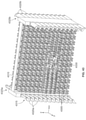
図43は、一実施形態によるパッチパネルアセンブリ4300の斜視図である。パッチパネルアセンブリ4300は、多数のパッチパネルサブアセンブリ4305と、フレーム4310と、多数のケーブルハンガー4315とを備えている。パッチパネルサブアセンブリ4305は、図21の構成のパッチパネルサブアセンブリ2105a,2105b,2105cと同じ形式のものとして示されている。しかし、この説明を検討すれば、図21に開示された形式のパッチパネルサブアセンブリ以外の本開示のパッチパネルサブアセンブリが図43の実施形態に用いられてもよいことが明らかであることに留意されたい。フレーム4310は、パッチパネルサブアセンブリ4305を支持すると共にケーブルハンガー4315の取付点を支持している。ケーブルハンガー4315は、アセンブリ4300の両端に設けられ、複数の第1のケーブルハンガー4320aは、フレーム4310の第1の端4325aに設けられ、複数の第2のケーブルハンガー4320bは、フレーム4310の第2の端4325bに設けられている。第1の端4325aは、X方向に関して第2の端4325bの反対側にある。図示されるように、ケーブルハンガー4315の各々は、サブアセンブリ取付プレートの長軸と直交する方向に延在していてもよい。例えば、図示の実施形態では、ケーブルハンガー4315は、Y方向と平行な方向に延在し、取付プレート4330は、X方向と平行に延在する長軸を有している。加えて、ケーブルハンガーは、フレーム4310に取り付けられるのではなく、フレーム4310の一体部分であってもよいことに留意されたい。
FIG. 43 is a perspective view of the patch panel assembly 4300 according to the embodiment. The patch panel assembly 4300 includes a large number of
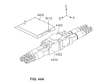
図44Aは、一実施形態によるパッチパネルサブアセンブリの一部の詳細図であり、取付プレート4405及びポートアセンブリ4410の一部を示している。取付プレート4405は、鳩尾型(dovetail)断面形状を有する切欠き4415を備えている。ポートアセンブリは、切欠き4415の断面に対応する鳩尾型形状の断面を有する係合部材4420を備えている。
FIG. 44A is a detailed view of a portion of the patch panel subassembly according to one embodiment, showing a portion of the mounting
ポートアセンブリ4410は、係合部材4420を切欠き4415内に挿入することによって、取付プレート4405に係合される。このように係合されると、ポートアセンブリは、取付プレート4405の長軸に沿って(図のX方向と平行に)自由に移動することができ、取付プレート4405の長軸と直交する(図のZ方向と平行な)軸を中心として自由に回転することができる。
The
図44Bは、図44Aの取付プレート4405に係合された図44Aのポートアセンブリ4410の輪郭図である。図44Bから分かるように、図44A及び44Bの構成では、ポートアセンブリ4410が取付プレート4405に係合されると、ポートアセンブリは、係合部材4420の中心を通る軸4425を中心として自由に回転することができる。
44B is a schematic view of the
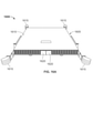
図44A,44Bに示される構成では、係合部材4420は、円形のベース部分4422を有している。しかし、ベース部分4422は、非円形の形状を有してもよいことに留意されたい。例えば、ベース部分4422は、楕円形状、レーストラック形状(すなわち、2つの直線部分によって接続された2つの湾曲部分)、等を有していてもよい。図45は、一実施形態によるパッチパネルサブアセンブリ4500の斜視図である。サブアセンブリ4500は、多数のポートアセンブリ4505a,4505b,・・・4505iを備えている。ポートアセンブリ4505a-4505iは、サブアセンブリ4500の取付手段として機能する取付ロッド4510に取り付けられている。ポートアセンブリ4505a-4505iは、取付ロッド4510の表面と平行な方向、すなわち、図45に示されるように、取付手段の長軸と平行な方向に沿って個別に移動可能である。更に、ポートアセンブリ4505a-4505iが個別に移動可能であるため、1つのポートアセンブリポート、例えば、ポートアセンブリ4505hのポート4515hと他の1つのポートアセンブリのポート、例えば、ポートアセンブリ4505iのポート4515iとの間の距離は、1つのポートアセンブリ、例えば、ポートアセンブリ4505h及び他の1つのポートアセンブリ、例えば、ポートアセンブリ4505iの一方又は両方を移動させることによって変更可能である。更に、ポートアセンブリ4505a-4505iは、いずれか1つのポートアセンブリにおいて、例えば、ポートアセンブリ4505eにおいて、1つのポートアセンブリの前側ポート、例えば、前側ポート4525の中心及び該1つのポートアセンブリの対応する後側ポート、例えば、後側ポート4530の中心を通る軸、例えば、軸4520が、他の1つのポートアセンブリ、例えば、ポートアセンブリ4505fの前側ポート、例えば、前側ポート4540の中心及び該他の1つのポートアセンブリの対応する後側ポート、例えば、後側ポート4545の中心を通る軸、例えば、軸4535と非平行に位置決め可能となるように、個別に回転可能である。
In the configuration shown in FIGS. 44A, 44B, the engaging
本技術の実施形態は、制限されるものではないが、以下のパッチパネルを含んでいる。 Embodiments of the present technology include, but are not limited to, the following patch panels.
[1]
フレームと、前記フレームに支持されて第1の方向に積み重ねられた複数のトレイとを備えるパッチパネルであって、前記トレイの各々は、ケーブル接続端子のそれぞれの対を受け入れるように構成され、前記ケーブル接続端子の各対において、前記対のケーブル接続端子は、第1の軸の方向において互いから離れて外方に延び、互いに通信可能に連結されるように構成されているパッチパネルにおいて、前記複数のトレイの各トレイは、前記複数のトレイの他のトレイと平行又は実質的に平行に前記第1の軸から角度ずれした第2の軸の方向に摺動することによって、前記フレーム内において1つ又は複数のガイドに沿ってトレイ・イン位置と少なくとも1つのトレイ・アウト位置との間で摺動するように適合され、前記トレイは、前記トレイ・イン位置と前記トレイ・アウト位置との間で摺動した時に100mm未満変位され、前記複数のトレイの1つ又は複数のトレイは、前記トレイの摺動に用いられるように構成された少なくとも1つのハンドルを備える、パッチパネル。
[1]
A patch panel comprising a frame and a plurality of trays supported by the frame and stacked in a first direction, each of which is configured to accept a pair of cable connection terminals. For each pair of cable connection terminals, said in a patch panel configured such that the pair of cable connection terminals extend outwardly away from each other in the direction of the first axis and are communicably connected to each other. Within the frame, each tray of the plurality of trays slides in the direction of the second axis, which is angularly offset from the first axis, in parallel or substantially parallel to the other trays of the plurality of trays. Fitted to slide between a tray-in position and at least one tray-out position along one or more guides, the tray is at the tray-in position and the tray-out position. A patch panel that is displaced less than 100 mm when slid between, and one or more of the trays comprises at least one handle configured to be used for sliding the trays.
[2]
前記複数のトレイの任意のトレイにおいて、互いに通信可能に連結されていない任意の互いに隣接する2つのケーブル接続端子は、距離(d)を隔てて互いに離間され、任意のケーブル接続端子は、前記トレイが前記トレイ・イン位置にある時、前記第1の軸の方向において第1の線に沿って延び、前記トレイが前記トレイ・アウト位置にある時、前記第1の軸の方向において第2の線に沿って延び、前記第1の線及び前記第2の線は、前記第1の軸と直交する方向において、距離(d/2)だけ離れている、[1]に記載のパッチパネル。
[2]
In any of the trays of the plurality of trays, any two adjacent cable connection terminals that are not communicably connected to each other are separated from each other with a distance (d), and any cable connection terminal is the tray. Extends along the first line in the direction of the first axis when in the tray-in position and the second in the direction of the first axis when the tray is in the tray-out position. The patch panel according to [1], wherein the first line and the second line are separated by a distance (d / 2) in a direction orthogonal to the first axis.
[3]
前記距離(d)は、約15mmから約25mmの間である、[2]に記載のパッチパネル。
[3]
The patch panel according to [2], wherein the distance (d) is between about 15 mm and about 25 mm.
[4]
ロック位置とロック解除位置との間で移動するように構成された機械的ストッパと、前記機械的ストッパを前記ロック位置に付勢するために前記機械的ストッパに力を加えるように構成された付勢バネと、を更に備え、前記機械的ストッパは、前記トレイの各々が前記ロック位置にある時に前記トレイ・イン位置から前記少なくとも1つのトレイーアウト位置に摺動するのを阻止し、前記トレイの各々が前記ロック解除位置にある時に前記トレイ・イン位置から前記少なくとも1つのトレイ・アウト位置に摺動するのを許容するようになっており、前記少なくとも1つのトレイ・アウト位置にある任意のトレイは、前記付勢バネが前記機械的ストッパを前記ロック位置に付勢するのを阻止するように構成されている、[1]に記載のパッチパネル。
[4]
A mechanical stopper configured to move between the locked and unlocked positions and an attachment configured to exert a force on the mechanical stopper to urge the mechanical stopper to the locked position. Further comprising a force spring, the mechanical stopper prevents the trays from sliding from the tray-in position to the at least one tray-out position when each of the trays is in the locked position. Each of the is allowed to slide from the tray-in position to the at least one tray-out position when in the unlocked position, and any of the tray-out positions. The patch panel according to [1], wherein the tray is configured to prevent the urging spring from urging the mechanical stopper to the locked position.
[5]
前記機械的ストッパは、フレーム幅方向に複数のノッチを備え、前記ノッチは、前記機械的ストッパが前記ロック位置にある時、前記フレームの前記ガイドと並ばないように構成され、前記ノッチは、前記機械的ストッパが前記ロック解除位置にある時、前記フレーム内の前記ガイドと並ぶように構成されている、[4]に記載のパッチパネル。
[5]
The mechanical stopper comprises a plurality of notches in the width direction of the frame, the notch being configured so as not to line up with the guide of the frame when the mechanical stopper is in the locked position, the notch being said. The patch panel according to [4], which is configured to line up with the guide in the frame when the mechanical stopper is in the unlocked position.
[6]
フレームと、前記フレームによって支持されて第1の方向に積み重ねられた複数のトレイ対とを備えるパッチパネルであって、前記複数のトレイ対の各々は、それぞれの対のケーブル接続端子を受け入れるように構成され、前記トレイ対に受け入れられた各対のケーブル接続端子において、前記ケーブル接続端子の第1のケーブル接続端子は、前記トレイ対の第1のトレイに受け入れられ、前記ケーブル接続端子の第2のケーブル接続端子は、前記トレイ対の第2のトレイに受け入れられ、前記第1のケーブル接続端子及び前記第2のケーブル接続端子は、前記対のケーブル接続端子が第1の軸の方向において互いから離れて外方に向かって延在し、中間ケーブルによって通信可能に互いに連結されるように構成され、前記トレイ対の前記第1のトレイは、前記トレイ対の前記第2のトレイが移動しない状態において、前記複数のトレイ対の他のトレイ対のトレイに対して平行又は実質的に平行に摺動することによって、第1のトレイ・イン位置と少なくとも1つの第1のトレイ・アウト位置との間で摺動するように適合されている、パッチパネル。
[6]
A patch panel comprising a frame and a plurality of tray pairs supported by the frame and stacked in a first direction such that each of the plurality of tray pairs accepts a pair of cable connection terminals. In each pair of cable connection terminals configured and received in the tray pair, the first cable connection terminal of the cable connection terminal is received in the first tray of the tray pair and the second of the cable connection terminals. The cable connection terminal of is received in the second tray of the tray pair, and the first cable connection terminal and the second cable connection terminal are such that the pair of cable connection terminals are mutually in the direction of the first axis. The first tray of the tray pair does not move the second tray of the tray pair, extending outwardly away from and communicably connected to each other by an intermediate cable. In the state, a first tray-in position and at least one first tray-out position by sliding parallel or substantially parallel to the trays of the other tray pairs of the plurality of tray pairs. A patch panel that is adapted to slide between.
[7]
前記中間ケーブルを支持するための支持体を更に備える、[6]に記載のパッチパネル。
[7]
The patch panel according to [6], further comprising a support for supporting the intermediate cable.
[8]
前記支持体は、前記第1のトレイが摺動するように適合された方向と直交又は実質的に直交する方向における支持を行い、前記第1のトレイが摺動するように適合された方向と平行又は実質的に平行な方向における支持を行なわない、[7]に記載のパッチパネル。
[8]
The support supports in a direction orthogonal to or substantially orthogonal to the direction in which the first tray is adapted to slide, and the direction in which the first tray is adapted to slide. The patch panel according to [7], which does not provide support in parallel or substantially parallel directions.
[9]
前記トレイ対の前記第2のトレイは、前記トレイ対の前記第1のトレイが移動しない状態において、前記複数のトレイ対の他のトレイ対のトレイに対して平行又は実質的に平行に摺動することによって、第2のトレイ・イン位置と少なくとも1つの第2のトレイ・アウト位置との間で摺動するように適合されている、[6]に記載のパッチパネル。
[9]
The second tray of the tray pair slides parallel or substantially parallel to the trays of the other tray pairs of the plurality of tray pairs in a state where the first tray of the tray pair does not move. [6]. The patch panel according to [6], which is adapted to slide between a second tray-in position and at least one second tray-out position.
[10]
前記複数のトレイ対の1つ又は複数のトレイは、前記トレイの摺動に用いられるように構成された少なくとも1つのハンドルを備える、[6]に記載のパッチパネル。
[10]
6. The patch panel according to [6], wherein the one or more trays in the plurality of tray pairs comprises at least one handle configured to be used for sliding the trays.
[11]
少なくとも1つのパッチパネルサブアセンブリを備えるパッチパネルであって、前記パッチパネルサブアセンブリは、少なくとも1つの取付プレートと複数のポートアセンブリとを備え、前記少なくとも1つの取付プレートは、各ポートアセンブリが個別に前記取付プレートの表面と平行な方向に沿って移動することができ、かつ前記取付プレートの前記表面と直交する軸を中心として回転することができるように、前記ポートアセンブリを取り付けるように構成されている、パッチパネル。
[11]
A patch panel comprising at least one patch panel subassembly, said patch panel subassembly comprising at least one mounting plate and a plurality of port assemblies, said at least one mounting plate having each port assembly individually. The port assembly is configured to mount so that it can move along a direction parallel to the surface of the mounting plate and can rotate about an axis orthogonal to the surface of the mounting plate. There is a patch panel.
[12]
前記少なくとも1つの取付プレートは、前記ポートアセンブリを取り付けるための少なくとも1つの開口を備える、[11]に記載のパッチパネル。
[12]
11. The patch panel according to [11], wherein the at least one mounting plate comprises at least one opening for mounting the port assembly.
[13]
前記少なくとも1つの取付プレートは、前記複数のポートアセンブリのそれぞれを取り付けるための複数の開口を備え、各ポートアセンブリは、それぞれの開口の長軸に沿って移動可能であり、かつ前記長軸と直交する軸を中心として回転可能である、[12]に記載のパッチパネル。
[13]
The at least one mounting plate comprises a plurality of openings for mounting each of the plurality of port assemblies, each port assembly being movable along the major axis of each opening and orthogonal to the major axis. The patch panel according to [12], which is rotatable about an axis.
[14]
少なくとも1つのサブアセンブリにおいて、前記ポートアセンブリは、前記少なくとも1つの取付プレートの長手方向に沿って均一に互いに離間するように作動可能であり、前記ポートアセンブリは、共通の幅寸法を有し、前記ポートアセンブリ間の間隔距離は、前記幅寸法の約2%から前記幅寸法の約20%の範囲内にある、[13]に記載のパッチパネル。
[14]
In at least one subassembly, the port assemblies are operable so as to be evenly spaced apart from each other along the longitudinal direction of the at least one mounting plate, the port assemblies having a common width dimension, said. 13. The patch panel according to [13], wherein the spacing distance between the port assemblies is in the range of about 2% of the width dimension to about 20% of the width dimension.
[15]
各ポートアセンブリは、ポートホルダー内に固定されたポートを備え、各ポートは、前記ポートの第1のインターフェイスにおいて1つ又は複数のケーブル接続端子を受け入れ、前記ポートの第2のインターフェイスにおいて1つ又は複数のケーブル接続端子を受け入れるように構成されている、[11]に記載のパッチパネル。
[15]
Each port assembly comprises a fixed port within a port holder, where each port accepts one or more cabling terminals on the first interface of the port and one or more on the second interface of the port. The patch panel according to [11], which is configured to accept a plurality of cable connection terminals.
[16]
前記ポートアセンブリの各々は、ラベルタブを備える、[11]に記載のパッチパネル。
[16]
11. The patch panel according to [11], wherein each of the port assemblies comprises a label tab.
[17]
ケーブルハンガーを備える少なくとも1つのヒンジ付き部分を更に備え、前記少なくとも1つのヒンジ付き部分は、前記少なくとも1つのサブアセンブリの少なくとも一部の側面を露出させるように開くことが可能である、[11]に記載のパッチパネル。
[17]
Further comprising at least one hinged portion comprising a cable hanger, said at least one hinged portion can be opened to expose at least a portion of the sides of the at least one subassembly. [11] The patch panel described in.
[18]
少なくとも2つのヒンジ付き部分を備え、前記ヒンジ付き部分の第1のヒンジ付き部分は、1つ又は複数の第1のケーブルハンガーを備え、前記少なくとも1つのサブアセンブリの少なくとも一部の第1の側面を露出させるように開くことが可能であり、前記ヒンジ付き部分の第2のヒンジ付き部分は、1つ又は複数の第2のケーブルハンガーを備え、少なくとも1つのサブアセンブリの第2の側面を露出させるように開くことが可能である、[17]に記載のパッチパネル。
[18]
It comprises at least two hinged portions, the first hinged portion of the hinged portion comprising one or more first cable hangers, the first aspect of at least a portion of the at least one subassembly. The second hinged portion of the hinged portion comprises one or more second cable hangers, exposing the second side of at least one subassembly. The patch panel according to [17], which can be opened so as to allow.
[19]
前記1つ又は複数の第1のケーブルハンガーは、前記少なくとも1つのサブアセンブリの前記第1の側面から延在するケーブルを支持し、前記第2のケーブルハンガーは、前記少なくとも1つのサブアセンブリの前記第2の側面から延在するケーブルを支持する、[18]に記載のパネルパッチ。
[19]
The one or more first cable hangers support cables extending from the first side of the at least one subassembly, and the second cable hanger is the said of the at least one subassembly. The panel patch according to [18], which supports a cable extending from the second side surface.
[20]
前記ヒンジ付き部分の前記第1のヒンジ付き部分の第1のヒンジは、第1の回転軸を有し、前記ヒンジ付き部分の前記第2のヒンジ付き部分の第2のヒンジは、第2の回転軸を有し、前記第1の回転軸は、前記第2の回転軸と平行又は実質的に平行である、[18]に記載のパッチパネル。
[20]
The first hinge of the first hinged portion of the hinged portion has a first axis of rotation, and the second hinge of the second hinged portion of the hinged portion is a second hinge. The patch panel according to [18], which has a rotation axis, wherein the first rotation axis is parallel to or substantially parallel to the second rotation axis.
[21]
前記ヒンジ付き部分の前記第1のヒンジ付き部分の第1のヒンジは、第1の回転軸を有し、前記ヒンジ付き部分の前記第2のヒンジ付き部分の第2のヒンジは、第2の回転軸を有し、前記第1の回転軸は、前記第2の回転軸と直交又は実質的に直交している、[18]に記載のパッチパネル。
[21]
The first hinge of the first hinged portion of the hinged portion has a first axis of rotation, and the second hinge of the second hinged portion of the hinged portion is a second hinge. The patch panel according to [18], which has a rotation axis, wherein the first rotation axis is orthogonal to or substantially orthogonal to the second rotation axis.
[22]
前記複数のパッチパネルサブアセンブリが取り付けられた摺動トレイを更に備える、[11]に記載のパッチパネル。
[22]
11. The patch panel according to [11], further comprising a sliding tray to which the plurality of patch panel subassemblies are attached.
[23]
前記複数のパッチパネルサブアセンブリの第1の側から延在する1つ又は複数のケーブルを取り囲むための第1のケーブルジャケットと、前記摺動トレイの摺動方向と直交する方向において前記第1のケーブルジャケットを支持し、前記第1のケーブルジャケットが前記摺動トレイが摺動する面と平行又は実質的に平行な面内において移動することを可能にする第1の支持体と、前記第1のケーブルジャケットの一端を位置決めするための第1のケーブルハンガーと、前記複数のパッチパネルサブアセンブリの第2の側から延在する1つ又は複数のケーブルを取り囲むための第2のケーブルジャケットと、前記摺動トレイの摺動方向と直交する方向において前記第2のケーブルジャケットを支持し、前記第2のケーブルジャケットが前記摺動トレイが摺動する面と平行又は実質的に平行な面内において移動することを可能にする第2の支持体と、前記第2のケーブルジャケットの一端を位置決めするための第2のケーブルハンガーと、を更に備える、[22]に記載のパッチパネル。
[23]
A first cable jacket for enclosing one or more cables extending from the first side of the plurality of patch panel subassemblies, and the first cable in a direction orthogonal to the sliding direction of the sliding tray. A first support that supports the cable jacket and allows the first cable jacket to move in a plane parallel to or substantially parallel to the plane on which the sliding tray slides, and the first. A first cable hanger for positioning one end of the cable jacket and a second cable jacket for enclosing one or more cables extending from the second side of the plurality of patch panel subassemblies. The second cable jacket is supported in a direction orthogonal to the sliding direction of the sliding tray, and the second cable jacket is parallel to or substantially parallel to the surface on which the sliding tray slides. 22. The patch panel according to [22], further comprising a second support that allows movement and a second cable hanger for positioning one end of the second cable jacket.
[24]
第1の方向において積み重ねられた複数のパッチパネルサブアセンブリを備える、[11]に記載のパッチパネル。
[24]
11. The patch panel according to [11], comprising a plurality of patch panel subassemblies stacked in a first direction.
[25]
前記少なくとも1つの取付プレートは、鳩尾型断面を有する切欠きを備える、[11]に記載のパッチパネル。
[25]
11. The patch panel according to [11], wherein the at least one mounting plate comprises a notch having a dovetail-shaped cross section.
[26]
前記ポートアセンブリの少なくとも一部は、前記取付プレートに係合するための鳩尾型断面を有する係合部材を備える、[25]に記載のパッチパネル。
[26]
25. The patch panel according to [25], wherein at least a portion of the port assembly comprises an engaging member having a dovetail cross section for engaging the mounting plate.
[27]
複数のポートアセンブリを備えるパッチパネルであって、前記複数のポートアセンブリは個別に回転可能であり、前記複数のポートアセンブリのいずれか1つのポートアセンブリの前側ポートの中心及び前記1つのポートアセンブリの対応する後側ポートの中心を貫通する軸が、前記複数のポートアセンブリの他の1つポートアセンブリの前側ポートの中心及び前記他の1つのポートアセンブリの対応する後側ポートの中心を貫通する軸と非平行となるように位置決め可能である、パッチパネル。
[27]
A patch panel with a plurality of port assemblies, wherein the plurality of port assemblies can be rotated individually, and the center of the front port of any one of the plurality of port assemblies and the correspondence of the one port assembly. An axis that penetrates the center of the rear port is the axis that penetrates the center of the front port of the other one port assembly of the plurality of port assemblies and the center of the corresponding rear port of the other port assembly. A patch panel that can be positioned so that it is non-parallel.
[28]
空間内に配置された複数のポートアセンブリを備えるパッチパネルであって、前記空間の1つの寸法は、前記ポートアセンブリの深さ寸法の2倍よりも小さく、前記ポートアセンブリは、前記空間内において個別に並進可能及び回転可能である、パッチパネル。
[28]
A patch panel with multiple port assemblies arranged in space, one dimension of the space being less than twice the depth dimension of the port assembly, the port assemblies being individual in the space. A patch panel that is translatable and rotatable.
[29]
空間内に配置された複数のポートアセンブリを備えるパッチパネルであって、前記空間の1つの寸法は、前記ポートアセンブリの深さ寸法の2倍よりも小さく、前記ポートアセンブリは、前記空間内において個別に移動可能及び回転可能であり、前記ポートアセンブリの1つのポートと前記ポートアセンブリの他の1つのポートとの間の距離は、前記ポートアセンブリの前記1つ及び前記ポートアセンブリの前記他の1つの一方又は両方を移動させることによって、変化させることが可能である、パッチパネル。
[29]
A patch panel with multiple port assemblies arranged in space, one dimension of the space being less than twice the depth dimension of the port assembly, the port assemblies being individual in the space. Movable and rotatable, the distance between one port in the port assembly and the other port in the port assembly is such that one in the port assembly and the other in the port assembly. A patch panel that can be changed by moving one or both.
[30]
少なくとも1つの取付手段に関連付けられた複数のポートアセンブリを備えるパッチパネルであって、前記複数のポートアセンブリの各々は、前記少なくとも1つの取付手段との接触を保ちながら回転可能及び移動可能である、パッチパネル。
[30]
A patch panel with a plurality of port assemblies associated with at least one mounting means, each of the plurality of port assemblies being rotatable and movable while maintaining contact with the at least one mounting means. Patch panel.
[31]
前記複数のポートアセンブリの各々は、狭小部分を有する係合部材を備え、前記取付手段は、前記ポートアセンブリの移動を一方向の移動に拘束するために、前記係合部材に係合するための拘束部分を備える、[30]に記載のパッチパネル。
[31]
Each of the plurality of port assemblies comprises an engaging member having a narrow portion, the mounting means for engaging the engaging member in order to constrain the movement of the port assembly to one-way movement. The patch panel according to [30], which comprises a restraining portion.
[32]
細長の空間内に固定された複数のポートアセンブリであって、前記空間の長軸が第1の方向を画定し、前記ポートアセンブリは、少なくとも1つの前側ポート及び1つの後側ポートを有し、前記前側ポートに第1のケーブル接続端子を受け入れると共に前記後側ポートに第2のケーブル接続端子を受け入れ、前記第1のケーブル接続端子と前記第2のケーブル接続端子との間にエネルギー伝搬接続をもたらすように構成され、前記前側ポート及び前記後側ポートの相対位置は、第2の方向を画定し、前記第1の方向と前記第2の方向との間の角度は、30°から90°の範囲内において調整可能であり、前記ポートアセンブリは、少なくとも前記第1の方向において移動可能である、複数のポートアセンブリ。
[32]
A plurality of port assemblies fixed in an elongated space, wherein the long axis of the space defines a first direction, the port assembly having at least one front port and one rear port. The front port accepts the first cable connection terminal and the rear port accepts the second cable connection terminal, and an energy propagation connection is established between the first cable connection terminal and the second cable connection terminal. Configured to bring, the relative positions of the front port and the rear port define a second direction, and the angle between the first direction and the second direction is 30 ° to 90 °. A plurality of port assemblies that are adjustable within the range of and are movable in at least the first direction.
以上、本発明を特定の実施形態を参照して説明してきたが、これらの実施形態は、本発明の原理及び用途の単なる例示にすぎないことを理解されたい。従って、例示的な実施形態に対して多くの修正がなされてもよいこと、及び添付の請求項によって規定される本発明の概念及び範囲から逸脱することなく他の構成が考案されてもよいことを理解されたい。 Although the present invention has been described above with reference to specific embodiments, it should be understood that these embodiments are merely exemplary of the principles and uses of the invention. Accordingly, many modifications may be made to the exemplary embodiments, and other configurations may be devised without departing from the concepts and scope of the invention as defined by the appended claims. Please understand.
Claims (18)
前記パッチパネルサブアセンブリは、少なくとも1つの取付プレートと、複数のポートアセンブリとを備え、
前記少なくとも1つの取付プレートは、各ポートアセンブリが個別に前記取付プレートの表面と平行な方向に沿って移動することができ、かつ前記取付プレートの前記表面と直交する軸を中心として回転することができるように、前記ポートアセンブリを取り付けるように構成されている、パッチパネル。 A patch panel with at least one patch panel subassembly.
The patch panel subassembly comprises at least one mounting plate and a plurality of port assemblies.
The at least one mounting plate may allow each port assembly to move individually along a direction parallel to the surface of the mounting plate and rotate about an axis orthogonal to the surface of the mounting plate. A patch panel configured to mount the port assembly so that it can be installed.
各ポートは、前記ポートの第1のインターフェイスにおいて1つ又は複数のケーブル接続端子を受け入れ、前記ポートの第2のインターフェイスにおいて1つ又は複数のケーブル接続端子を受け入れるように構成されている、請求項1に記載のパッチパネル。 Each port assembly has a fixed port inside the port holder
Claimed, each port is configured to accept one or more cabling terminals on the first interface of the port and one or more cabling terminals on the second interface of the port. The patch panel according to 1.
前記複数のポートアセンブリは個別に回転可能であって、前記複数のポートアセンブリのいずれか1つのポートアセンブリの前側ポートの中心及び前記1つのポートアセンブリの対応する後側ポートの中心を貫通する軸が、前記複数のポートアセンブリの他の1つのポートアセンブリの前側ポートの中心及び前記他の1つのポートアセンブリの対応する後側ポートの中心を貫通する軸と非平行となるように位置決め可能である、パッチパネル。 A patch panel with multiple port assemblies
The plurality of port assemblies are individually rotatable and have an axis that penetrates the center of the front port of any one of the plurality of port assemblies and the center of the corresponding rear port of the one port assembly. Can be positioned non-parallel to an axis penetrating the center of the anterior port of the other port assembly of the plurality of port assemblies and the corresponding posterior port of the other port assembly. Patch panel.
前記複数のポートアセンブリの各々は、前記少なくとも1つの取付手段との接触を保ちながら回転可能及び移動可能である、パッチパネル。 A patch panel with multiple port assemblies associated with at least one mounting means.
Each of the plurality of port assemblies is a patch panel that is rotatable and movable while maintaining contact with the at least one mounting means.
前記取付手段は、前記ポートアセンブリの移動を一方向の移動に拘束するように前記係合部材と係合するための拘束部分を備える、請求項11に記載のパッチパネル。 Each of the plurality of port assemblies comprises an engaging member having a narrow portion.
11. The patch panel of claim 11, wherein the mounting means comprises a restraining portion for engaging the engaging member such that the movement of the port assembly is constrained to movement in one direction.
前記空間の長軸が第1の方向を画定し、
前記ポートアセンブリの各々は、少なくとも1つの前側ポート及び1つの後側ポートを有し、前記前側ポートに第1のケーブル接続端子を受け入れると共に前記後側ポートに第2のケーブル接続端子を受け入れ、前記第1のケーブル接続端子と前記第2のケーブル接続端子との間にエネルギー伝搬接続をもたらすように構成され、
前記前側ポート及び前記後側ポートの相対位置は、第2の方向を画定し、前記第1の方向と前記第2の方向との間の角度は、30°から90°の範囲内において調整可能であり、
前記ポートアセンブリは、少なくとも前記第1の方向において移動可能である、複数のポートアセンブリ。 Multiple port assemblies fixed in an elongated space,
The long axis of the space defines the first direction and
Each of the port assemblies has at least one front port and one rear port, the front port accepting a first cable connection terminal and the rear port accepting a second cable connection terminal. It is configured to provide an energy propagation connection between the first cable connection terminal and the second cable connection terminal.
The relative positions of the front port and the rear port define a second direction, and the angle between the first direction and the second direction can be adjusted within the range of 30 ° to 90 °. And
The port assembly is a plurality of port assemblies that are movable in at least the first direction.
Applications Claiming Priority (4)
| Application Number | Priority Date | Filing Date | Title |
|---|---|---|---|
| US16/916,980 US20210409841A1 (en) | 2020-06-30 | 2020-06-30 | Easy Access Patch Panel |
| US16/916,980 | 2020-06-30 | ||
| US17/193,840 US11228819B1 (en) | 2020-06-30 | 2021-03-05 | Easy access patch panel |
| US17/193,840 | 2021-03-05 |
Publications (1)
| Publication Number | Publication Date |
|---|---|
| JP2022013884A true JP2022013884A (en) | 2022-01-18 |
Family
ID=76584349
Family Applications (1)
| Application Number | Title | Priority Date | Filing Date |
|---|---|---|---|
| JP2021108911A Pending JP2022013884A (en) | 2020-06-30 | 2021-06-30 | Easily accessible patch panel |
Country Status (4)
| Country | Link |
|---|---|
| US (1) | US11228819B1 (en) |
| EP (1) | EP3940439A1 (en) |
| JP (1) | JP2022013884A (en) |
| CN (1) | CN113871928B (en) |
Families Citing this family (2)
| Publication number | Priority date | Publication date | Assignee | Title |
|---|---|---|---|---|
| US11703651B2 (en) * | 2018-11-02 | 2023-07-18 | Go!Foton Holdings, Inc. | Cable termination assembly with disengagement prevention structures |
| US11811163B2 (en) | 2021-02-26 | 2023-11-07 | Leviton Manufacturing Co., Inc. | Mutoa and quad floating connector |
Family Cites Families (40)
| Publication number | Priority date | Publication date | Assignee | Title |
|---|---|---|---|---|
| US5100221A (en) * | 1990-01-22 | 1992-03-31 | Porta Systems Corp. | Optical fiber cable distribution frame and support |
| FR2703844B1 (en) * | 1993-04-09 | 1995-05-24 | Sepm | Electrical connector and more specifically charging connector. |
| JP2001126821A (en) * | 1999-10-27 | 2001-05-11 | Sumitomo Wiring Syst Ltd | Connector attaching structure |
| US6301424B1 (en) * | 2000-04-13 | 2001-10-09 | Lucent Technologies Inc. | Distribution frame cable routing apparatus |
| US6786647B1 (en) * | 2001-03-16 | 2004-09-07 | Nortel Networks Limited | Mechanically constrained connection |
| US6736670B2 (en) * | 2001-11-16 | 2004-05-18 | Adc Telecommunications, Inc. | Angled RJ to RJ patch panel |
| US7031588B2 (en) * | 2004-04-27 | 2006-04-18 | Commscope Solutions Properties, Llc | Articulated high density fiber optic splice and termination shelf |
| WO2006012389A1 (en) * | 2004-07-22 | 2006-02-02 | Panduit Corp. | Front access punch down patch panel |
| US7540748B2 (en) * | 2007-04-11 | 2009-06-02 | Hewlett-Packard Development Company, L.P. | Flexible I/O connection system and method |
| US7715679B2 (en) * | 2007-05-07 | 2010-05-11 | Adc Telecommunications, Inc. | Fiber optic enclosure with external cable spool |
| US7590328B2 (en) * | 2007-08-02 | 2009-09-15 | Adc Telecommunications, Inc. | Fiber termination block with splitters |
| US8463091B2 (en) * | 2007-10-15 | 2013-06-11 | Telescent Inc. | Methods to reconfigure all-fiber optical cross-connects |
| US8130502B2 (en) * | 2008-02-15 | 2012-03-06 | Panduit Corp. | Modular stackable angled patch panel for enclosure |
| US8315498B2 (en) * | 2008-04-11 | 2012-11-20 | Adc Telecommunications, Inc. | Fiber management panel |
| US8452148B2 (en) | 2008-08-29 | 2013-05-28 | Corning Cable Systems Llc | Independently translatable modules and fiber optic equipment trays in fiber optic equipment |
| US8712206B2 (en) | 2009-06-19 | 2014-04-29 | Corning Cable Systems Llc | High-density fiber optic modules and module housings and related equipment |
| WO2010148336A1 (en) | 2009-06-19 | 2010-12-23 | Corning Cable Systems Llc | High density and bandwidth fiber optic apparatuses and related equipment and methods |
| WO2011038387A1 (en) * | 2009-09-28 | 2011-03-31 | Molex Incorporated | Shielded modular jack assembly |
| MX2011009233A (en) * | 2009-10-14 | 2011-09-27 | Afl Telecommunications Llc | Fiber splice enclosure. |
| CN103069836B (en) * | 2010-06-23 | 2016-06-08 | Adc电信公司 | telecommunication assembly |
| US8638550B2 (en) * | 2011-03-16 | 2014-01-28 | Lenovo (Singapore) Pte. Ltd. | Keyed media drive rails |
| US8605424B2 (en) * | 2011-03-16 | 2013-12-10 | Lenovo (Singapore) Pte. Ltd. | Media drive unseating mechanism |
| US9052877B2 (en) * | 2011-03-16 | 2015-06-09 | Lenovo (Singapore) Pte. Ltd. | Flush faced servers |
| EP3205362B1 (en) * | 2011-05-24 | 2022-07-06 | DEKA Products Limited Partnership | Hemodialysis system |
| WO2012178070A2 (en) * | 2011-06-24 | 2012-12-27 | Adc Telecommunications, Inc. | Fiber termination enclosure with modular plate assemblies |
| US8879953B2 (en) * | 2012-06-25 | 2014-11-04 | Lexmark International, Inc. | Retainer assembly having positioning features for processing circuitry used within an image forming device supply item |
| US20140133822A1 (en) * | 2012-11-13 | 2014-05-15 | Cesar Alejandro de los Santos Campos | Rotatable furcation assembly |
| US8827568B1 (en) * | 2013-02-28 | 2014-09-09 | Corning Cable Systems Llc | Fiber optic connector adapter module assemblies and methods |
| CN104009333A (en) * | 2014-06-09 | 2014-08-27 | 常熟精微康电子元件有限公司 | FPC connector |
| US9632271B2 (en) * | 2014-06-17 | 2017-04-25 | Ortronics, Inc. | Modularly mountable cable management systems and associated methods |
| CN107111092B (en) * | 2014-09-16 | 2020-01-21 | 康普连通比利时私人有限公司 | Rotatable jumper cable holder |
| NZ730425A (en) * | 2014-09-16 | 2020-08-28 | CommScope Connectivity Belgium BVBA | Multi-positionable telecommunications tray |
| EP3286589B1 (en) * | 2015-04-22 | 2022-01-12 | CommScope Connectivity Belgium BVBA | Cable storage arrangement |
| KR20180067579A (en) * | 2015-10-12 | 2018-06-20 | 쓰리엠 이노베이티브 프로퍼티즈 컴파니 | Optical assembly with cable retainer |
| CN108139544B (en) * | 2015-10-12 | 2020-08-07 | 3M创新有限公司 | Configurable modular connector |
| US10488612B2 (en) * | 2016-11-07 | 2019-11-26 | Corning Optical Communications LLC | Fiber optic spool drawer with translatable and/or removable drawer for deployment of fiber optic cable |
| US10310206B2 (en) * | 2017-05-22 | 2019-06-04 | Go!Foton Holdings, Inc. | Apparatus for cable routing |
| WO2018217461A1 (en) * | 2017-05-23 | 2018-11-29 | Corning Research & Development Corporation | Mechanical cable entry port |
| EP3887883B1 (en) * | 2018-11-29 | 2023-11-08 | Corning Research & Development Corporation | Multiport having connection ports with rotating actuators |
| CN113874771A (en) * | 2019-03-26 | 2021-12-31 | 扇港元器件有限公司 | Integrated optical cable fan-out connector |
-
2021
- 2021-03-05 US US17/193,840 patent/US11228819B1/en active Active
- 2021-06-23 EP EP21181022.1A patent/EP3940439A1/en active Pending
- 2021-06-30 JP JP2021108911A patent/JP2022013884A/en active Pending
- 2021-06-30 CN CN202110742792.XA patent/CN113871928B/en active Active
Also Published As
| Publication number | Publication date |
|---|---|
| US20210409842A1 (en) | 2021-12-30 |
| US11228819B1 (en) | 2022-01-18 |
| CN113871928A (en) | 2021-12-31 |
| EP3940439A1 (en) | 2022-01-19 |
| CN113871928B (en) | 2024-04-05 |
Similar Documents
| Publication | Publication Date | Title |
|---|---|---|
| US11506854B2 (en) | Slidable telecommunications tray with cable slack management | |
| JP2022013884A (en) | Easily accessible patch panel | |
| US11448843B2 (en) | Rotatable patch cable holder | |
| USRE46780E1 (en) | High density patching system for cable and optical fiber | |
| EP4224227A2 (en) | Slidable fiber optic connection module with cable slack management | |
| US20190320542A1 (en) | Door hinge mechanism for telecommunications panel | |
| US20120211447A1 (en) | Communication Shelf Having Supports for Pivotable Adapter Panels and Method of Mounting Adapter Panels Therein | |
| US11686912B1 (en) | Optical fiber assemblies for accommodating mini duplex connectors | |
| WO2014009344A1 (en) | Slidable fibre optic module comprising a rail with electrical contacts | |
| US20140262487A1 (en) | Patch panel assembly | |
| BR112015026995B1 (en) | user module and method for connecting an external communication network to a building user network | |
| US11175470B2 (en) | Enclosure assemblies for handling MDC connectors and associated cabling | |
| EP3537198B1 (en) | Fibre-optic cable fanout | |
| US20210409841A1 (en) | Easy Access Patch Panel | |
| EP3762752B1 (en) | High density optical fiber distribution sub-rack | |
| JP3824740B2 (en) | Optical distribution board | |
| US20230324638A1 (en) | Cable routing storage assemblies for data communication systems | |
| JP2012226257A (en) | Optical connector housing unit | |
| CZ218692A3 (en) | Supporting arrangement for optical-fiber cables |
Legal Events
| Date | Code | Title | Description |
|---|---|---|---|
| A521 | Request for written amendment filed |
Free format text: JAPANESE INTERMEDIATE CODE: A523 Effective date: 20211116 |
|
| A521 | Request for written amendment filed |
Free format text: JAPANESE INTERMEDIATE CODE: A523 Effective date: 20220203 |
|
| A621 | Written request for application examination |
Free format text: JAPANESE INTERMEDIATE CODE: A621 Effective date: 20240328 |