JP2022012003A - Combine harvester - Google Patents
Combine harvester Download PDFInfo
- Publication number
- JP2022012003A JP2022012003A JP2020113480A JP2020113480A JP2022012003A JP 2022012003 A JP2022012003 A JP 2022012003A JP 2020113480 A JP2020113480 A JP 2020113480A JP 2020113480 A JP2020113480 A JP 2020113480A JP 2022012003 A JP2022012003 A JP 2022012003A
- Authority
- JP
- Japan
- Prior art keywords
- abnormality
- electrode rollers
- moisture sensor
- pair
- electrode
- Prior art date
- Legal status (The legal status is an assumption and is not a legal conclusion. Google has not performed a legal analysis and makes no representation as to the accuracy of the status listed.)
- Granted
Links
Images



Landscapes
- Investigating Or Analyzing Materials By The Use Of Electric Means (AREA)
- Threshing Machine Elements (AREA)
Abstract
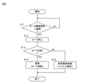
【課題】水分センサの動作の異常を検知して、その異常の解消を図ることができる、コンバインを提供する。【解決手段】水分センサの電極ローラが良好に回転しないローラロックの異常を検知するため、水分センサの電極ローラを回転させるDCモータに供給されるモータ駆動電流が検出される。そして、そのモータ駆動電流が予め定められた閾値よりも大きいか否かが判定される(S11)。モータ駆動電流が閾値よりも大きいと判定された場合(S11:YES)、電極ローラが停止される(S12)。そして、電極ローラが停止前に正転していた場合には(S13:YES)、DCモータが制御されて、予め定められた通常時間にわたって、電極ローラが逆転される(S14)。【選択図】図8A combine harvester capable of detecting an abnormality in the operation of a moisture sensor and resolving the abnormality is provided. A motor drive current supplied to a DC motor for rotating the electrode roller of the moisture sensor is detected in order to detect a roller lock abnormality in which the electrode roller of the moisture sensor does not rotate well. Then, it is determined whether or not the motor drive current is greater than a predetermined threshold (S11). If it is determined that the motor drive current is greater than the threshold (S11: YES), the electrode roller is stopped (S12). Then, if the electrode roller was rotating forward before stopping (S13: YES), the DC motor is controlled to rotate the electrode roller in reverse for a predetermined normal time (S14). [Selection drawing] Fig. 8
Description
本発明は、コンバインに関する。 The present invention relates to a combine.
コンバインでは、圃場に植立している穀稈の株元が刈取装置により刈られ、その刈られた穀稈が刈取装置から脱穀装置に搬送されて、脱穀装置で穀稈が脱穀される。穀稈から外れた籾などの穀粒は、脱穀装置からグレンタンクの上部に設けられた排出部に搬送され、その排出部からグレンタンク内に排出される。 In the combine, the root of the grain culm planted in the field is cut by a cutting device, the cut grain culm is transported from the cutting device to the threshing device, and the grain culm is threshed by the threshing device. Grains such as paddy that have come off the culm are transported from the threshing device to a discharge section provided at the upper part of the grain tank, and are discharged from the discharge section into the grain tank.
コンバインには、収穫された穀粒に含まれる水分量を測定するための水分センサ(水分計)を搭載したものがある。水分センサは、たとえば、1対の電極ローラを穀粒を巻き込む方向に回転させて、電極ローラ間で穀粒を圧砕し、そのときの電極ローラ間の電気抵抗値を検出する構成であり、穀粒に含まれる水分量は、その電気抵抗値から求めることができる(たとえば、特許文献1参照)。 Some combines are equipped with a moisture sensor (moisture meter) for measuring the amount of moisture contained in the harvested grains. The moisture sensor has a configuration in which, for example, a pair of electrode rollers are rotated in a direction in which grains are involved, the grains are crushed between the electrode rollers, and the electric resistance value between the electrode rollers at that time is detected. The amount of water contained in the grains can be determined from the electric resistance value (see, for example, Patent Document 1).
そのため、水分が多く含まれる穀粒の水分量を測定すると、圧砕された穀物が電極ローラに付着し、その穀物が電極ローラから脱落せずに電極ローラに付着したままの状態になることがある。この状態で、穀粒の水分量の次の測定が行われると、その水分量を正確に測定できない。また、その状態が放置されると、電極ローラに穀物が固着し、電極ローラが良好に回転しなくなるおそれがある。 Therefore, when the water content of grains containing a large amount of water is measured, the crushed grains may adhere to the electrode rollers, and the grains may remain attached to the electrode rollers without falling off from the electrode rollers. .. If the next measurement of the water content of the grain is performed in this state, the water content cannot be accurately measured. Further, if the state is left unattended, grains may adhere to the electrode rollers and the electrode rollers may not rotate satisfactorily.
本発明の目的は、水分センサの動作の異常を検知して、その異常の解消を図ることができる、コンバインを提供することである。 An object of the present invention is to provide a combine capable of detecting an abnormality in the operation of a moisture sensor and eliminating the abnormality.
前記の目的を達成するため、本発明に係るコンバインは、1対の電極ローラを備えており、1対の電極ローラが電極ローラ間に穀粒を巻き込む方向に正転して、電極ローラ間で穀粒を圧砕し、当該圧砕時における電極ローラ間の電気抵抗値を検出する検出動作を行い、1対の電極ローラの逆転により、電極ローラの表面を清掃する清掃動作を行う水分センサと、水分センサの動作を制御する制御装置と、を含み、制御装置は、1対の電極ローラの回転中に、水分センサの異常の検知のための判定を行い、この判定により水分センサの異常を検知した場合、当該異常を解消するため、水分センサを異常解消動作させる。 In order to achieve the above object, the combine according to the present invention includes a pair of electrode rollers, and the pair of electrode rollers rotate forward in the direction in which grains are caught between the electrode rollers, and the pair of electrode rollers rotates between the electrode rollers. A moisture sensor that crushes grains, performs a detection operation to detect the electric resistance value between the electrode rollers at the time of crushing, and performs a cleaning operation to clean the surface of the electrode rollers by reversing the pair of electrode rollers, and moisture. The control device includes a control device for controlling the operation of the sensor, and the control device makes a determination for detecting an abnormality of the moisture sensor during the rotation of the pair of electrode rollers, and the abnormality of the moisture sensor is detected by this determination. In this case, in order to eliminate the abnormality, the moisture sensor is operated to eliminate the abnormality.
この構成によれば、水分センサの1対の電極ローラの回転中に、水分センサの異常の検知のための判定を行うことにより、水分センサの異常を検知することができる。そして、水分センサの異常が検知された場合には、水分センサの異常解消動作により、その異常の解消を図ることができる。 According to this configuration, the abnormality of the moisture sensor can be detected by making a determination for detecting the abnormality of the moisture sensor during the rotation of the pair of electrode rollers of the moisture sensor. When an abnormality of the moisture sensor is detected, the abnormality can be eliminated by the abnormality elimination operation of the moisture sensor.
制御装置は、1対の電極ローラを回転させるモータの駆動電流が閾値を超えているか否かを判定し、閾値を超えているとの判定を以て水分センサの異常を検知してもよい。この手法により、電極ローラに穀物が固着することにより電極ローラが良好に回転しない異常を検知することができる。 The control device may determine whether or not the drive current of the motor that rotates the pair of electrode rollers exceeds the threshold value, and may detect the abnormality of the moisture sensor by determining that the threshold value is exceeded. By this method, it is possible to detect an abnormality in which the electrode roller does not rotate well due to the grain sticking to the electrode roller.
そして、制御装置は、その手法により、1対の電極ローラの正転中に異常を検知した場合、異常解消動作として、1対の電極ローラを停止させた後、水分センサを清掃動作させることが好ましい。これにより、電極ローラに固着している穀物の除去による異常の解消を図ることができる。また、電極ローラ間に噛み込まれた切れ藁などの異物の除去による異常の解消を図ることができる。 Then, when the control device detects an abnormality during the normal rotation of the pair of electrode rollers by the method, the control device can stop the pair of electrode rollers and then clean the moisture sensor as an abnormality elimination operation. preferable. As a result, it is possible to eliminate the abnormality due to the removal of the grain adhering to the electrode roller. In addition, it is possible to eliminate the abnormality by removing foreign substances such as cut straw caught between the electrode rollers.
また、制御装置は、その手法により、1対の電極ローラの逆転中に異常を検知した場合、1対の電極ローラを停止させて、異常警報を発してもよい。 Further, when the control device detects an abnormality during the reversal of the pair of electrode rollers by the method, the control device may stop the pair of electrode rollers and issue an abnormality alarm.
制御装置は、清掃動作中における電極ローラ間の電気抵抗値が異常値であるか否かを判定し、異常値であるとの判定を以て水分センサの異常を検知してもよい。この手法により、電極ローラから穀物が脱落せずに電極ローラに穀物が付着している異常(ローラ目詰まり)を検知することができる。 The control device may determine whether or not the electric resistance value between the electrode rollers during the cleaning operation is an abnormal value, and detect the abnormality of the moisture sensor based on the determination that the electric resistance value is an abnormal value. By this method, it is possible to detect an abnormality (roller clogging) in which grains are attached to the electrode rollers without falling off from the electrode rollers.
そして、制御装置は、その手法により、通常時間にわたる清掃動作中に異常を検知した場合、異常解消動作として、通常時間よりも長い時間にわたって清掃動作を継続させることが好ましい。これにより、電極ローラから穀物を除去することによる異常の解消を図ることができる。 When the control device detects an abnormality during the cleaning operation over a normal time by the method, it is preferable that the control device continues the cleaning operation for a longer time than the normal time as the abnormality eliminating operation. As a result, it is possible to eliminate the abnormality by removing the grain from the electrode roller.
また、制御装置は、水分センサの異常を複数回検知した場合、異常警報を発してもよい。 Further, the control device may issue an abnormality alarm when the abnormality of the moisture sensor is detected a plurality of times.
本発明によれば、水分センサの動作の異常を検知して、その異常の解消を図ることができる。 According to the present invention, it is possible to detect an abnormality in the operation of the moisture sensor and eliminate the abnormality.
以下では、本発明の実施の形態について、添付図面を参照しつつ詳細に説明する。 Hereinafter, embodiments of the present invention will be described in detail with reference to the accompanying drawings.
<コンバインの全体構成>
図1は、本発明の一実施形態に係るコンバイン1の右側面図である。
<Overall composition of combine>
FIG. 1 is a right side view of the
コンバイン1は、圃場を走行しながら穀稈の刈り取りおよび穀稈からの脱穀を行う収穫機の一例である。コンバイン1は、圃場などの不整地を走破する能力を有する走行装置として、左右一対のクローラ2を採用しており、その左右一対のクローラ2に支持される機体3には、キャビン4およびグレンタンク5が設けられている。
キャビン4は、クローラ2の前端部上に配置されている。キャビン4は、その内部に運転者が搭乗する空間を提供し、その空間内には、たとえば、運転者が着座する運転席や操作レバーおよび操作ペダルなどの操作部材が配置されている。キャビン4の右側面には、開閉可能なドア6が設けられており、運転者は、ドア6を開いて、キャビン4内に乗り込むことができる。
The
グレンタンク5は、クローラ2上でキャビン4の後方に配置されている。
The
また、コンバイン1の機体3には、刈取装置7および脱穀装置(図示せず)が設けられている。刈取装置7は、クローラ2の前側に配置されており、コンバイン1の前進に伴って、圃場に植立されている穀稈を刈り取る。脱穀装置は、グレンタンク5の左側に配置されており、刈取装置7に刈り取られた穀稈の株元側を脱穀フィードチェーンによって後側に搬送し、穀稈の穂先側を扱室に供給して脱穀する。そして、穀稈から外れた穀粒が脱穀装置からグレンタンク5に搬送されて、グレンタンク5に穀粒が貯留される。グレンタンク5には、アンローダ8が接続されており、グレンタンク5に貯留された穀粒は、アンローダ8により搬出して機外に排出することができる。
Further, the body 3 of the
<グレンタンクの内部構成>
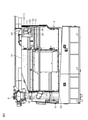
図2は、グレンタンク5の内部を右側から見た図である。図3は、グレンタンク5内の前端上部の斜視図である。
<Internal configuration of Glen tank>
FIG. 2 is a view of the inside of the Glen
グレンタンク5内には、図2および図3に示されるように、前端上部に、搬送排出部11が設けられている。搬送排出部11は、図3に示されるように、脱穀装置から送出される穀粒をグレンタンク5内に搬送する搬送部12と、搬送部12により搬送される穀粒をグレンタンク5内に排出する排出部13とを一体に備えている。
In the
搬送部12は、グレンタンク5の左側壁14の前上端部から右側に延びている。搬送部12は、略円筒状の搬送ケース15内に、搬送スクリュー16を備えている。
The
搬送ケース15は、左側壁14に接続されている。左側壁14には、搬送ケース15に囲まれる部分に、円形の開口が搬送ケース15の内径とほぼ同じ径で形成されている。
The
搬送スクリュー16は、搬送ケース15の中心線上を延びるスクリュー軸17と、スクリュー軸17に支持される螺旋状のスクリュー羽根18とを備えている。スクリュー軸17は、左側壁14の開口を通して左側壁14の左側に延出している。スクリュー軸17の左側の端部には、プーリ(図示せず)が相対回転不能に取り付けられており、搬送スクリュー16は、そのプーリに入力される駆動力により回転する。
The
排出部13は、搬送部12の右端に接続されており、搬送部12に支持されて、グレンタンク5内の左右方向の中央部において、グレンタンク5の前壁21に対して後側に間隔を空けて配置されている。
The
排出部13は、排出ケース22を備えている。排出ケース22は、前側に膨出する半円筒状の周面部23と、周面部23の上端から後側に延びる板状の上板部24と、周面部23の下端から後上側に傾斜して延びる板状の案内板部25と、周面部23の内側の空間を右側から閉塞する端面部26とを有している。上板部24と案内板部25との間は、排出ケース22内をグレンタンク5内と連通させる排出口27として開放されている。
The
スクリュー軸17は、排出ケース22内に進出し、排出ケース22の端面部26に回転可能に挿通されている。排出ケース22内において、スクリュー軸17には、2つの回転羽根28,29が支持されている。回転羽根28,29は、それぞれ略矩形板状に形成され、スクリュー軸17から互いに反対側に延出している。
The
搬送スクリュー16は、回転羽根28,29が排出口27を下から上に通過する方向に回転する。脱穀装置から送出される穀粒は、スクリュー羽根18の回転により、搬送ケース15内を排出ケース22に向けて搬送される。そして、排出ケース22内に搬送された穀粒は、回転する回転羽根28,29により掃き飛ばされ、排出口27からグレンタンク5内に、主として排出ケース22の案内板部25の上面に沿う方向に飛び出す。
The
図4は、グレンタンク5内の後端部の斜視図である。
FIG. 4 is a perspective view of the rear end portion in the
グレンタンク5の後壁31には、穀粒に含まれる水分量を測定するための水分センサ32が取り付けられている。水分センサ32は、後壁31を貫通し、その前端部が後壁31の内面、つまりグレンタンク5内の後面33からグレンタンク5内に露出している。水分センサ32は、後面33において、上下方向で中央よりも上方かつ排出部13の排出口27よりも低い位置であって、左右方向で中央よりも右側に片寄った位置(右端に近い位置)に配置されている。具体的には、排出口27から飛散する穀粒の流量を一定流量として、一定以上の水分を含む穀粒であって、排出口27から案内板部25に沿う方向に飛び出して放物線を描いて飛散する穀粒の後面33における到達位置が実験またはシミュレーションにより求められて、その求められた到達位置に水分センサ32が配置されている。
A
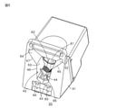
図5は、水分センサ32の斜視図である。
FIG. 5 is a perspective view of the
水分センサ32は、箱型のセンサケース41を備えている。センサケース41の前面には、センサケース41内に穀粒を受け入れるための受入口42が形成されている。受入口42は、左右対称の形状であり、上側に開いたV字状の下辺43と、下辺43の左上端から上下方向(鉛直方向)に対して左側に相対的に小さい角度で傾斜して上方に延びる第1左辺44と、第1左辺44の上端から上下方向に対して左側に相対的に大きい角度で傾斜して上方に延びる第2左辺45と、下辺43の右上端から上下方向に対して右側に相対的に小さい角度で傾斜して上方に延びる第1右辺46と、第1右辺46の上端から上下方向に対して右側に相対的に大きい角度で傾斜して上方に延びる第2右辺47とを有している。第1左辺44、第2左辺45、第1右辺46および第2右辺47から後側に、それぞれ平面51,52,53,54が延びており、これらの平面51,52,53,54は、穀粒をセンサケース41内に案内する案内面として機能する。
The
センサケース41内には、受入口42の後側のローラ収容空間に、1対の電極ローラ61,62が設けられている。電極ローラ61,62は、それぞれ互いに平行をなして前後方向に延びるローラ軸63,64を一体的に有している。電極ローラ61,62の周面は、左右方向に近接して並んでいる。電極ローラ61,62の周面には、微小な凹凸が多数形成されている。
In the
センサケース41内には、DCモータ(図示せず)が設けられており、そのDCモータの駆動力により、1対の電極ローラ61,62は、正転および逆転する。電極ローラ61,62の正転では、グレンタンク5内から見て、電極ローラ61が反時計回りに回転し、電極ローラ62が時計回りに回転する。電極ローラ61,62の逆転では、グレンタンク5内から見て、電極ローラ61が時計回りに回転し、電極ローラ62が反時計回りに回転する。
A DC motor (not shown) is provided in the
また、センサケース41内には、案内部材65が設けられている。案内部材65は、左側の電極ローラ61のローラ軸63に相対回転可能に支持されているが、ローラ軸63との間に適度の摩擦抵抗を有するため、案内部材65にローラ軸63以外からの外力が作用しない状態では、ローラ軸63につられて回動する。センサケース41内には、案内部材65の回動範囲を規制するストッパが設けられている。これにより、案内部材65は、電極ローラ61,62の正転時には、電極ローラ61,62の前上側の位置に配置され、電極ローラ61,62の逆転時には、正転時の位置に対して左上側の位置(電極ローラ61,62の左前上側の位置)に配置される。案内部材65は、電極ローラ61,62の前上側の位置に配置された状態で、平面視で略三角形状、かつ前面視で上側に開いた略V字状をなしている。
Further, a
排出部13の排出口27から飛散する穀粒の一部は、センサケース41の位置に到達し、センサケース41の受入口42からセンサケース41内に受け入れられる。電極ローラ61,62の正転時には、案内部材65が電極ローラ61,62の前上側の位置に位置しているので、受入口42から飛入して案内部材65上に到達した穀粒は、案内部材65により、電極ローラ61,62上に案内される。また、受入口42からセンサケース41内に飛入する穀粒の一部は、電極ローラ61,62上に直接到達する。そして、電極ローラ61,62上の穀粒は、電極ローラ61,62の正転により、電極ローラ61,62に挟まれて圧砕される。水分センサ32では、穀粒の圧砕時における電極ローラ61,62間の電気抵抗値が検出されて、その電気抵抗値から穀粒に含まれる水分量の値が求められる。そして、その求められた値が水分センサ32から出力される(検出動作)。
A part of the grains scattered from the
なお、水分センサ32からは、穀粒の圧砕時における電極ローラ61,62間の電気抵抗値が出力されて、その水分センサ32の出力値が入力される制御装置において、電気抵抗値から穀粒に含まれる水分量の値が求められてもよい。
In the control device in which the electric resistance value between the
また、電極ローラ61,62の逆転時には、電極ローラ61,62の各周面にブラシ(図示せず)が当接し、電極ローラ61,62の周面(表面)が清掃される(清掃動作)。このとき、案内部材65は、電極ローラ61,62の前上側の位置に対して左上側の位置に退避しているので、電極ローラ61,62上から圧砕されていない穀粒が落下する妨げにならない。
Further, when the
電極ローラ61,62が収容されるローラ収容空間は、その底面が開放されている。したがって、受入口42からセンサケース41内に受け入れられた穀粒は、電極ローラ61,62上を除いて、ローラ収容空間には溜まらず、ローラ収容空間から水分センサ32の下側に設けられている戻し通路66(図4参照)を通してグレンタンク5内に戻される。
The bottom surface of the roller accommodating space in which the
<コンバインの電気的構成>
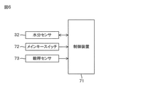
図6は、コンバイン1の電気的構成の要部を示すブロック図である。
<Electrical composition of combine>
FIG. 6 is a block diagram showing a main part of the electrical configuration of the
コンバイン1には、水分センサ32の動作を制御するため、制御装置71が搭載されている。制御装置71は、マイクロコントローラユニット(MCU:Micro Controller Unit)を含む構成であり、マイクロコントローラユニットには、たとえば、CPU、フラッシュメモリなどの不揮発性メモリおよびDRAM(Dynamic Random Access Memory)などの揮発性メモリが内蔵されている。
A
制御装置71には、水分センサ32から出力される値(検出信号)のほか、メインキースイッチ72のオン/オフ信号および穀稈センサ73の検出信号が入力される。メインキースイッチ72は、コンバイン1の運転開始(始動)および運転終了の際に、ユーザがキーをキーシリンダに挿入して操作することにより、オン/オフするスイッチである。穀稈センサ73は、刈取装置7に設けられて、刈取装置7における穀稈の存在を検出するセンサである。穀稈センサ73は、刈取装置7に穀稈が存在するときにオンレベルの検出信号を出力し、刈取装置7に穀稈が存在しないときにオフレベルの検出信号を出力する。
In addition to the value (detection signal) output from the
<センサ駆動制御>
図7は、水分センサ32の駆動制御の流れを示すフローチャートである。
<Sensor drive control>
FIG. 7 is a flowchart showing the flow of drive control of the
メインキースイッチ72がオンされると、制御装置71により、水分センサ32の駆動(動作)の制御が開始される。水分センサ32の駆動制御は、メインキースイッチ72がオフにされるまで続けられる。
When the main key switch 72 is turned on, the
水分センサ32の駆動制御では、メインキースイッチ72がオンされたことに応じて、水分センサ32のDCモータが制御されて、予め定められた通常時間にわたって、電極ローラ61,62が逆転される(ステップS1)。これにより、水分センサ32は、通常時間にわたる清掃動作を行う。清掃動作により、電極ローラ61,62の周面が清掃される。
In the drive control of the
その後、刈取装置7および脱穀装置が作動(オン)しているか否かが判断される(ステップS2)。刈取装置7および脱穀装置が作動していない非作動状態(オフ)である場合(ステップS2のNO)、刈取装置7および脱穀装置が作動するまで、水分センサ32の駆動制御は先に進まない。
After that, it is determined whether or not the
刈取装置7および脱穀装置が作動していると判断されると(ステップS2のYES)、通常時間にわたって、電極ローラ61,62が逆転される。これにより、水分センサ32は、通常時間にわたる清掃動作を行う。
When it is determined that the reaping
清掃動作の開始から通常時間が経過すると、所定時間にわたって、電極ローラ61,62が正転される(ステップS4)。所定時間は、電極ローラ61,62の左前上側の位置に配置されている案内部材65が電極ローラ61,62の前上側の位置に移動するのに必要な時間に設定されている。したがって、電極ローラ61,62が所定時間にわたって正転されることにより、案内部材65が電極ローラ61,62の左前上側の位置から電極ローラ61,62の前上側の位置に移動する。
When the normal time has elapsed from the start of the cleaning operation, the
その後、穀稈センサ73の検出信号がオンレベルであるか否かが判断される(ステップS5)。穀稈センサ73の検出信号がオフレベルである間は(ステップS5のNO)、水分センサ32の駆動制御は先に進まない。
After that, it is determined whether or not the detection signal of the
刈取装置7に穀稈が進入し、穀稈センサ73の検出信号がオンレベルになると(ステップS5のYES)、電極ローラ61,62間の電気抵抗値が検出されて、その電気抵抗値から、電極ローラ61,62上における穀粒(作物)の有無が判定される(ステップS6)。電極ローラ61,62上に穀粒が存在する場合、その穀粒が圧砕されていなくても、電極ローラ61,62上に穀粒が存在しない場合と電極ローラ61,62間の電気抵抗値が異なる。したがって、電極ローラ61,62間の電気抵抗値から、電極ローラ61,62上における穀粒の有無を判定することができる。
When the grain enters the
電極ローラ61,62上に穀粒がない場合(ステップS6のNO)、穀稈センサ73の検出信号がオンレベルであるか否かが再び判断される(ステップS5)。
When there are no grains on the
電極ローラ61,62上に穀粒が乗り、電極ローラ61,62上に穀粒があると判定されると(ステップS6のYES)、電極ローラ61,62が正転されて、電極ローラ61,62による穀粒の圧砕時における電極ローラ61,62間の電気抵抗値が検出され、その電気抵抗値から穀粒に含まれる水分量の値が求められる。すなわち、水分センサ32は、穀粒に含まれる水分量を測定するために、穀粒の圧砕時における電極ローラ61,62間の電気抵抗値を検出する検出動作を行う。
When the grains are placed on the
穀粒の水分量が測定されると、通常時間にわたって、電極ローラ61,62が逆転される(ステップS8)。これにより、水分センサ32は、通常時間にわたる清掃動作を行う。
When the water content of the grain is measured, the
水分センサ32の清掃動作の終了後は、刈取装置7および脱穀装置が作動(オン)しているか否かが再び判断されて(ステップS2)、刈取装置7および脱穀装置が作動している状態であれば(ステップS2のYES)、前述したステップS3以降の処理が実行される。これにより、刈取装置7および脱穀装置が作動している状態では、穀粒の水分量が周期的に測定される。
After the cleaning operation of the
<第1異常解消処理>
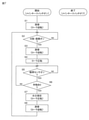
図8は、第1異常解消処理の流れを示すフローチャートである。
<First abnormality resolution processing>
FIG. 8 is a flowchart showing the flow of the first abnormality elimination process.
たとえば、藁の切れ端である切れ藁(藁くず)などの異物が水分センサ32のセンサケース41内に入り、その異物が電極ローラ61,62間に噛み込むと、電極ローラ61,62が良好に回転しない異常(以下、「ローラロック」という。)が発生するおそれがある。また、電極ローラ61,62に圧砕された穀物が付着した状態で放置されると、その穀物が電極ローラ61,62に固着し、ローラロックが発生するおそれがある。
For example, when a foreign substance such as a piece of straw, which is a piece of straw, enters the
そのため、制御装置71により、前述した水分センサ32の駆動制御と並行して、第1異常解消処理が実行される。第1異常解消処理は、ローラロックを検知して、ローラロックを検知した場合に、ローラロックを解消する処理である。
Therefore, the
第1異常解消処理では、まず、ローラロックの検知のための判定が行われる。すなわち、ローラロックを検知するため、水分センサ32の電極ローラ61,62を回転させるDCモータに供給されるモータ駆動電流が検出される。そして、そのモータ駆動電流が予め定められた閾値よりも大きいか否かが判定される(ステップS11)。モータ駆動電流が閾値よりも大きいことは、電極ローラ61,62の回転抵抗が大きく、電極ローラ61,62が良好に回転していないことを示す。したがって、モータ駆動電流が閾値よりも大きいか否かの判定は、ローラロックの検知のための判定であり、モータ駆動電流が閾値よりも大きい場合、ローラロックが発生していると判断できる。
In the first abnormality elimination process, first, a determination for detecting the roller lock is performed. That is, in order to detect the roller lock, the motor drive current supplied to the DC motor that rotates the
モータ駆動電流が閾値よりも大きいと判定された場合(ステップS11のYES)、DCモータへのモータ駆動電流の供給が停止されて、電極ローラ61,62が停止される(ステップS12)。
When it is determined that the motor drive current is larger than the threshold value (YES in step S11), the supply of the motor drive current to the DC motor is stopped, and the
そして、電極ローラ61,62が停止前に正転していたか逆転していたかが判断される(ステップS13)。
Then, it is determined whether the
電極ローラ61,62が停止前に正転していた場合(ステップS13のYES)、DCモータが制御されて、予め定められた通常時間にわたって、電極ローラ61,62が逆転される(ステップS14)。これにより、水分センサ32は、ローラロックを解消するための異常解消動作として、通常時間にわたる清掃動作を行う。清掃動作により、電極ローラ61,62の周面が清掃されるので、電極ローラ61,62に圧砕された穀物が固着していることによるローラロックが解消される可能性がある。また、電極ローラ61,62間に噛み込むことによるローラロックは、電極ローラ61,62の逆転により解消される可能性がある。
When the
一方、電極ローラ61,62が停止前に逆転していた場合(ステップS13のNO)、つまり水分センサ32が清掃動作していた場合には、ローラロックを解消する術がないので、異常の発生をユーザに報知するため、異常警報が発報される(ステップS15)。
On the other hand, when the
<第2異常解消処理>
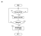
図9は、第2異常解消処理の流れを示すフローチャートである。
<Second abnormality resolution processing>
FIG. 9 is a flowchart showing the flow of the second abnormality elimination process.
たとえば、穀粒に水分が多く含まれていると、電極ローラ61,62に圧砕された穀物が付着したままの状態になる異常(以下、「ローラ目詰まり」という。)が発生するおそれがある。この異常状態では、穀粒の水分量の次の測定が行われると、その水分量を正確に測定できない可能性がある。
For example, if the grain contains a large amount of water, an abnormality may occur in which the crushed grain remains attached to the
そのため、制御装置71により、前述した水分センサ32の駆動制御と並行して、第2異常解消処理が実行される。第2異常解消処理は、ローラ目詰まりを検知して、ローラ目詰まりを検知した場合に、ローラ目詰まりを解消する処理である。
Therefore, the
第2異常解消処理では、まず、ローラ目詰まりの検知のための判定が行われる。すなわち、ローラ目詰まりを検知するため、水分センサ32の電極ローラ61,62の逆転中、つまり水分センサ32の清掃動作中に、電極ローラ61,62間の電気抵抗値が検出される。そして、その検出値が異常値であるか否かが判定される(ステップS21)。電極ローラ61,62に穀物が付着している場合、その穀物を介して電極ローラ61,62間に電流が流れるので、電極ローラ61,62に穀物が付着していない場合と比較して、電極ローラ61,62間の電気抵抗値の検出値が大きく低下した異常値を示す。したがって、電極ローラ61,62間の電気抵抗値の検出値が異常値であるか否かの判定は、ローラ目詰まりの検知のための判定であり、電極ローラ61,62間の電気抵抗値が異常値である場合、ローラ目詰まりが発生していると判断できる。
In the second abnormality elimination process, first, a determination for detecting roller clogging is performed. That is, in order to detect the roller clogging, the electric resistance value between the
電極ローラ61,62間の電気抵抗値の検出値が異常値である場合(ステップS21のYES)、通常時間よりも長い時間にわたって、電極ローラ61,62が逆転される(ステップS22)。これにより、水分センサ32は、ローラ目詰まりを解消するための異常解消動作として、通常よりも長く清掃動作を行う。清掃動作が長く行われることにより、電極ローラ61,62の周面から穀物が除去されて、ローラ目詰まりが解消される可能性がある。
When the detected value of the electric resistance value between the
その後、ローラ目詰まりが複数回発生したか否かが判断される(ステップS23)。ローラ目詰まりが複数回発生していなければ(ステップS23のNO)、電極ローラ61,62間の電気抵抗値の検出値が異常値であるか否かが再び判定される(ステップS21)。
After that, it is determined whether or not the roller clogging has occurred a plurality of times (step S23). If the roller clogging has not occurred a plurality of times (NO in step S23), it is determined again whether or not the detected value of the electric resistance value between the
そして、ローラ目詰まりが複数回発生して、ローラ目詰まりが複数回検知され、これに伴って、通常より長い清掃動作が複数回行われた場合、ローラ目詰まりが解消されない可能性が高いので、異常の発生をユーザに報知するため、異常警報が発報される(ステップS24)。 Then, if the roller clogging occurs a plurality of times, the roller clogging is detected multiple times, and the cleaning operation longer than usual is performed a plurality of times, there is a high possibility that the roller clogging will not be cleared. , An abnormality alarm is issued in order to notify the user of the occurrence of an abnormality (step S24).
<作用効果>
以上のように、水分センサ32の異常(ローラロック、ローラ目詰まり)の検知のための判定を行うことにより、水分センサ32の異常を検知することができる。そして、水分センサ32の異常が検知された場合には、水分センサ32の異常解消動作により、その異常の解消を図ることができる。
<Action effect>
As described above, the abnormality of the
<変形例>
以上、本発明の一実施形態について説明したが、本発明は、他の形態で実施することもできる。
<Modification example>
Although one embodiment of the present invention has been described above, the present invention can also be implemented in other embodiments.
たとえば、ローラロックの検知のため、水分センサ32の電極ローラ61,62を回転させるDCモータに供給されるモータ駆動電流が予め定められた閾値よりも大きいか否かが判定されるとした。ローラロックの検知のための判定は、これに限らず、たとえば、電極ローラ61,62または電極ローラ61,62を回転させるDCモータの回転数が検出可能である場合には、その検出される回転数が予め定められた閾値未満であるか否かの判定であってもよい。
For example, in order to detect the roller lock, it is determined whether or not the motor drive current supplied to the DC motor that rotates the
その他、前述の構成には、特許請求の範囲に記載された事項の範囲で種々の設計変更を施すことが可能である。 In addition, various design changes can be made to the above-mentioned configuration within the scope of the matters described in the claims.
1:コンバイン
32:水分センサ
61,62:電極ローラ
71:制御装置
1: Combine 32:
Claims (5)
前記水分センサの動作を制御する制御装置と、を含み、
前記制御装置は、前記1対の電極ローラの回転中に、前記水分センサの異常の検知のための判定を行い、この判定により前記水分センサの異常を検知した場合、当該異常を解消するため、前記水分センサを異常解消動作させる、コンバイン。 A pair of electrode rollers are provided, and the pair of electrode rollers rotate in a normal direction in a direction in which grains are caught between the electrode rollers to crush the grains between the electrode rollers, and the electrodes at the time of the crushing. A moisture sensor that performs a detection operation to detect the electrical resistance value between the rollers and cleans the surface of the electrode rollers by reversing the pair of electrode rollers.
Including a control device for controlling the operation of the moisture sensor.
The control device makes a determination for detecting an abnormality in the moisture sensor during the rotation of the pair of electrode rollers, and when an abnormality in the moisture sensor is detected by this determination, the abnormality is eliminated in order to eliminate the abnormality. A combine that operates the moisture sensor to eliminate abnormalities.
Priority Applications (3)
| Application Number | Priority Date | Filing Date | Title |
|---|---|---|---|
| JP2020113480A JP7304319B2 (en) | 2020-06-30 | 2020-06-30 | combine |
| KR1020210075250A KR20220002097A (en) | 2020-06-30 | 2021-06-10 | Combine |
| CN202110727025.1A CN113853929B (en) | 2020-06-30 | 2021-06-29 | Combine Harvester |
Applications Claiming Priority (1)
| Application Number | Priority Date | Filing Date | Title |
|---|---|---|---|
| JP2020113480A JP7304319B2 (en) | 2020-06-30 | 2020-06-30 | combine |
Publications (2)
| Publication Number | Publication Date |
|---|---|
| JP2022012003A true JP2022012003A (en) | 2022-01-17 |
| JP7304319B2 JP7304319B2 (en) | 2023-07-06 |
Family
ID=80148465
Family Applications (1)
| Application Number | Title | Priority Date | Filing Date |
|---|---|---|---|
| JP2020113480A Active JP7304319B2 (en) | 2020-06-30 | 2020-06-30 | combine |
Country Status (1)
| Country | Link |
|---|---|
| JP (1) | JP7304319B2 (en) |
Cited By (2)
| Publication number | Priority date | Publication date | Assignee | Title |
|---|---|---|---|---|
| JP2024170012A (en) * | 2023-05-26 | 2024-12-06 | 株式会社クボタ | Moisture content measuring device |
| US20260096509A1 (en) * | 2024-10-03 | 2026-04-09 | Deere & Company | Agricultural work machine and method for controlling operation thereof to avoid crop material plugging and/or remove plugged crop material |
Citations (4)
| Publication number | Priority date | Publication date | Assignee | Title |
|---|---|---|---|---|
| JPS61292047A (en) * | 1985-06-19 | 1986-12-22 | Iseki & Co Ltd | Abnormality detector for grain moisture measuring instrument |
| JPS6353459A (en) * | 1986-08-25 | 1988-03-07 | Iseki & Co Ltd | Moisture meter abnormality detection device |
| JP2000214118A (en) * | 1999-01-01 | 2000-08-04 | Satake Eng Co Ltd | Grain resistance moisture meter |
| JP2017000027A (en) * | 2015-06-05 | 2017-01-05 | 井関農機株式会社 | combine |
-
2020
- 2020-06-30 JP JP2020113480A patent/JP7304319B2/en active Active
Patent Citations (4)
| Publication number | Priority date | Publication date | Assignee | Title |
|---|---|---|---|---|
| JPS61292047A (en) * | 1985-06-19 | 1986-12-22 | Iseki & Co Ltd | Abnormality detector for grain moisture measuring instrument |
| JPS6353459A (en) * | 1986-08-25 | 1988-03-07 | Iseki & Co Ltd | Moisture meter abnormality detection device |
| JP2000214118A (en) * | 1999-01-01 | 2000-08-04 | Satake Eng Co Ltd | Grain resistance moisture meter |
| JP2017000027A (en) * | 2015-06-05 | 2017-01-05 | 井関農機株式会社 | combine |
Cited By (3)
| Publication number | Priority date | Publication date | Assignee | Title |
|---|---|---|---|---|
| JP2024170012A (en) * | 2023-05-26 | 2024-12-06 | 株式会社クボタ | Moisture content measuring device |
| JP7813260B2 (en) | 2023-05-26 | 2026-02-12 | 株式会社クボタ | Moisture content measuring device |
| US20260096509A1 (en) * | 2024-10-03 | 2026-04-09 | Deere & Company | Agricultural work machine and method for controlling operation thereof to avoid crop material plugging and/or remove plugged crop material |
Also Published As
| Publication number | Publication date |
|---|---|
| JP7304319B2 (en) | 2023-07-06 |
Similar Documents
| Publication | Publication Date | Title |
|---|---|---|
| EP1344444B1 (en) | Device for detecting the presence of a flow in a harvesting machine | |
| JP6675843B2 (en) | Combine | |
| JP7304319B2 (en) | combine | |
| JP6650708B2 (en) | Combine | |
| CN113853928A (en) | combine harvester | |
| JP2022012002A (en) | combine | |
| JP2022012000A (en) | combine | |
| JP2022012001A (en) | combine | |
| JPH11266668A (en) | Combine | |
| CN113853929B (en) | Combine Harvester | |
| JP7434084B2 (en) | combine | |
| JP2000032833A (en) | Waste clogging detection device in threshing equipment | |
| JP2022011999A (en) | combine | |
| JP2023015558A (en) | Harvester | |
| JPH0629951Y2 (en) | Harvester spreader equipment | |
| JP2022085453A (en) | combine | |
| JP7587480B2 (en) | Moisture detection device | |
| JP2613679B2 (en) | Threshing sorting controller | |
| JP2010075119A (en) | Thresher | |
| JP2694086B2 (en) | Threshing device clogging detection device | |
| JP2721078B2 (en) | Threshing device clogging detection device | |
| JPH0553434U (en) | Axial flow type handle body mounting structure | |
| JPH10136767A (en) | Combine Glen Tank | |
| US10674672B2 (en) | Free-rolling rotor cage | |
| JP2752293B2 (en) | Grain transport amount detection device |
Legal Events
| Date | Code | Title | Description |
|---|---|---|---|
| A621 | Written request for application examination |
Free format text: JAPANESE INTERMEDIATE CODE: A621 Effective date: 20220622 |
|
| A977 | Report on retrieval |
Free format text: JAPANESE INTERMEDIATE CODE: A971007 Effective date: 20221227 |
|
| A131 | Notification of reasons for refusal |
Free format text: JAPANESE INTERMEDIATE CODE: A131 Effective date: 20230110 |
|
| A601 | Written request for extension of time |
Free format text: JAPANESE INTERMEDIATE CODE: A601 Effective date: 20230309 |
|
| A521 | Request for written amendment filed |
Free format text: JAPANESE INTERMEDIATE CODE: A523 Effective date: 20230511 |
|
| TRDD | Decision of grant or rejection written | ||
| A01 | Written decision to grant a patent or to grant a registration (utility model) |
Free format text: JAPANESE INTERMEDIATE CODE: A01 Effective date: 20230530 |
|
| A61 | First payment of annual fees (during grant procedure) |
Free format text: JAPANESE INTERMEDIATE CODE: A61 Effective date: 20230626 |
|
| R150 | Certificate of patent or registration of utility model |
Ref document number: 7304319 Country of ref document: JP Free format text: JAPANESE INTERMEDIATE CODE: R150 |