JP2022011402A - Robot control method and robot system - Google Patents
Robot control method and robot system Download PDFInfo
- Publication number
- JP2022011402A JP2022011402A JP2020112527A JP2020112527A JP2022011402A JP 2022011402 A JP2022011402 A JP 2022011402A JP 2020112527 A JP2020112527 A JP 2020112527A JP 2020112527 A JP2020112527 A JP 2020112527A JP 2022011402 A JP2022011402 A JP 2022011402A
- Authority
- JP
- Japan
- Prior art keywords
- work
- robot
- robot arm
- force
- control
- Prior art date
- Legal status (The legal status is an assumption and is not a legal conclusion. Google has not performed a legal analysis and makes no representation as to the accuracy of the status listed.)
- Pending
Links
- 238000000034 method Methods 0.000 title claims abstract description 35
- 230000001186 cumulative effect Effects 0.000 abstract description 9
- 238000001514 detection method Methods 0.000 description 35
- 239000012636 effector Substances 0.000 description 26
- 239000013256 coordination polymer Substances 0.000 description 22
- 238000010586 diagram Methods 0.000 description 16
- 238000012937 correction Methods 0.000 description 12
- 238000006243 chemical reaction Methods 0.000 description 11
- 238000005498 polishing Methods 0.000 description 10
- 238000012986 modification Methods 0.000 description 6
- 230000004048 modification Effects 0.000 description 6
- 230000007423 decrease Effects 0.000 description 5
- 230000036544 posture Effects 0.000 description 5
- 230000005484 gravity Effects 0.000 description 4
- 230000010354 integration Effects 0.000 description 4
- 238000013528 artificial neural network Methods 0.000 description 3
- 230000000306 recurrent effect Effects 0.000 description 3
- 230000001133 acceleration Effects 0.000 description 2
- 238000013459 approach Methods 0.000 description 2
- 238000004364 calculation method Methods 0.000 description 2
- 239000000470 constituent Substances 0.000 description 2
- 230000006870 function Effects 0.000 description 2
- 238000010801 machine learning Methods 0.000 description 2
- 230000002093 peripheral effect Effects 0.000 description 2
- 238000012545 processing Methods 0.000 description 2
- 238000012935 Averaging Methods 0.000 description 1
- 239000006061 abrasive grain Substances 0.000 description 1
- 238000004891 communication Methods 0.000 description 1
- 230000000593 degrading effect Effects 0.000 description 1
- 230000001747 exhibiting effect Effects 0.000 description 1
- 238000003384 imaging method Methods 0.000 description 1
Images


Classifications
-
- B—PERFORMING OPERATIONS; TRANSPORTING
- B25—HAND TOOLS; PORTABLE POWER-DRIVEN TOOLS; MANIPULATORS
- B25J—MANIPULATORS; CHAMBERS PROVIDED WITH MANIPULATION DEVICES
- B25J9/00—Programme-controlled manipulators
- B25J9/16—Programme controls
- B25J9/1602—Programme controls characterised by the control system, structure, architecture
-
- B—PERFORMING OPERATIONS; TRANSPORTING
- B25—HAND TOOLS; PORTABLE POWER-DRIVEN TOOLS; MANIPULATORS
- B25J—MANIPULATORS; CHAMBERS PROVIDED WITH MANIPULATION DEVICES
- B25J9/00—Programme-controlled manipulators
- B25J9/16—Programme controls
- B25J9/1628—Programme controls characterised by the control loop
- B25J9/163—Programme controls characterised by the control loop learning, adaptive, model based, rule based expert control
-
- B—PERFORMING OPERATIONS; TRANSPORTING
- B25—HAND TOOLS; PORTABLE POWER-DRIVEN TOOLS; MANIPULATORS
- B25J—MANIPULATORS; CHAMBERS PROVIDED WITH MANIPULATION DEVICES
- B25J9/00—Programme-controlled manipulators
- B25J9/16—Programme controls
- B25J9/1628—Programme controls characterised by the control loop
- B25J9/1633—Programme controls characterised by the control loop compliant, force, torque control, e.g. combined with position control
-
- B—PERFORMING OPERATIONS; TRANSPORTING
- B25—HAND TOOLS; PORTABLE POWER-DRIVEN TOOLS; MANIPULATORS
- B25J—MANIPULATORS; CHAMBERS PROVIDED WITH MANIPULATION DEVICES
- B25J9/00—Programme-controlled manipulators
- B25J9/16—Programme controls
- B25J9/1656—Programme controls characterised by programming, planning systems for manipulators
- B25J9/1661—Programme controls characterised by programming, planning systems for manipulators characterised by task planning, object-oriented languages
-
- B—PERFORMING OPERATIONS; TRANSPORTING
- B25—HAND TOOLS; PORTABLE POWER-DRIVEN TOOLS; MANIPULATORS
- B25J—MANIPULATORS; CHAMBERS PROVIDED WITH MANIPULATION DEVICES
- B25J9/00—Programme-controlled manipulators
- B25J9/16—Programme controls
- B25J9/1656—Programme controls characterised by programming, planning systems for manipulators
- B25J9/1664—Programme controls characterised by programming, planning systems for manipulators characterised by motion, path, trajectory planning
-
- G—PHYSICS
- G05—CONTROLLING; REGULATING
- G05B—CONTROL OR REGULATING SYSTEMS IN GENERAL; FUNCTIONAL ELEMENTS OF SUCH SYSTEMS; MONITORING OR TESTING ARRANGEMENTS FOR SUCH SYSTEMS OR ELEMENTS
- G05B2219/00—Program-control systems
- G05B2219/30—Nc systems
- G05B2219/39—Robotics, robotics to robotics hand
- G05B2219/39322—Force and position control
Abstract
Description
本発明は、ロボットの制御方法およびロボットシステムに関する。 The present invention relates to a robot control method and a robot system.
例えば、特許文献1に示すように、先端に工具が装着されるロボットアームを有し、ロボットアームを駆動することによって、作業の対象部材に対して所定の作業を行うロボットが知られている。
For example, as shown in
特許文献1に記載のロボットは、対象部材の表面に沿って加工等を行う倣い制御により動作を行う。具体的には、工具が予め設定された目標位置に向かうようにロボットアームを移動させつつ、ロボットアームと対象部材との接触力を検出する。そして、検出した力が目標力に一致するように目標位置を補正し、ロボットアームを所定の速度で動作させる。
The robot described in
また、対象部材に工具を確実に接触させるために、倣い制御における目標位置は、工具と対象部材との実際の距離よりも長くなるような位置に設定される。すなわち、実際に工具と対象部材とが接触する位置は、目標位置とずれている。工具と対象部材とが接触するまでの間、比較的遅い速度でロボットアームを動作させるため、このずれ量の大きさによっては、作業時間が長くなる。特に、複数のワークに対して作業を行う場合、累積の作業時間が長くなってしまう。 Further, in order to ensure that the tool is in contact with the target member, the target position in the copying control is set to a position longer than the actual distance between the tool and the target member. That is, the position where the tool and the target member actually contact is deviated from the target position. Since the robot arm is operated at a relatively slow speed until the tool and the target member come into contact with each other, the working time becomes long depending on the magnitude of this deviation amount. In particular, when work is performed on a plurality of works, the cumulative work time becomes long.
本発明のロボットの制御方法は、第1作業対象物に対して第1作業を行い、前記第1作業対象物と同種の第2作業対象物に対して前記第1作業と同種の第2作業を行うロボットアームを有するロボットの制御方法であって、
所定の位置指令値に基づいて力制御により前記ロボットアームを動作させて前記第1作業対象物に対して前記第1作業を実行する第1作業ステップと、
前記ロボットアームに設定された制御点が、前記第1作業ステップにおいて通過した軌道の第1位置情報を記憶する第1記憶ステップと、
前記第1記憶ステップにおいて記憶した前記第1位置情報に基づいて前記ロボットアームに対する位置指令値を更新し、更新した前記位置指令値である更新値に基づいて力制御により前記ロボットアームを動作させて前記第2作業対象物に対して前記第2作業を実行する第2作業ステップと、を有することを特徴とする。
In the robot control method of the present invention, the first work is performed on the first work object, and the second work of the same type as the first work is performed on the second work object of the same type as the first work object. It is a control method of a robot having a robot arm that performs
A first work step in which the robot arm is operated by force control based on a predetermined position command value to execute the first work on the first work object, and
A first storage step in which the control point set on the robot arm stores the first position information of the trajectory passed in the first work step, and
The position command value for the robot arm is updated based on the first position information stored in the first storage step, and the robot arm is operated by force control based on the updated value which is the updated position command value. It is characterized by having a second work step of executing the second work on the second work object.
本発明のロボットシステムは、第1作業対象物に対して第1作業を行い、前記第1作業対象物と同種の第2作業対象物に対して前記第1作業と同種の第2作業を行うロボットアームと、
記憶部を有し、前記ロボットアームの作動を制御する制御部と、を備え、
前記制御部は、
所定の位置指令値に基づいて力制御により前記ロボットアームを動作させて前記第1作業対象物に対して前記第1作業を実行し、
前記ロボットアームに設定された制御点が、前記第1作業において通過した軌道の第1位置情報を記憶し、
記憶した前記第1位置情報に基づいて前記ロボットアームに対する位置指令値を更新し、
更新した前記位置指令値である更新値に基づいて力制御により前記ロボットアームを動作させて前記第2作業対象物に対して前記第2作業を実行することを特徴とする。
The robot system of the present invention performs the first work on the first work object, and performs the second work of the same type as the first work on the second work object of the same type as the first work object. With the robot arm,
It has a storage unit, and includes a control unit that controls the operation of the robot arm.
The control unit
The robot arm is operated by force control based on a predetermined position command value to execute the first work on the first work object.
The control point set on the robot arm stores the first position information of the trajectory passed in the first operation, and stores the first position information.
The position command value for the robot arm is updated based on the stored first position information, and the position command value is updated.
It is characterized in that the robot arm is operated by force control based on the updated value which is the updated position command value to execute the second work on the second work object.
<第1実施形態>
図1は、第1実施形態のロボットシステムの全体構成を示す図である。図2は、図1に示すロボットシステムのブロック図である。図3は、図1に示すロボットの作業対象物であるワークの斜視図である。図4は、図3に示すワークに目標位置を設定した状態を示す斜視図である。図5は、図4中のA-A線断面図である。図6は、図4中のB-B線断面図である。図7は、図3に示すワークの斜視図であって、各目標位置を制御点が通過する順番を矢印で示した図である。図8は、図4中のA-A線断面図であって、作業を行っている状態を示す図である。図9は、ワークの横断面図であって、2回目の作業を行う際の目標位置を設定した状態を示す図である。図10は、図2に示す制御装置が行う制御動作を説明するためのフローチャートであって、1回目の作業を行う際のフローチャートである。図11は、図2に示す制御装置が行う制御動作を説明するためのフローチャートであって、2回目の作業を行う際のフローチャートである。
<First Embodiment>
FIG. 1 is a diagram showing an overall configuration of the robot system of the first embodiment. FIG. 2 is a block diagram of the robot system shown in FIG. FIG. 3 is a perspective view of a work that is a work object of the robot shown in FIG. FIG. 4 is a perspective view showing a state in which a target position is set on the work shown in FIG. FIG. 5 is a cross-sectional view taken along the line AA in FIG. FIG. 6 is a cross-sectional view taken along the line BB in FIG. FIG. 7 is a perspective view of the work shown in FIG. 3, which is a diagram showing the order in which control points pass through each target position with arrows. FIG. 8 is a cross-sectional view taken along the line AA in FIG. 4, showing a state in which work is being performed. FIG. 9 is a cross-sectional view of the work, and is a diagram showing a state in which a target position is set when performing the second work. FIG. 10 is a flowchart for explaining the control operation performed by the control device shown in FIG. 2, and is a flowchart for performing the first operation. FIG. 11 is a flowchart for explaining the control operation performed by the control device shown in FIG. 2, and is a flowchart for performing the second operation.
以下、本発明のロボットの制御方法およびロボットシステムを添付図面に示す好適な実施形態に基づいて詳細に説明する。なお、以下では、説明の便宜上、図1中の+Z軸方向、すなわち、上側を「上」、-Z軸方向、すなわち、下側を「下」とも言う。また、ロボットアームについては、図1中の基台11側を「基端」、その反対側、すなわち、エンドエフェクター20側を「先端」とも言う。また、図1中のZ軸方向、すなわち、上下方向を「鉛直方向」とし、X軸方向およびY軸方向、すなわち、左右方向を「水平方向」とする。
Hereinafter, the robot control method and the robot system of the present invention will be described in detail based on the preferred embodiments shown in the accompanying drawings. In the following, for convenience of explanation, the + Z-axis direction in FIG. 1, that is, the upper side is referred to as “upper”, and the −Z-axis direction, that is, the lower side is also referred to as “lower”. Further, regarding the robot arm, the
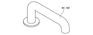
図1に示すように、ロボットシステム100は、第1作業対象物であるワークW1および第2作業対象物であるワークW2に対して順次作業を行うロボット1と、ロボット1を制御する制御装置3と、教示装置4と、を備え、本発明のロボットの制御方法を実行する。
As shown in FIG. 1, the
まず、ロボット1について説明する。
図1に示すロボット1は、本実施形態では単腕の6軸垂直多関節ロボットであり、基台11と、ロボットアーム10と、を有する。また、ロボットアーム10の先端部にエンドエフェクター20を装着することができる。エンドエフェクター20は、ロボット1の構成要件であってもよく、ロボット1の構成要件でなくてもよい。
First, the
The
なお、ロボット1は、図示の構成に限定されず、例えば、双腕型の多関節ロボットであってもよい。また、ロボット1は、水平多関節ロボットであってもよい。
The
基台11は、ロボットアーム10を下側から駆動可能に支持する支持体であり、例えば工場内の床に固定されている。ロボット1は、基台11が中継ケーブル18を介して制御装置3と電気的に接続されている。なお、ロボット1と制御装置3との接続は、図1に示す構成のように有線による接続に限定されず、例えば、無線による接続であってもよく、さらには、インターネットのようなネットワークを介して接続されていてもよい。
The
本実施形態では、ロボットアーム10は、第1アーム12と、第2アーム13と、第3アーム14と、第4アーム15と、第5アーム16と、第6アーム17とを有し、これらのアームが基台11側からこの順に連結されている。なお、ロボットアーム10が有するアームの数は、6つに限定されず、例えば、1つ、2つ、3つ、4つ、5つまたは7つ以上であってもよい。また、各アームの全長等の大きさは、それぞれ、特に限定されず、適宜設定可能である。
In the present embodiment, the
基台11と第1アーム12とは、関節171を介して連結されている。そして、第1アーム12は、基台11に対し、鉛直方向と平行な第1回動軸を回動中心とし、その第1回動軸回りに回動可能となっている。第1回動軸は、基台11が固定される床の法線と一致している。
The
第1アーム12と第2アーム13とは、関節172を介して連結されている。そして、第2アーム13は、第1アーム12に対し、水平方向と平行な第2回動軸を回動中心として回動可能となっている。第2回動軸は、第1回動軸に直交する軸と平行である。
The
第2アーム13と第3アーム14とは、関節173を介して連結されている。そして、第3アーム14は、第2アーム13に対して水平方向と平行な第3回動軸を回動中心として回動可能となっている。第3回動軸は、第2回動軸と平行である。
The
第3アーム14と第4アーム15とは、関節174を介して連結されている。そして、第4アーム15は、第3アーム14に対し、第3アーム14の中心軸方向と平行な第4回動軸を回動中心として回動可能となっている。第4回動軸は、第3回動軸と直交している。
The
第4アーム15と第5アーム16とは、関節175を介して連結されている。そして、第5アーム16は、第4アーム15に対して第5回動軸を回動中心として回動可能となっている。第5回動軸は、第4回動軸と直交している。
The
第5アーム16と第6アーム17とは、関節176を介して連結されている。そして、第6アーム17は、第5アーム16に対して第6回動軸を回動中心として回動可能となっている。第6回動軸は、第5回動軸と直交している。
The
また、第6アーム17は、ロボットアーム10の中で最も先端側に位置するロボット先端部となっている。この第6アーム17は、ロボットアーム10の駆動により、エンドエフェクター20ごと回動することができる。
Further, the
ロボット1は、駆動部としてのモーターM1、モーターM2、モーターM3、モーターM4、モーターM5およびモーターM6と、エンコーダーE1、エンコーダーE2、エンコーダーE3、エンコーダーE4、エンコーダーE5およびエンコーダーE6とを備える。モーターM1は、関節171に内蔵され、基台11と第1アーム12とを相対的に回転させる。モーターM2は、関節172に内蔵され、第1アーム12と第2アーム13とを相対的に回転させる。モーターM3は、関節173に内蔵され、第2アーム13と第3アーム14とを相対的に回転させる。モーターM4は、関節174に内蔵され、第3アーム14と第4アーム15とを相対的に回転させる。モーターM5は、関節175に内蔵され、第4アーム15と第5アーム16とを相対的に回転させる。モーターM6は、関節176に内蔵され、第5アーム16と第6アーム17とを相対的に回転させる。
The
また、エンコーダーE1は、関節171に内蔵され、モーターM1の位置を検出する。エンコーダーE2は、関節172に内蔵され、モーターM2の位置を検出する。エンコーダーE3は、関節173に内蔵され、モーターM3の位置を検出する。エンコーダーE4は、関節174に内蔵され、モーターM4の位置を検出する。エンコーダーE5は、関節175に内蔵され、モーターM5の位置を検出する。エンコーダーE6は、関節176に内蔵され、モーターM6の位置を検出する。 Further, the encoder E1 is built in the joint 171 and detects the position of the motor M1. The encoder E2 is built in the joint 172 and detects the position of the motor M2. The encoder E3 is built in the joint 173 and detects the position of the motor M3. The encoder E4 is built in the joint 174 and detects the position of the motor M4. The encoder E5 is built in the joint 175 and detects the position of the motor M5. The encoder E6 is built in the joint 176 and detects the position of the motor M6.
エンコーダーE1~E6は、制御装置3と電気的に接続されており、モーターM1~モーターM6の位置情報、すなわち、回転量が制御装置3に電気信号として送信される。そして、この情報に基づいて、制御装置3は、モーターM1~モーターM6を、図示しないモータードライバーを介して駆動させる。すなわち、ロボットアーム10を制御するということは、モーターM1~モーターM6を制御することである。
The encoders E1 to E6 are electrically connected to the
また、ロボットアーム10の先端には、制御点CPが設定されている。制御点CPは、ロボットアーム10の制御を行う際の基準となる点のことである。ロボットシステム100では、ロボット座標系で制御点CPの位置を把握し、制御点CPが所望の位置に移動するようにロボットアーム10を駆動する。
Further, a control point CP is set at the tip of the
また、ロボット1では、ロボットアーム10に、力を検出する力検出部19が着脱自在に設置される。そして、ロボットアーム10は、力検出部19が設置された状態で駆動することができる。力検出部19は、本実施形態では、6軸力覚センサーである。力検出部19は、互いに直交する3個の検出軸上の力の大きさと、当該3個の検出軸まわりのトルクの大きさとを検出する。すなわち、互いに直交するX軸、Y軸、Z軸の各軸方向の力成分と、X軸回りとなるW方向の力成分と、Y軸回りとなるV方向の力成分と、Z軸回りとなるU方向の力成分とを検出する。なお、本実施形態では、Z軸方向が鉛直方向となっている。また、各軸方向の力成分を「並進力成分」と言い、各軸回りの力成分を「トルク成分」と言うこともできる。また、力検出部19は、6軸力覚センサーに限定されず、他の構成のものであってもよい。
Further, in the
本実施形態では、力検出部19は、第6アーム17に設置されている。なお、力検出部19の設置箇所としては、第6アーム17、すなわち、最も先端側に位置するアームに限定されず、例えば、他のアームや、隣り合うアーム同士の間であってもよい。
In this embodiment, the
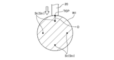
力検出部19には、エンドエフェクター20を着脱可能に装着することができる。エンドエフェクター20は、本実施形態では、作業対象物であるワークW1およびワークW2の研磨を行う研磨機である。この研磨機は、外周部に砥粒を有する研磨部材21と、研磨部材21を回転させる図示しないモーターと、モーターを駆動する図示しない電源と、を有する。また、ロボット座標系において、研磨部材21の先端面の任意の位置、好ましくは中心にツールセンターポイントTCPが設定されている。なお、これに限定されず、ツールセンターポイントTCPは、研磨部材21の外周部に設定されていてもよい。
The
前述したように、ロボットシステム100では、ロボット座標系で制御点CPの位置を把握し、制御点CPが所望の位置に移動するようにロボットアーム10を駆動する。また、エンドエフェクター20の種類、特に、長さを把握しておくことにより、ツールセンターポイントTCPと制御点CPとのオフセット量を把握することができる。このため、ツールセンターポイントTCPの位置をロボット座標系で把握することができる。したがって、ツールセンターポイントTCPを制御の基準とすることができる。すなわち、制御点CPの位置を制御するということは、ツールセンターポイントTCPの位置を制御することである。また、後述するように、ツールセンターポイントTCPの位置を記憶するということは、制御点CPの位置を記憶することである。
As described above, in the
また、以下では、ワークW1およびワークW2に作業を行う際、エンドエフェクター20において、少なくともツールセンターポイントTCPの位置は、ワークW1およびワークW2と接触することとする。
Further, in the following, when working on the work W1 and the work W2, at least the position of the tool center point TCP on the
また、本実施形態では、エンドエフェクター20は、研磨機で構成されているが、本発明ではこれに限定されず、例えば、研削機、切削機等や、ドライバー、レンチ等の工具であってもよく、吸引、挟持によりワークW1およびワークW2を把持するハンドであってもよい。
Further, in the present embodiment, the
また、本実施形態では、図1および図3に示すように、ワークW1およびワークW2は、横断面形状が円形の長尺体で構成され、その長手方向の途中が2か所湾曲した部材として説明する。 Further, in the present embodiment, as shown in FIGS. 1 and 3, the work W1 and the work W2 are formed of a long body having a circular cross-sectional shape, and the work W1 and the work W2 are formed as members curved in two places in the middle in the longitudinal direction thereof. explain.
ワークW1およびワークW2は、同種の作業対象物である。ここで、「同種の作業対象物」とは、全体形状が一致している場合はもちろん、作業対象部位の寸法が一致しており、作業対象部位以外の部位の形状が異なっている場合も含む。また、「寸法が一致」とは、同一部位で比較したときの寸法誤差が、1mm以下のことを言う。 The work W1 and the work W2 are the same type of work objects. Here, "the same type of work object" includes not only the case where the overall shape is the same, but also the case where the dimensions of the work target part are the same and the shapes of the parts other than the work target part are different. .. Further, "matching dimensions" means that the dimensional error when compared at the same site is 1 mm or less.
また、ロボット1は、ワークW1およびワークW2に対して同種の作業を行う。ロボットが行う作業としては、研磨、研削、切削、組み立て等が挙げられる。「同種の作業」とは、これらのカテゴリーが同じ作業であり、同じ工具を用いて行う作業のことを言う。
Further, the
次に、制御装置3および教示装置4について説明する。
制御部としての制御装置3は、ロボット1から離間して配置されており、プロセッサーの1例であるCPU(Central Processing Unit)が内蔵されたコンピューター等で構成することができる。この制御装置3は、ロボット1の基台11に内蔵されていてもよい。
Next, the
The
制御装置3は、中継ケーブル18によりロボット1と通信可能に接続される。また、制御装置3は、教示装置4とケーブルで、または無線通信可能に接続される。教示装置4は、専用のコンピューターであってもよいし、ロボット1を教示するためのプログラムがインストールされた汎用のコンピューターであってもよい。例えばロボット1を教示するための専用装置であるティーチングペンダント等を教示装置4の代わりに用いても良い。さらに、制御装置3と教示装置4とは、別々の筐体を備えていてもよいし、一体に構成されていてもよい。
The
また、教示装置4には、制御装置3に後述する目標位置Stと目標力fStとを引数とする実行プログラムを生成して制御装置3にロードするためのプログラムがインストールされていてもよい。教示装置4は、ディスプレイ41、プロセッサー、RAMやROMを備え、これらのハードウェア資源が教示プログラムと協働して実行プログラムを生成する。
Further, the
図2に示すように、制御装置3は、ロボット1の制御を行うための制御プログラムがインストールされたコンピューターである。制御装置3は、プロセッサーや図示しないRAMやROMを備え、これらのハードウェア資源がプログラムと協働することによりロボット1を制御する。
As shown in FIG. 2, the
また、図2に示すように、制御装置3は、目標位置設定部3Aと、駆動制御部3Bと、記憶部3Cと、を有する。記憶部3Cは、例えば、RAM(Random Access Memory)等の揮発性メモリー、ROM(Read Only Memory)等の不揮発性メモリー、着脱式の外部記憶装置等で構成される。記憶部3Cには、本発明のロボットの制御方法を実行するためのプログラム等、ロボット1を作動させるための動作プログラムや、ワークW1およびワークW2の形状に関する情報、および、ワークW1およびワークW2が配置されるロボット座標系における位置が記憶されている。また、記憶部3Cには、後述する第1位置情報や、第2位置情報等が記憶される。
Further, as shown in FIG. 2, the
目標位置設定部3Aは、ワークW1およびワークW2に対して所定の作業を実行するための目標位置Stおよび経路計画を設定する。
The target
まず、目標位置設定部3Aは、ワークW1およびワークW2の形状に関する情報、および、ワークW1およびワークW2が配置されるロボット座標系における位置を記憶部3Cから取得する。なお、記憶部3Cに記憶されているこれらの情報は、例えば作業者が教示装置4を用いて入力した3次元データから得られたものであってもよく、図示しない撮像装置がワークW1およびワークW2の撮像を行い、その撮像データから得られたものであってもよい。
First, the target
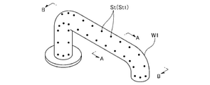
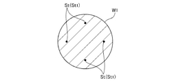
次いで、目標位置設定部3Aは、図4に示すように、ワークW1に対し、目標位置Stをロボット座標系で設定する。目標位置設定部3Aは、図5および図6に示すように、ワークW1の外表面よりも奥まった位置、すなわち、内側に目標位置Stを複数設定する。目標位置Stをこのように設定することにより、後述する第1作業時に、より確実にエンドエフェクター20とワークW1を接触させることができ、より正確な作業を行うことができる。
Next, as shown in FIG. 4, the target
また、目標位置設定部3Aは、各目標位置Stを所定の間隔で設定する。これらの間隔は、全て同じであってもよく、異なる箇所があってもよい。また、これらの間隔は、予め設定されていてもよく、教示装置4を用いて作業者が設定する構成であってもよい。
Further, the target
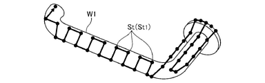
次いで、各目標位置Stに対してロボットアーム10の制御点CPまたはツールセンターポイントTCPが移動する順番を設定する。すなわち、ロボットアーム10の動作経路を設定する。例えば、動作経路は、最初の目標位置Stを作業開始位置として、隣り合う目標位置Stを順次通過するような経路である。なお、動作経路は、予め設定されていてもよく、教示装置4を用いて作業者が設定する構成であってもよい。また、「目標位置Stに対してロボットアーム10の制御点CPまたはツールセンターポイントTCPが移動する」とは、制御点CPまたはツールセンターポイントTCPが目標位置Stと一致するまで移動しなくても、目標位置Stを目標として移動することを言う。
Next, the order in which the control point CP or the tool center point TCP of the
また、作業開始位置は、実際にワークW1が置かれている位置や、ロボットアーム10の姿勢、すなわち、制御点CPの位置に応じて設定することができる。例えば、制御点CPに一番近い目標位置Stを作業開始位置とすることができる。
Further, the work start position can be set according to the position where the work W1 is actually placed and the posture of the
なお、各目標位置Stに対してロボットアーム10の制御点CPまたはツールセンターポイントTCPが移動する順番を設定する際、各目標位置Stに対してロボットアーム10が接近する姿勢も設定する。すなわち、各目標位置Stに対して順番を設定する際、目標位置Stごとにどの方向からどのような姿勢で接近するかを紐づけて記憶部3Cに記憶する。
When setting the order in which the control point CP or the tool center point TCP of the
駆動制御部3Bは、ロボットアーム10の駆動を制御するものであり、位置制御部30と、座標変換部31と、座標変換部32と、補正部33と、力制御部34と、指令統合部35と、を有する。
The
位置制御部30は、予め作成されたコマンドで指定される位置に従って、ロボット1のツールセンターポイントTCPの位置を制御する位置指令信号を生成する。すなわち、位置制御部30は、各目標位置StにツールセンターポイントTCPが移動する位置指令値Pを生成する。
The
ここで、制御装置3は、ロボット1の動作を力制御等で制御することが可能である。「力制御」とは、力検出部19の検出結果に基づいて、エンドエフェクター20の位置、すなわち、ツールセンターポイントTCPの位置や、第1アーム12~第6アーム17の姿勢を変更したりするロボット1の動作の制御のことである。
Here, the
力制御には、例えば、フォーストリガー制御と、インピーダンス制御とが含まれている。フォーストリガー制御では、力検出部19により力検出を行い、その力検出部19により所定の力を検出するまで、ロボットアーム10に移動や姿勢の変更の動作をさせる。
Force control includes, for example, force trigger control and impedance control. In the force trigger control, the
インピーダンス制御は、倣い制御を含む。まず、簡単に説明すると、インピーダンス制御では、ロボットアーム10の先端部に加わる力を可能な限り所定の力に維持、すなわち、力検出部19により検出される所定方向の力を可能な限り目標力fStに維持するようにロボットアーム10の動作を制御する。これにより、例えば、ロボットアーム10に対してインピーダンス制御を行うと、ロボットアーム10は、対象物や、オペレーターから加わった外力に対し、前記所定方向について倣う動作を行う。なお、目標力fStには、0も含まれる。例えば、倣い動作の場合には、目標値を「0」とすることができる。なお、目標力fStを0以外の数値とすることもできる。この目標力fStは、作業者が適宜設定可能である。
Impedance control includes copying control. First, briefly explaining, in impedance control, the force applied to the tip of the
記憶部3Cは、モーターM1~モーターM6の回転角度の組み合わせと、ロボット座標系におけるツールセンターポイントTCPの位置との対応関係を記憶している。また、制御装置3は、ロボット1が行う作業の工程ごとに目標位置Stと目標力fStとの少なくとも一方をコマンドに基づいて記憶部3Cに記憶する。目標位置Stおよび目標力fStを引数、すなわち、パラメーターとするコマンドは、ロボット1が行う作業の工程ごとに設定される。
The
駆動制御部3Bは、設定された目標位置Stと目標力fStとがツールセンターポイントTCPにて一致されるように、コマンドに基づいて第1アーム12~第6アーム17を制御する。目標力fStとは、第1アーム12~第6アーム17の動作に応じて力検出部19が検出すべき力である。ここで、「S」の文字は、ロボット座標系を規定する軸の方向(X,Y,Z,U,V,W)のいずれか1つの方向を表すこととする。また、Sは、S方向の位置も表すこととする。例えば、S=Xの場合、ロボット座標系にて設定された目標位置のX方向成分がSt=Xtとなり、目標力のX方向成分がfSt=fXtとなる。
The
また、駆動制御部3Bでは、モーターM1~モーターM6の回転角度を取得すると、図2に示す座標変換部31が、対応関係に基づいて、当該回転角度をロボット座標系におけるツールセンターポイントTCPの位置S(X,Y,Z,V,W,U)に変換する。そして、座標変換部32が、ツールセンターポイントTCPの位置Sと、力検出部19の検出値とに基づいて、力検出部19に実際に作用している作用力fSをロボット座標系において特定する。
Further, when the
作用力fSの作用点は、ツールセンターポイントTCPとは別に原点として定義される。原点は、力検出部19が力を検出している点に対応する。なお、制御装置3は、ロボット座標系におけるツールセンターポイントTCPの位置Sごとに、力検出部19のセンサー座標系における検出軸の方向を規定した対応関係を記憶している。従って、制御装置3は、ロボット座標系におけるツールセンターポイントTCPの位置Sと対応関係とに基づいて、ロボット座標系における作用力fSを特定できる。また、ロボットに作用するトルクは、作用力fSと、接触点から力検出部19までの距離とから算出することができ、トルク成分として特定される。なお、ワークW1およびワークW2に対してエンドエフェクター20が接触して作業を行う場合、接触点は、ツールセンターポイントTCPとみなすことができる。
The point of action of the acting force fS is defined as the origin separately from the tool center point TCP. The origin corresponds to the point where the
補正部33は、作用力fSに対して重力補償を行う。重力補償とは、作用力fSから重力に起因する力やトルクの成分を除去することである。重力補償を行った作用力fSは、ロボットアーム10またはエンドエフェクター20に作用している重力以外の力と見なすことができる。
The correction unit 33 compensates for the acting force fS by gravity. Gravity compensation is to remove the components of force and torque caused by gravity from the acting force fS . The gravitationally compensated acting force fS can be regarded as a force other than gravity acting on the
また、補正部33は、作用力fSに対して慣性補償を行う。慣性補償とは、作用力fSから慣性力に起因する力やトルクの成分を除去することである。慣性補償を行った作用力fSは、ロボットアーム10またはエンドエフェクター20に作用している慣性力以外の力と見なすことができる。
Further, the correction unit 33 performs inertial compensation for the acting force fS . Inertia compensation is to remove the force and torque components caused by the inertial force from the acting force fS . The inertially compensated acting force fS can be regarded as a force other than the inertial force acting on the
力制御部34は、インピーダンス制御を行う。インピーダンス制御は、仮想の機械的インピーダンスをモーターM1~モーターM6によって実現する能動インピーダンス制御である。制御装置3は、このようなインピーダンス制御を、ワークの嵌合作業、螺合作業、研磨作業等、エンドエフェクター20が対象物であるワークから力を受ける接触状態の工程や、直接教示を行う際に実行する。なお、このような工程以外であっても、例えば、人がロボット1に接触した際にインピーダンス制御を行うことにより、安全性を高めることができる。
The
インピーダンス制御では、目標力fStを後述する運動方程式に代入してモーターM1~モーターM6の回転角度を導出する。制御装置3がモーターM1~モーターM6を制御する信号は、PWM(Pulse Width Modulation)変調された信号である。
In impedance control, the target force fSt is substituted into the equation of motion described later to derive the rotation angles of the motors M1 to M6. The signals for which the
また、制御装置3は、エンドエフェクター20が外力を受けない非接触状態の工程では、目標位置Stから線形演算で導出する回転角度でモーターM1~モーターM6を制御する。目標位置Stから線形演算で導出する回転角度でモーターM1~モーターM6を制御するモードのことを、位置制御モードと言う。
Further, in the non-contact process in which the
制御装置3は、目標力fStと作用力fSとをインピーダンス制御の運動方程式に代入することにより、力由来補正量ΔSを特定する。力由来補正量ΔSとは、ツールセンターポイントTCPが機械的インピーダンスを受けた場合に、目標力fStとの力偏差ΔfS(t)を解消するために、ツールセンターポイントTCPが移動すべき位置Sの大きさを意味する。下記の式(1)は、インピーダンス制御の運動方程式である。
The
![]()
![]()
式(1)の左辺は、ツールセンターポイントTCPの位置Sの2階微分値に仮想質量係数m(以下、「質量係数m」と言う)を乗算した第1項と、ツールセンターポイントTCPの位置Sの微分値に仮想粘性係数d(以下、「粘性係数d」と言う)を乗算した第2項と、ツールセンターポイントTCPの位置Sに仮想弾性係数k(以下、「弾性係数k」と言う)を乗算した第3項とによって構成される。式(1)の右辺は、目標力fStから現実の力fを減算した力偏差ΔfS(t)によって構成される。式(1)における微分とは、時間による微分を意味する。ロボット1が行う工程において、目標力fStとして一定値が設定される場合もあるし、目標力fStとして時間の関数が設定される場合もある。
The left side of the equation (1) is the first term obtained by multiplying the second-order differential value of the position S of the tool center point TCP by the virtual mass coefficient m (hereinafter referred to as “mass coefficient m”) and the position of the tool center point TCP. The second term obtained by multiplying the differential value of S by the virtual viscosity coefficient d (hereinafter referred to as "viscosity coefficient d") and the position S of the tool center point TCP are referred to as the virtual elasticity coefficient k (hereinafter referred to as "elastic coefficient k"). ) Is multiplied by the third term. The right side of the equation (1) is composed of a force deviation Δf S (t) obtained by subtracting the actual force f from the target force f St. The derivative in the equation (1) means the derivative with time. In the process performed by the
質量係数mは、ツールセンターポイントTCPが仮想的に有する質量を意味し、粘性係数dは、ツールセンターポイントTCPが仮想的に受ける粘性抵抗を意味し、弾性係数kは、ツールセンターポイントTCPが仮想的に受ける弾性力のバネ定数を意味する。 The mass coefficient m means the mass virtually possessed by the tool center point TCP, the viscosity coefficient d means the viscosity resistance virtually received by the tool center point TCP, and the elastic modulus k means the virtual resistance of the tool center point TCP. It means the spring constant of the elastic force received.
質量係数mの値が大きくなるにつれて、動作の加速度が小さくなり、質量係数mの値が小さくなるにつれて動作の加速度が大きくなる。粘性係数dの値が大きくなるにつれて、動作の速度が遅くなり、粘性係数dの値が小さくなるにつれて動作の速度が速くなる。弾性係数kの値が大きくなるにつれて、バネ性が大きくなり、弾性係数kの値が小さくなるにつれて、バネ性が小さくなる。 As the value of the mass coefficient m increases, the acceleration of operation decreases, and as the value of the mass coefficient m decreases, the acceleration of operation increases. As the value of the viscosity coefficient d increases, the speed of operation slows down, and as the value of the viscosity coefficient d decreases, the speed of operation increases. As the value of the elastic modulus k increases, the springiness increases, and as the value of the elastic modulus k decreases, the springiness decreases.
本明細書では、質量係数m、粘性係数dおよび弾性係数kの各々を力制御パラメーターと言う。これら質量係数m、粘性係数dおよび弾性係数kは、方向ごとに異なる値に設定されてもよいし、方向に関わらず共通の値に設定されてもよい。また、質量係数m、粘性係数dおよび弾性係数kは、作業者が、作業前に適宜設定可能である。 In the present specification, each of the mass coefficient m, the viscosity coefficient d, and the elastic modulus k is referred to as a force control parameter. The mass coefficient m, the viscosity coefficient d, and the elastic modulus k may be set to different values for each direction, or may be set to common values regardless of the direction. Further, the mass coefficient m, the viscosity coefficient d, and the elastic modulus k can be appropriately set by the operator before the work.
このように、ロボットシステム100では、力検出部19の検出値、予め設定された力制御パラメーター、および、予め設定された目標力から力由来補正量ΔSを求める。力由来補正量ΔSは、外力を受けたその位置からツールセンターポイントTCPを移動すべき位置との差のことである。
As described above, in the
そして、指令統合部35は、位置制御部30が生成した位置指令値Pに、力由来補正量ΔSを合算する。これを随時行うことにより、指令統合部35は、外力を受けた位置に移動させるために用いていた位置指令値Pから、新たな位置指令値である位置指令値P’を求める。なお、位置指令値Pは、目標位置StにツールセンターポイントTCPを移動させるための指令値のことである。
Then, the
そして、この位置指令値P’を座標変換部31がロボット座標に変換し、実行部351が実行することにより、力由来補正量ΔSを加味した位置にツールセンターポイントTCPを移動させて、外力が加わった衝撃を緩和し、ロボット1に接触した対象物に対し、それ以上負荷がかかるのを緩和することができる。
Then, the position command value P'is converted into robot coordinates by the coordinate
ここで、力制御において、力検出部19により検出される所定方向の力を可能な限り目標力fStに維持するためには、ロボットアーム10の動作速度を比較的遅くする必要がある。特に、エンドエフェクター20とワークW1とをより確実に接触させるためには、図5および図6に示すように、ワークW1の外表面よりも奥まった位置、すなわち、内側に目標位置Stを設定する。このため、実際にエンドエフェクター20とワークW1とが接触する位置は、ずれている。エンドエフェクター20とワークW1とが接触するまでは、いつ接触してもワークW1に過剰な負荷がかからないようにロボットアーム10の動作速度を比較的低くする必要がある。このため、図8に示すように、実際にエンドエフェクター20とワークW1とが接触する位置と、目標位置Stとのずれ量Dが比較的大きいと、ロボットアーム10の動作速度をさらに遅くする必要があり、作業時間が長くなってしまう。特に、複数のワークに対して作業を行う場合、累積の作業時間が長くなってしまう。これに対し、本発明では、以下のようにして、累積の作業時間を短縮することができる。
Here, in the force control, in order to maintain the force in the predetermined direction detected by the
なお、以下では、ワークW1に設定された目標位置Stを目標位置St1と言い、ワークW2に設定された目標位置Stを目標位置St2と言う。また、ワークW1に対する作業を第1作業と言い、ワークW2に対する作業を第2作業と言う。 In the following, the target position St set in the work W1 is referred to as a target position St1 , and the target position St set in the work W2 is referred to as a target position St2 . Further, the work on the work W1 is referred to as a first work, and the work on the work W2 is referred to as a second work.
ロボットシステム100では、第1作業を行う際、目標位置設定部3Aが、図5および図6に示すように、ワークW1の外表面よりも奥まった位置、すなわち、内側に目標位置Stを複数設定する。これは、前述したように、力制御によりロボットアーム10を駆動する際、エンドエフェクター20とワークW1とをより確実に接触させるためである。
In the
作業開始位置の目標位置St1に向かってエンドエフェクター20を移動させて、エンドエフェクター20とワークW1とが接触すると、力検出部19がワークW1からの反力を検出する。そして、この反力が目標力fStと一致するように、前述したような力制御を行う。そして、力制御でロボットアーム10を駆動しつつ、ツールセンターポイントTCPが予め設定された順番で目標位置St1に向かうようロボットアーム10を駆動することにより、第1作業が行われる。
When the
また、各目標位置St1において、目標位置St1からずれ量Dをキャンセルした位置、すなわち、実際に作業を行った位置を記憶部3Cに記憶する。すなわち、第1作業において、ツールセンターポイントTCPが通過した軌道を記憶部3Cに記憶する。なお、軌道とは、ツールセンターポイントTCPが移動した点の集合のことを言う。なお、記憶する間隔、タイミングは、特に限定されないが、本実施形態では、目標位置St1ごとに記憶することとする。
Further, at each target position St1 , the position where the deviation amount D is canceled from the target position St1 , that is, the position where the work is actually performed is stored in the
第1作業が完了すると第2作業に移行する。なお、第1作業が完了したとき、作業者、または、ロボットアーム10がワークW1と同じ位置にワークW2を搬送してきてもよく、図1に示すように、異なる位置にて作業を順次行ってもよい。この場合、ワークW1およびワークW2の位置ずれを考慮して、目標位置St1および目標位置St2をそれぞれ設定する。
When the first work is completed, the process proceeds to the second work. When the first work is completed, the worker or the
そして、ワークW2に目標位置St2を設定する際、記憶部3Cに記憶されている第1位置情報に基づいて、ロボットアーム10に対する位置指令値Pを更新する。具体的には、図9に示すように、第1作業で実際にツールセンターポイントTCPが移動した第1位置情報を目標位置St2に設定する。次いで、この目標位置St2に対応する位置指令値Pを更新して、更新値を算出する。つまり、更新値とは、更新された位置指令値Pのことである。そして、この更新値に基づいて、第2作業を力制御により実行する。これにより、第2作業における目標位置St2を、第1作業における目標位置St1よりも外表面側にシフトさせることができる。すなわち、第1作業において実際にツールセンターポイントTCPが通過した位置を目標位置として力制御を行うことができる。よって、第2作業におけるずれ量Dを第1作業よりも小さくすることができ、第2作業では、第1作業よりもロボットアーム10の動作速度を早くすることができる。その結果、第2作業を迅速に行うことができ、累積の作業時間を短縮することができる。
Then, when the target position St2 is set in the work W2, the position command value P for the
このように、本発明のロボットシステム100は、第1作業対象物であるワークW1に対して第1作業を行い、ワークW1と同種の第2作業対象物であるワークW2に対して第1作業と同種の第2作業を行うロボットアーム10と、記憶部3Cを有し、ロボットアーム10の作動を制御する制御部である制御装置3と、を備える。また、制御装置3は、所定の位置指令値に基づいて力制御によりロボットアーム10を動作させてワークW1に対して第1作業を実行し、ロボットアーム10に設定された制御点CPが、第1作業において通過した軌道の第1位置情報を記憶し、記憶した第1位置情報に基づいてロボットアーム10に対する位置指令値を更新し、更新した位置指令値Pである更新値に基づいて力制御によりロボットアームを動作させてワークW2に対して第2作業を実行する。これにより、第2作業において、実際にエンドエフェクター20とワークW1とが接触する位置と、目標位置Stとのずれ量Dを、第1作業よりも小さくすることができる。よって、第2作業では、第1作業よりもロボットアーム10の動作速度を早くすることができる。その結果、第2作業を迅速に行うことができ、累積の作業時間を短縮することができる。
As described above, the
次に、図10および図11に示すフローチャートを参照しつつ説明する。まず、図10に示すフローチャートを用いて、ワークW1に対する作業について説明する。 Next, it will be described with reference to the flowcharts shown in FIGS. 10 and 11. First, the work on the work W1 will be described with reference to the flowchart shown in FIG.
まず、ステップS101において、ワークW1に対し、目標位置St1を設定する。この目標位置St1は、ワークW1の外表面よりも奥まった位置、すなわち、内側に位置している。また、本ステップにおいて、各目標位置St1を通過する順番も設定する。 First, in step S101, the target position St1 is set for the work W1. This target position St1 is located deeper than the outer surface of the work W1, that is, inside. Further, in this step, the order of passing through each target position St1 is also set.
次いで、ステップS102において、力制御により第1作業を開始するとともに、逐次軌道計画処理を行う。この逐次軌道計画処理によって、軌道計画で生成した軌道に従ったアームの位置指令値Pを計算し、力制御によりロボットアーム10を駆動する。
Next, in step S102, the first work is started by force control, and the sequential trajectory planning process is performed. By this sequential trajectory planning process, the position command value P of the arm according to the trajectory generated by the trajectory plan is calculated, and the
ステップS103において、位置指令値Pに力由来補正量ΔSを合算して、位置指令値P’を算出する。すなわち、力検出部19が検出した検出値、すなわち、ワークW1から受けた反力に応じて、力由来補正量ΔSを算出し、位置指令値Pに合算して、新たな位置指令値P’を求める。
In step S103, the force-derived correction amount ΔS is added to the position command value P to calculate the position command value P'. That is, the force-derived correction amount ΔS is calculated according to the detection value detected by the
次いで、ステップS104では、ステップS103で算出した位置指令値P’を記憶する。すなわち、第1作業において、ツールセンターポイントTCPが通過した軌道、すなわち、第1位置情報を記憶部3Cに記憶する。
Next, in step S104, the position command value P'calculated in step S103 is stored. That is, in the first operation, the trajectory through which the tool center point TCP has passed, that is, the first position information is stored in the
次いで、ステップS105では、ステップS103で算出した位置指令値P’をロボットアーム10に送信する。これにより、ワークW1に過剰な負荷をかけることなく第1作業を行うことができる。
Next, in step S105, the position command value P'calculated in step S103 is transmitted to the
次いで、ステップS106において、全ての目標位置St1を目標として移動が完了したか否かを判断する。未だ完了していないと判断した場合、ステップS102に戻り、以下のステップを順次繰り返す。 Next, in step S106, it is determined whether or not the movement is completed with all the target positions St1 as targets. If it is determined that the process has not been completed yet, the process returns to step S102, and the following steps are sequentially repeated.
以上のような第1作業において、ステップS102、ステップS103およびステップS105が、第1作業ステップである。また、ステップS104が第1記憶ステップである。なお、本実施形態では、第1作業ステップと第1記憶ステップとを並行して行うが、本発明ではこれに限定されず、第1作業ステップと第1記憶ステップとを順次行ってもよい。すなわち、ステップS102、ステップS103およびステップS106が完了した後にステップS104を行ってもよい。 In the first work as described above, step S102, step S103 and step S105 are the first work steps. Further, step S104 is the first storage step. In the present embodiment, the first work step and the first storage step are performed in parallel, but the present invention is not limited to this, and the first work step and the first storage step may be sequentially performed. That is, step S104 may be performed after step S102, step S103, and step S106 are completed.
次に、第2作業について説明する。
まず、ステップS201において、1回目の作業時のデータを読み出し、目標位置を設定する。すなわち、第1作業においてステップS104で記憶した第1位置情報を読み出し、目標位置St2として設定する。さらに換言すれば、第1作業時にツールセンターポイントTCPが移動した位置を目標位置St2に設定する。
Next, the second work will be described.
First, in step S201, the data at the time of the first work is read out and the target position is set. That is, the first position information stored in step S104 in the first operation is read out and set as the target position St2 . In other words, the position where the tool center point TCP was moved during the first work is set to the target position St2 .
次いで、ステップS202において、力制御により第2作業を開始するとともに、逐次軌道計画処理を行う。このステップでは、第1位置情報に基づいて位置指令値を更新し、更新値に基づいて力制御を行う。これにより、ロボットアーム10の動作速度を第1作業よりも早くすることができる。
Next, in step S202, the second work is started by force control, and the sequential trajectory planning process is performed. In this step, the position command value is updated based on the first position information, and the force is controlled based on the updated value. As a result, the operating speed of the
次いで、ステップS203において、力検出部19が検出した検出値、すなわち、ワークW1から受けた反力が所定値を超えたか否かを判断する。ここで言う所定値とは、検出した力の大きさの閾値であり、予め記憶部3Cに記憶されている。
Next, in step S203, it is determined whether or not the detection value detected by the
ステップS203において、力検出部19が検出した検出値が所定値を超えていないと判断した場合、ステップS204、ステップS205、ステップS206およびステップS207を順次行う。これらのステップは、第1作業におけるステップS103~ステップS106と略同様であるため、その説明を省略する。なお、ステップS206は、第2記憶ステップである。
If it is determined in step S203 that the detection value detected by the
ステップS203において、力検出部19が検出した検出値が所定値を超えたと判断した場合、ステップS105において、ロボットアーム10の動作速度を調節する。
ステップS105としては、以下のような2つのパターンがある。
If it is determined in step S203 that the detection value detected by the
Step S105 has the following two patterns.
1つ目のパターンは、第2作業ステップでは、ロボットアーム10に加わる力が所定値を超えた場合、制御点CPの移動速度を低下させてロボットアーム10を動作させる。これにより、第2作業では、第1作業よりも動作速度を上げたとしても、ワークW2に過剰な負荷がかるのを防止または抑制することができる。また、第2作業を止めることがないため、生産性を高めることができる。
In the first pattern, in the second work step, when the force applied to the
2つめのパターンは、第2作業ステップでは、ロボットアーム10に加わる力が所定値を超えた場合、ロボットアーム10の動作を停止する。これにより、第2作業では、第1作業よりも動作速度を上げたとしても、ワークW2に過剰な負荷がかるのを防止または抑制することができる。また、動作を停止するため、より安全性を高めることができる。
In the second pattern, in the second work step, when the force applied to the
なお、2つめのパターンでは、例えば作業者からの指示により、作業を再開する構成とすることができる。 In the second pattern, for example, the work can be restarted according to an instruction from the worker.
以上のような第2作業において、ステップS202、ステップS203、ステップS204、ステップS205、ステップS207およびステップS208が、第2作業ステップである。また、ステップS206が第2記憶ステップである。なお、本実施形態では、第2作業ステップと第2記憶ステップとを並行して行うが、本発明ではこれに限定されず、第2作業ステップと第2記憶ステップとを順次行ってもよい。すなわち、ステップS202、ステップS203、ステップS204、ステップS205、ステップS207およびステップS208が完了した後にステップS206を行ってもよい。 In the second work as described above, step S202, step S203, step S204, step S205, step S207 and step S208 are the second work steps. Further, step S206 is a second storage step. In the present embodiment, the second work step and the second storage step are performed in parallel, but the present invention is not limited to this, and the second work step and the second storage step may be performed in sequence. That is, step S206 may be performed after step S202, step S203, step S204, step S205, step S207 and step S208 are completed.
以上説明したように、本発明のロボットの制御方法は、第1作業対象物であるワークW1に対して第1作業を行い、ワークW1と同種の第2作業対象物であるワークW2に対して第1作業と同種の第2作業を行うロボットアーム10を有するロボットの制御方法である。また、ロボットの制御方法は、所定の位置指令値に基づいて力制御によりロボットアーム10を動作させて第1作業対象物に対して第1作業を実行する第1作業ステップと、ロボットアーム10に設定された制御点CPが、第1作業ステップにおいて通過した軌道の第1位置情報を記憶する第1記憶ステップと、第1記憶ステップにおいて記憶した第1位置情報に基づいてロボットアーム10に対する位置指令値を更新し、更新した位置指令値Pである更新値に基づいて力制御によりロボットアーム10を動作させてワークW2に対して第2作業を実行する第2作業ステップと、を有する。これにより、第2作業において、実際にエンドエフェクター20とワークW1とが接触する位置と、目標位置Stとのずれ量Dを、第1作業よりも小さくすることができる。よって、第2作業では、第1作業よりもロボットアーム10の動作速度を早くすることができる。その結果、第2作業を迅速に行うことができ、累積の作業時間を短縮することができる。
As described above, in the robot control method of the present invention, the first work is performed on the work W1 which is the first work object, and the work W2 which is the second work object of the same type as the work W1 is subjected to the first work. This is a control method for a robot having a
また、第1作業と第2作業とは、連続して行われる作業である。換言すれば、第1作業は、第2作業の直前の作業である。さらに換言すれば、ロボット1は、第1作業を行った後、他の作業をすることなく、第2作業を実行する。第1作業および第2作業がこのような関係であることにより、累積の作業時間を効果的に短縮することができる。
Further, the first work and the second work are works performed continuously. In other words, the first work is the work immediately before the second work. In other words, after performing the first work, the
また、図示はしないが、第2作業ステップが完了した後に、ワークW1およびワークW2とは別で、かつ、同種のワークに対して第3作業を行ってもよい。すなわち、ワークの数に応じて、第3作業ステップ、または、それ以降のステップを行ってもよい。この場合、第3作業ステップでは、第1位置情報および第2位置情報の平均値に基づいてロボットアームに対する位置指令値Pを更新し、更新値に基づいて前記ロボットアームを動作させて第3作業を行うのが好ましい。 Further, although not shown, after the second work step is completed, the third work may be performed on a work of the same type and separately from the work W1 and the work W2. That is, depending on the number of works, the third work step or the subsequent steps may be performed. In this case, in the third work step, the position command value P for the robot arm is updated based on the average value of the first position information and the second position information, and the robot arm is operated based on the updated value to perform the third work. It is preferable to do.
このように、本発明のロボットの制御方法は、第2作業ステップにおいて制御点CPが通過した軌道の第2位置情報を記憶する第2記憶ステップと、第1位置情報および第2位置情報の平均値に基づいてロボットアーム10に対する位置指令値Pを更新し、平均値に基づいて更新した位置指令値Pである更新値に基づいてロボットアーム10を動作させて第3作業を行う第3作業ステップと、を有する。これにより、従来と比較した場合、累積時間をさらに短縮することができる。また、第3作業ステップでは、第1位置情報および第2位置情報の平均値に基づいて位置指令値の更新値を求めるため、過去の傾向を考慮して作業を行うことができる。その結果、さらに迅速かつ正確に作業を行うことができる。
As described above, in the robot control method of the present invention, the second storage step for storing the second position information of the trajectory passed by the control point CP in the second work step, and the averaging of the first position information and the second position information. A third work step in which the position command value P for the
なお、第3作業ステップでは、第2位置情報に基づいて位置指令値Pの更新値を算出してもよい。すなわち、直前の作業での位置情報に基づいて位置指令値Pの更新値を算出してもよい。 In the third work step, the updated value of the position command value P may be calculated based on the second position information. That is, the update value of the position command value P may be calculated based on the position information in the immediately preceding work.
また、第2作業では、目標位置St2の数を第1作業での目標位置St1の数よりも少なくしてもよい、すなわち、間引いてもよい。これにより、ロボットアーム10のさらに移動速度を早くすることができ、より迅速な作業を行うことができる。
Further, in the second work, the number of target positions St2 may be smaller than the number of target positions St1 in the first work, that is, they may be thinned out. As a result, the moving speed of the
また、第2作業では、力制御と位置制御とを併用してもよい。例えば、ワークW2の表面形状が複雑な部分に対しては力制御で作業を行い、ワークW2の表面形状が簡素な部分に対しては位置制御で作業を行ってもよい。これにより、作業の質を落とすことなく、さらに迅速に作業を行うことができる。 Further, in the second work, the force control and the position control may be used together. For example, the work may be performed by force control on the portion where the surface shape of the work W2 is complicated, and the work may be performed by position control on the portion where the surface shape of the work W2 is simple. As a result, the work can be performed more quickly without degrading the quality of the work.
<第2実施形態>
図12は、第2実施形態のロボットシステムの制御装置が生成する学習モデルの概念図である。
<Second Embodiment>
FIG. 12 is a conceptual diagram of a learning model generated by the control device of the robot system of the second embodiment.
以下、図12を参照して本発明のロボットの制御方法およびロボットシステムの第2実施形態について説明するが、前述した実施形態との相違点を中心に説明し、同様の事項はその説明を省略する。 Hereinafter, the robot control method of the present invention and the second embodiment of the robot system will be described with reference to FIG. 12, but the differences from the above-described embodiments will be mainly described, and the same matters will be omitted. do.
制御装置3は、図12に示すように、機械学習により学習モデル200を生成するモデル生成部300を有する。なお、機械学習により学習モデル200を生成するということは、入力データから反復的に学習し、各入力データから読み取れる特徴、傾向等を見出し、その結果を新たな入力データに当てはめて予測しつつ、学習モデル200を生成することを言う。
As shown in FIG. 12, the
学習モデル200とは、入力値を受け取り、評価、判定を行い、その結果を出力値として出力するもののことを言う。入力値は、過去の作業において、制御点CPが実際に通過した位置、すなわち、位置指令値、および、ロボットアーム10に加わる力であり、出力値は、位置指令値の更新値である。
The
モデル生成部300は、例えば、図12に示すようなリカレント型のニューラルネットワークを使用して構築することができる。具体的には、モデル生成部300は、入力層と、中間層と、出力層と、を有する構成とすることができる。各情報が、隣り合う層の情報と、ネットワークでつながり、より大きなネットワークが展開される。また、中間層は、図示の構成では、1層であるが、複数層有しているのが好ましい。これにより、中間層の各層において、情報の重要性に重み付けを行うことができ、さらに正確な故障予測を行うことができる。
The
また、リカレント型のニューラルネットワークでは、前回の時刻の中間層の情報を、今回の時刻の中間層の情報に置き換えてネットワークを構築することができる。よって、時系列情報を考慮したネットワークを構築することができる。その結果、さらに正確な目標位置の設定を行うことができる。 Further, in the recurrent type neural network, the information of the intermediate layer at the previous time can be replaced with the information of the intermediate layer at the current time to construct the network. Therefore, it is possible to construct a network in consideration of time series information. As a result, it is possible to set a more accurate target position.
なお、モデル生成部300における学習法としては、教師あり学習や、教師なし学習や、これらを組み合わせた学習法が挙げられる。教師あり学習の場合、出力値、または、その合否結果を入力値に反映することで、より正確な目標位置の設定を行うことができる。教師なし学習の場合、入力値と出力値のデータの組を大量に準備しておき、モデル生成部300に与えることで、それらのデータセットにある特徴を学習し、入力から結果を推定するモデル、すなわち、その関係性を帰納的に獲得することができる。よって、目標位置の合否の判定に関する情報が与えられなくても、正確な目標位置の設定を行うことができる。その結果、さらに迅速かつ正確な作業を行うことができる。例えば、リカレント型のニューラルネットワークに、例えば誤差逆伝播法を適用することにより、教師なし学習が可能となり、正確な目標位置の設定を行うことができる。
Examples of the learning method in the
このように、制御部である制御装置3は、ロボットアーム10に対する位置指令値と、ロボットアーム10に加わる力を入力とし、更新値を出力とする学習モデル200を生成する。これにより、過去の作業において制御点CPがどの位置を通過し、ロボットアーム10がどれだけの力を受けたかという傾向を考慮しつつ、更新値を出力することができる。よって、さらに正確な目標位置の設定を行うことができる。
As described above, the
<ロボットシステムの他の構成例>
図13は、ロボットシステムについてハードウェアを中心として説明するためのブロック図である。
<Other configuration examples of robot system>
FIG. 13 is a block diagram for explaining the robot system with a focus on hardware.
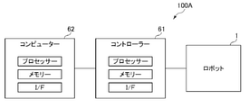
図13には、ロボット1とコントローラー61とコンピューター62が接続されたロボットシステム100Aの全体構成が示されている。ロボット1の制御は、コントローラー61にあるプロセッサーによりメモリーにある指令を読み出して実行されてもよいし、コンピューター62に存在するプロセッサーによりメモリーにある指令を読み出してコントローラー61を介して実行されてもよい。
FIG. 13 shows the overall configuration of the
従って、コントローラー61とコンピューター62とのいずれか一方または両方を「制御装置」として捉えることができる。
Therefore, either one or both of the
<変形例1>
図14は、ロボットシステムのハードウェアを中心とした変形例1を示すブロック図である。
<
FIG. 14 is a block diagram showing a
図14には、ロボット1に直接コンピューター63が接続されたロボットシステム100Bの全体構成が示されている。ロボット1の制御は、コンピューター63に存在するプロセッサーによりメモリーにある指令を読み出して直接実行される。
従って、コンピューター63を「制御装置」として捉えることができる。
FIG. 14 shows the overall configuration of the
Therefore, the
<変形例2>
図15は、ロボットシステムのハードウェアを中心とした変形例2を示すブロック図である。
<Modification 2>
FIG. 15 is a block diagram showing a modification 2 centering on the hardware of the robot system.
図15には、コントローラー61が内蔵されたロボット1とコンピューター66が接続され、コンピューター66がLAN等のネットワーク65を介してクラウド64に接続されているロボットシステム100Cの全体構成が示されている。ロボット1の制御は、コンピューター66に存在するプロセッサーによりメモリーにある指令を読み出して実行されてもよいし、クラウド64上に存在するプロセッサーによりコンピューター66を介してメモリーにある指令を読み出して実行されてもよい。
FIG. 15 shows the overall configuration of a
従って、コントローラー61とコンピューター66とクラウド64とのいずれか1つ、または、いずれか2つ、または、3つを「制御装置」として捉えることができる。
Therefore, any one, two, or three of the
以上、本発明のロボットの制御方法およびロボットシステムを図示の実施形態について説明したが、本発明は、これに限定されるものではない。また、ロボットシステムを構成する各部は、同様の機能を発揮し得る任意の構成のものと置換することができる。また、任意の構成物が付加されていてもよい。 Although the robot control method and the robot system of the present invention have been described above with respect to the illustrated embodiments, the present invention is not limited thereto. Further, each part constituting the robot system can be replaced with an arbitrary configuration capable of exhibiting the same function. Further, any component may be added.
1…ロボット、3…制御装置、3A…目標位置設定部、3B…駆動制御部、3C…記憶部、4…教示装置、10…ロボットアーム、11…基台、12…第1アーム、13…第2アーム、14…第3アーム、15…第4アーム、16…第5アーム、17…第6アーム、18…中継ケーブル、19…力検出部、20…エンドエフェクター、21…研磨部材、30…位置制御部、31…座標変換部、32…座標変換部、33…補正部、34…力制御部、35…指令統合部、41…ディスプレイ、61…コントローラー、62…コンピューター、63…コンピューター、64…クラウド、65…ネットワーク、66…コンピューター、100…ロボットシステム、100A…ロボットシステム、100B…ロボットシステム、100C…ロボットシステム、171…関節、172…関節、173…関節、174…関節、175…関節、176…関節、200…学習モデル、300…モデル生成部、351…実行部、CP…制御点、D…ずれ量、E1…エンコーダー、E2…エンコーダー、E3…エンコーダー、E4…エンコーダー、E5…エンコーダー、E6…エンコーダー、M1…モーター、M2…モーター、M3…モーター、M4…モーター、M5…モーター、M6…モーター、P…位置指令値、P’…位置指令値、St…目標位置、St1…目標位置、St2…目標位置、TCP…ツールセンターポイント、W1…ワーク、W2…ワーク 1 ... Robot, 3 ... Control device, 3A ... Target position setting unit, 3B ... Drive control unit, 3C ... Storage unit, 4 ... Teaching device, 10 ... Robot arm, 11 ... Base, 12 ... First arm, 13 ... 2nd arm, 14 ... 3rd arm, 15 ... 4th arm, 16 ... 5th arm, 17 ... 6th arm, 18 ... relay cable, 19 ... force detector, 20 ... end effector, 21 ... polishing member, 30 ... position control unit, 31 ... coordinate conversion unit, 32 ... coordinate conversion unit, 33 ... correction unit, 34 ... force control unit, 35 ... command integration unit, 41 ... display, 61 ... controller, 62 ... computer, 63 ... computer, 64 ... Cloud, 65 ... Network, 66 ... Computer, 100 ... Robot System, 100A ... Robot System, 100B ... Robot System, 100C ... Robot System, 171 ... Joint, 172 ... Joint, 173 ... Joint, 174 ... Joint, 175 ... Joints, 176 ... joints, 200 ... learning models, 300 ... model generators, 351 ... execution units, CP ... control points, D ... deviations, E1 ... encoders, E2 ... encoders, E3 ... encoders, E4 ... encoders, E5 ... Encoder, E6 ... Encoder, M1 ... Motor, M2 ... Motor, M3 ... Motor, M4 ... Motor, M5 ... Motor, M6 ... Motor, P ... Position command value, P'... Position command value, St ... Target position, S t1 ... target position, St2 ... target position, TCP ... tool center point, W1 ... work, W2 ... work
Claims (7)
所定の位置指令値に基づいて力制御により前記ロボットアームを動作させて前記第1作業対象物に対して前記第1作業を実行する第1作業ステップと、
前記ロボットアームに設定された制御点が、前記第1作業ステップにおいて通過した軌道の第1位置情報を記憶する第1記憶ステップと、
前記第1記憶ステップにおいて記憶した前記第1位置情報に基づいて前記ロボットアームに対する位置指令値を更新し、更新した前記位置指令値である更新値に基づいて力制御により前記ロボットアームを動作させて前記第2作業対象物に対して前記第2作業を実行する第2作業ステップと、を有することを特徴とするロボットの制御方法。 Control of a robot having a robot arm that performs a first work on a first work object and a second work of the same type as the first work on a second work object of the same type as the first work object. It ’s a method,
A first work step in which the robot arm is operated by force control based on a predetermined position command value to execute the first work on the first work object, and
A first storage step in which the control point set on the robot arm stores the first position information of the trajectory passed in the first work step, and
The position command value for the robot arm is updated based on the first position information stored in the first storage step, and the robot arm is operated by force control based on the updated value which is the updated position command value. A robot control method comprising a second work step of executing the second work on the second work object.
前記第1位置情報および前記第2位置情報の平均値に基づいて前記ロボットアームに対する位置指令値を更新し、前記平均値に基づいて更新した前記位置指令値である更新値に基づいて前記ロボットアームを動作させて第3作業を行う第3作業ステップと、を有する請求項1ないし3のいずれか1項に記載のロボットの制御方法。 In the second work step, a second storage step for storing the second position information of the orbit through which the control point has passed, and a second storage step.
The position command value for the robot arm is updated based on the average value of the first position information and the second position information, and the robot arm is updated based on the updated value which is the position command value updated based on the average value. The robot control method according to any one of claims 1 to 3, further comprising a third work step of operating the robot to perform the third work.
記憶部を有し、前記ロボットアームの作動を制御する制御部と、を備え、
前記制御部は、
所定の位置指令値に基づいて力制御により前記ロボットアームを動作させて前記第1作業対象物に対して前記第1作業を実行し、
前記ロボットアームに設定された制御点が、前記第1作業において通過した軌道の第1位置情報を記憶し、
記憶した前記第1位置情報に基づいて前記ロボットアームに対する位置指令値を更新し、
更新した前記位置指令値である更新値に基づいて力制御により前記ロボットアームを動作させて前記第2作業対象物に対して前記第2作業を実行することを特徴とするロボットシステム。 A robot arm that performs the first work on the first work object and performs the second work of the same type as the first work on the second work object of the same type as the first work object.
It has a storage unit, and includes a control unit that controls the operation of the robot arm.
The control unit
The robot arm is operated by force control based on a predetermined position command value to execute the first work on the first work object.
The control point set on the robot arm stores the first position information of the trajectory passed in the first operation, and stores the first position information.
The position command value for the robot arm is updated based on the stored first position information, and the position command value is updated.
A robot system characterized in that the robot arm is operated by force control based on the updated value which is the updated position command value to execute the second work on the second work object.
Priority Applications (3)
| Application Number | Priority Date | Filing Date | Title |
|---|---|---|---|
| JP2020112527A JP2022011402A (en) | 2020-06-30 | 2020-06-30 | Robot control method and robot system |
| CN202110722227.7A CN113858189B (en) | 2020-06-30 | 2021-06-28 | Robot control method and robot system |
| US17/361,425 US11951625B2 (en) | 2020-06-30 | 2021-06-29 | Control method for robot and robot system |
Applications Claiming Priority (1)
| Application Number | Priority Date | Filing Date | Title |
|---|---|---|---|
| JP2020112527A JP2022011402A (en) | 2020-06-30 | 2020-06-30 | Robot control method and robot system |
Publications (1)
| Publication Number | Publication Date |
|---|---|
| JP2022011402A true JP2022011402A (en) | 2022-01-17 |
Family
ID=78990001
Family Applications (1)
| Application Number | Title | Priority Date | Filing Date |
|---|---|---|---|
| JP2020112527A Pending JP2022011402A (en) | 2020-06-30 | 2020-06-30 | Robot control method and robot system |
Country Status (3)
| Country | Link |
|---|---|
| US (1) | US11951625B2 (en) |
| JP (1) | JP2022011402A (en) |
| CN (1) | CN113858189B (en) |
Families Citing this family (2)
| Publication number | Priority date | Publication date | Assignee | Title |
|---|---|---|---|---|
| JP2021049597A (en) * | 2019-09-24 | 2021-04-01 | ソニー株式会社 | Information processing device, information processing system, and information processing method |
| US20230075185A1 (en) * | 2021-09-09 | 2023-03-09 | Ford Global Technologies, Llc | Method and system for positioning a moveable robotic system |
Family Cites Families (12)
| Publication number | Priority date | Publication date | Assignee | Title |
|---|---|---|---|---|
| JPH0631663A (en) | 1992-07-17 | 1994-02-08 | Fujitsu Ltd | Track control device for profile control robot |
| JPH06170763A (en) | 1992-12-04 | 1994-06-21 | Fanuc Ltd | Polishing method using control of force |
| US7117068B2 (en) * | 2003-09-29 | 2006-10-03 | Quantum Corporation | System and method for library robotics positional accuracy using parallax viewing |
| WO2006093652A2 (en) * | 2005-02-25 | 2006-09-08 | Abb Research Ltd. | Method of and apparatus for automated path learning |
| JP5765615B2 (en) | 2011-02-28 | 2015-08-19 | 株式会社Ihi | Trajectory tracking device and method for machining robot |
| JP2015000455A (en) * | 2013-06-17 | 2015-01-05 | キヤノン株式会社 | Robot device and control method for robot device |
| WO2015058297A1 (en) * | 2013-10-25 | 2015-04-30 | Vakanski Aleksandar | Image-based trajectory robot programming planning approach |
| JP5927259B2 (en) * | 2014-09-30 | 2016-06-01 | ファナック株式会社 | Robot system for force control |
| JP6034900B2 (en) * | 2015-03-06 | 2016-11-30 | ファナック株式会社 | Robot control device for judging resumption of operation program |
| JP6567998B2 (en) * | 2016-03-23 | 2019-08-28 | 国立大学法人 東京大学 | Control method |
| CN109483556B (en) * | 2018-10-30 | 2021-04-16 | 武汉大学 | Robot polishing system and method based on teaching learning |
| US10946519B1 (en) * | 2018-11-30 | 2021-03-16 | X Development Llc | Offline computation and caching of precalculated joint trajectories |
-
2020
- 2020-06-30 JP JP2020112527A patent/JP2022011402A/en active Pending
-
2021
- 2021-06-28 CN CN202110722227.7A patent/CN113858189B/en active Active
- 2021-06-29 US US17/361,425 patent/US11951625B2/en active Active
Also Published As
| Publication number | Publication date |
|---|---|
| CN113858189A (en) | 2021-12-31 |
| CN113858189B (en) | 2024-01-09 |
| US11951625B2 (en) | 2024-04-09 |
| US20210402596A1 (en) | 2021-12-30 |
Similar Documents
| Publication | Publication Date | Title |
|---|---|---|
| CN108422420B (en) | Robot system having learning control function and learning control method | |
| US11691290B2 (en) | Robot control method and robot system | |
| CN113858189B (en) | Robot control method and robot system | |
| JP6697544B2 (en) | Optimizer and vertical articulated robot equipped with the same | |
| US11660742B2 (en) | Teaching method and robot system | |
| JP7423943B2 (en) | Control method and robot system | |
| JP2009056593A (en) | Gripping control device | |
| JP2005335010A (en) | Gripping control device | |
| JP2021146435A (en) | Robot system, method to be executed by robot system and method for generating teaching data | |
| CN114833820B (en) | Action parameter adjusting method, recording medium and robot system | |
| CN114179077B (en) | Force control parameter adjustment method, robot system, and storage medium | |
| JP6668629B2 (en) | Robot controller and robot system | |
| CN114367958B (en) | Force control parameter adjusting method | |
| WO2021095833A1 (en) | Master/slave system, and method for controlling same | |
| CN113442131B (en) | Teaching method | |
| US20220314450A1 (en) | Method For Controlling Robot, Robot System, And Storage Medium | |
| EP4067012B1 (en) | Method for controlling robot, robot system, and program for controlling robot | |
| CN114179076B (en) | Work time presentation method, force control parameter setting method, robot system, and storage medium | |
| US20220134565A1 (en) | Control Method For Robot | |
| US20220314451A1 (en) | Method For Controlling Robot, Robot System, And Storage Medium | |
| JP2023039052A (en) | Operational parameter adjustment method | |
| JP2024024201A (en) | Robot control method and robot system | |
| JP2020157459A (en) | Control method and robot system |
Legal Events
| Date | Code | Title | Description |
|---|---|---|---|
| RD04 | Notification of resignation of power of attorney |
Free format text: JAPANESE INTERMEDIATE CODE: A7424 Effective date: 20210913 |
|
| RD03 | Notification of appointment of power of attorney |
Free format text: JAPANESE INTERMEDIATE CODE: A7423 Effective date: 20211104 |
|
| A621 | Written request for application examination |
Free format text: JAPANESE INTERMEDIATE CODE: A621 Effective date: 20230607 |
|
| A977 | Report on retrieval |
Free format text: JAPANESE INTERMEDIATE CODE: A971007 Effective date: 20240221 |
|
| A131 | Notification of reasons for refusal |
Free format text: JAPANESE INTERMEDIATE CODE: A131 Effective date: 20240402 |