JP2022011248A - Game machine - Google Patents
Game machine Download PDFInfo
- Publication number
- JP2022011248A JP2022011248A JP2020112246A JP2020112246A JP2022011248A JP 2022011248 A JP2022011248 A JP 2022011248A JP 2020112246 A JP2020112246 A JP 2020112246A JP 2020112246 A JP2020112246 A JP 2020112246A JP 2022011248 A JP2022011248 A JP 2022011248A
- Authority
- JP
- Japan
- Prior art keywords
- result
- executed
- setting
- processing
- game
- Prior art date
- Legal status (The legal status is an assumption and is not a legal conclusion. Google has not performed a legal analysis and makes no representation as to the accuracy of the status listed.)
- Pending
Links
Images


Classifications
-
- Y—GENERAL TAGGING OF NEW TECHNOLOGICAL DEVELOPMENTS; GENERAL TAGGING OF CROSS-SECTIONAL TECHNOLOGIES SPANNING OVER SEVERAL SECTIONS OF THE IPC; TECHNICAL SUBJECTS COVERED BY FORMER USPC CROSS-REFERENCE ART COLLECTIONS [XRACs] AND DIGESTS
- Y02—TECHNOLOGIES OR APPLICATIONS FOR MITIGATION OR ADAPTATION AGAINST CLIMATE CHANGE
- Y02D—CLIMATE CHANGE MITIGATION TECHNOLOGIES IN INFORMATION AND COMMUNICATION TECHNOLOGIES [ICT], I.E. INFORMATION AND COMMUNICATION TECHNOLOGIES AIMING AT THE REDUCTION OF THEIR OWN ENERGY USE
- Y02D10/00—Energy efficient computing, e.g. low power processors, power management or thermal management
Abstract
Description
本発明は、遊技機に関するものである。 The present invention relates to a gaming machine.
遊技機の一種として、パチンコ機やスロットマシン等が知られている。これらの遊技機では、所定の抽選条件が成立したことに基づいて内部抽選が行われ、当該内部抽選の結果に応じて遊技者に特典が付与される構成が知られている。 Pachinko machines, slot machines, and the like are known as a type of gaming machine. It is known that these gaming machines perform an internal lottery based on the fact that a predetermined lottery condition is satisfied, and a privilege is given to a player according to the result of the internal lottery.
パチンコ機について具体的には、遊技領域に設けられた入球部に遊技球が入球したことに基づく内部抽選にて当選結果となることで特別遊技状態に移行する構成や、所定の入球部に遊技球が入球したことに基づき特別遊技状態に移行する構成が知られている。そして、特別遊技状態に移行した場合には、例えば遊技領域に設けられた入球装置の開閉が開始され、当該入球装置への入球に基づき遊技球が払い出されるようになっている(例えば特許文献1参照)。 Specifically, for pachinko machines, a configuration that shifts to a special gaming state by winning a result in an internal lottery based on the entry of a gaming ball into a ball entry section provided in the gaming area, or a predetermined entry It is known that a pachinko ball enters a club and shifts to a special pachinko state. Then, when the state shifts to the special gaming state, for example, the opening and closing of the ball entry device provided in the game area is started, and the game ball is paid out based on the entry into the ball entry device (for example). See Patent Document 1).
ここで、上記例示等のような遊技機においては制御手段にて処理が好適に実行される必要があり、この点について未だ改良の余地がある。 Here, in a gaming machine such as the above example, it is necessary that the processing is suitably executed by the control means, and there is still room for improvement in this respect.
本発明は、上記例示した事情等に鑑みてなされたものであり、制御手段にて処理を好適に実行することが可能な遊技機を提供することを目的とするものである。 The present invention has been made in view of the above-exemplified circumstances and the like, and an object of the present invention is to provide a gaming machine capable of suitably performing processing by a control means.
上記課題を解決すべく請求項1記載の発明は、各種処理を実行する制御手段を備えた遊技機において、
前記制御手段は、
前記各種処理のうち第1処理群の処理を実行する第1処理群実行手段と、
前記各種処理のうち第2処理群の処理を実行する第2処理群実行手段と、
を備え、
本遊技機は、
前記第1処理群の処理が実行される場合には情報の書き込み及び情報の読み出しが可能である一方、前記第2処理群の処理が実行される場合には情報の読み出しは可能であるものの情報の書き込みが不可である第1処理対応記憶領域と、
前記第2処理群の処理が実行される場合には情報の書き込み及び情報の読み出しが可能である一方、前記第1処理群の処理が実行される場合には情報の読み出しは可能であるものの情報の書き込みが不可である第2処理対応記憶領域と、
を備え、
前記第1処理群実行手段は、前記第1処理群の処理として、第1送信契機が発生した場合に送信情報記憶領域に第1送信情報を記憶させる第1送信情報記憶処理を実行する手段を備え、
前記第2処理群実行手段は、前記第2処理群の処理として、第2送信契機が発生した場合に前記送信情報記憶領域に第2送信情報を記憶させる第2送信情報記憶処理を実行する手段を備え、
本遊技機は、前記送信情報記憶領域に前記第1送信情報が記憶されている場合には当該第1送信情報を送信対象に送信し、前記送信情報記憶領域に前記第2送信情報が記憶されている場合には当該第2送信情報を送信対象に送信する送信実行手段を備えていることを特徴とする。
The invention according to
The control means is
The first processing group execution means for executing the processing of the first processing group among the various processes, and
A second processing group execution means for executing the processing of the second processing group among the various processes,
Equipped with
This gaming machine is
Information can be written and read when the processing of the first processing group is executed, while information can be read when the processing of the second processing group is executed. The storage area corresponding to the first processing, which cannot be written to,
Information can be written and read when the processing of the second processing group is executed, while information can be read when the processing of the first processing group is executed. The second processing-compatible storage area where writing is not possible,
Equipped with
The first processing group execution means, as the processing of the first processing group, is a means for executing a first transmission information storage process for storing the first transmission information in the transmission information storage area when the first transmission trigger occurs. Prepare,
The second processing group execution means is a means for executing a second transmission information storage process for storing the second transmission information in the transmission information storage area when a second transmission trigger occurs as the processing of the second processing group. Equipped with
When the first transmission information is stored in the transmission information storage area, the gaming machine transmits the first transmission information to the transmission target, and the second transmission information is stored in the transmission information storage area. If so, it is characterized in that it is provided with a transmission executing means for transmitting the second transmission information to the transmission target.
本発明によれば、制御手段にて処理を好適に実行することが可能となる。 According to the present invention, it is possible to suitably execute the process by the control means.
<第1の実施形態>
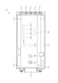
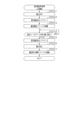
以下、遊技機の一種であるパチンコ遊技機(以下、「パチンコ機」という)の第1の実施形態を、図面に基づいて詳細に説明する。図1はパチンコ機10の斜視図、図2はパチンコ機10の主要な構成を分解して示す斜視図である。なお、図2では便宜上、遊技領域内の構成を省略している。
<First Embodiment>
Hereinafter, a first embodiment of a pachinko gaming machine (hereinafter referred to as “pachinko machine”), which is a type of gaming machine, will be described in detail with reference to the drawings. FIG. 1 is a perspective view of the
パチンコ機10は、図1に示すように、当該パチンコ機10の外殻を形成する外枠11と、この外枠11に対して前方に回動可能に取り付けられた遊技機本体12とを有する。外枠11は木製の板材を四辺に連結し構成されるものであって矩形枠状をなしている。パチンコ機10は、外枠11を島設備に取り付け固定することにより、遊技ホールに設置される。なお、パチンコ機10において外枠11は必須の構成ではなく、遊技ホールの島設備に外枠11が備え付けられた構成としてもよい。
As shown in FIG. 1, the
遊技機本体12は、図2に示すように、内枠13と、その内枠13の前方に配置される前扉枠14と、内枠13の後方に配置される裏パックユニット15とを備えている。遊技機本体12のうち内枠13が外枠11に対して回動可能に支持されている。詳細には、正面視で左側を回動基端側とし右側を回動先端側として内枠13が前方へ回動可能とされている。
As shown in FIG. 2, the gaming machine
内枠13には、前扉枠14が回動可能に支持されており、正面視で左側を回動基端側とし右側を回動先端側として前方へ回動可能とされている。また、内枠13には、裏パックユニット15が回動可能に支持されており、正面視で左側を回動基端側とし右側を回動先端側として後方へ回動可能とされている。
The
なお、遊技機本体12には、その回動先端部に施錠装置が設けられており、遊技機本体12を外枠11に対して開放不能に施錠状態とする機能を有しているとともに、前扉枠14を内枠13に対して開放不能に施錠状態とする機能を有している。これらの各施錠状態は、パチンコ機10前面にて露出させて設けられたシリンダ錠17に対して解錠キーを用いて解錠操作を行うことにより、それぞれ解除される。
The gaming machine
次に、遊技機本体12の前面側の構成について説明する。
Next, the configuration of the front side of the gaming machine
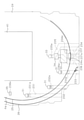
内枠13は、外形が外枠11とほぼ同一形状をなす樹脂ベース21を主体に構成されている。樹脂ベース21の中央部には略楕円形状の窓孔23が形成されている。樹脂ベース21には遊技盤24が着脱可能に取り付けられている。遊技盤24は合板よりなり、遊技盤24の前面に形成された遊技領域PAが樹脂ベース21の窓孔23を通じて内枠13の前面側に露出した状態となっている。
The
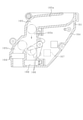
遊技盤24の構成を図3に基づいて説明する。図3は遊技盤24の正面図である。
The configuration of the
遊技盤24には、遊技領域PAの外縁の一部を区画するようにして内レール部25と外レール部26とが取り付けられており、これら内レール部25と外レール部26とにより誘導手段としての誘導レールが構成されている。樹脂ベース21において窓孔23の下方に取り付けられた遊技球発射機構27(図2参照)から発射された遊技球は誘導レールにより遊技領域PAの上部に案内されるようになっている。
An
ちなみに、遊技球発射機構27は、誘導レールに向けて延びる発射レール27aと、後述する上皿66aに貯留されている遊技球を発射レール27a上に供給する球送り装置27bと、発射レール27a上に供給された遊技球を誘導レールに向けて発射させる電動アクチュエータであるソレノイド27cと、を備えている。前扉枠14に設けられた発射操作装置(又は発射ハンドル)28が回動操作されることによりソレノイド27cが駆動制御され、遊技球が発射される。
Incidentally, the game
遊技盤24には、前後方向に貫通する大小複数の開口部が形成されている。各開口部には一般入賞口31、特電入賞装置32、第1作動口33、第2作動口34、スルーゲート35、可変表示ユニット36、特図ユニット37及び普図ユニット38等がそれぞれ設けられている。
The
スルーゲート35への入球が発生したとしても遊技球の払い出しは実行されない。一方、一般入賞口31、特電入賞装置32、第1作動口33及び第2作動口34への入球が発生すると、所定個数の遊技球の払い出しが実行される。当該賞球個数について具体的には、第1作動口33への入球が発生した場合又は第2作動口34への入球が発生した場合には3個の賞球の払い出しが実行され、一般入賞口31への入球が発生した場合には10個の賞球の払い出しが実行され、特電入賞装置32への入球が発生した場合には15個の賞球の払い出しが実行される。
Even if a ball enters the through
なお、上記賞球個数は任意であり、例えば、第2作動口34の方が第1作動口33よりも賞球個数が少ない構成としてもよく、第2作動口34の方が第1作動口33よりも賞球個数が多い構成としてもよい。また、第1作動口33への入球が発生した場合の賞球個数及び第2作動口34への入球が発生した場合の賞球個数の両方が複数である構成に限定されることはなく、第1作動口33への入球が発生した場合の賞球個数が1個である構成としてもよく、第2作動口34への入球が発生した場合の賞球個数が1個である構成としてもよく、両者の賞球個数がいずれも1個である構成としてもよい。
The number of prize balls is arbitrary. For example, the number of prize balls in the
その他に、遊技盤24の最下部にはアウト口24aが設けられており、各種入賞口等に入らなかった遊技球はアウト口24aを通って遊技領域PAから排出される。また、遊技盤24には、遊技球の落下方向を適宜分散、調整等するために多数の釘24bが植設されているとともに、風車等の各種部材が配設されている。
In addition, an out opening 24a is provided at the lowermost portion of the
ここで、入球とは所定の開口部を遊技球が通過することを意味し、開口部を通過した後に遊技領域PAから排出される態様だけではなく、開口部を通過した後に遊技領域PAから排出されることなく遊技領域PAの流下を継続する態様も含まれる。但し、以下の説明では、アウト口24aへの遊技球の入球と明確に区別するために、一般入賞口31、特電入賞装置32、第1作動口33、第2作動口34及びスルーゲート35への遊技球の入球を、入賞とも表現する。
Here, the entry ball means that the game ball passes through a predetermined opening, and not only the mode in which the game ball is discharged from the game area PA after passing through the opening, but also from the game area PA after passing through the opening. A mode in which the flow of the game area PA is continued without being discharged is also included. However, in the following description, in order to clearly distinguish the ball from entering the game ball into the out opening 24a, the general winning
第1作動口33及び第2作動口34は、作動口装置としてユニット化されて遊技盤24に設置されている。第1作動口33及び第2作動口34は共に上向きに開放されている。また、第1作動口33が上方となるようにして両作動口33,34は鉛直方向に並んでいる。
The
可変表示ユニット36における図柄表示装置41の下方の部分である下枠部36aには、第1作動口33の上方において横方向に延在するようにしてステージ部36bが設けられており、可変表示ユニット36における図柄表示装置41の左方の部分である左枠部36cには可変表示ユニット36の左方の領域を流下する遊技球をステージ部36bに誘導することを可能とするワープ通路の入口部36dが形成されている。そして、ステージ部36bの横方向の中央部分は第1作動口33の鉛直上方に存在しており、当該中央部分にはステージ部36bの下方へと遊技球を自重により導出するための導出部36eが形成されている。この場合、ステージ部36bに導出された遊技球であって導出部36e以外の領域からステージ部36bの下方へと導出される遊技球は第1作動口33に入球しづらいが、導出部36eからステージ部36bの下方へと導出される遊技球は第1作動口33に高い確率で入球する。
The lower frame portion 36a, which is a lower portion of the
第1作動口33には、上向きに開放されており、第1作動口33への遊技球の入球を阻止するための開閉部材といった部材は設けられていない。そして、同一の態様で遊技球が発射されている状況では遊技状態に依存することなく第1作動口33への入賞確率は一定となっている。換言すれば、第1作動口33は、遊技領域PAを当該第1作動口33に向けて流下する遊技球が常時入球可能となっている。
The
第2作動口34には、左右一対の可動片よりなるガイド片としての普電役物34aが設けられている。普電役物34aの閉鎖状態では遊技球が第2作動口34に入賞できず、普電役物34aが開放状態となることで第2作動口34への入賞が可能となる。
The
第2作動口34よりも遊技球の流下方向の上流側に、スルーゲート35が設けられている。スルーゲート35は縦方向に貫通した図示しない貫通孔を有しており、スルーゲート35に入賞した遊技球は入賞後に遊技領域PAを流下する。これにより、スルーゲート35に入賞した遊技球が第2作動口34へ入賞することが可能となっている。
A through
スルーゲート35への入賞に基づき第2作動口34の普電役物34aが閉鎖状態から開放状態に切り換えられる。具体的には、スルーゲート35への入賞をトリガとして普図当否判定処理が行われるとともに、遊技領域PAにおいて遊技球が通過しない領域である右下の隅部に設けられた普図ユニット38の普図表示部38aにて絵柄の変動表示が行われる。そして、普図当否判定処理の結果が電役開放当選であり当該結果に対応した停止結果が表示されて普図表示部38aの変動表示が終了された場合に普電開放状態へ移行する。普電開放状態では、普電役物34aが所定の態様で開放状態となる。
Based on the winning of the through
なお、普図表示部38aは、複数のセグメント発光部が所定の態様で配列されてなるセグメント表示器により構成されているが、これに限定されることはなく、液晶表示装置、有機EL表示装置、CRT又はドットマトリックス表示器等その他のタイプの表示装置によって構成されていてもよい。また、普図表示部38aにて変動表示される絵柄としては、複数種の文字が変動表示される構成、複数種の記号が変動表示される構成、複数種のキャラクタが変動表示される構成又は複数種の色が切り換え表示される構成などが考えられる。 The cathode ray display unit 38a is composed of a segment display device in which a plurality of segment light emitting units are arranged in a predetermined manner, but the present invention is not limited to this, and the liquid crystal display device and the organic EL display device are not limited thereto. , CRT or other types of display devices such as dot matrix displays. Further, as the pattern to be variablely displayed on the general map display unit 38a, a configuration in which a plurality of types of characters are variablely displayed, a configuration in which a plurality of types of symbols are variablely displayed, a configuration in which a plurality of types of characters are variablely displayed, or a configuration in which a plurality of types of characters are variablely displayed. A configuration in which multiple types of colors are switched and displayed can be considered.
普図ユニット38において、普図表示部38aに隣接した位置には、普図保留表示部38bが設けられている。遊技球がスルーゲート35に入賞した個数は最大4個まで保留され、普図保留表示部38bの点灯によってその保留個数が表示されるようになっている。
In the
第1作動口33又は第2作動口34への入賞をトリガとして当否判定処理が行われる。そして、当該当否判定処理の結果は特図ユニット37及び可変表示ユニット36の図柄表示装置41における表示演出を通じて明示される。
The winning / failing determination process is performed with the winning of the
特図ユニット37には第1特図表示部37aと第2特図表示部37bとが設けられている。第1特図表示部37aでは、第1作動口33への入賞をトリガとして当否判定処理が行われることで絵柄の変動表示が行われる。そして、当否判定処理の結果に対応した停止結果が表示される。この場合、当否判定処理の結果として後述する大当たり結果、時短結果及び外れ結果が存在しているが、第1特図表示部37aの停止結果の内容は大当たり結果、時短結果及び外れ結果のそれぞれで相違している。第1特図表示部37aにおける停止結果の表示は、次回の遊技回が開始されて第1特図表示部37aにて新たな絵柄の変動表示が開始されるまで維持される。また、第2特図表示部37bでは、第2作動口34への入賞をトリガとして当否判定処理が行われることで絵柄の変動表示が行われる。そして、当否判定処理の結果に対応した停止結果が表示される。この場合、当否判定処理の結果として後述する大当たり結果、時短結果及び外れ結果が存在しているが、第2特図表示部37bの停止結果の内容は大当たり結果、時短結果及び外れ結果のそれぞれで相違している。第2特図表示部37bにおける停止結果の表示は、次回の遊技回が開始されて第2特図表示部37bにて新たな絵柄の変動表示が開始されるまで維持される。
The
なお、第1特図表示部37a及び第2特図表示部37bは、複数のセグメント発光部が所定の態様で配列されてなるセグメント表示器により構成されているが、これに限定されることはなく、液晶表示装置、有機EL表示装置、CRT又はドットマトリックス表示器等その他のタイプの表示装置によって構成されていてもよい。また、第1特図表示部37a及び第2特図表示部37bにて表示される絵柄としては、複数種の文字が表示される構成、複数種の記号が表示される構成、複数種のキャラクタが表示される構成又は複数種の色が表示される構成などが考えられる。
The first special figure display unit 37a and the second special
特図ユニット37において、第1特図表示部37a及び第2特図表示部37bに隣接した位置には、第1特図保留表示部37c及び第2特図保留表示部37dが設けられている。遊技球が第1作動口33に入賞した個数は最大4個まで保留され、第1特図保留表示部37cの点灯によってその保留個数が表示されるようになっている。また、遊技球が第2作動口34に入賞した個数は最大4個まで保留され、第2特図保留表示部37dの点灯によってその保留個数が表示されるようになっている。
In the
図柄表示装置41について詳細には、図柄表示装置41は、液晶ディスプレイを備えた液晶表示装置として構成されており、後述する表示制御装置により表示内容が制御される。なお、図柄表示装置41は、液晶表示装置に限定されることはなく、プラズマディスプレイ装置、有機EL表示装置又はCRTといった表示面を有する他の表示装置であってもよく、ドットマトリクス表示器であってもよい。
Regarding the
図柄表示装置41では、第1作動口33への入賞に基づき第1特図表示部37aにて絵柄の変動表示が行われる場合にそれに合わせて図柄の変動表示が行われるとともに、第2作動口34への入賞に基づき第2特図表示部37bにて絵柄の変動表示が行われる場合にそれに合わせて図柄の変動表示が行われる。なお、図柄表示装置41では、第1作動口33又は第2作動口34への入賞をトリガとした表示演出だけでなく、大当たり結果となった後に移行する後述の開閉実行モード中の表示演出などが行われる。
In the
いずれかの作動口33,34への入賞に基づいて、いずれかの特図表示部37a,37b及び図柄表示装置41にて表示が開始され、当否判定処理の結果に対応する停止結果を表示して終了されて後述する主制御装置71における特図確定中処理の実行が完了するまでが遊技回の1回に相当する。
Based on the winning of any of the operating
本パチンコ機10では、作動口33,34への入賞に基づき当否判定処理が実行され、当否判定処理の結果が大当たり結果となることにより開閉実行モードへ移行する。開閉実行モードでは、特電入賞装置32の開閉制御が実行され、開放状態となっている特電入賞装置32への入賞が発生することで遊技球の払い出しが実行される。具体的には、開閉実行モードでは予め定められた回数のラウンド遊技が実行される。ラウンド遊技とは、予め定められた開放継続期間が経過すること、及び予め定められた上限個数の遊技球が特電入賞装置32に入賞することのいずれか一方の条件が満たされるまで継続する遊技のことである。この場合、発射操作装置28が遊技者により操作されている状況では0.6秒に1個の遊技球が遊技領域PAに向けて発射されるように遊技球発射機構27が駆動制御される構成において、開放継続期間が29秒に設定されているとともに上限個数が10個に設定されている。したがって、ラウンド遊技の開放継続期間は遊技球の発射周期と1回のラウンド遊技の上限個数との積よりも長い時間に設定されていることとなるため、各ラウンド遊技において特電入賞装置32に上限個数以上の遊技球が入賞することを期待することができる。また、ラウンド遊技の上限回数は、その移行の契機となった大当たり結果の種類に応じて相違している。
In the
当否判定処理の当否抽選モードとして、開閉実行モードへの移行が発生する大当たり結果となる確率が相対的に高低となるように高確率モードと低確率モードとが存在している。また、本パチンコ機10では、第2作動口34の普電役物34aが開放状態となる態様が相互に異なるように複数種類のサポートモードが設定されている。詳細には、サポートモードには、遊技領域PAに対して同様の態様で遊技球の発射が継続されている状況で比較した場合に、普電役物34aが単位時間当たりに開放状態となる頻度が相対的に高低となるように、高頻度サポートモード(後述する第1高頻度サポートモード及び第2高頻度サポートモード)と低頻度サポートモードとが設定されている。当否抽選モード及びサポートモードの組合せの種類に応じて開閉実行モードではない状況における遊技状態が相違することとなる。当該遊技状態としては、低確率モードであって低頻度サポートモードである通常遊技状態と、高確率モードであって高頻度サポートモードである高確率状態と、低確率モードであって高頻度サポートモードである時短状態とが設定されている。高確率状態及び時短状態では通常遊技状態よりも1回の遊技回が消化されるのに要する期間の平均期間が短くなる。
As the winning / failing lottery mode of the winning / failing determination process, there are a high probability mode and a low probability mode so that the probability of a jackpot result in which the transition to the open / close execution mode occurs is relatively high or low. Further, in the
第1作動口33及び第2作動口34は共に、遊技領域PAにおいて可変表示ユニット36の下方の領域である下側領域PAUに設置されている。また、第1作動口33及び第2作動口34は、第1作動口33が上方及び第2作動口34が下方となるようにして縦方向に並設された状態で作動口装置としてユニット化されている。また、第2作動口34の普電役物34aはスルーゲート35への入賞を契機として開放状態に制御され得るが、当該スルーゲート35は遊技領域PAにおいて可変表示ユニット36の左方の領域である左側領域PALに配置されている。そして、左側領域PALを流下する遊技球は下側領域PAUに誘導されるとともに、下側領域PAUに誘導された遊技球は第1作動口33及び第2作動口34が設けられた領域に誘導され得る。したがって、第1作動口33への入賞を狙って発射操作を行った場合、第1作動口33への入賞が発生し得るだけではなく第2作動口34への入賞が発生し得ることとなり、第2作動口34への入賞を狙って発射操作を行った場合、第2作動口34への入賞が発生し得るだけではなく第1作動口33への入賞が発生し得る。
Both the
遊技状態が通常遊技状態である場合には上記のとおりサポートモードが低頻度サポートモードとなるため、第2作動口34への入賞が発生しづらくなり、第2作動口34よりも第1作動口33への入賞が発生し易くなる。したがって、通常遊技状態では基本的には遊技回の実行対象が第1特図表示部37aとなり、偶発的に第2作動口34への入賞が発生した場合には第2特図表示部37bが遊技回の実行対象となる。
When the gaming state is the normal gaming state, the support mode becomes the low frequency support mode as described above, so that it is difficult for the
一方、遊技状態が高確率状態又は時短状態である場合には上記のとおりサポートモードが高頻度サポートモードとなるため、第2作動口34への入賞が発生し易くなる。この場合、第1作動口33よりも第2作動口34への入賞が発生し易くなる。但し、既に説明したとおり第2作動口34への入賞を狙って発射操作を行った場合には第1作動口33への入賞が発生し得るとともに、ステージ部36bの導出部36eに誘導された遊技球は高い確率で第1作動口33に入賞することとなるため、高頻度サポートモードであっても低頻度サポートモードと同様の頻度で第1作動口33への入賞が発生することとなる。
On the other hand, when the gaming state is a high probability state or a time saving state, the support mode becomes the high frequency support mode as described above, so that the
遊技回の実行対象となっている特図表示部37a,37bのパターンに対応する態様で、図柄表示装置41にて遊技回用の演出が実行される。遊技回用の演出が実行される場合における図柄表示装置41の表示内容について説明する。
The effect for the game round is executed by the
図4(a)及び図4(b)は遊技回が実行される場合における図柄表示装置41の表示内容を説明するための説明図である。
4 (a) and 4 (b) are explanatory diagrams for explaining the display contents of the
図4(a)に示すように、図柄表示装置41の表示面には、複数の表示領域として、上段・中段・下段の3つの図柄列Z1,Z2,Z3が設定されている。各図柄列Z1~Z3は、主図柄と副図柄が所定の順序で配列されて構成されている。つまり、遊技回が実行される場合、図柄表示装置41の表示面の大部分を利用して図柄の変動表示が行われる。
As shown in FIG. 4A, on the display surface of the
図5(a)~図5(j)は各図柄列Z1~Z3にて変動表示される主図柄及び副図柄を説明するための説明図である。図5(a)~図5(j)に示すように、絵柄の一種である図柄は、「1」~「9」の数字が各々付された9種類の主図柄と、貝形状の絵図柄からなる副図柄とにより構成されている。より詳しくは、タコ等の9種類のキャラクタ図柄に「1」~「9」の数字がそれぞれ付されて主図柄が構成されている。 5 (a) to 5 (j) are explanatory diagrams for explaining the main symbol and the sub symbol which are variablely displayed in the respective symbol rows Z1 to Z3. As shown in FIGS. 5 (a) to 5 (j), the symbols which are a kind of symbols are 9 kinds of main symbols with numbers "1" to "9" and shell-shaped symbols. It is composed of a sub-design consisting of. More specifically, nine types of character symbols such as an octopus are assigned numbers "1" to "9" to form a main symbol.
図4(b)に示すように、上図柄列Z1には、「1」~「9」の9種類の主図柄が数字の降順に配列されるとともに、各主図柄の間に副図柄が1つずつ配されている。下図柄列Z3には、「1」~「9」の9種類の主図柄が数字の昇順に配列されるとともに各主図柄の間に副図柄が1つずつ配されている。つまり、上図柄列Z1と下図柄列Z3は18個の図柄により構成されている。これに対し、中図柄列Z2には、数字の昇順に「1」~「9」の9種類の主図柄が配列された上で「9」の主図柄と「1」の主図柄との間に「4」の主図柄が付加的に配列され、これら各主図柄の間に副図柄が1つずつ配されている。つまり、中図柄列Z2に限っては、10個の主図柄が配されて20個の図柄により構成されている。そして、表示面では、これら各図柄列Z1~Z3の図柄が周期性をもって所定の向きにスクロールするように変動表示される。図柄表示装置41は、図柄列Z1~Z3毎に3個の図柄が停止表示されるようになっており、結果として3×3の計9個の図柄が停止表示されるようになっている。また、図柄表示装置41には、図4(a)に示すように、5つの有効ライン、すなわち左ラインL1、中ラインL2、右ラインL3、右下がりラインL4及び右上がりラインL5が設定されている。
As shown in FIG. 4 (b), in the upper symbol row Z1, nine types of main symbols "1" to "9" are arranged in descending order of numbers, and a sub symbol is 1 between each main symbol. They are arranged one by one. In the lower symbol row Z3, nine types of main symbols "1" to "9" are arranged in ascending order of numbers, and one sub symbol is arranged between each main symbol. That is, the upper symbol row Z1 and the lower symbol row Z3 are composed of 18 symbols. On the other hand, in the middle symbol string Z2, nine types of main symbols "1" to "9" are arranged in ascending order of numbers, and then between the main symbol of "9" and the main symbol of "1". The main symbol of "4" is additionally arranged in the above, and one sub symbol is arranged between each of these main symbols. That is, only in the middle symbol row Z2, 10 main symbols are arranged and composed of 20 symbols. Then, on the display surface, the symbols of each of the symbol rows Z1 to Z3 are variably displayed so as to scroll in a predetermined direction with periodicity. The
第1作動口33又は第2作動口34への入賞に基づいて図柄表示装置41において図柄の変動表示が行われる場合には、各図柄列Z1~Z3の図柄が周期性をもって所定の向きにスクロールするように変動表示が開始される。そして、基本的には上図柄列Z1→下図柄列Z3→中図柄列Z2の順に変動表示から待機表示に切り換えられ、最終的に各図柄列Z1~Z3にて所定の図柄を静止表示した状態で終了される。
When the
図柄の変動表示が終了する場合、後述する主制御装置71における当否判定処理の結果が後述する大当たり結果であった場合にはいずれかの有効ラインL1~L5上に同一の図柄の組合せが形成される。また、当否判定処理の結果が後述する時短結果であった場合であって当該時短結果を契機として時短状態の設定が行われる場合には、図柄の変動表示が終了する場合にいずれかの有効ラインL1~L5上に同一図柄の組合せではなく且つリーチ図柄の組合せでもない所定の図柄の組合せ(例えば「1・2・3」、「3・4・1」)が形成される。この場合、時短結果の種類は後述するように複数種類存在しているため、所定の図柄の組合せの内容も時短結果の種類に応じて相違している。一方、当否判定処理の結果が後述する時短結果であった場合であって当該時短結果を契機とした時短状態の設定が行われない場合には、図柄の変動表示が終了する場合にリーチ図柄の組合せが形成されない非リーチ外れ用の停止図柄が表示される。つまり、当否判定処理の結果が後述する時短結果であった場合であって当該時短結果を契機とした時短状態の設定が行われない場合には、図柄列Z1~Z3における停止結果は当否判定処理の結果が外れ結果であった場合と同じ停止結果となり得る。
When the variation display of the symbol ends, if the result of the hit / fail determination process in the
上記のように各図柄列Z1~Z3にて図柄の変動表示が行われる構成において、遊技回が実行される場合における図柄表示装置41の表示演出として期待演出が設定されている。期待演出とは、図柄表示装置41における図柄の変動表示が開始されてから停止結果が導出表示される前段階で、大当たり結果となり易い変動表示状態であると遊技者に思わせるための表示状態をいう。期待演出には、リーチ表示と、リーチ表示が発生する前段階などにおいてリーチ表示の発生や大当たり結果の発生を期待させるための予告表示との2種類が設定されている。
As described above, in the configuration in which the fluctuation display of the symbols is performed in each of the symbol rows Z1 to Z3, the expected effect is set as the display effect of the
リーチ表示には、複数の図柄列Z1~Z3のうち上図柄列Z1及び下図柄列Z3について同一の種類の図柄を停止表示させることでリーチ図柄の組合せを表示し、その状態で残りの中図柄列Z2において図柄の変動表示を行う表示状態が含まれる。また、上記のようにリーチ図柄の組合せを表示した状態で、残りの図柄列において図柄の変動表示を行うとともに、その背景画面において所定のキャラクタなどを動画として表示することによりリーチ演出を行うものや、リーチ図柄の組合せを縮小表示させる又は非表示とした上で、表示面の略全体において所定のキャラクタなどを動画として表示することによりリーチ演出を行うものが含まれる。大当たり結果となる遊技回であればリーチ図柄の組合せを形成している図柄と同一の種類の図柄が中図柄列Z2におけるリーチライン上に停止表示され、大当たり結果とならない遊技回であればリーチ図柄の組合せを形成している図柄とは異なる種類の図柄が中図柄列Z2におけるリーチライン上に停止表示される。 In the reach display, the combination of reach symbols is displayed by stopping and displaying the same type of symbols for the upper symbol row Z1 and the lower symbol row Z3 among the plurality of symbol rows Z1 to Z3, and the remaining middle symbols are displayed in that state. The display state in which the variable display of the symbol is performed in the column Z2 is included. In addition, in the state where the combination of reach symbols is displayed as described above, the variation display of the symbols is performed in the remaining symbol rows, and the reach effect is performed by displaying a predetermined character or the like as a moving image on the background screen. , A combination of reach symbols is reduced or hidden, and a predetermined character or the like is displayed as a moving image on substantially the entire display surface to perform a reach effect. If it is a game time that results in a big hit, a symbol of the same type as the symbol forming the combination of reach symbols is stopped and displayed on the reach line in the middle symbol row Z2, and if it is a game time that does not result in a big hit, the reach symbol A symbol of a type different from the symbol forming the combination of is stopped and displayed on the reach line in the middle symbol row Z2.
予告表示には、各図柄列Z1~Z3にて図柄の変動表示が開始されてから、全ての図柄列Z1~Z3にて図柄が変動表示されている状況において、又は一部の図柄列Z1~Z3であって複数の図柄列Z1~Z3にて図柄が変動表示されている状況において、図柄列Z1~Z3上の図柄とは別にキャラクタを表示させる態様が含まれる。また、背景画面をそれまでの態様とは異なる所定の態様とするものや、図柄列Z1~Z3上の図柄をそれまでの態様とは異なる所定の態様とするものも含まれる。かかる予告表示は、リーチ表示が行われる場合及びリーチ表示が行われない場合のいずれの遊技回においても発生し得るが、リーチ表示が行われない場合よりもリーチ表示が行われる場合の方が高確率で発生するように設定されている。 In the notice display, after the variable display of the symbols is started in each symbol row Z1 to Z3, the symbols are variablely displayed in all the symbol rows Z1 to Z3, or some of the symbol rows Z1 to Z1 to In a situation where the symbols are variablely displayed in a plurality of symbol rows Z1 to Z3 in Z3, an embodiment in which a character is displayed separately from the symbols on the symbol rows Z1 to Z3 is included. Further, the background screen has a predetermined mode different from the previous mode, and the symbols on the symbol rows Z1 to Z3 have a predetermined mode different from the previous mode. Such a notice display may occur in any of the game times when the reach display is performed and when the reach display is not performed, but it is higher when the reach display is performed than when the reach display is not performed. It is set to occur with a probability.
図柄表示装置41の表示面には図4(b)に示すように図柄列Z1~Z3以外にも保留表示領域42と状態示唆領域43とが設定されている。保留表示領域42は図柄表示装置41の表示面の下部に設定されている。保留表示領域42には、第1作動口33への入賞に基づき後述する主制御装置71にて取得された保留情報の数を遊技者に報知するための画像が表示される第1保留表示領域42aと、第2作動口34への入賞に基づき後述する主制御装置71にて取得された保留情報の数を遊技者に報知するための画像が表示される第2保留表示領域42bとを有する。保留情報とは、主制御装置71における当否判定処理の実行契機となる情報であって遊技回の実行契機となる情報である。第1作動口33への入賞を契機として取得された保留情報(以下、第1保留情報ともいう)は第1特図表示部37aにおける遊技回の実行契機となり、第2作動口34への入賞を契機として取得された保留情報(以下、第2保留情報ともいう)は第2特図表示部37bにおける遊技回の実行契機となる。第1保留情報は最大で4個保留記憶され、第2保留情報も最大で4個保留記憶される。
As shown in FIG. 4B, a
第1保留表示領域42aには第1保留情報の数に対応する数の第1保留画像G1が表示される。つまり、保留記憶されている第1保留情報の数が0個であれば第1保留表示領域42aには第1保留画像G1は表示されない。また、保留記憶されている第1保留情報の数が1個であれば第1保留画像G1が1個表示され、保留記憶されている第1保留情報の数が2個であれば第1保留画像G1が2個表示され、保留記憶されている第1保留情報の数が3個であれば第1保留画像G1が3個表示され、保留記憶されている第1保留情報の数が4個であれば第1保留画像G1が4個表示される。第1保留画像G1が複数表示される場合、それら複数の第1保留画像G1は一定の間隔となるように横並びで表示される。また、保留記憶されている第1保留情報の数が増加する場合には第1保留画像G1が右方に向けて増加するように表示され、第1保留情報が遊技回の開始契機となり保留記憶されている第1保留情報の数が減少する場合には第1保留画像G1が左方に向けて減少するように表示される。 In the first hold display area 42a, a number of first hold images G1 corresponding to the number of first hold information is displayed. That is, if the number of the first reserved information stored on hold is 0, the first reserved image G1 is not displayed in the first reserved display area 42a. Further, if the number of the first reserved information stored on hold is one, one first reserved image G1 is displayed, and if the number of first reserved information stored on hold is two, the first reserved image G1 is displayed. If two images G1 are displayed and the number of first reserved information stored on hold is three, three first reserved images G1 are displayed and the number of first reserved information stored on hold is four. If so, four first reserved images G1 are displayed. When a plurality of first reserved images G1 are displayed, the plurality of first reserved images G1 are displayed side by side at regular intervals. Further, when the number of the first reserved information stored on hold increases, the first reserved image G1 is displayed so as to increase toward the right, and the first reserved information serves as a trigger for the start of the game round and is stored on hold. When the number of the first reserved information being stored decreases, the first reserved image G1 is displayed so as to decrease toward the left.
第2保留表示領域42bには第2保留情報の数に対応する数の第2保留画像G2が表示される。つまり、保留記憶されている第2保留情報の数が0個であれば第2保留表示領域42bには第2保留画像G2は表示されない。また、保留記憶されている第2保留情報の数が1個であれば第2保留画像G2が1個表示され、保留記憶されている第2保留情報の数が2個であれば第2保留画像G2が2個表示され、保留記憶されている第2保留情報の数が3個であれば第2保留画像G2が3個表示され、保留記憶されている第2保留情報の数が4個であれば第2保留画像G2が4個表示される。第2保留画像G2が複数表示される場合、それら複数の第2保留画像G2は一定の間隔となるように横並びで表示される。また、保留記憶されている第2保留情報の数が増加する場合には第2保留画像G2が右方に向けて増加するように表示され、第2保留情報が遊技回の開始契機となり保留記憶されている第2保留情報の数が減少する場合には第2保留画像G2が左方に向けて減少するように表示される。
In the second
なお、図4(b)においては保留記憶されている第1保留情報の数が4個であるとともに第2保留情報の数が4個であることにより、第1保留表示領域42aに第1保留画像G1が4個表示され、第2保留表示領域42bに第2保留画像G2が4個表示されている。
In addition, in FIG. 4B, since the number of the first reserved information stored on hold is four and the number of the second reserved information is four, the first reserved information is first reserved in the first reserved display area 42a. Four images G1 are displayed, and four second reserved images G2 are displayed in the second
状態示唆領域43は図柄表示装置41の表示面の上部に設定されている。状態示唆領域43は図柄列Z1~Z3における図柄の表示領域よりも狭い表示面積となっている。状態示唆領域43では、図柄表示装置41の図柄列Z1~Z3において遊技回用の図柄の変動表示が行われており当該遊技回の当否判定処理の結果に対応する停止結果が停止表示されていない状況では色の切り換え表示が行われる。具体的には、赤→青→緑→赤→青→緑→赤・・・というように所定の表示色パターンが繰り返される。そして、図柄列Z1~Z3において当否判定処理の結果に対応する停止結果が表示されて確定表示(静止表示)が開始されるタイミングで、その時点の遊技状況及び当否判定処理の結果に対応する停止結果が表示される。この場合、当否判定処理の結果が大当たり結果又は外れ結果である場合には状態示唆領域43に赤色が停止表示される。また、当否判定処理の結果が後述する時短結果である場合には、当該時短結果を契機として時短状態の設定が行われる場合にはその時短結果の種類に関係なく赤色が停止表示され、当該時短結果を契機とした時短状態の設定が行われない場合にはその時短結果の種類に応じて青色又は緑色が停止表示される。上記のとおり当否判定処理の結果が後述する時短結果であった場合であって当該時短結果を契機とした時短状態の設定が行われない場合には図柄列Z1~Z3における停止結果が当否判定処理の結果が外れ結果であった場合と同じ停止結果となり得る構成において、当否判定処理の結果が後述する時短結果であった場合であって当該時短結果を契機とした時短状態の設定が行われない場合と、当否判定処理の結果が外れ結果となった場合とで状態示唆領域43の表示内容を異ならせることにより、当否判定処理の結果が後述する時短結果であった場合であって当該時短結果を契機とした時短状態の設定が行われない場合と、当否判定処理の結果が外れ結果となった場合とで図柄表示装置41の全体の表示内容としては異なる表示内容とすることが可能となる。
The
遊技盤24の説明に戻り(図3参照)、当否判定処理の結果が大当たり結果となった場合、既に説明したとおり開閉実行モードに移行する。開閉実行モードでは特電入賞装置32の開閉制御が実行される。特電入賞装置32は、遊技盤24の背面側へと通じる図示しない大入賞口を備えているとともに、当該大入賞口を開閉する開閉扉32aを備えている。開閉扉32aは、閉鎖状態及び開放状態のいずれかに配置される。具体的には、開閉扉32aは、通常は遊技球が入賞できない閉鎖状態になっており、当否判定処理において大当たり結果が選択された場合に遊技球が入賞可能な開放状態に切り換えられるようになっている。なお、閉鎖状態では入賞が不可ではないが開放状態よりも入賞が発生しづらい状態となる構成としてもよい。また、開閉実行モードにおいては、当該開閉実行モードに対応した表示演出が図柄表示装置41にて実行される。
Returning to the explanation of the game board 24 (see FIG. 3), when the result of the hit / fail determination process is a big hit result, the game shifts to the open / close execution mode as described above. In the open / close execution mode, the open / close control of the special
上記構成の遊技盤24が樹脂ベース21に取り付けられてなる内枠13の前面側全体を覆うようにして前扉枠14が設けられている。前扉枠14には、図1に示すように、遊技領域PAのほぼ全域を前方から視認することができるようにした窓部61が形成されている。窓部61は、略楕円形状をなし、窓パネル62が嵌め込まれている。窓パネル62は、ガラスによって無色透明に形成されているが、これに限定されることはなく合成樹脂によって無色透明に形成されていてもよく、パチンコ機10前方から窓パネル62を通じて遊技領域PAを視認可能であれば有色透明に形成されていてもよい。
The
窓部61の上方には表示発光部64が設けられている。また、遊技状態に応じた効果音などが出力される左右一対のスピーカ部65が設けられている。また、窓部61の下方には、手前側へ膨出した上側膨出部66と下側膨出部67とが上下に並設されている。上側膨出部66内側には上方に開口した上皿66aが設けられており、下側膨出部67内側には同じく上方に開口した下皿67aが設けられている。上皿66aは、後述する払出装置より払い出された遊技球を一旦貯留し、一列に整列させながら遊技球発射機構27側へ導くための機能を有する。また、下皿67aは、上皿66a内にて余剰となった遊技球を貯留する機能を有する。
A display
次に、遊技機本体12の背面側の構成について説明する。
Next, the configuration of the back side of the gaming machine
図2に示すように、内枠13(具体的には、遊技盤24)の背面には、遊技の主たる制御を司る主制御装置71が搭載されている。主制御装置71は主制御基板が基板ボックスに収容されてなる。なお、基板ボックスに、その開放の痕跡を残すための痕跡手段を付与する又はその開放の痕跡を残すための痕跡構造を設けてもよい。当該痕跡手段としては、基板ボックスを構成する複数のケース体を分離不能に結合するとともにその分離に際して所定部位の破壊を要する結合部の構成や、引き剥がしに際して粘着層が接着対象に残ることで剥がされたことの痕跡を残す封印シールを複数のケース体間の境界を跨ぐようにして貼り付ける構成が考えられる。また、痕跡構造としては、基板ボックスを構成する複数のケース体間の境界に対して接着剤を塗布する構成が考えられる。
As shown in FIG. 2, a
主制御装置71を含めて内枠13の背面側を覆うようにして裏パックユニット15が設置されている。裏パックユニット15は、透明性を有する合成樹脂により形成された裏パック72を備えており、当該裏パック72に対して、払出機構部73及び制御装置集合ユニット74が取り付けられている。
The
払出機構部73は、遊技ホールの島設備から供給される遊技球が逐次補給されるタンク75と、当該タンク75に貯留された遊技球を払い出すための払出装置76とを備えている。払出装置76より払い出された遊技球は、当該払出装置76の下流側に設けられた払出通路を通じて、上皿66a又は下皿67aに排出される。なお、払出機構部73には、例えば交流24ボルトの主電源が供給されるとともに、電源のON操作及びOFF操作を行うための電源スイッチを有する裏パック基板が搭載されている。
The
制御装置集合ユニット74は、払出装置76を制御する機能を有する払出制御装置77と、各種制御装置等で要する所定の電力が生成されて出力されるとともに遊技者による発射操作装置28の操作に伴う遊技球の打ち出しの制御が行われる電源・発射制御装置78とを備えている。これら払出制御装置77と電源・発射制御装置78とは、払出制御装置77がパチンコ機10後方となるように前後に重ねて配置されている。
The control device
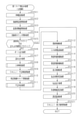
<パチンコ機10の電気的構成>
図6は、パチンコ機10の電気的構成を示すブロック図である。
<Electrical configuration of
FIG. 6 is a block diagram showing an electrical configuration of the
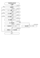
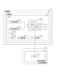
主制御装置71は、遊技の主たる制御を司る主制御基板81を具備している。主制御基板81には、MPU82が搭載されている。MPU82には、当該MPU82により実行される各種の制御プログラムや固定値データを記憶したROM83と、そのROM83内に記憶される制御プログラムの実行に際して各種のデータ等を一時的に記憶するためのメモリであるRAM84と、割込回路、タイマ回路、データ入出力回路、乱数発生器としての各種カウンタ回路などが内蔵されている。なお、MPU82に対してROM83及びRAM84が1チップ化されていることは必須の構成ではなく、それぞれが個別にチップ化された構成としてもよい。これは主制御装置71以外の制御装置のMPUについても同様である。
The
MPU82には、入力ポート及び出力ポートがそれぞれ設けられている。MPU82の入力側には、主制御装置71に設けられた停電監視基板85が接続されているとともに、払出制御装置77が接続されている。停電監視基板85には、動作電力を供給する機能を有する電源・発射制御装置78が接続されており、MPU82には停電監視基板85を介して電力が供給される。
The
MPU82の入力側には、各種入賞検知センサ86a~86eといった各種センサが接続されている。各種入賞検知センサ86a~86eには、一般入賞口31に設けられた検知センサ86a、特電入賞装置32に設けられた検知センサ86b、第1作動口33に設けられた検知センサ86c、第2作動口34に設けられた検知センサ86d及びスルーゲート35に設けられた検知センサ86eが含まれる。これら各種入賞検知センサ86a~86eの検知結果に基づいて、MPU82において各入賞対応入球部への入賞判定が行われる。また、MPU82では第1作動口33又は第2作動口34への入賞に基づいて各種抽選が実行される。
Various sensors such as various prize detection sensors 86a to 86e are connected to the input side of the
MPU82の出力側には、停電監視基板85、払出制御装置77及び音声発光制御装置91が接続されている。払出制御装置77には、例えば、上記入賞対応入球部への入賞判定結果に基づいて賞球コマンドが出力される。音声発光制御装置91には、変動用コマンド、種別コマンド及びオープニングコマンドなどの各種コマンドが出力される。
A power
MPU82の出力側には、特電入賞装置32の開閉扉32aを開閉動作させる特電用の駆動部32b、第2作動口34の普電役物34aを開閉動作させる普電用の駆動部34b、特図ユニット37及び普図ユニット38が接続されている。ちなみに、特図ユニット37には、第1特図表示部37a、第2特図表示部37b、第1特図保留表示部37c及び第2特図保留表示部37dが設けられているが、これらの全てがMPU82の出力側に接続されている。同様に、普図ユニット38には、普図表示部38a及び普図保留表示部38bが設けられているが、これらの全てがMPU82の出力側に接続されている。主制御基板81には各種ドライバ回路が設けられており、当該ドライバ回路を通じてMPU82は各種駆動部の駆動制御を実行する。
On the output side of the
つまり、開閉実行モードにおいては特電入賞装置32が開閉されるように、MPU82において特電用の駆動部32bの駆動制御が実行される。また、普電役物34aの電役開放当選となった場合には普電役物34aが開閉されるように、MPU82において普電用の駆動部34bの駆動制御が実行される。また、各遊技回に際しては、MPU82において特図ユニット37の表示制御が実行される。また、普電役物34aが開放状態となる普電開放状態とするか否かの抽選結果を明示する場合に、MPU82において普図ユニット38の表示制御が実行される。
That is, in the open / close execution mode, the drive control of the special electric drive unit 32b is executed in the
停電監視基板85は、主制御基板81と電源・発射制御装置78とを中継し、また電源・発射制御装置78から出力される最大電圧である直流安定24ボルトの電圧を監視する。払出制御装置77は、主制御装置71のMPU82から入力した賞球コマンドに基づいて、払出装置76により賞球や貸し球の払出制御を行うものである。
The power
電源・発射制御装置78は、例えば、遊技ホール等における商用電源(外部電源)に接続されている。そして、その商用電源から供給される外部電力に基づいて主制御装置71や払出制御装置77等に対して各々に必要な動作電力を生成し、その生成した動作電力を供給する。
The power supply /
当該動作電力を供給するための構成について具体的には、電源・発射制御装置78には、電入中用電源部78aと電断中用電源部78bとが設けられている。電入中用電源部78aは、例えば、遊技ホール等における商用電源に接続されており、商用電源から外部電力が供給されている状況において動作電力を生成するとともに、その生成した動作電力を供給する機能を有する。電断中用電源部78bは、コンデンサからなり、パチンコ機10の電源がON状態の場合(外部電源からの電力供給が行われている場合)に電入中用電源部78aから供給される電力により充電される。また、パチンコ機10の電源がOFF状態の場合や商用電源における停電発生時といった電源遮断状態(外部電源からの電力供給が遮断されている場合)では、電断中用電源部78bから放電され主制御装置71のRAM84及び払出制御装置77の図示しないRAMに対してバックアップ電力が供給される。よって、当該状況であっても、電断中用電源部78bからバックアップ電力が供給されている間は主制御装置71のRAM84及び払出制御装置77のRAMに記憶された情報が消去されることなく記憶保持される。
Specifically, the power supply /
ここで、主制御装置71のRAM84には現状の遊技状態及び遊技の進行内容の情報が一時的に記憶されるとともに、払出制御装置77のRAMには未払出の賞球個数の情報が一時記憶される。この場合に、これらRAMに上記のように電断中用電源部78bからバックアップ電力が供給されることにより、電入中用電源部78aからの電力供給がない状況であっても、現状の遊技状態、遊技の進行内容及び未払出の賞球情報を所定期間に亘って記憶保持することが可能となる。その一方、音声発光制御装置91及び表示制御装置101には、電断中用電源部78bからバックアップ電力は供給されない。したがって、音声発光制御装置91のRAM95及び表示制御装置101のRAM105に記憶された情報は、バックアップされることはなく、電入中用電源部78aからの電力供給が停止された場合には破壊又は消去される。
Here, the
電断中用電源部78bの容量は比較的大きく確保されており、電源遮断前に主制御装置71のRAM84に記憶されていた情報は所定の期間内(例えば、1日や2日)保持される。電断中用電源部78bは、コンデンサに限定されることはなく、バッテリや非充電式電池などであってもよい。
The capacity of the power supply unit 78b during power failure is secured relatively large, and the information stored in the
なお、電源・発射制御装置78には、上記電断中用電源部78bとは異なる図示しない停電時用電源部が設けられている。電源・発射制御装置78では、直流安定24ボルトの電源が22ボルト未満になった後においても、停電時用電源部から放電することにより、後述する停電時処理の実行に十分な時間の間、制御系の駆動電源である5ボルトの出力を正常値に維持するように構成されている。これにより、主制御装置71などは、停電時処理を正常に実行し完了することができる。
The power supply /
電源・発射制御装置78には、各種電源部78a,78bの他に、発射制御部78cが設けられている。発射制御部78cには、発射操作装置28に内蔵されたタッチセンサ28a、プッシュセンサ28b及び可変抵抗器28cが電気的に接続されている。
The power supply /
タッチセンサ28aにはコンデンサが内蔵されており、遊技者の手が操作ハンドルの外表面に接触してコンデンサの静電容量が変化すると、ハンドル操作検知に対応した所定の電気信号を発射制御部78cに出力する。発射制御部78cでは当該所定の電気信号の受信により、遊技者の手が操作ハンドルの外表面に接触していると認識する。また、発射制御部78cでは、プッシュセンサ28bから受信した電気信号に応じて発射操作装置28の発射止めスイッチの操作の有無を把握するとともに、可変抵抗器28cを通じて受信した電気信号に応じて操作ハンドルの回動操作量を把握する。
The touch sensor 28a has a built-in capacitor, and when the player's hand comes into contact with the outer surface of the operation handle and the capacitance of the capacitor changes, a predetermined electric signal corresponding to the handle operation detection is emitted. Output to. Upon receiving the predetermined electric signal, the launch control unit 78c recognizes that the player's hand is in contact with the outer surface of the operation handle. Further, the launch control unit 78c grasps whether or not the launch stop switch of the
発射制御部78cは、予め定められた遊技球の発射条件が成立している場合に主制御装置71のMPU82に所定の信号形態の条件成立信号を送信する。具体的には、発射制御部78cは、タッチセンサ28aから操作ハンドルが遊技者により触れられていることを示す信号を受信するとともに、発射止めスイッチが遊技者により手動操作されていないことを示す信号をプッシュセンサ28bから受信していることを条件に、MPU82に対してHIレベルの条件成立信号(条件成立に対応した信号)を継続して送信する。なお、上記各信号のいずれかを受信していない場合には、MPU82に対してLOWレベルの条件成立信号(条件成立に対応していない信号)を送信する。但し、LOWレベルとHIレベルとの関係が逆であってもよい。また、条件成立に対応した条件成立信号を送信する条件として、上記条件に加えて、球貸装置がパチンコ機10に接続されていることという条件を付加してもよい。
The launch control unit 78c transmits a condition satisfaction signal in a predetermined signal form to the
MPU82では、HIレベルの条件成立信号を受信している状況であって、遊技球の発射を許可できる状況であれば、発射制御部78cにHIレベルの発射許可信号(発射許可に対応した信号)を継続して送信する。なお、MPU82は、発射制御部78cからHIレベルの条件成立信号を受信していない場合にはLOWレベルの発射許可信号(発射許可に対応していない信号)を送信するが、発射許可信号のLOWレベルとHIレベルとの関係が逆であってもよい。
In the
発射制御部78cは、遊技球発射機構27が電気的に接続されており、MPU82からHIレベルの発射許可信号を受信している場合、遊技球発射機構27を定期的に駆動制御する。この場合、遊技球発射機構27に継続して遊技球が供給されている状況であれば、特定発射周期(具体的には0.6秒)に1個の遊技球が遊技領域PAに発射される。また、この発射に際しては可変抵抗器28cから受信した信号に基づき発射強度が調整されるため、操作ハンドルの回動操作量に応じた強度で遊技球が発射される。
The launch control unit 78c periodically drives and controls the game
音声発光制御装置91は、MPU93が搭載された音声発光制御基板92を備えている。MPU93には、当該MPU93により実行される各種の制御プログラムや固定値データを記憶したROM94と、そのROM94内に記憶される制御プログラムの実行に際して各種のデータ等を一時的に記憶するためのメモリであるRAM95と、割込回路、タイマ回路、データ入出力回路などが内蔵されている。MPU93では、主制御装置71から受信したコマンドに基づき、表示発光部64及びスピーカ部65を駆動制御するとともに、表示制御装置101にコマンドを送信する。
The voice
表示制御装置101は、MPU103が搭載された表示制御基板102を備えている。MPU103には、当該MPU103により実行される各種の制御プログラムや固定値データを記憶したROM104と、そのROM104内に記憶される制御プログラムの実行に際して各種のデータ等を一時的に記憶するためのメモリであるRAM105と、割込回路、タイマ回路、データ入出力回路などが内蔵されている。MPU103では、音声発光制御装置91から受信したコマンドに基づき、図柄表示装置41の制御を実施する。
The
表示制御基板102には、図示は省略するが、MPU103の他に、ビデオディスプレイプロセッサ(VDP)、キャラクタROM、及びビデオRAM等が搭載されている。VDPは、図柄表示装置41に組み込まれた液晶表示部ドライバとしての画像処理デバイスを直接操作する一種の描画回路である。VDPは、ビデオRAMのデータの読み書きに介在するとともに、ビデオRAMに記憶させる画像データを、キャラクタROMから所定のタイミングで読み出して図柄表示装置41に表示させる。キャラクタROMは、図柄表示装置41に表示される図柄などのキャラクタデータを記憶するための画像データライブラリとしての役割を担うものである。このキャラクタROMには、各種の表示図柄のビットマップ形式画像データ、ビットマップ画像の各ドットでの表現色を決定する際に参照する色パレットテーブル等が保持されている。ビデオRAMは、図柄表示装置41に表示させる表示データを記憶するためのメモリであり、ビデオRAMの内容を書き替えることに基づき図柄表示装置41の表示内容が変更される。
Although not shown, the
なお、以下の説明では説明の便宜上、主制御装置71のMPU82、ROM83及びRAM84を主側MPU82、主側ROM83及び主側RAM84といい、音声発光制御装置91のMPU93、ROM94及びRAM95を音光側MPU93、音光側ROM94及び音光側RAM95といい、表示制御装置101のMPU103、ROM104及びRAM105を表示側MPU103、表示側ROM104及び表示側RAM105という。
In the following description, for convenience of explanation, the
<主側MPU82にて各種抽選を行うための電気的構成>
次に、主側MPU82にて各種抽選を行うための電気的な構成について図7を用いて説明する。
<Electrical configuration for performing various lottery on the
Next, an electrical configuration for performing various lottery on the
主側MPU82は遊技に際し各種カウンタ情報を用いて、当たり発生抽選、特図表示部37a,37bの表示の設定、図柄表示装置41の図柄表示の設定、普図表示部38aの表示の設定などを行うこととしており、具体的には、図7に示すように、当たり発生の抽選に使用する当たり乱数カウンタC1と、大当たり結果種別及び時短結果種別を判定する際に使用する種別乱数カウンタC2と、図柄表示装置41が外れ変動する際のリーチ発生抽選に使用するリーチ乱数カウンタC3と、当たり乱数カウンタC1の初期値設定に使用する乱数初期値カウンタCINIと、特図表示部37a,37b及び図柄表示装置41における変動表示期間を決定する変動種別カウンタCSとを用いることとしている。さらに、第2作動口34の普電役物34aを普電開放状態とするか否かの抽選に使用する普電乱数カウンタC4を用いることとしている。なお、上記各カウンタC1~C3,CINI,CS,C4は、主側RAM84の各種カウンタエリア84bに設けられている。
The
各カウンタC1~C3,CINI,CS,C4は、その更新の都度前回値に1が加算され、最大値に達した後に「0」に戻るループカウンタとなっている。各カウンタは短時間間隔で更新される。当たり乱数カウンタC1、種別乱数カウンタC2及びリーチ乱数カウンタC3に対応した情報は、第1作動口33又は第2作動口34への入賞が発生した場合に、主側RAM84に設けられた特図保留エリア84aに格納される。特図保留エリア84aは、第1特図保留エリア111と、第2特図保留エリア112と、特図用の実行エリア113とを備えている。
Each of the counters C1 to C3, CINI, CS, and C4 is a loop counter in which 1 is added to the previous value each time the counter is updated, and the counter returns to "0" after reaching the maximum value. Each counter is updated at short intervals. The information corresponding to the hit random number counter C1, the type random number counter C2, and the reach random number counter C3 is reserved for special figures provided in the
第1特図保留エリア111は第1エリア111a、第2エリア111b、第3エリア111c及び第4エリア111dを備えており、第1作動口33への入賞履歴に合わせて、当たり乱数カウンタC1、種別乱数カウンタC2及びリーチ乱数カウンタC3の各数値情第1保留情報として、いずれかのエリア111a~111dに格納される。この場合、第1エリア111a~第4エリア111dには、第1作動口33への入賞が複数回連続して発生した場合に、第1エリア111a→第2エリア111b→第3エリア111c→第4エリア111dの順に各数値情報が時系列的に格納されていく。このように4つのエリア111a~111dが設けられていることにより、第1作動口33への遊技球の入賞履歴が最大4個まで保留記憶されるようになっている。なお、第1特図保留エリア111において保留記憶可能な数は、4個に限定されることはなく任意であり、2個、3個又は5個以上といったように他の複数であってもよく、単数であってもよい。
The first special
第2特図保留エリア112は第1エリア112a、第2エリア112b、第3エリア112c及び第4エリア112dを備えており、第2作動口34への入賞履歴に合わせて、当たり乱数カウンタC1、種別乱数カウンタC2及びリーチ乱数カウンタC3の各数値情報が第2保留情報として、いずれかのエリア112a~112dに格納される。この場合、第1エリア112a~第4エリア112dには、第2作動口34への入賞が複数回連続して発生した場合に、第1エリア112a→第2エリア112b→第3エリア112c→第4エリア112dの順に各数値情報が時系列的に格納されていく。このように4つのエリア112a~112dが設けられていることにより、第2作動口34への遊技球の入賞履歴が最大4個まで保留記憶されるようになっている。なお、第2特図保留エリア112において保留記憶可能な数は、4個に限定されることはなく任意であり、2個、3個又は5個以上といったように他の複数であってもよく、単数であってもよい。
The second special
特図用の実行エリア113は、いずれかの特図表示部37a,37bにて変動表示を開始する際に、当否判定や振分判定などを行う対象の保留情報が格納されるエリアである。具体的には、第1特図表示部37aの変動表示を開始する際には第1特図保留エリア111の第1エリア111aに格納された保留情報が特図用の実行エリア113に移動される。一方、第2特図表示部37bの変動表示を開始する際には第2特図保留エリア112の第1エリア112aに格納された保留情報が特図用の実行エリア113に移動される。
The
普電乱数カウンタC4に対応した情報は、スルーゲート35への入賞が発生した場合に、普図保留エリア84cに格納される。普図保留エリア84cは、第1エリア114a、第2エリア114b、第3エリア114c及び第4エリア114dを備えており、スルーゲート35への入賞履歴に合わせて、普電乱数カウンタC4の数値情報が普図側の保留情報として、いずれかのエリア114a~114dに格納される。この場合、第1エリア114a~第4エリア114dには、スルーゲート35への入賞が複数回連続して発生した場合に、第1エリア114a→第2エリア114b→第3エリア114c→第4エリア114dの順に数値情報が時系列的に格納されていく。このように4つのエリア114a~114dが設けられていることにより、スルーゲート35への遊技球の入賞履歴が最大4個まで保留記憶されるようになっている。なお、普図保留エリア84cにおいて保留記憶可能な数は、4個に限定されることはなく任意であり、2個、3個又は5個以上といったように他の複数であってもよく、単数であってもよい。普図保留エリア84cには、普図用の実行エリア115が設けられている。普図用の実行エリア115は普図表示部38aにて変動表示を開始する際に普図当否判定処理を行う対象の保留情報が格納されるエリアである。具体的には、普図表示部38aの変動表示を開始する際には、普図保留エリア84cの第1エリア114aに格納された保留情報が普図用の実行エリア115に移動される。
The information corresponding to the normal electric random number counter C4 is stored in the normal
上記各カウンタについて詳細に説明する。 Each of the above counters will be described in detail.
まず、普電乱数カウンタC4について説明する。普電乱数カウンタC4は、例えば、0~250の範囲内で順に1ずつ加算され、最大値に達した後に「0」に戻る構成となっている。普電乱数カウンタC4は定期的に更新され、スルーゲート35に遊技球が入賞したタイミングで普図保留エリア84cに格納される。そして、所定のタイミングにおいて、その格納された普電乱数カウンタC4の値によって普電役物34aを開放状態に制御するか否かを決定するための普図当否判定処理が行われる。
First, the Fuden random number counter C4 will be described. The normal electric random number counter C4 is configured to, for example, add 1 in order within the range of 0 to 250 and return to "0" after reaching the maximum value. The Fuden random number counter C4 is periodically updated and stored in the
本パチンコ機10では既に説明したとおり、普電役物34aによるサポートの態様が相互に異なるように複数種類のサポートモードが設定されている。図8はサポートモードの内容を説明するための説明図である。
As described above, in the
サポートモードには、遊技領域に対して同様の態様で遊技球の発射が継続されている状況で比較した場合に第2作動口34の普電役物34aが単位時間当たりに開放状態となる頻度が相対的に高低となるように、高頻度サポートモードと低頻度サポートモードとが設定されている。また、高頻度サポートモードとして第1高頻度サポートモードと第2高頻度サポートモードとが設定されている。
In the support mode, the frequency with which the general electric accessory 34a of the
普電役物34aが開放状態となる普電開放状態とするか否かを抽選により決定するための普図当否判定処理が実行される場合における判定モードとして、電役開放当選となる確率が相対的に高低となるように普図側の高確率モードと普図側の低確率モードとが存在している。普図側の低確率モードでは1回の普図当否判定処理において電役開放当選となる確率が1/2であるのに対して、普図側の高確率モードでは1回の普図当否判定処理において電役開放当選となる確率が4/5である。 The probability of winning the electric service is relative as the judgment mode when the normal figure winning / failing determination process for determining whether or not the utility object 34a is in the open state is executed by lottery. There is a high-probability mode on the normal map side and a low-probability mode on the normal map side so as to be high and low. In the low-probability mode on the normal map side, the probability of winning the electric service is halved in one normal-figure winning / failing judgment process, whereas in the high-probability mode on the normal-figure side, one normal-figure winning / failing judgment is made. The probability of winning the electric service opening in the process is 4/5.
普図当否判定処理が実行された場合には普図表示部38aにおいて絵柄の変動表示が開始されることとなる。この場合に、普図表示部38aにおいて絵柄の変動表示が実行される変動表示回の継続期間である普図の変動期間として、当該期間が相対的に長短となるように長期間と短期間とが存在している。長期間は10秒であるのに対して、短期間は1秒である。 When the normal map pass / fail determination process is executed, the variable display of the pattern is started on the normal map display unit 38a. In this case, the fluctuation period of the normal map, which is the continuation period of the variable display times in which the variable display of the pattern is executed on the normal map display unit 38a, is set to a long period and a short period so that the period is relatively long and short. Exists. The long term is 10 seconds, while the short term is 1 second.
普図表示部38aの変動表示回が終了する場合に当該普図表示部38aには当該変動表示回の実行の契機となった普図当否判定処理の判定結果に対応する停止結果が表示される。この場合に、普図当否判定処理の判定結果が外れ結果であった場合には普図表示部38aに外れ結果に対応する停止結果が表示され、普電開放状態への移行は発生しない。普図保留エリア84cに普図側の保留情報が記憶されている場合には、当該普図側の保留情報に対して新たに普図当否判定処理が実行されて普図表示部38aにて新たな変動表示回が開始される。一方、普図当否判定処理の判定結果が電役開放当選に対応する結果であった場合には普図表示部38aに当選結果に対応する停止結果が表示され、普電開放状態への移行が発生する。
When the variation display times of the normal map display unit 38a are completed, the stop result corresponding to the judgment result of the normal map hit / miss determination process that triggered the execution of the fluctuation display times is displayed on the normal map display unit 38a. .. In this case, if the determination result of the normal map pass / fail determination process is a deviation result, the stop result corresponding to the deviation result is displayed on the normal map display unit 38a, and the transition to the normal power open state does not occur. When the holding information on the normal drawing side is stored in the normal
普電開放状態の実行モードとして、普電役物34aへの遊技球の入球期待度が相対的に高低となるように高期待度モードと低期待度モードとが存在している。低期待度モードでは普電役物34aの短開放が1回発生する。短開放の継続期間は0.7秒となっている。既に説明したとおり遊技球の発射周期は0.6秒であるため、普電役物34aの短開放が1回発生した場合には第2作動口34への遊技球の入球が基本的には発生することなく発生したとしても入球個数は1個程度である。なお、普電開放状態は第2作動口34への遊技球の入球個数が普電側の上限個数である10個となった場合にも終了するが、短開放が1回発生した場合には上記のとおり第2作動口34への遊技球の入球が発生したとしても1個程度であるため第2作動口34に普電側の上限個数の遊技球が入球することはない。
As the execution mode in the open state of the normal electric power, there are a high expectation degree mode and a low expectation degree mode so that the expected degree of entry of the game ball into the general electric power accessory 34a is relatively high and low. In the low expectation mode, the short opening of the general electric accessory 34a occurs once. The duration of the short opening is 0.7 seconds. As already explained, the firing cycle of the game ball is 0.6 seconds, so if the short opening of the general electric accessory 34a occurs once, the game ball basically enters the
高期待度モードでは普電役物34aの長開放が3回発生する。長開放の継続期間は2秒となっている。既に説明したとおり遊技球の発射周期は0.6秒であるため、普電役物34aの長開放が1回発生した場合には第2作動口34に3個程度の遊技球が入球し得る。そして、高期待度モードの普電開放状態では第2作動口34が閉鎖状態となっている普電側のインターバル期間(具体的には1秒)を挟んで長開放が3回発生する。したがって、高期待度モードの普電開放状態が発生した場合には9個程度の遊技球が入球し得る。なお、上記のとおり普電開放状態は第2作動口34への遊技球の入球個数が普電側の上限個数である10個となった場合に終了するため、高期待度モードの普電開放状態が発生した場合には第2作動口34に普電側の上限個数の遊技球が入球することで当該普電開放状態が終了する事象が発生し得る。
In the high expectation mode, the long opening of the general electric accessory 34a occurs three times. The duration of the long opening is 2 seconds. As already explained, the firing cycle of the game ball is 0.6 seconds, so if the long opening of the general electric accessory 34a occurs once, about three game balls will enter the
上記のように普図当否判定処理の判定モード、普図表示部38aにおける普図の変動期間及び普電開放状態の実行モードが設定されている構成において、低頻度サポートモードでは普図当否判定処理の判定モードは普図側の低確率モードとなり、普図の変動期間は長期間となり、普電開放状態の実行モードは短開放1回が発生する低期待度モードとなる。また、第1高頻度サポートモードでは普図当否判定処理の判定モードは普図側の高確率モードとなり、普図の変動期間は短期間となり、普電開放状態の実行モードは長開放3回が発生する高期待度モードとなる。また、第2高頻度サポートモードでは普図当否判定処理の判定モードは普図側の低確率モードとなり、普図の変動期間は短期間となり、普電開放状態の実行モードは長開放3回が発生する高期待度モードとなる。したがって、スルーゲート35への入賞が発生するように同一の態様で遊技球の発射が継続された場合、単位時間当たりで第2作動口34の普電役物34aが開放状態となっている割合の期待度は、第1高頻度サポートモードが最も高く、第2高頻度サポートモードが次に高く、低頻度サポートモードが最も低い。また、低頻度サポートモードでは普電開放状態の実行モードが低期待度モードとなるため、低頻度サポートモードである場合には第2作動口34への遊技球の入球がほとんど発生しないのに対して、第1高頻度サポートモード及び第2高頻度サポートモードでは普電開放状態の実行モードが高期待度モードとなるため、第1高頻度サポートモード又は第2高頻度サポートモードである場合には第2作動口34への遊技球の入球が第2特図保留エリア112における第2保留情報の上限個数以上発生することが期待できる。
In the configuration in which the judgment mode of the normal figure hit / fail judgment process, the fluctuation period of the normal figure in the normal figure display unit 38a, and the execution mode of the normal power open state are set as described above, the normal figure hit / fail judgment process is performed in the low frequency support mode. The judgment mode is the low probability mode on the normal map side, the fluctuation period of the normal map is long, and the execution mode in the normal power open state is the low expectation mode in which one short opening occurs. In addition, in the first high-frequency support mode, the judgment mode of the normal-figure hit / fail judgment process is the high-probability mode on the normal-figure side, the fluctuation period of the normal-figure is short, and the execution mode of the normal-power open state is three long open times. It becomes a high expectation mode that occurs. In addition, in the second high-frequency support mode, the judgment mode of the normal-figure hit / fail judgment process is the low-probability mode on the normal-figure side, the fluctuation period of the normal-figure is short, and the execution mode of the normal-power open state is three long open times. It becomes a high expectation mode that occurs. Therefore, when the launch of the game ball is continued in the same manner so as to generate a prize in the through
なお、第1高頻度サポートモードと第2高頻度サポートモードとで単位時間当たりで第2作動口34の普電役物34aが開放状態となっている割合の期待度を相違させるための構成は上記のものに限定されることはなく、例えば普図の変動期間として第1高頻度サポートモードでは短期間が選択されるのに対して第2高頻度サポートモードでは短期間と長期間との間である中期間が選択される構成としてもよく、普電開放状態の実行モードとして第1高頻度サポートモードでは長開放が3回発生するのに対して第2高頻度サポートモードでは長開放が2回発生する構成としてもよい。また、第1高頻度サポートモードと第2高頻度サポートモードとで普図当否判定処理の判定モードが普図側の高確率モードで同一であるものの普図の変動期間又は普電開放状態の実行モードの内容によって第1高頻度サポートモードの方が第2高頻度サポートモードよりも単位時間当たりで第2作動口34の普電役物34aが開放状態となっている割合の期待度が高くなる構成としてもよい。
It should be noted that the configuration for differentiating the expected degree of the ratio of the general electric accessory 34a of the
次に、当たり乱数カウンタC1について説明する。当たり乱数カウンタC1は、0~9999の範囲内で順に1ずつ加算され、最大値に達した後に「0」に戻る構成となっている。特に当たり乱数カウンタC1が1周した場合、その時点の乱数初期値カウンタCINIの値が当該当たり乱数カウンタC1の初期値として読み込まれる。なお、乱数初期値カウンタCINIは、当たり乱数カウンタC1と同様のループカウンタである(値=0~9999)。当たり乱数カウンタC1は定期的に更新され、遊技球が第1作動口33に入賞したタイミングで第1特図保留エリア111に格納され、遊技球が第2作動口34に入賞したタイミングで第2特図保留エリア112に格納される。そして、この格納された当たり乱数カウンタC1の数値情報を利用して当否判定処理が行われる。
Next, the winning random number counter C1 will be described. The winning random number counter C1 is configured to be incremented by 1 in order within the range of 0 to 9999 and returned to "0" after reaching the maximum value. In particular, when the hit random number counter C1 makes one round, the value of the random number initial value counter CINI at that time is read as the initial value of the hit random number counter C1. The random number initial value counter CINI is a loop counter similar to the hit random number counter C1 (value = 0 to 9999). The winning random number counter C1 is periodically updated, stored in the first special
当否判定処理に際して当選となる乱数の値は、主側ROM83に当否テーブルとして記憶されている。本パチンコ機10では当否判定処理の当否抽選モードとして大当たり結果となる確率が相対的に高低となる高確率モードと低確率モードとが存在している。低確率モードにおいて当否判定処理にて参照される当否テーブルとして、第1保留情報に対して当否判定処理が実行される場合に参照される低確率時の第1当否テーブル121と、第2保留情報に対して当否判定処理が実行される場合に参照される低確率時の第2当否テーブル122とが設けられている。また、高確率モードにおいて当否判定処理にて参照される当否テーブルとして高確率時の当否テーブル123が設けられている。
The value of the random number that is won in the winning / failing determination process is stored in the
図9(a)は低確率時の第1当否テーブル121を説明するための説明図であり、図9(b)は低確率時の第2当否テーブル122を説明するための説明図であり、図9(c)は高確率時の当否テーブル123を説明するための説明図である。 FIG. 9A is an explanatory diagram for explaining the first hit / miss table 121 at the time of low probability, and FIG. 9B is an explanatory diagram for explaining the second hit / miss table 122 at the time of low probability. FIG. 9C is an explanatory diagram for explaining the pass / fail table 123 at the time of high probability.
図9(a)~図9(c)に示すように当否判定処理の結果として、大当たり結果と、時短結果と、外れ結果とが存在している。大当たり結果は、複数回のラウンド遊技が実行される開閉実行モードへの移行契機となるとともに、当否抽選モード及びサポートモードの移行契機となり得る当否結果である。時短結果は、開閉実行モードへの移行契機となることはなくさらに当否抽選モードの移行契機とならないものの、サポートモードの移行契機となり得る当否結果である。外れ結果は、開閉実行モードの移行契機とならずに、さらに当否抽選モード及びサポートモードについても移行契機とならない当否結果である。 As shown in FIGS. 9 (a) to 9 (c), as a result of the hit / fail determination process, there are a big hit result, a time saving result, and a missed result. The jackpot result is a result of success or failure that can be a trigger for transition to the open / close execution mode in which a plurality of round games are executed, and a trigger for transition to the win / fail lottery mode and the support mode. The time saving result is a result of success or failure that can be a trigger for transition to the support mode, although it does not trigger a transition to the open / close execution mode and further does not trigger a transition to the win / fail lottery mode. The deviation result is a winning / failing result that does not trigger the transition of the open / close execution mode and also does not trigger the transition of the winning / failing lottery mode and the support mode.
本パチンコ機10には単位時間当たりの有利度を定める設定値が存在している。設定値は「設定n」(nは「1」~「6」の整数)のnが大きい値ほど(すなわち設定値が高いほど)有利度が高くなる。設定値として「設定1」~「設定6」が存在している。図9(a)に示すように低確率時の第1当否テーブル121では、高い設定値ほど大当たり結果となる確率が高く、高い設定値ほど外れ結果となる確率が低くなるように設定されている。一方、時短結果となる確率は「設定1」~「設定6」のいずれであっても同一となるように設定されている。
The
具体的には、最も低い設定値である「設定1」には大当たり結果となる当たり乱数カウンタC1の数値情報の数として50個が設定されており、時短結果となる当たり乱数カウンタC1の数値情報の数として100個が設定されており、外れ結果となる当たり乱数カウンタC1の数値情報の数として9850個が設定されている。また、「設定1」よりも1段階高い設定値である「設定2」には大当たり結果となる当たり乱数カウンタC1の数値情報の数として52個が設定されており、時短結果となる当たり乱数カウンタC1の数値情報の数として100個が設定されており、外れ結果となる当たり乱数カウンタC1の数値情報の数として9848個が設定されている。また、「設定2」よりも1段階高い設定値である「設定3」には大当たり結果となる当たり乱数カウンタC1の数値情報の数として54個が設定されており、時短結果となる当たり乱数カウンタC1の数値情報の数として100個が設定されており、外れ結果となる当たり乱数カウンタC1の数値情報の数として9846個が設定されている。また、「設定3」よりも1段階高い設定値である「設定4」には大当たり結果となる当たり乱数カウンタC1の数値情報の数として56個が設定されており、時短結果となる当たり乱数カウンタC1の数値情報の数として100個が設定されており、外れ結果となる当たり乱数カウンタC1の数値情報の数として9844個が設定されている。また、「設定4」よりも1段階高い設定値である「設定5」には大当たり結果となる当たり乱数カウンタC1の数値情報の数として58個が設定されており、時短結果となる当たり乱数カウンタC1の数値情報の数として100個が設定されており、外れ結果となる当たり乱数カウンタC1の数値情報の数として9842個が設定されている。また、最も高い設定値である「設定6」には大当たり結果となる当たり乱数カウンタC1の数値情報の数として60個が設定されており、時短結果となる当たり乱数カウンタC1の数値情報の数として100個が設定されており、外れ結果となる当たり乱数カウンタC1の数値情報の数として9840個が設定されている。上記のとおりいずれの設定値であっても低確率モードにおいては時短結果となる確率は大当たり結果となる確率よりも高くなっている。 Specifically, 50 pieces are set as the number of numerical information of the hit random number counter C1 which is the big hit result in the lowest setting value "setting 1", and the numerical information of the hit random number counter C1 which is the time saving result is set. 100 pieces are set as the number of, and 9850 pieces are set as the number of numerical information of the random number counter C1 which is a result of deviation. Further, in "setting 2", which is a setting value one step higher than "setting 1", 52 pieces are set as the number of numerical information of the hit random number counter C1 which is a big hit result, and the hit random number counter which is a time saving result. 100 pieces are set as the number of numerical information of C1, and 9848 pieces are set as the number of numerical information of the random number counter C1 which is a result of deviation. In addition, 54 pieces of numerical information of the hit random number counter C1 which is a big hit result are set in "setting 3" which is a setting value one step higher than "setting 2", and a hit random number counter which is a time saving result. 100 pieces are set as the number of numerical information of C1, and 9846 pieces are set as the number of numerical information of the random number counter C1 which is a result of deviation. In addition, 56 pieces of numerical information of the hit random number counter C1 which is a big hit result are set in "setting 4" which is a setting value one step higher than "setting 3", and a hit random number counter which is a time saving result. 100 pieces are set as the number of numerical information of C1, and 9844 pieces are set as the number of numerical information of the random number counter C1 which is a result of deviation. In addition, 58 pieces of numerical information of the hit random number counter C1 which is a big hit result are set in "setting 5" which is a setting value one step higher than "setting 4", and a hit random number counter which is a time saving result. 100 pieces are set as the number of numerical information of C1, and 9842 pieces are set as the number of numerical information of the random number counter C1 which is a result of deviation. Further, in the highest setting value "setting 6", 60 pieces are set as the number of numerical information of the hit random number counter C1 which is a big hit result, and as the number of numerical information of the hit random number counter C1 which is a time saving result. 100 pieces are set, and 9840 pieces are set as the number of numerical information of the random number counter C1 which is a result of deviation. As described above, the probability of a time-saving result is higher than the probability of a jackpot result in the low probability mode regardless of the set value.
図9(b)に示すように低確率時の第2当否テーブル122では、高い設定値ほど大当たり結果となる確率が高く、高い設定値ほど外れ結果となる確率が低くなるように設定されている。一方、時短結果となる確率は「設定1」~「設定6」のいずれであっても同一となるように設定されている。 As shown in FIG. 9B, in the second hit / fail table 122 at the time of low probability, the higher the set value, the higher the probability of a jackpot result, and the higher the set value, the lower the probability of a deviation result. .. On the other hand, the probability of achieving a time saving result is set to be the same regardless of any of "setting 1" to "setting 6".
具体的には、最も低い設定値である「設定1」には大当たり結果となる当たり乱数カウンタC1の数値情報の数として50個が設定されており、時短結果となる当たり乱数カウンタC1の数値情報の数として120個が設定されており、外れ結果となる当たり乱数カウンタC1の数値情報の数として9830個が設定されている。また、「設定1」よりも1段階高い設定値である「設定2」には大当たり結果となる当たり乱数カウンタC1の数値情報の数として52個が設定されており、時短結果となる当たり乱数カウンタC1の数値情報の数として120個が設定されており、外れ結果となる当たり乱数カウンタC1の数値情報の数として9828個が設定されている。また、「設定2」よりも1段階高い設定値である「設定3」には大当たり結果となる当たり乱数カウンタC1の数値情報の数として54個が設定されており、時短結果となる当たり乱数カウンタC1の数値情報の数として120個が設定されており、外れ結果となる当たり乱数カウンタC1の数値情報の数として9826個が設定されている。また、「設定3」よりも1段階高い設定値である「設定4」には大当たり結果となる当たり乱数カウンタC1の数値情報の数として56個が設定されており、時短結果となる当たり乱数カウンタC1の数値情報の数として120個が設定されており、外れ結果となる当たり乱数カウンタC1の数値情報の数として9824個が設定されている。また、「設定4」よりも1段階高い設定値である「設定5」には大当たり結果となる当たり乱数カウンタC1の数値情報の数として58個が設定されており、時短結果となる当たり乱数カウンタC1の数値情報の数として120個が設定されており、外れ結果となる当たり乱数カウンタC1の数値情報の数として9822個が設定されている。また、最も高い設定値である「設定6」には大当たり結果となる当たり乱数カウンタC1の数値情報の数として60個が設定されており、時短結果となる当たり乱数カウンタC1の数値情報の数として120個が設定されており、外れ結果となる当たり乱数カウンタC1の数値情報の数として9820個が設定されている。 Specifically, 50 pieces are set as the number of numerical information of the hit random number counter C1 which is a big hit result in "setting 1" which is the lowest setting value, and the numerical information of the hit random number counter C1 which is a time saving result. 120 pieces are set as the number of, and 9830 pieces are set as the number of numerical information of the random number counter C1 which is a result of deviation. Further, in "setting 2", which is a setting value one step higher than "setting 1", 52 pieces are set as the number of numerical information of the hit random number counter C1 which is a big hit result, and the hit random number counter which is a time saving result. 120 pieces are set as the number of numerical information of C1, and 9828 pieces are set as the number of numerical information of the random number counter C1 which is a result of deviation. In addition, 54 pieces of numerical information of the hit random number counter C1 which is a big hit result are set in "setting 3" which is a setting value one step higher than "setting 2", and a hit random number counter which is a time saving result. 120 pieces are set as the number of numerical information of C1, and 9826 pieces are set as the number of numerical information of the random number counter C1 which is a result of deviation. Further, in "setting 4", which is a setting value one step higher than "setting 3", 56 pieces are set as the number of numerical information of the hit random number counter C1 which is a big hit result, and the hit random number counter which is a time saving result. 120 pieces are set as the number of numerical information of C1, and 9824 pieces are set as the number of numerical information of the random number counter C1 which is a result of deviation. In addition, 58 pieces of numerical information of the hit random number counter C1 which is a big hit result are set in "setting 5" which is a setting value one step higher than "setting 4", and a hit random number counter which is a time saving result. 120 pieces are set as the number of numerical information of C1, and 9822 pieces are set as the number of numerical information of the random number counter C1 which is a result of deviation. Further, in the highest setting value "setting 6", 60 pieces are set as the number of numerical information of the hit random number counter C1 which is a big hit result, and as the number of numerical information of the hit random number counter C1 which is a time saving result. 120 pieces are set, and 9820 pieces are set as the number of numerical information of the random number counter C1 which is a result of deviation.
つまり、低確率時の第1当否テーブル121と低確率時の第2当否テーブル122とで各設定値の大当たり結果の確率は同一となっている。これに対して、当否判定処理にて時短結果が選択される確率は低確率時の第2当否テーブル122の方が低確率の第1当否テーブル121よりも高くなっている。したがって、当否抽選モードが低確率モードである場合には第2保留情報に対して当否判定処理が実行された場合の方が、第1保留情報に対して当否判定処理が実行された場合よりも、時短結果が選択される確率が高くなる。 That is, the probability of the jackpot result of each set value is the same in the first hit / fail table 121 at the time of low probability and the second hit / fail table 122 at the time of low probability. On the other hand, the probability that the time saving result is selected in the hit / fail determination process is higher in the second hit / miss table 122 at the time of low probability than in the first hit / miss table 121 with low probability. Therefore, when the winning / failing lottery mode is the low probability mode, the case where the winning / failing determination process is executed for the second reserved information is more than the case where the winning / failing determination process is executed for the first reserved information. , The probability that a time-saving result will be selected increases.
なお、これに限定されることはなく、当否判定処理にて時短結果が選択される確率が、低確率時の第1当否テーブル121と低確率時の第2当否テーブル122とで同一又は略同一である構成としてもよく、低確率時の第1当否テーブル121の方が低確率の第2当否テーブル122よりも高い構成としてもよい。また、低確率時の第1当否テーブル121では時短結果の確率が各設定値で同一である構成に限定されることはなく、設定値に応じて変動する構成としてもよい。この場合、高い設定値ほど時短結果の確率が高くなる構成としてもよく、高い設定値ほど時短結果の確率が低くなる構成としてもよい。また、低確率時の第2当否テーブル122では時短結果の確率が各設定値で同一である構成に限定されることはなく、設定値に応じて変動する構成としてもよい。この場合、高い設定値ほど時短結果の確率が高くなる構成としてもよく、高い設定値ほど時短結果の確率が低くなる構成としてもよい。 It should be noted that the probability of selecting the time saving result in the hit / fail determination process is not limited to this, and is the same or substantially the same in the first hit / miss table 121 at the time of low probability and the second hit / miss table 122 at the time of low probability. The configuration may be such that the first hit / miss table 121 at the time of low probability is higher than the second hit / miss table 122 at the low probability. Further, the first hit / fail table 121 at the time of low probability is not limited to the configuration in which the probability of the time saving result is the same for each set value, and may be configured to fluctuate according to the set value. In this case, the higher the set value, the higher the probability of the time saving result, or the higher the setting value, the lower the probability of the time saving result. Further, the second hit / fail table 122 at the time of low probability is not limited to the configuration in which the probability of the time saving result is the same for each set value, and may be configured to fluctuate according to the set value. In this case, the higher the set value, the higher the probability of the time saving result, or the higher the setting value, the lower the probability of the time saving result.
図9(c)に示すように高確率時の当否テーブル123では、高い設定値ほど大当たり結果となる確率が高く、高い設定値ほど外れ結果となる確率が低くなるように設定されている。一方、時短結果となる確率は「設定1」~「設定6」のいずれであっても同一となるように設定されている。 As shown in FIG. 9C, in the hit / fail table 123 at the time of high probability, the higher the set value, the higher the probability of a jackpot result, and the higher the set value, the lower the probability of a deviation result. On the other hand, the probability of achieving a time saving result is set to be the same regardless of any of "setting 1" to "setting 6".
具体的には、最も低い設定値である「設定1」には大当たり結果となる当たり乱数カウンタC1の数値情報の数として500個が設定されており、時短結果となる当たり乱数カウンタC1の数値情報の数として100個が設定されており、外れ結果となる当たり乱数カウンタC1の数値情報の数として9400個が設定されている。また、「設定1」よりも1段階高い設定値である「設定2」には大当たり結果となる当たり乱数カウンタC1の数値情報の数として520個が設定されており、時短結果となる当たり乱数カウンタC1の数値情報の数として100個が設定されており、外れ結果となる当たり乱数カウンタC1の数値情報の数として9380個が設定されている。また、「設定2」よりも1段階高い設定値である「設定3」には大当たり結果となる当たり乱数カウンタC1の数値情報の数として540個が設定されており、時短結果となる当たり乱数カウンタC1の数値情報の数として100個が設定されており、外れ結果となる当たり乱数カウンタC1の数値情報の数として9360個が設定されている。また、「設定3」よりも1段階高い設定値である「設定4」には大当たり結果となる当たり乱数カウンタC1の数値情報の数として560個が設定されており、時短結果となる当たり乱数カウンタC1の数値情報の数として100個が設定されており、外れ結果となる当たり乱数カウンタC1の数値情報の数として9340個が設定されている。また、「設定4」よりも1段階高い設定値である「設定5」には大当たり結果となる当たり乱数カウンタC1の数値情報の数として580個が設定されており、時短結果となる当たり乱数カウンタC1の数値情報の数として100個が設定されており、外れ結果となる当たり乱数カウンタC1の数値情報の数として9320個が設定されている。また、最も高い設定値である「設定6」には大当たり結果となる当たり乱数カウンタC1の数値情報の数として600個が設定されており、時短結果となる当たり乱数カウンタC1の数値情報の数として100個が設定されており、外れ結果となる当たり乱数カウンタC1の数値情報の数として9300個が設定されている。 Specifically, 500 pieces are set as the number of numerical information of the hit random number counter C1 which is the big hit result in the lowest setting value "setting 1", and the numerical information of the hit random number counter C1 which is the time saving result is set. 100 pieces are set as the number of, and 9400 pieces are set as the number of numerical information of the random number counter C1 which is a result of deviation. Further, in "setting 2", which is a setting value one step higher than "setting 1", 520 pieces of numerical information of the hit random number counter C1 which is a big hit result are set, and the hit random number counter which is a time saving result is set. 100 pieces are set as the number of numerical information of C1, and 9380 pieces are set as the number of numerical information of the random number counter C1 which is a result of deviation. Further, in "setting 3", which is a setting value one step higher than "setting 2", 540 pieces are set as the number of numerical information of the hit random number counter C1 which is a big hit result, and the hit random number counter which is a time saving result. 100 pieces are set as the number of numerical information of C1, and 9360 pieces are set as the number of numerical information of the random number counter C1 which is a result of deviation. Further, in "setting 4", which is a setting value one step higher than "setting 3", 560 pieces of numerical information of the hit random number counter C1 which is a big hit result are set, and the hit random number counter which is a time saving result is set. 100 pieces are set as the number of numerical information of C1, and 9340 pieces are set as the number of numerical information of the random number counter C1 which is a result of deviation. Further, in "setting 5", which is a setting value one step higher than "setting 4", 580 pieces of numerical information of the hit random number counter C1 which is a big hit result are set, and the hit random number counter which is a time saving result is set. 100 pieces are set as the number of numerical information of C1, and 9320 pieces are set as the number of numerical information of the random number counter C1 which is a result of deviation. Further, in the highest setting value "setting 6", 600 pieces are set as the number of numerical information of the hit random number counter C1 which is a big hit result, and as the number of numerical information of the hit random number counter C1 which is a time saving result. 100 pieces are set, and 9300 pieces are set as the number of numerical information of the random number counter C1 which is a result of deviation.
高確率時の当否テーブル123は高確率モードである場合には第1保留情報に対して当否判定処理が実行される場合及び第2保留情報に対して当否判定処理が実行される場合のいずれであっても参照される。これにより、高確率モードにおいて第1保留情報に対して当否判定処理が実行される場合及び高確率モードにおいて第2保留情報に対して当否判定処理が実行される場合のそれぞれに対応させて当否テーブルを設ける構成に比べて、当否テーブルを記憶するために必要な主側ROM83の記憶容量を抑えることが可能となる。
When the hit / fail table 123 at the time of high probability is in the high probability mode, either the case where the hit / fail determination process is executed for the first hold information or the case where the hit / fail judgment process is executed for the second hold information. Even if there is, it is referred. As a result, the hit / fail table corresponds to the case where the hit / fail determination process is executed for the first hold information in the high probability mode and the case where the hit / fail judgment process is executed for the second hold information in the high probability mode. It is possible to suppress the storage capacity of the
「設定1」において大当たり結果となる確率は低確率モードである場合には1/200であり高確率モードである場合にはその10倍の1/20である。「設定2」において大当たり結果となる確率は低確率モードである場合には約1/192であり高確率モードである場合にはその10倍の約1/19.2である。「設定3」において大当たり結果となる確率は低確率モードである場合には約1/185であり高確率モードである場合にはその10倍の約1/18.5である。「設定4」において大当たり結果となる確率は低確率モードである場合には約1/179であり高確率モードである場合にはその10倍の約1/17.9である。「設定5」において大当たり結果となる確率は低確率モードである場合には約1/172であり高確率モードである場合にはその10倍の約1/17.2である。「設定6」において大当たり結果となる確率は低確率モードである場合には約1/167であり高確率モードである場合にはその10倍の約1/16.7である。つまり、「設定1」~「設定6」のいずれであっても大当たり結果となる確率は高確率モードである場合には低確率モードである場合に対して10倍となる。 In "setting 1", the probability of a jackpot result is 1/200 in the low probability mode and 1/20 of 10 times that in the high probability mode. In "setting 2", the probability of a jackpot result is about 1/192 in the low probability mode and about 1/19.2, which is 10 times that in the high probability mode. In "setting 3", the probability of a jackpot result is about 1/185 in the low probability mode and about 1/18.5, which is 10 times that in the high probability mode. In "setting 4", the probability of a jackpot result is about 1/179 in the low probability mode and about 1 / 17.9, which is 10 times that in the high probability mode. In "setting 5", the probability of a jackpot result is about 1/172 in the low probability mode and about 1 / 17.2, which is 10 times that in the high probability mode. In "setting 6", the probability of a jackpot result is about 1/167 in the low probability mode and about 1 / 16.7, which is 10 times that in the high probability mode. That is, in any of "setting 1" to "setting 6", the probability of a big hit result is 10 times higher in the high probability mode than in the low probability mode.
一方、時短結果となる確率は、低確率時の第1当否テーブル121及び高確率時の当否テーブル123においては「設定1」~「設定6」のいずれであっても1/100となり、低確率時の第2当否テーブル122においては「設定1」~「設定6」のいずれであっても約1/83となる。但し、これに限定されることはなく、高確率時の当否テーブル123においては時短結果となる確率が、低確率時の第1当否テーブル121よりも高くなり低確率時の第2当否テーブル122よりも低くなるように設定されている構成としてもよく、低確率時の第2当否テーブル122よりも高くなるように設定されている構成としてもよい。 On the other hand, the probability of a time-saving result is 1/100 in any of "setting 1" to "setting 6" in the first hit / fail table 121 at the time of low probability and the hit / miss table 123 at the time of high probability, which is a low probability. In the second hit / fail table 122 at the time, any of "setting 1" to "setting 6" is about 1/83. However, the present invention is not limited to this, and in the high-probability hit / miss table 123, the probability of a time-saving result is higher than that of the low-probability first hit / miss table 121 and is higher than that of the low-probability second hit / miss table 122. It may be set to be lower than that of the second hit / miss table 122 at the time of low probability.
なお、大当たり結果となる当たり乱数カウンタC1の数値情報は連番となるように集約して設定されている構成としてもよく、少なくとも一部又は全部が連番とならないように分散させて設定されている構成としてもよい。また、時短結果となる当たり乱数カウンタC1の数値情報は連番となるように集約して設定されている構成としてもよく、少なくとも一部又は全部が連番とならないように分散させて設定されている構成としてもよい。 The numerical information of the hit random number counter C1 that is the result of the big hit may be aggregated and set so as to be a serial number, and at least a part or all of the numerical information may be distributed and set so as not to be a serial number. It may be configured as such. Further, the numerical information of the random number counter C1 which is the result of shortening the time may be aggregated and set so as to be a serial number, and at least a part or all of the numerical information may be distributed and set so as not to be a serial number. It may be configured as such.
上記のとおり第1保留情報を契機とした場合及び第2保留情報を契機とした場合のいずれであっても高い設定値ほど大当たり結果となる確率が高くなるように設定されていることにより高い設定値ほど遊技者にとって有利となる。また、開閉実行モードは単位時間当たりにおける遊技者の持ち球の増加量が最も多くなる期間であり、当該開閉実行モードの移行契機となる大当たり結果の確率が設定値に応じて変動することにより、設定値に対する遊技者の注目度を高めることが可能となる。 As described above, the higher the set value, the higher the probability of a big hit result, regardless of whether the first hold information is the trigger or the second hold information is the trigger. The higher the value, the more advantageous it is for the player. In addition, the open / close execution mode is the period in which the amount of increase in the number of balls held by the player per unit time is the largest, and the probability of the jackpot result that triggers the transition to the open / close execution mode fluctuates according to the set value. It is possible to increase the player's attention to the set value.
低確率モードよりも高確率モードの方が大当たり結果となる確率が高くなる構成において、「設定1」~「設定6」のいずれであっても高確率モードにおいて大当たり結果となる確率は低確率モードにおいて大当たり結果となる確率に対して「1」よりも大きい数である一定数倍(具体的には10倍)高い確率となっている。これにより、いずれの設定状態であっても低確率モードと高確率モードとの間における大当たり結果となる確率の変動率を一定とすることが可能となる。
In a configuration in which the probability of a jackpot result is higher in the high probability mode than in the low probability mode, the probability of a jackpot result in the high probability mode is low probability mode regardless of any of "Setting 1" to "
設定値及び当否抽選モードの組合せが同一となる組合せで比較した場合に大当たり結果となる確率は第1保留情報を契機とした場合と第2保留情報を契機とした場合とで同一となっている。これにより、第1保留情報を契機とした場合と第2保留情報を契機とした場合とで大当たり結果の発生確率に差異が生じないようにすることが可能となる。 The probability that a big hit result will be obtained when the combination of the set value and the winning / failing lottery mode is the same is the same in the case where the first hold information is the trigger and the case where the second hold information is the trigger. .. As a result, it is possible to prevent a difference in the probability of occurrence of the jackpot result between the case where the first hold information is used as the trigger and the case where the second hold information is used as a trigger.
第1保留情報を契機とした場合に時短結果となる確率は「設定1」~「設定6」のいずれであっても同一となる。また、第2保留情報を契機とした場合に時短結果となる確率は「設定1」~「設定6」のいずれであっても同一となる。これにより、、遊技者が設定値を推測するために注目する対象を大当たり結果に限定させることが可能となり、設定値の推測を行いづらくさせることが可能となる。その一方、時短結果となる確率は第2保留情報を契機とした場合の方が第1保留情報を契機とした場合よりも高い確率となっている。これにより、第1保留情報を契機とした遊技回が実行される場合と第2保留情報を契機とした遊技回が実行される場合とで時短結果の発生頻度を異ならせることが可能となる。 The probability of a time saving result when the first hold information is used as an opportunity is the same regardless of any of "setting 1" to "setting 6". Further, the probability that the time saving result is obtained when the second hold information is used as an opportunity is the same regardless of any of "setting 1" to "setting 6". As a result, it becomes possible for the player to limit the target to be focused on in order to estimate the set value to the jackpot result, and it becomes possible to make it difficult to estimate the set value. On the other hand, the probability of a time saving result is higher when the second hold information is used as a trigger than when the first hold information is used as a trigger. As a result, it is possible to make the frequency of occurrence of the time saving result different between the case where the game round triggered by the first hold information is executed and the case where the game round triggered by the second hold information is executed.
種別乱数カウンタC2は、0~29の範囲内で順に1ずつ加算され、最大値に達した後に「0」に戻る構成となっている。種別乱数カウンタC2は定期的に更新され、遊技球が第1作動口33に入賞したタイミングで第1特図保留エリア111に格納され、遊技球が第2作動口34に入賞したタイミングで第2特図保留エリア112に格納される。
The type random number counter C2 is configured to add 1 in order within the range of 0 to 29 and return to "0" after reaching the maximum value. The type random number counter C2 is periodically updated, stored in the first special
本パチンコ機10では、開閉実行モードにおけるラウンド遊技の実行回数、開閉実行モード終了後の当否抽選モード及び開閉実行モード終了後のサポートモードという3つの条件に差異を設けることにより、複数の大当たり結果が設定されている。第1保留情報に対する当否判定処理にて大当たり結果が選択された場合における大当たり用の振分判定処理にて参照される大当たり振分テーブルとして第1特図用の大当たり振分テーブル125が設けられている。また、第2保留情報に対する当否判定処理にて大当たり結果が選択された場合における大当たり用の振分判定処理にて参照される大当たり振分テーブルとして第2特図用の大当たり振分テーブル126が設けられている。
In this
図10(a)は第1特図用の大当たり振分テーブル125を説明するための説明図であり、図10(b)は第2特図用の大当たり振分テーブル126を説明するための説明図である。図10(a)及び図10(b)に示すように各大当たり振分テーブル125,126には、大当たり結果の種類として、5R低確結果と、5R高確結果と、10R高確結果とが設定されている。図11(a)は各大当たり結果の内容を説明するための説明図である。 FIG. 10A is an explanatory diagram for explaining the jackpot distribution table 125 for the first special drawing, and FIG. 10B is an explanation for explaining the jackpot distribution table 126 for the second special drawing. It is a figure. As shown in FIGS. 10A and 10B, the jackpot distribution tables 125 and 126 have 5R low accuracy results, 5R high accuracy results, and 10R high accuracy results as the types of jackpot results. It is set. FIG. 11A is an explanatory diagram for explaining the content of each jackpot result.
5R低確結果は、既に説明したとおり当否判定処理にて大当たり結果となり大当たり用の振分判定処理にて選択されることで発生する。5R低確結果は、開閉実行モードにおけるラウンド遊技の実行回数が5回となり、開閉実行モードの終了後の当否抽選モードが低確率モードとなり、開閉実行モードの終了後のサポートモードが第1高頻度サポートモードとなる大当たり結果である。この場合の低確率モードは少なくとも次回の開閉実行モードが発生するまで継続する。また、第1高頻度サポートモードは開閉実行モードが新たに発生することなく100回の遊技回が消化された場合に終了する。100回の遊技回が消化された場合にはサポートモードは低頻度サポートモードとなる。 As already explained, the 5R low probability result is generated by the jackpot result in the hit / fail determination process and being selected in the distribution determination process for the jackpot. As for the 5R low probability result, the number of round games executed in the open / close execution mode is 5, the win / fail lottery mode after the end of the open / close execution mode becomes the low probability mode, and the support mode after the end of the open / close execution mode is the first high frequency. It is a big hit result that becomes a support mode. The low-probability mode in this case continues at least until the next open / close execution mode occurs. In addition, the first high-frequency support mode ends when 100 game times have been completed without a new opening / closing execution mode. When 100 game times have been digested, the support mode becomes the low frequency support mode.
5R高確結果は、既に説明したとおり当否判定処理にて大当たり結果となり大当たり用の振分判定処理にて選択されることで発生する。5R高確結果は、開閉実行モードにおけるラウンド遊技の実行回数が5回となり、開閉実行モードの終了後の当否抽選モードが高確率モードとなり、開閉実行モードの終了後のサポートモードが第1高頻度サポートモードとなる大当たり結果である。この場合の高確率モード及び第1高頻度サポートモードは開閉実行モードが新たに発生することなく100回の遊技回が消化された場合に終了する。100回の遊技回が消化された場合には当否抽選モードは低確率モードとなり、サポートモードは低頻度サポートモードとなる。 As already explained, the 5R high accuracy result is generated by the jackpot result in the hit / fail determination process and being selected in the distribution determination process for the jackpot. As for the 5R high probability result, the number of round games executed in the open / close execution mode is 5, the win / fail lottery mode after the end of the open / close execution mode becomes the high probability mode, and the support mode after the end of the open / close execution mode is the first high frequency. It is a big hit result that becomes a support mode. In this case, the high-probability mode and the first high-frequency support mode are terminated when 100 game times have been completed without a new opening / closing execution mode. When 100 game times are exhausted, the winning / failing lottery mode becomes the low probability mode, and the support mode becomes the low frequency support mode.
10R高確結果は、既に説明したとおり当否判定処理にて大当たり結果となり大当たり用の振分判定処理にて選択されることで発生する。10R高確結果は、開閉実行モードにおけるラウンド遊技の実行回数が10回となり、開閉実行モードの終了後の当否抽選モードが高確率モードとなり、開閉実行モードの終了後のサポートモードが第1高頻度サポートモードとなる大当たり結果である。この場合の高確率モード及び第1高頻度サポートモードは開閉実行モードが新たに発生することなく100回の遊技回が消化された場合に終了する。100回の遊技回が消化された場合には当否抽選モードは低確率モードとなり、サポートモードは低頻度サポートモードとなる。 As described above, the 10R high accuracy result becomes a big hit result in the hit / fail judgment process and is selected in the big hit distribution judgment process. As for the 10R high probability result, the number of round games executed in the open / close execution mode is 10, the win / fail lottery mode after the end of the open / close execution mode becomes the high probability mode, and the support mode after the end of the open / close execution mode is the first high frequency. It is a big hit result that becomes a support mode. In this case, the high-probability mode and the first high-frequency support mode are terminated when 100 game times have been completed without a new opening / closing execution mode. When 100 game times are exhausted, the winning / failing lottery mode becomes the low probability mode, and the support mode becomes the low frequency support mode.
第1特図用の大当たり振分テーブル125は図10(a)に示すように、振分対象となる大当たり結果の種類として、5R低確結果、5R高確結果及び10R高確結果が設定されている。第1特図用の大当たり振分テーブル125では、「0~14」の種別乱数カウンタC2が5R低確結果に対応しており、「15~22」の種別乱数カウンタC2が5R高確結果に対応しており、「23~29」の種別乱数カウンタC2が10R高確結果に対応している。一方、第2特図用の大当たり振分テーブル126は図10(b)に示すように、振分対象となる大当たり結果の種類として、5R低確結果及び10R高確結果が設定されている。第2特図用の大当たり振分テーブル126では、「0~14」の種別乱数カウンタC2が5R低確結果に対応しており、「15~29」の種別乱数カウンタC2が10R高確結果に対応している。 As shown in FIG. 10A, the jackpot distribution table 125 for the first special figure is set to 5R low accuracy result, 5R high accuracy result and 10R high accuracy result as the types of jackpot results to be distributed. ing. In the jackpot distribution table 125 for the first special figure, the type random number counter C2 of "0 to 14" corresponds to the 5R low accuracy result, and the type random number counter C2 of "15 to 22" corresponds to the 5R high accuracy result. Corresponding, the type random number counter C2 of "23-29" corresponds to the 10R high accuracy result. On the other hand, in the jackpot distribution table 126 for the second special drawing, as shown in FIG. 10B, 5R low accuracy result and 10R high accuracy result are set as the types of jackpot results to be distributed. In the jackpot distribution table 126 for the second special figure, the type random number counter C2 of "0 to 14" corresponds to the 5R low accuracy result, and the type random number counter C2 of "15 to 29" corresponds to the 10R high accuracy result. It corresponds.
第1特図用の大当たり振分テーブル125と第2特図用の大当たり振分テーブル126とでは、大当たり当選となった場合において開閉実行モード後に高確率モードとなる確率が同一である。その一方、ラウンド遊技の平均実行回数は、第2特図用の大当たり振分テーブル126の方が第1特図用の大当たり振分テーブル125よりも多い。したがって、大当たり当選となった場合に選択され得る大当たり結果の種類としては、第1作動口33への入賞が発生して当否判定処理が行われる場合よりも、第2作動口34への入賞が発生して当否判定処理が行われる場合の方が遊技者にとって有利である。
The jackpot distribution table 125 for the first special figure and the jackpot distribution table 126 for the second special figure have the same probability of becoming the high probability mode after the opening / closing execution mode when the jackpot is won. On the other hand, the average number of times the round game is executed is larger in the jackpot distribution table 126 for the second special figure than in the jackpot distribution table 125 for the first special figure. Therefore, as the type of jackpot result that can be selected when the jackpot is won, the prize in the
大当たり結果が複数種類設定されているだけではなく、時短結果も複数種類設定されている。そして、当否判定処理にて時短結果が選択された場合には、大当たり結果の種類を抽選により決定するために利用された種別乱数カウンタC2を利用して時短結果の種類が抽選により決定される。つまり、当否判定処理にて時短結果を選択するための乱数として、大当たり結果を選択するために利用される当たり乱数カウンタC1が利用されるだけではなく、当否判定処理にて時短結果が選択された場合において時短結果の種類を選択するための乱数として、大当たり結果の種類を選択するために利用される種別乱数カウンタC2が利用される。これにより、抽選用のカウンタの数を抑えることが可能となり、抽選を行うために必要な主側RAM84の記憶容量を抑えることが可能となる。
Not only are multiple types of jackpot results set, but multiple types of time-saving results are also set. Then, when the time saving result is selected in the hit / fail determination process, the type of the time saving result is determined by the lottery using the type random number counter C2 used for determining the type of the jackpot result by the lottery. That is, not only the hit random number counter C1 used for selecting the jackpot result is used as the random number for selecting the time saving result in the hit / fail determination process, but also the time saving result is selected in the hit / fail determination process. In this case, as the random number for selecting the type of the time saving result, the type random number counter C2 used for selecting the type of the jackpot result is used. As a result, it is possible to reduce the number of counters for lottery, and it is possible to reduce the storage capacity of the
第1保留情報に対する当否判定処理にて時短結果が選択された場合における時短用の振分判定処理にて参照される時短振分テーブルとして第1特図用の時短振分テーブル127が設けられている。また、第2保留情報に対する当否判定処理にて時短結果が選択された場合における時短用の振分判定処理にて参照される時短振分テーブルとして第2特図用の時短振分テーブル128が設けられている。 A time-saving distribution table 127 for the first special figure is provided as a time-saving distribution table to be referred to in the time-saving distribution determination process when a time-saving result is selected in the hit / fail determination process for the first reserved information. There is. Further, a time saving distribution table 128 for the second special figure is provided as a time saving distribution table referred to in the time saving distribution determination process when the time saving result is selected in the hit / fail determination process for the second reserved information. Has been done.
図10(c)は第1特図用の時短振分テーブル127を説明するための説明図であり、図10(d)は第2特図用の時短振分テーブル128を説明するための説明図である。図10(c)及び図10(d)に示すように各時短振分テーブル127,128には、時短結果の種類として、第1時短結果と第2時短結果とが設定されている。図11(b)は各時短契機の内容を説明するための説明図である。 FIG. 10 (c) is an explanatory diagram for explaining the time saving distribution table 127 for the first special drawing, and FIG. 10 (d) is an explanation for explaining the time saving distribution table 128 for the second special drawing. It is a figure. As shown in FIGS. 10C and 10D, the time saving distribution tables 127 and 128 are set to the first time saving result and the second time saving result as the types of the time saving result. FIG. 11B is an explanatory diagram for explaining the contents of each time saving opportunity.
第1時短結果は、既に説明したとおり当否判定処理にて時短結果となり時短用の振分判定処理にて選択されることで発生する。第1時短結果は、開閉実行モードの移行契機となることはなくさらに当否抽選モードの移行契機となることはなく、サポートモードを第2高頻度サポートモードとする時短結果である。この場合の第2高頻度サポートモードは開閉実行モードが新たに発生することなく100回の遊技回が消化された場合に終了する。100回の遊技回が消化された場合にはサポートモードは低頻度サポートモードとなる。 As described above, the first time saving result is generated by the time saving result in the hit / fail determination process and being selected in the time saving distribution determination process. The first time saving result is a time saving result in which the support mode is set to the second high frequency support mode without triggering the transition of the open / close execution mode and further not the transition trigger of the winning / failing lottery mode. In this case, the second high-frequency support mode ends when 100 game times have been completed without a new opening / closing execution mode. When 100 game times have been digested, the support mode becomes the low frequency support mode.
第2時短結果は、既に説明したとおり当否判定処理にて時短結果となり時短用の振分判定処理にて選択されることで発生する。第2時短結果は、開閉実行モードの移行契機となることはなくさらに当否抽選モードの移行契機となることはなく、サポートモードを第2高頻度サポートモードとする時短結果である。この場合の第2高頻度サポートモードは開閉実行モードが新たに発生することなく150回の遊技回が消化された場合に終了する。150回の遊技回が消化された場合にはサポートモードは低頻度サポートモードとなる。つまり、第2時短結果の方が第1時短結果よりも第2高頻度サポートモードが継続する遊技回の実行回数が多い。したがって、第2時短結果の方が第1時短結果よりも遊技者にとって有利である。 As described above, the second time saving result is generated by the time saving result in the hit / fail determination process and being selected in the time saving distribution determination process. The second time saving result is a time saving result in which the support mode is set to the second high frequency support mode without triggering the transition of the open / close execution mode and further not the transition trigger of the winning / failing lottery mode. In this case, the second high-frequency support mode ends when 150 game rounds are completed without a new open / close execution mode. When 150 game times have been digested, the support mode becomes the low frequency support mode. That is, the second time saving result has a larger number of executions of the game times in which the second high frequency support mode continues than the first time saving result. Therefore, the second time saving result is more advantageous to the player than the first time saving result.
第1特図用の時短振分テーブル127は図10(c)に示すように、振分対象となる時短結果の種類として、第1時短結果及び第2時短結果が設定されている。第1特図用の時短振分テーブル127では、「0~19」の種別乱数カウンタC2が第1時短結果に対応しており、「20~29」の種別乱数カウンタC2が第2時短結果に対応している。一方、第2特図用の時短振分テーブル128は、図10(d)に示すように、振分対象となる時短結果の種類として、第1時短結果及び第2時短結果が設定されている。第2特図用の時短振分テーブル128では、「0~9」の種別乱数カウンタC2が第1時短結果に対応しており、「10~29」の種別乱数カウンタC2が第2時短結果に対応している。 As shown in FIG. 10 (c), in the time saving distribution table 127 for the first special figure, the first time saving result and the second time saving result are set as the types of the time saving results to be distributed. In the time saving distribution table 127 for the first special figure, the type random number counter C2 of "0 to 19" corresponds to the first time saving result, and the type random number counter C2 of "20 to 29" corresponds to the second time saving result. It corresponds. On the other hand, in the time saving distribution table 128 for the second special drawing, as shown in FIG. 10D, the first time saving result and the second time saving result are set as the types of the time saving results to be distributed. .. In the time saving distribution table 128 for the second special figure, the type random number counter C2 of "0 to 9" corresponds to the first time saving result, and the type random number counter C2 of "10 to 29" corresponds to the second time saving result. It corresponds.
第1特図用の時短振分テーブル127では相対的に不利である第1時短結果の選択確率の方が相対的に有利である第2時短結果の選択確率よりも高いのに対して、第2特図用の時短振分テーブル128では相対的に有利である第2時短結果の選択確率の方が相対的に不利である第1時短結果の選択確率よりも高い。さらに言うと相対的に有利である第2時短結果の選択確率は、第2特図用の時短振分テーブル128の方が第1特図用の時短振分テーブル127よりも高い。したたって、当否判定処理にて時短結果となった場合に選択され得る時短結果の種類としては、第1作動口33への入賞が発生して当否判定処理が行われる場合よりも、第2作動口34への入賞が発生して当否判定処理が行われる場合の方が遊技者にとって有利である。
In the time saving distribution table 127 for the first special figure, the selection probability of the first time saving result, which is relatively disadvantageous, is higher than the selection probability of the second time saving result, which is relatively advantageous. In the time saving distribution table 128 for 2 special figures, the selection probability of the second time saving result, which is relatively advantageous, is higher than the selection probability of the first time saving result, which is relatively disadvantageous. Furthermore, the selection probability of the second time saving result, which is relatively advantageous, is higher in the time saving distribution table 128 for the second special figure than in the time saving distribution table 127 for the first special figure. Therefore, as the type of the time saving result that can be selected when the time saving result is obtained in the hit / fail determination process, the second operation is performed as compared with the case where the winning of the
ここで、当否判定処理にて時短結果が選択されることは当否抽選モードが低確率モード及び高確率モードのいずれであっても発生し得るが、高確率モードにおいて時短結果が選択されたとしても当該時短結果を契機としたサポートモードの設定は行われない。また、当否判定処理にて時短結果が選択されることはサポートモードが低頻度サポートモード、第1高頻度サポートモード及び第2高頻度サポートモードのいずれであっても発生し得るが、第1高頻度サポートモード又は第2高頻度サポートモードにおいて時短結果が選択されたとしても当該時短結果を契機としたサポートモードの設定は行われない。つまり、当否判定処理にて時短結果が選択されたことに対する当該時短結果を契機としたサポートモードの設定は、低確率モードであって低頻度サポートモードである状況においてのみ発生する。なお、当該低確率モードであって低頻度サポートモードである状況には、低確率モードであって第1高頻度サポートモード又は第2高頻度サポートモードである状況における当該高頻度サポートモードの最後の遊技回において当該高頻度サポートモードを終了させて低頻度サポートモードに移行させるための処理が実行された後の状況も含まれる。 Here, the selection of the time saving result in the winning / failing determination process may occur regardless of whether the winning / failing lottery mode is the low probability mode or the high probability mode, but even if the time saving result is selected in the high probability mode. The support mode is not set based on the time saving result. Further, the selection of the time saving result in the hit / fail determination process may occur regardless of whether the support mode is the low frequency support mode, the first high frequency support mode, or the second high frequency support mode, but the first high frequency support mode is selected. Even if the time saving result is selected in the frequency support mode or the second high frequency support mode, the support mode triggered by the time saving result is not set. That is, the setting of the support mode triggered by the time saving result when the time saving result is selected in the hit / fail determination process occurs only in the situation of the low probability mode and the low frequency support mode. In addition, in the situation where the low probability mode is the low frequency support mode, the last of the high frequency support modes in the situation where the low probability mode is the first high frequency support mode or the second high frequency support mode. It also includes the situation after the process for terminating the high-frequency support mode and shifting to the low-frequency support mode is executed in the game round.
時短結果による第2高頻度サポートモードへの移行は低確率モードである場合にのみ発生するため、時短結果が発生して第2高頻度サポートモードへの移行が発生した場合には低確率モードであって第2高頻度サポートモードとなる。つまり、時短結果は開閉実行モードを介在させることなく遊技状態を上記時短状態に移行させる結果である。また、大当たり結果となったことを契機として開閉実行モード後に設定されるサポートモードは第1高頻度サポートモードであるのに対して、時短結果となったことを契機として設定されるサポートモードは第2高頻度サポートモードである。つまり、大当たり結果を契機としたサポートモードの方が時短結果を契機としたサポートモードよりも有利である。 Since the transition to the second high-frequency support mode due to the time-saving result occurs only in the low-probability mode, when the time-saving result occurs and the transition to the second high-frequency support mode occurs, the low-probability mode is used. Therefore, it becomes the second high-frequency support mode. That is, the time saving result is the result of shifting the gaming state to the above time saving state without intervening the opening / closing execution mode. In addition, the support mode set after the open / close execution mode triggered by the big hit result is the first high frequency support mode, while the support mode set triggered by the time saving result is the first. 2 High frequency support mode. In other words, the support mode triggered by the jackpot result is more advantageous than the support mode triggered by the reduced working hours result.
本パチンコ機10では開閉実行モードを発生させることなくサポートモードを第2高頻度サポートモードに移行させる事象として、上記のような時短結果以外にも、天井時短が存在している。天井時短は、図11(b)に示すように大当たり結果となることなく天井回数の遊技回が消化された場合に発生する。なお、天井回数のセットは大当たり結果が発生した場合に発生するとともに動作電力の供給開始時にも発生する。これについては後に詳細に説明する。天井時短は、開閉実行モードの移行契機となることはなくさらに当否抽選モードの移行契機となることはなく、サポートモードを第2高頻度サポートモードとする結果である。この場合の第2高頻度サポートモードは開閉実行モードが新たに発生することなく100回の遊技回が消化された場合に終了する。100回の遊技回が消化された場合にはサポートモードは低頻度サポートモードとなる。
In the
天井時短となることにより発生する第2高頻度サポートモードの継続回数は、第1時短結果となることにより発生する第2高頻度サポートモードの継続回数と同一であり、第2時短結果となることにより発生する第2高頻度サポートモードの継続回数よりも少ない。したがって、天井時短となることよりも当否判定処理にて時短結果が選択される場合の方が遊技者にとって有利である。 The number of continuations of the second high-frequency support mode generated by the ceiling time reduction is the same as the number of continuations of the second high-frequency support mode generated by the first time reduction result, and the second time reduction result is obtained. Less than the number of continuations of the second high frequency support mode caused by. Therefore, it is more advantageous for the player to select the time saving result in the hit / fail determination process than to shorten the ceiling time.
天井回数の遊技回の消化は高確率モードにおいては発生しない。したがって、5R高確結果又は10R高確結果となることで天井回数が新たにセットされたとしてもその後の高確率モードが終了するまでは残りの天井回数は減算されない。一方、天井回数の遊技回の消化は低確率モードにおいてはサポートモードがいずれのモードであったとしても発生する。但し、第1高頻度サポートモード又は第2高頻度サポートモードにおいて天井回数の遊技回の消化が完了したとしても当該天井回数の遊技回の消化を契機としたサポートモードの設定は行われない。つまり、天井回数の遊技回の消化が完了したことに対する当該天井時短を契機としたサポートモードの設定は、低確率モードであって低頻度サポートモードである状況においてのみ発生する。なお、当該低確率モードであって低頻度サポートモードである状況には、低確率モードであって第1高頻度サポートモード又は第2高頻度サポートモードである状況における当該高頻度サポートモードの最後の遊技回において当該高頻度サポートモードを終了させて低頻度サポートモードに移行させるための処理が実行された後の状況も含まれる。 The digestion of the game times of the ceiling number does not occur in the high probability mode. Therefore, even if the number of ceilings is newly set due to the 5R high probability result or the 10R high probability result, the remaining number of ceilings is not subtracted until the subsequent high probability mode ends. On the other hand, the digestion of the game times of the number of ceilings occurs in the low probability mode regardless of the support mode. However, even if the digestion of the game times of the ceiling number is completed in the first high frequency support mode or the second high frequency support mode, the support mode is not set triggered by the digestion of the game times of the ceiling number. That is, the setting of the support mode triggered by the shortening of the ceiling time for the completion of the digestion of the game times of the number of ceilings occurs only in the situation of the low probability mode and the low frequency support mode. In addition, in the situation where the low probability mode is the low frequency support mode, the last of the high frequency support modes in the situation where the low probability mode is the first high frequency support mode or the second high frequency support mode. It also includes the situation after the process for terminating the high-frequency support mode and shifting to the low-frequency support mode is executed in the game round.
天井時短による第2高頻度サポートモードへの移行は低確率モードである場合にのみ発生するため、天井時短が発生して第2高頻度サポートモードへの移行が発生した場合には低確率モードであって第2高頻度サポートモードとなる。つまり、天井時短は開閉実行モードを介在させることなく遊技状態を上記時短状態に移行させる結果である。また、大当たり結果となったことを契機として開閉実行モード後に設定されるサポートモードは第1高頻度サポートモードであるのに対して、天井時短となったことを契機として設定されるサポートモードは第2高頻度サポートモードである。つまり、大当たり結果を契機としたサポートモードの方が天井時短を契機としたサポートモードよりも有利である。 Since the transition to the second high-frequency support mode due to the ceiling time reduction occurs only in the low-probability mode, if the ceiling time reduction occurs and the transition to the second high-frequency support mode occurs, the low-probability mode is used. Therefore, it becomes the second high-frequency support mode. That is, the ceiling time reduction is a result of shifting the game state to the above time reduction state without intervening the opening / closing execution mode. In addition, the support mode set after the open / close execution mode triggered by the big hit result is the first high frequency support mode, while the support mode set triggered by the shortened ceiling time is the first. 2 High frequency support mode. In other words, the support mode triggered by the jackpot result is more advantageous than the support mode triggered by the shortened ceiling time.
図12は時短結果又は天井時短によって時短状態が設定される様子を示すタイムチャートである。図12(a)は開閉実行モードである期間を示し、図12(b)は主側RAM84に設けられた天井カウンタ131の状態を示し、図12(c)は高確率状態である期間を示し、図12(d)は当否判定処理にて時短結果が選択されるタイミングを示し、図12(e)は時短状態である期間を示す。
FIG. 12 is a time chart showing how the time reduction state is set according to the time reduction result or the ceiling time reduction. FIG. 12 (a) shows a period in which the open / close execution mode is set, FIG. 12 (b) shows a state of the
まず時短結果となることを契機として時短状態となる事象及び天井時短となることを契機として時短状態となる事象が非連続で発生する場合について説明する。 First, a case will be described in which an event that becomes a time saving state triggered by a time saving result and an event that becomes a time saving state triggered by a ceiling time saving occur discontinuously.
当否判定処理の結果が5R高確結果又は10R高確結果となることで、t1のタイミングで図12(a)に示すように開閉実行モードが開始される。この場合、当該開閉実行モードの開始を契機として、図12(b)に示すように、主側RAM84に設けられた天井カウンタ131に固定天井回数である500回がセットされる。天井カウンタ131は残りの天井回数を主側MPU82にて特定するためのカウンタである。
When the result of the hit / fail determination process becomes a 5R high accuracy result or a 10R high accuracy result, the opening / closing execution mode is started at the timing of t1 as shown in FIG. 12 (a). In this case, as shown in FIG. 12B, the
その後、t2のタイミングで図12(a)に示すように開閉実行モードが終了することで、図12(c)に示すように高確率状態となる。高確率状態は高確率モードであって第1高頻度サポートモードである遊技状態である。当該高確率状態は100回の遊技回が消化されることでt4のタイミングで終了する。開閉実行モードでは遊技回が実行されないため天井カウンタ131の減算は行われず、さらに高確率モードにおいては遊技回が実行されたとしても天井カウンタ131の減算は行われない。したがって、高確率状態が終了したt4のタイミングにおいては天井カウンタ131の値は、当該天井カウンタ131に固定天井回数がセットされたt1のタイミングから変化していない。また、高確率状態の途中のタイミングであるt3のタイミングで図12(d)に示すように当否判定処理にて時短結果が選択されているが、高確率モードであるため当該時短結果は無効化される。
After that, when the open / close execution mode ends as shown in FIG. 12 (a) at the timing of t2, the high probability state is reached as shown in FIG. 12 (c). The high-probability state is a high-probability mode, which is a gaming state which is the first high-probability support mode. The high probability state ends at the timing of t4 when 100 game times are digested. Since the game round is not executed in the open / close execution mode, the
t4のタイミングで図12(c)に示すように高確率状態が終了することで遊技状態は通常遊技状態となる。通常遊技状態においては第1保留情報を契機とした遊技回が実行された場合及び第2保留情報を契機とした遊技回が実行された場合のいずれであっても、図12(b)に示すように天井カウンタ131の値は減算される。
When the high probability state ends as shown in FIG. 12 (c) at the timing of t4, the gaming state becomes the normal gaming state. In the normal gaming state, FIG. 12 (b) shows whether the game round triggered by the first hold information is executed or the game round triggered by the second hold information is executed. As described above, the value of the
その後、t5のタイミングで図12(d)に示すように当否判定処理にて時短結果が選択される。当該t5のタイミングにおける遊技状態は通常遊技状態であるため、図12(e)に示すように当該時短結果を契機として時短状態に移行する。この場合、図12(a)に示すように開閉実行モードは介在することはなく、さらに当否抽選モードは低確率モードに維持される。当該時短状態は低確率モードであって第2高頻度サポートモードである遊技状態である。時短状態においては第1保留情報を契機とした遊技回が実行された場合及び第2保留情報を契機とした遊技回が実行された場合のいずれであっても、図12(b)に示すように天井カウンタ131の値は減算される。その後、当該時短状態において大当たり結果が発生することなくt6のタイミングで時短状態の残りの継続回数が0回となることで、図12(e)に示すように時短状態が終了する。この場合、遊技状態は通常遊技状態となる。
After that, at the timing of t5, as shown in FIG. 12 (d), the time saving result is selected in the hit / fail determination process. Since the gaming state at the timing of t5 is the normal gaming state, as shown in FIG. 12 (e), the game state shifts to the time saving state triggered by the time saving result. In this case, as shown in FIG. 12A, the opening / closing execution mode does not intervene, and the winning / failing lottery mode is maintained in the low probability mode. The time saving state is a gaming state which is a low probability mode and a second high frequency support mode. As shown in FIG. 12 (b), in the time saving state, regardless of whether the game round triggered by the first hold information is executed or the game round triggered by the second hold information is executed. The value of the
その後、t7のタイミングで図12(b)に示すように天井カウンタ131の値が「0」となる。つまり、天井回数の遊技回の消化が完了する。当該t7のタイミングにおける遊技状態は通常遊技状態であるため、図12(e)に示すように当該天井時短を契機として時短状態に移行する。この場合、図12(a)に示すように開閉実行モードは介在することはなく、さらに当否抽選モードは低確率モードに維持される。当該時短状態は低確率モードであって第2高頻度サポートモードである遊技状態である。その後、当該時短状態において大当たり結果が発生することなくt8のタイミングで時短状態の残りの継続回数が0回となることで、図12(e)に示すように時短状態が終了する。この場合、遊技状態は通常遊技状態となる。
After that, at the timing of t7, the value of the
天井時短を契機として時短状態に移行した場合及び当該時短状態が終了した場合のいずれであっても天井カウンタ131の値はセットされない。また、天井時短を契機とした時短状態への移行は、天井カウンタ131の値が1以上である状況において遊技回が消化されて天井カウンタ131の値が減算された結果、当該天井カウンタ131の値が「0」となった場合に発生する。したがって、天井時短を契機とした時短状態への移行は大当たり結果が発生した後に1回のみ発生し、天井時短を契機とした時短状態への移行が1回発生した場合には基本的にその後に大当たり結果が発生して天井カウンタ131の値のセットが行われない限り、天井時短を契機とした時短状態への移行は発生しない。
The value of the
次に、時短結果となることを契機として時短状態となる事象及び天井時短となることを契機として時短状態となる事象が連続的に発生する場合について説明する。 Next, a case will be described in which an event that becomes a time saving state triggered by a time saving result and an event that becomes a time saving state triggered by a ceiling time saving occur continuously.
当否判定処理の結果が5R高確結果又は10R高確結果となることで、t9のタイミングで図12(a)に示すように開閉実行モードが開始される。この場合、当該開閉実行モードの開始を契機として、図12(b)に示すように、天井カウンタ131に固定天井回数である500回がセットされる。
When the result of the hit / fail determination process becomes a 5R high accuracy result or a 10R high accuracy result, the opening / closing execution mode is started at the timing of t9 as shown in FIG. 12A. In this case, as shown in FIG. 12B, the
その後、t10のタイミングで図12(a)に示すように開閉実行モードが終了することで、図12(c)に示すように高確率状態となる。当該高確率状態は100回の遊技回が消化されることでt11のタイミングで終了する。この場合、開閉実行モードでは遊技回が実行されないため天井カウンタ131の減算は行われず、さらに高確率モードにおいては遊技回が実行されたとしても天井カウンタ131の減算は行われない。したがって、高確率状態が終了したt11のタイミングにおいては天井カウンタ131の値は、当該天井カウンタ131に固定天井回数がセットされたt9のタイミングから変化していない。
After that, when the open / close execution mode ends as shown in FIG. 12 (a) at the timing of t10, the high probability state is reached as shown in FIG. 12 (c). The high probability state ends at the timing of t11 when 100 game times are digested. In this case, the
t11のタイミングで図12(c)に示すように高確率状態が終了することで遊技状態は通常遊技状態となる。通常遊技状態においては第1保留情報を契機とした遊技回が実行された場合及び第2保留情報を契機とした遊技回が実行された場合のいずれであっても、図12(b)に示すように天井カウンタ131の値は減算される。
When the high probability state ends as shown in FIG. 12 (c) at the timing of t11, the gaming state becomes the normal gaming state. In the normal gaming state, FIG. 12 (b) shows whether the game round triggered by the first hold information is executed or the game round triggered by the second hold information is executed. As described above, the value of the
その後、t12のタイミングで図12(d)に示すように当否判定処理にて時短結果が選択される。当該t12のタイミングにおける遊技状態は通常遊技状態であるため、図12(e)に示すように当該時短結果を契機として時短状態に移行する。この場合、図12(a)に示すように開閉実行モードは介在することはなく、さらに当否抽選モードは低確率モードに維持される。当該時短状態は低確率モードであって第2高頻度サポートモードである遊技状態である。時短状態においては第1保留情報を契機とした遊技回が実行された場合及び第2保留情報を契機とした遊技回が実行された場合のいずれであっても、図12(b)に示すように天井カウンタ131の値は減算される。その後、時短状態の途中のタイミングであるt13のタイミングで図12(d)に示すように当否判定処理にて時短結果が選択されているが、時短状態であるため当該時短結果は無効化される。
After that, at the timing of t12, as shown in FIG. 12 (d), the time saving result is selected in the hit / fail determination process. Since the gaming state at the timing of t12 is the normal gaming state, as shown in FIG. 12 (e), the game state shifts to the time saving state triggered by the time saving result. In this case, as shown in FIG. 12A, the opening / closing execution mode does not intervene, and the winning / failing lottery mode is maintained in the low probability mode. The time saving state is a gaming state which is a low probability mode and a second high frequency support mode. As shown in FIG. 12 (b), in the time saving state, regardless of whether the game round triggered by the first hold information is executed or the game round triggered by the second hold information is executed. The value of the
その後、当該時短状態において大当たり結果が発生することなくt14のタイミングで時短状態の残りの継続回数が0回となるとともに、図12(b)に示すように天井カウンタ131の値が「0」となる。この場合、時短状態の最後の遊技回が開始されたタイミングにおいては時短状態であるが、当該遊技回が終了する場合に実行される処理にて時短状態の残りの継続回数が0回となったことが特定されることでサポートモードが第2高頻度サポートモードから低頻度サポートモードに変更され、遊技状態は時短状態から通常遊技状態となる。また、当該遊技回が終了する場合において当該処理が実行された後に天井カウンタ131の値が1減算されて当該天井カウンタ131の値が「0」となる。つまり、当該遊技回において遊技状態が時短状態から通常遊技状態に設定された後に、天井カウンタ131の値が「0」となる。したがって、当該遊技回において天井回数の遊技回の消化が完了したことを契機とした時短状態の設定が行われる。よって、t14のタイミングで時短状態が終了することなく当該時短状態が継続することとなる。当該時短状態は低確率モードであって第2高頻度サポートモードである遊技状態である。その後、当該時短状態において大当たり結果が発生することなくt15のタイミングで時短状態の残りの継続回数が0回となることで、図12(e)に示すように時短状態が終了する。この場合、遊技状態は通常遊技状態となる。
After that, the number of remaining continuations of the time saving state becomes 0 at the timing of t14 without the big hit result occurring in the time saving state, and the value of the
次に、図7のリーチ乱数カウンタC3について説明する。リーチ乱数カウンタC3は、例えば0~238の範囲内で順に1ずつ加算され、最大値に達した後に「0」に戻る構成となっている。リーチ表示は、最終的に同一の図柄の組合せが停止表示される遊技回ではリーチ乱数カウンタC3の値に関係なく実行される。また、時短結果に対応した遊技回では、リーチ乱数カウンタC3の値に関係なくリーチ表示は実行されない。また、外れ結果に対応した遊技回では、主側ROM83に記憶されたリーチ用テーブルを参照してリーチ乱数カウンタC3がリーチ表示の発生に対応している場合にリーチ表示が実行される。
Next, the reach random number counter C3 of FIG. 7 will be described. The reach random number counter C3 is configured to be incremented by 1 in order within the range of, for example, 0 to 238, and return to "0" after reaching the maximum value. The reach display is executed regardless of the value of the reach random number counter C3 in the game times when the combination of the same symbols is finally stopped and displayed. Further, in the game times corresponding to the time saving result, the reach display is not executed regardless of the value of the reach random number counter C3. Further, in the game times corresponding to the deviation result, the reach display is executed when the reach random number counter C3 corresponds to the occurrence of the reach display by referring to the reach table stored in the
次に、変動種別カウンタCSについて説明する。変動種別カウンタCSは、例えば0~198の範囲内で順に1ずつ加算され、最大値に達した後に「0」に戻る構成となっている。変動種別カウンタCSは、特図表示部37a,37bにおける変動表示期間と、図柄表示装置41における図柄の変動表示期間とを主側MPU82において決定する上で用いられる。変動種別カウンタCSは繰り返し更新され、特図表示部37a,37bにおける変動表示の開始時及び図柄表示装置41による図柄の変動開始時における変動パターン決定に際して取得される。
Next, the variable type counter CS will be described. The variation type counter CS is configured to be incremented by 1 in order within the range of 0 to 198, and returns to "0" after reaching the maximum value. The variation type counter CS is used in the
<主側MPU82にて実行される各種処理について>
次に、主側MPU82にて遊技を進行させるために実行される各処理を説明する。かかる主側MPU82の処理としては大別して、電源投入に伴い起動されるメイン処理と、定期的に(本実施の形態では4msec周期で)起動されるタイマ割込み処理とがある。
<About various processes executed by the
Next, each process executed for advancing the game on the
<メイン処理>
まず、図13のフローチャートを参照しながらメイン処理を説明する。
<Main processing>
First, the main process will be described with reference to the flowchart of FIG.
まず電源投入初期設定処理を実行する(ステップS101)。電源投入初期設定処理では、例えばメイン処理が起動されてからウエイト用の所定時間(具体的には1秒)が経過するまで次の処理に進行することなく待機する。このウエイト用の所定期間において図柄表示装置41の動作開始及び初期設定が完了することとなる。また、主側RAM84のアクセスを許可する。
First, the power-on initial setting process is executed (step S101). In the power-on initial setting process, for example, the process waits without proceeding to the next process until a predetermined time for weight (specifically, 1 second) elapses after the main process is started. The operation start and initial setting of the
その後、内部機能レジスタ設定処理を実行する(ステップS102)。内部機能レジスタ設定処理では、当該メイン処理に対して定期的に割り込んで起動される処理であるタイマ割込み処理(図14)の割込み周期を所定周期(具体的には4ミリ秒)に設定する。タイマ割込み処理(図14)の詳細については後に説明する。また、内部機能レジスタ設定処理では割込み周期の設定以外にも例えば当たり乱数カウンタC1の数値範囲といった各種カウンタの数値範囲の設定処理などを実行する。 After that, the internal function register setting process is executed (step S102). In the internal function register setting process, the interrupt cycle of the timer interrupt process (FIG. 14), which is a process that is started by interrupting the main process periodically, is set to a predetermined cycle (specifically, 4 milliseconds). The details of the timer interrupt processing (FIG. 14) will be described later. In addition to setting the interrupt cycle, the internal function register setting process also executes setting processing of the numerical range of various counters such as the numerical range of the hit random number counter C1.
その後、主側RAM84に設けられた立ち上げ処理中フラグに「1」をセットする(ステップS103)。立ち上げ処理中フラグは、タイマ割込み処理(図14)が起動されたとしても当該タイマ割込み処理(図14)に設定されている各種処理のうち停電監視、各種カウンタの更新及び不正監視を行うための処理は実行する一方、遊技を進行させるための処理を実行することなく当該タイマ割込み処理(図14)を終了すべき状況であることを主側MPU82にて特定するためのフラグである。
After that, "1" is set in the start-up processing flag provided in the main RAM 84 (step S103). The start-up processing flag is used to monitor power failure, update various counters, and monitor fraud among various processes set in the timer interrupt process (FIG. 14) even if the timer interrupt process (FIG. 14) is started. This is a flag for the
立ち上げ処理中フラグは、メイン処理(図13)において動作電力の供給開始時の処理(ステップS101~ステップS126)が開始された場合に「1」がセットされ、動作電力の供給開始時の処理(ステップS101~ステップS126)が終了して残余処理(ステップS127~ステップS130)が開始される前に「0」クリアされる。タイマ割込み処理(図14)では立ち上げ処理中フラグに「1」がセットされている場合にはステップS207~ステップS220の処理を実行しないようにすることにより、動作電力の供給開始時の処理(ステップS101~ステップS126)のうち後述する設定確認用処理(ステップS112)又は設定値更新処理(ステップS117)が実行されている状況において遊技を進行させるための処理が実行されないようにすることが可能となる。その一方、上記のとおりタイマ割込み処理(図14)では立ち上げ処理中フラグに「1」がセットされている場合であってもステップS201~ステップS205の処理を実行することで、動作電力の供給開始時の処理(ステップS101~ステップS126)のうち後述する設定確認用処理(ステップS112)又は設定値更新処理(ステップS117)が実行されている状況であっても停電監視が実行されるとともに、当たり乱数カウンタC1、種別乱数カウンタC2、リーチ乱数カウンタC3及び乱数初期値カウンタCINIの更新が実行され、さらに不正の検知が実行される。 The start-up process flag is set to "1" when the process at the start of supply of operating power (steps S101 to S126) is started in the main process (FIG. 13), and the process at the start of supply of operating power is set. "0" is cleared before (steps S101 to S126) are completed and the residual processing (steps S127 to S130) is started. In the timer interrupt processing (FIG. 14), when "1" is set in the start-up processing flag, the processing of steps S207 to S220 is not executed, so that the processing at the start of supply of operating power (the processing at the start of supply of operating power). It is possible to prevent the process for advancing the game from being executed in the situation where the setting confirmation process (step S112) or the set value update process (step S117) described later in steps S101 to S126) is being executed. Will be. On the other hand, as described above, in the timer interrupt processing (FIG. 14), even when the start-up processing flag is set to "1", the processing of steps S201 to S205 is executed to supply the operating power. Even if the setting confirmation process (step S112) or the set value update process (step S117), which will be described later, is being executed among the processes at the start (steps S101 to S126), the power failure monitoring is executed and the power failure monitoring is executed. The hit random number counter C1, the type random number counter C2, the reach random number counter C3, and the random number initial value counter CINI are updated, and fraud detection is further executed.
特に、立ち上げ処理中フラグに「1」がセットされている状況であっても停電監視処理(ステップS201)が実行されることにより、動作電力の供給開始時の処理(ステップS101~ステップSB126)のうち後述する設定確認用処理(ステップS112)又は設定値更新処理(ステップS117)が実行されている状況において停電が発生したとしてもそれに対して停電時処理を実行することが可能となる。停電時処理では主側RAM84に設けられた停電フラグに「1」をセットするとともに、チェックサムを算出しその算出したチェックサムを主側RAM84に保存するため、動作電力の供給が再度開始された場合には主側RAM84の異常発生と特定されないようにすることが可能となる。これにより、後述する設定確認用処理(ステップS112)又は設定値更新処理(ステップS117)の途中で停電が発生した場合には、これら設定関連処理の途中で停電が発生したことを次回の動作電力の供給開始時に特定することが可能となる。ちなみに、後述する設定確認用処理(ステップS112)又は設定値更新処理(ステップS117)が実行されている状況では、タイマ割込み処理(図14)の割込みが禁止されることはなく任意のタイミングで割込み可能となっている。
In particular, even when the start-up processing flag is set to "1", the power failure monitoring process (step S201) is executed, so that the process at the start of supply of operating power (step S101 to step SB126). Of these, even if a power failure occurs in a situation where the setting confirmation process (step S112) or the setting value update process (step S117), which will be described later, is being executed, it is possible to execute the power failure processing for the power failure. In the power failure processing, "1" is set in the power failure flag provided in the
ステップS103にて立ち上げ処理中フラグに「1」をセットした後は、主側RAM84に設けられた停電フラグに「1」がセットされているか否かを判定する(ステップS104)。タイマ割込み処理(図14)の停電監視処理(ステップS201)にて停電時処理が実行された場合に停電フラグに「1」がセットされる。停電フラグは、前回の電源遮断時において停電時処理が適切に行われたか否かを主側MPU82にて特定するためのフラグである。
After setting "1" in the start-up processing flag in step S103, it is determined whether or not "1" is set in the power failure flag provided in the main RAM 84 (step S104). When the power failure processing is executed in the power failure monitoring process (step S201) of the timer interrupt process (FIG. 14), the power failure flag is set to "1". The power failure flag is a flag for the
停電フラグに「1」がセットされている場合(ステップS104:YES)、チェックサムが正常であるか否かを判定する(ステップS105)。具体的には、まず主側RAM84についてチェックサムを算出する。チェックサムの算出方法は任意であるが、後述するタイマ割込み処理(図14)の停電監視処理(ステップS201)における停電時処理においてチェックサムが算出される場合の算出方法と同一の算出方法となっている。その後、主側MPU82への動作電力の供給が停止される直前に実行された停電時処理において算出されて主側RAM84に保存されたチェックサムを読み出すとともに、その読み出したチェックサムを、今回のメイン処理にて算出したチェックサムと比較する。そして、それらチェックサムが一致しているか否かを判定する。
When "1" is set in the power failure flag (step S104: YES), it is determined whether or not the checksum is normal (step S105). Specifically, first, the checksum is calculated for the
チェックサムが一致している場合(ステップS105:YES)、主側RAM84の設定参照用エリアに格納された情報に対応する設定値が正常な範囲であるか否かを判定する(ステップS106)。設定参照用エリアは現状のパチンコ機10において使用対象として設定されている設定値を主側MPU82にて特定するための情報が格納される記憶エリアである。設定参照用エリアに「1」の数値情報が格納されている場合には現状のパチンコ機10の設定値は「設定1」となる。設定参照用エリアに「2」の数値情報が格納されている場合には現状のパチンコ機10の設定値は「設定2」となる。設定参照用エリアに「3」の数値情報が格納されている場合には現状のパチンコ機10の設定値は「設定3」となる。設定参照用エリアに「4」の数値情報が格納されている場合には現状のパチンコ機10の設定値は「設定4」となる。設定参照用エリアに「5」の数値情報が格納されている場合には現状のパチンコ機10の設定値は「設定5」となる。設定参照用エリアに「6」の数値情報が格納されている場合には現状のパチンコ機10の設定値は「設定6」となる。ステップS106では設定参照用エリアに格納された設定値の情報が「1」~「6」のいずれかであるか否かを判定する。
When the checksums match (step S105: YES), it is determined whether or not the set value corresponding to the information stored in the setting reference area of the
ステップS104~ステップS106の全てで肯定判定をした場合、主側RAM84に情報異常が発生していないことを意味する。この場合、主側RAM84に設けられた設定更新中フラグに「1」がセットされているか否かを判定する(ステップS107)。設定更新中フラグは後述する設定値更新処理(ステップS117)が実行されていることを主側MPU82にて特定するためのフラグであり、設定更新中フラグに「1」がセットされている場合には主制御装置71の主制御基板81に搭載された報知用表示装置141(図6参照)にて、設定値を更新している状況であることを示す表示及び更新途中の設定値を示す表示が行われる。報知用表示装置141は複数のセグメント表示器を備えている。これら複数のセグメント表示器は主制御基板81の素子搭載面において並設されており、主制御装置71の基板ボックスを開封しなくても基板ボックスの外部から各セグメント表示器の表示面を視認可能となっている。
When an affirmative determination is made in all of steps S104 to S106, it means that no information abnormality has occurred in the
設定更新中フラグは、設定値更新処理(ステップS117)が開始された場合に「1」がセットされ設定値更新処理(ステップS117)が終了される場合に「0」クリアされるフラグであるため、設定値更新処理(ステップS117)が実行されていない状況においては基本的に設定更新中フラグに「1」がセットされた状態とはならない。しかしながら、設定値更新処理(ステップS117)が実行されている状況において主側MPU82への動作電力の供給が停止された場合には、その後に主側MPU82への動作電力の供給が開始された場合において設定更新中フラグに「1」がセットされた状態となる。この設定更新中フラグに「1」がセットされた状態は設定値更新処理(ステップS117)にて設定更新中フラグを「0」クリアする処理が実行されるまでは維持される。
Since the setting updating flag is a flag in which "1" is set when the setting value updating process (step S117) is started and "0" is cleared when the setting value updating process (step S117) is completed. , In the situation where the setting value updating process (step S117) is not executed, basically, the setting updating flag is not set to "1". However, when the supply of the operating power to the
設定更新中フラグに「1」がセットされていないことでステップS107にて否定判定をした場合、リセットボタン142(図6参照)が押圧操作されているか否かを判定する(ステップS108)。リセットボタン142は主制御基板81の素子搭載面に設けられており、リセットボタン142の押圧操作部は主制御装置71の基板ボックスに覆われていない。したがって、当該基板ボックスを開封することなくリセットボタン142を操作することが可能となっている。ステップS108では、リセットボタン142が押圧操作されている状態においてパチンコ機10の電源ON操作が行われて主側MPU82への動作電力の供給が開始されたか否かを判定する。
When a negative determination is made in step S107 because "1" is not set in the setting updating flag, it is determined whether or not the reset button 142 (see FIG. 6) is pressed (step S108). The
リセットボタン142が押圧操作されていない場合(ステップS108:NO)、主側RAM84に設けられた遊技停止フラグに「1」がセットされているか否かを判定する(ステップS109)。遊技停止フラグは、停電フラグに「1」がセットされていない場合、チェックサムが一致しなかった場合又は設定値が異常であった場合に「1」がセットされるフラグである。遊技停止フラグに「1」がセットされることにより、後述するタイマ割込み処理(図14)においてステップS201~ステップS205の処理を実行する一方、ステップS206にて肯定判定をすることでステップS207~ステップS220の処理を実行しない。これにより、前回の電源遮断時において停電時処理が適切に行われなかったことで停電フラグに「1」がセットされていない場合、前回の電源遮断時から主側RAM84の記憶状態が変化していることに起因してチェックサムが一致しない場合、又は設定値が異常である場合には、停電監視、各種カウンタの更新及び不正監視を行うための処理は実行される一方、遊技を進行させるための処理が実行されないことになる。ステップS109にて肯定判定をした場合、後述するステップS124及びステップS125の処理を実行する。
When the
ステップS109にて否定判定をした場合、設定キー挿入部143(図6参照)が設定キーを利用してON操作されているか否かを判定する(ステップS110)。設定キー挿入部143は主制御基板81の素子搭載面に設けられており、設定キー挿入部143に対して設定キーを利用してON操作を行うための鍵穴部分は主制御装置71の基板ボックスに覆われていない。したがって、当該基板ボックスを開封することなく設定キー挿入部143への設定キーによるON操作を行うことが可能となっている。設定キー挿入部143が設定キーを利用してON操作されている場合(ステップS110:YES)、設定確認用処理を実行する(ステップS112)。また、設定キー挿入部143が設定キーを利用してON操作されていない場合であっても(ステップS110:NO)、主側RAM84に設けられた設定確認中フラグに「1」がセットされている場合(ステップS111:YES)、設定確認用処理を実行する(ステップS112)。
When a negative determination is made in step S109, it is determined whether or not the setting key insertion unit 143 (see FIG. 6) is turned on by using the setting key (step S110). The setting key insertion unit 143 is provided on the element mounting surface of the
設定確認中フラグは設定確認用処理(ステップS112)が実行されていることを主側MPU82にて特定するためのフラグであり、設定確認中フラグに「1」がセットされている場合には報知用表示装置141にて、設定値を確認している状況であることを示す表示及び現状設定されている設定値を示す表示が行われる。設定確認中フラグは、設定確認用処理(ステップS112)が開始された場合に「1」がセットされ設定確認用処理(ステップS112)が終了される場合に「0」クリアされるフラグであるため、設定確認用処理(ステップS112)が実行されていない状況においては基本的に設定確認中フラグに「1」がセットされた状態とはならない。しかしながら、設定確認用処理(ステップS112)が実行されている状況において主側MPU82への動作電力の供給が停止された場合には、その後に主側MPU82への動作電力の供給が開始された場合において設定確認中フラグに「1」がセットされた状態となる。この設定確認中フラグに「1」がセットされた状態は後述するRAMクリア処理(ステップS119)が実行されるか、後述する設定値更新処理(ステップS117)が実行されるか、又は設定確認用処理(ステップS112)において設定確認中フラグを「0」クリアする処理が実行されるまでは維持される。
The setting confirmation flag is a flag for the
上記のようにリセットボタン142が押圧操作されていない状況であって設定キー挿入部143がON操作されている場合(すなわち「設定確認操作」が行われた場合)だけではなく、リセットボタン142が押圧操作されていない状況であって設定確認中フラグに「1」がセットされている場合にも設定確認用処理(ステップS112)が実行されることにより、設定確認用処理(ステップS112)が実行されている状況において停電時処理が実行された場合には、その後の動作電力の供給の再開に際して「設定確認操作」が行われなかったとしても設定確認用処理(ステップS112)が実行される。これにより、パチンコ機10の現状の設定値の確認を引き続き行わせることが可能となる。一方、設定確認用処理(ステップS112)が実行されている状況において停電時処理が実行された場合であってもその後の動作電力の供給の再開に際してリセットボタン142が押圧操作された場合には、設定確認用処理(ステップS112)が実行されることなくRAMクリア処理(ステップS119)及び設定値更新処理(ステップS117)のうち動作電力の供給の再開に際して行われた操作に対応する処理が実行される。これにより、設定確認用処理(ステップS112)よりもRAMクリア処理(ステップS119)又は設定値更新処理(ステップS117)の実行を優先させることが可能となる。
Not only when the
ここで、ステップS112にて実行される設定確認用処理について説明する。 Here, the setting confirmation process executed in step S112 will be described.
設定確認用処理ではまず割込み許可の設定を行う。これにより、タイマ割込み処理(図14)が所定周期で割り込んで起動される。本パチンコ機10においては動作電力の供給開始時の処理(ステップS101~ステップS126)では基本的にタイマ割込み処理(図14)の割込みが禁止されており、設定確認用処理(ステップS112)及び設定値更新処理(ステップS117)が実行されている状況においてタイマ割込み処理(図14)の実行が許可される。但し、設定確認用処理(ステップS112)又は設定値更新処理(ステップS117)が実行されている状況においては立ち上げ処理中フラグに「1」がセットされているため、タイマ割込み処理(図14)が起動されたとしても当該タイマ割込み処理(図14)の各種処理のうち停電監視、各種カウンタの更新及び不正監視を行うための処理は実行される一方、遊技を進行させるための処理が実行されることなく当該タイマ割込み処理(図14)が終了される。その後、主側RAM84の設定確認中フラグに「1」がセットされていないことを条件として、設定確認中フラグに「1」をセットする。設定確認中フラグに「1」がセットされることにより、パチンコ機10の設定値を確認している状況であることを示す表示及びパチンコ機10の現状の設定値を示す表示が報知用表示装置141にて行われる。その後、確認開始コマンドを音光側MPU93に送信する。これにより、設定確認用処理(ステップS112)が実行されていることを示す画像及び設定確認用処理(ステップS112)を終了させるための操作内容を認識可能とさせるための画像が図柄表示装置41にて表示されるように表示側MPU103が表示制御される。
In the setting confirmation process, interrupt enable is first set. As a result, the timer interrupt process (FIG. 14) is interrupted and started at a predetermined cycle. In the
その後、設定キー挿入部143が設定キーを利用してON状態からOFF状態に切り換わったか否かを判定する。設定キー挿入部143がON状態からOFF状態に切り換わったことを特定した場合、主側RAM84の設定確認中フラグを「0」クリアする。これにより、報知用表示装置141にて、パチンコ機10の現状の設定値を確認している状況であることを示す表示及びパチンコ機10の現状の設定値を示す表示が行われる状態が解除される。その後、割込み禁止の設定を行う。これにより、設定確認用処理(ステップS112)を終了してメイン処理(図13)における動作電力の供給開始時の処理(ステップS101~ステップS126)に復帰する場合にはタイマ割込み処理(図14)の割込みが禁止される。その後、確認時の復帰コマンドを音光側MPU93に送信する。これにより、図柄表示装置41における設定確認用処理(ステップS112)が実行されていることを示す画像及び設定確認用処理(ステップS112)を終了させるための操作内容を認識可能とさせるための画像の表示が終了される。
After that, it is determined whether or not the setting key insertion unit 143 has switched from the ON state to the OFF state by using the setting key. When it is specified that the setting key insertion unit 143 has switched from the ON state to the OFF state, the setting confirmation flag of the
メイン処理(図13)の説明に戻り、設定キー挿入部143が設定キーを利用してON操作されていない場合であって設定確認中フラグに「1」がセットされていない場合(ステップS110及びステップS111:NO)、遊技機本体12が開放中であるか否かを判定する(ステップS113)。内枠13の樹脂ベース21には本体開放検知センサ144(図6参照)が設けられている。本体開放検知センサ144は主側MPU82と電気的に接続されており、遊技機本体12が外枠11に対して閉鎖状態となっている場合にはLOWレベルの開放検知信号を主側MPU82に送信し、遊技機本体12が外枠11に対して開放状態となっている場合にはHIレベルの開放検知信号を主側MPU82に送信する。なお、これらLOW・HIの関係が逆であってもよい。ステップS113では本体開放検知センサ144からHIレベルの開放検知信号を受信しているか否かを判定する。
Returning to the explanation of the main process (FIG. 13), when the setting key insertion unit 143 is not turned on by using the setting key and "1" is not set in the setting confirmation flag (step S110 and). Step S111: NO), it is determined whether or not the gaming machine
本体開放検知センサ144からHIレベルの開放検知信号を受信している場合(ステップS113:YES)、すなわち遊技機本体12が外枠11に対して開放状態となっている場合、主側RAM84の天井カウンタ131に固定天井回数である500回の情報をセットする(ステップS114)。ステップS113の処理が実行される場合というのは、パチンコ機10への動作電力の供給が開始された場合にリセットボタン142の押圧操作及び設定キー挿入部143に対する設定キーによるON操作が行われておらず、さらに主側RAM84の設定更新中フラグ及び設定確認中フラグの両方に「1」がセットされていない状況である。この場合というのは動作電力の供給開始時の処理(ステップS101~ステップS126)にて設定確認用処理(ステップS112)、設定値更新処理(ステップS117)及びRAMクリア処理(ステップS119)が実行されない状況である。また、遊技ホールでは、各パチンコ機10に動作電力を供給するための主電源をOFFにした状態で、各パチンコ機10の電源・発射制御装置78に設けられた電源スイッチを予めONにしておき、1日の営業を開始する時刻となった場合には主電源をONにすることで各パチンコ機10が一斉に起動状態となるようにしている。
When the HI level opening detection signal is received from the main body opening detection sensor 144 (step S113: YES), that is, when the gaming machine
このような事情においてステップS113にて肯定判定をする場合というのは、設定確認用処理(ステップS112)、設定値更新処理(ステップS117)及びRAMクリア処理(ステップS119)を実行させない状況において遊技機本体12を意図的に開放状態とした状況で動作電力の供給を開始させた場合である。そして、このような状況においては天井カウンタ131に固定天井回数である500回の情報がセットされる。これにより、動作電力の供給開始時に天井カウンタ131に固定天井回数である500回の情報がセットされる状況を、通常の営業開始時とは異なる状況として発生させることが可能となるとともに、設定確認用処理(ステップS112)、設定値更新処理(ステップS117)及びRAMクリア処理(ステップS119)を伴うことなく発生させることが可能となる。
In such a situation, when the affirmative judgment is made in step S113, the gaming machine is in a situation where the setting confirmation process (step S112), the set value update process (step S117), and the RAM clear process (step S119) are not executed. This is a case where the supply of operating power is started in a state where the
ステップS113にて否定判定をした場合又はステップS114の処理を実行した場合、通常復帰コマンドを音光側MPU93に送信する(ステップS115)。音光側MPU93は通常復帰コマンドを受信することにより、主側MPU82において動作電力の供給開始時の処理(ステップS101~ステップS126)が終了したことを特定するとともに、今回の動作電力の供給開始時の処理(ステップS101~ステップS126)にてRAMクリア処理(ステップS119)、設定確認用処理(ステップS112)及び設定値更新処理(ステップS117)のいずれもが実行されていないことを特定する。
When a negative determination is made in step S113 or the process of step S114 is executed, a normal return command is transmitted to the sound light side MPU 93 (step S115). By receiving the normal return command, the sound and
一方、ステップS108にてリセットボタン142が押圧操作されていると判定した場合であって、設定キー挿入部143が設定キーを利用してON操作されていると判定した場合(ステップS116:YES)、又はステップS107にて設定更新中フラグに「1」がセットされていると判定した場合、設定値更新処理を実行する(ステップS117)。上記のようにリセットボタン142が押圧操作されている場合であって設定キー挿入部143がON操作されている場合(すなわち「設定変更操作」が行われた場合)だけではなく、リセットボタン142の押圧操作及び設定キー挿入部143のON操作の有無に関係なく設定更新中フラグに「1」がセットされている場合にも設定値更新処理(ステップS117)が実行されることにより、設定値更新処理(ステップS117)が実行されている状況において停電時処理が実行された場合には、その後の動作電力の供給の開始に際しての操作内容が「操作無し」、「RAMクリア操作」、「設定変更操作」及び「設定確認操作」のいずれであったとしても設定値更新処理(ステップS117)が実行される。これにより、設定値更新処理(ステップS117)の実行を優先させることが可能となる。
On the other hand, when it is determined in step S108 that the
ここで、ステップS117にて実行される設定値更新処理について説明する。 Here, the setting value update process executed in step S117 will be described.
設定値更新処理ではまず割込み許可の設定を行う。これにより、タイマ割込み処理(図14)が所定周期で割り込んで起動される。本パチンコ機10においては動作電力の供給開始時の処理(ステップS101~ステップS126)では基本的にタイマ割込み処理(図14)の割込みが禁止されており、設定確認用処理(ステップS112)及び設定値更新処理(ステップS117)が実行されている状況においてタイマ割込み処理(図14)の実行が許可される。但し、設定確認用処理(ステップS112)又は設定値更新処理(ステップS117)が実行されている状況においては立ち上げ処理中フラグに「1」がセットされているため、タイマ割込み処理(図14)が起動されたとしても当該タイマ割込み処理(図14)の各種処理のうち停電監視、各種カウンタの更新及び不正監視を行うための処理は実行される一方、遊技を進行させるための処理が実行されることなく当該タイマ割込み処理(図14)が終了される。その後、主側RAM84の設定更新中フラグに「1」がセットされていないことを条件として、設定更新中フラグに「1」をセットする。設定更新中フラグに「1」がセットされることにより、パチンコ機10の設定値を更新している状況であることを示す表示及びパチンコ機10の更新対象として選択されている設定値の表示が報知用表示装置141にて行われる。
In the setting value update process, interrupt enable is first set. As a result, the timer interrupt process (FIG. 14) is interrupted and started at a predetermined cycle. In the
その後、主側RAM84の遊技停止フラグを「0」クリアする。遊技停止フラグは、前回の電源遮断時において停電時処理が適切に行われなかったことで停電フラグに「1」がセットされていない場合(ステップS104:NO)、前回の電源遮断時から主側RAM84の記憶状態が変化していることに起因してチェックサムが一致しない場合(ステップS105:NO)、又は設定参照用エリアに格納された情報に対応する設定値が正常な範囲ではない場合に(ステップS106:NO)、メイン処理(図13)のステップS121にて「1」がセットされるフラグである。遊技停止フラグに「1」がセットされることにより、タイマ割込み処理(図14)においてステップS201~ステップS205の処理を実行する一方、ステップS206にて肯定判定をすることでステップS207~ステップS220の処理を実行しない。これにより、上記のような主側RAM84の情報異常が発生した場合には、停電監視、各種カウンタの更新及び不正監視を行うための処理は実行される一方、遊技を進行させるための処理が実行されないことになる。設定値更新処理にて遊技停止フラグを「0」クリアすることで、主側RAM84の情報異常の発生が特定されている状態を設定値更新処理(ステップS117)が実行された場合に解除することが可能となる。
After that, the game stop flag of the
その後、主側RAM84に設けられた設定更新用エリアに「1」を設定する。設定更新用エリアは設定値更新処理(ステップS117)において更新途中の設定値の情報が格納される記憶エリアである。設定更新用エリアに「1」の数値情報が格納されている場合には更新対象の設定値は「設定1」となる。設定更新用エリアに「2」の数値情報が格納されている場合には更新対象の設定値は「設定2」となる。設定更新用エリアに「3」の数値情報が格納されている場合には更新対象の設定値は「設定3」となる。設定更新用エリアに「4」の数値情報が格納されている場合には更新対象の設定値は「設定4」となる。設定更新用エリアに「5」の数値情報が格納されている場合には更新対象の設定値は「設定5」となる。設定更新用エリアに「6」の数値情報が格納されている場合には更新対象の設定値は「設定6」となる。その後、更新開始コマンドを音光側MPU93に送信する。これにより、設定値更新処理(ステップS117)が実行されていることを示す画像、設定値を変更するための操作内容を認識可能とさせるための画像、及び設定値更新処理(ステップS117)を終了させるための操作内容を認識可能とさせるための画像が図柄表示装置41にて表示されるように表示側MPU103が表示制御される。
After that, "1" is set in the setting update area provided in the
設定値更新処理では、リセットボタン142が押圧操作されていることを条件として、設定更新用エリアの値を1加算する。これにより、リセットボタン142が1回押圧操作される度に1段階上の設定値に更新される。また、1加算後の設定更新用エリアの値が7以上である場合には、設定更新用エリアに「1」をセットする。これにより、「設定6」の状況でリセットボタン142が1回押圧操作された場合には「設定1」に戻ることになる。
In the setting value update process, the value of the setting update area is added by 1 on condition that the
設定値更新処理では、設定キー挿入部143が設定キーを利用してON状態からOFF状態に切り換わったか否かを判定する。設定キー挿入部143がON状態からOFF状態に切り換わったことを特定した場合、設定更新用エリアに格納された設定値の情報を設定参照用エリアに上書きする。これにより、今回の設定値更新処理(ステップS117)にて更新された結果の設定値の情報が設定参照用エリアに設定された状態となり、その設定された情報に対応する設定値が現状のパチンコ機10の設定値となる。その後、割込み禁止の設定を行う。これにより、設定値更新処理(ステップS117)を終了してメイン処理(図13)における動作電力の供給開始時の処理(ステップS101~ステップS126)に復帰する場合にはタイマ割込み処理(図14)の割込みが禁止される。
In the set value update process, it is determined whether or not the setting key insertion unit 143 has switched from the ON state to the OFF state by using the setting key. When it is specified that the setting key insertion unit 143 has switched from the ON state to the OFF state, the information of the setting value stored in the setting update area is overwritten in the setting reference area. As a result, the information of the set value as a result of being updated in the current set value update process (step S117) is set in the setting reference area, and the set value corresponding to the set information is the current pachinko machine. It becomes the set value of the
その後、RAMクリア処理を実行する。RAMクリア処理では、主側RAM84においてパチンコ機10の設定状態を示す設定値の情報が設定されたエリア(すなわち設定参照用エリア)、天井カウンタ131及び主側RAM84において役比を算出するための情報が記憶されたエリアを除いて、主側RAM84を「0」クリアするとともに初期設定を実行する。これにより、当否抽選モードが高確率モードであるか否かを示すエリアが「0」クリアされるため、パチンコ機10への動作電力の供給が停止される直前における当否抽選モードに関係なく当否抽選モードは低確率モードとなる。また、遊技回が実行されていない状況となるとともに開閉実行モードが実行されていない状況となり、さらに普図表示部38aが変動表示されていない状況であって普電役物34aが閉鎖状態である状況となる。また、特図保留エリア84a及び普図保留エリア84cも「0」クリアされるため、第1保留情報、第2保留情報及び普図側の保留情報が消去される。また、設定更新中フラグ、設定確認中フラグ及び設定更新用エリアを「0」クリアする。また、RAMクリア処理では主側MPU82の各種レジスタも「0」クリアした後に初期設定を実行する。この初期設定ではステップS102の内部機能レジスタ設定処理と同様の処理を実行する。
After that, the RAM clear process is executed. In the RAM clear processing, the area in which the information of the set value indicating the setting state of the
ここで、設定値更新処理(ステップS117)が実行されたとしても主側RAM84の天井カウンタ131に対する初期化は実行されることはなく、さらに固定天井回数の情報を含めて天井回数の新たな設定は行われない。これにより、設定値更新処理(ステップS117)が実行されたとしても残りの天井回数を維持させることが可能となる。
Here, even if the set value update process (step S117) is executed, the initialization of the
その後、更新時の復帰コマンドを音光側MPU93に送信する。これにより、図柄表示装置41における設定値更新処理(ステップS117)が実行されていることを示す画像、設定値を変更するための操作内容を認識可能とさせるための画像、及び設定値更新処理(ステップS117)を終了させるための操作内容を認識可能とさせるための画像の表示が終了される。
After that, the return command at the time of update is transmitted to the sound light side MPU93. As a result, an image indicating that the set value update process (step S117) in the
メイン処理(図13)の説明に戻り、ステップS108にてリセットボタン142が押圧操作されていると判定した場合であって、設定キー挿入部143が設定キーを利用してON操作されていないと判定した場合(ステップS116:NO)、主側RAM84の遊技停止フラグに「1」がセットされているか否かを判定する(ステップS118)。遊技停止フラグは、停電フラグに「1」がセットされていない場合、チェックサムが一致しなかった場合又は設定値が異常であった場合に「1」がセットされるフラグである。遊技停止フラグに「1」がセットされることにより、タイマ割込み処理(図14)においてステップS201~ステップS205の処理を実行する一方、ステップS206にて肯定判定をすることでステップS207~ステップS220の処理を実行しない。これにより、前回の電源遮断時において停電時処理が適切に行われなかったことで停電フラグに「1」がセットされていない場合、前回の電源遮断時から主側RAM84の記憶状態が変化していることに起因してチェックサムが一致しない場合、又は設定値が異常である場合には、停電監視、各種カウンタの更新及び不正監視を行うための処理は実行される一方、遊技を進行させるための処理が実行されないことになる。
Returning to the explanation of the main process (FIG. 13), it is the case that the
遊技停止フラグに「1」がセットされていない場合(ステップS118:NO)、RAMクリア処理を実行する(ステップS119)。RAMクリア処理では、主側RAM84においてパチンコ機10の設定状態を示す設定値の情報が設定されたエリア(すなわち設定参照用エリア)、天井カウンタ131及び主側RAM84において役比を算出するための情報が記憶されたエリアを除いて、主側RAM84を「0」クリアするとともに初期設定を実行する。これにより、当否抽選モードが高確率モードであるか否かを示すエリアが「0」クリアされるため、パチンコ機10への動作電力の供給が停止される直前における当否抽選モードに関係なく当否抽選モードは低確率モードとなる。また、遊技回が実行されていない状況となるとともに開閉実行モードが実行されていない状況となり、さらに普図表示部38aが変動表示されていない状況であって普電役物34aが閉鎖状態である状況となる。また、特図保留エリア84a及び普図保留エリア84cも「0」クリアされるため、第1保留情報、第2保留情報及び普図側の保留情報が消去される。また、設定更新中フラグ及び設定確認中フラグを「0」クリアする。また、RAMクリア処理では主側MPU82の各種レジスタも「0」クリアした後に初期設定を実行する。この初期設定ではステップSB102の内部機能レジスタ設定処理と同様の処理を実行する。
When "1" is not set in the game stop flag (step S118: NO), the RAM clear process is executed (step S119). In the RAM clear processing, the area in which the information of the set value indicating the setting state of the
ここで、RAMクリア処理(ステップS119)が実行されたとしても主側RAM84の天井カウンタ131に対する初期化は実行されることはなく、さらに固定天井回数の情報を含めて天井回数の新たな設定は行われない。これにより、RAMクリア処理(ステップS119)が実行されたとしても残りの天井回数を維持させることが可能となる。
Here, even if the RAM clear process (step S119) is executed, the initialization of the
その後、クリア時の復帰コマンドを音光側MPU93に送信する(ステップS120)。音光側MPU93はクリア時の復帰コマンドを受信することにより、主側MPU82において動作電力の供給開始時の処理(ステップS101~ステップS126)が終了したことを特定するとともに今回の動作電力の供給開始時の処理(ステップS101~ステップS126)にてRAMクリア処理(ステップS119)が実行されたことを特定する。
After that, the return command at the time of clearing is transmitted to the sound light side MPU93 (step S120). By receiving the return command at the time of clearing, the sound and
メイン処理(図13)においてステップS104~ステップS106のいずれかにて否定判定をした場合、すなわち停電フラグに「1」がセットされていない場合、チェックサムが一致しなかった場合又は設定値が異常であった場合、主側RAM84の遊技停止フラグに「1」をセットする(ステップS121)。既に説明したとおり遊技停止フラグに「1」がセットされることにより、タイマ割込み処理(図14)においてステップS201~ステップS205の処理を実行する一方、ステップS206にて肯定判定をすることでステップS207~ステップS220の処理を実行しない。これにより、前回の電源遮断時において停電時処理が適切に行われなかったことで停電フラグに「1」がセットされていない場合、前回の電源遮断時から主側RAM84の記憶状態が変化していることに起因してチェックサムが一致しない場合、又は設定値が異常である場合には、停電監視、各種カウンタの更新及び不正監視を行うための処理は実行される一方、遊技を進行させるための処理が実行されないことになる。
When a negative determination is made in any of steps S104 to S106 in the main process (FIG. 13), that is, when "1" is not set in the power failure flag, the checksums do not match, or the set value is abnormal. If this is the case, "1" is set in the game stop flag of the main RAM 84 (step S121). As described above, by setting the game stop flag to "1", the processes of steps S201 to S205 are executed in the timer interrupt process (FIG. 14), while the affirmative determination is made in step S206 to make a positive determination in step S207. -The process of step S220 is not executed. As a result, if the power failure flag is not set to "1" because the power failure processing was not performed properly when the power was cut off last time, the storage state of the
その後、主側RAM84の天井カウンタ131に固定天井回数である500回の情報をセットする(ステップS122)。既に説明したとおり設定値更新処理(ステップS117)が実行されたが実行されたとしても主側RAM84の天井カウンタ131に対する初期化は実行されることはなく、さらに固定天井回数の情報を含めて天井回数の新たな設定は行われない。したがって、主側RAM84の情報異常が発生した場合においてその情報異常による遊技停止状態を解除するために設定値更新処理(ステップS117)が実行されたとしても、天井カウンタ131の情報はそのまま維持される。これに対して主側RAM84の情報異常が発生していることが特定されて主側RAM84の遊技停止フラグに「1」がセットされる場合には、天井カウンタ131に固定天井回数である500回の情報がセットされる。これにより、主側RAM84の情報異常が発生した場合に天井カウンタ131の情報が書き換わっていたとしても、当該天井カウンタ131の情報を固定天井回数である500回の情報にセットしなおすことが可能となる。
After that, information of 500 times, which is the fixed number of ceilings, is set in the
その後、リセットボタン142が押圧操作されているか否かを判定する(ステップS123)。リセットボタン142が押圧操作されていない場合(ステップS123:NO)、動作電力の供給開始時において停電フラグ、チェックサム又は設定値に関して異常が発生したことを示す異常コマンドを音光側MPU93に送信する(ステップS124)。音光側MPU93は当該異常コマンドを受信することにより、表示発光部64を動作電力の供給開始時における情報異常に対応する態様で発光させるとともに、スピーカ部65から「設定変更をして下さい。」という音声を出力させる。また、図柄表示装置41にて「設定変更をして下さい。」という文字画像が表示されるようにする。これら報知はパチンコ機10への動作電力の供給が停止されるまでは維持され、パチンコ機10への動作電力の供給が停止された場合に終了される。但し、パチンコ機10への動作電力の供給が一旦停止されたとしても設定値更新処理(ステップS117)が実行されるまではパチンコ機10への動作電力の供給が再開された場合に上記報知が再度開始されることとなる。
After that, it is determined whether or not the
その後、異常時の外部出力処理を実行する(ステップS125)。異常時の外部出力処理では、遊技ホールの管理コンピュータに向けて異常信号を外部出力するための処理を実行する。この場合、異常信号の信号出力が予め定められた所定期間(例えば100ミリ秒)に亘って行われる。但し、これに限定されることはなく遊技停止フラグに「1」がセットされている状況下においては異常信号の信号出力が継続され、遊技停止フラグが「0」クリアされることで異常信号の信号出力が停止される構成としてもよい。 After that, the external output process at the time of abnormality is executed (step S125). In the external output processing at the time of abnormality, the processing for externally outputting the abnormal signal to the management computer of the game hall is executed. In this case, the signal output of the abnormal signal is performed over a predetermined period (for example, 100 milliseconds). However, the present invention is not limited to this, and when the game stop flag is set to "1", the signal output of the abnormal signal is continued, and the game stop flag is cleared to "0", so that the abnormal signal is displayed. The signal output may be stopped.
リセットボタン142が押圧操作されている場合(ステップS123:YES)、設定キー挿入部143が設定キーを利用してON操作されているか否かを判定する(ステップS116)。リセットボタン142が押圧操作されているとともに設定キー挿入部143が設定キーを利用してON操作されている場合(ステップS116及びステップS123:YES)、設定値更新処理を実行する(ステップS117)。設定値更新処理の処理内容は既に説明したとおりである。つまり、「設定変更操作」が行われている状況で主側MPU82への動作電力が供給された場合、主側RAM84について異常が発生していることでステップS104~ステップS106のいずれかにて否定判定をした場合であっても設定値更新処理(ステップS117)が実行される。これにより、設定値の変更を優先させることが可能となる。また、設定値更新処理(ステップS117)では既に説明したとおり遊技停止フラグを「0」クリアする。これにより、設定値更新処理(ステップS117)が実行された場合には、設定値の更新が完了した後に、主側RAM84について異常が発生している状態を解消させることが可能となる。
When the
一方、リセットボタン142が押圧操作されているものの設定キー挿入部143がON操作されていない場合(ステップS123:YES、ステップS116:NO)、主側RAM84の遊技停止フラグに「1」がセットされているか否かを判定する(ステップS118)。ステップS121にて遊技停止フラグに「1」がセットされた後におけるステップS118の処理では当然のことながら遊技停止フラグに「1」がセットされているため、ステップS118にて肯定判定をする。この場合、ステップS124にて音光側MPU93に異常コマンドを送信するとともにステップS125にて異常信号を外部出力する。
On the other hand, when the
つまり、停電フラグ、チェックサム及び設定値に関する異常が発生してステップS104~ステップS106のいずれかにて否定判定をした場合、「RAMクリア操作」が行われている状況で主側MPU82への動作電力の供給が開始されたとしてもRAMクリア処理(ステップS119)は実行されない。また、遊技停止フラグに「1」がセットされている状況であって「RAMクリア操作」が行われている状況で主側MPU82への動作電力の供給が開始された場合にもRAMクリア処理(ステップS119)は実行されない。これにより、「RAMクリア操作」が行われている状況で主側MPU82への動作電力の供給が開始されたとしても遊技停止フラグに「1」がセットされた状態が解消されないようにすることが可能となる。これに対して、「設定変更操作」が行われている場合には遊技停止フラグに「1」がセットされているか否かに関係なく設定値更新処理(ステップS117)が実行されるとともに当該設定値更新処理(ステップS117)にて遊技停止フラグが「0」クリアされる。これにより、遊技停止フラグに「1」がセットされた状態を解消するためには設定値更新処理(ステップS117)を実行する必要が生じることとなる。よって、主側RAM84の情報異常の発生に際しては主側RAM84の一部のエリアを初期化するための処理だけではなく、設定値の再設定を要するようにすることが可能となる。
That is, when an abnormality related to the power failure flag, checksum, and set value occurs and a negative determination is made in any of steps S104 to S106, the operation to the
遊技停止フラグに「1」がセットされている状況において主側MPU82への動作電力の供給が開始された場合には、「設定変更操作」が行われていない場合、すなわち「操作無し」の場合又は「RAMクリア操作」若しくは「設定確認操作」が行われた場合、ステップS109又はステップS118にて肯定判定をすることで、ステップS124にて異常コマンドを送信するとともにステップS125にて異常時の外部出力処理を実行する。これにより、遊技停止フラグに「1」がセットされた場合には、その後のメイン処理におけるステップS104~ステップS106の処理結果に関係なく、設定値更新処理(ステップS117)が実行されない限り、主側MPU82への動作電力の供給が開始される度にパチンコ機10における異常報知及びパチンコ機10の外部への異常時の外部出力が行われる。よって、遊技ホールの管理者に設定値を変更すべきことを認識させることが可能となる。
When the supply of operating power to the
ステップS112の処理を実行した場合、ステップS115の処理を実行した場合、ステップS117の処理を実行した場合、ステップS120の処理を実行した場合又はステップS125の処理を実行した場合、主側RAM84の立ち上げ処理中フラグを「0」クリアする(ステップS126)。立ち上げ処理中フラグが「0」クリアされることにより、タイマ割込み処理(図14)が起動された場合にステップS206にて否定判定をすることでステップS201~ステップS205の処理だけではなくステップS207~ステップS220の処理を実行することとなり、遊技を進行させるための処理が実行されない状態が解除される。なお、ステップS126では主側RAM84の停電フラグも「0」クリアする。
When the process of step S112 is executed, the process of step S115 is executed, the process of step S117 is executed, the process of step S120 is executed, or the process of step S125 is executed, the
その後、ステップS127~ステップS130の残余処理に進む。つまり、主側MPU82はタイマ割込み処理(図14)を定期的に実行する構成であるが、1のタイマ割込み処理と次のタイマ割込み処理との間に残余時間が生じることとなる。この残余時間はタイマ割込み処理の処理完了時間に応じて変動することとなるが、かかる不規則な時間を利用してステップS127~ステップS130の残余処理を繰り返し実行する。この点、当該ステップS127~ステップS130の残余処理は非定期的に実行される非定期処理であると言える。
After that, the process proceeds to the residual processing of steps S127 to S130. That is, although the
残余処理では、まずステップS127にてタイマ割込み処理(図14)の発生を禁止するために割込み禁止の設定を行う。続くステップS128では、乱数初期値カウンタCINIの更新を行う乱数初期値更新処理を実行するとともに、ステップS129にて変動種別カウンタCSの更新を行う変動用カウンタ更新処理を実行する。これらの更新処理では、主側RAM84の対応するカウンタから現状の数値情報を読み出し、その読み出した数値情報を1加算する処理を実行した後に、読み出し元のカウンタに上書きする処理を実行する。この場合、カウンタ値が最大値を超えた際にそれぞれ「0」にクリアする。その後、ステップS130にて、タイマ割込み処理(図14)の発生を禁止している状態から許可する状態へ切り換える割込み許可の設定を行う。ステップS130の処理を実行した場合、ステップS127に戻り、ステップS127~ステップS130の処理を繰り返す。
In the residual processing, first, in step S127, interrupt prohibition is set in order to prohibit the occurrence of timer interrupt processing (FIG. 14). In the following step S128, the random number initial value update process for updating the random number initial value counter CINI is executed, and the variation counter update process for updating the variation type counter CS is executed in step S129. In these update processes, the current numerical information is read from the corresponding counter of the
<タイマ割込み処理>
次に、図14のフローチャートを参照しながらタイマ割込み処理を説明する。タイマ割込み処理は4msecの周期で繰り返し起動される。
<Timer interrupt processing>
Next, the timer interrupt process will be described with reference to the flowchart of FIG. The timer interrupt process is repeatedly started in a cycle of 4 msec.
まず停電監視処理を実行する(ステップS201)。停電監視処理では、停電監視基板85から電源遮断の発生に対応した停電信号を受信しているか否かを監視し、停電の発生を特定した場合には停電時処理を実行した後に無限ループとなる。停電時処理では、主側RAM84の停電フラグに「1」をセットするとともに、チェックサムを算出しその算出したチェックサムを保存する。
First, the power failure monitoring process is executed (step S201). In the power failure monitoring process, whether or not a power failure signal corresponding to the occurrence of power failure is received from the power
その後、抽選用乱数更新処理を実行する(ステップS202)。抽選用乱数更新処理では、当たり乱数カウンタC1、種別乱数カウンタC2、リーチ乱数カウンタC3及び普電乱数カウンタC4の更新を実行する。具体的には、当たり乱数カウンタC1、種別乱数カウンタC2、リーチ乱数カウンタC3及び普電乱数カウンタC4から現状の数値情報を順次読み出し、それら読み出した数値情報をそれぞれ1加算する処理を実行した後に、読み出し元のカウンタに上書きする処理を実行する。この場合、カウンタ値が最大値を超えた際にそれぞれ「0」にクリアする。その後、ステップS203ではメイン処理(図13)のステップS128と同様に乱数初期値更新処理を実行するとともに、ステップS204にてメイン処理(図13)のステップS129と同様に変動用カウンタ更新処理を実行する。 After that, the lottery random number update process is executed (step S202). In the lottery random number update process, the winning random number counter C1, the type random number counter C2, the reach random number counter C3, and the general electric random number counter C4 are updated. Specifically, after executing a process of sequentially reading the current numerical information from the hit random number counter C1, the type random number counter C2, the reach random number counter C3, and the general electric random number counter C4, and adding 1 to each of the read numerical information. Executes the process of overwriting the read source counter. In this case, when the counter value exceeds the maximum value, it is cleared to "0" respectively. After that, in step S203, the random number initial value update process is executed in the same manner as in step S128 of the main process (FIG. 13), and in step S204, the variable counter update process is executed in the same manner as in step S129 of the main process (FIG. 13). do.
その後、不正用の監視対象として設定されている所定の事象が発生しているか否かを監視する不正検知処理を実行する(ステップS205)。当該不正検知処理では、複数種類の事象の発生を監視し、所定の事象が発生していることを確認することで、主側RAM84に設けられた遊技停止フラグに「1」をセットする。
After that, a fraud detection process for monitoring whether or not a predetermined event set as a monitoring target for fraud has occurred is executed (step S205). In the fraud detection process, "1" is set in the game stop flag provided in the
その後、主側RAM84の遊技停止フラグ及び立ち上げ処理中フラグのいずれかに「1」がセットされているか否かを判定する(ステップS206)。遊技停止フラグ及び立ち上げ処理中フラグのいずれかに「1」がセットされている場合(ステップS206:YES)、ステップS207~ステップS220の処理を実行することなく本タイマ割込み処理を終了する。これにより、遊技停止フラグ又は立ち上げ処理中フラグに「1」がセットされている状況においては、タイマ割込み処理(図14)にて停電監視、乱数更新及び不正監視を実行するようにしながら、ステップS207~ステップS220における遊技を進行させるための処理は実行されないようにすることが可能となる。 After that, it is determined whether or not "1" is set in any of the game stop flag and the start-up processing flag of the main RAM 84 (step S206). When "1" is set in either the game stop flag or the start-up processing flag (step S206: YES), the timer interrupt processing ends without executing the processing of steps S207 to S220. As a result, in a situation where "1" is set in the game stop flag or the start-up processing flag, the timer interrupt process (FIG. 14) executes power failure monitoring, random number update, and fraud monitoring while performing the step. It is possible to prevent the process for advancing the game in steps S207 to S220 from being executed.
遊技停止フラグ及び立ち上げ処理中フラグの両方に「1」がセットされていない場合(ステップS206:NO)、ステップS207~ステップS220における遊技を進行させるための処理を実行する。具体的には、まずポート出力処理を実行する(ステップS207)。ポート出力処理では、前回のタイマ割込み処理において出力情報の設定が行われている場合に、その出力情報に対応した出力を各種駆動部32b,34bに行うための処理を実行する。例えば、特電入賞装置32を開放状態に切り換えるべき情報が設定されている場合には特電用の駆動部32bへの駆動信号の出力を開始させ、閉鎖状態に切り換えるべき情報が設定されている場合には当該駆動信号の出力を停止させる。また、第2作動口34の普電役物34aを開放状態に切り換えるべき情報が設定されている場合には普電用の駆動部34bへの駆動信号の出力を開始させ、閉鎖状態に切り換えるべき情報が設定されている場合には当該駆動信号の出力を停止させる。
When "1" is not set in both the game stop flag and the start-up processing flag (step S206: NO), the process for advancing the game in steps S207 to S220 is executed. Specifically, first, the port output process is executed (step S207). In the port output process, when the output information is set in the previous timer interrupt process, the process for outputting the output corresponding to the output information to the various drive units 32b and 34b is executed. For example, when the information to switch the special
その後、読み込み処理を実行する(ステップS208)。読み込み処理では、停電信号及び入賞信号以外の信号の読み込みを実行し、その読み込んだ情報を今後の処理にて利用するために記憶する。その後、入球検知処理を実行する(ステップS209)。当該入球検知処理では、各入賞検知センサ86a~86eから受信している信号を読み込むとともに、一般入賞口31、特電入賞装置32、第1作動口33、第2作動口34及びスルーゲート35への入球の有無を特定する処理を実行する。
After that, the reading process is executed (step S208). In the reading process, signals other than the power failure signal and the winning signal are read, and the read information is stored for use in future processing. After that, the ball entry detection process is executed (step S209). In the ball entry detection process, the signals received from the winning detection sensors 86a to 86e are read, and the general winning
その後、主側RAM84に設けられている複数種類のタイマカウンタの数値情報をまとめて更新するためのタイマ更新処理を実行する(ステップS210)。この場合、記憶されている数値情報が減算されて更新されるタイマカウンタを集約して扱う構成であるが、減算式のタイマカウンタの更新及び加算式のタイマカウンタの更新の両方を集約して行う構成としてもよい。
After that, a timer update process for collectively updating the numerical information of a plurality of types of timer counters provided in the
その後、遊技球の発射制御を行うための発射制御処理を実行する(ステップS211)。発射操作装置28に対して発射操作が継続されている状況では、既に説明したとおり、所定の発射周期となるように0.6秒に1個の遊技球が発射される。
After that, a launch control process for controlling the launch of the game ball is executed (step S211). In a situation where the firing operation is continued for the
その後、入力状態監視処理として、ステップS208の読み込み処理にて読み込んだ情報に基づいて、各入賞検知センサ86a~86eの断線確認や、遊技機本体12及び前扉枠14の開放確認を行う(ステップS212)。
After that, as the input state monitoring process, the disconnection confirmation of each of the winning detection sensors 86a to 86e and the opening confirmation of the gaming machine
その後、遊技回の実行制御及び開閉実行モードの実行制御を行うための特図特電制御処理を実行するとともに(ステップS213)、普図表示部38aの表示制御及び普電開放状態の実行制御を行うための普図普電制御処理を実行する(ステップS214)。これら特図特電制御処理及び普図普電制御処理については後に詳細に説明する。 After that, the special figure special electric control process for performing the execution control of the game times and the execution control of the open / close execution mode is executed (step S213), and the display control of the normal figure display unit 38a and the execution control of the normal electric open state are performed. (Step S214). These special figure special electric control processing and general figure general electric control processing will be described in detail later.
続くステップS215では、直前のステップS213及びステップS214の処理結果に基づいて、第1保留情報の増減個数を第1特図保留表示部37cに反映させるための出力情報の設定、第2保留情報の増減個数を第2特図保留表示部37dに反映させるための出力情報の設定、及び普図側の保留情報の増減個数を普図保留表示部38bに反映させるための出力情報の設定を行う。また、ステップS215では、直前のステップS213及びステップS214の処理結果に基づいて、第1特図表示部37a及び第2特図表示部37bの表示内容を更新させるための出力情報の設定を行うとともに、普図表示部38aの表示内容を更新させるための出力情報の設定を行う。
In the following step S215, based on the processing results of the immediately preceding steps S213 and S214, the output information for reflecting the increased / decreased number of the first reserved information on the first special figure reserved
その後、払出制御装置77から受信したコマンド及び信号の内容を確認し、その確認結果に対応した処理を行うための払出状態受信処理を実行する(ステップS216)。また、賞球コマンドを出力対象として設定するための払出出力処理を実行する(ステップS217)。また、今回のタイマ割込み処理にて実行された各種処理の処理結果に応じた外部信号の出力の開始及び終了を制御するための外部情報設定処理を実行する(ステップS218)。
After that, the contents of the command and the signal received from the
その後、設定監視処理を実行する(ステップS219)。設定監視処理では、主側RAM84の設定参照用エリアに記憶された設定値の情報が「1」~「6」のいずれかであるか否かを判定することで、使用対象として設定されている設定値が「設定1」~「設定6」のいずれかであるか否かを判定する。設定参照用エリアに記憶された設定値の情報が「0」又は7以上である場合には使用対象として設定されている設定値が異常であることを意味するため、主側RAM84の遊技停止フラグに「1」をセットする。これにより、設定値更新処理(ステップS117)にて使用対象の設定値の設定が新たに行われるまで遊技を進行させることができなくなる。その後、管理用処理を実行する(ステップS220)。管理用処理では役比を算出するための遊技履歴を記憶するための処理、その記憶された遊技履歴を利用して役比を算出するための処理、及びその算出された役比が報知用表示装置141にて表示されるようにするための処理を実行する。
After that, the setting monitoring process is executed (step S219). In the setting monitoring process, the setting value information stored in the setting reference area of the
<普図普電制御処理>
次に、タイマ割込み処理(図14)のステップS214にて実行される普図普電制御処理について、図15のフローチャートを参照しながら説明する。
<Fuzu Fuden control processing>
Next, the general-purpose electric power control process executed in step S214 of the timer interrupt process (FIG. 14) will be described with reference to the flowchart of FIG.
スルーゲート35への入賞が発生している場合(ステップS301:YES)、普図保留エリア84cの第1エリア114a~第4エリア114dに記憶されている普図側の保留情報の数が上限個数である4個未満であることを条件として(ステップS302:NO)、普図保留エリア84cへの格納処理を実行する(ステップS303)。当該格納処理では、普電乱数カウンタC4の数値情報を普図側の保留情報として、普図保留エリア84cの第1エリア114a~第4エリア114dにおける普図側の保留情報が記憶されていないエリアのうち消化順序が早い側のエリアに格納する。なお、普図側の保留情報を取得した場合には、普図側の保留情報の個数が今回増加したことに合わせて普図保留表示部38bの表示内容が更新されるようにするためのデータ設定を行う。
When a prize has been awarded to the through gate 35 (step S301: YES), the maximum number of reserved information on the normal drawing side stored in the
ステップS301にて否定判定をした場合、ステップS302にて肯定判定をした場合又はステップS303の処理を実行した場合、主側ROM83に記憶されている普図普電アドレステーブルを読み出す(ステップS304)。普図普電アドレステーブルには、普図普電カウンタの数値情報に対応する処理を実行するためのプログラムの開始アドレスが設定されている。普図普電カウンタは、普図普電制御処理にて実行すべき処理内容を主側MPU82にて特定するためのカウンタである。
When a negative determination is made in step S301, an affirmative determination is made in step S302, or the process of step S303 is executed, the normal drawing address table stored in the
普図普電カウンタは「0」~「3」の値を取り得るものであり「0」~「3」の各値は各処理(ステップS307~ステップS310)に対応している。具体的には、普図普電カウンタの値が「0」である場合には普図表示部38aにおける変動表示回を開始させるための処理である普図変動開始処理(ステップS307)が実行対象となり、普図普電カウンタの値が「1」である場合には普図表示部38aにおける変動表示回を進行させるための処理である普図変動中処理(ステップS308)が実行対象となり、普図普電カウンタの値が「2」である場合には普図表示部38aにおける変動表示回を終了させるための処理である普図確定中処理(ステップS309)が実行対象となり、普図普電カウンタの値が「3」である場合には第2作動口34における普電役物34aの普電開放状態を制御するための処理である普電制御処理(ステップS310)が実行対象となる。
The Fuzu Fuden counter can take values of "0" to "3", and each value of "0" to "3" corresponds to each process (step S307 to step S310). Specifically, when the value of the normal map normal electric counter is "0", the normal figure change start process (step S307), which is a process for starting the change display times in the normal figure display unit 38a, is an execution target. When the value of the normal map fluctuation counter is "1", the normal map fluctuation processing (step S308), which is a process for advancing the fluctuation display times in the normal map display unit 38a, is executed. When the value of the figure Fuden counter is "2", the Fuzu finalizing process (step S309), which is a process for ending the fluctuation display times in the Fuzu display unit 38a, is executed, and the Fuzu Fuden is executed. When the value of the counter is "3", the normal power control process (step S310), which is a process for controlling the normal power open state of the normal power accessory 34a in the
普図普電制御処理では、普図普電アドレステーブルを読み出した後は(ステップS304)、普図普電カウンタの情報に対応した開始アドレスを普図普電アドレステーブルから取得し(ステップS305)、その取得した開始アドレスの示す処理にジャンプする(ステップS306)。以下、ステップS307~ステップS310の各処理について個別に説明する。 In the Fuzu Fuden control process, after reading the Fuzu Fuden address table (step S304), the start address corresponding to the information of the Fuzu Fuden counter is acquired from the Fuzu Fuden address table (step S305). , Jumps to the process indicated by the acquired start address (step S306). Hereinafter, each process of steps S307 to S310 will be described individually.
<普図変動開始処理>
まずステップS307の普図変動開始処理について、図16のフローチャートを参照しながら説明する。
<Public map fluctuation start processing>
First, the normal map fluctuation start process in step S307 will be described with reference to the flowchart of FIG.
普図変動開始処理では、普図側の保留情報が普図保留エリア84cに記憶されていることを条件として(ステップS401:YES)、データ設定処理を実行する(ステップS402)。データ設定処理では、普図保留エリア84cの第1エリア114aに格納されたデータを普図用の実行エリア115に移動する。その後、普図保留エリア84cの記憶エリアに格納されたデータをシフトさせる処理を実行する。このデータシフト処理は、第1~第4エリア114a~114dに格納されているデータを下位エリア側に順にシフトさせる処理であり、具体的には、第2エリア114b→第1エリア114a、第3エリア114c→第2エリア114b、第4エリア114d→第3エリア114cといった具合に各エリア内のデータをシフトさせる。そして、第4エリア114dを「0」クリアする。また、データ設定処理では、普図側の保留情報の個数が今回減少したことに合わせて普図保留表示部38bの表示内容が更新されるようにするためのデータ設定を行う。
In the normal map fluctuation start process, the data setting process is executed on condition that the hold information on the normal map side is stored in the normal
その後、現状が開閉実行モードであるか否かを判定し(ステップS403)、開閉実行モードではない場合には主側RAM84に設けられた第1高頻度フラグに「1」がセットされているか否かを判定する(ステップS404)。第1高頻度フラグは、サポートモードが第1高頻度サポートモードであるか否かを主側MPU82にて特定するためのフラグであり、第1高頻度サポートモードへの移行が発生する場合に第1高頻度フラグに「1」がセットされ、当該第1高頻度サポートモードが終了する場合に第1高頻度フラグが「0」クリアされる。
After that, it is determined whether or not the current state is the open / close execution mode (step S403), and if it is not the open / close execution mode, whether or not "1" is set in the first high frequency flag provided in the
開閉実行モードである場合(ステップS403:YES)、主側ROM83から主側RAM84に普図側の低確率テーブルを読み出す(ステップS405)。また、開閉実行モードではないものの第1高頻度フラグに「1」がセットされていない場合(ステップS404:NO)、つまりサポートモードが低頻度サポートモード又は第2高頻度サポートモードである場合、主側ROM83から主側RAM84に普図側の低確率テーブルを読み出す(ステップS405)。一方、開閉実行モードではなくさらに第1高頻度フラグに「1」がセットされている場合(ステップS404:YES)、つまりサポートモードが第1高頻度サポートモードである場合、主側ROM83から主側RAM84に普図側の高確率テーブルを読み出す(ステップS406)。普図側の低確率テーブル及び普図側の高確率テーブルのそれぞれには電役開放当選となる普電乱数カウンタC4の値が設定されている。この場合、普図側の高確率テーブルの方が普図側の低確率テーブルよりも電役開放当選となる普電乱数カウンタC4の値の数が多く設定されている。これにより、普図側の高確率テーブルが参照される場合の方が普図側の低確率テーブルが参照される場合よりも電役開放当選となる確率が高くなる。つまり、後述する普図当否判定処理(ステップS407)の判定モードとして電役開放当選となる確率が相対的に高低となるように普図側の高確率モードと普図側の低確率モードとが存在している。普図側の低確率テーブルは電役開放当選となる確率が1/2となるように設定されており、普図側の高確率テーブルは電役開放当選となる確率が4/5となるように設定されているが、普図側の高確率モードの方が普図側の低確率モードよりも電役開放当選となる確率が高いのであればこれら電役開放当選となる確率は任意である。
In the open / close execution mode (step S403: YES), the low probability table on the normal side is read from the
ステップS405の処理又はステップS406の処理を実行した場合、普図当否判定処理を実行する(ステップS407)。普図当否判定処理ではステップS405又はステップS406にて読み出したテーブルに対して、今回の普図当否判定処理の実行対象となっている普図側の保留情報における普電乱数カウンタC4についての数値情報を照合する。 When the process of step S405 or the process of step S406 is executed, the normal figure hit / miss determination process is executed (step S407). Numerical information about the Fuden random number counter C4 in the hold information on the Fuzu side, which is the execution target of the Fuzu hit / fail judgment process this time, for the table read in step S405 or Step S406 in the normal figure hit / fail judgment process. To match.
普図当否判定処理の結果が電役開放当選である場合(ステップS408:YES)、普図当選結果用の停止結果設定処理を実行する(ステップS409)。具体的には、普図表示部38aにおける今回の変動表示回において最終的に停止表示させる普図当選結果用の絵柄の停止態様の情報を、主側ROM83から主側RAM84に読み出す。なお、普図当選結果用の絵柄の停止態様として1種類の絵柄の停止態様が設定されていてもよく、複数種類の絵柄の停止態様が設定されていてもよい。
When the result of the normal figure winning / failing determination process is the electric service open winning (step S408: YES), the stop result setting process for the normal figure winning result is executed (step S409). Specifically, the information on the stop mode of the pattern for the result of winning the normal map to be finally stopped and displayed in the current variation display time in the normal map display unit 38a is read from the
普図当否判定処理の結果が電役開放当選ではない場合(ステップS408:NO)、普図外れ結果用の停止結果設定処理を実行する(ステップS410)。具体的には、普図表示部38aに今回の表示継続回において最終的に停止表示させる普図外れ結果用の絵柄の停止態様の情報を、主側ROM83から主側RAM84に読み出す。この場合に選択される絵柄の態様の情報は、普図当選結果用の絵柄の停止態様の情報とは異なっている。
When the result of the normal figure hit / fail determination process is not the electric service open winning (step S408: NO), the stop result setting process for the normal figure wrong result is executed (step S410). Specifically, the information on the stop mode of the pattern for the result of out-of-drawing, which is finally stopped and displayed on the normal drawing display unit 38a in the current display continuation time, is read from the
ステップS409の処理又はステップS410の処理を実行した場合、現状が開閉実行モードであるか否かを判定し(ステップS411)、開閉実行モードではない場合には主側RAM84に設けられた第1高頻度フラグ及び第2高頻度フラグのいずれかに「1」がセットされているか否かを判定する(ステップS412)。第1高頻度フラグは既に説明したとおり、サポートモードが第1高頻度サポートモードであるか否かを主側MPU82にて特定するためのフラグであり、第1高頻度サポートモードへの移行が発生する場合に第1高頻度フラグに「1」がセットされ、当該第1高頻度サポートモードが終了する場合に第1高頻度フラグが「0」クリアされる。第2高頻度フラグは、サポートモードが第2高頻度サポートモードであるか否かを主側MPU82にて特定するためのフラグであり、第2高頻度サポートモードへの移行が発生する場合に第2高頻度フラグに「1」がセットされ、当該第2高頻度サポートモードが終了する場合に第2高頻度フラグが「0」クリアされる。
When the process of step S409 or the process of step S410 is executed, it is determined whether or not the current state is the open / close execution mode (step S411), and if it is not the open / close execution mode, the first height provided in the
開閉実行モードである場合(ステップS411:YES)、今回の普図表示部38aにおける変動表示回の継続期間として長期間である10秒に対応する情報を、主側RAM84に設けられた普図側タイマカウンタに設定する(ステップS413)。また、第1高頻度フラグ及び第2高頻度フラグの両方に「1」がセットされていない場合(ステップS412:NO)、つまりサポートモードが低頻度サポートモードである場合、今回の普図表示部38aにおける変動表示回の継続期間として長期間である10秒に対応する情報を、主側RAM84に設けられた普図側タイマカウンタに設定する(ステップS413)。普図側タイマカウンタにセットされた数値情報の更新はタイマ割込み処理(図14)におけるステップS210のタイマ更新処理にて実行される。これにより、開閉実行モードである場合又はサポートモードが低頻度サポートモードである場合には普図表示部38aにおける変動表示回が相対的に長い継続期間である長期間に亘って行われる。
In the case of the open / close execution mode (step S411: YES), the information corresponding to the long-
開閉実行モードではなくさらに第1高頻度フラグ又は第2高頻度フラグに「1」がセットされている場合(ステップS412:YES)、つまりサポートモードが第1高頻度サポートモード又は第2高頻度サポートモードである場合、今回の普図表示部38aにおける変動表示回の継続期間として短期間である1秒に対応する情報を、主側RAM84の普図側タイマカウンタに設定する(ステップS414)。これにより、サポートモードが第1高頻度サポートモード又は第2高頻度サポートモードである場合には普図表示部38aにおける変動表示回が相対的に短い継続期間である短期間に亘って行われる。 When "1" is set in the first high frequency flag or the second high frequency flag instead of the open / close execution mode (step S412: YES), that is, the support mode is the first high frequency support mode or the second high frequency support. In the mode, the information corresponding to 1 second, which is a short period as the continuation period of the fluctuation display times in the normal map display unit 38a this time, is set in the normal map side timer counter of the main RAM 84 (step S414). As a result, when the support mode is the first high-frequency support mode or the second high-frequency support mode, the variable display times on the normal map display unit 38a are performed over a short period of time, which is a relatively short duration.
その後、普図表示部38aにおける絵柄の変動表示を開始させる(ステップS415)。普図表示部38aにて絵柄の変動表示を行わせる場合に主側MPU82に参照されるテーブルとして、普図用の変動表示テーブルが主側ROM83に予め記憶されている。普図表示部38aにおいて絵柄の変動表示が実行される場合には、普図当否判定処理の結果に関係なく同一の変動表示テーブルが使用される。普図表示部38aにおいて絵柄の変動表示が行われる場合、所定のパターンによる絵柄の変動表示が繰り返されることとなるが、普図用の変動表示テーブルにはその所定のパターンによる絵柄の変動表示における1周分の制御データが設定されている。したがって、普図表示部38aにおいて絵柄の変動表示が行われる場合、確定表示を行う直前まで普図用の変動表示テーブルが繰り返し使用されることとなる。その後、普図普電カウンタの値を1加算する(ステップS416)。これにより、普図普電カウンタの値は普図変動中処理(ステップS308)に対応する「1」となる。
After that, the variable display of the pattern on the normal map display unit 38a is started (step S415). A variable display table for normal drawings is stored in advance in the
<普図変動中処理>
次に、普図普電制御処理(図15)におけるステップS308の普図変動中処理について説明する。
<Processing during fluctuation of normal map>
Next, the processing during the fluctuation of the normal map in step S308 in the normal drawing control process (FIG. 15) will be described.
普図変動中処理では、普図表示部38aにおける絵柄の変動表示中であって確定表示前のタイミングであるか否かを判定する。具体的には、今回の変動表示回の継続期間を計測している普図側タイマカウンタの値が残り0.4秒となっている場合に確定表示前のタイミングであると判定する。確定表示前であれば、普図表示部38aにおける絵柄の表示態様を規則的に変化させるための処理を実行する。この規則的な変化は、確定表示を開始させるタイミングとなるまで継続される。また、この規則的な変化は、普図当否判定処理(ステップS407)の結果が電役開放当選となったか否かに関係なく一定の態様で行われる。また、確定表示させるタイミングとなった場合には、普図表示部38aにおける絵柄の表示態様を今回の普図当否判定処理の結果に対応した停止態様とする。この停止態様は普図変動開始処理(図16)のステップS409又はステップS410にて主側RAM84に読み出された情報に対応する停止態様である。そして、普図普電カウンタの値を1加算することで、当該カウンタの値を普図確定中処理に対応したものに更新する。
In the normal map fluctuation processing, it is determined whether or not the timing is during the variable display of the pattern on the normal map display unit 38a and before the final display. Specifically, when the value of the timer counter on the normal drawing side, which measures the duration of the fluctuation display times this time, is 0.4 seconds remaining, it is determined that the timing is before the confirmation display. Before the final display, a process for regularly changing the display mode of the pattern on the normal map display unit 38a is executed. This regular change is continued until it is time to start the final display. Further, this regular change is performed in a certain manner regardless of whether or not the result of the normal figure winning / failing determination process (step S407) is the electric service open winning. Further, when it is time to confirm the display, the display mode of the pattern on the normal map display unit 38a is set to the stop mode corresponding to the result of the current normal map pass / fail determination process. This stop mode corresponds to the information read out to the
<普図確定中処理>
次に、普図普電制御処理(図15)におけるステップS309の普図確定中処理について、図17のフローチャートを参照しながら説明する。
<Processing during confirmation of normal map>
Next, the process during the determination of the normal figure in step S309 in the normal figure general control process (FIG. 15) will be described with reference to the flowchart of FIG.
今回の変動表示回の継続期間を計測している普図側タイマカウンタの値が「0」となっているか否かを判定することで、今回の変動表示回の確定表示期間(具体的には0.4秒)が経過したか否かを判定する(ステップS501)。確定表示期間が経過している場合には(ステップS501:YES)、今回の変動表示回における普図当否判定処理の結果が電役開放当選であるか否かを判定する(ステップS502)。電役開放当選ではない場合(ステップS502:NO)、普図普電カウンタの値を「0」クリアした後に(ステップS503)、本普図確定中処理を終了する。これにより、普図普電カウンタの値が普図変動開始処理に対応したものとなる。 By determining whether or not the value of the timer counter on the normal map side, which measures the duration of the current fluctuation display times, is "0", the final display period of the current fluctuation display times (specifically, It is determined whether or not 0.4 seconds) has elapsed (step S501). When the definite display period has elapsed (step S501: YES), it is determined whether or not the result of the normal figure hit / miss determination process in the current variable display times is the electric service open winning (step S502). If the electric service opening is not won (step S502: NO), after clearing the value of the normal drawing counter to "0" (step S503), the processing during confirmation of the normal drawing is terminated. As a result, the value of the Fuzu Fuden counter corresponds to the Fuzu fluctuation start processing.
電役開放当選である場合(ステップS502:YES)、現状が開閉実行モードであるか否かを判定し(ステップS504)、開閉実行モードではない場合には主側RAM84の第1高頻度フラグ及び第2高頻度フラグのいずれかに「1」がセットされているか否かを判定する(ステップS505)。開閉実行モードである場合(ステップS504:YES)、ステップS506~ステップS508の処理を実行する。また、開閉実行モードではないものの第1高頻度フラグ及び第2高頻度フラグの両方に「1」がセットされていない場合(ステップS505:NO)、つまりサポートモードが低頻度サポートモードである場合、ステップS506~ステップS508の処理を実行する。
When the electric service opening is won (step S502: YES), it is determined whether or not the current state is the open / close execution mode (step S504), and when it is not the open / close execution mode, the first high frequency flag of the
ステップS506~ステップS508では、まず主側RAM84に設けられた普電開放カウンタに「1」をセットする(ステップS506)。また、主側RAM84に設けられた普電入賞カウンタに「10」をセットする(ステップS507)。また、主側RAM84の普図側タイマカウンタに普電側の短開放の継続期間である0.7秒に対応する情報をセットする(ステップS508)。普電開放カウンタは今回の普電開放状態において第2作動口34の普電役物34aを開放状態とする回数を主側MPU82にて特定するためのカウンタである。普電入賞カウンタは今回の普電開放状態において第2作動口34への遊技球の入球個数が普電側の上限個数である10個に到達したか否かを主側MPU82にて特定するためのカウンタである。
In steps S506 to S508, first, "1" is set in the normal power release counter provided in the main RAM 84 (step S506). Further, "10" is set in the general electric winning counter provided in the main RAM 84 (step S507). Further, information corresponding to 0.7 seconds, which is the duration of the short opening on the normal power side, is set in the timer counter on the normal side of the main RAM 84 (step S508). The normal power release counter is a counter for specifying the number of times the normal power accessory 34a of the
ステップS506~ステップS508の処理が実行されることにより、低頻度サポートモードにおいて発生する普電開放状態の実行モードは低期待度モードとなる。つまり、低期待度モードの普電開放状態では、普電役物34aの短開放が1回発生する。既に説明したとおり遊技球の発射周期は0.6秒であるため、普電役物34aの短開放が1回発生した場合には第2作動口34への遊技球の入球が基本的には発生することなく発生したとしても入球個数は1個程度である。
By executing the processes of steps S506 to S508, the execution mode in the open state of the normal power generated in the low frequency support mode becomes the low expectation mode. That is, in the low expectation mode, the short opening of the utility object 34a occurs once. As already explained, the firing cycle of the game ball is 0.6 seconds, so if the short opening of the general electric accessory 34a occurs once, the game ball basically enters the
開閉実行モードではなくさらに第1高頻度フラグ又は第2高頻度フラグに「1」がセットされている場合(ステップS505:YES)、つまりサポートモードが第1高頻度サポートモード又は第2高頻度サポートモードである場合、主側RAM84の普電開放カウンタに「3」をセットし(ステップS509)、主側RAM84の普電入賞カウンタに「10」をセットし(ステップS510)、主側RAM84の普図側タイマカウンタに普電側の長開放の継続期間である2秒に対応する情報をセットする(ステップS511)。ステップS509~ステップS511の処理が実行されることにより、第1高頻度サポートモード又は第2高頻度サポートモードにおいて発生する普電開放状態の実行モードは高期待度モードとなる。つまり、高期待度モードの普電開放状態では、普電役物34aの長開放が3回発生する。既に説明したとおり遊技球の発射周期は0.6秒であるため、普電役物34aの長開放が1回発生した場合には第2作動口34に3個程度の遊技球が入球し得る。そして、高期待度モードの普電開放状態では第2作動口34が閉鎖状態となっている普電側のインターバル期間を挟んで長開放が3回発生する。したがって、高期待度モードの普電開放状態が発生した場合には9個程度の遊技球が入球し得る。なお、普電開放状態は第2作動口34への遊技球の入球個数が普電側の上限個数である10個となった場合に終了するため、高期待度モードの普電開放状態が発生した場合には第2作動口34に普電側の上限個数の遊技球が入球することで当該普電開放状態が終了する事象が発生し得る。
When "1" is set in the first high frequency flag or the second high frequency flag instead of the open / close execution mode (step S505: YES), that is, the support mode is the first high frequency support mode or the second high frequency support. In the mode, "3" is set in the timer opening counter of the main RAM 84 (step S509), "10" is set in the timer prize counter of the main RAM 84 (step S510), and the timer of the
ステップS507の処理又はステップS510の処理を実行した場合、普電用の駆動部34bへの駆動信号の出力を開始することで第2作動口34の普電役物34aを開放状態とする。その後、普図普電カウンタの値を1加算することで、当該カウンタの値を普電制御処理に対応したものに更新する。
When the process of step S507 or the process of step S510 is executed, the output of the drive signal to the drive unit 34b for electric power is started to open the general electric accessory 34a of the
<普電制御処理>
次に、普図普電制御処理(図15)におけるステップS310の普電制御処理について説明する。
<Public control processing>
Next, the normal power control process in step S310 in the normal power control process (FIG. 15) will be described.
普電制御処理では、第2作動口34への入賞が発生している場合にその入賞個数に対応する値を主側RAM84の普電入賞カウンタの値から減算する。そして、普電入賞カウンタの値が「0」である場合には主側RAM84の普電開放カウンタの値を「0」クリアし、さらに普電用の駆動部34bへの駆動信号の出力を停止することで第2作動口34を閉鎖状態とする。そして、普図普電カウンタの値を「0」クリアする。これにより、普図普電制御処理の次回の処理回における実行対象の処理が普図変動開始処理(ステップS307)となる。
In the general electric control process, when a prize is generated in the
第2作動口34への入賞が発生していない場合又は普電入賞カウンタの値が「0」ではない場合、主側RAM84の普図側タイマカウンタの値が「0」であるか否かを判定する。普図側タイマカウンタの値が「0」である場合には、普電用の駆動部34bへの駆動信号の出力を停止することで第2作動口34を閉鎖状態とする。そして、主側RAM84の普電開放カウンタの値を1減算し、1減算後における普電開放カウンタの値が「0」であるか否かを判定する。1減算後における普電開放カウンタの値が1以上である場合、普電側のインターバル期間(具体的には1秒)に亘って第2作動口34を閉鎖状態に維持した後に、普電用の駆動部34bへの駆動信号の出力を再度行うことで第2作動口34を開放状態とする。また、主側RAM84の普図側タイマカウンタに普電側の長開放の継続期間である2秒に対応する情報をセットする。これにより、第2作動口34が再度開放状態となるとともに、当該開放状態の継続期間として普電側の長開放の継続期間である2秒が設定される。1減算後における普電開放カウンタの値が「0」である場合には普図普電カウンタの値を「0」クリアする。これにより、普図普電制御処理の次回の処理回における実行対象の処理が普図変動開始処理(ステップS307)となる。
If the
<特図特電制御処理>
次に、タイマ割込み処理(図14)のステップS213にて実行される特図特電制御処理について、図18のフローチャートを参照しながら説明する。
<Special figure special electric control processing>
Next, the special figure special electric control process executed in step S213 of the timer interrupt process (FIG. 14) will be described with reference to the flowchart of FIG.
まず保留情報の取得処理を実行する(ステップS601)。保留情報の取得処理では、図19のフローチャートに示すように、第1作動口33への入賞が発生しており(ステップS701:YES)、さらに第1特図保留エリア111に記憶されている第1保留情報の数が上限記憶数未満である場合(ステップS702:YES)、第1保留情報を取得するための処理を実行する。
First, the pending information acquisition process is executed (step S601). In the hold information acquisition process, as shown in the flowchart of FIG. 19, a prize is generated in the first operating port 33 (step S701: YES), and the first special
第1保留情報を取得するための処理では、まず第1特図保留エリア111に記憶されている未処理の第1保留情報の数を主側MPU82にて把握するために主側RAM84に設けられた第1特図保留カウンタの値を1加算する(ステップS703)。当該第1特図保留カウンタの値に応じて、特図ユニット37における第1特図保留表示部37cの表示内容が調整される。これにより、第1特図保留表示部37cの表示内容が第1特図保留エリア111に格納されている第1保留情報の数に対応することとなる。その後、当たり乱数カウンタC1、種別乱数カウンタC2及びリーチ乱数カウンタC3の各値を、第1特図保留エリア111のうち最初の記憶エリア、すなわちステップS703にて1加算した保留記憶数と対応する記憶エリアに格納する(ステップS704)。その後、第1保留コマンドを音光側MPU93に送信する(ステップS705)。これにより、図柄表示装置41の第1保留表示領域42aの表示内容が第1保留情報の増加に対応する表示内容となるように表示側MPU103によって図柄表示装置41が表示制御される。
In the process for acquiring the first reserved information, first, the
ステップS701にて否定判定をした場合、ステップS702にて否定判定をした場合又はステップS705の処理を実行した場合には、第2作動口34への入賞が発生しており(ステップS706:YES)、さらに第2特図保留エリア112に記憶されている第2保留情報の数が上限記憶数未満であることを条件として(ステップS707:YES)、第2保留情報を取得するための処理を実行する。
When a negative determination is made in step S701, a negative determination is made in step S702, or the process of step S705 is executed, a prize is generated in the second operating port 34 (step S706: YES). Further, on the condition that the number of the second reserved information stored in the second special figure reserved
第2保留情報を取得するための処理では、まず第2特図保留エリア112に記憶されている未処理の第2保留情報の数を主側MPU82にて把握するために主側RAM84に設けられた第2特図保留カウンタの値を1加算する(ステップS708)。当該第2特図保留カウンタの値に応じて、特図ユニット37における第2特図保留表示部37dの表示内容が調整される。これにより、第2特図保留表示部37dの表示内容が第2特図保留エリア112に格納されている第2保留情報の数に対応することとなる。その後、当たり乱数カウンタC1、種別乱数カウンタC2及びリーチ乱数カウンタC3の各値を、第2特図保留エリア112のうち最初の記憶エリア、すなわちステップS708にて1加算した保留記憶数と対応する記憶エリアに格納する(ステップS709)。その後、第2保留コマンドを音光側MPU93に送信する(ステップS710)。これにより、図柄表示装置41の第2保留表示領域42bの表示内容が第2保留情報の増加に対応する表示内容となるように表示側MPU103によって図柄表示装置41が表示制御される。
In the process for acquiring the second reserved information, first, the
特図特電制御処理(図18)の説明に戻り、ステップS601にて保留情報の取得処理を実行した後は、主側RAM84に設けられた特図特電カウンタの数値情報を読み出すとともに(ステップS602)、主側ROM83に設けられた特図特電アドレステーブルを読み出す(ステップS603)。そして、特図特電アドレステーブルから特図特電カウンタの数値情報に対応した開始アドレスを取得し(ステップS604)、その取得した開始アドレスの示す処理にジャンプする(ステップS605)。
Returning to the description of the special figure special electric control process (FIG. 18), after executing the hold information acquisition process in step S601, the numerical information of the special figure special electric counter provided in the
特図特電カウンタは、特図特電制御処理におけるステップS606~ステップS612の各処理のうちいずれを実行すべきであるかを主側MPU82にて把握するためのカウンタであり、特図特電アドレステーブルには、特図特電カウンタの数値情報に対応させて、ステップS606~ステップS612の各処理を実行するためのプログラムにおける開始アドレスが設定されている。特図特電カウンタの値が「0」である場合にはステップS606の特図変動開始処理にジャンプし、特図特電カウンタの値が「1」である場合にはステップS607の特図変動中処理にジャンプし、特図特電カウンタの値が「2」である場合にはステップS608の特図確定中処理にジャンプし、特図特電カウンタの値が「3」である場合にはステップS609の特電開始処理にジャンプし、特図特電カウンタの値が「4」である場合にはステップS610の特電開放中処理にジャンプし、特図特電カウンタの値が「5」である場合にはステップS611の特電閉鎖中処理にジャンプし、特図特電カウンタの値が「6」である場合にはステップS612の特電終了処理にジャンプする。以下、ステップS606~ステップS612の各処理について個別に説明する。
The special figure special electric counter is a counter for the
<特図変動開始処理>
まずステップS606の特図変動開始処理について、図20のフローチャートを参照しながら説明する。なお、特図変動開始処理は既に遊技回が実行されている状況及び開閉実行モードが実行されている状況においては実行されない。
<Special figure change start processing>
First, the special figure fluctuation start process in step S606 will be described with reference to the flowchart of FIG. It should be noted that the special figure change start process is not executed in the situation where the game round is already executed and the open / close execution mode is executed.
特図変動開始処理では、第2特図保留エリア112に第2保留情報が格納されておらず第1特図保留エリア111に第1保留情報が格納されている場合(ステップS801:YES、ステップS802:NO)、第1データ設定処理を実行する(ステップS803)。第1データ設定処理では、第1特図保留エリア111の第1エリア111aに格納されたデータを特図用の実行エリア113に移動させる。その後、第1特図保留エリア111の記憶エリアに格納されたデータをシフトさせる処理を実行する。このデータシフト処理は、第1~第4エリア111a~111dに格納されているデータを下位エリア側に順にシフトさせる処理であり、具体的には、第2エリア111b→第1エリア111a、第3エリア111c→第2エリア111b、第4エリア111d→第3エリア111cといった具合に各エリア内のデータをシフトさせる。そして、第4エリア111dを「0」クリアする。その後、主側RAM84の第1特図保留カウンタの値を1減算する。これにより、特図ユニット37における第1特図保留表示部37cの表示内容が、第1保留情報が1個減少した内容に変更される。また、当該データ設定処理では、第1特図保留エリア111における第1保留情報が1個減少したことを示す第1減少時コマンドを音光側MPU93に送信する。これにより、図柄表示装置41の第1保留表示領域42aの表示内容が第1保留情報の減少に対応する表示内容となるように表示側MPU103によって図柄表示装置41が表示制御される。
In the special figure change start process, when the second reserved information is not stored in the second special figure reserved
一方、第2特図保留エリア112に第2保留情報が格納されている場合には(ステップS801及びステップS802:YES)、当該第2保留情報よりも先に取得された第1保留情報が第1特図保留エリア111に記憶されていたとしても、第2データ設定処理を実行する(ステップS804)。第2データ設定処理では、第2特図保留エリア112の第1エリア112aに格納されたデータを特図用の実行エリア113に移動させる。その後、第2特図保留エリア112の記憶エリアに格納されたデータをシフトさせる処理を実行する。このデータシフト処理は、第1~第4エリア112a~112dに格納されているデータを下位エリア側に順にシフトさせる処理であり、具体的には、第2エリア112b→第1エリア112a、第3エリア112c→第2エリア112b、第4エリア112d→第3エリア112cといった具合に各エリア内のデータをシフトさせる。そして、第4エリア112dを「0」クリアする。その後、主側RAM84の第2特図保留カウンタの値を1減算する。これにより、特図ユニット37における第2特図保留表示部37dの表示内容が、第2保留情報が1個減少した内容に変更される。また、当該データ設定処理では、第2特図保留エリア112における第2保留情報が1個減少したことを示す第2減少時コマンドを音光側MPU93に送信する。これにより、図柄表示装置41の第2保留表示領域42bの表示内容が第2保留情報の減少に対応する表示内容となるように表示側MPU103によって図柄表示装置41が表示制御される。
On the other hand, when the second hold information is stored in the second special figure hold area 112 (step S801 and step S802: YES), the first hold information acquired before the second hold information is the first. 1 Even if it is stored in the special
上記のように第2保留情報が記憶されている場合には当該第2保留情報よりも先に取得された第1保留情報が記憶されていたとしても第2保留情報が特図用の実行エリア113へのシフト対象となる。これにより、第1保留情報よりも第2保留情報の方が、遊技回の開始対象として優先して消化されることとなる。 When the second hold information is stored as described above, even if the first hold information acquired before the second hold information is stored, the second hold information is the execution area for the special figure. It becomes a shift target to 113. As a result, the second hold information is preferentially digested as the start target of the game round rather than the first hold information.
ステップS803の処理又はステップS804の処理を実行した場合、当否判定処理を実行する(ステップS805)。当否判定処理では、当否抽選モードが低確率モードであって遊技回の開始対象が第1保留情報であれば低確率時の第1当否テーブル121(図9(a)参照)を主側ROM83から主側RAM84に読み出し、当否抽選モードが低確率モードであって遊技回の開始対象が第2保留情報であれば低確率時の第2当否テーブル122(図9(b)参照)を主側ROM83から主側RAM84に読み出し、当否抽選モードが高確率モードであれば遊技回の開始対象が第1保留情報及び第2保留情報のいずれであっても高確率時の当否テーブル123(図9(c)参照)を主側ROM83から主側RAM84に読み出す。当否テーブル121~123を読み出した後は、特図用の実行エリア113に格納された保留情報から、当否判定用の情報すなわち当たり乱数カウンタC1から取得した数値情報を読み出し、その読み出した数値情報が、上記読み出した当否テーブル121~123のうち現状の使用対象の設定値に対応するデータ群において、大当たり結果として設定されている数値情報のいずれかと一致しているか否かを判定する。また、大当たり結果として設定されている数値情報と一致していない場合には、上記当否判定用の情報が、上記読み出した当否テーブル121~123のうち現状の使用対象の設定値に対応するデータ群において、時短結果として設定されている数値情報のいずれかと一致しているか否かを判定する。
When the process of step S803 or the process of step S804 is executed, the pass / fail determination process is executed (step S805). In the win / fail determination process, if the win / fail lottery mode is the low probability mode and the start target of the game round is the first hold information, the first win / fail table 121 (see FIG. 9A) at the time of low probability is displayed from the
当否判定処理の結果が大当たり結果である場合(ステップS806:YES)、大当たり用の振分判定処理を実行する(ステップS807)。大当たり用の振分判定処理では、遊技回の開始対象が第1保留情報であれば第1特図用の大当たり振分テーブル125(図10(a)参照)を主側ROM83から主側RAM84に読み出し、遊技回の開始対象が第2保留情報であれば第2特図用の大当たり振分テーブル126(図10(b)参照)を主側ROM83から主側RAM84に読み出す。大当たり振分テーブル125,126を読み出した後は、特図用の実行エリア113に格納された保留情報から、振分判定用の情報すなわち種別乱数カウンタC2から取得した数値情報を読み出し、上記大当たり振分テーブル125,126を参照することにより、その読み出した数値情報がいずれの種類の大当たり結果に対応しているのかを特定する。
When the result of the hit / fail determination process is the jackpot result (step S806: YES), the distribution determination process for the jackpot is executed (step S807). In the jackpot distribution determination process, if the start target of the game round is the first hold information, the jackpot distribution table 125 for the first special figure (see FIG. 10A) is transferred from the
大当たり用の振分判定処理を実行した後は、当該大当たり用の振分判定処理にて特定した大当たり結果の種類に対応する主側RAM84のフラグに「1」をセットする(ステップS808)。その後、大当たり結果用の停止結果設定処理を実行する(ステップS809)。具体的には、今回の遊技回の開始対象である特図表示部37a,37bに最終的に停止表示させる絵柄の停止態様の情報を、主側ROM83に予め記憶されている大当たり結果用の停止結果テーブルから特定し、その特定した情報を主側RAM84に記憶する。この大当たり結果用の停止結果テーブルには、第1特図表示部37a又は第2特図表示部37bに停止表示される絵柄の停止態様の種類が、大当たり結果の種類毎に相違させて設定されており、ステップS809では、ステップS808にて特定した大当たり結果の種類に応じた絵柄の停止態様の情報を主側RAM84に記憶する。なお、各大当たり結果に1対1で対応させて絵柄の停止態様が設定されていてもよく、少なくとも一部の大当たり結果に対して複数種類の絵柄の停止態様が設定されていてもよい。複数種類の絵柄の停止態様が設定されている大当たり結果について停止結果を選択する方法は任意であるが、例えば種別乱数カウンタC2の値に応じて停止結果が選択される構成としてもよい。
After executing the jackpot distribution determination process, "1" is set in the flag of the
当否判定処理の結果が大当たり結果ではなく時短結果である場合(ステップS806:NO、ステップS810:YES)、時短用の振分判定処理を実行する(ステップS811)。時短用の振分判定処理では、遊技回の開始対象が第1保留情報であれば第1特図用の時短振分テーブル127(図10(c)参照)を主側ROM83から主側RAM84に読み出し、遊技回の開始対象が第2保留情報であれば第2特図用の時短振分テーブル128(図10(d)参照)を主側ROM83から主側RAM84に読み出す。時短振分テーブル127,128を読み出した後は、特図用の実行エリア113に格納された保留情報から、振分判定用の情報すなわち種別乱数カウンタC2から取得した数値情報を読み出し、上記時短振分テーブル127,128を参照することにより、その読み出した数値情報がいずれの種類の時短結果に対応しているのかを特定する。
When the result of the hit / fail determination process is not a jackpot result but a time saving result (step S806: NO, step S810: YES), the time saving distribution determination process is executed (step S811). In the time-saving distribution determination process, if the start target of the game round is the first hold information, the time-saving distribution table 127 for the first special figure (see FIG. 10C) is transferred from the
時短用の振分判定処理を実行した後は、当該時短用の振分判定処理にて特定した時短結果の種類に対応する主側RAM84のフラグに「1」をセットする(ステップS812)。その後、時短結果用の停止結果設定処理を実行する(ステップS813)。具体的には、今回の遊技回の開始対象である特図表示部37a,37bに最終的に停止表示させる絵柄の停止態様の情報を、主側ROM83に予め記憶されている時短結果用の停止結果テーブルから特定し、その特定した情報を主側RAM84に記憶する。この時短結果用の停止結果テーブルには、第1特図表示部37a又は第2特図表示部37bに停止表示される絵柄の停止態様の種類が、時短結果の種類毎に相違させて設定されており、ステップS813では、ステップS812にて特定した時短結果の種類に応じた絵柄の停止態様の情報を主側RAM84に記憶する。なお、各時短結果に1対1で対応させて絵柄の停止態様が設定されていてもよく、少なくとも一部の時短結果に対して複数種類の絵柄の停止態様が設定されていてもよい。複数種類の絵柄の停止態様が設定されている時短結果について停止結果を選択する方法は任意であるが、例えば種別乱数カウンタC2の値に応じて停止結果が選択される構成としてもよい。ステップS813にて選択される絵柄の態様の情報は、大当たり結果の場合に選択される絵柄の態様の情報とは異なっている。
After executing the time saving distribution determination process, "1" is set in the flag of the
当否判定処理の結果が大当たり結果及び時短結果のいずれでもない場合(ステップS810:NO)、外れ結果用の停止結果設定処理を実行する(ステップS814)。具体的には、今回の遊技回において第1特図表示部37a又は第2特図表示部37bに最終的に停止表示させる絵柄の態様の情報を、主側ROM83に予め記憶されている外れ結果用の停止結果テーブルから特定し、その特定した情報を主側RAM84に記憶する。この場合に選択される絵柄の態様の情報は、大当たり結果の場合に選択される絵柄の態様の情報及び時短結果の場合に選択される絵柄の態様の情報とは異なっており、さらに第1特図表示部37a及び第2特図表示部37bにおいて共通の1種類となっている。
When the result of the hit / fail determination process is neither the jackpot result nor the time saving result (step S810: NO), the stop result setting process for the missed result is executed (step S814). Specifically, the information on the mode of the pattern to be finally stopped and displayed on the first special figure display unit 37a or the second special
ステップS809の処理、ステップS813の処理又はステップS814の処理を実行した場合、変動表示期間の特定処理を実行する(ステップS815)。図21は変動表示期間の特定処理を示すフローチャートである。 When the process of step S809, the process of step S813, or the process of step S814 is executed, the process of specifying the variable display period is executed (step S815). FIG. 21 is a flowchart showing a process for specifying a variable display period.
まず主側RAM84の高確率フラグに「1」がセットされているか否かを判定する(ステップS901)。高確率フラグは、当否抽選モードが高確率モードであるか否かを主側MPU82にて特定するためのフラグであり、高確率モードへの移行が発生する場合に高確率フラグに「1」がセットされ、当該高確率モードが終了する場合に高確率フラグが「0」クリアされる。高確率フラグに「1」がセットされている場合(ステップS901:YES)、つまり当否抽選モードが高確率モードである場合、高確率用のテーブル群を主側ROM83から主側RAM84に読み出す(ステップS902)。高確率用のテーブル群を参照してステップS908にて変動表示期間の選択処理が実行される状況においては、今回の遊技回において大当たり結果が発生する場合、又は当否判定処理の結果が外れ結果であるとともに実行対象となっている保留情報におけるリーチ乱数カウンタC3に対応する数値情報が外れリーチ表示の発生に対応しており今回の遊技回において外れリーチ表示が発生する場合、その時点の変動種別カウンタCSの数値情報を高確率用のテーブル群におけるリーチ対応のテーブルに対して照合することで、リーチ表示態様の変動表示期間の情報を読み出す。リーチ表示態様の変動表示期間は複数種類存在しているが、いずれのリーチ表示態様の変動表示期間であってもリーチ表示が発生しない場合における変動表示期間よりも長い期間となる。
First, it is determined whether or not "1" is set in the high probability flag of the main RAM 84 (step S901). The high-probability flag is a flag for the
今回の遊技回において大当たり結果が発生することなくさらに外れリーチ表示も発生しない場合には、第2保留情報が遊技回の実行対象であって第2特図保留エリア112に2個以上の第2保留情報が記憶されている状況で開始された遊技回であれば、今回の遊技回の変動表示期間として特図側の最短期間(具体的には3秒)の情報を読み出す。これにより、高確率モードにおいて第2保留情報を契機とした遊技回の消化効率を高めることが可能となる。また、今回の遊技回において時短結果が発生する場合であっても、第2保留情報が遊技回の実行対象であって第2特図保留エリア112に2個以上の第2保留情報が記憶されている状況で開始された遊技回であれば、特図側の最短期間(具体的には3秒)の情報を読み出す。
If the jackpot result does not occur in this game round and the out-of-reach display does not occur, the second hold information is the execution target of the game round, and two or more second cards are in the second special
一方、今回の遊技回において大当たり結果が発生することなくさらに外れリーチ表示も発生しない場合において第2保留情報が遊技回の実行対象であって第2特図保留エリア112に1個の第2保留情報が記憶されている状況で開始された遊技回である場合、又は今回の遊技回において大当たり結果が発生することなくさらに外れリーチ表示も発生しない場合において第1保留情報が遊技回の実行対象となっている場合、今回の遊技回の変動表示期間として特図側の中期間(具体的には10秒)の情報を読み出す。これにより、高確率モードにおいて第2保留情報が取得される状況を担保することが可能となる。また、今回の遊技回において時短結果が発生する場合であっても、第2保留情報が遊技回の実行対象であって第2特図保留エリア112に1個の第2保留情報が記憶されている状況で開始された遊技回である場合、又は第1保留情報が遊技回の実行対象となっている場合、特図側の中期間(具体的には10秒)の情報を読み出す。
On the other hand, when the jackpot result does not occur in this game round and the out-of-reach display does not occur, the second hold information is the execution target of the game round and one second hold in the second special
高確率モードにおいては当否判定処理(ステップS805)にて時短結果が選択されたとしてもそれが無効化される。この場合に、高確率用のテーブル群を参照して遊技回の変動表示期間が選択される場合には時短結果は外れ結果と同様の扱いとすることにより、無効化される時短結果の発生を目立たせないようにすることが可能となる。 In the high probability mode, even if the time saving result is selected in the hit / fail determination process (step S805), it is invalidated. In this case, if the variation display period of the game times is selected with reference to the table group for high probability, the time saving result is treated in the same way as the out-of-time result, so that the time saving result that is invalidated is generated. It is possible to make it inconspicuous.
主側RAM84の高確率フラグに「1」がセットされていない場合(ステップS901:NO)、主側RAM84の第1高頻度フラグ及び第2高頻度フラグのいずれかに「1」がセットされているか否かを判定する(ステップS903)。第1高頻度フラグ又は第2高頻度フラグに「1」がセットされている場合(ステップS903:YES)、つまり当否抽選モードが低確率モードであってサポートモードが第1高頻度サポートモード又は第2高頻度サポートモードである場合、高頻度サポート用のテーブル群を主側ROM83から主側RAM84に読み出す(ステップS904)。高頻度サポート用のテーブル群を参照してステップS908にて変動表示期間の選択処理が実行される状況においては、今回の遊技回において大当たり結果が発生する場合、又は当否判定処理の結果が外れ結果であるとともに実行対象となっている保留情報におけるリーチ乱数カウンタC3に対応する数値情報が外れリーチ表示の発生に対応しており今回の遊技回において外れリーチ表示が発生する場合、その時点の変動種別カウンタCSの数値情報を高頻度サポート用のテーブル群におけるリーチ対応のテーブルに対して照合することで、リーチ表示態様の変動表示期間の情報を読み出す。この場合におけるリーチ表示態様の変動表示期間の選択態様は高確率用のテーブル群が参照される場合と異なっており、具体的には高確率用のテーブル群が参照された場合の方が高頻度サポート用のテーブル群が参照される場合よりも長い変動表示期間が選択され易くなっている。但し、この関係が逆であってもよい。
When "1" is not set in the high probability flag of the main RAM 84 (step S901: NO), "1" is set in either the first high frequency flag or the second high frequency flag of the
今回の遊技回において大当たり結果が発生することなくさらに外れリーチ表示も発生しない場合には、第2保留情報が遊技回の実行対象であって第2特図保留エリア112に2個以上の第2保留情報が記憶されている状況で開始された遊技回であれば、今回の遊技回の変動表示期間として特図側の最短期間(具体的には3秒)の情報を読み出す。これにより、第1高頻度サポートモード又は第2高頻度サポートモードにおいて第2保留情報を契機とした遊技回の消化効率を高めることが可能となる。また、今回の遊技回において時短結果が発生する場合であっても、第2保留情報が遊技回の実行対象であって第2特図保留エリア112に2個以上の第2保留情報が記憶されている状況で開始された遊技回であれば、特図側の最短期間(具体的には3秒)の情報を読み出す。
If the jackpot result does not occur in this game round and the out-of-reach display does not occur, the second hold information is the execution target of the game round, and two or more second cards are in the second special
一方、今回の遊技回において大当たり結果が発生することなくさらに外れリーチ表示も発生しない場合において第2保留情報が遊技回の実行対象であって第2特図保留エリア112に1個の第2保留情報が記憶されている状況で開始された遊技回である場合、又は今回の遊技回において大当たり結果が発生することなくさらに外れリーチ表示も発生しない場合において第1保留情報が遊技回の実行対象となっている場合、今回の遊技回の変動表示期間として特図側の中期間(具体的には10秒)の情報を読み出す。これにより、第1高頻度サポートモード又は第2高頻度サポートモードにおいて第2保留情報が取得される状況を担保することが可能となる。また、今回の遊技回において時短結果が発生する場合であっても、第2保留情報が遊技回の実行対象であって第2特図保留エリア112に1個の第2保留情報が記憶されている状況で開始された遊技回である場合、又は第1保留情報が遊技回の実行対象となっている場合、特図側の中期間(具体的には10秒)の情報を読み出す。
On the other hand, when the jackpot result does not occur in this game round and the out-of-reach display does not occur, the second hold information is the execution target of the game round and one second hold in the second special
低確率モードであって第1高頻度サポートモード又は第2高頻度サポートモードである状況においては当否判定処理(ステップS805)にて時短結果が選択されたとしても、高頻度サポートモードの最後の遊技回ではない限り、それが無効化される。この場合に、高頻度サポート用のテーブル群を参照して遊技回の変動表示期間が選択される場合には時短結果は外れ結果と同様の扱いとすることにより、無効化される時短結果の発生を目立たせないようにすることが可能となる。また、高頻度サポートモードの最後の遊技回において時短結果が選択された場合には、当該時短結果を契機とした第2高頻度サポートモードが発生することとなるが、この場合であっても当該遊技回の変動表示期間はリーチ表示が発生しない外れ結果の場合と同様の変動表示期間が選択されることとなるため、遊技回の変動表示期間からは時短結果及び外れ結果のいずれであるのかを遊技者に認識しづらくさせることが可能となる。 In the situation where the low probability mode is the first high frequency support mode or the second high frequency support mode, even if the time saving result is selected in the hit / fail determination process (step S805), the last game of the high frequency support mode. Unless it is a time, it will be invalidated. In this case, if the variable display period of the game times is selected by referring to the table group for high frequency support, the time saving result is treated in the same way as the out-of-time result, so that the time saving result is invalidated. Can be made inconspicuous. Further, when the time saving result is selected in the last game round of the high frequency support mode, the second high frequency support mode triggered by the time saving result is generated, but even in this case, the said As for the variable display period of the game times, the same variable display period as in the case of the deviation result in which the reach display does not occur is selected. It becomes possible to make it difficult for the player to recognize.
第1高頻度フラグ及び第2高頻度フラグのいずれにも「1」がセットされていない場合(ステップS903;NO)、つまり当否抽選モードが低確率モードであってサポートモードが低頻度サポートモードである場合、主側RAM84に設けられたリーチ高頻度状態フラグに「1」がセットされているか否かを判定する(ステップS905)。リーチ高頻度状態フラグは、低確率モードであって低頻度サポートモードにおいて発生し得るリーチ高頻度状態であるか否かを主側MPU82にて特定するためのフラグである。リーチ高頻度状態は、低確率モードであって低頻度サポートモードである状況におけるリーチ高頻度状態ではない状況よりも外れリーチ表示が発生する頻度が高くなる遊技状態である。
When "1" is not set in either the first high frequency flag or the second high frequency flag (step S903; NO), that is, the winning / failing lottery mode is the low probability mode and the support mode is the low frequency support mode. If so, it is determined whether or not "1" is set in the reach high frequency state flag provided in the main RAM 84 (step S905). The reach high frequency state flag is a flag for the
リーチ高頻度状態フラグに「1」がセットされている場合(ステップS905:YES)、つまり低確率モード及び低頻度サポートモードでありさらにリーチ高頻度状態である場合、リーチ高頻度用のテーブル群を主側ROM83から主側RAM84に読み出す(ステップS906)。リーチ高頻度用のテーブル群を参照してステップS908にて変動表示期間の選択処理が実行される状況においては、後述する低頻度サポート用のテーブル群を参照してステップS908にて変動表示期間の選択処理が実行される状況よりも、当否判定処理の結果が外れ結果となった場合に実行対象となっている保留情報におけるリーチ乱数カウンタC3に対応する数値情報が外れリーチ表示の発生に対応していると特定される確率が高くなる。
When "1" is set in the reach high frequency state flag (step S905: YES), that is, when the low probability mode and the low frequency support mode are set and the reach high frequency state is set, the table group for the high reach frequency is displayed. Read from the
今回の遊技回において大当たり結果が発生する場合、又は当否判定処理の結果が外れ結果であるとともに実行対象となっている保留情報におけるリーチ乱数カウンタC3に対応する数値情報が外れリーチ表示の発生に対応しており今回の遊技回において外れリーチ表示が発生する場合、その時点の変動種別カウンタCSの数値情報をリーチ高頻度用のテーブル群におけるリーチ対応のテーブルに対して照合することで、リーチ表示態様の変動表示期間の情報を読み出す。この場合におけるリーチ表示態様の変動表示期間の選択態様は後述する低頻度サポート用のテーブル群が参照される場合よりも長い変動表示期間が選択され易くなっている。また、この場合におけるリーチ表示態様の変動表示期間の選択態様は高確率用のテーブル群が参照される場合と同一となっているが、高確率用のテーブル群が参照される場合よりも長い変動表示期間が選択され易い構成としてもよく、高確率用のテーブル群が参照される場合よりも短い変動表示期間が選択され易い構成としてもよく、高頻度サポート用のテーブル群が参照される場合と同一となっている構成としてもよく、高頻度サポート用のテーブル群が参照される場合よりも短い変動表示期間が選択され易い構成としてもよい。 When a big hit result occurs in this game round, or when the result of the hit / fail judgment process is a miss result and the numerical information corresponding to the reach random number counter C3 in the hold information to be executed is missed and the reach display occurs. If an out-of-reach display occurs in this game, the reach display mode is by collating the numerical information of the variation type counter CS at that time with the reach-compatible table in the table group for high reach frequency. Read the information of the fluctuation display period of. In this case, as the selection mode of the variable display period of the reach display mode, a longer variable display period is more likely to be selected than when the table group for low frequency support described later is referred to. Further, in this case, the selection mode of the variation display period of the reach display mode is the same as the case where the table group for high probability is referred to, but the fluctuation is longer than the case where the table group for high probability is referred to. The display period may be easily selected, or a shorter variable display period may be more easily selected than when the table group for high probability is referred to, and the table group for high frequency support may be referred to. The configuration may be the same, or a configuration in which a shorter variable display period can be easily selected than when a table group for high frequency support is referred to may be used.
今回の遊技回において時短結果が発生する場合、その時点の変動種別カウンタCSの数値情報をリーチ高頻度用のテーブル群における時短結果対応のテーブルに対して照合することで、時短結果対応の変動表示期間の情報を読み出す。当該時短結果対応の変動表示期間の情報は複数種類設定されており、いずれの時短結果対応の変動表示期間であっても、特図側の最短期間よりも長く、リーチ表示が発生することに対応する変動表示期間よりも短い期間となっている。具体的には、時短結果対応の変動表示期間として10秒、11秒、12秒及び13秒が設定されており、これらのうち取得された変動種別カウンタCSの値に対応する期間が今回の遊技回の変動表示期間として選択される。 When a time saving result occurs in this game, the numerical information of the variation type counter CS at that time is collated with the table corresponding to the time saving result in the table group for high reach frequency, so that the variation display corresponding to the time saving result is displayed. Read the period information. Multiple types of information on the variable display period corresponding to the time reduction result are set, and it corresponds to the fact that reach display occurs longer than the shortest period on the special figure side regardless of the variable display period corresponding to the time reduction result. The period is shorter than the variable display period. Specifically, 10 seconds, 11 seconds, 12 seconds, and 13 seconds are set as the variation display period corresponding to the time saving result, and the period corresponding to the acquired value of the variation type counter CS is the period of this game. Selected as the variable display period of times.
今回の遊技回において大当たり結果及び時短結果が発生することなくさらに外れリーチ表示も発生しない場合には、第1保留情報が遊技回の実行対象であって第1特図保留エリア111に3個以上の第1保留情報が記憶されている状況で開始された遊技回であれば、今回の遊技回の変動表示期間として特図側の最短期間(具体的には3秒)の情報を読み出す。これにより、低頻度サポートモードにおいて第1保留情報を契機とした遊技回の消化効率を高めることが可能となる。
If the jackpot result and the time saving result do not occur in this game round and the out-of-reach display does not occur, the first hold information is the execution target of the game round and three or more in the first special
一方、今回の遊技回において大当たり結果及び時短結果が発生することなくさらに外れリーチ表示も発生しない場合において第1保留情報が遊技回の実行対象であって第1特図保留エリア111に1個又は2個の第1保留情報が記憶されている状況で開始された遊技回である場合、又は今回の遊技回において大当たり結果及び時短結果が発生することなくさらに外れリーチ表示も発生しない場合において第2保留情報が遊技回の実行対象となっている場合、その時点の変動種別カウンタCSの数値情報をリーチ高頻度用のテーブル群における完全外れ結果対応のテーブルに対して照合することで、完全外れ結果対応の変動表示期間の情報を読み出す。当該完全外れ結果対応の変動表示期間の情報は複数種類設定されており、いずれの完全外れ結果対応の変動表示期間であっても、特図側の最短期間よりも長く、時短結果対応の変動表示期間及びリーチ表示が発生することに対応する変動表示期間よりも短い期間となっている。具体的には、完全外れ結果対応の変動表示期間として5秒、6秒、7秒及び8秒が設定されており、これらのうち取得された変動種別カウンタCSの値に対応する期間が今回の遊技回の変動表示期間として選択される。
On the other hand, when the jackpot result and the time saving result do not occur in this game round and the off-reach display does not occur, the first hold information is the execution target of the game round and one in the first special
リーチ高頻度状態フラグに「1」がセットされていない場合(ステップS905:NO)、つまり低確率モードであって低頻度サポートモードでありさらにリーチ高頻度状態ではない場合、低頻度サポート用のテーブル群を主側ROM83から主側RAM84に読み出す(ステップS907)。低頻度サポート用のテーブル群を参照してステップS908にて変動表示期間の選択処理が実行される状況においては、既に説明したとおりリーチ高頻度用のテーブル群を参照してステップS908にて変動表示期間の選択処理が実行される状況よりも、当否判定処理の結果が外れ結果となった場合に実行対象となっている保留情報におけるリーチ乱数カウンタC3に対応する数値情報が外れリーチ表示の発生に対応していると特定される確率が低くなる。
When "1" is not set in the reach high frequency state flag (step S905: NO), that is, when the low probability mode is in the low frequency support mode and the reach high frequency state is not set, the table for low frequency support is used. The group is read from the
今回の遊技回において大当たり結果が発生する場合、又は当否判定処理の結果が外れ結果であるとともに実行対象となっている保留情報におけるリーチ乱数カウンタC3に対応する数値情報が外れリーチ表示の発生に対応しており今回の遊技回において外れリーチ表示が発生する場合、その時点の変動種別カウンタCSの数値情報を低頻度サポート用のテーブル群におけるリーチ対応のテーブルに対して照合することで、リーチ表示態様の変動表示期間の情報を読み出す。この場合におけるリーチ表示態様の変動表示期間の選択態様は既に説明したとおりリーチ高頻度用のテーブル群が参照される場合よりも短い変動表示期間が選択され易くなっている。 When a big hit result occurs in this game round, or when the result of the hit / fail judgment process is a miss result and the numerical information corresponding to the reach random number counter C3 in the hold information to be executed is missed and the reach display occurs. If an out-of-reach display occurs in this game, the reach display mode is by collating the numerical information of the variable type counter CS at that time with the reach-compatible table in the table group for low-frequency support. Read the information of the fluctuation display period of. In this case, as for the selection mode of the variable display period of the reach display mode, as described above, it is easier to select a shorter variable display period than when the table group for high reach frequency is referred to.
今回の遊技回において時短結果が発生する場合、その時点の変動種別カウンタCSの数値情報を低頻度サポート用のテーブル群における時短結果対応のテーブルに対して照合することで、時短結果対応の変動表示期間の情報を読み出す。当該時短結果対応の変動表示期間の情報の選択態様はリーチ高頻度用のテーブル群における時短結果対応のテーブルが参照される場合と同様である。つまり、時短結果対応の変動表示期間の情報は複数種類設定されており、いずれの時短結果対応の変動表示期間であっても、特図側の最短期間よりも長く、リーチ表示が発生することに対応する変動表示期間よりも短い期間となっている。具体的には、時短結果対応の変動表示期間として10秒、11秒、12秒及び13秒が設定されており、これらのうち取得された変動種別カウンタCSの値に対応する期間が今回の遊技回の変動表示期間として選択される。 When a time saving result occurs in this game, the numerical information of the variation type counter CS at that time is collated with the table corresponding to the time saving result in the table group for low frequency support, so that the variation display corresponding to the time saving result is displayed. Read the period information. The mode of selecting the information of the variable display period corresponding to the time saving result is the same as the case where the table corresponding to the time saving result in the table group for high reach frequency is referred. In other words, multiple types of information on the variable display period corresponding to the time saving result are set, and the reach display occurs longer than the shortest period on the special map side regardless of the variable display period corresponding to the time saving result. The period is shorter than the corresponding variable display period. Specifically, 10 seconds, 11 seconds, 12 seconds, and 13 seconds are set as the variation display period corresponding to the time saving result, and the period corresponding to the acquired value of the variation type counter CS is the period of this game. Selected as the variable display period of times.
今回の遊技回において大当たり結果及び時短結果が発生することなくさらに外れリーチ表示も発生しない場合には、第1保留情報が遊技回の実行対象であって第1特図保留エリア111に3個以上の第1保留情報が記憶されている状況で開始された遊技回であれば、今回の遊技回の変動表示期間として特図側の最短期間(具体的には3秒)の情報を読み出す。これにより、低頻度サポートモードにおいて第1保留情報を契機とした遊技回の消化効率を高めることが可能となる。
If the jackpot result and the time saving result do not occur in this game round and the out-of-reach display does not occur, the first hold information is the execution target of the game round and three or more in the first special
一方、今回の遊技回において大当たり結果及び時短結果が発生することなくさらに外れリーチ表示も発生しない場合において第1保留情報が遊技回の実行対象であって第1特図保留エリア111に1個又は2個の第1保留情報が記憶されている状況で開始された遊技回である場合、又は今回の遊技回において大当たり結果及び時短結果が発生することなくさらに外れリーチ表示も発生しない場合において第2保留情報が遊技回の実行対象となっている場合、その時点の変動種別カウンタCSの数値情報を低頻度サポート用のテーブル群における完全外れ結果対応のテーブルに対して照合することで、完全外れ結果対応の変動表示期間の情報を読み出す。当該完全外れ結果対応の変動表示期間の情報の選択態様はリーチ高頻度用のテーブル群における完全外れ結果対応のテーブルが参照される場合と同様である。つまり、完全外れ結果対応の変動表示期間の情報は複数種類設定されており、いずれの完全外れ結果対応の変動表示期間であっても、特図側の最短期間よりも長く、時短結果対応の変動表示期間及びリーチ表示が発生することに対応する変動表示期間よりも短い期間となっている。具体的には、完全外れ結果対応の変動表示期間として5秒、6秒、7秒及び8秒が設定されており、これらのうち取得された変動種別カウンタCSの値に対応する期間が今回の遊技回の変動表示期間として選択される。
On the other hand, when the jackpot result and the time saving result do not occur in this game round and the off-reach display does not occur, the first hold information is the execution target of the game round and one in the first special
ステップS902の処理、ステップS904の処理、ステップS906の処理又はステップS907の処理を実行した場合、それらいずれかの処理にて読み出したテーブル群を参照して変動表示期間の選択処理を実行する(ステップS908)。当該選択処理の内容は既に説明したとおりである。そして、ステップS908にて選択した変動表示期間の情報を主側RAM84に設けられた特図側タイマカウンタにセットする(ステップS909)。特図側タイマカウンタにセットされた数値情報の更新はタイマ割込み処理(図14)におけるステップS210のタイマ更新処理にて実行される。 When the process of step S902, the process of step S904, the process of step S906, or the process of step S907 is executed, the variable display period selection process is executed with reference to the table group read in any of these processes (step). S908). The content of the selection process is as described above. Then, the information of the fluctuation display period selected in step S908 is set in the special figure side timer counter provided in the main RAM 84 (step S909). The update of the numerical information set in the special figure side timer counter is executed in the timer update process of step S210 in the timer interrupt process (FIG. 14).
特図変動開始処理(図20)の説明に戻り、ステップS815にて変動表示期間の特定処理を実行した後は、今回の開始対象となっている遊技回に対応する変動用コマンド及び種別コマンドを音光側MPU93に送信する(ステップS816)。変動用コマンドには、ステップS815にて特定された変動表示期間の情報が含まれるとともに開始対象となっている遊技回が第1特図表示部37a及び第2特図表示部37bのうちいずれに対応しているのかを示す情報が含まれる。なお、変動用コマンドにはリーチ表示を実行するか否かの情報が含まれていないが、リーチ表示が発生する場合の変動表示期間はリーチ表示が発生しない場合の変動表示期間よりも長い期間として設定されているため、音光側MPU93は変動表示期間の情報からリーチ表示の発生の有無を特定することが可能となる。種別コマンドには、今回の開始対象となっている遊技回が大当たり結果に対応しているか否かの情報が含まれるとともに、大当たり結果に対応している場合にはいずれの種類の大当たり結果であるかを示す情報が含まれる。また、種別コマンドには、今回の開始対象となっている遊技回が時短結果に対応しているか否かの情報が含まれるとともに、時短結果に対応している場合にはいずれの種類の時短結果であるかを示す情報が含まれる。
Returning to the explanation of the special figure change start process (FIG. 20), after executing the change display period specifying process in step S815, the change command and the type command corresponding to the game times to be started this time are executed. It is transmitted to the sound light side MPU93 (step S816). The variation command includes information on the variation display period specified in step S815, and the game times to be started are included in either the first special figure display unit 37a or the second special
その後、第1特図表示部37a及び第2特図表示部37bのうち今回の遊技回の開始対象となっている表示部において、絵柄の変動表示を開始させる(ステップS817)。そして、特図特電カウンタの値を1加算する(ステップS818)。これにより、特図特電カウンタの値は特図変動中処理(ステップS607)に対応する「1」となる。
After that, in the display unit of the first special figure display unit 37a and the second special
なお、音光側MPU93は変動用コマンド及び種別コマンドを受信した場合、それらコマンドに対応した遊技回用演出の実行内容を決定するための処理を実行する。そして、その処理結果に対応するテーブルに従って表示発光部64の発光制御及びスピーカ部65の音出力制御を実行する。これにより、今回の遊技回の変動表示期間に亘って表示発光部64における発光演出、及びスピーカ部65における音出力演出が実行される。また、音光側MPU93は今回決定した遊技回用演出の実行内容に対応するコマンドを表示側MPU103に送信する。表示側MPU103は当該コマンドを受信することにより、そのコマンドに対応するテーブルに従って図柄表示装置41の表示制御を実行する。これにより、今回の遊技回の変動表示期間に亘って図柄表示装置41における表示演出が実行される。
When the sound /
<特図変動中処理>
次に、特図特電制御処理(図18)のステップS607にて実行される特図変動中処理について説明する。
<Processing during special figure change>
Next, the special figure changing process executed in step S607 of the special figure special electric control process (FIG. 18) will be described.
特図側タイマカウンタの値が1以上であり今回の遊技回の変動表示期間が経過していない場合であって、今回の遊技回の実行対象となっている特図表示部37a,37bの表示内容の更新タイミングである場合、当該特図表示部37a,37bの表示内容を更新するためのデータ設定を行う。これにより、制御対象の特図表示部37a,37bにおける絵柄の表示内容が次の順番の表示内容に更新される。
When the value of the timer counter on the special figure side is 1 or more and the fluctuation display period of the current game round has not elapsed, the display of the special
特図表示部37a,37bにおける絵柄の変動表示の開始時の態様、及び絵柄の変動表示の更新態様は、当否判定結果及び振分判定結果に関係なく一定の態様で行われるとともに、図柄表示装置41における遊技回用の演出の内容に関係なく一定の態様で行われる。例えば、所定の複数回の更新タイミングが発生することで絵柄の表示内容が1周するとともに表示順序が一定の順序である表示パターンが繰り返し行われ、変動表示期間が経過した場合には当該表示パターンのいずれの順序の表示が行われている状況であっても、その遊技回の開始時に決定された停止結果が表示される。これにより、特図表示部37a,37bを表示制御するための処理構成の簡素化を図ることが可能となる。
The mode at the start of the variable display of the pattern on the special
一方、特図側タイマカウンタの値が「0」である場合、すなわち変動表示期間が経過している場合、最終停止コマンドを音光側MPU93に送信する。その後、遊技回の開始時に特図変動開始処理(図20)におけるステップS809、ステップS813及びステップS814のいずれかにて主側RAM84に記憶された特図表示部37a,37bの絵柄の停止態様の情報を読み出す。これにより、制御対象の特図表示部37a,37bにおいて今回の遊技回の遊技結果に対応する絵柄が表示された状態で絵柄の変動表示が停止される。その後、特図側タイマカウンタに、最終停止期間(具体的には0.5sec)の情報をセットする。これにより、最終停止期間の計測が開始される。その後、特図特電カウンタの値を1加算する。これにより、特図特電カウンタの値は特図確定中処理(ステップS608)に対応する「2」となる。
On the other hand, when the value of the timer counter on the special figure side is "0", that is, when the fluctuation display period has elapsed, the final stop command is transmitted to the
なお、音光側MPU93は最終停止コマンドを受信した場合、それに対応したコマンドを表示側MPU103に送信する。表示側MPU103は当該コマンドを受信した場合、今回の遊技回の停止結果に対応する図柄の組合せを最終停止期間に亘って図柄表示装置41にて確定表示させる。
When the sound /
<特図確定中処理>
次に、特図特電制御処理(図18)のステップS608にて実行される特図確定中処理について、図22のフローチャートを参照しながら説明する。
<Processing during special drawing confirmation>
Next, the special figure finalizing process executed in step S608 of the special figure special electric control process (FIG. 18) will be described with reference to the flowchart of FIG. 22.
特図側タイマカウンタの値が「0」であり最終停止期間が経過している場合であって(ステップS1001:YES)、今回の遊技回の遊技結果が大当たり結果である場合(ステップS1002:YES)、オープニング期間に対応する情報(具体的には5秒)を特図側タイマカウンタにセットし(ステップS1003)、オープニングコマンドを音光側MPU93に送信する(ステップS1004)。音光側MPU93はオープニングコマンドを受信した場合、オープニング期間に対応する演出が、図柄表示装置41、表示発光部64及びスピーカ部65にて行われるようにする。
When the value of the timer counter on the special figure side is "0" and the final stop period has elapsed (step S1001: YES), and the game result of this game is a jackpot result (step S1002: YES). ), Information corresponding to the opening period (specifically, 5 seconds) is set in the timer counter on the special figure side (step S1003), and the opening command is transmitted to the MPU93 on the sound light side (step S1004). When the sound /
その後、主側RAM84の天井カウンタ131に固定天井回数である500回の情報をセットする(ステップS1005)。つまり、大当たり結果に対応する遊技回が終了して開閉実行モードが開始される場合に天井カウンタ131に固定天井回数である500回の情報がセットされる。開閉実行モードが開始される場合ではなく、開閉実行モードの途中や開閉実行モードが終了する場合に天井カウンタ131に固定天井回数のセットが行われる構成の場合、開閉実行モードが開始された後に動作電力の供給を停止させるとともに動作電力の供給の再開時に設定値更新処理(ステップS117)又はRAMクリア処理(ステップS119)が実行されるようにする不正行為が行われた場合、設定値更新処理(ステップS117)又はRAMクリア処理(ステップS119)では既に説明したとおり開閉実行モード中であることを示す情報がクリアされるのに対して天井カウンタ131の値は維持されるため、その動作電力の供給が停止されるまでにおける開閉実行モードの利益を得ながら、残りの天井回数が少ない状況で遊技が再開されてしまうおそれがある。これに対して、開閉実行モードが開始される場合に天井カウンタ131に固定天井回数である500回の情報がセットされることにより、上記のような不正行為を無力化させることが可能となる。
After that, information of 500 times, which is the fixed number of ceilings, is set in the
その後、主側RAM84に設けられた変動選択状態カウンタ132に期間切換基準回数である450回の情報をセットする(ステップS1006)。変動選択状態カウンタ132の値が1減算される契機は天井カウンタ131の値が1減算される契機と同一である。すなわち、当否抽選モードが高確率モードではない状況において遊技回が1回消化された場合に当該遊技回の終了時に変動選択状態カウンタ132の値が1減算される。そして、変動選択状態カウンタ132の値が1以上である状況において変動選択状態カウンタ132の値が1減算された結果、当該変動選択状態カウンタ132の値が「0」となった場合に主側RAM84のリーチ高頻度状態フラグに「1」がセットされる。低確率モードであって低頻度サポートモードである状況においてリーチ高頻度状態フラグに「1」がセットされている場合には既に説明したとおり変動表示期間の特定処理(図21)にてリーチ高頻度用のテーブル群を参照して遊技回の変動表示期間が選択される。
After that, information of 450 times, which is the period switching reference number, is set in the fluctuation selection state counter 132 provided in the main RAM 84 (step S1006). The trigger for the value of the variable selection state counter 132 to be subtracted by 1 is the same as the trigger for the value of the
つまり、開閉実行モードが終了した後において低確率モードである状況で期間切換基準回数の遊技回が消化された場合、低頻度サポートモードであれば、リーチ高頻度用のテーブル群が参照されるリーチ高頻度状態となる。そして、リーチ高頻度状態においては既に説明したとおり低確率モード及び低頻度サポートモードである状況であってリーチ高頻度状態ではない状況よりも外れ結果である場合にリーチ表示が選択される確率が高くなるとともに、リーチ表示が選択された場合における変動表示期間も低確率モード及び低頻度サポートモードである状況であってリーチ高頻度状態ではない状況よりも長くなり易い。また、期間切換基準回数は固定天井回数よりも所定回数(具体的には50回)少ない回数である。したがって、天井時短の発生によって第2高頻度サポートモードが発生する前にリーチ高頻度状態を発生させることが可能となる。 In other words, if the game times of the period switching reference number are exhausted in the low probability mode after the open / close execution mode ends, the reach high frequency table group is referred to in the low frequency support mode. It becomes a high frequency state. And, in the high reach state, as already explained, there is a high probability that the reach display is selected when the result is out of order in the situation where the low probability mode and the low frequency support mode are used and the reach is not the high frequency state. At the same time, the variable display period when the reach display is selected tends to be longer than the situation in which the low probability mode and the low frequency support mode are used and the reach is not in the high frequency state. Further, the period switching reference number of times is a predetermined number of times (specifically, 50 times) less than the number of times of the fixed ceiling. Therefore, it is possible to generate the reach high frequency state before the second high frequency support mode occurs due to the occurrence of the ceiling time reduction.
その後、特図特電カウンタの値を1加算する(ステップS1007)。これにより、特図特電カウンタの値は特電開始処理(ステップS609)に対応する「3」となる。 After that, the value of the special figure special electric counter is added by 1 (step S1007). As a result, the value of the special electric power counter becomes "3" corresponding to the special electric power start processing (step S609).
今回の遊技回の遊技結果が大当たり結果ではない場合(ステップS1002:NO)、ステップS1008にて時短状態カウンタ134(図6参照)の減算処理を実行し、ステップS1009にて変動選択状態カウンタ132の減算処理を実行し、ステップS1010にて時短結果用の設定処理を実行し、ステップS1011にて天井カウンタ131の減算処理を実行し、ステップS1012にて高確率状態カウンタ133(図6参照)の減算処理を実行する。これらステップS1008~ステップS1012の処理の内容は後に詳細に説明する。その後、特図特電カウンタを「0」クリアする(ステップS1013)。これにより、特図特電カウンタの値は特図変動開始処理(ステップS606)に対応する「0」となる。
If the game result of this game is not a big hit result (step S1002: NO), the subtraction process of the time saving state counter 134 (see FIG. 6) is executed in step S1008, and the variable selection state counter 132 of the variable selection state counter 132 is executed in step S1009. The subtraction process is executed, the setting process for the time saving result is executed in step S1010, the subtraction process of the
<特電開始処理>
次に、特図特電制御処理(図18)のステップS609にて実行される特電開始処理について説明する。
<Special electric start processing>
Next, the special electric start processing executed in step S609 of the special electric special electric control process (FIG. 18) will be described.
特図側タイマカウンタの値が「0」であること、すなわちオープニング期間が経過していることを条件として、開閉回数の設定処理を実行する。この場合、今回の遊技結果が5R低確結果又は5R高確結果であれば主側RAM84に設けられたラウンドカウンタに「5」をセットし、今回の遊技結果が10R高確結果であれば主側RAM84のラウンドカウンタに「10」をセットする。ラウンドカウンタは、開閉実行モードにおける残りのラウンド遊技の回数を主側MPU82にて特定するためのカウンタである。また、ラウンド遊技の開放継続期間の情報(具体的には29秒)を特図側タイマカウンタにセットする。また、主側RAM84に設けられた入賞カウンタに「10」をセットする。入賞カウンタは、入賞上限個数の残り個数を主側MPU82にて特定するためのカウンタである。また、特電用の駆動部32bへの駆動信号の出力が行われるようにすることで特電入賞装置32を開放状態とする。その後、特図特電カウンタの値を1加算する。これにより、特図特電カウンタの値は特電開放中処理(ステップS610)に対応する「4」となる。
The opening / closing count setting process is executed on condition that the value of the special figure side timer counter is "0", that is, the opening period has elapsed. In this case, if the current game result is a 5R low accuracy result or a 5R high accuracy result, "5" is set in the round counter provided in the
<特電開放中処理>
次に、特図特電制御処理(図18)のステップS610にて実行される特電開放中処理について説明する。
<Processing while the special electric train is open>
Next, the processing during opening of the special electric power executed in step S610 of the special electric power control process (FIG. 18) will be described.
特図側タイマカウンタの値が「0」である場合、すなわち開放継続期間が経過している場合、主側RAM84のラウンドカウンタの値を1減算するとともに特電用の駆動部32bへの駆動信号の出力が停止されるようにすることで特電入賞装置32を閉鎖状態とする。また、特電入賞装置32への遊技球の入球が発生している場合には入賞カウンタの値を1減算し、1減算後における入賞カウンタの値が「0」である場合には主側RAM84のラウンドカウンタの値を1減算するとともに特電用の駆動部32bへの駆動信号の出力が停止されるようにすることで特電入賞装置32を閉鎖状態とする。また、ラウンドカウンタの値を1減算した場合、その1減算後のラウンドカウンタの値が1以上であれば、インターバル期間の情報(具体的には3秒)を特図側タイマカウンタにセットした後に、特図特電カウンタの値を1加算する。これにより、特図特電カウンタの値は特電閉鎖中処理(ステップS611)に対応する「5」となる。一方、1減算後のラウンドカウンタの値が「0」であれば、エンディング期間の情報(具体的には5秒)を特図側タイマカウンタにセットするとともに、エンディングコマンドを音光側MPU93に送信した後に、特図特電カウンタの値を2加算する。これにより、特図特電カウンタの値は特電終了処理(ステップS612)に対応する「6」となる。なお、音光側MPU93はエンディングコマンドを受信した場合、エンディング期間に対応する演出が、図柄表示装置41、表示発光部64及びスピーカ部65にて行われるようにする。
When the value of the timer counter on the special figure side is "0", that is, when the open continuation period has elapsed, the value of the round counter of the
<特電閉鎖中処理>
次に、特図特電制御処理(図18)のステップS611にて実行される特電閉鎖中処理について説明する。
<Processing while the special electric train is closed>
Next, the special electric closing process executed in step S611 of the special drawing special electric control process (FIG. 18) will be described.
特図側タイマカウンタの値が「0」である場合、すなわちインターバル期間が経過している場合、ラウンド遊技の開放継続期間の情報(具体的には29秒)を特図側タイマカウンタにセットする。また、主側RAM84の入賞カウンタに「10」をセットする。また、特電用の駆動部32bへの駆動信号の出力が行われるようにすることで特電入賞装置32を開放状態とする。その後、特図特電カウンタの値を1減算する。これにより、特図特電カウンタの値は特電開放中処理(ステップS610)に対応する「4」となる。
When the value of the special figure side timer counter is "0", that is, when the interval period has elapsed, the information on the open continuation period of the round game (specifically, 29 seconds) is set in the special figure side timer counter. .. Further, "10" is set in the winning counter of the
<特電終了処理>
次に、特図特電制御処理(図18)のステップS612にて実行される特電終了処理について、図23のフローチャートを参照しながら説明する。
<Special train end processing>
Next, the special electric power termination process executed in step S612 of the special figure special electric power control process (FIG. 18) will be described with reference to the flowchart of FIG. 23.
特図側タイマカウンタの値が「0」である場合、すなわちエンディング期間が経過している場合(ステップS1101:YES)、今回の開閉実行モードの契機となった遊技結果が5R高確結果又は10R高確結果である場合には(ステップS1102:YES)、主側RAM84の高確率フラグに「1」をセットする(ステップS1103)。高確率フラグは既に説明したとおり当否抽選モードが高確率モードであるか否かを主側MPU82にて特定するためのフラグである。高確率フラグに「1」がセットされることで当否抽選モードが高確率モードとなる。
When the value of the special figure side timer counter is "0", that is, when the ending period has elapsed (step S1101: YES), the game result that triggered the opening / closing execution mode this time is the 5R high probability result or the 10R. If the result is highly accurate (step S1102: YES), the high probability flag of the
その後、主側RAM84の第1高頻度フラグに「1」をセットするとともに主側RAM84の第2高頻度フラグを「0」クリアする(ステップS1104)。第1高頻度フラグは既に説明したとおりサポートモードが第1高頻度サポートモードであるか否かを主側MPU82にて特定するためのフラグであり、第2高頻度フラグは既に説明したとおりサポートモードが第2高頻度サポートモードであるか否かを主側MPU82にて特定するためのフラグである。第1高頻度フラグに「1」がセットされ第2高頻度フラグが「0」クリアされることでサポートモードが第1高頻度サポートモードとなる。
After that, "1" is set in the first high frequency flag of the
その後、主側RAM84に設けられた高確率状態カウンタ133に高確率継続回数である「100」の情報をセットする(ステップS1105)。高確率状態カウンタ133は高確率モードの残りの継続回数を主側MPU82にて特定するためのカウンタである。本パチンコ機10では5R高確結果又は10R高確結果を契機とした開閉実行モードが終了することで高確率モード及び第1高頻度サポートモードとなるが、当該高確率モード及び第1高頻度サポートモードである状況において大当たり結果が新たに発生することなく実行された遊技回の回数が高確率継続回数である100回となった場合には、大当たり結果が発生していなくても低確率モード及び低頻度サポートモードとなる。
After that, the information of "100" which is the high probability continuation number is set in the high
一方、今回の開閉実行モードの契機となった遊技結果が5R低確結果である場合には(ステップS1102:NO)、主側RAM84の高確率フラグを「0」クリアする(ステップS1106)。高確率フラグが「0」クリアされることで当否抽選モードが低確率モードとなる。その後、主側RAM84の第1高頻度フラグに「1」をセットするとともに主側RAM84の第2高頻度フラグを「0」クリアする(ステップS1107)。第1高頻度フラグに「1」がセットされ第2高頻度フラグが「0」クリアされることでサポートモードが第1高頻度サポートモードとなる。
On the other hand, when the game result that triggered the opening / closing execution mode this time is a 5R low probability result (step S1102: NO), the high probability flag of the
その後、主側RAM84に設けられた時短状態カウンタ134に第1時短継続回数である「100」の情報をセットする(ステップS1108)。時短状態カウンタ134は低確率モードである状況における高頻度サポートモード(第1高頻度サポートモード又は第2高頻度サポートモード)の残りの継続回数を主側MPU82にて特定するためのカウンタである。本パチンコ機10では5R低確結果を契機とした開閉実行モードが終了することで低確率モード及び第1高頻度サポートモードとなる。低確率モード及び第1高頻度サポートモードである状況において大当たり結果が新たに発生することなく実行された遊技回の回数が第1時短継続回数となった場合には、大当たり結果が発生していなくても低確率モード及び低頻度サポートモードとなる。
After that, the information of "100" which is the first time reduction continuation number is set in the time
ステップS1105の処理又はステップS1108の処理を実行した場合、状態指定コマンドの送信処理を実行する(ステップS1019)。当該送信処理では、ステップS1102~ステップS1108の処理によって決定されたパチンコ機10の状態に対応する状態指定コマンドが音光側MPU93に送信されるようにする。音光側MPU93は受信した状態指定コマンドの内容に対応する演出が図柄表示装置41、表示発光部64及びスピーカ部65にて実行されるようにするための処理を実行する。その後、特図特電カウンタを「0」クリアする。これにより、特図特電カウンタの値は特図変動開始処理(ステップS606)に対応する「0」となる。
When the process of step S1105 or the process of step S1108 is executed, the state specification command transmission process is executed (step S1019). In the transmission process, the state designation command corresponding to the state of the
<高確率状態カウンタ133の減算処理>
次に、特図確定中処理(図22)のステップS1012にて実行される高確率状態カウンタ133の減算処理について、図24のフローチャートを参照しながら説明する。
<Subtraction process of high
Next, the subtraction process of the high-
主側RAM84の高確率フラグに「1」がセットされている場合(ステップS1201:YES)、すなわち当否抽選モードが高確率モードである場合、主側RAM84の高確率状態カウンタ133の値を1減算する(ステップS1202)。そして、その1減算後における高確率状態カウンタ133の値が「0」である場合(ステップS1203:YES)、開閉実行モードの終了後における高確率モードであって第1高頻度サポートモードである状況で高確率継続回数である100回の遊技回が消化されたことを意味する。この場合、高確率フラグを「0」クリアするとともに(ステップS1204)、主側RAM84の第1高頻度フラグを「0」クリアする(ステップS1205)。これにより、低確率モードであって低頻度サポートモードである通常遊技状態となる。その後、状態指定コマンドの送信処理を実行する(ステップS1206)。当該送信処理では、高確率状態が終了したことを示す状態指定コマンドが音光側MPU93に送信されるようにする。音光側MPU93は当該状態指定コマンドを受信することにより、図柄表示装置41、表示発光部64及びスピーカ部65における高確率モードに対応する演出の実行を終了させて、通常遊技状態に対応する演出を開始させる。
When "1" is set in the high probability flag of the main RAM 84 (step S1201: YES), that is, when the winning / failing lottery mode is the high probability mode, the value of the high
<時短結果用の設定処理>
次に、特図確定中処理(図22)のステップS1010にて実行される時短結果用の設定処理について、図25のフローチャートを参照しながら説明する。
<Setting process for time saving results>
Next, the setting process for the time saving result executed in step S1010 of the special figure finalizing process (FIG. 22) will be described with reference to the flowchart of FIG.
今回の遊技回の遊技結果が時短結果である場合(ステップS1301:YES)、主側RAM84の高確率フラグに「1」がセットされているか否かを判定する(ステップS1302)。そして、高確率フラグに「1」がセットされている場合には(ステップS1302:YES)、ステップS1303以降の処理を実行することなく本時短結果用の設定処理を終了する。つまり、高確率モードである状況において実行された遊技回の当否判定処理にて時短結果(第1時短結果又は第2時短結果)が選択されとしても、当該時短結果を契機として第2高頻度サポートモードの設定が行われることなく時短結果は無効化される。 When the game result of this game is a time saving result (step S1301: YES), it is determined whether or not "1" is set in the high probability flag of the main RAM 84 (step S1302). Then, when "1" is set in the high probability flag (step S1302: YES), the setting process for the time saving result is terminated without executing the process after step S1303. That is, even if the time saving result (first time saving result or second time saving result) is selected in the winning / failing determination process of the game times executed in the situation of the high probability mode, the second high frequency support is triggered by the time saving result. Time saving results are invalidated without setting the mode.
ここで、特図確定中処理(図22)においては既に説明したとおり高確率状態カウンタ133の減算処理(図24)よりも前に時短結果用の設定処理(図25)が実行される。これにより、高確率モード及び第1高頻度サポートモードである状況における最後の遊技回において、高確率状態カウンタ133の減算処理(図24)にて高確率状態カウンタ133の値が1減算されて当該高確率状態カウンタ133の値が「0」となることで高確率フラグ及び第1高頻度フラグが「0」クリアされる前に、時短結果用の設定処理(図25)が実行されることになる。そして、当該タイミングで時短結果用の設定処理(図25)が実行された場合、未だ高確率フラグに「1」がセットされているため、時短結果を契機とした第2高頻度サポートモードの設定は行われない。よって、高確率モードに対応する実行態様で当否判定処理が実行された遊技回においては、時短結果を確実に無効化させることが可能となる。また、このような効果を特図確定中処理(図22)において高確率状態カウンタ133の減算処理(図24)よりも前に時短結果用の設定処理(図25)を実行するという処理順序の設定によって実現することが可能となる。
Here, in the special figure finalizing process (FIG. 22), as described above, the setting process for the time saving result (FIG. 25) is executed before the subtraction process (FIG. 24) of the high
高確率フラグに「1」がセットされていない場合(ステップS1302:NO)、主側RAM84の第1高頻度フラグ又は第2高頻度フラグに「1」がセットされているか否かを判定する(ステップS1303、ステップS1304)。つまり、サポートモードが第1高頻度サポートモード及び第2高頻度サポートモードのいずれかであるか否かを判定する。サポートモードが第1高頻度サポートモード又は第2高頻度サポートモードである場合(ステップS1303又はステップS1304:YES)、ステップS1305以降の処理を実行することなく本時短結果用の設定処理を終了する。つまり、第1高頻度サポートモード又は第2高頻度サポートモードである状況において実行された遊技回の当否判定処理にて時短結果(第1時短結果又は第2時短結果)が選択されとしても、時短結果用の設定処理(図25)が実行されたタイミングにおいて第1高頻度サポートモード又は第2高頻度サポートモードである場合には、当該時短結果を契機とした第2高頻度サポートモードの設定が行われることなく時短結果は無効化される。これにより、高頻度サポートモードの途中で当該高頻度サポートモードに移行させるための設定が追加で実行されてしまわないようにすることが可能となる。 When "1" is not set in the high probability flag (step S1302: NO), it is determined whether or not "1" is set in the first high frequency flag or the second high frequency flag of the main RAM 84 (step S1302: NO). Step S1303, step S1304). That is, it is determined whether or not the support mode is either the first high-frequency support mode or the second high-frequency support mode. When the support mode is the first high-frequency support mode or the second high-frequency support mode (step S1303 or step S1304: YES), the setting process for this time saving result is terminated without executing the processes after step S1305. That is, even if the time saving result (first time saving result or second time saving result) is selected in the hit / fail determination process of the game times executed in the situation of the first high frequency support mode or the second high frequency support mode, the time saving is shortened. If the first high-frequency support mode or the second high-frequency support mode is executed at the timing when the setting process for the result (FIG. 25) is executed, the setting of the second high-frequency support mode triggered by the time-saving result is set. Time saving results are invalidated without being done. This makes it possible to prevent additional settings for shifting to the high-frequency support mode from being executed in the middle of the high-frequency support mode.
サポートモードが低頻度サポートモードである場合(ステップS1303及びステップS1304:NO)、主側RAM84の第2高頻度フラグに「1」をセットする(ステップS1305)。これにより、サポートモードが第2高頻度サポートモードとなる。そして、今回の時短結果が第1時短結果であれば(ステップS1306:YES)、主側RAM84に設けられた時短状態カウンタ134(図6参照)に第1時短継続回数である「100」の情報をセットし(ステップS1307)、今回の時短結果が第2時短結果であれば(ステップS1306:NO)、時短状態カウンタ134に第2時短継続回数である「150」の情報をセットする(ステップS1308)。時短状態カウンタ134は低確率モードであって高頻度サポートモード(第1高頻度サポートモード又は第2高頻度サポートモード)である時短状態の残りの継続回数を主側MPU82にて特定するためのカウンタである。時短状態である状況において大当たり結果が新たに発生することなく実行された遊技回の回数が第1時短継続回数である100回又は第2時短継続回数である150回となった場合には、大当たり結果が発生していなくても低確率モード及び低頻度サポートモードとなる。
When the support mode is the low frequency support mode (step S1303 and step S1304: NO), "1" is set in the second high frequency flag of the main RAM 84 (step S1305). As a result, the support mode becomes the second high frequency support mode. If the time saving result this time is the first time saving result (step S1306: YES), the information of "100" which is the first time saving continuation number is displayed in the time saving state counter 134 (see FIG. 6) provided in the
ステップS1307の処理又はステップS1308の処理を実行した場合、状態指定コマンドの送信処理を実行する(ステップS1309)。当該送信処理では時短状態が開始されたことを示す状態指定コマンドが音光側MPU93に送信されるようにする。当該状態指定コマンドには今回設定された時短継続回数の情報も含まれる。音光側MPU93は当該状態指定コマンドを受信した場合、時短状態が開始されることを示す演出が図柄表示装置41、表示発光部64及びスピーカ部65にて実行されるようにするための処理を実行する。
When the process of step S1307 or the process of step S1308 is executed, the state specification command transmission process is executed (step S1309). In the transmission process, a state specification command indicating that the time saving state has started is transmitted to the sound / light side MPU93. The status specification command also includes information on the number of time reduction continuations set this time. When the sound /
上記のとおり当否判定処理にて時短結果が選択されたとしても当該時短結果となった遊技回の終了時において時短結果用の設定処理(図25)が実行されるタイミングにおける状況に応じて、当該時短結果を契機とした第2高頻度サポートモードの設定が行われる場合と行われない場合とがある。この場合に、当否判定処理にて時短結果が選択された遊技回において特図表示部37a,37bに停止表示される停止結果は、当該時短結果を契機とした第2高頻度サポートモードの設定が行われるか否かによって変化しないのに対して、図柄表示装置41に停止表示される停止結果は、当該時短結果を契機とした第2高頻度サポートモードの設定が行われるか否かによって変化する。かかる内容について以下に詳細に説明する。図26は特図表示部37a,37bの停止結果及び図柄表示装置41の停止結果を説明するための説明図である。
Even if the time saving result is selected in the hit / fail determination process as described above, the time saving result setting process (FIG. 25) is executed at the end of the game round that resulted in the time saving result, depending on the situation. The second high-frequency support mode may or may not be set based on the time saving result. In this case, the stop result displayed as a stop on the special
既に説明したとおり遊技回の当否判定処理(ステップS805)及び各種振分判定処理(ステップS807、ステップS811)により選択され得る遊技結果として、5R低確結果、5R高確結果、10R高確結果、第1時短結果、第2時短結果及び外れ結果が存在している。特図表示部37a,37bにおいて遊技回の確定表示として停止表示される停止結果は、5R低確結果の場合には「1」であり、5R高確結果の場合には「2」であり、10R高確結果の場合には「3」であり、第1時短結果の場合には「4」であり、第2時短結果の場合には「5」であり、外れ結果の場合には「-」である。これら停止結果はいずれの遊技状況であっても変化しない。したがって、遊技ホールの管理者は特図表示部37a,37bの停止結果を確認することで、遊技回の遊技結果を一義的に把握することが可能となる。
As described above, as the game results that can be selected by the game round hit / fail determination process (step S805) and various distribution determination processes (step S807, step S811), 5R low accuracy result, 5R high accuracy result, 10R high accuracy result, There are first time reduction results, second time reduction results, and missed results. The stop result displayed as a definite display of the game times on the special
図柄表示装置41において遊技回の確定表示として停止表示される停止結果は、大当たり結果である場合及び外れ結果である場合にはいずれの遊技状況であっても変化しないのに対して、時短結果である場合には遊技状況によって変化する。詳細には、5R低確結果の場合には図柄列Z1~Z3のいずれかの有効ラインL1~L5に同一の偶数図柄の組合せが停止表示されるとともに状態示唆領域43には赤色が停止表示される。5R高確結果の場合には図柄列Z1~Z3のいずれかの有効ラインL1~L5に「7」図柄以外の同一の奇数図柄の組合せが停止表示されるとともに状態示唆領域43には赤色が停止表示される。10R高確結果の場合には図柄列Z1~Z3のいずれかの有効ラインL1~L5に「7」図柄の組合せが停止表示されるとともに状態示唆領域43には赤色が停止表示される。外れ結果の場合には図柄列Z1~Z3の各有効ラインL1~L5に大当たり結果に対応する図柄の組合せ、第1時短発生図柄の組合せ(「1・2・3」)及び第2時短発生図柄の組合せ(「3・4・1」)以外である外れ図柄の組合せが停止表示されるとともに状態示唆領域43には赤色が停止表示される。
The stop result, which is stopped and displayed as the confirmation display of the game times on the
第1時短結果の場合には低確率モード及び低頻度サポートモードである通常遊技状態、又は低確率モード及び高頻度サポートモード(第1高頻度サポートモード又は第2高頻度サポートモード)である時短状態の最終遊技回である場合には図柄列Z1~Z3のいずれかの有効ラインL1~L5に第1時短発生図柄の組合せ(「1・2・3」)が停止表示されるとともに状態示唆領域43には赤色が停止表示される。第2時短結果の場合には低確率モード及び低頻度サポートモードである通常遊技状態、又は低確率モード及び高頻度サポートモード(第1高頻度サポートモード又は第2高頻度サポートモード)である時短状態の最終遊技回である場合には図柄列Z1~Z3のいずれかの有効ラインL1~L5に第2時短発生図柄の組合せ(「3・4・1」)が停止表示されるとともに状態示唆領域43には赤色が停止表示される。なお、詳細は後述するが、時短状態の最終遊技回においては当該時短状態を終了させるための時短状態カウンタ134の減算処理(ステップS1008)が実行された後に時短結果用の設定処理(図25)が実行されるため、当該時短結果用の設定処理(図25)が実行されるタイミングにおいては既に時短状態が終了して通常遊技状態となっている。
In the case of the first time saving result, the normal gaming state which is the low probability mode and the low frequency support mode, or the time saving state which is the low probability mode and the high frequency support mode (the first high frequency support mode or the second high frequency support mode). In the case of the final game round of, the combination of the first time saving occurrence symbols (“1, 2, 3”) is stopped and displayed on the effective lines L1 to L5 of any of the symbol rows Z1 to Z3, and the
図27(a)は通常遊技状態又は時短状態の最終遊技回であって第1保留情報を契機とした遊技回において第1時短結果となった場合における第1特図表示部37a及び図柄表示装置41の停止結果を説明するための説明図である。図27(a1)に示すように図柄表示装置41の図柄列Z1~Z3には中ラインL2に第1時短発生図柄の組合せ(「1・2・3」)が停止表示されており、状態示唆領域43には赤色が停止表示されている。また、図27(a2)に示すように第1特図表示部37aには第1時短結果に対応する停止結果である「4」が停止表示されている。
FIG. 27 (a) shows the first special figure display unit 37a and the symbol display device in the case where the first game time is obtained in the game time triggered by the first hold information, which is the final game time in the normal game state or the time reduction state. It is explanatory drawing for demonstrating the stop result of 41. As shown in FIG. 27 (a1), the combination of the first time reduction occurrence symbols (“1 ・ 2 ・ 3”) is stopped and displayed on the middle line L2 in the symbol rows Z1 to Z3 of the
一方、高確率モード及び第1高頻度サポートモードである高確率状態、又は時短状態の最終遊技回以外の遊技回である場合、第1時短結果及び第2時短結果のいずれであっても図柄列Z1~Z3には各有効ラインL1~L5に非リーチ外れ図柄の組合せが停止表示される。非リーチ外れ図柄の組合せとは、大当たり結果に対応する図柄の組合せ、第1時短発生図柄の組合せ(「1・2・3」)、第2時短発生図柄の組合せ(「3・4・1」)及び外れリーチ図柄の組合せ以外の図柄の組合せのことである。状態示唆領域43には第1時短結果の場合には青色が停止表示され第2時短結果の場合には緑色が停止表示される。
On the other hand, in the case of a high-probability mode and a high-probability state in which the first high-frequency support mode is used, or a game round other than the final game round in the time-saving state, the symbol sequence is used regardless of whether the time-saving result is the first time-saving result or the second time-saving result. In Z1 to Z3, the combination of non-reach off symbols is stopped and displayed on each effective line L1 to L5. The non-reach out-of-reach symbol combination is a combination of symbols corresponding to the jackpot result, a combination of the first time reduction occurrence symbols ("1 ・ 2 ・ 3"), and a combination of the second time reduction occurrence symbols ("3.4.1"). ) And a combination of symbols other than the out-of-reach symbol combination. In the
図27(b)は高確率状態又は時短状態の最終遊技回以外の遊技回であって第2保留情報を契機とした遊技回において第1時短結果となった場合における第2特図表示部37b及び図柄表示装置41の停止結果を説明するための説明図である。図27(b2)に示すように第2特図表示部37bには第1時短結果に対応する停止結果である「4」が停止表示されている。一方、図27(b1)に示すように図柄表示装置41の図柄列Z1~Z3には各有効ラインL1~L5に非リーチ外れ図柄の組合せが停止表示されているとともに、状態示唆領域43には青色が停止表示されている。
FIG. 27 (b) shows a second special
第2高頻度サポートモードの設定の契機とならない時短結果(第1時短結果又は第2時短結果)である場合には、図柄列Z1~Z3の各有効ラインL1~L5に非リーチ外れ図柄の組合せが停止表示される。そして、当該非リーチ外れ図柄の組合せは当否判定処理の結果が外れ結果である場合にも停止表示される。 In the case of a time saving result (first time saving result or second time saving result) that does not trigger the setting of the second high frequency support mode, each effective line L1 to L5 of the symbol columns Z1 to Z3 is combined with a non-reach off symbol. Is stopped and displayed. Then, the combination of the non-reach out-of-reach symbols is stopped and displayed even when the result of the hit / miss determination process is the out-of-reach result.
図27(c)は第2保留情報を契機とした遊技回において当否判定処理の外れ結果となった場合における第2特図表示部37b及び図柄表示装置41の停止結果を説明するための説明図である。図27(c2)に示すように第2特図表示部37bには外れ結果に対応する停止結果である「-」が停止表示されている。また、図27(c1)に示すように図柄表示装置41の図柄列Z1~Z3には各有効ラインL1~L5に非リーチ外れ図柄の組合せが停止表示されているとともに、状態示唆領域43には赤色が停止表示されている。
FIG. 27 (c) is an explanatory diagram for explaining the stop result of the second special
図柄表示装置41の表示面積は特図表示部37a,37bの表示面積よりも広く、さらに図柄表示装置41は遊技領域PAの略中央に配置されているのに対して特図表示部37a,37bは遊技領域PAの隅角側に配置されているため、図柄表示装置41の方が特図表示部37a,37bよりも遊技者に注目される。また、図柄表示装置41ではリーチ表示といった多種多様な演出が実行されるのに対して特図表示部37a,37bでは既に説明したとおり一定の態様による絵柄の変動表示が行われて遊技結果に対応する停止結果が表示されるだけであるため、この点からも図柄表示装置41の方が特図表示部37a,37bよりも遊技者に注目される。このような事情において第2高頻度サポートモードの設定の契機とならない時短結果(第1時短結果又は第2時短結果)である場合には図柄列Z1~Z3の各有効ラインL1~L5に外れ結果の場合に停止表示され得る非リーチ外れ図柄の組合せが停止表示されることにより、時短結果が選択されたにも関わらずそれが無効化されたことを遊技者に認識しづらくさせることが可能となる。
The display area of the
第2高頻度サポートモードの設定の契機とならない時短結果(第1時短結果又は第2時短結果)である場合、上記のように図柄列Z1~Z3の各有効ラインL1~L5に当否判定処理の結果が外れ結果である場合にも停止表示される非リーチ外れ図柄の組合せが停止表示されるとしても、状態示唆領域43には当否判定処理の結果が外れ結果である場合とは異なる停止結果が停止表示される。つまり、図27(b)及び図27(c)の場合であれば、第2高頻度サポートモードの設定の契機とならない第1時短結果である場合には図27(b)に示すように状態示唆領域43に青色が停止表示されるのに対して、外れ結果である場合には図27(c)に示すように状態示唆領域43に赤色が停止表示される。また、第2高頻度サポートモードの設定の契機とならない第2時短結果である場合には状態示唆領域43に緑色が停止表示されるのに対して、外れ結果である場合には状態示唆領域43に赤色が停止表示される。これにより、遊技ホールの管理者にとって特図表示部37a,37bが視認しづらい状況において図柄表示装置41における図柄列Z1~Z3の各有効ラインL1~L5に非リーチ外れ図柄の組合せが停止表示された場合、状態示唆領域43を確認することで時短結果及び外れ結果のいずれであるのかを把握することが可能となる。
In the case of a time saving result (first time saving result or second time saving result) that does not trigger the setting of the second high frequency support mode, the hit / fail determination process is performed on each effective line L1 to L5 of the symbol columns Z1 to Z3 as described above. Even if the combination of non-reach out-of-reach symbols that is stopped and displayed even if the result is an out-of-reach result is stopped and displayed, the stop result different from the case where the result of the hit / fail determination process is the out-of-reach result is displayed in the
第2高頻度サポートモードの設定の契機とならない第1時短結果である場合、及び第2高頻度サポートモードの設定の契機とならない第2時間結果である場合のいずれであっても図柄列Z1~Z3の各有効ラインL1~L5に非リーチ外れ図柄の組合せが停止表示されるとしても、状態示唆領域43には第1時短結果である場合と第2時短結果である場合とは異なる停止結果が停止表示される。つまり、第2高頻度サポートモードの設定の契機とならない第1時短結果である場合には状態示唆領域43に青色が停止表示されるのに対して、第2高頻度サポートモードの設定の契機とならない第2時短結果である場合には状態示唆領域43に緑色が停止表示される。これにより、遊技ホールの管理者にとって特図表示部37a,37bが視認しづらい状況において図柄表示装置41における図柄列Z1~Z3の各有効ラインL1~L5に非リーチ外れ図柄の組合せが停止表示された場合、状態示唆領域43を確認することで時短結果及び外れ結果のいずれであるのかだけではなく、時短結果である場合にはそれが第1時短結果及び第2時短結果のいずれであるのかを把握することが可能となる。
The symbol column Z1 to either is the first time saving result that does not trigger the setting of the second high frequency support mode, or the second time result that does not trigger the setting of the second high frequency support mode. Even if the combination of non-reach off symbols is stopped and displayed on each effective line L1 to L5 of Z3, the stop result different from the case of the first time saving result and the case of the second time saving result is displayed in the
上記のような図柄表示装置41における停止結果の表示を可能とする処理構成について説明する。図28は音光側MPU93にて実行される変動パターンの決定処理を示すフローチャートである。なお、変動パターンの決定処理は主側MPU82から変動用コマンド及び種別コマンドを受信した場合に実行される。
The processing configuration that enables the display of the stop result in the
今回受信した種別コマンドに今回開始対象となっている遊技回が大当たり結果に対応していることを示す情報が設定されている場合(ステップS1401:YES)、大当たり結果用の停止図柄決定処理を実行する(ステップS1402)。大当たり結果用の停止図柄決定処理では、図柄表示装置41の図柄列Z1~Z3に停止表示させる停止結果として、今回の大当たり結果の種類に対応する停止図柄の組合せを選択する。大当たり結果の種類と停止図柄の組合せとの関係は図26に示す通りである。また、大当たり結果用の停止図柄決定処理では、今回の大当たり結果の種類に対応する停止図柄の組合せを停止表示させる有効ラインL1~L5を抽選により決定する。その後、図柄表示装置41の状態示唆領域43の停止結果として赤色を選択する(ステップS1403)。
If the type command received this time has information indicating that the game times to be started this time correspond to the jackpot result (step S1401: YES), the stop symbol determination process for the jackpot result is executed. (Step S1402). In the stop symbol determination process for the jackpot result, a combination of stop symbols corresponding to the type of the current jackpot result is selected as the stop result to be stopped and displayed in the symbol rows Z1 to Z3 of the
今回受信した種別コマンドに今回開始対象となっている遊技回が時短結果に対応していることを示す情報が設定されている場合(ステップS1404:YES)、現状の遊技状態が高確率状態及び時短状態ではない場合(ステップS1405及びステップS1406:NO)、又は現状の遊技状態が時短状態であったとしても当該時短状態の最終遊技回である場合(ステップS1406及びステップS1407:YES)、時短示唆用の停止図柄決定処理を実行する(ステップS1408)。なお、音光側MPU93は主側MPU82から受信する状態指定コマンドにより現状の遊技状態が通常遊技状態、高確率状態及び時短状態のいずれであるのかを特定可能であり、さらに時短状態の開始に対応する状態指定コマンドを受信した後における変動用コマンドの受信回数によって時短状態の最終遊技回であるか否かを特定可能である。
When the type command received this time is set with information indicating that the game times to be started this time correspond to the time saving result (step S1404: YES), the current game state is the high probability state and the time saving state. When it is not in the state (step S1405 and step S1406: NO), or when the current gaming state is the final game round in the time saving state (step S1406 and step S1407: YES), the time saving suggestion is used. The stop symbol determination process of is executed (step S1408). The sound /
時短示唆用の停止図柄決定処理では、図柄表示装置41の図柄列Z1~Z3に停止表示させる停止結果として、今回の時短結果の種類に対応する停止図柄の組合せを選択する。具体的には、第1時短結果であれば第1時短発生図柄の組合せ(「1・2・3」)を選択し、第2時短結果であれば第2時短発生図柄の組合せ(「3・4・1」)を選択する。また、時短示唆用の停止図柄決定処理では、今回の時短結果の種類に対応する停止図柄の組合せを停止表示させる有効ラインL1~L5を抽選により決定する。その後、図柄表示装置41の状態示唆領域43の停止結果として赤色を選択する(ステップS1409)。
In the stop symbol determination process for suggesting a time reduction, a combination of stop symbols corresponding to the type of the time reduction result is selected as the stop result to be stopped and displayed in the symbol rows Z1 to Z3 of the
一方、今回受信した種別コマンドに今回開始対象となっている遊技回が時短結果に対応していることを示す情報が設定されている場合(ステップS1404:YES)であって、現状の遊技状態が高確率状態である場合(ステップS1405:YES)、又は現状の遊技状態が時短状態であって当該時短状態の最終遊技回ではない場合(ステップS1406:YES、ステップS1407:NO)、非リーチ外れ用の停止図柄決定処理を実行する(ステップS1410)。非リーチ外れ用の停止図柄決定処理では、図柄表示装置41の図柄列Z1~Z3に停止表示させる停止結果として、大当たり結果に対応する図柄の組合せ、第1時短発生図柄の組合せ(「1・2・3」)、第2時短発生図柄の組合せ(「3・4・1」)及び外れリーチ図柄の組合せ以外の図柄の組合せである非リーチ外れ図柄の組合せが停止表示される停止結果を抽選により決定する。
On the other hand, when the type command received this time is set with information indicating that the game times to be started this time correspond to the time saving result (step S1404: YES), the current game state is When it is in a high probability state (step S1405: YES), or when the current gaming state is in a time-saving state and is not the final game round in the time-saving state (step S1406: YES, step S1407: NO), it is for non-reach off. The stop symbol determination process of is executed (step S1410). In the stop symbol determination process for non-reach off, as the stop display of the symbol rows Z1 to Z3 of the
その後、今回受信した種別コマンドに今回開始対象となっている遊技回が第1時短結果に対応していることを示す情報が設定されている場合には(ステップS1411:YES)、図柄表示装置41の状態示唆領域43の停止結果として青色を選択する(ステップS1412)。また、今回受信した種別コマンドに今回開始対象となっている遊技回が第2時短結果に対応していることを示す情報が設定されている場合には(ステップS1411:NO)、図柄表示装置41の状態示唆領域43の停止結果として緑色を選択する(ステップS1413)。
After that, if the type command received this time is set with information indicating that the game times to be started this time correspond to the first time saving result (step S1411: YES), the
今回受信した種別コマンドに今回開始対象となっている遊技回が外れ結果に対応していることを示す情報が設定されている場合(ステップS1404:NO)、外れ結果用の停止図柄決定処理を実行する(ステップS1414)。外れ結果用の停止図柄決定処理では、今回受信した変動用コマンドに今回開始対象となっている遊技回がリーチ表示の発生に対応していることを示す変動表示期間の情報が設定されている場合には、図柄表示装置41の図柄列Z1~Z3に停止表示させる停止結果として、外れリーチ図柄の組合せを抽選により決定するとともにその決定した外れリーチ図柄の組合せを停止表示させる有効ラインL1~L5を抽選により決定する。また、外れ結果用の停止図柄決定処理では、今回受信した変動用コマンドに今回開始対象となっている遊技回がリーチ表示の発生に対応していないことを示す変動表示期間の情報が設定されている場合には、大当たり結果に対応する図柄の組合せ、第1時短発生図柄の組合せ(「1・2・3」)、第2時短発生図柄の組合せ(「3・4・1」)及び外れリーチ図柄の組合せ以外の図柄の組合せが停止表示される停止結果を抽選により決定する。その後、図柄表示装置41の状態示唆領域43の停止結果として赤色を選択する(ステップS1415)。
When the type command received this time is set with information indicating that the game times to be started this time correspond to the missed result (step S1404: NO), the stop symbol determination process for the missed result is executed. (Step S1414). In the stop symbol determination process for the deviation result, when the information of the fluctuation display period indicating that the game times to be started this time corresponds to the occurrence of the reach display is set in the fluctuation command received this time. As a stop result for displaying the stop display on the symbol rows Z1 to Z3 of the
ステップS1403の処理、ステップS1409の処理、ステップS1412の処理、ステップS1413の処理又はステップS1415の処理を実行した場合、変動パターンの決定処理を実行する(ステップS1416)。変動パターンの決定処理では、まず予告表示の実行の有無及び予告表示を実行する場合にはその種類を決定するための予告抽選処理を実行する。そして、当該予告抽選処理の結果、ステップS1401~ステップS1415にて決定した停止結果及び今回受信した変動用コマンドに含まれる変動表示期間の情報に対応する変動パターンを選択し、その選択した変動パターンに対応する変動パターンテーブルを音光側ROM94から音光側RAM95に読み出す。音光側MPU93はその読み出した変動パターンテーブルに従って表示発光部64及びスピーカ部65を制御することにより、これら表示発光部64及びスピーカ部65において今回の遊技回に対応する変動パターンの演出を実行させる。
When the process of step S1403, the process of step S1409, the process of step S1412, the process of step S1413, or the process of step S1415 is executed, the variation pattern determination process is executed (step S1416). In the variation pattern determination process, first, the presence / absence of execution of the advance notice display and, if the advance notice display is executed, the advance notice lottery process for determining the type is executed. Then, as a result of the advance notice lottery process, a variation pattern corresponding to the stop result determined in steps S1401 to S1415 and the variation display period information included in the variation command received this time is selected, and the selected variation pattern is used. The corresponding variation pattern table is read from the sound
その後、ステップS1416にて決定した変動パターンに対応する変動パターンコマンドを表示側MPU103に送信する(ステップS1417)。表示側MPU1417はその受信した変動パターンコマンドに対応する表示制御テーブルを表示側ROM104から表示側RAM105に読み出す。表示側MPU103はその読み出した表示制御テーブルに従って図柄表示装置41を制御することにより、当該図柄表示装置41において今回の遊技回に対応する変動パターンの表示演出を実行させる。この場合、当該遊技回において図柄表示装置41の図柄列Z1~Z3に停止表示させる停止結果及び図柄表示装置41の状態示唆領域43に停止表示させる停止結果は、変動パターンの決定処理(図28)におけるステップS1401~ステップS1415にて決定された停止結果となる。
After that, the fluctuation pattern command corresponding to the fluctuation pattern determined in step S1416 is transmitted to the display side MPU 103 (step S1417). The display-side MPU 1417 reads the display control table corresponding to the received fluctuation pattern command from the display-
<天井カウンタ131の減算処理>
次に、特図確定中処理(図22)のステップS1011にて実行される天井カウンタ131の減算処理について、図29のフローチャートを参照しながら説明する。
<Subtraction process of
Next, the subtraction process of the
まず主側RAM84の高確率フラグに「1」がセットされているか否かを判定する(ステップS1501)。そして、高確率フラグに「1」がセットされている場合には(ステップS1501:YES)、ステップS1502以降の処理を実行することなく本天井カウンタ131の減算処理を終了する。つまり、高確率モードである状況において実行された遊技回においては天井カウンタ131の値の減算が実行されることはなく、さらに天井カウンタ131の値の減算が実行されないことで天井時短が発生することもない。
First, it is determined whether or not "1" is set in the high probability flag of the main RAM 84 (step S1501). Then, when "1" is set in the high probability flag (step S1501: YES), the subtraction process of the
ここで、特図確定中処理(図22)においては既に説明したとおり高確率状態カウンタ133の減算処理(図24)よりも前に天井カウンタ131の減算処理(図29)が実行される。これにより、高確率モード及び第1高頻度サポートモードである状況における最後の遊技回において、高確率状態カウンタ133の減算処理(図24)にて高確率状態カウンタ133の値が1減算されて当該高確率状態カウンタ133の値が「0」となることで高確率フラグ及び第1高頻度フラグが「0」クリアされる前に、天井カウンタ131の減算処理(図29)が実行されることになる。そして、当該タイミングで天井カウンタ131の減算処理(図29)が実行された場合、未だ高確率フラグに「1」がセットされているため、天井カウンタ131の値の減算が実行されない。よって、高確率モードに対応する実行態様で当否判定処理が実行された遊技回においては、天井カウンタ131の値の減算が実行されないようにすることが可能となる。また、このような効果を特図確定中処理(図22)において高確率状態カウンタ133の減算処理(図24)よりも前に天井カウンタ131の減算処理(図29)を実行するという処理順序の設定によって実現することが可能となる。
Here, in the special figure finalizing process (FIG. 22), the subtraction process (FIG. 29) of the
高確率フラグに「1」がセットされていない場合(ステップS1501:NO)、天井カウンタ131の値が1以上であるか否かを判定する(ステップS1502)。天井カウンタ131の値が「0」である場合には(ステップS1502:NO)、ステップS1503以降の処理を実行することなく本天井カウンタ131の減算処理を終了する。天井カウンタ131に情報をセットする処理は既に説明したとおり、「RAMクリア操作」、「設定変更操作」及び「設定確認操作」のいずれもが実行されない状況であって遊技機本体12が開放状態である状況で動作電力の供給が開始された場合におけるステップS114、動作電力の供給が開始された場合に主側RAM84の情報異常が発生している場合におけるステップS122、並びに開閉実行モードが開始される場合におけるステップS1005のみであり、天井カウンタ131の値が「0」となった後においては上記いずれかの処理が実行されない限り天井カウンタ131の値は「0」に維持される。一方、天井時短は、天井カウンタ131の値が1以上である状況で当該天井カウンタ131の値が1減算されて当該天井カウンタ131の値が「0」となった場合に発生する。この場合に、上記のとおり天井カウンタ131の値が「0」である場合には(ステップS1502:NO)、ステップS1503以降の処理を実行することなく本天井カウンタ131の減算処理を終了する。これにより、1減算後における天井カウンタ131の値が「0」となり天井時短を契機とした時短状態が発生し、当該時短状態において大当たり結果が発生することなく時短継続回数の遊技回が消化されて時短状態が終了して通常遊技状態となった場合、その後に大当たり結果が発生しない遊技回の消化が繰り返されたとしても天井時短を契機とした時短状態は発生しない。よって、天井時短を契機とした時短状態が過剰に発生してしまわないようにすることが可能となる。
When "1" is not set in the high probability flag (step S1501: NO), it is determined whether or not the value of the
天井カウンタ131の値が1以上である場合(ステップS1502:YES)、天井カウンタ131の値を1減算し(ステップS1503)、その1減算後における天井カウンタ131の値が「0」であるか否かを判定する(ステップS1504)。天井カウンタ131の値が「0」である場合(ステップS1504:YES)、主側RAM84の第2高頻度フラグに「1」がセットされていないことを条件として(ステップS1505:NO)、主側RAM84の第2高頻度フラグに「1」をセットし(ステップS1506)、主側RAM84の時短状態カウンタ134に第1時短継続回数である「100」の情報をセットする(ステップS1507)。これにより、低確率モードであって第2高頻度サポートモードである時短状態となる。また、当該時短状態は大当たり結果が発生することなく実行された遊技回の回数が第1時短継続回数である100回となった場合に終了し、低確率モード及び低頻度サポートモードである通常遊技状態となる。
When the value of the
その後、状態指定コマンドの送信処理を実行する(ステップS1508)。当該送信処理では時短状態が開始されたことを示す状態指定コマンドが音光側MPU93に送信されるようにする。当該状態指定コマンドには今回設定された第1時短継続回数の情報も含まれる。音光側MPU93は当該状態指定コマンドを受信した場合、時短状態が開始されることを示す演出が図柄表示装置41、表示発光部64及びスピーカ部65にて実行されるようにするための処理を実行する。
After that, the transmission process of the state specification command is executed (step S1508). In the transmission process, a state specification command indicating that the time saving state has started is transmitted to the sound / light side MPU93. The status specification command also includes information on the number of times of continuation of the first time reduction set this time. When the sound /
一方、1減算後における天井カウンタ131の値が「0」となったとしても第2高頻度フラグに「1」がセットされている場合にはステップS1506~ステップS1508の処理が実行されないため、今回の天井時短を契機とした第2高頻度サポートモードの設定は行われることなく今回の天井時短は無効化される。つまり、時短状態である状況において固定天井回数の遊技回の消化が完了したとしても、当該天井時短を契機として第2高頻度サポートモードの設定が行われることなく天井時短は無効化される。これにより、高頻度サポートモードの途中で当該高頻度サポートモードに移行させるための設定が追加で実行されてしまわないようにすることが可能となる。なお、第1高頻度サポートモードは開閉実行モード後において100回の遊技回が消化されるまでの範囲でしか設定されないのに対して、開閉実行モードが開始される場合に500回の固定天井回数が設定される構成であるため、第1高頻度サポートモードである状況において1減算後における天井カウンタ131の値が「0」となることはない。
On the other hand, even if the value of the
ステップS1505にて肯定判定をした場合又はステップS1508の処理を実行した場合、主側RAM84のリーチ高頻度状態フラグを「0」クリアする(ステップS1509)。これにより、天井時短が発生した場合には当該天井時短を契機とした第2高頻度サポートモードの設定が行われたか否かに関係なくリーチ高頻度状態が終了する。
When an affirmative determination is made in step S1505 or when the process of step S1508 is executed, the reach high frequency state flag of the
<時短状態カウンタ134の減算処理>
次に、特図確定中処理(図22)のステップS1008にて実行される時短状態カウンタ134の減算処理について、図30のフローチャートを参照しながら説明する。
<Subtraction process of time saving
Next, the subtraction process of the time saving
まず主側RAM84の高確率フラグに「1」がセットされているか否かを判定する(ステップS1601)。高確率フラグに「1」がセットされている場合には(ステップS1601:YES)、ステップS1602以降の処理を実行することなく本時短状態カウンタ134の減算処理を終了する。高確率状態においてはサポートモードが第1高頻度サポートモードとなるが、高確率状態の終了契機は既に説明したとおり高確率状態カウンタ133を利用して特定されるため、高確率フラグに「1」がセットされている場合には時短状態カウンタ134の値を減算するための処理は実行されない。
First, it is determined whether or not "1" is set in the high probability flag of the main RAM 84 (step S1601). When "1" is set in the high probability flag (step S1601: YES), the subtraction process of the time saving
高確率フラグに「1」がセットされていない場合であって主側RAM84の第1高頻度フラグ又は第2高頻度フラグに「1」がセットされている場合(ステップS1602:YES)、すなわち時短状態である場合、主側RAM84の時短状態カウンタ134の値を1減算し(ステップS1603)、その1減算後における時短状態カウンタ134の値が「0」である場合(ステップS1604:YES)、主側RAM84の第1高頻度フラグ及び第2高頻度フラグの両方を「0」クリアする(ステップS1605)。これにより、第1高頻度サポートモードであった場合には当該第1高頻度サポートモードが終了して低頻度サポートモードとなり、第2高頻度サポートモードであった場合には当該第2高頻度サポートモードが終了して低頻度サポートモードとなる。つまり、時短状態が終了して通常遊技状態となる。
When "1" is not set in the high probability flag and "1" is set in the first high frequency flag or the second high frequency flag of the main RAM 84 (step S1602: YES), that is, the time is shortened. In the case of a state, the value of the time saving
その後、状態指定コマンドの送信処理を実行する(ステップS1606)。当該送信処理では、時短状態が終了したことを示す状態指定コマンドが音光側MPU93に送信されるようにする。音光側MPU93は当該状態指定コマンドを受信することにより、図柄表示装置41、表示発光部64及びスピーカ部65における時短状態に対応する演出の実行を終了させて、通常遊技状態に対応する演出を開始させる。
After that, the transmission process of the status specification command is executed (step S1606). In the transmission process, a state specification command indicating that the time saving state has ended is transmitted to the sound /
ここで、特図確定中処理(図22)においては既に説明したとおり、時短結果用の設定処理(図25)よりも前に時短状態カウンタ134の減算処理(図30)が実行されるとともに、天井カウンタ131の減算処理(図29)よりも前に時短状態カウンタ134の減算処理(図30)が実行される。また、特図確定中処理(図22)においては既に説明したとおり、天井カウンタ131の減算処理(図29)よりも前に時短結果用の設定処理(図25)が実行される。このような処理の実行順序が設定されていることによる作用について図31のタイムチャートを参照しながら説明する。図31(a)は遊技回が実行されている期間を示し、図31(b)は時短状態である期間を示し、図31(c)は時短状態カウンタ134の減算(ステップS1603)が実行されるタイミングを示し、図31(d)は時短結果を契機とした時短状態の設定(ステップS1305~ステップS1308)が実行されるタイミングを示し、図31(e)は天井カウンタ131の減算(ステップS1503)が実行されるタイミングを示す。
Here, in the special figure finalizing process (FIG. 22), as already described, the subtraction process (FIG. 30) of the time saving
まず時短状態の最終遊技回において当否判定処理の結果が時短結果となるとともに天井カウンタ131の値が「0」となる場合について説明する。
First, a case where the result of the hit / fail determination process becomes the time saving result and the value of the
図31(b)に示すように時短状態である状況において、t1のタイミングで図31(a)に示すように遊技回が開始される。そして、当該遊技回の変動表示期間が経過することで、第1特図表示部37a及び第2特図表示部37bのうち遊技回の実行対象となった側において遊技結果に対応する停止結果が確定表示されるとともに図柄表示装置41において遊技結果に対応する停止結果が確定表示される。これら停止結果が確定表示された状態で最終停止期間が経過することで特図確定中処理(図22)におけるステップS1002以降の処理が実行される。この場合、当該遊技回の遊技結果は大当たり結果ではないため特図確定中処理(図22)のステップS1002にて否定判定をしてステップS1008以降の処理を実行する。
In the situation where the time is shortened as shown in FIG. 31 (b), the game rotation is started as shown in FIG. 31 (a) at the timing of t1. Then, as the variable display period of the game times elapses, the stop result corresponding to the game result is obtained on the side of the first special figure display unit 37a and the second special
ステップS1008以降の処理ではまず時短状態カウンタ134の減算処理(図30)を実行する。今回は時短状態において実行された遊技回であるため、当該時短状態カウンタ134の減算処理(図30)を実行中のタイミングであるt2のタイミングで図31(c)に示すように時短状態カウンタ134の値を1減算する。そして、その1減算後における時短状態カウンタ134の値が「0」となることで主側RAM84の第1高頻度フラグ及び第2高頻度フラグが「0」クリアされることにより、t2のタイミングで図31(b)に示すように現状の時短状態が終了して低確率モード及び低頻度サポートモードである通常遊技状態となる。
In the processing after step S1008, the subtraction processing (FIG. 30) of the time saving
その後、特図確定中処理(図22)において時短状態カウンタ134の減算処理(図30)よりも処理の実行順序が後の順序に設定されている時短結果用の設定処理(図25)を実行する。今回は当否判定処理において時短結果が選択されているため、時短結果用の設定処理(図25)の実行中のタイミングであるt3のタイミングで図31(d)に示すように今回の時短結果を契機とした時短状態の設定が行われる。したがって、当該t3のタイミングで図31(b)に示すように遊技状態が低確率モード及び第2高頻度サポートモードである時短状態となる。また、今回の時短結果は第2時短結果であるため時短状態カウンタ134には第2時短継続回数である「150」の情報がセットされる。
After that, in the special figure finalizing process (FIG. 22), the setting process for the time saving result (FIG. 25) in which the execution order of the processes is set to the later order than the subtraction process (FIG. 30) of the time saving
その後、特図確定中処理(図22)において時短結果用の設定処理(図25)よりも処理の実行順序が後の順序に設定されている天井カウンタ131の減算処理(図29)を実行する。当該天井カウンタ131の減算処理(図29)の実行中のタイミングであるt4のタイミングで図31(e)に示すように天井カウンタ131の値が1減算されてその1減算後における天井カウンタ131の値が「0」となる。つまり、天井時短が発生する。しかしながら、既に説明したとおり今回の遊技回における当否判定処理の結果が時短結果であり、今回の遊技回におけるt3のタイミングで既に当該時短結果を契機とした時短状態の設定が行われている。したがって、今回発生した天井時短は無効化される。その後、t5のタイミングで図31(a)に示すように今回の遊技回が終了する。
After that, in the special figure finalizing process (FIG. 22), the subtraction process (FIG. 29) of the
以上のとおり特図確定中処理(図22)において時短状態カウンタ134の減算処理(図30)よりも処理の実行順序が後の順序に時短結果用の設定処理(図25)が設定されていることにより、時短状態の最終遊技回以外の遊技回において当否判定処理の結果が時短結果となったとしても当該時短結果を契機とした第2高頻度サポートモードの設定が行われないようにしながら、時短状態の最終遊技回において当否判定処理の結果が時短結果となった場合には当該時短結果を契機とした第2高頻度サポートモードの設定が行われるようにすることが可能となる。これにより、時短状態の途中で時短状態の設定が新たに行われてしまわないようにすることで時短状態が過剰に継続してしまわないようにしながら、時短状態の最終遊技回における時短結果を契機とした時短状態の設定を有効なものとすることで、当否判定処理にて時短結果が選択されたことの利益が遊技者に極力付与されるようにすることが可能となる。また、このような優れた効果を上記のような処理の実行順序の設定によって生じさせることが可能となる。
As described above, in the special figure finalizing process (FIG. 22), the setting process for the time saving result (FIG. 25) is set in the order in which the execution order of the processes is later than the subtraction process (FIG. 30) of the time saving
上記のように時短状態の最終遊技回以外の遊技回においては当否判定処理の結果が時短結果となったとしても当該時短結果を契機とした第2高頻度サポートモードの設定が行われないようにしながら、時短状態の最終遊技回においては当否判定処理の結果が時短結果となった場合には当該時短結果を契機とした第2高頻度サポートモードの設定が行われるようにした構成において既に説明したとおり、図柄表示装置41の図柄列Z1~Z3では時短状態の最終遊技回以外の遊技回において当否判定処理の結果が時短結果となった場合には各有効ラインL1~L5に非リーチ外れ図柄の組合せを停止表示させ、時短状態の最終遊技回において当否判定処理の結果が時短結果となった場合にはいずれかの有効ラインL1~L5に時短発生図柄の組合せ(第1時短発生図柄の組合せ又は第2時短発生図柄の組合せ)を停止表示させる。これにより、図柄表示装置41の図柄列Z1~Z3における停止結果を、時短結果が時短状態の設定の契機となるか否かに対応する停止結果とすることが可能となる。
As described above, in the game times other than the final game time in the time saving state, even if the result of the hit / fail determination process is the time saving result, the second high frequency support mode is not set with the time saving result as a trigger. However, in the final game round in the time-reduced state, if the result of the hit / fail determination process is the time-reduced result, the second high-frequency support mode is set with the time-reduced result as an opportunity. As shown, in the symbol rows Z1 to Z3 of the
特に、時短状態の最終遊技回以外の遊技回において当否判定処理の結果が時短結果となった場合に停止表示される非リーチ外れ図柄の組合せは、当否判定処理の結果が外れ結果の場合に停止表示される図柄の組合せである。これにより、時短結果となったものの当該時短結果を契機とした第2高頻度サポートモードの設定が行われないことを遊技者に認識しづらくさせることが可能となる。 In particular, the combination of non-reach out-of-reach symbols that is stopped and displayed when the result of the hit / fail judgment process becomes the time-saving result in the game times other than the final game times in the time-saving state is stopped when the result of the hit / fail judgment process is the result of the loss. It is a combination of displayed symbols. As a result, it is possible to make it difficult for the player to recognize that the second high frequency support mode is not set triggered by the time saving result, although the time saving result is obtained.
上記のように時短結果となったものの当該時短結果を契機とした第2高頻度サポートモードの設定が行われない場合に図柄列Z1~Z3では当否判定処理の結果が外れ結果の場合に停止表示される停止結果が表示される構成であったとしても、特図表示部37a,37bでは時短結果に対応する絵柄が停止表示される。これにより、遊技ホールの管理者は第2高頻度サポートモードの設定が行われたか否かに関係なく時短結果が発生したか否かを目視確認することが可能となる。
Although the time reduction result is obtained as described above, when the second high frequency support mode is not set triggered by the time reduction result, the symbol columns Z1 to Z3 display a stop when the result of the pass / fail judgment process is incorrect. Even if the stop result is displayed, the special
上記のように時短結果となったものの当該時短結果を契機とした第2高頻度サポートモードの設定が行われない場合に図柄列Z1~Z3では当否判定処理の結果が外れ結果の場合に停止表示される停止結果が表示される構成であったとしても、図柄表示装置41の状態示唆領域43では当否判定処理の結果が外れ結果の場合とは異なる停止結果が表示される。これにより、遊技ホールの管理者は第2高頻度サポートモードの設定が行われたか否かに関係なく時短結果が発生したか否かを目視確認することが可能となる。
Although the time reduction result is obtained as described above, when the second high frequency support mode is not set triggered by the time reduction result, the symbol columns Z1 to Z3 display a stop when the result of the hit / fail judgment process is incorrect. Even if the stop result is displayed, the stop result different from the case where the result of the hit / fail determination process is out of order is displayed in the
特図確定中処理(図22)において天井カウンタ131の減算処理(図29)よりも処理の実行順序が前の順序に時短結果用の設定処理(図25)が設定されていることにより、当否判定処理の結果が時短結果となった遊技回において1減算後における天井カウンタ131の値が「0」となった場合、天井時短を契機とした第2高頻度サポートモードの設定よりも時短結果を契機とした第2高頻度サポートモードの設定を優先させることが可能となる。天井時短を契機とした第2高頻度サポートモードの時短継続回数は100回で固定であるのに対して、時短結果を契機とした第2高頻度サポートモードの時短継続回数は第1時短結果であれば100回であり第2時短結果であれば150回である。つまり、時短結果を契機とした第2高頻度サポートモードの時短継続回数は天井時短を契機とした第2高頻度サポートモードの時短継続回数以上の回数となっている。この場合に、上記のとおり天井時短を契機とした第2高頻度サポートモードの設定よりも時短結果を契機とした第2高頻度サポートモードの設定が優先されることにより、当否判定処理の結果が時短結果となった遊技回において1減算後における天井カウンタ131の値が「0」となった場合に時短継続回数の設定態様が遊技者にとって不利なものとならないようにすることが可能となる。また、このような優れた効果を上記のような処理の実行順序の設定によって生じさせることが可能となる。
In the process of confirming the special figure (FIG. 22), the setting process (FIG. 25) for the time saving result is set in the order in which the process is executed before the subtraction process (FIG. 29) of the
次に、時短状態の最終遊技回において当否判定処理の結果が外れ結果となるとともに天井カウンタ131の値が「0」となる場合について説明する。
Next, a case will be described in which the result of the hit / fail determination process becomes a wrong result and the value of the
図31(b)に示すように時短状態である状況において、t6のタイミングで図31(a)に示すように遊技回が開始される。そして、当該遊技回の変動表示期間が経過することで、第1特図表示部37a及び第2特図表示部37bのうち遊技回の実行対象となった側において遊技結果に対応する停止結果が確定表示されるとともに図柄表示装置41において遊技結果に対応する停止結果が確定表示される。これら停止結果が確定表示された状態で最終停止期間が経過することで特図確定中処理(図22)におけるステップS1002以降の処理が実行される。この場合、当該遊技回の遊技結果は大当たり結果ではないため特図確定中処理(図22)のステップS1002にて否定判定をしてステップS1008以降の処理を実行する。
In the situation where the time is shortened as shown in FIG. 31 (b), the game rotation is started as shown in FIG. 31 (a) at the timing of t6. Then, as the variable display period of the game times elapses, the stop result corresponding to the game result is obtained on the side of the first special figure display unit 37a and the second special
ステップS1008以降の処理ではまず時短状態カウンタ134の減算処理(図30)を実行する。今回は時短状態において実行された遊技回であるため、当該時短状態カウンタ134の減算処理(図30)を実行中のタイミングであるt7のタイミングで図31(c)に示すように時短状態カウンタ134の値を1減算する。そして、その1減算後における時短状態カウンタ134の値が「0」となることで主側RAM84の第1高頻度フラグ及び第2高頻度フラグが「0」クリアされることにより、t7のタイミングで図31(b)に示すように時短状態が終了して低確率モード及び低頻度サポートモードである通常遊技状態となる。その後、特図確定中処理(図22)において時短状態カウンタ134の減算処理(図30)よりも処理の実行順序が後の順序に設定されている時短結果用の設定処理(図25)を実行するが、今回の遊技回では当否判定処理の結果が外れ結果であるため当該設定処理にて時短状態の設定は行われない。
In the processing after step S1008, the subtraction processing (FIG. 30) of the time saving
その後、特図確定中処理(図22)において時短状態カウンタ134の減算処理(図30)よりも処理の実行順序が後の順序に設定されている天井カウンタ131の減算処理(図29)を実行する。当該天井カウンタ131の減算処理(図29)の実行中のタイミングであるt8のタイミングで図31(e)に示すように天井カウンタ131の値が1減算されてその1減算後における天井カウンタ131の値が「0」となる。つまり、天井時短が発生する。そして、当該天井時短の発生を契機とした時短状態の設定が行われることで、当該t8のタイミングで図31(b)に示すように遊技状態が低確率モード及び第2高頻度サポートモードである時短状態となる。また、天井時短を契機としているため時短状態カウンタ134には第1時短継続回数である「100」の情報がセットされる。その後、t9のタイミングで図31(a)に示すように今回の遊技回が終了する。
After that, in the special figure finalizing process (FIG. 22), the subtraction process (FIG. 29) of the
以上のとおり特図確定中処理(図22)において時短状態カウンタ134の減算処理(図30)よりも処理の実行順序が後の順序に天井カウンタ131の減算処理(図29)が設定されていることにより、時短状態の最終遊技回以外の遊技回において1減算後における天井カウンタ131の値が「0」となったとしても当該天井時短を契機とした第2高頻度サポートモードの設定が行われないようにしながら、時短状態の最終遊技回において1減算後における天井カウンタ131の値が「0」となった場合には当該天井時短を契機とした第2高頻度サポートモードの設定が行われるようにすることが可能となる。これにより、時短状態の途中で時短状態の設定が新たに行われてしまわないようにすることで時短状態が過剰に継続してしまわないようにしながら、時短状態の最終遊技回における天井時短の発生を契機とした時短状態の設定を有効なものとすることで、天井時短が発生したことの利益が遊技者に極力付与されるようにすることが可能となる。また、このような優れた効果を上記のような処理の実行順序の設定によって生じさせることが可能となる。
As described above, in the process during confirmation of the special figure (FIG. 22), the subtraction process (FIG. 29) of the
<変動選択状態カウンタ132の減算処理>
次に、特図確定中処理(図22)のステップS1009にて実行される変動選択状態カウンタ132の減算処理について、図32のフローチャートを参照しながら説明する。
<Subtraction process of variable selection state counter 132>
Next, the subtraction process of the variable selection state counter 132 executed in step S1009 of the process during determination of the special figure (FIG. 22) will be described with reference to the flowchart of FIG. 32.
まず主側RAM84の高確率フラグに「1」がセットされているか否かを判定する(ステップS1701)。高確率フラグに「1」がセットされている場合には(ステップS1701:YES)、ステップS1702以降の処理を実行することなく本変動選択状態カウンタ132の減算処理を終了する。 First, it is determined whether or not "1" is set in the high probability flag of the main RAM 84 (step S1701). When "1" is set in the high probability flag (step S1701: YES), the subtraction process of the variable selection state counter 132 is terminated without executing the processes after step S1702.
既に説明したとおり開閉実行モードが終了した後において低確率モードである状況で期間切換基準回数の遊技回が消化された場合、低頻度サポートモードであれば、リーチ高頻度用のテーブル群が参照されるリーチ高頻度状態となる。そして、リーチ高頻度状態においては既に説明したとおり低確率モード及び低頻度サポートモードである状況であってリーチ高頻度状態ではない状況よりも外れ結果である場合にリーチ表示が選択される確率が高くなるとともに、リーチ表示が選択された場合における変動表示期間も低確率モード及び低頻度サポートモードである状況であってリーチ高頻度状態ではない状況よりも長くなり易い。また、期間切換基準回数は固定天井回数よりも所定回数(具体的には50回)少ない回数である。したがって、天井時短の発生によって第2高頻度サポートモードが発生する前にリーチ高頻度状態を発生させることが可能となる。変動選択状態カウンタ132は残りの期間切換基準回数の遊技回を計測するためのカウンタである。この場合に、既に説明したとおり高確率状態においては天井カウンタ131の値が減算されることはなく、高確率状態において天井時短は発生しない。したがって、高確率フラグに「1」がセットされている場合には変動選択状態カウンタ132の値を減算するための処理は実行されない。
As already explained, if the game times of the period switching reference number are exhausted in the low probability mode after the open / close execution mode ends, the table group for high reach frequency is referred to in the low frequency support mode. Reach becomes a high frequency state. And, in the high reach state, as already explained, there is a high probability that the reach display is selected when the result is out of order in the situation where the low probability mode and the low frequency support mode are used and the reach is not the high frequency state. At the same time, the variable display period when the reach display is selected tends to be longer than the situation in which the low probability mode and the low frequency support mode are used and the reach is not in the high frequency state. Further, the period switching reference number of times is a predetermined number of times (specifically, 50 times) less than the number of times of the fixed ceiling. Therefore, it is possible to generate the reach high frequency state before the second high frequency support mode occurs due to the occurrence of the ceiling time reduction. The variable selection state counter 132 is a counter for measuring the game times of the remaining period switching reference number of times. In this case, as described above, the value of the
高確率フラグに「1」がセットされていない場合(ステップS1701:NO)、変動選択状態カウンタ132の値が1以上であるか否かを判定する(ステップS1702)。変動選択状態カウンタ132の値が「0」である場合には(ステップS1702:NO)、ステップS1703以降の処理を実行することなく本変動選択状態カウンタ132の減算処理を終了する。変動選択状態カウンタ132に情報をセットする処理は既に説明したとおり開閉実行モードが開始される場合におけるステップS1006のみであり、変動選択状態カウンタ132の値が「0」となった後においてはステップS1006の処理が実行されない限り変動選択状態カウンタ132の値は「0」に維持される。一方、リーチ高頻度状態は、変動選択状態カウンタ132の値が1以上である状況で当該変動選択状態カウンタ132の値が1減算されて当該変動選択状態カウンタ132の値が「0」となった場合に発生する。この場合に、上記のとおり変動選択状態カウンタ132の値が「0」である場合には(ステップS1702:NO)、ステップS1703以降の処理を実行することなく本変動選択状態カウンタ132の減算処理を終了する。これにより、1減算後における変動選択状態カウンタ132の値が「0」となりリーチ高頻度状態が発生し、当該リーチ高頻度状態が終了した場合、その後に大当たり結果が発生しない遊技回の消化が繰り返されたとしてもリーチ高頻度状態は発生しない。これにより、リーチ高頻度状態が過剰に発生してしまわないようにすることが可能となる。 When "1" is not set in the high probability flag (step S1701: NO), it is determined whether or not the value of the variation selection state counter 132 is 1 or more (step S1702). When the value of the variable selection state counter 132 is "0" (step S1702: NO), the subtraction process of the variable selection state counter 132 is terminated without executing the processes after step S1703. The process of setting information in the variable selection state counter 132 is only step S1006 when the open / close execution mode is started as described above, and after the value of the variable selection state counter 132 becomes “0”, step S1006 The value of the variable selection state counter 132 is maintained at "0" unless the process of is executed. On the other hand, in the high reach high frequency state, the value of the variable selection state counter 132 is subtracted by 1 in the situation where the value of the variable selection state counter 132 is 1 or more, and the value of the variable selection state counter 132 becomes “0”. Occurs when. In this case, if the value of the variable selection state counter 132 is "0" as described above (step S1702: NO), the subtraction process of the variable selection state counter 132 is performed without executing the processes after step S1703. finish. As a result, the value of the fluctuation selection state counter 132 after 1 subtraction becomes "0", a high reach high frequency state occurs, and when the high high reach reach state ends, the digestion of the game times in which the jackpot result does not occur is repeated. Even if it does, the high reach condition does not occur. This makes it possible to prevent the high reach state from occurring excessively.
また、既に説明したとおり期間切換基準回数は固定天井回数よりも所定回数(具体的には50回)少ない回数に設定されているため、天井時短の発生によって第2高頻度サポートモードが発生する前にリーチ高頻度状態が発生することとなるが、天井時短も1度発生した場合にはその後に大当たり結果が発生しない遊技回の消化が繰り返されたとしても発生しない。この場合に、上記のとおりリーチ高頻度状態が終了した場合にはその後に大当たり結果が発生しない遊技回の消化が繰り返されたとしてもリーチ高頻度状態が発生しないようにすることにより、天井時短が発生しない状況においてリーチ高頻度状態が発生してしまわないようにすることが可能となる。 Further, as already explained, the period switching reference number is set to a predetermined number of times (specifically, 50 times) less than the fixed number of times of the ceiling, so that before the second high frequency support mode occurs due to the occurrence of the ceiling time reduction. However, if the ceiling time is shortened once, the jackpot result does not occur after that, even if the digestion of the game times is repeated, it does not occur. In this case, when the high-reach state ends as described above, the jackpot result does not occur after that. Even if the digestion of the game times is repeated, the high-reach state does not occur, so that the ceiling time can be shortened. It is possible to prevent a high-reach state from occurring in a situation where it does not occur.
変動選択状態カウンタ132の値が1以上である場合(ステップS1702:YES)、変動選択状態カウンタ132の値を1減算し(ステップS1703)、その1減算後における変動選択状態カウンタ132の値が「0」であるか否かを判定する(ステップS1704)。変動選択状態カウンタ132の値が「0」である場合(ステップS1704:YES)、主側RAM84のリーチ高頻度状態フラグに「1」をセットする(ステップS1705)。 When the value of the variable selection state counter 132 is 1 or more (step S1702: YES), the value of the variable selection state counter 132 is subtracted by 1 (step S1703), and the value of the variable selection state counter 132 after the 1 subtraction is ". It is determined whether or not it is "0" (step S1704). When the value of the variable selection state counter 132 is "0" (step S1704: YES), "1" is set in the reach high frequency state flag of the main RAM 84 (step S1705).
リーチ高頻度状態フラグに「1」がセットされた状態は天井カウンタ131の減算処理(図29)にて1減算されることで天井カウンタ131の値が「0」となり、ステップS1509におけるリーチ高頻度状態フラグを「0」クリアする処理が実行されることにより解除される。つまり、リーチ高頻度状態フラグに「1」がセットされた状態は、天井時短が発生した場合に当該天井時短を契機とした時短状態の設定が行われるか否かに関係なく解除される。
When "1" is set in the reach high frequency state flag, the value of the
ここで、ステップS1705の処理は時短状態であっても実行される。これに対して、変動表示期間の特定処理(図21)では主側RAM84のリーチ高頻度状態フラグに「1」がセットされているか否かを判定するステップS905の処理よりも前に、主側RAM84の第1高頻度フラグ及び第2高頻度フラグのいずれかに「1」がセットされているか否かを判定するステップS903の処理が実行されるため、リーチ高頻度状態フラグに「1」がセットされていたとしても遊技回の変動表示期間の選択に際しては時短状態における変動表示期間の選択態様の方がリーチ高頻度状態における変動表示期間の選択態様よりも優先される。これにより、時短状態において遊技回の消化効率が高くなっている状況が、リーチ高頻度状態フラグに「1」がセットされることによって阻害されてしまわないようにすることが可能となる。
Here, the process of step S1705 is executed even in the time saving state. On the other hand, in the variable display period specifying process (FIG. 21), the main side is prior to the process of step S905 for determining whether or not "1" is set in the reach high frequency state flag of the
その一方、時短状態であってもリーチ高頻度状態フラグに「1」がセットされるとともにリーチ高頻度状態フラグに「1」がセットされた状態は維持される。したがって、リーチ高頻度状態フラグを「0」クリアする契機が発生する前に時短状態が終了した場合にはその時点からリーチ高頻度状態を発生させることが可能となる。 On the other hand, even in the time saving state, the state in which "1" is set in the reach high frequency state flag and "1" is set in the reach high frequency state flag is maintained. Therefore, if the time saving state ends before the opportunity to clear the reach high frequency state flag "0" occurs, it is possible to generate the reach high frequency state from that point.
その後、状態指定コマンドの送信処理を実行する(ステップS1706)。当該送信処理ではリーチ高頻度状態フラグに「1」がセットされたことを示す状態指定コマンドが音光側MPU93に送信されるようにする。音光側MPU93は当該状態指定コマンドを受信した場合、時短状態ではないことを条件として、リーチ高頻度状態が開始されることを示す演出が図柄表示装置41、表示発光部64及びスピーカ部65にて実行されるようにするための処理を実行する。また、音光側MPU93は時短状態において上記状態指定コマンドを受信した場合、期間切換基準回数の遊技回が消化される前に時短状態が終了した場合にはリーチ高頻度状態が開始されることを示す演出が図柄表示装置41、表示発光部64及びスピーカ部65にて実行されるようにするための処理を実行する。
After that, the transmission process of the state specification command is executed (step S1706). In the transmission process, a status specification command indicating that "1" is set in the reach high frequency status flag is transmitted to the sound / light side MPU93. When the sound /
次に、リーチ高頻度状態と天井時短を契機とした時短状態との実行タイミングの関係について図33のタイムチャートを参照しながら説明する。図33(a)は開閉実行モードである期間を示し、図33(b)は高確率状態(高確率モード及び第1高頻度サポートモード)である期間を示し、図33(c)は時短状態(低確率モードであって第1高頻度サポートモード又は第2高頻度サポートモード)である期間を示し、図33(d)は変動選択状態カウンタ132の状態を示し、図33(e)はリーチ高頻度状態である期間を示し、図33(f)は天井カウンタ131の状態を示す。
Next, the relationship between the high reach frequency state and the time reduction state triggered by the ceiling time reduction will be described with reference to the time chart of FIG. 33. FIG. 33 (a) shows a period in which the open / close execution mode is used, FIG. 33 (b) shows a period in which the high probability state (high probability mode and the first high frequency support mode) is set, and FIG. 33 (c) shows a time saving state. (Low probability mode, first high frequency support mode or second high frequency support mode) is shown, FIG. 33 (d) shows the state of the variable selection state counter 132, and FIG. 33 (e) shows the reach. The period in which the frequency is high is shown, and FIG. 33 (f) shows the state of the
まず変動選択状態カウンタ132の値が「0」となったタイミングでリーチ高頻度状態となる場合を説明する。 First, a case where the reach high frequency state is reached at the timing when the value of the fluctuation selection state counter 132 becomes “0” will be described.
5R高確結果となる遊技回がt1のタイミングで終了することで、図33(a)に示すようにt1のタイミングで開閉実行モードが開始される。この場合、当該t1のタイミングで、図33(d)に示すように変動選択状態カウンタ132に期間切換基準回数である450回の情報がセットされるとともに、図33(f)に示すように天井カウンタ131に固定天井回数である500回の情報がセットされる。
When the game round that gives a 5R high accuracy result ends at the timing of t1, the opening / closing execution mode is started at the timing of t1 as shown in FIG. 33 (a). In this case, at the timing of t1, the variable selection state counter 132 is set with information of 450 times, which is the period switching reference number, as shown in FIG. 33 (d), and the ceiling is set as shown in FIG. 33 (f). Information of 500 times, which is the fixed number of ceilings, is set in the
その後、t2のタイミングで図33(a)に示すように開閉実行モードが終了することで、図33(b)に示すように高確率モード及び第1高頻度サポートモードである高確率状態となる。当該高確率状態において遊技回が繰り返し実行されるが、高確率状態においては遊技回が繰り返し実行されたとしても図33(f)に示すように天井カウンタ131の値が減算されることはなく図33(d)に示すように変動選択状態カウンタ132の値が減算されることはない。
After that, when the open / close execution mode ends as shown in FIG. 33 (a) at the timing of t2, the high-probability mode and the first high-probability support mode, which are the high-probability mode, are set as shown in FIG. 33 (b). .. Although the game times are repeatedly executed in the high probability state, the value of the
その後、t3のタイミングで高確率状態における高確率継続回数の遊技回の消化が完了することで、図33(b)に示すように高確率状態が終了して、低確率モード及び低頻度サポートモードである通常遊技状態となる。当該通常遊技状態となることで遊技回が消化される度に、図33(f)に示すように天井カウンタ131の値が減算されるとともに図33(d)に示すように変動選択状態カウンタ132の値が減算される。
After that, when the digestion of the game times of the high probability continuation number in the high probability state is completed at the timing of t3, the high probability state ends as shown in FIG. 33 (b), and the low probability mode and the low frequency support mode are completed. It becomes a normal game state. Each time the game times are digested by entering the normal game state, the value of the
その後、t4のタイミングで当否判定処理にて時短結果が選択されることで、図33(c)に示すように時短状態が開始される。時短状態においては遊技回が消化される度に、図33(f)に示すように天井カウンタ131の値が減算されるとともに図33(d)に示すように変動選択状態カウンタ132の値が減算される。
After that, the time saving result is selected in the hit / fail determination process at the timing of t4, so that the time saving state is started as shown in FIG. 33 (c). In the time saving state, the value of the
その後、t5のタイミングで時短継続回数の遊技回の消化が完了することで、図33(c)に示すように時短状態が終了して通常遊技状態となる。通常遊技状態においては遊技回が消化される度に、図33(f)に示すように天井カウンタ131の値が減算されるとともに図33(d)に示すように変動選択状態カウンタ132の値が減算される。
After that, when the digestion of the game times of the number of times of continuous time reduction is completed at the timing of t5, the time reduction state ends and the normal game state is reached as shown in FIG. 33 (c). In the normal game state, the value of the
その後、t6のタイミングで図33(d)に示すように変動選択状態カウンタ132の値が「0」となる。当該t6のタイミングでは図33(c)に示すように時短状態ではない。したがって、当該t6のタイミングで図33(e)に示すようにリーチ高頻度状態となる。リーチ高頻度状態においては既に説明したとおり通常遊技状態であってリーチ高頻度状態ではない状況よりも外れ結果である場合にリーチ表示が選択される確率が高くなるとともに、リーチ表示が選択された場合における変動表示期間も通常遊技状態であってリーチ高頻度状態ではない状況よりも長くなり易い。 After that, at the timing of t6, the value of the variable selection state counter 132 becomes “0” as shown in FIG. 33 (d). At the timing of t6, as shown in FIG. 33 (c), the time is not shortened. Therefore, at the timing of t6, the reach high frequency state is reached as shown in FIG. 33 (e). In the high reach state, as already explained, the probability that the reach display is selected is higher when the result is out of the normal gaming state and the result is different from the situation where the reach high frequency state is not, and when the reach display is selected. The variable display period in is also likely to be longer than in the normal gaming state and not in the reach high frequency state.
その後、リーチ高頻度状態であるt7のタイミングで図33(f)に示すように天井カウンタ131の値が「0」となる。当該t7のタイミングでは図33(c)に示すように時短状態ではない。したがって、当該t7のタイミングで図33(c)に示すように時短状態となる。また、当該t7のタイミングで図33(e)に示すようにリーチ高頻度状態が終了する。時短状態では遊技回の変動表示期間として短い期間が選択され易くなるため遊技回の消化効率が高くなる。
After that, the value of the
その後、t8のタイミングで時短継続回数の遊技回の消化が完了することで、図33(c)に示すように時短状態が終了して通常遊技状態となる。この場合、当該t8のタイミングで図33(f)に示すように天井カウンタ131への値の再セットは行われることなく当該天井カウンタ131の値は「0」に維持される。また、当該t8のタイミングで図33(d)に示すように変動選択状態カウンタ132への値の再セットは行われることなく当該変動選択状態カウンタ132の値は「0」に維持される。
After that, when the digestion of the game times of the number of times of continuous time reduction is completed at the timing of t8, the time reduction state ends and the normal game state is reached as shown in FIG. 33 (c). In this case, as shown in FIG. 33 (f), the value of the
次に、変動選択状態カウンタ132の値が「0」となったタイミングで時短状態であることによりリーチ高頻度状態の設定が遅延される場合について説明する。 Next, a case where the setting of the reach high frequency state is delayed due to the time saving state at the timing when the value of the variable selection state counter 132 becomes “0” will be described.
5R低確結果となる遊技回がt9のタイミングで終了することで、図33(a)に示すようにt9のタイミングで開閉実行モードが開始される。この場合、当該t9のタイミングで、図33(d)に示すように変動選択状態カウンタ132に期間切換基準回数である450回の情報がセットされるとともに、図33(f)に示すように天井カウンタ131に固定天井回数である500回の情報がセットされる。
When the game round that gives a 5R low probability result ends at the timing of t9, the open / close execution mode is started at the timing of t9 as shown in FIG. 33 (a). In this case, at the timing of t9, information of 450 times, which is the period switching reference number, is set in the variable selection state counter 132 as shown in FIG. 33 (d), and the ceiling is shown as shown in FIG. 33 (f). Information of 500 times, which is the fixed number of ceilings, is set in the
その後、t10のタイミングで図33(a)に示すように開閉実行モードが終了することで、図33(c)に示すように低確率モード及び第1高頻度サポートモードである時短状態となる。時短状態においては遊技回が消化される度に、図33(f)に示すように天井カウンタ131の値が減算されるとともに図33(d)に示すように変動選択状態カウンタ132の値が減算される。
After that, when the opening / closing execution mode is terminated as shown in FIG. 33 (a) at the timing of t10, the time saving state of the low probability mode and the first high frequency support mode is set as shown in FIG. 33 (c). In the time saving state, the value of the
その後、t11のタイミングで時短継続回数の遊技回の消化が完了することで、図33(c)に示すように時短状態が終了して通常遊技状態となる。通常遊技状態においては遊技回が消化される度に、図33(f)に示すように天井カウンタ131の値が減算されるとともに図33(d)に示すように変動選択状態カウンタ132の値が減算される。
After that, when the digestion of the game times of the number of times of continuous time reduction is completed at the timing of t11, the time reduction state ends and the normal game state is reached as shown in FIG. 33 (c). In the normal game state, the value of the
その後、t12のタイミングで当否判定処理にて時短結果が選択されることで、図33(c)に示すように時短状態が開始される。時短状態においては遊技回が消化される度に、図33(f)に示すように天井カウンタ131の値が減算されるとともに図33(d)に示すように変動選択状態カウンタ132の値が減算される。
After that, the time saving result is selected in the hit / fail determination process at the timing of t12, so that the time saving state is started as shown in FIG. 33 (c). In the time saving state, the value of the
その後、時短状態であるt13のタイミングで図33(d)に示すように変動選択状態カウンタ132の値が「0」となる。当該t13のタイミングでは図33(c)に示すように時短状態である。したがって、当該t13のタイミングでは図33(e)に示すようにリーチ高頻度状態とならない。但し、主側RAM84のリーチ高頻度状態フラグに「1」がセットされるとともに、リーチ高頻度状態フラグに「1」がセットされた状態が維持される。この場合、時短状態が継続され、時短状態においては遊技回が消化される度に図33(f)に示すように天井カウンタ131の値が減算される。
After that, the value of the variable selection state counter 132 becomes “0” as shown in FIG. 33 (d) at the timing of t13, which is the time saving state. At the timing of t13, the time is shortened as shown in FIG. 33 (c). Therefore, at the timing of t13, the reach high frequency state does not occur as shown in FIG. 33 (e). However, "1" is set in the reach high frequency state flag of the
その後、t14のタイミングで時短継続回数の遊技回の消化が完了することで、図33(c)に示すように時短状態が終了して通常遊技状態となる。但し、主側RAM84のリーチ高頻度状態フラグに「1」がセットされているため、当該t14のタイミングで図33(e)に示すようにリーチ高頻度状態となる。リーチ高頻度状態においては既に説明したとおり通常遊技状態であってリーチ高頻度状態ではない状況よりも外れ結果である場合にリーチ表示が選択される確率が高くなるとともに、リーチ表示が選択された場合における変動表示期間も通常遊技状態であってリーチ高頻度状態ではない状況よりも長くなり易い。
After that, when the digestion of the game times of the number of times of continuous time reduction is completed at the timing of t14, the time reduction state ends and the normal game state is reached as shown in FIG. 33 (c). However, since "1" is set in the reach high frequency state flag of the
その後、リーチ高頻度状態であるt15のタイミングで図33(f)に示すように天井カウンタ131の値が「0」となる。当該t15のタイミングでは図33(c)に示すように時短状態ではない。したがって、当該t15のタイミングで図33(c)に示すように時短状態となる。また、当該t15のタイミングで図33(e)に示すようにリーチ高頻度状態が終了する。時短状態では遊技回の変動表示期間として短い期間が選択され易くなるため遊技回の消化効率が高くなる。
After that, the value of the
その後、t16のタイミングで時短継続回数の遊技回の消化が完了することで、図33(c)に示すように時短状態が終了して通常遊技状態となる。この場合、当該t16のタイミングで図33(f)に示すように天井カウンタ131への値の再セットは行われることなく当該天井カウンタ131の値は「0」に維持される。また、当該t16のタイミングで図33(d)に示すように変動選択状態カウンタ132への値の再セットは行われることなく当該変動選択状態カウンタ132の値は「0」に維持される。
After that, when the digestion of the game times of the number of times of continuous time reduction is completed at the timing of t16, the time reduction state ends and the normal game state is reached as shown in FIG. 33 (c). In this case, as shown in FIG. 33 (f), the value of the
以上詳述した実施形態によれば、以下の優れた効果を奏する。 According to the embodiment described in detail above, the following excellent effects are obtained.
時短状態(最終遊技回を除く)において時短結果又は天井時短が発生したとしても、これら時短結果又は天井時短を契機とした時短状態の設定は行われない。これにより、時短状態の途中で時短状態の設定が新たに行われてしまわないようにすることが可能となり、時短状態が過剰に継続してしまわないようにすることが可能となる。 Even if a time reduction result or ceiling time reduction occurs in the time reduction state (excluding the final game round), the time reduction state is not set triggered by these time reduction results or ceiling time reduction. As a result, it is possible to prevent the time saving state from being newly set in the middle of the time saving state, and it is possible to prevent the time saving state from continuing excessively.
特図確定中処理(図22)において時短状態カウンタ134の減算処理(図30)よりも処理の実行順序が後の順序に時短結果用の設定処理(図25)が設定されていることにより、時短状態の最終遊技回以外の遊技回において当否判定処理の結果が時短結果となったとしても当該時短結果を契機とした第2高頻度サポートモードの設定が行われないようにしながら、時短状態の最終遊技回において当否判定処理の結果が時短結果となった場合には当該時短結果を契機とした第2高頻度サポートモードの設定が行われるようにすることが可能となる。これにより、時短状態の途中で時短状態の設定が新たに行われてしまわないようにすることで時短状態が過剰に継続してしまわないようにしながら、時短状態の最終遊技回における時短結果を契機とした時短状態の設定を有効なものとすることで、当否判定処理にて時短結果が選択されたことの利益が遊技者に極力付与されるようにすることが可能となる。また、このような優れた効果を上記のような処理の実行順序の設定によって生じさせることが可能となる。
Since the setting process for the time saving result (FIG. 25) is set in the execution order of the processing after the subtraction processing (FIG. 30) of the time saving
時短状態の最終遊技回以外の遊技回においては当否判定処理の結果が時短結果となったとしても当該時短結果を契機とした第2高頻度サポートモードの設定が行われないようにしながら、時短状態の最終遊技回においては当否判定処理の結果が時短結果となった場合には当該時短結果を契機とした第2高頻度サポートモードの設定が行われるようにした構成において、図柄表示装置41の図柄列Z1~Z3では時短状態の最終遊技回以外の遊技回において当否判定処理の結果が時短結果となった場合には各有効ラインL1~L5に非リーチ外れ図柄の組合せを停止表示させ、時短状態の最終遊技回において当否判定処理の結果が時短結果となった場合にはいずれかの有効ラインL1~L5に時短発生図柄の組合せ(第1時短発生図柄の組合せ又は第2時短発生図柄の組合せ)を停止表示させる。これにより、図柄表示装置41の図柄列Z1~Z3における停止結果を、時短結果が時短状態の設定の契機となるか否かに対応する停止結果とすることが可能となる。
In the game times other than the final game times in the time saving state, even if the result of the hit / fail determination process is the time saving result, the time saving state is made while preventing the setting of the second high frequency support mode triggered by the time saving result. In the final game round, if the result of the hit / fail determination process is a time saving result, the second high frequency support mode is set with the time saving result as a trigger, and the symbol of the
特に、時短状態の最終遊技回以外の遊技回において当否判定処理の結果が時短結果となった場合に停止表示される非リーチ外れ図柄の組合せは、当否判定処理の結果が外れ結果の場合に停止表示される図柄の組合せである。これにより、時短結果となったものの当該時短結果を契機とした第2高頻度サポートモードの設定が行われないことを遊技者が認識しづらくさせることが可能となる。 In particular, the combination of non-reach out-of-reach symbols that is stopped and displayed when the result of the hit / fail judgment process becomes the time-saving result in the game times other than the final game times in the time-saving state is stopped when the result of the hit / fail judgment process is the result of the loss. It is a combination of displayed symbols. This makes it difficult for the player to recognize that the second high-frequency support mode is not set in the wake of the time-saving result, although the time-saving result is obtained.
時短結果となったものの当該時短結果を契機とした第2高頻度サポートモードの設定が行われない場合に図柄列Z1~Z3では当否判定処理の結果が外れ結果の場合に停止表示される停止結果が表示される構成であったとしても、特図表示部37a,37bでは時短結果に対応する絵柄が停止表示される。これにより、遊技ホールの管理者は第2高頻度サポートモードの設定が行われたか否かに関係なく時短結果が発生したか否かを目視確認することが可能となる。
Although the time reduction result is obtained, when the second high frequency support mode is not set triggered by the time reduction result, the stop result is stopped and displayed when the result of the pass / fail judgment process is incorrect in the symbol columns Z1 to Z3. Is displayed, the special
時短結果となったものの当該時短結果を契機とした第2高頻度サポートモードの設定が行われない場合に図柄列Z1~Z3では当否判定処理の結果が外れ結果の場合に停止表示される停止結果が表示される構成であったとしても、図柄表示装置41の状態示唆領域43では当否判定処理の結果が外れ結果の場合とは異なる停止結果が表示される。これにより、遊技ホールの管理者は第2高頻度サポートモードの設定が行われたか否かに関係なく時短結果が発生したか否かを目視確認することが可能となる。
Although the time reduction result is obtained, when the second high frequency support mode is not set triggered by the time reduction result, the stop result is stopped and displayed when the result of the hit / fail judgment process is incorrect in the symbol columns Z1 to Z3. Is displayed, in the
時短結果となったものの当該時短結果を契機とした第2高頻度サポートモードの設定が行われない場合、時短結果が第1時短結果及び第2時短結果のいずれであったとしても図柄列Z1~Z3では当否判定処理の結果が外れ結果の場合に停止表示される停止結果が表示される。これにより、時短結果となったことが無効化されたことだけではなく、相対的に有利な第2時短結果が発生したことが無効化されたことも目立たせないようにすることが可能となる。 If the second high frequency support mode is not set with the time saving result as a trigger, the time saving result is either the first time saving result or the second time saving result, and the symbol column Z1 to In Z3, the stop result that is stopped and displayed when the result of the hit / fail determination process is out of order is displayed. This makes it possible to make it inconspicuous not only that the time saving result was invalidated, but also that the occurrence of the relatively advantageous second time saving result was invalidated. ..
時短結果となったものの当該時短結果を契機とした第2高頻度サポートモードの設定が行われない場合、時短結果が第1時短結果及び第2時短結果のいずれであったとしても図柄列Z1~Z3では当否判定処理の結果が外れ結果の場合に停止表示される停止結果が表示される構成において、特図表示部37a,37bでは第1時短結果及び第2時短結果のそれぞれに対応する絵柄が停止表示される。これにより、遊技ホールの管理者は第2高頻度サポートモードの設定が行われたか否かに関係なく第1時短結果及び第2時短結果のそれぞれが発生したか否かを目視確認することが可能となる。
If the second high frequency support mode is not set with the time saving result as a trigger, the time saving result is either the first time saving result or the second time saving result, and the symbol column Z1 to In the Z3, in the configuration in which the stop result is displayed when the result of the hit / fail judgment process is out of alignment, the special
時短結果となったものの当該時短結果を契機とした第2高頻度サポートモードの設定が行われない場合、時短結果が第1時短結果及び第2時短結果のいずれであったとしても図柄列Z1~Z3では当否判定処理の結果が外れ結果の場合に停止表示される停止結果が表示される構成において、図柄表示装置41の状態示唆領域43では第1時短結果及び第2時短結果のそれぞれに対応する停止結果が表示される。これにより、遊技ホールの管理者は第2高頻度サポートモードの設定が行われたか否かに関係なく第1時短結果及び第2時短結果のそれぞれが発生したか否かを目視確認することが可能となる。
If the second high frequency support mode is not set with the time saving result as a trigger, although the time saving result is obtained, the symbol column Z1 to the symbol column Z1 to the time saving result is either the first time saving result or the second time saving result. In Z3, in the configuration in which the stop result is displayed when the result of the hit / fail determination process is out of alignment, the
特図確定中処理(図22)において時短状態カウンタ134の減算処理(図30)よりも処理の実行順序が後の順序に天井カウンタ131の減算処理(図29)が設定されていることにより、時短状態の最終遊技回以外の遊技回において1減算後における天井カウンタ131の値が「0」となったとしても当該天井時短を契機とした第2高頻度サポートモードの設定が行われないようにしながら、時短状態の最終遊技回において1減算後における天井カウンタ131の値が「0」となった場合には当該天井時短を契機とした第2高頻度サポートモードの設定が行われるようにすることが可能となる。これにより、時短状態の途中で時短状態の設定が新たに行われてしまわないようにすることで時短状態が過剰に継続してしまわないようにしながら、時短状態の最終遊技回における天井時短の発生を契機とした時短状態の設定を有効なものとすることで、天井時短が発生したことの利益が遊技者に極力付与されるようにすることが可能となる。また、このような優れた効果を上記のような処理の実行順序の設定によって生じさせることが可能となる。
Since the
時短状態の最終遊技回において時短結果又は天井時短が発生している場合、現状の時短状態の終了に続けてそれら時短結果又は天井時短を契機とした時短状態が開始されるため、これら時短状態における遊技回の実行回数の合計回数が、通常遊技状態から時短状態が開始された場合における時短状態の遊技回の実行回数よりも多い回数となる。これにより、時短状態の最終遊技回において時短結果又は天井時短が発生している場合には現状の時短状態の終了に続けてそれら時短結果又は天井時短を契機とした時短状態が開始されるようにしたことの有利度を高めることが可能となる。 If a time reduction result or ceiling time reduction occurs in the final game round in the time reduction state, the time reduction state triggered by the time reduction result or ceiling time reduction is started following the end of the current time reduction state. The total number of times the game is executed is larger than the number of times the game times in the time-reduced state are executed when the time-reduced state is started from the normal game state. As a result, if a time reduction result or ceiling time reduction occurs in the final game in the time reduction state, the time reduction state triggered by the time reduction result or ceiling time reduction is started following the end of the current time reduction state. It is possible to increase the advantage of what has been done.
特図確定中処理(図22)において天井カウンタ131の減算処理(図29)よりも処理の実行順序が前の順序に時短結果用の設定処理(図25)が設定されていることにより、当否判定処理の結果が時短結果となった遊技回において1減算後における天井カウンタ131の値が「0」となった場合、天井時短を契機とした第2高頻度サポートモードの設定よりも時短結果を契機とした第2高頻度サポートモードの設定を優先させることが可能となる。天井時短を契機とした第2高頻度サポートモードの時短継続回数は100回で固定であるのに対して、時短結果を契機とした第2高頻度サポートモードの時短継続回数は第1時短結果であれば100回であり第2時短結果であれば150回である。つまり、時短結果を契機とした第2高頻度サポートモードの時短継続回数は天井時短を契機とした第2高頻度サポートモードの時短継続回数以上の回数となっている。この場合に、上記のとおり天井時短を契機とした第2高頻度サポートモードの設定よりも時短結果を契機とした第2高頻度サポートモードの設定が優先されることにより、当否判定処理の結果が時短結果となった遊技回において1減算後における天井カウンタ131の値が「0」となった場合に時短継続回数の設定態様が遊技者にとって不利なものとならないようにすることが可能となる。また、このような優れた効果を上記のような処理の実行順序の設定によって生じさせることが可能となる。
In the process of confirming the special figure (FIG. 22), the setting process (FIG. 25) for the time saving result is set in the order in which the process is executed before the subtraction process (FIG. 29) of the
特図確定中処理(図22)においては高確率状態カウンタ133の減算処理(図24)よりも前に時短結果用の設定処理(図25)が実行される。これにより、高確率モード及び第1高頻度サポートモードである状況における最後の遊技回において、高確率状態カウンタ133の減算処理(図24)にて高確率状態カウンタ133の値が1減算されて当該高確率状態カウンタ133の値が「0」となることで高確率フラグ及び第1高頻度フラグが「0」クリアされる前に、時短結果用の設定処理(図25)が実行されることになる。そして、当該タイミングで時短結果用の設定処理(図25)が実行された場合、未だ高確率フラグに「1」がセットされているため、時短結果を契機とした第2高頻度サポートモードの設定は行われない。よって、高確率モードに対応する実行態様で当否判定処理が実行された遊技回においては、時短結果を確実に無効化させることが可能となる。また、このような効果を特図確定中処理(図22)において高確率状態カウンタ133の減算処理(図24)よりも前に時短結果用の設定処理(図25)を実行するという処理順序の設定によって実現することが可能となる。
In the special figure fixing process (FIG. 22), the setting process for the time saving result (FIG. 25) is executed before the subtraction process (FIG. 24) of the high
特図確定中処理(図22)においては高確率状態カウンタ133の減算処理(図24)よりも前に天井カウンタ131の減算処理(図29)が実行される。これにより、高確率モード及び第1高頻度サポートモードである状況における最後の遊技回において、高確率状態カウンタ133の減算処理(図24)にて高確率状態カウンタ133の値が1減算されて当該高確率状態カウンタ133の値が「0」となることで高確率フラグ及び第1高頻度フラグが「0」クリアされる前に、天井カウンタ131の減算処理(図29)が実行されることになる。そして、当該タイミングで天井カウンタ131の減算処理(図29)が実行された場合、未だ高確率フラグに「1」がセットされているため、天井カウンタ131の値の減算が実行されない。よって、高確率モードに対応する実行態様で当否判定処理が実行された遊技回においては、天井カウンタ131の値の減算が実行されないようにすることが可能となる。また、このような効果を特図確定中処理(図22)において高確率状態カウンタ133の減算処理(図24)よりも前に天井カウンタ131の減算処理(図29)を実行するという処理順序の設定によって実現することが可能となる。
In the process of determining the special figure (FIG. 22), the subtraction process of the ceiling counter 131 (FIG. 29) is executed before the subtraction process of the high probability state counter 133 (FIG. 24). As a result, in the final game round in the situation of the high probability mode and the first high frequency support mode, the value of the high
高確率状態においては天井時短を契機とした時短状態が発生しないだけではなく、天井カウンタ131を1減算するための処理自体が実行されない。これにより、遊技者にとって有利な高確率状態において実行された遊技回の実行回数を天井カウンタ131の値の減算対象となる遊技回から除外することが可能となる。
In the high probability state, not only the time reduction state triggered by the ceiling time reduction does not occur, but also the process itself for subtracting 1 from the
天井時短を契機として時短状態に移行した場合及び当該時短状態が終了した場合のいずれであっても天井カウンタ131の値はセットされない。また、天井時短を契機とした時短状態への移行は、天井カウンタ131の値が1以上である状況において遊技回が消化されて天井カウンタ131の値が減算された結果、当該天井カウンタ131の値が「0」となった場合に発生する。したがって、天井時短を契機とした時短状態への移行は大当たり結果が発生した後に1回のみ発生し、天井時短を契機とした時短状態への移行が1回発生した場合には基本的にその後に大当たり結果が発生して天井カウンタ131の値のセットが行われない限り、天井時短を契機とした時短状態への移行は発生しない。これにより、天井時短を契機とした時短状態への移行が過剰に発生してしまわないようにすることが可能となる。
The value of the
設定値更新処理(ステップS117)が実行されたとしても主側RAM84の天井カウンタ131に対する初期化は実行されることはなく、さらに固定天井回数の情報を含めて天井回数の新たな設定は行われない。これにより、設定値更新処理(ステップS117)が実行されたとしても残りの天井回数を維持させることが可能となる。
Even if the set value update process (step S117) is executed, the initialization of the
RAMクリア処理(ステップS119)が実行されたとしても主側RAM84の天井カウンタ131に対する初期化は実行されることはなく、さらに固定天井回数の情報を含めて天井回数の新たな設定は行われない。これにより、RAMクリア処理(ステップS119)が実行されたとしても残りの天井回数を維持させることが可能となる。
Even if the RAM clear process (step S119) is executed, the initialization of the
設定値更新処理(ステップS117)が実行されたが実行されたとしても主側RAM84の天井カウンタ131に対する初期化は実行されることはなく、さらに固定天井回数の情報を含めて天井回数の新たな設定は行われない。したがって、主側RAM84の情報異常が発生した場合においてその情報異常による遊技停止状態を解除するために設定値更新処理(ステップS117)が実行されたとしても、天井カウンタ131の情報はそのまま維持される。これに対して主側RAM84の情報異常が発生していることが特定されて主側RAM84の遊技停止フラグに「1」がセットされる場合には、天井カウンタ131に固定天井回数である500回の情報がセットされる。これにより、主側RAM84の情報異常が発生した場合に天井カウンタ131の情報が書き換わっていたとしても、当該天井カウンタ131の情報を固定天井回数である500回の情報にセットしなおすことが可能となる。
Even if the set value update process (step S117) is executed, the initialization of the
遊技機本体12が外枠11に対して開放状態となっている場合、主側RAM84の天井カウンタ131に固定天井回数である500回の情報をセットする。このような処理が実行される場合というのは、動作電力の供給開始時の処理(ステップS101~ステップS126)にて設定確認用処理(ステップS112)、設定値更新処理(ステップS117)及びRAMクリア処理(ステップS119)が実行されない状況である。また、遊技ホールでは、各パチンコ機10に動作電力を供給するための主電源をOFFにした状態で、各パチンコ機10の電源・発射制御装置78に設けられた電源スイッチを予めONにしておき、1日の営業を開始する時刻となった場合には主電源をONすることで各パチンコ機10が一斉に起動状態となるようにしている。このような事情において、設定確認用処理(ステップS112)、設定値更新処理(ステップS117)及びRAMクリア処理(ステップS119)を実行させない状況において遊技機本体12を意図的に開放状態として動作電力の供給が開始されるようにした場合、天井カウンタ131に固定天井回数である500回の情報がセットされる。これにより、動作電力の供給開始時に天井カウンタ131に固定天井回数である500回の情報がセットされる状況を、通常の営業開始時とは異なる状況として発生させることが可能となるとともに、設定確認用処理(ステップS112)、設定値更新処理(ステップS117)及びRAMクリア処理(ステップS119)を伴うことなく発生させることが可能となる。
When the gaming machine
大当たり結果に対応する遊技回が終了して開閉実行モードが開始される場合に天井カウンタ131に固定天井回数である500回の情報がセットされる。開閉実行モードが開始される場合ではなく、開閉実行モードの途中や開閉実行モードが終了する場合に天井カウンタ131に固定天井回数のセットが行われる構成の場合、開閉実行モードが開始された後に動作電力の供給を停止させるとともに動作電力の供給の再開時に設定値更新処理(ステップS117)又はRAMクリア処理(ステップS119)が実行されるようにする不正行為が行われた場合、設定値更新処理(ステップS117)又はRAMクリア処理(ステップS119)では既に説明したとおり開閉実行モード中であることを示す情報がクリアされるのに対して天井カウンタ131の値は維持されるため、その動作電力の供給が停止されるまでにおける開閉実行モードの利益を得ながら、残りの天井回数が少ない状況で遊技が再開されてしまうおそれがある。これに対して、開閉実行モードが開始される場合に天井カウンタ131に固定天井回数である500回の情報がセットされることにより、上記のような不正行為を無力化させることが可能となる。
When the game round corresponding to the jackpot result ends and the open / close execution mode is started, information of 500 times, which is the fixed number of ceilings, is set in the
開閉実行モードが終了した後において低確率モードである状況で期間切換基準回数の遊技回が消化された場合、低頻度サポートモードであれば、リーチ高頻度用のテーブル群が参照されるリーチ高頻度状態となる。そして、リーチ高頻度状態においては低確率モード及び低頻度サポートモードである状況であってリーチ高頻度状態ではない状況よりも外れ結果である場合にリーチ表示が選択される確率が高くなるとともに、リーチ表示が選択された場合における変動表示期間も低確率モード及び低頻度サポートモードである状況であってリーチ高頻度状態ではない状況よりも長くなり易い。また、期間切換基準回数は天井時短の発生契機となる固定天井回数よりも所定回数(具体的には50回)少ない回数である。したがって、天井時短の発生によって第2高頻度サポートモードが発生する前にリーチ高頻度状態を発生させることが可能となる。 If the game times of the period switching reference number are exhausted in the low probability mode after the open / close execution mode is completed, the table group for high reach frequency is referred to in the low frequency support mode. It becomes a state. Then, in the high-reach state, the probability that the reach display is selected is higher when the result is out of range than in the situation where the low-probability mode and the low-frequency support mode are not the high-reach state, and the reach is high. The variable display period when the display is selected is also likely to be longer in the low probability mode and the low frequency support mode than in the non-reach high frequency state. Further, the period switching reference number of times is a predetermined number of times (specifically, 50 times) less than the number of times of the fixed ceiling that triggers the occurrence of the ceiling time reduction. Therefore, it is possible to generate the reach high frequency state before the second high frequency support mode occurs due to the occurrence of the ceiling time reduction.
リーチ高頻度状態において1減算後における天井カウンタ131の値が「0」となり天井時短を契機とした時短状態が発生した場合、リーチ高頻度状態が終了する。そして、時短状態では遊技回の変動表示期間として短い期間が選択され易くなるため遊技回の消化効率が高くなる。これにより、時短状態において遊技回の消化効率が高くなることを阻害しないようにしながら、リーチ高頻度状態が発生し得るようにすることが可能となる。
When the value of the
1減算後における変動選択状態カウンタ132の値が「0」となった場合に主側RAM84のリーチ高頻度状態フラグに「1」をセットする処理は、時短状態であっても実行される。これに対して、変動表示期間の特定処理(図21)では主側RAM84のリーチ高頻度状態フラグに「1」がセットされているか否かを判定するステップS905の処理よりも前に、主側RAM84の第1高頻度フラグ及び第2高頻度フラグのいずれかに「1」がセットされているか否かを判定するステップS903の処理が実行されるため、リーチ高頻度状態フラグに「1」がセットされていたとしても遊技回の変動表示期間の選択に際しては時短状態における変動表示期間の選択態様の方がリーチ高頻度状態における変動表示期間の選択態様よりも優先される。これにより、時短状態において遊技回の消化効率が高くなっている状況が、リーチ高頻度状態フラグに「1」がセットされることによって阻害されてしまわないようにすることが可能となる。
The process of setting the reach high frequency state flag of the
その一方、時短状態であってもリーチ高頻度状態フラグに「1」がセットされるとともにリーチ高頻度状態フラグに「1」がセットされた状態は維持される。したがって、リーチ高頻度状態フラグを「0」クリアする契機が発生する前に時短状態が終了した場合にはその時点からリーチ高頻度状態を発生させることが可能となる。 On the other hand, even in the time saving state, the state in which "1" is set in the reach high frequency state flag and "1" is set in the reach high frequency state flag is maintained. Therefore, if the time saving state ends before the opportunity to clear the reach high frequency state flag "0" occurs, it is possible to generate the reach high frequency state from that point.
変動選択状態カウンタ132に情報をセットする処理は開閉実行モードが開始される場合におけるステップS1006のみであり、変動選択状態カウンタ132の値が「0」となった後においてはステップS1006の処理が実行されない限り変動選択状態カウンタ132の値は「0」に維持される。一方、リーチ高頻度状態は、変動選択状態カウンタ132の値が1以上である状況で当該変動選択状態カウンタ132の値が1減算されて当該変動選択状態カウンタ132の値が「0」となった場合に発生する。この場合に、変動選択状態カウンタ132の値が「0」である場合には(ステップS1702:NO)、ステップS1703以降の処理を実行することなく本変動選択状態カウンタ132の減算処理を終了する。これにより、1減算後における変動選択状態カウンタ132の値が「0」となりリーチ高頻度状態が発生し、当該リーチ高頻度状態が終了した場合、その後に大当たり結果が発生しない遊技回の消化が繰り返されたとしてもリーチ高頻度状態は発生しない。これにより、リーチ高頻度状態が過剰に発生してしまわないようにすることが可能となる。 The process of setting information in the variable selection state counter 132 is only step S1006 when the open / close execution mode is started, and the process of step S1006 is executed after the value of the variable selection state counter 132 becomes “0”. Unless this is done, the value of the variable selection state counter 132 is maintained at "0". On the other hand, in the high reach high frequency state, the value of the variable selection state counter 132 is subtracted by 1 in the situation where the value of the variable selection state counter 132 is 1 or more, and the value of the variable selection state counter 132 becomes “0”. Occurs when. In this case, if the value of the variable selection state counter 132 is "0" (step S1702: NO), the subtraction process of the variable selection state counter 132 is terminated without executing the processes after step S1703. As a result, the value of the fluctuation selection state counter 132 after 1 subtraction becomes "0", a high reach high frequency state occurs, and when the high high reach reach state ends, the digestion of the game times in which the jackpot result does not occur is repeated. Even if it does, the high reach condition does not occur. This makes it possible to prevent the high reach state from occurring excessively.
期間切換基準回数は固定天井回数よりも所定回数(具体的には50回)少ない回数に設定されているため、天井時短の発生によって第2高頻度サポートモードが発生する前にリーチ高頻度状態が発生することとなるが、天井時短も1度発生した場合にはその後に大当たり結果が発生しない遊技回の消化が繰り返されたとしても天井時短は発生しない。この場合に、リーチ高頻度状態が終了した場合にはその後に大当たり結果が発生しない遊技回の消化が繰り返されたとしてもリーチ高頻度状態が発生しないようにすることにより、天井時短が発生しない状況においてリーチ高頻度状態が発生してしまわないようにすることが可能となる。 Since the period switching reference number is set to a predetermined number (specifically, 50 times) less than the fixed ceiling number, the reach high frequency state occurs before the second high frequency support mode occurs due to the occurrence of the ceiling time reduction. However, if the ceiling time reduction occurs once, the jackpot result does not occur after that. Even if the digestion of the game times is repeated, the ceiling time reduction does not occur. In this case, when the high-reach state ends, the jackpot result does not occur after that. Even if the digestion of the game times is repeated, the high-reach state does not occur, so that the ceiling time is not shortened. It is possible to prevent a high-reach state from occurring in the ceiling.
<第2の実施形態>
本実施形態では特図確定中処理における処理の実行順序が上記第1の実施形態と相違している。以下、上記第1の実施形態と相違する構成について説明する。なお、上記第1の実施形態と同一の構成については基本的にその説明を省略する。
<Second embodiment>
In the present embodiment, the execution order of the processes in the process during the determination of the special figure is different from that of the first embodiment. Hereinafter, a configuration different from that of the first embodiment will be described. The description of the same configuration as that of the first embodiment is basically omitted.
図34は主側MPU82にて実行される本実施形態における特図変動開始処理を示すフローチャートである。
FIG. 34 is a flowchart showing a special figure fluctuation start process in the present embodiment executed by the
ステップS1801~ステップS1817では上記第1の実施形態における特図変動開始処理(図20)のステップS801~ステップS817と同一の処理を実行する。ステップS1817の処理を実行した後は、主側RAM84の高確率フラグに「1」がセットされているか否かを判定することで、現状の遊技状態が高確率状態であるか否かを判定する(ステップS1818)。高確率フラグに「1」がセットされている場合(ステップS1818:YES)、主側RAM84に設けられたスタート高確フラグに「1」をセットし(ステップS1819)、高確率フラグに「1」がセットされていない場合(ステップS1818:NO)、当該スタート高確フラグを「0」クリアする(ステップS1820)。スタート高確フラグは、遊技回の開始時における当否抽選モードが高確率モードであったか否かを後述する特図確定中処理(図35)にて主側MP82が特定するためのフラグである。
In steps S1801 to S1817, the same processing as in steps S801 to S817 of the special figure variation start processing (FIG. 20) in the first embodiment is executed. After executing the process of step S1817, it is determined whether or not the current gaming state is a high probability state by determining whether or not "1" is set in the high probability flag of the
ステップS1819の処理又はステップS1820の処理を実行した場合、図特電カウンタの値を1加算する(ステップS1821)。これにより、特図特電カウンタの値は特図変動中処理(ステップS607)に対応する「1」となる。 When the process of step S1819 or the process of step S1820 is executed, the value of the special electric counter in the figure is added by 1 (step S1821). As a result, the value of the special figure special electric counter becomes "1" corresponding to the special figure change processing (step S607).
図35は主側MPU82にて実行される本実施形態における特図確定中処理を示すフローチャートである。
FIG. 35 is a flowchart showing a process during special figure determination in the present embodiment executed by the
ステップS1901~ステップS1907では上記第1の実施形態における特図確定中処理(図22)のステップS1001~ステップS1007と同一の処理を実行する。特図側タイマカウンタの値が「0」であり最終停止期間が経過している場合であって(ステップS1901:YES)、今回の遊技回の遊技結果が大当たり結果ではない場合(ステップS1902:NO)、ステップS1908にて高確率状態カウンタ133の減算処理を実行し、ステップS1909にて時短状態カウンタ134の減算処理を実行し、ステップS1910にて変動選択状態カウンタ132の減算処理を実行し、ステップS1911にて時短結果用の設定処理を実行し、ステップS1912にて天井カウンタ131の減算処理を実行する。そして、特図特電カウンタを「0」クリアする(ステップS1913)。つまり、本実施形態では時短結果用の設定処理及び天井カウンタ131の減算処理の後の処理順序として高確率状態カウンタ133の減算処理が設定されているのではなく、時短結果用の設定処理及び天井カウンタ131の減算処理よりも前の処理順序として高確率状態カウンタ133の減算処理が設定されている。
In steps S1901 to S1907, the same processing as in steps S1001 to S1007 of the special figure determination process (FIG. 22) in the first embodiment is executed. When the value of the special figure side timer counter is "0" and the final stop period has elapsed (step S1901: YES), and the game result of this game is not a jackpot result (step S1902: NO). ), The subtraction process of the high
図36は特図確定中処理(図35)のステップS1911にて実行される本実施形態における時短結果用の設定処理を示すフローチャートである。 FIG. 36 is a flowchart showing a setting process for a time saving result in the present embodiment executed in step S1911 of the special figure finalizing process (FIG. 35).
今回の遊技回の遊技結果が時短結果である場合(ステップS2001:YES)、主側RAM84のスタート高確率フラグに「1」がセットされているか否かを判定する(ステップS2002)。そして、スタート高確率フラグに「1」がセットされている場合には(ステップS2002:YES)、ステップS2003以降の処理を実行することなく本時短結果用の設定処理を終了する。つまり、高確率モードである状況において開始された遊技回の当否判定処理にて時短結果(第1時短結果又は第2時短結果)が選択されとしても、当該時短結果を契機として第2高頻度サポートモードの設定が行われることなく時短結果は無効化される。 When the game result of this game is a time saving result (step S2001: YES), it is determined whether or not "1" is set in the start high probability flag of the main RAM 84 (step S2002). Then, when "1" is set in the start high probability flag (step S2002: YES), the setting process for the time saving result is terminated without executing the process after step S2003. That is, even if the time saving result (first time saving result or second time saving result) is selected in the winning / failing determination process of the game round started in the situation of the high probability mode, the second high frequency support is triggered by the time saving result. Time saving results are invalidated without setting the mode.
スタート高確率フラグに「1」がセットされていない場合(ステップS2002:NO)、主側RAM84の第1高頻度フラグ又は第2高頻度フラグに「1」がセットされているか否かを判定する(ステップS2003、ステップS2004)。つまり、サポートモードが第1高頻度サポートモード及び第2高頻度サポートモードのいずれかであるか否かを判定する。サポートモードが第1高頻度サポートモード又は第2高頻度サポートモードである場合(ステップS2003又はステップS2004:YES)、ステップS2005以降の処理を実行することなく本時短結果用の設定処理を終了する。つまり、第1高頻度サポートモード又は第2高頻度サポートモードである状況において実行された遊技回の当否判定処理にて時短結果(第1時短結果又は第2時短結果)が選択されとしても、時短結果用の設定処理(図36)が実行されたタイミングにおいて第1高頻度サポートモード又は第2高頻度サポートモードである場合には、当該時短結果を契機とした第2高頻度サポートモードの設定が行われることなく時短結果は無効化される。これにより、高頻度サポートモードの途中で当該高頻度サポートモードに移行させるための設定が追加で実行されてしまわないようにすることが可能となる。
When "1" is not set in the start high probability flag (step S2002: NO), it is determined whether or not "1" is set in the first high frequency flag or the second high frequency flag of the
サポートモードが低頻度サポートモードである場合(ステップS2003及びステップS2004:NO)、主側RAM84の第2高頻度フラグに「1」をセットする(ステップS2005)。これにより、サポートモードが第2高頻度サポートモードとなる。そして、今回の時短結果が第1時短結果であれば(ステップS2006:YES)、主側RAM84に設けられた時短状態カウンタ134に第1時短継続回数である「100」の情報をセットし(ステップS2007)、今回の時短結果が第2時短結果であれば(ステップS2006:NO)、時短状態カウンタ134に第2時短継続回数である「150」の情報をセットする(ステップS2008)。時短状態である状況において大当たり結果が新たに発生することなく実行された遊技回の回数が第1時短継続回数である100回又は第2時短継続回数である150回となった場合には、大当たり結果が発生していなくても低確率モード及び低頻度サポートモードとなる。
When the support mode is the low frequency support mode (step S2003 and step S2004: NO), "1" is set in the second high frequency flag of the main RAM 84 (step S2005). As a result, the support mode becomes the second high frequency support mode. If the time saving result this time is the first time saving result (step S2006: YES), the information of "100" which is the first time saving continuation number is set in the time saving
ステップS2007の処理又はステップS2008の処理を実行した場合、状態指定コマンドの送信処理を実行する(ステップS2009)。当該送信処理では時短状態が開始されたことを示す状態指定コマンドが音光側MPU93に送信されるようにする。当該状態指定コマンドには今回設定された時短継続回数の情報も含まれる。音光側MPU93は当該状態指定コマンドを受信した場合、時短状態が開始されることを示す演出が図柄表示装置41、表示発光部64及びスピーカ部65にて実行されるようにするための処理を実行する。
When the process of step S2007 or the process of step S2008 is executed, the process of transmitting the state specification command is executed (step S2009). In the transmission process, a state specification command indicating that the time saving state has started is transmitted to the sound / light side MPU93. The status specification command also includes information on the number of time reduction continuations set this time. When the sound /
図37は特図確定中処理(図35)のステップS1912にて実行される本実施形態における天井カウンタ131の減算処理を示すフローチャートである。
FIG. 37 is a flowchart showing the subtraction process of the
まず主側RAM84のスタート高確率フラグに「1」がセットされているか否かを判定する(ステップS2101)。そして、スタート高確率フラグに「1」がセットされている場合には(ステップS2101:YES)、ステップS2102以降の処理を実行することなく本天井カウンタ131の減算処理を終了する。つまり、高確率モードである状況において開始された遊技回においては天井カウンタ131の値の減算が実行されることはなく、さらに天井カウンタ131の値の減算が実行されないことで天井時短が発生することもない。
First, it is determined whether or not "1" is set in the start high probability flag of the main RAM 84 (step S2101). Then, when "1" is set in the start high probability flag (step S2101: YES), the subtraction process of the
スタート高確率フラグに「1」がセットされていない場合(ステップS2101:NO)、天井カウンタ131の値が1以上であるか否かを判定する(ステップS2102)。天井カウンタ131の値が「0」である場合には(ステップS2102:NO)、ステップS2103以降の処理を実行することなく本天井カウンタ131の減算処理を終了する。これにより、1減算後における天井カウンタ131の値が「0」となり天井時短を契機とした時短状態が発生し、当該時短状態において大当たり結果が発生することなく時短継続回数の遊技回が消化されて時短状態が終了して通常遊技状態となった場合、その後に大当たり結果が発生しない遊技回の消化が繰り返されたとしても天井時短を契機とした時短状態は発生しない。よって、天井時短を契機とした時短状態が過剰に発生してしまわないようにすることが可能となる。
When "1" is not set in the start high probability flag (step S2101: NO), it is determined whether or not the value of the
天井カウンタ131の値が1以上である場合(ステップS2102:YES)、天井カウンタ131の値を1減算し(ステップS2103)、その1減算後における天井カウンタ131の値が「0」であるか否かを判定する(ステップS2104)。天井カウンタ131の値が「0」である場合(ステップS2104:YES)、主側RAM84の第2高頻度フラグに「1」がセットされていないことを条件として(ステップS2105:NO)、主側RAM84の第2高頻度フラグに「1」をセットし(ステップS2106)、主側RAM84の時短状態カウンタ134に第1時短継続回数である「100」の情報をセットする(ステップS2107)。これにより、低確率モードであって第2高頻度サポートモードである時短状態となる。また、当該時短状態は大当たり結果が発生することなく実行された遊技回の回数が第1時短継続回数である100回となった場合に終了し、低確率モード及び低頻度サポートモードである通常遊技状態となる。
When the value of the
その後、状態指定コマンドの送信処理を実行する(ステップS2108)。当該送信処理では時短状態が開始されたことを示す状態指定コマンドが音光側MPU93に送信されるようにする。当該状態指定コマンドには今回設定された第1時短継続回数の情報も含まれる。音光側MPU93は当該状態指定コマンドを受信した場合、時短状態が開始されることを示す演出が図柄表示装置41、表示発光部64及びスピーカ部65にて実行されるようにするための処理を実行する。
After that, the transmission process of the state specification command is executed (step S2108). In the transmission process, a state specification command indicating that the time saving state has started is transmitted to the sound / light side MPU93. The status specification command also includes information on the number of times of continuation of the first time reduction set this time. When the sound /
一方、1減算後における天井カウンタ131の値が「0」となったとしても第2高頻度フラグに「1」がセットされている場合にはステップS2106~ステップS2108の処理が実行されないため、今回の天井時短を契機とした第2高頻度サポートモードの設定は行われることなく今回の天井時短は無効化される。つまり、時短状態である状況において固定天井回数の遊技回の消化が完了したとしても、当該天井時短を契機として第2高頻度サポートモードの設定が行われることなく天井時短は無効化される。これにより、高頻度サポートモードの途中で当該高頻度サポートモードに移行させるための設定が追加で実行されてしまわないようにすることが可能となる。なお、第1高頻度サポートモードは開閉実行モード後において100回の遊技回が消化されるまでの範囲でしか設定されないのに対して、開閉実行モードが開始される場合に500回の固定天井回数が設定される構成であるため、第1高頻度サポートモードである状況において1減算後における天井カウンタ131の値が「0」となることはない。
On the other hand, even if the value of the
ステップS2105にて肯定判定をした場合又はステップS2108の処理を実行した場合、主側RAM84のリーチ高頻度状態フラグを「0」クリアする(ステップS2109)。これにより、天井時短が発生した場合には当該天井時短を契機とした第2高頻度サポートモードの設定が行われたか否かに関係なくリーチ高頻度状態が終了する。
When an affirmative determination is made in step S2105 or the process of step S2108 is executed, the reach high frequency state flag of the
以上詳述した実施形態によれば、以下の優れた効果を奏する。 According to the embodiment described in detail above, the following excellent effects are obtained.
特図確定中処理(図35)においては高確率状態カウンタ133の減算処理(ステップS1908)よりも後に時短結果用の設定処理(図36)が実行される。但し、遊技回が開始される場合に高確率モードであり高確率時の当否テーブル123を参照して当否判定処理が実行された場合には主側RAM84のスタート高確フラグに「1」がセットされる。そして、時短結果用の設定処理(図36)が開始された場合にスタート高確フラグに「1」がセットされている場合には当否判定処理にて時短結果が選択されていたとしても当該時短結果を契機とした時短状態の設定は行われない。これにより、高確率モードに対応する実行態様で当否判定処理が実行された遊技回においては時短結果を確実に無効化させることが可能となる。
In the process of determining the special figure (FIG. 35), the setting process (FIG. 36) for the time saving result is executed after the subtraction process (step S1908) of the high
遊技回が開始された場合に高確率モードであることを条件として「1」がセットされるスタート高確率フラグを利用して、時短結果用の設定処理(図36)において時短結果を無効化させるか否かを決定する構成であるため、特図確定中処理(図35)における処理の実行順序に関係なく上記のような優れた効果を奏することが可能となる。 Using the start high-probability flag, which is set to "1" on condition that it is in the high-probability mode when the game round is started, the time-saving result is invalidated in the setting process for the time-saving result (FIG. 36). Since it is configured to determine whether or not it is, it is possible to obtain the above-mentioned excellent effect regardless of the execution order of the processes in the process during special figure determination (FIG. 35).
特図確定中処理(図35)においては高確率状態カウンタ133の減算処理(ステップS1908)よりも後に天井カウンタ131の減算処理(図37)が実行される。但し、遊技回が開始される場合に高確率モードであり高確率時の当否テーブル123を参照して当否判定処理が実行された場合には主側RAM84のスタート高確フラグに「1」がセットされる。そして、天井カウンタ131の減算処理(図37)が開始された場合にスタート高確フラグに「1」がセットされている場合には天井カウンタ131の値の減算が実行されない。これにより、高確率モードに対応する実行態様で当否判定処理が実行された遊技回においては、天井カウンタ131の値の減算が実行されないようにすることが可能となる。
In the process of determining the special figure (FIG. 35), the subtraction process of the ceiling counter 131 (FIG. 37) is executed after the subtraction process of the high probability state counter 133 (step S1908). However, when the game round is started in the high probability mode and the hit / fail determination process is executed with reference to the hit / miss table 123 at the time of high probability, "1" is set in the start high probability flag of the
遊技回が開始された場合に高確率モードであることを条件として「1」がセットされるスタート高確率フラグを利用して、天井カウンタ131の減算処理(図37)において天井カウンタ131の値を減算するか否かを決定する構成であるため、特図確定中処理(図35)における処理の実行順序に関係なく上記のような優れた効果を奏することが可能となる。
The value of the
<第3の実施形態>
本実施形態では当否抽選モードを高確率モードから低確率モードに移行させる契機が上記第1の実施形態と相違している。以下、上記第1の実施形態と相違する構成について説明する。なお上記第1の実施形態と同一の構成については基本的にその説明を省略する。
<Third embodiment>
In the present embodiment, the opportunity to shift the winning / failing lottery mode from the high-probability mode to the low-probability mode is different from the first embodiment. Hereinafter, a configuration different from that of the first embodiment will be described. The description of the same configuration as that of the first embodiment is basically omitted.
図38は本実施形態における主側MPU82にて各種抽選を行うための電気的な構成を説明するための説明図である。
FIG. 38 is an explanatory diagram for explaining an electrical configuration for performing various lottery on the
本実施形態では当たり乱数カウンタC1、種別乱数カウンタC2、リーチ乱数カウンタC3、乱数初期値カウンタCINI、変動種別カウンタCS及び普電乱数カウンタC4の他に、転落乱数カウンタC5が設けられている。なお、当たり乱数カウンタC1、種別乱数カウンタC2、リーチ乱数カウンタC3、乱数初期値カウンタCINI、変動種別カウンタCS及び普電乱数カウンタC4の内容及びこれらカウンタC1~C4,CINI,CSを利用する処理の内容は上記第1の実施形態と同一である。 In the present embodiment, in addition to the hit random number counter C1, the type random number counter C2, the reach random number counter C3, the random number initial value counter CINI, the variable type counter CS, and the general electric random number counter C4, a fall random number counter C5 is provided. The contents of the hit random number counter C1, the type random number counter C2, the reach random number counter C3, the random number initial value counter CINI, the variable type counter CS and the general electric random number counter C4, and the processing using these counters C1 to C4, CINI, CS. The content is the same as that of the first embodiment.
転落乱数カウンタC5は、0~29の範囲内で順に1ずつ加算され、最大値に達した後に「0」に戻る構成となっている。転落乱数カウンタC5は定期的に更新され、遊技球が第1作動口33に入賞したタイミングで第1特図保留エリア111に格納され、遊技球が第2作動口34に入賞したタイミングで第2特図保留エリア112に格納される。高確率モードにおいては遊技回が開始された場合に当該遊技回の開始対象となった保留情報のうち転落乱数カウンタC5に対応する数値情報を利用して転落判定処理が実行される。そして、転落判定処理にて転落結果が選択された場合にその時点で当否抽選モードが高確率モードから低確率モードとなる。つまり、上記第1の実施形態では高確率モードにおいて実行された遊技回の回数が高確率継続回数となった場合に当否抽選モードが高確率モードから低確率モードに移行する構成としたが、本実施形態では高確率モードにおいて実行された遊技回の回数によっては低確率モードへの移行は発生することなく、転落判定処理にて転落結果が選択されることで低確率モードへの移行が発生する。
The fall random number counter C5 is configured to add 1 in order within the range of 0 to 29 and return to "0" after reaching the maximum value. The fall random number counter C5 is periodically updated, stored in the first special
図39は主側MPU82にて実行される本実施形態における特図変動開始処理を示すフローチャートである。
FIG. 39 is a flowchart showing a special figure fluctuation start process in the present embodiment executed by the
第2特図保留エリア112に第2保留情報が格納されておらず第1特図保留エリア111に第1保留情報が格納されている場合(ステップS2201:YES、ステップS2202:NO)、第1データ設定処理を実行する(ステップS2203)。第1データ設定処理の内容は上記第1の実施形態における特図変動開始処理(図20)のステップS803と同一である。一方、第2特図保留エリア112に第2保留情報が格納されている場合には(ステップS2201及びステップS2202:YES)、当該第2保留情報よりも先に取得された第1保留情報が第1特図保留エリア111に記憶されていたとしても、第2データ設定処理を実行する(ステップS2204)。第2データ設定処理の内容は上記第1の実施形態における特図変動開始処理(図20)のステップS804と同一である。
When the second reserved information is not stored in the second special figure reserved
ステップS2203の処理又はステップS2204の処理を実行した場合、主側RAM84の高確率フラグに「1」がセットされていることを条件として(ステップS2205:YES)、転落判定処理を実行する(ステップS2206)。転落判定処理では、転落判定テーブルを主側ROM83から主側RAM84に読み出す。転落判定テーブルには転落結果となる転落乱数カウンタC5の数値情報が設定されている。当該転落判定テーブルは1種類のみ設けられており、転落判定処理にて転落結果が選択される確率は設定値に関係なく一定であるとともに遊技回の開始対象が第1保留情報及び第2保留情報のいずれであっても一定である。但し、これに限定されることはなく、転落判定処理にて転落結果が選択される確率が設定値に応じて変動する構成としてもよく、転落判定処理にて転落結果が選択される確率が第1保留情報及び第2保留情報のいずれが遊技回の開始対象であるかによって変動する構成としてもよい。
When the process of step S2203 or the process of step S2204 is executed, the fall determination process is executed on condition that "1" is set in the high probability flag of the main RAM 84 (step S2205: YES) (step S2206). ). In the fall determination process, the fall determination table is read from the
転落結果が選択される確率が1/15となるように転落判定テーブルが設定されているが、当該確率が1/15よりも低くてもよく、1/15よりも高くてもよい。転落判定処理では、特図用の実行エリア113に格納された保留情報から、転落判定用の情報すなわち転落乱数カウンタC5から取得した数値情報を読み出し、その読み出した数値情報が、上記読み出した転落判定テーブルにおいて転落結果として設定されている数値情報のいずれかと一致しているか否かを判定する。
The fall determination table is set so that the probability that the fall result is selected is 1/15, but the probability may be lower than 1/15 or higher than 1/15. In the fall determination process, the information for the fall determination, that is, the numerical information acquired from the fall random number counter C5 is read from the hold information stored in the
転落判定処理の結果が転落結果である場合(ステップS2207:YES)、主側RAM84の高確率フラグを「0」クリアし(ステップS2208)、転落判定処理の結果が転落結果ではない場合(ステップS2207:NO)、高確率フラグに「1」がセットされた状態を維持させる。これにより、転落判定処理の結果が転落結果である場合には当否抽選モードが高確率モードから低確率モードに移行し、転落判定処理の結果が転落結果ではない場合には当否抽選モードが高確率モードに維持される。また、転落判定処理は当否判定処理(ステップS2209)よりも前に実行されるとともに、転落判定処理の結果が転落結果である場合における低確率モードへの移行も当否判定処理(ステップS2209)よりも前に実行される。これにより、転落判定処理の結果が転落結果となった場合には当否抽選モードが低確率モードである状況において当否判定処理(ステップS2209)が実行されるようにすることが可能となる。
When the result of the fall determination process is the fall result (step S2207: YES), the high probability flag of the
ステップS2205にて否定判定をした場合、ステップS2207にて否定判定をした場合又はステップS2208の処理を実行した場合、当否判定処理を実行する(ステップS2209)。当否判定処理の内容は上記第1の実施形態における特図変動開始処理(図20)のステップS805と同一である。 When a negative determination is made in step S2205, a negative determination is made in step S2207, or the process of step S2208 is executed, the pass / fail determination process is executed (step S2209). The content of the hit / fail determination process is the same as step S805 of the special figure change start process (FIG. 20) in the first embodiment.
当否判定処理の結果が大当たり結果である場合(ステップS2210:YES)、大当たり用の振分判定処理を実行し(ステップS2211)、大当たり用のフラグセット処理を実行し(ステップS2212)、大当たり結果用の停止結果設定処理を実行する(ステップS2213)。ステップS2211~ステップS2213の内容は上記第1の実施形態における特図変動開始処理(図20)のステップS807~ステップS809と同一である。 When the result of the hit / fail determination process is the jackpot result (step S2210: YES), the jackpot distribution determination process is executed (step S2211), the jackpot flag set process is executed (step S2212), and the jackpot result is executed. The stop result setting process of is executed (step S2213). The contents of steps S2211 to S2213 are the same as those of steps S807 to S809 of the special figure variation start processing (FIG. 20) in the first embodiment.
当否判定処理の結果が大当たり結果ではなく時短結果である場合(ステップS2210:NO、ステップS2214:YES)、主側RAM84の高確率フラグに「1」がセットされているのであれば(ステップS2215:YES)、第1時短結果を選択し(ステップS2216)、主側RAM84の高確率フラグに「1」がセットされていない場合には(ステップS2215:NO)、時短用の振分判定処理を実行する(ステップS2217)。時短用の振分判定処理では上記第1の実施形態における特図変動開始処理(図20)のステップS811と同様に、遊技回の開始対象が第1保留情報であれば第1特図用の時短振分テーブル127(図10(c)参照)を主側ROM83から主側RAM84に読み出し、遊技回の開始対象が第2保留情報であれば第2特図用の時短振分テーブル128(図10(d)参照)を主側ROM83から主側RAM84に読み出す。時短振分テーブル127,128を読み出した後は、特図用の実行エリア113に格納された保留情報から、振分判定用の情報すなわち種別乱数カウンタC2から取得した数値情報を読み出し、上記時短振分テーブル127,128を参照することにより、その読み出した数値情報がいずれの種類の時短結果に対応しているのかを特定する。したがって、第1時短結果及び第2時短結果のいずれかが選択される。
If the result of the hit / fail determination process is not a jackpot result but a time saving result (step S2210: NO, step S2214: YES), and if "1" is set in the high probability flag of the main RAM 84 (step S2215: YES), the first time saving result is selected (step S2216), and if "1" is not set in the high probability flag of the main RAM 84 (step S2215: NO), the time saving distribution determination process is executed. (Step S2217). In the distribution determination process for shortening the time, as in step S811 of the special figure variation start process (FIG. 20) in the first embodiment, if the start target of the game round is the first hold information, the first special figure is used. The time-saving distribution table 127 (see FIG. 10C) is read from the
本実施形態であっても上記第1の実施形態と同様に高確率状態において当否判定処理の結果が時短結果となったとしても当該時短結果を契機とした時短状態の設定は行われない。この場合に、高確率状態において当否判定処理の結果が時短結果となった場合には、第2時短結果よりも有利度が低い第1時短結果を強制的に選択する構成とすることにより、高確率状態において当否判定処理の結果が時短結果となったことが特図表示部37a,37bや図柄表示装置41の表示内容から遊技者に認識されたとしても、有利度が高い第2時短結果ではなく有利度が低い第1時短結果が無効化されたと遊技者に認識させることが可能となり、当該無効化が発生したことに対する無駄引き感を低減させることが可能となる。なお、当該構成を上記第1の実施形態や上記第2の実施形態に適用してもよく、後述する第4~第12の実施形態に適用してもよい。
Even in this embodiment, even if the result of the hit / miss determination process is a time saving result in the high probability state as in the first embodiment, the time saving state is not set triggered by the time saving result. In this case, if the result of the hit / fail determination process is a time-saving result in the high probability state, the first time-saving result, which has a lower advantage than the second time-saving result, is forcibly selected. Even if the player recognizes from the display contents of the special
ステップS2216の処理又はステップS2217の処理を実行した場合、時短用のフラグセット処理を実行し(ステップS2218)、時短結果用の停止結果設定処理を実行する(ステップS2219)。ステップS2217~ステップS2219の内容は上記第1の実施形態における特図変動開始処理(図20)のステップS811~ステップS813と同一である。また、当否判定処理の結果が大当たり結果及び時短結果のいずれでもない場合(ステップS2214:NO)、外れ結果用の停止結果設定処理を実行する(ステップS2220)。ステップS2220の内容は上記第1の実施形態における特図変動開始処理(図20)のステップS814と同一である。 When the process of step S2216 or the process of step S2217 is executed, the flag set process for time saving is executed (step S2218), and the stop result setting process for the time saving result is executed (step S2219). The contents of steps S2217 to S2219 are the same as those of steps S811 to S813 of the special figure variation start process (FIG. 20) in the first embodiment. Further, when the result of the hit / fail determination process is neither the jackpot result nor the time saving result (step S2214: NO), the stop result setting process for the missed result is executed (step S2220). The content of step S2220 is the same as step S814 of the special figure fluctuation start processing (FIG. 20) in the first embodiment.
ステップS2213の処理、ステップS2219の処理又はステップS2220の処理を実行した場合、ステップS2221~ステップS2224の処理を実行する。ステップS2221~ステップS2224の内容は上記第1の実施形態における特図変動開始処理(図20)のステップS815~ステップS818と同一である。 When the process of step S2213, the process of step S2219, or the process of step S2220 is executed, the processes of steps S2221 to S2224 are executed. The contents of steps S2221 to S2224 are the same as those of steps S815 to S818 of the special figure variation start processing (FIG. 20) in the first embodiment.
図40は主側MPU82にて実行される本実施形態における特図確定中処理を示すフローチャートである。
FIG. 40 is a flowchart showing a process during special figure determination in the present embodiment executed by the
ステップS2301~ステップS2307では上記第1の実施形態における特図確定中処理(図22)のステップS1001~ステップS1007と同一の処理を実行する。特図側タイマカウンタの値が「0」であり最終停止期間が経過している場合であって(ステップS2301:YES)、今回の遊技回の遊技結果が大当たり結果ではない場合(ステップS2302:NO)、ステップS2308にて時短状態カウンタ134の減算処理を実行し、ステップS2309にて変動選択状態カウンタ132の減算処理を実行し、ステップS2310にて時短結果用の設定処理を実行し、ステップS2311にて天井カウンタ131の減算処理を実行する。そして、特図特電カウンタを「0」クリアする(ステップS2312)。ステップS2308~ステップS2311では上記第1の実施形態における特図確定中処理(図22)のステップS1008~ステップS1011と同一の処理を実行する。
In steps S2301 to S2307, the same processing as in steps S1001 to S1007 of the special figure determination process (FIG. 22) in the first embodiment is executed. When the value of the special figure side timer counter is "0" and the final stop period has elapsed (step S2301: YES), and the game result of this game is not a jackpot result (step S2302: NO). ), The subtraction process of the time saving
つまり、本実施形態では特図確定中処理(図40)に上記第1の実施形態における特図確定中処理(図22)に設定されていた高確率状態カウンタ133の減算処理が設定されていない。したがって、本実施形態では高確率モードにおいて実行された遊技回の回数によっては低確率モードへの移行は発生しない。
That is, in the present embodiment, the subtraction process of the high
上記のとおり高確率モードにおいて遊技回が開始された場合には転落判定処理(ステップS2206)が実行され、転落判定処理(ステップS2206)の結果が転落結果である場合にはその時点で当否抽選モードが高確率モードから低確率モードとなる。そして、これらの処理は当否判定処理(ステップS2209)よりも前に実行される。これにより、転落判定処理の結果が転落結果となった場合には当否抽選モードが低確率モードである状況において当否判定処理(ステップS2209)が実行されるようにすることが可能となる。 As described above, when the game round is started in the high probability mode, the fall determination process (step S2206) is executed, and when the result of the fall determination process (step S2206) is the fall result, the winning / fail lottery mode is performed at that time. Changes from high-probability mode to low-probability mode. Then, these processes are executed before the pass / fail determination process (step S2209). As a result, when the result of the fall determination process is a fall result, it is possible to execute the pass / fail determination process (step S2209) in a situation where the win / fail lottery mode is the low probability mode.
当否判定処理(ステップS2209)にて時短結果が選択された場合、低確率モードである場合には時短用の振分判定処理(ステップS2217)にて第1時短結果又は第2時短結果が選択されるのに対して、高確率モードである場合には第1時短結果が強制的に選択される。本実施形態であっても上記第1の実施形態と同様に高確率状態において当否判定処理の結果が時短結果となったとしても当該時短結果を契機とした時短状態の設定は行われない。この場合に高確率状態において当否判定処理の結果が時短結果となった場合には、第2時短結果よりも有利度が低い第1時短結果を強制的に選択する構成とすることにより、高確率状態において当否判定処理の結果が時短結果となったことが特図表示部37a,37bや図柄表示装置41の表示内容から遊技者に認識されたとしても、有利度が高い第2時短結果ではなく有利度が低い第1時短結果が無効化されたと遊技者に認識させることが可能となり、当該無効化が発生したことに対する無駄引き感を低減させることが可能となる。
When the time saving result is selected in the hit / fail determination process (step S2209), the first time saving result or the second time saving result is selected in the time saving distribution determination process (step S2217) in the low probability mode. On the other hand, in the high probability mode, the first time saving result is forcibly selected. Even in this embodiment, even if the result of the hit / miss determination process is a time saving result in the high probability state as in the first embodiment, the time saving state is not set triggered by the time saving result. In this case, if the result of the hit / fail determination process is a time-saving result in the high-probability state, the first time-saving result, which has a lower advantage than the second time-saving result, is forcibly selected to have a high probability. Even if the player recognizes from the display contents of the special
高確率モードにおいて当否判定処理(ステップS2209)の結果が時短結果となった場合には相対的に有利度が低い第1時短結果が選択される構成において、時短結果を第1時短結果及び第2時短結果のいずれかに振り分ける処理(ステップS2215~ステップS2219)よりも前に転落判定処理(ステップS2206)が実行される。これにより、転落判定処理(ステップS2206)の結果が転落結果となることにより低確率モードへの移行が発生する場合には、当該低確率モードへの移行が行われた後に時短結果を第1時短結果及び第2時短結果のいずれかに振り分ける処理(ステップS2215~ステップS2219)が実行される。よって、転落判定処理(ステップS2206)の結果が転落結果となることにより低確率モードへの移行が発生する遊技回において、当否判定処理(ステップS2209)の結果が時短結果となった場合に相対的に有利である第2時短結果が選択され得るようにすることが可能となる。 In the configuration in which the first time-saving result, which has a relatively low advantage, is selected when the result of the hit / fail determination process (step S2209) is the time-saving result in the high probability mode, the time-saving result is the first time-saving result and the second time-saving result. The fall determination process (step S2206) is executed before the process of allocating to any of the time saving results (step S2215 to step S2219). As a result, when the result of the fall determination process (step S2206) becomes the fall result and the transition to the low probability mode occurs, the time saving result is reduced to the first time after the transition to the low probability mode is performed. The process of allocating to either the result or the second time saving result (step S2215 to step S2219) is executed. Therefore, in the game times in which the transition to the low probability mode occurs due to the result of the fall determination process (step S2206) being the fall result, the result of the hit / fail determination process (step S2209) is relative to the time saving result. It is possible to allow the second time saving result to be selected, which is advantageous to.
転落判定処理(ステップS2206)の結果が転落結果となった場合には高確率モードから低確率モードに移行する構成において、当該低確率モードに移行する処理は遊技回の開始時に実行されるのに対して、時短結果用の設定処理(ステップS2310)及び天井カウンタ131の減算処理(ステップS2311)は遊技回の終了時における処理である特図確定中処理(図40)にて実行される。これにより、転落判定処理(ステップS2206)の結果が転落結果となることにより低確率モードへの移行が発生する場合には、当該低確率モードへの移行が行われた後に時短結果用の設定処理(ステップS2310)及び天井カウンタ131の減算処理(ステップS2311)が実行される。よって、転落判定処理(ステップS2206)の結果が転落結果となることにより低確率モードへの移行が発生する遊技回において、当否判定処理(ステップS2209)の結果が時短結果となった場合に当該時短結果を契機とした時短状態の設定が行われるようにすることが可能となるとともに、1減算後における天井カウンタ131の値が「0」となることで天井時短が発生した場合に当該天井時短を契機とした時短状態の設定が行われるようにすることが可能となる。
In the configuration of shifting from the high-probability mode to the low-probability mode when the result of the fall determination process (step S2206) is the fall result, the process of shifting to the low-probability mode is executed at the start of the game round. On the other hand, the setting process for the time saving result (step S2310) and the subtraction process of the ceiling counter 131 (step S2311) are executed in the special figure finalizing process (FIG. 40) which is the process at the end of the game round. As a result, when the result of the fall determination process (step S2206) becomes the fall result and the transition to the low probability mode occurs, the setting process for the time saving result is performed after the transition to the low probability mode is performed. (Step S2310) and the subtraction process of the ceiling counter 131 (step S2311) are executed. Therefore, in the game round in which the transition to the low probability mode occurs due to the result of the fall determination process (step S2206) being the fall result, when the result of the hit / fail determination process (step S2209) is the time reduction result, the time reduction is concerned. It is possible to set the time reduction state triggered by the result, and when the ceiling time reduction occurs because the value of the
<第4の実施形態>
本実施形態ではメイン処理の処理構成が上記第1の実施形態と相違している。以下、上記第1の実施形態と相違する構成について説明する。なお上記第1の実施形態と同一の構成については基本的にその説明を省略する。
<Fourth Embodiment>
In this embodiment, the processing configuration of the main processing is different from that of the first embodiment. Hereinafter, a configuration different from that of the first embodiment will be described. The description of the same configuration as that of the first embodiment is basically omitted.
図41は主側MPU82にて実行される本実施形態におけるメイン処理を示すフローチャートである。
FIG. 41 is a flowchart showing the main process in the present embodiment executed by the
ステップS2401~ステップS2416では上記第1の実施形態におけるメイン処理(図13)のステップS101~ステップS116と同一の処理を実行する。リセットボタン142が押圧操作されていると判定した場合であって(ステップS2408又はステップS2422:YES)、設定キー挿入部143が設定キーを利用してON操作されていると判定した場合(ステップS2416:YES)、又はステップS2407にて主側RAM84の設定更新中フラグに「1」がセットされていると判定した場合、設定値更新処理を実行する(ステップS2417)。設定値更新処理については後に説明する。また、ステップS2418~ステップS2420では上記第1の実施形態におけるメイン処理(図13)のステップS118~ステップS120と同一の処理を実行する。
In steps S2401 to S2416, the same processing as in steps S101 to S116 of the main processing (FIG. 13) in the first embodiment is executed. When it is determined that the
ステップS2404~ステップS2406のいずれかにて否定判定をした場合、すなわち停電フラグに「1」がセットされていない場合、チェックサムが一致しなかった場合又は設定値が異常であった場合、主側RAM84の遊技停止フラグに「1」をセットする(ステップS2421)。上記第1の実施形態と同様に遊技停止フラグに「1」がセットされることにより、タイマ割込み処理(図14)においてステップS201~ステップS205の処理を実行する一方、ステップS206にて肯定判定をすることでステップS207~ステップS220の処理を実行しない。これにより、前回の電源遮断時において停電時処理が適切に行われなかったことで停電フラグに「1」がセットされていない場合、前回の電源遮断時から主側RAM84の記憶状態が変化していることに起因してチェックサムが一致しない場合、又は設定値が異常である場合には、停電監視、各種カウンタの更新及び不正監視を行うための処理は実行される一方、遊技を進行させるための処理が実行されないことになる。
If a negative judgment is made in any of steps S2404 to S2406, that is, if the power failure flag is not set to "1", the checksums do not match, or the set value is abnormal, the main side “1” is set in the game stop flag of the RAM 84 (step S2421). By setting the game stop flag to "1" as in the first embodiment, the processing of steps S201 to S205 is executed in the timer interrupt processing (FIG. 14), while the affirmative determination is made in step S206. By doing so, the processes of steps S207 to S220 are not executed. As a result, if the power failure flag is not set to "1" because the power failure processing was not performed properly when the power was cut off last time, the storage state of the
上記第1の実施形態では主側RAM84に情報異常が発生していることを特定することでステップS121にて遊技停止フラグに「1」をセットした場合、ステップS122にて主側RAM84の天井カウンタ131に固定天井回数である500回の情報をセットする処理を実行する構成としたが、本実施形態では当該処理は設定されていない。つまり、主側RAM84に情報異常が発生していることを特定することでステップS2421にて遊技停止フラグに「1」をセットしたとしても天井カウンタ131に情報をセットする処理を実行しない。
In the first embodiment, when the game stop flag is set to "1" in step S121 by specifying that an information abnormality has occurred in the
その後、リセットボタン142が押圧操作されているか否かを判定する(ステップS2422)。リセットボタン142が押圧操作されていない場合(ステップS2422:NO)、ステップS2423及びステップS2424の処理を実行する。これらステップS2423及びステップS2424の処理では上記第1の実施形態におけるメイン処理(図13)のステップS124及びステップS125と同一の処理を実行する。
After that, it is determined whether or not the
リセットボタン142が押圧操作されている場合(ステップS2422:YES)、設定キー挿入部143が設定キーを利用してON操作されていることを条件として(ステップS2416:YES)、設定値更新処理を実行する(ステップS2417)。なお、ステップS2425~ステップS2429では上記第1の実施形態におけるメイン処理(図13)のステップS126~ステップS130と同一の処理を実行する。
When the
図42はメイン処理(図41)のステップS2417にて実行される設定値更新処理を示すフローチャートである。 FIG. 42 is a flowchart showing a set value update process executed in step S2417 of the main process (FIG. 41).
まず割込み許可の設定を行う(ステップS2501)。その後、主側RAM84の設定更新中フラグに「1」をセットする(ステップS2502)。その後、主側RAM84の遊技停止フラグに「1」がセットされていないのであれば(ステップS2503:NO)、RAMクリア処理を実行した後に(ステップS2504)、ステップS2507に進み、遊技停止フラグに「1」がセットされているのであれば(ステップS2503:YES)、RAMクリア処理を実行するとともに(ステップS2505)、天井カウンタ131のセット処理を実行した後に(ステップS2506)、ステップS2507に進む。
First, the interrupt permission is set (step S2501). After that, "1" is set in the setting updating flag of the main RAM 84 (step S2502). After that, if "1" is not set in the game stop flag of the main RAM 84 (step S2503: NO), after executing the RAM clear process (step S2504), the process proceeds to step S2507 and the game stop flag is set to "1". If "1" is set (step S2503: YES), the RAM clear process is executed (step S2505), and after the
ステップS2504及びステップS2505のそれぞれにおけるRAMクリア処理では、主側RAM84においてパチンコ機10の設定状態を示す設定値の情報が設定されたエリア(すなわち設定参照用エリア)、天井カウンタ131、設定更新中フラグ及び主側RAM84において役比を算出するための情報が記憶されたエリアを除いて、主側RAM84を「0」クリアするとともに初期設定を実行する。これにより、当否抽選モードが高確率モードであるか否かを示すエリアが「0」クリアされるため、パチンコ機10への動作電力の供給が停止される直前における当否抽選モードに関係なく当否抽選モードは低確率モードとなる。また、遊技回が実行されていない状況となるとともに開閉実行モードが実行されていない状況となり、さらに普図表示部38aが変動表示されていない状況であって普電役物34aが閉鎖状態である状況となる。また、特図保留エリア84a及び普図保留エリア84cも「0」クリアされるため、第1保留情報、第2保留情報及び普図側の保留情報が消去される。また、設定確認中フラグ及び設定更新用エリアを「0」クリアする。また、RAMクリア処理では主側MPU82の各種レジスタも「0」クリアした後に初期設定を実行する。この初期設定ではステップS2402の内部機能レジスタ設定処理と同様の処理を実行する。
In the RAM clear processing in each of step S2504 and step S2505, the area in which the setting value information indicating the setting state of the
ステップS2506の天井カウンタ131のセット処理では、天井カウンタ131に固定天井回数である500回の情報をセットする。これにより、主側RAM84の情報異常が発生していることが特定されて主側RAM84の遊技停止フラグに「1」がセットされていることで遊技を進行させるための処理の開始が阻止されている状況において設定値更新処理が実行されて当該阻止されている状況が解除された場合には、天井カウンタ131に固定天井回数である500回の情報がセットされる。
In the setting process of the
その後、主側RAM84の設定更新用エリアに「1」をセットし(ステップS2507)、更新開始コマンドを音光側MPU93に送信する(ステップS2508)。また、設定更新用エリアに格納された設定値の情報が「1」~「6」のいずれかであるか否かを判定する(ステップS2509)。「1」~「6」のいずれかではない場合(ステップS2509:NO)、設定更新用エリアに「1」をセットする(ステップS2510)。これにより、更新対象の設定値が「設定1」となる。 After that, "1" is set in the setting update area of the main RAM 84 (step S2507), and the update start command is transmitted to the sound / light side MPU 93 (step S2508). Further, it is determined whether or not the information of the set value stored in the setting update area is any of "1" to "6" (step S2509). If it is not any of "1" to "6" (step S2509: NO), "1" is set in the setting update area (step S2510). As a result, the setting value to be updated becomes "setting 1".
ステップS2509にて肯定判定をした場合又はステップS2510の処理を実行した場合、設定キー挿入部143が設定キーを利用してON状態からOFF状態に切り換わったか否かを判定する(ステップS2511)。ステップS2511にて否定判定をした場合、リセットボタン142が押圧操作されていることを条件として(ステップS2512:YES)、設定更新用エリアの値を1加算する(ステップS2513)。これにより、リセットボタン142が1回押圧操作される度に1段階上の設定値に更新される。また、リセットボタン142が押圧操作されていない場合(ステップS2512:NO)又は設定更新用エリアの値を1加算した場合にはステップS2509の処理に戻ることとなるが、ステップS2509にて設定更新用エリアの値が7以上であると判定すると、ステップS2510にて設定更新用エリアに「1」をセットする。これにより、「設定6」の状況でリセットボタン142が1回押圧操作された場合には「設定1」に戻ることになる。
When an affirmative determination is made in step S2509 or when the process of step S2510 is executed, it is determined whether or not the setting key insertion unit 143 has switched from the ON state to the OFF state by using the setting key (step S2511). When a negative determination is made in step S2511, the value of the setting update area is added by 1 (step S2513), provided that the
設定キー挿入部143がON状態からOFF状態に切り換わったことを特定した場合(ステップS2511:YES)、設定更新用エリアに格納された設定値の情報を設定参照用エリアに上書きする(ステップS2514)。これにより、今回の設定値更新処理にて更新された結果の設定値の情報が設定参照用エリアに設定された状態となり、その設定された情報に対応する設定値が現状のパチンコ機10の設定値となる。
When it is specified that the setting key insertion unit 143 has switched from the ON state to the OFF state (step S2511: YES), the information of the setting value stored in the setting update area is overwritten in the setting reference area (step S2514). ). As a result, the information of the setting value of the result updated in the current setting value update process is set in the setting reference area, and the setting value corresponding to the set information is the setting of the
その後、割込み禁止の設定を行う(ステップS2515)。また、更新時の復帰コマンドを音光側MPU93に送信する(ステップS2516)。また、主側RAM84の設定更新中フラグを「0」クリアする(ステップS2517)。
After that, interrupt prohibition is set (step S2515). Further, the return command at the time of update is transmitted to the sound / light side MPU93 (step S2516). Further, the setting updating flag of the
上記構成によれば、主側RAM84の情報異常が発生していることが特定されて主側RAM84の遊技停止フラグに「1」がセットされていることで遊技を進行させるための処理の開始が阻止されている状況において設定値更新処理が実行されて当該阻止されている状況が解除された場合には、天井カウンタ131に固定天井回数である500回の情報がセットされる。これにより、主側RAM84の情報異常が発生した場合に天井カウンタ131の情報が書き換わっていたとしても、当該天井カウンタ131の情報を固定天井回数である500回の情報にセットしなおすことが可能となる。
According to the above configuration, it is specified that an information abnormality in the
主側RAM84の情報異常が発生した場合に天井カウンタ131の情報を固定天井回数である500回の情報にセットしなおす処理を、遊技を進行させるための処理の開始が阻止されている状況を解除するために実行される設定値更新処理に集約することが可能となる。また、主側RAM84の情報異常が発生した場合に天井カウンタ131の情報を固定天井回数である500回の情報にセットしなおす処理が、遊技を進行させるための処理の開始が阻止されている状況を解除するために設定値更新処理が実行された場合には自ずと実行されるようにすることが可能となる。
When an information error in the
<第5の実施形態>
本実施形態ではメイン処理の処理構成が上記第1の実施形態と相違している。以下、上記第1の実施形態と相違する構成について説明する。なお上記第1の実施形態と同一の構成については基本的にその説明を省略する。
<Fifth Embodiment>
In this embodiment, the processing configuration of the main processing is different from that of the first embodiment. Hereinafter, a configuration different from that of the first embodiment will be described. The description of the same configuration as that of the first embodiment is basically omitted.
図43は主側MPU82にて実行される本実施形態におけるメイン処理を示すフローチャートである。
FIG. 43 is a flowchart showing the main process in the present embodiment executed by the
ステップS2601~ステップS2612では上記第1の実施形態におけるメイン処理(図13)のステップS101~ステップS112と同一の処理を実行する。設定キー挿入部143が設定キーを利用してON操作されていない場合であって設定確認中フラグに「1」がセットされていない場合(ステップS2610及びステップS2611:NO)、本体開放検知センサ144からHIレベルの開放検知信号を受信しているか否かを判定することで遊技機本体12が開放中であるか否かを判定する(ステップS2613)。
In steps S2601 to S2612, the same processing as in steps S101 to S112 of the main processing (FIG. 13) in the first embodiment is executed. When the setting key insertion unit 143 is not turned on using the setting key and "1" is not set in the setting checking flag (step S2610 and step S2611: NO), the main body open detection sensor 144 It is determined whether or not the gaming machine
本体開放検知センサ144からHIレベルの開放検知信号を受信している場合(ステップS2613:YES)、すなわち遊技機本体12が外枠11に対して開放状態となっている場合、主側RAM84の天井カウンタ131に第1天井回数である500回の情報をセットする(ステップS2614)。ステップS2613の処理が実行される場合というのは、パチンコ機10への動作電力の供給が開始された場合にリセットボタン142の押圧操作及び設定キー挿入部143に対する設定キーによるON操作が行われておらず、さらに主側RAM84の設定更新中フラグ及び設定確認中フラグの両方に「1」がセットされていない状況である。この場合というのは動作電力の供給開始時の処理(ステップS2601~ステップS2626)にて設定確認用処理(ステップS2612)、設定値更新処理(ステップS2617)及びRAMクリア処理(ステップS2619)が実行されない状況である。また、遊技ホールでは、各パチンコ機10に動作電力を供給するための主電源をOFFにした状態で、各パチンコ機10の電源・発射制御装置78に設けられた電源スイッチを予めONにしておき、1日の営業を開始する時刻となった場合には主電源をONすることで各パチンコ機10が一斉に起動状態となるようにしている。このような事情においてステップS2613にて肯定判定をする場合というのは、設定確認用処理(ステップS2612)、設定値更新処理(ステップS2617)及びRAMクリア処理(ステップS2619)を実行させない状況において遊技機本体12を意図的に開放状態とした状態で動作電力の供給を開始させた場合である。そして、このような状況においては天井カウンタ131に第1天井回数である500回の情報がセットされる。これにより、動作電力の供給開始時に天井カウンタ131に第1天井回数である500回の情報がセットされる状況を、通常の営業開始時とは異なる状況として発生させることが可能となるとともに、設定確認用処理(ステップS2612)、設定値更新処理(ステップS2617)及びRAMクリア処理(ステップS2619)を伴うことなく発生させることが可能となる。なお、大当たり結果となり開閉実行モードが開始される場合にも天井カウンタ131に第1天井回数である500回の情報がセットされる。
When the HI level opening detection signal is received from the main body opening detection sensor 144 (step S2613: YES), that is, when the gaming machine
ステップS2615~ステップS2620では上記第1の実施形態におけるメイン処理(図13)のステップS115~ステップS120と同一の処理を実行する。ステップS2604~ステップS2606のいずれかにて否定判定をした場合、すなわち停電フラグに「1」がセットされていない場合、チェックサムが一致しなかった場合又は設定値が異常であった場合、主側RAM84の遊技停止フラグに「1」をセットする(ステップS2621)。上記第1の実施形態と同様に遊技停止フラグに「1」がセットされることにより、タイマ割込み処理(図14)においてステップS201~ステップS205の処理を実行する一方、ステップS206にて肯定判定をすることでステップS207~ステップS220の処理を実行しない。これにより、前回の電源遮断時において停電時処理が適切に行われなかったことで停電フラグに「1」がセットされていない場合、前回の電源遮断時から主側RAM84の記憶状態が変化していることに起因してチェックサムが一致しない場合、又は設定値が異常である場合には、停電監視、各種カウンタの更新及び不正監視を行うための処理は実行される一方、遊技を進行させるための処理が実行されないことになる。
In steps S2615 to S2620, the same processes as in steps S115 to S120 of the main process (FIG. 13) in the first embodiment are executed. When a negative judgment is made in any of steps S2604 to S2606, that is, when "1" is not set in the power failure flag, when the checksums do not match, or when the set value is abnormal, the main side “1” is set in the game stop flag of the RAM 84 (step S2621). By setting the game stop flag to "1" as in the first embodiment, the processing of steps S201 to S205 is executed in the timer interrupt processing (FIG. 14), while the affirmative determination is made in step S206. By doing so, the processes of steps S207 to S220 are not executed. As a result, if the power failure flag is not set to "1" because the power failure processing was not performed properly when the power was cut off last time, the storage state of the
その後、主側RAM84の天井カウンタ131に第1天井回数よりも多い第2天井回数である800回の情報をセットする(ステップS2622)。ステップS2623~ステップS2630では上記第1の実施形態におけるメイン処理(図13)のステップS123~ステップS130と同一の処理を実行する。
After that, information of 800 times, which is a second ceiling number larger than the first ceiling number, is set in the
上記第1の実施形態と同様に設定値更新処理(ステップS2617)が実行されたとしても主側RAM84の天井カウンタ131に対する初期化は実行されることはなく、さらに天井回数の新たな設定は行われない。したがって、主側RAM84の情報異常が発生した場合においてその情報異常による遊技停止状態を解除するために設定値更新処理(ステップS2617)が実行されたとしても、天井カウンタ131の情報はそのまま維持される。これに対して主側RAM84の情報異常が発生していることが特定されて主側RAM84の遊技停止フラグに「1」がセットされる場合には、天井カウンタ131に第2天井回数である800回の情報がセットされる。これにより、主側RAM84の情報異常が発生した場合に天井カウンタ131の情報が書き換わっていたとしても、当該天井カウンタ131の情報を第2天井回数である800回の情報にセットしなおすことが可能となる。
Even if the set value update process (step S2617) is executed as in the first embodiment, the initialization of the
第2天井回数は、開閉実行モードが開始される場合又はメイン処理(図43)のステップS2614にて天井カウンタ131にセットされる第1天井回数よりも多い回数である。これにより、主側RAM84の情報異常が発生した場合には相対的に多い回数である第2天井回数が天井カウンタ131にセットされることとなり、主側RAM84の情報異常の発生を伴うような不正行為が行われた場合には天井時短を発生させるために必要な遊技回の実行回数が多くなるというペナルティを与えることが可能となる。
The second ceiling count is a number larger than the first ceiling count set in the
<第6の実施形態>
本実施形態では遊技盤24に設けられた遊技領域PAの構成が上記第1の実施形態と相違している。以下、上記第1の実施形態と相違する構成について説明する。なお上記第1の実施形態と同一の構成については基本的にその説明を省略する。
<Sixth Embodiment>
In the present embodiment, the configuration of the game area PA provided on the
図44は本実施形態における遊技領域PAの構成を説明するための遊技盤24の正面図である。
FIG. 44 is a front view of the
遊技盤24には、遊技領域PAの外縁の一部を区画するようにして内レール部25と外レール部26とが取り付けられており、これら内レール部25と外レール部26とにより誘導手段としての誘導レールが構成されている。遊技球発射機構27(図2参照)から発射された遊技球は誘導レールにより遊技領域PAの上部に案内されるようになっている。
An
遊技盤24には、上記第1の実施形態と同様に、一般入賞口31、特電入賞装置32、第1作動口33、スルーゲート35、可変表示ユニット36、特図ユニット37及び普図ユニット38が設けられている。また、上記第1の実施形態における第2作動口34に代えて特別入賞装置151が設けられている。また、本実施形態では振分入賞装置161が設けられている。
Similar to the first embodiment, the
スルーゲート35への入球が発生したとしても遊技球の払い出しは実行されない。一方、一般入賞口31、特電入賞装置32、第1作動口33、特別入賞装置151及び振分入賞装置161のいずれかへの入球が発生した場合、遊技者が使用可能な遊技媒体数を増加させるべく所定数の遊技球の払い出しが実行される。当該賞球個数について具体的には、一般入賞口31への入球が発生した場合には10個の遊技球の払い出しが実行され、特電入賞装置32への入球が発生した場合には15個の遊技球の払い出しが実行され、第1作動口33への入球が発生した場合には3個の遊技球の払い出しが実行され、特別入賞装置151への入球が発生した場合には1個の遊技球の払い出しが実行され、振分入賞装置161への入球が発生した場合には15個の遊技球の払い出しが実行される。
Even if a ball enters the through
なお、振分入賞装置161には後述するように排出通路領域165bとV入賞通路領域165cとが設けられており、振分入賞装置161に入球した遊技球は排出通路領域165b及びV入賞通路領域165cのいずれかを通過することとなるが、排出通路領域165b及びV入賞通路領域165cのいずれを遊技球が通過したとしても同一個数(具体的には15個)の遊技球の払い出しが実行される。また、上記賞球個数は任意であり、例えば第1作動口33及び特別入賞装置151の賞球個数が同一である構成としてもよく、振分入賞装置161の賞球個数の方が特電入賞装置32の賞球個数よりも多い構成としてもよく少ない構成としてもよい。
The distribution winning
その他に、遊技盤24の最下部にはアウト口24aが設けられており、各種入賞口等に入らなかった遊技球はアウト口24aを通って遊技領域PAから排出される。また、遊技盤24には、遊技球の落下方向を適宜分散、調整等するために多数の釘24bが植設されているとともに、風車等の各種部材が配設されている。
In addition, an out opening 24a is provided at the lowermost portion of the
遊技領域PAの中央部を含むようにして可変表示ユニット36が設けられている。当該可変表示ユニット36の周縁部が遊技盤24の表面よりもパチンコ機10前方に突出していることに起因して、遊技領域PAに発射された遊技球が流下可能な領域が区画されている。具体的には、遊技領域PAにおいて可変表示ユニット36の所定の高さ位置よりも上方の領域である上側領域PA1と、当該上側領域PA1に対してその下方にて連続し可変表示ユニット36よりも左方の領域である左側領域PA2と、上側領域PA1に対してその下方にて連続し可変表示ユニット36よりも右方の領域である右側領域PA3と、左側領域PA2及び右側領域PA3のそれぞれに対してその下方にて連続し可変表示ユニット36よりも下方の領域である下側領域PA4とに区画されている。
The
遊技者が第1発射操作として基準回動量未満である第1範囲の回動量で発射操作装置28の操作を行うことで、上側領域PA1において横方向の中央位置よりも左方にて遊技球が流下し出す。この場合、上側領域PA1→左側領域PA2→下側領域PA4の順で遊技球が流下することとなる。その一方、遊技者が第2発射操作として基準回動量以上である第2範囲の回動量で発射操作装置28の操作を行うことで、上側領域PA1において横方向の中央位置よりも右方にて遊技球が流下し出す。この場合、上側領域PA1→右側領域PA3→下側領域PA4の順で遊技球が流下することとなる。つまり、遊技者は発射操作装置28の回動操作量を調整することで、左側領域PA2及び右側領域PA3のうち左側領域PA2を遊技球が流下するように遊技を行うことができるとともに、右側領域PA3を遊技球が流下するように遊技を行うことができる。ちなみに、最大回動量で発射操作装置28の操作が行われた場合、上側領域PA1→右側領域PA3→下側領域PA4の順で遊技球が流下することとなる。
As the first launch operation, the player operates the
第1作動口33は、下側領域PA4に設置されている。第1作動口33は上向きに開放されており、第1作動口33への遊技球の入球を阻止するための開閉部材といった部材は設けられていない。そして、同一の態様で遊技球が発射されている状況では遊技状態に依存することなく第1作動口33への入賞確率は一定となっている。換言すれば、第1作動口33は、遊技領域PAを当該第1作動口33に向けて流下する遊技球が常時入球可能となっている。また、第1作動口33は可変表示ユニット36に形成されたステージ部36bの真下に配置されており、可変表示ユニット36に形成された誘導通路を介してステージ部36b上に流入した遊技球であってステージ部36bの横方向の中央から可変表示ユニット36外に排出される遊技球は第1作動口33に入賞し易くなっている。
The first actuating
上記のように第1作動口33は下側領域PA4に設けられているが、第1作動口33に対して右側領域PA3に向けた上流側には当該右側領域PA3を流下した遊技球が第1作動口33に到達することを不可とするように規制釘24cが設けられている。また、ステージ部36bへの誘導通路の入口が左側領域PA2に対して設けられており右側領域PA3に対して設けられていない。これらの構成により、左側領域PA2を遊技球が流下するように発射操作装置28が操作されている場合には第1作動口33への入賞は可能であるが、右側領域PA3を遊技球が流下するように発射操作装置28が操作されている場合には第1作動口33への入賞が不可となる。但し、これに限定されることはなく、規制釘24cが設けられていない又はステージ部36bへの誘導通路の入口が右側領域PA3に設けられていることにより、右側領域PA3を遊技球が流下するように発射操作装置28が操作されている場合であっても第1作動口33への入賞が可能である構成としてもよい。
As described above, the
特別入賞装置151は、右側領域PA3に設置されている。つまり、特別入賞装置151は左側領域PA2を遊技球が流下するように発射操作装置28が操作されている場合には入賞が不可であり、右側領域PA3を遊技球が流下するように発射操作装置28が操作されている場合には入賞が可能である。
The special winning
特別入賞装置151の構成について図45(a)を参照しながら説明する。図45(a)は非誘導状態である場合における特別入賞装置151の縦断面図である。特別入賞装置151は、遊技領域PAから流入した遊技球を遊技盤24の後方に排出するための排出通路153が形成されたベースユニット151aと、遊技領域PAを流下する遊技球を排出通路153に誘導するための誘導ユニット152と、を備えている。排出通路153の入口部153aは遊技球1個分以上の開口面積を有しており、パチンコ機10前方に向けて開放されている。排出通路153の出口部153b側には検知センサ154が設けられており、当該検知センサ154により特別入賞装置151に入賞した遊技球が検知される。
The configuration of the special winning
誘導ユニット152は、遊技領域PAにおける入口部153aの前方領域を流下する遊技球を下方から受け、その受けた遊技球を排出通路153内に誘導するためのガイド部材155と、排出通路153内への遊技球の誘導を不可とする初期位置と当該誘導を可能とする誘導位置との間でガイド部材155を変位させるためのガイド駆動部156と、ガイド部材155が初期位置に配置されている状況において排出通路153への遊技球の流入を阻止する阻止位置に配置されガイド部材155が誘導位置に配置されている状況において排出通路153への遊技球の流入を阻止しない非阻止位置に配置される阻止部材157とを備えている。ガイド部材155及び阻止部材157は、ガイド部材155が下方となるようにして縦方向に所定の間隔を置いて対向配置されている。これらガイド部材155及び阻止部材157にガイド駆動部156の駆動力を伝達するように伝達ユニット158が設けられている。
The
ガイド駆動部156が非駆動状態である場合には図示しないバネなどといった付勢手段の付勢力によってガイド部材155は初期位置に配置され、阻止部材157は阻止位置に配置される。この場合、ガイド部材155及び阻止部材157はその全体が排出通路153内に埋没しており遊技領域PA内に突出していない。これにより、遊技領域PAにおける排出通路153の入口部153aの前方領域を流下する遊技球がガイド部材155及び阻止部材157によって排出通路153内に誘導されることはなく、つまり当該遊技球が特別入賞装置151に入球することなく遊技領域PAを下方へと流下する。また、阻止部材157が阻止位置に配置されていることにより、排出通路153の入口部153aの実質的な開口面積が遊技球1個分未満となる。これにより、ガイド部材155が初期位置に配置されている状況においては特別入賞装置151への遊技球の入球を確実に阻止することが可能となる。
When the
ガイド駆動部156が駆動状態となることにより、ガイド部材155及び阻止部材157が上記付勢手段の付勢力に抗して変位し、ガイド部材155が誘導位置に配置されるとともに阻止部材157が非阻止位置に配置される。図45(b)は誘導状態である場合における特別入賞装置151の縦断面図である。
When the
ガイド部材155が誘導位置に配置されている場合、当該ガイド部材155の先端側が排出通路153の入口部153aから遊技領域PA側に突出する。この突出量は遊技領域PAにおける入口部153aの前方領域を流下する遊技球を下方から受けることが可能な程度となっている。そして、このガイド部材155の先端側は上面が排出通路153の入口部153aに向けて下り傾斜となっていることにより、ガイド部材155の先端側において下方から受けた遊技球はガイド部材155の上面を転がって排出通路153内に誘導されることとなる。また、阻止部材157が非阻止位置に配置されている場合、当該阻止部材157はその先端部が阻止位置よりも上方の位置となるように変位されているため、ガイド部材155の上面を転がる遊技球は阻止部材157に干渉することなく排出通路153内に流入する。これにより、ガイド駆動部156が駆動状態となることにより、遊技領域PAにおける入口部153aの前方領域を流下する遊技球が特別入賞装置151に入球することとなる。以下、説明の便宜上、ガイド駆動部156が非駆動状態でありガイド部材155が初期位置に配置され阻止部材157が阻止位置に配置されている状態を誘導ユニット152の非誘導状態又は特別入賞装置151の閉鎖状態といい、ガイド駆動部156が駆動状態でありガイド部材155が誘導位置に配置され阻止部材157が非阻止位置に配置されている状態を誘導ユニット152の誘導状態又は特別入賞装置151の開放状態という。
When the
特別入賞装置151は、排出通路153の入口部153aに対してパチンコ機10前方から対向するようにして設けられたカバー部材159を備えている。カバー部材159は、遊技領域PAにおける入口部153aの前方領域において鉛直方向の通路部159aを形成するようにゲート状に形成されており、当該入口部153aの前方領域を同時に通過する遊技球を1個に制限するとともに当該遊技球のパチンコ機10前方への移動及び横方向への移動を規制するように設けられている。これにより、特別入賞装置151の誘導ユニット152が誘導状態となった場合に複数の遊技球が同時に特別入賞装置151の排出通路153内に誘導されてしまうことが阻止されているとともに、当該誘導状態において入口部153aの前方領域を通過する遊技球を排出通路153内に確実に誘導することが可能となる。
The
図44に示すように、右側領域PA3において特別入賞装置151の上方にはスルーゲート35が設けられている。つまり、スルーゲート35は左側領域PA2を遊技球が流下するように発射操作装置28が操作されている場合には入賞が不可であり、右側領域PA3を遊技球が流下するように発射操作装置28が操作されている場合には入賞が可能である。スルーゲート35は縦方向に貫通した貫通孔を有している。また、スルーゲート35の鉛直下方の位置には特別入賞装置151が設けられており、さらには右側領域PA3において特別入賞装置151よりも下流側には特電入賞装置32及び振分入賞装置161が設けられている。したがって、スルーゲート35に入賞した遊技球が、特別入賞装置151、特電入賞装置32又は振分入賞装置161へ入賞することが可能となっている。
As shown in FIG. 44, a through
特別入賞装置151及びスルーゲート35が集約配置された右側領域PA3は、左方が可変表示ユニット36において遊技盤24の盤面よりもパチンコ機10前方に膨出している側壁36fにより規定されているとともに、右方が内枠13の樹脂ベース21に設けられ遊技盤24の盤面よりもパチンコ機10前方に突出した規制壁により規定されている。当該右側領域PA3は、下側領域PA4よりも横方向の寸法が狭く設定されており、その横方向の寸法は遊技球の入球装置を同じ高さ位置において横方向に並べることが不可な程度となっている。これにより、右側領域PA3を流下する遊技球の流下軌道を所定の範囲に制限することが可能となり、特別入賞装置151及びスルーゲート35への遊技球の入球が発生し易くなっている。
The right side region PA3 in which the
右側領域PA3においてスルーゲート35よりも上流側における複数の釘24bの配列態様が、右側領域PA3を流下する遊技球をスルーゲート35に誘導するように設定されている。これにより、右側領域PA3を流下する遊技球がスルーゲート35に入球し易くなっており、スルーゲート35に入球し易いことに伴って特別入賞装置151に入球し易くなっている。
The arrangement of the plurality of
スルーゲート35への入賞に基づき特別入賞装置151の誘導ユニット152が非誘導状態から誘導状態に切り換えられることで、特別入賞装置151が閉鎖状態から開放状態となる。具体的には、スルーゲート35への入賞をトリガとして普図当否判定処理が行われるとともに、遊技領域PAにおいて遊技球が通過しない領域である左下の隅部に設けられた普図ユニット38の普図表示部38aにて絵柄の変動表示が行われる。そして、普図当否判定処理の結果が電役開放当選であり当該結果に対応した停止結果が表示されて普図表示部38aの変動表示が終了された場合に普電開放状態へ移行する。普電開放状態では、誘導ユニット152が所定の態様で誘導状態となることで、特別入賞装置151が所定の態様で開放状態となる。
The
本実施形態であってもサポートモードとして低頻度サポートモードと、第1高頻度サポートモードと第2高頻度サポートモードとが設定されており、これら各サポートモードにおける普図当否判定処理にて電役開放当選となる確率、普図表示部38aにおける変動表示回の継続期間の選択態様及び普図表示部38aにおける停止結果の選択態様は上記第1の実施形態と同一である。また、各サポートモードにおいて普電開放状態となった場合に特別入賞装置151が開放状態となる態様(開放継続期間、開放回数、上限入賞個数、インターバル期間)は、上記第1の実施形態において各サポートモードにて普電開放状態となった場合に第2作動口34の普電役物34aが開放状態となる態様(開放継続期間、開放回数、上限入賞個数、インターバル期間)と同一である。
Even in this embodiment, a low-frequency support mode, a first high-frequency support mode, and a second high-frequency support mode are set as support modes. The probability of winning an open prize, the mode of selecting the duration of the variable display times in the normal map display unit 38a, and the mode of selecting the stop result in the normal map display unit 38a are the same as those in the first embodiment. Further, the mode (opening continuation period, number of times of opening, maximum number of winnings, interval period) in which the
第1高頻度サポートモード及び第2高頻度サポートモードでは、低頻度サポートモードよりも特別入賞装置151への入賞が発生する確率が高くなる。換言すれば、低頻度サポートモードでは特別入賞装置151よりも第1作動口33への入賞が発生する確率が高くなるが、第1高頻度サポートモード及び第2高頻度サポートモードでは第1作動口33よりも特別入賞装置151への入賞が発生する確率が高くなる。そして、特別入賞装置151への入賞が発生した場合には、所定個数の遊技球の払出が実行されるため、第1高頻度サポートモード及び第2高頻度サポートモードでは遊技者は持ち球をあまり減らさないようにしながら遊技を行うことができる。
In the first high-frequency support mode and the second high-frequency support mode, the probability of winning the
第1作動口33又は特別入賞装置151への入賞が発生したことに基づいて当否判定処理が行われる。そして、当該当否判定処理の結果は特図ユニット37及び可変表示ユニット36の図柄表示装置41における表示演出を通じて明示される。特図ユニット37には上記第1の実施形態と同様に第1特図表示部37a及び第2特図表示部37bが設けられている。第1特図表示部37aでは第1作動口33への入賞が発生することで取得された第1保留情報に対して当否判定処理が行われることで絵柄の変動表示が行われる。そして、当否判定処理の判定結果に対応した停止結果が表示される。この場合、当否判定処理の判定結果として上記第1の実施形態と同様に大当たり結果、時短結果及び外れ結果が存在しているが、第1特図表示部37aの停止結果の内容は大当たり結果、時短結果及び外れ結果のそれぞれで相違している。第1特図表示部37aにおける停止結果の表示は、次回の遊技回が開始されて第1特図表示部37aにて新たな絵柄の変動表示が開始されるまで維持される。また、第2特図表示部37bでは特別入賞装置151への入賞が発生することで取得された第2保留情報に対して当否判定処理が行われることで絵柄の変動表示が行われる。そして、当否判定処理の判定結果に対応した結果が表示される。この場合、当否判定処理の判定結果として上記第1の実施形態と同様に大当たり結果、時短結果及び外れ結果が存在しているとともにそれ以外にも小当たり結果が存在している。第2特図表示部37bの停止結果の内容は大当たり結果、時短結果、小当たり結果及び外れ結果のそれぞれで相違している。第2特図表示部37bにおける停止結果の表示は、次回の遊技回が開始されて第2特図表示部37bにて新たな絵柄の変動表示が開始されるまで維持される。
The winning / failing determination process is performed based on the occurrence of a prize in the
特図ユニット37において、第1特図表示部37aに隣接した位置には第1特図保留表示部37cが設けられている。遊技球が第1作動口33に入賞した個数は最大4個まで保留され、第1特図保留表示部37cの点灯によってその保留個数が表示されるようになっている。一方、第2特図表示部37bに対応する特図保留表示部は設けられていない。遊技球が特別入賞装置151に入賞した個数は第1作動口33と異なり保留記憶されない。つまり、遊技回を開始させることが可能な状況において特別入賞装置151への入賞が発生した場合には第2特図表示部37bにおける遊技回が実行されるものの、遊技回を開始させることができない状況において特別入賞装置151への入賞が発生したとしてもそれに対して遊技回の開始契機となる保留情報は記憶されない。但し、遊技回を開始させることができない状況において特別入賞装置151への入賞が発生した場合であってもそれに対する遊技球の払い出しは実行される。
In the
第1特図表示部37a及び第2特図表示部37bの表示範囲は図柄表示装置41の表示面よりも狭い範囲となっている。また、第1特図表示部37a、第2特図表示部37b及び第1特図保留表示部37cの全体分の表示範囲も、図柄表示装置41の表示面よりも狭い範囲となっている。これにより、第1特図表示部37a、第2特図表示部37b及び第1特図保留表示部37cよりも図柄表示装置41への遊技者の注目度を高めることが可能となる。
The display range of the first special figure display unit 37a and the second special
第1特図表示部37a又は第2特図表示部37bにおいて絵柄の変動表示が行われる場合、すなわち遊技回が実行されている場合、図柄表示装置41においてそれに合わせて表示演出が行われる。図柄表示装置41において遊技回用の演出が実行される場合、上記第1の実施形態と同様に図柄列Z1~Z3、第1保留表示領域42a及び状態示唆領域43が設定される。但し、本実施形態では第2保留情報が保留記憶されないため第2保留表示領域42bは表示されない。また、図柄表示装置41では遊技回用の表示演出だけでなく、大当たり結果となった後などに移行する開閉実行モード中の表示演出などが行われる。
When the first special figure display unit 37a or the second special
第1作動口33又は特別入賞装置151への入賞に基づき実行された当否判定処理にて大当たり結果が選択された場合、当該大当たり結果に対応する遊技回が終了した後に開閉実行モードに移行する。開閉実行モードにおいては特電入賞装置32への入賞が可能となる。図44に示すように、特電入賞装置32は、右側領域PA3において特別入賞装置151の下方であって振分入賞装置161よりも上方の位置に設けられている。つまり、特電入賞装置32は左側領域PA2を遊技球が流下するように発射操作装置28が操作されている場合には入賞が不可であり、右側領域PA3を遊技球が流下するように発射操作装置28が操作されている場合には入賞が可能である。
When a jackpot result is selected in the winning / failing determination process executed based on the winning of the
特電入賞装置32は、遊技盤24の背面側へと通じる図示しない大入賞口を備えているとともに、当該大入賞口を開閉する開閉扉32aを備えている。開閉扉32aは閉鎖状態及び開放状態のいずれかに配置される。具体的には、開閉扉32aは、通常は遊技球が入賞できない閉鎖状態になっており、当否判定処理において大当たり結果が選択された場合に遊技球が入賞可能な開放状態に切り換えられるようになっている。なお、閉鎖状態では入賞が不可ではないが開放状態よりも入賞が発生しづらい状態となる構成としてもよい。また、開閉実行モードの実行内容は上記第1の実施形態と同様である。
The special
特別入賞装置151への入賞に基づき実行された当否判定処理にて小当たり結果が選択された場合、当該小当たり結果に対応する遊技回が終了した後に振分実行モードに移行する。振分実行モードにおいては振分入賞装置161への入賞が可能となる。
When a small hit result is selected in the winning / failing determination process executed based on the winning of the
振分入賞装置161は、図44に示すように、右側領域PA3において特別入賞装置151よりも下方の位置に設けられている。つまり、振分入賞装置161は左側領域PA2を遊技球が流下するように発射操作装置28が操作されている場合には入賞が不可であり、右側領域PA3を遊技球が流下するように発射操作装置28が操作されている場合には入賞が可能である。
As shown in FIG. 44, the
振分入賞装置161の構成について図44に加えて図46を参照しながら説明する。図46は振分入賞装置161の内部構成を説明するための縦断面図である。
The configuration of the
振分入賞装置161は、図44に示すように、遊技球が通過可能な大きさの振分入口161aを備えているとともに、当該振分入口161aを遊技球が通過不可である閉鎖状態と遊技球が通過可能である開放状態とに切り換える振分側開閉部材162を備えている。振分側開閉部材162は振分入口用の駆動部163により図示しないリンク機構を通じて駆動されることで開放状態となる。
As shown in FIG. 44, the
振分入口161aに入賞した遊技球は、図46に示すように、振分入賞装置161のベース体164に形成された分岐通路165に導出される。分岐通路165は、分岐通路165の入口部分から当該分岐通路165の途中位置に亘って通路方向が横方向に下り傾斜となるように設定された上流通路領域165aと、当該上流通路領域165aの下流側端部に連続し通路方向が鉛直下方となるように設定された排出通路領域165bと、当該排出通路領域165bの途中位置から分岐させて設けられ排出通路領域165bとは異なる側に遊技球を導くためのV入賞通路領域165cとを備えている。この場合、上流通路領域165aは通路方向に対して直交する方向の寸法が遊技球1個分以上であって遊技球2個分未満となっているため、通路方向に対して直交する方向に複数の遊技球が並んだ状態で上流通路領域165aを遊技球が通過することが阻止される。よって、排出通路領域165bにおけるV入賞通路領域165cへの分岐位置に複数の遊技球が同時に到達することが阻止される。
As shown in FIG. 46, the game ball winning the distribution entrance 161a is led out to the
排出通路領域165bにおけるV入賞通路領域165cへの分岐箇所には、排出通路領域165bに流入した遊技球をV入賞通路領域165cに誘導するための切換片166が設けられている。切換片166は、ベース体164における排出通路領域165bを基準としてV入賞通路領域165c側とは逆側の領域に回動可能に支持されており、排出通路領域165bの外部に全体が退避した退避位置と、排出通路領域165b内に突出したV誘導位置との間で変位可能となっている。切換片166には図示しない伝達ユニットを通じて切換用駆動部167の駆動力が伝達される。切換片166は、切換用駆動部167が非駆動状態である場合には図示しないバネなどの付勢手段の付勢力によって退避位置に配置され、切換用駆動部167が駆動状態となることでその付勢力に抗して切換片166が変位してV誘導位置に配置される。
At the branching point of the
切換片166が退避位置に配置されている場合には、分岐通路165に流入した遊技球はV入賞通路領域165cに誘導されることなく排出通路領域165bを流下する。そして、その遊技球は、排出通路領域165bにおいて切換片166による分岐位置よりも下流に設けられたカウント検知センサ168により検知された後に遊技盤24の後方に排出される。一方、切換片166がV誘導位置に配置されている場合には、分岐通路165に流入した遊技球は切換片166により下方から受けられる。V誘導位置に配置されている状態における切換片166の上面は、V入賞通路領域165cに向けて下り傾斜となっている。これにより、切換片166により下方から受けられた遊技球は自重により、V入賞通路領域165cに流入し、当該V入賞通路領域165cを流下する。そして、その遊技球は、V入賞通路領域165cに設けられたV入賞検知センサ169により検知された後に、遊技盤24の後方に排出される。
When the
振分側開閉部材162が開放状態となる場合、当該開放状態に維持される期間は遊技球の発射周期よりも長い期間である2秒で一定となっているとともに、振分実行モードにおいて振分入賞装置161に入球可能な遊技球の上限個数は5個で一定となっている。また、発射操作装置28が遊技者により操作されている状況では、0.6secに1個の遊技球が遊技領域PAに向けて発射されるように遊技球発射機構27が駆動制御される。そうすると、振分側開閉部材162が開放状態となった場合に振分入賞装置161に入賞する遊技球の個数は1個又は2個となることが多く最大でも3個程度である。これに対して、切換片166はパチンコ機10への動作電力の供給が行われた場合に動作が開始され、切換片166は一定の周期で一定の期間に亘ってV誘導位置に配置される。そして、切換片166がV誘導位置に配置される周期は4秒に1回であり、さらにV誘導位置に保持される期間は1秒である。したがって、開放状態となった振分入賞装置161に遊技球が入球したとしても当該遊技球が切換片166の位置に到達したタイミングにおいて当該切換片166がV誘導位置に配置されていないことが想定され、この場合には当該遊技球はV入賞検知センサ169に検知されない。
When the distribution side opening / closing
カウント検知センサ168により遊技球が検知された場合及びV入賞検知センサ169により遊技球が検知された場合のいずれであっても、振分入賞装置161に対応する同一個数の賞球の払い出しが実行される。また、振分実行モードにおいてV入賞検知センサ169にて遊技球が検知された場合には、当該振分実行モード後に開閉実行モードが発生する。一方、V入賞検知センサ169にて遊技球が検知されることなく振分実行モードが終了した場合には開閉実行モードが発生しない。
Regardless of whether the game ball is detected by the
本実施形態では振分実行モードが発生した場合であって振分入賞装置161に向けた遊技球の発射が継続されている場合には1/2の確率でV入賞検知センサ169における遊技球の検知が発生する。但し、これに限定されることはなく当該確率が1/2よりも低い確率であってもよく高い確率であってもよい。また、振分実行モードが発生した場合であって振分入賞装置161に向けた遊技球の発射が継続されている場合には100%又は略100%の確率でV入賞検知センサ169における遊技球の検知が発生する構成としてもよい。
In the present embodiment, when the distribution execution mode is generated and the firing of the game ball toward the
図47は本実施形態における主側MPU82にて各種抽選を行うための電気的な構成を説明するための説明図である。
FIG. 47 is an explanatory diagram for explaining an electrical configuration for performing various lottery on the
本実施形態においても上記第1の実施形態と同様に当たり乱数カウンタC1、種別乱数カウンタC2、リーチ乱数カウンタC3、乱数初期値カウンタCINI、変動種別カウンタCS及び普電乱数カウンタC4が設けられている。当たり乱数カウンタC1、種別乱数カウンタC2、リーチ乱数カウンタC3、乱数初期値カウンタCINI、変動種別カウンタCS及び普電乱数カウンタC4の内容及びこれらカウンタC1~C4,CINI,CSを利用する処理の内容は上記第1の実施形態と同一である。また、スルーゲート35への入賞が発生した場合に普電乱数カウンタC4の数値情報が普図保留エリア84cに格納される点、及び普図保留エリア84cの構成は上記第1の実施形態と同様である。
Similar to the first embodiment, the present embodiment also includes a hit random number counter C1, a type random number counter C2, a reach random number counter C3, a random number initial value counter CINI, a variable type counter CS, and a general electric random number counter C4. The contents of the hit random number counter C1, the type random number counter C2, the reach random number counter C3, the random number initial value counter CINI, the variable type counter CS and the general electric random number counter C4, and the contents of the processing using these counters C1 to C4, CINI, CS It is the same as the first embodiment. Further, when a prize is won in the through
当たり乱数カウンタC1、種別乱数カウンタC2及びリーチ乱数カウンタC3の各数値情報は、第1作動口33への入賞が発生した場合に、主側RAM84に設けられた第1特図用エリア171に格納される。また、当たり乱数カウンタC1及び種別乱数カウンタC2の各数値情報は、特別入賞装置151への入賞が発生した場合に、主側RAM84に設けられた第2特図用の実行エリア174に格納される。
The numerical information of the winning random number counter C1, the type random number counter C2, and the reach random number counter C3 is stored in the first
第1特図用エリア171は、第1エリア172a、第2エリア172b、第3エリア172c及び第4エリア172dを備えており、第1作動口33への入賞履歴に合わせて、当たり乱数カウンタC1、種別乱数カウンタC2及びリーチ乱数カウンタC3の各数値情報が第1保留情報として、いずれかのエリア172a~172dに格納される。この場合、第1エリア172a~第4エリア172dには、第1作動口33への入賞が複数回連続して発生した場合に、第1エリア172a→第2エリア172b→第3エリア172c→第4エリア172dの順に各数値情報が時系列的に格納されていく。このように4つのエリア172a~172dが設けられていることにより、第1作動口33への遊技球の入賞履歴が最大4個まで保留記憶されるようになっている。なお、第1特図用エリア171において保留記憶可能な数は、4個に限定されることはなく任意であり、2個、3個又は5個以上といったように他の複数であってもよく、単数であってもよい。
The first
第1特図用エリア171には第1エリア172a~第4エリア172d以外にも第1特図用の実行エリア173が設けられている。第1特図用の実行エリア173は、第1特図表示部37aにて絵柄の変動表示を開始する際に、当否判定処理や各種振分判定処理などを行う対象の第1保留情報が格納されるエリアである。第1特図用の実行エリア173には、第1特図表示部37aの変動表示を開始する際に第1エリア172aに格納された保留情報がシフトされる。
The first
第2特図用の実行エリア174には、遊技回を開始させることが可能な状況において特別入賞装置151への入賞が発生した場合に当たり乱数カウンタC1及び種別乱数カウンタC2の各数値情報が第2保留情報として格納される。ここで、第1特図用エリア171には既に説明したとおり第1~第4エリア172a~172dが設けられており、遊技回を開始させることが不可な状況であっても第1保留情報が保留記憶される構成であるのに対して、第2保留情報については第2特図用の実行エリア174のみが設けられており当該第2保留情報を保留記憶するためのエリアは設けられていない。これにより、第1保留情報と第2保留情報とで保留記憶の有無の扱いを異ならせることが可能となる。また、第2保留情報が契機となった遊技回においては最終的に外れとなるリーチ演出が発生しないため、第1保留情報にはリーチ乱数カウンタC3の数値情報が含まれるのに対して、第2保留情報にはリーチ乱数カウンタC3の数値情報は含まれない。但し、これに限定されることはなく第2保留情報にリーチ乱数カウンタC3の数値情報が含まれる構成としてもよい。
In the
当たり乱数カウンタC1を利用して当否判定処理が実行されることとなる。上記第1の実施形態では当否抽選モードとして低確率モードと高確率モードとが設定されていたが、本実施形態では当否抽選モードは1種類のみとなっている。 The hit / fail determination process is executed using the hit random number counter C1. In the first embodiment, the low-probability mode and the high-probability mode are set as the winning / failing lottery mode, but in the present embodiment, there is only one type of winning / failing lottery mode.
第1保留情報に対して当否判定処理が実行される場合、主側ROM83に記憶された第1当否テーブル181が参照される。図48(a)は使用対象として設定されている設定値が「設定3」である場合における第1当否テーブル181を説明するための説明図である。図48(a)に示すように第1当否テーブル181には当否判定処理の結果として、大当たり結果、時短結果及び外れ結果が設定されている。なお、「設定3」以外の設定値に対応する第1当否テーブル181であっても大当たり結果、時短結果及び外れ結果が設定されている。大当たり結果に対応させて設定されている当たり乱数カウンタC1の数値情報の数が上記第1の実施形態と同様に各設定値で相違しており、時短結果に対応させて設定されている当たり乱数カウンタC1の数値情報の数が各設定値で同一となっている。
When the pass / fail determination process is executed for the first hold information, the first pass / fail table 181 stored in the
第2保留情報に対して当否判定処理が実行される場合、主側ROM83に記憶された第2当否テーブル182が参照される。図48(b)は使用対象として設定されている設定値が「設定3」である場合における第2当否テーブル182を説明するための説明図である。図48(b)に示すように第2当否テーブル182には当否判定処理の結果として、大当たり結果、時短結果及び外れ結果が設定されているとともに、さらに小当たり結果が設定されている。なお、「設定3」以外の設定値に対応する第2当否テーブル182であっても大当たり結果、時短結果、小当たり結果及び外れ結果が設定されている。大当たり結果に対応させて設定されている当たり乱数カウンタC1の数値情報の数が上記第1の実施形態と同様に各設定値で相違しており、時短結果及び小当たり結果のそれぞれに対応させて設定されている当たり乱数カウンタC1の数値情報の数が各設定値で同一となっている。
When the pass / fail determination process is executed for the second hold information, the second pass / fail table 182 stored in the
当否判定処理にて大当たり結果が選択された場合、種別乱数カウンタC2を利用して大当たり結果の種類が選択される。この大当たり結果の種類を決定するための大当たり用の振分判定処理が実行される場合、主側ROM83に記憶された大当たり振分テーブル183が参照される。図48(c)は大当たり振分テーブル183を説明するための説明図である。図48(c)に示すように大当たり振分テーブル183には大当たり用の振分判定処理の結果として、低頻度大当たり結果と高頻度大当たり結果とが設定されている。
When the jackpot result is selected in the hit / fail determination process, the type of the jackpot result is selected by using the type random number counter C2. When the jackpot distribution determination process for determining the type of the jackpot result is executed, the jackpot distribution table 183 stored in the
低頻度大当たり結果は開閉実行モードの移行契機となる。低頻度大当たり結果を契機とした開閉実行モードではラウンド遊技の実行回数が10回となる。また、開閉実行モードの終了後のサポートモードが低頻度サポートモードとなる。この場合の低頻度サポートモードは少なくとも次回の開閉実行モードが発生するまで継続する。 The low-frequency jackpot result triggers the transition to the open / close execution mode. In the open / close execution mode triggered by the low-frequency jackpot result, the number of round game executions is 10. In addition, the support mode after the end of the open / close execution mode becomes the low frequency support mode. The low frequency support mode in this case continues at least until the next open / close execution mode occurs.
高頻度大当たり結果は開閉実行モードの移行契機となる。高頻度大当たり結果を契機とした開閉実行モードではラウンド遊技の実行回数が10回となる。また、開閉実行モードの終了後のサポートモードが第1高頻度サポートモードとなる。この場合の第1高頻度サポートモードは開閉実行モードが新たに発生することなく10回の遊技回が消化された場合に終了する。10回の遊技回が消化された場合にはサポートモードは低頻度サポートモードとなる。 The high-frequency jackpot result triggers the transition to the open / close execution mode. In the open / close execution mode triggered by the high-frequency jackpot result, the number of round game executions is 10. Further, the support mode after the end of the open / close execution mode becomes the first high-frequency support mode. In this case, the first high-frequency support mode ends when 10 game times have been completed without a new opening / closing execution mode. When 10 game times have been digested, the support mode becomes the low frequency support mode.
大当たり振分テーブル183は、第1保留情報に対する当否判定処理の結果が大当たり結果となった場合、及び第2保留情報に対する当否判定処理の結果が大当たり結果となった場合のいずれであっても参照される。また、いずれの設定値であっても同一の大当たり振分テーブル183が参照される。大当たり振分テーブル183は2/3の確率で低頻度大当たり結果が選択され1/3の確率で高頻度大当たり結果が選択されるように設定されているが、これらの選択確率は任意である。 The jackpot distribution table 183 is referred to regardless of whether the result of the hit / fail determination process for the first hold information is the jackpot result or the result of the hit / fail determination process for the second hold information is the jackpot result. Will be done. Further, the same jackpot distribution table 183 is referred to regardless of the set value. The jackpot distribution table 183 is set so that the low frequency jackpot result is selected with a probability of 2/3 and the high frequency jackpot result is selected with a probability of 1/3, but these selection probabilities are arbitrary.
当否判定処理にて時短結果が選択された場合、種別乱数カウンタC2を利用して時短結果の種類が選択される。この時短結果の種類を決定するための時短用の振分判定処理が実行される場合、主側ROM83に記憶された時短振分テーブル184が参照される。図48(d)は時短振分テーブル184を説明するための説明図である。図48(d)に示すように時短振分テーブル184には時短用の振分判定処理の結果として、第1時短結果と第2時短結果とが設定されている。
When the time saving result is selected in the hit / fail determination process, the type of the time saving result is selected by using the type random number counter C2. When the distribution determination process for time reduction for determining the type of the time reduction result is executed, the time reduction distribution table 184 stored in the
第1時短結果は、開閉実行モードの移行契機となることはなく、サポートモードを第2高頻度サポートモードとする時短結果である。この場合の第2高頻度サポートモードは開閉実行モードが新たに発生することなく第1時短継続回数である10回の遊技回が消化された場合に終了する。10回の遊技回が消化された場合にはサポートモードは低頻度サポートモードとなる。 The first time saving result does not trigger the transition to the open / close execution mode, and is the time saving result in which the support mode is set to the second high frequency support mode. In this case, the second high-frequency support mode ends when the opening / closing execution mode is not newly generated and the ten game times, which is the first time-saving continuation number, is exhausted. When 10 game times have been digested, the support mode becomes the low frequency support mode.
第2時短結果は、開閉実行モードの移行契機となることはなく、サポートモードを第2高頻度サポートモードとする時短結果である。この場合の第2高頻度サポートモードは開閉実行モードが新たに発生することなく第2時短継続回数である15回の遊技回が消化された場合に終了する。15回の遊技回が消化された場合にはサポートモードは低頻度サポートモードとなる。つまり、第2時短結果の方が第1時短結果よりも第2高頻度サポートモードが継続する遊技回の実行回数が多い。したがって、第2時短結果の方が第1時短結果よりも遊技者にとって有利である。 The second time saving result is a time saving result in which the support mode is set to the second high frequency support mode without triggering the transition to the open / close execution mode. In this case, the second high-frequency support mode ends when the opening / closing execution mode is not newly generated and the 15 game times, which is the second time-saving continuation number, is exhausted. When 15 game times have been digested, the support mode becomes the low frequency support mode. That is, the second time saving result has a larger number of executions of the game times in which the second high frequency support mode continues than the first time saving result. Therefore, the second time saving result is more advantageous to the player than the first time saving result.
なお、本実施形態であっても天井時短が存在している。天井時短を契機として第2高頻度サポートモードが設定された場合、第1時短結果の場合と同様に、第2高頻度サポートモードは開閉実行モードが新たに発生することなく第1時短継続回数である10回の遊技回が消化された場合に終了する。10回の遊技回が消化された場合にはサポートモードは低頻度サポートモードとなる。 Even in this embodiment, the ceiling time is shortened. When the second high frequency support mode is set with the ceiling time reduction as an opportunity, the second high frequency support mode is the first time reduction continuation number without a new opening / closing execution mode, as in the case of the first time reduction result. It ends when a certain 10 game times are digested. When 10 game times have been digested, the support mode becomes the low frequency support mode.
時短振分テーブル184は、第1保留情報に対する当否判定処理の結果が時短結果となった場合、及び第2保留情報に対する当否判定処理の結果が時短結果となった場合のいずれであっても参照される。また、いずれの設定値であっても同一の時短振分テーブル184が参照される。時短振分テーブル184は2/3の確率で第1時短結果が選択され1/3の確率で第2時短結果が選択されるように設定されているが、これらの選択確率は任意である。 The time saving distribution table 184 is referred to regardless of whether the result of the hit / fail determination process for the first reserved information is the time saving result or the result of the hit / miss determination process for the second reserved information is the time saving result. Will be done. Further, the same time saving distribution table 184 is referred to regardless of the set value. The time saving distribution table 184 is set so that the first time saving result is selected with a probability of 2/3 and the second time saving result is selected with a probability of 1/3, but these selection probabilities are arbitrary.
当否判定処理にて小当たり結果が選択された場合、種別乱数カウンタC2を利用して小当たり結果の種類が選択される。この小当たり結果の種類を決定するための小当たり用の振分判定処理が実行される場合、主側ROM83に記憶された小当たり振分テーブル185が参照される。図48(e)は小当たり振分テーブル185を説明するための説明図である。図48(e)に示すように小当たり振分テーブル185には小当たり用の振分判定処理の結果として、第1小当たり結果と第2小当たり結果と第3小当たり結果とが設定されている。
When the small hit result is selected in the hit / fail determination process, the type of the small hit result is selected by using the type random number counter C2. When the distribution determination process for small hits for determining the type of the small hit result is executed, the small hit distribution table 185 stored in the
これら第1~第3小当たり結果はいずれも振分実行モードへの移行契機となる。振分実行モードにおいては既に説明したとおり振分入賞装置161が開放状態となる。当該振分入賞装置161に入球した遊技球がV入賞通路領域165cに流入してV入賞検知センサ169にて検知されることで、振分実行モード後に開閉実行モードに移行する。そして、開閉実行モードの終了後は小当たり結果の種類に応じたサポートモードとなる。図48(f)は各小当たり結果に対応する開閉実行モード及びサポートモードの組合せを説明するための説明図である。
All of these first to third small hit results trigger the transition to the distribution execution mode. In the distribution execution mode, the
第1小当たり結果は、振分実行モードにおいてV入賞検知センサ169における遊技球の検知が発生して移行した開閉実行モードにおけるラウンド遊技の実行回数が1回となる小当たり結果である。また、開閉実行モードの終了後のサポートモードが低頻度サポートモードとなる。
The first small hit result is a small hit result in which the number of executions of the round game in the open / close execution mode shifted by the detection of the game ball by the V winning
第2小当たり結果は、振分実行モードにおいてV入賞検知センサ169における遊技球の検知が発生して移行した開閉実行モードにおけるラウンド遊技の実行回数が4回となる小当たり結果である。また、開閉実行モードの終了後のサポートモードが第1高頻度サポートモードとなる。この場合の第1高頻度サポートモードは開閉実行モードが新たに発生することなく10回の遊技回が消化された場合に終了する。10回の遊技回が消化された場合にはサポートモードは低頻度サポートモードとなる。
The second small hit result is a small hit result in which the number of round games executed in the open / close execution mode shifted by the detection of the game ball by the V winning
第3小当たり結果は、振分実行モードにおいてV入賞検知センサ169における遊技球の検知が発生して移行した開閉実行モードにおけるラウンド遊技の実行回数が9回となる小当たり結果である。また、開閉実行モードの終了後のサポートモードが第1高頻度サポートモードとなる。この場合の第1高頻度サポートモードは開閉実行モードが新たに発生することなく10回の遊技回が消化された場合に終了する。10回の遊技回が消化された場合にはサポートモードは低頻度サポートモードとなる。
The third small hit result is a small hit result in which the number of round games executed in the open / close execution mode shifted by the detection of the game ball by the V winning
小当たり振分テーブル185は図48(e)に示すように、第1保留情報に対する当否判定処理の結果が小当たり結果となった場合、及び第2保留情報に対する当否判定処理の結果が小当たり結果となった場合のいずれであっても参照される。また、いずれの設定値であっても同一の小当たり振分テーブル185が参照される。小当たり振分テーブル185は1/3の確率で第1小当たり結果が選択され1/3の確率で第2小当たり結果が選択され1/3の確率で第3小当たり結果が選択されるように設定されているが、これらの選択確率は任意である。 As shown in FIG. 48 (e), in the small hit distribution table 185, when the result of the hit / fail determination process for the first reserved information is the small hit result, and the result of the hit / miss determination process for the second reserved information is the small hit. It is referred to in any case that results. Further, the same small hit distribution table 185 is referred to regardless of the set value. In the small hit distribution table 185, the first small hit result is selected with a probability of 1/3, the second small hit result is selected with a probability of 1/3, and the third small hit result is selected with a probability of 1/3. However, these selection probabilities are arbitrary.
図49は主側MPU82にて実行される本実施形態における特図特電制御処理を示すフローチャートである。
FIG. 49 is a flowchart showing a special figure special electric control process in the present embodiment executed by the
まず保留情報の取得処理を実行する(ステップS2701)。図50は保留情報の取得処理を示すフローチャートである。第1作動口33への入賞が発生している場合(ステップS2801:YES)、第1特図用エリア171の第1エリア172a~第4エリア172dに記憶されている第1保留情報の数が上限記憶数である4個未満であることを条件として(ステップS2802:NO)、第1特図用エリア171への格納処理を実行する(ステップS2803)。当該格納処理では、当たり乱数カウンタC1、種別乱数カウンタC2及びリーチ乱数カウンタC3の各数値情報を第1保留情報として、第1特図用エリア171の第1エリア172a~第4エリア172dにおける第1保留情報が記憶されていないエリアのうち消化順序が早い側のエリアに格納する。なお、第1保留情報を取得した場合には、第1保留情報の個数が今回増加したことに合わせて第1特図保留表示部37cの表示内容が更新されるようにするためのデータ設定を行う。また、第1保留情報を取得した場合にはそれに対応するコマンドを音光側MPU93に送信する。これにより、図柄表示装置41における第1保留表示領域42aの画像が第1保留情報の新たな取得に対応させて更新される。
First, the pending information acquisition process is executed (step S2701). FIG. 50 is a flowchart showing the process of acquiring the pending information. When a prize has been awarded to the first operating port 33 (step S2801: YES), the number of first reserved information stored in the
ステップS2801にて否定判定をした場合、ステップS2802にて否定判定をした場合又はステップS2803の処理を実行した場合、特別入賞装置151への入賞が発生しているか否かを判定する(ステップS2804)。ステップS2804にて肯定判定をした場合、現状が遊技回、振分実行モード及び開閉実行モードのいずれもが実行されていない状況であることを条件として(ステップS2805:YES)、第2特図用の実行エリア174への格納処理を実行する(ステップS2806)。当該格納処理では、当たり乱数カウンタC1及び種別乱数カウンタC2の各数値情報を第2保留情報として、第2特図用の実行エリア174に格納する。つまり、第2保留情報は、第1保留情報を契機とした遊技回、第2保留情報を契機とした遊技回、振分実行モード及び開閉実行モードのいずれもが実行されていない状況においてのみ取得される。そして、詳細は後述するように当否判定処理の実行に関して、換言すれば遊技回の実行に関して、第2保留情報は第1保留情報よりも実行契機として優先されるため、第2保留情報が第2特図用の実行エリア174に格納された場合には即座に当該第2保留情報を契機とした当否判定処理が実行され、当該第2保留情報を契機とした遊技回が開始される。なお、第2保留情報が記憶されている個数を報知するための第2特図保留表示部は設けられておらず、さらに図柄表示装置41において第2保留情報の保留記憶数を報知するための画像は表示されない。
When a negative determination is made in step S2801, a negative determination is made in step S2802, or the process of step S2803 is executed, it is determined whether or not a prize has been generated in the special winning device 151 (step S2804). .. When an affirmative judgment is made in step S2804, the second special figure is provided on the condition that none of the game times, the distribution execution mode, and the open / close execution mode is executed (step S2805: YES). Is executed in the execution area 174 (step S2806). In the storage process, each numerical information of the hit random number counter C1 and the type random number counter C2 is stored in the
特図特電制御処理(図49)の説明に戻り、ステップS2701にて保留情報の取得処理を実行した後は、主側ROM83に記憶されている特図特電アドレステーブルを読み出す(ステップS2702)。特図特電アドレステーブルには、特図特電カウンタの数値情報に対応する処理を実行するためのプログラムの開始アドレスが設定されている。特図特電カウンタは、特図特電制御処理にて実行すべき処理内容を主側MPU82にて特定するためのカウンタである。
Returning to the description of the special figure special electric control process (FIG. 49), after executing the hold information acquisition process in step S2701, the special figure special electric address table stored in the
特図特電カウンタは「0」~「8」の値を取り得るものであり、「0」~「8」の各値は各処理(ステップS2705~ステップS2713)の開始アドレスに対応している。具体的には、特図特電カウンタの値が「0」である場合には遊技回用の演出を開始させるための処理である特図変動開始処理(ステップS2705)が実行対象となり、特図特電カウンタの値が「1」である場合には遊技回用の演出を進行させるための処理である特図変動中処理(ステップS2706)が実行対象となり、特図特電カウンタの値が「2」である場合には遊技回用の演出を終了させるための処理である特図確定中処理(ステップS2707)が実行対象となり、特図特電カウンタの値が「3」である場合には振分実行モードの開始設定を行うための処理である振分開始用処理(ステップS2708)が実行対象となり、特図特電カウンタの値が「4」である場合には振分実行モード中の各種処理を実行するための振分用処理(ステップS2709)が実行対象となり、特図特電カウンタの値が「5」である場合には開閉実行モードのオープニングを制御するための処理である特電開始処理(ステップS2710)が実行対象となり、特図特電カウンタの値が「6」である場合には特電入賞装置32の開放中の状態を制御するための処理である特電開放中処理(ステップS2711)が実行対象となり、特図特電カウンタの値が「7」である場合には特電入賞装置32の閉鎖中の状態を制御するための処理である特電閉鎖中処理(ステップS2712)が実行対象となり、特図特電カウンタの値が「8」である場合には開閉実行モードのエンディング及び開閉実行モード終了時の遊技状態の移行を制御するための処理である特電終了処理(ステップS2713)が実行対象となる。
The special figure special electric counter can take a value of "0" to "8", and each value of "0" to "8" corresponds to a start address of each process (step S2705 to step S2713). Specifically, when the value of the special figure special electric counter is "0", the special figure fluctuation start process (step S2705), which is a process for starting the effect for the game round, is the execution target, and the special figure special electric is executed. When the value of the counter is "1", the special figure changing process (step S2706), which is the process for advancing the effect for the game round, is the execution target, and the value of the special figure special electric counter is "2". In some cases, the special figure determination process (step S2707), which is the process for ending the effect for the game round, is the execution target, and when the value of the special figure special electric counter is "3", the distribution execution mode The distribution start process (step S2708), which is the process for setting the start of, is the execution target, and when the value of the special figure special electric counter is "4", various processes in the distribution execution mode are executed. The special electric power start process (step S2710) is a process for controlling the opening of the open / close execution mode when the special electric power counter value is “5”. Is the execution target, and when the value of the special power special electric counter is "6", the special electric power opening process (step S2711), which is a process for controlling the open state of the special electric
特図特電制御処理では、特図特電アドレステーブルを読み出した後は(ステップS2702)、特図特電カウンタの情報に対応した開始アドレスを特図特電アドレステーブルから取得し(ステップS2703)、その取得した開始アドレスの示す処理にジャンプする(ステップS2704)。以下、ステップS2705~ステップS2713の各処理について個別に説明する。 In the special figure special electric control process, after reading the special figure special electric address table (step S2702), the start address corresponding to the information of the special figure special electric counter is acquired from the special figure special electric address table (step S2703), and the acquisition is obtained. Jump to the process indicated by the start address (step S2704). Hereinafter, each process of step S2705 to step S2713 will be described individually.
<特図変動開始処理>
まずステップS2705の特図変動開始処理について、図51のフローチャートを参照しながら説明する。
<Special figure change start processing>
First, the special figure fluctuation start process in step S2705 will be described with reference to the flowchart of FIG.
特図変動開始処理では、第1保留情報又は第2保留情報が記憶されていることを条件として(ステップS2901:YES)、データ設定処理を実行する(ステップS2902)。データ設定処理では、第2特図用の実行エリア174に第2保留情報が記憶されている場合、第1特図用エリア171に当該第2保留情報よりも先に取得された第1保留情報が取得されているか否かに関係なく、第2特図用の実行エリア174に記憶されている第2保留情報を実行対象として設定する。これにより、第2保留情報を第1保留情報よりも当否判定処理の実行契機として優先させることが可能となるとともに、遊技回の実行契機として優先させることが可能となる。なお、第2特図用の実行エリア174に記憶された第2保留情報は当該第2保留情報を契機とした遊技回が終了した場合に消去される。
In the special figure change start process, the data setting process is executed on condition that the first hold information or the second hold information is stored (step S2901: YES) (step S2902). In the data setting process, when the second reserved information is stored in the
一方、データ設定処理では、第2特図用の実行エリア174に第2保留情報が記憶されていない場合、第1特図用エリア171の第1エリア172aに格納されたデータを第1特図用の実行エリア173に移動する。その後、第1特図用エリア171の記憶エリアに格納されたデータをシフトさせる処理を実行する。このデータシフト処理は、第1~第4エリア172a~172dに格納されているデータを下位エリア側に順にシフトさせる処理であって、第2エリア172b→第1エリア172a、第3エリア172c→第2エリア172b、第4エリア172d→第3エリア172cといった具合に各エリア内のデータがシフトされた後に第4エリア172dが「0」クリアされる。また、データ設定処理では、第1特図側の保留情報の個数が今回減少したことに合わせて第1特図保留表示部37cの表示内容が更新されるようにするためのデータ設定を行う。また、データ設定処理では、保留減少コマンドを音光側MPU93に送信する。これにより、図柄表示装置41における第1保留表示領域42aの画像が第1保留情報の減少に対応させて更新される。
On the other hand, in the data setting process, when the second reserved information is not stored in the
データ設定処理を実行した後は当否判定処理を実行する(ステップS2903)。当否判定処理では、今回の遊技回の実行対象が第1保留情報であれば現状の設定値に対応する第1当否テーブル181(図48(a)参照)を主側ROM83から読み出し、今回の遊技回の実行対象が第2保留情報であれば現状の設定に対応する第2当否テーブル182(図48(b)参照)を主側ROM83から読み出す。なお、既に説明したとおり当否抽選モードは1種類である。当否テーブル181,182を読み出した後は、第1保留情報が今回の遊技回の契機である場合には第1特図用の実行エリア173に格納されている当たり乱数カウンタC1についての数値情報を読み出し、第2保留情報が今回の遊技回の契機である場合には第2特図用の実行エリア174に格納されている当たり乱数カウンタC1についての数値情報を読み出す。そして、その読み出した当たり乱数カウンタC1についての数値情報が上記当否テーブル181に,182に設定されている遊技結果のいずれと一致しているのかを判定する。
After executing the data setting process, the pass / fail determination process is executed (step S2903). In the hit / fail determination process, if the execution target of the current game round is the first hold information, the first hit / miss table 181 (see FIG. 48 (a)) corresponding to the current set value is read from the
当否判定処理の結果が大当たり結果である場合(ステップS2904:YES)、大当たり結果用の処理を実行する(ステップS2905)。大当たり結果用の処理では、上記第1の実施形態における特図変動開始処理(図20)のステップS807~ステップS809と同一の処理を実行する。但し、大当たり用の振分判定処理では遊技回の開始対象となっている保留情報の種類及び設定値に関係なく図48(c)に示す大当たり振分テーブル183を参照する。この場合、第1保留情報が遊技回の開始対象となっている場合には第1特図用の実行エリア173に格納されている種別乱数カウンタC2についての数値情報が大当たり振分テーブル183に設定されている大当たり結果のいずれと一致しているのかを判定する。また、第2保留情報が遊技回の開始対象となっている場合には第2特図用の実行エリア174に格納されている種別乱数カウンタC2についての数値情報が大当たり振分テーブル183に設定されている大当たり結果のいずれと一致しているのかを判定する。また、大当たり用のフラグセット処理では、大当たり用の振分判定処理にて、低頻度大当たり結果が選択された場合にはそれに対応するフラグのセットを行い、高頻度大当たり結果が選択された場合にはそれに対応するフラグのセットを行う。また、大当たり結果用の停止結果設定処理では、大当たり用の振分判定処理にて、低頻度大当たり結果が選択された場合にはそれに対応する停止結果の情報を主側RAM84に記憶し、高頻度大当たり結果が選択された場合にはそれに対応する停止結果の情報を主側RAM84に記憶する。
When the result of the hit / fail determination process is the jackpot result (step S2904: YES), the process for the jackpot result is executed (step S2905). In the processing for the jackpot result, the same processing as in steps S807 to S809 of the special figure fluctuation start processing (FIG. 20) in the first embodiment is executed. However, in the jackpot distribution determination process, the jackpot distribution table 183 shown in FIG. 48 (c) is referred to regardless of the type and set value of the reserved information that is the start target of the game round. In this case, when the first hold information is the start target of the game round, the numerical information about the type random number counter C2 stored in the
当否判定処理の結果が時短結果である場合(ステップS2906:YES)、時短結果用の処理を実行する(ステップS2907)。時短結果用の処理では、上記第1の実施形態における特図変動開始処理(図20)のステップS811~ステップS813と同一の処理を実行する。但し、時短用の振分判定処理では遊技回の開始対象となっている保留情報の種類及び設定値に関係なく図48(d)に示す時短振分テーブル184を参照する。この場合、第1保留情報が遊技回の開始対象となっている場合には第1特図用の実行エリア173に格納されている種別乱数カウンタC2についての数値情報が時短振分テーブル184に設定されている時短結果のいずれと一致しているのかを判定する。また、第2保留情報が遊技回の開始対象となっている場合には第2特図用の実行エリア174に格納されている種別乱数カウンタC2についての数値情報が時短振分テーブル184に設定されている時短結果のいずれと一致しているのかを判定する。また、時短用のフラグセット処理では、時短用の振分判定処理にて、第1時短結果が選択された場合にはそれに対応するフラグのセットを行い、第2時短結果が選択された場合にはそれに対応するフラグのセットを行う。また、時短結果用の停止結果設定処理では、時短用の振分判定処理にて、第1時短結果が選択された場合にはそれに対応する停止結果の情報を主側RAM84に記憶し、第2時短結果が選択された場合にはそれに対応する停止結果の情報を主側RAM84に記憶する。この場合に選択される絵柄の態様の情報は、大当たり結果の場合に選択される絵柄の態様の情報とは異なっている。
When the result of the hit / fail determination process is the time saving result (step S2906: YES), the process for the time saving result is executed (step S2907). In the process for shortening the time, the same process as in steps S811 to S813 of the special figure variation start process (FIG. 20) in the first embodiment is executed. However, in the time saving distribution determination process, the time saving distribution table 184 shown in FIG. 48 (d) is referred to regardless of the type and set value of the reserved information that is the start target of the game round. In this case, when the first hold information is the start target of the game round, the numerical information about the type random number counter C2 stored in the
当否判定処理の結果が小当たり結果である場合(ステップS2908:YES)、小当たり用の振分判定処理を実行する(ステップS2909)。小当たり用の振分判定処理では、遊技回の開始対象となっている保留情報の種類及び設定値に関係なく図48(e)に示す小当たり振分テーブル185を参照する。この場合、第1保留情報が遊技回の開始対象となっている場合には第1特図用の実行エリア173に格納されている種別乱数カウンタC2についての数値情報が小当たり振分テーブル185に設定されている小当たり結果のいずれと一致しているのかを判定する。また、第2保留情報が遊技回の開始対象となっている場合には第2特図用の実行エリア174に格納されている種別乱数カウンタC2についての数値情報が小当たり振分テーブル185に設定されている小当たり結果のいずれと一致しているのかを判定する。
When the result of the hit / fail determination process is the small hit result (step S2908: YES), the distribution determination process for the small hit is executed (step S2909). In the distribution determination process for small hits, the small hit distribution table 185 shown in FIG. 48 (e) is referred to regardless of the type and set value of the reserved information that is the start target of the game round. In this case, when the first hold information is the start target of the game round, the numerical information about the type random number counter C2 stored in the
その後、小当たり用のフラグセット処理を実行する(ステップS2910)。小当たり用のフラグセット処理では、ステップS2909における小当たり用の振分判定処理にて、第1小当たり結果が選択された場合にはそれに対応するフラグのセットを行い、第2小当たり結果が選択された場合にはそれに対応するフラグのセットを行い、第3小当たり結果が選択された場合にはそれに対応するフラグのセットを行う。 After that, the flag setting process for small hits is executed (step S2910). In the flag set process for small hits, when the first small hit result is selected in the distribution determination process for small hits in step S2909, the corresponding flag is set and the second small hit result is obtained. If selected, the corresponding flag is set, and if the third small hit result is selected, the corresponding flag is set.
その後、小当たり結果用の停止結果設定処理を実行する(ステップS2911)。小当たり結果用の停止結果設定処理では、第2特図表示部37bに今回の遊技回において最終的に停止表示させる絵柄の停止態様の情報を、主側ROM83に予め記憶されている小当たり結果用の停止結果テーブルから特定し、その特定した情報を主側RAM84に記憶する。この小当たり結果用の停止結果テーブルには、第2特図表示部37bに停止表示される絵柄の停止態様の種類が、小当たり結果の種類毎に相違させて設定されており、ステップS2911では、ステップS2909にて特定した小当たり結果の種類に応じた絵柄の停止態様の情報を主側RAM84に記憶する。この場合に選択される絵柄の態様の情報は、大当たり結果の場合に選択される絵柄の態様の情報とは異なっているとともに時短結果の場合に選択される絵柄の態様の情報とは異なっている。なお、各小当たり結果に1対1で対応させて絵柄の停止態様が設定されていてもよく、少なくとも一部の小当たり結果に対して複数種類の絵柄の停止態様が設定されていてもよい。
After that, the stop result setting process for the small hit result is executed (step S2911). In the stop result setting process for the small hit result, the information on the stop mode of the pattern to be finally stopped and displayed in the second special
当否判定処理の結果が外れ結果である場合(ステップS2908:NO)、外れ結果用の停止結果設定処理を実行する(ステップS2912)。具体的には、第1特図表示部37a及び第2特図表示部37bのうち遊技回の実行対象となっている側に今回の遊技回において最終的に停止表示させる絵柄の停止態様の情報を、主側ROM83に予め記憶されている外れ結果用の停止結果テーブルから特定し、その特定した情報を主側RAM84に記憶する。この場合に選択される絵柄の態様の情報は、大当たり結果の場合に選択される絵柄の態様の情報、時短結果の場合に選択される絵柄の態様の情報及び小当たり結果の場合に選択される絵柄の態様の情報とは異なっている。
When the result of the hit / fail determination process is a loss result (step S2908: NO), the stop result setting process for the loss result is executed (step S2912). Specifically, information on the stop mode of the pattern to be finally stopped and displayed on the side of the first special figure display unit 37a and the second special
いずれかの停止結果設定処理を実行した後は、変動表示期間の特定処理を実行する(ステップS2913)。変動表示期間の特定処理では、現状が第1高頻度サポートモード又は第2高頻度サポートモードであれば、今回の遊技回において大当たり結果が発生する場合、又は当否判定処理の結果が外れ結果であるとともに実行対象となっている保留情報におけるリーチ乱数カウンタC3に対応する数値情報が外れリーチ表示の発生に対応しており今回の遊技回において外れリーチ表示が発生する場合、その時点の変動種別カウンタCSの数値情報を高頻度サポート用のテーブル群におけるリーチ対応のテーブルに対して照合することで、リーチ表示態様の変動表示期間の情報を読み出す。また、今回の遊技回において小当たり結果が発生する場合には、その時点の変動種別カウンタCSの数値情報を高頻度サポート用のテーブル群における小当たり対応のテーブルに対して照合することで、小当たり態様の変動表示期間の情報を読み出す。また、今回の遊技回において大当たり結果、外れリーチ表示及び小当たり結果が発生しない場合には、第2保留情報が遊技回の実行対象であれば、今回の遊技回の変動表示期間として特図側の最短期間(具体的には3秒)の情報を読み出す。これにより、第1高頻度サポートモード又は第2高頻度サポートモードにおいて第2保留情報を契機とした遊技回の消化効率を高めることが可能となる。一方、今回の遊技回において大当たり結果、外れリーチ表示及び小当たり結果が発生しない場合において第1保留情報が遊技回の実行対象となっている場合、今回の遊技回の変動表示期間として特図側の中期間(具体的には10秒)の情報を読み出す。 After executing any of the stop result setting processes, the variable display period specifying process is executed (step S2913). In the specification process of the variable display period, if the current state is the first high frequency support mode or the second high frequency support mode, if a big hit result is generated in this game round, or the result of the hit / fail determination process is out of order. If the numerical information corresponding to the reach random number counter C3 in the hold information to be executed at the same time corresponds to the occurrence of the out-of-reach display and the out-of-reach display occurs in this game round, the variation type counter CS at that time. By collating the numerical information of the above with respect to the reach-compatible table in the table group for high-frequency support, the information of the variable display period of the reach display mode is read out. In addition, when a small hit result occurs in this game, the numerical information of the fluctuation type counter CS at that time is collated with the table corresponding to the small hit in the table group for high frequency support. Read out the information of the variation display period of the hit mode. In addition, if the big hit result, the missed reach display and the small hit result do not occur in this game round, if the second hold information is the execution target of the game round, the special figure side as the variable display period of this game round. The information of the shortest period (specifically, 3 seconds) of is read out. This makes it possible to improve the digestion efficiency of the game times triggered by the second hold information in the first high-frequency support mode or the second high-frequency support mode. On the other hand, if the first hold information is the execution target of the game round when the big hit result, the missed reach display and the small hit result do not occur in this game round, the special figure side as the variable display period of this game round. Information for a medium period (specifically, 10 seconds) is read out.
現状が低頻度サポートモードであれば、今回の遊技回において大当たり結果が発生する場合、又は当否判定処理の結果が外れ結果であるとともに実行対象となっている保留情報におけるリーチ乱数カウンタC3に対応する数値情報が外れリーチ表示の発生に対応しており今回の遊技回において外れリーチ表示が発生する場合、その時点の変動種別カウンタCSの数値情報を低頻度サポート用のテーブル群におけるリーチ対応のテーブルに対して照合することで、リーチ表示態様の変動表示期間の情報を読み出す。また、今回の遊技回において小当たり結果が発生する場合には、その時点の変動種別カウンタCSの数値情報を低頻度サポート用のテーブル群における小当たり対応のテーブルに対して照合することで、小当たり態様の変動表示期間の情報を読み出す。また、今回の遊技回において時短結果が発生する場合には、その時点の変動種別カウンタCSの数値情報を低頻度サポート用のテーブル群における時短対応のテーブルに対して照合することで、時短態様の変動表示期間の情報を読み出す。また、今回の遊技回において大当たり結果、外れリーチ表示、小当たり結果及び時短結果が発生しない場合には、第2保留情報が遊技回の実行対象であれば、今回の遊技回の変動表示期間として特図側の最長期間(具体的には10分)の情報を読み出す。これにより、低頻度サポートモードにおいて第2保留情報を契機とした遊技回の消化効率を低下させることが可能となる。一方、今回の遊技回において大当たり結果、外れリーチ表示、小当たり結果及び時短結果が発生しない場合において第1保留情報が遊技回の実行対象となっている場合、第1特図用エリア171に3個以上の第1保留情報が記憶されている状況で開始された遊技回であれば、今回の遊技回の変動表示期間として特図側の最短期間(具体的には3秒)の情報を読み出し、第1特図用エリア171に1個又は2個の第1保留情報が記憶されている状況で開始された遊技回である場合、その時点の変動種別カウンタCSの数値情報を低頻度サポート用のテーブル群における完全外れ結果対応のテーブルに対して照合することで、完全外れ結果対応の変動表示期間の情報を読み出す。
If the current state is the low frequency support mode, it corresponds to the reach random number counter C3 in the hold information that is the execution target as well as the result of the jackpot result occurring in this game round or the result of the hit / fail judgment process being out of order. If the numerical information corresponds to the occurrence of the out-of-reach display and the out-of-reach display occurs in this game, the numerical information of the variation type counter CS at that time is displayed in the reach-compatible table in the table group for low frequency support. By collating with each other, the information of the variable display period of the reach display mode is read out. In addition, when a small hit result occurs in this game, the numerical information of the fluctuation type counter CS at that time is collated with the table corresponding to the small hit in the table group for low frequency support. Read out the information of the variation display period of the hit mode. In addition, when a time saving result occurs in this game round, the numerical information of the variation type counter CS at that time is collated with the time saving corresponding table in the table group for low frequency support, so that the time saving mode can be obtained. Read the information of the variable display period. In addition, if the big hit result, the missed reach display, the small hit result, and the time saving result do not occur in this game round, if the second hold information is the execution target of the game round, it is set as the variable display period of this game round. The information of the longest period (specifically, 10 minutes) on the special figure side is read out. This makes it possible to reduce the digestion efficiency of the game times triggered by the second hold information in the low frequency support mode. On the other hand, if the first hold information is the execution target of the game round when the big hit result, the missed reach display, the small hit result and the time saving result do not occur in this game round, 3 in the first
ステップS2913にて変動表示期間の特定処理を実行した後は、今回の開始対象となっている遊技回に対応する変動用コマンド及び種別コマンドを音光側MPU93に送信する(ステップS2914)。変動用コマンドには、ステップS2913にて特定された変動表示期間の情報が含まれるとともに開始対象となっている遊技回が第1特図表示部37a及び第2特図表示部37bのうちいずれに対応しているのかを示す情報が含まれる。なお、変動用コマンドにはリーチ表示を実行するか否かの情報が含まれていないが、リーチ表示が発生する場合の変動表示期間はリーチ表示が発生しない場合の変動表示期間よりも長い期間として設定されているため、音光側MPU93は変動表示期間の情報からリーチ表示の発生の有無を特定することが可能となる。種別コマンドには、今回の開始対象となっている遊技回が大当たり結果に対応しているか否かの情報が含まれるとともに、大当たり結果に対応している場合にはいずれの種類の大当たり結果であるかを示す情報が含まれる。また、種別コマンドには、今回の開始対象となっている遊技回が時短結果に対応しているか否かの情報が含まれるとともに、時短結果に対応している場合にはいずれの種類の時短結果であるかを示す情報が含まれる。また、種別コマンドには、今回の開始対象となっている遊技回が小当たり結果に対応しているか否かの情報が含まれるとともに、小当たり結果に対応している場合にはいずれの種類の小当たり結果であるかを示す情報が含まれる。
After the variation display period specifying process is executed in step S2913, the variation command and the type command corresponding to the game times to be started this time are transmitted to the sound / light side MPU93 (step S2914). The variation command includes information on the variation display period specified in step S2913, and the game times to be started are set to either the first special figure display unit 37a or the second special
その後、第1特図表示部37a及び第2特図表示部37bのうち今回の遊技回の開始対象となっている表示部において、絵柄の変動表示を開始させる(ステップS2915)。そして、特図特電カウンタの値を1加算する(ステップS2916)。これにより、特図特電カウンタの値は特図変動中処理(ステップS2706)に対応する「1」となる。
After that, in the display unit of the first special figure display unit 37a and the second special
<特図変動中処理>
次に、特図特電制御処理(図49)のステップS2706にて実行される特図変動中処理について説明する。
<Processing during special figure change>
Next, the special figure changing process executed in step S2706 of the special figure special electric control process (FIG. 49) will be described.
特図側タイマカウンタの値が1以上であり今回の遊技回の変動表示期間が経過していない場合であって、今回の遊技回の実行対象となっている特図表示部37a,37bの表示内容の更新タイミングである場合、当該特図表示部37a,37bの表示内容を更新するためのデータ設定を行う。これにより、制御対象の特図表示部37a,37bにおける絵柄の表示内容が次の順番の表示内容に更新される。
When the value of the timer counter on the special figure side is 1 or more and the fluctuation display period of the current game round has not elapsed, the display of the special
特図表示部37a,37bにおける絵柄の変動表示の開始時の態様、及び絵柄の変動表示の更新態様は、当否判定結果及び振分判定結果に関係なく一定の態様で行われるとともに、図柄表示装置41における遊技回用の演出の内容に関係なく一定の態様で行われる。例えば、所定の複数回の更新タイミングが発生することで絵柄の表示内容が1周するとともに表示順序が一定の順序である表示パターンが繰り返し行われ、変動表示期間が経過した場合には当該表示パターンのいずれの順序の表示が行われている状況であっても、その遊技回の開始時に決定された停止結果が表示される。これにより、特図表示部37a,37bを表示制御するための処理構成の簡素化を図ることが可能となる。
The mode at the start of the variable display of the pattern on the special
一方、特図側タイマカウンタの値が「0」である場合、すなわち変動表示期間が経過している場合、最終停止コマンドを音光側MPU93に送信する。その後、遊技回の開始時に特図変動開始処理(図51)におけるステップS2905、ステップS2907、ステップS2911及びステップS2912のいずれかにて主側RAM84に記憶された特図表示部37a,37bの絵柄の停止態様の情報を読み出す。これにより、制御対象の特図表示部37a,37bにおいて今回の遊技回の遊技結果に対応する絵柄が表示された状態で絵柄の変動表示が停止される。その後、特図側タイマカウンタに、最終停止期間(具体的には0.5sec)の情報をセットする。これにより、最終停止期間の計測が開始される。その後、特図特電カウンタの値を1加算する。これにより、特図特電カウンタの値は特図確定中処理(ステップS2707)に対応する「2」となる。
On the other hand, when the value of the timer counter on the special figure side is "0", that is, when the fluctuation display period has elapsed, the final stop command is transmitted to the
なお、音光側MPU93は最終停止コマンドを受信した場合、それに対応したコマンドを表示側MPU103に送信する。表示側MPU103は当該コマンドを受信した場合、今回の遊技回の停止結果に対応する図柄の組合せを最終停止期間に亘って図柄表示装置41にて確定表示させる。
When the sound /
<特図確定中処理>
次に、特図特電制御処理(図49)のステップS2707にて実行される特図確定中処理について、図52のフローチャートを参照しながら説明する。
<Processing during special drawing confirmation>
Next, the special figure finalizing process executed in step S2707 of the special figure special electric control process (FIG. 49) will be described with reference to the flowchart of FIG. 52.
特図側タイマカウンタの値が「0」であり最終停止期間が経過している場合であって(ステップS3001:YES)、今回の遊技回の遊技結果が大当たり結果である場合(ステップS3002:YES)、オープニング期間に対応する情報(具体的には5秒)を特図側タイマカウンタにセットし(ステップS3003)、オープニングコマンドを音光側MPU93に送信する(ステップS3004)。音光側MPU93はオープニングコマンドを受信した場合、オープニング期間に対応する演出が、図柄表示装置41、表示発光部64及びスピーカ部65にて行われるようにする。その後、特図特電カウンタの値を3加算する(ステップS3005)。これにより、特図特電カウンタの値は特電開始処理(ステップS2710)に対応する「5」となる。
When the value of the timer counter on the special figure side is "0" and the final stop period has elapsed (step S3001: YES), and the game result of this game is a jackpot result (step S3002: YES). ), Information corresponding to the opening period (specifically, 5 seconds) is set in the timer counter on the special figure side (step S3003), and the opening command is transmitted to the MPU93 on the sound light side (step S3004). When the sound /
今回の遊技回の遊技結果が大当たり結果ではない場合(ステップS3002:NO)、ステップS3006にて時短状態カウンタ134の減算処理を実行し、ステップS3007にて時短結果用の設定処理を実行し、ステップS3008にて天井カウンタ131の減算処理を実行する。ステップS3006における時短状態カウンタ134の減算処理は、高確率モードが存在していないことに伴ってステップS1601の処理が実行されないことを除き、上記第1の実施形態における時短状態カウンタ134の減算処理(図30)と同一である。また、ステップS3007における時短結果用の設定処理は、高確率モードが存在していないことに伴ってステップS1302の処理が実行されないことを除き、上記第1の実施形態における時短結果用の設定処理(図25)と同一である。また、ステップS3008における天井カウンタ131の減算処理は、高確率モードが存在していないことに伴ってステップS1501の処理が実行されないこと、及び天井時短を契機として第2高頻度サポートモードが発生する場合には時短状態カウンタ134に第1時短継続回数である10回の情報をセットすることを除き、上記第1の実施形態における天井カウンタ131の減算処理(図29)と同一である。
If the game result of this game is not a big hit result (step S3002: NO), the subtraction process of the time saving
その後、今回の遊技回の遊技結果が小当たり結果であるか否かを判定する(ステップS3009)。今回の遊技回の遊技結果が小当たり結果である場合(ステップS3009:YES)、特図特電カウンタの値を1加算する(ステップS3010)。これにより、特図特電カウンタの値は振分開始用処理(ステップS2708)に対応する「3」となる。今回の遊技回の遊技結果が小当たり結果ではない場合(ステップS3009:NO)、特図特電カウンタを「0」クリアする(ステップS3011)。これにより、特図特電カウンタの値は特図変動開始処理(ステップS2705)に対応する「0」となる。 After that, it is determined whether or not the game result of this game is a small hit result (step S3009). When the game result of this game is a small hit result (step S3009: YES), the value of the special figure special electric counter is added by 1 (step S3010). As a result, the value of the special figure special electric counter becomes "3" corresponding to the distribution start processing (step S2708). When the game result of this game is not a small hit result (step S3009: NO), the special figure special electric counter is cleared to "0" (step S3011). As a result, the value of the special figure special electric counter becomes "0" corresponding to the special figure fluctuation start processing (step S2705).
<振分開始用処理>
次に、特図特電制御処理(図49)のステップS2708にて実行される振分開始用処理について説明する。
<Processing for starting distribution>
Next, the distribution start process executed in step S2708 of the special figure special electric control process (FIG. 49) will be described.
まず振分開始コマンドを音光側MPU93に送信する。音光側MPU93は、主側MPU82から振分開始コマンドを受信した場合、振分実行モード中であることを示す演出が実行されるように表示発光部64の発光制御及びスピーカ部65の音出力制御を実行する。また、音光側MPU93は表示側MPU103に振分開始コマンドを送信する。表示側MPU103は、音光側MPU93から振分開始コマンドを受信した場合、振分実行モードが開始されたことを示す表示演出が実行された後に、振分実行モード中であることを示す表示演出が実行されるように図柄表示装置41を表示制御する。
First, the distribution start command is transmitted to the sound light side MPU93. When the sound
その後、主側RAM84に設けられた振分入賞カウンタに「5」をセットする。振分入賞カウンタは、振分実行モードにおいて開放状態となっている振分入賞装置161に入球した遊技球の個数との関係で当該振分入賞装置161を開放状態から閉鎖状態に切り換える契機を主側MPU82にて特定するためのカウンタである。また、振分開放期間のセット処理を実行する。振分開放期間のセット処理では、振分入賞装置161が開放状態に維持される期間が振分開放期間である2秒となるように当該2秒に対応する情報を主側RAM84のタイマカウンタにセットする。そして、振分入賞装置161を開放状態とするために振分入口用の駆動部163への駆動信号の出力を開始する。その後、特図特電カウンタの値を1加算する。これにより、特図特電カウンタの値は振分用処理(ステップS2709)に対応する「4」となる。
After that, "5" is set in the distribution winning counter provided in the
<振分用処理>
次に、特図特電制御処理(図49)のステップS2709にて実行される振分用処理について説明する。
<Distribution processing>
Next, the distribution process executed in step S2709 of the special figure special electric control process (FIG. 49) will be described.
振分入賞装置161のV入賞検知センサ169にて遊技球が検知されている場合、主側RAM84に設けられたV入賞フラグに「1」をセットする。V入賞フラグは、V入賞検知センサ169にて遊技球が検知されたことを主側MPU82にて特定するためのフラグである。また、V入賞コマンドを音光側MPU93に送信する。音光側MPU93は主側MPU82からV入賞コマンドを受信した場合、V入賞検知センサ169にて遊技球が検知されたことに対応する演出が実行されるように表示発光部64の発光制御及びスピーカ部65の音出力制御を実行する。また、音光側MPU93は表示側MPU103にV入賞コマンドを送信する。表示側MPU103は、音光側MPU93からV入賞コマンドを受信した場合、V入賞検知センサ169にて遊技球が検知されたことを示す表示演出が実行されるように図柄表示装置41を表示制御する。
When the game ball is detected by the V winning
振分用処理では、振分入賞装置161が開放状態である状況において主側RAM84のタイマカウンタを利用して計測している振分開放期間が経過したか否かを判定する。振分開放期間が経過していない場合、振分入賞装置161のカウント検知センサ168又はV入賞検知センサ169にて遊技球が検知されたか否かを判定することで振分入賞装置161への入賞が発生したか否かを判定する。振分入賞装置161への入賞が発生している場合、主側RAM84の振分入賞カウンタの値を1減算する。そして、その1減算後における振分入賞カウンタの値が「0」であるか否かを判定する。
In the distribution process, it is determined whether or not the distribution release period measured by using the timer counter of the
振分開放期間が経過している場合又は1減算後における振分入賞カウンタの値が「0」である場合、振分入賞装置161の閉鎖条件が成立しているため、振分入口用の駆動部163への駆動信号の出力を停止することで振分入賞装置161を閉鎖状態とする。その後、振分入賞装置161内に確実に遊技球が存在しなくなるまで振分実行モードの終了を待機するために、主側RAM84のタイマカウンタに待機期間に対応する情報をセットする。待機期間は、振分入賞装置161に入球した遊技球がカウント検知センサ168及びV入賞検知センサ169のいずれかに検知されるまでに要する最長期間よりも長い期間として設定されている。具体的には4秒に設定されている。このように待機期間が経過するまで振分実行モードの終了を待機することで、振分入賞装置161を閉鎖状態とする直前に当該振分入賞装置161に入球した遊技球が仮にV入賞検知センサ169にて検知された場合にそれを有効なものとして扱うことが可能となる。
When the distribution opening period has elapsed or when the value of the distribution winning counter after 1 subtraction is "0", the closing condition of the
振分用処理では、主側RAM84のタイマカウンタにて計測している待機期間が経過したか否かを判定する。待機期間が経過した場合、主側RAM84のV入賞フラグに「1」がセットされているか否かを判定する。V入賞フラグに「1」がセットされている場合、開閉実行モードに移行させるための処理を実行する。具体的には、遊技盤24に設けられた特別表示部191の表示開始処理を実行する。当該表示開始処理では、特別表示部191の表示状態が開閉実行モードの実行に対応する所定の表示状態となるように当該特別表示部191を表示制御する。その後、特図確定中処理(図52)におけるステップS3003~ステップS3005と同一の処理を実行する。これにより、開閉実行モードのオープニング期間が開始されるとともに、特図特電カウンタの値は特電開始処理(ステップS2710)に対応する「5」となる。なお、特図確定中処理(図52)においても開閉実行モードに移行させるための処理を実行する場合に特別表示部191の表示態様が開閉実行モードの実行に対応する所定の表示状態となるように当該特別表示部191を表示制御する構成としてもよい。
In the distribution process, it is determined whether or not the waiting period measured by the timer counter of the
一方、主側RAM84のV入賞フラグに「1」がセットされていない場合、フラグクリア処理を実行する。フラグクリア処理では、今回の遊技回において利用した主側RAM84の各種フラグを「0」クリアする。例えば、振分実行モードにおいては主側RAM84の第1~第3小当たりフラグのいずれかに「1」がセットされているが、その「1」がセットされているフラグを「0」クリアする。その後、特図特電カウンタの値を「0」クリアする。これにより、特図特電カウンタの値は特図変動開始処理(ステップS2705)に対応する「0」となる。
On the other hand, if "1" is not set in the V winning flag of the
ここで、振分実行モードに移行したもののV入賞検知センサ169にて遊技球が検知されなかった場合、サポートモードを移行させるための処理は実行されない。これにより、振分実行モードに移行したもののその後に開閉実行モードが発生しない場合には、振分実行モードの契機となった小当たり結果の種類に対応するサポートモード及び遊技回の継続期間テーブルの設定が行われないようにすることが可能となる。そして、振分実行モードの終了後には振分実行モードの開始前におけるサポートモードが維持される。
Here, if the game ball is not detected by the V winning
第1高頻度サポートモード又は第2高頻度サポートモードにおいては、小当たり結果の遊技回が実行された場合には時短状態カウンタ134の減算処理(ステップS3006)にて時短状態カウンタ134の値が1減算されているとともにその1減算後における時短状態カウンタ134の値が「0」である場合には低頻度サポートモードに移行させるための処理が実行されるため、第1高頻度サポートモード又は第2高頻度サポートモードにおいて小当たり結果の遊技回が開始されたとしても、振分実行モードにおいては低頻度サポートモードとなっていることがあり得る。この場合、振分実行モード後に開閉実行モードが発生しない場合には低頻度サポートモードの状況で新たな遊技回が実行されることになる。
In the first high-frequency support mode or the second high-frequency support mode, when the game round of the small hit result is executed, the value of the time-saving
小当たり結果の遊技回であっても天井カウンタ131の減算処理(ステップS3008)にて天井カウンタ131の値を1減算する処理が実行されるとともにその1減算後における天井カウンタ131の値が「0」である場合には天井時短を契機として第2高頻度サポートモードに移行させるための処理が実行されるため、低頻度サポートモードにおいて小当たり結果の遊技回が開始されたとしても、振分実行モードにおいては第2高頻度サポートモードとなっていることがあり得る。この場合、振分実行モード後に開閉実行モードが発生しない場合には第2高頻度サポートモードの状況で新たな遊技回が実行されることになる。
Even in the game times of the small hit result, the process of subtracting 1 from the value of the
<特電開始処理>
次に、特図特電制御処理(図49)のステップS2710にて実行される特電開始処理について説明する。
<Special electric start processing>
Next, the special electric start process executed in step S2710 of the special figure special electric control process (FIG. 49) will be described.
特図側タイマカウンタの値が「0」であること、すなわちオープニング期間が経過していることを条件として、開閉回数の設定処理を実行する。この場合、今回の遊技結果が低頻度大当たり結果又は高頻度大当たり結果であれば主側RAM84のラウンドカウンタに「10」をセットし、今回の遊技結果が第1小当たり結果であれば主側RAM84のラウンドカウンタに「1」をセットし、今回の遊技結果が第2小当たり結果であれば主側RAM84のラウンドカウンタに「4」をセットし、今回の遊技結果が第3小当たり結果であれば主側RAM84のラウンドカウンタに「9」をセットする。ラウンドカウンタは、開閉実行モードにおける残りのラウンド遊技の回数を主側MPU82にて特定するためのカウンタである。また、ラウンド遊技の開放継続期間の情報(具体的には29秒)を特図側タイマカウンタにセットする。また、主側RAM84の入賞カウンタに「10」をセットする。入賞カウンタは、入賞上限個数の残り個数を主側MPU82にて特定するためのカウンタである。また、特電用の駆動部32bへの駆動信号の出力が行われるようにすることで特電入賞装置32を開放状態とする。その後、特図特電カウンタの値を1加算する。これにより、特図特電カウンタの値は特電開放中処理(ステップS2711)に対応する「6」となる。
The opening / closing count setting process is executed on condition that the value of the special figure side timer counter is "0", that is, the opening period has elapsed. In this case, if the current game result is a low-frequency jackpot result or a high-frequency jackpot result, "10" is set in the round counter of the
<特電開放中処理>
次に、特図特電制御処理(図49)のステップS2711にて実行される特電開放中処理について説明する。
<Processing while the special electric train is open>
Next, the special electric power opening processing executed in step S2711 of the special figure special electric power control process (FIG. 49) will be described.
特図側タイマカウンタの値が「0」である場合、すなわち開放継続期間が経過している場合、主側RAM84のラウンドカウンタの値を1減算するとともに特電用の駆動部32bへの駆動信号の出力が停止されるようにすることで特電入賞装置32を閉鎖状態とする。また、特電入賞装置32への遊技球の入球が発生している場合には入賞カウンタの値を1減算し、1減算後における入賞カウンタの値が「0」である場合には主側RAM84のラウンドカウンタの値を1減算するとともに特電用の駆動部32bへの駆動信号の出力が停止されるようにすることで特電入賞装置32を閉鎖状態とする。また、ラウンドカウンタの値を1減算した場合、その1減算後のラウンドカウンタの値が1以上であれば、インターバル期間の情報(具体的には3秒)を特図側タイマカウンタにセットした後に、特図特電カウンタの値を1加算する。これにより、特図特電カウンタの値は特電閉鎖中処理(ステップS2712)に対応する「7」となる。一方、1減算後のラウンドカウンタの値が「0」であれば、エンディング期間の情報(具体的には5秒)を特図側タイマカウンタにセットするとともに、エンディングコマンドを音光側MPU93に送信した後に、特図特電カウンタの値を2加算する。これにより、特図特電カウンタの値は特電終了処理(ステップS2713)に対応する「8」となる。なお、音光側MPU93はエンディングコマンドを受信した場合、エンディング期間に対応する演出が、図柄表示装置41、表示発光部64及びスピーカ部65にて行われるようにする。
When the value of the timer counter on the special figure side is "0", that is, when the open continuation period has elapsed, the value of the round counter of the
<特電閉鎖中処理>
次に、特図特電制御処理(図49)のステップS2712にて実行される特電閉鎖中処理について説明する。
<Processing while the special electric train is closed>
Next, the special electric closing process executed in step S2712 of the special drawing special electric control process (FIG. 49) will be described.
特図側タイマカウンタの値が「0」である場合、すなわちインターバル期間が経過している場合、ラウンド遊技の開放継続期間の情報(具体的には29秒)を特図側タイマカウンタにセットする。また、主側RAM84の入賞カウンタに「10」をセットする。また、特電用の駆動部32bへの駆動信号の出力が行われるようにすることで特電入賞装置32を開放状態とする。その後、特図特電カウンタの値を1減算する。これにより、特図特電カウンタの値は特電開放中処理(ステップS2711)に対応する「6」となる。
When the value of the special figure side timer counter is "0", that is, when the interval period has elapsed, the information on the open continuation period of the round game (specifically, 29 seconds) is set in the special figure side timer counter. .. Further, "10" is set in the winning counter of the
<特電終了処理>
次に、特図特電制御処理(図49)のステップS2713にて実行される特電終了処理について、図53のフローチャートを参照しながら説明する。
<Special train end processing>
Next, the special electric stop processing executed in step S2713 of the special figure special electric control process (FIG. 49) will be described with reference to the flowchart of FIG. 53.
特図側タイマカウンタの値が「0」である場合、すなわちエンディング期間が経過している場合(ステップS3101:YES)、今回の開閉実行モードの契機となった遊技結果が高頻度大当たり結果、第2小当たり結果又は第3小当たり結果である場合には(ステップS3102:YES)、主側RAM84の第1高頻度フラグに「1」をセットするとともに(ステップS3103)、主側RAM84の第2高頻度フラグを「0」クリアする(ステップS3104)。第1高頻度フラグは既に説明したとおりサポートモードが第1高頻度サポートモードであるか否かを主側MPU82にて特定するためのフラグであり、第2高頻度フラグは既に説明したとおりサポートモードが第2高頻度サポートモードであるか否かを主側MPU82にて特定するためのフラグである。第1高頻度フラグに「1」がセットされ第2高頻度フラグが「0」クリアされることでサポートモードが第1高頻度サポートモードとなる。
When the value of the special figure side timer counter is "0", that is, when the ending period has elapsed (step S3101: YES), the game result that triggered the opening / closing execution mode this time is the high frequency jackpot result, the first. If it is a 2 small hit result or a 3rd small hit result (step S3102: YES), "1" is set in the first high frequency flag of the main RAM 84 (step S3103), and the second of the
その後、主側RAM84の時短状態カウンタ134に第1時短継続回数である「10」の情報をセットする(ステップS3105)。時短状態カウンタ134は高頻度サポートモード(第1高頻度サポートモード又は第2高頻度サポートモード)の残りの継続回数を主側MPU82にて特定するためのカウンタである。これにより、第1時短継続回数である10回の遊技回が消化されるまでは第1高頻度サポートモードに維持される。第1高頻度サポートモードにおいては特別入賞装置151が高頻度で開放状態となる。特別入賞装置151への遊技球の入球が発生することで、高い確率で小当たり結果が選択され、小当たり結果が選択されることで振分実行モードが実行される。そして、振分実行モードにおいて振分入賞装置161のV入賞検知センサ169にて遊技球が検知されることで開閉実行モードが発生する。
After that, the information of "10" which is the first time reduction continuation number is set in the time
ここで、当否判定処理の結果が第1時短結果となることで第2高頻度サポートモードに設定される場合には時短状態カウンタ134に第1時短継続回数である「10」の情報がセットされるのに対して、当否判定処理の結果が第2時短結果となることで第2高頻度サポートモードに設定される場合には時短状態カウンタ134に第1時短継続回数よりも多い第2時短継続回数である「15」の情報がセットされる。つまり、第2時短結果となることで第2高頻度サポートモードに設定される場合には大当たり結果又は小当たり結果を契機として第1高頻度サポートモードが設定される場合よりも多い回数の時短継続回数が設定される。これにより、当否判定処理の結果が第2時短結果となることの有利度を高めることが可能となる。
Here, when the result of the hit / fail determination process is the first time saving result and the second high frequency support mode is set, the information of "10" which is the first time saving continuation number is set in the time saving
一方、今回の開閉実行モードの契機となった遊技結果が低頻度大当たり結果又は第1小当たり結果である場合には(ステップS3102:NO)、主側RAM84の第1高頻度フラグ及び第2高頻度フラグの両方を「0」クリアする(ステップS3106)。また、主側RAM84の時短状態カウンタ134を「0」クリアする(ステップS3107)。これにより、サポートモードが低頻度サポートモードとなる。
On the other hand, when the game result that triggered the opening / closing execution mode this time is a low frequency big hit result or a first small hit result (step S3102: NO), the first high frequency flag and the second high frequency flag of the
ステップS3105の処理又はステップS3107の処理を実行した場合、状態指定コマンドの送信処理を実行する(ステップS3108)。当該送信処理では、ステップS3102~ステップS3107の処理によって決定されたパチンコ機10の状態に対応する状態指定コマンドが音光側MPU93に送信されるようにする。音光側MPU93は受信した状態指定コマンドの内容に対応する演出が図柄表示装置41、表示発光部64及びスピーカ部65にて実行されるようにするための処理を実行する。
When the process of step S3105 or the process of step S3107 is executed, the state specification command transmission process is executed (step S3108). In the transmission process, the state designation command corresponding to the state of the
その後、主側RAM84の天井カウンタ131に固定天井回数に対応する「500」の情報をセットする(ステップS3109)。そして、特図特電カウンタを「0」クリアする(ステップS3110)。これにより、特図特電カウンタの値は特図変動開始処理(ステップS2705)に対応する「0」となる。
After that, the information of "500" corresponding to the fixed number of ceilings is set in the
上記のとおり開閉実行モードが終了する場合に天井カウンタ131に固定天井回数である500回の情報がセットされる。本実施形態では既に説明したとおり当否判定処理の結果が大当たり結果となった場合には遊技回が終了した場合に開閉実行モードに移行し、当否判定処理の結果が小当たり結果となった場合には遊技回が終了した場合ではなく、V入賞検知センサ169における遊技球の検知が発生した振分実行モードが終了した場合に開閉実行モードに移行する。すなわち、開閉実行モードに移行するルートが複数種類存在している。当該構成において、開閉実行モードが終了する場合に天井カウンタ131に固定天井回数である500回の情報をセットする構成とすることにより、いずれのルートで開閉実行モードが発生した場合であっても当該固定天井回数の情報をセットする処理を一の処理に集約することが可能となる。よって、プログラム容量の削減を図りながら、開閉実行モードの発生を契機として天井カウンタ131に固定天井回数である500回の情報がセットされるようにすることが可能となる。
As described above, when the open / close execution mode ends, the
図54は主側MPU82にて実行される本実施形態における停電監視処理を示すフローチャートである。なお、停電監視処理はタイマ割込み処理(図14)におけるステップS201にて実行される。
FIG. 54 is a flowchart showing a power failure monitoring process in the present embodiment executed by the
停電監視基板85から電源遮断の発生に対応した停電信号を受信している場合(ステップS3201:YES)、現状が開閉実行モード中であって、当該開閉実行モードの移行の契機となった遊技結果が低頻度大当たり結果又は第1小当たり結果であることを条件として(ステップS3202及びステップS3203:YES)、天井カウンタ131に特別天井回数に対応する「800」の情報をセットする(ステップS3204)。この特別天井回数は特電終了処理(図53)のステップS3109にて天井カウンタ131にセットされる固定天井回数よりも多い回数である。一方、現状が開閉実行モードではない場合(ステップS3202:NO)、又は現状が開閉実行モードであったとしても当該開閉実行モードの移行の契機となった遊技結果が高頻度大当たり結果、第2小当たり結果及び第3小当たり結果のいずれかである場合(ステップS3202:NO)、ステップS3204の処理を実行しない。
When a power failure signal corresponding to the occurrence of power failure is received from the power failure monitoring board 85 (step S3201: YES), the game result is that the current state is in the open / close execution mode and the transition to the open / close execution mode is triggered. Is a low-frequency jackpot result or a first small hit result (step S3202 and step S3203: YES), and the
ステップS3202にて否定判定をした場合、ステップS3203にて否定判定をした場合又はステップS3204の処理を実行した場合、主側RAM84の停電フラグに「1」をセットし(ステップS3205)、主側RAM84のチェックサムを算出してその算出したチェックサムを主側RAM84に記憶し(ステップS3206)、さらに出力ポートのクリア処理を実行する(ステップS3207)。その後、主側MPU82への動作電力の供給が停止されるまで処理の進行を待機する。
When a negative determination is made in step S3202, a negative determination is made in step S3203, or the process of step S3204 is executed, "1" is set in the power failure flag of the main RAM 84 (step S3205), and the
本実施形態のように開閉実行モードが終了する場合に天井カウンタ131に固定天井回数のセットが行われる構成においては、低頻度大当たり結果を契機とした開閉実行モードが開始された場合、又は第1小当たり結果を契機とした振分実行モードが発生してさらに当該振分実行モードにおいてV入賞検知センサ169にて遊技球が検知されることで開閉実行モードが開始された場合、開閉実行モードの途中で動作電力の供給を停止させるとともに動作電力の供給の再開時に設定値更新処理(ステップS117)又はRAMクリア処理(ステップS119)が実行されるようにする不正行為が行われた場合、設定値更新処理(ステップS117)又はRAMクリア処理(ステップS119)では上記第1の実施形態と同様に開閉実行モード中であることを示す情報がクリアされるのに対して天井カウンタ131の値は維持されるため、その動作電力の供給が停止されるまでにおける開閉実行モードの利益を得ながら、残りの天井回数が少ない状況で遊技が再開されてしまうおそれがある。特に、低頻度大当たり結果又は第1小当たり結果を契機とした開閉実行モードが実行された場合には当該開閉実行モード後にサポートモードが低頻度サポートモードとなるため、低頻度大当たり結果又は第1小当たり結果を契機とした開閉実行モードにおいて上記のような不正行為を行ったとしてもサポートモードとの関係で当該不正行為者に不利益が発生しない。これに対して、低頻度大当たり結果又は第1小当たり結果を契機とした開閉実行モードの途中で動作電力の供給が停止される場合には、動作電力の供給が停止される前に天井カウンタ131に特別天井回数に対応する「800」の情報がセットされる。これにより、上記のような不正行為を無力化させることが可能となる。
In the configuration in which the fixed number of ceilings is set in the
さらにまた上記のような不正行為が行われた場合には開閉実行モードが終了する場合にセットされる固定天井回数よりも多い回数である特別天井回数が天井カウンタ131にセットされる。よって、上記のような不正行為が行われた場合にはそれに対してペナルティを与えることが可能となる。
Furthermore, when the above-mentioned fraudulent activity is performed, the number of special ceilings, which is a number larger than the number of fixed ceilings set when the open / close execution mode ends, is set in the
その一方、本実施形態であっても上記第1の実施形態と同様に「RAMクリア操作」、「設定変更操作」及び「設定確認操作」のいずれもが実行されない状況であって遊技機本体12が開放状態である状況で動作電力の供給が開始された場合には、メイン処理(図13)におけるステップS114にて、天井カウンタ131に固定天井回数である「500」の情報がセットされる。これにより、上記のような不正行為が行われていないにも関わらず、低頻度大当たり結果又は第1小当たり結果を契機とした開閉実行モードの途中で動作電力の供給が停止された場合には、遊技ホールの管理者が「RAMクリア操作」、「設定変更操作」及び「設定確認操作」のいずれもが実行されない状況であって遊技機本体12が開放状態である状況で動作電力の供給が開始されるようにする操作を行うことで、開閉実行モードが終了した場合と同様に、天井カウンタ131に固定天井回数である「500」の情報をセットさせることが可能となる。
On the other hand, even in this embodiment, as in the first embodiment, none of the "RAM clear operation", "setting change operation", and "setting confirmation operation" is executed, and the gaming machine
<第7の実施形態>
本実施形態では遊技回の変動表示期間の選択態様が上記第1の実施形態と相違している。以下、上記第1の実施形態と相違する構成について説明する。なお上記第1の実施形態と同一の構成については基本的にその説明を省略する。
<7th Embodiment>
In this embodiment, the mode of selecting the variable display period of the game times is different from that of the first embodiment. Hereinafter, a configuration different from that of the first embodiment will be described. The description of the same configuration as that of the first embodiment is basically omitted.
図55は主側MPU82にて実行される本実施形態における特定確定中処理を示すフローチャートである。
FIG. 55 is a flowchart showing a process during specific determination in the present embodiment executed by the
特図側タイマカウンタの値が「0」であり最終停止期間が経過している場合であって(ステップS3301:YES)、今回の遊技回の遊技結果が大当たり結果である場合(ステップS3302:YES)、オープニング期間に対応する情報(具体的には5秒)を特図側タイマカウンタにセットし(ステップS3303)、オープニングコマンドを音光側MPU93に送信する(ステップS3304)。音光側MPU93はオープニングコマンドを受信した場合、オープニング期間に対応する演出が、図柄表示装置41、表示発光部64及びスピーカ部65にて行われるようにする。
When the value of the timer counter on the special figure side is "0" and the final stop period has elapsed (step S3301: YES), and the game result of this game is a jackpot result (step S3302: YES). ), Information corresponding to the opening period (specifically, 5 seconds) is set in the timer counter on the special figure side (step S3303), and the opening command is transmitted to the MPU93 on the sound light side (step S3304). When the sound /
その後、主側RAM84の天井カウンタ131に固定天井回数である500回の情報をセットする(ステップS3305)。つまり、大当たり結果に対応する遊技回が終了して開閉実行モードが開始される場合に天井カウンタ131に固定天井回数である500回の情報がセットされる。開閉実行モードが開始される場合ではなく、開閉実行モードの途中や開閉実行モードが終了する場合に天井カウンタ131に固定天井回数のセットが行われる構成の場合、開閉実行モードが開始された後に動作電力の供給を停止させるとともに動作電力の供給の再開時に設定値更新処理(ステップS117)又はRAMクリア処理(ステップS119)が実行されるようにする不正行為が行われた場合、設定値更新処理(ステップS117)又はRAMクリア処理(ステップS119)では既に説明したとおり開閉実行モード中であることを示す情報がクリアされるのに対して天井カウンタ131の値は維持されるため、その動作電力の供給が停止されるまでにおける開閉実行モードの利益を得ながら、残りの天井回数が少ない状況で遊技が再開されてしまうおそれがある。これに対して、開閉実行モードが開始される場合に天井カウンタ131に固定天井回数である500回の情報がセットされることにより、上記のような不正行為を無力化させることが可能となる。
After that, information of 500 times, which is the fixed number of ceilings, is set in the
その後、主側RAM84に設けられた遊技回数カウンタを「0」クリアする(ステップS3306)。遊技回数カウンタは開閉実行モードが終了した後に開始された遊技回の実行回数が基準回数となったか否かを主側MPU82にて特定するためのカウンタである。基準回数は遊技回の実行回数の下1桁の数字が基準数となる回数である。基準数として「7」が設定されている。したがって、開閉実行モードが終了した後に開始された遊技回の実行回数が「7」、「17」、「27」、「37」、「47」、「57」、「67」、「77」、「87」、「97」、「107」・・・・というように、開閉実行モードが終了した後に開始された下1桁の数字が「7」である遊技回の実行回数はいずれも基準回数となる。その後、特図特電カウンタの値を1加算する(ステップS3307)。これにより、特図特電カウンタの値は特電開始処理(ステップS609)に対応する「3」となる。
After that, the game count counter provided in the
今回の遊技回の遊技結果が大当たり結果ではない場合(ステップS3302:NO)、時短状態カウンタ134の減算処理を実行する(ステップS3308)。当該処理の内容は上記第1の実施形態における時短状態カウンタ134の減算処理(図30)と同一である。その後、時短結果用の設定処理を実行する(ステップS3309)。当該処理の内容は上記第1の実施形態における時短結果用の設定処理(図25)と同一である。その後、天井カウンタ131の減算処理を実行する(ステップS3310)。当該処理の内容は上記第1の実施形態における天井カウンタ131の減算処理(図29)と同一である。その後、高確率状態カウンタ133の減算処理を実行する(ステップS3311)。当該処理の内容は上記第1の実施形態における高確率状態カウンタ133の減算処理(図24)と同一である。その後、特図特電カウンタを「0」クリアする(ステップS3312)。これにより、特図特電カウンタの値は特図変動開始処理(ステップS606)に対応する「0」となる。
When the game result of the current game times is not the jackpot result (step S3302: NO), the subtraction process of the time saving
図56は主側MPU82にて実行される本実施形態における変動表示期間の特定処理を示すフローチャートである。
FIG. 56 is a flowchart showing a variable display period specifying process in the present embodiment executed by the
まず主側RAM84の遊技回数カウンタの値を1加算する(ステップS3401)。つまり、遊技回数カウンタは開閉実行モードが開始される場合に特図確定中処理(図55)におけるステップS3306にて「0」クリアされ、遊技状態に関係なく遊技回が開始される度に変動表示期間の特定処理(図56)におけるステップS3401にて1加算される。また、遊技回数カウンタの値は、時短結果を契機として第2高頻度サポートモードへの移行が発生した場合及び天井時短を契機として第2高頻度サポートモードへの移行が発生した場合のいずれであっても「0」クリアを含めて更新されない。これにより、主側MPU82は遊技回数カウンタを利用して開閉実行モードが終了された後に実行された遊技回の回数を計測することが可能となる。なお、動作電力の供給が開始された場合にメイン処理(図13)にて設定値更新処理(ステップS117)又はRAMクリア処理(ステップS119)が実行された場合にも主側RAM84の遊技回数カウンタが「0」クリアされる。これにより、動作電力の供給が開始された場合に設定値更新処理(ステップS117)又はRAMクリア処理(ステップS119)が実行された場合には、開閉実行モードが新たに発生するまでは、主側MPU82は遊技回数カウンタを利用して動作電力の供給開始後に実行された遊技回の回数を計測することが可能となる。
First, the value of the game count counter of the
その後、主側RAM84の遊技回数カウンタの値が基準回数であるか否かを判定する(ステップS3402)。基準回数は既に説明したとおり遊技回の実行回数の下1桁の数字が基準数(具体的には「7」)となる回数である。ステップS3402にて肯定判定をした場合、今回の遊技回の当否判定処理にて大当たり結果が選択されたか否かを判定する(ステップS3403)。
After that, it is determined whether or not the value of the game count counter of the
大当たり結果が選択されている場合には(ステップS3403:YES)、大当たり結果用のテーブルを主側ROM83から主側RAM84に読み出す(ステップS3404)。大当たり結果用のテーブルを参照してステップS3411にて変動表示期間の選択処理が実行される状況においては、その時点の変動種別カウンタCSの数値情報を大当たり結果用のテーブルに対して照合することで、リーチ表示態様の変動表示期間の情報を読み出す。リーチ表示態様の変動表示期間は複数種類存在しているが、いずれのリーチ表示態様の変動表示期間であってもリーチ表示が発生しない場合における変動表示期間よりも長い期間となる。リーチ表示態様の変動表示期間の情報が選択された場合、上記第1の実施形態と同様に図柄表示装置41にて確実にリーチ表示が発生する。
When the jackpot result is selected (step S3403: YES), the table for the jackpot result is read from the
大当たり結果が選択されていない場合には(ステップS3403:NO)、リーチ非発生用のテーブルを主側ROM83から主側RAM84に読み出す(ステップS3405)。リーチ非発生用のテーブルを参照してステップS3411にて変動表示期間の選択処理が実行される状況においては、その時点の変動種別カウンタCSの数値情報をリーチ非発生用のテーブルに対して照合することで、リーチ表示が発生しない態様の変動表示期間の情報を読み出す。リーチ表示が発生しない態様の変動表示期間は複数種類存在しているが、当該複数種類の変動表示期間はいずれであってもリーチ表示が発生する場合における変動表示期間よりも短い期間となる。リーチ表示が発生しない態様の変動表示期間の情報が選択された場合、上記第1の実施形態と同様に図柄表示装置41にて確実にリーチ表示が発生しない。
If the jackpot result is not selected (step S3403: NO), the non-reach table is read from the
ステップS3402にて否定判定をした場合、主側RAM84の高確率フラグに「1」がセットされている場合には(ステップS3406:YES)、高確率用のテーブル群を主側ROM83から主側RAM84に読み出す(ステップS3407)。高確率用のテーブル群が参照される場合における変動表示期間の選択態様は上記第1の実施形態と同様である。また、主側RAM84の高確率フラグに「1」がセットされていない場合において(ステップS3406:NO)、主側RAM84の第1高頻度フラグ及び第2高頻度フラグのいずれかに「1」がセットされている場合には(ステップS3408:YES)、高頻度サポート用のテーブル群を主側ROM83から主側RAM84に読み出す(ステップS3409)。高頻度サポート用のテーブル群が参照される場合における変動表示期間の選択態様は上記第1の実施形態と同様である。また、また、主側RAM84の高確率フラグに「1」がセットされていない場合において(ステップS3406:NO)、主側RAM84の第1高頻度フラグ及び第2高頻度フラグのいずれにも「1」がセットされていない場合には(ステップS3408:NO)、低頻度サポート用のテーブル群を主側ROM83から主側RAM84に読み出す(ステップS3410)。低頻度サポート用のテーブル群が参照される場合における変動表示期間の選択態様は上記第1の実施形態と同様である。
When a negative determination is made in step S3402 and "1" is set in the high probability flag of the main RAM 84 (step S3406: YES), the table group for high probability is changed from the
ステップS3404の処理、ステップS3405の処理、ステップS3407の処理、ステップS3409の処理又はステップS3410の処理を実行した場合、それらいずれかの処理にて読み出したテーブル群を参照して変動表示期間の選択処理を実行する(ステップS3411)。当該選択処理の内容は既に説明したとおりである。そして、ステップS3411にて選択した変動表示期間の情報を主側RAM84の特図側タイマカウンタにセットする(ステップS3412)。特図側タイマカウンタにセットされた数値情報の更新はタイマ割込み処理(図14)におけるステップS210のタイマ更新処理にて実行される。 When the process of step S3404, the process of step S3405, the process of step S3407, the process of step S3409, or the process of step S3410 is executed, the variable display period selection process is performed with reference to the table group read in any of these processes. Is executed (step S3411). The content of the selection process is as described above. Then, the information of the fluctuation display period selected in step S3411 is set in the special figure side timer counter of the main RAM 84 (step S3412). The update of the numerical information set in the special figure side timer counter is executed in the timer update process of step S210 in the timer interrupt process (FIG. 14).
上記構成によれば、開閉実行モードが終了してからの実行回数が基準回数目となる遊技回においては、大当たり結果とならない限り図柄表示装置41にてリーチ表示が発生しないことになる。この場合、基準回数目の遊技回においてはリーチ表示が発生した時点で大当たり結果の発生が確定することとなる。これにより、遊技回の実行回数との関係で図柄表示装置41における遊技回用の演出に遊技者を注目させることが可能となる。
According to the above configuration, in the game times in which the number of executions after the opening / closing execution mode ends is the reference number of times, the reach display does not occur on the
基準回数を計測するための遊技回数カウンタは、開閉実行モードが実行される場合に「0」クリアされ、時短結果を契機とした第2高頻度サポートモードが発生した場合及び天井時短を契機とした第2高頻度サポートモードが発生した場合のいずれであっても「0」クリアされない。これにより、開閉実行モードが終了した後に時短結果を契機とした第2高頻度サポートモード又は天井時短を契機とした第2高頻度サポートモードが発生したとしても、開閉実行モードが終了してからの実行回数が基準回数目となる遊技回において、大当たり結果となる場合にのみリーチ表示が発生するようにすることが可能となる。よって、基準回数目となる遊技回が遊技者にとって分かり易いものとなる。 The game count counter for measuring the reference number of times is cleared to "0" when the open / close execution mode is executed, and when the second high frequency support mode triggered by the time saving result occurs or when the ceiling time is shortened. "0" is not cleared in any case when the second high frequency support mode occurs. As a result, even if the second high-frequency support mode triggered by the time reduction result or the second high-frequency support mode triggered by the ceiling time reduction occurs after the opening / closing execution mode ends, after the opening / closing execution mode ends. It is possible to make the reach display occur only when a big hit result is obtained in the game times in which the number of executions is the reference number of times. Therefore, the game times, which is the reference number of times, is easy for the player to understand.
なお、開閉実行モードが終了してからの遊技回の実行回数が図柄表示装置41にて表示される構成としてもよい。この場合、図柄表示装置41における当該遊技回の実行回数の表示は時短結果を契機とした第2高頻度サポートモードが発生した場合及び天井時短を契機とした第2高頻度サポートモードが発生した場合のいずれであっても「0」クリアされないようにする。これにより、基準回数目となる遊技回を遊技者が認識し易くなる。
It should be noted that the
<第8の実施形態>
本実施形態では主側MPU82にて実行される時短状態カウンタ134の減算処理の処理構成が上記第1の実施形態と相違している。以下、上記第1の実施形態と相違する構成について説明する。なお上記第1の実施形態と同一の構成については基本的にその説明を省略する。
<Eighth Embodiment>
In the present embodiment, the processing configuration of the subtraction processing of the time saving
図57は主側MPU82にて実行される本実施形態における時短状態カウンタ134の減算処理を示すフローチャートである。
FIG. 57 is a flowchart showing a subtraction process of the time saving
まず主側RAM84の高確率フラグに「1」がセットされているか否かを判定する(ステップS3501)。高確率フラグに「1」がセットされている場合には(ステップS3501:YES)、ステップS3502以降の処理を実行することなく本時短状態カウンタ134の減算処理を終了する。高確率状態においてはサポートモードが第1高頻度サポートモードとなるが、高確率状態の終了契機は既に説明したとおり高確率状態カウンタ133を利用して特定されるため、高確率フラグに「1」がセットされている場合には時短状態カウンタ134の値を減算するための処理は実行されない。
First, it is determined whether or not "1" is set in the high probability flag of the main RAM 84 (step S3501). When "1" is set in the high probability flag (step S3501: YES), the subtraction process of the time saving
高確率フラグに「1」がセットされていない場合であって主側RAM84の第1高頻度フラグに「1」がセットされている場合(ステップS3502:YES)、すなわち低確率モード及び第1高頻度サポートモードである場合、主側RAM84の時短状態カウンタ134の値を1減算し(ステップS3503)、その1減算後における時短状態カウンタ134の値が「0」である場合(ステップS3504:YES)、主側RAM84の第1高頻度フラグを「0」クリアする(ステップS3505)。これにより、第1高頻度サポートモードが終了して低頻度サポートモードとなる。つまり、時短状態が終了して通常遊技状態となる。
When "1" is not set in the high probability flag and "1" is set in the first high frequency flag of the main RAM 84 (step S3502: YES), that is, the low probability mode and the first high. In the frequency support mode, the value of the time saving
その後、状態指定コマンドの送信処理を実行する(ステップS3506)。当該送信処理では、時短状態が終了したことを示す状態指定コマンドが音光側MPU93に送信されるようにする。音光側MPU93は当該状態指定コマンドを受信することにより、図柄表示装置41、表示発光部64及びスピーカ部65における時短状態に対応する演出の実行を終了させて、通常遊技状態に対応する演出を開始させる。
After that, the transmission process of the state specification command is executed (step S3506). In the transmission process, a state specification command indicating that the time saving state has ended is transmitted to the sound
高確率フラグに「1」がセットされていない場合であって主側RAM84の第2高頻度フラグに「1」がセットされている場合(ステップS3507:YES)、すなわち低確率モード及び第2高頻度サポートモードである場合、主側RAM84の時短状態カウンタ134の値を1減算し(ステップS3508)、その1減算後における時短状態カウンタ134の値が「0」である場合(ステップS3509:YES)、主側RAM84の第2高頻度フラグを「0」クリアする(ステップS3510)。これにより、第2高頻度サポートモードが終了して低頻度サポートモードとなる。つまり、時短状態が終了して通常遊技状態となる。また、状態指定コマンドの送信処理を実行する(ステップS3511)。当該送信処理では、時短状態が終了したことを示す状態指定コマンドが音光側MPU93に送信されるようにする。音光側MPU93は当該状態指定コマンドを受信することにより、図柄表示装置41、表示発光部64及びスピーカ部65における時短状態に対応する演出の実行を終了させて、通常遊技状態に対応する演出を開始させる。
When "1" is not set in the high probability flag and "1" is set in the second high frequency flag of the main RAM 84 (step S3507: YES), that is, the low probability mode and the second high. In the frequency support mode, the value of the time saving
その後、変動選択状態カウンタ132のセット処理を実行する(ステップS3512)。この場合、主側RAM84の変動選択状態カウンタ132に所定切換基準回数である50回の情報をセットする。本実施形態であっても上記第1の実施形態と同様に、当否抽選モードが高確率モードではない状況において遊技回が1回消化された場合に当該遊技回の終了時に変動選択状態カウンタ132の値が1減算される。そして、変動選択状態カウンタ132の値が1以上である状況において変動選択状態カウンタ132の値が1減算された結果、当該変動選択状態カウンタ132の値が「0」となった場合に主側RAM84のリーチ高頻度状態フラグに「1」がセットされる。低確率モードであって低頻度サポートモードである状況においてリーチ高頻度状態フラグに「1」がセットされている場合には上記第1の実施形態と同様に変動表示期間の特定処理(図21)にてリーチ高頻度用のテーブル群を参照して遊技回の変動表示期間が選択される。
After that, the setting process of the variable selection state counter 132 is executed (step S3512). In this case, information of 50 times, which is a predetermined switching reference number, is set in the fluctuation selection state counter 132 of the
つまり、時短結果を契機とした時短状態及び天井時短を契機とした時短状態のいずれかが終了した後において低確率モードである状況で所定切換基準回数の遊技回が消化された場合、低頻度サポートモードであれば、リーチ高頻度用のテーブル群が参照されるリーチ高頻度状態となる。そして、リーチ高頻度状態においては上記第1の実施形態と同様に低確率モード及び低頻度サポートモードである状況であってリーチ高頻度状態ではない状況よりも外れ結果である場合にリーチ表示が選択される確率が高くなるとともに、リーチ表示が選択された場合における変動表示期間も低確率モード及び低頻度サポートモードである状況であってリーチ高頻度状態ではない状況よりも長くなり易い。したがって、時短結果を契機とした時短状態及び天井時短を契機とした時短状態のいずれかが終了した後において所定切換基準回数の遊技回が消化された場合には、リーチ高頻度状態が発生することで遊技への注目度を高めることが可能となる。 In other words, if either the time saving state triggered by the time saving result or the time saving state triggered by the ceiling time saving is completed and the game times of the predetermined switching reference number are exhausted in the low probability mode, the low frequency support is provided. In the mode, the reach high frequency state is set in which the table group for high reach frequency is referred. Then, in the high reach state, the reach display is selected when the result is different from the situation in which the low probability mode and the low frequency support mode are used and the reach is not the high frequency state as in the first embodiment. In addition to increasing the probability of being reached, the variable display period when the reach display is selected tends to be longer than in the situation where the low probability mode and the low frequency support mode are used and the reach is not in the high frequency state. Therefore, if either the time saving state triggered by the time saving result or the time saving state triggered by the ceiling time saving is completed and the game times of the predetermined switching reference number are exhausted, the reach high frequency state occurs. It is possible to increase the degree of attention to the game.
時短状態においては遊技回の消化効率が高くなるのに対して、リーチ高頻度状態は遊技回の消化効率が低くなる。この場合に、時短状態が終了した後はリーチ高頻度状態が発生するようにすることで、遊技回の消化効率が過剰に高くなってしまわないようにすることが可能となる。 In the short time state, the digestion efficiency of the game times is high, whereas in the high reach state, the digestion efficiency of the game times is low. In this case, it is possible to prevent the digestion efficiency of the game times from becoming excessively high by causing the reach high frequency state to occur after the time saving state is completed.
時短状態が終了した場合には即座にリーチ高頻度状態となるのではなく、時短状態が終了した後において所定切換基準回数の遊技回が消化された場合にリーチ高頻度状態となる構成であることにより、遊技回の消化効率が高い状態から低い状態に急激に変化してしまわないようにすることが可能となる。よって、遊技者に違和感を与えないようにしながら上記のような優れた効果を奏することが可能となる。 When the time reduction state ends, the reach high frequency state does not occur immediately, but when the game times of the predetermined switching reference number are exhausted after the time reduction state ends, the reach high frequency state shall be established. This makes it possible to prevent the digestive efficiency of the game from suddenly changing from a high state to a low state. Therefore, it is possible to achieve the above-mentioned excellent effect while not giving the player a sense of discomfort.
<第9の実施形態>
本実施形態では時短状態において時短結果又は天井時短が発生した場合における処理構成が上記第1の実施形態と相違している。以下、上記第1の実施形態と相違する構成について説明する。なお上記第1の実施形態と同一の構成については基本的にその説明を省略する。
<9th embodiment>
In the present embodiment, the processing configuration when the time reduction result or the ceiling time reduction occurs in the time reduction state is different from the first embodiment. Hereinafter, a configuration different from that of the first embodiment will be described. The description of the same configuration as that of the first embodiment is basically omitted.
図58は主側MPU82にて実行される本実施形態における時短結果用の設定処理を示すフローチャートである。
FIG. 58 is a flowchart showing a setting process for a time saving result in the present embodiment executed by the
今回の遊技回の遊技結果が時短結果である場合(ステップS3601:YES)、主側RAM84の高確率フラグに「1」がセットされているか否かを判定する(ステップS3602)。そして、高確率フラグに「1」がセットされている場合には(ステップS3602:YES)、ステップS3603以降の処理を実行することなく本時短結果用の設定処理を終了する。つまり、高確率モードである状況において実行された遊技回の当否判定処理にて時短結果(第1時短結果又は第2時短結果)が選択されとしても、当該時短結果を契機として第2高頻度サポートモードの設定が行われることなく時短結果は無効化される。 When the game result of this game is a time saving result (step S3601: YES), it is determined whether or not "1" is set in the high probability flag of the main RAM 84 (step S3602). Then, when "1" is set in the high probability flag (step S3602: YES), the setting process for the time saving result is terminated without executing the process after step S3603. That is, even if the time saving result (first time saving result or second time saving result) is selected in the winning / failing determination process of the game times executed in the situation of the high probability mode, the second high frequency support is triggered by the time saving result. Time saving results are invalidated without setting the mode.
ここで、特図確定中処理(図22)においては既に説明したとおり高確率状態カウンタ133の減算処理(図24)よりも前に時短結果用の設定処理(図58)が実行される。これにより、高確率モード及び第1高頻度サポートモードである状況における最後の遊技回において、高確率状態カウンタ133の減算処理(図24)にて高確率状態カウンタ133の値が1減算されて当該高確率状態カウンタ133の値が「0」となることで高確率フラグ及び第1高頻度フラグが「0」クリアされる前に、時短結果用の設定処理(図58)が実行されることになる。そして、当該タイミングで時短結果用の設定処理(図58)が実行された場合、未だ高確率フラグに「1」がセットされているため、時短結果を契機とした第2高頻度サポートモードの設定は行われない。よって、高確率モードに対応する実行態様で当否判定処理が実行された遊技回においては、時短結果を確実に無効化させることが可能となる。また、このような効果を特図確定中処理(図22)において高確率状態カウンタ133の減算処理(図24)よりも前に時短結果用の設定処理(図58)を実行するという処理順序の設定によって実現することが可能となる。
Here, in the special figure finalizing process (FIG. 22), as described above, the setting process for the time saving result (FIG. 58) is executed before the subtraction process (FIG. 24) of the high
高確率フラグに「1」がセットされていない場合(ステップS3602:NO)、主側RAM84の第1高頻度フラグに「1」がセットされているか否かを判定する(ステップS3603)。つまり、サポートモードが第1高頻度サポートモードであるか否かを判定する。サポートモードが第1高頻度サポートモードではない場合(ステップS3603:NO)、主側RAM84の第2高頻度フラグに「1」をセットし(ステップS3604)、サポートモードが第1高頻度サポートモードである場合(ステップS3603:YES)、ステップS3604の処理を実行しない。これにより、低確率モード及び第1高頻度サポートモードにおいて時短結果となった場合には低確率モード及び第1高頻度サポートモードが維持され、低確率モード及び第2高頻度サポートモードにおいて時短結果となった場合には低確率モード及び第2高頻度サポートモードが維持され、低確率モード及び低頻度サポートモードにおいて時短結果となった場合には低確率モード及び第2高頻度サポートモードとなる。 When "1" is not set in the high probability flag (step S3602: NO), it is determined whether or not "1" is set in the first high frequency flag of the main RAM 84 (step S3603). That is, it is determined whether or not the support mode is the first high frequency support mode. When the support mode is not the first high frequency support mode (step S3603: NO), "1" is set in the second high frequency flag of the main RAM 84 (step S3604), and the support mode is the first high frequency support mode. If there is (step S3603: YES), the process of step S3604 is not executed. As a result, when the time saving result is obtained in the low probability mode and the first high frequency support mode, the low probability mode and the first high frequency support mode are maintained, and the time saving result is obtained in the low probability mode and the second high frequency support mode. If this happens, the low-probability mode and the second high-frequency support mode are maintained, and if the time-reduced result is obtained in the low-probability mode and the low-frequency support mode, the low-probability mode and the second high-frequency support mode are set.
ステップS3603にて肯定判定をした場合又はステップS3604の処理を実行した場合、今回の時短結果が第1時短結果であるか否かを判定する(ステップS3605)。今回の時短結果が第1時短結果である場合(ステップS3605:YES)、主側RAM84の時短状態カウンタ134の値が第1時短継続回数に対応する「100」以上であるか否かを判定する(ステップS3606)。時短状態カウンタ134の値が第1時短継続回数の値未満である場合(ステップS3606:NO)、時短状態カウンタ134に第1時短継続回数に対応する「100」の情報をセットする(ステップS3607)。
When an affirmative determination is made in step S3603 or when the process of step S3604 is executed, it is determined whether or not the current time saving result is the first time saving result (step S3605). When the time saving result this time is the first time saving result (step S3605: YES), it is determined whether or not the value of the time saving
その後、状態指定コマンドの送信処理を実行する(ステップS3608)。当該送信処理では時短状態が開始されたこと又は第1時短継続回数が再セットされたことを示す状態指定コマンドが音光側MPU93に送信されるようにする。 After that, the transmission process of the state specification command is executed (step S3608). In the transmission process, a state specification command indicating that the time reduction state has started or the first time reduction continuation number has been reset is transmitted to the sound / light side MPU93.
現状の遊技状態が時短状態ではない状況においてステップS3607の処理が実行された後にステップS3608の処理が実行された場合には状態指定コマンドに第1時短継続回数の時短状態が開始されることを示す情報が含まれる。音光側MPU93は当該状態指定コマンドを受信した場合、第1時短継続回数の時短状態が開始されることを示す演出が図柄表示装置41、表示発光部64及びスピーカ部65にて実行されるようにするための処理を実行する。この場合、図柄表示装置41における図柄列Z1~Z3では第1時短発生図柄の組合せ(「1・2・3」)が停止表示される。そして、これら停止結果が停止表示された後に、図柄表示装置41では時短状態が発生することを示す画像及び第1時短継続回数を示す画像が表示される。当該画像が表示されるタイミングは遊技回が終了するタイミングであるため、即座に新たな遊技回が開始され得る。この場合には、図柄表示装置41の表示面において図柄列Z1~Z3が設定される領域を縮小し、その縮小した領域において新たな遊技回に対応する図柄の変動表示を行いながら、その縮小によって確保された領域において時短状態が発生することを示す画像及び第1時短継続回数を示す画像の表示を継続する。当該画像の表示は遊技回が1回終了した場合に終了し、当該画像の表示が終了した場合に図柄列Z1~Z3が設定される領域は元の大きさに復帰する。
If the process of step S3608 is executed after the process of step S3607 is executed in a situation where the current gaming state is not the time-saving state, the state specification command indicates that the time-saving state of the first time-saving continuation number is started. Contains information. When the sound /
現状の遊技状態が時短状態である状況においてステップS3607の処理が実行された後にステップS3608の処理が実行された場合には状態指定コマンドに第1時短継続回数の再セットが行われたことを示す情報が含まれる。音光側MPU93は当該状態指定コマンドを受信した場合、第1時短継続回数の再セットが行われたことを示す演出が図柄表示装置41、表示発光部64及びスピーカ部65にて実行されるようにするための処理を実行する。この場合、図柄表示装置41における図柄列Z1~Z3では大当たり結果に対応する図柄の組合せ、第1時短発生図柄の組合せ(「1・2・3」)、第2時短発生図柄の組合せ(「3・4・1」)及び外れリーチ図柄の組合せ以外の図柄の組合せである非リーチ外れ図柄の組合せが停止表示される。そして、当該停止結果が停止表示されて最終停止期間に亘る確定表示が終了した後に、実際には時短状態における時短継続回数が再セットされたことを示す画像及び第1時短継続回数を示す画像が表示される。当該画像が表示されるタイミングは遊技回が終了するタイミングであるため、即座に新たな遊技回が開始され得る。この場合には、図柄表示装置41の表示面において図柄列Z1~Z3が設定される領域を縮小し、その縮小した領域において新たな遊技回に対応する図柄の変動表示を行いながら、その縮小によって確保された領域において時短状態における時短継続回数が再セットされたことを示す画像及びその再セットされた第1時短継続回数を示す画像の表示を継続する。当該画像の表示は遊技回が1回終了した場合に終了し、当該画像の表示が終了した場合に図柄列Z1~Z3が設定される領域は元の大きさに復帰する。
If the process of step S3608 is executed after the process of step S3607 is executed in the situation where the current gaming state is the time saving state, it indicates that the first time saving continuation number has been reset to the state specification command. Contains information. When the sound /
今回の時短結果が第2時短結果である場合(ステップS3605:NO)、時短状態カウンタ134の現状の値に関係なく、時短状態カウンタ134に第2時短継続回数に対応する「150」の情報をセットする(ステップS3609)。その後、状態指定コマンドの送信処理を実行する(ステップS3610)。当該送信処理では時短状態が開始されたこと又は第2時短継続回数が再セットされたことを示す状態指定コマンドが音光側MPU93に送信されるようにする。
When the current time saving result is the second time saving result (step S3605: NO), the information of "150" corresponding to the second time saving continuation number is input to the time saving
現状の遊技状態が時短状態ではない状況においてステップS3609の処理が実行された後にステップS3610の処理が実行された場合には状態指定コマンドに第2時短継続回数の時短状態が開始されることを示す情報が含まれる。音光側MPU93は当該状態指定コマンドを受信した場合、第2時短継続回数の時短状態が開始されることを示す演出が図柄表示装置41、表示発光部64及びスピーカ部65にて実行されるようにするための処理を実行する。この場合、図柄表示装置41における図柄列Z1~Z3では第2時短発生図柄の組合せ(「3・4・1」)が停止表示される。そして、これら停止結果が停止表示された後に、図柄表示装置41では時短状態が発生することを示す画像及び第2時短継続回数を示す画像が表示される。当該画像が表示されるタイミングは遊技回が終了するタイミングであるため、即座に新たな遊技回が開始され得る。この場合には、図柄表示装置41の表示面において図柄列Z1~Z3が設定される領域を縮小し、その縮小した領域において新たな遊技回に対応する図柄の変動表示を行いながら、その縮小によって確保された領域において時短状態が発生することを示す画像及び第2時短継続回数を示す画像の表示を継続する。当該画像の表示は遊技回が1回終了した場合に終了し、当該画像の表示が終了した場合に図柄列Z1~Z3が設定される領域は元の大きさに復帰する。
If the process of step S3610 is executed after the process of step S3609 is executed in a situation where the current gaming state is not the time-saving state, the state specification command indicates that the time-saving state of the second time-saving continuation number is started. Contains information. When the sound /
現状の遊技状態が時短状態である状況においてステップS3609の処理が実行された後にステップS3610の処理が実行された場合には状態指定コマンドに第2時短継続回数の再セットが行われたことを示す情報が含まれる。音光側MPU93は当該状態指定コマンドを受信した場合、第2時短継続回数の再セットが行われたことを示す演出が図柄表示装置41、表示発光部64及びスピーカ部65にて実行されるようにするための処理を実行する。この場合、図柄表示装置41における図柄列Z1~Z3では大当たり結果に対応する図柄の組合せ、第1時短発生図柄の組合せ(「1・2・3」)、第2時短発生図柄の組合せ(「3・4・1」)及び外れリーチ図柄の組合せ以外の図柄の組合せである非リーチ外れ図柄の組合せが停止表示される。そして、当該停止結果が停止表示されて最終停止期間に亘る確定表示が終了した後に、実際には時短状態における時短継続回数が再セットされたことを示す画像及び第2時短継続回数を示す画像が表示される。当該画像が表示されるタイミングは遊技回が終了するタイミングであるため、即座に新たな遊技回が開始され得る。この場合には、図柄表示装置41の表示面において図柄列Z1~Z3が設定される領域を縮小し、その縮小した領域において新たな遊技回に対応する図柄の変動表示を行いながら、その縮小によって確保された領域において時短状態における時短継続回数が再セットされたことを示す画像及びその再セットされた第2時短継続回数を示す画像の表示を継続する。当該画像の表示は遊技回が1回終了した場合に終了し、当該画像の表示が終了した場合に図柄列Z1~Z3が設定される領域は元の大きさに復帰する。
If the process of step S3610 is executed after the process of step S3609 is executed in the situation where the current gaming state is the time saving state, it indicates that the second time saving continuation number has been reset to the state specification command. Contains information. When the sound /
図59は主側MPU82にて実行される本実施形態における天井カウンタ131の減算処理を示すフローチャートである。
FIG. 59 is a flowchart showing the subtraction process of the
まず主側RAM84の高確率フラグに「1」がセットされているか否かを判定する(ステップS3701)。そして、高確率フラグに「1」がセットされている場合には(ステップS3701:YES)、ステップS3702以降の処理を実行することなく本天井カウンタ131の減算処理を終了する。つまり、高確率モードである状況において実行された遊技回においては天井カウンタ131の値の減算が実行されることはなく、さらに天井カウンタ131の値の減算が実行されないことで天井時短が発生することもない。
First, it is determined whether or not "1" is set in the high probability flag of the main RAM 84 (step S3701). Then, when "1" is set in the high probability flag (step S3701: YES), the subtraction process of the
ここで、特図確定中処理(図22)においては既に説明したとおり高確率状態カウンタ133の減算処理(図24)よりも前に天井カウンタ131の減算処理(図59)が実行される。これにより、高確率モード及び第1高頻度サポートモードである状況における最後の遊技回において、高確率状態カウンタ133の減算処理(図24)にて高確率状態カウンタ133の値が1減算されて当該高確率状態カウンタ133の値が「0」となることで高確率フラグ及び第1高頻度フラグが「0」クリアされる前に、天井カウンタ131の減算処理(図59)が実行されることになる。そして、当該タイミングで天井カウンタ131の減算処理(図59)が実行された場合、未だ高確率フラグに「1」がセットされているため、天井カウンタ131の値の減算が実行されない。よって、高確率モードに対応する実行態様で当否判定処理が実行された遊技回においては、天井カウンタ131の値の減算が実行されないようにすることが可能となる。また、このような効果を特図確定中処理(図22)において高確率状態カウンタ133の減算処理(図24)よりも前に天井カウンタ131の減算処理(図59)を実行するという処理順序の設定によって実現することが可能となる。
Here, in the special figure finalizing process (FIG. 22), the subtraction process (FIG. 59) of the
高確率フラグに「1」がセットされていない場合(ステップS3701:NO)、天井カウンタ131の値が1以上であるか否かを判定する(ステップS3702)。天井カウンタ131の値が「0」である場合には(ステップS3702:NO)、ステップS3703以降の処理を実行することなく本天井カウンタ131の減算処理を終了する。天井カウンタ131に情報をセットする処理は上記第1の実施形態と同様に、「RAMクリア操作」、「設定変更操作」及び「設定確認操作」のいずれもが実行されない状況であって遊技機本体12が開放状態である状況で動作電力の供給が開始された場合におけるステップS114、動作電力の供給が開始された場合に主側RAM84の情報異常が発生している場合におけるステップS122、並びに開閉実行モードが開始される場合におけるステップS1005のみであり、天井カウンタ131の値が「0」となった後においては上記いずれかの処理が実行されない限り天井カウンタ131の値は「0」に維持される。一方、天井時短は、天井カウンタ131の値が1以上である状況で当該天井カウンタ131の値が1減算されて当該天井カウンタ131の値が「0」となった場合に発生する。この場合に、上記のとおり天井カウンタ131の値が「0」である場合には(ステップS3702:NO)、ステップS3703以降の処理を実行することなく本天井カウンタ131の減算処理を終了する。これにより、1減算後における天井カウンタ131の値が「0」となり天井時短を契機とした時短状態が発生し、当該時短状態において大当たり結果が発生することなく時短継続回数の遊技回が消化されて時短状態が終了して通常遊技状態となった場合、その後に大当たり結果が発生しない遊技回の消化が繰り返されたとしても天井時短を契機とした時短状態は発生しない。よって、天井時短を契機とした時短状態が過剰に発生してしまわないようにすることが可能となる。
When "1" is not set in the high probability flag (step S3701: NO), it is determined whether or not the value of the
天井カウンタ131の値が1以上である場合(ステップS3702:YES)、天井カウンタ131の値を1減算し(ステップS3703)、その1減算後における天井カウンタ131の値が「0」であるか否かを判定する(ステップS3704)。天井カウンタ131の値が「0」である場合(ステップS3704:YES)、主側RAM84の第2高頻度フラグに「1」がセットされているか否かに関係なく、第2高頻度フラグに「1」をセットする(ステップS3705)。これにより、低確率モード及び第2高頻度サポートモードにおいて天井時短となった場合には低確率モード及び第2高頻度サポートモードが維持され、低確率モード及び低頻度サポートモードにおいて天井時短となった場合には低確率モード及び第2高頻度サポートモードとなる。なお、低確率モード及び第1高頻度サポートモードは5R低確結果を契機とした開閉実行モードが終了した後において発生し、第1時短継続回数である100回の遊技回が消化された場合に第1高頻度サポートモードは終了するため、開閉実行モードが終了した後に低確率モードにおいて固定天井回数である500回の遊技回が消化された場合に発生する天井時短は、第1高頻度サポートモードである状況において発生することはない。
When the value of the
その後、主側RAM84の時短状態カウンタ134の値が第1時短継続回数に対応する「100」以上であるか否かを判定する(ステップS3706)。時短状態カウンタ134の値が第1時短継続回数の値未満である場合(ステップS3706:NO)、時短状態カウンタ134に第1時短継続回数に対応する「100」の情報をセットする(ステップS3707)。
After that, it is determined whether or not the value of the time
その後、状態指定コマンドの送信処理を実行する(ステップS3708)。当該送信処理では時短状態が開始されたこと又は第1時短継続回数が再セットされたことを示す状態指定コマンドが音光側MPU93に送信されるようにする。 After that, the transmission process of the state specification command is executed (step S3708). In the transmission process, a state specification command indicating that the time reduction state has started or the first time reduction continuation number has been reset is transmitted to the sound / light side MPU93.
現状の遊技状態が時短状態ではない状況においてステップS3707の処理が実行された後にステップS3708の処理が実行された場合には状態指定コマンドに第1時短継続回数の時短状態が開始されることを示す情報が含まれる。音光側MPU93は当該状態指定コマンドを受信した場合、第1時短継続回数の時短状態が開始されることを示す演出が図柄表示装置41、表示発光部64及びスピーカ部65にて実行されるようにするための処理を実行する。天井時短を契機とした時短状態は大当たり結果及び時短結果のいずれもが発生しない遊技回において発生するため、図柄表示装置41における図柄列Z1~Z3では大当たり結果に対応する図柄の組合せ、第1時短発生図柄の組合せ(「1・2・3」)及び第2時短発生図柄の組合せ(「3・4・1」)以外の図柄の組合せである外れ図柄の組合せ(外れリーチ図柄の組合せを含む)が停止表示される。そして、当該停止結果が停止表示されて最終停止期間に亘る確定表示が終了した後に、天井時短を契機とした時短状態が発生することを示す画像及び第1時短継続回数を示す画像が表示される。当該画像が表示されるタイミングは遊技回が終了するタイミングであるため、即座に新たな遊技回が開始され得る。この場合には、図柄表示装置41の表示面において図柄列Z1~Z3が設定される領域を縮小し、その縮小した領域において新たな遊技回に対応する図柄の変動表示を行いながら、その縮小によって確保された領域において天井時短を契機とした時短状態が発生することを示す画像及び第1時短継続回数を示す画像の表示を継続する。当該画像の表示は遊技回が1回終了した場合に終了し、当該画像の表示が終了した場合に図柄列Z1~Z3が設定される領域は元の大きさに復帰する。
If the process of step S3708 is executed after the process of step S3707 is executed in a situation where the current gaming state is not the time-saving state, the state specification command indicates that the time-saving state of the first time-saving continuation number is started. Contains information. When the sound /
現状の遊技状態が時短状態である状況においてステップS3707の処理が実行された後にステップS3708の処理が実行された場合には状態指定コマンドに第1時短継続回数の再セットが行われたことを示す情報が含まれる。音光側MPU93は当該状態指定コマンドを受信した場合、第1時短継続回数の再セットが行われたことを示す演出が図柄表示装置41、表示発光部64及びスピーカ部65にて実行されるようにするための処理を実行する。天井時短を契機とした第1時短継続回数の再セットは大当たり結果及び時短結果のいずれもが発生しない遊技回において発生するため、図柄表示装置41における図柄列Z1~Z3では大当たり結果に対応する図柄の組合せ、第1時短発生図柄の組合せ(「1・2・3」)及び第2時短発生図柄の組合せ(「3・4・1」)以外の図柄の組合せである外れ図柄の組合せ(外れリーチ図柄の組合せを含む)が停止表示される。そして、当該停止結果が停止表示されて最終停止期間に亘る確定表示が終了した後に、天井時短を契機とした時短状態が発生することを示す画像及び第1時短継続回数が再セットされたことを示す画像が表示される。当該画像が表示されるタイミングは遊技回が終了するタイミングであるため、即座に新たな遊技回が開始され得る。この場合には、図柄表示装置41の表示面において図柄列Z1~Z3が設定される領域を縮小し、その縮小した領域において新たな遊技回に対応する図柄の変動表示を行いながら、その縮小によって確保された領域において天井時短を契機とした時短状態が発生することを示す画像及び第1時短継続回数が再セットされたことを示す画像の表示を継続する。当該画像の表示は遊技回が1回終了した場合に終了し、当該画像の表示が終了した場合に図柄列Z1~Z3が設定される領域は元の大きさに復帰する。
If the process of step S3708 is executed after the process of step S3707 is executed in the situation where the current gaming state is the time saving state, it indicates that the first time saving continuation number has been reset to the state specification command. Contains information. When the sound /
ステップS3706にて肯定判定をした場合又はステップS3708の処理を実行した場合、主側RAM84のリーチ高頻度状態フラグを「0」クリアする(ステップS3709)。これにより、天井時短が発生した場合には当該天井時短を契機とした第2高頻度サポートモードの設定が行われたか否かに関係なくリーチ高頻度状態が終了する。
When an affirmative determination is made in step S3706 or the process of step S3708 is executed, the reach high frequency state flag of the
ここで、特図確定中処理(図22)においては時短結果用の設定処理(図58)が実行された後に天井カウンタ131の減算処理(図59)が実行されるとともに当該天井カウンタ131の減算処理(図59)では1減算後における天井カウンタ131の値が「0」であったとしても時短状態カウンタ134の値が「100」以上であればステップS3707及びステップS3708の処理を実行しない構成とすることにより、第1時短結果又は第2時短結果となった遊技回において天井時短を契機とした第1時短継続回数の再セットが行われないようにすることが可能となる。これにより、時短結果を契機とした時短継続回数の再セットと天井時短を契機とした時短継続回数の再セットが重複して実行されないようにすることが可能となる。特に、第2時短結果を契機とした第2時短継続回数の再セットが行われた後に天井時短を契機とした第1時短継続回数の再セットが行われると時短継続回数が少なくなってしまうが、上記構成とすることによりこのような不都合が発生してしまわないようにすることが可能となる。
Here, in the special figure finalizing process (FIG. 22), the
次に、時短状態において時短結果又は天井時短が発生した場合におけるその後の遊技状態について図60のタイムチャートを参照しながら説明する。図60(a)は開閉実行モードである期間を示し、図60(b)は主側RAM84の第1高頻度フラグに「1」がセットされている期間を示し、図60(c)は主側RAM84の第2高頻度フラグに「1」がセットされている期間を示し、図60(d)は時短状態カウンタ134の状態を示し、図60(e)は第1時短結果が発生するタイミングを示し、図60(f)は第2時短結果が発生するタイミングを示し、図60(g)は天井時短が発生するタイミングを示す。
Next, the subsequent gaming state when the time saving result or the ceiling time saving occurs in the time saving state will be described with reference to the time chart of FIG. FIG. 60 (a) shows a period in which the open / close execution mode is set, FIG. 60 (b) shows a period in which “1” is set in the first high frequency flag of the
まず低確率モード及び第2高頻度サポートモードの途中で第2時短結果が発生する場合について説明する。 First, the case where the second time saving result occurs in the middle of the low probability mode and the second high frequency support mode will be described.
t1のタイミングで図60(e)に示すように当否判定処理の結果が第1時短結果となることで、当該当否判定処理が実行された遊技回が終了する場合に図60(c)に示すように主側RAM84の第2高頻度フラグに「1」がセットされるとともに図60(d)に示すように時短状態カウンタ134に第1時短継続回数に対応する「100」の情報がセットされる。これにより、低確率モード及び第2高頻度サポートモードである時短状態となるとともに、当該時短状態の残りの継続回数として第1時短継続回数が設定された状態となる。そして、開閉実行モードへの移行契機とならない遊技回が繰り返し実行されることで図60(d)に示すように時短状態カウンタ134の値が減算されていく。
As shown in FIG. 60 (e) at the timing of t1, when the result of the hit / fail determination process becomes the first time saving result and the game round in which the hit / fail determination process is executed ends, it is shown in FIG. 60 (c). As shown in FIG. 60 (d), "1" is set in the second high frequency flag of the
その後、時短状態カウンタ134の値が1以上であり第2高頻度サポートモードであるt2のタイミングで図60(f)に示すように当否判定処理の結果が第2時短結果となることで、当該当否判定処理が実行された遊技回が終了する場合に図60(d)に示すように時短状態カウンタ134に第2時短継続回数に対応する「150」の情報がセットされる。これにより、時短状態の途中で当該時短状態の残りの継続回数が第1時短継続回数よりも少ない回数から第2時短継続回数に増加する。
After that, when the value of the time saving
次に、低確率モード及び第2高頻度サポートモードの途中で天井時短が発生するものの当該天井時短の発生による利益が付与されない場合について説明する。 Next, a case where a ceiling time reduction occurs in the middle of the low probability mode and the second high frequency support mode, but the profit due to the occurrence of the ceiling time reduction is not given will be described.
t3のタイミングで図60(f)に示すように当否判定処理の結果が第2時短結果となることで、当該当否判定処理が実行された遊技回が終了する場合に図60(c)に示すように主側RAM84の第2高頻度フラグに「1」がセットされるとともに図60(d)に示すように時短状態カウンタ134に第2時短継続回数に対応する「150」の情報がセットされる。これにより、低確率モード及び第2高頻度サポートモードである時短状態となるとともに、当該時短状態の残りの継続回数として第2時短継続回数が設定された状態となる。そして、開閉実行モードへの移行契機とならない遊技回が繰り返し実行されることで図60(d)に示すように時短状態カウンタ134の値が減算されていく。
As shown in FIG. 60 (f) at the timing of t3, the result of the hit / fail determination process becomes the second time saving result, and when the game round in which the hit / fail determination process is executed ends, it is shown in FIG. 60 (c). As shown in FIG. 60 (d), "1" is set in the second high frequency flag of the
その後、時短状態カウンタ134の値が1以上であり第2高頻度サポートモードであるt4のタイミングで図60(g)に示すように天井時短が発生する。この場合、時短状態カウンタ134の値が天井時短の発生を契機として設定される第1時短継続回数よりも大きい値となっている。したがって、図60(d)に示すように時短状態カウンタ134の値はそのまま維持される。このように時短状態の途中で天井時短が発生したとしても、時短状態におけるその時点の残りの継続回数が天井時短の発生を契機として設定される第1時短継続回数よりも大きい値である場合には天井時短の発生が無効化される。
After that, when the value of the time
次に、低確率モード及び第2高頻度サポートモードの途中で天井時短が発生し、当該天井時短の発生による利益が付与される場合について説明する。 Next, a case where a ceiling time reduction occurs in the middle of the low probability mode and the second high frequency support mode, and a profit due to the occurrence of the ceiling time reduction is given will be described.
t5のタイミングで図60(e)に示すように当否判定処理の結果が第1時短結果となることで、当該当否判定処理が実行された遊技回が終了する場合に図60(c)に示すように主側RAM84の第2高頻度フラグに「1」がセットされるとともに図60(d)に示すように時短状態カウンタ134に第1時短継続回数に対応する「100」の情報がセットされる。これにより、低確率モード及び第2高頻度サポートモードである時短状態となるとともに、当該時短状態の残りの継続回数として第1時短継続回数が設定された状態となる。そして、開閉実行モードへの移行契機とならない遊技回が繰り返し実行されることで図60(d)に示すように時短状態カウンタ134の値が減算されていく。
As shown in FIG. 60 (e) at the timing of t5, when the result of the hit / fail determination process becomes the first time saving result and the game round in which the hit / fail determination process is executed ends, it is shown in FIG. 60 (c). As shown in FIG. 60 (d), "1" is set in the second high frequency flag of the
その後、時短状態カウンタ134の値が1以上であり第2高頻度サポートモードであるt6のタイミングで図60(g)に示すように天井時短が発生する。この場合、時短状態カウンタ134の値が天井時短の発生を契機として設定される第1時短継続回数よりも小さい値となっている。したがって、天井時短が発生したt6のタイミングで図60(d)に示すように時短状態カウンタ134に第1時短継続回数に対応する「100」の情報がセットされる。これにより、時短状態の途中で当該時短状態の残りの継続回数が第1時短継続回数よりも少ない回数から第1時短継続回数に増加する。
After that, when the value of the time
次に、低確率モード及び第1高頻度サポートモードの途中で第1時短結果が発生する場合について説明する。 Next, a case where the first time saving result occurs in the middle of the low probability mode and the first high frequency support mode will be described.
t7のタイミングで図60(a)に示すように5R低確結果を契機とした開閉実行モードが終了することで、図60(b)に示すように主側RAM84の第1高頻度フラグに「1」がセットされるとともに図60(d)に示すように時短状態カウンタ134に第1時短継続回数に対応する「100」の情報がセットされる。これにより、低確率モード及び第1高頻度サポートモードである時短状態となるとともに、当該時短状態の残りの継続回数として第1時短継続回数が設定された状態となる。そして、開閉実行モードへの移行契機とならない遊技回が繰り返し実行されることで図60(d)に示すように時短状態カウンタ134の値が減算されていく。
When the open / close execution mode triggered by the 5R low probability result is terminated as shown in FIG. 60 (a) at the timing of t7, the first high frequency flag of the
その後、時短状態カウンタ134の値が1以上であり第1高頻度サポートモードであるt8のタイミングで図60(e)に示すように当否判定処理の結果が第1時短結果となる。この場合、時短状態カウンタ134の値が第1時短結果の発生を契機として設定される第1時短継続回数よりも小さい値となっている。したがって、当否判定処理の結果が第1時短結果となった遊技回が終了する場合に図60(d)に示すように時短状態カウンタ134に第1時短継続回数に対応する「100」の情報がセットされる。これにより、時短状態の途中で当該時短状態の残りの継続回数が第1時短継続回数よりも少ない回数から第1時短継続回数に増加する。また、当該時短状態のサポートモードは第2高頻度サポートモードに変更されるのではなく当該第2高頻度サポートモードよりも遊技者に有利な第1高頻度サポートモードが維持されるため、第1時短結果の発生を契機として第1高頻度サポートモードである時短状態の残りの継続回数が第1時短継続回数に設定されることになる。
After that, as shown in FIG. 60 (e), the result of the hit / miss determination process becomes the first time saving result at the timing of t8 in which the value of the time saving
次に、低確率モード及び第1高頻度サポートモードの途中で第2時短結果が発生する場合について説明する。 Next, a case where the second time saving result occurs in the middle of the low probability mode and the first high frequency support mode will be described.
t9のタイミングで図60(a)に示すように5R低確結果を契機とした開閉実行モードが終了することで、図60(b)に示すように主側RAM84の第1高頻度フラグに「1」がセットされるとともに図60(d)に示すように時短状態カウンタ134に第1時短継続回数に対応する「100」の情報がセットされる。これにより、低確率モード及び第1高頻度サポートモードである時短状態となるとともに、当該時短状態の残りの継続回数として第1時短継続回数が設定された状態となる。そして、開閉実行モードへの移行契機とならない遊技回が繰り返し実行されることで図60(d)に示すように時短状態カウンタ134の値が減算されていく。
When the open / close execution mode triggered by the 5R low probability result is terminated as shown in FIG. 60 (a) at the timing of t9, the first high frequency flag of the
その後、時短状態カウンタ134の値が1以上であり第1高頻度サポートモードであるt10のタイミングで図60(f)に示すように当否判定処理の結果が第2時短結果となる。第2時短結果の発生を契機として設定される第2時短継続回数は5R低確結果を契機とした開閉実行モードが終了する場合に設定される時短状態の第1時短継続回数よりも多い回数である。したがって、当否判定処理の結果が第2時短結果となった遊技回が終了する場合に図60(d)に示すように時短状態カウンタ134に第2時短継続回数に対応する「150」の情報がセットされる。これにより、時短状態の途中で当該時短状態の残りの継続回数が第1時短継続回数よりも少ない回数から第2時短継続回数に増加する。また、当該時短状態のサポートモードは第2高頻度サポートモードに変更されるのではなく当該第2高頻度サポートモードよりも遊技者に有利な第1高頻度サポートモードが維持されるため、第2時短結果の発生を契機として第1高頻度サポートモードである時短状態の残りの継続回数が第2時短継続回数に設定されることになる。
After that, the value of the time saving
上記構成であることにより、低確率モード及び低頻度サポートモードにおいて時短結果が発生した場合には当該時短結果の種類に対応する時短継続回数の時短状態に移行する。これにより、低確率モード及び低頻度サポートモードにおいて当否判定処理の結果に基づき、開閉実行モードを介することなく時短状態への移行が発生する状況を生じさせることが可能となる。 With the above configuration, when a time saving result occurs in the low probability mode and the low frequency support mode, it shifts to the time saving state of the time saving continuation number corresponding to the type of the time saving result. As a result, it is possible to create a situation in which the transition to the time saving state occurs without going through the open / close execution mode based on the result of the pass / fail determination process in the low probability mode and the low frequency support mode.
低確率モード及び第1高頻度サポートモードにおいて第1時短結果が発生した場合、時短状態カウンタ134の値が第1時短継続回数である100回に再セットされた状態で低確率モード及び第1高頻度サポートモードが継続する。また、低確率モード及び第1高頻度サポートモードにおいて第2時短結果が発生した場合、時短状態カウンタ134の値が第2時短継続回数である150回にセットされた状態で低確率モード及び第1高頻度サポートモードが継続する。これにより、第1高頻度サポートモードにおいて時短結果が発生した場合には、第2高頻度サポートモードよりも第2作動口34が開放状態となり易い第1高頻度サポートモードを継続させながら、それまでよりも時短状態の残りの継続回数が多くなる状況が発生する。よって、時短状態において時短結果が発生することの有利度を高めることが可能となる。
When the first time saving result occurs in the low probability mode and the first high frequency support mode, the value of the time saving
低確率モード及び第2高頻度サポートモードにおいて第1時短結果が発生した場合に時短状態カウンタ134の値が第1時短継続回数である100回以上であれば、今回の第1時短結果の発生によって時短状態に関する新たな設定が行われることなく低確率モード及び第2高頻度サポートモードが継続する。また、低確率モード及び第2高頻度サポートモードにおいて第1時短結果が発生した場合に時短状態カウンタ134の値が第1時短継続回数である100回未満であれば、時短状態カウンタ134の値が第1時短継続回数である100回にセットされた状態で低確率モード及び第2高頻度サポートモードが継続する。また、低確率モード及び第2高頻度サポートモードにおいて第2時短結果が発生した場合、時短状態カウンタ134の値が第2時短継続回数である150回にセットされた状態で低確率モード及び第2高頻度サポートモードが継続する。これにより、第2高頻度サポートモードにおいて時短結果が発生した場合には、当該第2高頻度サポートモードを継続させながら、それまでよりも時短状態の残りの継続回数が多くなる状況が発生し得る。よって、時短状態において時短結果が発生することの有利度を高めることが可能となる。
If the value of the time saving
時短状態において時短結果が発生した場合、現状の時短状態の残りの継続回数と、新たに発生した時短結果により設定可能な時短継続回数とのうち多い方の回数が、その後の時短状態における残りの継続回数となる。これにより、時短状態において時短結果が発生することの有利度を高めることが可能となる。 When a time saving result occurs in the time saving state, the larger number of the remaining number of continuations in the current time saving state and the number of times of the time saving continuation that can be set by the newly generated time saving result is the remaining number of times in the subsequent time saving state. It will be the number of continuations. This makes it possible to increase the advantage of generating a time saving result in the time saving state.
低確率モード及び低頻度サポートモードにおいて天井時短が発生した場合には第1時短継続回数の時短状態に移行する。これにより、低確率モード及び低頻度サポートモードにおいて天井回数の遊技回の消化に基づき、開閉実行モードを介することなく時短状態への移行が発生する状況を生じさせることが可能となる。 When the ceiling time reduction occurs in the low probability mode and the low frequency support mode, the process shifts to the time reduction state of the first time reduction continuation number. This makes it possible to create a situation in which the transition to the time saving state occurs without going through the opening / closing execution mode based on the digestion of the game times of the number of ceilings in the low probability mode and the low frequency support mode.
低確率モード及び第2高頻度サポートモードにおいて天井時短が発生した場合に時短状態カウンタ134の値が第1時短継続回数である100回以上であれば、今回の天井時短の発生によって時短状態に関する新たな設定が行われることなく低確率モード及び第2高頻度サポートモードが継続する。また、低確率モード及び第2高頻度サポートモードにおいて天井時短が発生した場合に時短状態カウンタ134の値が第1時短継続回数である100回未満であれば、時短状態カウンタ134の値が第1時短継続回数である100回にセットされた状態で低確率モード及び第2高頻度サポートモードが継続する。つまり、時短状態において天井時短が発生した場合、現状の時短状態の残りの継続回数と、新たに発生した天井時短により設定可能な時短継続回数とのうち多い方の回数が、その後の時短状態における残りの継続回数となる。これにより、第2高頻度サポートモードにおいて天井時短が発生した場合には、それまでよりも時短状態の残りの継続回数が多くなる状況が発生し得るため、時短状態において天井時短が発生することの有利度を高めることが可能となる。
If the value of the time
<第10の実施形態>
本実施形態では遊技盤24に設けられた遊技領域PAの構成が上記第1の実施形態と相違している。以下、上記第1の実施形態と相違する構成について説明する。なお上記第1の実施形態と同一の構成については基本的にその説明を省略する。
<10th Embodiment>
In the present embodiment, the configuration of the game area PA provided on the
図61は本実施形態における遊技領域PAの構成を説明するための遊技盤24の正面図である。
FIG. 61 is a front view of the
遊技盤24には、遊技領域PAの外縁の一部を区画するようにして内レール部25と外レール部26とが取り付けられており、これら内レール部25と外レール部26とにより誘導手段としての誘導レールが構成されている。遊技球発射機構27(図2参照)から発射された遊技球は誘導レールにより遊技領域PAの上部に案内されるようになっている。
An
遊技盤24には、上記第1の実施形態と同様に、一般入賞口31、特電入賞装置32、第1作動口33、スルーゲート35、可変表示ユニット36、特図ユニット37及び普図ユニット38が設けられている。また、上記第1の実施形態における第2作動口34に代えて特別入賞装置151が設けられている。特別入賞装置151の構成は上記第6の実施形態と同様である。
Similar to the first embodiment, the
スルーゲート35への入球が発生したとしても遊技球の払い出しは実行されない。一方、一般入賞口31、特電入賞装置32、第1作動口33及び特別入賞装置151のいずれかへの入球が発生した場合、遊技者が使用可能な遊技媒体数を増加させるべく所定数の遊技球の払い出しが実行される。当該賞球個数について具体的には、一般入賞口31への入球が発生した場合には10個の遊技球の払い出しが実行され、特電入賞装置32への入球が発生した場合には15個の遊技球の払い出しが実行され、第1作動口33への入球が発生した場合には3個の遊技球の払い出しが実行され、特別入賞装置151への入球が発生した場合には1個の遊技球の払い出しが実行される。なお、上記賞球個数は任意であり、第1作動口33及び特別入賞装置151の賞球個数が同一である構成としてもよい。
Even if a ball enters the through
その他に、遊技盤24の最下部にはアウト口24aが設けられており、各種入賞口等に入らなかった遊技球はアウト口24aを通って遊技領域PAから排出される。また、遊技盤24には、遊技球の落下方向を適宜分散、調整等するために多数の釘24bが植設されているとともに、風車等の各種部材が配設されている。
In addition, an out opening 24a is provided at the lowermost portion of the
遊技領域PAの中央部を含むようにして可変表示ユニット36が設けられている。当該可変表示ユニット36の周縁部が遊技盤24の表面よりもパチンコ機10前方に突出していることに起因して、遊技領域PAに発射された遊技球が流下可能な領域が区画されている。具体的には、遊技領域PAにおいて可変表示ユニット36の所定の高さ位置よりも上方の領域である上側領域PA1と、当該上側領域PA1に対してその下方にて連続し可変表示ユニット36よりも左方の領域である左側領域PA2と、上側領域PA1に対してその下方にて連続し可変表示ユニット36よりも右方の領域である右側領域PA3と、左側領域PA2及び右側領域PA3のそれぞれに対してその下方にて連続し可変表示ユニット36よりも下方の領域である下側領域PA4とに区画されている。
The
遊技者が第1発射操作として基準回動量未満である第1範囲の回動量で発射操作装置28の操作を行うことで、上側領域PA1において横方向の中央位置よりも左方にて遊技球が流下し出す。この場合、上側領域PA1→左側領域PA2→下側領域PA4の順で遊技球が流下することとなる。その一方、遊技者が第2発射操作として基準回動量以上である第2範囲の回動量で発射操作装置28の操作を行うことで、上側領域PA1において横方向の中央位置よりも右方にて遊技球が流下し出す。この場合、上側領域PA1→右側領域PA3→下側領域PA4の順で遊技球が流下することとなる。つまり、遊技者は発射操作装置28の回動操作量を調整することで、左側領域PA2及び右側領域PA3のうち左側領域PA2を遊技球が流下するように遊技を行うことができるとともに、右側領域PA3を遊技球が流下するように遊技を行うことができる。ちなみに、最大回動量で発射操作装置28の操作が行われた場合、上側領域PA1→右側領域PA3→下側領域PA4の順で遊技球が流下することとなる。
As the first launch operation, the player operates the
第1作動口33は、下側領域PA4に設置されている。第1作動口33は上向きに開放されており、第1作動口33への遊技球の入球を阻止するための開閉部材といった部材は設けられていない。そして、同一の態様で遊技球が発射されている状況では遊技状態に依存することなく第1作動口33への入賞確率は一定となっている。換言すれば、第1作動口33は、遊技領域PAを当該第1作動口33に向けて流下する遊技球が常時入球可能となっている。また、第1作動口33は可変表示ユニット36に形成されたステージ部36bの真下に配置されており、可変表示ユニット36に形成された誘導通路を介してステージ部36b上に流入した遊技球であってステージ部36bの横方向の中央から可変表示ユニット36外に排出される遊技球は第1作動口33に入賞し易くなっている。
The
上記のように第1作動口33は下側領域PA4に設けられているが、第1作動口33に対して右側領域PA3に向けた上流側には当該右側領域PA3を流下した遊技球が第1作動口33に到達することを不可とするように規制釘24cが設けられている。また、ステージ部36bへの誘導通路の入口が左側領域PA2に対して設けられており、右側領域PA3に対して設けられていない。これらの構成により、左側領域PA2を遊技球が流下するように発射操作装置28が操作されている場合には第1作動口33への入賞は可能であるが、右側領域PA3を遊技球が流下するように発射操作装置28が操作されている場合には第1作動口33への入賞が不可となる。但し、これに限定されることはなく、規制釘24cが設けられていない又はステージ部36bへの誘導通路の入口が右側領域PA3に対して設けられていることにより、右側領域PA3を遊技球が流下するように発射操作装置28が操作されている場合であっても第1作動口33への入賞が可能である構成としてもよい。
As described above, the
特別入賞装置151は、右側領域PA3に設置されている。つまり、特別入賞装置151は左側領域PA2を遊技球が流下するように発射操作装置28が操作されている場合には入賞が不可であり、右側領域PA3を遊技球が流下するように発射操作装置28が操作されている場合には入賞が可能である。
The
右側領域PA3において特別入賞装置151の上方にはスルーゲート35が設けられている。つまり、スルーゲート35は左側領域PA2を遊技球が流下するように発射操作装置28が操作されている場合には入賞が不可であり、右側領域PA3を遊技球が流下するように発射操作装置28が操作されている場合には入賞が可能である。スルーゲート35は縦方向に貫通した貫通孔を有している。また、スルーゲート35の鉛直下方の位置には特別入賞装置151が設けられており、さらには右側領域PA3において特別入賞装置151よりも下流側には特電入賞装置32が設けられている。したがって、スルーゲート35に入賞した遊技球が、特別入賞装置151又は特電入賞装置32へ入賞することが可能となっている。
A through
特別入賞装置151及びスルーゲート35が集約配置された右側領域PA3は、左方が可変表示ユニット36において遊技盤24の盤面よりもパチンコ機10前方に膨出している側壁36fにより規定されているとともに、右方が内枠13の樹脂ベース21に設けられ遊技盤24の盤面よりもパチンコ機10前方に突出した規制壁により規定されている。当該右側領域PA3は、下側領域PA4よりも横方向の寸法が狭く設定されており、その横方向の寸法は遊技球の入球装置を同じ高さ位置において横方向に並べることが不可な程度となっている。これにより、右側領域PA3を流下する遊技球の流下軌道を所定の範囲に制限することが可能となり、特別入賞装置151及びスルーゲート35への遊技球の入球が発生し易くなっている。
The right side region PA3 in which the
右側領域PA3においてスルーゲート35よりも上流側における複数の釘24bの配列態様が、右側領域PA3を流下する遊技球をスルーゲート35に誘導するように設定されている。これにより、右側領域PA3を流下する遊技球がスルーゲート35に入球し易くなっており、スルーゲート35に入球し易いことに伴って特別入賞装置151に入球し易くなっている。
The arrangement of the plurality of
スルーゲート35への入賞に基づき特別入賞装置151の誘導ユニット152が非誘導状態から誘導状態に切り換えられることで、特別入賞装置151が閉鎖状態から開放状態となる。具体的には、スルーゲート35への入賞をトリガとして普図当否判定処理が行われるとともに、遊技領域PAにおいて遊技球が通過しない領域である左下の隅部に設けられた普図ユニット38の普図表示部38aにて絵柄の変動表示が行われる。そして、普図当否判定処理の結果が電役開放当選であり当該結果に対応した停止結果が表示されて普図表示部38aの変動表示が終了された場合に普電開放状態へ移行する。普電開放状態では、誘導ユニット152が所定の態様で誘導状態となることで、特別入賞装置151が所定の態様で開放状態となる。
The
本実施形態であってもサポートモードとして低頻度サポートモードと、第1高頻度サポートモードと第2高頻度サポートモードとが設定されており、これら各サポートモードにおける普図当否判定処理にて電役開放当選となる確率、普図表示部38aにおける変動表示回の継続期間の選択態様及び普図表示部38aにおける停止結果の選択態様は上記第1の実施形態と同一である。また、各サポートモードにおいて普電開放状態となった場合に特別入賞装置151が開放状態となる態様(開放継続期間、開放回数、上限入賞個数、インターバル期間)は、上記第1の実施形態において各サポートモードにて普電開放状態となった場合に第2作動口34の普電役物34aが開放状態となる態様(開放継続期間、開放回数、上限入賞個数、インターバル期間)と同一である。
Even in this embodiment, a low-frequency support mode, a first high-frequency support mode, and a second high-frequency support mode are set as support modes. The probability of winning an open prize, the mode of selecting the duration of the variable display times in the normal map display unit 38a, and the mode of selecting the stop result in the normal map display unit 38a are the same as those in the first embodiment. Further, the mode (opening continuation period, number of times of opening, maximum number of winnings, interval period) in which the
第1高頻度サポートモード及び第2高頻度サポートモードでは、低頻度サポートモードよりも特別入賞装置151への入賞が発生する確率が高くなる。換言すれば、低頻度サポートモードでは特別入賞装置151よりも第1作動口33への入賞が発生する確率が高くなるが、第1高頻度サポートモード及び第2高頻度サポートモードでは第1作動口33よりも特別入賞装置151への入賞が発生する確率が高くなる。そして、特別入賞装置151への入賞が発生した場合には、所定個数の遊技球の払出が実行されるため、第1高頻度サポートモード及び第2高頻度サポートモードでは遊技者は持ち球をあまり減らさないようにしながら遊技を行うことができる。
In the first high-frequency support mode and the second high-frequency support mode, the probability of winning the
第1作動口33又は特別入賞装置151への入賞が発生したことに基づいて当否判定処理が行われる。そして、当該当否判定処理の結果は特図ユニット37及び可変表示ユニット36の図柄表示装置41における表示演出を通じて明示される。特図ユニット37には上記第1の実施形態と同様に第1特図表示部37a及び第2特図表示部37bが設けられている。第1特図表示部37aでは第1作動口33への入賞が発生することで取得された第1保留情報に対して当否判定処理が行われることで絵柄の変動表示が行われる。そして、当否判定処理の判定結果に対応した停止結果が表示される。この場合、当否判定処理の判定結果として上記第1の実施形態と同様に大当たり結果、時短結果及び外れ結果が存在しているが、第1特図表示部37aの停止結果の内容は大当たり結果、時短結果及び外れ結果のそれぞれで相違している。第1特図表示部37aにおける停止結果の表示は、次回の遊技回が開始されて第1特図表示部37aにて新たな絵柄の変動表示が開始されるまで維持される。また、第2特図表示部37bでは特別入賞装置151への入賞が発生することで取得された第2保留情報に対して当否判定処理が行われることで絵柄の変動表示が行われる。そして、当否判定処理の判定結果に対応した結果が表示される。この場合、当否判定処理の判定結果として上記第1の実施形態と同様に大当たり結果、時短結果及び外れ結果が存在しているが、第2特図表示部37bの停止結果の内容は大当たり結果、時短結果及び外れ結果のそれぞれで相違している。第2特図表示部37bにおける停止結果の表示は、次回の遊技回が開始されて第2特図表示部37bにて新たな絵柄の変動表示が開始されるまで維持される。
The winning / failing determination process is performed based on the occurrence of a prize in the
特図ユニット37において、第1特図表示部37aに隣接した位置には第1特図保留表示部37cが設けられている。遊技球が第1作動口33に入賞した個数は最大4個まで保留され、第1特図保留表示部37cの点灯によってその保留個数が表示されるようになっている。また、特図ユニット37において、第2特図表示部37bに隣接した位置には第2特図保留表示部37dが設けられている。遊技球が特別入賞装置151に入賞した個数は最大4個まで保留され、第2特図保留表示部37dの点灯によってその保留個数が表示されるようになっている。
In the
第1特図表示部37a及び第2特図表示部37bの表示範囲は図柄表示装置41の表示面よりも狭い範囲となっている。また、第1特図表示部37a、第2特図表示部37b、第1特図保留表示部37c及び第2特図保留表示部37dの全体分の表示範囲も、図柄表示装置41の表示面よりも狭い範囲となっている。これにより、第1特図表示部37a、第2特図表示部37b、第1特図保留表示部37c及び第2特図保留表示部37dよりも図柄表示装置41への遊技者の注目度を高めることが可能となる。
The display range of the first special figure display unit 37a and the second special
第1特図表示部37a又は第2特図表示部37bにおいて絵柄の変動表示が行われる場合、すなわち遊技回が実行されている場合、図柄表示装置41においてそれに合わせて表示演出が行われる。図柄表示装置41において遊技回用の演出が実行される場合、上記第1の実施形態と同様に図柄列Z1~Z3、第1保留表示領域42a、第2保留表示領域42b及び状態示唆領域43が設定される。また、図柄表示装置41では遊技回用の表示演出だけでなく、大当たり結果となった後などに移行する開閉実行モード中の表示演出などが行われる。
When the first special figure display unit 37a or the second special
第1作動口33又は特別入賞装置151への入賞に基づき実行された当否判定処理にて大当たり結果が選択された場合、当該大当たり結果に対応する遊技回が終了した後に開閉実行モードに移行する。開閉実行モードにおいては特電入賞装置32への入賞が可能となる。特電入賞装置32は、右側領域PA3において特別入賞装置151の下方の位置に設けられている。つまり、特電入賞装置32は左側領域PA2を遊技球が流下するように発射操作装置28が操作されている場合には入賞が不可であり、右側領域PA3を遊技球が流下するように発射操作装置28が操作されている場合には入賞が可能である。
When a jackpot result is selected in the winning / failing determination process executed based on the winning of the
特電入賞装置32は、遊技盤24の背面側へと通じる図示しない大入賞口を備えているとともに、当該大入賞口を開閉する開閉扉32aを備えている。開閉扉32aは閉鎖状態及び開放状態のいずれかに配置される。具体的には、開閉扉32aは、通常は遊技球が入賞できない閉鎖状態になっており、当否判定処理において大当たり結果が選択された場合に遊技球が入賞可能な開放状態に切り換えられるようになっている。なお、閉鎖状態では入賞が不可ではないが開放状態よりも入賞が発生しづらい状態となる構成としてもよい。また、開閉実行モードの実行内容は上記第1の実施形態と同様である。
The special
図62は本実施形態における主側MPU82にて各種抽選を行うための電気的な構成を説明するための説明図である。
FIG. 62 is an explanatory diagram for explaining an electrical configuration for performing various lottery on the
本実施形態においても上記第1の実施形態と同様に当たり乱数カウンタC1、種別乱数カウンタC2、リーチ乱数カウンタC3、乱数初期値カウンタCINI、変動種別カウンタCS及び普電乱数カウンタC4が設けられている。当たり乱数カウンタC1、種別乱数カウンタC2、リーチ乱数カウンタC3、乱数初期値カウンタCINI、変動種別カウンタCS及び普電乱数カウンタC4の内容及びこれらカウンタC1~C4,CINI,CSを利用する処理の内容は上記第1の実施形態と同一である。また、スルーゲート35への入賞が発生した場合に普電乱数カウンタC4の数値情報が普図保留エリア84cに格納される点、及び普図保留エリア84cの構成は上記第1の実施形態と同様である。
Similar to the first embodiment, the present embodiment also includes a hit random number counter C1, a type random number counter C2, a reach random number counter C3, a random number initial value counter CINI, a variable type counter CS, and a general electric random number counter C4. The contents of the hit random number counter C1, the type random number counter C2, the reach random number counter C3, the random number initial value counter CINI, the variable type counter CS and the general electric random number counter C4, and the contents of the processing using these counters C1 to C4, CINI, CS It is the same as the first embodiment. Further, when a prize is won in the through
当たり乱数カウンタC1、種別乱数カウンタC2及びリーチ乱数カウンタC3の各数値情報は、第1作動口33への入賞が発生した場合に、上記第1の実施形態と同様に主側RAM84の第1特図保留エリア111に格納される。当たり乱数カウンタC1、種別乱数カウンタC2及びリーチ乱数カウンタC3の各数値情報は、特別入賞装置151への入賞が発生した場合に、上記第1の実施形態において第2作動口34への入賞が発生した場合と同様に主側RAM84の第2特図保留エリア112に格納される。
Each numerical information of the hit random number counter C1, the type random number counter C2, and the reach random number counter C3 is the first special feature of the
特図用の実行エリア192は第1特図用の実行エリア192aと第2特図用の実行エリア192bとを備えている。第1特図用の実行エリア192aは第1特図表示部37aにて変動表示を開始する際に、当否判定処理や振分判定処理などを行う対象の第1保留情報が格納されるエリアである。第2特図用の実行エリア192bは第2特図表示部37bにて変動表示を開始する際に、当否判定処理や振分判定処理などを行う対象の第2保留情報が格納されるエリアである。具体的には、第1特図表示部37aの変動表示を開始する際には、第1特図保留エリア111の第1エリア111aに格納された第1保留情報が第1特図用の実行エリア192aにシフトされる。一方、第2特図表示部37bの変動表示を開始する際には、第2特図保留エリア112の第1エリア112aに格納された第2保留情報が第2特図用の実行エリア192bにシフトされる。
The
本実施形態では、第1特図表示部37aにおける遊技回の期間の少なくとも一部と、第2特図表示部37bにおける遊技回の期間の少なくとも一部とが重複し得る構成となっている。つまり、第1特図表示部37aにおいて遊技回が実行されている途中であっても第2特図表示部37bにおける遊技回が開始され得るとともに、第2特図表示部37bにおいて遊技回が実行されている途中であっても第1特図表示部37aにおける遊技回が開始され得る。
In the present embodiment, at least a part of the period of the game times in the first special figure display unit 37a and at least a part of the period of the game times in the second special
第1保留情報に対して当否判定処理が実行される場合、上記第1の実施形態と同様に、低確率モードであれば低確率時の第1当否テーブル121が参照され、高確率モードであれば高確率時の当否テーブル123が参照される。また、第2保留情報に対して当否判定処理が実行される場合、上記第1の実施形態と同様に、低確率モードであれば低確率時の第2当否テーブル122が参照され、高確率モードであれば高確率時の当否テーブル123が参照される。また、第1保留情報に対する当否判定処理にて大当たり結果が選択された場合には、上記第1の実施形態と同様に第1特図用の大当たり振分テーブル125を参照して大当たり用の振分判定処理が実行され、第1保留情報に対する当否判定処理にて時短結果が選択された場合には、上記第1の実施形態と同様に第1特図用の時短振分テーブル127を参照して時短用の振分判定処理が実行される。また、第2保留情報に対する当否判定処理にて大当たり結果が選択された場合には、上記第1の実施形態と同様に第2特図用の大当たり振分テーブル126を参照して大当たり用の振分判定処理が実行され、第2保留情報に対する当否判定処理にて時短結果が選択された場合には、上記第1の実施形態と同様に第2特図用の時短振分テーブル128を参照して時短用の振分判定処理が実行される。 When the pass / fail determination process is executed for the first hold information, the first pass / fail table 121 at the time of low probability is referred to in the low probability mode as in the first embodiment, and the high probability mode may be used. For example, the hit / fail table 123 at the time of high probability is referred to. Further, when the hit / fail determination process is executed for the second hold information, the second hit / miss table 122 at the time of low probability is referred to in the low probability mode as in the first embodiment, and the high probability mode is performed. If so, the hit / miss table 123 at the time of high probability is referred to. Further, when the jackpot result is selected in the hit / fail determination process for the first reserved information, the jackpot distribution table 125 for the first special figure is referred to in the same manner as in the first embodiment. When the minute determination process is executed and the time saving result is selected in the hit / fail determination process for the first reserved information, the time saving distribution table 127 for the first special figure is referred to as in the first embodiment. The distribution determination process for shortening the time is executed. Further, when the jackpot result is selected in the hit / fail determination process for the second reserved information, the jackpot distribution table 126 for the second special figure is referred to in the same manner as in the first embodiment. When the minute determination process is executed and the time saving result is selected in the hit / fail determination process for the second reserved information, the time saving distribution table 128 for the second special figure is referred to as in the first embodiment. The distribution determination process for shortening the time is executed.
本実施形態では特図特電制御処理として、第1保留情報に対応する第1特図特電制御処理と第2保留情報に対応する第2特図特電制御処理とが設定されている。これらの処理について以下に説明する。 In the present embodiment, as the special figure special electric control process, the first special figure special electric control process corresponding to the first hold information and the second special figure special electric control process corresponding to the second hold information are set. These processes will be described below.
図63は主側MPU82にて実行される第1特図特電制御処理を示すフローチャートであり、図64は主側MPU82にて実行される第2特図特電制御処理を示すフローチャートである。なお、第1特図特電制御処理と第2特図特電制御処理とは処理構成が類似しているため、対応する処理構成ごとに説明をする。
FIG. 63 is a flowchart showing the first special figure special electric control process executed by the
第1特図特電制御処理(図63)ではまず第1保留情報の取得処理を実行する(ステップS3801)。また、第2特図特電制御処理(図64)ではまず第2保留情報の取得処理を実行する(ステップS3901)。 In the first special figure special electric control process (FIG. 63), the first hold information acquisition process is first executed (step S3801). Further, in the second special figure special electric control process (FIG. 64), first, the second hold information acquisition process is executed (step S3901).
第1保留情報の取得処理では、第1作動口33への入賞が発生しており、さらに第1特図保留エリア111に記憶されている第1保留情報の数が上限記憶数未満である場合、当たり乱数カウンタC1、種別乱数カウンタC2及びリーチ乱数カウンタC3の各値を第1保留情報として、第1特図保留エリア111の第1エリア111a~第4エリア111dにおける第1保留情報が記憶されていないエリアのうち消化順序が早い側のエリアに格納する。なお、第1保留情報を取得した場合には、第1保留情報の個数が今回増加したことに合わせて第1特図保留表示部37cの表示内容が更新されるようにするためのデータ設定を行う。また、第1保留情報が増加したことを示す第1保留コマンドを音光側MPU93に送信する。音光側MPU93は受信した第1保留コマンドに対応したコマンドを表示側MPU103に送信することで、図柄表示装置41の第1保留表示領域42aにおける第1保留情報の数の表示を保留個数の増加に対応させて変更させる。
In the process of acquiring the first reserved information, a prize is generated in the
第2保留情報の取得処理では、特別入賞装置151への入賞が発生しており、さらに第2特図保留エリア112に記憶されている第2保留情報の数が上限記憶数未満である場合、当たり乱数カウンタC1、種別乱数カウンタC2及びリーチ乱数カウンタC3の各値を第2保留情報として、第2特図保留エリア112の第1エリア112a~第4エリア112dにおける第2保留情報が記憶されていないエリアのうち消化順序が早い側のエリアに格納する。なお、第2保留情報を取得した場合には、第2保留情報の個数が今回増加したことに合わせて第2特図保留表示部37dの表示内容が更新されるようにするためのデータ設定を行う。また、第2保留情報が増加したことを示す第2保留コマンドを音光側MPU93に送信する。音光側MPU93は受信した第2保留コマンドに対応したコマンドを表示側MPU103に送信することで、図柄表示装置41の第2保留表示領域42bにおける第2保留情報の数の表示を保留個数の増加に対応させて変更させる。
In the process of acquiring the second reserved information, when the
第1特図特電制御処理(図63)及び第2特図特電制御処理(図64)では、保留情報の取得処理(ステップS3801又はステップS3901)を実行した後は、主側ROM83に記憶されている特図特電アドレステーブルを読み出す(ステップS3802、ステップS3902)。特図特電アドレステーブルには、主側RAM84に設けられた第1特図特電カウンタ及び主側RAM84に設けられた第2特図特電カウンタの数値情報に対応する処理を実行するためのプログラムの開始アドレスが設定されている。第1特図特電カウンタは第1特図特電制御処理(図63)にて実行すべき処理内容を主側MPU82にて特定するためのカウンタである。第2特図特電カウンタは第2特図特電制御処理(図64)にて実行すべき処理内容を主側MPU82にて特定するためのカウンタである。各特図特電カウンタの値は開始アドレスにそれぞれ対応しており、各特図特電カウンタの値が「0」である場合には特図変動開始処理(ステップS3805、ステップS3905)が実行され、各特図特電カウンタの値が「1」である場合には特図変動中処理(ステップS3806、ステップS3906)が実行され、各特図特電カウンタの値が「2」である場合には特図確定中処理(ステップS3807、ステップS3907)が実行され、各特図特電カウンタの値が「3」である場合には特電開始処理(ステップS3808、ステップS3908)が実行され、各特図特電カウンタの値が「4」である場合には特電開放中処理(ステップS3809、ステップS3909)が実行され、各特図特電カウンタの値が「5」である場合には特電閉鎖中処理(ステップS3810、ステップS3910)が実行され、各特図特電カウンタの値が「6」である場合には特電終了処理(ステップS3811、ステップS3911)が実行される。
In the first special figure special electric control process (FIG. 63) and the second special figure special electric control process (FIG. 64), after the hold information acquisition process (step S3801 or step S3901) is executed, the information is stored in the
第1特図特電制御処理(図63)及び第2特図特電制御処理(図64)では、特図特電アドレステーブルを読み出した後は(ステップS3802、ステップS3902)、対応する特図特電カウンタの情報に対応した開始アドレスを特図特電アドレステーブルから取得し(ステップS3803、ステップS3903)、その取得した開始アドレスの示す処理にジャンプする(ステップS3804、ステップS3904)。以下、特図変動開始処理(ステップS3805、ステップS3905)、特図変動中処理(ステップS3806、ステップS3906)及び特図確定中処理(ステップS3807、ステップS3907)について説明する。なお、特電開始処理(ステップS3808、ステップS3908)、特電開放中処理(ステップS3809、ステップS3909)及び特電閉鎖中処理(ステップS3810、ステップS3910)は上記第1の実施形態におけるステップS609~ステップS611と同一である。また、特電終了処理(ステップS3811、ステップS3911)は、主側RAM84に高確率状態カウンタ133が設けられておらず、5R高確結果又は10R高確結果を契機とした開閉実行モードが終了した場合には高確率モード及び第1高頻度サポートモードである高確率状態が、大当たり結果となる遊技回が次回発生するまで継続されるようにする点を除き、上記第1の実施形態における特電終了処理(図23)と同一の処理を実行する。
In the first special figure special electric control process (FIG. 63) and the second special figure special electric control process (FIG. 64), after reading the special figure special electric address table (step S3802, step S3902), the corresponding special figure special electric counter The start address corresponding to the information is acquired from the special figure special electric address table (step S3803, step S3903), and the process jumps to the process indicated by the acquired start address (step S3804, step S3904). Hereinafter, the special figure change start process (step S3805, step S3905), the special figure change process (step S3806, step S3906), and the special figure determination process (step S3807, step S3907) will be described. The special electric start processing (step S3808, step S3908), the special electric opening processing (step S3809, step S3909) and the special electric closing processing (step S3810, step S3910) are described in steps S609 to S611 in the first embodiment. It is the same. Further, in the special electric termination processing (step S3811, step S3911), when the high
<特図変動開始処理>
まずステップS3805及びステップS3905の特図変動開始処理について、図65のフローチャートを参照しながら説明する。
<Special figure change start processing>
First, the special figure variation start processing of step S3805 and step S3905 will be described with reference to the flowchart of FIG. 65.
まず今回の特図特電制御処理(図63、図64)に対応しない側において大当たり状態用の処理が実行されているか否かを判定する(ステップS4001)。既に説明したとおり本実施形態では第1特図表示部37a及び第2特図表示部37bのうち一方において遊技回が実行されている状況であっても他方において遊技回が実行され得る。この場合に、ステップS4001が実行され、今回の特図特電制御処理(図63、図64)に対応しない側において大当たり状態用の処理が実行されている場合にはステップS4002以降の処理が実行されずに新たな遊技回の開始が規制される。これにより、第1特図表示部37a及び第2特図表示部37bのうち一方における遊技回を契機として開閉実行モードが実行されている状況においては、他方における遊技回が新たに開始されないように規制される。よって、開閉実行モードへの遊技者の注目度を高めることが可能となる。なお、今回が第1特図特電制御処理(図63)における特図変動開始処理であれば第2特図特電カウンタの値が3以上であるか否かをステップS4001にて判定し、3以上である場合にはステップS4002以降の処理を実行しない構成であり、今回が第2特図特電制御処理(図64)における特図変動開始処理であれば第1特図特電カウンタの値が3以上であるか否かをステップS4001にて判定し、3以上である場合にはステップS4002以降の処理を実行しない構成である。
First, it is determined whether or not the process for the jackpot state is executed on the side that does not correspond to the special figure special electric control process (FIGS. 63 and 64) this time (step S4001). As described above, in the present embodiment, even if the game times are executed in one of the first special figure display unit 37a and the second special
ステップS4001にて否定判定をした場合には、対応する保留個数が1個以上であるか否かを判定する(ステップS4002)。今回が第1特図特電制御処理(図63)における特図変動開始処理であれば第1特図保留エリア111に第1保留情報が1個以上記憶されているか否かを判定し、今回が第2特図特電制御処理(図64)における特図変動開始処理であれば第2特図保留エリア112に第2保留情報が1個以上記憶されているか否かを判定する。
If a negative determination is made in step S4001, it is determined whether or not the corresponding number of reserved items is one or more (step S4002). If this time is the special figure fluctuation start process in the first special figure special electric control process (FIG. 63), it is determined whether or not one or more first reserved information is stored in the first special figure reserved
ステップS4002にて肯定判定をした場合には、データ設定処理を実行する(ステップS4003)。データ設定処理では、今回が第1特図特電制御処理(図63)であれば、第1特図保留エリア111の第1エリア111aに格納されたデータを第1特図用の実行エリア192aに移動する。その後、第1特図保留エリア111の記憶エリアに格納されたデータをシフトさせる処理を実行する。このデータシフト処理は、第1~第4エリア111a~111dに格納されているデータを下位エリア側に順にシフトさせる処理であって、第2エリア111b→第1エリア111a、第3エリア111c→第2エリア111b、第4エリア111d→第3エリア111cといった具合に各エリア内のデータがシフトされた後に第4エリア111dが「0」クリアされる。この場合、特図ユニット37における第1特図保留表示部37cの表示内容が、第1保留情報が1個減少した内容に変更される。また、当該データ設定処理では、第1特図保留エリア111における第1保留情報が1個減少したことを示すコマンドを音光側MPU93に送信する。音光側MPU93は当該コマンドに対応したコマンドを表示側MPU103に送信することで、図柄表示装置41の第1保留表示領域42aにおける第1保留情報の数の表示を保留情報の数の減少に対応させて変更する。
If an affirmative determination is made in step S4002, the data setting process is executed (step S4003). In the data setting process, if this time is the first special figure special electric control process (FIG. 63), the data stored in the first area 111a of the first special
データ設定処理では、今回が第2特図特電制御処理(図64)であれば、第2特図保留エリア112の第1エリア112aに格納されたデータを第2特図用の実行エリア192bに移動する。その後、第2特図保留エリア112の記憶エリアに格納されたデータをシフトさせる処理を実行する。このデータシフト処理は、第1~第4エリア112a~112dに格納されているデータを下位エリア側に順にシフトさせる処理であって、第2エリア112b→第1エリア112a、第3エリア112c→第2エリア112b、第4エリア112d→第3エリア112cといった具合に各エリア内のデータがシフトされた後に第4エリア112dが「0」クリアされる。この場合、特図ユニット37における第2特図保留表示部37dの表示内容が、第2保留情報が1個減少した内容に変更される。また、当該データ設定処理では、第2特図保留エリア112における第2保留情報が1個減少したことを示すコマンドを音光側MPU93に送信する。音光側MPU93は当該コマンドに対応したコマンドを表示側MPU103に送信することで、図柄表示装置41の第2保留表示領域42bにおける第2保留情報の数の表示を保留情報の数の減少に対応させて変更する。
In the data setting process, if this time is the second special figure special electric control process (FIG. 64), the data stored in the
データ設定処理を実行した後は、今回の特図特電制御処理(図63、図64)に対応しない側において遊技回が実行されており且つその遊技回の開始契機となった保留情報が大当たり結果に対応しているか否かを判定する(ステップS4004)。ステップS4004にて否定判定をした場合には当否判定処理を実行する(ステップS4005)。当否判定処理では、当否抽選モードが低確率モードであって遊技回の開始対象が第1保留情報であれば低確率時の第1当否テーブル121を主側ROM83から読み出し、当否抽選モードが低確率モードであって遊技回の開始対象が第2保留情報であれば低確率時の第2当否テーブル122を主側ROM83から読み出し、当否抽選モードが高確率モードであれば遊技回の開始対象が第1保留情報及び第2保留情報のいずれであっても高確率時の当否テーブル123を主側ROM83から読み出す。当否テーブルを読み出した後は、第1特図用の実行エリア192a及び第2特図用の実行エリア192bのうち今回の遊技回の開始対象である側に格納された保留情報から、当否判定用の情報すなわち当たり乱数カウンタC1から取得した数値情報を読み出し、その読み出した数値情報が上記当否テーブルにおけるいずれの遊技結果と対応しているのかを判定する。
After the data setting process is executed, the game round is executed on the side that does not correspond to the special figure special electric control process (FIGS. 63 and 64), and the hold information that triggered the start of the game round is the jackpot result. (Step S4004). If a negative determination is made in step S4004, a hit / fail determination process is executed (step S4005). In the win / fail determination process, if the win / fail lottery mode is the low probability mode and the start target of the game round is the first hold information, the first win / fail table 121 at the time of low probability is read from the
当否判定処理の結果が大当たり結果である場合(ステップS4006:YES)、大当たり用の振分判定処理を実行する(ステップS4007)。大当たり用の振分判定処理では、遊技回の開始対象が第1保留情報であれば第1特図用の大当たり振分テーブル125を主側ROM83から読み出し、遊技回の開始対象が第2保留情報であれば第2特図用の大当たり振分テーブル126を読み出す。そして、第1特図用の実行エリア192a及び第2特図用の実行エリア192bのうち今回の遊技回の開始対象である側に格納された保留情報から、振分判定用の情報すなわち種別乱数カウンタC2から取得した数値情報を読み出し、上記振分テーブルを参照することにより、その読み出した数値情報がいずれの種類の大当たり結果に対応しているのかを特定する。
When the result of the hit / fail determination process is the jackpot result (step S4006: YES), the distribution determination process for the jackpot is executed (step S4007). In the jackpot distribution determination process, if the start target of the game round is the first hold information, the jackpot distribution table 125 for the first special figure is read from the
大当たり用の振分判定処理を実行した後は、当該振分判定処理にて特定した大当たり結果の種類に対応する主側RAM84のフラグに「1」をセットする(ステップS4008)。その後、大当たり結果用の停止結果設定処理を実行する(ステップS4009)。具体的には、今回の遊技回の開始対象である特図表示部37a,37bに最終的に停止表示させる絵柄の停止態様の情報を、主側ROM83に予め記憶されている大当たり結果用の停止結果テーブルから特定し、その特定した情報を主側RAM84に記憶する。この大当たり結果用の停止結果テーブルには、第1特図表示部37a又は第2特図表示部37bに停止表示される絵柄の停止態様の種類が、大当たり結果の種類毎に相違させて設定されており、ステップS4009では、ステップS4008にて特定した大当たり結果の種類に応じた絵柄の停止態様の情報を主側RAM84に記憶する。なお、各大当たり結果に1対1で対応させて絵柄の停止態様が設定されていてもよく、少なくとも一部の大当たり結果に対して複数種類の絵柄の停止態様が設定されていてもよい。
After executing the distribution determination process for the jackpot, "1" is set in the flag of the
当否判定処理の結果が時短結果である場合(ステップS4010:YES)、時短用の振分判定処理を実行する(ステップS4011)。時短用の振分判定処理では、遊技回の開始対象が第1保留情報であれば第1特図用の時短振分テーブル127を主側ROM83から読み出し、遊技回の開始対象が第2保留情報であれば第2特図用の時短振分テーブル128を読み出す。そして、第1特図用の実行エリア192a及び第2特図用の実行エリア192bのうち今回の遊技回の開始対象である側に格納された保留情報から、振分判定用の情報すなわち種別乱数カウンタC2から取得した数値情報を読み出し、上記振分テーブルを参照することにより、その読み出した数値情報がいずれの種類の時短結果に対応しているのかを特定する。
When the result of the hit / fail determination process is a time saving result (step S4010: YES), the distribution determination process for time saving is executed (step S4011). In the time-saving distribution determination process, if the start target of the game round is the first hold information, the time-saving distribution table 127 for the first special figure is read from the
時短用の振分判定処理を実行した後は、当該振分判定処理にて特定した時短結果の種類に対応する主側RAM84のフラグに「1」をセットする(ステップS4012)。その後、時短結果用の停止結果設定処理を実行する(ステップS4013)。具体的には、今回の遊技回の開始対象である特図表示部37a,37bに最終的に停止表示させる絵柄の停止態様の情報を、主側ROM83に予め記憶されている時短結果用の停止結果テーブルから特定し、その特定した情報を主側RAM84に記憶する。この時短結果用の停止結果テーブルには、第1特図表示部37a又は第2特図表示部37bに停止表示される絵柄の停止態様の種類が、時短結果の種類毎に相違させて設定されており、ステップS4013では、ステップS4012にて特定した時短結果の種類に応じた絵柄の停止態様の情報を主側RAM84に記憶する。なお、各時短結果に1対1で対応させて絵柄の停止態様が設定されていてもよく、少なくとも一部の時短結果に対して複数種類の絵柄の停止態様が設定されていてもよい。ステップS4013にて選択される絵柄の態様の情報は、大当たり結果の場合に選択される絵柄の態様の情報とは異なっている。
After executing the time saving determination process, "1" is set in the flag of the
当否判定処理の結果が大当たり結果及び時短結果のいずれでもない場合(ステップS4010:NO)、外れ結果用の停止結果設定処理を実行する(ステップS4014)。具体的には、今回の遊技回において第1特図表示部37a又は第2特図表示部37bに最終的に停止表示させる絵柄の態様の情報を、主側ROM83に予め記憶されている外れ結果用の停止結果テーブルから特定し、その特定した情報を主側RAM84に記憶する。この場合に選択される絵柄の態様の情報は、大当たり結果の場合に選択される絵柄の態様の情報及び時短結果の場合に選択される絵柄の態様の情報とは異なっており、さらに第1特図表示部37a及び第2特図表示部37bにおいて共通の1種類となっている。
When the result of the hit / fail determination process is neither the jackpot result nor the time saving result (step S4010: NO), the stop result setting process for the missed result is executed (step S4014). Specifically, the information on the mode of the pattern to be finally stopped and displayed on the first special figure display unit 37a or the second special
一方、ステップS4004にて肯定判定をした場合、すなわち今回の特図特電制御処理(図63、図64)に対応しない側において遊技回が実行されており且つその遊技回の開始契機となった保留情報が大当たり結果に対応している場合、当否判定処理を実行することなく、既に説明した外れ結果用の停止結果設定処理を実行する(ステップS4014)。つまり、本パチンコ機10は第1特図表示部37a及び第2特図表示部37bのうち一方にて遊技回が実行されている状況であっても他方にて遊技回が開始され得る構成ではあるものの、既に実行されている遊技回の開始契機となった保留情報がいずれかの大当たり結果に対応している場合には、新たに実行される遊技回はその開始契機となった保留情報が大当たり結果に対応しているか否かに関係なく外れ結果に対応する遊技回となる。これにより、大当たり結果に対応する遊技回が重複して実行されてしまわないようにすることが可能となる。また、大当たり結果に対応する遊技回が既に実行されている場合には新たな遊技回の開始が阻止される構成の場合、遊技回の開始対象となっている保留情報が取得されているにも関わらず新たな遊技回が開始されない時点で現状実行されている遊技回が大当たり結果に対応する遊技回であることが明確となってしまうおそれがあるが、大当たり結果に対応する遊技回が既に実行されている場合であっても新たな遊技回が開始され得る構成とすることでこのような事象が発生しないようにすることが可能となる。
On the other hand, when an affirmative judgment is made in step S4004, that is, the game round is being executed on the side that does not correspond to the special figure special electric control process (FIGS. 63 and 64) this time, and the hold that triggered the start of the game round is held. When the information corresponds to the jackpot result, the stop result setting process for the missed result already described is executed without executing the hit / fail determination process (step S4014). That is, in the
ステップS4009の処理、ステップS4013の処理又はステップS4014の処理を実行した場合、主側RAM84の時短状態カウンタ134の値が1以上であることを条件として(ステップS4015:YES)、時短状態カウンタ134の値を1減算する(ステップS4016)。そして、その1減算後における時短状態カウンタ134の値が「0」である場合(ステップS4017:YES)、主側RAM84に設けられた第1時短終了フラグ及び第2時短終了フラグのうち今回の特図特電制御処理(図63、図64)に対応する側の時短終了フラグに「1」をセットする(ステップS4018)。第1時短終了フラグは、第1特図表示部37aにおける遊技回が終了した場合に時短状態を終了させて通常遊技状態に移行させるべきであることを主側MPU82にて特定するためのフラグである。第2時短終了フラグは、第2特図表示部37bにおける遊技回が終了した場合に時短状態を終了させて通常遊技状態に移行させるべきであることを主側MPU82にて特定するためのフラグである。
When the processing of step S4009, the processing of step S4013, or the processing of step S4014 is executed, the time saving
ステップS4015にて否定判定をした場合、ステップS4017にて否定判定をした場合又はステップS4018の処理を実行した場合、変動表示期間の特定処理を実行する(ステップS4019)。変動表示期間の特定処理については後に説明する。その後、今回の開始対象となっている遊技回に対応する変動用コマンド及び種別コマンドを音光側MPU93に送信する(ステップS4020)。変動用コマンドには、ステップS4019にて特定された変動表示期間の情報が含まれるとともに開始対象となっている遊技回が第1特図表示部37a及び第2特図表示部37bのうちいずれに対応しているのかを示す情報が含まれる。種別コマンドには、今回の開始対象となっている遊技回が大当たり結果、時短結果及び外れ結果のうちいずれに対応しているのかを示す情報が含まれるとともに、大当たり結果に対応している場合にはいずれの種類の大当たり結果であるかを示す情報が含まれ、時短結果に対応している場合にはいずれの種類の時短結果であるかを示す情報が含まれる。
When a negative determination is made in step S4015, a negative determination is made in step S4017, or the process of step S4018 is executed, the variable display period specifying process is executed (step S4019). The process for specifying the variable display period will be described later. After that, the variable command and the type command corresponding to the game times to be started this time are transmitted to the sound / light side MPU93 (step S4020). The variation command includes information on the variation display period specified in step S4019, and the game times to be started are included in either the first special figure display unit 37a or the second special
音光側MPU93は低頻度サポートモードにおいては、第1保留情報が遊技回の開始対象となっていることを示す変動用コマンド及び種別コマンドを受信した場合に図柄表示装置41の図柄列Z1~Z3における図柄の変動表示を開始させるとともに当該図柄の変動表示に対応する演出を表示発光部64及びスピーカ部65にて行わせる一方、第2保留情報が遊技回の開始対象となっていることを示す変動用コマンド及び種別コマンドを受信したとしても図柄表示装置41の図柄列Z1~Z3における図柄の変動表示並びにそれに対応する表示発光部64及びスピーカ部65における演出を実行させない。したがって、低頻度サポートモードにおいて第1保留情報を契機とした遊技回が実行される場合、第1特図表示部37aにて絵柄の変動表示が行われるとともに図柄表示装置41の図柄列Z1~Z3にて図柄の変動表示が行われるのに対して、低頻度サポートモードにおいて第2保留情報を契機とした遊技回が実行される場合、第2特図表示部37bにて絵柄の変動表示が行われる一方、図柄表示装置41の図柄列Z1~Z3においては図柄の変動表示が行われない。
In the low frequency support mode, the sound /
なお、図柄表示装置41の表示面における外縁側に小さく区画した表示領域を設定し、低頻度サポートモードにおいて第2保留情報を契機とした遊技回が実行されている場合には当該表示領域にて点滅表示や色の切り換え表示が行われる構成としてもよい。また、低頻度サポートモードにおいて第2保留情報を契機とした遊技回にて大当たり結果が発生した場合には当該遊技回が終了したタイミングで図柄表示装置41にて大当たり結果の発生を告知する演出が行われ、低頻度サポートモードにおいて第2保留情報を契機とした遊技回にて時短結果が発生した場合には当該遊技回が終了したタイミングで図柄表示装置41にて時短結果の発生を告知する演出が行われる。
A small divided display area is set on the outer edge side of the display surface of the
音光側MPU93は第1高頻度サポートモード又は第2高頻度サポートモードにおいては、第2保留情報が遊技回の開始対象となっていることを示す変動用コマンド及び種別コマンドを受信した場合に図柄表示装置41の図柄列Z1~Z3における図柄の変動表示を開始させるとともに当該図柄の変動表示に対応する演出を表示発光部64及びスピーカ部65にて行わせる一方、第1保留情報が遊技回の開始対象となっていることを示す変動用コマンド及び種別コマンドを受信したとしても図柄表示装置41の図柄列Z1~Z3における図柄の変動表示並びにそれに対応する表示発光部64及びスピーカ部65における演出を実行させない。したがって、第1高頻度サポートモード又は第2高頻度サポートモードにおいて第1保留情報を契機とした遊技回が実行される場合、第1特図表示部37aにて絵柄の変動表示が行われる一方、図柄表示装置41の図柄列Z1~Z3においては図柄の変動表示が行われないのに対して、第1高頻度サポートモード又は第2高頻度サポートモードにおいて第2保留情報を契機とした遊技回が実行される場合、第2特図表示部37bにて絵柄の変動表示が行われるとともに図柄表示装置41の図柄列Z1~Z3にて図柄の変動表示が行われる。
In the first high-frequency support mode or the second high-frequency support mode, the sound-
なお、図柄表示装置41の表示面における外縁側に小さく区画した表示領域を設定し、第1高頻度サポートモード又は第2高頻度サポートモードにおいて第1保留情報を契機とした遊技回が実行されている場合には当該表示領域にて点滅表示や色の切り換え表示が行われる構成としてもよい。また、第1高頻度サポートモード又は第2高頻度サポートモードにおいて第1保留情報を契機とした遊技回にて大当たり結果が発生した場合には当該遊技回が終了したタイミングで図柄表示装置41にて大当たり結果の発生を告知する演出が行われ、第1高頻度サポートモード又は第2高頻度サポートモードにおいて第1保留情報を契機とした遊技回にて時短結果が発生した場合には当該遊技回が終了したタイミングで図柄表示装置41にて時短結果の発生を告知する演出が行われる。
A small divided display area is set on the outer edge side of the display surface of the
その後、第1特図表示部37a及び第2特図表示部37bのうち今回の遊技回の開始対象となっている表示部において、絵柄の変動表示を開始させる(ステップS4021)。また、今回の処理が第1特図特電制御処理(図63)に対応しているのであれば第1特図特電カウンタの値を1加算し、今回の処理が第2特図特電制御処理(図64)に対応しているのであれば第2特図特電カウンタの値を1加算する(ステップS4022)。
After that, in the display unit of the first special figure display unit 37a and the second special
図66はステップS4019にて実行される変動表示期間の特定処理を示すフローチャートである。 FIG. 66 is a flowchart showing a variable display period specifying process executed in step S4019.
主側RAM84の第1高頻度フラグ及び第2高頻度フラグの両方に「1」がセットされていない場合(ステップS4101:NO)、すなわちサポートモードが低頻度サポートモードである場合、今回の遊技回の開始対象が第1保留情報であるか否かを判定する(ステップS4102)。今回の遊技回の開始対象が第1保留情報である場合(ステップS4102:YES)、通常変動期間用のテーブル群を主側ROM83から主側RAM84に読み出す(ステップS4103)。そして、当該通常変動期間用のテーブル群を利用して変動表示期間の選択処理を実行し(ステップS4104)、当該選択処理にて選択した変動表示期間の情報を主側RAM84に設けられた第1特図側タイマカウンタにセットする(ステップS4105)。第1特図側タイマカウンタにセットされた数値情報の更新はタイマ割込み処理(図14)におけるステップS210のタイマ更新処理にて実行される。
When "1" is not set in both the first high frequency flag and the second high frequency flag of the main RAM 84 (step S4101: NO), that is, when the support mode is the low frequency support mode, this game round. It is determined whether or not the start target of is the first reserved information (step S4102). When the target for starting the game round this time is the first hold information (step S4102: YES), the table group for the normal variable period is read from the
通常変動期間用のテーブル群を参照してステップS4104における変動表示期間の選択処理が実行される状況においては、今回の遊技回において大当たり結果が発生する場合、又は当否判定処理の結果が外れ結果であるとともに実行対象となっている保留情報におけるリーチ乱数カウンタC3に対応する数値情報が外れリーチ表示の発生に対応しており今回の遊技回において外れリーチ表示が発生する場合、その時点の変動種別カウンタCSの数値情報を通常変動期間用のテーブル群におけるリーチ対応のテーブルに対して照合することで、リーチ表示態様の変動表示期間の情報を読み出す。 In the situation where the variation display period selection process in step S4104 is executed with reference to the table group for the normal variation period, if a big hit result occurs in this game round, or the result of the hit / fail determination process is out of order. If the numerical information corresponding to the reach random number counter C3 in the hold information that is being executed at the same time corresponds to the occurrence of the out-of-reach display and the out-of-reach display occurs in this game round, the variation type counter at that time. By collating the numerical information of CS with the reach-corresponding table in the table group for the normal variable period, the information of the variable display period of the reach display mode is read out.
今回の遊技回において時短結果が発生する場合、その時点の変動種別カウンタCSの数値情報を通常変動期間用のテーブル群における時短結果対応のテーブルに対して照合することで、時短結果対応の変動表示期間の情報を読み出す。時短結果対応の変動表示期間の情報は複数種類設定されており、いずれの時短結果対応の変動表示期間であっても、特図側の最短期間よりも長く、リーチ表示が発生することに対応する変動表示期間よりも短い期間となっている。具体的には、時短結果対応の変動表示期間として10秒、11秒、12秒及び13秒が設定されており、これらのうち取得された変動種別カウンタCSの値に対応する期間が今回の遊技回の変動表示期間として選択される。 When a time saving result occurs in this game, the numerical information of the fluctuation type counter CS at that time is collated with the table corresponding to the time saving result in the table group for the normal fluctuation period, so that the variation display corresponding to the time saving result is displayed. Read the period information. Multiple types of information on the variable display period corresponding to the time saving result are set, and it corresponds to the fact that reach display occurs longer than the shortest period on the special map side regardless of the variable display period corresponding to the time saving result. The period is shorter than the variable display period. Specifically, 10 seconds, 11 seconds, 12 seconds, and 13 seconds are set as the variation display period corresponding to the time saving result, and the period corresponding to the acquired value of the variation type counter CS is the period of this game. Selected as the variable display period of times.
今回の遊技回において大当たり結果及び時短結果が発生することなくさらに外れリーチ表示も発生しない場合には、第1特図保留エリア111に3個以上の第1保留情報が記憶されている状況で開始された遊技回であれば、今回の遊技回の変動表示期間として特図側の最短期間(具体的には3秒)の情報を読み出す。これにより、低頻度サポートモードにおいて第1保留情報を契機とした遊技回の消化効率を高めることが可能となる。
If the jackpot result and the time saving result do not occur in this game round and the off-reach display does not occur, the game starts in the situation where three or more first hold information is stored in the first special
一方、今回の遊技回において大当たり結果及び時短結果が発生することなくさらに外れリーチ表示も発生しない場合において第1保留情報が遊技回の実行対象であって第1特図保留エリア111に1個又は2個の第1保留情報が記憶されている状況で開始された遊技回である場合、その時点の変動種別カウンタCSの数値情報を通常変動期間用のテーブル群における完全外れ結果対応のテーブルに対して照合することで、完全外れ結果対応の変動表示期間の情報を読み出す。完全外れ結果対応の変動表示期間の情報は複数種類設定されており、いずれの完全外れ結果対応の変動表示期間であっても、特図側の最短期間よりも長く、時短結果対応の変動表示期間及びリーチ表示が発生することに対応する変動表示期間よりも短い期間となっている。具体的には、完全外れ結果対応の変動表示期間として5秒、6秒、7秒及び8秒が設定されており、これらのうち取得された変動種別カウンタCSの値に対応する期間が今回の遊技回の変動表示期間として選択される。
On the other hand, when the jackpot result and the time saving result do not occur in this game round and the off-reach display does not occur, the first hold information is the execution target of the game round and one in the first special
低頻度サポートモードである場合であって(ステップS4101:NO)、今回の遊技回の開始対象が第2保留情報である場合(ステップS4102:NO)、今回の遊技回の変動表示期間として特図側の最長期間(具体的には10分)の情報を、主側RAM84に設けられた第2特図側タイマカウンタにセットする(ステップS4106)。第2特図側タイマカウンタにセットされた数値情報の更新はタイマ割込み処理(図14)におけるステップS210のタイマ更新処理にて実行される。 In the case of the low frequency support mode (step S4101: NO), when the start target of the current game round is the second hold information (step S4102: NO), the special figure is set as the variable display period of the current game round. Information on the longest period (specifically, 10 minutes) on the side is set in the second special figure side timer counter provided in the main RAM 84 (step S4106). The update of the numerical information set in the second special figure side timer counter is executed in the timer update process of step S210 in the timer interrupt process (FIG. 14).
上記のとおり低頻度サポートモードにおいては、第1保留情報が遊技回の開始対象となるのであれば通常変動期間用のテーブル群を参照して遊技回の変動表示期間が選択されるのに対して、第2保留情報が遊技回の開始対象となるのであれば当該遊技回の遊技結果に関係なく特図側の最長期間(具体的には10分)が遊技回の変動表示期間として選択される。そして、特図側の最長期間は通常変動期間用のテーブル群を参照して選択されるいずれの変動表示期間よりも長い期間となっている。したがって、低頻度サポートモードにおいては、遊技者は左側領域PA2を遊技球が流下するように発射操作装置28を操作して遊技を行う。
As described above, in the low frequency support mode, if the first hold information is the start target of the game round, the variable display period of the game round is selected by referring to the table group for the normal variable period. If the second hold information is the start target of the game round, the longest period (specifically, 10 minutes) on the special map side is selected as the variable display period of the game round regardless of the game result of the game round. .. The longest period on the special map side is longer than any of the variable display periods selected by referring to the table group for the normal variable period. Therefore, in the low frequency support mode, the player operates the
主側RAM84の第1高頻度フラグ及び第2高頻度フラグのいずれかに「1」がセットされている場合(ステップS4101:YES)、すなわちサポートモードが第1高頻度サポートモード又は第2高頻度サポートモードである場合、今回の遊技回の開始対象が第1保留情報であるか否かを判定する(ステップS4107)。今回の遊技回の開始対象が第1保留情報である場合(ステップS4107:YES)、今回の遊技回の変動表示期間として特図側の長期間(具体的には2分)の情報を、主側RAM84の第1特図側タイマカウンタにセットする(ステップS4108)。 When "1" is set in either the first high frequency flag or the second high frequency flag of the main RAM 84 (step S4101: YES), that is, the support mode is the first high frequency support mode or the second high frequency flag. In the support mode, it is determined whether or not the start target of the current game round is the first hold information (step S4107). When the start target of the current game round is the first hold information (step S4107: YES), the long-term (specifically, 2 minutes) information on the special figure side is mainly used as the variable display period of the current game round. It is set in the first special figure side timer counter of the side RAM 84 (step S4108).
第1高頻度サポートモード又は第2高頻度サポートモードである場合であって(ステップS4101:YES)、今回の遊技回の開始対象が第2保留情報である場合(ステップS4107:NO)、短期間変動用のテーブル群を主側ROM83から主側RAM84に読み出す(ステップS4109)。そして、当該短期間変動用のテーブル群を利用して変動表示期間の選択処理を実行し(ステップS4110)、当該選択処理にて選択した変動表示期間の情報を主側RAM84の第2特図側タイマカウンタにセットする(ステップS4111)。
In the case of the first high-frequency support mode or the second high-frequency support mode (step S4101: YES) and the start target of the current game round is the second hold information (step S4107: NO), a short period of time. The table group for fluctuation is read from the
短期間変動用のテーブル群を参照してステップS4110における変動表示期間の選択処理が実行される状況においては、今回の遊技回において大当たり結果が発生する場合、又は当否判定処理の結果が外れ結果であるとともに実行対象となっている保留情報におけるリーチ乱数カウンタC3に対応する数値情報が外れリーチ表示の発生に対応しており今回の遊技回において外れリーチ表示が発生する場合、その時点の変動種別カウンタCSの数値情報を短期間変動用のテーブル群におけるリーチ対応のテーブルに対して照合することで、リーチ表示態様の変動表示期間の情報を読み出す。 In the situation where the variation display period selection process in step S4110 is executed with reference to the table group for short-term variation, if a big hit result occurs in this game round, or the result of the hit / fail determination process is out of order. If the numerical information corresponding to the reach random number counter C3 in the hold information that is being executed at the same time corresponds to the occurrence of the out-of-reach display and the out-of-reach display occurs in this game round, the variation type counter at that time. By collating the numerical information of CS with the reach-corresponding table in the table group for short-term variation, the information of the variation display period of the reach display mode is read out.
今回の遊技回において大当たり結果が発生することなくさらに外れリーチ表示も発生しない場合には、第2特図保留エリア112に2個以上の第2保留情報が記憶されている状況で開始された遊技回であれば、今回の遊技回の変動表示期間として特図側の最短期間(具体的には3秒)の情報を読み出す。これにより、第1高頻度サポートモード又は第2高頻度サポートモードにおいて第2保留情報を契機とした遊技回の消化効率を高めることが可能となる。また、今回の遊技回において時短結果が発生する場合であっても、第2特図保留エリア112に2個以上の第2保留情報が記憶されている状況で開始された遊技回であれば、特図側の最短期間(具体的には3秒)の情報を読み出す。
If the jackpot result does not occur and the reach display does not occur in this game, the game is started in a situation where two or more second hold information is stored in the second special
一方、今回の遊技回において大当たり結果が発生することなくさらに外れリーチ表示も発生しない場合において第2特図保留エリア112に1個の第2保留情報が記憶されている状況で開始された遊技回である場合、今回の遊技回の変動表示期間として特図側の中期間(具体的には10秒)の情報を読み出す。これにより、第1高頻度サポートモード又は第2高頻度サポートモードにおいて第2保留情報が取得される状況を担保することが可能となる。また、今回の遊技回において時短結果が発生する場合であっても、第2特図保留エリア112に1個の第2保留情報が記憶されている状況で開始された遊技回である場合、特図側の中期間(具体的には10秒)の情報を読み出す。
On the other hand, in the case where the jackpot result does not occur and the reach display does not occur in this game round, the game round started in the situation where one second hold information is stored in the second special
上記のとおり第1高頻度サポートモード又は第2高頻度サポートモードにおいては、第2保留情報が遊技回の開始対象となるのであれば短期間変動用のテーブル群を参照して遊技回の変動表示期間が選択されるのに対して、第1保留情報が遊技回の開始対象となるのであれば当該遊技回の遊技結果に関係なく特図側の長期間(具体的には2分)が遊技回の変動表示期間として選択される。当該特図側の長期間は、第2保留情報を契機としたリーチ表示が発生しない外れ結果の遊技回において選択される特図側の最短期間(具体的には3秒)よりも長い期間である。したがって、第1高頻度サポートモード又は第2高頻度サポートモードにおいては、遊技者は右側領域PA3を遊技球が流下するように発射操作装置28を操作して遊技を行う。
As described above, in the first high-frequency support mode or the second high-frequency support mode, if the second hold information is the target for starting the game round, the variation display of the game round is referred to with reference to the table group for short-term fluctuation. While the period is selected, if the first hold information is the start target of the game round, the game is played for a long period (specifically, 2 minutes) on the special figure side regardless of the game result of the game round. Selected as the variable display period of times. The long term on the special map side is longer than the shortest period (specifically, 3 seconds) on the special map side selected in the game times of the off result that the reach display does not occur triggered by the second hold information. be. Therefore, in the first high-frequency support mode or the second high-frequency support mode, the player operates the
<特図変動中処理>
次に、第1特図特電制御処理(図63)のステップS3806及び第2特図特電制御処理(図64)のステップS3906にて実行される特図変動中処理について説明する。
<Processing during special figure change>
Next, the special figure changing process executed in step S3806 of the first special figure special electric control process (FIG. 63) and step S3906 of the second special figure special electric control process (FIG. 64) will be described.
制御対象の特図表示部37a,37bにおける今回の遊技回の変動表示期間が経過していない場合であって、当該特図表示部37a,37bの表示内容の更新タイミングである場合、当該特図表示部37a,37bの表示内容を更新するためのデータ設定を行う。これにより、制御対象の特図表示部37a,37bにおける絵柄の表示内容が次の順番の表示内容に更新される。
When the fluctuation display period of the current game times on the special
特図表示部37a,37bにおける絵柄の変動表示の開始時の態様、及び絵柄の変動表示の更新態様は、当否判定処理の結果及び振分判定処理の結果に関係なく一定の態様で行われるとともに、図柄表示装置41における遊技回用の演出の内容に関係なく一定の態様で行われる。例えば、所定の複数回の更新タイミングが発生することで絵柄の表示内容が1周するとともに表示順序が一定の順序である表示パターンが繰り返し行われ、変動表示期間が経過した場合には当該表示パターンのいずれの順序の表示が行われている状況であっても、その遊技回の開始時に決定された停止結果が表示される。これにより、特図表示部37a,37bを表示制御するための処理構成の簡素化を図ることが可能となる。
The mode at the start of the variable display of the pattern on the special
一方、変動表示期間が経過している場合、最終停止コマンドを音光側MPU93に送信する。最終停止コマンドには、第1特図表示部37a及び第2特図表示部37bのうち変動表示期間が経過した側に対応する情報が含まれる。その後、今回終了対象となっている遊技回の開始時に主側RAM84に記憶された特図表示部37a,37bの絵柄の停止態様の情報を読み出す。これにより、制御対象の特図表示部37a,37bにおいて今回の遊技回の遊技結果に対応する絵柄が表示された状態で絵柄の変動表示が停止される。
On the other hand, when the variable display period has elapsed, the final stop command is transmitted to the sound / light side MPU93. The final stop command includes information corresponding to the side of the first special figure display unit 37a and the second special
その後、制御対象の特図表示部37a,37bに対応するタイマカウンタに、最終停止期間(具体的には0.5sec)の情報をセットする。これにより、最終停止期間の計測が開始される。その後、今回の処理が第1特図特電制御処理(図63)に対応しているのであれば第1特図特電カウンタの値を1加算し、今回の処理が第2特図特電制御処理(図64)に対応しているのであれば第2特図特電カウンタの値を1加算する。
After that, the information of the final stop period (specifically, 0.5 sec) is set in the timer counter corresponding to the special
<特図確定中処理>
次に、第1特図特電制御処理(図63)のステップS3807及び第2特図特電制御処理(図64)のステップS3907にて実行される特図確定中処理について、図67のフローチャートを参照しながら説明する。
<Processing during special drawing confirmation>
Next, refer to the flowchart of FIG. 67 for the special figure finalizing process executed in step S3807 of the first special figure special electric control process (FIG. 63) and step S3907 of the second special figure special electric control process (FIG. 64). I will explain while doing.
最終停止期間が経過している場合であって(ステップS4201:YES)、今回の遊技回の遊技結果が大当たり結果である場合(ステップS4202:YES)、今回の特図特電制御処理(図63、図64)に対応しない側の特図特電カウンタの値が「0」であるか否かを判定することで、今回の特図特電制御処理(図63、図64)に対応しない側の特図表示部37a,37bにて遊技回が実行されている状況であるか否かを判定する(ステップS4203)。今回の特図特電制御処理(図63、図64)に対応しない側の特図特電カウンタの値が「0」ではない場合(ステップS4203:NO)、今回の特図特電制御処理(図63、図64)に対応しない側の特図表示部37a,37bにおける絵柄の変動表示を、外れ結果を停止表示させた状態で終了させる(ステップS4204)。そして、今回の特図特電制御処理(図63、図64)に対応しない側の特図特電カウンタを「0」クリアする(ステップS4205)。これにより、第1特図表示部37a及び第2特図表示部37bの両方にて絵柄の変動表示が実行されている状況において一方の絵柄の変動表示が停止して大当たり結果となり開閉実行モードが発生する場合には、他方の絵柄の変動表示は外れ結果を停止表示させた状態で強制的に終了される。
When the final stop period has elapsed (step S4201: YES) and the game result of the current game round is a jackpot result (step S4202: YES), the special figure special electric control process (FIG. 63, FIG. By determining whether or not the value of the special figure special electric counter on the side that does not correspond to FIG. 64) is "0", the special figure on the side that does not correspond to the current special figure special electric control process (FIGS. 63 and 64). It is determined whether or not the game times are being executed on the
ステップS4203にて否定判定をした場合又はステップS4205の処理を実行した場合、オープニング期間に対応する情報(具体的には5秒)を今回の特図特電制御処理(図63、図64)に対応する側のタイマカウンタにセットし(ステップS4206)、オープニングコマンドを音光側MPU93に送信する(ステップS4207)。音光側MPU93はオープニングコマンドを受信した場合、オープニング期間に対応する演出が、図柄表示装置41、表示発光部64及びスピーカ部65にて行われるようにする。
When a negative determination is made in step S4203 or when the process of step S4205 is executed, the information corresponding to the opening period (specifically, 5 seconds) corresponds to the special figure special electric control process (FIGS. 63, 64). It is set in the timer counter on the side of the sound (step S4206), and the opening command is transmitted to the MPU93 on the sound and light side (step S4207). When the sound /
その後、主側RAM84の天井カウンタ131に固定天井回数である500回の情報をセットする(ステップS4208)。つまり、大当たり結果に対応する遊技回が終了して開閉実行モードが開始される場合に天井カウンタ131に固定天井回数である500回の情報がセットされる。開閉実行モードが開始される場合ではなく、開閉実行モードの途中や開閉実行モードが終了する場合に天井カウンタ131に固定天井回数のセットが行われる構成の場合、開閉実行モードが開始された後に動作電力の供給を停止させるとともに動作電力の供給の再開時に設定値更新処理(ステップS117)又はRAMクリア処理(ステップS119)が実行されるようにする不正行為が行われた場合、設定値更新処理(ステップS117)又はRAMクリア処理(ステップS119)では既に説明したとおり開閉実行モード中であることを示す情報がクリアされるのに対して天井カウンタ131の値は維持されるため、その動作電力の供給が停止されるまでにおける開閉実行モードの利益を得ながら、残りの天井回数が少ない状況で遊技が再開されてしまうおそれがある。これに対して、開閉実行モードが開始される場合に天井カウンタ131に固定天井回数である500回の情報がセットされることにより、上記のような不正行為を無力化させることが可能となる。
After that, information of 500 times, which is the fixed number of ceilings, is set in the
その後、今回の処理が第1特図特電制御処理(図63)に対応しているのであれば第1特図特電カウンタの値を1加算し、今回の処理が第2特図特電制御処理(図64)に対応しているのであれば第2特図特電カウンタの値を1加算する(ステップS4209)。 After that, if the current process corresponds to the first special figure special electric control process (FIG. 63), the value of the first special figure special electric counter is added by 1, and this process is the second special figure special electric control process (FIG. 63). If it corresponds to FIG. 64), the value of the second special figure special electric counter is added by 1 (step S4209).
今回の遊技回の遊技結果が大当たり結果ではない場合(ステップS4202:NO)、ステップS4210にて時短状態の終了判定処理を実行し、ステップS4211にて時短結果用の設定処理を実行し、ステップS4212にて天井カウンタ131の減算処理を実行する。その後、今回の処理が第1特図特電制御処理(図63)に対応しているのであれば第1特図特電カウンタを「0」クリアし、今回の処理が第2特図特電制御処理(図64)に対応しているのであれば第2特図特電カウンタを「0」クリアする(ステップS4213)。
If the game result of the current game is not a big hit result (step S4202: NO), the end determination process of the time saving state is executed in step S4210, the setting process for the time saving result is executed in step S4211, and the setting process for the time saving result is executed. The subtraction process of the
図68は特図確定中処理(図67)のステップS4210にて実行される時短状態の終了判定処理を示すフローチャートである。 FIG. 68 is a flowchart showing the end determination process of the time saving state executed in step S4210 of the special figure finalizing process (FIG. 67).
まず主側RAM84において今回の特図特電制御処理(図63、図64)に対応する時短終了フラグに「1」がセットされているか否かを判定する(ステップS4301)。すなわち今回の処理が第1特図特電制御処理(図63)に対応しているのであれば主側RAM84の第1時短終了フラグに「1」がセットされているか否かを判定し、今回の処理が第2特図特電制御処理(図64)に対応しているのであれば主側RAM84の第2時短終了フラグに「1」がセットされているか否かを判定する。
First, in the
ステップS4301にて肯定判定をした場合、今回の特図特電制御処理(図63、図64)に対応する時短終了フラグを「0」クリアする(ステップS4302)。その後、主側RAM84の第1高頻度フラグ及び第2高頻度フラグの両方を「0」クリアする(ステップS4303)。これにより、時短状態が終了して通常遊技状態となる。
When an affirmative determination is made in step S4301, the time saving end flag corresponding to the current special figure special electric control process (FIGS. 63 and 64) is cleared to "0" (step S4302). After that, both the first high frequency flag and the second high frequency flag of the
第1特図表示部37aにおいて遊技回が実行されている途中であっても第2特図表示部37bにおける遊技回が開始され得るとともに、第2特図表示部37bにおいて遊技回が実行されている途中であっても第1特図表示部37aにおける遊技回が開始され得る構成において、時短状態は残りの継続回数が1回である状況で開始された終了対応の遊技回が終了した場合に終了する。この場合、終了対応の遊技回が開始された後に開始された遊技回が終了対応の遊技回よりも先に終了したとしても時短状態は継続し、終了対応の遊技回が終了した場合に終了する。これに対して、時短状態(すなわち第1高頻度サポートモード又は第2高頻度サポートモード)では第2保留情報を実行対象とした遊技回であれば短期間変動用のテーブル群を参照して遊技回の変動表示期間が選択されるのに対して、第1保留情報を実行対象とした遊技回では特図側の長期間(具体的には2分)が一義的に選択される。そうすると、時短状態においては基本的に右側領域PA3を遊技球が流下するように発射操作装置28を操作することで第2保留情報を実行対象とした遊技回が繰り返し実行されるようにし、時短状態の残りの継続回数が1回となった場合には第1保留情報が遊技回の実行対象となるように、左側領域PA2を遊技球が流下するように発射操作装置28を操作することで、時短状態における終了対応の遊技回が第1保留情報を実行対象とした遊技回となるようにすることが可能となる。そして、第1保留情報を実行対象として終了対応の遊技回が開始されることで当該終了対応の遊技回は特図側の長期間(具体的には2分)に亘って実行されるため、当該終了対応の遊技回が実行されている間に右側領域PA3を遊技球が流下するように発射操作装置28を操作して第2保留情報を実行対象とした遊技回が繰り返し実行されるようにすることで、時短状態の継続回数を実質的に増加させることが可能となる。
Even while the game times are being executed in the first special figure display unit 37a, the game times in the second special
図69は特図確定中処理(図67)のステップS4211にて実行される時短結果用の設定処理を示すフローチャートである。 FIG. 69 is a flowchart showing a setting process for the time saving result executed in step S4211 of the special figure finalizing process (FIG. 67).
今回の遊技回の遊技結果が時短結果である場合(ステップS4401:YES)、主側RAM84の高確率フラグに「1」がセットされているか否かを判定する(ステップS4402)。そして、高確率フラグに「1」がセットされている場合には(ステップS4402:YES)、ステップS4403以降の処理を実行することなく本時短結果用の設定処理を終了する。つまり、高確率モードである状況において実行された遊技回の当否判定処理にて時短結果(第1時短結果又は第2時短結果)が選択されとしても、当該時短結果を契機として第2高頻度サポートモードの設定が行われることなく時短結果は無効化される。 When the game result of this game is a time saving result (step S4401: YES), it is determined whether or not "1" is set in the high probability flag of the main RAM 84 (step S4402). Then, when "1" is set in the high probability flag (step S4402: YES), the setting process for the time saving result is terminated without executing the processes after step S4403. That is, even if the time saving result (first time saving result or second time saving result) is selected in the winning / failing determination process of the game times executed in the situation of the high probability mode, the second high frequency support is triggered by the time saving result. Time saving results are invalidated without setting the mode.
高確率フラグに「1」がセットされていない場合(ステップS4402:NO)、主側RAM84の第1高頻度フラグに「1」がセットされているか否かを判定する(ステップS4403)。つまり、サポートモードが第1高頻度サポートモードであるか否かを判定する。サポートモードが第1高頻度サポートモードではない場合(ステップS4403:NO)、主側RAM84の第2高頻度フラグに「1」をセットし(ステップS4404)、サポートモードが第1高頻度サポートモードである場合(ステップS4403:YES)、ステップS4404の処理を実行しない。これにより、低確率モード及び第1高頻度サポートモードにおいて時短結果となった場合には低確率モード及び第1高頻度サポートモードが維持され、低確率モード及び第2高頻度サポートモードにおいて時短結果となった場合には低確率モード及び第2高頻度サポートモードが維持され、低確率モード及び低頻度サポートモードにおいて時短結果となった場合には低確率モード及び第2高頻度サポートモードとなる。 When "1" is not set in the high probability flag (step S4402: NO), it is determined whether or not "1" is set in the first high frequency flag of the main RAM 84 (step S4403). That is, it is determined whether or not the support mode is the first high frequency support mode. When the support mode is not the first high frequency support mode (step S4403: NO), "1" is set in the second high frequency flag of the main RAM 84 (step S4404), and the support mode is the first high frequency support mode. If there is (step S4403: YES), the process of step S4404 is not executed. As a result, when the time saving result is obtained in the low probability mode and the first high frequency support mode, the low probability mode and the first high frequency support mode are maintained, and the time saving result is obtained in the low probability mode and the second high frequency support mode. If this happens, the low-probability mode and the second high-frequency support mode are maintained, and if the time-reduced result is obtained in the low-probability mode and the low-frequency support mode, the low-probability mode and the second high-frequency support mode are set.
ステップS4403にて肯定判定をした場合又はステップS4404の処理を実行した場合、今回の時短結果が第1時短結果であるか否かを判定する(ステップS4405)。今回の時短結果が第1時短結果である場合(ステップS4405:YES)、主側RAM84の時短状態カウンタ134の値が第1時短継続回数に対応する「100」以上であるか否かを判定する(ステップS4406)。時短状態カウンタ134の値が第1時短継続回数の値未満である場合(ステップS4406:NO)、時短状態カウンタ134に第1時短継続回数に対応する「100」の情報をセットする(ステップS4407)。
When an affirmative determination is made in step S4403 or when the process of step S4404 is executed, it is determined whether or not the current time saving result is the first time saving result (step S4405). When the time saving result this time is the first time saving result (step S4405: YES), it is determined whether or not the value of the time saving
その後、状態指定コマンドの送信処理を実行する(ステップS4408)。当該送信処理では時短状態が開始されたこと又は第1時短継続回数が再セットされたことを示す状態指定コマンドが音光側MPU93に送信されるようにする。 After that, the transmission process of the state specification command is executed (step S4408). In the transmission process, a state specification command indicating that the time reduction state has started or the first time reduction continuation number has been reset is transmitted to the sound / light side MPU93.
現状の遊技状態が時短状態ではない状況においてステップS4407の処理が実行された後にステップS4408の処理が実行された場合には状態指定コマンドに第1時短継続回数の時短状態が開始されることを示す情報が含まれる。音光側MPU93は当該状態指定コマンドを受信した場合、第1時短継続回数の時短状態が開始されることを示す演出が図柄表示装置41、表示発光部64及びスピーカ部65にて実行されるようにするための処理を実行する。この場合、図柄表示装置41における図柄列Z1~Z3では第1時短発生図柄の組合せ(「1・2・3」)が停止表示される。そして、これら停止結果が停止表示された後に、図柄表示装置41では時短状態が発生することを示す画像及び第1時短継続回数を示す画像が表示される。当該画像が表示されるタイミングは遊技回が終了するタイミングであるため、即座に新たな遊技回が開始され得る。この場合には、図柄表示装置41の表示面において図柄列Z1~Z3が設定される領域を縮小し、その縮小した領域において新たな遊技回に対応する図柄の変動表示を行いながら、その縮小によって確保された領域において時短状態が発生することを示す画像及び第1時短継続回数を示す画像の表示を継続する。当該画像の表示は遊技回が1回終了した場合に終了し、当該画像の表示が終了した場合に図柄列Z1~Z3が設定される領域は元の大きさに復帰する。
If the process of step S4408 is executed after the process of step S4407 is executed in a situation where the current gaming state is not the time-saving state, the state specification command indicates that the time-saving state of the first time-saving continuation number is started. Contains information. When the sound /
現状の遊技状態が時短状態である状況においてステップS4407の処理が実行された後にステップS4408の処理が実行された場合には状態指定コマンドに第1時短継続回数の再セットが行われたことを示す情報が含まれる。音光側MPU93は当該状態指定コマンドを受信した場合、第1時短継続回数の再セットが行われたことを示す演出が図柄表示装置41、表示発光部64及びスピーカ部65にて実行されるようにするための処理を実行する。この場合、図柄表示装置41における図柄列Z1~Z3では大当たり結果に対応する図柄の組合せ、第1時短発生図柄の組合せ(「1・2・3」)、第2時短発生図柄の組合せ(「3・4・1」)及び外れリーチ図柄の組合せ以外の図柄の組合せである非リーチ外れ図柄の組合せが停止表示される。そして、当該停止結果が停止表示されて最終停止期間に亘る確定表示が終了した後に、実際には時短状態における時短継続回数が再セットされたことを示す画像及び第1時短継続回数を示す画像が表示される。当該画像が表示されるタイミングは遊技回が終了するタイミングであるため、即座に新たな遊技回が開始され得る。この場合には、図柄表示装置41の表示面において図柄列Z1~Z3が設定される領域を縮小し、その縮小した領域において新たな遊技回に対応する図柄の変動表示を行いながら、その縮小によって確保された領域において時短状態における時短継続回数が再セットされたことを示す画像及びその再セットされた第1時短継続回数を示す画像の表示を継続する。当該画像の表示は遊技回が1回終了した場合に終了し、当該画像の表示が終了した場合に図柄列Z1~Z3が設定される領域は元の大きさに復帰する。
If the process of step S4408 is executed after the process of step S4407 is executed in the situation where the current gaming state is the time saving state, it indicates that the first time saving continuation number has been reset to the state specification command. Contains information. When the sound /
今回の時短結果が第2時短結果である場合(ステップS4405:NO)、時短状態カウンタ134の現状の値に関係なく、時短状態カウンタ134に第2時短継続回数に対応する「150」の情報をセットする(ステップS4409)。その後、状態指定コマンドの送信処理を実行する(ステップS4410)。当該送信処理では時短状態が開始されたこと又は第2時短継続回数が再セットされたことを示す状態指定コマンドが音光側MPU93に送信されるようにする。
When the current time saving result is the second time saving result (step S4405: NO), the information of "150" corresponding to the second time saving continuation number is input to the time saving
現状の遊技状態が時短状態ではない状況においてステップS4409の処理が実行された後にステップS4410の処理が実行された場合には状態指定コマンドに第2時短継続回数の時短状態が開始されることを示す情報が含まれる。音光側MPU93は当該状態指定コマンドを受信した場合、第2時短継続回数の時短状態が開始されることを示す演出が図柄表示装置41、表示発光部64及びスピーカ部65にて実行されるようにするための処理を実行する。この場合、図柄表示装置41における図柄列Z1~Z3では第2時短発生図柄の組合せ(「3・4・1」)が停止表示される。そして、これら停止結果が停止表示された後に、図柄表示装置41では時短状態が発生することを示す画像及び第2時短継続回数を示す画像が表示される。当該画像が表示されるタイミングは遊技回が終了するタイミングであるため、即座に新たな遊技回が開始され得る。この場合には、図柄表示装置41の表示面において図柄列Z1~Z3が設定される領域を縮小し、その縮小した領域において新たな遊技回に対応する図柄の変動表示を行いながら、その縮小によって確保された領域において時短状態が発生することを示す画像及び第2時短継続回数を示す画像の表示を継続する。当該画像の表示は遊技回が1回終了した場合に終了し、当該画像の表示が終了した場合に図柄列Z1~Z3が設定される領域は元の大きさに復帰する。
If the process of step S4410 is executed after the process of step S4409 is executed in a situation where the current gaming state is not the time-saving state, the state specification command indicates that the time-saving state of the second time-saving continuation number is started. Contains information. When the sound /
現状の遊技状態が時短状態である状況においてステップS4409の処理が実行された後にステップS4410の処理が実行された場合には状態指定コマンドに第2時短継続回数の再セットが行われたことを示す情報が含まれる。音光側MPU93は当該状態指定コマンドを受信した場合、第2時短継続回数の再セットが行われたことを示す演出が図柄表示装置41、表示発光部64及びスピーカ部65にて実行されるようにするための処理を実行する。この場合、図柄表示装置41における図柄列Z1~Z3では大当たり結果に対応する図柄の組合せ、第1時短発生図柄の組合せ(「1・2・3」)、第2時短発生図柄の組合せ(「3・4・1」)及び外れリーチ図柄の組合せ以外の図柄の組合せである非リーチ外れ図柄の組合せが停止表示される。そして、当該停止結果が停止表示されて最終停止期間に亘る確定表示が終了した後に、実際には時短状態における時短継続回数が再セットされたことを示す画像及び第2時短継続回数を示す画像が表示される。当該画像が表示されるタイミングは遊技回が終了するタイミングであるため、即座に新たな遊技回が開始され得る。この場合には、図柄表示装置41の表示面において図柄列Z1~Z3が設定される領域を縮小し、その縮小した領域において新たな遊技回に対応する図柄の変動表示を行いながら、その縮小によって確保された領域において時短状態における時短継続回数が再セットされたことを示す画像及びその再セットされた第2時短継続回数を示す画像の表示を継続する。当該画像の表示は遊技回が1回終了した場合に終了し、当該画像の表示が終了した場合に図柄列Z1~Z3が設定される領域は元の大きさに復帰する。
If the process of step S4410 is executed after the process of step S4409 is executed in the situation where the current gaming state is the time saving state, it indicates that the second time saving continuation number has been reset to the state specification command. Contains information. When the sound /
ステップS4408の処理又はステップS4410の処理を実行した場合、主側RAM84に設けられた第1時短終了フラグ及び第2時短終了フラグのそれぞれを「0」クリアする(ステップS4411)。これにより、時短状態における終了対応の遊技回が第1保留情報を実行対象として特図側の長期間(具体的には2分)に亘って実行されている途中で第2保留情報を実行対象とした遊技回において時短結果が発生した場合には、当該時短状態の残りの継続回数が延長される。よって、時短状態における終了対応の遊技回が第1保留情報を実行対象として実行されることの有利度を高めることが可能となる。
When the process of step S4408 or the process of step S4410 is executed, each of the first time reduction end flag and the second time reduction end flag provided in the
上記構成であることにより、低確率モード及び低頻度サポートモードにおいて時短結果が発生した場合には当該時短結果の種類に対応する時短継続回数の時短状態に移行する。これにより、低確率モード及び低頻度サポートモードにおいて当否判定処理の結果に基づき、開閉実行モードを介することなく時短状態への移行が発生する状況を生じさせることが可能となる。 With the above configuration, when a time saving result occurs in the low probability mode and the low frequency support mode, it shifts to the time saving state of the time saving continuation number corresponding to the type of the time saving result. As a result, it is possible to create a situation in which the transition to the time saving state occurs without going through the open / close execution mode based on the result of the pass / fail determination process in the low probability mode and the low frequency support mode.
低確率モード及び第1高頻度サポートモードにおいて第1時短結果が発生した場合、時短状態カウンタ134の値が第1時短継続回数である100回に再セットされた状態で低確率モード及び第1高頻度サポートモードが継続する。また、低確率モード及び第1高頻度サポートモードにおいて第2時短結果が発生した場合、時短状態カウンタ134の値が第2時短継続回数である150回にセットされた状態で低確率モード及び第1高頻度サポートモードが継続する。これにより、第1高頻度サポートモードにおいて時短結果が発生した場合には、第2高頻度サポートモードよりも第2作動口34が開放状態となり易い第1高頻度サポートモードを継続させながら、それまでよりも時短状態の残りの継続回数が多くなる状況が発生する。よって、時短状態において時短結果が発生することの有利度を高めることが可能となる。
When the first time saving result occurs in the low probability mode and the first high frequency support mode, the value of the time saving
低確率モード及び第2高頻度サポートモードにおいて第1時短結果が発生した場合に時短状態カウンタ134の値が第1時短継続回数である100回以上であれば、今回の第1時短結果の発生によって時短状態に関する新たな設定が行われることなく低確率モード及び第2高頻度サポートモードが継続する。また、低確率モード及び第2高頻度サポートモードにおいて第1時短結果が発生した場合に時短状態カウンタ134の値が第1時短継続回数である100回未満であれば、時短状態カウンタ134の値が第1時短継続回数である100回にセットされた状態で低確率モード及び第2高頻度サポートモードが継続する。また、低確率モード及び第2高頻度サポートモードにおいて第2時短結果が発生した場合、時短状態カウンタ134の値が第2時短継続回数である150回にセットされた状態で低確率モード及び第2高頻度サポートモードが継続する。これにより、第2高頻度サポートモードにおいて時短結果が発生した場合には、当該第2高頻度サポートモードを継続させながら、それまでよりも時短状態の残りの継続回数が多くなる状況が発生し得る。よって、時短状態において時短結果が発生することの有利度を高めることが可能となる。
If the value of the time saving
時短状態において時短結果が発生した場合、現状の時短状態の残りの継続回数と、新たに発生した時短結果により設定可能な時短継続回数とのうち多い方の回数が、その後の時短状態における残りの継続回数となる。これにより、時短状態において時短結果が発生することの有利度を高めることが可能となる。 When the time saving result occurs in the time saving state, the larger number of the remaining number of continuations in the current time saving state and the number of times of the time saving continuation that can be set by the newly generated time saving result is the remaining number of times in the subsequent time saving state. It will be the number of continuations. This makes it possible to increase the advantage of generating a time saving result in the time saving state.
図70は特図確定中処理(図67)のステップS4213にて実行される天井カウンタ131の減算処理を示すフローチャートである。
FIG. 70 is a flowchart showing the subtraction process of the
まず主側RAM84の高確率フラグに「1」がセットされているか否かを判定する(ステップS4501)。そして、高確率フラグに「1」がセットされている場合には(ステップS4501:YES)、ステップS4502以降の処理を実行することなく本天井カウンタ131の減算処理を終了する。つまり、高確率モードである状況において実行された遊技回においては天井カウンタ131の値の減算が実行されることはなく、さらに天井カウンタ131の値の減算が実行されないことで天井時短が発生することもない。
First, it is determined whether or not "1" is set in the high probability flag of the main RAM 84 (step S4501). Then, when "1" is set in the high probability flag (step S4501: YES), the subtraction process of the
高確率フラグに「1」がセットされていない場合(ステップS4501:NO)、天井カウンタ131の値が1以上であるか否かを判定する(ステップS4502)。天井カウンタ131の値が「0」である場合には(ステップS4502:NO)、ステップS4503以降の処理を実行することなく本天井カウンタ131の減算処理を終了する。天井カウンタ131に情報をセットする処理は上記第1の実施形態と同様に、「RAMクリア操作」、「設定変更操作」及び「設定確認操作」のいずれもが実行されない状況であって遊技機本体12が開放状態である状況で動作電力の供給が開始された場合におけるステップS114、動作電力の供給が開始された場合に主側RAM84の情報異常が発生している場合におけるステップS122、並びに開閉実行モードが開始される場合におけるステップS4208のみであり、天井カウンタ131の値が「0」となった後においては上記いずれかの処理が実行されない限り天井カウンタ131の値は「0」に維持される。一方、天井時短は、天井カウンタ131の値が1以上である状況で当該天井カウンタ131の値が1減算されて当該天井カウンタ131の値が「0」となった場合に発生する。この場合に、上記のとおり天井カウンタ131の値が「0」である場合には(ステップS4502:NO)、ステップS4503以降の処理を実行することなく本天井カウンタ131の減算処理を終了する。これにより、1減算後における天井カウンタ131の値が「0」となり天井時短を契機とした時短状態が発生し、当該時短状態において大当たり結果が発生することなく時短継続回数の遊技回が消化されて時短状態が終了して通常遊技状態となった場合、その後に大当たり結果が発生しない遊技回の消化が繰り返されたとしても天井時短を契機とした時短状態は発生しない。よって、天井時短を契機とした時短状態が過剰に発生してしまわないようにすることが可能となる。
When "1" is not set in the high probability flag (step S4501: NO), it is determined whether or not the value of the
天井カウンタ131の値が1以上である場合(ステップS4502:YES)、天井カウンタ131の値を1減算し(ステップS4503)、その1減算後における天井カウンタ131の値が「0」であるか否かを判定する(ステップS4504)。天井カウンタ131の値が「0」である場合(ステップS4504:YES)、主側RAM84の第2高頻度フラグに「1」がセットされているか否かに関係なく、第2高頻度フラグに「1」をセットする(ステップS4505)。これにより、低確率モード及び第2高頻度サポートモードにおいて天井時短となった場合には低確率モード及び第2高頻度サポートモードが維持され、低確率モード及び低頻度サポートモードにおいて天井時短となった場合には低確率モード及び第2高頻度サポートモードとなる。なお、低確率モード及び第1高頻度サポートモードは5R低確結果を契機とした開閉実行モードが終了した後において発生し、第1時短継続回数である100回の遊技回が消化された場合に第1高頻度サポートモードは終了するため、開閉実行モードが終了した後に低確率モードにおいて固定天井回数である500回の遊技回が消化された場合に発生する天井時短は、第1高頻度サポートモードである状況において発生することはない。
When the value of the
その後、主側RAM84の時短状態カウンタ134の値が第1時短継続回数に対応する「100」以上であるか否かを判定する(ステップS4506)。時短状態カウンタ134の値が第1時短継続回数の値未満である場合(ステップS4506:NO)、時短状態カウンタ134に第1時短継続回数に対応する「100」の情報をセットする(ステップS4507)。
After that, it is determined whether or not the value of the time
その後、状態指定コマンドの送信処理を実行する(ステップS4508)。当該送信処理では時短状態が開始されたこと又は第1時短継続回数が再セットされたことを示す状態指定コマンドが音光側MPU93に送信されるようにする。 After that, the transmission process of the status specification command is executed (step S4508). In the transmission process, a state specification command indicating that the time reduction state has started or the first time reduction continuation number has been reset is transmitted to the sound / light side MPU93.
現状の遊技状態が時短状態ではない状況においてステップS4507の処理が実行された後にステップS4508の処理が実行された場合には状態指定コマンドに第1時短継続回数の時短状態が開始されることを示す情報が含まれる。音光側MPU93は当該状態指定コマンドを受信した場合、第1時短継続回数の時短状態が開始されることを示す演出が図柄表示装置41、表示発光部64及びスピーカ部65にて実行されるようにするための処理を実行する。天井時短を契機とした時短状態は大当たり結果及び時短結果のいずれもが発生しない遊技回において発生するため、図柄表示装置41における図柄列Z1~Z3では大当たり結果に対応する図柄の組合せ、第1時短発生図柄の組合せ(「1・2・3」)及び第2時短発生図柄の組合せ(「3・4・1」)以外の図柄の組合せである外れ図柄の組合せ(外れリーチ図柄の組合せを含む)が停止表示される。そして、当該停止結果が停止表示されて最終停止期間に亘る確定表示が終了した後に、天井時短を契機とした時短状態が発生することを示す画像及び第1時短継続回数を示す画像が表示される。当該画像が表示されるタイミングは遊技回が終了するタイミングであるため、即座に新たな遊技回が開始され得る。この場合には、図柄表示装置41の表示面において図柄列Z1~Z3が設定される領域を縮小し、その縮小した領域において新たな遊技回に対応する図柄の変動表示を行いながら、その縮小によって確保された領域において天井時短を契機とした時短状態が発生することを示す画像及び第1時短継続回数を示す画像の表示を継続する。当該画像の表示は遊技回が1回終了した場合に終了し、当該画像の表示が終了した場合に図柄列Z1~Z3が設定される領域は元の大きさに復帰する。
If the process of step S4508 is executed after the process of step S4507 is executed in a situation where the current gaming state is not the time-saving state, the state specification command indicates that the time-saving state of the first time-saving continuation number is started. Contains information. When the sound /
現状の遊技状態が時短状態である状況においてステップS4507の処理が実行された後にステップS4508の処理が実行された場合には状態指定コマンドに第1時短継続回数の再セットが行われたことを示す情報が含まれる。音光側MPU93は当該状態指定コマンドを受信した場合、第1時短継続回数の再セットが行われたことを示す演出が図柄表示装置41、表示発光部64及びスピーカ部65にて実行されるようにするための処理を実行する。天井時短を契機とした第1時短継続回数の再セットは大当たり結果及び時短結果のいずれもが発生しない遊技回において発生するため、図柄表示装置41における図柄列Z1~Z3では大当たり結果に対応する図柄の組合せ、第1時短発生図柄の組合せ(「1・2・3」)及び第2時短発生図柄の組合せ(「3・4・1」)以外の図柄の組合せである外れ図柄の組合せ(外れリーチ図柄の組合せを含む)が停止表示される。そして、当該停止結果が停止表示されて最終停止期間に亘る確定表示が終了した後に、天井時短を契機とした時短状態が発生することを示す画像及び第1時短継続回数が再セットされたことを示す画像が表示される。当該画像が表示されるタイミングは遊技回が終了するタイミングであるため、即座に新たな遊技回が開始され得る。この場合には、図柄表示装置41の表示面において図柄列Z1~Z3が設定される領域を縮小し、その縮小した領域において新たな遊技回に対応する図柄の変動表示を行いながら、その縮小によって確保された領域において天井時短を契機とした時短状態が発生することを示す画像及び第1時短継続回数が再セットされたことを示す画像の表示を継続する。当該画像の表示は遊技回が1回終了した場合に終了し、当該画像の表示が終了した場合に図柄列Z1~Z3が設定される領域は元の大きさに復帰する。
If the process of step S4508 is executed after the process of step S4507 is executed in the situation where the current gaming state is the time saving state, it indicates that the first time reduction continuation number has been reset to the state specification command. Contains information. When the sound /
ステップS4506にて肯定判定をした場合又はステップS4508の処理を実行した場合、主側RAM84に設けられた第1時短終了フラグ及び第2時短終了フラグのそれぞれを「0」クリアする(ステップS4509)。これにより、時短状態における終了対応の遊技回が第1保留情報を実行対象として特図側の長期間(具体的には2分)に亘って実行されている途中で第2保留情報を実行対象とした遊技回において時短結果が発生した場合には、当該時短状態の残りの継続回数が延長される。よって、時短状態における終了対応の遊技回が第1保留情報を実行対象として実行されることの有利度を高めることが可能となる。
When an affirmative determination is made in step S4506 or when the process of step S4508 is executed, each of the first time reduction end flag and the second time reduction end flag provided in the
ここで、特図確定中処理(図67)においては時短結果用の設定処理(図69)が実行された後に天井カウンタ131の減算処理(図70)が実行されるとともに当該天井カウンタ131の減算処理(図70)では1減算後における天井カウンタ131の値が「0」であったとしても時短状態カウンタ134の値が「100」以上であればステップS4507及びステップS4508の処理を実行しない構成とすることにより、第1時短結果又は第2時短結果となった遊技回において天井時短を契機とした第1時短継続回数の再セットが行われないようにすることが可能となる。これにより、時短結果を契機とした時短継続回数の再セットと天井時短を契機とした時短継続回数の再セットが重複して実行されないようにすることが可能となる。特に、第2時短結果を契機とした第2時短継続回数の再セットが行われた後に天井時短を契機とした第1時短継続回数の再セットが行われると時短継続回数が少なくなってしまうが、上記構成とすることによりこのような不都合が発生してしまわないようにすることが可能となる。
Here, in the special figure finalizing process (FIG. 67), the
上記構成であることにより、低確率モード及び低頻度サポートモードにおいて天井時短が発生した場合には第1時短継続回数の時短状態に移行する。これにより、低確率モード及び低頻度サポートモードにおいて天井回数の遊技回の消化に基づき、開閉実行モードを介することなく時短状態への移行が発生する状況を生じさせることが可能となる。 With the above configuration, when the ceiling time reduction occurs in the low probability mode and the low frequency support mode, the process shifts to the time reduction state of the first time reduction continuation number. This makes it possible to create a situation in which the transition to the time saving state occurs without going through the opening / closing execution mode based on the digestion of the game times of the number of ceilings in the low probability mode and the low frequency support mode.
低確率モード及び第2高頻度サポートモードにおいて天井時短が発生した場合に時短状態カウンタ134の値が第1時短継続回数である100回以上であれば、今回の天井時短の発生によって時短状態に関する新たな設定が行われることなく低確率モード及び第2高頻度サポートモードが継続する。また、低確率モード及び第2高頻度サポートモードにおいて天井時短が発生した場合に時短状態カウンタ134の値が第1時短継続回数である100回未満であれば、時短状態カウンタ134の値が第1時短継続回数である100回にセットされた状態で低確率モード及び第1高頻度サポートモードが継続する。つまり、時短状態において天井時短が発生した場合、現状の時短状態の残りの継続回数と、新たに発生した天井時短により設定可能な時短継続回数とのうち多い方の回数が、その後の時短状態における残りの継続回数となる。これにより、第2高頻度サポートモードにおいて天井時短が発生した場合には、それまでよりも時短状態の残りの継続回数が多くなる状況が発生し得るため、時短状態において天井時短が発生することの有利度を高めることが可能となる。
When the ceiling time reduction occurs in the low probability mode and the second high frequency support mode, if the value of the time
次に、音光側MPU93にて実行される左打ち報知処理について、図71のフローチャートを参照しながら説明する。左打ち報知処理は比較的短い周期(例えば4ミリ秒)で繰り返し実行される。
Next, the left-handed notification process executed by the sound-
高確率モードではなく(ステップS4601:NO)、高頻度サポートモード(第1高頻度サポートモード又は第2高頻度サポートモード)である場合(ステップS4602:YES)、現状の高頻度サポートモードが開始されてから実行された遊技回の回数が報知基準回数であるか否かを判定する(ステップS4603)。報知基準回数は、高頻度サポートモード(すなわち時短状態)の残りの継続回数が5回となった場合である。この5回は、第2特図保留エリア112における第2保留情報の保留上限個数に1を加算した値の回数として設定されている。
When it is not the high probability mode (step S4601: NO) but the high frequency support mode (first high frequency support mode or second high frequency support mode) (step S4602: YES), the current high frequency support mode is started. It is determined whether or not the number of game times executed after that is the notification reference number (step S4603). The notification reference number is when the remaining number of continuations of the high frequency support mode (that is, the time saving state) is five. This 5 times is set as the number of times of the value which added 1 to the holding upper limit number of the 2nd holding information in the 2nd special
ステップS4603にて左打ち報知用処理を実行する(ステップS4604)。左打ち報知用処理では、左打ち報知画像が図柄表示装置41にて表示されるようにするための処理を実行する。左打ち報知画像として、現状から5回後の遊技回の実行対象が第1保留情報となるように左側領域PA2を狙って遊技球の発射操作を行うべきことを遊技者に認識可能とさせる画像が表示される。これにより、時短状態における終了対応の遊技回が第1保留情報を実行対象として実行されるように発射操作を行うことを遊技者に促すことが可能となる。
The left-handed notification process is executed in step S4603 (step S4604). In the left-handed notification process, a process for displaying the left-handed notification image on the
次に、時短状態における終了対応の遊技回が第1保留情報を実行対象として実行される様子について、図72のタイムチャートを参照しながら説明する。図72(a)は時短状態である期間を示し、図72(b)は第1保留情報を実行対象とした遊技回が実行されている期間を示し、図72(c)は第2保留情報を実行対象とした遊技回が実行されている期間を示し、図72(d)は主側RAM84の第1時短終了フラグに「1」がセットされている期間を示し、図72(e)は時短結果の発生タイミングを示し、図72(f)は天井時短の発生タイミングを示す。
Next, a state in which the game times corresponding to the end in the time saving state are executed with the first hold information as the execution target will be described with reference to the time chart of FIG. 72. FIG. 72 (a) shows a period in which the time is shortened, FIG. 72 (b) shows a period during which the game round for which the first hold information is executed is executed, and FIG. 72 (c) shows the second hold information. 72 (d) shows a period in which "1" is set in the first time reduction end flag of the
まず時短状態における終了対応の遊技回が第1保留情報を実行対象として実行されるとともに終了対応の遊技回の途中で時短結果及び天井時短のいずれもが発生しない場合について説明する。 First, a case will be described in which the end-corresponding game times in the time-saving state are executed with the first hold information as the execution target, and neither the time-saving result nor the ceiling time-saving occurs in the middle of the end-corresponding game times.
図72(a)に示すように時短状態であるt1のタイミングで図72(b)に示すように第1保留情報を実行対象とする遊技回が開始される。当該遊技回の変動表示期間は特図側の長期間である2分である。当該遊技回は、時短状態の残りの継続回数が1回である状況において開始されているため、時短状態における終了対応の遊技回であり、当該t1のタイミングで図72(d)に示すように主側RAM84の第1時短終了フラグに「1」がセットされる。その後、図72(b)に示すように第1保留情報を実行対象とした終了対応の遊技回が実行されている状況であるt2のタイミング、t3のタイミング、t4のタイミング、t5のタイミング及びt6のタイミングを含む複数のタイミングのそれぞれで、図72(c)に示すように第2保留情報を実行対象とする遊技回が実行される。この場合、これらt2のタイミング~t6のタイミングを含む複数のタイミングのそれぞれにおいては図72(a)に示すように時短状態であるため、これらt2のタイミング~t6のタイミングを含む複数のタイミングのそれぞれで開始される遊技回は短期間変動用のテーブル群を参照して遊技回の変動表示期間が決定される。これら各遊技回は、第2特図保留エリア112に2個以上の第2保留情報が記憶されている状況で開始されているとともに大当たり結果及び外れリーチ表示のいずれも発生しないため、遊技回の変動表示期間は特図側の最短期間(具体的には3秒)となる。
As shown in FIG. 72 (a), at the timing of t1 which is a time saving state, as shown in FIG. 72 (b), the game round in which the first hold information is executed is started. The variable display period of the game times is 2 minutes, which is a long period on the special map side. Since the game round is started in a situation where the remaining number of continuations of the time saving state is one, it is a game round corresponding to the end in the time saving state, and as shown in FIG. 72 (d) at the timing of the t1. "1" is set in the first time reduction end flag of the
その後、t7のタイミングで図72(b)に示すように第1保留情報を実行対象とする終了対応の遊技回が終了する。この場合、図72(d)に示すように主側RAM84の第1時短終了フラグに「1」がセットされているためサポートモードが低頻度サポートモードとなり、図72(a)に示すように時短状態が終了する。
After that, at the timing of t7, as shown in FIG. 72 (b), the end-corresponding game round for which the first hold information is to be executed ends. In this case, since "1" is set in the first time reduction end flag of the
上記のとおり時短状態における終了対応の遊技回として第1保留情報が実行対象の遊技回が実行され、当該終了対応の遊技回では遊技回の変動表示期間が特図側の長期間(具体的には2分)となる。そして、当該終了対応の遊技回において最短期間の変動表示期間となる第2保留情報を契機とした遊技回が30回程度発生している。これにより、今回の時短状態においては第1時短継続回数及び第2時短継続回数のうち設定対象となった継続回数よりも30回程度多い回数の遊技回が実行されたことになる。 As described above, the game times for which the first hold information is to be executed are executed as the game times corresponding to the end in the time saving state, and in the game times corresponding to the end, the variation display period of the game times is a long period on the special figure side (specifically). Is 2 minutes). Then, in the game times corresponding to the end, about 30 game times have occurred triggered by the second hold information, which is the shortest variable display period. As a result, in the current time reduction state, the game times of the first time reduction continuation number and the second time reduction continuation number are executed about 30 times more than the continuation number set as the setting target.
次に、時短状態における終了対応の遊技回が第1保留情報を実行対象として実行されるとともに終了対応の遊技回の途中で時短結果が発生する場合について説明する。 Next, a case will be described in which the end-corresponding game times in the time-saving state are executed with the first hold information as the execution target, and the time-saving result occurs in the middle of the end-corresponding game times.
図72(a)に示すように時短状態であるt8のタイミングで図72(b)に示すように第1保留情報を実行対象とする遊技回が開始される。当該遊技回の変動表示期間は特図側の長期間である2分である。当該遊技回は、時短状態の残りの継続回数が1回である状況において開始されているため、時短状態における終了対応の遊技回であり、当該t8のタイミングで図72(d)に示すように主側RAM84の第1時短終了フラグに「1」がセットされる。
As shown in FIG. 72 (a), at the timing of t8, which is a time-saving state, as shown in FIG. 72 (b), the game round for executing the first hold information is started. The variable display period of the game times is 2 minutes, which is a long period on the special map side. Since the game round is started in a situation where the remaining number of continuations of the time saving state is one, it is a game round corresponding to the end in the time saving state, and as shown in FIG. 72 (d) at the timing of the t8. "1" is set in the first time reduction end flag of the
その後、図72(b)に示すように第1保留情報を実行対象とした終了対応の遊技回が実行されている状況であるt9のタイミング、t10のタイミング、t11のタイミング、t13のタイミング及びt14のタイミングを含む複数のタイミングのそれぞれで、図72(c)に示すように第2保留情報を実行対象とする遊技回が実行される。この場合、これらt9のタイミング、t10のタイミング、t11のタイミング、t13のタイミング及びt14のタイミングを含む複数のタイミングのそれぞれにおいては図72(a)に示すように時短状態であるため、これらt9のタイミング、t10のタイミング、t11のタイミング、t13のタイミング及びt14のタイミングを含む複数のタイミングのそれぞれで開始される遊技回は短期間変動用のテーブル群を参照して遊技回の変動表示期間が決定される。これら各遊技回は、第2特図保留エリア112に2個以上の第2保留情報が記憶されている状況で開始されているとともに大当たり結果及び外れリーチ表示のいずれも発生しないため、遊技回の変動表示期間は特図側の最短期間(具体的には3秒)となる。
After that, as shown in FIG. 72 (b), the timing of t9, the timing of t10, the timing of t11, the timing of t13, and t14, which are the situations in which the end-corresponding game times with the first hold information as the execution target are executed. As shown in FIG. 72 (c), the game times for which the second hold information is to be executed are executed at each of the plurality of timings including the timing of. In this case, as shown in FIG. 72 (a), each of the plurality of timings including the timing of t9, the timing of t10, the timing of t11, the timing of t13, and the timing of t14 is in a time-saving state. For the game times started at each of a plurality of timings including the timing, the timing of t10, the timing of t11, the timing of t13, and the timing of t14, the variation display period of the game times is determined by referring to the table group for short-term variation. Will be done. Each of these game rounds is started in a situation where two or more second hold information are stored in the second special
t9のタイミング、t10のタイミング、t11のタイミング、t13のタイミング及びt14のタイミングを含む複数のタイミングのそれぞれの遊技回のうちt11のタイミングの遊技回は、図72(e)に示すように当否判定処理の結果が時短結果となる。したがって、当該遊技回が終了するt12のタイミングで図72(d)に示すように主側RAM84の第1時短終了フラグが「0」クリアされるとともに、第1時短結果であれば時短状態カウンタ134に第1時短継続回数が再セットされ、第2時短結果であれば時短状態カウンタ134に第2時短継続回数が再セットされる。よって、時短状態が延長された状態となる。
Of the respective game times of a plurality of timings including the timing of t9, the timing of t10, the timing of t11, the timing of t13, and the timing of t14, the game times of the timing of t11 are determined as shown in FIG. 72 (e). The result of processing is a time-saving result. Therefore, as shown in FIG. 72 (d), the first time reduction end flag of the
その後、t14のタイミングで図72(b)に示すように第1保留情報を実行対象とする終了対応の遊技回が終了する。但し、t12のタイミングで第1時短終了フラグが「0」クリアされているとともに時短状態が延長されているため、t14のタイミングでは時短状態は終了しない。 After that, at the timing of t14, as shown in FIG. 72 (b), the end-corresponding game round for which the first hold information is to be executed ends. However, since the first time reduction end flag is cleared to "0" at the timing of t12 and the time reduction state is extended, the time reduction state does not end at the timing of t14.
上記のとおり時短状態における終了対応の遊技回として第1保留情報が実行対象の遊技回が実行され、当該終了対応の遊技回では遊技回の変動表示期間が特図側の長期間(具体的には2分)となる。そして、当該終了対応の遊技回において実行された第2保留情報が実行対象の遊技回にて時短結果が発生することで、時短状態が延長されている。時短状態における終了対応の遊技回として第1保留情報が実行対象の遊技回が実行されることにより、時短状態の延長という利益が付与され得るようにすることが可能となる。 As described above, the game times for which the first hold information is to be executed are executed as the game times corresponding to the end in the time saving state, and in the game times corresponding to the end, the variation display period of the game times is a long period on the special figure side (specifically). Is 2 minutes). Then, the time saving state is extended because the second hold information executed in the game time corresponding to the end causes the time saving result in the game time to be executed. By executing the game times for which the first hold information is to be executed as the game times corresponding to the end in the time saving state, it becomes possible to give the benefit of extending the time saving state.
次に、時短状態における終了対応の遊技回が第1保留情報を実行対象として実行されるとともに終了対応の遊技回の途中で天井時短が発生する場合について説明する。 Next, a case will be described in which the end-corresponding game times in the time-saving state are executed with the first hold information as the execution target, and the ceiling time is shortened in the middle of the end-corresponding game times.
図72(a)に示すように時短状態であるt15のタイミングで図72(b)に示すように第1保留情報を実行対象とする遊技回が開始される。当該遊技回の変動表示期間は特図側の長期間である2分である。当該遊技回は、時短状態の残りの継続回数が1回である状況において開始されているため、時短状態における終了対応の遊技回であり、当該t15のタイミングで図72(d)に示すように主側RAM84の第1時短終了フラグに「1」がセットされる。
As shown in FIG. 72 (a), at the timing of t15, which is a time-saving state, as shown in FIG. 72 (b), the game round in which the first hold information is executed is started. The variable display period of the game times is 2 minutes, which is a long period on the special map side. Since the game round is started in a situation where the remaining number of continuations of the time saving state is one, it is a game round corresponding to the end in the time saving state, and as shown in FIG. 72 (d) at the timing of the t15. "1" is set in the first time reduction end flag of the
その後、図72(b)に示すように第1保留情報を実行対象とした終了対応の遊技回が実行されている状況であるt16のタイミング、t17のタイミング、t18のタイミング、t19のタイミング及びt21のタイミングを含む複数のタイミングのそれぞれで、図72(c)に示すように第2保留情報を実行対象とする遊技回が実行される。この場合、これらt16のタイミング、t17のタイミング、t18のタイミング、t19のタイミング及びt21のタイミングを含む複数のタイミングのそれぞれにおいては図72(a)に示すように時短状態であるため、これらt16のタイミング、t17のタイミング、t18のタイミング、t19のタイミング及びt21のタイミングを含む複数のタイミングのそれぞれで開始される遊技回は短期間変動用のテーブル群を参照して遊技回の変動表示期間が決定される。これら各遊技回は、第2特図保留エリア112に2個以上の第2保留情報が記憶されている状況で開始されているとともに大当たり結果及び外れリーチ表示のいずれも発生しないため、遊技回の変動表示期間は特図側の最短期間(具体的には3秒)となる。
After that, as shown in FIG. 72 (b), the timing of t16, the timing of t17, the timing of t18, the timing of t19, and t21, which are the situations in which the end-corresponding game times with the first hold information as the execution target are executed. As shown in FIG. 72 (c), the game times for which the second hold information is to be executed are executed at each of the plurality of timings including the timing of. In this case, as shown in FIG. 72 (a), each of the plurality of timings including the timing of t16, the timing of t17, the timing of t18, the timing of t19, and the timing of t21 is in a time-saving state. For the game times started at each of a plurality of timings including the timing, the timing of t17, the timing of t18, the timing of t19, and the timing of t21, the variation display period of the game times is determined by referring to the table group for short-term variation. Will be done. Each of these game rounds is started in a situation where two or more second hold information are stored in the second special
t16のタイミング、t17のタイミング、t18のタイミング、t19のタイミング及びt21のタイミングを含む複数のタイミングのそれぞれの遊技回のうちt19のタイミングの遊技回が終了するタイミングであるt20のタイミングで、1減算後における天井カウンタ131の値が「0」となり、図72(f)に示すように天井時短が発生する。当該t20のタイミングで図72(d)に示すように主側RAM84の第1時短終了フラグが「0」クリアされるとともに、時短状態カウンタ134に第1時短継続回数が再セットされる。よって、時短状態が延長された状態となる。
Of the multiple timings including the timing of t16, the timing of t17, the timing of t18, the timing of t19, and the timing of t21, one subtraction is made at the timing of t20, which is the timing at which the timing of t19 ends. Later, the value of the
その後、t21のタイミングで図72(b)に示すように第1保留情報を実行対象とする終了対応の遊技回が終了する。但し、t20のタイミングで第1時短終了フラグが「0」クリアされているとともに時短状態が延長されているため、t21のタイミングでは時短状態は終了しない。 After that, at the timing of t21, as shown in FIG. 72 (b), the end-corresponding game round for which the first hold information is to be executed ends. However, since the first time reduction end flag is cleared to "0" at the timing of t20 and the time reduction state is extended, the time reduction state does not end at the timing of t21.
上記のとおり時短状態における終了対応の遊技回として第1保留情報が実行対象の遊技回が実行され、当該終了対応の遊技回では遊技回の変動表示期間が特図側の長期間(具体的には2分)となる。そして、当該終了対応の遊技回において実行された第2保留情報が実行対象の遊技回を契機として天井時短が発生することで、時短状態が延長されている。時短状態における終了対応の遊技回として第1保留情報が実行対象の遊技回が実行されることにより、時短状態の延長という利益が付与され得るようにすることが可能となる。 As described above, the game times for which the first hold information is to be executed are executed as the game times corresponding to the end in the time saving state, and in the game times corresponding to the end, the variation display period of the game times is a long period on the special figure side (specifically). Is 2 minutes). Then, the second hold information executed in the game times corresponding to the end is triggered by the game times to be executed, and the ceiling time reduction occurs, so that the time reduction state is extended. By executing the game times for which the first hold information is to be executed as the game times corresponding to the end in the time saving state, it becomes possible to give the benefit of extending the time saving state.
<第11の実施形態>
本実施形態では主側MPU82にて実行される変動表示期間の特定処理の処理構成が上記第10の実施形態と相違している。以下、上記第10の実施形態と相違する構成について説明する。なお、上記第10の実施形態と同一の構成については基本的にその説明を省略する。
<11th Embodiment>
In the present embodiment, the processing configuration of the specific processing of the variable display period executed by the
図73は主側MPU82にて実行される本実施形態における変動表示期間の特定処理を示すフローチャートである。
FIG. 73 is a flowchart showing a variable display period specifying process in the present embodiment executed by the
主側RAM84の第1高頻度フラグ及び第2高頻度フラグの両方に「1」がセットされていない場合(ステップS4701:NO)、すなわちサポートモードが低頻度サポートモードである場合、ステップS4702~ステップS4706の処理を実行する。これらステップS4702~ステップS4706は上記第10の実施形態における変動表示期間の特定処理(図66)におけるステップS4102~ステップS4106と同一である。つまり、低頻度サポートモードにおいては、第1保留情報が遊技回の開始対象となるのであれば通常変動期間用のテーブル群を参照して遊技回の変動表示期間が選択されるのに対して、第2保留情報が遊技回の開始対象となるのであれば当該遊技回の遊技結果に関係なく特図側の最長期間(具体的には10分)が遊技回の変動表示期間として選択される。そして、特図側の最長期間は通常変動期間用のテーブル群を参照して選択されるいずれの変動表示期間よりも長い期間となっている。したがって、低頻度サポートモードにおいては、遊技者は左側領域PA2を遊技球が流下するように発射操作装置28を操作して遊技を行う。
When "1" is not set in both the first high frequency flag and the second high frequency flag of the main RAM 84 (step S4701: NO), that is, when the support mode is the low frequency support mode, steps S4702 to step. The process of S4706 is executed. These steps S4702 to S4706 are the same as steps S4102 to S4106 in the variable display period specifying process (FIG. 66) in the tenth embodiment. That is, in the low frequency support mode, if the first hold information is the start target of the game round, the variable display period of the game round is selected by referring to the table group for the normal variable period. If the second hold information is the target for starting the game round, the longest period (specifically, 10 minutes) on the special map side is selected as the variable display period of the game round regardless of the game result of the game round. The longest period on the special map side is longer than any of the variable display periods selected by referring to the table group for the normal variable period. Therefore, in the low frequency support mode, the player operates the
主側RAM84の第1高頻度フラグ及び第2高頻度フラグのいずれかに「1」がセットされている場合(ステップS4701:YES)、すなわちサポートモードが第1高頻度サポートモード又は第2高頻度サポートモードである場合、今回の遊技回の開始対象が第1保留情報であるか否かを判定する(ステップS4707)。今回の遊技回の開始対象が第1保留情報である場合(ステップS4707:YES)、主側RAM84の第1時短終了フラグに「1」がセットされているか否かを判定する(ステップS4708)。つまり、今回の第1保留情報が実行対象である遊技回が時短状態における終了対応の遊技回であるか否かを判定する。第1時短終了フラグに「1」がセットされている場合には(ステップS4708:YES)、今回の遊技回の変動表示期間として特図側の最短期間(具体的には3秒)の情報を主側RAM84の第1特図側タイマカウンタにセットし(ステップS4709)、第1時短終了フラグに「1」がセットされていない場合には(ステップS4708:NO)、今回の遊技回の変動表示期間として特図側の長期間(具体的には2分)の情報を、主側RAM84の第1特図側タイマカウンタにセットする(ステップS4710)。 When "1" is set in either the first high frequency flag or the second high frequency flag of the main RAM 84 (step S4701: YES), that is, the support mode is the first high frequency support mode or the second high frequency flag. In the support mode, it is determined whether or not the start target of the current game round is the first hold information (step S4707). When the start target of the current game round is the first hold information (step S4707: YES), it is determined whether or not "1" is set in the first time reduction end flag of the main RAM 84 (step S4708). That is, it is determined whether or not the game times for which the first hold information of this time is the execution target is the game times corresponding to the end in the reduced working hours state. When "1" is set in the first time reduction end flag (step S4708: YES), the information of the shortest period (specifically, 3 seconds) on the special figure side as the variation display period of this game round is displayed. If it is set in the timer counter on the first special figure side of the main RAM 84 (step S4709) and "1" is not set in the first time reduction end flag (step S4708: NO), the fluctuation display of the game times this time is displayed. As the period, long-term (specifically, 2 minutes) information on the special figure side is set in the first special figure side timer counter of the main RAM 84 (step S4710).
第1高頻度サポートモード又は第2高頻度サポートモードである場合であって(ステップS4701:YES)、今回の遊技回の開始対象が第2保留情報である場合(ステップS4707:NO)、ステップS4711~ステップS4713の処理を実行する。これらステップS4711~ステップS4713は、上記第10の実施形態における変動表示期間の特定処理(図66)におけるステップS4109~ステップS4111と同一である。 In the case of the first high-frequency support mode or the second high-frequency support mode (step S4701: YES) and the start target of the current game round is the second hold information (step S4707: NO), step S4711 -The process of step S4713 is executed. These steps S4711 to S4713 are the same as steps S4109 to S4111 in the variable display period specifying process (FIG. 66) in the tenth embodiment.
上記のとおり時短状態において第1保留情報を契機とした遊技回が終了対応の遊技回以外の遊技回として実行される場合、当該第1保留情報を契機とした遊技回の変動表示期間として特図側の長期間(具体的には2分)が選択される。これにより、時短状態において第1保留情報を契機とした遊技回の消化効率を低くすることが可能となる。その一方、時短状態における終了対応の遊技回として第1保留情報を契機とした遊技回が開始される場合、当該第1保留情報を契機とした遊技回の変動表示期間として特図側の最短期間(具体的には3秒)が選択される。この特図側の最短期間は時短状態において第2保留情報を契機とした遊技回であってリーチ表示が発生しない遊技回の変動表示期間として選択される期間である。これにより、第1保留情報を契機とした遊技回が時短状態における終了対応の遊技回となった場合に、当該終了対応の遊技回が実行されている状況で第2保留情報を契機とした遊技回が繰り返し実行されてしまわないようにすることが可能となる。 As described above, when the game round triggered by the first hold information is executed as a game round other than the game round corresponding to the end in the time saving state, the special figure is set as the variable display period of the game round triggered by the first hold information. A long term (specifically 2 minutes) on the side is selected. As a result, it is possible to reduce the digestion efficiency of the game times triggered by the first hold information in the time-saving state. On the other hand, when the game round triggered by the first hold information is started as the game round corresponding to the end in the time saving state, the shortest period on the special figure side is the variable display period of the game round triggered by the first hold information. (Specifically, 3 seconds) is selected. The shortest period on the special figure side is a period selected as a variable display period of the game times in which the reach display does not occur, which is the game times triggered by the second hold information in the time saving state. As a result, when the game times triggered by the first hold information become the game times corresponding to the end in the reduced working hours state, the game triggered by the second hold information in the situation where the game times corresponding to the end are executed. It is possible to prevent the times from being executed repeatedly.
なお、時短状態における終了対応の遊技回が第1保留情報を契機とした遊技回となった場合、当該遊技回において大当たり結果が発生する場合には当該遊技回の継続期間として特図側の最短期間よりも長い期間が選択される構成としてもよい。例えば、特図側の中期間(具体的には10秒)が選択される構成としてもよく、特図側の長期間(具体的には2分)が選択される構成としてもよい。また、ステップS4711にて読み出される短期間変動用のテーブル群に含まれる大当たり用のテーブル及びその時点の変動種別カウンタCSの値を利用して、リーチ表示に発生に対応する変動表示期間が抽選により決定される構成としてもよい。これにより、時短状態における終了対応の遊技回が第1保留情報を契機とした遊技回となった場合であっても、大当たり結果が発生するまでの期間をある程度確保することが可能となる。 In addition, when the game time corresponding to the end in the time saving state becomes the game time triggered by the first hold information, and if a big hit result occurs in the game time, the shortest duration of the game time on the special figure side. A period longer than the period may be selected. For example, the configuration may be such that the medium period (specifically, 10 seconds) on the special map side is selected, or the long period (specifically, 2 minutes) on the special map side may be selected. Further, by using the value of the jackpot table included in the table group for short-term fluctuation read in step S4711 and the value of the fluctuation type counter CS at that time, the fluctuation display period corresponding to the occurrence of the reach display is determined by lottery. It may be a determined configuration. As a result, even if the end-corresponding game times in the time-saving state becomes the game times triggered by the first hold information, it is possible to secure a certain period until the jackpot result occurs.
<第12の実施形態>
本実施形態では主側MPU82にて実行される変動表示期間の特定処理の処理構成が上記第10の実施形態と相違している。以下、上記第10の実施形態と相違する構成について説明する。なお、上記第10の実施形態と同一の構成については基本的にその説明を省略する。
<Twelfth Embodiment>
In the present embodiment, the processing configuration of the specific processing of the variable display period executed by the
図74は主側MPU82にて実行される本実施形態における変動表示期間の特定処理を示すフローチャートである。
FIG. 74 is a flowchart showing a variable display period specifying process in the present embodiment executed by the
主側RAM84の第1高頻度フラグ及び第2高頻度フラグの両方に「1」がセットされていない場合(ステップS4801:NO)、すなわちサポートモードが低頻度サポートモードである場合、ステップS4802~ステップS4806の処理を実行する。これらステップS4802~ステップS4806は上記第10の実施形態における変動表示期間の特定処理(図66)におけるステップS4102~ステップS4106と同一である。つまり、低頻度サポートモードにおいては、第1保留情報が遊技回の開始対象となるのであれば通常変動期間用のテーブル群を参照して遊技回の変動表示期間が選択されるのに対して、第2保留情報が遊技回の開始対象となるのであれば当該遊技回の遊技結果に関係なく特図側の最長期間(具体的には10分)が遊技回の変動表示期間として選択される。そして、特図側の最長期間は通常変動期間用のテーブル群を参照して選択されるいずれの変動表示期間よりも長い期間となっている。したがって、低頻度サポートモードにおいては、遊技者は左側領域PA2を遊技球が流下するように発射操作装置28を操作して遊技を行う。
When "1" is not set in both the first high frequency flag and the second high frequency flag of the main RAM 84 (step S4801: NO), that is, when the support mode is the low frequency support mode, steps S4802 to step. The process of S4806 is executed. These steps S4802 to S4806 are the same as steps S4102 to S4106 in the variable display period specifying process (FIG. 66) in the tenth embodiment. That is, in the low frequency support mode, if the first hold information is the start target of the game round, the variable display period of the game round is selected by referring to the table group for the normal variable period. If the second hold information is the target for starting the game round, the longest period (specifically, 10 minutes) on the special map side is selected as the variable display period of the game round regardless of the game result of the game round. The longest period on the special map side is longer than any of the variable display periods selected by referring to the table group for the normal variable period. Therefore, in the low frequency support mode, the player operates the
主側RAM84の第1高頻度フラグ及び第2高頻度フラグのいずれかに「1」がセットされている場合(ステップS4801:YES)、すなわちサポートモードが第1高頻度サポートモード又は第2高頻度サポートモードである場合、今回の遊技回の開始対象が第1保留情報であるか否かを判定する(ステップS4807)。今回の遊技回の開始対象が第1保留情報である場合(ステップS4807:YES)、主側RAM84の第1時短終了フラグに「1」がセットされているか否かを判定する(ステップS4808)。つまり、今回の第1保留情報が実行対象である遊技回が時短状態における終了対応の遊技回であるか否かを判定する。 When "1" is set in either the first high frequency flag or the second high frequency flag of the main RAM 84 (step S4801: YES), that is, the support mode is the first high frequency support mode or the second high frequency flag. In the support mode, it is determined whether or not the start target of the current game round is the first hold information (step S4807). When the start target of the current game round is the first hold information (step S4807: YES), it is determined whether or not "1" is set in the first time reduction end flag of the main RAM 84 (step S4808). That is, it is determined whether or not the game times for which the first hold information of this time is the execution target is the game times corresponding to the end in the reduced working hours state.
第1時短終了フラグに「1」がセットされている場合には(ステップS4808:YES)、終了タイミング用のテーブル群を主側ROM83から主側RAM84に読み出す(ステップS4809)。そして、当該終了タイミング用のテーブル群を利用して変動表示期間の選択処理を実行し(ステップS4810)、当該選択処理にて選択した変動表示期間の情報を主側RAM84の第1特図側タイマカウンタにセットする(ステップS4811)。
When "1" is set in the first time reduction end flag (step S4808: YES), the table group for the end timing is read from the
終了タイミング用のテーブル群を参照してステップS4810における変動表示期間の選択処理が実行される状況においては、今回の遊技回において大当たり結果又は時短結果が発生する場合、特図側の最短期間(具体的には3秒)の情報を読み出す。本実施形態であっても音光側MPU93は上記第10の実施形態と同様に、第1高頻度サポートモード又は第2高頻度サポートモードにおいては、第2保留情報が遊技回の開始対象となっていることを示す変動用コマンド及び種別コマンドを受信した場合に図柄表示装置41の図柄列Z1~Z3における図柄の変動表示を開始させるとともに当該図柄の変動表示に対応する演出を表示発光部64及びスピーカ部65にて行わせる一方、第1保留情報が遊技回の開始対象となっていることを示す変動用コマンド及び種別コマンドを受信したとしても図柄表示装置41の図柄列Z1~Z3における図柄の変動表示並びにそれに対応する表示発光部64及びスピーカ部65における演出を実行させない。また、第1高頻度サポートモード又は第2高頻度サポートモードにおいて第1保留情報を契機とした遊技回にて大当たり結果が発生した場合には当該遊技回が終了したタイミングで図柄表示装置41にて大当たり結果の発生を告知する演出が行われ、第1高頻度サポートモード又は第2高頻度サポートモードにおいて第1保留情報を契機とした遊技回にて時短結果が発生した場合には当該遊技回が終了したタイミングで図柄表示装置41にて時短結果の発生を告知する演出が行われる
今回の遊技回において大当たり結果及び時短結果の両方が発生しない場合、その時点の変動種別カウンタCSの数値情報を終了タイミング用のテーブル群における終了タイミング対応のテーブルに対して照合することで、終了対応の変動表示期間の情報を読み出す。当該終了対応の変動表示期間の情報として、特図側の最短期間である3秒、特図側の中期間である10秒、特図側の長期間である2分が設定されている。終了タイミング対応のテーブルでは、1/3の確率で特図側の最短期間が選択され、1/3の確率で特図側の中期間が選択され、1/3の確率で特図側の長期間が選択されるように設定されている。
In the situation where the selection process of the variable display period in step S4810 is executed with reference to the table group for the end timing, if a big hit result or a time saving result occurs in this game round, the shortest period on the special figure side (specifically). 3 seconds) information is read out. Even in this embodiment, in the sound
第1時短終了フラグに「1」がセットされていない場合には(ステップS4808:NO)、今回の遊技回の変動表示期間として特図側の長期間(具体的には2分)の情報を、主側RAM84の第1特図側タイマカウンタにセットする(ステップS4812)。 If "1" is not set in the first time reduction end flag (step S4808: NO), long-term (specifically, 2 minutes) information on the special figure side is displayed as the variation display period of this game round. , Set to the first special figure side timer counter of the main RAM 84 (step S4812).
第1高頻度サポートモード又は第2高頻度サポートモードである場合であって(ステップS4801:YES)、今回の遊技回の開始対象が第2保留情報である場合(ステップS4807:NO)、ステップS4813~ステップS4815の処理を実行する。これらステップS4813~ステップS4815は、上記第10の実施形態における変動表示期間の特定処理(図66)におけるステップS4109~ステップS4111と同一である。 In the case of the first high-frequency support mode or the second high-frequency support mode (step S4801: YES) and the start target of the current game round is the second hold information (step S4807: NO), step S4813. -The process of step S4815 is executed. These steps S4813 to S4815 are the same as steps S4109 to S4111 in the variable display period specifying process (FIG. 66) in the tenth embodiment.
上記のとおり時短状態において第1保留情報を契機とした遊技回が終了対応の遊技回以外の遊技回として実行される場合、当該第1保留情報を契機とした遊技回の変動表示期間として特図側の長期間(具体的には2分)が選択される。これにより、時短状態において第1保留情報を契機とした遊技回の消化効率を低くすることが可能となる。その一方、時短状態における終了対応の遊技回として第1保留情報を契機とした遊技回が開始される場合、当該第1保留情報を契機とした遊技回の変動表示期間として特図側の最短期間(具体的には3秒)、特図側の中期間(具体的には10秒)及び特図側の長期間(具体的には2分)のいずれかが抽選により選択される。特図側の最短期間が選択された場合には第1保留情報を契機とした終了対応の遊技回が実行されている状況で第2保留情報を契機とした遊技回が繰り返し実行されることはなく、特図側の中期間が選択された場合には第1保留情報を契機とした終了対応の遊技回が実行されている状況で第2保留情報を契機とした遊技回がわずかな回数実行され、特図側の長期間が選択された場合には第1保留情報を契機とした終了対応の遊技回が実行されている状況で第2保留情報を契機とした遊技回が多数回繰り返される。これにより、第1保留情報を契機として終了対応の遊技回が実行された場合、遊技者はより長い変動表示期間が選択されることを期待することとなり、遊技の興趣向上を図ることが可能となる。 As described above, when the game round triggered by the first hold information is executed as a game round other than the game round corresponding to the end in the time saving state, the special figure is set as the variable display period of the game round triggered by the first hold information. A long term (specifically 2 minutes) on the side is selected. As a result, it is possible to reduce the digestion efficiency of the game times triggered by the first hold information in the time-saving state. On the other hand, when the game round triggered by the first hold information is started as the game round corresponding to the end in the time saving state, the shortest period on the special figure side is the variable display period of the game round triggered by the first hold information. (Specifically, 3 seconds), a medium period on the special map side (specifically, 10 seconds), or a long period on the special map side (specifically, 2 minutes) are selected by lottery. When the shortest period on the special figure side is selected, the game times corresponding to the end corresponding to the first hold information are executed repeatedly, and the game times triggered by the second hold information may be repeatedly executed. If the middle period on the special map side is selected, the game times corresponding to the end corresponding to the first hold information are executed, and the game times triggered by the second hold information are executed a small number of times. If a long period of time on the special map side is selected, the game times corresponding to the end corresponding to the first hold information are executed, and the game times triggered by the second hold information are repeated many times. .. As a result, when the game round corresponding to the end is executed with the first hold information as a trigger, the player expects that a longer variable display period is selected, and it is possible to improve the interest of the game. Become.
<第13の実施形態>
本実施形態では主側MPU82の処理構成が上記第1の実施形態と相違している。以下、上記第1の実施形態と相違している構成について説明する。なお、上記第1の実施形態と同一の構成については基本的にその説明を省略する。
<13th embodiment>
In this embodiment, the processing configuration of the
図75は本実施形態における主制御装置71の正面図である。
FIG. 75 is a front view of the
主制御装置71は、図75に示すように、主制御基板81が基板ボックス71aに収容されてなる。主制御基板81の一方の板面である素子搭載面には、主側MPU82が搭載されている。基板ボックス71aは当該基板ボックス71aの外部から当該基板ボックス71a内に収容された主側MPU82を目視することが可能となるように透明に形成されている。なお、基板ボックス71aは無色透明に形成されているが、基板ボックス71aの外部から当該基板ボックス71a内に収容された主側MPU82を目視することが可能であれば有色透明に形成されていてもよい。主制御装置71は基板ボックス71aにおいて主制御基板81の素子搭載面と対向する対向壁部71bがパチンコ機10後方を向くようにして樹脂ベース21の背面に搭載されている。したがって、遊技機本体12を外枠11に対してパチンコ機10前方に開放させて樹脂ベース21の背面を露出させることにより、基板ボックス71aの対向壁部71bを目視することが可能となるとともに当該対向壁部71bを通じて主側MPU82を目視することが可能となる。
As shown in FIG. 75, the
基板ボックス71aは複数のケース体71cを前後に組合せることにより形成されているが、これら複数のケース体71cには、これらケース体71cの分離を阻止するとともにこれらケース体71cの分離に際してその痕跡を残すための結合部71dが設けられている。結合部71dは、略直方体形状の基板ボックス71aにおける一辺に複数並設されている。これにより、一部の結合部71dを利用してケース体71cの分離を阻止している状態において当該一部の結合部71dを破壊してケース体71cを分離したとしても、その後に別の結合部71dを結合状態とすることでケース体71cの分離を再度阻止することが可能となる。また、ケース体71cの分離に際して結合部71dが破壊されてその痕跡が残ることにより、結合部71dを目視確認することでケース体71cの分離が不正に行われているか否かを把握することが可能となる。また、基板ボックス71aにおいて結合部71dが並設された一辺とは逆の一辺にはケース体71c間の境界を跨ぐようにして封印シール71eが貼り付けられている。封印シール71eはその引き剥がしに際して粘着層がケース体71cに残る。これにより、ケース体71cの分離に際して封印シール71eが剥がされた場合にはその痕跡を残すことが可能となる。
The
上記構成の主制御装置71において主制御基板81には、設定キー挿入部195と、リセットボタン196と、第1~第4報知用表示装置201~204と、設定表示装置205と、異常表示装置206とが設けられている。なお、パチンコ機10の設定状態は「設定1」~「設定6」の6段階に限定されることはなく任意である。
In the
これら設定キー挿入部195、リセットボタン196、第1~第4報知用表示装置201~204、設定表示装置205及び異常表示装置206はいずれも主制御基板81の素子搭載面に設けられている。また、主制御基板81の素子搭載面は既に説明したとおり基板ボックス71aの対向壁部71bと対向しているが、設定キー挿入部195及びリセットボタン196は対向壁部71bにより覆われていない。つまり、対向壁部71bにおいて設定キー挿入部195及びリセットボタン196のそれぞれと対向する領域が個別の開口部とされている。これにより、基板ボックス71aの開放を要することなく、設定キー挿入部195に設定キーを挿入することが可能であり、リセットボタン196を押圧操作することが可能である。
The setting
設定キー挿入部195に設定キーを挿入して所定方向に回転操作することにより設定キー挿入部195がON操作された状態となる。この状態においてリセットボタン196を押圧操作しながらパチンコ機10への動作電力の供給を開始させることで(すなわち主制御装置71の主側MPU82への動作電力の供給を開始させることで)、パチンコ機10の設定状態を変更することが可能な状態となる。そして、この状態においてリセットボタン196を1回押圧操作する度にパチンコ機10の設定状態が「設定1」~「設定6」の範囲において昇順で1段階ずつ変更される。なお、「設定6」の状態でリセットボタン196が操作された場合には「設定1」に更新される。また、設定キー挿入部195に挿入している設定キーをON操作の位置から所定方向とは反対方向に回転操作して初期位置に復帰させることにより設定キー挿入部195がOFF操作された状態となる。設定キー挿入部195がOFF操作された状態となることで設定値を変更可能な状態が終了し、その時点における設定値の状態で遊技を行うことが可能な状態となる。なお、設定値を変更可能な状態が終了した後にリセットボタン196を操作しても設定値を変更することはできない。
By inserting the setting key into the setting
設定キー挿入部195に対するON操作はパチンコ機10への動作電力の供給開始時(すなわち主制御装置71の主側MPU82への動作電力の供給開始時)のみ有効とされる。したがって、主制御装置71の主側MPU82において動作電力の供給開始時の処理が終了した後に設定キー挿入部195aに対するON操作を行ったとしても設定値を変更することはできない。
The ON operation for the setting
パチンコ機10の設定状態は当該パチンコ機10における単位時間当たりの有利度を定めるものであり、「設定n」(nは「1」~「6」の整数)のnが大きい値ほど(すなわち設定値が高いほど)有利度が高くなる。大当たり結果の当選確率を決定する当否抽選モードとして相対的に当選確率が低くなる低確率モードと相対的に当選確率が高くなる高確率モードとが存在しているが、設定値が高いほど低確率モード及び高確率モードのそれぞれにおける大当たり結果の当選確率が高くなるように設定されている。
The setting state of the
設定キー挿入部195をON操作した状態であってリセットボタン196を押圧操作しない状態でパチンコ機10への動作電力の供給を開始させることで(すなわち主制御装置71の主側MPU82への動作電力の供給を開始させることで)、パチンコ機10の設定値を確認可能な状態となる。また、設定キー挿入部195がOFF操作された状態となることで設定値を確認可能な状態が終了する。
By starting the supply of the operating power to the pachinko machine 10 (that is, the operating power to the
設定キー挿入部195をON操作することなくリセットボタン196を押圧操作した状態でパチンコ機10への動作電力の供給を開始させることで(すなわち主制御装置71の主側MPU82への動作電力の供給を開始させることで)、主側RAM84における所定のエリアのデータがクリアされる状態となる。リセットボタン196に対するON操作はパチンコ機10への動作電力の供給開始時(すなわち主制御装置71の主側MPU82への動作電力の供給開始時)のみ有効とされる。したがって、主制御装置71の主側MPU82において動作電力の供給開始時の処理が終了した後にリセットボタン196を押圧操作したとしても主側RAM84のデータのクリアを行うことはできない。
By starting the supply of operating power to the
第1~第4報知用表示装置201~204及び設定表示装置205はいずれも、LEDによる表示用セグメントが8個配列されたセグメント表示器であるが、これに限定されることはなく液晶表示装置であってもよく、有機ELディスプレイであってもよい。第1~第4報知用表示装置201~204及び設定表示装置205はいずれもその表示面が主制御基板81の素子搭載面が向く方向を向くようにして設置されているとともに、基板ボックス71aの対向壁部71bにより覆われている。この場合に、基板ボックス71aが透明に形成されていることにより、基板ボックス71aの外部から当該基板ボックス71a内に収容された第1~第4報知用表示装置201~204の表示面及び設定表示装置205の表示面を目視することが可能となる。また、主制御装置71は基板ボックス71aにおいて主制御基板81の素子搭載面と対向する対向壁部71bがパチンコ機10後方を向くようにして樹脂ベース21の背面に搭載されているため、遊技機本体12を外枠11に対してパチンコ機10前方に開放させて樹脂ベース21の背面をパチンコ機10前方に露出させた場合には、対向壁部71bを通じて第1~第4報知用表示装置201~204の表示面及び設定表示装置205の表示面を目視することが可能となる。
The first to fourth
第1~第4報知用表示装置201~204においては遊技履歴の管理結果の表示が行われる。また、設定表示装置205においては、設定値を変更するための設定値更新処理が実行されている状況下では選択対象となっている設定値が表示され、設定値を確認するための設定確認用処理が実行されている状況下では設定対象となっている設定値が表示される。つまり、上記選択対象又は上記設定対象の設定値が「設定1」である場合には設定表示装置205にて「1」が表示され、上記選択対象又は上記設定対象の設定値が「設定2」である場合には設定表示装置205にて「2」が表示され、上記選択対象又は上記設定対象の設定値が「設定3」である場合には設定表示装置205にて「3」が表示され、上記選択対象又は上記設定対象の設定値が「設定4」である場合には設定表示装置205にて「4」が表示され、上記選択対象又は上記設定対象の設定値が「設定5」である場合には設定表示装置205にて「5」が表示され、上記選択対象又は上記設定対象の設定値が「設定6」である場合には設定表示装置205にて「6」が表示される。なお、設定値更新処理及び設定確認用処理のいずれもが実行されていない状況では設定表示装置205は消灯状態に維持される。
The game history management results are displayed on the first to fourth
遊技履歴の管理結果を表示するための第1~第4報知用表示装置201~204及び設定値を表示するための設定表示装置205は、主制御基板81の素子搭載面において並設されている。そして、上記のとおり主制御装置71は基板ボックス71aにおいて主制御基板81の素子搭載面と対向する対向壁部71bがパチンコ機10後方を向くようにして樹脂ベース21の背面に搭載されているため、遊技機本体12を外枠11に対してパチンコ機10前方に開放させて樹脂ベース21の背面をパチンコ機10前方に露出させた場合には、対向壁部71bを通じて第1~第4報知用表示装置201~204の表示面及び設定表示装置205の表示面を目視することが可能となる。主制御基板81の素子搭載面には設定キー挿入部195及びリセットボタン196が設けられているため設定値更新処理又は設定確認用処理を実行する場合には遊技機本体12を外枠11に対してパチンコ機10前方に開放させて樹脂ベース21の背面をパチンコ機10前方に露出させることとなるが、上記のとおりの第1~第4報知用表示装置201~204及び設定表示装置205が素子搭載面に設けられていることにより、設定表示装置205における選択対象又は設定対象の設定値の表示だけではなく、第1~第4報知用表示装置201~204における遊技履歴の管理結果の表示も目視することが可能となる。
The first to fourth
異常表示装置206には単色発光タイプのLEDが設けられている。異常表示装置206はその発光面が主制御基板81の素子搭載面が向く方向を向くようにして設置されているとともに、基板ボックス71aの対向壁部71bにより覆われている。この場合に、基板ボックス71aが透明に形成されていることにより、基板ボックス71aの外部から当該基板ボックス71a内に収容された異常表示装置206を目視することが可能となる。また、主制御装置71は基板ボックス71aにおいて主制御基板81の素子搭載面と対向する対向壁部71bがパチンコ機10後方を向くようにして樹脂ベース21の背面に搭載されているため、遊技機本体12を外枠11に対してパチンコ機10前方に開放させて樹脂ベース21の背面をパチンコ機10前方に露出させた場合には、対向壁部71bを通じて異常表示装置206を目視することが可能となる。所定の異常が発生した場合に異常表示装置206が消灯状態から点灯状態となり、その点灯状態は主側MPU82への動作電力の供給が停止されるまで継続される。
The
<特定制御及び非特定制御>
次に、主側MPU82における各種制御の実行内容について説明する。
<Specific control and non-specific control>
Next, the execution contents of various controls in the
主側MPU82においてプログラムを利用して実行される各種制御は特定制御と非特定制御とで区別される。具体的には、遊技履歴の管理及び不正の監視に関する制御が非特定制御とされ、遊技者による遊技操作に基づき遊技を進行させるための制御を含めて非特定制御以外の制御が特定制御とされている。詳細には、主側MPU82への動作電力の供給が開始された場合に実行されるメイン処理(図81)による制御は後述する第1管理用処理以外の処理はいずれも特定制御に含まれ、第1管理用処理は非特定制御に含まれる。また、定期的に割り込んで起動される処理として第1タイマ割込み処理(図88)と第2タイマ割込み処理(図114)とが存在しているが、第2タイマ割込み処理(図114)はその全ての処理が特定制御に含まれ、第1タイマ割込み処理(図88)は後述する不正検知用処理及び第2管理用処理以外の処理はいずれも特定制御に含まれ、不正検知用処理及び第2管理用処理は非特定制御に含まれる。
Various controls executed by using the program in the
図76は主側ROM83におけるプログラム及びデータの設定態様を説明するための説明図である。主側MPU82にて実行される制御が特定制御と非特定制御とで区別されていることに対応させて、図76に示すように、主側ROM83においても特定制御用のプログラム及び特定制御用のデータと、非特定制御用のプログラム及び非特定制御用のデータとが記憶されているエリアのアドレスが明確に区別されている。
FIG. 76 is an explanatory diagram for explaining a program and data setting mode in the
具体的には、アドレスX(1)~アドレスX(k+2)の範囲内における連続する各アドレスのエリアに特定制御用のプログラムが集約して記憶されている。また、アドレスX(1)~アドレスX(k+2)に連続するアドレスX(k+3)~アドレスX(k+5)はデータが記憶されていない未使用のエリアのアドレスとなっており、その後に続けてアドレスX(k+6)~アドレスX(m+2)の範囲内における連続する各アドレスのエリアに特定制御用のデータが集約して記憶されている。また、アドレスX(k+6)~アドレスX(m+2)に連続するアドレスX(m+3)~アドレスX(m+5)はデータが記憶されていない未使用のエリアのアドレスとなっており、その後に続けてアドレスX(m+6)~アドレスX(n+2)の範囲内における連続する各アドレスのエリアに非特定制御用のプログラムが集約して記憶されている。また、アドレスX(m+6)~アドレスX(n+2)に連続するアドレスX(n+3)~アドレスX(n+5)はデータが記憶されていない未使用のエリアのアドレスとなっており、その後に続けてアドレスX(n+6)~アドレスX(p+2)の範囲内における連続する各アドレスのエリアに非特定制御用のデータが集約して記憶されている。なお、上記のようなプログラム及びデータとアドレスとの関係は、主側ROM83における物理アドレス及び主側MPU82において認識されるメモリマップ上の論理アドレスの両方において設定されている。
Specifically, the program for specific control is collectively stored in the area of each consecutive address within the range of the address X (1) to the address X (k + 2). Further, the addresses X (k + 3) to the addresses X (k + 5) consecutive to the addresses X (1) to the addresses X (k + 2) are the addresses of unused areas in which the data is not stored, and the addresses are subsequently followed. Data for specific control is aggregated and stored in a continuous area of each address within the range of X (k + 6) to address X (m + 2). Further, the addresses X (m + 3) to the addresses X (m + 5) consecutive to the addresses X (k + 6) to the addresses X (m + 2) are the addresses of unused areas in which the data is not stored, and the addresses are subsequently followed. Programs for non-specific control are collectively stored in a continuous area of addresses within the range of X (m + 6) to address X (n + 2). Further, the addresses X (n + 3) to the addresses X (n + 5) consecutive to the addresses X (m + 6) to the addresses X (n + 2) are the addresses of unused areas in which the data is not stored, and the addresses are subsequently followed. Data for non-specific control is aggregated and stored in a continuous area of addresses within the range of X (n + 6) to address X (p + 2). The relationship between the program and data and the address as described above is set in both the physical address in the
上記のように特定制御用のプログラム及び特定制御用のデータと、非特定制御用のプログラム及び非特定制御用のデータとが、対応する制御を実行するための処理の実行順序とは関係なく、異なる範囲のアドレスのエリアに記憶されていることにより、特定制御用のプログラム及び特定制御用のデータのみをチェックする場合にはこれら特定制御用のプログラム及び特定制御用のデータが記憶されたアドレス範囲のエリアのみをチェックすればよく、非特定制御用のプログラム及び非特定制御用のデータのみをチェックする場合にはこれら非特定制御用のプログラム及び非特定制御用のデータが記憶されたアドレス範囲のエリアのみをチェックすればよい。よって、プログラム及びデータを特定制御と非特定制御とで区別してチェックする場合の作業を効率的に行うことが可能となる。また、それに伴ってプログラム及びデータを特定制御と非特定制御とで区別して修正する場合の作業を効率的に行うことが可能となる。 As described above, the program for specific control and the data for specific control and the program for non-specific control and the data for non-specific control are irrespective of the execution order of the processes for executing the corresponding control. By storing in areas of addresses in different ranges, when checking only the program for specific control and the data for specific control, the address range in which the program for specific control and the data for specific control are stored. It is only necessary to check the area of, and when checking only the program for non-specific control and the data for non-specific control, the address range in which the program for non-specific control and the data for non-specific control are stored. You only have to check the area. Therefore, it is possible to efficiently perform the work when the program and the data are checked separately for the specific control and the non-specific control. In addition, it becomes possible to efficiently perform the work when the program and the data are distinguished and corrected by the specific control and the non-specific control accordingly.
特定制御用のプログラム及び特定制御用のデータが記憶されたエリアのアドレス範囲と、非特定制御用のプログラム及び非特定制御用のデータが記憶されたエリアのアドレス範囲との間に何らデータが記憶されていない未使用のエリアのアドレス範囲が設定されていることにより、特定制御用のアドレス範囲と非特定制御用のアドレス範囲との境界をチェック作業に際して把握し易くなる。 No data is stored between the address range of the area where the program for specific control and the data for specific control are stored and the address range of the area where the program for non-specific control and the data for non-specific control are stored. Since the address range of the unused area that has not been set is set, it becomes easy to grasp the boundary between the address range for specific control and the address range for non-specific control during the check work.
特定制御用のアドレス範囲及び非特定制御用のアドレス範囲のそれぞれにおいて、プログラムとデータとが、対応する制御を実行するための処理の実行順序とは関係なく、異なる範囲のアドレスのエリアに記憶されていることにより、プログラムとデータとで区別してチェックする場合の作業を効率的に行うことが可能となる。また、プログラムが記憶されたエリアのアドレス範囲と、データが記憶されたエリアのアドレス範囲との間に何らデータが記憶されていない未使用のエリアのアドレス範囲が設定されていることにより、プログラムのアドレス範囲とデータのアドレス範囲との境界をチェック作業に際して把握し易くなる。 In each of the address range for specific control and the address range for non-specific control, the program and the data are stored in the area of the address in a different range regardless of the execution order of the processes for executing the corresponding control. By doing so, it is possible to efficiently perform the work when checking the program and the data separately. In addition, the address range of the unused area where no data is stored is set between the address range of the area where the program is stored and the address range of the area where the data is stored. It becomes easier to grasp the boundary between the address range and the data address range during the check work.
図77は主側RAM84における各エリアの設定態様を説明するための説明図である。主側MPU82にてプログラムを利用して実行される制御が特定制御と非特定制御とで区別されていることに対応させて、図77に示すように、主側RAM84においても特定制御用のワークエリア211及び特定制御用のスタックエリア212のアドレス範囲と、非特定制御用のワークエリア213及び非特定制御用のスタックエリア214のアドレス範囲とが明確に区別されている。
FIG. 77 is an explanatory diagram for explaining a setting mode of each area in the
具体的には、アドレスY(1)~アドレスY(r+2)の範囲内における連続する各アドレスのエリアが特定制御用のワークエリア211として設定されている。また、アドレスY(1)~アドレスY(r+2)に連続するアドレスY(r+3)~アドレスY(r+5)は未使用のエリアのアドレスとなっており、その後に続けてアドレスY(r+6)~アドレスY(s+2)の範囲内における連続する各アドレスのエリアが特定制御用のスタックエリア212として設定されている。また、アドレスY(r+6)~アドレスY(s+2)に連続するアドレスY(s+3)~アドレスY(s+5)は未使用のエリアのアドレスとなっており、その後に続けてアドレスY(s+6)~アドレスY(t+2)の範囲内における連続する各アドレスのエリアが非特定制御用のワークエリア213として設定されている。また、アドレスY(s+6)~アドレスY(t+2)に連続するアドレスY(t+3)~アドレスY(t+5)は未使用のエリアのアドレスとなっており、その後に続けてアドレスY(t+6)~アドレスY(u+2)の範囲内における連続する各アドレスのエリアが非特定制御用のスタックエリア214として設定されている。なお、上記のような各エリアとアドレスとの関係は、主側RAM84における物理アドレス及び主側MPU82において認識されるメモリマップ上の論理アドレスの両方において設定されている。
Specifically, a continuous area of each address within the range of the address Y (1) to the address Y (r + 2) is set as the
上記のように特定制御用のワークエリア211と、非特定制御用のワークエリア213とが区別して設定されていることにより、主側MPU82において特定制御を実行する場合と非特定制御を実行する場合とで、各種演算などを実行する場合において主側RAM84の異なるエリアが使用されることとなる。これにより、特定制御及び非特定制御のうち一方を実行する場合に他方において必要な主側RAM84の情報が消去されてしまうといった事象を発生しづらくさせることが可能となる。ちなみに、各ワークエリア211,213への情報の書き込み及び各ワークエリア211,213からの情報の読み出しに際しては主側MPU82にてロード命令が行われる。
When the
特定制御用のスタックエリア212と、非特定制御用のスタックエリア214とが区別して設定されていることにより、主側MPU82において特定制御を実行する場合と非特定制御を実行する場合とで、主側MPU82のレジスタに記憶された情報を退避する場合及びプログラム上の戻り番地の情報を記憶する場合において主側RAM84の異なるエリアが使用されることとなる。これにより、特定制御及び非特定制御のうち一方を実行している状況において主側MPU82のレジスタに記憶された情報を退避する場合及びプログラム上の戻り番地の情報を記憶する場合に、他方において使用される情報が消去されてしまうといった事象を発生しづらくさせることが可能となる。ちなみに、各スタックエリア212,214への情報の書き込みに際しては主側MPU82にてプッシュ命令が行われ、各スタックエリア212,214からの情報の読み出しに際しては主側MPU82にてポップ命令が行われる。また、各スタックエリア212,214からの情報の読み出しに際しては当該スタックエリア212,214への書き込み順序が後の情報から先に読み出し対象となる。
Since the
ここで、主側MPU82において特定制御に対応する処理を実行する場合には、主側MPU82は特定制御用のワークエリア211及び特定制御用のスタックエリア212への情報の書き込みが可能であるとともに、特定制御用のワークエリア211及び特定制御用のスタックエリア212からの情報の読み出しが可能である。一方、主側MPU82において特定制御に対応する処理を実行する場合には、主側MPU82は非特定制御用のワークエリア213及び非特定制御用のスタックエリア214からの情報の読み出しは可能であるものの、非特定制御用のワークエリア213及び非特定制御用のスタックエリア214への情報の書き込みは不可である。これにより、特定制御に対応する処理が実行されている状況において、非特定制御に対応する処理にて利用される情報を誤って消去してしまわないようにすることが可能となる。
Here, when the
また、主側MPU82において非特定制御に対応する処理を実行する場合には、主側MPU82は非特定制御用のワークエリア213及び非特定制御用のスタックエリア214への情報の書き込みが可能であるとともに、非特定制御用のワークエリア213及び非特定制御用のスタックエリア214からの情報の読み出しが可能である。一方、主側MPU82において非特定制御に対応する処理を実行する場合には、主側MPU82は特定制御用のワークエリア211及び特定制御用のスタックエリア212からの情報の読み出しは可能であるものの、特定制御用のワークエリア211及び特定制御用のスタックエリア212への情報の書き込みは不可である。これにより、非特定制御に対応する処理が実行されている状況において、特定制御に対応する処理にて利用される情報を誤って消去してしまわないようにすることが可能となる。
Further, when the
なお、主側RAM84にはパチンコ機10の電源遮断後においてもバックアップ電力が供給されることとなるが、当該バックアップ電力は特定制御用のワークエリア211、特定制御用のスタックエリア212、非特定制御用のワークエリア213及び非特定制御用のスタックエリア214の全てに供給される。これにより、これら特定制御用のワークエリア211、特定制御用のスタックエリア212、非特定制御用のワークエリア213及び非特定制御用のスタックエリア214に記憶された情報は、パチンコ機10の電源遮断後においてもバックアップ電力が供給されている間は記憶保持される。
The backup power is supplied to the
図78は特定制御用のワークエリア211に設けられた各種記憶エリア及び非特定制御用のワークエリア213に設けられた各種記憶エリアを説明するための説明図である。
FIG. 78 is an explanatory diagram for explaining various storage areas provided in the
特定制御用のワークエリア211には、第1セキュリティカウンタ211a、特電用監視遅延タイマカウンタ211b、普電用監視遅延タイマカウンタ211c、確認フラグ群211d、前回値記憶エリア211e、セキュリティフラグ211f及びチェック中カウンタ211gが設けられている。非特定制御用のワークエリア213には、第1~第8入賞監視タイマカウンタ213a~213h、磁気検知カウンタ213i、磁気監視遅延タイマカウンタ213j、第2セキュリティカウンタ213k、第1~第3一般入賞異常フラグ213l~213n、特電入賞異常フラグ213o、第1作動入賞異常フラグ213p、第2作動入賞異常フラグ213q、アウト異常フラグ213r、ゲート入賞異常フラグ213s及び磁気異常フラグ213tが設けられている。
The
特定制御用のワークエリア211における第1セキュリティカウンタ211a及び非特定制御用のワークエリア213における第2セキュリティカウンタ213kはいずれも、主側MPU82から遊技ホールの管理コンピュータにパルス状のセキュリティ信号を外部出力する必要があるか否かを主側MPU82にて特定するために利用されるカウンタであって、外部出力する場合にはパルス状のセキュリティ信号の外部出力回数を主側MPU82にて特定するために利用されるカウンタである。パルス状のセキュリティ信号を外部出力する契機となる事象としては、設定値更新処理の実行、主側RAM84のクリア処理の実行、所定の検知センサの断線検知、所定の検知センサの短絡検知、入賞異常の検知、及び磁気異常の検知などが挙げられる。なお、パルス状のセキュリティ信号を外部出力する契機となる事象はこれら列挙したものに限定されることはなく、これらに加えて又はこれらの少なくとも一部に代えて、電波異常の検知や遊技機本体12の開放操作などが含まれていてもよい。また、上記のようなセキュリティ信号の外部出力及びそれに付随する処理を実行する場合に、前回値記憶エリア211e及びセキュリティフラグ211fが利用される。
Both the first security counter 211a in the
特定制御用のワークエリア211の特電用監視遅延タイマカウンタ211bは、特電入賞装置32に設けられた特電検知センサ234aにおける遊技球の検知を、開放状態である特電入賞装置32が閉鎖状態となった後においても有効として扱う期間を主側MPU82にて特定するために利用されるカウンタである。特定制御用のワークエリア211の普電用監視遅延タイマカウンタ211cは、第2作動口34に設けられた第2作動口検知センサ236aにおける遊技球の検知を、開放状態である第2作動口34が閉鎖状態となった後においても有効として扱う期間を主側MPU82にて特定するために利用されるカウンタである。特定制御用のワークエリア211の確認フラグ群211dには、アウト口24a、3個の一般入賞口31、特電入賞装置32、第1作動口33、第2作動口34及びスルーゲート35のそれぞれへの遊技球の入球確認を主側MPU82にて行うための各種確認フラグが設けられている。特定制御用のワークエリア211のチェック中カウンタ211gは、第1~第4報知用表示装置201~204の表示制御を実行する場合に利用される。
The special electric monitoring
非特定制御用のワークエリア213の第1~第3入賞監視タイマカウンタ213a~213cは3個設けられた一般入賞口31に1対1で対応している。第1~第3入賞監視タイマカウンタ213a~213cは、対応する一般入賞口31に設けられた入賞口検知センサ231a~233aにおいて1個の遊技球を検知してから次の遊技球の検知を無効として扱う期間を主側MPU82にて特定するために利用されるカウンタである。なお、上記第1の実施形態では一般入賞口31は4個設けられていたが本実施形態では一般入賞口31は3個設けられている。
The first to third prize monitoring timer counters 213a to 213c of the
非特定制御用のワークエリア213の第4入賞監視タイマカウンタ213dは、特電入賞装置32の特電検知センサ234aにおいて1個の遊技球を検知してから次の遊技球の検知を無効として扱う期間を主側MPU82にて特定するために利用されるカウンタである。非特定制御用のワークエリア213の第5入賞監視タイマカウンタ213eは、第1作動口33に設けられた第1作動口検知センサ235aにおいて1個の遊技球を検知してから次の遊技球の検知を無効として扱う期間を主側MPU82にて特定するために利用されるカウンタである。非特定制御用のワークエリア213の第6入賞監視タイマカウンタ213fは、第2作動口34の第2作動口検知センサ236aにおいて1個の遊技球を検知してから次の遊技球の検知を無効として扱う期間を主側MPU82にて特定するために利用されるカウンタである。非特定制御用のワークエリア213の第7入賞監視タイマカウンタ213gは、アウト口24aに設けられたアウト口検知センサ237aにおいて1個の遊技球を検知してから次の遊技球の検知を無効として扱う期間を主側MPU82にて特定するために利用されるカウンタである。非特定制御用のワークエリア213の第8入賞監視タイマカウンタ213hは、スルーゲート35に設けられたゲート検知センサ238aにおいて1個の遊技球を検知してから次の遊技球の検知を無効として扱う期間を主側MPU82にて特定するために利用されるカウンタである。
The fourth prize monitoring timer counter 213d of the
詳細は後述するが3個の一般入賞口31、特電入賞装置32、第1作動口33、第2作動口34、スルーゲート35及びアウト口24aへの遊技球の入球が正常であるか否かを監視するための処理は非特定制御に含まれる。この場合に、3個の一般入賞口31、特電入賞装置32、第1作動口33、第2作動口34、スルーゲート35及びアウト口24aへの遊技球の入球が正常であるか否かの監視を行うために設けられた各種タイマカウンタ211b,211c,213a~213hのうち特電用監視遅延タイマカウンタ211b及び普電用監視遅延タイマカウンタ211cは特定制御用のワークエリア211に設けられているのに対して、第1~第8入賞監視タイマカウンタ213a~213hは非特定制御用のワークエリア213に設けられている。
Details will be described later, but whether or not the game ball is normally entered into the three general winning
第1~第8入賞監視タイマカウンタ213a~213hを利用した遊技球の検知の無効期間の計測は各検知センサ231a~238aの検知結果を契機に開始されるため、当該開始契機を特定制御の処理結果を踏まえることなく非特定制御の処理にて特定することが可能である。したがって、第1~第8入賞監視タイマカウンタ213a~213hを非特定制御用のワークエリア213に設けることで、特定制御の処理結果を踏まえることなく、第1~第8入賞監視タイマカウンタ213a~213hを利用した遊技球の検知の無効期間の計測を非特定制御の処理にて行うことが可能となる。そして、このような事情において第1~第8入賞監視タイマカウンタ213a~213hを非特定制御用のワークエリア213に設けることで、特定制御用のワークエリア211において必要な記憶容量を低減させることが可能となる。
Since the measurement of the invalid period of the detection of the game ball using the 1st to 8th prize monitoring timer counters 213a to 213h is started by the detection result of each
その一方、特電用監視遅延タイマカウンタ211bを利用した遊技球の検知の有効期間の計測は特電入賞装置32を開放状態から閉鎖状態とする処理の実行を契機に開始されるとともに、普電用監視遅延タイマカウンタ211cを利用した遊技球の検知の有効期間の計測は第2作動口34を開放状態から閉鎖状態とする処理の実行を契機に開始される。そして、これら特電入賞装置32及び第2作動口34を閉鎖状態とする処理は特定制御の処理として実行されるため、当該開始契機をと特定制御の処理結果を踏まえることなく非特定制御の処理にて特定することは不可能である。この場合に、特電用監視遅延タイマカウンタ211b及び普電用監視遅延タイマカウンタ211cが非特定制御用のワークエリア213に設けられていると、特電用監視遅延タイマカウンタ211b及び普電用監視遅延タイマカウンタ211cにおける有効期間の計測の開始契機を特定するための処理構成が複雑化してしまうおそれがある。これに対して、特電用監視遅延タイマカウンタ211b及び普電用監視遅延タイマカウンタ211cを非特定制御用のワークエリア213ではなく特定制御用のワークエリア211に設けることで、特定制御用のワークエリア211において必要な記憶容量がそれだけ増大してしまうものの処理構成が複雑化してしまわないようにすることが可能となる。
On the other hand, the measurement of the valid period of the detection of the game ball using the special electric monitoring
非特定制御用のワークエリア213の第1~第3一般入賞異常フラグ213l~213nは3個の一般入賞口31に1対1で対応させて設けられており、第1~第3入賞監視タイマカウンタ213a~213cを利用した監視処理の結果、正常ではない遊技球の入球の検知が発生したことが非特定制御の処理にて特定された場合には当該非特定制御の処理にて第1~第3一般入賞異常フラグ213l~213nのうち対応するフラグに「1」がセットされる。非特定制御用のワークエリア213の特電入賞異常フラグ213oは特電入賞装置32に対応させて設けられており、特電用監視遅延タイマカウンタ211b又は第4入賞監視タイマカウンタ213dを利用した監視処理の結果、正常ではない遊技球の入球の検知が発生したことが非特定制御の処理にて特定された場合には当該非特定制御の処理にて特電入賞異常フラグ213oに「1」がセットされる。
The 1st to 3rd general winning abnormality flags 213l to 213n of the
非特定制御用のワークエリア213の第1作動入賞異常フラグ213pは第1作動口33に対応させて設けられており、第5入賞監視タイマカウンタ213eを利用した監視処理の結果、正常ではない遊技球の入球の検知が発生したことが非特定制御の処理にて特定された場合には当該非特定制御の処理にて第1作動入賞異常フラグ213pに「1」がセットされる。非特定制御用のワークエリア213の第2作動入賞異常フラグ213qは第2作動口34に対応させて設けられており、普電用監視遅延タイマカウンタ211c又は第6入賞監視タイマカウンタ213fを利用した監視処理の結果、正常ではない遊技球の入球の検知が発生したことが非特定制御の処理にて特定された場合には当該非特定制御の処理にて第2作動入賞異常フラグ213qに「1」がセットされる。
The first operation winning
非特定制御用のワークエリア213のアウト異常フラグ213rはアウト口24aに対応させて設けられており、第7入賞監視タイマカウンタ213gを利用した監視処理の結果、正常ではない遊技球の入球の検知が発生したことが非特定制御の処理にて特定された場合には当該非特定制御の処理にてアウト異常フラグ213rに「1」がセットされる。特定制御用のワークエリア213のゲート入賞異常フラグ213sはスルーゲート35に対応させて設けられており、第8入賞監視タイマカウンタ213hを利用した監視処理の結果、正常ではない遊技球の入球の検知が発生したことが非特定制御の処理にて特定された場合には当該非特定制御の処理にてゲート入賞異常フラグ213sに「1」がセットされる。
The out
非特定制御用のワークエリア213の磁気検知カウンタ213iは、磁気異常の発生を特定した回数を主側MPU82にて特定するためのカウンタである。本実施形態では遊技盤24の背面に図示しない磁気検知センサが設けられており、当該磁気検知センサの検知結果は主側MPU82に入力される。磁気検知センサは、磁気を検知していない場合にはLOWレベルの磁気検知信号を主側MPU82に出力し、磁気を検知した場合にHIレベルの磁気検知信号を主側MPU82に出力する。非特定制御用のワークエリア213の磁気監視遅延タイマカウンタ213jは、磁気異常の監視を行わない期間を主側MPU82にて特定するためのカウンタである。非特定制御用のワークエリア213の磁気異常フラグ213tには、磁気監視遅延タイマカウンタ213jにおいて磁気異常の監視を行わない期間の計測が行われていない状況で磁気検知カウンタ213iにて計測している時期異常の発生回数が異常基準回数(具体的には「3」)となったことが非特定制御の処理にて特定された場合に当該非特定制御の処理にて「1」がセットされる。
The
<コマンド送信の構成>
図79は主側MPU82から音光側MPU93にコマンドを送信するための電気的な構成を説明するための説明図である。
<Configuration of command transmission>
FIG. 79 is an explanatory diagram for explaining an electrical configuration for transmitting a command from the
主側MPU82には、主側ROM83に記憶された特定制御用のプログラム及び特定制御用のデータを利用して特定制御の処理を実行する機能として特定制御処理部221が設けられているとともに、主側ROM83に記憶された非特定制御用のプログラム及び非特定制御用のデータを利用して非特定制御の処理を実行する機能として非特定制御処理部222が設けられている。特定制御処理部221にて特定制御の処理が実行される場合には既に説明したとおり、特定制御用のワークエリア211及び特定制御用のスタックエリア212からの情報の読み出し及び情報の書き込みが行われるとともに、非特定制御用のワークエリア213からの情報の読み出しが行われる。なお、特定制御処理部221にて特定制御の処理が実行される場合には非特定制御用のワークエリア213及び非特定制御用のスタックエリア214への情報の書き込みは行われない。非特定制御処理部222にて非特定制御の処理が実行される場合には既に説明したとおり、非特定制御用のワークエリア213及び非特定制御用のスタックエリア214からの情報の読み出し及び情報の書き込みが行われるとともに、特定制御用のワークエリア211からの情報の読み出しが行われる。なお、非特定制御処理部222にて非特定制御の処理が実行される場合には特定制御用のワークエリア211及び特定制御用のスタックエリア212への情報の書き込みは行われない。
The
特定制御処理部221にて特定制御の処理が実行される場合及び非特定制御処理部222にて非特定制御の処理が実行される場合のいずれであっても、主側MPU82に設けられたレジスタエリア223からの情報の読み出し及びレジスタエリア223への情報の書き込みが行われる。レジスタエリア223には汎用レジスタエリア223aと、コマンド送信バッファ223bとが設けられている。汎用レジスタエリア223aには、フラグレジスタ、各種の汎用レジスタ、補助レジスタ及びインデックスレジスタなどが存在している。各種の汎用レジスタ、補助レジスタ及びインデックスレジスタとして、WAレジスタ、BCレジスタ、DEレジスタ、HLレジスタ、IXレジスタ及びIYレジスタなどが設けられている。
Regardless of whether the specific
コマンド送信バッファ223bは、特定制御処理部221にて特定制御の処理が実行されたことにより所定のコマンドを音声発光制御装置91の音声発光制御基板92に設けられた音光側MPU93に送信する必要が生じた場合にその送信対象となる所定のコマンドが格納される。また、コマンド送信バッファ223bは、非特定制御処理部222にて非特定制御の処理が実行されたことにより特定のコマンドを音光側MPU93に送信する必要が生じた場合にその送信対象となる特定のコマンドが格納される。コマンド送信バッファ223bは1種類のコマンドを格納することが可能な単位格納エリアが複数設けられたリングバッファとして設けられている。送信対象となったコマンドは主側MPU82に設けられた書き込みポインタの情報に対応する単位格納エリアに書き込まれる。この場合、書き込み対象となる単位格納エリアは所定の順序に従って順次切り換えられ、最後の順番の単位格納エリアが書き込み対象となった次は最初の順番の単位格納エリアが書き込み対象となる。
The command transmission buffer 223b needs to transmit a predetermined command to the sound
コマンド送信バッファ223bの各単位格納エリアに書き込まれたコマンドは、主側MPU82に設けられたコマンド送信回路224によって音光側MPU93に送信される。コマンド送信回路224には読み出しポインタが設けられており、当該読み出しポインタの情報に対応する単位格納エリアに格納されたコマンドを音光側MPU93に送信する。この場合、読み出し対象となる単位可能エリアは特定の順序に従って順次切り換えられ、最後の順番の単位格納エリアが読み出し対象となった次は最初の順番の単位格納エリアが読み出し対象となる。
The command written in each unit storage area of the command transmission buffer 223b is transmitted to the sound
コマンド送信回路224は、主側MPU82の特定制御処理部221及び非特定制御処理部222におけるプログラムを利用した処理の実行を介在させることなく、すなわちプログラムを利用した処理の実行を介在させることなく、コマンド送信バッファ223bの読み出し対象の単位格納エリアからコマンドを読み出しその読み出したコマンドの送信を行う。したがって、コマンド送信回路224において音光側MPU93へのコマンドの送信が行われている状況であっても特定制御処理部221にて特定制御の処理が実行され得るとともに非特定制御処理部222にて非特定制御の処理が実行され得る。さらに言うと、特定制御処理部221にて特定制御の処理が実行されることによりコマンド送信バッファ223bに格納されたコマンドがコマンド送信回路224により送信されている状況であっても特定制御処理部221にて特定制御の処理が実行され得るだけではなく非特定制御処理部222にて非特定制御の処理が実行され得る構成であり、非特定制御処理部222にて非特定制御の処理が実行されることによりコマンド送信バッファ223bに格納されたコマンドがコマンド送信回路224により送信されている状況であっても非特定制御処理部222にて非特定制御の処理が実行され得るだけではなく特定制御処理部221にて特定制御の処理が実行され得る構成である。
The
なお、コマンド送信回路224による音光側MPU93へのコマンドの送信速度は、コマンド送信バッファ223bに新たにコマンドが格納されることによって当該コマンド送信バッファ223bに格納されている未送信のコマンドが上書きされてしまわない速度に設定されている。
The command transmission speed of the
コマンドが送信される様子について図80のタイムチャートを参照しながら説明する。図80(a)は特定制御処理部221にて特定制御の処理が実行されている期間を示し、図80(b)は非特定制御処理部222にて非特定制御の処理が実行されている期間を示し、図80(c)はコマンド送信バッファ223bにコマンドが格納されるタイミングを示し、図80(d)はコマンド送信回路224により音光側MPU93にコマンドが送信される期間を示す。
The state in which the command is transmitted will be described with reference to the time chart of FIG. FIG. 80A shows a period during which the specific control processing is executed by the specific
t1のタイミングで図80(a)に示すように特定制御処理部221における特定制御の処理が開始される。その後、t2のタイミングで当該特定制御の処理が実行されることにより図80(c)に示すようにコマンド送信バッファ223bにコマンドが格納される。コマンド送信バッファ223bに未送信のコマンドが存在していることでコマンド送信回路224は当該t2のタイミングで図80(d)に示すように当該コマンドの送信を開始する。特定制御処理部221における特定制御の処理とコマンド送信回路224におけるコマンドを送信する動作とは相互に独立して行われるため、図80(d)に示すようにt2のタイミング~t3のタイミングに亘ってコマンド送信回路224にてコマンドが送信されている期間であっても図80(a)に示すように特定制御処理部221にて特定制御の処理が実行される。
As shown in FIG. 80A, the specific control process in the specific
その後、図80(a)に示すように特定制御処理部221にて特定制御の処理が実行されている状況においてt4のタイミングで図80(c)に示すようにコマンド送信バッファ223bにコマンドが再度格納される。コマンド送信バッファ223bに未送信のコマンドが存在していることでコマンド送信回路224は当該t4のタイミングで図80(d)に示すように当該コマンドの送信を開始する。
After that, in the situation where the specific
その後、t4のタイミングで開始されたコマンドの送信が継続されている状況においてt5のタイミングで図80(a)及び図80(b)に示すように特定制御処理部221にて特定制御の処理が実行されている状況から非特定制御処理部222にて非特定制御の処理が実行される状況に切り換わる。この場合、コマンド送信回路224におけるコマンドを送信する動作は、特定制御処理部221における特定制御の処理と独立して行われるだけではなく非特定制御処理部222における非特定制御の処理とも独立して行われる。したがって、t5のタイミングで特定制御の処理が実行されている状況から非特定制御の処理が実行される状況に切り換わったとしても、図80(d)に示すようにコマンドの送信は継続される。当該コマンドの送信はt6のタイミングで終了する。
After that, in the situation where the transmission of the command started at the timing of t4 is continued, the specific
その後、t7のタイミングで非特定制御の処理が実行されることにより図80(c)に示すようにコマンド送信バッファ223bにコマンドが格納される。コマンド送信バッファ223bに未送信のコマンドが存在していることでコマンド送信回路224は当該t7のタイミングで図80(d)に示すように当該コマンドの送信を開始する。非特定制御処理部222における非特定制御の処理とコマンド送信回路224におけるコマンドを送信する動作とは相互に独立して行われるため、図80(d)に示すようにt7のタイミング~t8のタイミングに亘ってコマンド送信回路224にてコマンドが送信されている期間であっても図80(b)に示すように非特定制御処理部222にて非特定制御の処理が実行される。
After that, the non-specific control process is executed at the timing of t7, so that the command is stored in the command transmission buffer 223b as shown in FIG. 80 (c). Since there is an untransmitted command in the command transmission buffer 223b, the
その後、図80(b)に示すように非特定制御処理部222にて非特定制御の処理が実行されている状況においてt9のタイミングで図80(c)に示すようにコマンド送信バッファ223bにコマンドが再度格納される。コマンド送信バッファ223bに未送信のコマンドが存在していることでコマンド送信回路224は当該t9のタイミングで図80(d)に示すように当該コマンドの送信を開始する。
After that, in a situation where the non-specific
その後、t9のタイミングで開始されたコマンドの送信が継続されている状況においてt10のタイミングで図80(a)及び図80(b)に示すように非特定制御処理部222にて非特定制御の処理が実行されている状況から特定制御処理部221にて特定制御の処理が実行される状況に切り換わる。この場合、コマンド送信回路224におけるコマンドを送信する動作は、非特定制御処理部222における非特定制御の処理と独立して行われるだけではなく特定制御処理部221における特定制御の処理とも独立して行われる。したがって、t10のタイミングで特定制御の処理が実行されている状況から非特定制御の処理が実行される状況に切り換わったとしても、図80(d)に示すようにコマンドの送信は継続される。当該コマンドの送信はt11のタイミングで終了する。
After that, in a situation where the transmission of the command started at the timing of t9 is continued, the non-specific
上記のとおり特定制御処理部221にて特定制御の処理が実行されている状況及び非特定制御処理部222にて非特定制御の処理が実行されている状況のいずれであっても送信対象となったコマンドは、レジスタエリア223のコマンド送信バッファ223bに格納される。つまり、主側RAM84において情報の書き込み対象となるエリアが特定制御の処理が実行されている状況と非特定制御の処理が実行されている状況とで相違している構成であっても、送信対象のコマンドを書き込むエリアは特定制御の処理が実行されている状況及び非特定制御の処理が実行されている状況において兼用される。よって、コマンドを格納するための処理を特定制御の処理及び非特定制御の処理の一方のみに集約させる必要がないため、コマンドを格納するための処理構成が複雑化してしまわないようにすることが可能となる。
As described above, the transmission target is in either the situation where the specific control processing is being executed by the specific
コマンド送信バッファ223bに格納されたコマンドは、特定制御の処理及び非特定制御の処理とは独立して動作するコマンド送信回路224により音光側MPU93に送信される。これにより、主側MPU82におけるプログラムを利用した処理の実行内容との関係でコマンドの送信タイミングを調整する必要がないため、主側MPU82におけるプログラムを利用した処理の処理構成を簡素化させることが可能となる。
The command stored in the command transmission buffer 223b is transmitted to the sound
<メイン処理>
次に、主側MPU82にてプログラムを利用して実行される各種処理について説明する。図81は主側MPU82にて実行される本実施形態におけるメイン処理を示すフローチャートである。なお、メイン処理におけるステップS4901~ステップS4932の処理のうちステップS4927にて呼び出されて実行される第1管理用処理以外の処理は、特定制御用のプログラム及び特定制御用のデータを利用して主側MPU82の特定制御処理部221にて実行され、第1管理用処理は非特定制御用のプログラム及び非特定制御用のデータを利用して主側MPU82の非特定制御処理部222にて実行される。
<Main processing>
Next, various processes executed by using the program on the
まず電源投入初期設定処理を実行する(ステップS4901)。電源投入初期設定処理では、例えばメイン処理が起動されてからウエイト用の所定時間(具体的には1秒)が経過するまで次の処理に進行することなく待機する。このウエイト用の所定期間において図柄表示装置41の動作開始及び初期設定が完了することとなる。また、主側RAM84のアクセスを許可する。
First, the power-on initial setting process is executed (step S4901). In the power-on initial setting process, for example, the process waits without proceeding to the next process until a predetermined time for weight (specifically, 1 second) elapses after the main process is started. The operation start and initial setting of the
その後、内部機能レジスタ設定処理を実行する(ステップS4902)。内部機能レジスタ設定処理では、当該メイン処理に対して定期的に割り込んで起動される処理である後述する第1タイマ割込み処理(図88)の割込み周期を第1割込み周期(具体的には4ミリ秒)に設定するとともに、当該メイン処理に対して定期的に割り込んで起動される処理である後述する第2タイマ割込み処理(図114)の割込み周期を上記第1割込み周期よりも短い周期である第2割込み周期(具体的には2ミリ秒)に設定する。 After that, the internal function register setting process is executed (step S4902). In the internal function register setting process, the interrupt cycle of the first timer interrupt process (FIG. 88), which is a process that is started by interrupting the main process periodically, is changed to the first interrupt cycle (specifically, 4 mm). The interrupt cycle of the second timer interrupt process (FIG. 114), which will be described later and is a process that is started by interrupting the main process periodically while being set to (seconds), is shorter than the first interrupt cycle. Set to the second interrupt period (specifically, 2 milliseconds).
つまり、本実施形態ではタイマ割込み処理として割込み周期が相対的に長短となるように第1タイマ割込み処理(図88)と第2タイマ割込み処理(図114)とが存在している。第1タイマ割込み処理(図88)及び第2タイマ割込み処理(図114)はいずれもメイン処理に対して割り込んで起動される。また、第2タイマ割込み処理(図114)は第1タイマ割込み処理(図88)に対して割り込んで起動される。一方、第1タイマ割込み処理(図88)は第2タイマ割込み処理(図114)に対して割り込んで起動されない。また、第1タイマ割込み処理(図88)及び第2タイマ割込み処理(図114)の両方が実行されていない状況において第1割込み周期及び第2割込み周期の両方が経過している場合、それら周期の経過順序に関係なく第2タイマ割込み処理(図114)から先に起動される。この点、第2タイマ割込み処理(図114)は第1タイマ割込み処理(図88)よりも優先して起動される処理であると言える。但し、これに限定されることはなく第1タイマ割込み処理(図88)が第2タイマ割込み処理(図114)よりも優先して起動される構成としてもよい。 That is, in the present embodiment, the first timer interrupt process (FIG. 88) and the second timer interrupt process (FIG. 114) exist as the timer interrupt process so that the interrupt cycle is relatively long and short. Both the first timer interrupt process (FIG. 88) and the second timer interrupt process (FIG. 114) are started by interrupting the main process. Further, the second timer interrupt process (FIG. 114) is started by interrupting the first timer interrupt process (FIG. 88). On the other hand, the first timer interrupt process (FIG. 88) is not started by interrupting the second timer interrupt process (FIG. 114). If both the first interrupt cycle and the second interrupt cycle have elapsed in a situation where both the first timer interrupt process (FIG. 88) and the second timer interrupt process (FIG. 114) have not been executed, those cycles have elapsed. The second timer interrupt process (FIG. 114) is started first regardless of the elapsed order of. In this respect, it can be said that the second timer interrupt process (FIG. 114) is a process that is started with priority over the first timer interrupt process (FIG. 88). However, the present invention is not limited to this, and the first timer interrupt process (FIG. 88) may be started with priority over the second timer interrupt process (FIG. 114).
内部機能レジスタ設定処理では、第1タイマ割込み処理(図88)の第1割込み周期を主側MPU82の所定のレジスタに設定するとともに、第2タイマ割込み処理(図114)の第2割込み周期を主側MPU82の特定のレジスタに設定する。また、内部機能レジスタ設定処理では上記第1,第2割込み周期の設定以外にも例えば当たり乱数カウンタC1の数値範囲といった各種カウンタの数値範囲の設定処理などを実行する。
In the internal function register setting process, the first interrupt cycle of the first timer interrupt process (FIG. 88) is set to a predetermined register of the
その後、プロテクト設定処理を実行する(ステップS4903)。プロテクト設定処理では、主側MPU82のレジスタエリア223に設けられたプロテクトレジスタ223cに「1」をセットすることで、主側RAM84の各エリアのうち特定制御用のワークエリア211、特定制御用のスタックエリア212、非特定制御用のワークエリア213及び非特定制御用のスタックエリア214以外のエリアである未使用のエリアが情報の書き込み(「0」クリアを含む)の対象から除外されるようにする。
After that, the protect setting process is executed (step S4903). In the protect setting process, by setting "1" in the protect register 223c provided in the
具体的には、主側MPU82には主側RAM84に対する情報の書き込み及び主側RAM84からの情報の読み出しを行うためのRAM管理回路225(図79参照)が設けられている。RAM管理回路225は、主側MPU82におけるプログラムによる処理の実行により情報の読み出し対象となるエリアのアドレスが指定された場合、その指定されたアドレスのエリアから情報を読み出して主側MPU82に供給し、主側MPU82におけるプログラムによる処理の実行により情報の書き込み対象となるエリアのアドレスが指定された場合、その指定されたアドレスのエリアに指定された情報を書き込む。この場合に、主側ROM83には主側RAM84において未使用のエリアのアドレス範囲(アドレスY(r+3)~アドレスY(r+5)、アドレスY(s+3)~アドレスY(s+5)、アドレスY(t+3)~アドレスY(t+5))が予め記憶されている。RAM管理回路225はプロテクト設定が行われている場合には、情報の書き込み対象となるエリアのアドレスが指定された場合にそのアドレスが主側ROM83に記憶されている未使用のエリアのアドレス範囲に含まれているのであれば、当該情報の書き込みを行わない。この情報の書き込みには「0」クリアも含まれる。これにより、主側RAM84における未使用のエリアに対して情報の書き込みが行われてしまわないようにすることが可能となる。
Specifically, the
なお、プロテクト設定が行われている状況において情報の書き込み対象として指定されたアドレスが主側ROM83に記憶されている未使用のエリアのアドレス範囲に含まれていることがRAM管理回路225にて特定された場合には、当該情報の書き込みを行わないだけではなく異常報知が実行される構成としてもよい。当該異常報知の実行態様は任意であるが、例えば表示発光部64にて異常用の発光を行わせる構成としてもよく、スピーカ部65から異常用の音を出力させる構成としてもよく、図柄表示装置41にて異常用の表示を行わせる構成としてもよく、遊技ホールに設けられた管理コンピュータに異常用の外部出力を行わせる構成としてもよい。
The
主側MPU82のレジスタエリア223には図79に示すようにプロテクトレジスタ223cが設けられている。プロテクトレジスタ223cは主側RAM84における未使用のエリア(アドレスY(r+3)~アドレスY(r+5)、アドレスY(s+3)~アドレスY(s+5)、アドレスY(t+3)~アドレスY(t+5))に対する情報の書き込みを不可とするか否かをRAM管理回路225において特定するための記憶エリアである。プロテクトレジスタ223cにプロテクト情報が設定されている場合には上記プロテクト設定が行われている状況となり、主側ROM83に記憶されている未使用のエリアのアドレス範囲に含まれているアドレスが書き込み対象として指定されたとしても上記のとおり当該アドレスのエリアには情報の書き込みは行われない。一方、プロテクトレジスタ223cにプロテクト情報が設定されていない場合には上記プロテクト設定が行われていない状況となり、主側ROM83に記憶されている未使用のエリアのアドレス範囲に含まれているアドレスが書き込み対象として指定された場合にそのアドレスのエリアに情報の書き込みが行われる。
As shown in FIG. 79, a protect register 223c is provided in the
プロテクトレジスタ223cは1ビットのエリアとして設定されている。当該プロテクトレジスタ223cに「1」が設定されている場合が当該プロテクトレジスタ223cにプロテクト情報が設定されている場合に該当し、当該プロテクトレジスタ223cの情報が「0」である場合が当該プロテクトレジスタ223cにプロテクト情報が設定されていない場合に該当する。主側MPU82への動作電力の供給が開始された場合にはプロテクトレジスタ223cの情報が「0」であることによりプロテクト情報が設定されていない状態であるが、ステップS4903のプロテクト設定処理が実行されることにより、プロテクトレジスタ223cに「1」がセットされてプロテクト情報が設定されている状態となる。これにより、主側RAM84における未使用のエリア(アドレスY(r+3)~アドレスY(r+5)、アドレスY(s+3)~アドレスY(s+5)、アドレスY(t+3)~アドレスY(t+5))に対する情報の書き込みが不可となる。
The protect register 223c is set as a 1-bit area. The case where "1" is set in the protect register 223c corresponds to the case where the protect information is set in the protect register 223c, and the case where the information in the protect register 223c is "0" corresponds to the case where the protect register 223c is set. Applicable when the protection information is not set in. When the supply of operating power to the
なお、プロテクトレジスタ223cは1ビットのエリアである構成に限定されることはなく、2ビット以上のエリア、1バイトのエリア又は2バイトのエリアとして設定されている構成としてもよい。 The protect register 223c is not limited to a configuration in which it is a 1-bit area, and may be configured as an area of 2 bits or more, a 1-byte area, or a 2-byte area.
その後、特定制御用のワークエリア211に設けられた立ち上げ処理中フラグに「1」をセットする(ステップS4904)。立ち上げ処理中フラグは、後述する第1タイマ割込み処理(図88)が起動されたとしても当該第1タイマ割込み処理(図88)に設定されている各種処理のうち停電監視、各種カウンタの更新、及び遊技履歴の管理を行うための処理は実行する一方、遊技を進行させるための処理を実行することなく当該第1タイマ割込み処理(図88)を終了すべき状況であることを主側MPU82にて特定するためのフラグである。
After that, "1" is set in the start-up processing flag provided in the
立ち上げ処理中フラグは、メイン処理(図81)において動作電力の供給開始時の処理(ステップS4901~ステップS4928)が開始された場合に「1」がセットされ、動作電力の供給開始時の処理(ステップS4901~ステップS4928)が終了して残余処理(ステップS4929~ステップS4932)が開始される前に「0」クリアされる。第1タイマ割込み処理(図88)では立ち上げ処理中フラグに「1」がセットされている場合にはステップS5506~ステップS5520の処理を実行しないようにすることにより、動作電力の供給開始時の処理(ステップS4901~ステップS4928)のうち後述する設定確認用処理又は設定値更新処理が実行されている状況において遊技を進行させるための処理が実行されないようにすることが可能となる。その一方、第1タイマ割込み処理(図88)では立ち上げ処理中フラグに「1」がセットされている場合であってもステップS5501~ステップS5504及びステップS5521の処理を実行することで、動作電力の供給開始時の処理(ステップS4901~ステップS4928)のうち後述する設定確認用処理又は設定値更新処理が実行されている状況であっても停電監視が実行されるとともに、当たり乱数カウンタC1、種別乱数カウンタC2、リーチ乱数カウンタC3及び乱数初期値カウンタCINIの更新が実行され、さらに遊技履歴の管理が実行される。 The start-up process flag is set to "1" when the process at the start of supply of operating power (steps S4901 to S4928) is started in the main process (FIG. 81), and the process at the start of supply of operating power is set. "0" is cleared before (step S4901 to step S4928) are completed and the residual processing (step S4929 to step S4932) is started. In the first timer interrupt process (FIG. 88), when the start-up process flag is set to "1", the process of steps S5506 to S5520 is not executed, so that the operation power supply is started. Among the processes (steps S4901 to S4928), it is possible to prevent the process for advancing the game from being executed in the situation where the setting confirmation process or the set value update process described later is being executed. On the other hand, in the first timer interrupt process (FIG. 88), even when the start-up process flag is set to "1", the operating power is executed by executing the processes of steps S5501 to S5504 and step S5521. Even in the situation where the setting confirmation process or the set value update process, which will be described later, is being executed among the processes at the start of supply (steps S4901 to S4928), the power failure monitoring is executed and the hit random number counter C1 and type. The random number counter C2, the reach random number counter C3, and the random number initial value counter CINI are updated, and the game history is further managed.
ちなみに、設定確認用処理又は設定値更新処理が実行されている状況では、第1タイマ割込み処理(図88)及び第2タイマ割込み処理(図114)のいずれについても割込みが禁止されることはなく任意のタイミングで割込み可能となっている。この場合、設定確認用処理又は設定値更新処理において第1タイマ割込み処理(図88)又は第2タイマ割込み処理(図114)が割り込んで起動される場合には、その起動対象となったタイマ割込み処理が終了した後に復帰するためのメイン処理(図81)の戻り番地の情報が特定制御用のスタックエリア212に退避されるとともに、当該タイマ割込み処理が起動される直前における主側MPU82の各種レジスタの情報が特定制御用のスタックエリア212に退避される。そして、起動対象となったタイマ割込み処理が終了した場合には特定制御用のスタックエリア212に退避された戻り番地の情報に対応するメイン処理(図81)の処理に復帰することとなるとともに、特定制御用のスタックエリア212に退避された情報が主側MPU82の各種レジスタに復帰される。
By the way, in the situation where the setting confirmation process or the setting value update process is being executed, interrupts are not prohibited in either the first timer interrupt process (FIG. 88) or the second timer interrupt process (FIG. 114). It is possible to interrupt at any timing. In this case, if the first timer interrupt process (FIG. 88) or the second timer interrupt process (FIG. 114) is interrupted and activated in the setting confirmation process or the set value update process, the timer interrupt that is the activation target is interrupted. Information on the return address of the main process (FIG. 81) for returning after the process is completed is saved in the
ステップS4904にて立ち上げ処理中フラグに「1」をセットした後は、特定制御用のワークエリア211に設けられた停電フラグに「1」がセットされているか否かを判定する(ステップS4905)。第1タイマ割込み処理(図88)の停電情報記憶処理(ステップS5501)にて停電時処理が実行された場合に停電フラグに「1」がセットされる。停電フラグは、前回の電源遮断時において停電時処理が適切に行われたか否かを主側MPU82にて特定するためのフラグである。
After setting "1" to the start-up processing flag in step S4904, it is determined whether or not "1" is set to the power failure flag provided in the
停電フラグに「1」がセットされている場合(ステップS4905:YES)、チェックサムが正常であるか否かを判定する(ステップS4906)。具体的には、まず特定制御用のワークエリア211及び特定制御用のスタックエリア212についてチェックサムを算出する。その後、主側MPU82への動作電力の供給が停止される直前に実行された停電時処理において算出されて特定制御用のワークエリア211に保存された特定制御用のワークエリア211及び特定制御用のスタックエリア212についてのチェックサムを読み出すとともに、その読み出したチェックサムを、今回のメイン処理にて上記のように算出したチェックサムと比較する。そして、それらチェックサムが一致しているか否かを判定する。
When "1" is set in the power failure flag (step S4905: YES), it is determined whether or not the checksum is normal (step S4906). Specifically, first, the checksum is calculated for the
チェックサムが一致している場合(ステップS4906:YES)、特定制御用のワークエリア211における設定参照用エリアに格納された情報に対応する設定値が正常な範囲であるか否かを判定する(ステップS4907)。設定参照用エリアは現状のパチンコ機10の設定値を主側MPU82にて特定するための情報が格納される記憶エリアである。設定参照用エリアに「1」の数値情報が格納されている場合には現状のパチンコ機10の設定値は「設定1」となる。設定参照用エリアに「2」の数値情報が格納されている場合には現状のパチンコ機10の設定値は「設定2」となる。設定参照用エリアに「3」の数値情報が格納されている場合には現状のパチンコ機10の設定値は「設定3」となる。設定参照用エリアに「4」の数値情報が格納されている場合には現状のパチンコ機10の設定値は「設定4」となる。設定参照用エリアに「5」の数値情報が格納されている場合には現状のパチンコ機10の設定値は「設定5」となる。設定参照用エリアに「6」の数値情報が格納されている場合には現状のパチンコ機10の設定値は「設定6」となる。ステップS4907では設定参照用エリアに格納された設定値の情報が「1」~「6」のいずれかであるか否かを判定する。
When the checksums match (step S4906: YES), it is determined whether or not the setting value corresponding to the information stored in the setting reference area in the
ステップS4905~ステップS4907の全てで肯定判定をした場合、特定制御用のワークエリア211に設けられた設定更新表示フラグに「1」がセットされているか否かを判定する(ステップS4908)。設定更新表示フラグは後述する設定値更新処理が実行されていることを主側MPU82にて特定するためのフラグであり、設定更新表示フラグに「1」がセットされている場合には主制御装置71の設定表示装置205にて更新途中の設定値を示す表示が行われる。設定更新表示フラグは、設定値更新処理が開始された場合に「1」がセットされ設定値更新処理が終了される場合に「0」クリアされるフラグであるため、設定値更新処理が実行されていない状況においては基本的に設定更新表示フラグに「1」がセットされた状態とはならない。しかしながら、設定値更新処理が実行されている状況において主側MPU82への動作電力の供給が停止された場合には、その後に主側MPU82への動作電力の供給が開始された場合において設定更新表示フラグに「1」がセットされた状態となる。この設定更新表示フラグに「1」がセットされた状態は設定値更新処理において設定更新表示フラグを「0」クリアする処理が実行されるまでは維持される。
When an affirmative determination is made in all of steps S4905 to S4907, it is determined whether or not "1" is set in the setting update display flag provided in the
設定更新表示フラグに「1」がセットされていないことでステップS4908にて否定判定をした場合、リセットボタン196が押圧操作されているか否かを判定する(ステップS4909)。つまり、リセットボタン196が押圧操作されている状態においてパチンコ機10の電源ON操作が行われて主側MPU82への動作電力の供給が開始されたか否かを判定する。
When a negative determination is made in step S4908 because "1" is not set in the setting update display flag, it is determined whether or not the
リセットボタン196が押圧操作されていない場合(ステップS4909:NO)、特定制御用のワークエリア211に設けられた遊技停止フラグに「1」がセットされているか否かを判定する(ステップS4910)。遊技停止フラグは、停電フラグに「1」がセットされていない場合、チェックサムが一致しなかった場合又は設定値が異常であった場合に「1」がセットされるフラグである。遊技停止フラグに「1」がセットされることにより、第1タイマ割込み処理(図88)においてステップS5501~ステップS5504及びステップS5521の処理を実行する一方、ステップS5505にて肯定判定をすることでステップS5506~ステップS5520の処理を実行しない。これにより、前回の電源遮断時において停電時処理が適切に行われなかったことで停電フラグに「1」がセットされていない場合、特定制御用のワークエリア211及び特定制御用のスタックエリア212の少なくとも一方について前回の電源遮断時から情報の記憶状態が変化していることに起因してチェックサムが一致しない場合、又は設定値が異常である場合には、停電監視、各種カウンタの更新及び遊技履歴の管理を行うための処理は実行される一方、遊技を進行させるための処理が実行されないことになる。ステップS4910にて肯定判定をした場合、後述するステップS4924及びステップS4925の処理を実行する。
When the
ステップS4910にて否定判定をした場合、設定キー挿入部195が設定キーを利用してON操作されているか否かを判定する(ステップS4911)。設定キー挿入部195が設定キーを利用してON操作されている場合(ステップS4911:YES)、設定確認用処理を実行する(ステップS4913)。また設定キー挿入部195が設定キーを利用してON操作されていない場合であっても(ステップS4911:NO)、特定制御用のワークエリア211に設けられた設定確認表示フラグに「1」がセットされている場合(ステップS4912:YES)、設定確認用処理を実行する(ステップS4913)。
When a negative determination is made in step S4910, it is determined whether or not the setting
設定確認表示フラグは設定確認用処理が実行されていることを主側MPU82にて特定するためのフラグであり、設定確認表示フラグに「1」がセットされている場合には主制御装置71の設定表示装置205にて現状設定されている設定値を示す表示が行われる。設定確認表示フラグは、設定確認用処理が開始された場合に「1」がセットされ設定確認用処理が終了される場合に「0」クリアされるフラグであるため、設定確認用処理が実行されていない状況においては基本的に設定確認表示フラグに「1」がセットされた状態とはならない。しかしながら、設定確認用処理が実行されている状況において主側MPU82への動作電力の供給が停止された場合には、その後に主側MPU82への動作電力の供給が開始された場合において設定確認表示フラグに「1」がセットされた状態となる。この設定確認表示フラグに「1」がセットされた状態は後述するRAMクリア処理(ステップS4919)が実行されるか、後述する設定値更新処理が実行されるか、又は設定確認用処理において設定確認表示フラグを「0」クリアする処理が実行されるまでは維持される。
The setting confirmation display flag is a flag for the
上記のようにリセットボタン196が押圧操作されていない状況であって設定キー挿入部195がON操作されている場合(すなわち「設定確認操作」が行われた場合)だけではなく、リセットボタン196が押圧操作されていない状況であって設定確認表示フラグに「1」がセットされている場合にも設定確認用処理が実行されることにより、設定確認用処理が実行されている状況において停電時処理が実行された場合には、その後の動作電力の供給の再開に際して「設定確認操作」が行われなかったとしても設定確認用処理が実行される。これにより、パチンコ機10の現状の設定値の確認を引き続き行わせることが可能となる。一方、設定確認用処理が実行されている状況において停電時処理が実行された場合であってもその後の動作電力の供給の再開に際してリセットボタン196が押圧操作された場合には、設定確認用処理が実行されることなくRAMクリア処理(ステップS4919)及び設定値更新処理のうち動作電力の供給の再開に際して行われた操作に対応する処理が実行される。これにより、設定確認用処理よりもRAMクリア処理(ステップS4919)又は設定値更新処理の実行を優先させることが可能となる。
Not only when the
ここで、ステップS4913にて実行される設定確認用処理について説明する。図82は設定確認用処理を示すフローチャートである。なお、設定確認用処理におけるステップS5001~ステップS5007の処理は、特定制御用のプログラム及び特定制御用のデータを利用して主側MPU82の特定制御処理部221にて実行される。
Here, the setting confirmation process executed in step S4913 will be described. FIG. 82 is a flowchart showing the setting confirmation process. The processes of steps S5001 to S5007 in the setting confirmation process are executed by the specific
まず割込み許可の設定を行う(ステップS5001)。これにより、第1タイマ割込み処理(図88)が第1割込み周期で割り込んで起動されるとともに、第2タイマ割込み処理(図114)が第2割込み周期で割り込んで起動される。 First, the interrupt permission is set (step S5001). As a result, the first timer interrupt process (FIG. 88) is interrupted and activated in the first interrupt cycle, and the second timer interrupt process (FIG. 114) is interrupted and activated in the second interrupt cycle.
動作電力の供給開始時の処理(ステップS4901~ステップS4928)では基本的に第1タイマ割込み処理(図88)及び第2タイマ割込み処理(図114)の割込みが禁止されており、設定確認用処理及び設定値更新処理において割込みが許可される。したがって、動作電力の供給開始時の処理(ステップS4901~ステップS4928)において設定確認用処理及び設定値更新処理が実行されていない状況においては第1タイマ割込み処理(図88)及び第2タイマ割込み処理(図114)の実行が禁止され、設定確認用処理又は設定値更新処理が実行されている状況において第1タイマ割込み処理(図88)及び第2タイマ割込み処理(図114)の実行が許可される。但し、設定確認用処理又は設定値更新処理が実行されている状況においては立ち上げ処理中フラグに「1」がセットされているため、第1タイマ割込み処理(図88)が起動されたとしても当該第1タイマ割込み処理(図88)の各種処理のうち停電監視、各種カウンタの更新及び遊技履歴の管理を行うための処理は実行される一方、遊技を進行させるための処理が実行されることなく当該第1タイマ割込み処理(図88)が終了される。 In the processing at the start of supply of operating power (steps S4901 to S4928), the interrupts of the first timer interrupt processing (FIG. 88) and the second timer interrupt processing (FIG. 114) are basically prohibited, and the setting confirmation processing is performed. And interrupts are allowed in the setting value update process. Therefore, in the situation where the setting confirmation process and the set value update process are not executed in the process at the start of supply of the operating power (step S4901 to step S4928), the first timer interrupt process (FIG. 88) and the second timer interrupt process are performed. Execution of (FIG. 114) is prohibited, and execution of the first timer interrupt process (FIG. 88) and the second timer interrupt process (FIG. 114) is permitted in a situation where the setting confirmation process or the set value update process is being executed. To. However, since "1" is set in the start-up processing flag in the situation where the setting confirmation processing or the setting value update processing is being executed, even if the first timer interrupt processing (FIG. 88) is started. Of the various processes of the first timer interrupt process (FIG. 88), the process for monitoring the power failure, updating the various counters, and managing the game history is executed, while the process for advancing the game is executed. The first timer interrupt process (FIG. 88) is terminated without any notice.
その後、特定制御用のワークエリア211に設けられた設定確認表示フラグに「1」がセットされていないことを条件として、設定確認表示フラグに「1」をセットする(ステップS5002)。設定確認表示フラグに「1」がセットされることにより、主制御装置71の設定表示装置205にて現状設定されている設定値を示す表示が行われる。
After that, "1" is set in the setting confirmation display flag on condition that "1" is not set in the setting confirmation display flag provided in the
その後、確認開始コマンドを主側MPU82のレジスタエリア223におけるコマンド送信バッファ223bに格納する(ステップS5003)。コマンド送信バッファ223bに確認開始コマンドが格納されることにより、コマンド送信回路224の動作によって当該確認開始コマンドが音光側MPU93に送信される。音光側MPU93は確認開始コマンドを受信することにより、設定確認用処理が実行されていることを示す画像及び設定確認用処理を終了させるための操作内容を認識可能とさせるための画像が図柄表示装置41にて表示されるように表示側MPU103を表示制御する。これにより、パチンコ機10の現状の設定値を確認している状況であることを遊技ホールの管理者が認識することが可能となるとともに、設定確認用処理を終了させるために必要な操作内容を遊技ホールの管理者が認識することが可能となる。
After that, the confirmation start command is stored in the command transmission buffer 223b in the
その後、設定キー挿入部195が設定キーを利用してON状態からOFF状態に切り換わったか否かを判定する(ステップS5004)。具体的には、設定キー挿入部195の状態を検知する検知センサから受信している信号の受信状態がON状態に対応する受信状態からOFF状態に対応する受信状態となったか否かを判定する。したがって、設定キー挿入部195がON状態に維持されている場合だけではなく、設定キー挿入部195がOFF状態である状況で設定確認用処理が開始された場合においてそのOFF状態が維持されている場合にもステップS5004にて否定判定をする。設定キー挿入部195がON状態からOFF状態に切り換わったことを特定していない場合(ステップS5004:NO)、ステップS5004の処理を繰り返す。
After that, it is determined whether or not the setting
設定キー挿入部195がON状態からOFF状態に切り換わったことを特定した場合(ステップS5004:YES)、特定制御用のワークエリア211における設定確認表示フラグを「0」クリアする(ステップS5005)。これにより、設定表示装置205における現状設定されている設定値を示す表示が終了する。
When it is specified that the setting
その後、割込み禁止の設定を行う(ステップS5006)。これにより、設定確認用処理を終了してメイン処理(図81)における動作電力の供給開始時の処理(ステップS4901~ステップS4928)に復帰する場合には第1タイマ割込み処理(図88)及び第2タイマ割込み処理(図114)の割込みが禁止される。 After that, interrupt prohibition is set (step S5006). As a result, when the setting confirmation process is terminated and the process returns to the process (step S4901 to step S4928) at the start of supply of the operating power in the main process (FIG. 81), the first timer interrupt process (FIG. 88) and the first timer interrupt process (FIG. 88). 2 Interrupts of timer interrupt processing (FIG. 114) are prohibited.
その後、確認時の復帰コマンドを主側MPU82のレジスタエリア223におけるコマンド送信バッファ223bに格納する(ステップS5007)。コマンド送信バッファ223bに確認時の復帰コマンドが格納されることにより、コマンド送信回路224の動作によって当該確認時の復帰コマンドが音光側MPU93に送信される。音光側MPU93は確認時の復帰コマンドを受信することにより、図柄表示装置41における設定確認用処理が実行されていることを示す画像及び設定確認用処理を終了させるための操作内容を認識可能とさせるための画像の表示を終了させる。
After that, the return command at the time of confirmation is stored in the command transmission buffer 223b in the
上記のとおりリセットボタン196を押圧操作することなく設定キー挿入部195を設定キーによりON操作した状態でパチンコ機10の電源ON操作が行われることにより、主側MPU82への動作電力の供給が開始されてメイン処理(図81)が開始された状況においてリセットボタン196が押圧操作されていないとともに設定キー挿入部195がON操作された状態となり、メイン処理(図81)にて遊技を進行させるための処理が実行される前の状況である動作電力の供給開始時の処理が実行されている状況において設定確認用処理が実行される。これにより、遊技が行われていない状況下において設定値の確認を行うことが可能となる。
As described above, when the power of the
メイン処理(図81)の説明に戻り、設定キー挿入部195が設定キーを利用してON操作されていない場合であって設定確認表示フラグに「1」がセットされていない場合(ステップS4911及びステップS4912:NO)、通常復帰コマンドを主側MPU82のレジスタエリア223におけるコマンド送信バッファ223bに格納する(ステップS4914)。コマンド送信バッファ223bに通常復帰コマンドが格納されることにより、コマンド送信回路224の動作によって当該通常復帰コマンドが音光側MPU93に送信される。音光側MPU93は通常復帰コマンドを受信することにより、主側MPU82において動作電力の供給開始時の処理(ステップS4901~ステップS4928)が終了したことを特定するとともに、今回の動作電力の供給開始時の処理(ステップS4901~ステップS4928)にてRAMクリア処理(ステップS4919)、設定確認用処理及び設定値更新処理のいずれもが実行されていないことを特定する。そして、通常復帰コマンドを受信したことに対応する処理を実行する。
Returning to the explanation of the main process (FIG. 81), when the setting
一方、ステップS4909にてリセットボタン196が押圧操作されていると判定した場合であって、ステップS4915にて設定キー挿入部195が設定キーを利用してON操作されていると判定した場合又はステップS4908にて設定更新表示フラグに「1」がセットされていると判定した場合、設定値更新処理を実行する(ステップS4916)。上記のようにリセットボタン196が押圧操作されている場合であって設定キー挿入部195がON操作されている場合(すなわち「設定変更操作」が行われた場合)だけではなく、リセットボタン196の押圧操作及び設定キー挿入部195のON操作の有無に関係なく設定更新表示フラグに「1」がセットされている場合にも設定値更新処理が実行されることにより、設定値更新処理が実行されている状況において停電時処理が実行された場合には、その後の動作電力の供給の開始に際しての操作内容が「操作無し」、「RAMクリア操作」、「設定変更操作」及び「設定確認操作」のいずれであったとしても設定値更新処理が実行される。これにより、設定値更新処理の実行を優先させることが可能となる。
On the other hand, when it is determined in step S4909 that the
ここで、ステップS4916にて実行される設定値更新処理について説明する。図83は設定値更新処理を示すフローチャートである。なお、設定値更新処理におけるステップS5101~ステップS5115の処理は、特定制御用のプログラム及び特定制御用のデータを利用して主側MPU82の特定制御処理部221にて実行される。
Here, the setting value update process executed in step S4916 will be described. FIG. 83 is a flowchart showing the set value update process. The processes of steps S5101 to S5115 in the set value update process are executed by the specific
まず割込み許可の設定を行う(ステップS5101)。これにより、第1タイマ割込み処理(図88)が第1割込み周期で割り込んで起動されるとともに、第2タイマ割込み処理(図114)が第2割込み周期で割り込んで起動される。 First, the interrupt permission is set (step S5101). As a result, the first timer interrupt process (FIG. 88) is interrupted and activated in the first interrupt cycle, and the second timer interrupt process (FIG. 114) is interrupted and activated in the second interrupt cycle.
動作電力の供給開始時の処理(ステップS4901~ステップS4928)では基本的に第1タイマ割込み処理(図88)及び第2タイマ割込み処理(図114)の割込みが禁止されており、設定確認用処理及び設定値更新処理において割込みが許可される。したがって、動作電力の供給開始時の処理(ステップS4901~ステップS4928)において設定確認用処理及び設定値更新処理が実行されていない状況においては第1タイマ割込み処理(図88)及び第2タイマ割込み処理(図114)の実行が禁止され、設定確認用処理又は設定値更新処理が実行されている状況において第1タイマ割込み処理(図88)及び第2タイマ割込み処理(図114)の実行が許可される。但し、設定確認用処理又は設定値更新処理が実行されている状況においては立ち上げ処理中フラグに「1」がセットされているため、第1タイマ割込み処理(図88)が起動されたとしても当該第1タイマ割込み処理(図88)の各種処理のうち停電監視、各種カウンタの更新及び遊技履歴の管理を行うための処理は実行される一方、遊技を進行させるための処理が実行されることなく当該第1タイマ割込み処理(図88)が終了される。 In the processing at the start of supply of operating power (steps S4901 to S4928), the interrupts of the first timer interrupt processing (FIG. 88) and the second timer interrupt processing (FIG. 114) are basically prohibited, and the setting confirmation processing is performed. And interrupts are allowed in the setting value update process. Therefore, in the situation where the setting confirmation process and the set value update process are not executed in the process at the start of supply of the operating power (step S4901 to step S4928), the first timer interrupt process (FIG. 88) and the second timer interrupt process are performed. Execution of (FIG. 114) is prohibited, and execution of the first timer interrupt process (FIG. 88) and the second timer interrupt process (FIG. 114) is permitted in a situation where the setting confirmation process or the set value update process is being executed. To. However, since "1" is set in the start-up processing flag in the situation where the setting confirmation processing or the setting value update processing is being executed, even if the first timer interrupt processing (FIG. 88) is started. Of the various processes of the first timer interrupt process (FIG. 88), the process for monitoring the power failure, updating the various counters, and managing the game history is executed, while the process for advancing the game is executed. The first timer interrupt process (FIG. 88) is terminated without any notice.
その後、特定制御用のワークエリア211に設けられた設定更新表示フラグに「1」がセットされていないことを条件として、設定更新表示フラグに「1」をセットする(ステップS5102)。設定更新表示フラグに「1」がセットされることにより、主制御装置71の設定表示装置205にて現状選択されている設定値を示す表示が行われる。
After that, "1" is set in the setting update display flag on condition that "1" is not set in the setting update display flag provided in the
その後、開始時の初期設定を行う(ステップS5103)。当該初期設定では、特定制御用のワークエリア211に設けられた遊技停止フラグを「0」クリアする。遊技停止フラグは、前回の電源遮断時において停電時処理が適切に行われなかったことで停電フラグに「1」がセットされていない場合(ステップS4905:NO)、特定制御用のワークエリア211及び特定制御用のスタックエリア212の少なくとも一方について前回の電源遮断時から情報の記憶状態が変化していることに起因してチェックサムが一致しない場合(ステップS4906:NO)、又は設定参照用エリアに格納された情報に対応する設定値が正常な範囲ではない場合に(ステップS4907:NO)、メイン処理(図81)のステップS4922にて「1」がセットされるフラグである。遊技停止フラグに「1」がセットされることにより、第1タイマ割込み処理(図88)においてステップS5501~ステップS5504及びステップS5521の処理を実行する一方、ステップS5505にて肯定判定をすることでステップS5506~ステップS5520の処理を実行しない。これにより、上記のような主側RAM84の情報異常が発生した場合には、停電監視、各種カウンタの更新及び遊技履歴の管理を行うための処理は実行される一方、遊技を進行させるための処理が実行されないことになる。ステップS5103の処理にて遊技停止フラグを「0」クリアすることで、主側RAM84の情報異常の発生が特定されている状態を設定値更新処理が実行された場合に解除することが可能となる。
After that, the initial setting at the start is performed (step S5103). In the initial setting, the game stop flag provided in the
その後、特定制御用のワークエリア211における設定更新用エリアに「1」をセットする(ステップS5104)。設定更新用エリアは設定値更新処理において更新途中の設定値の情報が格納される記憶エリアである。設定更新用エリアに「1」の数値情報が格納されている場合には選択対象の設定値は「設定1」となる。設定更新用エリアに「2」の数値情報が格納されている場合には選択対象の設定値は「設定2」となる。設定更新用エリアに「3」の数値情報が格納されている場合には選択対象の設定値は「設定3」となる。設定更新用エリアに「4」の数値情報が格納されている場合には選択対象の設定値は「設定4」となる。設定更新用エリアに「5」の数値情報が格納されている場合には選択対象の設定値は「設定5」となる。設定更新用エリアに「6」の数値情報が格納されている場合には選択対象の設定値は「設定6」となる。
After that, "1" is set in the setting update area in the
ステップS5104にて設定更新用エリアに「1」を設定することで、選択対象の設定値が「設定1」となる。つまり、パチンコ機10の現状の設定値がいずれであったとしても設定値更新処理が開始された場合には選択対象の設定値は「設定1」となる。なお、ステップS5104の処理が実行されない構成としてもよい。この場合、設定値更新処理が開始された場合には設定参照用エリアの情報が設定更新用エリアに書き込まれるようにすることで、設定値更新処理が開始された場合にはその時点における設定対象の設定値が選択対象の設定値となる。
By setting "1" in the setting update area in step S5104, the set value to be selected becomes "setting 1". That is, regardless of the current set value of the
その後、更新開始コマンドを主側MPU82のレジスタエリア223におけるコマンド送信バッファ223bに格納する(ステップS5105)。コマンド送信バッファ223bに更新開始コマンドが格納されることにより、コマンド送信回路224の動作によって当該更新開始コマンドが音光側MPU93に送信される。音光側MPU93は更新開始コマンドを受信することにより、設定値更新処理が実行されていることを示す画像、設定値を変更するための操作内容を認識可能とさせるための画像、及び設定値更新処理を終了させるための操作内容を認識可能とさせるための画像が図柄表示装置41にて表示されるように表示側MPU103を表示制御する。これにより、設定値を変更している状況であることを遊技ホールの管理者が認識することが可能となるとともに、設定値を変更させるために必要な操作内容及び設定値更新処理を終了させるために必要な操作内容を遊技ホールの管理者が認識することが可能となる。
After that, the update start command is stored in the command transmission buffer 223b in the
その後、設定更新用エリアに格納された設定値の情報が「1」~「6」のいずれかであるか否かを判定する(ステップS5106)。「1」~「6」のいずれかではない場合(ステップS5106:NO)、設定更新用エリアに「1」を設定する(ステップS5107)。これにより、選択対象の設定値が「設定1」となる。 After that, it is determined whether or not the information of the set value stored in the setting update area is any of "1" to "6" (step S5106). If it is not any of "1" to "6" (step S5106: NO), "1" is set in the setting update area (step S5107). As a result, the set value to be selected becomes "setting 1".
ステップS5106にて肯定判定をした場合又はステップS5107の処理を実行した場合、設定キー挿入部195が設定キーを利用してON状態からOFF状態に切り換わったか否かを判定する(ステップS5108)。具体的には、設定キー挿入部195の状態を検知する検知センサから受信している信号の受信状態が、ON状態に対応する受信状態からOFF状態に対応する受信状態となったか否かを判定する。したがって、設定キー挿入部195がON状態に維持されている場合だけではなく、設定キー挿入部195がOFF状態である状況で設定値更新処理が開始された場合においてそのOFF状態が維持されている場合にもステップS5108にて否定判定をする。
When an affirmative determination is made in step S5106 or when the process of step S5107 is executed, it is determined whether or not the setting
ステップS5108にて否定判定をした場合、リセットボタン196が押圧操作されていることを条件として(ステップS5109:YES)、設定更新用エリアの値を1加算する(ステップS5110)。これにより、リセットボタン196が1回押圧操作される度に1段階上の設定値に更新される。また、リセットボタン196が押圧操作されていない場合(ステップS5109:NO)又は設定更新用エリアの値を1加算した場合にはステップS5106の処理に戻ることとなるが、ステップS5106にて設定更新用エリアの値が7以上であると判定されると、ステップS5107にて設定更新用エリアに「1」がセットされる。これにより、「設定6」の状況でリセットボタン196が1回押圧操作された場合には「設定1」に戻ることになる。
When a negative determination is made in step S5108, the value of the setting update area is added by 1 (step S5110), provided that the
設定キー挿入部195がON状態からOFF状態に切り換わったことを特定した場合(ステップS5108:YES)、設定更新用エリアに格納された設定値の情報を設定参照用エリアに上書きする(ステップS5111)。これにより、今回の設定値更新処理にて更新された結果の設定値の情報が設定参照用エリアに設定された状態となり、その設定された情報に対応する設定値が現状のパチンコ機10の設定値となる。
When it is specified that the setting
その後、割込み禁止の設定を行う(ステップS5112)。これにより、設定値更新処理を終了してメイン処理(図81)における動作電力の供給開始時の処理(ステップS4901~ステップS4928)に復帰する場合には第1タイマ割込み処理(図88)及び第2タイマ割込み処理(図114)の割込みが禁止される。 After that, interrupt prohibition is set (step S5112). As a result, when the set value update process is terminated and the process returns to the process (step S4901 to step S4928) at the start of supply of the operating power in the main process (FIG. 81), the first timer interrupt process (FIG. 88) and the first timer interrupt process (FIG. 88). 2 Interrupts of timer interrupt processing (FIG. 114) are prohibited.
その後、RAMクリア処理を実行する(ステップS5113)。RAMクリア処理では、特定制御用のワークエリア211においてパチンコ機10の設定状態を示す設定値の情報が設定されたエリア(すなわち設定参照用エリア)及び設定更新表示フラグを除いて、当該特定制御用のワークエリア211を「0」クリアするとともに初期設定を実行する。これにより、当否抽選モードが高確率モードであるか否かを示すエリアが「0」クリアされるため、パチンコ機10への動作電力の供給が停止される直前における当否抽選モードに関係なく当否抽選モードは低確率モードとなる。また、遊技回が実行されていない状況となるとともに開閉実行モードが実行されていない状況となり、さらに普図表示部38aが変動表示されていない状況であって普電役物34aが閉鎖状態である状況となる。また、特定制御用のワークエリア211に設けられた特図保留エリア84a及び普図保留エリア84cも「0」クリアされるため、第1特図表示部37a用の保留情報及び第2特図表示部37b用の保留情報が消去されるとともに普図表示部38a用の保留情報が消去される。また、特定制御用のワークエリア211に設けられた設定確認表示フラグを「0」クリアする。また、特定制御用のワークエリア211に設けられた設定更新用エリアを「0」クリアする。また、特定制御用のワークエリア211に設けられた遊技停止フラグを「0」クリアする。また、RAMクリア処理では特定制御用のスタックエリア212を「0」クリアするとともに初期設定を実行する。また、RAMクリア処理では主側MPU82の各種レジスタも「0」クリアした後に初期設定を実行する。この初期設定ではステップS4902の内部機能レジスタ設定処理と同様の処理を実行する。なお、非特定制御用のワークエリア213及び非特定制御用のスタックエリア214については「0」クリアするための処理及び初期設定を行うための処理は実行しない。
After that, the RAM clear process is executed (step S5113). In the RAM clear processing, the specific
その後、更新時の復帰コマンドを主側MPU82のレジスタエリア223におけるコマンド送信バッファ223bに格納する(ステップS5114)。コマンド送信バッファ223bに更新時の復帰コマンドが格納されることにより、コマンド送信回路224の動作によって当該更新時の復帰コマンドが音光側MPU93に送信される。音光側MPU93は更新時の復帰コマンドを受信することにより、図柄表示装置41における設定値更新処理が実行されていることを示す画像、設定値を変更するための操作内容を認識可能とさせるための画像、及び設定値更新処理を終了させるための操作内容を認識可能とさせるための画像の表示を終了させる。その後、特定制御用のワークエリア211における設定更新表示フラグを「0」クリアする(ステップS5115)。
After that, the return command at the time of update is stored in the command transmission buffer 223b in the
上記のとおりリセットボタン196を押圧操作しながらパチンコ機10の電源ON操作を行うだけではなくさらに設定キー挿入部195を設定キーによりON操作しながらパチンコ機10の電源ON操作を行うことに基づき、設定値更新処理が実行される。また、既に説明したとおりリセットボタン196を押圧操作することなく設定キー挿入部195を設定キーによりON操作しながらパチンコ機10の電源ON操作を行うことに基づき、設定確認用処理が実行される。これにより、設定値に関する設定関連処理が実行されるための操作として、設定キー挿入部195に対するON操作を共通させることが可能となる。よって、設定関連処理を発生させるための操作内容を遊技ホールの管理者にとって分かり易いものとすることが可能となる。
Based on not only turning on the power of the
また、設定キー挿入部195を設定キーによりON操作しながらパチンコ機10の電源ON操作を行う場合であって、リセットボタン196の押圧操作を付加しない場合には設定確認用処理が実行され、リセットボタン196の押圧操作を付加する場合には設定値更新処理が実行される。これにより、リセットボタン196の押圧操作の有無によって設定確認用処理及び設定値更新処理のうち実行対象の処理を相違させることが可能となる。よって、設定確認用処理及び設定値更新処理のうち所望の処理を実行させるための操作内容を遊技ホールの管理者にとって分かり易いものとすることが可能となる。また、設定確認用処理よりも設定値更新処理を実行させるための操作内容を多くすることにより、設定値更新処理を不正に行わせる行為を特に行いづらくさせることが可能となる。
Further, when the power of the
メイン処理(図81)の説明に戻り、ステップS4916にて設定値更新処理を実行した後は、特定制御用のワークエリア211に設けられた第1セキュリティカウンタ211aの値を1加算する(ステップS4917)。第1セキュリティカウンタ211aは既に説明したとおり、主側MPU82から遊技ホールの管理コンピュータにパルス状のセキュリティ信号を外部出力する必要があるか否かを主側MPU82にて特定するために利用されるカウンタであって、外部出力する場合にはパルス状のセキュリティ信号の外部出力回数を主側MPU82にて特定するために利用されるカウンタである。
Returning to the description of the main process (FIG. 81), after executing the set value update process in step S4916, the value of the first security counter 211a provided in the
メイン処理(図81)において、ステップS4909にてリセットボタン196が押圧操作されていると判定した場合であって、設定キー挿入部195が設定キーを利用してON操作されていないと判定した場合(ステップS4915:NO)、特定制御用のワークエリア211における遊技停止フラグに「1」がセットされているか否かを判定する(ステップS4918)。遊技停止フラグは、停電フラグに「1」がセットされていない場合、チェックサムが一致しなかった場合又は設定値が異常であった場合に「1」がセットされるフラグである。遊技停止フラグに「1」がセットされることにより、第1タイマ割込み処理(図88)においてステップS5501~ステップS5504及びステップS5521の処理を実行する一方、ステップS5505にて肯定判定をすることでステップS5506~ステップS5520の処理を実行しない。これにより、前回の電源遮断時において停電時処理が適切に行われなかったことで停電フラグに「1」がセットされていない場合、特定制御用のワークエリア211及び特定制御用のスタックエリア212の少なくとも一方について前回の電源遮断時から情報の記憶状態が変化していることに起因してチェックサムが一致しない場合、又は設定値が異常である場合には、停電監視、各種カウンタの更新及び遊技履歴の管理を行うための処理は実行される一方、遊技を進行させるための処理が実行されないことになる。
In the main process (FIG. 81), when it is determined in step S4909 that the
遊技停止フラグに「1」がセットされていない場合(ステップS4918:NO)、RAMクリア処理を実行する(ステップS4919)。RAMクリア処理では、特定制御用のワークエリア211においてパチンコ機10の設定状態を示す設定値の情報が設定されたエリア(すなわち設定参照用エリア)及び設定更新表示フラグを除いて、当該特定制御用のワークエリア211を「0」クリアするとともに初期設定を実行する。これにより、当否抽選モードが高確率モードであるか否かを示すエリアが「0」クリアされるため、パチンコ機10への動作電力の供給が停止される直前における当否抽選モードに関係なく当否抽選モードは低確率モードとなる。また、遊技回が実行されていない状況となるとともに開閉実行モードが実行されていない状況となり、さらに普図表示部38aが変動表示されていない状況であって普電役物34aが閉鎖状態である状況となる。また、特定制御用のワークエリア211に設けられた特図保留エリア84a及び普図保留エリア84cも「0」クリアされるため、第1特図表示部37a用の保留情報及び第2特図表示部37b用の保留情報が消去されるとともに普図表示部38a用の保留情報が消去される。また、特定制御用のワークエリア211に設けられた設定確認表示フラグを「0」クリアする。また、特定制御用のワークエリア211に設けられた設定更新用エリアを「0」クリアする。また、特定制御用のワークエリア211に設けられた遊技停止フラグを「0」クリアする。また、RAMクリア処理では特定制御用のスタックエリア212を「0」クリアするとともに初期設定を実行する。また、RAMクリア処理では主側MPU82の各種レジスタも「0」クリアした後に初期設定を実行する。この初期設定ではステップS4902の内部機能レジスタ設定処理と同様の処理を実行する。なお、非特定制御用のワークエリア213及び非特定制御用のスタックエリア214については「0」クリアするための処理及び初期設定を行うための処理は実行しない。
When "1" is not set in the game stop flag (step S4918: NO), the RAM clear process is executed (step S4919). In the RAM clear processing, the specific
その後、特定制御用のワークエリア211に設けられた第1セキュリティカウンタ211aの値を1加算する(ステップS4920)。第1セキュリティカウンタ211aは既に説明したとおり、主側MPU82から遊技ホールの管理コンピュータにパルス状のセキュリティ信号を外部出力する必要があるか否かを主側MPU82にて特定するために利用されるカウンタであって、外部出力する場合にはパルス状のセキュリティ信号の外部出力回数を主側MPU82にて特定するために利用されるカウンタである。
After that, the value of the first security counter 211a provided in the
その後、クリア時の復帰コマンドを主側MPU82のレジスタエリア223におけるコマンド送信バッファ223bに格納する(ステップS4921)。コマンド送信バッファ223bにクリア時の復帰コマンドが格納されることにより、コマンド送信回路224の動作によって当該クリア時の復帰コマンドが音光側MPU93に送信される。音光側MPU93はクリア時の復帰コマンドを受信することにより、主側MPU82において動作電力の供給開始時の処理(ステップS4901~ステップS4928)が終了したことを特定するとともに今回の動作電力の供給開始時の処理(ステップS4901~ステップS4928)にてステップS4919のRAMクリア処理が実行されたことを特定する。そして、クリア時の復帰コマンドを受信したことに対応する処理を実行する。
After that, the return command at the time of clearing is stored in the command transmission buffer 223b in the
ここで、設定値更新処理又は設定確認用処理が実行されている状況において停電時処理が実行された場合に、その後の動作電力の供給の再開に際してメイン処理(図81)にて実行される処理の内容について図84の説明図を参照しながら説明する。 Here, when the power failure processing is executed in the situation where the setting value update processing or the setting confirmation processing is being executed, the processing executed in the main processing (FIG. 81) when the subsequent operation power supply is restarted. The contents of the above will be described with reference to the explanatory diagram of FIG. 84.
設定値更新処理及び設定確認用処理のいずれもが実行されていない状況において停電時処理が実行された場合においてその後の動作電力の供給の再開に際してメイン処理(図81)にて実行される処理の内容をまず説明する。 When the power failure process is executed in a situation where neither the setting value update process nor the setting confirmation process is executed, the process executed in the main process (FIG. 81) when the subsequent operation power supply is restarted. The contents will be explained first.
「操作無し」の状況で動作電力の供給が再開された場合にはメイン処理(図81)ではRAMクリア処理(ステップS4919)、設定値更新処理及び設定確認用処理のいずれも実行されない。また、「RAMクリア操作」が行われた状況で動作電力の供給が再開された場合にはメイン処理(図81)ではRAMクリア処理(ステップS4919)が実行される一方、設定値更新処理及び設定確認用処理は実行されない。「設定変更操作」が行われた状況で動作電力の供給が再開された場合にはメイン処理(図81)では設定値更新処理が実行される一方、RAMクリア処理(ステップS4919)及び設定確認用処理は実行されない。「設定確認操作」が行われた状況で動作電力の供給が再開された場合にはメイン処理(図81)では設定確認用処理が実行される一方、RAMクリア処理(ステップS4919)及び設定値更新処理は実行されない。 When the supply of operating power is restarted in the "no operation" situation, none of the RAM clear processing (step S4919), the set value update process, and the setting confirmation process is executed in the main process (FIG. 81). Further, when the supply of operating power is restarted in the situation where the "RAM clear operation" is performed, the RAM clear process (step S4919) is executed in the main process (FIG. 81), while the set value update process and setting are performed. The confirmation process is not executed. When the supply of operating power is resumed in the situation where the "setting change operation" is performed, the setting value update process is executed in the main process (FIG. 81), while the RAM clear process (step S4919) and the setting confirmation are performed. No processing is performed. When the supply of operating power is resumed in the situation where the "setting confirmation operation" is performed, the setting confirmation process is executed in the main process (FIG. 81), while the RAM clear process (step S4919) and the set value update. No processing is performed.
次に、設定値更新処理が実行されている状況(すなわち設定更新表示フラグに「1」がセットされた状況)において停電時処理が実行された場合に、その後の動作電力の供給の再開に際してメイン処理(図81)にて実行される処理の内容について説明する。 Next, when the power failure processing is executed in the situation where the setting value update processing is executed (that is, the setting update display flag is set to "1"), the main operation power supply is restarted thereafter. The contents of the process executed in the process (FIG. 81) will be described.
「操作無し」の状況で動作電力の供給が再開された場合、「RAMクリア操作」が行われた状況で動作電力の供給が再開された場合、「設定変更操作」が行われた状況で動作電力の供給が再開された場合、及び「設定確認操作」が行われた状況で動作電力の供給が再開された場合のいずれであっても、メイン処理(図81)では設定値更新処理が実行される一方、RAMクリア処理(ステップS4919)及び設定確認用処理は実行されない。つまり、設定値更新処理が実行されている状況において停電時処理が実行された場合には、その後の動作電力の供給の再開に際しての操作内容がいずれであったとしても設定値更新処理が新たに開始される。 If the operating power supply is resumed in the "no operation" situation, if the operating power supply is resumed in the situation where the "RAM clear operation" is performed, the operation is performed in the situation where the "setting change operation" is performed. The setting value update process is executed in the main process (FIG. 81) regardless of whether the power supply is restarted or the operating power supply is restarted in the situation where the "setting confirmation operation" is performed. On the other hand, the RAM clear process (step S4919) and the setting confirmation process are not executed. That is, if the power failure processing is executed in the situation where the setting value update processing is being executed, the setting value update processing is newly performed regardless of the operation content when the subsequent operation power supply is restarted. It will be started.
上記構成であることにより、設定値更新処理の途中で動作電力の供給が停止された場合には動作電力の供給の再開に際しては、パチンコ機10の電源ON時における設定キー挿入部195及びリセットボタン196への操作内容に関係なく設定値更新処理が新たに開始されるようにすることが可能となる。これにより、設定値の更新を完了させる機会を確実に生じさせることが可能となる。よって、設定値の更新が完了していないにも関わらず遊技が開始されてしまわないようにすることが可能となる。
With the above configuration, if the supply of operating power is stopped during the setting value update process, when the supply of operating power is restarted, the setting
また、設定値更新処理の途中で動作電力の供給が停止された場合には動作電力の供給の再開に際しての操作内容に関係なく一義的に設定値更新処理が実行されるようにすることで、各操作内容に応じて実行される処理内容を変更させる構成に比べて処理構成を簡素化しながら上記のような優れた効果を奏することが可能となる。 In addition, if the supply of operating power is stopped during the setting value update process, the set value update process is uniquely executed regardless of the operation content when restarting the supply of operating power. It is possible to achieve the above-mentioned excellent effects while simplifying the processing configuration as compared with the configuration in which the processing content to be executed is changed according to each operation content.
次に、設定確認用処理が実行されている状況(すなわち設定確認表示フラグに「1」がセットされた状況)において停電時処理が実行された場合に、その後の動作電力の供給の再開に際してメイン処理(図81)にて実行される処理の内容について説明する。 Next, when the power failure processing is executed in the situation where the setting confirmation processing is executed (that is, the setting confirmation display flag is set to "1"), the main operation power supply is restarted thereafter. The contents of the process executed in the process (FIG. 81) will be described.
「RAMクリア操作」が行われた状況で動作電力の供給が再開された場合、メイン処理(図81)ではRAMクリア処理(ステップS4919)が実行される一方、設定値更新処理及び設定確認用処理は実行されない。つまり、設定確認用処理が実行されている状況において停電時処理が実行されたとしても、その後の動作電力の供給の再開に際して「RAMクリア操作」が行われた場合には設定確認用処理(図81)を新たに実行することなく、RAMクリア処理(ステップS4919)を実行する。これにより、「RAMクリア操作」に対するRAMクリア処理(ステップS4919)の実行を優先させることが可能となる。なお、RAMクリア処理(ステップS4919)が実行されることで設定確認表示フラグは「0」クリアされる。 When the supply of operating power is restarted in the situation where the "RAM clear operation" is performed, the RAM clear process (step S4919) is executed in the main process (FIG. 81), while the set value update process and the setting confirmation process are performed. Is not executed. That is, even if the power failure processing is executed in the situation where the setting confirmation processing is being executed, if the "RAM clear operation" is performed when the subsequent operation power supply is restarted, the setting confirmation processing (Fig.) The RAM clear process (step S4919) is executed without newly executing 81). This makes it possible to prioritize the execution of the RAM clear process (step S4919) for the "RAM clear operation". By executing the RAM clear process (step S4919), the setting confirmation display flag is cleared to "0".
「設定変更操作」が行われた状況で動作電力の供給が再開された場合、メイン処理(図81)では設定値更新処理が実行される一方、設定確認用処理は実行されない。つまり、設定確認用処理が実行されている状況において停電時処理が実行されたとしても、その後の動作電力の供給の再開に際して「設定変更操作」が行われた場合には設定確認用処理を新たに実行することなく、設定値更新処理を実行する。これにより、「設定変更操作」に対する設定値更新処理の実行を優先させることが可能となる。また、このように設定確認用処理が実行されなかったとしても、設定値更新処理が実行されることで選択対象の設定値が設定表示装置205にて表示されるとともに設定値更新処理の終了に際してその時点で選択対象となっている設定値の情報が設定参照用エリアに設定されるため、遊技ホールの管理者は現状のパチンコ機10の設定値を確認することができる。なお、設定値更新処理においてRAMクリア処理(ステップS5113)が実行されることで設定確認表示フラグは「0」クリアされる。
When the supply of operating power is restarted in the situation where the "setting change operation" is performed, the setting value update processing is executed in the main process (FIG. 81), but the setting confirmation process is not executed. That is, even if the power failure processing is executed in the situation where the setting confirmation processing is being executed, the setting confirmation processing is newly performed when the "setting change operation" is performed when the subsequent operation power supply is restarted. Execute the setting value update process without executing. This makes it possible to prioritize the execution of the setting value update process for the "setting change operation". Further, even if the setting confirmation process is not executed in this way, the set value to be selected is displayed on the
「設定確認操作」が行われた状況で動作電力の供給が再開された場合、メイン処理(図81)では停電フラグ、チェックサム及び設定値に関して異常が発生していないことを条件として設定確認用処理を実行する。これにより、設定確認用処理の途中で停電時処理が実行されたとしても、動作電力の供給の再開に際して「設定確認操作」を行うことで設定値の確認を再開することが可能となる。 When the supply of operating power is resumed in the situation where the "setting confirmation operation" is performed, the setting confirmation is performed on condition that no abnormality has occurred in the power failure flag, checksum, and set value in the main process (Fig. 81). Execute the process. As a result, even if the power failure processing is executed during the setting confirmation processing, it is possible to resume the confirmation of the set value by performing the "setting confirmation operation" when the supply of the operating power is restarted.
「操作無し」の状況で動作電力の供給が再開された場合、メイン処理(図81)では停電フラグ、チェックサム及び設定値に関して異常が発生していないことを条件として、設定キー挿入部195がON操作されていなくても設定確認用処理が実行される。これにより、設定確認用処理の途中で停電時処理が実行された場合であってその後の動作電力の供給の再開に際して「操作無し」の状況であったとしても設定値の確認を再開させることが可能となる。
When the supply of operating power is restarted in the situation of "no operation", the setting
メイン処理(図81)においてステップS4905~ステップS4907のいずれかにて否定判定をした場合、すなわち停電フラグに「1」がセットされていない場合、チェックサムが一致しなかった場合又は設定値が異常であった場合、特定制御用のワークエリア211における遊技停止フラグに「1」をセットする(ステップS4922)。既に説明したとおり遊技停止フラグに「1」がセットされることにより、第1タイマ割込み処理(図88)においてステップS5501~ステップS5504及びステップS5521の処理を実行する一方、ステップS5505にて肯定判定をすることでステップS5506~ステップS5520の処理を実行しない。これにより、前回の電源遮断時において停電時処理が適切に行われなかったことで停電フラグに「1」がセットされていない場合、特定制御用のワークエリア211及び特定制御用のスタックエリア212の少なくとも一方について前回の電源遮断時から情報の記憶状態が変化していることに起因してチェックサムが一致しない場合、又は設定値が異常である場合には、停電監視、各種カウンタの更新及び遊技履歴の管理を行うための処理は実行される一方、遊技を進行させるための処理が実行されないことになる。
When a negative determination is made in any of steps S4905 to S4907 in the main process (FIG. 81), that is, when "1" is not set in the power failure flag, the checksums do not match, or the set value is abnormal. If this is the case, "1" is set in the game stop flag in the
その後、リセットボタン196が押圧操作されているか否かを判定する(ステップS4923)。リセットボタン196が押圧操作されていない場合(ステップS4923:NO)、動作電力の供給開始時において停電フラグ、チェックサム又は設定値に関して異常が発生したことを示す異常コマンドを主側MPU82のレジスタエリア223におけるコマンド送信バッファ223bに格納する(ステップS4924)。コマンド送信バッファ223bに異常コマンドが格納されることにより、コマンド送信回路224の動作によって当該異常コマンドが音光側MPU93に送信される。音光側MPU93は当該異常コマンドを受信することにより、表示発光部64を動作電力の供給開始時における情報異常に対応する態様で発光させるとともに、スピーカ部65から「設定変更をして下さい。」という音声を出力させる。また、図柄表示装置41にて「設定変更をして下さい。」という文字画像が表示されるようにする。これら報知はパチンコ機10への動作電力の供給が停止されるまでは維持され、パチンコ機10への動作電力の供給が停止された場合に終了される。但し、パチンコ機10への動作電力の供給が一旦停止されたとしても設定値更新処理が実行されるまではパチンコ機10への動作電力の供給が再開された場合に上記報知が再度開始されることとなる。
After that, it is determined whether or not the
その後、異常時の外部出力処理を実行する(ステップS4920)。異常時の外部出力処理では、遊技ホールの管理コンピュータに向けて異常信号を外部出力するための処理を実行する。この場合、異常信号の信号出力が予め定められた所定期間(例えば100ミリ秒)に亘って行われる。但し、これに限定されることはなく遊技停止フラグに「1」がセットされている状況下においては異常信号の信号出力が継続され、遊技停止フラグが「0」クリアされることで異常信号の信号出力が停止される構成としてもよい。 After that, the external output process at the time of abnormality is executed (step S4920). In the external output processing at the time of abnormality, the processing for externally outputting the abnormal signal to the management computer of the game hall is executed. In this case, the signal output of the abnormal signal is performed over a predetermined period (for example, 100 milliseconds). However, the present invention is not limited to this, and when the game stop flag is set to "1", the signal output of the abnormal signal is continued, and the game stop flag is cleared to "0", so that the abnormal signal is displayed. The signal output may be stopped.
リセットボタン196が押圧操作されている場合(ステップS4923:YES)、設定キー挿入部195が設定キーを利用してON操作されているか否かを判定する(ステップS4915)。リセットボタン196が押圧操作されているとともに設定キー挿入部195が設定キーを利用してON操作されている場合(ステップS4915及びステップS4923:YES)、設定値更新処理を実行する(ステップS4916)。設定値更新処理の処理内容は既に説明したとおりである。つまり、「設定変更操作」が行われている状況で主側MPU82への動作電力が供給された場合、主側RAM84について異常が発生していることでステップS4905~ステップS4907のいずれかにて否定判定をした場合であっても設定値更新処理が実行される。これにより、設定値の変更を優先させることが可能となる。また、設定値更新処理では既に説明したとおりステップS5103にて開始時の初期設定が実行されることで遊技停止フラグが「0」クリアされる。これにより、設定値更新処理が実行された場合には、設定値の更新が完了した後に、主側RAM84について異常が発生している状態を解消させることが可能となる。
When the
一方、リセットボタン196が押圧操作されているものの設定キー挿入部195がON操作されていない場合(ステップS4923:YES、ステップS4915:NO)、特定制御用のワークエリア211における遊技停止フラグに「1」がセットされているか否かを判定する(ステップS4918)。ステップS4922にて遊技停止フラグに「1」がセットされた後におけるステップS4918の処理では当然のことながら遊技停止フラグに「1」がセットされているため、ステップS4918にて肯定判定をする。この場合、ステップS4924にて音光側MPU93に異常コマンドを送信するための処理を実行するとともに、ステップS4925にて異常信号を外部出力する。
On the other hand, when the
つまり、停電フラグ、チェックサム及び設定値に関する異常が発生してステップS4905~ステップS4907のいずれかにて否定判定をした場合、「RAMクリア操作」が行われている状況で主側MPU82への動作電力の供給が開始されたとしてもRAMクリア処理(ステップS4919)は実行されない。また、遊技停止フラグに「1」がセットされている状況であって「RAMクリア操作」が行われている状況で主側MPU82への動作電力の供給が開始された場合にもRAMクリア処理(ステップS4919)は実行されない。これにより、「RAMクリア操作」が行われている状況で主側MPU82への動作電力の供給が開始されたとしても遊技停止フラグに「1」がセットされた状態が解消されないようにすることが可能となる。これに対して、「設定変更操作」が行われている場合には遊技停止フラグに「1」がセットされているか否かに関係なく設定値更新処理が実行されるとともに当該設定値更新処理の開始時の初期設定(ステップS5103)にて遊技停止フラグが「0」クリアされる。これにより、遊技停止フラグに「1」がセットされた状態を解消するためには設定値更新処理を実行する必要が生じることとなる。よって、特定制御用のワークエリア211の情報異常の発生に際しては当該特定制御用のワークエリア211を初期化するための処理だけではなく、設定値の再設定を要するようにすることが可能となる。
That is, when an abnormality related to the power failure flag, checksum, and set value occurs and a negative determination is made in any of steps S4905 to S4907, the operation to the
また、遊技停止フラグに「1」がセットされている状況において主側MPU82への動作電力の供給が開始された場合には、「設定変更操作」が行われていない場合、すなわち「操作無し」の場合又は「RAMクリア操作」若しくは「設定確認操作」が行われた場合、ステップS4910又はステップS4918にて肯定判定をすることで、ステップS4924にて異常コマンドを送信するための処理を実行するとともにステップS4925にて異常時の外部出力処理を実行する。これにより、遊技停止フラグに「1」がセットされた場合には、その後のメイン処理におけるステップS4905~ステップS4907の処理結果に関係なく、設定値更新処理が実行されない限り、主側MPU82への動作電力の供給が開始される度にパチンコ機10における異常報知及びパチンコ機10の外部への異常時の外部出力が行われる。よって、遊技ホールの管理者に設定値を変更すべきことを認識させることが可能となる。
Further, when the supply of the operating power to the
ステップS4913の処理を実行した場合、ステップS4914の処理を実行した場合、ステップS4917の処理を実行した場合、ステップS4921の処理を実行した場合、又はステップS4925の処理を実行した場合、特定制御用のワークエリア211に設けられたチェック中カウンタ211g(図78参照)に初期チェック期間(具体的には5秒)に対応する情報をセットする(ステップS4926)。チェック中カウンタ211gにセットされた値は第2タイマ割込み処理(図114)が起動される度に1減算される。チェック中カウンタ211gに1以上の値が設定されている場合、第1~第4報知用表示装置201~204にてチェック用表示が継続される。当該チェック用表示の内容については後に詳細に説明する。
When the process of step S4913 is executed, the process of step S4914 is executed, the process of step S4917 is executed, the process of step S4921 is executed, or the process of step S4925 is executed, the specific control is used. Information corresponding to the initial check period (specifically, 5 seconds) is set in the checking
上記構成によれば主側MPU82への動作電力の供給が開始された場合、当該主側MPU82にて動作電力の供給開始時の処理(ステップS4901~ステップS4928)が終了した後であって後述する残余処理(ステップS4929~ステップS4932)が開始される前に、初期チェック期間が開始される。これにより、動作電力の供給開始時の処理が実行されている状況において初期チェック期間を制御する必要がないため、当該動作電力の供給開始時の処理が実行されている状況における処理負荷を軽減することが可能となる。
According to the above configuration, when the supply of the operating power to the
また、設定確認用処理及び設定値更新処理は動作電力の供給開始時の処理(ステップS4901~ステップS4928)として実行されるのに対して、初期チェック期間は動作電力の供給開始時の処理が終了する場合に開始される。これにより、初期チェック期間において第1~第4報知用表示装置201~204にてチェック用表示が行われるとしても、第1~第4報知用表示装置201~204を利用した設定値の表示に影響を与えないようにすることが可能となる。
Further, the setting confirmation process and the set value update process are executed as the process at the start of the supply of the operating power (steps S4901 to S4928), whereas the process at the start of the supply of the operating power ends during the initial check period. Will be started when you do. As a result, even if the check display is performed on the first to fourth
その後、CALLI命令により第1管理用処理を実行する(ステップS4927)。CALLI命令及び第1管理用処理については後に詳細に説明する。 After that, the first management process is executed by the CALLI instruction (step S4927). The CALLI instruction and the first management process will be described in detail later.
その後、特定制御用のワークエリア211における立ち上げ処理中フラグを「0」クリアする(ステップS4928)。立ち上げ処理中フラグが「0」クリアされることにより、第1タイマ割込み処理(図88)が起動された場合にステップS5505にて否定判定をすることでステップS5501~ステップS5504及びステップS5521の処理だけではなくステップS5506~ステップS5520の処理を実行することとなり、遊技を進行させるための処理が実行されない状態が解除される。なお、ステップS4928では特定制御用のワークエリア211における停電フラグも「0」クリアする。
After that, the start-up processing flag in the
その後、ステップS4929~ステップS4932の残余処理に進む。つまり、主側MPU82は第1タイマ割込み処理(図88)及び第2タイマ割込み処理(図114)を定期的に実行する構成であるが、1のタイマ割込み処理と次のタイマ割込み処理との間に残余時間が生じることとなる。この残余時間は各タイマ割込み処理の処理完了時間に応じて変動することとなるが、かかる不規則な時間を利用してステップS4929~ステップS4932の残余処理を繰り返し実行する。この点、当該ステップS4929~ステップS4932の残余処理は非定期的に実行される非定期処理であると言える。ステップS4929~ステップS4932では、上記第1の実施形態におけるメイン処理(図13)のステップS127~ステップS130と同一の処理を実行する。
After that, the process proceeds to the residual processing of steps S4929 to S4932. That is, the
次に、メイン処理(図81)のステップS4927の処理について説明する。 Next, the process of step S4927 of the main process (FIG. 81) will be described.
メイン処理(図81)のステップS4927では既に説明したとおりCALLI命令により第1管理用処理を実行する。第1管理用処理は非特定制御の処理に含まれる。つまり、メイン処理(図81)において特定制御の処理を実行している状況から非特定制御の処理を実行する状況となる場合に、当該非特定制御の処理がCALLI命令を利用して呼び出される。 In step S4927 of the main process (FIG. 81), the first management process is executed by the CALLI instruction as described above. The first management process is included in the non-specific control process. That is, when the situation in which the specific control process is executed in the main process (FIG. 81) changes to the situation in which the non-specific control process is executed, the non-specific control process is called by using the CALLI instruction.
CALLI命令により第1管理用処理が実行される場合、まず主側MPU82のフラグレジスタの情報が特定制御用のスタックエリア212に退避される。フラグレジスタにはキャリフラグ、ゼロフラグ、P/Vフラグ、サインフラグ及びハーフキャリフラグなどを含み、演算命令、ローテート命令及び入出力命令などの実行結果によってフラグレジスタの情報は変化することとなる。このようなフラグレジスタの情報を非特定制御の処理である第1管理用処理のプログラムが開始される前に退避させることにより、当該第1管理用処理のコールや当該第1管理用処理の開始後において変化する前の状態のフラグレジスタの情報を特定制御用のスタックエリア212に退避させておくことが可能となる。
When the first management process is executed by the CALLI instruction, the information of the flag register of the
CALLI命令により第1管理用処理が実行される場合には、フラグレジスタの情報が特定制御用のスタックエリア212に退避された後、第1タイマ割込み処理(図88)及び後述する第2タイマ割込み処理(図114)の割込みが禁止される。これにより、非特定制御の処理である第1管理用処理の実行中に、特定制御の処理である第1タイマ割込み処理(図88)及び第2タイマ割込み処理(図114)が割り込んで起動されてしまわないようにすることが可能となる。
When the first management process is executed by the CALLI instruction, the flag register information is saved in the
CALLI命令により第1管理用処理が実行される場合には、フラグレジスタの情報が特定制御用のスタックエリア212に退避され、第1タイマ割込み処理(図88)及び第2タイマ割込み処理(図114)の割込みが禁止された後、第1管理用処理に対応するプログラムが開始される。
When the first management process is executed by the CALLI instruction, the information in the flag register is saved in the
このように、CALLI命令により第1管理用処理を実行する構成とすることにより、一の命令(「CALLI」)により、主側MPU82のフラグレジスタの情報が特定制御用のスタックエリア212に退避されるとともに、第1タイマ割込み処理(図88)及び第2タイマ割込み処理(図114)の割込みが禁止される。そして、第1管理用処理に対応するプログラムを開始させることができる。このため、主側MPU82のフラグレジスタの情報を特定制御用のスタックエリア212に退避させるための命令と、第1タイマ割込み処理(図88)及び第2タイマ割込み処理(図114)の割込みを禁止するための命令と、第1管理用処理のプログラムを開始するための命令とを個別に設ける場合と比較して、第1管理用処理を実行するためにプログラムに設定される命令の数を減らすことができる。これにより、プログラムを記憶しておくための主側ROM83における記憶容量を低減することができる。
In this way, by configuring the first management process to be executed by the CALLI instruction, the information of the flag register of the
図85は第1管理用処理を示すフローチャートである。なお、第1管理用処理におけるステップS5201~ステップS5216の処理は、非特定制御用のプログラム及び非特定制御用のデータを利用して主側MPU82の非特定制御処理部222にて実行される。
FIG. 85 is a flowchart showing the first management process. The processes of steps S5201 to S5216 in the first management process are executed by the non-specific
まず「LD SP,Y(u+2)」として、ロード命令により、主側MPU82のスタックポインタに非特定制御の開始時における固定アドレスとしてY(u+2)を設定する(ステップS5201)。スタックポインタは、スタックエリア212,214においてプッシュ命令による情報の書き込み対象となる記憶エリアを主側MPU82にて特定するためのアドレスの情報が設定されるエリアである。プッシュ命令が行われる度にスタックポインタの情報が、次の順番の書き込み対象となる記憶エリアのアドレスの情報に更新され、ポップ命令が行われる度にスタックポインタの情報が、前の順番の書き込み対象となる記憶エリアのアドレスの情報に更新される。また、非特定制御用のスタックエリア214を使用する場合、記憶対象となる情報は非特定制御用のスタックエリア214における最後のアドレスの記憶エリアから記憶され、記憶対象となる情報が追加される度に非特定制御用のスタックエリア214における最初のアドレス側に向けて記憶先の記憶エリアが変更される。したがって、ステップS5201では、非特定制御用のスタックエリア214における最後のアドレスの情報をスタックポインタに設定する。このように最後のアドレスの記憶エリアから最初のアドレスの記憶エリアに向けて情報が記憶されることは、特定制御用のスタックエリア212についても同様である。
First, as "LD SP, Y (u + 2)", Y (u + 2) is set as a fixed address at the start of non-specific control in the stack pointer of the
ちなみに、特定制御用のスタックエリア212及び非特定制御用のスタックエリア214のいずれについても、全ての記憶エリアに情報が設定されているにも関わらず追加でプッシュ命令が実行された場合には、記憶処理に関して異常が発生したものとして主側RAM84の全エリアが「0」クリアされる。これにより、記憶処理に関して異常が発生しているにも関わらずそのまま遊技が進行してしまわないようにすることが可能となる。
By the way, in both the
その後、「LD (_WABUF),WA」として、ロード命令により、主側MPU82のWAレジスタの情報を非特定制御用のワークエリア213に設定されたWAバッファに退避させる(ステップS5202)。また、「LD (_BCBUF),BC」として、ロード命令により、主側MPU82のBCレジスタの情報を非特定制御用のワークエリア213に設定されたBCバッファに退避させる(ステップS5203)。また、「LD (_DEBUF),DE」として、ロード命令により、主側MPU82のDEレジスタの情報を非特定制御用のワークエリア213に設定されたDEバッファに退避させる(ステップS5204)。また、「LD (_HLBUF),HL」として、ロード命令により、主側MPU82のHLレジスタの情報を非特定制御用のワークエリア213に設定されたHLバッファに退避させる(ステップS5205)。また、「LD (_IXBUF),IX」として、ロード命令により、主側MPU82のIXレジスタの情報を非特定制御用のワークエリア213に設定されたIXバッファに退避させる(ステップS5206)。また、「LD (_IYBUF),IY」として、ロード命令により、主側MPU82のIYレジスタの情報を非特定制御用のワークエリア213に設定されたIYバッファに退避させる(ステップS5207)。
After that, as "LD (_WABUF), WA", the information of the WA register of the
主側MPU82のレジスタエリア223における汎用レジスタエリア223aには、既に説明したフラグレジスタ以外にも、各種の汎用レジスタ、補助レジスタ及びインデックスレジスタが存在している。この場合に、ステップS5202~ステップS5207では、これら各種の汎用レジスタ、補助レジスタ及びインデックスレジスタのうち一部のレジスタであるWAレジスタ、BCレジスタ、DEレジスタ、HLレジスタ、IXレジスタ及びIYレジスタの各情報を、非特定制御用のワークエリア213における対応するバッファに退避させている。なお、WAレジスタ、BCレジスタ、DEレジスタ、HLレジスタ、IXレジスタ及びIYレジスタの情報量はいずれも2バイトとなっている。
In the general-purpose register area 223a in the
これらWAレジスタ、BCレジスタ、DEレジスタ、HLレジスタ、IXレジスタ及びIYレジスタは非特定制御に対応する処理である初期設定処理(ステップS5208)及び断線短絡処理(ステップS5209)にて利用されるレジスタである。そのようなレジスタに設定されている情報を初期設定処理(ステップS5208)及び断線短絡処理(ステップS5209)の実行に先立ち非特定制御用のワークエリア213に退避させることにより、特定制御に際して利用されていたこれらレジスタの情報を非特定制御が開始される前に退避させることが可能となる。よって、非特定制御に際してこれらレジスタが上書きされたとしても、非特定制御を終了する場合には非特定制御用のワークエリア213に退避させた情報をこれらレジスタに復帰させることで、これらレジスタの状態を非特定制御が実行される前における特定制御に対応する状態に復帰させることが可能となる。
These WA registers, BC registers, DE registers, HL registers, IX registers, and IY registers are registers used in the initial setting process (step S5208) and the disconnection short circuit process (step S5209), which are processes corresponding to non-specific control. be. The information set in such a register is saved in the
また、各種の汎用レジスタ、補助レジスタ及びインデックスレジスタの全ての情報を非特定制御用のワークエリア213に退避させるのではなく、非特定制御に対応する処理である初期設定処理(ステップS5208)及び断線短絡処理(ステップS5209)にて利用対象となるWAレジスタ、BCレジスタ、DEレジスタ、HLレジスタ、IXレジスタ及びIYレジスタの情報を選択的に非特定制御用のワークエリア213に退避させることにより、非特定制御用のワークエリア213においてレジスタの情報を退避させるために確保する容量を抑えることが可能となる。よって、初期設定処理(ステップS5208)及び断線短絡処理(ステップS5209)に際して利用可能となる非特定制御用のワークエリア213の容量を大きく確保しながら、上記のようなレジスタの情報の退避を行うことが可能となる。
Further, instead of saving all the information of various general-purpose registers, auxiliary registers, and index registers to the
なお、当然のことながら主側MPU82における各種の汎用レジスタ、補助レジスタ及びインデックスレジスタのうちWAレジスタ、BCレジスタ、DEレジスタ、HLレジスタ、IXレジスタ及びIYレジスタ以外のレジスタについては、非特定制御に対応する処理が開始される前に設定された情報が当該非特定制御に対応する処理が終了して特定制御に対応する処理が再開されるまで記憶保持される。
As a matter of course, among various general-purpose registers, auxiliary registers and index registers in the
また、レジスタの情報を非特定制御用のスタックエリア214に退避させるのではなく非特定制御用のワークエリア213に退避させることにより、それだけ非特定制御用のスタックエリア214の容量を小さく抑えることが可能となる。また、非特定制御用のスタックエリア214を利用する場合、既に説明したとおり情報の書き込み順序が後の情報から先に読み出されることとなるため、仮に何らかのノイズなどの原因で情報の読み出し順序がずれてしまうとそれ以降の読み出し順序の情報が全て異なるレジスタに復帰されることとなってしまう。このような事象の発生確率は非特定制御用のスタックエリア214に退避させる情報量が多くなるほど高くなってしまう。これに対して、レジスタの情報を非特定制御用のワークエリア213に退避させることにより退避対象となる情報が多い場合であっても上記のような事象が発生しないようにすることが可能となる。
Further, by saving the register information in the
ステップS5202~ステップS5207の処理を実行した後は、初期設定処理(ステップS5208)及び断線短絡処理(ステップS5209)を実行する。初期設定処理(ステップS5208)及び断線短絡処理(ステップS5209)の実行に際しては、非特定制御用のプログラムに設定されている初期設定処理(ステップS5208)及び断線短絡処理(ステップS5209)に対応するサブルーチンのプログラムが実行されることとなるが、当該サブルーチンのプログラムの実行に際しては初期設定処理(ステップS5208)及び断線短絡処理(ステップS5209)の実行後における第1管理用処理の戻り番地を特定するための情報がプッシュ命令により非特定制御用のスタックエリア214に書き込まれる。そして、初期設定処理(ステップS5208)及び断線短絡処理(ステップS5209)が終了した場合にはポップ命令によりその戻り番地を特定するための情報が読み出され、当該戻り番地が示す第1管理用処理のプログラムに復帰する。初期設定処理(ステップS5208)及び断線短絡処理(ステップS5209)の詳細については後に説明する。
After executing the processes of steps S5202 to S5207, the initial setting process (step S5208) and the disconnection short circuit process (step S5209) are executed. When executing the initial setting process (step S5208) and the disconnection short circuit process (step S5209), the subroutine corresponding to the initial setting process (step S5208) and the disconnection short circuit process (step S5209) set in the program for non-specific control. In order to specify the return address of the first management process after the initial setting process (step S5208) and the disconnection short circuit process (step S5209) are executed when the program of the subroutine is executed. Information is written to the
初期設定処理(ステップS5208)及び断線短絡処理(ステップS5209)を実行した後は、「LD SP,Y(r+a)」として、ロード命令により、主側MPU82のスタックポインタに第1管理用処理の終了後における特定制御への復帰時における固定アドレスとしてY(r+a)を設定する(ステップS5210)。Y(r+a)のアドレスは、特定制御用のスタックエリア212におけるY(r+8)とY(s)との間のアドレスとして設定されている。
After executing the initial setting process (step S5208) and the disconnection short circuit process (step S5209), the first management process is terminated at the stack pointer of the
メイン処理(図81)のステップS4927にて第1管理用処理が呼び出される直前において特定制御用のスタックエリア212に記憶されている情報量は常に一定であり、それに伴って当該タイミングにおける主側MPU82のスタックポインタの情報(すなわちスタックポインタの値)は一定である。この場合に特定制御用のスタックエリア212に記憶されている情報としては、例えば第1管理用処理が終了した後におけるメイン処理(図81)の戻り番地の情報が挙げられる。スタックポインタの上記一定の情報がY(r+a)となっている。したがって、非特定制御に対応する処理である初期設定処理(ステップS5208)及び断線短絡処理(ステップS5209)が終了して特定制御に対応する処理に復帰する場合には、その一定の情報であるY(r+a)を主側MPU82のスタックポインタに設定することで、当該スタックポインタの情報を非特定制御に対応する処理が開始される直前の情報に復帰させることが可能となる。このように固定の情報をスタックポインタに設定することによって当該スタックポインタの情報を非特定制御に対応する処理が開始される直前の情報に復帰させる構成とすることで、特定制御に対応する主側MPU82のスタックポインタの情報を非特定制御に対応する処理を開始する前に主側RAM84に退避させる必要がなくなる。よって、処理負荷を軽減させることが可能となるとともに当該退避させるための領域を主側RAM84において確保する必要がなくなる。
Immediately before the first management process is called in step S4927 of the main process (FIG. 81), the amount of information stored in the
その後、「LD WA,(_WABUF)」として、ロード命令により、非特定制御用のワークエリア213のWAバッファに退避された情報を主側MPU82のWAレジスタに上書きする(ステップS5211)。また「LD BC,(_BCBUF)」として、ロード命令により、非特定制御用のワークエリア213のBCバッファに退避された情報を主側MPU82のBCレジスタに上書きする(ステップS5212)。また「LD DE,(_DEBUF)」として、ロード命令により、非特定制御用のワークエリア213のDEバッファに退避された情報を主側MPU82のDEレジスタに上書きする(ステップS5213)。また「LD HL,(_HLBUF)」として、ロード命令により、非特定制御用のワークエリア213のHLバッファに退避された情報を主側MPU82のHLレジスタに上書きする(ステップS5214)。また「LD IX,(_IXBUF)」として、ロード命令により、非特定制御用のワークエリア213のIXバッファに退避された情報を主側MPU82のIXレジスタに上書きする(ステップS5215)。また「LD IY,(_IYBUF)」として、ロード命令により、非特定制御用のワークエリア213のIYバッファに退避された情報を主側MPU82のIYレジスタに上書きする(ステップS5216)。ステップS5211~ステップS5216の処理が実行されることにより、主側MPU82のWAレジスタ、BCレジスタ、DEレジスタ、HLレジスタ、IXレジスタ及びIYレジスタの各情報を、非特定制御に対応する処理が開始される直前における特定制御に対応する情報に復帰させることが可能となる。
After that, as "LD WA, (_WABUF)", the information saved in the WA buffer of the
ステップS5211~ステップS5216の処理を実行した後は、RETI命令により特定制御の処理に含まれるメイン処理(図81)に復帰する。RETI命令が実行されることにより、第1管理用処理の実行前に特定制御用のスタックエリア212に退避させたフラグレジスタの情報が主側MPU82のフラグレジスタに復帰されるとともに、第1タイマ割込み処理(図88)及び第2タイマ割込み処理(図114)の発生を禁止している状態から許可する状態へ切り換えられる。これにより、主側MPU82のフラグレジスタの情報が特定制御を実行するための情報に復帰するとともに、第1タイマ割込み処理及び第2タイマ割込み処理の新たな実行が可能となる。
After executing the processes of steps S5211 to S5216, the process returns to the main process (FIG. 81) included in the specific control process by the RETI instruction. By executing the RETI instruction, the information of the flag register saved in the
RETI命令を実行する構成であることにより、一の命令(「RETI」)により、第1管理用処理の実行前に特定制御用のスタックエリア212に退避させたフラグレジスタの情報を主側MPU82のフラグレジスタに復帰させ、第1タイマ割込み処理(図88)及び第2タイマ割込み処理(図114)の発生を禁止している状態から許可する状態へ切り換えることができる。このため、第1管理用処理の実行前に特定制御用のスタックエリア212に退避させたフラグレジスタの情報を主側MPU82のフラグレジスタに復帰させるための命令と、第1タイマ割込み処理(図88)及び第2タイマ割込み処理(図114)の発生を禁止している状態から許可する状態へ切り換えるための命令とを個別に設ける場合と比較して、非特定制御の処理のプログラムに設定される命令の数を減らすことができる。これにより、非特定制御の処理のプログラムを記憶しておくための主側ROM83における記憶容量を低減することができる。
Due to the configuration for executing the RETI instruction, the information of the flag register saved in the
ここで、非特定制御の処理が実行された場合に主側MPU82のフラグレジスタ及び各種レジスタに記憶された情報は、特定制御の処理が再開される場合に主側RAM84に退避されない。これにより、特定制御用のワークエリア211及び特定制御用のスタックエリア212において上記情報を退避させるための記憶エリアを確保する必要が生じない。
Here, the information stored in the flag register of the
また、非特定制御の処理が実行された場合に主側MPU82のフラグレジスタ及び各種レジスタに記憶された情報は、特定制御の処理への復帰後において非特定制御の処理が再度開始された場合に利用されない情報である。つまり、特定制御の処理を間に挟んで実行される非特定制御の処理の複数回の処理回において必要な情報は非特定制御用のワークエリア213又は非特定制御用のスタックエリア214に記憶されており、主側MPU82のフラグレジスタ及び各種レジスタには記憶されていない。したがって、非特定制御の処理が実行された場合に主側MPU82のフラグレジスタ及び各種レジスタに記憶された情報が主側RAM84に退避されないとしても、非特定制御の処理を実行する上で問題が生じない。
Further, the information stored in the flag register and various registers of the
次に、ステップS5208にてサブルーチンのプログラムが呼び出されることにより実行される初期設定処理について説明する。図86は初期設定処理を示すフローチャートである。なお、初期設定処理におけるステップS5301~ステップS5304の処理は、非特定制御用のプログラム及び非特定制御用のデータを利用して主側MPU82の非特定制御処理部222にて実行される。
Next, the initial setting process executed by calling the subroutine program in step S5208 will be described. FIG. 86 is a flowchart showing the initial setting process. The processes of steps S5301 to S5304 in the initial setting process are executed by the non-specific
初期設定処理では、非特定制御用のワークエリア213の各記憶エリアのうち、既に説明した第1~第8入賞監視タイマカウンタ213a~213h、磁気検知カウンタ213i、磁気監視遅延タイマカウンタ213j、第2セキュリティカウンタ213k、第1~第3一般入賞異常フラグ213l~213n、特電入賞異常フラグ213o、第1作動入賞異常フラグ213p、第2作動入賞異常フラグ213q、アウト異常フラグ213r、ゲート入賞異常フラグ213s及び磁気異常フラグ213tの初期設定を行うための処理を実行する。これら第1~第8入賞監視タイマカウンタ213a~213h、磁気検知カウンタ213i、磁気監視遅延タイマカウンタ213j、第2セキュリティカウンタ213k、第1~第3一般入賞異常フラグ213l~213n、特電入賞異常フラグ213o、第1作動入賞異常フラグ213p、第2作動入賞異常フラグ213q、アウト異常フラグ213r、ゲート入賞異常フラグ213s及び磁気異常フラグ213tはいずれも1バイトのデータ容量となっており、これら各エリアに対して連番となるようにアドレスが設定されている。第1~第8入賞監視タイマカウンタ213a~213hのそれぞれ→磁気検知カウンタ213i→磁気監視遅延タイマカウンタ213j→第2セキュリティカウンタ213k→第1~第3一般入賞異常フラグ213l~213n→特電入賞異常フラグ213o→第1作動入賞異常フラグ213p→第2作動入賞異常フラグ213q→アウト異常フラグ213r→ゲート入賞異常フラグ213s→磁気異常フラグ213tの順序でアドレスが「1」ずつ増加する。
In the initial setting process, among the storage areas of the
初期設定処理では、まず主側MPU82の所定のレジスタに初期設定対象アドレスとして開始アドレスを設定する(ステップS5301)。当該開始アドレスは、第1入賞監視タイマカウンタ213aのアドレスとなっている。 In the initial setting process, first, the start address is set as the initial setting target address in the predetermined register of the main MPU 82 (step S5301). The start address is the address of the first winning monitoring timer counter 213a.
その後、初期設定対象アドレスに対応するエリアに対して初期設定を行う(ステップS5302)。初期設定対象アドレスが開始アドレスである場合には当該開始アドレスに対応するエリアが第1入賞監視タイマカウンタ213aであるため、当該第1入賞監視タイマカウンタ213aに対して初期設定を行う。具体的には、初期設定として第1入賞監視タイマカウンタ213aを「0」クリアする。 After that, the initial setting is performed for the area corresponding to the initial setting target address (step S5302). When the initial setting target address is the start address, the area corresponding to the start address is the first winning monitoring timer counter 213a, so the initial setting is performed for the first winning monitoring timer counter 213a. Specifically, the first winning monitoring timer counter 213a is cleared to "0" as an initial setting.
その後、初期設定対象アドレスが最終アドレスであるか否かを判定する(ステップS5303)。最終アドレスは、磁気異常フラグ213tのアドレスとなっている。初期設定対象アドレスが最終アドレスではない場合(ステップS5303:NO)、初期設定対象アドレスを次の順番のアドレスに更新する(ステップS5304)。具体的には初期設定対象アドレスを1加算する。そして、その1加算後におけるアドレスに対応するエリアに対してステップS5302にて初期設定を行い、ステップS5303の処理を実行する。
After that, it is determined whether or not the initial setting target address is the final address (step S5303). The final address is the address of the
初期設定対象アドレスが開始アドレスである状況でステップS5304の処理が実行された場合には、初期設定対象アドレスが第2入賞監視タイマカウンタ213bのアドレスとなり、当該第2入賞監視タイマカウンタ213bに対して初期設定が行われる。具体的には、初期設定として第2入賞監視タイマカウンタ213bを「0」クリアする。また、当該第2入賞監視タイマカウンタ213bのアドレスが初期設定対象アドレスである状況でステップS5304の処理が実行された場合には、初期設定対象アドレスが第3入賞監視タイマカウンタ213cのアドレスとなり、当該第3入賞監視タイマカウンタ213cに対して初期設定が行われる。具体的には、初期設定として第3入賞監視タイマカウンタ213cを「0」クリアする。 When the process of step S5304 is executed in the situation where the initial setting target address is the start address, the initial setting target address becomes the address of the second winning monitoring timer counter 213b, and the initial setting target address is the address of the second winning monitoring timer counter 213b. Initial settings are made. Specifically, the second prize monitoring timer counter 213b is cleared to "0" as an initial setting. If the process of step S5304 is executed in a situation where the address of the second winning monitoring timer counter 213b is the initial setting target address, the initial setting target address becomes the address of the third winning monitoring timer counter 213c. Initial settings are made for the third prize monitoring timer counter 213c. Specifically, the third prize monitoring timer counter 213c is cleared to "0" as an initial setting.
上記ステップS5302~ステップS5304の処理が繰り返されることによってステップS5304の処理にて最終アドレスに対応する磁気異常フラグ213tのアドレスが初期設定対象アドレスに設定された場合、当該磁気異常フラグ213tを初期設定として「0」クリアした後におけるステップS5303では肯定判定をする。ステップS5303にて肯定判定をすることで本初期設定処理を終了する。なお、当該初期設定処理(図86)では非特定制御用のワークエリア213に設けられた後述する通常用カウンタエリア251、演算結果記憶エリア252、表示対象設定エリア253、切換タイミングカウンタ254及び表示対象カウンタ255に対してステップS5302の初期設定は実行されない。
When the address of the
次に、ステップS5209にてサブルーチンのプログラムが呼び出されることにより実行される断線短絡処理について説明する。図87は断線短絡処理を示すフローチャートである。なお、断線短絡処理におけるステップS5401~ステップS5411の処理は、非特定制御用のプログラム及び非特定制御用のデータを利用して主側MPU82の非特定制御処理部222にて実行される。
Next, the disconnection short-circuit processing executed by calling the subroutine program in step S5209 will be described. FIG. 87 is a flowchart showing a disconnection short circuit process. The processes of steps S5401 to S5411 in the disconnection short-circuit process are executed by the non-specific
まず非特定制御用のワークエリア213に設けられた監視対象カウンタの値を「0」クリアする(ステップS5401)。監視対象カウンタは断線又は短絡の発生を監視する対象となる検知センサの種類を主側MPU82にて特定するためのカウンタである。断線又は短絡の発生を監視する対象となる検知センサとして、3個の一般入賞口31のそれぞれに対して設けられた第1~第3入賞口検知センサ231a~233a、特電入賞装置32に設けられた特電検知センサ234a、第1作動口33に設けられた第1作動口検知センサ235a、第2作動口34に設けられた第2作動口検知センサ236a、アウト口24aに設けられたアウト口検知センサ237a及びスルーゲート35に設けられたゲート検知センサ238aが存在している(図90参照)。監視対象カウンタの値が「0」である場合が第1入賞口検知センサ231aに対応しており、監視対象カウンタの値が「1」である場合が第2入賞口検知センサ232aに対応しており、監視対象カウンタの値が「2」である場合が第3入賞口検知センサ233aに対応しており、監視対象カウンタの値が「3」である場合が特電検知センサ234aに対応しており、監視対象カウンタの値が「4」である場合が第1作動口検知センサ235aに対応しており、監視対象カウンタの値が「5」である場合が第2作動口検知センサ236aに対応しており、監視対象カウンタの値が「6」である場合がアウト口検知センサ237aに対応しており、監視対象カウンタの値が「7」である場合がゲート検知センサ238aに対応している。
First, the value of the monitored counter provided in the
上記各検知センサ231a~238aは入力用の電気経路を通じて12Vの電圧が印加される。また、上記各検知センサ231a~238aは出力用の電気経路を通じて主側MPU82と接続されており、上記各検知センサ231a~238aにおける検知結果に応じた電圧を主側MPU82に対して印加する。この場合に、出力用の電気経路に対しては複数の抵抗が接続されており、これら抵抗により主側MPU82に印加される電圧を所定値以下とするとともに供給される電流を所定値以下とする機能が果たされる。
A voltage of 12V is applied to each of the
主側MPU82には、上記各検知センサ231a~238aの検知部における遊技球の通過の有無に応じて電気信号が入力される。この場合、上記各検知センサ231a~238aの検知部を遊技球が通っていない状況ではLOWレベルの電気信号が主側MPU82に入力され、検知部を遊技球が通っている状況ではHIレベルの電気信号が主側MPU82に入力される。
An electric signal is input to the
上記各検知センサ231a~238aについて、上記各電気経路又はセンサ内部にて断線が生じた場合には、上記各検知センサ231a~238aから主側MPU82に入力される電圧がLOWレベルの場合よりも低い電圧(すなわち0V)となる。また、上記各電気経路間又はセンサ内部にて短絡が生じた場合には、上記各検知センサ231a~238aから主側MPU82に入力される電圧がHIレベルの場合よりも高い電圧となる。主側MPU82は、上記各検知センサ231a~238aから印加されている電圧がLOWレベルの場合よりも低い電圧となった場合には断線の発生と判定し、上記各検知センサ231a~238aから印加されている電圧がHIレベルの場合よりも高い電圧となった場合には短絡の発生と判定する。
For each of the
断線短絡処理では、ステップS5401にて監視対象カウンタの値を「0」クリアした後は、監視対象カウンタの値に対応する検知センサ231a~238aから入力される電圧がLOWレベルの場合よりも低い電圧(すなわち0V)となっているか否かを判定することで、断線が発生しているか否かを判定する(ステップS5402)。そして、断線が発生していると判定した場合には(ステップS5403:YES)、断線発生コマンドを主側MPU82のレジスタエリア223におけるコマンド送信バッファ223bに格納する(ステップS5404)。コマンド送信バッファ223bに断線発生コマンドが格納されることにより、コマンド送信回路224の動作によって当該断線発生コマンドが音光側MPU93に送信される。音光側MPU93は断線発生コマンドを受信することにより、表示発光部64、スピーカ部65及び図柄表示装置41にて断線が発生したことを示す報知が実行されるようにする。この断線報知では今回断線の発生を特定した検知センサ231a~238aの種類も報知される構成としてもよい。
In the disconnection short-circuit process, after the value of the monitored counter is cleared to "0" in step S5401, the voltage input from the
その後、非特定制御用のワークエリア213に設けられた第2セキュリティカウンタ213kの値を1加算する(ステップS5405)。第2セキュリティカウンタ213kは既に説明したとおり、主側MPU82から遊技ホールの管理コンピュータにパルス状のセキュリティ信号を外部出力する必要があるか否かを主側MPU82にて特定するために利用されるカウンタであって、外部出力する場合にはパルス状のセキュリティ信号の外部出力回数を主側MPU82にて特定するために利用されるカウンタである。
After that, the value of the
ステップS5403にて否定判定をした場合、又はステップS5405の処理を実行した場合、監視対象カウンタの値に対応する検知センサ231a~238aから入力される電圧がHIレベルの場合よりも高い電圧となっているか否かを判定することで、短絡が発生しているか否かを判定する(ステップS5406)。そして、短絡が発生していると判定した場合には(ステップS5407:YES)、短絡発生コマンドを主側MPU82のレジスタエリア223におけるコマンド送信バッファ223bに格納する(ステップS5408)。コマンド送信バッファ223bに短絡発生コマンドが格納されることにより、コマンド送信回路224の動作によって当該短絡発生コマンドが音光側MPU93に送信される。音光側MPU93は短絡発生コマンドを受信することにより、表示発光部64、スピーカ部65及び図柄表示装置41にて短絡が発生したことを示す報知が実行されるようにする。この短絡報知では今回短絡の発生を特定した検知センサ231a~238aの種類も報知される構成としてもよい。
When a negative determination is made in step S5403 or when the process of step S5405 is executed, the voltage input from the
その後、非特定制御用のワークエリア213に設けられた第2セキュリティカウンタ213kの値を1加算する(ステップS5409)。第2セキュリティカウンタ213kは既に説明したとおり、主側MPU82から遊技ホールの管理コンピュータにパルス状のセキュリティ信号を外部出力する必要があるか否かを主側MPU82にて特定するために利用されるカウンタであって、外部出力する場合にはパルス状のセキュリティ信号の外部出力回数を主側MPU82にて特定するために利用されるカウンタである。
After that, the value of the
ステップS5407にて否定判定をした場合、又はステップS5409の処理を実行した場合、監視対象カウンタの値が最大値である「7」であるか否かを判定する(ステップS5410)。ステップS5410にて否定判定をした場合、監視対象カウンタの値を1加算した後に(ステップS5411)、その1加算後における監視対象カウンタの値に対応する検知センサ231a~238aに対してステップS5402~ステップS5409の処理を実行する。ステップS5410にて監視対象カウンタの値が最大値であると判定した場合に、本断線短絡処理を終了する。
When a negative determination is made in step S5407, or when the process of step S5409 is executed, it is determined whether or not the value of the monitored counter is "7", which is the maximum value (step S5410). When a negative determination is made in step S5410, after adding 1 to the value of the monitoring target counter (step S5411), steps S5402 to 238a with respect to the
<第1タイマ割込み処理>
次に、主側MPU82にて実行される第1タイマ割込み処理について説明する。図88は第1タイマ割込み処理を示すフローチャートである。なお、第1タイマ割込み処理におけるステップS5501~ステップS5521の処理のうちステップS5509にて呼び出されて実行される不正検知用処理及びステップS5521にて呼び出されて実行される第2管理用処理以外の処理は、特定制御用のプログラム及び特定制御用のデータを利用して主側MPU82の特定制御処理部221にて実行され、不正検知用処理及び第2管理用処理は非特定制御用のプログラム及び非特定制御用のデータを利用して主側MPU82の非特定制御処理部222にて実行される。
<1st timer interrupt processing>
Next, the first timer interrupt processing executed by the
まず停電監視処理を実行する(ステップS5501)。停電監視処理では、停電監視基板85から電源遮断の発生に対応した停電信号を受信しているか否かを監視し、停電の発生を特定した場合には停電時処理を実行した後に無限ループとなる。停電時処理では、主側RAM84の停電フラグに「1」をセットするとともに、チェックサムを算出しその算出したチェックサムを保存する。
First, the power failure monitoring process is executed (step S5501). In the power failure monitoring process, whether or not a power failure signal corresponding to the occurrence of power failure is received from the power
その後、抽選用乱数更新処理を実行する(ステップS5502)。抽選用乱数更新処理では、当たり乱数カウンタC1、種別乱数カウンタC2、リーチ乱数カウンタC3及び普電乱数カウンタC4の更新を実行する。具体的には、当たり乱数カウンタC1、種別乱数カウンタC2、リーチ乱数カウンタC3及び普電乱数カウンタC4から現状の数値情報を順次読み出し、それら読み出した数値情報をそれぞれ1加算する処理を実行した後に、読み出し元のカウンタに上書きする処理を実行する。この場合、カウンタ値が最大値を超えた際にそれぞれ「0」にクリアする。その後、ステップS5503ではメイン処理(図81)のステップS4930と同様に乱数初期値更新処理を実行するとともに、ステップS5504にてメイン処理(図81)のステップS4931と同様に変動用カウンタ更新処理を実行する。 After that, the lottery random number update process is executed (step S5502). In the lottery random number update process, the winning random number counter C1, the type random number counter C2, the reach random number counter C3, and the general electric random number counter C4 are updated. Specifically, after executing a process of sequentially reading the current numerical information from the hit random number counter C1, the type random number counter C2, the reach random number counter C3, and the general electric random number counter C4, and adding 1 to each of the read numerical information. Executes the process of overwriting the read source counter. In this case, when the counter value exceeds the maximum value, it is cleared to "0" respectively. After that, in step S5503, the random number initial value update process is executed in the same manner as in step S4930 of the main process (FIG. 81), and in step S5504, the variable counter update process is executed in the same manner as in step S4931 of the main process (FIG. 81). do.
その後、主側RAM84の遊技停止フラグ及び立ち上げ処理中フラグのいずれかに「1」がセットされているか否かを判定する(ステップS5505)。遊技停止フラグ及び立ち上げ処理中フラグのいずれかに「1」がセットされている場合(ステップS5505:YES)、ステップS5506~ステップS5520の処理を実行することなくステップS5521における遊技履歴の管理を行うための処理に進む。これにより、遊技停止フラグ又は立ち上げ処理中フラグに「1」がセットされている状況においては、第1タイマ割込み処理(図88)にて停電監視、乱数更新及び遊技履歴の管理を実行するようにしながら、ステップS5506~ステップS5520における遊技を進行させるための処理は実行されないようにすることが可能となる。 After that, it is determined whether or not "1" is set in any of the game stop flag and the start-up processing flag of the main RAM 84 (step S5505). When "1" is set in either the game stop flag or the start-up processing flag (step S5505: YES), the game history in step S5521 is managed without executing the processes of steps S5506 to S5520. Proceed to the process for. As a result, when "1" is set in the game stop flag or the start-up processing flag, power failure monitoring, random number update, and game history management are executed in the first timer interrupt process (FIG. 88). However, it is possible to prevent the process for advancing the game in steps S5506 to S5520 from being executed.
遊技停止フラグ及び立ち上げ処理中フラグの両方に「1」がセットされていない場合(ステップS5505:NO)、ステップS5506~ステップS5520における遊技を進行させるための処理を実行する。具体的には、まずポート出力処理を実行する(ステップS5506)。ポート出力処理では、前回の第1タイマ割込み処理において出力情報の設定が行われている場合に、その出力情報に対応した出力を各種駆動部32b,34bに行うための処理を実行する。例えば、特電入賞装置32を開放状態に切り換えるべき情報が設定されている場合には特電用の駆動部32bへの駆動信号の出力を開始させ、閉鎖状態に切り換えるべき情報が設定されている場合には当該駆動信号の出力を停止させる。また、第2作動口34の普電役物34aを開放状態に切り換えるべき情報が設定されている場合には普電用の駆動部34bへの駆動信号の出力を開始させ、閉鎖状態に切り換えるべき情報が設定されている場合には当該駆動信号の出力を停止させる。
When "1" is not set in both the game stop flag and the start-up processing flag (step S5505: NO), the process for advancing the game in steps S5506 to S5520 is executed. Specifically, first, the port output process is executed (step S5506). In the port output process, when the output information is set in the previous first timer interrupt process, the process for outputting the output corresponding to the output information to the various drive units 32b and 34b is executed. For example, when the information to switch the special
その後、読み込み処理を実行する(ステップS5507)。読み込み処理では、停電信号及び入賞信号以外の信号の読み込みを実行し、その読み込んだ情報を今後の処理にて利用するために記憶する。その後、入球検知処理を実行する(ステップS5508)。当該入球検知処理では、各検知センサ231a~238aから受信している信号を読み込むとともに、アウト口24a、一般入賞口31、特電入賞装置32、第1作動口33、第2作動口34及びスルーゲート35への入球の有無を特定する処理を実行する。
After that, the reading process is executed (step S5507). In the reading process, signals other than the power failure signal and the winning signal are read, and the read information is stored for use in future processing. After that, the ball entry detection process is executed (step S5508). In the ball entry detection process, the signals received from the
その後、CALLI命令により不正検知用処理を実行する(ステップS5509)。不正検知用処理については後に詳細に説明する。その後、主側RAM84の特定制御用のワークエリア211に設けられている複数種類のタイマカウンタの数値情報をまとめて更新するための特定制御のタイマ更新処理を実行する(ステップS5510)。この場合、記憶されている数値情報が減算されて更新されるタイマカウンタを集約して扱う構成であるが、減算式のタイマカウンタの更新及び加算式のタイマカウンタの更新の両方を集約して行う構成としてもよい。その後、不正対応処理を実行する(ステップS5511)。不正対応処理については後に詳細に説明する。
After that, the fraud detection process is executed by the CALLI instruction (step S5509). The fraud detection process will be described in detail later. After that, a timer update process for specific control for collectively updating the numerical information of a plurality of types of timer counters provided in the
その後、遊技球の発射制御を行うための発射制御処理を実行する(ステップS5512)。発射操作装置28に対して発射操作が継続されている状況では、上記第1の実施形態と同様に所定の発射周期となるように0.6秒に1個の遊技球が発射される。その後、入力状態監視処理として、ステップS5507の読み込み処理にて読み込んだ情報に基づいて、遊技機本体12及び前扉枠14の開放確認を行う(ステップS5513)。
After that, a launch control process for controlling the launch of the game ball is executed (step S5512). In a situation where the firing operation is continued for the
その後、遊技回の実行制御及び開閉実行モードの実行制御を行うための特図特電制御処理を実行するとともに(ステップS5514)、普図表示部38aの表示制御及び普電開放状態の実行制御を行うための普図普電制御処理を実行する(ステップS5515)。これら特図特電制御処理及び普図普電制御処理の処理内容は基本的に上記第1の実施形態と同様である。相違する部分の処理構成については後に説明する。 After that, the special figure special electric control process for performing the execution control of the game times and the execution control of the open / close execution mode is executed (step S5514), and the display control of the normal figure display unit 38a and the execution control of the normal electric open state are performed. (Step S5515). The processing contents of the special figure special electric control process and the normal figure general electric control process are basically the same as those of the first embodiment. The processing configuration of the different parts will be described later.
続くステップS5516では、直前のステップS5514及びステップS5515の処理結果に基づいて、第1保留情報の増減個数を第1特図保留表示部37cに反映させるための出力情報の設定、第2保留情報の増減個数を第2特図保留表示部37dに反映させるための出力情報の設定、及び普図側の保留情報の増減個数を普図保留表示部38bに反映させるための出力情報の設定を行う。また、ステップS5516では、直前のステップS5514及びステップS5515の処理結果に基づいて、第1特図表示部37a及び第2特図表示部37bの表示内容を更新させるための出力情報の設定を行うとともに、普図表示部38aの表示内容を更新させるための出力情報の設定を行う。
In the following step S5516, based on the processing results of the immediately preceding steps S5514 and S5515, the output information for reflecting the increase / decrease number of the first reserved information in the first special figure reserved
その後、払出制御装置77から受信したコマンド及び信号の内容を確認し、その確認結果に対応した処理を行うための払出状態受信処理を実行する(ステップS5517)。また、賞球コマンドを出力対象として設定するための払出出力処理を実行する(ステップS5518)。また、今回の第1タイマ割込み処理にて実行された各種処理の処理結果に応じた外部信号の出力の開始及び終了を制御するための外部情報設定処理を実行する(ステップS5519)。
After that, the contents of the command and the signal received from the
その後、設定監視処理を実行する(ステップS5520)。設定監視処理では、主側RAM84の設定参照用エリアに記憶された設定値の情報が「1」~「6」のいずれかであるか否かを判定することで、使用対象として設定されている設定値が「設定1」~「設定6」のいずれかであるか否かを判定する。設定参照用エリアに記憶された設定値の情報が「0」又は7以上である場合には使用対象として設定されている設定値が異常であることを意味するため、主側RAM84の遊技停止フラグに「1」をセットする。これにより、設定値更新処理(図83)にて使用対象の設定値の設定が新たに行われるまで遊技を進行させることができなくなる。
After that, the setting monitoring process is executed (step S5520). In the setting monitoring process, the setting value information stored in the setting reference area of the
ステップS5505にて肯定判定をした場合、又はステップS5520の処理を実行した場合、CALLI命令により第2管理用処理を実行する(ステップS5521)。第2管理用処理については後に詳細に説明する。 When an affirmative determination is made in step S5555 or when the process of step S5520 is executed, the second management process is executed by the CALLI instruction (step S5521). The second management process will be described in detail later.
<入賞に関する構成>
次に、入賞に関する構成について説明する。図89は、遊技領域PAを流下した遊技球の排出に関する構成を説明するための説明図である。
<Structure related to winning>
Next, the configuration related to winning will be described. FIG. 89 is an explanatory diagram for explaining a configuration relating to discharge of a game ball flowing down the game area PA.
上記第1の実施形態と同様に一般入賞口31、特電入賞装置32、第1作動口33、第2作動口34及びアウト口24aのいずれかに入球した遊技球は遊技領域PAから排出される。換言すれば、遊技球発射機構27から発射されて遊技領域PAに流入した遊技球は一般入賞口31、特電入賞装置32、第1作動口33、第2作動口34及びアウト口24aのいずれかに入球することにより遊技領域PAから排出されることとなる。一般入賞口31、特電入賞装置32、第1作動口33、第2作動口34及びアウト口24aのいずれかに入球した遊技球は遊技盤24の背面側に導かれる。
Similar to the first embodiment, the game ball that has entered any of the general winning
遊技盤24の背面には、一般入賞口31、特電入賞装置32、第1作動口33、第2作動口34及びアウト口24aのそれぞれに対応させて排出通路部231~237が形成されている。排出通路部231~237に流入した遊技球はその流入した排出通路部231~237を流下することにより、遊技盤24の背面側において遊技盤24の下端部に導かれ図示しない排出球回収部にて回収される。そして、排出球回収部にて回収された遊技球は、遊技ホールにおいてパチンコ機10が設置された島設備の球循環装置に排出される。
On the back surface of the
各排出通路部231~237には遊技球を検知するための各種検知センサ231a~237aが設けられている。これら排出通路部231~237及び検知センサ231a~237aについて以下に説明する。一般入賞口31は3個設けられているため、それら3個のそれぞれに対応させて排出通路部231~233が存在している。これらのうち最も左の一般入賞口31に対応する第1排出通路部231の途中位置に検知範囲が存在するようにして第1入賞口検知センサ231aが設けられており、その右隣りの一般入賞口31に対応する第2排出通路部232の途中位置に検知範囲が存在するように第2入賞口検知センサ232aが設けられており、最も右の一般入賞口31に対応する第3排出通路部233の途中位置に検知範囲が存在するように第3入賞口検知センサ233aが設けられている。
特電入賞装置32に対応させて第4排出通路部234が存在している。第4排出通路部234の途中位置に検知範囲が存在するようにして特電検知センサ234aが設けられており、特電入賞装置32に入球した遊技球は第4排出通路部234を通過する途中で特電検知センサ234aにて検知される。第1作動口33に対応させて第5排出通路部235が存在している。第5排出通路部235の途中位置に検知範囲が存在するようにして第1作動口検知センサ235aが設けられており、第1作動口33に入球した遊技球は第5排出通路部235を通過する途中で第1作動口検知センサ235aにて検知される。第2作動口34に対応させて第6排出通路部236が存在している。第6排出通路部236の途中位置に検知範囲が存在するようにして第2作動口検知センサ236aが設けられており、第2作動口34に入球した遊技球は第6排出通路部236を通過する途中で第2作動口検知センサ236aにて検知される。アウト口24aに対応させて第7排出通路部237が存在している。第7排出通路部237の途中位置に検知範囲が存在するようにしてアウト口検知センサ237aが設けられており、アウト口24aに入球した遊技球は第7排出通路部237を通過する途中でアウト口検知センサ237aにて検知される。
The fourth
各種検知センサ231a~237aのうちいずれか1個の検知センサ231a~237aにて検知対象となった遊技球は他の検知センサ231a~237aの検知対象となることはない。また、スルーゲート35に対してもゲート検知センサ238aが設けられており、遊技領域PAを流下する途中でスルーゲート35を通過する遊技球はゲート検知センサ238aにて検知される。
The game ball detected by any one of the
各種検知センサ231a~238aとしては、いずれも電磁誘導型の近接センサが用いられているが、遊技球を個別に検知できるのであれば使用するセンサは任意である。また、各種検知センサ231a~238aは主側MPU82と電気的に接続されており、各種検知センサ231a~238aの検知結果は主側MPU82に出力される。具体的には、各種検知センサ231a~238aは、遊技球を検知していない状況ではLOWレベル信号を出力し、遊技球を検知している状況ではHIレベル信号を出力する。なお、これに限定されることはなくHI及びLOWの関係が逆であってもよい。
As the
次に、主側MPU82にて、各検知センサ231a~238aの検知結果に基づき、アウト口24a、一般入賞口31、特電入賞装置32、第1作動口33、第2作動口34及びスルーゲート35への遊技球の入球の有無を特定するための構成について説明する。図90は主側MPU82に検知センサ231a~238aの検知結果が入力されるようにする構成を説明するための説明図である。
Next, based on the detection results of the
主側MPU82には入力ポート241が設けられている。入力ポート241は、8種類の信号を同時に扱うことができるように8ビットのパラレルインターフェースとして構成されている。そして、各信号の電圧に応じて「0」又は「1」の情報が格納されるエリアが、各端子に1対1で対応させて設けられている。つまり、当該エリアとして、第0ビットD0~第7ビットD7を備えている。また、入力ポート241には8種類を超える信号が入力されることとなるが、同時に入力される対象を8種類に制限するために、入力ポート241への入力対象となる信号群はドライバICによる切換制御を通じて切り換えられる。
The
第1タイマ割込み処理(図88)の入球検知処理(ステップS5508)では、入力ポート241への入力対象となる信号群が各検知センサ231a~238aからの信号群に設定される。かかる設定がなされた状況では、第0ビットD0は第1入賞口検知センサ231aからの検知信号に対応した情報が格納され、第1ビットD1は第2入賞口検知センサ232aからの検知信号に対応した情報が格納され、第2ビットD2は第3入賞口検知センサ233aからの検知信号に対応した情報が格納され、第3ビットD3は特電検知センサ234aからの検知信号に対応した情報が格納され、第4ビットD4は第1作動口検知センサ235aからの検知信号に対応した情報が格納され、第5ビットD5は第2作動口検知センサ236aからの検知信号に対応した情報が格納され、第6ビットD6はアウト口検知センサ237aからの検知信号に対応した情報が格納され、第7ビットD7はゲート検知センサ238aからの検知信号に対応した情報が格納される。
In the ball entry detection process (step S5508) of the first timer interrupt process (FIG. 88), the signal group to be input to the
上記各検知センサ231a~238aは、遊技球の通過を検知していない場合には検知信号として非検知中であることを示すLOWレベル信号を出力し、遊技球の通過を検知している場合には検知信号として検知中であることを示すHIレベル信号を出力する。そして、入力ポート241ではLOWレベル信号を受信している場合に該当するビットに対して「0」の情報を格納し、HIレベル信号を受信している場合に該当するビットに対して「1」の情報を格納する。つまり、検知センサ231a~238aにおいて遊技球の通過が検知されていない状況では該当するビットに対して非検知中を示す情報に対応した「0」の情報が格納され、遊技球の通過が検知されている状況では該当するビットに対して検知中を示す情報に対応した「1」の情報が格納される。
Each of the
図91は第1タイマ割込み処理(図88)のステップS5508にて実行される入球検知処理を示すフローチャートである。なお、入球検知処理におけるステップS5601~ステップS5623の処理は、特定制御用のプログラム及び特定制御用のデータを利用して主側MPU82の特定制御処理部221にて実行される。
FIG. 91 is a flowchart showing a ball entry detection process executed in step S5508 of the first timer interrupt process (FIG. 88). The processes of steps S5601 to S5623 in the ball entry detection process are executed by the specific
まず各種フラグクリア処理を実行する(ステップS5601)。各種フラグクリア処理では、特定制御用のワークエリア211の確認フラグ群211dに設けられた第1入賞確認フラグ、第2入賞確認フラグ、第3入賞確認フラグ、特電入賞フラグ、第1作動入賞確認フラグ、第2作動入賞確認フラグ、アウト確認フラグ及びゲート入賞確認フラグを「0」クリアする。これら各確認フラグの内容については後に説明する。なお、入球検知処理は第1タイマ割込み処理(図88)のステップS5505にて否定判定をする状況においては当該第1タイマ割込み処理(図88)の各処理回において実行されるが、当該状況においては第1タイマ割込み処理(図88)の各処理回にて入球検知処理を実行した後に上記確認フラグの状態に対応する処理の実行が完了するため、入球検知処理が開始される度に上記確認フラグを「0」クリアしたとしても問題は生じない。
First, various flag clearing processes are executed (step S5601). In the various flag clearing processes, the first winning confirmation flag, the second winning confirmation flag, the third winning confirmation flag, the special electric winning confirmation flag, and the first operation winning confirmation flag provided in the
第0ビットD0に「0」の情報が格納されている状況から「1」の情報が格納されている状況に切り換わったことを確認した場合、第1入賞口検知センサ231aにて1個の遊技球が検知されたと判定する(ステップS5602:YES)。この場合、特定制御用のワークエリア211の第1入賞確認フラグに「1」をセットするとともに(ステップS5603)、特定制御用のワークエリア211に設けられた10個賞球用カウンタの値を1加算する(ステップS5604)。第1入賞確認フラグは第1入賞口検知センサ231aにて1個の遊技球が検知されたことを主側MPU82にて特定するためのフラグである。10個賞球用カウンタは10個の遊技球の払い出しを実行すべき回数を主側MPU82にて特定するためのカウンタである。10個賞球用カウンタの値が1以上である場合、第1タイマ割込み処理(図88)におけるステップS5518の払出出力処理にて10個賞球コマンドを払出制御装置77に出力するとともに、10個賞球コマンドを1回出力した場合には10個賞球用カウンタの値を1減算する。払出制御装置77は10個賞球コマンドを受信した場合、10個の遊技球が払い出されるように払出装置76を駆動制御する。
When it is confirmed that the situation in which the information of "0" is stored in the 0th bit D0 has been switched to the situation in which the information of "1" is stored, one piece is used by the first winning
第1ビットD1に「0」の情報が格納されている状況から「1」の情報が格納されている状況に切り換わったことを確認した場合、第2入賞口検知センサ232aにて1個の遊技球が検知されたと判定する(ステップS5605:YES)。この場合、特定制御用のワークエリア211の第2入賞確認フラグに「1」をセットするとともに(ステップS5606)、特定制御用のワークエリア211における10個賞球用カウンタの値を1加算する(ステップS5607)。第2入賞確認フラグは、第2入賞口検知センサ232aにて1個の遊技球が検知されたことを主側MPU82にて特定するためのフラグである。
When it is confirmed that the situation in which the information of "0" is stored in the first bit D1 is switched to the situation in which the information of "1" is stored, one piece is used by the second winning
第2ビットD2に「0」の情報が格納されている状況から「1」の情報が格納されている状況に切り換わったことを確認した場合、第3入賞口検知センサ233aにて1個の遊技球が検知されたと判定する(ステップS5608:YES)。この場合、特定制御用のワークエリア211の第3入賞確認フラグに「1」をセットするとともに(ステップS5609)、特定制御用のワークエリア211における10個賞球用カウンタの値を1加算する(ステップS5610)。第3入賞確認フラグは、第3入賞口検知センサ233aにて1個の遊技球が検知されたことを主側MPU82にて特定するためのフラグである。
When it is confirmed that the situation in which the information of "0" is stored in the second bit D2 is switched to the situation in which the information of "1" is stored, one piece is used by the third winning
第3ビットD3に「0」の情報が格納されている状況から「1」の情報が格納されている状況に切り換わったことを確認した場合、特電検知センサ234aにて1個の遊技球が検知されたと判定する(ステップS5611:YES)。この場合、特定制御用のワークエリア211の特電入賞確認フラグに「1」をセットするとともに(ステップS5612)、特定制御用のワークエリア211に設けられた15個賞球用カウンタの値を1加算する(ステップS5613)。特電入賞確認フラグは特電入賞装置32に1個の遊技球が入球したことを主側MPU82にて特定するためのフラグである。第1タイマ割込み処理(図88)の特図特電制御処理(ステップS5514)では特電入賞確認フラグに「1」がセットされていることを確認することで、特電入賞装置32への1個の遊技球の入球が発生したことを特定しラウンド遊技における特電入賞装置32への残りの入球可能個数を1減算する。また、当該特電入賞確認フラグの内容は第1タイマ割込み処理(図88)において特図特電制御処理(ステップS5514)よりも後に実行される第2管理用処理(ステップS5521)でも参照されるため、特図特電制御処理(ステップS5514)にて特電入賞確認フラグの情報が確認されたとしても、当該特電入賞確認フラグの情報はそのまま維持される。15個賞球用カウンタは15個の遊技球の払い出しを実行すべき回数を主側MPU82にて特定するためのカウンタである。15個賞球用カウンタの値が1以上である場合、第1タイマ割込み処理(図88)におけるステップS5518の払出出力処理にて15個賞球コマンドを払出制御装置77に出力するとともに、15個賞球コマンドを1回出力した場合には15個賞球用カウンタの値を1減算する。払出制御装置77は15個賞球コマンドを受信した場合、15個の遊技球が払い出されるように払出装置76を駆動制御する。
When it is confirmed that the situation where the information of "0" is stored in the third bit D3 is switched to the situation where the information of "1" is stored, one game ball is set by the special
第4ビットD4に「0」の情報が格納されている状況から「1」の情報が格納されている状況に切り換わったことを確認した場合、第1作動口検知センサ235aにて1個の遊技球が検知されたと判定する(ステップS5614:YES)。この場合、特定制御用のワークエリア211の第1作動入賞確認フラグに「1」をセットするとともに(ステップS5615)、特定制御用のワークエリア211に設けられた1個賞球用カウンタの値を1加算する(ステップS5618)。1個賞球用カウンタは1個の遊技球の払い出しを実行すべき回数を主側MPU82にて特定するためのカウンタである。1個賞球用カウンタの値が1以上である場合、第1タイマ割込み処理(図88)におけるステップS5518の払出出力処理にて1個賞球コマンドを払出制御装置77に出力するとともに、1個賞球コマンドを1回出力した場合には1個賞球用カウンタの値を1減算する。払出制御装置77は1個賞球コマンドを受信した場合、1個の遊技球が払い出されるように払出装置76を駆動制御する。第1作動入賞確認フラグは第1作動口33に1個の遊技球が入球したことを主側MPU82にて特定するためのフラグである。
When it is confirmed that the situation in which the information of "0" is stored in the 4th bit D4 is switched to the situation in which the information of "1" is stored, one piece is used by the first operation
図92は主側MPU82にて実行される本実施形態における保留情報の取得処理を示すフローチャートである。なお、保留情報の取得処理におけるステップS5701~ステップS5710の処理は、特定制御用のプログラム及び特定制御用のデータを利用して主側MPU82の特定制御処理部221にて実行される。
FIG. 92 is a flowchart showing a hold information acquisition process in the present embodiment executed by the
第1作動入賞確認フラグに「1」がセットされている場合(ステップS5701:YES)、第1特図保留エリア111に記憶されている第1保留情報の数が上限記憶数未満であることを条件として(ステップS5702:YES)、第1保留情報を取得するための処理を実行する。第1保留情報を取得するための処理では、まず第1特図保留カウンタの値を1加算する(ステップS5703)。当該第1特図保留カウンタの値に応じて、特図ユニット37における第1特図保留表示部37cの表示内容が調整される。これにより、第1特図保留表示部37cの表示内容が第1特図保留エリア111に格納されている第1保留情報の数に対応することとなる。その後、当たり乱数カウンタC1、種別乱数カウンタC2及びリーチ乱数カウンタC3の各値を、第1特図保留エリア111のうち最初の記憶エリア、すなわちステップS5703にて1加算した保留記憶数と対応する記憶エリアに格納する(ステップS5704)。その後、第1保留コマンドをレジスタエリア223のコマンド送信バッファ223bに格納する(ステップS5705)。コマンド送信バッファ223bに第1保留コマンドが格納されることにより、コマンド送信回路224の動作によって当該第1保留コマンドが音光側MPU93に送信される。これにより、図柄表示装置41の第1保留表示領域42aの表示内容が第1保留情報の増加に対応する表示内容となるように表示側MPU103によって図柄表示装置41が表示制御される。
When "1" is set in the first operation winning confirmation flag (step S5701: YES), the number of the first reserved information stored in the first special figure reserved
なお、第1作動入賞確認フラグの内容は第1タイマ割込み処理(図88)において特図特電制御処理(ステップS5514)よりも後に実行される第2管理用処理(ステップS5521)でも参照される。したがって、特図特電制御処理(ステップS5514)におおける保留情報の取得処理(図92)にて第1作動入賞確認フラグの情報が確認されたとしても、当該第1作動入賞確認フラグの情報はそのまま維持される。 The content of the first operation winning confirmation flag is also referred to in the second management process (step S5521) executed after the special figure special electric control process (step S5514) in the first timer interrupt process (FIG. 88). Therefore, even if the information of the first operation prize confirmation flag is confirmed in the hold information acquisition process (FIG. 92) in the special figure special electric control process (step S5514), the information of the first operation prize confirmation flag is still available. It will be maintained as it is.
入球検知処理(図91)の説明に戻り、第5ビットD5に「0」の情報が格納されている状況から「1」の情報が格納されている状況に切り換わったことを確認した場合、第2作動口検知センサ236aにて1個の遊技球が検知されたと判定する(ステップS5617:YES)。この場合、特定制御用のワークエリア211の第2作動入賞確認フラグに「1」をセットするとともに(ステップS5618)、特定制御用のワークエリア211における1個賞球用カウンタの値を1加算する(ステップS5619)。
Returning to the explanation of the ball entry detection process (FIG. 91), it is confirmed that the situation where the information of "0" is stored in the 5th bit D5 is switched to the situation where the information of "1" is stored. , It is determined that one game ball is detected by the second operating
図92に示す保留情報の取得処理では、第2作動入賞確認フラグに「1」がセットされている場合(ステップS5706:YES)、第2特図保留エリア112に記憶されている第2保留情報の数が上限記憶数未満であることを条件として(ステップS5707:YES)、第2保留情報を取得するための処理を実行する。第2保留情報を取得するための処理では、まず第2特図保留カウンタの値を1加算する(ステップS5708)。当該第2特図保留カウンタの値に応じて、特図ユニット37における第2特図保留表示部37dの表示内容が調整される。これにより、第2特図保留表示部37dの表示内容が第2特図保留エリア112に格納されている第2保留情報の数に対応することとなる。その後、当たり乱数カウンタC1、種別乱数カウンタC2及びリーチ乱数カウンタC3の各値を、第2特図保留エリア112のうち最初の記憶エリア、すなわちステップS5708にて1加算した保留記憶数と対応する記憶エリアに格納する(ステップS5709)。その後、第2保留コマンドをレジスタエリア223のコマンド送信バッファ223bに格納する(ステップS5710)。コマンド送信バッファ223bに第2保留コマンドが格納されることにより、コマンド送信回路224の動作によって当該第2保留コマンドが音光側MPU93に送信される。これにより、図柄表示装置41の第2保留表示領域42bの表示内容が第2保留情報の増加に対応する表示内容となるように表示側MPU103によって図柄表示装置41が表示制御される。
In the hold information acquisition process shown in FIG. 92, when “1” is set in the second operation winning confirmation flag (step S5706: YES), the second hold information stored in the second special
なお、第2作動入賞確認フラグの内容は第1タイマ割込み処理(図88)において特図特電制御処理(ステップS5514)よりも後に実行される第2管理用処理(ステップS5521)でも参照されるため、特図特電制御処理(ステップS5514)にて第2作動入賞確認フラグの情報が確認されたとしても、当該第2作動入賞確認フラグの情報はそのまま維持される。 Since the content of the second operation winning confirmation flag is also referred to in the second management process (step S5521) executed after the special figure special electric control process (step S5514) in the first timer interrupt process (FIG. 88). Even if the information of the second operation winning confirmation flag is confirmed in the special figure special electric control process (step S5514), the information of the second operation winning confirmation flag is maintained as it is.
入球検知処理(図91)の説明に戻り、第6ビットD6に「0」の情報が格納されている状況から「1」の情報が格納されている状況に切り換わったことを確認した場合、アウト口検知センサ237aにて1個の遊技球が検知されたと判定する(ステップS5620:YES)。この場合、特定制御用のワークエリア211のアウト確認フラグに「1」をセットする(ステップS5621)。アウト確認フラグはアウト口検知センサ237aにて1個の遊技球が検知されたことを主側MPU82にて特定するためのフラグである。
Returning to the explanation of the ball entry detection process (FIG. 91), it is confirmed that the situation where the information of "0" is stored in the 6th bit D6 is switched to the situation where the information of "1" is stored. , It is determined that one game ball is detected by the out
第7ビットD7に「0」の情報が格納されている状況から「1」の情報が格納されている状況に切り換わったことを確認した場合、ゲート検知センサ238aにて1個の遊技球が検知されたと判定する(ステップS5622:YES)。この場合、特定制御用のワークエリア211のゲート入賞確認フラグに「1」をセットする(ステップS5623)。ゲート入賞確認フラグはスルーゲート35に1個の遊技球が入球したことを主側MPU82にて特定するためのフラグである。第1タイマ割込み処理(図88)の普図普電制御処理(ステップS5515)ではゲート入賞確認フラグに「1」がセットされていることを確認することで、普図保留エリア84cに格納されている普図側の保留情報の個数が上限数である4個未満であることを条件として、現状の普電乱数カウンタC4の数値情報を普図側の保留情報として普図保留エリア84cに格納する処理を実行する。
When it is confirmed that the situation where the information of "0" is stored in the 7th bit D7 is switched to the situation where the information of "1" is stored, one game ball is released by the
次に第1タイマ割込み処理(図88)のステップS5509の処理について説明する。 Next, the process of step S5509 of the first timer interrupt process (FIG. 88) will be described.
第1タイマ割込み処理(図88)のステップS5509では既に説明したとおりCALLI命令により不正検知用処理を実行する。不正検知用処理は非特定制御の処理に含まれる。つまり、第1タイマ割込み処理(図88)において特定制御の処理を実行している状況から非特定制御の処理を実行する状況となる場合に、当該非特定制御の処理がCALLI命令を利用して呼び出される。 In step S5509 of the first timer interrupt process (FIG. 88), the fraud detection process is executed by the CALLI instruction as described above. The fraud detection process is included in the non-specific control process. That is, when the situation in which the specific control process is executed in the first timer interrupt process (FIG. 88) changes to the situation in which the non-specific control process is executed, the non-specific control process uses the CALLI instruction. Called.
CALLI命令により不正検知用処理が実行される場合、まず主側MPU82のフラグレジスタの情報が特定制御用のスタックエリア212に退避される。フラグレジスタにはキャリフラグ、ゼロフラグ、P/Vフラグ、サインフラグ及びハーフキャリフラグなどを含み、演算命令、ローテート命令及び入出力命令などの実行結果によってフラグレジスタの情報は変化することとなる。このようなフラグレジスタの情報を非特定制御の処理である不正検知用処理のプログラムが開始される前に退避させることにより、当該不正検知用処理のコールや当該不正検知用処理の開始後において変化する前の状態のフラグレジスタの情報を特定制御用のスタックエリア212に退避させておくことが可能となる。
When the fraud detection process is executed by the CALLI instruction, the information of the flag register of the
CALLI命令により不正検知用処理が実行される場合には、フラグレジスタの情報が特定制御用のスタックエリア212に退避された後、第1タイマ割込み処理(図88)及び後述する第2タイマ割込み処理(図114)の割込みが禁止される。これにより、非特定制御の処理である不正検知用処理の実行中に、特定制御の処理である第1タイマ割込み処理(図88)及び第2タイマ割込み処理(図114)が割り込んで起動されてしまわないようにすることが可能となる。
When the fraud detection process is executed by the CALLI instruction, the flag register information is saved in the
CALLI命令により不正検知用処理が実行される場合には、フラグレジスタの情報が特定制御用のスタックエリア212に退避され、第1タイマ割込み処理(図88)及び第2タイマ割込み処理(図114)の割込みが禁止された後、不正検知用処理に対応するプログラムが開始される。
When the fraud detection process is executed by the CALLI instruction, the information in the flag register is saved in the
このように、CALLI命令により不正検知用処理を実行する構成とすることにより、一の命令(「CALLI」)により、主側MPU82のフラグレジスタの情報が特定制御用のスタックエリア212に退避されるとともに、第1タイマ割込み処理(図88)及び第2タイマ割込み処理(図114)の割込みが禁止される。そして、不正検知用処理に対応するプログラムを開始させることができる。このため、主側MPU82のフラグレジスタの情報を特定制御用のスタックエリア212に退避させるための命令と、第1タイマ割込み処理(図88)及び第2タイマ割込み処理(図114)の割込みを禁止するための命令と、不正検知用処理のプログラムを開始するための命令とを個別に設ける場合と比較して、不正検知用処理を実行するためにプログラムに設定される命令の数を減らすことができる。これにより、プログラムを記憶しておくための主側ROM83における記憶容量を低減することができる。
In this way, by configuring the fraud detection process to be executed by the CALLI instruction, the information of the flag register of the
図93は不正検知用処理を示すフローチャートである。なお、不正検知用処理におけるステップS5801~ステップS5818の処理は、非特定制御用のプログラム及び非特定制御用のデータを利用して主側MPU82の非特定制御処理部222にて実行される。
FIG. 93 is a flowchart showing a fraud detection process. The processes of steps S5801 to S5818 in the fraud detection process are executed by the non-specific
まず「LD SP,Y(u+2)」として、ロード命令により、主側MPU82のスタックポインタに非特定制御の開始時における固定アドレスとしてY(u+2)を設定する(ステップS5801)。スタックポインタは、スタックエリア212,214においてプッシュ命令による情報の書き込み対象となる記憶エリアを主側MPU82にて特定するためのアドレスの情報が設定されるエリアである。プッシュ命令が行われる度にスタックポインタの情報が、次の順番の書き込み対象となる記憶エリアのアドレスの情報に更新され、ポップ命令が行われる度にスタックポインタの情報が、前の順番の書き込み対象となる記憶エリアのアドレスの情報に更新される。また、非特定制御用のスタックエリア214を使用する場合、記憶対象となる情報は非特定制御用のスタックエリア214における最後のアドレスの記憶エリアから記憶され、記憶対象となる情報が追加される度に非特定制御用のスタックエリア214における最初のアドレス側に向けて記憶先の記憶エリアが変更される。したがって、ステップS5801では、非特定制御用のスタックエリア214における最後のアドレスの情報をスタックポインタに設定する。
First, as "LD SP, Y (u + 2)", Y (u + 2) is set as a fixed address at the start of non-specific control in the stack pointer of the
その後、「LD (_WABUF),WA」として、ロード命令により、主側MPU82のWAレジスタの情報を非特定制御用のワークエリア213に設定されたWAバッファに退避させる(ステップS5802)。また、「LD (_BCBUF),BC」として、ロード命令により、主側MPU82のBCレジスタの情報を非特定制御用のワークエリア213に設定されたBCバッファに退避させる(ステップS5803)。また、「LD (_DEBUF),DE」として、ロード命令により、主側MPU82のDEレジスタの情報を非特定制御用のワークエリア213に設定されたDEバッファに退避させる(ステップS5804)。また、「LD (_HLBUF),HL」として、ロード命令により、主側MPU82のHLレジスタの情報を非特定制御用のワークエリア213に設定されたHLバッファに退避させる(ステップS5805)。また、「LD (_IXBUF),IX」として、ロード命令により、主側MPU82のIXレジスタの情報を非特定制御用のワークエリア213に設定されたIXバッファに退避させる(ステップS5806)。また、「LD (_IYBUF),IY」として、ロード命令により、主側MPU82のIYレジスタの情報を非特定制御用のワークエリア213に設定されたIYバッファに退避させる(ステップS5807)。
After that, as "LD (_WABUF), WA", the information of the WA register of the
主側MPU82のレジスタエリア223における汎用レジスタエリア223aには、既に説明したフラグレジスタ以外にも、各種の汎用レジスタ、補助レジスタ及びインデックスレジスタが存在している。この場合に、ステップS5802~ステップS5807では、これら各種の汎用レジスタ、補助レジスタ及びインデックスレジスタのうち一部のレジスタであるWAレジスタ、BCレジスタ、DEレジスタ、HLレジスタ、IXレジスタ及びIYレジスタの各情報を、非特定制御用のワークエリア213における対応するバッファに退避させている。なお、WAレジスタ、BCレジスタ、DEレジスタ、HLレジスタ、IXレジスタ及びIYレジスタの情報量はいずれも2バイトとなっている。
In the general-purpose register area 223a in the
これらWAレジスタ、BCレジスタ、DEレジスタ、HLレジスタ、IXレジスタ及びIYレジスタは非特定制御に対応する処理である情報クリア処理(ステップS5808)、試射試験処理(ステップS5809)、非特定制御のタイマ更新処理(ステップS5810)及び不正検知実行処理(ステップS5811)にて利用されるレジスタである。そのようなレジスタに設定されている情報を情報クリア処理(ステップS5808)、試射試験処理(ステップS5809)、非特定制御のタイマ更新処理(ステップS5810)及び不正検知実行処理(ステップS5811)の実行に先立ち非特定制御用のワークエリア213に退避させることにより、特定制御に際して利用されていたこれらレジスタの情報を非特定制御が開始される前に退避させることが可能となる。よって、非特定制御に際してこれらレジスタが上書きされたとしても、非特定制御を終了する場合には非特定制御用のワークエリア213に退避させた情報をこれらレジスタに復帰させることで、これらレジスタの状態を非特定制御が実行される前における特定制御に対応する状態に復帰させることが可能となる。
These WA register, BC register, DE register, HL register, IX register and IY register are information clear processing (step S5808), test firing test processing (step S5809), and timer update of non-specific control, which are processes corresponding to non-specific control. This is a register used in the process (step S5810) and the fraud detection execution process (step S5811). The information set in such a register is used to execute information clear processing (step S5808), test firing test processing (step S5809), non-specific control timer update processing (step S5810), and fraud detection execution processing (step S5811). By saving the information in the
また、各種の汎用レジスタ、補助レジスタ及びインデックスレジスタの全ての情報を非特定制御用のワークエリア213に退避させるのではなく、非特定制御に対応する処理である情報クリア処理(ステップS5808)、試射試験処理(ステップS5809)、非特定制御のタイマ更新処理(ステップS5810)及び不正検知実行処理(ステップS5811)にて利用対象となるWAレジスタ、BCレジスタ、DEレジスタ、HLレジスタ、IXレジスタ及びIYレジスタの情報を選択的に非特定制御用のワークエリア213に退避させることにより、非特定制御用のワークエリア213においてレジスタの情報を退避させるために確保する容量を抑えることが可能となる。よって、情報クリア処理(ステップS5808)、試射試験処理(ステップS5809)、非特定制御のタイマ更新処理(ステップS5810)及び不正検知実行処理(ステップS5811)に際して利用可能となる非特定制御用のワークエリア213の容量を大きく確保しながら、上記のようなレジスタの情報の退避を行うことが可能となる。
Further, instead of saving all the information of various general-purpose registers, auxiliary registers, and index registers to the
なお、当然のことながら主側MPU82における各種の汎用レジスタ、補助レジスタ及びインデックスレジスタのうちWAレジスタ、BCレジスタ、DEレジスタ、HLレジスタ、IXレジスタ及びIYレジスタ以外のレジスタについては、非特定制御に対応する処理が開始される前に設定された情報が当該非特定制御に対応する処理が終了して特定制御に対応する処理が再開されるまで記憶保持される。
As a matter of course, among various general-purpose registers, auxiliary registers and index registers in the
また、レジスタの情報を非特定制御用のスタックエリア214に退避させるのではなく非特定制御用のワークエリア213に退避させることにより、それだけ非特定制御用のスタックエリア214の容量を小さく抑えることが可能となる。また、非特定制御用のスタックエリア214を利用する場合、既に説明したとおり情報の書き込み順序が後の情報から先に読み出されることとなるため、仮に何らかのノイズなどの原因で情報の読み出し順序がずれてしまうとそれ以降の読み出し順序の情報が全て異なるレジスタに復帰されることとなってしまう。このような事象の発生確率は非特定制御用のスタックエリア214に退避させる情報量が多くなるほど高くなってしまう。これに対して、レジスタの情報を非特定制御用のワークエリア213に退避させることにより退避対象となる情報が多い場合であっても上記のような事象が発生しないようにすることが可能となる。
Further, by saving the register information in the
ステップS5802~ステップS5807の処理を実行した後は、情報クリア処理(ステップS5808)、試射試験処理(ステップS5809)、非特定制御のタイマ更新処理(ステップS5810)及び不正検知実行処理(ステップS5811)を実行する。情報クリア処理(ステップS5808)、試射試験処理(ステップS5809)、非特定制御のタイマ更新処理(ステップS5810)及び不正検知実行処理(ステップS5811)の実行に際しては、非特定制御用のプログラムに設定されている情報クリア処理(ステップS5808)、試射試験処理(ステップS5809)、非特定制御のタイマ更新処理(ステップS5810)及び不正検知実行処理(ステップS5811)に対応するサブルーチンのプログラムが実行されることとなるが、当該サブルーチンのプログラムの実行に際しては情報クリア処理(ステップS5808)、試射試験処理(ステップS5809)、非特定制御のタイマ更新処理(ステップS5810)及び不正検知実行処理(ステップS5811)の実行後における不正検知用処理の戻り番地を特定するための情報がプッシュ命令により非特定制御用のスタックエリア214に書き込まれる。そして、情報クリア処理(ステップS5808)、試射試験処理(ステップS5809)、非特定制御のタイマ更新処理(ステップS5810)及び不正検知実行処理(ステップS5811)が終了した場合にはポップ命令によりその戻り番地を特定するための情報が読み出され、当該戻り番地が示す不正検知用処理のプログラムに復帰する。
After executing the processes of steps S5802 to S5807, information clear processing (step S5808), test firing test processing (step S5809), non-specific control timer update processing (step S5810), and fraud detection execution processing (step S5811) are performed. Execute. Information clear processing (step S5808), test firing test processing (step S5809), non-specific control timer update processing (step S5810), and fraud detection execution processing (step S5811) are set in the program for non-specific control. The program of the subroutine corresponding to the information clearing process (step S5808), the test firing test process (step S5809), the non-specific control timer update process (step S5810), and the fraud detection execution process (step S5811) is executed. However, when the program of the subroutine is executed, after the information clear processing (step S5808), the test firing test processing (step S5809), the non-specific control timer update processing (step S5810), and the fraud detection execution processing (step S5811) are executed. Information for specifying the return address of the fraud detection process in the above is written in the
ステップS5809の試射試験処理では、試射試験情報を生成し、その生成した試射試験情報を非特定制御用のワークエリア213に格納する。ステップS5810の非特定制御のタイマ更新処理では、主側RAM84の非特定制御用のワークエリア213に設けられている複数種類のタイマカウンタの数値情報をまとめて更新する。当該タイマカウンタには、第1~第8入賞監視タイマカウンタ213a~213h及び磁気監視遅延タイマカウンタ213jが含まれる。これらタイマカウンタ213a~213jはいずれもステップS5810の処理が実行される度に1減算され、既に「0」の状況で1減算されたことでキャリーフラグ(又はボローフラグ)に「1」がセットされたタイマカウンタは「0」クリアされる。情報クリア処理(ステップS5808)及び不正検知実行処理(ステップS5811)の詳細については後に説明する。
In the test firing test process of step S5809, the test firing test information is generated, and the generated test firing test information is stored in the
情報クリア処理(ステップS5808)、試射試験処理(ステップS5809)、非特定制御のタイマ更新処理(ステップS5810)及び不正検知実行処理(ステップS5811)を実行した後は、「LD SP,Y(r+b)」として、ロード命令により、主側MPU82のスタックポインタに不正検知用処理の終了後における特定制御への復帰時における固定アドレスとしてY(r+b)を設定する(ステップS5812)。Y(r+b)のアドレスは、特定制御用のスタックエリア212におけるY(r+8)とY(s)との間のアドレスとして設定されている。
After executing the information clear processing (step S5808), the test firing test processing (step S5809), the non-specific control timer update processing (step S5810), and the fraud detection execution processing (step S5811), "LD SP, Y (r + b)". As a load instruction, Y (r + b) is set in the stack pointer of the
第1タイマ割込み処理(図88)のステップS5509にて不正検知用処理が呼び出される直前において特定制御用のスタックエリア212に記憶されている情報量は常に一定であり、それに伴って当該タイミングにおける主側MPU82のスタックポインタの情報(すなわちスタックポインタの値)は一定である。この場合に特定制御用のスタックエリア212に記憶されている情報としては、例えば不正検知用処理が終了した後における第1タイマ割込み処理(図88)の戻り番地の情報が挙げられる。スタックポインタの上記一定の情報がY(r+b)となっている。したがって、非特定制御に対応する処理である情報クリア処理(ステップS5808)、試射試験処理(ステップS5809)、非特定制御のタイマ更新処理(ステップS5810)及び不正検知実行処理(ステップS5811)が終了して特定制御に対応する処理に復帰する場合には、その一定の情報であるY(r+b)を主側MPU82のスタックポインタに設定することで、当該スタックポインタの情報を非特定制御に対応する処理が開始される直前の情報に復帰させることが可能となる。このように固定の情報をスタックポインタに設定することによって当該スタックポインタの情報を非特定制御に対応する処理が開始される直前の情報に復帰させる構成とすることで、非特定制御に対応する処理を開始する前に特定制御に対応する主側MPU82のスタックポインタの情報を主側RAM84に退避させる必要がなくなる。よって、処理負荷を軽減させることが可能となるとともに当該退避させるための領域を主側RAM84において確保する必要がなくなる。
Immediately before the fraud detection process is called in step S5509 of the first timer interrupt process (FIG. 88), the amount of information stored in the
その後、「LD WA,(_WABUF)」として、ロード命令により、非特定制御用のワークエリア213のWAバッファに退避された情報を主側MPU82のWAレジスタに上書きする(ステップS5813)。また「LD BC,(_BCBUF)」として、ロード命令により、非特定制御用のワークエリア213のBCバッファに退避された情報を主側MPU82のBCレジスタに上書きする(ステップS5814)。また「LD DE,(_DEBUF)」として、ロード命令により、非特定制御用のワークエリア213のDEバッファに退避された情報を主側MPU82のDEレジスタに上書きする(ステップS5815)。また「LD HL,(_HLBUF)」として、ロード命令により、非特定制御用のワークエリア213のHLバッファに退避された情報を主側MPU82のHLレジスタに上書きする(ステップS5816)。また「LD IX,(_IXBUF)」として、ロード命令により、非特定制御用のワークエリア213のIXバッファに退避された情報を主側MPU82のIXレジスタに上書きする(ステップS5817)。また「LD IY,(_IYBUF)」として、ロード命令により、非特定制御用のワークエリア213のIYバッファに退避された情報を主側MPU82のIYレジスタに上書きする(ステップS5818)。ステップS5813~ステップS5818の処理が実行されることにより、主側MPU82のWAレジスタ、BCレジスタ、DEレジスタ、HLレジスタ、IXレジスタ及びIYレジスタの各情報を、非特定制御に対応する処理が開始される直前における特定制御に対応する情報に復帰させることが可能となる。
After that, as "LD WA, (_WABUF)", the information saved in the WA buffer of the
ステップS5813~ステップS5818の処理を実行した後は、RETI命令により特定制御の処理に含まれる第1タイマ割込み処理(図88)に復帰する。RETI命令が実行されることにより、不正検知用処理の実行前に特定制御用のスタックエリア212に退避させたフラグレジスタの情報が主側MPU82のフラグレジスタに復帰されるとともに、第1タイマ割込み処理(図88)及び第2タイマ割込み処理(図114)の発生を禁止している状態から許可する状態へ切り換えられる。これにより、主側MPU82のフラグレジスタの情報が特定制御を実行するための情報に復帰するとともに、第1タイマ割込み処理及び第2タイマ割込み処理の新たな実行が可能となる。なお、不正検知用処理(図93)におけるRETI命令では第1タイマ割込み処理については発生を禁止している状態が維持される構成としてもよい。
After executing the processes of steps S5813 to S5818, the process returns to the first timer interrupt process (FIG. 88) included in the specific control process by the RETI instruction. By executing the RETI instruction, the information of the flag register saved in the
RETI命令を実行する構成であることにより、一の命令(「RETI」)により、不正検知用処理の実行前に特定制御用のスタックエリア212に退避させたフラグレジスタの情報を主側MPU82のフラグレジスタに復帰させ、第1タイマ割込み処理(図88)及び第2タイマ割込み処理(図114)の発生を禁止している状態から許可する状態へ切り換えることができる。このため、不正検知用処理の実行前に特定制御用のスタックエリア212に退避させたフラグレジスタの情報を主側MPU82のフラグレジスタに復帰させるための命令と、第1タイマ割込み処理(図88)及び第2タイマ割込み処理(図114)の発生を禁止している状態から許可する状態へ切り換えるための命令とを個別に設ける場合と比較して、非特定制御の処理のプログラムに設定される命令の数を減らすことができる。これにより、非特定制御の処理のプログラムを記憶しておくための主側ROM83における記憶容量を低減することができる。
Due to the configuration for executing the RETI instruction, the flag register information saved in the
ここで、非特定制御の処理が実行された場合に主側MPU82のフラグレジスタ及び各種レジスタに記憶された情報は、特定制御の処理が再開される場合に主側RAM84に退避されない。これにより、特定制御用のワークエリア211及び特定制御用のスタックエリア212において上記情報を退避させるための記憶エリアを確保する必要が生じない。
Here, the information stored in the flag register of the
また、非特定制御の処理が実行された場合に主側MPU82のフラグレジスタ及び各種レジスタに記憶された情報は、特定制御の処理への復帰後において非特定制御の処理が再度開始された場合に利用されない情報である。つまり、特定制御の処理を間に挟んで実行される非特定制御の処理の複数回の処理回において必要な情報は非特定制御用のワークエリア213又は非特定制御用のスタックエリア214に記憶されており、主側MPU82のフラグレジスタ及び各種レジスタには記憶されていない。したがって、非特定制御の処理が実行された場合に主側MPU82のフラグレジスタ及び各種レジスタに記憶された情報が主側RAM84に退避されないとしても、非特定制御の処理を実行する上で問題が生じない。
Further, the information stored in the flag register and various registers of the
次に、ステップS5808にてサブルーチンのプログラムが呼び出されることにより実行される情報クリア処理について説明する。図94は情報クリア処理を示すフローチャートである。なお、情報クリア処理におけるステップS5901~ステップS5904の処理は、非特定制御用のプログラム及び非特定制御用のデータを利用して主側MPU82の非特定制御処理部222にて実行される。
Next, the information clearing process executed by calling the subroutine program in step S5808 will be described. FIG. 94 is a flowchart showing the information clearing process. The processes of steps S5901 to S5904 in the information clearing process are executed by the non-specific
情報クリア処理では、非特定制御用のワークエリア213の各記憶エリアのうち、既に説明した第1一般入賞異常フラグ213l、第2一般入賞異常フラグ213m、第3一般入賞異常フラグ213n、特電入賞異常フラグ213o、第1作動入賞異常フラグ213p、第2作動入賞異常フラグ213q、アウト異常フラグ213r、ゲート入賞異常フラグ213s及び磁気異常フラグ213tの「0」クリアを行うための処理を実行する。これら第1一般入賞異常フラグ213l、第2一般入賞異常フラグ213m、第3一般入賞異常フラグ213n、特電入賞異常フラグ213o、第1作動入賞異常フラグ213p、第2作動入賞異常フラグ213q、アウト異常フラグ213r、ゲート入賞異常フラグ213s及び磁気異常フラグ213tはいずれも1バイトのデータ容量となっており、これら各エリアに対して連番となるようにアドレスが設定されている。第1一般入賞異常フラグ213l→第2一般入賞異常フラグ213m→第3一般入賞異常フラグ213n→特電入賞異常フラグ213o→第1作動入賞異常フラグ213p→第2作動入賞異常フラグ213q→アウト異常フラグ213r→ゲート入賞異常フラグ213s→磁気異常フラグ213tの順序でアドレスが「1」ずつ増加する。
In the information clear processing, among the storage areas of the
情報クリア処理では、まず主側MPU82の所定のレジスタにクリア対象アドレスとして開始アドレスを設定する(ステップS5901)。当該開始アドレスは、第1一般入賞異常フラグ213lのアドレスとなっている。 In the information clearing process, first, the start address is set as the clear target address in the predetermined register of the main MPU 82 (step S5901). The start address is the address of the first general winning abnormality flag 213l.
その後、クリア対象アドレスに対応するエリアに対して「0」クリアを行う(ステップS5902)。クリア対象アドレスが開始アドレスである場合には当該開始アドレスに対応するエリアが第1一般入賞異常フラグ213lであるため、当該第1一般入賞異常フラグ213lを「0」クリアする。 After that, "0" is cleared for the area corresponding to the address to be cleared (step S5902). When the clear target address is the start address, the area corresponding to the start address is the first general prize abnormality flag 213l, so that the first general prize abnormality flag 213l is cleared by "0".
その後、クリア対象アドレスが最終アドレスであるか否かを判定する(ステップS5903)。最終アドレスは、磁気異常フラグ213tのアドレスとなっている。クリア対象アドレスが最終アドレスではない場合(ステップS5903:NO)、クリア対象アドレスを次の順番のアドレスに更新する(ステップS5904)。具体的にはクリア対象アドレスを1加算する。そして、その1加算後におけるアドレスに対応するエリアに対してステップS5902にて「0」クリアを行い、ステップS5903の処理を実行する。
After that, it is determined whether or not the clear target address is the final address (step S5903). The final address is the address of the
クリア対象アドレスが開始アドレスである状況でステップS5904の処理が実行された場合には、クリア対象アドレスが第2一般入賞異常フラグ213mのアドレスとなり、当該第2一般入賞異常フラグ213mに対して「0」クリアが行われる。また、当該第2一般入賞異常フラグ213mのアドレスがクリア対象アドレスである状況でステップS5904の処理が実行された場合には、クリア対象アドレスが第3一般入賞異常フラグ213nのアドレスとなり、当該第3一般入賞異常フラグ213nに対して「0」クリアが行われる。
When the process of step S5904 is executed in the situation where the clear target address is the start address, the clear target address becomes the address of the second general
上記ステップS5902~ステップS5904の処理が繰り返されることによってステップS5904の処理にて最終アドレスに対応する磁気異常フラグ213tのアドレスがクリア対象アドレスに設定された場合、当該磁気異常フラグ213tを「0」クリアした後におけるステップS5903では肯定判定をする。ステップS5903にて肯定判定をすることで本情報クリア処理を終了する。なお、当該初期設定処理(図86)では非特定制御用のワークエリア213における第1~第8入賞監視タイマカウンタ213a~213h、磁気検知カウンタ213i、磁気監視遅延タイマカウンタ213j、第2セキュリティカウンタ213k、通常用カウンタエリア251、演算結果記憶エリア252、表示対象設定エリア253、切換タイミングカウンタ254及び表示対象カウンタ255に対してステップS5902のクリア処理は実行されない。
When the address of the
上記のように情報クリア処理が実行されることにより、後述する不正検知実行処理が実行される前に第1一般入賞異常フラグ213l、第2一般入賞異常フラグ213m、第3一般入賞異常フラグ213n、特電入賞異常フラグ213o、第1作動入賞異常フラグ213p、第2作動入賞異常フラグ213q、アウト異常フラグ213r、ゲート入賞異常フラグ213s及び磁気異常フラグ213tを「0」クリアすることが可能となる。これらフラグ213l~213tが不正検知実行処理の実行前に「0」クリアされることの作用効果については後に説明する。
By executing the information clear processing as described above, the first general winning abnormality flag 213l, the second general winning
次に、ステップS5811にてサブルーチンのプログラムが呼び出されることにより実行される不正検知実行処理について説明する。図95は不正検知実行処理を示すフローチャートである。なお、不正検知実行処理におけるステップS6001~ステップS6019の処理は、非特定制御用のプログラム及び非特定制御用のデータを利用して主側MPU82の非特定制御処理部222にて実行される。
Next, the fraud detection execution process executed by calling the subroutine program in step S5811 will be described. FIG. 95 is a flowchart showing the fraud detection execution process. The processes of steps S6001 to S6019 in the fraud detection execution process are executed by the non-specific
まず特定制御用のワークエリア211における第2作動入賞確認フラグに「1」がセットされているか否かを判定する(ステップS6001)。既に説明したとおり特定制御の処理に含まれる入球検知処理(図91)において第2作動口検知センサ236aにて1個の遊技球が検知されたと判定された場合、すなわち第2作動口34への1個の遊技球の入賞が発生した場合に第2作動入賞確認フラグに「1」がセットされる。
First, it is determined whether or not "1" is set in the second operation winning confirmation flag in the
第2作動入賞確認フラグに「1」がセットされている場合(ステップS6001:YES)、特定制御用のワークエリア211に設けられた普電開放状態フラグに「1」がセットされているか否かを判定するとともに(ステップS6002)、特定制御用のワークエリア211の普電用監視遅延タイマカウンタ211cの値が「0」であるか否かを判定する(ステップS6003)。
When "1" is set in the second operation winning confirmation flag (step S6001: YES), whether or not "1" is set in the general electric open state flag provided in the
ここで、第1タイマ割込み処理(図88)のステップS5515の普図普電制御処理にて実行される普電制御処理について図96のフローチャートを参照しながら説明する。普電制御処理は上記第1の実施形態と同様に第2作動口34における普電役物34aの普電開放状態を制御するための処理である。なお、普電制御処理におけるステップS6101~ステップS6111の処理は、特定制御用のプログラム及び特定制御用のデータを利用して主側MPU82の特定制御処理部221にて実行される。
Here, the normal power control process executed in the normal power control process of step S5515 of the first timer interrupt process (FIG. 88) will be described with reference to the flowchart of FIG. 96. The normal power control process is a process for controlling the normal power open state of the normal power accessory 34a in the
まず特定制御用のワークエリア211に設けられた普電開放状態フラグに「1」がセットされているか否かを判定することで、第2作動口34が開放状態であるか否かを判定する(ステップS6101)。普電開放状態フラグは、普電用の駆動部34bへの駆動信号の出力が行われており第2作動口34が開放状態であることを主側MPU82にて特定するためのフラグである。なお、普図普電制御処理(図15)の普図確定中処理(ステップS309)において普電用の駆動部34bへの駆動信号の出力が開始された場合に普電開放状態フラグに「1」がセットされるとともに、後述するステップS6110にて普電用の駆動部34bへの駆動信号の出力が開始された場合にも普電開放状態フラグに「1」がセットされる。
First, it is determined whether or not the
普電開放状態フラグに「1」がセットされている場合(ステップS6101:YES)、閉鎖判定用処理を実行する(ステップS6102)。閉鎖判定用処理では、特定制御用のワークエリア211における確認フラグ群211dの第2作動入賞確認フラグに「1」がセットされている場合、すなわち第2作動口34への入賞が発生している場合に特定制御用のワークエリア211に設けられた普電入賞カウンタの値を1減算する。普電入賞カウンタは上記第1の実施形態と同様に、今回の普電開放状態において第2作動口34への遊技球の入球個数が普電側の上限個数である10個に到達したか否かを主側MPU82にて特定するためのカウンタである。1減算後における普電入賞カウンタの値が「0」である場合、第2作動口34の閉鎖条件が成立したと判定する。また、第2作動口34への入賞が発生していない場合又は普電入賞カウンタの値が「0」ではない場合、特定制御用のワークエリア211に設けられた普図側タイマカウンタの値が「0」であるか否かを判定することで、第2作動口34における1回の開放の継続期間が経過したか否かを判定する。普図側タイマカウンタの値が「0」である場合には、第2作動口34の閉鎖条件が成立したと判定する。
When "1" is set in the normal power open state flag (step S6101: YES), the closing determination process is executed (step S6102). In the closing determination process, when "1" is set in the second operation winning confirmation flag of the
第2作動口34の閉鎖条件が成立している場合(ステップS6103:YES)、閉鎖設定処理を実行する(ステップS6104)。閉鎖設定処理では、普電用の駆動部34bへの駆動信号の出力を停止することで第2作動口34を閉鎖状態とする。その後、特定制御用のワークエリア211における普電開放状態フラグを「0」クリアする(ステップS6105)。
When the closing condition of the
その後、特定制御用のワークエリア211における普電用監視遅延タイマカウンタ211cに普電用監視遅延期間の情報をセットする(ステップS6106)。普電用監視遅延タイマカウンタ211cは、第2作動口34に設けられた第2作動口検知センサ236aにおける遊技球の検知を、開放状態である第2作動口34が閉鎖状態となった後においても有効として扱う期間を主側MPU82にて特定するために利用されるカウンタである。普電用監視遅延期間は、開放状態である第2作動口34に入賞した遊技球が第2作動口検知センサ236aに検知されるまでの期間として想定される最長期間以上の期間として設定されており、具体的には1秒に設定されている。
After that, the information of the monitoring delay period for the general power is set in the monitoring
その後、終了分岐処理を実行する(ステップS6107)。終了分岐処理では、普電入賞カウンタの値が「0」である場合には、今回の普電開放状態が終了したとして特定制御用のワークエリア211に設けられた普図普電カウンタの値を「0」クリアする。これにより、普図普電制御処理の次回の処理回における実行対象の処理が普図変動開始処理(ステップS307)となる。普電入賞カウンタの値が1以上である場合には特定制御用のワークエリア211に設けられた普電開放カウンタの値を1減算する。普電開放カウンタは上記第1の実施形態と同様に、今回の普電開放状態において第2作動口34の普電役物34aを開放状態とする回数を主側MPU82にて特定するためのカウンタである。1減算後における普電開放カウンタの値が「0」である場合には今回の普電開放状態が終了したとして特定制御用のワークエリア211における普図普電カウンタの値を「0」クリアする。これにより、普図普電制御処理の次回の処理回における実行対象の処理が普図変動開始処理(ステップS307)となる。1減算後における普電開放カウンタの値が1以上である場合には、普電側のインターバル期間(具体的には2秒)の情報を特定制御用のワークエリア211の普図側タイマカウンタにセットする。この場合、普図普電カウンタの値が維持されるため、普図普電制御処理の次回の処理回における実行対象の処理は普電制御処理(図96)に維持される。
After that, the end branch process is executed (step S6107). In the end branch processing, when the value of the normal power winning counter is "0", the value of the normal power counter provided in the
普電制御処理において特定制御用のワークエリア211における普電開放状態フラグの値が「0」であると判定した場合(ステップS6101:NO)、特定制御用のワークエリア211における普図側タイマカウンタの値が「0」であるか否かを判定することで、普電側のインターバル期間が経過したか否かを判定する(ステップS6108)。普電側のインターバル期間が経過している場合(ステップS6108:YES)、普図側タイマカウンタに普電側の長開放の継続期間(具体的には2秒)に対応する情報をセットする(ステップS6109)。また、普電用の駆動部34bへの駆動信号の出力を再度行うことで第2作動口34を開放状態とする(ステップS6110)。その後、特定制御用のワークエリア211における普電開放状態フラグに「1」をセットする(ステップS6111)。この場合、普図普電カウンタの値が維持されるため、普図普電制御処理の次回の処理回における実行対象の処理は普電制御処理(図96)に維持される。
When it is determined in the normal power control process that the value of the normal power open state flag in the
不正検知実行処理(図95)の説明に戻り、特定制御用のワークエリア211における第2作動入賞確認フラグに「1」がセットされている状況において(ステップS6001:YES)、特定制御用のワークエリア211における普電開放状態フラグに「1」がセットされておらず(ステップS6002:NO)、さらに特定制御用のワークエリア211における普電用監視遅延タイマカウンタ211cの値が「0」である場合(ステップS6003:YES)、第2作動口34が閉鎖状態となってから第2作動口検知センサ236aにおける遊技球の検知を有効として扱う期間が経過した後であるにも関わらず当該第2作動口検知センサ236aにて遊技球が検知されたことを意味する。この場合、非特定制御用のワークエリア213における第2作動入賞異常フラグ213qに「1」をセットする(ステップS6004)。第2作動入賞異常フラグ213qは既に説明したとおり、第2作動口34に対応させて設けられている。普電用監視遅延タイマカウンタ211c又は第6入賞監視タイマカウンタ213gを利用した監視処理の結果、正常ではない遊技球の入球の検知が発生したことが非特定制御の処理にて特定された場合、当該非特定制御の処理にて第2作動入賞異常フラグ213qに「1」がセットされる。
Returning to the description of the fraud detection execution process (FIG. 95), in the situation where "1" is set in the second operation winning confirmation flag in the
その後、普電入賞異常コマンドを主側MPU82のレジスタエリア223におけるコマンド送信バッファ223bに格納する(ステップS6005)。コマンド送信バッファ223bに普電入賞異常コマンドが格納されることにより、コマンド送信回路224の動作によって当該普電入賞異常コマンドが音光側MPU93に送信される。音光側MPU93は普電入賞異常コマンドを受信することにより、表示発光部64、スピーカ部65及び図柄表示装置41にて第2作動口34への入賞に関して異常が発生したことを示す報知が実行されるようにする。
After that, the Fuden winning abnormality command is stored in the command transmission buffer 223b in the
その後、非特定制御用のワークエリア213における第2セキュリティカウンタ213kの値を1加算する(ステップS6006)。第2セキュリティカウンタ213kは既に説明したとおり、主側MPU82から遊技ホールの管理コンピュータにパルス状のセキュリティ信号を外部出力する必要があるか否かを主側MPU82にて特定するために利用されるカウンタであって、外部出力する場合にはパルス状のセキュリティ信号の外部出力回数を主側MPU82にて特定するために利用されるカウンタである。
After that, the value of the
ステップS6001にて否定判定をした場合、ステップS6002にて肯定判定をした場合、ステップS6003にて否定判定をした場合、又はステップS6006の処理を実行した場合、特定制御用のワークエリア211における特電入賞確認フラグに「1」がセットされているか否かを判定する(ステップS6007)。既に説明したとおり特定制御の処理に含まれる入球検知処理(図91)において特電検知センサ234aにて1個の遊技球が検知されたと判定された場合、すなわち特電入賞装置32への1個の遊技球の入賞が発生した場合に特電入賞確認フラグに「1」がセットされる。
When a negative judgment is made in step S6001, an affirmative judgment is made in step S6002, a negative judgment is made in step S6003, or the process of step S6006 is executed, a special electric prize is awarded in the
特電入賞確認フラグに「1」がセットされている場合(ステップS6007:YES)、特定制御用のワークエリア211に設けられた特電開放状態フラグに「1」がセットされているか否かを判定するとともに(ステップS6008)、特定制御用のワークエリア211の特電用監視遅延タイマカウンタ211bの値が「0」であるか否かを判定する(ステップS6009)。
When "1" is set in the special electric winning confirmation flag (step S6007: YES), it is determined whether or not "1" is set in the special electric open state flag provided in the
ここで、第1タイマ割込み処理(図88)のステップS5514の特図特電制御処理にて実行される特電開始処理、特電開放中処理及び特電閉鎖中処理について図97(a)~図97(c)のフローチャートを参照しながら説明する。特電開始処理、特電開放中処理及び特電閉鎖中処理は上記第1の実施形態と同様に開閉実行モードにおいて特電入賞装置32の開閉制御を行うための処理である。なお、特電開始処理におけるステップS6201~ステップS6208、特電開放中処理におけるステップS6301~ステップS6307及び特電閉鎖中処理におけるステップS6401~ステップS6407の処理は、特定制御用のプログラム及び特定制御用のデータを利用して主側MPU82の特定制御処理部221にて実行される。
Here, FIGS. 97 (a) to 97 (c) regarding the special electric start processing, the special electric opening processing, and the special electric closing processing executed in the special electric special electric control processing of step S5514 of the first timer interrupt processing (FIG. 88). ) Will be explained with reference to the flowchart. The special electric start processing, the special electric opening processing, and the special electric closing processing are processing for controlling the opening / closing of the special
図97(a)に示すように特電開始処理では、特定制御用のワークエリア211に設けられた特図側タイマカウンタの値が「0」であるか否かを判定することで、開閉実行モードのオープニング期間が経過しているか否かを判定する(ステップS6201)。ステップS6201にて肯定判定をした場合、特定制御用のワークエリア211に設けられたラウンドカウンタに今回の開閉実行モードの実行契機となった遊技結果に対応するラウンド遊技の回数の情報をセットする(ステップS6202)。ラウンドカウンタは上記第1の実施形態と同様に開閉実行モードにおける残りのラウンド遊技の回数を主側MPU82にて特定するためのカウンタである。また、ラウンド遊技の開放継続期間の情報(具体的には29秒)を特図側タイマカウンタにセットする(ステップS6203)。また、特定制御用のワークエリア211に設けられた入賞カウンタに「10」をセットする(ステップS6204)。入賞カウンタは上記第1の実施形態と同様に入賞上限個数の残り個数を主側MPU82にて特定するためのカウンタである。また、特電用の駆動部32bへの駆動信号の出力が行われるようにすることで特電入賞装置32を開放状態とする(ステップS6205)。
As shown in FIG. 97 (a), in the special electric start processing, the open / close execution mode is determined by determining whether or not the value of the special figure side timer counter provided in the
その後、特定制御用のワークエリア211に設けられた特電開放状態フラグに「1」をセットする(ステップS6206)。特電開放状態フラグは、特電用の駆動部32bへの駆動信号の出力が行われており特電入賞装置32が開放状態であることを主側MPU82にて特定するためのフラグである。
After that, "1" is set in the special electric open state flag provided in the
その後、特電開放コマンドを主側MPU82のレジスタエリア223におけるコマンド送信バッファ223bに格納する(ステップS6207)。コマンド送信バッファ223bに特電開放コマンドが格納されることにより、コマンド送信回路224の動作によって当該特電開放コマンドが音光側MPU93に送信される。音光側MPU93は特電開放コマンドを受信することにより、表示発光部64、スピーカ部65及び図柄表示装置41にて特電入賞装置32が開放状態となったことを示す演出が実行されるようにする。
After that, the special electric release command is stored in the command transmission buffer 223b in the
その後、特定制御用のワークエリア211に設けられた特図特電カウンタの値を1加算する(ステップS6208)。これにより、特図特電カウンタの値は特電開放中処理(図97(b))に対応する「4」となる。
After that, the value of the special figure special electric counter provided in the
図97(b)に示す特電開放中処理では、閉鎖判定用処理を実行する(ステップS6301)。閉鎖判定用処理では、特定制御用のワークエリア211における確認フラグ群211dの特電入賞確認フラグに「1」がセットされている場合、すなわち特電入賞装置32への入賞が発生している場合に特定制御用のワークエリア211における入賞カウンタの値を1減算する。1減算後における入賞カウンタの値が「0」である場合、特電入賞装置32の閉鎖条件が成立したと判定する。また、特電入賞装置32への入賞が発生していない場合又は入賞カウンタの値が「0」ではない場合、特定制御用のワークエリア211における特図側タイマカウンタの値が「0」であるか否かを判定することで、ラウンド遊技の開放継続期間が経過したか否かを判定する。特図側タイマカウンタの値が「0」である場合には、特電入賞装置32の閉鎖条件が成立したと判定する。
In the process during opening of the special electric power shown in FIG. 97 (b), the process for determining closure is executed (step S6301). In the closing determination process, it is specified when "1" is set in the special electric winning confirmation flag of the
特電入賞装置32の閉鎖条件が成立している場合(ステップS6302:YES)、閉鎖設定処理を実行する(ステップS6303)。閉鎖設定処理では、特電用の駆動部32bへの駆動信号の出力を停止することで特電入賞装置32を閉鎖状態とする。その後、特定制御用のワークエリア211における特電開放状態フラグを「0」クリアする(ステップS6304)。
When the closing condition of the special
その後、特定制御用のワークエリア211における特電用監視遅延タイマカウンタ211bに特電用監視遅延期間の情報をセットする(ステップS6305)。特電用監視遅延タイマカウンタ211bは、特電入賞装置32に設けられた特電検知センサ234aにおける遊技球の検知を、開放状態である特電入賞装置32が閉鎖状態となった後においても有効として扱う期間を主側MPU82にて特定するために利用されるカウンタである。特電用監視遅延期間は、開放状態である特電入賞装置32に入賞した遊技球が特電検知センサ234aに検知されるまでの期間として想定される最長期間以上の期間として設定されており、具体的には1秒に設定されている。
After that, the information of the special electric monitoring delay period is set in the special electric monitoring
その後、特定制御用のワークエリア211におけるラウンドカウンタの値を1減算した後に(ステップS6306)、エンディング分岐処理を実行する(ステップS6307)。エンディング分岐処理では、1減算後のラウンドカウンタの値が1以上であれば、インターバル期間の情報(具体的には3秒)を特定制御用のワークエリア211における特図側タイマカウンタにセットした後に、特定制御用のワークエリア211における特図特電カウンタの値を1加算する。これにより、特図特電カウンタの値は特電閉鎖中処理(図97(c))に対応する「5」となる。一方、1減算後のラウンドカウンタの値が「0」であれば、エンディング期間の情報(具体的には5秒)を特定制御用のワークエリア211における特図側タイマカウンタにセットする。また、エンディングコマンドを主側MPU82のレジスタエリア223におけるコマンド送信バッファ223bに格納する。コマンド送信バッファ223bにエンディングコマンドが格納されることにより、コマンド送信回路224の動作によって当該エンディングコマンドが音光側MPU93に送信される。音光側MPU93はエンディングコマンドを受信することにより、表示発光部64、スピーカ部65及び図柄表示装置41にて開閉実行モードのエンディング演出が実行されるようにする。その後、特図特電カウンタの値を2加算する。これにより、特図特電カウンタの値は特図特電制御処理(図18)の特電終了処理(ステップS612)に対応する「6」となる。
Then, after subtracting 1 from the value of the round counter in the
図97(c)に示す特電閉鎖中処理では、特定制御用のワークエリア211における特図側タイマカウンタの値が「0」であるか否かを判定することで、インターバル期間が経過しているか否かを判定する(ステップS6401)。ステップS6401にて肯定判定をした場合、ラウンド遊技の開放継続期間の情報(具体的には29秒)を特図側タイマカウンタにセットする(ステップS6402)。また、特定制御用のワークエリア211における入賞カウンタに「10」をセットする(ステップS6403)。また、特電用の駆動部32bへの駆動信号の出力が行われるようにすることで特電入賞装置32を開放状態とする(ステップS6404)。
In the special electric closing processing shown in FIG. 97 (c), whether the interval period has elapsed by determining whether or not the value of the special figure side timer counter in the
その後、特定制御用のワークエリア211における特電開放状態フラグに「1」をセットする(ステップS6405)。その後、特電開放コマンドを主側MPU82のレジスタエリア223におけるコマンド送信バッファ223bに格納する(ステップS6406)。コマンド送信バッファ223bに特電開放コマンドが格納されることにより、コマンド送信回路224の動作によって当該特電開放コマンドが音光側MPU93に送信される。音光側MPU93は特電開放コマンドを受信することにより、表示発光部64、スピーカ部65及び図柄表示装置41にて特電入賞装置32が開放状態となったことを示す演出が実行されるようにする。その後、特定制御用のワークエリア211における特図特電カウンタの値を1減算する(ステップS6407)。これにより、特図特電カウンタの値は特電開放中処理(図97(b))に対応する「4」となる。
After that, "1" is set in the special electric open state flag in the
不正検知実行処理(図95)の説明に戻り、特定制御用のワークエリア211における特電入賞確認フラグに「1」がセットされている状況において(ステップS6007:YES)、特定制御用のワークエリア211における特電開放状態フラグに「1」がセットされておらず(ステップS6008:NO)、さらに特定制御用のワークエリア211における特電用監視遅延タイマカウンタ211bの値が「0」である場合(ステップS6009:YES)、特電入賞装置32が閉鎖状態となってから特電検知センサ234aにおける遊技球の検知を有効として扱う期間が経過した後であるにも関わらず当該特電検知センサ234aにて遊技球が検知されたことを意味する。この場合、非特定制御用のワークエリア213における特電入賞異常フラグ213oに「1」をセットする(ステップS6010)。特電入賞異常フラグ213oは既に説明したとおり、特電入賞装置32に対応させて設けられている。特電用監視遅延タイマカウンタ211b又は第4入賞監視タイマカウンタ213eを利用した監視処理の結果、正常ではない遊技球の入球の検知が発生したことが非特定制御の処理にて特定された場合、当該非特定制御の処理にて特電入賞異常フラグ213oに「1」がセットされる。
Returning to the description of the fraud detection execution process (FIG. 95), in the situation where "1" is set in the special electric winning confirmation flag in the
その後、特電入賞異常コマンドを主側MPU82のレジスタエリア223におけるコマンド送信バッファ223bに格納する(ステップS6011)。コマンド送信バッファ223bに特電入賞異常コマンドが格納されることにより、コマンド送信回路224の動作によって当該特電入賞異常コマンドが音光側MPU93に送信される。音光側MPU93は特電入賞異常コマンドを受信することにより、表示発光部64、スピーカ部65及び図柄表示装置41にて特電入賞装置32への入賞に関して異常が発生したことを示す報知が実行されるようにする。
After that, the special electric winning abnormality command is stored in the command transmission buffer 223b in the
その後、非特定制御用のワークエリア213における第2セキュリティカウンタ213kの値を1加算する(ステップS6012)。第2セキュリティカウンタ213kは既に説明したとおり、主側MPU82から遊技ホールの管理コンピュータにパルス状のセキュリティ信号を外部出力する必要があるか否かを主側MPU82にて特定するために利用されるカウンタであって、外部出力する場合にはパルス状のセキュリティ信号の外部出力回数を主側MPU82にて特定するために利用されるカウンタである。
After that, the value of the
ステップS6007にて否定判定をした場合、ステップS6008にて肯定判定をした場合、ステップS6009にて否定判定をした場合、又はステップS6012の処理を実行した場合、特定制御用のワークエリア211における確認フラグ群211dの第1入賞確認フラグ、第2入賞確認フラグ、第3入賞確認フラグ、特電入賞確認フラグ、第1作動入賞確認フラグ、第2作動入賞確認フラグ、アウト確認フラグ及びゲート入賞確認フラグのうち、非特定制御用のワークエリア213に設けられた監視対象カウンタの値に対応する確認フラグに「1」がセットされているか否かを判定する(ステップS6013)。
A confirmation flag in the
監視対象カウンタは、ステップS6014~ステップS6016の監視処理の対象となる確認フラグの種類を主側MPU82にて特定するためのカウンタである。不正検知実行処理(図95)が開始されたタイミングにおいては監視対象カウンタの値は「0」となっている。ステップS6014~ステップS6016の監視処理の対象となる確認フラグの種類は、監視対象カウンタの値が「0」である場合が第1入賞確認フラグであり、監視対象カウンタの値が「1」である場合が第2入賞確認フラグであり、監視対象カウンタの値が「2」である場合が第3入賞確認フラグであり、監視対象カウンタの値が「3」である場合が特電入賞確認フラグであり、監視対象カウンタの値が「4」である場合が第1作動入賞確認フラグであり、監視対象カウンタの値が「5」である場合が第2作動入賞確認フラグであり、監視対象カウンタの値が「6」である場合がアウト確認フラグであり、監視対象カウンタの値が「7」である場合がゲート入賞確認フラグである。
The monitoring target counter is a counter for specifying the type of the confirmation flag to be the target of the monitoring processing in steps S6014 to S6016 by the
監視対象カウンタの現状の値に対応する確認フラグに「1」がセットされている場合(ステップS6013:YES)、非特定制御用のワークエリア213における入賞監視タイマカウンタ213a~213hのうち非特定制御用のワークエリア213における監視対象カウンタの値に対応する入賞監視タイマカウンタ213a~213hの値が1以上であるか否かを判定する(ステップS6014)。
When "1" is set in the confirmation flag corresponding to the current value of the monitoring target counter (step S6013: YES), the non-specific control among the winning monitoring timer counters 213a to 213h in the
第1~第3入賞監視タイマカウンタ213a~213cは既に説明したとおり、対応する一般入賞口31に設けられた入賞口検知センサ231a~233aにおいて1個の遊技球を検知してから次の遊技球の検知を無効として扱う期間を主側MPU82にて特定するために利用されるカウンタである。第4入賞監視タイマカウンタ213dは既に説明したとおり、特電入賞装置32の特電検知センサ234aにおいて1個の遊技球を検知してから次の遊技球の検知を無効として扱う期間を主側MPU82にて特定するために利用されるカウンタである。第5入賞監視タイマカウンタ213eは既に説明したとおり、第1作動口33に設けられた第1作動口検知センサ235aにおいて1個の遊技球を検知してから次の遊技球の検知を無効として扱う期間を主側MPU82にて特定するために利用されるカウンタである。第6入賞監視タイマカウンタ213fは既に説明したとおり、第2作動口34の第2作動口検知センサ236aにおいて1個の遊技球を検知してから次の遊技球の検知を無効として扱う期間を主側MPU82にて特定するために利用されるカウンタである。第7入賞監視タイマカウンタ213gは既に説明したとおり、アウト口24aに設けられたアウト口検知センサ237aにおいて1個の遊技球を検知してから次の遊技球の検知を無効として扱う期間を主側MPU82にて特定するために利用されるカウンタである。第8入賞監視タイマカウンタ213hは既に説明したとおり、スルーゲート35に設けられたゲート検知センサ238aにおいて1個の遊技球を検知してから次の遊技球の検知を無効として扱う期間を主側MPU82にて特定するために利用されるカウンタである。
As described above, the first to third winning monitoring timer counters 213a to 213c detect one game ball by the winning
監視対象カウンタの値が「0」である場合には第1入賞監視タイマカウンタ213aが確認対象となる。監視対象カウンタの値が「1」である場合には第2入賞監視タイマカウンタ213bが確認対象となる。監視対象カウンタの値が「2」である場合には第3入賞監視タイマカウンタ213cが確認対象となる。監視対象カウンタの値が「3」である場合には第4入賞監視タイマカウンタ213dが確認対象となる。監視対象カウンタの値が「4」である場合には第5入賞監視タイマカウンタ213eが確認対象となる。監視対象カウンタの値が「5」である場合には第6入賞監視タイマカウンタ213fが確認対象となる。監視対象カウンタの値が「6」である場合には第7入賞監視タイマカウンタ213gが確認対象となる。監視対象カウンタの値が「7」である場合には第8入賞監視タイマカウンタ213hが確認対象となる。
When the value of the monitoring target counter is "0", the first winning monitoring timer counter 213a is the confirmation target. When the value of the monitoring target counter is "1", the second winning monitoring timer counter 213b is the confirmation target. When the value of the monitoring target counter is "2", the third winning monitoring timer counter 213c is the confirmation target. When the value of the monitoring target counter is "3", the fourth winning monitoring timer counter 213d is the confirmation target. When the value of the monitoring target counter is "4", the fifth winning monitoring timer counter 213e is the confirmation target. When the value of the monitoring target counter is "5", the sixth winning
監視対象カウンタの値に対応する入賞監視タイマカウンタ213a~213hの値が1以上である場合(ステップS6014:YES)、監視対象カウンタの値に対応する検知センサ231a~238aの検知結果が1個の遊技球の検知結果となってから検知無効期間(例えば0.1秒)が経過する前に当該検知センサ231a~238aの検知結果が新たな遊技球の検知結果となったことを意味する。このような状況が発生する場合としては、例えば当該検知センサ231a~238aの検知範囲において遊技球のチャタリングが発生したことで、1個の遊技球の通過に対して当該検知センサ231a~238aの検知結果が複数個の遊技球の通過に対応する検知結果となる場合が挙げられる。検知無効期間は、チャタリングが発生することなく遊技球の正常な通過が行われた場合には遊技球の新たな検知が発生しない期間として設定されている。
When the value of the winning monitoring timer counters 213a to 213h corresponding to the value of the monitoring target counter is 1 or more (step S6014: YES), the detection result of the
ステップS6014にて肯定判定をした場合、監視対象カウンタの値に対応する検知センサ231a~238aにおいて検知無効期間が経過する前に遊技球の検知が発生したことを意味する。この場合、非特定制御用のワークエリア213における第1一般入賞異常フラグ213l、第2一般入賞異常フラグ213m、第3一般入賞異常フラグ213n、特電入賞異常フラグ213o、第1作動入賞異常フラグ213p、第2作動入賞異常フラグ213q、アウト異常フラグ213r及びゲート入賞異常フラグ213sのうち、監視対象カウンタの値に対応する異常フラグ213l~213sに「1」をセットする(ステップS6015)。監視対象カウンタの値が「0」である場合には第1一般入賞異常フラグ213lに「1」をセットする。監視対象カウンタの値が「1」である場合には第2一般入賞異常フラグ213mに「1」をセットする。監視対象カウンタの値が「2」である場合には第3一般入賞異常フラグ213nに「1」をセットする。監視対象カウンタの値が「3」である場合には特電入賞異常フラグ213oに「1」をセットする。監視対象カウンタの値が「4」である場合には第1作動入賞異常フラグ213pに「1」をセットする。監視対象カウンタの値が「5」である場合には第2作動入賞異常フラグ213qに「1」をセットする。監視対象カウンタの値が「6」である場合にはアウト異常フラグ213rに「1」をセットする。監視対象カウンタの値が「7」である場合にはゲート入賞異常フラグ213sに「1」をセットする。これにより、監視対象カウンタの値に対応する検知センサ231a~238aにおいて検知無効期間が経過する前に遊技球の検知が発生した場合には、対応する異常フラグ213l~213sに「1」がセットされる。
When an affirmative determination is made in step S6014, it means that the detection of the game ball has occurred before the detection invalid period elapses in the
ステップS6014にて否定判定をした場合、又はステップS6015の処理を実行した場合、監視対象カウンタの値に対応する入賞監視タイマカウンタ213a~213hに検知無効期間をセットする(ステップS6016)。これにより、監視対象カウンタに対応する検知センサ231a~238aにおいて検知無効期間が経過する前に遊技球の検知が発生した場合及び検知無効期間が経過した後に遊技球の検知が発生した場合のいずれであっても、監視対象カウンタに対応する入賞監視タイマカウンタ213a~213hに検知無効期間がセットされる。
When a negative determination is made in step S6014 or the process of step S6015 is executed, the detection invalid period is set in the winning monitoring timer counters 213a to 213h corresponding to the values of the monitoring target counters (step S6016). As a result, in either the case where the detection of the game ball occurs before the detection invalid period elapses in the
その後、監視対象カウンタの値が最大値である「7」であるか否かを判定する(ステップS6017)。監視対象カウンタの値が最大値未満である場合(ステップS6017:NO)、監視対象カウンタの値を1加算した後に(ステップS6018)、ステップS6013に戻る。これにより、次の順番の監視対象の検知センサ231a~238aについてステップS6014~ステップS6016の監視処理が実行される。上記のようにステップS6013~ステップS6018の処理が実行されることにより、検知センサ231a~238aのそれぞれに対して検知無効期間内における遊技球の検知が発生していないか否かが特定される。
After that, it is determined whether or not the value of the monitored counter is "7", which is the maximum value (step S6017). If the value of the monitored counter is less than the maximum value (step S6017: NO), the value of the monitored counter is added by 1 (step S6018), and then the process returns to step S6013. As a result, the monitoring processes of steps S6014 to S6016 are executed for the
監視対象カウンタの値が最大値である場合(ステップS6017:YES)、磁気監視処理を実行する(ステップS6019)。図98は当該磁気監視処理を示すフローチャートである。なお、磁気監視処理におけるステップS6501~ステップS6509の処理は、非特定制御用のプログラム及び非特定制御用のデータを利用して主側MPU82の非特定制御処理部222にて実行される。
When the value of the monitoring target counter is the maximum value (step S6017: YES), the magnetic monitoring process is executed (step S6019). FIG. 98 is a flowchart showing the magnetic monitoring process. The processing of steps S6501 to S6509 in the magnetic monitoring process is executed by the non-specific
まず非特定制御用のワークエリア213における磁気監視遅延タイマカウンタ213jの値が「0」か否かを判定する(ステップS6501)。磁気監視遅延タイマカウンタ213jは既に説明したとおり、磁気異常の監視を行わない磁気監視遅延期間を主側MPU82にて特定するためのカウンタである。当該磁気監視遅延期間は任意であるが、本パチンコ機10では0.5秒に設定されている。
First, it is determined whether or not the value of the magnetic monitoring
磁気監視遅延タイマカウンタ213jの値が「0」である場合(ステップS6501:YES)、遊技盤24の背面に設けられた磁気検知センサの検知結果が磁気の検知に対応する検知結果であるか否かを判定する(ステップS6502)。ステップS6502にて否定判定をした場合、非特定制御用のワークエリア213における磁気検知カウンタ213iの値を「0」クリアする(ステップS6503)。磁気検知カウンタ213iは既に説明したとおり、磁気異常の発生を特定した回数を主側MPU82にて特定するためのカウンタである。
When the value of the magnetic monitoring
ステップS6502にて肯定判定をした場合、非特定制御用のワークエリア213における磁気検知カウンタ213iの値を1加算する(ステップS6504)。そして、その1加算後における磁気検知カウンタ213iの値が異常基準回数(具体的には「3」)以上である場合(ステップS6505:YES)、非特定制御用のワークエリア213における磁気異常フラグ213tに「1」をセットする(ステップS6506)。磁気異常フラグ213tに「1」がセットされることで、主側MPU82では磁気異常の発生に対処するための処理が実行される。
When an affirmative determination is made in step S6502, the value of the
その後、磁気異常コマンドを主側MPU82のレジスタエリア223におけるコマンド送信バッファ223bに格納する(ステップS6507)。コマンド送信バッファ223bに磁気異常コマンドが格納されることにより、コマンド送信回路224の動作によって当該磁気異常コマンドが音光側MPU93に送信される。音光側MPU93は磁気異常コマンドを受信することにより、表示発光部64、スピーカ部65及び図柄表示装置41にて磁気異常が発生したことを示す報知が実行されるようにする。
After that, the magnetic anomaly command is stored in the command transmission buffer 223b in the
その後、非特定制御用のワークエリア213における第2セキュリティカウンタ213kの値を1加算する(ステップS6508)。第2セキュリティカウンタ213kは既に説明したとおり、主側MPU82から遊技ホールの管理コンピュータにパルス状のセキュリティ信号を外部出力する必要があるか否かを主側MPU82にて特定するために利用されるカウンタであって、外部出力する場合にはパルス状のセキュリティ信号の外部出力回数を主側MPU82にて特定するために利用されるカウンタである。
After that, the value of the
ステップS6505にて否定判定をした場合、又はステップS6508の処理を実行した場合、非特定制御用のワークエリア213における磁気監視遅延タイマカウンタ213jに磁気監視遅延期間をセットする(ステップS6509)。これにより、磁気異常の監視を行わない磁気監視遅延期間の計測が開始される。このように磁気異常の監視を行わない磁気監視遅延期間が設定されているとともに、上記のとおり磁気検知カウンタ213iの値が複数の回数として定められた異常基準回数以上となった場合に磁気異常の発生と特定する構成とすることにより、不正な磁気出力ではなく、電気的なノイズにより磁気が発生した場合にまで磁気異常の発生と特定されてしまわないようにすることが可能となる。
When a negative determination is made in step S6505 or the process of step S6508 is executed, the magnetic monitoring delay period is set in the magnetic monitoring
次に、第1タイマ割込み処理(図88)において上記不正検知実行処理を含む不正検知用処理よりも後の処理順序であるステップS5511にて実行される不正対応処理について、図99のフローチャートを参照しながら説明する。なお、不正対応処理におけるステップS6601~ステップS6625の処理は、特定制御用のプログラム及び特定制御用のデータを利用して主側MPU82の特定制御処理部221にて実行される。
Next, refer to the flowchart of FIG. 99 for the fraud handling process executed in step S5511, which is a processing order after the fraud detection process including the fraud detection execution process in the first timer interrupt process (FIG. 88). I will explain while doing. The processes of steps S6601 to S6625 in the fraud handling process are executed by the specific
非特定制御用のワークエリア213における第1一般入賞異常フラグ213lに「1」がセットされている場合(ステップS6601:YES)、今回の処理回における第1タイマ割込み処理(図88)において本不正対応処理よりも前の処理順序であるステップS5508の入球検知処理(図91)にて特定した第1入賞口検知センサ231aにおける遊技球の検知(すなわち一般入賞口31への入賞)がチャタリングなどによる異常に起因したものであることを意味する。この場合、今回の処理回における第1タイマ割込み処理(図88)において本不正対応処理よりも前の処理順序であるステップS5508の入球検知処理(図91)にて特定制御用のワークエリア211における確認フラグ群211dの第1入賞確認フラグに「1」をセットしたものの、当該第1入賞確認フラグを「0」クリアする(ステップS6602)。不正対応処理(図99)は、第1タイマ割込み処理(図88)の処理順序において入球検知処理(図91)よりも後の処理順序であって後述する第2管理用処理よりも前の処理順序に設定されている。したがって、後述する第2管理用処理において第1入賞口検知センサ231aにおいて遊技球が検知されていないと特定される。
When "1" is set in the first general winning error flag 213l in the
その後、特定制御用のワークエリア211における10個賞球用カウンタの値を1減算する(ステップS6603)。今回の処理回における第1タイマ割込み処理(図88)において本不正対応処理よりも前の処理順序であるステップS5508の入球検知処理(図91)にて第1入賞口検知センサ231aにおける遊技球の検知を契機として10個賞球用カウンタの値が1加算されている。また、10個賞球用カウンタの値が1以上である場合には、第1タイマ割込み処理(図88)において本不正対応処理よりも後の処理順序であるステップS5518の払出出力処理にて、10個の遊技球の払い出しを指示する10個賞球コマンドが払出制御装置77に送信されるようにするための処理が実行される。この場合に、当該第1入賞口検知センサ231aにおける遊技球の検知が異常に起因している場合には、10個賞球用カウンタの値が1加算された処理回の第1タイマ割込み処理(図88)においてステップS5518の払出出力処理が実行される前に不正対応処理(図99)にて10個賞球用カウンタの値が1減算される。これにより、遊技球の払い出しが過剰に行われてしまわないようにすることが可能となる。
After that, the value of the 10 prize ball counter in the
ステップS6604~ステップS6606では第2入賞口検知センサ232aについてステップS6601~ステップS6603と同様の処理を実行し、ステップS6607~ステップS6609では第3入賞口検知センサ233aについてステップS6601~ステップS6603と同様の処理を実行する。具体的には、非特定制御用のワークエリア213における第2一般入賞異常フラグ213mに「1」がセットされている場合(ステップS6604:YES)、特定制御用のワークエリア211における確認フラグ群211dの第2入賞確認フラグを「0」クリアするとともに(ステップS6605)、特定制御用のワークエリア211における10個賞球用カウンタの値を1減算する(ステップS6606)。また、非特定制御用のワークエリア213における第3一般入賞異常フラグ213nに「1」がセットされている場合(ステップS6607:YES)、特定制御用のワークエリア211における確認フラグ群211dの第3入賞確認フラグを「0」クリアするとともに(ステップS6608)、特定制御用のワークエリア211における10個賞球用カウンタの値を1減算する(ステップS6609)。
In steps S6604 to S6606, the same processing as in step S6601 to step S6603 is executed for the second winning
非特定制御用のワークエリア213における特電入賞異常フラグ213oに「1」がセットされている場合(ステップS6610:YES)、今回の処理回における第1タイマ割込み処理(図88)において本不正対応処理よりも前の処理順序であるステップS5508の入球検知処理(図91)にて特定した特電検知センサ234aにおける遊技球の検知(すなわち特電入賞装置32への入賞)がチャタリングなどによる異常又は閉鎖状態であるはずの特電入賞装置32に遊技球を入賞させる不正に起因したものであることを意味する。この場合、今回の処理回における第1タイマ割込み処理(図88)において本不正対応処理よりも前の処理順序であるステップS5508の入球検知処理(図91)にて特定制御用のワークエリア211における確認フラグ群211dの特電入賞確認フラグに「1」をセットしたものの、当該特電入賞確認フラグを「0」クリアする(ステップS6611)。不正対応処理(図99)は、第1タイマ割込み処理(図88)の処理順序において入球検知処理(図91)よりも後の処理順序であって特図特電制御処理(ステップS5514)及び後述する第2管理用処理よりも前の処理順序に設定されている。したがって、特電開放中処理(図97(b))又は後述する第2管理用処理において特電検知センサ234aにおいて遊技球が検知されていないと特定される。
When "1" is set in the special electric winning abnormality flag 213o in the
その後、特定制御用のワークエリア211における15個賞球用カウンタの値を1減算する(ステップS6612)。今回の処理回における第1タイマ割込み処理(図88)において本不正対応処理よりも前の処理順序であるステップS5508の入球検知処理(図91)にて特電検知センサ234aにおける遊技球の検知を契機として15個賞球用カウンタの値が1加算されている。また、15個賞球用カウンタの値が1以上である場合には、第1タイマ割込み処理(図88)において本不正対応処理よりも後の処理順序であるステップS5518の払出出力処理にて、15個の遊技球の払い出しを指示する15個賞球コマンドが払出制御装置77に送信されるようにするための処理が実行される。この場合に、当該特電検知センサ234aにおける遊技球の検知が異常又は不正に起因している場合には、15個賞球用カウンタの値が1加算された処理回の第1タイマ割込み処理(図88)においてステップS5518の払出出力処理が実行される前に不正対応処理(図99)にて15個賞球用カウンタの値が1減算される。これにより、遊技球の払い出しが過剰に行われてしまわないようにすることが可能となる。
After that, the value of the 15 prize ball counters in the
非特定制御用のワークエリア213における第1作動入賞異常フラグ213pに「1」がセットされている場合(ステップS6613:YES)、今回の処理回における第1タイマ割込み処理(図88)において本不正対応処理よりも前の処理順序であるステップS5508の入球検知処理(図91)にて特定した第1作動口検知センサ235aにおける遊技球の検知(すなわち第1作動口33への入賞)がチャタリングなどによる異常に起因したものであることを意味する。この場合、今回の処理回における第1タイマ割込み処理(図88)において本不正対応処理よりも前の処理順序であるステップS5508の入球検知処理(図91)にて特定制御用のワークエリア211における確認フラグ群211dの第1作動入賞確認フラグに「1」をセットしたものの、当該第1作動入賞確認フラグを「0」クリアする(ステップS6614)。不正対応処理(図99)は、第1タイマ割込み処理(図88)の処理順序において入球検知処理(図91)よりも後の処理順序であって特図特電制御処理(ステップS5514)及び後述する第2管理用処理よりも前の処理順序に設定されている。したがって、保留情報の取得処理(図92)又は後述する第2管理用処理において第1作動口検知センサ235aにおいて遊技球が検知されていないと特定される。
When "1" is set in the first operation winning
その後、特定制御用のワークエリア211における1個賞球用カウンタの値を1減算する(ステップS6615)。今回の処理回における第1タイマ割込み処理(図88)において本不正対応処理よりも前の処理順序であるステップS5508の入球検知処理(図91)にて第1作動口検知センサ235aにおける遊技球の検知を契機として1個賞球用カウンタの値が1加算されている。また、1個賞球用カウンタの値が1以上である場合には、第1タイマ割込み処理(図88)において本不正対応処理よりも後の処理順序であるステップS5518の払出出力処理にて、1個の遊技球の払い出しを指示する1個賞球コマンドが払出制御装置77に送信されるようにするための処理が実行される。この場合に、当該第1作動口検知センサ235aにおける遊技球の検知が異常に起因している場合には、1個賞球用カウンタの値が1加算された処理回の第1タイマ割込み処理(図88)においてステップS5518の払出出力処理が実行される前に不正対応処理(図99)にて1個賞球用カウンタの値が1減算される。これにより、遊技球の払い出しが過剰に行われてしまわないようにすることが可能となる。
After that, the value of the one prize ball counter in the
非特定制御用のワークエリア213における第2作動入賞異常フラグ213qに「1」がセットされている場合(ステップS6616:YES)、今回の処理回における第1タイマ割込み処理(図88)において本不正対応処理よりも前の処理順序であるステップS5508の入球検知処理(図91)にて特定した第2作動口検知センサ236aにおける遊技球の検知(すなわち第2作動口34への入賞)がチャタリングなどによる異常又は閉鎖状態であるはずの第2作動口34に遊技球を入賞させる不正に起因したものであることを意味する。この場合、今回の処理回における第1タイマ割込み処理(図88)において本不正対応処理よりも前の処理順序であるステップS5508の入球検知処理(図91)にて特定制御用のワークエリア211における確認フラグ群211dの第2作動入賞確認フラグに「1」をセットしたものの、当該第2作動入賞確認フラグを「0」クリアする(ステップS6617)。不正対応処理(図99)は、第1タイマ割込み処理(図88)の処理順序において入球検知処理(図91)よりも後の処理順序であって特図特電制御処理(ステップS5514)、普図普電制御処理(ステップS5515)及び後述する第2管理用処理よりも前の処理順序に設定されている。したがって、保留情報の取得処理(図92)、普電制御処理(図96)又は後述する第2管理用処理において第2作動口検知センサ236aにおいて遊技球が検知されていないと特定される。
When "1" is set in the second operation winning abnormality flag 213q in the
その後、特定制御用のワークエリア211における1個賞球用カウンタの値を1減算する(ステップS6618)。今回の処理回における第1タイマ割込み処理(図88)において本不正対応処理よりも前の処理順序であるステップS5508の入球検知処理(図91)にて第2作動口検知センサ236aにおける遊技球の検知を契機として1個賞球用カウンタの値が1加算されている。また、1個賞球用カウンタの値が1以上である場合には、第1タイマ割込み処理(図88)において本不正対応処理よりも後の処理順序であるステップS5518の払出出力処理にて、1個の遊技球の払い出しを指示する1個賞球コマンドが払出制御装置77に送信されるようにするための処理が実行される。この場合に、当該第2作動口検知センサ236aにおける遊技球の検知が異常又は不正に起因している場合には、1個賞球用カウンタの値が1加算された処理回の第1タイマ割込み処理(図88)においてステップS5518の払出出力処理が実行される前に不正対応処理(図99)にて1個賞球用カウンタの値が1減算される。これにより、遊技球の払い出しが過剰に行われてしまわないようにすることが可能となる。
After that, the value of the one prize ball counter in the
非特定制御用のワークエリア213におけるアウト異常フラグ213rに「1」がセットされている場合(ステップS6619:YES)、今回の処理回における第1タイマ割込み処理(図88)において本不正対応処理よりも前の処理順序であるステップS5508の入球検知処理(図91)にて特定したアウト口検知センサ237aにおける遊技球の検知(すなわちアウト口24aへの入球)がチャタリングなどによる異常に起因したものであることを意味する。この場合、今回の処理回における第1タイマ割込み処理(図88)において本不正対応処理よりも前の処理順序であるステップS5508の入球検知処理(図91)にて特定制御用のワークエリア211における確認フラグ群211dのアウト確認フラグに「1」をセットしたものの、当該アウト確認フラグを「0」クリアする(ステップS6620)。不正対応処理(図99)は、第1タイマ割込み処理(図88)の処理順序において入球検知処理(図91)よりも後の処理順序であって後述する第2管理用処理よりも前の処理順序に設定されている。したがって、後述する第2管理用処理においてアウト口検知センサ237aにおいて遊技球が検知されていないと特定される。
When "1" is set in the
非特定制御用のワークエリア213におけるゲート入賞異常フラグ213sに「1」がセットされている場合(ステップS6621:YES)、今回の処理回における第1タイマ割込み処理(図88)において本不正対応処理よりも前の処理順序であるステップS5508の入球検知処理(図91)にて特定したゲート検知センサ238aにおける遊技球の検知(すなわちスルーゲート35への入賞)がチャタリングなどによる異常に起因したものであることを意味する。この場合、今回の処理回における第1タイマ割込み処理(図88)において本不正対応処理よりも前の処理順序であるステップS5508の入球検知処理(図91)にて特定制御用のワークエリア211における確認フラグ群211dのゲート入賞確認フラグに「1」をセットしたものの、当該ゲート入賞確認フラグを「0」クリアする(ステップS6622)。不正対応処理(図99)は、第1タイマ割込み処理(図88)の処理順序において入球検知処理(図91)よりも後の処理順序であって普図普電制御処理(ステップS5515)よりも前の処理順序に設定されている。したがって、普図普電制御処理(ステップS5515)における普図側の保留情報を取得するための処理においてゲート検知センサ238aにおいて遊技球が検知されていないと特定される。
When "1" is set in the gate winning
非特定制御用のワークエリア213における磁気異常フラグ213tに「1」がセットされている場合(ステップS6623:YES)、特定制御用のワークエリア211に設けられた遊技停止フラグに「1」をセットする(ステップS6624)。遊技停止フラグに「1」がセットされている場合、第1タイマ割込み処理(図88)においてステップS5501~ステップS5504及びステップS5521の処理を実行する一方、ステップS5505にて肯定判定をすることでステップS5506~ステップS5520の処理を実行しない。これにより、磁気異常が発生していることが特定された場合には、停電監視、各種カウンタの更新及び遊技履歴の管理を行うための処理は実行される一方、遊技を進行させるための処理が実行されないことになる。
When "1" is set in the
不正対応処理では、ステップS6601~ステップS6624の処理を実行した後、ステップS6625にてセキュリティ用処理を実行する。セキュリティ用処理については後に詳細に説明する。 In the fraud handling process, after executing the processes of steps S6601 to S6624, the security process is executed in step S6625. The security process will be described in detail later.
第2作動口検知センサ236aの検知結果が正常か否かの監視が行われる様子を、図100のタイムチャートを参照しながら説明する。図100(a)は第1タイマ割込み処理(図88)が実行されている期間を示し、図100(b)は特定制御の処理に含まれる入球検知処理(図91)が実行されている期間を示し、図100(c)は特定制御用のワークエリア211における確認フラグ群211dの第2作動入賞確認フラグの状態を示し、図100(d)は特定制御の処理に含まれる不正対応処理(図99)が実行されている期間を示し、図100(e)は特定制御の処理に含まれる保留情報の取得処理(図92)が実行されている期間を示し、図100(f)は非特定制御の処理に含まれる情報クリア処理(図94)が実行されている期間を示し、図100(g)は非特定制御の処理に含まれる不正検知実行処理(図95)が実行されている期間を示し、図100(h)は非特定制御用のワークエリア213における第2作動入賞異常フラグ213qの状態を示す。
A state in which monitoring of whether or not the detection result of the second operating
まず第2作動口検知センサ236aにおける遊技球の検知が異常や不正によるものではない場合について説明する。
First, a case where the detection of the game ball by the second operating
t1のタイミングで図100(a)に示すように第1タイマ割込み処理(図88)の新たな処理回が開始される。そして、当該処理回の第1タイマ割込み処理(図88)が実行されている状況であるt2のタイミングで図100(b)に示すように入球検知処理(図91)が開始される。入球検知処理(図91)では最初に特定制御用のワークエリア211における確認フラグ群211dの第1入賞確認フラグ、第2入賞確認フラグ、第3入賞確認フラグ、特電入賞フラグ、第1作動入賞確認フラグ、第2作動入賞確認フラグ、アウト確認フラグ及びゲート入賞確認フラグを「0」クリアする。また、当該入球検知処理(図91)において第2作動口検知センサ236aにて遊技球が検知されていることが特定されることで、t3のタイミングで図100(c)に示すように特定制御用のワークエリア211における確認フラグ群211dの第2作動入賞確認フラグに「1」がセットされる。
At the timing of t1, as shown in FIG. 100A, a new processing round of the first timer interrupt processing (FIG. 88) is started. Then, as shown in FIG. 100 (b), the ball entry detection process (FIG. 91) is started at the timing of t2, which is the situation in which the first timer interrupt process (FIG. 88) of the process is being executed. In the ball entry detection process (FIG. 91), first, the first prize confirmation flag, the second prize confirmation flag, the third prize confirmation flag, the special electric prize prize flag, and the first operation prize of the
その後、t4のタイミングで図100(b)に示すように入球検知処理(図91)が終了し、当該t4のタイミングでCALLI命令により不正検知用処理(図93)が呼び出されて、図100(f)に示すように情報クリア処理(図94)が開始される。当該情報クリア処理(図94)では既に説明したとおり非特定制御用のワークエリア213の各記憶エリアのうち、第1一般入賞異常フラグ213l、第2一般入賞異常フラグ213m、第3一般入賞異常フラグ213n、特電入賞異常フラグ213o、第1作動入賞異常フラグ213p、第2作動入賞異常フラグ213q、アウト異常フラグ213r、ゲート入賞異常フラグ213s及び磁気異常フラグ213tが「0」クリアされる。
After that, the ball entry detection process (FIG. 91) is completed at the timing of t4 as shown in FIG. 100 (b), and the fraud detection process (FIG. 93) is called by the CALLI command at the timing of t4, and FIG. 100 As shown in (f), the information clearing process (FIG. 94) is started. In the information clear processing (FIG. 94), among the storage areas of the
その後、t5のタイミングで図100(f)に示すように情報クリア処理(図94)が終了し、当該t5のタイミングで図100(g)に示すように不正検知実行処理(図95)が開始される。非特定制御の処理に含まれる当該不正検知実行処理(図95)では特定制御用のワークエリア211における第2作動入賞確認フラグに「1」がセットされていることが特定されるが、当該第2作動入賞確認フラグへの「1」のセットは異常や不正に起因するものとは特定されない。したがって、図100(h)に示すように非特定制御用のワークエリア213における第2作動入賞異常フラグ213qに「1」はセットされることなく、当該第2作動入賞異常フラグ213qの情報が「0」に維持される。
After that, the information clearing process (FIG. 94) ends at the timing of t5 as shown in FIG. 100 (f), and the fraud detection execution process (FIG. 95) starts at the timing of t5 as shown in FIG. 100 (g). Will be done. In the fraud detection execution process (FIG. 95) included in the non-specific control process, it is specified that "1" is set in the second operation winning confirmation flag in the
その後、t6のタイミングで図100(g)に示すように不正検知実行処理(図95)が終了し、当該t6のタイミングで図100(d)に示すように不正対応処理(図99)が開始される。特定制御の処理に含まれる当該不正対応処理(図99)では非特定制御用のワークエリア213における第2作動入賞異常フラグ213qに「1」がセットされていないことが特定されるため、特定制御用のワークエリア211における第2作動入賞確認フラグを「0」クリアする処理は実行されない。したがって、図100(c)に示すように当該第2作動入賞確認フラグに「1」がセットされた状態が維持される。
After that, the fraud detection execution process (FIG. 95) ends at the timing of t6 as shown in FIG. 100 (g), and the fraud response process (FIG. 99) starts at the timing of t6 as shown in FIG. 100 (d). Will be done. In the fraud handling process (FIG. 99) included in the specific control process, it is specified that "1" is not set in the second operation winning abnormality flag 213q in the
その後、t7のタイミングで図100(d)に示すように不正対応処理(図99)が終了し、当該t7のタイミングで図100(e)に示すように保留情報の取得処理(図92)が開始される。当該保留情報の取得処理(図92)では図100(c)に示すように特定制御用のワークエリア211における第2作動入賞確認フラグに「1」がセットされているため、第2特図保留エリア112に記憶されている第2保留情報の数が上限記憶数未満であることを条件として、第2保留情報を取得するための処理を実行する。なお、第2作動入賞確認フラグに「1」がセットされた状態は、第1タイマ割込み処理(図88)の次回の処理回における入球検知処理(図91)にて「0」クリアが行われることで解除される。その後、t8のタイミングで図100(a)に示すように第1タイマ割込み処理(図88)の今回の処理回が終了する。
After that, the fraud response process (FIG. 99) is completed at the timing of t7 as shown in FIG. 100 (d), and the hold information acquisition process (FIG. 92) is completed at the timing of t7 as shown in FIG. 100 (e). It will be started. In the hold information acquisition process (FIG. 92), as shown in FIG. 100 (c), “1” is set in the second operation winning confirmation flag in the
次に、第2作動口検知センサ236aにおける遊技球の検知が異常や不正によるものである場合について説明する。
Next, a case where the detection of the game ball by the second operating
t9のタイミングで図100(a)に示すように第1タイマ割込み処理(図88)の新たな処理回が開始される。そして、当該処理回の第1タイマ割込み処理(図88)が実行されている状況であるt10のタイミングで図100(b)に示すように入球検知処理(図91)が開始される。入球検知処理(図91)では最初に特定制御用のワークエリア211における確認フラグ群211dの第1入賞確認フラグ、第2入賞確認フラグ、第3入賞確認フラグ、特電入賞フラグ、第1作動入賞確認フラグ、第2作動入賞確認フラグ、アウト確認フラグ及びゲート入賞確認フラグを「0」クリアする。また、当該入球検知処理(図91)において第2作動口検知センサ236aにて遊技球が検知されていることが特定されることで、t11のタイミングで図100(c)に示すように特定制御用のワークエリア211における確認フラグ群211dの第2作動入賞確認フラグに「1」がセットされる。
At the timing of t9, as shown in FIG. 100A, a new processing round of the first timer interrupt processing (FIG. 88) is started. Then, as shown in FIG. 100 (b), the ball entry detection process (FIG. 91) is started at the timing of t10, which is the situation in which the first timer interrupt process (FIG. 88) of the process is being executed. In the ball entry detection process (FIG. 91), first, the first prize confirmation flag, the second prize confirmation flag, the third prize confirmation flag, the special electric prize prize flag, and the first operation prize of the
その後、t12のタイミングで図100(b)に示すように入球検知処理(図91)が終了し、当該t12のタイミングでCALLI命令により不正検知用処理(図93)が呼び出されて、図100(f)に示すように情報クリア処理(図94)が開始される。当該情報クリア処理(図94)では既に説明したとおり非特定制御用のワークエリア213の各記憶エリアのうち、第1一般入賞異常フラグ213l、第2一般入賞異常フラグ213m、第3一般入賞異常フラグ213n、特電入賞異常フラグ213o、第1作動入賞異常フラグ213p、第2作動入賞異常フラグ213q、アウト異常フラグ213r、ゲート入賞異常フラグ213s及び磁気異常フラグ213tが「0」クリアされる。
After that, the ball entry detection process (FIG. 91) is completed at the timing of t12 as shown in FIG. 100 (b), and the fraud detection process (FIG. 93) is called by the CALLI command at the timing of t12, and FIG. 100 As shown in (f), the information clearing process (FIG. 94) is started. In the information clear processing (FIG. 94), among the storage areas of the
その後、t13のタイミングで図100(f)に示すように情報クリア処理(図94)が終了し、当該t13のタイミングで図100(g)に示すように不正検知実行処理(図95)が開始される。非特定制御の処理に含まれる当該不正検知実行処理(図95)では特定制御用のワークエリア211における第2作動入賞確認フラグに「1」がセットされていることが特定される。そして、当該第2作動入賞確認フラグへの「1」のセットが異常や不正に起因するものであると特定される。したがって、t14のタイミングで図100(h)に示すように非特定制御用のワークエリア213における第2作動入賞異常フラグ213qに「1」がセットされる。
After that, the information clearing process (FIG. 94) ends as shown in FIG. 100 (f) at the timing of t13, and the fraud detection execution process (FIG. 95) starts as shown in FIG. 100 (g) at the timing of the t13. Will be done. In the fraud detection execution process (FIG. 95) included in the non-specific control process, it is specified that "1" is set in the second operation winning confirmation flag in the
その後、t15のタイミングで図100(g)に示すように不正検知実行処理(図95)が終了し、当該t15のタイミングで図100(d)に示すように不正対応処理(図99)が開始される。特定制御の処理に含まれる当該不正対応処理(図99)では非特定制御用のワークエリア213における第2作動入賞異常フラグ213qに「1」がセットされていることが特定される。したがって、t16のタイミングで図100(c)に示すように特定制御用のワークエリア211における第2作動入賞確認フラグが「0」クリアされる。
After that, the fraud detection execution process (FIG. 95) ends at the timing of t15 as shown in FIG. 100 (g), and the fraud response process (FIG. 99) starts at the timing of t15 as shown in FIG. 100 (d). Will be done. In the fraud handling process (FIG. 99) included in the specific control process, it is specified that "1" is set in the second operation winning abnormality flag 213q in the
その後、t17のタイミングで図100(d)に示すように不正対応処理(図99)が終了し、当該t17のタイミングで図100(e)に示すように保留情報の取得処理(図92)が開始される。当該保留情報の取得処理(図92)では図100(c)に示すように特定制御用のワークエリア211における第2作動入賞確認フラグに「1」がセットされていないため、第2保留情報を取得するための処理を実行しない。その後、t18のタイミングで図100(a)に示すように第1タイマ割込み処理(図88)の今回の処理回が終了する。
After that, the fraud response process (FIG. 99) is completed at the timing of t17 as shown in FIG. 100 (d), and the hold information acquisition process (FIG. 92) is completed at the timing of t17 as shown in FIG. 100 (e). It will be started. In the hold information acquisition process (FIG. 92), as shown in FIG. 100 (c), “1” is not set in the second operation winning confirmation flag in the
その後、t19のタイミングで図100(a)に示すように第1タイマ割込み処理(図88)の新たな処理回が開始される。そして、当該処理回の第1タイマ割込み処理(図88)が実行されている状況であるt20のタイミングで図100(b)に示すように入球検知処理(図91)が開始される。当該入球検知処理(図91)において第2作動口検知センサ236aにて遊技球が検知されていないことが特定されることで、図100(c)に示すように特定制御用のワークエリア211における確認フラグ群211dの第2作動入賞確認フラグに「1」がセットされない。
After that, at the timing of t19, as shown in FIG. 100A, a new processing round of the first timer interrupt processing (FIG. 88) is started. Then, as shown in FIG. 100 (b), the ball entry detection process (FIG. 91) is started at the timing of t20, which is the situation in which the first timer interrupt process (FIG. 88) of the process is being executed. When it is specified that the game ball is not detected by the second operating
その後、t21のタイミングで図100(b)に示すように入球検知処理(図91)が終了し、当該t21のタイミングでCALLI命令により不正検知用処理(図93)が呼び出されて、図100(f)に示すように情報クリア処理(図94)が開始される。当該情報クリア処理(図94)では既に説明したとおり非特定制御用のワークエリア213の各記憶エリアのうち、第1一般入賞異常フラグ213l、第2一般入賞異常フラグ213m、第3一般入賞異常フラグ213n、特電入賞異常フラグ213o、第1作動入賞異常フラグ213p、第2作動入賞異常フラグ213q、アウト異常フラグ213r、ゲート入賞異常フラグ213s及び磁気異常フラグ213tが「0」クリアされる。したがって、t22のタイミングで図100(h)に示すように第2作動入賞異常フラグ213qが「0」クリアされる。その後、t23のタイミングで図100(f)に示すように情報クリア処理(図94)が終了し、当該t23のタイミングで図100(g)に示すように不正検知実行処理(図95)が開始される。
After that, the ball entry detection process (FIG. 91) is completed at the timing of t21 as shown in FIG. 100 (b), and the fraud detection process (FIG. 93) is called by the CALLI command at the timing of the t21. As shown in (f), the information clearing process (FIG. 94) is started. In the information clear processing (FIG. 94), among the storage areas of the
上記のとおり一般入賞口31、特電入賞装置32、第1作動口33、第2作動口34、アウト口24a及びスルーゲート35のそれぞれへの遊技球の入球を検知する各検知センサ231a~238aにて遊技球が検知されたか否かを特定するための入球検知処理(図91)及び各検知センサ231a~238aにて遊技球が検知されたことに対応させて遊技を進行させるための処理(保留情報の取得処理(図92)、普電制御処理(図96)、特電開放中処理(図97(c))、払出出力処理(ステップS5518)など)が特定制御の処理に含まれるのに対して、各検知センサ231a~238aにおける遊技球の検知が異常や不正によるものであるか否かを監視するための不正検知実行処理(図95)が非特定制御の処理に含まれている。これにより、特定制御の処理において各検知センサ231a~238aにおける遊技球の検知が異常や不正によるものであるか否かを監視するための不正検知実行処理(図95)を実行する必要がないため、主側ROM83における特定制御用のプログラム及び特定制御用のデータに対して割り当てられているデータ容量を不正検知実行処理(図95)以外の処理に割り当てることが可能となる。
As described above, each
第1タイマ割込み処理(図88)における処理順序において、特定制御の処理に含まれるとともに各検知センサ231a~238aにて遊技球が検知されたか否かを特定するための処理である入球検知処理(図91)よりも後に、非特定制御の処理に含まれるとともに各検知センサ231a~238aにおける遊技球の検知が異常や不正によるものであるか否かを監視するための不正検知実行処理(図95)が実行され、当該不正検知実行処理(図95)よりも後に、特定制御の処理に含まれるとともに各検知センサ231a~238aにて遊技球が検知されたことに対応させて遊技を進行させるための処理(保留情報の取得処理(図92)、普電制御処理(図96)、特電開放中処理(図97(c))、払出出力処理(ステップS5518)など)が実行される。これにより、各検知センサ231a~238aにおける遊技球の検知が異常や不正によるものであるか否かを監視するための不正検知実行処理(図95)を非特定制御の処理として実行するようにした構成であっても、異常や不正に起因した各検知センサ231a~238aにおける遊技球の検知に応じて遊技を進行させるための処理が実行されてしまわないようにすることが可能となる。
In the processing order in the first timer interrupt processing (FIG. 88), the ball entry detection processing is included in the specific control processing and is a processing for specifying whether or not the game ball is detected by each of the
特定制御の処理に含まれる入球検知処理(図91)において検知センサ231a~238aにて遊技球が検知されたことが特定された場合には特定制御用のワークエリア211における確認フラグ群211dに設けられた各確認フラグに「1」がセットされ、非特定制御の処理に含まれる不正検知実行処理(図95)にて当該遊技球の検知が異常や不正に起因するものであることが特定された場合には非特定制御用のワークエリア213に設けられた各異常フラグ213l~213sに「1」がセットされ、異常フラグ213l~213sに「1」がセットされている場合には、特定制御の処理に含まれる不正対応処理(図99)において「1」がセットされた異常フラグ213l~213sに対応する確認フラグが「0」クリアされる。これにより、特定制御用のワークエリア211に記憶された情報の読み出しは特定制御の処理及び非特定制御の処理のいずれにおいても可能であるのに対して、特定制御用のワークエリア211への情報の書き込みは特定制御の処理では可能であるものの非特定制御の処理では不可であり、さらに非特定制御用のワークエリア213に記憶された情報の読み出しは特定制御の処理及び非特定制御の処理のいずれにおいても可能であるのに対して、非特定制御用のワークエリア213への情報の書き込みは非特定制御の処理では可能であるものの特定制御の処理では不可であるという構成としながら、上記のような優れた効果を奏することが可能となる。
When it is specified that the game ball is detected by the
非特定制御の処理に含まれる不正検知実行処理(図95)が実行された後において当該不正検知実行処理(図95)が再度実行されるまでに、特定制御の処理に含まれる不正対応処理(図99)が実行される。そして、当該不正対応処理(図99)では不正検知実行処理(図95)において情報の設定が行われた異常フラグ213l~213sに応じて、確認フラグの「0」クリアや各種賞球用カウンタの減算処理を実行する。この場合に、不正検知実行処理(図95)では最初に異常フラグ213l~213sを「0」クリアした後に、当該異常フラグ213l~213sに情報を設定するための処理を実行する。これにより、非特定制御用のワークエリア213への情報の書き込みは非特定制御の処理では可能であるものの特定制御の処理では不可であるという構成において、非特定制御の処理における適切なタイミングで異常フラグ213l~213sを「0」クリアすることが可能となる。
Fraud handling processing included in the specific control process (FIG. 95) after the fraud detection execution process (FIG. 95) included in the non-specific control process is executed until the fraud detection execution process (FIG. 95) is executed again. FIG. 99) is executed. Then, in the fraud handling process (FIG. 99), the confirmation flag "0" is cleared and the counters for various prize balls are cleared according to the abnormality flags 213l to 213s for which information is set in the fraud detection execution process (FIG. 95). Execute the subtraction process. In this case, in the fraud detection execution process (FIG. 95), after first clearing the abnormality flags 213l to 213s to "0", a process for setting information in the abnormality flags 213l to 213s is executed. As a result, in a configuration in which writing information to the
<セキュリティ信号に関する構成>
次に、特定制御の処理に含まれる不正対応処理(図99)のステップS6625にて実行されるセキュリティ用処理について、図101のフローチャートを参照しながら説明する。なお、セキュリティ用処理におけるステップS6701~ステップS6714の処理は、特定制御用のプログラム及び特定制御用のデータを利用して主側MPU82の特定制御処理部221にて実行される。
<Structure related to security signals>
Next, the security process executed in step S6625 of the fraud response process (FIG. 99) included in the specific control process will be described with reference to the flowchart of FIG. 101. The processes of steps S6701 to S6714 in the security process are executed by the specific
まず非特定制御用のワークエリア213における第2セキュリティカウンタ213kの値が前回のセキュリティ用処理の実行時から増加しているか否かを判定する(ステップS6701)。特定制御用のワークエリア211には、セキュリティ用処理が実行された場合に第2セキュリティカウンタ213kの値を記憶するための前回値記憶エリア211e(図78参照)が設けられている。ステップS6701では、当該前回値記憶エリア211eの値よりも第2セキュリティカウンタ213kの値が大きい値であるか否かを判定する。
First, it is determined whether or not the value of the
前回値記憶エリア211eの値よりも第2セキュリティカウンタ213kの値が大きい場合(ステップS6701:YES)、第2セキュリティカウンタ213kの値から前回値記憶エリア211eの値を減算し、その減算後の値を増加分の値として、特定制御用のワークエリア211における第1セキュリティカウンタ211aに加算する(ステップS6702)。その後、第2セキュリティカウンタ213kの値を前回値記憶エリア211eに上書きする(ステップS6703)。
When the value of the
第1セキュリティカウンタ211aに「1」が加算される契機は既に説明したとおり、メイン処理(図81)において設定値更新処理(ステップS4916)が実行された場合(ステップS4917)及びメイン処理(図81)においてRAMクリア処理(ステップS4919)が実行された場合(ステップS4920)である。第2セキュリティカウンタ213kに「1」が加算される契機は既に説明したとおり、断線短絡処理(図87)において断線の発生が確認された場合(ステップS5405)、断線短絡処理(図87)において短絡の発生が確認された場合(ステップS5409)、不正検知実行処理(図95)において閉鎖状態である第2作動口34への遊技球の入球が確認された場合(ステップS6006)、不正検知実行処理(図95)において閉鎖状態である特電入賞装置32への遊技球の入球が確認された場合(ステップS6012)、及び磁気監視処理(図98)において磁気異常の発生が確認された場合(ステップS6508)である。
As described above, the trigger for adding "1" to the first security counter 211a is when the set value update process (step S4916) is executed in the main process (FIG. 81) and the main process (step S4917) and the main process (FIG. 81). ), The RAM clear process (step S4919) is executed (step S4920). As described above, the trigger for adding "1" to the
ステップS6701にて否定判定をした場合又はステップS6703の処理を実行した場合、第1セキュリティカウンタ211aの値が1以上であるか否かを判定する(ステップS6704)。第1セキュリティカウンタ211aの値が1以上である場合には(ステップS6704:YES)、特定制御用のワークエリア211に設けられたセキュリティフラグ211f(図78参照)に「1」をセットする(ステップS6705)。セキュリティフラグ211fに「1」がセットされている場合、主制御装置71の主制御基板81に搭載された異常表示装置206が発光状態となる。なお、セキュリティフラグ211fの値が「0」である場合には異常表示装置206は消灯状態に維持される。セキュリティフラグ211fに「1」がセットされた状態は主側MPU82への動作電力の供給が継続されている場合には維持され、メイン処理(図81)におけるRAMクリア処理(ステップS4919)又は設定値更新処理(図83)におけるRAMクリア処理(ステップS5113)が実行された場合にセキュリティフラグ211fが「0」クリアされる。
When a negative determination is made in step S6701 or when the process of step S6703 is executed, it is determined whether or not the value of the first security counter 211a is 1 or more (step S6704). When the value of the first security counter 211a is 1 or more (step S6704: YES), "1" is set in the security flag 211f (see FIG. 78) provided in the
ステップS6704にて否定判定をした場合又はステップS6705の処理を実行した場合、現状が主側MPU82から遊技ホールの管理コンピュータにセキュリティ信号を外部出力している状況であるか否かを判定する(ステップS6706)。セキュリティ信号を外部出力している状況ではない場合(ステップS6706:NO)、第1セキュリティカウンタ211aの値が1以上であるか否かを判定するとともに(ステップS6707)、特定制御用のワークエリア211に設けられた継続期間カウンタの値が「0」であるか否かを判定する(ステップS6708)。継続期間カウンタは、セキュリティ信号の出力を出力継続期間(具体的には200ミリ秒)に亘って継続する場合における当該出力継続期間の計測、及びセキュリティ信号の出力停止を停止継続期間(具体的には200ミリ秒)に亘って継続する場合における当該停止継続期間の計測を主側MPU82にて行うためのカウンタである。継続期間カウンタにセットされた値は第1タイマ割込み処理(図88)におけるステップS5510の特定制御のタイマ更新処理が実行される度に1減算される。
When a negative determination is made in step S6704 or when the process of step S6705 is executed, it is determined whether or not the current situation is that a security signal is externally output from the
第1セキュリティカウンタ211aの値が1以上であって継続期間カウンタの値が「0」である場合(ステップS6707及びステップS6708:YES)、セキュリティ信号の出力開始処理を実行する(ステップS6709)。これにより、主側MPU82から遊技ホールの管理コンピュータに向けたセキュリティ信号の外部出力が開始される。その後、特定制御用のワークエリア211における継続期間カウンタに出力継続期間(具体的には200ミリ秒)に対応する情報をセットする(ステップS6710)。また、第1セキュリティカウンタ211aの値を1減算する(ステップS6711)。
When the value of the first security counter 211a is 1 or more and the value of the duration counter is "0" (step S6707 and step S6708: YES), the security signal output start processing is executed (step S6709). As a result, the external output of the security signal from the
セキュリティ信号を外部出力している状況である場合(ステップS6706:YES)、特定制御用のワークエリア211における継続期間カウンタの値が「0」であるか否かを判定することで、出力継続期間が経過したか否かを判定する(ステップS6712)。継続期間カウンタの値が「0」である場合(ステップS6712:YES)、セキュリティ信号の出力停止処理を実行する(ステップS6713)。これにより、主側MPU82から遊技ホールの管理コンピュータに向けたセキュリティ信号の外部出力が停止される。その後、特定制御用のワークエリア211における継続期間カウンタに停止継続期間(具体的には200ミリ秒)に対応する情報をセットする(ステップS6714)。
When the security signal is output externally (step S6706: YES), the output continuation period is determined by determining whether or not the value of the continuation period counter in the
次に、セキュリティ信号が外部出力される様子について図102のタイムチャートを参照しながら説明する。図102(a)は特定制御の処理が実行されている期間を示し、図102(b)は特定制御用のワークエリア211における第1セキュリティカウンタ211aの値を示し、図102(c)は非特定制御の処理が実行されている期間を示し、図102(d)は非特定制御用のワークエリア213における第2セキュリティカウンタ213kの値を示し、図102(e)は特定制御の処理に含まれるセキュリティ用処理(図101)が実行されている期間を示し、図102(f)特定制御用のワークエリア211におけるセキュリティフラグ211fの状態を示し、図102(g)は主制御装置71の主制御基板81に搭載された異常表示装置206が発光状態となっている期間を示し、図102(h)は主側MPU82から遊技ホールの管理コンピュータにセキュリティ信号が外部出力されている期間を示す。
Next, a state in which the security signal is output to the outside will be described with reference to the time chart of FIG. 102. 102 (a) shows the period during which the specific control process is executed, FIG. 102 (b) shows the value of the first security counter 211a in the
t1のタイミング~t3のタイミングに亘って図102(a)に示すように主側MPU82にて特定制御の処理が実行される。この場合、主側MPU82への動作電力の供給が開始されることでメイン処理(図81)が実行される。そして、当該メイン処理(図81)において設定値更新処理(ステップS4916)又はRAMクリア処理(ステップS4919)が実行されることで、t2のタイミングで図102(b)に示すように第1セキュリティカウンタ211aの値が1加算される。
As shown in FIG. 102 (a), the specific control process is executed on the
その後、t3のタイミングでメイン処理(図81)において特定制御の処理が実行されている状況でCALLI命令により非特定制御の処理に含まれる第1管理用処理(図85)が呼び出される(ステップS4927)。当該第1管理用処理(図85)は図102(c)に示すようにt3のタイミング~t5のタイミングに亘って実行される。この場合、当該第1管理用処理(図85)における断線短絡処理(図87)にて断線の発生又は短絡の発生が特定される。したがって、t4のタイミングで図102(d)に示すように第2セキュリティカウンタ213kの値が1加算される。
After that, the first management process (FIG. 85) included in the non-specific control process is called by the CALLI instruction in the situation where the specific control process is executed in the main process (FIG. 81) at the timing of t3 (step S4927). ). The first management process (FIG. 85) is executed from the timing of t3 to the timing of t5 as shown in FIG. 102 (c). In this case, the occurrence of disconnection or the occurrence of short circuit is specified by the disconnection short circuit process (FIG. 87) in the first management process (FIG. 85). Therefore, at the timing of t4, the value of the
その後、t5のタイミングで第1管理用処理(図85)が終了することで、図102(a)に示すようにt5のタイミング~t6のタイミングに亘って特定制御の処理が実行される。当該特定制御の処理ではメイン処理(図81)におけるステップS4927~ステップS4932の処理及び第1タイマ割込み処理(図88)におけるステップS5501~ステップS5508の処理が実行される。 After that, when the first management process (FIG. 85) is completed at the timing of t5, the specific control process is executed from the timing of t5 to the timing of t6 as shown in FIG. 102 (a). In the specific control process, the processes of steps S4927 to S4932 in the main process (FIG. 81) and the processes of steps S5501 to S5508 in the first timer interrupt process (FIG. 88) are executed.
その後、t6のタイミングで第1タイマ割込み処理(図88)において特定制御の処理が実行されている状況でCALLI命令により非特定制御の処理に含まれる不正検知用処理(図93)が呼び出される(ステップS5509)。当該不正検知用処理(図93)は図102(c)に示すようにt6のタイミング~t7のタイミングに亘って実行される。この場合、当該不正検知用処理(図93)における不正検知実行処理(図95)では閉鎖状態である第2作動口34への入賞、閉鎖状態である特電入賞装置32への入賞及び磁気異常の発生が特定されないため、第2セキュリティカウンタ213kの値は1加算されることなく維持される。
After that, in the situation where the specific control process is executed in the first timer interrupt process (FIG. 88) at the timing of t6, the fraud detection process (FIG. 93) included in the non-specific control process is called by the CALLI instruction (FIG. 93). Step S5509). The fraud detection process (FIG. 93) is executed from the timing of t6 to the timing of t7 as shown in FIG. 102 (c). In this case, in the fraud detection execution process (FIG. 95) in the fraud detection process (FIG. 93), the
その後、t7のタイミングで不正検知用処理(図93)が終了することで、図102(a)に示すようにt7のタイミング~t10のタイミングに亘って特定制御の処理が実行される。当該特定制御の処理では第1タイマ割込み処理(図88)におけるステップS5510~ステップS5520の処理が実行される。この場合、t8のタイミング~t9のタイミングに亘って図102(e)に示すように不正対応処理(ステップS5511)にてセキュリティ用処理(図101)が実行される。 After that, when the fraud detection process (FIG. 93) ends at the timing of t7, the specific control process is executed from the timing of t7 to the timing of t10 as shown in FIG. 102 (a). In the specific control process, the processes of steps S5510 to S5520 in the first timer interrupt process (FIG. 88) are executed. In this case, the security process (FIG. 101) is executed in the fraud response process (step S5511) as shown in FIG. 102 (e) from the timing of t8 to the timing of t9.
セキュリティ用処理(図101)では、非特定制御用のワークエリア213における第2セキュリティカウンタ213kの値が特定制御用のワークエリア211における前回値記憶エリア211eの値よりも増加していることを特定することで、その増加分の値を第1セキュリティカウンタ211aに加算する。したがって、図102(b)に示すようにt8のタイミングで第1セキュリティカウンタ211aの値が「1」から「2」に増加する。
In the security process (FIG. 101), it is specified that the value of the
セキュリティ用処理(図101)では、第1セキュリティカウンタ211aの値が1以上であることを特定することで、t8のタイミングで図102(f)に示すようにセキュリティフラグ212fに「1」をセットする。セキュリティフラグ212fに「1」がセットされることで、当該t8のタイミングで図102(g)に示すように異常表示装置206が発光状態となる。
In the security process (FIG. 101), by specifying that the value of the first security counter 211a is 1 or more, "1" is set in the security flag 212f at the timing of t8 as shown in FIG. 102 (f). do. When "1" is set in the security flag 212f, the
セキュリティ用処理(図101)では、第1セキュリティカウンタ211aの値が1以上であることを特定することで、t9のタイミングで図102(h)に示すようにセキュリティ信号の外部出力を開始し、図102(b)に示すように第1セキュリティカウンタ211aの値を1減算する。 In the security process (FIG. 101), by specifying that the value of the first security counter 211a is 1 or more, the external output of the security signal is started at the timing of t9 as shown in FIG. 102 (h). As shown in FIG. 102 (b), the value of the first security counter 211a is subtracted by 1.
その後、t10のタイミングで第1タイマ割込み処理(図88)において特定制御の処理が実行されている状況でCALLI命令により非特定制御の処理に含まれる後述する第2管理用処理(図107)が呼び出される(ステップS5521)、当該第2管理用処理(図107)は図102(c)に示すようにt10のタイミング~t11のタイミングに亘って実行される。 After that, in a situation where the specific control process is executed in the first timer interrupt process (FIG. 88) at the timing of t10, the second management process (FIG. 107) described later included in the non-specific control process by the CALLI instruction is performed. Called (step S5521), the second management process (FIG. 107) is executed from the timing of t10 to the timing of t11 as shown in FIG. 102 (c).
その後、t11のタイミングで第2管理用処理(図107)が終了することで、図102(a)に示すようにt11のタイミング~t12のタイミングに亘って特定制御の処理が実行される。当該特定制御の処理ではメイン処理(図81)におけるステップS4927~ステップS4932の処理及び第1タイマ割込み処理(図88)におけるステップS5501~ステップS5508の処理が実行される。 After that, when the second management process (FIG. 107) is completed at the timing of t11, the specific control process is executed from the timing of t11 to the timing of t12 as shown in FIG. 102 (a). In the specific control process, the processes of steps S4927 to S4932 in the main process (FIG. 81) and the processes of steps S5501 to S5508 in the first timer interrupt process (FIG. 88) are executed.
その後、t12のタイミングで第1タイマ割込み処理(図88)において特定制御の処理が実行されている状況でCALLI命令により非特定制御の処理に含まれる不正検知用処理(図93)が呼び出される(ステップS5509)。当該不正検知用処理(図93)は図102(c)に示すようにt12のタイミング~t13のタイミングに亘って実行される。この場合、当該不正検知用処理(図93)における不正検知実行処理(図95)では閉鎖状態である第2作動口34への入賞、閉鎖状態である特電入賞装置32への入賞及び磁気異常の発生が特定されないため、第2セキュリティカウンタ213kの値は1加算されることなく維持される。
After that, in the situation where the specific control process is executed in the first timer interrupt process (FIG. 88) at the timing of t12, the fraud detection process (FIG. 93) included in the non-specific control process is called by the CALLI instruction (FIG. 93). Step S5509). The fraud detection process (FIG. 93) is executed from the timing of t12 to the timing of t13 as shown in FIG. 102 (c). In this case, in the fraud detection execution process (FIG. 95) in the fraud detection process (FIG. 93), the
その後、t13のタイミングで不正検知用処理(図93)が終了することで、図102(a)に示すようにt13のタイミング~t16のタイミングに亘って特定制御の処理が実行される。当該特定制御の処理では第1タイマ割込み処理(図88)におけるステップS5510~ステップS5520の処理が実行される。この場合、t14のタイミング~t15のタイミングに亘って図102(e)に示すように不正対応処理(ステップS5511)にてセキュリティ用処理(図101)が実行される。 After that, when the fraud detection process (FIG. 93) ends at the timing of t13, the specific control process is executed from the timing of t13 to the timing of t16 as shown in FIG. 102 (a). In the specific control process, the processes of steps S5510 to S5520 in the first timer interrupt process (FIG. 88) are executed. In this case, the security process (FIG. 101) is executed in the fraud response process (step S5511) as shown in FIG. 102 (e) from the timing of t14 to the timing of t15.
セキュリティ用処理(図101)では、非特定制御用のワークエリア213における第2セキュリティカウンタ213kの値が特定制御用のワークエリア211における前回値記憶エリア211eの値から変化していないため、図102(b)に示すように第2セキュリティカウンタ213kの値に応じて第1セキュリティカウンタ211aの値を増加させる処理は実行しない。また、セキュリティフラグ211fに「1」がセットされた状態は主側MPU82への動作電力の供給が継続されている場合には維持されるとともにメイン処理(図81)におけるRAMクリア処理(ステップS4919)又は設定値更新処理(図83)におけるRAMクリア処理(ステップS5113)が実行されない限り維持されるため、図102(g)に示すように異常表示装置206の発光状態は維持される。また、セキュリティ信号の外部出力を開始してから出力継続期間(具体的には200ミリ秒)が経過していないため、図102(h)に示すようにセキュリティ信号の外部出力を継続させる。
In the security process (FIG. 101), the value of the
その後、t16のタイミングで第1タイマ割込み処理(図88)において特定制御の処理が実行されている状況でCALLI命令により非特定制御の処理に含まれる後述する第2管理用処理(図107)が呼び出される(ステップS5521)。 After that, in a situation where the specific control process is executed in the first timer interrupt process (FIG. 88) at the timing of t16, the second management process (FIG. 107) described later, which is included in the non-specific control process by the CALLI instruction, is performed. Called (step S5521).
上記のとおりセキュリティ信号の外部出力の対象となる事象が発生しているか否かを特定するための処理が特定制御の処理だけではなく非特定制御の処理においても実行される。これにより、セキュリティ信号の外部出力の対象となる事象が発生しているか否かを監視するための処理が非特定制御の処理に対して割り当てられることとなり、特定制御の処理についてのプログラムやデータの容量を他の処理に割り当てることが可能となる。 As described above, the process for specifying whether or not the event subject to the external output of the security signal has occurred is executed not only in the specific control process but also in the non-specific control process. As a result, the process for monitoring whether or not the event subject to the external output of the security signal has occurred is assigned to the non-specific control process, and the program or data related to the specific control process is assigned. Capacity can be allocated to other processes.
特定制御用のワークエリア211に第1セキュリティカウンタ211aを設けるとともに非特定制御用のワークエリア213に第2セキュリティカウンタ213kを設け、特定制御の処理にてセキュリティ信号の外部出力の対象となる事象が発生していることが特定された場合には第1セキュリティカウンタ211aの値を1加算し、非特定制御の処理にてセキュリティ信号の外部出力の対象となる事象が発生していることが特定された場合には第2セキュリティカウンタ213kの値を1加算する。これにより、特定制御用のワークエリア211への情報の書き込みは特定制御の処理にて可能とするとともに非特定制御の処理では不可とし、非特定制御用のワークエリア213への情報の書き込みは非特定制御の処理にて可能とするとともに特定制御の処理では不可としながら、特定制御の処理及び非特定制御の処理のそれぞれにて、セキュリティ信号の外部出力の対象となる事象が発生していることの特定を適切に行うことが可能となる。
A first security counter 211a is provided in the
特定制御の処理に含まれるセキュリティ用処理(図101)にて非特定制御用のワークエリア213における第2セキュリティカウンタ213kの値の増加分が第1セキュリティカウンタ211aに加算され、第1セキュリティカウンタ211aの値が1以上である場合にセキュリティ用処理(図101)にてセキュリティ信号の外部出力が行われる。そして、所定の停止継続期間を挟んで所定の出力継続期間以上に亘るパルス状のセキュリティ信号の外部出力が第1セキュリティカウンタ211aの値が「0」となるまで繰り返し実行される。これにより、セキュリティ信号の外部出力の対象となる事象が発生していることの特定が特定制御の処理及び非特定制御の処理のそれぞれにて行われる構成において、セキュリティ信号を外部出力するための処理を特定制御の処理に集約させることが可能となる。
In the security process (FIG. 101) included in the specific control process, the increase in the value of the
第1セキュリティカウンタ211aの値が1以上となった場合にはセキュリティフラグ211fに「1」がセットされ、セキュリティフラグ211fに「1」がセットされた場合には異常表示装置206が発光状態となる。また、セキュリティフラグ211fに「1」がセットされた状態は、主側MPU82への動作電力の供給が継続されている場合には維持されるとともにメイン処理(図81)におけるRAMクリア処理(ステップS4919)又は設定値更新処理(図83)におけるRAMクリア処理(ステップS5113)が実行されない限り維持され、セキュリティフラグ211fに「1」がセットされている場合には異常表示装置206が発光状態に維持される。これにより、少なくとも遊技ホールの営業中であれば、異常表示装置206の確認タイミングに関係なく、セキュリティ信号の外部出力の対象となる事象が発生したか否かを遊技ホールの管理者に認識させることが可能となる。
When the value of the first security counter 211a is 1 or more, "1" is set in the security flag 211f, and when "1" is set in the security flag 211f, the
<遊技履歴の管理に関する構成>
次に、遊技履歴の管理に関する構成について説明する。
<Structure related to game history management>
Next, the configuration related to the management of the game history will be described.
遊技履歴を管理するために使用される非特定制御用のワークエリア213の各種エリア251~254の内容について説明する。図103は遊技履歴を管理するために使用される非特定制御用のワークエリア213の各種エリアを説明するための説明図である。
The contents of
非特定制御用のワークエリア213には、通常用カウンタエリア251が設けられている。通常用カウンタエリア251には、一般入賞カウンタ251a、特電入賞カウンタ251b、第1作動カウンタ251c、第2作動カウンタ251d及びアウトカウンタ251eが設けられている。一般入賞カウンタ251aは所定の計測開始契機からの一般入賞口31への遊技球の入球個数を計測するためのカウンタである。特電入賞カウンタ251bは所定の計測開始契機からの特電入賞装置32への遊技球の入球個数を計測するためのカウンタである。第1作動カウンタ251cは所定の計測開始契機からの第1作動口33への遊技球の入球個数を計測するためのカウンタである。第2作動カウンタ251dは所定の計測開始契機からの第2作動口34への遊技球の入球個数を計測するためのカウンタである。アウトカウンタ251eは所定の計測開始契機からのアウト口24aへの遊技球の入球個数を計測するためのカウンタである。
The
通常用カウンタエリア251の各カウンタ251a~251eは、前扉枠14が閉鎖状態となっている状況であって開閉実行モード及び高頻度サポートモードのいずれでもない状況において、対象となる入球部24a,31~34に入球した遊技球の個数を計測するために利用される。なお、前扉枠14が開放状態となっている状況が計測対象外となっているのは、前扉枠14を開放した状態で入球部24a,31~34に手入れで遊技球が入球された場合の入球個数を計測対象から除外するためである。但し、これに限定されることはなく前扉枠14が開放状態となっている状況も前扉枠14が閉鎖状態となっている状況と同様に計測対象とする構成としてもよい。
Each of the
非特定制御用のワークエリア213には、通常用カウンタエリア251以外にも演算結果記憶エリア252が設けられている。演算結果記憶エリア252は、通常用カウンタエリア251を利用して算出した遊技履歴の管理結果の情報を記憶するためのエリアである。演算結果記憶エリア252に記憶された遊技履歴の管理結果の情報は、遊技履歴の管理結果の情報が新たに算出されることで当該新たに算出された情報が上書きされるまで記憶保持される。
The
図104は非特定制御用のワークエリア213における演算結果記憶エリア252の電気的構成を説明するための説明図である。
FIG. 104 is an explanatory diagram for explaining the electrical configuration of the calculation
演算結果記憶エリア252には、主側MPU82により算出されるベース値の情報が記憶される。ベース値とは、大当たり結果による開閉実行モード及び高頻度サポートモードのいずれでもない状況における遊技領域PAから排出された遊技球の合計個数(すなわち遊技領域PAに供給された遊技球の合計個数)に対する遊技球の合計払出個数の割合のことである。
Information on the base value calculated by the
大当たり結果による開閉実行モード及び高頻度サポートモードのいずれでもない状況において、一般入賞口31に1個の遊技球が入球した場合には一般入賞カウンタ251aの値が1加算され、特電入賞装置32に1個の遊技球が入球した場合には特電入賞カウンタ251bの値が1加算され、第1作動口33に1個の遊技球が入球した場合には第1作動カウンタ251cの値が1加算され、第2作動口34に1個の遊技球が入球した場合には第2作動カウンタ251dの値が1加算され、アウト口24aに1個の遊技球が入球した場合にはアウトカウンタ251eの値が1加算される。そして、大当たり結果による開閉実行モード及び高頻度サポートモードのいずれでもない状況における通常用カウンタエリア251の各種カウンタ251a~251eの値をK91~K95とした場合にベース値は以下のものとなる。
・ベース値:遊技球の合計払出個数(K91×「一般入賞口31への入賞に対する賞球個数」+K92×「特電入賞装置32への入賞に対する賞球個数」+K93×「第1作動口33への入賞に対する賞球個数」+K94×「第2作動口34への入賞に対する賞球個数」)/遊技領域PAから排出された遊技球の合計個数(K91+K92+K93+K94+K95)の割合。
In a situation where neither the open / close execution mode nor the high frequency support mode is based on the jackpot result, when one game ball enters the general winning
-Base value: Total number of game balls paid out (K91 x "number of prize balls for winning the general winning
ベース値の算出は、非特定制御の処理に含まれる第2管理用処理(図107)にて後述する結果演算処理(図110)が実行される度に行われるが、通常用カウンタエリア251の各種カウンタ251a~251eの値は、非特定制御用のワークエリア213に設けられた管理開始フラグに「1」がセットされていない状況であって大当たり結果による開閉実行モード及び高頻度サポートモードのいずれでもない状況において遊技領域PAから排出された遊技球の合計個数(すなわち遊技領域PAに供給された遊技球の合計個数)が管理開始基準個数となることで「0」クリアされるとともに、管理開始フラグに「1」がセットされている状況であって大当たり結果による開閉実行モード及び高頻度サポートモードのいずれでもない状況において遊技領域PAから排出された遊技球の合計個数(すなわち遊技領域PAに供給された遊技球の合計個数)がシフト基準個数となることで「0」クリアされる。
The calculation of the base value is performed every time the result calculation process (FIG. 110) described later is executed in the second management process (FIG. 107) included in the non-specific control process, and the
管理開始基準個数は、シフト基準個数よりも少ない個数である300個に設定されている。パチンコ機10の出荷段階などにおいては出荷前にパチンコ機10の動作チェックが行われることがあり、その際には各入球部に遊技球を手入れしてその後の動作がチェックされる。このような状況下におけるベース値は通常の遊技が行われる状況とは異なる値となり得る。したがって、管理開始フラグに「1」がセットされていない状況であって大当たり結果による開閉実行モード及び高頻度サポートモードのいずれでもない状況において遊技領域PAから排出された遊技球の合計個数(すなわち遊技領域PAに供給された遊技球の合計個数)がシフト基準個数よりも少ない個数である管理開始基準個数となった段階で一旦、通常用カウンタエリア251の各種カウンタ251a~251eを「0」クリアすることで、パチンコ機10の出荷後において通常の遊技が行われている状況におけるベース値に対する上記動作チェックの影響を低減することが可能となる。なお、管理開始基準個数は300個に限定されることはなく複数個数であれば任意であり、300個よりも少ない個数に設定されていてもよく、300個よりも多い個数に設定されていてもよい。
The management start reference number is set to 300, which is less than the shift reference number. At the shipping stage of the
シフト基準個数は、60000個に設定されている。パチンコ機10では1分間に最大で100個の遊技球の発射が行われるため、60000個は10時間における最大の発射個数となる。この場合に遊技ホールにおける一般的な営業時間は13時間程度であり、そのうち大当たり結果による開閉実行モード及び高頻度サポートモードのいずれでもない状況において遊技が行われる時間は10時間程度となる。したがって、シフト基準個数は概ね1営業日における遊技球の最大発射個数を想定して設定されている。シフト基準個数となる度に通常用カウンタエリア251の各種カウンタ251a~251eを「0」クリアすることで、シフト基準個数の範囲においてベース値を算出することが可能となる。なお、シフト基準個数は60000個に限定されることはなく複数個数であれば任意であり、60000個よりも少ない個数に設定されていてもよく、60000個よりも多い個数に設定されていてもよい。
The shift reference number is set to 60,000. Since the
演算結果記憶エリア252には上記ベース値の情報を格納するための記憶エリアとして、現状エリア256と、第1履歴エリア257と、第2履歴エリア258と、第3履歴エリア259とが設けられている。これら各種エリア256~259はいずれも同一の記憶容量となっており、具体的にはベース値の情報を格納可能とするように1バイトの容量となっている。
The calculation
現状エリア256には直近の結果演算処理(図110)にて算出されたベース値が格納される。つまり、現状エリア256には直近のベース値が格納されることとなる。
The base value calculated in the latest result calculation process (FIG. 110) is stored in the
第1履歴エリア257には1回前の算出期間における最終的なベース値が格納される。この場合、1回前の算出期間が管理開始フラグに「1」がセットされた後である状況であれば、第1履歴エリア257には、1回前の算出期間において大当たり結果による開閉実行モード及び高頻度サポートモードのいずれでもない状況で遊技領域PAから排出された遊技球の合計個数(すなわち遊技領域PAに供給された遊技球の合計個数)がシフト基準個数となったタイミングにおけるベース値が格納される。また、1回前の算出期間が経過することで管理開始フラグに「1」がセットされたのであれば、第1履歴エリア257には、1回前の算出期間において大当たり結果による開閉実行モード及び高頻度サポートモードのいずれでもない状況で遊技領域PAから排出された遊技球の合計個数(すなわち遊技領域PAに供給された遊技球の合計個数)が管理開始基準個数となったタイミングにおけるベース値が格納される。
The final base value in the previous calculation period is stored in the
第2履歴エリア258には2回前の算出期間における最終的なベース値が格納される。この場合、2回前の算出期間が管理開始フラグに「1」がセットされた後である状況であれば、第2履歴エリア258には、2回前の算出期間において大当たり結果による開閉実行モード及び高頻度サポートモードのいずれでもない状況で遊技領域PAから排出された遊技球の合計個数(すなわち遊技領域PAに供給された遊技球の合計個数)がシフト基準個数となったタイミングにおけるベース値が格納される。また、2回前の算出期間が経過することで管理開始フラグに「1」がセットされたのであれば、第2履歴エリア258には、2回前の算出期間において大当たり結果による開閉実行モード及び高頻度サポートモードのいずれでもない状況で遊技領域PAから排出された遊技球の合計個数(すなわち遊技領域PAに供給された遊技球の合計個数)が管理開始基準個数となったタイミングにおけるベース値が格納される。
The final base value in the calculation period two times before is stored in the
第3履歴エリア259には3回前の算出期間における最終的なベース値が格納される。この場合、3回前の算出期間が管理開始フラグに「1」がセットされた後である状況であれば、第3履歴エリア259には、3回前の算出期間において大当たり結果による開閉実行モード及び高頻度サポートモードのいずれでもない状況で遊技領域PAから排出された遊技球の合計個数(すなわち遊技領域PAに供給された遊技球の合計個数)がシフト基準個数となったタイミングにおけるベース値が格納される。また、3回前の算出期間が経過することで管理開始フラグに「1」がセットされたのであれば、第3履歴エリア259には、3回前の算出期間において大当たり結果による開閉実行モード及び高頻度サポートモードのいずれでもない状況で遊技領域PAから排出された遊技球の合計個数(すなわち遊技領域PAに供給された遊技球の合計個数)が管理開始基準個数となったタイミングにおけるベース値が格納される。
The final base value in the calculation period three times before is stored in the
現状エリア256、第1履歴エリア257、第2履歴エリア258及び第3履歴エリア259に格納されたベース値は、第1~第4報知用表示装置201~204にて順次報知される。具体的には、表示継続期間(具体的には5秒)が経過する度に、現状エリア256→第1履歴エリア257→第2履歴エリア258→第3履歴エリア259という予め定められた順序で報知対象となるベース値が切り換えられるとともに、当該予め定められた順序による報知対象となるベース値の切り換えが繰り返される。
The base values stored in the
図105(a)~図105(d)は管理開始フラグに「1」がセットされている状況において各種エリア256~259に格納されたベース値が報知される場合における第1~第4報知用表示装置201~204の表示内容を説明するための説明図である。図105(a)は現状エリア256に格納されたベース値が報知される場合における第1~第4報知用表示装置201~204の表示内容の一例を示し、図105(b)は第1履歴エリア257に格納されたベース値が報知される場合における第1~第4報知用表示装置201~204の表示内容の一例を示し、図105(c)は第2履歴エリア258に格納されたベース値が報知される場合における第1~第4報知用表示装置201~204の表示内容の一例を示し、図105(d)は第3履歴エリア259に格納されたベース値が報知される場合における第1~第4報知用表示装置201~204の表示内容の一例を示す。
105 (a) to 105 (d) are for the first to fourth notifications when the base values stored in
図105(a)~図105(d)に示すように第1~第4報知用表示装置201~204はいずれも8個の表示用セグメント201a~204aを有している。8個の表示用セグメント201a~204aのうち7個の表示用セグメント201a~204aはいずれも同一形状及び同一サイズとなる棒状の発光領域となっており、「8」の字を生じさせるように配列されている。一方、1個の表示用セグメント201a~204aは円形状の発光領域となっており、「8」の字状に配列されている7個の表示用セグメント201a~204aに対して右下の位置に設けられている。各種エリア256~259のいずれのベース値を報知する場合であっても、第1~第4報知用表示装置201~204のそれぞれにおいて少なくとも1個の表示用セグメント201a~204aが発光状態となる。
As shown in FIGS. 105 (a) to 105 (d), the first to fourth
第1報知用表示装置201では、第1~第4報知用表示装置201~204においてベース値を報知している状況であることを示す表示が行われる。具体的には、各種エリア256~259のいずれのベース値を報知する場合であっても第1報知用表示装置201には「b」の文字が表示される。第1~第4報知用表示装置201~204においてベース値以外の情報が報知される場合には第1報知用表示装置201にて「b」の文字が表示されることはない。これにより、第1報知用表示装置201にて「b」の文字が表示されていることを確認することで、遊技ホールの管理者は第1~第4報知用表示装置201~204にてベース値が報知されていることを把握することが可能となる。
In the first
第2報知用表示装置202では、各種エリア256~259のうちいずれのベース値を報知している状況であるのかを示す表示が行われる。具体的には、現状エリア256のベース値が報知されている状況においては図105(a)に示すように第2報知用表示装置202にて「L.」の文字が表示される。第1履歴エリア257のベース値が報知されている状況においては図105(b)に示すように第2報知用表示装置202にて「1.」の文字が表示される。第2履歴エリア258のベース値が報知されている状況においては図105(c)に示すように第2報知用表示装置202にて「2.」の文字が表示される。第3履歴エリア259のベース値が報知されている状況においては図105(d)に示すように第2報知用表示装置202にて「3.」の文字が表示される。これにより、第2報知用表示装置202に表示されている文字を確認することで、遊技ホールの管理者は第1~第4報知用表示装置201~204にて報知されているベース値がいずれの算出期間におけるものであるのかを把握することが可能となる。
In the second
第2報知用表示装置202では各種エリア256~259のうちいずれのベース値を報知している状況であっても円形状の表示用セグメント201a~204aが発光状態となる。第3報知用表示装置203及び第4報知用表示装置204ではベース値に対応する表示として「0」~「9」のいずれかの数字が表示されることとなる。この場合に、第2報知用表示装置202にて「1」~「3」のいずれかの数字が表示されると、第2~第4報知用表示装置202~204にて3個の数字が並ぶこととなり、ベース値を把握しづらくなってしまう。これに対して、第2報知用表示装置202の右下に設けられた円形状の表示用セグメント201a~204aが発光状態となることにより、第2報知用表示装置202にて「1」~「3」のいずれかの数字が表示される場合であっても、その第2報知用表示装置202に表示される数字と第3報知用表示装置203及び第4報知用表示装置204に表示される数字とを区別して把握することが可能となる。
In the second
第3報知用表示装置203及び第4報知用表示装置204では、報知対象となっているベース値の数字が表示される。ベース値は小数点第2位までの少数として算出されることとなるが、当該ベース値のうち小数点第1位の数字が第3報知用表示装置203にて表示され、当該ベース値のうち小数点第2位の数字が第4報知用表示装置204にて表示される。ここで、ベース値が「1.00」の場合には第3報知用表示装置203及び第4報知用表示装置204のそれぞれにて「0」の数字が表示される。一方、報知対象となっているエリア256~259にベース値が未だ格納されていない場合には、図106(a)の説明図に示すように第3報知用表示装置203及び第4報知用表示装置204のそれぞれにて「-」の文字が表示される。これにより、第3報知用表示装置203及び第4報知用表示装置204の2個の表示装置にて小数点第2位までの少数として算出されるベース値を報知する場合であっても、ベース値が「1.00」の場合と、報知対象となっているエリア256~259にベース値が未だ格納されていない場合とで表示内容を区別することが可能となる。
On the third
なお、ベース値が「1.00」の場合とベース値が「0.00」の場合とでは第3報知用表示装置203及び第4報知用表示装置204の組合せの表示内容が同一となる。これに対して、両者を区別するために前者及び後者のうち一方では「00」の表示の発光状態が維持され、他方では「00」の表示が点滅状態とされる構成としてもよい。
The display content of the combination of the third
主側MPU82への動作電力の供給が開始された場合、第1~第4報知用表示装置201~204に設けられた各表示用セグメント201a~204aが正常に発光状態となり得るかどうかを遊技ホールの管理者に確認させるために、初期チェック期間が経過するまで第1~第4報知用表示装置201~204にてチェック用表示が行われる。当該チェック用表示として具体的には、図106(b)の説明図に示すように第1~第4報知用表示装置201~204の全ての表示用セグメント201a~204aが発光状態に維持される。
When the supply of operating power to the
非特定制御用のワークエリア213における管理開始フラグに「1」がセットされていない状況においては、図106(c)の説明図に示すように、第1,第2報知用表示装置201,202のそれぞれにおいて全ての表示用セグメント201a,202aが発光状態となっている状況において、第3報知用表示装置203にて現状の算出期間において算出されているベース値の小数点第1位の数字が表示されるとともに、第4報知用表示装置204にて現状の算出期間において算出されているベース値の小数点第2位の数字が表示される。第1,第2報知用表示装置201,202のそれぞれにおいて全ての表示用セグメント201a,202aを発光状態としながら第3,第4報知用表示装置203,204にてベース値に対応する数字を表示することにより、現状報知されているベース値が管理開始フラグに「1」がセットされていない状況におけるベース値であることを遊技ホールの管理者に認識させることが可能となる。
In the situation where "1" is not set in the management start flag in the
次に第1タイマ割込み処理(図88)のステップS5521の処理について説明する。 Next, the process of step S5521 of the first timer interrupt process (FIG. 88) will be described.
第1タイマ割込み処理(図88)のステップS5521では既に説明したとおりCALLI命令により第2管理用処理を実行する。第2管理用処理は非特定制御の処理に含まれる。つまり、第1タイマ割込み処理(図88)において特定制御の処理を実行している状況から非特定制御の処理を実行する状況となる場合に、当該非特定制御の処理がCALLI命令を利用して呼び出される。 In step S5521 of the first timer interrupt process (FIG. 88), the second management process is executed by the CALLI instruction as described above. The second management process is included in the non-specific control process. That is, when the situation in which the specific control process is executed in the first timer interrupt process (FIG. 88) changes to the situation in which the non-specific control process is executed, the non-specific control process uses the CALLI instruction. Called.
CALLI命令により第2管理用処理が実行される場合、まず主側MPU82のフラグレジスタの情報が特定制御用のスタックエリア212に退避される。フラグレジスタにはキャリフラグ、ゼロフラグ、P/Vフラグ、サインフラグ及びハーフキャリフラグなどを含み、演算命令、ローテート命令及び入出力命令などの実行結果によってフラグレジスタの情報は変化することとなる。このようなフラグレジスタの情報を非特定制御の処理である第2管理用処理のプログラムが開始される前に退避させることにより、当該第2管理用処理のコールや当該第2管理用処理の開始後において変化する前の状態のフラグレジスタの情報を特定制御用のスタックエリア212に退避させておくことが可能となる。
When the second management process is executed by the CALLI instruction, the information of the flag register of the
CALLI命令により第2管理用処理が実行される場合には、フラグレジスタの情報が特定制御用のスタックエリア212に退避された後、第1タイマ割込み処理(図88)及び後述する第2タイマ割込み処理(図114)の割込みが禁止される。これにより、非特定制御の処理である第2管理用処理の実行中に、特定制御の処理である第1タイマ割込み処理(図88)及び第2タイマ割込み処理(図114)が割り込んで起動されてしまわないようにすることが可能となる。
When the second management process is executed by the CALLI instruction, the flag register information is saved in the
CALLI命令により第2管理用処理が実行される場合には、フラグレジスタの情報が特定制御用のスタックエリア212に退避され、第1タイマ割込み処理(図88)及び第2タイマ割込み処理(図114)の割込みが禁止された後、第2管理用処理に対応するプログラムが開始される。
When the second management process is executed by the CALLI instruction, the information in the flag register is saved in the
このように、CALLI命令により第2管理用処理を実行する構成とすることにより、一の命令(「CALLI」)により、主側MPU82のフラグレジスタの情報が特定制御用のスタックエリア212に退避されるとともに、第1タイマ割込み処理(図88)及び第2タイマ割込み処理(図114)の割込みが禁止される。そして、第2管理用処理に対応するプログラムを開始させることができる。このため、主側MPU82のフラグレジスタの情報を特定制御用のスタックエリア212に退避させるための命令と、第1タイマ割込み処理(図88)及び第2タイマ割込み処理(図114)の割込みを禁止するための命令と、第2管理用処理のプログラムを開始するための命令とを個別に設ける場合と比較して、第2管理用処理を実行するためにプログラムに設定される命令の数を減らすことができる。これにより、プログラムを記憶しておくための主側ROM83における記憶容量を低減することができる。
In this way, by configuring the second management process to be executed by the CALLI instruction, the information of the flag register of the
図107は第2管理用処理を示すフローチャートである。なお、第2管理用処理におけるステップS6801~ステップS6816の処理は非特定制御用のプログラム及び非特定制御用のデータを利用して主側MPU82の非特定制御処理部222にて実行される。
FIG. 107 is a flowchart showing the second management process. The processes of steps S6801 to S6816 in the second management process are executed by the non-specific
まず「LD SP,Y(u+2)」として、ロード命令により、主側MPU82のスタックポインタに非特定制御の開始時における固定アドレスとしてY(u+2)を設定する(ステップS6801)。スタックポインタは、スタックエリア212,214においてプッシュ命令による情報の書き込み対象となる記憶エリアを主側MPU82にて特定するためのアドレスの情報が設定されるエリアである。プッシュ命令が行われる度にスタックポインタの情報が、次の順番の書き込み対象となる記憶エリアのアドレスの情報に更新され、ポップ命令が行われる度にスタックポインタの情報が、前の順番の書き込み対象となる記憶エリアのアドレスの情報に更新される。また、非特定制御用のスタックエリア214を使用する場合、記憶対象となる情報は非特定制御用のスタックエリア214における最後のアドレスの記憶エリアから記憶され、記憶対象となる情報が追加される度に非特定制御用のスタックエリア214における最初のアドレス側に向けて記憶先の記憶エリアが変更される。したがって、ステップS6801では、非特定制御用のスタックエリア214における最後のアドレスの情報をスタックポインタに設定する。
First, as "LD SP, Y (u + 2)", Y (u + 2) is set as a fixed address at the start of non-specific control in the stack pointer of the
その後、「LD (_WABUF),WA」として、ロード命令により、主側MPU82のWAレジスタの情報を非特定制御用のワークエリア213に設定されたWAバッファに退避させる(ステップS6802)。また、「LD (_BCBUF),BC」として、ロード命令により、主側MPU82のBCレジスタの情報を非特定制御用のワークエリア213に設定されたBCバッファに退避させる(ステップS6803)。また、「LD (_DEBUF),DE」として、ロード命令により、主側MPU82のDEレジスタの情報を非特定制御用のワークエリア213に設定されたDEバッファに退避させる(ステップS6804)。また、「LD (_HLBUF),HL」として、ロード命令により、主側MPU82のHLレジスタの情報を非特定制御用のワークエリア213に設定されたHLバッファに退避させる(ステップS6805)。また、「LD (_IXBUF),IX」として、ロード命令により、主側MPU82のIXレジスタの情報を非特定制御用のワークエリア213に設定されたIXバッファに退避させる(ステップS6806)。また、「LD (_IYBUF),IY」として、ロード命令により、主側MPU82のIYレジスタの情報を非特定制御用のワークエリア213に設定されたIYバッファに退避させる(ステップS6807)。
After that, as "LD (_WABUF), WA", the information of the WA register of the
主側MPU82のレジスタエリア223における汎用レジスタエリア223aには、既に説明したフラグレジスタ以外にも、各種の汎用レジスタ、補助レジスタ及びインデックスレジスタが存在している。この場合に、ステップS6802~ステップS6807では、これら各種の汎用レジスタ、補助レジスタ及びインデックスレジスタのうち一部のレジスタであるWAレジスタ、BCレジスタ、DEレジスタ、HLレジスタ、IXレジスタ及びIYレジスタの各情報を、非特定制御用のワークエリア213における対応するバッファに退避させている。なお、WAレジスタ、BCレジスタ、DEレジスタ、HLレジスタ、IXレジスタ及びIYレジスタの情報量はいずれも2バイトとなっている。
In the general-purpose register area 223a in the
これらWAレジスタ、BCレジスタ、DEレジスタ、HLレジスタ、IXレジスタ及びIYレジスタは非特定制御に対応する処理である情報異常監視処理(ステップS6808)及びチェック処理(ステップS6809)にて利用されるレジスタである。そのようなレジスタに設定されている情報を情報異常監視処理(ステップS6808)及びチェック処理(ステップS6809)の実行に先立ち非特定制御用のワークエリア213に退避させることにより、特定制御に際して利用されていたこれらレジスタの情報を非特定制御が開始される前に退避させることが可能となる。よって、非特定制御に際してこれらレジスタが上書きされたとしても、非特定制御を終了する場合には非特定制御用のワークエリア213に退避させた情報をこれらレジスタに復帰させることで、これらレジスタの状態を非特定制御が実行される前における特定制御に対応する状態に復帰させることが可能となる。
These WA registers, BC registers, DE registers, HL registers, IX registers, and IY registers are registers used in the information abnormality monitoring process (step S6808) and the check process (step S6809), which are processes corresponding to non-specific control. be. The information set in such a register is saved in the
また、各種の汎用レジスタ、補助レジスタ及びインデックスレジスタの全ての情報を非特定制御用のワークエリア213に退避させるのではなく、非特定制御に対応する処理である情報異常監視処理(ステップS6808)及びチェック処理(ステップS6809)にて利用対象となるWAレジスタ、BCレジスタ、DEレジスタ、HLレジスタ、IXレジスタ及びIYレジスタの情報を選択的に非特定制御用のワークエリア213に退避させることにより、非特定制御用のワークエリア213においてレジスタの情報を退避させるために確保する容量を抑えることが可能となる。よって、情報異常監視処理(ステップS6808)及びチェック処理(ステップS6809)に際して利用可能となる非特定制御用のワークエリア213の容量を大きく確保しながら、上記のようなレジスタの情報の退避を行うことが可能となる。
Further, the information abnormality monitoring process (step S6808), which is a process corresponding to the non-specific control, is performed instead of saving all the information of various general-purpose registers, auxiliary registers, and index registers in the
なお、当然のことながら主側MPU82における各種の汎用レジスタ、補助レジスタ及びインデックスレジスタのうちWAレジスタ、BCレジスタ、DEレジスタ、HLレジスタ、IXレジスタ及びIYレジスタ以外のレジスタについては、非特定制御に対応する処理が開始される前に設定された情報が当該非特定制御に対応する処理が終了して特定制御に対応する処理が再開されるまで記憶保持される。
As a matter of course, among various general-purpose registers, auxiliary registers and index registers in the
また、レジスタの情報を非特定制御用のスタックエリア214に退避させるのではなく非特定制御用のワークエリア213に退避させることにより、それだけ非特定制御用のスタックエリア214の容量を小さく抑えることが可能となる。また、非特定制御用のスタックエリア214を利用する場合、既に説明したとおり情報の書き込み順序が後の情報から先に読み出されることとなるため、仮に何らかのノイズなどの原因で情報の読み出し順序がずれてしまうとそれ以降の読み出し順序の情報が全て異なるレジスタに復帰されることとなってしまう。このような事象の発生確率は非特定制御用のスタックエリア214に退避させる情報量が多くなるほど高くなってしまう。これに対して、レジスタの情報を非特定制御用のワークエリア213に退避させることにより退避対象となる情報が多い場合であっても上記のような事象が発生しないようにすることが可能となる。
Further, by saving the register information in the
ステップS6802~ステップS6807の処理を実行した後は、情報異常監視処理(ステップS6808)及びチェック処理(ステップS6809)を実行する。情報異常監視処理(ステップS6808)及びチェック処理(ステップS6809)の実行に際しては、非特定制御用のプログラムに設定されている情報異常監視処理(ステップS6808)及びチェック処理(ステップS6809)に対応するサブルーチンのプログラムが実行されることとなるが、当該サブルーチンのプログラムの実行に際しては情報異常監視処理(ステップS6808)及びチェック処理(ステップS6809)の実行後における第2管理用処理の戻り番地を特定するための情報がプッシュ命令により非特定制御用のスタックエリア214に書き込まれる。そして、情報異常監視処理(ステップS6808)及びチェック処理(ステップS6809)が終了した場合にはポップ命令によりその戻り番地を特定するための情報が読み出され、当該戻り番地が示す第2管理用処理のプログラムに復帰する。情報異常監視処理(ステップS6808)及びチェック処理(ステップS6809)の詳細については後に説明する。
After executing the processes of steps S6802 to S6807, the information abnormality monitoring process (step S6808) and the check process (step S6809) are executed. When executing the information abnormality monitoring process (step S6808) and the check process (step S6809), the subroutine corresponding to the information abnormality monitoring process (step S6808) and the check process (step S6809) set in the program for non-specific control. In order to specify the return address of the second management process after the information abnormality monitoring process (step S6808) and the check process (step S6809) are executed when the program of the subroutine is executed. Information is written to the
情報異常監視処理(ステップS6808)及びチェック処理(ステップS6809)を実行した後は、「LD SP,Y(r+c)」として、ロード命令により、主側MPU82のスタックポインタに第2管理用処理の終了後における特定制御への復帰時における固定アドレスとしてY(r+c)を設定する(ステップS6810)。Y(r+c)のアドレスは、特定制御用のスタックエリア212におけるY(r+8)とY(s)との間のアドレスとして設定されている。
After executing the information abnormality monitoring process (step S6808) and the check process (step S6809), the second management process is terminated by the load instruction as "LD SP, Y (r + c)" on the stack pointer of the
第1タイマ割込み処理(図88)のステップS5521にて第2管理用処理が呼び出される直前において特定制御用のスタックエリア212に記憶されている情報量は常に一定であり、それに伴って当該タイミングにおける主側MPU82のスタックポインタの情報(すなわちスタックポインタの値)は一定である。この場合に特定制御用のスタックエリア212に記憶されている情報としては、例えば第2管理用処理が終了した後における第1タイマ割込み処理(図88)の戻り番地の情報が挙げられる。スタックポインタの上記一定の情報がY(r+c)となっている。したがって、非特定制御に対応する処理である情報異常監視処理(ステップS6808)及びチェック処理(ステップS6809)が終了して特定制御に対応する処理に復帰する場合には、その一定の情報であるY(r+c)を主側MPU82のスタックポインタに設定することで、当該スタックポインタの情報を非特定制御に対応する処理が開始される直前の情報に復帰させることが可能となる。このように固定の情報をスタックポインタに設定することによって当該スタックポインタの情報を非特定制御に対応する処理が開始される直前の情報に復帰させる構成とすることで、非特定制御に対応する処理を開始する前に特定制御に対応する主側MPU82のスタックポインタの情報を主側RAM84に退避させる必要がなくなる。よって、処理負荷を軽減させることが可能となるとともに当該退避させるための領域を主側RAM84において確保する必要がなくなる。
Immediately before the second management process is called in step S5521 of the first timer interrupt process (FIG. 88), the amount of information stored in the
その後、「LD WA,(_WABUF)」として、ロード命令により、非特定制御用のワークエリア213のWAバッファに退避された情報を主側MPU82のWAレジスタに上書きする(ステップS6811)。また「LD BC,(_BCBUF)」として、ロード命令により、非特定制御用のワークエリア213のBCバッファに退避された情報を主側MPU82のBCレジスタに上書きする(ステップS6812)。また「LD DE,(_DEBUF)」として、ロード命令により、非特定制御用のワークエリア213のDEバッファに退避された情報を主側MPU82のDEレジスタに上書きする(ステップS6813)。また「LD HL,(_HLBUF)」として、ロード命令により、非特定制御用のワークエリア213のHLバッファに退避された情報を主側MPU82のHLレジスタに上書きする(ステップS6814)。また「LD IX,(_IXBUF)」として、ロード命令により、非特定制御用のワークエリア213のIXバッファに退避された情報を主側MPU82のIXレジスタに上書きする(ステップS6815)。また「LD IY,(_IYBUF)」として、ロード命令により、非特定制御用のワークエリア213のIYバッファに退避された情報を主側MPU82のIYレジスタに上書きする(ステップS6816)。ステップS6811~ステップS6816の処理が実行されることにより、主側MPU82のWAレジスタ、BCレジスタ、DEレジスタ、HLレジスタ、IXレジスタ及びIYレジスタの各情報を、非特定制御に対応する処理が開始される直前における特定制御に対応する情報に復帰させることが可能となる。
After that, as "LD WA, (_WABUF)", the information saved in the WA buffer of the
ステップS6811~ステップS6816の処理を実行した後は、RETI命令により特定制御の処理に含まれる第1タイマ割込み処理(図88)に復帰する。RETI命令が実行されることにより、第2管理用処理の実行前に特定制御用のスタックエリア212に退避させたフラグレジスタの情報が主側MPU82のフラグレジスタに復帰されるとともに、第1タイマ割込み処理(図88)及び第2タイマ割込み処理(図114)の発生を禁止している状態から許可する状態へ切り換えられる。これにより、主側MPU82のフラグレジスタの情報が特定制御を実行するための情報に復帰するとともに、第1タイマ割込み処理及び第2タイマ割込み処理の新たな実行が可能となる。
After executing the processes of steps S6811 to S6816, the process returns to the first timer interrupt process (FIG. 88) included in the specific control process by the RETI instruction. By executing the RETI instruction, the information of the flag register saved in the
RETI命令を実行する構成であることにより、一の命令(「RETI」)により、第2管理用処理の実行前に特定制御用のスタックエリア212に退避させたフラグレジスタの情報を主側MPU82のフラグレジスタに復帰させ、第1タイマ割込み処理(図88)及び第2タイマ割込み処理(図114)の発生を禁止している状態から許可する状態へ切り換えることができる。このため、第2管理用処理の実行前に特定制御用のスタックエリア212に退避させたフラグレジスタの情報を主側MPU82のフラグレジスタに復帰させるための命令と、第1タイマ割込み処理(図88)及び第2タイマ割込み処理(図114)の発生を禁止している状態から許可する状態へ切り換えるための命令とを個別に設ける場合と比較して、非特定制御の処理のプログラムに設定される命令の数を減らすことができる。これにより、非特定制御の処理のプログラムを記憶しておくための主側ROM83における記憶容量を低減することができる。
Due to the configuration for executing the RETI instruction, the information of the flag register saved in the
ここで、非特定制御の処理が実行された場合に主側MPU82のフラグレジスタ及び各種レジスタに記憶された情報は、特定制御の処理が再開される場合に主側RAM84に退避されない。これにより、特定制御用のワークエリア211及び特定制御用のスタックエリア212において上記情報を退避させるための記憶エリアを確保する必要が生じない。
Here, the information stored in the flag register of the
また、非特定制御の処理が実行された場合に主側MPU82のフラグレジスタ及び各種レジスタに記憶された情報は、特定制御の処理への復帰後において非特定制御の処理が再度開始された場合に利用されない情報である。つまり、特定制御の処理を間に挟んで実行される非特定制御の処理の複数回の処理回において必要な情報は非特定制御用のワークエリア213又は非特定制御用のスタックエリア214に記憶されており、主側MPU82のフラグレジスタ及び各種レジスタには記憶されていない。したがって、非特定制御の処理が実行された場合に主側MPU82のフラグレジスタ及び各種レジスタに記憶された情報が主側RAM84に退避されないとしても、非特定制御の処理を実行する上で問題が生じない。
Further, the information stored in the flag register and various registers of the
次に、ステップS6809にてサブルーチンのプログラムが呼び出されることにより実行されるチェック処理について説明する。図108はチェック処理を示すフローチャートである。なお、チェック処理におけるステップS6901~ステップS6906の処理は、非特定制御用のプログラム及び非特定制御用のデータを利用して主側MPU82の非特定制御処理部222にて実行される。
Next, the check process executed by calling the subroutine program in step S6809 will be described. FIG. 108 is a flowchart showing the check process. The processes of steps S6901 to S6906 in the check process are executed by the non-specific
チェック処理では、前扉枠14が開放状態ではなく(ステップS6901:NO)、開閉実行モードではなく(ステップS6902:NO)、さらに高頻度サポートモードではない場合(ステップS6903:NO)、通常の入球管理処理(ステップS6904)を実行した後に、結果演算処理(ステップS6905)及び表示用処理(ステップS6906)を実行する。一方、前扉枠14が開放状態である場合(ステップS6901:YES)、開閉実行モードである場合(ステップS6902:YES)、又は高頻度サポートモードである場合(ステップS6903:YES)、通常の入球管理処理(ステップS6904)を実行することなく、結果演算処理(ステップS6905)及び表示用処理(ステップS6906)を実行する。
In the check process, when the
図109は、ステップS6904における通常の入球管理処理を示すフローチャートである。なお、通常の入球管理処理におけるステップS7001~ステップS7014の処理は、非特定制御用のプログラム及び非特定制御用のデータを利用して主側MPU82の非特定制御処理部222にて実行される。
FIG. 109 is a flowchart showing a normal ball entry management process in step S6904. The processes of steps S7001 to S7014 in the normal ball entry management process are executed by the non-specific
特定制御用のワークエリア211における確認フラグ群211dの第1入賞確認フラグに「1」がセットされている場合(ステップS7001:YES)、一般入賞口31への入賞が発生して第1入賞口検知センサ231aにて1個の遊技球が正常に検知されたことを意味する。この場合、非特定制御用のワークエリア213の通常用カウンタエリア251における一般入賞カウンタ251aの値を1加算する(ステップS7002)。また、特定制御用のワークエリア211における確認フラグ群211dの第2入賞確認フラグに「1」がセットされている場合(ステップS7003:YES)、一般入賞口31への入賞が発生して第2入賞口検知センサ232aにて1個の遊技球が正常に検知されたことを意味する。この場合、非特定制御用のワークエリア213の通常用カウンタエリア251における一般入賞カウンタ251aの値を1加算する(ステップS7004)。また、特定制御用のワークエリア211における確認フラグ群211dの第3入賞確認フラグに「1」がセットされている場合(ステップS7005:YES)、一般入賞口31への入賞が発生して第3入賞口検知センサ233aにて1個の遊技球が正常に検知されたことを意味する。この場合、非特定制御用のワークエリア213の通常用カウンタエリア251における一般入賞カウンタ251aの値を1加算する(ステップS7006)。
When "1" is set in the first winning confirmation flag of the
特定制御用のワークエリア211における確認フラグ群211dの特電入賞確認フラグに「1」がセットされている場合(ステップS7007:YES)、特電入賞装置32への入賞が発生して特電検知センサ234aにて1個の遊技球が正常に検知されたことを意味する。この場合、非特定制御用のワークエリア213の通常用カウンタエリア251における特電入賞カウンタ251bの値を1加算する(ステップS7008)。
When "1" is set in the special electric winning confirmation flag of the
特定制御用のワークエリア211における確認フラグ群211dの第1作動入賞確認フラグに「1」がセットされている場合(ステップS7009:YES)、第1作動口33への入賞が発生して第1作動口検知センサ235aにて1個の遊技球が正常に検知されたことを意味する。この場合、非特定制御用のワークエリア213の通常用カウンタエリア251における第1作動カウンタ251cの値を1加算する(ステップS7010)。
When "1" is set in the first operation winning confirmation flag of the
特定制御用のワークエリア211における確認フラグ群211dの第2作動入賞確認フラグに「1」がセットされている場合(ステップS7011:YES)、第2作動口34への入賞が発生して第2作動口検知センサ236aにて1個の遊技球が正常に検知されたことを意味する。この場合、非特定制御用のワークエリア213の通常用カウンタエリア251における第2作動カウンタ251dの値を1加算する(ステップS7012)。
When "1" is set in the second operation winning confirmation flag of the
特定制御用のワークエリア211における確認フラグ群211dのアウト確認フラグに「1」がセットされている場合(ステップS7013:YES)、アウト口24aへの遊技球の入球が発生してアウト口検知センサ237aにて1個の遊技球が正常に検知されたことを意味する。この場合、非特定制御用のワークエリア213の通常用カウンタエリア251におけるアウトカウンタ251eの値を1加算する(ステップS7014)。
When "1" is set in the out confirmation flag of the
特定制御用のワークエリア211における確認フラグ群211dの第1入賞確認フラグ、第2入賞確認フラグ、第3入賞確認フラグ、特電入賞確認フラグ、第1作動入賞確認フラグ、第2作動入賞確認フラグ及びアウト確認フラグの情報は、非特定制御の処理に含まれる通常の入球管理処理にて読み出されることとなるが、これらフラグに対する情報の更新は当該通常の入球管理処理においては実行されない。これらフラグを「0」クリアする処理や「1」をセットする処理は既に説明したとおり特定制御の処理に含まれる入球検知処理(図91)にて実行される。
The first winning confirmation flag, the second winning confirmation flag, the third winning confirmation flag, the special electric winning confirmation flag, the first operation winning confirmation flag, the second operation winning confirmation flag and the
図110はチェック処理(図108)のステップS6905にて実行される結果演算処理を示すフローチャートである。なお、結果演算処理におけるステップS7101~ステップS7115の処理は、非特定制御用のプログラム及び非特定制御用のデータを利用して主側MPU82の非特定制御処理部222にて実行される。
FIG. 110 is a flowchart showing a result calculation process executed in step S6905 of the check process (FIG. 108). The processes of steps S7101 to S7115 in the result calculation process are executed by the non-specific
まずベース値の演算処理を実行する(ステップS7101)。当該演算処理では、通常用カウンタエリア251の各種カウンタ251a~251eの値を利用してベース値を算出する。ベース値の演算方法は既に説明したとおりである。そして、その算出したベース値を現状エリア256に上書きする(ステップS7102)。
First, the operation process of the base value is executed (step S7101). In the calculation process, the base value is calculated by using the values of
その後、非特定制御用のワークエリア213に設けられた管理開始フラグに「1」がセットされているか否かを判定する(ステップS7103)。管理開始フラグは、パチンコ機10の製造後に初めて当該パチンコ機10への動作電力の供給が開始された場合において「0」の値となっている。また、非特定制御用のワークエリア213が管理開始フラグを含めて「0」クリアされて初期化された場合にも管理開始フラグの値は「0」となる。管理開始フラグが「0」の値である状況であって大当たり結果による開閉実行モード及び高頻度サポートモードのいずれでもない状況において遊技領域PAから排出された遊技球の合計個数(すなわち遊技領域PAに供給された遊技球の合計個数)が管理開始基準個数となることで管理開始フラグに「1」がセットされる。また、管理開始フラグに「1」がセットされる場合に、通常用カウンタエリア251の各種カウンタ251a~251eの値が「0」クリアされて新たな算出期間が開始される。これにより、パチンコ機10の出荷段階における動作チェックの影響が、パチンコ機10の出荷後において通常の遊技が行われている状況におけるベース値に対して及びづらくさせることが可能となる。
After that, it is determined whether or not "1" is set in the management start flag provided in the
ステップS7103にて否定判定をした場合、通常用カウンタエリア251の各種カウンタ251a~251eの値を全て合計することで合計個数を算出する(ステップS7104)。そして、その算出した合計個数が管理開始基準個数である300個よりも多い個数であるか否かを判定する(ステップS7105)。なお、合計個数が管理開始基準個数である300個以上であるか否かを判定する構成としてもよい。
When a negative determination is made in step S7103, the total number is calculated by summing all the values of the
ステップS7105にて肯定判定をした場合、管理開始フラグに「1」をセットする(ステップS7106)。その後、データシフト処理を実行する(ステップS7107)。データシフト処理では、演算結果記憶エリア252における現状エリア256、第1履歴エリア257、第2履歴エリア258及び第3履歴エリア259に記憶された情報を、第2履歴エリア258→第3履歴エリア259、第1履歴エリア257→第2履歴エリア258、現状エリア256→第1履歴エリア257の順序でシフトする。これにより、2回前の算出期間における最終的なベース値が3回前の算出期間における最終的なベース値として第3履歴エリア259に記憶され、1回前の算出期間における最終的なベース値が2回前の算出期間における最終的なベース値として第2履歴エリア258に記憶され、現状の算出期間において最後に算出されたベース値が1回前の算出期間における最終的なベース値として第1履歴エリア257に記憶される。データシフト処理では、上記のような情報のシフトを行う場合、LDIR命令を利用する。LDIR命令では、情報の記憶元のエリアのアドレスと情報の記憶先のエリアのアドレスとを指定することで、記憶元のエリアに記憶された情報が記憶先のエリアにシフト(コピー)されることとなる。
If an affirmative determination is made in step S7105, "1" is set in the management start flag (step S7106). After that, the data shift process is executed (step S7107). In the data shift process, the information stored in the
但し、管理開始フラグに「1」がセットされていない状況においては基本的に第1~第3履歴エリア257~259にベース値の情報が記憶されていないため、ステップS7107では実質的に、管理開始フラグに「1」がセットされていない状況における算出期間の最終的なベース値の第1履歴エリア257へのシフトのみが行われる。その後、通常用カウンタエリア251の各カウンタ251a~251eを全て「0」クリアする(ステップS7108)。
However, in the situation where "1" is not set in the management start flag, the base value information is basically not stored in the first to
ステップS7103にて肯定判定をした場合、通常用カウンタエリア251の各種カウンタ251a~251eの値を全て合計することで合計個数を算出する(ステップS7109)。そして、その算出した合計個数が初期基準個数である6000個よりも多い個数であるか否かを判定する(ステップS7110)。ステップS7110にて否定判定をした場合には非特定制御用のワークエリア213に設けられた演算初期フラグに「1」をセットし(ステップS7111)、ステップS7110にて肯定判定をした場合には当該演算初期フラグを「0」クリアする(ステップS7112)。演算初期フラグは、ベース値の算出期間が新たに開始されてから大当たり結果による開閉実行モード及び高頻度サポートモードのいずれでもない状況で遊技領域PAから排出された遊技球の合計個数(すなわち遊技領域PAに供給された遊技球の合計個数)が初期基準個数に達しているか否かを主側MPU82にて特定するためのフラグである。
When an affirmative determination is made in step S7103, the total number is calculated by summing all the values of the
ステップS7111又はステップS7112の処理を実行した場合、ステップS7109にて算出した合計個数がシフト基準個数である60000個以上であるか否かを判定する(ステップS7113)。ステップS7113にて肯定判定をした場合、データシフト処理を実行する(ステップS7114)。データシフト処理ではステップS7107と同様に演算結果記憶エリア252における現状エリア256、第1履歴エリア257、第2履歴エリア258及び第3履歴エリア259に記憶された情報を、第2履歴エリア258→第3履歴エリア259、第1履歴エリア257→第2履歴エリア258、現状エリア256→第1履歴エリア257の順序でシフトする。これにより、2回前の算出期間における最終的なベース値が3回前の算出期間における最終的なベース値として第3履歴エリア259に記憶され、1回前の算出期間における最終的なベース値が2回前の算出期間における最終的なベース値として第2履歴エリア258に記憶され、現状の算出期間において最後に算出されたベース値が1回前の算出期間における最終的なベース値として第1履歴エリア257に記憶される。データシフト処理では、上記のような情報のシフトを行う場合、LDIR命令を利用する。LDIR命令では、情報の記憶元のエリアのアドレスと情報の記憶先のエリアのアドレスとを指定することで、記憶元のエリアに記憶された情報が記憶先のエリアにシフト(コピー)されることとなる。その後、通常用カウンタエリア251の各カウンタ251a~251eを全て「0」クリアする(ステップS7115)。
When the process of step S7111 or step S7112 is executed, it is determined whether or not the total number calculated in step S7109 is 60,000 or more, which is the shift reference number (step S7113). If an affirmative determination is made in step S7113, the data shift process is executed (step S7114). In the data shift process, the information stored in the
次に、ベース値を報知するための構成について説明する。まず、主側MPU82にて各種表示部を表示制御するための構成について説明する。図111は主側MPU82にて各種表示部を表示制御するための構成を説明するためのブロック図である。
Next, a configuration for notifying the base value will be described. First, a configuration for controlling the display of various display units on the
主側MPU82にて表示制御が行われる対象として、第1特図表示部37a、第2特図表示部37b、第1特図保留表示部37c、第2特図保留表示部37d、普図表示部38a、普図保留表示部38b、設定表示装置205及び第1~第4報知用表示装置201~204が少なくとも存在している。これらはいずれもLEDによる表示用セグメントが複数配列されたセグメント表示部として設けられている。これらセグメント表示部は、発光状態に対応するデータ(例えば2値データのうち一方である「1」のデータ)が設定されることにより発光状態となり、消灯状態に対応するデータ(例えば2値データのうち他方である「0」のデータ)が設定されることにより消灯状態となる。
The first special figure display unit 37a, the second special
主制御基板81には、第1特図表示部37aに対応させて第1表示回路261が設けられており、第2特図表示部37bに対応させて第2表示回路262が設けられており、第1特図保留表示部37cに対応させて第3表示回路(図示略)が設けられており、第2特図保留表示部37dに対応させて第4表示回路(図示略)が設けられており、普図表示部38aに対応させて第5表示回路(図示略)が設けられており、普図保留表示部38bに対応させて第6表示回路(図示略)が設けられており、設定表示装置205に対応させて第7表示回路263が設けられており、第1~第4報知用表示装置201~204に対応させて第8表示回路264が設けられている。
The
第1表示回路261は供給された表示データに対応するデータを第1特図表示部37aの複数の表示用セグメントのそれぞれに提供する。これにより、第1表示回路261に提供された表示データに対応する態様で第1特図表示部37aの各表示用セグメントが発光状態又は消灯状態となる。この場合に、第1表示回路261は提供された表示データを所定期間(例えば20ミリ秒)に亘って記憶保持することが可能であるものの所定期間が経過すると表示データは徐々にオール「0」の状態に近付くこととなる。したがって、第1表示回路261に提供された表示データによって発光状態となっている第1特図表示部37aの表示用セグメントは新たな表示データが第1表示回路261に提供されることなく所定期間が経過することで徐々に消灯状態となる。また、このような構成であることにより第1特図表示部37aの表示内容が変更される場合だけではなく第1特図表示部37aの表示内容が変更されない場合であっても、前回の表示データの出力処理回と同一の表示データが第1表示回路261に供給される。
The
第2表示回路262は供給された表示データに対応するデータを第2特図表示部37bの複数の表示用セグメントのそれぞれに提供する。これにより、第2表示回路262に提供された表示データに対応する態様で第2特図表示部37bの各表示用セグメントが発光状態又は消灯状態となる。この場合に、第2表示回路262は提供された表示データを所定期間(例えば20ミリ秒)に亘って記憶保持することが可能であるものの所定期間が経過すると表示データは徐々にオール「0」の状態に近付くこととなる。したがって、第2表示回路262に提供された表示データによって発光状態となっている第2特図表示部37bの表示用セグメントは新たな表示データが第2表示回路262に提供されることなく所定期間が経過することで徐々に消灯状態となる。また、このような構成であることにより第2特図表示部37bの表示内容が変更される場合だけではなく第2特図表示部37bの表示内容が変更されない場合であっても、前回の表示データの出力処理回と同一の表示データが第2表示回路262に供給される。
The
第3表示回路は供給された表示データに対応するデータを第1特図保留表示部37cの複数の表示用セグメントのそれぞれに提供する。これにより、第3表示回路に提供された表示データに対応する態様で第1特図保留表示部37cの各表示用セグメントが発光状態又は消灯状態となる。この場合に、第3表示回路は提供された表示データを所定期間(例えば20ミリ秒)に亘って記憶保持することが可能であるものの所定期間が経過すると表示データは徐々にオール「0」の状態に近付くこととなる。したがって、第3表示回路に提供された表示データによって発光状態となっている第1特図保留表示部37cの表示用セグメントは新たな表示データが第3表示回路に提供されることなく所定期間が経過することで徐々に消灯状態となる。また、このような構成であることにより第1特図保留表示部37cの表示内容が変更される場合だけではなく第1特図保留表示部37cの表示内容が変更されない場合であっても、前回の表示データの出力処理回と同一の表示データが第3表示回路に供給される。
The third display circuit provides data corresponding to the supplied display data to each of the plurality of display segments of the first special figure holding
第4表示回路は供給された表示データに対応するデータを第2特図保留表示部37dの複数の表示用セグメントのそれぞれに提供する。これにより、第4表示回路に提供された表示データに対応する態様で第2特図保留表示部37dの各表示用セグメントが発光状態又は消灯状態となる。この場合に、第4表示回路は提供された表示データを所定期間(例えば20ミリ秒)に亘って記憶保持することが可能であるものの所定期間が経過すると表示データは徐々にオール「0」の状態に近付くこととなる。したがって、第4表示回路に提供された表示データによって発光状態となっている第2特図保留表示部37dの表示用セグメントは新たな表示データが第4表示回路に提供されることなく所定期間が経過することで徐々に消灯状態となる。また、このような構成であることにより第2特図保留表示部37dの表示内容が変更される場合だけではなく第2特図保留表示部37dの表示内容が変更されない場合であっても、前回の表示データの出力処理回と同一の表示データが第4表示回路に供給される。
The fourth display circuit provides data corresponding to the supplied display data to each of the plurality of display segments of the second special figure holding
第5表示回路は供給された表示データに対応するデータを普図表示部38aの複数の表示用セグメントのそれぞれに提供する。これにより、第5表示回路に提供された表示データに対応する態様で普図表示部38aの各表示用セグメントが発光状態又は消灯状態となる。この場合に、第5表示回路は提供された表示データを所定期間(例えば20ミリ秒)に亘って記憶保持することが可能であるものの所定期間が経過すると表示データは徐々にオール「0」の状態に近付くこととなる。したがって、第5表示回路に提供された表示データによって発光状態となっている普図表示部38aの表示用セグメントは新たな表示データが第5表示回路に提供されることなく所定期間が経過することで徐々に消灯状態となる。また、このような構成であることにより普図表示部38aの表示内容が変更される場合だけではなく普図表示部38aの表示内容が変更されない場合であっても、前回の表示データの出力処理回と同一の表示データが第5表示回路に供給される。 The fifth display circuit provides data corresponding to the supplied display data to each of the plurality of display segments of the general map display unit 38a. As a result, each display segment of the normal drawing display unit 38a is turned on or off in a mode corresponding to the display data provided to the fifth display circuit. In this case, although the fifth display circuit can store and retain the provided display data for a predetermined period (for example, 20 milliseconds), the display data gradually becomes all "0" after the predetermined period elapses. It will be closer to the state. Therefore, the display segment of the normal figure display unit 38a, which is in a light emitting state due to the display data provided to the fifth display circuit, has passed a predetermined period without new display data being provided to the fifth display circuit. It gradually turns off. Further, with such a configuration, not only when the display content of the normal map display unit 38a is changed but also when the display content of the normal map display unit 38a is not changed, the output processing of the previous display data is performed. The same display data as the times is supplied to the fifth display circuit.
第6表示回路は供給された表示データに対応するデータを普図保留表示部38bの複数の表示用セグメントのそれぞれに提供する。これにより、第6表示回路に提供された表示データに対応する態様で普図保留表示部38bの各表示用セグメントが発光状態又は消灯状態となる。この場合に、第6表示回路は提供された表示データを所定期間(例えば20ミリ秒)に亘って記憶保持することが可能であるものの所定期間が経過すると表示データは徐々にオール「0」の状態に近付くこととなる。したがって、第6表示回路に提供された表示データによって発光状態となっている普図保留表示部38bの表示用セグメントは新たな表示データが第6表示回路に提供されることなく所定期間が経過することで徐々に消灯状態となる。また、このような構成であることにより普図保留表示部38bの表示内容が変更される場合だけではなく普図保留表示部38bの表示内容が変更されない場合であっても、前回の表示データの出力処理回と同一の表示データが第6表示回路に供給される。
The sixth display circuit provides data corresponding to the supplied display data to each of the plurality of display segments of the general drawing
第7表示回路263は供給された表示データに対応するデータを設定表示装置205のそれぞれに設けられた複数の表示用セグメントのそれぞれに提供する。これにより、第7表示回路263に提供された表示データに対応する態様で設定表示装置205の各表示用セグメントが発光状態又は消灯状態となる。この場合に、第7表示回路263は提供された表示データを所定期間(例えば20ミリ秒)に亘って記憶保持することが可能であるものの所定期間が経過すると表示データは徐々にオール「0」の状態に近付くこととなる。したがって、第7表示回路263に提供された表示データによって発光状態となっている設定表示装置205の表示用セグメントは新たな表示データが第7表示回路263に提供されることなく所定期間が経過することで徐々に消灯状態となる。また、このような構成であることにより設定表示装置205の表示内容が変更される場合だけではなく設定表示装置205の表示内容が変更されない場合であっても、前回の表示データの出力処理回と同一の表示データが第7表示回路263に供給される。
The
第8表示回路264は供給された表示データに対応するデータを第1~第4報知用表示装置201~204のそれぞれに設けられた複数の表示用セグメントのそれぞれに提供する。これにより、第8表示回路264に提供された表示データに対応する態様で第1~第4報知用表示装置201~204の各表示用セグメントが発光状態又は消灯状態となる。この場合に、第8表示回路264は提供された表示データを所定期間(例えば20ミリ秒)に亘って記憶保持することが可能であるものの所定期間が経過すると表示データは徐々にオール「0」の状態に近付くこととなる。したがって、第8表示回路264に提供された表示データによって発光状態となっている第1~第4報知用表示装置201~204の表示用セグメントは新たな表示データが第8表示回路264に提供されることなく所定期間が経過することで徐々に消灯状態となる。また、このような構成であることにより第1~第4報知用表示装置201~204の表示内容が変更される場合だけではなく第1~第4報知用表示装置201~204の表示内容が変更されない場合であっても、前回の表示データの出力処理回と同一の表示データが第8表示回路264に供給される。
The
なお、第1~第4報知用表示装置201~204のそれぞれには表示用セグメントが8個設けられている。これに対して、表示データの提供は8ビット単位で行われる。第1~第4報知用表示装置201~204の表示データが第8表示回路264に提供される場合、第1報知用表示装置201に対応する8ビットの表示データが8ビット単位のデータとして提供され、その後に第2報知用表示装置202に対応する8ビットの表示データが8ビット単位のデータとして提供され、その後に第3報知用表示装置203に対応する8ビットの表示データが8ビット単位のデータとして提供され、最後に第4報知用表示装置204に対応する8ビットの表示データが8ビット単位のデータとして提供される。
Eight display segments are provided in each of the first to fourth
上記のように第1~第8表示回路261~264が設けられた構成において、主側MPU82は表示IC266に対して表示データを供給する。つまり、第1~第8表示回路261~264に1対1で表示IC266が設けられているのではなく、第1~第8表示回路261~264の全てに対して共通となるように1個の表示IC266が設けられている。そして、主側MPU82は表示IC266に表示データを供給する場合、その表示データが第1~第8表示回路261~264のいずれに対応しているのかを示す種別データも表示IC266に供給する。
In the configuration in which the first to
主側MPU82と表示IC266との電気的な接続について詳細には、主側MPU82と表示IC266とは、種別データ信号線LN1と、種別クロック信号線LN2と、表示データ信号線LN3と、表示クロック信号線LN4とを利用して電気的に接続されている。これら信号線LN1~LN4はいずれも主側MPU82から表示IC266に一方向通信で信号を送信するための信号線である。
For details on the electrical connection between the
種別データ信号線LN1を利用して主側MPU82から表示IC266に種別データがシリアル通信で送信される。この場合、シリアル通信による種別データの各1ビットの区切りが、種別クロック信号線LN2を利用して主側MPU82から表示IC266に送信される種別クロック信号により示される。種別データは送信対象となっている表示データが第1~第8表示回路261~264のいずれに対応しているのかを示すデータである。種別データは第1ビット~第8ビットによる8ビットのデータとして送信される。表示データが第1表示回路261に対応している場合には第1ビットがHIレベルとなるとともに他のビットはLOWレベルとなる。表示データが第2表示回路262に対応している場合には第2ビットがHIレベルとなるとともに他のビットはLOWレベルとなる。表示データが第3表示回路に対応している場合には第3ビットがHIレベルとなるとともに他のビットはLOWレベルとなる。表示データが第4表示回路に対応している場合には第4ビットがHIレベルとなるとともに他のビットはLOWレベルとなる。表示データが第5表示回路に対応している場合には第5ビットがHIレベルとなるとともに他のビットはLOWレベルとなる。表示データが第6表示回路に対応している場合には第6ビットがHIレベルとなるとともに他のビットはLOWレベルとなる。表示データが第7表示回路263に対応している場合には第7ビットがHIレベルとなるとともに他のビットはLOWレベルとなる。表示データが第8表示回路264に対応している場合には第8ビットがHIレベルとなるとともに他のビットはLOWレベルとなる。
The type data is transmitted from the
表示データ信号線LN3を利用して主側MPU82から表示IC266に表示データがシリアル通信で送信される。この場合、シリアル通信による表示データの各1ビットの区切りが、表示クロック信号線LN4を利用して主側MPU82から表示IC266に送信される表示クロック信号により示される。表示データは第1~第8ビットによる8ビット単位で送信される。
The display data is transmitted from the
主側MPU82は後述する第2タイマ割込み処理(図114)にて、第1~第8表示回路261~264のそれぞれに対応する表示データを表示IC266に送信する。この場合、第2タイマ割込み処理の1回の処理回では第1~第8表示回路261~264のうち1個の表示回路に対して表示データを送信するとともに、第n表示回路→第n+1表示回路となる順序に従って第2タイマ割込み処理の新たな処理回が発生する度に表示データの送信対象となる表示回路261~264が1個ずつ変更される。また、当該順序において最後の順番となる第8表示回路264に対応する表示データを送信した処理回の次の処理回における第2タイマ割込み処理では上記順序において最初の順番となる第1表示回路261に対応する表示データを送信する。なお、第1~第7表示回路261~263のいずれかに表示データを送信する第2タイマ割込み処理の処理回では8ビット単位の表示データが1個のみ送信されるが、第8表示回路264に表示データを送信する第2タイマ割込み処理の処理回では8ビット単位の表示データが第1~第4報知用表示装置201~204の数に対応させて4個送信される。
The
上記のように主側MPU82が表示データを送信する構成において特定制御用のワークエリア211及び非特定制御用のワークエリア213には表示データを送信するために主側MPU82により参照される各種記憶エリアが設定されている。図112は特定制御用のワークエリア211に設けられた各種バッファ271~278を説明するための説明図である。
As described above, in the configuration in which the
図112に示すように特定制御用のワークエリア211には第1表示データバッファ271と、第2表示データバッファ272と、第3表示データバッファ273と、第4表示データバッファ274と、第5表示データバッファ275と、第6表示データバッファ276と、第7表示データバッファ277と、第8表示データバッファ278とが設けられている。
As shown in FIG. 112, the
第1表示データバッファ271には第1表示回路261に供給するための表示データが格納される。第1表示回路261は既に説明したとおり第1特図表示部37aに対応させて設けられているため、第1表示データバッファ271には第1特図表示部37aに所定の表示を行わせるための表示データが格納されることになる。この場合、第1表示データバッファ271に対する表示データの格納は第1タイマ割込み処理(図88)における特図特電制御処理(ステップS5514)の内容を踏まえて表示制御処理(ステップS5516)にて行われる。また、第1表示回路261に表示データを送信する第2タイマ割込み処理(図114)の処理回となった場合には、第1表示データバッファ271に格納された表示データが変更された場合だけではなく、当該表示データが変更されていない場合であっても、第1表示データバッファ271に格納された表示データが表示IC266に送信される。
The first display data buffer 271 stores display data to be supplied to the
第2表示データバッファ272には第2表示回路262に供給するための表示データが格納される。第2表示回路262は既に説明したとおり第2特図表示部37bに対応させて設けられているため、第2表示データバッファ272には第2特図表示部37bに所定の表示を行わせるための表示データが格納されることになる。この場合、第2表示データバッファ272に対する表示データの格納は第1タイマ割込み処理(図88)における特図特電制御処理(ステップS5514)の内容を踏まえて表示制御処理(ステップS5516)にて行われる。また、第2表示回路262に表示データを送信する第2タイマ割込み処理(図114)の処理回となった場合には、第2表示データバッファ272に格納された表示データが変更された場合だけではなく、当該表示データが変更されていない場合であっても、第2表示データバッファ272に格納された表示データが表示IC266に送信される。
The second display data buffer 272 stores display data to be supplied to the
第3表示データバッファ273には第3表示回路に供給するための表示データが格納される。第3表示回路は既に説明したとおり第1特図保留表示部37cに対応させて設けられているため第3表示データバッファ273には第1特図保留表示部37cに所定の表示を行わせるための表示データが格納されることになる。この場合、第3表示データバッファ273に対する表示データの格納は第1タイマ割込み処理(図88)における特図特電制御処理(ステップS5514)の内容を踏まえて表示制御処理(ステップS5516)にて行われる。また、第3表示回路に表示データを送信する第2タイマ割込み処理(図114)の処理回となった場合には、第3表示データバッファ273に格納された表示データが変更された場合だけではなく、当該表示データが変更されていない場合であっても、第3表示データバッファ273に格納された表示データが表示IC266に送信される。
The third display data buffer 273 stores display data to be supplied to the third display circuit. As described above, the third display circuit is provided corresponding to the first special figure holding
第4表示データバッファ274には第4表示回路に供給するための表示データが格納される。第4表示回路は既に説明したとおり第2特図保留表示部37dに対応させて設けられているため第4表示データバッファ274には第2特図保留表示部37dに所定の表示を行わせるための表示データが格納されることになる。この場合、第4表示データバッファ274に対する表示データの格納は第1タイマ割込み処理(図88)における特図特電制御処理(ステップS5514)の内容を踏まえて表示制御処理(ステップS5516)にて行われる。また、第4表示回路に表示データを送信する第2タイマ割込み処理(図114)の処理回となった場合には、第4表示データバッファ274に格納された表示データが変更された場合だけではなく、当該表示データが変更されていない場合であっても、第4表示データバッファ274に格納された表示データが表示IC266に送信される。
The fourth display data buffer 274 stores display data to be supplied to the fourth display circuit. As described above, the fourth display circuit is provided corresponding to the second special figure holding
第5表示データバッファ275には第5表示回路に供給するための表示データが格納される。第5表示回路は既に説明したとおり普図表示部38aに対応させて設けられているため、第5表示データバッファ275には普図表示部38aに所定の表示を行わせるための表示データが格納されることになる。この場合、第5表示データバッファ275に対する表示データの格納は第1タイマ割込み処理(図88)における普図普電制御処理(ステップS5515)の内容を踏まえて表示制御処理(ステップS5516)にて行われる。また、第5表示回路に表示データを送信する第2タイマ割込み処理(図114)の処理回となった場合には、第5表示データバッファ275に格納された表示データが変更された場合だけではなく、当該表示データが変更されていない場合であっても、第5表示データバッファ275に格納された表示データが表示IC266に送信される。
The fifth display data buffer 275 stores display data to be supplied to the fifth display circuit. Since the fifth display circuit is provided corresponding to the normal map display unit 38a as described above, the fifth display data buffer 275 stores display data for causing the normal map display unit 38a to perform a predetermined display. Will be done. In this case, the display data is stored in the fifth
第6表示データバッファ276には第6表示回路に供給するための表示データが格納される。第6表示回路は既に説明したとおり普図保留表示部38bに対応させて設けられているため、第6表示データバッファ276には普図保留表示部38bに所定の表示を行わせるための表示データが格納されることになる。この場合、第6表示データバッファ276に対する表示データの格納は第1タイマ割込み処理(図88)における普図普電制御処理(ステップS5515)の内容を踏まえて表示制御処理(ステップS5516)にて行われる。また、第6表示回路に表示データを送信する第2タイマ割込み処理(図114)の処理回となった場合には、第6表示データバッファ276に格納された表示データが変更された場合だけではなく、当該表示データが変更されていない場合であっても、第6表示データバッファ276に格納された表示データが表示IC266に送信される。
The sixth display data buffer 276 stores display data to be supplied to the sixth display circuit. Since the sixth display circuit is provided corresponding to the normal figure holding
第7表示データバッファ277には第7表示回路263に供給するための表示データが格納される。第7表示回路263は既に説明したとおり設定表示装置205に対応させて設けられているため、第7表示データバッファ277には設定表示装置205に所定の表示を行わせるための表示データが格納されることになる。具体的には、設定確認用処理(図82)が実行されている状況である場合には、特定制御に対応する処理である第2タイマ割込み処理(図114)にて、設定表示装置205においてパチンコ機10の現状の設定値を示す表示が行われるようにするための表示データが第7表示データバッファ277に格納される。また、設定値更新処理(図83)が実行されている状況である場合には、特定制御に対応する処理である第2タイマ割込み処理(図114)にて、設定表示装置205においてパチンコ機10の現状の設定値を示す表示が行われるようにするための表示データが第7表示データバッファ277に格納される。第7表示回路263に表示データを送信する第2タイマ割込み処理の処理回となった場合には、第7表示データバッファ277に格納された表示データが変更された場合だけではなく、当該表示データが変更されていない場合であっても、第7表示データバッファ277に格納された表示データが表示IC266に送信される。
The seventh display data buffer 277 stores display data to be supplied to the
第8表示データバッファ278には第8表示回路264に供給するための表示データが格納される。第8表示回路264は既に説明したとおり第1~第4報知用表示装置201~204に対応させて設けられているため、第8表示データバッファ278には第1~第4報知用表示装置201~204に所定の表示を行わせるための表示データが格納されることになる。第8表示回路264に表示データを送信する第2タイマ割込み処理の処理回となった場合には、第8表示データバッファ278に格納された表示データが変更された場合だけではなく、当該表示データが変更されていない場合であっても、第8表示データバッファ278に格納された表示データが表示IC266に送信される。
The eighth display data buffer 278 stores display data to be supplied to the
ここで、第1~第4報知用表示装置201~204ではベース値に対応する表示が行われる。この場合に、第8表示データバッファ278は特定制御用のワークエリア211に設けられているため、第8表示データバッファ278に表示データを格納する処理は特定制御に対応する処理として行われる。一方、ベース値を導出するための処理は非特定制御に対応する処理として行われるとともに、現状エリア256、第1履歴エリア257、第2履歴エリア258及び第3履歴エリア259に格納された各ベース値は第1~第4報知用表示装置201~204において順次表示対象となる。
Here, on the first to fourth
そこで、図103に示すように非特定制御用のワークエリア213には各ベース値を格納するための演算結果記憶エリア252だけではなく、現状エリア256、第1履歴エリア257、第2履歴エリア258及び第3履歴エリア259に格納された各ベース値のうち第1~第4報知用表示装置201~204への表示対象となるベース値を格納するための表示対象設定エリア253が設けられている。一のベース値が継続して表示される期間は5秒となっているため、非特定制御に対応する処理にて、5秒が経過する毎に予め定められた表示順序に従って表示対象となるベース値が演算結果記憶エリア252から読み出され、その読み出されたベース値が表示対象設定エリア253に格納される。そして、第1~第4報知用表示装置201~204にてベース値を表示する状況である場合には、特定制御に対応する処理である第2タイマ割込み処理(図114)にて、表示対象設定エリア253に格納された表示データが読み出され、その読み出された表示データが第8表示データバッファ278に格納される。
Therefore, as shown in FIG. 103, the
上記のように第1~第8表示データバッファ271~278が設けられた構成において、主側MPU82は第2タイマ割込み処理(図114)の各処理回にて、その処理回に対応する表示データバッファ271~278から表示データを読み出し、その読み出した表示データを表示IC266に送信するとともに、その表示データが第1~第8表示回路261~264のいずれに対応しているのかを示す種別データを表示IC266に送信する。図113は表示IC266の電気的な構成を説明するための説明図である。
In the configuration in which the first to eighth display data buffers 271 to 278 are provided as described above, the
表示IC266は図113に示すように、種別データバッファ281と、選択信号出力部282と、表示データバッファ283と、表示データ出力部284とを備えている。表示データバッファ283には主側MPU82から受信した表示データが格納される。表示データ出力部284は表示データバッファ283に格納された表示データを第1~第8表示回路261~264に送信する。種別データバッファ281には主側MPU82から受信した種別データが格納される。選択信号出力部282は第1~第8表示回路261~264のうち種別データバッファ281に格納されている種別データに対応する表示回路261~264を表示データの受信先として指定するための選択信号を出力する。
As shown in FIG. 113, the
詳細には図111に示すように、表示IC266と第1表示回路261とは表示用信号群291を利用して電気的に接続されている。表示用信号群291は8ビットの表示データを一度に送信することを可能とするように設けられており、8ビット単位の表示データはパラレル通信で表示IC266から送信される。また、表示用信号群291から分岐させて分岐信号群292が設けられており、当該分岐信号群292は第2表示回路262、第3表示回路、第4表示回路、第5表示回路、第6表示回路、第7表示回路263及び第8表示回路264のそれぞれと電気的に接続されている。分岐信号群292は表示用信号群291と同様に8ビットの表示データを一度に送信することを可能とするように設けられており、8ビット単位の表示データはパラレル通信で表示IC266から送信される。
In detail, as shown in FIG. 111, the
上記のように表示用信号群291及び分岐信号群292が設けられていることにより、表示データバッファ283に格納された表示データが表示データ出力部284により送信された場合、その表示データは第1~第8表示回路261~264の全てに供給される。この場合に、その供給された表示データを受信して利用すべき表示回路261~264を指定するために第1~第8選択信号線301~304が設けられている。
When the display data stored in the
第1選択信号線301は表示IC266と第1表示回路261とを電気的に接続するように設けられている。種別データバッファ281に第1表示回路261に対応する種別データが格納されている場合には、表示データ出力部284から供給している表示データを第1表示回路261に受信させて利用させるために、表示IC266の選択信号出力部282は第1選択信号線301を通じて第1表示回路261に第1選択信号を送信する。これにより、表示用信号群291及び分岐信号群292を通じて第1~第8表示回路261~264の全てに供給されている表示データが、第1表示回路261のみにおいて受信されて利用される。
The first
第2選択信号線302は表示IC266と第2表示回路262とを電気的に接続するように設けられている。種別データバッファ281に第2表示回路262に対応する種別データが格納されている場合には、表示データ出力部284から供給している表示データを第2表示回路262に受信させて利用させるために、表示IC266の選択信号出力部282は第2選択信号線302を通じて第2表示回路262に第2選択信号を送信する。これにより、表示用信号群291及び分岐信号群292を通じて第1~第8表示回路261~264の全てに供給されている表示データが、第2表示回路262のみにおいて受信されて利用される。
The second
第3選択信号線(図示略)は表示IC266と第3表示回路とを電気的に接続するように設けられている。種別データバッファ281に第3表示回路に対応する種別データが格納されている場合には、表示データ出力部284から供給している表示データを第3表示回路に受信させて利用させるために、表示IC266の選択信号出力部282は第3選択信号線を通じて第3表示回路に第3選択信号を送信する。これにより、表示用信号群291及び分岐信号群292を通じて第1~第8表示回路261~264の全てに供給されている表示データが、第3表示回路のみにおいて受信されて利用される。
The third selection signal line (not shown) is provided so as to electrically connect the
第4選択信号線(図示略)は表示IC266と第4表示回路とを電気的に接続するように設けられている。種別データバッファ281に第4表示回路に対応する種別データが格納されている場合には、表示データ出力部284から供給している表示データを第4表示回路に受信させて利用させるために、表示IC266の選択信号出力部282は第4選択信号線を通じて第4表示回路に第4選択信号を送信する。これにより、表示用信号群291及び分岐信号群292を通じて第1~第8表示回路261~264の全てに供給されている表示データが、第4表示回路のみにおいて受信されて利用される。
The fourth selection signal line (not shown) is provided so as to electrically connect the
第5選択信号線(図示略)は表示IC266と第5表示回路とを電気的に接続するように設けられている。種別データバッファ281に第5表示回路に対応する種別データが格納されている場合には、表示データ出力部284から供給している表示データを第5表示回路に受信させて利用させるために、表示IC266の選択信号出力部282は第5選択信号線を通じて第5表示回路に第5選択信号を送信する。これにより、表示用信号群291及び分岐信号群292を通じて第1~第8表示回路261~264の全てに供給されている表示データが、第5表示回路のみにおいて受信されて利用される。
The fifth selection signal line (not shown) is provided so as to electrically connect the
第6選択信号線(図示略)は表示IC266と第6表示回路とを電気的に接続するように設けられている。種別データバッファ281に第6表示回路に対応する種別データが格納されている場合には、表示データ出力部284から供給している表示データを第6表示回路に受信させて利用させるために、表示IC266の選択信号出力部282は第6選択信号線を通じて第6表示回路に第6選択信号を送信する。これにより、表示用信号群291及び分岐信号群292を通じて第1~第8表示回路261~264の全てに供給されている表示データが、第6表示回路のみにおいて受信されて利用される。
The sixth selection signal line (not shown) is provided so as to electrically connect the
第7選択信号線303は表示IC266と第7表示回路263とを電気的に接続するように設けられている。種別データバッファ281に第7表示回路263に対応する種別データが格納されている場合には、表示データ出力部284から供給している表示データを第7表示回路263に受信させて利用させるために、表示IC266の選択信号出力部282は第7選択信号線303を通じて第7表示回路263に第7選択信号を送信する。これにより、表示用信号群291及び分岐信号群292を通じて第1~第8表示回路261~264の全てに供給されている表示データが、第7表示回路263のみにおいて受信されて利用される。
The seventh
第8選択信号線304は表示IC266と第8表示回路264とを電気的に接続するように設けられている。種別データバッファ281に第8表示回路264に対応する種別データが格納されている場合には、表示データ出力部284から供給している表示データを第8表示回路264に受信させて利用させるために、表示IC266の選択信号出力部282は第8選択信号線304を通じて第8表示回路264に第8選択信号を送信する。これにより、表示用信号群291及び分岐信号群292を通じて第1~第8表示回路261~264の全てに供給されている表示データが、第8表示回路264のみにおいて受信されて利用される。
The eighth
次に、主側MPU82にて実行される本実施形態における第2タイマ割込み処理について、図114のフローチャートを参照しながら説明する。なお、第2タイマ割込み処理におけるステップS7201~ステップS7213の処理は、特定制御用のプログラム及び特定制御用のデータを利用して主側MPU82の特定制御処理部221にて実行される。
Next, the second timer interrupt process in the present embodiment executed by the
まず第1タイマ割込み処理(図88)及び第2タイマ割込み処理(図114)の発生を禁止するために割込み禁止の設定を行う(ステップS7201)。第1タイマ割込み処理(図88)の発生が禁止されることにより、第1割込み周期が経過したとしても第2タイマ割込み処理(図114)に対して第1タイマ割込み処理(図88)が割り込んで起動されてしまわないようにすることが可能となる。また、第2タイマ割込み処理(図114)の発生が禁止されることにより、第2タイマ割込み処理(図114)の実行途中において仮に第2割込み周期が経過してしまったとしても第2タイマ割込み処理(図114)が重複して起動されてしまわないようにすることが可能となる。 First, interrupt prohibition is set in order to prohibit the occurrence of the first timer interrupt process (FIG. 88) and the second timer interrupt process (FIG. 114) (step S7201). By prohibiting the generation of the first timer interrupt process (FIG. 88), the first timer interrupt process (FIG. 88) interrupts the second timer interrupt process (FIG. 114) even if the first interrupt cycle has elapsed. It is possible to prevent it from being started by. Further, since the generation of the second timer interrupt process (FIG. 114) is prohibited, even if the second timer interrupt cycle elapses during the execution of the second timer interrupt process (FIG. 114), the second timer interrupt is interrupted. It is possible to prevent the process (FIG. 114) from being started twice.
その後、特定制御用のワークエリア211における設定更新表示フラグに「1」がセットされているか否かを判定する(ステップS7202)。設定更新表示フラグは主側MPU82にて設定値更新処理(図83)を実行している状況であるか否かを主側MPU82にて特定するためのフラグである。既に説明したとおり設定値更新処理(図83)は主側MPU82への動作電力の供給が開始された場合におけるメイン処理(図81)において動作電力の供給開始時の処理が実行されている状況で実行されることとなるが、設定値更新処理(図83)が開始された場合にステップS5101にて割込みが許可される。したがって、主側MPU82にて設定値更新処理(図83)が実行されている状況であっても第2タイマ割込み処理(図114)は割り込んで起動される。
After that, it is determined whether or not "1" is set in the setting update display flag in the
設定更新表示フラグに「1」がセットされている状況とは、第2タイマ割込み処理(図114)の今回の処理回が主側MPU82にて設定値更新処理(図83)が実行されている状況で割り込んで起動された処理回であることを意味する。ステップS7202にて肯定判定をした場合、設定更新中における第7表示データバッファ277への設定処理を実行する(ステップS7203)。当該設定処理では、パチンコ機10の現状の選択対象となっている設定値を示す表示を設定表示装置205にて行わせるための表示データを第7表示データバッファ277に格納する。これにより、設定表示装置205にて、現状の選択対象となっている設定値を示す表示が行われる。
The situation where "1" is set in the setting update display flag means that the setting value update processing (FIG. 83) is being executed by the
ステップS7202にて否定判定をした場合又はステップS7203の処理を実行した場合、特定制御用のワークエリア211における設定確認表示フラグに「1」がセットされているか否かを判定する(ステップS7204)。設定確認表示フラグは主側MPU82にて設定確認用処理(図82)を実行している状況であるか否かを主側MPU82にて特定するためのフラグである。既に説明したとおり設定確認用処理(図82)は主側MPU82への動作電力の供給が開始された場合におけるメイン処理(図81)において動作電力の供給開始時の処理が実行されている状況で実行されることとなるが、設定確認用処理(図82)が開始された場合にステップS5001にて割込みが許可される。したがって、主側MPU82にて設定確認用処理(図82)が実行されている状況であっても第2タイマ割込み処理(図114)は割り込んで起動される。
When a negative determination is made in step S7202 or when the process of step S7203 is executed, it is determined whether or not "1" is set in the setting confirmation display flag in the
設定確認表示フラグに「1」がセットされている状況とは、第2タイマ割込み処理(図114)の今回の処理回が主側MPU82にて設定確認用処理(図82)が実行されている状況で割り込んで起動された処理回であることを意味する。ステップS7204にて肯定判定をした場合、設定確認中における第7表示データバッファ277への設定処理を実行する(ステップS7205)。当該設定処理では、パチンコ機10の現状の設定値を示す表示を設定表示装置205にて行わせるための表示データを第7表示データバッファ277に格納する。これにより、設定表示装置205にて、現状の設定対象となっている設定値を示す表示が行われる。
The situation where "1" is set in the setting confirmation display flag means that the setting confirmation process (FIG. 82) is being executed by the
ステップS7204にて否定判定をした場合又はステップS7205の処理を実行した場合、第8表示データバッファ278への設定処理を実行する(ステップS7206)。図115は第8表示データバッファ278への設定処理を示すフローチャートである。なお、第8表示データバッファ278への設定処理におけるステップS7301~ステップS7310の処理は、特定制御用のプログラム及び特定制御用のデータを利用して主側MPU82の特定制御処理部221にて実行される。
When a negative determination is made in step S7204 or the process of step S7205 is executed, the setting process for the eighth
まず特定制御用のワークエリア211におけるチェック中カウンタ211gの値が1以上であるか否かを判定する(ステップS7301)。チェック中カウンタ211gの値が1以上である場合(ステップS7301:YES)、初期チェック期間(具体的には5秒)であることを意味する。この場合、チェック用表示のデータを特定制御用のワークエリア211における第8表示データバッファ278に設定する(ステップS7302)。第8表示データバッファ278に設定された表示データは既に説明したとおり第1~第4報知用表示装置201~204を表示制御するための表示データである。また、チェック用表示のデータは、第1~第4報知用表示装置201~204にてチェック用表示を行わせるための表示データ、すなわち第1~第4報知用表示装置201~204のそれぞれにおいて全ての表示用セグメント201a~204aを発光状態とするための表示データである。当該チェック用表示のデータが表示IC266に供給されることにより、図106(b)の説明図に示すように、チェック用表示として、第1~第4報知用表示装置201~204のそれぞれにおいて全ての表示用セグメント201a~204aが発光状態となる。これにより、遊技ホールの管理者は第1~第4報知用表示装置201~204の各表示用セグメント201a~204aが正常に発光状態となり得るか否かを把握することが可能となる。
First, it is determined whether or not the value of the checking
その後、特定制御用のワークエリア211におけるチェック中カウンタ211gの値を1減算する(ステップS7303)。これにより、チェック中カウンタ211gを利用して初期チェック期間を計測している状況である場合には、当該チェック中カウンタ211gの値が第2タイマ割込み処理(図114)が起動される度に定期的に減算されることとなる。
After that, the value of the checking
チェック中カウンタ211gの値が「0」であり初期チェック期間ではない場合(ステップS7301:NO)、非特定制御用のワークエリア213に設けられた管理開始フラグに「1」がセットされているか否かを判定する(ステップS7304)。管理開始フラグに「1」がセットされていない場合(ステップS7304:NO)、第1,第2報知用表示装置201,202について管理開始前表示の設定処理を実行する(ステップS7305)。当該設定処理では、第1,第2報知用表示装置201,202のそれぞれにおいて全ての表示用セグメント201a,202aを発光状態とするための表示データを第8表示データバッファ278に設定する。なお、第1,第2報知用表示装置201,202のそれぞれにおいて全ての表示用セグメント201a,202aを発光状態とする構成に限定されることはなく、第1,第2報知用表示装置201,202のそれぞれにおいて全ての表示用セグメント201a,202aにて点滅表示が行われるようにする構成としてもよい。
When the value of the checking
その後、非特定制御用のワークエリア213における表示対象設定エリア253に設定された演算結果データを読み出し(ステップS7306)、その読み出した演算結果データを第3,第4報知用表示装置203,204に適用する表示データとして第8表示データバッファ278に設定する(ステップS7307)。詳細は後述するが非特定制御の処理に含まれる表示用処理(図116)では管理開始フラグに「1」がセットされていない場合、現状エリア256からベース値を読み出し、その読み出したベース値における小数点第1位の数字及び小数点第2位の数字に対応する演算結果データを表示対象設定エリア253に設定する。ステップS7307ではこの演算結果データを第3,第4報知用表示装置203,204に適用する表示データとして第8表示データバッファ278に設定する。
After that, the calculation result data set in the display
ステップS7305及びステップS7307にて第8表示データバッファ278に設定された表示データが表示IC266に供給されることにより、図106(c)の説明図に示すように、第1,第2報知用表示装置201,202のそれぞれにおいて全ての表示用セグメント201a,202aが発光状態となっている状況において、第3報知用表示装置203にて現状の算出期間において算出されているベース値の小数点第1位の数字が表示されるとともに、第4報知用表示装置204にて現状の算出期間において算出されているベース値の小数点第2位の数字が表示される。第1,第2報知用表示装置201,202のそれぞれにおいて全ての表示用セグメント201a,202aを発光状態としながら第3,第4報知用表示装置203,204にてベース値に対応する数字を表示することにより、現状報知されているベース値が管理開始フラグに「1」がセットされていない状況におけるベース値であることを遊技ホールの管理者に認識させることが可能となる。
By supplying the display data set in the eighth
管理開始フラグに「1」がセットされている状況においては、既に説明したとおり表示継続期間(具体的には5秒)が経過する度に、現状エリア256→第1履歴エリア257→第2履歴エリア258→第3履歴エリア259という予め定められた順序で第1~第4報知用表示装置201~204にて報知対象となるベース値が切り換えられるのに対して、管理開始フラグに「1」がセットされていない状況においては現状エリア256のベース値が報知対象として維持される。これにより、パチンコ機10の出荷段階においてパチンコ機10の動作チェックが行われる場合には、現状のベース値を任意のタイミングで確認することが可能となる。
In the situation where "1" is set in the management start flag, as described above, every time the display continuation period (specifically, 5 seconds) elapses, the
管理開始フラグに「1」がセットされている場合(ステップS7304:YES)、非特定制御用のワークエリア213における表示対象設定エリア253に設定された表示データを読み出し、その読み出した表示データを第8表示データバッファ278に設定する(ステップS7308)。当該表示データが表示IC266に供給されることにより、現状エリア256のベース値が報知対象となっているのであれば図105(a)の説明図に示すような表示が第1~第4報知用表示装置201~204にて行われ、第1履歴エリア257のベース値が報知対象となっているのであれば図105(b)の説明図に示すような表示が第1~第4報知用表示装置201~204にて行われ、第2履歴エリア258のベース値が報知対象となっているのであれば図105(c)の説明図に示すような表示が第1~第4報知用表示装置201~204にて行われ、第3履歴エリア259のベース値が報知対象となっているのであれば図105(d)の説明図に示すような表示が第1~第4報知用表示装置201~204にて行われる。
When "1" is set in the management start flag (step S7304: YES), the display data set in the display
その後、非特定制御用のワークエリア213に設けられた初期表示フラグに「1」がセットされているか否かを判定する(ステップS7309)。初期表示フラグは、現状エリア256のベース値が報知対象となっている状況において当該ベース値が算出期間の開始後における演算初期のベース値であることを報知するために第1報知用表示装置201及び第2報知用表示装置202を点滅表示させるべき状況であることを主側MPU82にて特定するためのフラグである。初期表示フラグに「1」がセットされている場合(ステップS7309:YES)、第1,第2報知用表示装置201,202について点滅設定処理を実行する(ステップS7310)。
After that, it is determined whether or not "1" is set in the initial display flag provided in the
当該点滅設定処理では、第8表示データバッファ278に現状設定されている表示データに対応する表示が第1,第2報知用表示装置201,202にて行われる場合に、当該表示が点滅表示されるようにするための設定を行う。点滅表示されるようにするための設定として、具体的には第1,第2報知用表示装置201,202に対する表示データの送信については第8表示データバッファ278に現状設定されている表示データに対応するデータを所定点灯期間(例えば0.5秒)が経過するまでは表示IC266に送信し、その後に第1,第2報知用表示装置201,202の全ての表示用セグメント201a,202aを消灯状態とするデータを所定消灯期間(例えば0.5秒)が経過するまでは表示IC266に送信し、その後はこれら所定点灯期間と所定消灯期間とが交互に繰り返されるようにする。これにより、ベース値の新たな算出期間が開始された直後において現状エリア256のベース値が報知対象となった場合には第1,第2報知用表示装置201,202にて演算初期表示が行われることとなり、第1~第4報知用表示装置201~204にて報知されている現状のベース値が新たな算出期間の開始直後のものであることを遊技ホールの管理者に把握させることが可能となる。
In the blinking setting process, when the display corresponding to the display data currently set in the eighth
ここで、ベース値を表示するための第1~第4報知用表示装置201~204とは別に、設定確認用処理(図82)又は設定値更新処理(図83)において設定値を表示するための設定表示装置205が設けられているとともに、第2タイマ割込み処理(図114)では設定確認用処理(図82)又は設定値更新処理(図83)が実行されている状況において、設定表示装置205に設定値を表示させるための処理(ステップS7202~ステップS7205)だけではなく、第1~第4報知用表示装置201~204にベース値を表示させるための処理(ステップS7206)が実行される。これにより、設定確認用処理(図82)又は設定値更新処理(図83)が実行されている状況においては、遊技ホールの管理者は遊技機本体12を外枠11に対してパチンコ機10前方に回動させて主制御装置71の正面側を露出させることによって、設定表示装置205に表示されている設定値及び第1~第4報知用表示装置201~204に表示されているベース値の両方を目視確認することが可能となる。よって、遊技ホールの管理者は、設定値更新処理(図83)において過去のベース値を確認しながら設定値を新たに設定したり、設定確認処理(図82)において過去のベース値と現状の設定値との対応関係を確認したりすることが可能となる。
Here, in order to display the set value in the setting confirmation process (FIG. 82) or the set value update process (FIG. 83) separately from the first to fourth
第2タイマ割込み処理(図114)の説明に戻り、ステップS7206の処理を実行した後は、種別データ信号線LN1及び種別クロック信号線LN2を通じた信号の送信状態をOFF状態とするとともに(ステップS7207)、表示データ信号線LN3及び表示クロック信号線LN4を通じた信号の送信状態をOFF状態とする(ステップS7208)。その後、特定制御用のワークエリア211に設けられた種別カウンタの更新処理を実行する(ステップS7209)。
Returning to the description of the second timer interrupt process (FIG. 114), after executing the process of step S7206, the transmission state of the signal through the type data signal line LN1 and the type clock signal line LN2 is turned off (step S7207). ), The transmission state of the signal through the display data signal line LN3 and the display clock signal line LN4 is set to the OFF state (step S7208). After that, the type counter provided in the
種別カウンタは、第2タイマ割込み処理の今回の処理回において第1~第8表示データバッファ271~278のうち表示データの送信対象を主側MPU82にて特定するためのカウンタである。種別カウンタの値が「1」である場合、第1表示データバッファ271の表示データが送信対象となり、種別カウンタの値が「2」である場合、第2表示データバッファ272の表示データが送信対象となり、種別カウンタの値が「3」である場合、第3表示データバッファ273の表示データが送信対象となり、種別カウンタの値が「4」である場合、第4表示データバッファ274の表示データが送信対象となり、種別カウンタの値が「5」である場合、第5表示データバッファ275の表示データが送信対象となり、種別カウンタの値が「6」である場合、第6表示データバッファ276の表示データが送信対象となり、種別カウンタの値が「7」である場合、第7表示データバッファ277の表示データが送信対象となり、種別カウンタの値が「8」である場合、第8表示データバッファ278の表示データが送信対象となる。種別カウンタの更新処理では種別カウンタの値を1加算するとともに、その1加算後における種別カウンタの値が上限値である「8」を超えた場合には種別カウンタの値を「1」に設定する。これにより、第2タイマ割込み処理の各処理回ごとに第1~第8表示データバッファ271~278において表示データの送信対象が順次変更される。
The type counter is a counter for specifying the transmission target of the display data among the first to eighth display data buffers 271 to 278 in the
その後、種別カウンタの値に対応する種別データを主側ROM83から読み出す(ステップS7210)。具体的には、種別カウンタの値が「1」である場合には第1表示回路261に対応する種別データを主側ROM83から読み出し、種別カウンタの値が「2」である場合には第2表示回路262に対応する種別データを主側ROM83から読み出し、種別カウンタの値が「3」である場合には第3表示回路に対応する種別データを主側ROM83から読み出し、種別カウンタの値が「4」である場合には第4表示回路に対応する種別データを主側ROM83から読み出し、種別カウンタの値が「5」である場合には第5表示回路に対応する種別データを主側ROM83から読み出し、種別カウンタの値が「6」である場合には第6表示回路に対応する種別データを主側ROM83から読み出し、種別カウンタの値が「7」である場合には第7表示回路263に対応する種別データを主側ROM83から読み出し、種別カウンタの値が「8」である場合には第8表示回路264に対応する種別データを主側ROM83から読み出す。
After that, the type data corresponding to the value of the type counter is read from the main ROM 83 (step S7210). Specifically, when the value of the type counter is "1", the type data corresponding to the
その後、種別カウンタの値に対応する表示データバッファ271~278から表示データを読み出す(ステップS7211)。具体的には、種別カウンタの値が「1」である場合には第1表示データバッファ271から表示データを読み出し、種別カウンタの値が「2」である場合には第2表示データバッファ272から表示データを読み出し、種別カウンタの値が「3」である場合には第3表示データバッファ273から表示データを読み出し、種別カウンタの値が「4」である場合には第4表示データバッファ274から表示データを読み出し、種別カウンタの値が「5」である場合には第5表示データバッファ275から表示データを読み出し、種別カウンタの値が「6」である場合には第6表示データバッファ276から表示データを読み出し、種別カウンタの値が「7」である場合には第7表示データバッファ277から表示データを読み出し、種別カウンタの値が「8」である場合には第8表示データバッファ278から表示データを読み出す。
After that, the display data is read from the display data buffers 271 to 278 corresponding to the value of the type counter (step S7211). Specifically, when the value of the type counter is "1", the display data is read from the first
その後、各種信号の送信処理を実行する(ステップS7212)。当該送信処理では、ステップS7210にて読み出した種別データが表示IC266に送信されるように、種別データ信号線LN1及び種別クロック信号線LN2に対する信号出力を行う。また、当該送信処理では、ステップS7211にて読み出した表示データが表示IC266に送信されるように、表示データ信号線LN3及び表示クロック信号線LN4に対する信号出力を行う。
After that, transmission processing of various signals is executed (step S7212). In the transmission process, signal output is performed for the type data signal line LN1 and the type clock signal line LN2 so that the type data read in step S7210 is transmitted to the
その後、第1タイマ割込み処理(図88)及び第2タイマ割込み処理(図114)の発生を許可するために割込み許可の設定を行う(ステップS7213)。 After that, interrupt permission is set to allow the generation of the first timer interrupt process (FIG. 88) and the second timer interrupt process (FIG. 114) (step S7213).
図116はチェック処理(図108)のステップS6906にて実行される表示用処理を示すフローチャートである。なお、表示用処理におけるステップS7401~ステップS7420の処理は、非特定制御用のプログラム及び非特定制御用のデータを利用して主側MPU82の非特定制御処理部222にて実行される。
FIG. 116 is a flowchart showing a display process executed in step S6906 of the check process (FIG. 108). The processes of steps S7401 to S7420 in the display process are executed by the non-specific
まず特定制御用のワークエリア211におけるチェック中カウンタ211gの値が1以上であるか否かを判定する(ステップS7401)。チェック中カウンタ211gの値が1以上である場合(ステップS7401:YES)、非特定制御用のワークエリア213に設けられた前回チェック中フラグに「1」をセットする(ステップS7402)。前回チェック中フラグはチェック中カウンタ211gの値が1以上であることを表示用処理の前回の処理回において確認したことを主側MPU82にて特定するためのフラグである。
First, it is determined whether or not the value of the checking
チェック中カウンタ211gの値が「0」である場合(ステップS7401:NO)、非特定制御用のワークエリア213における管理開始フラグに「1」がセットされているか否かを判定する(ステップS7403)。管理開始フラグに「1」がセットされていない場合(ステップS7403:NO)、非特定制御用のワークエリア213における前回チェック中フラグを「0」クリアする(ステップS7404)。
When the value of the checking
その後、現状エリア256からベース値を読み出し、その読み出したベース値における小数点第1位の数字及び小数点第2位の数字に対応する演算結果データを非特定制御用のワークエリア213における表示対象設定エリア253に設定する(ステップS7405)。当該演算結果データに対応する表示データが表示IC266に送信されることにより、現状エリア256のベース値における小数点第1位の数字が第3報知用表示装置203にて表示され、現状エリア256のベース値における小数点第2位の数字が第4報知用表示装置204にて表示される。上記構成であることにより、管理開始フラグに「1」がセットされていない状況においては過去の算出期間におけるベース値は報知されることなく、現状の算出期間において算出されているベース値のみが報知される。
After that, the base value is read from the
管理開始フラグに「1」がセットされていない状況においては表示対象設定エリア253に演算結果データは設定されるものの表示種別データは設定されない。管理開始フラグに「1」がセットされていない状況においてベース値の報知が行われる場合には既に説明したとおり、第1報知用表示装置201及び第2報知用表示装置202の表示内容が、管理開始フラグに「1」がセットされている状況においてベース値の報知が行われる場合とは異なる表示内容となる。具体的には、第1,第2報知用表示装置201,202のそれぞれにおいて全ての表示用セグメント201a,202aが発光状態となる。
In the situation where "1" is not set in the management start flag, the calculation result data is set in the display
管理開始フラグに「1」がセットされている場合(ステップS7403:YES)、非特定制御用のワークエリア213における前回チェック中フラグに「1」がセットされているか否かを判定する(ステップS7406)。前回チェック中フラグに「1」がセットされていない場合(ステップS7406:NO)、非特定制御用のワークエリア213に設けられた切換タイミングカウンタ254(図103参照)の値を1減算する(ステップS7407)。切換タイミングカウンタ254は、演算結果記憶エリア252の現状エリア256、第1履歴エリア257、第2履歴エリア258及び第3履歴エリア259のそれぞれに記憶されたベース値のうち第1~第4報知用表示装置201~204における報知対象となるベース値を切り換えるタイミングであることを主側MPU82にて特定するためのカウンタである。既に説明したとおり表示継続期間(具体的には5秒)が経過する度に、現状エリア256→第1履歴エリア257→第2履歴エリア258→第3履歴エリア259という予め定められた順序で報知対象となるベース値が切り換えられるとともに、当該予め定められた順序による報知対象となるベース値の切り換えが繰り返される。
When "1" is set in the management start flag (step S7403: YES), it is determined whether or not "1" is set in the previous checking flag in the
ステップS7407の処理を実行した場合、1減算後における切換タイミングカウンタ254の値が「0」となっているか否かを判定することで、現状の報知対象となっているベース値が報知対象となってから表示継続期間が経過したか否かを判定する(ステップS7408)。ステップS7408にて肯定判定をした場合、非特定制御用のワークエリア213に設けられた表示対象カウンタ255(図103参照)の値を1加算する(ステップS7409)。そして、1加算後における表示対象カウンタ255の値が最大値である「3」を超えた場合(ステップS7410:YES)、表示対象カウンタ255の値を「0」クリアする(ステップS7411)。
When the process of step S7407 is executed, the base value currently being notified becomes the notification target by determining whether or not the value of the
表示対象カウンタ255は、演算結果記憶エリア252における現状エリア256、第1履歴エリア257、第2履歴エリア258及び第3履歴エリア259のそれぞれに記憶されたベース値のうち第1~第4報知用表示装置201~204における報知対象となるベース値を主側MPU82にて特定するためのカウンタである。具体的には表示対象カウンタの値が「0」である場合には現状エリア256に記憶されたベース値が報知対象となり、表示対象カウンタの値が「1」である場合には第1履歴エリア257に記憶されたベース値が報知対象となり、表示対象カウンタの値が「2」である場合には第2履歴エリア258に記憶されたベース値が報知対象となり、表示対象カウンタの値が「3」である場合には第3履歴エリア259に記憶されたベース値が報知対象となる。
The
ステップS7410にて否定判定をした場合、又はステップS7411の処理を実行した場合、非特定制御用のワークエリア213における切換タイミングカウンタ254に次回の報知対象の切換タイミングに対応する値として表示継続期間(具体的には5秒)に対応する値をセットする(ステップS7412)。
When a negative determination is made in step S7410, or when the process of step S7411 is executed, the switching
ステップS7408にて否定判定をした場合、又はステップS7412の処理を実行した場合、非特定制御用のワークエリア213における表示対象設定エリア253に今回の報知対象となっているベース値に対応する表示データを設定するための処理を実行する。具体的には、まず表示対象カウンタ255の値に対応する表示種別データを表示対象設定エリア253に設定する(ステップS7413)。表示種別データは、第1~第4報知用表示装置201~204の報知対象がベース値であることを示す表示を第1報知用表示装置201に行わせるための表示データと、報知対象のベース値が演算結果記憶エリア252における現状エリア256、第1履歴エリア257、第2履歴エリア258及び第3履歴エリア259のうちいずれに対応しているのかを示す表示を第2報知用表示装置202に行わせるための表示データとを含む。
When a negative determination is made in step S7408, or when the process of step S7412 is executed, the display data corresponding to the base value to be notified this time is displayed in the display
その後、演算結果記憶エリア252における現状エリア256、第1履歴エリア257、第2履歴エリア258及び第3履歴エリア259のうち表示対象カウンタ255の値に対応するエリアからベース値を読み出し、その読み出したベース値における少数点第1位の数字及び少数点第2位の数字に対応する演算結果データを表示対象設定エリア253に設定する(ステップS7414)。演算結果データは、報知対象のベース値における小数点第1位の数字に対応する表示を第3報知用表示装置203に行わせるための表示データと、報知対象のベース値における小数点第2位の数字に対応する表示を第4報知用表示装置204に行わせるための表示データとを含む。
After that, the base value was read from the area corresponding to the value of the
上記のように表示対象設定エリア253に表示種別データと演算結果データとからなる表示データが設定される。第2タイマ割込み処理(図114)にて当該表示データが表示IC266に送信されることにより、第1~第4報知用表示装置201~204にて当該表示データに対応する表示が行われる。
As described above, the display data including the display type data and the calculation result data is set in the display
また、ステップS7414の処理は報知対象のベース値の切換タイミングとは関係なく表示用処理(図116)が実行される度に実行される。既に説明したとおり演算結果記憶処理(図110)が実行される度に通常用カウンタエリア251の各カウンタ251a~251eにおける現状の値を利用してベース値が算出され、その算出されたベース値が演算結果記憶エリア252の現状エリア256に記憶される。この場合に、上記のとおり演算結果データを表示対象設定エリア253に設定するためのステップS7414の処理が報知対象のベース値の切換タイミングとは関係なく表示用処理(図116)が実行される度に実行されることにより、現状エリア256のベース値が報知対象となっている状況において当該ベース値が変更された場合にはその変更されたベース値を報知することが可能となる。
Further, the process of step S7414 is executed every time the display process (FIG. 116) is executed regardless of the switching timing of the base value to be notified. As described above, each time the calculation result storage process (FIG. 110) is executed, a base value is calculated using the current values in the
その後、表示対象カウンタの値に基づき現状エリア256のベース値が報知対象となっているか否かを判定するとともに(ステップS7415)、非特定制御用のワークエリア213に設けられた演算初期フラグに「1」がセットされているか否かを判定する(ステップS7416)。演算初期フラグは既に説明した通り、ベース値の算出期間が新たに開始されてから大当たり結果による開閉実行モード及び高頻度サポートモードのいずれでもない状況で遊技領域PAから排出された遊技球の合計個数(すなわち遊技領域PAに供給された遊技球の合計個数)が初期基準個数に達しているか否かを主側MPU82にて特定するためのフラグである。ステップS7415及びステップS7416の両方にて肯定判定をした場合、非特定制御用のワークエリア213における初期表示フラグに「1」をセットし(ステップS7417)、ステップS7415及びステップS7416のいずれかにて否定判定をした場合、初期表示フラグを「0」クリアする(ステップS7418)。
After that, it is determined whether or not the base value of the
初期表示フラグは、現状エリア256のベース値が報知対象となっている状況において当該ベース値が算出期間の開始後における演算初期のベース値であることを報知するために第1報知用表示装置201及び第2報知用表示装置202を点滅表示させるべき状況であることを主側MPU82にて特定するためのフラグである。第2タイマ割込み処理(図114)にて初期表示フラグに「1」がセットされていることを特定した場合、表示対象設定エリア253に記憶された表示データを表示IC266に送信するだけではなく、当該表示データに対応する表示を第1~第4報知用表示装置201~204にて行わせる場合に第1報知用表示装置201及び第2報知用表示装置202を点滅表示させるとともに第3報知用表示装置203及び第4報知用表示装置204を点灯表示させる。なお、第2タイマ割込み処理(図114)にて初期表示フラグに「1」がセットされていないことを特定した場合、表示対象設定エリア253に記憶された表示データに対応する表示を第1~第4報知用表示装置201~204にて行わせる場合に第1~4報知用表示装置201~204を点灯表示させる。
The initial display flag is the first
特定制御用のワークエリア211におけるチェック中カウンタ211gの値が「0」であるとともに非特定制御用のワークエリア213における管理開始フラグに「1」がセットされている場合であって(ステップS7401:NO、ステップS7403:YES)、非特定制御用のワークエリア213における前回チェック中フラグに「1」がセットされている場合(ステップS7406:YES)、管理開始フラグに「1」がセットされている状況で主側MPU82への動作電力の供給が開始された場合において、初期チェック期間(具体的には5秒)が経過したことを意味する。この場合、非特定制御用のワークエリア213における前回チェック中フラグを「0」クリアした後に(ステップS7419)、切換タイミングカウンタ254の設定処理を実行する(ステップS7420)。
When the value of the checking
切換タイミングカウンタ254の設定処理では、非特定制御用のワークエリア213における切換タイミングカウンタ254に次回の報知対象の切換タイミングに対応する値として表示継続期間(具体的には5秒)に対応する値を設定する。一方、非特定制御用のワークエリア213における表示対象カウンタ255の値は更新されることなく維持される。表示対象カウンタ255は、演算結果記憶エリア252における現状エリア256、第1履歴エリア257、第2履歴エリア258及び第3履歴エリア259のそれぞれに記憶されたベース値のうち第1~第4報知用表示装置201~204における報知対象となるベース値を主側MPU82にて特定するためのカウンタである。
In the setting process of the
ステップS7419及びステップS7420の処理を実行した後は、ステップS7413~ステップS7418の処理を実行する。これにより、演算結果記憶エリア252における現状エリア256、第1履歴エリア257、第2履歴エリア258及び第3履歴エリア259のそれぞれに記憶されたベース値のうち表示対象カウンタ255の値に対応するベース値の表示が第1~第4報知用表示装置201~204にて開始される。
After executing the processes of step S7419 and step S7420, the processes of steps S7413 to S7418 are executed. As a result, among the base values stored in the
上記のとおり主側MPU82への動作電力の供給が開始された場合における動作電力の供給開始時の処理(ステップS4901~ステップS4928)において設定確認用処理(図82)又は設定値更新処理(図83)が実行されることで第1~第4報知用表示装置201~204にてベース値の表示が開始された後に、設定確認用処理(図82)又は設定値更新処理(図83)が終了して初期チェック期間(具体的には5秒)が発生した場合、当該初期チェック期間が終了した場合には、演算結果記憶エリア252における現状エリア256、第1履歴エリア257、第2履歴エリア258及び第3履歴エリア259のそれぞれに記憶されたベース値のうち当該初期チェック期間が開始される直前に報知対象であったベース値の表示が第1~第4報知用表示装置201~204にて再開されるとともに、その再開されたベース値の表示は初期チェック期間が開始されたタイミングにおける残りの表示継続期間に関係なく表示継続期間(具体的には5秒)に亘って行われる。これにより、初期チェック期間の終了後におけるベース値の表示を適切に行うことが可能となる。
As described above, the setting confirmation process (FIG. 82) or the set value update process (FIG. 83) in the process at the start of the supply of the operating power when the supply of the operating power to the
なお、切換タイミングカウンタ254及び表示対象カウンタ255は既に説明したとおり非特定制御用のワークエリア213に設けられている。設定値更新処理(図83)ではRAMクリア処理(ステップS5113)が実行されることとなるが、当該RAMクリア処理(ステップS5113)では特定制御用のワークエリア211及び特定制御用のスタックエリア212に対するクリア処理が実行されるが、非特定制御用のワークエリア213及び非特定制御用のスタックエリア214に対するクリア処理が実行されない。したがって、設定値更新処理(図83)においてRAMクリア処理(ステップS5113)が実行されたとしても切換タイミングカウンタ254の情報及び表示対象カウンタ255の情報はクリアされることなく維持される。
The switching
図117は主側MPU82への動作電力の供給が開始された場合における第1~第4報知用表示装置201~204及び設定表示装置205にて各種表示が行われる様子を示すタイムチャートである。図117(a)は主側MPU82に動作電力が供給されている期間を示し、図117(b)は設定値更新処理(図83)が実行されている期間を示し、図117(c)は演算結果記憶エリア252における現状エリア256に格納されているベース値が第1~第4報知用表示装置201~204にて表示されている期間を示し、図117(d)は演算結果記憶エリア252における第1履歴エリア257に格納されているベース値が第1~第4報知用表示装置201~204にて表示されている期間を示し、図117(e)は演算結果記憶エリア252における第2履歴エリア258に格納されているベース値が第1~第4報知用表示装置201~204にて表示されている期間を示し、図117(f)は演算結果記憶エリア252における第3履歴エリア259に格納されているベース値が第1~第4報知用表示装置201~204にて表示されている期間を示し、図117(g)は非特定制御用のワークエリア213における切換タイミングカウンタ254の値を示し、図117(h)は設定表示装置205にて設定値の表示が行われている期間を示し、図117(i)は第1~第4報知用表示装置201~204にてチェック用表示が行われている期間を示す。
FIG. 117 is a time chart showing how various displays are performed on the first to fourth
まず動作電力の供給が開始された場合に設定確認処理(図82)及び設定値更新処理(図83)が実行されない場合について説明する。 First, a case where the setting confirmation process (FIG. 82) and the set value update process (FIG. 83) are not executed when the supply of operating power is started will be described.
t1のタイミングで図117(a)に示すように主側MPU82への動作電力の供給が開始される。この場合、第1タイマ割込み処理(図88)及び第2タイマ割込み処理(図114)の実行は禁止されている。第2タイマ割込み処理(図114)の実行が禁止されていることで、第1~第4報知用表示装置201~204は消灯状態に維持され、ベース値の表示は開始されない。
At the timing of t1, as shown in FIG. 117 (a), the supply of the operating power to the
その後、t2のタイミングで、チェック中カウンタ211gの設定処理(ステップS4926)が実行されるとともに、第1タイマ割込み処理(図88)及び第2タイマ割込み処理(図114)の実行が許可される。したがって、当該t2のタイミングで図117(i)に示すように第1~第4報知用表示装置201~204においてチェック用表示が開始される。遊技ホールの管理者は当該チェック用表示を目視確認することで、第1~第4報知用表示装置201~204に故障が発生していないか否かを特定することが可能となる。
After that, at the timing of t2, the setting process (step S4926) of the checking
その後、t2のタイミングから初期チェック期間(具体的には5秒)が経過することで、t3のタイミングで図117(i)に示すように第1~第4報知用表示装置201~204におけるチェック用表示が終了する。第2タイマ割込み処理(図114)の実行が許可されている状況においてチェック用表示が終了することで、図117(c)に示すように現状エリア256に格納されているベース値の表示が第1~第4報知用表示装置201~204にて開始される。また、当該t3のタイミングで図117(g)に示すように、切換タイミングカウンタ254に表示継続期間(具体的には5秒)に対応する情報がセットされる。
After that, when the initial check period (specifically, 5 seconds) elapses from the timing of t2, the checks on the first to fourth
その後、t4のタイミングで図117(g)に示すように切換タイミングカウンタ254において計測されている表示継続期間(具体的には5秒)が経過することで、当該t4のタイミングで図117(c)及び図117(d)に示すように、第1~第4報知用表示装置201~204における報知対象が現状エリア256に格納されているベース値から第1履歴エリア257に格納されているベース値に変更される。その後、t5のタイミング、t6のタイミング及びt7のタイミングを含めて、図117(g)に示すように表示継続期間(具体的には5秒)が経過する度に、図117(c)~図117(f)に示すように第1~第4報知用表示装置201~204において報知対象となるベース値が予め定められた順序(現状エリア256→第1履歴エリア257→第2履歴エリア258→第3履歴エリア259)に従って順次切り換えられる。また、最後の順序である第3履歴エリア259におけるベース値の表示が表示継続期間(具体的には5秒)に亘って行われた後は、最初の順序である現状エリア256におけるベース値の表示が表示継続期間(具体的には5秒)に亘って行われる。
After that, as shown in FIG. 117 (g) at the timing of t4, the display continuation period (specifically, 5 seconds) measured by the switching
次に、動作電力の供給が開始された場合に設定値更新処理(図83)が実行される場合について説明する。 Next, a case where the set value update process (FIG. 83) is executed when the supply of the operating power is started will be described.
t8のタイミングで図117(a)に示すように主側MPU82への動作電力の供給が開始される。この場合、第1タイマ割込み処理(図88)及び第2タイマ割込み処理(図114)の実行は禁止されている。第2タイマ割込み処理(図114)の実行が禁止されていることで、第1~第4報知用表示装置201~204は消灯状態に維持され、ベース値の表示は開始されない。
At the timing of t8, supply of operating power to the
その後、t9のタイミングで図117(b)に示すように主側MPU82にて設定値更新処理(図83)が開始される。設定値更新処理(図83)が開始されることで、当該t9のタイミングで図117(h)に示すように現状の選択対象となっている設定値の表示が設定表示装置205にて開始される。
After that, at the timing of t9, the set value update process (FIG. 83) is started on the
また、設定値更新処理(図83)が開始されることで第1タイマ割込み処理(図88)及び第2タイマ割込み処理(図114)の実行が許可される。第2タイマ割込み処理(図114)の実行が許可されることによって、t9のタイミングで図117(c)に示すように現状エリア256に格納されているベース値の表示が第1~第4報知用表示装置201~204にて開始される。これにより、図117(h)に示すように設定表示装置205にて設定値が表示されているとともに図117(c)に示すように第1~第4報知用表示装置201~204にてベース値が表示されている状況となる。また、当該t9のタイミングで図117(g)に示すように、切換タイミングカウンタ254に表示継続期間(具体的には5秒)に対応する情報がセットされる。
Further, when the set value update process (FIG. 83) is started, the execution of the first timer interrupt process (FIG. 88) and the second timer interrupt process (FIG. 114) is permitted. When the execution of the second timer interrupt process (FIG. 114) is permitted, the display of the base value stored in the
その後、t10のタイミングで図117(g)に示すように切換タイミングカウンタ254において計測されている表示継続期間(具体的には5秒)が経過することで、当該t10のタイミングで図117(c)及び図117(d)に示すように、第1~第4報知用表示装置201~204における報知対象が現状エリア256に格納されているベース値から第1履歴エリア257に格納されているベース値に変更される。また、当該t10のタイミングで図117(g)に示すように、切換タイミングカウンタ254に表示継続期間(具体的には5秒)に対応する情報がセットされる。
After that, as shown in FIG. 117 (g) at the timing of t10, the display continuation period (specifically, 5 seconds) measured by the switching
その後、t11のタイミングで図117(g)に示すように切換タイミングカウンタ254において計測されている表示継続期間(具体的には5秒)が経過することで、当該t11のタイミングで図117(d)及び図117(e)に示すように、第1~第4報知用表示装置201~204における報知対象が第1履歴エリア257に格納されているベース値から第2履歴エリア258に格納されているベース値に変更される。また、当該t11のタイミングで図117(g)に示すように、切換タイミングカウンタ254に表示継続期間(具体的には5秒)に対応する情報がセットされる。
After that, as shown in FIG. 117 (g) at the timing of t11, the display continuation period (specifically, 5 seconds) measured by the switching
その後、t12のタイミングで図117(g)に示すように切換タイミングカウンタ254において計測されている表示継続期間(具体的には5秒)が経過することで、当該t12のタイミングで図117(e)及び図117(f)に示すように、第1~第4報知用表示装置201~204における報知対象が第2履歴エリア258に格納されているベース値から第3履歴エリア259に格納されているベース値に変更される。また、当該t12のタイミングで図117(g)に示すように、切換タイミングカウンタ254に表示継続期間(具体的には5秒)に対応する情報がセットされる。
After that, as shown in FIG. 117 (g) at the timing of t12, the display continuation period (specifically, 5 seconds) measured by the switching
その後、図117(g)に示すように切換タイミングカウンタ254における表示継続期間の計測途中であるt13のタイミングで、図117(b)に示すように設定値更新処理(図83)が終了する。設定値更新処理(図83)が終了することで当該t13のタイミングで図117(h)に示すように設定表示装置205における設定値の表示が終了される。この場合、設定表示装置205は消灯状態となる。
After that, as shown in FIG. 117 (g), the set value update process (FIG. 83) is completed as shown in FIG. 117 (b) at the timing of t13 during the measurement of the display continuation period in the
また、設定値更新処理(図83)が終了することで当該t13のタイミングで図117(f)に示すように第1~第4報知用表示装置201~204においてベース値の表示が終了する。また、当該t13のタイミングで、チェック中カウンタ211gの設定処理(ステップS4926)が実行されるとともに、第1タイマ割込み処理(図88)及び第2タイマ割込み処理(図114)の実行が許可される。したがって、当該t13のタイミングで図117(i)に示すように第1~第4報知用表示装置201~204においてチェック用表示が開始される。遊技ホールの管理者は当該チェック用表示を目視確認することで、第1~第4報知用表示装置201~204に故障が発生していないか否かを特定することが可能となる。
Further, when the set value update process (FIG. 83) is completed, the display of the base value is completed on the first to fourth
その後、t13のタイミングから初期チェック期間(具体的には5秒)が経過することで、t14のタイミングで図117(i)に示すように第1~第4報知用表示装置201~204におけるチェック用表示が終了する。第2タイマ割込み処理(図114)の実行が許可されている状況においてチェック用表示が終了することで、ベース値の表示が開始される。この場合、図117(f)に示すように第1~第4報知用表示装置201~204の報知対象となるベース値は、チェック用表示が開始される直前に行われていた第3履歴エリア259のベース値である。また、図117(g)に示すように切換タイミングカウンタ254には表示継続期間(具体的には5秒)に対応する情報が新たにセットされる。これにより、チェック用表示が開始される直前に行われていた種類のベース値の表示がチェック用表示の終了後に再開されるとともに、当該ベース値の表示はチェック用表示が開始される直前における残りの表示継続期間に亘って行われるのではなく、表示継続期間が新たにセットされることで当該表示継続期間に亘って行われる。
After that, when the initial check period (specifically, 5 seconds) elapses from the timing of t13, the checks on the first to fourth
その後、t15のタイミングで図117(g)に示すように切換タイミングカウンタ254において計測されている表示継続期間(具体的には5秒)が経過することで、当該t15のタイミングで図117(c)及び図117(f)に示すように、第1~第4報知用表示装置201~204における報知対象が第3履歴エリア259に格納されているベース値から現状エリア256に格納されているベース値に変更される。また、t16のタイミングで図117(g)に示すように切換タイミングカウンタ254において計測されている表示継続期間(具体的には5秒)が経過することで、当該t16のタイミングで図117(c)及び図117(d)に示すように、第1~第4報知用表示装置201~204における報知対象が現状エリア256に格納されているベース値から第1履歴エリア257に格納されているベース値に変更される。
After that, as shown in FIG. 117 (g) at the timing of t15, the display continuation period (specifically, 5 seconds) measured by the switching
ベース値を表示するための第1~第4報知用表示装置201~204とは別に、設定確認用処理(図82)又は設定値更新処理(図83)において設定値を表示するための設定表示装置205が設けられているとともに、第2タイマ割込み処理(図114)では設定確認用処理(図82)又は設定値更新処理(図83)が実行されている状況において、設定表示装置205に設定値を表示させるための処理(ステップS7202~ステップS7205)だけではなく、第1~第4報知用表示装置201~204にベース値を表示させるための処理(ステップS7206)が実行される。これにより、設定確認用処理(図82)又は設定値更新処理(図83)が実行されている状況においては、遊技ホールの管理者は遊技機本体12を外枠11に対してパチンコ機10前方に回動させて主制御装置71の正面側を露出させることによって、設定表示装置205に表示されている設定値及び第1~第4報知用表示装置201~204に表示されているベース値の両方を目視確認することが可能となる。よって、遊技ホールの管理者は、設定値更新処理(図83)において過去のベース値を確認しながら設定値を新たに設定したり、設定確認処理(図82)において過去のベース値と現状の設定値との対応関係を確認したりすることが可能となる。
Aside from the first to fourth
主側MPU82への動作電力の供給が開始された場合における動作電力の供給開始時の処理(ステップS4901~ステップS4928)において設定確認用処理(図82)又は設定値更新処理(図83)が実行されることで第1~第4報知用表示装置201~204にてベース値の表示が開始された後に、設定確認用処理(図82)又は設定値更新処理(図83)が終了して初期チェック期間(具体的には5秒)が発生した場合、当該初期チェック期間が終了した場合には、演算結果記憶エリア252における現状エリア256、第1履歴エリア257、第2履歴エリア258及び第3履歴エリア259のそれぞれに記憶されたベース値のうち当該初期チェック期間が開始される直前に報知対象であったベース値の表示が第1~第4報知用表示装置201~204にて再開されるとともに、その再開されたベース値の表示は初期チェック期間が開始されたタイミングにおける残りの表示継続期間に関係なく表示継続期間(具体的には5秒)に亘って行われる。これにより、初期チェック期間の終了後におけるベース値の表示を適切に行うことが可能となる。
The setting confirmation process (FIG. 82) or the set value update process (FIG. 83) is executed in the process (step S4901 to step S4928) at the start of the supply of the operating power when the supply of the operating power to the
<情報を消去するための処理>
次に、情報を消去するための処理について説明する。図118は、メイン処理(図81)のステップS4919又は設定値更新処理(図83)のステップS5113にて実行されるRAMクリア処理を示すフローチャートである。なお、RAMクリア処理におけるステップS7501~ステップS7506の処理は、特定制御用のプログラム及び特定制御用のデータを利用して主側MPU82の特定制御処理部221にて実行される。
<Processing for erasing information>
Next, the process for erasing the information will be described. FIG. 118 is a flowchart showing a RAM clearing process executed in step S4919 of the main process (FIG. 81) or step S5113 of the set value update process (FIG. 83). The processing of steps S7501 to S7506 in the RAM clear processing is executed by the specific
まずプロテクト解除処理を実行する(ステップS7501)。プロテクト解除処理では、主側RAM84の各エリアのうち特定制御用のワークエリア211、特定制御用のスタックエリア212、非特定制御用のワークエリア213及び非特定制御用のスタックエリア214以外のエリアである未使用のエリアが情報の書き込み(「0」クリアを含む)の対象から除外された状態を解除するための処理を実行する。
First, the protection release process is executed (step S7501). In the protection release processing, in each area of the
主側MPU82には既に説明したとおり、主側RAM84に対する情報の書き込み及び主側RAM84からの情報の読み出しを行うためのRAM管理回路225(図79参照)が設けられている。RAM管理回路225は、主側MPU82におけるプログラムによる処理の実行により情報の読み出し対象となるエリアのアドレスが指定された場合、その指定されたアドレスのエリアから情報を読み出して主側MPU82に供給し、主側MPU82におけるプログラムによる処理の実行により情報の書き込み対象となるエリアのアドレスが指定された場合、その指定されたアドレスのエリアに指定された情報を書き込む。この場合に、主側ROM83における特定制御用のデータには主側RAM84において未使用のエリアのアドレス範囲(アドレスY(r+3)~アドレスY(r+5)、アドレスY(s+3)~アドレスY(s+5)、アドレスY(t+3)~アドレスY(t+5))が予め記憶されている。RAM管理回路225は、プロテクト設定が行われている場合には、情報の書き込み対象となるエリアのアドレスが指定された場合にそのアドレスが主側ROM83に記憶されている未使用のエリアのアドレス範囲に含まれているのであれば当該情報の書き込みを行わない一方、プロテクト設定が解除されている場合には、情報の書き込み対象として指定されたアドレスに含まれているのであれば未使用のエリアのアドレス範囲であってもそのアドレス範囲のエリアに対して情報の書き込みを行う。この情報の書き込みには「0」クリアも含まれる。
As described above, the
主側MPU82のレジスタエリア223には既に説明したとおりプロテクトレジスタ223cが設けられている(図79参照)。プロテクトレジスタ223cは主側RAM84における未使用のエリア(アドレスY(r+3)~アドレスY(r+5)、アドレスY(s+3)~アドレスY(s+5)、アドレスY(t+3)~アドレスY(t+5))に対する情報の書き込みを不可とするか否かをRAM管理回路225において特定するための記憶エリアである。プロテクトレジスタ223cにプロテクト情報が設定されている場合には上記プロテクト設定が行われている状況となり、主側ROM83に記憶されている未使用のエリアのアドレス範囲に含まれているアドレスが書き込み対象として指定されたとしても上記のとおり当該アドレスのエリアには情報の書き込みは行われない。一方、プロテクトレジスタ223cにプロテクト情報が設定されていない場合には上記プロテクト設定が行われていない状況となり、主側ROM83に記憶されている未使用のエリアのアドレス範囲に含まれているアドレスが書き込み対象として指定された場合にそのアドレスのエリアに情報の書き込みが行われる。
As described above, the protect register 223c is provided in the
プロテクトレジスタ223cは1ビットのエリアとして設定されているとともに、当該プロテクトレジスタ223cに「1」が設定されている場合が当該プロテクトレジスタ223cにプロテクト情報が設定されている場合に該当し、当該プロテクトレジスタ223cの情報が「0」である場合が当該プロテクトレジスタ223cにプロテクト情報が設定されていない場合に該当する。ステップS7501のプロテクト解除処理では、プロテクトレジスタ223cを「0」クリアする。 The protect register 223c is set as a 1-bit area, and the case where "1" is set in the protect register 223c corresponds to the case where the protect information is set in the protect register 223c, and the protect register is set. The case where the information of 223c is "0" corresponds to the case where the protection information is not set in the protect register 223c. In the protection release process in step S7501, the protect register 223c is cleared to "0".
その後、主側MPU82の所定のレジスタに対象アドレスとしてアドレスY(3)を設定する(ステップS7502)。アドレスY(3)は、図77に示すように主側RAM84において特定制御用のワークエリア211に含まれるエリアのアドレスであって、主側RAM84及び特定制御用のワークエリア211における先頭アドレスY(1)及び2番目のアドレスY(2)に対して次の順番に設定されているアドレスである。先頭アドレスY(1)に対応するエリアは、使用対象の設定値の情報が記憶される設定参照用エリアとなっている。また、2番目のアドレスY(2)に対応するエリアは、設定更新表示フラグとなっている。RAMクリア処理(図118)では3番目のアドレスY(3)以降のアドレスに対応するエリアに対してクリア処理が実行されるが、先頭アドレスY(1)に対応する設定参照用エリア及び2番目のアドレスY(2)に対応する設定更新表示フラグに対してはクリア処理が実行されない。これにより、RAMクリア処理(図118)によって使用対象の設定値の情報が消去されてしまわないようにすることが可能となるとともに、設定値更新処理(図83)の実行途中の状況であることを示す情報が消去されてしまわないようにすることが可能となる。なお、RAMクリア処理(図118)の対象から除外されたエリアとして、上記第1の実施形態と同様に天井カウンタ131が含まれている構成としてもよい。
After that, the address Y (3) is set as the target address in the predetermined register of the main MPU 82 (step S7502). As shown in FIG. 77, the address Y (3) is the address of the area included in the
その後、対象アドレスに対応するエリアに対して「0」クリアを行うとともに初期設定を実行する(ステップS7503)。クリア対象アドレスがアドレスY(3)である場合には当該アドレスY(3)に対応するエリアを「0」クリアするとともに初期設定を実行する。また、クリア対象アドレスがアドレスY(r+3)~アドレスY(r+5)のいずれかである場合には対応するエリアが未使用のエリアとなるが、ステップS7501にてプロテクトレジスタ223cが「0」クリアされているため、当該未使用のエリアに対しても「0」クリアするとともに初期設定を実行する。 After that, "0" is cleared for the area corresponding to the target address, and the initial setting is executed (step S7503). When the address to be cleared is the address Y (3), the area corresponding to the address Y (3) is cleared to "0" and the initial setting is executed. If the address to be cleared is any of the address Y (r + 3) to the address Y (r + 5), the corresponding area becomes an unused area, but the protect register 223c is cleared to "0" in step S7501. Therefore, even for the unused area, "0" is cleared and the initial setting is executed.
その後、対象アドレスがアドレスY(s+1)であるか否かを判定する(ステップS7504)。アドレスY(s+1)は、図77に示すように特定制御用のスタックエリア212に含まれるエリアのアドレスであって、当該特定制御用のスタックエリア212における最終アドレスY(s+2)に対して1個前の順序のアドレスである。特定制御用のスタックエリア212における最終アドレスY(s+2)にはRAMクリア処理(図118)を終了した後におけるプログラム上の戻り番地の情報が設定されているため、RAMクリア処理(図118)の対象から除外されている。
After that, it is determined whether or not the target address is the address Y (s + 1) (step S7504). As shown in FIG. 77, the address Y (s + 1) is an address of an area included in the
対象アドレスがアドレスY(s+1)ではない場合(ステップS7504:NO)、対象アドレスを次の順番のアドレスに更新する(ステップS7505)。具体的には、対象アドレスを1加算する。そして、その1加算後におけるアドレスに対応するエリアに対してステップS7503にて「0」クリア及び初期設定を行い、ステップS7504の処理を実行する。 When the target address is not the address Y (s + 1) (step S7504: NO), the target address is updated to the address in the next order (step S7505). Specifically, the target address is added by 1. Then, "0" is cleared and the initial setting is performed in step S7503 for the area corresponding to the address after the 1 addition, and the process of step S7504 is executed.
対象アドレスが特定制御用のワークエリア211における最終アドレスY(r+2)である状況でステップS7505の処理が実行された場合には、対象アドレスが未使用のエリアに対応するアドレスY(r+3)となり、当該未使用のエリアに対して「0」クリア及び初期設定が行われる。この場合、初期設定は行われないため、単に「0」クリアされる。また、対象アドレスが未使用のエリアに対応するアドレスY(r+5)である状況でステップS7505の処理が実行された場合には、対象アドレスが特定制御用のスタックエリア212における先頭アドレスY(r+6)となり、当該特定制御用のスタックエリア212における先頭アドレスY(r+6)のエリアに対して「0」クリア及び初期設定が行われる。この場合、初期設定は行われないため、単に「0」クリアされる。
When the process of step S7505 is executed in the situation where the target address is the final address Y (r + 2) in the
上記ステップS7503~ステップS7505の処理が繰り返されることによって、特定制御用のワークエリア211におけるアドレスY(3)~アドレスY(r+2)のエリア、特定制御用のワークエリア211と特定制御用のスタックエリア212との間のアドレス範囲(アドレスY(r+3)~アドレスY(r+5))における未使用のエリア、及び特定制御用のスタックエリア212におけるアドレスY(r+6)~アドレスY(s+1)のエリアに対して「0」クリア及び初期設定が行われる。そして、アドレスY(s+1)のエリアに対して「0」クリア及び初期設定を行った後におけるステップS7504にて肯定判定をする。
By repeating the processes of steps S7503 to S7505, the area of the address Y (3) to the address Y (r + 2) in the
ステップS7504にて肯定判定をした場合、メイン処理(図81)のステップS4903と同様に、プロテクト設定処理を実行する(ステップS7506)。プロテクト設定処理では既に説明したとおり、プロテクトレジスタ223cに「1」をセットする。プロテクトレジスタ223cに「1」がセットされてプロテクト情報が設定されている状態となることにより、主側RAM84における未使用のエリア(アドレスY(r+3)~アドレスY(r+5)、アドレスY(s+3)~アドレスY(s+5)、アドレスY(t+3)~アドレスY(t+5))に対する情報の書き込みが不可となる。その後、本RAMクリア処理を終了する。
If an affirmative determination is made in step S7504, the protect setting process is executed in the same manner as in step S4903 of the main process (FIG. 81) (step S7506). In the protect setting process, "1" is set in the protect register 223c as described above. When "1" is set in the protect register 223c and the protect information is set, the unused area (address Y (r + 3) to address Y (r + 5), address Y (s + 3) in the
上記のようにRAMクリア処理(図118)が実行されることにより、動作電力の供給が開始された場合に必要に応じて特定制御用のワークエリア211及び特定制御用のスタックエリア212の一部のエリアに対してクリア処理を実行することが可能となる。この場合に、主側RAM84において特定制御用のワークエリア211と特定制御用のスタックエリア212との間に未使用のエリア(アドレスY(r+3)~アドレスY(r+5))が設定されている構成において、RAMクリア処理(図118)が実行される場合にはプロテクト解除処理(ステップS7501)が実行されてプロテクトレジスタ223cが「0」クリアされることで、未使用のエリア(アドレスY(r+3)~アドレスY(r+5)、アドレスY(s+3)~アドレスY(s+5)、アドレスY(t+3)~アドレスY(t+5))に対する情報の書き込みが不可となった状態が解除される。これにより、RAMクリア処理(図118)においては特定制御用のワークエリア211及び特定制御用のスタックエリア212に対してクリア処理を実行する場合に、特定制御用のワークエリア211と特定制御用のスタックエリア212との間に設定されている未使用のエリア(アドレスY(r+3)~アドレスY(r+5))を含めて特定制御用のワークエリア211から特定制御用のスタックエリア212に亘る一連の範囲となるアドレス範囲(アドレスY(3)~Y(s+1))を指定してクリア処理を実行すればよい。よって、特定制御用のワークエリア211においてクリア処理の対象となるアドレス範囲と特定制御用のスタックエリア212においてクリア処理の対象となるアドレス範囲とを区別してRAMクリア処理(図118)を実行する構成に比べて処理負荷を軽減することが可能となる。
By executing the RAM clear process (FIG. 118) as described above, when the supply of operating power is started, a part of the
RAMクリア処理(図118)が開始される場合にプロテクト解除処理(ステップS7501)が実行されてプロテクトレジスタ223cが「0」クリアされたとしても、クリア対象となるアドレス範囲のエリアに対するクリア処理の実行が完了した場合には、プロテクト設定処理(ステップS7506)が実行されてプロテクトレジスタ223cに「1」がセットされる。これにより、RAMクリア処理(図118)が完了した段階においては、主側RAM84における未使用のエリア(アドレスY(r+3)~アドレスY(r+5)、アドレスY(s+3)~アドレスY(s+5)、アドレスY(t+3)~アドレスY(t+5))に対する情報の書き込みを再度不可とすることが可能となる。 Even if the protection release process (step S7501) is executed and the protect register 223c is cleared to "0" when the RAM clear process (FIG. 118) is started, the clear process is executed for the area of the address range to be cleared. When is completed, the protect setting process (step S7506) is executed and "1" is set in the protect register 223c. As a result, when the RAM clear processing (FIG. 118) is completed, unused areas in the main RAM 84 (address Y (r + 3) to address Y (r + 5), address Y (s + 3) to address Y (s + 5), It is possible to disable writing of information to the address Y (t + 3) to the address Y (t + 5)) again.
プロテクト解除処理(ステップS7501)においては主側MPU82のレジスタエリア223におけるプロテクトレジスタ223cを「0」クリアし、プロテクト設定処理(ステップS7506)においては当該プロテクトレジスタ223cに「1」を設定する構成である。これにより、RAMクリア処理(図118)において処理負荷を軽減しながら、主側RAM84における未使用のエリア(アドレスY(r+3)~アドレスY(r+5)、アドレスY(s+3)~アドレスY(s+5)、アドレスY(t+3)~アドレスY(t+5))に対する情報の書き込みを可能とするための処理、及び当該未使用のエリア(アドレスY(r+3)~アドレスY(r+5)、アドレスY(s+3)~アドレスY(s+5)、アドレスY(t+3)~アドレスY(t+5))に対する情報の書き込みを不可とするための処理を行うことが可能となる。
In the protect release process (step S7501), the protect register 223c in the
次に、非特定制御の処理に含まれる第2管理用処理(図107)のステップS6808にて実行される情報異常監視処理について図119のフローチャートを参照しながら説明する。なお、情報異常監視処理におけるステップS7601~ステップS7606の処理は、非特定制御用のプログラム及び非特定制御用のデータを利用して主側MPU82の非特定制御処理部222にて実行される。
Next, the information abnormality monitoring process executed in step S6808 of the second management process (FIG. 107) included in the non-specific control process will be described with reference to the flowchart of FIG. 119. The processes of steps S7601 to S7606 in the information abnormality monitoring process are executed by the non-specific
まず非特定制御用のワークエリア213の監視処理を実行する(ステップS7601)。当該監視処理では、非特定制御用のプログラムにおいて実行している処理の処理位置を示すポインタの値が正常な数値範囲を超えた値となっているか否かを判定し、正常な数値範囲を超えた場合には異常有りと特定する。また、非特定制御用のワークエリア213における通常用カウンタエリア251に記憶されている情報が明らかに異常な情報となっているか否かを判定する。例えば通常用カウンタエリア251においてアウトカウンタ251eの値が「0」であるにも関わらず一般入賞カウンタ251aの値が1000以上となっている場合には異常有りと特定する。
First, the monitoring process of the
ステップS7601における監視処理にて異常有りと特定した場合(ステップS7602:YES)、主側MPU82の所定のレジスタに対象アドレスとしてアドレスY(s+k)を設定する(ステップS7603)。非特定制御用のワークエリア213においてその先頭アドレスY(s+6)~アドレスY(s+k-1)までのエリアは、特定制御の処理から非特定制御の処理が実行される場合に主側MPU82のWAレジスタ、BCレジスタ、DEレジスタ、HLレジスタ、IXレジスタ及びIYレジスタの情報が退避されるWAバッファ、BCバッファ、DEバッファ、HLバッファ、IXバッファ及びIYバッファとなっている。情報異常監視処理(図119)では非特定制御用のワークエリア213のうちアドレスY(s+k)以降のアドレスに対応するエリアに対してクリア処理が実行されるが、非特定制御用のワークエリア213における先頭アドレスY(s+6)~アドレスY(s+k-1)のアドレス範囲のエリアに対してはクリア処理が実行されない。これにより、情報異常監視処理(図119)において情報異常の発生が特定されたとしても、特定制御の処理から非特定制御の処理が実行される場合に主側MPU82のWAレジスタ、BCレジスタ、DEレジスタ、HLレジスタ、IXレジスタ及びIYレジスタから非特定制御用のワークエリア213に退避された情報が消去されてしまわないようにすることが可能となる。
When it is specified that there is an abnormality in the monitoring process in step S7601 (step S7602: YES), the address Y (s + k) is set as the target address in the predetermined register of the main MPU 82 (step S7603). In the
その後、対象アドレスに対応するエリアに対して「0」クリアを行うとともに初期設定を実行する(ステップS7604)。クリア対象アドレスがアドレスY(s+k)である場合には当該アドレスY(s+k)に対応するエリアを「0」クリアするとともに初期設定を実行する。 After that, "0" is cleared for the area corresponding to the target address, and the initial setting is executed (step S7604). When the address to be cleared is the address Y (s + k), the area corresponding to the address Y (s + k) is cleared to "0" and the initial setting is executed.
その後、対象アドレスがアドレスY(t+2)であるか否かを判定する(ステップS7605)。アドレスY(t+2)は、図77に示すように非特定制御用のワークエリア213における最終アドレスである。
After that, it is determined whether or not the target address is the address Y (t + 2) (step S7605). The address Y (t + 2) is the final address in the
対象アドレスが非特定制御用のワークエリア213における最終アドレス(t+2)ではない場合(ステップS7605:NO)、対象アドレスを次の順番のアドレスに更新する(ステップS7606)。具体的には、対象アドレスを1加算する。そして、その1加算後におけるアドレスに対応するエリアに対してステップS7604にて「0」クリア及び初期設定を行い、ステップS7605の処理を実行する。これにより、非特定制御用のワークエリア213における所定のアドレス範囲(アドレスY(s+k)~アドレスY(t+2))に含まれるエリアに対して「0」クリア及び初期設定が行われる。当該アドレス範囲(アドレスY(s+k)~アドレスY(t+2))のエリアには、第1~第8入賞監視タイマカウンタ213a~213h、磁気検知カウンタ213i、磁気監視遅延タイマカウンタ213j、第2セキュリティカウンタ213k、第1~第3一般入賞異常フラグ213l~213n、特電入賞異常フラグ213o、第1作動入賞異常フラグ213p、第2作動入賞異常フラグ213q、アウト異常フラグ213r、ゲート入賞異常フラグ213s、磁気異常フラグ213t、通常用カウンタエリア251、演算結果記憶エリア252、表示対象設定エリア253、切換タイミングカウンタ254及び表示対象カウンタ255が含まれる。非特定制御用のワークエリア213における最終アドレス(t+2)に対してクリア処理が実行されてステップS7605にて肯定判定をした場合、本情報異常監視処理を終了する。
When the target address is not the final address (t + 2) in the
上記のように情報異常監視処理(図119)では非特定制御用のワークエリア213に情報異常が発生していることが特定された場合には、当該非特定制御用のワークエリア213において主側MPU82におけるレジスタの情報が退避されたエリア以外のエリアに対してクリア処理が実行される。これにより、情報異常に対処することが可能となる。
As described above, when it is specified that an information abnormality has occurred in the
情報異常監視処理(図119)では非特定制御用のワークエリア213に対してクリア処理が実行されるが、非特定制御用のスタックエリア214に対してはクリア処理が実行されない。非特定制御用のワークエリア213と非特定制御用のスタックエリア214との間には未使用のエリア(アドレスY(t+3)~アドレスY(t+5))が存在しているが、非特定制御用のワークエリア213には未使用のエリアが存在していない。したがって、情報異常監視処理(図119)において一連のアドレス範囲を指定してクリア処理を実行する構成であったとしても、プロテクト解除処理及びプロテクト設定処理を実行する必要がない。
In the information abnormality monitoring process (FIG. 119), the clear process is executed for the
以上詳述した本実施形態によれば、以下の優れた効果を奏する。 According to the present embodiment described in detail above, the following excellent effects are obtained.
主側MPU82にて特定制御の処理が実行される場合に情報の書き込みが行われる主側RAM84の記憶領域として特定制御用のワークエリア211と特定制御用のスタックエリア212とが設けられていることにより、情報の書き込み対象となる記憶領域を役割に応じて特定制御用のワークエリア211と特定制御用のスタックエリア212とで使い分けることが可能となる。また、主側RAM84のアドレスにおいて特定制御用のワークエリア211と特定制御用のスタックエリア212との間に未使用のエリア(アドレスY(r+3)~アドレスY(r+5))が設けられており、当該未使用のエリアには特定制御の処理が実行される場合に情報の書き込みが行われないため、主側RAM84のアドレスにおいて特定制御用のワークエリア211と特定制御用のスタックエリア212とを明確に区別することが可能となる。
A
この場合に、RAMクリア処理(図118)が実行される場合にはプロテクト解除処理(ステップS7501)が実行されてプロテクトレジスタ223cが「0」クリアされることで、未使用のエリア(アドレスY(r+3)~アドレスY(r+5)、アドレスY(s+3)~アドレスY(s+5)、アドレスY(t+3)~アドレスY(t+5))に対する情報の書き込みが不可となった状態が解除される。これにより、RAMクリア処理(図118)においては、特定制御用のワークエリア211と特定制御用のスタックエリア212との間に設定されている未使用のエリア(アドレスY(r+3)~アドレスY(r+5))を含めて特定制御用のワークエリア211から特定制御用のスタックエリア212に亘る一連の範囲となるアドレス範囲(アドレスY(3)~Y(s+1))を指定してクリア処理を実行すればよい。よって、特定制御用のワークエリア211においてクリア処理の対象となるアドレス範囲と特定制御用のスタックエリア212においてクリア処理の対象となるアドレス範囲とを区別してRAMクリア処理(図118)を実行する構成に比べて処理負荷を軽減することが可能となる。
In this case, when the RAM clear process (FIG. 118) is executed, the protect release process (step S7501) is executed and the protect register 223c is cleared to "0", so that the unused area (address Y (address Y)) is executed. The state in which information cannot be written to r + 3) to address Y (r + 5), address Y (s + 3) to address Y (s + 5), and address Y (t + 3) to address Y (t + 5)) is released. As a result, in the RAM clear processing (FIG. 118), an unused area (address Y (r + 3) to address Y (address Y (r + 3)) set between the
RAMクリア処理(図118)が開始される場合にプロテクト解除処理(ステップS7501)が実行されてプロテクトレジスタ223cが「0」クリアされたとしても、クリア対象となるアドレス範囲のエリアに対するクリア処理の実行が完了した場合には、プロテクト設定処理(ステップS7506)が実行されてプロテクトレジスタ223cに「1」がセットされる。これにより、RAMクリア処理(図118)が完了した段階においては、主側RAM84における未使用のエリア(アドレスY(r+3)~アドレスY(r+5)、アドレスY(s+3)~アドレスY(s+5)、アドレスY(t+3)~アドレスY(t+5))に対する情報の書き込みを再度不可とすることが可能となる。
Even if the protection release process (step S7501) is executed and the protect register 223c is cleared to "0" when the RAM clear process (FIG. 118) is started, the clear process is executed for the area of the address range to be cleared. When is completed, the protect setting process (step S7506) is executed and "1" is set in the protect register 223c. As a result, when the RAM clear processing (FIG. 118) is completed, the unused areas (address Y (r + 3) to address Y (r + 5), address Y (s + 3) to address Y (s + 5) in the
プロテクト解除処理(ステップS7501)においては主側MPU82のレジスタエリア223におけるプロテクトレジスタ223cを「0」クリアし、プロテクト設定処理(ステップS7506)においては当該プロテクトレジスタ223cに「1」を設定する構成である。これにより、RAMクリア処理(図118)において処理負荷を軽減しながら、主側RAM84における未使用のエリア(アドレスY(r+3)~アドレスY(r+5)、アドレスY(s+3)~アドレスY(s+5)、アドレスY(t+3)~アドレスY(t+5))に対する情報の書き込みを可能とするための処理、及び当該未使用のエリア(アドレスY(r+3)~アドレスY(r+5)、アドレスY(s+3)~アドレスY(s+5)、アドレスY(t+3)~アドレスY(t+5))に対する情報の書き込みを不可とするための処理を行うことが可能となる。
In the protect release process (step S7501), the protect register 223c in the
RAMクリア処理(図118)では未使用のエリア(アドレスY(r+3)~アドレスY(r+5))を含めて特定制御用のワークエリア211及び特定制御用のスタックエリア212に対してクリア処理が実行されるものの、非特定制御の処理で利用される非特定制御用のワークエリア213及び非特定制御用のスタックエリア214に対してクリア処理は実行されない。これにより、処理構成を簡素化すべく未使用のエリア(アドレスY(r+3)~アドレスY(r+5))を含めてクリア処理を実行するようにした構成において、クリア処理の実行対象においても特定制御用の処理にて利用される特定制御用のワークエリア211及び特定制御用のスタックエリア212と、非特定制御用の処理にて利用される非特定制御用のワークエリア213及び非特定制御用のスタックエリア214とを明確に区別することが可能となる。
In the RAM clear process (FIG. 118), the clear process is executed for the
情報異常監視処理(図119)では非特定制御用のワークエリア213に情報異常が発生していることが特定された場合には、当該非特定制御用のワークエリア213において主側MPU82におけるレジスタの情報が退避されたエリア以外のエリアに対してクリア処理が実行される。これにより、情報異常に対処することが可能となる。この場合に、情報異常監視処理(図119)では非特定制御用のワークエリア213に対してクリア処理が実行されるが、非特定制御用のスタックエリア214に対してはクリア処理が実行されない。非特定制御用のワークエリア213と非特定制御用のスタックエリア214との間には未使用のエリア(アドレスY(t+3)~アドレスY(t+5))が存在しているが、非特定制御用のワークエリア213には未使用のエリアが存在していない。当該構成において、情報異常監視処理(図119)にて一連のアドレス範囲を指定してクリア処理を実行する構成であったとしても、プロテクト解除処理及びプロテクト設定処理が実行されない。これにより、未使用のエリア(アドレスY(r+3)~アドレスY(r+5)、アドレスY(s+3)~アドレスY(s+5)、アドレスY(t+3)~アドレスY(t+5))に対するプロテクトの解除が不要に行われてしまわないようにすることが可能となる。
When it is specified in the information abnormality monitoring process (FIG. 119) that an information abnormality has occurred in the
ベース値を表示するための第1~第4報知用表示装置201~204とは別に、設定確認用処理(図82)又は設定値更新処理(図83)において設定値を表示するための設定表示装置205が設けられているとともに、第2タイマ割込み処理(図114)では設定確認用処理(図82)又は設定値更新処理(図83)が実行されている状況において、設定表示装置205に設定値を表示させるための処理(ステップS7202~ステップS7205)だけではなく、第1~第4報知用表示装置201~204にベース値を表示させるための処理(ステップS7206)が実行される。これにより、設定確認用処理(図82)又は設定値更新処理(図83)が実行されている状況においては、遊技ホールの管理者は遊技機本体12を外枠11に対してパチンコ機10前方に回動させて主制御装置71の正面側を露出させることによって、設定表示装置205に表示されている設定値及び第1~第4報知用表示装置201~204に表示されているベース値の両方を目視確認することが可能となる。よって、遊技ホールの管理者は、設定値更新処理(図83)において過去のベース値を確認しながら設定値を新たに設定したり、設定確認処理(図82)において過去のベース値と現状の設定値との対応関係を確認したりすることが可能となる。
Aside from the first to fourth
ベース値が表示される第1~第4報知用表示装置201~204が主制御基板81の素子搭載面に搭載された構成において、設定値が表示される設定表示装置205も当該素子搭載面に設けられている。これにより、第1~第4報知用表示装置201~204に表示されているベース値、及び設定表示装置205に表示されている設定値の両方の確認を行い易くなる。
In the configuration in which the first to fourth
主側MPU82への動作電力の供給が開始された場合に設定値更新処理(図83)が実行される場合において、当該設定値更新処理(図83)が開始された場合に第1~第4報知用表示装置201~204におけるベース値の表示が開始される。これにより、遊技ホールの管理者が設定値を変更するための作業を開始する前にベース値の表示が開始されてしまわないようにすることが可能となる。
When the set value update process (FIG. 83) is executed when the supply of operating power to the
主側MPU82への動作電力の供給が開始された場合には第1~第4報知用表示装置201~204にて当該第1~第4報知用表示装置201~204の各表示用セグメント201a~204aに異常が発生しているか否かを確認可能とするチェック用表示が実行される。これにより、遊技が開始される前のタイミングにおいて、第1~第4報知用表示装置201~204における表示が正常に行われるか否かを確認することが可能となる。この場合に、設定値更新処理(図83)が実行される場合には当該設定値更新処理(図83)が終了した場合に第1~第4報知用表示装置201~204におけるチェック用表示が開始される。これにより、設定値更新処理(図83)が実行されている状況においては第1~第4報知用表示装置201~204にてベース値を表示することを優先させながら、第1~第4報知用表示装置201~204においてチェック用表示を行うことが可能となる。
When the supply of operating power to the
主側MPU82への動作電力の供給が開始された場合において設定確認用処理(図82)及び設定値更新処理(図83)が実行されることなく動作電力の供給開始時の処理が終了して遊技を進行させる処理が開始されることとなる場合、第1~第4報知用表示装置201~204ではチェック用表示が最初に開始され、当該チェック用表示が終了した後にベース値の表示が開始される。これにより、当該状況においてはベース値の表示開始よりもチェック用表示を優先させることが可能となる。
When the supply of the operating power to the
主側MPU82への動作電力の供給が開始された場合における動作電力の供給開始時の処理(ステップS4901~ステップS4928)において設定確認用処理(図82)又は設定値更新処理(図83)が実行されることで第1~第4報知用表示装置201~204にてベース値の表示が開始された後に、設定確認用処理(図82)又は設定値更新処理(図83)が終了して初期チェック期間(具体的には5秒)が発生した場合、当該初期チェック期間が終了した場合には、演算結果記憶エリア252における現状エリア256、第1履歴エリア257、第2履歴エリア258及び第3履歴エリア259のそれぞれに記憶されたベース値のうち当該初期チェック期間が開始される直前に報知対象であったベース値の表示が第1~第4報知用表示装置201~204にて再開されるとともに、その再開されたベース値の表示は初期チェック期間が開始されたタイミングにおける残りの表示継続期間に関係なく表示継続期間(具体的には5秒)に亘って行われる。これにより、初期チェック期間の終了後におけるベース値の表示を適切に行うことが可能となる。
The setting confirmation process (FIG. 82) or the set value update process (FIG. 83) is executed in the process (step S4901 to step S4928) at the start of the supply of the operating power when the supply of the operating power to the
特定制御の処理が実行される場合には特定制御用のワークエリア211及び特定制御用のスタックエリア212が情報の書き込み対象となるものの非特定制御用のワークエリア213及び非特定制御用のスタックエリア214が情報の書き込み対象となることはなく、非特定制御の処理が実行される場合には非特定制御用のワークエリア213及び非特定制御用のスタックエリア214が情報の書き込み対象となるものの特定制御用のワークエリア211及び特定制御用のスタックエリア212が情報の書き込み対象となることはない。これにより、特定制御の処理が実行される場合と非特定制御の処理が実行される場合とで情報の書き込み対象となる記憶領域の種類を明確に区別することが可能となる。その一方、特定制御の処理が実行される場合であっても特定制御用のワークエリア211及び特定制御用のスタックエリア212からだけではなく非特定制御用のワークエリア213及び非特定制御用のスタックエリア214からも情報の読み出しが可能であるとともに、非特定制御の処理が実行される場合であっても非特定制御用のワークエリア213及び非特定制御用のスタックエリア214からだけではなく特定制御用のワークエリア211及び特定制御用のスタックエリア212からも情報の読み出しが可能である。これにより、特定制御の処理及び非特定制御の処理のうち一方の処理における処理結果に対応する情報を他方の処理において参照することが可能となる。
When the specific control process is executed, the
この場合に、非特定制御の処理において各検知センサ231a~238aにおける遊技球の検知が異常又は不正に起因していたことが特定された場合には、特定制御の処理においてそれに対応する処理が実行される。これにより、各検知センサ231a~238aにおける遊技球の検知が異常又は不正に起因しているか否かを特定するための処理を特定制御の処理ではなく非特定制御の処理として実行することで特定制御の処理として実行可能な処理に余裕を持たせた構成であっても、各検知センサ231a~238aにおける遊技球の検知が異常又は不正に起因していたことに対応する処理を特定制御の処理として実行することが可能となる。
In this case, if it is specified that the detection of the game ball by the
特定制御の処理にて各検知センサ231a~238aにて遊技球が検知されたか否かを特定するための処理が実行される構成において、非特定制御の処理にて各検知センサ231a~238aにおける遊技球の検知が異常又は不正に起因していたことが特定された場合には、特定制御の処理にて当該遊技球の検知を無効化させるための処理が実行される。これにより、各検知センサ231a~238aにおける遊技球の検知が異常又は不正に起因しているか否かを特定するための処理を特定制御の処理ではなく非特定制御の処理として実行することで特定制御の処理として実行可能な処理に余裕を持たせながら、各検知センサ231a~238aにて遊技球が検知されたか否かを特定するための処理及び当該遊技球の検知を無効化させるための処理を特定制御の処理において集約して行うことが可能となる。
In a configuration in which a process for specifying whether or not a game ball is detected by each
一般入賞口31、特電入賞装置32、第1作動口33、第2作動口34、アウト口24a及びスルーゲート35のそれぞれへの遊技球の入球を検知する各検知センサ231a~238aにて遊技球が検知されたか否かを特定するための入球検知処理(図91)及び各検知センサ231a~238aにて遊技球が検知されたことに対応させて遊技を進行させるための処理(保留情報の取得処理(図92)、普電制御処理(図96)、特電開放中処理(図97(c))、払出出力処理(ステップS5518)など)が特定制御の処理に含まれるのに対して、各検知センサ231a~238aにおける遊技球の検知が異常や不正によるものであるか否かを監視するための不正検知実行処理(図95)が非特定制御の処理に含まれている。これにより、特定制御の処理において各検知センサ231a~238aにおける遊技球の検知が異常や不正によるものであるか否かを監視するための不正検知実行処理(図95)を実行する必要がないため、主側ROM83における特定制御用のプログラム及び特定制御用のデータに対して割り当てられているデータ容量を不正検知実行処理(図95)以外の処理に割り当てることが可能となる。
The game is played by the
第1タイマ割込み処理(図88)における処理順序において、特定制御の処理に含まれるとともに各検知センサ231a~238aにて遊技球が検知されたか否かを特定するための処理である入球検知処理(図91)よりも後に、非特定制御の処理に含まれるとともに各検知センサ231a~238aにおける遊技球の検知が異常や不正によるものであるか否かを監視するための不正検知実行処理(図95)が実行され、当該不正検知実行処理(図95)よりも後に、特定制御の処理に含まれるとともに各検知センサ231a~238aにて遊技球が検知されたことに対応させて遊技を進行させるための処理(保留情報の取得処理(図92)、普電制御処理(図96)、特電開放中処理(図97(c))、払出出力処理(ステップS5518)など)が実行される。これにより、各検知センサ231a~238aにおける遊技球の検知が異常や不正によるものであるか否かを監視するための不正検知実行処理(図95)を非特定制御の処理として実行するようにした構成であっても、異常や不正に起因した各検知センサ231a~238aにおける遊技球の検知に応じて遊技を進行させるための処理が実行されてしまわないようにすることが可能となる。
In the processing order in the first timer interrupt processing (FIG. 88), the ball entry detection processing is included in the specific control processing and is a processing for specifying whether or not the game ball is detected by each of the
特定制御の処理に含まれる入球検知処理(図91)において検知センサ231a~238aにて遊技球が検知されたことが特定された場合には特定制御用のワークエリア211における確認フラグ群211dに設けられた各確認フラグに「1」がセットされ、非特定制御の処理に含まれる不正検知実行処理(図95)にて当該遊技球の検知が異常や不正に起因するものであることが特定された場合には非特定制御用のワークエリア213に設けられた各異常フラグ213l~213sに「1」がセットされ、異常フラグ213l~213sに「1」がセットされている場合には、特定制御の処理に含まれる不正対応処理(図99)において「1」がセットされた異常フラグ213l~213sに対応する確認フラグが「0」クリアされる。これにより、特定制御用のワークエリア211に記憶された情報の読み出しは特定制御の処理及び非特定制御の処理のいずれにおいても可能であるのに対して、特定制御用のワークエリア211への情報の書き込みは特定制御の処理では可能であるものの非特定制御の処理では不可であり、さらに非特定制御用のワークエリア213に記憶された情報の読み出しは特定制御の処理及び非特定制御の処理のいずれにおいても可能であるのに対して、非特定制御用のワークエリア213への情報の書き込みは非特定制御の処理では可能であるものの特定制御の処理では不可であるという構成としながら、上記のような優れた効果を奏することが可能となる。
When it is specified that the game ball is detected by the
非特定制御の処理に含まれる不正検知実行処理(図95)が実行された後において当該不正検知実行処理(図95)が再度実行されるまでに、特定制御の処理に含まれる不正対応処理(図99)が実行される。そして、当該不正対応処理(図99)では不正検知実行処理(図95)において情報の設定が行われた異常フラグ213l~213sに応じて、確認フラグの「0」クリアや各種賞球用カウンタの減算処理を実行する。この場合に、不正検知実行処理(図95)では最初に異常フラグ213l~213sを「0」クリアした後に、当該異常フラグ213l~213sに情報を設定するための処理を実行する。これにより、非特定制御用のワークエリア213への情報の書き込みは非特定制御の処理では可能であるものの特定制御の処理では不可であるという構成において、非特定制御の処理における適切なタイミングで異常フラグ213l~213sを「0」クリアすることが可能となる。
Fraud handling processing included in the specific control process (FIG. 95) after the fraud detection execution process (FIG. 95) included in the non-specific control process is executed until the fraud detection execution process (FIG. 95) is executed again. FIG. 99) is executed. Then, in the fraud handling process (FIG. 99), the confirmation flag "0" is cleared and the counters for various prize balls are cleared according to the abnormality flags 213l to 213s for which information is set in the fraud detection execution process (FIG. 95). Execute the subtraction process. In this case, in the fraud detection execution process (FIG. 95), after first clearing the abnormality flags 213l to 213s to "0", a process for setting information in the abnormality flags 213l to 213s is executed. As a result, in a configuration in which writing information to the
各検知センサ231a~238aにおける遊技球の検知が異常又は不正に起因したものであるか否かの特定が非特定制御の処理にて実行される構成において、当該特定に際して参照される特電用監視遅延タイマカウンタ211b及び普電用監視遅延タイマカウンタ211cは特定制御用のワークエリア211に設けられている。これにより、これら特電用監視遅延タイマカウンタ211b及び普電用監視遅延タイマカウンタ211cを利用して期間の計測を行うための処理を特定制御の処理にて行うことが可能となる。
In a configuration in which identification of whether or not the detection of a game ball by each of the
また、特電用監視遅延タイマカウンタ211bを利用した遊技球の検知の有効期間の計測は特電入賞装置32を開放状態から閉鎖状態とする処理の実行を契機に開始されるとともに、普電用監視遅延タイマカウンタ211cを利用した遊技球の検知の有効期間の計測は第2作動口34を開放状態から閉鎖状態とする処理の実行を契機に開始される。そして、これら特電入賞装置32及び第2作動口34を閉鎖状態とする処理は特定制御の処理として実行されるため、当該開始契機を特定制御の処理結果を踏まえることなく非特定制御の処理にて特定することは不可能である。この場合に、特電用監視遅延タイマカウンタ211b及び普電用監視遅延タイマカウンタ211cが非特定制御用のワークエリア213に設けられていると、特電用監視遅延タイマカウンタ211b及び普電用監視遅延タイマカウンタ211cにおける有効期間の計測の開始契機を特定するための処理構成が複雑化してしまうおそれがある。これに対して、特電用監視遅延タイマカウンタ211b及び普電用監視遅延タイマカウンタ211cを非特定制御用のワークエリア213ではなく特定制御用のワークエリア211に設けることで、特定制御用のワークエリア211において必要な記憶容量がそれだけ増大してしまうものの処理構成が複雑化してしまわないようにすることが可能となる。
Further, the measurement of the valid period of the detection of the game ball using the special electric monitoring
各検知センサ231a~238aにおける遊技球の検知が異常又は不正に起因したものであるか否かの特定が非特定制御の処理にて実行される構成において、一般入賞口31、特電入賞装置32、第1作動口33、第2作動口34、スルーゲート35及びアウト口24aへの遊技球の入球が正常であるか否かの監視を行う場合に参照される第1~第8入賞監視タイマカウンタ213a~213hは非特定制御用のワークエリア213に設けられている。第1~第8入賞監視タイマカウンタ213a~213hを利用した遊技球の検知の無効期間の計測は各検知センサ231a~238aの検知結果を契機に開始されるため、当該開始契機を特定制御の処理結果を踏まえることなく非特定制御の処理にて特定することが可能である。したがって、第1~第8入賞監視タイマカウンタ213a~213hを非特定制御用のワークエリア213に設けることで、第1~第8入賞監視タイマカウンタ213a~213hを利用した遊技球の検知の無効期間の計測を非特定制御の処理にて行うことが可能となる。そして、このような事情において第1~第8入賞監視タイマカウンタ213a~213hを非特定制御用のワークエリア213に設けることで、特定制御用のワークエリア211において必要な記憶容量を低減させることが可能となる。
In a configuration in which identification of whether or not the detection of a game ball by each of the
特定制御処理部221にて特定制御の処理が実行されている状況及び非特定制御処理部222にて非特定制御の処理が実行されている状況のいずれであっても送信対象となったコマンドは、レジスタエリア223のコマンド送信バッファ223bに格納される。つまり、主側RAM84において情報の書き込み対象となるエリアが特定制御の処理が実行されている状況と非特定制御の処理が実行されている状況とで相違している構成であっても、送信対象のコマンドを書き込むエリアは特定制御の処理が実行されている状況及び非特定制御の処理が実行されている状況において兼用される。よって、コマンドを格納するための処理を特定制御の処理及び非特定制御の処理の一方のみに集約させる必要がないため、コマンドを格納するための処理構成が複雑化してしまわないようにすることが可能となる。
The command to be transmitted is the command to be transmitted regardless of whether the specific
コマンド送信バッファ223bは主側RAM84ではなく主側MPU82のレジスタエリア223に設けられている。これにより、特定制御の処理にて情報の書き込みが可能な主側RAM84の記憶領域と非特定制御の処理にて情報の書き込みが可能な主側RAM84の記憶領域とを特定制御用のワークエリア211及び特定制御用のスタックエリア212と非特定制御用のワークエリア213及び非特定制御用のスタックエリア214とで明確に区別した構成において、これらエリア211~214を利用しないようにしながら、コマンドを書き込む記憶領域を特定制御の処理と非特定制御の処理とで共通化させることが可能となる。
The command transmission buffer 223b is provided in the
コマンド送信バッファ223bに格納されたコマンドは、特定制御の処理及び非特定制御の処理とは独立して動作するコマンド送信回路224により音光側MPU93に送信される。これにより、主側MPU82におけるプログラムを利用した処理の実行内容との関係でコマンドの送信タイミングを調整する必要がないため、主側MPU82におけるプログラムを利用した処理の処理構成を簡素化させることが可能となる。
The command stored in the command transmission buffer 223b is transmitted to the sound
セキュリティ信号の外部出力の対象となる事象が発生しているか否かを特定するための処理が特定制御の処理だけではなく非特定制御の処理においても実行される。これにより、セキュリティ信号の外部出力の対象となる事象が発生しているか否かを監視するための処理が非特定制御の処理に対して割り当てられることとなり、特定制御の処理についてのプログラムやデータの容量を他の処理に割り当てることが可能となる。 The process for specifying whether or not an event that is the target of the external output of the security signal has occurred is executed not only in the specific control process but also in the non-specific control process. As a result, the process for monitoring whether or not the event subject to the external output of the security signal has occurred is assigned to the non-specific control process, and the program or data related to the specific control process is assigned. Capacity can be allocated to other processes.
特定制御用のワークエリア211に第1セキュリティカウンタ211aを設けるとともに非特定制御用のワークエリア213に第2セキュリティカウンタ213kを設け、特定制御の処理にてセキュリティ信号の外部出力の対象となる事象が発生していることが特定された場合には第1セキュリティカウンタ211aの値を1加算し、非特定制御の処理にてセキュリティ信号の外部出力の対象となる事象が発生していることが特定された場合には第2セキュリティカウンタ213kの値を1加算する。これにより、特定制御用のワークエリア211への情報の書き込みは特定制御の処理にて可能とするとともに非特定制御の処理では不可とし、非特定制御用のワークエリア213への情報の書き込みは非特定制御の処理にて可能とするとともに特定制御の処理では不可としながら、特定制御の処理及び非特定制御の処理のそれぞれにて、セキュリティ信号の外部出力の対象となる事象が発生していることの特定を適切に行うことが可能となる。
A first security counter 211a is provided in the
特定制御の処理に含まれるセキュリティ用処理(図101)にて非特定制御用のワークエリア213における第2セキュリティカウンタ213kの値の増加分が第1セキュリティカウンタ211aに加算され、第1セキュリティカウンタ211aの値が1以上である場合にセキュリティ用処理(図101)にてセキュリティ信号の外部出力が行われる。そして、所定の停止継続期間を挟んで所定の出力継続期間以上に亘るパルス状のセキュリティ信号の外部出力が第1セキュリティカウンタ211aの値が「0」となるまで繰り返し実行される。これにより、セキュリティ信号の外部出力の対象となる事象が発生していることの特定が特定制御の処理及び非特定制御の処理のそれぞれにて行われる構成において、セキュリティ信号を外部出力するための処理を特定制御の処理に集約させることが可能となる。
In the security process (FIG. 101) included in the specific control process, the increase in the value of the
第1セキュリティカウンタ211aの値が1以上となった場合にはセキュリティフラグ211fに「1」がセットされ、セキュリティフラグ211fに「1」がセットされた場合には異常表示装置206が発光状態となる。また、セキュリティフラグ211fに「1」がセットされた状態は、主側MPU82への動作電力の供給が継続されている場合には維持されるとともにメイン処理(図81)におけるRAMクリア処理(ステップS4919)又は設定値更新処理(図83)におけるRAMクリア処理(ステップS5113)が実行されない限り維持され、セキュリティフラグ211fに「1」がセットされている場合には異常表示装置206が発光状態に維持される。これにより、少なくとも遊技ホールの営業中であれば、遊技ホールの管理者による異常表示装置206の確認タイミングに関係なく、セキュリティ信号の外部出力の対象となる事象が発生したか否かを遊技ホールの管理者に認識させることが可能となる。
When the value of the first security counter 211a is 1 or more, "1" is set in the security flag 211f, and when "1" is set in the security flag 211f, the
<第14の実施形態>
本実施形態では主側MPU82にて実行される第1タイマ割込み処理の処理構成が上記第13の実施形態と相違している。以下、上記第13の実施形態と相違する構成について説明する。なお、上記第13の実施形態と同一の構成については基本的にその説明を省略する。
<14th embodiment>
In the present embodiment, the processing configuration of the first timer interrupt processing executed by the
図120は主側MPU82にて実行される本実施形態における第1タイマ割込み処理を示すフローチャートである。なお、第1タイマ割込み処理におけるステップS7701~ステップS7719の処理のうちステップS7719にて呼び出されて実行される管理用処理以外の処理は、特定制御用のプログラム及び特定制御用のデータを利用して主側MPU82の特定制御処理部221にて実行され、管理用処理は非特定制御用のプログラム及び非特定制御用のデータを利用して主側MPU82の非特定制御処理部222にて実行される。
FIG. 120 is a flowchart showing a first timer interrupt process in the present embodiment executed by the
ステップS7701~ステップS7707では上記第13の実施形態における第1タイマ割込み処理(図88)のステップS5501~ステップS5507と同一の処理を実行する。ステップS7708では入球検知処理を実行する。 In steps S7701 to S7707, the same processing as in steps S5501 to S5507 of the first timer interrupt processing (FIG. 88) in the thirteenth embodiment is executed. In step S7708, the ball entry detection process is executed.
図121はステップS7708の入球検知処理を示すフローチャートである。なお、入球検知処理におけるステップS7801~ステップS7818の処理は、特定制御用のプログラム及び特定制御用のデータを利用して主側MPU82の特定制御処理部221にて実行される。
FIG. 121 is a flowchart showing the ball entry detection process in step S7708. The processes of steps S7801 to S7818 in the ball entry detection process are executed by the specific
まず賞球用カウンタの設定処理を実行する(ステップS7801)。賞球用カウンタの設定処理は、前回の処理回における入球検知処理(図121)の処理内容及び不正検知実行処理(ステップS7911)の処理内容に応じて各賞球用カウンタの設定を行うための処理である。賞球用カウンタの設定処理の詳細については後に説明する。 First, the setting process of the prize ball counter is executed (step S7801). The prize ball counter setting process is for setting each prize ball counter according to the processing content of the ball entry detection process (FIG. 121) and the processing content of the fraud detection execution process (step S7911) in the previous processing round. It is the processing of. The details of the setting process of the prize ball counter will be described later.
その後、各種フラグクリア処理を実行する(ステップS7802)。各種フラグクリア処理では上記第13の実施形態における各種フラグクリア処理(ステップS5601)と同様に、特定制御用のワークエリア211の確認フラグ群211dにおける第1入賞確認フラグ、第2入賞確認フラグ、第3入賞確認フラグ、特電入賞フラグ、第1作動入賞確認フラグ、第2作動入賞確認フラグ、アウト確認フラグ及びゲート入賞確認フラグを「0」クリアする。
After that, various flag clearing processes are executed (step S7802). In the various flag clearing processes, as in the various flag clearing processes (step S5601) in the thirteenth embodiment, the first winning confirmation flag, the second winning confirmation flag, and the second winning confirmation flag in the
第0ビットD0に「0」の情報が格納されている状況から「1」の情報が格納されている状況に切り換わったことを確認した場合、第1入賞口検知センサ231aにて1個の遊技球が検知されたと判定する(ステップS7803:YES)。この場合、特定制御用のワークエリア211における第1入賞確認フラグに「1」をセットする(ステップS7804)。第1入賞確認フラグは上記第13の実施形態と同様に、第1入賞口検知センサ231aにて1個の遊技球が検知されたことを主側MPU82にて特定するためのフラグである。
When it is confirmed that the situation in which the information of "0" is stored in the 0th bit D0 has been switched to the situation in which the information of "1" is stored, one piece is used by the first winning
第1ビットD1に「0」の情報が格納されている状況から「1」の情報が格納されている状況に切り換わったことを確認した場合、第2入賞口検知センサ232aにて1個の遊技球が検知されたと判定する(ステップS7805:YES)。この場合、特定制御用のワークエリア211における第2入賞確認フラグに「1」をセットする(ステップS7806)。第2入賞確認フラグは上記第13の実施形態と同様に、第2入賞口検知センサ232aにて1個の遊技球が検知されたことを主側MPU82にて特定するためのフラグである。
When it is confirmed that the situation in which the information of "0" is stored in the first bit D1 is switched to the situation in which the information of "1" is stored, one piece is used by the second winning
第2ビットD2に「0」の情報が格納されている状況から「1」の情報が格納されている状況に切り換わったことを確認した場合、第3入賞口検知センサ233aにて1個の遊技球が検知されたと判定する(ステップS7807:YES)。この場合、特定制御用のワークエリア211における第3入賞確認フラグに「1」をセットする(ステップS7808)。第3入賞確認フラグは上記第13の実施形態と同様に、第3入賞口検知センサ233aにて1個の遊技球が検知されたことを主側MPU82にて特定するためのフラグである。
When it is confirmed that the situation in which the information of "0" is stored in the second bit D2 is switched to the situation in which the information of "1" is stored, one piece is used by the third winning
第3ビットD3に「0」の情報が格納されている状況から「1」の情報が格納されている状況に切り換わったことを確認した場合、特電検知センサ234aにて1個の遊技球が検知されたと判定する(ステップS7809:YES)。この場合、特定制御用のワークエリア211における特電入賞確認フラグに「1」をセットする(ステップS7810)。特電入賞確認フラグは上記第13の実施形態と同様に、特電検知センサ234aにて1個の遊技球が検知されたことを主側MPU82にて特定するためのフラグである。
When it is confirmed that the situation where the information of "0" is stored in the third bit D3 is switched to the situation where the information of "1" is stored, one game ball is set by the special
第4ビットD4に「0」の情報が格納されている状況から「1」の情報が格納されている状況に切り換わったことを確認した場合、第1作動口検知センサ235aにて1個の遊技球が検知されたと判定する(ステップS7811:YES)。この場合、特定制御用のワークエリア211における第1作動入賞確認フラグに「1」をセットする(ステップS7812)。第1作動入賞確認フラグは上記第13の実施形態と同様に、第1作動口検知センサ235aにて1個の遊技球が検知されたことを主側MPU82にて特定するためのフラグである。
When it is confirmed that the situation in which the information of "0" is stored in the 4th bit D4 is switched to the situation in which the information of "1" is stored, one piece is used by the first operation
第5ビットD5に「0」の情報が格納されている状況から「1」の情報が格納されている状況に切り換わったことを確認した場合、第2作動口検知センサ236aにて1個の遊技球が検知されたと判定する(ステップS7813:YES)。この場合、特定制御用のワークエリア211における第2作動入賞確認フラグに「1」をセットする(ステップS7814)。第2作動入賞確認フラグは上記第13の実施形態と同様に、第2作動口検知センサ236aにて1個の遊技球が検知されたことを主側MPU82にて特定するためのフラグである。
When it is confirmed that the situation where the information of "0" is stored in the 5th bit D5 has been switched to the situation where the information of "1" is stored, one piece is used by the second operation
第6ビットD6に「0」の情報が格納されている状況から「1」の情報が格納されている状況に切り換わったことを確認した場合、アウト口検知センサ237aにて1個の遊技球が検知されたと判定する(ステップS7815:YES)。この場合、特定制御用のワークエリア211におけるアウト確認フラグに「1」をセットする(ステップS7816)。アウト確認フラグは上記第13の実施形態と同様に、アウト口検知センサ237aにて1個の遊技球が検知されたことを主側MPU82にて特定するためのフラグである。
When it is confirmed that the situation where the information of "0" is stored in the 6th bit D6 is switched to the situation where the information of "1" is stored, one game ball is used by the out-
第7ビットD7に「0」の情報が格納されている状況から「1」の情報が格納されている状況に切り換わったことを確認した場合、ゲート検知センサ238aにて1個の遊技球が検知されたと判定する(ステップS7817:YES)。この場合、特定制御用のワークエリア211のゲート入賞確認フラグに「1」をセットする(ステップS7818)。ゲート入賞確認フラグは上記第13の実施形態と同様に、ゲート検知センサ238aにて1個の遊技球が検知されたことを主側MPU82にて特定するためのフラグである。
When it is confirmed that the situation where the information of "0" is stored in the 7th bit D7 is switched to the situation where the information of "1" is stored, one game ball is released by the
第1タイマ割込み処理(図120)の説明に戻り、ステップS7708にて入球検知処理を実行した後は、ステップS7709にて上記第13の実施形態における第1タイマ割込み処理(図88)のステップS5510と同様に特定制御のタイマ更新処理を実行する。その後、ステップS7710~ステップS7718の処理を実行する。ステップS7710~ステップS7718では上記第13の実施形態における第1タイマ割込み処理(図88)のステップS5512~ステップS5520と同一の処理を実行する。 Returning to the description of the first timer interrupt process (FIG. 120), after executing the ball entry detection process in step S7708, the step of the first timer interrupt process (FIG. 88) in the thirteenth embodiment is performed in step S7709. Similar to S5510, the timer update process of specific control is executed. After that, the processes of steps S7710 to S7718 are executed. In steps S7710 to S7718, the same processing as in steps S5512 to S5520 of the first timer interrupt processing (FIG. 88) in the thirteenth embodiment is executed.
本実施形態では上記第13の実施形態における第1タイマ割込み処理(図88)に設定されていた不正検知用処理(ステップS5509)及び不正対応処理(ステップS5511)が実行されない。その代わりに本実施形態における第1タイマ割込み処理(図120)では、ステップS7719にてCALLI命令により管理用処理が呼び出され、当該管理用処理にて不正検知実行処理が実行される。なお、ステップS7719の処理は、ステップS7705にて肯定判定をした場合又はステップS7718の処理を実行した場合に実行される。 In this embodiment, the fraud detection process (step S5509) and the fraud response process (step S5511) set in the first timer interrupt process (FIG. 88) in the thirteenth embodiment are not executed. Instead, in the first timer interrupt process (FIG. 120) in the present embodiment, the management process is called by the CALLI instruction in step S7719, and the fraud detection execution process is executed in the management process. The process of step S7719 is executed when an affirmative determination is made in step S7705 or when the process of step S7718 is executed.
次に、第1タイマ割込み処理(図120)のステップS7719の処理について説明する。 Next, the process of step S7719 of the first timer interrupt process (FIG. 120) will be described.
第1タイマ割込み処理(図120)のステップS7719では既に説明したとおりCALLI命令により管理用処理を実行する。管理用処理は非特定制御の処理に含まれる。つまり、第1タイマ割込み処理(図120)において特定制御の処理を実行している状況から非特定制御の処理を実行する状況となる場合に、当該非特定制御の処理がCALLI命令を利用して呼び出される。 In step S7719 of the first timer interrupt process (FIG. 120), the management process is executed by the CALLI instruction as described above. The management process is included in the non-specific control process. That is, when the situation in which the specific control process is executed in the first timer interrupt process (FIG. 120) changes to the situation in which the non-specific control process is executed, the non-specific control process uses the CALLI instruction. Called.
CALLI命令により管理用処理が実行される場合、まず主側MPU82のフラグレジスタの情報が特定制御用のスタックエリア212に退避される。フラグレジスタにはキャリフラグ、ゼロフラグ、P/Vフラグ、サインフラグ及びハーフキャリフラグなどを含み、演算命令、ローテート命令及び入出力命令などの実行結果によってフラグレジスタの情報は変化することとなる。このようなフラグレジスタの情報を非特定制御の処理である管理用処理のプログラムが開始される前に退避させることにより、当該管理用処理のコールや当該管理用処理の開始後において変化する前の状態のフラグレジスタの情報を特定制御用のスタックエリア212に退避させておくことが可能となる。
When the management process is executed by the CALLI instruction, the information of the flag register of the
CALLI命令により管理用処理が実行される場合には、フラグレジスタの情報が特定制御用のスタックエリア212に退避された後、第1タイマ割込み処理(図120)及び第2タイマ割込み処理(図114)の割込みが禁止される。これにより、非特定制御の処理である管理用処理の実行中に、特定制御の処理である第1タイマ割込み処理(図120)及び第2タイマ割込み処理(図114)が割り込んで起動されてしまわないようにすることが可能となる。
When the management process is executed by the CALLI instruction, the flag register information is saved in the
CALLI命令により管理用処理が実行される場合には、フラグレジスタの情報が特定制御用のスタックエリア212に退避され、第1タイマ割込み処理(図120)及び第2タイマ割込み処理(図114)の割込みが禁止された後、管理用処理に対応するプログラムが開始される。
When the management process is executed by the CALLI instruction, the information of the flag register is saved in the
このように、CALLI命令により管理用処理を実行する構成とすることにより、一の命令(「CALLI」)により、主側MPU82のフラグレジスタの情報が特定制御用のスタックエリア212に退避されるとともに、第1タイマ割込み処理(図120)及び第2タイマ割込み処理(図114)の割込みが禁止される。そして、管理用処理に対応するプログラムを開始させることができる。このため、主側MPU82のフラグレジスタの情報を特定制御用のスタックエリア212に退避させるための命令と、第1タイマ割込み処理(図120)及び第2タイマ割込み処理(図114)の割込みを禁止するための命令と、管理用処理のプログラムを開始するための命令とを個別に設ける場合と比較して、管理用処理を実行するためにプログラムに設定される命令の数を減らすことができる。これにより、プログラムを記憶しておくための主側ROM83における記憶容量を低減することができる。
In this way, by configuring the management process to be executed by the CALLI instruction, the information of the flag register of the
図122は管理用処理を示すフローチャートである。なお、管理用処理におけるステップS7901~ステップS7920の処理は、非特定制御用のプログラム及び非特定制御用のデータを利用して主側MPU82の非特定制御処理部222にて実行される。
FIG. 122 is a flowchart showing a management process. The processes of steps S7901 to S7902 in the management process are executed by the non-specific
まず「LD SP,Y(u+2)」として、ロード命令により、主側MPU82のスタックポインタに非特定制御の開始時における固定アドレスとしてY(u+2)を設定する(ステップS7901)。スタックポインタは、スタックエリア212,214においてプッシュ命令による情報の書き込み対象となる記憶エリアを主側MPU82にて特定するためのアドレスの情報が設定されるエリアである。プッシュ命令が行われる度にスタックポインタの情報が、次の順番の書き込み対象となる記憶エリアのアドレスの情報に更新され、ポップ命令が行われる度にスタックポインタの情報が、前の順番の書き込み対象となる記憶エリアのアドレスの情報に更新される。また、非特定制御用のスタックエリア214を使用する場合、記憶対象となる情報は非特定制御用のスタックエリア214における最後のアドレスの記憶エリアから記憶され、記憶対象となる情報が追加される度に非特定制御用のスタックエリア214における最初のアドレス側に向けて記憶先の記憶エリアが変更される。したがって、ステップS6801では、非特定制御用のスタックエリア214における最後のアドレスの情報をスタックポインタに設定する。
First, as "LD SP, Y (u + 2)", Y (u + 2) is set as a fixed address at the start of non-specific control in the stack pointer of the
その後、「LD (_WABUF),WA」として、ロード命令により、主側MPU82のWAレジスタの情報を非特定制御用のワークエリア213に設定されたWAバッファに退避させる(ステップS7902)。また、「LD (_BCBUF),BC」として、ロード命令により、主側MPU82のBCレジスタの情報を非特定制御用のワークエリア213に設定されたBCバッファに退避させる(ステップS7903)。また、「LD (_DEBUF),DE」として、ロード命令により、主側MPU82のDEレジスタの情報を非特定制御用のワークエリア213に設定されたDEバッファに退避させる(ステップS7904)。また、「LD (_HLBUF),HL」として、ロード命令により、主側MPU82のHLレジスタの情報を非特定制御用のワークエリア213に設定されたHLバッファに退避させる(ステップS7905)。また、「LD (_IXBUF),IX」として、ロード命令により、主側MPU82のIXレジスタの情報を非特定制御用のワークエリア213に設定されたIXバッファに退避させる(ステップS7906)。また、「LD (_IYBUF),IY」として、ロード命令により、主側MPU82のIYレジスタの情報を非特定制御用のワークエリア213に設定されたIYバッファに退避させる(ステップS7907)。
After that, as "LD (_WABUF), WA", the information in the WA register of the
これらWAレジスタ、BCレジスタ、DEレジスタ、HLレジスタ、IXレジスタ及びIYレジスタは非特定制御に対応する処理である情報クリア処理(ステップS7908)、試射試験処理(ステップS7909)、非特定制御のタイマ更新処理(ステップS7910)、不正検知実行処理(ステップS7911)、情報異常監視処理(ステップS7912)及びチェック処理(ステップS7913)にて利用されるレジスタである。そのようなレジスタに設定されている情報を情報クリア処理(ステップS7908)、試射試験処理(ステップS7909)、非特定制御のタイマ更新処理(ステップS7910)、不正検知実行処理(ステップS7911)、情報異常監視処理(ステップS7912)及びチェック処理(ステップS7913)の実行に先立ち非特定制御用のワークエリア213に退避させることにより、特定制御に際して利用されていたこれらレジスタの情報を非特定制御が開始される前に退避させることが可能となる。よって、非特定制御に際してこれらレジスタが上書きされたとしても、非特定制御を終了する場合には非特定制御用のワークエリア213に退避させた情報をこれらレジスタに復帰させることで、これらレジスタの状態を非特定制御が実行される前における特定制御に対応する状態に復帰させることが可能となる。
These WA register, BC register, DE register, HL register, IX register and IY register are information clear processing (step S7908), test firing test processing (step S7909), and timer update of non-specific control, which are processes corresponding to non-specific control. It is a register used in the process (step S7910), the fraud detection execution process (step S7911), the information abnormality monitoring process (step S7912), and the check process (step S7913). Information set in such registers is information clear processing (step S7908), test firing test processing (step S7909), non-specific control timer update processing (step S7910), fraud detection execution processing (step S7911), information abnormality. By saving the information in the
また、各種の汎用レジスタ、補助レジスタ及びインデックスレジスタの全ての情報を非特定制御用のワークエリア213に退避させるのではなく、非特定制御に対応する処理である情報クリア処理(ステップS7908)、試射試験処理(ステップS7909)、非特定制御のタイマ更新処理(ステップS7910)、不正検知実行処理(ステップS7911)、情報異常監視処理(ステップS7912)及びチェック処理(ステップS7913)にて利用対象となるWAレジスタ、BCレジスタ、DEレジスタ、HLレジスタ、IXレジスタ及びIYレジスタの情報を選択的に非特定制御用のワークエリア213に退避させることにより、非特定制御用のワークエリア213においてレジスタの情報を退避させるために確保する容量を抑えることが可能となる。よって、情報クリア処理(ステップS7908)、試射試験処理(ステップS7909)、非特定制御のタイマ更新処理(ステップS7910)、不正検知実行処理(ステップS7911)、情報異常監視処理(ステップS7912)及びチェック処理(ステップS7913)に際して利用可能となる非特定制御用のワークエリア213の容量を大きく確保しながら、上記のようなレジスタの情報の退避を行うことが可能となる。
Further, instead of saving all the information of various general-purpose registers, auxiliary registers, and index registers to the
なお、当然のことながら主側MPU82における各種の汎用レジスタ、補助レジスタ及びインデックスレジスタのうちWAレジスタ、BCレジスタ、DEレジスタ、HLレジスタ、IXレジスタ及びIYレジスタ以外のレジスタについては、非特定制御に対応する処理が開始される前に設定された情報が当該非特定制御に対応する処理が終了して特定制御に対応する処理が再開されるまで記憶保持される。
As a matter of course, among various general-purpose registers, auxiliary registers and index registers in the
ステップS7902~ステップS7907の処理を実行した後は、情報クリア処理(ステップS7908)、試射試験処理(ステップS7909)、非特定制御のタイマ更新処理(ステップS7910)、不正検知実行処理(ステップS7911)、情報異常監視処理(ステップS7912)及びチェック処理(ステップS7913)を実行する。情報クリア処理(ステップS7908)、試射試験処理(ステップS7909)、非特定制御のタイマ更新処理(ステップS7910)、不正検知実行処理(ステップS7911)、情報異常監視処理(ステップS7912)及びチェック処理(ステップS7913)の実行に際しては、非特定制御用のプログラムに設定されている情報クリア処理(ステップS7908)、試射試験処理(ステップS7909)、非特定制御のタイマ更新処理(ステップS7910)、不正検知実行処理(ステップS7911)、情報異常監視処理(ステップS7912)及びチェック処理(ステップS7913)に対応するサブルーチンのプログラムが実行されることとなるが、当該サブルーチンのプログラムの実行に際しては情報クリア処理(ステップS7908)、試射試験処理(ステップS7909)、非特定制御のタイマ更新処理(ステップS7910)、不正検知実行処理(ステップS7911)、情報異常監視処理(ステップS7912)及びチェック処理(ステップS7913)の実行後における管理用処理の戻り番地を特定するための情報がプッシュ命令により非特定制御用のスタックエリア214に書き込まれる。そして、情報クリア処理(ステップS7908)、試射試験処理(ステップS7909)、非特定制御のタイマ更新処理(ステップS7910)、不正検知実行処理(ステップS7911)、情報異常監視処理(ステップS7912)及びチェック処理(ステップS7913)が終了した場合にはポップ命令によりその戻り番地を特定するための情報が読み出され、当該戻り番地が示す管理用処理のプログラムに復帰する。
After executing the processes of steps S7902 to S7907, information clear process (step S7908), test firing test process (step S7909), non-specific control timer update process (step S7910), fraud detection execution process (step S7911), The information abnormality monitoring process (step S7912) and the check process (step S7913) are executed. Information clear processing (step S7908), test firing test processing (step S7909), non-specific control timer update processing (step S7910), fraud detection execution processing (step S7911), information abnormality monitoring processing (step S7912) and check processing (step). When executing S7913), information clear processing (step S7908), test firing test processing (step S7909), non-specific control timer update processing (step S7910), and fraud detection execution processing set in the program for non-specific control are executed. (Step S7911), the program of the subroutine corresponding to the information abnormality monitoring process (step S7912) and the check process (step S7913) is executed, but the information clear process (step S7908) is executed when the program of the subroutine is executed. , Test firing test processing (step S7909), non-specific control timer update processing (step S7910), fraud detection execution processing (step S7911), information abnormality monitoring processing (step S7912), and management after execution of check processing (step S7913). Information for specifying the return address of the processing is written in the
情報クリア処理(ステップS7908)の処理内容は上記第13の実施形態における不正検知用処理(図93)のステップS5808にて実行される情報クリア処理(図94)と同様である。試射試験処理(ステップS7909)の処理内容は上記第13の実施形態における不正検知用処理(図93)のステップS5809にて実行される試射試験処理と同様である。非特定制御のタイマ更新処理(ステップS7910)の処理内容は上記第13の実施形態における不正検知用処理(図93)のステップS5810にて実行される非特定制御のタイマ更新処理と同様である。不正検知実行処理(ステップS7911)の処理内容は上記第13の実施形態における不正検知用処理(図93)のステップS5811にて実行される不正検知実行処理(図95)と同様である。情報異常監視処理(ステップS7912)の処理内容は上記第13の実施形態における第2管理用処理(図107)のステップS6808にて実行される情報異常監視処理(図119)と同様である。チェック処理(ステップS7913)の処理内容は上記第13の実施形態における第2管理用処理(図107)のステップS6809にて実行されるチェック処理(図108)と同様である。 The processing content of the information clearing process (step S7908) is the same as the information clearing process (FIG. 94) executed in step S5808 of the fraud detection process (FIG. 93) in the thirteenth embodiment. The processing content of the test firing test process (step S7909) is the same as the test firing test process executed in step S5809 of the fraud detection process (FIG. 93) in the thirteenth embodiment. The processing content of the non-specific control timer update process (step S7910) is the same as the non-specific control timer update process executed in step S5810 of the fraud detection process (FIG. 93) in the thirteenth embodiment. The processing content of the fraud detection execution process (step S7911) is the same as the fraud detection execution process (FIG. 95) executed in step S5811 of the fraud detection process (FIG. 93) in the thirteenth embodiment. The processing content of the information abnormality monitoring process (step S7912) is the same as the information abnormality monitoring process (FIG. 119) executed in step S6808 of the second management process (FIG. 107) in the thirteenth embodiment. The processing content of the check processing (step S7913) is the same as the check processing (FIG. 108) executed in step S6809 of the second management processing (FIG. 107) in the thirteenth embodiment.
情報クリア処理(ステップS7908)、試射試験処理(ステップS7909)、非特定制御のタイマ更新処理(ステップS7910)、不正検知実行処理(ステップS7911)、情報異常監視処理(ステップS7912)及びチェック処理(ステップS7913)を実行した後は、「LD SP,Y(r+d)」として、ロード命令により、主側MPU82のスタックポインタに管理用処理の終了後における特定制御への復帰時における固定アドレスとしてY(r+d)を設定する(ステップS7914)。Y(r+d)のアドレスは、特定制御用のスタックエリア212におけるY(r+8)とY(s)との間のアドレスとして設定されている。
Information clear processing (step S7908), test firing test processing (step S7909), non-specific control timer update processing (step S7910), fraud detection execution processing (step S7911), information abnormality monitoring processing (step S7912) and check processing (step). After executing S7913), Y (r + d) is set as "LD SP, Y (r + d)" to the stack pointer of the
第1タイマ割込み処理(図120)のステップS7719にて管理用処理が呼び出される直前において特定制御用のスタックエリア212に記憶されている情報量は常に一定であり、それに伴って当該タイミングにおける主側MPU82のスタックポインタの情報(すなわちスタックポインタの値)は一定である。この場合に特定制御用のスタックエリア212に記憶されている情報としては、例えば第1タイマ割込み処理(図120)が終了した後におけるメイン処理(図81)の戻り番地の情報が挙げられる。スタックポインタの上記一定の情報がY(r+d)となっている。したがって、非特定制御に対応する処理である情報情報クリア処理(ステップS7908)、試射試験処理(ステップS7909)、非特定制御のタイマ更新処理(ステップS7910)、不正検知実行処理(ステップS7911)、情報異常監視処理(ステップS7912)及びチェック処理(ステップS7913)が終了して特定制御に対応する処理に復帰する場合には、その一定の情報であるY(r+d)を主側MPU82のスタックポインタに設定することで、当該スタックポインタの情報を非特定制御に対応する処理が開始される直前の情報に復帰させることが可能となる。このように固定の情報をスタックポインタに設定することによって当該スタックポインタの情報を非特定制御に対応する処理が開始される直前の情報に復帰させる構成とすることで、非特定制御に対応する処理を開始する前に特定制御に対応する主側MPU82のスタックポインタの情報を主側RAM84に退避させる必要がなくなる。よって、処理負荷を軽減させることが可能となるとともに当該退避させるための領域を主側RAM84において確保する必要がなくなる。
Immediately before the management process is called in step S7719 of the first timer interrupt process (FIG. 120), the amount of information stored in the
その後、「LD WA,(_WABUF)」として、ロード命令により、非特定制御用のワークエリア213のWAバッファに退避された情報を主側MPU82のWAレジスタに上書きする(ステップS7915)。また「LD BC,(_BCBUF)」として、ロード命令により、非特定制御用のワークエリア213のBCバッファに退避された情報を主側MPU82のBCレジスタに上書きする(ステップS7916)。また「LD DE,(_DEBUF)」として、ロード命令により、非特定制御用のワークエリア213のDEバッファに退避された情報を主側MPU82のDEレジスタに上書きする(ステップS7917)。また「LD HL,(_HLBUF)」として、ロード命令により、非特定制御用のワークエリア213のHLバッファに退避された情報を主側MPU82のHLレジスタに上書きする(ステップS7918)。また「LD IX,(_IXBUF)」として、ロード命令により、非特定制御用のワークエリア213のIXバッファに退避された情報を主側MPU82のIXレジスタに上書きする(ステップS7919)。また「LD IY,(_IYBUF)」として、ロード命令により、非特定制御用のワークエリア213のIYバッファに退避された情報を主側MPU82のIYレジスタに上書きする(ステップS7920)。ステップS7915~ステップS7920の処理が実行されることにより、主側MPU82のWAレジスタ、BCレジスタ、DEレジスタ、HLレジスタ、IXレジスタ及びIYレジスタの各情報を、非特定制御に対応する処理が開始される直前における特定制御に対応する情報に復帰させることが可能となる。
After that, as "LD WA, (_WABUF)", the information saved in the WA buffer of the
ステップS7915~ステップS7920の処理を実行した後は、RETI命令により特定制御の処理に含まれる第1タイマ割込み処理(図120)に復帰する。RETI命令が実行されることにより、管理用処理の実行前に特定制御用のスタックエリア212に退避させたフラグレジスタの情報が主側MPU82のフラグレジスタに復帰されるとともに、第1タイマ割込み処理(図120)及び第2タイマ割込み処理(図114)の発生を禁止している状態から許可する状態へ切り換えられる。これにより、主側MPU82のフラグレジスタの情報が特定制御を実行するための情報に復帰するとともに、第1タイマ割込み処理及び第2タイマ割込み処理の新たな実行が可能となる。
After executing the processes of steps S7915 to S7920, the process returns to the first timer interrupt process (FIG. 120) included in the specific control process by the RETI instruction. By executing the RETI instruction, the information of the flag register saved in the
RETI命令を実行する構成であることにより、一の命令(「RETI」)により、管理用処理の実行前に特定制御用のスタックエリア212に退避させたフラグレジスタの情報を主側MPU82のフラグレジスタに復帰させ、第1タイマ割込み処理(図120)及び第2タイマ割込み処理(図114)の発生を禁止している状態から許可する状態へ切り換えることができる。このため、管理用処理の実行前に特定制御用のスタックエリア212に退避させたフラグレジスタの情報を主側MPU82のフラグレジスタに復帰させるための命令と、第1タイマ割込み処理(図120)及び第2タイマ割込み処理(図114)の発生を禁止している状態から許可する状態へ切り換えるための命令とを個別に設ける場合と比較して、非特定制御の処理のプログラムに設定される命令の数を減らすことができる。これにより、非特定制御の処理のプログラムを記憶しておくための主側ROM83における記憶容量を低減することができる。
Due to the configuration for executing the RETI instruction, the information of the flag register saved in the
ここで、非特定制御の処理が実行された場合に主側MPU82のフラグレジスタ及び各種レジスタに記憶された情報は、特定制御の処理が再開される場合に主側RAM84に退避されない。これにより、特定制御用のワークエリア211及び特定制御用のスタックエリア212において上記情報を退避させるための記憶エリアを確保する必要が生じない。
Here, the information stored in the flag register of the
また、非特定制御の処理が実行された場合に主側MPU82のフラグレジスタ及び各種レジスタに記憶された情報は、特定制御の処理への復帰後において非特定制御の処理が再度開始された場合に利用されない情報である。つまり、特定制御の処理を間に挟んで実行される非特定制御の処理の複数回の処理回において必要な情報は非特定制御用のワークエリア213又は非特定制御用のスタックエリア214に記憶されており、主側MPU82のフラグレジスタ及び各種レジスタには記憶されていない。したがって、非特定制御の処理が実行された場合に主側MPU82のフラグレジスタ及び各種レジスタに記憶された情報が主側RAM84に退避されないとしても、非特定制御の処理を実行する上で問題が生じない。
Further, the information stored in the flag register and various registers of the
上記のとおり本実施形態では第1タイマ割込み処理(図120)において非特定制御の処理が分散して設定されているのではなく、一か所の処理として集約して設定されている。これにより、特定制御の処理を実行している状況から非特定制御の処理を実行する状況となる場合における主側MPU82の各種レジスタの情報を主側RAM84に退避させるための処理、及び非特定制御の処理が終了して特定制御の処理に復帰する場合に主側RAM84に退避されている情報を主側MPU82の各種レジスタに復帰させる処理を第1タイマ割込み処理(図120)の1回の処理回において繰り返し実行する必要が生じない。よって、第1タイマ割込み処理(図120)の処理負荷を軽減することが可能となる。
As described above, in the present embodiment, the non-specific control processes are not distributed and set in the first timer interrupt process (FIG. 120), but are collectively set as one process. As a result, the process for saving the information of various registers of the
第1タイマ割込み処理(図120)において一か所の処理として集約して設定された非特定制御の処理が第1タイマ割込み処理(図120)における最後の処理順序に設定されている。これにより、第1タイマ割込み処理(図120)の各回の処理回において当該処理回における全ての特定制御の処理の処理内容を踏まえて非特定制御の処理を実行することが可能となる。また、第1タイマ割込み処理(図120)における最後の処理順序に非特定制御の処理が設定されていることにより、当該非特定制御の処理が終了した後における第1タイマ割込み処理(図120)の戻り番地の情報を主側RAM84に記憶させる必要が生じない。
The non-specific control processes collectively set as one process in the first timer interrupt process (FIG. 120) are set in the final process order in the first timer interrupt process (FIG. 120). As a result, it becomes possible to execute the non-specific control process in each process of the first timer interrupt process (FIG. 120) based on the process contents of all the specific control processes in the process. Further, since the non-specific control process is set in the final processing order in the first timer interrupt process (FIG. 120), the first timer interrupt process (FIG. 120) after the non-specific control process is completed. There is no need to store the information of the return address in the
非特定制御の処理が第1タイマ割込み処理(図120)における最後の処理順序に集約して設定されているため、第1タイマ割込み処理(図120)において入球検知処理(ステップS7708)の実行後であって特図特電制御処理(ステップS7712)、普図普電制御処理(ステップS7713)及び払出出力処理(ステップS7716)の実行前に不正検知実行処理(ステップS7911)が実行されない。この場合に、第1タイマ割込み処理(図120)の所定の処理回における入球検知処理(ステップS7708)の処理結果を、当該所定の処理回における特図特電制御処理(ステップS7712)、普図普電制御処理(ステップS7713)及び払出出力処理(ステップS7716)においてそのまま利用してしまうと、異常又は不正に起因した遊技球の入賞結果を契機として遊技を進行させるための処理や遊技者に遊技球を払い出すための処理が実行されてしまうおそれがある。このような不都合を発生させないようにするための処理構成について以下に説明する。 Since the non-specific control processing is collectively set in the final processing order in the first timer interrupt processing (FIG. 120), the ball entry detection processing (step S7708) is executed in the first timer interrupt processing (FIG. 120). The fraud detection execution process (step S7911) is not executed before the execution of the special figure special electric control process (step S7712), the normal figure normal electric control process (step S7713), and the payout output process (step S7716). In this case, the processing result of the ball entry detection processing (step S7708) in the predetermined processing time of the first timer interrupt processing (FIG. 120) is the special figure special electric control processing (step S7712) in the predetermined processing time. If it is used as it is in the timer control process (step S7713) and the payout output process (step S7716), it is a process for advancing the game or a game for the player with the winning result of the game ball caused by an abnormality or fraud as an opportunity. There is a risk that the process for paying out the ball will be executed. The processing configuration for preventing such inconvenience will be described below.
図123は主側MPU82にて実行される本実施形態における保留情報の取得処理を示すフローチャートである。なお、保留情報の取得処理におけるステップS8001~ステップS8022の処理は、特定制御用のプログラム及び特定制御用のデータを利用して主側MPU82の特定制御処理部221にて実行される。
FIG. 123 is a flowchart showing a hold information acquisition process in the present embodiment executed by the
ステップS8001では特定制御用のワークエリア211に設けられた第1格納待機フラグに「1」がセットされているか否かを判定し、ステップS8008では特定制御用のワークエリア211に設けられた第2格納待機フラグに「1」がセットされているか否かを判定する。第1格納待機フラグは第1作動口検知センサ235aにて遊技球が検知されたことが特定された後において第1特図保留エリア111への第1保留情報の格納が待機されている状況であることを主側MPU82にて特定するためのフラグである。第2格納待機フラグは第2作動口検知センサ236aにて遊技球が検知されたことが特定された後において第2特図保留エリア112への第2保留情報の格納が待機されている状況であることを主側MPU82にて特定するためのフラグである。
In step S8001, it is determined whether or not "1" is set in the first storage standby flag provided in the
第1格納待機フラグに「1」がセットされていない場合であって(ステップS8001:NO)、第2格納待機フラグに「1」がセットされていない場合(ステップS8008:NO)、特定制御用のワークエリア211における第1作動入賞確認フラグに「1」がセットされているか否かを判定する(ステップS8015)。第1作動入賞確認フラグに「1」がセットされている場合(ステップS8015:YES)、第1特図保留エリア111に記憶されている第1保留情報の数が上限記憶数未満であることを条件として(ステップS8016:YES)、当たり乱数カウンタC1、種別乱数カウンタC2及びリーチ乱数カウンタC3の各値を、特定制御用のワークエリア211に設けられた第1待機エリアに格納する(ステップS8017)。第1待機エリアは、第1作動口検知センサ235aにて遊技球が検知されたことを契機として取得された第1保留情報を、当該第1作動口検知センサ235aにおける遊技球の検知が異常に起因したものではないことが不正検知実行処理(ステップS7911)にて特定されるまで第1特図保留エリア111に格納することなく待機させるためのエリアである。その後、特定制御用のワークエリア211における第1格納待機フラグに「1」をセットする(ステップS8018)。
When "1" is not set in the first storage standby flag (step S8001: NO) and "1" is not set in the second storage standby flag (step S8008: NO), for specific control. It is determined whether or not "1" is set in the first operation winning confirmation flag in the work area 211 (step S8015). When "1" is set in the first operation winning confirmation flag (step S8015: YES), the number of the first reserved information stored in the first special figure reserved
第1格納待機フラグに「1」がセットされている場合(ステップS8001:YES)、非特定制御用のワークエリア213における第1作動入賞異常フラグ213pに「1」がセットされているか否かを判定する(ステップS8002)。つまり、第1格納待機フラグに「1」がセットされる契機となった第1作動口検知センサ235aにおける遊技球の検知が、前回の処理回の第1タイマ割込み処理(図120)における不正検知実行処理(ステップS7911)にて異常に起因したものであると特定されたか否かを判定する。
When "1" is set in the first storage standby flag (step S8001: YES), it is determined whether or not "1" is set in the first operation winning
第1作動入賞異常フラグ213pに「1」がセットされていない場合(ステップS8002:NO)、第1格納待機フラグに「1」がセットされる契機となった第1作動口検知センサ235aにおける遊技球の検知が、前回の処理回の第1タイマ割込み処理(図120)における不正検知実行処理(ステップS7911)にて異常に起因したものであると特定されなかったことを意味する。この場合、第1特図保留カウンタの値を1加算する(ステップS8003)。当該第1特図保留カウンタの値に応じて、特図ユニット37における第1特図保留表示部37cの表示内容が調整される。これにより、第1特図保留表示部37cの表示内容が第1特図保留エリア111に格納されている第1保留情報の数に対応することとなる。その後、第1待機エリアに待機されている第1保留情報を第1特図保留エリア111のうち最初の記憶エリア、すなわちステップS8003にて1加算した保留記憶数と対応する記憶エリアに格納する(ステップS8004)。その後、第1保留コマンドをレジスタエリア223のコマンド送信バッファ223bに格納する(ステップS8005)。コマンド送信バッファ223bに第1保留コマンドが格納されることにより、コマンド送信回路224の動作によって当該第1保留コマンドが音光側MPU93に送信される。これにより、図柄表示装置41の第1保留表示領域42aの表示内容が第1保留情報の増加に対応する表示内容となるように表示側MPU103によって図柄表示装置41が表示制御される。
When "1" is not set in the first operation winning
一方、第1作動入賞異常フラグ213pに「1」がセットされている場合(ステップS8002:YES)、第1格納待機フラグに「1」がセットされる契機となった第1作動口検知センサ235aにおける遊技球の検知が、前回の処理回の第1タイマ割込み処理(図120)における不正検知実行処理(ステップS7911)にて異常に起因したものであると特定されたことを意味する。この場合、第1待機エリアに待機されている第1保留情報を消去する(ステップS8006)。また、ステップS8005の処理又はステップS8006の処理を実行した場合、第1格納待機フラグを「0」クリアする(ステップS8007)。
On the other hand, when "1" is set in the first operation winning
ステップS8015にて否定判定をした場合、ステップS8016にて否定判定をした場合又はステップS8018の処理を実行した場合、特定制御用のワークエリア211における第2作動入賞確認フラグに「1」がセットされているか否かを判定する(ステップS8019)。第2作動入賞確認フラグに「1」がセットされている場合(ステップS8019:YES)、第2特図保留エリア112に記憶されている第2保留情報の数が上限記憶数未満であることを条件として(ステップS8020:YES)、当たり乱数カウンタC1、種別乱数カウンタC2及びリーチ乱数カウンタC3の各値を、特定制御用のワークエリア211に設けられた第2待機エリアに格納する(ステップS8021)。第2待機エリアは、第2作動口検知センサ236aにて遊技球が検知されたことを契機として取得された第2保留情報を、当該第2作動口検知センサ236aにおける遊技球の検知が異常又は不正に起因したものではないことが不正検知実行処理(ステップS7911)にて特定されるまで第2特図保留エリア112に格納することなく待機させるためのエリアである。その後、特定制御用のワークエリア211における第2格納待機フラグに「1」をセットする(ステップS8022)。
When a negative determination is made in step S8015, a negative determination is made in step S8016, or the process of step S8018 is executed, "1" is set in the second operation winning confirmation flag in the
第2格納待機フラグに「1」がセットされている場合(ステップS8008:YES)、非特定制御用のワークエリア213における第2作動入賞異常フラグ213qに「1」がセットされているか否かを判定する(ステップS8009)。つまり、第2格納待機フラグに「1」がセットされる契機となった第2作動口検知センサ236aにおける遊技球の検知が、前回の処理回の第1タイマ割込み処理(図120)における不正検知実行処理(ステップS7911)にて異常に起因したものであると特定されたか否かを判定する。
When "1" is set in the second storage standby flag (step S8008: YES), whether or not "1" is set in the second operation winning abnormality flag 213q in the
第2作動入賞異常フラグ213qに「1」がセットされていない場合(ステップS8009:NO)、第2格納待機フラグに「1」がセットされる契機となった第2作動口検知センサ236aにおける遊技球の検知が、前回の処理回の第1タイマ割込み処理(図120)における不正検知実行処理(ステップS7911)にて異常又は不正に起因したものであると特定されなかったことを意味する。この場合、第2特図保留カウンタの値を1加算する(ステップS8010)。当該第2特図保留カウンタの値に応じて、特図ユニット37における第2特図保留表示部37dの表示内容が調整される。これにより、第2特図保留表示部37dの表示内容が第2特図保留エリア112に格納されている第2保留情報の数に対応することとなる。その後、第2待機エリアに待機されている第2保留情報を第2特図保留エリア112のうち最初の記憶エリア、すなわちステップS8010にて1加算した保留記憶数と対応する記憶エリアに格納する(ステップS8011)。その後、第2保留コマンドをレジスタエリア223のコマンド送信バッファ223bに格納する(ステップS8012)。コマンド送信バッファ223bに第2保留コマンドが格納されることにより、コマンド送信回路224の動作によって当該第2保留コマンドが音光側MPU93に送信される。これにより、図柄表示装置41の第2保留表示領域42bの表示内容が第2保留情報の増加に対応する表示内容となるように表示側MPU103によって図柄表示装置41が表示制御される。
When "1" is not set in the second operation winning abnormality flag 213q (step S8009: NO), the game in the second operation
一方、第2作動入賞異常フラグ213qに「1」がセットされている場合(ステップS8009:YES)、第2格納待機フラグに「1」がセットされる契機となった第2作動口検知センサ236aにおける遊技球の検知が、前回の処理回の第1タイマ割込み処理(図120)における不正検知実行処理(ステップS7911)にて異常又は不正に起因したものであると特定されたことを意味する。この場合、第2待機エリアに待機されている第2保留情報を消去する(ステップS8013)。また、ステップS8012の処理又はステップS8013の処理を実行した場合、第2格納待機フラグを「0」クリアする(ステップS8014)。
On the other hand, when "1" is set in the second operation winning abnormality flag 213q (step S8009: YES), the second operation
上記構成であることにより第1タイマ割込み処理(図120)の所定の処理回における入球検知処理(ステップS7708)にて第1作動口検知センサ235a又は第2作動口検知センサ236aにて遊技球が検知されたことが特定されたとしても、当該所定の処理回の第1タイマ割込み処理(図120)における保留情報の取得処理(図123)では、それに対応する保留情報が一旦、対応する待機エリアに待機される。そして、当該所定の処理回の第1タイマ割込み処理(図120)における不正検知実行処理(ステップS7911)にて、当該保留情報の取得の契機となった遊技球の検知が異常又は不正に起因したものではないことが特定された場合に、当該所定の処理回に対して次の処理回の第1タイマ割込み処理(図120)における保留情報の取得処理(図123)にて、待機エリアに待機された保留情報が対応する特図保留エリア111,112に格納される。これにより、第1タイマ割込み処理(図120)の最後の処理順序に不正検知実行処理(ステップS7911)を含めて非特定制御の処理が集約されていることに起因して、第1タイマ割込み処理(図120)における入球検知処理(ステップS7708)と保留情報の取得処理(図123)との間に不正検知実行処理(ステップS7911)が設定されていない構成であったとしても、異常又は不正に起因した遊技球の検知を契機として保留情報が特図保留エリア111,112に格納されてしまわないようにすることが可能となる。
With the above configuration, the game ball is used by the first actuating
なお、上記のように遊技球の検知を契機とした所定の処理の実行を一旦待機してその後に不正検知実行処理(ステップS7911)にて当該遊技球の検知が異常又は不正に起因していないことが特定された場合にその待機していた所定の処理を実行する構成は、ゲート検知センサ238aにおける遊技球の検知を契機とした普図普電制御処理(ステップS7713)における普図側の保留情報を取得するための処理においても採用されている。
As described above, the execution of the predetermined process triggered by the detection of the game ball is temporarily waited, and then the detection of the game ball in the fraud detection execution process (step S7911) is not caused by an abnormality or fraud. When it is specified, the configuration for executing the standby predetermined process is the hold on the normal map side in the normal map normal electric control process (step S7713) triggered by the detection of the game ball by the
図124は入球検知処理(図121)のステップS7801にて実行される賞球用カウンタの設定処理を示すフローチャートである。なお、賞球用カウンタの設定処理におけるステップS8101~ステップS8120の処理は、特定制御用のプログラム及び特定制御用のデータを利用して主側MPU82の特定制御処理部221にて実行される。
FIG. 124 is a flowchart showing a prize ball counter setting process executed in step S7801 of the ball entry detection process (FIG. 121). The processes of steps S8101 to S8120 in the setting process of the prize ball counter are executed by the specific
特定制御用のワークエリア211における第1入賞確認フラグに「1」がセットされている場合(ステップS8101:YES)、非特定制御用のワークエリア213における第1一般入賞異常フラグ213lに「1」がセットされていないことを条件として(ステップS8102:NO)、特定制御用のワークエリア211における10個賞球用カウンタの値を1加算する(ステップS8103)。前回の処理回における第1タイマ割込み処理(図120)の不正検知実行処理(ステップS7911)にて第1入賞口検知センサ231aにおける遊技球の検知が異常に起因していることが特定された場合に第1一般入賞異常フラグ213lに「1」がセットされる。10個賞球用カウンタの値が1以上である場合、第1タイマ割込み処理(図120)におけるステップS7716の払出出力処理にて10個賞球コマンドを払出制御装置77に出力するとともに、10個賞球コマンドを1回出力した場合には10個賞球用カウンタの値を1減算する。払出制御装置77は10個賞球コマンドを受信した場合、10個の遊技球が払い出されるように払出装置76を駆動制御する。なお、第1入賞確認フラグは、今回の賞球用カウンタの設定処理(図124)が終了した後における入球検知処理(図121)のステップS7802にて「0」クリアされる。
When "1" is set in the first prize confirmation flag in the
特定制御用のワークエリア211における第2入賞確認フラグに「1」がセットされている場合(ステップS8104:YES)、非特定制御用のワークエリア213における第2一般入賞異常フラグ213mに「1」がセットされていないことを条件として(ステップS8105:NO)、特定制御用のワークエリア211における10個賞球用カウンタの値を1加算する(ステップS8106)。前回の処理回における第1タイマ割込み処理(図120)の不正検知実行処理(ステップS7911)にて第2入賞口検知センサ232aにおける遊技球の検知が異常に起因していることが特定された場合に第2一般入賞異常フラグ213mに「1」がセットされる。10個賞球用カウンタの値が1以上である場合、第1タイマ割込み処理(図120)におけるステップS7716の払出出力処理にて10個賞球コマンドを払出制御装置77に出力するとともに、10個賞球コマンドを1回出力した場合には10個賞球用カウンタの値を1減算する。払出制御装置77は10個賞球コマンドを受信した場合、10個の遊技球が払い出されるように払出装置76を駆動制御する。なお、第2入賞確認フラグは、今回の賞球用カウンタの設定処理(図124)が終了した後における入球検知処理(図121)のステップS7802にて「0」クリアされる。
When "1" is set in the second prize confirmation flag in the
特定制御用のワークエリア211における第3入賞確認フラグに「1」がセットされている場合(ステップS8107:YES)、非特定制御用のワークエリア213における第3一般入賞異常フラグ213nに「1」がセットされていないことを条件として(ステップS8108:NO)、特定制御用のワークエリア211における10個賞球用カウンタの値を1加算する(ステップS8109)。前回の処理回における第1タイマ割込み処理(図120)の不正検知実行処理(ステップS7911)にて第3入賞口検知センサ233aにおける遊技球の検知が異常に起因していることが特定された場合に第3一般入賞異常フラグ213nに「1」がセットされる。10個賞球用カウンタの値が1以上である場合、第1タイマ割込み処理(図120)におけるステップS7716の払出出力処理にて10個賞球コマンドを払出制御装置77に出力するとともに、10個賞球コマンドを1回出力した場合には10個賞球用カウンタの値を1減算する。払出制御装置77は10個賞球コマンドを受信した場合、10個の遊技球が払い出されるように払出装置76を駆動制御する。なお、第3入賞確認フラグは、今回の賞球用カウンタの設定処理(図124)が終了した後における入球検知処理(図121)のステップS7802にて「0」クリアされる。
When "1" is set in the third prize confirmation flag in the
特定制御用のワークエリア211における特電入賞確認フラグに「1」がセットされている場合(ステップS8110:YES)、非特定制御用のワークエリア213における特電入賞異常フラグ213oに「1」がセットされていないことを条件として(ステップS8111:NO)、特定制御用のワークエリア211における15個賞球用カウンタの値を1加算するとともに(ステップS8112)、特定制御用のワークエリア211における入賞カウンタの値が1以上である場合にこの値を1減算する(ステップS8113)。前回の処理回における第1タイマ割込み処理(図120)の不正検知実行処理(ステップS7911)にて特電検知センサ234aにおける遊技球の検知が異常又は不正に起因していることが特定された場合に特電入賞異常フラグ213oに「1」がセットされる。15個賞球用カウンタの値が1以上である場合、第1タイマ割込み処理(図120)におけるステップS7716の払出出力処理にて15個賞球コマンドを払出制御装置77に出力するとともに、15個賞球コマンドを1回出力した場合には15個賞球用カウンタの値を1減算する。払出制御装置77は15個賞球コマンドを受信した場合、15個の遊技球が払い出されるように払出装置76を駆動制御する。また、入賞カウンタの値が「0」となった場合、特図特電制御処理(ステップS7712)において開放状態となっている特電入賞装置32を閉鎖状態とするための処理を実行する。なお、特電入賞確認フラグは、今回の賞球用カウンタの設定処理(図124)が終了した後における入球検知処理(図121)のステップS7802にて「0」クリアされる。
When "1" is set in the special electric winning confirmation flag in the
特定制御用のワークエリア211における第1作動入賞確認フラグに「1」がセットされている場合(ステップS8114:YES)、非特定制御用のワークエリア213における第1作動入賞異常フラグ213pに「1」がセットされていないことを条件として(ステップS8115:NO)、特定制御用のワークエリア211における1個賞球用カウンタの値を1加算する(ステップS8116)。前回の処理回における第1タイマ割込み処理(図120)の不正検知実行処理(ステップS7911)にて第1作動口検知センサ235aにおける遊技球の検知が異常に起因していることが特定された場合に第1作動入賞異常フラグ213pに「1」がセットされる。1個賞球用カウンタの値が1以上である場合、第1タイマ割込み処理(図120)におけるステップS7716の払出出力処理にて1個賞球コマンドを払出制御装置77に出力するとともに、1個賞球コマンドを1回出力した場合には1個賞球用カウンタの値を1減算する。払出制御装置77は1個賞球コマンドを受信した場合、1個の遊技球が払い出されるように払出装置76を駆動制御する。なお、第1作動入賞確認フラグは今回の賞球用カウンタの設定処理(図124)が終了した後における入球検知処理(図121)のステップS7802にて「0」クリアされる。
When "1" is set in the first operation winning confirmation flag in the
特定制御用のワークエリア211における第2作動入賞確認フラグに「1」がセットされている場合(ステップS8117:YES)、非特定制御用のワークエリア213における第2作動入賞異常フラグ213qに「1」がセットされていないことを条件として(ステップS8118:NO)、特定制御用のワークエリア211における1個賞球用カウンタの値を1加算するとともに(ステップS8119)、特定制御用のワークエリア211における普電入賞カウンタの値が1以上である場合にこの値を1減算する(ステップS8120)。前回の処理回における第1タイマ割込み処理(図120)の不正検知実行処理(ステップS7911)にて第2作動口検知センサ236aにおける遊技球の検知が異常又は不正に起因していることが特定された場合に第2作動入賞異常フラグ213qに「1」がセットされる。1個賞球用カウンタの値が1以上である場合、第1タイマ割込み処理(図120)におけるステップS7716の払出出力処理にて1個賞球コマンドを払出制御装置77に出力するとともに、1個賞球コマンドを1回出力した場合には1個賞球用カウンタの値を1減算する。払出制御装置77は1個賞球コマンドを受信した場合、1個の遊技球が払い出されるように払出装置76を駆動制御する。また、普電入賞カウンタの値が「0」となった場合、普図普電制御処理(ステップS7713)において開放状態となっている第2作動口34を閉鎖状態とするための処理を実行する。なお、第2作動入賞確認フラグは、今回の賞球用カウンタの設定処理(図124)が終了した後における入球検知処理(図121)のステップS7802にて「0」クリアされる。
When "1" is set in the second operation winning confirmation flag in the
上記構成であることにより第1タイマ割込み処理(図120)の所定の処理回における入球検知処理(ステップS7708)にて各種検知センサ231a~236aにて遊技球が検知されたことが特定されたとしても、当該所定の処理回の第1タイマ割込み処理(図120)における払出出力処理(ステップS7716)ではそれに対応する遊技球の払い出しを実行させるための処理を実行することはなく、当該所定の処理回の第1タイマ割込み処理(図120)における特図特電制御処理(ステップS7712)ではラウンド遊技を進行させるための処理を実行することはなく、当該所定の処理回の第1タイマ割込み処理(図120)における普図普電制御処理(ステップS7713)では普電開放状態を進行させるための処理を実行しない。そして、当該所定の処理回の第1タイマ割込み処理(図120)における不正検知実行処理(ステップS7911)にて、各種検知センサ231a~236aにおける遊技球の検知が異常又は不正に起因したものではないことが特定された場合に、遊技球の払い出しを実行させるための処理、ラウンド遊技を進行させるための処理及び普電開放状態を進行させるための処理が実行される。これにより、第1タイマ割込み処理(図120)の最後の処理順序に不正検知実行処理(ステップS7911)を含めて非特定制御の処理が集約されていることに起因して、第1タイマ割込み処理(図120)における入球検知処理(ステップS7708)と払出出力処理(ステップS7716)、特図特電制御処理(ステップS7712)及び普図普電制御処理(ステップS7713)との間に不正検知実行処理(ステップS7911)が設定されていない構成であったとしても、異常又は不正に起因した遊技球の検知を契機として遊技球の払い出しを実行させるための処理、ラウンド遊技を進行させるための処理及び普電開放状態を進行させるための処理が実行されてしまわないようにすることが可能となる。
With the above configuration, it was specified that the game ball was detected by the
図125は管理用処理(図122)のステップS7913におけるチェック処理にて実行される通常の入球管理処理を示すフローチャートである。なお、通常の入球管理処理におけるステップS8201~ステップS8221の処理は、非特定制御用のプログラム及び非特定制御用のデータを利用して主側MPU82の非特定制御処理部222にて実行される。
FIG. 125 is a flowchart showing a normal ball entry management process executed in the check process in step S7913 of the management process (FIG. 122). The processes of steps S8201 to S8221 in the normal ball entry management process are executed by the non-specific
特定制御用のワークエリア211における第1入賞確認フラグに「1」がセットされている場合であって(ステップS8201:YES)、非特定制御用のワークエリア213における第1一般入賞異常フラグ213lに「1」がセットされていない場合(ステップS8202:NO)、一般入賞口31への入賞が発生して第1入賞口検知センサ231aにて1個の遊技球が正常に検知されたことを意味する。この場合、非特定制御用のワークエリア213の通常用カウンタエリア251における一般入賞カウンタ251aの値を1加算する(ステップS8203)。また、特定制御用のワークエリア211における第2入賞確認フラグに「1」がセットされている場合であって(ステップS8204:YES)、非特定制御用のワークエリア213における第2一般入賞異常フラグ213mに「1」がセットされていない場合(ステップS8205:NO)、一般入賞口31への入賞が発生して第2入賞口検知センサ232aにて1個の遊技球が正常に検知されたことを意味する。この場合、非特定制御用のワークエリア213の通常用カウンタエリア251における一般入賞カウンタ251aの値を1加算する(ステップS8206)。また、特定制御用のワークエリア211における第3入賞確認フラグに「1」がセットされている場合であって(ステップS8207:YES)、非特定制御用のワークエリア213における第3一般入賞異常フラグ213nに「1」がセットされていない場合(ステップS8208:NO)、一般入賞口31への入賞が発生して第3入賞口検知センサ233aにて1個の遊技球が正常に検知されたことを意味する。この場合、非特定制御用のワークエリア213の通常用カウンタエリア251における一般入賞カウンタ251aの値を1加算する(ステップS8209)。
When "1" is set in the first prize confirmation flag in the
特定制御用のワークエリア211における特電入賞確認フラグに「1」がセットされている場合であって(ステップS8210:YES)、非特定制御用のワークエリア213における特電入賞異常フラグ213oに「1」がセットされていない場合(ステップS8211:NO)、特電入賞装置32への入賞が発生して特電検知センサ234aにて1個の遊技球が正常に検知されたことを意味する。この場合、非特定制御用のワークエリア213の通常用カウンタエリア251における特電入賞カウンタ251bの値を1加算する(ステップS8212)。
When "1" is set in the special electric winning confirmation flag in the
特定制御用のワークエリア211における第1作動入賞確認フラグに「1」がセットされている場合であって(ステップS8213:YES)、非特定制御用のワークエリア213における第1作動入賞異常フラグ213pに「1」がセットされていない場合(ステップS8214:NO)、第1作動口33への入賞が発生して第1作動口検知センサ235aにて1個の遊技球が正常に検知されたことを意味する。この場合、非特定制御用のワークエリア213の通常用カウンタエリア251における第1作動カウンタ251cの値を1加算する(ステップS8215)。
When "1" is set in the first operation winning confirmation flag in the
特定制御用のワークエリア211における第2作動入賞確認フラグに「1」がセットされている場合であって(ステップS8216:YES)、非特定制御用のワークエリア213における第2作動入賞異常フラグ213qに「1」がセットされていない場合(ステップS8217:NO)、第2作動口34への入賞が発生して第2作動口検知センサ236aにて1個の遊技球が正常に検知されたことを意味する。この場合、非特定制御用のワークエリア213の通常用カウンタエリア251における第2作動カウンタ251dの値を1加算する(ステップS8218)。
When "1" is set in the second operation winning confirmation flag in the
特定制御用のワークエリア211におけるアウト確認フラグに「1」がセットされている場合であって(ステップS8219:YES)、非特定制御用のワークエリア213におけるアウト異常フラグ213rに「1」がセットされていない場合(ステップS8220:NO)、アウト口24aへの遊技球の入球が発生してアウト口検知センサ237aにて1個の遊技球が正常に検知されたことを意味する。この場合、非特定制御用のワークエリア213の通常用カウンタエリア251におけるアウトカウンタ251eの値を1加算する(ステップS8221)。
When "1" is set in the out confirmation flag in the
通常の入球監視処理(図125)は第1タイマ割込み処理(図120)における各処理回において入球検知処理(ステップS7708)よりも後であって不正検知実行処理(ステップS7911)よりも後に実行される。したがって、各種検知センサ231a~237aにおける遊技球の検知が異常又は不正に起因したものであるか否かが特定された後に、通常の入球監視処理(図125)が実行されることとなる。そして、通常の入球監視処理(図125)では異常フラグ213l~213rに「1」がセットされている場合には対応する確認フラグに「1」がセットされていたとしても、当該「1」がセットされている確認フラグに対応するカウンタ251a~251eに「1」を加算しない。これにより、遊技履歴の管理を正確に行うことが可能となる。
The normal ball entry monitoring process (FIG. 125) is after the ball entry detection process (step S7708) and after the fraud detection execution process (step S7911) at each processing time in the first timer interrupt process (FIG. 120). Will be executed. Therefore, after it is specified whether or not the detection of the game ball by the
<他の実施形態>
なお、上述した実施形態の記載内容に限定されず、本発明の趣旨を逸脱しない範囲内で種々の変形改良が可能である。例えば以下のように変更してもよい。ちなみに、以下の別形態の構成を、上記各実施形態の構成に対して、個別に適用してもよく、組合せて適用してもよい。また、上記各実施形態の構成を相互に組合せて適用してもよく(例えば第1の実施形態、第7の実施形態及び第10の実施形態の組合せや、第6の実施形態、第8の実施形態及び第9の実施形態の組合せや、第1の実施形態、第8の実施形態及び第13の実施形態の組合せや、第6の実施形態及び第14の実施形態の組合せ)、上記各実施形態の構成を相互に組合せるとともにそれに対して以下の別形態の構成を個別に又は組合せて適用してもよい。
<Other embodiments>
It should be noted that the description is not limited to the above-described embodiment, and various modifications and improvements can be made without departing from the spirit of the present invention. For example, it may be changed as follows. Incidentally, the following configuration of another embodiment may be applied individually or in combination to the configuration of each of the above embodiments. Further, the configurations of the above embodiments may be applied in combination with each other (for example, the combination of the first embodiment, the seventh embodiment and the tenth embodiment, the sixth embodiment, and the eighth embodiment). Combination of the embodiment and the ninth embodiment, the combination of the first embodiment, the eighth embodiment and the thirteenth embodiment, the combination of the sixth embodiment and the fourteenth embodiment), each of the above. The configurations of the embodiments may be combined with each other, and the following different configurations may be applied individually or in combination thereof.
(1)上記各実施形態において特定確定中処理にて時短結果用の設定処理が実行された後に天井カウンタ131の減算処理が実行される構成に限定されることはなく、天井カウンタ131の減算処理が実行された後に時短結果用の設定処理が実行される構成としてもよい。この場合、時短状態の設定が可能な遊技回において当否判定処理にて時短結果が選択されるとともに1減算後における天井カウンタ131の値が「0」となる天井時短が発生した場合、天井時短を契機とした時短状態の設定が時短結果を契機とした時短状態の設定よりも優先されることとなる。したがって、天井時短を契機とした時短状態において設定される時短継続回数は、時短結果を契機とした時短状態において設定される時短継続回数以上の回数又は時短結果を契機とした時短状態において設定される時短継続回数よりも多い回数であることが好ましい。
(1) The subtraction process of the
(2)上記各実施形態において時短結果として第1時短結果及び第2時短結果が設定されている構成としたが、第1時短結果及び第2時短結果のうち一方のみが設定されている構成としてもよい。また、3種類以上の時短結果が設定されている構成としてもよい。この場合、時短結果を契機とした時短状態において設定される時短継続回数は上記各実施形態と同様にいずれの種類の時短結果であったとしても天井時短を契機とした時短状態において設定される時短継続回数以上である構成としてもよく、少なくとも一部の時短結果については時短継続回数が天井時短を契機とした時短状態において設定される時短継続回数よりも少ない回数である構成としてもよい。 (2) In each of the above embodiments, the first time saving result and the second time saving result are set as the time saving result, but only one of the first time saving result and the second time saving result is set. May be good. Further, a configuration in which three or more types of time saving results are set may be used. In this case, the number of time reduction continuations set in the time reduction state triggered by the time reduction result is set in the time reduction state triggered by the ceiling time reduction regardless of the type of time reduction result as in each of the above embodiments. The number of continuations may be greater than or equal to the number of continuations, and at least for some of the time reduction results, the number of times of shortening of time may be less than the number of times of continuation of time reduction set in the time reduction state triggered by the ceiling time reduction.
(3)上記各実施形態において時短結果を契機とした時短状態において設定される時短継続回数は、天井時短を契機とした時短状態において設定される時短継続回数以下である構成としてもよく、天井時短を契機とした時短状態において設定される時短継続回数よりも少ない回数である構成としてもよい。 (3) In each of the above embodiments, the number of time reduction continuations set in the time reduction state triggered by the time reduction result may be less than or equal to the time reduction continuation number set in the time reduction state triggered by the ceiling time reduction. The number of times may be less than the number of times of continuation of time reduction set in the time reduction state triggered by.
(4)上記各実施形態において時短結果を契機とした時短状態では第2高頻度サポートモードとなるのではなく第1高頻度サポートモードとなる構成としてもよい。この場合、大当たり結果又は時短結果を契機とした時短状態では第1高頻度サポートモードとなり、天井時短を契機とした時短状態では第2高頻度サポートモードとなる。 (4) In each of the above embodiments, in the time saving state triggered by the time saving result, the first high frequency support mode may be set instead of the second high frequency support mode. In this case, the first high-frequency support mode is set in the time-saving state triggered by the jackpot result or the time-saving result, and the second high-frequency support mode is set in the time-saving state triggered by the ceiling time reduction.
(5)上記各実施形態において天井時短を契機とした時短状態では第2高頻度サポートモードとなるのではなく第1高頻度サポートモードとなる構成としてもよい。この場合、大当たり結果又は天井時短を契機とした時短状態では第1高頻度サポートモードとなり、時短結果を契機とした時短状態では第2高頻度サポートモードとなる。 (5) In each of the above embodiments, the second high-frequency support mode may be set instead of the second high-frequency support mode in the time-saving state triggered by the ceiling time reduction. In this case, the first high-frequency support mode is set in the time-saving state triggered by the jackpot result or the ceiling time reduction, and the second high-frequency support mode is set in the time-saving state triggered by the time-saving result.
(6)上記各実施形態において第1時短結果及び第2時短結果のうち一方を契機とした時短状態では第1高頻度サポートモードとなり、他方を契機とした時短状態では第2高頻度サポートモードとなる構成としてもよい。これにより、時短結果の種類に応じた高頻度サポートモードが設定されるようにすることが可能となる。 (6) In each of the above embodiments, the first high-frequency support mode is set in the time-saving state triggered by one of the first time-saving result and the second time-saving result, and the second high-frequency support mode is set in the time-saving state triggered by the other. It may be configured as follows. This makes it possible to set the high frequency support mode according to the type of time saving result.
(7)上記各実施形態において第1高頻度サポートモードと第2高頻度サポートモードとでは普図当否判定において電役開放当選となる確率が相違し、それ以外の普図・普電の実行態様が同一である構成としたが、当該確率に加えて又は代えて、他の実行態様が異なる構成としてもよい。例えば、第1高頻度サポートモード及び第2高頻度サポートモードのうち一方が他方よりも普図表示部38aにおける変動表示回の継続期間が長い構成としてもよく、第1高頻度サポートモード及び第2高頻度サポートモードのうち一方が他方よりも普図表示部38aにおける変動表示回の継続期間の平均期間が長い構成としてもよく、第1高頻度サポートモード及び第2高頻度サポートモードのうち一方が他方よりも普電開放状態において第2作動口34又は特別入賞装置151が開放状態となる回数が多い構成としてもよく、第1高頻度サポートモード及び第2高頻度サポートモードのうち一方が他方よりも普電開放状態において第2作動口34又は特別入賞装置151が開放状態となる合計の期間が長い構成としてもよい。この場合、いずれの実行態様であっても第1高頻度サポートモードの方が第2高頻度サポートモードよりも有利となる構成としてもよく、いずれの実行態様であっても第2高頻度サポートモードの方が第1高頻度サポートモードよりも有利となる構成としてもよく、一部の実行態様については第1高頻度サポートモードの方が第2高頻度サポートモードよりも有利であり残りの実行態様については第2高頻度サポートモードの方が第1高頻度サポートモードよりも有利である構成としてもよい。
(7) In each of the above embodiments, the probability of winning the electric service opening is different between the first high-frequency support mode and the second high-frequency support mode in the judgment of whether or not the normal figure is correct. However, in addition to or in place of the probability, other embodiments may be different. For example, one of the first high-frequency support mode and the second high-frequency support mode may have a configuration in which the duration of the variable display times on the normal map display unit 38a is longer than that of the other, and the first high-frequency support mode and the second high-frequency support mode may be configured. One of the high-frequency support modes may have a configuration in which the average period of the duration of the variable display times on the normal map display unit 38a is longer than that of the other, and one of the first high-frequency support mode and the second high-frequency support mode may be used. The
(8)上記各実施形態では時短結果が発生した場合及び天井時短が発生した場合のいずれであっても第2高頻度サポートモードの時短状態が発生する構成としたが、これに限定されることはなく、例えば時短結果が発生した場合には第1高頻度サポートモードの時短状態が発生するのに対して天井時短が発生した場合には第2高頻度サポートモードの時短状態が発生する構成としてもよく、時短結果が発生した場合には第2高頻度サポートモードの時短状態が発生するのに対して天井時短が発生した場合には第1高頻度サポートモードの時短状態が発生する構成としてもよく、時短結果が発生した場合には第1高頻度サポートモードの時短状態が発生するのに対して天井時短が発生した場合には高確率状態が発生する構成としてもよく、時短結果が発生した場合には第2高頻度サポートモードの時短状態が発生するのに対して天井時短が発生した場合には高確率状態が発生する構成としてもよい。 (8) In each of the above embodiments, the time saving state of the second high frequency support mode is generated regardless of whether the time saving result occurs or the ceiling time saving occurs, but the configuration is limited to this. For example, when a time reduction result occurs, the time reduction state of the first high frequency support mode occurs, whereas when a ceiling time reduction occurs, the time reduction state of the second high frequency support mode occurs. Also, when a time reduction result occurs, the time reduction state of the second high frequency support mode occurs, whereas when the ceiling time reduction occurs, the time reduction state of the first high frequency support mode occurs. Often, when a time saving result occurs, the time saving state of the first high frequency support mode occurs, whereas when a ceiling time saving occurs, a high probability state may occur, and the time saving result occurs. In this case, the time saving state of the second high frequency support mode may occur, whereas the high probability state may occur when the ceiling time saving occurs.
(9)上記各実施形態では当否判定処理にて時短結果となり時短状態が発生する場合には図柄表示装置41の図柄列Z1~Z3の停止結果によって時短状態が発生することが報知される構成としたが、これに限定されることはなく、遊技回の変動表示期間の中間で図柄表示装置41の図柄列Z1~Z3では時短結果に対応する停止結果が停止表示され、その後に当該遊技回の終了タイミングまで、時短結果を契機とした時短状態が開始されることを遊技者に認識可能とさせるための報知が実行される構成としてもよい。但し、当該構成の場合、遊技回用の演出を決定する段階で時短結果を契機とした時短状態が発生するか否かを特定する必要があるため、時短結果用の設定処理は遊技回の開始時に実行されるようにする必要がある。
(9) In each of the above embodiments, when the time saving result is obtained in the pass / fail determination process and the time saving state occurs, it is notified that the time saving state is generated by the stop result of the symbol columns Z1 to Z3 of the
(10)上記各実施形態では天井時短を契機とした時短状態が発生する場合、図柄表示装置41の図柄列Z1~Z3の停止結果によっては当該時短状態が発生することの報知が実行されない構成としたが、これに限定されることはなく、遊技回の変動表示期間の中間で図柄表示装置41の図柄列Z1~Z3では天井時短に対応する停止結果が停止表示され、その後に当該遊技回の終了タイミングまで、天井時短を契機とした時短状態が開始されることを遊技者に認識可能とさせるための報知が実行される構成としてもよい。但し、当該構成の場合、遊技回用の演出を決定する段階で天井時短を契機とした時短状態が発生するか否かを特定する必要があるため、天井カウンタ131の減算処理は遊技回の開始時に実行されるようにする必要がある。
(10) In each of the above embodiments, when a time reduction state occurs triggered by a ceiling time reduction, the notification that the time reduction state occurs is not executed depending on the stop result of the symbol rows Z1 to Z3 of the
(11)上記各実施形態では当否判定処理にて時短結果となり当該当否判定処理が実行された遊技回が終了した場合、当該時短結果を契機とした時短状態における新たな遊技回の開始が即座に許容される構成としたが、これに限定されることはなく、時短結果を契機として時短状態が発生する場合には当該時短結果となった遊技回が終了した場合には所定期間(例えば5秒)に亘って新たな遊技回の開始が阻止される構成としてもよい。この場合、当該所定期間を利用して、時短結果を契機とした時短状態が開始されることを遊技者に認識可能とさせるための報知を実行することが可能となる。 (11) In each of the above embodiments, when the time saving result is obtained in the hit / fail determination process and the game round in which the hit / fail determination process is executed is completed, the start of a new game round in the time saving state triggered by the time saving result is immediately started. Although the configuration is permissible, the configuration is not limited to this, and if a time saving state occurs due to a time saving result, a predetermined period (for example, 5 seconds) is set when the game round that resulted in the time saving result is completed. ) May be configured to prevent the start of a new game round. In this case, using the predetermined period, it is possible to execute the notification for making the player recognizable that the time saving state is started triggered by the time saving result.
(12)上記各実施形態では天井時短が発生する遊技回が終了した場合、当該天井時短を契機とした時短状態における新たな遊技回の開始が即座に許容される構成としたが、これに限定されることはなく、天井時短を契機として時短状態が発生する場合には当該天井時短となった遊技回が終了した場合には所定期間(例えば5秒)に亘って新たな遊技回の開始が阻止される構成としてもよい。この場合、当該所定期間を利用して、天井時短を契機とした時短状態が開始されることを遊技者に認識可能とさせるための報知を実行することが可能となる。 (12) In each of the above embodiments, when a game round in which a ceiling time reduction occurs is completed, a new game round in a time reduction state triggered by the ceiling time reduction is allowed to start immediately, but the configuration is limited to this. If the time reduction state occurs due to the ceiling time reduction, a new game rotation will be started for a predetermined period (for example, 5 seconds) when the game rotation with the ceiling time reduction is completed. It may be configured to be blocked. In this case, using the predetermined period, it is possible to execute a notification for the player to be able to recognize that the time reduction state triggered by the ceiling time reduction is started.
(13)上記各実施形態では遊技回が終了する場合に時短状態カウンタ134の減算処理、変動選択状態カウンタ132の減算処理、時短結果用の設定処理及び天井カウンタ131の減算処理を実行する構成としたが、これらの処理を、当否判定処理を実行した後であって変動表示期間の特定処理を実行する前に実行する構成としてもよい。この場合、変動表示期間の特定処理を実行する前に天井時短が発生するか否かを特定することが可能となるため、特図表示部37a,37bの停止結果として天井時短の発生に対応する停止結果が選択される構成としてもよく、図柄表示装置41の図柄列Z1~Z3における停止結果として天井時短の発生に対応する停止結果が選択される構成としてもよい。
(13) In each of the above embodiments, when the game round is completed, the subtraction process of the time saving
(14)上記各実施形態では時短状態カウンタ134の減算処理及び時短結果用の設定処理の両方を遊技回の終了時に実行する構成としたが、これに限定されることはなく、時短状態カウンタ134の減算処理については遊技回の開始時に実行し、時短結果用の設定処理は遊技回の終了時に実行する構成としてもよい。
(14) In each of the above embodiments, both the subtraction process of the time saving
(15)上記各実施形態では時短状態カウンタ134の減算処理及び天井カウンタ131の減算処理の両方を遊技回の終了時に実行する構成としたが、これに限定されることはなく、時短状態カウンタ134の減算処理については遊技回の開始時に実行し、天井カウンタ131の減算処理は遊技回の終了時に実行する構成としてもよい。
(15) In each of the above embodiments, both the subtraction process of the time saving
(16)上記各実施形態では時短状態は所定の時短継続回数の遊技回が消化された場合に終了する構成としたが、これに限定されることはなく、時短状態において実行された終了抽選処理にて終了抽選結果となった場合に当該時短状態が終了する構成としてもよい。この場合、当該終了抽選処理を実行して終了抽選結果となった場合には時短状態を終了させる処理が、時短結果用の設定処理及び天井カウンタ131の減算処理よりも前に実行される構成としてもよい。これにより、時短状態が終了した遊技回において時短結果又は天井時短を契機とした新たな時短状態が開始され得るようにすることが可能となる。
(16) In each of the above embodiments, the time saving state is configured to end when the game times of a predetermined time saving continuation number are exhausted, but the present invention is not limited to this, and the ending lottery process executed in the time saving state is not limited to this. When the result of the end lottery is reached, the time saving state may be terminated. In this case, if the end lottery process is executed and the end lottery result is obtained, the process of ending the time saving state is executed before the setting process for the time saving result and the subtraction process of the
(17)上記第1の実施形態などでは時短結果用の設定処理及び高確率状態カウンタ133の減算処理の両方を遊技回の終了時に実行する構成としたが、これに限定されることはなく、時短結果用の設定処理については遊技回の開始時に実行し、高確率状態カウンタ133の減算処理は遊技回の終了時に実行する構成としてもよい。
(17) In the first embodiment and the like, both the setting process for the time saving result and the subtraction process of the high
(18)上記第1の実施形態などでは天井カウンタ131の減算処理及び高確率状態カウンタ133の減算処理の両方を遊技回の終了時に実行する構成としたが、これに限定されることはなく、天井カウンタ131の減算処理については遊技回の開始時に実行し、高確率状態カウンタ133の減算処理は遊技回の終了時に実行する構成としてもよい。
(18) In the first embodiment and the like, both the subtraction process of the
(19)上記各実施形態では高確率状態においては遊技回が実行されたとしても天井カウンタ131の値が減算されない構成としたが、これに限定されることはなく、高確率状態であっても遊技回が実行された場合には天井カウンタ131の値が減算される構成としてもよい。この場合、高確率状態において1減算後における天井カウンタ131の値が「0」となることが起こり得るが、この場合には天井時短の発生を無効として高確率状態を継続させることが好ましい。
(19) In each of the above embodiments, the value of the
(20)上記各実施形態では時短状態であっても遊技回が実行された場合には天井カウンタ131の値が減算される構成としたが、これに限定されることはなく、時短状態においては遊技回が実行されたとしても天井カウンタ131の値が減算されない構成としてもよい。
(20) In each of the above embodiments, the value of the
(21)上記各実施形態では所定の契機が発生した場合に天井カウンタ131に固定天井回数などの数値がセットされるとともに遊技回が実行された場合に天井カウンタ131の値が1減算され、その1減算後における天井カウンタ131の値が「0」となった場合に時短状態が発生する構成としたが、これに限定されることはなく、所定の契機が発生した場合に天井カウンタ131が「0」クリアされるとともに遊技回が実行された場合に天井カウンタ131の値が1加算され、その1加算後における天井カウンタ131の値が固定天井回数などの発生契機に対応する値となった場合に時短状態が発生する構成としてもよい。
(21) In each of the above embodiments, a numerical value such as a fixed number of ceilings is set in the
(22)上記各実施形態では当たり乱数カウンタC1を利用した当否判定処理にて時短結果を発生させるか否かを決定する構成としたが、これに限定されることはなく、当たり乱数カウンタC1とは別の乱数カウンタを利用した別の判定処理にて時短結果を発生させるか否かを決定する構成としてもよい。この場合、上記第3の実施形態においては転落乱数カウンタC5を利用した転落判定処理にて時短結果を発生させるか否かを決定する構成としてもよい。 (22) In each of the above embodiments, the hit random number counter C1 is used to determine whether or not to generate a time saving result in the hit random number counter C1. May be configured to determine whether or not to generate a time saving result by another determination process using another random number counter. In this case, the third embodiment may be configured to determine whether or not to generate a time saving result in the fall determination process using the fall random number counter C5.
(23)上記各実施形態では種別乱数カウンタC2を利用して時短結果の種類を決定する構成としたが、これに限定されることはなく、種別乱数カウンタC2とは異なる乱数カウンタを利用して時短結果の種類を決定する構成としてもよい。また、当たり乱数カウンタC1を利用した当否判定処理にて時短結果を発生させるか否かを決定するのではなく、当たり乱数カウンタC1を利用した当否判定処理にて大当たり結果、第1時短結果、第2時短結果及び外れ結果のいずれを発生させるのかを決定する構成としてもよい。 (23) In each of the above embodiments, the type random number counter C2 is used to determine the type of the time saving result, but the present invention is not limited to this, and a random number counter different from the type random number counter C2 is used. It may be configured to determine the type of time saving result. Further, instead of deciding whether or not to generate a time saving result in the winning / failing determination process using the hit random number counter C1, the big hit result, the first time saving result, and the first time saving result in the winning / failing determination process using the winning random number counter C1. It may be configured to determine whether to generate a two-time reduction result or an out-of-time result.
(24)上記第1の実施形態では主側RAM84の情報異常が発生した場合には天井カウンタ131に開閉実行モードが発生した場合と同じ固定天井回数に対応する情報をセットする構成としたが、これに限定されることはなく、開閉実行モードが発生した場合における固定天井回数よりも少ない回数に対応する情報をセットする構成としてもよい。また、上記第4の実施形態では主側RAM84の情報異常が発生した場合において設定値更新処理が実行された場合には天井カウンタ131に開閉実行モードが発生した場合と同じ固定天井回数に対応する情報をセットする構成としたが、これに限定されることはなく、開閉実行モードが発生した場合における固定天井回数よりも少ない回数に対応する情報をセットする構成としてもよい。
(24) In the first embodiment, when an information abnormality occurs in the
(25)上記各実施形態では1減算後における天井カウンタ131の値が「0」となった場合に天井時短を契機とした時短状態が発生する構成において情報異常が発生した場合に天井カウンタ131に天井回数の情報をセットする構成としたが、これに限定されることはなく、1減算後における天井カウンタ131の値が「0」となった場合に高確率状態が発生する構成において情報異常が発生した場合に天井カウンタ131に天井回数の情報をセットする構成としてもよく、1減算後における天井カウンタ131の値が「0」となった場合に開閉実行モードが発生する構成において情報異常が発生した場合に天井カウンタ131に天井回数の情報をセットする構成としてもよい。
(25) In each of the above embodiments, when an information abnormality occurs in a configuration in which a time reduction state triggered by a ceiling time reduction occurs when the value of the
(26)上記第1の実施形態などでは設定値更新処理が実行される場合には天井カウンタ131に天井回数の情報をセットしない構成としたが、設定値更新処理が実行される場合には天井カウンタ131に天井回数の情報をセットする構成としてもよい。これにより、設定値の変更に際して天井カウンタ131に天井回数の情報がセットされるようにすることが可能となる。
(26) In the first embodiment or the like, when the set value update process is executed, the information on the number of ceilings is not set in the
(27)上記各実施形態ではRAMクリア処理が実行される場合には天井カウンタ131に天井回数の情報をセットしない構成としたが、RAMクリア処理が実行される場合には天井カウンタ131に天井回数の情報をセットする構成としてもよい。これにより、主側RAM84のクリアに際して天井カウンタ131に天井回数の情報がセットされるようにすることが可能となる。
(27) In each of the above embodiments, when the RAM clear processing is executed, the information on the number of ceilings is not set in the
(28)上記各実施形態では設定変更操作、設定確認操作及びRAMクリア操作が行われていない状況であって遊技機本体12が開放状態とされた状況で動作電力の供給が開始された場合に天井カウンタ131に固定天井回数に対応する情報をセットする構成としたが、これに限定されることはなく、当該状況においては固定天井回数よりも多い回数に対応する情報をセットする構成としてもよく、当該状況においては固定天井回数よりも少ない回数に対応する情報をセットする構成としてもよい。また、設定変更操作、設定確認操作及びRAMクリア操作が行われていない状況であって前扉枠14が開放状態とされた状況で動作電力の供給が開始された場合に天井カウンタ131に固定天井回数に対応する情報をセットする構成としてもよく、固定天井回数よりも多い回数に対応する情報をセットする構成としてもよく、固定天井回数よりも少ない回数に対応する情報をセットする構成としてもよい。また、専用の操作ボタンが操作されている状況で動作電力の供給が開始された場合に天井カウンタ131に固定天井回数に対応する情報をセットする構成としてもよく、固定天井回数よりも多い回数に対応する情報をセットする構成としてもよく、固定天井回数よりも少ない回数に対応する情報をセットする構成としてもよい。
(28) In each of the above embodiments, when the setting change operation, the setting confirmation operation, and the RAM clear operation are not performed and the operating power supply is started in the situation where the gaming machine
(29)上記第1の実施形態などでは開閉実行モードが開始される場合には特図確定中処理にて天井カウンタ131に天井回数に対応する情報をセットする構成としたが、これに限定されることはなく、オープニング期間の途中のタイミングで天井カウンタ131に天井回数に対応する情報をセットする構成としてもよく、開閉実行モードにおける最初のラウンド遊技が開始される直前のタイミングで天井カウンタ131に天井回数に対応する情報をセットする構成としてもよい。これらの場合であっても開閉実行モードが開始される場合に天井カウンタ131に天井回数に対応する情報をセットすることが可能となる。
(29) In the first embodiment or the like, when the opening / closing execution mode is started, the
(30)上記第6の実施形態では特電終了処理にてエンディング期間が経過したことを確認した場合に天井カウンタ131に天井回数に対応する情報をセットする構成としたが、これに限定されることはなく、開閉実行モードにおける最後のラウンド遊技が終了したタイミングで天井カウンタ131に天井回数に対応する情報をセットする構成としてもよく、エンディング期間が開始される直前のタイミングで天井カウンタ131に天井回数に対応する情報をセットする構成としてもよく、エンディング期間の途中のタイミングで天井カウンタ131に天井回数に対応する情報をセットする構成としてもよい。
(30) In the sixth embodiment, when it is confirmed that the ending period has passed in the special electric power ending process, the
(31)上記第6の実施形態では停電監視処理において低頻度大当たり結果又は第1小当たり結果を契機とした開閉実行モード中であることを特定した場合には、固定天井回数よりも多い回数である特別天井回数に対応する情報を天井カウンタ131にセットする構成としたが、これに限定されることはなく、上記状況においては固定天井回数に対応する情報を天井カウンタ131にセットする構成としてもよく、上記状況においては固定天井回数よりも少ない回数に対応する情報を天井カウンタ131にセットする構成としてもよい。また、停電監視処理では開閉実行モード中であればその契機が低頻度大当たり結果又は第1小当たり結果ではなかったとしても、天井回数に対応する情報を天井カウンタ131にセットする構成としてもよい。
(31) In the sixth embodiment, when it is specified in the power failure monitoring process that the opening / closing execution mode is triggered by the low frequency big hit result or the first small hit result, the number of times is larger than the fixed ceiling number. The configuration is such that the information corresponding to a certain number of special ceilings is set in the
(32)上記第1の実施形態などでは1減算後における変動選択状態カウンタ132の値が「0」となった場合、リーチ高頻度状態となりリーチ表示が発生し易くなる構成としたが、これに限定されることはなく、1減算後における変動選択状態カウンタ132の値が「0」となった場合には、天井時短が近づいていることを示す演出が行われる状態となる構成としてもよい。この状態における遊技回の変動表示期間はリーチ表示が発生する場合及び完全外れ結果となる場合とは異なる変動表示期間が選択されるようにすることにより、当該変動表示期間の情報から音光側MPU93は天井時短が近づいていることを示す演出を実行すべき状態であることを特定することが可能となる。 (32) In the first embodiment or the like, when the value of the fluctuation selection state counter 132 after 1 subtraction becomes "0", the reach high frequency state is set and the reach display is likely to occur. The configuration is not limited, and when the value of the fluctuation selection state counter 132 after 1 subtraction becomes "0", an effect indicating that the ceiling time reduction is approaching may be performed. By selecting a variable display period different from the case where the reach display occurs and the case where the result is completely off, the variable display period of the game times in this state is selected from the information of the variable display period. Can identify that it is in a state where an effect indicating that the ceiling time is approaching is to be executed.
(33)上記第1の実施形態などでは開閉実行モードを契機として天井カウンタ131に天井回数の情報をセットする場合に変動選択状態カウンタ132に期間切換基準回数に対応する情報をセットするものの、動作電力の供給が開始される場合におけるメイン処理にて天井カウンタ131に天井回数の情報をセットする場合には変動選択状態カウンタ132に期間切換基準回数に対応する情報をセットしない構成としたが、これに限定されることはなく、動作電力の供給が開始される場合におけるメイン処理にて天井カウンタ131に天井回数の情報をセットする場合には変動選択状態カウンタ132に期間切換基準回数に対応する情報をセットする構成としてもよい。つまり、天井カウンタ131に天井回数の情報をセットする場合には常に変動選択状態カウンタ132に期間切換基準回数に対応する情報をセットする構成としてもよい。この場合、天井カウンタ131にセットされる天井回数が複数種類存在している場合には当該天井回数に対して所定回数少ない回数に対応する情報を変動選択状態カウンタ132にセットする構成とすることで、いずれの天井回数がセットされた場合であったとしても天井時短が発生する所定回数前の遊技回においてリーチ高頻度状態となるようにすることが可能となる。
(33) In the first embodiment or the like, when the information on the number of ceilings is set in the
(34)上記第1の実施形態などでは1減算後における変動選択状態カウンタ132の値が「0」となった場合であっても時短状態である場合にはリーチ高頻度状態とならない構成としたが、時短状態であってもリーチ高頻度状態となる構成としてもよい。時短状態においてリーチ高頻度状態となった場合、外れ結果となる遊技回にてリーチ表示が発生する確率が高くなるとともに大当たり結果又は外れリーチ表示が発生する遊技回において長い期間の変動表示期間が選択される確率が高くなるものの、リーチ表示が発生しない外れ結果の遊技回では特図側の最短期間が選択されることとなる。 (34) In the first embodiment or the like, even if the value of the fluctuation selection state counter 132 after 1 subtraction becomes "0", the reach high frequency state does not occur when the time is shortened. However, even if the time is shortened, the reach frequency may be high. When the reach frequency is high in the short time state, the probability that the reach display will occur in the game times that result in the loss is high, and the variable display period for a long period is selected in the game times that the jackpot result or the loss reach display occurs. Although the probability of being played is high, the shortest period on the special map side will be selected in the game times of the off result that the reach display does not occur.
(35)上記第7の実施形態では主側RAM84の遊技回数カウンタの値が基準回数となった場合にはいずれの遊技状態であっても大当たり結果が発生しない遊技回にてリーチ表示が発生しない制御が実行される構成としたが、これに限定されることはなく、高確率状態においては基準回数となったとしても当該制御が行われない構成としてもよく、時短状態においては基準回数となったとしても当該制御が行われない構成としてもよい。
(35) In the seventh embodiment, when the value of the game count counter of the
(36)上記第7の実施形態では主側RAM84の遊技回数カウンタの値が基準回数となった場合にはその遊技回においてのみ大当たり結果が発生しない遊技回にてリーチ表示が発生しない制御が実行される構成としたが、これに限定されることはなく、基準回数となった遊技回から特定回数(例えば3回)の遊技回に亘って大当たり結果が発生しない遊技回にてリーチ表示が発生しない制御が実行される構成としてもよい。
(36) In the seventh embodiment, when the value of the game count counter of the
(37)上記第7の実施形態では開閉実行モードが終了した後に実行された遊技回の回数が基準回数となる度に大当たり結果が発生しない遊技回にてリーチ表示が発生しない制御が実行される構成としたが、これに限定されることはなく、開閉実行モード又は時短状態が終了した後に実行された遊技回の回数が基準回数となる度に大当たり結果が発生しない遊技回にてリーチ表示が発生しない制御が実行される構成としてもよく、時短状態が終了した後に実行された遊技回の回数が基準回数となる度に大当たり結果が発生しない遊技回にてリーチ表示が発生しない制御が実行される構成としてもよい。 (37) In the seventh embodiment, the control that the reach display does not occur is executed in the game times in which the jackpot result does not occur every time the number of game times executed after the opening / closing execution mode ends becomes the reference number. However, the configuration is not limited to this, and the reach display is displayed in the game times in which the jackpot result does not occur every time the number of game times executed after the open / close execution mode or the time saving state ends becomes the reference number. The control that does not occur may be executed, and the control that the reach display does not occur is executed in the game times in which the jackpot result does not occur every time the number of game times executed after the time saving state ends becomes the reference number. It may be configured as such.
(38)上記第8の実施形態では時短結果を契機とした時短状態及び天井時短を契機とした時短状態のいずれが終了した場合であっても変動選択状態カウンタ132に所定切換基準回数に対応する情報をセットし、1減算後における変動選択状態カウンタ132の値が「0」となった場合にリーチ高頻度状態とする構成としたが、これに限定されることはなく、変動選択状態カウンタ132に所定切換基準回数に対応する情報をセットする処理が、時短結果を契機とした時短状態が終了する場合には実行されるが天井時短を契機とした時短状態が終了する場合には実行されない構成としてもよく、天井時短を契機とした時短状態が終了する場合には実行されるが時短結果を契機とした時短状態が終了する場合には実行されない構成としてもよい。 (38) In the eighth embodiment, the variable selection state counter 132 corresponds to the predetermined number of switching reference times regardless of whether the time saving state triggered by the time saving result or the time saving state triggered by the ceiling time saving is completed. Information is set, and when the value of the fluctuation selection state counter 132 after 1 subtraction becomes "0", the reach high frequency state is set, but the configuration is not limited to this, and the fluctuation selection state counter 132 is not limited to this. The process of setting the information corresponding to the predetermined number of switching reference times is executed when the time saving state triggered by the time saving result ends, but is not executed when the time saving state triggered by the ceiling time saving ends. However, it may be executed when the time reduction state triggered by the ceiling time reduction ends, but not executed when the time reduction state triggered by the time reduction result ends.
(39)上記第9の実施形態では時短状態において時短結果又は天井時短が発生した場合には、現状の時短状態における残りの継続回数及び新たな時短状態に対応する時短継続回数のうち多い側の回数がその後の時短状態における残りの継続回数となる構成としたが、これに限定されることはなく、現状の時短状態における残りの継続回数及び新たな時短状態に対応する時短継続回数のうち少ない側の回数がその後の時短状態における残りの継続回数となる構成としてもよく、現状の時短状態における残りの継続回数に関係なく新たな時短状態に対応する時短継続回数がその後の時短状態における残りの継続回数となる構成としてもよく、現状の時短状態における残りの継続回数に新たな時短状態に対応する時短継続回数が加算された結果の回数がその後の時短状態における残りの継続回数となる構成としてもよい。 (39) In the ninth embodiment, when the time reduction result or the ceiling time reduction occurs in the time reduction state, the larger number of the remaining number of continuations in the current time reduction state and the time reduction continuation number corresponding to the new time reduction state. The number of times is set to be the remaining number of continuations in the subsequent time saving state, but it is not limited to this, and is smaller than the remaining number of continuations in the current time saving state and the number of time saving continuations corresponding to the new time saving state. The number of times on the side may be the remaining number of continuations in the subsequent time reduction state, and the number of time reduction continuations corresponding to the new time reduction state is the remaining number of continuations in the subsequent time reduction state regardless of the remaining number of continuations in the current time reduction state. The configuration may be the number of continuations, and the number of results obtained by adding the number of continuations corresponding to the new time reduction to the remaining number of continuations in the current time reduction state is the remaining number of continuations in the subsequent time reduction state. May be good.
(40)上記第9の実施形態では第1高頻度サポートモードである時短状態において時短結果又は天井時短が発生した場合、時短状態の残りの継続回数が第1時短継続回数又は第2時短継続回数に設定され得るものの第1高頻度サポートモードである時短状態が継続する構成としたが、これに限定されることはなく、時短状態の残りの継続回数が第1時短継続回数又は第2時短継続回数に設定され得るとともに第2高頻度サポートモードである時短状態となる構成としてもよい。 (40) In the ninth embodiment, when a time reduction result or a ceiling time reduction occurs in the time reduction state in the first high frequency support mode, the remaining number of continuations of the time reduction state is the first time reduction continuation number or the second time reduction continuation number. Although it can be set to, the configuration is such that the time saving state, which is the first high frequency support mode, continues, but it is not limited to this, and the remaining number of times of the time saving state is the first time saving continuation number or the second time saving continuation. It may be configured to be set to the number of times and to be in the time saving state which is the second high frequency support mode.
(41)上記各実施形態では高確率状態などにおいて当否判定処理にて時短結果が選択されて当該時短結果が無効とされる場合には図柄表示装置41の図柄列Z1~Z3では非リーチ外れ図柄の組合せが停止表示される構成としたが、これに限定されることはなく、外れリーチ図柄の組合せが停止表示される構成としてもよい。この場合であっても、時短結果が無効とされたことを図柄列Z1~Z3における停止結果からは遊技者が認識しづらくなる。
(41) In each of the above embodiments, when the time saving result is selected in the hit / fail determination process in the high probability state or the like and the time saving result is invalidated, the non-reach out-of-reach symbol is used in the symbol strings Z1 to Z3 of the
(42)上記各実施形態では高確率状態などにおいて当否判定処理にて時短結果が選択されて当該時短結果が無効とされる場合には図柄表示装置41の図柄列Z1~Z3では非リーチ外れ図柄の組合せが停止表示される構成としたが、これに限定されることはなく、時短結果が無効とされる場合であっても時短結果が無効とされない場合と同様に図柄列Z1~Z3の停止結果として第1時短発生図柄の組合せ又は第2時短発生図柄の組合せが停止表示される構成としてもよい。
(42) In each of the above embodiments, when the time saving result is selected in the hit / fail determination process in the high probability state or the like and the time saving result is invalidated, the non-reach out-of-reach symbol is used in the symbol rows Z1 to Z3 of the
(43)上記各実施形態では高確率状態などにおいて当否判定処理にて時短結果が選択されて当該時短結果が無効とされる場合、第1時短結果である場合と第2時短結果である場合とで図柄表示装置41の状態示唆領域43の表示内容が異なる構成としたが、これに限定されることはなく、時短結果が無効とされる場合には第1時短結果である場合及び第2時短結果である場合のいずれであっても状態示唆領域43の表示内容が同一である構成としてもよい。
(43) In each of the above embodiments, when the time saving result is selected in the hit / fail determination process and the time saving result is invalidated in a high probability state or the like, the case where the time saving result is the first time saving result and the case where the time saving result is the second time saving result. However, the display content of the
(44)上記第10~第12の実施形態では1減算後における時短状態カウンタ134の値が「0」となる契機となった遊技回が終了するまでは当該遊技回の開始契機となった保留情報とは異なる側の保留情報を契機とした遊技回が終了したとしても時短状態が終了しない構成としたが、これに限定されることはなく、時短状態において1減算後における時短状態カウンタ134の値が「0」となる契機となった所定の遊技回が開始される前に開始された特定の遊技回が継続している場合には所定の遊技回が終了したとしても特定の遊技回が終了するまでは時短状態が継続される構成としてもよい。所定の遊技回が第2保留情報を契機とした遊技回であり、特定の遊技回が第1保留情報を契機とした遊技回である場合、第10の実施形態又は第12の実施形態において第1保留情報を契機とした遊技回の変動表示期間として特図側の長期間が選択された場合には、第2保留情報を契機とした上記所定の遊技回が終了した後であっても上記特定の遊技回が終了するまでに第2保留情報を契機とした遊技回を繰り返し消化することが可能となる。
(44) In the tenth to twelfth embodiments, the hold that triggered the start of the game round until the game round that triggered the value of the time saving
(45)第10~第12の実施形態では時短状態における第2保留情報を契機とした遊技回にて短期間変動用のテーブル群を参照して遊技回の変動表示期間が決定される場合、当該遊技回の当否判定処理の結果が時短結果であったとしても、リーチ表示が発生しない外れ結果の遊技回と同様の態様で変動表示期間が決定される構成としたが、これに限定されることはなく、第2保留情報を契機とした遊技回にて短期間変動用のテーブル群を参照して遊技回の変動表示期間が決定される場合において当該遊技回の当否判定処理の結果が時短結果であった場合にはリーチ表示が発生しない外れ結果の遊技回とは異なる態様で変動表示期間が決定される構成としてもよい。これにより、時短状態において時短結果が発生する場合には遊技回の変動表示期間の決定態様をそれに対応する態様とすることが可能となる。 (45) In the tenth to twelfth embodiments, when the fluctuation display period of the game times is determined by referring to the table group for short-term fluctuations in the game times triggered by the second hold information in the time-saving state. Even if the result of the hit / fail determination process of the game round is a time-saving result, the variable display period is determined in the same manner as the game round of the off-result without the reach display, but the configuration is limited to this. In the case where the variation display period of the game round is determined by referring to the table group for short-term fluctuation in the game round triggered by the second hold information, the result of the success / failure determination process of the game round is shortened. If it is a result, the variable display period may be determined in a manner different from that of the game times of the off-result in which the reach display does not occur. As a result, when the time saving result occurs in the time saving state, the mode of determining the variation display period of the game times can be set to the corresponding mode.
(46)上記第1~第5、第7~第12の実施形態において主側MPU82の当否判定処理の結果として、大当たり結果、時短結果及び外れ結果の他に小当たり結果が存在している構成としてもよい。当該小当たり結果は、開閉実行モードへの移行契機とはなるものの、当否抽選モード及びサポートモードの移行契機とならない当否結果である。また、小当たり結果を契機とした開閉実行モードでは特電入賞装置32の開放が短期間(例えば1秒)で1回又は2回発生する構成であるため、当該開閉実行モードにおける特電入賞装置32への遊技球の入球は1個~3個程度となる。当該小当たり結果を契機とした開閉実行モードが発生したとしても天井カウンタ131への天井回数のセット及び変動選択状態カウンタ132への回数のセットが行われないようにすることが好ましい。これにより、大当たり結果を契機とした開閉実行モードを基準として天井時短及びリーチ高頻度状態を発生させることが可能となる。
(46) In the first to fifth and seventh to twelfth embodiments described above, as a result of the hit / fail determination process of the
(47)上記各実施形態において時短結果となった場合における図柄表示装置41の状態示唆領域43の停止結果が当該時短結果を契機として第2高頻度サポートモードが設定される場合と設定されない場合とで変化する構成としたが、これに限定されることはなく、時短結果となった場合における図柄表示装置41の状態示唆領域43の停止結果が当該時短結果を契機として第2高頻度サポートモードが設定される場合と設定されない場合とで変化しない構成としてもよい。例えば、第1時短結果となった場合には当該第1時短結果を契機として第2高頻度サポートモードが設定されるか否かに関係なく状態示唆領域43に青色が停止表示され、第2時短結果となった場合には当該第2時短結果を契機として第2高頻度サポートモードが設定されるか否かに関係なく状態示唆領域43に緑色が停止表示される構成としてもよい。
(47) When the stop result of the
(48)上記第13の実施形態では主側RAM84の未使用のエリア(アドレスY(r+3)~アドレスY(r+5)、アドレスY(s+3)~アドレスY(s+5)、アドレスY(t+3)~アドレスY(t+5))に対してプロテクト設定が行われる構成としたが、当該未使用のエリア(アドレスY(r+3)~アドレスY(r+5)、アドレスY(s+3)~アドレスY(s+5)、アドレスY(t+3)~アドレスY(t+5))に対してプロテクト設定が行われない構成としてもよい。この場合であってもRAMクリア処理(図118)では主側RAM84のアドレスにおいて特定制御用のワークエリア211と特定制御用のスタックエリア212との間に存在している未使用のエリア(アドレスY(r+3)~アドレスY(r+5))を含めてクリア処理が実行される構成とすることで、当該クリア処理の実行対象となるアドレス範囲を指定するための処理構成を簡素化することが可能となる。
(48) In the thirteenth embodiment, the unused areas of the main RAM 84 (address Y (r + 3) to address Y (r + 5), address Y (s + 3) to address Y (s + 5), address Y (t + 3) to address. Although the protection setting is made for Y (t + 5)), the unused area (address Y (r + 3) to address Y (r + 5), address Y (s + 3) to address Y (s + 5), address Y The protection setting may not be made for (t + 3) to the address Y (t + 5)). Even in this case, in the RAM clear processing (FIG. 118), an unused area (address Y) existing between the
(49)上記第13の実施形態では情報異常監視処理(図119)においてクリア処理の対象となる記憶領域が非特定制御用のワークエリア213である構成としたが、これに限定されることはなく、当該クリア処理の対象となる記憶領域が非特定制御用のワークエリア213及び非特定制御用のスタックエリア214である構成としてもよい。この場合、主側RAM84のアドレスにおいて非特定制御用のワークエリア213と非特定制御用のスタックエリア214との間には未使用のエリア(アドレスY(t+3)~アドレスY(t+5))が存在しているため、クリア処理を実行する前にRAMクリア処理(図118)のステップS7501と同様にプロテクト解除処理を実行してプロテクトレジスタ223cを「0」クリアすることでプロテクトを解除した後に、当該未使用のエリア(アドレスY(t+3)~アドレスY(t+5))を含めて非特定制御用のワークエリア213に含まれるアドレスから非特定制御用のスタックエリア214に含まれるアドレスまでの一連のアドレスを指定してクリア処理を実行し、さらに当該クリア処理の実行後にRAMクリア処理(図118)のステップS7506と同様にプロテクト設定処理を実行してプロテクトレジスタ223cに「1」を設定することでプロテクトを再度設定する構成としてもよい。これにより、情報異常監視処理(図119)において非特定制御用のワークエリア213だけではなく非特定制御用のスタックエリア214にもクリア処理を実行する場合における処理構成を簡素化することが可能となる。
(49) In the thirteenth embodiment, the storage area to be cleared in the information abnormality monitoring process (FIG. 119) is configured to be the
(50)上記第13の実施形態ではRAMクリア処理(図118)においてプロテクト解除処理(ステップS7501)が実行された場合には、主側RAM84のアドレスにおいて特定制御用のワークエリア211と特定制御用のスタックエリア212との間に設けられた未使用のエリア(アドレスY(r+3)~アドレスY(r+5))、主側RAM84のアドレスにおいて特定制御用のスタックエリア212と非特定制御用のワークエリア213との間に設けられた未使用のエリア(アドレスY(s+3)~アドレスY(s+5))、及び主側RAM84のアドレスにおいて非特定制御用のワークエリア213と非特定制御用のスタックエリア214との間に設けられた未使用のエリア(アドレスY(t+3)~アドレスY(t+5))の全てについてプロテクトが解除される構成としたが、これに限定されることはなく、クリア処理の対象となるアドレス範囲に含まれる未使用のエリア(アドレスY(r+3)~アドレスY(r+5))についてはプロテクトが解除されるが、それ以外の未使用のエリア(アドレスY(s+3)~アドレスY(s+5)、アドレスY(t+3)~アドレスY(t+5))についてはプロテクトが解除されない構成としてもよい。
(50) In the thirteenth embodiment, when the protection release process (step S7501) is executed in the RAM clear process (FIG. 118), the
この場合、クリア処理の対象となるアドレス範囲に含まれる未使用のエリア(アドレスY(r+3)~アドレスY(r+5))と、クリア処理の対象となるアドレス範囲に含まれない未使用のエリア(アドレスY(s+3)~アドレスY(s+5)、アドレスY(t+3)~アドレスY(t+5))のそれぞれに対応させてプロテクトレジスタ223cを設け、メイン処理(図81)のプロテクト設定処理(ステップS4903)ではそれらプロテクトレジスタ223cの全てに「1」をセットすることで、全ての未使用のエリア(アドレスY(r+3)~アドレスY(r+5)、アドレスY(s+3)~アドレスY(s+5)、アドレスY(t+3)~アドレスY(t+5))についてプロテクトを設定し、RAMクリア処理(図118)のプロテクト解除処理(ステップS7501)ではクリア処理の対象となるアドレス範囲に含まれる未使用のエリア(アドレスY(r+3)~アドレスY(r+5))に対応するプロテクトレジスタ223cを「0」クリアしてプロテクトを解除する一方、クリア処理の対象となるアドレス範囲に含まれない未使用のエリア(アドレスY(s+3)~アドレスY(s+5)、アドレスY(t+3)~アドレスY(t+5))に対応するプロテクトレジスタ223cは「0」クリアしないことでプロテクトを解除しない構成としてもよい。また、クリア処理が終了した後におけるRAMクリア処理(図118)のプロテクト設定処理(ステップS7506)では未使用のエリア(アドレスY(r+3)~アドレスY(r+5))に対応するプロテクトレジスタ223cに「1」をセットすることで当該未使用のエリア(アドレスY(r+3)~アドレスY(r+5))に対してプロテクトを再度設定する。これにより、クリア処理の対象となるアドレス範囲に含まれない未使用のエリア(アドレスY(s+3)~アドレスY(s+5)、アドレスY(t+3)~アドレスY(t+5))に対するプロテクトが不必要に解除されてしまわないようにすることが可能となる。 In this case, an unused area (address Y (r + 3) to address Y (r + 5)) included in the address range targeted for clear processing and an unused area not included in the address range targeted for clear processing (address Y (r + 3) to address Y (r + 5)). A protect register 223c is provided corresponding to each of the address Y (s + 3) to the address Y (s + 5) and the address Y (t + 3) to the address Y (t + 5)), and the protect setting process (step S4903) of the main process (FIG. 81) is provided. Then, by setting "1" in all of these protect registers 223c, all unused areas (address Y (r + 3) to address Y (r + 5), address Y (s + 3) to address Y (s + 5), address Y Protect is set for (t + 3) to address Y (t + 5)), and an unused area (address Y) included in the address range to be cleared in the protection release process (step S7501) of the RAM clear process (FIG. 118). While clearing the protect register 223c corresponding to (r + 3) to address Y (r + 5)) to "0" to release the protection, an unused area (address Y (s + 3)) not included in the address range to be cleared is processed. ) -Address Y (s + 5), Address Y (t + 3) -Address Y (t + 5)) The protect register 223c may be configured so that the protection is not released by not clearing "0". Further, in the protect setting process (step S7506) of the RAM clear process (FIG. 118) after the clear process is completed, the protect register 223c corresponding to the unused area (address Y (r + 3) to address Y (r + 5)) is set to ". By setting "1", the protection is set again for the unused area (address Y (r + 3) to address Y (r + 5)). This makes it unnecessary to protect unused areas (address Y (s + 3) to address Y (s + 5), address Y (t + 3) to address Y (t + 5)) that are not included in the address range to be cleared. It is possible to prevent it from being released.
(51)上記第13の実施形態ではRAMクリア処理(図118)において特定制御用のワークエリア211及び特定制御用のスタックエリア212に対するクリア処理は実行されるが、非特定制御用のワークエリア213及び非特定制御用のスタックエリア214に対するクリア処理は実行されない構成としたが、これに限定されることはなく、特定制御用のワークエリア211及び特定制御用のスタックエリア212に加えて、非特定制御用のワークエリア213に対するクリア処理も実行される構成としてもよく、非特定制御用のワークエリア213及び非特定制御用のスタックエリア214に対するクリア処理も実行される構成としてもよい。非特定制御用のワークエリア213に対するクリア処理も実行される構成においては、主側RAM84のアドレスにおいて特定制御用のスタックエリア212と非特定制御用のワークエリア213との間に設けられた未使用のエリア(アドレスY(s+3)~アドレスY(s+5))もクリア処理の実行対象となる一連のアドレス範囲に含まれることとなる。また、非特定制御用のワークエリア213及び非特定制御用のスタックエリア214に対するクリア処理も実行される構成においては、主側RAM84のアドレスにおいて特定制御用のスタックエリア212と非特定制御用のワークエリア213との間に設けられた未使用のエリア(アドレスY(s+3)~アドレスY(s+5))、及び主側RAM84のアドレスにおいて非特定制御用のワークエリア213と非特定制御用のスタックエリア214との間に設けられた未使用のエリア(アドレスY(t+3)~アドレスY(t+5))もクリア処理の実行対象となる一連のアドレス範囲に含まれることとなる。
(51) In the thirteenth embodiment, in the RAM clearing process (FIG. 118), the clearing process for the
(52)上記第13の実施形態では設定表示装置205が設けられており設定確認用処理(図82)及び設定値更新処理(図83)では当該設定表示装置205にて設定値が表示される構成としたが、これに限定されることはなく、設定表示装置205が設けられておらず、上記設定値の表示が図柄表示装置41にて行われる構成としてもよい。また、上記設定値の表示が第1~第4報知用表示装置201~204にて行われる構成としてもよい。
(52) In the thirteenth embodiment, the
第1~第4報知用表示装置201~204にて設定値が表示される構成においては、設定確認用処理(図82)及び設定値更新処理(図83)では、第1~第4報知用表示装置201~204において設定値の表示とベース値の表示とが所定期間(例えば5秒)毎に交互に表示される構成としてもよい。これにより、ベース値が表示される第1~第4報知用表示装置201~204において設定値が表示される構成であったとしても、当該第1~第4報知用表示装置201~204を確認することでベース値と設定値との両方を確認しながら、設定確認作業又は設定変更作業を行うことが可能となる。
In the configuration in which the set values are displayed on the first to fourth
また、第1~第4報知用表示装置201~204にて設定値が表示される構成においては、設定確認用処理(図82)又は設定値更新処理(図83)が実行されている状況においては第1~第4報知用表示装置201~204にて設定値の表示が行われ、設定確認用処理(図82)及び設定値更新処理(図83)のうち実行対象となっていた処理が終了した場合に当該設定値の表示が終了される構成としてもよい。この場合、設定確認用処理(図82)及び設定値更新処理(図83)が開始される前にベース値の表示が開始される構成においては、設定値の表示が終了した場合には設定値の表示が開始される直前に第1~第4報知用表示装置201~204にて表示対象となっていた種類のベース値の表示が第1~第4報知用表示装置201~204にて再開される構成としてもよい。また、この再開に際しては、その再開される種類のベース値の表示が前回中止されたタイミングにおける残りの表示継続期間に関係なく、表示継続期間に亘って行われる構成としてもよい。
Further, in the configuration in which the set values are displayed on the first to fourth
また、設定確認用処理(図82)及び設定値更新処理(図83)が開始される前にベース値の表示が開始される構成において、第1~第4報知用表示装置201~204にて設定値の表示が行われる場合には当該表示の前又は後に第1~第4報知用表示装置201~204にてチェック用表示が行われる構成としてもよい。この場合、設定値の表示が終了してベース値の表示が再開される場合又はチェック用表示が終了してベース値の表示が再開される場合に、チェック用表示又は設定値の表示の開始直前に第1~第4報知用表示装置201~204にて表示対象となっていた種類のベース値の表示が第1~第4報知用表示装置201~204にて再開される構成としてもよい。また、この再開に際しては、その再開される種類のベース値の表示が前回中止されたタイミングにおける残りの表示継続期間に関係なく、表示継続期間に亘って行われる構成としてもよい。
Further, in the configuration in which the display of the base value is started before the setting confirmation process (FIG. 82) and the set value update process (FIG. 83) are started, the first to fourth
(53)上記第13の実施形態では第1~第4報知用表示装置201~204ではベース値が表示される構成としたが、これに限定されることはなく、ベース値に代えて又は加えて以下のパラメータの少なくとも1個が演算されて表示される構成としてもよい。なお、アウト口24aへの遊技球の入球個数を「K1」とし、一般入賞口31への遊技球の入球個数を「K2」とし、特電入賞装置32への遊技球の入球個数を「K3」とし、第1作動口33への遊技球の入球個数を「K4」とし、第2作動口34への遊技球の入球個数を「K5」とする。
・第1パラメータ:一般入賞口31への遊技球の合計入球個数K2/遊技領域PAから排出された遊技球の合計個数(K1+K2+K3+K4+K5)の割合
・第2パラメータ:特電入賞装置32への遊技球の合計入球個数K3/遊技領域PAから排出された遊技球の合計個数(K1+K2+K3+K4+K5)の割合
・第3パラメータ:第1作動口33への遊技球の合計入球個数K4/遊技領域PAから排出された遊技球の合計個数(K1+K2+K3+K4+K5)の割合
・第4パラメータ:第2作動口34への遊技球の合計入球個数K5/遊技領域PAから排出された遊技球の合計個数(K1+K2+K3+K4+K5)の割合
・第5パラメータ:(K3×「特電入賞装置32への入賞に対する賞球個数」+K5×「第2作動口34への入賞に対する賞球個数」)/遊技球の合計払出個数(K2×「一般入賞口31への入賞に対する賞球個数」+K3×「特電入賞装置32への入賞に対する賞球個数」+K4×「第1作動口33への入賞に対する賞球個数」+K5×「第2作動口34への入賞に対する賞球個数」)の割合
・第6パラメータ:K3×「特電入賞装置32への入賞に対する賞球個数」/遊技球の合計払出個数(K2×「一般入賞口31への入賞に対する賞球個数」+K3×「特電入賞装置32への入賞に対する賞球個数」+K4×「第1作動口33への入賞に対する賞球個数」+K5×「第2作動口34への入賞に対する賞球個数」)の割合
・第7パラメータ:全遊技状態における遊技球の合計払出個数(K2×「一般入賞口31への入賞に対する賞球個数」+K3×「特電入賞装置32への入賞に対する賞球個数」+K4×「第1作動口33への入賞に対する賞球個数」+K5×「第2作動口34への入賞に対する賞球個数」)/全遊技状態における遊技領域PAから排出された遊技球の合計個数(K1+K2+K3+K4+K5)の割合。
(53) In the thirteenth embodiment, the base value is displayed on the first to fourth
・ First parameter: Total number of game balls entered into the general winning opening 31 K2 / Ratio of total number of game balls discharged from the game area PA (K1 + K2 + K3 + K4 + K5) ・ Second parameter: Game balls to the special electric winning device 32 Total number of balls entered K3 / Ratio of total number of game balls discharged from the game area PA (K1 + K2 + K3 + K4 + K5) ・ Third parameter: Total number of game balls ejected into the first operating port 33 K4 / ejected from the game area PA Ratio of total number of game balls (K1 + K2 + K3 + K4 + K5) ・ Fourth parameter: ratio of total number of game balls entered into the second operating port 34 / total number of game balls discharged from the game area PA (K1 + K2 + K3 + K4 + K5) Fifth parameter: (K3 x "number of prize balls for winning the special electric winning device 32" + K5 x "number of winning balls for winning the second operating port 34") / total number of game balls paid out (K2 x "general""Number of prize balls for winning in the winning opening 31" + K3 x "Number of winning balls for winning in the special electric winning device 32" + K4 x "Number of winning balls for winning in the first operating port 33" + K5 x "Number of winning balls for winning in the first operating port 33" + K5 x "Second operating port 34" Ratio of "number of prize balls for winning a prize") ・ Sixth parameter: K3 x "number of prize balls for winning a prize in the special electric winning device 32" / total number of game balls paid out (K2 x "for winning a prize in the general winning opening 31" Number of prize balls "+ K3 x" Number of prize balls for winning the special electric winning device 32 "+ K4 x" Number of prize balls for winning the first operating port 33 "+ K5 x" Number of winning balls for winning the second operating port 34 " ”) Ratio ・ Seventh parameter: Total number of game balls to be paid out in all game states (K2 ד Number of prize balls for winning the general winning opening 31 ”+ K3 ד Number of winning balls for winning the special electric winning device 32 ” + K4 x "Number of prize balls for winning the first operating port 33" + K5 x "Number of winning balls for winning the second operating port 34") / Total number of game balls ejected from the gaming area PA in all gaming states Ratio of (K1 + K2 + K3 + K4 + K5).
上記構成において例えば第1パラメータが第1~第4報知用表示装置201~204における報知対象として設定されているとともに、複数の異なるタイミングの第1パラメータが第1~第4報知用表示装置201~204にて所定の表示継続期間(例えば5秒)が経過する毎に順次切り換え表示される構成としてもよい。この場合、主側MPU82への動作電力の供給が開始された場合に設定確認用処理(図82)又は設定値更新処理(図83)が実行される場合には、設定確認用処理(図82)又は設定値更新処理(図83)が実行されている状況において第1~第4報知用表示装置201~204にて第1パラメータの上記順次切り換え表示が行われる構成としてもよい。また、第1パラメータの上記順次切り換え表示が行われている状況において第1~第4報知用表示装置201~204におけるチェック用表示が実行された場合には、当該チェック用表示の終了後には当該チェック用表示の開始直前に表示対象となっていた種類の第1パラメータの表示が再開される構成としてもよく、当該再開に際しては所定の表示継続期間の計測が新たに開始される構成としてもよい。
In the above configuration, for example, the first parameter is set as a notification target in the first to fourth
また、例えば第1~第7パラメータが第1~第4報知用表示装置201~204における報知対象として設定されているとともに、第1~第7パラメータが第1~第4報知用表示装置201~204にて所定の表示継続期間(例えば5秒)が経過する毎に順次切り換え表示される構成としてもよい。この場合、主側MPU82への動作電力の供給が開始された場合に設定確認用処理(図82)又は設定値更新処理(図83)が実行される場合には、設定確認用処理(図82)又は設定値更新処理(図83)が実行されている状況において第1~第4報知用表示装置201~204にて第1~第7パラメータの上記順次切り換え表示が行われる構成としてもよい。また、第1~第7パラメータの順次切り換え表示が行われている状況において第1~第4報知用表示装置201~204におけるチェック用表示が実行された場合には、当該チェック用表示の終了後には当該チェック用表示の開始直前に表示対象となっていた種類のパラメータの表示が再開される構成としてもよく、当該再開に際しては所定の表示継続期間の計測が新たに開始される構成としてもよい。
Further, for example, the first to seventh parameters are set as notification targets in the first to fourth
(54)上記第13の実施形態では第1~第4報知用表示装置201~204及び設定表示装置205が遊技盤24の背面に搭載された主制御装置71に設けられており、第1~第4報知用表示装置201~204及び設定表示装置205を確認するためには外枠11に対する遊技機本体12の施錠状態を解除して、当該遊技機本体12をパチンコ機10前方に回動させる必要がある構成としたが、これに限定されることはなく、第1~第4報知用表示装置201~204がパチンコ機10の前面に設けられている構成としてもよく、設定表示装置205がパチンコ機10の前面に設けられている構成としてもよく、第1~第4報知用表示装置201~204及び設定表示装置205の両方がパチンコ機10の前面に設けられている構成としてもよい。
(54) In the thirteenth embodiment, the first to fourth
また、第1~第4報知用表示装置201~204及び設定表示装置205の少なくとも一方がパチンコ機10の前面に設けられている構成においては、その前面に設けられた表示装置が他の情報を表示するための表示装置として兼用される構成としてもよい。例えば、第1~第4報知用表示装置201~204がパチンコ機10の前面に設けられた構成においては当該第1~第4報知用表示装置201~204ではベース値以外にも開閉実行モードにおける遊技球の払出個数が表示される構成としてもよい。また、設定表示装置205がパチンコ機10の前面に設けられた構成においては当該設定表示装置205では設定値以外にもパチンコ機10の異常に対応する表示が行われる構成としてもよい。
Further, in a configuration in which at least one of the first to fourth
また、第1~第4報知用表示装置201~204及び設定表示装置205が遊技機の前面に設けられた構成をスロットマシンに適用してもよい。この場合、第1~第4報知用表示装置201~204ではベース値以外にも遊技者が所有している仮想メダルの数及び小役入賞が成立した場合に遊技者に付与された遊技媒体の数のうち一方が表示され、設定表示装置205では設定値以外にも上記仮想メダルの数及び上記付与された遊技媒体の数のうち他方が表示される構成としてもよい。
Further, the configuration in which the first to fourth
(55)上記第13の実施形態ではチェック用表示が終了した後は遊技機本体12が閉鎖状態及び開放状態のいずれであっても主側MPU82への動作電力の供給が継続されている場合には第1~第4報知用表示装置201~204におけるベース値の表示が継続される構成としたが、これに限定されることはなく、遊技機本体12が開放状態となった場合に第1~第4報知用表示装置201~204におけるベース値の表示が開始される構成としてもよい。この場合、遊技機本体12が開放状態となった場合には、遊技機本体12が前回閉鎖される直前に第1~第4報知用表示装置201~204にて表示対象となっていた種類のベース値の表示が第1~第4報知用表示装置201~204にて再開される構成としてもよい。また、この再開に際しては、その再開される種類のベース値の表示が前回中止されたタイミングにおける残りの表示継続期間に関係なく、その再開される種類のベース値の表示継続期間に亘る表示が新たに行われる構成としてもよい。
(55) In the thirteenth embodiment, after the check display is completed, the operating power is continuously supplied to the
(56)上記第13の実施形態では、主側MPU82における非特定制御の処理にて、各検知センサ231a~238aにおける遊技球の検知が異常又は不正に起因したものであるか否かを監視するための処理、及び磁気検知センサにて磁気を検知したか否かを監視するための処理が実行され、主側MPU82における特定制御の処理にて、それら監視結果に対応する処理が実行される構成としたが、非特定制御の処理においてこれら監視するための処理のうち一部の処理が実行される構成としてもよい。また、これら監視するための処理に加えて又は代えて、非特定制御の処理にて、電波検知センサにて電波を検知したか否かを監視するための処理が実行され、特定制御の処理にてその監視結果に対応する処理が実行される構成としてもよい。
(56) In the thirteenth embodiment, in the non-specific control process on the
(57)上記第13の実施形態では各検知センサ231a~238aにおける遊技球の検知が異常又は不正に起因したものであるか否かを特定するための特電用監視遅延タイマカウンタ211b、普電用監視遅延タイマカウンタ211c及び第1~第8入賞監視タイマカウンタ213a~213hのうち特電用監視遅延タイマカウンタ211b及び普電用監視遅延タイマカウンタ211cが特定制御用のワークエリア211に設けられ、第1~第8入賞監視タイマカウンタ213a~213hが非特定制御用のワークエリア213に設けられた構成としたが、これに限定されない。例えば上記タイマカウンタ211b,211c,213a~213hの全てが特定制御用のワークエリア211に設けられている構成としてもよく、例えば上記タイマカウンタ211b,211c,213a~213hの全てが非特定制御用のワークエリア213に設けられている構成としてもよい。
(57) In the thirteenth embodiment, the special electric monitoring
(58)上記第14の実施形態では入球検知処理(図121)において賞球用カウンタの設定処理(ステップS7801)を実行した後に各種フラグクリア処理(ステップS7802)を実行し、当該各種フラグクリア処理(ステップS7802)を実行した後に各検知センサ231a~238aにて遊技球が検知されたか否かを監視するための処理(ステップS7803~ステップS7818)を実行することにより、所定処理回の第1タイマ割込み処理(図120)の入球検知処理(図121)における各検知センサ231a~238aの監視結果に応じた各種賞球用カウンタへの設定処理が、所定処理回に対して次の処理回の第1タイマ割込み処理(図120)における入球検知処理(図121)まで留保される構成としたが、これに限定されることはなく、入球検知処理(図121)では各処理回において各検知センサ231a~238aにて遊技球が検知されたか否かを監視するための処理が実行されるとともに当該監視結果に応じた各種賞球用カウンタへの設定処理が実行され、その後の不正検知実行処理(ステップS7911)において検知センサ231a~238aにおける遊技球の検知が異常又は不正に起因していることが特定された場合には、その検知センサ231a~238aに対応する賞球用カウンタの値が1減算される構成としてもよい。この場合、入球検知処理(図121)にて所定の賞球用カウンタの値が1加算され、その後の払出出力処理(ステップS7716)において当該所定の賞球用カウンタの値が「1」であることに起因してそれに対応する賞球コマンドが出力されるとともに当該所定の賞球用カウンタの値が1減算されてその値が「0」となった後に、所定の賞球用カウンタの値を1加算する契機となった遊技球の検知が異常又は不正に起因したことが特定された場合には当該所定の賞球用カウンタの値が1減算されて「-1」となる。「-1」となった所定の賞球用カウンタは、その後に当該所定の賞球用カウンタに対応する検知センサにて遊技球が検知されたことが新たに特定された場合に1加算されて「0」となる。したがって、異常又は不正に起因した遊技球の検知に基づき実行された遊技球の払出分は、その後の正規の遊技球の検知に基づく遊技球の払い出しが実行されないことにより補われることとなる。
(58) In the 14th embodiment, after executing the prize ball counter setting process (step S7801) in the ball entry detection process (FIG. 121), various flag clear processes (step S7802) are executed to clear the various flags. By executing the process (step S7803 to step S7818) for monitoring whether or not the game ball is detected by each of the
(59)上記第13,第14の実施形態では第1作動口検知センサ235aにおける遊技球の検知が異常又は不正に起因していることが特定された場合には、第1保留情報の第1特図保留エリア111への格納及び1個の遊技球の払い出しの両方が実行されない構成としたが、これに限定されることはなく、これらのうち一方のみが実行されない構成としてもよい。また、当該構成を第2作動口検知センサ236aにおける遊技球の検知が異常又は不正に起因していることが特定された場合における処理に対して適用してもよい。
(59) In the thirteenth and fourteenth embodiments, when it is specified that the detection of the game ball by the first operating
(60)上記第13,第14の実施形態では特定制御用のワークエリア211に設けられた特電用監視遅延タイマカウンタ211bにおいて計測されている期間との関係で特電検知センサ234aにおける遊技球の検知が不正に起因していることが特定された場合、及び非特定制御用のワークエリア213に設けられた第4入賞監視タイマカウンタ213eにおいて計測されている期間との関係で特電検知センサ234aにおける遊技球の検知が異常に起因していることが特定された場合のいずれであっても特電入賞異常フラグ213oに「1」がセットされる構成としたが、これに限定されることはなく、それぞれの場合に応じて異なる異常フラグに「1」がセットされて、その「1」がセットされた異常フラグに対応する処理が実行される構成としてもよい。例えば、特電検知センサ234aにおける遊技球の検知が不正に起因していることが特定された場合には所定の異常フラグに「1」がセットされ、当該所定の異常フラグに「1」がセットされている場合には15個賞球用カウンタの値が1加算されないだけではなく遊技停止フラグに「1」がセットされて遊技を進行させるための処理の実行が阻止されるのに対して、特電検知センサ234aにおける遊技球の検知が異常に起因していることが特定された場合には特定の異常フラグに「1」がセットされ、当該特定の異常フラグに「1」がセットされている場合には15個賞球用カウンタの値は1加算されないものの遊技停止フラグに「1」がセットされないことで遊技を進行させるための処理の実行が阻止されない構成としてもよい。これにより、それぞれに対応した処理を実行することが可能となる。
(60) In the thirteenth and fourteenth embodiments, the detection of a game ball by the special
(61)上記第13,第14の実施形態では特定制御用のワークエリア211に設けられた特電用監視遅延タイマカウンタ211b又は普電用監視遅延タイマカウンタ211cにおいて計測されている期間との関係で特電検知センサ234a又は第2作動口検知センサ236aにおける遊技球の検知が不正に起因したものであるか否かの監視が非特定制御の処理にて実行されるとともに、非特定制御用のワークエリア213に設けられた第1~第8入賞監視タイマカウンタ213a~213hにおいて計測されている期間との関係で検知センサ231a~238aにおける遊技球の検知が異常に起因したものであるか否かの監視が非特定制御の処理にて実行される構成としたが、これに限定されることはなく、例えば前者の監視が非特定制御の処理にて実行され、後者の監視が特定制御の処理にて実行される構成としてもよい。
(61) In the thirteenth and fourteenth embodiments, in relation to the period measured by the special electric monitoring
(62)上記第13の実施形態ではコマンド送信バッファ223bに格納されたコマンドは、プログラムを利用することなく動作するコマンド送信回路224により音光側MPU93に送信される構成としたが、これに限定されることはなく、プログラムを利用した制御により音光側MPU93に送信される構成としてもよい。この場合、当該制御が特定制御の処理として実行される構成としてもよく、非特定制御の処理として実行される構成としてもよい。
(62) In the thirteenth embodiment, the command stored in the command transmission buffer 223b is configured to be transmitted to the sound
(63)上記第13の実施形態では音光側MPU93に送信されるコマンドがコマンド送信バッファ223bに格納される構成としたが、これに加えて又は代えて、払出制御装置77に送信されるコマンドがコマンド送信バッファ223bに格納される構成としてもよい。
(63) In the thirteenth embodiment, the command transmitted to the sound
(64)上記第13の実施形態では特定制御の処理にて音光側MPU93にコマンドを送信する必要が生じた場合にはそのコマンドがコマンド送信バッファ223bに格納されるとともに、非特定制御の処理にて音光側MPU93にコマンドを送信する必要が生じた場合にもそのコマンドがコマンド送信バッファ223bに格納される構成としたが、これに限定されることはなく、特定制御の処理にて音光側MPU93にコマンドを送信する必要が生じた場合にはそのコマンドが特定制御用のワークエリア211又は特定制御用のスタックエリア212に格納され、非特定制御の処理にて音光側MPU93にコマンドを送信する必要が生じた場合にはそのコマンドが非特定制御用のワークエリア213又は非特定制御用のスタックエリア214に格納される構成としてもよい。この場合、それら格納されたコマンドを送信するための処理がコマンド送信回路224によって行われる構成としてもよく、特定制御の処理にて行われる構成としてもよく、非特定制御の処理にて行われる構成としてもよい。
(64) In the thirteenth embodiment, when it becomes necessary to transmit a command to the sound and light side MPU93 in the specific control process, the command is stored in the command transmission buffer 223b and the non-specific control process. Even when it becomes necessary to send a command to the sound and light side MPU93, the command is stored in the command transmission buffer 223b, but the configuration is not limited to this, and the sound is processed by specific control processing. When it becomes necessary to send a command to the
(65)上記第13の実施形態ではセキュリティ用処理(図101)において第2セキュリティカウンタ213kの値が第1セキュリティカウンタ211aの値に加算され、その加算後における第1セキュリティカウンタ211aの値に対応する数のセキュリティ信号が外部出力される構成としたが、これに限定されることはなく、第1セキュリティカウンタ211aの値と第2セキュリティカウンタ213kの値との合計値が主側MPU82のレジスタに格納され、当該レジスタに格納された合計値に対応する数のセキュリティ信号が外部出力される構成としてもよい。
(65) In the thirteenth embodiment, the value of the
(66)上記第13の実施形態ではセキュリティ信号を出力するための処理が特定制御の処理にて実行される構成としたが、非特定制御の処理にて実行される構成としてもよい。この場合、第1セキュリティカウンタ211aの値が第2セキュリティカウンタ213kの値に加算され、その加算後における第2セキュリティカウンタ213kの値に対応する数のセキュリティ信号が外部出力される構成としてもよい。また、非特定制御の処理において、第1セキュリティカウンタ211aの値と第2セキュリティカウンタ213kの値との合計値が主側MPU82のレジスタに格納され、当該レジスタに格納された合計値に対応する数のセキュリティ信号が外部出力される構成としてもよい。
(66) In the thirteenth embodiment, the process for outputting the security signal is executed by the specific control process, but the process may be executed by the non-specific control process. In this case, the value of the first security counter 211a may be added to the value of the
(67)上記第13,第14の実施形態では特定制御の処理が実行されている状況において非特定制御の処理が開始される場合には主側MPU82のフラグレジスタの情報が特定制御の処理にて特定制御用のスタックエリア212に退避され、その他のレジスタの情報が非特定制御の処理にて非特定制御用のワークエリア213に退避される構成としたが、これに限定されることはなく、フラグレジスタの情報が特定制御用のワークエリア211に退避され、その他のレジスタの情報が非特定制御用のスタックエリア214に退避される構成としてもよい。
(67) In the thirteenth and fourteenth embodiments, when the non-specific control process is started in the situation where the specific control process is being executed, the information in the flag register of the
また、フラグレジスタの情報及びその他のレジスタの情報のいずれもが特定制御の処理にて特定制御用のワークエリア211又は特定制御用のスタックエリア212に退避される構成としてもよい。この場合、非特定制御の処理が終了して特定制御の処理に復帰する場合には、特定制御の処理にてフラグレジスタ及びその他のレジスタへの情報の復帰が行われる。
Further, both the information of the flag register and the information of other registers may be saved in the
また、フラグレジスタの情報及びその他のレジスタの情報のいずれもが非特定制御の処理にて非特定制御用のワークエリア213又は非特定制御用のスタックエリア214に退避される構成としてもよい。この場合、非特定制御の処理が終了して特定制御の処理に復帰する場合には、非特定制御の処理にてフラグレジスタ及びその他のレジスタへの情報の復帰が行われる。
Further, both the flag register information and the other register information may be saved in the
(68)上記第13,第14の実施形態では設定キー挿入部195がON操作されているとともにリセットボタン196が押圧操作されている操作が設定変更操作であり、設定キー挿入部195がON操作されているとともにリセットボタン196が押圧操作されていない操作が設定確認操作である構成としたが、これら設定変更操作及び設定確認操作はこれに限定されることはなく、設定キー挿入部195が設定キーによってOFF位置、第1位置及び第2位置に切り換え配置可能である構成においては設定キー挿入部195が設定キーにより第1位置に切り換え配置されることが設定変更操作であり、設定キー挿入部195が設定キーにより第2位置に切り換え配置されることが設定確認操作である構成としてもよい。
(68) In the thirteenth and fourteenth embodiments, the operation in which the setting
(69)主制御装置71から出力されるコマンドに基づいて、音声発光制御装置91により表示制御装置101が制御される構成に代えて、主制御装置71から出力されるコマンドに基づいて、表示制御装置101が音声発光制御装置91を制御する構成としてもよい。また、音声発光制御装置91と表示制御装置101とが別々に設けられた構成に代えて、両制御装置が一の制御装置として設けられた構成としてもよく、それら両制御装置のうち一方の機能が主制御装置71に集約されていてもよく、それら両制御装置の両機能が主制御装置71に集約されていてもよい。また、主制御装置71から音声発光制御装置91に出力されるコマンドの構成や、音声発光制御装置91から表示制御装置101に出力されるコマンドの構成も任意である。
(69) Display control based on the command output from the
(70)遊技回用の演出が実行される装置は、図柄表示装置41に限定されることはなく、可動式に設けられた装飾部材が動作することで遊技回用の演出が実行される構成としてもよく、所定の発光部を点灯させることで遊技回用の演出が実行される構成としてもよく、上記各態様の全部又は一部の組合せによって遊技回用の演出が実行される構成としてもよい。
(70) The device for executing the effect for the game round is not limited to the
(71)上記実施形態とは異なる他のタイプのパチンコ機等、例えば特別装置の特定領域に遊技球が入ると電動役物が所定回数開放するパチンコ機や、特別装置の特定領域に遊技球が入ると権利が発生して大当たりとなるパチンコ機、他の役物を備えたパチンコ機、アレンジボール機、雀球等の遊技機にも、本発明を適用できる。 (71) A pachinko machine of another type different from the above embodiment, for example, a pachinko machine in which an electric accessory is opened a predetermined number of times when a game ball enters a specific area of a special device, or a game ball is placed in a specific area of the special device. The present invention can also be applied to a pachinko machine, which is a big hit when a player enters, a pachinko machine equipped with other accessories, an arrange ball machine, a game machine such as a sparrow ball, and the like.
また、弾球式でない遊技機、例えば、複数種の図柄が周方向に付された複数のリールを備え、メダルの投入及びスタートレバーの操作によりリールの回転を開始し、ストップスイッチが操作されるか所定時間が経過することでリールが停止した後に、表示窓から視認できる有効ライン上に特定図柄又は特定図柄の組合せが成立していた場合にはメダルの払い出し等といった特典を遊技者に付与するスロットマシンにも本発明を適用できる。 In addition, a non-bullet type gaming machine, for example, a plurality of reels with a plurality of types of symbols attached in the circumferential direction is provided, the reels are started to rotate by inserting medals and operating the start lever, and the stop switch is operated. Or, after the reel has stopped after a predetermined time has elapsed, if a specific symbol or a combination of specific symbols is established on the effective line that can be seen from the display window, a privilege such as paying out a medal is given to the player. The present invention can also be applied to slot machines.
また、外枠に開閉可能に支持された遊技機本体に貯留部及び取込装置を備え、貯留部に貯留されている所定数の遊技球が取込装置により取り込まれた後にスタートレバーが操作されることによりリールの回転を開始する、パチンコ機とスロットマシンとが融合された遊技機にも、本発明を適用できる。 In addition, the main body of the gaming machine, which is supported to be openable and closable on the outer frame, is equipped with a storage unit and a take-in device, and the start lever is operated after a predetermined number of game balls stored in the storage unit are taken in by the take-in device. The present invention can also be applied to a gaming machine in which a pachinko machine and a slot machine are fused to start rotation of a reel.
<上記実施形態から抽出される発明群について>
以下、上述した実施形態から抽出される発明群の特徴について、必要に応じて効果等を示しつつ説明する。なお以下においては、理解の容易のため、上記実施形態において対応する構成を括弧書き等で適宜示すが、この括弧書き等で示した具体的構成に限定されるものではない。
<About the invention group extracted from the above embodiment>
Hereinafter, the characteristics of the invention group extracted from the above-described embodiments will be described while showing the effects and the like as necessary. In the following, for the sake of easy understanding, the corresponding configurations in the above-described embodiment are appropriately shown in parentheses or the like, but the present invention is not limited to the specific configurations shown in the parentheses or the like.
<特徴A群>
特徴A1.遊技回において遊技回用動作が実行されるように遊技回実行手段(第1特図表示部37a、第2特図表示部37b)を制御する遊技回制御手段(第1~第8の実施形態における主側MPU82の特図変動開始処理、特図変動中処理及び特図確定中処理を実行する機能)と、
前記遊技回において、所定開始契機(時短結果、天井時短)が発生していることを特定した場合に所定遊技状態(低確率モード及び第2高頻度サポートモードである時短状態)を開始させ、当該所定開始契機が発生していないことを特定した場合に前記所定遊技状態を開始させない所定開始処理(第1~第8の実施形態における主側MPU82にて実行される時短結果用の設定処理又は天井カウンタ131の減算処理)を実行する所定開始実行手段(第1~第8の実施形態における主側MPU82の時短結果用の設定処理を実行する機能、第1~第8の実施形態における主側MPU82の天井カウンタ131の減算処理を実行する機能)と、
前記遊技回において、所定終了契機(1減算後における時短状態カウンタ134の値が「0」となること)が発生していることを特定した場合に前記所定遊技状態を終了させ、当該所定終了契機が発生していないことを特定した場合に前記所定遊技状態を終了させない所定終了処理(第1~第8の実施形態における主側MPU82にて実行される時短状態カウンタ134の減算処理)を実行する所定終了実行手段(第1~第8の実施形態における主側MPU82の時短状態カウンタ134の減算処理を実行する機能)と、
を備え、
1回の前記遊技回において前記所定終了処理が実行された後に前記所定開始処理が実行されることを特徴とする遊技機。
<Characteristic A group>
Features A1. Game times control means (first to eighth embodiments) that controls game times execution means (first special figure display unit 37a, second special
When it is specified that a predetermined start trigger (time reduction result, ceiling time reduction) has occurred in the game round, the predetermined game state (low probability mode and second high frequency support mode) is started. Predetermined start processing that does not start the predetermined gaming state when it is specified that the predetermined start trigger has not occurred (setting process for time saving result or ceiling executed by the
When it is specified that a predetermined end trigger (the value of the time saving
Equipped with
A gaming machine characterized in that the predetermined start process is executed after the predetermined end process is executed in one game round.
特徴A1によれば、所定開始処理にて所定開始契機が発生していることが特定された場合に所定遊技状態が開始され、所定終了処理にて所定終了契機が発生していることが特定された場合に所定遊技状態が終了するため、所定遊技状態であることを期待する遊技者は、所定遊技状態ではない場合には所定開始契機が発生することを期待し、所定遊技状態である場合には所定終了契機が発生しないことを期待する。この場合に、1回の遊技回において所定終了処理が実行された後に所定開始処理が実行される。これにより、1回の遊技回において所定開始契機及び所定終了契機の両方が発生する場合には、当該遊技回において先に所定終了処理が実行されることで現状の所定遊技状態が終了された後に、当該遊技回において後に所定開始処理が実行されることで所定遊技状態が再度開始される。よって、所定終了契機が発生した遊技回であっても所定遊技状態が継続され得るようにすることが可能となる。また、1回の遊技回における処理の実行順序を所定終了処理の実行後に所定開始処理が実行される順序とするという簡素な構成によって上記のような優れた効果を奏することが可能である。 According to the feature A1, it is specified that the predetermined game state is started when the predetermined start trigger is specified in the predetermined start process, and the predetermined end trigger is generated in the predetermined end process. In that case, the predetermined gaming state ends, so that the player who expects to be in the predetermined gaming state expects that a predetermined start opportunity will occur if the predetermined gaming state is not present, and if the predetermined gaming state is in effect. Expects that a predetermined termination opportunity does not occur. In this case, the predetermined start process is executed after the predetermined end process is executed in one game round. As a result, when both the predetermined start trigger and the predetermined end trigger occur in one game round, the predetermined end processing is executed first in the game round, and the current predetermined game state is terminated. , The predetermined game state is restarted by executing the predetermined start process later in the game times. Therefore, it is possible to continue the predetermined game state even in the game times when the predetermined end trigger occurs. Further, it is possible to achieve the above-mentioned excellent effect by a simple configuration in which the execution order of the processes in one game is the order in which the predetermined start process is executed after the execution of the predetermined end process.
特徴A2.前記所定開始実行手段は、前記所定遊技状態においては前記所定開始契機の発生を無効とすることを特徴とする特徴A1に記載の遊技機。 Feature A2. The gaming machine according to feature A1, wherein the predetermined start executing means invalidates the occurrence of the predetermined start trigger in the predetermined gaming state.
特徴A2によれば、所定遊技状態においては所定開始契機の発生が無効となるため、所定遊技状態の途中で所定遊技状態が新たに開始されてしまわないようにすることが可能となる。この場合に、1回の遊技回において所定開始契機及び所定終了契機の両方が発生する場合には、当該遊技回において先に所定終了処理が実行されることで現状の所定遊技状態が終了された後に、当該遊技回において後に所定開始処理が実行されることで所定遊技状態が再度開始される。これにより、所定遊技状態の途中で所定遊技状態が新たに開始されてしまわないようにした構成において、1回の遊技回において所定開始契機及び所定終了契機の両方が発生した場合には当該所定開始契機の発生が有効なものとして扱われて所定遊技状態が長く継続する状況が発生し得るようにすることが可能となる。 According to the feature A2, since the occurrence of the predetermined start trigger is invalid in the predetermined game state, it is possible to prevent the predetermined game state from being newly started in the middle of the predetermined game state. In this case, if both the predetermined start trigger and the predetermined end trigger occur in one game round, the predetermined end processing is executed first in the game round, so that the current predetermined game state is terminated. Later, in the game round, the predetermined game state is restarted by executing the predetermined start process later. As a result, in a configuration in which the predetermined gaming state is not newly started in the middle of the predetermined gaming state, if both the predetermined start trigger and the predetermined end trigger occur in one game round, the predetermined start is started. It is possible to treat the occurrence of an opportunity as effective and to allow a situation in which a predetermined gaming state continues for a long time.
特徴A3.前記所定終了処理及び前記所定開始処理はいずれも前記遊技回において前記遊技回実行手段における前記遊技回用動作が終了した後に実行されることを特徴とする特徴A1又はA2に記載の遊技機。 Feature A3. The gaming machine according to feature A1 or A2, wherein both the predetermined end process and the predetermined start process are executed after the game turn operation in the game turn execution means is completed in the game turn.
特徴A3によれば、所定終了処理及び所定開始処理はいずれも遊技回用動作が終了した後に実行されるため、これら処理が遊技回用動作を開始させるための処理及び遊技回用動作を進行させるための処理が実行されない状況で実行されることとなり、処理負荷を分散することが可能となる。また、このように処理負荷を分散した構成であっても上記特徴A1の構成を備え、1回の遊技回において所定終了処理が実行された後に所定開始処理が実行されるため、1回の遊技回において所定開始契機及び所定終了契機の両方が発生する場合には当該遊技回において先に所定終了処理が実行されることで現状の所定遊技状態が終了された後に、当該遊技回において後に所定開始処理が実行されることで所定遊技状態が再度開始される。 According to the feature A3, since both the predetermined end process and the predetermined start process are executed after the game turn operation is completed, these processes advance the process for starting the game turn operation and the game turn operation. It will be executed in the situation where the processing for the purpose is not executed, and the processing load can be distributed. Further, even in such a configuration in which the processing load is distributed, the configuration of the above feature A1 is provided, and the predetermined start processing is executed after the predetermined end processing is executed in one game round, so that the predetermined start processing is executed once. When both the predetermined start trigger and the predetermined end trigger occur in the game round, the predetermined end process is executed first in the game round to end the current predetermined game state, and then the predetermined start trigger is later in the game round. When the process is executed, the predetermined gaming state is restarted.
特徴A4.前記遊技回の実行回数を計測する所定計測手段(天井カウンタ131)を備え、
当該所定計測手段により計測されている前記遊技回の実行回数が所定契機回数(第1~4,第7,第8の実施形態では固定天井回数、第5の実施形態では第1天井回数又は第2天井回数、第6の実施形態では固定天井回数又は特別天井回数)となった場合に前記所定開始契機が発生することを特徴とする特徴A1乃至A3のいずれか1に記載の遊技機。
Feature A4. A predetermined measuring means (ceiling counter 131) for measuring the number of times the game is executed is provided.
The number of times the game is executed, which is measured by the predetermined measuring means, is the predetermined number of triggers (the number of fixed ceilings in the first to fourth, seventh, and eighth embodiments, and the number of first ceilings or the first in the fifth embodiment. 2. The gaming machine according to any one of features A1 to A3, characterized in that the predetermined start trigger occurs when the number of ceilings is the number of times, or the number of fixed ceilings or the number of special ceilings in the sixth embodiment).
特徴A4によれば、所定契機回数の遊技回が実行されたことに基づいて所定遊技状態が発生する構成において、上記特徴A1の構成を備え、1回の遊技回において所定終了処理が実行された後に所定開始処理が実行されるため、1回の遊技回において所定開始契機及び所定終了契機の両方が発生する場合には当該遊技回において先に所定終了処理が実行されることで現状の所定遊技状態が終了された後に、当該遊技回において所定開始処理が実行されることで所定遊技状態が再度開始される。これにより、所定契機回数の遊技回が実行されたことを契機として所定遊技状態が発生する可能性を高めることが可能となる。 According to the feature A4, in a configuration in which a predetermined gaming state is generated based on the execution of a predetermined number of game rounds, the configuration of the above feature A1 is provided, and a predetermined end process is executed in one game round. Since the predetermined start process is executed later, if both the predetermined start trigger and the predetermined end trigger occur in one game round, the predetermined end process is executed first in the game round, so that the current predetermined game is executed. After the state is terminated, the predetermined game state is restarted by executing the predetermined start process in the game times. As a result, it is possible to increase the possibility that a predetermined gaming state will occur when a predetermined number of gaming times are executed.
特徴A5.所定抽選処理(第1~第8の実施形態における主側MPU82にて実行される保留情報の取得処理及び当否判定処理)を実行する所定抽選手段(第1~第8の実施形態における主側MPU82の保留情報の取得処理及び当否判定処理を実行する機能)を備え、
前記遊技回制御手段は、前記所定抽選処理の結果に対応する動作結果となるように前記遊技回実行手段を制御するものであり、
前記所定抽選処理の結果が所定抽選結果(時短結果)となった場合に前記所定開始契機が発生することを特徴とする特徴A1乃至A4のいずれか1に記載の遊技機。
Feature A5. Predetermined lottery means (
The game round control means controls the game round execution means so as to have an operation result corresponding to the result of the predetermined lottery process.
The gaming machine according to any one of features A1 to A4, wherein the predetermined start trigger occurs when the result of the predetermined lottery process becomes the predetermined lottery result (time saving result).
特徴A5によれば、所定抽選処理の結果が所定抽選結果となったことに基づいて所定遊技状態が発生する構成において、上記特徴A1の構成を備え、1回の遊技回において所定終了処理が実行された後に所定開始処理が実行されるため、1回の遊技回において所定開始契機及び所定終了契機の両方が発生する場合には当該遊技回において先に所定終了処理が実行されることで現状の所定遊技状態が終了された後に、当該遊技回において後に所定開始処理が実行されることで所定遊技状態が再度開始される。これにより、所定抽選処理の結果が所定抽選結果となったことを契機として所定遊技状態が発生する可能性を高めることが可能となる。 According to the feature A5, in a configuration in which a predetermined gaming state is generated based on the result of the predetermined lottery process being the predetermined lottery result, the configuration of the above feature A1 is provided, and the predetermined end process is executed in one game round. Since the predetermined start process is executed after this, if both the predetermined start trigger and the predetermined end trigger occur in one game round, the predetermined end process is executed first in the game round, which is the current situation. After the predetermined game state is completed, the predetermined game state is restarted by executing the predetermined start process later in the game times. As a result, it is possible to increase the possibility that a predetermined gaming state will occur when the result of the predetermined lottery process becomes the predetermined lottery result.
特徴A6.前記所定遊技状態における前記遊技回の実行回数を計測する特定計測手段(時短状態カウンタ134)を備え、
当該特定計測手段により計測されている前記遊技回の実行回数が特定契機回数(第1時短継続回数、第2時短継続回数)となった場合に前記所定終了契機が発生することを特徴とする特徴A1乃至A5のいずれか1に記載の遊技機。
Feature A6. A specific measuring means (time saving state counter 134) for measuring the number of times the game is executed in the predetermined game state is provided.
A feature characterized in that the predetermined end trigger occurs when the number of executions of the game round measured by the specific measuring means becomes the specific trigger number (first time reduction continuation number, second time reduction continuation number). The gaming machine according to any one of A1 to A5.
特徴A6によれば、所定遊技状態において実行された遊技回の実行回数が特定契機回数となったことに基づいて所定遊技状態が終了するため、所定遊技状態の終了契機が遊技者にとって明確なものとなる。 According to the feature A6, since the predetermined game state ends based on the number of times the game times executed in the predetermined game state becomes the specific number of triggers, the end trigger of the predetermined game state is clear to the player. Will be.
特徴A7.1回の前記遊技回において前記所定開始契機及び前記所定終了契機の両方が発生する場合、前記所定終了処理が実行されるまでに前記所定遊技状態において実行された前記遊技回の回数と前記所定開始処理が実行されてから前記所定遊技状態において実行された前記遊技回の回数との合計回数が、前記所定遊技状態ではない遊技状態から前記所定遊技状態となった場合に設定される当該所定遊技状態の継続可能回数よりも多い回数となり得ることを特徴とする特徴A6に記載の遊技機。 Feature A7.1 When both the predetermined start trigger and the predetermined end trigger occur in the predetermined game round, the number of the game rounds executed in the predetermined game state before the predetermined end process is executed. The total number of times of the game times executed in the predetermined game state after the predetermined start process is executed is set when the game state is changed from the game state other than the predetermined game state to the predetermined game state. The gaming machine according to feature A6, wherein the number of times the predetermined gaming state can be continued is greater than the number of times the predetermined gaming state can be continued.
特徴A7によれば、1回の遊技回において所定開始契機及び所定終了契機の両方が発生する場合、上記特徴A1の構成を備え、1回の遊技回において所定終了処理が実行された後に所定開始処理が実行されるため、1回の遊技回において所定開始契機及び所定終了契機の両方が発生する場合には当該遊技回において先に所定終了処理が実行されることで現状の所定遊技状態が終了された後に、当該遊技回において後に所定開始処理が実行されることで所定遊技状態が再度開始される。そして、このような事象が発生した場合、所定終了処理が実行されるまでに所定遊技状態において実行された遊技回の回数と所定開始処理が実行されてから所定遊技状態において実行された遊技回の回数との合計回数が、所定遊技状態ではない遊技状態から所定遊技状態となった場合に設定される当該所定遊技状態の継続可能回数よりも多い回数となり得る。これにより、1回の遊技回において所定開始契機及び所定終了契機の両方が発生することの有利度を高めることが可能となる。 According to the feature A7, when both the predetermined start trigger and the predetermined end trigger occur in one game round, the configuration of the above feature A1 is provided, and the predetermined start process is executed after the predetermined end processing is executed in one game round. Since the process is executed, if both the predetermined start trigger and the predetermined end trigger occur in one game round, the predetermined end process is executed first in the game round, and the current predetermined game state ends. After that, the predetermined game state is restarted by executing the predetermined start process later in the game times. When such an event occurs, the number of game times executed in the predetermined game state before the predetermined end process is executed and the number of game times executed in the predetermined game state after the predetermined start process is executed. The total number of times with the number of times may be larger than the number of times that the predetermined gaming state can be continued, which is set when the predetermined gaming state changes from the gaming state that is not the predetermined gaming state. As a result, it is possible to increase the advantage that both the predetermined start trigger and the predetermined end trigger occur in one game round.
特徴A8.遊技領域を流下する遊技球が入球可能である所定入球手段(第1~第5,第7,第8の実施形態では第2作動口34、第6の実施形態では特別入賞装置151)と、
当該所定入球手段に遊技球が入球したことに基づいて特別情報(第2保留情報)を取得する取得手段(第1~第5,第7,第8の実施形態では主側MPU82におけるステップS709の処理を実行する機能、第6の実施形態では主側MPU82におけるステップS2806の処理を実行する機能)と、
前記特別情報が付与対応情報に対応しているか否かの付与判定(当否判定処理)を行う付与判定手段(第1~第8の実施形態における主側MPU82の当否判定処理を実行する機能)と、
前記付与判定の結果が、前記特別情報が前記付与対応情報に対応しているとする付与対応結果(大当たり結果)となったことに基づいて、遊技者に特典(開閉実行モード)を付与する特典付与手段(第1~第8の実施形態における主側MPU82の特電開始処理、特電開放中処理、特電閉鎖中処理及び特電終了処理を実行する機能)と、
前記所定入球手段を、閉鎖状態と開放状態との間で切り換え可能な所定入球制御手段(第1~第8の実施形態における主側MPU82の普図普電制御処理を実行する機能)と、
を備え、
前記遊技回制御手段は、遊技回用動作が開始され、前記付与判定の判定結果に対応する状態として当該遊技回用動作が終了されることを遊技回の1回として、各遊技回において前記遊技回用動作が行われるようにするものであり、
前記所定遊技状態は、別遊技状態(通常遊技状態)よりも前記所定入球手段が前記開放状態となり易い遊技状態であることを特徴とする特徴A1乃至A7のいずれか1に記載の遊技機。
Feature A8. Predetermined ball entry means on which a game ball flowing down the game area can enter (
Acquisition means for acquiring special information (second hold information) based on the fact that a game ball has entered the predetermined ball entry means (steps in the
With the grant determination means (function for executing the pass / fail determination process of the
A privilege (opening / closing execution mode) is given to a player based on the result of the grant determination being a grant correspondence result (big hit result) in which the special information corresponds to the grant correspondence information. Granting means (a function of executing the special electric start processing, the special electric opening processing, the special electric closing processing, and the special electric ending processing of the
The predetermined ball entry control means (a function of executing the normal power control process of the
Equipped with
In each game round, the game round control means starts the game round operation and ends the game round operation as a state corresponding to the determination result of the grant determination, as one game round. It is intended to allow the diversion operation to be performed.
The gaming machine according to any one of features A1 to A7, wherein the predetermined gaming state is a gaming state in which the predetermined ball entry means is more likely to be in the open state than in another gaming state (normal gaming state).
特徴A8によれば、閉鎖状態と開放状態との間で切り換えられる所定入球手段に遊技球が入球したことに基づき特別情報が取得され、当該特別情報が付与対応情報に対応している場合に遊技者に特典が付与される構成において、所定遊技状態である場合、別遊技状態である場合よりも所定入球手段が開放状態となり易くなる。よって、遊技者は所定遊技状態となること及び所定遊技状態が長く継続することを期待することとなる。この場合に、上記特徴A1の構成を備え、1回の遊技回において所定終了処理が実行された後に所定開始処理が実行されるため、1回の遊技回において所定開始契機及び所定終了契機の両方が発生する場合には当該遊技回において先に所定終了処理が実行されることで現状の所定遊技状態が終了された後に、当該遊技回において後に所定開始処理が実行されることで所定遊技状態が再度開始される。よって、遊技者は所定終了契機が発生するのであれば当該所定終了契機が発生する遊技回において所定開始契機が発生することを期待することとなる。 According to the feature A8, when the special information is acquired based on the fact that the game ball has entered the predetermined ball entry means that is switched between the closed state and the open state, and the special information corresponds to the grant correspondence information. In the configuration in which the privilege is given to the player, the predetermined ball entry means is more likely to be in the open state when the player is in the predetermined game state than when the player is in the separate game state. Therefore, the player is expected to be in the predetermined gaming state and to continue the predetermined gaming state for a long time. In this case, since the configuration of the above feature A1 is provided and the predetermined start process is executed after the predetermined end process is executed in one game round, both the predetermined start trigger and the predetermined end trigger are executed in one game round. When is generated, the predetermined game state is changed by executing the predetermined start process later in the game after the current predetermined game state is completed by executing the predetermined end process first in the game times. It will be started again. Therefore, if a predetermined end trigger occurs, the player expects that the predetermined start trigger will occur at the game times in which the predetermined end trigger occurs.
なお、特徴A1~A8の構成に対して、特徴A1~A8、特徴B1~B8、特徴C1~C8、特徴D1~D8、特徴E1~E9、特徴F1~F6、特徴G1~G11、特徴H1~H8、特徴I1~I5、特徴J1~J7、特徴K1~K7、特徴L1~L5、特徴M1~M4、特徴N1~N8、特徴O1~O8、特徴P1~P6、特徴Q1~Q16、特徴R1~R6、特徴S1~S7、特徴T1~T3、特徴U1~U5、特徴V1~V6のうちいずれか1又は複数の構成を適用してもよい。これにより、その組み合わせた構成による相乗的な効果を奏することが可能となる。 In addition, with respect to the composition of the features A1 to A8, the features A1 to A8, the features B1 to B8, the features C1 to C8, the features D1 to D8, the features E1 to E9, the features F1 to F6, the features G1 to G11, and the features H1 to H1 to H8, Features I1 to I5, Features J1 to J7, Features K1 to K7, Features L1 to L5, Features M1 to M4, Features N1 to N8, Features O1 to O8, Features P1 to P6, Features Q1 to Q16, Features R1 to One or a plurality of configurations of R6, features S1 to S7, features T1 to T3, features U1 to U5, and features V1 to V6 may be applied. This makes it possible to produce a synergistic effect due to the combined configuration.
上記特徴A群に係る発明によれば、以下の課題を解決することが可能である。 According to the invention according to the above-mentioned feature A group, the following problems can be solved.
遊技機の一種として、パチンコ機やスロットマシン等が知られている。これらの遊技機では、所定の抽選条件が成立したことに基づいて内部抽選が行われ、当該内部抽選の結果に応じて遊技者に特典が付与される構成が知られている。 Pachinko machines, slot machines, and the like are known as a type of gaming machine. It is known that these gaming machines perform an internal lottery based on the fact that a predetermined lottery condition is satisfied, and a privilege is given to a player according to the result of the internal lottery.
パチンコ機について具体的には、遊技領域に設けられた入球部に遊技球が入球したことに基づく内部抽選にて当選結果となることで特別遊技状態に移行する構成や、所定の入球部に遊技球が入球したことに基づき特別遊技状態に移行する構成が知られている。そして、特別遊技状態に移行した場合には、例えば遊技領域に設けられた入球装置の開閉が開始され、当該入球装置への入球に基づき遊技球が払い出されるようになっている。 Specifically, for pachinko machines, a configuration that shifts to a special gaming state by winning a result in an internal lottery based on the entry of a gaming ball into a ball entry section provided in the gaming area, or a predetermined entry It is known that a pachinko ball enters a club and shifts to a special pachinko state. Then, when the state shifts to the special gaming state, for example, the opening and closing of the ball entry device provided in the game area is started, and the game ball is paid out based on the ball entry into the ball entry device.
ここで、上記例示等のような遊技機においては遊技を進行させるための処理が好適に実行される必要があり、この点について未だ改良の余地がある。 Here, in a gaming machine such as the above example, it is necessary to preferably execute a process for advancing the game, and there is still room for improvement in this respect.
<特徴B群>
特徴B1.遊技回において遊技回用動作が実行されるように遊技回実行手段(第1特図表示部37a、第2特図表示部37b)を制御する遊技回制御手段(第1,第4,第5,第7~第9の実施形態における主側MPU82の特図変動開始処理、特図変動中処理及び特図確定中処理を実行する機能)と、
前記遊技回において、特定終了契機(1減算後における高確率状態カウンタ133の値が「0」となること)が発生していることを特定した場合に特定遊技状態(高確率状態)を終了させ、当該特定終了契機が発生していないことを特定した場合に前記特定遊技状態を終了させない特定終了処理(第1,第4,第5,第7~第9の実施形態における主側MPU82にて実行される高確率状態カウンタ133の減算処理)を実行する特定終了実行手段(第1,第4,第5,第7~第9の実施形態における主側MPU82の高確率状態カウンタ133の減算処理を実行する機能)と、
前記遊技回において、所定開始契機(時短結果、天井時短)が発生していることを特定した場合に所定遊技状態(低確率モード及び第2高頻度サポートモードである時短状態)を開始させ、当該所定開始契機が発生していないことを特定した場合に前記所定遊技状態を開始させない所定開始処理(第1,第4,第5,第7~第9の実施形態における主側MPU82にて実行される時短結果用の設定処理又は天井カウンタ131の減算処理)を実行する所定開始実行手段(第1,第4,第5,第7~第9の実施形態における主側MPU82の時短結果用の設定処理を実行する機能、第1,第4,第5,第7~第9の実施形態における主側MPU82の天井カウンタ131の減算処理を実行する機能)と、
を備え、
前記所定開始実行手段は、前記特定遊技状態において前記所定開始処理が実行された場合には前記所定開始契機が発生しないようにするものであり、又は前記特定遊技状態において前記所定開始処理が実行された場合には前記所定開始契機の発生を無効とするものであり、
1回の前記遊技回において前記所定開始処理が実行された後に前記特定終了処理が実行されることを特徴とする遊技機。
<Characteristic B group>
Feature B1. Game times control means (first, fourth, fourth) that controls game times execution means (first special figure display unit 37a, second special
When it is specified that a specific end trigger (the value of the high
When it is specified that a predetermined start trigger (time reduction result, ceiling time reduction) has occurred in the game round, the predetermined game state (low probability mode and second high frequency support mode) is started. A predetermined start process (executed by the
Equipped with
The predetermined start execution means is for preventing the predetermined start trigger from occurring when the predetermined start process is executed in the specific game state, or the predetermined start process is executed in the specific game state. In such a case, the occurrence of the predetermined start trigger is invalidated.
A gaming machine characterized in that the specific end process is executed after the predetermined start process is executed in one game round.
特徴B1によれば、特定終了処理にて特定終了契機が発生していることが特定された場合に特定遊技状態が終了され、所定開始処理にて所定開始契機が発生していることが特定された場合に所定遊技状態が開始されるため、特定遊技状態であることを期待する遊技者は特定遊技状態において特定終了契機が発生しないことを期待し、所定遊技状態であることを期待する遊技者は所定遊技状態ではない遊技状態において所定開始契機が発生することを期待する。 According to the feature B1, it is specified that the specific game state is terminated when the specific end trigger is specified in the specific end process, and the predetermined start trigger is generated in the predetermined start process. In that case, the predetermined gaming state is started, so that the player who expects to be in the specific gaming state expects that the specific end trigger does not occur in the specific gaming state and expects to be in the predetermined gaming state. Expects that a predetermined start trigger occurs in a gaming state that is not a predetermined gaming state.
この場合に、特定遊技状態において所定開始処理が実行された場合には所定開始契機が発生しない、又は特定遊技状態において所定開始処理が実行された場合には所定開始契機の発生が無効となる。これにより、特定遊技状態において所定遊技状態が重複して発生してしまわないようにすることが可能となる。 In this case, if the predetermined start process is executed in the specific game state, the predetermined start trigger does not occur, or if the predetermined start process is executed in the specific game state, the occurrence of the predetermined start trigger becomes invalid. This makes it possible to prevent the predetermined gaming states from being duplicated in the specific gaming state.
また、1回の遊技回において所定開始処理が実行された後に特定終了処理が実行されるため、特定遊技状態が終了する遊技回であっても、特定遊技状態において所定開始処理が実行された場合には所定開始契機が発生しない、又は特定遊技状態において所定開始処理が実行された場合には所定開始契機の発生が無効となる。これにより、特定遊技状態の最後の遊技回であっても特定遊技状態において開始された遊技回において所定遊技状態が発生してしまわないようにすることが可能となる。よって、遊技者に対する利益の付与が過剰なものとなってしまわないようにすることが可能となる。また、1回の遊技回における処理の実行順序を所定開始処理の実行後に特定終了処理が実行される順序とするという簡素な構成によって上記のような優れた効果を奏することが可能である。 Further, since the specific end process is executed after the predetermined start process is executed in one game, even if the specific game state ends, the predetermined start process is executed in the specific game state. If the predetermined start trigger does not occur, or if the predetermined start process is executed in the specific gaming state, the occurrence of the predetermined start trigger becomes invalid. This makes it possible to prevent the predetermined gaming state from occurring in the gaming rounds started in the specific gaming state even in the last gaming round in the specific gaming state. Therefore, it is possible to prevent the giving of profits to the player from becoming excessive. Further, it is possible to achieve the above-mentioned excellent effect by a simple configuration in which the execution order of the processes in one game is the order in which the specific end process is executed after the execution of the predetermined start process.
特徴B2.前記特定遊技状態の方が前記所定遊技状態よりも遊技者にとって有利であることを特徴とする特徴B1に記載の遊技機。 Feature B2. The gaming machine according to feature B1, wherein the specific gaming state is more advantageous to the player than the predetermined gaming state.
特徴B2によれば、特定遊技状態の方が所定遊技状態よりも遊技者にとって有利であるため、特定遊技状態において実行された遊技回においては所定遊技状態が発生しない構成であっても遊技者に大きな不利益を与えてしまわないようにすることが可能となる。 According to the feature B2, since the specific gaming state is more advantageous to the player than the predetermined gaming state, the player can use the configuration in which the predetermined gaming state does not occur in the game times executed in the specific gaming state. It is possible not to give a big disadvantage.
特徴B3.前記特定終了処理及び前記所定開始処理はいずれも前記遊技回において前記遊技回実行手段における前記遊技回用動作が終了した後に実行されることを特徴とする特徴B1又はB2に記載の遊技機。 Feature B3. The gaming machine according to feature B1 or B2, wherein both the specific end process and the predetermined start process are executed after the game turn operation in the game turn execution means is completed in the game turn.
特徴B3によれば、特定終了処理及び所定開始処理はいずれも遊技回用動作が終了した後に実行されるため、これら処理が遊技回用動作を開始させるための処理及び遊技回用動作を進行させるための処理が実行されない状況で実行されることとなり、処理負荷を分散することが可能となる。また、このように処理負荷を分散した構成であっても上記特徴B1の構成を備え、特定遊技状態において所定開始処理が実行された場合には所定開始契機が発生しない、又は特定遊技状態において所定開始処理が実行された場合には所定開始契機の発生が無効となる構成において、1回の遊技回において所定開始処理が実行された後に特定終了処理が実行されるため、遊技者に対する利益の付与が過剰なものとなってしまわないようにすることが可能となる。 According to the feature B3, since both the specific end process and the predetermined start process are executed after the game turn operation is completed, these processes advance the process for starting the game turn operation and the game turn operation. It will be executed in the situation where the processing for the purpose is not executed, and the processing load can be distributed. Further, even in such a configuration in which the processing load is distributed, the configuration of the above feature B1 is provided, and when the predetermined start process is executed in the specific gaming state, the predetermined start trigger does not occur, or the predetermined start is predetermined in the specific gaming state. In a configuration in which the occurrence of a predetermined start trigger is invalidated when the start process is executed, the specific end process is executed after the predetermined start process is executed in one game round, so that a profit is given to the player. Can be prevented from becoming excessive.
特徴B4.所定抽選処理(第1,第4,第5,第7~第9の実施形態における主側MPU82にて実行される保留情報の取得処理及び当否判定処理)を実行する所定抽選手段(第1,第4,第5,第7~第9の実施形態における主側MPU82の保留情報の取得処理及び当否判定処理を実行する機能)を備え、
前記遊技回制御手段は、前記所定抽選処理の結果に対応する動作結果となるように前記遊技回実行手段を制御するものであり、
前記所定抽選処理の結果が所定抽選結果(時短結果)となった場合に前記所定開始契機が発生する構成であり、
前記所定開始実行手段は、前記特定遊技状態において前記所定開始処理が実行された場合には前記所定開始契機の発生を無効とするものであることを特徴とする特徴B1乃至B3のいずれか1に記載の遊技機。
Feature B4. Predetermined lottery means (1st, 4th, 5th, 7th to 9th embodiments of the 1st, 4th, 5th, 7th to 9th embodiments, in which the holding information acquisition process and the pass / fail determination process are executed) are executed. It is provided with a function of executing the hold information acquisition process and the pass / fail determination process of the
The game round control means controls the game round execution means so as to have an operation result corresponding to the result of the predetermined lottery process.
The configuration is such that the predetermined start trigger occurs when the result of the predetermined lottery process becomes the predetermined lottery result (time saving result).
The predetermined start executing means has one of the features B1 to B3 characterized in that when the predetermined start process is executed in the specific gaming state, the generation of the predetermined start trigger is invalidated. The described gaming machine.
特徴B4によれば、所定抽選処理の結果が所定抽選結果となったことに基づいて所定遊技状態が発生する構成において、上記特徴B1の構成を備え、特定遊技状態において所定開始処理が実行された場合には所定開始契機の発生が無効となる構成において、1回の遊技回において所定開始処理が実行された後に特定終了処理が実行されるため、遊技者に対する利益の付与が過剰なものとなってしまわないようにすることが可能となる。 According to the feature B4, in the configuration in which the predetermined gaming state is generated based on the result of the predetermined lottery process being the predetermined lottery result, the configuration of the above feature B1 is provided, and the predetermined start process is executed in the specific gaming state. In this case, in a configuration in which the occurrence of the predetermined start trigger is invalid, the specific end process is executed after the predetermined start process is executed in one game round, so that the profit is excessively given to the player. It is possible to prevent it from being lost.
特徴B5.前記遊技回の実行回数を計測する所定計測手段(天井カウンタ131)を備え、
前記所定開始実行手段は、前記所定開始処理として、前記遊技回が実行された場合に前記所定計測手段にて計測されている前記遊技回の実行回数を更新する回数更新処理(第1,第4,第5,第7,第8の実施形態では主側MPU82にて実行されるステップS1503、第9の実施形態では主側MPU82にて実行されるステップS3703)、及び当該所定計測手段により計測されている前記遊技回の実行回数が所定契機回数(第1,第4,第5,第7~第9の実施形態では固定天井回数)となった場合に前記所定開始契機の発生として前記所定遊技状態を開始させる開始実行処理(第1,第4,第5,第7,第8の実施形態では主側MPU82にて実行されるステップS1506、第9の実施形態では主側MPU82にて実行されるステップS3705)を実行するものであり、
前記特定遊技状態においては前記回数更新処理が実行されないことを特徴とする特徴B1乃至B4のいずれか1に記載の遊技機。
Feature B5. A predetermined measuring means (ceiling counter 131) for measuring the number of times the game is executed is provided.
The predetermined start execution means, as the predetermined start process, is a number update process (first, fourth) for updating the number of executions of the game times measured by the predetermined measuring means when the game times are executed. , Step S1503 executed by the
The gaming machine according to any one of features B1 to B4, wherein the number-of-times updating process is not executed in the specific gaming state.
特徴B5によれば、所定契機回数の遊技回が実行されたことに基づいて所定遊技状態が発生する構成において、特定遊技状態においては遊技回が実行されたとしても所定計測手段にて計測されている遊技回の実行回数を更新するための回数更新処理が実行されない。これにより、特定遊技状態においては、所定遊技状態が発生しないだけではなく、所定遊技状態の発生を近付ける回数更新処理すら実行されないようにすることが可能となる。この場合に、上記特徴B1の構成を備え、1回の遊技回において所定開始処理が実行された後に特定終了処理が実行されるため、特定遊技状態が終了する遊技回であっても所定遊技状態の発生を近付ける回数更新処理が実行されないようにすることが可能となる。 According to the feature B5, in a configuration in which a predetermined gaming state is generated based on the execution of a predetermined number of gaming times, even if the gaming times are executed in the specific gaming state, the measurement is performed by the predetermined measuring means. The number update process for updating the number of executions of the existing game times is not executed. As a result, in the specific gaming state, it is possible not only that the predetermined gaming state does not occur, but also that the renewal process for the number of times that the predetermined gaming state is brought close to is not executed. In this case, since the configuration of the above feature B1 is provided and the specific end process is executed after the predetermined start process is executed in one game round, the predetermined game state is executed even in the game round in which the specific game state ends. It is possible to prevent the update process from being executed the number of times that the occurrence of the above is approached.
特徴B6.取得契機が発生したことに基づいて特別情報(第1保留情報、第2保留情報)を取得する取得手段(第1,第4,第5,第7~第9の実施形態では主側MPU82におけるステップS704及びステップS709の処理を実行する機能)と、
前記特別情報が付与対応情報に対応しているか否かの付与判定(当否判定処理)を行う付与判定手段(第1,第4,第5,第7~第9の実施形態における主側MPU82の当否判定処理を実行する機能)と、
前記付与判定の結果が、前記特別情報が前記付与対応情報に対応しているとする付与対応結果(大当たり結果)となったことに基づいて、遊技者に特典(開閉実行モード)を付与する特典付与手段(第1,第4,第5,第7~第9の実施形態における主側MPU82の特電開始処理、特電開放中処理、特電閉鎖中処理及び特電終了処理を実行する機能)と、
を備え、
前記遊技回制御手段は、遊技回用動作が開始され、前記付与判定の判定結果に対応する状態として当該遊技回用動作が終了されることを遊技回の1回として、各遊技回において前記遊技回用動作が行われるようにするものであり、
前記特定遊技状態は、別遊技状態(通常遊技状態)よりも前記付与判定の結果が前記付与対応結果となる確率が高い遊技状態であることを特徴とする特徴B1乃至B5のいずれか1に記載の遊技機。
Feature B6. Acquisition means for acquiring special information (first hold information, second hold information) based on the occurrence of an acquisition opportunity (in the first, fourth, fifth, seventh to ninth embodiments, the main MPU 82 (Function to execute the process of step S704 and step S709) and
The grant determination means (
A privilege (opening / closing execution mode) is given to a player based on the result of the grant determination being a grant correspondence result (big hit result) in which the special information corresponds to the grant correspondence information. Granting means (functions for executing special electric start processing, special electric opening processing, special electric closing processing, and special electric end processing of the
Equipped with
In each game round, the game round control means starts the game round operation and ends the game round operation as a state corresponding to the determination result of the grant determination, as one game round. It is intended to allow the diversion operation to be performed.
The specific gaming state is described in any one of features B1 to B5, which is a gaming state in which the probability that the result of the grant determination becomes the grant correspondence result is higher than that in the separate gaming state (normal gaming state). Gaming machine.
特徴B6によれば、特定遊技状態においては付与判定の結果が付与対応結果となる確率が高くなるため、特定遊技状態は遊技者にとって有利な遊技状態となる。この場合に、既に説明したような優れた効果を奏することが可能である。 According to the feature B6, in the specific gaming state, the probability that the result of the grant determination becomes the grant correspondence result is high, so that the specific gaming state is an advantageous gaming state for the player. In this case, it is possible to achieve the excellent effect as described above.
特徴B7.遊技領域を流下する遊技球が入球可能である所定入球手段(第1,第4,第5,第7~第9の実施形態における第2作動口34)と、
当該所定入球手段に遊技球が入球したことに基づいて特別情報(第2保留情報)を取得する取得手段(第1,第4,第5,第7~第9の実施形態では主側MPU82におけるステップS709の処理を実行する機能)と、
前記特別情報が付与対応情報に対応しているか否かの付与判定(当否判定処理)を行う付与判定手段(第1,第4,第5,第7~第9の実施形態における主側MPU82の当否判定処理を実行する機能)と、
前記付与判定の結果が、前記特別情報が前記付与対応情報に対応しているとする付与対応結果(大当たり結果)となったことに基づいて、遊技者に特典(開閉実行モード)を付与する特典付与手段(第1,第4,第5,第7~第9の実施形態における主側MPU82の特電開始処理、特電開放中処理、特電閉鎖中処理及び特電終了処理を実行する機能)と、
前記所定入球手段を、閉鎖状態と開放状態との間で切り換え可能な所定入球制御手段(第1,第4,第5,第7~第9の実施形態における主側MPU82の普図普電制御処理を実行する機能)と、
を備え、
前記遊技回制御手段は、遊技回用動作が開始され、前記付与判定の判定結果に対応する状態として当該遊技回用動作が終了されることを遊技回の1回として、各遊技回において前記遊技回用動作が行われるようにするものであり、
前記所定遊技状態は、別遊技状態(通常遊技状態)よりも前記所定入球手段が前記開放状態となり易い遊技状態であることを特徴とする特徴B1乃至B6のいずれか1に記載の遊技機。
Feature B7. Predetermined ball entry means (first, fourth, fifth, seventh to ninth embodiments, second actuation port 34) through which a game ball flowing down the game area can enter.
Acquisition means for acquiring special information (second holding information) based on the fact that a game ball has entered the predetermined ball entry means (main side in the first, fourth, fifth, seventh to ninth embodiments). (Function to execute the process of step S709 in MPU82) and
The grant determination means (
A privilege (opening / closing execution mode) is given to a player based on the result of the grant determination being a grant correspondence result (big hit result) in which the special information corresponds to the grant correspondence information. Granting means (functions for executing special electric start processing, special electric opening processing, special electric closing processing, and special electric end processing of the
The predetermined ball entry control means (first, fourth, fifth, seventh to ninth embodiments, in which the predetermined ball entry control means can be switched between the closed state and the open state) of the
Equipped with
In each game round, the game round control means starts the game round operation and ends the game round operation as a state corresponding to the determination result of the grant determination, as one game round. It is intended to allow the diversion operation to be performed.
The gaming machine according to any one of features B1 to B6, wherein the predetermined gaming state is a gaming state in which the predetermined ball entry means is more likely to be in the open state than in another gaming state (normal gaming state).
特徴B7によれば、閉鎖状態と開放状態との間で切り換えられる所定入球手段に遊技球が入球したことに基づき特別情報が取得され、当該特別情報が付与対応情報に対応している場合に遊技者に特典が付与される構成において、所定遊技状態である場合、別遊技状態である場合よりも所定入球手段が開放状態となり易くなる。よって、所定遊技状態は遊技者にとって有利な遊技状態となる。この場合に、既に説明したような優れた効果を奏することが可能である。 According to the feature B7, when the special information is acquired based on the fact that the game ball has entered the predetermined ball entry means that is switched between the closed state and the open state, and the special information corresponds to the grant correspondence information. In the configuration in which the privilege is given to the player, the predetermined ball entry means is more likely to be in the open state when the player is in the predetermined game state than when the player is in the separate game state. Therefore, the predetermined gaming state is an advantageous gaming state for the player. In this case, it is possible to achieve the excellent effect as described above.
特徴B8.前記特定遊技状態は、前記所定遊技状態よりも前記所定入球手段が前記開放状態となり易い遊技状態であることを特徴とする特徴B7に記載の遊技機。 Feature B8. The gaming machine according to feature B7, wherein the specific gaming state is a gaming state in which the predetermined ball entering means is more likely to be in the open state than the predetermined gaming state.
特徴B8によれば、所定入球手段の開放状態のなり易さに関して、特定遊技状態は所定遊技状態よりも有利となる。したがって、特定遊技状態において実行された遊技回においては所定遊技状態が発生しない構成であっても遊技者に大きな不利益を与えてしまわないようにすることが可能となる。 According to the feature B8, the specific gaming state is more advantageous than the predetermined gaming state in terms of the ease with which the predetermined ball entry means is in the open state. Therefore, it is possible to prevent the player from being given a great disadvantage even if the predetermined gaming state does not occur in the gaming times executed in the specific gaming state.
なお、特徴B1~B8の構成に対して、特徴A1~A8、特徴B1~B8、特徴C1~C8、特徴D1~D8、特徴E1~E9、特徴F1~F6、特徴G1~G11、特徴H1~H8、特徴I1~I5、特徴J1~J7、特徴K1~K7、特徴L1~L5、特徴M1~M4、特徴N1~N8、特徴O1~O8、特徴P1~P6、特徴Q1~Q16、特徴R1~R6、特徴S1~S7、特徴T1~T3、特徴U1~U5、特徴V1~V6のうちいずれか1又は複数の構成を適用してもよい。これにより、その組み合わせた構成による相乗的な効果を奏することが可能となる。 In addition, with respect to the composition of the features B1 to B8, the features A1 to A8, the features B1 to B8, the features C1 to C8, the features D1 to D8, the features E1 to E9, the features F1 to F6, the features G1 to G11, and the features H1 to H8, Features I1 to I5, Features J1 to J7, Features K1 to K7, Features L1 to L5, Features M1 to M4, Features N1 to N8, Features O1 to O8, Features P1 to P6, Features Q1 to Q16, Features R1 to One or a plurality of configurations of R6, features S1 to S7, features T1 to T3, features U1 to U5, and features V1 to V6 may be applied. This makes it possible to produce a synergistic effect due to the combined configuration.
<特徴C群>
特徴C1.遊技回において遊技回用動作が実行されるよう遊技回実行手段(第1特図表示部37a、第2特図表示部37b)を制御する遊技回制御手段(第2の実施形態における主側MPU82の特図変動開始処理、特図変動中処理及び特図確定中処理を実行する機能)と、
前記遊技回が開始された場合における遊技状態の情報を記憶する状態記憶手段(主側RAM84のスタート高確フラグ)と、
前記遊技回用動作が終了した後において、所定開始契機(時短結果、天井時短)が発生していることを特定した場合に所定遊技状態(低確率モード及び第2高頻度サポートモードである時短状態)を開始させ、当該所定開始契機が発生していないことを特定した場合に前記所定遊技状態を開始させない所定開始処理(第2の実施形態における主側MPU82にて実行される時短結果用の設定処理又は天井カウンタ131の減算処理)を実行する所定開始実行手段(第2の実施形態における主側MPU82の時短結果用の設定処理を実行する機能、第2の実施形態における主側MPU82の天井カウンタ131の減算処理を実行する機能)と、
を備え、
前記所定開始実行手段は、前記状態記憶手段に特定状態情報が記憶されている状況(主側RAM84のスタート高確フラグに「1」がセットされている状況)において前記所定開始処理が実行された場合、前記所定開始契機が発生しないようにする又は前記所定開始契機の発生を無効とすることを特徴とする遊技機。
<Characteristic C group>
Features C1. The game turn control means (
A state storage means (start high accuracy flag of the main RAM 84) for storing information on the game state when the game round is started, and
When it is specified that a predetermined start trigger (time reduction result, ceiling time reduction) has occurred after the game rotation operation is completed, the predetermined game state (low probability mode and second high frequency support mode) is the time reduction state. ), And the predetermined start process (setting for the time saving result executed by the
Equipped with
The predetermined start execution means has executed the predetermined start process in a situation where specific state information is stored in the state storage means (a situation in which "1" is set in the start high probability flag of the main RAM 84). In this case, the gaming machine is characterized in that the predetermined start trigger is prevented from occurring or the occurrence of the predetermined start trigger is invalidated.
特徴C1によれば、所定開始処理にて所定開始契機が発生していることが特定された場合に所定遊技状態が開始されるため、所定遊技状態であることを期待する遊技者は所定遊技状態ではない遊技状態において所定開始契機が発生することを期待する。また、所定開始処理は遊技回用動作が終了した後に実行されるため、所定開始処理が遊技回用動作を開始させるための処理及び遊技回用動作を進行させるための処理が実行されない状況で実行されることとなり、処理負荷を分散することが可能となる。 According to the feature C1, the predetermined game state is started when the predetermined start trigger is specified in the predetermined start process, so that the player who expects to be in the predetermined game state is in the predetermined game state. It is expected that a predetermined start opportunity will occur in a game state that is not. Further, since the predetermined start process is executed after the game rounding operation is completed, the predetermined start process is executed in a situation where the process for starting the game rounding operation and the process for advancing the game rounding operation are not executed. This makes it possible to distribute the processing load.
この場合に、状態記憶手段に特定状態情報が記憶されている状況において所定開始処理が実行された場合には、所定開始契機が発生しないようにする又は所定開始契機の発生を無効とする。これにより、特定状態情報を記憶させる契機となる遊技状態において所定遊技状態が重複して発生してしまわないようにすることが可能となる。また、状態記憶手段には遊技回が開始された場合における遊技状態の情報が記憶される。これにより、遊技回用動作が終了した後に所定開始処理が実行される構成において、遊技回が開始された場合における遊技状態が特定状態情報を記憶させる契機となる遊技状態であり当該遊技回において所定開始処理が実行される前に当該遊技状態の終了条件が成立していたとしても、当該遊技回において所定遊技状態が発生してしまわなようにすることが可能となる。よって、特定状態情報を記憶させる契機となる遊技状態の利益が付与された遊技回において所定遊技状態が発生してしまわないようにすることが可能となり、遊技者に対する利益の付与が過剰なものとなってしまわないようにすることが可能となる。 In this case, when the predetermined start process is executed in the situation where the specific state information is stored in the state storage means, the predetermined start trigger is prevented from occurring or the occurrence of the predetermined start trigger is invalidated. This makes it possible to prevent the predetermined gaming states from being duplicated in the gaming states that trigger the storage of the specific state information. Further, the state storage means stores information on the gaming state when the gaming round is started. As a result, in the configuration in which the predetermined start process is executed after the game round operation is completed, the game state when the game round is started is a game state that triggers the storage of the specific state information, and is predetermined in the game round. Even if the end condition of the game state is satisfied before the start process is executed, it is possible to prevent the predetermined game state from occurring in the game times. Therefore, it is possible to prevent the predetermined game state from occurring in the game times in which the profit of the game state that triggers the storage of the specific state information is given, and the profit is excessively given to the player. It is possible to prevent it from becoming.
特徴C2.前記状態記憶手段は、前記遊技回が開始された場合における遊技状態が特定遊技状態(高確率状態)である場合に前記特定状態情報を記憶するものであり、
本遊技機は、前記遊技回用動作が終了した後において、特定終了契機(1減算後における高確率状態カウンタ133の値が「0」となること)が発生していることを特定した場合に特定遊技状態(高確率状態)を終了させ、当該特定終了契機が発生していないことを特定した場合に前記特定遊技状態を終了させない特定終了処理(第2の実施形態における主側MPU82にて実行される高確率状態カウンタ133の減算処理)を実行する特定終了実行手段(第2の実施形態における主側MPU82の高確率状態カウンタ133の減算処理を実行する機能)を備えていることを特徴とする特徴C1に記載の遊技機。
Feature C2. The state storage means stores the specific state information when the game state when the game round is started is a specific game state (high probability state).
When it is specified that the specific end trigger (the value of the high
特徴C2によれば、特定終了処理にて特定終了契機が発生していることが特定された場合に特定遊技状態が終了されるため、特定遊技状態であることを期待する遊技者は特定遊技状態において特定終了契機が発生しないことを期待する。また、特定終了処理は遊技回用動作が終了した後に実行されるため、特定終了処理が遊技回用動作を開始させるための処理及び遊技回用動作を進行させるための処理が実行されない状況で実行されることとなり、処理負荷を分散することが可能となる。 According to the feature C2, since the specific game state is terminated when it is specified that the specific end trigger has occurred in the specific end process, the player who expects to be in the specific game state is in the specific game state. It is expected that the specific termination opportunity will not occur in. Further, since the specific end process is executed after the game rounding operation is completed, the specific end process is executed in a situation where the process for starting the game rounding operation and the process for advancing the game rounding operation are not executed. This makes it possible to distribute the processing load.
この場合に、遊技回用動作が終了した後に特定終了処理及び所定開始処理の両方が実行されることになる。そうすると、これら特定終了処理及び所定開始処理の実行順序によっては特定遊技状態において開始された遊技回であっても特定遊技状態ではない遊技状態となった後に所定開始処理が実行される可能性がある。これに対して、上記特徴C1の構成を備え、特定遊技状態において開始された遊技回では、当該遊技回が開始された場合に情報記憶手段に特定状態情報が記憶され、状態記憶手段に特定状態情報が記憶されている状況において所定開始処理が実行された場合には所定開始契機が発生しないようにする又は所定開始契機の発生を無効とする。よって、特定終了処理及び所定開始処理の実行順序に関係なく、特定遊技状態において開始された遊技回において所定遊技状態が発生してしまわなようにすることが可能となる。 In this case, both the specific end process and the predetermined start process are executed after the game rounding operation is completed. Then, depending on the execution order of the specific end process and the predetermined start process, the predetermined start process may be executed after the game state is not the specific game state even if the game times are started in the specific game state. .. On the other hand, in the game rounds having the configuration of the above feature C1 and started in the specific gaming state, the specific state information is stored in the information storage means when the game round is started, and the specific state is stored in the state storage means. When the predetermined start process is executed in the situation where the information is stored, the predetermined start trigger is prevented from occurring or the occurrence of the predetermined start trigger is invalidated. Therefore, regardless of the execution order of the specific end process and the predetermined start process, it is possible to prevent the predetermined game state from occurring in the game times started in the specific game state.
特徴C3.前記状態記憶手段は、前記遊技回が開始された場合における遊技状態が特定遊技状態(高確率状態)である場合に前記特定状態情報を記憶するものであり、
前記特定遊技状態の方が前記所定遊技状態よりも遊技者にとって有利であることを特徴とする特徴C1又はC2に記載の遊技機。
Feature C3. The state storage means stores the specific state information when the game state when the game round is started is a specific game state (high probability state).
The gaming machine according to feature C1 or C2, wherein the specific gaming state is more advantageous to the player than the predetermined gaming state.
特徴C3によれば、特定遊技状態の方が所定遊技状態よりも遊技者にとって有利であるため、特定遊技状態において開始された遊技回においては所定遊技状態が発生しない構成であっても遊技者に大きな不利益を与えてしまわないようにすることが可能となる。 According to the feature C3, since the specific gaming state is more advantageous to the player than the predetermined gaming state, the player can use the configuration in which the predetermined gaming state does not occur in the game times started in the specific gaming state. It is possible not to give a big disadvantage.
特徴C4.取得契機が発生したことに基づいて特別情報(第1保留情報、第2保留情報)を取得する取得手段(第2の実施形態では主側MPU82におけるステップS704及びステップS709の処理を実行する機能)と、
前記特別情報が付与対応情報に対応しているか否かの付与判定(当否判定処理)を行う付与判定手段(第2の実施形態における主側MPU82の当否判定処理を実行する機能)と、
前記付与判定の結果が、前記特別情報が前記付与対応情報に対応しているとする付与対応結果(大当たり結果)となったことに基づいて、遊技者に特典(開閉実行モード)を付与する特典付与手段(第2の実施形態における主側MPU82の特電開始処理、特電開放中処理、特電閉鎖中処理及び特電終了処理を実行する機能)と、
を備え、
前記遊技回制御手段は、遊技回用動作が開始され、前記付与判定の判定結果に対応する状態として当該遊技回用動作が終了されることを遊技回の1回として、各遊技回において前記遊技回用動作が行われるようにするものであり、
前記特定遊技状態は、別遊技状態(通常遊技状態)よりも前記付与判定の結果が前記付与対応結果となる確率が高い遊技状態であることを特徴とする特徴C2又はC3に記載の遊技機。
Feature C4. Acquisition means for acquiring special information (first hold information, second hold information) based on the occurrence of an acquisition opportunity (in the second embodiment, a function of executing the processes of steps S704 and S709 in the main MPU 82). When,
Grant determination means (function for executing the validity determination process of the
A privilege (opening / closing execution mode) is given to a player based on the result of the grant determination being a grant correspondence result (big hit result) in which the special information corresponds to the grant correspondence information. Granting means (a function of executing the special electric start processing, the special electric opening processing, the special electric closing processing, and the special electric ending processing of the
Equipped with
In each game round, the game round control means starts the game round operation and ends the game round operation as a state corresponding to the determination result of the grant determination, as one game round. It is intended to allow the diversion operation to be performed.
The gaming machine according to feature C2 or C3, wherein the specific gaming state is a gaming state in which the probability that the result of the grant determination becomes the grant correspondence result is higher than that in the separate gaming state (normal gaming state).
特徴C4によれば、特定遊技状態においては付与判定の結果が付与対応結果となる確率が高くなるため、特定遊技状態は遊技者にとって有利な遊技状態となる。この場合に、既に説明したような優れた効果を奏することが可能である。 According to the feature C4, in the specific gaming state, the probability that the result of the grant determination becomes the grant correspondence result is high, so that the specific gaming state is an advantageous gaming state for the player. In this case, it is possible to achieve the excellent effect as described above.
特徴C5.所定抽選処理(第2の実施形態における主側MPU82にて実行される保留情報の取得処理及び当否判定処理)を実行する所定抽選手段(第2の実施形態における主側MPU82の保留情報の取得処理及び当否判定処理を実行する機能)を備え、
前記遊技回制御手段は、前記所定抽選処理の結果に対応する動作結果となるように前記遊技回実行手段を制御するものであり、
前記所定抽選処理の結果が所定抽選結果(時短結果)となった場合に前記所定開始契機が発生する構成であり、
前記所定開始実行手段は、前記状態記憶手段に前記特定状態情報が記憶されている状況において前記所定開始処理が実行された場合、前記所定開始契機の発生を無効とするものであることを特徴とする特徴C1乃至C4のいずれか1に記載の遊技機。
Feature C5. Predetermined lottery means for executing a predetermined lottery process (acquisition process of hold information and pass / fail determination process executed by the
The game round control means controls the game round execution means so as to have an operation result corresponding to the result of the predetermined lottery process.
The configuration is such that the predetermined start trigger occurs when the result of the predetermined lottery process becomes the predetermined lottery result (time saving result).
The predetermined start executing means is characterized in that when the predetermined start process is executed in a situation where the specific state information is stored in the state storage means, the occurrence of the predetermined start trigger is invalidated. The gaming machine according to any one of C1 to C4.
特徴C5によれば、所定抽選処理の結果が所定抽選結果となったことに基づいて所定遊技状態が発生する構成において、上記特徴C1の構成を備え、遊技回が開始された場合における遊技状態の情報が状態記憶手段に記憶されるとともに、状態記憶手段に特定状態情報が記憶されている状況において所定開始処理が実行された場合には所定開始契機の発生を無効とするため、遊技回が開始された場合における遊技状態が特定状態情報を記憶させる契機となる遊技状態であり当該遊技回において所定開始処理が実行される前に当該遊技状態の終了条件が成立していたとしても、当該遊技回において所定遊技状態が発生してしまわなようにすることが可能となる。 According to the feature C5, in a configuration in which a predetermined gaming state is generated based on the result of the predetermined lottery process being the predetermined lottery result, the configuration of the above feature C1 is provided, and the gaming state when the game round is started. If the information is stored in the state storage means and the predetermined start process is executed in the situation where the specific state information is stored in the state storage means, the occurrence of the predetermined start trigger is invalidated, so that the game round starts. Even if the game state in the case of being played is a game state that triggers the storage of specific state information and the end condition of the game state is satisfied before the predetermined start process is executed in the game time, the game time is concerned. It is possible to prevent a predetermined gaming state from occurring in the game.
特徴C6.前記遊技回の実行回数を計測する所定計測手段(天井カウンタ131)を備え、
前記所定開始実行手段は、前記所定開始処理として、前記遊技回が実行された場合に前記所定計測手段にて計測されている前記遊技回の実行回数を更新する回数更新処理(第2の実施形態における主側MPU82にて実行されるステップS2103)、及び当該所定計測手段により計測されている前記遊技回の実行回数が所定契機回数(第2の実施形態では固定天井回数)となった場合に前記所定開始契機の発生として前記所定遊技状態を開始させる開始実行処理(第2の実施形態における主側MPU82にて実行されるステップS2106)を実行するものであり、
前記状態記憶手段に特定状態情報が記憶されている場合、前記回数更新処理が実行されないことを特徴とする特徴C1乃至C5のいずれか1に記載の遊技機。
Feature C6. A predetermined measuring means (ceiling counter 131) for measuring the number of times the game is executed is provided.
As the predetermined start process, the predetermined start execution means updates the number of times the game times have been executed, which is measured by the predetermined measuring means when the game times are executed (second embodiment). Step S2103) executed by the
The gaming machine according to any one of features C1 to C5, wherein the number-of-times update process is not executed when the specific state information is stored in the state storage means.
特徴C6によれば、所定契機回数の遊技回が実行されたことに基づいて所定遊技状態が発生する構成において、状態記憶手段に特定状態情報が記憶されている場合には遊技回が実行されたとしても所定計測手段にて計測されている遊技回の実行回数を更新するための回数更新処理が実行されない。これにより、特定状態情報を記憶させる契機となる遊技状態においては、所定遊技状態が発生しないだけではなく、所定遊技状態の発生を近付ける回数更新処理すら実行されないようにすることが可能となる。この場合に、上記特徴C1の構成を備え、遊技回が開始された場合における遊技状態の情報が状態記憶手段に記憶されるとともに、状態記憶手段に特定状態情報が記憶されている状況において所定開始処理が実行された場合には所定計測手段にて計測されている遊技回の実行回数を更新するための回数更新処理が実行されないため、特定状態情報を記憶させる契機となる遊技状態が終了する遊技回であっても所定遊技状態の発生を近付ける回数更新処理が実行されないようにすることが可能となる。 According to the feature C6, in the configuration in which the predetermined game state is generated based on the execution of the game times of the predetermined number of triggers, the game times are executed when the specific state information is stored in the state storage means. Even so, the number update process for updating the number of times the game has been executed measured by the predetermined measuring means is not executed. As a result, in the gaming state that triggers the storage of the specific state information, it is possible not only that the predetermined gaming state does not occur, but also that the update process of the number of times that the occurrence of the predetermined gaming state approaches is not executed. In this case, the configuration of the above feature C1 is provided, and the information of the game state when the game round is started is stored in the state storage means, and the predetermined start is performed in the situation where the specific state information is stored in the state storage means. When the process is executed, the number update process for updating the number of times the game is executed measured by the predetermined measuring means is not executed, so that the game state that triggers the storage of the specific state information ends. It is possible to prevent the update process from being executed the number of times that the occurrence of the predetermined gaming state approaches even if it is the number of times.
特徴C7.遊技領域を流下する遊技球が入球可能である所定入球手段(第2の実施形態における第2作動口34)と、
当該所定入球手段に遊技球が入球したことに基づいて特別情報(第2保留情報)を取得する取得手段(第2の実施形態では主側MPU82におけるステップS709の処理を実行する機能)と、
前記特別情報が付与対応情報に対応しているか否かの付与判定(当否判定処理)を行う付与判定手段(第2の実施形態における主側MPU82の当否判定処理を実行する機能)と、
前記付与判定の結果が、前記特別情報が前記付与対応情報に対応しているとする付与対応結果(大当たり結果)となったことに基づいて、遊技者に特典(開閉実行モード)を付与する特典付与手段(第2の実施形態における主側MPU82の特電開始処理、特電開放中処理、特電閉鎖中処理及び特電終了処理を実行する機能)と、
前記所定入球手段を、閉鎖状態と開放状態との間で切り換え可能な所定入球制御手段(第2の実施形態における主側MPU82の普図普電制御処理を実行する機能)と、
を備え、
前記遊技回制御手段は、前記遊技回用動作が開始され、前記付与判定の判定結果に対応する状態として当該遊技回用動作が終了されることを遊技回の1回として、各遊技回において前記遊技回用動作が行われるようにするものであり、
前記所定遊技状態は、別遊技状態(通常遊技状態)よりも前記所定入球手段が前記開放状態となり易い遊技状態であることを特徴とする特徴C1乃至C6のいずれか1に記載の遊技機。
Feature C7. A predetermined ball entry means (
With the acquisition means for acquiring special information (second hold information) based on the fact that the game ball has entered the predetermined ball entry means (in the second embodiment, the function of executing the process of step S709 in the main MPU 82). ,
Grant determination means (function for executing the validity determination process of the
A privilege (opening / closing execution mode) is given to a player based on the result of the grant determination being a grant correspondence result (big hit result) in which the special information corresponds to the grant correspondence information. Granting means (a function of executing the special electric start processing, the special electric opening processing, the special electric closing processing, and the special electric ending processing of the
The predetermined ball entry control means (a function of executing the normal power control process of the
Equipped with
In each game round, the game round control means starts the game round operation and ends the game round operation as a state corresponding to the determination result of the grant determination, as one game round. It is intended to enable the game rounding operation to be performed.
The gaming machine according to any one of features C1 to C6, wherein the predetermined gaming state is a gaming state in which the predetermined ball entry means is more likely to be in the open state than in another gaming state (normal gaming state).
特徴C7によれば、閉鎖状態と開放状態との間で切り換えられる所定入球手段に遊技球が入球したことに基づき特別情報が取得され、当該特別情報が付与対応情報に対応している場合に遊技者に特典が付与される構成において、所定遊技状態である場合、別遊技状態である場合よりも所定入球手段が開放状態となり易くなる。よって、所定遊技状態は遊技者にとって有利な遊技状態となる。この場合に、既に説明したような優れた効果を奏することが可能である。 According to the feature C7, when the special information is acquired based on the fact that the game ball has entered the predetermined ball entry means that is switched between the closed state and the open state, and the special information corresponds to the grant correspondence information. In the configuration in which the privilege is given to the player, the predetermined ball entry means is more likely to be in the open state when the player is in the predetermined game state than when the player is in the separate game state. Therefore, the predetermined gaming state is an advantageous gaming state for the player. In this case, it is possible to achieve the excellent effect as described above.
特徴C8.前記状態記憶手段は、前記遊技回が開始された場合における遊技状態が特定遊技状態(高確率状態)である場合に前記特定状態情報を記憶するものであり、
前記特定遊技状態は、前記所定遊技状態よりも前記所定入球手段が前記開放状態となり易い遊技状態であることを特徴とする特徴C7に記載の遊技機。
Feature C8. The state storage means stores the specific state information when the game state when the game round is started is a specific game state (high probability state).
The gaming machine according to feature C7, wherein the specific gaming state is a gaming state in which the predetermined ball entering means is more likely to be in the open state than the predetermined gaming state.
特徴C8によれば、所定入球手段の開放状態のなり易さに関して、特定遊技状態は所定遊技状態よりも有利となる。したがって、特定遊技状態において実行された遊技回においては所定遊技状態が発生しない構成であっても遊技者に大きな不利益を与えてしまわないようにすることが可能となる。 According to the feature C8, the specific gaming state is more advantageous than the predetermined gaming state in terms of the ease with which the predetermined ball entry means is in the open state. Therefore, it is possible to prevent the player from being given a great disadvantage even if the predetermined gaming state does not occur in the gaming times executed in the specific gaming state.
なお、特徴C1~C8の構成に対して、特徴A1~A8、特徴B1~B8、特徴C1~C8、特徴D1~D8、特徴E1~E9、特徴F1~F6、特徴G1~G11、特徴H1~H8、特徴I1~I5、特徴J1~J7、特徴K1~K7、特徴L1~L5、特徴M1~M4、特徴N1~N8、特徴O1~O8、特徴P1~P6、特徴Q1~Q16、特徴R1~R6、特徴S1~S7、特徴T1~T3、特徴U1~U5、特徴V1~V6のうちいずれか1又は複数の構成を適用してもよい。これにより、その組み合わせた構成による相乗的な効果を奏することが可能となる。 In addition, with respect to the composition of the features C1 to C8, the features A1 to A8, the features B1 to B8, the features C1 to C8, the features D1 to D8, the features E1 to E9, the features F1 to F6, the features G1 to G11, and the features H1 to H8, Features I1 to I5, Features J1 to J7, Features K1 to K7, Features L1 to L5, Features M1 to M4, Features N1 to N8, Features O1 to O8, Features P1 to P6, Features Q1 to Q16, Features R1 to One or a plurality of configurations of R6, features S1 to S7, features T1 to T3, features U1 to U5, and features V1 to V6 may be applied. This makes it possible to produce a synergistic effect due to the combined configuration.
上記特徴B群及び上記特徴C群に係る発明によれば、以下の課題を解決することが可能である。 According to the inventions related to the feature B group and the feature C group, the following problems can be solved.
遊技機の一種として、パチンコ機やスロットマシン等が知られている。これらの遊技機では、所定の抽選条件が成立したことに基づいて内部抽選が行われ、当該内部抽選の結果に応じて遊技者に特典が付与される構成が知られている。 Pachinko machines, slot machines, and the like are known as a type of gaming machine. It is known that these gaming machines perform an internal lottery based on the fact that a predetermined lottery condition is satisfied, and a privilege is given to a player according to the result of the internal lottery.
パチンコ機について具体的には、遊技領域に設けられた入球部に遊技球が入球したことに基づく内部抽選にて当選結果となることで特別遊技状態に移行する構成や、所定の入球部に遊技球が入球したことに基づき特別遊技状態に移行する構成が知られている。そして、特別遊技状態に移行した場合には、例えば遊技領域に設けられた入球装置の開閉が開始され、当該入球装置への入球に基づき遊技球が払い出されるようになっている。 Specifically, for pachinko machines, a configuration that shifts to a special gaming state by winning a result in an internal lottery based on the entry of a gaming ball into a ball entry section provided in the gaming area, or a predetermined entry It is known that a pachinko ball enters a club and shifts to a special pachinko state. Then, when the state shifts to the special gaming state, for example, the opening and closing of the ball entry device provided in the game area is started, and the game ball is paid out based on the ball entry into the ball entry device.
ここで、上記例示等のような遊技機においては遊技者に対する利益の付与が好適に行われる必要があり、この点について未だ改良の余地がある。 Here, in a gaming machine such as the above example, it is necessary to preferably give a profit to a player, and there is still room for improvement in this respect.
<特徴D群>
特徴D1.遊技回において遊技回用動作が実行されるように遊技回実行手段(第1特図表示部37a、第2特図表示部37b)を制御する遊技回制御手段(第3の実施形態における主側MPU82の特図変動開始処理、特図変動中処理及び特図確定中処理を実行する機能)と、
特定遊技状態(高確率状態)において当該特定遊技状態を終了させるか否かを決定する特定終了抽選処理(第3の実施形態における主側MPU82にて実行される転落判定処理)を実行する特定抽選手段(第3の実施形態における主側MPU82の転落判定処理を実行する機能)と、
所定抽選処理(第3の実施形態における主側MPU82にて実行される保留情報の取得処理及び当否判定処理)を実行する所定抽選手段(第3の実施形態における主側MPU82の保留情報の取得処理及び当否判定処理を実行する機能)と、
前記所定抽選処理の結果が所定抽選結果(時短結果)となったことに基づいて、遊技者に所定特典(第2高頻度サポートモード)を付与する所定特典付与手段(第3の実施形態における主側MPU82の時短結果用の設定処理を実行する機能)と、
を備え、
前記特定抽選手段は、1回の前記遊技回において前記所定抽選処理が実行される前に前記特定終了抽選処理を実行することを特徴とする遊技機。
<Characteristic D group>
Feature D1. The game turn control means (main side in the third embodiment) that controls the game turn execution means (first special figure display unit 37a, second special
A specific lottery for executing a specific end lottery process (a fall determination process executed by the
Predetermined lottery means for executing a predetermined lottery process (acquisition process of hold information and pass / fail determination process executed by the
A predetermined privilege granting means (main in the third embodiment) for granting a predetermined privilege (second high frequency support mode) to a player based on the result of the predetermined lottery process being a predetermined lottery result (time saving result). Function to execute the setting process for the time saving result of the side MPU 82),
Equipped with
The specific lottery means is a gaming machine characterized in that the specific end lottery process is executed before the predetermined lottery process is executed in one game round.
特徴D1によれば、特定終了抽選処理にて特定遊技状態を終了させる抽選結果となった場合に特定遊技状態が終了され、所定抽選処理にて所定抽選結果となったことに基づき所定特典が遊技者に付与されるため、特定遊技状態であることを期待する遊技者は特定遊技状態において特定終了抽選処理にて当該特定遊技状態を終了させる抽選結果とならないことを期待し、所定特典が付与されることを期待する遊技者は所定抽選処理にて所定抽選結果となることを期待する。この場合に、1回の遊技回において所定抽選処理が実行される前に特定終了抽選処理が実行される。これにより、特定遊技状態における遊技回において特定終了抽選処理の抽選結果が特定遊技状態を終了させる抽選結果となる場合には、当該特定遊技状態を終了させる抽選結果となった後に所定抽選処理が実行されるため、特定遊技状態が終了する遊技回においては特定遊技状態が終了した状況で所定抽選処理が実行されるようにすることが可能となる。よって、抽選処理を好適に行うことが可能となる。 According to the feature D1, when the specific game state is terminated in the specific end lottery process, the specific game state is terminated, and the predetermined privilege is a game based on the predetermined lottery result in the predetermined lottery process. Since it is given to a person, a player who expects to be in a specific gaming state expects that the lottery result for ending the specific gaming state will not be obtained in the specific ending lottery process in the specific gaming state, and a predetermined privilege is given. The player who expects to do so expects that the predetermined lottery result will be obtained in the predetermined lottery process. In this case, the specific end lottery process is executed before the predetermined lottery process is executed in one game round. As a result, if the lottery result of the specific end lottery process is the lottery result for ending the specific game state in the game times in the specific game state, the predetermined lottery process is executed after the lottery result for ending the specific game state is obtained. Therefore, in the game times when the specific game state ends, it is possible to execute the predetermined lottery process in the situation where the specific game state ends. Therefore, the lottery process can be preferably performed.
特徴D2.前記所定抽選手段は、前記特定遊技状態であるか否かに応じて前記所定抽選処理の実行態様を相違させることを特徴とする特徴D1に記載の遊技機。 Feature D2. The gaming machine according to feature D1, wherein the predetermined lottery means differs in the execution mode of the predetermined lottery process depending on whether or not the predetermined lottery state is in the specific gaming state.
特徴D2によれば、特定遊技状態であるか否かに応じて所定抽選処理の実行態様が相違するため、所定抽選処理が実行されるタイミングにおける遊技状態に遊技者は注目することとなる。この場合に、上記特徴D1の構成を備え、特定遊技状態における遊技回において特定終了抽選処理の抽選結果が特定遊技状態を終了させる抽選結果となる場合には当該特定遊技状態を終了させる抽選結果となった後に所定抽選処理が実行されるため、特定遊技状態が終了する遊技回においては特定遊技状態が終了した状況で所定抽選処理が実行される。よって、所定抽選処理においては特定遊技状態が終了する遊技回を特定遊技状態ではない遊技回として扱うことが可能となる。 According to the feature D2, since the execution mode of the predetermined lottery process differs depending on whether or not the predetermined game state is executed, the player pays attention to the game state at the timing when the predetermined lottery process is executed. In this case, if the lottery result of the specific end lottery process is the lottery result for ending the specific game state in the game times in the specific game state, the lottery result for ending the specific game state is provided. Since the predetermined lottery process is executed after that, in the game times when the specific game state ends, the predetermined lottery process is executed in the situation where the specific game state ends. Therefore, in the predetermined lottery process, it is possible to treat the game times at which the specific game state ends as a game times that are not in the specific game state.
特徴D3.前記特定終了抽選処理の結果が終了結果(転落結果)となったことに基づいて、前記特定遊技状態を終了させる特定終了処理(第3の実施形態における主側MPU82にて実行されるステップS2208)を実行する手段(第3の実施形態における主側MPU82のステップS2208の処理を実行する機能)を備え、
前記特定終了抽選処理の結果が前記終了結果となった場合、前記所定抽選処理が実行される前に前記特定終了処理が実行されることを特徴とする特徴D1又はD2に記載の遊技機。
Feature D3. The specific end process for terminating the specific game state based on the result of the specific end lottery process (fall result) (step S2208 executed by the
The gaming machine according to feature D1 or D2, wherein when the result of the specific end lottery process is the end result, the specific end process is executed before the predetermined lottery process is executed.
特徴D3によれば、特定遊技状態における遊技回において特定終了抽選処理の結果が終了結果となった場合には、当該遊技回において所定抽選処理が実行される前に特定遊技状態を終了させることが可能となる。 According to the feature D3, when the result of the specific end lottery process is the end result in the game times in the specific game times, the specific game state may be terminated before the predetermined lottery process is executed in the game times. It will be possible.
特徴D4.遊技球が流下する遊技領域に設けられ、開放状態と閉鎖状態との間で切り換え可能に設けられた可変入球手段(特電入賞装置32)と、
当該可変入球手段を前記開放状態とした後に前記閉鎖状態に切り換える可変入球制御を実行する可変入球制御手段(第3の実施形態における主側MPU82の特電開始処理、特電開放中処理及び特電閉鎖中処理を実行する機能)と、
前記所定抽選処理の結果が特別抽選結果(大当たり結果)となったことに基づいて、前記可変入球制御が実行される特別遊技状態(開閉実行モード)に遊技状態を移行させる特別移行手段(第3の実施形態における主側MPU82の特電開始処理を実行する機能)と、
を備えていることを特徴とする特徴D1乃至D3のいずれか1に記載の遊技機。
Feature D4. A variable ball entry means (special electric winning device 32) provided in the game area where the game ball flows down and switchable between an open state and a closed state,
Variable entry control means for executing variable entry control for switching the variable entry means to the closed state after the variable entry means is set to the open state (special electric start processing, special electric opening processing, and special electric power of the
Based on the result of the predetermined lottery process being the special lottery result (big hit result), the special transition means (first) for shifting the gaming state to the special gaming state (opening / closing execution mode) in which the variable ball entry control is executed. (Function of executing the special electric start processing of the
The gaming machine according to any one of features D1 to D3.
特徴D4によれば、所定抽選処理の結果が特別抽選結果となったことに基づいて可変入球手段に対する可変入球制御が実行される特別遊技状態が発生する構成において、所定抽選処理の結果が所定抽選結果となったことに基づいて所定特典が付与される。これにより、特別遊技状態を発生させるか否かを決定する所定抽選処理の構成を利用して、所定特典を付与するか否かを決定することが可能となる。 According to the feature D4, the result of the predetermined lottery process is the result of the predetermined lottery process in the configuration in which the special game state in which the variable ball entry control for the variable ball entry means is executed based on the result of the predetermined lottery process is the special lottery result. A predetermined privilege will be given based on the result of the predetermined lottery. This makes it possible to determine whether or not to grant the predetermined privilege by using the configuration of the predetermined lottery process that determines whether or not to generate the special gaming state.
特徴D5.前記特定遊技状態は、別遊技状態(通常遊技状態)よりも前記所定抽選処理の結果が前記特別抽選結果となる確率が高い遊技状態であることを特徴とする特徴D4に記載の遊技機。 Feature D5. The gaming machine according to feature D4, wherein the specific gaming state is a gaming state in which the probability that the result of the predetermined lottery process becomes the special lottery result is higher than that of another gaming state (normal gaming state).
特徴D5によれば、特定遊技状態においては特別遊技状態が発生する確率が高くなるため、特定遊技状態は遊技者にとって有利な遊技状態となる。この場合に、上記特徴D1の構成を備え、特定抽選処理の結果が特定遊技状態を終了させる結果となる遊技回においては特定遊技状態が終了した後に所定抽選処理が実行される。これにより、特定遊技状態において所定抽選処理が実行される遊技回の発生頻度を抑えることが可能となる。 According to the feature D5, since the probability that the special gaming state occurs is high in the specific gaming state, the specific gaming state becomes an advantageous gaming state for the player. In this case, the predetermined lottery process is executed after the specific game state is completed in the game times in which the configuration of the above-mentioned feature D1 is provided and the result of the specific lottery process ends the specific game state. This makes it possible to reduce the frequency of occurrence of game times in which the predetermined lottery process is executed in the specific game state.
特徴D6.数値情報を更新する特定更新手段(種別乱数カウンタC2)と、
前記所定抽選処理の結果が前記特別抽選結果となった場合に前記特定更新手段により更新された前記数値情報を利用して特別種類抽選処理(第3の実施形態における主側MPU82にて実行されるステップS2211の処理)を実行することで、遊技者に付与可能な特典(開閉実行モード、当否抽選モード及びサポートモード)の種類を決定する手段(第3の実施形態における主側MPU82のステップS2211の処理を実行する機能)と、
前記所定抽選処理の結果が前記所定抽選結果となった場合に前記特定更新手段により更新された前記数値情報を利用して所定種類抽選処理(第3の実施形態における主側MPU82にて実行されるステップS2217の処理)を実行することで、遊技者に付与可能な前記所定特典の種類を決定する手段(第3の実施形態における主側MPU82のステップS2217の処理を実行する機能)と、
を備えていることを特徴とする特徴D4又はD5に記載の遊技機。
Feature D6. Specific update means (type random number counter C2) for updating numerical information,
When the result of the predetermined lottery process becomes the special lottery result, the special type lottery process (executed by the
When the result of the predetermined lottery process becomes the predetermined lottery result, the predetermined type lottery process (executed by the
The gaming machine according to the feature D4 or D5, which comprises the above-mentioned feature D4 or D5.
特徴D6によれば、所定抽選処理の結果が特別抽選結果となった場合には特別種類抽選処理により選択された種類の特典が付与されるため、当該特典の付与態様を多様化させることが可能となる。また、所定抽選処理の結果が所定抽選結果となった場合には所定種類抽選処理により選択された種類の所定特典が付与されるため、当該所定特典の付与態様を多様化させることが可能となる。この場合に、特別種類抽選処理にて特定更新手段の数値情報が利用される構成において、所定種類抽選処理においても特定更新手段の数値情報が利用される。これにより、特別抽選結果となった場合に付与する特典の種類を決定するための構成を利用して、所定抽選結果となった場合に付与する所定特典の種類を決定することが可能となる。 According to the feature D6, when the result of the predetermined lottery process is the special lottery result, the privilege of the type selected by the special type lottery process is given, so that it is possible to diversify the granting mode of the privilege. Will be. Further, when the result of the predetermined lottery process is the predetermined lottery result, the predetermined privilege of the type selected by the predetermined type lottery process is granted, so that it is possible to diversify the mode of granting the predetermined privilege. .. In this case, in the configuration in which the numerical information of the specific update means is used in the special type lottery process, the numerical information of the specific update means is also used in the predetermined type lottery process. As a result, it is possible to determine the type of predetermined privilege to be given when the predetermined lottery result is obtained by using the configuration for determining the type of the privilege to be given when the special lottery result is obtained.
特徴D7.前記所定特典付与手段は、前記特定遊技状態である状況で前記所定抽選処理の結果が前記所定抽選結果となったとしても、前記所定特典を付与しないことを特徴とする特徴D1乃至D6のいずれか1に記載の遊技機。 Feature D7. The predetermined privilege granting means is any one of the features D1 to D6, which is characterized in that the predetermined privilege is not granted even if the result of the predetermined lottery process is the predetermined lottery result in the situation of the specific gaming state. The gaming machine according to 1.
特徴D7によれば、特定遊技状態である状況で所定抽選処理の結果が所定抽選結果となったとしても所定特典が付与されないことにより、所定特典が過剰に付与されてしまわないようにすることが可能となる。この場合に、上記特徴D1の構成を備え、特定遊技状態における遊技回において特定終了抽選処理の抽選結果が特定遊技状態を終了させる抽選結果となる場合には当該特定遊技状態を終了させる抽選結果となった後に所定抽選処理が実行されるため、特定遊技状態が終了する遊技回においては特定遊技状態が終了した状況で所定抽選処理が実行される。よって、特定遊技状態が終了する遊技回においては所定特典が付与され得るようにすることが可能となる。 According to the feature D7, even if the result of the predetermined lottery process is the predetermined lottery result in the situation of the specific gaming state, the predetermined privilege is not given, so that the predetermined privilege is not excessively given. It will be possible. In this case, if the lottery result of the specific end lottery process is the lottery result for ending the specific game state in the game times in the specific game state, the lottery result for ending the specific game state is provided. Since the predetermined lottery process is executed after that, in the game times when the specific game state ends, the predetermined lottery process is executed in the situation where the specific game state ends. Therefore, it is possible to grant a predetermined privilege at the game times when the specific game state ends.
特徴D8.遊技領域を流下する遊技球が入球可能である所定入球手段(第2作動口34)と、
当該所定入球手段に遊技球が入球したことに基づいて特別情報(第2保留情報)を取得する取得手段(第3の実施形態における主側MPU82のステップS709の処理を実行する機能)と、
前記所定入球手段を、閉鎖状態と開放状態との間で切り換え可能な所定入球制御手段(第3の実施形態における主側MPU82の普図普電制御処理を実行する機能)と、
を備え、
前記所定抽選手段は、前記特別情報が取得されたことに基づいて前記所定抽選処理を実行し、
前記所定特典付与手段は、前記所定特典の付与として、別遊技状態(通常遊技状態)よりも前記所定入球手段が前記開放状態となり易い所定遊技状態(第2高頻度サポートモード)に遊技状態を移行させることを特徴とする特徴D1乃至D7のいずれか1に記載の遊技機。
Feature D8. Predetermined ball entry means (second operating port 34) capable of entering a game ball flowing down the game area, and
With the acquisition means for acquiring special information (second hold information) based on the fact that the game ball has entered the predetermined ball entry means (the function of executing the process of step S709 of the
The predetermined ball entry control means (a function of executing the normal power control process of the
Equipped with
The predetermined lottery means executes the predetermined lottery process based on the acquisition of the special information.
As the granting of the predetermined privilege, the predetermined privilege granting means puts the gaming state into the predetermined gaming state (second high frequency support mode) in which the predetermined ball entry means is more likely to be in the open state than in the separate gaming state (normal gaming state). The gaming machine according to any one of features D1 to D7, which is characterized by being migrated.
特徴D8によれば、閉鎖状態と開放状態との間で切り換えられる所定入球手段に遊技球が入球したことに基づき特別情報が取得され、特別情報が取得されることで所定抽選処理が実行される構成において、所定遊技状態である場合には別遊技状態である場合よりも所定入球手段が開放状態となり易くなる。よって、遊技者は所定遊技状態となること及び所定遊技状態が長く継続することを期待することとなる。この場合に、既に説明したような優れた効果を奏することが可能である。 According to the feature D8, special information is acquired based on the fact that the game ball has entered the predetermined ball entry means that is switched between the closed state and the open state, and the predetermined lottery process is executed by acquiring the special information. In the configuration described above, when the predetermined game state is set, the predetermined ball entry means is more likely to be in the open state than when the game state is different. Therefore, the player is expected to be in the predetermined gaming state and to continue the predetermined gaming state for a long time. In this case, it is possible to achieve the excellent effect as described above.
なお、特徴D1~D8の構成に対して、特徴A1~A8、特徴B1~B8、特徴C1~C8、特徴D1~D8、特徴E1~E9、特徴F1~F6、特徴G1~G11、特徴H1~H8、特徴I1~I5、特徴J1~J7、特徴K1~K7、特徴L1~L5、特徴M1~M4、特徴N1~N8、特徴O1~O8、特徴P1~P6、特徴Q1~Q16、特徴R1~R6、特徴S1~S7、特徴T1~T3、特徴U1~U5、特徴V1~V6のうちいずれか1又は複数の構成を適用してもよい。これにより、その組み合わせた構成による相乗的な効果を奏することが可能となる。 It should be noted that, with respect to the configuration of the features D1 to D8, the features A1 to A8, the features B1 to B8, the features C1 to C8, the features D1 to D8, the features E1 to E9, the features F1 to F6, the features G1 to G11, and the features H1 to H1 to H8, Features I1 to I5, Features J1 to J7, Features K1 to K7, Features L1 to L5, Features M1 to M4, Features N1 to N8, Features O1 to O8, Features P1 to P6, Features Q1 to Q16, Features R1 to One or a plurality of configurations of R6, features S1 to S7, features T1 to T3, features U1 to U5, and features V1 to V6 may be applied. This makes it possible to produce a synergistic effect due to the combined configuration.
上記特徴D群に係る発明によれば、以下の課題を解決することが可能である。 According to the invention according to the above-mentioned feature D group, the following problems can be solved.
遊技機の一種として、パチンコ機やスロットマシン等が知られている。これらの遊技機では、所定の抽選条件が成立したことに基づいて内部抽選が行われ、当該内部抽選の結果に応じて遊技者に特典が付与される構成が知られている。 Pachinko machines, slot machines, and the like are known as a type of gaming machine. It is known that these gaming machines perform an internal lottery based on the fact that a predetermined lottery condition is satisfied, and a privilege is given to a player according to the result of the internal lottery.
パチンコ機について具体的には、遊技領域に設けられた入球部に遊技球が入球したことに基づく内部抽選にて当選結果となることで特別遊技状態に移行する構成や、所定の入球部に遊技球が入球したことに基づき特別遊技状態に移行する構成が知られている。そして、特別遊技状態に移行した場合には、例えば遊技領域に設けられた入球装置の開閉が開始され、当該入球装置への入球に基づき遊技球が払い出されるようになっている。 Specifically, for pachinko machines, a configuration that shifts to a special gaming state by winning a result in an internal lottery based on the entry of a gaming ball into a ball entry section provided in the gaming area, or a predetermined entry It is known that a pachinko ball enters a club and shifts to a special pachinko state. Then, when the state shifts to the special gaming state, for example, the opening and closing of the ball entry device provided in the game area is started, and the game ball is paid out based on the ball entry into the ball entry device.
ここで、上記例示等のような遊技機においては抽選処理が好適に実行される必要があり、この点について未だ改良の余地がある。 Here, it is necessary to preferably execute the lottery process in a gaming machine such as the above example, and there is still room for improvement in this respect.
<特徴E群>
特徴E1.遊技回において遊技回用動作が実行されるように遊技回実行手段(第1特図表示部37a、第2特図表示部37b)を制御する遊技回制御手段(第1~第12の実施形態における主側MPU82の特図変動開始処理、特図変動中処理及び特図確定中処理を実行する機能)と、
前記遊技回の実行回数を計測する所定計測手段(天井カウンタ131)と、
前記遊技回が実行された場合に前記所定計測手段にて計測されている前記遊技回の実行回数を更新する回数更新手段(第1,第3~第8の実施形態では主側MPU82におけるステップS1503の処理を実行する機能、第2の実施形態では主側MPU82におけるステップS2103の処理を実行する機能、第9の実施形態では主側MPU82におけるステップS3703の処理を実行する機能、第10~第12の実施形態では主側MPU82におけるステップS4503の処理を実行する機能)と、
前記所定計測手段により計測されている前記遊技回の実行回数が所定契機回数(第1~第4,第6~第12の実施形態では固定天井回数、第5の実施形態では第1天井回数又は第2天井回数)となった場合に所定特典(第2高頻度サポートモード)を付与する所定特典付与手段(第1,第3~第8の実施形態では主側MPU82におけるステップS1506の処理を実行する機能、第2の実施形態では主側MPU82におけるステップS2106の処理を実行する機能、第9の実施形態では主側MPU82におけるステップS3705の処理を実行する機能、第10~第12の実施形態では主側MPU82におけるステップS4505の処理を実行する機能)と、
動作電力の供給が開始された場合に所定記憶手段(主側RAM84)に情報異常が発生していることを特定した場合、異常対応処理(第1~第3,第6~第12の実施形態では主側MPU82にて実行されるステップS121、第4の実施形態では主側MPU82にて実行されるステップS2421、第5の実施形態では主側MPU82にて実行されるステップS2621)を実行する異常対応手段(第1~第3,第6~第12の実施形態では主側MPU82におけるステップS121の処理を実行する機能、第4の実施形態では主側MPU82におけるステップS2421の処理を実行する機能、第5の実施形態では主側MPU82におけるステップS2621の処理を実行する機能)と、
前記情報異常が発生したことに基づいて、前記所定計測手段の情報が所定の初期値(第1~第4,第6~第12の実施形態では「500」、第5の実施形態では「800」)となるようにする所定設定処理(第1~第3,第6~第12の実施形態では主側MPU82にて実行されるステップS122、第4の実施形態では主側MPU82にて実行されるステップS2506、第5の実施形態では主側MPU82にて実行されるステップS2622)を実行する所定設定手段(第1~第3,第6~第12の実施形態では主側MPU82におけるステップS122の処理を実行する機能、第4の実施形態では主側MPU82におけるステップS2506の処理を実行する機能、第5の実施形態では主側MPU82におけるステップS2622の処理を実行する機能)と、
を備えていることを特徴とする遊技機。
<Characteristic E group>
Features E1. Game times control means (first to twelfth embodiments) that control game times execution means (first special figure display unit 37a, second special
A predetermined measuring means (ceiling counter 131) for measuring the number of times the game is executed, and
When the game times are executed, the number of times updating means for updating the number of times the game times are executed, which is measured by the predetermined measuring means (in the first, third to eighth embodiments, step S1503 in the main MPU 82). The function of executing the process of step S2103 in the second embodiment, the function of executing the process of step S2103 in the
The number of times the game is executed, which is measured by the predetermined measuring means, is the predetermined number of triggers (fixed ceiling number in the first to fourth, sixth to twelfth embodiments, first ceiling number in the fifth embodiment, or The process of step S1506 in the
When it is specified that an information abnormality has occurred in the predetermined storage means (main side RAM 84) when the supply of the operating power is started, the abnormality handling process (first to third, sixth to twelfth embodiments). Then, an abnormality in which step S121 executed by the
Based on the occurrence of the information abnormality, the information of the predetermined measuring means has a predetermined initial value (“500” in the first to fourth, sixth to twelfth embodiments, and “800” in the fifth embodiment. A predetermined setting process (step S122 executed by the
A gaming machine characterized by being equipped with.
特徴E1によれば、所定計測手段により計測されている遊技回の実行回数が所定契機回数となった場合に所定特典が付与されるため、遊技回が繰り返し実行されたことに対して遊技者に所定特典が付与されるようにすることが可能となる。また、動作電力の供給が開始された場合に所定記憶手段に情報異常が発生している場合には異常対応処理が実行されるため、情報異常の発生に対して対処することが可能となる。この場合に、情報異常が発生したことに基づいて所定計測手段の情報が所定の初期値となる。情報異常が発生している場合には所定計測手段の情報も異常な情報となっているおそれがあるが、このような状況においては所定計測手段の情報が所定の初期値となるため、所定計測手段の情報が異常な情報のまま遊技が開始されてしまわないようにすることが可能となる。 According to the feature E1, when the number of executions of the game times measured by the predetermined measurement means reaches the predetermined number of triggers, the predetermined privilege is given, so that the player is informed of the repeated execution of the game times. It is possible to grant predetermined benefits. Further, when the supply of the operating power is started and an information abnormality has occurred in the predetermined storage means, the abnormality handling process is executed, so that it is possible to deal with the occurrence of the information abnormality. In this case, the information of the predetermined measuring means becomes a predetermined initial value based on the occurrence of the information abnormality. When an information abnormality has occurred, the information of the predetermined measuring means may also be abnormal information, but in such a situation, the information of the predetermined measuring means becomes the predetermined initial value, so that the predetermined measurement is performed. It is possible to prevent the game from being started with the information of the means being abnormal information.
特徴E2.遊技者の有利度に対応する複数段階の設定値の中から使用対象として設定されている設定値に対応する態様で利益付与用処理(当否判定処理)を実行する手段(主側MPU82における当否判定処理を実行する機能)と、
動作電力の供給が開始される場合に所定関連操作(設定変更操作)が行われたことに基づいて前記使用対象となる設定値の変更を行うことが可能な設定可能状況(設定値更新処理が実行される状況)となるようにする状況発生手段(第1~第3,第6~第12の実施形態では主側MPU82におけるステップS117の処理を実行する機能、第5の実施形態では主側MPU82におけるステップS2617の処理を実行する機能)と、
を備え、
前記所定設定手段は、前記設定可能状況において前記所定設定処理を実行しないことを特徴とする特徴E1に記載の遊技機。
Feature E2. Means for executing profit-giving processing (win / fail judgment processing) in a mode corresponding to the set value set as the target of use from the set values of a plurality of stages corresponding to the player's advantage (hit / fail judgment in the main MPU 82). Function to execute processing) and
The configurable status (setting value update processing) that can change the setting value to be used based on the predetermined related operation (setting change operation) when the supply of operating power is started. Situation generating means (a function for executing the process of step S117 in the
Equipped with
The gaming machine according to feature E1, wherein the predetermined setting means does not execute the predetermined setting process in the configurable situation.
特徴E2によれば、遊技者の有利度に対応する複数段階の設定値の中から使用対象となる設定値が設定される構成であるため、遊技者はより有利な設定値が使用対象となっていることを期待することとなる。この場合に、設定可能状況において所定計測手段の情報が所定の初期値に設定されないため、設定可能状況が発生したとしても所定計測手段の情報を動作電力の供給停止前の情報に維持させることが可能となる。当該構成において上記特徴E1の構成を備え、情報異常が発生したことに基づいて所定計測手段の情報が所定の初期値となるため、所定計測手段の情報が異常な情報のまま遊技が開始されてしまわないようにすることが可能となる。 According to the feature E2, since the setting value to be used is set from the setting values of a plurality of stages corresponding to the advantage of the player, the player can use the more advantageous setting value. You will expect it to be. In this case, since the information of the predetermined measuring means is not set to the predetermined initial value in the settable situation, the information of the predetermined measuring means can be maintained in the information before the supply of the operating power is stopped even if the settable situation occurs. It will be possible. In this configuration, the configuration of the above feature E1 is provided, and since the information of the predetermined measuring means becomes a predetermined initial value based on the occurrence of the information abnormality, the game is started with the information of the predetermined measuring means as the abnormal information. It is possible to prevent it from being stored.
特徴E3.前記異常対応手段は、前記異常対応処理にて異常対応情報(「1」の情報)を異常対応記憶領域(主側RAM84の遊技停止フラグ)に記憶させるものであり、
本遊技機は、前記設定可能状況が発生する場合に前記異常対応記憶領域を初期化する手段(第1~第3,第5~第12の実施形態では主側MPU82における設定値更新処理にてRAMクリアを実行する機能)を備えていることを特徴とする特徴E2に記載の遊技機。
Feature E3. The abnormality response means stores the abnormality response information (information of "1") in the abnormality response storage area (game stop flag of the main RAM 84) in the abnormality response process.
This gaming machine is a means for initializing the abnormality-corresponding storage area when the settable situation occurs (in the first to third, fifth to twelfth embodiments, in the set value update process in the
特徴E3によれば、情報異常が発生したことに基づき記憶された異常対応情報を消去するためには設定可能状況を発生させる必要がある構成において、当該設定可能状況において所定計測手段の情報が所定の初期値となるのではなく、異常対応情報が記憶される場合に所定計測手段の情報が所定の初期値となる。これにより、設定可能状況においては異常対応情報が記憶されているか否かに関係なく異常対応記憶領域を初期化すればよく、異常対応情報が記憶されているか否かによって設定可能状況における処理の実行内容を相違させる必要がない。よって、設定可能状況における処理の負荷を軽減することが可能となる。 According to the feature E3, in a configuration in which it is necessary to generate a configurable status in order to erase the abnormality response information stored based on the occurrence of an information abnormality, the information of the predetermined measuring means is predetermined in the configurable status. When the abnormality response information is stored, the information of the predetermined measuring means becomes the predetermined initial value instead of the initial value of. As a result, the anomaly response storage area may be initialized regardless of whether or not the anomaly response information is stored in the configurable status, and processing is executed in the configurable status depending on whether or not the anomaly response information is stored. There is no need to make the content different. Therefore, it is possible to reduce the processing load in the configurable situation.
特徴E4.前記異常対応手段は、前記異常対応処理にて異常対応情報(「1」の情報)を異常対応記憶領域(主側RAM84の遊技停止フラグ)に記憶させるものであり、
本遊技機は、
遊技者の有利度に対応する複数段階の設定値の中から使用対象として設定されている設定値に対応する態様で利益付与用処理(当否判定処理)を実行する手段(主側MPU82における当否判定処理を実行する機能)と、
動作電力の供給が開始される場合に所定関連操作(設定変更操作)が行われたことに基づいて前記使用対象となる設定値の変更を行うことが可能な設定可能状況(設定値更新処理が実行される状況)となるようにする状況発生手段(第4の実施形態における主側MPU82のステップS2417の処理を実行する機能)と、
前記設定可能状況が発生する場合に前記異常対応記憶領域を初期化する手段(第4の実施形態における主側MPU82のステップS2504及びステップS2505の処理を実行する機能)と、
を備え、
前記所定設定手段は、前記異常対応情報が記憶されていない状況で前記設定可能状況が発生する場合には前記所定設定処理を実行することはなく、前記異常対応情報が記憶されている状況で前記設定可能状況が発生する場合に前記所定設定処理を実行することを特徴とする特徴E1に記載の遊技機。
Feature E4. The abnormality response means stores the abnormality response information (information of "1") in the abnormality response storage area (game stop flag of the main RAM 84) in the abnormality response process.
This gaming machine is
Means for executing profit-giving processing (win / fail judgment processing) in a mode corresponding to the set value set as the target of use from the set values of a plurality of stages corresponding to the player's advantage (hit / fail judgment in the main MPU 82). Function to execute processing) and
The configurable status (setting value update processing) that can change the setting value to be used based on the predetermined related operation (setting change operation) when the supply of operating power is started. A situation generating means (a function of executing the process of step S2417 of the
A means for initializing the abnormality-corresponding storage area when the configurable situation occurs (a function of executing the processes of steps S2504 and S2505 of the
Equipped with
The predetermined setting means does not execute the predetermined setting process when the settable situation occurs in a situation where the abnormality response information is not stored, and the predetermined setting means is stored in the situation where the abnormality response information is stored. The gaming machine according to feature E1, characterized in that the predetermined setting process is executed when a settable situation occurs.
特徴E4によれば、遊技者の有利度に対応する複数段階の設定値の中から使用対象となる設定値が設定される構成であるため、遊技者はより有利な設定値が使用対象となっていることを期待することとなる。また、情報異常が発生したことに基づき記憶された異常対応情報を消去するためには設定可能状況を発生させる必要がある。この場合に、異常対応情報が記憶されていない状況で設定可能状況が発生する場合には所定計測手段の情報が所定の初期値となることはなく、異常対応情報が記憶されている状況で設定可能状況が発生する場合には所定計測手段の情報が所定の初期値となる。これにより、設定可能状況が発生した場合には基本的に所定計測手段の情報が所定の初期値とならないようにしながら、異常対応情報を消去するために設定可能状況が発生した場合にはそれに合わせて所定計測手段の情報が所定の初期値となるようにすることが可能となる。 According to the feature E4, since the setting value to be used is set from the setting values of a plurality of stages corresponding to the advantage of the player, the player can use the more advantageous setting value. You will expect it to be. In addition, it is necessary to generate a configurable status in order to erase the abnormality response information stored based on the occurrence of an information abnormality. In this case, if the setting possible situation occurs in the situation where the abnormality response information is not stored, the information of the predetermined measuring means does not become the predetermined initial value, and the setting is made in the situation where the abnormality response information is stored. When a possible situation occurs, the information of the predetermined measuring means becomes a predetermined initial value. As a result, when a settable situation occurs, the information of the predetermined measuring means is basically prevented from becoming a predetermined initial value, and when a settable situation occurs in order to erase the abnormality response information, it is adjusted accordingly. Therefore, it is possible to set the information of the predetermined measuring means to a predetermined initial value.
特徴E5.動作電力の供給が開始された場合に特定関連操作(RAMクリア操作)が行われていることに基づいて前記所定記憶手段に対して所定の情報の初期化処理を実行する手段(第1~第3,第6~第12の実施形態では主側MPU82におけるステップS119の処理を実行する機能、第4の実施形態では主側MPU82におけるステップS2419の処理を実行する機能、第5の実施形態では主側MPU82におけるステップS2619の処理を実行する機能)を備え、
前記初期化処理が実行されたとしても前記所定計測手段の情報が初期化されることはなく、
前記所定設定手段は、前記初期化処理が実行されたとしても前記所定設定処理を実行しないことを特徴とする特徴E1乃至E4のいずれか1に記載の遊技機。
Feature E5. Means for executing predetermined information initialization processing for the predetermined storage means (first to first) based on the specific related operation (RAM clear operation) being performed when the supply of operating power is started. 3. The function of executing the process of step S119 in the
Even if the initialization process is executed, the information of the predetermined measuring means is not initialized, and the information is not initialized.
The gaming machine according to any one of features E1 to E4, wherein the predetermined setting means does not execute the predetermined setting process even if the initialization process is executed.
特徴E5によれば、動作電力の供給が開始された場合に特定関連操作が行われていることに基づいて所定記憶手段に対して所定の情報の初期化処理が実行される構成において、当該初期化処理が実行されたとしても所定計測手段の情報が所定の初期値に設定されない。これにより、初期化処理が実行されたとしても所定計測手段の情報を動作電力の供給停止前の情報に維持させることが可能となる。当該構成において上記特徴E1の構成を備え、情報異常が発生したことに基づいて所定計測手段の情報が所定の初期値となるため、所定計測手段の情報が異常な情報のまま遊技が開始されてしまわないようにすることが可能となる。 According to the feature E5, in the configuration in which the initialization process of the predetermined information is executed for the predetermined storage means based on the specific related operation being performed when the supply of the operating power is started, the initial stage is described. Even if the conversion process is executed, the information of the predetermined measuring means is not set to the predetermined initial value. As a result, even if the initialization process is executed, the information of the predetermined measuring means can be maintained in the information before the supply of the operating power is stopped. In this configuration, the configuration of the above feature E1 is provided, and since the information of the predetermined measuring means becomes a predetermined initial value based on the occurrence of the information abnormality, the game is started with the information of the predetermined measuring means as the abnormal information. It is possible to prevent it from being stored.
特徴E6.遊技者に有利な特別遊技状態(開閉実行モード)に遊技状態を移行させる手段(第1~第4,第6~第12の実施形態における主側MPU82の特電開始処理を実行する機能)と、
前記特別遊技状態への移行を契機として、前記所定計測手段の情報が前記所定の初期値となるようにする手段(第1,第4,第8,第9の実施形態では主側MPU82におけるステップS1005の処理を実行する機能、第2の実施形態では主側MPU82におけるステップS1905の処理を実行する機能、第3の実施形態では主側MPU82におけるステップS2305の処理を実行する機能、第6の実施形態では主側MPU82におけるステップS3109の処理を実行する機能、第7の実施形態では主側MPU82におけるステップS3305の処理を実行する機能、第10~第12の実施形態では主側MPU82におけるステップS4208の処理を実行する機能)と、
を備えていることを特徴とする特徴E1乃至E5のいずれか1に記載の遊技機。
Feature E6. Means for shifting the gaming state to a special gaming state (opening / closing execution mode) advantageous to the player (a function of executing the special electric start processing of the
Means for ensuring that the information of the predetermined measuring means becomes the predetermined initial value in the wake of the transition to the special gaming state (steps in the
The gaming machine according to any one of features E1 to E5.
特徴E6によれば、特別遊技状態への移行を契機として所定計測手段の情報が所定の初期値となる構成において、動作電力の供給が開始された場合に情報異常が発生している場合にも所定計測手段の情報が所定の初期値となる。これにより、情報異常が発生した場合には所定特典が付与されるために必要な遊技回の実行回数を、特別遊技状態が発生した後において所定特典が付与されるために必要な遊技回の実行回数と同一とすることが可能となる。 According to the feature E6, in a configuration in which the information of the predetermined measuring means becomes a predetermined initial value triggered by the transition to the special gaming state, even when an information abnormality occurs when the supply of the operating power is started. The information of the predetermined measuring means becomes a predetermined initial value. As a result, when an information abnormality occurs, the number of times the game times required for the predetermined privilege to be granted is executed, and the number of game times required for the predetermined privilege to be granted after the special game state occurs. It can be the same as the number of times.
特徴E7.遊技者に有利な特別遊技状態(開閉実行モード)に遊技状態を移行させる手段(主側MPU82における特電開始処理を実行する機能)を備え、
前記所定特典付与手段は、前記特別遊技状態が終了した後において実行された前記遊技回の実行回数が前記所定契機回数となっていることを前記所定計測手段により計測されている情報に基づいて特定した場合、前記所定特典を付与するものであり、
前記所定設定処理が実行された後に前記遊技回の実行回数が前記所定契機回数となったと特定されるまでに必要な前記遊技回の実行回数(第5の実施形態における「800」)と、前記特別遊技状態が終了した後に前記遊技回の実行回数が前記所定契機回数となったと特定されるまでに必要な前記遊技回の実行回数(第5の実施形態における「500」)とが相違していることを特徴とする特徴E1乃至E5のいずれか1に記載の遊技機。
Feature E7. Equipped with a means to shift the game state to a special game state (open / close execution mode) that is advantageous to the player (a function to execute the special electric start processing in the main MPU 82).
The predetermined privilege granting means specifies based on the information measured by the predetermined measuring means that the number of executions of the game times executed after the special gaming state ends is the predetermined number of triggers. If this is the case, the above-mentioned prescribed benefits will be granted.
The number of executions of the game (“800” in the fifth embodiment) required until the number of executions of the game is specified to be the predetermined number of triggers after the predetermined setting process is executed, and the above. It is different from the number of executions of the game (“500” in the fifth embodiment) required until the number of executions of the game is specified to be the predetermined number of triggers after the end of the special game state. The gaming machine according to any one of features E1 to E5, characterized in that it is present.
特徴E7によれば、特別遊技状態が発生した後に実行された遊技回の実行回数が所定契機回数となった場合に所定特典が付与される構成において、情報異常が発生した後に遊技回の実行回数が所定契機回数となったと特定されるまでに必要な遊技回の実行回数と、特別遊技状態が終了した後に遊技回の実行回数が所定契機回数となったと特定されるまでに必要な遊技回の実行回数とが相違している。これにより、所定特典が付与されるまでに必要な遊技回の実行回数を、特別遊技状態が終了した後と、情報異常が発生した後とで相違させることが可能となる。 According to the feature E7, in the configuration in which the predetermined privilege is given when the number of executions of the game times executed after the special game state occurs becomes the predetermined number of triggers, the number of times the game is executed after the information abnormality occurs. The number of times the game is executed until it is specified that the number of times the game has reached the predetermined number of times, and the number of times the game is executed until the number of times the game is executed after the special game state ends is specified as the number of times the game has been executed. The number of executions is different. As a result, it is possible to make the number of executions of the game times required until the predetermined privilege is granted different between after the special game state ends and after the information abnormality occurs.
特徴E8.前記所定設定処理が実行された後に前記遊技回の実行回数が前記所定契機回数となったと特定されるまでに必要な前記遊技回の実行回数の方が、前記特別遊技状態が終了した後に前記遊技回の実行回数が前記所定契機回数となったと特定されるまでに必要な前記遊技回の実行回数よりも多い回数であることを特徴とする特徴E7に記載の遊技機。 Feature E8. The number of times the game is executed, which is required until the number of times the game is executed reaches the predetermined number of triggers after the predetermined setting process is executed, is the number of times the game is executed after the special game state is completed. The gaming machine according to feature E7, wherein the number of executions is larger than the number of executions of the gaming times required until it is specified that the predetermined number of triggers has been reached.
特徴E8によれば、情報異常が発生した後に遊技回の実行回数が所定契機回数となったと特定されるまでに必要な遊技回の実行回数の方が、特別遊技状態が終了した後に遊技回の実行回数が所定契機回数となったと特定されるまでに必要な遊技回の実行回数よりも多い回数であることにより、不正に情報異常を発生させる行為が行われた場合にはその後に所定特典が付与されるまでに必要な遊技回の実行回数を多くすることが可能となる。 According to the feature E8, the number of times the game is executed until it is specified that the number of times the game is executed reaches the predetermined number of times after the information abnormality occurs is the number of times the game is executed after the special game state is completed. If the number of executions is larger than the number of executions of the game required until it is specified that the predetermined number of triggers has been reached, and the act of illegally causing an information abnormality is performed, the predetermined privilege is subsequently given. It is possible to increase the number of times the game is executed before it is granted.
特徴E9.遊技領域を流下する遊技球が入球可能である所定入球手段(第1~第5,第7~第9の実施形態では第2作動口34、第6,第10~第12の実施形態では特別入賞装置151)と、
当該所定入球手段に遊技球が入球したことに基づいて特別情報(第2保留情報)を取得する取得手段(第1~第5,第7~第9の実施形態では主側MPU82におけるステップS709の処理を実行する機能、第6の実施形態では主側MPU82におけるステップS2806の処理を実行する機能、第10~第12の実施形態では主側MPU82におけるステップS3901の処理を実行する機能)と、
前記特別情報が付与対応情報に対応しているか否かの付与判定(当否判定処理)を行う付与判定手段(第1~第12の実施形態における主側MPU82の当否判定処理を実行する機能)と、
前記付与判定の結果が、前記特別情報が前記付与対応情報に対応しているとする付与対応結果(大当たり結果)となったことに基づいて、遊技者に特典(開閉実行モード)を付与する特典付与手段(第1~第12の実施形態における主側MPU82の特電開始処理、特電開放中処理、特電閉鎖中処理及び特電終了処理を実行する機能)と、
前記所定入球手段を、閉鎖状態と開放状態との間で切り換え可能な所定入球制御手段(第1~第12の実施形態における主側MPU82の普図普電制御処理を実行する機能)と、
を備え、
前記遊技回制御手段は、前記遊技回用動作が開始され、前記付与判定の判定結果に対応する状態として当該遊技回用動作が終了されることを遊技回の1回として、各遊技回において前記遊技回用動作が行われるようにするものであり、
前記所定特典付与手段は、前記所定特典の付与として、別遊技状態(通常遊技状態)よりも前記所定入球手段が前記開放状態となり易い所定遊技状態(第2高頻度サポートモード)に遊技状態を移行させることを特徴とする特徴E1乃至E8のいずれか1に記載の遊技機。
Feature E9. Predetermined ball entry means (in the first to fifth, seventh to ninth embodiments, the
Acquisition means for acquiring special information (second hold information) based on the fact that a game ball has entered the predetermined ball entry means (steps in the
With a grant determination means (a function of executing the validity determination process of the
A privilege (opening / closing execution mode) is given to a player based on the result of the grant determination being a grant correspondence result (big hit result) in which the special information corresponds to the grant correspondence information. Granting means (a function of executing the special electric start processing, the special electric opening processing, the special electric closing processing, and the special electric ending processing of the
The predetermined ball entry control means (a function of executing the normal power control process of the
Equipped with
In each game round, the game round control means starts the game round operation and ends the game round operation as a state corresponding to the determination result of the grant determination, as one game round. It is intended to enable the game rounding operation to be performed.
As the granting of the predetermined privilege, the predetermined privilege granting means puts the gaming state into the predetermined gaming state (second high frequency support mode) in which the predetermined ball entry means is more likely to be in the open state than in the separate gaming state (normal gaming state). The gaming machine according to any one of features E1 to E8, which is characterized by being transferred.
特徴E9によれば、閉鎖状態と開放状態との間で切り換えられる所定入球手段に遊技球が入球したことに基づき特別情報が取得され、当該特別情報が付与対応情報に対応している場合に遊技者に特典が付与される構成において、所定遊技状態である場合、別遊技状態である場合よりも所定入球手段が開放状態となり易くなる。よって、所定遊技状態は遊技者にとって有利な遊技状態となる。この場合に、既に説明したような優れた効果を奏することが可能である。 According to the feature E9, when the special information is acquired based on the fact that the game ball has entered the predetermined ball entry means that is switched between the closed state and the open state, and the special information corresponds to the grant correspondence information. In the configuration in which the privilege is given to the player, the predetermined ball entry means is more likely to be in the open state when the player is in the predetermined game state than when the player is in the separate game state. Therefore, the predetermined gaming state is an advantageous gaming state for the player. In this case, it is possible to achieve the excellent effect as described above.
なお、特徴E1~E9の構成に対して、特徴A1~A8、特徴B1~B8、特徴C1~C8、特徴D1~D8、特徴E1~E9、特徴F1~F6、特徴G1~G11、特徴H1~H8、特徴I1~I5、特徴J1~J7、特徴K1~K7、特徴L1~L5、特徴M1~M4、特徴N1~N8、特徴O1~O8、特徴P1~P6、特徴Q1~Q16、特徴R1~R6、特徴S1~S7、特徴T1~T3、特徴U1~U5、特徴V1~V6のうちいずれか1又は複数の構成を適用してもよい。これにより、その組み合わせた構成による相乗的な効果を奏することが可能となる。 In addition, with respect to the composition of the features E1 to E9, the features A1 to A8, the features B1 to B8, the features C1 to C8, the features D1 to D8, the features E1 to E9, the features F1 to F6, the features G1 to G11, and the features H1 to H8, Features I1 to I5, Features J1 to J7, Features K1 to K7, Features L1 to L5, Features M1 to M4, Features N1 to N8, Features O1 to O8, Features P1 to P6, Features Q1 to Q16, Features R1 to One or a plurality of configurations of R6, features S1 to S7, features T1 to T3, features U1 to U5, and features V1 to V6 may be applied. This makes it possible to produce a synergistic effect due to the combined configuration.
上記特徴E群に係る発明によれば、以下の課題を解決することが可能である。 According to the invention according to the above-mentioned feature E group, the following problems can be solved.
遊技機の一種として、パチンコ機やスロットマシン等が知られている。これらの遊技機では、所定の抽選条件が成立したことに基づいて内部抽選が行われ、当該内部抽選の結果に応じて遊技者に特典が付与される構成が知られている。 Pachinko machines, slot machines, and the like are known as a type of gaming machine. It is known that these gaming machines perform an internal lottery based on the fact that a predetermined lottery condition is satisfied, and a privilege is given to a player according to the result of the internal lottery.
パチンコ機について具体的には、遊技領域に設けられた入球部に遊技球が入球したことに基づく内部抽選にて当選結果となることで特別遊技状態に移行する構成や、所定の入球部に遊技球が入球したことに基づき特別遊技状態に移行する構成が知られている。そして、特別遊技状態に移行した場合には、例えば遊技領域に設けられた入球装置の開閉が開始され、当該入球装置への入球に基づき遊技球が払い出されるようになっている。 Specifically, for pachinko machines, a configuration that shifts to a special gaming state by winning a result in an internal lottery based on the entry of a gaming ball into a ball entry section provided in the gaming area, or a predetermined entry It is known that a pachinko ball enters a club and shifts to a special pachinko state. Then, when the state shifts to the special gaming state, for example, the opening and closing of the ball entry device provided in the game area is started, and the game ball is paid out based on the ball entry into the ball entry device.
ここで、上記例示等のような遊技機においては遊技が好適に行われる必要があり、この点について未だ改良の余地がある。 Here, it is necessary to play games favorably in a gaming machine such as the above example, and there is still room for improvement in this respect.
<特徴F群>
特徴F1.遊技回において遊技回用動作が実行されるように遊技回実行手段(第1特図表示部37a、第2特図表示部37b)を制御する遊技回制御手段(第1~第5,第7~第12の実施形態における主側MPU82の特図変動開始処理、特図変動中処理及び特図確定中処理を実行する機能)と、
前記遊技回の実行回数を計測する所定計測手段(天井カウンタ131)と、
前記遊技回が実行された場合に前記所定計測手段にて計測されている前記遊技回の実行回数を更新する回数更新手段(第1,第3~第5,第7,第8の実施形態では主側MPU82におけるステップS1503の処理を実行する機能、第2の実施形態では主側MPU82におけるステップS2103の処理を実行する機能、第9の実施形態では主側MPU82におけるステップS3703の処理を実行する機能、第10~第12の実施形態では主側MPU82におけるステップS4503の処理を実行する機能)と、
前記所定計測手段により計測されている前記遊技回の実行回数が所定契機回数(第1~第4,第7~第12の実施形態では固定天井回数、第5の実施形態では第1天井回数又は第2天井回数)となった場合に所定特典(第2高頻度サポートモード)を付与する所定特典付与手段(第1,第3~第5,第7,第8の実施形態では主側MPU82におけるステップS1506の処理を実行する機能、第2の実施形態では主側MPU82におけるステップS2106の処理を実行する機能、第9の実施形態では主側MPU82におけるステップS3705の処理を実行する機能、第10~第12の実施形態では主側MPU82におけるステップS4505の処理を実行する機能)と、
遊技者に有利な特別遊技状態(開閉実行モード)に遊技状態を移行させる特別移行手段(第1~第5,第7~第12の実施形態における主側MPU82の特電開始処理を実行する機能)と、
前記特別遊技状態が開始される場合に前記所定計測手段の情報が特定の初期値(第1~第5,第7~第12の実施形態における「500」)となるようにする所定設定処理(第1,第4,第5,第8,第9の実施形態では主側MPU82にて実行されるステップS1005の処理、第2の実施形態では主側MPU82にて実行されるステップS1905の処理、第3の実施形態では主側MPU82にて実行されるステップS2305の処理、第7の実施形態では主側MPU82にて実行されるステップS3305の処理、第10~第12の実施形態では主側MPU82にて実行されるステップS4208の処理)を実行する所定設定手段(第1,第4,第5,第8,第9の実施形態では主側MPU82におけるステップS1005の処理を実行する機能、第2の実施形態では主側MPU82におけるステップS1905の処理を実行する機能、第3の実施形態では主側MPU82におけるステップS2305の処理を実行する機能、第7の実施形態では主側MPU82におけるステップS3305の処理を実行する機能、第10~第12の実施形態では主側MPU82におけるステップS4208の処理を実行する機能)と、
を備えていることを特徴とする遊技機。
<Characteristic F group>
Features F1. Game times control means (first to fifth, fifth and seventh) that controls game times execution means (first special figure display unit 37a, second special
A predetermined measuring means (ceiling counter 131) for measuring the number of times the game is executed, and
When the game times are executed, the number of times updating means for updating the number of times the game times are executed, which is measured by the predetermined measuring means (in the first, third to fifth, seventh, and eighth embodiments). A function to execute the process of step S1503 in the
The number of times the game is executed, which is measured by the predetermined measuring means, is the predetermined number of triggers (fixed ceiling number in the first to fourth, seventh to twelfth embodiments, first ceiling number in the fifth embodiment, or In the first, third to fifth, seventh, and eighth embodiments, the
Special transition means for transitioning the gaming state to a special gaming state (opening / closing execution mode) advantageous to the player (function for executing the special electric start processing of the
Predetermined setting process (“500” in the first to fifth, seventh to twelfth embodiments) so that the information of the predetermined measuring means becomes a specific initial value (“500” in the first to fifth and seventh to twelfth embodiments) when the special gaming state is started. In the first, fourth, fifth, eighth, and ninth embodiments, the process of step S1005 executed by the
A gaming machine characterized by being equipped with.
特徴F1によれば、所定計測手段により計測されている遊技回の実行回数が所定契機回数となった場合に所定特典が付与されるため、遊技回が繰り返し実行されたことに対して遊技者に所定特典が付与されるようにすることが可能となる。また、特別遊技状態を契機として所定計測手段の情報が特定の初期値に設定されるため、特別遊技状態の終了後に実行された遊技回の実行回数が所定契機回数となった場合に所定特典が付与されるようにすることが可能となる。この場合に、特別遊技状態を契機として所定計測手段の情報が特定の初期値に設定される場合、特別遊技状態が開始される場合に当該特定の初期値の設定が行われる。これにより、特別遊技状態においてある程度の利益を得た後であって特別遊技状態が終了する前に、動作電力の供給を停止させるとともに動作電力の供給を再度開始させることによって所定計測手段の情報が維持されるようにしながら特別遊技状態を強制的に終了させる不正行為が行われたとしても、その維持された所定計測手段の情報は特別遊技状態が開始される場合に設定された特定の初期値となる。よって、上記のような不正行為を無力化させることが可能となる。 According to the feature F1, when the number of executions of the game times measured by the predetermined measurement means reaches the predetermined number of triggers, the predetermined privilege is given, so that the player is informed of the repeated execution of the game times. It is possible to grant predetermined benefits. In addition, since the information of the predetermined measuring means is set to a specific initial value triggered by the special gaming state, the predetermined privilege is given when the number of executions of the game times executed after the end of the special gaming state becomes the predetermined number of triggers. It becomes possible to be granted. In this case, when the information of the predetermined measuring means is set to a specific initial value triggered by the special gaming state, the specific initial value is set when the special gaming state is started. As a result, the information of the predetermined measuring means can be obtained by stopping the supply of the operating power and restarting the supply of the operating power even after the special gaming state has gained a certain amount of profit and before the special gaming state ends. Even if a fraudulent act is performed that forcibly terminates the special gaming state while maintaining it, the information of the maintained predetermined measuring means is a specific initial value set when the special gaming state is started. Will be. Therefore, it is possible to neutralize the above-mentioned fraudulent acts.
特徴F2.遊技者の有利度に対応する複数段階の設定値の中から使用対象として設定されている設定値に対応する態様で利益付与用処理(当否判定処理)を実行する手段(主側MPU82における当否判定処理を実行する機能)と、
動作電力の供給が開始される場合に所定関連操作(設定変更操作)が行われたことに基づいて前記使用対象となる設定値の変更を行うことが可能な設定可能状況(設定値更新処理が実行される状況)となるようにする状況発生手段(第1~第3,第7~第12の実施形態では主側MPU82におけるステップS117の処理を実行する機能、第4の実施形態では主側MPU82におけるステップS2417の処理を実行する機能、第5の実施形態では主側MPU82におけるステップS2617の処理を実行する機能)と、
を備え、
前記所定設定手段は、前記設定可能状況において前記所定設定処理を実行しないことを特徴とする特徴F1に記載の遊技機。
Feature F2. Means for executing profit-giving processing (win / fail judgment processing) in a mode corresponding to the set value set as the target of use from the set values of a plurality of stages corresponding to the player's advantage (hit / fail judgment in the main MPU 82). Function to execute processing) and
The configurable status (setting value update processing) that can change the setting value to be used based on the predetermined related operation (setting change operation) when the supply of operating power is started. Situation generating means (in the first to third, seventh to twelfth embodiments, the function of executing the process of step S117 in the
Equipped with
The gaming machine according to feature F1, wherein the predetermined setting means does not execute the predetermined setting process in the configurable situation.
特徴F2によれば、遊技者の有利度に対応する複数段階の設定値の中から使用対象となる設定値が設定される構成であるため、遊技者はより有利な設定値が使用対象となっていることを期待することとなる。この場合に、設定可能状況において所定計測手段の情報が特定の初期値に設定されないため、設定可能状況が発生したとしても所定計測手段の情報を動作電力の供給停止前の情報に維持させることが可能となる。当該構成において上記特徴F1の構成を備え、特別遊技状態が開始される場合に当該特定の初期値の設定が行われる。これにより、特別遊技状態においてある程度の利益を得た後であって特別遊技状態が終了する前に、動作電力の供給を停止させるとともに動作電力の供給を再度開始させることによって所定計測手段の情報が維持されるようにしながら特別遊技状態を強制的に終了させる不正行為が行われたとしても、その維持された所定計測手段の情報は特別遊技状態が開始される場合に設定された特定の初期値となる。よって、上記のような不正行為を無力化させることが可能となる。 According to the feature F2, since the setting value to be used is set from the setting values of a plurality of stages corresponding to the advantage of the player, the player can use the more advantageous setting value. You will expect to be doing it. In this case, since the information of the predetermined measuring means is not set to a specific initial value in the configurable situation, the information of the predetermined measuring means can be maintained in the information before the supply of the operating power is stopped even if the settable situation occurs. It will be possible. In this configuration, the configuration of the above-mentioned feature F1 is provided, and the specific initial value is set when the special gaming state is started. As a result, the information of the predetermined measuring means can be obtained by stopping the supply of the operating power and restarting the supply of the operating power even after the special gaming state has gained a certain amount of profit and before the special gaming state ends. Even if a fraudulent act is performed that forcibly terminates the special gaming state while maintaining it, the information of the maintained predetermined measuring means is a specific initial value set when the special gaming state is started. Will be. Therefore, it is possible to neutralize the above-mentioned fraudulent acts.
特徴F3.動作電力の供給が開始された場合に特定関連操作(RAMクリア操作)が行われていることに基づいて所定記憶手段(主側RAM84)に対して所定の情報の初期化処理を実行する手段(第1~第3,第7~第12の実施形態では主側MPU82におけるステップS119の処理を実行する機能、第4の実施形態では主側MPU82におけるステップS2419の処理を実行する機能、第5の実施形態では主側MPU82におけるステップS2619の処理を実行する機能)を備え、
前記初期化処理が実行されたとしても前記所定計測手段の情報が初期化されることはなく、
前記所定設定手段は、前記初期化処理が実行されたとしても前記所定設定処理を実行しないことを特徴とする特徴F1又はF2に記載の遊技機。
Feature F3. A means for executing a predetermined information initialization process for a predetermined storage means (main side RAM 84) based on a specific related operation (RAM clear operation) being performed when the supply of operating power is started (RAM clear operation). In the first to third, seventh to twelfth embodiments, the function of executing the process of step S119 in the
Even if the initialization process is executed, the information of the predetermined measuring means is not initialized, and the information is not initialized.
The gaming machine according to feature F1 or F2, wherein the predetermined setting means does not execute the predetermined setting process even if the initialization process is executed.
特徴F3によれば、動作電力の供給が開始された場合に特定関連操作が行われていることに基づいて所定記憶手段に対して所定の情報の初期化処理が実行される構成において、当該初期化処理が実行されたとしても所定計測手段の情報が特定の初期値に設定されない。これにより、初期化処理が実行されたとしても所定計測手段の情報を動作電力の供給停止前の情報に維持させることが可能となる。当該構成において上記特徴F1の構成を備え、特別遊技状態が開始される場合に当該特定の初期値の設定が行われる。これにより、特別遊技状態においてある程度の利益を得た後であって特別遊技状態が終了する前に、動作電力の供給を停止させるとともに動作電力の供給を再度開始させることによって所定計測手段の情報が維持されるようにしながら特別遊技状態を強制的に終了させる不正行為が行われたとしても、その維持された所定計測手段の情報は特別遊技状態が開始される場合に設定された特定の初期値となる。よって、上記のような不正行為を無力化させることが可能となる。 According to the feature F3, in the configuration in which the initialization process of the predetermined information is executed for the predetermined storage means based on the specific related operation being performed when the supply of the operating power is started, the initial stage is described. Even if the conversion process is executed, the information of the predetermined measuring means is not set to a specific initial value. As a result, even if the initialization process is executed, the information of the predetermined measuring means can be maintained in the information before the supply of the operating power is stopped. In this configuration, the configuration of the above-mentioned feature F1 is provided, and the specific initial value is set when the special gaming state is started. As a result, the information of the predetermined measuring means can be obtained by stopping the supply of the operating power and restarting the supply of the operating power even after the special gaming state has gained a certain amount of profit and before the special gaming state ends. Even if a fraudulent act is performed that forcibly terminates the special gaming state while maintaining it, the information of the maintained predetermined measuring means is a specific initial value set when the special gaming state is started. Will be. Therefore, it is possible to neutralize the above-mentioned fraudulent acts.
特徴F4.遊技者の有利度に対応する複数段階の設定値の中から使用対象として設定されている設定値に対応する態様で利益付与用処理(当否判定処理)を実行する手段(第1~第5,第7~第12の実施形態における主側MPU82の当否判定処理を実行する機能)と、
動作電力の供給が開始される場合に所定関連操作(設定変更操作)が行われたことに基づいて前記使用対象となる設定値の変更を行うことが可能な設定可能状況(設定値更新処理が実行される状況)となるようにする状況発生手段(第1~第3,第7~第12の実施形態では主側MPU82におけるステップS117の処理を実行する機能、第4の実施形態では主側MPU82におけるステップS2417の処理を実行する機能、第5の実施形態では主側MPU82におけるステップS2617の処理を実行する機能)と、
を備え、
前記所定設定手段は、前記初期化処理が実行されたとしても前記所定設定処理を実行しない構成であって前記設定可能状況において前記所定設定処理を実行しない構成であり、動作電力の供給が開始される場合に前記特定関連操作及び前記所定関連操作の両方が行われていない所定状況(第1~第3,第7~第12の実施形態では主側MPU82におけるステップS113にて肯定判定をする状況、第4の実施形態では主側MPU82におけるステップS2413にて肯定判定をする状況、第5の実施形態では主側MPU82におけるステップS2613にて肯定判定をする状況)である場合に前記所定設定処理を実行することを特徴とする特徴F3に記載の遊技機。
Features F4. Means (1st to 5th) for executing profit-giving processing (win / fail determination processing) in a mode corresponding to the setting value set as the target of use from the setting values of a plurality of stages corresponding to the player's advantage. (Function to execute the hit / fail determination process of the
The configurable status (setting value update processing) that can change the setting value to be used based on the predetermined related operation (setting change operation) when the supply of operating power is started. Situation generating means (in the first to third, seventh to twelfth embodiments, the function of executing the process of step S117 in the
Equipped with
The predetermined setting means has a configuration in which the predetermined setting process is not executed even if the initialization process is executed, and the predetermined setting process is not executed in the configurable situation, and the supply of operating power is started. In this case, a predetermined situation in which both the specific related operation and the predetermined related operation are not performed (in the first to third, seventh to twelfth embodiments, a positive determination is made in step S113 in the main MPU 82). In the fourth embodiment, the affirmative determination is made in step S2413 in the
特徴F4によれば、遊技者の有利度に対応する複数段階の設定値の中から使用対象となる設定値が設定される構成であるため、遊技者はより有利な設定値が使用対象となっていることを期待することとなる。この場合に、初期化処理が実行されたとしても所定計測手段の情報が特定の初期値に設定されないとともに、設定可能状況において所定計測手段の情報が特定の初期値に設定されないため、初期化処理が実行されたとしても所定計測手段の情報を動作電力の供給停止前の情報に維持させることが可能となるだけではなく、設定可能状況が発生したとしても所定計測手段の情報を動作電力の供給停止前の情報に維持させることが可能となる。この場合に、動作電力の供給が開始される場合に特定関連操作及び所定関連操作の両方が行われていない所定状況である場合に所定計測手段の情報が特定の初期値に設定される。これにより、初期化処理が実行されたとしても所定計測手段の情報が特定の初期値に設定されないとともに設定可能状況において所定計測手段の情報が特定の初期値に設定されない構成において、動作電力の供給が開始される場合に所定状況となるようにすることで所定計測手段の情報を特定の初期値に設定することが可能となる。 According to the feature F4, since the setting value to be used is set from the setting values of a plurality of stages corresponding to the advantage of the player, the player can use the more advantageous setting value. You will expect it to be. In this case, even if the initialization process is executed, the information of the predetermined measuring means is not set to a specific initial value, and the information of the predetermined measuring means is not set to a specific initial value in the configurable situation, so that the initialization process is performed. Is executed, not only is it possible to maintain the information of the predetermined measuring means in the information before the supply of the operating power is stopped, but also the information of the predetermined measuring means is supplied of the operating power even if a configurable situation occurs. It is possible to maintain the information before the stop. In this case, when the supply of the operating power is started and both the specific related operation and the predetermined related operation are not performed in the predetermined situation, the information of the predetermined measuring means is set to the specific initial value. As a result, even if the initialization process is executed, the information of the predetermined measuring means is not set to a specific initial value, and the information of the predetermined measuring means is not set to a specific initial value in the configurable situation. It is possible to set the information of the predetermined measuring means to a specific initial value by setting the predetermined situation when the operation is started.
特徴F5.遊技球が流下する遊技領域に設けられ、開放状態と閉鎖状態との間で切り換え可能に設けられた可変入球手段(特電入賞装置32)と、
当該可変入球手段を前記開放状態とした後に前記閉鎖状態に切り換える可変入球制御を実行する可変入球制御手段(第1~第5,第7~第12の実施形態における主側MPU82の特電開始処理、特電開放中処理及び特電閉鎖中処理を実行する機能)と、
を備え、
前記特別移行手段は、前記遊技回用動作の動作結果が特別結果(大当たり結果に対応する停止結果)となる前記遊技回が終了した後に前記特別遊技状態に遊技状態を移行させるものであり、
前記特別遊技状態において前記可変入球制御が実行される構成であり、
前記所定設定手段は、前記遊技回用動作の動作結果が前記特別結果となった以降であって前記特別遊技状態において前記可変入球制御が開始される前に前記所定設定処理を実行することを特徴とする特徴F1乃至F4のいずれか1に記載の遊技機。
Feature F5. A variable ball entry means (special electric winning device 32) provided in the game area where the game ball flows down and switchable between an open state and a closed state,
The special electric power of the
Equipped with
The special transition means shifts the gaming state to the special gaming state after the gaming round in which the operation result of the gaming rotation operation becomes a special result (stop result corresponding to the jackpot result) is completed.
It is a configuration in which the variable ball entry control is executed in the special gaming state.
The predetermined setting means executes the predetermined setting process after the operation result of the game rotation operation becomes the special result and before the variable ball entry control is started in the special game state. Characteristic Feature The gaming machine according to any one of F1 to F4.
特徴F5によれば、遊技回用動作の動作結果が特別結果となった以降であって特別遊技状態において可変入球制御が開始される前に、所定計測手段の情報を特定の初期値に設定することが可能となる。 According to the feature F5, the information of the predetermined measuring means is set to a specific initial value after the operation result of the game rotation operation becomes a special result and before the variable ball entry control is started in the special game state. It becomes possible to do.
特徴F6.遊技領域を流下する遊技球が入球可能である所定入球手段(第1~第5,第7~第9の実施形態では第2作動口34、第10~第12の実施形態では特別入賞装置151)と、
当該所定入球手段に遊技球が入球したことに基づいて特別情報(第2保留情報)を取得する取得手段(第1~第5,第7~第9の実施形態では主側MPU82におけるステップS709の処理を実行する機能、第10~第12の実施形態では主側MPU82におけるステップS3901の処理を実行する機能)と、
前記特別情報が付与対応情報に対応しているか否かの付与判定(当否判定処理)を行う付与判定手段(第1~第5,第7~第12の実施形態における主側MPU82の当否判定処理を実行する機能)と、
前記所定入球手段を、閉鎖状態と開放状態との間で切り換え可能な所定入球制御手段(第1~第5,第7~第12の実施形態における主側MPU82の普図普電制御処理を実行する機能)と、
を備え、
前記遊技回制御手段は、前記遊技回用動作が開始され、前記付与判定の判定結果に対応する状態として当該遊技回用動作が終了されることを遊技回の1回として、各遊技回において前記遊技回用動作が行われるようにするものであり、
前記所定特典付与手段は、前記所定特典の付与として、別遊技状態(通常遊技状態)よりも前記所定入球手段が前記開放状態となり易い所定遊技状態(第2高頻度サポートモード)に遊技状態を移行させることを特徴とする特徴F1乃至F5のいずれか1に記載の遊技機。
Feature F6. Predetermined ball entry means (the
Acquisition means for acquiring special information (second hold information) based on the fact that a game ball has entered the predetermined ball entry means (steps in the
Grant determination means (first to fifth, seventh to twelfth embodiments) of grant determination means for determining whether or not the special information corresponds to grant correspondence information (win / fail determination process) Function to execute) and
Predetermined ball entry control means (first to fifth, seventh to twelfth embodiments, in which the predetermined ball entry control means can be switched between a closed state and an open state) Function to execute) and
Equipped with
In each game round, the game round control means starts the game round operation and ends the game round operation as a state corresponding to the determination result of the grant determination, as one game round. It is intended to enable the game rounding operation to be performed.
As the granting of the predetermined privilege, the predetermined privilege granting means puts the gaming state into the predetermined gaming state (second high frequency support mode) in which the predetermined ball entry means is more likely to be in the open state than in the separate gaming state (normal gaming state). The gaming machine according to any one of features F1 to F5, which is characterized by being transferred.
特徴F6によれば、閉鎖状態と開放状態との間で切り換えられる所定入球手段に遊技球が入球したことに基づき特別情報が取得され、当該特別情報が付与対応情報に対応している場合に遊技者に特典が付与される構成において、所定遊技状態である場合、別遊技状態である場合よりも所定入球手段が開放状態となり易くなる。よって、所定遊技状態は遊技者にとって有利な遊技状態となる。この場合に、既に説明したような優れた効果を奏することが可能である。 According to the feature F6, when the special information is acquired based on the fact that the game ball has entered the predetermined ball entry means that is switched between the closed state and the open state, and the special information corresponds to the grant correspondence information. In the configuration in which the privilege is given to the player, the predetermined ball entry means is more likely to be in the open state when the player is in the predetermined game state than when the player is in the separate game state. Therefore, the predetermined gaming state is an advantageous gaming state for the player. In this case, it is possible to achieve the excellent effect as described above.
なお、特徴F1~F6の構成に対して、特徴A1~A8、特徴B1~B8、特徴C1~C8、特徴D1~D8、特徴E1~E9、特徴F1~F6、特徴G1~G11、特徴H1~H8、特徴I1~I5、特徴J1~J7、特徴K1~K7、特徴L1~L5、特徴M1~M4、特徴N1~N8、特徴O1~O8、特徴P1~P6、特徴Q1~Q16、特徴R1~R6、特徴S1~S7、特徴T1~T3、特徴U1~U5、特徴V1~V6のうちいずれか1又は複数の構成を適用してもよい。これにより、その組み合わせた構成による相乗的な効果を奏することが可能となる。 In addition, with respect to the composition of the features F1 to F6, the features A1 to A8, the features B1 to B8, the features C1 to C8, the features D1 to D8, the features E1 to E9, the features F1 to F6, the features G1 to G11, and the features H1 to H8, Features I1 to I5, Features J1 to J7, Features K1 to K7, Features L1 to L5, Features M1 to M4, Features N1 to N8, Features O1 to O8, Features P1 to P6, Features Q1 to Q16, Features R1 to One or a plurality of configurations of R6, features S1 to S7, features T1 to T3, features U1 to U5, and features V1 to V6 may be applied. This makes it possible to produce a synergistic effect due to the combined configuration.
上記特徴F群に係る発明によれば、以下の課題を解決することが可能である。 According to the invention according to the above-mentioned feature F group, the following problems can be solved.
遊技機の一種として、パチンコ機やスロットマシン等が知られている。これらの遊技機では、所定の抽選条件が成立したことに基づいて内部抽選が行われ、当該内部抽選の結果に応じて遊技者に特典が付与される構成が知られている。 Pachinko machines, slot machines, and the like are known as a type of gaming machine. It is known that these gaming machines perform an internal lottery based on the fact that a predetermined lottery condition is satisfied, and a privilege is given to a player according to the result of the internal lottery.
パチンコ機について具体的には、遊技領域に設けられた入球部に遊技球が入球したことに基づく内部抽選にて当選結果となることで特別遊技状態に移行する構成や、所定の入球部に遊技球が入球したことに基づき特別遊技状態に移行する構成が知られている。そして、特別遊技状態に移行した場合には、例えば遊技領域に設けられた入球装置の開閉が開始され、当該入球装置への入球に基づき遊技球が払い出されるようになっている。 Specifically, for pachinko machines, a configuration that shifts to a special gaming state by winning a result in an internal lottery based on the entry of a gaming ball into a ball entry section provided in the gaming area, or a predetermined entry It is known that a pachinko ball enters a club and shifts to a special pachinko state. Then, when the state shifts to the special gaming state, for example, the opening and closing of the ball entry device provided in the game area is started, and the game ball is paid out based on the ball entry into the ball entry device.
ここで、上記例示等のような遊技機においては遊技が適切に行われるようにする必要があり、この点について未だ改良の余地がある。 Here, it is necessary to appropriately play a game in a gaming machine such as the above example, and there is still room for improvement in this respect.
<特徴G群>
特徴G1.遊技回において遊技回用動作が実行されるように遊技回実行手段(第1特図表示部37a、第2特図表示部37b)を制御する遊技回制御手段(第6の実施形態における主側MPU82の特図変動開始処理、特図変動中処理及び特図確定中処理を実行する機能)と、
前記遊技回の実行回数を計測する所定計測手段(天井カウンタ131)と、
前記遊技回が実行された場合に前記所定計測手段にて計測されている前記遊技回の実行回数を更新する回数更新手段(第6の実施形態における主側MPU82のステップS1503の処理を実行する機能)と、
前記所定計測手段により計測されている前記遊技回の実行回数が所定契機回数(第6の実施形態における固定天井回数又は特別天井回数)となった場合に所定特典(第2高頻度サポートモード)を付与する所定特典付与手段(第6の実施形態における主側MPU82のステップS1506の処理を実行する機能)と、
遊技者に有利な特別遊技状態(開閉実行モード)に遊技状態を移行させる特別移行手段(第6の実施形態における主側MPU82の特電開始処理を実行する機能)と、
前記特別遊技状態が終了する場合に前記所定計測手段の情報が特定の初期値(第6の実施形態における「500」)となるようにする所定設定処理(第6の実施形態における主側MPU82のステップS3109の処理)を実行する所定設定手段(第6の実施形態における主側MPU82のステップS3109の処理を実行する機能)と、
を備えていることを特徴とする遊技機。
<Characteristic G group>
Features G1. The game turn control means (main side in the sixth embodiment) that controls the game turn execution means (first special figure display unit 37a, second special
A predetermined measuring means (ceiling counter 131) for measuring the number of times the game is executed, and
When the game times are executed, the number of times updating means for updating the number of times the game times are executed measured by the predetermined measuring means (a function of executing the process of step S1503 of the
When the number of times the game is executed measured by the predetermined measuring means becomes the predetermined number of triggers (the number of fixed ceilings or the number of special ceilings in the sixth embodiment), the predetermined privilege (second high frequency support mode) is given. Predetermined privilege granting means to be granted (a function of executing the process of step S1506 of the
A special transition means (a function of executing the special electric start processing of the
Predetermined setting process (
A gaming machine characterized by being equipped with.
特徴G1によれば、所定計測手段により計測されている遊技回の実行回数が所定契機回数となった場合に所定特典が付与されるため、遊技回が繰り返し実行されたことに対して遊技者に所定特典が付与されるようにすることが可能となる。また、特別遊技状態を契機として所定計測手段の情報が特定の初期値に設定されるため、特別遊技状態の終了後に実行された遊技回の実行回数が所定契機回数となった場合に所定特典が付与されるようにすることが可能となる。この場合に、特別遊技状態を契機として所定計測手段の情報が特定の初期値に設定される場合、特別遊技状態が終了する場合に当該特定の初期値の設定が行われる。これにより、特別遊技状態に移行する直前の遊技状況が複数パターン存在する構成であっても特別遊技状態を契機として所定計測手段に特定の初期値を設定する処理を特別遊技状態が終了する場合の処理として集約することが可能となる。よって、処理構成の簡素化を図りながら上記のような優れた効果を奏することが可能となる。 According to the feature G1, when the number of executions of the game times measured by the predetermined measurement means reaches the predetermined number of triggers, the predetermined privilege is given, so that the player is informed of the repeated execution of the game times. It is possible to grant predetermined benefits. In addition, since the information of the predetermined measuring means is set to a specific initial value triggered by the special gaming state, the predetermined privilege is given when the number of executions of the game times executed after the end of the special gaming state becomes the predetermined number of triggers. It becomes possible to be granted. In this case, when the information of the predetermined measuring means is set to a specific initial value triggered by the special gaming state, the specific initial value is set when the special gaming state ends. As a result, even if there are multiple patterns of game situations immediately before shifting to the special game state, the process of setting a specific initial value in the predetermined measuring means triggered by the special game state ends when the special game state ends. It can be aggregated as a process. Therefore, it is possible to achieve the above-mentioned excellent effects while simplifying the processing configuration.
特徴G2.前記特別移行手段は、
前記遊技回が終了した場合に前記特別遊技状態に遊技状態を移行させる手段(第6の実施形態における主側MPU82のステップS3002~ステップS3005の処理を実行する機能)と、
前記遊技回の終了とは異なる事象が発生した場合に前記特別遊技状態に遊技状態を移行させる手段(第6の実施形態における主側MPU82の振分用処理を実行する機能)と、
を備えていることを特徴とする特徴G1に記載の遊技機。
Feature G2. The special transition means
A means for shifting the gaming state to the special gaming state when the gaming round is completed (a function of executing the processes of steps S3002 to S3005 of the
Means for shifting the gaming state to the special gaming state when an event different from the end of the gaming round occurs (a function of executing the distribution process of the
The gaming machine according to the feature G1, which is characterized by having.
特徴G2によれば、遊技回が終了した後に特別遊技状態に移行する場合と、遊技回の終了とは異なる事象が発生した場合に特別遊技状態に移行する場合とがある。これにより、特別遊技状態に移行するパターンを多様化させることが可能となる。この場合に、上記特徴G1の構成を備え、特別遊技状態が終了する場合に所定計測手段に特定の初期値が設定されるため、特別遊技状態に移行する直前の遊技状況が複数パターン存在する構成であっても特別遊技状態を契機として所定計測手段に特定の初期値を設定する処理を特別遊技状態が終了する場合の処理として集約することが可能となる。 According to the feature G2, there are a case where the game shifts to the special gaming state after the game round ends, and a case where the game shifts to the special game state when an event different from the end of the game round occurs. This makes it possible to diversify the pattern of transitioning to the special gaming state. In this case, the configuration of the above feature G1 is provided, and since a specific initial value is set in the predetermined measuring means when the special gaming state ends, there are a plurality of patterns of gaming situations immediately before the transition to the special gaming state. Even so, it is possible to aggregate the process of setting a specific initial value in the predetermined measuring means triggered by the special game state as the process when the special game state ends.
特徴G3.前記特別遊技状態の途中で動作電力の供給が停止された場合には、動作電力の供給が開始された後に前記所定計測手段の情報が前記特定の初期値又は当該特定の初期値とは異なる初期値である状況で前記遊技回が実行されるようにするための特定設定処理(第6の実施形態における主側MPU82にて実行されるステップS3204)を実行する特定設定手段(第6の実施形態における主側MPU82のステップS3204の処理を実行する機能)を備えていることを特徴とする特徴G1又はG2に記載の遊技機。
Feature G3. When the supply of the operating power is stopped in the middle of the special gaming state, the information of the predetermined measuring means is different from the specific initial value or the specific initial value after the supply of the operating power is started. Specific setting means (sixth embodiment) for executing the specific setting process (step S3204 executed by the
特別遊技状態が終了する場合に所定計測手段に特定の初期値が設定される構成の場合、特別遊技状態においてある程度の利益を得た後であって特別遊技状態が終了する前に、動作電力の供給を停止させるとともに動作電力の供給を再度開始させることによって所定計測手段の情報が維持されるようにしながら特別遊技状態を強制的に終了させる不正行為が想定される。これに対して、特徴G3によれば、特別遊技状態の途中で動作電力の供給が停止された場合には、動作電力の供給が開始された後に所定計測手段の情報が特定の初期値又は当該特定の初期値とは異なる初期値である状況で遊技回が実行されるようにするための特定設定処理が実行される。これにより、上記のような不正行為を無力化させることが可能となる。 In the case of a configuration in which a specific initial value is set in the predetermined measuring means when the special gaming state ends, the operating power of the operating power is set after the special gaming state has gained a certain amount of profit and before the special gaming state ends. It is assumed that the special gaming state is forcibly terminated while the information of the predetermined measuring means is maintained by stopping the supply and restarting the supply of the operating power. On the other hand, according to the feature G3, when the supply of the operating power is stopped in the middle of the special gaming state, the information of the predetermined measuring means is the specific initial value or the relevant initial value after the supply of the operating power is started. A specific setting process is executed so that the game times are executed in a situation where the initial value is different from the specific initial value. This makes it possible to neutralize the above-mentioned fraudulent activities.
特徴G4.動作電力の供給が停止されることを特定した場合、停電時処理(第6の実施形態における主側MPU82にて実行される停電監視処理)を実行する手段(第6の実施形態における主側MPU82の停電監視処理を実行する機能)を備え、
前記特定設定手段は、前記特別遊技状態の途中で動作電力の供給が停止される場合、前記停電時処理において前記特定設定処理を実行することを特徴とする特徴G3に記載の遊技機。
Features G4. When it is specified that the supply of operating power is stopped, a means for executing a power failure processing (power failure monitoring process executed by the
The gaming machine according to feature G3, wherein the specific setting means executes the specific setting process in the power failure processing when the supply of operating power is stopped in the middle of the special gaming state.
特徴G4によれば、特別遊技状態の途中で動作電力の供給が停止される場合、停電時処理において所定計測手段に特定の初期値又は当該特定の初期値とは異なる初期値が設定されるため、当該所定計測手段に初期値を設定する処理を動作電力の供給開始時に実行する構成に比べて、特別遊技状態の途中で動作電力の供給が停止される状況であるか否かを特定し易くなる。 According to the feature G4, when the supply of the operating power is stopped in the middle of the special gaming state, a specific initial value or an initial value different from the specific initial value is set in the predetermined measuring means in the power failure processing. Compared to the configuration in which the process of setting the initial value in the predetermined measuring means is executed at the start of the supply of the operating power, it is easier to specify whether or not the supply of the operating power is stopped in the middle of the special gaming state. Become.
特徴G5.前記所定設定処理が実行された後に前記遊技回の実行回数が前記所定契機回数となったと特定されるまでに必要な前記遊技回の実行回数(第6の実施形態における「500」)と、前記特定設定処理が実行された後に前記遊技回の実行回数が前記所定契機回数となったと特定されるまでに必要な前記遊技回の実行回数(第6の実施形態における「800」)とが相違していることを特徴とする特徴G3又はG4に記載の遊技機。 Feature G5. The number of executions of the game (“500” in the sixth embodiment) required until the number of executions of the game is specified to be the predetermined number of triggers after the predetermined setting process is executed, and the above. It is different from the number of executions of the game (“800” in the sixth embodiment) required until the number of executions of the game becomes the predetermined number of triggers after the specific setting process is executed. The gaming machine according to the feature G3 or G4, which is characterized in that it is used.
特徴G5によれば、特別遊技状態が終了した後に遊技回の実行回数が所定契機回数となったと特定されるまでに必要な遊技回の実行回数と、特別遊技状態の途中で動作電力の供給が停止された場合であって動作電力の供給が再開された後に遊技回の実行回数が所定契機回数となったと特定されるまでに必要な遊技回の実行回数とが相違している。これにより、所定特典が付与されるまでに必要な遊技回の実行回数を、特別遊技状態が終了した後と、特別遊技状態の途中で動作電力の供給が停止されて動作電力の供給が再開された後とで相違させることが可能となる。 According to the feature G5, the number of times the game is executed until it is specified that the number of times the game is executed reaches the predetermined number of times after the end of the special game state, and the number of times the game is executed and the supply of operating power in the middle of the special game state are supplied. Even when it is stopped, the number of times the game is executed is different from the number of times the game is executed until it is specified that the number of times the game is executed reaches the predetermined number of triggers after the supply of the operating power is restarted. As a result, the number of times the game is executed required until the predetermined privilege is granted is determined by stopping the supply of operating power after the end of the special game state and in the middle of the special game state, and restarting the supply of operating power. It is possible to make a difference afterwards.
特徴G6.前記特定設定処理が実行された後に前記遊技回の実行回数が前記所定契機回数となったと特定されるまでに必要な前記遊技回の実行回数の方が、前記所定設定処理が実行された後に前記遊技回の実行回数が前記所定契機回数となったと特定されるまでに必要な前記遊技回の実行回数よりも多い回数であることを特徴とする特徴G3乃至G5のいずれか1に記載の遊技機。 Feature G6. The number of times the game is executed, which is required until the number of times the game is executed becomes the predetermined number of triggers after the specific setting process is executed, is the number of times the game is executed after the predetermined setting process is executed. The gaming machine according to any one of the features G3 to G5, wherein the number of executions of the game is larger than the number of executions of the game required until it is specified that the predetermined number of triggers has been reached. ..
特徴G6によれば、特別遊技状態の途中で動作電力の供給が停止された場合であって動作電力の供給が再開された後に遊技回の実行回数が所定契機回数となったと特定されるまでに必要な遊技回の実行回数の方が、特別遊技状態が終了した後に遊技回の実行回数が所定契機回数となったと特定されるまでに必要な遊技回の実行回数よりも多い回数であることにより、不正に特別遊技状態の途中で動作電力の供給を停止させる行為が行われた場合にはその後に所定特典が付与されるまでに必要な遊技回の実行回数を多くすることが可能となる。 According to the feature G6, even when the supply of the operating power is stopped in the middle of the special gaming state and the number of times the game is executed becomes the predetermined number of triggers after the supply of the operating power is restarted. Because the number of executions of the required game times is larger than the number of executions of the game times required until it is specified that the number of executions of the game times has reached the predetermined number of triggers after the special game state ends. If an act of stopping the supply of operating power is performed illegally in the middle of a special game state, it is possible to increase the number of times the game is executed until the predetermined privilege is granted thereafter.
特徴G7.遊技者の有利度に対応する複数段階の設定値の中から使用対象として設定されている設定値に対応する態様で利益付与用処理(第6の実施形態における主側MPU82にて実行される当否判定処理)を実行する手段(第6の実施形態における主側MPU82の当否判定処理を実行する機能)と、
動作電力の供給が開始される場合に所定関連操作(設定変更操作)が行われたことに基づいて前記使用対象となる設定値の変更を行うことが可能な設定可能状況(設定値更新処理が実行される状況)となるようにする状況発生手段(第6の実施形態における主側MPU82のステップS117の処理を実行する機能)と、
を備え、
前記設定可能状況において前記所定計測手段の情報が変更されないことを特徴とする特徴G3乃至G6のいずれか1に記載の遊技機。
Feature G7. Profit-giving process (whether or not it is executed by the
The configurable status (setting value update processing) that can change the setting value to be used based on the predetermined related operation (setting change operation) when the supply of operating power is started. Situation generating means (function for executing the process of step S117 of the
Equipped with
The gaming machine according to any one of features G3 to G6, wherein the information of the predetermined measuring means is not changed in the configurable situation.
特徴G7によれば、遊技者の有利度に対応する複数段階の設定値の中から使用対象となる設定値が設定される構成であるため、遊技者はより有利な設定値が使用対象となっていることを期待することとなる。この場合に、設定可能状況において所定計測手段の情報が初期値に設定されないため、設定可能状況が発生したとしても所定計測手段の情報を動作電力の供給停止前の情報に維持させることが可能となる。当該構成において上記特徴G3の構成を備え、特別遊技状態の途中で動作電力の供給が停止された場合には、動作電力の供給が開始された後に所定計測手段の情報が特定の初期値又は当該特定の初期値とは異なる初期値である状況で遊技回が実行されるようにするための特定設定処理が実行される。これにより、特別遊技状態においてある程度の利益を得た後であって特別遊技状態が終了する前に、動作電力の供給を停止させるとともに動作電力の供給を再度開始させることによって所定計測手段の情報が維持されるようにしながら特別遊技状態を強制的に終了させる不正行為を無力化させることが可能となる。 According to the feature G7, since the setting value to be used is set from the setting values of a plurality of stages corresponding to the advantage of the player, the player can use the more advantageous setting value. You will expect it to be. In this case, since the information of the predetermined measuring means is not set to the initial value in the configurable situation, it is possible to maintain the information of the predetermined measuring means in the information before the supply of the operating power is stopped even if the settable situation occurs. Become. In the configuration, the configuration of the above feature G3 is provided, and when the supply of the operating power is stopped in the middle of the special gaming state, the information of the predetermined measuring means is the specific initial value or the relevant initial value after the supply of the operating power is started. A specific setting process is executed so that the game times are executed in a situation where the initial value is different from the specific initial value. As a result, the information of the predetermined measuring means can be obtained by stopping the supply of the operating power and restarting the supply of the operating power even after the special gaming state has gained a certain amount of profit and before the special gaming state ends. It is possible to neutralize the cheating that forcibly terminates the special game state while maintaining it.
特徴G8.動作電力の供給が開始された場合に特定関連操作(RAMクリア操作)が行われていることに基づいて所定記憶手段(主側RAM84)に対して所定の情報の初期化処理を実行する手段(第6の実施形態における主側MPU82のステップS119の処理を実行する機能)を備え、
前記初期化処理が実行されたとしても前記所定計測手段の情報が初期化されることはなく、
前記初期化処理が実行されたとしても前記所定計測手段の情報が変更されないことを特徴とする特徴G3乃至G7のいずれか1に記載の遊技機。
Features G8. A means for executing a predetermined information initialization process for a predetermined storage means (main side RAM 84) based on a specific related operation (RAM clear operation) being performed when the supply of operating power is started (RAM clear operation). The function of executing the process of step S119 of the
Even if the initialization process is executed, the information of the predetermined measuring means is not initialized, and the information is not initialized.
The gaming machine according to any one of features G3 to G7, wherein the information of the predetermined measuring means is not changed even if the initialization process is executed.
特徴G8によれば、動作電力の供給が開始された場合に特定関連操作が行われていることに基づいて所定記憶手段に対して所定の情報の初期化処理が実行される構成において、当該初期化処理が実行されたとしても所定計測手段の情報が初期値に設定されない。これにより、初期化処理が実行されたとしても所定計測手段の情報を動作電力の供給停止前の情報に維持させることが可能となる。当該構成において上記特徴G3の構成を備え、特別遊技状態の途中で動作電力の供給が停止された場合には、動作電力の供給が開始された後に所定計測手段の情報が特定の初期値又は当該特定の初期値とは異なる初期値である状況で遊技回が実行されるようにするための特定設定処理が実行される。これにより、特別遊技状態においてある程度の利益を得た後であって特別遊技状態が終了する前に、動作電力の供給を停止させるとともに動作電力の供給を再度開始させることによって所定計測手段の情報が維持されるようにしながら特別遊技状態を強制的に終了させる不正行為を無力化させることが可能となる。 According to the feature G8, in a configuration in which a predetermined information initialization process is executed for a predetermined storage means based on a specific related operation being performed when the supply of operating power is started, the initial stage is described. Even if the conversion process is executed, the information of the predetermined measuring means is not set to the initial value. As a result, even if the initialization process is executed, the information of the predetermined measuring means can be maintained in the information before the supply of the operating power is stopped. In the configuration, the configuration of the above feature G3 is provided, and when the supply of the operating power is stopped in the middle of the special gaming state, the information of the predetermined measuring means is the specific initial value or the relevant initial value after the supply of the operating power is started. A specific setting process is executed so that the game times are executed in a situation where the initial value is different from the specific initial value. As a result, the information of the predetermined measuring means can be obtained by stopping the supply of the operating power and restarting the supply of the operating power even after the special gaming state has gained a certain amount of profit and before the special gaming state ends. It is possible to neutralize the cheating that forcibly terminates the special game state while maintaining it.
特徴G9.遊技者の有利度に対応する複数段階の設定値の中から使用対象として設定されている設定値に対応する態様で利益付与用処理(第6の実施形態における主側MPU82にて実行される当否判定処理)を実行する手段(第6の実施形態における主側MPU82の当否判定処理を実行する機能)と、
動作電力の供給が開始される場合に所定関連操作(設定変更操作)が行われたことに基づいて前記使用対象となる設定値の変更を行うことが可能な設定可能状況(設定値更新処理が実行される状況)となるようにする状況発生手段(第6の実施形態における主側MPU82のステップS117の処理を実行する機能)と、
を備え、
前記初期化処理が実行されたとしても前記所定計測手段の情報が変更されない構成であって前記設定可能状況において前記所定計測手段の情報が変更されない構成であり、
本遊技機は、動作電力の供給が開始される場合に前記特定関連操作及び前記所定関連操作の両方が行われていない所定状況(第6の実施形態における主側MPU82のステップS113にて肯定判定をする状況)である場合に前記所定計測手段の情報が前記特定の初期値又は当該特定の初期値とは異なる初期値となるようにする手段(第6の実施形態における主側MPU82のステップS114の処理を実行する機能)を備えていることを特徴とする特徴G8に記載の遊技機。
Feature G9. Profit-giving process (whether or not it is executed by the
The configurable status (setting value update processing) that can change the setting value to be used based on the predetermined related operation (setting change operation) when the supply of operating power is started. Situation generating means (function for executing the process of step S117 of the
Equipped with
The configuration is such that the information of the predetermined measuring means is not changed even if the initialization process is executed, and the information of the predetermined measuring means is not changed in the configurable situation.
This gaming machine has a predetermined situation in which both the specific related operation and the predetermined related operation are not performed when the supply of operating power is started (affirmative determination in step S113 of the
特徴G9によれば、遊技者の有利度に対応する複数段階の設定値の中から使用対象となる設定値が設定される構成であるため、遊技者はより有利な設定値が使用対象となっていることを期待することとなる。この場合に、初期化処理が実行されたとしても所定計測手段の情報が初期値に設定されないとともに、設定可能状況において所定計測手段の情報が初期値に設定されないため、初期化処理が実行されたとしても所定計測手段の情報を動作電力の供給停止前の情報に維持させることが可能となるだけではなく、設定可能状況が発生したとしても所定計測手段の情報を動作電力の供給停止前の情報に維持させることが可能となる。この場合に、動作電力の供給が開始される場合に特定関連操作及び所定関連操作の両方が行われていない所定状況である場合に所定計測手段の情報が特定の初期値又は当該特定の初期値とは異なる初期値に設定される。これにより、初期化処理が実行されたとしても所定計測手段の情報が初期値に設定されないとともに設定可能状況において所定計測手段の情報が初期値に設定されない構成において、動作電力の供給が開始される場合に所定状況となるようにすることで所定計測手段の情報を特定の初期値又は当該特定の初期値とは異なる初期値に設定することが可能となる。 According to the feature G9, since the setting value to be used is set from the setting values of a plurality of stages corresponding to the advantage of the player, the player can use the more advantageous setting value. You will expect it to be. In this case, even if the initialization process is executed, the information of the predetermined measuring means is not set to the initial value, and the information of the predetermined measuring means is not set to the initial value in the configurable situation, so that the initialization process is executed. Not only is it possible to maintain the information of the predetermined measuring means in the information before the supply of the operating power is stopped, but also the information of the predetermined measuring means is retained in the information before the supply of the operating power is stopped even if a configurable situation occurs. It is possible to maintain the power. In this case, when the supply of the operating power is started and both the specific related operation and the predetermined related operation are not performed in the predetermined situation, the information of the predetermined measuring means is the specific initial value or the specific initial value. It is set to a different initial value from. As a result, even if the initialization process is executed, the information of the predetermined measuring means is not set to the initial value and the information of the predetermined measuring means is not set to the initial value in the configurable situation, and the supply of the operating power is started. In some cases, it is possible to set the information of the predetermined measuring means to a specific initial value or an initial value different from the specific initial value by setting the predetermined situation.
特徴G10.遊技球が流下する遊技領域に設けられ、開放状態と閉鎖状態との間で切り換え可能に設けられた可変入球手段(特電入賞装置32)と、
当該可変入球手段を前記開放状態とした後に前記閉鎖状態に切り換える可変入球制御を実行する可変入球制御手段(第6の実施形態における主側MPU82の特電開始処理、特電開放中処理及び特電閉鎖中処理を実行する機能)と、
を備え、
前記特別遊技状態において前記可変入球制御が実行される構成であり、
前記所定設定手段は、前記特別遊技状態における前記可変入球制御が完了した以降であって当該特別遊技状態の終了タイミング以前に前記所定設定処理を実行することを特徴とする特徴G1乃至G9のいずれか1に記載の遊技機。
Feature G10. A variable ball entry means (special electric winning device 32) provided in the game area where the game ball flows down and which can be switched between an open state and a closed state,
Variable entry control means for executing variable entry control for switching the variable entry means to the closed state after the variable entry means is set to the open state (special electric start processing, special electric opening processing, and special electric power of the
Equipped with
It is a configuration in which the variable ball entry control is executed in the special gaming state.
Any of the features G1 to G9, wherein the predetermined setting means executes the predetermined setting process after the variable ball entry control in the special gaming state is completed and before the end timing of the special gaming state. The gaming machine described in 1.
特徴G10によれば、特別遊技状態において可変入球制御が完了した以降であって特別遊技状態の終了タイミング以前に、所定計測手段の情報を特定の初期値に設定することが可能となる。 According to the feature G10, it is possible to set the information of the predetermined measuring means to a specific initial value after the variable ball entry control is completed in the special gaming state and before the end timing of the special gaming state.
特徴G11.遊技領域を流下する遊技球が入球可能である所定入球手段(第6の実施形態における特別入賞装置151)と、
当該所定入球手段に遊技球が入球したことに基づいて特別情報(第2保留情報)を取得する取得手段(第6の実施形態における主側MPU82のステップS2806の処理を実行する機能)と、
前記特別情報が付与対応情報に対応しているか否かの付与判定(第6の実施形態における主側MPU82にて実行される当否判定処理)を行う付与判定手段(第6の実施形態における主側MPU82の当否判定処理を実行する機能)と、
前記所定入球手段を、閉鎖状態と開放状態との間で切り換え可能な所定入球制御手段(第6の実施形態における主側MPU82の普図普電制御処理を実行する機能)と、
を備え、
前記遊技回制御手段は、前記遊技回用動作が開始され、前記付与判定の判定結果に対応する状態として当該遊技回用動作が終了されることを遊技回の1回として、各遊技回において前記遊技回用動作が行われるようにするものであり、
前記所定特典付与手段は、前記所定特典の付与として、別遊技状態(通常遊技状態)よりも前記所定入球手段が前記開放状態となり易い所定遊技状態(第2高頻度サポートモード)に遊技状態を移行させることを特徴とする特徴G1乃至G10のいずれか1に記載の遊技機。
Feature G11. Predetermined ball entry means (
With the acquisition means for acquiring special information (second hold information) based on the fact that the game ball has entered the predetermined ball entry means (the function of executing the process of step S2806 of the
Grant determination means (main side in the sixth embodiment) for performing grant determination (whether or not the hit / fail determination process executed by the
The predetermined ball entry control means (a function of executing the normal power control process of the
Equipped with
In each game round, the game round control means starts the game round operation and ends the game round operation as a state corresponding to the determination result of the grant determination, as one game round. It is intended to enable the game rounding operation to be performed.
As the granting of the predetermined privilege, the predetermined privilege granting means puts the gaming state into the predetermined gaming state (second high frequency support mode) in which the predetermined ball entry means is more likely to be in the open state than in the separate gaming state (normal gaming state). The gaming machine according to any one of features G1 to G10, which is characterized by being transferred.
特徴G11によれば、閉鎖状態と開放状態との間で切り換えられる所定入球手段に遊技球が入球したことに基づき特別情報が取得され、当該特別情報が付与対応情報に対応している場合に遊技者に特典が付与される構成において、所定遊技状態である場合、別遊技状態である場合よりも所定入球手段が開放状態となり易くなる。よって、所定遊技状態は遊技者にとって有利な遊技状態となる。この場合に、既に説明したような優れた効果を奏することが可能である。 According to the feature G11, when the special information is acquired based on the fact that the game ball has entered the predetermined ball entry means that is switched between the closed state and the open state, and the special information corresponds to the grant correspondence information. In the configuration in which the privilege is given to the player, the predetermined ball entry means is more likely to be in the open state when the player is in the predetermined game state than when the player is in the separate game state. Therefore, the predetermined gaming state is an advantageous gaming state for the player. In this case, it is possible to achieve the excellent effect as described above.
なお、特徴G1~G11の構成に対して、特徴A1~A8、特徴B1~B8、特徴C1~C8、特徴D1~D8、特徴E1~E9、特徴F1~F6、特徴G1~G11、特徴H1~H8、特徴I1~I5、特徴J1~J7、特徴K1~K7、特徴L1~L5、特徴M1~M4、特徴N1~N8、特徴O1~O8、特徴P1~P6、特徴Q1~Q16、特徴R1~R6、特徴S1~S7、特徴T1~T3、特徴U1~U5、特徴V1~V6のうちいずれか1又は複数の構成を適用してもよい。これにより、その組み合わせた構成による相乗的な効果を奏することが可能となる。 It should be noted that, with respect to the configuration of the features G1 to G11, the features A1 to A8, the features B1 to B8, the features C1 to C8, the features D1 to D8, the features E1 to E9, the features F1 to F6, the features G1 to G11, and the features H1 to H1 to H8, Features I1 to I5, Features J1 to J7, Features K1 to K7, Features L1 to L5, Features M1 to M4, Features N1 to N8, Features O1 to O8, Features P1 to P6, Features Q1 to Q16, Features R1 to One or a plurality of configurations of R6, features S1 to S7, features T1 to T3, features U1 to U5, and features V1 to V6 may be applied. This makes it possible to produce a synergistic effect due to the combined configuration.
上記特徴G群に係る発明によれば、以下の課題を解決することが可能である。 According to the invention according to the above-mentioned feature G group, the following problems can be solved.
遊技機の一種として、パチンコ機やスロットマシン等が知られている。これらの遊技機では、所定の抽選条件が成立したことに基づいて内部抽選が行われ、当該内部抽選の結果に応じて遊技者に特典が付与される構成が知られている。 Pachinko machines, slot machines, and the like are known as a type of gaming machine. It is known that these gaming machines perform an internal lottery based on the fact that a predetermined lottery condition is satisfied, and a privilege is given to a player according to the result of the internal lottery.
パチンコ機について具体的には、遊技領域に設けられた入球部に遊技球が入球したことに基づく内部抽選にて当選結果となることで特別遊技状態に移行する構成や、所定の入球部に遊技球が入球したことに基づき特別遊技状態に移行する構成が知られている。そして、特別遊技状態に移行した場合には、例えば遊技領域に設けられた入球装置の開閉が開始され、当該入球装置への入球に基づき遊技球が払い出されるようになっている。 Specifically, for pachinko machines, a configuration that shifts to a special gaming state by winning a result in an internal lottery based on the entry of a gaming ball into a ball entry section provided in the gaming area, or a predetermined entry It is known that a pachinko ball enters a club and shifts to a special pachinko state. Then, when the state shifts to the special gaming state, for example, the opening and closing of the ball entry device provided in the game area is started, and the game ball is paid out based on the ball entry into the ball entry device.
ここで、上記例示等のような遊技機においては処理が好適に実行される必要があり、この点について未だ改良の余地がある。 Here, in a gaming machine such as the above example, it is necessary that the processing is preferably executed, and there is still room for improvement in this respect.
<特徴H群>
特徴H1.遊技回において遊技回用動作が実行されるように遊技回実行手段(第1特図表示部37a、第2特図表示部37b)を制御する遊技回制御手段(第1~第5,第7,第9の実施形態における主側MPU82の特図変動開始処理、特図変動中処理及び特図確定中処理を実行する機能)と、
前記遊技回の継続期間を決定する期間決定手段(第1~第5,第7,第9の実施形態における主側MPU82の変動表示期間の特定処理を実行する機能)と、
前記遊技回の実行回数を計測する特定計測手段(第1~第5,第9の実施形態では変動選択状態カウンタ132、第7の実施形態では主側RAM84の遊技回数カウンタ)と、
前記遊技回が実行された場合に前記特定計測手段にて計測されている前記遊技回の実行回数を更新する特定更新手段(第1~第5,第9の実施形態における主側MPU82のステップS1703の処理を実行する機能、第7の実施形態における主側MPU82のステップS3401の処理を実行する機能)と、
計測基準契機(開閉実行モード)が発生してから前記特定計測手段により計測されている前記遊技回の実行回数が特定基準回数(第1~第5,第9の実施形態では500回、第7の実施形態では下1桁が「7」となる遊技回数)となったことに基づいて、前記期間決定手段における前記遊技回の継続期間の決定態様を変更させる態様変更手段(第1~第5,第9の実施形態における主側MPU82のステップS1705の処理を実行する機能、第7の実施形態では主側MPU82のステップS3402~ステップS3405の処理を実行する機能)と、
所定付与契機(時短結果)が発生した場合に所定特典(第2高頻度サポートモード)を付与する所定特典付与手段(第1~第5,第7,第9の実施形態における主側MPU82の時短結果用の設定処理を実行する機能)と、
を備え、
前記所定付与契機が発生して前記所定特典が付与されたとしても前記計測基準契機は発生しないことを特徴とする遊技機。
<Characteristic H group>
Features H1. Game times control means (first to fifth, fifth and seventh) that controls game times execution means (first special figure display unit 37a, second special
A period determining means for determining the duration of the game (a function of executing a process for specifying a variable display period of the
A specific measuring means for measuring the number of times the game has been executed (variable selection state counter 132 in the first to fifth and ninth embodiments, and a game number counter in the
When the game round is executed, the specific update means for updating the number of executions of the game round measured by the specific measuring means (step S1703 of the
The number of executions of the game times measured by the specific measurement means after the measurement reference trigger (open / close execution mode) is generated is the specific reference number (500 in the first to fifth and ninth embodiments, the seventh. In the embodiment, the mode changing means (first to fifth) for changing the mode of determining the duration of the game in the period determining means based on the fact that the last digit is "7"). , The function of executing the process of step S1705 of the
Predetermined privilege granting means (first to fifth, seventh, ninth embodiment) that grants a predetermined privilege (second high frequency support mode) when a predetermined grant opportunity (time reduction result) occurs. Function to execute the setting process for the result) and
Equipped with
A gaming machine characterized in that even if the predetermined grant trigger occurs and the predetermined privilege is granted, the measurement reference trigger does not occur.
特徴H1によれば、計測基準契機が発生してから実行された遊技回の回数が特定基準回数となったことに基づいて遊技回の継続期間の決定態様が変更されるため、遊技回が繰り返し実行された場合において遊技回の継続期間の決定態様が画一化してしまわないようにすることが可能となる。また、所定付与契機が発生した場合には所定特典が付与されるため、遊技者は所定付与契機が発生することを期待することとなる。この場合に、所定付与契機が発生して所定特典が付与されたとしても計測基準契機は発生しない。これにより、遊技回の継続期間の決定態様が変更されるタイミングに影響を与えないようにしながら、所定付与契機の発生に対して所定特典を付与することが可能となる。 According to the feature H1, since the determination mode of the duration of the game round is changed based on the number of game rounds executed after the measurement reference trigger is generated becomes the specific reference number, the game round is repeated. When executed, it is possible to prevent the determination mode of the duration of the game round from being standardized. Further, since the predetermined privilege is given when the predetermined grant opportunity occurs, the player expects the predetermined grant opportunity to occur. In this case, even if the predetermined grant trigger occurs and the predetermined privilege is granted, the measurement reference trigger does not occur. As a result, it is possible to grant a predetermined privilege to the occurrence of a predetermined grant opportunity while not affecting the timing at which the determination mode of the duration of the game round is changed.
特徴H2.所定抽選処理(第1~第5,第7,第9の実施形態における主側MPU82にて実行される保留情報の取得処理及び当否判定処理)を実行する所定抽選手段(第1~第5,第7,第9の実施形態における主側MPU82の保留情報の取得処理及び当否判定処理を実行する機能)を備え、
前記遊技回制御手段は、前記所定抽選処理の結果に対応する動作結果となるように前記遊技回実行手段を制御するものであり、
前記所定抽選処理の結果が所定抽選結果(時短結果)となった場合に前記所定付与契機が発生する構成であることを特徴とする特徴H1に記載の遊技機。
Feature H2. Predetermined lottery means (1st to 5th) for executing a predetermined lottery process (acquisition process of reserved information and pass / fail determination process executed by the
The game round control means controls the game round execution means so as to have an operation result corresponding to the result of the predetermined lottery process.
The gaming machine according to feature H1, wherein the predetermined grant trigger is generated when the result of the predetermined lottery process is the predetermined lottery result (time saving result).
特徴H2によれば、所定抽選処理の結果が所定抽選結果となった場合に所定特典が付与され得る構成において、遊技回の継続期間の決定態様が変更されるタイミングに影響を与えないようにしながら、所定抽選結果となったことに基づく所定特典の付与を行うことが可能となる。 According to the feature H2, in the configuration in which the predetermined privilege can be given when the result of the predetermined lottery process becomes the predetermined lottery result, the timing in which the determination mode of the duration of the game round is changed is not affected. , It is possible to grant a predetermined privilege based on the result of a predetermined lottery.
特徴H3.遊技領域を流下する遊技球が入球可能である所定入球手段(第1~第5,第7,第9の実施形態における第2作動口34)と、
当該所定入球手段に遊技球が入球したことに基づいて特別情報(第2保留情報)を取得する取得手段(第1~第5,第7,第9の実施形態における主側MPU82のステップS709の処理を実行する機能)と、
前記特別情報が付与対応情報に対応しているか否かの付与判定(当否判定処理)を行う付与判定手段(第1~第5,第7,第9の実施形態における主側MPU82の当否判定処理を実行する機能)と、
前記付与判定の結果が、前記特別情報が前記付与対応情報に対応しているとする付与対応結果(大当たり結果)となったことに基づいて、遊技者に特典(開閉実行モード)を付与する特典付与手段(第1~第5,第7,第9の実施形態における主側MPU82の特電開始処理、特電開放中処理、特電閉鎖中処理及び特電終了処理を実行する機能)と、
前記所定入球手段を、閉鎖状態と開放状態との間で切り換え可能な所定入球制御手段(第1~第5,第7,第9の実施形態における主側MPU82の普図普電制御処理を実行する機能)と、
を備え、
前記遊技回制御手段は、前記遊技回用動作が開始され、前記付与判定の判定結果に対応する状態として当該遊技回用動作が終了されることを遊技回の1回として、各遊技回において前記遊技回用動作が行われるようにするものであり、
前記所定特典付与手段は、前記所定特典の付与として、別遊技状態(通常遊技状態)よりも前記所定入球手段が前記開放状態となり易い所定遊技状態(第2高頻度サポートモード)に遊技状態を移行させることを特徴とする特徴H1又はH2に記載の遊技機。
Feature H3. Predetermined ball-entry means (
Steps of the
Grant determination means for determining whether or not the special information corresponds to grant correspondence information (win / fail determination process) (pass / fail determination process of the
A privilege (opening / closing execution mode) is given to a player based on the result of the grant determination being a grant correspondence result (big hit result) in which the special information corresponds to the grant correspondence information. Granting means (functions for executing special electric start processing, special electric opening processing, special electric closing processing, and special electric ending processing of the
Predetermined ball entry control means (1st to 5th, 7th, 9th embodiments in which the predetermined ball entry control means can be switched between a closed state and an open state) Function to execute) and
Equipped with
In each game round, the game round control means starts the game round operation and ends the game round operation as a state corresponding to the determination result of the grant determination, as one game round. It is intended to enable the game rounding operation to be performed.
As the granting of the predetermined privilege, the predetermined privilege granting means puts the gaming state into the predetermined gaming state (second high frequency support mode) in which the predetermined ball entry means is more likely to be in the open state than in the separate gaming state (normal gaming state). The gaming machine according to feature H1 or H2, which is characterized by being transferred.
特徴H3によれば、閉鎖状態と開放状態との間で切り換えられる所定入球手段に遊技球が入球したことに基づき特別情報が取得され、当該特別情報が付与対応情報に対応している場合に遊技者に特典が付与される構成において、所定遊技状態である場合、別遊技状態である場合よりも所定入球手段が開放状態となり易くなる。よって、所定遊技状態は遊技者にとって有利な遊技状態となる。この場合に、上記特徴H1の構成を備え、所定付与契機が発生して所定遊技状態が発生したとしても計測基準契機は発生しない。これにより、遊技回の継続期間の決定態様が変更されるタイミングに影響を与えないようにしながら、所定付与契機の発生に対する所定遊技状態への移行を発生させることが可能となる。 According to the feature H3, when the special information is acquired based on the fact that the game ball has entered the predetermined ball entry means that is switched between the closed state and the open state, and the special information corresponds to the grant correspondence information. In the configuration in which the privilege is given to the player, the predetermined ball entry means is more likely to be in the open state when the player is in the predetermined game state than when the player is in the separate game state. Therefore, the predetermined gaming state is an advantageous gaming state for the player. In this case, the configuration of the above-mentioned feature H1 is provided, and even if a predetermined grant trigger occurs and a predetermined gaming state occurs, the measurement reference trigger does not occur. As a result, it is possible to generate a transition to a predetermined gaming state in response to the occurrence of a predetermined granting opportunity while not affecting the timing at which the determination mode of the duration of the game round is changed.
特徴H4.前記遊技回の実行回数を計測する所定計測手段(天井カウンタ131)と、
前記遊技回が実行された場合に前記所定計測手段にて計測されている前記遊技回の実行回数を更新する回数更新手段(第1,第3~第5,第7の実施形態では主側MPU82におけるステップS1503の処理を実行する機能、第2の実施形態では主側MPU82におけるステップS2103の処理を実行する機能、第9の実施形態では主側MPU82におけるステップS3703の処理を実行する機能)と、
を備え、
前記計測基準契機から前記所定計測手段により計測されている前記遊技回の実行回数が所定契機回数(第1~第4,第7~第9の実施形態では固定天井回数、第5の実施形態では第1天井回数又は第2天井回数)となった場合に前記所定特典(第2高頻度サポートモード)又はそれとは異なる特典が付与される構成であり、
前記特定基準回数は、前記所定契機回数よりも所定の回数分少ない回数であることを特徴とする特徴H1乃至H3のいずれか1に記載の遊技機。
Features H4. A predetermined measuring means (ceiling counter 131) for measuring the number of times the game is executed, and
When the game times are executed, the number of times updating means for updating the number of times the game times are executed measured by the predetermined measuring means (the
Equipped with
The number of times the game is executed, which is measured by the predetermined measuring means from the measurement reference trigger, is the predetermined number of triggers (fixed ceiling number in the first to fourth, seventh to ninth embodiments, fixed ceiling number in the fifth embodiment). When the number of times of the first ceiling or the number of times of the second ceiling is reached), the predetermined privilege (second high frequency support mode) or a privilege different from the predetermined privilege is given.
The gaming machine according to any one of features H1 to H3, wherein the specific reference number of times is less than the predetermined number of times by a predetermined number of times.
特徴H4によれば、計測基準契機から所定計測手段により計測されている遊技回の実行回数が所定契機回数となった場合に所定特典又はそれとは異なる特典が付与されるため、遊技回が繰り返し実行されたことに対して遊技者に所定特典又はそれとは異なる特典が付与されるようにすることが可能となる。この場合に、特定基準回数は所定契機回数よりも所定の回数分少ない回数である。これにより、計測基準契機から所定計測手段により計測されている遊技回の実行回数が所定契機回数となり所定特典又はそれとは異なる特典が付与されるよりも所定の回数分前の遊技回において遊技回の継続期間の決定態様を異ならせることが可能となる。よって、遊技回の継続期間の決定態様を変更することを利用して、遊技回の実行回数が所定契機回数となることにより所定特典又はそれとは異なる特典が付与される状況が近づいていることを遊技者に認識させることが可能となる。この場合に、上記特徴H1の構成を備え、所定付与契機が発生して所定特典が付与されたとしても計測基準契機は発生しない。これにより、上記のような遊技内容に対して、所定付与契機の発生による所定特典の付与が影響を与えてしまわないようにすることが可能となる。 According to the feature H4, when the number of executions of the game times measured by the predetermined measurement means from the measurement reference opportunity reaches the predetermined number of times, the predetermined privilege or a privilege different from the predetermined privilege is given, so that the game times are repeatedly executed. It is possible to give the player a predetermined privilege or a privilege different from the predetermined privilege for what has been done. In this case, the specific reference number of times is a predetermined number of times less than the predetermined number of triggers. As a result, the number of times the game is executed, which is measured by the predetermined measurement means from the measurement reference opportunity, becomes the predetermined number of times, and the game times are played in the game times before the predetermined privilege or the privilege different from the predetermined privilege is given. It is possible to make different modes of determining the duration. Therefore, it is approaching that a predetermined privilege or a privilege different from the predetermined privilege is given by changing the determination mode of the duration of the game round and the number of times the game round is executed becomes the predetermined number of triggers. It becomes possible to make the player recognize it. In this case, even if the configuration of the above-mentioned feature H1 is provided and a predetermined grant trigger occurs and a predetermined privilege is granted, the measurement reference trigger does not occur. As a result, it is possible to prevent the granting of the predetermined privilege due to the occurrence of the predetermined grant opportunity from affecting the game content as described above.
特徴H5.前記態様変更手段は、前記計測基準契機が発生してから前記特定計測手段により計測されている前記遊技回の実行回数が前記特定基準回数となったことに基づいて前記期間決定手段における前記遊技回の継続期間の決定態様を変更させる場合、前記遊技回の継続期間の平均期間がそれまでよりも長くなるようにすることを特徴とする特徴H4に記載の遊技機。 Feature H5. The mode changing means is the game number in the period determining means based on the fact that the number of executions of the game number measured by the specific measurement means after the measurement reference opportunity is generated becomes the specific reference number. The gaming machine according to feature H4, wherein when the mode for determining the duration of the game is changed, the average period of the duration of the gaming times is made longer than before.
特徴H5によれば、計測基準契機から所定計測手段により計測されている遊技回の実行回数が所定契機回数となり所定特典又はそれとは異なる特典が付与されるよりも所定の回数分前の遊技回において遊技回の継続期間の平均期間がそれまでよりも長くなるため、遊技回の実行回数が所定契機回数となることにより所定特典又はそれとは異なる特典が付与される前に遊技回の消化効率を低下させることが可能となり、短期間に過剰な特典が付与されてしまわないようにすることが可能となる。この場合に、上記特徴H1の構成を備え、所定付与契機が発生して所定特典が付与されたとしても計測基準契機は発生しない。これにより、上記のような遊技内容に対して、所定付与契機の発生による所定特典の付与が影響を与えてしまわないようにすることが可能となる。 According to the feature H5, the number of times the game is executed, which is measured by the predetermined measurement means from the measurement reference opportunity, becomes the predetermined number of times, and in the game times before the predetermined privilege or the privilege different from the predetermined privilege is given. Since the average period of the duration of the game is longer than before, the digestion efficiency of the game is reduced before the predetermined benefit or a different benefit is given by the number of times the game is executed becomes the predetermined number of triggers. It is possible to prevent excessive benefits from being given in a short period of time. In this case, even if the configuration of the above-mentioned feature H1 is provided and a predetermined grant trigger occurs and a predetermined privilege is granted, the measurement reference trigger does not occur. As a result, it is possible to prevent the granting of the predetermined privilege due to the occurrence of the predetermined grant opportunity from affecting the game content as described above.
特徴H6.前記特定基準回数は複数種類設定されており、
前記態様変更手段は、計測基準契機が発生してから前記特定計測手段により計測されている前記遊技回の実行回数が前記特定基準回数となる度に、前記期間決定手段における前記遊技回の継続期間の決定態様を所定決定態様に変更させる(第7の実施形態における主側MPU82のステップS3401~ステップS3405の処理を実行する機能)ことを特徴とする特徴H1乃至H3のいずれか1に記載の遊技機。
Feature H6. Multiple types of the specific reference times are set, and
The mode changing means is a continuation period of the game times in the period determining means every time the number of executions of the game times measured by the specific measurement means becomes the specific reference times after the measurement reference opportunity is generated. The game according to any one of features H1 to H3, characterized in that the determination mode of the above is changed to a predetermined determination mode (a function of executing the processes of steps S3401 to S3405 of the
特徴H6によれば、計測基準契機が発生してから実行された遊技回の回数が複数種類の特定基準回数のいずれかとなる度に、遊技回の継続期間の決定態様が所定決定態様に変更されるため、遊技回の内容に遊技者が注目する状況を規則的に繰り返し発生させることが可能となる。この場合に、上記特徴H1の構成を備え、所定付与契機が発生して所定特典が付与されたとしても計測基準契機は発生しない。これにより、上記のような遊技内容に対して、所定付与契機の発生による所定特典の付与が影響を与えてしまわないようにすることが可能となる。 According to the feature H6, every time the number of game times executed after the measurement reference opportunity occurs becomes any one of a plurality of types of specific reference times, the mode of determining the duration of the game times is changed to the predetermined determination mode. Therefore, it is possible to regularly and repeatedly generate a situation in which the player pays attention to the content of the game. In this case, even if the configuration of the above-mentioned feature H1 is provided and a predetermined grant trigger occurs and a predetermined privilege is granted, the measurement reference trigger does not occur. As a result, it is possible to prevent the granting of the predetermined privilege due to the occurrence of the predetermined grant opportunity from affecting the game content as described above.
特徴H7.前記態様変更手段は、前記計測基準契機が発生してから前記特定計測手段により計測されている前記遊技回の実行回数が前記特定基準回数となった場合の状況が特定状況(第2高頻度サポートモード)である場合、前記期間決定手段における前記遊技回の継続期間の決定態様を変更させないことを特徴とする特徴H1乃至H6のいずれか1に記載の遊技機。 Feature H7. In the mode changing means, the situation when the number of executions of the game times measured by the specific measurement means after the occurrence of the measurement reference trigger becomes the specific reference number is a specific situation (second high frequency support). Mode), the gaming machine according to any one of features H1 to H6, wherein the period determining means does not change the mode of determining the duration of the gaming times.
特徴H7によれば、特定状況である場合には計測基準契機が発生してから実行された遊技回の回数が特定基準回数となったとしても遊技回の継続期間の決定態様が変更されないため、遊技回の継続期間の決定態様を変更することが好ましくない状況においては遊技回の継続期間の決定態様が変更されてしまわないようにすることが可能となる。 According to the feature H7, in the case of a specific situation, even if the number of game times executed after the measurement reference trigger occurs becomes the specific reference number, the mode of determining the duration of the game times is not changed. In a situation where it is not preferable to change the mode of determining the duration of the game, it is possible to prevent the mode of determining the duration of the game from being changed.
特徴H8.前記態様変更手段は、前記計測基準契機が発生してから前記特定計測手段により計測されている前記遊技回の実行回数が前記特定基準回数となったことに基づいて前記期間決定手段における前記遊技回の継続期間の決定態様を変更させる場合、前記遊技回の継続期間の平均期間がそれまでよりも長くなるようにするものであり、
前記特定状況は、前記期間決定手段における前記遊技回の継続期間の決定態様が、通常遊技状態である場合よりも前記遊技回の継続期間の平均期間が短くなる決定態様である状況であることを特徴とする特徴H7に記載の遊技機。
Feature H8. The mode changing means is the game number in the period determining means based on the fact that the number of executions of the game number measured by the specific measurement means has reached the specific reference number since the measurement reference opportunity was generated. When changing the mode of determining the duration of the game, the average duration of the duration of the game is made longer than before.
The specific situation is a situation in which the mode of determining the duration of the game round in the period determination means is a mode of determining that the average period of the duration of the game round is shorter than in the case of the normal gaming state. The gaming machine according to the feature H7.
特徴H8によれば、計測基準契機が発生してから実行された遊技回の回数が特定基準回数となった場合には遊技回の継続期間の平均期間がそれまでよりも長くなることにより、遊技回の演出として派手な演出が発生する状況を生じさせることが可能となる。この場合に、遊技回の継続期間の平均期間が通常遊技状態である場合よりも短い状況において、計測基準契機が発生してから実行された遊技回の回数が特定基準回数となった場合には遊技回の継続期間の決定態様が変更されない。これにより、遊技回の消化効率が高い状況を優先させることが可能となる。 According to the feature H8, when the number of game times executed after the measurement reference opportunity occurs becomes the specific reference number, the average period of the duration of the game times becomes longer than before, so that the game is played. It is possible to create a situation in which a flashy production occurs as a production of times. In this case, in a situation where the average period of the duration of the game rounds is shorter than that in the normal gaming state, when the number of game rounds executed after the measurement reference trigger occurs becomes the specific reference number of times. The mode of determining the duration of the game is not changed. This makes it possible to prioritize situations where the digestion efficiency of game times is high.
なお、特徴H1~H8の構成に対して、特徴A1~A8、特徴B1~B8、特徴C1~C8、特徴D1~D8、特徴E1~E9、特徴F1~F6、特徴G1~G11、特徴H1~H8、特徴I1~I5、特徴J1~J7、特徴K1~K7、特徴L1~L5、特徴M1~M4、特徴N1~N8、特徴O1~O8、特徴P1~P6、特徴Q1~Q16、特徴R1~R6、特徴S1~S7、特徴T1~T3、特徴U1~U5、特徴V1~V6のうちいずれか1又は複数の構成を適用してもよい。これにより、その組み合わせた構成による相乗的な効果を奏することが可能となる。 In addition, with respect to the composition of the features H1 to H8, the features A1 to A8, the features B1 to B8, the features C1 to C8, the features D1 to D8, the features E1 to E9, the features F1 to F6, the features G1 to G11, and the features H1 to H8, Features I1 to I5, Features J1 to J7, Features K1 to K7, Features L1 to L5, Features M1 to M4, Features N1 to N8, Features O1 to O8, Features P1 to P6, Features Q1 to Q16, Features R1 to One or a plurality of configurations of R6, features S1 to S7, features T1 to T3, features U1 to U5, and features V1 to V6 may be applied. This makes it possible to produce a synergistic effect due to the combined configuration.
<特徴I群>
特徴I1.遊技領域を流下する遊技球が入球可能である所定入球手段(第8の実施形態における第2作動口34)と、
当該所定入球手段に遊技球が入球したことに基づいて特別情報(第2保留情報)を取得する取得手段(第8の実施形態における主側MPU82のステップS709の処理を実行する機能)と、
前記特別情報が付与対応情報に対応しているか否かの付与判定(当否判定処理)を行う付与判定手段(第8の実施形態における主側MPU82の当否判定処理を実行する機能)と、
前記付与判定の結果が、前記特別情報が前記付与対応情報に対応しているとする付与対応結果(大当たり結果)となったことに基づいて、遊技者に特典(開閉実行モード)を付与する特典付与手段(第8の実施形態における主側MPU82の特電開始処理、特電開放中処理、特電閉鎖中処理及び特電終了処理を実行する機能)と、
遊技回用動作が開始され、前記付与判定の判定結果に対応する状態として当該遊技回用動作が終了されることを遊技回の1回として、各遊技回において前記遊技回用動作が行われるように遊技実行手段(第1特図表示部37a、第2特図表示部37b)を制御する遊技回制御手段(第8の実施形態における主側MPU82の特図変動開始処理、特図変動中処理及び特図確定中処理を実行する機能)と、
前記遊技回の継続期間を決定する期間決定手段(第8の実施形態における主側MPU82の変動表示期間の特定処理を実行する機能)と、
前記所定入球手段を、閉鎖状態と開放状態との間で切り換え可能な所定入球制御手段(第8の実施形態における主側MPU82の普図普電制御処理を実行する機能)と、
別遊技状態(通常遊技状態)よりも前記所定入球手段が前記開放状態となり易い所定遊技状態(第2高頻度サポートモード)に遊技状態を移行させる所定移行手段と、
前記遊技回の実行回数を計測する特定計測手段(第8の実施形態では変動選択状態カウンタ132)と、
前記所定遊技状態が終了してから前記特定計測手段により計測されている前記遊技回の実行回数が特定基準回数(第8の実施形態における50回)となったことに基づいて、前記期間決定手段における前記遊技回の継続期間の決定態様を変更させる態様変更手段(第8の実施形態における主側MPU82のステップS1705及びステップS3512の処理を実行する機能)と、
を備えていることを特徴とする遊技機。
<Characteristic I group>
Features I1. A predetermined ball entry means (
Acquisition means for acquiring special information (second hold information) based on the fact that a game ball has entered the predetermined ball entry means (a function of executing the process of step S709 of the
Grant determination means (function for executing the validity determination process of the
A privilege (opening / closing execution mode) is given to a player based on the result of the grant determination being a grant correspondence result (big hit result) in which the special information corresponds to the grant correspondence information. Granting means (a function of executing the special electric start processing, the special electric opening processing, the special electric closing processing, and the special electric ending processing of the
The game round operation is started, and the game round operation is terminated as a state corresponding to the determination result of the grant determination as one game round, so that the game round operation is performed in each game round. In addition, the game rotation control means (processing for starting special figure change and processing during special figure change in the eighth embodiment) for controlling the game executing means (first special figure display unit 37a, second special
A period determining means for determining the duration of the game (a function of executing a process for specifying a variable display period of the
The predetermined ball entry control means (a function of executing the normal power control process of the
A predetermined transition means for shifting the gaming state to a predetermined gaming state (second high frequency support mode) in which the predetermined ball entry means is more likely to be in the open state than in another gaming state (normal gaming state).
A specific measuring means (variable selection state counter 132 in the eighth embodiment) for measuring the number of times the game is executed, and
The period determination means is based on the fact that the number of times the game has been executed, which has been measured by the specific measurement means since the end of the predetermined game state, has reached the specific reference number (50 times in the eighth embodiment). A mode changing means (a function of executing the processing of step S1705 and step S3512 of the
A gaming machine characterized by being equipped with.
特徴I1によれば、閉鎖状態と開放状態との間で切り換えられる所定入球手段に遊技球が入球したことに基づき特別情報が取得され、当該特別情報が付与対応情報に対応している場合に遊技者に特典が付与される構成において、所定遊技状態である場合、別遊技状態である場合よりも所定入球手段が開放状態となり易くなる。よって、所定遊技状態は遊技者にとって有利な遊技状態となる。この場合に、所定遊技状態が終了してから実行された遊技回の回数が特定基準回数となったことに基づいて遊技回の継続期間の決定態様が変更されるため、所定遊技状態が終了してから特定基準回数の遊技回が消化されたタイミングで遊技回の継続期間の決定態様に変化を与えることが可能となる。よって、遊技回の継続期間の決定態様が画一化してしまわないようにすることが可能となるとともに、遊技者に意外性を与えることが可能となる。 According to the feature I1, when the special information is acquired based on the fact that the game ball has entered the predetermined ball entry means that is switched between the closed state and the open state, and the special information corresponds to the grant correspondence information. In the configuration in which the privilege is given to the player, the predetermined ball entry means is more likely to be in the open state when the player is in the predetermined game state than when the player is in the separate game state. Therefore, the predetermined gaming state is an advantageous gaming state for the player. In this case, since the mode of determining the duration of the game times is changed based on the number of game times executed after the predetermined game state ends becomes the specific reference number, the predetermined game state ends. After that, it is possible to change the mode of determining the duration of the game times at the timing when the game times of a specific reference number are digested. Therefore, it is possible to prevent the determination mode of the duration of the game times from being standardized, and it is possible to give the player unexpectedness.
特徴I2.前記所定移行手段は、前記付与判定の結果が、前記特別情報が所定対応情報に対応しているとする所定対応結果(時短結果)となったことに基づいて、前記特典を付与することなく、前記所定遊技状態に遊技状態を移行させることを特徴とする特徴I1に記載の遊技機。 Feature I2. The predetermined transition means does not grant the privilege based on the result of the grant determination being a predetermined response result (time saving result) that the special information corresponds to the predetermined response information. The gaming machine according to feature I1, wherein the gaming state is shifted to the predetermined gaming state.
特徴I2によれば、付与判定の結果に基づき、特典が付与されることなく所定遊技状態に遊技状態が移行する状況を生じさせることが可能となる。そして、上記特徴I1の構成を備え、当該所定遊技状態が終了してから実行された遊技回の回数が特定基準回数となったことに基づいて遊技回の継続期間の決定態様が変更されるため、所定遊技状態が終了してから特定基準回数の遊技回が消化されたタイミングで遊技回の継続期間の決定態様に変化を与えることが可能となる。よって、遊技回の継続期間の決定態様が画一化してしまわないようにすることが可能となるとともに、遊技者に意外性を与えることが可能となる。 According to the feature I2, based on the result of the grant determination, it is possible to generate a situation in which the gaming state shifts to the predetermined gaming state without the privilege being granted. Further, since the configuration of the above feature I1 is provided, the mode of determining the duration of the game times is changed based on the number of game times executed after the predetermined game state is completed becomes the specific reference number of times. , It is possible to change the mode of determining the duration of the game times at the timing when the game times of a specific reference number of times are digested after the predetermined game state is completed. Therefore, it is possible to prevent the determination mode of the duration of the game times from being standardized, and it is possible to give the player unexpectedness.
特徴I3.前記態様変更手段は、前記所定遊技状態が終了してから前記特定計測手段により計測されている前記遊技回の実行回数が前記特定基準回数となったことに基づいて前記期間決定手段における前記遊技回の継続期間の決定態様を変更させる場合、前記遊技回の継続期間の平均期間がそれまでよりも長くなるようにすることを特徴とする特徴I1又はI2に記載の遊技機。 Feature I3. The mode changing means is the game number in the period determining means based on the fact that the number of executions of the game number measured by the specific measuring means after the end of the predetermined gaming state becomes the specific reference number. The gaming machine according to feature I1 or I2, wherein when the mode of determining the duration of the game is changed, the average period of the duration of the gaming times is made longer than before.
特徴I3によれば、所定遊技状態が終了してから実行された遊技回の回数が特定基準回数となった場合には遊技回の継続期間の平均期間がそれまでよりも長くなるため、所定遊技状態が発生した場合にはその後に遊技回の消化効率を低下させることが可能となり、短期間に過剰な特典が付与されてしまわないようにすることが可能となる。 According to the feature I3, when the number of game times executed after the predetermined game state ends becomes the specific reference number, the average period of the duration of the game times becomes longer than before, so that the predetermined game When a condition occurs, it is possible to reduce the digestion efficiency of the game times after that, and it is possible to prevent excessive benefits from being given in a short period of time.
特徴I4.前記態様変更手段は、前記所定遊技状態が終了してから前記特定計測手段により計測されている前記遊技回の実行回数が前記特定基準回数となった場合の状況が特定状況(第2高頻度サポートモード)である場合、前記期間決定手段における前記遊技回の継続期間の決定態様を変更させないことを特徴とする特徴I1乃至I3のいずれか1に記載の遊技機。 Feature I4. In the mode changing means, the situation when the number of executions of the game times measured by the specific measuring means after the end of the predetermined gaming state becomes the specific reference number is a specific situation (second high frequency support). Mode), the gaming machine according to any one of features I1 to I3, wherein the period determining means does not change the mode of determining the duration of the gaming times.
特徴I4によれば、特定状況である場合には所定遊技状態が終了してから実行された遊技回の回数が特定基準回数となったとしても遊技回の継続期間の決定態様が変更されないため、遊技回の継続期間の決定態様を変更することが好ましくない状況においては遊技回の継続期間の決定態様が変更されてしまわないようにすることが可能となる。 According to the feature I4, in the case of a specific situation, even if the number of game times executed after the predetermined game state ends becomes the specific reference number, the mode of determining the duration of the game time is not changed. In a situation where it is not preferable to change the mode for determining the duration of the game, it is possible to prevent the mode for determining the duration of the game from being changed.
特徴I5.前記態様変更手段は、前記所定遊技状態が終了してから前記特定計測手段により計測されている前記遊技回の実行回数が前記特定基準回数となったことに基づいて前記期間決定手段における前記遊技回の継続期間の決定態様を変更させる場合、前記遊技回の継続期間の平均期間がそれまでよりも長くなるようにするものであり、
前記特定状況は、前記期間決定手段における前記遊技回の継続期間の決定態様が、通常遊技状態である場合よりも前記遊技回の継続期間の平均期間が短くなる決定態様である状況であることを特徴とする特徴I4に記載の遊技機。
Feature I5. The mode changing means is the game number in the period determining means based on the fact that the number of executions of the game number measured by the specific measuring means after the end of the predetermined gaming state becomes the specific reference number. When changing the mode of determining the duration of the game, the average duration of the duration of the game is made longer than before.
The specific situation is a situation in which the determination mode of the duration of the game round in the period determination means is a determination mode in which the average period of the duration of the game round is shorter than that in the normal gaming state. The gaming machine according to the feature I4.
特徴I5によれば、所定遊技状態が終了してから実行された遊技回の回数が特定基準回数となった場合には遊技回の継続期間の平均期間がそれまでよりも長くなることにより、遊技回の演出として派手な演出が発生する状況を生じさせることが可能となる。この場合に、遊技回の継続期間の平均期間が通常遊技状態である場合よりも短い状況において、所定遊技状態が終了してから実行された遊技回の回数が特定基準回数となった場合には遊技回の継続期間の決定態様が変更されない。これにより、遊技回の消化効率が高い状況を優先させることが可能となる。 According to the feature I5, when the number of game times executed after the predetermined game state ends becomes the specific reference number, the average period of the duration of the game times becomes longer than before, so that the game is played. It is possible to create a situation where a flashy production occurs as a production of times. In this case, in a situation where the average period of the duration of the game times is shorter than that in the normal game state, when the number of game times executed after the predetermined game state ends becomes the specific reference number of times. The mode of determining the duration of the game is not changed. This makes it possible to prioritize situations where the digestion efficiency of game times is high.
なお、特徴I1~I5の構成に対して、特徴A1~A8、特徴B1~B8、特徴C1~C8、特徴D1~D8、特徴E1~E9、特徴F1~F6、特徴G1~G11、特徴H1~H8、特徴I1~I5、特徴J1~J7、特徴K1~K7、特徴L1~L5、特徴M1~M4、特徴N1~N8、特徴O1~O8、特徴P1~P6、特徴Q1~Q16、特徴R1~R6、特徴S1~S7、特徴T1~T3、特徴U1~U5、特徴V1~V6のうちいずれか1又は複数の構成を適用してもよい。これにより、その組み合わせた構成による相乗的な効果を奏することが可能となる。 For the configurations of features I1 to I5, features A1 to A8, features B1 to B8, features C1 to C8, features D1 to D8, features E1 to E9, features F1 to F6, features G1 to G11, and features H1 to H8, Features I1 to I5, Features J1 to J7, Features K1 to K7, Features L1 to L5, Features M1 to M4, Features N1 to N8, Features O1 to O8, Features P1 to P6, Features Q1 to Q16, Features R1 to One or a plurality of configurations of R6, features S1 to S7, features T1 to T3, features U1 to U5, and features V1 to V6 may be applied. This makes it possible to produce a synergistic effect due to the combined configuration.
<特徴J群>
特徴J1.遊技領域を流下する遊技球が入球可能である所定入球手段(第9の実施形態における第2作動口34)と、
当該所定入球手段に遊技球が入球したことに基づいて特別情報(第2保留情報)を取得する取得手段(第9の実施形態における主側MPU82のステップS709の処理を実行する機能)と、
前記特別情報が付与対応情報に対応しているか否かの付与判定(当否判定処理)を行う付与判定手段(第9の実施形態における主側MPU82の当否判定処理を実行する機能)と、
前記付与判定の結果が、前記特別情報が前記付与対応情報に対応しているとする付与対応結果(大当たり結果)となったことに基づいて、遊技者に特典(開閉実行モード)を付与する特典付与手段(第9の実施形態における主側MPU82の特電開始処理、特電開放中処理、特電閉鎖中処理及び特電終了処理を実行する機能)と、
遊技回用動作が開始され、前記付与判定の判定結果に対応する状態として当該遊技回用動作が終了されることを遊技回の1回として、各遊技回において前記遊技回用動作が行われるように遊技実行手段(第1特図表示部37a、第2特図表示部37b)を制御する遊技回制御手段(第9の実施形態における主側MPU82の特図変動開始処理、特図変動中処理及び特図確定中処理を実行する機能)と、
前記所定入球手段を、閉鎖状態と開放状態との間で切り換え可能な所定入球制御手段(第9の実施形態における主側MPU82の普図普電制御処理を実行する機能)と、
所定移行契機(時短結果、天井時短)が発生したことに基づいて、前記特典を付与することなく、別遊技状態(通常遊技状態)よりも前記所定入球手段が前記開放状態となり易い所定遊技状態(第2高頻度サポートモード)とする所定状態設定手段(第9の実施形態における主側MPU82のステップS3604及びステップS3705の処理を実行する機能)と、
を備え、
前記所定移行契機が発生した遊技状況に応じて、その後の前記所定遊技状態の実行態様が相違し得ることを特徴とする遊技機。
<Characteristic J group>
Features J1. A predetermined ball entry means (
Acquisition means for acquiring special information (second hold information) based on the fact that a game ball has entered the predetermined ball entry means (a function of executing the process of step S709 of the
Grant determination means (function for executing the validity determination process of the
A privilege (opening / closing execution mode) is given to a player based on the result of the grant determination being a grant correspondence result (big hit result) in which the special information corresponds to the grant correspondence information. Granting means (a function of executing the special electric start processing, the special electric opening processing, the special electric closing processing, and the special electric ending processing of the
The game round operation is started, and the game round operation is terminated as a state corresponding to the determination result of the grant determination as one game round, so that the game round operation is performed in each game round. In addition, the game rotation control means (processing for starting special figure change and processing during special figure change in the ninth embodiment) for controlling the game executing means (first special figure display unit 37a, second special
The predetermined ball entry control means (a function of executing the normal power control process of the
Based on the occurrence of the predetermined transition opportunity (time reduction result, ceiling time reduction), the predetermined gaming state in which the predetermined ball entry means is more likely to be in the open state than in the separate gaming state (normal gaming state) without granting the privilege. (Second high-frequency support mode), a predetermined state setting means (a function of executing the processes of step S3604 and step S3705 of the
Equipped with
A gaming machine characterized in that the subsequent execution mode of the predetermined gaming state may be different depending on the gaming situation in which the predetermined transition opportunity has occurred.
特徴J1によれば、閉鎖状態と開放状態との間で切り換えられる所定入球手段に遊技球が入球したことに基づき特別情報が取得され、当該特別情報が付与対応情報に対応している場合に遊技者に特典が付与される構成において、所定遊技状態である場合、別遊技状態である場合よりも所定入球手段が開放状態となり易くなる。よって、所定遊技状態は遊技者にとって有利な遊技状態となる。また、所定移行契機が発生したことに基づいて所定遊技状態となる場合、特典が付与されることなく所定遊技状態となる。これにより、遊技者に意外性を与えることが可能となる。この場合に、所定移行契機が発生した遊技状況に応じてその後の所定遊技状態の実行態様が相違し得る。これにより、所定遊技状態の実行態様を多様化させることが可能となり、遊技の興趣向上を図ることが可能となる。 According to the feature J1, when the special information is acquired based on the fact that the game ball has entered the predetermined ball entry means that is switched between the closed state and the open state, and the special information corresponds to the grant correspondence information. In the configuration in which the privilege is given to the player, the predetermined ball entry means is more likely to be in the open state when the player is in the predetermined game state than when the player is in the separate game state. Therefore, the predetermined gaming state is an advantageous gaming state for the player. In addition, when the predetermined gaming state is reached based on the occurrence of the predetermined transition opportunity, the predetermined gaming state is reached without the privilege being granted. This makes it possible to give the player unexpectedness. In this case, the execution mode of the subsequent predetermined gaming state may differ depending on the gaming situation in which the predetermined transition opportunity has occurred. As a result, it is possible to diversify the execution mode of the predetermined game state, and it is possible to improve the interest of the game.
特徴J2.前記所定遊技状態において前記所定移行契機が発生した場合と、前記所定遊技状態ではない状況において前記所定移行契機が発生した場合とで、その後の前記所定遊技状態の実行態様が相違し得ることを特徴とする特徴J1に記載の遊技機。 Feature J2. It is characterized in that the subsequent execution mode of the predetermined gaming state may differ between the case where the predetermined transition trigger occurs in the predetermined gaming state and the case where the predetermined transition trigger occurs in a situation other than the predetermined gaming state. The gaming machine described in J1.
特徴J2によれば、所定遊技状態において所定移行契機が発生したか否かに応じて、その後の所定遊技状態の移行態様が相違し得るため、所定移行契機が発生するか否かだけではなく、所定遊技状態において所定移行契機が発生するか否かに遊技者を注目させることが可能となる。 According to the feature J2, since the subsequent transition mode of the predetermined gaming state may differ depending on whether or not the predetermined transition trigger occurs in the predetermined gaming state, not only whether or not the predetermined transition trigger occurs, but also whether or not the predetermined transition trigger occurs. It is possible to draw the player's attention to whether or not a predetermined transition opportunity occurs in the predetermined gaming state.
特徴J3.前記所定遊技状態として、第1所定遊技状態(第1高頻度サポートモード)と、当該第1所定遊技状態とは前記所定入球手段が前記開放状態となる頻度が相違する第2所定遊技状態(第2高頻度サポートモード)と、が存在しており、
前記所定状態設定手段は、
前記第1所定遊技状態において前記所定移行契機が発生した場合、当該第1所定遊技状態が継続されるようにする第1所定状態設定手段(第9の実施形態における主側MPU82のステップS3603にて肯定判定をする機能)と、
前記第1所定遊技状態ではない遊技状態において前記所定移行契機が発生した場合、その後の遊技状態が前記第2所定遊技状態であるようにする第2所定状態設定手段(第9の実施形態における主側MPU82のステップS3604の処理を実行する機能)と、
を備えていることを特徴とする特徴J1又はJ2に記載の遊技機。
Feature J3. As the predetermined gaming state, the first predetermined gaming state (first high frequency support mode) and the second predetermined gaming state in which the frequency at which the predetermined ball entry means is in the open state differs from the first predetermined gaming state (the first predetermined gaming state). 2nd high frequency support mode) and exists,
The predetermined state setting means is
When the predetermined transition trigger occurs in the first predetermined gaming state, the first predetermined state setting means (in step S3603 of the
When the predetermined transition trigger occurs in a gaming state that is not the first predetermined gaming state, the second predetermined state setting means (main in the ninth embodiment) so that the subsequent gaming state is the second predetermined gaming state. (Function to execute the process of step S3604 of the side MPU 82) and
The gaming machine according to the feature J1 or J2, which comprises the above-mentioned feature J1 or J2.
特徴J3によれば、所定遊技状態として第1所定遊技状態と、当該第1所定遊技状態とは所定入球手段が開放状態となる頻度が相違する第2所定遊技状態とが存在していることにより、所定遊技状態の実行態様を多様化させることが可能となる。また、第1所定遊技状態において所定移行契機が発生した場合には第1所定遊技状態が継続され、第2所定遊技状態ではない遊技状態において所定移行契機が発生した場合にはその後の遊技状態が第2所定遊技状態である。これにより、第1所定遊技状態において所定移行契機が発生するか否かに遊技者を注目させることが可能となる。 According to the feature J3, there are a first predetermined gaming state as a predetermined gaming state and a second predetermined gaming state in which the frequency at which the predetermined ball entry means is opened differs from the first predetermined gaming state. Therefore, it is possible to diversify the execution mode of the predetermined gaming state. Further, when the predetermined transition trigger occurs in the first predetermined gaming state, the first predetermined gaming state is continued, and when the predetermined transition trigger occurs in the gaming state other than the second predetermined gaming state, the subsequent gaming state is changed. It is the second predetermined gaming state. This makes it possible for the player to pay attention to whether or not a predetermined transition trigger occurs in the first predetermined gaming state.
特徴J4.前記第1所定遊技状態の方が前記第2所定遊技状態よりも前記所定入球手段が前記開放状態となる頻度が高いことを特徴とする特徴J3に記載の遊技機。 Features J4. The gaming machine according to feature J3, wherein the predetermined gaming state is more frequently in the open state than the second predetermined gaming state.
特徴J4によれば、第1所定遊技状態の方が第2所定遊技状態よりも所定入球手段が開放状態となる頻度が高い構成において、第1所定遊技状態において所定移行契機が発生した場合には第1所定遊技状態が継続されることにより、遊技者にとって有利な側である第1所定遊技状態の継続を優先させることが可能となる。 According to the feature J4, when the predetermined transition trigger occurs in the first predetermined gaming state in the configuration in which the predetermined ball entry means is more frequently opened in the first predetermined gaming state than in the second predetermined gaming state. By continuing the first predetermined gaming state, it becomes possible to give priority to the continuation of the first predetermined gaming state, which is an advantageous side for the player.
特徴J5.前記所定遊技状態において実行された前記遊技回の回数が終了基準回数(第1時短継続回数、第2時短継続回数)となったことに基づいて、当該所定遊技状態を終了させる手段(第9の実施形態における主側MPU82の時短状態カウンタ134の減算処理を実行する機能)を備え、
前記所定状態設定手段は、前記所定移行契機が発生したことに基づいて前記所定遊技状態に移行させる場合、当該所定遊技状態の前記終了基準回数が所定の回数(第1時短継続回数、第2時短継続回数)となるようにする構成であり、
本遊技機は、前記所定遊技状態において前記所定移行契機が発生した場合、その時点における前記所定遊技状態の前記終了基準回数に到達するまでに必要な残りの回数、及び前記所定の回数のうち多い側の回数が、その後の前記所定遊技状態の前記終了基準回数となるようにする手段(第9の実施形態における主側MPU82のステップS3605~ステップS3610及びステップS3706~ステップS3708の処理を実行する機能)を備えていることを特徴とする特徴J1乃至J4のいずれか1に記載の遊技機。
Feature J5. A means for terminating the predetermined gaming state (9th) based on the fact that the number of times of the game executed in the predetermined gaming state becomes the end reference number of times (first time reduction continuation number, second time reduction continuation number). A function of executing the subtraction process of the time saving
When the predetermined state setting means shifts to the predetermined gaming state based on the occurrence of the predetermined transition trigger, the end reference number of times of the predetermined gaming state is a predetermined number of times (first time reduction continuation number, second time reduction). The number of continuations)
When the predetermined transition trigger occurs in the predetermined gaming state, the gaming machine has a larger number of remaining times required to reach the end reference number of times of the predetermined gaming state at that time, and the predetermined number of times. A function for executing the processes of steps S3605 to S3610 and steps S3706 to S3708 of the
特徴J5によれば、所定遊技状態において所定移行契機が発生した場合にはその後の所定遊技状態の終了基準回数が遊技者にとって有利な回数となるようにすることが可能となる。 According to the feature J5, when a predetermined transition trigger occurs in the predetermined gaming state, it is possible to make the number of times of the end reference number of the subsequent predetermined gaming state advantageous for the player.
特徴J6.前記所定移行契機は、前記付与判定の結果が、前記特別情報が所定対応情報に対応しているとする所定対応結果(時短結果)となったことに基づいて発生することを特徴とする特徴J1乃至J5のいずれか1に記載の遊技機。 Features J6. The predetermined transition trigger is characterized in that the result of the grant determination is generated based on the predetermined correspondence result (time saving result) that the special information corresponds to the predetermined correspondence information. The gaming machine according to any one of J5.
特徴J6によれば、付与判定の結果に基づき、特典が付与されることなく所定遊技状態に遊技状態が移行する状況を生じさせることが可能となる。この場合に上記のように優れた効果を奏することが可能となる。 According to the feature J6, based on the result of the grant determination, it is possible to generate a situation in which the gaming state shifts to the predetermined gaming state without the privilege being granted. In this case, it is possible to obtain an excellent effect as described above.
特徴J7.前記遊技回の実行回数を計測する所定計測手段(天井カウンタ131)と、
前記遊技回が実行された場合に前記所定計測手段にて計測されている前記遊技回の実行回数を更新する回数更新手段(第9の実施形態における主側MPU82のステップS3703の処理を実行する機能)と、
を備え、
前記所定移行契機は、前記所定計測手段により計測されている前記遊技回の実行回数が所定契機回数(固定天井回数)となった場合に発生することを特徴とする特徴J1乃至J6のいずれか1に記載の遊技機。
Feature J7. A predetermined measuring means (ceiling counter 131) for measuring the number of times the game is executed, and
When the game times are executed, the number of times updating means for updating the number of times the game times are executed measured by the predetermined measuring means (a function of executing the process of step S3703 of the
Equipped with
The predetermined transition trigger is any one of the features J1 to J6, which is generated when the number of executions of the game round measured by the predetermined measuring means becomes the predetermined number of triggers (fixed ceiling count). The gaming machine described in.
特徴J7によれば、所定計測手段により計測されている遊技回の実行回数が所定契機回数となった場合に所定遊技状態となるため、遊技回が繰り返し実行されたことに対して遊技状態が所定遊技状態に移行するようにすることが可能となる。この場合に上記のように優れた効果を奏することが可能となる。 According to the feature J7, when the number of executions of the game times measured by the predetermined measurement means reaches the predetermined number of triggers, the predetermined game state is set. Therefore, the game state is predetermined for the repeated execution of the game times. It is possible to shift to the gaming state. In this case, it is possible to obtain an excellent effect as described above.
なお、特徴J1~J7の構成に対して、特徴A1~A8、特徴B1~B8、特徴C1~C8、特徴D1~D8、特徴E1~E9、特徴F1~F6、特徴G1~G11、特徴H1~H8、特徴I1~I5、特徴J1~J7、特徴K1~K7、特徴L1~L5、特徴M1~M4、特徴N1~N8、特徴O1~O8、特徴P1~P6、特徴Q1~Q16、特徴R1~R6、特徴S1~S7、特徴T1~T3、特徴U1~U5、特徴V1~V6のうちいずれか1又は複数の構成を適用してもよい。これにより、その組み合わせた構成による相乗的な効果を奏することが可能となる。 For the configurations of features J1 to J7, features A1 to A8, features B1 to B8, features C1 to C8, features D1 to D8, features E1 to E9, features F1 to F6, features G1 to G11, and features H1 to H8, Features I1 to I5, Features J1 to J7, Features K1 to K7, Features L1 to L5, Features M1 to M4, Features N1 to N8, Features O1 to O8, Features P1 to P6, Features Q1 to Q16, Features R1 to One or a plurality of configurations of R6, features S1 to S7, features T1 to T3, features U1 to U5, and features V1 to V6 may be applied. This makes it possible to produce a synergistic effect due to the combined configuration.
上記特徴H群、上記特徴I群及び上記特徴J群に係る発明によれば、以下の課題を解決することが可能である。 According to the inventions relating to the feature H group, the feature I group, and the feature J group, the following problems can be solved.
遊技機の一種として、パチンコ機やスロットマシン等が知られている。これらの遊技機では、所定の抽選条件が成立したことに基づいて内部抽選が行われ、当該内部抽選の結果に応じて遊技者に特典が付与される構成が知られている。 Pachinko machines, slot machines, and the like are known as a type of gaming machine. It is known that these gaming machines perform an internal lottery based on the fact that a predetermined lottery condition is satisfied, and a privilege is given to a player according to the result of the internal lottery.
パチンコ機について具体的には、遊技領域に設けられた入球部に遊技球が入球したことに基づく内部抽選にて当選結果となることで特別遊技状態に移行する構成や、所定の入球部に遊技球が入球したことに基づき特別遊技状態に移行する構成が知られている。そして、特別遊技状態に移行した場合には、例えば遊技領域に設けられた入球装置の開閉が開始され、当該入球装置への入球に基づき遊技球が払い出されるようになっている。 Specifically, for pachinko machines, a configuration that shifts to a special gaming state by winning a result in an internal lottery based on the entry of a gaming ball into a ball entry section provided in the gaming area, or a predetermined entry It is known that a pachinko ball enters a club and shifts to a special pachinko state. Then, when the state shifts to the special gaming state, for example, the opening and closing of the ball entry device provided in the game area is started, and the game ball is paid out based on the ball entry into the ball entry device.
ここで、上記例示等のような遊技機においては遊技の興趣向上を図る必要があり、この点について未だ改良の余地がある。 Here, in a gaming machine such as the above example, it is necessary to improve the interest of the game, and there is still room for improvement in this respect.
<特徴K群>
特徴K1.取得契機が発生したことに基づいて特別情報(第1保留情報、第2保留情報)を取得する取得手段(第1~第5,第7~第9の実施形態では主側MPU82におけるステップS704及びステップS709の処理を実行する機能、第6の実施形態では主側MPU82におけるステップS2803及びステップS2806の処理を実行する機能、第10~第12の実施形態では主側MPU82におけるステップS3801及びステップS3901の処理を実行する機能)と、
前記特別情報が所定対応情報に対応しているか否かの所定判定(当否判定処理)を行う所定判定手段(第1~第12の実施形態における主側MPU82の当否判定処理を実行する機能)と、
前記所定判定の結果が、前記特別情報が前記所定対応情報に対応しているとする所定対応結果(時短結果)となったことに基づいて、遊技者に所定特典(第2高頻度サポートモード)を付与する所定特典付与手段(第1~第12の実施形態における主側MPU82の時短結果用の設定処理を実行する機能)と、
所定絵柄の変動表示が開始され、前記所定判定の判定結果に対応する停止結果として当該所定絵柄の変動表示が終了されることを遊技回の1回として、各遊技回において前記所定絵柄の変動表示が行われるように所定表示手段(第1特図表示部37a、第2特図表示部37b)を表示制御する所定表示制御手段(第1~第12の実施形態における主側MPU82の特図変動開始処理、特図変動中処理及び特図確定中処理を実行する機能)と、
前記遊技回において特定絵柄(図柄列Z1~Z3の図柄)の変動表示が実行されるように特定表示手段(図柄表示装置41)を表示制御する特定表示制御手段(音光側MPU93、表示側MPU103)と、
を備え、
前記所定表示手段は、前記特定表示手段よりも表示範囲が狭い構成であり、
前記所定特典付与手段は、制限状況(第1~第8の実施形態では高確率状態又は時短状態、第9~第12の実施形態では高確率状態)ではない付与可能状況(第1~第8の実施形態では通常遊技状態、第9~第12の実施形態では通常遊技状態又は時短状態)において前記所定判定の結果が前記所定対応結果となったことに基づいて前記所定特典を付与し、前記制限状況において前記所定判定の結果が前記所定対応結果となった場合には前記所定特典を付与しない構成であり、
前記所定表示制御手段は、前記付与可能状況及び前記制限状況のいずれであっても、前記所定判定の結果が前記所定対応結果となった場合、前記所定表示手段における前記所定絵柄の変動表示の停止結果として所定停止結果(「4」又は「5」)が表示されるようにするものであり、
前記特定表示制御手段は、
前記付与可能状況において前記所定判定の結果が前記所定対応結果となった場合、前記特定表示手段における前記特定絵柄の変動表示の停止結果として特定停止結果(「1・23」又は「3・4・1」)が表示されるようにする付与可能対応手段(第1~第12の実施形態における音光側MPU93のステップS1408の処理を実行する機能)と、
前記制限状況において前記所定判定の結果が前記所定対応結果となった場合、前記特定表示手段における前記特定絵柄の変動表示の停止結果として、前記所定判定の結果が外れ結果である場合に表示され得る所定外れ結果(非リーチ外れ図柄の組合せ)が表示されるようにする制限対応手段(第1~第12の実施形態における音光側MPU93のステップS1410の処理を実行する機能)と、
を備えていることを特徴とする遊技機。
<Characteristic K group>
Features K1. Acquisition means for acquiring special information (first reserved information, second reserved information) based on the occurrence of an acquisition opportunity (in the first to fifth, seventh to ninth embodiments, step S704 in the
A predetermined determination means (a function for executing the hit / fail determination process of the
Based on the result of the predetermined determination being the predetermined response result (time saving result) that the special information corresponds to the predetermined response information, the player is given a predetermined privilege (second high frequency support mode). (A function to execute the setting process for the time saving result of the
The variation display of the predetermined pattern is started, and the variation display of the predetermined pattern is terminated as a stop result corresponding to the determination result of the predetermined determination. Predetermined display control means (special figure variation of the
Specific display control means (sound / light side MPU93, display side MPU103) that display-controls the specific display means (design display device 41) so that variable display of specific symbols (designs of symbol rows Z1 to Z3) is executed in the game round. )When,
Equipped with
The predetermined display means has a configuration in which a display range is narrower than that of the specific display means.
The predetermined privilege granting means is not a restricted situation (high probability state or time saving state in the first to eighth embodiments, high probability state in the ninth to twelfth embodiments), and is not a grantable situation (first to eighth). In the normal gaming state in the embodiment, and in the normal gaming state or the time saving state in the ninth to twelfth embodiments), the predetermined privilege is given based on the result of the predetermined determination being the predetermined correspondence result. If the result of the predetermined determination is the predetermined response result in the restricted situation, the predetermined privilege is not given.
The predetermined display control means stops the variation display of the predetermined pattern in the predetermined display means when the result of the predetermined determination is the predetermined correspondence result in either the grantable situation or the restriction situation. As a result, the predetermined stop result ("4" or "5") is displayed.
The specific display control means is
When the result of the predetermined determination becomes the predetermined correspondence result in the grantable situation, the specific stop result ("1.23" or "3.4." As the stop result of the variation display of the specific pattern in the specific display means. 1 ”) can be displayed (a function of executing the process of step S1408 of the sound
When the result of the predetermined determination becomes the predetermined correspondence result in the restricted situation, it may be displayed when the result of the predetermined determination is a deviation result as the stop result of the variation display of the specific pattern in the specific display means. Restriction-corresponding means (a function of executing the process of step S1410 of the sound
A gaming machine characterized by being equipped with.
特徴K1によれば、所定判定の結果が所定対応結果となったことに基づいて所定特典が付与されるため、遊技者は所定判定の結果が所定対応結果となることを期待することとなる。また、付与可能状況において所定判定の結果が所定対応結果となったことに基づいて所定特典が付与される一方、制限状況において所定判定の結果が所定対応結果となったとしても所定特典が付与されない。これにより、所定特典が付与される状況を制限することが可能となる。 According to the feature K1, since the predetermined privilege is given based on the result of the predetermined determination being the predetermined correspondence result, the player expects the result of the predetermined determination to be the predetermined correspondence result. Further, while the predetermined privilege is given based on the result of the predetermined response being the predetermined response result in the grantable situation, the predetermined privilege is not granted even if the result of the predetermined determination is the predetermined response result in the restricted situation. .. This makes it possible to limit the situations in which the predetermined benefits are granted.
この場合に、所定表示手段よりも表示範囲が広い特定表示手段においては、付与可能状況において所定判定の結果が所定対応結果となった場合には特定絵柄の変動表示の停止結果として特定停止結果が表示されるのに対して、制限状況において所定判定の結果が所定対応結果となった場合には特定絵柄の変動表示の停止結果として所定判定の結果が外れ結果である場合に表示され得る所定外れ結果が表示される。これにより、所定特典が付与される場合には当該所定特典が付与されることを目立たせることができ、所定判定の結果が所定対応結果となったにも関わらず所定特典が付与されない場合にはそれが目立たないようにすることが可能となる。 In this case, in the specific display means having a wider display range than the predetermined display means, if the result of the predetermined determination becomes the predetermined correspondence result in the grantable situation, the specific stop result is obtained as the stop result of the variable display of the specific pattern. On the other hand, if the result of the predetermined judgment becomes the predetermined correspondence result in the restricted situation, the predetermined deviation that can be displayed when the result of the predetermined judgment is the deviation result as the stop result of the variation display of the specific pattern is displayed. The result is displayed. As a result, when the predetermined privilege is granted, it is possible to make it stand out that the predetermined privilege is granted, and when the predetermined response result is the predetermined response result but the predetermined privilege is not granted. It is possible to make it inconspicuous.
その一方、所定表示手段においては、付与可能状況及び制限状況のいずれであっても、所定判定の結果が所定対応結果となった場合には所定絵柄の変動表示の停止結果として所定停止結果が表示される。これにより、所定判定の結果が所定対応結果となったことを遊技ホールの管理者が容易に目視確認することが可能となる。また、所定表示手段は特定表示手段よりも表示範囲が狭いため、制限状況において所定表示手段にて所定停止結果が表示されたとしても、制限状況において所定判定の結果が所定対応結果となったことを遊技者が気付きづらくなる。 On the other hand, in the predetermined display means, the predetermined stop result is displayed as the stop result of the variation display of the predetermined pattern when the result of the predetermined determination is the predetermined correspondence result regardless of the grantable status or the restriction status. Will be done. As a result, the manager of the game hall can easily visually confirm that the result of the predetermined determination is the predetermined response result. Further, since the predetermined display means has a narrower display range than the specific display means, even if the predetermined stop result is displayed by the predetermined display means in the restricted situation, the result of the predetermined determination is the predetermined response result in the restricted situation. It becomes difficult for the player to notice.
特徴K2.前記特定表示制御手段は、前記制限状況において前記所定判定の結果が前記所定対応結果となった場合と前記所定判定の結果が前記外れ結果となった場合とで、前記特定表示手段における特別表示領域(状態示唆領域43)の表示内容を相違させる表示相違手段(第1~第12の実施形態における音光側MPU93のステップS1412及びステップS1413の処理を実行する機能)を備えていることを特徴とする特徴K1に記載の遊技機。
Feature K2. The specific display control means has a special display area in the specific display means depending on whether the result of the predetermined determination is the predetermined correspondence result or the result of the predetermined determination is the deviation result in the restricted situation. It is characterized by having a display difference means (a function of executing the processes of steps S1412 and S1413 of the sound
特徴K2によれば、制限状況において所定判定の結果が所定対応結果となった場合に特定表示手段における特定絵柄の変動表示の停止結果として所定外れ結果が表示されるとしても、特定表示手段の特別表示領域における表示内容は所定判定の結果が外れ結果となった場合とは異なる表示内容となるため、遊技ホールの管理者は特定表示手段において所定外れ結果が表示されている場合にそれが制限状況における所定対応結果を契機としているのか否かを特定表示手段の表示内容からも把握することが可能となる。 According to the feature K2, when the result of the predetermined determination becomes the predetermined correspondence result in the restricted situation, even if the predetermined deviation result is displayed as the stop result of the variable display of the specific pattern in the specific display means, the special display means is special. Since the display content in the display area is different from the display content when the result of the predetermined determination is out of order, the manager of the game hall is restricted when the out-of-predetermined result is displayed in the specific display means. It is also possible to grasp from the display contents of the specific display means whether or not it is triggered by the predetermined response result in.
特徴K3.前記所定対応結果として、少なくとも第1所定対応結果(第1時短結果)と第2所定対応結果(第2時短結果)とが存在しており、
前記所定特典付与手段は、前記所定判定の結果が前記第1所定対応結果である場合と前記所定判定の結果が前記第2所定対応結果である場合とで、付与する前記所定特典の内容を相違させるものであり、
前記所定表示制御手段は、前記所定判定の結果が前記第1所定対応結果である場合と前記所定判定の結果が前記第2所定対応結果である場合とで前記所定停止結果の内容を相違させるものであり、
前記付与可能対応手段は、前記付与可能状況において前記所定判定の結果が前記第1所定対応結果となった場合と前記第2所定対応結果となった場合とで前記特定停止結果の内容を相違させるものであり、
前記制限対応手段は、前記制限状況において前記所定判定の結果が前記第1所定対応結果となった場合及び前記第2所定対応結果となった場合のいずれであっても、前記特定表示手段における前記特定絵柄の変動表示の停止結果として、前記所定外れ結果が表示されるようにするものであり、
前記表示相違手段は、前記制限状況において前記所定判定の結果が前記第1所定対応結果となった場合と前記第2所定対応結果となった場合とで、前記特別表示領域の表示内容を相違させるものであることを特徴とする特徴K2に記載の遊技機。
Feature K3. As the predetermined response result, at least the first predetermined response result (first time reduction result) and the second predetermined response result (second time reduction result) exist.
The predetermined privilege granting means differs in the content of the predetermined privilege to be given depending on whether the result of the predetermined determination is the first predetermined correspondence result or the result of the predetermined determination is the second predetermined correspondence result. To make
The predetermined display control means makes the content of the predetermined stop result different between the case where the result of the predetermined determination is the first predetermined correspondence result and the case where the result of the predetermined determination is the second predetermined correspondence result. And
The grantable response means makes the content of the specific stop result different depending on whether the result of the predetermined determination is the first predetermined response result or the second predetermined response result in the grantable situation. It is a thing
The restriction response means is the said in the specific display means regardless of whether the result of the predetermined determination is the first predetermined response result or the second predetermined response result in the restriction situation. As a result of stopping the variable display of a specific pattern, the above-mentioned deviation result is displayed.
The display difference means makes the display content of the special display area different depending on whether the result of the predetermined determination is the first predetermined correspondence result or the second predetermined correspondence result in the restricted situation. The gaming machine according to the feature K2, which is characterized by being a thing.
特徴K3によれば、付与可能状況において所定判定の結果が第1所定対応結果となった場合と第2所定対応結果となった場合とで、特定表示手段における特定絵柄の変動表示の停止結果である特定停止結果の内容が相違することにより、その後に付与される所定特典の内容を特定停止結果の内容によって遊技者に示唆することが可能となる。その一方、制限状況において所定判定の結果が第1所定対応結果となった場合及び第2所定対応結果となった場合のいずれであっても、特定表示手段における特定絵柄の変動表示の停止結果として所定外れ結果が表示されるため、所定対応結果の種類も含めて所定対応結果となったことを遊技者が認識しづらくなるようにすることが可能となる。また、この場合であっても特定表示手段における特別表示領域の表示内容は所定判定の結果が第1所定対応結果となった場合と第2所定対応結果となった場合とで相違するため、遊技ホールの管理者は特定表示手段において所定外れ結果が表示されている場合にそれが制限状況におけるいずれの所定対応結果を契機としているのか否かを特定表示手段の表示内容からも把握することが可能となる。 According to the feature K3, in the case where the result of the predetermined determination is the first predetermined correspondence result and the second predetermined correspondence result in the grantable situation, it is the stop result of the variation display of the specific pattern in the specific display means. When the content of a certain stop result is different, it becomes possible to suggest the content of the predetermined privilege to be given after that to the player by the content of the specific stop result. On the other hand, regardless of whether the result of the predetermined determination is the first predetermined correspondence result or the second predetermined correspondence result in the restricted situation, as a result of stopping the variable display of the specific pattern in the specific display means. Since the non-predetermined result is displayed, it is possible to make it difficult for the player to recognize that the predetermined response result is obtained, including the type of the predetermined response result. Further, even in this case, the display content of the special display area in the specific display means differs depending on whether the result of the predetermined determination is the first predetermined correspondence result or the second predetermined correspondence result. The hall manager can grasp from the display contents of the specific display means which predetermined response result in the restricted situation is triggered when the predetermined deviation result is displayed in the specific display means. Will be.
特徴K4.前記特定表示手段における前記特別表示領域の表示範囲は、前記特定表示手段における前記特定絵柄が表示される表示領域の表示範囲よりも狭いことを特徴とする特徴K2又はK3に記載の遊技機。 Features K4. The gaming machine according to feature K2 or K3, wherein the display range of the special display area in the specific display means is narrower than the display range of the display area in which the specific pattern is displayed in the specific display means.
特徴K4によれば、制限状況において所定判定の結果が所定対応結果となった場合には特定表示手段における特別表示領域の表示内容が、所定判定の結果が外れ結果となった場合とは異なる表示内容となる構成であっても、特定表示手段における特別表示領域の表示範囲は特定表示手段における特定絵柄が表示される表示領域の表示範囲よりも狭いため、遊技者にとって当該特別表示領域が目立たないようにすることが可能となる。 According to the feature K4, when the result of the predetermined determination is the predetermined correspondence result in the restricted situation, the display content of the special display area in the specific display means is different from the case where the result of the predetermined determination is out of order. Even in the configuration of the content, the display range of the special display area in the specific display means is narrower than the display range of the display area in which the specific pattern is displayed in the specific display means, so that the special display area is not conspicuous for the player. It becomes possible to do so.
特徴K5.遊技領域を流下する遊技球が入球可能である所定入球手段(第8の実施形態における第2作動口34)と、
前記所定入球手段を、閉鎖状態と開放状態との間で切り換え可能な所定入球制御手段(第8の実施形態における主側MPU82の普図普電制御処理を実行する機能)と、
を備え、
前記取得契機は、前記所定入球手段に遊技球が入球したことに基づいて発生する構成であり、
前記所定特典付与手段は、前記所定特典の付与として、別遊技状態(通常遊技状態)よりも前記所定入球手段が前記開放状態となり易い所定遊技状態(第2高頻度サポートモード)に遊技状態を移行させることを特徴とする特徴K1乃至K4のいずれか1に記載の遊技機。
Feature K5. A predetermined ball entry means (
The predetermined ball entry control means (a function of executing the normal power control process of the
Equipped with
The acquisition trigger is a configuration that occurs based on the fact that a game ball has entered the predetermined ball entry means.
As the granting of the predetermined privilege, the predetermined privilege granting means puts the gaming state into the predetermined gaming state (second high frequency support mode) in which the predetermined ball entry means is more likely to be in the open state than in the separate gaming state (normal gaming state). The gaming machine according to any one of features K1 to K4, which is characterized by being transferred.
特徴K5によれば、閉鎖状態と開放状態との間で切り換えられる所定入球手段に遊技球が入球したことに基づき特別情報が取得され、当該特別情報が所定対応情報に対応している場合に所定遊技状態に移行し得る。そして、所定遊技状態である場合、別遊技状態である場合よりも所定入球手段が開放状態となり易くなる。よって、所定遊技状態は遊技者にとって有利な遊技状態となる。この場合に、既に説明したような優れた効果を奏することが可能である。 According to the feature K5, when the special information is acquired based on the fact that the game ball has entered the predetermined ball entry means that is switched between the closed state and the open state, and the special information corresponds to the predetermined correspondence information. It is possible to shift to a predetermined gaming state. Then, in the case of the predetermined gaming state, the predetermined ball entry means is more likely to be in the open state than in the case of another gaming state. Therefore, the predetermined gaming state is an advantageous gaming state for the player. In this case, it is possible to achieve the excellent effect as described above.
特徴K6.前記所定判定の結果が、前記特別情報が付与対応情報に対応しているとする付与対応結果(大当たり結果)となったことに基づいて、遊技者に特定特典(開閉実行モード)を付与する特定特典付与手段(第8の実施形態における主側MPU82の特電開始処理、特電開放中処理、特電閉鎖中処理及び特電終了処理を実行する機能)を備え、
前記所定特典付与手段は、前記所定判定の結果が前記所定対応結果となったことに基づいて、前記特定特典を付与することなく前記所定遊技状態に遊技状態を移行させることを特徴とする特徴K5に記載の遊技機。
Features K6. Specific privilege (opening / closing execution mode) is given to the player based on the result of the predetermined determination being the grant response result (big hit result) that the special information corresponds to the grant response information. Equipped with privilege granting means (a function of executing the special electric start processing, the special electric opening processing, the special electric closing processing, and the special electric ending processing of the
The feature K5 is characterized in that the predetermined privilege granting means shifts the gaming state to the predetermined gaming state without granting the specific privilege based on the result of the predetermined determination being the predetermined correspondence result. The gaming machine described in.
特徴K6によれば、所定判定の結果が所定対応結果となった場合、特定特典が付与されることなく所定遊技状態に遊技状態が移行する。これにより、遊技者に意外性を与えることが可能となる。 According to the feature K6, when the result of the predetermined determination becomes the predetermined correspondence result, the gaming state shifts to the predetermined gaming state without the specific privilege being given. This makes it possible to give the player unexpectedness.
特徴K7.前記所定判定の結果が、前記特別情報が付与対応情報に対応しているとする付与対応結果(大当たり結果)となったことに基づいて、遊技者に特定特典(開閉実行モード)を付与する特定特典付与手段(第8の実施形態における主側MPU82の特電開始処理、特電開放中処理、特電閉鎖中処理及び特電終了処理を実行する機能)を備え、
前記制限状況は、前記所定判定の結果が前記付与対応結果となる確率が別遊技状態よりも高くなる特定遊技状態(高確率状態)である状況であることを特徴とする特徴K1乃至K6のいずれか1に記載の遊技機。
Feature K7. Specific privilege (opening / closing execution mode) is given to the player based on the result of the predetermined determination being the grant response result (big hit result) that the special information corresponds to the grant response information. Equipped with privilege granting means (a function of executing the special electric start processing, the special electric opening processing, the special electric closing processing, and the special electric ending processing of the
The restriction situation is any of the features K1 to K6, which is a specific gaming state (high probability state) in which the probability that the result of the predetermined determination becomes the grant correspondence result is higher than that of the separate gaming state. The gaming machine described in 1.
特徴K7によれば、所定判定の結果が付与対応結果となる確率が別遊技状態よりも高くなる特定遊技状態においては所定判定の結果が所定対応結果となったとしても所定特典が付与されないようにすることが可能となる。この場合に、既に説明したような優れた効果を奏することが可能である。 According to the feature K7, in the specific gaming state in which the probability that the result of the predetermined determination becomes the given correspondence result is higher than that in the separate gaming state, even if the predetermined determination result becomes the predetermined correspondence result, the predetermined privilege is not given. It becomes possible to do. In this case, it is possible to achieve the excellent effect as described above.
なお、特徴K1~K7の構成に対して、特徴A1~A8、特徴B1~B8、特徴C1~C8、特徴D1~D8、特徴E1~E9、特徴F1~F6、特徴G1~G11、特徴H1~H8、特徴I1~I5、特徴J1~J7、特徴K1~K7、特徴L1~L5、特徴M1~M4、特徴N1~N8、特徴O1~O8、特徴P1~P6、特徴Q1~Q16、特徴R1~R6、特徴S1~S7、特徴T1~T3、特徴U1~U5、特徴V1~V6のうちいずれか1又は複数の構成を適用してもよい。これにより、その組み合わせた構成による相乗的な効果を奏することが可能となる。 For the configurations of features K1 to K7, features A1 to A8, features B1 to B8, features C1 to C8, features D1 to D8, features E1 to E9, features F1 to F6, features G1 to G11, and features H1 to H8, Features I1 to I5, Features J1 to J7, Features K1 to K7, Features L1 to L5, Features M1 to M4, Features N1 to N8, Features O1 to O8, Features P1 to P6, Features Q1 to Q16, Features R1 to One or a plurality of configurations of R6, features S1 to S7, features T1 to T3, features U1 to U5, and features V1 to V6 may be applied. This makes it possible to produce a synergistic effect due to the combined configuration.
上記特徴K群に係る発明によれば、以下の課題を解決することが可能である。 According to the invention according to the above-mentioned feature K group, the following problems can be solved.
遊技機の一種として、パチンコ機やスロットマシン等が知られている。これらの遊技機では、所定の抽選条件が成立したことに基づいて内部抽選が行われ、当該内部抽選の結果に応じて遊技者に特典が付与される構成が知られている。 Pachinko machines, slot machines, and the like are known as a type of gaming machine. It is known that these gaming machines perform an internal lottery based on the fact that a predetermined lottery condition is satisfied, and a privilege is given to a player according to the result of the internal lottery.
パチンコ機について具体的には、遊技領域に設けられた入球部に遊技球が入球したことに基づく内部抽選にて当選結果となることで特別遊技状態に移行する構成や、所定の入球部に遊技球が入球したことに基づき特別遊技状態に移行する構成が知られている。そして、特別遊技状態に移行した場合には、例えば遊技領域に設けられた入球装置の開閉が開始され、当該入球装置への入球に基づき遊技球が払い出されるようになっている。 Specifically, for pachinko machines, a configuration that shifts to a special gaming state by winning a result in an internal lottery based on the entry of a gaming ball into a ball entry section provided in the gaming area, or a predetermined entry It is known that a pachinko ball enters a club and shifts to a special pachinko state. Then, when the state shifts to the special gaming state, for example, the opening and closing of the ball entry device provided in the game area is started, and the game ball is paid out based on the ball entry into the ball entry device.
ここで、上記例示等のような遊技機においては遊技が好適に行われる必要があり、この点について未だ改良の余地がある。 Here, it is necessary to play games favorably in a gaming machine such as the above example, and there is still room for improvement in this respect.
<特徴L群>
特徴L1.第1取得契機(第1作動口33への遊技球の入球)が発生したことに基づいて第1特別情報(第1保留情報)を取得する第1取得手段(第10~第12の実施形態における主側MPU82のステップS3801の処理を実行する機能)と、
前記第1特別情報が特定特典(開閉実行モード)の付与に対応する情報であるか否かの第1付与判定(第10~第12の実施形態における主側MPU82の第1特図特電制御処理における特図変動開始処理のステップS4005)を実行する第1付与判定手段(第10~第12の実施形態における主側MPU82の第1特図特電制御処理における特図変動開始処理にてステップS4005の処理を実行する機能)と、
第1遊技回用動作が開始され、前記第1付与判定の結果に対応する状態として当該第1遊技回用動作が終了されることを遊技回の1回として、前記第1特別情報を契機とした各遊技回において前記第1遊技回用動作が第1遊技実行手段(第1特図表示部37a)にて実行されるようにする第1遊技制御手段(第10~第12の実施形態における主側MPU82の第1特図特電制御処理における特図変動開始処理、特図変動中処理及び特図確定中処理を実行する機能)と、
第2取得契機(特別入賞装置151への遊技球の入球)が発生したことに基づいて第2特別情報(第2保留情報)を取得する第2取得手段(第10~第12の実施形態における主側MPU82のステップS3901の処理を実行する機能)と、
前記第2特別情報が前記特定特典の付与に対応する情報であるか否かの第2付与判定(第10~第12の実施形態における主側MPU82の第2特図特電制御処理における特図変動開始処理のステップS4005)を実行する第2付与判定手段(第10~第12の実施形態における主側MPU82の第2特図特電制御処理における特図変動開始処理にてステップS4005の処理を実行する機能)と、
第2遊技回用動作が開始され、前記第2付与判定の結果に対応する状態として当該第2遊技回用動作が終了されることを遊技回の1回として、前記第2特別情報を契機とした各遊技回において前記第2遊技回用動作が第2遊技実行手段(第2特図表示部37b)にて実行されるようにする第2遊技制御手段(第10~第12の実施形態における主側MPU82の第2特図特電制御処理における特図変動開始処理、特図変動中処理及び特図確定中処理を実行する機能)と、
所定遊技状態(時短状態)に遊技状態を移行させる所定移行手段(第10~第12の実施形態における主側MPU82の時短結果用の設定処理及び天井カウンタ131の減算処理を実行する機能)と、
前記所定遊技状態にて実行された前記第1特別情報を契機とした遊技回及び前記第2特別情報を契機とした遊技回の合計回数が終了契機回数(第1時短継続回数、第2時短継続回数)となったことに基づいて、前記所定遊技状態を終了させる所定終了手段(第10~第12の実施形態における主側MPU82の時短状態の終了判定処理を実行する機能)と、
を備え、
前記第1特別情報を契機とした遊技回が実行されている期間の少なくとも一部と、前記第2特別情報を契機とした遊技回が実行されている期間の少なくとも一部とが重複し得る構成であり、
前記所定終了手段は、前記第1特別情報を契機とした遊技回及び前記第2特別情報を契機とした遊技回のうち一方の遊技回が終了した場合に前記合計回数が前記終了契機回数となったとしても、当該一方の遊技回が開始される前に開始されていた他方の遊技回の途中である場合には当該他方の遊技回が終了した後に前記所定遊技状態を終了させることを特徴とする遊技機。
<Characteristic L group>
Feature L1. First acquisition means (10th to 12th implementation) to acquire the first special information (first hold information) based on the occurrence of the first acquisition opportunity (the entry of the game ball into the first operation port 33). (Function to execute the process of step S3801 of the
First grant determination (first special figure special electric control process of
Taking the first special information as an opportunity, the first game round operation is started and the first game round operation is terminated as a state corresponding to the result of the first grant determination. In each of the game rounds, the first game control means (in the tenth to twelfth embodiments) so that the first game round operation is executed by the first game execution means (first special figure display unit 37a). (Function to execute special figure change start processing, special figure change process, and special figure determination process) in the first special figure special electric control process of the main MPU 82)
The second acquisition means (10th to 12th embodiments) to acquire the second special information (second hold information) based on the occurrence of the second acquisition opportunity (the entry of the game ball into the special winning device 151). (Function to execute the process of step S3901 of the main MPU 82) in
Second grant determination of whether or not the second special information corresponds to the grant of the specific privilege (special figure variation in the second special figure special electric control process of the
The second special information is triggered by the fact that the second game round operation is started and the second game round operation is terminated as a state corresponding to the result of the second grant determination. In each of the game rounds, the second game control means (in the tenth to twelfth embodiments) so that the second game round operation is executed by the second game execution means (second special
Predetermined transition means for transitioning the gaming state to a predetermined gaming state (time reduction state) (a function of executing setting processing for the time reduction result of the
The total number of game times triggered by the first special information and the game times triggered by the second special information executed in the predetermined game state is the number of end triggers (first time reduction continuation number, second time reduction continuation number). Based on the number of times), the predetermined end means (function for executing the end determination process of the time saving state of the
Equipped with
A configuration in which at least a part of the period during which the game round triggered by the first special information is executed and at least a part of the period during which the game round triggered by the second special information is executed can overlap. And
In the predetermined end means, when one of the game times triggered by the first special information and the game times triggered by the second special information is completed, the total number of times becomes the end trigger number. Even if it is, if it is in the middle of the other game round that was started before the one game round is started, the predetermined gaming state is terminated after the other game round is finished. A game machine to play.
特徴L1によれば、第1特別情報を契機とした遊技回と第2特別情報を契機とした遊技回とが重複して実行され得るため、遊技回の全体的な実行頻度を高めることが可能となる。この場合に、第1特別情報を契機とした遊技回及び第2特別情報を契機とした遊技回のうち一方の遊技回が終了した場合に合計回数が終了契機回数となったとしても、当該一方の遊技回が開始される前に開始されていた他方の遊技回の途中である場合には当該他方の遊技回が終了した後に所定遊技状態が終了する。これにより、所定遊技状態における合計回数が終了契機回数よりも1回少ない状況で開始された遊技回の継続期間、並びに当該遊技回の契機となった特別情報とは異なる側の特別情報を契機とした遊技回の開始タイミング及びその遊技回の継続期間に応じて所定遊技状態が終了するまでに実行された遊技回の回数が変動することになり、遊技の興趣向上を図ることが可能となる。 According to the feature L1, since the game times triggered by the first special information and the game times triggered by the second special information can be executed in duplicate, it is possible to increase the overall execution frequency of the game times. It becomes. In this case, even if the total number of times is the end trigger number when one of the game times triggered by the first special information and the game times triggered by the second special information is completed, that one If the other game is in the middle of the other game that was started before the other game is started, the predetermined game state ends after the other game is finished. As a result, the duration of the game round started in a situation where the total number of times in the predetermined game state is one less than the number of end triggers, and the special information on the side different from the special information that triggered the game round are used as a trigger. The number of game times executed until the end of the predetermined game state varies depending on the start timing of the game times and the duration of the game times, and it is possible to improve the interest of the game.
特徴L2.前記所定遊技状態において前記第2特別情報を契機とした遊技回の継続期間の平均期間が前記第1特別情報を契機とした遊技回の継続期間の平均期間よりも短くなるようにする期間決定手段(第10~第12の実施形態における主側MPU82の変動表示期間の特定処理を実行する機能)を備えていることを特徴とする特徴L1に記載の遊技機。
Feature L2. A period determining means for making the average period of the duration of the game triggered by the second special information shorter than the average period of the duration of the game triggered by the first special information in the predetermined gaming state. The gaming machine according to feature L1, wherein the gaming machine is provided with (a function of executing a function of executing a process of specifying a variation display period of the
特徴L2によれば、所定遊技状態においては遊技回の継続期間の平均期間が相対的に短くなる第2特別情報を契機とした遊技回が繰り返されるようにすることで、遊技回の消化効率を高めることが可能となる。その一方、所定遊技状態における合計回数が終了契機回数よりも1回少ない状況では、遊技回の継続期間の平均期間が相対的に長くなる第1特別情報を契機とした遊技回が開始されるようにすることで、当該第1特別情報を契機とした遊技回が終了するまでは所定遊技状態は継続する。そして、当該第1特別情報を契機とした遊技回が実行されている間に第2特別情報を契機とした遊技回が実行されるようにすることで、所定遊技状態において実行された遊技回の合計回数を終了契機回数よりも多くさせることが可能となる。 According to the feature L2, the digestion efficiency of the game times is improved by repeating the game times triggered by the second special information in which the average period of the duration of the game times is relatively short in the predetermined game state. It will be possible to increase. On the other hand, in a situation where the total number of times in the predetermined gaming state is one less than the number of ending triggers, the gaming rounds triggered by the first special information in which the average period of the duration of the gaming rounds becomes relatively long are started. By setting this, the predetermined gaming state continues until the gaming round triggered by the first special information is completed. Then, the game times executed in the predetermined game state are executed by executing the game times triggered by the second special information while the game times triggered by the first special information are being executed. It is possible to make the total number of times larger than the number of end triggers.
特徴L3.前記期間決定手段は、前記所定遊技状態において前記合計回数が前記終了契機回数よりも1回少ない状況で開始された前記第1特別情報を契機とした遊技回の継続期間を抽選により決定する手段(第12の実施形態における主側MPU82のステップS4809~ステップS4811の処理を実行する機能)を備えていることを特徴とする特徴L2に記載の遊技機。
Feature L3. The period determination means is a means for determining by lottery the duration of the game round triggered by the first special information started in a situation where the total number of times is one less than the end trigger number in the predetermined gaming state ( The gaming machine according to feature L2, which comprises a function of executing the processes of steps S4809 to S4811 of the
特徴L3によれば、所定遊技状態における合計回数が終了契機回数よりも1回少ない状況において第1特別情報を契機とした遊技回が開始される場合、当該遊技回の継続期間が抽選により決定されるため、所定遊技状態において実行される遊技回の回数を極力多くしたい遊技者は当該第1特別情報を契機とした遊技回の継続期間として長い期間が選択されることを期待することとなる。 According to the feature L3, when the game round triggered by the first special information is started in the situation where the total number of times in the predetermined game state is one less than the number of times of the end trigger, the continuation period of the game round is determined by lottery. Therefore, a player who wants to increase the number of game times executed in a predetermined game state as much as possible expects that a long period is selected as the continuation period of the game times triggered by the first special information.
特徴L4.第1領域(左側領域PA2)を遊技球が流下する場合に当該遊技球が入球可能となる第1入球手段(第1作動口33)と、
第2領域(右側領域PA3)を遊技球が流下する場合に当該遊技球が入球可能となる第2入球手段(特別入賞装置151)と、
を備え、
前記第1取得契機は前記第1入球手段に遊技球が入球した場合に発生し、
前記第2取得契機は前記第2入球手段に遊技球が入球した場合に発生することを特徴とする特徴L1乃至L3のいずれか1に記載の遊技機。
Feature L4. When the game ball flows down the first area (left side area PA2), the first ball entry means (first operating port 33) that allows the game ball to enter, and
When the game ball flows down the second area (right area PA3), the second ball entry means (special winning device 151) that allows the game ball to enter, and
Equipped with
The first acquisition opportunity occurs when a game ball enters the first ball entry means.
The gaming machine according to any one of features L1 to L3, wherein the second acquisition trigger is generated when a gaming ball enters the second entering means.
特徴L4によれば、所定遊技状態において第1特別情報を契機とした遊技回及び第2特別情報を契機とした遊技回のいずれを実行させるのかを遊技者が選択することが可能となる。特に、上記特徴L2又はL3を備えた構成においては、所定遊技状態における合計回数が終了契機回数よりも1回少ない状況となるまでは第2特別情報を契機とした遊技回が繰り返されるようにし、所定遊技状態における合計回数が終了契機回数よりも1回少ない状況となった場合には第1特別情報を契機とした遊技回が実行されるようにし、当該第1特別情報を契機とした遊技回が開始された後は第2特別情報を契機とした遊技回が実行されるようにすることで、所定遊技状態が終了するまでに極力多くの遊技回が実行されるようにすることが可能となる。 According to the feature L4, the player can select whether to execute the game times triggered by the first special information or the game times triggered by the second special information in the predetermined gaming state. In particular, in the configuration provided with the above features L2 or L3, the game times triggered by the second special information are repeated until the total number of times in the predetermined game state is one less than the number of times of the end trigger. When the total number of times in the predetermined game state becomes one less than the number of times of the end opportunity, the game times triggered by the first special information are executed, and the game times triggered by the first special information. By making it possible to execute the game times triggered by the second special information after the start of, it is possible to execute as many game times as possible by the end of the predetermined game state. Become.
特徴L5.遊技領域を流下する遊技球が入球可能である所定入球手段(第10~第12の実施形態における特別入賞装置151)と、
前記所定入球手段を閉鎖状態と開放状態との間で切り換え可能な所定入球制御手段(主側MPU82の普図普電制御処理を実行する機能)と、
を備え、
前記第2取得契機は前記所定入球手段に遊技球が入球した場合に発生し、
前記所定遊技状態は、別遊技状態(通常遊技状態)よりも前記所定入球手段が前記開放状態となり易い遊技状態であることを特徴とする特徴L1乃至L4のいずれか1に記載の遊技機。
Feature L5. Predetermined ball entry means (
A predetermined ball entry control means (a function of executing the normal power control process of the main MPU 82) capable of switching the predetermined ball entry means between the closed state and the open state, and
Equipped with
The second acquisition opportunity occurs when a game ball enters the predetermined ball entry means.
The gaming machine according to any one of features L1 to L4, wherein the predetermined gaming state is a gaming state in which the predetermined ball entry means is more likely to be in the open state than in another gaming state (normal gaming state).
特徴L5によれば、閉鎖状態と開放状態との間で切り換えられる所定入球手段に遊技球が入球したことに基づき第2特別情報が取得され、当該第2特別情報が特定特典の付与に対応する情報であるか否かが判定される構成において、所定遊技状態である場合、別遊技状態である場合よりも所定入球手段が開放状態となり易くなる。よって、所定遊技状態は遊技者にとって有利な遊技状態となる。この場合に、既に説明したような優れた効果を奏することが可能である。 According to the feature L5, the second special information is acquired based on the fact that the game ball enters the predetermined ball entry means that is switched between the closed state and the open state, and the second special information is used to grant the specific privilege. In the configuration in which it is determined whether or not the information is the corresponding information, in the case of the predetermined gaming state, the predetermined ball entry means is more likely to be in the open state than in the case of another gaming state. Therefore, the predetermined gaming state is an advantageous gaming state for the player. In this case, it is possible to achieve the excellent effect as described above.
なお、特徴L1~L5の構成に対して、特徴A1~A8、特徴B1~B8、特徴C1~C8、特徴D1~D8、特徴E1~E9、特徴F1~F6、特徴G1~G11、特徴H1~H8、特徴I1~I5、特徴J1~J7、特徴K1~K7、特徴L1~L5、特徴M1~M4、特徴N1~N8、特徴O1~O8、特徴P1~P6、特徴Q1~Q16、特徴R1~R6、特徴S1~S7、特徴T1~T3、特徴U1~U5、特徴V1~V6のうちいずれか1又は複数の構成を適用してもよい。これにより、その組み合わせた構成による相乗的な効果を奏することが可能となる。 For the configurations of features L1 to L5, features A1 to A8, features B1 to B8, features C1 to C8, features D1 to D8, features E1 to E9, features F1 to F6, features G1 to G11, and features H1 to H8, Features I1 to I5, Features J1 to J7, Features K1 to K7, Features L1 to L5, Features M1 to M4, Features N1 to N8, Features O1 to O8, Features P1 to P6, Features Q1 to Q16, Features R1 to One or a plurality of configurations of R6, features S1 to S7, features T1 to T3, features U1 to U5, and features V1 to V6 may be applied. This makes it possible to produce a synergistic effect due to the combined configuration.
上記特徴L群に係る発明によれば、以下の課題を解決することが可能である。 According to the invention according to the above-mentioned feature L group, the following problems can be solved.
遊技機の一種として、パチンコ機やスロットマシン等が知られている。これらの遊技機では、所定の抽選条件が成立したことに基づいて内部抽選が行われ、当該内部抽選の結果に応じて遊技者に特典が付与される構成が知られている。 Pachinko machines, slot machines, and the like are known as a type of gaming machine. It is known that these gaming machines perform an internal lottery based on the fact that a predetermined lottery condition is satisfied, and a privilege is given to a player according to the result of the internal lottery.
パチンコ機について具体的には、遊技領域に設けられた入球部に遊技球が入球したことに基づく内部抽選にて当選結果となることで特別遊技状態に移行する構成や、所定の入球部に遊技球が入球したことに基づき特別遊技状態に移行する構成が知られている。そして、特別遊技状態に移行した場合には、例えば遊技領域に設けられた入球装置の開閉が開始され、当該入球装置への入球に基づき遊技球が払い出されるようになっている。 Specifically, for pachinko machines, a configuration that shifts to a special gaming state by winning a result in an internal lottery based on the entry of a gaming ball into a ball entry section provided in the gaming area, or a predetermined entry It is known that a pachinko ball enters a club and shifts to a special pachinko state. Then, when the state shifts to the special gaming state, for example, the opening and closing of the ball entry device provided in the game area is started, and the game ball is paid out based on the ball entry into the ball entry device.
ここで、上記例示等のような遊技機においては遊技の興趣向上を図る必要があり、この点について未だ改良の余地がある。 Here, in a gaming machine such as the above example, it is necessary to improve the interest of the game, and there is still room for improvement in this respect.
<特徴M群>
特徴M1.第1取得契機(第1作動口33への遊技球の入球)が発生したことに基づいて第1特別情報(第1保留情報)を取得する第1取得手段(第11,第12の実施形態における主側MPU82のステップS3801の処理を実行する機能)と、
前記第1特別情報が特定特典(開閉実行モード)の付与に対応する情報であるか否かの第1付与判定(第11,第12の実施形態における主側MPU82の第1特図特電制御処理における特図変動開始処理のステップS4005)を実行する第1付与判定手段(第11,第12の実施形態における主側MPU82の第1特図特電制御処理における特図変動開始処理にてステップS4005の処理を実行する機能)と、
第1遊技回用動作が開始され、前記第1付与判定の結果に対応する状態として当該第1遊技回用動作が終了されることを遊技回の1回として、前記第1特別情報を契機とした各遊技回において前記第1遊技回用動作が第1遊技実行手段(第1特図表示部37a)にて実行されるようにする第1遊技制御手段(第11,第12の実施形態における主側MPU82の第1特図特電制御処理における特図変動開始処理、特図変動中処理及び特図確定中処理を実行する機能)と、
第2取得契機(特別入賞装置151への遊技球の入球)が発生したことに基づいて第2特別情報(第2保留情報)を取得する第2取得手段(第11,第12の実施形態における主側MPU82のステップS3901の処理を実行する機能)と、
前記第2特別情報が前記特定特典の付与に対応する情報であるか否かの第2付与判定(第11,第12の実施形態における主側MPU82の第2特図特電制御処理における特図変動開始処理のステップS4005)を実行する第2付与判定手段(第11,第12の実施形態における主側MPU82の第2特図特電制御処理における特図変動開始処理にてステップS4005の処理を実行する機能)と、
第2遊技回用動作が開始され、前記第2付与判定の結果に対応する状態として当該第2遊技回用動作が終了されることを遊技回の1回として、前記第2特別情報を契機とした各遊技回において前記第2遊技回用動作が第2遊技実行手段(第2特図表示部37b)にて実行されるようにする第2遊技制御手段(第11,第12の実施形態における主側MPU82の第2特図特電制御処理における特図変動開始処理、特図変動中処理及び特図確定中処理を実行する機能)と、
所定遊技状態(時短状態)に遊技状態を移行させる所定移行手段(第11,第12の実施形態における主側MPU82の時短結果用の設定処理及び天井カウンタ131の減算処理を実行する機能)と、
前記所定遊技状態にて実行された前記第1特別情報を契機とした遊技回及び前記第2特別情報を契機とした遊技回の合計回数が終了契機回数(第1時短継続回数、第2時短継続回数)となったことに基づいて、前記所定遊技状態を終了させる所定終了手段(第11,第12の実施形態における主側MPU82の時短状態の終了判定処理を実行する機能)と、
前記所定遊技状態において前記第2特別情報を契機とした遊技回の継続期間の平均期間が前記第1特別情報を契機とした遊技回の継続期間の平均期間よりも短くなるようにする期間決定手段(第11の実施形態では主側MPU82のステップS4710~ステップS4713の処理を実行する機能、第12の実施形態では主側MPU82のステップS4812~ステップS4815の処理を実行する機能)と、
を備え、
前記第1特別情報を契機とした遊技回が実行されている期間の少なくとも一部と、前記第2特別情報を契機とした遊技回が実行されている期間の少なくとも一部とが重複し得る構成であり、
前記所定終了手段は、前記第1特別情報を契機とした遊技回及び前記第2特別情報を契機とした遊技回のうち一方の遊技回が終了した場合に前記合計回数が前記終了契機回数となったとしても、当該一方の遊技回が開始される前に開始されていた他方の遊技回の途中である場合には当該他方の遊技回が終了した後に前記所定遊技状態を終了させるものであり、
前記期間決定手段は、前記所定遊技状態において前記合計回数が前記終了契機回数よりも1回少ない状況で開始された前記第1特別情報を契機とした遊技回の継続期間を、前記所定遊技状態における他の状況で開始された前記第1特別情報を契機とした遊技回の継続期間よりも短い期間となるようにする又は短い期間となり易くする短期間選択手段(第11の実施形態では主側MPU82のステップS4709の処理を実行する機能、第12の実施形態では主側MPU82のステップS4809~ステップS4811の処理を実行する機能)を備えていることを特徴とする遊技機。
<Characteristic M group>
Features M1. Implementation of the first acquisition means (11th and 12th) to acquire the first special information (first holding information) based on the occurrence of the first acquisition opportunity (the entry of the game ball into the first operation port 33). (Function to execute the process of step S3801 of the
The first special electric control process of the
Taking the first special information as an opportunity, the first game round operation is started and the first game round operation is terminated as a state corresponding to the result of the first grant determination. In each of the game rounds, the first game control means (in the eleventh and twelfth embodiments) so that the first game round operation is executed by the first game execution means (first special figure display unit 37a). (Function to execute special figure change start processing, special figure change process, and special figure determination process) in the first special figure special electric control process of the main MPU 82)
The second acquisition means (11th and 12th embodiments) for acquiring the second special information (second holding information) based on the occurrence of the second acquisition opportunity (the entry of the game ball into the special winning device 151). (Function to execute the process of step S3901 of the main MPU 82) in
Second grant determination of whether or not the second special information corresponds to the grant of the specific privilege (special figure variation in the second special figure special electric control process of the
The second special information is triggered by the fact that the second game round operation is started and the second game round operation is terminated as a state corresponding to the result of the second grant determination. In each of the game rounds, the second game control means (in the eleventh and twelfth embodiments) so that the second game round operation is executed by the second game execution means (second special
Predetermined transition means for transitioning the gaming state to the predetermined gaming state (time saving state) (a function of executing the setting processing for the time saving result of the
The total number of game times triggered by the first special information and the game times triggered by the second special information executed in the predetermined game state is the number of end triggers (first time reduction continuation number, second time reduction continuation number). Based on the number of times), the predetermined end means (function for executing the end determination process of the time saving state of the
A period determining means for making the average period of the duration of the game triggered by the second special information shorter than the average period of the duration of the game triggered by the first special information in the predetermined gaming state. (In the eleventh embodiment, the function of executing the processes of steps S4710 to S4713 of the
Equipped with
A configuration in which at least a part of the period during which the game round triggered by the first special information is executed and at least a part of the period during which the game round triggered by the second special information is executed can overlap. And
In the predetermined end means, when one of the game times triggered by the first special information and the game times triggered by the second special information is completed, the total number of times becomes the end trigger number. Even if it is in the middle of the other game round that was started before the one game round was started, the predetermined game state is terminated after the other game round is finished.
The period determining means sets the continuation period of the game times triggered by the first special information, which was started in the situation where the total number of times is one less than the end trigger number in the predetermined game state, in the predetermined game state. A short-term selection means (in the eleventh embodiment, the main MPU 82) that makes the period shorter than the duration of the game round triggered by the first special information started in another situation or makes it easier to make the period shorter. The gaming machine is characterized by having a function of executing the process of step S4709 of the above, and a function of executing the process of step S4809 to step S4811 of the
特徴M1によれば、第1特別情報を契機とした遊技回と第2特別情報を契機とした遊技回とが重複して実行され得るため、遊技回の全体的な実行頻度を高めることが可能となる。また、所定遊技状態においては遊技回の継続期間の平均期間が相対的に短くなる第2特別情報を契機とした遊技回が繰り返されるようにすることで、遊技回の消化効率を高めることが可能となる。 According to the feature M1, since the game times triggered by the first special information and the game times triggered by the second special information can be executed in duplicate, it is possible to increase the overall execution frequency of the game times. It becomes. In addition, it is possible to improve the digestion efficiency of the game times by repeating the game times triggered by the second special information in which the average period of the duration of the game times is relatively short in the predetermined game state. It becomes.
この場合に、第1特別情報を契機とした遊技回及び第2特別情報を契機とした遊技回のうち一方の遊技回が終了した場合に合計回数が終了契機回数となったとしても、当該一方の遊技回が開始される前に開始されていた他方の遊技回の途中である場合には当該他方の遊技回が終了した後に所定遊技状態が終了する。これにより、所定遊技状態の終了契機となった遊技回が終了するまでは所定遊技状態を継続させることが可能となる。 In this case, even if the total number of times is the end trigger number when one of the game times triggered by the first special information and the game times triggered by the second special information is completed, that one If the other game is in the middle of the other game that was started before the other game is started, the predetermined game state ends after the other game is finished. As a result, the predetermined gaming state can be continued until the game round that triggered the end of the predetermined gaming state is completed.
但し、当該構成においては、所定遊技状態における合計回数が終了契機回数よりも1回少ない状況で第1特別情報を契機とした遊技回が開始されるようにした場合、当該第1特別情報を契機とした遊技回が終了するまでの間に第2特別情報を契機とした遊技回が繰り返し実行されて、所定遊技状態において実行された遊技回の実質的な合計回数が終了契機回数よりも極端に多くなってしまうおそれがある。これに対して、所定遊技状態において合計回数が終了契機回数よりも1回少ない状況で開始された第1特別情報を契機とした遊技回の継続期間は、所定遊技状態における他の状況で開始された第1特別情報を契機とした遊技回の継続期間よりも短い期間となる又は短い期間となり易くなる。これにより、所定遊技状態において実行された遊技回の実質的な合計回数が終了契機回数よりも極端に多くなってしまわないようにすることが可能となる。 However, in the configuration, when the game round triggered by the first special information is started in a situation where the total number of times in the predetermined gaming state is one less than the number of times of the end trigger, the first special information is triggered. The game rounds triggered by the second special information are repeatedly executed until the end of the game rounds, and the actual total number of game rounds executed in the predetermined game state is extremely larger than the number of end triggers. There is a risk that it will increase. On the other hand, the continuation period of the game times triggered by the first special information started in the situation where the total number of times is one less than the number of times of the end opportunity in the predetermined game state is started in other situations in the predetermined game state. The period is shorter or more likely to be shorter than the duration of the game round triggered by the first special information. As a result, it is possible to prevent the substantially total number of game times executed in the predetermined game state from becoming extremely larger than the number of end triggers.
特徴M2.前記短期間選択手段は、前記所定遊技状態において前記合計回数が前記終了契機回数よりも1回少ない状況で開始された前記第1特別情報を契機とした遊技回の継続期間を、前記所定遊技状態における前記第2特別情報を契機とした遊技回において選択される継続期間以下の期間とすることを特徴とする特徴M1に記載の遊技機。 Features M2. The short-term selection means sets the duration of the game times triggered by the first special information, which was started in the situation where the total number of times is one less than the number of times of the end in the predetermined game state, in the predetermined game state. The gaming machine according to feature M1, characterized in that the duration is equal to or less than the duration selected in the gaming times triggered by the second special information in the above.
特徴M2によれば、所定遊技状態において合計回数が終了契機回数よりも1回少ない状況で開始された第1特別情報を契機とした遊技回の継続期間は、所定遊技状態における第2特別情報を契機とした遊技回において選択される継続期間以下の期間となるため、所定遊技状態において実行された遊技回の実質的な合計回数が終了契機回数よりも多くなってしまわないようにすることが可能となる。 According to the feature M2, the duration of the game round triggered by the first special information started in the situation where the total number of times is one less than the end trigger number in the predetermined game state is the second special information in the predetermined game state. Since the period is less than or equal to the duration selected in the triggered game, it is possible to prevent the actual total number of games executed in the predetermined game state from becoming larger than the end trigger. It becomes.
特徴M3.第1領域(左側領域PA2)を遊技球が流下する場合に当該遊技球が入球可能となる第1入球手段(第1作動口33)と、
第2領域(右側領域PA3)を遊技球が流下する場合に当該遊技球が入球可能となる第2入球手段(特別入賞装置151)と、
を備え、
前記第1取得契機は前記第1入球手段に遊技球が入球した場合に発生し、
前記第2取得契機は前記第2入球手段に遊技球が入球した場合に発生することを特徴とする特徴M1又はM2に記載の遊技機。
Features M3. When the game ball flows down the first area (left side area PA2), the first ball entry means (first operating port 33) that allows the game ball to enter, and
When the game ball flows down the second area (right area PA3), the second ball entry means (special winning device 151) that allows the game ball to enter, and
Equipped with
The first acquisition trigger occurs when a game ball enters the first ball entry means.
The gaming machine according to feature M1 or M2, wherein the second acquisition trigger is generated when a gaming ball enters the second entering means.
特徴M3によれば、所定遊技状態において第1特別情報を契機とした遊技回及び第2特別情報を契機とした遊技回のいずれを実行させるのかを遊技者が選択することが可能となる。 According to the feature M3, the player can select whether to execute the game times triggered by the first special information or the game times triggered by the second special information in the predetermined gaming state.
特徴M4.遊技領域を流下する遊技球が入球可能である所定入球手段(第11,第12の実施形態における特別入賞装置151)と、
前記所定入球手段を、閉鎖状態と開放状態との間で切り換え可能な所定入球制御手段(主側MPU82の普図普電制御処理を実行する機能)と、
を備え、
前記第2取得契機は前記所定入球手段に遊技球が入球した場合に発生し、
前記所定遊技状態は、別遊技状態(通常遊技状態)よりも前記所定入球手段が前記開放状態となり易い遊技状態であることを特徴とする特徴M1乃至M3のいずれか1に記載の遊技機。
Features M4. Predetermined ball entry means (
The predetermined ball entry control means (a function of executing the normal power control process of the main MPU 82) capable of switching the predetermined ball entry means between the closed state and the open state, and
Equipped with
The second acquisition opportunity occurs when a game ball enters the predetermined ball entry means.
The gaming machine according to any one of features M1 to M3, wherein the predetermined gaming state is a gaming state in which the predetermined ball entry means is more likely to be in the open state than in another gaming state (normal gaming state).
特徴M4によれば、閉鎖状態と開放状態との間で切り換えられる所定入球手段に遊技球が入球したことに基づき第2特別情報が取得され、当該第2特別情報が特定特典の付与に対応する情報であるか否かが判定される構成において、所定遊技状態である場合、別遊技状態である場合よりも所定入球手段が開放状態となり易くなる。よって、所定遊技状態は遊技者にとって有利な遊技状態となる。この場合に、既に説明したような優れた効果を奏することが可能である。 According to the feature M4, the second special information is acquired based on the fact that the game ball enters the predetermined ball entry means that is switched between the closed state and the open state, and the second special information is used to grant the specific privilege. In the configuration in which it is determined whether or not the information corresponds to the corresponding information, the predetermined ball entry means is more likely to be in the open state in the case of the predetermined gaming state than in the case of the separate gaming state. Therefore, the predetermined gaming state is an advantageous gaming state for the player. In this case, it is possible to achieve the excellent effect as described above.
なお、特徴M1~M4の構成に対して、特徴A1~A8、特徴B1~B8、特徴C1~C8、特徴D1~D8、特徴E1~E9、特徴F1~F6、特徴G1~G11、特徴H1~H8、特徴I1~I5、特徴J1~J7、特徴K1~K7、特徴L1~L5、特徴M1~M4、特徴N1~N8、特徴O1~O8、特徴P1~P6、特徴Q1~Q16、特徴R1~R6、特徴S1~S7、特徴T1~T3、特徴U1~U5、特徴V1~V6のうちいずれか1又は複数の構成を適用してもよい。これにより、その組み合わせた構成による相乗的な効果を奏することが可能となる。 In addition, with respect to the composition of the features M1 to M4, the features A1 to A8, the features B1 to B8, the features C1 to C8, the features D1 to D8, the features E1 to E9, the features F1 to F6, the features G1 to G11, and the features H1 to H8, Features I1 to I5, Features J1 to J7, Features K1 to K7, Features L1 to L5, Features M1 to M4, Features N1 to N8, Features O1 to O8, Features P1 to P6, Features Q1 to Q16, Features R1 to One or a plurality of configurations of R6, features S1 to S7, features T1 to T3, features U1 to U5, and features V1 to V6 may be applied. This makes it possible to produce a synergistic effect due to the combined configuration.
上記特徴M群に係る発明によれば、以下の課題を解決することが可能である。 According to the invention according to the above-mentioned feature M group, the following problems can be solved.
遊技機の一種として、パチンコ機やスロットマシン等が知られている。これらの遊技機では、所定の抽選条件が成立したことに基づいて内部抽選が行われ、当該内部抽選の結果に応じて遊技者に特典が付与される構成が知られている。 Pachinko machines, slot machines, and the like are known as a type of gaming machine. It is known that these gaming machines perform an internal lottery based on the fact that a predetermined lottery condition is satisfied, and a privilege is given to a player according to the result of the internal lottery.
パチンコ機について具体的には、遊技領域に設けられた入球部に遊技球が入球したことに基づく内部抽選にて当選結果となることで特別遊技状態に移行する構成や、所定の入球部に遊技球が入球したことに基づき特別遊技状態に移行する構成が知られている。そして、特別遊技状態に移行した場合には、例えば遊技領域に設けられた入球装置の開閉が開始され、当該入球装置への入球に基づき遊技球が払い出されるようになっている。 Specifically, for pachinko machines, a configuration that shifts to a special gaming state by winning a result in an internal lottery based on the entry of a gaming ball into a ball entry section provided in the gaming area, or a predetermined entry It is known that a pachinko ball enters a club and shifts to a special pachinko state. Then, when the state shifts to the special gaming state, for example, the opening and closing of the ball entry device provided in the game area is started, and the game ball is paid out based on the ball entry into the ball entry device.
ここで、上記例示等のような遊技機においては遊技が好適に行われる必要があり、この点について未だ改良の余地がある。 Here, it is necessary to play games favorably in a gaming machine such as the above example, and there is still room for improvement in this respect.
<特徴N群>
特徴N1.所定の各種処理(特定制御の処理)を実行する制御手段(第13の実施形態における主側MPU82)と、
当該制御手段において前記所定の各種処理が実行される場合に情報が書き込まれる情報記憶手段(第13の実施形態における主側RAM84)と、
を備え、
前記情報記憶手段は、
前記所定の各種処理が実行される場合に情報の書き込みが行われる第1記憶領域(第13の実施形態における特定制御用のワークエリア211)と、
当該第1記憶領域に対して前記情報記憶手段のアドレスにおいて連続し、前記所定の各種処理が実行される場合に情報の書き込みが行われない第2記憶領域(第13の実施形態における未使用のエリア(アドレスY(r+3)~アドレスY(r+5))と、
当該第2記憶領域に対して前記情報記憶手段のアドレスにおいて連続し、前記所定の各種処理が実行される場合に情報の書き込みが行われる第3記憶領域(第13の実施形態における特定制御用のスタックエリア212)と、
を備え、
本遊技機は、所定の情報消去契機(ステップS4918にて否定判定、又は設定値更新処理の実行)が発生した場合、前記第1記憶領域、前記第2記憶領域及び前記第3記憶領域を含む前記情報記憶手段の記憶領域に対して情報消去処理(RAMクリア処理)を実行する消去実行手段(第13の実施形態における主側MPU82のRAMクリア処理を実行する機能)を備えていることを特徴とする遊技機。
<Characteristic N group>
Feature N1. A control means (
Information storage means (
Equipped with
The information storage means is
A first storage area (
A second storage area (unused in the thirteenth embodiment) that is continuous with the first storage area at the address of the information storage means and is not written with information when the predetermined various processes are executed. Area (address Y (r + 3) to address Y (r + 5)) and
A third storage area (for specific control in the thirteenth embodiment) in which information is continuously written to the second storage area at the address of the information storage means and information is written when the predetermined various processes are executed. Stack area 212) and
Equipped with
The game machine includes the first storage area, the second storage area, and the third storage area when a predetermined information erasure trigger (negative determination or execution of set value update process in step S4918) occurs. It is characterized by having an erasing execution means (a function of executing a RAM clearing process of the
特徴N1によれば、制御手段において所定の各種処理が実行される場合に情報の書き込みが行われる記憶領域として、第1記憶領域と第3記憶領域とが設けられていることにより、情報の書き込み対象となる記憶領域を役割に応じて第1記憶領域と第3記憶領域とで使い分けることが可能となる。また、情報記憶手段のアドレスにおいて第1記憶領域と第3記憶領域との間に第2記憶領域が設けられており、当該第2記憶領域には所定の各種処理が実行される場合に情報の書き込みが行われないため、情報記憶手段のアドレスにおいて第1記憶領域と第3記憶領域とを明確に区別することが可能となる。 According to the feature N1, the first storage area and the third storage area are provided as the storage areas for writing the information when the control means executes various predetermined processes, so that the information can be written. It is possible to use the target storage area properly in the first storage area and the third storage area according to the role. Further, in the address of the information storage means, a second storage area is provided between the first storage area and the third storage area, and the second storage area contains information when predetermined various processes are executed. Since writing is not performed, it is possible to clearly distinguish between the first storage area and the third storage area in the address of the information storage means.
この場合に、所定の情報消去契機が発生した場合には、所定の各種処理が実行される場合に利用される第1記憶領域及び第3記憶領域だけではなく、所定の各種処理が実行される場合に利用されない第2記憶領域も含めて情報消去処理が実行される。これにより、第1記憶領域及び第3記憶領域を個別に指定して情報消去処理を実行するのではなく、情報記憶手段のアドレスにおいて連続する第1記憶領域、第2記憶領域及び第3記憶領域をまとめて指定して情報消去処理を実行することが可能となる。よって、情報消去処理を実行する場合における処理構成を簡素化することが可能となる。 In this case, when a predetermined information erasure trigger occurs, not only the first storage area and the third storage area used when the predetermined various processes are executed, but also the predetermined various processes are executed. The information erasing process is executed including the second storage area which is not used in the case. As a result, instead of individually designating the first storage area and the third storage area and executing the information erasing process, the first storage area, the second storage area, and the third storage area that are continuous at the address of the information storage means It is possible to execute the information erasure process by specifying all at once. Therefore, it is possible to simplify the processing configuration when the information erasing processing is executed.
特徴N2.前記消去実行手段は、前記第1記憶領域の所定のアドレス(アドレスY(3))から前記第3記憶領域の特定のアドレス(アドレスY(s+1))までの連続するアドレス範囲の前記情報記憶手段における記憶領域に対して前記情報消去処理を実行することを特徴とする特徴N1に記載の遊技機。 Feature N2. The erasing execution means is the information storage means having a continuous address range from a predetermined address (address Y (3)) of the first storage area to a specific address (address Y (s + 1)) of the third storage area. The gaming machine according to feature N1, characterized in that the information erasing process is executed for the storage area in the above.
特徴N2によれば、第1記憶領域と第3記憶領域との間に未使用の領域として第2記憶領域が設けられている構成であっても、第1記憶領域の所定のアドレスから第3記憶領域の特定のアドレスまでの一連のアドレス範囲の記憶領域に対して情報消去処理を実行すればよいため、情報消去処理を実行する場合における処理構成を簡素化することが可能となる。 According to the feature N2, even if the second storage area is provided as an unused area between the first storage area and the third storage area, the third storage area is connected to a predetermined address. Since the information erasing process may be executed for the storage area of a series of address ranges up to a specific address in the storage area, it is possible to simplify the processing configuration when executing the information erasing process.
特徴N3.前記第2記憶領域に対して情報の書き込みが行われないように所定不可設定を行う所定不可設定手段(第13の実施形態における主側MPU82のステップS4903及びステップS7506の処理を実行する機能)と、
前記情報消去処理が実行される場合に、前記所定不可設定を解除する所定不可解除手段(第13の実施形態における主側MPU82のステップS7501の処理を実行する機能)と、
を備えていることを特徴とする特徴N1又はN2に記載の遊技機。
Feature N3. Predetermined non-setting means for setting non-predeterminable setting so that information is not written to the second storage area (a function of executing the processes of step S4903 and step S7506 of the
When the information erasing process is executed, the predetermined impossibility canceling means (function for executing the process of step S7501 of the
The gaming machine according to the feature N1 or N2, which comprises the above-mentioned feature N1 or N2.
特徴N3によれば、所定不可設定が行われることにより第2記憶領域に対して情報の書き込みが行われないようになるため、第2記憶領域に対して間違って情報の書き込みが行われてしまわないようにすることが可能となる。この場合に、情報消去処理が実行される場合には所定不可設定が敢えて解除される。これにより、第2記憶領域に対して間違って情報の書き込みが行われてしまわないようにした構成において、情報記憶手段のアドレスにおいて連続する第1記憶領域、第2記憶領域及び第3記憶領域をまとめて指定して情報消去処理を実行することが可能となる。 According to the feature N3, since the information cannot be written to the second storage area due to the non-predetermined setting, the information is erroneously written to the second storage area. It is possible to avoid it. In this case, when the information erasing process is executed, the non-predetermined setting is intentionally canceled. As a result, in a configuration in which information is not erroneously written to the second storage area, the first storage area, the second storage area, and the third storage area that are continuous at the address of the information storage means are set. It is possible to specify all of them and execute the information erasure process.
特徴N4.前記所定不可設定手段は、前記情報消去処理が実行された後に、前記所定不可設定を行うことを特徴とする特徴N3に記載の遊技機。 Feature N4. The gaming machine according to feature N3, wherein the non-predeterminable setting means performs the non-predeterminable setting after the information erasing process is executed.
特徴N4によれば、情報消去処理が実行される場合に所定不可設定が解除されたとしても、情報消去処理が実行された後に所定不可設定が行われる。これにより、情報消去処理が実行された後は、第2記憶領域に対して間違って情報の書き込みが行われてしまわない状態に再度することが可能となる。 According to the feature N4, even if the non-predetermined setting is canceled when the information erasure process is executed, the non-predeterminable setting is performed after the information erasure process is executed. As a result, after the information erasing process is executed, it is possible to re-enter the state in which the information is not erroneously written to the second storage area.
特徴N5.前記所定不可設定手段は、前記制御手段への動作電力の供給が開始された場合に、前記所定不可設定を行うことを特徴とする特徴N3又はN4に記載の遊技機。 Feature N5. The gaming machine according to feature N3 or N4, wherein the non-predeterminable setting means performs the non-predeterminable setting when the supply of operating power to the control means is started.
特徴N5によれば、制御手段への動作電力の供給が開始された場合に所定不可設定が行われるため、遊技が開始される前に、第2記憶領域に対して間違って情報の書き込みが行われてしまわない状態とすることが可能となる。 According to the feature N5, since the predetermined impossibility setting is made when the supply of the operating power to the control means is started, the information is erroneously written to the second storage area before the game is started. It is possible to make it in a state where it will not be damaged.
特徴N6.前記所定不可設定が行われた場合に二値情報のうち一方の情報となり、前記所定不可設定が解除された場合に当該二値情報のうち他方の情報となる所定設定領域(プロテクトレジスタ223c)を有し、
本遊技機は、前記所定設定領域の情報が前記一方の情報である場合、前記第2記憶領域を情報の書き込み対象から除外する手段(RAM管理回路225)を備えていることを特徴とする特徴N3乃至N5のいずれか1に記載の遊技機。
Feature N6. A predetermined setting area (protect register 223c) that becomes information of one of the binary information when the non-predeterminable setting is performed and becomes the other information of the binary information when the non-predeterminable setting is canceled. Have and
The gaming machine is characterized by comprising means (RAM management circuit 225) for excluding the second storage area from the information writing target when the information in the predetermined setting area is one of the information. The gaming machine according to any one of N3 to N5.
特徴N6によれば、所定不可設定とするためには所定設定領域の情報を二値情報のうち一方の情報とし、所定不可設定を解除するためには所定設定領域の情報を二値情報のうち他方の情報とすればよい。これにより、所定不可設定とするための処理負荷、及び所定不可設定を解除するための処理負荷を軽減することが可能となる。 According to the feature N6, the information in the predetermined setting area is used as one of the binary information in order to set the non-predeterminable setting, and the information in the predetermined setting area is used as the binary information in order to cancel the non-predeterminable setting. The other information may be used. This makes it possible to reduce the processing load for setting the non-predeterminable setting and the processing load for canceling the non-predeterminable setting.
特徴N7.前記制御手段は、
前記所定の各種処理を実行する所定制御実行手段(第13の実施形態における主側MPU82の特定制御の処理を実行する機能)と、
別の各種処理(非特定制御の処理)を実行する別制御実行手段(第13の実施形態における主側MPU82の非特定制御の処理を実行する機能)と、
を備え、
前記情報記憶手段は、前記別の各種処理が実行される場合に情報の書き込みが行われる第4記憶領域(第13の実施形態における非特定制御用のワークエリア213)を備え、
前記第1記憶領域及び前記第3記憶領域は、前記所定の各種処理が実行される場合には情報の書き込みが行われる一方、前記別の各種処理が実行される場合には情報の書き込みが行われることはなく、
前記第4記憶領域は、前記別の各種処理が実行される場合には情報の書き込みが行われる一方、前記所定の各種処理が実行される場合には情報の書き込みが行われることはなく、
前記消去実行手段は、前記所定の情報消去契機が発生した場合に前記第4記憶領域に対しては前記情報消去処理を実行しないことを特徴とする特徴N1乃至N6のいずれか1に記載の遊技機。
Feature N7. The control means is
A predetermined control execution means (a function of executing a specific control process of the
Another control execution means (a function of executing the non-specific control process of the
Equipped with
The information storage means includes a fourth storage area (
In the first storage area and the third storage area, information is written when the predetermined various processes are executed, while information is written when the other various processes are executed. Never get sick
In the fourth storage area, information is written when the other various processes are executed, while information is not written when the predetermined various processes are executed.
The game according to any one of features N1 to N6, wherein the erasing execution means does not execute the information erasing process for the fourth storage area when the predetermined information erasing trigger occurs. Machine.
特徴N7によれば、制御手段において所定の各種処理が実行される場合には情報記憶手段における第1記憶領域及び第3記憶領域が情報の書き込み対象となり、制御手段において別の各種処理が実行される場合には情報記憶手段における第4記憶領域が情報の書き込み対象となる。これにより、制御手段において実行される処理の種類に応じて情報の書き込み対象となる記憶領域の種類を区別することが可能となる。この場合に、所定の情報消去契機が発生した場合には所定の各種処理が実行される場合に未使用の領域である第2記憶領域を含めて情報消去処理が実行される構成において、第4記憶領域に対しては情報消去処理が実行されない。これにより、処理構成を簡素化すべく第2記憶領域を含めて情報消去処理を実行するようにした構成において、情報消去処理の実行対象においても第1記憶領域及び第3記憶領域と第4記憶領域とを区別することが可能となる。 According to the feature N7, when predetermined various processes are executed in the control means, the first storage area and the third storage area in the information storage means are the targets for writing information, and the control means executes another various processes. In this case, the fourth storage area in the information storage means is the target for writing information. This makes it possible to distinguish the type of storage area to which information is written according to the type of processing executed by the control means. In this case, in a configuration in which the information erasing process is executed including the second storage area which is an unused area when the predetermined information erasing opportunity occurs and the predetermined various processes are executed, the fourth Information erasure processing is not executed for the storage area. As a result, in a configuration in which the information erasing process is executed including the second storage area in order to simplify the processing configuration, the first storage area, the third storage area, and the fourth storage area are also executed for the information erasing process. It becomes possible to distinguish between.
特徴N8.前記第2記憶領域に対して情報の書き込みが行われないように所定不可設定を行う所定不可設定手段(第13の実施形態における主側MPU82のステップS4903及びステップS7506の処理を実行する機能)と、
前記情報消去処理が実行される場合に、前記所定不可設定を解除する所定不可解除手段(第13の実施形態における主側MPU82のステップS7501の処理を実行する機能)と、
特定の情報消去契機(ステップS7602にて肯定判定)が発生した場合に前記第4記憶領域に対して情報の消去処理を実行する別消去手段(第13の実施形態における主側MPU82の情報異常監視処理を実行する機能)と、
を備え、
当該別消去手段により前記第4記憶領域に対して前記情報の消去処理が実行される場合、前記所定不可設定が解除されないことを特徴とする特徴N7に記載の遊技機。
Feature N8. Predetermined non-setting means for setting non-predeterminable setting so that information is not written to the second storage area (a function of executing the processes of step S4903 and step S7506 of the
When the information erasing process is executed, the predetermined impossibility canceling means (function for executing the process of step S7501 of the
Another erasing means (information abnormality monitoring of the
Equipped with
The gaming machine according to feature N7, wherein when the information erasing process is executed for the fourth storage area by the separate erasing means, the predetermined impossibility setting is not canceled.
特徴N8によれば、所定の情報消去契機が発生した場合には第4記憶領域に対して情報消去処理が実行されないようにした構成において、特定の情報消去契機が発生した場合には第4記憶領域に対して情報の消去処理が実行される。これにより、第4記憶領域に対しても情報の消去処理が実行され得るようにすることが可能となる。この場合に、当該情報の消去処理が実行される場合には所定不可設定が解除されない。これにより、第2記憶領域に対して情報の消去処理が実行されない状況において所定不可設定が解除されてしまわないようにすることが可能となる。 According to the feature N8, in the configuration in which the information erasing process is not executed for the fourth storage area when a predetermined information erasing trigger occurs, the fourth storage occurs when a specific information erasing trigger occurs. Information erasure processing is executed for the area. This makes it possible to execute the information erasing process also for the fourth storage area. In this case, when the information erasing process is executed, the non-predetermined setting is not canceled. This makes it possible to prevent the predetermined impossibility setting from being canceled in a situation where the information erasing process is not executed for the second storage area.
なお、特徴N1~N8の構成に対して、特徴A1~A8、特徴B1~B8、特徴C1~C8、特徴D1~D8、特徴E1~E9、特徴F1~F6、特徴G1~G11、特徴H1~H8、特徴I1~I5、特徴J1~J7、特徴K1~K7、特徴L1~L5、特徴M1~M4、特徴N1~N8、特徴O1~O8、特徴P1~P6、特徴Q1~Q16、特徴R1~R6、特徴S1~S7、特徴T1~T3、特徴U1~U5、特徴V1~V6のうちいずれか1又は複数の構成を適用してもよい。これにより、その組み合わせた構成による相乗的な効果を奏することが可能となる。 For the configurations of features N1 to N8, features A1 to A8, features B1 to B8, features C1 to C8, features D1 to D8, features E1 to E9, features F1 to F6, features G1 to G11, and features H1 to H8, Features I1 to I5, Features J1 to J7, Features K1 to K7, Features L1 to L5, Features M1 to M4, Features N1 to N8, Features O1 to O8, Features P1 to P6, Features Q1 to Q16, Features R1 to One or a plurality of configurations of R6, features S1 to S7, features T1 to T3, features U1 to U5, and features V1 to V6 may be applied. This makes it possible to produce a synergistic effect due to the combined configuration.
上記特徴N群に係る発明によれば、以下の課題を解決することが可能である。 According to the invention according to the above-mentioned feature N group, the following problems can be solved.
遊技機の一種として、パチンコ機やスロットマシン等が知られている。これらの遊技機では、所定の抽選条件が成立したことに基づいて内部抽選が行われ、当該内部抽選の結果に応じて遊技者に特典が付与される構成が知られている。 Pachinko machines, slot machines, and the like are known as a type of gaming machine. It is known that these gaming machines perform an internal lottery based on the fact that a predetermined lottery condition is satisfied, and a privilege is given to a player according to the result of the internal lottery.
パチンコ機について具体的には、遊技領域に設けられた入球部に遊技球が入球したことに基づく内部抽選にて当選結果となることで特別遊技状態に移行する構成や、所定の入球部に遊技球が入球したことに基づき特別遊技状態に移行する構成が知られている。そして、特別遊技状態に移行した場合には、例えば遊技領域に設けられた入球装置の開閉が開始され、当該入球装置への入球に基づき遊技球が払い出されるようになっている。 Specifically, for pachinko machines, a configuration that shifts to a special gaming state by winning a result in an internal lottery based on the entry of a gaming ball into a ball entry section provided in the gaming area, or a predetermined entry It is known that a pachinko ball enters a club and shifts to a special pachinko state. Then, when the state shifts to the special gaming state, for example, the opening and closing of the ball entry device provided in the game area is started, and the game ball is paid out based on the ball entry into the ball entry device.
ここで、上記例示等のような遊技機においては制御手段にて処理が好適に実行される必要があり、この点について未だ改良の余地がある。 Here, in a gaming machine such as the above example, it is necessary that the processing is suitably executed by the control means, and there is still room for improvement in this respect.
<特徴O群>
特徴O1.遊技者の有利度に対応する設定値に対応する態様で利益付与用処理(主側MPU82のステップS805)を実行する手段(主側MPU82のステップS805の処理を実行する機能)と、
使用対象となる前記設定値の設定を行うことが可能な設定可能状況(第13の実施形態における設定値更新処理が実行される状況)となるようにする状況発生手段(第13の実施形態における主側MPU82のステップS4908又はステップS4915にて肯定判定をする機能)と、
遊技が実行されることにより特定事象(アウト口24a、一般入賞口31、特電入賞装置32、第1作動口33及び第2作動口34への遊技球の入球)が発生した場合にそれに対応する遊技の履歴情報を履歴記憶手段(通常用カウンタエリア251)に記憶させる履歴記憶実行手段(第13及び第14の実施形態における主側MPU82の通常の入球管理処理を実行する機能)と、
前記履歴記憶手段に記憶されている前記履歴情報を利用して遊技の結果に対応する態様情報(ベース値)を導出する情報導出手段(第13の実施形態における主側MPU82の結果演算処理を実行する機能)と、
当該情報導出手段により導出された前記態様情報が報知されるように態様報知手段(第1~第4報知用表示装置201~204)を制御する態様報知制御手段(第13の実施形態における主側MPU82の第2タイマ割込み処理及び表示用処理を実行する機能)と、
を備え、
前記設定可能状況であっても前記態様報知手段にて前記態様情報が報知され得ることを特徴とする遊技機。
<Characteristic O group>
Features O1. Means for executing the profit-giving process (step S805 of the main MPU 82) (function for executing the process of step S805 of the main MPU 82) in an manner corresponding to the set value corresponding to the player's advantage, and
Situation generating means (in the thirteenth embodiment) for making it possible to set the set value to be used in a settable state (a situation in which the set value update process in the thirteenth embodiment is executed). (Function to make an affirmative judgment in step S4908 or step S4915 of the main MPU 82) and
Corresponding to the case where a specific event (out port 24a, general winning
Information derivation means (execution of result calculation processing of the
Aspect notification control means (main side in the thirteenth embodiment) that controls the mode notification means (first to fourth
Equipped with
A gaming machine characterized in that the aspect information can be notified by the aspect notification means even in the configurable situation.
特徴O1によれば、使用対象となる設定値が設定される構成であるため、遊技者はより有利な設定値が使用対象となっていることを期待することとなる。また、特定事象が発生した場合にはそれに対応する履歴情報が履歴記憶手段にて記憶される。履歴情報が遊技機自身にて記憶されることにより、履歴情報への不正なアクセスや不正な改変を阻止することができる。また、履歴記憶手段に記憶されている履歴情報を利用して遊技の結果に対応する態様情報が導出されるとともに、その導出された態様情報が報知される。これにより、特定事象の発生回数又は発生頻度を遊技ホールの管理者に認識させることが可能となる。この場合に、設定可能状況であっても態様報知手段にて態様情報が報知され得る。これにより、報知されている態様情報の内容を確認しながら、それに応じた態様で設定値を設定することが可能となる。よって、遊技機の管理を好適に行うことが可能となる。 According to the feature O1, since the set value to be used is set, the player expects that the set value to be used is the target to be used. Further, when a specific event occurs, the history information corresponding to the occurrence is stored in the history storage means. By storing the history information in the gaming machine itself, it is possible to prevent unauthorized access and modification of the history information. In addition, the mode information corresponding to the result of the game is derived by using the history information stored in the history storage means, and the derived mode information is notified. This makes it possible for the manager of the game hall to recognize the number of occurrences or the frequency of occurrence of a specific event. In this case, the mode information can be notified by the mode notification means even if the setting is possible. This makes it possible to set the set value in a mode corresponding to the content of the notified mode information. Therefore, it is possible to suitably manage the gaming machine.
特徴O2.前記設定可能状況において前記設定値が報知されるように設定報知手段(設定表示装置205)を制御する手段(第13の実施形態における主側MPU82のステップS7203及びステップS7207~ステップS7212の処理を実行する機能)を備えていることを特徴とする特徴O1に記載の遊技機。
Feature O2. Execution of the means for controlling the setting notification means (setting display device 205) so that the setting value is notified in the configurable situation (steps S7203 and steps S7207 to S7212 of the
特徴O2によれば、設定可能状況においては設定報知手段にて設定値が報知され、態様報知手段にて態様情報が報知される。これにより、遊技ホールの管理者は、態様報知手段にて報知されている態様情報の内容を確認しながら、当該態様情報の内容を踏まえた所望の設定値が設定報知手段にて報知された状態となるまで設定作業を行うことが可能となる。よって、態様情報の内容を踏まえた所望の設定値を設定するための作業効率を高めることが可能となる。 According to the feature O2, in the settable situation, the set value is notified by the setting notification means, and the aspect information is notified by the aspect notification means. As a result, the manager of the game hall is in a state where the desired set value based on the content of the aspect information is notified by the setting notification means while confirming the content of the aspect information notified by the aspect notification means. It is possible to perform the setting work until it becomes. Therefore, it is possible to improve the work efficiency for setting a desired set value based on the content of the aspect information.
特徴O3.前記設定報知手段は、前記態様報知手段が搭載された搭載面(主制御基板81の素子搭載面)に搭載されていることを特徴とする特徴O2に記載の遊技機。 Feature O3. The gaming machine according to feature O2, wherein the setting notification means is mounted on a mounting surface (element mounting surface of the main control board 81) on which the mode notification means is mounted.
特徴O3によれば、態様報知手段が搭載された搭載面に設定報知手段が搭載されているため、態様報知手段にて報知されている態様情報の内容及び設定報知手段にて報知されている設定値の両方の確認を行い易くなる。 According to the feature O3, since the setting notification means is mounted on the mounting surface on which the aspect notification means is mounted, the content of the aspect information notified by the aspect notification means and the setting notified by the setting notification means. It will be easier to check both values.
特徴O4.前記状況発生手段は、動作電力の供給が開始された場合に状況発生契機(リセットボタン196の押圧操作及び設定キー挿入部195のON操作の両方が行われていること、設定更新表示フラグに「1」がセットされていること)が発生していることに基づいて前記設定可能状況となるようにするものであり、
前記態様報知制御手段は、動作電力の供給が開始された場合であって前記設定可能状況となる場合、当該設定可能状況が開始された場合に前記態様情報に対応する報知を開始させることを特徴とする特徴O1乃至O3のいずれか1に記載の遊技機。
Feature O4. When the supply of the operating power is started, the situation generating means indicates that the situation occurrence trigger (both the pressing operation of the
The aspect notification control means is characterized in that when the supply of operating power is started and the settable state is reached, the notification corresponding to the mode information is started when the settable state is started. The gaming machine according to any one of the features O1 to O3.
特徴O4によれば、動作電力の供給が開始された場合に状況発生契機が発生していることに基づいて設定可能状況となるため、設定値の設定を行うためには動作電力の供給を再度開始させる必要が生じる。よって、設定値の設定を不正に行う行為を行いづらくさせることが可能となる。この場合に、動作電力の供給が開始された場合であって設定可能状況となる場合、当該設定可能状況が開始された場合に態様情報に対応する報知が開始される。これにより、遊技ホールの管理者が設定値を設定するための作業を開始する前に態様情報に対応する報知が開始されてしまわないようにすることが可能となる。 According to the feature O4, when the supply of the operating power is started, the setting is possible based on the occurrence of the situation trigger. Therefore, in order to set the set value, the operating power is supplied again. It will be necessary to start. Therefore, it is possible to make it difficult to perform an act of improperly setting a set value. In this case, when the supply of the operating power is started and the settable state is reached, the notification corresponding to the mode information is started when the settable state is started. This makes it possible to prevent the notification corresponding to the mode information from being started before the manager of the game hall starts the work for setting the set value.
特徴O5.前記態様報知手段に異常が発生しているか否かを確認可能とするチェック用表示を当該態様報知手段に行わせるチェック制御手段(第13の実施形態における主側MPU82のステップS4926及びステップS7302の処理を実行する機能)を備え、
当該チェック制御手段は、前記設定可能状況が終了した場合、前記態様報知手段において前記チェック用表示を開始させることを特徴とする特徴O1乃至O4のいずれか1に記載の遊技機。
Feature O5. Check control means for causing the aspect notification means to display a check display for confirming whether or not an abnormality has occurred in the aspect notification means (processing of steps S4926 and step S7302 of the
The gaming machine according to any one of features O1 to O4, wherein the check control means starts the check display in the mode notification means when the settable status is completed.
特徴O5によれば、態様報知手段に異常が発生しているか否かを確認可能とするチェック用表示が行われるため、遊技ホールの管理者はチェック用表示を確認することで態様報知手段に異常が発生しているか否かを特定することが可能となる。この場合に、設定可能状況が発生する場合には当該設定可能状況が終了した場合にチェック用表示が開始される。これにより、設定可能状況において態様報知手段にて態様情報に対応する報知を行うことを、態様報知手段のチェック用表示よりも優先させることが可能となる。 According to the feature O5, a check display is performed so that it is possible to confirm whether or not an abnormality has occurred in the mode notification means. Therefore, the manager of the game hall confirms the check display to make the mode notification means abnormal. It becomes possible to identify whether or not the occurrence of. In this case, if a configurable status occurs, the check display is started when the configurable status ends. As a result, it is possible to prioritize the notification corresponding to the mode information by the mode notification means in the configurable situation over the check display of the mode notification means.
特徴O6.前記状況発生手段は、動作電力の供給が開始された場合に状況発生契機(リセットボタン196の押圧操作及び設定キー挿入部195のON操作の両方が行われていること、設定更新表示フラグに「1」がセットされていること)が発生していることに基づいて前記設定可能状況となるようにするものであり、
前記態様報知制御手段は、前記動作電力の供給が開始された場合に前記設定可能状況とならない所定状況(設定確認用処理及び設定値更新処理が実行されない状況)となった場合、前記チェック用表示が終了した後に前記態様情報に対応する報知を開始させる(第13の実施形態におけるメイン処理のステップS4932にて第2タイマ割込み処理の実行が許可されることにより第1~第4報知用表示装置201~204におけるベース値の報知が開始される場合)ことを特徴とする特徴O5に記載の遊技機。
Feature O6. When the supply of the operating power is started, the situation generating means indicates that the situation occurrence trigger (both the pressing operation of the
When the mode notification control means becomes a predetermined situation (a situation in which the setting confirmation process and the set value update process are not executed) that does not become the settable state when the supply of the operating power is started, the check display is displayed. Is completed, the notification corresponding to the mode information is started (the execution of the second timer interrupt processing is permitted in step S4932 of the main processing in the thirteenth embodiment, so that the first to fourth notification display devices are displayed. The gaming machine according to feature O5, wherein the notification of the base value in 201 to 204 is started).
特徴O6によれば、動作電力の供給が開始された場合に状況発生契機が発生していることに基づいて設定可能状況となるため、設定値の設定を行うためには動作電力の供給を再度開始させる必要が生じる。よって、設定値の設定を不正に行う行為を行いづらくさせることが可能となる。この場合に、動作電力の供給が開始された場合に設定可能状況とならない所定状況となった場合、チェック用表示が終了した後に態様情報に対応する報知が開始される。これにより、設定可能状況とならない場合には態様情報に対応する報知の開始よりもチェック用表示を優先させることが可能となる。 According to the feature O6, when the supply of the operating power is started, the setting is possible based on the occurrence of the situation trigger. Therefore, in order to set the set value, the operating power is supplied again. It will be necessary to start. Therefore, it is possible to make it difficult to perform an act of improperly setting a set value. In this case, when the predetermined situation that does not become the settable state is reached when the supply of the operating power is started, the notification corresponding to the mode information is started after the check display is completed. As a result, when the settable status is not reached, the check display can be prioritized over the start of the notification corresponding to the mode information.
特徴O7.前記情報導出手段により導出された前記態様情報を複数記憶する態様情報記憶手段(第13の実施形態における演算結果記憶エリア252)を備え、
前記態様報知制御手段は、
前記態様情報記憶手段に記憶された複数の前記態様情報のそれぞれに対応する報知が順次実行されるように前記態様報知手段を制御する順次報知制御手段(第13の実施形態における主側MPU82のステップS7408~ステップS7414の処理を実行する機能)と、
前記設定可能状況の終了後における前記チェック用表示が終了した場合、当該チェック用表示が開始される直前に報知対象となっていた種類の前記態様情報から報知が実行されるように前記態様報知手段を制御する報知再開手段(第13の実施形態における主側MPU82のステップS7419及びステップS7420の処理を実行する機能)と、
を備えていることを特徴とする特徴O5又はO6に記載の遊技機。
Feature O7. A mode information storage means (calculation
The mode notification control means is
Sequential notification control means (step of the
When the check display ends after the end of the configurable status, the mode notification means so that the notification is executed from the mode information of the type that was the notification target immediately before the check display starts. (A function to execute the processes of steps S7419 and S7420 of the
The gaming machine according to the feature O5 or O6, which comprises the above-mentioned feature O5 or O6.
特徴O7によれば、態様報知手段では複数の態様情報のそれぞれに対応する報知が順次実行されるため、遊技ホールの管理者は態様報知手段を確認することで複数の態様情報の内容を把握することが可能となる。この場合に、設定可能状況の終了後におけるチェック用表示が終了した場合には、当該チェック用表示が開始される直前に報知対象となっていた種類の態様情報から報知が実行される。これにより、チェック用表示の終了後には、当該チェック用表示の発生によって中断された種類の態様情報の内容から遊技ホールの管理者は確認することが可能となる。 According to the feature O7, since the mode notification means sequentially executes the notification corresponding to each of the plurality of mode information, the manager of the game hall grasps the contents of the plurality of mode information by checking the mode notification means. Is possible. In this case, when the check display after the end of the configurable status ends, the notification is executed from the type of mode information that was the notification target immediately before the check display starts. As a result, after the check display is completed, the manager of the game hall can confirm from the content of the type of mode information interrupted by the occurrence of the check display.
特徴O8.前記順次報知制御手段は、所定の報知継続期間(表示継続期間)が経過したことに基づいて報知対象となる前記態様情報の種類を変更するものであり、
前記報知再開手段は、前記設定可能状況の終了後における前記チェック用表示が終了した場合、当該チェック用表示が開始される直前に報知対象となっていた種類の前記態様情報から報知が実行されるようにするものであって、当該種類の前記態様情報に対応する報知が、前記チェック用表示が開始された場合における残りの前記所定の報知継続期間に関係なく前記所定の報知継続期間に亘って実行されるようにするものであることを特徴とする特徴O7に記載の遊技機。
Feature O8. The sequential notification control means changes the type of the mode information to be notified based on the elapse of a predetermined notification continuation period (display continuation period).
When the check display ends after the settable status ends, the notification resuming means executes notification from the type of mode information that was the notification target immediately before the check display starts. The notification corresponding to the mode information of the type is to be performed over the predetermined notification continuation period regardless of the remaining predetermined notification continuation period when the check display is started. The gaming machine according to feature O7, characterized in that it is to be executed.
特徴O8によれば、設定可能状況の終了後におけるチェック用表示が終了した場合には、当該チェック用表示が開始される直前に報知対象となっていた種類の態様情報から報知が実行されるとともに、当該種類の態様情報の報知はチェック用表示の終了後から所定の報知継続期間に亘って実行される。これにより、チェック用表示の終了後には、当該チェック用表示の発生によって中断された種類の態様情報の内容を遊技ホールの管理者が確認する機会を十分に担保することが可能となる。 According to the feature O8, when the check display ends after the settable status ends, the notification is executed from the type of mode information that was the notification target immediately before the check display starts. , The notification of the mode information of the type is executed for a predetermined notification continuation period from the end of the check display. As a result, after the check display is completed, it is possible to sufficiently secure an opportunity for the manager of the game hall to confirm the content of the type of mode information interrupted by the occurrence of the check display.
なお、特徴O1~O8の構成に対して、特徴A1~A8、特徴B1~B8、特徴C1~C8、特徴D1~D8、特徴E1~E9、特徴F1~F6、特徴G1~G11、特徴H1~H8、特徴I1~I5、特徴J1~J7、特徴K1~K7、特徴L1~L5、特徴M1~M4、特徴N1~N8、特徴O1~O8、特徴P1~P6、特徴Q1~Q16、特徴R1~R6、特徴S1~S7、特徴T1~T3、特徴U1~U5、特徴V1~V6のうちいずれか1又は複数の構成を適用してもよい。これにより、その組み合わせた構成による相乗的な効果を奏することが可能となる。 In addition, with respect to the composition of the features O1 to O8, the features A1 to A8, the features B1 to B8, the features C1 to C8, the features D1 to D8, the features E1 to E9, the features F1 to F6, the features G1 to G11, and the features H1 to H8, Features I1 to I5, Features J1 to J7, Features K1 to K7, Features L1 to L5, Features M1 to M4, Features N1 to N8, Features O1 to O8, Features P1 to P6, Features Q1 to Q16, Features R1 to One or a plurality of configurations of R6, features S1 to S7, features T1 to T3, features U1 to U5, and features V1 to V6 may be applied. This makes it possible to produce a synergistic effect due to the combined configuration.
上記特徴O群に係る発明によれば、以下の課題を解決することが可能である。 According to the invention relating to the above-mentioned feature O group, the following problems can be solved.
遊技機の一種として、パチンコ機やスロットマシン等が知られている。これらの遊技機では、所定の抽選条件が成立したことに基づいて内部抽選が行われ、当該内部抽選の結果に応じて遊技者に特典が付与される構成が知られている。 Pachinko machines, slot machines, and the like are known as a type of gaming machine. It is known that these gaming machines perform an internal lottery based on the fact that a predetermined lottery condition is satisfied, and a privilege is given to a player according to the result of the internal lottery.
パチンコ機について具体的には、遊技領域に設けられた入球部に遊技球が入球したことに基づく内部抽選にて当選結果となることで特別遊技状態に移行する構成や、所定の入球部に遊技球が入球したことに基づき特別遊技状態に移行する構成が知られている。そして、特別遊技状態に移行した場合には、例えば遊技領域に設けられた入球装置の開閉が開始され、当該入球装置への入球に基づき遊技球が払い出されるようになっている。 Specifically, for pachinko machines, a configuration that shifts to a special gaming state by winning a result in an internal lottery based on the entry of a gaming ball into a ball entry section provided in the gaming area, or a predetermined entry It is known that a pachinko ball enters a club and shifts to a special pachinko state. Then, when the state shifts to the special gaming state, for example, the opening and closing of the ball entry device provided in the game area is started, and the game ball is paid out based on the ball entry into the ball entry device.
ここで、上記例示等のような遊技機においては、遊技機の管理が好適に行われる必要があり、この点について未だ改良の余地がある。 Here, in a gaming machine such as the above example, it is necessary to manage the gaming machine preferably, and there is still room for improvement in this respect.
<特徴P群>
特徴P1.表示対象情報(ベース値)を複数記憶する表示対象記憶手段(第13の実施形態における演算結果記憶エリア252)と、
当該表示対象記憶手段に記憶された複数の前記表示対象情報のそれぞれに対応する表示が順次実行されるように所定表示手段(第1~第4報知用表示装置201~204)を制御し、所定の表示継続期間(表示継続期間)が経過したことに基づいて表示対象となる前記表示対象情報の種類を変更する所定表示制御手段(第13の実施形態における主側MPU82の第2タイマ割込み処理及び表示用処理を実行する機能)と、
を備え、
前記所定表示制御手段は、前記表示対象情報に対応する表示が行われない所定状況が終了した場合、当該所定状況が開始される直前に表示対象となっていた種類の前記表示対象情報から表示が実行されるようにするものであって、当該種類の前記表示対象情報に対応する表示が、前記所定状況が開始された場合における残りの前記所定の表示継続期間に関係なく前記所定の表示継続期間に亘って実行されるようにする表示再開手段(第13の実施形態における主側MPU82のステップS7419及びステップS7420の処理を実行する機能)を備えていることを特徴とする遊技機。
<Characteristic P group>
Features P1. Display target storage means (calculation
The predetermined display means (first to fourth
Equipped with
When the predetermined situation in which the display corresponding to the display target information is not performed ends, the predetermined display control means displays from the display target information of the type that was the display target immediately before the predetermined situation starts. The display corresponding to the display target information of the type is to be executed, and the predetermined display continuation period is irrespective of the remaining predetermined display continuation period when the predetermined situation is started. A gaming machine comprising a display resuming means (a function of executing the processes of steps S7419 and S7420 of the
特徴P1によれば、所定表示手段では複数の表示対象情報のそれぞれに対応する表示が順次実行されるとともに所定の表示継続期間が経過したことに基づいて表示対象となる表示対象情報の種類が変更されるため、遊技ホールの管理者は所定表示手段を確認することで複数の表示対象情報の内容を把握することが可能となる。この場合に、所定状況が終了した場合には、当該所定状況が開始される直前に表示対象となっていた種類の表示対象情報から表示が実行されるとともに、当該種類の表示対象情報の表示は所定状況の終了後から所定の表示継続期間に亘って実行される。これにより、所定状況の終了後には、当該所定状況の発生によって中断された種類の表示対象情報の内容を遊技ホールの管理者が確認する機会を十分に担保することが可能となる。 According to the feature P1, the predetermined display means sequentially executes the display corresponding to each of the plurality of display target information, and the type of the display target information to be displayed is changed based on the elapse of the predetermined display continuation period. Therefore, the manager of the game hall can grasp the contents of a plurality of display target information by confirming the predetermined display means. In this case, when the predetermined situation ends, the display is executed from the display target information of the type that was the display target immediately before the predetermined situation starts, and the display target information of the type is displayed. It is executed for a predetermined display continuation period after the end of the predetermined situation. As a result, after the end of the predetermined situation, it is possible to sufficiently secure an opportunity for the manager of the game hall to confirm the content of the display target information of the type interrupted by the occurrence of the predetermined situation.
特徴P2.前記所定表示手段に前記表示対象情報に対応する表示とは異なる別表示を行わせる別表示制御手段(第13の実施形態における主側MPU82のステップS4926及びステップS7302の処理を実行する機能)を備え、
前記所定状況は前記別表示が行われている状況であり、
前記表示再開手段は、前記別表示が終了した場合、当該別表示が開始される直前に表示対象となっていた種類の前記表示対象情報から表示が実行されるようにするものであって、当該種類の前記表示対象情報に対応する表示が、前記別表示が開始された場合における残りの前記所定の表示継続期間に関係なく前記所定の表示継続期間に亘って実行されるようにすることを特徴とする特徴P1に記載の遊技機。
Feature P2. The predetermined display means is provided with a separate display control means (a function of executing the processes of steps S4926 and S7302 of the
The predetermined situation is a situation in which the separate display is performed.
When the separate display ends, the display resuming means causes the display to be executed from the display target information of the type that was the display target immediately before the separate display starts. It is characterized in that the display corresponding to the display target information of the type is executed over the predetermined display continuation period regardless of the remaining predetermined display continuation period when the separate display is started. The gaming machine according to the feature P1.
特徴P2によれば、所定表示手段にて別表示が行われる状況となった場合には表示対象情報に対応する表示が行われないため、別表示を優先して行うことが可能となる。この場合に、別表示が終了した場合には、当該別表示が開始される直前に表示対象となっていた種類の表示対象情報から表示が実行されるとともに、当該種類の表示対象情報の表示は別表示の終了後から所定の表示継続期間に亘って実行される。これにより、別表示の終了後には、当該別表示の発生によって中断された種類の表示対象情報の内容を遊技ホールの管理者が確認する機会を十分に担保することが可能となる。 According to the feature P2, when another display is performed by the predetermined display means, the display corresponding to the display target information is not performed, so that the separate display can be given priority. In this case, when the separate display ends, the display is executed from the display target information of the type that was the display target immediately before the separate display starts, and the display of the display target information of the type is displayed. It is executed for a predetermined display continuation period from the end of the separate display. As a result, after the end of the separate display, it is possible to sufficiently secure an opportunity for the manager of the game hall to confirm the content of the display target information of the type interrupted by the occurrence of the separate display.
特徴P3.前記別表示制御手段は、前記別表示として、前記所定表示手段に異常が発生しているか否かを確認可能とするチェック用表示を当該所定表示手段に行わせることを特徴とする特徴P2に記載の遊技機。 Feature P3. The separate display control means is described in feature P2, wherein the separate display control means causes the predetermined display means to perform a check display that enables confirmation of whether or not an abnormality has occurred in the predetermined display means. Pachinko machine.
特徴P3によれば、所定表示手段に異常が発生しているか否かを確認可能とするチェック用表示が行われるため、遊技ホールの管理者はチェック用表示を確認することで所定表示手段に異常が発生していないか否かを特定することが可能となる。この場合に、上記特徴P1の構成を備え、チェック用表示が終了した場合には、当該チェック用表示が開始される直前に表示対象となっていた種類の表示対象情報から表示が実行されるとともに、当該種類の表示対象情報の表示はチェック用表示の終了後から所定の表示継続期間に亘って実行される。これにより、チェック用表示の終了後には、当該チェック用表示の発生によって中断された種類の表示対象情報の内容を遊技ホールの管理者が確認する機会を十分に担保することが可能となる。 According to the feature P3, a check display is performed so that it is possible to confirm whether or not an abnormality has occurred in the predetermined display means. Therefore, the manager of the game hall confirms the check display and causes an abnormality in the predetermined display means. It becomes possible to specify whether or not the occurrence of. In this case, when the check display is completed with the configuration of the above feature P1, the display is executed from the display target information of the type that was the display target immediately before the check display is started. , The display of the display target information of the relevant type is executed for a predetermined display continuation period from the end of the check display. As a result, after the check display is completed, it is possible to sufficiently secure an opportunity for the manager of the game hall to confirm the content of the display target information of the type interrupted by the occurrence of the check display.
特徴P4.前記所定表示制御手段は、
動作電力の供給が開始された場合において第1状況(設定値更新処理が実行される状況)である場合、前記チェック用表示が開始される前に前記表示対象情報の表示を開始する手段(第13の実施形態における主側MPU82のステップS5101の処理を実行する機能)と、
動作電力の供給が開始された場合において第2状況(設定確認用処理及び設定値更新処理が実行されない状況)である場合、前記チェック用表示が終了するまで前記表示対象情報の表示を開始させることなく前記チェック用表示が終了した後に前記表示対象情報の表示を開始させる手段(第13の実施形態における主側MPU82のステップS4932の処理を実行する機能)と、
を備えていることを特徴とする特徴P3に記載の遊技機。
Features P4. The predetermined display control means is
In the case of the first situation (the situation where the set value update process is executed) when the supply of the operating power is started, the means for starting the display of the display target information before the check display is started (the first). The function of executing the process of step S5101 of the
In the second situation (the situation where the setting confirmation process and the set value update process are not executed) when the supply of the operating power is started, the display of the display target information is started until the check display is completed. A means for starting the display of the display target information after the check display is completed (a function of executing the process of step S4932 of the
The gaming machine according to the feature P3, which is characterized by having.
特徴P4によれば、動作電力の供給が開始された場合における状況に応じて、チェック用表示が開始される前に表示対象情報の表示が開始される場合と、チェック用表示が終了するまで表示対象情報の表示が開始されることなくチェック用表示が終了した後に表示対象情報の表示が開始される場合とを生じさせることが可能となる。 According to the feature P4, depending on the situation when the supply of the operating power is started, the display of the display target information is started before the check display is started, and the display is displayed until the check display is finished. It is possible to cause a case where the display of the display target information is started after the check display is completed without starting the display of the target information.
特徴P5.遊技者の有利度に対応する設定値に対応する態様で利益付与用処理(主側MPU82のステップS805)を実行する手段(主側MPU82のステップS805の処理を実行する機能)と、
動作電力の供給が開始された場合に状況発生契機(リセットボタン196の押圧操作及び設定キー挿入部195のON操作の両方が行われていること、設定更新表示フラグに「1」がセットされていること)が発生していることに基づいて、前記チェック用表示が開始される前に、使用対象となる前記設定値の設定を行うことが可能な設定可能状況(第13の実施形態における設定値更新処理が実行される状況)となるようにする状況発生手段(第13の実施形態における主側MPU82のステップS4908又はステップS4915にて肯定判定をする機能)と、
を備え、
前記第1状況は、前記設定可能状況が発生する場合に発生し、
前記第2状況は、前記設定可能状況が発生しない場合に発生することを特徴とする特徴P4に記載の遊技機。
Feature P5. Means for executing the profit-giving process (step S805 of the main MPU 82) (function for executing the process of step S805 of the main MPU 82) in an manner corresponding to the set value corresponding to the player's advantage, and
When the supply of operating power is started, the situation occurrence trigger (both the pressing operation of the
Equipped with
The first situation occurs when the configurable situation occurs,
The gaming machine according to feature P4, wherein the second situation occurs when the settable situation does not occur.
特徴P5によれば、使用対象となる設定値が設定される構成であるため、遊技者はより有利な設定値が使用対象となっていることを期待することとなる。この場合に、動作電力の供給が開始された場合に設定可能状況が発生する場合にはチェック用表示が開始される前に表示対象情報の表示が開始され、動作電力の供給が開始された場合に設定可能状況が発生しない場合にはチェック用表示が終了するまで表示対象情報の表示が開始されることなくチェック用表示が終了した後に表示対象情報の表示が開始される。これにより、設定可能状況となる場合には当該設定可能状況において表示対象情報の表示が実行され得るようにしながら、設定可能状況とならない場合にはチェック用表示が終了した後に表示対象情報の表示が開始されるようにすることが可能となる。 According to the feature P5, since the set value to be used is set, the player expects that the more advantageous set value is set to be used. In this case, if the configurable status occurs when the supply of operating power is started, the display of the display target information is started before the check display is started, and the supply of operating power is started. If the setting possible status does not occur, the display target information is not started until the check display is completed, and the display target information is started after the check display is completed. As a result, when the settable status is reached, the display target information can be displayed in the settable status, and when the settable status is not set, the display target information is displayed after the check display is completed. It will be possible to get started.
特徴P6.遊技が実行されることにより特定事象(アウト口24a、一般入賞口31、特電入賞装置32、第1作動口33及び第2作動口34への遊技球の入球)が発生した場合にそれに対応する遊技の履歴情報を履歴記憶手段(通常用カウンタエリア251)に記憶させる履歴記憶実行手段(第13及び第14の実施形態における主側MPU82の通常の入球管理処理を実行する機能)と、
前記履歴記憶手段に記憶されている前記履歴情報を利用して遊技の結果に対応する態様情報(ベース値)を導出する情報導出手段(第13の実施形態における主側MPU82の結果演算処理を実行する機能)と、
を備え、
前記表示対象情報は前記態様情報であることを特徴とする特徴P1乃至P5のいずれか1に記載の遊技機。
Feature P6. Corresponding to the case where a specific event (out port 24a, general winning
Information derivation means (execution of result calculation processing of the
Equipped with
The gaming machine according to any one of features P1 to P5, wherein the display target information is the aspect information.
特徴P6によれば、特定事象が発生した場合にはそれに対応する履歴情報が履歴記憶手段にて記憶される。履歴情報が遊技機自身にて記憶されることにより、履歴情報への不正なアクセスや不正な改変を阻止することができる。また、履歴記憶手段に記憶されている履歴情報を利用して遊技の結果に対応する態様情報が導出されるとともに、その導出された態様情報が表示される。これにより、特定事象の発生回数又は発生頻度を遊技ホールの管理者に認識させることが可能となる。この場合に、上記特徴P1に説明したような優れた効果を奏することが可能となる。 According to the feature P6, when a specific event occurs, the history information corresponding to it is stored in the history storage means. By storing the history information in the gaming machine itself, it is possible to prevent unauthorized access and modification of the history information. In addition, the mode information corresponding to the result of the game is derived by using the history information stored in the history storage means, and the derived mode information is displayed. This makes it possible for the manager of the game hall to recognize the number of occurrences or the frequency of occurrence of a specific event. In this case, it is possible to obtain an excellent effect as described in the above feature P1.
なお、特徴P1~P6の構成に対して、特徴A1~A8、特徴B1~B8、特徴C1~C8、特徴D1~D8、特徴E1~E9、特徴F1~F6、特徴G1~G11、特徴H1~H8、特徴I1~I5、特徴J1~J7、特徴K1~K7、特徴L1~L5、特徴M1~M4、特徴N1~N8、特徴O1~O8、特徴P1~P6、特徴Q1~Q16、特徴R1~R6、特徴S1~S7、特徴T1~T3、特徴U1~U5、特徴V1~V6のうちいずれか1又は複数の構成を適用してもよい。これにより、その組み合わせた構成による相乗的な効果を奏することが可能となる。 It should be noted that, with respect to the configuration of the features P1 to P6, the features A1 to A8, the features B1 to B8, the features C1 to C8, the features D1 to D8, the features E1 to E9, the features F1 to F6, the features G1 to G11, and the features H1 to H1 to H8, Features I1 to I5, Features J1 to J7, Features K1 to K7, Features L1 to L5, Features M1 to M4, Features N1 to N8, Features O1 to O8, Features P1 to P6, Features Q1 to Q16, Features R1 to One or a plurality of configurations of R6, features S1 to S7, features T1 to T3, features U1 to U5, and features V1 to V6 may be applied. This makes it possible to produce a synergistic effect due to the combined configuration.
上記特徴P群に係る発明によれば、以下の課題を解決することが可能である。 According to the invention according to the above-mentioned feature P group, the following problems can be solved.
遊技機の一種として、パチンコ機やスロットマシン等が知られている。これらの遊技機では、所定の抽選条件が成立したことに基づいて内部抽選が行われ、当該内部抽選の結果に応じて遊技者に特典が付与される構成が知られている。 Pachinko machines, slot machines, and the like are known as a type of gaming machine. It is known that these gaming machines perform an internal lottery based on the fact that a predetermined lottery condition is satisfied, and a privilege is given to a player according to the result of the internal lottery.
パチンコ機について具体的には、遊技領域に設けられた入球部に遊技球が入球したことに基づく内部抽選にて当選結果となることで特別遊技状態に移行する構成や、所定の入球部に遊技球が入球したことに基づき特別遊技状態に移行する構成が知られている。そして、特別遊技状態に移行した場合には、例えば遊技領域に設けられた入球装置の開閉が開始され、当該入球装置への入球に基づき遊技球が払い出されるようになっている。 Specifically, for pachinko machines, a configuration that shifts to a special gaming state by winning a result in an internal lottery based on the entry of a gaming ball into a ball entry section provided in the gaming area, or a predetermined entry It is known that a pachinko ball enters a club and shifts to a special pachinko state. Then, when the state shifts to the special gaming state, for example, the opening and closing of the ball entry device provided in the game area is started, and the game ball is paid out based on the ball entry into the ball entry device.
ここで、上記例示等のような遊技機においては、所定表示手段における表示が好適に行われるようにする必要があり、この点について未だ改良の余地がある。 Here, in a gaming machine such as the above example, it is necessary to preferably perform display by a predetermined display means, and there is still room for improvement in this respect.
<特徴Q群>
特徴Q1.第1処理群の処理(特定制御の処理)を実行する第1処理群実行手段(第13,第14の実施形態における主側MPU82の特定制御の処理を実行する機能)と、
第2処理群の処理(非特定制御の処理)を実行する第2処理群実行手段(第13,第14の実施形態における主側MPU82の非特定制御の処理を実行する機能)と、
前記第1処理群の処理が実行される場合には情報の書き込み及び情報の読み出しが可能である一方、前記第2処理群の処理が実行される場合には情報の読み出しは可能であるものの情報の書き込みが不可である第1処理対応記憶領域(第13,第14の実施形態における特定制御用のワークエリア211及び特定制御用のスタックエリア212)と、
前記第2処理群の処理が実行される場合には情報の書き込み及び情報の読み出しが可能である一方、前記第1処理群の処理が実行される場合には情報の読み出しは可能であるものの情報の書き込みが不可である第2処理対応記憶領域(第13,第14の実施形態における非特定制御用のワークエリア213及び非特定制御用のスタックエリア214)と、
を備え、
前記第2処理群実行手段は、前記第2処理群の処理として、所定事象(第13,第14の実施形態における主側MPU82のステップS6003にて肯定判定する事象、ステップS6009にて肯定判定する事象、ステップS6014にて肯定判定する事象又はステップS6505にて肯定判定する事象)が発生している場合に前記第2処理対応記憶領域に所定事象発生情報(異常フラグ213l~213tのいずれかに「1」をセットすること)を記憶させる発生情報記憶処理を実行する手段(第13,第14の実施形態における主側MPU82のステップS6004、ステップS6010、ステップS6015又はステップS6506の処理を実行する機能)を備え、
前記第1処理群実行手段は、前記第1処理群の処理として、前記第2処理対応記憶領域に前記所定事象発生情報が記憶されている場合に特別処理を実行する特別処理実行手段(第13の実施形態では主側MPU82のステップS6602、ステップS6603、ステップS6605、ステップS6606、ステップS6608、ステップS6609、ステップS6611、ステップS6612、ステップS6614、ステップS6615、ステップS6617、ステップS6618、ステップS6620、ステップS6622又はステップS6624の処理を実行する機能、第14の実施形態では主側MPU82のステップS8006の処理、ステップS8013の処理、ステップS8102にて肯定判定をする処理、ステップS8105にて肯定判定をする処理、ステップS8108にて肯定判定をする処理、ステップS8111にて肯定判定をする処理、ステップS8115にて肯定判定をする処理、ステップS8118にて肯定判定をする処理を実行する機能)を備えていることを特徴とする遊技機。
<Characteristic Q group>
Features Q1. The first processing group execution means (function for executing the specific control processing of the
The second processing group execution means (function for executing the non-specific control processing of the
Information can be written and read when the processing of the first processing group is executed, while information can be read when the processing of the second processing group is executed. The first processing-compatible storage area (
Information can be written and read when the processing of the second processing group is executed, while information can be read when the processing of the first processing group is executed. 2nd processing-compatible storage area (
Equipped with
As the processing of the second processing group, the second processing group executing means determines a predetermined event (an event to be affirmed in step S6003 of the
The first processing group executing means is a special processing executing means (13th) that executes special processing when the predetermined event occurrence information is stored in the second processing corresponding storage area as the processing of the first processing group. In the embodiment of the
特徴Q1によれば、第1処理群の処理が実行される場合には第1処理対応記憶領域が情報の書き込み対象となるものの第2処理対応記憶領域が情報の書き込み対象となることはなく、第2処理群の処理が実行される場合には第2処理対応記憶領域が情報の書き込み対象となるものの第1処理対応記憶領域が情報の書き込み対象となることはない。これにより、第1処理群の処理が実行される場合と第2処理群の処理が実行される場合とで情報の書き込み対象となる記憶領域の種類を明確に区別することが可能となる。その一方、第1処理群の処理が実行される場合であっても第1処理対応記憶領域からだけではなく第2処理対応記憶領域からも情報の読み出しが可能であるとともに、第2処理群の処理が実行される場合であっても第2処理対応記憶領域からだけではなく第1処理対応記憶領域からも情報の読み出しが可能である。これにより、第1処理群の処理及び第2処理群の処理のうち一方の処理における処理結果に対応する情報を他方の処理において参照することが可能となる。 According to the feature Q1, when the processing of the first processing group is executed, the storage area corresponding to the first processing is the writing target of the information, but the storage area corresponding to the second processing is not the writing target of the information. When the processing of the second processing group is executed, the storage area corresponding to the second processing is the writing target of the information, but the storage area corresponding to the first processing is not the writing target of the information. As a result, it is possible to clearly distinguish the type of the storage area for which the information is to be written depending on whether the processing of the first processing group is executed or the processing of the second processing group is executed. On the other hand, even when the processing of the first processing group is executed, information can be read not only from the storage area corresponding to the first processing but also from the storage area corresponding to the second processing, and the processing of the second processing group Even when the processing is executed, the information can be read not only from the storage area corresponding to the second processing but also from the storage area corresponding to the first processing. This makes it possible to refer to the information corresponding to the processing result in one of the processing of the first processing group and the processing of the second processing group in the other processing.
この場合に、第2処理群の処理において所定事象が発生していることが特定されて第2処理対応記憶領域に所定事象発生情報が記憶された場合には、第1処理群の処理においてそれに対応する特別処理が実行される。これにより、所定事象が発生しているか否かを特定するための処理を第1処理群の処理ではなく第2処理群の処理として実行することで第1処理群の処理として実行可能な処理に余裕を持たせた構成であっても、所定事象が発生したことに対する特別処理を第1処理群の処理として実行することが可能となる。よって、制御手段における処理を好適に実行することが可能となる。 In this case, if it is specified that a predetermined event has occurred in the processing of the second processing group and the predetermined event occurrence information is stored in the storage area corresponding to the second processing, it is stored in the processing of the first processing group. The corresponding special processing is performed. As a result, by executing the process for specifying whether or not a predetermined event has occurred as the process of the second process group instead of the process of the first process group, the process can be executed as the process of the first process group. Even if the configuration has a margin, it is possible to execute special processing for the occurrence of a predetermined event as the processing of the first processing group. Therefore, it is possible to suitably execute the processing in the control means.
特徴Q2.前記第1処理群実行手段は、前記第1処理群の処理として、特典の付与契機が発生しているか否かを特定する付与契機処理を実行する手段(第13の実施形態では主側MPU82のステップS5602、ステップS5605、ステップS5608、ステップS5611、ステップS5614、ステップS5617、ステップS5620又はステップS5622の処理を実行する機能、第14の実施形態では主側MPU82のステップS7803、ステップS7805、ステップS7807、ステップS7809、ステップS7811、ステップS7813、ステップS7815又はステップS7817の処理を実行する機能)を備え、
前記特別処理は、前記付与契機処理にて特定された前記特典の付与契機を無効化させる処理であることを特徴とする特徴Q1に記載の遊技機。
Features Q2. The first processing group executing means is a means for executing a granting trigger processing for specifying whether or not a privilege granting trigger has occurred as the processing of the first processing group (in the thirteenth embodiment, the
The gaming machine according to feature Q1, wherein the special process is a process for invalidating the grant trigger of the privilege specified in the grant trigger process.
特徴Q2によれば、第1処理群の処理である付与契機処理にて特典の付与契機が発生しているか否かが特定され、第2処理群の処理である発生情報記憶処理にて所定事象が発生していることが特定されて第2処理対応記憶領域に所定事象発生情報が記憶された場合には第1処理群の処理である特別処理にて上記特典の付与契機が無効化される。これにより、所定事象が発生しているか否かを特定するための処理を第1処理群の処理ではなく第2処理群の処理として実行することで第1処理群の処理として実行可能な処理に余裕を持たせながら、特典の付与契機の発生を特定するための処理及び当該特典の付与契機を無効化させるための処理を第1処理群の処理において集約して行うことが可能となる。 According to the feature Q2, it is specified whether or not the privilege granting trigger has occurred in the granting trigger processing which is the processing of the first processing group, and a predetermined event is generated in the generation information storage processing which is the processing of the second processing group. When the occurrence of the above is specified and the predetermined event occurrence information is stored in the storage area corresponding to the second process, the trigger for granting the above privilege is invalidated by the special process which is the process of the first process group. .. As a result, by executing the process for specifying whether or not a predetermined event has occurred as the process of the second process group instead of the process of the first process group, the process can be executed as the process of the first process group. It is possible to collectively perform the process for identifying the occurrence of the privilege granting opportunity and the process for invalidating the privilege granting opportunity in the processing of the first processing group while providing a margin.
特徴Q3.前記第1処理群実行手段は、
前記第1処理群の処理として、前記特典の付与契機が発生していることが前記付与契機処理にて特定された場合、前記特典の付与を留保するための留保処理を実行する手段(第14の実施形態における主側MPU82のステップS8017~ステップS8018又はステップS8021~ステップS8022の処理を実行する機能)と、
前記第1処理群の処理として、前記留保処理が実行された後において前記特別処理が実行されなかった場合、前記留保処理において留保された前記特典を付与するための特典付与処理を実行する手段(第14の実施形態における主側MPU82のステップS8004又はステップS8011の処理を実行する機能)と、
を備えていることを特徴とする特徴Q2に記載の遊技機。
Features Q3. The first processing group execution means is
As the process of the first processing group, when it is specified in the grant trigger process that the privilege grant trigger has occurred, the means for executing the reservation process for reserving the grant of the privilege (14th). The function of executing the process of step S8017 to step S8018 or step S8021 to step S8022 of the
As the processing of the first processing group, when the special processing is not executed after the reservation processing is executed, a means for executing the privilege granting processing for granting the privilege reserved in the reservation processing ( The function of executing the process of step S8004 or step S8011 of the
The gaming machine according to the feature Q2, which is characterized by having.
特徴Q3によれば、第1処理群の処理では特典の付与契機が発生していることが特定された場合には特典の付与が一旦留保され、その後に第2処理群の処理にて第2処理対応記憶領域に所定事象発生情報が記憶されることなく第1処理群の処理にて特典の付与契機を無効化させる処理が実行されなかった場合に、第1処理群の処理にて上記一旦留保された特典が付与される。これにより、第1処理群の処理における付与契機処理と特典付与処理との間で第2処理群の処理である発生情報記憶処理が実行されなかったとしても、所定事象が発生していない場合には特典の付与契機に対して特典が付与されるようにするとともに、所定事象が発生している場合には特典の付与契機を無効化して特典が付与されないようにすることが可能となる。 According to the feature Q3, when it is specified that the privilege granting opportunity has occurred in the processing of the first processing group, the granting of the privilege is temporarily reserved, and then the second processing group is processed. If the process of invalidating the privilege grant trigger is not executed in the process of the first process group without storing the predetermined event occurrence information in the process-corresponding storage area, the process of the first process group once described above. Reserved benefits will be granted. As a result, even if the generation information storage process, which is the process of the second process group, is not executed between the grant trigger process and the privilege grant process in the process of the first process group, the predetermined event does not occur. Is able to grant the privilege to the opportunity to grant the privilege, and to invalidate the opportunity to grant the privilege when a predetermined event occurs so that the privilege is not granted.
特徴Q4.前記留保処理は、抽選処理にて利用される数値情報を数値情報更新手段(当たり乱数カウンタC1、種別乱数カウンタC2、リーチ乱数カウンタC3)から取得する処理であり、
前記特典付与処理は、前記数値情報を前記抽選処理にて利用可能となるように前記第1処理対応記憶領域に記憶させる処理であることを特徴とする特徴Q3に記載の遊技機。
Features Q4. The reservation process is a process of acquiring the numerical information used in the lottery process from the numerical information updating means (hit random number counter C1, type random number counter C2, reach random number counter C3).
The gaming machine according to feature Q3, wherein the privilege granting process is a process of storing the numerical information in the storage area corresponding to the first process so that the numerical information can be used in the lottery process.
特徴Q4によれば、特典の付与契機が発生した場合には、数値情報更新手段から数値情報が取得されてその取得された数値情報を利用して抽選処理が実行される構成において、特典の付与契機が発生した場合には数値情報更新手段から数値情報は取得されるもののそれが留保された状態となり、その後に所定事象が発生していないことが特定された場合にその留保された数値情報が抽選処理にて利用可能となるように第1処理対応記憶領域に記憶される。これにより、特典の付与契機が発生したタイミングにおける数値情報の取得を可能としながら、上記特徴Q3にて説明したような優れた効果を奏することが可能となる。 According to the feature Q4, when a privilege granting opportunity occurs, the bonus is granted in a configuration in which the numerical information is acquired from the numerical information updating means and the lottery process is executed using the acquired numerical information. When an opportunity occurs, the numerical information is acquired from the numerical information updating means, but it is in a reserved state, and when it is specified that a predetermined event has not occurred after that, the reserved numerical information is obtained. It is stored in the storage area corresponding to the first process so that it can be used in the lottery process. As a result, it is possible to obtain the numerical information at the timing when the privilege granting opportunity occurs, and at the same time, it is possible to achieve the excellent effect as described in the above-mentioned feature Q3.
特徴Q5.前記第1処理群実行手段は、前記第1処理群の処理として、前記留保処理において前記特典の付与が留保されている状況において前記第2処理対応記憶領域に前記所定事象発生情報が記憶されているか否かを特定する情報特定処理を実行する手段(第14の実施形態における主側MPU82のステップS8002又はステップS8009の処理を実行する機能)を備え、
前記特別処理実行手段は、前記情報特定処理にて前記第2処理対応記憶領域に前記所定事象発生情報が記憶されていることが特定された場合に前記特別処理を実行するものであることを特徴とする特徴Q3又はQ4に記載の遊技機。
Features Q5. The first processing group executing means stores the predetermined event occurrence information in the second processing corresponding storage area in a situation where the privilege is reserved in the reservation processing as the processing of the first processing group. It is provided with a means for executing an information specifying process for specifying whether or not it is present (a function for executing the process of step S8002 or step S8009 of the
The special process executing means is characterized in that the special process is executed when it is specified in the information specifying process that the predetermined event occurrence information is stored in the storage area corresponding to the second process. The gaming machine according to the feature Q3 or Q4.
特徴Q5によれば、留保処理にて特典の付与が留保されている状況において第2処理対応記憶領域に所定事象発生情報が記憶されているか否かを特定するための情報特定処理が実行され、当該所定事象発生情報が記憶されていることが特定された場合に特別処理として特典の付与契機が無効化される構成である。これにより、特典の付与が留保されていない状況において情報特定処理が実行されてしまわないようにすることが可能となる。 According to the feature Q5, the information specifying process for specifying whether or not the predetermined event occurrence information is stored in the storage area corresponding to the second process is executed in the situation where the grant of the privilege is reserved in the reserved process. When it is specified that the predetermined event occurrence information is stored, the privilege granting opportunity is invalidated as a special process. This makes it possible to prevent the information identification process from being executed in a situation where the grant of benefits is not reserved.
特徴Q6.処理実行契機が発生した場合に所定単位処理(第1タイマ割込み処理)を開始させる手段(第14の実施形態における主側MPU82の第1タイマ割込み処理を実行する機能)を備え、
前記所定単位処理に、前記発生情報記憶処理、前記特別処理、前記付与契機処理、前記留保処理及び前記特典付与処理が含まれており、
前記発生情報記憶処理が前記第1処理群の処理よりも後の処理順序となるように、1回の処理回における前記所定単位処理の処理順序が設定されていることを特徴とする特徴Q3乃至Q5のいずれか1に記載の遊技機。
Features Q6. A means for starting a predetermined unit process (first timer interrupt process) when a process execution trigger occurs (a function for executing the first timer interrupt process of the
The predetermined unit process includes the generated information storage process, the special process, the grant trigger process, the reservation process, and the privilege grant process.
Features Q3 to feature Q3 to feature that the processing order of the predetermined unit processing in one processing time is set so that the generated information storage processing has a processing order after the processing of the first processing group. The gaming machine according to any one of Q5.
特徴Q6によれば、第2処理群の処理である発生情報記憶処理が1回の処理回における所定単位処理において第1処理群の処理よりも後の処理順序となるようにしながら、上記のような優れた効果を奏することが可能となる。 According to the feature Q6, as described above, the generated information storage processing, which is the processing of the second processing group, is performed in the predetermined unit processing in one processing time in the processing order after the processing of the first processing group. It is possible to produce excellent effects.
特徴Q7.前記所定単位処理には、前記発生情報記憶処理以外にも前記第2処理群の処理(第14の実施形態における情報クリア処理、試射試験処理、非特定制御のタイマ更新処理、情報異常監視処理及びチェック処理)が含まれており、
前記第2処理群の処理が前記第1処理群の処理よりも後の処理順序となるように、1回の処理回における前記所定単位処理の処理順序が設定されていることを特徴とする特徴Q6に記載の遊技機。
Features Q7. In addition to the generated information storage process, the predetermined unit process includes processes of the second process group (information clear process, test firing test process, non-specific control timer update process, information abnormality monitoring process, and information abnormality monitoring process in the 14th embodiment). Check processing) is included
The feature is that the processing order of the predetermined unit processing in one processing time is set so that the processing of the second processing group has a processing order after the processing of the first processing group. The gaming machine described in Q6.
特徴Q7によれば、1回の処理回における所定単位処理において第2処理群の処理が第1処理群の処理よりも後の処理順序として集約されることにより、1回の処理回における所定単位処理において第1処理群の処理と第2処理群の処理との間の移行を繰り返し行う必要がなくなる。また、当該構成であっても上記特徴Q3の構成を備え、第1処理群の処理では特典の付与契機が発生していることが特定された場合には特典の付与が一旦留保され、その後に第2処理群の処理にて第2処理対応記憶領域に所定事象発生情報が記憶されることなく第1処理群の処理にて特典の付与契機を無効化させる処理が実行されなかった場合に、第1処理群の処理にて上記一旦留保された特典が付与される。これにより、第1処理群の処理における付与契機処理と特典付与処理との間で第2処理群の処理である発生情報記憶処理が実行されなかったとしても、所定事象が発生していない場合には特典の付与契機に対して特典が付与されるようにするとともに、所定事象が発生している場合には特典の付与契機を無効化して特典が付与されないようにすることが可能となる。 According to the feature Q7, in the predetermined unit processing in one processing time, the processing of the second processing group is aggregated as the processing order after the processing of the first processing group, so that the predetermined unit in one processing time is performed. In the processing, it is not necessary to repeatedly perform the transition between the processing of the first processing group and the processing of the second processing group. Further, even in this configuration, the configuration of the above feature Q3 is provided, and if it is specified that an opportunity for granting the privilege has occurred in the processing of the first processing group, the granting of the privilege is temporarily reserved, and then the grant of the privilege is reserved. When the process of the first process group does not execute the process of invalidating the privilege granting opportunity without storing the predetermined event occurrence information in the storage area corresponding to the second process in the process of the second process group. The privilege once reserved in the processing of the first processing group is given. As a result, even if the generation information storage process, which is the process of the second process group, is not executed between the grant trigger process and the privilege grant process in the process of the first process group, the predetermined event does not occur. Is able to grant the privilege to the opportunity to grant the privilege, and to invalidate the opportunity to grant the privilege when a predetermined event occurs so that the privilege is not granted.
特徴Q8.前記第1処理群実行手段は、前記第1処理群の処理として、特典の付与契機が発生していることを特定した場合に前記第1処理対応記憶領域に付与契機情報(確認フラグ群211dの各確認フラグに「1」をセットすること)を記憶させる付与契機処理を実行する手段(第13の実施形態における主側MPU82のステップS5603、ステップS5606、ステップS5609、ステップS5612、ステップS5615、ステップS5618、ステップS5621又はステップS5623の処理を実行する機能)を備え、
前記特別処理は、前記第1処理対応記憶領域に記憶された前記付与契機情報を消去させる処理であることを特徴とする特徴Q1乃至Q7のいずれか1に記載の遊技機。
Features Q8. When the first processing group execution means identifies that a privilege granting trigger has occurred as the processing of the first processing group, the first processing group corresponding storage area is given trigger information (
The gaming machine according to any one of features Q1 to Q7, wherein the special processing is a processing for erasing the granting trigger information stored in the storage area corresponding to the first processing.
特徴Q8によれば、第1処理群の処理である付与契機処理において特典の付与契機が発生していることが特定された場合には第1処理対応記憶領域に付与契機情報が記憶され、その後に第2処理群の処理である発生情報記憶処理にて所定事象が発生していることが特定されることで第2処理対応記憶領域に所定事象発生情報が記憶された場合には第1処理群の処理である特別処理にて第1処理対応記憶領域の上記付与契機情報が消去される。これにより、所定事象が発生しているか否かを特定するための処理を第1処理群の処理ではなく第2処理群の処理として実行することで第1処理群の処理として実行可能な処理に余裕を持たせながら、特典の付与契機の発生を特定するための処理及び当該特典の付与契機を無効化させるための処理を、第1処理対応記憶領域を利用しながら第1処理群の処理において集約して行うことが可能となる。 According to the feature Q8, when it is specified that the privilege grant trigger is generated in the grant trigger process which is the process of the first process group, the grant trigger information is stored in the storage area corresponding to the first process, and then the grant trigger information is stored. When the predetermined event occurrence information is stored in the storage area corresponding to the second process by specifying that the predetermined event has occurred in the generated information storage process which is the process of the second process group, the first process is performed. In the special process which is the process of the group, the above-mentioned grant trigger information of the storage area corresponding to the first process is deleted. As a result, by executing the process for specifying whether or not a predetermined event has occurred as the process of the second process group instead of the process of the first process group, the process can be executed as the process of the first process group. In the processing of the first processing group while using the storage area corresponding to the first processing, the processing for identifying the occurrence of the privilege granting opportunity and the processing for invalidating the privilege granting trigger while having a margin are performed. It can be done collectively.
特徴Q9.前記第1処理群実行手段は、前記第1処理群の処理として、前記第1処理対応記憶領域に前記付与契機情報が記憶されている場合に特典付与処理を実行する手段(第13の実施形態における主側MPU82のステップS5518、ステップS5704又はステップS5709の処理を実行する機能)を備え、
前記発生情報記憶処理及び前記特別処理は、前記付与契機処理が実行された後であって前記特典付与処理が実行される前に実行されることを特徴とする特徴Q8に記載の遊技機。
Features Q9. The first processing group executing means is a means (13th embodiment) for executing a privilege granting process when the granting trigger information is stored in the first processing corresponding storage area as the processing of the first processing group. The function of executing the process of step S5518, step S5704 or step S5709 of the
The gaming machine according to feature Q8, wherein the generated information storage process and the special process are executed after the grant trigger process is executed and before the privilege grant process is executed.
特徴Q9によれば、第2処理群の処理である発生情報記憶処理及び第1処理群の処理である特別処理は、第1処理群の処理である付与契機処理が実行された後であって第1処理群の処理である特典付与処理が実行される前に実行される。これにより、所定事象が発生しているか否かを特定するための処理を第1処理群の処理ではなく第2処理群の処理として実行することで第1処理群の処理として実行可能な処理に余裕を持たせながら、所定事象が発生している場合には特典付与処理が実行される前に特典の付与契機を無効化させることが可能となる。 According to the feature Q9, the generation information storage process which is the process of the second process group and the special process which is the process of the first process group are performed after the grant trigger process which is the process of the first process group is executed. It is executed before the privilege granting process, which is the process of the first processing group, is executed. As a result, by executing the process for specifying whether or not a predetermined event has occurred as the process of the second process group instead of the process of the first process group, the process can be executed as the process of the first process group. If a predetermined event has occurred, it is possible to invalidate the privilege granting opportunity before the privilege granting process is executed, while allowing a margin.
特徴Q10.処理実行契機が発生した場合に所定単位処理(第1タイマ割込み処理)を開始させる手段(第13の実施形態における主側MPU82の第1タイマ割込み処理を実行する機能)を備え、
前記第1処理群実行手段は、前記第1処理群の処理として、前記第2処理対応記憶領域に前記所定事象発生情報が記憶されているか否かを特定する情報特定処理を実行する手段(第13の実施形態における主側MPU82のステップS6601、ステップS6604、ステップS6607、ステップS6610、ステップS6613、ステップS6616、ステップS6619又はステップS6621の処理を実行する機能)を備え、
前記特別処理実行手段は、前記情報特定処理にて前記第2処理対応記憶領域に前記所定事象発生情報が記憶されていることが特定された場合に前記特別処理を実行するものであり、
前記所定単位処理に、前記発生情報記憶処理、前記付与契機処理、前記特典付与処理及び前記情報特定処理が含まれており、
前記付与契機処理が実行された後に前記発生情報記憶処理が実行され、当該発生情報記憶処理が実行された後に前記情報特定処理が実行され、当該情報特定処理が実行された後に前記特典付与処理が実行されるように、1回の処理回における前記所定単位処理の処理順序が設定されていることを特徴とする特徴Q9に記載の遊技機。
Features Q10. A means for starting a predetermined unit process (first timer interrupt process) when a process execution trigger occurs (a function of executing the first timer interrupt process of the
The first processing group executing means is a means (first) for executing information specifying processing for specifying whether or not the predetermined event occurrence information is stored in the second processing corresponding storage area as the processing of the first processing group. The function of executing the process of step S6601, step S6604, step S6607, step S6610, step S6613, step S6616, step S6619 or step S6621 of the
The special process executing means executes the special process when it is specified in the information specifying process that the predetermined event occurrence information is stored in the storage area corresponding to the second process.
The predetermined unit process includes the generated information storage process, the grant trigger process, the privilege grant process, and the information identification process.
The generated information storage process is executed after the grant trigger process is executed, the information specifying process is executed after the generated information storage process is executed, and the privilege granting process is executed after the information specifying process is executed. The gaming machine according to feature Q9, wherein the processing order of the predetermined unit processing in one processing time is set so as to be executed.
特徴Q10によれば、所定単位処理に発生情報記憶処理、付与契機処理、特典付与処理及び情報特定処理が含まれている構成において、付与契機処理が実行された後に発生情報記憶処理が実行され、当該発生情報記憶処理が実行された後に情報特定処理が実行され、当該情報特定処理が実行された後に特典付与処理が実行されるように当該所定単位処理における処理の実行順序を設定するだけで、上記のような優れた効果を奏することが可能となる。 According to the feature Q10, in the configuration in which the predetermined unit process includes the generated information storage process, the grant trigger process, the privilege grant process, and the information specifying process, the generated information storage process is executed after the grant trigger process is executed. Just by setting the execution order of the processes in the predetermined unit process so that the information identification process is executed after the generated information storage process is executed and the privilege grant process is executed after the information identification process is executed. It is possible to achieve the above-mentioned excellent effects.
特徴Q11.前記第1処理群実行手段は、前記第1処理群の処理として、前記第2処理対応記憶領域に前記所定事象発生情報が記憶されているか否かを特定する情報特定処理を実行する手段(第13の実施形態では主側MPU82のステップS6601、ステップS6604、ステップS6607、ステップS6610、ステップS6613、ステップS6616、ステップS6619又はステップS6621の処理を実行する機能、第14の実施形態では主側MPU82のステップS8002、ステップS8009、ステップS8102、ステップS8105、ステップS8108、ステップS8111、ステップS8115、ステップS8118の処理を実行する機能)を備え、
前記特別処理実行手段は、前記情報特定処理にて前記第2処理対応記憶領域に前記所定事象発生情報が記憶されていることが特定された場合に前記特別処理を実行するものであり、
前記第2処理群実行手段は、前記第2処理群の処理として、前記情報特定処理が実行された後に前記所定事象発生情報を消去させる発生情報消去処理を実行する手段(第13,第14の実施形態における主側MPU82の情報クリア処理を実行する機能)を備えていることを特徴とする特徴Q1乃至Q10のいずれか1に記載の遊技機。
Features Q11. The first processing group executing means is a means (first) for executing information specifying processing for specifying whether or not the predetermined event occurrence information is stored in the second processing corresponding storage area as the processing of the first processing group. In the thirteenth embodiment, the function of executing the processing of step S6601, step S6604, step S6607, step S6610, step S6613, step S6616, step S6619 or step S6621 of the
The special process executing means executes the special process when it is specified in the information specifying process that the predetermined event occurrence information is stored in the storage area corresponding to the second process.
The second processing group executing means, as the processing of the second processing group, is means for executing the generation information erasing processing (13th, 14th) for erasing the predetermined event occurrence information after the information specifying processing is executed. The gaming machine according to any one of features Q1 to Q10, which comprises a function of executing information clearing processing of the
特徴Q11によれば、第1処理群の処理である情報特定処理において第2処理対応記憶領域に所定事象発生情報が記憶されていることが特定された場合に、第1処理群の処理である特別処理が実行される構成において、上記情報特定処理が実行された後に、第2処理群の処理である発生情報消去処理にて所定事象発生情報が消去される。これにより、第2処理対応記憶領域に所定事象発生情報が記憶された場合にはそれに対して特別処理が実行されるようにしながら、当該所定事象発生情報を第2処理群の処理において消去することが可能となる。 According to the feature Q11, when it is specified that the predetermined event occurrence information is stored in the storage area corresponding to the second processing in the information specifying processing which is the processing of the first processing group, it is the processing of the first processing group. In the configuration in which the special processing is executed, after the information specifying processing is executed, the predetermined event occurrence information is erased by the occurrence information erasing processing which is the processing of the second processing group. As a result, when the predetermined event occurrence information is stored in the storage area corresponding to the second processing, the predetermined event occurrence information is deleted in the processing of the second processing group while the special processing is executed for the predetermined event occurrence information. Is possible.
特徴Q12.前記第2処理群実行手段は、前記第2処理群の処理として、前記所定事象が発生しているか否かを特定する事象発生特定処理を実行する手段(第13,第14の実施形態におけるステップS6001~ステップS6003、ステップS6007~ステップS6009又はステップS6013~ステップS6014の処理を実行する機能)を備え、
前記所定事象が発生していることが前記事象発生特定処理にて特定された場合に、前記発生情報記憶処理にて前記第2処理対応記憶領域への前記所定事象発生情報の記憶が行われる構成であり、
前記発生情報消去処理は、前記事象発生特定処理が実行される場合において当該事象発生特定処理が実行される前に実行されることを特徴とする特徴Q11に記載の遊技機。
Features Q12. The second processing group executing means is a means for executing an event occurrence specifying process for specifying whether or not the predetermined event has occurred as the processing of the second processing group (steps in the thirteenth and fourteenth embodiments). A function for executing the processes of S6001 to step S6003, step S6007 to step S6009, or step S6013 to step S6014) is provided.
When it is specified by the event occurrence specifying process that the predetermined event has occurred, the occurrence information storage process stores the predetermined event occurrence information in the second processing corresponding storage area. It is a composition,
The gaming machine according to feature Q11, wherein the occurrence information erasing process is executed before the event occurrence specifying process is executed when the event occurrence specifying process is executed.
特徴Q12によれば、第2処理群の処理である事象発生特定処理において所定事象が発生していることが特定された場合に、第2処理群の処理である発生情報記憶処理にて第2処理対応記憶領域への所定事象発生情報の記憶が行われる構成において、事象発生特定処理が実行される場合において当該事象発生特定処理が実行される前に、所定事象発生情報を消去するための発生情報消去処理が実行される。つまり、所定事象発生情報が一旦消去された後に事象発生特定処理及び発生情報記憶処理が実行される。これにより、第2処理対応記憶領域に所定事象発生情報を記憶させるための処理が第2処理群の処理にて実行されるとともに第2処理対応記憶領域に所定事象発生情報が記憶されている場合における特別処理が第1処理群の処理にて実行される構成において、1回の所定事象発生情報の記憶によって特別処理が複数回実行されてしまわないようにしながら、第2処理群の処理において適切なタイミングで所定事象発生情報を消去する発生情報消去処理を実行することが可能となる。 According to the feature Q12, when it is specified that a predetermined event has occurred in the event occurrence specifying process which is the process of the second process group, the second process is the event information storage process which is the process of the second process group. Occurrence to erase the predetermined event occurrence information before the event occurrence identification process is executed when the event occurrence identification process is executed in the configuration in which the predetermined event occurrence information is stored in the process corresponding storage area. Information erasure processing is executed. That is, the event occurrence specifying process and the event occurrence information storage process are executed after the predetermined event occurrence information is once deleted. As a result, when the process for storing the predetermined event occurrence information in the storage area corresponding to the second process is executed by the process of the second process group and the predetermined event occurrence information is stored in the storage area corresponding to the second process. In the configuration in which the special processing in is executed in the processing of the first processing group, it is appropriate in the processing of the second processing group while preventing the special processing from being executed multiple times by storing the predetermined event occurrence information once. It is possible to execute the occurrence information erasing process for erasing the predetermined event occurrence information at various timings.
特徴Q13.前記第1処理群実行手段は、前記第1処理群の処理として、所定の計測開始事象(第13,第14の実施形態における主側MPU82のステップS6104又はステップS6303)が発生したことに基づいて、前記第1処理対応記憶領域に設けられた所定の計測用記憶領域(特電用監視遅延タイマカウンタ211b、普電用監視遅延タイマカウンタ211c)を用いて所定監視期間の計測を開始する所定計測開始処理を実行する手段(第13,第14の実施形態における主側MPU82のステップS6106又はステップS6305の処理を実行する機能)を備え、
前記発生情報記憶処理では、前記所定監視期間との関係で所定対応事象が発生すべきではない状況において当該所定対応事象が発生している場合に前記所定事象の発生として前記第2処理対応記憶領域に前記所定事象発生情報を記憶させることを特徴とする特徴Q1乃至Q12のいずれか1に記載の遊技機。
Features Q13. The first processing group executing means is based on the occurrence of a predetermined measurement start event (step S6104 or step S6303 of the
In the generated information storage process, when the predetermined response event occurs in a situation where the predetermined response event should not occur in relation to the predetermined monitoring period, the second process correspondence storage area is regarded as the occurrence of the predetermined event. The gaming machine according to any one of features Q1 to Q12, characterized in that the predetermined event occurrence information is stored in the game machine.
特徴Q13によれば、所定監視期間との関係で所定対応事象が発生すべきではない状況において所定対応事象が発生している場合に所定事象の発生として第2処理対応記憶領域に所定事象発生情報が記憶されて特別処理が実行される構成において、所定の計測用記憶領域を用いた所定監視期間の計測を行うための処理を第1処理群の処理において行うことが可能となる。 According to the feature Q13, when the predetermined response event occurs in the situation where the predetermined response event should not occur in relation to the predetermined monitoring period, the predetermined event occurrence information is stored in the second processing corresponding storage area as the occurrence of the predetermined event. In a configuration in which is stored and special processing is executed, it is possible to perform processing for measuring a predetermined monitoring period using a predetermined storage area for measurement in the processing of the first processing group.
特徴Q14.前記第1処理群実行手段は、前記第1処理群の処理として、前記所定の計測開始事象が発生したか否かを特定するための処理を実行する手段(第13,第14の実施形態における主側MPU82のステップS6103又はステップS6302の処理を実行する機能)を備えていることを特徴とする特徴Q13に記載の遊技機。 Features Q14. The first processing group executing means is means for executing a processing for specifying whether or not the predetermined measurement start event has occurred as the processing of the first processing group (in the thirteenth and fourteenth embodiments). The gaming machine according to feature Q13, which comprises a function of executing the process of step S6103 or step S6302 of the main MPU 82).
特徴Q14によれば、第1処理群の処理において所定の計測開始事象が発生したか否かを特定するための処理が実行される構成において、上記特徴Q13の構成を備え、所定の計測用記憶領域を用いた所定監視期間の計測を行うための処理が第1処理群の処理において行われる。これにより、所定監視期間の計測を行うための処理を第1処理群の処理に集約させることが可能となる。 According to the feature Q14, in a configuration in which a process for specifying whether or not a predetermined measurement start event has occurred in the process of the first process group is executed, the configuration of the feature Q13 is provided and a predetermined measurement memory is provided. The process for measuring the predetermined monitoring period using the area is performed in the process of the first process group. This makes it possible to consolidate the processes for measuring the predetermined monitoring period into the processes of the first process group.
特徴Q15.前記第2処理群実行手段は、前記第2処理群の処理として、特定の計測開始事象(第13,第14の実施形態における主側MPU82のステップS6013の肯定判定)が発生したことに基づいて、前記第2処理対応記憶領域に設けられた特定の計測用記憶領域(第1~第8入賞監視タイマカウンタ213a~213h)を用いて特定監視期間の計測を開始する特定計測開始処理を実行する手段(第13,第14の実施形態における主側MPU82のステップS6016の処理を実行する機能)を備えていることを特徴とする特徴Q13又はQ14に記載の遊技機。
Features Q15. The second processing group execution means is based on the occurrence of a specific measurement start event (affirmative determination in step S6013 of the
特徴Q15によれば、特定の計測開始事象が発生したことに基づいて特定監視期間の計測を行うための処理は第2処理群の処理に含まれている。これにより、各種期間を計測するための処理を、計測対象となる期間の種類の単位で、第1処理群の処理と第2処理群の処理とに分散させることが可能となる。 According to the feature Q15, the process for performing the measurement of the specific monitoring period based on the occurrence of the specific measurement start event is included in the process of the second process group. Thereby, the processing for measuring various periods can be distributed into the processing of the first processing group and the processing of the second processing group in the unit of the type of the period to be measured.
特徴Q16.前記第2処理群実行手段は、前記第2処理群の処理として、前記特定監視期間との関係で特定対応事象が発生すべきではない状況において当該特定対応事象が発生している場合に前記第2処理対応記憶領域に前記所定事象発生情報を記憶させる処理を実行する手段(第13,第14の実施形態における主側MPU82のステップS6015の処理を実行する機能)を備えていることを特徴とする特徴Q15に記載の遊技機。
Features Q16. The second processing group execution means is the first processing group when the specific response event occurs in a situation where the specific response event should not occur in relation to the specific monitoring period as the processing of the second processing group. 2. It is characterized in that it is provided with means for executing a process of storing the predetermined event occurrence information in the process-corresponding storage area (a function of executing the process of step S6015 of the
特徴Q16によれば、第1処理群の処理において計測される所定監視期間との関係で所定対応事象が発生すべきではない状況において所定対応事象が発生している場合に所定事象の発生として第2処理対応記憶領域に所定事象発生情報が記憶されて特別処理が実行されるとともに、第2処理群の処理において計測される特定監視期間との関係で特定対応事象が発生すべきではない状況において特定対応事象が発生している場合にも第2処理対応記憶領域に所定事象発生情報が記憶されて特別処理が実行される。これにより、第2処理対応記憶領域に所定事象発生情報を記憶させる契機となる事象が発生しているか否かを特定するための各期間を計測する処理を、計測対象となる期間の種類の単位で、第1処理群の処理と第2処理群の処理とに分散させることが可能となる。 According to the feature Q16, when the predetermined response event occurs in the situation where the predetermined response event should not occur in relation to the predetermined monitoring period measured in the processing of the first processing group, the predetermined event occurs. 2 In a situation where predetermined event occurrence information is stored in the processing corresponding storage area and special processing is executed, and a specific corresponding event should not occur in relation to the specific monitoring period measured in the processing of the second processing group. Even when a specific corresponding event has occurred, predetermined event occurrence information is stored in the second processing corresponding storage area and special processing is executed. As a result, the process of measuring each period for specifying whether or not an event that triggers the storage of predetermined event occurrence information in the storage area corresponding to the second process has occurred is a unit of the type of period to be measured. Therefore, it is possible to disperse the processing into the processing of the first processing group and the processing of the second processing group.
なお、特徴Q1~Q16の構成に対して、特徴A1~A8、特徴B1~B8、特徴C1~C8、特徴D1~D8、特徴E1~E9、特徴F1~F6、特徴G1~G11、特徴H1~H8、特徴I1~I5、特徴J1~J7、特徴K1~K7、特徴L1~L5、特徴M1~M4、特徴N1~N8、特徴O1~O8、特徴P1~P6、特徴Q1~Q16、特徴R1~R6、特徴S1~S7、特徴T1~T3、特徴U1~U5、特徴V1~V6のうちいずれか1又は複数の構成を適用してもよい。これにより、その組み合わせた構成による相乗的な効果を奏することが可能となる。 For the configurations of features Q1 to Q16, features A1 to A8, features B1 to B8, features C1 to C8, features D1 to D8, features E1 to E9, features F1 to F6, features G1 to G11, and features H1 to H8, Features I1 to I5, Features J1 to J7, Features K1 to K7, Features L1 to L5, Features M1 to M4, Features N1 to N8, Features O1 to O8, Features P1 to P6, Features Q1 to Q16, Features R1 to One or a plurality of configurations of R6, features S1 to S7, features T1 to T3, features U1 to U5, and features V1 to V6 may be applied. This makes it possible to produce a synergistic effect due to the combined configuration.
<特徴R群>
特徴R1.第1処理群の処理(特定制御の処理)を実行する第1処理群実行手段(第13,第14の実施形態における主側MPU82の特定制御の処理を実行する機能)と、
第2処理群の処理(非特定制御の処理)を実行する第2処理群実行手段(第13,第14の実施形態における主側MPU82の非特定制御の処理を実行する機能)と、
前記第1処理群の処理が実行される場合には情報の書き込み及び情報の読み出しが可能である一方、前記第2処理群の処理が実行される場合には情報の読み出しは可能であるものの情報の書き込みが不可である第1処理対応記憶領域(第13,第14の実施形態における特定制御用のワークエリア211及び特定制御用のスタックエリア212)と、
前記第2処理群の処理が実行される場合には情報の書き込み及び情報の読み出しが可能である一方、前記第1処理群の処理が実行される場合には情報の読み出しは可能であるものの情報の書き込みが不可である第2処理対応記憶領域(第13,第14の実施形態における非特定制御用のワークエリア213及び非特定制御用のスタックエリア214)と、
を備え、
前記第2処理群実行手段は、
前記第2処理群の処理として、所定事象(第13,第14の実施形態における主側MPU82のステップS6003にて肯定判定する事象、ステップS6009にて肯定判定する事象、又はステップS6014にて肯定判定する事象)が発生しているか否かを特定する事象発生特定処理を実行する手段(第13,第14の実施形態におけるステップS6001~ステップS6003、ステップS6007~ステップS6009又はステップS6013~ステップS6014の処理を実行する機能)と、
前記第2処理群の処理として、前記所定事象が発生していることが前記事象発生特定処理にて特定された場合に、前記第2処理対応記憶領域に所定事象発生情報(異常フラグ213l~213rのいずれかに「1」をセットすること)を記憶させる発生情報記憶処理を実行する手段(第13,第14の実施形態における主側MPU82のステップS6004、ステップS6010又はステップS6015の処理を実行する機能)と、
を備え、
前記第1処理群実行手段は、
前記第2処理対応記憶領域に前記所定事象発生情報が記憶されているか否かを特定する情報特定処理を実行する手段(第13の実施形態では主側MPU82のステップS6601、ステップS6604、ステップS6607、ステップS6610、ステップS6613、ステップS6616、ステップS6619又はステップS6621の処理を実行する機能、第14の実施形態では主側MPU82のステップS8002、ステップS8009、ステップS8102、ステップS8105、ステップS8108、ステップS8111、ステップS8115、ステップS8118の処理を実行する機能)と、
前記第1処理群の処理として、前記情報特定処理にて前記第2処理対応記憶領域に前記所定事象発生情報が記憶されていることが特定された場合に特別処理を実行する特別処理実行手段(第13の実施形態では主側MPU82のステップS6602、ステップS6603、ステップS6605、ステップS6606、ステップS6608、ステップS6609、ステップS6611、ステップS6612、ステップS6614、ステップS6615、ステップS6617、ステップS6618、ステップS6620又はステップS6622の処理を実行する機能、第14の実施形態では主側MPU82のステップS8006の処理、ステップS8013の処理、ステップS8102にて肯定判定をする処理、ステップS8105にて肯定判定をする処理、ステップS8108にて肯定判定をする処理、ステップS8111にて肯定判定をする処理、ステップS8115にて肯定判定をする処理、ステップS8118にて肯定判定をする処理を実行する機能)と、
を備え、
前記第2処理群実行手段は、前記第2処理群の処理として、前記事象発生特定処理が実行される場合において当該事象発生特定処理が実行される前に前記所定事象発生情報を消去させる発生情報消去処理を実行する手段(第13,第14の実施形態における主側MPU82の情報クリア処理を実行する機能)を備えていることを特徴とする遊技機。
<Characteristic R group>
Feature R1. The first processing group execution means (function for executing the specific control processing of the
The second processing group execution means (function for executing the non-specific control processing of the
Information can be written and read when the processing of the first processing group is executed, while information can be read when the processing of the second processing group is executed. The first processing-compatible storage area (
Information can be written and read when the processing of the second processing group is executed, while information can be read when the processing of the first processing group is executed. 2nd processing-compatible storage area (
Equipped with
The second processing group execution means is
As the processing of the second processing group, a predetermined event (an event to be affirmed in step S6003 of the
As the processing of the second processing group, when it is specified by the event occurrence specifying processing that the predetermined event has occurred, the predetermined event occurrence information (abnormality flag 213l to Execution of the means for executing the generation information storage process (setting "1" in any of 213r) (the process of step S6004, step S6010 or step S6015 of the
Equipped with
The first processing group execution means is
Means for executing information specifying processing for specifying whether or not the predetermined event occurrence information is stored in the second processing corresponding storage area (in the thirteenth embodiment, step S6601, step S6604, step S6607, step S6607 of the
As the processing of the first processing group, a special processing executing means for executing a special processing when it is specified in the information specifying processing that the predetermined event occurrence information is stored in the storage area corresponding to the second processing ( In the thirteenth embodiment, step S6602, step S6603, step S6605, step S6666, step S6608, step S6669, step S6611, step S6612, step S6614, step S6615, step S6617, step S6618, step S6620 or step of the
Equipped with
When the event occurrence specifying process is executed, the second processing group executing means erases the predetermined event occurrence information before the event occurrence specifying process is executed as the processing of the second processing group. A gaming machine characterized by comprising means for executing information erasing processing (a function for executing information clearing processing of the
特徴R1によれば、第1処理群の処理が実行される場合には第1処理対応記憶領域が情報の書き込み対象となるものの第2処理対応記憶領域が情報の書き込み対象となることはなく、第2処理群の処理が実行される場合には第2処理対応記憶領域が情報の書き込み対象となるものの第1処理対応記憶領域が情報の書き込み対象となることはない。これにより、第1処理群の処理が実行される場合と第2処理群の処理が実行される場合とで情報の書き込み対象となる記憶領域の種類を明確に区別することが可能となる。その一方、第1処理群の処理が実行される場合であっても第1処理対応記憶領域からだけではなく第2処理対応記憶領域からも情報の読み出しが可能であるとともに、第2処理群の処理が実行される場合であっても第2処理対応記憶領域からだけではなく第1処理対応記憶領域からも情報の読み出しが可能である。これにより、第1処理群の処理及び第2処理群の処理のうち一方の処理における処理結果に対応する情報を他方の処理において参照することが可能となる。 According to the feature R1, when the processing of the first processing group is executed, the storage area corresponding to the first processing is the writing target of the information, but the storage area corresponding to the second processing is not the writing target of the information. When the processing of the second processing group is executed, the storage area corresponding to the second processing is the writing target of the information, but the storage area corresponding to the first processing is not the writing target of the information. As a result, it is possible to clearly distinguish the type of the storage area for which the information is to be written depending on whether the processing of the first processing group is executed or the processing of the second processing group is executed. On the other hand, even when the processing of the first processing group is executed, information can be read not only from the storage area corresponding to the first processing but also from the storage area corresponding to the second processing, and the processing of the second processing group Even when the processing is executed, the information can be read not only from the storage area corresponding to the second processing but also from the storage area corresponding to the first processing. This makes it possible to refer to the information corresponding to the processing result in one of the processing of the first processing group and the processing of the second processing group in the other processing.
この場合に、第2処理群の処理において所定事象が発生していることが特定されて第2処理対応記憶領域に所定事象発生情報が記憶された場合には、第1処理群の処理においてそれに対応する特別処理が実行される。これにより、所定事象が発生しているか否かを特定するための処理を第1処理群の処理ではなく第2処理群の処理として実行することで第1処理群の処理として実行可能な処理に余裕を持たせた構成であっても、所定事象が発生したことに対する特別処理を第1処理群の処理として実行することが可能となる。よって、制御手段における処理を好適に実行することが可能となる。 In this case, if it is specified that a predetermined event has occurred in the processing of the second processing group and the predetermined event occurrence information is stored in the storage area corresponding to the second processing, it is stored in the processing of the first processing group. The corresponding special processing is performed. As a result, by executing the process for specifying whether or not a predetermined event has occurred as the process of the second process group instead of the process of the first process group, the process can be executed as the process of the first process group. Even if the configuration has a margin, it is possible to execute special processing for the occurrence of a predetermined event as the processing of the first processing group. Therefore, it is possible to suitably execute the processing in the control means.
また、第2処理群の処理である事象発生特定処理において所定事象が発生していることが特定された場合に、第2処理群の処理である発生情報記憶処理にて第2処理対応記憶領域への所定事象発生情報の記憶が行われる構成において、事象発生特定処理が実行される場合において当該事象発生特定処理が実行される前に、所定事象発生情報を消去するための発生情報消去処理が実行される。つまり、所定事象発生情報が一旦消去された後に事象発生特定処理及び発生情報記憶処理が実行される。これにより、第2処理対応記憶領域に所定事象発生情報を記憶させるための処理が第2処理群の処理にて実行されるとともに第2処理対応記憶領域に所定事象発生情報が記憶されている場合における特別処理が第1処理群の処理にて実行される構成において、1回の所定事象発生情報の記憶によって特別処理が複数回実行されてしまわないようにしながら、第2処理群の処理において適切なタイミングで所定事象発生情報を消去する発生情報消去処理を実行することが可能となる。 Further, when it is specified that a predetermined event has occurred in the event occurrence specifying process which is the process of the second process group, the second process corresponding storage area is performed in the generated information storage process which is the process of the second process group. In the configuration in which the predetermined event occurrence information is stored in, when the event occurrence identification process is executed, the occurrence information deletion process for erasing the predetermined event occurrence information is performed before the event occurrence identification process is executed. Will be executed. That is, the event occurrence specifying process and the event occurrence information storage process are executed after the predetermined event occurrence information is once deleted. As a result, when the process for storing the predetermined event occurrence information in the storage area corresponding to the second process is executed by the process of the second process group and the predetermined event occurrence information is stored in the storage area corresponding to the second process. In the configuration in which the special processing in is executed in the processing of the first processing group, it is appropriate in the processing of the second processing group while preventing the special processing from being executed multiple times by storing the predetermined event occurrence information once. It is possible to execute the occurrence information erasing process for erasing the predetermined event occurrence information at various timings.
特徴R2.前記事象発生特定処理が実行された後であって次回の前記事象発生特定処理の実行に対応する前記発生情報消去処理が実行される前に、前記情報特定処理が実行されることを特徴とする特徴R1に記載の遊技機。 Feature R2. The feature is that the information specifying process is executed after the event occurrence specifying process is executed and before the occurrence information erasing process corresponding to the next execution of the event occurrence specifying process is executed. The gaming machine according to the feature R1.
特徴R2によれば、第1処理群の処理である情報特定処理において第2処理対応記憶領域に所定事象発生情報が記憶されていることが特定された場合に、第1処理群の処理である特別処理が実行される構成において、上記情報特定処理が実行された後に、第2処理群の処理である発生情報消去処理にて所定事象発生情報が消去される。これにより、第2処理対応記憶領域に所定事象発生情報が記憶された場合にはそれに対して特別処理が実行されるようにしながら、当該所定事象発生情報を第2処理群の処理において消去することが可能となる。 According to the feature R2, when it is specified that the predetermined event occurrence information is stored in the storage area corresponding to the second process in the information specifying process which is the process of the first process group, it is the process of the first process group. In the configuration in which the special processing is executed, after the information specifying processing is executed, the predetermined event occurrence information is erased by the occurrence information erasing processing which is the processing of the second processing group. As a result, when the predetermined event occurrence information is stored in the storage area corresponding to the second processing, the predetermined event occurrence information is deleted in the processing of the second processing group while the special processing is executed for the predetermined event occurrence information. Is possible.
特徴R3.前記第1処理群実行手段は、前記第1処理群の処理として、特典の付与契機が発生しているか否かを特定する付与契機処理を実行する手段(第13の実施形態では主側MPU82のステップS5602、ステップS5605、ステップS5608、ステップS5611、ステップS5614、ステップS5617、ステップS5620又はステップS5622の処理を実行する機能、第14の実施形態では主側MPU82のステップS7803、ステップS7805、ステップS7807、ステップS7809、ステップS7811、ステップS7813、ステップS7815又はステップS7817の処理を実行する機能)を備え、
前記特別処理は、前記付与契機処理にて特定された前記特典の付与契機を無効化させる処理であることを特徴とする特徴R1又はR2に記載の遊技機。
Feature R3. The first processing group executing means is a means for executing a granting trigger processing for specifying whether or not a privilege granting trigger has occurred as the processing of the first processing group (in the thirteenth embodiment, the
The gaming machine according to feature R1 or R2, wherein the special process is a process for invalidating the grant trigger of the privilege specified in the grant trigger process.
特徴R3によれば、第1処理群の処理である付与契機処理にて特典の付与契機が発生しているか否かが特定され、第2処理群の処理である発生情報記憶処理にて所定事象が発生していることが特定されて第2処理対応記憶領域に所定事象発生情報が記憶された場合には第1処理群の処理である特別処理にて上記特典の付与契機が無効化される。これにより、所定事象が発生しているか否かを特定するための処理を第1処理群の処理ではなく第2処理群の処理として実行することで第1処理群の処理として実行可能な処理に余裕を持たせながら、特典の付与契機の発生を特定するための処理及び当該特典の付与契機を無効化させるための処理を第1処理群の処理において集約して行うことが可能となる。 According to the feature R3, it is specified whether or not the privilege granting trigger has occurred in the granting trigger processing which is the processing of the first processing group, and a predetermined event is generated in the generation information storage processing which is the processing of the second processing group. When the occurrence of the above is specified and the predetermined event occurrence information is stored in the storage area corresponding to the second processing, the trigger for granting the above privilege is invalidated by the special processing which is the processing of the first processing group. .. As a result, by executing the process for specifying whether or not a predetermined event has occurred as the process of the second process group instead of the process of the first process group, the process can be executed as the process of the first process group. It is possible to collectively perform the process for identifying the occurrence of the privilege granting opportunity and the process for invalidating the privilege granting opportunity in the processing of the first processing group while providing a margin.
特徴R4.前記第1処理群実行手段は、前記第1処理群の処理として、特典の付与契機が発生していることを特定した場合に前記第1処理対応記憶領域に付与契機情報(確認フラグ群211dの各確認フラグに「1」をセットすること)を記憶させる付与契機処理を実行する手段(第13の実施形態における主側MPU82のステップS5603、ステップS5606、ステップS5609、ステップS5612、ステップS5615、ステップS5618、ステップS5621又はステップS5623の処理を実行する機能)を備え、
前記特別処理は、前記第1処理対応記憶領域に記憶された前記付与契機情報を消去させる処理であることを特徴とする特徴R1乃至R3のいずれか1に記載の遊技機。
Feature R4. When the first processing group execution means identifies that a privilege granting trigger has occurred as the processing of the first processing group, the first processing group corresponding storage area is given trigger information (
The gaming machine according to any one of features R1 to R3, wherein the special processing is a processing for erasing the granting trigger information stored in the storage area corresponding to the first processing.
特徴R4によれば、第1処理群の処理である付与契機処理において特典の付与契機が発生していることが特定された場合には第1処理対応記憶領域に付与契機情報が記憶され、その後に第2処理群の処理である発生情報記憶処理にて所定事象が発生していることが特定されることで第2処理対応記憶領域に所定事象発生情報が記憶された場合には第1処理群の処理である特別処理にて第1処理対応記憶領域の上記付与契機情報が消去される。これにより、所定事象が発生しているか否かを特定するための処理を第1処理群の処理ではなく第2処理群の処理として実行することで第1処理群の処理として実行可能な処理に余裕を持たせながら、特典の付与契機の発生を特定するための処理及び当該特典の付与契機を無効化させるための処理を、第1処理対応記憶領域を利用しながら第1処理群の処理において集約して行うことが可能となる。 According to the feature R4, when it is specified that the privilege grant trigger is generated in the grant trigger process which is the process of the first process group, the grant trigger information is stored in the storage area corresponding to the first process, and then the grant trigger information is stored. When the predetermined event occurrence information is stored in the storage area corresponding to the second process by specifying that the predetermined event has occurred in the generated information storage process which is the process of the second process group, the first process is performed. In the special process which is the process of the group, the above-mentioned grant trigger information of the storage area corresponding to the first process is deleted. As a result, by executing the process for specifying whether or not a predetermined event has occurred as the process of the second process group instead of the process of the first process group, the process can be executed as the process of the first process group. In the processing of the first processing group while using the storage area corresponding to the first processing, the processing for identifying the occurrence of the privilege granting opportunity and the processing for invalidating the privilege granting trigger while having a margin are performed. It can be done collectively.
特徴R5.前記第1処理群実行手段は、前記第1処理群の処理として、前記第1処理対応記憶領域に前記付与契機情報が記憶されている場合に特典付与処理を実行する手段(第13の実施形態における主側MPU82のステップS5518、ステップS5704又はステップS5709の処理を実行する機能)を備え、
前記事象発生特定処理及び前記情報特定処理は、前記付与契機処理が実行された後であって前記特典付与処理が実行される前に実行されることを特徴とする特徴R4に記載の遊技機。
Feature R5. The first processing group executing means is a means (13th embodiment) for executing a privilege granting process when the granting trigger information is stored in the first processing corresponding storage area as the processing of the first processing group. The function of executing the process of step S5518, step S5704 or step S5709 of the
The gaming machine according to feature R4, wherein the event occurrence specifying process and the information specifying process are executed after the granting trigger process is executed and before the privilege granting process is executed. ..
特徴R5によれば、第2処理群の処理である事象発生特定処理及び第1処理群の処理である情報特定処理は、第1処理群の処理である付与契機処理が実行された後であって第1処理群の処理である特典付与処理が実行される前に実行される。これにより、所定事象が発生しているか否かを特定するための処理を第1処理群の処理ではなく第2処理群の処理として実行することで第1処理群の処理として実行可能な処理に余裕を持たせながら、所定事象が発生している場合には特典付与処理が実行される前に特典の付与契機を無効化させることが可能となる。 According to the feature R5, the event occurrence identification process which is the process of the second process group and the information identification process which is the process of the first process group are performed after the grant trigger process which is the process of the first process group is executed. This is executed before the privilege grant processing, which is the processing of the first processing group, is executed. As a result, by executing the process for specifying whether or not a predetermined event has occurred as the process of the second process group instead of the process of the first process group, the process can be executed as the process of the first process group. If a predetermined event has occurred, it is possible to invalidate the privilege granting opportunity before the privilege granting process is executed, while allowing a margin.
特徴R6.処理実行契機が発生した場合に所定単位処理(第1タイマ割込み処理)を開始させる手段(第13の実施形態における主側MPU82の第1タイマ割込み処理を実行する機能)を備え、
前記所定単位処理に、前記事象発生特定処理、前記付与契機処理、前記特典付与処理及び前記情報特定処理が含まれており、
前記付与契機処理が実行された後に前記事象発生特定処理が実行され、当該事象発生特定処理が実行された後に前記情報特定処理が実行され、当該情報特定処理が実行された後に前記特典付与処理が実行されるように、1回の処理回における前記所定単位処理の処理順序が設定されていることを特徴とする特徴R5に記載の遊技機。
Feature R6. A means for starting a predetermined unit process (first timer interrupt process) when a process execution trigger occurs (a function of executing the first timer interrupt process of the
The predetermined unit process includes the event occurrence specifying process, the granting opportunity process, the privilege granting process, and the information specifying process.
The event occurrence specifying process is executed after the grant trigger process is executed, the information specifying process is executed after the event occurrence specifying process is executed, and the privilege granting process is executed after the information specifying process is executed. The gaming machine according to feature R5, wherein the processing order of the predetermined unit processing in one processing time is set so as to be executed.
特徴R6によれば、所定単位処理に事象発生特定処理、付与契機処理、特典付与処理及び情報特定処理が含まれている構成において、付与契機処理が実行された後に事象発生特定処理が実行され、当該事象発生特定処理が実行された後に情報特定処理が実行され、当該情報特定処理が実行された後に特典付与処理が実行されるように当該所定単位処理における処理の実行順序を設定するだけで、上記のような優れた効果を奏することが可能となる。 According to the feature R6, in the configuration in which the event occurrence identification process, the grant trigger process, the privilege grant process, and the information identification process are included in the predetermined unit process, the event occurrence identification process is executed after the grant trigger process is executed. Just by setting the execution order of the processes in the predetermined unit process so that the information identification process is executed after the event occurrence identification process is executed and the privilege grant process is executed after the information identification process is executed. It is possible to achieve the above-mentioned excellent effects.
なお、特徴R1~R6の構成に対して、特徴A1~A8、特徴B1~B8、特徴C1~C8、特徴D1~D8、特徴E1~E9、特徴F1~F6、特徴G1~G11、特徴H1~H8、特徴I1~I5、特徴J1~J7、特徴K1~K7、特徴L1~L5、特徴M1~M4、特徴N1~N8、特徴O1~O8、特徴P1~P6、特徴Q1~Q16、特徴R1~R6、特徴S1~S7、特徴T1~T3、特徴U1~U5、特徴V1~V6のうちいずれか1又は複数の構成を適用してもよい。これにより、その組み合わせた構成による相乗的な効果を奏することが可能となる。 It should be noted that, with respect to the configuration of the features R1 to R6, the features A1 to A8, the features B1 to B8, the features C1 to C8, the features D1 to D8, the features E1 to E9, the features F1 to F6, the features G1 to G11, and the features H1 to H1 to H8, Features I1 to I5, Features J1 to J7, Features K1 to K7, Features L1 to L5, Features M1 to M4, Features N1 to N8, Features O1 to O8, Features P1 to P6, Features Q1 to Q16, Features R1 to One or a plurality of configurations of R6, features S1 to S7, features T1 to T3, features U1 to U5, and features V1 to V6 may be applied. This makes it possible to produce a synergistic effect due to the combined configuration.
<特徴S群>
特徴S1.第1処理群の処理(特定制御の処理)を実行する第1処理群実行手段(第13,第14の実施形態における主側MPU82の特定制御の処理を実行する機能)と、
第2処理群の処理(非特定制御の処理)を実行する第2処理群実行手段(第13,第14の実施形態における主側MPU82の非特定制御の処理を実行する機能)と、
前記第1処理群の処理が実行される場合には情報の書き込み及び情報の読み出しが可能である一方、前記第2処理群の処理が実行される場合には情報の読み出しは可能であるものの情報の書き込みが不可である第1処理対応記憶領域(第13,第14の実施形態における特定制御用のワークエリア211及び特定制御用のスタックエリア212)と、
前記第2処理群の処理が実行される場合には情報の書き込み及び情報の読み出しが可能である一方、前記第1処理群の処理が実行される場合には情報の読み出しは可能であるものの情報の書き込みが不可である第2処理対応記憶領域(第13,第14の実施形態における非特定制御用のワークエリア213及び非特定制御用のスタックエリア214)と、
を備え、
前記第1処理群実行手段は、前記第1処理群の処理として、所定の計測開始事象(第13,第14の実施形態における主側MPU82のステップS6104又はステップS6303)が発生したことに基づいて、前記第1処理対応記憶領域に設けられた所定の計測用記憶領域(特電用監視遅延タイマカウンタ211b、普電用監視遅延タイマカウンタ211c)を用いて所定監視期間の計測を開始する所定計測開始処理を実行する手段(第13,第14の実施形態における主側MPU82のステップS6106又はステップS6305の処理を実行する機能)を備え、
前記第2処理群実行手段は、前記第2処理群の処理として、前記所定監視期間との関係で所定対応事象が発生すべきではない状況において当該所定対応事象が発生している場合に所定対応処理を実行する所定対応実行手段(第13,第14の実施形態における主側MPU82のステップS6004、ステップS6010又はステップS6015の処理を実行する機能)を備えていることを特徴とする遊技機。
<Characteristic S group>
Features S1. The first processing group execution means (function for executing the specific control processing of the
The second processing group execution means (function for executing the non-specific control processing of the
Information can be written and read when the processing of the first processing group is executed, while information can be read when the processing of the second processing group is executed. The first processing-compatible storage area (
Information can be written and read when the processing of the second processing group is executed, while information can be read when the processing of the first processing group is executed. 2nd processing-compatible storage area (
Equipped with
The first processing group executing means is based on the occurrence of a predetermined measurement start event (step S6104 or step S6303 of the
The second processing group execution means, as the processing of the second processing group, when the predetermined response event occurs in a situation where the predetermined response event should not occur in relation to the predetermined monitoring period, the predetermined response A gaming machine comprising a predetermined corresponding execution means for executing a process (a function of executing the process of step S6004, step S6010 or step S6015 of the
特徴S1によれば、第1処理群の処理が実行される場合には第1処理対応記憶領域が情報の書き込み対象となるものの第2処理対応記憶領域が情報の書き込み対象となることはなく、第2処理群の処理が実行される場合には第2処理対応記憶領域が情報の書き込み対象となるものの第1処理対応記憶領域が情報の書き込み対象となることはない。これにより、第1処理群の処理が実行される場合と第2処理群の処理が実行される場合とで情報の書き込み対象となる記憶領域の種類を明確に区別することが可能となる。その一方、第1処理群の処理が実行される場合であっても第1処理対応記憶領域からだけではなく第2処理対応記憶領域からも情報の読み出しが可能であるとともに、第2処理群の処理が実行される場合であっても第2処理対応記憶領域からだけではなく第1処理対応記憶領域からも情報の読み出しが可能である。これにより、第1処理群の処理及び第2処理群の処理のうち一方の処理における処理結果に対応する情報を他方の処理において参照することが可能となる。 According to the feature S1, when the processing of the first processing group is executed, the storage area corresponding to the first processing is the writing target of the information, but the storage area corresponding to the second processing is not the writing target of the information. When the processing of the second processing group is executed, the storage area corresponding to the second processing is the writing target of the information, but the storage area corresponding to the first processing is not the writing target of the information. As a result, it is possible to clearly distinguish the type of the storage area for which the information is to be written depending on whether the processing of the first processing group is executed or the processing of the second processing group is executed. On the other hand, even when the processing of the first processing group is executed, information can be read not only from the storage area corresponding to the first processing but also from the storage area corresponding to the second processing, and the processing of the second processing group Even when the processing is executed, the information can be read not only from the storage area corresponding to the second processing but also from the storage area corresponding to the first processing. This makes it possible to refer to the information corresponding to the processing result in one of the processing of the first processing group and the processing of the second processing group in the other processing.
この場合に、所定監視期間との関係で所定対応事象が発生すべきではない状況において所定対応事象が発生している場合に第2処理群の処理において所定対応処理が実行される。これにより、所定対応事象が発生しているか否かを特定するための処理を第1処理群の処理ではなく第2処理群の処理として実行することで第1処理群の処理として実行可能な処理に余裕を持たせることが可能となる。よって、制御手段における処理を好適に実行することが可能となる。 In this case, when the predetermined response event occurs in the situation where the predetermined response event should not occur in relation to the predetermined monitoring period, the predetermined response process is executed in the processing of the second processing group. As a result, the process for specifying whether or not a predetermined response event has occurred is executed not as the process of the first process group but as the process of the second process group, so that the process can be executed as the process of the first process group. It is possible to have a margin in. Therefore, it is possible to suitably execute the processing in the control means.
また、所定監視期間との関係で所定対応事象が発生すべきではない状況において所定対応事象が発生している場合に第2処理群の処理にて所定対応処理が実行される構成において、所定の計測用記憶領域を用いた所定監視期間の計測を行うための処理を第1処理群の処理において行うことが可能となる。 Further, in a configuration in which the predetermined response process is executed in the process of the second processing group when the predetermined response event occurs in a situation where the predetermined response event should not occur in relation to the predetermined monitoring period, the predetermined response event is specified. It becomes possible to perform the process for measuring the predetermined monitoring period using the measurement storage area in the process of the first process group.
特徴S2.前記第1処理群実行手段は、前記第1処理群の処理として、前記所定の計測開始事象が発生したか否かを特定するための処理を実行する手段(第13,第14の実施形態における主側MPU82のステップS6103又はステップS6302の処理を実行する機能)を備えていることを特徴とする特徴S1に記載の遊技機。
Feature S2. The first processing group executing means is means for executing a processing for specifying whether or not the predetermined measurement start event has occurred as the processing of the first processing group (in the thirteenth and fourteenth embodiments). The gaming machine according to feature S1, wherein the
特徴S2によれば、第1処理群の処理において所定の計測開始事象が発生したか否かを特定するための処理が実行される構成において、上記特徴S1の構成を備え、所定の計測用記憶領域を用いた所定監視期間の計測を行うための処理が第1処理群の処理において行われる。これにより、所定監視期間の計測を行うための処理を第1処理群の処理に集約させることが可能となる。 According to the feature S2, in a configuration in which a process for specifying whether or not a predetermined measurement start event has occurred in the process of the first process group is executed, the configuration of the feature S1 is provided and a predetermined measurement memory is provided. The process for measuring the predetermined monitoring period using the area is performed in the process of the first process group. This makes it possible to consolidate the processes for measuring the predetermined monitoring period into the processes of the first process group.
特徴S3.前記第2処理群実行手段は、前記第2処理群の処理として、特定の計測開始事象(第13,第14の実施形態における主側MPU82のステップS6013の肯定判定)が発生したことに基づいて、前記第2処理対応記憶領域に設けられた特定の計測用記憶領域(第1~第8入賞監視タイマカウンタ213a~213h)を用いて特定監視期間の計測を開始する特定計測開始処理を実行する手段(第13,第14の実施形態における主側MPU82のステップS6016の処理を実行する機能)を備えていることを特徴とする特徴S1又はS2に記載の遊技機。
Feature S3. The second processing group execution means is based on the occurrence of a specific measurement start event (affirmative determination in step S6013 of the
特徴S3によれば、特定の計測開始事象が発生したことに基づいて特定監視期間の計測を行うための処理は第2処理群の処理に含まれている。これにより、各種期間を計測するための処理を、計測対象となる期間の種類の単位で、第1処理群の処理と第2処理群の処理とに分散させることが可能となる。 According to the feature S3, the process for performing the measurement of the specific monitoring period based on the occurrence of the specific measurement start event is included in the process of the second process group. Thereby, the processing for measuring various periods can be distributed into the processing of the first processing group and the processing of the second processing group in the unit of the type of the period to be measured.
特徴S4.前記所定対応実行手段は、前記特定監視期間との関係で特定対応事象が発生すべきではない状況において当該特定対応事象が発生している場合に前記所定対応処理を実行することを特徴とする特徴S3に記載の遊技機。 Features S4. The predetermined response executing means is characterized in that the predetermined response process is executed when the specific response event occurs in a situation where the specific response event should not occur in relation to the specific monitoring period. The gaming machine described in S3.
特徴S4によれば、第1処理群の処理において計測される所定監視期間との関係で所定対応事象が発生すべきではない状況において所定対応事象が発生している場合に所定対応処理が実行されるとともに、第2処理群の処理において計測される特定監視期間との関係で特定対応事象が発生すべきではない状況において特定対応事象が発生している場合にも所定対応処理が実行される。これにより、所定対応処理を実行する契機となる事象が発生しているか否かを特定するための各期間を計測する処理を、計測対象となる期間の種類の単位で、第1処理群の処理と第2処理群の処理とに分散させることが可能となる。 According to the feature S4, the predetermined response processing is executed when the predetermined response event occurs in the situation where the predetermined response event should not occur in relation to the predetermined monitoring period measured in the processing of the first processing group. At the same time, the predetermined response processing is executed even when the specific response event occurs in the situation where the specific response event should not occur in relation to the specific monitoring period measured in the processing of the second processing group. As a result, the process of measuring each period for specifying whether or not an event that triggers the execution of the predetermined response process has occurred is the process of the first process group in the unit of the type of the period to be measured. And the processing of the second processing group can be dispersed.
特徴S5.前記所定対応処理は、前記所定監視期間との関係で前記所定対応事象が発生すべきではない状況において当該所定対応事象が発生している場合に前記第2処理対応記憶領域に所定事象発生情報(異常フラグ213l~213rのいずれかに「1」をセットすること)を記憶させる処理であり、
前記第1処理群実行手段は、前記第1処理群の処理として、前記第2処理対応記憶領域に前記所定事象発生情報が記憶されている場合に特別処理を実行する特別処理実行手段(第13の実施形態では主側MPU82のステップS6602、ステップS6603、ステップS6605、ステップS6606、ステップS6608、ステップS6609、ステップS6611、ステップS6612、ステップS6614、ステップS6615、ステップS6617、ステップS6618、ステップS6620又はステップS6622の処理を実行する機能、第14の実施形態では主側MPU82のステップS8006の処理、ステップS8013の処理、ステップS8102にて肯定判定をする処理、ステップS8105にて肯定判定をする処理、ステップS8108にて肯定判定をする処理、ステップS8111にて肯定判定をする処理、ステップS8115にて肯定判定をする処理、ステップS8118にて肯定判定をする処理を実行する機能)を備えていることを特徴とする特徴S1乃至S4のいずれか1に記載の遊技機。
Feature S5. In the predetermined response process, when the predetermined response event occurs in a situation where the predetermined response event should not occur in relation to the predetermined monitoring period, the predetermined event occurrence information (predetermined event occurrence information in the second process correspondence storage area) It is a process to store "1" in any of the abnormality flags 213l to 213r).
The first processing group executing means is a special processing executing means (13th) that executes special processing when the predetermined event occurrence information is stored in the second processing corresponding storage area as the processing of the first processing group. In the embodiment of the
特徴S5によれば、所定監視期間との関係で所定対応事象が発生すべきではない状況において所定対応事象が発生している場合に第2処理対応記憶領域に所定事象発生情報が記憶され、第2処理対応記憶領域に所定事象発生情報が記憶されている場合に第1処理群の処理において特別処理が実行される。これにより、所定対応事象が発生しているか否かを特定するための処理を第1処理群の処理ではなく第2処理群の処理として実行することで第1処理群の処理として実行可能な処理に余裕を持たせた構成であっても、所定対応事象が発生したことに対する特別処理を第1処理群の処理として実行することが可能となる。 According to the feature S5, when the predetermined response event occurs in the situation where the predetermined response event should not occur in relation to the predetermined monitoring period, the predetermined event occurrence information is stored in the second processing correspondence storage area, and the first 2 When the predetermined event occurrence information is stored in the processing corresponding storage area, the special processing is executed in the processing of the first processing group. As a result, the process for specifying whether or not a predetermined response event has occurred is executed not as the process of the first process group but as the process of the second process group, so that the process can be executed as the process of the first process group. Even if the configuration has a margin, it is possible to execute a special process for the occurrence of a predetermined response event as the process of the first process group.
特徴S6.前記第1処理群実行手段は、前記第1処理群の処理として、特典の付与契機が発生しているか否かを特定する付与契機処理を実行する手段(第13の実施形態では主側MPU82のステップS5602、ステップS5605、ステップS5608、ステップS5611、ステップS5614、ステップS5617、ステップS5620又はステップS5622の処理を実行する機能、第14の実施形態では主側MPU82のステップS7803、ステップS7805、ステップS7807、ステップS7809、ステップS7811、ステップS7813、ステップS7815又はステップS7817の処理を実行する機能)を備え、
前記特別処理は、前記付与契機処理にて特定された前記特典の付与契機を無効化させる処理であることを特徴とする特徴S5に記載の遊技機。
Feature S6. The first processing group executing means is a means for executing a granting trigger processing for specifying whether or not a privilege granting trigger has occurred as the processing of the first processing group (in the thirteenth embodiment, the
The gaming machine according to feature S5, wherein the special process is a process for invalidating the grant trigger of the privilege specified in the grant trigger process.
特徴S6によれば、第1処理群の処理である付与契機処理にて特典の付与契機が発生しているか否かが特定され、第2処理群の処理である発生情報記憶処理にて所定事象が発生していることが特定されて第2処理対応記憶領域に所定事象発生情報が記憶された場合には第1処理群の処理である特別処理にて上記特典の付与契機が無効化される。これにより、所定事象が発生しているか否かを特定するための処理を第1処理群の処理ではなく第2処理群の処理として実行することで第1処理群の処理として実行可能な処理に余裕を持たせながら、特典の付与契機の発生を特定するための処理及び当該特典の付与契機を無効化させるための処理を第1処理群の処理において集約して行うことが可能となる。 According to the feature S6, it is specified whether or not the privilege granting trigger is generated in the grant trigger processing which is the processing of the first processing group, and a predetermined event is generated in the generation information storage processing which is the processing of the second processing group. When the occurrence of the above is specified and the predetermined event occurrence information is stored in the storage area corresponding to the second processing, the trigger for granting the above privilege is invalidated by the special processing which is the processing of the first processing group. .. As a result, by executing the process for specifying whether or not a predetermined event has occurred as the process of the second process group instead of the process of the first process group, the process can be executed as the process of the first process group. It is possible to collectively perform the process for identifying the occurrence of the privilege granting opportunity and the process for invalidating the privilege granting opportunity in the processing of the first processing group while providing a margin.
特徴S7.前記第1処理群実行手段は、前記第1処理群の処理として、特典の付与契機が発生していることを特定した場合に前記第1処理対応記憶領域に付与契機情報(確認フラグ群211dの各確認フラグに「1」をセットすること)を記憶させる付与契機処理を実行する手段(第13の実施形態における主側MPU82のステップS5603、ステップS5606、ステップS5609、ステップS5612、ステップS5615、ステップS5618、ステップS5621又はステップS5623の処理を実行する機能)を備え、
前記特別処理は、前記第1処理対応記憶領域に記憶された前記付与契機情報を消去させる処理であることを特徴とする特徴S5に記載の遊技機。
Feature S7. When the first processing group execution means identifies that a privilege granting trigger has occurred as the processing of the first processing group, the first processing group corresponding storage area is given trigger information (
The gaming machine according to feature S5, wherein the special process is a process of erasing the grant trigger information stored in the storage area corresponding to the first process.
特徴S7によれば、第1処理群の処理である付与契機処理において特典の付与契機が発生していることが特定された場合には第1処理対応記憶領域に付与契機情報が記憶され、その後に第2処理群の処理である発生情報記憶処理にて所定事象が発生していることが特定されることで第2処理対応記憶領域に所定事象発生情報が記憶された場合には第1処理群の処理である特別処理にて第1処理対応記憶領域の上記付与契機情報が消去される。これにより、所定事象が発生しているか否かを特定するための処理を第1処理群の処理ではなく第2処理群の処理として実行することで第1処理群の処理として実行可能な処理に余裕を持たせながら、特典の付与契機の発生を特定するための処理及び当該特典の付与契機を無効化させるための処理を、第1処理対応記憶領域を利用しながら第1処理群の処理において集約して行うことが可能となる。 According to the feature S7, when it is specified that the privilege grant trigger is generated in the grant trigger process which is the process of the first process group, the grant trigger information is stored in the storage area corresponding to the first process, and then the grant trigger information is stored. When the predetermined event occurrence information is stored in the storage area corresponding to the second process by specifying that the predetermined event has occurred in the generated information storage process which is the process of the second process group, the first process is performed. In the special process which is the process of the group, the above-mentioned grant trigger information of the storage area corresponding to the first process is deleted. As a result, by executing the process for specifying whether or not a predetermined event has occurred as the process of the second process group instead of the process of the first process group, the process can be executed as the process of the first process group. In the processing of the first processing group while using the storage area corresponding to the first processing, the processing for identifying the occurrence of the privilege granting opportunity and the processing for invalidating the privilege granting trigger while having a margin are performed. It can be done collectively.
なお、特徴S1~S7の構成に対して、特徴A1~A8、特徴B1~B8、特徴C1~C8、特徴D1~D8、特徴E1~E9、特徴F1~F6、特徴G1~G11、特徴H1~H8、特徴I1~I5、特徴J1~J7、特徴K1~K7、特徴L1~L5、特徴M1~M4、特徴N1~N8、特徴O1~O8、特徴P1~P6、特徴Q1~Q16、特徴R1~R6、特徴S1~S7、特徴T1~T3、特徴U1~U5、特徴V1~V6のうちいずれか1又は複数の構成を適用してもよい。これにより、その組み合わせた構成による相乗的な効果を奏することが可能となる。 In addition, with respect to the composition of the features S1 to S7, the features A1 to A8, the features B1 to B8, the features C1 to C8, the features D1 to D8, the features E1 to E9, the features F1 to F6, the features G1 to G11, and the features H1 to H8, Features I1 to I5, Features J1 to J7, Features K1 to K7, Features L1 to L5, Features M1 to M4, Features N1 to N8, Features O1 to O8, Features P1 to P6, Features Q1 to Q16, Features R1 to One or a plurality of configurations of R6, features S1 to S7, features T1 to T3, features U1 to U5, and features V1 to V6 may be applied. This makes it possible to produce a synergistic effect due to the combined configuration.
<特徴T群>
特徴T1.第1処理群の処理(特定制御の処理)を実行する第1処理群実行手段(第13,第14の実施形態における主側MPU82の特定制御の処理を実行する機能)と、
第2処理群の処理(非特定制御の処理)を実行する第2処理群実行手段(第13,第14の実施形態における主側MPU82の非特定制御の処理を実行する機能)と、
前記第1処理群の処理が実行される場合には情報の書き込み及び情報の読み出しが可能である一方、前記第2処理群の処理が実行される場合には情報の読み出しは可能であるものの情報の書き込みが不可である第1処理対応記憶領域(第13,第14の実施形態における特定制御用のワークエリア211及び特定制御用のスタックエリア212)と、
前記第2処理群の処理が実行される場合には情報の書き込み及び情報の読み出しが可能である一方、前記第1処理群の処理が実行される場合には情報の読み出しは可能であるものの情報の書き込みが不可である第2処理対応記憶領域(第13,第14の実施形態における非特定制御用のワークエリア213及び非特定制御用のスタックエリア214)と、
を備え、
前記第2処理群実行手段は、前記第2処理群の処理として、所定事象(第13,第14の実施形態における主側MPU82のステップS6003にて肯定判定する事象、ステップS6009にて肯定判定する事象、又はステップS6014にて肯定判定する事象)が発生している場合に前記第2処理対応記憶領域に所定事象発生情報(異常フラグ213l~213rのいずれかに「1」をセットすること)を記憶させる発生情報記憶処理を実行する手段(第13,第14の実施形態における主側MPU82のステップS6004、ステップS6010又はステップS6015の処理を実行する機能)を備え、
前記第1処理群実行手段は、
前記第1処理群の処理として、特典の付与契機が発生していることを特定した場合に前記第1処理対応記憶領域に付与契機情報(確認フラグ群211dの各確認フラグに「1」をセットすること)を記憶させる付与契機処理を実行する手段(第13の実施形態における主側MPU82のステップS5603、ステップS5606、ステップS5609、ステップS5612、ステップS5615、ステップS5618、ステップS5621又はステップS5623の処理を実行する機能)と、
前記第1処理群の処理として、前記第2処理対応記憶領域に前記所定事象発生情報が記憶されている場合に前記第1処理対応記憶領域に記憶された前記付与契機情報を消去させる特別処理を実行する特別処理実行手段(第13の実施形態では主側MPU82のステップS6602、ステップS6603、ステップS6605、ステップS6606、ステップS6608、ステップS6609、ステップS6611、ステップS6612、ステップS6614、ステップS6615、ステップS6617、ステップS6618、ステップS6620又はステップS6622の処理を実行する機能、第14の実施形態では主側MPU82のステップS8006の処理、ステップS8013の処理、ステップS8102にて肯定判定をする処理、ステップS8105にて肯定判定をする処理、ステップS8108にて肯定判定をする処理、ステップS8111にて肯定判定をする処理、ステップS8115にて肯定判定をする処理、ステップS8118にて肯定判定をする処理を実行する機能)と、
を備えていることを特徴とする遊技機。
<Characteristic T group>
Features T1. The first processing group execution means (function for executing the specific control processing of the
The second processing group execution means (function for executing the non-specific control processing of the
Information can be written and read when the processing of the first processing group is executed, while information can be read when the processing of the second processing group is executed. The first processing-compatible storage area (
Information can be written and read when the processing of the second processing group is executed, while information can be read when the processing of the first processing group is executed. 2nd processing-compatible storage area (
Equipped with
As the processing of the second processing group, the second processing group executing means determines a predetermined event (an event to be affirmed in step S6003 of the
The first processing group execution means is
When it is specified that the privilege granting trigger has occurred as the processing of the first processing group, the granting trigger information ("1" is set in each confirmation flag of the
As the processing of the first processing group, when the predetermined event occurrence information is stored in the storage area corresponding to the second processing, a special processing for erasing the grant trigger information stored in the storage area corresponding to the first processing is performed. Special processing execution means to be executed (in the thirteenth embodiment, step S6602, step S6603, step S6605, step S6606, step S6668, step S6609, step S6611, step S6612, step S6614, step S6615, step S6617, A function to execute the process of step S6618, step S6620 or step S6622, in the 14th embodiment, the process of step S8006 of the
A gaming machine characterized by being equipped with.
特徴T1によれば、第1処理群の処理が実行される場合には第1処理対応記憶領域が情報の書き込み対象となるものの第2処理対応記憶領域が情報の書き込み対象となることはなく、第2処理群の処理が実行される場合には第2処理対応記憶領域が情報の書き込み対象となるものの第1処理対応記憶領域が情報の書き込み対象となることはない。これにより、第1処理群の処理が実行される場合と第2処理群の処理が実行される場合とで情報の書き込み対象となる記憶領域の種類を明確に区別することが可能となる。その一方、第1処理群の処理が実行される場合であっても第1処理対応記憶領域からだけではなく第2処理対応記憶領域からも情報の読み出しが可能であるとともに、第2処理群の処理が実行される場合であっても第2処理対応記憶領域からだけではなく第1処理対応記憶領域からも情報の読み出しが可能である。これにより、第1処理群の処理及び第2処理群の処理のうち一方の処理における処理結果に対応する情報を他方の処理において参照することが可能となる。 According to the feature T1, when the processing of the first processing group is executed, the storage area corresponding to the first processing is the writing target of the information, but the storage area corresponding to the second processing is not the writing target of the information. When the processing of the second processing group is executed, the storage area corresponding to the second processing is the writing target of the information, but the storage area corresponding to the first processing is not the writing target of the information. As a result, it is possible to clearly distinguish the type of the storage area for which the information is to be written depending on whether the processing of the first processing group is executed or the processing of the second processing group is executed. On the other hand, even when the processing of the first processing group is executed, information can be read not only from the storage area corresponding to the first processing but also from the storage area corresponding to the second processing, and the processing of the second processing group Even when the processing is executed, the information can be read not only from the storage area corresponding to the second processing but also from the storage area corresponding to the first processing. This makes it possible to refer to the information corresponding to the processing result in one of the processing of the first processing group and the processing of the second processing group in the other processing.
この場合に、第1処理群の処理である付与契機処理において特典の付与契機が発生していることが特定された場合には第1処理対応記憶領域に付与契機情報が記憶され、その後に第2処理群の処理である発生情報記憶処理にて所定事象が発生していることが特定されることで第2処理対応記憶領域に所定事象発生情報が記憶された場合には第1処理群の処理である特別処理にて第1処理対応記憶領域の上記付与契機情報が消去される。これにより、所定事象が発生しているか否かを特定するための処理を第1処理群の処理ではなく第2処理群の処理として実行することで第1処理群の処理として実行可能な処理に余裕を持たせながら、特典の付与契機の発生を特定するための処理及び当該特典の付与契機を無効化させるための処理を、第1処理対応記憶領域を利用しながら第1処理群の処理において集約して行うことが可能となる。 In this case, if it is specified that the privilege grant trigger has occurred in the grant trigger process, which is the process of the first process group, the grant trigger information is stored in the storage area corresponding to the first process, and then the first. When the predetermined event occurrence information is stored in the storage area corresponding to the second processing by specifying that the predetermined event has occurred in the generation information storage processing which is the processing of the two processing groups, the first processing group In the special process which is the process, the above-mentioned grant trigger information of the storage area corresponding to the first process is deleted. As a result, by executing the process for specifying whether or not a predetermined event has occurred as the process of the second process group instead of the process of the first process group, the process can be executed as the process of the first process group. In the processing of the first processing group while using the storage area corresponding to the first processing, the processing for identifying the occurrence of the privilege granting opportunity and the processing for invalidating the privilege granting trigger while having a margin are performed. It can be done collectively.
特徴T2.前記第1処理群実行手段は、前記第1処理群の処理として、前記第1処理対応記憶領域に前記付与契機情報が記憶されている場合に特典付与処理を実行する手段(第13の実施形態における主側MPU82のステップS5518、ステップS5704又はステップS5709の処理を実行する機能)を備え、
前記発生情報記憶処理及び前記特別処理は、前記付与契機処理が実行された後であって前記特典付与処理が実行される前に実行されることを特徴とする特徴T1に記載の遊技機。
Feature T2. The first processing group executing means is a means (13th embodiment) for executing a privilege granting process when the granting trigger information is stored in the first processing corresponding storage area as the processing of the first processing group. The function of executing the process of step S5518, step S5704 or step S5709 of the
The gaming machine according to feature T1, wherein the generated information storage process and the special process are executed after the grant trigger process is executed and before the privilege grant process is executed.
特徴T2によれば、第2処理群の処理である発生情報記憶処理及び第1処理群の処理である特別処理は、第1処理群の処理である付与契機処理が実行された後であって第1処理群の処理である特典付与処理が実行される前に実行される。これにより、所定事象が発生しているか否かを特定するための処理を第1処理群の処理ではなく第2処理群の処理として実行することで第1処理群の処理として実行可能な処理に余裕を持たせながら、所定事象が発生している場合には特典付与処理が実行される前に特典の付与契機を無効化させることが可能となる。 According to the feature T2, the generation information storage process, which is the process of the second process group, and the special process, which is the process of the first process group, are performed after the grant trigger process, which is the process of the first process group, is executed. It is executed before the privilege granting process, which is the process of the first processing group, is executed. As a result, by executing the process for specifying whether or not a predetermined event has occurred as the process of the second process group instead of the process of the first process group, the process can be executed as the process of the first process group. If a predetermined event has occurred, it is possible to invalidate the privilege granting opportunity before the privilege granting process is executed, while allowing a margin.
特徴T3.処理実行契機が発生した場合に所定単位処理(第1タイマ割込み処理)を開始させる手段(第13の実施形態における主側MPU82の第1タイマ割込み処理を実行する機能)を備え、
前記第1処理群実行手段は、前記第1処理群の処理として、前記第2処理対応記憶領域に前記所定事象発生情報が記憶されているか否かを特定する情報特定処理を実行する手段(第13の実施形態における主側MPU82のステップS6601、ステップS6604、ステップS6607、ステップS6610、ステップS6613、ステップS6616、ステップS6619又はステップS6621の処理を実行する機能)を備え、
前記特別処理実行手段は、前記情報特定処理にて前記第2処理対応記憶領域に前記所定事象発生情報が記憶されていることが特定された場合に前記特別処理を実行するものであり、
前記所定単位処理に、前記発生情報記憶処理、前記付与契機処理、前記特典付与処理及び前記情報特定処理が含まれており、
前記付与契機処理が実行された後に前記発生情報記憶処理が実行され、当該発生情報記憶処理が実行された後に前記情報特定処理が実行され、当該情報特定処理が実行された後に前記特典付与処理が実行されるように、1回の処理回における前記所定単位処理の処理順序が設定されていることを特徴とする特徴T2に記載の遊技機。
Feature T3. A means for starting a predetermined unit process (first timer interrupt process) when a process execution trigger occurs (a function of executing the first timer interrupt process of the
The first processing group executing means is a means (first) for executing information specifying processing for specifying whether or not the predetermined event occurrence information is stored in the second processing corresponding storage area as the processing of the first processing group. The function of executing the process of step S6601, step S6604, step S6607, step S6610, step S6613, step S6616, step S6619 or step S6621 of the
The special process executing means executes the special process when it is specified in the information specifying process that the predetermined event occurrence information is stored in the storage area corresponding to the second process.
The predetermined unit process includes the generated information storage process, the grant trigger process, the privilege grant process, and the information identification process.
The generated information storage process is executed after the grant trigger process is executed, the information specifying process is executed after the generated information storage process is executed, and the privilege granting process is executed after the information specifying process is executed. The gaming machine according to feature T2, wherein the processing order of the predetermined unit processing in one processing time is set so as to be executed.
特徴T3によれば、所定単位処理に発生情報記憶処理、付与契機処理、特典付与処理及び情報特定処理が含まれている構成において、付与契機処理が実行された後に発生情報記憶処理が実行され、当該発生情報記憶処理が実行された後に情報特定処理が実行され、当該情報特定処理が実行された後に特典付与処理が実行されるように当該所定単位処理における処理の実行順序を設定するだけで、上記のような優れた効果を奏することが可能となる。 According to the feature T3, in the configuration in which the predetermined unit process includes the generated information storage process, the grant trigger process, the privilege grant process, and the information specifying process, the generated information storage process is executed after the grant trigger process is executed. Just by setting the execution order of the processes in the predetermined unit process so that the information identification process is executed after the generated information storage process is executed and the privilege grant process is executed after the information identification process is executed. It is possible to achieve the above-mentioned excellent effects.
なお、特徴T1~T3の構成に対して、特徴A1~A8、特徴B1~B8、特徴C1~C8、特徴D1~D8、特徴E1~E9、特徴F1~F6、特徴G1~G11、特徴H1~H8、特徴I1~I5、特徴J1~J7、特徴K1~K7、特徴L1~L5、特徴M1~M4、特徴N1~N8、特徴O1~O8、特徴P1~P6、特徴Q1~Q16、特徴R1~R6、特徴S1~S7、特徴T1~T3、特徴U1~U5、特徴V1~V6のうちいずれか1又は複数の構成を適用してもよい。これにより、その組み合わせた構成による相乗的な効果を奏することが可能となる。 For the configurations of features T1 to T3, features A1 to A8, features B1 to B8, features C1 to C8, features D1 to D8, features E1 to E9, features F1 to F6, features G1 to G11, and features H1 to H8, Features I1 to I5, Features J1 to J7, Features K1 to K7, Features L1 to L5, Features M1 to M4, Features N1 to N8, Features O1 to O8, Features P1 to P6, Features Q1 to Q16, Features R1 to One or a plurality of configurations of R6, features S1 to S7, features T1 to T3, features U1 to U5, and features V1 to V6 may be applied. This makes it possible to produce a synergistic effect due to the combined configuration.
<特徴U群>
特徴U1.各種処理を実行する制御手段(第13の実施形態における主側MPU82)を備えた遊技機において、
前記制御手段は、
前記各種処理のうち第1処理群の処理(特定制御の処理)を実行する第1処理群実行手段(第13の実施形態における主側MPU82の特定制御の処理を実行する機能)と、
前記各種処理のうち第2処理群の処理(非特定制御の処理)を実行する第2処理群実行手段(第13の実施形態における主側MPU82の非特定制御の処理を実行する機能)と、
を備え、
本遊技機は、
前記第1処理群の処理が実行される場合には情報の書き込み及び情報の読み出しが可能である一方、前記第2処理群の処理が実行される場合には情報の読み出しは可能であるものの情報の書き込みが不可である第1処理対応記憶領域(第13の実施形態における特定制御用のワークエリア211及び特定制御用のスタックエリア212)と、
前記第2処理群の処理が実行される場合には情報の書き込み及び情報の読み出しが可能である一方、前記第1処理群の処理が実行される場合には情報の読み出しは可能であるものの情報の書き込みが不可である第2処理対応記憶領域(第13の実施形態における非特定制御用のワークエリア213及び非特定制御用のスタックエリア214)と、
を備え、
前記第1処理群実行手段は、前記第1処理群の処理として、第1送信契機が発生した場合に送信情報記憶領域(コマンド送信バッファ223b)に第1送信情報(通常復帰コマンド、クリア時の復帰コマンド、確認開始コマンド、確認時の復帰コマンド、更新開始コマンド、更新時の復帰コマンド、第1保留コマンド、第2保留コマンド)を記憶させる第1送信情報記憶処理を実行する手段(第13の実施形態における主側MPU82のステップS4914、ステップS4921、ステップS5003、ステップS5007、ステップS5105、ステップS5114、ステップS5705又はステップS5710の処理を実行する機能)を備え、
前記第2処理群実行手段は、前記第2処理群の処理として、第2送信契機が発生した場合に前記送信情報記憶領域に第2送信情報(断線発生コマンド、短絡発生コマンド、普電入賞異常コマンド、特電入賞異常コマンド又は磁気異常コマンド)を記憶させる第2送信情報記憶処理を実行する手段(第13の実施形態における主側MPU82のステップS5404、ステップS5408、ステップS6005、ステップS6011又はステップS6507の処理を実行する機能)を備え、
本遊技機は、前記送信情報記憶領域に前記第1送信情報が記憶されている場合には当該第1送信情報を送信対象(音光側MPU93)に送信し、前記送信情報記憶領域に前記第2送信情報が記憶されている場合には当該第2送信情報を送信対象(音光側MPU93)に送信する送信実行手段(コマンド送信回路224)を備えていることを特徴とする遊技機。
<Characteristic U group>
Features U1. In a gaming machine provided with a control means (
The control means is
Among the various processes, the first process group execution means (function for executing the specific control process of the
A second processing group execution means (a function of executing the non-specific control processing of the
Equipped with
This gaming machine is
Information can be written and read when the processing of the first processing group is executed, while information can be read when the processing of the second processing group is executed. The first processing-compatible storage area (
Information can be written and read when the processing of the second processing group is executed, while information can be read when the processing of the first processing group is executed. Second processing-compatible storage area (
Equipped with
The first processing group execution means, as the processing of the first processing group, receives the first transmission information (normal return command, at the time of clearing) in the transmission information storage area (command transmission buffer 223b) when the first transmission trigger occurs. Means for executing the first transmission information storage process (13th) for storing the return command, the confirmation start command, the return command at the time of confirmation, the update start command, the return command at the time of update, the first hold command, and the second hold command). A function of executing the processing of step S4914, step S4921, step S5003, step S5007, step S5105, step S5114, step S5705 or step S5710 of the
The second processing group execution means, as the processing of the second processing group, when a second transmission trigger occurs, the second transmission information (disconnection generation command, short circuit generation command, general electric winning abnormality) is stored in the transmission information storage area. In step S5404, step S5408, step S6005, step S6011 or step S6507 of the
When the first transmission information is stored in the transmission information storage area, the gaming machine transmits the first transmission information to the transmission target (sound-light side MPU93), and the transmission information storage area has the first transmission information. (2) A gaming machine comprising a transmission executing means (command transmission circuit 224) for transmitting the second transmission information to a transmission target (sound / light side MPU93) when the transmission information is stored.
特徴U1によれば、第1処理群の処理が実行される場合には第1処理対応記憶領域が情報の書き込み対象となるものの第2処理対応記憶領域が情報の書き込み対象となることはなく、第2処理群の処理が実行される場合には第2処理対応記憶領域が情報の書き込み対象となるものの第1処理対応記憶領域が情報の書き込み対象となることはない。これにより、第1処理群の処理が実行される場合と第2処理群の処理が実行される場合とで情報の書き込み対象となる記憶領域の種類を明確に区別することが可能となる。その一方、第1処理群の処理が実行される場合であっても第1処理対応記憶領域からだけではなく第2処理対応記憶領域からも情報の読み出しが可能であるとともに、第2処理群の処理が実行される場合であっても第2処理対応記憶領域からだけではなく第1処理対応記憶領域からも情報の読み出しが可能である。これにより、第1処理群の処理及び第2処理群の処理のうち一方の処理における処理結果に対応する情報を他方の処理において参照することが可能となる。 According to the feature U1, when the processing of the first processing group is executed, the storage area corresponding to the first processing is the writing target of the information, but the storage area corresponding to the second processing is not the writing target of the information. When the processing of the second processing group is executed, the storage area corresponding to the second processing is the writing target of the information, but the storage area corresponding to the first processing is not the writing target of the information. As a result, it is possible to clearly distinguish the type of the storage area for which the information is to be written depending on whether the processing of the first processing group is executed or the processing of the second processing group is executed. On the other hand, even when the processing of the first processing group is executed, information can be read not only from the storage area corresponding to the first processing but also from the storage area corresponding to the second processing, and the processing of the second processing group Even when the processing is executed, the information can be read not only from the storage area corresponding to the second processing but also from the storage area corresponding to the first processing. This makes it possible to refer to the information corresponding to the processing result in one of the processing of the first processing group and the processing of the second processing group in the other processing.
この場合に、第1送信契機が発生した場合には第1処理群の処理である第1送信情報記憶処理にて第1送信情報が送信情報記憶領域に記憶され、第2送信契機が発生した場合には第2処理群の処理である第2送信情報記憶処理にて第2送信情報が送信情報記憶領域に記憶される。そして、送信情報記憶領域に第1送信情報が記憶されている場合には当該第1送信情報が送信対象に送信され、送信情報記憶領域に第2送信情報が記憶されている場合には当該第2送信情報が送信対象に送信される。つまり、第1処理群の処理にて情報の書き込みが可能な記憶領域と第2処理群の処理にて情報の書き込みが可能な記憶領域とを第1処理対応記憶領域と第2処理対応記憶領域とで区別した構成において、送信対象に送信される送信情報については共通の送信情報記憶領域に書き込まれる。これにより、第1処理群の処理及び第2処理群の処理のそれぞれで送信情報が個別に送信される構成に比べて、送信情報を送信するための構成を集約することが可能となる。 In this case, when the first transmission trigger occurs, the first transmission information is stored in the transmission information storage area in the first transmission information storage process, which is the processing of the first processing group, and the second transmission trigger occurs. In this case, the second transmission information is stored in the transmission information storage area in the second transmission information storage processing, which is the processing of the second processing group. Then, when the first transmission information is stored in the transmission information storage area, the first transmission information is transmitted to the transmission target, and when the second transmission information is stored in the transmission information storage area, the first transmission information is transmitted. 2 The transmission information is transmitted to the transmission target. That is, the storage area in which information can be written in the processing of the first processing group and the storage area in which information can be written in the processing of the second processing group are the storage area corresponding to the first processing and the storage area corresponding to the second processing. In the configuration distinguished by the above, the transmission information transmitted to the transmission target is written in the common transmission information storage area. This makes it possible to aggregate the configurations for transmitting the transmission information as compared with the configuration in which the transmission information is individually transmitted in each of the processing of the first processing group and the processing of the second processing group.
特徴U2.前記制御手段は前記各種処理を実行する場合に当該制御手段に設けられた内部記憶手段(レジスタエリア223)に情報を書き込む構成であり、
前記送信情報記憶領域は、前記内部記憶手段に設けられていることを特徴とする特徴U1に記載の遊技機。
Features U2. The control means is configured to write information to the internal storage means (register area 223) provided in the control means when executing the various processes.
The gaming machine according to feature U1, wherein the transmission information storage area is provided in the internal storage means.
特徴U2によれば、第1処理群の処理にて第1送信情報が記憶されるとともに第2処理群の処理にて第2送信情報が記憶される送信情報記憶領域が制御手段の内部記憶手段に設けられている。これにより、第1処理群の処理にて情報の書き込みが可能な記憶領域と第2処理群の処理にて情報の書き込みが可能な記憶領域とを第1処理対応記憶領域と第2処理対応記憶領域とで明確に区別した構成において、これら第1処理対応記憶領域及び第2処理対応記憶領域を利用しないようにしながら、送信情報を書き込む記憶領域を第1処理群の処理と第2処理群の処理とで共通化させることが可能となる。 According to the feature U2, the transmission information storage area in which the first transmission information is stored in the processing of the first processing group and the second transmission information is stored in the processing of the second processing group is the internal storage means of the control means. It is provided in. As a result, the storage area in which information can be written in the processing of the first processing group and the storage area in which information can be written in the processing of the second processing group are divided into a storage area corresponding to the first processing and a storage corresponding to the second processing. In the configuration clearly distinguished from the area, the storage area for writing the transmission information is divided into the processing of the first processing group and the processing of the second processing group while not using the storage area corresponding to the first processing and the storage area corresponding to the second processing. It is possible to make it common with processing.
特徴U3.前記送信実行手段は、前記第1処理群実行手段及び前記第2処理群実行手段のいずれにも含まれないことを特徴とする特徴U1又はU2に記載の遊技機。 Features U3. The gaming machine according to feature U1 or U2, wherein the transmission executing means is not included in any of the first processing group executing means and the second processing group executing means.
特徴U3によれば、第1処理群の処理及び第2処理群の処理とは独立して、送信情報記憶領域に記憶された送信情報を送信対象に送信することが可能となる。 According to the feature U3, the transmission information stored in the transmission information storage area can be transmitted to the transmission target independently of the processing of the first processing group and the processing of the second processing group.
特徴U4.前記第1処理群実行手段はプログラムを利用して前記第1処理群の処理を実行し、
前記第2処理群実行手段はプログラムを利用して前記第2処理群の処理を実行し、
前記送信実行手段はプログラムを利用することなく前記送信を行うことを特徴とする特徴U1乃至U3のいずれか1に記載の遊技機。
Features U4. The first processing group execution means uses a program to execute the processing of the first processing group.
The second processing group execution means uses a program to execute the processing of the second processing group.
The gaming machine according to any one of features U1 to U3, wherein the transmission executing means performs the transmission without using a program.
特徴U4によれば、第1処理群の処理及び第2処理群の処理はプログラムを利用して実行されるのに対して、送信情報記憶領域に記憶された送信情報の送信対象への送信はプログラムを利用することなく行われる。これにより、第1処理群の処理及び第2処理群の処理とは独立して、送信情報記憶領域に記憶された送信情報を送信対象に送信することが可能となるとともに、必要なプログラム容量を増加させることなく送信情報を送信する制御を実行することが可能となる。 According to the feature U4, the processing of the first processing group and the processing of the second processing group are executed by using a program, whereas the transmission of the transmission information stored in the transmission information storage area is transmitted to the transmission target. It is done without using the program. As a result, the transmission information stored in the transmission information storage area can be transmitted to the transmission target independently of the processing of the first processing group and the processing of the second processing group, and the required program capacity can be increased. It is possible to execute control to transmit transmission information without increasing the number.
特徴U5.前記第1送信情報が前記制御手段にて前記第1処理群の処理が実行されている状況だけではなく前記第2処理群の処理が実行されている状況であっても送信され得る構成であって、前記第2送信情報が前記制御手段にて前記第2処理群の処理が実行されている状況だけではなく前記第1処理群の処理が実行されている状況であっても送信され得る構成であることを特徴とする特徴U1乃至U4のいずれか1に記載の遊技機。 Features U5. The first transmission information can be transmitted not only in the situation where the processing of the first processing group is being executed by the control means but also in the situation where the processing of the second processing group is being executed. Therefore, the second transmission information can be transmitted not only in the situation where the processing of the second processing group is being executed by the control means but also in the situation where the processing of the first processing group is being executed. The gaming machine according to any one of features U1 to U4.
特徴U5によれば、第1処理群の処理及び第2処理群の処理の実行状況に関係なく、送信情報記憶領域に記憶された送信情報を送信対象に送信することが可能となる。 According to the feature U5, the transmission information stored in the transmission information storage area can be transmitted to the transmission target regardless of the execution status of the processing of the first processing group and the processing of the second processing group.
なお、特徴U1~U5の構成に対して、特徴A1~A8、特徴B1~B8、特徴C1~C8、特徴D1~D8、特徴E1~E9、特徴F1~F6、特徴G1~G11、特徴H1~H8、特徴I1~I5、特徴J1~J7、特徴K1~K7、特徴L1~L5、特徴M1~M4、特徴N1~N8、特徴O1~O8、特徴P1~P6、特徴Q1~Q16、特徴R1~R6、特徴S1~S7、特徴T1~T3、特徴U1~U5、特徴V1~V6のうちいずれか1又は複数の構成を適用してもよい。これにより、その組み合わせた構成による相乗的な効果を奏することが可能となる。 For the configurations of features U1 to U5, features A1 to A8, features B1 to B8, features C1 to C8, features D1 to D8, features E1 to E9, features F1 to F6, features G1 to G11, and features H1 to H8, Features I1 to I5, Features J1 to J7, Features K1 to K7, Features L1 to L5, Features M1 to M4, Features N1 to N8, Features O1 to O8, Features P1 to P6, Features Q1 to Q16, Features R1 to One or a plurality of configurations of R6, features S1 to S7, features T1 to T3, features U1 to U5, and features V1 to V6 may be applied. This makes it possible to produce a synergistic effect due to the combined configuration.
<特徴V群>
特徴V1.各種処理のうち第1処理群の処理(特定制御の処理)を実行する第1処理群実行手段(第13の実施形態における主側MPU82の特定制御の処理を実行する機能)と、
前記各種処理のうち第2処理群の処理(非特定制御の処理)を実行する第2処理群実行手段(第13の実施形態における主側MPU82の非特定制御の処理を実行する機能)と、
前記第1処理群の処理が実行される場合には情報の書き込み及び情報の読み出しが可能である一方、前記第2処理群の処理が実行される場合には情報の読み出しは可能であるものの情報の書き込みが不可である第1処理対応記憶領域(第13の実施形態における特定制御用のワークエリア211及び特定制御用のスタックエリア212)と、
前記第2処理群の処理が実行される場合には情報の書き込み及び情報の読み出しが可能である一方、前記第1処理群の処理が実行される場合には情報の読み出しは可能であるものの情報の書き込みが不可である第2処理対応記憶領域(第13の実施形態における非特定制御用のワークエリア213及び非特定制御用のスタックエリア214)と、
を備え、
前記第1処理群実行手段は、前記第1処理群の処理として、第1更新契機が発生した場合に第1数値記憶領域(第1セキュリティカウンタ211a)の情報を更新する第1更新処理を実行する手段(第13の実施形態における主側MPU82のステップS4917又はステップS4920の処理を実行する機能)を備え、
前記第2処理群実行手段は、前記第2処理群の処理として、第2更新契機が発生した場合に第2数値記憶領域(第2セキュリティカウンタ213k)の情報を更新する第2更新処理を実行する手段(第13の実施形態における主側MPU82のステップS5405、ステップS5409、ステップS6006、ステップS6012又はステップS6508の処理を実行する機能)を備え、
本遊技機は、前記第1数値記憶領域の情報と前記第2数値記憶領域の情報との両方に対応する特定対応処理を実行する手段(第13の実施形態における主側MPU82のセキュリティ用処理を実行する機能)を備えていることを特徴とする遊技機。
<Characteristic V group>
Features V1. The first processing group execution means (function for executing the specific control processing of the
A second processing group execution means (a function of executing the non-specific control processing of the
Information can be written and read when the processing of the first processing group is executed, while information can be read when the processing of the second processing group is executed. The first processing-compatible storage area (
Information can be written and read when the processing of the second processing group is executed, while information can be read when the processing of the first processing group is executed. Second processing-compatible storage area (
Equipped with
As the process of the first process group, the first process group execution means executes a first update process for updating information in the first numerical storage area (first security counter 211a) when a first update trigger occurs. (A function to execute the process of step S4917 or step S4920 of the
The second processing group execution means executes a second update processing for updating information in the second numerical storage area (
The gaming machine has means for executing specific correspondence processing corresponding to both the information in the first numerical storage area and the information in the second numerical storage area (the security processing of the
特徴V1によれば、第1処理群の処理が実行される場合には第1処理対応記憶領域が情報の書き込み対象となるものの第2処理対応記憶領域が情報の書き込み対象となることはなく、第2処理群の処理が実行される場合には第2処理対応記憶領域が情報の書き込み対象となるものの第1処理対応記憶領域が情報の書き込み対象となることはない。これにより、第1処理群の処理が実行される場合と第2処理群の処理が実行される場合とで情報の書き込み対象となる記憶領域の種類を明確に区別することが可能となる。その一方、第1処理群の処理が実行される場合であっても第1処理対応記憶領域からだけではなく第2処理対応記憶領域からも情報の読み出しが可能であるとともに、第2処理群の処理が実行される場合であっても第2処理対応記憶領域からだけではなく第1処理対応記憶領域からも情報の読み出しが可能である。これにより、第1処理群の処理及び第2処理群の処理のうち一方の処理における処理結果に対応する情報を他方の処理において参照することが可能となる。 According to the feature V1, when the processing of the first processing group is executed, the storage area corresponding to the first processing is the writing target of the information, but the storage area corresponding to the second processing is not the writing target of the information. When the processing of the second processing group is executed, the storage area corresponding to the second processing is the writing target of the information, but the storage area corresponding to the first processing is not the writing target of the information. As a result, it is possible to clearly distinguish the type of the storage area for which the information is to be written depending on whether the processing of the first processing group is executed or the processing of the second processing group is executed. On the other hand, even when the processing of the first processing group is executed, information can be read not only from the storage area corresponding to the first processing but also from the storage area corresponding to the second processing, and the processing of the second processing group Even when the processing is executed, the information can be read not only from the storage area corresponding to the second processing but also from the storage area corresponding to the first processing. This makes it possible to refer to the information corresponding to the processing result in one of the processing of the first processing group and the processing of the second processing group in the other processing.
この場合に、第1更新契機が発生した場合には第1処理群の処理である第1更新処理において第1数値記憶領域の情報が更新され、第2更新契機が発生した場合には第2処理群の処理である第2更新処理において第2数値記憶領域の情報が更新される。そして、第1数値記憶領域の情報と第2数値記憶領域の情報との両方に対応する特定対応処理が実行される。これにより、第1処理群の処理と第2処理群の処理とで明確に区別された構成において、これら第1処理群の処理及び第2処理群の処理のそれぞれにおいて特定された内容に対応する処理を実行することが可能となる。 In this case, when the first update trigger occurs, the information in the first numerical storage area is updated in the first update process, which is the process of the first processing group, and when the second update trigger occurs, the second update process occurs. The information in the second numerical storage area is updated in the second update process, which is the process of the process group. Then, the specific correspondence process corresponding to both the information in the first numerical storage area and the information in the second numerical storage area is executed. As a result, in a configuration in which the processing of the first processing group and the processing of the second processing group are clearly distinguished, the contents specified in each of the processing of the first processing group and the processing of the second processing group correspond to the contents specified in each of the processing of the first processing group and the processing of the second processing group. It becomes possible to execute the process.
特徴V2.前記第1数値記憶領域は前記第1処理対応記憶領域に設けられていることを特徴とする特徴V1に記載の遊技機。 Feature V2. The gaming machine according to feature V1, wherein the first numerical value storage area is provided in the first processing-compatible storage area.
特徴V2によれば、第1更新契機が発生したことに対応する情報を記憶するための記憶領域として第1処理対応記憶領域を利用することが可能となる。 According to the feature V2, it is possible to use the first processing corresponding storage area as the storage area for storing the information corresponding to the occurrence of the first update trigger.
特徴V3.前記第2数値記憶領域は前記第2処理対応記憶領域に設けられていることを特徴とする特徴V2に記載の遊技機。 Feature V3. The gaming machine according to feature V2, wherein the second numerical value storage area is provided in the second processing corresponding storage area.
特徴V3によれば、第1更新契機が発生したことに対応する情報を記憶するための記憶領域として第1処理対応記憶領域を利用することが可能となるとともに、第2更新契機が発生したことに対応する情報を記憶するための記憶領域として第2処理対応記憶領域を利用することが可能となる。 According to the feature V3, it is possible to use the storage area corresponding to the first processing as the storage area for storing the information corresponding to the occurrence of the first update opportunity, and the second update opportunity has occurred. It becomes possible to use the second processing corresponding storage area as the storage area for storing the information corresponding to.
特徴V4.前記特定対応処理は、前記第1処理群の処理及び前記第2処理群の処理のうちいずれか一方に含まれていることを特徴とする特徴V1乃至V3のいずれか1に記載の遊技機。 Features V4. The gaming machine according to any one of features V1 to V3, wherein the specific corresponding processing is included in either one of the processing of the first processing group and the processing of the second processing group.
特徴V4によれば、第1更新処理が含まれる第1処理群の処理及び第2更新処理が含まれる第2処理群の処理のいずれかに特定対応処理を集約させることが可能となる。 According to the feature V4, it is possible to consolidate the specific corresponding processing into either the processing of the first processing group including the first update processing or the processing of the second processing group including the second update processing.
特徴V5.前記特定対応処理は、前記第1処理群の処理に含まれており、
前記第1処理対応記憶領域には、前記特定対応処理が実行された場合における前記第2数値記憶領域の情報を記憶する確認済み記憶領域(前回値記憶エリア211e)を備え、
前記特定対応処理には、
前記第2数値記憶領域の情報と前記確認済み記憶領域の情報との差分を特定する差分特定処理(第13の実施形態における主側MPU82のステップS6701~ステップS6703の処理)と、
当該差分特定処理により特定された差分の情報と前記第1数値記憶領域の情報との両方に対応する制御が実行されるようにする処理(第13の実施形態における主側MPU82のステップS6706~ステップS6714の処理)と、
が含まれていることを特徴とする特徴V1乃至V4のいずれか1に記載の遊技機。
Feature V5. The specific correspondence process is included in the process of the first process group, and is included in the process.
The first processing-corresponding storage area includes a confirmed storage area (previous value storage area 211e) for storing information in the second numerical value storage area when the specific correspondence processing is executed.
For the specific correspondence process,
Difference specifying processing for specifying the difference between the information in the second numerical storage area and the information in the confirmed storage area (processing in steps S6701 to S6703 of the
A process for executing control corresponding to both the difference information specified by the difference specifying process and the information in the first numerical storage area (steps S6706 to step S6706 of the
The gaming machine according to any one of the features V1 to V4, which comprises the above-mentioned feature V1 to V4.
特徴V5によれば、第1更新処理及び所定対応処理が第1処理群の処理に含まれ、第2更新処理が第2処理群の処理に含まれる構成において、第2数値記憶領域の情報の差分と第1数値記憶領域の情報との両方に対応する制御を特定対応処理にて実行することが可能となる。 According to the feature V5, in the configuration in which the first update process and the predetermined correspondence process are included in the process of the first process group and the second update process is included in the process of the second process group, the information of the second numerical storage area is recorded. It is possible to execute the control corresponding to both the difference and the information in the first numerical storage area in the specific correspondence process.
特徴V6.前記第1数値記憶領域を利用して前記第1更新契機が発生した回数を計測することが可能であり、
前記第2数値記憶領域を利用して前記第2更新契機が発生した回数を計測することが可能であり、
前記特定対応処理では、前記第1数値記憶領域の情報と前記第2数値記憶領域の情報との合計に対応する処理を実行することを特徴とする特徴V1乃至V5のいずれか1に記載の遊技機。
Feature V6. It is possible to measure the number of times the first update trigger has occurred by using the first numerical storage area.
It is possible to measure the number of times the second update trigger has occurred by using the second numerical storage area.
The game according to any one of features V1 to V5, wherein the specific correspondence process executes a process corresponding to the sum of the information in the first numerical storage area and the information in the second numerical storage area. Machine.
特徴V6によれば、第1更新契機が発生した回数と第2更新契機が発生した回数との合計に対応する処理を実行する構成において既に説明したような優れた効果を奏することが可能となる。 According to the feature V6, it is possible to achieve the excellent effect as already described in the configuration for executing the process corresponding to the total of the number of times the first update trigger has occurred and the number of times the second update trigger has occurred. ..
なお、特徴V1~V6の構成に対して、特徴A1~A8、特徴B1~B8、特徴C1~C8、特徴D1~D8、特徴E1~E9、特徴F1~F6、特徴G1~G11、特徴H1~H8、特徴I1~I5、特徴J1~J7、特徴K1~K7、特徴L1~L5、特徴M1~M4、特徴N1~N8、特徴O1~O8、特徴P1~P6、特徴Q1~Q16、特徴R1~R6、特徴S1~S7、特徴T1~T3、特徴U1~U5、特徴V1~V6のうちいずれか1又は複数の構成を適用してもよい。これにより、その組み合わせた構成による相乗的な効果を奏することが可能となる。 For the configurations of features V1 to V6, features A1 to A8, features B1 to B8, features C1 to C8, features D1 to D8, features E1 to E9, features F1 to F6, features G1 to G11, and features H1 to H8, Features I1 to I5, Features J1 to J7, Features K1 to K7, Features L1 to L5, Features M1 to M4, Features N1 to N8, Features O1 to O8, Features P1 to P6, Features Q1 to Q16, Features R1 to One or a plurality of configurations of R6, features S1 to S7, features T1 to T3, features U1 to U5, and features V1 to V6 may be applied. This makes it possible to produce a synergistic effect due to the combined configuration.
上記特徴Q群、上記特徴R群、上記特徴S群、上記特徴T群、上記特徴U群及び上記特徴V群に係る発明によれば、以下の課題を解決することが可能である。 According to the inventions relating to the feature Q group, the feature R group, the feature S group, the feature T group, the feature U group, and the feature V group, the following problems can be solved.
遊技機の一種として、パチンコ機やスロットマシン等が知られている。これらの遊技機では、所定の抽選条件が成立したことに基づいて内部抽選が行われ、当該内部抽選の結果に応じて遊技者に特典が付与される構成が知られている。 Pachinko machines, slot machines, and the like are known as a type of gaming machine. It is known that these gaming machines perform an internal lottery based on the fact that a predetermined lottery condition is satisfied, and a privilege is given to a player according to the result of the internal lottery.
パチンコ機について具体的には、遊技領域に設けられた入球部に遊技球が入球したことに基づく内部抽選にて当選結果となることで特別遊技状態に移行する構成や、所定の入球部に遊技球が入球したことに基づき特別遊技状態に移行する構成が知られている。そして、特別遊技状態に移行した場合には、例えば遊技領域に設けられた入球装置の開閉が開始され、当該入球装置への入球に基づき遊技球が払い出されるようになっている。 Specifically, for pachinko machines, a configuration that shifts to a special gaming state by winning a result in an internal lottery based on the entry of a gaming ball into a ball entry section provided in the gaming area, or a predetermined entry It is known that a pachinko ball enters a club and shifts to a special pachinko state. Then, when the state shifts to the special gaming state, for example, the opening and closing of the ball entry device provided in the game area is started, and the game ball is paid out based on the ball entry into the ball entry device.
ここで、上記例示等のような遊技機においては、制御手段により処理が好適に実行される必要があり、この点について未だ改良の余地がある。 Here, in a gaming machine such as the above example, it is necessary that the processing is suitably executed by the control means, and there is still room for improvement in this respect.
以下に、以上の各特徴を適用し得る又は各特徴に適用される遊技機の基本構成を示す。 The following shows the basic configuration of a gaming machine to which each of the above features can be applied or is applied to each feature.
パチンコ遊技機:遊技者が操作する操作手段と、その操作手段の操作に基づいて遊技球を発射する遊技球発射手段と、その発射された遊技球を所定の遊技領域に導く球通路と、遊技領域内に配置された各遊技部品とを備え、それら各遊技部品のうち所定の通過部を遊技球が通過した場合に遊技者に特典を付与する遊技機。 Pachinko gaming machine: An operating means operated by a player, a game ball launching means for launching a game ball based on the operation of the operating means, a ball passage for guiding the launched game ball to a predetermined game area, and a game. A gaming machine that includes each gaming component arranged in an area and grants a privilege to a player when a gaming ball passes through a predetermined passing portion of each gaming component.
スロットマシン等の回胴式遊技機:複数の絵柄を可変表示させる絵柄表示装置を備え、始動操作手段の操作に起因して前記複数の絵柄の可変表示が開始され、停止操作手段の操作に起因して又は所定時間経過することにより前記複数の絵柄の可変表示が停止され、その停止後の絵柄に応じて遊技者に特典を付与する遊技機。 Rotating machine such as a slot machine: Equipped with a picture display device that variably displays a plurality of pictures, the variable display of the plurality of pictures is started due to the operation of the start operation means, and is caused by the operation of the stop operation means. A gaming machine in which the variable display of the plurality of symbols is stopped after a lapse of a predetermined time, and a privilege is given to the player according to the symbols after the stop.
10…パチンコ機、24a…アウト口、27…遊技球発射機構、31…一般入賞口、32…特電入賞装置、33…第1作動口、34…第2作動口、37a…第1特図表示部、37b…第2特図表示部、41…図柄表示装置、43…状態示唆領域、81…主制御基板、82…主側MPU、83…主側ROM、84…主側RAM、93…音光側MPU、103…表示側MPU、131…天井カウンタ、133…高確率状態カウンタ、134…時短状態カウンタ、151…特別入賞装置、195…設定キー挿入部、196…リセットボタン、201~204…第1~第4報知用表示装置、205…設定表示装置、211…特定制御用のワークエリア、211a…第1セキュリティカウンタ、211b…特電用監視遅延タイマカウンタ、211c…普電用監視遅延タイマカウンタ、211d…確認フラグ群、211e…前回値記憶エリア、212…特定制御用のスタックエリア、213…非特定制御用のワークエリア、213a~213h…第1~第8入賞監視タイマカウンタ、213k…第2セキュリティカウンタ、213l~213r…異常フラグ、214…非特定制御用のスタックエリア、223…レジスタエリア、223b…コマンド送信バッファ、223c…プロテクトレジスタ、224…コマンド送信回路、225…RAM管理回路、251…通常用カウンタエリア、252…演算結果記憶エリア、PA2…左側領域、PA3…右側領域。
10 ... Pachinko machine, 24a ... Out port, 27 ... Game ball launch mechanism, 31 ... General winning port, 32 ... Special electric winning device, 33 ... 1st operating port, 34 ... 2nd operating port, 37a ... 1st special figure display Unit, 37b ... 2nd special figure display unit, 41 ... symbol display device, 43 ... state suggestion area, 81 ... main control board, 82 ... main side MPU, 83 ... main side ROM, 84 ... main side RAM, 93 ... sound Optical side MPU, 103 ... Display side MPU, 131 ...
Claims (5)
前記制御手段は、
前記各種処理のうち第1処理群の処理を実行する第1処理群実行手段と、
前記各種処理のうち第2処理群の処理を実行する第2処理群実行手段と、
を備え、
本遊技機は、
前記第1処理群の処理が実行される場合には情報の書き込み及び情報の読み出しが可能である一方、前記第2処理群の処理が実行される場合には情報の読み出しは可能であるものの情報の書き込みが不可である第1処理対応記憶領域と、
前記第2処理群の処理が実行される場合には情報の書き込み及び情報の読み出しが可能である一方、前記第1処理群の処理が実行される場合には情報の読み出しは可能であるものの情報の書き込みが不可である第2処理対応記憶領域と、
を備え、
前記第1処理群実行手段は、前記第1処理群の処理として、第1送信契機が発生した場合に送信情報記憶領域に第1送信情報を記憶させる第1送信情報記憶処理を実行する手段を備え、
前記第2処理群実行手段は、前記第2処理群の処理として、第2送信契機が発生した場合に前記送信情報記憶領域に第2送信情報を記憶させる第2送信情報記憶処理を実行する手段を備え、
本遊技機は、前記送信情報記憶領域に前記第1送信情報が記憶されている場合には当該第1送信情報を送信対象に送信し、前記送信情報記憶領域に前記第2送信情報が記憶されている場合には当該第2送信情報を送信対象に送信する送信実行手段を備えていることを特徴とする遊技機。 In a gaming machine equipped with control means for executing various processes,
The control means is
The first processing group execution means for executing the processing of the first processing group among the various processes, and
A second processing group execution means for executing the processing of the second processing group among the various processes,
Equipped with
This gaming machine is
Information can be written and read when the processing of the first processing group is executed, while information can be read when the processing of the second processing group is executed. The storage area corresponding to the first processing, which cannot be written to,
Information can be written and read when the processing of the second processing group is executed, while information can be read when the processing of the first processing group is executed. The second processing-compatible storage area where writing is not possible,
Equipped with
The first processing group execution means, as the processing of the first processing group, is a means for executing a first transmission information storage process for storing the first transmission information in the transmission information storage area when the first transmission trigger occurs. Prepare,
The second processing group execution means is a means for executing a second transmission information storage process for storing the second transmission information in the transmission information storage area when a second transmission trigger occurs as the processing of the second processing group. Equipped with
When the first transmission information is stored in the transmission information storage area, the gaming machine transmits the first transmission information to the transmission target, and the second transmission information is stored in the transmission information storage area. If so, the gaming machine is provided with a transmission executing means for transmitting the second transmission information to the transmission target.
前記送信情報記憶領域は、前記内部記憶手段に設けられていることを特徴とする請求項1に記載の遊技機。 The control means has a configuration in which information is written in an internal storage means provided in the control means when the various processes are executed.
The gaming machine according to claim 1, wherein the transmission information storage area is provided in the internal storage means.
前記第2処理群実行手段はプログラムを利用して前記第2処理群の処理を実行し、
前記送信実行手段はプログラムを利用することなく前記送信を行うことを特徴とする請求項1乃至3のいずれか1に記載の遊技機。 The first processing group execution means uses a program to execute the processing of the first processing group.
The second processing group execution means uses a program to execute the processing of the second processing group.
The gaming machine according to any one of claims 1 to 3, wherein the transmission executing means performs the transmission without using a program.
Priority Applications (2)
| Application Number | Priority Date | Filing Date | Title |
|---|---|---|---|
| JP2020112246A JP2022011248A (en) | 2020-06-30 | 2020-06-30 | Game machine |
| JP2023115577A JP2023126459A (en) | 2020-06-30 | 2023-07-14 | game machine |
Applications Claiming Priority (1)
| Application Number | Priority Date | Filing Date | Title |
|---|---|---|---|
| JP2020112246A JP2022011248A (en) | 2020-06-30 | 2020-06-30 | Game machine |
Related Child Applications (1)
| Application Number | Title | Priority Date | Filing Date |
|---|---|---|---|
| JP2023115577A Division JP2023126459A (en) | 2020-06-30 | 2023-07-14 | game machine |
Publications (1)
| Publication Number | Publication Date |
|---|---|
| JP2022011248A true JP2022011248A (en) | 2022-01-17 |
Family
ID=80148033
Family Applications (2)
| Application Number | Title | Priority Date | Filing Date |
|---|---|---|---|
| JP2020112246A Pending JP2022011248A (en) | 2020-06-30 | 2020-06-30 | Game machine |
| JP2023115577A Pending JP2023126459A (en) | 2020-06-30 | 2023-07-14 | game machine |
Family Applications After (1)
| Application Number | Title | Priority Date | Filing Date |
|---|---|---|---|
| JP2023115577A Pending JP2023126459A (en) | 2020-06-30 | 2023-07-14 | game machine |
Country Status (1)
| Country | Link |
|---|---|
| JP (2) | JP2022011248A (en) |
Citations (4)
| Publication number | Priority date | Publication date | Assignee | Title |
|---|---|---|---|---|
| JP2006043176A (en) * | 2004-08-05 | 2006-02-16 | Heiwa Corp | One-way communication method, serial communication apparatus and game machine |
| JP2012152404A (en) * | 2011-01-26 | 2012-08-16 | Kyoraku Sangyo Kk | Game machine |
| JP2013042879A (en) * | 2011-08-23 | 2013-03-04 | Sankyo Co Ltd | Game machine |
| JP2019042335A (en) * | 2017-09-06 | 2019-03-22 | 株式会社三洋物産 | Game machine |
-
2020
- 2020-06-30 JP JP2020112246A patent/JP2022011248A/en active Pending
-
2023
- 2023-07-14 JP JP2023115577A patent/JP2023126459A/en active Pending
Patent Citations (4)
| Publication number | Priority date | Publication date | Assignee | Title |
|---|---|---|---|---|
| JP2006043176A (en) * | 2004-08-05 | 2006-02-16 | Heiwa Corp | One-way communication method, serial communication apparatus and game machine |
| JP2012152404A (en) * | 2011-01-26 | 2012-08-16 | Kyoraku Sangyo Kk | Game machine |
| JP2013042879A (en) * | 2011-08-23 | 2013-03-04 | Sankyo Co Ltd | Game machine |
| JP2019042335A (en) * | 2017-09-06 | 2019-03-22 | 株式会社三洋物産 | Game machine |
Also Published As
| Publication number | Publication date |
|---|---|
| JP2023126459A (en) | 2023-09-07 |
Similar Documents
| Publication | Publication Date | Title |
|---|---|---|
| JP2022011241A (en) | Game machine | |
| JP2022053580A (en) | Game machine | |
| JP2022011248A (en) | Game machine | |
| JP2022011245A (en) | Game machine | |
| JP2022011255A (en) | Game machine | |
| JP2022011247A (en) | Game machine | |
| JP2022011256A (en) | Game machine | |
| JP2022011250A (en) | Game machine | |
| JP2022011244A (en) | Game machine | |
| JP2022011258A (en) | Game machine | |
| JP2022011254A (en) | Game machine | |
| JP2022011251A (en) | Game machine | |
| JP2022011243A (en) | Game machine | |
| JP2022011242A (en) | Game machine | |
| JP2022011253A (en) | Game machine | |
| JP2022011257A (en) | Game machine | |
| JP2022011249A (en) | Game machine | |
| JP2022011252A (en) | Game machine | |
| JP2022011246A (en) | Game machine | |
| JP2022059128A (en) | Game machine | |
| JP2022059130A (en) | Game machine | |
| JP2022059132A (en) | Game machine | |
| JP2022059135A (en) | Game machine | |
| JP2022059129A (en) | Game machine | |
| JP2022059134A (en) | Game machine |
Legal Events
| Date | Code | Title | Description |
|---|---|---|---|
| A621 | Written request for application examination |
Free format text: JAPANESE INTERMEDIATE CODE: A621 Effective date: 20211126 |
|
| A977 | Report on retrieval |
Free format text: JAPANESE INTERMEDIATE CODE: A971007 Effective date: 20220930 |
|
| A131 | Notification of reasons for refusal |
Free format text: JAPANESE INTERMEDIATE CODE: A131 Effective date: 20221018 |
|
| A02 | Decision of refusal |
Free format text: JAPANESE INTERMEDIATE CODE: A02 Effective date: 20230418 |