JP2022010572A - Image processing apparatus, image processing method and program - Google Patents
Image processing apparatus, image processing method and program Download PDFInfo
- Publication number
- JP2022010572A JP2022010572A JP2020111225A JP2020111225A JP2022010572A JP 2022010572 A JP2022010572 A JP 2022010572A JP 2020111225 A JP2020111225 A JP 2020111225A JP 2020111225 A JP2020111225 A JP 2020111225A JP 2022010572 A JP2022010572 A JP 2022010572A
- Authority
- JP
- Japan
- Prior art keywords
- image
- tomographic image
- tomographic
- slice
- generation unit
- Prior art date
- Legal status (The legal status is an assumption and is not a legal conclusion. Google has not performed a legal analysis and makes no representation as to the accuracy of the status listed.)
- Granted
Links
Images


Landscapes
- Apparatus For Radiation Diagnosis (AREA)
- Magnetic Resonance Imaging Apparatus (AREA)
- Ultra Sonic Daignosis Equipment (AREA)
Abstract
Description
本発明は、撮像装置で撮影された画像中に描出されている注目領域を指示する正解画像を作成する画像処理装置、画像処理方法およびプログラムに関する。 The present invention relates to an image processing device, an image processing method, and a program for creating a correct image indicating a region of interest drawn in an image taken by an image pickup device.
近年、医用画像解析の分野において、機械学習を利用したセグメンテーションが重要になってきている。セグメンテーションとは、画像中に描出されている注目領域と注目領域以外の領域を区別する処理のことであり、領域抽出、領域分割、画像分割とも呼ばれる。機械学習に基づくセグメンテーションの精度を向上させるためには、大量の学習画像と正解画像を準備する必要がある。非特許文献1では、すでに作成されている複数の正解画像の中から二つの正解画像を選択し、選択された正解画像から新たな正解画像を人工的に生成する技術が開示されている。
In recent years, segmentation using machine learning has become important in the field of medical image analysis. Segmentation is a process of distinguishing a region of interest drawn in an image from an region other than the region of interest, and is also called region extraction, region division, or image division. In order to improve the accuracy of segmentation based on machine learning, it is necessary to prepare a large number of learning images and correct answer images. Non-Patent
CT画像のように複数枚のスライスから構成される3次元医用画像においては、例え同じ注目領域であっても、スライスの間隔またはスライスの厚さが異なると、注目領域の見え方が異なる。そのため、スライス間隔とスライス厚を考慮して、正解画像を作成することが重要である。しかし、非特許文献1で開示されている技術では、スライス間隔とスライス厚を考慮することなく、正解画像を作成する。
In a three-dimensional medical image composed of a plurality of slices such as a CT image, the appearance of the region of interest differs depending on the interval between slices or the thickness of the slices, even if the region of interest is the same. Therefore, it is important to create a correct image in consideration of the slice interval and slice thickness. However, in the technique disclosed in Non-Patent
本発明は、スライス間隔とスライス厚を考慮した正解画像を簡便に作成することのできる画像処理装置を提供することを目的とする。 An object of the present invention is to provide an image processing apparatus capable of easily creating a correct image in consideration of a slice interval and a slice thickness.
本発明の第一の態様に係る画像処理装置は、
被写体を撮影して得られた複数の第一の断層画像と、前記複数の第一の断層画像のそれぞれに対して注目領域を示す複数の第二の断層画像とを取得する第一の取得部と、
前記複数の第一の断層画像のうち、所定の厚さの範囲内に含まれる前記第一の断層画像を用いて、前記被写体を表す第三の断層画像を生成する第一の生成部と、
前記複数の第二の断層画像のうち、前記所定の厚さの範囲内に含まれる前記第二の断層画像を用いて、前記第三の断層画像中の注目領域を示す第四の断層画像を生成する第二の生成部と、
を備える。
The image processing apparatus according to the first aspect of the present invention is
A first acquisition unit that acquires a plurality of first tomographic images obtained by photographing a subject and a plurality of second tomographic images indicating a region of interest for each of the plurality of first tomographic images. When,
A first generation unit that generates a third tomographic image representing the subject by using the first tomographic image included in a predetermined thickness range among the plurality of first tomographic images.
Of the plurality of second tomographic images, the second tomographic image included within the predetermined thickness range is used to obtain a fourth tomographic image showing a region of interest in the third tomographic image. The second generator to generate and
To prepare for.
本発明の第二の態様に係る画像処理方法は、
コンピュータが行う画像処理方法であって、
被写体を撮影して得られた複数の第一の断層画像と、前記複数の第一の断層画像のそれぞれに対して注目領域を示す複数の第二の断層画像とを取得する第一の取得ステップと、
前記複数の第一の断層画像のうち、所定の厚さの範囲内に含まれる前記第一の断層画像
を用いて、前記被写体を表す第三の断層画像を生成する第一の生成ステップと、
前記複数の第二の断層画像のうち、前記所定の厚さの範囲内に含まれる前記第二の断層画像を用いて、前記第三の断層画像中の注目領域を示す第四の断層画像を生成する第二の生成ステップと、
を含む。
The image processing method according to the second aspect of the present invention is
It is an image processing method performed by a computer.
The first acquisition step of acquiring a plurality of first tomographic images obtained by photographing a subject and a plurality of second tomographic images indicating a region of interest for each of the plurality of first tomographic images. When,
A first generation step of generating a third tomographic image representing the subject by using the first tomographic image included in a predetermined thickness range among the plurality of first tomographic images.
Of the plurality of second tomographic images, the second tomographic image included within the predetermined thickness range is used to obtain a fourth tomographic image showing a region of interest in the third tomographic image. The second generation step to generate and
including.
本発明によれば、スライス間隔とスライス厚を考慮した正解画像を簡便に作成することができる。 According to the present invention, it is possible to easily create a correct image in consideration of the slice interval and the slice thickness.
以下、図面を参照して本発明の実施形態を説明する。各図面に示される同一または同等の構成要素、部材、処理には、同一の符号を付するものとし、適宜重複した説明は省略する。また、各図面において構成要素、部材、処理の一部は省略して表示する。 Hereinafter, embodiments of the present invention will be described with reference to the drawings. The same or equivalent components, members, and processes shown in the drawings shall be designated by the same reference numerals, and duplicate description thereof will be omitted as appropriate. In addition, some of the components, members, and processes are omitted in each drawing.
以下では、X線コンピュータ断層撮像(X線CT)装置で撮影されたCT画像中に描出されている肝臓を注目領域として例に挙げ、本発明について説明する。しかしながら、本発明は、肝臓のみならず、他の臓器、骨、筋肉など人体のあらゆる構造物に対して適用可能である。また本発明は、CT画像のみならず、核磁気共鳴画像撮像装置(MRI)装置、ポジトロン断層撮像(PET)装置、超音波撮像装置等、X線CT装置以外のモダリティで撮像された断層画像に対しても適用可能である。なお、本発明の実施形態は以下の実施形態に限定されるものではない。 Hereinafter, the present invention will be described by taking as an example the liver depicted in a CT image taken by an X-ray computed tomography (X-ray CT) apparatus as an area of interest. However, the present invention is applicable not only to the liver but also to all structures of the human body such as other organs, bones and muscles. Further, the present invention applies not only to CT images but also to tomographic images captured by modalities other than X-ray CT devices such as magnetic resonance imaging (MRI) devices, positron emission tomography (PET) devices, and ultrasonic image pickup devices. It is also applicable to this. The embodiment of the present invention is not limited to the following embodiments.
<第一の実施形態>
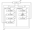
図1を参照して、第一の実施形態に係る画像処理装置100の構成について説明する。画像処理装置100は、CT画像から肝臓領域を抽出する識別器の学習を行う装置である。画像処理装置100は、教示データ生成部101と学習処理実行部102からなる。教示データ生成部101は、操作者等により指定されたスライス厚とスライス間隔からなる所定の厚さに基づいて、事前に作成されている教示データから、新たな教示データを生成する。学習処理実行部102は、教示データ生成部101によって生成された教示データを用いて、識別器103の学習を行う。識別器103は、CT画像を入力として受け付け、CT画像中に描出されている注目領域を抽出する識別器である。学習処理実行部102により学習された識別器103は、操作者等により指定されたスライス厚とスライス間隔を持つCT画像から、注目領域を高い精度で抽出することが可能となる。
<First embodiment>
The configuration of the
画像処理装置100は、プロセッサとメモリとを含み、メモリに格納されたプログラムをプロセッサが実行することによって上述の各機能部が実現される。なお、各機能部の一部または全部は専用のハードウェア装置によって実現されてもよい。
The
画像処理装置100のほかに、画像処理装置100への入力となるデータ、および画像処理装置100が出力するデータを保存するためのデータサーバ200が存在する。デー
タサーバ200はコンピュータ記憶媒体の一例であり、ハードディスクドライブ(HDD)やソリッドステイトドライブ(SSD)に代表される大容量情報記憶装置である。データサーバ200は、画像処理装置100内に保持されていてもよいし、画像処理装置100外に別途設けられネットワークを介して通信可能に構成されていてもよい。
In addition to the
教示データは、セグメンテーション処理の対象となるデータと同等の入力データと、この入力データが識別器103に入力されたときに期待される出力である正解データを含む。本実施例では、入力データはCT画像であり、正解データはCT画像中の注目領域を示す画像である。教示データは、教師データあるいはトレーニングデータとも呼ばれる。入力データは、入力画像、学習画像、学習データとも呼ばれる。正解データは、正解画像とも呼ばれる。 The teaching data includes input data equivalent to the data to be segmented, and correct answer data which is an output expected when this input data is input to the classifier 103. In this embodiment, the input data is a CT image, and the correct answer data is an image showing a region of interest in the CT image. Teaching data is also called teacher data or training data. The input data is also called an input image, a learning image, and learning data. The correct answer data is also called a correct answer image.
[教示データ生成部]
図1を参照して、教示データ生成部101の構成をさらに詳しく説明する。
[Teaching data generator]
The configuration of the teaching
第一の取得部110は、被写体を撮影して得られる複数の第一の断層画像と、複数の第一の断層画像のそれぞれに対して注目領域を示す複数の第二の断層画像とを取得する。第一の取得部110は、また、第一の断層画像および第二の断層画像の第一のスライス間隔および第一のスライス厚と、第三の断層画像および第四の断層画像の第二のスライス間隔および第二のスライス厚とを取得する。
The
第一の取得部110は、データサーバ200に格納されている教示データSinputの中から一組のCT画像(入力画像)と正解画像を取得する。また、第一の取得部110は、識別器103が処理の対象とするCT画像のスライス厚やスライス間隔の値をデータサーバ200から取得して、新たに生成するCT画像と正解画像のスライス厚とスライス間隔に関する情報を生成する。第一の取得部110は、取得したCT画像と、新たに生成するCT画像のスライス厚とスライス間隔に関する情報を、第一の生成部120に送信する。また、第一の取得部110は、取得した正解画像と、新たに生成する正解画像のスライス厚とスライス間隔に関する情報を、第二の生成部130に送信する。
The
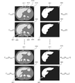
図3を参照して、第一の取得部110により取得されるCT画像と正解画像について説明する。第一の取得部110により取得されるCT画像(入力画像)は、複数枚の断層画像から構成される3次元画像(複数の第一の断層画像)である。図3の断層画像310、断層画像320、断層画像330、断層画像340は、ひとつのCT画像を構成する断層画像の一例である。断層画像310、断層画像320、断層画像330、断層画像340は、連続するNinput枚のスライスであり、患者の体軸に沿って並んでいる。注目領域311、注目領域321、注目領域331、注目領域341はCT画像に描出された肝臓であり、識別器103が抽出しようとする領域(注目領域)である。また、領域312、領域313、領域324、領域325、領域326はそれぞれ、CT画像に描出された胴体、胃、背骨、右腎臓、左腎臓である。これらの領域は、正解画像において注目領域として設定された領域ではない。すべての断層画像にはこのような注目領域として設定された領域ではない領域が写っているが、図3では見やすさを考慮して、一部の非注目領域には符号を付与していない。
The CT image and the correct answer image acquired by the
正解画像もまた、複数枚の断層画像から構成される3次元画像(複数の第二の断層画像)である。図3の断層画像350、断層画像360、断層画像370、断層画像380は、ひとつの正解画像を構成する断層画像の一例である。正解画像のそれぞれの断層画像は、CT画像の断層画像に対応する。図3では、断層画像350、断層画像360、断層画像370、断層画像380は、それぞれ、断層画像310、断層画像320、断層画像330、断層画像340に対応する。正解画像の各断層画像は、対応するCT画像の断層画
像中に描出されている肝臓の領域を示す2値画像である。領域351、領域361、領域371、領域381は、それぞれ、注目領域311、注目領域321、注目領域331、注目領域341を示している。尚、断層画像には注目領域が描出されていることは必須ではなく、注目領域が描出されていない断層画像に対して、注目領域が描出されていないことを示す正解画像が組として教示データに含まれていてもよい。
The correct image is also a three-dimensional image (a plurality of second tomographic images) composed of a plurality of tomographic images. The
第一の取得部110により取得されたCT画像と正解画像は、スライス厚やスライス間隔についての情報を保持している。スライス厚とは、それぞれの断層画像を構成する面(スライス)の厚みである。一般に、ひとつのCT画像を構成するすべての断層画像は、同じスライス厚を持つ。スライス間隔とは、連続して並ぶ二つの断層画像間の撮像空間での距離のことである。一般に、ひとつのCT画像を構成するすべての断層画像は、患者の体軸に沿って等しい間隔で配置される。そのため、ひとつのCT画像(断層画像310、断層画像320、・・・、断層画像330、断層画像340)は、一つの(同じ)スライス間隔を持つ。また、一般的なCT画像では、スライス厚とスライス間隔は同じ値をとる。ここで、正解画像の各断層画像は、CT画像の断層画像に対応するため、正解画像のスライス厚やスライス間隔は、CT画像のスライス厚やスライス間隔と等しい。以降、第一の取得部110により取得されたCT画像と正解画像のスライス厚をTinput、スライス間隔をDinputと記述する。Tinputが第一のスライス厚に相当し、Dinputが第一のスライス間隔に相当する。
The CT image and the correct answer image acquired by the
また、第一の取得部110は、データサーバ200より、識別器103が処理の対象とするCT画像のスライス厚やスライス間隔の値を取得する。そして、新たに生成するCT画像と正解画像のスライス間隔とスライス厚の値を設定する。以降、第一の取得部110が設定したスライス厚とスライス間隔をそれぞれ、Ttarget、Dtargetと記述する。Ttargetが第二のスライス厚に相当し、Dtargetが第二のスライス間隔に相当する。
Further, the
第一の取得部110は、Ttargetを、識別器103で処理したいCT画像のスライス厚と等しい値に設定する。例えば、識別器103で5mm厚のCT画像に描出されている肝臓を抽出したいとする。この時、Ttargetを5とする。すると、画像処理装置100は、最終結果(第二の出力部170の出力)として、5mm厚のCT画像に描出されている肝臓を抽出するために最も効果的な識別器103のパラメータを出力する。
The
識別器103がCT画像を3次元画像として入力して識別する識別器である場合には、第一の取得部110は、Dtargetを、Ttargetと等しい値に設定する。これによると、生成する教示データのスライス厚とスライス間隔を、識別器103が処理する対象のCT画像と一致させることができる。一方、識別器103がCT画像を断層画像毎に2次元画像として入力して識別する識別器である場合には、第一の取得部110は、Dtargetを、Dinputと等しい値に設定する。これによると、入力する教示データに近い数の教示データを生成することができる。なお、識別器103が2次元の場合のDtargetの値は、3次元の場合と同様にTtargetと同じ値にしてもよいし、DinputともTtargetとも異なる値に設定してもよい。
When the classifier 103 is a classifier that inputs and discriminates a CT image as a three-dimensional image, the
上記では、第一の取得部110は、データサーバ200より、識別器103が処理の対象とするCT画像のスライス厚やスライス間隔の値を取得しているが、これらの値をユーザからの入力として取得してもよい。第一の取得部110は、スライス厚とスライス間隔のいずれか又は両方を数値としてユーザから取得してもよい。あるいは第一の取得部110は、識別器103に入力される画像の種類をユーザから取得して、この画像の種類に応じてスライス厚とスライス間隔のいずれかまたは両方を設定してもよい。
In the above, the
第一の生成部120は、第一の取得部110から受け取ったCT画像(複数の第一の断層画像)から、新たなCT画像(複数の第三の断層画像)を生成する。第一の生成部120は、前記複数の第一の断層画像のうち、所定の厚さの範囲内に含まれる前記第一の断層画像を用いて、前記被写体を表す第三の断層画像を生成する。今、第一の生成部120が第一の取得部110から受け取ったCT画像をCinput、第一の生成部120が生成するCT画像をCtargetと記述する。第一の生成部120は、Cinputを構成する断層画像Cinput[i](i=1,・・・,Ninput)のうち、所定の厚みの範囲Rjに含まれる複数枚の断層画像を平均化することで、新たな一枚の断層画像Ctarget[j](j=1,・・・,Ntarget)を生成する。ここで、厚みの範囲Rjは、それぞれのjごとに、次式で計算される。
![]()
![]()
なお、断層画像Cinput[i]は厚みを有するので、その一部分のみが厚みの範囲Rjに含まれることがある。第一の生成部120は、少なくとも一部分が厚みの範囲Rjに含まれる断層画像を平均化して新たな断層画像Ctarget[j]を生成してもよい。あるいは、第一の生成部120は、所定割合以上の部分が厚みの範囲Rjに含まれる断層画像を平均化して新たな断層画像Ctarget[j]を生成してもよい。また、第一の生成部120は、少なくとも一部分が厚みの範囲Rjに含まれる断層画像を、厚みの範囲Rjに含まれる部分の割合に応じた重みを用いて加重平均して、新たな断層画像Ctarget[j]を生成してもよい。
Since the tomographic image Cinput [i] has a thickness, only a part thereof may be included in the thickness range Rj. The
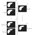
図4は、新たな断層画像の生成例を説明する図である。この例では、Dtarget=Ttarget=2×Dinput=2×Tinputである。第一の生成部120は、二枚の断層画像310、320を平均化して、新たな断層画像410を生成し、また、二枚の断層画像330、340を平均化して、新たな断層画像420を生成している。断層画像320と断層画像330の間に存在する不図示の断層画像についても、同様の処理を行う。第一の生成部120は、生成された断層画像410、・・・、断層画像420を新しい一つのCT画像とみなす。
FIG. 4 is a diagram illustrating an example of generating a new tomographic image. In this example, Dtarget = Ttarget = 2 × Dinput = 2 × Tinput. The
第二の生成部130は、第一の取得部110から受け取った正解画像(複数の第二の断層画像)から、新たな正解画像(複数の第四の断層画像)を生成する。第二の生成部130は、複数の第二の断層画像のうち、所定の厚さの範囲内に含まれる第二の断層画像を用いて、第三の断層画像中の注目領域を示す第四の断層画像を生成する。第四の断層画像の各座標の画素値は、所定の厚さの範囲に含まれる第二の断層画像の座標の画素値の代表値として決定すればよい。第二の生成部130が新たに生成する正解画像は、二値画像であってもよいし連続値画像であってもよい。いずれの表現の正解画像を生成するかは、学習処理実行部102が実行する識別器103の学習に必要な正解画像の表現に応じて(必要な表現の正解画像が得られるように)決定する。
The
今、第二の生成部130が第一の取得部110から受け取った正解画像をMinput、第二の生成部130が生成する新たな正解画像をMtargetと記述する。正解画像が二値画像である場合、正解画像の各画素は、二つの画素値のいずれか一つを取る。一つめの画素値は、当該画素が注目領域に含まれる画素であることを示す。もう一つの画素値は、当該画素が注目領域に含まれない画素であることを示す。一方、正解画像が連続値画像である場合、正解画像の各画素は、二つの所定の値、例えば0と1の間の任意の値を取る。この時、画素値の大きさは、当該画素が注目領域に含まれる確からしさを表す。すなわち、画素値が大きな値であればあるほど、当該画素は注目領域に含まれる可能性が高い。
Now, the correct answer image received by the
まず、新たな正解画像Mtargetを二値画像として生成する場合について説明する。このとき、第二の生成部130は、Minputを構成する断層画像Minput[i](i=1,・・・,Ninput)のうち、所定の厚みの範囲Rjに含まれる複数枚の断層画像を平均化する。そして、その結果に対してしきい値処理を適用することで、新たな一枚の断層画像Mtarget[j](j=1,・・・,Ntarget)を生成する。Rjは、上述の数式(式1)で計算される。
First, a case where a new correct image Mtaget is generated as a binary image will be described. At this time, the
なお、新たな正解画像の生成は上記に限られない。新たな正解画像Mtarget[j]における各座標の画素値が、範囲Rjに含まれる各断層画像Minput[i]の当該座標の画素値の代表値に基づいて定められればどのような方法で新たな正解画像を生成してもよい。たとえば、新たな正解画像の各座標の画素値を、範囲Rjに含まれる各断層画像Minput[i]の当該座標の画素値の多数決で定めてもよい。また、当該座標の画素値の平均を閾値処理することで、新たな正解画像の画素値を定めてもよい。この場合、画素値の平均は単純平均であってもよいし、範囲Rjの中心に近い断層画像の重みを相対的に大きく設定した加重平均であってもよい。また、画素値の積によって新たな正解画像の画素値を定めてもよい。 The generation of a new correct image is not limited to the above. If the pixel value of each coordinate in the new correct image Mtaget [j] is determined based on the representative value of the pixel value of the coordinate in each tomographic image Minput [i] included in the range Rj, a new method is used. A correct image may be generated. For example, the pixel value of each coordinate of the new correct image may be determined by a majority determination of the pixel value of the coordinate of each tomographic image Minput [i] included in the range Rj. Further, a new pixel value of the correct image may be determined by performing threshold processing on the average of the pixel values of the coordinates. In this case, the average of the pixel values may be a simple average or a weighted average in which the weight of the tomographic image near the center of the range Rj is set relatively large. Further, the pixel value of the new correct image may be determined by the product of the pixel values.
図5は、新たな正解画像を二値画像として生成する例を説明する図である。スライス厚およびスライス間隔の設定は図4の場合と同様である。第二の生成部130は、二枚の断層画像350、360から、新たな断層画像510を生成し、また、断層画像360、370から、新たな断層画像520を生成している。断層画像360と断層画像370の間に存在する不図示の断層画像についても、同様の処理を行う。第二の生成部130は、生成された断層画像510、・・・、断層画像520を新しい一つの正解画像とみなす。
FIG. 5 is a diagram illustrating an example of generating a new correct image as a binary image. The setting of the slice thickness and the slice interval is the same as in the case of FIG. The
次に、新たな正解画像Mtargetを連続値画像として生成する場合について説明する。このとき、第二の生成部130は、Minputを構成する断層画像Minput[i](i=1,・・・,Ninput)のうち、所定の厚みの範囲Rjに含まれる複数枚の断層画像を平均化することで、新たな一枚の断層画像Mtarget[j]を生成する。Rjは、上述の数式(式1)で計算される。なお、新たな正解画像Mtarget[j]における各座標の画素値が、範囲Rjに含まれる各断層画像Minput[i]の当該座標の画素値の代表値に基づいて定められればどのような方法で新たな正解画像を生成してもよい。例えば、単純平均の代わりに、加重平均や和によって新たな正解画像の各座標の画素値を決定してもよい。
Next, a case where a new correct image Mtaget is generated as a continuous value image will be described. At this time, the
図6は、新たな正解画像を連続画像として生成する例を説明する図である。スライス厚およびスライス間隔の設定は図4の場合と同様である。第二の生成部130は、二枚の断層画像350、360から、新たな断層画像610を生成し、また、断層画像360、370から、新たな断層画像620を生成している。断層画像360と断層画像370の間に存在する不図示の断層画像についても、同様の処理を行う。第二の生成部130は、生成された断層画像610、・・・、断層画像620を新しい一つの正解画像とみなす。
FIG. 6 is a diagram illustrating an example of generating a new correct image as a continuous image. The setting of the slice thickness and the slice interval is the same as in the case of FIG. The
第一の出力部140は、第一の生成部120から受け取ったCT画像と第二の生成部130から受け取った正解画像を一つの組として対応付ける。そして、第一の出力部140は、対応付けられたCT画像と正解画像を、データサーバ200に格納されている教示データに追加する。
The
なお、第一の出力部140は、CT画像に対応する正解画像を図1には不図示の表示部に出力してもよい。表示部に含まれる表示装置の一例は、ディスプレイである。表示部は、CT画像に対応する正解画像のみを表示してもよい。また、表示部は、CT画像と、対
応する正解画像を同時に表示してもよい。また、表示部は、データサーバ200から取得したCT画像および正解画像と、教示データ生成部101が生成したCT画像および正解画像を同時に表示してもよいし、いずれかのみを表示してもよい。
The
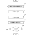
次に図2を参照して、教示データ生成部101が行う画像処理方法の処理手順を説明する。
Next, with reference to FIG. 2, the processing procedure of the image processing method performed by the teaching
(S110)
ステップS110において、第一の取得部110は、データサーバ200に格納されている教示データの中から、一組のCT画像と正解画像を取得する。また、第一の取得部110は、データサーバ200から、識別器103が処理の対象とするCT画像のスライス厚やスライス間隔の値を取得して、新たに生成するCT画像と正解画像のスライス厚とスライス間隔に関する情報を設定する。処理の詳細については、第一の取得部110の説明で述べた通りである。そして、第一の取得部110は、取得したCT画像と、新たに生成するCT画像のスライス厚とスライス間隔に関する情報を、第一の生成部120に送信する。また、第一の取得部110は、取得した正解画像と、新たに生成する正解画像のスライス厚とスライス間隔に関する情報を、第二の生成部130に送信する。
(S110)
In step S110, the
(S120)
ステップS120において、第一の生成部120は、第一の取得部110からCT画像とスライス間隔に関する情報を取得する。そして、第一の生成部120は、第一の取得部110から受け取ったCT画像から、新たなCT画像を生成する。処理の詳細については、第一の生成部120の説明で述べた通りである。最後に、第一の生成部120は、新たに生成された抽出されたCT画像を第一の出力部140に送信する。
(S120)
In step S120, the
(S130)
ステップS130において、第二の生成部130は、第一の取得部110から正解画像とスライス間隔に関する情報を取得する。そして、第二の生成部130は、第一の取得部110から受け取った正解画像から、新たな正解画像を生成する。処理の詳細については、第二の生成部130の説明で述べた通りである。最後に、第二の生成部130は、新たに生成された抽出された正解画像を第一の出力部140に送信する。
(S130)
In step S130, the
(S140)
ステップS140において、第一の出力部140は、第一の生成部120から受信したCT画像と、第二の生成部130から受信した正解画像を対応付ける。そして、第一の出力部140は、データサーバ200に格納されている教示データSnewに、対応付けられたCT画像と正解画像を追加する。もしデータサーバにSnewが存在していない場合、第一の出力部140はデータサーバ200にSnewを作成する。そして、作成されたSnewに対応付けられたCT画像と正解画像を追加する。
(S140)
In step S140, the
(S150)
ステップS150において、画像処理装置100の不図示の制御部は、データサーバ200に格納されている教示データSinputにまだ処理していないCT画像と正解画像が存在しているか否かを判定する。もし、処理していないCT画像と正解画像が存在している場合、不図示の制御部は教示データ生成部101にステップS110の処理を実行させる。逆に、処理していないCT画像と正解画像が存在しない場合、不図示の制御部は教示データ生成部101の処理を終了させる。
(S150)
In step S150, the control unit (not shown) of the
以上の手順に従い、教示データ生成部101は、データサーバ200に格納されている教示データSinputから、新たな教示データSnewを生成する。
According to the above procedure, the teaching
[学習処理実行部]
続いて、図1を参照して、学習処理実行部102の構成を説明する。第二の取得部150は、データサーバ200から、教示データ生成部101により生成された教示データSnewを取得し、それを学習部160に送信する。教示データSnewは、複数個のCT画像と正解画像からなる。それぞれの正解画像は、対応するCT画像と関連付けられており、一つのCT画像と一つの正解画像で一組のデータをなしている。これらのCT画像と正解画像は、第一の生成部120と第二の生成部130で生成されたCT画像と正解画像である。第二の取得部150は、Snewに加えて、データサーバ200から教示データSinputを取得し、SinputとSnewを学習部160に送信してもよい。
[Learning process execution unit]
Subsequently, the configuration of the learning
学習部160は、第二の取得部150から教示データを取得する。そして、学習部160は、取得した教示データを用いて注目領域を抽出するための識別器103の学習を行う。学習の結果、学習部160は、識別器103のパラメータを取得する。最後に、学習部160は、取得した識別器103のパラメータを第二の出力部170に送信する。
The
識別器103は、セグメンテーションに利用可能な識別器であれば、どのような識別器であってもよい。識別器103の種類に応じて、学習部160が実行する学習アルゴリズムは一意に決まる。そのため、学習部160は、識別器103に対応する学習アルゴリズムを実行する。これらの学習アルゴリズムは公知の技術であり、その処理手順は文献等で開示されている。そのため、ここでは処理手順の詳細については説明を省略する。以下では、CT画像を2次元の断面画像毎に処理し、注目領域を抽出した結果の画像を2次元の断面画像として出力する、2次元の識別器を構成する場合を例に説明する。
The classifier 103 may be any classifier as long as it can be used for segmentation. The learning algorithm executed by the
学習アルゴリズムの処理ステップの一つに、損失の計算がある。損失の計算に利用される損失関数は、識別器103が、CT画像中の各画素について、当該画素が注目領域に含まれるか否かを二値で出力する識別器か、当該画素が注目領域に含まれる確からしさ(連続値)を出力する識別器か、に応じて選択される。 One of the processing steps of the learning algorithm is the calculation of loss. The loss function used to calculate the loss is whether the classifier 103 is a classifier that outputs, for each pixel in the CT image, whether or not the pixel is included in the region of interest in binary, or the pixel is the region of interest. It is selected according to whether it is a classifier that outputs the certainty (continuous value) contained in.
識別器103が二値を出力する識別器である場合、正解画像には二値画像が用いられる。このとき、学習部160は、損失関数としてbinary cross entropy等を用いる。今、教示データにT組のCT画像Iiと正解画像Riが格納されているとする。ただし、i=1,・・・,Tである。T個のCT画像Iiに学習途中の識別器103を適用して、注目領域を抽出した結果の画像をOiとする。画像RiとOiの画像サイズをM×Nとし、正解画像の画素値をRi(x,y)、抽出画像の画素値をOi(x,y)とする。ただし、1<=x<=W、1<=y<=Hである。すると、binary cross entropyは以下のように計算される。

一方、識別器103が確からしさを出力する識別器である場合、正解画像には連続値画像が用いられる。このとき、学習部160は、損失関数として二乗誤差等を用いる。二乗誤差は、以下のように計算される。

学習部160が損失関数(式3)を用いて識別器103の学習を行うとき、結果として得られる識別器103は、CT画像中の各画素について、当該画素が注目領域に含まれる確からしさを出力するようになる。
When the
第二の出力部170は、学習部160から受け取った識別器103のパラメータをデータサーバ200に格納する。
The
以上で、学習処理実行部102の説明を終える。
This is the end of the explanation of the learning
次に、図7を参照して、学習処理実行部102の処理手順を説明する。上述の通り、損失関数の計算方法が異なることを除き、学習処理実行部102は公知の学習アルゴリズムと同じ処理を実行する。そこで、以下では、学習処理実行部102の処理手順を短く説明する。
Next, the processing procedure of the learning
(S210)
ステップS210において、第二の取得部150は、データサーバ200から教示データを取得する。
(S210)
In step S210, the
(S220)
ステップS220において、学習部160は、識別器103の種類に応じて決定される学習アルゴリズムを実行する。本ステップで実行される処理の詳細については、学習部160の説明で述べたとおりである。
(S220)
In step S220, the
(S230)
ステップS230において、第二の出力部170は、ステップS220で得られた識別器103のパラメータをデータサーバ200に格納する。
(S230)
In step S230, the
以上の手順に従い、学習処理実行部102は、識別器103の学習を行う。
According to the above procedure, the learning
第一の実施形態に係る画像処理装置100は、識別器103に処理させるCT画像のスライス厚とスライス間隔を考慮した正解画像を効率よく生成することが出来る。そして、その取得結果に基づいて識別器103を学習させる。結果として得られる識別器103は、当該スライス厚とスライス間隔を有するCT画像から、注目領域を高い精度で抽出することができるようになる。
The
なお、上記の説明では、識別器103が処理の対象とするCT画像のスライス厚が固定値である場合を例として、その学習に用いる教示データとしてSnewを生成する場合を例として説明したが、それ以外の実施形態でもよい。 In the above description, the case where the slice thickness of the CT image to be processed by the classifier 103 is a fixed value is taken as an example, and the case where Snew is generated as the teaching data used for the learning is described as an example. Other embodiments may be used.
たとえば、領域抽出を行いたいCT画像のスライス厚が複数(たとえば、1mm、2mm、3mm、5mm)ある場合に、それぞれのスライス厚に対して個々に上記の処理を行ってもよい。言い換えると、スライス厚毎に、新たな正解画像の生成および識別器の学習を行ってもよい。この場合、教示データ生成部101は、想定されるスライス厚ごとに、新たな教示データSnewを生成する。また、学習処理実行部102は、それぞれのスラ
イス厚に対応する識別器103を、それぞれ、対応するスライス厚の教示データSnewを用いて学習して生成する。このとき、学習した識別器103を用いて未知のCT画像の領域抽出を行う際には、処理を行うCT画像のスライス厚に基づいて当該スライス厚の識別器103を選択し、当該識別器を用いて領域抽出処理を行えばよい。また、スライス厚だけでなく、スライス間隔も複数設定してもよい。例えば、想定されるスライス厚およびスライス間隔の複数の組のそれぞれについて、対応するスライス厚およびスライス間隔の教示データを生成して、識別器103の学習に用いてもよい。
For example, when there are a plurality of slice thicknesses (for example, 1 mm, 2 mm, 3 mm, 5 mm) of the CT image for which region extraction is desired, the above processing may be individually performed for each slice thickness. In other words, a new correct image may be generated and the discriminator may be learned for each slice thickness. In this case, the teaching
また、想定されるスライス厚Tをいくつかのグループにグループ分けして(たとえば、T≦1mm、1mm<T≦2mm、2mm<T≦3mm、3mm<T≦5mm、5mm<T)、それぞれのグループに対応する識別器103を生成するようにしてもよい。この場合、教示データ生成部101は、想定されるスライス厚のグループごとに、当該グループの範囲に含まれる様々なスライス厚をTtargetとして設定しながら、新たな教示データSnewを生成する。また、学習処理実行部102は、それぞれのグループに対応する識別器103を、それぞれ、対応するグループの教示データSnewを用いて学習して生成する。このとき、学習した識別器103を用いて未知のCT画像の領域抽出を行う際には、処理を行うCT画像のスライス厚に基づいて当該スライス厚が含まれるグループの識別器103を選択し、当該識別器を用いて領域抽出処理を行えばよい。また、グループ分けは必ずしも必要ではなく、すべてのスライス厚を一つのグループとして同様の処理を行ってもよい。上記のいずれの方法によっても、様々なスライス厚のCT画像に対して注目領域を高い精度で抽出することができる。
Further, the assumed slice thickness T is divided into several groups (for example, T ≦ 1 mm, 1 mm <T ≦ 2 mm, 2 mm <T ≦ 3 mm, 3 mm <T ≦ 5 mm, 5 mm <T), and each of them is divided into several groups. The classifier 103 corresponding to the group may be generated. In this case, the teaching
上記の説明では、処理対象の画像はX線CT装置で撮像したCT画像を例にとって説明しているが、処理対象の画像は、MRI断層画像、PET断層画像、超音波断層画像等の任意の断層画像であってもよい。 In the above description, the image to be processed is described by taking a CT image captured by an X-ray CT apparatus as an example, but the image to be processed can be any arbitrary image such as an MRI tomographic image, a PET tomographic image, and an ultrasonic tomographic image. It may be a tomographic image.
(その他の実施例)
また、本発明は、以下の処理を実行することによっても実現される。即ち、上述した実施形態の機能を実現するソフトウェア(プログラム)を、ネットワーク又は各種記憶媒体を介してシステム或いは装置に供給し、そのシステム或いは装置のコンピュータ(またはCPUやMPU等)がプログラムを読み出して実行する処理である。
(Other examples)
The present invention is also realized by executing the following processing. That is, software (program) that realizes the functions of the above-described embodiment is supplied to the system or device via a network or various storage media, and the computer (or CPU, MPU, etc.) of the system or device reads the program. This is the process to be executed.
100:画像処理装置
110:第一の取得部
120:第一の生成部
130:第二の生成部
100: Image processing device 110: First acquisition unit 120: First generation unit 130: Second generation unit
Claims (16)
前記複数の第一の断層画像のうち、所定の厚さの範囲内に含まれる前記第一の断層画像を用いて、前記被写体を表す第三の断層画像を生成する第一の生成部と、
前記複数の第二の断層画像のうち、前記所定の厚さの範囲内に含まれる前記第二の断層画像を用いて、前記第三の断層画像中の注目領域を示す第四の断層画像を生成する第二の生成部と、
を備える、画像処理装置。 A first acquisition unit that acquires a plurality of first tomographic images obtained by photographing a subject and a plurality of second tomographic images indicating a region of interest for each of the plurality of first tomographic images. When,
A first generation unit that generates a third tomographic image representing the subject by using the first tomographic image included in a predetermined thickness range among the plurality of first tomographic images.
Of the plurality of second tomographic images, the second tomographic image included within the predetermined thickness range is used to obtain a fourth tomographic image showing a region of interest in the third tomographic image. The second generator to generate and
An image processing device.
請求項1に記載の画像処理装置。 The first generation unit averages the first tomographic image included in the predetermined thickness range to generate the third tomographic image.
The image processing apparatus according to claim 1.
請求項1または2に記載の画像処理装置。 The second generation unit determines the pixel value of each coordinate of the fourth tomographic image as a representative value of the pixel value of the coordinate of the second tomographic image included in the predetermined thickness range. ,
The image processing apparatus according to claim 1 or 2.
請求項3に記載の画像処理装置。 The second generation unit performs the fourth tomographic image by averaging the second tomographic image included in the predetermined thickness range, or by performing threshold processing after averaging. To generate,
The image processing apparatus according to claim 3.
請求項4に記載の画像処理装置。 The averaging performed by the second generation unit is a weighted average in which the weight of the second tomographic image near the center of the predetermined thickness range is set relatively large.
The image processing apparatus according to claim 4.
請求項1から5のいずれか1項に記載の画像処理装置。 Further, a learning unit for learning a classifier for extracting the region of interest by using the third tomographic image and the fourth tomographic image is provided.
The image processing apparatus according to any one of claims 1 to 5.
前記学習部は、前記識別器が、前記第三の断層画像中のそれぞれの画素について、当該画素が前記注目領域に含まれるか含まれないかを示す二つの画素値のいずれかを出力するように学習を行う、
請求項6に記載の画像処理装置。 The fourth generation unit takes either of two pixel values indicating whether each pixel in the third tomographic image is included or not included in the region of interest. Generate a tomographic image and
The learning unit causes the discriminator to output one of two pixel values indicating whether or not the pixel is included in the region of interest for each pixel in the third tomographic image. To learn,
The image processing apparatus according to claim 6.
前記学習部は、前記識別器が、前記第三の断層画像中のそれぞれの画素について、当該画素が前記注目領域に含まれる確からしさを表す値を出力するように学習を行う、
請求項6に記載の画像処理装置。 The second generation unit generates the fourth tomographic image in which each pixel in the third tomographic image takes a value representing the certainty that the pixel is included in the region of interest.
The learning unit learns so that the discriminator outputs a value indicating the certainty that the pixel is included in the region of interest for each pixel in the third tomographic image.
The image processing apparatus according to claim 6.
前記所定の厚さの範囲は、前記第二のスライス間隔および前記第二のスライス厚に基づ
いて求められ、
前記所定の厚さの範囲内に含まれる前記第一の断層画像および前記第二の断層画像は、前記第一のスライス間隔および前記第一のスライス厚に基づいて求められる、
請求項6から8のいずれか1項に記載の画像処理装置。 The first acquisition unit includes the first slice interval and the first slice thickness of the first tomographic image and the second tomographic image, and the third tomographic image and the fourth tomographic image. Get the second slice interval and the second slice thickness,
The predetermined thickness range is determined based on the second slice interval and the second slice thickness.
The first tomographic image and the second tomographic image included within the predetermined thickness range are obtained based on the first slice interval and the first slice thickness.
The image processing apparatus according to any one of claims 6 to 8.
請求項9に記載の画像処理装置。 The first acquisition unit acquires the type of image input to the classifier and determines the second slice interval and the second slice thickness based on the type of image input to the classifier. decide,
The image processing apparatus according to claim 9.
前記第一の生成部は、前記第二のスライス間隔と前記第二のスライス厚の組ごとに、前記第三の断層画像を生成し、
前記第二の生成部は、前記第二のスライス間隔と前記第二のスライス厚の組ごとに、前記第四の断層画像を生成する、
請求項9または10に記載の画像処理装置。 The first acquisition unit acquires a plurality of sets of the second slice interval and the second slice thickness.
The first generation unit generates the third tomographic image for each set of the second slice interval and the second slice thickness.
The second generation unit generates the fourth tomographic image for each set of the second slice interval and the second slice thickness.
The image processing apparatus according to claim 9 or 10.
請求項11に記載の画像処理装置。 The learning unit learns the classifier for each set of the second slice interval and the second slice thickness.
The image processing apparatus according to claim 11.
請求項1から12のいずれか1項に記載の画像処理装置。 The first tomographic image is a tomographic image constituting any one of a CT image, an MRI tomographic image, a PET tomographic image, and an ultrasonic tomographic image.
The image processing apparatus according to any one of claims 1 to 12.
前記第一の生成部および前記第二の生成部は、前記第三の断層画像および前記第四の断層画像を前記データサーバに出力する、
請求項1から13のいずれか1項に記載の画像処理装置。 The first acquisition unit acquires the first tomographic image and the second tomographic image from the data server, and obtains the first tomographic image and the second tomographic image.
The first generation unit and the second generation unit output the third tomographic image and the fourth tomographic image to the data server.
The image processing apparatus according to any one of claims 1 to 13.
被写体を撮影して得られた複数の第一の断層画像と、前記複数の第一の断層画像のそれぞれに対して注目領域を示す複数の第二の断層画像とを取得する第一の取得ステップと、
前記複数の第一の断層画像のうち、所定の厚さの範囲内に含まれる前記第一の断層画像を用いて、前記被写体を表す第三の断層画像を生成する第一の生成ステップと、
前記複数の第二の断層画像のうち、前記所定の厚さの範囲内に含まれる前記第二の断層画像を用いて、前記第三の断層画像中の注目領域を示す第四の断層画像を生成する第二の生成ステップと、
を含む、画像処理方法。 It is an image processing method performed by a computer.
The first acquisition step of acquiring a plurality of first tomographic images obtained by photographing a subject and a plurality of second tomographic images indicating a region of interest for each of the plurality of first tomographic images. When,
A first generation step of generating a third tomographic image representing the subject by using the first tomographic image included in a predetermined thickness range among the plurality of first tomographic images.
Of the plurality of second tomographic images, the second tomographic image included within the predetermined thickness range is used to obtain a fourth tomographic image showing a region of interest in the third tomographic image. The second generation step to generate and
Image processing methods, including.
Priority Applications (1)
| Application Number | Priority Date | Filing Date | Title |
|---|---|---|---|
| JP2020111225A JP7483528B2 (en) | 2020-06-29 | 2020-06-29 | Image processing device, image processing method, and program |
Applications Claiming Priority (1)
| Application Number | Priority Date | Filing Date | Title |
|---|---|---|---|
| JP2020111225A JP7483528B2 (en) | 2020-06-29 | 2020-06-29 | Image processing device, image processing method, and program |
Publications (2)
| Publication Number | Publication Date |
|---|---|
| JP2022010572A true JP2022010572A (en) | 2022-01-17 |
| JP7483528B2 JP7483528B2 (en) | 2024-05-15 |
Family
ID=80148515
Family Applications (1)
| Application Number | Title | Priority Date | Filing Date |
|---|---|---|---|
| JP2020111225A Active JP7483528B2 (en) | 2020-06-29 | 2020-06-29 | Image processing device, image processing method, and program |
Country Status (1)
| Country | Link |
|---|---|
| JP (1) | JP7483528B2 (en) |
Citations (6)
| Publication number | Priority date | Publication date | Assignee | Title |
|---|---|---|---|---|
| JP2006043431A (en) * | 2004-08-06 | 2006-02-16 | Toshiba Corp | Method to reduce helical windmill artifact with recovery noise for helical multi-slice CT |
| JP2008200373A (en) * | 2007-02-22 | 2008-09-04 | Fujifilm Corp | Similar case search device, method, and program, and similar case database registration device, method, and program |
| JP2011092684A (en) * | 2009-09-30 | 2011-05-12 | Fujifilm Corp | Lesion region extraction apparatus and method, and program |
| JP2016174656A (en) * | 2015-03-19 | 2016-10-06 | コニカミノルタ株式会社 | Image processing device and program |
| WO2019167883A1 (en) * | 2018-02-28 | 2019-09-06 | 富士フイルム株式会社 | Machine learning device and method |
| JP2020021228A (en) * | 2018-07-31 | 2020-02-06 | キヤノン株式会社 | Information processing device, information processing method, and program |
-
2020
- 2020-06-29 JP JP2020111225A patent/JP7483528B2/en active Active
Patent Citations (6)
| Publication number | Priority date | Publication date | Assignee | Title |
|---|---|---|---|---|
| JP2006043431A (en) * | 2004-08-06 | 2006-02-16 | Toshiba Corp | Method to reduce helical windmill artifact with recovery noise for helical multi-slice CT |
| JP2008200373A (en) * | 2007-02-22 | 2008-09-04 | Fujifilm Corp | Similar case search device, method, and program, and similar case database registration device, method, and program |
| JP2011092684A (en) * | 2009-09-30 | 2011-05-12 | Fujifilm Corp | Lesion region extraction apparatus and method, and program |
| JP2016174656A (en) * | 2015-03-19 | 2016-10-06 | コニカミノルタ株式会社 | Image processing device and program |
| WO2019167883A1 (en) * | 2018-02-28 | 2019-09-06 | 富士フイルム株式会社 | Machine learning device and method |
| JP2020021228A (en) * | 2018-07-31 | 2020-02-06 | キヤノン株式会社 | Information processing device, information processing method, and program |
Also Published As
| Publication number | Publication date |
|---|---|
| JP7483528B2 (en) | 2024-05-15 |
Similar Documents
| Publication | Publication Date | Title |
|---|---|---|
| EP3685350B1 (en) | Image reconstruction using machine learning regularizers | |
| EP3525171B1 (en) | Method and system for 3d reconstruction of x-ray ct volume and segmentation mask from a few x-ray radiographs | |
| JP6947759B2 (en) | Systems and methods for automatically detecting, locating, and semantic segmenting anatomical objects | |
| JP7325954B2 (en) | Medical image processing device, medical image processing program, learning device and learning program | |
| JP7463575B2 (en) | Information processing device, information processing method, and program | |
| CN108885781B (en) | Method and system for synthesizing a virtual high dose or high kV computed tomography image from a low dose or low kV computed tomography image | |
| CN109598697B (en) | Determination of a two-dimensional mammography data set | |
| CN107545309A (en) | Scored using the picture quality of depth generation machine learning model | |
| Ratul et al. | CCX-rayNet: a class conditioned convolutional neural network for biplanar X-rays to CT volume | |
| CN111815735B (en) | A CT Reconstruction Method and Reconstruction System of Human Tissue Adaptive | |
| CN113989407B (en) | Training method and system for limb part recognition model in CT image | |
| Teixeira et al. | Generating synthetic x-ray images of a person from the surface geometry | |
| JP2024155904A (en) | Image data processing device and method | |
| Kolarik et al. | Upsampling algorithms for autoencoder segmentation neural networks: A comparison study | |
| CN108038840A (en) | A kind of image processing method, device, image processing equipment and storage medium | |
| Mangalagiri et al. | Toward generating synthetic CT volumes using a 3D-conditional generative adversarial network | |
| JP2024509039A (en) | Visual explanations, methods and systems of classification | |
| CN112365512A (en) | Method for training image segmentation model, method for image segmentation and device thereof | |
| JP2022010572A (en) | Image processing apparatus, image processing method and program | |
| EP4343680A1 (en) | De-noising data | |
| EP4386680A1 (en) | Cbct simulation for training ai-based ct-to-cbct registration and cbct segmentation | |
| CN112233126B (en) | Windowing method and device for medical image | |
| JP7486349B2 (en) | Neural network, neural network learning method, program, and image processing device | |
| Slabaugh et al. | Probabilistic spatial regression using a deep fully convolutional neural network | |
| Paul et al. | Lung CT image segmentation with optimal parameters using UNET Architecture |
Legal Events
| Date | Code | Title | Description |
|---|---|---|---|
| A621 | Written request for application examination |
Free format text: JAPANESE INTERMEDIATE CODE: A621 Effective date: 20230622 |
|
| A977 | Report on retrieval |
Free format text: JAPANESE INTERMEDIATE CODE: A971007 Effective date: 20231228 |
|
| A131 | Notification of reasons for refusal |
Free format text: JAPANESE INTERMEDIATE CODE: A131 Effective date: 20240116 |
|
| A521 | Request for written amendment filed |
Free format text: JAPANESE INTERMEDIATE CODE: A523 Effective date: 20240313 |
|
| TRDD | Decision of grant or rejection written | ||
| A01 | Written decision to grant a patent or to grant a registration (utility model) |
Free format text: JAPANESE INTERMEDIATE CODE: A01 Effective date: 20240409 |
|
| A61 | First payment of annual fees (during grant procedure) |
Free format text: JAPANESE INTERMEDIATE CODE: A61 Effective date: 20240501 |
|
| R150 | Certificate of patent or registration of utility model |
Ref document number: 7483528 Country of ref document: JP Free format text: JAPANESE INTERMEDIATE CODE: R150 |