JP2022010097A - Manufacturing method of electrode - Google Patents
Manufacturing method of electrode Download PDFInfo
- Publication number
- JP2022010097A JP2022010097A JP2021181123A JP2021181123A JP2022010097A JP 2022010097 A JP2022010097 A JP 2022010097A JP 2021181123 A JP2021181123 A JP 2021181123A JP 2021181123 A JP2021181123 A JP 2021181123A JP 2022010097 A JP2022010097 A JP 2022010097A
- Authority
- JP
- Japan
- Prior art keywords
- granulator
- granulated
- granulated body
- electrode
- pores
- Prior art date
- Legal status (The legal status is an assumption and is not a legal conclusion. Google has not performed a legal analysis and makes no representation as to the accuracy of the status listed.)
- Pending
Links
Images


Classifications
-
- Y—GENERAL TAGGING OF NEW TECHNOLOGICAL DEVELOPMENTS; GENERAL TAGGING OF CROSS-SECTIONAL TECHNOLOGIES SPANNING OVER SEVERAL SECTIONS OF THE IPC; TECHNICAL SUBJECTS COVERED BY FORMER USPC CROSS-REFERENCE ART COLLECTIONS [XRACs] AND DIGESTS
- Y02—TECHNOLOGIES OR APPLICATIONS FOR MITIGATION OR ADAPTATION AGAINST CLIMATE CHANGE
- Y02E—REDUCTION OF GREENHOUSE GAS [GHG] EMISSIONS, RELATED TO ENERGY GENERATION, TRANSMISSION OR DISTRIBUTION
- Y02E60/00—Enabling technologies; Technologies with a potential or indirect contribution to GHG emissions mitigation
- Y02E60/10—Energy storage using batteries
Abstract
Description
本開示は、造粒体の製造方法に関する。 The present disclosure relates to a method for producing a granulated product.
特開平10-55801号公報(特許文献1)には、充填密度の高い負極合材を得るための造粒体の製造装置(押出し造粒機)が開示されている。該押出し造粒機は、真円状の細孔(貫通孔)形状を有する。 Japanese Unexamined Patent Publication No. 10-55801 (Patent Document 1) discloses an apparatus for producing a granulated body (extruded granulator) for obtaining a negative electrode mixture having a high filling density. The extrusion granulator has a perfect circular pore (through hole) shape.
特許文献1に係る押出し造粒機により製造された造粒体は、真円状の細孔(貫通孔)形状に由来した形状を有するものと考えられる。すなわち、造粒体の形状は凹凸が少ないか、あるいは凹凸を有さないと考えられる。なお、本明細書において凹凸とは、平坦な状態から隆起した構造を意味する。隆起の仕方にはさまざまな形状があるため、凹凸の形状は特に限定されない。
It is considered that the granulated body produced by the extruder according to
造粒体の形状が、凹凸が少ない場合や、あるいは造粒体の形状が、凹凸を有さない場合は、隣接する造粒体同士が接触し得る面積(以後、「接触面積」とも記す)が大きくなると考えられる。造粒体は粘着質であるため、造粒体の形状が、凹凸が少ない場合や、あるいは造粒体の形状が、凹凸を有さない場合は、造粒体同士が接着し、造粒体が大粒化する懸念がある。係る大粒化された造粒体を用い、たとえば湿潤粉体成膜(MPS)装置により電極合材層を製造した場合、MPS装置のロールとロールとの間(ギャップ)に大粒化された造粒体が詰まり、製造された電極合材層に欠陥が生じる可能性がある。なお、本明細書において「大粒化された造粒体」とは、たとえば4mm以上の大きさを有する造粒体を意味する。 If the shape of the granulated body has few irregularities, or if the shape of the granulated body does not have unevenness, the area where adjacent granulated bodies can come into contact with each other (hereinafter, also referred to as "contact area"). Is expected to increase. Since the granulated body is sticky, if the shape of the granulated body has few irregularities, or if the shape of the granulated body has no unevenness, the granulated bodies adhere to each other and the granulated bodies are formed. There is a concern that it will grow in size. When the electrode mixture layer is produced by, for example, a wet powder film forming (MPS) device using the large-sized granules, the large-sized granules are formed between the rolls (gap) of the MPS device. The body may become clogged and the manufactured electrode mixture layer may be defective. In addition, in this specification, "enlarged granulation body" means a granulation body having a size of 4 mm or more, for example.
本開示の目的は、造粒体の大粒化を抑制することが可能な、造粒体の製造方法を提供することにある。 An object of the present disclosure is to provide a method for producing a granulated product, which can suppress the enlargement of the granulated product.
以下、本開示の技術的構成および作用効果が説明される。ただし本開示の作用メカニズムは推定を含んでいる。作用メカニズムの正否により特許請求の範囲が限定されるべきではない。 Hereinafter, the technical configuration and the action and effect of the present disclosure will be described. However, the mechanism of action of the present disclosure includes estimation. The scope of claims should not be limited by the correctness of the mechanism of action.
造粒体の製造方法は、混錬ステップ、成型ステップおよび切断ステップを含む。混錬ステップは、電極活物質、導電材、バインダおよび溶媒を造粒機で混錬し、混錬物を得るステップである。成型ステップは、混錬ステップにより得られた混錬物を、造粒機の細孔から押し出すステップである。切断ステップは、成型ステップにより押し出された混錬物を、所望の長さに切断し、造粒体を得るステップである。造粒機の細孔形状は、凹凸を有する。 The method for producing a granulated body includes a kneading step, a molding step and a cutting step. The kneading step is a step of kneading the electrode active material, the conductive material, the binder and the solvent with a granulator to obtain a kneaded product. The molding step is a step of extruding the kneaded product obtained by the kneading step from the pores of the granulator. The cutting step is a step of cutting the kneaded product extruded by the molding step to a desired length to obtain a granulated product. The pore shape of the granulator has irregularities.
造粒機の細孔(貫通孔)形状は、凹凸を有している。そのため、造粒機の細孔(貫通孔)から押し出された混錬物、および押し出された混錬物を所望の長さに切断することにより得られる造粒体は、造粒機の細孔形状に由来した凹凸を有する。造粒体が造粒機の細孔形状に由来した凹凸を有することにより、隣接する造粒体同士が接触しうる接触面積が低減される。したがって、造粒体同士が接触することが抑制され、造粒体の大粒化が抑制されるものと期待される。なお、本開示において「造粒体」とは、電極活物質、導電材、バインダおよび溶媒を含有する造粒粒子(複合粒子)の集合体(粒体)を意味する。造粒体をシート状に圧延し、圧延された造粒体を集電体の表面に配置することにより、電池用電極を製造することができる。 The shape of the pores (through holes) of the granulator has irregularities. Therefore, the kneaded product extruded from the pores (through holes) of the granulator and the granulated body obtained by cutting the extruded kneaded product to a desired length are the pores of the granulator. It has irregularities derived from its shape. Since the granulation body has irregularities derived from the pore shape of the granulator, the contact area where adjacent granulation bodies can come into contact with each other is reduced. Therefore, it is expected that the contact between the granulated bodies is suppressed and the enlargement of the granulated bodies is suppressed. In the present disclosure, the "granular material" means an aggregate (granular material) of granulated particles (composite particles) containing an electrode active material, a conductive material, a binder and a solvent. A battery electrode can be manufactured by rolling the granulated body into a sheet and arranging the rolled granulated body on the surface of the current collector.
以下、本開示の実施形態(本明細書では「本実施形態」と記される)が説明される。ただし、本実施形態は以下の説明に限定されるものではない。たとえば、以下の説明では、造粒体の非水電解質二次電池(典型的にはリチウムイオン電池)用電極への適用例を説明するが、本実施形態は非水電解質二次電池用電極の製造方法に限定されるものではない。 Hereinafter, embodiments of the present disclosure (referred to as "the present embodiment" in the present specification) will be described. However, this embodiment is not limited to the following description. For example, in the following description, an example of application of the granulated body to an electrode for a non-aqueous electrolyte secondary battery (typically a lithium ion battery) will be described, but the present embodiment describes an electrode for a non-aqueous electrolyte secondary battery. It is not limited to the manufacturing method.
以下の説明では、負極および正極を総称して「電極」とも称している。すなわち以下の説明において「電極」は、「正極」または「負極」を示し、「電極合材層」は、「正極合材層」または「負極合材層」を示している。 In the following description, the negative electrode and the positive electrode are collectively referred to as “electrode”. That is, in the following description, the "electrode" indicates a "positive electrode" or a "negative electrode", and the "electrode mixture layer" indicates a "positive electrode mixture layer" or a "negative electrode mixture layer".
<造粒体の製造方法>
図1に示されるように、本開示に係る製造方法は、混錬ステップ(S01)、成型ステップ(S02)および切断ステップ(S03)を含む。図2(b)に示されるように、本開示に係る製造方法において用いられる造粒機50の細孔(貫通孔)53の形状は、凹凸を有する。以下図面を参照しつつ、造粒機50および各ステップ(S01)~(S03)について説明する。
<Manufacturing method of granulated body>
As shown in FIG. 1, the manufacturing method according to the present disclosure includes a kneading step (S01), a molding step (S02) and a cutting step (S03). As shown in FIG. 2B, the shape of the pores (through holes) 53 of the
《造粒機》
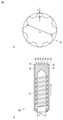
図2(a)に示されるように、造粒機50は押し出しスクリュー51を備えている。造粒機50の先端部には、複数の細孔(貫通孔)53が設けられている。押し出しスクリュー51は、図示しない駆動装置によって回転する。図2(a)において、押し出しスクリュー51に描かれた曲線矢印は、押し出しスクリュー51の回転方向を示している。
《Granulation machine》
As shown in FIG. 2A, the
(造粒機50の細孔(貫通孔)形状)
図2(b)に示されるように、造粒機50の細孔(貫通孔)53の形状は、凹凸を有する。凹凸は造粒機50の細孔(貫通孔)の断面に形成されてもよいし、造粒機50の細孔(貫通孔)の長さ方向に形成されてもよいし、造粒機50の細孔(貫通孔)の断面および長さ方向の両方に形成されてもよい。細孔(貫通孔)53の直径(φ)は、たとえば0.1mm以上4.0mm未満であってもよく、0.1mm以上3.0mm以下であることが望ましい。細孔(貫通孔)53の直径(φ)が0.1mm未満の場合、造粒体の直径も0.1mm未満となると考えられる。同様に、細孔(貫通孔)53の直径(φ)が4.0mm以上の場合、造粒体の直径も4.0mm以上となると考えられる。造粒体の直径が0.1mm未満である場合、MPS装置を用いた成膜が困難になるおそれがある。造粒体の直径が4.0mm以上である場合、造粒体をMPS装置に投入し、電極合材層を製造する際、MPS装置のロールとロールとのギャップに造粒体が入りきらず、成膜品質が低下する(すなわち、電極合材層に欠陥が生じる)傾向にある。図2(b)に示されるように、細孔(貫通孔)53は、真円に対してたとえば所定の高さ(d)の凸部もしくは凹部が8個以上ある構成としてもよい。凸凹の高さ(d)は、たとえば200μm以上300μm以下であってもよい。なお、本明細書において「凸凹の高さ(d)」とは、凸部の最も高い位置と、凹部の最も低い位置との距離を意味する。
(Pore (through hole) shape of the granulator 50)
As shown in FIG. 2B, the shape of the pores (through holes) 53 of the
《混錬ステップ(S01)》
混錬ステップでは、電極活物質、導電材、バインダおよび溶媒を造粒機50で混錬することにより、混錬物を得る。混錬物は、たとえば粘土状である。本ステップに先立って、電極活物質、導電材、バインダおよび溶媒を予め従来公知の攪拌造粒装置を用いて混錬してもよい。
<< Kneading step (S01) >>
In the kneading step, the electrode active material, the conductive material, the binder and the solvent are kneaded with the
(電極活物質)
電極活物質は、電荷担体(典型的にはリチウムイオン)を電気化学的に吸蔵、放出できる物質であればよい。正極の製造に用いられる造粒体を製造する場合、電極活物質(正極活物質)は、たとえばLiCoO2、LiNiO2、LiNi1/3Co1/3Mn1/3O2(NCM)、LiNi0.8Co0.15Al0.05O2(NCA)、LiMnO2、LiMn2O4、LiFePO4等であってもよい。また、負極の製造に用いられる造粒体を製造する場合、電極活物質(負極活物質)は、たとえばアモルファスコートグラファイト(黒鉛粒子の表面にアモルファスカーボンがコートされた形態のもの)、黒鉛、易黒鉛化性炭素、難黒鉛化性炭素、珪素、酸化珪素、錫、酸化錫等であってもよい。
(Electrode active material)
The electrode active material may be any material that can electrochemically occlude and release charge carriers (typically lithium ions). When producing a granule used for producing a positive electrode, the electrode active material (positive electrode active material) is, for example, LiCoO 2 , LiNiO 2 , LiNi 1/3 Co 1/3 Mn 1/3 O 2 (NCM), LiNi. 0.8 Co 0.15 Al 0.05 O 2 (NCA), LiMnO 2 , LiMn 2 O 4 , LiFePO 4 and the like may be used. When manufacturing a granulated body used for manufacturing a negative electrode, the electrode active material (negative electrode active material) may be, for example, amorphous coated graphite (a form in which the surface of graphite particles is coated with amorphous carbon), graphite, or easy. Graphitizable carbon, non-graphitizable carbon, silicon, silicon oxide, tin, tin oxide and the like may be used.
(導電材およびバインダ)
導電材およびバインダは特に限定されるべきではない。正極の製造に用いられる造粒体を製造する場合、導電材はたとえばアセチレンブラック(AB)、ファーネスブラック、気相成長炭素繊維(VGCF)、黒鉛等であってもよい。バインダは、たとえばポリフッ化ビニリデン(PVdF)、スチレンブタジエンゴム(SBR)、ポリテトラフルオロエチレン(PTFE)等であってもよい。負極の製造に用いられる造粒体を製造する場合、導電材は、正極の製造に用いられる造粒体を製造する際と同様の導電材を用いてもよい。バインダは、たとえば、カルボキシメチルセルロース(CMC)、スチレンブタジエンゴム(SBR)等であってもよい。
(Conductive material and binder)
Conductive materials and binders should not be particularly limited. When producing the granulated body used for producing the positive electrode, the conductive material may be, for example, acetylene black (AB), furnace black, vapor phase grown carbon fiber (VGCF), graphite or the like. The binder may be, for example, polyvinylidene fluoride (PVdF), styrene butadiene rubber (SBR), polytetrafluoroethylene (PTFE), or the like. When the granulated body used for manufacturing the negative electrode is manufactured, the same conductive material as in the case of manufacturing the granulated body used for manufacturing the positive electrode may be used as the conductive material. The binder may be, for example, carboxymethyl cellulose (CMC), styrene butadiene rubber (SBR), or the like.
(溶媒)
正極の製造に用いられる造粒体を製造する場合、溶媒はたとえばN-メチル-2-ピロリドン(NMP)であってもよい。負極の製造に用いられる造粒体を製造する場合、溶媒はたとえば水であってもよい。
(solvent)
When producing the granules used for producing the positive electrode, the solvent may be, for example, N-methyl-2-pyrrolidone (NMP). When producing the granules used for producing the negative electrode, the solvent may be, for example, water.
(混錬物)
正極の製造に用いられる造粒体を製造する場合、混錬物は、混錬物の固形分全体に対して80~98質量%の正極活物質、1~15質量%以下の導電材および1~5質量%以下のバインダを含んでもよい。負極の製造に用いられる造粒体を製造する場合、混錬物は、混錬物の固形分全体に対して70~98質量%の負極活物質、1~15質量%の導電材および1~15質量%のバインダを含んでもよい。
(Kneaded product)
When producing the granules used for producing the positive electrode, the kneaded material is 80 to 98% by mass of the positive electrode active material with respect to the total solid content of the kneaded material, 1 to 15% by mass or less of the conductive material, and 1 It may contain a binder of up to 5% by mass or less. When producing the granules used for the production of the negative electrode, the kneaded material is 70 to 98% by mass of the negative electrode active material and 1 to 15% by mass of the conductive material and 1 to 1 to the total solid content of the kneaded material. It may contain 15% by weight binder.
《成型ステップ(S02)》
成型ステップ(S02)は、混錬ステップ(S01)により得られた混錬物52を、造粒機50の細孔(貫通孔)53から押し出すステップである。図2(a)に示されるように、成型ステップ(S02)により、成型された混錬物54を得ることができる。図2(b)に示されるように、造粒機50の細孔(貫通孔)53の形状は、凹凸を有している。そのため、細孔(貫通孔)53から押し出された混錬物54は、造粒機50の細孔(貫通孔)53の形状に由来した凹凸を有する。
<< Molding step (S02) >>
The molding step (S02) is a step of extruding the kneaded
《切断ステップ(S03)》
本工程(S03)は、成型ステップ(S02)により押し出された混錬物54を所望の長さに切断し、造粒体を得るステップである。なお、切断はカッター等の従来公知の方法により行い得る。図3は、本工程(S03)にて得られる造粒体1aを示している。図3における造粒体1aの径(φ)は、図2(b)に示される造粒機50の細孔(貫通孔)53の直径(φ)と一致するものと考えられる。図3を参照して、造粒体1aの長さ(L)は、0.1mm以上4.0mm未満であってもよく、0.1mm以上3.0mm以下であることが望ましい。造粒体1aの長さ(L)が0.1mm未満の場合、MPS装置を用いた成膜が困難になるおそれがある。造粒体1aの長さ(L)が4.0mm以上である場合、造粒体をMPS装置に投入した際、MPS装置のロールとロールとのギャップに造粒体が入りきらず、成膜品質が低下する(すなわち、電極合材層に欠陥が生じる)傾向にある。
<< Cutting step (S03) >>
This step (S03) is a step of cutting the kneaded
<電極の製造>
混錬ステップ(S01)、成型ステップ(S02)および切断ステップ(S03)を経て製造された造粒体1aを用いて、電池用電極を製造することができる。本実施形態における電池用電極は、たとえば帯状のシート部材である。
<Manufacturing of electrodes>
A battery electrode can be manufactured by using the
電極を製造する工程は、造粒体1aを圧延し、シート状に成型された造粒体である造粒体1bを得ること(圧延操作)および造粒体1bを集電体の表面に配置すること(配置操作)を含む。以下に説明するように、「配置すること」の一態様として、「転写すること」が挙げられる。圧延操作および配置操作は、この順に実行されてもよいし、相前後して実行されてもよいし、あるいは同時に実行されてもよい。
In the process of manufacturing the electrode, the
(電極製造装置)
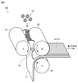
図4は、電極を製造するための工程の一例を示す概略図である。図4に示される電極製造装置90はMPS装置であり、3本のロール、すなわちAロール91、Bロール92およびCロール93を備えている。各ロールは、図示しない駆動装置によって回転駆動される。図4において、各ロールに描かれた曲線矢印は、各ロールの回転方向を示している。
(Electrode manufacturing equipment)
FIG. 4 is a schematic view showing an example of a process for manufacturing an electrode. The
造粒体1aは、Aロール91とBロール92とのギャップに供給される。Aロール91には、Aロール91からBロール92に向かう方向に荷重が加えられている。そのためAロール91とBロール92とのギャップでは、造粒体1aが圧延され、シート状に成型され、造粒体1bが得られる。
The
造粒体1b(シート体)は、Bロール92によって搬送され、Bロール92とCロール93とのギャップに供給される。集電体11は、Cロール93によって搬送され、Bロール92とCロール93とのギャップに供給される。電池用電極が正極である場合、集電体11はたとえばアルミニウム(Al)箔である。電池用電極が負極である場合、集電体11はたとえば銅(Cu)箔である。
The
Bロール92とCロール93とのギャップでは、造粒体1bが集電体11に擦り付けられる。これにより、造粒体1bが集電体11に圧着され、造粒体1bが集電体11の表面に配置される。すなわち造粒体1bが、Bロール92の表面から集電体11の表面へと転写される。
In the gap between the
造粒体1bを集電体11の表面に配置することにより、造粒体1bは電極合材層12となる。その後、造粒体1bに残存する溶媒を蒸発させる操作を行ってもよい。溶媒の蒸発操作は、図示しない乾燥炉において行われ得る。さらに電池の仕様に合わせて、圧縮、裁断等を行うことにより、電池用電極を製造することができる。
By arranging the
図3に示されるように、造粒体1aは造粒機51の細孔(貫通孔)53の形状に由来した凹凸を有している。そのため、造粒体1aが大粒化されることが抑制されている。これにより、造粒体1aがAロール91とBロール92とのギャップに詰まることが抑制されると考えられる。したがって、造粒体1bに欠陥が生じる可能性が抑制され、延いては電極合材層12に欠陥が生じる可能性が抑制されると考えられる。
As shown in FIG. 3, the
<電池用電極>
《構成》
図5は、電池用電極の構成の一例を示す概略図である。電極10は、典型的には上記の製造方法により製造される電極である。
<Battery electrode>
"Constitution"
FIG. 5 is a schematic view showing an example of the configuration of the battery electrode. The
電極10は、集電体11と、集電体11の表面に配置されている電極合材層12とを含む。電極合材層12は、前述の造粒体1bにより形成された層であり、電極活物質、導電材およびバインダを含有する。電極合材層12は、集電体11の両方の表面(表裏)に配置されている。前述のように、集電体11は、電池用電極が正極である場合、たとえばアルミニウム(Al)箔であり、電池用電極が負極である場合、たとえば銅(Cu)箔である。
The
集電体11の厚さは、集電体11が正極集電体である場合は、たとえば10~30μmの厚さを有してもよく、集電体11が負極集電体である場合は、たとえば5~20μmの厚さを有してもよい。電極合材層12の厚さは、電極合材層12が正極合材層である場合は、たとえば100~200μmの厚さを有してもよく、電極合材層12が負極合材層である場合は、たとえば50~150μmの厚さを有してもよい。
The thickness of the
<その他の実施形態>
細孔(貫通孔)53の形状は、図2(b)に示されるような凹凸を有する形状の他、たとえば真円状の細孔(貫通孔)にブラスト処理を施し、細かな凹凸を有する形状としてもよい。これにより、細かい凹凸のついた造粒体を得ることができる。係る造粒体においても、隣接する造粒体1a同士が接するための接触面積が低減されると考えられる。これにより、造粒体1a同士が接着することが抑制され、造粒体1aの大粒化が抑制されるものと期待される。
<Other embodiments>
The shape of the pores (through holes) 53 has irregularities as shown in FIG. 2 (b), and for example, the perfect circular pores (through holes) are blasted to have fine irregularities. It may be in shape. As a result, it is possible to obtain a granulated body having fine irregularities. In such a granulated body, it is considered that the contact area for the adjacent
ブラスト処理に用いるブラスト装置としては、エアーを用いてメディア(研削材)を投射するエアーブラスト装置(ブロワタイプ、コンプレッサータイプ等)、モーターによる回転運動によりメディアを投射するショットブラスト装置などを用いてもよい。メディアの材質としては、たとえばアルミナ(褐色、白色)、炭化ケイ素、ガラス、鉄、銅、亜鉛、アルミニウム、ステンレス、珪砂、ガーネット、樹脂等を用いてもよい。メディアの形状は特に制限されず、たとえば球状や略球状であってもよい。メディアの粒径(直径)は、たとえば5μm~30μmであってもよい。 As the blasting device used for blasting, an air blasting device (blower type, compressor type, etc.) that projects media (abrasive material) using air, a shot blasting device that projects media by rotational motion by a motor, etc. can also be used. good. As the material of the media, for example, alumina (brown, white), silicon carbide, glass, iron, copper, zinc, aluminum, stainless steel, silica sand, garnet, resin and the like may be used. The shape of the media is not particularly limited, and may be spherical or substantially spherical, for example. The particle size (diameter) of the media may be, for example, 5 μm to 30 μm.
以下、実施例が説明される。ただし以下の説明は特許請求の範囲を限定するものではない。 Hereinafter, examples will be described. However, the following explanation does not limit the scope of claims.
<造粒体の製造>
《実施例1》
1.電池用電極(正極)に用いられる、造粒体の製造
以下の材料が準備された
正極活物質:LiNi1/3Co1/3Mn1/3O2(NCM)
導電材:AB
バインダ:PVdF
溶媒:N-メチル-2-ピロリドン(NMP)
<Manufacturing of granulated material>
<< Example 1 >>
1. 1. Manufacture of granulated material used for battery electrode (positive electrode) Positive electrode active material prepared with the following materials: LiNi 1/3 Co 1/3 Mn 1/3 O 2 (NCM)
Conductive material: AB
Binder: PVdF
Solvent: N-methyl-2-pyrrolidone (NMP)
2.混錬ステップ(S01)
造粒機50内で、NCM、AB、PVdFおよびNMPが混合された。これにより、混錬物52を得た。混錬物52の固形分組成は、混錬物52の固形分を100重量部としたとき、NCM93重量部、AB4重量部、PVdF3重量部であった。造粒機50の細孔(貫通孔)は、凹凸を有している。
2. 2. Kneading step (S01)
NCM, AB, PVdF and NMP were mixed in the
3.成型ステップ(S02)
押し出しスクリュー51を30rpmで回転させることにより、混錬物52を造粒機50の細孔(貫通孔)53から押し出した。これにより、押し出された混錬物52(成型された混錬物54)を得た。
3. 3. Molding step (S02)
By rotating the
4.切断ステップ(S03)
押し出された混錬物52(成型された混錬物54)を、カッターを用いて切断することにより、実施例1に係る造粒体1aを得た。実施例1に係る造粒体1aは、図3に示されるように造粒機50の細孔(貫通孔)53の形状に由来した凹凸を有していた。造粒体1aの最大径は2.5mmであり、造粒体1aの長さ(L)は2mmであり、凹凸の数は8つであり、凸凹の高さは、250μmであった。
4. Cutting step (S03)
The extruded kneaded product 52 (molded kneaded product 54) was cut with a cutter to obtain a
《比較例1》
造粒機の細孔(貫通孔)形状が真円状であり、凹凸を有さない造粒機を用いたことを除いては、実施例1と同様に造粒体1aが製造された。造粒体1aの最大径は2.5mmであり、造粒体1aの長さ(L)は2mmであったが、比較例1に係る造粒体1aは、凹凸を有していなかった。
<< Comparative Example 1 >>
The
<篩試験>
目開きが4mmの篩が準備された。実施例1に係る造粒体1aおよび比較例1に係る造粒体1aが乾燥され、その固形分率が実質的に100質量%に調整された。実施例1に係る造粒体1aおよび比較例1に係る造粒体1aが、それぞれ100gずつ別の容器に封入された。各容器に対して、振とう機にて振幅1mm/60rpmの条件で30秒間振とうを行った。その後、実施例1に係る造粒体1aおよび比較例1に係る造粒体1aを篩にかけ、篩を通過できない造粒体の割合を測定した。結果は以下の表1の、「篩非通過率」の欄に示されている。篩非通過率が0%の場合、全ての造粒体1aが篩を通過したことを意味し、篩非通過率が100%の場合、全ての造粒体1aが篩を通過しなかったことを意味する。
<Sieve test>
A sieve with an opening of 4 mm was prepared. The

<結果>
実施例1に係る造粒体1aは、目開きが4mmの篩を全て通過した。すなわち、実施例1に係る製造方法で製造された造粒体1aは、造粒体の大粒化が抑制されていた。図3に示されるように、実施例1に係る造粒体1aは造粒機50の細孔(貫通孔)53の形状に由来した凹凸円形状を有していた。そのため、隣接する造粒体1a同士が接するための接触面積が低減されたものと考えられる。これにより、隣接する造粒体1同士が接着することが抑制され、造粒体1の大粒化(すなわち、4mm以上の粒径となること)が抑制されたものと考えられる。
<Result>
The
実施例1に係る造粒体は、造粒体1aの大粒化が抑制されていた。したがって、実施例1に係る造粒体1aを用いてMPS装置により電極合材層12を製造した場合、MPS装置のロールとロールとのギャップに大粒化された造粒体が詰まることが抑制され、製造された電極合材層12に欠陥が生じる可能性が抑制されるものと考えられる。
In the granulated body according to Example 1, the enlargement of the
比較例1に係る造粒体は、7%の造粒体が、目開きが4mmの篩を通過することができなかった。比較例1に係る造粒体は、細孔(貫通孔)の形状に由来した真円形状を有していた。そのため、隣接する造粒体1a同士が接するための接触面積が、実施例1に係る造粒体1aと比較して大きかったものと考えられる。隣接する造粒体1a同士が接するための接触面積が大きかった結果、造粒体同士が接着することが抑制されず、結果として7%もの造粒体が大粒化されたと考えられる。
In the granulated product according to Comparative Example 1, 7% of the granulated products could not pass through a sieve having an opening of 4 mm. The granulated body according to Comparative Example 1 had a perfect circular shape derived from the shape of the pores (through holes). Therefore, it is probable that the contact area for the
比較例1に係る造粒体は、造粒体の一部(7%)が大粒化している。そのため、比較例1に係る造粒体を用い、MPS装置により電極合材層を製造した場合、MPS装置のロールとロールとのギャップに大粒化された造粒体が詰まり、製造された電極合材層12に欠陥が生じるおそれがある。
In the granulated body according to Comparative Example 1, a part (7%) of the granulated body is enlarged. Therefore, when the electrode mixture layer is manufactured by the MPS device using the granulation body according to Comparative Example 1, the gap between the rolls of the MPS device is clogged with the enlarged granulation body, and the manufactured electrode mixture is formed. Defects may occur in the
以上の結果から、混錬ステップ(S01)、成型ステップ(S02)および切断ステップ(S03)を含み、かつ、造粒機の細孔形状が、凹凸を有している造粒体の製造方法により、大粒化が抑制された造粒体が得られることが示された。 From the above results, a method for producing a granulated body, which includes a kneading step (S01), a molding step (S02), and a cutting step (S03) and has an uneven pore shape in the granulator, is used. It was shown that granulated bodies with suppressed granulation can be obtained.
上記の実施形態および実施例はすべての点で例示であって制限的なものではない。特許請求の範囲の記載によって確定される技術的範囲は、特許請求の範囲と均等の意味および範囲内でのすべての変更を含む。 The above embodiments and examples are exemplary in all respects and are not restrictive. The technical scope defined by the description of the scope of claims includes all changes within the meaning and scope equivalent to the scope of claims.
1a、1b 造粒体、10 電極、11 集電体、12 電極合材層、50 造粒機、51 押し出しスクリュー、52 混錬物、53 造粒機の細孔(貫通孔)、54 成型された混錬物、90 電極製造装置、91 Aロール、92 Bロール、93 Cロール。 1a, 1b Granulator, 10 Electrode, 11 Collector, 12 Electrode Mixture Layer, 50 Granulator, 51 Extrude Screw, 52 Kneaded Material, 53 Granulator Pore (Through Hole), 54 Molded Kneaded material, 90 electrode manufacturing equipment, 91 A roll, 92 B roll, 93 C roll.
Claims (1)
前記混錬物を、前記造粒機の細孔から押し出す成型ステップと、
押し出された前記混錬物を所望の長さに切断し、造粒体を得る切断ステップと、
前記造粒体を圧延し、シート状に成型された前記造粒体を得る圧延ステップと、
前記造粒体を集電体の表面に配置する配置ステップと、を含み、
前記造粒機の細孔の形状が凹凸を有し、
前記造粒体は、前記造粒機の細孔の形状に由来した凹凸を有する、
電極の製造方法。 The kneading step of kneading the electrode active material, the conductive material, the binder and the solvent with a granulator to obtain a kneaded product,
A molding step of extruding the kneaded product from the pores of the granulator,
A cutting step of cutting the extruded kneaded product to a desired length to obtain granulated bodies, and
A rolling step of rolling the granulation body to obtain the granulation body molded into a sheet, and
Including a placement step of placing the granulated body on the surface of a current collector.
The shape of the pores of the granulator has irregularities,
The granulated body has irregularities derived from the shape of the pores of the granulator.
Electrode manufacturing method.
Priority Applications (1)
| Application Number | Priority Date | Filing Date | Title |
|---|---|---|---|
| JP2021181123A JP2022010097A (en) | 2017-11-02 | 2021-11-05 | Manufacturing method of electrode |
Applications Claiming Priority (2)
| Application Number | Priority Date | Filing Date | Title |
|---|---|---|---|
| JP2017212576A JP2019087330A (en) | 2017-11-02 | 2017-11-02 | Method of producing granulated body |
| JP2021181123A JP2022010097A (en) | 2017-11-02 | 2021-11-05 | Manufacturing method of electrode |
Related Parent Applications (1)
| Application Number | Title | Priority Date | Filing Date |
|---|---|---|---|
| JP2017212576A Division JP2019087330A (en) | 2017-11-02 | 2017-11-02 | Method of producing granulated body |
Publications (1)
| Publication Number | Publication Date |
|---|---|
| JP2022010097A true JP2022010097A (en) | 2022-01-14 |
Family
ID=66764272
Family Applications (2)
| Application Number | Title | Priority Date | Filing Date |
|---|---|---|---|
| JP2017212576A Pending JP2019087330A (en) | 2017-11-02 | 2017-11-02 | Method of producing granulated body |
| JP2021181123A Pending JP2022010097A (en) | 2017-11-02 | 2021-11-05 | Manufacturing method of electrode |
Family Applications Before (1)
| Application Number | Title | Priority Date | Filing Date |
|---|---|---|---|
| JP2017212576A Pending JP2019087330A (en) | 2017-11-02 | 2017-11-02 | Method of producing granulated body |
Country Status (1)
| Country | Link |
|---|---|
| JP (2) | JP2019087330A (en) |
Citations (9)
| Publication number | Priority date | Publication date | Assignee | Title |
|---|---|---|---|---|
| JPS5746470A (en) * | 1980-09-03 | 1982-03-16 | Hitachi Maxell Ltd | Production of anode mixture sheet |
| JPH0663859A (en) * | 1992-08-17 | 1994-03-08 | Makurosu:Kk | Protruded abrasives for barrel polishing, etc. and recessed surface polishing method |
| JPH07171827A (en) * | 1993-12-20 | 1995-07-11 | Terumo Corp | Polymer pellet |
| JPH09180709A (en) * | 1995-12-27 | 1997-07-11 | Matsushita Electric Ind Co Ltd | Manufacture of positive electrode mix for battery |
| JPH1055801A (en) * | 1996-08-09 | 1998-02-24 | Toshiba Battery Co Ltd | Nonaqueous solvent secondary battery, manufacture of negative electrode mix therefor and device for the manufacture |
| JP2005153397A (en) * | 2003-11-27 | 2005-06-16 | Hitachi Cable Ltd | Method for producing electric wire cable |
| WO2010098018A1 (en) * | 2009-02-24 | 2010-09-02 | パナソニック株式会社 | Electrode plate for nonaqueous secondary battery, manufacturing method therefor, and nonaqueous secondary battery using same |
| JP2017098029A (en) * | 2015-11-20 | 2017-06-01 | トヨタ自動車株式会社 | Electrode plate manufacturing method |
| JP2017174522A (en) * | 2016-03-21 | 2017-09-28 | トヨタ自動車株式会社 | Manufacturing method for electrode plate |
-
2017
- 2017-11-02 JP JP2017212576A patent/JP2019087330A/en active Pending
-
2021
- 2021-11-05 JP JP2021181123A patent/JP2022010097A/en active Pending
Patent Citations (9)
| Publication number | Priority date | Publication date | Assignee | Title |
|---|---|---|---|---|
| JPS5746470A (en) * | 1980-09-03 | 1982-03-16 | Hitachi Maxell Ltd | Production of anode mixture sheet |
| JPH0663859A (en) * | 1992-08-17 | 1994-03-08 | Makurosu:Kk | Protruded abrasives for barrel polishing, etc. and recessed surface polishing method |
| JPH07171827A (en) * | 1993-12-20 | 1995-07-11 | Terumo Corp | Polymer pellet |
| JPH09180709A (en) * | 1995-12-27 | 1997-07-11 | Matsushita Electric Ind Co Ltd | Manufacture of positive electrode mix for battery |
| JPH1055801A (en) * | 1996-08-09 | 1998-02-24 | Toshiba Battery Co Ltd | Nonaqueous solvent secondary battery, manufacture of negative electrode mix therefor and device for the manufacture |
| JP2005153397A (en) * | 2003-11-27 | 2005-06-16 | Hitachi Cable Ltd | Method for producing electric wire cable |
| WO2010098018A1 (en) * | 2009-02-24 | 2010-09-02 | パナソニック株式会社 | Electrode plate for nonaqueous secondary battery, manufacturing method therefor, and nonaqueous secondary battery using same |
| JP2017098029A (en) * | 2015-11-20 | 2017-06-01 | トヨタ自動車株式会社 | Electrode plate manufacturing method |
| JP2017174522A (en) * | 2016-03-21 | 2017-09-28 | トヨタ自動車株式会社 | Manufacturing method for electrode plate |
Also Published As
| Publication number | Publication date |
|---|---|
| JP2019087330A (en) | 2019-06-06 |
Similar Documents
| Publication | Publication Date | Title |
|---|---|---|
| JP6090213B2 (en) | Binder composition, electrode slurry, electrode and non-aqueous electrolyte secondary battery | |
| JP6026997B2 (en) | Positive electrode active material for lithium secondary battery and lithium secondary battery | |
| WO2013027686A1 (en) | Composite active material for lithium secondary batteries and method for producing same | |
| US20120258365A1 (en) | Cathode active material precursor particle, cathode active material particle for lithium secondary battery and lithium secondary battery | |
| WO2007116718A1 (en) | Composite particles for electrochemical element electrode, process for producing composite particles for electrochemical element electrode, and electrochemical element electrode | |
| JP6096101B2 (en) | Method for producing positive electrode for lithium secondary battery | |
| JP2017104784A (en) | Granulated material sheet manufacturing apparatus | |
| JP6875193B2 (en) | Electrode manufacturing method | |
| JP6700204B2 (en) | Electrode manufacturing method | |
| JP6919801B2 (en) | Electrode manufacturing method | |
| KR20160065282A (en) | Fabricating method of lithium electrode and lithium ion battery | |
| KR101833919B1 (en) | Electrode for non-aqueous secondary battery | |
| JP6183027B2 (en) | Production method of reduced particle size composite particles for electrochemical device electrodes and reduced particle size composite particles for electrochemical device electrodes | |
| JP4297533B2 (en) | Method for producing lithium ion battery material | |
| JP2015011896A (en) | Method for manufacturing secondary battery electrode | |
| JP6669050B2 (en) | Electrode manufacturing method | |
| JP2022010097A (en) | Manufacturing method of electrode | |
| JP6790882B2 (en) | Manufacturing method of positive electrode for lithium ion secondary battery | |
| JP2018073645A (en) | Method of manufacturing electrode for lithium ion secondary battery | |
| JP6705400B2 (en) | Method for manufacturing secondary battery electrode | |
| JP2017120705A (en) | Method for manufacturing electrode for battery | |
| JP2017111963A (en) | Method of producing electrode | |
| JP2017134911A (en) | Method for manufacturing electrode for battery | |
| WO2024024737A1 (en) | Method for producing molded body for sheet-like electrode | |
| JP2019057398A (en) | Manufacturing method of electrode |
Legal Events
| Date | Code | Title | Description |
|---|---|---|---|
| A621 | Written request for application examination |
Free format text: JAPANESE INTERMEDIATE CODE: A621 Effective date: 20211105 |
|
| A131 | Notification of reasons for refusal |
Free format text: JAPANESE INTERMEDIATE CODE: A131 Effective date: 20221213 |
|
| A02 | Decision of refusal |
Free format text: JAPANESE INTERMEDIATE CODE: A02 Effective date: 20230418 |