JP2021531970A - Crusher system and method for crushing materials - Google Patents
Crusher system and method for crushing materials Download PDFInfo
- Publication number
- JP2021531970A JP2021531970A JP2021524081A JP2021524081A JP2021531970A JP 2021531970 A JP2021531970 A JP 2021531970A JP 2021524081 A JP2021524081 A JP 2021524081A JP 2021524081 A JP2021524081 A JP 2021524081A JP 2021531970 A JP2021531970 A JP 2021531970A
- Authority
- JP
- Japan
- Prior art keywords
- housing
- arm
- crusher
- wall
- rotor
- Prior art date
- Legal status (The legal status is an assumption and is not a legal conclusion. Google has not performed a legal analysis and makes no representation as to the accuracy of the status listed.)
- Pending
Links
- 239000000463 material Substances 0.000 title claims abstract description 238
- 238000000034 method Methods 0.000 title claims description 20
- 239000002245 particle Substances 0.000 claims abstract description 40
- 239000012530 fluid Substances 0.000 claims description 93
- 230000001012 protector Effects 0.000 claims description 82
- 238000000227 grinding Methods 0.000 claims description 53
- 239000007787 solid Substances 0.000 claims description 21
- 230000007246 mechanism Effects 0.000 claims description 19
- 238000003825 pressing Methods 0.000 claims description 17
- 238000012545 processing Methods 0.000 claims description 14
- 238000003801 milling Methods 0.000 claims description 12
- 229910000831 Steel Inorganic materials 0.000 claims description 10
- 239000010959 steel Substances 0.000 claims description 10
- 230000007423 decrease Effects 0.000 claims description 9
- 239000000919 ceramic Substances 0.000 claims description 8
- 239000000428 dust Substances 0.000 claims description 8
- 229920001903 high density polyethylene Polymers 0.000 claims description 6
- 239000004700 high-density polyethylene Substances 0.000 claims description 6
- 230000033001 locomotion Effects 0.000 claims description 6
- 230000001681 protective effect Effects 0.000 claims description 6
- UFGZSIPAQKLCGR-UHFFFAOYSA-N chromium carbide Chemical compound [Cr]#C[Cr]C#[Cr] UFGZSIPAQKLCGR-UHFFFAOYSA-N 0.000 claims description 5
- 229910003470 tongbaite Inorganic materials 0.000 claims description 5
- 230000008859 change Effects 0.000 claims description 4
- 230000002441 reversible effect Effects 0.000 claims description 4
- UONOETXJSWQNOL-UHFFFAOYSA-N tungsten carbide Chemical compound [W+]#[C-] UONOETXJSWQNOL-UHFFFAOYSA-N 0.000 claims description 4
- 229910001018 Cast iron Inorganic materials 0.000 claims description 2
- 229910045601 alloy Inorganic materials 0.000 claims description 2
- 239000000956 alloy Substances 0.000 claims description 2
- 239000003365 glass fiber Substances 0.000 claims description 2
- 230000003116 impacting effect Effects 0.000 claims description 2
- 230000002093 peripheral effect Effects 0.000 claims 1
- 238000007711 solidification Methods 0.000 abstract description 7
- 230000005540 biological transmission Effects 0.000 description 8
- 230000006866 deterioration Effects 0.000 description 8
- 230000002829 reductive effect Effects 0.000 description 6
- 239000002699 waste material Substances 0.000 description 5
- 238000012544 monitoring process Methods 0.000 description 4
- 229910052720 vanadium Inorganic materials 0.000 description 4
- 238000004140 cleaning Methods 0.000 description 3
- XLYOFNOQVPJJNP-UHFFFAOYSA-N water Substances O XLYOFNOQVPJJNP-UHFFFAOYSA-N 0.000 description 3
- 102100022332 Sharpin Human genes 0.000 description 2
- 230000015572 biosynthetic process Effects 0.000 description 2
- 239000004568 cement Substances 0.000 description 2
- 230000002301 combined effect Effects 0.000 description 2
- 238000005553 drilling Methods 0.000 description 2
- 230000000694 effects Effects 0.000 description 2
- 230000000670 limiting effect Effects 0.000 description 2
- 230000036961 partial effect Effects 0.000 description 2
- 238000000926 separation method Methods 0.000 description 2
- 108010088972 sharpin Proteins 0.000 description 2
- 238000012546 transfer Methods 0.000 description 2
- 241000473391 Archosargus rhomboidalis Species 0.000 description 1
- 229910000760 Hardened steel Inorganic materials 0.000 description 1
- 230000009286 beneficial effect Effects 0.000 description 1
- 238000005266 casting Methods 0.000 description 1
- 230000015556 catabolic process Effects 0.000 description 1
- 238000006243 chemical reaction Methods 0.000 description 1
- 239000002361 compost Substances 0.000 description 1
- 238000007796 conventional method Methods 0.000 description 1
- 238000006731 degradation reaction Methods 0.000 description 1
- 238000001514 detection method Methods 0.000 description 1
- 238000010586 diagram Methods 0.000 description 1
- 238000009826 distribution Methods 0.000 description 1
- 239000011152 fibreglass Substances 0.000 description 1
- 239000011521 glass Substances 0.000 description 1
- 239000003292 glue Substances 0.000 description 1
- 230000005484 gravity Effects 0.000 description 1
- 229910052500 inorganic mineral Inorganic materials 0.000 description 1
- 238000009434 installation Methods 0.000 description 1
- 238000012423 maintenance Methods 0.000 description 1
- 238000004519 manufacturing process Methods 0.000 description 1
- 229910052751 metal Inorganic materials 0.000 description 1
- 239000002184 metal Substances 0.000 description 1
- 239000011707 mineral Substances 0.000 description 1
- -1 ore Substances 0.000 description 1
- 239000003973 paint Substances 0.000 description 1
- 239000002985 plastic film Substances 0.000 description 1
- 229920006255 plastic film Polymers 0.000 description 1
- 230000004224 protection Effects 0.000 description 1
- 230000009979 protective mechanism Effects 0.000 description 1
- 238000010298 pulverizing process Methods 0.000 description 1
- 230000009467 reduction Effects 0.000 description 1
- 230000008439 repair process Effects 0.000 description 1
- 239000011435 rock Substances 0.000 description 1
- 239000011343 solid material Substances 0.000 description 1
- 239000007921 spray Substances 0.000 description 1
- 238000005507 spraying Methods 0.000 description 1
Images


Classifications
-
- B—PERFORMING OPERATIONS; TRANSPORTING
- B02—CRUSHING, PULVERISING, OR DISINTEGRATING; PREPARATORY TREATMENT OF GRAIN FOR MILLING
- B02C—CRUSHING, PULVERISING, OR DISINTEGRATING IN GENERAL; MILLING GRAIN
- B02C13/00—Disintegrating by mills having rotary beater elements ; Hammer mills
- B02C13/14—Disintegrating by mills having rotary beater elements ; Hammer mills with vertical rotor shaft, e.g. combined with sifting devices
- B02C13/18—Disintegrating by mills having rotary beater elements ; Hammer mills with vertical rotor shaft, e.g. combined with sifting devices with beaters rigidly connected to the rotor
-
- B—PERFORMING OPERATIONS; TRANSPORTING
- B02—CRUSHING, PULVERISING, OR DISINTEGRATING; PREPARATORY TREATMENT OF GRAIN FOR MILLING
- B02C—CRUSHING, PULVERISING, OR DISINTEGRATING IN GENERAL; MILLING GRAIN
- B02C13/00—Disintegrating by mills having rotary beater elements ; Hammer mills
- B02C13/26—Details
- B02C13/28—Shape or construction of beater elements
-
- B—PERFORMING OPERATIONS; TRANSPORTING
- B02—CRUSHING, PULVERISING, OR DISINTEGRATING; PREPARATORY TREATMENT OF GRAIN FOR MILLING
- B02C—CRUSHING, PULVERISING, OR DISINTEGRATING IN GENERAL; MILLING GRAIN
- B02C13/00—Disintegrating by mills having rotary beater elements ; Hammer mills
- B02C13/26—Details
- B02C13/282—Shape or inner surface of mill-housings
-
- B—PERFORMING OPERATIONS; TRANSPORTING
- B02—CRUSHING, PULVERISING, OR DISINTEGRATING; PREPARATORY TREATMENT OF GRAIN FOR MILLING
- B02C—CRUSHING, PULVERISING, OR DISINTEGRATING IN GENERAL; MILLING GRAIN
- B02C13/00—Disintegrating by mills having rotary beater elements ; Hammer mills
- B02C13/26—Details
- B02C13/286—Feeding or discharge
-
- B—PERFORMING OPERATIONS; TRANSPORTING
- B02—CRUSHING, PULVERISING, OR DISINTEGRATING; PREPARATORY TREATMENT OF GRAIN FOR MILLING
- B02C—CRUSHING, PULVERISING, OR DISINTEGRATING IN GENERAL; MILLING GRAIN
- B02C13/00—Disintegrating by mills having rotary beater elements ; Hammer mills
- B02C13/26—Details
- B02C13/288—Ventilating, or influencing air circulation
-
- B—PERFORMING OPERATIONS; TRANSPORTING
- B02—CRUSHING, PULVERISING, OR DISINTEGRATING; PREPARATORY TREATMENT OF GRAIN FOR MILLING
- B02C—CRUSHING, PULVERISING, OR DISINTEGRATING IN GENERAL; MILLING GRAIN
- B02C13/00—Disintegrating by mills having rotary beater elements ; Hammer mills
- B02C13/26—Details
- B02C13/30—Driving mechanisms
-
- B—PERFORMING OPERATIONS; TRANSPORTING
- B02—CRUSHING, PULVERISING, OR DISINTEGRATING; PREPARATORY TREATMENT OF GRAIN FOR MILLING
- B02C—CRUSHING, PULVERISING, OR DISINTEGRATING IN GENERAL; MILLING GRAIN
- B02C13/00—Disintegrating by mills having rotary beater elements ; Hammer mills
- B02C13/14—Disintegrating by mills having rotary beater elements ; Hammer mills with vertical rotor shaft, e.g. combined with sifting devices
- B02C2013/145—Disintegrating by mills having rotary beater elements ; Hammer mills with vertical rotor shaft, e.g. combined with sifting devices with fast rotating vanes generating vortexes effecting material on material impact
-
- B—PERFORMING OPERATIONS; TRANSPORTING
- B02—CRUSHING, PULVERISING, OR DISINTEGRATING; PREPARATORY TREATMENT OF GRAIN FOR MILLING
- B02C—CRUSHING, PULVERISING, OR DISINTEGRATING IN GENERAL; MILLING GRAIN
- B02C13/00—Disintegrating by mills having rotary beater elements ; Hammer mills
- B02C13/26—Details
- B02C13/28—Shape or construction of beater elements
- B02C2013/2808—Shape or construction of beater elements the beater elements are attached to disks mounted on a shaft
-
- B—PERFORMING OPERATIONS; TRANSPORTING
- B02—CRUSHING, PULVERISING, OR DISINTEGRATING; PREPARATORY TREATMENT OF GRAIN FOR MILLING
- B02C—CRUSHING, PULVERISING, OR DISINTEGRATING IN GENERAL; MILLING GRAIN
- B02C13/00—Disintegrating by mills having rotary beater elements ; Hammer mills
- B02C13/26—Details
- B02C13/282—Shape or inner surface of mill-housings
- B02C2013/2825—Shape or inner surface of mill-housings with fastening means for fixing lining members to the inner surface of mill-housings
-
- B—PERFORMING OPERATIONS; TRANSPORTING
- B02—CRUSHING, PULVERISING, OR DISINTEGRATING; PREPARATORY TREATMENT OF GRAIN FOR MILLING
- B02C—CRUSHING, PULVERISING, OR DISINTEGRATING IN GENERAL; MILLING GRAIN
- B02C13/00—Disintegrating by mills having rotary beater elements ; Hammer mills
- B02C13/26—Details
- B02C13/286—Feeding or discharge
- B02C2013/28618—Feeding means
- B02C2013/28636—Feeding means of conveyor belt type
-
- B—PERFORMING OPERATIONS; TRANSPORTING
- B02—CRUSHING, PULVERISING, OR DISINTEGRATING; PREPARATORY TREATMENT OF GRAIN FOR MILLING
- B02C—CRUSHING, PULVERISING, OR DISINTEGRATING IN GENERAL; MILLING GRAIN
- B02C2210/00—Codes relating to different types of disintegrating devices
- B02C2210/01—Indication of wear on beaters, knives, rollers, anvils, linings and the like
Landscapes
- Engineering & Computer Science (AREA)
- Food Science & Technology (AREA)
- Crushing And Pulverization Processes (AREA)
- Catching Or Destruction (AREA)
Abstract
入力物質粒子のサイズを低減するための粉砕機であって、粉砕機は、ハウジングと、ロータアーム、およびロータアームと協働して粉砕機内の気流を偏向して、内部チャンバ内に少なくとも2つの重なり合う渦を形成し、双方の重なり合う渦における浮遊状態の入力物質粒子が互いに衝突し、それによって粉砕されるようにする、少なくとも1つの気流偏向器を有する回転可能なシャフトとを備える、粉砕機;また、ハウジングの外側構造壁に取り付けられ、外側構造壁に沿って延びる複数のハウジングライナ部分を含むハウジングライナを備える粉砕機;また、複数の壁セクションを含む外側構造壁を有するハウジング側壁を備える粉砕機;また、傾斜したロータアームを有する粉砕機、および取り外し可能な摩耗パッドを有するロータアームを備える粉砕機;また、粉砕機等のベッセルのための固化防止デバイス。A crusher for reducing the size of input material particles, the crusher works with the housing, rotor arm, and rotor arm to deflect airflow in the crusher and at least two in the internal chamber. A crusher with a rotatable shaft having at least one airflow deflector that forms an overlapping vortex and allows suspended input material particles in both overlapping vortices to collide with each other and thereby be crushed; Also, a crusher with a housing liner that is attached to the outer structural wall of the housing and includes a plurality of housing liner portions extending along the outer structural wall; and a crusher with a housing sidewall having an outer structural wall including multiple wall sections. Machines; also crushers with sloping rotor arms, and crushers with rotor arms with removable wear pads; also anti-solidification devices for vessels such as crushers.
Description
本技術分野は、一般に、粉砕機に関し、より詳細には、入力材料を粉砕するための高速粉砕機および方法に関する。本技術分野は更に、装置の壁から固化した材料を除去するための固化防止システムおよび方法に関する。 The art generally relates to grinders, and more particularly to high speed grinders and methods for grind input materials. The art further relates to anti-solidification systems and methods for removing solidified material from the walls of equipment.
粉砕装置、すなわち「粉砕機」は、廃棄物材料等の固体材料を粉砕、分離、曝気および/または均質化するために用いられてきた。粉砕機は、場合によっては、鉱石等の入力材料の粒子サイズを低減する特定の産業変換動作において用いられる。 Grinding equipment, or "crushers," have been used to grind, separate, aerate and / or homogenize solid materials such as waste materials. Crushers are optionally used in certain industrial conversion operations that reduce the particle size of input materials such as ores.
既存の粉砕機には、多くの場合、複数の欠点がある。いくつかの粉砕機は、入力物質粒子を所望のサイズまで低減することを可能にしない場合がある。更に、粉砕機の様々な構成要素は、材料および流動流を高速で動かすことに起因した劣化および摩耗が生じる場合があり、結果として、比較的頻繁に変更される必要がある場合がある。ドラムの側壁等のいくつかの構成要素は、損傷を受けたときに交換するのが困難である可能性があり、結果として、停止時間が増大し、これにより粉砕機の性能が低減する可能性がある。 Existing grinders often have multiple drawbacks. Some grinders may not be able to reduce the input material particles to the desired size. In addition, the various components of the grinder may experience deterioration and wear due to the high speed movement of the material and flow flow, and as a result may need to be changed relatively frequently. Some components, such as the side walls of the drum, can be difficult to replace when damaged, resulting in increased downtime, which can reduce the performance of the grinder. There is.
1つの態様によれば、粉砕機であって、この粉砕機は:上端および下端を有するハウジングであって、ハウジングは、微粉化するための入力材料を受けるために上端に向かって配置された入口と、ハウジングから粉砕された入力材料を排出するために下端に向かって配置された出口とを更に有し、ハウジングは、上端と下端との間に延び、内部チャンバを画定するハウジング側壁を備え、ハウジングは中心ハウジング軸を有する、ハウジングと;中心ハウジング軸に沿ってハウジングの上端と下端との間に延びる回転可能なシャフトと;回転可能なシャフトが回転するときに、内部チャンバ内で中心ハウジング軸を中心に旋回する気流を形成するために、回転可能なシャフトからハウジング側壁に向かって外方に延びる少なくとも1つのロータアームと;ハウジング側壁から内部チャンバ内に内方に延びる少なくとも1つの気流偏向器であって、少なくとも1つの気流偏向器は、少なくとも1つのロータアームと協働して、少なくとも1つのロータアームによって発生させた気流を偏向して、内部チャンバ内に少なくとも2つの重なり合う渦を形成し、双方の重なり合う渦における浮遊状態の入力物質粒子が互いに衝突し、それによって粉砕されるようにする、気流偏向器とを備える、粉砕機が提供される。 According to one embodiment, the crusher is: a housing with an upper end and a lower end, the housing having an inlet located towards the upper end to receive input material for milling. And further having an outlet located towards the lower end to expel the ground input material from the housing, the housing extending between the upper and lower ends and having a housing sidewall defining an internal chamber. The housing has a central housing axis, with the housing; with a rotatable shaft extending between the top and bottom edges of the housing along the central housing axis; and the central housing axis within the internal chamber as the rotatable shaft rotates; With at least one rotor arm extending outward from the rotatable shaft toward the side wall of the housing to form a swirling airflow around the; at least one airflow deflector extending inward from the side wall of the housing into the internal chamber. And at least one airflow deflector, in cooperation with at least one rotor arm, deflects the airflow generated by at least one rotor arm to form at least two overlapping vortices in the internal chamber. A crusher is provided that comprises an airflow deflector that allows suspended input material particles in both overlapping vortices to collide with each other and thereby be crushed.
少なくとも1つの実施形態において、各偏向器は、細長く、中心ハウジング軸に対し平行に延びる。 In at least one embodiment, each deflector is elongated and extends parallel to the central housing axis.
少なくとも1つの実施形態において、各ロータアームは、中心ハウジング軸を通って直交して延びる回転面に沿って延び、各偏向器は回転面に交差する。 In at least one embodiment, each rotor arm extends along a plane of revolution extending orthogonally through the central housing axis, and each deflector intersects the plane of revolution.
少なくとも1つの実施形態において、各偏向器は、ハウジング側壁から離れて、内部チャンバ内に内方に延びる、流れに面する偏向面を含む。 In at least one embodiment, each deflector comprises a flow facing deflection surface that extends inward into the internal chamber away from the housing sidewall.
少なくとも1つの実施形態において、流れに面する偏向面は平面である。 In at least one embodiment, the deflection plane facing the flow is a plane.
少なくとも1つの実施形態において、流れに面する偏向面は、約1°〜約89°の偏向角度、および任意選択で30°〜60°の角度でハウジング側壁の内面に対し角度をなす。 In at least one embodiment, the deflection plane facing the flow is angled with respect to the inner surface of the housing sidewall at a deflection angle of about 1 ° to about 89 °, and optionally an angle of 30 ° to 60 °.
少なくとも1つの実施形態において、各偏向器は、ハウジング側壁から離れて、内部チャンバ内に内方に延びる、反対側の偏向面を更に備え、流れに面する偏向面および反対側の偏向面は、互いに向かって収束し、ハウジング側壁から内方に離間した頂点において合わさる。 In at least one embodiment, each deflector further comprises an opposite deflection surface extending inward into the internal chamber away from the housing sidewall, with the flow facing deflection surface and the opposite deflection surface. They converge towards each other and meet at vertices inwardly spaced from the side walls of the housing.
少なくとも1つの実施形態において、頂点は、約15cm〜約25cm、および任意選択で約20cmの径方向距離だけ中心ハウジング軸に向かってハウジング側壁から離間される。 In at least one embodiment, the vertices are spaced from the housing sidewalls towards the central housing axis by a radial distance of about 15 cm to about 25 cm, and optionally about 20 cm.
少なくとも1つの実施形態において、頂点は、約1cm〜約5cmの径方向距離だけロータアームの先端から離間される。 In at least one embodiment, the vertices are separated from the tip of the rotor arm by a radial distance of about 1 cm to about 5 cm.
少なくとも1つの実施形態において、各偏向器は、ハウジングの半径に沿って延びる対称軸を中心に実質的に対称である。 In at least one embodiment, each deflector is substantially symmetric about an axis of symmetry extending along the radius of the housing.
少なくとも1つの実施形態において、流れに面する偏向面は、約1°〜約89°の偏向角度、および任意選択で、30°〜60°の角度でハウジング側壁の内面に対し角度をなす。 In at least one embodiment, the deflection plane facing the flow is angled with respect to the inner surface of the housing sidewall at a deflection angle of about 1 ° to about 89 ° and, optionally, an angle of 30 ° to 60 °.
少なくとも1つの実施形態において、偏向器は、中心ハウジング軸の周りでアジマス方向に互いに実質的に均等に離間される。 In at least one embodiment, the deflectors are substantially evenly spaced from each other in the azimuth direction around the central housing axis.
少なくとも1つの実施形態において、少なくとも1つの気流偏向器は、複数の気流偏向器を含み、少なくとも1つのロータアームは複数のロータアームを含み、気流偏向器の数は、ロータアームの数に等しい。 In at least one embodiment, the at least one airflow deflector comprises a plurality of airflow deflectors, the at least one rotor arm comprises a plurality of rotor arms, and the number of airflow deflectors is equal to the number of rotor arms.
少なくとも1つの実施形態において、少なくとも1つの気流偏向器は2つ以上の気流偏向器を含む。 In at least one embodiment, the at least one airflow deflector comprises two or more airflow deflectors.
少なくとも1つの実施形態において、少なくとも1つの気流偏向器は、2つ〜8つの偏向器を含み、任意選択で、6つの気流偏向器を含む。 In at least one embodiment, the at least one airflow deflector comprises two to eight deflectors and, optionally, six airflow deflectors.
少なくとも1つの実施形態において、粉砕機は、ハウジング側壁から内方に、ハウジング側壁の周りを周方向に延びる少なくとも1つの棚を更に備え、各棚は、棚の上で入力物質粒子を一時的に浮遊状態に維持するために、気流を偏向して棚に向かって上方に方向付けるように構成される。 In at least one embodiment, the grinder further comprises at least one shelf extending inwardly from the side wall of the housing and circumferentially around the side wall of the housing, where each shelf temporarily holds input material particles on the shelf. It is configured to deflect the airflow and direct it upwards towards the shelves to keep it floating.
少なくとも1つの実施形態において、棚は、ハウジング側壁から離れて下方に延びる棚上面を含む。 In at least one embodiment, the shelf comprises a shelf top that extends downward away from the side wall of the housing.
少なくとも1つの実施形態において、棚上面は実質的に円錐形である。 In at least one embodiment, the shelf surface is substantially conical.
少なくとも1つの実施形態において、棚上面は、約1°〜約89°の棚角度、より具体的には、30°〜60°の角度でハウジング側壁の内面から離れるように角度をなす。 In at least one embodiment, the top surface of the shelf is angled away from the inner surface of the side wall of the housing at a shelf angle of about 1 ° to about 89 °, more specifically, an angle of 30 ° to 60 °.
別の態様によれば、入力材料を粉砕するための方法であって、この方法は:入力材料を、粉砕機のハウジング内にハウジングの上端を通じて提供するステップと;ハウジングの中心ハウジング軸を中心に内部チャンバ内に円形気流を発生させるステップと;気流発生器によって発生させた気流を偏向するステップであって、内部チャンバ内に少なくとも2つの重なり合う渦を形成し、双方の重なり合う渦における浮遊状態の入力物質粒子が互いに衝突し、それによって粉砕されるようにする、ステップとを含む、方法も提供される。 According to another aspect, it is a method for crushing the input material, in which the input material is provided through the top edge of the housing in the housing of the crusher; and around the center housing axis of the housing. A step to generate a circular airflow in the internal chamber; a step to deflect the airflow generated by the airflow generator, forming at least two overlapping vortices in the internal chamber and inputting the floating state in both overlapping vortices. Methods are also provided, including steps, which allow the material particles to collide with each other and thereby be crushed.
少なくとも1つの実施形態において、円形気流を発生させるステップは、中心ハウジング軸に沿って延びる回転可能なシャフトと、シャフトからハウジング側壁に向かって外方に延びる少なくとも1つのロータアームとを含む粉砕ロータアセンブリを回転させるステップを含む。 In at least one embodiment, the step of generating a circular airflow is a grinding rotor assembly comprising a rotatable shaft extending along a central housing axis and at least one rotor arm extending outward from the shaft toward the side wall of the housing. Includes a step to rotate.
少なくとも1つの実施形態において、粉砕ロータアセンブリを回転させるステップは、回転可能なシャフトを、約700rpm〜約1100rpmの回転速度で回転させるステップを含む。 In at least one embodiment, the step of rotating the grinding rotor assembly comprises rotating the rotatable shaft at a rotational speed of about 700 rpm to about 1100 rpm.
少なくとも1つの実施形態において、粉砕ロータアセンブリを回転させるステップは、回転可能なシャフトを、約1000rpm〜約1100rpmの回転速度で回転させるステップを含む。 In at least one embodiment, the step of rotating the grinding rotor assembly comprises rotating the rotatable shaft at a rotational speed of about 1000 rpm to about 1100 rpm.
少なくとも1つの実施形態において、気流発生器によって発生させた気流を偏向するステップは、ハウジング側壁から内部チャンバ内に内方に延びる少なくとも1つの気流偏向器を用いて行われる。 In at least one embodiment, the step of deflecting the airflow generated by the airflow generator is performed with at least one airflow deflector extending inward from the side wall of the housing into the internal chamber.
別の態様によれば、粉砕機であって、この粉砕機は:上端および下端を有するハウジングであって、ハウジングは、微粉化するための入力材料を受けるために上端に向かって配置された入口と、ハウジングから粉砕された入力材料を排出するために下端に向かって配置された出口とを更に有し、ハウジングは、上端と下端との間に延び、内部チャンバを画定するハウジング側壁を備え、ハウジングは中心ハウジング軸を有する、ハウジングと;入力材料の粒子が気流内で浮遊した状態で、中心ハウジング軸を中心に旋回する円形気流を発生させるために内部チャンバ内に配設される気流発生器と;気流発生器によって発生させた気流を偏向して、内部チャンバ内に少なくとも2つの重なり合う渦を形成し、双方の重なり合う渦における浮遊状態の入力物質粒子が互いに衝突し、それによって粉砕されるようにするために、ハウジング側壁から内方に延びる少なくとも1つの気流偏向器とを備える、粉砕機が提供される。 According to another embodiment, the crusher is: a housing with upper and lower ends, the housing having an inlet located towards the upper end to receive input material for pulverization. And further having an outlet located towards the lower end to expel the ground input material from the housing, the housing extending between the upper and lower ends and having a housing sidewall defining an internal chamber. The housing has a central housing axis, with the housing; an airflow generator placed in the internal chamber to generate a circular airflow that swirls around the central housing axis, with particles of input material suspended in the airflow. And; deflect the airflow generated by the airflow generator to form at least two overlapping vortices in the internal chamber so that the suspended input material particles in both overlapping vortices collide with each other and are thereby crushed. A crusher is provided with at least one airflow deflector extending inward from the side wall of the housing.
別の態様によれば、粉砕機であって、この粉砕機は:上端および下端を有するハウジングであって、ハウジングは、微粉化するための入力材料を受けるために上端に向かって配置された入口と、ハウジングから粉砕された入力材料を排出するために下端に向かって配置された出口とを更に有し、ハウジングは、上端と下端との間に延び、内部チャンバを画定するハウジング側壁を備え、ハウジング側壁は:内面および外面を有する外側構造壁と;外側構造壁の内面に対し延びるハウジングライナであって、ハウジングライナは、外側構造壁に取り付けられ、外側構造壁に沿って延びる複数のハウジングライナ部分を含み、各ハウジングライナ部分は、他のハウジングライナ部分と独立して外側構造壁から取り外し可能である、ハウジングライナとを備える、ハウジングと;入力材料が入口から出口までハウジングを通過する際に、入口を介してハウジング内に供給された入力材料を粉砕するために、ハウジングの内部チャンバ内に回転可能に装着された少なくとも1つの粉砕ロータとを備える、粉砕機が提供される。 According to another embodiment, the crusher is: a housing with an upper end and a lower end, the housing having an inlet arranged towards the upper end to receive input material for micronization. And further having an outlet located towards the lower end to expel the ground input material from the housing, the housing extending between the upper and lower ends and having a housing sidewall defining an internal chamber. The housing sidewalls are: an outer structural wall with inner and outer surfaces; a housing liner that extends relative to the inner surface of the outer structural wall, where the housing liner is attached to the outer structural wall and extends along the outer structural wall. Each housing liner portion, including the portion, comprises a housing liner that is removable from the outer structural wall independently of the other housing liner portions, with the housing; as the input material passes through the housing from inlet to exit. A grinder is provided that comprises at least one grind rotor rotatably mounted within the internal chamber of the housing to grind the input material supplied into the housing through the inlet.
少なくとも1つの実施形態において、各ハウジングライナ部分は、少なくとも1つの締結具を用いて外側構造壁に取り付けられる。 In at least one embodiment, each housing liner portion is attached to the outer structural wall using at least one fastener.
少なくとも1つの実施形態において、各ライナ部分は、ハウジング側壁の内面の対応する平面部分に対し延びるようにサイズ設定および成形された少なくとも1つの平面部分を含む。 In at least one embodiment, each liner portion comprises at least one planar portion sized and molded to extend relative to the corresponding planar portion of the inner surface of the housing sidewall.
少なくとも1つの実施形態において、複数のハウジングライナ部分は、ハウジング側壁から内部チャンバ内に内方に延びる棚を画定する複数の棚板を含む。 In at least one embodiment, the plurality of housing liner portions comprises a plurality of shelves defining shelves extending inward from the side walls of the housing into the internal chamber.
少なくとも1つの実施形態において、ハウジングライナ部分はガラス繊維から作製される。 In at least one embodiment, the housing liner portion is made of glass fiber.
少なくとも1つの実施形態において、ハウジングライナ部分は、高密度ポリエチレン(HDPE)から作製される。 In at least one embodiment, the housing liner portion is made of high density polyethylene (HDPE).
少なくとも1つの実施形態において、ハウジングライナ部分はセラミックから作製される。 In at least one embodiment, the housing liner portion is made of ceramic.
少なくとも1つの実施形態において、ハウジングライナ部分は鋼から作製される。 In at least one embodiment, the housing liner portion is made of steel.
少なくとも1つの実施形態において、ハウジングライナ部分は、炭化クロムオーバーレイおよび炭化タングステンオーバーレイのうちの少なくとも1つを含む。 In at least one embodiment, the housing liner portion comprises at least one of a chromium carbide overlay and a tungsten carbide overlay.
少なくとも1つの実施形態において、ハウジングライナ部分はセラミックオーバーレイを含む。 In at least one embodiment, the housing liner portion comprises a ceramic overlay.
少なくとも1つの実施形態において、外側構造壁は、ハウジングの上端と下端との間に延び、並んで配設される複数の壁セクションを含む。 In at least one embodiment, the outer structural wall comprises a plurality of wall sections extending between the upper and lower ends of the housing and arranged side by side.
別の態様によれば、粉砕機であって、この粉砕機は:上端および下端を有するハウジングであって、ハウジングは、微粉化するための入力材料を受けるために上端に向かって配置された入口と、ハウジングから粉砕された入力材料を排出するために下端に向かって配置された出口とを更に有し、ハウジングは、上端と下端との間に延びるハウジング側壁を備え、ハウジング側壁は外側構造壁を含み、外側構造壁は、実質的に上端と下端との間に延び、並んで配設されて外側構造壁を形成する、複数の壁セクションを含む、ハウジングと;入力材料が入口から出口までハウジングを通過する際に、入口を介してハウジング内に供給された入力材料を粉砕するために、ハウジング内に回転可能に装着された少なくとも1つの粉砕ロータとを備える、粉砕機が提供される。 According to another aspect, it is a grinder, which is a housing with an upper end and a lower end, the housing having an inlet arranged towards the upper end to receive input material for micronization. And further having an outlet located towards the lower end to drain the ground input material from the housing, the housing has a housing sidewall extending between the upper and lower ends, and the housing sidewall is an outer structural wall. The outer structural wall extends substantially between the upper and lower ends and is arranged side by side to form the outer structural wall, including multiple wall sections, including the housing and; input material from inlet to exit. A grinder is provided that comprises at least one grinder rotor rotatably mounted within the housing to grind the input material supplied into the housing through the inlet as it passes through the housing.
少なくとも1つの実施形態において、各壁セクションは、内部チャンバの方に向いた凹型の内面を有する。 In at least one embodiment, each wall section has a concave inner surface facing towards the inner chamber.
少なくとも1つの実施形態において、各壁セクションは、互いに隣接して配設され、互いに対し角度をなして凹型の内面を画定する、複数の平面部分を含む。 In at least one embodiment, each wall section comprises a plurality of planar portions that are disposed adjacent to each other and define a concave inner surface at an angle to each other.
少なくとも1つの実施形態において、各壁セクションの平面部分は、約10°〜30°の角度で互いに対し角度をなす。 In at least one embodiment, the planar portions of each wall section are angled with respect to each other at an angle of about 10 ° to 30 °.
少なくとも1つの実施形態において、各壁セクションは、凹型の内面の反対側に配置された凸型の外面を含み、各壁セクションは、凹型の内面から離れて延びる一対の側面フランジを更に含む。 In at least one embodiment, each wall section includes a convex outer surface located opposite the concave inner surface, and each wall section further includes a pair of side flanges extending away from the concave inner surface.
少なくとも1つの実施形態において、側面フランジは、対応する内側パネル部分に対し、約30°〜89°の角度をなす。 In at least one embodiment, the side flanges form an angle of approximately 30 ° to 89 ° with respect to the corresponding inner panel portion.
少なくとも1つの実施形態において、壁セクションの各側面フランジは、隣接する壁セクションの対応する側面フランジに隣接して延び、対応する側面フランジと共に、ハウジング内に延びる気流偏向器を画定する。 In at least one embodiment, each side flange of the wall section extends adjacent to the corresponding side flange of the adjacent wall section and, together with the corresponding side flange, defines an airflow deflector extending into the housing.
少なくとも1つの実施形態において、ハウジング側壁は、外側構造壁内に配設されたハウジングライナを更に含み、ハウジングライナは、外側構造壁に沿って取り付けられ、外側構造壁に沿って延びる複数のハウジングライナ部分を含み、各ハウジングライナ部分は、他のハウジングライナ部分と独立して外側構造壁から取り外し可能である。 In at least one embodiment, the housing sidewall further comprises a housing liner disposed within the outer structural wall, the housing liner being mounted along the outer structural wall and extending along the outer structural wall. Each housing liner portion, including the portion, is removable from the outer structural wall independently of the other housing liner portions.
別の態様によれば、粉砕機であって、この粉砕機は:上端および下端を有するハウジングであって、ハウジングは、微粉化するための入力材料を受けるために上端に向かって配置された入口と、ハウジングから粉砕された入力材料を排出するために下端に向かって配置された出口とを更に有し、ハウジングは、上端と下端との間に延び、内部チャンバを画定するハウジング側壁を備え、ハウジングは中心ハウジング軸を有する、ハウジングと;入力材料が入口から出口までハウジングを通過する際に、入口を介してハウジング内に供給された入力材料を粉砕するために、ハウジングの内部チャンバ内に回転可能に装着された粉砕ロータであって、この粉砕ロータは:中心ハウジング軸に沿ってハウジングの上端と下端との間に延びる回転可能なシャフトと;回転可能なシャフトからハウジング側壁に向かって外方に延びる複数のアームであって、各アームは、回転可能なシャフトに向かって配置された近位端と、回転可能なシャフトから離れて配置された遠位端とを有し、各アームは、アームの近位端および遠位端を通って延びる長手方向軸を有し、アームのうちの少なくとも1つは、アームのうちの少なくとも1つの長手方向アーム軸が、回転可能なシャフトと、アームのうちの少なくとも1つの近位端とを通って延びる対応する径方向の軸に対し角度をなすように位置決めされる、複数のアームとを備える、粉砕ロータとを備える、粉砕機も提供される。 According to another embodiment, the grinder is: a housing with an upper end and a lower end, the housing having an inlet located towards the upper end to receive input material for milling. And further having an outlet located towards the lower end to expel the ground input material from the housing, the housing extending between the upper and lower ends and having a housing sidewall defining an internal chamber. The housing has a central housing axis, with the housing; as the input material passes through the housing from inlet to outlet, it rotates into the inner chamber of the housing to grind the input material supplied into the housing through the inlet. A freely mounted crushing rotor, this crushing rotor: with a rotatable shaft extending between the top and bottom of the housing along the central housing axis; outward from the rotatable shaft towards the side wall of the housing. Each arm has a proximal end located towards a rotatable shaft and a distal end located away from the rotatable shaft. It has a longitudinal axis that extends through the proximal and distal ends of the arm, with at least one of the arms having at least one longitudinal arm axis of the arm rotatable with a shaft of the arm. Also provided is a grinder with a grinder, with a plurality of arms, positioned at an angle to a corresponding radial axis extending through at least one of the proximal ends.
少なくとも1つの実施形態において、アームのうちの少なくとも1つは、長手方向アーム軸が、約5°〜約90°の角度で対応する径方向の軸に対し角度をなすように位置決めされる。 In at least one embodiment, at least one of the arms is positioned so that the longitudinal arm axis is angled with respect to the corresponding radial axis at an angle of about 5 ° to about 90 °.
少なくとも1つの実施形態において、粉砕ロータは、回転シャフトに接続されたロータハブを備え、アームはロータハブから外方に延びる。 In at least one embodiment, the grinding rotor comprises a rotor hub connected to a rotating shaft, the arm extending outward from the rotor hub.
少なくとも1つの実施形態において、各ハブは、アームが、所与のアームに対し所定の力が加わると、長手方向アーム軸が対応する径方向の軸に対し傾動角で角度をなす第1の位置から、長手方向アーム軸が対応する径方向の軸に対し傾動角と異なる角度で角度をなす第2の位置に移動することを可能にするための解放機構を備える。 In at least one embodiment, each hub is in a first position where the arm is tilted at an angle with respect to the corresponding radial axis when a given force is applied to the given arm. A release mechanism is provided to allow the longitudinal arm axis to move to a second position at an angle different from the tilt angle with respect to the corresponding radial axis.
少なくとも1つの実施形態において、解放機構は、各アームが、他のアームと独立して、第1の位置から第2の位置に動くことを可能にするように構成される。 In at least one embodiment, the release mechanism is configured to allow each arm to move from a first position to a second position independently of the other arm.
少なくとも1つの実施形態において、解放機構は、対応するアームを第1の位置に保持するように構成された少なくとも1つのメカニカルヒューズを備え、各メカニカルヒューズは、対応するアームに対し所定の力が加わると、対応するアームを解放するように適合される。 In at least one embodiment, the release mechanism comprises at least one mechanical fuse configured to hold the corresponding arm in the first position, and each mechanical fuse applies a predetermined force to the corresponding arm. And adapted to release the corresponding arm.
少なくとも1つの実施形態において、ハブは、上板および底板を含み、各アームは、上板および底板間に挟持された近位部分と、ハブから内部チャンバ内に延びる遠位部分とを含む。 In at least one embodiment, the hub comprises a top plate and a bottom plate, and each arm comprises a proximal portion sandwiched between the top plate and the bottom plate and a distal portion extending from the hub into the internal chamber.
少なくとも1つの実施形態において、アームは、アームと、上板および底板のうちの少なくとも一方とを通って延びる第1のコネクタおよび第2のコネクタを介して、上板および底板間でハブに接続される。 In at least one embodiment, the arm is connected to the hub between the top and bottom plates via a first connector and a second connector that extend through the arm and at least one of the top and bottom plates. NS.
少なくとも1つの実施形態において、第2のコネクタはメカニカルヒューズであり、メカニカルヒューズがアームを解放すると、アームは第1のコネクタを中心に旋回することが可能になる。 In at least one embodiment, the second connector is a mechanical fuse, and when the mechanical fuse releases the arm, the arm can swivel around the first connector.
少なくとも1つの実施形態において、メカニカルヒューズは、アームに対し所定の力が加わると破断するように構成されたシャーピンである。 In at least one embodiment, the mechanical fuse is a shear pin configured to break when a predetermined force is applied to the arm.
少なくとも1つの実施形態において、第2のコネクタは、第1のコネクタよりも小さな直径を有する。 In at least one embodiment, the second connector has a smaller diameter than the first connector.
少なくとも1つの実施形態において、所定の力は、アームのせん断破壊力の約半分である。 In at least one embodiment, the given force is about half the shear breaking force of the arm.
少なくとも1つの実施形態において、ハブは、第1のコネクタおよび第2のコネクタを保護するために第1のコネクタおよび第2のコネクタを少なくとも部分的に取り囲むように上板に装着された少なくとも1つのカバープレートを含む。 In at least one embodiment, the hub is mounted on the top plate so as to at least partially surround the first and second connectors to protect the first and second connectors. Includes cover plate.
少なくとも1つの実施形態において、カバープレートは、パズル接続で噛み合った第1の部分および第2の部分を含む。 In at least one embodiment, the cover plate comprises a first portion and a second portion meshed with a puzzle connection.
少なくとも1つの実施形態において、粉砕ロータは、回転シャフトに接続され、回転シャフトに沿って互いに離間された複数のロータハブを備え、各ハブは、そこから外方に延びる1組のアームを有する。 In at least one embodiment, the grinding rotor comprises a plurality of rotor hubs connected to a rotary shaft and spaced apart from each other along the rotary shaft, each hub having a set of arms extending outward from it.
別の態様によれば、粉砕機であって、この粉砕機は:上端および下端を有するハウジングであって、ハウジングは、微粉化するための入力材料を受けるために上端に向かって配置された入口と、ハウジングから粉砕された入力材料を排出するために下端に向かって配置された出口とを更に有し、ハウジングは、上端と下端との間に延び、内部チャンバを画定するハウジング側壁を備え、ハウジングは中心ハウジング軸を有する、ハウジングと;入力材料が入口から出口までハウジングを通過する際に、入口を介してハウジング内に供給された入力材料を粉砕するために、ハウジングの内部チャンバ内に回転可能に装着された粉砕ロータであって、粉砕ロータは:中心ハウジング軸に沿ってハウジングの上端と下端との間に延びる回転可能なシャフトと;回転可能なシャフトからハウジング側壁に向かって外方に延びる複数のアームであって、各アームは、回転可能なシャフトに向かって配置された近位端と、回転可能なシャフトから離れて配置された遠位端とを有し、各アームは、その遠位端に接続された摩耗パッドを備え、摩耗パッドは、アームの回転中に粉砕機に供給される材料に衝撃を与えるように成形およびサイズ設定された前面を有する、複数のアームとを備える、粉砕ロータと、を備える、粉砕機も提供される。 According to another embodiment, the grinder is: a housing with an upper end and a lower end, the housing having an inlet located towards the upper end to receive input material for milling. And further having an outlet located towards the lower end to expel the ground input material from the housing, the housing extending between the upper and lower ends and having a housing sidewall defining an internal chamber. The housing has a central housing axis, with the housing; as the input material passes through the housing from inlet to outlet, it rotates into the inner chamber of the housing to grind the input material supplied into the housing through the inlet. Possible mounted crushing rotors, the crushing rotors are: with a rotatable shaft extending between the top and bottom of the housing along the central housing axis; outward from the rotatable shaft towards the side wall of the housing. A plurality of extending arms, each arm having a proximal end located towards a rotatable shaft and a distal end located away from the rotatable shaft, each arm having its distal end. Featuring a wear pad connected to the distal end, the wear pad comprises a plurality of arms having a front surface molded and sized to impact the material supplied to the grinder during arm rotation. A crusher is also provided, comprising a crushing rotor.
少なくとも1つの実施形態において、摩耗パッドは、丸められた周縁部を有する。 In at least one embodiment, the wear pad has a rounded perimeter.
少なくとも1つの実施形態において、摩耗パッドは、前面およびアームを通って延びる少なくとも1つのボルトを用いてアームに接続される。 In at least one embodiment, the wear pad is connected to the arm with at least one bolt extending through the front surface and the arm.
少なくとも1つの実施形態において、摩耗パッドの前面は少なくとも1つの凹部を含み、各凹部は、摩耗パッドをアームに接続する対応するボルトのボルトヘッドを受けるように成形およびサイズ設定される。 In at least one embodiment, the anterior surface of the wear pad comprises at least one recess, each recess being molded and sized to receive the bolt head of the corresponding bolt connecting the wear pad to the arm.
少なくとも1つの実施形態において、ボルトヘッドは、凹部に受けられたとき、前面と同一平面上にある。 In at least one embodiment, the bolt head is coplanar with the anterior surface when received in the recess.
少なくとも1つの実施形態において、ボルトヘッドは、凹部に受けられたとき、前面に対し窪んでいる。 In at least one embodiment, the bolt head is recessed with respect to the anterior surface when received in the recess.
少なくとも1つの実施形態において、ボルトヘッドが対応する凹部に受けられたとき、ボルトヘッドの回転は阻止される。 In at least one embodiment, rotation of the bolt head is blocked when the bolt head is received in the corresponding recess.
少なくとも1つの実施形態において、摩耗パッドは、アームの遠位部分に沿って延び、反対側の後方面および前方面間に画定された長さを有し、摩耗パッドは、アームの高さを超える高さを有する。 In at least one embodiment, the wear pad extends along the distal portion of the arm and has a length defined between the contralateral posterior and anterior surfaces, and the wear pad exceeds the height of the arm. Has a height.
少なくとも1つの実施形態において、アームの高さを超える摩耗パッドの高さは約300%以下である。 In at least one embodiment, the height of the wear pad above the height of the arm is about 300% or less.
少なくとも1つの実施形態において、アームの高さを超える摩耗パッドの高さは、少なくとも約150%である。 In at least one embodiment, the height of the wear pad above the height of the arm is at least about 150%.
少なくとも1つの実施形態において、摩耗パッドは、前面の反対側の後面を有し、後面上をパッドの長さに沿って延びるチャネルを更に備え、チャネルは、アームの遠位部分を少なくとも部分的に受けるように成形およびサイズ設定される。 In at least one embodiment, the wear pad has a posterior surface opposite the anterior surface and further comprises a channel extending over the posterior surface along the length of the pad, the channel at least partially extending the distal portion of the arm. Molded and sized to receive.
少なくとも1つの実施形態において、パッドの後面は、チャネルの片側に設けられ、側面間をチャネルに沿って延びる、上部フランジおよび底部フランジを備え、上部フランジおよび底部フランジは、アームの遠位部分に少なくとも部分的に巻き付くように適合される。 In at least one embodiment, the rear surface of the pad is provided on one side of the channel and comprises an upper and bottom flange extending along the channel between the sides, the upper and bottom flanges being at least on the distal portion of the arm. Fitted to partially wrap.
少なくとも1つの実施形態において、上部フランジおよび底部フランジの厚みは、パッドの長さに沿って変動する。 In at least one embodiment, the thickness of the top and bottom flanges varies along the length of the pad.
少なくとも1つの実施形態において、上部フランジおよび底部フランジのうちの一方の厚みは、アームの遠位端に向かって増大し、上部フランジおよび底部フランジのうちの他方の厚みは、アームの遠位端に向かって減少する。 In at least one embodiment, the thickness of one of the top and bottom flanges increases towards the distal end of the arm and the thickness of the other of the top and bottom flanges is at the distal end of the arm. Decreases towards.
少なくとも1つの実施形態において、摩耗パッドは、摩耗パッドの寿命を増大させるようにアーム上でフリップされるように構成される。 In at least one embodiment, the wear pad is configured to flip on the arm to increase the life of the wear pad.
少なくとも1つの実施形態において、パッドは、鋼およびその合金、炭化タングステン、炭化クロム、セラミック、鋳鉄からなる群から選択された耐摩耗性材料から作製される。 In at least one embodiment, the pad is made from a wear resistant material selected from the group consisting of steel and its alloys, tungsten carbide, chromium carbide, ceramics, cast iron.
少なくとも1つの実施形態において、パッドはAR鋼から作製される。 In at least one embodiment, the pad is made from AR steel.
少なくとも1つの実施形態において、摩耗パッドは、摩耗パッドの摩耗レベルを示すために対応する前面に設けられた1つまたは複数の摩耗インジケータを含む。 In at least one embodiment, the wear pad comprises one or more wear indicators provided on the corresponding front surface to indicate the wear level of the wear pad.
少なくとも1つの実施形態において、摩耗インジケータは、所定の深さを有する溝および孔のうちの1つであり、摩耗パッドの摩耗により、少なくとも1つの摩耗インジケータの深さが減少する。 In at least one embodiment, the wear indicator is one of grooves and holes having a predetermined depth, and wear of the wear pad reduces the depth of at least one wear indicator.
少なくとも1つの実施形態において、各アームは、そのアームに接続されたアーム保護具であって、ハブと摩耗パッドとの間に延びる、アームを保護するためのアーム保護具を備える。 In at least one embodiment, each arm comprises an arm protector connected to the arm, which extends between the hub and the wear pad to protect the arm.
少なくとも1つの実施形態において、アーム保護具は、アーム保護具の第1の端部から延びる少なくとも1つのパッド係合要素を備え、摩耗パッドは、少なくとも1つのパッド係合要素を受けるために側面のうちの少なくとも1つに沿って設けられた1つまたは複数のパッドスロットを備える。 In at least one embodiment, the arm protector comprises at least one pad engaging element extending from the first end of the arm protector and the wear pad is lateral to receive at least one pad engaging element. It comprises one or more pad slots provided along at least one of them.
少なくとも1つの実施形態において、各アームは、ハブから離れる方に向いた保護具スロットを備え、アーム保護具は、アーム保護具の第2の端部から延び、アーム保護具をアームに接続するために保護具スロット内に受けられるように成形およびサイズ設定された少なくともアーム係合要素を備える。 In at least one embodiment, each arm comprises a protective device slot that faces away from the hub so that the arm protector extends from the second end of the arm protector and connects the arm protector to the arm. Equipped with at least an arm engaging element molded and sized to be received within the protective equipment slot.
少なくとも1つの実施形態において、アーム係合要素およびパッド係合要素は、アーム保護具が、アーム保護具の寿命を増大させるようにアーム上でフリップされることを可能にするために、実質的に同一である。 In at least one embodiment, the arm engagement element and the pad engagement element are substantially to allow the arm protector to be flipped onto the arm to increase the life of the arm protector. It is the same.
少なくとも1つの実施形態において、アーム保護具は、回転中にアームの空気力学を増大させるための湾曲した前表面を備える。 In at least one embodiment, the arm protector comprises a curved anterior surface to increase the aerodynamics of the arm during rotation.
少なくとも1つの実施形態において、アーム保護具は、アーム保護具の摩耗レベルを示すために対応する前面に設けられた1つまたは複数の摩耗インジケータを備える。 In at least one embodiment, the arm protector comprises one or more wear indicators provided on the corresponding front surface to indicate the wear level of the arm protector.
少なくとも1つの実施形態において、摩耗インジケータは、所定の深さを有する溝および孔のうちの1つであり、アーム保護具の摩耗により、少なくとも1つの摩耗インジケータの深さが減少する。 In at least one embodiment, the wear indicator is one of grooves and holes having a predetermined depth, and wear of the arm protector reduces the depth of at least one wear indicator.
別の態様によれば、粉砕機であって、この粉砕機は:上端および下端を有するハウジングであって、ハウジングは、微粉化するための入力材料を受けるために上端に向かって配置された入口と、ハウジングから粉砕された入力材料を排出するために下端に向かって配置された出口とを更に有し、ハウジングは、上端と下端との間に延び、内部チャンバを画定するハウジング側壁を備え、ハウジングは中心ハウジング軸を有する、ハウジングと;入力材料が入口から出口までハウジングを通過する際に、入口を介してハウジング内に供給された入力材料を粉砕するために、ハウジングの内部チャンバ内に回転可能に装着された粉砕ロータと;粉砕ロータを回転させるために粉砕ロータに作動的に結合されたモータと;ハウジングおよび粉砕ロータのうちの対応する1つの状態を監視するためにハウジングおよび粉砕ロータのうちの1つに装着されたセンサと;センサによって検知された状態に少なくとも部分的に基づいて粉砕ロータの回転速度を制御するために回転アクチュエータおよびセンサに作動的に接続されたプロセッサとを備える、粉砕機も提供される。 According to another embodiment, the grinder is: a housing with an upper end and a lower end, the housing having an inlet located towards the upper end to receive input material for milling. And further having an outlet located towards the lower end to expel the ground input material from the housing, the housing extending between the upper and lower ends and having a housing sidewall defining an internal chamber. The housing has a central housing axis, with the housing; as the input material passes through the housing from inlet to outlet, it rotates into the inner chamber of the housing to grind the input material supplied into the housing through the inlet. With a possible mounted crushing rotor; with a motor operatively coupled to the crushing rotor to rotate the crushing rotor; of the housing and crushing rotor to monitor the condition of one of the housing and crushing rotors. It comprises a sensor mounted on one of them; a rotary actuator and a processor operatively connected to the sensor to control the rotational speed of the milling rotor based at least in part on the state detected by the sensor. A crusher is also provided.
少なくとも1つの実施形態において、モータは変速モータを含む。 In at least one embodiment, the motor includes a speed change motor.
少なくとも1つの実施形態において、粉砕機は、材料をハウジング本体の入口に供給するためのコンベアを更に備え、プロセッサは、センサによって検知された状態に基づいてコンベアの速度を制御するようにコンベアに作動的に接続される。 In at least one embodiment, the grinder further comprises a conveyor for feeding the material to the inlet of the housing body, and the processor operates on the conveyor to control the speed of the conveyor based on the condition detected by the sensor. Is connected.
少なくとも1つの実施形態において、センサは、振動センサを含み、プロセッサは、振動が第1の振動閾値を超えている場合、コンベアおよびモータのうちの少なくとも一方の速度を下げるように適合される。 In at least one embodiment, the sensor comprises a vibration sensor and the processor is adapted to slow down at least one of the conveyor and the motor if the vibration exceeds the first vibration threshold.
少なくとも1つの実施形態において、プロセッサは、振動が第2の振動閾値を超えている場合、粉砕ロータの回転を停止するように適合される。 In at least one embodiment, the processor is adapted to stop the rotation of the grinding rotor if the vibration exceeds the second vibration threshold.
少なくとも1つの実施形態において、プロセッサは、内部チャンバ内の圧力を制御するように構成される。 In at least one embodiment, the processor is configured to control the pressure in the internal chamber.
少なくとも1つの実施形態において、粉砕機は、ハウジングに作動的に結合された集塵システムを更に備え、プロセッサは、センサによって検知された状態に基づいて集塵システムを制御するために集塵システムに作動的に接続される。 In at least one embodiment, the grinder further comprises a dust collection system operatively coupled to the housing, and the processor is in the dust collection system to control the dust collection system based on the condition detected by the sensor. Operatively connected.
少なくとも1つの実施形態において、粉砕ロータは、回転可能なシャフトと、回転可能なシャフトからハウジング側壁に向けて外方に延びる複数のアームとを備え、センサは、回転可能なシャフトの回転速度を監視するために回転可能なシャフトに作動的に結合された回転可能なシャフト速度センサを含む。 In at least one embodiment, the grind rotor comprises a rotatable shaft and a plurality of arms extending outward from the rotatable shaft toward the side wall of the housing, and a sensor monitors the rotational speed of the rotatable shaft. Includes a rotatable shaft speed sensor operatively coupled to a rotatable shaft to.
少なくとも1つの実施形態において、プロセッサは、粉砕機の性能に基づいて、アームの周りの材料の巻き付きを検出するように適合される。 In at least one embodiment, the processor is adapted to detect wrapping of material around the arm based on the performance of the grinder.
少なくとも1つの実施形態において、アームの周りの材料の巻き付きを検出すると、プロセッサは、巻き付いた材料を取り除くために、回転シャフトの回転方向を逆にするように適合される。 Upon detecting the wrapping of material around the arm in at least one embodiment, the processor is adapted to reverse the direction of rotation of the rotating shaft to remove the wrapping material.
別の実施形態によれば、材料を処理するためのベッセルであって、このベッセルは:ベッセルの少なくとも一部を画定する壁であって、壁は、ベッセルの内部チャンバの方に向いた内面を備え、内面は、ベッセル内に、材料の処理中に固化した材料を受ける、壁と;壁内に延びる固化防止デバイスであって、固化防止デバイスは;内面を越えて壁内に窪み、内部空洞を有するケーシングと;内部空洞内からベッセルの内部チャンバに向けて押圧力を発生させ、固化した材料の後ろから、固化した材料を壁から離して内部チャンバ内に押すためにケーシングに結合された押圧力発生器とを備える、固化防止デバイスとを備える、ベッセルが提供される。 According to another embodiment, the vessel for processing the material, the vessel: the wall defining at least a portion of the vessel, the wall having an inner surface facing towards the inner chamber of the vessel. The inner surface is inside the vessel, which receives the material solidified during the processing of the material, with the wall; the anti-caking device extending into the wall; the anti-caking device; With a casing; from inside the inner cavity towards the inner chamber of the vessel, from behind the solidified material, a push coupled to the casing to push the solidified material away from the wall and into the inner chamber. Vessels are provided with anti-solidification devices, including pressure generators.
少なくとも1つの実施形態において、押圧力発生器は、ケーシングの空洞内に設けられた、閉位置と開位置との間で変位可能な固体構成要素を備え、ここで固体構成要素は、固化した材料の一部分を押し、この一部分を壁の内面から離すように変位させる。 In at least one embodiment, the pressing force generator comprises a solid component displaceable between the closed and open positions provided in the cavity of the casing, where the solid component is a solidified material. Push a portion of the wall and displace this portion away from the inner surface of the wall.
少なくとも1つの実施形態において、固体構成要素は、開位置において固化した材料の一部分を押すプランジャヘッドを有するプランジャを備える。 In at least one embodiment, the solid component comprises a plunger having a plunger head that pushes a portion of the solidified material in the open position.
少なくとも1つの実施形態において、固体構成要素は、ケーシング内で軸方向に、かつ壁に対し垂直に、閉位置と開位置との間で動くように構成される。 In at least one embodiment, the solid component is configured to move axially within the casing and perpendicular to the wall between the closed and open positions.
少なくとも1つの実施形態において、押圧力発生器は、固化した材料の除去を支援する流体流を提供するように構成された流体入口を更に備える。 In at least one embodiment, the pressurizing generator further comprises a fluid inlet configured to provide a fluid flow that assists in the removal of solidified material.
少なくとも1つの実施形態において、流体入口は、固体構成要素が開位置にあるとき、固体構成要素とケーシングとの間の間隙として形成される。 In at least one embodiment, the fluid inlet is formed as a gap between the solid component and the casing when the solid component is in the open position.
少なくとも1つの実施形態において、押圧力発生器は:流体流を供給するように構成された流体供給部と;ケーシングに結合され、流体供給部と流体連通する流体入口であって、流体入口は、閉構成と開構成との間で動作するように構成され、ここで、流体は、流体入口を通って、壁の内面と固化した材料との間に入り、固化した材料の一部分を押して、この一部分を壁の内面から離すように変位させる、流体入口とを備える。 In at least one embodiment, the pressurizing generator is: a fluid inlet configured to supply a fluid flow; a fluid inlet coupled to a casing and communicating with the fluid feeder, the fluid inlet. It is configured to operate between a closed configuration and an open configuration, where the fluid enters between the inner surface of the wall and the solidified material through the fluid inlet and pushes a portion of the solidified material into this. It is equipped with a fluid inlet that displaces a portion away from the inner surface of the wall.
少なくとも1つの実施形態において、押圧力発生器は、ケーシングの内部空洞内に設けられた、閉位置と開位置との間で変位可能な固体構成要素を更に備え、ここで、固体構成要素は、固化した材料の一部分を押し、この一部分を壁の内面から離すように変位させ、開位置において、固体構成要素とケーシングとの間に流体入口を画定する間隙が形成される。 In at least one embodiment, the pressing force generator further comprises a solid component displaceable between the closed and open positions provided within the internal cavity of the casing, wherein the solid component is. A portion of the solidified material is pushed and displaced away from the inner surface of the wall to form a gap defining the fluid inlet between the solid component and the casing in the open position.
少なくとも1つの実施形態において、ベッセルは、内部に供給された入力材料を粉砕するための粉砕機として構成される。 In at least one embodiment, the vessel is configured as a crusher for crushing the input material supplied internally.
別の態様によれば、壁の表面から固化した材料を除去するための固化防止デバイスであって、このデバイスは:壁内に窪み、表面を越えて延びるケーシングであって、ケーシングは内部空洞を有する、ケーシングと;壁から外方に内部空洞内から押圧力を発生させ、固化した材料の後ろから、固化した材料を壁から離すように押すためにケーシングに結合された押圧力発生器とを備える、固化防止デバイスも提供される。 According to another aspect, it is an anti-solidification device for removing solidified material from the surface of the wall, the device being: a casing that is recessed in the wall and extends beyond the surface, the casing having an internal cavity. It has a casing and a pressing force generator coupled to the casing to generate a pressing force outward from the wall from inside the internal cavity and from behind the solidified material to push the solidified material away from the wall. Also provided is an anti-solidification device.
少なくとも1つの実施形態において、押圧力発生器は、ケーシングに受けられたプランジャを備え、プランジャは、遠位表面を有するプランジャヘッドを有し、プランジャは、プランジャヘッドが壁の表面に対し位置合わせされた第1の位置と、プランジャヘッドが、プランジャヘッドと壁の表面との間に間隙をもたらすように表面から離間された第2の位置との間で、ケーシング内で軸方向に移動可能である。 In at least one embodiment, the push pressure generator comprises a plunger received in a casing, the plunger has a plunger head having a distal surface, and the plunger has the plunger head aligned with respect to the surface of the wall. The plunger head is axially movable within the casing between the first position and the second position where the plunger head is separated from the surface so as to provide a gap between the plunger head and the surface of the wall. ..
少なくとも1つの実施形態において、プランジャヘッドの遠位表面は、第1の位置にあるとき、壁の表面と同一平面上にあるように構成される。 In at least one embodiment, the distal surface of the plunger head is configured to be coplanar with the surface of the wall when in the first position.
少なくとも1つの実施形態において、ケーシングは、壁に当接する端部を有し、壁の表面と同一平面上にある端面を有する。 In at least one embodiment, the casing has an end that abuts on the wall and has an end that is coplanar with the surface of the wall.
少なくとも1つの実施形態において、ケーシングの端面は、第1の位置にあるとき、プランジャヘッドの遠位表面と同一平面上にある。 In at least one embodiment, the end face of the casing is coplanar with the distal surface of the plunger head when in the first position.
少なくとも1つの実施形態において、プランジャは、第1の位置に戻るように付勢されたばねである。 In at least one embodiment, the plunger is a spring urged to return to the first position.
少なくとも1つの実施形態において、プランジャヘッドは、第1の位置にあるとき、ケーシング内の対応する凹部に嵌まるようにサイズ設定および成形された近位表面を含む。 In at least one embodiment, the plunger head comprises a proximal surface sized and shaped to fit into the corresponding recess in the casing when in the first position.
少なくとも1つの実施形態において、近位表面はテーパ状である。 In at least one embodiment, the proximal surface is tapered.
少なくとも1つの実施形態において、押圧力発生器は、ケーシングの内部空洞と連通した流体供給部を更に含み、流体供給部は、ケーシングの内部空洞を通り、プランジャが第2の位置にあるときに間隙から出て、固化した材料を壁の表面から除去するのを支援する流体を提供するように構成される。 In at least one embodiment, the pressurizing generator further comprises a fluid supply that communicates with the inner cavity of the casing, which passes through the inner cavity of the casing and gaps when the plunger is in the second position. It is configured to provide a fluid that assists in removing the solidified material from the surface of the wall.
少なくとも1つの実施形態において、流体供給部は、圧力下でプランジャを第2の位置に動かす流体を提供するように構成される。 In at least one embodiment, the fluid feeder is configured to provide fluid that moves the plunger to a second position under pressure.
少なくとも1つの実施形態において、流体は空気である。 In at least one embodiment, the fluid is air.
少なくとも1つの実施形態において、流体供給部は、約40psig以下で間隙を通る流体を提供するように構成される。 In at least one embodiment, the fluid feeder is configured to provide fluid through the gap at about 40 psig or less.
少なくとも1つの実施形態において、流体供給部は、予め選択された圧力の流体を提供するように構成される。 In at least one embodiment, the fluid supply unit is configured to provide fluid at a preselected pressure.
少なくとも1つの実施形態において、流体供給部は、5〜10psigの圧力の流体を提供するように構成される。 In at least one embodiment, the fluid feeder is configured to provide a fluid with a pressure of 5-10 psig.
少なくとも1つの実施形態において、流体供給部は、予め選択された時間にわたって圧力下で流体を提供するように構成される。 In at least one embodiment, the fluid supply unit is configured to provide the fluid under pressure for a preselected time.
少なくとも1つの実施形態において、流体供給部は、圧力下で異なる間隔で流体を提供するように構成され、流体は、各間隔において異なる流体圧で提供される。 In at least one embodiment, the fluid feeder is configured to provide fluid at different intervals under pressure and the fluid is provided at different fluid pressures at each interval.
少なくとも1つの実施形態において、流体の圧力は、1つの間隔から後続の間隔まで徐々に増大する。 In at least one embodiment, the pressure of the fluid gradually increases from one interval to a subsequent interval.
少なくとも1つの実施形態において、デバイスは、第2の位置にあるプランジャを用いて流体の圧力を制御するように構成された制御システムを更に備える。 In at least one embodiment, the device further comprises a control system configured to control the pressure of the fluid with a plunger in a second position.
少なくとも1つの実施形態において、制御システムは、処理ユニットと、少なくとも1つの弁であって、処理ユニットがこの少なくとも1つの弁を制御することを可能にするように処理ユニットに作動的に接続された、少なくとも1つの弁とを更に備える。 In at least one embodiment, the control system is operably connected to the processing unit and the processing unit, which is at least one valve and allows the processing unit to control this at least one valve. Further equipped with at least one valve.
少なくとも1つの実施形態において、流体供給部は、第2の位置にあるとき、流体が、プランジャヘッドの面積よりも大きな面積を有する固化した材料の一部分を変位させるように構成される。 In at least one embodiment, the fluid feeder is configured to displace a portion of the solidified material having an area larger than the area of the plunger head when in the second position.
別の態様によれば、粉砕機の壁の内面から固化した材料を除去する方法であって、壁を通り、粉砕機の内部に向かう押圧力発生器の軸方向の移動によって、固化した材料の一部分を、粉砕機の内部に向かって変位させるステップを含む、方法が提供される。 According to another aspect, it is a method of removing the solidified material from the inner surface of the wall of the crusher, in which the solidified material is moved by the axial movement of the pressing force generator through the wall and toward the inside of the crusher. A method is provided that comprises the step of displacing a portion towards the inside of the grinder.
少なくとも1つの実施形態において、押圧力発生器は上記で規定した通りである。 In at least one embodiment, the push pressure generator is as defined above.
例示の単純化および明瞭化のために、適当と考えられる場合には、対応するまたは類似の要素またはステップを示すために、図面間で参照番号を繰り返すことがあることは理解されよう。更に、本明細書に記載の主題の例示的な実施形態の完全な理解を与えるために、数多くの具体的な詳細が示される。しかしながら、本明細書に記載の実施形態はこれらの具体的な詳細なしで実施することができることを当業者は理解するであろう。他の例では、本明細書に記載の実施形態を不明瞭にしないように、既知の方法、手順および構成要素は詳細に説明されていない。更に、この説明は、決して本明細書に記載の実施形態の範囲を限定するものではなく、むしろ本明細に記載の様々な実施形態の実施態様を単に示すものとみなされるべきである。 It will be appreciated that reference numbers may be repeated between drawings to indicate corresponding or similar elements or steps where appropriate for the sake of simplicity and clarity of the illustration. In addition, a number of specific details are provided to provide a complete understanding of the exemplary embodiments of the subject matter described herein. However, those skilled in the art will appreciate that the embodiments described herein can be practiced without these specific details. In other examples, known methods, procedures and components are not described in detail so as not to obscure the embodiments described herein. Moreover, this description is by no means limiting the scope of the embodiments described herein, but rather should be regarded as merely indicating embodiments of the various embodiments described herein.
単純化および明瞭化のために、すなわちいくつかの参照符号で図に過度に負担をかけないように、全ての図が全ての構成要素および特徴への参照を含むとは限らず、いくつかの構成要素および特徴への参照は1つの図にしか見出されない場合があり、他の図に例示された本開示の構成要素および特徴はそれらから容易に推測することができる。述べられる実施形態、幾何学的構成、材料、および/または図に示される寸法は、任意選択であり、例示のみを目的として与えられる。 Not all figures contain references to all components and features, but some, for simplicity and clarity, i.e. not to overload the figure with some reference codes. References to components and features may be found in only one figure, from which the components and features of the present disclosure exemplified in the other figures can be easily inferred. The embodiments, geometries, materials, and / or dimensions shown in the figures described are optional and are given for illustrative purposes only.
更に、「上」、「下」、「上部」、「底部」、「前方」、「後方」、「左」、「右」等の位置の説明は、別段の指示がない限り、図面との関連で解釈され、使用時の粉砕機および対応する部品の位置および向きに対応する。位置の説明は限定であるとみなされるべきでない。 Furthermore, the explanation of the positions such as "top", "bottom", "top", "bottom", "front", "rear", "left", "right", etc. is with the drawings unless otherwise instructed. Interpreted in relation to the position and orientation of the grinder and corresponding parts in use. The location description should not be considered limited.
ここで図1〜図8および図12を参照すると、1つの実施形態による粉砕機10が示されている。粉砕機10は、入力材料を受け、入力材料を粉砕または微粉化するように適合される。
Here, with reference to FIGS. 1-8 and 12, a
「粉砕する」、「粉砕」、「微粉化する」、「微粉化」という用語は、本明細書において、入力材料における粒子のサイズの低減を指すのに用いられることが理解されよう。 It will be appreciated that the terms "ground", "ground", "micronized", and "micronized" are used herein to refer to reducing the size of particles in an input material.
入力材料は、完全に固体であるか、または少なくとも部分的に固体であり得る。特に、入力材料は、廃棄物、ガラス、堆肥、プラスチックフィルム、岩石、鉱石、鉱物、セメント、セラミック、金属片、またはユーザが粉砕することを望む任意の他の材料を含むことができる。 The input material can be completely solid, or at least partially solid. In particular, the input material can include waste, glass, compost, plastic film, rock, ore, minerals, cement, ceramics, pieces of metal, or any other material that the user wishes to grind.
示される実施形態において、粉砕機10は、基部12と、基部12の上に装着されたハウジング20とを含む。特に、ハウジング20は、基部12に接続された下端22と、下端22の反対側の上端24とを含む。ハウジング20は中空であり、粉砕が行われる内部チャンバ28を画定するように上端24および下端22間を延びるハウジング側壁26を含む。特に、ハウジング20は、入力材料を受けるように上端24に配置された入口30と、内部チャンバ28内で粉砕された後、粉砕された材料を排出することができる、下端22に配置された出口32とを含む。示される実施形態において、出口32は、粉砕された材料が、ハウジング側壁26に対し接線方向に排出されることを可能にする。出口は、異なる形で構成されてもよいことが理解されよう。例えば、出口32は、粉砕された材料を、ハウジング20から軸方向に下方に排出することができるようにハウジング20の底面に配置されてもよい。代替的に、出口32は、ハウジング20の下端22に厳密に位置決めされなくてもよく、概ね下端22に向かって位置決めされてもよいことも理解されよう。同様に、入口30は、ハウジング20の上端24に厳密に位置決めされなくてもよく、代わりに、概ね上端24に向かって配置されてもよい。
In the embodiments shown, the
示される実施形態において、ハウジング20は、概ね円筒形であり、ハウジング20の上端24と下端22との間を延びる中心ハウジング軸Hを画定する。ハウジング20は、粉砕機10が動作しているとき、中心ハウジング軸Hが実質的に垂直に延びるように配設されるように適合される。この構成において、入口30に供給される入力材料は、最終的に、重力により出口32に向かって下降する傾向にある。
In the embodiments shown, the
示される実施形態において、入力材料の粉砕は、入力材料の粒子を、内部チャンバ28内で動かし、これらの粒子が比較的高い速度で入力材料の他の粒子と衝突するようにすることを含む。より具体的には、粉砕機10は、内部チャンバ28内の中心ハウジング軸Hを中心に旋回する円形気流を発生させるように適合された気流発生器100を含む。入力材料の粒子は、実質的に、気流内で浮遊し、したがって、気流によって内部チャンバ28内で動かされる。
In the embodiments shown, grinding of the input material comprises moving the particles of the input material within the
粉砕機10は、ハウジング側壁26から内部チャンバ28内に内方に延び、気流発生器によって発生させた気流を偏向する、複数の気流偏向器200を更に備える。以下で更に説明するように、これは、気流が中心ハウジング軸Hの周りで更に旋回することを防ぎ、気流を複数の渦に強制的に分解する。
The
示される実施形態において、気流発生器100は、内部チャンバ28内に配設された粉砕ロータアセンブリ102と、気流を発生させるために粉砕ロータアセンブリ102を回転させるために粉砕ロータアセンブリ102に作動的に結合された回転アクチュエータ104とを備える。特に、粉砕ロータアセンブリ102は、内部チャンバ28内に配置され、中心ハウジング軸Hに沿ってハウジング20の上端24と下端22との間に延びる回転可能なシャフト106と、回転可能なシャフト106が回転されるときに中心ハウジング軸Hを中心に回転するように回転可能なシャフト106に固定された複数の粉砕ロータ108a、108b、108cとを備える。
In the embodiments shown, the
回転可能なシャフト106は、ハウジングの上端24に接続された上端110と、ハウジング20の下端22に向かって配置された下端112とを含む。回転可能なシャフト106は、ハウジング20の上端24および下端22に配置されたベアリングを介してハウジング20に装着され、回転可能なシャフト106が中心ハウジング軸Hに対し回転することを可能にしながら、回転可能なシャフト106を、中心ハウジング軸Hと位置合わせされた状態に維持することができる。
The
示される実施形態において、回転アクチュエータ104は、ハウジング20の外側に配置され、ハウジング20に隣接した基部12に装着されたモータ105を備える。
In the embodiments shown, the
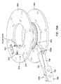
更に、示される実施形態において、粉砕機10は、回転可能なシャフト106にモータ105の回転を伝達するためのトランスミッションアセンブリ114を更に備える。特に、トランスミッションアセンブリ114は、モータ105から延びる出力シャフト118と、回転可能なシャフト106の下端112とに巻き付くベルト116を含む。代替的に、ベルトではなく、トランスミッションアセンブリ114は、モータ105の出力シャフト118と回転可能なシャフト106の下端112との周りに巻き付くチェーンを代わり含んでもよい。更に別の実施形態では、トランスミッションアセンブリ114は、代わりに、互いに噛み合うギア、またはモータ105から回転可能なシャフト106への回転運動の伝達を可能にする任意の他の適切な回転伝達構成要素を含んでもよい。更に別の実施形態では、粉砕機10は、トランスミッションアセンブリを含まない場合さえある。モータ105の出力シャフト118は、代わりに、回転可能なシャフト106と同軸とし、回転可能なシャフト106を直接回転させるように回転可能なシャフト106に固定されてもよい。
Further, in the embodiments shown, the
示される実施形態において、複数の粉砕ロータ108a、108b、108cは、ハウジング20の上端24付近に配置された上側粉砕ロータ108aと、ハウジング20の下端22付近に配置された下側粉砕ロータ108bと、上側ロータ108aと下側ロータ108bとの間に配置された中間粉砕ロータ108cとを備える。代替的に、粉砕ロータアセンブリ102は、代わりに3つより多いかまたは少ない粉砕ロータを含んでもよい。
In the embodiments shown, the plurality of grinding rotors 108a, 108b, 108c are an
更に、示される実施形態において、粉砕ロータ108a、108b、108cは互いから離間され、中間粉砕ロータ108cは、上側粉砕ロータ108aよりも下側粉砕ロータ108bのより近くに配置される。換言すれば、中間粉砕ロータ108cは、下側粉砕ロータ108bから第1の垂直距離だけ離間され、上側粉砕ロータ108aから、第1の垂直距離よりも大きい第2の垂直距離だけ離間される。代替的に、中間粉砕ロータ108cは、下側粉砕ロータ108bよりも上側粉砕ロータ108aの近くに位置決めされてもよく、または上側ロータ108aおよび下側ロータ108bから当距離にあってもよい。
Further, in the embodiments shown, the grinding
各粉砕ロータ108a、108b、108cは、ロータハブ120と、ロータハブ120から外方にハウジング側壁26に向かって延びる複数のロータアーム122とを備える。回転可能なシャフト106は、ロータアーム122が、中心ハウジング軸Hを通って直交して延びる回転面R(図10Bに最も良好に示される)に配設されるように、ロータハブ120を通って延びる。したがって、この構成において、回転可能なシャフト106が回転されるとき、ロータアーム122は回転面Rに留まり、回転面Rに沿って移動する。代替的に、回転面に全てが配設されるのではなく、ロータアーム122は代わりに、回転可能なシャフト106に対し上方または下方に角度をなしてもよい。更に別の実施形態では、ロータアーム122は、代わりに、1つまたは複数のアームアクチュエータを用いて手動でまたは自動的に、ロータアーム122を所望に応じて選択的に上方および下方に角度付けすることができるように、回転可能なシャフト106に旋回可能に接続されてもよい。
Each crushing
示される実施形態において、複数の気流偏向器200は、実質的に互いに類似し、中心ハウジング軸Hの周りに互いにアジマス方向に(すなわち、ハウジング側壁26の周囲に沿って)実質的に均等に離間された、6つの偏向器200を含む。代替的に、全ての偏向器200が互いに類似していなくてもよく、互いに均等に離間されていなくてもよく、かつ/または粉砕機10は6つよりも多いかまたは少ない偏向器を含んでもよい。例えば、粉砕機10は、2つ〜8つの偏向器200を含むことができる。
In the embodiments shown, the plurality of
示される実施形態において、各偏向器200は細長く、ハウジング軸Hに対し実質的に平行に延びる。特に、ハウジング20は、中心ハウジング軸Hが実質的に垂直に延びるように位置決めされるため、偏向器200も実質的に垂直方向に延びる。
In the embodiments shown, each
図5〜図7に最も良好に示すように、各偏向器200は、ハウジング20の上端24に向かって配置された上端202と、ハウジング20の下端22に向かって配置された下端204とを備える。示される実施形態において、各偏向器200は、上側粉砕ロータ108aおよび中間粉砕ロータ108cの回転面Rと交差するように位置決めされる。より具体的には、偏向器200の上端202は、上側粉砕ロータ108aの上に配置されるのに対し、偏向器200の下端204は、中間粉砕ロータ108cの下に配置され、偏向器200は、その上端202と下端204との間に連続して延びる。
As best shown in FIGS. 5-7, each
ロータアーム122の回転により、内部チャンバ28内の空気がハウジング側壁26に向かって外方に動くことが理解されよう。上記の構成において、偏向器200は、上側粉砕ロータ108aおよび中間粉砕ロータ108cと水平方向に位置合わせされているため、空気は、上側粉砕ロータ108aおよび中間粉砕ロータ108cによって、偏向器200に対し外方に動かされ、偏向器200によって偏向されて渦Vを形成する。これについては図8および図9に最も良好に示される。
It will be appreciated that the rotation of the
示される実施形態において、各偏向器200は、概ね楔形状である。特に、各偏向器200は、概ね三角形の断面を有し、回転可能なシャフト106が回転されるときに気流の方を向く、流れに面する偏向面206と、気流から離れる方を向く、反対側の偏向面208とを含む。流れに面する偏向面206および反対側の偏向面208は、ハウジング側壁26から離れる方に延び、互いに向かって収束し、ハウジング中心軸Hの方を指す頂点210において合わさる。流れに面する偏向面206は、第1の偏向角度θ1でハウジング側壁26の内面34に対し角度をなし、反対側の偏向面208は、第2の偏向角度θ2でハウジング側壁26の内面34に対し角度をなす。
In the embodiments shown, each
示される実施形態において、各偏向器200は、ハウジング20の半径に沿って延びる対称軸Sを中心に対称である。したがって、この実施形態において、第1の偏向角度θ1は、第2の偏向角度θ2に実質的に等しい。1つの実施形態において、第1の偏向角度θ1および第2の偏向角度θ2は、約1°〜89°、より具体的には、約30°〜60°に等しくすることができる。代替的に、偏向器200は対称でなくてもよく、第1の偏向角度θ1および第2の偏向角度θ2は互いに異なっていてもよい。
In the embodiments shown, each
示される実施形態において、各偏向器200の頂点210は、約7 3/4インチまたは約20cmの径方向距離だけハウジング側壁の内面34から径方向に内方に離間されている。更に、示される実施形態において、頂点210は、約1/2インチまたは約1cm〜約2インチまたは約5cmの径方向の距離だけロータアーム122の先端130から径方向に外方に更に離間されている。1つの実施形態において、ロータアーム122の先端130と頂点210との間の径方向の距離または「隙間空間」は、回転可能なシャフト106が回転されるときに所望に応じて渦Vを形成することができるように選択することができる。
In the embodiments shown, the
代替的に、偏向器200は、異なる形で成形および/またはサイズ設定されてもよい。例えば、流れに面する偏向面206および反対側の偏向面208は平面でなくてもよく、代わりに湾曲していてもよい。別の実施形態において、偏向器200は、反対側の偏向面208を含まない場合がある。更に別の実施形態において、偏向器200は、楔形状ではなく、代わりに矩形断面を有してもよく、または当業者が適切であるとみなす任意の他の形状およびサイズを有してもよい。
Alternatively, the
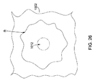
図9は、粉砕機10の動作時に内部チャンバ28内に発生する渦Vの概略表現である。
FIG. 9 is a schematic representation of the vortex V generated in the
粉砕機10の動作中、回転可能なシャフト106は、ロータアーム122がハウジング軸Hを中心に旋回する円形気流を形成するようにハウジング軸Hを中心に回転する。図9に示す例において、回転可能なシャフト106は、上から見たとき、内部チャンバ28において反時計回りの気流を形成するように時計回りの方向に回転される。
During the operation of the
回転可能なシャフト106は、粉砕機において所望の粉砕効果をもたらすように比較的高い速度で回転させることができる。1つの実施形態において、回転可能なシャフト106は、約700rpm〜約1100rpmの回転速度で回転され、より具体的には、約1000rpm〜約1100rpmの回転速度で回転される。代替的に、回転可能なシャフト106は、以下で説明されるように渦の形成を可能にする異なる回転速度で回転することができる。
The
気流は、概ねハウジング側壁26の内面34に沿って進行するが、ロータアーム122と、より具体的にはロータアーム122の先端と協働する偏向器200の流れに面する偏向面206によって妨害され、渦Vを形成する。図9に示すように、渦Vは、隣接する偏向器200'によって、中心軸Hに向かって内方に戻るように更に誘導することができる。
The airflow travels generally along the
更に図9を参照すると、各渦Vは、少なくとも1つの隣接する渦V1、V2と更に重なり合い、浮遊している入力物質粒子を、隣接する1つまたは複数の渦V1、V2に浮遊している入力物質粒子と衝突させる。より具体的には、発生した各渦Vは、概して、シャフト106からハウジング側壁26に向かって循環する気流によって概ね規定される外方に移動する部分500と、ハウジング側壁26からシャフト106に向かって循環する気流によって概ね規定される内方に移動する部分502とを含む。図9に示すように、各渦Vの外方に移動する部分500が、第1の隣接する渦V1の内方に移動する部分502と重なり合い、各渦の内方に移動する部分502は、第2の隣接する渦V2の外方に移動する部分500と重なり合う。
Further referring to FIG. 9, each vortex V further overlaps with at least one adjacent vortex V 1 and V 2, and the floating input material particles are transferred to one or more adjacent vortices V 1 and V 2 . Collide with floating input material particles. More specifically, each generated vortex V generally has a
したがって、この構成において、渦内の入力物質粒子は、渦V内の粒子の移動速度の2倍で移動する入力物質粒子と衝突する。例えば、1つの実施形態において、渦V、V1、V2は、音速の約1/3で回転している。第1の隣接する渦V1および第2の隣接する渦V2からの入力物質粒子が、同じ速度であるが反対方向に移動している、渦V内に浮遊している入力物質粒子と衝突するとき、粒子は音速の約2/3で互いに衝突することになる。 Therefore, in this configuration, the input material particles in the vortex collide with the input material particles that move at twice the moving speed of the particles in the vortex V. For example, in one embodiment, the vortices V, V 1 , and V 2 rotate at about 1/3 of the speed of sound. Input material particles from the first adjacent vortex V 1 and the second adjacent vortex V 2 collide with the input material particles floating in the vortex V that are moving at the same velocity but in opposite directions. When doing so, the particles will collide with each other at about 2/3 of the speed of sound.
1つの実施形態において、気流および渦Vを介した入力物質粒子の衝突に加えて、入力材料は、回転可能なシャフト106が回転される際、内部チャンバ28内の入力物質粒子に衝撃を与えるロータアーム122によって更に粉砕され得る。この実施形態において、重なり合う渦V、V1、V2において互いに衝撃を与える入力物質粒子と、入力物質粒子に衝撃を与えるロータアームとの組み合わされた効果により、粉砕機の効率を高めることができる。更に、重なり合う渦Vにより、粒子が、ハウジング20内の表面ではなく互いに衝撃を与えるため、ハウジング20内の構成要素の摩耗を低減することができる。
In one embodiment, in addition to the collision of the input material particles through the airflow and vortex V, the input material is a rotor that impacts the input material particles in the
図8および図9に示す渦Vは、理解を容易にするため単純化されていること、および実際には、渦Vは示されるように厳密に円形ではないか、または図9に示されるように厳密に配置されていない場合があることが理解されよう。 The vortex V shown in FIGS. 8 and 9 has been simplified for ease of understanding, and in fact the vortex V is not exactly circular as shown, or as shown in FIG. It will be understood that it may not be exactly placed in.
示される実施形態において、粉砕機10は、ハウジング側壁26から内方に延びる複数の棚300a、300bを更に備える。特に、複数の棚300a、300bは、上側棚300aと、上側棚300aから下方に離間された下側棚300bとを含む。各棚300a、300bは、ハウジング軸Hの周りをハウジング側壁26に沿って周方向に延びる。したがって、棚は、偏向器200に対し実質的に直交して延びることが理解されよう。特に、偏向器200は、ハウジング軸Hに対し概ね平行に延び、したがって、ハウジング20に対し軸方向に延びると言えるのに対し、棚は、ハウジング20に対しアジマス方向に延びると言える。示される実施形態において、偏向器200は実質的に垂直方向に延びるのに対し、各棚300a、300bは、概ね水平の面内に配設され、したがって、概ね水平方向に延びる。
In the embodiments shown, the
更に、示される実施形態において、各棚300a、300bは、ハウジング側壁26の周りを実質的に連続して延びる。代替的に、棚300a、300bは、ハウジング側壁26の周りを連続して延びない場合があり、代わりに、隣接する棚セグメント間に間隙を画定するように互いに離間された複数の棚セグメントを含むことができる。
Further, in the embodiments shown, the
示される実施形態において、上側棚300aは、実質的に上側粉砕ロータ108aと水平方向に位置合わせされ、下側棚300bは、中間粉砕ロータ108cと実質的に水平方向に位置合わせされる。代替的に、各棚300a、300bは、対応する粉砕ロータ108a、108cの僅かに下に配置することができる。
In the embodiments shown, the
示される実施形態において、各棚300a、300bは、ハウジング側壁26から下方に、ハウジング側壁26から離れるように延びる棚上面302を含む。特に、棚300a、300bは、ハウジング側壁26に沿ってハウジング軸Hの周りに延びるため、棚上面302は実質的に円錐形である。更に、示される実施形態において、棚上面302は、ハウジング側壁26に対し、棚上面302がハウジング側壁26に対しほぼ平坦である約1°と、棚上面302がハウジング軸Hに対しほぼ直交する約89°との間の角度でハウジング側壁26に対し角度をなす。1つの実施形態において、棚上面302は、30°〜60°の角度でハウジング側壁26に対し角度をなすことができる。
In the embodiments shown, each
棚300a、300bは、棚に向かって方向付けられた気流を上方に偏向するように構成される。これによって、入力物質粒子が、棚300、300bの上で浮遊状態に一時的に維持されることが可能になる。したがって、入力物質粒子は、渦の効果、およびロータアーム122との衝突による粉砕を長期間にわたって受けることができ、結果として、入力物質粒子が次のロータステージまたは出口32に向かって進行する際、それらの入力物質粒子のサイズが更に低減されることとなる。
The
気流の上方偏向は、内部チャンバ28内の渦Vに更に寄与することができる。より具体的には、図8に示すように、渦Vは、図9に示すようなハウジング軸Hに対し直交する面における回転に加えて、ハウジング軸に対し概ね平行な面において、すなわち、上方-下方に回転することができる。したがって、棚300a、300bおよび偏向器200の組み合わされた効果は、渦V内の空気が3次元の進行経路に沿って動くように3次元である渦Vを形成することに寄与し、これは、隣接する重なり合う渦Vの入力物質粒子間の衝突を更に促進することができる。
The upward deflection of the airflow can further contribute to the vortex V in the
この構成は、偏向器200によって発生する渦Vの数に、ハウジング20内の棚300a、300bの数を乗算することを更に可能にする。例えば、示される実施形態において、粉砕機10は、内部チャンバ28全体において合計12個の渦について、各棚300a、300bの上に6つの渦を形成することができる6つの偏向器200を含む。
This configuration further makes it possible to multiply the number of vortices V generated by the
図1に示す実施形態において、ハウジング側壁26は、内面402および外面404を有する外側構造壁400と、外側構造壁400の内面の上に延びるハウジングライナ406とを含む。ハウジングライナ406は、内部チャンバ28内の入力物質粒子の衝撃から外側構造壁400を保護するために用いられる。
In the embodiment shown in FIG. 1, the
示される実施形態において、外側構造壁400は、単一の一体円筒体から作製されるのではなく、実質的にハウジング20の上端24と下端22との間に延び、外側構造壁400を形成するように並んで配設された、複数の壁セクション450を含む。
In the embodiments shown, the outer
特に、各壁セクション400は、内部チャンバ28の方に向いた凹型の内面452と、凹型の内面452から離れる方に向いた凸型の外面454とを有する。図5に最も良好に示すように、各壁セクション400は、互いに隣接して配設され、凹型の内面452を画定するように互いに角度をなす、複数の平面部分462、464を含む。示される実施形態において、複数の平面部分462、464は、中央の平面部分462と、中央の平面部分462の両側に延びる一対の側方の平面部分とを含む。
In particular, each
示される実施形態において、外側構造壁400は、6つの壁セクション450を含み、各壁セクション450の平面部分462、464は、約10°〜30°の角度で互いに対し角度をなす。代替的に、平面部分462、464は、10°未満または30°超の角度で角度をなしてもよく、この場合、外側構造壁400は、外側構造壁400全体を形成する6つよりも多いかまたは少ない壁セクション450を含んでもよい。
In the embodiments shown, the outer
示される実施形態において、各壁セクション450は、一対の側面フランジ470を更に含む。各側面フランジ470は、壁セクション450の対応する側方の平面部分464から側方に延び、凹型の内面452から離れるように更に延びる。特に、各側面フランジ470は、側方の平面部分464と、対応する中央の平面部分462との間の角度よりも実質的に大きい角度で、対応する側方の平面部分464に対し角度をなす。示される実施形態において、各側面フランジ470は、約30°〜89°の角度で対応する側方の平面部分464に対し角度をなす。代替的に、側面フランジ470は、30°未満または89°超の角度で対応する側方の平面部分664に対し角度をなしてもよい。
In the embodiments shown, each
したがって、図6に最も良好に示すように、壁セクション450が外側構造壁400を形成するように並んで配設されるとき、側面フランジ470は、内部チャンバ28内に内方に延びる。示される実施形態において、壁セクション450の各側面フランジ470は、隣接する壁セクション450の対応する側面フランジ470に隣接して延び、対応する側面フランジ470と共に、偏向器200のうちの対応する偏向器を画定する。この構成により、偏向器200を、ハウジング側壁26の内面34に固定する必要がある別個の片として提供する必要がなくなる。更に、この構成により、偏向器200が粉砕機10の動作中にハウジング側壁26に固定されていない状態になり得るリスクがなくなり、したがって、偏向器200が、内部チャンバ28内の力に対しより抵抗することが可能になる。
Thus, as best shown in FIG. 6, the
壁セクション450は、上述したのと異なる形で構成されてもよいことが理解されよう、例えば、壁セクション450は、ハウジング20の上端24から下端22に連続して延びるのではなく、代わりに、壁セクション450を形成するようにハウジング20の下端22から上端24に実質的に垂直に重ねることができる複数の壁サブセクションを含んでもよい。
It will be appreciated that the
特に材料を粉砕するのに適したサイズの単一の連続した円筒形状片としてハウジング側壁26を設けることが高価であると判明し得ることが理解されよう。容易に製造し、共に組み立てることができる複数の平坦な片で複数のハウジング20を提供することによって、この構成は、ハウジング20の製造コストを低減することができる。更に、この構成は、粉砕機10のメンテナンスを容易にすることができる。なぜなら、各壁セクション450を他の壁セクション450から個々に除去し、ハウジング20内へのアクセスを可能にすることができるためである。
It will be appreciated that it may prove expensive to provide the
図23を参照すると、別の実施形態による、ハウジング20'を有する粉砕機10が示されている。この実施形態において、ハウジング20'は、複数の壁セクション450を用いて作製されるのではなく、円筒形状で成形された単一の連続した材料片から作製された外側構造壁400'を含む。
Referring to FIG. 23, another embodiment shows a
再び図5〜図7を参照すると、ハウジングライナ406は、外側構造壁400に取り付けられ、外側構造壁400に沿って延びる複数のハウジングライナ部分480を含む。
Referring again to FIGS. 5-7, the
特に、各ハウジングライナ部分480は、他のハウジングライナ部分480から独立して外側構造壁400から取り外し可能である。これにより、ハウジングライナ406全体を除去する必要なく、各ハウジングライナ部分480を取り外して修理または交換することが可能になる。
In particular, each
示される実施形態において、各ハウジングライナ部分480は、少なくとも1つの締結具を用いて外側構造壁400に取り付けられる。少なくとも1つの締結具は、当業者が適切であるとみなすボルト、リベット、ねじ、または任意の他のタイプの締結具を含むことができる。
In the embodiments shown, each
示される実施形態において、複数のハウジングライナ部分480は、壁セクション450の平面部分462、464に対し延びる複数の側壁ライナパネル482を含む。特に、側壁ライナパネル482は、概ね矩形であり、壁セクション450の平面部分462、464の幅に概ね対応する幅を有する。側壁ライナパネル482は更に、それらが取り付けられる壁セクション450の対応する平面部分462、464に対し平坦に延びるように、概ね平面である。
In the embodiments shown, the plurality of
示される実施形態において、複数のハウジングライナ部分480は、流れに面する偏向面206および反対側の偏向面208に対し延びる複数の偏向器ライナパネル484を更に含む。特に、流れに面する偏向面206および反対側の偏向面208は、示される実施形態において実質的に平面であるため、偏向器ライナパネル484も、それらが取り付けられた対応する偏向面206、208に対し平坦に延びるように実質的に平面である。
In the embodiments shown, the plurality of
更に、示される実施形態において、複数のハウジングライナ部分480は、棚300a、300bを形成するようにハウジング側壁26に対し並んで配設された複数の棚ライナパネル486a、486bを更に含む。特に、複数の棚ライナパネル486a、486bは、上側の棚300aを形成するように実質的に水平な列に並んで配設された棚ライナパネルの第1の組486aと、下側の棚300bを形成するように実質的に水平な列に並んで配設された棚ライナパネルの第2の組486bとを含む。
Further, in the embodiments shown, the plurality of
互いから取り外し可能な複数の別個の部分で棚300a、300bを提供することにより、棚300a、300b全体を除去する必要なく、棚300a、300bの一部のみを取り外して修理または交換することが可能になる。
By providing
示される実施形態において、複数の棚ライナパネル486a、486bは、対応する壁セクション450の中央の平面部分462に対し配設されるように構成された複数の中央棚ライナパネル490と、中央の平面部分462の両側の、対応する壁セクション450の側方の平面部分464に対し配設されるように構成された複数の側方棚ライナパネル492とを更に含む。
In the embodiments shown, the plurality of
図10Aに示すように、各中央棚ライナパネル490は、対応する壁セクション450の中央の平面部分462に沿って延びるように構成された上側の平面部分494と、上側の平面部分494に対し角度をなす、下側の傾斜部分496とを備える。下側の傾斜部分496は上面497を含み、上面497は、棚ライナパネル486a、486bの対応する組における他の棚ライナパネル490、492の上面497と共に、対応する棚300a、300bの棚上面302を画定する。下側の傾斜部分496は、上側の平面部分494から離れる方に延びる際に互いに向かってテーパ状になる一対の側縁498a、498bを更に含む。
As shown in FIG. 10A, each center
図7に示すように、各側方棚ライナパネル492は、偏向器200のうちの1つに隣接して更に配置される。各側方棚ライナパネル492は、側方棚ライナパネル492が実質的に三角形の翼部分499を更に含むことを除いて中央棚ライナパネル490と概ね同様である。三角形の翼部分499は、下側の傾斜部分496から側方に延び、隣接する偏向器200と当接し、それによって下側の傾斜部分496と隣接した偏向器200との間の間隙を架橋する。
As shown in FIG. 7, each side
いくつかの実施形態では、ハウジングライナ406は、ガラス繊維、高密度ポリエチレン(HDPE)、セラミック、鋼、または当業者が適切であるとみなすことができる任意の他の材料から作製することができる。更に、ハウジングライナ部分480のうちの少なくともいくつかは、炭化クロムオーバーレイ、炭化物オーバーレイ等のオーバーレイによってカバーすることができ、これによりハウジングライナ406に更なる摩耗耐性がもたらされる。例えば、偏向器200の流れに面する偏向面206は、偏向器200における摩耗を更に防ぐために、オーバーレイ等によってカバーすることができる。
In some embodiments, the
図11Aおよび図11Bを参照すると、別の実施形態が示されている。この実施形態では、複数の棚ライナパネル486a、486bに加えて、複数のハウジングライナ部分480は、並べて配設され、各棚300a、300bの上に下方に向いた水平偏向器552を画定する、複数の下方に向いたパネル550を更に含むことができる。特に、各下方に向いたパネル550は、対応する棚ライナパネル486a、486bの鏡像であり、下側の平面部分554と、下側の平面部分554に対し角度をなす上側の傾斜部分556とを含む。特に、上側の傾斜部分556は、概ね下方に向いた底面558を含む。この構成は、図11Bに示すように、気流が垂直方向に動く3次元渦に気流を更に偏向することに寄与することができる。代替的に、下方に向かうパネル550および対応する棚ライナパネル486a、486bは、2つの別個の片として提供されるのではなく、単一の一体片として提供されてもよい。
Another embodiment is shown with reference to FIGS. 11A and 11B. In this embodiment, in addition to the plurality of
再び図6を参照すると、所与の粉砕ロータ108のロータアーム122は、他の粉砕ロータ108のロータアーム122に対し回転可能なシャフトの周りで角度方向にオフセットすることが理解されよう。したがって、上側粉砕ロータ108aのアームによって発生した渦は、中間粉砕ロータ108cおよび下側粉砕ロータ108bによって発生した渦と垂直方向に位置合わせされない。この構成は、粉砕機を通る材料が衝撃を受けない可能性を低減させることができる。例えば、材料が、上側ロータアームを、衝撃を受けずに(例えば、渦内に引きずり込まれることなく)通過する場合、上側レベルの下で発生した渦が材料と相互作用し、材料を効果的に粉砕する可能性が高い。
With reference to FIG. 6 again, it will be appreciated that the
図13〜図15を参照すると、ここで、単一の粉砕ロータ108および対応する構成要素の可能な実施形態が説明される。複数のロータアーム122は、ロータハブ120および回転可能なシャフトの周りで実質的に均等に離間され、内部チャンバ内の回転可能なシャフトの周りで同様に離間された複数の渦を発生させることに留意されたい。ロータハブ120の周りのアームの角度間隔は、(例えば、ロータアームに、回転可能なシャフトの周りを360°均等に離間させるために、)このハブに接続されたアーム122の数に依拠することができる。例えば、4つのロータアームを有するロータハブの場合、ロータアームは、約90°だけ離間することができ、または6つのロータアームが接続されたロータハブの場合、約60°だけ離間することができる。しかしながら、ロータアーム122は、それらの間の任意の角度で任意のロケーションにおいてロータハブ120に接続することができる。
With reference to FIGS. 13-15, possible embodiments of a
いくつかの実施形態では、ロータハブ120は、ロータアーム122を接続することができる1つまたは複数のプレートを含むことができる。この実施形態において、ロータハブ120は、互いに離間された上板600および底板602を含み、それらの間にロータアーム122が接続される。より具体的には、ロータアーム122は、上板600および底板602間に挟持された近位部分122a(図16Aにおいて最も良好に見られる)と、ハブから内部チャンバ内に延びる遠位部分122bとを含むことができる。再び図12を参照すると、各ハブのアームは、概ね同じ距離だけ外方に延びることができるが、他の構成も可能であることが理解されよう。例えば、この実施形態において、下側粉砕ロータ108bのアームは、中間粉砕ロータ108cまたは上側粉砕ロータ108aのアームよりも短い。ハウジング側壁26は、同様に、下側粉砕ロータ108bの周りでより短い直径を有することができ、それによって、ハウジング側壁、またはより具体的には、偏向器の頂点と、ロータアーム122の先端130との間の距離は、概ね同じままである。
In some embodiments, the
以下で更に説明されるように、ロータアーム122は、上板600と底板602との間で、アームと、ハブ板のうちの少なくとも1つとを通って延びる1つまたは複数のコネクタを介して接続することができる。粉砕機の動作中(すなわち、回転可能なシャフト、ロータハブおよびロータアームの回転中)の空気力学を促進するために、ロータハブの板は、好ましくは円形であることに留意されたい。しかしながら、任意の適切な多角形形状を有するハブ板、または互いに異なる形状を有する上板および底板等の、他の形状および構成も可能であることを理解されたい。
As further described below, the
ロータアーム122は、内部チャンバ内に(例えば、回転可能なシャフトに対し)実質的に径方向に、または角度をなして延びることができることに留意されたい。図14の示される実施形態では、ロータアーム122は、ロータハブ120に対し傾いているか、または傾斜しており、これによって、ロータアームの長手方向軸Lと、ロータアームの近位端においてハブ120から径方向に外方に延びる対応する軸R'との間に角度が画定される。この構成は、各アームのそれぞれの長手方向軸に沿って外方に移動する流動流の発生が促進されるため、内部チャンバ内の渦の発生を容易にすることができる。更に、傾斜したロータアーム122は、回転中のロータアーム122の周りの材料の巻き付きを防ぐかまたは少なくとも低減することができる。示される実施形態において、ロータアーム122は、例えば、約5°〜約90°の傾動角θ3、例えば約20°〜60°の傾動角θ3を画定するように傾斜することができる。「傾動角」という表現は、任意の所与のロータアームの長手方向軸と、同じロータアームの近位端を通って延びるハブの径方向の軸との間で画定された角度を指すことを理解されたい。
Note that the
ここで、図14に加えて図15および図16Aを参照すると、数ある中でも、ロータアーム、ロータハブ、回転可能なシャフト、ハウジング、偏向器および/または棚等の、粉砕機の構成要素を保護するように構成された安全機構をハブに設けることができる。本実施形態において、所定の大きさの力が加えられた場合(すなわち、力閾値に到達した場合)にロータアーム122が移動することを可能にするように構成された解放機構610が各ロータハブ120に設けられる。例えば、大きな、密度の高い、硬い、または他の形で不適切な材料が粉砕機内に導入された場合、解放機構610は、ロータアームに対する損傷を防ぐようにロータアームが動くことを可能にするように適合される。
Now referring to FIGS. 15 and 16A in addition to FIG. 14, it protects the crusher components, such as rotor arms, rotor hubs, rotatable shafts, housings, deflectors and / or shelves, among others. A safety mechanism configured as described above can be provided in the hub. In this embodiment, each
いくつかの実施形態では、ロータアーム122は、上述した傾斜した位置等の第1の位置と、所定の力が加わるときの第2の位置との間で動作することができる。第2の位置にあるときの傾斜した角度θ3は、第1の位置にあるときの傾斜した角度θ3と異なることが理解されるべきである。より具体的には、ロータアーム122は、所定の力が加えられると、ロータアームおよび/またはロータハブに対する損傷を回避するか、または少なくとも部分的に低減するために、或る点を中心に回転することを可能にすることができる。解放機構610は、各ロータアームが互いに独立して動くことを可能にするように適合することができるが、2つ以上のロータアームの同時移動を可能にする等の他の構成も可能であることに留意されたい。
In some embodiments, the
この実施形態において、解放機構610は、ロータアームを第1の位置に保持し、所定の力が加わるとロータアームを解放するように成形および構成された、ロータアーム122ごとのメカニカルヒューズ612を含む。上述したように、ロータアーム122は、上板600と底板602との間で、これら通って(すなわち、アームと、板のうちの少なくとも1つとを通って)延びるコネクタを介して接続される。本実施形態において、コネクタは、ロータアームに沿って離間され、ロータアームと、上板600および底板602の双方とを通って延びる第1のコネクタ615および第2のコネクタ616を含む。ロータアームは、例示的に、その近位端122aにおいて、第2のコネクタ616を受けるように適合された近位凹部620を含み、第1のコネクタ614はロータアームに沿っての近位凹部620から離間される。
In this embodiment, the
この実施形態において、第2のコネクタ616は、メカニカルヒューズ612としての役割を果たし、第1のコネクタ614は、旋回点としての役割を果たすボルトを含むことができる。換言すれば、ロータアーム122は、メカニカルヒューズ612がロータアームを解放すると、第1のコネクタ614を中心に旋回することを可能にされる。例示的な実施形態において、メカニカルヒューズ(すなわち、第2のコネクタ)は、ロータアーム122に対する力閾値に達すると破断するように構成されたシャーピン618である。シャーピン618は、概して、第1のコネクタ614よりも小さい直径を有することを理解されたい。なぜなら、シャーピン618は、ロータアームまたは周囲の構成要素に対する損傷が生じる前に崩壊するように構成されているためである。したがって、所定の力、または閾値は、ロータアームのせん断破壊の約半分とすることができるが、任意の他の適切な閾値も可能である。
In this embodiment, the second connector 616 serves as a mechanical fuse 612 and the
内部チャンバ内の高速の渦は、破断または更なる損傷を防ぐために交換を必要とする可能性がある内部構成要素(例えば、パネル、アーム、ハブ、様々な接続要素等)の摩耗または劣化を増大させる可能性がある。図15に示すように、解放機構の第1のコネクタ614および第2のコネクタ616は、その一部(例えば、ボルトヘッド622)がロータハブの120の上板600の上に延びるか、または上板600上に載ることができる。このため、ロータハブには、ボルトヘッド622を摩耗から保護するように適合された追加の安全機構を設けることができる。
High speed vortices in the internal chamber increase wear or deterioration of internal components (eg, panels, arms, hubs, various connecting elements, etc.) that may need to be replaced to prevent breakage or further damage. There is a possibility of causing it. As shown in FIG. 15, the
この実施形態において、ロータハブは、解放機構の各コネクタのボルトヘッド622を少なくとも部分的に取り囲むような形状およびサイズにされた、上板600に装着されたカバープレート624を含む。より具体的には、カバープレート624は、一対の第1および第2のコネクタボルトヘッド622をそれぞれ受けるための複数の凹部625を有する。更に、カバープレート624は、ボルトヘッド622の厚みよりも概ね大きな厚みを有し、それによって、ボルトヘッド622は、カバープレート624の凹部625に嵌められ(niched)、流動流がカバープレート624の表面を横切ってボルトヘッド622の上を概ね流れることが可能になる。示される実施形態において、カバープレート624は、共に接続され、上板600に装着されて、回転可能なシャフトの周りにカバープレート624を装着することを容易にする一対のカバープレート部分624a、624bを含む。カバープレート部分624a、624bは、任意の適切な接続手段を介して共に接続することができ、例えば、この実施形態では、これらの部分はパズル接続(すなわち、各部分の噛み合う部品)を介して接続される。カバープレート624は、任意の適切な方法/手段を用いて接続することができる3つ以上の部分を含むことができることが理解されよう。
In this embodiment, the rotor hub includes a
ここで、図16B〜図16Eを参照すると、更にまたは代替的にボルトヘッド622を保護するように構成されたボルト保護具650が提供される。ボルト保護具650は、中にボルトを受けるための凹部を画定するウェル652を含むことができ、ウェルの底部の突起が、ボルトのシャフトが中を通って延びることを可能にする。ウェル652は、例えば六角形等のボルトヘッド622を受け、収容するように適合された任意の適切な形状を有することができ、これにより、ボルトヘッド622がウェル652内で回転することを更に防ぐことができる。このため、ボルト(例えば第1または第2のコネクタ)を上板600(または任意の他の構造体)上の孔に挿入する前に、ボルト保護具650を同じ孔に挿入することができることが理解されるべきである。ボルト保護具650を、摩擦嵌めにより構造体に接続し、比較的ぴったりと嵌め、ウェル652が設置時に回転することを防ぐことができる。
Here, with reference to FIGS. 16B-16E, a
ボルト保護具650は、例示的に、ウェル652の上端においてウェル652を取り囲み、ボルトが接続された構造体の表面上に載るように構成された基部654を含む。換言すれば、基部654は、ウェル652の周りに外方に延び、ボルト保護具650をそれに応じて位置決めするためのリップを提供する。ボルトは、基部654がボルトヘッド622の上に延び、内部チャンバ28内を回る入力物質粒子からボルトヘッドを保護するような方式で、ウェル652内に嵌めることができる。ボルト保護具650は、好ましくは、耐摩耗性材料を用いて構築される。
The
いくつかの実施形態では、ボルト保護具650の基部654は、少なくとも部分的に、ボルトヘッド622から離れるように流れを方向付けるように成形およびサイズ設定することができる。例えば、基部654は、ウェルから離れて延びるにつれ細くなるセクション(すなわち、先端656)を有する、涙滴等の流線形状を有することができる。内部チャンバ28内の、ボルト保護具650が接続された表面に沿った気流の流れは、先端656において、基部654の側面に向かって逸らすことができる。いくつかの実施形態では、先端656は、ボルトヘッド622の周りおよび/または上の空気を逸らすのに役立つように、予期される気流の方向に位置決めすることができる。
In some embodiments, the
いくつかの実施形態では、各ロータアーム122は、ロータアーム122の様々な部品を保護するための保護機構を含むことができる。いくつかの実施形態では、保護機構は、摩耗量が所定のレベルに達すると、取り替えられるかまたは交換されるように適合される。
In some embodiments, each
図16Aおよび図17〜図20を参照すると、各ロータアーム122は、その遠位端122bに取り外し可能に接続された摩耗パッド700を含むことができる。摩耗パッド700は、アームの回転中、粉砕機に供給される材料に衝撃を与えるように成形および構成され、損傷を受けるかまたは摩耗した場合に交換することができる。図16Aに示すように、摩耗パッド700は、実質的に矩形とすることができ、締結具(例えば、ボルト、ねじ、糊等)を介して遠位端122bにおいて接続することができる。示される実施形態において、締結具は、摩耗パッド700の前面702を通り、ロータアーム122を通って延びるボルトである。更に、前面702は、概ね平坦であり、これにより、摩耗パッド700との衝突時に材料を破断させることを促進することができる。摩耗パッドの他の構成も可能であり、以下で更に説明される。
With reference to FIGS. 16A and 17-20, each
摩耗パッド70に加えて、各ロータアーム122には、ロータアームに接続され、ロータハブ120と摩耗パッド700との間に延び、ロータアーム122の対応する部分を保護するためのアーム保護具704を設けることができる。アーム保護具704は、任意の適切な締結具を用いて、または任意の適切な方法を介してロータアーム122に接続することができる。例えば、この実施形態において、各ロータアーム122は、近位端付近に位置決めされ、ハブから離れる方に向いた保護具スロット706(図18)を含む。保護具スロット706は、アーム保護具704の第1の端部を受けるように成形およびサイズ設定され、内部でこの第1の端部を保持するように適合される。アーム保護具704は、ロータアーム122の前面に沿って、摩耗パッド700に向かって軸方向に延び、それによって、アーム保護具704の第2の端部は、位置決めされる摩耗パッド700と係合し、実質的に、摩耗パッド700とロータアーム122の遠位部分122bとの間で固定される。したがって、アーム保護具704は、アーム保護具自体を通って延びる締結具を用いることなく、ロータアーム122上の適所に効果的に保持することができる。
In addition to the wear pad 70, each
更に図17および図18を参照すると、ロータアームの例示的な実施形態が示される。この実施形態において、摩耗パッド700は、その前面702の周りに延びる、丸められたまたは湾曲した縁部708a、708b、708c、708dを有する。湾曲した縁部は、抗力を低減するのを支援し、これによりロータアーム122の空気力学を増大させながら、摩耗パッド700に巻き付く材料の量も低減することができることが理解される。更に、摩耗パッド700は、材料がパッドの前面702に衝撃を与えることを促進するために、ロータアーム122の高さを超える高さ(すなわち、上縁部708cおよび底縁部708d間の距離)を有することができる。換言すれば、摩耗パッドの上縁部708cおよび底縁部708dは、例示的に、その遠位端122bの周りでロータアームに覆い被さる。例えば、摩耗パッド700の高さは、アームの高さを少なくとも150%、ただし300%以下だけ超えることができるが、他の構成も可能であることが理解されよう。同様に、摩耗パッド700は、摩耗パッド700をロータアーム122に固定しながら、前縁部708bを遠位端122bよりも遠くに延ばすことも可能にするような任意の長さ(すなわち、後縁部708aおよび前縁部708b間の距離)を有することができる。
Further, with reference to FIGS. 17 and 18, exemplary embodiments of the rotor arm are shown. In this embodiment, the
いくつかの実施形態では、摩耗パッド700をロータアーム122に接続するために用いられる締結具のヘッドは、前面702に形成される空洞710に受けることができる。ボルトヘッドは、空洞と係合し、例えば、前面702に対し窪むか、または前面702と同一平面になることができる。更に、空洞710内に係合しているとき、摩耗パッド700がロータアーム122から誤って切り離されることを回避するために、ボルトヘッドの回転を防ぐことができるか、または少なくとも妨げることができる。
In some embodiments, the head of the fastener used to connect the
図19および図20に示すように、摩耗パッド700はロータアームの前面に接続されると、この前面と係合するように適合された、前面の反対側の後面712を更に有する。摩耗パッド700は、内部にアームの少なくとも一部分を受けるために、後面712の長さにわたって延びるチャネル714を有することができる。この実施形態において、後面712は、チャネル714の両側に画定され、摩耗パッドの長さに沿って延びる上部フランジ716および底部フランジ718を含む。上部フランジ716および底部フランジ718は、アーム上の所望の位置に摩耗パッド700を維持するのを支援するようにチャネル内に係合されるとき、ロータアームに少なくとも部分的に巻き付くように成形および構成される。ロータアームの周りに部分的に摩耗パッドを巻きつけることによって、例えば摩耗パッドに対する材料の衝撃からロータアームに加わる力の分散を促進することができることに留意されたい。
As shown in FIGS. 19 and 20, when connected to the front surface of the rotor arm, the
示される実施形態において、摩耗パッド700には、摩耗パッドの寿命を増大させる更なる劣化が予期される場所に追加材料が提供される。本実施形態において、摩耗パッドの前面702に衝撃が生じることが理解される。しかしながら、ロータアームの回転により、径方向に外方に(例えば、ハウジング側壁26に向かって)動く流動流が発生し、それによって、前縁部708bは摩耗パッドの他の場所よりも早く摩耗する可能性がある。より具体的には、前縁部708bの上角部720は、より高速に劣化する摩耗パッド700の場所に対応することに留意されたい。したがって、上角部720におよび/またはこれに近接して追加の材料を提供することができる。図20に示すように、上角部720に材料を加えることにより、上部フランジ716が摩耗パッドの長さに沿って(すなわち、チャネル714に沿って)減少する厚みを有する可能性がある。換言すれば、前縁部の上角部720は、後縁部708aの角部722よりも大きな厚みを有する。
In the embodiments shown, the
いくつかの実施形態では、摩耗パッドをロータアーム上で回転させることができるように、摩耗パッド700の対角線上の反対側の角部に追加の材料を提供することができる。より具体的には、前縁部の上角部が後縁部の底角部になるように摩耗パッドが回転され、逆もまた同様である。したがって、前縁部708bが摩耗する(例えば、上角部720の厚みが所定の閾値まで減少する)と、摩耗パッドは、交換するのではなく単にフリップすることができ、パッドの寿命が効果的に増大する(例えば、2倍になる)。このため、底部フランジ718は、後縁部の底角部724における追加の材料に起因して、後縁部708aから前縁部708bにかけて減少する厚みを有することができることが理解されるべきである。更に、摩耗パッドの全体質量を低減させ、それによって内部チャンバ28内のアームの回転中にこのアームに加わる力を低減するために、劣化が最小である場所では提供する材料の量を減らすことができることが理解される。
In some embodiments, additional material can be provided at the diagonally opposite corners of the
図19および図20を更に参照すると、摩耗パッド700には、後縁部708aおよび/または前縁部708bに沿って位置決めされたパッドスロット730と、後表面712上の開口部とを設けることができる。以下で更に説明されるように、アーム保護具をロータアーム上に少なくとも部分的に固定するために、パッドスロット730は、アーム保護具704の対応する部分を受けるように成形およびサイズ設定することができる。摩耗パッド700がフリップされるとき、アーム保護具が依然として摩耗パッドに同じ方式で係合することができるように、後縁部および前縁部の双方にパッドスロット730を設けることができることに留意されたい。
Further referring to FIGS. 19 and 20, the
再び図17および図18を参照すると、アーム保護具704は、粉砕機の動作中に抗力を低減し、これによりロータアームの空気力学を増大させるように適合された湾曲したまたは丸められた前表面732を有することができる。丸められた前表面732は、材料がロータアームに巻き付く可能性を更に低減することができる。なぜなら、材料が90°未満の角度で前表面に接触することができ、これによりロータアームの上および/または下の材料の偏向が促進されるためである。この実施形態において、アーム保護具704は、摩耗パッド700とロータハブとの間でロータアームを覆うように実質的に細長くされる。上述したように、アーム保護具704の第1の端部は、(保護具スロット706において)ロータアームに係合するように構成され、第2の端部は、(パッドスロット730において)摩耗パッド700に係合する。
Referring again to FIGS. 17 and 18, the
より具体的には、アーム保護具704は、アームの保護具スロット706に効果的に係合するように成形および構成された第1の端部から延びるアーム係合要素734を含む。アーム係合要素734は、アーム保護具704の第1の端部から径方向に外方に延びる1つまたは複数のプロング735またはタブを含むことができる。プロング735は、互いに平行とすることができるが、他の構成も可能であることが理解されよう(例えば、プロング735は、互いに向かってまたは離れるように傾けられる)。保護具スロット706は、第1の端部を保護具スロット706と係合させるときにアーム保護具704のプロング735間に延びるように適合された対応する内部タブ(図示せず)を含むことができる。したがって、内部タブは、アーム保護具704が内部タブと係合しているとき、アーム保護具704が上および/または下に動かないようにするのを支援することができることに留意されたい。
More specifically, the
同様に、アーム保護具は、摩耗パッドのパッドスロット730に効果的に係合するように成形および構成された第2の端部から延びるパッド係合要素736を含むことができる。パッド係合要素736は、アーム保護具704の第2の端部から径方向に外方に延びるプロングまたはタブ737とすることができる。この実施形態において、アーム保護具704を、片方の端部がアームまたは摩耗パッドのうちのいずれか一方に係合している状態で設置することができるように、パッド係合要素736およびアーム係合要素734は、実質的に同じにすることができる。この実施形態において、アーム保護具704には、耐性を増大させるために、劣化がより大きい場所には追加の材料を提供し、総重量を低減するために、他の場所では提供する材料を減らす。アーム保護具がロータアーム上でフリップされることを可能にし、これにより、交換が必要となる前のアーム保護具の寿命を増大させるために、アーム保護具は、対角線上の反対側のセクションにおいて類似の特性を有するように構成することができる。
Similarly, the arm protector can include a pad engagement element 736 extending from a second end formed and configured to effectively engage the
ここで、図17、図21および図22を参照すると、摩耗パッド700および/またはアーム保護具704の摩耗量を決定するために、摩耗パッド700および/またはアーム保護具704の対応する前面に摩耗インジケータ740を提供することができる。摩耗インジケータ740は、好ましくは、上記で説明した追加の材料と同様に、高い摩耗が予期される場所に位置決めされ、摩耗パッドまたはアーム保護具が受ける劣化(すなわち、摩耗)の量に関する情報を提供することができる。図21の実施形態において、摩耗インジケータ740は、より大きな劣化が予期される角部(例えば、前縁部の上角部)において摩耗パッドの前面702にわたって延びる溝741を含むことができる。摩耗パッド700が使用中に摩耗されるにつれ、溝741の深さは、消滅するまで徐々に減少し、比較的平坦な前面702が残り、これにより、摩耗パッド700が交換されるかまたは回転される必要があるという指示がもたらされる。
Now with reference to FIGS. 17, 21 and 22, wear on the corresponding front surface of the
代替的に、摩耗パッドは、第1の溝の対角線上の反対側の第2の溝741を含むことができ、それによって、ロータアーム位置における摩耗パッドのフリップにより、第1の溝の位置に第2の溝が位置決めされる。したがって、劣化に起因して第1の溝が消失すると、摩耗パッドは交換するのではなく単にフリップすることができ、粉砕機の動作を、第2の溝が摩耗するまで再開することができることが理解される。図22は、上述した溝741と同様に機能するように適合された孔742を含む摩耗インジケータ740の別の例示的な実施形態を示す。摩耗パッドが受ける劣化量を示すために摩耗インジケータ740の任意の他の適切な構成が可能であることが理解される。図17に示すように、アーム保護具704は、所与のアーム保護具がフリップまたは交換されるべきであるときを示すのを支援するために、アーム保護具の前表面732に設けられた摩耗インジケータ740も含むことができることが更に理解される。
Alternatively, the wear pad can include a second groove 741 diagonally opposite to the first groove, thereby flipping the wear pad at the rotor arm position to the position of the first groove. The second groove is positioned. Therefore, if the first groove disappears due to deterioration, the wear pad can simply flip rather than replace and the crusher can resume operation until the second groove wears. Understood. FIG. 22 shows another exemplary embodiment of a
摩耗パッド700および/またはアーム保護具704は、必要な形状を生成し、パッドまたは保護具の所定の部分において追加の(または低減された)材料を提供するために、鋳造によって製造することができる。更に、摩耗パッドおよびアーム保護具は、鋼から作製することができ、より具体的には、AR鋼またはHX鋼等の硬化鋼から作製することができるが、任意の他の適切な材料も可能であることが理解される。
The
図1〜図23を広く参照することに加えて、図24を参照すると、粉砕機10は、粉砕機の動作可能な構成要素のうちの1つまたは複数を制御するように構成された制御システムを備えることができる。粉砕機は、数ある中でも、清掃目的の集塵システム、粉砕機のハウジングの特定の領域内で真空を発生させるための真空システム、ならびに/または粉砕機に、および粉砕機から材料を輸送するための搬送システム802等の補助システムを含むことができる。したがって、制御システムは、上述したシステムのうちの任意のものを制御するように構成することができる。更に、制御システムは、数ある特徴の中でも、材料の送り速度、回転可能なシャフト106の回転速度、またはモータ105の電力消費を更に制御することができ、これにより粉砕機10の性能特性を向上させることができる。
With reference to FIG. 24, in addition to the broad reference of FIGS. 1-23, the
制御システムは、例えば、ロータアーム122またはハブ120の周りに巻き付いた材料を除去するのを支援することによって、または故障が特定された(例えば、解放機構610が1つまたは複数のロータアーム122について作動している)ときの材料の送り速度を減少させる(または停止する)ことによって、粉砕機のいくつかの安全機構を改善することもできる。材料は、搬送アセンブリを介してハウジング内に供給することができること、および送り速度は、送り込みコンベア804の速度を制御することによって制御することができることが理解される。低減された材料を受け、粉砕機から離れるように搬送するために、ハウジングの出口に近接して送り出しコンベア806を提供することもできる。送り出しコンベア806は、材料が追加の研削/粉砕を必要とする状況において、送り込みコンベア804に戻るように材料の方向を変えることができることが理解される。送り出しコンベアの方向は、制御システムによって制御することができることが理解されるべきである。
The control system has identified a failure, for example, by assisting in removing material wrapped around the
この実施形態において、制御システムは、回転可能なシャフト106、モータ105および搬送アセンブリ82のうちの少なくとも1つに作動的に接続された、それらの速度を制御するためのプロセッサを備える。プロセッサは、例えば棚等の、粉砕機の様々な構成要素またはシステムに更に作動的に接続することができ、それによって角度または垂直方向の位置を調節することができることに留意されたい。制御システムは、粉砕機内または粉砕機の周りの様々なロケーションに位置決めされた、粉砕機の1つまたは複数の状態を監視するための1つまたは複数のプロセッサを更に備える。センサは、例えば、センサによって提供された入力に基づいて上述した構成要素を制御するようにプロセッサ810に作動的に接続することができる。
In this embodiment, the control system comprises a processor for controlling their speeds, operatively connected to at least one of a
いくつかの実施形態では、センサは、シャフトの速度をプロセッサに効果的に通信するための速度センサを含むことができる。代替的に、速度センサは、回転可能なシャフトではなく、ロータアームの回転速度を検出するように構成されてもよいが、他の構成も可能である。速度センサは、ハウジング内の回転可能なシャフトの実質的に一定の回転速度を維持するのを支援することができる。例えば、通常動作中、特に硬い製品が入口を介してハウジング内に供給される場合、シャフトの回転速度は減少する場合がある。通常動作状態に再び上昇させるために、プロセッサに速度上昇ルーチンを提供することができ、それによって瞬時に速度を維持しようとするのではなく、例えば速度を徐々に増大させる速度上昇ルーチンを選択することができる。いくつかの実施形態では、モータは可変周波数駆動部を有する変速モータであり、それによって、プロセッサはモータの速度の制御を支援することができる。 In some embodiments, the sensor can include a speed sensor for effectively communicating the speed of the shaft to the processor. Alternatively, the speed sensor may be configured to detect the rotational speed of the rotor arm rather than the rotatable shaft, but other configurations are possible. The speed sensor can help maintain a substantially constant rotational speed of the rotatable shaft within the housing. For example, during normal operation, the rotational speed of the shaft may decrease, especially if a hard product is fed into the housing through the inlet. A speed-up routine can be provided to the processor to bring it back up to normal operating conditions, thereby selecting a speed-up routine that gradually increases speed, for example, rather than trying to maintain speed instantly. Can be done. In some embodiments, the motor is a speed change motor with a variable frequency drive, whereby the processor can assist in controlling the speed of the motor.
速度センサは、粉砕機の性能に関する情報も提供することができる。例えば、ロータアーム122またはモータ105の検出された速度が減少する場合、これは、材料がロータアームのうちの1つまたは複数に巻き付いたことを示すものである場合がある。換言すれば、プロセッサは、センサからの支援により、粉砕機10の性能に基づいてロータアームの周りの材料の巻き付きを検出するように適合することができる。そのような場合、制御システム800は、巻き付いた材料を取り除くために、回転可能なシャフト106の回転方向を逆にするようにモータ105を制御するように構成することができる。代替的に、回転可能なシャフトの速度は、(例えば、材料によって生じる耐力が、回転方向を逆にするには低すぎるとみなされる場合、)材料を取り除くために増大させることを試みることができる。材料の巻き付きは、回転可能なシャフトに接続されたモータ105を監視することによっても検出することができる。一定の速度で粉砕機を動作させるのに必要なアンペア数の増大は、材料の巻き付きを示すものであり得る。
The speed sensor can also provide information about the performance of the grinder. For example, if the detected speed of the
更に、回転可能なシャフトの上部付近に巻き付いた材料を除去する、シャフト巻き付き除去システム(図示せず)を提供することができる。回転可能なシャフトには、回転可能なシャフトから離れるように材料を偏向させるように適合された離間リブを設けることができる。材料が離間リブに沿って進むにつれ、材料を切り開くように構成される1つまたは複数のブレードに遭遇する場合がある。更にまたは代替的に、シャフト巻き付き除去システムは、材料をハウジングの内部チャンバ内に戻すように、またはリブに近接したブレードに向かって方向付けることを支援するようにシャフトから外方に延びるシェディングコーンを含むことができる。 Further, a shaft wrapping removal system (not shown) can be provided that removes material wrapping around the top of a rotatable shaft. The rotatable shaft may be provided with separating ribs adapted to deflect the material away from the rotatable shaft. As the material progresses along the separation ribs, one or more blades configured to cut through the material may be encountered. Further or alternative, the shaft wrap removal system extends outward from the shaft to assist in directing the material back into the inner chamber of the housing or towards the blade in close proximity to the ribs. Can be included.
いくつかの実施形態では、第1の構成要素の速度が減少する場合に、任意の連結した構成要素の速度がこれと共に減少するような方式で、粉砕機のうちの2つ以上を互いに作動的に連結することができる。例えば、送り込みコンベア804を回転可能なシャフト106に連結することができ、物体がシャフトの性能を妨げ、これによりその回転速度を低減させる場合、送り込みコンベア804の速度をそれに応じて減少させて、シャフト106および/またはロータアーム122の速度に対し調節するようにする。コンベアの速度は、プロセッサに作動的に接続された別の速度センサを介して監視することもでき、これは、ハウジングに供給されている材料の速度を制御するのに有用とすることができるが、他の構成も可能である。入力速度(すなわち、コンベアの速度)および回転可能なシャフト106の回転速度を監視および/または制御することにより、制御システムが様々な動作条件に対処することを可能にすることができることが理解される。更に、入口を通じて供給されている材料のタイプに依拠して、材料を効果的に粉砕するのに必要とされるシャフトおよびロータアームの回転速度に対しコンベアの速度を選択することができる。
In some embodiments, two or more of the grinders actuate on each other in such a way that when the speed of the first component decreases, the speed of any connected component decreases with it. Can be linked to. For example, if the
更にまたは代替的に、センサは、ハウジングの内圧を監視および/または制御するための圧力センサを含むことができる。このため、圧力は、例えば集塵システムまたは別のシステムの真空を操作することによって制御することができる。いくつかの実施形態では、ハウジング内に供給される材料のサイズの低減を促進するために、大気圧未満の内圧を維持することが好ましい。プロセッサは、例えば、出口に近接した領域等のいくつかの領域において実質的に一定の真空を維持するように圧力を制御することができ、これは、材料を出口に向けて、送り出しコンベア806上に方向付けるのを更に支援することができる。
Further or alternatively, the sensor may include a pressure sensor for monitoring and / or controlling the internal pressure of the housing. For this reason, the pressure can be controlled, for example, by manipulating the vacuum of a dust collection system or another system. In some embodiments, it is preferable to maintain an internal pressure below atmospheric pressure to facilitate a reduction in the size of the material supplied within the housing. The processor can control the pressure to maintain a substantially constant vacuum in some areas, for example in areas close to the outlet, which directs the material towards the outlet on the
更に別の実施形態において、センサ822は、粉砕機の様々な構成要素(例えば、ハウジング、棚、偏向器、アーム、ハブ等)において生じる振動を検出するように構成された振動センサを含むことができる。したがって、プロセッサは、所定の振動閾値を超える振動の検出時に、モータ105、コンベア804、806または回転可能なシャフト106の速度を減少させるように適合することができる。更に、プロセッサは、所定の緊急振動閾値を超える振動の検出時に粉砕機10を完全に停止するように適合することができる。振動は、ロータアーム122の解放機構610が作動された場合(例えば、シャーピンの破断)、アームの摩耗パッド700が損傷した場合、材料がロータアームのうちの1つまたは複数に巻き付いた場合、または任意の他の複雑な要因により引き起こされた場合に生じ得る。
In yet another embodiment, the sensor 822 may include a vibration sensor configured to detect vibrations generated in various components of the grinder (eg, housings, shelves, deflectors, arms, hubs, etc.). can. Thus, the processor can be adapted to reduce the speed of the
他のセンサおよび/またはシステムを含めることができる。例えば、ドアが誤って開くことを防ぐためにハウジングのアクセスドアを制御するドア係止デバイスを提供することができる。いくつかの実施形態では、ドア係止デバイスは、回転可能なシャフトの回転中にドアを閉じた状態に維持するように構成することができる。換言すれば、アクセスドアは、回転可能なシャフトが静止しているときに解放することができる。 Other sensors and / or systems can be included. For example, a door locking device can be provided that controls the access door of the housing to prevent the door from being accidentally opened. In some embodiments, the door locking device can be configured to keep the door closed during the rotation of the rotatable shaft. In other words, the access door can be released when the rotatable shaft is stationary.
ここで、図25および図26を参照すると、1つの実施形態による、壁1500から固化した材料を除去するための固化防止デバイス1000が更に提供される。
Here, with reference to FIGS. 25 and 26, further provided is an
固化防止デバイス1000は、材料が固着している場合があるベッセルの表面から「固化した」材料を除去するために用いられる。固化防止デバイス1000は、固化した材料が、ベッセルの表面の少なくとも一部分にわたって、固化した材料の連続層を形成しているときに、固化した材料を除去するのに特に有用とすることができる。
The
入力材料の粒子は、粉砕機10の動作中にハウジングライナ406に固着する場合があるため、ベッセルは、粉砕機10を含むことができ、より具体的には、粉砕機10のハウジング20を含むことができる。
The vessel can include the
代替的に、ベッセルは、廃物/廃棄物トラック、セメントミキサー、塗料噴射ブース等、または更には材料が固着し、固化する傾向にある場合がある壁または表面を有する部屋、容器または筐体全体を含むことができる。 Alternatively, the vessel can be used for waste / waste trucks, cement mixers, paint spray booths, etc., or even entire rooms, containers or enclosures with walls or surfaces where the material may stick and solidify. Can include.
ベッセルの壁から固化した材料を除去するための従来の方法は、圧力ワッシャまたは類似のデバイスを用いて水または別の洗浄液を固化した材料の露出した表面上に噴射することを含むが、この方法は一般的に時間がかかり、大量の水もしくは洗浄液の廃棄物が生じる場合があり、かつ/またはベッセルの表面から固化した材料を効率的に除去するのに成功しない場合があることが理解されよう。 Conventional methods for removing solidified material from the walls of the vessel include spraying water or another cleaning solution onto the exposed surface of the solidified material using a pressure washer or similar device. It will be appreciated that is generally time consuming, can generate large amounts of water or cleaning fluid waste, and / or may not succeed in efficiently removing solidified material from the surface of the vessel. ..
図25および図26に示す実施形態において、デバイス1000は、ベッセルの壁1500内に延びる。上記で説明したように、ベッセルの壁1500は、例えば粉砕機10のハウジング側壁26に対応することができる。
In the embodiments shown in FIGS. 25 and 26, the
特に、デバイス1000は、ベッセルの内部チャンバ1504の方に面する壁1500の内壁表面1502を超えて壁1500内に延びる。
In particular, the
図25および図26を更に参照すると、デバイス1000は、壁1500内に窪んだケーシング1002を含む。特に、ケーシング1002は、壁1500内に内壁表面1502を越えて延びる孔1506にぴったりと受けられるようにサイズ設定および成形される。1つの実施形態において、ケーシング1002および孔1506は、共に概ね円筒形である。代替的に、ケーシング1002および孔1506は、共に、矩形の断面または任意の他の適切な形状を有することができる。
Further referring to FIGS. 25 and 26, the
示される実施形態において、ケーシング1002は、ケーシング本体1200と、ケーシング本体1200から径方向に外方に延びる端部1202とを含む。特に、ケーシング本体1200は、内壁表面から離れて配置された遠位端1204と、内壁表面1502に向かって配置された近位端1206とを含み、端部1202は、ケーシング1002の近位端1206に配置される。
In the embodiments shown, the
端部1202は、ケーシング本体1200の遠位端1204から離れる方に向いた端面1208を更に含む。ケーシング1002が孔1506内に受けられるとき、端部1202は、壁1500内に孔1506の周りを延びる壁凹部1510に受けられ、端部1202は、端面1208が内壁表面1502と実質的に同一平面にあるようにサイズ設定および成形される。
The
デバイス1000は、ケーシング1002から、より具体的にはケーシング1002の内部空洞1006から、ベッセルの内部チャンバに向けて押圧力を発生させ、内壁表面1502上に受けた固化した材料を、固化した材料の裏から内部チャンバ1504内へ、壁1500から離れるように押すためにケーシング1002に結合された押圧力発生器1004を更に備える。
The
示される実施形態において、押圧力発生器1004は、ケーシング1002の内部空洞1006内に可動に受けられた、固体構成要素、より具体的にはプランジャ1008を備える。プランジャ1008は、内部空洞1006と概ね同軸に位置決めされた細長いプランジャ本体1010と、内壁表面1502に向けて配置されたプランジャヘッド1012とを備える。
In the embodiments shown, the
プランジャ1008は、プランジャヘッド1012が内壁表面1502と実質的に位置合わせされた閉位置と、プランジャヘッド1012が内壁表面1502を超えて内部チャンバ1504内に動かされる開位置との間で内部空洞1006内を軸方向に動くように構成される。特に、プランジャヘッド1012は、ケーシング1002から離れて配置された遠位面1014と、ケーシング1002の方に配置された近位面1016とを含む。示される実施形態において、遠位面1014は実質的に平坦である。プランジャ1008が閉位置にあるとき、遠位面1014は、壁1500の内面1502と実質的に同一平面上にある。示される実施形態において、遠位面1014は、ケーシング1002の端面1208とも実質的に同一平面上にある。この位置において、近位面1016はまた、ケーシング1002の端部1202において画定される対応する凹部1210に受けられる。示される実施形態において、近位面1016は、テーパ状にされ、対応する凹部1210が同様にテーパ状にされる。代替的に、近位面1016および対応する凹部1210は、任意の他の適切な形状を有してもよい。
The
ベッセルが動作しているとき、プランジャ1008は、遠位面1014が内壁表面1502と同一平面上にあるような閉位置にある。したがって、遠位面1014および遠位面1014を取り囲む内壁表面1502にわたって実質的に均一にかつ連続して材料が受けられ、固化される。プランジャ1008が閉位置から開位置まで動かされるとき、プランジャヘッド1012は、プランジャヘッド1012の上および近くの内壁表面1502上に配置された固化した材料の少なくとも一部分を、壁1500から離れるように押す。
When the vessel is operating, the
プランジャヘッド1012を、比較的低い押圧力および/または比較的低い速度で開位置に動かし、プランジャヘッド1012が固化した材料に単に穿孔することを防ぐことが有益であり得ることが理解されよう。代わりに、図26において最も良好に示されるように、プランジャヘッド1012によって壁1500から離れるように押された固化した材料は、隣接した固化した材料に付着したままであってもよく、それによって、開位置に向けたプランジャヘッド1012の更なる外方の移動により、固化した材料が、プランジャヘッド1012よりも大きな面積を有する拡張領域Rにおいて内壁表面1502から離れることになる。最終的に、切り離された固化した材料に亀裂または割れ目が形成される場合があり、1つまたは複数の切り離された材料片がベッセル内に落下する場合があり、ベッセルにおいてこれを容易に収集することができる。
It will be appreciated that it may be beneficial to move the
1つの実施形態において、押圧力発生器1004は、ケーシング1002の内部空洞1006と連通する流体供給部1300を更に備える。流体供給部1300は、ケーシング1002の内部空洞1006を通じて空気または水等の流体を提供し、固化した材料を壁1500から離れるように更に押すように構成される。より具体的には、プランジャ1008が開位置に動かされるとき、プランジャヘッド1012とケーシング1002の端部1202との間に間隙1550が形成される。間隙1550は、流体が間隙1550から出て、固化した材料を内壁表面1502から除去するのを支援することを可能にする流体入口を画定する。流体は更に、切り離された材料の拡張領域Rの拡張に寄与し、かつ/または固化した材料片の切り離しに寄与することができる。
In one embodiment, the
示される実施形態において、流体供給部1300は、閉位置から開位置までプランジャ1008を動かすように圧力下で流体を提供するように更に構成される。更に、示される実施形態において、プランジャ1008は、プランジャ本体1010に同軸に搭載されたばね1302によって閉位置に戻るように更にばね付勢される。したがって、プランジャ1008を閉位置から開位置まで動かすために、流体圧力は、ばね1302の力に対抗するのに十分でなくてはならない。1つの実施形態において、ばね1302は、その剛性が所望に応じて変更されることを可能にするように調整可能である。代替的に、ばね1302は調整可能でない場合がある。
In the embodiments shown, the
1つの実施形態において、流体供給部1300は、予め選択された圧力で流体を提供するように構成される。例えば、流体供給部1300は、5psigまたは約34.47kPa〜10psigまたは約68.95kPaの圧力で流体を提供するように構成することができる。代替的に、デバイス1000は、流体の圧力が変わることを可能にするように構成することができる。
In one embodiment, the
示される実施形態において、デバイス1000は、流体の圧力を制御するために流体供給部1300に作動的に接続された制御システム1700を更に備える。特に、制御システム1700は、パーソナルコンピュータ等の処理ユニット1702と、処理ユニットが弁1704を制御することを可能にするように処理ユニット1702および流体供給部1300に結合された1つまたは複数の弁1704とを備える。
In the embodiments shown, the
弁を用いて、流体圧力は、ベッセル内の条件に依拠して固化した材料を除去するように変えることができる。1つの実施形態において、流体圧力は、上述したように固化した材料を穿孔することを回避するために、40psigまたは275.79kPaの上限まで変えることができる。代替的に、デバイス1000は、流体圧が異なる上限を有するかまたは上限を有しないように構成されてもよい。
Using a valve, the fluid pressure can be varied to remove solidified material depending on the conditions in the vessel. In one embodiment, the fluid pressure can be varied up to an upper limit of 40 psig or 275.79 kPa to avoid drilling the solidified material as described above. Alternatively, the
1つの実施形態において、制御システム1700は、プランジャ1008が開位置にあるとき、流体圧が異なる間隔で経時的に変動する所望のパターンに従って流体を提供することができるように構成される。特に、流体圧は、1つの間隔から後続の間隔へと漸進的に増大することができる。例えば、制御システム1700は、2秒にわたって0psig〜5psig、2秒にわたって5psig〜10psig、2秒にわたって20psi、および40秒にわたって40psiで流体を提供するように構成することができる。様々な他のパターンを検討することができることが理解されよう。
In one embodiment, the
上記実施形態は例としてのみ提供されること、および多くの他の変形形態が可能であることが理解されよう。例えば、押圧力発生器1004は、プランジャを備えていない場合があり、流体供給部1300のみを含み得る。単一の固化防止デバイスが示され、上記で説明されたが、複数のそのような固化防止デバイスを互いに離間して使用し、内壁表面1502の比較的大きな表面積をカバーすることが有利である場合があることが更に理解されよう。
It will be appreciated that the above embodiments are provided by way of example only, and that many other variants are possible. For example, the
上記の説明は実施形態の例を提供するが、説明された実施形態のいくつかの特徴および/または機能は、説明された実施形態の動作の趣旨および原理から逸脱することなく変更されることが理解されよう。したがって、上記で説明したものは例示的で非限定的なものであることが意図され、当業者は、添付の特許請求の範囲において規定される本発明の範囲から逸脱することなく他の変形および変更を行うことができることを理解するであろう。 Although the above description provides examples of embodiments, some features and / or functions of the embodiments described may be modified without departing from the spirit and principles of operation of the embodiments described. Will be understood. Accordingly, those described above are intended to be exemplary and non-limiting, and one of ordinary skill in the art will not deviate from the scope of the invention as defined in the appended claims. You will understand that you can make changes.
10 粉砕機
12 基部
20 ハウジング
20' ハウジング
22 下端
24 上端
26 ハウジング側壁
28 内部チャンバ
30 入口
32 出口
34 内面
70 摩耗パッド
82 搬送アセンブリ
100 気流発生器
102 粉砕ロータアセンブリ
104 回転アクチュエータ
105 モータ
106 シャフト
108 粉砕ロータ
108a 上側粉砕ロータ
108b 下側粉砕ロータ
108c 中間粉砕ロータ
110 上端
112 下端
114 トランスミッションアセンブリ
116 ベルト
118 出力シャフト
120 ロータハブ
122 ロータアーム
122a 近位部分、近位端
122b 遠位部分、遠位端
130 先端
200 偏向器、気流偏向器
202 上端
204 下端
206 偏向面
208 偏向面
210 頂点
300 棚
300a 上側棚
300b 下側棚
302 棚上面
400 外側構造壁、壁セクション
400' 外側構造壁
402 内面
404 外面
406 ハウジングライナ
450 壁セクション
452 内面
454 外面
462 平面部分
464 平面部分
470 側面フランジ
480 ハウジングライナ部分
482 側壁ライナパネル
484 偏向器ライナパネル
486a 棚ライナパネル
486b 棚ライナパネル
490 中央棚ライナパネル
492 側方棚ライナパネル
494 平面部分
496 傾斜部分
497 上面
498a 側縁
498b 側縁
499 翼部分
500 部分
502 部分
550 パネル
552 水平偏向器
554 平面部分
556 傾斜部分
558 底面
600 上板
602 底板
610 解放機構
612 メカニカルヒューズ
614 シャーピン
614 コネクタ
615 コネクタ
616 コネクタ
618 シャーピン
620 近位凹部
622 コネクタボルトヘッド
622 ボルトヘッド
624 カバープレート
624a カバープレート部分
624b カバープレート部分
625 凹部
650 ボルト保護具
652 ウェル
654 基部
656 先端
664 平面部分
700 摩耗パッド
702 前面
704 アーム保護具
706 保護具スロット
708a 縁部
708b 前縁部
708c 上縁部
708d 底縁部
710 空洞
712 後表面
712 後面
714 チャネル
716 上部フランジ
718 底部フランジ
720 上角部
722 角部
724 底角部
730 パッドスロット
732 前表面
734 アーム係合要素
735 プロング
736 パッド係合要素
737 タブ
740 摩耗インジケータ
741 溝
742 孔
800 制御システム
802 搬送システム
804 送り込みコンベア
806 送り出しコンベア
810 プロセッサ
822 センサ
1000 固化防止デバイス
1002 ケーシング
1004 押圧力発生器
1006 内部空洞
1008 プランジャ
1010 プランジャ本体
1012 プランジャヘッド
1014 遠位面
1016 近位面
1200 ケーシング本体
1202 端部
1204 遠位端
1206 近位端
1208 端面
1210 凹部
1300 流体供給部
1302 ばね
1406 孔
1500 壁
1502 内壁表面
1504 内部チャンバ
1506 孔
1510 壁凹部
1550 間隙
1700 制御システム
1702 処理ユニット
1704 弁
10 crusher
12 base
20 housing
20'housing
22 Bottom edge
24 Top
26 Housing side wall
28 Internal chamber
30 entrance
32 exit
34 Inside
70 Wear pad
82 Transport assembly
100 Airflow generator
102 Grinding rotor assembly
104 rotary actuator
105 motor
106 shaft
108 Grinding rotor
108a Upper grinding rotor
108b Lower grinding rotor
108c Intermediate grinding rotor
110 top edge
112 Bottom edge
114 Transmission assembly
116 belt
118 Output shaft
120 rotor hub
122 Rotor arm
122a Proximal part, proximal end
122b Distal, distal end
130 tip
200 deflector, airflow deflector
202 top edge
204 Bottom edge
206 Deflection plane
208 Deflection plane
210 vertices
300 shelves
300a upper shelf
300b lower shelf
302 Shelf top
400 outer structure wall, wall section
400'outer structural wall
402 Inner surface
404 exterior
406 Housing liner
450 wall section
452 inside
454 exterior
462 plane part
464 Plane part
470 Side flange
480 Housing liner part
482 Side wall liner panel
484 Deflexor liner panel
486a Shelf Liner Panel
486b Shelf liner panel
490 Central shelf liner panel
492 Side shelf liner panel
494 Plane part
496 Inclined part
497 Top surface
498a side edge
498b side edge
499 Wing part
500 parts
502 part
550 panel
552 Horizontal deflector
554 plane part
556 Inclined part
558 bottom
600 Top plate
602 bottom plate
610 release mechanism
612 Mechanical fuse
614 Sharpin
614 connector
615 connector
616 connector
618 Sharpin
620 Proximal recess
622 Connector Bolt Head
622 bolt head
624 cover plate
624a Cover plate part
624b Cover plate part
625 Recess
650 bolt protector
652 well
654 base
656 tip
664 Plane part
700 wear pad
702 front
704 Arm protector
706 Protective equipment slot
708a edge
708b leading edge
708c upper edge
708d bottom edge
710 cavity
712 rear surface
712 rear
714 channel
716 Top flange
718 Bottom flange
720 upper corner
722 corners
724 Bottom corner
730 pad slot
732 Front surface
734 Arm engaging element
735 Prong
736 Pad engagement element
737 tab
740 Wear indicator
741 groove
742 holes
800 control system
802 transport system
804 Send-in conveyor
806 Sending conveyor
810 processor
822 sensor
1000 Anticaking device
1002 casing
1004 Pressurizing pressure generator
1006 Internal cavity
1008 Plunger
1010 Plunger body
1012 Plunger head
1014 Distal surface
1016 Proximal surface
1200 Casing body
1202 end
1204 Distal end
1206 Proximal end
1208 end face
1210 Recess
1300 Fluid supply
1302 spring
1406 hole
1500 wall
1502 Inner wall surface
1504 internal chamber
1506 hole
1510 wall recess
1550 gap
1700 control system
1702 processing unit
1704 valve
Claims (133)
前記中心ハウジング軸に沿って前記ハウジングの前記上端と前記下端との間に延びる回転可能なシャフトと、
前記回転可能なシャフトが回転するときに、前記内部チャンバ内で前記中心ハウジング軸を中心に旋回する気流を形成するために、前記回転可能なシャフトから前記ハウジング側壁に向かって外方に延びる少なくとも1つのロータアームと、
前記ハウジング側壁から前記内部チャンバ内に内方に延びる少なくとも1つの気流偏向器であって、前記少なくとも1つの気流偏向器は、前記少なくとも1つのロータアームと協働して、前記少なくとも1つのロータアームによって発生させた前記気流を偏向して、前記内部チャンバ内に少なくとも2つの重なり合う渦を形成し、双方の重なり合う渦における浮遊状態の入力物質粒子が互いに衝突し、それによって粉砕されるようにする、気流偏向器と、
を備える、粉砕機。 A chamber having upper and lower ends, wherein the housing has an inlet located towards the upper end to receive input material for micronization and said to expel crushed input material from the housing. The housing further comprises an outlet disposed towards the lower end, the housing comprising a housing sidewall extending between the upper end and the lower end and defining an internal chamber, wherein the housing has a central housing axis with the housing. ,
A rotatable shaft extending between the upper end and the lower end of the housing along the central housing axis.
At least one extending outward from the rotatable shaft towards the housing sidewall to form a swirling airflow around the central housing axis within the internal chamber as the rotatable shaft rotates. With one rotor arm,
At least one airflow deflector extending inward from the housing sidewall into the internal chamber, wherein the at least one airflow deflector cooperates with the at least one rotor arm to said the at least one rotor arm. The airflow generated by the airflow is deflected to form at least two overlapping vortices in the internal chamber so that the suspended input material particles in both overlapping vortices collide with each other and are thereby crushed. With the airflow deflector,
Equipped with a crusher.
前記入力材料を、粉砕機のハウジング内に前記ハウジングの上端を通じて提供するステップと、
前記ハウジングの中心ハウジング軸を中心に内部チャンバ内に円形気流を発生させるステップと、
気流発生器によって発生させた気流を偏向するステップであって、前記内部チャンバ内に少なくとも2つの重なり合う渦を形成し、双方の重なり合う渦における浮遊状態の入力物質粒子が互いに衝突し、それによって粉砕されるようにする、ステップと、
を含む、方法。 A method for crushing input materials
A step of providing the input material into the housing of the crusher through the upper end of the housing.
A step of generating a circular air flow in the internal chamber centered on the central housing axis of the housing,
A step of deflecting the airflow generated by the airflow generator, which forms at least two overlapping vortices in the internal chamber, where the suspended input material particles in both overlapping vortices collide with each other and are thereby crushed. Steps and
Including, how.
前記入力材料の粒子が気流内で浮遊した状態で、前記中心ハウジング軸を中心に旋回する円形気流を発生させるために前記内部チャンバ内に配設される気流発生器と、
前記気流発生器によって発生させた気流を偏向して、前記内部チャンバ内に少なくとも2つの重なり合う渦を形成し、双方の重なり合う渦における浮遊状態の入力物質粒子が互いに衝突し、それによって粉砕されるようにするために、前記ハウジング側壁から内方に延びる少なくとも1つの気流偏向器と、
を備える、粉砕機。 A chamber having upper and lower ends, wherein the housing has an inlet located towards the upper end to receive input material for micronization and said to expel crushed input material from the housing. The housing further comprises an outlet disposed towards the lower end, the housing comprising a housing sidewall extending between the upper end and the lower end and defining an internal chamber, wherein the housing has a central housing axis with the housing. ,
An airflow generator disposed in the internal chamber to generate a circular airflow that swirls around the central housing axis while the particles of the input material are suspended in the airflow.
The airflow generated by the airflow generator is deflected to form at least two overlapping vortices in the internal chamber so that the suspended input material particles in both overlapping vortices collide with each other and are thereby crushed. With at least one airflow deflector extending inward from the side wall of the housing,
Equipped with a crusher.
内面および外面を有する外側構造壁と、
前記外側構造壁の前記内面に対し延びるハウジングライナであって、前記ハウジングライナは、前記外側構造壁に取り付けられ、前記外側構造壁に沿って延びる複数のハウジングライナ部分を含み、各ハウジングライナ部分は、他のハウジングライナ部分と独立して前記外側構造壁から取り外し可能である、ハウジングライナと、
を備える、ハウジングと、
前記入力材料が前記入口から前記出口まで前記ハウジングを通過する際に、前記入口を介して前記ハウジング内に供給された前記入力材料を粉砕するために、前記ハウジングの前記内部チャンバ内に回転可能に装着された少なくとも1つの粉砕ロータと、
を備える、粉砕機。 A chamber having upper and lower ends, wherein the housing has an inlet located towards the upper end to receive input material for micronization and said to expel crushed input material from the housing. The housing further comprises an outlet disposed towards the lower end, the housing extending between the upper end and the lower end, comprising a housing sidewall defining an internal chamber, the housing sidewall.
An outer structural wall with inner and outer surfaces,
A housing liner that extends relative to the inner surface of the outer structural wall, wherein the housing liner includes a plurality of housing liner portions that are attached to the outer structural wall and extend along the outer structural wall, each housing liner portion. The housing liner, which is removable from the outer structural wall independently of the other housing liner portions,
With a housing and
As the input material passes through the housing from the inlet to the outlet, it is rotatable into the internal chamber of the housing to grind the input material supplied into the housing through the inlet. With at least one crushing rotor installed,
Equipped with a crusher.
前記入力材料が前記入口から前記出口まで前記ハウジングを通過する際に、前記入口を介して前記ハウジング内に供給された前記入力材料を粉砕するために、前記ハウジング内に回転可能に装着された少なくとも1つの粉砕ロータと、
を備える、粉砕機。 A housing having upper and lower ends, wherein the housing has an inlet located towards the upper end to receive input material for micronization and said to expel crushed input material from the housing. Further having an outlet disposed towards the lower end, the housing comprises a housing sidewall extending between the upper end and the lower end, the housing sidewall comprising an outer structural wall, the outer structural wall being substantially. A housing comprising a plurality of wall sections extending between the upper end and the lower end and arranged side by side to form the outer structural wall.
At least rotatably mounted in the housing to grind the input material supplied into the housing through the inlet as the input material passes through the housing from the inlet to the outlet. With one crushing rotor,
Equipped with a crusher.
前記入力材料が前記入口から前記出口まで前記ハウジングを通過する際に、前記入口を介して前記ハウジング内に供給された前記入力材料を粉砕するために、前記ハウジングの前記内部チャンバ内に回転可能に装着された粉砕ロータであって、前記粉砕ロータは、
前記中心ハウジング軸に沿って前記ハウジングの前記上端と前記下端との間に延びる回転可能なシャフトと、
前記回転可能なシャフトから前記ハウジング側壁に向かって外方に延びる複数のアームであって、各アームは、前記回転可能なシャフトに向かって配置された近位端と、前記回転可能なシャフトから離れて配置された遠位端とを有し、各アームは、前記アームの前記近位端および前記遠位端を通って延びる長手方向軸を有し、前記アームのうちの少なくとも1つは、前記アームのうちの少なくとも1つの長手方向アーム軸が、前記回転可能なシャフトと、前記アームのうちの少なくとも1つの前記近位端とを通って延びる対応する径方向の軸に対し角度をなすように位置決めされる、複数のアームと、
を備える、粉砕ロータと、
を備える、粉砕機。 A chamber having upper and lower ends, wherein the housing has an inlet located towards the upper end to receive input material for micronization and said to expel crushed input material from the housing. The housing further comprises an outlet disposed towards the lower end, the housing comprising a housing sidewall extending between the upper end and the lower end and defining an internal chamber, wherein the housing has a central housing axis with the housing. ,
As the input material passes through the housing from the inlet to the outlet, it is rotatable into the internal chamber of the housing to grind the input material supplied into the housing through the inlet. The crushing rotor is mounted, and the crushing rotor is
A rotatable shaft extending between the upper end and the lower end of the housing along the central housing axis.
A plurality of arms extending outward from the rotatable shaft toward the side wall of the housing, each arm separated from a proximal end located towards the rotatable shaft and the rotatable shaft. Each arm has a longitudinal axis extending through said proximal end and said distal end of said arm, with at least one of said said. At least one longitudinal arm axis of the arm is angled with respect to the rotatable shaft and a corresponding radial axis extending through the at least one proximal end of the arm. With multiple arms to be positioned,
With a crushing rotor and
Equipped with a crusher.
前記入力材料が前記入口から前記出口まで前記ハウジングを通過する際に、前記入口を介して前記ハウジング内に供給された前記入力材料を粉砕するために、前記ハウジングの前記内部チャンバ内に回転可能に装着された粉砕ロータであって、前記粉砕ロータは、
前記中心ハウジング軸に沿って前記ハウジングの前記上端と前記下端との間に延びる回転可能なシャフトと、
前記回転可能なシャフトから前記ハウジング側壁に向かって外方に延びる複数のアームであって、各アームは、前記回転可能なシャフトに向かって配置された近位端と、前記回転可能なシャフトから離れて配置された遠位端とを有し、各アームは、その遠位端に接続された摩耗パッドを備え、前記摩耗パッドは、前記アームの回転中に粉砕機に供給される材料に衝撃を与えるように成形およびサイズ設定された前面を有する、複数のアームと、
を備える、粉砕ロータと、
を備える、粉砕機。 A chamber having upper and lower ends, wherein the housing has an inlet located towards the upper end to receive input material for micronization and said to expel crushed input material from the housing. The housing further comprises an outlet disposed towards the lower end, the housing comprising a housing sidewall extending between the upper end and the lower end and defining an internal chamber, wherein the housing has a central housing axis with the housing. ,
As the input material passes through the housing from the inlet to the outlet, it is rotatable into the internal chamber of the housing to grind the input material supplied into the housing through the inlet. The crushing rotor is mounted, and the crushing rotor is
A rotatable shaft extending between the upper end and the lower end of the housing along the central housing axis.
A plurality of arms extending outward from the rotatable shaft toward the side wall of the housing, each arm separated from a proximal end located towards the rotatable shaft and the rotatable shaft. Each arm has a wear pad connected to its distal end, the wear pad impacting the material supplied to the grinder during rotation of the arm. With multiple arms, with a front that is molded and sized to give,
With a crushing rotor and
Equipped with a crusher.
前記入力材料が前記入口から前記出口まで前記ハウジングを通過する際に、前記入口を介して前記ハウジング内に供給された前記入力材料を粉砕するために、前記ハウジングの前記内部チャンバ内に回転可能に装着された粉砕ロータと、
前記粉砕ロータを回転させるために前記粉砕ロータに作動的に結合されたモータと、
前記ハウジングおよび前記粉砕ロータのうちの対応する1つの状態を監視するために前記ハウジングおよび前記粉砕ロータのうちの1つに装着されたセンサと、
前記センサによって検知された状態に少なくとも部分的に基づいて前記粉砕ロータの回転速度を制御するために回転アクチュエータおよび前記センサに作動的に接続されたプロセッサと、
を備える、粉砕機。 A chamber having upper and lower ends, wherein the housing has an inlet located towards the upper end to receive input material for micronization and said to expel crushed input material from the housing. The housing further comprises an outlet disposed towards the lower end, the housing comprising a housing sidewall extending between the upper end and the lower end and defining an internal chamber, wherein the housing has a central housing axis with the housing. ,
As the input material passes through the housing from the inlet to the outlet, it is rotatable into the internal chamber of the housing to grind the input material supplied into the housing through the inlet. With the installed crushing rotor,
With a motor operatively coupled to the crushing rotor to rotate the crushing rotor,
A sensor mounted on the housing and one of the grinding rotors to monitor the state of the corresponding one of the housing and the grinding rotor.
With a rotary actuator and a processor operatively connected to the sensor to control the rotational speed of the grinding rotor based at least in part on the state detected by the sensor.
Equipped with a crusher.
前記ベッセルの少なくとも一部を画定する壁であって、前記壁は、前記ベッセルの内部チャンバの方に向いた内面を備え、前記内面は、前記ベッセル内に、前記材料の処理中に固化した材料を受ける、壁と、
前記壁内に延びる固化防止デバイスであって、
前記内面を越えて前記壁内に窪み、内部空洞を有するケーシングと、
前記内部空洞内から前記ベッセルの前記内部チャンバに向けて押圧力を発生させ、前記固化した材料の後ろから、前記固化した材料を前記壁から離して前記内部チャンバ内に押すために前記ケーシングに結合された押圧力発生器と、
を備える、固化防止デバイスと、
を備える、ベッセル。 A vessel for processing materials,
A wall defining at least a portion of the vessel, wherein the wall comprises an inner surface facing towards the inner chamber of the vessel, the inner surface being a material solidified in the vessel during processing of the material. Receive, the wall,
An anticaking device that extends into the wall.
A casing that is recessed into the wall beyond the inner surface and has an internal cavity.
A pressing force is generated from within the internal cavity towards the internal chamber of the vessel and is coupled to the casing from behind the solidified material to push the solidified material away from the wall and into the internal chamber. Pressurized pressure generator and
With anticaking device and
With, Vessel.
流体流を供給するように構成された流体供給部と、
前記ケーシングに結合され、前記流体供給部と流体連通する流体入口であって、前記流体入口は、閉構成と開構成との間で動作するように構成され、ここで、流体は、前記流体入口を通って、前記壁の内面と前記固化した材料との間に入り、前記固化した材料の一部分を押して、この一部分を前記壁の前記内面から離すように変位させる、流体入口と、
を備える、請求項101に記載のベッセル。 The pressing force generator is
A fluid supply unit configured to supply a fluid flow,
A fluid inlet that is coupled to the casing and communicates with the fluid supply, wherein the fluid inlet is configured to operate between a closed configuration and an open configuration, wherein the fluid is the fluid inlet. A fluid inlet, which enters between the inner surface of the wall and the solidified material through and pushes a portion of the solidified material to displace this portion away from the inner surface of the wall.
The vessel according to claim 101.
前記壁内に窪み、前記表面を越えて延びるケーシングであって、前記ケーシングは内部空洞を有する、ケーシングと、
前記壁から外方に前記内部空洞内から押圧力を発生させ、前記固化した材料の後ろから、前記固化した材料を前記壁から離すように押すために前記ケーシングに結合された押圧力発生器と、
を備える、固化防止デバイス。 An anticaking device for removing solidified material from the surface of a wall, said device.
A casing that is recessed in the wall and extends beyond the surface, wherein the casing has an internal cavity.
With a pressing force generator coupled to the casing to generate a pressing force outward from the wall from inside the internal cavity and to push the solidified material away from the wall from behind the solidified material. ,
An anticaking device.
Applications Claiming Priority (5)
| Application Number | Priority Date | Filing Date | Title |
|---|---|---|---|
| US201862697080P | 2018-07-12 | 2018-07-12 | |
| US201862697149P | 2018-07-12 | 2018-07-12 | |
| US62/697,149 | 2018-07-12 | ||
| US62/697,080 | 2018-07-12 | ||
| PCT/CA2019/050967 WO2020010469A1 (en) | 2018-07-12 | 2019-07-12 | Pulverizer systems and methods for pulverizing material |
Publications (2)
| Publication Number | Publication Date |
|---|---|
| JP2021531970A true JP2021531970A (en) | 2021-11-25 |
| JPWO2020010469A5 JPWO2020010469A5 (en) | 2022-07-20 |
Family
ID=69142257
Family Applications (1)
| Application Number | Title | Priority Date | Filing Date |
|---|---|---|---|
| JP2021524081A Pending JP2021531970A (en) | 2018-07-12 | 2019-07-12 | Crusher system and method for crushing materials |
Country Status (11)
| Country | Link |
|---|---|
| US (1) | US11958054B2 (en) |
| EP (1) | EP3820620A4 (en) |
| JP (1) | JP2021531970A (en) |
| KR (1) | KR102633063B1 (en) |
| CN (2) | CN112512693A (en) |
| AU (1) | AU2019301603A1 (en) |
| BR (1) | BR112021000422A2 (en) |
| CA (1) | CA3104554A1 (en) |
| MX (1) | MX2021000412A (en) |
| SG (1) | SG11202100042RA (en) |
| WO (1) | WO2020010469A1 (en) |
Families Citing this family (6)
| Publication number | Priority date | Publication date | Assignee | Title |
|---|---|---|---|---|
| US11583866B2 (en) * | 2019-08-30 | 2023-02-21 | Nick Hail | Air mill with rotary disc assembly |
| WO2022187506A2 (en) * | 2021-03-03 | 2022-09-09 | Micronizing Technologies, Llc | Configurable apparatus and methods for decorticating, comminuting, and liberating fibers and hurd from hemp stalks and related materials using selective differential fragmentation |
| WO2022266766A1 (en) * | 2021-06-25 | 2022-12-29 | Torxx Kinetic Pulverizer Limited | Process for treating fines stream derived from waste processing facilities |
| CA3141842A1 (en) * | 2021-12-10 | 2023-06-10 | Torxx Kinetic Pulverizer Limited | Pulverizer with output flow control and methods for controlling output flow in a pulverizer |
| CA3150178A1 (en) * | 2022-02-25 | 2023-08-25 | Torxx Kinetic Pulverizer Limited | Processing of mining feedstocks using kinetic pulverization and separation |
| CA3159525A1 (en) * | 2022-05-20 | 2023-11-20 | Torxx Kinetic Pulverizer Limited | Pulverizer with vibration reducer and base for pulverizer |
Family Cites Families (138)
| Publication number | Priority date | Publication date | Assignee | Title |
|---|---|---|---|---|
| US3123115A (en) | 1964-03-03 | Apparatus for hulling nuts | ||
| US125172A (en) | 1872-04-02 | Improvement in scouring and hulling machines | ||
| US441372A (en) | 1890-11-25 | Separating-machine | ||
| US499795A (en) | 1893-06-20 | Grain-separator | ||
| US248923A (en) | 1881-11-01 | dlfchamp | ||
| US56672A (en) | 1866-07-24 | Improvement in smut-mills | ||
| US375A (en) | 1837-09-08 | Machine foe | ||
| US7000A (en) | 1850-01-08 | Smut-machine | ||
| US277138A (en) | 1883-05-08 | knight | ||
| US134513A (en) | 1873-01-07 | Improvement in ivjachines for preparing flour | ||
| US964102A (en) | 1908-11-28 | 1910-07-12 | Elmer Preston Gordon | Centrifugal pulverizer. |
| US1048869A (en) | 1912-02-19 | 1912-12-31 | Stearns Roger Mfg Company | Apparatus for preparing and feeding fine fuel. |
| US1197888A (en) | 1915-01-28 | 1916-09-12 | Adams Mining Corp | Centrifugal crusher and separator. |
| US1212418A (en) | 1916-07-27 | 1917-01-16 | Sturtevant Mill Co | Rotary-beater mill. |
| US1212419A (en) | 1916-07-27 | 1917-01-16 | Sturtevant Mill Co | Rotary-beater mill. |
| US1300192A (en) | 1916-08-21 | 1919-04-08 | Gustave A Overstrom | Method of and apparatus for pulverizing frangible substances. |
| US1608717A (en) | 1923-03-15 | 1926-11-30 | Int Comb Eng Corp | Art of pulverizing |
| US1636033A (en) | 1926-03-10 | 1927-07-19 | Minerva A Brotherton | Centrifugal impact pulverizer |
| US1669239A (en) | 1926-07-17 | 1928-05-08 | Grindle Fuel Equipment Company | Pulverizer |
| US1656756A (en) | 1927-05-05 | 1928-01-17 | Clarence E Payne | Ore-grinding machine |
| US1911193A (en) | 1927-10-07 | 1933-05-30 | James D Canary | Pulverizer |
| US1758010A (en) | 1928-08-18 | 1930-05-13 | George F Pettinos | Grinding mill |
| US1798465A (en) | 1929-07-29 | 1931-03-31 | Pulverized Fuel Equipment Co | Coal mill |
| US1935344A (en) | 1931-06-16 | 1933-11-14 | American Pulverizing Corp Camd | Impact pulverizer |
| US2012694A (en) | 1933-07-08 | 1935-08-27 | Edward Harding | Crusher and pulverizer |
| US2130064A (en) | 1933-08-08 | 1938-09-13 | University Patents Inc | Process of and machine for crushing and mixing |
| US2171525A (en) | 1933-10-04 | 1939-09-05 | Dolores Ainsa | Attrition mill |
| US2093703A (en) | 1933-11-09 | 1937-09-21 | Riley Stoker Corp | Pulverizing apparatus |
| US2092307A (en) | 1935-06-20 | 1937-09-07 | Peabody Engineering Corp | Pulverizer |
| US2164409A (en) | 1937-08-27 | 1939-07-04 | Vinson L Johnson | Fine grinding |
| US2248927A (en) | 1938-04-11 | 1941-07-15 | Dolores C Ainsa | Ore reduction mill |
| US2275595A (en) | 1938-04-22 | 1942-03-10 | Babcock & Wilcox Co | Pulverizer |
| US2259939A (en) | 1940-09-09 | 1941-10-21 | Southern Pecan Company | Nut shelling machine |
| US2355784A (en) | 1942-01-07 | 1944-08-15 | Eugene J Dondlinger | Pulverizer |
| US2367906A (en) | 1942-01-09 | 1945-01-23 | Wall | Apparatus for separating wood flour |
| US2592994A (en) | 1942-05-28 | 1952-04-15 | Smidth & Co As F L | Method and apparatus for grinding by the use of grinding bodies subjected to centrifugal force |
| US2392958A (en) | 1943-07-19 | 1946-01-15 | Reuben S Tice | Mill |
| US2562560A (en) | 1946-01-18 | 1951-07-31 | John H Macartney | Apparatus for centrifugal pulverizing and separating |
| US2546286A (en) | 1947-06-28 | 1951-03-27 | Zakel Paul | Rotary beater mill with imperforate concaves, vertical baffled discharge, upper anvil plate, and air and material inlets |
| US2639747A (en) | 1948-04-15 | 1953-05-26 | Burn Lewis | Rotary granulating machine |
| US2595117A (en) | 1950-03-08 | 1952-04-29 | Smidth & Co As F L | Method and apparatus for grinding |
| US2713977A (en) | 1950-12-29 | 1955-07-26 | H H And H Mfg Co | Milling apparatus for grains and other materials |
| DE1803019A1 (en) | 1951-01-28 | 1970-07-09 | Sfm Corp | Method and apparatus for processing waste material |
| US2707594A (en) | 1951-08-06 | 1955-05-03 | Jack K Moore | Method and apparatus for reducing materials |
| US2709552A (en) | 1952-03-06 | 1955-05-31 | Microcyclomat Co | Method and apparatus for reducing solid materials utilizing vibratory shock waves |
| US2700512A (en) | 1952-06-06 | 1955-01-25 | John J Denovan | Vertical axis rotary beater mill for treatment of fibrous materials |
| US2750120A (en) | 1953-03-02 | 1956-06-12 | Pallmann Ludwig | Impact process and apparatus for disintegrating materials |
| US2847168A (en) | 1954-10-29 | 1958-08-12 | Gruendler Crusher And Pulveriz | Pressurized refining blender for reducing liquid-solid suspensions |
| US2937815A (en) | 1956-07-11 | 1960-05-24 | Eirich Wilhelm | Disc mills |
| US2919864A (en) | 1956-12-27 | 1960-01-05 | Benjamin J Parmele | Centrifugal pulverizer |
| US2917248A (en) | 1957-03-20 | 1959-12-15 | Kohlenscheidungs Gmbh | Pulverizing system |
| US2940676A (en) | 1958-06-04 | 1960-06-14 | Jeffrey Mfg Co | Material crushing apparatus |
| GB899816A (en) | 1958-11-18 | 1962-06-27 | Altenburger Maschinen G M B H | Improvements in or relating to grinding machines |
| US3062459A (en) | 1959-01-08 | 1962-11-06 | Arthur G Dearing | Two stage centrifugal impact pulverizing apparatus with annular elastomeric concaves |
| US2992783A (en) | 1959-02-03 | 1961-07-18 | Simplicity Eng Co | Crusher apparatus and methods of crushing aggregates |
| US3015392A (en) | 1959-08-14 | 1962-01-02 | Microcyclomat Co | Vertical feed centripetal classifier |
| US2981489A (en) | 1960-02-15 | 1961-04-25 | Jr William B Hannum | Reduction apparatus |
| US3065919A (en) | 1960-09-06 | 1962-11-27 | Colorado Mfg & Mining Co Inc | Ore concentrator |
| ES282545A1 (en) | 1961-11-22 | 1963-02-01 | Sevin Roger Joseph | Procedure and apparatus for crushing (Machine-translation by Google Translate, not legally binding) |
| US3155326A (en) | 1962-04-16 | 1964-11-03 | Richard E Rhodes | Ore pulverizer and sizing device |
| US3180582A (en) | 1963-06-12 | 1965-04-27 | Bath Iron Works Corp | Bowl for centrifugal pulverizer |
| US3207447A (en) | 1963-08-22 | 1965-09-21 | Kennecott Copper Corp | Method of crushing ores with explosive energy released in a liquid medium, and apparatus therefor |
| US3302895A (en) | 1963-08-26 | 1967-02-07 | Macartney Patents Ltd | Pulverizing apparatus |
| US3160354A (en) | 1964-02-05 | 1964-12-08 | Burkett Albert Leroy | Comminution device |
| ES309990A1 (en) | 1964-03-03 | 1965-09-01 | Santos Izquierdo Federico De L | Rotatory mills |
| US3329350A (en) | 1964-05-25 | 1967-07-04 | Otis Gay | Pulverising apparatus |
| US3346203A (en) | 1965-07-12 | 1967-10-10 | Bath Iron Works Corp | Impeller for centrifugal pulverizer |
| US3490704A (en) | 1966-08-09 | 1970-01-20 | Asbestos Grading Equipment Co | Mills for the comminution of raw material |
| US3474974A (en) | 1967-02-27 | 1969-10-28 | Bruce V Wood | Impact type crusher |
| US3615008A (en) | 1969-02-17 | 1971-10-26 | Silver Lining Inc | Centrifugal classifying system |
| US3555996A (en) | 1969-06-23 | 1971-01-19 | Sfm Corp | Method and apparatus for reducing the volume of waste materials |
| US3873034A (en) | 1971-12-30 | 1975-03-25 | Chisso Corp | Apparatus for producing synthetic pulp |
| US3834631A (en) | 1973-04-18 | 1974-09-10 | T King | Spin breaking process |
| US3887141A (en) | 1973-09-17 | 1975-06-03 | Ind Mining Machinery Corp | Impact-attrition mill utilizing air flow |
| US4030670A (en) | 1974-06-28 | 1977-06-21 | Abernathy Frank W | Garbage recycling apparatus |
| US3946953A (en) | 1974-10-30 | 1976-03-30 | Nobutoshi Ohuchi | Crusher for breaking discarded glass articles into gem-like granules |
| US3976002A (en) | 1975-02-06 | 1976-08-24 | Summit Metal Fabricating, Inc. | Can and bottle crusher |
| US4098466A (en) | 1975-03-03 | 1978-07-04 | Macelvain Robert C | Impact mill for reducing solids |
| US3987970A (en) * | 1975-06-16 | 1976-10-26 | Burkett Albert L | Centrifugal mill |
| US4202078A (en) | 1975-09-02 | 1980-05-13 | The Western States Machine Company | Depither |
| US4144167A (en) | 1977-04-14 | 1979-03-13 | Burkett Albert L | Sewage treatment system |
| US4151959A (en) | 1978-01-30 | 1979-05-01 | Clifford E. Rawlings | Apparatus for comminuting pulverizable material |
| US4151794A (en) | 1978-05-24 | 1979-05-01 | Burkett Albert L | Apparatus for treating organic materials |
| US4493459A (en) | 1979-12-03 | 1985-01-15 | Burkett Albert L | Multi-purpose centrifugal mill |
| US4690338A (en) | 1982-05-14 | 1987-09-01 | T.A.S., Inc. | Solid fuel pulverizer for pulverized fuel burning system |
| US4531461A (en) | 1982-05-14 | 1985-07-30 | T.A.S., Inc. | Solid fuel pulverizing and burning system and method and pulverizer and burner therefor |
| US4593861A (en) | 1982-08-12 | 1986-06-10 | The Black Clawson Company | Apparatus for pulping paper making stock at high consistencies |
| CA1209111A (en) | 1982-11-15 | 1986-08-05 | Dan O. Edberg | Beater mill having at least one vertically or obliquely extending cylindrical milling chamber |
| IT1183544B (en) | 1985-04-01 | 1987-10-22 | Secit Spa | EQUIPMENT FOR PRIMARY SELECTION OF SOLID URBAN WASTE |
| JPS63265638A (en) * | 1987-02-16 | 1988-11-02 | Unitika Ltd | Laminated polyester film |
| US4871119A (en) * | 1987-03-06 | 1989-10-03 | Kabushiki Kaisha Kobe Seiko Sho | Impact crushing machine |
| US4834300A (en) | 1988-03-07 | 1989-05-30 | Wojciechowski Christopher R | Method and apparatus for solid waste disposal |
| US4886216A (en) | 1988-03-08 | 1989-12-12 | Goble Ralph W | Mill for pulverizing rock and other material |
| US4989796A (en) | 1989-07-10 | 1991-02-05 | Light Work Inc. | Mill for grinding garbage |
| US5680994A (en) | 1989-07-10 | 1997-10-28 | Wastenot International Ltd. | Mill for grinding garbage or the like |
| US5067661A (en) | 1989-07-10 | 1991-11-26 | Light Work Inc. | Mill for grinding garbage or the like |
| US5192029A (en) | 1990-02-05 | 1993-03-09 | Universal Entech | Gyroscopic centrifuge and mill apparatus and method of use for treatment of solid waste products |
| CA2098571C (en) | 1990-12-26 | 2005-07-05 | John H. Hughes | Comminuting method and apparatus |
| US5280857A (en) | 1991-08-06 | 1994-01-25 | Reichner Thomas W | Fluidized impact mill |
| JP2554833Y2 (en) * | 1991-12-17 | 1997-11-19 | ニチアス株式会社 | High-speed rotating pulverizer |
| US5184781A (en) | 1992-01-14 | 1993-02-09 | James Andela | Glass pulverizer |
| CA2147666A1 (en) | 1995-04-24 | 1996-10-25 | Mihail Ion Marcu | Rock pulverizer system |
| US5839671A (en) | 1996-10-19 | 1998-11-24 | Spectrasonic Disintegration Equipment Corp. | Device and method for comminution |
| DE69809264D1 (en) | 1997-06-05 | 2002-12-12 | R & J Hansen L L C | GLASS CRUSHING DEVICE AND METHOD |
| US6726133B2 (en) | 1997-07-18 | 2004-04-27 | Pulsewave Llc | Process for micronizing materials |
| CN1224462C (en) | 1997-07-18 | 2005-10-26 | 阿诺德有限公司 | Pulverizing materials into small particles |
| US6129297A (en) | 1997-07-30 | 2000-10-10 | Martin Marietta Materials, Inc. | Cone crusher with wear indicator |
| JP3591412B2 (en) * | 1999-05-31 | 2004-11-17 | 松下電器産業株式会社 | Crushing equipment |
| US6179231B1 (en) | 1999-07-12 | 2001-01-30 | Ernest Csendes | Method and apparatus for comminuting solid particles |
| JP2002302702A (en) * | 2001-04-04 | 2002-10-18 | Sumitomo Special Metals Co Ltd | Method for manufacturing powder of magnetic iron alloy |
| JP2005305390A (en) * | 2004-04-26 | 2005-11-04 | Hitachi Furukawa Kenki Kk | Hammer knife for crushing device |
| KR100668144B1 (en) * | 2005-02-16 | 2007-01-16 | 조선덕 | grinding separator |
| JP4789007B2 (en) * | 2006-08-07 | 2011-10-05 | 中国電力株式会社 | Ceramic liner, ceramic liner mounting structure, and ceramic liner mounting method |
| US8267337B2 (en) | 2007-04-27 | 2012-09-18 | Fibrecycle Pty Ltd. | Particle reduction device |
| US7837138B2 (en) * | 2007-05-03 | 2010-11-23 | Riley Power, Inc. | Swing hammer for particulate size reduction system |
| US7516912B2 (en) * | 2007-05-03 | 2009-04-14 | Riley Power, Inc. | Swing hammer for particulate size reduction system |
| US8020791B2 (en) | 2008-02-06 | 2011-09-20 | Eagle Crusher Co. Inc. | Pivoting shoes for an impact crushing apparatus |
| US20100301148A1 (en) | 2009-06-01 | 2010-12-02 | Arnone James L | Bottle crusher |
| US7950601B2 (en) | 2009-06-29 | 2011-05-31 | Energy Creates Energy Llc | Grinder |
| US20130126647A1 (en) * | 2010-05-21 | 2013-05-23 | Charles Allen Arnold | Comminution Reactor |
| KR20130142714A (en) * | 2012-06-20 | 2013-12-30 | 삼환환경 주식회사 | Impact crusher having crushing blade |
| US9498780B2 (en) | 2012-09-20 | 2016-11-22 | Gary L. Watts | Grinding mill with cable grinding arms |
| US9751087B2 (en) | 2012-09-20 | 2017-09-05 | Gary L. Watts | Comminution mill with cable impact arms |
| MX361972B (en) | 2012-11-07 | 2018-12-19 | Heritage Hd Llc | Vertical shaft impactor. |
| DE102013110352A1 (en) | 2013-09-19 | 2015-03-19 | Pms Handelskontor Gmbh | comminution device |
| US10376894B2 (en) | 2014-02-14 | 2019-08-13 | Glennon C. Sontag | Grinder |
| DE202014008874U1 (en) * | 2014-11-10 | 2015-02-19 | Huning Maschinenbau Gmbh | Device for processing in particular biomass materials |
| US10799873B2 (en) | 2015-02-12 | 2020-10-13 | Energy Creates Energy Llc | Nautiloid shaped fan housing for a comminution mill |
| PE20171115A1 (en) | 2015-02-18 | 2017-08-07 | Pms Handelskontor Gmbh | CRUSHING MACHINE |
| AU2016299853B2 (en) | 2015-07-28 | 2020-01-23 | Outotec (Finland) Oy | Improvements in grinding mills |
| CN105080662B (en) | 2015-09-22 | 2018-04-06 | 何征徽 | A kind of fuel pulverizing plant |
| US11298703B2 (en) | 2016-01-13 | 2022-04-12 | Torxx Kinetic Pulverizer Limited | Modular pulverizer |
| US20190001336A1 (en) | 2016-01-15 | 2019-01-03 | Jaroslaw Lutoslawski | Centrifugal Pulverizing Mill |
| CA3029673A1 (en) | 2016-06-29 | 2018-01-04 | Superior Industries, Inc. | Vertical shaft impact crusher |
| CA2963657C (en) * | 2017-01-13 | 2021-02-16 | Jaroslaw Lutoslawski | Centrifugal pulverizing mill |
| CA2963654C (en) | 2017-01-13 | 2019-11-26 | Torxx Kinetic Pulverizer Limited | Modular pulverizer |
| KR101800152B1 (en) * | 2017-06-19 | 2017-11-21 | 박기홍 | The cutter assembly for shredder and recycled material shredder using therefor |
| DK179613B1 (en) | 2017-09-09 | 2019-02-28 | Total Entreprise | Mobile household waste shredder for carton/cardboard and plastic refuse |
-
2019
- 2019-07-12 CN CN201980046860.XA patent/CN112512693A/en active Pending
- 2019-07-12 AU AU2019301603A patent/AU2019301603A1/en active Pending
- 2019-07-12 JP JP2021524081A patent/JP2021531970A/en active Pending
- 2019-07-12 CN CN202311168676.7A patent/CN117019310A/en active Pending
- 2019-07-12 WO PCT/CA2019/050967 patent/WO2020010469A1/en unknown
- 2019-07-12 EP EP19835143.9A patent/EP3820620A4/en active Pending
- 2019-07-12 KR KR1020217001984A patent/KR102633063B1/en active IP Right Grant
- 2019-07-12 BR BR112021000422-0A patent/BR112021000422A2/en unknown
- 2019-07-12 SG SG11202100042RA patent/SG11202100042RA/en unknown
- 2019-07-12 US US17/258,962 patent/US11958054B2/en active Active
- 2019-07-12 CA CA3104554A patent/CA3104554A1/en active Pending
- 2019-07-12 MX MX2021000412A patent/MX2021000412A/en unknown
Also Published As
| Publication number | Publication date |
|---|---|
| WO2020010469A1 (en) | 2020-01-16 |
| US20210339261A1 (en) | 2021-11-04 |
| CN112512693A (en) | 2021-03-16 |
| KR102633063B1 (en) | 2024-02-01 |
| KR20210031698A (en) | 2021-03-22 |
| AU2019301603A1 (en) | 2021-03-11 |
| US11958054B2 (en) | 2024-04-16 |
| MX2021000412A (en) | 2021-05-27 |
| CA3104554A1 (en) | 2020-01-16 |
| CN117019310A (en) | 2023-11-10 |
| EP3820620A1 (en) | 2021-05-19 |
| SG11202100042RA (en) | 2021-01-28 |
| EP3820620A4 (en) | 2022-07-27 |
| BR112021000422A2 (en) | 2021-04-06 |
Similar Documents
| Publication | Publication Date | Title |
|---|---|---|
| JP2021531970A (en) | Crusher system and method for crushing materials | |
| US8302893B2 (en) | Conical-shaped impact mill | |
| CN107635665B (en) | Pulverizer comprising a rotor system and method for pulverizing a raw material | |
| JP4989059B2 (en) | Crusher | |
| EP2142300B1 (en) | A wear part for a vsi-crusher, and a method of reducing the wear on the rotor of such a crusher | |
| US9914128B2 (en) | Rotor for a rock crusher | |
| US20100078511A1 (en) | Star feeder with comminuting insert | |
| EP2572791B1 (en) | Wear tip holder for VSI crusher, and method of reducing wear of VSI crusher rotor | |
| CA2530447C (en) | Device and method for comminuting materials | |
| JP6734143B2 (en) | Crusher and liner of the crusher | |
| US5368243A (en) | Rotary collider mill | |
| RU2616792C1 (en) | Disintegrator-classifier of loose materials | |
| CA2955187C (en) | Discharge grates for reduction mills | |
| JP4276316B2 (en) | Rotor of centrifugal crusher | |
| WO2024077715A1 (en) | Ultrafine grinding system for rhizome traditional chinese medicine | |
| JP3302601B2 (en) | Horizontal mill | |
| JP2023123077A (en) | Discharge device, crushing device, and operation method of crushing device | |
| KR20220013616A (en) | Device for milling powder | |
| JP2005138002A (en) | Grinder |
Legal Events
| Date | Code | Title | Description |
|---|---|---|---|
| A521 | Request for written amendment filed |
Free format text: JAPANESE INTERMEDIATE CODE: A523 Effective date: 20220708 |
|
| A621 | Written request for application examination |
Free format text: JAPANESE INTERMEDIATE CODE: A621 Effective date: 20220708 |
|
| A131 | Notification of reasons for refusal |
Free format text: JAPANESE INTERMEDIATE CODE: A131 Effective date: 20230807 |
|
| A521 | Request for written amendment filed |
Free format text: JAPANESE INTERMEDIATE CODE: A523 Effective date: 20231107 |
|
| A02 | Decision of refusal |
Free format text: JAPANESE INTERMEDIATE CODE: A02 Effective date: 20240213 |