JP2021526068A - Controllable insertion sleeve - Google Patents
Controllable insertion sleeve Download PDFInfo
- Publication number
- JP2021526068A JP2021526068A JP2021517521A JP2021517521A JP2021526068A JP 2021526068 A JP2021526068 A JP 2021526068A JP 2021517521 A JP2021517521 A JP 2021517521A JP 2021517521 A JP2021517521 A JP 2021517521A JP 2021526068 A JP2021526068 A JP 2021526068A
- Authority
- JP
- Japan
- Prior art keywords
- insertion sleeve
- sleeve
- cavity
- control
- guide wire
- Prior art date
- Legal status (The legal status is an assumption and is not a legal conclusion. Google has not performed a legal analysis and makes no representation as to the accuracy of the status listed.)
- Pending
Links
- 238000003780 insertion Methods 0.000 title claims abstract description 82
- 230000037431 insertion Effects 0.000 title claims abstract description 82
- 238000005452 bending Methods 0.000 claims abstract description 3
- 210000004204 blood vessel Anatomy 0.000 claims description 15
- 230000000747 cardiac effect Effects 0.000 claims description 2
- 238000010586 diagram Methods 0.000 abstract 1
- 238000000034 method Methods 0.000 description 10
- 239000008280 blood Substances 0.000 description 7
- 210000004369 blood Anatomy 0.000 description 7
- 230000002792 vascular Effects 0.000 description 6
- 230000006378 damage Effects 0.000 description 3
- 208000024248 Vascular System injury Diseases 0.000 description 2
- 208000012339 Vascular injury Diseases 0.000 description 2
- 239000012530 fluid Substances 0.000 description 2
- 230000007246 mechanism Effects 0.000 description 2
- 208000027418 Wounds and injury Diseases 0.000 description 1
- 230000006978 adaptation Effects 0.000 description 1
- 230000002411 adverse Effects 0.000 description 1
- 210000000709 aorta Anatomy 0.000 description 1
- 210000002376 aorta thoracic Anatomy 0.000 description 1
- 230000001419 dependent effect Effects 0.000 description 1
- 239000000463 material Substances 0.000 description 1
- 210000005036 nerve Anatomy 0.000 description 1
- 230000037361 pathway Effects 0.000 description 1
- 230000008569 process Effects 0.000 description 1
- 238000004904 shortening Methods 0.000 description 1
- 230000003966 vascular damage Effects 0.000 description 1
Images


Classifications
-
- A—HUMAN NECESSITIES
- A61—MEDICAL OR VETERINARY SCIENCE; HYGIENE
- A61M—DEVICES FOR INTRODUCING MEDIA INTO, OR ONTO, THE BODY; DEVICES FOR TRANSDUCING BODY MEDIA OR FOR TAKING MEDIA FROM THE BODY; DEVICES FOR PRODUCING OR ENDING SLEEP OR STUPOR
- A61M25/00—Catheters; Hollow probes
- A61M25/01—Introducing, guiding, advancing, emplacing or holding catheters
- A61M25/0105—Steering means as part of the catheter or advancing means; Markers for positioning
- A61M25/0133—Tip steering devices
- A61M25/0147—Tip steering devices with movable mechanical means, e.g. pull wires
-
- A—HUMAN NECESSITIES
- A61—MEDICAL OR VETERINARY SCIENCE; HYGIENE
- A61M—DEVICES FOR INTRODUCING MEDIA INTO, OR ONTO, THE BODY; DEVICES FOR TRANSDUCING BODY MEDIA OR FOR TAKING MEDIA FROM THE BODY; DEVICES FOR PRODUCING OR ENDING SLEEP OR STUPOR
- A61M25/00—Catheters; Hollow probes
- A61M25/0021—Catheters; Hollow probes characterised by the form of the tubing
- A61M25/0023—Catheters; Hollow probes characterised by the form of the tubing by the form of the lumen, e.g. cross-section, variable diameter
- A61M25/0026—Multi-lumen catheters with stationary elements
-
- A—HUMAN NECESSITIES
- A61—MEDICAL OR VETERINARY SCIENCE; HYGIENE
- A61M—DEVICES FOR INTRODUCING MEDIA INTO, OR ONTO, THE BODY; DEVICES FOR TRANSDUCING BODY MEDIA OR FOR TAKING MEDIA FROM THE BODY; DEVICES FOR PRODUCING OR ENDING SLEEP OR STUPOR
- A61M25/00—Catheters; Hollow probes
- A61M25/01—Introducing, guiding, advancing, emplacing or holding catheters
- A61M25/09—Guide wires
- A61M2025/09175—Guide wires having specific characteristics at the distal tip
-
- A—HUMAN NECESSITIES
- A61—MEDICAL OR VETERINARY SCIENCE; HYGIENE
- A61M—DEVICES FOR INTRODUCING MEDIA INTO, OR ONTO, THE BODY; DEVICES FOR TRANSDUCING BODY MEDIA OR FOR TAKING MEDIA FROM THE BODY; DEVICES FOR PRODUCING OR ENDING SLEEP OR STUPOR
- A61M25/00—Catheters; Hollow probes
- A61M25/0021—Catheters; Hollow probes characterised by the form of the tubing
Abstract
本出願は、挿入スリーブ(2)を案内するために、ガイドワイヤ(3)が延在する挿入スリーブ(2)に関する。空洞(23)は、スリーブ壁(22)内に形成され、空洞は、スリーブの全長にわたって挿入スリーブ(2)の長手方向と平行に延在し、前述の空洞(23)はガイドワイヤ(3)を収容する。空洞(23)に加え、少なくとも一つの制御ワイヤ(4)がスリーブ壁(22)に一体化され、この少なくとも一つの制御ワイヤは、挿入スリーブ(2)の湾曲を生じさせるように設計される。【選択図】図2aThe present application relates to an insertion sleeve (2) in which a guide wire (3) extends to guide the insertion sleeve (2). The cavity (23) is formed in the sleeve wall (22), the cavity extends parallel to the longitudinal direction of the insertion sleeve (2) over the entire length of the sleeve, and the cavity (23) described above is the guide wire (3). To accommodate. In addition to the cavity (23), at least one control wire (4) is integrated into the sleeve wall (22), the at least one control wire being designed to cause bending of the insertion sleeve (2). [Selection diagram] FIG. 2a
Description
本発明は、ガイドワイヤが延在する空洞を有するスリーブ壁を含む制御可能な挿入スリーブに関する。本発明はさらに、そのような挿入スリーブを備える挿入装置に関する。 The present invention relates to a controllable insertion sleeve that includes a sleeve wall with a cavity in which the guide wire extends. The present invention further relates to an insertion device comprising such an insertion sleeve.
医学分野における外科用カテーテル処置(カテーテルインターベンション)中、通常はいわゆるセルディンガー法を使用して、ガイドワイヤを血管カニューレまたはシースを介して(血)管内に挿入し、所望の目標位置に進める。ガイドワイヤは、きつくらせん状に巻かれたガイドワイヤであり、回転の結果として比較的可撓性である。また、ガイドワイヤは、半円状に曲がった柔らかい可撓性の先端を含み、所望の目標位置までの血管内壁の穿孔を防ぐ。所望の目標位置に到達した後、ガイドワイヤを所定の位置に固定し、血管カニューレを除去する。中空円筒型カテーテルは、それを血管から離れたカテーテルの端に通し、ガイドワイヤに沿って進めることによって、(血)管に挿入することができる。これにより、ガイドワイヤは中空円筒型カテーテルの内側にある。カテーテルをガイドワイヤに沿って、所望の目標位置に到達するまで進める。次に、ガイドワイヤをカテーテルの内側から除去する。次に、中空円筒型カテーテルの空になった内側を使用して、組織または流体を(血)管の内側から除去する、または中空円筒型カテーテルの開口部を介して物体または流体を(血)管内に導入することができる。 During surgical catheterization (catheter intervention) in the medical field, a guidewire is inserted into the (blood) tube through a vascular cannula or sheath, usually using the so-called Seldinger method, to advance to the desired target position. The guide wire is a tightly spirally wound guide wire that is relatively flexible as a result of rotation. The guide wire also includes a soft, flexible tip that is bent in a semicircle to prevent perforation of the vascular inner wall to the desired target position. After reaching the desired target position, the guide wire is fixed in place and the vascular cannula is removed. The hollow cylindrical catheter can be inserted into the (blood) tube by passing it through the end of the catheter away from the blood vessel and advancing along the guide wire. This allows the guide wire to be inside the hollow cylindrical catheter. Advance the catheter along the guide wire until it reaches the desired target position. The guide wire is then removed from the inside of the catheter. The empty inside of the hollow cylindrical catheter is then used to remove tissue or fluid from the inside of the (blood) tube, or the object or fluid (blood) through the opening of the hollow cylindrical catheter. It can be introduced into the jurisdiction.
これに基づいて、本発明の根底にある目的は、特に挿入および配置オプションの拡張および損傷リスクの低減の観点から、当技術分野で公知の装置をさらに改善することである。 Based on this, an underlying object of the present invention is to further improve the devices known in the art, especially in terms of expanding insertion and placement options and reducing the risk of damage.
この目的を達成するために、独立請求項に明記された特徴の組み合わせが提案される。本発明の有利な構成およびさらなる展開が、従属請求項から明らかである。 To achieve this goal, a combination of features specified in the independent claims is proposed. The advantageous configuration and further development of the present invention is apparent from the dependent claims.
血管に挿入するための中空円筒形またはホース状の挿入スリーブが提案される。挿入スリーブは、スリーブ壁に形成された空洞(壁内腔)およびスリーブ壁と一体化された、またはスリーブ壁に取り付けられた少なくとも一つの制御ワイヤを備える。空洞は、その長手方向または長手方向軸に平行なその全長に沿って挿入スリーブを貫通する。ガイドワイヤは、スリーブ壁の断面内に形成された空洞または長手方向チャネル内に延在する。少なくとも一つの制御ワイヤを使用して、可撓性挿入スリーブの湾曲を制御し、それによって、挿入スリーブを挿入するときの血管損傷を回避するため、(血)管の空間的経路に挿入スリーブを適応させてうまく通り抜けさせることが可能である。 Hollow cylindrical or hose-shaped insertion sleeves for insertion into blood vessels are proposed. The insertion sleeve comprises a cavity formed in the sleeve wall (wall lumen) and at least one control wire integrated with or attached to the sleeve wall. The cavity penetrates the insertion sleeve along its longitudinal or its entire length parallel to its longitudinal axis. The guide wire extends into a cavity or longitudinal channel formed within the cross section of the sleeve wall. At least one control wire is used to control the curvature of the flexible insertion sleeve, thereby placing the insertion sleeve in the spatial pathway of the (blood) tube to avoid vascular injury when inserting the insertion sleeve. It can be adapted and passed through well.
ガイドワイヤはスリーブ壁に形成された空洞内に延在するため、中空円筒形挿入スリーブの内部に自由にアクセス可能である。挿入スリーブは、カメラ、センサー、または血液ポンプなどの複雑な血管内システムまたは装置を挿入するために使用することができ、その設計により、挿入スリーブ内に中央に位置するガイドワイヤを、内側を通って血管内に入れることができない。カメラによる画像記録は、したがって、挿入スリーブの挿入プロセスの間に既に可能である。 Since the guide wire extends into the cavity formed in the sleeve wall, the inside of the hollow cylindrical insertion sleeve is freely accessible. The insertion sleeve can be used to insert complex intravascular systems or devices such as cameras, sensors, or blood pumps, and its design allows a centrally located guide wire to pass through the inside of the insertion sleeve. Cannot be inserted into the blood vessel. Image recording by the camera is therefore already possible during the insertion process of the insertion sleeve.
本発明の一態様によれば、ガイドワイヤが延在する空洞は、完全にスリーブ壁の断面内に完全に構成される。スリーブ壁の外側および内側は、湾曲していない状態のまま変化しない。中空円筒形挿入スリーブの場合、中空シリンダーの外径および内径は一定である。スリーブ壁は、空洞が挿入スリーブのスリーブ壁に構成される領域において実質的に輪郭偏差を有さない。外輪郭または内輪郭の偏差は、とりわけ、血管を通過する際に挿入スリーブの湾曲のより困難な制御をもたらし、それを取り囲む血管への損傷のリスクを増加させる。また、内側輪郭偏差は、挿入スリーブの内部空間の狭小化をもたらし、挿入スリーブの内部空間を介した血管内への材料の導入に悪影響を与え得る。 According to one aspect of the invention, the cavity in which the guide wire extends is completely configured within the cross section of the sleeve wall. The outside and inside of the sleeve wall remain uncurved and unchanged. In the case of a hollow cylindrical insertion sleeve, the outer and inner diameters of the hollow cylinder are constant. The sleeve wall has substantially no contour deviation in the area where the cavity is composed of the sleeve wall of the insertion sleeve. Deviations in the outer or inner contour result in more difficult control of the curvature of the insertion sleeve, among other things, as it passes through the blood vessel, increasing the risk of damage to the surrounding blood vessel. In addition, the medial contour deviation results in a narrowing of the internal space of the insertion sleeve, which can adversely affect the introduction of the material into the blood vessel through the internal space of the insertion sleeve.
本発明のさらなる態様によれば、スリーブ壁は、少なくとも一つの突出部を有し得る。ガイドワイヤが延在する空洞またはプロファイルチャネルは、スリーブ壁の突出部の領域に少なくとも部分的に構成され得る。さらなる態様によれば、空洞は、スリーブ壁の突出部に完全に構成され得る。突出部がスリーブ壁の一部を形成することに留意されたい。 According to a further aspect of the invention, the sleeve wall may have at least one protrusion. The cavity or profile channel in which the guide wire extends can be at least partially constructed in the area of the protrusion of the sleeve wall. According to a further aspect, the cavity can be completely constructed in the protrusion of the sleeve wall. Note that the protrusions form part of the sleeve wall.
突出部は特に、外向きに、すなわち、中央内部空間から離れるように、または内向きに、すなわち、中央内部空間に向かって突出するように構成され得る。 The protrusions may in particular be configured to project outward, i.e. away from the central interior space, or inward, i.e. towards the central interior space.
ガイドワイヤは、セルディンガー法の要件に従って構成されることが好ましく、軟らかく、可撓性があり、近位に湾曲した先端を有する。セルディンガー法の要件に従って設計されたガイドワイヤは、血管内の挿入スリーブを案内するために使用される。ガイドワイヤを使用すると、ガイドワイヤを進める際の血管の損傷が最小限に抑えられ、外科処置による合併症を回避し得る。 The guide wire is preferably constructed according to the requirements of the Seldinger method and has a soft, flexible and proximally curved tip. Guide wires designed according to the requirements of the Seldinger method are used to guide the insertion sleeve within the blood vessel. The use of guidewires minimizes vascular damage as the guidewires advance and can avoid surgical complications.
一態様によれば、スリーブ壁に一体化された、または取り付けられた少なくとも一つの制御ワイヤの有効長は、短縮または延長することができ、その結果、挿入スリーブの湾曲が達成される。少なくとも一つの制御ワイヤは、挿入スリーブ上の少なくとも一つの位置において、変位不可能な様式で固定される。スリーブ内の制御ワイヤのセクションが短縮または延長された時の引張り力および/または押す力は、この少なくとも一つの位置に対して作用し、挿入スリーブの湾曲を可能にする。血管または神経路への損傷を可能な限り少なくして正確な通過を確保するために、血管のそれぞれの構成に必要な整列および適合を実施し得る。挿入スリーブは、したがって、例えば、大動脈弓などの血管曲線を有するアクセス困難な領域内に正確に配置され得る。 According to one aspect, the effective length of at least one control wire integrated or attached to the sleeve wall can be shortened or extended so that the insertion sleeve is curved. At least one control wire is secured in a non-displaceable manner at at least one position on the insertion sleeve. The pulling and / or pushing forces when the section of the control wire in the sleeve is shortened or extended acts on this at least one position, allowing the insertion sleeve to bend. The alignment and adaptation required for each configuration of the vessel can be performed to minimize damage to the vessel or nerve tract and ensure accurate passage. The insertion sleeve can therefore be precisely placed within an inaccessible area with a vascular curve, such as the aortic arch.
湾曲を制御するための短縮または延長は、好ましくは、血管外の個別の機構または共通の機構を介して行われ得、予め規定された位置またはステップで連続的にまたは固定された方法で調節され得る。 The shortening or extension to control the curvature can preferably be done via a separate or common mechanism outside the blood vessel and is adjusted in a continuous or fixed manner at a predetermined position or step. obtain.
本発明のさらなる態様は、血管内システム、特に心臓支持システムを、本発明による挿入スリーブおよびその中のガイドワイヤにより血管に挿入するための装置に関し、少なくとも一つの制御ワイヤが、挿入スリーブの湾曲を制御するために挿入スリーブ内に配置される。冒頭で言及した挿入スリーブの利点は、したがって、中央空洞のガイドワイヤの必要なしに、アクセス困難な血管領域における複雑な血管内システムの挿入のために、特に達成され得る。 A further aspect of the invention relates to a device for inserting an intravascular system, particularly a cardiac support system, into a blood vessel by an insertion sleeve according to the invention and a guide wire therein, with at least one control wire bending the insertion sleeve. Placed within the insertion sleeve for control. The advantages of the insertion sleeve mentioned at the beginning can therefore be achieved especially for the insertion of complex intravascular systems in inaccessible vascular areas without the need for a guide wire in the central cavity.
少なくとも一つの制御ワイヤは、有利には、挿入スリーブの遠位端の領域に変位不可能な様式で挿入スリーブに接続され、それによって、ワイヤの有効長をこの位置に対して調整し得る。 At least one control wire is advantageously connected to the insertion sleeve in a non-displaceable manner in the area of the distal end of the insertion sleeve, whereby the effective length of the wire can be adjusted relative to this position.
この文脈では、少なくとも一つの制御ワイヤが挿入スリーブに沿って延在し、制御装置内において近位で終端する場合、有利である。前述の制御装置は、挿入スリーブ内に位置する少なくとも一つの制御ワイヤのセクションを短縮および/または延長するように構成され得る。 In this context, it is advantageous if at least one control wire extends along the insertion sleeve and terminates proximally within the controller. The aforementioned control device may be configured to shorten and / or extend a section of at least one control wire located within the insertion sleeve.
複数の制御ワイヤの長さが、連動した様式で別の制御ワイヤに対して調整され得るという点で、さらなる改善が達成される。 Further improvements are achieved in that the lengths of multiple control wires can be adjusted for different control wires in an interlocking fashion.
血管損傷を回避するためには、ガイドワイヤの端部が挿入スリーブの遠位端を越えて自由に突出する場合、有利である。 To avoid vascular injury, it is advantageous if the end of the guide wire projects freely beyond the distal end of the insertion sleeve.
本発明の設計例は、図面に概略的に示され、以下の記述においてより詳細に説明される。 Design examples of the present invention are shown schematically in the drawings and will be described in more detail in the following description.
図1は、本発明による挿入スリーブ2が血管1(ここでは大動脈)を通過するときの、その概略図を示す。ガイドワイヤ3は、まず血管1を通して所望の位置まで押し込まれる。次に、挿入スリーブ2は、ガイドワイヤ3に沿ってこの位置まで進められる。ガイドワイヤ3は、セルディンガー法の要件に従って構成され、近位方向に湾曲する、軟らかい、可撓性の先端31を有する。挿入スリーブ2は、それが進められたとき、ガイドワイヤ3の湾曲に従う。
FIG. 1 shows a schematic view of the
挿入スリーブ2を曲げるために、前述の挿入スリーブは制御ワイヤ4を含み、そのうちの二つは図1に示される。制御ワイヤ4は、前述の挿入スリーブの遠位端の領域の接続点において、変位不可能な様式で挿入スリーブ2に接続され、その全長に沿ってその長手方向に平行な挿入スリーブ2を通って制御装置41の端部で終端する。この制御装置41は、身体外に位置する。制御装置41は、制御ワイヤ4を接続点まで短縮または延長するために使用され、アクセス困難な血管1を通過するときに挿入スリーブ2を制御する。これは、例えば、ツイストグリップまたはハンドル上で、血管システム1の外側の個別の機構または共通の機構を介して行われ得る。制御ワイヤは、したがって、連動した様式で、個別に、かつ別の制御ワイヤに対して、短縮され得る。これにより、血管内壁の変化をできるだけ少なく正確に通過させることができる。
To bend the
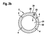
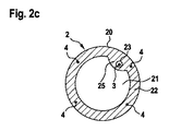
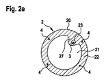
図2a〜eは、挿入スリーブ2のスリーブ壁22に空洞23を構成するための例示的な実施形態を示す。中空円筒形の挿入スリーブ2は、スリーブ壁22によって囲まれる中空内部空間21を含む。例えば、血管1で使用されるカメラ、センサー、または血液ポンプなどの、ここに示されない血管内システムまたは装置が、この内部空間21に提供される。空洞23は、スリーブ壁22の輪郭に構成され、その内部にガイドワイヤ3が延在する。空洞23は、挿入スリーブ2の長手方向または長手方向軸に平行な、挿入スリーブ2の全長に沿ってスリーブ壁22の内部に延在する。
2a-e show exemplary embodiments for forming the
図2a〜eはまた、スリーブ壁22に一体化され、挿入スリーブ2の湾曲を生じさせる、四つの制御ワイヤ4を示す。
2a-e also show four
図2a〜eは、スリーブ壁22でその中に延在するガイドワイヤ3を有する空洞23を構成するための様々なオプションを示す。図2aでは、空洞23は、空洞23の領域におけるスリーブ壁22の外輪郭および内輪郭を変形または変化させることなく、スリーブ壁22内で完全に構成される。
2a-e show various options for forming a
図2bでは、空洞23は、スリーブ壁22の外側上の隆起または突出部24に部分的に構成される。
In FIG. 2b, the
図2cでは、空洞23は、スリーブ壁22の内側上の突出部25に部分的に構成される。
In FIG. 2c, the
図2dでは、空洞23は、スリーブ壁22の外側上の突出部26に完全に構成される。
In FIG. 2d, the
図2eでは、空洞23は、スリーブ壁22の内側上の突出部27に完全に構成される。
In FIG. 2e, the
Claims (13)
The device according to any one of claims 1 to 12, wherein the end of the guide wire (3) freely projects beyond the distal end of the insertion sleeve (2).
Applications Claiming Priority (3)
| Application Number | Priority Date | Filing Date | Title |
|---|---|---|---|
| DE102018208564.1A DE102018208564A1 (en) | 2018-05-30 | 2018-05-30 | Controllable introducer sheath |
| DE102018208564.1 | 2018-05-30 | ||
| PCT/EP2019/064129 WO2019229206A1 (en) | 2018-05-30 | 2019-05-30 | Controllable insertion sleeve |
Publications (2)
| Publication Number | Publication Date |
|---|---|
| JP2021526068A true JP2021526068A (en) | 2021-09-30 |
| JPWO2019229206A5 JPWO2019229206A5 (en) | 2022-06-06 |
Family
ID=66770458
Family Applications (1)
| Application Number | Title | Priority Date | Filing Date |
|---|---|---|---|
| JP2021517521A Pending JP2021526068A (en) | 2018-05-30 | 2019-05-30 | Controllable insertion sleeve |
Country Status (4)
| Country | Link |
|---|---|
| US (1) | US20210205585A1 (en) |
| JP (1) | JP2021526068A (en) |
| DE (2) | DE102018208564A1 (en) |
| WO (1) | WO2019229206A1 (en) |
Families Citing this family (3)
| Publication number | Priority date | Publication date | Assignee | Title |
|---|---|---|---|---|
| CN113318324A (en) * | 2020-02-28 | 2021-08-31 | 巴德阿克塞斯系统股份有限公司 | Catheter with optical shape sensing capability |
| WO2021202589A1 (en) | 2020-03-30 | 2021-10-07 | Bard Access Systems, Inc. | Optical and electrical diagnostic systems and methods thereof |
| CN216985791U (en) | 2020-10-13 | 2022-07-19 | 巴德阿克塞斯系统股份有限公司 | Disinfection cover for optical fiber connector |
Citations (4)
| Publication number | Priority date | Publication date | Assignee | Title |
|---|---|---|---|---|
| JPS60187738U (en) * | 1984-05-24 | 1985-12-12 | 日本シヤ−ウツド株式会社 | Catheter assembly for vascular placement |
| JPH0928664A (en) * | 1995-07-14 | 1997-02-04 | Terumo Corp | Catheter tube |
| US6450948B1 (en) * | 1999-11-02 | 2002-09-17 | Vista Medical Technologies, Inc. | Deflecting tip for surgical cannula |
| EP3187222A1 (en) * | 2016-01-04 | 2017-07-05 | 510 Kardiac Devices, Inc. | Steerable introducer sheath assembly |
Family Cites Families (5)
| Publication number | Priority date | Publication date | Assignee | Title |
|---|---|---|---|---|
| EP1737335B1 (en) * | 2004-03-23 | 2013-05-15 | Boston Scientific Limited | In-vivo visualization system |
| US8747350B2 (en) * | 2006-09-11 | 2014-06-10 | Boston Scientific Scimed, Inc. | Steerable catheter with rapid exchange lumen |
| EP3682932B1 (en) * | 2008-01-14 | 2021-06-30 | Boston Scientific Scimed Inc. | Medical device |
| WO2013013248A2 (en) * | 2011-07-20 | 2013-01-24 | Retrovascular, Inc. | Energy facilitated composition delivery |
| WO2016009317A1 (en) * | 2014-07-13 | 2016-01-21 | Three Rivers Cardiovascular Systems Inc. | System and apparatus comprising a multisensor guidewire for use in interventional cardiology |
-
2018
- 2018-05-30 DE DE102018208564.1A patent/DE102018208564A1/en not_active Withdrawn
-
2019
- 2019-05-30 US US17/056,937 patent/US20210205585A1/en active Pending
- 2019-05-30 DE DE112019002757.3T patent/DE112019002757A5/en active Pending
- 2019-05-30 JP JP2021517521A patent/JP2021526068A/en active Pending
- 2019-05-30 WO PCT/EP2019/064129 patent/WO2019229206A1/en active Application Filing
Patent Citations (4)
| Publication number | Priority date | Publication date | Assignee | Title |
|---|---|---|---|---|
| JPS60187738U (en) * | 1984-05-24 | 1985-12-12 | 日本シヤ−ウツド株式会社 | Catheter assembly for vascular placement |
| JPH0928664A (en) * | 1995-07-14 | 1997-02-04 | Terumo Corp | Catheter tube |
| US6450948B1 (en) * | 1999-11-02 | 2002-09-17 | Vista Medical Technologies, Inc. | Deflecting tip for surgical cannula |
| EP3187222A1 (en) * | 2016-01-04 | 2017-07-05 | 510 Kardiac Devices, Inc. | Steerable introducer sheath assembly |
Also Published As
| Publication number | Publication date |
|---|---|
| DE102018208564A1 (en) | 2019-12-05 |
| US20210205585A1 (en) | 2021-07-08 |
| DE112019002757A5 (en) | 2021-02-18 |
| WO2019229206A1 (en) | 2019-12-05 |
Similar Documents
| Publication | Publication Date | Title |
|---|---|---|
| US20170028170A1 (en) | Guide catheter extension device and methods of use for cardiology procedures | |
| JP7104640B2 (en) | Self-fixing catheter and how to use it | |
| US4033331A (en) | Cardiac catheter and method of using same | |
| JP2021526068A (en) | Controllable insertion sleeve | |
| JP2019504746A (en) | Endovascular treatment site access | |
| JPH119696A (en) | Catheter system | |
| EP0528948A4 (en) | Steerable guide wire for tubular cannulation | |
| JP2009536048A (en) | Inserting means of shape imparting mechanism | |
| JP2007319668A (en) | Medical instrument including catheter having catheter stiffener, and method of using the same | |
| US20050228364A1 (en) | Tunneler device | |
| US11406802B2 (en) | Stent trimming devices and methods | |
| US20150119861A1 (en) | Guide wire | |
| JP2024500777A (en) | Flexible distal end section with rigid solid shaft | |
| JP4751553B2 (en) | Guiding aid | |
| SE1650363A1 (en) | A catheter assembly | |
| US9468743B2 (en) | Catheter for positioning a wire guide | |
| WO2018021179A1 (en) | Catheter | |
| WO2008008217A2 (en) | Vascular catheter apparatus and method | |
| JP2022050524A (en) | Method and device for sheathless transradial arterial catheterization | |
| EP3448489A1 (en) | Devices for assisting with advancement of catheters and related systems and methods | |
| WO2015015203A1 (en) | Medical guide wire | |
| US11253678B2 (en) | Multi-curvature catheter and medical device for surgery | |
| KR101906953B1 (en) | An end-angle-adjustable catheter device using left and right two guide lines and a method of using the same | |
| EP1897583B1 (en) | Guidewire structure including a medical guidewire | |
| KR102123122B1 (en) | Catheter device used to facilitate selection of branch arteries of the aorta and method of using the same |
Legal Events
| Date | Code | Title | Description |
|---|---|---|---|
| A521 | Request for written amendment filed |
Free format text: JAPANESE INTERMEDIATE CODE: A523 Effective date: 20220527 |
|
| A621 | Written request for application examination |
Free format text: JAPANESE INTERMEDIATE CODE: A621 Effective date: 20220527 |
|
| A131 | Notification of reasons for refusal |
Free format text: JAPANESE INTERMEDIATE CODE: A131 Effective date: 20230418 |
|
| A977 | Report on retrieval |
Free format text: JAPANESE INTERMEDIATE CODE: A971007 Effective date: 20230421 |
|
| A601 | Written request for extension of time |
Free format text: JAPANESE INTERMEDIATE CODE: A601 Effective date: 20230712 |
|
| A02 | Decision of refusal |
Free format text: JAPANESE INTERMEDIATE CODE: A02 Effective date: 20231114 |