JP2021523763A - Electroporation systems, methods, and equipment - Google Patents
Electroporation systems, methods, and equipment Download PDFInfo
- Publication number
- JP2021523763A JP2021523763A JP2020560398A JP2020560398A JP2021523763A JP 2021523763 A JP2021523763 A JP 2021523763A JP 2020560398 A JP2020560398 A JP 2020560398A JP 2020560398 A JP2020560398 A JP 2020560398A JP 2021523763 A JP2021523763 A JP 2021523763A
- Authority
- JP
- Japan
- Prior art keywords
- applicator
- electrode
- electrodes
- electroporation
- tip
- Prior art date
- Legal status (The legal status is an assumption and is not a legal conclusion. Google has not performed a legal analysis and makes no representation as to the accuracy of the status listed.)
- Pending
Links
- 238000004520 electroporation Methods 0.000 title claims abstract description 502
- 238000000034 method Methods 0.000 title claims abstract description 448
- 238000012377 drug delivery Methods 0.000 claims abstract description 275
- 238000002627 tracheal intubation Methods 0.000 claims abstract description 224
- 230000004044 response Effects 0.000 claims abstract description 41
- 206010028980 Neoplasm Diseases 0.000 claims description 360
- 239000003814 drug Substances 0.000 claims description 277
- 229940124597 therapeutic agent Drugs 0.000 claims description 266
- 238000003780 insertion Methods 0.000 claims description 253
- 230000037431 insertion Effects 0.000 claims description 253
- 230000003902 lesion Effects 0.000 claims description 242
- 238000002560 therapeutic procedure Methods 0.000 claims description 177
- 108090000765 processed proteins & peptides Proteins 0.000 claims description 152
- 102000004196 processed proteins & peptides Human genes 0.000 claims description 145
- 239000013612 plasmid Substances 0.000 claims description 144
- 229920001184 polypeptide Polymers 0.000 claims description 138
- 210000004027 cell Anatomy 0.000 claims description 112
- 108010065805 Interleukin-12 Proteins 0.000 claims description 109
- 102000013462 Interleukin-12 Human genes 0.000 claims description 109
- 229940076838 Immune checkpoint inhibitor Drugs 0.000 claims description 95
- 239000012274 immune-checkpoint protein inhibitor Substances 0.000 claims description 95
- 102000004127 Cytokines Human genes 0.000 claims description 85
- 108090000695 Cytokines Proteins 0.000 claims description 85
- 230000005684 electric field Effects 0.000 claims description 82
- 230000001225 therapeutic effect Effects 0.000 claims description 74
- 238000012384 transportation and delivery Methods 0.000 claims description 71
- 230000009278 visceral effect Effects 0.000 claims description 67
- 239000013604 expression vector Substances 0.000 claims description 60
- 239000000427 antigen Substances 0.000 claims description 53
- 230000002519 immonomodulatory effect Effects 0.000 claims description 51
- 238000012800 visualization Methods 0.000 claims description 48
- 229910001000 nickel titanium Inorganic materials 0.000 claims description 47
- HLXZNVUGXRDIFK-UHFFFAOYSA-N nickel titanium Chemical compound [Ti].[Ti].[Ti].[Ti].[Ti].[Ti].[Ti].[Ti].[Ti].[Ti].[Ti].[Ni].[Ni].[Ni].[Ni].[Ni].[Ni].[Ni].[Ni].[Ni].[Ni].[Ni].[Ni].[Ni].[Ni] HLXZNVUGXRDIFK-UHFFFAOYSA-N 0.000 claims description 47
- 108091007433 antigens Proteins 0.000 claims description 40
- 102000036639 antigens Human genes 0.000 claims description 40
- 230000000149 penetrating effect Effects 0.000 claims description 40
- 230000003308 immunostimulating effect Effects 0.000 claims description 38
- 210000004072 lung Anatomy 0.000 claims description 36
- 210000002784 stomach Anatomy 0.000 claims description 35
- 239000002671 adjuvant Substances 0.000 claims description 30
- 230000002068 genetic effect Effects 0.000 claims description 28
- -1 IL-15Rα Proteins 0.000 claims description 27
- 210000004881 tumor cell Anatomy 0.000 claims description 27
- 102100036170 C-X-C motif chemokine 9 Human genes 0.000 claims description 25
- 101000947172 Homo sapiens C-X-C motif chemokine 9 Proteins 0.000 claims description 25
- 210000000496 pancreas Anatomy 0.000 claims description 24
- 229940045513 CTLA4 antagonist Drugs 0.000 claims description 23
- 238000002591 computed tomography Methods 0.000 claims description 21
- 102000003812 Interleukin-15 Human genes 0.000 claims description 20
- 108090000172 Interleukin-15 Proteins 0.000 claims description 20
- 230000004927 fusion Effects 0.000 claims description 19
- 102000019034 Chemokines Human genes 0.000 claims description 16
- 108010012236 Chemokines Proteins 0.000 claims description 16
- 108010002352 Interleukin-1 Proteins 0.000 claims description 16
- 102000000589 Interleukin-1 Human genes 0.000 claims description 16
- 108010002350 Interleukin-2 Proteins 0.000 claims description 16
- 102000000588 Interleukin-2 Human genes 0.000 claims description 16
- 108090001012 Transforming Growth Factor beta Proteins 0.000 claims description 16
- 102000004887 Transforming Growth Factor beta Human genes 0.000 claims description 16
- 108090000174 Interleukin-10 Proteins 0.000 claims description 15
- 102000003814 Interleukin-10 Human genes 0.000 claims description 15
- 108060008682 Tumor Necrosis Factor Proteins 0.000 claims description 15
- 238000003860 storage Methods 0.000 claims description 15
- 108010065637 Interleukin-23 Proteins 0.000 claims description 14
- 108090000978 Interleukin-4 Proteins 0.000 claims description 14
- 108010002616 Interleukin-5 Proteins 0.000 claims description 14
- 108010002586 Interleukin-7 Proteins 0.000 claims description 14
- 108010002335 Interleukin-9 Proteins 0.000 claims description 14
- 102000000852 Tumor Necrosis Factor-alpha Human genes 0.000 claims description 14
- 230000008859 change Effects 0.000 claims description 14
- 108010074108 interleukin-21 Proteins 0.000 claims description 14
- 229960002621 pembrolizumab Drugs 0.000 claims description 14
- 238000001890 transfection Methods 0.000 claims description 14
- 206010073071 hepatocellular carcinoma Diseases 0.000 claims description 13
- 229960003301 nivolumab Drugs 0.000 claims description 13
- 210000004185 liver Anatomy 0.000 claims description 11
- 108010029697 CD40 Ligand Proteins 0.000 claims description 10
- 102100032937 CD40 ligand Human genes 0.000 claims description 10
- 230000036760 body temperature Effects 0.000 claims description 10
- 239000003607 modifier Substances 0.000 claims description 9
- 238000002271 resection Methods 0.000 claims description 8
- 230000004043 responsiveness Effects 0.000 claims description 8
- 101000801234 Homo sapiens Tumor necrosis factor receptor superfamily member 18 Proteins 0.000 claims description 7
- 101000679851 Homo sapiens Tumor necrosis factor receptor superfamily member 4 Proteins 0.000 claims description 7
- 101000851370 Homo sapiens Tumor necrosis factor receptor superfamily member 9 Proteins 0.000 claims description 7
- 102100033728 Tumor necrosis factor receptor superfamily member 18 Human genes 0.000 claims description 7
- 102100022153 Tumor necrosis factor receptor superfamily member 4 Human genes 0.000 claims description 7
- 102100036856 Tumor necrosis factor receptor superfamily member 9 Human genes 0.000 claims description 7
- 230000001154 acute effect Effects 0.000 claims description 7
- 238000002266 amputation Methods 0.000 claims description 7
- 230000004663 cell proliferation Effects 0.000 claims description 7
- 231100000844 hepatocellular carcinoma Toxicity 0.000 claims description 6
- 210000003238 esophagus Anatomy 0.000 claims description 5
- 230000003213 activating effect Effects 0.000 claims description 3
- 229950010773 pidilizumab Drugs 0.000 claims description 3
- 230000001105 regulatory effect Effects 0.000 claims description 3
- 229940121697 CD27 agonist Drugs 0.000 claims description 2
- 238000011282 treatment Methods 0.000 abstract description 100
- 210000001519 tissue Anatomy 0.000 description 194
- 201000011510 cancer Diseases 0.000 description 52
- 238000003825 pressing Methods 0.000 description 51
- 230000006870 function Effects 0.000 description 39
- 230000015654 memory Effects 0.000 description 36
- 238000000157 electrochemical-induced impedance spectroscopy Methods 0.000 description 32
- 150000007523 nucleic acids Chemical class 0.000 description 31
- 239000003795 chemical substances by application Substances 0.000 description 28
- 108090000623 proteins and genes Proteins 0.000 description 28
- 108020004414 DNA Proteins 0.000 description 27
- 241000699670 Mus sp. Species 0.000 description 27
- 230000014509 gene expression Effects 0.000 description 27
- 108020004707 nucleic acids Proteins 0.000 description 25
- 102000039446 nucleic acids Human genes 0.000 description 25
- 238000001514 detection method Methods 0.000 description 22
- 108020004684 Internal Ribosome Entry Sites Proteins 0.000 description 20
- 230000008901 benefit Effects 0.000 description 20
- 102000004169 proteins and genes Human genes 0.000 description 20
- 230000002601 intratumoral effect Effects 0.000 description 18
- 238000012545 processing Methods 0.000 description 18
- 238000013459 approach Methods 0.000 description 17
- 239000013598 vector Substances 0.000 description 16
- 238000005259 measurement Methods 0.000 description 15
- 230000008569 process Effects 0.000 description 14
- 239000000126 substance Substances 0.000 description 14
- 230000000139 costimulatory effect Effects 0.000 description 13
- 230000000694 effects Effects 0.000 description 13
- 239000000556 agonist Substances 0.000 description 12
- 201000010099 disease Diseases 0.000 description 12
- 208000037265 diseases, disorders, signs and symptoms Diseases 0.000 description 12
- 238000010248 power generation Methods 0.000 description 12
- 102100039498 Cytotoxic T-lymphocyte protein 4 Human genes 0.000 description 11
- 239000003990 capacitor Substances 0.000 description 11
- 238000001839 endoscopy Methods 0.000 description 11
- 238000012360 testing method Methods 0.000 description 11
- 108010021064 CTLA-4 Antigen Proteins 0.000 description 10
- 102000013264 Interleukin-23 Human genes 0.000 description 10
- 229940079593 drug Drugs 0.000 description 10
- 239000012634 fragment Substances 0.000 description 10
- 238000003384 imaging method Methods 0.000 description 10
- 238000002347 injection Methods 0.000 description 10
- 239000007924 injection Substances 0.000 description 10
- 230000007246 mechanism Effects 0.000 description 10
- 238000002965 ELISA Methods 0.000 description 9
- 241000699666 Mus <mouse, genus> Species 0.000 description 9
- 210000001744 T-lymphocyte Anatomy 0.000 description 9
- 241000219793 Trifolium Species 0.000 description 9
- 239000005557 antagonist Substances 0.000 description 9
- 210000000170 cell membrane Anatomy 0.000 description 9
- 238000002648 combination therapy Methods 0.000 description 9
- 208000014018 liver neoplasm Diseases 0.000 description 9
- 239000013600 plasmid vector Substances 0.000 description 9
- 206010027476 Metastases Diseases 0.000 description 8
- PXHVJJICTQNCMI-UHFFFAOYSA-N Nickel Chemical compound [Ni] PXHVJJICTQNCMI-UHFFFAOYSA-N 0.000 description 8
- 206010061902 Pancreatic neoplasm Diseases 0.000 description 8
- 241000700605 Viruses Species 0.000 description 8
- 238000004458 analytical method Methods 0.000 description 8
- 230000005284 excitation Effects 0.000 description 8
- 230000028993 immune response Effects 0.000 description 8
- 239000003446 ligand Substances 0.000 description 8
- 230000003211 malignant effect Effects 0.000 description 8
- 201000001441 melanoma Diseases 0.000 description 8
- 239000011148 porous material Substances 0.000 description 8
- 230000005855 radiation Effects 0.000 description 8
- 230000004614 tumor growth Effects 0.000 description 8
- 201000009030 Carcinoma Diseases 0.000 description 7
- 102000004190 Enzymes Human genes 0.000 description 7
- 108090000790 Enzymes Proteins 0.000 description 7
- 108010021625 Immunoglobulin Fragments Proteins 0.000 description 7
- 102000008394 Immunoglobulin Fragments Human genes 0.000 description 7
- 239000008186 active pharmaceutical agent Substances 0.000 description 7
- 210000004556 brain Anatomy 0.000 description 7
- 239000000872 buffer Substances 0.000 description 7
- 230000006378 damage Effects 0.000 description 7
- 229940088598 enzyme Drugs 0.000 description 7
- 230000002496 gastric effect Effects 0.000 description 7
- 239000003112 inhibitor Substances 0.000 description 7
- 201000002528 pancreatic cancer Diseases 0.000 description 7
- 150000003384 small molecules Chemical group 0.000 description 7
- 238000001356 surgical procedure Methods 0.000 description 7
- 206010039491 Sarcoma Diseases 0.000 description 6
- 239000002246 antineoplastic agent Substances 0.000 description 6
- 238000003776 cleavage reaction Methods 0.000 description 6
- 230000005611 electricity Effects 0.000 description 6
- 239000013613 expression plasmid Substances 0.000 description 6
- 108020001507 fusion proteins Proteins 0.000 description 6
- 102000037865 fusion proteins Human genes 0.000 description 6
- 238000009169 immunotherapy Methods 0.000 description 6
- 238000007913 intrathecal administration Methods 0.000 description 6
- 238000001990 intravenous administration Methods 0.000 description 6
- 201000007270 liver cancer Diseases 0.000 description 6
- 230000033001 locomotion Effects 0.000 description 6
- 208000015486 malignant pancreatic neoplasm Diseases 0.000 description 6
- 210000004379 membrane Anatomy 0.000 description 6
- 239000012528 membrane Substances 0.000 description 6
- 230000002503 metabolic effect Effects 0.000 description 6
- 230000009401 metastasis Effects 0.000 description 6
- 208000008443 pancreatic carcinoma Diseases 0.000 description 6
- 230000036961 partial effect Effects 0.000 description 6
- 239000000546 pharmaceutical excipient Substances 0.000 description 6
- 230000007017 scission Effects 0.000 description 6
- 210000003491 skin Anatomy 0.000 description 6
- 238000007920 subcutaneous administration Methods 0.000 description 6
- 230000000699 topical effect Effects 0.000 description 6
- 108010006654 Bleomycin Proteins 0.000 description 5
- 206010006187 Breast cancer Diseases 0.000 description 5
- 102100027207 CD27 antigen Human genes 0.000 description 5
- 101000914511 Homo sapiens CD27 antigen Proteins 0.000 description 5
- 108010074338 Lymphokines Proteins 0.000 description 5
- 102000008072 Lymphokines Human genes 0.000 description 5
- 208000003721 Triple Negative Breast Neoplasms Diseases 0.000 description 5
- 229960001561 bleomycin Drugs 0.000 description 5
- OYVAGSVQBOHSSS-UAPAGMARSA-O bleomycin A2 Chemical compound N([C@H](C(=O)N[C@H](C)[C@@H](O)[C@H](C)C(=O)N[C@@H]([C@H](O)C)C(=O)NCCC=1SC=C(N=1)C=1SC=C(N=1)C(=O)NCCC[S+](C)C)[C@@H](O[C@H]1[C@H]([C@@H](O)[C@H](O)[C@H](CO)O1)O[C@@H]1[C@H]([C@@H](OC(N)=O)[C@H](O)[C@@H](CO)O1)O)C=1N=CNC=1)C(=O)C1=NC([C@H](CC(N)=O)NC[C@H](N)C(N)=O)=NC(N)=C1C OYVAGSVQBOHSSS-UAPAGMARSA-O 0.000 description 5
- 238000013276 bronchoscopy Methods 0.000 description 5
- 229940127089 cytotoxic agent Drugs 0.000 description 5
- 230000007423 decrease Effects 0.000 description 5
- 230000010102 embolization Effects 0.000 description 5
- 238000000684 flow cytometry Methods 0.000 description 5
- 238000001727 in vivo Methods 0.000 description 5
- 238000007918 intramuscular administration Methods 0.000 description 5
- 230000004048 modification Effects 0.000 description 5
- 238000012986 modification Methods 0.000 description 5
- 230000002093 peripheral effect Effects 0.000 description 5
- 230000009467 reduction Effects 0.000 description 5
- 230000002829 reductive effect Effects 0.000 description 5
- 210000002345 respiratory system Anatomy 0.000 description 5
- 230000002441 reversible effect Effects 0.000 description 5
- 230000009885 systemic effect Effects 0.000 description 5
- 208000022679 triple-negative breast carcinoma Diseases 0.000 description 5
- 238000002604 ultrasonography Methods 0.000 description 5
- 210000003708 urethra Anatomy 0.000 description 5
- 108091032973 (ribonucleotides)n+m Proteins 0.000 description 4
- 208000026310 Breast neoplasm Diseases 0.000 description 4
- AOJJSUZBOXZQNB-TZSSRYMLSA-N Doxorubicin Chemical compound O([C@H]1C[C@@](O)(CC=2C(O)=C3C(=O)C=4C=CC=C(C=4C(=O)C3=C(O)C=21)OC)C(=O)CO)[C@H]1C[C@H](N)[C@H](O)[C@H](C)O1 AOJJSUZBOXZQNB-TZSSRYMLSA-N 0.000 description 4
- 102100020715 Fms-related tyrosine kinase 3 ligand protein Human genes 0.000 description 4
- 101710162577 Fms-related tyrosine kinase 3 ligand protein Proteins 0.000 description 4
- 102100039620 Granulocyte-macrophage colony-stimulating factor Human genes 0.000 description 4
- 108060003951 Immunoglobulin Proteins 0.000 description 4
- 102000015696 Interleukins Human genes 0.000 description 4
- 108010063738 Interleukins Proteins 0.000 description 4
- 206010027480 Metastatic malignant melanoma Diseases 0.000 description 4
- 230000003044 adaptive effect Effects 0.000 description 4
- 210000000612 antigen-presenting cell Anatomy 0.000 description 4
- 210000004204 blood vessel Anatomy 0.000 description 4
- 239000000969 carrier Substances 0.000 description 4
- 239000011248 coating agent Substances 0.000 description 4
- 230000001276 controlling effect Effects 0.000 description 4
- 238000010586 diagram Methods 0.000 description 4
- 238000004146 energy storage Methods 0.000 description 4
- 210000001035 gastrointestinal tract Anatomy 0.000 description 4
- 238000001415 gene therapy Methods 0.000 description 4
- 102000018358 immunoglobulin Human genes 0.000 description 4
- 239000002955 immunomodulating agent Substances 0.000 description 4
- 229940121354 immunomodulator Drugs 0.000 description 4
- 230000001976 improved effect Effects 0.000 description 4
- 230000002401 inhibitory effect Effects 0.000 description 4
- 238000011081 inoculation Methods 0.000 description 4
- 230000003834 intracellular effect Effects 0.000 description 4
- 210000001165 lymph node Anatomy 0.000 description 4
- 208000021039 metastatic melanoma Diseases 0.000 description 4
- 206010061289 metastatic neoplasm Diseases 0.000 description 4
- 229910052759 nickel Inorganic materials 0.000 description 4
- 210000001331 nose Anatomy 0.000 description 4
- 229920000642 polymer Polymers 0.000 description 4
- 239000000047 product Substances 0.000 description 4
- 239000010935 stainless steel Substances 0.000 description 4
- 229910001220 stainless steel Inorganic materials 0.000 description 4
- 230000004083 survival effect Effects 0.000 description 4
- 238000002626 targeted therapy Methods 0.000 description 4
- 210000003813 thumb Anatomy 0.000 description 4
- 230000009466 transformation Effects 0.000 description 4
- 239000013638 trimer Substances 0.000 description 4
- 230000002485 urinary effect Effects 0.000 description 4
- 230000003612 virological effect Effects 0.000 description 4
- MLDQJTXFUGDVEO-UHFFFAOYSA-N BAY-43-9006 Chemical compound C1=NC(C(=O)NC)=CC(OC=2C=CC(NC(=O)NC=3C=C(C(Cl)=CC=3)C(F)(F)F)=CC=2)=C1 MLDQJTXFUGDVEO-UHFFFAOYSA-N 0.000 description 3
- 101150013553 CD40 gene Proteins 0.000 description 3
- 108010017213 Granulocyte-Macrophage Colony-Stimulating Factor Proteins 0.000 description 3
- 101000914484 Homo sapiens T-lymphocyte activation antigen CD80 Proteins 0.000 description 3
- 239000005511 L01XE05 - Sorafenib Substances 0.000 description 3
- 102100028389 Melanoma antigen recognized by T-cells 1 Human genes 0.000 description 3
- 206010027458 Metastases to lung Diseases 0.000 description 3
- NWIBSHFKIJFRCO-WUDYKRTCSA-N Mytomycin Chemical compound C1N2C(C(C(C)=C(N)C3=O)=O)=C3[C@@H](COC(N)=O)[C@@]2(OC)[C@@H]2[C@H]1N2 NWIBSHFKIJFRCO-WUDYKRTCSA-N 0.000 description 3
- 108091028043 Nucleic acid sequence Proteins 0.000 description 3
- 108010003723 Single-Domain Antibodies Proteins 0.000 description 3
- 208000000453 Skin Neoplasms Diseases 0.000 description 3
- 108091008874 T cell receptors Proteins 0.000 description 3
- 102000016266 T-Cell Antigen Receptors Human genes 0.000 description 3
- 102100027222 T-lymphocyte activation antigen CD80 Human genes 0.000 description 3
- 102100040245 Tumor necrosis factor receptor superfamily member 5 Human genes 0.000 description 3
- 210000001015 abdomen Anatomy 0.000 description 3
- 230000009471 action Effects 0.000 description 3
- 238000001467 acupuncture Methods 0.000 description 3
- IFLVGRRVGPXYON-UHFFFAOYSA-N adci Chemical compound C12=CC=CC=C2C2(C(=O)N)C3=CC=CC=C3CC1N2 IFLVGRRVGPXYON-UHFFFAOYSA-N 0.000 description 3
- 208000009956 adenocarcinoma Diseases 0.000 description 3
- 210000003484 anatomy Anatomy 0.000 description 3
- 230000000259 anti-tumor effect Effects 0.000 description 3
- 238000009175 antibody therapy Methods 0.000 description 3
- 210000000988 bone and bone Anatomy 0.000 description 3
- 210000000621 bronchi Anatomy 0.000 description 3
- 208000035269 cancer or benign tumor Diseases 0.000 description 3
- 230000010261 cell growth Effects 0.000 description 3
- 210000004720 cerebrum Anatomy 0.000 description 3
- 238000000576 coating method Methods 0.000 description 3
- 238000004891 communication Methods 0.000 description 3
- 239000004020 conductor Substances 0.000 description 3
- 238000005520 cutting process Methods 0.000 description 3
- 238000013461 design Methods 0.000 description 3
- 238000009558 endoscopic ultrasound Methods 0.000 description 3
- 238000005516 engineering process Methods 0.000 description 3
- 210000003743 erythrocyte Anatomy 0.000 description 3
- 238000000605 extraction Methods 0.000 description 3
- 239000012530 fluid Substances 0.000 description 3
- 238000000799 fluorescence microscopy Methods 0.000 description 3
- 230000007274 generation of a signal involved in cell-cell signaling Effects 0.000 description 3
- 208000005017 glioblastoma Diseases 0.000 description 3
- PCHJSUWPFVWCPO-UHFFFAOYSA-N gold Chemical compound [Au] PCHJSUWPFVWCPO-UHFFFAOYSA-N 0.000 description 3
- 239000010931 gold Substances 0.000 description 3
- 229910052737 gold Inorganic materials 0.000 description 3
- 230000012010 growth Effects 0.000 description 3
- 206010020718 hyperplasia Diseases 0.000 description 3
- 230000001506 immunosuppresive effect Effects 0.000 description 3
- 230000005764 inhibitory process Effects 0.000 description 3
- 238000007917 intracranial administration Methods 0.000 description 3
- 238000002357 laparoscopic surgery Methods 0.000 description 3
- 230000000670 limiting effect Effects 0.000 description 3
- 150000002632 lipids Chemical class 0.000 description 3
- 239000000463 material Substances 0.000 description 3
- 238000012544 monitoring process Methods 0.000 description 3
- 210000003205 muscle Anatomy 0.000 description 3
- 238000011275 oncology therapy Methods 0.000 description 3
- 210000003200 peritoneal cavity Anatomy 0.000 description 3
- 230000035699 permeability Effects 0.000 description 3
- 230000003389 potentiating effect Effects 0.000 description 3
- 239000007787 solid Substances 0.000 description 3
- 229960003787 sorafenib Drugs 0.000 description 3
- 238000010186 staining Methods 0.000 description 3
- 230000000638 stimulation Effects 0.000 description 3
- 239000000758 substrate Substances 0.000 description 3
- 230000001629 suppression Effects 0.000 description 3
- 210000003437 trachea Anatomy 0.000 description 3
- 238000012546 transfer Methods 0.000 description 3
- 230000002792 vascular Effects 0.000 description 3
- 239000013603 viral vector Substances 0.000 description 3
- XLYOFNOQVPJJNP-UHFFFAOYSA-N water Substances O XLYOFNOQVPJJNP-UHFFFAOYSA-N 0.000 description 3
- KBPLFHHGFOOTCA-UHFFFAOYSA-N 1-Octanol Chemical compound CCCCCCCCO KBPLFHHGFOOTCA-UHFFFAOYSA-N 0.000 description 2
- IJGRMHOSHXDMSA-UHFFFAOYSA-N Atomic nitrogen Chemical compound N#N IJGRMHOSHXDMSA-UHFFFAOYSA-N 0.000 description 2
- 102100021663 Baculoviral IAP repeat-containing protein 5 Human genes 0.000 description 2
- 206010061692 Benign muscle neoplasm Diseases 0.000 description 2
- 102000053642 Catalytic RNA Human genes 0.000 description 2
- 108090000994 Catalytic RNA Proteins 0.000 description 2
- 102000000844 Cell Surface Receptors Human genes 0.000 description 2
- 108010001857 Cell Surface Receptors Proteins 0.000 description 2
- 206010008342 Cervix carcinoma Diseases 0.000 description 2
- 102000004626 Colony-Stimulating Factor Receptors Human genes 0.000 description 2
- 108010003384 Colony-Stimulating Factor Receptors Proteins 0.000 description 2
- KCXVZYZYPLLWCC-UHFFFAOYSA-N EDTA Chemical compound OC(=O)CN(CC(O)=O)CCN(CC(O)=O)CC(O)=O KCXVZYZYPLLWCC-UHFFFAOYSA-N 0.000 description 2
- 241000713813 Gibbon ape leukemia virus Species 0.000 description 2
- 206010018338 Glioma Diseases 0.000 description 2
- 230000005355 Hall effect Effects 0.000 description 2
- 241000713858 Harvey murine sarcoma virus Species 0.000 description 2
- 102000002812 Heat-Shock Proteins Human genes 0.000 description 2
- 108010004889 Heat-Shock Proteins Proteins 0.000 description 2
- 206010019695 Hepatic neoplasm Diseases 0.000 description 2
- 241000282412 Homo Species 0.000 description 2
- 101000793651 Homo sapiens Calreticulin Proteins 0.000 description 2
- 101000578784 Homo sapiens Melanoma antigen recognized by T-cells 1 Proteins 0.000 description 2
- 102000037982 Immune checkpoint proteins Human genes 0.000 description 2
- 108091008036 Immune checkpoint proteins Proteins 0.000 description 2
- 206010062016 Immunosuppression Diseases 0.000 description 2
- 206010025323 Lymphomas Diseases 0.000 description 2
- 102100035133 Lysosome-associated membrane glycoprotein 1 Human genes 0.000 description 2
- 241000124008 Mammalia Species 0.000 description 2
- 241001529936 Murinae Species 0.000 description 2
- 201000004458 Myoma Diseases 0.000 description 2
- 241000209094 Oryza Species 0.000 description 2
- 235000007164 Oryza sativa Nutrition 0.000 description 2
- 108010058846 Ovalbumin Proteins 0.000 description 2
- 229940124060 PD-1 antagonist Drugs 0.000 description 2
- 229930012538 Paclitaxel Natural products 0.000 description 2
- 208000007913 Pituitary Neoplasms Diseases 0.000 description 2
- 206010035226 Plasma cell myeloma Diseases 0.000 description 2
- 108020004459 Small interfering RNA Proteins 0.000 description 2
- FAPWRFPIFSIZLT-UHFFFAOYSA-M Sodium chloride Chemical compound [Na+].[Cl-] FAPWRFPIFSIZLT-UHFFFAOYSA-M 0.000 description 2
- 108010002687 Survivin Proteins 0.000 description 2
- RTAQQCXQSZGOHL-UHFFFAOYSA-N Titanium Chemical compound [Ti] RTAQQCXQSZGOHL-UHFFFAOYSA-N 0.000 description 2
- 108700019146 Transgenes Proteins 0.000 description 2
- 208000006105 Uterine Cervical Neoplasms Diseases 0.000 description 2
- VWQVUPCCIRVNHF-OUBTZVSYSA-N Yttrium-90 Chemical compound [90Y] VWQVUPCCIRVNHF-OUBTZVSYSA-N 0.000 description 2
- 150000001413 amino acids Chemical group 0.000 description 2
- 230000001772 anti-angiogenic effect Effects 0.000 description 2
- VSRXQHXAPYXROS-UHFFFAOYSA-N azanide;cyclobutane-1,1-dicarboxylic acid;platinum(2+) Chemical compound [NH2-].[NH2-].[Pt+2].OC(=O)C1(C(O)=O)CCC1 VSRXQHXAPYXROS-UHFFFAOYSA-N 0.000 description 2
- 230000001580 bacterial effect Effects 0.000 description 2
- 230000004888 barrier function Effects 0.000 description 2
- WPYMKLBDIGXBTP-UHFFFAOYSA-N benzoic acid Chemical compound OC(=O)C1=CC=CC=C1 WPYMKLBDIGXBTP-UHFFFAOYSA-N 0.000 description 2
- 210000000013 bile duct Anatomy 0.000 description 2
- 230000004071 biological effect Effects 0.000 description 2
- 210000000481 breast Anatomy 0.000 description 2
- 229960004562 carboplatin Drugs 0.000 description 2
- 210000001715 carotid artery Anatomy 0.000 description 2
- 239000006285 cell suspension Substances 0.000 description 2
- 201000010881 cervical cancer Diseases 0.000 description 2
- 238000012512 characterization method Methods 0.000 description 2
- 238000002512 chemotherapy Methods 0.000 description 2
- 208000006990 cholangiocarcinoma Diseases 0.000 description 2
- DQLATGHUWYMOKM-UHFFFAOYSA-L cisplatin Chemical compound N[Pt](N)(Cl)Cl DQLATGHUWYMOKM-UHFFFAOYSA-L 0.000 description 2
- 229960004316 cisplatin Drugs 0.000 description 2
- 238000002052 colonoscopy Methods 0.000 description 2
- 230000000295 complement effect Effects 0.000 description 2
- 150000001875 compounds Chemical class 0.000 description 2
- 238000007408 cone-beam computed tomography Methods 0.000 description 2
- 230000003111 delayed effect Effects 0.000 description 2
- 238000011161 development Methods 0.000 description 2
- 230000018109 developmental process Effects 0.000 description 2
- 238000010891 electric arc Methods 0.000 description 2
- 208000037828 epithelial carcinoma Diseases 0.000 description 2
- 239000000284 extract Substances 0.000 description 2
- 230000003325 follicular Effects 0.000 description 2
- 230000008014 freezing Effects 0.000 description 2
- 238000007710 freezing Methods 0.000 description 2
- 201000011066 hemangioma Diseases 0.000 description 2
- 102000053922 human CALR Human genes 0.000 description 2
- 238000005286 illumination Methods 0.000 description 2
- 210000002865 immune cell Anatomy 0.000 description 2
- 229940126546 immune checkpoint molecule Drugs 0.000 description 2
- 239000000367 immunologic factor Substances 0.000 description 2
- 229960001438 immunostimulant agent Drugs 0.000 description 2
- 239000003022 immunostimulating agent Substances 0.000 description 2
- 230000006872 improvement Effects 0.000 description 2
- 238000000338 in vitro Methods 0.000 description 2
- 206010022000 influenza Diseases 0.000 description 2
- 230000002427 irreversible effect Effects 0.000 description 2
- WABPQHHGFIMREM-UHFFFAOYSA-N lead(0) Chemical compound [Pb] WABPQHHGFIMREM-UHFFFAOYSA-N 0.000 description 2
- 230000003908 liver function Effects 0.000 description 2
- 239000000314 lubricant Substances 0.000 description 2
- 239000006166 lysate Substances 0.000 description 2
- 239000012139 lysis buffer Substances 0.000 description 2
- 210000002540 macrophage Anatomy 0.000 description 2
- 230000036210 malignancy Effects 0.000 description 2
- 238000004519 manufacturing process Methods 0.000 description 2
- 230000001404 mediated effect Effects 0.000 description 2
- 230000001394 metastastic effect Effects 0.000 description 2
- 208000037819 metastatic cancer Diseases 0.000 description 2
- 208000011575 metastatic malignant neoplasm Diseases 0.000 description 2
- 108091070501 miRNA Proteins 0.000 description 2
- 239000002679 microRNA Substances 0.000 description 2
- 229960004857 mitomycin Drugs 0.000 description 2
- 239000012811 non-conductive material Substances 0.000 description 2
- 239000003921 oil Substances 0.000 description 2
- 210000000056 organ Anatomy 0.000 description 2
- 229960001592 paclitaxel Drugs 0.000 description 2
- 239000002245 particle Substances 0.000 description 2
- 230000035515 penetration Effects 0.000 description 2
- 210000003800 pharynx Anatomy 0.000 description 2
- 239000002504 physiological saline solution Substances 0.000 description 2
- 239000004033 plastic Substances 0.000 description 2
- 229920003023 plastic Polymers 0.000 description 2
- 238000002360 preparation method Methods 0.000 description 2
- 102000005962 receptors Human genes 0.000 description 2
- 108020003175 receptors Proteins 0.000 description 2
- 108010054624 red fluorescent protein Proteins 0.000 description 2
- 210000003289 regulatory T cell Anatomy 0.000 description 2
- 108091092562 ribozyme Proteins 0.000 description 2
- 235000009566 rice Nutrition 0.000 description 2
- 150000003839 salts Chemical class 0.000 description 2
- 238000009097 single-agent therapy Methods 0.000 description 2
- 210000000813 small intestine Anatomy 0.000 description 2
- 210000004872 soft tissue Anatomy 0.000 description 2
- 210000003718 sphenoid sinus Anatomy 0.000 description 2
- 230000008093 supporting effect Effects 0.000 description 2
- 239000000725 suspension Substances 0.000 description 2
- 238000012385 systemic delivery Methods 0.000 description 2
- RCINICONZNJXQF-MZXODVADSA-N taxol Chemical compound O([C@@H]1[C@@]2(C[C@@H](C(C)=C(C2(C)C)[C@H](C([C@]2(C)[C@@H](O)C[C@H]3OC[C@]3([C@H]21)OC(C)=O)=O)OC(=O)C)OC(=O)[C@H](O)[C@@H](NC(=O)C=1C=CC=CC=1)C=1C=CC=CC=1)O)C(=O)C1=CC=CC=C1 RCINICONZNJXQF-MZXODVADSA-N 0.000 description 2
- 239000010936 titanium Substances 0.000 description 2
- 229910052719 titanium Inorganic materials 0.000 description 2
- 238000003151 transfection method Methods 0.000 description 2
- 238000002054 transplantation Methods 0.000 description 2
- 230000000472 traumatic effect Effects 0.000 description 2
- 210000003171 tumor-infiltrating lymphocyte Anatomy 0.000 description 2
- 241001430294 unidentified retrovirus Species 0.000 description 2
- 210000002385 vertebral artery Anatomy 0.000 description 2
- 238000001262 western blot Methods 0.000 description 2
- ASWBNKHCZGQVJV-UHFFFAOYSA-N (3-hexadecanoyloxy-2-hydroxypropyl) 2-(trimethylazaniumyl)ethyl phosphate Chemical compound CCCCCCCCCCCCCCCC(=O)OCC(O)COP([O-])(=O)OCC[N+](C)(C)C ASWBNKHCZGQVJV-UHFFFAOYSA-N 0.000 description 1
- SSOORFWOBGFTHL-OTEJMHTDSA-N (4S)-5-[[(2S)-1-[[(2S)-1-[[(2S)-1-[[(2S)-1-[[(2S)-1-[[(2S)-1-[[(2S)-1-[[(2S)-6-amino-1-[[(2S)-1-[[(2S)-1-[[(2S)-1-[[(2S)-1-[[2-[(2S)-2-[[(2S)-1-[[(2S)-1-[[(2S)-1-[[(2S)-1-[[(2S)-1-[[(2S)-1-[[(2S)-6-amino-1-[[(2S)-1-[[(2S)-1-[[(2S,3S)-1-[[(2S)-1-[[(2S)-1-[[(2S)-6-amino-1-[[(2S)-1-[[(2S)-1-[[(2S)-1-[[(2S)-1-[[(2S)-1-[[(2S)-5-amino-1-[[(2S)-1-[[(2S)-1-[[(2S)-6-amino-1-[[(2S)-6-amino-1-[[(2S)-1-[[(2S)-1-[[(2S)-5-amino-1-[[(2S)-5-carbamimidamido-1-[[(2S)-5-carbamimidamido-1-[[(1S)-4-carbamimidamido-1-carboxybutyl]amino]-1-oxopentan-2-yl]amino]-1-oxopentan-2-yl]amino]-1,5-dioxopentan-2-yl]amino]-5-carbamimidamido-1-oxopentan-2-yl]amino]-5-carbamimidamido-1-oxopentan-2-yl]amino]-1-oxohexan-2-yl]amino]-1-oxohexan-2-yl]amino]-5-carbamimidamido-1-oxopentan-2-yl]amino]-4-methyl-1-oxopentan-2-yl]amino]-1,5-dioxopentan-2-yl]amino]-4-methyl-1-oxopentan-2-yl]amino]-3-hydroxy-1-oxopropan-2-yl]amino]-3-hydroxy-1-oxopropan-2-yl]amino]-3-hydroxy-1-oxopropan-2-yl]amino]-1-oxopropan-2-yl]amino]-1-oxohexan-2-yl]amino]-3-hydroxy-1-oxopropan-2-yl]amino]-1-oxo-3-phenylpropan-2-yl]amino]-3-methyl-1-oxopentan-2-yl]amino]-3-methyl-1-oxobutan-2-yl]amino]-5-carbamimidamido-1-oxopentan-2-yl]amino]-1-oxohexan-2-yl]amino]-3-methyl-1-oxobutan-2-yl]amino]-5-carbamimidamido-1-oxopentan-2-yl]amino]-3-methyl-1-oxobutan-2-yl]amino]-4-methyl-1-oxopentan-2-yl]amino]-1-oxopropan-2-yl]amino]-5-carbamimidamido-1-oxopentan-2-yl]carbamoyl]pyrrolidin-1-yl]-2-oxoethyl]amino]-3-(1H-indol-3-yl)-1-oxopropan-2-yl]amino]-4-methyl-1-oxopentan-2-yl]amino]-1-oxo-3-phenylpropan-2-yl]amino]-5-carbamimidamido-1-oxopentan-2-yl]amino]-1-oxohexan-2-yl]amino]-3-methyl-1-oxobutan-2-yl]amino]-5-carbamimidamido-1-oxopentan-2-yl]amino]-4-methyl-1-oxopentan-2-yl]amino]-1-oxo-3-phenylpropan-2-yl]amino]-3-(1H-imidazol-4-yl)-1-oxopropan-2-yl]amino]-3-methyl-1-oxobutan-2-yl]amino]-4-methyl-1-oxopentan-2-yl]amino]-4-[[(2S)-2-[[(2S)-2-[[(2S)-2,6-diaminohexanoyl]amino]-3-methylbutanoyl]amino]propanoyl]amino]-5-oxopentanoic acid Chemical compound CC[C@H](C)[C@H](NC(=O)[C@@H](NC(=O)[C@H](CCCNC(N)=N)NC(=O)[C@H](CCCCN)NC(=O)[C@@H](NC(=O)[C@H](CCCNC(N)=N)NC(=O)[C@@H](NC(=O)[C@H](CC(C)C)NC(=O)[C@H](C)NC(=O)[C@H](CCCNC(N)=N)NC(=O)[C@@H]1CCCN1C(=O)CNC(=O)[C@H](Cc1c[nH]c2ccccc12)NC(=O)[C@H](CC(C)C)NC(=O)[C@H](Cc1ccccc1)NC(=O)[C@H](CCCNC(N)=N)NC(=O)[C@H](CCCCN)NC(=O)[C@@H](NC(=O)[C@H](CCCNC(N)=N)NC(=O)[C@H](CC(C)C)NC(=O)[C@H](Cc1ccccc1)NC(=O)[C@H](Cc1c[nH]cn1)NC(=O)[C@@H](NC(=O)[C@H](CC(C)C)NC(=O)[C@H](CCC(O)=O)NC(=O)[C@H](C)NC(=O)[C@@H](NC(=O)[C@@H](N)CCCCN)C(C)C)C(C)C)C(C)C)C(C)C)C(C)C)C(C)C)C(=O)N[C@@H](Cc1ccccc1)C(=O)N[C@@H](CO)C(=O)N[C@@H](CCCCN)C(=O)N[C@@H](C)C(=O)N[C@@H](CO)C(=O)N[C@@H](CO)C(=O)N[C@@H](CO)C(=O)N[C@@H](CC(C)C)C(=O)N[C@@H](CCC(N)=O)C(=O)N[C@@H](CC(C)C)C(=O)N[C@@H](CCCNC(N)=N)C(=O)N[C@@H](CCCCN)C(=O)N[C@@H](CCCCN)C(=O)N[C@@H](CCCNC(N)=N)C(=O)N[C@@H](CCCNC(N)=N)C(=O)N[C@@H](CCC(N)=O)C(=O)N[C@@H](CCCNC(N)=N)C(=O)N[C@@H](CCCNC(N)=N)C(=O)N[C@@H](CCCNC(N)=N)C(O)=O SSOORFWOBGFTHL-OTEJMHTDSA-N 0.000 description 1
- WEYNBWVKOYCCQT-UHFFFAOYSA-N 1-(3-chloro-4-methylphenyl)-3-{2-[({5-[(dimethylamino)methyl]-2-furyl}methyl)thio]ethyl}urea Chemical compound O1C(CN(C)C)=CC=C1CSCCNC(=O)NC1=CC=C(C)C(Cl)=C1 WEYNBWVKOYCCQT-UHFFFAOYSA-N 0.000 description 1
- RVCKCEDKBVEEHL-UHFFFAOYSA-N 2,3,4,5,6-pentachlorobenzyl alcohol Chemical compound OCC1=C(Cl)C(Cl)=C(Cl)C(Cl)=C1Cl RVCKCEDKBVEEHL-UHFFFAOYSA-N 0.000 description 1
- FDSYTWVNUJTPMA-UHFFFAOYSA-N 2-[3,9-bis(carboxymethyl)-3,6,9,15-tetrazabicyclo[9.3.1]pentadeca-1(15),11,13-trien-6-yl]acetic acid Chemical compound C1N(CC(O)=O)CCN(CC(=O)O)CCN(CC(O)=O)CC2=CC=CC1=N2 FDSYTWVNUJTPMA-UHFFFAOYSA-N 0.000 description 1
- QCVGEOXPDFCNHA-UHFFFAOYSA-N 5,5-dimethyl-2,4-dioxo-1,3-oxazolidine-3-carboxamide Chemical compound CC1(C)OC(=O)N(C(N)=O)C1=O QCVGEOXPDFCNHA-UHFFFAOYSA-N 0.000 description 1
- 102000007469 Actins Human genes 0.000 description 1
- 108010085238 Actins Proteins 0.000 description 1
- 101710137115 Adenylyl cyclase-associated protein 1 Proteins 0.000 description 1
- 208000006468 Adrenal Cortex Neoplasms Diseases 0.000 description 1
- 108010088751 Albumins Proteins 0.000 description 1
- 102000009027 Albumins Human genes 0.000 description 1
- 206010061424 Anal cancer Diseases 0.000 description 1
- 108090000663 Annexin A1 Proteins 0.000 description 1
- 108020000948 Antisense Oligonucleotides Proteins 0.000 description 1
- 208000007860 Anus Neoplasms Diseases 0.000 description 1
- 241000473391 Archosargus rhomboidalis Species 0.000 description 1
- 208000017925 Askin tumor Diseases 0.000 description 1
- 108091007065 BIRCs Proteins 0.000 description 1
- 229940111018 BTLA antagonist Drugs 0.000 description 1
- 206010004146 Basal cell carcinoma Diseases 0.000 description 1
- 239000005711 Benzoic acid Substances 0.000 description 1
- 206010004593 Bile duct cancer Diseases 0.000 description 1
- 206010005003 Bladder cancer Diseases 0.000 description 1
- 206010005949 Bone cancer Diseases 0.000 description 1
- 208000018084 Bone neoplasm Diseases 0.000 description 1
- 241000283690 Bos taurus Species 0.000 description 1
- 241000167854 Bourreria succulenta Species 0.000 description 1
- 238000011746 C57BL/6J (JAX™ mouse strain) Methods 0.000 description 1
- 229940122738 CD3 agonist Drugs 0.000 description 1
- 102100025570 Cancer/testis antigen 1 Human genes 0.000 description 1
- 102100039510 Cancer/testis antigen 2 Human genes 0.000 description 1
- 241000282472 Canis lupus familiaris Species 0.000 description 1
- 102100025475 Carcinoembryonic antigen-related cell adhesion molecule 5 Human genes 0.000 description 1
- 208000005024 Castleman disease Diseases 0.000 description 1
- 108010049048 Cholera Toxin Proteins 0.000 description 1
- 102000009016 Cholera Toxin Human genes 0.000 description 1
- 208000005243 Chondrosarcoma Diseases 0.000 description 1
- 102100022641 Coagulation factor IX Human genes 0.000 description 1
- 102000029816 Collagenase Human genes 0.000 description 1
- 108060005980 Collagenase Proteins 0.000 description 1
- 206010009944 Colon cancer Diseases 0.000 description 1
- 108010071942 Colony-Stimulating Factors Proteins 0.000 description 1
- 208000001333 Colorectal Neoplasms Diseases 0.000 description 1
- 208000009798 Craniopharyngioma Diseases 0.000 description 1
- 229920002307 Dextran Polymers 0.000 description 1
- 206010061818 Disease progression Diseases 0.000 description 1
- 102100035273 E3 ubiquitin-protein ligase CBL-B Human genes 0.000 description 1
- 108010000912 Egg Proteins Proteins 0.000 description 1
- 102000002322 Egg Proteins Human genes 0.000 description 1
- 206010014733 Endometrial cancer Diseases 0.000 description 1
- 206010014759 Endometrial neoplasm Diseases 0.000 description 1
- 241000283086 Equidae Species 0.000 description 1
- 208000000461 Esophageal Neoplasms Diseases 0.000 description 1
- 208000006168 Ewing Sarcoma Diseases 0.000 description 1
- 108010076282 Factor IX Proteins 0.000 description 1
- 108010054218 Factor VIII Proteins 0.000 description 1
- 102000001690 Factor VIII Human genes 0.000 description 1
- 241000282326 Felis catus Species 0.000 description 1
- 201000008808 Fibrosarcoma Diseases 0.000 description 1
- 206010016654 Fibrosis Diseases 0.000 description 1
- 239000004606 Fillers/Extenders Substances 0.000 description 1
- 102100026121 Flap endonuclease 1 Human genes 0.000 description 1
- GHASVSINZRGABV-UHFFFAOYSA-N Fluorouracil Chemical compound FC1=CNC(=O)NC1=O GHASVSINZRGABV-UHFFFAOYSA-N 0.000 description 1
- 208000003098 Ganglion Cysts Diseases 0.000 description 1
- 229930182566 Gentamicin Natural products 0.000 description 1
- CEAZRRDELHUEMR-URQXQFDESA-N Gentamicin Chemical compound O1[C@H](C(C)NC)CC[C@@H](N)[C@H]1O[C@H]1[C@H](O)[C@@H](O[C@@H]2[C@@H]([C@@H](NC)[C@@](C)(O)CO2)O)[C@H](N)C[C@@H]1N CEAZRRDELHUEMR-URQXQFDESA-N 0.000 description 1
- 208000007569 Giant Cell Tumors Diseases 0.000 description 1
- 208000032612 Glial tumor Diseases 0.000 description 1
- WQZGKKKJIJFFOK-GASJEMHNSA-N Glucose Natural products OC[C@H]1OC(O)[C@H](O)[C@@H](O)[C@@H]1O WQZGKKKJIJFFOK-GASJEMHNSA-N 0.000 description 1
- 206010018691 Granuloma Diseases 0.000 description 1
- 206010019629 Hepatic adenoma Diseases 0.000 description 1
- 208000017604 Hodgkin disease Diseases 0.000 description 1
- 208000010747 Hodgkins lymphoma Diseases 0.000 description 1
- 101000856237 Homo sapiens Cancer/testis antigen 1 Proteins 0.000 description 1
- 101000889345 Homo sapiens Cancer/testis antigen 2 Proteins 0.000 description 1
- 101000889276 Homo sapiens Cytotoxic T-lymphocyte protein 4 Proteins 0.000 description 1
- 101000737265 Homo sapiens E3 ubiquitin-protein ligase CBL-B Proteins 0.000 description 1
- 101000913035 Homo sapiens Flap endonuclease 1 Proteins 0.000 description 1
- 101001011382 Homo sapiens Interferon regulatory factor 3 Proteins 0.000 description 1
- 101000852964 Homo sapiens Interleukin-27 subunit beta Proteins 0.000 description 1
- 101000914514 Homo sapiens T-cell-specific surface glycoprotein CD28 Proteins 0.000 description 1
- 101100540311 Human papillomavirus type 16 E6 gene Proteins 0.000 description 1
- 101000767631 Human papillomavirus type 16 Protein E7 Proteins 0.000 description 1
- 108010003272 Hyaluronate lyase Proteins 0.000 description 1
- 102000001974 Hyaluronidases Human genes 0.000 description 1
- 206010021042 Hypopharyngeal cancer Diseases 0.000 description 1
- 206010056305 Hypopharyngeal neoplasm Diseases 0.000 description 1
- 206010062767 Hypophysitis Diseases 0.000 description 1
- 108010067060 Immunoglobulin Variable Region Proteins 0.000 description 1
- 102100029843 Interferon regulatory factor 3 Human genes 0.000 description 1
- 102000006992 Interferon-alpha Human genes 0.000 description 1
- 108010047761 Interferon-alpha Proteins 0.000 description 1
- 102000003996 Interferon-beta Human genes 0.000 description 1
- 108090000467 Interferon-beta Proteins 0.000 description 1
- 102000008070 Interferon-gamma Human genes 0.000 description 1
- 108010074328 Interferon-gamma Proteins 0.000 description 1
- 102000004551 Interleukin-10 Receptors Human genes 0.000 description 1
- 108010017550 Interleukin-10 Receptors Proteins 0.000 description 1
- 108010076561 Interleukin-23 Subunit p19 Proteins 0.000 description 1
- 102000011718 Interleukin-23 Subunit p19 Human genes 0.000 description 1
- 102100036712 Interleukin-27 subunit beta Human genes 0.000 description 1
- 108010002386 Interleukin-3 Proteins 0.000 description 1
- 102000000646 Interleukin-3 Human genes 0.000 description 1
- PIWKPBJCKXDKJR-UHFFFAOYSA-N Isoflurane Chemical compound FC(F)OC(Cl)C(F)(F)F PIWKPBJCKXDKJR-UHFFFAOYSA-N 0.000 description 1
- 208000008839 Kidney Neoplasms Diseases 0.000 description 1
- ZDXPYRJPNDTMRX-VKHMYHEASA-N L-glutamine Chemical compound OC(=O)[C@@H](N)CCC(N)=O ZDXPYRJPNDTMRX-VKHMYHEASA-N 0.000 description 1
- 229930182816 L-glutamine Natural products 0.000 description 1
- 239000005517 L01XE01 - Imatinib Substances 0.000 description 1
- 239000002147 L01XE04 - Sunitinib Substances 0.000 description 1
- 102000017578 LAG3 Human genes 0.000 description 1
- 101150030213 Lag3 gene Proteins 0.000 description 1
- 206010023825 Laryngeal cancer Diseases 0.000 description 1
- 206010058467 Lung neoplasm malignant Diseases 0.000 description 1
- 208000007433 Lymphatic Metastasis Diseases 0.000 description 1
- 108010009254 Lysosomal-Associated Membrane Protein 1 Proteins 0.000 description 1
- 101710116782 Lysosome-associated membrane glycoprotein 1 Proteins 0.000 description 1
- 210000004322 M2 macrophage Anatomy 0.000 description 1
- 108010010995 MART-1 Antigen Proteins 0.000 description 1
- 208000006644 Malignant Fibrous Histiocytoma Diseases 0.000 description 1
- 108010061593 Member 14 Tumor Necrosis Factor Receptors Proteins 0.000 description 1
- 208000015021 Meningeal Neoplasms Diseases 0.000 description 1
- 208000002030 Merkel cell carcinoma Diseases 0.000 description 1
- 229930192392 Mitomycin Natural products 0.000 description 1
- 239000004909 Moisturizer Substances 0.000 description 1
- 208000003445 Mouth Neoplasms Diseases 0.000 description 1
- 208000034578 Multiple myelomas Diseases 0.000 description 1
- 241000714177 Murine leukemia virus Species 0.000 description 1
- 208000001894 Nasopharyngeal Neoplasms Diseases 0.000 description 1
- 206010061306 Nasopharyngeal cancer Diseases 0.000 description 1
- 101710204212 Neocarzinostatin Proteins 0.000 description 1
- 206010029098 Neoplasm skin Diseases 0.000 description 1
- 208000034176 Neoplasms, Germ Cell and Embryonal Diseases 0.000 description 1
- 206010029260 Neuroblastoma Diseases 0.000 description 1
- 208000009277 Neuroectodermal Tumors Diseases 0.000 description 1
- 206010029266 Neuroendocrine carcinoma of the skin Diseases 0.000 description 1
- 208000032234 No therapeutic response Diseases 0.000 description 1
- 208000015914 Non-Hodgkin lymphomas Diseases 0.000 description 1
- 208000010505 Nose Neoplasms Diseases 0.000 description 1
- 239000004677 Nylon Substances 0.000 description 1
- 206010030155 Oesophageal carcinoma Diseases 0.000 description 1
- 201000010133 Oligodendroglioma Diseases 0.000 description 1
- 108091034117 Oligonucleotide Proteins 0.000 description 1
- 206010031096 Oropharyngeal cancer Diseases 0.000 description 1
- 206010057444 Oropharyngeal neoplasm Diseases 0.000 description 1
- 241000283973 Oryctolagus cuniculus Species 0.000 description 1
- 208000001715 Osteoblastoma Diseases 0.000 description 1
- 208000000035 Osteochondroma Diseases 0.000 description 1
- 206010033128 Ovarian cancer Diseases 0.000 description 1
- 206010061535 Ovarian neoplasm Diseases 0.000 description 1
- 229940123751 PD-L1 antagonist Drugs 0.000 description 1
- 241001494479 Pecora Species 0.000 description 1
- 208000002471 Penile Neoplasms Diseases 0.000 description 1
- 206010034299 Penile cancer Diseases 0.000 description 1
- 108010057150 Peplomycin Proteins 0.000 description 1
- 108091093037 Peptide nucleic acid Proteins 0.000 description 1
- 206010073144 Peripheral primitive neuroectodermal tumour of soft tissue Diseases 0.000 description 1
- 208000007452 Plasmacytoma Diseases 0.000 description 1
- 239000004696 Poly ether ether ketone Substances 0.000 description 1
- 239000004698 Polyethylene Substances 0.000 description 1
- 241001505332 Polyomavirus sp. Species 0.000 description 1
- 229940124158 Protease/peptidase inhibitor Drugs 0.000 description 1
- 241000700159 Rattus Species 0.000 description 1
- 108020004511 Recombinant DNA Proteins 0.000 description 1
- 102000007056 Recombinant Fusion Proteins Human genes 0.000 description 1
- 108010008281 Recombinant Fusion Proteins Proteins 0.000 description 1
- 206010038389 Renal cancer Diseases 0.000 description 1
- 208000006265 Renal cell carcinoma Diseases 0.000 description 1
- 201000010208 Seminoma Diseases 0.000 description 1
- 206010041067 Small cell lung cancer Diseases 0.000 description 1
- 208000021712 Soft tissue sarcoma Diseases 0.000 description 1
- 102100024483 Sororin Human genes 0.000 description 1
- 208000000102 Squamous Cell Carcinoma of Head and Neck Diseases 0.000 description 1
- 208000005718 Stomach Neoplasms Diseases 0.000 description 1
- 241000282887 Suidae Species 0.000 description 1
- 208000002847 Surgical Wound Diseases 0.000 description 1
- 208000005400 Synovial Cyst Diseases 0.000 description 1
- 230000006043 T cell recruitment Effects 0.000 description 1
- 230000005867 T cell response Effects 0.000 description 1
- 102100027213 T-cell-specific surface glycoprotein CD28 Human genes 0.000 description 1
- 229940123803 TIM3 antagonist Drugs 0.000 description 1
- 102100033082 TNF receptor-associated factor 3 Human genes 0.000 description 1
- 108010017842 Telomerase Proteins 0.000 description 1
- 208000024313 Testicular Neoplasms Diseases 0.000 description 1
- 206010057644 Testis cancer Diseases 0.000 description 1
- 201000000170 Thyroid lymphoma Diseases 0.000 description 1
- 208000024770 Thyroid neoplasm Diseases 0.000 description 1
- 206010044520 Traumatic delivery Diseases 0.000 description 1
- 239000007983 Tris buffer Substances 0.000 description 1
- 229920004890 Triton X-100 Polymers 0.000 description 1
- 239000013504 Triton X-100 Substances 0.000 description 1
- 102000004142 Trypsin Human genes 0.000 description 1
- 108090000631 Trypsin Proteins 0.000 description 1
- 102100028785 Tumor necrosis factor receptor superfamily member 14 Human genes 0.000 description 1
- 102100039094 Tyrosinase Human genes 0.000 description 1
- 108060008724 Tyrosinase Proteins 0.000 description 1
- 108010083111 Ubiquitin-Protein Ligases Proteins 0.000 description 1
- 102000006275 Ubiquitin-Protein Ligases Human genes 0.000 description 1
- 208000015778 Undifferentiated pleomorphic sarcoma Diseases 0.000 description 1
- 208000007097 Urinary Bladder Neoplasms Diseases 0.000 description 1
- 208000002495 Uterine Neoplasms Diseases 0.000 description 1
- 206010046865 Vaccinia virus infection Diseases 0.000 description 1
- 208000008383 Wilms tumor Diseases 0.000 description 1
- 208000027418 Wounds and injury Diseases 0.000 description 1
- JLCPHMBAVCMARE-UHFFFAOYSA-N [3-[[3-[[3-[[3-[[3-[[3-[[3-[[3-[[3-[[3-[[3-[[5-(2-amino-6-oxo-1H-purin-9-yl)-3-[[3-[[3-[[3-[[3-[[3-[[5-(2-amino-6-oxo-1H-purin-9-yl)-3-[[5-(2-amino-6-oxo-1H-purin-9-yl)-3-hydroxyoxolan-2-yl]methoxy-hydroxyphosphoryl]oxyoxolan-2-yl]methoxy-hydroxyphosphoryl]oxy-5-(5-methyl-2,4-dioxopyrimidin-1-yl)oxolan-2-yl]methoxy-hydroxyphosphoryl]oxy-5-(6-aminopurin-9-yl)oxolan-2-yl]methoxy-hydroxyphosphoryl]oxy-5-(6-aminopurin-9-yl)oxolan-2-yl]methoxy-hydroxyphosphoryl]oxy-5-(6-aminopurin-9-yl)oxolan-2-yl]methoxy-hydroxyphosphoryl]oxy-5-(6-aminopurin-9-yl)oxolan-2-yl]methoxy-hydroxyphosphoryl]oxyoxolan-2-yl]methoxy-hydroxyphosphoryl]oxy-5-(5-methyl-2,4-dioxopyrimidin-1-yl)oxolan-2-yl]methoxy-hydroxyphosphoryl]oxy-5-(4-amino-2-oxopyrimidin-1-yl)oxolan-2-yl]methoxy-hydroxyphosphoryl]oxy-5-(5-methyl-2,4-dioxopyrimidin-1-yl)oxolan-2-yl]methoxy-hydroxyphosphoryl]oxy-5-(5-methyl-2,4-dioxopyrimidin-1-yl)oxolan-2-yl]methoxy-hydroxyphosphoryl]oxy-5-(6-aminopurin-9-yl)oxolan-2-yl]methoxy-hydroxyphosphoryl]oxy-5-(6-aminopurin-9-yl)oxolan-2-yl]methoxy-hydroxyphosphoryl]oxy-5-(4-amino-2-oxopyrimidin-1-yl)oxolan-2-yl]methoxy-hydroxyphosphoryl]oxy-5-(4-amino-2-oxopyrimidin-1-yl)oxolan-2-yl]methoxy-hydroxyphosphoryl]oxy-5-(4-amino-2-oxopyrimidin-1-yl)oxolan-2-yl]methoxy-hydroxyphosphoryl]oxy-5-(6-aminopurin-9-yl)oxolan-2-yl]methoxy-hydroxyphosphoryl]oxy-5-(4-amino-2-oxopyrimidin-1-yl)oxolan-2-yl]methyl [5-(6-aminopurin-9-yl)-2-(hydroxymethyl)oxolan-3-yl] hydrogen phosphate Polymers Cc1cn(C2CC(OP(O)(=O)OCC3OC(CC3OP(O)(=O)OCC3OC(CC3O)n3cnc4c3nc(N)[nH]c4=O)n3cnc4c3nc(N)[nH]c4=O)C(COP(O)(=O)OC3CC(OC3COP(O)(=O)OC3CC(OC3COP(O)(=O)OC3CC(OC3COP(O)(=O)OC3CC(OC3COP(O)(=O)OC3CC(OC3COP(O)(=O)OC3CC(OC3COP(O)(=O)OC3CC(OC3COP(O)(=O)OC3CC(OC3COP(O)(=O)OC3CC(OC3COP(O)(=O)OC3CC(OC3COP(O)(=O)OC3CC(OC3COP(O)(=O)OC3CC(OC3COP(O)(=O)OC3CC(OC3COP(O)(=O)OC3CC(OC3COP(O)(=O)OC3CC(OC3COP(O)(=O)OC3CC(OC3COP(O)(=O)OC3CC(OC3CO)n3cnc4c(N)ncnc34)n3ccc(N)nc3=O)n3cnc4c(N)ncnc34)n3ccc(N)nc3=O)n3ccc(N)nc3=O)n3ccc(N)nc3=O)n3cnc4c(N)ncnc34)n3cnc4c(N)ncnc34)n3cc(C)c(=O)[nH]c3=O)n3cc(C)c(=O)[nH]c3=O)n3ccc(N)nc3=O)n3cc(C)c(=O)[nH]c3=O)n3cnc4c3nc(N)[nH]c4=O)n3cnc4c(N)ncnc34)n3cnc4c(N)ncnc34)n3cnc4c(N)ncnc34)n3cnc4c(N)ncnc34)O2)c(=O)[nH]c1=O JLCPHMBAVCMARE-UHFFFAOYSA-N 0.000 description 1
- HZEWFHLRYVTOIW-UHFFFAOYSA-N [Ti].[Ni] Chemical compound [Ti].[Ni] HZEWFHLRYVTOIW-UHFFFAOYSA-N 0.000 description 1
- 210000000683 abdominal cavity Anatomy 0.000 description 1
- 238000012084 abdominal surgery Methods 0.000 description 1
- 230000002159 abnormal effect Effects 0.000 description 1
- 229940124532 absorption promoter Drugs 0.000 description 1
- 230000004913 activation Effects 0.000 description 1
- 239000012190 activator Substances 0.000 description 1
- 239000013543 active substance Substances 0.000 description 1
- 230000004721 adaptive immunity Effects 0.000 description 1
- 229940009456 adriamycin Drugs 0.000 description 1
- 238000013019 agitation Methods 0.000 description 1
- XAGFODPZIPBFFR-UHFFFAOYSA-N aluminium Chemical compound [Al] XAGFODPZIPBFFR-UHFFFAOYSA-N 0.000 description 1
- 229910052782 aluminium Inorganic materials 0.000 description 1
- WNROFYMDJYEPJX-UHFFFAOYSA-K aluminium hydroxide Chemical compound [OH-].[OH-].[OH-].[Al+3] WNROFYMDJYEPJX-UHFFFAOYSA-K 0.000 description 1
- ILRRQNADMUWWFW-UHFFFAOYSA-K aluminium phosphate Chemical compound O1[Al]2OP1(=O)O2 ILRRQNADMUWWFW-UHFFFAOYSA-K 0.000 description 1
- 238000010171 animal model Methods 0.000 description 1
- 230000001093 anti-cancer Effects 0.000 description 1
- 230000000692 anti-sense effect Effects 0.000 description 1
- 239000003963 antioxidant agent Substances 0.000 description 1
- 239000000074 antisense oligonucleotide Substances 0.000 description 1
- 238000012230 antisense oligonucleotides Methods 0.000 description 1
- 201000011165 anus cancer Diseases 0.000 description 1
- 210000000709 aorta Anatomy 0.000 description 1
- 238000003782 apoptosis assay Methods 0.000 description 1
- 230000006907 apoptotic process Effects 0.000 description 1
- 238000003491 array Methods 0.000 description 1
- 210000003719 b-lymphocyte Anatomy 0.000 description 1
- 239000011324 bead Substances 0.000 description 1
- 238000005452 bending Methods 0.000 description 1
- 230000009286 beneficial effect Effects 0.000 description 1
- JUPQTSLXMOCDHR-UHFFFAOYSA-N benzene-1,4-diol;bis(4-fluorophenyl)methanone Chemical compound OC1=CC=C(O)C=C1.C1=CC(F)=CC=C1C(=O)C1=CC=C(F)C=C1 JUPQTSLXMOCDHR-UHFFFAOYSA-N 0.000 description 1
- 235000010233 benzoic acid Nutrition 0.000 description 1
- 229960000397 bevacizumab Drugs 0.000 description 1
- 208000026900 bile duct neoplasm Diseases 0.000 description 1
- 239000011230 binding agent Substances 0.000 description 1
- 230000008827 biological function Effects 0.000 description 1
- 230000033228 biological regulation Effects 0.000 description 1
- 230000000903 blocking effect Effects 0.000 description 1
- 230000017531 blood circulation Effects 0.000 description 1
- 210000001124 body fluid Anatomy 0.000 description 1
- 239000010839 body fluid Substances 0.000 description 1
- GXJABQQUPOEUTA-RDJZCZTQSA-N bortezomib Chemical compound C([C@@H](C(=O)N[C@@H](CC(C)C)B(O)O)NC(=O)C=1N=CC=NC=1)C1=CC=CC=C1 GXJABQQUPOEUTA-RDJZCZTQSA-N 0.000 description 1
- 229960001467 bortezomib Drugs 0.000 description 1
- 201000000220 brain stem cancer Diseases 0.000 description 1
- 230000005907 cancer growth Effects 0.000 description 1
- 238000002619 cancer immunotherapy Methods 0.000 description 1
- 201000007455 central nervous system cancer Diseases 0.000 description 1
- 238000005119 centrifugation Methods 0.000 description 1
- 239000000919 ceramic Substances 0.000 description 1
- 229910010293 ceramic material Inorganic materials 0.000 description 1
- 230000002490 cerebral effect Effects 0.000 description 1
- 238000006243 chemical reaction Methods 0.000 description 1
- 230000010109 chemoembolization Effects 0.000 description 1
- 235000019693 cherries Nutrition 0.000 description 1
- 230000002648 chondrogenic effect Effects 0.000 description 1
- 230000007882 cirrhosis Effects 0.000 description 1
- 208000019425 cirrhosis of liver Diseases 0.000 description 1
- 230000008045 co-localization Effects 0.000 description 1
- 238000011278 co-treatment Methods 0.000 description 1
- 208000037966 cold tumor Diseases 0.000 description 1
- 229960002424 collagenase Drugs 0.000 description 1
- 210000001072 colon Anatomy 0.000 description 1
- 208000029742 colonic neoplasm Diseases 0.000 description 1
- 239000003086 colorant Substances 0.000 description 1
- 239000002299 complementary DNA Substances 0.000 description 1
- 238000004590 computer program Methods 0.000 description 1
- 238000002788 crimping Methods 0.000 description 1
- 208000035250 cutaneous malignant susceptibility to 1 melanoma Diseases 0.000 description 1
- 208000017763 cutaneous neuroendocrine carcinoma Diseases 0.000 description 1
- 208000031513 cyst Diseases 0.000 description 1
- 231100000433 cytotoxic Toxicity 0.000 description 1
- 230000001472 cytotoxic effect Effects 0.000 description 1
- 238000013480 data collection Methods 0.000 description 1
- 230000001419 dependent effect Effects 0.000 description 1
- 238000000151 deposition Methods 0.000 description 1
- 210000004207 dermis Anatomy 0.000 description 1
- 230000001687 destabilization Effects 0.000 description 1
- 230000001066 destructive effect Effects 0.000 description 1
- 239000008121 dextrose Substances 0.000 description 1
- 230000010339 dilation Effects 0.000 description 1
- 239000003085 diluting agent Substances 0.000 description 1
- XEYBRNLFEZDVAW-ARSRFYASSA-N dinoprostone Chemical compound CCCCC[C@H](O)\C=C\[C@H]1[C@H](O)CC(=O)[C@@H]1C\C=C/CCCC(O)=O XEYBRNLFEZDVAW-ARSRFYASSA-N 0.000 description 1
- 229960002986 dinoprostone Drugs 0.000 description 1
- 229960003983 diphtheria toxoid Drugs 0.000 description 1
- 230000005750 disease progression Effects 0.000 description 1
- 239000007884 disintegrant Substances 0.000 description 1
- 238000002224 dissection Methods 0.000 description 1
- 238000010494 dissociation reaction Methods 0.000 description 1
- 230000005593 dissociations Effects 0.000 description 1
- 201000009777 distal biliary tract carcinoma Diseases 0.000 description 1
- 229960004679 doxorubicin Drugs 0.000 description 1
- 238000005553 drilling Methods 0.000 description 1
- 238000001647 drug administration Methods 0.000 description 1
- 238000002651 drug therapy Methods 0.000 description 1
- 241001493065 dsRNA viruses Species 0.000 description 1
- 230000009977 dual effect Effects 0.000 description 1
- 230000002183 duodenal effect Effects 0.000 description 1
- 210000001951 dura mater Anatomy 0.000 description 1
- 239000000975 dye Substances 0.000 description 1
- 230000004064 dysfunction Effects 0.000 description 1
- 235000014103 egg white Nutrition 0.000 description 1
- 210000000969 egg white Anatomy 0.000 description 1
- 239000013013 elastic material Substances 0.000 description 1
- 229920001971 elastomer Polymers 0.000 description 1
- 230000005672 electromagnetic field Effects 0.000 description 1
- 230000009881 electrostatic interaction Effects 0.000 description 1
- 238000001827 electrotherapy Methods 0.000 description 1
- 210000002308 embryonic cell Anatomy 0.000 description 1
- 239000003995 emulsifying agent Substances 0.000 description 1
- 239000000839 emulsion Substances 0.000 description 1
- 229940124642 endogenous agent Drugs 0.000 description 1
- 201000003908 endometrial adenocarcinoma Diseases 0.000 description 1
- 208000029382 endometrium adenocarcinoma Diseases 0.000 description 1
- 238000012277 endoscopic treatment Methods 0.000 description 1
- 230000002255 enzymatic effect Effects 0.000 description 1
- 208000010932 epithelial neoplasm Diseases 0.000 description 1
- 201000004101 esophageal cancer Diseases 0.000 description 1
- 238000013213 extrapolation Methods 0.000 description 1
- 229960004222 factor ix Drugs 0.000 description 1
- 229960000301 factor viii Drugs 0.000 description 1
- 230000008713 feedback mechanism Effects 0.000 description 1
- 210000001105 femoral artery Anatomy 0.000 description 1
- 206010016629 fibroma Diseases 0.000 description 1
- 239000000945 filler Substances 0.000 description 1
- 239000000796 flavoring agent Substances 0.000 description 1
- 235000019634 flavors Nutrition 0.000 description 1
- 238000001943 fluorescence-activated cell sorting Methods 0.000 description 1
- 238000002594 fluoroscopy Methods 0.000 description 1
- 229960002949 fluorouracil Drugs 0.000 description 1
- 235000003599 food sweetener Nutrition 0.000 description 1
- 230000005714 functional activity Effects 0.000 description 1
- 210000000232 gallbladder Anatomy 0.000 description 1
- 229940044627 gamma-interferon Drugs 0.000 description 1
- 206010017758 gastric cancer Diseases 0.000 description 1
- SDUQYLNIPVEERB-QPPQHZFASA-N gemcitabine Chemical compound O=C1N=C(N)C=CN1[C@H]1C(F)(F)[C@H](O)[C@@H](CO)O1 SDUQYLNIPVEERB-QPPQHZFASA-N 0.000 description 1
- 229940020967 gemzar Drugs 0.000 description 1
- 238000002695 general anesthesia Methods 0.000 description 1
- 210000004392 genitalia Anatomy 0.000 description 1
- 229960002518 gentamicin Drugs 0.000 description 1
- 201000003115 germ cell cancer Diseases 0.000 description 1
- 210000003128 head Anatomy 0.000 description 1
- 201000000459 head and neck squamous cell carcinoma Diseases 0.000 description 1
- 210000002216 heart Anatomy 0.000 description 1
- 229920001903 high density polyethylene Polymers 0.000 description 1
- 239000004700 high-density polyethylene Substances 0.000 description 1
- 238000000265 homogenisation Methods 0.000 description 1
- 229940088597 hormone Drugs 0.000 description 1
- 239000005556 hormone Substances 0.000 description 1
- 208000037967 hot tumor Diseases 0.000 description 1
- 229960002773 hyaluronidase Drugs 0.000 description 1
- 201000006866 hypopharynx cancer Diseases 0.000 description 1
- 239000012216 imaging agent Substances 0.000 description 1
- KTUFNOKKBVMGRW-UHFFFAOYSA-N imatinib Chemical compound C1CN(C)CCN1CC1=CC=C(C(=O)NC=2C=C(NC=3N=C(C=CN=3)C=3C=NC=CC=3)C(C)=CC=2)C=C1 KTUFNOKKBVMGRW-UHFFFAOYSA-N 0.000 description 1
- 229960002411 imatinib Drugs 0.000 description 1
- 230000001900 immune effect Effects 0.000 description 1
- 230000008076 immune mechanism Effects 0.000 description 1
- 230000036039 immunity Effects 0.000 description 1
- 230000005847 immunogenicity Effects 0.000 description 1
- 229940072221 immunoglobulins Drugs 0.000 description 1
- 230000002584 immunomodulator Effects 0.000 description 1
- 230000001024 immunotherapeutic effect Effects 0.000 description 1
- 239000007943 implant Substances 0.000 description 1
- MOFVSTNWEDAEEK-UHFFFAOYSA-M indocyanine green Chemical compound [Na+].[O-]S(=O)(=O)CCCCN1C2=CC=C3C=CC=CC3=C2C(C)(C)C1=CC=CC=CC=CC1=[N+](CCCCS([O-])(=O)=O)C2=CC=C(C=CC=C3)C3=C2C1(C)C MOFVSTNWEDAEEK-UHFFFAOYSA-M 0.000 description 1
- 229960004657 indocyanine green Drugs 0.000 description 1
- 230000006698 induction Effects 0.000 description 1
- 230000000977 initiatory effect Effects 0.000 description 1
- 208000014674 injury Diseases 0.000 description 1
- 230000015788 innate immune response Effects 0.000 description 1
- 229910052500 inorganic mineral Inorganic materials 0.000 description 1
- 238000009413 insulation Methods 0.000 description 1
- 230000010354 integration Effects 0.000 description 1
- 229940047122 interleukins Drugs 0.000 description 1
- 208000014899 intrahepatic bile duct cancer Diseases 0.000 description 1
- 230000009545 invasion Effects 0.000 description 1
- 206010073095 invasive ductal breast carcinoma Diseases 0.000 description 1
- 201000010985 invasive ductal carcinoma Diseases 0.000 description 1
- 229960002725 isoflurane Drugs 0.000 description 1
- 108010045069 keyhole-limpet hemocyanin Proteins 0.000 description 1
- 210000003734 kidney Anatomy 0.000 description 1
- 201000010982 kidney cancer Diseases 0.000 description 1
- 238000002372 labelling Methods 0.000 description 1
- 206010023841 laryngeal neoplasm Diseases 0.000 description 1
- 210000000867 larynx Anatomy 0.000 description 1
- 210000000088 lip Anatomy 0.000 description 1
- 208000012987 lip and oral cavity carcinoma Diseases 0.000 description 1
- 239000007788 liquid Substances 0.000 description 1
- 238000012317 liver biopsy Methods 0.000 description 1
- 208000019423 liver disease Diseases 0.000 description 1
- 230000008949 local secretion Effects 0.000 description 1
- 201000005202 lung cancer Diseases 0.000 description 1
- 208000020816 lung neoplasm Diseases 0.000 description 1
- 210000002751 lymph Anatomy 0.000 description 1
- 229920002521 macromolecule Polymers 0.000 description 1
- 206010027191 meningioma Diseases 0.000 description 1
- 108020004999 messenger RNA Proteins 0.000 description 1
- 230000029052 metamorphosis Effects 0.000 description 1
- 238000000520 microinjection Methods 0.000 description 1
- 239000004005 microsphere Substances 0.000 description 1
- 230000005012 migration Effects 0.000 description 1
- 238000013508 migration Methods 0.000 description 1
- 239000011707 mineral Substances 0.000 description 1
- 238000002324 minimally invasive surgery Methods 0.000 description 1
- 239000000203 mixture Substances 0.000 description 1
- 238000012821 model calculation Methods 0.000 description 1
- 230000001333 moisturizer Effects 0.000 description 1
- 201000010879 mucinous adenocarcinoma Diseases 0.000 description 1
- 230000004118 muscle contraction Effects 0.000 description 1
- 201000000050 myeloid neoplasm Diseases 0.000 description 1
- 208000037830 nasal cancer Diseases 0.000 description 1
- 210000003739 neck Anatomy 0.000 description 1
- QZGIWPZCWHMVQL-UIYAJPBUSA-N neocarzinostatin chromophore Chemical compound O1[C@H](C)[C@H](O)[C@H](O)[C@@H](NC)[C@H]1O[C@@H]1C/2=C/C#C[C@H]3O[C@@]3([C@@H]3OC(=O)OC3)C#CC\2=C[C@H]1OC(=O)C1=C(O)C=CC2=C(C)C=C(OC)C=C12 QZGIWPZCWHMVQL-UIYAJPBUSA-N 0.000 description 1
- 201000008026 nephroblastoma Diseases 0.000 description 1
- 210000000653 nervous system Anatomy 0.000 description 1
- 208000007538 neurilemmoma Diseases 0.000 description 1
- 229910052757 nitrogen Inorganic materials 0.000 description 1
- 208000002154 non-small cell lung carcinoma Diseases 0.000 description 1
- 231100000252 nontoxic Toxicity 0.000 description 1
- 230000003000 nontoxic effect Effects 0.000 description 1
- 229920001778 nylon Polymers 0.000 description 1
- 230000000414 obstructive effect Effects 0.000 description 1
- 230000000174 oncolytic effect Effects 0.000 description 1
- 210000003463 organelle Anatomy 0.000 description 1
- 201000006958 oropharynx cancer Diseases 0.000 description 1
- 201000008482 osteoarthritis Diseases 0.000 description 1
- 208000008798 osteoma Diseases 0.000 description 1
- 201000008968 osteosarcoma Diseases 0.000 description 1
- 229940092253 ovalbumin Drugs 0.000 description 1
- 230000002611 ovarian Effects 0.000 description 1
- 201000005163 papillary serous adenocarcinoma Diseases 0.000 description 1
- 208000024641 papillary serous cystadenocarcinoma Diseases 0.000 description 1
- 208000003154 papilloma Diseases 0.000 description 1
- 229960002566 papillomavirus vaccine Drugs 0.000 description 1
- 238000005192 partition Methods 0.000 description 1
- 230000001575 pathological effect Effects 0.000 description 1
- 230000037361 pathway Effects 0.000 description 1
- 229950003180 peplomycin Drugs 0.000 description 1
- QIMGFXOHTOXMQP-GFAGFCTOSA-N peplomycin Chemical compound N([C@H](C(=O)N[C@H](C)[C@@H](O)[C@H](C)C(=O)N[C@@H]([C@H](O)C)C(=O)NCCC=1SC=C(N=1)C=1SC=C(N=1)C(=O)NCCCN[C@@H](C)C=1C=CC=CC=1)[C@@H](O[C@H]1[C@H]([C@@H](O)[C@H](O)[C@H](CO)O1)O[C@@H]1[C@H]([C@@H](OC(N)=O)[C@H](O)[C@@H](CO)O1)O)C=1NC=NC=1)C(=O)C1=NC([C@H](CC(N)=O)NC[C@H](N)C(N)=O)=NC(N)=C1C QIMGFXOHTOXMQP-GFAGFCTOSA-N 0.000 description 1
- 239000000137 peptide hydrolase inhibitor Substances 0.000 description 1
- 150000003904 phospholipids Chemical class 0.000 description 1
- 238000000053 physical method Methods 0.000 description 1
- 201000002511 pituitary cancer Diseases 0.000 description 1
- 210000003635 pituitary gland Anatomy 0.000 description 1
- 229920001983 poloxamer Polymers 0.000 description 1
- 229920000447 polyanionic polymer Polymers 0.000 description 1
- 229920002530 polyetherether ketone Polymers 0.000 description 1
- 229920000573 polyethylene Polymers 0.000 description 1
- 108091033319 polynucleotide Proteins 0.000 description 1
- 102000040430 polynucleotide Human genes 0.000 description 1
- 239000002157 polynucleotide Substances 0.000 description 1
- 229920005862 polyol Polymers 0.000 description 1
- 150000003077 polyols Chemical class 0.000 description 1
- 229920002635 polyurethane Polymers 0.000 description 1
- 239000004814 polyurethane Substances 0.000 description 1
- 238000010837 poor prognosis Methods 0.000 description 1
- 238000002600 positron emission tomography Methods 0.000 description 1
- 238000007781 pre-processing Methods 0.000 description 1
- 239000003755 preservative agent Substances 0.000 description 1
- 230000002265 prevention Effects 0.000 description 1
- 238000004393 prognosis Methods 0.000 description 1
- 230000000770 proinflammatory effect Effects 0.000 description 1
- 230000035755 proliferation Effects 0.000 description 1
- XEYBRNLFEZDVAW-UHFFFAOYSA-N prostaglandin E2 Natural products CCCCCC(O)C=CC1C(O)CC(=O)C1CC=CCCCC(O)=O XEYBRNLFEZDVAW-UHFFFAOYSA-N 0.000 description 1
- 210000002307 prostate Anatomy 0.000 description 1
- 238000000751 protein extraction Methods 0.000 description 1
- 239000003197 protein kinase B inhibitor Substances 0.000 description 1
- 238000001959 radiotherapy Methods 0.000 description 1
- ZAHRKKWIAAJSAO-UHFFFAOYSA-N rapamycin Natural products COCC(O)C(=C/C(C)C(=O)CC(OC(=O)C1CCCCN1C(=O)C(=O)C2(O)OC(CC(OC)C(=CC=CC=CC(C)CC(C)C(=O)C)C)CCC2C)C(C)CC3CCC(O)C(C3)OC)C ZAHRKKWIAAJSAO-UHFFFAOYSA-N 0.000 description 1
- 230000007115 recruitment Effects 0.000 description 1
- 208000037922 refractory disease Diseases 0.000 description 1
- 208000015347 renal cell adenocarcinoma Diseases 0.000 description 1
- 239000005871 repellent Substances 0.000 description 1
- 230000002940 repellent Effects 0.000 description 1
- 238000011160 research Methods 0.000 description 1
- 239000012266 salt solution Substances 0.000 description 1
- 239000000523 sample Substances 0.000 description 1
- 206010039667 schwannoma Diseases 0.000 description 1
- 208000011581 secondary neoplasm Diseases 0.000 description 1
- 239000012781 shape memory material Substances 0.000 description 1
- 229910001285 shape-memory alloy Inorganic materials 0.000 description 1
- 238000007493 shaping process Methods 0.000 description 1
- 239000002924 silencing RNA Substances 0.000 description 1
- 208000037968 sinus cancer Diseases 0.000 description 1
- QFJCIRLUMZQUOT-HPLJOQBZSA-N sirolimus Chemical compound C1C[C@@H](O)[C@H](OC)C[C@@H]1C[C@@H](C)[C@H]1OC(=O)[C@@H]2CCCCN2C(=O)C(=O)[C@](O)(O2)[C@H](C)CC[C@H]2C[C@H](OC)/C(C)=C/C=C/C=C/[C@@H](C)C[C@@H](C)C(=O)[C@H](OC)[C@H](O)/C(C)=C/[C@@H](C)C(=O)C1 QFJCIRLUMZQUOT-HPLJOQBZSA-N 0.000 description 1
- 229960002930 sirolimus Drugs 0.000 description 1
- 201000000849 skin cancer Diseases 0.000 description 1
- 208000000649 small cell carcinoma Diseases 0.000 description 1
- 208000000587 small cell lung carcinoma Diseases 0.000 description 1
- 229940126586 small molecule drug Drugs 0.000 description 1
- 239000011780 sodium chloride Substances 0.000 description 1
- 238000005476 soldering Methods 0.000 description 1
- 239000000243 solution Substances 0.000 description 1
- 239000002904 solvent Substances 0.000 description 1
- 238000001228 spectrum Methods 0.000 description 1
- 230000005477 standard model Effects 0.000 description 1
- 238000011301 standard therapy Methods 0.000 description 1
- 238000011272 standard treatment Methods 0.000 description 1
- 210000004500 stellate cell Anatomy 0.000 description 1
- 201000011549 stomach cancer Diseases 0.000 description 1
- 230000035882 stress Effects 0.000 description 1
- 235000000346 sugar Nutrition 0.000 description 1
- 150000008163 sugars Chemical class 0.000 description 1
- 229960001796 sunitinib Drugs 0.000 description 1
- WINHZLLDWRZWRT-ATVHPVEESA-N sunitinib Chemical compound CCN(CC)CCNC(=O)C1=C(C)NC(\C=C/2C3=CC(F)=CC=C3NC\2=O)=C1C WINHZLLDWRZWRT-ATVHPVEESA-N 0.000 description 1
- 239000006228 supernatant Substances 0.000 description 1
- 229960005314 suramin Drugs 0.000 description 1
- FIAFUQMPZJWCLV-UHFFFAOYSA-N suramin Chemical compound OS(=O)(=O)C1=CC(S(O)(=O)=O)=C2C(NC(=O)C3=CC=C(C(=C3)NC(=O)C=3C=C(NC(=O)NC=4C=C(C=CC=4)C(=O)NC=4C(=CC=C(C=4)C(=O)NC=4C5=C(C=C(C=C5C(=CC=4)S(O)(=O)=O)S(O)(=O)=O)S(O)(=O)=O)C)C=CC=3)C)=CC=C(S(O)(=O)=O)C2=C1 FIAFUQMPZJWCLV-UHFFFAOYSA-N 0.000 description 1
- 230000002459 sustained effect Effects 0.000 description 1
- 238000013268 sustained release Methods 0.000 description 1
- 239000012730 sustained-release form Substances 0.000 description 1
- 239000003765 sweetening agent Substances 0.000 description 1
- 230000002195 synergetic effect Effects 0.000 description 1
- 238000007910 systemic administration Methods 0.000 description 1
- 238000009121 systemic therapy Methods 0.000 description 1
- 239000003826 tablet Substances 0.000 description 1
- 238000010998 test method Methods 0.000 description 1
- 201000003120 testicular cancer Diseases 0.000 description 1
- 210000001550 testis Anatomy 0.000 description 1
- 229960000814 tetanus toxoid Drugs 0.000 description 1
- 230000004797 therapeutic response Effects 0.000 description 1
- 230000008646 thermal stress Effects 0.000 description 1
- 239000002562 thickening agent Substances 0.000 description 1
- 210000000115 thoracic cavity Anatomy 0.000 description 1
- 210000000779 thoracic wall Anatomy 0.000 description 1
- 210000001541 thymus gland Anatomy 0.000 description 1
- 201000002510 thyroid cancer Diseases 0.000 description 1
- 210000001685 thyroid gland Anatomy 0.000 description 1
- 230000000451 tissue damage Effects 0.000 description 1
- 231100000827 tissue damage Toxicity 0.000 description 1
- 230000007704 transition Effects 0.000 description 1
- 239000012588 trypsin Substances 0.000 description 1
- 102000003390 tumor necrosis factor Human genes 0.000 description 1
- 208000013706 tumor of meninges Diseases 0.000 description 1
- 208000029729 tumor suppressor gene on chromosome 11 Diseases 0.000 description 1
- 238000004506 ultrasonic cleaning Methods 0.000 description 1
- 241000701161 unidentified adenovirus Species 0.000 description 1
- 241001529453 unidentified herpesvirus Species 0.000 description 1
- 238000011144 upstream manufacturing Methods 0.000 description 1
- 201000005112 urinary bladder cancer Diseases 0.000 description 1
- 210000001635 urinary tract Anatomy 0.000 description 1
- 206010046766 uterine cancer Diseases 0.000 description 1
- 210000004291 uterus Anatomy 0.000 description 1
- 229960005486 vaccine Drugs 0.000 description 1
- 208000007089 vaccinia Diseases 0.000 description 1
- 206010046885 vaginal cancer Diseases 0.000 description 1
- 208000013139 vaginal neoplasm Diseases 0.000 description 1
- GPXBXXGIAQBQNI-UHFFFAOYSA-N vemurafenib Chemical compound CCCS(=O)(=O)NC1=CC=C(F)C(C(=O)C=2C3=CC(=CN=C3NC=2)C=2C=CC(Cl)=CC=2)=C1F GPXBXXGIAQBQNI-UHFFFAOYSA-N 0.000 description 1
- 229960003862 vemurafenib Drugs 0.000 description 1
- 208000009540 villous adenoma Diseases 0.000 description 1
- 230000004580 weight loss Effects 0.000 description 1
- 239000000080 wetting agent Substances 0.000 description 1
- 238000004804 winding Methods 0.000 description 1
- 229950009268 zinostatin Drugs 0.000 description 1
Images


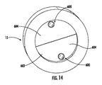


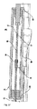


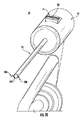


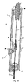


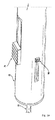


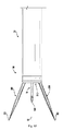


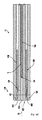


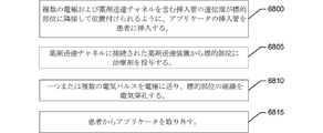


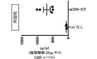


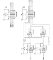


Classifications
-
- A—HUMAN NECESSITIES
- A61—MEDICAL OR VETERINARY SCIENCE; HYGIENE
- A61N—ELECTROTHERAPY; MAGNETOTHERAPY; RADIATION THERAPY; ULTRASOUND THERAPY
- A61N1/00—Electrotherapy; Circuits therefor
- A61N1/18—Applying electric currents by contact electrodes
- A61N1/32—Applying electric currents by contact electrodes alternating or intermittent currents
- A61N1/327—Applying electric currents by contact electrodes alternating or intermittent currents for enhancing the absorption properties of tissue, e.g. by electroporation
-
- A—HUMAN NECESSITIES
- A61—MEDICAL OR VETERINARY SCIENCE; HYGIENE
- A61B—DIAGNOSIS; SURGERY; IDENTIFICATION
- A61B17/00—Surgical instruments, devices or methods, e.g. tourniquets
- A61B17/34—Trocars; Puncturing needles
- A61B17/3476—Powered trocars, e.g. electrosurgical cutting, lasers, powered knives
-
- A—HUMAN NECESSITIES
- A61—MEDICAL OR VETERINARY SCIENCE; HYGIENE
- A61B—DIAGNOSIS; SURGERY; IDENTIFICATION
- A61B17/00—Surgical instruments, devices or methods, e.g. tourniquets
- A61B17/34—Trocars; Puncturing needles
- A61B17/3478—Endoscopic needles, e.g. for infusion
-
- A—HUMAN NECESSITIES
- A61—MEDICAL OR VETERINARY SCIENCE; HYGIENE
- A61B—DIAGNOSIS; SURGERY; IDENTIFICATION
- A61B18/00—Surgical instruments, devices or methods for transferring non-mechanical forms of energy to or from the body
- A61B18/04—Surgical instruments, devices or methods for transferring non-mechanical forms of energy to or from the body by heating
- A61B18/12—Surgical instruments, devices or methods for transferring non-mechanical forms of energy to or from the body by heating by passing a current through the tissue to be heated, e.g. high-frequency current
- A61B18/14—Probes or electrodes therefor
- A61B18/1477—Needle-like probes
-
- A—HUMAN NECESSITIES
- A61—MEDICAL OR VETERINARY SCIENCE; HYGIENE
- A61B—DIAGNOSIS; SURGERY; IDENTIFICATION
- A61B18/00—Surgical instruments, devices or methods for transferring non-mechanical forms of energy to or from the body
- A61B18/04—Surgical instruments, devices or methods for transferring non-mechanical forms of energy to or from the body by heating
- A61B18/12—Surgical instruments, devices or methods for transferring non-mechanical forms of energy to or from the body by heating by passing a current through the tissue to be heated, e.g. high-frequency current
- A61B18/14—Probes or electrodes therefor
- A61B18/1492—Probes or electrodes therefor having a flexible, catheter-like structure, e.g. for heart ablation
-
- A—HUMAN NECESSITIES
- A61—MEDICAL OR VETERINARY SCIENCE; HYGIENE
- A61K—PREPARATIONS FOR MEDICAL, DENTAL OR TOILETRY PURPOSES
- A61K38/00—Medicinal preparations containing peptides
- A61K38/16—Peptides having more than 20 amino acids; Gastrins; Somatostatins; Melanotropins; Derivatives thereof
- A61K38/17—Peptides having more than 20 amino acids; Gastrins; Somatostatins; Melanotropins; Derivatives thereof from animals; from humans
- A61K38/19—Cytokines; Lymphokines; Interferons
- A61K38/20—Interleukins [IL]
- A61K38/208—IL-12
-
- A—HUMAN NECESSITIES
- A61—MEDICAL OR VETERINARY SCIENCE; HYGIENE
- A61M—DEVICES FOR INTRODUCING MEDIA INTO, OR ONTO, THE BODY; DEVICES FOR TRANSDUCING BODY MEDIA OR FOR TAKING MEDIA FROM THE BODY; DEVICES FOR PRODUCING OR ENDING SLEEP OR STUPOR
- A61M5/00—Devices for bringing media into the body in a subcutaneous, intra-vascular or intramuscular way; Accessories therefor, e.g. filling or cleaning devices, arm-rests
-
- A—HUMAN NECESSITIES
- A61—MEDICAL OR VETERINARY SCIENCE; HYGIENE
- A61N—ELECTROTHERAPY; MAGNETOTHERAPY; RADIATION THERAPY; ULTRASOUND THERAPY
- A61N1/00—Electrotherapy; Circuits therefor
- A61N1/02—Details
- A61N1/04—Electrodes
- A61N1/0404—Electrodes for external use
- A61N1/0408—Use-related aspects
- A61N1/0412—Specially adapted for transcutaneous electroporation, e.g. including drug reservoirs
-
- A—HUMAN NECESSITIES
- A61—MEDICAL OR VETERINARY SCIENCE; HYGIENE
- A61N—ELECTROTHERAPY; MAGNETOTHERAPY; RADIATION THERAPY; ULTRASOUND THERAPY
- A61N1/00—Electrotherapy; Circuits therefor
- A61N1/02—Details
- A61N1/04—Electrodes
- A61N1/05—Electrodes for implantation or insertion into the body, e.g. heart electrode
- A61N1/0507—Electrodes for the digestive system
- A61N1/0509—Stomach and intestinal electrodes
-
- A—HUMAN NECESSITIES
- A61—MEDICAL OR VETERINARY SCIENCE; HYGIENE
- A61P—SPECIFIC THERAPEUTIC ACTIVITY OF CHEMICAL COMPOUNDS OR MEDICINAL PREPARATIONS
- A61P1/00—Drugs for disorders of the alimentary tract or the digestive system
- A61P1/18—Drugs for disorders of the alimentary tract or the digestive system for pancreatic disorders, e.g. pancreatic enzymes
-
- A—HUMAN NECESSITIES
- A61—MEDICAL OR VETERINARY SCIENCE; HYGIENE
- A61P—SPECIFIC THERAPEUTIC ACTIVITY OF CHEMICAL COMPOUNDS OR MEDICINAL PREPARATIONS
- A61P11/00—Drugs for disorders of the respiratory system
-
- A—HUMAN NECESSITIES
- A61—MEDICAL OR VETERINARY SCIENCE; HYGIENE
- A61P—SPECIFIC THERAPEUTIC ACTIVITY OF CHEMICAL COMPOUNDS OR MEDICINAL PREPARATIONS
- A61P35/00—Antineoplastic agents
-
- A—HUMAN NECESSITIES
- A61—MEDICAL OR VETERINARY SCIENCE; HYGIENE
- A61B—DIAGNOSIS; SURGERY; IDENTIFICATION
- A61B18/00—Surgical instruments, devices or methods for transferring non-mechanical forms of energy to or from the body
- A61B18/04—Surgical instruments, devices or methods for transferring non-mechanical forms of energy to or from the body by heating
- A61B18/12—Surgical instruments, devices or methods for transferring non-mechanical forms of energy to or from the body by heating by passing a current through the tissue to be heated, e.g. high-frequency current
- A61B18/1206—Generators therefor
-
- A—HUMAN NECESSITIES
- A61—MEDICAL OR VETERINARY SCIENCE; HYGIENE
- A61B—DIAGNOSIS; SURGERY; IDENTIFICATION
- A61B18/00—Surgical instruments, devices or methods for transferring non-mechanical forms of energy to or from the body
- A61B2018/00053—Mechanical features of the instrument of device
- A61B2018/00166—Multiple lumina
-
- A—HUMAN NECESSITIES
- A61—MEDICAL OR VETERINARY SCIENCE; HYGIENE
- A61B—DIAGNOSIS; SURGERY; IDENTIFICATION
- A61B18/00—Surgical instruments, devices or methods for transferring non-mechanical forms of energy to or from the body
- A61B2018/00053—Mechanical features of the instrument of device
- A61B2018/00214—Expandable means emitting energy, e.g. by elements carried thereon
-
- A—HUMAN NECESSITIES
- A61—MEDICAL OR VETERINARY SCIENCE; HYGIENE
- A61B—DIAGNOSIS; SURGERY; IDENTIFICATION
- A61B18/00—Surgical instruments, devices or methods for transferring non-mechanical forms of energy to or from the body
- A61B2018/00315—Surgical instruments, devices or methods for transferring non-mechanical forms of energy to or from the body for treatment of particular body parts
- A61B2018/00541—Lung or bronchi
-
- A—HUMAN NECESSITIES
- A61—MEDICAL OR VETERINARY SCIENCE; HYGIENE
- A61B—DIAGNOSIS; SURGERY; IDENTIFICATION
- A61B18/00—Surgical instruments, devices or methods for transferring non-mechanical forms of energy to or from the body
- A61B2018/00571—Surgical instruments, devices or methods for transferring non-mechanical forms of energy to or from the body for achieving a particular surgical effect
- A61B2018/00577—Ablation
-
- A—HUMAN NECESSITIES
- A61—MEDICAL OR VETERINARY SCIENCE; HYGIENE
- A61B—DIAGNOSIS; SURGERY; IDENTIFICATION
- A61B18/00—Surgical instruments, devices or methods for transferring non-mechanical forms of energy to or from the body
- A61B2018/00571—Surgical instruments, devices or methods for transferring non-mechanical forms of energy to or from the body for achieving a particular surgical effect
- A61B2018/00613—Irreversible electroporation
-
- A—HUMAN NECESSITIES
- A61—MEDICAL OR VETERINARY SCIENCE; HYGIENE
- A61B—DIAGNOSIS; SURGERY; IDENTIFICATION
- A61B18/00—Surgical instruments, devices or methods for transferring non-mechanical forms of energy to or from the body
- A61B2018/00636—Sensing and controlling the application of energy
- A61B2018/00642—Sensing and controlling the application of energy with feedback, i.e. closed loop control
-
- A—HUMAN NECESSITIES
- A61—MEDICAL OR VETERINARY SCIENCE; HYGIENE
- A61B—DIAGNOSIS; SURGERY; IDENTIFICATION
- A61B18/00—Surgical instruments, devices or methods for transferring non-mechanical forms of energy to or from the body
- A61B2018/00636—Sensing and controlling the application of energy
- A61B2018/00696—Controlled or regulated parameters
- A61B2018/00702—Power or energy
-
- A—HUMAN NECESSITIES
- A61—MEDICAL OR VETERINARY SCIENCE; HYGIENE
- A61B—DIAGNOSIS; SURGERY; IDENTIFICATION
- A61B18/00—Surgical instruments, devices or methods for transferring non-mechanical forms of energy to or from the body
- A61B2018/00636—Sensing and controlling the application of energy
- A61B2018/00773—Sensed parameters
- A61B2018/00875—Resistance or impedance
-
- A—HUMAN NECESSITIES
- A61—MEDICAL OR VETERINARY SCIENCE; HYGIENE
- A61B—DIAGNOSIS; SURGERY; IDENTIFICATION
- A61B18/00—Surgical instruments, devices or methods for transferring non-mechanical forms of energy to or from the body
- A61B18/04—Surgical instruments, devices or methods for transferring non-mechanical forms of energy to or from the body by heating
- A61B18/12—Surgical instruments, devices or methods for transferring non-mechanical forms of energy to or from the body by heating by passing a current through the tissue to be heated, e.g. high-frequency current
- A61B18/14—Probes or electrodes therefor
- A61B2018/1405—Electrodes having a specific shape
- A61B2018/1425—Needle
- A61B2018/143—Needle multiple needles
-
- A—HUMAN NECESSITIES
- A61—MEDICAL OR VETERINARY SCIENCE; HYGIENE
- A61B—DIAGNOSIS; SURGERY; IDENTIFICATION
- A61B34/00—Computer-aided surgery; Manipulators or robots specially adapted for use in surgery
- A61B34/30—Surgical robots
-
- A—HUMAN NECESSITIES
- A61—MEDICAL OR VETERINARY SCIENCE; HYGIENE
- A61K—PREPARATIONS FOR MEDICAL, DENTAL OR TOILETRY PURPOSES
- A61K39/00—Medicinal preparations containing antigens or antibodies
- A61K2039/505—Medicinal preparations containing antigens or antibodies comprising antibodies
-
- A—HUMAN NECESSITIES
- A61—MEDICAL OR VETERINARY SCIENCE; HYGIENE
- A61M—DEVICES FOR INTRODUCING MEDIA INTO, OR ONTO, THE BODY; DEVICES FOR TRANSDUCING BODY MEDIA OR FOR TAKING MEDIA FROM THE BODY; DEVICES FOR PRODUCING OR ENDING SLEEP OR STUPOR
- A61M2205/00—General characteristics of the apparatus
- A61M2205/05—General characteristics of the apparatus combined with other kinds of therapy
- A61M2205/054—General characteristics of the apparatus combined with other kinds of therapy with electrotherapy
-
- A—HUMAN NECESSITIES
- A61—MEDICAL OR VETERINARY SCIENCE; HYGIENE
- A61M—DEVICES FOR INTRODUCING MEDIA INTO, OR ONTO, THE BODY; DEVICES FOR TRANSDUCING BODY MEDIA OR FOR TAKING MEDIA FROM THE BODY; DEVICES FOR PRODUCING OR ENDING SLEEP OR STUPOR
- A61M2205/00—General characteristics of the apparatus
- A61M2205/50—General characteristics of the apparatus with microprocessors or computers
- A61M2205/502—User interfaces, e.g. screens or keyboards
-
- A—HUMAN NECESSITIES
- A61—MEDICAL OR VETERINARY SCIENCE; HYGIENE
- A61N—ELECTROTHERAPY; MAGNETOTHERAPY; RADIATION THERAPY; ULTRASOUND THERAPY
- A61N1/00—Electrotherapy; Circuits therefor
- A61N1/02—Details
- A61N1/04—Electrodes
- A61N1/0404—Electrodes for external use
- A61N1/0472—Structure-related aspects
- A61N1/0476—Array electrodes (including any electrode arrangement with more than one electrode for at least one of the polarities)
Abstract
本明細書では、アプリケータ、内視鏡、トロカール、またはこれに類するもの、ジェネレータ、および薬剤送達装置を含み得る、エレクトロポレーションのためのシステム、方法、および装置が提供される。アプリケータは、制御部分と、制御部分に接続された挿入管と、制御部分と係合するアクチュエータと、第一の先端を有する第一の電極および第二の先端を有する第二の電極を含む複数の電極とを含み得る。複数の電極は、アクチュエータによる作動に応答して、格納位置と展開位置との間で移動するよう構成され得る。第一の電極の第一の先端と第二の電極の第二の先端との間の距離が、格納位置においてよりも展開位置において大きくてもよい。また、さまざまな治療方法が提供される。【選択図】図47Provided herein are systems, methods, and devices for electroporation that may include applicators, endoscopes, trocars, or the like, generators, and drug delivery devices. The applicator includes a control portion, an intubation connected to the control portion, an actuator that engages the control portion, and a first electrode having a first tip and a second electrode having a second tip. It may include a plurality of electrodes. The plurality of electrodes may be configured to move between the retracted position and the deployed position in response to actuation by the actuator. The distance between the first tip of the first electrode and the second tip of the second electrode may be greater in the unfolded position than in the retracted position. In addition, various treatment methods are provided. FIG. 47.
Description
関連出願の参照
本出願は、2018年5月2日に提出された米国仮特許出願第62/665,553号、2018年10月8日に提出された米国仮特許出願第62/742,684号、2018年10月15日に提出された米国仮特許出願第62/745,699号、2018年11月2日に提出された米国仮特許出願第62/755,001号、そして2019年3月26日に提出された米国仮特許出願第62/824,011号の利益を主張し、これらのそれぞれは、本出願において完全に記載されるかのように、参照によりその全体が本明細書に組み込まれる。
References to Related Applications This application is filed on May 2, 2018, US Provisional Patent Application No. 62 / 665,553, and October 8, 2018, US Provisional Patent Application No. 62 / 742,684. No., US Provisional Patent Application No. 62 / 745,699 filed October 15, 2018, US Provisional Patent Application No. 62 / 755,001 filed November 2, 2018, and March 2019 Claiming the interests of US Provisional Patent Application No. 62 / 824,011 filed on 26th May, each of which is hereby by reference in its entirety as if fully described in this application. Incorporated in.
電界は、エレクトロポレーションとして知られるプロセスを通して細胞内に孔を形成するために使用されて、標的細胞の透過性を増加させ、患者にさまざまな局所的な治療を施すことができる。肺内の腫瘍の治療など、届きにくい身体の領域にはエレクトロポレーション療法の必要性があり、また、これらの届きにくい領域にエレクトロポレーション装置を取り付けることができる一方で、大きな治療領域を提供する必要がある。また、高い精度と最小限の侵襲性で、さまざまな治療剤および療法を施す必要性がある。 Electric fields are used to form pores in cells through a process known as electroporation, which can increase the permeability of target cells and provide a variety of topical treatments to patients. There is a need for electroporation therapy in hard-to-reach areas of the body, such as the treatment of tumors in the lungs, and while these hard-to-reach areas can be fitted with electroporation devices, they provide a large therapeutic area. There is a need to. There is also a need for a variety of therapeutic agents and therapies with high accuracy and minimal invasiveness.
適用された努力、創意工夫、および革新を通して、これらの特定された問題の多くは、本発明の実施形態に含まれる解決策を開発することによって解決されており、その多くの例が本明細書に詳述される。 Through applied efforts, ingenuity, and innovation, many of these identified problems have been solved by developing the solutions contained in embodiments of the present invention, many of which are described herein. Will be detailed in.
本明細書では、エレクトロポレーションシステム、アプリケータ、関連する治療および使用方法、ならびに関連する装置が開示される。いくつかの実施形態では、エレクトロポレーション用のアプリケータが提供され得る。アプリケータが、制御部分と、制御部分に接続された挿入管と、制御部分と係合するアクチュエータと、第一の先端を有する第一の電極および第二の先端を有する第二の電極を含む複数の電極とを含み得る。いくつかの実施形態では、アクチュエータの少なくとも一部分は、制御部分および挿入管に対して移動可能であり得る。複数の電極が、アクチュエータによる作動に応答して、格納位置と展開位置との間で動くように構成され得る。いくつかの実施形態では、第一の電極の第一の先端と第二の電極の第二の先端との間の距離が、格納位置よりも展開位置において大きくてもよい。 The present specification discloses electroporation systems, applicators, related treatments and uses, and related devices. In some embodiments, an applicator for electroporation may be provided. The applicator includes a control portion, an insertion tube connected to the control portion, an actuator that engages the control portion, and a first electrode having a first tip and a second electrode having a second tip. It may include a plurality of electrodes. In some embodiments, at least a portion of the actuator may be movable relative to the control portion and the intubation. Multiple electrodes may be configured to move between retracted and deployed positions in response to actuation by the actuator. In some embodiments, the distance between the first tip of the first electrode and the second tip of the second electrode may be greater in the unfolded position than in the retracted position.
いくつかの実施形態では、複数の電極が、格納位置の挿入管内に完全に埋め込まれてもよい。第一の電極および第二の電極の少なくとも一部分は、挿入管から展開位置の隣接する組織に延長するように構成され得る。 In some embodiments, the plurality of electrodes may be completely embedded within the insertion tube at the retracted position. At least a portion of the first and second electrodes may be configured to extend from the intubation to the adjacent tissue at the deployment position.
展開位置では、第一の電極の第一の先端と第二の電極の第二の先端との間の距離が、挿入管の外径よりも大きくてもよい。 In the unfolded position, the distance between the first tip of the first electrode and the second tip of the second electrode may be larger than the outer diameter of the intubation tube.
いくつかの実施形態では、挿入管は、挿入管の遠位端に画定される第一の角度付きチャネルおよび第二の角度付きチャネルを含み得る。第一の角度付きチャネルおよび第二の角度付きチャネルはそれぞれ、挿入管の長手方向軸に対して鋭角に配向され得る。第一の電極は、展開位置の第一の角度付きチャネルを少なくとも部分的に通って延在するように構成され得る。いくつかの実施形態では、第二の電極は、展開位置の第二の角度付きチャネルを少なくとも部分的に通って延在するように構成され得る。格納位置では、第一の電極および第二の電極は、挿入管内で互いに平行に配置され得る。展開位置では、第一の電極の少なくとも一部分および第二の電極の少なくとも一部分は、第一の角度付きチャネルおよび第二の角度付きチャネルのそれぞれの鋭角に配置され得る。 In some embodiments, the intubation may include a first angled channel and a second angled channel defined at the distal end of the intubation. The first angled channel and the second angled channel can each be oriented at an acute angle with respect to the longitudinal axis of the intubation. The first electrode may be configured to extend at least partially through the first angled channel in the unfolded position. In some embodiments, the second electrode may be configured to extend at least partially through the second angled channel in the unfolded position. In the retracted position, the first and second electrodes can be placed parallel to each other in the insertion tube. In the unfolded position, at least a portion of the first electrode and at least a portion of the second electrode may be located at the acute angles of the first angled channel and the second angled channel, respectively.
いくつかの実施形態では、アプリケータが、第一の電極および第二の電極と係合するブラダーを含み得る。ブラダーは、格納位置の挿入管内に完全に配置されてもよく、ブラダーは、展開位置の挿入管の外に少なくとも部分的に配置され得る。 In some embodiments, the applicator may include a first electrode and a bladder that engages the second electrode. The bladder may be placed completely inside the intubation in the retracted position and the bladder may be placed at least partially outside the intubation in the deployed position.
いくつかの実施形態では、第一の電極および第二の電極の少なくとも一部分は、ニチノールを含み得る。ニチノールは、複数の電極が展開位置にある場合、形状を変更するように構成されてもよく、ニチノールは、人体温度を超えると形状を変更するように構成され得る。 In some embodiments, at least a portion of the first and second electrodes may contain nitinol. Nitinol may be configured to change shape when multiple electrodes are in the deployed position, and nitinol may be configured to change shape above human body temperature.
いくつかの実施形態では、アプリケータが、第一の電極および第二の電極のそれぞれに取り付けられたニチノールスリーブを含み得、ニチノールは、複数の電極が展開位置にある場合、形状を変化させるように構成され、ニチノールは、人体温度を超えると形状が変化するように構成されている。 In some embodiments, the applicator may include a nitinol sleeve attached to each of the first and second electrodes, so that nitinol changes shape when multiple electrodes are in the unfolded position. Nitinol is configured to change shape when it exceeds the human body temperature.
いくつかの実施形態では、第一の電極および第二の電極は、非線形であり得る。 In some embodiments, the first and second electrodes can be non-linear.
アプリケータが、少なくとも部分的に挿入管内に可動式に配置されたキャリアを含んでもよい。第一の電極および第二の電極はそれぞれ、キャリア内に少なくとも部分的に配置され得る。キャリアは、第一の電極と関連する第一の部分および第二の電極と関連する第二の部分を画定することができ、第一の部分および第二の部分は、格納位置から拡張位置へと移動するときに、互いに半径方向に離れて拡張するように構成され得る。アプリケータが、キャリアの第一の部分および第二の部分を半径方向外側に拡張するためにアクチュエータから力を受けるように構成された内側部材を含み得る。アプリケータが、第一の部分と第二の部分との間に配置されるばねを含み得る。ばねは、キャリアの第一の部分および第二の部分を半径方向外側に拡張するように構成され得る。いくつかの実施形態では、アプリケータが、アプリケータの挿入管を介して標的部位と薬剤送達装置を流体接続するよう構成された薬剤送達チャネルを含み得る。 The applicator may include, at least partially, a carrier movably placed within the insertion tube. The first electrode and the second electrode can each be located at least partially within the carrier. The carrier can define a first part associated with the first electrode and a second part associated with the second electrode, the first part and the second part from the retracted position to the extended position. And can be configured to extend radially apart from each other as they move. The applicator may include an inner member configured to receive a force from the actuator to extend the first and second parts of the carrier radially outward. The applicator may include a spring placed between the first and second parts. The spring may be configured to extend the first and second portions of the carrier radially outward. In some embodiments, the applicator may include a drug delivery channel configured to fluidly connect the target site to the drug delivery device via the applicator's intubation.
いくつかの実施形態では、アクチュエータは、薬剤送達チャネルを標的部位に向かって変位させるように構成され得る。薬剤送達チャネルは、アクチュエータによる作動に応答して、薬剤送達チャネルの格納位置と薬剤送達チャネルの展開位置との間を、複数の電極と同時に移動するように構成され得る。いくつかの実施形態では、挿入管は、遠位端で貫通先端を画定する。 In some embodiments, the actuator may be configured to displace the drug delivery channel towards the target site. The drug delivery channel may be configured to move simultaneously between the storage position of the drug delivery channel and the deployment position of the drug delivery channel in response to actuation by the actuator. In some embodiments, the intubation defines a penetrating tip at the distal end.
別の実施形態では、エレクトロポレーションのためのシステムが提供される。システムは、制御部分、制御部分に接続された挿入管と、制御部分と係合するアクチュエータと、第一の先端を有する第一の電極および第二の先端を有する第二の電極とを含む複数の電極を含み得るアプリケータを含み得る。システムは、作業チャネルを画定する内視鏡、トロカールなど、複数の電極に電気的に接続されたジェネレータ、および内視鏡(例えば、可撓性内視鏡、剛性内視鏡、トロカールなど)の作業チャネルを介して一つまたは複数の治療剤を送達するように構成された薬剤送達装置をさらに含み得る。 In another embodiment, a system for electroporation is provided. The system includes a control portion, an insertion tube connected to the control portion, an actuator that engages with the control portion, and a first electrode having a first tip and a second electrode having a second tip. It may include an applicator which may include an electrode of. The system is a generator that is electrically connected to multiple electrodes, such as an endoscope that defines a work channel, a trocar, and an endoscope (eg, a flexible endoscope, a rigid endoscope, a trocar, etc.). It may further include a drug delivery device configured to deliver one or more therapeutic agents via a work channel.
本明細書で使用される場合、「制御部分」という用語は、電気パルスおよび/または一つまたは複数の治療剤をそれぞれ受けるための一つまたは複数の電気的接続および/または油圧接続を持つアプリケータのユーザー操作可能な部分を指し得る。本明細書で使用される場合、「挿入管」という用語は、任意の断面形状を有するアプリケータの任意の細長い中空部分を指し、その少なくとも一部分は、患者に挿入されるように構成され、それを通して電気パルスおよび/または一つまたは複数の治療剤が、標的治療部位に向けられるように構成される。 As used herein, the term "control portion" refers to an application having one or more electrical and / or hydraulic connections to receive electrical pulses and / or one or more therapeutic agents, respectively. It can point to a user-operable part of the data. As used herein, the term "intubation tube" refers to any elongated hollow portion of an applicator having any cross-sectional shape, at least a portion thereof configured to be inserted into a patient. An electrical pulse and / or one or more therapeutic agents are configured to be directed at the target treatment site through.
いくつかの実施形態では、アクチュエータの少なくとも一部分は、制御部分および挿入管に対して移動可能である。複数の電極が、アクチュエータによる作動に応答して、格納位置と展開位置との間で動くように構成され得る。第一の電極の第一の先端と第二の電極の第二の先端との間の距離が、格納位置においてよりも展開位置において大きくてもよい。アプリケータの挿入管の少なくとも一部分は、作業チャネルを通過するように構成され得る。ジェネレータは、電気信号を複数の電極に送達するように構成され得る。 In some embodiments, at least a portion of the actuator is movable relative to the control portion and the intubation. Multiple electrodes may be configured to move between retracted and deployed positions in response to actuation by the actuator. The distance between the first tip of the first electrode and the second tip of the second electrode may be greater in the unfolded position than in the retracted position. At least a portion of the intubation of the applicator may be configured to pass through the work channel. The generator can be configured to deliver electrical signals to multiple electrodes.
いくつかの実施形態では、展開位置において、第一の電極の第一の先端と第二の電極の第二の先端との間の距離が、作業チャネルの内径よりも大きくてもよい。 In some embodiments, the distance between the first tip of the first electrode and the second tip of the second electrode in the unfolded position may be greater than the inner diameter of the working channel.
いくつかの実施形態では、格納位置では、挿入管および複数の電極が、内視鏡または同類のもの作業チャネルを通過するように構成され得る。 In some embodiments, in the retracted position, the intubation and the plurality of electrodes may be configured to pass through the working channel of the endoscope or the like.
システムは、ジェネレータが、電気信号を第一の電極および第二の電極に送信し、第一の電極と第二の電極との間に配置される組織のインピーダンスを示す電気信号を受信するように構成されたプロセッサを含み得る。 The system causes the generator to send electrical signals to the first and second electrodes and receive electrical signals indicating the impedance of the tissue placed between the first and second electrodes. It may include a configured processor.
いくつかの実施形態では、内視鏡は気管支鏡であり得る。 In some embodiments, the endoscope can be a bronchoscope.
さらに別の実施形態では、腫瘍を内視鏡的または腹腔鏡下で治療する方法が提供され得る。この方法は、内視鏡の遠位端が標的部位に隣接して配置されるまで、内視鏡などを患者に挿入することと、薬剤送達装置の一部分が標的部位に隣接して配置されるように、薬剤送達装置の一部分を内視鏡の作業チャネルに挿入することと、薬剤送達装置から標的部位に治療剤を投与し、内視鏡から薬剤送達装置の一部分を除去することと、複数の電極を含む挿入管の遠位端が標的部位に隣接して配置されるように、内視鏡の作業チャネルにアプリケータの挿入管を挿入することと、ジェネレータから電極に一つまたは複数の電気パルスを供給して、標的部位の組織を電気穿孔することと、アプリケータと内視鏡を患者から取り外すこととを含み得る。 In yet another embodiment, a method of treating the tumor endoscopically or laparoscopically may be provided. In this method, the endoscope is inserted into the patient until the distal end of the endoscope is placed adjacent to the target site, and a part of the drug delivery device is placed adjacent to the target site. Such as inserting a part of the drug delivery device into the working channel of the endoscope, administering the therapeutic agent from the drug delivery device to the target site, and removing a part of the drug delivery device from the endoscope. Insert the applicator's insertion tube into the working channel of the endoscope so that the distal end of the insertion tube containing the electrodes of the endoscope is placed adjacent to the target site, and one or more from the generator to the electrodes. It may include supplying an electrical pulse to electroperforate the tissue at the target site and removing the applicator and endoscope from the patient.
別の実施形態では、エレクトロポレーションのためのシステムが提供され得る。システムは、制御部分、制御部分に接続された挿入管と、制御部分と係合するアクチュエータと、第一の先端を有する第一の電極および第二の先端を有する第二の電極とを含む複数の電極を含み得るアプリケータを含み得る。システムは、作業チャネルを画定するトロカールと、複数の電極に電気的に接続されたジェネレータと、トロカールの作業チャネルを通して一つまたは複数の治療剤を送達するように構成された薬剤送達装置とをさらに含み得る。いくつかの実施形態では、トロカールは、ガイドされた画像の下で対象の体腔に穿刺、またはそうでなければアクセスして、一つまたは複数の療法を施すように構成され得る。 In another embodiment, a system for electroporation may be provided. The system includes a control portion, an insertion tube connected to the control portion, an actuator that engages with the control portion, and a first electrode having a first tip and a second electrode having a second tip. It may include an applicator which may include an electrode of. The system further includes a trocar that defines the work channel, a generator that is electrically connected to multiple electrodes, and a drug delivery device that is configured to deliver one or more therapeutic agents through the trocar's work channel. Can include. In some embodiments, the trocar may be configured to puncture or otherwise access the body cavity of the subject under a guided image to administer one or more therapies.
いくつかの実施形態では、アクチュエータの少なくとも一部分は、制御部分および挿入管に対して移動可能であり得る。複数の電極が、アクチュエータによる作動に応答して、格納位置と展開位置との間で動くように構成され得る。いくつかの実施形態では、第一の電極の第一の先端と第二の電極の第二の先端との間の距離が、格納位置においてよりも展開位置において大きい。アプリケータの挿入管の少なくとも一部分は、作業チャネルを通過して内臓病変にアクセスするように構成され得る。ジェネレータは、電気信号を複数の電極に送達するように構成され得る。 In some embodiments, at least a portion of the actuator may be movable relative to the control portion and the intubation. Multiple electrodes may be configured to move between retracted and deployed positions in response to actuation by the actuator. In some embodiments, the distance between the first tip of the first electrode and the second tip of the second electrode is greater in the unfolded position than in the retracted position. At least a portion of the applicator's intubation may be configured to pass through a working channel to access visceral lesions. The generator can be configured to deliver electrical signals to multiple electrodes.
いくつかの実施形態では、内臓病変を治療する方法が提供される。方法は、トロカールの遠位端が、内臓病変を含む標的部位に隣接して配置されるまで、トロカールを患者に挿入することと、薬剤送達装置の一部分が標的部位に隣接して配置されるように、薬剤送達装置の一部分をトロカールの作業チャネルに挿入することと、薬剤送達装置から標的部位に治療剤を投与することと、薬剤送達装置の一部分をトロカールから取り外すことと、複数の電極を含む挿入管の遠位端が標的部位に隣接して配置されるように、アプリケータの挿入管をトロカールの作業チャネルに挿入することと、一つまたは複数の電気パルスをジェネレータから電極に送達して、標的部位の組織を電気穿孔することと、アプリケータとトロカールを患者から取り外すこととを含み得る。 In some embodiments, methods of treating visceral lesions are provided. The method is to insert the trocar into the patient until the distal end of the trocar is placed adjacent to the target site containing the visceral lesion, and to place a portion of the drug delivery device adjacent to the target site. Including a portion of the drug delivery device into the trocar's work channel, administration of the therapeutic agent from the drug delivery device to the target site, removal of a portion of the drug delivery device from the trocar, and multiple electrodes. Inserting the applicator's insertion tube into the trocar's working channel and delivering one or more electrical pulses from the generator to the electrode so that the distal end of the insertion tube is placed adjacent to the target site. It may include electroperforating the tissue at the target site and removing the applicator and trocar from the patient.
いくつかの実施形態では、腫瘍を有する対象を治療する方法が提供される。方法は、対象に治療用分子の有効用量を投与することと、腫瘍にエレクトロポレーション療法を施すこととを含む。エレクトロポレーション療法は、本明細書に記載のエレクトロポレーションシステムのいずれかを使用して、腫瘍に電気パルスを施すことを含み得る。腫瘍は、癌性または非癌性であり得る。腫瘍は、固形腫瘍、表面病変、非表面病変、体表面から15cm以内の病変、または内臓病変であり得るが、これらに限定されない。いくつかの実施形態では、記載された方法は、原発性腫瘍、ならびに遠位腫瘍および転移を治療するのに使用され得る。いくつかの実施形態では、記載された方法は、腫瘍のサイズの縮小、または腫瘍の増殖の減量、阻害、癌細胞の増殖の阻害、転移の阻害または低減、転移性癌の進展の低減または阻害、および/または癌に苦しんでいる対象の癌の再発の低減を提供する。腫瘍は、特定のタイプの腫瘍または癌に限定されるものではない。 In some embodiments, methods of treating a subject having a tumor are provided. The method comprises administering to the subject an effective dose of a therapeutic molecule and giving the tumor electroporation therapy. Electroporation therapy may include applying electrical pulses to the tumor using any of the electroporation systems described herein. Tumors can be cancerous or non-cancerous. Tumors can be, but are not limited to, solid tumors, surface lesions, non-surface lesions, lesions within 15 cm of the body surface, or visceral lesions. In some embodiments, the methods described can be used to treat primary tumors, as well as distal tumors and metastases. In some embodiments, the described methods reduce tumor size, or reduce or inhibit tumor growth, inhibit cancer cell growth, inhibit or reduce metastasis, reduce or inhibit the progression of metastatic cancer. And / or provide a reduction in cancer recurrence in a subject suffering from cancer. Tumors are not limited to any particular type of tumor or cancer.
いくつかの実施形態では、治療用分子は、アプリケータの薬剤送達装置で投与される。治療用分子は、治療用ポリペプチドをコードする発現ベクターを含み得る。いくつかの実施形態では、発現ベクターは、共刺激ポリペプチド、免疫調節性ポリペプチド、免疫刺激性サイトカイン、チェックポイント阻害剤、アジュバント、抗原、または遺伝学的アジュバント−抗原融合ポリペプチドのうちの一つまたは複数をコードする。共刺激分子は、GITR、CD137、CD134、CD40L、およびCD27作動薬からなる群から選択されることができる。いくつかの実施形態では、発現ベクターは、CXCL9、抗CD3 scFv、または抗CTLA−4 scFvを含むポリペプチドをコードする。免疫刺激性サイトカインは、TNFα、IL−1、IL−10、IL−12、IL−12 p35、IL−12 p40、IL−15、IL−15Rα、IL−23、IL−27、IFNα、IFNβ、IFNγ、IL−2、IL−4、IL−5、IL−7、IL−9、IL−21、TGFβ、およびTNFα、IL−1、IL−10、IL−12、IL−12 p35、IL−12 p40、IL−15、IL−15Rα、IL−23、IL−27、IFNα、IFNβ、IFNγ、IL−2、IL−4、IL−5、IL−7、IL−9、IL−21、TGFβのいずれか二つの組み合わせからなる群から選択されることができる。いくつかの実施形態では、発現ベクターは、抗CD3 scFv、CXCL9、または抗CTLA−4 scFvをコードする。いくつかの実施形態では、発現ベクターは、抗CD3 scFvおよびIL−12をコードする。いくつかの実施形態では、発現ベクターは、IL−12およびCXCL9をコードする。 In some embodiments, the therapeutic molecule is administered by the drug delivery device of the applicator. The therapeutic molecule may include an expression vector encoding a therapeutic polypeptide. In some embodiments, the expression vector is one of a costimulatory polypeptide, an immunomodulatory polypeptide, an immunostimulatory cytokine, a checkpoint inhibitor, an adjuvant, an antigen, or a genetic adjuvant-antigen fusion polypeptide. Code one or more. The co-stimulatory molecule can be selected from the group consisting of GITR, CD137, CD134, CD40L, and CD27 agonists. In some embodiments, the expression vector encodes a polypeptide comprising CXCL9, anti-CD3 scFv, or anti-CTLA-4 scFv. Immunostimulatory cytokines include TNFα, IL-1, IL-10, IL-12, IL-12 p35, IL-12 p40, IL-15, IL-15Rα, IL-23, IL-27, IFNα, IFNβ, IFNγ, IL-2, IL-4, IL-5, IL-7, IL-9, IL-21, TGFβ, and TNFα, IL-1, IL-10, IL-12, IL-12 p35, IL- 12 p40, IL-15, IL-15Rα, IL-23, IL-27, IFNα, IFNβ, IFNγ, IL-2, IL-4, IL-5, IL-7, IL-9, IL-21, TGFβ It can be selected from the group consisting of any two combinations of. In some embodiments, the expression vector encodes anti-CD3 scFv, CXCL9, or anti-CTLA-4 scFv. In some embodiments, the expression vector encodes anti-CD3 scFv and IL-12. In some embodiments, the expression vector encodes IL-12 and CXCL9.
方法は、対象にチェックポイント阻害剤の有効用量を投与することをさらに含み得る。いくつかの実施形態では、チェックポイント阻害剤は、全身に投与される。チェックポイント阻害剤は、免疫刺激性サイトカインをコードする発現ベクター上、または第二の発現ベクター上にコードされてもよく、エレクトロポレーション療法によって癌性腫瘍に送達され得る。チェックポイント阻害剤は、免疫刺激性サイトカインのエレクトロポレーションの前、同時、または後に投与され得る。 The method may further comprise administering to the subject an effective dose of a checkpoint inhibitor. In some embodiments, the checkpoint inhibitor is administered systemically. The checkpoint inhibitor may be encoded on an expression vector encoding an immunostimulatory cytokine or on a second expression vector and can be delivered to a cancerous tumor by electroporation therapy. Checkpoint inhibitors can be administered before, simultaneously with, or after electroporation of immunostimulatory cytokines.
いくつかの実施形態では、発現ベクターは、
a)P−A−T−C、
b)P−A−T−B−T−C、または
c)P−C−T−A−T−Bを含む。
式中、Pはプロモーターであり、Tは翻訳修飾要素であり、Aは、免疫調節分子、免疫調節分子の鎖、または共刺激分子をコードし、Bは、免疫調節分子、免疫調節分子の鎖、または共刺激分子をコードし、Cは、免疫調節分子、免疫調節分子の鎖、共刺激分子、遺伝学的アジュバント、抗原、遺伝学的アジュバント−抗原融合ポリペプチド、ケモカイン、または抗原結合ポリペプチドをコードする。
In some embodiments, the expression vector is
a) PATC,
b) PAT-B-TC, or c) P-C-T-A-T-B.
In the formula, P is a promoter, T is a translational modifier, A encodes an immunomodulatory molecule, a chain of an immunomodulatory molecule, or a costimulatory molecule, and B is a chain of an immunomodulatory molecule, an immunomodulatory molecule. , Or a costimulatory molecule, where C is an immunomodulatory molecule, a chain of immunomodulatory molecules, a costimulatory molecule, a genetic adjuvant, an antigen, a genetic adjuvant-antigen fusion polypeptide, a chemokine, or an antigen-binding polypeptide. To code.
方法はまた、腫瘍にアクセスするためにアプリケータの遠位端で組織を貫通することを含み得る。方法は、EISを使用してエレクトロポレーションパラメーターを最適化することをさらに含んでもよい。 The method may also include penetrating the tissue at the distal end of the applicator to access the tumor. The method may further include optimizing the electroporation parameters using EIS.
いくつかの実施形態では、哺乳類組織における腫瘍細胞増殖の再発を減少させる方法が提供される。方法は、治療用分子を腫瘍および/または腫瘍辺縁組織へ投与することと、本明細書で開示されるエレクトロポレーションシステムのいずれかを使用して、エレクトロポレーション療法を腫瘍および/または腫瘍辺縁組織へ施すこととを含み得る。 In some embodiments, methods are provided to reduce the recurrence of tumor cell proliferation in mammalian tissue. The method is to administer a therapeutic molecule to the tumor and / or tumor marginal tissue and to administer electroporation therapy to the tumor and / or tumor using any of the electroporation systems disclosed herein. It may include application to marginal tissue.
いくつかの実施形態では、治療用分子を投与することは、治療用分子をコードする発現ベクターを腫瘍および/または腫瘍辺縁組織に注射することを含む。エレクトロポレーション療法は、腫瘍細胞増殖の外科的切除または切断の前または後に実施され得る。 In some embodiments, administering the Therapeutic molecule comprises injecting an expression vector encoding the Therapeutic molecule into the tumor and / or tumor marginal tissue. Electroporation therapy can be performed before or after surgical resection or amputation of tumor cell proliferation.
いくつかの実施形態では、腫瘍を有する対象を治療する方法が提供される。方法は、対象に、少なくとも一つのDNAベースの治療剤の有効用量を投与することと、少なくとも一つのDNAベースの治療剤を、エレクトロポレーションアプリケータおよびジェネレータを使用して腫瘍の複数の細胞にトランスフェクトすることとを含み得る。いくつかの実施形態では、ジェネレータは、エレクトロポレーションアプリケータを介して低電圧エレクトロポレーションパルスを腫瘍に適用し得る。いくつかの実施形態では、治療領域内の腫瘍細胞の少なくとも4%、少なくとも5%、少なくとも6%、少なくとも7%、少なくとも8%、少なくとも9%、または少なくとも10%がトランスフェクトされる。 In some embodiments, methods of treating a subject having a tumor are provided. The method is to administer an effective dose of at least one DNA-based therapeutic agent to the subject and to apply the at least one DNA-based therapeutic agent to multiple cells of the tumor using an electroporation applicator and generator. It may include transfecting. In some embodiments, the generator may apply a low voltage electroporation pulse to the tumor via an electroporation applicator. In some embodiments, at least 4%, at least 5%, at least 6%, at least 7%, at least 8%, at least 9%, or at least 10% of the tumor cells in the therapeutic area are transfected.
いくつかの実施形態では、低電圧エレクトロポレーションパルスは、700V/cm以下の電界を含む。いくつかの実施形態では、低電圧エレクトロポレーションパルスは、600V/cm以下の電界を含む。いくつかの実施形態では、低電圧エレクトロポレーションパルスは、500V/cm以下の電界を含む。いくつかの実施形態では、低電圧エレクトロポレーションパルスは、400V/cm以下の電界を含む。 In some embodiments, the low voltage electroporation pulse comprises an electric field of 700 V / cm or less. In some embodiments, the low voltage electroporation pulse comprises an electric field of 600 V / cm or less. In some embodiments, the low voltage electroporation pulse comprises an electric field of 500 V / cm or less. In some embodiments, the low voltage electroporation pulse comprises an electric field of 400 V / cm or less.
いくつかの実施形態では、各低電圧エレクトロポレーションパルスが、1ms以上の持続時間を規定する。いくつかの実施形態では、各低電圧エレクトロポレーションパルスが、1ms〜1sの持続時間を規定する。 In some embodiments, each low voltage electroporation pulse defines a duration of 1 ms or longer. In some embodiments, each low voltage electroporation pulse defines a duration of 1 ms to 1 s.
いくつかの実施形態では、低電圧エレクトロポレーションパルスは、600V以下の電圧を画定する。いくつかの実施形態では、低電圧エレクトロポレーションパルスは、600V〜5Vの電圧を含む。 In some embodiments, the low voltage electroporation pulse defines a voltage of 600 V or less. In some embodiments, the low voltage electroporation pulse comprises a voltage of 600V-5V.
いくつかの実施形態では、アプリケータが、制御部分と、制御部分に接続された挿入管と、制御部分と係合するアクチュエータと、第一の先端および第二の先端を有する第一の電極および第二の電極を含む複数の電極とを含み得る。アクチュエータの少なくとも一部分は、制御部分および挿入管に対して移動可能であり得る。いくつかの実施形態では、複数の電極が、アクチュエータによる作動に応答して、格納位置と展開位置との間で移動するよう構成され得る。第一の電極の第一の先端と第二の電極の第二の先端との間の距離が、格納位置においてよりも展開位置において大きくてもよい。いくつかの実施形態では、ジェネレータは、複数の電極に電気的に接続されてもよく、ジェネレータは、複数の電極に電気信号を送達し得る。 In some embodiments, the applicator has a control portion, an insertion tube connected to the control portion, an actuator that engages the control portion, and a first electrode having a first tip and a second tip. It may include a plurality of electrodes including a second electrode. At least a portion of the actuator may be movable relative to the control portion and the intubation. In some embodiments, the plurality of electrodes may be configured to move between a retracted position and a deployed position in response to actuation by the actuator. The distance between the first tip of the first electrode and the second tip of the second electrode may be greater in the unfolded position than in the retracted position. In some embodiments, the generator may be electrically connected to multiple electrodes and the generator may deliver electrical signals to the plurality of electrodes.
いくつかの実施形態では、腫瘍を有する対象を治療する方法が提供される。この方法は、対象に少なくとも一つのDNAベースの治療剤の有効用量を投与することと、エレクトロポレーションアプリケータおよびジェネレータを使用して、少なくとも一つのDNAベースの治療剤を腫瘍の複数の細胞にトランスフェクトすることとを含み得、ジェネレータは、エレクトロポレーションアプリケータを介して腫瘍に高電圧エレクトロポレーションパルスを印加するように構成され、少なくとも一つのDNAベースの治療剤の8〜10%が腫瘍の細胞にトランスフェクトされる。 In some embodiments, methods of treating a subject having a tumor are provided. This method administers an effective dose of at least one DNA-based therapeutic agent to a subject and uses an electroporation applicator and generator to apply at least one DNA-based therapeutic agent to multiple cells of the tumor. The generator, which may include transfection, is configured to apply a high voltage electroporation pulse to the tumor via an electroporation applicator, with 8-10% of at least one DNA-based therapeutic agent. Transfected into tumor cells.
いくつかの実施形態では、非応答性対象におけるチェックポイント阻害剤非応答性を調節する方法が提供され得る。方法は、非応答性対象に少なくとも一つのチェックポイント阻害剤を投与することと、非応答性対象に、サイトカインをコードする少なくとも一つのプラスミドの有効用量で腫瘍を注射することと、腫瘍にエレクトロポレーション療法を施すこととを含み得る。 In some embodiments, methods of regulating checkpoint inhibitor non-responsiveness in non-responsive subjects may be provided. The method is to administer at least one checkpoint inhibitor to the non-responsive subject, to inject the non-responsive subject with the tumor at an effective dose of at least one plasmid encoding the cytokine, and to electroporate the tumor. It may include giving ration therapy.
方法のいくつかの実施形態では、腫瘍は肝臓内にあり得る。いくつかの実施形態では、腫瘍は肝細胞癌であり得る。いくつかの実施形態では、サイトカインは、TNFα、IL−1、IL−10、IL−12、IL−12 p35、IL−12 p40、IL−15、IL−15Rα、IL−23、IL−27、IFNα、IFNβ、IFNγ、IL−2、IL−4、IL−5、IL−7、IL−9、IL−21、およびTGFβ、ならびにTNFα、IL−1、IL−10、IL−12、IL−12 p35、IL−12 p40、IL−15、IL−15Rα、IL−23、IL−27、IFNα、IFNβ、IFNγ、IL−2、IL−4、IL−5、IL−7、IL−9、IL−21、およびTGFβのいずれか二つの組み合わせからなる群から選択されることができる。いくつかの実施形態では、サイトカインはIL−12であり得る。いくつかの実施形態では、CXCL9、抗CD3 scFv、または抗CTLA−4 scFvをコードするプラスミドは、肝臓腫瘍に投与され得る。 In some embodiments of the method, the tumor can be in the liver. In some embodiments, the tumor can be hepatocellular carcinoma. In some embodiments, the cytokines are TNFα, IL-1, IL-10, IL-12, IL-12 p35, IL-12 p40, IL-15, IL-15Rα, IL-23, IL-27, IFNα, IFNβ, IFNγ, IL-2, IL-4, IL-5, IL-7, IL-9, IL-21, and TGFβ, and TNFα, IL-1, IL-10, IL-12, IL- 12 p35, IL-12 p40, IL-15, IL-15Rα, IL-23, IL-27, IFNα, IFNβ, IFNγ, IL-2, IL-4, IL-5, IL-7, IL-9, It can be selected from the group consisting of any two combinations of IL-21 and TGFβ. In some embodiments, the cytokine can be IL-12. In some embodiments, a plasmid encoding CXCL9, anti-CD3 scFv, or anti-CTLA-4 scFv can be administered to a liver tumor.
いくつかの実施形態では、エレクトロポレーション用のトロカール系システムが提供され得る。いくつかの実施形態では、トロカール系システムは、制御部分と、制御部分に接続された挿入管と、制御部分と係合するアクチュエータとを含むアプリケータを含み得、アクチュエータの少なくとも一部分は、制御部分および挿入管に対して可動であり、複数の電極は第一の先端を有する第一の電極と第二の先端を有する第二の電極とを含み、複数の電極が、アクチュエータによる作動に応答して、格納位置と展開位置との間を移動するように構成される。いくつかの実施形態では、第一の電極の第一の先端と第二の電極の第二の先端との間の距離が、格納位置においてよりも展開位置において大きい。システムは、作業チャネルを画定するトロカールをさらに含み得、アプリケータの挿入管の少なくとも一部分は、作業チャネルを通過するように構成される。いくつかの実施形態では、システムは、複数の電極に電気的に接続されたジェネレータを含んでもよく、ジェネレータは、複数の電極に電気信号を送達するように構成される。システムはさらに、トロカールの作業チャネルを通して一つまたは複数の治療剤を送達するように構成された薬剤送達装置を含み得る。 In some embodiments, a trocar-based system for electroporation may be provided. In some embodiments, the trocar system may include an applicator including a control portion, an insertion tube connected to the control portion, and an actuator that engages the control portion, at least a portion of the actuator being the control portion. And movable with respect to the insertion tube, the plurality of electrodes includes a first electrode having a first tip and a second electrode having a second tip, and the plurality of electrodes respond to the operation by the actuator. It is configured to move between the storage position and the expansion position. In some embodiments, the distance between the first tip of the first electrode and the second tip of the second electrode is greater in the unfolded position than in the retracted position. The system may further include a trocar defining the work channel and at least a portion of the applicator's intubation is configured to pass through the work channel. In some embodiments, the system may include a generator electrically connected to a plurality of electrodes, the generator being configured to deliver an electrical signal to the plurality of electrodes. The system may further include a drug delivery device configured to deliver one or more therapeutic agents through Trocar's work channel.
一態様では、本開示は、組織のエレクトロポレーション用のアプリケータに関する。いくつかの実施形態では、アプリケータが、制御部分、制御部分に接続された挿入管、制御部分と係合するアクチュエータ、および複数の電極を含む。複数の電極が、第一の先端を有する第一の電極と、第二の先端を有する第二の電極とを含む。複数の電極が、アクチュエータの作動に応答して、格納位置と展開位置との間で動くように構成される。 In one aspect, the disclosure relates to an applicator for tissue electroporation. In some embodiments, the applicator comprises a control portion, an insertion tube connected to the control portion, an actuator that engages the control portion, and a plurality of electrodes. The plurality of electrodes include a first electrode having a first tip and a second electrode having a second tip. A plurality of electrodes are configured to move between the retracted position and the deployed position in response to the actuation of the actuator.
いくつかの実施形態では、第一の電極の第一の先端と第二の電極の第二の先端との間の距離が、格納位置においてよりも展開位置において大きい。いくつかの実施形態では、挿入管は、その中に配置される薬剤送達チャネルを含み、薬剤送達チャネルは少なくとも一つの治療剤を受けるように構成される。いくつかの実施例では、薬剤送達チャネルは、複数の電極とともに格納および配備するように構成される。いくつかの実施形態では、システムはアプリケータおよび別個の薬剤送達アプリケータを含む。いくつかの実施形態では、システムは、アプリケータおよびアプリケータに動作可能なように接続された低電圧ジェネレータを含む。 In some embodiments, the distance between the first tip of the first electrode and the second tip of the second electrode is greater in the unfolded position than in the retracted position. In some embodiments, the intubation comprises a drug delivery channel located therein, the drug delivery channel being configured to receive at least one therapeutic agent. In some embodiments, the drug delivery channel is configured to be stowed and deployed with multiple electrodes. In some embodiments, the system comprises an applicator and a separate drug delivery applicator. In some embodiments, the system comprises an applicator and a low voltage generator operably connected to the applicator.
一態様では、本開示は、組織のエレクトロポレーションのためのシステムに関する。いくつかの実施形態では、システムのアプリケータが、挿入管を有する本体と、本体と係合するアクチュエータと、少なくとも一つの電極とを含む。少なくとも一つの電極は、第一の先端を有する第一の電極を含む。少なくとも一つの電極は、アクチュエータの作動に応答して、格納位置と展開位置との間で動くように構成される。ジェネレータは低電圧で、少なくとも一つの電極に電気的に接続されている。 In one aspect, the present disclosure relates to a system for tissue electroporation. In some embodiments, the applicator of the system comprises a body having an intubation tube, an actuator that engages the body, and at least one electrode. At least one electrode includes a first electrode having a first tip. At least one electrode is configured to move between the retracted position and the deployed position in response to the actuation of the actuator. The generator is low voltage and is electrically connected to at least one electrode.
いくつかの実施形態では、システムは、その中に挿入管を配置するように構成された内視鏡を含む。いくつかの実施形態では、アプリケータが、その中に配置された薬剤送達チャネルを含み、薬剤送達チャネルは少なくとも一つの治療剤を送達するよう構成される。 In some embodiments, the system comprises an endoscope configured to place an intubation within it. In some embodiments, the applicator comprises a drug delivery channel disposed therein, the drug delivery channel being configured to deliver at least one therapeutic agent.
一態様では、本開示は、内臓病変などの罹患組織を治療する方法に関する。いくつかの実施形態では、方法は、内視鏡の遠位端が罹患組織を含む標的部位に隣接して配置されるまで、内視鏡を患者に挿入することと、アプリケータの一部分が標的部位に隣接して配置され、内視鏡が標的部位に隣接して配置されるように、アプリケータの一部分を内視鏡の作業チャネルに挿入することと、アプリケータを介して標的部位に少なくとも一つの治療剤を投与することと、アプリケータを作動させて、アプリケータの複数の電極を展開することと、ジェネレータから電極に一つまたは複数の電気パルスを供給して、標的部位の組織を電気穿孔することと、を含む。 In one aspect, the disclosure relates to a method of treating affected tissue such as a visceral lesion. In some embodiments, the method is to insert the endoscope into the patient and target a portion of the applicator until the distal end of the endoscope is placed adjacent to the target site containing the affected tissue. A portion of the applicator is inserted into the working channel of the endoscope so that it is placed adjacent to the site and the endoscope is placed adjacent to the target site, and at least to the target site via the applicator. Administering a single therapeutic agent, activating the applicator to deploy multiple electrodes on the applicator, and supplying one or more electrical pulses from the generator to the electrodes to depress the tissue at the target site. Including electric drilling.
いくつかの実施形態では、罹患組織を治療する方法は、内視鏡の遠位端が罹患組織を含む標的部位に隣接して配置されるまで、内視鏡を患者に挿入することと、薬剤送達装置の一部分が標的部位に隣接して配置され、内視鏡が標的部位に隣接して配置されるように、薬剤送達装置の一部分を内視鏡の作業チャネルに挿入することと、薬剤送達装置から標的部位に少なくとも一つの治療剤を投与することと、内視鏡から薬剤送達装置の一部分を取り除くことと、複数の電極を含む挿入管の遠位端が標的部位に隣接して配置され、内視鏡が標的部位に隣接して配置されるように、内視鏡の作業チャネルにアプリケータの挿入管を挿入することと、一つまたは複数の電気パルスをジェネレータから電極に送達して、標的部位の組織を電気穿孔することと、アプリケータと内視鏡を患者から取り外すこととを含む。 In some embodiments, the method of treating the affected tissue is to insert the endoscope into the patient until the distal end of the endoscope is placed adjacent to the target site containing the affected tissue, and the agent. Inserting a portion of the drug delivery device into the working channel of the endoscope and drug delivery so that a portion of the delivery device is placed adjacent to the target site and the endoscope is placed adjacent to the target site. Administering at least one therapeutic agent from the device to the target site, removing a portion of the drug delivery device from the endoscope, and placing the distal end of an insertion tube containing multiple electrodes adjacent to the target site. Inserting an applicator's insertion tube into the working channel of the endoscope and delivering one or more electrical pulses from the generator to the electrodes so that the endoscope is placed adjacent to the target site. Includes electroperforation of tissue at the target site and removal of the applicator and endoscope from the patient.
いくつかの実施形態では、罹患組織を治療する方法は、薬剤送達装置の一部分が、罹患組織を含む標的部位に隣接して配置されるまで、薬剤送達装置を患者に挿入することと、薬剤送達装置から標的部位に治療剤を投与することと、患者から薬剤送達装置を取り外すことと、内視鏡の遠位端が罹患組織を含む標的部位に隣接して配置されるまで、内視鏡を、患者に挿入することと、複数の電極を含む挿入管の遠位端が標的部位に隣接して配置され、内視鏡が標的部位に隣接して配置されるように、アプリケータの挿入管を内視鏡の作業チャネルに挿入することと、一つまたは複数の電気パルスをジェネレータから電極に送達して、標的部位の組織を電気穿孔することと、アプリケータと内視鏡を患者から取り外すこととを含む。 In some embodiments, the method of treating the affected tissue is to insert the drug delivery device into the patient until a portion of the drug delivery device is placed adjacent to the target site containing the affected tissue, and the drug delivery. Administer the therapeutic agent from the device to the target site, remove the drug delivery device from the patient, and keep the endoscope until the distal end of the endoscope is placed adjacent to the target site containing the affected tissue. The applicator's insertion tube is inserted into the patient and the distal end of the insertion tube containing multiple electrodes is placed adjacent to the target site and the endoscope is placed adjacent to the target site. Is inserted into the working channel of the endoscope, one or more electrical pulses are delivered from the generator to the electrodes to electroperforate the tissue at the target site, and the applicator and endoscope are removed from the patient. Including that.
例示的な実施形態において、抗PD−1または抗PD−L1療法に対して非応答性または非応答性であると予測される対象の肺の病変を治療する方法は、IL−12をコードする少なくとも一つのプラスミドの有効用量を病変に投与することと、病変にエレクトロポレーション療法を施すことと、対象に少なくとも一つのチェックポイント阻害剤の有効用量を投与することとを含み得て、エレクトロポレーション療法を施すことは、第一の先端を有する第一の電極および第二の先端を有する第二の電極を含む複数の電極を含むアプリケータを含むエレクトロポレーションシステムを使用して病変に電気パルスを施すことを含み、複数の電極が、格納位置と展開位置との間を移動するように構成され、第一の電極の第一の先端と第二の電極の第二の先端との間の距離が、格納位置においてよりも展開位置において大きい。システムは、複数の電極に電気的に接続されたジェネレータをさらに含み得、病変に電気パルスを施すことは、第一の電極および第二の電極を病変内または病変に隣接して配置し、電気パルスをジェネレータから第一の電極および第二の電極に送達することをさらに含む。 In an exemplary embodiment, a method of treating a lung lesion in a subject that is predicted to be non-responsive or non-responsive to anti-PD-1 or anti-PD-L1 therapy encodes IL-12. It can include administering an effective dose of at least one plasmid to the lesion, administering electroporation therapy to the lesion, and administering to the subject an effective dose of at least one checkpoint inhibitor. Ration therapy is performed on the lesion using an electroporation system that includes an applicator containing multiple electrodes, including a first electrode with a first tip and a second electrode with a second tip. Multiple electrodes are configured to move between the retracted and unfolded positions, including pulsing, between the first tip of the first electrode and the second tip of the second electrode. Distance is greater in the unfolded position than in the stowed position. The system may further include a generator electrically connected to multiple electrodes, applying electrical pulses to the lesion to place the first and second electrodes within or adjacent to the lesion and electrically. It further comprises delivering the pulse from the generator to the first and second electrodes.
いくつかの実施形態では、アプリケータが、制御部分と、制御部分に接続された挿入管と、制御部分と係合するアクチュエータとをさらに含み、アクチュエータの少なくとも一部分は、制御部分および挿入管に対して移動可能であり、複数の電極を格納位置と展開位置との間で移動させる。 In some embodiments, the applicator further comprises a control portion, an insertion tube connected to the control portion, and an actuator that engages the control portion, at least a portion of the actuator with respect to the control portion and the insertion tube. It is movable and moves a plurality of electrodes between the retracted position and the deployed position.
いくつかの実施形態では、エレクトロポレーションシステムが、少なくとも一つの作業チャネルを画定する剛性トロカールまたは可撓性内視鏡のうちの一つを含む挿入デバイスをさらに含み、アプリケータの少なくとも一部分は、病変にアクセスするために少なくとも一つの作業チャネルを通過するように構成される。 In some embodiments, the electroporation system further comprises an insertion device that includes one of a rigid trocar or flexible endoscope that defines at least one working channel, and at least a portion of the applicator. It is configured to pass through at least one work channel to access the lesion.
いくつかの実施形態では、エレクトロポレーションシステムが、少なくとも一つのプラスミドまたは少なくとも一つのチェックポイント阻害剤のうちの少なくとも一つを、挿入デバイスの少なくとも一つの作業チャネルを通して送達するように構成された薬剤送達装置をさらに含む。 In some embodiments, the electroporation system is configured to deliver at least one of at least one plasmid or at least one checkpoint inhibitor through at least one working channel of the insertion device. Further includes a delivery device.
いくつかの実施形態では、アプリケータが、少なくとも一つのプラスミドまたは少なくとも一つのチェックポイント阻害剤のうちの少なくとも一つを病変に送達するように構成された薬剤送達チャネルをさらに画定する。 In some embodiments, the applicator further defines a drug delivery channel configured to deliver at least one of at least one plasmid or at least one checkpoint inhibitor to the lesion.
いくつかの実施形態では、エレクトロポレーションシステムが、少なくとも一つのプラスミド、少なくとも一つのチェックポイント阻害剤、またはエレクトロポレーション療法のうちの少なくとも一つの投与中にアプリケータの位置を制御するためにアプリケータと係合する少なくとも一つのロボットアームをさらに含む。 In some embodiments, the electroporation system applies to control the position of the applicator during administration of at least one plasmid, at least one checkpoint inhibitor, or at least one of electroporation therapies. It further includes at least one robot arm that engages with the plasmid.
いくつかの実施形態では、エレクトロポレーションシステムが、少なくとも一つのプラスミド、少なくとも一つのチェックポイント阻害剤、またはエレクトロポレーション療法の少なくとも一つの投与の前または投与中に、病変の画像を生成するように構成された少なくとも一つの可視化装置をさらに含む。いくつかの実施形態では、少なくとも一つの可視化装置は、コンピューター断層撮影スキャナーを含む。 In some embodiments, the electroporation system produces images of lesions before or during administration of at least one plasmid, at least one checkpoint inhibitor, or at least one dose of electroporation therapy. Further includes at least one visualization device configured in. In some embodiments, the at least one visualization device comprises a computed tomography scanner.
いくつかの実施形態では、ジェネレータは低電圧電気パルスを出力するように構成される。電気パルスは、700V/cm以下の電界強度を有し得る。 In some embodiments, the generator is configured to output a low voltage electrical pulse. The electrical pulse can have an electric field strength of 700 V / cm or less.
いくつかの実施形態では、ジェネレータは高電圧電気パルスを出力するように構成される。 In some embodiments, the generator is configured to output a high voltage electrical pulse.
いくつかの実施形態では、少なくとも一つのプラスミドは、タボキノーゲンテルセプラスミドを含む。 In some embodiments, the at least one plasmid comprises a tabokinogen terce plasmid.
いくつかの実施形態では、チェックポイント阻害剤は、全身に投与される。 In some embodiments, the checkpoint inhibitor is administered systemically.
いくつかの実施形態では、チェックポイント阻害剤は、抗PD−1抗体または抗PD−L1抗体である。 In some embodiments, the checkpoint inhibitor is an anti-PD-1 antibody or an anti-PD-L1 antibody.
いくつかの実施形態では、チェックポイント阻害剤は、ニボルマブ、ペンブロリズマブ、ピジリズマブ、またはMPDL3280Aを含む。 In some embodiments, checkpoint inhibitors include nivolumab, pembrolizumab, pidilizumab, or MPDL3280A.
別の例示的な実施形態では、抗PD−1または抗PDL1療法に非応答性または非応答性であると予測される対象の肺の病変を治療するためのシステムは、第一の先端を有する第一の電極および第二の先端を有する第二の電極を含む複数の電極であって、格納位置と展開位置との間を移動するように構成され、第一の電極の第一の先端と第二の電極の第二の先端との間の距離が、格納位置においてよりも展開位置において大きい、複数の電極と、複数の電極に電気的に接続されたジェネレータであって、電気パルスを第一の電極および第二の電極に送達して、電気パルスを病変に投与するように構成される、ジェネレータと、IL−12をコードする少なくとも一つのプラスミドの有効用量および少なくとも一つのチェックポイント阻害剤の有効用量を対象に送達するように構成された少なくとも一つの薬剤送達装置とを含むアプリケータを含み得る。 In another exemplary embodiment, the system for treating lung lesions in a subject that is predicted to be non-responsive or non-responsive to anti-PD-1 or anti-PDL1 therapy has a first tip. A plurality of electrodes, including a first electrode and a second electrode having a second tip, configured to move between a retracted position and a deployed position, with the first tip of the first electrode. A generator in which the distance between the second tip of the second electrode and the second tip is larger in the deployed position than in the retracted position, the plurality of electrodes and the generator electrically connected to the plurality of electrodes, and the electric pulse is generated. An effective dose of a generator and at least one plasmid encoding IL-12 and at least one checkpoint inhibitor configured to deliver an electrical pulse to the lesion by delivering to one and a second electrode. It may include an applicator comprising at least one drug delivery device configured to deliver an effective dose of.
いくつかの実施形態では、アプリケータが、制御部分と、制御部分に接続された挿入管と、制御部分と係合するアクチュエータとをさらに含み、アクチュエータの少なくとも一部分は、制御部分および挿入管に対して移動可能であり、複数の電極を格納位置と展開位置との間で移動させる。 In some embodiments, the applicator further comprises a control portion, an insertion tube connected to the control portion, and an actuator that engages the control portion, at least a portion of the actuator with respect to the control portion and the insertion tube. It is movable and moves a plurality of electrodes between the retracted position and the deployed position.
いくつかの実施形態では、システムは、少なくとも一つの作業チャネルを画定する剛性トロカールまたは可撓性内視鏡のうちの一つを含む挿入デバイスを含んでもよく、アプリケータの少なくとも一部分は、病変にアクセスするために少なくとも一つの作業チャネルを通過するように構成される。 In some embodiments, the system may include an insertion device that includes one of a rigid trocar or flexible endoscope that defines at least one work channel, and at least a portion of the applicator is in the lesion. It is configured to go through at least one work channel for access.
いくつかの実施形態では、システムは、挿入デバイスの少なくとも一つの作業チャネルを通して少なくとも一つのプラスミドを送達するように構成された薬剤送達装置を含み得る。 In some embodiments, the system may include a drug delivery device configured to deliver at least one plasmid through at least one working channel of the insertion device.
いくつかの実施形態では、アプリケータが、少なくとも一つのプラスミドを病変に送達するように構成された薬剤送達チャネルをさらに画定する。 In some embodiments, the applicator further defines a drug delivery channel configured to deliver at least one plasmid to the lesion.
いくつかの実施形態では、システムは、少なくとも一つのプラスミドまたはエレクトロポレーション療法の少なくとも一つの投与中にアプリケータの位置を制御するためにアプリケータと係合する少なくとも一つのロボットアームを含み得る。 In some embodiments, the system may include at least one plasmid or at least one robot arm that engages the applicator to control the position of the applicator during at least one administration of electroporation therapy.
いくつかの実施形態では、システムは、少なくとも一つのプラスミドまたはエレクトロポレーション療法の少なくとも一つの投与前または投与中に、病変の画像を生成するように構成された少なくとも一つの可視化装置を含み得る。少なくとも一つの可視化装置は、コンピューター断層撮影スキャナーを含み得る。 In some embodiments, the system may include at least one plasmid or at least one visualization device configured to generate an image of the lesion before or during at least one administration of electroporation therapy. At least one visualization device may include a computed tomography scanner.
いくつかの実施形態では、ジェネレータは低電圧電気パルスを出力するように構成される。いくつかの実施形態では、電気パルスは700V/cm以下の電界強度を有する。 In some embodiments, the generator is configured to output a low voltage electrical pulse. In some embodiments, the electrical pulse has an electric field strength of 700 V / cm or less.
いくつかの実施形態では、ジェネレータは高電圧電気パルスを出力するように構成される。 In some embodiments, the generator is configured to output a high voltage electrical pulse.
いくつかの実施形態では、少なくとも一つのプラスミドは、タボキノーゲンテルセプラスミドを含む。 In some embodiments, the at least one plasmid comprises a tabokinogen terce plasmid.
さらに別の例示的な実施形態では、対象の肺の病変を治療する方法は、病変に少なくとも一つの治療剤の有効用量を投与することと、病変にエレクトロポレーション療法を施すこととを含み得、エレクトロポレーション療法は、第一の先端を有する第一の電極および第二の先端を有する第二の電極を含む複数の電極であって、格納位置と展開位置との間を移動するように構成され、第一の電極の第一の先端と第二の電極の第二の先端との間の距離が、格納位置においてよりも展開位置において大きい、複数の電極を含むアプリケータを含む、エレクトロポレーションシステムを使用して病変に電気パルスを施すことを含む。システムは、複数の電極に電気的に接続されたジェネレータをさらに含み得、病変に電気パルスを施すことは、第一の電極および第二の電極を病変内または病変に隣接して配置し、電気パルスをジェネレータから第一の電極および第二の電極に送達することをさらに含む。 In yet another exemplary embodiment, a method of treating a lesion in a subject's lung may include administering to the lesion an effective dose of at least one therapeutic agent and subjecting the lesion to electroporation therapy. Electroporation therapy is a plurality of electrodes, including a first electrode having a first tip and a second electrode having a second tip, so as to move between a retracted position and a deployed position. Electro, including an applicator containing multiple electrodes, configured such that the distance between the first tip of the first electrode and the second tip of the second electrode is greater in the unfolded position than in the retracted position. It involves applying electrical pulses to the lesion using a poration system. The system may further include a generator electrically connected to multiple electrodes, applying electrical pulses to the lesion to place the first and second electrodes within or adjacent to the lesion and electrically. It further comprises delivering the pulse from the generator to the first and second electrodes.
いくつかの実施形態では、アプリケータが、制御部分と、制御部分に接続された挿入管と、制御部分と係合するアクチュエータとをさらに含み、アクチュエータの少なくとも一部分は、制御部分および挿入管に対して移動可能であり、複数の電極を格納位置と展開位置との間で移動させる。 In some embodiments, the applicator further comprises a control portion, an insertion tube connected to the control portion, and an actuator that engages the control portion, at least a portion of the actuator with respect to the control portion and the insertion tube. It is movable and moves a plurality of electrodes between the retracted position and the deployed position.
いくつかの実施形態では、エレクトロポレーションシステムが、少なくとも一つの作業チャネルを画定する挿入デバイスをさらに含み得、アプリケータの少なくとも一部分は、少なくとも一つの作業チャネルを通過して病変にアクセスするように構成される。 In some embodiments, the electroporation system may further include an insertion device that defines at least one work channel so that at least a portion of the applicator passes through at least one work channel to access the lesion. It is composed.
いくつかの実施形態では、エレクトロポレーションシステムが、挿入デバイスの少なくとも一つの作業チャネルを通して少なくとも一つの治療剤を送達するように構成された薬剤送達装置をさらに含み得る。いくつかの実施形態では、挿入デバイスは気管支鏡を含んでもよく、アプリケータは少なくとも部分的に可撓性である。 In some embodiments, the electroporation system may further include a drug delivery device configured to deliver at least one therapeutic agent through at least one work channel of the insertion device. In some embodiments, the insertion device may include a bronchoscope and the applicator is at least partially flexible.
いくつかの実施形態では、アプリケータが、少なくとも一つの治療剤を病変に送達するように構成された薬剤送達チャネルをさらに画定する。 In some embodiments, the applicator further defines a drug delivery channel configured to deliver at least one therapeutic agent to the lesion.
いくつかの実施形態では、エレクトロポレーションシステムが、少なくとも一つの治療剤またはエレクトロポレーション療法の少なくとも一つの投与中にアプリケータの位置を制御するためにアプリケータと係合する少なくとも一つのロボットアームをさらに含む。 In some embodiments, the electroporation system engages with the applicator to control the position of the applicator during at least one administration of the therapeutic agent or electroporation therapy. Including further.
いくつかの実施形態では、エレクトロポレーションシステムが、少なくとも一つの治療剤またはエレクトロポレーション療法の少なくとも一つの投与の前または投与中に病変の画像を生成するように構成された少なくとも一つの可視化装置をさらに含む。少なくとも一つの可視化装置は、コンピューター断層撮影スキャナーを含み得る。 In some embodiments, the electroporation system is configured to generate an image of the lesion before or during the administration of at least one therapeutic agent or electroporation therapy. Including further. At least one visualization device may include a computed tomography scanner.
いくつかの実施形態では、ジェネレータは低電圧電気パルスを出力するように構成される。電気パルスは、700V/cm以下の電界強度を有し得る。 In some embodiments, the generator is configured to output a low voltage electrical pulse. The electrical pulse can have an electric field strength of 700 V / cm or less.
いくつかの実施形態では、ジェネレータは高電圧電気パルスを出力するように構成される。 In some embodiments, the generator is configured to output a high voltage electrical pulse.
いくつかの実施形態では、少なくとも一つの治療剤の有効用量を対象に投与することは、サイトカインをコードする少なくとも一つのプラスミドの有効用量を投与することを含む。少なくとも一つのプラスミドは、タボキノーゲンテルセプラスミドを含み得る。いくつかの実施形態では、少なくとも一つの治療剤の有効用量を対象に投与することは、少なくとも一つのチェックポイント阻害剤の有効用量を対象に投与することをさらに含むことができる。 In some embodiments, administering to a subject an effective dose of at least one therapeutic agent comprises administering an effective dose of at least one plasmid encoding a cytokine. At least one plasmid may contain a tabokinogen terce plasmid. In some embodiments, administering to the subject an effective dose of at least one therapeutic agent can further comprise administering to the subject an effective dose of at least one checkpoint inhibitor.
いくつかの実施形態では、方法は、アプリケータの一部分を対象の食道を介して対象の肺に挿入することを含み得る。 In some embodiments, the method may include inserting a portion of the applicator into the subject's lungs through the subject's esophagus.
別の例示的な実施形態では、対象の肺の病変を治療するためのシステムは、第一の先端を有する第一の電極および第二の先端を有する第二の電極を含む複数の電極であって、格納位置と展開位置との間を移動するように構成され、第一の電極の第一の先端と第二の電極の第二の先端との間の距離が、格納位置においてよりも展開位置において大きい、複数の電極を含むアプリケータと、複数の電極に電気的に接続されたジェネレータであって、電気パルスを第一の電極および第二の電極に送達して、電気パルスを病変に施すように構成されるジェネレータと、対象に少なくとも一つの治療剤の有効用量を送達するように構成された少なくとも一つの薬剤送達チャネルと、を含み得る。 In another exemplary embodiment, the system for treating a lesion in the subject's lung is a plurality of electrodes, including a first electrode having a first tip and a second electrode having a second tip. The distance between the first tip of the first electrode and the second tip of the second electrode is larger than that at the retracted position. An applicator containing multiple electrodes that is large in position and a generator that is electrically connected to multiple electrodes, delivering electrical pulses to the first and second electrodes and delivering electrical pulses to the lesion. It may include a generator configured to administer and at least one drug delivery channel configured to deliver an effective dose of at least one therapeutic agent to the subject.
いくつかの実施形態では、アプリケータが、制御部分と、制御部分に接続された挿入管と、制御部分と係合するアクチュエータとをさらに含み、アクチュエータの少なくとも一部分は、制御部分および挿入管に対して移動可能であり、複数の電極を格納位置と展開位置との間で移動させる。 In some embodiments, the applicator further comprises a control portion, an insertion tube connected to the control portion, and an actuator that engages the control portion, at least a portion of the actuator with respect to the control portion and the insertion tube. It is movable and moves a plurality of electrodes between the retracted position and the deployed position.
いくつかの実施形態では、システムは、少なくとも一つの作業チャネルを画定する挿入デバイスを含んでもよく、アプリケータの少なくとも一部分は、少なくとも一つの作業チャネルを通過して病変にアクセスするように構成される。 In some embodiments, the system may include an insertion device that defines at least one work channel, and at least a portion of the applicator is configured to pass through at least one work channel to access the lesion. ..
いくつかの実施形態では、システムは、挿入デバイスの少なくとも一つの作業チャネルを通して少なくとも一つの治療剤を送達するように構成された薬剤送達装置を含み得る。挿入デバイスは気管支鏡を含んでもよく、アプリケータは少なくとも部分的に可撓性である。 In some embodiments, the system may include a drug delivery device configured to deliver at least one therapeutic agent through at least one work channel of the insertion device. The insertion device may include a bronchoscope and the applicator is at least partially flexible.
いくつかの実施形態では、アプリケータが、少なくとも一つの治療剤を病変に送達するように構成された薬剤送達チャネルをさらに画定する。 In some embodiments, the applicator further defines a drug delivery channel configured to deliver at least one therapeutic agent to the lesion.
いくつかの実施形態では、システムは、少なくとも一つの治療剤またはエレクトロポレーション療法の少なくとも一つの送達中に、アプリケータの位置を制御するためにアプリケータと係合する少なくとも一つのロボットアームを含み得る。 In some embodiments, the system comprises at least one robotic arm that engages the applicator to control the position of the applicator during at least one delivery of the therapeutic agent or electroporation therapy. obtain.
いくつかの実施形態では、システムは、少なくとも一つの治療剤またはエレクトロポレーション療法の少なくとも一つの送達前または送達中に病変の画像を生成するように構成された少なくとも一つの可視化装置を含み得る。少なくとも一つの可視化装置は、コンピューター断層撮影スキャナーを含み得る。 In some embodiments, the system may include at least one visualizing device configured to generate an image of the lesion before or during delivery of at least one therapeutic agent or electroporation therapy. At least one visualization device may include a computed tomography scanner.
いくつかの実施形態では、ジェネレータは低電圧電気パルスを出力するように構成される。電気パルスは、700V/cm以下の電界強度を有し得る。 In some embodiments, the generator is configured to output a low voltage electrical pulse. The electrical pulse can have an electric field strength of 700 V / cm or less.
いくつかの実施形態では、ジェネレータは高電圧電気パルスを出力するように構成される。 In some embodiments, the generator is configured to output a high voltage electrical pulse.
例示的な実施形態において、対象の膵臓における内臓病変を治療する方法は、対象に少なくとも一つの治療剤の有効用量を投与することと、内臓病変にエレクトロポレーション療法を施すことを含んでもよく、エレクトロポレーション療法は、第一の先端を有する第一の電極と第二の先端を有する第二の電極とを含む複数の電極であって、格納位置と展開位置との間を移動するように構成され、第一の電極の第一の先端と第二の電極の第二の先端との間の距離が、格納位置においてよりも展開位置において大きい、複数の電極を含むアプリケータを含むエレクトロポレーションシステムを使用して、内臓病変に電気パルスを施すことを含む。システムは、複数の電極に電気的に接続されたジェネレータをさらに含み得、電気パルスを内臓病変に施すことは、第一の電極および第二の電極を内臓病変内またはそれに隣接して配置し、電気パルスをジェネレータから第一の電極および第二の電極に送達することを含む。 In an exemplary embodiment, a method of treating a visceral lesion in a subject's pancreas may include administering to the subject an effective dose of at least one therapeutic agent and subjecting the visceral lesion to electroporation therapy. Electroporation therapy is a plurality of electrodes, including a first electrode having a first tip and a second electrode having a second tip, so as to move between a retracted position and a deployed position. An electropo. It involves applying electrical pulses to visceral lesions using a treatment system. The system may further include a generator electrically connected to multiple electrodes, applying electrical pulses to the visceral lesions by placing the first and second electrodes within or adjacent to the visceral lesions. It involves delivering an electrical pulse from the generator to the first and second electrodes.
いくつかの実施形態では、アプリケータが、制御部分と、制御部分に接続された挿入管と、制御部分と係合するアクチュエータとをさらに含み、アクチュエータの少なくとも一部分は、制御部分および挿入管に対して移動可能であり、複数の電極を格納位置と展開位置との間で移動させる。 In some embodiments, the applicator further comprises a control portion, an insertion tube connected to the control portion, and an actuator that engages the control portion, at least a portion of the actuator with respect to the control portion and the insertion tube. It is movable and moves a plurality of electrodes between the retracted position and the deployed position.
いくつかの実施形態では、システムは、少なくとも一つの作業チャネルを画定する挿入デバイスを含んでもよく、アプリケータの少なくとも一部分は、少なくとも一つの作業チャネルを通過して内臓病変にアクセスするように構成される。いくつかの実施形態では、エレクトロポレーションシステムが、挿入デバイスの少なくとも一つの作業チャネルを通して少なくとも一つの治療剤を送達するよう構成された薬剤送達装置をさらに含む。いくつかの実施形態では、挿入デバイスは内視鏡を含み、アプリケータは少なくとも部分的に可撓性である。 In some embodiments, the system may include an insertion device that defines at least one work channel, and at least a portion of the applicator is configured to pass through at least one work channel to access visceral lesions. NS. In some embodiments, the electroporation system further comprises a drug delivery device configured to deliver at least one therapeutic agent through at least one work channel of the insertion device. In some embodiments, the insertion device comprises an endoscope and the applicator is at least partially flexible.
いくつかの実施形態では、アプリケータが、少なくとも一つの治療剤を内臓病変に送達するように構成された薬剤送達チャネルをさらに画定する。 In some embodiments, the applicator further defines a drug delivery channel configured to deliver at least one therapeutic agent to a visceral lesion.
いくつかの実施形態では、エレクトロポレーションシステムが、少なくとも一つの治療剤またはエレクトロポレーション療法の少なくとも一つの投与中にアプリケータの位置を制御するためにアプリケータと係合する少なくとも一つのロボットアームをさらに含む。 In some embodiments, the electroporation system engages with the applicator to control the position of the applicator during at least one administration of the therapeutic agent or electroporation therapy. Including further.
いくつかの実施形態では、エレクトロポレーションシステムが、少なくとも一つの治療剤またはエレクトロポレーション療法の少なくとも一つの投与の前または投与中に内臓病変の画像を生成するように構成された少なくとも一つの可視化装置をさらに含む。少なくとも一つの可視化装置は、コンピューター断層撮影スキャナーを含み得る。 In some embodiments, the electroporation system is configured to generate images of visceral lesions before or during administration of at least one therapeutic agent or electroporation therapy. Includes additional equipment. At least one visualization device may include a computed tomography scanner.
いくつかの実施形態では、ジェネレータは低電圧電気パルスを出力するように構成される。電気パルスは、700V/cm以下の電界強度を有し得る。 In some embodiments, the generator is configured to output a low voltage electrical pulse. The electrical pulse can have an electric field strength of 700 V / cm or less.
いくつかの実施形態では、ジェネレータは高電圧電気パルスを出力するように構成される。 In some embodiments, the generator is configured to output a high voltage electrical pulse.
いくつかの実施形態では、少なくとも一つの治療剤の有効用量を対象に投与することは、サイトカインをコードする少なくとも一つのプラスミドの有効用量を投与することを含む。少なくとも一つのプラスミドは、タボキノーゲンテルセプラスミドを含み得る。 In some embodiments, administering to a subject an effective dose of at least one therapeutic agent comprises administering an effective dose of at least one plasmid encoding a cytokine. At least one plasmid may contain a tabokinogen terce plasmid.
いくつかの実施形態では、少なくとも一つの治療剤の有効用量を対象に投与することは、対象に少なくとも一つのチェックポイント阻害剤の有効用量を投与することをさらに含む。 In some embodiments, administering to a subject an effective dose of at least one therapeutic agent further comprises administering to the subject an effective dose of at least one checkpoint inhibitor.
一部の実施例では、アプリケータはさらに貫通先端から成る。方法は、アプリケータの一部分を対象の胃に挿入することと、胃壁を貫通先端で貫通することと、複数の電極を格納位置から展開位置に移動させることとをさらに含み得る。 In some embodiments, the applicator further comprises a penetrating tip. The method may further include inserting a portion of the applicator into the subject's stomach, penetrating the stomach wall with a penetrating tip, and moving multiple electrodes from the retracted position to the deployed position.
例示的な実施形態では、対象の膵臓の内臓病変を治療するためのシステムは、第一の先端を有する第一の電極および第二の先端を有する第二の電極を含む複数の電極であって、アクチュエータによる作動に応答して格納位置と展開位置との間を移動するように構成され、第一の電極の第一の先端と第二の電極の第二の先端との間の距離が、格納位置においてよりも展開位置において大きい、複数の電極を含むアプリケータと、複数の電極に電気的に接続されたジェネレータであって、電気パルスを第一の電極および第二の電極に送達して、電気パルスを内臓病変に施すように構成されるジェネレータと、対象に少なくとも一つの治療剤の有効用量を送達するように構成された少なくとも一つの薬剤送達チャネルとを含み得る。 In an exemplary embodiment, the system for treating a visceral lesion in the pancreas of interest is a plurality of electrodes, including a first electrode having a first tip and a second electrode having a second tip. The distance between the first tip of the first electrode and the second tip of the second electrode is configured to move between the retracted position and the deployed position in response to actuation by the actuator. An applicator containing multiple electrodes, which is larger in the retracted position than in the deployed position, and a generator electrically connected to the multiple electrodes, delivering electrical pulses to the first and second electrodes. , A generator configured to apply an electrical pulse to a visceral lesion and at least one drug delivery channel configured to deliver an effective dose of at least one therapeutic agent to a subject.
いくつかの実施形態では、アプリケータが、制御部分と、制御部分に接続された挿入管と、制御部分と係合するアクチュエータとをさらに含み、アクチュエータの少なくとも一部分は、制御部分および挿入管に対して移動可能であり、複数の電極を格納位置と展開位置との間で移動させる。 In some embodiments, the applicator further comprises a control portion, an insertion tube connected to the control portion, and an actuator that engages the control portion, at least a portion of the actuator with respect to the control portion and the insertion tube. It is movable and moves a plurality of electrodes between the retracted position and the deployed position.
いくつかの実施形態では、システムは、少なくとも一つの作業チャネルを画定する挿入デバイスを含んでもよく、アプリケータの少なくとも一部分は、少なくとも一つの作業チャネルを通過して内臓病変にアクセスするように構成される。いくつかの実施形態では、システムは、挿入デバイスの少なくとも一つの作業チャネルを通して少なくとも一つの治療剤を送達するように構成された薬剤送達装置を含み得る。いくつかの実施形態では、挿入デバイスは気管支鏡を含み、アプリケータは少なくとも部分的に可撓性である。 In some embodiments, the system may include an insertion device that defines at least one work channel, and at least a portion of the applicator is configured to pass through at least one work channel to access visceral lesions. NS. In some embodiments, the system may include a drug delivery device configured to deliver at least one therapeutic agent through at least one work channel of the insertion device. In some embodiments, the insertion device comprises a bronchoscope and the applicator is at least partially flexible.
いくつかの実施形態では、アプリケータが、少なくとも一つの治療剤を内臓病変に送達するように構成された薬剤送達チャネルをさらに画定する。 In some embodiments, the applicator further defines a drug delivery channel configured to deliver at least one therapeutic agent to a visceral lesion.
いくつかの実施形態では、システムは、少なくとも一つの治療剤またはエレクトロポレーション療法の少なくとも一つの送達中に、アプリケータの位置を制御するためにアプリケータと係合する少なくとも一つのロボットアームを含み得る。 In some embodiments, the system comprises at least one robotic arm that engages the applicator to control the position of the applicator during at least one delivery of the therapeutic agent or electroporation therapy. obtain.
いくつかの実施形態では、システムは、少なくとも一つの治療剤またはエレクトロポレーション療法の少なくとも一つの送達前または送達中に内臓病変の画像を生成するように構成された少なくとも一つの可視化装置を含み得る。少なくとも一つの可視化装置は、コンピューター断層撮影スキャナーを含み得る。 In some embodiments, the system may include at least one visualization device configured to generate an image of a visceral lesion before or during delivery of at least one therapeutic agent or electroporation therapy. .. At least one visualization device may include a computed tomography scanner.
いくつかの実施形態では、ジェネレータは低電圧電気パルスを出力するように構成される。電気パルスは、700V/cm以下の電界強度を有し得る。 In some embodiments, the generator is configured to output a low voltage electrical pulse. The electrical pulse can have an electric field strength of 700 V / cm or less.
いくつかの実施形態では、ジェネレータは高電圧電気パルスを出力するように構成される。 In some embodiments, the generator is configured to output a high voltage electrical pulse.
いくつかの実施形態では、アプリケータが、膵臓上の内臓病変に、または膵臓上の内臓病変に近接して、少なくとも一つの治療剤または電気パルスの少なくとも一つを投与するために、対象の胃壁を貫通するように構成された貫通先端をさらに含む。 In some embodiments, the wall of the subject's stomach wall for the applicator to administer at least one therapeutic agent or at least one electrical pulse to or in close proximity to a visceral lesion on the pancreas. Further includes a penetrating tip configured to penetrate.
例示的な実施形態では、対象の病変を治療する方法は、対象に少なくとも一つの治療剤の有効用量を投与することと、病変にエレクトロポレーション療法を施すこととを含み、エレクトロポレーション療法は、第一の先端を有する第一の電極および第二の先端を有する第二の電極を含む複数の電極を含むアプリケータを含む、エレクトロポレーションシステムを使用して病変に電気パルスを投与することを含む。エレクトロポレーションシステムが、複数の電極に電気的に接続されたジェネレータをさらに含み得、病変に電気パルスを施すことは、第一の電極および第二の電極を病変内または病変に隣接して配置し、電気パルスをジェネレータから第一の電極および第二の電極に送達することを含む。 In an exemplary embodiment, a method of treating a subject's lesion comprises administering to the subject an effective dose of at least one therapeutic agent and applying electroporation therapy to the lesion. To administer an electrical pulse to a lesion using an electroporation system, including an applicator containing multiple electrodes, including a first electrode with a first tip and a second electrode with a second tip. including. The electroporation system may further include a generator electrically connected to multiple electrodes, applying electrical pulses to the lesion to place the first and second electrodes within or adjacent to the lesion. And it involves delivering an electrical pulse from the generator to the first and second electrodes.
いくつかの実施形態では、複数の電極が、格納位置と展開位置との間で移動するよう構成され、第一の電極の第一の先端と第二の電極の第二の先端との間の距離が、格納位置においてよりも展開位置において大きい。 In some embodiments, a plurality of electrodes are configured to move between a retracted position and a deployed position, between the first tip of the first electrode and the second tip of the second electrode. The distance is greater at the unfolded position than at the stowed position.
いくつかの実施形態では、アプリケータが、制御部分と、制御部分に接続された挿入管と、制御部分と係合するアクチュエータとをさらに含み、アクチュエータの少なくとも一部分は、制御部分および挿入管に対して移動可能であり、複数の電極を格納位置と展開位置との間で移動させる。 In some embodiments, the applicator further comprises a control portion, an insertion tube connected to the control portion, and an actuator that engages the control portion, at least a portion of the actuator with respect to the control portion and the insertion tube. It is movable and moves a plurality of electrodes between the retracted position and the deployed position.
いくつかの実施形態では、エレクトロポレーションシステムが、少なくとも一つの作業チャネルを画定する挿入デバイスをさらに含み、アプリケータの少なくとも一部分は、少なくとも一つの作業チャネルを通過して病変にアクセスするように構成される。 In some embodiments, the electroporation system further comprises an insertion device that defines at least one work channel, and at least a portion of the applicator is configured to pass through at least one work channel to access the lesion. Will be done.
いくつかの実施形態では、エレクトロポレーションシステムが、挿入デバイスの少なくとも一つの作業チャネルを通して少なくとも一つの治療剤を送達するよう構成された薬剤送達装置をさらに含む。 In some embodiments, the electroporation system further comprises a drug delivery device configured to deliver at least one therapeutic agent through at least one work channel of the insertion device.
いくつかの実施形態では、挿入デバイスは内視鏡を含み、アプリケータは少なくとも部分的に可撓性である。 In some embodiments, the insertion device comprises an endoscope and the applicator is at least partially flexible.
いくつかの実施形態では、挿入デバイスはトロカールを含み、アプリケータは実質的に剛性である。 In some embodiments, the insertion device comprises a trocar and the applicator is substantially rigid.
いくつかの実施形態では、アプリケータが、少なくとも一つの治療剤を病変に送達するように構成された薬剤送達チャネルをさらに画定する。 In some embodiments, the applicator further defines a drug delivery channel configured to deliver at least one therapeutic agent to the lesion.
いくつかの実施形態では、エレクトロポレーションシステムが、少なくとも一つの治療剤またはエレクトロポレーション療法の少なくとも一つの投与中にアプリケータの位置を制御するためにアプリケータと係合する少なくとも一つのロボットアームをさらに含む。 In some embodiments, the electroporation system engages with the applicator to control the position of the applicator during at least one administration of the therapeutic agent or electroporation therapy. Including further.
いくつかの実施形態では、エレクトロポレーションシステムが、少なくとも一つの治療剤またはエレクトロポレーション療法の少なくとも一つの投与の前または投与中に病変の画像を生成するように構成された少なくとも一つの可視化装置をさらに含む。少なくとも一つの可視化装置は、コンピューター断層撮影スキャナーを含み得る。 In some embodiments, the electroporation system is configured to generate an image of the lesion before or during the administration of at least one therapeutic agent or electroporation therapy. Including further. At least one visualization device may include a computed tomography scanner.
いくつかの実施形態では、ジェネレータは低電圧電気パルスを出力するように構成される。電気パルスは、700V/cm以下の電界強度を有し得る。 In some embodiments, the generator is configured to output a low voltage electrical pulse. The electrical pulse can have an electric field strength of 700 V / cm or less.
いくつかの実施形態では、ジェネレータは高電圧電気パルスを出力するように構成される。 In some embodiments, the generator is configured to output a high voltage electrical pulse.
いくつかの実施形態では、病変を治療することは、サイトカインをコードする少なくとも一つのプラスミドの有効用量を投与することを含む。いくつかの実施形態では、サイトカインはIL−12を含む。いくつかの実施形態では、少なくとも一つのプラスミドは、タボキノーゲンテルセプラスミドを含む。いくつかの実施形態では、病変を治療することは、対象に少なくとも一つのチェックポイント阻害剤の有効用量を投与することをさらに含む。 In some embodiments, treating a lesion comprises administering an effective dose of at least one plasmid encoding a cytokine. In some embodiments, the cytokine comprises IL-12. In some embodiments, the at least one plasmid comprises a tabokinogen terce plasmid. In some embodiments, treating the lesion further comprises administering to the subject an effective dose of at least one checkpoint inhibitor.
いくつかの実施形態では、治療剤は、免疫調節性ポリペプチドをコードする少なくとも一つのプラスミドを含む。いくつかの実施形態では、免疫調節性ポリペプチドは、サイトカイン、共刺激分子、遺伝学的アジュバント、抗原、遺伝学的アジュバント−抗原融合ポリペプチド、ケモカイン、または抗原結合ポリペプチドを含む。 In some embodiments, the therapeutic agent comprises at least one plasmid encoding an immunomodulatory polypeptide. In some embodiments, immunomodulatory polypeptides include cytokines, costimulatory molecules, genetic adjuvants, antigens, genetic adjuvant-antigen fusion polypeptides, chemocaines, or antigen binding polypeptides.
例示的な実施形態では、対象の病変を治療するためのシステムは、第一の先端を有する第一の電極および第二の先端を有する第二の電極を含む複数の電極を含むアプリケータと、複数の電極に電気的に接続されたジェネレータであって、電気パルスを第一の電極および第二の電極に送達して、電気パルスを病変に投与するように構成されるジェネレータと、対象に少なくとも一つの治療剤の有効用量を送達するように構成された少なくとも一つの薬剤送達チャネルとを含んでもよい。 In an exemplary embodiment, the system for treating a lesion of interest comprises an applicator comprising a plurality of electrodes, including a first electrode having a first tip and a second electrode having a second tip. A generator that is electrically connected to multiple electrodes and is configured to deliver electrical pulses to the first and second electrodes to administer electrical pulses to the lesion, and at least to the subject. It may include at least one drug delivery channel configured to deliver an effective dose of one therapeutic agent.
いくつかの実施形態では、複数の電極が、格納位置と展開位置との間で移動するよう構成され、第一の電極の第一の先端と第二の電極の第二の先端との間の距離が、格納位置においてよりも展開位置において大きい。 In some embodiments, a plurality of electrodes are configured to move between a retracted position and a deployed position, between the first tip of the first electrode and the second tip of the second electrode. The distance is greater at the unfolded position than at the stowed position.
いくつかの実施形態では、アプリケータが、制御部分と、制御部分に接続された挿入管と、制御部分と係合するアクチュエータとをさらに含み、アクチュエータの少なくとも一部分は、制御部分および挿入管に対して移動可能であり、複数の電極を格納位置と展開位置との間で移動させる。 In some embodiments, the applicator further comprises a control portion, an insertion tube connected to the control portion, and an actuator that engages the control portion, at least a portion of the actuator with respect to the control portion and the insertion tube. It is movable and moves a plurality of electrodes between the retracted position and the deployed position.
いくつかの実施形態では、システムは、少なくとも一つの作業チャネルを画定する挿入デバイスを含んでもよく、アプリケータの少なくとも一部分は、少なくとも一つの作業チャネルを通過して病変にアクセスするように構成される。 In some embodiments, the system may include an insertion device that defines at least one work channel, and at least a portion of the applicator is configured to pass through at least one work channel to access the lesion. ..
いくつかの実施形態では、システムは、挿入デバイスの少なくとも一つの作業チャネルを通して少なくとも一つの治療剤を送達するように構成された薬剤送達装置を含み得る。 In some embodiments, the system may include a drug delivery device configured to deliver at least one therapeutic agent through at least one work channel of the insertion device.
いくつかの実施形態では、挿入デバイスは内視鏡を含み、アプリケータは少なくとも部分的に可撓性である。 In some embodiments, the insertion device comprises an endoscope and the applicator is at least partially flexible.
いくつかの実施形態では、挿入デバイスはトロカールを含み、アプリケータは実質的に剛性である。 In some embodiments, the insertion device comprises a trocar and the applicator is substantially rigid.
いくつかの実施形態では、アプリケータが、少なくとも一つの治療剤を病変に送達するように構成された薬剤送達チャネルをさらに画定する。 In some embodiments, the applicator further defines a drug delivery channel configured to deliver at least one therapeutic agent to the lesion.
いくつかの実施形態では、システムは、少なくとも一つの治療剤または電気パルスの少なくとも一つの送達中に、アプリケータの位置を制御するためにアプリケータと係合する少なくとも一つのロボットアームを含み得る。 In some embodiments, the system may include at least one robotic arm that engages the applicator to control the position of the applicator during at least one delivery of at least one therapeutic agent or electrical pulse.
いくつかの実施形態では、システムは、少なくとも一つの治療剤または電気パルスの少なくとも一つの送達前または送達中に病変の画像を生成するように構成された少なくとも一つの可視化装置を含み得る。少なくとも一つの可視化装置は、コンピューター断層撮影スキャナーを含み得る。 In some embodiments, the system may include at least one visualization device configured to generate an image of the lesion before or during delivery of at least one therapeutic agent or electrical pulse. At least one visualization device may include a computed tomography scanner.
いくつかの実施形態では、ジェネレータは低電圧電気パルスを出力するように構成される。電気パルスは、700V/cm以下の電界強度を有し得る。 In some embodiments, the generator is configured to output a low voltage electrical pulse. The electrical pulse can have an electric field strength of 700 V / cm or less.
いくつかの実施形態では、ジェネレータは高電圧電気パルスを出力するように構成される。 In some embodiments, the generator is configured to output a high voltage electrical pulse.
いくつかの実施形態では、病変を治療することは、サイトカインをコードする少なくとも一つのプラスミドの有効用量を送達することを含む。いくつかの実施形態では、少なくとも一つのプラスミドは、タボキノーゲンテルセプラスミドを含む。いくつかの実施形態では、少なくとも一つの治療剤の有効用量を病変に送達することは、対象に少なくとも一つのチェックポイント阻害剤の有効用量を送達することをさらに含む。 In some embodiments, treating a lesion comprises delivering an effective dose of at least one plasmid encoding a cytokine. In some embodiments, the at least one plasmid comprises a tabokinogen terce plasmid. In some embodiments, delivering an effective dose of at least one therapeutic agent to the lesion further comprises delivering an effective dose of at least one checkpoint inhibitor to the subject.
いくつかの実施形態では、治療剤は、免疫調節性ポリペプチドをコードする少なくとも一つのプラスミドを含む。 In some embodiments, the therapeutic agent comprises at least one plasmid encoding an immunomodulatory polypeptide.
いくつかの実施形態では、免疫調節性ポリペプチドは、サイトカイン、共刺激分子、遺伝学的アジュバント、抗原、遺伝学的アジュバント−抗原融合ポリペプチド、ケモカイン、または抗原結合ポリペプチドを含む。 In some embodiments, immunomodulatory polypeptides include cytokines, costimulatory molecules, genetic adjuvants, antigens, genetic adjuvant-antigen fusion polypeptides, chemocaines, or antigen binding polypeptides.
いくつかの実施形態では、免疫調節分子は、CXCL9、抗CD3 scFv、または抗CTLA−4 scFvを含む。 In some embodiments, the immunomodulatory molecule comprises CXCL9, anti-CD3 scFv, or anti-CTLA-4 scFv.
本発明の実施形態を一般用語で説明したが、必ずしも縮尺通りに描かれていない添付図面を参照する。 Although embodiments of the present invention have been described in general terms, reference is made to the accompanying drawings which are not necessarily drawn to scale.
本発明の一部の実施形態は、添付図面を参照して、本明細書にさらに詳細に説明され、本発明の一部の実施形態は示されるが、本発明の全ての実施形態は示されるわけではない。実際に、本発明のさまざまな実施形態は、多くの異なる形態で具現化されてもよく、本明細書に記述される実施形態に限定されないと解釈されるべきではない。むしろ、これらの実施形態は、本開示が適用される法的要件を満足するように提供される。同様の参照番号は、全体を通して同様の要素を指す。 Some embodiments of the invention are described in more detail herein with reference to the accompanying drawings, and while some embodiments of the invention are shown, all embodiments of the invention are shown. Do not mean. In fact, the various embodiments of the invention may be embodied in many different embodiments and should not be construed as not limited to the embodiments described herein. Rather, these embodiments are provided to meet the legal requirements to which this disclosure applies. Similar reference numbers refer to similar elements throughout.
システム概要
本明細書では、さまざまなエレクトロポレーションシステム、装置、および方法が開示される。いくつかの実施形態では、本明細書に開示されるエレクトロポレーションシステム、装置、および方法は、狭い開口部を介してアプリケータの一部を患者に挿入し、いくつかの実施形態では、それを通してさまざまな療法および治療剤を投与することを含む低侵襲手順に関連して使用され得る。本明細書で使用されるシステム、装置、および方法は、任意の治療剤(例えば、核酸系療法)を送達し、任意のエレクトロポレーション療法を内臓的に適用するために使用され得る。いくつかの実施形態では、本明細書に開示されるエレクトロポレーションシステム、装置、および方法は、挿入デバイスに関連して使用され得る。
System Overview This specification discloses various electroporation systems, devices, and methods. In some embodiments, the electroporation systems, devices, and methods disclosed herein insert a portion of an applicator into a patient through a narrow opening, and in some embodiments, it. It can be used in connection with minimally invasive procedures involving the administration of various therapies and therapeutic agents through. The systems, devices, and methods used herein can be used to deliver any therapeutic agent (eg, nucleic acid system therapy) and to apply any electroporation therapy visceral. In some embodiments, the electroporation systems, devices, and methods disclosed herein can be used in connection with insertion devices.
本明細書で使用される場合、「挿入デバイス」という用語は、例えば、カニューレまたは他の作業チャネルを介して、アプリケータの一部分を患者に挿入することを可能にすることができる任意の装置または構造を意味する。いくつかの実施形態では、本明細書に開示されるエレクトロポレーションシステム、装置、および方法は、患者内の遠隔組織(例えば、腫瘍などの内臓病変)に到達し治療するための内視鏡装置および処置に関連して使用され得る。いくつかの実施形態では、気管支鏡装置、腹腔鏡装置、またはそのような遠隔組織にアクセスを提供するのに適した他のカニューレ挿入装置など、遠隔組織の特定の位置に応じて、本明細書に開示されるエレクトロポレーションシステム、装置、および方法とともに、さまざまなタイプの内視鏡装置を使用することができる。こうした内視鏡装置は、例えば、可撓性内視鏡機器または剛性内視鏡機器(例えば、腹腔鏡処置での使用のためのトロカールなど)のいずれかを含む、任意のタイプのものであってもよく、予想される処置および/または遠隔組織の位置に基づいて選択され得る。いくつかの実施形態では、本明細書に開示されるエレクトロポレーションシステム、装置、および方法は、治療管内の任意の場所または治療管に隣接した任意の場所の病変にアクセスするために使用され得る。いくつかの実施形態では、本明細書に開示されるエレクトロポレーションシステム、装置、および方法は、肺の病変にアクセスするために使用され得る。いくつかの実施形態では、本明細書に開示されるエレクトロポレーションシステム、装置、および方法は、低侵襲性エレクトロポレーションに関連して使用することができ、一例は、任意の前述の内視鏡機器に関連し得る。 As used herein, the term "insertion device" can be any device or device that can allow a portion of the applicator to be inserted into a patient, eg, via a cannula or other work channel. Means structure. In some embodiments, the electroporation systems, devices, and methods disclosed herein are endoscopic devices for reaching and treating distant tissues within a patient (eg, visceral lesions such as tumors). And can be used in connection with treatment. In some embodiments, the present specification depends on the particular location of the remote tissue, such as a bronchoscope, laparoscopic device, or other cannula insertion device suitable for providing access to such remote tissue. Various types of endoscopic devices can be used with the electroporation systems, devices, and methods disclosed in. Such endoscopic devices can be of any type, including, for example, either flexible endoscopic devices or rigid endoscopic devices (eg, trocars for use in laparoscopic procedures). It may be selected based on the expected treatment and / or the location of the distant tissue. In some embodiments, the electroporation systems, devices, and methods disclosed herein can be used to access lesions anywhere within the treatment tube or adjacent to the treatment tube. .. In some embodiments, the electroporation systems, devices, and methods disclosed herein can be used to access lung lesions. In some embodiments, the electroporation systems, devices, and methods disclosed herein can be used in connection with minimally invasive electroporation, an example of which is any of the aforementioned endoscopy. May be related to mirror equipment.
さまざまな医学的治療において、エレクトロポレーションは、永久的な損傷(例えば、可逆的エレクトロポレーション)を引き起こすことなく、電気電界を使用して生物学的細胞内に孔を形成することによって細胞の透過性を増加させるために使用され得る。場合によっては、可逆性エレクトロポレーションの透過性の増加は、薬剤投与または遺伝子療法などの同時治療が細胞に浸透するより良好な治療能力を有するため、より効果的な治療を可能にし得る。エレクトロポレーションの間、電圧は、二つ以上の電極にわたって印加されて、その間に電界を生成し得る。いくつかの実施例では、電極は、電界に供される細胞組織の一方の側上に配置されてもよく、埋め込まれてもよく、またはそうでなければ、細胞組織に対して配置され得る。電界は、細胞組織内の細孔を形成し、その後、細胞が一つまたは複数の治療剤によって浸透されることを可能にする。本明細書に記載される低電圧ジェネレータを用いたエレクトロポレーションの性能は、可逆的エレクトロポレーションを達成するために必要な条件を満たす上で特に有利である。標的部位の周囲の組織はさまざまな電界閾値を有する可能性があるが、低電圧の印加は、閾値の現存する範囲の中でも、エレクトロポレーション手順中の組織への損傷を最小化または回避するためにそのような閾値よりも低い電圧量を印加することを意図している。 In a variety of medical treatments, electroporation uses an electric field to form pores within a biological cell without causing permanent damage (eg, reversible electroporation). It can be used to increase permeability. In some cases, increased permeability of reversible electroporation may allow for more effective treatment because co-treatments such as drug administration or gene therapy have better therapeutic capacity to penetrate cells. During electroporation, a voltage can be applied over two or more electrodes, between which an electric field can be generated. In some embodiments, the electrodes may be placed on one side of the cell tissue exposed to the electric field, implanted, or otherwise placed on the cell tissue. The electric field forms pores in the cell tissue, which then allows the cells to be penetrated by one or more therapeutic agents. The performance of electroporation with the low voltage generators described herein is particularly advantageous in satisfying the conditions required to achieve reversible electroporation. The tissue surrounding the target site can have different electric field thresholds, but the application of low voltage is to minimize or avoid damage to the tissue during the electroporation procedure, even within the existing range of thresholds. Is intended to apply a voltage amount lower than such a threshold.
図1〜3を参照すると、例示的なエレクトロポレーションシステム10が示される。図示した実施形態では、システム10は、電気信号を生成して少なくとも二つの電極100に送達するためのジェネレータ12と、少なくとも二つの電極を含むアプリケータ14とを含む。参照番号14を使用して本明細書に記述されたアプリケータ14は、各アプリケータが個別に議論されたかのように、本明細書に記述された特定のアプリケータ14、60、70、110、1000の実施例のそれぞれを一般的に代表し得る。参照番号100を使用して本明細書に記述された電極100は、各電極が個別に議論されたかのように、本明細書に記述された電極100、200、300、400、500、600、700、800の実施形態のそれぞれを一般的に代表し得る。本開示のさまざまな実施形態において、アプリケータおよび電極のさまざまな実施形態間に差異がある限り、かかる差異は、該当するものとして説明される。いくつかの実施形態では、電極100は、二つ以上の電極を含んでもよく、それぞれ、標的部位で組織を貫通するための遠位端で尖った先端を画定することができる。いくつかの実施形態では、電極の先端は露出される一方、電極の隣接する表面は、電流が先端のみを通過するように絶縁される。いくつかの実施形態では、先端から離れたそれぞれの電極上の領域が露出される一方、周囲の表面は絶縁され、電流は電極間のこれらの露出した表面を通してのみ方向付けられる。露出位置は、電極が展開位置にあるときに、電極の露出部分がアプリケータの挿入管15の外側にあるように、先端および/または先端に十分近くてもよい。いくつかの実施形態では、以下でさらに詳細に論じられるように、電極100の先端は、(例えば、作業チャネルを介して)患者に挿入するために格納位置で互いに接近し得、および所定の位置に配置されると、電極は、より広い治療領域にエレクトロポレーションを施すために、電極の先端がさらに離れて広げられている展開位置に展開され得る。いくつかの実施形態では、電極は、電極が格納位置または展開位置のいずれにあるかにかかわらず、間隔が一定であるように、所定の間隔を有するアプリケータの一部として含まれる。一実施例では、このような実施形態の電極の間隔は約4mmである。電極は、これらの実施形態において、管またはその他の送達構造に依然として収容され得る。また別の例では、アプリケータは単一の電極100のみを含んでもよく、一方で第二の電極は、例えば、ハウジングチューブの最も遠位の部分またはアプリケータ本体または同様の構造のその他の部分によって構成され得る。こうした実施例では、アプリケータが、所望の組織に電圧を提供し、アーク放電を防止するのに効果があるように、第二の電極を構成する構造から十分な距離だけ離間している必要がある(従って、固定または展開可能であり得る)単一の針のみを有する。
An
いくつかの実施形態では、システム10のアプリケータ14は、一つまたは複数の治療剤(例えば、薬剤および/またはプラスミド)を投与するために使用され得る。例えば、アプリケータが、治療剤の送達経路として機能する挿入管15を含み得る。いくつかの実施例では、また本出願の他の箇所でより詳細に記載されるように、指定された薬剤送達チャネル18は、治療剤の投与のために挿入管15内に含まれ得る(例えば、図47〜67に示す通り)。薬剤送達チャネル18は、電極および治療剤の共局在化のためにアプリケータ14を通って延在し得る。薬剤送達チャネル18は、エレクトロポレーション部位に隣接する電極100で終了して、電気穿孔される細胞に隣接する、または可能な限り近い一つまたは複数の治療剤を投与し得る。いくつかの実施例では、薬剤送達チャネルは、電極先端のわずかに近位で終了し得る。またその他の例では、送達チャネルは、送達チャネルが電極先端でまたは電極先端の遠位に延長するように、針などの電気穿孔される組織への挿入に適した形状も持ち得る。
In some embodiments, the
いくつかの実施形態では、エレクトロポレーションシステム10は、一つまたは複数の治療剤(例えば、薬剤および/またはプラスミド)をエレクトロポレーション部位に投与するための薬剤送達装置16をさらに含み得る。図1は、薬剤送達装置16がシステム内に位置付けられる方法のいくつかの例を示し、より大きな文脈では、流体流路を示す破線矢印および電気的接続を示す実矢印を含む。図1を参照すると、薬剤送達装置16は、治療剤を投与するための遠位チューブまたは針を持つ注射器を規定し得る。いくつかの実施形態では、薬剤送達装置16は、一つまたは複数の治療剤を受容するように構成された少なくとも一つのリザーバー、およびエレクトロポレーション部位に治療剤を送達するように構成された少なくとも一つのポンプを含み得る。いくつかの実施形態では、薬剤送達装置16は、一つまたは複数の治療剤を標的部位に直接投与する一方、アプリケータ14は標的部位でのエレクトロポレーションを実施するために使用される。いくつかの実施形態では、薬剤送達装置16は、一つまたは複数の治療剤をアプリケータ14に投与し、次に、該治療剤を標的部位に直接投与する。このように、アプリケータ14は、治療剤の投与およびエレクトロポレーションの実施に使用される。いくつかの実施例では、治療剤は、アプリケータ14内の薬剤送達チャネル18を通して送達される。
In some embodiments, the
いくつかの実施形態では、および本明細書の他の場所で論じられるように、一つまたは複数の治療剤は、図1に示すように、アプリケータ14自体を介して投与される代わりに、別個の薬剤送達アプリケータ19(例えば、長い遠位針、内視鏡機器を通過する導管など)を介して投与され得る。さらに、薬剤送達アプリケータ19は、エレクトロポレーション部位に直接送達するよりもむしろ、治療剤の少なくとも一つを全身に送達し得る。別個の薬剤送達アプリケータ19(またはその他の投与装置)は、エレクトロポレーションアプリケータ14とともに順次使用して、一つまたは複数の治療剤をエレクトロポレーション部位に投与し得る。いくつかの実施例では、薬剤送達アプリケータ19のみを使用して、一つまたは複数の治療剤を投与する。他の実施例では、薬剤送達アプリケータ16は、図1に示すように、一つまたは複数の治療剤投与するために、薬剤送達装置19と併せて使用される。これらの実施例では、アプリケータ14は別々にエレクトロポレーションを実施する。
In some embodiments, and as discussed elsewhere herein, one or more therapeutic agents are administered instead of being administered via the
システムアーキテクチャーの例
いくつかの実施形態では、ジェネレータ12およびアプリケータ14は、少なくともプロセッサ30およびメモリ36を含む一つまたは複数のコントローラー24によって制御される。いくつかの実施形態では、コントローラー24は、ジェネレータ12内に配置されてもよく、それとともにアプリケータ14を制御し得る。薬剤送達装置16が電子制御を必要とする実施形態では、一つまたは複数のコントローラーが薬剤送達装置を操作することができ、薬剤送達装置16が電子制御を持たない実施形態では、薬剤送達装置は手動で(例えば、注射器を押すことによって)操作することができる。いくつかの実施形態では、電子制御は、本明細書の他の箇所で説明されるロボット工学の形態であり得る。いくつかの実施形態では、ジェネレータ12、アプリケータ14および薬剤送達装置16のそれぞれは、独自のコントローラーを持ち得る。いくつかの実施形態では、コントローラーのうちの一つまたは複数は、別のコントローラーによって制御され得る(例えば、マスタ−スレーブ関係において)。いくつかの実施形態では、各コントローラー24は、単一のデバイスとして、または分散処理システムとして具現化されてもよく、その一部または全ては、制御するそれぞれのデバイスから遠隔であり得る。エレクトロポレーションシステムおよび対応する電子制御方法、信号、および装置、治療剤、並びに治療法の例は、米国特許第7,412,284号および第9,020,605号ならびに国際出願第WO2016/161201号に記載されており、これらのそれぞれは、参照によりその全体が本明細書に組み込まれる。
System Architecture Examples In some embodiments, the
引き続き図1を参照すると、いくつかの実施形態では、ジェネレータ12は、エレクトロポレーション療法を施す、および/または本明細書に記載の電気化学インピーダンス分光法(EIS)を実施するための低電圧ジェネレータであり得る。いくつかの実施形態では、ジェネレータ12は、エレクトロポレーション中の電極の励起のための波形を生成するように構成されたパルス回路33を含み得る。いくつかの実施形態では、ジェネレータ12は、エレクトロポレーション療法のみを実施するように構成される。いくつかの実施形態では、ジェネレータ12は、電極100からの信号(例えば、本明細書に記載されるEIS信号)を受信し、標的組織の特性の分析を促進するように構成された検出回路31を含み得る。本明細書に記述したように、いくつかの実施形態では、ジェネレータ12は、検出回路31によって決定された標的組織の検知されたパラメーターおよび治療剤に応答して、パルス回路33から出力されたパルスを制御し得る。検出回路31を有するシステムの実施形態では、エレクトロポレーション療法のパラメーターの制御を、システムによって受信されるEIS信号の分析に基づいて起動または停止するように、回路を切り替えてもよい。このようにして、回路がオフに切り替わる場合、治療は、センサーによってシステムに報告されたインピーダンスのいかなる変動にかかわらず、プリセット電圧およびパルス持続時間(または所定の電圧およびパルス持続時間パターン)を維持する。
Continuing with reference to FIG. 1, in some embodiments, the
システムのジェネレータの構造を参照すると、いくつかの実施形態では、低電圧ジェネレータは、デジタル基板および発電基板を含む。各基板を含む低電圧ジェネレータの詳細を図92〜109に図示する。デジタル基板は、信号処理、周辺出力、およびジェネレータの安全機能を実装する中央コンピューティングシステムを提供し、発電基板はエレクトロポレーション処理中のパルス送達のための全ての電気部品を含む。 With reference to the structure of the generator of the system, in some embodiments, the low voltage generator includes a digital board and a power generation board. Details of the low voltage generator including each substrate are illustrated in FIGS. 92-109. The digital board provides a central computing system that implements signal processing, peripheral output, and generator safety features, and the power generation board contains all electrical components for pulse delivery during electroporation processing.
デジタル基板には、マイクロコントローラー(MC)、デジタルアナログコンバータ(DAC)、二つのアナログデジタルコンバータ(ADC)、レジスタバンク回路、プリアンプ回路、および周辺回路が含まれている。これらの各構成要素は、デバイスの出力およびEISの信号処理に貢献する。また、MCはソフトウェアベースの安全機能も計算し、危険な治療が行われるのを防ぐ。 The digital board includes a microcontroller (MC), a digital-to-analog converter (DAC), two analog-to-digital converters (ADCs), a register bank circuit, a preamplifier circuit, and peripheral circuits. Each of these components contributes to device output and EIS signal processing. The MC also calculates software-based safety features to prevent dangerous treatments.
デジタル基板全体を概略する概略図が、図92に示される。高レベル回路は全て灰色で表示される。各高レベル回路は、デジタル信号処理およびジェネレータの動作中に使用される周辺構成要素の動作のためにMCに接続されている。周辺構成要素は、図102に示されるものを含む。 A schematic diagram illustrating the entire digital substrate is shown in FIG. All high level circuits are shown in gray. Each high-level circuit is connected to the MC for the operation of peripheral components used during digital signal processing and the operation of the generator. Peripheral components include those shown in FIG.
図93に示す電源回路は、MCおよび様々な周辺装置を含むデジタル基板構成要素に電圧を供給する。この回路は、大部分のデジタル基板に3.3Vを分配するが、対応する構成要素要件に応じて最大5Vまでステップアップする。さまざまなテストポイントとLEDライトにより、基板のトラブルシューティングが可能である。 The power supply circuit shown in FIG. 93 supplies voltage to digital board components including the MC and various peripherals. This circuit distributes 3.3V to most digital boards, but steps up to 5V depending on the corresponding component requirements. Various test points and LED lights allow you to troubleshoot the board.
図101に示すMCは、デジタル基板および発電基板の両方を制御する中央プロセッサである。デジタル基板の他の要素を参照すると、DACはEIS信号生成を制御する。ADCには、ADCiとADCvが含まれる。ADCiはレジスタバンクの電圧を測定し、ADCvはMCの右側にある電極リード線の電圧を測定する。図101に示すSWリレー制御は、出力パルス送達のための各リレースイッチの正確な制御を提供する。I2Cバスは、I/Oポート、EEPROM読み取り/書き込み、レオスタット、不揮発性メモリのレギュレーションを提供する。また、図101に、異なる抵抗を循環する際にEIS信号で使用される特定の周波数および電圧を分離するレジスタバンクロジックを示す。レジスタバンク回路は、EIS信号の較正にも使用される。 The MC shown in FIG. 101 is a central processor that controls both a digital board and a power generation board. With reference to other elements of the digital board, the DAC controls EIS signal generation. ADCs include ADCi and ADCv. ADCi measures the voltage of the register bank, and ADCv measures the voltage of the electrode lead wire on the right side of the MC. The SW relay control shown in FIG. 101 provides precise control of each relay switch for output pulse delivery. The I2C bus provides regulation of I / O ports, EEPROM read / write, rheostat, and non-volatile memory. Also shown in FIG. 101 is a register bank logic that separates specific frequencies and voltages used in EIS signals when circulating different resistors. The register bank circuit is also used to calibrate the EIS signal.
MCは、EIS信号処理を通じてソフトウェアベースの安全機能を実装するために使用される。電極リード線で測定された電圧および電流情報は、負荷/組織の状態を識別し、危険なパラメーターの検出時の治療の実施を防止するために使用される。 MCs are used to implement software-based safety features through EIS signal processing. The voltage and current information measured on the electrode leads is used to identify load / tissue conditions and prevent treatment from being performed when dangerous parameters are detected.
図94に示すDAC回路は、MCデジタル入力によって定義される特定の周波数および電圧でのEIS AC信号生成を可能にする。高周波差動計測アンプは、2.5MHzに設定された高次カットオフ周波数で使用され、差動出力を駆動し、スイッチングノイズを除去する。 The DAC circuit shown in FIG. 94 allows EIS AC signal generation at specific frequencies and voltages defined by the MC digital input. The high frequency differential measurement amplifier is used at a higher cutoff frequency set to 2.5 MHz to drive the differential output and eliminate switching noise.
図95に示すADCi回路は、電極リード線を通して受信した電流のアナログ信号を処理し、レジスタバンクの電圧を直接測定して負荷/組織特性を計算する情報を処理する外部構成要素である。電流は、電流検出抵抗の電位降下を測定することによって計算され、抵抗/ゲイン値に従って補正される。高周波差動計測アンプは、高次カットオフ周波数を2.5MHzに設定して使用される。追加の2次ローパスアンチエイリアジングフィルターが計測フィルターの出力と14ビットADCの入力の間に使用される。差動計測アンプの出力と14ビットADCの入力の間に、15.9kHzのカットオフ周波数を持つ追加の2次ローパスアンチエイリアジングフィルターを使用する。 The ADCi circuit shown in FIG. 95 is an external component that processes the analog signal of the current received through the electrode lead wire, directly measures the voltage of the register bank, and processes the information for calculating the load / tissue characteristics. The current is calculated by measuring the potential drop of the current sense resistor and is corrected according to the resistance / gain value. The high frequency differential measurement amplifier is used by setting the high-order cutoff frequency to 2.5 MHz. An additional secondary lowpass anti-aliasing filter is used between the output of the measurement filter and the input of the 14-bit ADC. An additional second-order low-pass antialiasing filter with a cutoff frequency of 15.9 kHz is used between the output of the differential measurement amplifier and the input of the 14-bit ADC.
図96に示すADCv回路は、電極リード線を通して受信したアナログ信号を電圧のために処理し、電極負荷の電圧を直接測定して、負荷/組織特性を計算する情報を処理する外部構成要素である。電圧は、DAC計測アンプとハイエンドの電流検出抵抗の正出力の電位降下を測定することによって計算される。高周波差動計測アンプは、高次カットオフ周波数を2.5MHzに設定して使用される。追加の2次ローパスアンチエイリアジングフィルターが計測フィルターの出力と14ビットADCの入力の間に使用される。差動計測アンプの出力と14ビットADCの入力の間に、15.9kHzのカットオフ周波数を持つ追加の2次ローパスアンチエイリアジングフィルターを使用する。 The ADCv circuit shown in FIG. 96 is an external component that processes the analog signal received through the electrode leads for voltage, directly measures the voltage of the electrode load, and processes the information to calculate the load / tissue characteristics. .. The voltage is calculated by measuring the positive output potential drop of the DAC instrumentation amplifier and the high-end current sense resistor. The high frequency differential measurement amplifier is used by setting the high-order cutoff frequency to 2.5 MHz. An additional secondary lowpass anti-aliasing filter is used between the output of the measurement filter and the input of the 14-bit ADC. An additional second-order low-pass antialiasing filter with a cutoff frequency of 15.9 kHz is used between the output of the differential measurement amplifier and the input of the 14-bit ADC.
二つのレジスタバンク回路(図97および図98に示す)は、EIS信号処理を循環させるときに使用される。光学的に絶縁されたI/OポートPG0−PG12を介してMCUによって有効化される、許容誤差0.1%の10オーム〜10Mオームの13の異なる電流検出抵抗のセットがある。抵抗は、DACに関連付けられた計測アンプのリターンパスに接続される。抵抗は、10.0Ω、47.0Ω、100Ω、470Ω、1.00kΩ、4.70kΩ、10.0kΩ、47.0kΩ、100kΩ、470kΩ、1.00MΩ、4.7MΩ、10.0MΩに選択される。これらの抵抗は、それぞれSW_GAIN0〜SW_GAIN12を使用して設定される。並列のこれらの抵抗の組み合わせを使用して、次の表を生成する。

100kオームのハードセット値を有する図99に示す内部較正抵抗は、EIS信号を較正して、出力および入力値の大きさを決定するのに使用される基準信号を与えるために使用される。 The internal calibration resistor shown in FIG. 99 with a hard set value of 100 kohms is used to calibrate the EIS signal and provide a reference signal used to determine the magnitude of the output and input values.
図100に示すプリアンプ回路は、DACから負荷およびリターンラインを通って戻るアンプ回路からのEIS信号生成の経路を概説する。リターン信号はADCを介して処理される。そのような処理を通して得られたデータ(例えば、電圧および電流応答などの信号値)は、短絡送達を防止し得る安全機能を決定するための負荷/組織分析のための回路モデル計算に使用される。負荷/組織分析は、組織特性の特定や電気出力の最適化を含む大きな利点を提供する。 The preamplifier circuit shown in FIG. 100 outlines the path of EIS signal generation from the amplifier circuit returning from the DAC through the load and return lines. The return signal is processed via the ADC. The data obtained through such processing (eg, signal values such as voltage and current response) are used in circuit model calculations for load / tissue analysis to determine safety features that can prevent short-circuit delivery. .. Load / tissue analysis offers great benefits, including identifying tissue characteristics and optimizing electrical output.
発電基板を参照すると、図103および104は、ブロック図および概略図でそれぞれ基板の詳細を示す。発電基板は、いくつかの異なるサブ基板間で組織的に分割することができ、各サブ基板は固有の機能を表す。例えば、発電基板は、主充電回路、絶縁壁、リレー制御回路、療法出力回路、およびクローバーおよびウォッチドッグ回路を含み得る。主充電回路は、フライバックコンバータ回路および10ミリファラドコンデンサーを介して療法電圧を供給し得る。絶縁壁は、PCBAのアナログ側に任意のデジタル信号をバッファする複数のソリッドステートデジタルアイソレータを含んでもよい。リレー制御回路は、低電圧パルスの送達を制御し得、いくつかの監視フィードバックループを含む。ウォッチドッグおよびクローバー回路は、ウォッチドッグタイマーおよび高電圧ラインに対しトリガーおよび無効化する機構などのいくつかの機能を含み得る。 With reference to the power generation board, FIGS. 103 and 104 show the details of the board in the block diagram and the schematic view, respectively. The power generation board can be systematically divided among several different sub-boards, and each sub-board represents a unique function. For example, the power generation board may include a main charging circuit, an insulating wall, a relay control circuit, a therapy output circuit, and a clover and watchdog circuit. The main charging circuit may supply therapeutic voltage via a flyback converter circuit and a 10 millifarad capacitor. The insulating wall may include multiple solid state digital isolators that buffer any digital signal on the analog side of the PCBA. The relay control circuit can control the delivery of low voltage pulses and includes several monitoring feedback loops. The watchdog and clover circuit may include several functions such as a watchdog timer and a mechanism for triggering and disabling the high voltage line.
発電基板の主充電回路を図105に示す。回路のコアはLT3750コンデンサー充電器コントローラー内にあり、DA2034フライバック変圧器、STB42N60M2パワーMOSFET、およびMURS160T3Gパワー整流ダイオードと組み合わせて、必須のフライバックコンバータコンデンサー充電回路(本明細書では「フライバック回路」とも呼ばれる)を形成する。LT3750コンデンサー充電器コントローラーは、例えば、Linear Technologies,Inc.によって供給され得る。 The main charging circuit of the power generation board is shown in FIG. 105. The core of the circuit is in the LT3750 Condenser Charger Controller, which, in combination with the DA2034 Flyback Transformer, STB42N60M2 Power MOSFET, and MURS160T3G Power Rectifier Diode, is the essential flyback converter capacitor charging circuit (“flyback circuit” herein. Also called). The LT3750 condenser charger controller is described, for example, by Linear Technologies, Inc. Can be supplied by.
フライバックコンバータコンデンサー充電回路の動作には、エネルギー貯蔵とフライバックという二つの動作フェーズがある。エネルギー貯蔵フェーズでは、NMOSはアクティブモードにあり、一次電流はランピングしている。変圧器にエネルギーが蓄えられている。二次電圧は負であるため、D1は逆バイアスされ、コンデンサーを絶縁する。図示した実施形態では、D1は整流ダイオードである。D1は、フライバックコンバータ回路の文脈で動作し得、MOSFETがオフのときにエネルギーがコンデンサーに伝達されるのを防止し得る。フライバックコンバータ回路の二次ループに電流が流れている場合は、変圧器にエネルギーが蓄積されていない。フライバックフェーズでは、NMOSはカットオフモードにあり、一次電流は低下している。フライバックフェーズでは、蓄えられたエネルギーがコンデンサーを充電する。この回路には、ゲート電圧(電流制限機能)と、負荷(振幅変調)の要求を満たすために一次電流振幅を変調するDCM(非連続モード)機能を制御する追加のフィードバックループがある。DCMを実現するために、LT3750コントローラーはNMOSドレイン−ソース間電圧を調べてフライバックフェーズからエネルギー貯蔵フェーズに切り替える(NMOSをオンに戻す)前のドレイン−ソース間電圧が入力電圧と等しいときを決定し、従って、一次電流がないことを保証することにより、NMOSのエネルギー損失を最小限に抑える。 The operation of the flyback converter capacitor charging circuit has two operating phases: energy storage and flyback. In the energy storage phase, the NMOS is in active mode and the primary current is ramping. Energy is stored in the transformer. Since the secondary voltage is negative, D1 is reverse biased to insulate the capacitor. In the illustrated embodiment, D1 is a rectifying diode. The D1 can operate in the context of a flyback converter circuit and can prevent energy from being transferred to the capacitor when the MOSFET is off. If current is flowing in the secondary loop of the flyback converter circuit, no energy is stored in the transformer. In the flyback phase, the NMOS is in cutoff mode and the primary current is reduced. In the flyback phase, the stored energy charges the condenser. The circuit has an additional feedback loop that controls the gate voltage (current limiting function) and the DCM (discontinuous mode) function that modulates the primary current amplitude to meet load (amplitude modulation) requirements. To achieve DCM, the LT3750 controller examines the NMOS drain-source voltage to determine when the drain-source voltage before switching from the flyback phase to the energy storage phase (turning on the Now on) is equal to the input voltage. Thus, the energy loss of the NMOS is minimized by ensuring that there is no primary current.
また、AD5274BRMZ(U11およびU2)には、LT3750コントローラーの出力電圧検出ピン(RBG)を設定するために設計されたデジタルレオスタットが含まれている。フライバックコンバータ充電回路には、出力コンデンサーにさまざまな電圧(0〜300V)を印加できるレオスタットが含まれている。監視信号VOUT_SENSEはバッファ/コンパレータ(U7A/U7B)に供給される。アナログ信号は、STM32メインマイクロコントローラーに供給するためにデジタル基板にフィルターされる。 The AD5274BRMZ (U11 and U2) also includes a digital rheostat designed to set the output voltage detection pins (RBGs) of the LT3750 controller. The flyback converter charging circuit includes a rheostat that can apply various voltages (0 to 300V) to the output capacitor. The monitoring signal VOUT_SENSE is supplied to the buffer / comparator (U7A / U7B). The analog signal is filtered on a digital board for supply to the STM32 main microcontroller.
本開示では、発電基板は、ヒートシンクを有する三つの470オーム、100W抵抗器を有する。その効果は、電流が約14秒(例えば、1410オーム*10mF=14.1秒)で急速に放電し、より速い速度で考えられるリスク要因を排除することである。発電基板には、二次電流検出用のホール効果センサーU27が含まれ、クローバー過電流回路に使用することができる。また、電圧モニターU23も含まれており、クローバー過電圧に使用することができる。マイクロコントローラー、5V、+12V、および9Vレールを監視するために、ウォッチドッグ回路U22(および支持構成要素)が含まれている。 In the present disclosure, the power generation board has three 470 ohm, 100 W resistors with heat sinks. The effect is that the current discharges rapidly in about 14 seconds (eg, 1410 ohms * 10 mF = 14.1 seconds), eliminating possible risk factors at higher speeds. The power generation board includes a Hall effect sensor U27 for detecting secondary currents, which can be used in a clover overcurrent circuit. A voltage monitor U23 is also included and can be used for clover overvoltage. A watchdog circuit U22 (and support component) is included to monitor the microcontroller, 5V, + 12V, and 9V rails.
この回路は、DA2034変圧器の包含が、ハンド半田付けおよび超音波洗浄に対する応答性を改善することが見出されたという点で有利である。さらに、変圧器(T1)の一次電流は、電流制限が78V/R検出のR14検出抵抗で5.2アンペアである。電流検出回路は、高電圧ライン上の電流を制限することにより、さらなる安全層をもたらす。電流検出回路は、デバイスの出力への高電圧コンデンサーラインを監視する。電流検出回路は、フィルター処理してSTM32メインマイクロコントローラーに送信される検出電流に比例する電圧(VIOUT)を生成する。 This circuit is advantageous in that inclusion of a DA2034 transformer has been found to improve responsiveness to hand soldering and ultrasonic cleaning. Further, the primary current of the transformer (T1) is 5.2 amperes with an R14 detection resistor with a current limit of 78V / R detection. The current sensing circuit provides an additional layer of safety by limiting the current on the high voltage line. The current detector circuit monitors the high voltage capacitor line to the output of the device. The current detection circuit filters to generate a voltage (VIOUT) proportional to the detection current transmitted to the STM32 main microcontroller.
別の利点は、図109に示すように、クローバー保護回路、サイリスタQ12(Q6N3RP)に起因する。サイリスタは、+5V電源レールとアースにわたって接続される。適切な電流/電圧感知アナログ/デジタル信号によって起動されると、サイリスタは伝導状態にラッチする。+5V電源レールは、オームを表すR76とR77で20にわたって伝導している。この増加した電流は、500mA電流制限を有する図105(XF3)のヒューズF3を切る。この結果、+5V電源レール全体が電源(L7805CD2T電圧レギュレータ(U5))から絶縁され、高電圧回路が効果的に遮断され、最も重要なこととして、リレーREL1B(G2RL−1−E DC5)が、高ワットの抵抗R4、R7、およびR12を介して高電圧ラインを直接アースに接続する通常の状態にリセットされる。結果として、高電圧コンデンサーは素早くアースに放電され、潜在的なリスク要因が排除される。 Another advantage is due to the clover protection circuit, thyristor Q12 (Q6N3RP), as shown in FIG. 109. The thyristor is connected to the + 5V power rail over ground. When activated by the appropriate current / voltage sensing analog / digital signal, the thyristor latches into a conduction state. The + 5V power rail conducts over 20 at R76 and R77, which represent ohms. This increased current blows the fuse F3 in FIG. 105 (XF3), which has a 500 mA current limit. As a result, the entire + 5V power supply rail is isolated from the power supply (L7805CD2T voltage regulator (U5)), the high voltage circuit is effectively cut off, and most importantly, the relay REL1B (G2RL-1-E DC5) is high. It is reset to the normal state where the high voltage line is directly connected to ground via the watt resistors R4, R7, and R12. As a result, the high voltage capacitors are quickly discharged to ground, eliminating potential risk factors.
図106は、デジタル基板から来る3.3V信号をバッファし電力基板上の論理回路(図107を参照)に電力を供給するために使用される5Vに駆動する絶縁壁を詳述する。 FIG. 106 details an insulating wall driven to 5V used to buffer a 3.3V signal coming from a digital board and power a logic circuit on the power board (see FIG. 107).
図107は、絶縁回路からのデジタル信号をバッファし駆動し制御信号をリレーするリレー制御回路を詳述する。NORゲートU18A、U18B、U19A、U19Bは、パルスを可能にするために、所定の射出パターンで開閉するようにリレーを同期させる。 FIG. 107 details a relay control circuit that buffers and drives a digital signal from an isolated circuit and relays a control signal. NOR gates U18A, U18B, U19A, U19B synchronize relays to open and close in a predetermined ejection pattern to allow pulses.
図108は、リレーを通る高電圧ラインの、本開示の装置の治療出力への印加を詳述する。図の左から、PULSE_P信号は、(図105のU1に加えて)高電圧ラインのコンデンサー電流を監視し、クローバー回路に信号(OVER_CURRENT)を送ることができる、ACS710ホール効果電流センサー(U27)を通る。高電圧ラインは、高電圧ラインが治療出力に接続される前の、二つの安全対策である、リレーSSR5およびヒューズF1を通過する。また、R74はパワーMOSFET Q6のフィードバックループに使用される電流検出抵抗である。Q6の目的は、リニア領域で動作することにより電流出力(R74で定義)を制限することである。このアクティブ回路は、Q6の電圧を落とすことによって治療電流を設定値に制限する。Q6のゲートは、BUFF_HV_APPLYによって駆動されるQ8によって有効化される。この信号により、高電圧治療パルスの印加が可能になる。Q9は、パルス・イネーブル信号がC40コンデンサーの放電時間より長い場合、パルス・イネーブル信号を自動的に無効にする追加の安全機能である。最後に、射出パターンを決定するリレーを見ると、EIS信号と高電圧信号が同じ二つの電極で一致していることは注目すべき点である。リレーの同期は、高電圧信号とEIS信号が回路を通して適切に導通されることを保証する。 FIG. 108 details the application of a high voltage line through a relay to the therapeutic output of the apparatus of the present disclosure. From the left of the figure, the PULSE_P signal provides an ACS710 Hall effect current sensor (U27) that can monitor the capacitor current in the high voltage line (in addition to U1 in FIG. 105) and send the signal (OVER_CURRENT) to the clover circuit. Pass. The high voltage line passes through two safety measures, the relay SSR5 and the fuse F1, before the high voltage line is connected to the therapeutic output. Further, R74 is a current detection resistor used in the feedback loop of the power MOSFET Q6. The purpose of Q6 is to limit the current output (defined in R74) by operating in the linear region. This active circuit limits the therapeutic current to a set value by dropping the voltage of Q6. The gate of Q6 is activated by Q8 driven by BUFF_HV_APPLY. This signal allows the application of high voltage therapy pulses. Q9 is an additional safety feature that automatically disables the pulse enable signal if it is longer than the discharge time of the C40 capacitor. Finally, looking at the relays that determine the injection pattern, it is noteworthy that the EIS signal and the high voltage signal match on the same two electrodes. Relay synchronization ensures that the high voltage and EIS signals are properly conducted through the circuit.
図109は、発電基板のウォッチドッグ回路およびクローバー回路を詳述する。クローバー回路は、複数の信号が、高電圧ラインを効果的に「クローバー」する一連のイベントに拍車をかけるQ12サイリスタをトリップするのを可能にする。TPS386000電圧スーパーバイザー(U22)を介したウォッチドッグ回路は、電源レールを監視し、ソフトウェアのハングアップを検出して、メインマイクロコントローラーにリセット信号を送信する。また、メインマイクロコントローラーはU22のステータスも確認する。 FIG. 109 details the watchdog circuit and the clover circuit of the power generation board. The clover circuit allows multiple signals to trip the Q12 thyristor, spurring a series of events that effectively "clover" the high voltage line. The watchdog circuit via the TPS386000 voltage supervisor (U22) monitors the power rails, detects software hangs, and sends a reset signal to the main microcontroller. The main microcontroller also checks the status of U22.
組み合わされて、デジタル基板は、両方のデータ収集構成要素とマイクロコントローラーユニットを統合し、二つの基板間のケーブルアセンブリーをやめることで信号品質を高める。 Combined, the digital board integrates both data collection components and the microcontroller unit and enhances signal quality by eliminating the cable assembly between the two boards.
いくつかの実施形態では、ジェネレータ12は、電気本線から電力を受け取り、電気エネルギーをシステム10に供給するように構成された電源29を含み得る。いくつかの実施形態では、ジェネレータ12は、図51に示され、および本開示の他の場所で説明されるケーブル136などの有線接続を介してアプリケータに接続する。いくつかの実施形態では、ジェネレータ12とアプリケータとの間の接続は無線接続である。いくつかの実施例では、無線接続は、信号を送受信するように構成されるそれぞれの要素と低エネルギー通信を利用し得る。低エネルギー通信技術は、Bluetooth(登録商標)であり得る。いくつかの実施形態では、ジェネレータは高電圧ジェネレータであり得る。
In some embodiments, the
プロセッサ30は、いくつかの異なる方法で具現化され得る。例えば、プロセッサ30は、一つまたは複数のマイクロプロセッサまたは他の処理要素、コプロセッサ、コントローラー、または、例えば、ASIC(特定用途向け集積回路)、FPGA(フィールドプログラマーブルゲートアレイ)などの集積回路を含むさまざまな他のコンピューティングまたは処理デバイスなどのさまざまな処理手段として具体化することができる。単一のプロセッサとして図示されるが、プロセッサ30は、システムの各デバイス内に複数のプロセッサ、または複数のデバイスのための単一または複数の集中型プロセッサを含み得ることが理解されるであろう。プロセッサは、本明細書に記述されるエレクトロポレーションシステム10の装置のための一つまたは複数の機能を実行するように動作可能に通信してもよく、またそのように構成され得る。プロセッサは、単一のコンピューティングデバイス上に具体化されてもよく、またはコントローラー24として機能するように集合的に構成された複数のコンピューティングデバイスに分散され得る。例えば、スマートフォン、タブレット、パーソナルコンピューターおよび/または同類のものなどのユーザーデバイスは、Bluetooth(登録商標)通信などの手段によって、またはローカルエリアネットワークを介して、プロセッサとリンクした検出デバイスと通信するように構成され得る。追加的に、または代替的に、リモートサーバーデバイスは、センサーのいずれかによって収集されたデータを処理し、結果として得られるデータを他のデバイスに適宜提供または通信するなど、本明細書に記載の動作の一部を実行し得る。
いくつかの実施形態では、プロセッサ30は、メモリ36内に格納されたまたはプロセッサにアクセスできる命令を実行するように構成され得る。従って、ハードウェアによって構成されようと、ハードウェアとソフトウェアの組み合わせによって構成されようと、プロセッサ30は、それに応じて構成される間、本発明の実施形態による動作を実行することができるエンティティ(例えば、回路に物理的に具体化される−処理回路の形態で)を表すことができる、。従って、例えば、プロセッサ30がASIC、FPGA等として具現化されるとき、プロセッサ30は、本明細書に記載の動作を実施するために特別に構成されたハードウェアであり得る。あるいは、別の例として、プロセッサ30がソフトウェア命令の実行者として具現化される場合、命令は、本明細書に記述された一つまたは複数の動作を実施するようにプロセッサ30を具体的に構成し得る。
In some embodiments, the
一部の実施例では、アプリケータ14はさらに、アプリケータに関連する情報を保存するメモリ38を含み得る。コントローラー24は、アプリケータのメモリ38に問い合わせて、アプリケータおよびメモリ38に保存されたデータに基づいてエレクトロポレーションを実行するために必要な任意のステップまたは命令を識別し得る。このように、コントローラー24は、エレクトロポレーションを開始する前にアプリケータ14を識別し得る。いくつかの実施形態では、メモリ38は、ケーブルアセンブリー(例えば、図19に示す、ケーブル76およびコネクター78)に配置され得る。
In some embodiments, the
一部の例示的な実施形態では、ジェネレータおよびアプリケータのメモリ36、38はそれぞれ、例えば、固定または取り外し可能のいずれかであり得る揮発性および/または不揮発性メモリなどの一つまたは複数の非一時的メモリデバイスを含み得る。この点に関して、各メモリ36、38は、非一時的コンピューター可読記憶媒体を含んでもよい。各メモリ36、38は、各デバイスの単一メモリとして図示されるが、各メモリ36、38は、一つまたは複数のデバイス内に複数のメモリ、または単一メモリ、または集中型メモリ、または複数のデバイス用の複数のメモリを含んでもよいことが理解されるであろう。集中型メモリは、単一のコンピューティングデバイス上に具体化されてもよく、または複数のコンピューティングデバイスに分散され得る。各メモリ36、38(または集中型メモリ(複数可))は、一つまたは複数の例示的な実施形態に従って、エレクトロポレーションシステム10がさまざまな機能を実行できるように、情報、データ、アプリケーション、コンピュータープログラムコード、命令および/または同類のものを保存するように構成され得る。
In some exemplary embodiments, the generator and
各メモリ36、38(または任意の集中型メモリなど)は、プロセッサ30による処理のために入力データをバッファするように構成され得る。追加的に、または代替的に、こうしたメモリは、プロセッサ30によって実行される命令を格納するように構成され得る。いくつかの実施形態では、このようなメモリは、さまざまなファイル、コンテンツ、またはデータセットを記憶し得る一つまたは複数のデータベースを含み得る。例えば、各メモリ36、38の内容のうち、プロセッサ30によって実行するためにアプリケーションを保存して、それぞれのアプリケーションに関連する機能を実行し得る。さらなる例として、各メモリ36、38は、実施形態の例に従って、検出デバイスのセンサーによって検出されたデータ、および/またはそのようなデータを処理するためのアプリケーションコードを保存し得る。一部の事例では、各メモリ36、38は、プロセッサ30、電極100、ジェネレータ12、薬剤送達装置16、および/または他の装置およびセンサーのうちの一つまたは複数と通信し得る。いくつかの実施形態では、各メモリ36、38は、プロセッサによって実行され得る特定の外科手術処置のためのステップバイステップコマンドを記憶し得る。例えば、これには、気管支鏡検査のためにアプリケータを標的部位までナビゲートするための詳細が含まれ得る。さらなる実施例では、こうした詳細は、アプリケータを標的部位に移動させる、および/または処置を実施するロボットのためのコマンドとして使用され得る(そのような例では、集中型メモリまたはメモリが好ましく、そのようなメモリはロボット自体に含まれ得る)。このタイプの保管はまた、本開示の他の箇所に記載される他の手順についても意図される。いくつかの実施形態では、メモリ36、38のうちの一つまたは複数は、電気的に消去可能なプログラム可能な読み取り専用メモリ(EEPROM)を含んでもよい。いくつかの実施形態では、アプリケータ14メモリ38は、EEPROMチップを含み得る。
Each
図3を参照すると、例示的なジェネレータ12および簡易化されたアプリケータ14が示される。ジェネレータは、標的組織を電気穿孔するための電気信号を生成し得る。ジェネレータ12は、電気信号の特性(例えば、電圧、振幅、周波数、持続時間など)を調節して、標的組織を損傷することなく組織の可逆的エレクトロポレーションを引き起こし得る。いくつかの実施形態では、ジェネレータ12は、使用者がジェネレータおよびエレクトロポレーションを作動させて操作することを可能にするためのフットペダル58を含み得る。フットペダル58は、有線接続を介して、またはBluetooth(登録商標)などの低エネルギー無線接続を介して、ジェネレータに接続され得る。無線接続が使用される場合、フットペダル58およびジェネレータの各々は、フットペダル58の状態の変化を伝える信号を送受信するためのセンサーを含み得る。ジェネレータの動作は、ロボットシステムによって支援されてもよく、または完全に制御され得る。例えば、ロボットアームは、エレクトロポレーションのための所望の電気パラメーターを達成するために、ジェネレータを制御するように構成され得る。エレクトロポレーションシステムおよび対応する電子制御方法、信号、および装置の例は、米国特許第7,412,284号および第9,020,605号ならびに国際出願第WO2016/161201号に記載されており、その各々は参照によりその全体が本明細書に組み込まれる。
With reference to FIG. 3, an
エレクトロポレーションアプリケータの例
いくつかの実施形態では、エレクトロポレーションシステム10は、内視鏡または同類のものなどのアクセス器具と併用するために動作可能であり得る。内視鏡検査は、患者の空洞内に内視鏡を挿入し、内視鏡(例えば、図4に示す内視鏡52)を使って、少なくとも治療の一部を局所的に施すことを含む。内視鏡は、剛性(例えば、トロカール)または可撓性であってもよく、内視鏡を用いて外科医を支援するための撮像、照射、または手術機能を含んでもよい。エレクトロポレーションシステム10に組み込まれ得る内視鏡の一例は、米国特許第6,181,964号に記述され、参照により全体が本明細書に援用される。図4を参照すると、いくつかの実施形態では、内視鏡52はまた、内視鏡の上端または近位端(例えば、ユーザーによって作動される制御セクション)から、内視鏡処置を実施するために、アプリケータ14などの一つまたは複数の器具を挿入することができる内視鏡の遠位端56に延びる作業チャネル54を含む。場合によっては、可撓性内視鏡は、剛性内視鏡よりも狭い作業チャネルを有し得る。当技術分野で公知のように、可撓性内視鏡は通常、アクセス経路が、肺に到達するための食道アプローチなど、導管を介している手順で使用され、一方、剛性内視鏡は通常、アクセス経路が、多くの腹部手術で使用されるような、患者および特定の組織への「視線」である手順に使用される。
Examples of Electroporation Applicators In some embodiments, the
内視鏡エレクトロポレーションは、アプリケータの遠位端で、内視鏡の作業チャネルを介して、電極(例えば、電極100)を有するアプリケータの少なくとも一部分(例えば、図2に示されるアプリケータ60の挿入管15、図19に示されるアプリケータ70の挿入管15、または図47に示されるアプリケータ110の挿入管15)を挿入し、内視鏡の遠位端に隣接する組織に電界を印加することを含み得る。いくつかの例では、アプリケータと内視鏡を一緒に保持するスライド可能な接続は、内視鏡がエレクトロポレーション療法の標的部位に近づく体内の位置に進められると、アプリケータが、アプリケータの遠位端が標的部位に到達するように内視鏡に対して制御可能に前進することができ、一方で内視鏡が標的部位に対して距離を置いたままであるように、制御可能であり得る。本明細書の他の箇所で考察したように、アプリケータの実施形態は、先端がアプリケータのハンドルでの、またはそのハンドルに近接したコントロールを介して標的部位に操縦され得るように、機械的に操縦可能であり得る。制御メカニズムは、直接の視覚化(例えば、内視鏡に関連付けられたカメラ)、外科的ナビゲーション、アプリケータ表面と内視鏡の内面との間の予想される摩擦に基づく手動ガイダンス、またはシステムに含まれる特定の構造に適用可能な他のパラメーターに基づいて確立することができる。内視鏡に対するアプリケータのこの制御可能な前進は、標的部位へのアクセスが直径の小さい内部血管を通る場合、特に有利である。そのような状況では、内視鏡に対するアプリケータの直径が小さいため、患者にとっての小さいリスクで、アプリケータを独立して進めることができる。この状況は、例えば、治療される腫瘍が大脳内にあり、頭蓋内血管を横断して腫瘍に到達しなければならない場合などに発生し得る。
Endoscopic intubation is at the distal end of the applicator, through the working channel of the endoscope, at least a portion of the applicator having electrodes (eg, electrode 100) (eg, the applicator shown in FIG. 2). Insert the
エレクトロポレーションシステム10は、その使用および目的を満たすために望ましい任意の内視鏡アクセスアプローチで使用することができる。例えば、いくつかの実施形態では、エレクトロポレーションシステム10は、気管支鏡検査を実施するためにオリンパスEBUS(登録商標)気管支鏡と併用され得る。いくつかの実施形態では、柔軟な腹腔鏡用器具は、その中に配置されるアプリケータの挿入管と併用され得る。さらに、いくつかの実施形態では、アプリケータが、(例えば、図86に示す腹腔鏡装置を使用して)患者の鍵穴開口部に直接挿入され得る。この配置では、患者の身体の鍵穴開口部は、エレクトロポレーション処置の間、作業チャネルとして動作する。従って、いくつかの実施例では、システムは、挿入デバイスによって閉鎖されていない標的部位に前進するように構成された挿入端を有するアプリケータを含み得る。いくつかの実施例では、挿入管の特性および構造は、処置におけるスタンドアロンアクセス要素としてのアプリケータの使用を収容するように修正され得る。上述の例では、システムは任意のタイプの所望の内視鏡機器とともに使用され得るが、内視鏡なしで完成している。さらに、上述のシステムの一部の実施例では、アプリケータ14、60、70、110、1000は、システムのアプリケータであり得る。
The
いくつかの実施例では、エレクトロポレーションシステム10は、内視鏡、薬剤送達チャネルまたはアプリケータ、エレクトロポレーションアプリケータ、ステアリングシステム、ビジョンシステム、および/または撮像システム(例えば、超音波)のうちの一つまたは複数の任意の組み合わせを有する、一体型の「オールインワン」システムを含み得る。前述の構成要素のそれぞれの実施形態は、本明細書の他の箇所で考察されるものを含み得る。こうした実施形態では、アプリケータ(例えば、電極および/または薬剤送達チャネルを含む)は、本明細書に開示されるアプリケータ14、60、70、110、1000のいずれかであり得る。いくつかの実施形態では、アプリケータが、オールインワンシステムの格納可能な部分とし得る。
In some embodiments, the
ここでアプリケータ自体の構造を参照すると、図2を参照すると、例示的なアプリケータ60は、挿入管15、アクチュエータ42、および制御部分48を有することが示される。挿入管15は、挿入管が作業チャネルに挿入され、外端(例えば、患者の外側の端)で内視鏡の外側の制御部分48から内視鏡の遠位端にある患者内の内視鏡部位に延びることができるように、内視鏡の作業チャネル(例えば、図4に示される内視鏡52の作業チャネル54)の内径よりも小さい直径を有し得る。挿入管15は、内視鏡の作業チャネルよりも長くてもよい。挿入管15はまた、それを通って延在する一つまたは複数のチャネルを含んでもよく、本明細書に記載のさまざまな構成要素が治療のために患者に延在することを可能にする。例えば、アクチュエータ42は、制御部分48の少なくとも一部分と移動可能に係合され得、挿入管15を通って延在して電極と相互作用し、ユーザーがトリガー44から力を加えて、電極を本明細書に記載の挿入管15の遠位端に展開することを可能にし得る。図2に示される実施形態では、アクチュエータ42は、トリガーが作動したとき、押圧要素46が挿入管15に沿って軸方向に移動して電極を移動するように、制御部分48に枢動可能に取り付けられたトリガー44と、トリガー44を電極に接続する押圧要素46とを含む。
With reference to the structure of the applicator itself here, with reference to FIG. 2, it is shown that the exemplary applicator 60 has an
いくつかの実施例では、電極は、トリガー44に力が加えられないとき、電極が格納位置にあるように付勢される。いくつかの実施例では、トリガー44は、トリガーが解放されるときはいつでも、電極がそれらの収納状態に戻るように、電極の展開を維持するために保持されなければならない。いくつかの実施例では、アクチュエータは、トリガーを作動位置に保持するためのロックを含むように、またはトリガーに加えられる力が止まった後に電極の後退が遅延および/または制御されるように、ゆっくりした解放を含むように修正され得る。これらの原理は、物理的動作を必要とするもの、および電気的接続の制御のみによって動作する他のもの両方である、他のアクチュエータにも適用され得ることが意図される。いくつかの実施例では、制御部分48、挿入管15、およびアクチュエータ42の各々は、別個の要素である。他の実施例では、制御部分、挿入管、およびアクチュエータのうちの二つ以上が互いに一体である。
In some embodiments, the electrode is urged so that the electrode is in the retracted position when no force is applied to the trigger 44. In some embodiments, the trigger 44 must be held to maintain the electrode deployment so that the electrodes return to their stowed state whenever the trigger is released. In some embodiments, the actuator is slow so that it includes a lock to hold the trigger in the working position, or the retraction of the electrode is delayed and / or controlled after the force applied to the trigger ceases. Can be modified to include the released release. It is intended that these principles may apply to other actuators, both those that require physical operation and those that operate solely by controlling electrical connections. In some embodiments, each of the
図19を参照すると、挿入管15、アクチュエータ74、および制御部分72を有する別の例のアプリケータ70が示される。挿入管15は、挿入管が内視鏡の作業チャネルに挿入され、外端(例えば、患者の外側の端)で内視鏡の外側の制御部分72から内視鏡の遠位端にある患者内の内視鏡部位に延びることができるように、内視鏡の作業チャネル(例えば、図4に示される内視鏡52の作業チャネル54)の内径よりも小さい直径を有し得る。挿入管15は、内視鏡の作業チャネルよりも長くてもよい。さらに、挿入管15の少なくとも一部分は、例えば、鼻または口から肺への曲がりくねった経路を通ってすでに配置された可撓性内視鏡を通過することを可能にするために、可撓性であり得るか、または剛性カニューレを通過するのに、またはさらに、いかなる種類のアクセス器具を必要とせずに患者の体内に通過するのに、またはもちろん、剛性内視鏡と併用するのにより適しているように、剛性であり得る。挿入管15およびアクセス器具のこれらの構成は、当然ながら、柔軟な挿入管15を有する構成が、剛性内視鏡などの剛性カニューレとともに使用され得るため、例にすぎない。挿入管15はまた、それを通って延在する一つまたは複数のチャネルを含んでもよく、本明細書に記載のさまざまな構成要素が治療のために患者に延在することを可能にする。例えば、アクチュエータ74は、制御部分72の少なくとも一部分と移動可能に係合することができ、挿入管15を通って延在して、ユーザーが、(例えば、スイッチ80を介して)制御部分72から手動の力を加え、本明細書に記載されるように、挿入管15の遠位端に電極を配置することを可能にすることができる。制御部分72は、本体90と、挿入管15および/またはその中にケーブル76を支持し得る少なくとも一つのエンドキャップ88とを含み得る。図19、図27、および図34に示す実施形態では、アクチュエータ74は、制御部分72にスライド式に取り付けられ、コネクター84を介して中空マンドレル86と係合するサムスイッチ80を含む。図36を参照すると、マンドレル86は、アクチュエータ74がユーザースライドスイッチ80によって制御部分72上で前方にスライドされるとき、スイッチ80が、中空マンドレル86を軸方向前方に押し、押圧要素92を軸方向前方に駆動して、(例えば、直接または電極キャリア206、602、802またはバルーン302などの他の中間構成要素を駆動することにより)電極100を挿入管15から延ばすように、(例えば、圧着することによって)押圧要素92に取り付けられ得る。電極展開のためのこのような手動作動機構は、図示したサムスイッチ80以外の任意の構造であってもよく、例えば、スイッチ80はサムホイール、押しボタン、トリガー機構、または同類のものであり得る。
Referring to FIG. 19, another
図47を参照すると、挿入管15、アクチュエータ112、および制御部分114を有する、さらに別の例のアプリケータ110が示される。いくつかの例では、挿入管15は、挿入管が作業チャネルに挿入され、制御部分114から、外端(例えば、患者の外側の端)の内視鏡の外側の位置まで、内視鏡の遠位端にある患者内の内視鏡部位まで、延びることができるように、内視鏡などのカニューレを挿入されたアクセス器具の作業チャネル(例えば、図4に示される内視鏡52の作業チャネル54)の内径よりも小さい直径を有し得る。挿入管15は、内視鏡の作業チャネルよりも長くてもよい。挿入管15はまた、それを通って延在する一つまたは複数のチャネルを含んでもよく、本明細書に記載のさまざまな構成要素が治療のために患者に延在することを可能にする。例えば、アクチュエータ112は、制御部分114の少なくとも一部分と移動可能に係合することができ、アクチュエータの一部分は、挿入管15内に延在して、ユーザーがスイッチ116から力を加えて、電極を本明細書に記載の挿入管15の遠位端118に展開することを可能にすることができる。制御部分114は、本体120と、中に挿入管15を支持し得る少なくとも一つのエンドキャップ122とを含み得る。図47、図51、図52、および図57に示す実施形態では、アクチュエータ112は、制御部分114にスライド式に取り付けられ、コネクター126(例えば、ルアーロック)を介してアクチュエータの中空マンドレル124と係合するサムスイッチ116を含む。マンドレル124は、アクチュエータ112がユーザースライドスイッチ116によって制御部分114上で前方にスライドされるとき、スイッチ116が、中空マンドレル124を軸方向前方に押し、押圧要素128を軸方向前方に駆動して、(例えば、直接または電極キャリア206、602、802またはバルーン302などの他の中間構成要素を駆動することにより)電極100を挿入管15から延ばすように、(例えば、図36の実施形態に示されるように圧着することによって)押圧要素128に取り付けられ得る。このようにして、スイッチ116、マンドレル124、および押圧要素128を含むアクチュエータ112は、挿入管15内に少なくとも部分的に延在して電極(例えば、電極100)を駆動し得る。
Referring to FIG. 47, yet another
アプリケータ14、110は、本開示の他の場所でより詳細に説明される、アクチュエータ42、74構造、第二のアクチュエータ94(図35)、二次ボタン82、および/または、個々の機能が各実施形態に関して記述されるかのように、およびそのような機能が、そのような組み合わされた実施形態におけるそれらの意図された目的に従って動作し得るように、本明細書に記載のアプリケータ14、60、70、1000からの他の機能のいずれかをさらに含み得る。同様に、いくつかの実施形態では、任意の一つのアプリケータ14、60、70、110、1000の機能は、他のアプリケータのうちの一つに含まれてもよい。
The
図49、50、および56を参照すると、アプリケータ110は、挿入管15の遠位端118で貫通先端130を画定することができる。貫通先端130は、尖った端部132と、それを通して電極(例えば、電極100)および/または薬剤送達チャネル18が通過し得る中空コアとを有する、一般に針形状の突起部を画定し得る。貫通先端130は、電極(例えば、電極100)および/または治療剤を配置する前に、標的部位に到達するように身体組織を穿刺するように構成され得る。例えば、貫通先端130は、膵臓または肝臓などの近くの臓器に到達するために患者の胃ライナーを貫通するために使用され得る。いくつかの実施形態では、遠位端118は、図5および6に示されるように、本明細書に考察される他の実施形態による平坦な非貫通先端を含んでもよい。
With reference to FIGS. 49, 50, and 56, the
図53、58、59を参照すると、いくつかの実施形態では、押圧要素128は、電極用の配線の一部分を含み得る。ジェネレータ(例えば、図1に示すジェネレータ12)は、図51および57に示すように、ケーブル開口部134を介して制御部分114の本体120に入るケーブルを介して、電気インパルスを供給し得る。図51を参照すると、ケーブル136は、ケーブル開口部134を通過し、マンドレルまたはその中の一つまたは複数のワイヤ(例えば、図36に示すワイヤ17)に接続され得る。ワイヤは、図53に示すように、電気インパルスをケーブル136から押圧要素128に、および押圧要素128から電極500に伝達し得る。
With reference to FIGS. 53, 58, 59, in some embodiments, the
図59に図示した実施形態を参照すると、押圧要素128は、二つのそれぞれの電極(例えば、本明細書で考察した電極100)に向けられたインパルスを運ぶ、二つのコイル状および電気的に絶縁されたワイヤ138、140を含んでもよい。コイル状ワイヤ138、140は、例えば、絶縁ケーシング(例えば、ポリエチレン、PVC、ゴム様ポリマーなどから作製される)で絶縁されてもよく、それを通る導電性コアを有し得る。コイル状ワイヤ138、140は、電極のそれぞれの対向する信号(例えば、正および負の電気接点)がショートしないように絶縁され得る。押圧要素128およびマンドレル124は、薬剤送達チャネル(例えば、薬剤送達チャネル18)または追加の治療関連装置が通過し得る中央空洞142を画定し得る。アプリケータの制御部分114に最も近いコイル状ワイヤ138、140の端部は、対応する電気ワイヤ(例えば、ケーブル136のワイヤ)に電気的に接続し得る。ケーブル136のこれらの対応する電気ワイヤは、コイル状ワイヤ138、140から、マンドレル124に沿って(例えば、マンドレルの外に浮かぶように)、ケーブル開口部134を介してアプリケータから外に走ってもよい。
With reference to the embodiment illustrated in FIG. 59, the
図1、51〜53および56〜58を参照すると、アプリケータ110は、薬剤送達装置16(図1に示す)から患者の標的部位(例えば、腫瘍または病変)に流体を向けるように構成された薬剤送達チャネル18を含み得る。薬剤送達装置16(図1に示す)は、(例えば、ねじ山付き接続146を介して)アプリケータ110のシュラウド144に連結されてもよく、このシュラウド144は薬剤送達チャネル18の第二の遠位端148と係合し得る。システムの代替構成では、治療剤は、第二の遠位端148を介して薬剤送達チャネル18に直接供給され得る。薬剤送達チャネル18は、シュラウド144での第二の遠位端148から、それを通して一つまたは複数の治療剤が送達され得る第一の遠位端164まで延在し得る。薬剤送達チャネル18は、コネクター126でのアクチュエータ112、マンドレル124、および/または押圧要素128に連結されてもよく、薬剤送達チャネル18は、挿入管15に対してアクチュエータ112とともに軸方向に移動し得る。いくつかの実施形態では、薬剤送達チャネル18は、押圧要素128に接合され得る。いくつかの実施形態では、例えば、図51〜53および56〜58に示すように、シュラウド144は、薬剤送達チャネル18に取り付けられ、それとともに移動し得る。いくつかの実施形態では、薬剤送達チャネル18は、マンドレルおよび押圧要素128の中央空洞142内に配置され得る。薬剤送達チャネル18は、図52〜53に示されるように、一つまたは複数の治療剤がそれを通してシュラウド144から治療部位に送達され得る、第一の遠位端164から第二の遠位端148まで延在する送達チャネル166を含み得る。薬剤送達チャネル18の第一の遠位端164は、標的部位で組織を貫通するように先が尖っているか、または代わりに標的部位での組織への非外傷性送達のための鈍端を持ち得る。薬剤送達管18は、管が制御部分114から標的組織へと望ましい任意の方向に下方に延在し得るように、可撓性であり得る。
With reference to FIGS. 1, 51-53 and 56-58, the
いくつかの実施形態では、薬剤送達チャネルは、非円形の断面形状を持ち得る。例えば、形状は、多角形、長方形、楕円形、楕円形などであり得る。いくつかの実施形態では、送達チャネル18は、挿入管15を通る経路の周辺上に位置付けられ得る。いくつかの実施例では、送達チャネル18は、電極の経路の外側に位置付けられ得る。いくつかの実施例では、送達チャネル18は、挿入管18の内壁に当接する。いくつかの実施例では、送達チャネル18は、挿入管18の内壁で形成され、方法の実行中に薬剤送達のために挿入管から外に前進するためにそれを通過するさらなるチューブを含む。いくつかの実施形態では、薬剤送達チャネル18は、ハイポチューブであり得る。
In some embodiments, the drug delivery channel may have a non-circular cross-sectional shape. For example, the shape can be polygonal, rectangular, elliptical, elliptical, or the like. In some embodiments, the
いくつかの実施形態では、薬剤送達チャネル18は、非導電性材料で作製され得る。いくつかの実施形態では、薬剤送達チャネル18は、セラミック材料で作製され得る。いくつかの態様において、薬剤送達チャネル18は、ステンレス鋼で作製され得る。導電性の実施形態(例えば、ステンレス鋼)では、電極に隣接する薬剤送達チャネル18の遠位端は、非導電性材料(例えば、非導電性セラミック)で被覆され得る。いくつかの実施形態では、薬剤送達チャネル18はプラスチックで作製され得る。いくつかの実施例では、薬剤送達チャネルは、約0.025インチの直径を定義し得る。薬剤送達チャネル18は、治療剤を送達するためにアプリケータ内に保護された構造を提供するという点で有利である。従って、エレクトロポレーション用の電極および治療剤は全て、一つの構造内で安全に運ばれ、外科手術処置を簡略化することができる。
In some embodiments, the
図53、56、および58を参照すると、電極500(例えば、本明細書で考察した電極100のいずれか)および薬剤送達チャネル18は、アクチュエータ112によって同時に作動され得る。いくつかの実施形態では、電極500(例えば、本明細書に考察される電極100、200、300、400、600、700、800のいずれか)および薬剤送達チャネル18は、単一のユニットとして移動し得る。いくつかの実施例では、電極および薬剤送達チャネルは、単一のユニットとして移動し、電極は薬剤送達チャネル18に対して固定される。他の例では、薬剤送達チャネルは、電極とは独立して移動可能であり得、アプリケータが、薬剤送達チャネルおよび電極のそれぞれについて、ユーザーにアクセス可能であるか、そうでなければ制御可能である別個の作動機構を含み得る(および同様に、電極は、集合的かつ同時に作動するか、または別個の作動動作によって個別に作動させることができる)。このように、アプリケータが、使用者が両方を同時にまたは連続的に作動させることを決定できるように、薬剤送達チャネルの展開が電極の展開から独立して発生し得るように構成され得る。平坦な平面状の標的部位を仮定すると、電極が薬剤送達チャネル18の前に標的部位を貫通するように、薬剤送達チャネル18の第一の遠位端164は電極の先端501からオフセットされ得る。他の実施例では、薬剤送達チャネル18の第一の遠位端164は、電極500の先端501に近接し得る。いくつかの実施形態では、薬剤送達チャネル18の第一の遠位端164は、エンドキャップ510の外向きの面のすぐ内側に位置付けられ、電極500が展開されるとき、静止したままである。
With reference to FIGS. 53, 56, and 58, the electrode 500 (eg, any of the
代替的実施形態では、薬剤送達チャネルは、電極が治療剤の流路を提供するためにカニューレ状になるように、電極の一つと一体化し得る。こうした代替構成では、電極は、最初に標的組織内に位置付けられ、次いで、治療剤は、電極を通してカニューレ状経路を介して組織に送達される。 In an alternative embodiment, the drug delivery channel can be integrated with one of the electrodes such that the electrodes are cannulated to provide a channel for the therapeutic agent. In such an alternative configuration, the electrode is first positioned within the target tissue and then the therapeutic agent is delivered to the tissue through the electrode via a cannula-like pathway.
図61を参照すると、挿入管15の遠位端118は、作動中に薬剤送達チャネル18を整列させ位置付けるための各例において、アライメントチャネル168および/またはアライメント開口部512を含むエンドキャップ510を含み得る。図53に示すように、アライメントチャネル168は、その移動の全範囲にわたって薬剤送達チャネル18と係合して、位置ずれを防止し得る。同様に、アライメントチャネル168は、挿入管15の一部のみを表す長さを有してもよく、または長さのかなり大部分にわたって延在し得る。いくつかの実施形態では、アライメントチャネル168および/またはエンドキャップ510は、治療剤または体液がアプリケータ110に入るのを防ぐために、挿入管15の端部を密封し得る。
Referring to FIG. 61, the
図86を参照すると、操縦可能な挿入管1015を有する別の例のアプリケータ1000が示される。アプリケータ1000は、特にアプリケータが可撓性本体を有する場合、アプリケータの追加的な制御を提供する操縦機構を含む。例えば、アプリケータ1000は、ユーザーが遠位端1018、電極500および送達チャネル18を患者内の標的部位に操縦することを可能にするために、挿入管1015の制御部分1014から遠位端1018まで延在する一つまたは複数のケーブルを含み得る。挿入管1015は、操縦中にアプリケータの所望の部分のみが曲がることを可能にするために、可撓性部分1005および剛性部分1010を含み得る(例えば、ケーブルは、一つまたは複数のケーブルに力を加えると、可撓性部分1005がケーブルの方向に曲がるように、挿入管の軸方向中心からオフセットされ得る)。ケーブルは、制御部分1014で、または制御部分1014の近くで、および剛性部分1010と第一の遠位端1018との間にアプリケータに取り付けられて、制御部分からのケーブルに力が加えられると、可撓性部分1005を曲げることができる。
Referring to FIG. 86, another
アプリケータ1000は、電極500、送達チャネル18、制御部分1014、およびアクチュエータ1012を含み得るが、アプリケータ14、60、70、110のそれらのような、本明細書に記載の電極、制御部分、アクチュエータ、および送達チャネルのいずれかの機能、構造、および動作を含み得、およびジェネレータおよび薬剤送達装置を含む、本明細書に開示されるエレクトロポレーションシステムの他の構成要素と協力し得る。挿入管1015および操縦可能な構成要素は、まるで個々の機能が各実施形態に関して説明されたかのように、本明細書で論じられる他の任意の実施形態の挿入管15の代わりになり得、そしてそのような機能は、そのような組み合わされた実施形態におけるそれらの意図された目的に従って動作し得る。挿入管1015は、操縦可能な構成要素の追加とともに、本明細書に記載の挿入管15の寸法または構成のいずれかを含み得る。
The
いくつかの実施形態では、アプリケータ1000は、操縦可能な腹腔鏡用アプリケータであり得る。本明細書に記載されるように、操縦可能な腹腔鏡用アプリケータが、内視鏡用アプリケータの代わりに使用され得る。例えば、いくつかの実施形態では、アプリケータ1000は、トロカールを介して内部解剖学的構造にアクセスすることができる。挿入管1015の剛性部分1010は、容易に操作できるようにしてもよく、可撓性部分1005は、ケーブルを介した操縦を可能にする。アプリケータ1000は、各方向に剛性部分1010に対してアプリケータの先端の動きを120度以下まで上下にトリガーする回転可能なノブを有し得る。いくつかの実施形態では、操縦可能な先端は、二つ以上の方向(例えば、上下に)90度以上移動し得る。
In some embodiments, the
いくつかの実施形態では、本明細書に考察されるように、内視鏡は、トロカール、可撓性カニューレ、または患者への挿入のための他の挿入器具であり得る。いくつかの実施形態では、アプリケータ14は、別個の挿入デバイスなしで患者に挿入され得る操縦可能な装置(例えば、図86に示す腹腔鏡用アプリケータ1000)であり得る。いくつかの実施形態では、アプリケータが、その遠位端でX線不透過性であり得る。
In some embodiments, the endoscope can be a trocar, a flexible cannula, or other insertion instrument for insertion into a patient, as discussed herein. In some embodiments, the
さまざまな内視鏡検査に使用される内視鏡の作業チャネル(例えば、図4に示される内視鏡52の作業チャネル54)は、エレクトロポレーションシステム10の一つまたは複数の部分が内視鏡部位(例えば、図4に示される内視鏡52の隣接する遠位端56)に到達するために挿入され得る限られた直径を有し得る。システムの一部として内視鏡を含む実施形態では、内視鏡内に延在するエレクトロポレーションシステム10の部分は、内視鏡の作業チャネル内に適合しなければならない。例えば、気管支鏡検査などのいくつかの例において、内視鏡の作業チャネルは、直径が2.2mm以下であってもよく、内視鏡に入るエレクトロポレーションシステム10の部分(例えば、挿入管15)は、直径が2.0mm以下であり得る。いくつかの実施形態では、内視鏡の作業チャネルは、直径が4mm以下であり得る。いくつかの実施形態では、挿入管15は、内視鏡の作業チャネルの任意の曲線または屈曲に従うように可撓性である。
The work channel of the endoscope used for various endoscopy (for example, the work channel 54 of the
いくつかの実施形態では、アプリケータ14は、挿入管15の遠位端(例えば、制御部分48、72、114の反対側の端部)に少なくとも二つの電極100を含み得、一つまたは複数のワイヤまたは他の導電性材料がジェネレータ12(図1に示される)から挿入管15を介して電極100まで延びる。いくつかの実施形態では(例えば、図47〜67に関して以下に記載されるように)、アプリケータ14は、挿入管15を通って、薬剤送達装置16(図1に示す)から、薬剤挿入管15の遠位端まで延在する薬剤送達チャネル18などの他の構成要素も含み得る。そのような実施形態では、電極100および薬剤送達チャネル18の配線は、アプリケータ14の制御部分(例えば、図2に示される制御部分48、図19に示される制御部分72または、図47に示される制御部分114)から遠位端まで挿入管15を下って互いに平行に走ることができる。一部の実施例では、アプリケータ60、70、110、1000は、前述の機能を含み得る。
In some embodiments, the
いくつかの実施形態では、アプリケータ14は、挿入管15を通って遠位端まで延在する少なくとも二つの電極100を含んでもよく、別個の薬剤送達アプリケータ19は、プラスミド、薬剤、および/または他の治療剤をエレクトロポレーション部位に送達し得る。薬剤送達アプリケータ19は、一つまたは複数の治療剤をエレクトロポレーションを用いて、または異なるチャネルまたはベクターを通して同時に、連続的に投与し得る。一部の実施例では、アプリケータ60、70、110、1000は、前述の機能を含み得る。
In some embodiments, the
例えば、内視鏡を備えたシステムでは、内視鏡が患者内の所定の位置に配置されると、薬剤送達アプリケータ19の遠位端が、内視鏡の遠位端でのまたはその近くの標的エレクトロポレーション部位(例えば、腫瘍または他の内臓病変)に到達するまで、薬剤送達アプリケータ19を最初に内視鏡に挿入することができ、その後、治療剤を投与することができる。次いで、薬剤送達アプリケータ19は、エレクトロポレーションのために内視鏡内でアプリケータ14によって除去および交換されてもよく、標的エレクトロポレーション部位は、細胞内への治療剤の浸透を促進するために電気穿孔され得る。
For example, in a system with an endoscope, when the endoscope is placed in place within the patient, the distal end of the
いくつかの実施形態では、一つまたは複数の治療剤は、内視鏡または薬剤送達アプリケータ19を介して治療剤を投与する代わりに、またはそれに加えて、他の手段を介して投与され得る。例えば、一つまたは複数の治療剤は、エレクトロポレーションの前、間、または後に筋肉内(IM)、髄腔内(IT)、または静脈内(IV)注射によって投与され得る。
In some embodiments, one or more therapeutic agents may be administered instead of, or in addition, via other means, via an endoscope or
図44〜46を参照すると、ケーブル76および対応するコネクター78は、アプリケータ14、60、70、110、1000をジェネレータ12に接続するために示される。
With reference to FIGS. 44-46, the
いくつかの実施形態では、アプリケータが、作動時に物理的に静止したままのアクチュエータを含み得る。例えば、アクチュエータは、挿入管内の電極の展開を制御するように動作可能なタッチスクリーンディスプレイ上のボタンであり得る。タッチスクリーンは、スクリーンとの接触を検出し、それによって、アプリケータ内の制御要素にリンクされた回路が制御要素を回路の開閉に応答して軸方向に移動させるかどうかを制御するセンサー(例えば、圧力、静電容量式タッチ、および/またはジェスチャセンサー)を含み得る。要素は、制御要素の軸方向移動が電極の軸方向移動とともに起こるように、電極と物理的に関連付けられてもよい。いくつかの実施例では、回路は、回路の開閉に応答して電極を直接移動させるように構成され得る。いくつかの実施例では、アプリケータの作動は、無線接続を介してアプリケータに連結された遠隔装置上で発生し得る。この配置では、電極の動きを制御するために、アクチュエータからの信号がアプリケータで受信される。いくつかの実施例では、電極に対して軸方向に固定された薬剤送達チャネルは、この電子作動手段を介して同時に制御され得る。他の実施例では、第二の電気制御(例えば、タッチスクリーン)は、電極とは別個に薬剤送達チャネルの展開を制御するために含まれてもよい。 In some embodiments, the applicator may include an actuator that remains physically stationary during operation. For example, the actuator can be a button on a touch screen display that can operate to control the deployment of electrodes in the insertion tube. The touch screen detects contact with the screen and thereby controls whether the circuit linked to the control element in the applicator moves the control element axially in response to the opening and closing of the circuit (eg,). , Pressure, capacitive touch, and / or gesture sensor). The element may be physically associated with the electrode such that the axial movement of the control element occurs with the axial movement of the electrode. In some embodiments, the circuit may be configured to move the electrodes directly in response to opening and closing the circuit. In some embodiments, the actuation of the applicator may occur on a remote device connected to the applicator via a wireless connection. In this arrangement, a signal from the actuator is received by the applicator to control the movement of the electrodes. In some embodiments, the drug delivery channels axially fixed to the electrodes can be controlled simultaneously via this electronically actuated means. In other embodiments, a second electrical control (eg, a touch screen) may be included to control the deployment of the drug delivery channel separately from the electrodes.
電極展開
エレクトロポレーション中、電極(例えば、電極100)間の距離が、治療領域のサイズおよびエレクトロポレーションに必要な電気信号の必要な振幅、周波数、および/または波長に影響を及ぼし得る。内視鏡またはアプリケータの挿入管内の作業チャネルのサイズは、電極が作業チャネル内に収まらなければならないため、電極間の間隔を制限することができる。従って、エレクトロポレーション治療領域のサイズは、内視鏡治療中に、非内視鏡的方法および装置または非低侵襲的手順では必要とされない方法で制限され得る。
During electrode deployment electroporation, the distance between the electrodes (eg, electrode 100) can affect the size of the therapeutic area and the required amplitude, frequency, and / or wavelength of the electrical signal required for electroporation. The size of the working channel within the insertion tube of the endoscope or applicator can limit the spacing between the electrodes because the electrodes must fit within the working channel. Therefore, the size of the electroporation treatment area can be limited during endoscopic treatment in ways that are not required by non-endoscopic methods and devices or non-invasive procedures.
本開示のいくつかの実施形態では、アプリケータ14および電極100は、電極が内視鏡の遠位端を通過できる場合、電極が作業チャネルよりも広い間隔に展開できるように構成され得る。いくつかの実施形態では、電極100は、患者のアクセスポイントで開口部(例えば、鍵穴開口部)よりも広く拡張し得る。いくつかの実施形態では、電極100は、挿入管15の遠位端よりも広く拡張し得る。いくつかの実施形態では、電極100は、挿入管15内の一つまたは複数のチャネル(例えば、チャネル204、404など)よりも広く拡張し得る。いくつかの実施形態では、電極は、挿入管15の遠位端とほぼ等しい、または一つまたは複数のチャネルの幅とほぼ等しい間隔まで拡張し得る。いくつかの実施形態では、電極は、挿入管15の遠位端よりも小さい間隔まで膨張し得る。いくつかの実施形態では、アクチュエータ42、74、112は、アプリケータ14の挿入管15を通って、またはその上に延在してもよく、電極100に軸方向の力(例えば、挿入管15の長手方向軸に沿って構成要素を有する力)を印加するように構成され得る。この軸方向の力は、電極を、アプリケータ14の挿入管15の遠位端から軸方向および/または半径方向外側に延ばして、エレクトロポレーション部位で標的組織を電気穿孔させ得る。いくつかの実施例では、電極の拡張の様式は、挿入管の断面サイズおよび格納位置のチューブ内の電極位置を考慮して利用可能な空間の関数であり得る。一つの特定の例では、格納位置で電極が非常に接近しているアプリケータが、電極先端が展開時にアプリケータの安全で効果的な操作に必要な間隔に達するように(例えば、電極間の電気アークの可能性を最小限に抑える)、そのような電極の半径方向に拡張する展開を含み得る。
In some embodiments of the present disclosure, the
いくつかの実施形態では、挿入管15は、約2mmの直径を画定し得る。格納位置では、挿入管15内に保存され、電極100の先端は、約1.8mm離間し得る。展開位置では、電極100の先端は、約3mm離間し得る。いくつかの実施形態では、展開位置において、電極100の先端は、挿入管の遠位端の外径よりも大きく離間され得る。いくつかの実施形態では、展開位置において、電極100の先端は、挿入デバイス(例えば、内視鏡)の遠位端の外径よりも離間し得る。いくつかの実施形態では、展開位置において、電極100の先端は、2mmよりも大きく離間し得る。いくつかの実施形態では、展開位置において、電極100の先端は、3mmよりも大きく離間し得る。いくつかの実施形態では、展開位置において、電極100の先端は、2mm〜3mm離間し得る。いくつかの実施形態では、展開位置において、電極100の先端は、約4mm離間し得る。いくつかの実施形態では、展開位置において、電極100の先端は、4mmよりも大きく離間し得る。いくつかの実施形態では、展開位置において、電極100の先端は、4mm未満離間し得る。いくつかの実施形態では、展開位置において、電極100の先端は、5mmよりも大きく離間し得る。いくつかの実施形態では、展開位置において、電極100の先端は、3mm〜5mm離間し得る。いくつかの実施形態では、展開位置において、電極100の先端は、2mm〜5mm離間し得る。いくつかの実施形態では、展開位置において、電極100の先端は、約5mm離間し得る。いくつかの実施形態では、展開位置において、電極100の先端は、5mm未満離間し得る。一つの特定の実施例では、電極間隔は、低電圧ジェネレータのエレクトロポレーションと併せて記載されるアプリケータに対して約5mm以下であることが好ましい。上記の構成のいずれかでは、低電圧または高電圧のエレクトロポレーションのいずれかを実施し得る。
In some embodiments, the
いくつかの実施形態では、電極100は、ステンレス鋼で作製され、金でコーティングされ得る。いくつかの実施形態では、電極100は、実質的に可撓性であってもよく、刺鍼法針と類似の構造を有する。電極100は、いくつかの実施形態では、直径0.25mmであり得る。電極100は、一部の実施形態では、約6mmの長さで延在し得る。いくつかの実施形態では、電極の直径および長さは、本明細書に記載の特定の寸法から変化し得る。いくつかの実施形態では、アクチュエータ42、74、112および本体90、120およびエンドキャップ88、122などのアプリケータ14、60、70、110、1000の残りの非金属構成要素は、プラスチック材料(例えば、高密度ポリエチレン、編組ポリウレタン(FEP、PEEKなど)など)で作製され得る。
In some embodiments, the
図2、図19、図47、および図86を参照すると、上述したように、アプリケータ14、60、70、110、1000は、挿入管15、1015、制御部分48、72、114、1014、およびアクチュエータ42、74、112、1012を含み得る。アクチュエータ42、74、112、1012は、トリガー44、スイッチ80、116またはその他の作動要素、および一部の実施形態においては剛性であり、一部の実施形態においては可撓性内視鏡とともに曲がるのに十分な柔軟性を有する押圧要素46、92、128を含み得る。例えば、一部の喉頭用途では、挿入管15およびアクチュエータ42、74、112は剛性であり得る。図2を参照すると、トリガー44は、トリガーを引くことにより、押圧要素46がアプリケータ60の挿入管15に沿って、挿入管15の遠位端の内視鏡部位に向かって押し出され、およびトリガー44を伸ばす(例えば、トリガーを図2に示される位置に戻す)ことにより、押圧要素46を制御部分48に向かって後退させるように、制御部分48および押圧要素46に枢動可能に取り付けられ得る。図19を参照すると、スイッチ80は、スイッチをスライドさせることにより、押圧要素92がアプリケータ70の挿入管15に沿って、挿入管15の遠位端の内視鏡部位に向かって押し出され、およびスイッチ80を後退させる(例えば、スイッチをユーザーの方に戻す)ことにより、押圧要素92を制御部分72に向かって後退させるように、中空マンドレル86を介して制御部分72および押圧要素92にスライド式に取り付けられ得る。図47を参照すると、スイッチ116は、スイッチをスライドさせることにより、押圧要素128がアプリケータ110の挿入管15に沿って、挿入管15の遠位端の内視鏡部位に向かって押し出され、およびスイッチ116を後退させる(例えば、スイッチをユーザーの方に戻す)ことにより、押圧要素128を制御部分114に向かって後退させるように、制御部分126および中空マンドレル124にスライド式に取り付けられ得る。
With reference to FIGS. 2, 19, 47, and 86, as described above, the
図5〜41および60〜66を参照すると、アプリケータ14の挿入管15の遠位端アセンブリーのいくつかの実施形態が示される。各実施形態において、電極は、軸方向および半径方向外向きに駆動されて、電極の端部間のより大きな間隔を作り出すことができる。いくつかの実施形態では、展開位置に移動すると、電極の端部は、アクチュエータ14の挿入管15の外径よりも離れて配置される。いくつかの実施形態では、展開位置に移動すると、電極の端部は、作業チャネル(例えば、図4にしめす内視鏡52の作業チャネル54)の内径よりも離れて配置される。各実施形態において、電極は、外側方向(例えば、展開する)および内側方向(例えば、格納する)の両方において、押圧要素を介してアクチュエータによって直接的または間接的に作動され得る。
With reference to FIGS. 5-41 and 60-66, some embodiments of the distal end assembly of the
図5、6、20〜21、62、63を参照すると、本明細書に記載のいくつかの実施形態による、一対の電極200が、格納位置(図5、21、63)および展開位置(図6、20、62)を有することが示される。電極200はそれぞれ、挿入管15の反対側のその遠位端に先端201を含み得る。電極200の先端201は、エレクトロポレーションのために標的組織を貫通するように構成された尖った端部を画定し得る。図示した実施形態では、アプリケータ14、110は、中に画定される少なくとも二つの角度付きチャネル204を有する挿入管15の遠位端に、エンドキャップ202、210を含む。図示した実施形態の二つの角度付きチャネル204は、電極の端部間の間隔が増加するように、展開位置(図6、図20、図62)で電極を外側に角度付けするように構成される。図62および63の実施形態は、電極200が角度付きチャネル204を介して延びてもよく、またその中に薬剤送達チャネル18を支持するアライメント開口部212およびアライメントチャネル168も図示する、挿入管15およびエンドキャップ210の別の実施形態を図示する。図62〜63の実施形態は、それを通って延びる薬剤送達チャネル18を有する挿入管15を有する図5、6、20〜21の実施形態を図示する。薬剤送達チャネル18および電極200は、本明細書の実施形態のいずれかに従って操作および構成され得る。
With reference to FIGS. 5, 6, 20-21, 62, 63, the pair of
図5および63を参照すると、角度付きチャネル204は、長手方向軸50に対してそれぞれの角度α、βで配向される。いくつかの実施形態では、角度α、βは、電極200が展開位置の軸50に対して実質的に鏡面角度で配向されるように、等しくてもよい。いくつかの実施形態では、角度α、βは、わずかに異なっていてもよいが、軸50に対して異なる方向に延在する。いくつかの実施形態では、角度α、βは、押圧要素46が電極200に直接または間接的に軸方向の力をエンドキャップ202、210に向けて加えるとき、電極がエンドキャップ202から図6および62に示される展開位置に外向きに延びるとき、チャネル204の角度が、電極を旋回させて、チャネル204の方向に電極を角度付けするように、それぞれ鋭角である。同様に、押圧要素46、128が上記のように制御部分48、114に向かって後退するとき、電極200は、アプリケータ14、110のエンドキャップ202、210、および挿入管15の内部空洞に引き戻され得、電極が挿入管15内で再配向することを可能にする。従って、格納位置(図5、21、63)では、電極200は互いに実質的に平行であり、展開位置では、電極200の少なくとも一部分は、アクチュエータが電極を角度付きチャネルに押し込んだ結果として、角度付きチャネル204によって画定されるように互いに、ある角度(例えば、α+β)にある。
Referring to FIGS. 5 and 63, the
本明細書に記述した実施形態のいずれかでは、電極(例えば、針)は、格納位置と展開位置との間で移動するときに電極が曲がるのを可能にするのに十分な柔軟性のある材料で作製され得る。いくつかの実施形態では、電極100は、ステンレス鋼で作製され、金でコーティングされ得る。例えば、いくつかの実施形態では、電極は、刺鍼法針と実質的に同一であり得る。図21を参照すると、キャリア206は、電極がキャリア(例えば、5mm)から所定の距離だけ突出するように、電極200を固定的に保持し得る。こうした実施形態では、電極200は、電極の遠位端が角度付きチャネルの方向に配向され、一方で電極の基部(遠位端の反対側)が平行であるように、角度付きチャネル204に沿ってエンドキャップ202、210を通過するときに曲げられ得る。電極キャリアを含む本明細書の実施形態のいずれかでは、キャリアは、その中の電極の配置のための通路および薬剤送達チャネルの配置のためのさらなる通路を含み得る。
In any of the embodiments described herein, the electrodes (eg, needles) are flexible enough to allow the electrodes to bend as they move between the retracted and unfolded positions. Can be made of material. In some embodiments, the
図20〜21に示す実施形態では、キャリア206は、押圧要素92(図33、36に示す)によって格納位置と展開位置との間で作動され、押圧要素は、遠位端の反対側のキャリアの近接する後面に当接し得る。電極200に電気信号を供給する電線17は、キャリア206内のチャネル208を通過して、ジェネレータを電極に接続し得る。いくつかの実施形態では、押圧要素92は、キャリア206に固定され得る。
In the embodiments shown in FIGS. 20-21, the
図7、図8、および図22〜25を参照すると、本明細書に記述したいくつかの実施形態による、一対の電極300が、格納位置(図7、図25)および展開位置(図8、図22、24)を有することが示される。電極300はそれぞれ、挿入管15の反対側のその遠位端に先端301を含み得る。電極300の先端301は、エレクトロポレーションのために標的組織を貫通するように構成された尖った端部を画定し得る。図示した実施形態では、アプリケータ14、60、70、110、1000は、電極300の端部が埋め込まれている拡張可能なブラダー302を含む。いくつかの実施形態では、ブラダーはゴムなどの柔軟な弾性材料で作製され得る。使用中、ブラダー302は、挿入管15内で格納位置(図7、25)内に格納および圧縮され得る。格納位置では、ブラダー302が挿入管15によって半径方向内側に圧縮されるため、電極300は、挿入管15の内径より小さい距離で互いに近接して位置付けられる。
With reference to FIGS. 7, 8 and 22-25, the pair of
動作中、押圧要素46、92は、直接的または間接的に、ブラダー302に軸方向の力を加え、ブラダーを挿入管15の遠位端から出させる。挿入管15の遠位端を通過すると、ブラダー302は、展開された形状(例えば、実質的に球状の形状)へと拡張し得る。いくつかの実施形態では、ブラダー302は、ブラダー302の上流の空気供給部から供給される空気圧によって(例えば、アプリケータを通って走る導管を介して)拡張し得る。例えば、図22〜図23を参照すると、制御部分72は、ブラダー302を膨張させるために空気圧供給部を作動させるための二次ボタン82を含み得る。いくつかの実施形態では、ブラダー302は、空気による補助の有無にかかわらず、自然に拡張された形状に戻るブラダーの弾性回復力のため、機械的に拡張し得る。同様に、押圧要素46が上述のように制御部分48に向かって後退すると、電極300はアプリケータ14の挿入管15に引き戻され、ブラダー302を再圧縮および変形させ、電極300を共に近くに動かす。
During operation, the
電極300は、格納位置(図7)および拡張位置(図8)の両方で平行であり得る。いくつかの実施形態では、電極300は、格納位置および拡張位置のいずれかまたは両方で角度付けられてもよい。例えば、電極は、ブラダー302上の任意の位置および任意の所望の配向(例えば、図5〜6の実施形態に類似した、外向きに傾斜した)に取り付けられ得る。
The
図9、図10、図64、および図65を参照すると、電極400の別の実施形態が示されており、電極400はニッケルチタン(ニチノール)で作製される。ニチノールは、プログラムされた形状を「記憶」し、特定の温度条件下でプログラムされた形状に戻ることができる形状記憶合金である。ニチノールは、ニチノールを所定の位置に保持し、ニチノールを約500°C(932°F)に加熱して、ニチノールの形状を設定することによって、特定の形状(例えば、図10に示す「S」形状)にプログラムされ得る。形状設定の後、ニチノールは、室温に冷却され、第二の形状(例えば、図9に示す直線形状)に機械的に変形する。使用中、ニチノールが変態温度を超えて加熱されると、ニチノールはプログラムされた形状に戻る。電極400はそれぞれ、挿入管15の反対側のその遠位端に先端401を含み得る。電極400の先端401は、エレクトロポレーションのために標的組織を貫通するように構成された尖った端部を画定し得る。
With reference to FIGS. 9, 10, 64, and 65, another embodiment of the
ニチノール中のニッケルとチタンの比率を調整することにより、ニチノールの変態温度(例えば、ニチノールの50%が図9、65に示される形状から図10、64に示される位置に変化する温度)は、ニチノールが患者の体組織の温度と接触すると形が変わるように、人体温度に関連して調整することができる。使用において、ニチノールは、変態形がそれぞれ開始および終了する「開始」温度および「終了」温度を有し得る。いくつかの実施形態では、終了温度は、体温以下であり得る。例えば、いくつかの実施形態では、ニチノールは、54.5%のニッケルおよび45.5%のチタンを含むことができ、60℃の変態温度を有し得る。いくつかの実施形態では、ニチノールの遷移温度は、人体温度であり得る。あるいは、ニチノールを温めるために患者の体温に頼るのではなく、代わりに、電極400は、エレクトロポレーションに使用される実際の電圧であろうと、電極の形状変化を支援することのみを目的としたより小さな電圧など、ある程度のプレ電圧であろうと、それを通過する電圧によって形状を変えることができる。形状が変更されると、標準電圧が電極を通過する。
By adjusting the ratio of nickel to titanium in nitinol, the transformation temperature of nitinol (eg, the temperature at which 50% of nitinol changes from the shape shown in FIGS. 9 and 65 to the position shown in FIGS. 10 and 64) Nitinol can be adjusted in relation to human body temperature so that it changes shape when it comes into contact with the temperature of the patient's body tissue. In use, nitinol can have a "start" temperature and a "end" temperature at which the metamorphosis begins and ends, respectively. In some embodiments, the end temperature can be below body temperature. For example, in some embodiments, nitinol can contain 54.5% nickel and 45.5% titanium and can have a transformation temperature of 60 ° C. In some embodiments, the transition temperature of nitinol can be human body temperature. Alternatively, instead of relying on the patient's body temperature to warm the nitinol, the
押圧要素46、128は、電極400が変形した実質的に直線の形状(例えば、図9、65に示す形状)にあるとき、電極400に軸方向の力を直接的または間接的に遠位端およびエンドキャップ402、420に向かって印加することによって、電極400を配置し得る。押圧要素46、128は、電極の一部分がアプリケータ14の遠位端から延びるまで、電極400をチャネル404エンドキャップ402、420を通して軸方向に並進移動させ得る。いくつかの実施形態では、チャネル404は、アプリケータ14の軸50に実質的に平行であり得る。変態温度を超えて温度を変えると、電極400は、図10、64に示されるように、電極の端部間の間隔を広げるために、電極が外向きに湾曲する、プログラムされた形状に形状を変え得る。図64および図65の実施形態は、電極400がチャネル404を介して延び得、またその中に薬剤送達チャネル18を支持するアライメント開口部422およびアライメントチャネル168図示する挿入管15およびエンドキャップ420の別の実施形態を図示する。図64および図65の実施形態は、それを通って延びる薬剤送達チャネル18を有する挿入管15を有する図9〜10の実施形態を図示する。薬剤送達チャネル18および電極400は、本明細書の実施形態のいずれかに従って操作および構成され得る。
The
いくつかの実施形態では、電極400の先端401は、格納位置(図9、65)および展開位置(図10、64)の両方で互いに実質的に平行であり得、一方、電極の中央部分は、格納位置から展開位置に移行するときに「S」字型に湾曲する。同様に、上記のように、押圧要素46、128が制御部分48、114に向かって後退すると、電極400は、アプリケータ14のエンドキャップ402および挿入管15の空洞に引き戻され得、ニチノールがチャネル404に対して強制されるとき、ニチノールを機械的に変形させて実質的に直線位置に戻す。
In some embodiments, the
図11を参照すると、いくつかの実施形態では、電極400は、外側ニチノールスリーブ410およびスリーブを通って走るワイヤ17(例えば、別個のワイヤ17または伝導性押圧要素128に接続されたワイヤ)と係合し得る。例えば、電極400は、一端でニチノールスリーブ410に貼り付けられた剛性の針(例えば、エンドキャップ402から出る時の遠位端)であってもよく、ワイヤ17は、電極をジェネレータ(例えば、本明細書に記載のジェネレータ12)に接続し得る。こうした実施形態では、ニチノールはエレクトロポレーションのために電気信号を運ぶ必要はなく、代わりに伝導性素子の周りで形状を変えるスリーブを形成する。いくつかの実施形態では、電極400は、導電性材料にコーティングされたニチノールで作製されて、その上に電気信号を運ぶことができる。例えば、電極400は、ニッケル基コーティングおよびニッケルコーティング上の金導電性コーティングを有するニチノール構造を有し得る。
Referring to FIG. 11, in some embodiments, the
図26〜30は、図11の開示に従い、別の実施形態を示す。特に、図26〜30の実施形態は、電極800、および図9〜11の実施形態に関して説明したのと実質的に同じ方法で、形状を変化させる二つの少なくとも部分的に円筒形の半片804を有し、アクチュエータ74が電極を展開した後、体温以上で事前にプログラムされた「S」字型に戻ることによって展開された場合、電極800をより広い位置に配置する、ニチノールキャリア802(スリーブとも呼ばれる)を含む。いくつかの実施形態では、電極800は、ワイヤ17がキャリア802の形状変更部分に配置される状態で、キャリア半片804の直線部分に取り付けられてもよい。電極800は、標的組織内に延びるように構成された先端801を含み得る。
26-30 show another embodiment in accordance with the disclosure of FIG. In particular, embodiments of FIGS. 26-30 have two at least partially cylindrical hanpen 804s that change shape in substantially the same manner as described for the
キャリア802は、二つの半片804を接続する円筒形部分806を含み得る。図29〜30を参照すると、押圧要素92は、キャリア802の円筒形部分806と係合して電極800を作動させてもよく、電極はキャリアに固定して取り付けられてもよい。いくつかの実施形態では、円筒形部分806は、押圧要素92に固定され得る。図示した実施形態では、ジェネレータから電気信号を供給するためのワイヤ17は、ニチノールキャリア802を通過し得、(図30に示される)電極800に接続され得る。いくつかの実施形態では、ワイヤ17は、キャリア半片804が形状を変化させるとき、ワイヤがキャリアに対してスライドし得るように、キャリア802に取り付けられなくてもよい。いくつかの実施形態では、ニチノールキャリア802は、まっすぐに伸ばされたとき、長さが20〜25mmであり得る。いくつかの実施形態では、押圧要素92は、ニチノールキャリアの基端でニチノールキャリア802に固定され得る。
The
図12、13、31、32、60、および61を参照すると、電極500の実施形態は、図10に示すニチノール電極400と同じ展開された形状(図13、31、60に示す)有するように示される。電極500はそれぞれ、挿入管15の反対側のその遠位端に先端501を含み得る。電極500の先端501は、エレクトロポレーションのために標的組織を貫通するように構成された尖った端部を画定し得る。図12、13、31、32、60、および61の実施形態では、電極500は、ある程度柔軟であり得るが、応力力が取り除かれた時に弾性的に元の形状に戻る従来的な導電性材料で作製されている。例えば、上で考察したように、電極500は、刺鍼法針の特性を有する可撓性の針で作製され得る。図示した実施形態では、電極500は、格納位置(図12、32、61)において半径方向内側に圧縮され、次いで、展開位置(図13、31、62)において外向きに拡張することができる。
With reference to FIGS. 12, 13, 31, 32, 60, and 61, the embodiment of the
アプリケータ14、60、70、110、1000の挿入管15は、電極500がそれを通って延び得る、その中にチャネル504を画定するエンドキャップ502、510を含み得る。図示した実施形態では、電極500は、常に湾曲した「S」形状を有し、エンドキャップ502、510を通して電極を強制することは、電極のいくらかの変形を必要とし得る。押圧要素46、92、128は、挿入管15の遠位端およびエンドキャップ502、510に向かって、直接的または間接的に軸方向の力を印加することによって電極500を展開し得る。押圧要素46、92、128は、電極500をエンドキャップ502、510を通して押し込み、電極500が展開位置の最終幅まで拡張することを可能にし得る。いくつかの実施形態では、電極500の端部は、少なくとも展開位置において実質的に平行であり得る。押圧要素46、92、128は次に、電極を挿入管15に引き戻すことによって電極500を格納し得る。いくつかの実施形態では、キャリア(例えば、図21に示すキャリア206)は、電極500および押圧要素46、92、128と係合して、アクチュエータ42、74、112から電極に軸方向の力を伝達することができる。図60および図61の実施形態は、電極500がチャネル504を介して延び得、またその中に薬剤送達チャネル18を支持するアライメント開口部512およびアライメントチャネル168図示する挿入管15およびエンドキャップ510の別の実施形態を図示する。図60および61の実施形態は、それを通って延在する薬剤送達チャネル18を有する挿入管15を有する、図12、13、31、および32の実施形態を図示する。薬剤送達チャネル18および電極500は、本明細書の実施形態のいずれかに従って操作および構成され得る。
The
本明細書に記述した電極100の実施形態のいずれかでは、先端に最も近い電極100の部分は、配置位置および格納位置の両方で互いに平行に画定され得る。いくつかの実施形態では、先端から最も遠い電極100の部分は、展開位置および格納位置の両方で平行であってもよく、この最も遠い部分の少なくとも一部は、展開位置および格納位置の両方で挿入管15内に留まり得る。先端から最も遠い部分と先端に最も近い部分との間に、電極は、電極の直線または湾曲した部分100を含み得る。例えば、「S」形状の曲線は、電極のそれぞれの端部の間に画定され得る。いくつかの実施形態では、電極の中央部分は、格納位置で直線であり、展開位置で湾曲し得る。
In any of the embodiments of the
図14、15、33〜41、および66を参照すると、電極600の実施形態は、電極が延在する拡張可能センターキャリア602内に配置されて示される。電極600はそれぞれ、挿入管15の反対側のその遠位端に先端601を含み得る。電極600の先端601は、エレクトロポレーションのために標的組織を貫通するように構成された尖った端部を画定し得る。いくつかの実施形態では、格納位置(図14)では、電極600はキャリア602内に引き込まれてもよく、キャリアは挿入管15の遠位端内に引き込まれてもよい。いくつかの実施形態では(図33〜41)、電極600は、キャリア602に固定されてもよく、キャリアは、格納位置(図38、40)で挿入管15の遠位端に引き込まれてもよい。図33を参照すると、いくつかの実施形態では、ワイヤ17は、チャネル612を介して、キャリア602を通って電極600に通過し得る。
With reference to FIGS. 14, 15, 33-41, and 66, embodiments of the
いくつかの実施形態では、押圧要素46、92、128は、内側部材606、610、620に軸方向の力を直接的または間接的に印加してもよく、キャリア602の半片604を分離して電極600を外側に広げてもよい。いくつかの実施形態では、内側部材は、キャリア602内のくさび606(図15に示す)であり得る。いくつかの実施形態では、内側部材は、シリンダー610(図33、38に示す)であり得る。いくつかの実施形態では、内側部材606、610は、キャリア602に対して軸方向に50並進移動してもよく、一方で、キャリアを少なくとも部分的に挿入管15の遠位端から押し出す。図66の実施形態は、キャリア602および電極600を展開し得る挿入管15および内側部材620の別の実施形態を図示する。図66の実施形態は、挿入管15およびそれを通って延在する薬剤送達チャネル18を有する内側部材620を有する、図14、15、および33〜41の実施形態を図示する。薬剤送達チャネル18、内側部材620、および電極600は、本明細書の実施形態のいずれかに従って操作および構成され得る。
In some embodiments, the
いくつかの実施形態では、内側部材606、610は、第二のアクチュエータ94(図35、37、39、および40に示す)によって別個に作動され得る。動作中、図35、37、39、および40を参照して、アクチュエータ74がキャリア802を挿入管15の遠位端から前方に展開した後、第二のアクチュエータ94は、制御部分72の本体90に内向きに押し込まれて、第二のアクチュエータの遠位端98を(例えば、図14に示される軸50に沿って)、中空マンドレル86の開口部と位置合わせすることができ、屈曲部分97を有する第二のアクチュエータは、遠位端が中空マンドレル内により深く到達することを可能にする。アクチュエータ74による中空マンドレル86の作動は、第二のアクチュエータ94が、その開口部と並んで中空マンドレルの後ろに収まることを可能にし得る。内側部材606、610(図15、41)は、第二のアクチュエータの遠位端98が内側部材606、610のベース表面614(図33、38に示す)と係合するように、ユーザーが第二のスイッチ96を(例えば、挿入管15の遠位端に向かって)軸方向前方にスライドさせることによって第二のアクチュエータ94を作動させることができるように、中空マンドレル86に対して、中空マンドレル内の位置から並進するように構成され得る。これにより、第二のアクチュエータ94は、キャリア602の半片604を、キャリア602がアクチュエータ74によって作動された後(例えば、キャリア602が、第一のアクチュエータの作動によって挿入管15内から軸方向に前進した後に)、中空マンドレル86を通して内側部材606、610を作動させることによって、(図15および41に示すように)分離させることができる。
In some embodiments, the inner members 606,610 may be actuated separately by a second actuator 94 (shown in FIGS. 35, 37, 39, and 40). During operation, with reference to FIGS. 35, 37, 39, and 40, after the
内側部材606、610とキャリア602との間の相対的軸方向移動は、キャリアの二つの半片604内の勾配表面に半径方向の力を加え、半片604を半径方向外側に拡張させ得る。例えば、図38を参照すると、キャリア602は、内側部材606、610によって操作されるとき、キャリアの半片604を外側に拡張させる、その内部に先細り表面616を含み得る。図15、35、および41は、展開位置において互いに実質的に平行に関節運動されるキャリア602および電極600の一部分を示しているが、いくつかの実施形態では、キャリア602および電極600は、キャリア602の半片604のみが実質的に隣接する材料片であるくさび606の作動に応答して、半径方向外向きに湾曲(例えば、図5の角度と同様)し得る。
Relative axial movement between the
いくつかの実施形態では、キャリア602は、遠位端の近くに二つの半片604のみを画定することができ、キャリアの残りの部分は、二つの半片がまだ互いに固定されるように(例えば、円筒形部分606)、単一の固体片であり得る。
In some embodiments, the
いくつかの実施形態では、図41を参照すると、内側部材606、610は、キャリア602の半片604が分離した後、内側部材が治療剤を標的領域に投与するように、薬剤送達装置(例えば、図1に示される薬剤送達装置16)に流体的に接続された針を規定し得る。こうした実施形態では、治療剤は、本明細書に記載の挿入管15を通って延在する薬剤送達チャネル(例えば、図1に示す薬剤送達チャネル18)を介して送達され得る。
In some embodiments, referring to FIG. 41, the
図16、17、42、および43を参照すると、電極700の別の実施形態が示される。図示の実施形態では、電極700、キャリア702、およびアプリケータ14、60、70は、内側部材(例えば、くさび606またはシリンダー610)、および第二のアクチュエータ94が、キャリアの半片704を半径方向外向きに拡張するばね706と交換され、一方、押圧要素46、92が、電極700およびキャリア702を、アプリケータ14、60、70から軸方向に離れて展開位置に駆動する(図17、42)ことを除いて、図14、15、および33〜41の実施形態と実質的に同じ方法で動作することができる。電極700はそれぞれ、挿入管15の反対側のその遠位端に先端701を含み得る。電極700の先端701は、エレクトロポレーションのために標的組織を貫通するように構成された尖った端部を画定し得る。いくつかの実施例では、ばね706は、挿入管15からの展開時に、ばねがその付勢位置へと拡張し、それによって電極および電極先端701と広がるように付勢され得る。
With reference to FIGS. 16, 17, 42, and 43, another embodiment of the
追加的に、または代替的に、プッシャー部材は、使用者による作動時に、電極がばね式アクチュエータによって展開位置に強制的に押し込まれるように、同様にばね付勢され得る。そして、存在する場合、ばね706は、電極を互いに離れて同時に拡張し得る(または上述のように、別の機構がこの動作を完了し得る)。
Additional or alternative, the pusher member can also be spring-loaded so that when actuated by the user, the electrodes are forced into the unfolded position by a spring-loaded actuator. And, if present, the
本明細書に記載の実施形態のほとんどにおいて、電極は、治療される組織を貫通することができる、尖った先端を有する針の形状であるが、他の実施形態では、電極は、組織を貫通できるチップを含んでもよいし、含まなくてもよい、針以外の何かの形状をとることができる。例えば、一つまたは複数の電極が、治療される組織を貫通するのではなく、治療される組織を単に押し付ける平坦な形状、丸みを帯びた形状、または同類のものを持ち得る。そのような場合、電極は非外傷性であるため、電極は必ずしも作動可能である必要はなく、代わりに互いに対して固定された位置に位置付けることができる。当然ながら、アプリケータが内視鏡などのアクセス器具を通るようにサイズ決めされる場合、治療される組織上の電極間の適切な間隔を許容するために、少なくとも一つの電極の作動が必要とされ得る。従って、電極のうちの少なくとも一つは、他の電極のうちの少なくとも一つが動作可能であってもよく、または上述のように、電極の各々が独立してまたは集合的に動作可能であり得る一方で、固定され得る。 In most of the embodiments described herein, the electrode is in the form of a needle with a pointed tip that can penetrate the tissue to be treated, but in other embodiments, the electrode penetrates the tissue. It can take the form of something other than a needle, which may or may not include a tip that can be made. For example, one or more electrodes may have a flat shape, a rounded shape, or the like that simply presses against the tissue to be treated rather than penetrating the tissue to be treated. In such cases, since the electrodes are non-traumatic, the electrodes do not necessarily have to be operable and can instead be positioned in a fixed position with respect to each other. Of course, if the applicator is sized to pass through an access device such as an endoscope, at least one electrode must be activated to allow proper spacing between the electrodes on the tissue to be treated. Can be done. Thus, at least one of the electrodes may allow at least one of the other electrodes to operate, or, as described above, each of the electrodes may operate independently or collectively. On the other hand, it can be fixed.
このように、前に論じたように、特定の実施形態では、一つまたは複数の電極が、治療される組織を圧迫または貫通するのに適した針形状または他の何らかの突出形状を有し得、一方、他の電極(例えば、対極または負極)が、治療される組織に隣接して配置され、故に、電極として機能するのに適していることができる、アプリケータまたは内視鏡の遠位先端に配置するか、実際に遠位先端であることができる。さらに、この例示的な実施形態では、一つまたは複数の正極は、作動可能である必要はなく、代わりに、アプリケータの遠位先端から十分に離れた位置に遠位に突出するように、固定された場所に単に配置(または内視鏡または他のアクセス器具の遠位端から適切な距離に配置)することができ、本明細書に記載されるように、電気パルスの供給を可能にする。 Thus, as discussed earlier, in certain embodiments, one or more electrodes may have a needle shape or some other protruding shape suitable for compressing or penetrating the tissue to be treated. On the other hand, other electrodes (eg, counter electrode or negative electrode) are placed adjacent to the tissue to be treated and can therefore be suitable to function as electrodes, distal to the applicator or endoscope. It can be placed at the tip or is actually the distal tip. Further, in this exemplary embodiment, the one or more positive electrodes need not be operable and instead project distally well away from the distal tip of the applicator. It can simply be placed in a fixed location (or at an appropriate distance from the distal end of the endoscope or other access device), allowing the supply of electrical pulses as described herein. do.
いくつかの実施形態では、電極の展開を制御するための作動機構は、受動的であり得る(例えば、電極400用の形状記憶材料、電極700用のばね706)。いくつかの実施形態では、電極の展開を制御する作動機構は、能動的であり得る(例えば、電極600が離れるように、第二のアクチュエータを通る内側部材606、610の前進)。
In some embodiments, the actuating mechanism for controlling the deployment of the electrodes can be passive (eg, shape memory material for the
いくつかの実施形態では、アプリケータが、アプリケータからの展開の前後に、エレクトロポレーションのために動作可能な間隔にある複数の電極を含み得る。このように、電極間の間隔は、展開の前後で同じままである。この構成における展開の効果は、単に、アプリケータの挿入管に対して電極を軸方向に前進させることである。 In some embodiments, the applicator may include multiple electrodes at operational intervals for electroporation before and after deployment from the applicator. Thus, the spacing between the electrodes remains the same before and after deployment. The effect of deployment in this configuration is simply to advance the electrode axially with respect to the intubation of the applicator.
いくつかの実施形態では、アプリケーションのさまざまな実施形態に記載されるアプリケータが、三つの電極、四つの電極、またはそれ以上を含み得る。これらの配置の図示された例は、本開示の他の箇所に提供される。各アプリケータについて、より多くの数の電極が、既存の設計の構造構成に従って組み込まれ得ることが意図される。従って、例えば、図21に示す挿入管15は、管15の中心線から外側に角度付けられた先端にチャネル204を含む。三つの電極を有する本実施形態の変形では、それぞれが等間隔に、管中心線から管の外周に向かって離れて延在する、三つのチャネル204が含まれ得る。
In some embodiments, the applicators described in various embodiments of the application may include three electrodes, four electrodes, or more. Illustrated examples of these arrangements are provided elsewhere in the disclosure. For each applicator, it is intended that a larger number of electrodes may be incorporated according to the structural configuration of the existing design. Thus, for example, the
いくつかの実施例では、アプリケータが、四つの電極を含み得る。アプリケータが、約5mm間隔の電極を有する長方形の形状であり得る。いくつかの実施例では、アプリケータが、直径約5mmの円周の周りに周辺に配置される六つの電極を含み得る。前述の二つの配置は、検討の一部として高電圧および低電圧の両方の条件下でエレクトロポレーション手順において使用された。実行された処理の詳細および低電圧エレクトロポレーションの利点を説明する結果は、Burkart等の「新規プラスミド設計および改変パラメーターによるIL−12腫瘍内遺伝子エレクトロトランスファーの治療効果の改善、遺伝子治療、25、93−103(2018年3月9日)」に記載されており、参照によりその全体が本明細書に組み込まれる。 In some embodiments, the applicator may include four electrodes. The applicator can be in the shape of a rectangle with electrodes spaced about 5 mm apart. In some embodiments, the applicator may include six electrodes arranged around a circumference of about 5 mm in diameter. The two configurations mentioned above were used in the electroporation procedure under both high and low voltage conditions as part of the study. The details of the treatment performed and the results explaining the benefits of low-voltage electroporation include "Improvement of therapeutic effect of IL-12 intratumoral gene electroporation by novel plasmid design and modification parameters, Gene Therapy, 25, 25. 93-103 (March 9, 2018) ”, which is incorporated herein by reference in its entirety.
上述の実施形態のいずれかでは、一つまたは複数の電極が、全ての電極または電極の総数の任意の部分と同時に、およびまとめて展開され得る。あるいは、各個々の電極は、他の電極とは独立して作動および展開され得る。 In any of the embodiments described above, one or more electrodes may be deployed simultaneously with or together with any portion of all electrodes or the total number of electrodes. Alternatively, each individual electrode can be actuated and deployed independently of the other electrodes.
さらに別の実施形態では、電極は、ハープーンとして動作してもよく、それによって、各電極は、各電極が、電極への電気的接続を提供するワイヤまたは同様の構造によってのみつながれたアプリケータ14から分離するように、組織に挿入される。従って、各電極は、所望の任意の位置で組織に位置付けることができる。例えば、各電極は、アプリケータから、標的組織内およびその周囲のさまざまな場所で一度に一つずつ展開される。各電極は、アプリケータおよび/または別の電極に繋がっている。処置の完了後、スプールリール、ワイヤの引っ張り、アプリケータと電極との間の磁気引力などによって、各電極がアプリケータに引き戻される。
In yet another embodiment, the electrodes may act as a harpoon, whereby each electrode is connected only by a wire or similar structure to which each electrode provides an electrical connection to the
上述のように、電極は通常、ワイヤを介して電源に接続されるが、ほとんどの実施形態ではまた、プッシャー部材および挿入管である。いくつかの実施形態では、プッシャー部材または挿入管は、電極の少なくとも一つへの電気的接続として動作し得、それによって、ワイヤの少なくとも一つの必要性を排除する。一例として、二つの電極を有する場合、電極のうちの一つへの正の接続はプッシャー部材を介し得るが、他方の電極への負または戻り接続は挿入管本体であり得る。当然ながら、電極のアーク放電および/または使用者への傷害を回避するために、これらの構造の適切な絶縁が必要である。 As mentioned above, the electrodes are usually connected to the power supply via wires, but in most embodiments they are also pusher members and intubations. In some embodiments, the pusher member or intubation can act as an electrical connection to at least one of the electrodes, thereby eliminating the need for at least one wire. As an example, when having two electrodes, the positive connection to one of the electrodes can be via a pusher member, while the negative or return connection to the other electrode can be the intubation body. Of course, proper insulation of these structures is required to avoid arcing of the electrodes and / or injury to the user.
また別の実施形態では、電源と少なくとも一つの電極との間の電気的接続は、例えば、電磁場を介した誘導電力伝達の使用を介して、無線であり得る。このような電力接続は、標的組織と電源との間を通過するのにワイヤを必要としないように、経皮的に完了され得る。このような電気的接続を継続して、特定の実施形態では、前述したハープーン様電極は、ワイヤを介して電源に接続されない標的組織内に位置付けられてもよい。このように、薬剤送達は任意の所望の処置によって生じ得、エレクトロポレーションは外科手術設定に入らないで起こり得る。例えば、電極が標的組織に埋め込まれると、治療剤が患者および/または標的組織に供給されたかどうかにかかわらず、患者は手術室から動かされ、治療は、針などの薬剤送達装置、および電極への経皮電力送達を使用する外科手術設定の外で1回以上提供されることができる。電極はその後、後日、除去されるか、または生分解性であってもよく、またはそれらが非外傷性(例えば、組織に対して縫合された円盤形状の電極)であるか、またはそうでなければ、緩みの心配なく、患者に固定される形状のものである場合、移植片は、永久に患者の内部に留まり得る。 In yet another embodiment, the electrical connection between the power source and the at least one electrode can be wireless, for example, through the use of induced power transfer via an electromagnetic field. Such a power connection can be completed percutaneously without the need for wires to pass between the target tissue and the power source. Continuing such electrical connections, in certain embodiments, the harpoon-like electrodes described above may be positioned within a target tissue that is not connected to a power source via a wire. Thus, drug delivery can occur by any desired procedure and electroporation can occur without entering the surgical setting. For example, when the electrode is implanted in the target tissue, the patient is moved from the operating room and treatment is delivered to the drug delivery device, such as a needle, and the electrode, regardless of whether the therapeutic agent has been delivered to the patient and / or the target tissue. Can be provided more than once outside the surgical setting using percutaneous power delivery. The electrodes may then be removed or biodegradable at a later date, or they must or are not traumatic (eg, disc-shaped electrodes sutured to tissue). For example, if the shape is fixed to the patient without worrying about loosening, the implant can stay inside the patient forever.
電気パラメーターの例
ジェネレータ12によって生成される電界の性質は、組織の性質、選択された組織のサイズ、およびその位置によって決定される。磁場は、可能な限り均質で、正しい振幅であることが望ましい。過剰な電界強度は細胞を溶解させるが、低い電界強度は有効性を低下させる。電極は、本明細書に記載されるものを含むがこれに限定されない多くの方法で取り付けられ、操作され得る。本明細書に記述したシステム10を使用して、エレクトロポレーションのパラメーター(例えば、電圧、パルス持続時間など)は全て(例えば、本明細書に記述した一つまたは複数のコントローラーを介して)プログラム可能および最適化可能である。いくつかの実施形態では、パルスのパラメーターは、エレクトロポレーション手順全体を通して一貫した方法であらかじめ決定され、使用される。いくつかの実施形態では、パルスのパラメーターは、エレクトロポレーション(例えば、EIS)中にパルスのパラメーターを継続的に調整するために電気がアプリケータに供給される間、フィードバック機構を使用して決定され得る。
Examples of Electrical Parameters The nature of the electric field generated by the
場合によっては、エレクトロポレーションは、腫瘍の治療のために高電圧および短いパルス持続時間を使用する。1200〜1300V/cmおよび100マイクロ秒の電界条件は、ブレオマイシン、シスプラチン、ペプロマイシン、マイトマイシンおよびカルボプラチンなどの抗癌剤とともに生体外および生体内で使用されてきた。これらの結果は、生体外および生体内での研究を指す。このような電気的状態は、臨床状況で患者に忍容され得るが、このような治療は、典型的には、筋肉の収縮および時折の不快感を患者に生じさせ、特定の治療剤(例えば、より大きな分子)でより悪い結果をもたらし得る。これらの問題の一部は、電気化学療法に低電圧高パルス持続時間を使用することで大幅に低減され得る。本開示によって意図される低電圧エレクトロポレーションは、約600V以下の電圧、約700V/cm以下の電界、および約0.5ミリ秒〜約1秒のパルス長さの印加の使用を含む。いくつかの実施例では、400V/cm以下の電界を低電圧ジェネレータ構成で利用し得る。いくつかの実施形態では、ジェネレータ12は、300V以下の電圧を電極100に印加し得る。いくつかの実施形態では、ジェネレータ12は、60〜300Vの電圧を電極100に印加し得る。いくつかの実施形態では、ジェネレータ12は、150〜200Vの電圧を印加し得る。いくつかの実施形態では、1000Vを超える高電圧は、不可逆的エレクトロポレーション(IRE)を引き起こし得る。従って、低電圧ジェネレータを組み込んだエレクトロポレーションシステムが、より高い電圧を用いる治療と比較して、IREのリスクが低いという点で有利である。
In some cases, electroporation uses high voltage and short pulse duration for the treatment of tumors. Electric field conditions of 1200 to 1300 V / cm and 100 microseconds have been used in vitro and in vivo with anticancer agents such as bleomycin, cisplatin, peplomycin, mitomycin and carboplatin. These results refer to in vitro and in vivo studies. Such electrical conditions can be tolerated by the patient in clinical situations, but such treatments typically cause muscle contraction and occasional discomfort in the patient, with certain therapeutic agents (eg, eg). , Larger molecules) can give worse results. Some of these problems can be significantly reduced by using low voltage, high pulse duration for electrochemotherapy. The low voltage electroporation intended by the present disclosure includes the use of a voltage of about 600 V or less, an electric field of about 700 V / cm or less, and a pulse length application of about 0.5 ms to about 1 second. In some embodiments, an electric field of 400 V / cm or less may be utilized in the low voltage generator configuration. In some embodiments, the
ジェネレータ12によって提供される電気信号の波形は、指数関数的に減衰するパルス、正方形パルス、単極振動パルス列、双極振動パルス列、またはこれらの形態のいずれかの組み合わせとすることができる。いくつかの実施形態では、低電圧ジェネレータと高電圧ジェネレータの両方の範囲を含むジェネレータの電気パラメーターは、約10V/cmから約20kV/cmの公称電界強度を含み得る(公称電界強度は、電極針間の電圧を針間の距離で割って計算することによって決定される)。低電圧ジェネレータおよび高電圧ジェネレータの両方の範囲を包含するいくつかの実施形態では、パルス長さは、約10マイクロ秒〜約100ミリ秒であり得る。低電圧ジェネレータの範囲を包含するいくつかの実施形態では、パルス長さは、約1ミリ秒〜約1秒であり得る。任意の所望の数のパルス、典型的には毎秒1〜100パルスであり得る。パルスセット間の待機は、例えば1秒などの任意の所望の時間であり得る。波形、電界強度およびパルス持続時間はまた、細胞の種類およびエレクトロポレーションを介して細胞に入る分子の種類に依存し得る。任意の既知のセルのエレクトロポレーションに必要な電界強度を含むさまざまなパラメーターは、その主題について報告する多くの研究論文から一般的に入手可能である。パルス強度と持続時間の関係の概要は、Weaver等の「A brief overview of electroporation pulse strength−duration space:A region where additional intracellular effects are expected,Bioelectrochemistry,2012 October;87:236−243.doi:10.1016/j.bioelechem.2012.02.007」に記載され、参照によりその全体が本明細書に組み込まれる。いくつかの実施形態では、任意の数のパルスを治療に使用することができる。いくつかの実施形態では、6のパルスが使用される。いくつかの実施形態では、8のパルスが使用される。いくつかの実施形態では、10のパルスが使用される。
The waveform of the electrical signal provided by the
図示した実施形態では、公称電界は、「高」または「低」のいずれかで指定され得る。以降の項では、高電圧ジェネレータを含むシステムの電気パラメーターと、それに続く低電圧ジェネレータを含むシステムについて説明する。 In the illustrated embodiment, the nominal electric field can be specified as either "high" or "low". The following sections describe the electrical parameters of a system that includes a high voltage generator, followed by a system that includes a low voltage generator.
高電圧システム、すなわち、高電界を有する高電圧システムに関し、いくつかの実施形態では、公称電界が約700V/cm〜1500V/cmであることが好ましい。いくつかの実施形態では、公称電界は、約1000V/cm〜1500V/cmであることがさらに好ましい。いくつかの実施形態では、高電界は、約1500V/cmであり得る。高電圧システムのパルス持続時間に関して、いくつかの実施形態では、1ms未満のパルス持続時間が使用され得る。いくつかの実施形態では、100マイクロ秒〜1ミリ秒の間のパルス持続時間を使用し得る。 For high voltage systems, i.e., high voltage systems with high electric fields, in some embodiments it is preferred that the nominal electric field is from about 700 V / cm to 1500 V / cm. In some embodiments, the nominal electric field is even more preferably from about 1000 V / cm to 1500 V / cm. In some embodiments, the high electric field can be about 1500 V / cm. With respect to the pulse duration of the high voltage system, in some embodiments a pulse duration of less than 1 ms may be used. In some embodiments, pulse durations between 100 microseconds and 1 millisecond may be used.
低電圧システムを参照すると、具体的には、いくつかの実施形態では、ジェネレータは低電圧ジェネレータであり得る。エレクトロポレーション療法は、700V/cm以下、600V/cm以下、500V/cm以下、400V/cm以下、300V/cm以下、200V/cm以下、または100V/cm以下の電界を生成する低電圧ジェネレータを使用して実施され得る。エレクトロポレーション療法は、700V/cm〜10V/cmの電界を生成する低電圧ジェネレータを使用して実施され得る。エレクトロポレーション療法は、600V/cm〜10V/cmの電界を生成する低電圧ジェネレータを使用して実施され得る。エレクトロポレーション療法は、500V/cm〜10V/cmの電界を生成する低電圧ジェネレータを使用して実施され得る。エレクトロポレーション療法は、400V/cm〜10V/cmの電界を生成する低電圧ジェネレータを使用して実施され得る。エレクトロポレーション療法は、300V/cm〜10V/cmの電界を生成する低電圧ジェネレータを使用して実施され得る。エレクトロポレーション療法は、700V/cm〜60V/cmの電界を生成する低電圧ジェネレータを使用して実施され得る。エレクトロポレーション療法は、600V/cm〜60V/cmの電界を生成する低電圧ジェネレータを使用して実施され得る。エレクトロポレーション療法は、500V/cm〜60V/cmの電界を生成する低電圧ジェネレータを使用して実施され得る。エレクトロポレーション療法は、400V/cm〜60V/cmの電界を生成する低電圧ジェネレータを使用して実施され得る。エレクトロポレーション療法は、300V/cm〜60V/cmの電界を生成する低電圧ジェネレータを使用して実施され得る。エレクトロポレーション療法は、700V/cm〜100V/cmの電界を生成する低電圧ジェネレータを使用して実施され得る。エレクトロポレーション療法は、600V/cm〜100V/cmの電界を生成する低電圧ジェネレータを使用して実施され得る。エレクトロポレーション療法は、500V/cm〜100V/cmの電界を生成する低電圧ジェネレータを使用して実施され得る。エレクトロポレーション療法は、400V/cm〜100V/cmの電界を生成する低電圧ジェネレータを使用して実施され得る。エレクトロポレーション療法は、300V/cm〜100V/cmの電界を生成する低電圧ジェネレータを使用して実施され得る。エレクトロポレーション療法は、300V/cm〜200V/cmの電界を生成する低電圧ジェネレータを使用して実施され得る。エレクトロポレーション療法は、400V/cm〜300V/cmの電界を生成する低電圧ジェネレータを使用して実施され得る。いくつかの実施形態では、低電圧ジェネレータのパルス持続時間は、1ミリ秒(ms)〜1秒(s)であり得る。 With reference to a low voltage system, specifically, in some embodiments, the generator can be a low voltage generator. Electroporation therapy is a low voltage generator that produces an electric field of 700 V / cm or less, 600 V / cm or less, 500 V / cm or less, 400 V / cm or less, 300 V / cm or less, 200 V / cm or less, or 100 V / cm or less. Can be carried out using. Electroporation therapy can be performed using a low voltage generator that produces an electric field of 700 V / cm to 10 V / cm. Electroporation therapy can be performed using a low voltage generator that produces an electric field of 600 V / cm to 10 V / cm. Electroporation therapy can be performed using a low voltage generator that produces an electric field of 500 V / cm to 10 V / cm. Electroporation therapy can be performed using a low voltage generator that produces an electric field of 400 V / cm to 10 V / cm. Electroporation therapy can be performed using a low voltage generator that produces an electric field of 300 V / cm to 10 V / cm. Electroporation therapy can be performed using a low voltage generator that produces an electric field of 700 V / cm to 60 V / cm. Electroporation therapy can be performed using a low voltage generator that produces an electric field of 600 V / cm to 60 V / cm. Electroporation therapy can be performed using a low voltage generator that produces an electric field of 500 V / cm to 60 V / cm. Electroporation therapy can be performed using a low voltage generator that produces an electric field of 400 V / cm to 60 V / cm. Electroporation therapy can be performed using a low voltage generator that produces an electric field of 300 V / cm to 60 V / cm. Electroporation therapy can be performed using a low voltage generator that produces an electric field of 700 V / cm to 100 V / cm. Electroporation therapy can be performed using a low voltage generator that produces an electric field of 600 V / cm to 100 V / cm. Electroporation therapy can be performed using a low voltage generator that produces an electric field of 500 V / cm to 100 V / cm. Electroporation therapy can be performed using a low voltage generator that produces an electric field of 400 V / cm to 100 V / cm. Electroporation therapy can be performed using a low voltage generator that produces an electric field of 300 V / cm to 100 V / cm. Electroporation therapy can be performed using a low voltage generator that produces an electric field of 300 V / cm to 200 V / cm. Electroporation therapy can be performed using a low voltage generator that produces an electric field of 400 V / cm to 300 V / cm. In some embodiments, the pulse duration of the low voltage generator can be from 1 millisecond (ms) to 1 second (s).
好ましくは、低電界が使用されるとき、公称電界は、約10V/cm〜400V/cmである。いくつかの実施形態では、公称電界は、約25V/cm〜75V/cmであり得る。いくつかの実施形態では、低公称電界は、約400V/cmであり得る。特定の実施形態において、電界が低いとき、パルス長さは、高電界パルスに対して長いことが好ましい。例えば、公称電界が本明細書に記述される「低」範囲内にある場合、パルス長さが約10ミリ秒であることが好ましい。 Preferably, when a low electric field is used, the nominal electric field is from about 10 V / cm to 400 V / cm. In some embodiments, the nominal electric field can be from about 25 V / cm to 75 V / cm. In some embodiments, the low nominal electric field can be about 400 V / cm. In certain embodiments, when the electric field is low, the pulse length is preferably longer with respect to the high electric field pulse. For example, if the nominal electric field is within the "low" range described herein, the pulse length is preferably about 10 ms.
低電圧ジェネレータを有するシステムを引き続き参照すると、いくつかの実施形態では、低電圧ジェネレータは、600V〜5Vの範囲の電圧を生成し得る。いくつかの実施形態では、低電圧ジェネレータは、500V〜5Vの範囲の電圧を生成し得る。いくつかの実施形態では、低電圧ジェネレータは、400V〜5Vの範囲の電圧を生成し得る。いくつかの実施形態では、低電圧ジェネレータは、300V〜5Vの範囲の電圧を生成し得る。いくつかの実施形態では、低電圧ジェネレータは、200V〜5Vの範囲の電圧を生成し得る。いくつかの実施形態では、低電圧ジェネレータは、100V〜5Vの範囲の電圧を生成し得る。いくつかの実施形態では、低電圧ジェネレータは、600V〜10Vの範囲の電圧を生成し得る。いくつかの実施形態では、低電圧ジェネレータは、500V〜10Vの範囲の電圧を生成し得る。いくつかの実施形態では、低電圧ジェネレータは、400V〜10Vの範囲の電圧を生成し得る。いくつかの実施形態では、低電圧ジェネレータは、300V〜10Vの範囲の電圧を生成し得る。いくつかの実施形態では、低電圧ジェネレータは、200V〜10Vの範囲の電圧を生成し得る。いくつかの実施形態では、低電圧ジェネレータは、100V〜10Vの範囲の電圧を生成し得る。いくつかの実施形態では、低電圧ジェネレータは、600V〜50Vの範囲の電圧を生成し得る。いくつかの実施形態では、低電圧ジェネレータは、500V〜50Vの範囲の電圧を生成し得る。いくつかの実施形態では、低電圧ジェネレータは、400V〜50Vの範囲の電圧を生成し得る。いくつかの実施形態では、低電圧ジェネレータは、300V〜50Vの範囲の電圧を生成し得る。いくつかの実施形態では、低電圧ジェネレータは、200V〜50Vの範囲の電圧を生成し得る。いくつかの実施形態では、低電圧ジェネレータは、100V〜50Vの範囲の電圧を生成し得る。いくつかの実施形態では、低電圧ジェネレータは、600V〜100Vの範囲の電圧を生成し得る。いくつかの実施形態では、低電圧ジェネレータは、500V〜100Vの範囲の電圧を生成し得る。いくつかの実施形態では、低電圧ジェネレータは、400V〜100Vの範囲の電圧を生成し得る。いくつかの実施形態では、低電圧ジェネレータは、300V〜1001Vの範囲の電圧を生成し得る。いくつかの実施形態では、低電圧ジェネレータは、200V〜100Vの範囲の電圧を生成し得る。いくつかの実施形態では、低電圧ジェネレータは、600V〜200Vの範囲の電圧を生成し得る。いくつかの実施形態では、低電圧ジェネレータは、500V〜200Vの範囲の電圧を生成し得る。いくつかの実施形態では、低電圧ジェネレータは、400V〜200Vの範囲の電圧を生成し得る。いくつかの実施形態では、低電圧ジェネレータは、300V〜200Vの範囲の電圧を生成し得る。いくつかの実施形態では、低電圧ジェネレータは、600V〜300Vの範囲の電圧を生成し得る。いくつかの実施形態では、低電圧ジェネレータは、500V〜300Vの範囲の電圧を生成し得る。いくつかの実施形態では、低電圧ジェネレータは、400V〜300Vの範囲の電圧を生成し得る。いくつかの実施形態では、低電圧ジェネレータは、600V〜400Vの範囲の電圧を生成し得る。いくつかの実施形態では、低電圧ジェネレータは、500V〜400Vの範囲の電圧を生成し得る。いくつかの実施形態では、低電圧ジェネレータは、600V〜500Vの範囲の電圧を生成し得る。 Continuing to refer to systems with low voltage generators, in some embodiments, the low voltage generators may generate voltages in the range of 600V to 5V. In some embodiments, the low voltage generator can generate a voltage in the range of 500V to 5V. In some embodiments, the low voltage generator can generate a voltage in the range of 400V to 5V. In some embodiments, the low voltage generator can generate a voltage in the range of 300V to 5V. In some embodiments, the low voltage generator can generate a voltage in the range of 200V to 5V. In some embodiments, the low voltage generator can generate a voltage in the range of 100V to 5V. In some embodiments, the low voltage generator can generate voltages in the range of 600V to 10V. In some embodiments, the low voltage generator can generate voltages in the range of 500V to 10V. In some embodiments, the low voltage generator can generate voltages in the range of 400V to 10V. In some embodiments, the low voltage generator can generate voltages in the range of 300V to 10V. In some embodiments, the low voltage generator can generate voltages in the range of 200V to 10V. In some embodiments, the low voltage generator can generate voltages in the range of 100V to 10V. In some embodiments, the low voltage generator can generate a voltage in the range of 600V to 50V. In some embodiments, the low voltage generator can generate a voltage in the range of 500V to 50V. In some embodiments, the low voltage generator can generate a voltage in the range of 400V to 50V. In some embodiments, the low voltage generator can generate a voltage in the range of 300V to 50V. In some embodiments, the low voltage generator can generate a voltage in the range of 200V to 50V. In some embodiments, the low voltage generator can generate a voltage in the range of 100V to 50V. In some embodiments, the low voltage generator can generate a voltage in the range of 600V to 100V. In some embodiments, the low voltage generator can generate a voltage in the range of 500V to 100V. In some embodiments, the low voltage generator can generate a voltage in the range of 400V to 100V. In some embodiments, the low voltage generator can generate a voltage in the range of 300V-1001V. In some embodiments, the low voltage generator can generate a voltage in the range of 200V to 100V. In some embodiments, the low voltage generator can generate a voltage in the range of 600V to 200V. In some embodiments, the low voltage generator can generate a voltage in the range of 500V to 200V. In some embodiments, the low voltage generator can generate a voltage in the range of 400V to 200V. In some embodiments, the low voltage generator can generate a voltage in the range of 300V to 200V. In some embodiments, the low voltage generator can generate a voltage in the range of 600V to 300V. In some embodiments, the low voltage generator may generate a voltage in the range of 500V to 300V. In some embodiments, the low voltage generator can generate a voltage in the range of 400V to 300V. In some embodiments, the low voltage generator can generate a voltage in the range of 600V to 400V. In some embodiments, the low voltage generator can generate a voltage in the range of 500V to 400V. In some embodiments, the low voltage generator can generate a voltage in the range of 600V to 500V.
低電圧ジェネレータの利点は、高電圧ジェネレータのそれよりもトランスフェクトされた治療剤の発現の改善を含み得る。いくつかの実施形態では、本明細書の他の箇所に記載される組織検出システムの存在は、別のジェネレータの性能よりも性能をさらに向上させ得る。低電圧ジェネレータ出力を通して達成された組織検出は、治療部位の特性化を可能にし得る。特に、安全でない治療を決定し、治療状態を最適化するために療法からフィードバックを収集する可能性は非常に包括的である可能性がある。従って、治療における一連のパルスの後、治療剤の発現は、本明細書に記載の例示的な実施形態の下で、著しく高く、より耐久性があり得る。さらに、本開示の他の箇所で言及したように、低電圧ジェネレータを用いて700V/cm未満の電界を生成する600V未満の電圧を生成することは、治療のための標的位置内およびその周辺の組織に損傷をもたらし得る不可逆的エレクトロポレーションのリスクを軽減する。さらに、これらのパラメーターを用いたエレクトロポレーションは、全体的により長い治療期間を可能にし、それによって治療剤の送達が成功する可能性を高める。 Advantages of low voltage generators may include improved expression of transfected therapeutic agents over those of high voltage generators. In some embodiments, the presence of a tissue detection system described elsewhere herein may further improve performance over the performance of another generator. Tissue detection achieved through the low voltage generator output may allow for characterization of the treatment site. In particular, the possibility of collecting feedback from therapy to determine unsafe treatments and optimize treatment conditions can be very comprehensive. Thus, after a series of pulses in treatment, the expression of the therapeutic agent can be significantly higher and more durable under the exemplary embodiments described herein. Moreover, as mentioned elsewhere in the disclosure, using a low voltage generator to generate an electric field of less than 700 V / cm to generate a voltage of less than 600 V is in and around the target location for treatment. Reduces the risk of irreversible electroporation that can cause tissue damage. In addition, electroporation with these parameters allows for an overall longer treatment period, thereby increasing the likelihood of successful delivery of the therapeutic agent.
好ましくは、本発明の治療方法は、アプリケータ、アプリケータから延在するように構成された複数の電極、および電極に電気信号を印加するためのジェネレータを含み得る、本明細書に記載のシステムを利用する。いくつかの実施形態では、システムはまた、適用の他の箇所、例えば内視鏡などの挿入デバイスを含んでもよい。いくつかの実施形態では、ジェネレータからの電気パルスは、特定の手術の電界強度が、電極先端が互いに離れているアプリケータを含むシステムの方が高くなるように、所定の強度の電場を生成するための前述の距離に比例し得る。いくつかの実施形態では、低電圧ジェネレータを含むシステムは、約4mm離間した先端を有する電極を有するアプリケータを含み得る。いくつかの実施形態では、高電圧または低電圧ジェネレータを有するシステムのための、上記電気パラメーターが、エレクトロポレーション手順中に印加された電圧を制御し、そうでなければ更新するために、検出回路からのフィードバックを使用することなく使用され得る。 Preferably, the therapeutic method of the present invention may include an applicator, a plurality of electrodes configured to extend from the applicator, and a generator for applying electrical signals to the electrodes, the system described herein. To use. In some embodiments, the system may also include other parts of the application, such as an insertion device such as an endoscope. In some embodiments, the electrical pulse from the generator produces an electric field of a given intensity such that the electric field strength of a particular operation is higher in a system that includes an applicator with electrode tips separated from each other. Can be proportional to the aforementioned distance for. In some embodiments, the system including the low voltage generator may include an applicator having electrodes with tips that are about 4 mm apart. In some embodiments, for systems with high or low voltage generators, the above electrical parameters control the voltage applied during the electroporation procedure and otherwise update the detection circuit. Can be used without the feedback from.
いくつかの実施形態では、電気パルスは、エレクトロポレーション中に連続的に電極100および標的組織のパラメーターを測定し得る検出回路31からのフィードバックを介して制御され得る。いくつかの実施形態では、検出パルスは、ジェネレータが治療的エレクトロポレーションの適用と電極および組織のパラメーターの検出との間を素早く交互するように、エレクトロポレーションパルス間で伝達され得る。いくつかの実施形態では、適応制御方法を使用して、エレクトロポレーションパラメーターをリアルタイムで設定し得る。ジェネレータが(例えば、検出回路31、パルス回路33、およびコントローラー24を介して)エレクトロポレーションパラメーターを測定し、ジェネレータのパルスを制御する一つの方法は、電気化学インピーダンス分光法(EIS)を介し得る。いくつかの実施形態では、EISは、低電圧ジェネレータとともに使用され得る。
In some embodiments, the electrical pulse can be controlled via feedback from the
エレクトロポレーションシステム10を使用して細胞または組織のエレクトロポレーション中に、エレクトロポレーションパルスパラメーターを制御するための適応制御方法は、エレクトロポレーションパルスパラメーターを含むエレクトロポレーションパルスパラメーターを最適化するための適応制御のための、システム(例えば、ジェネレータ12およびその対応する回路)を提供することと、(例えば、パルス回路33を介して)セルに電圧および電流励起信号を適用することと、(例えば、検出回路31を介して)電流と電圧の測定値からデータを取得することと、(例えば、コントローラー24およびプロセッサ30を介して)データを処理して、望ましいデータを望ましくないデータから分離することと、(例えば、コントローラー24およびプロセッサ30を介して)望ましいデータから関連する機能を抽出することと、(例えば、コントローラー24およびプロセッサ30を介して)関連する機能の少なくとも一部分を、本明細書では「訓練されたモデル」とも呼ばれる、訓練された診断モデルに適用することと、(例えば、コントローラー24およびプロセッサ30を介して)適用された関連機能の結果に基づいてエレクトロポレーションパルスパラメーターを推定することであって、初期化されたエレクトロポレーションパルスパラメーターが、訓練されたモデルと関連する機能に基づいて、エレクトロポレーションパルスパラメーターを最適化するように、推定することと、ジェネレータによって、第一のパルスパラメーターに基づいて第一のエレクトロポレーションパルスを印加することとを含む。
An adaptive control method for controlling electroporation pulse parameters during cell or tissue electroporation using the
エレクトロポレーションの有効性を最大化するには、リアルタイムで測定可能な膜完全性の定量化可能なメトリックが望ましい。本明細書に記載されるように、EISは、生理学的および化学システムの特性化のための方法であり、本明細書に記述される電極である「EP」とも称される、任意の標準的なエレクトロポレーションを用いて実施され得る。この技術は、一連の周波数にわたるシステムの電気応答を測定し、エネルギー貯蔵と散逸特性を明らかにする。生物系では、細胞外および細胞内マトリックスは電流の流れに抵抗するため、抵抗器として電気的に表すことができる。無傷の細胞膜および細胞小器官の脂質はエネルギーを貯蔵し、コンデンサーとして表される。電気インピーダンスは、一連の周波数にわたるこれらの抵抗素子と容量素子の合計である。これらのパラメーターのそれぞれを定量化するために、組織インピーダンスデータを等価回路モデルに適合させることができる。組織の電気特性のリアルタイムモニターリングにより、エレクトロポレーションパラメーターのフィードバック制御が可能になり、異種腫瘍における最適なトランスフェクションが可能になる。EISフィードバックを使用して、(1)リアルタイムで照射パラメーターを調整すること、(2)治療反応を生成するために必要なパルスのみ供給すること、(3)結果として、全体的なEP介在性組織損傷を低減することを可能にする。 To maximize the effectiveness of electroporation, a quantifiable metric of membrane integrity that can be measured in real time is desirable. As described herein, EIS is a method for the characterization of physiological and chemical systems and is any standard, also referred to as the electrode "EP" described herein. It can be performed using various electroporations. This technique measures the electrical response of a system over a range of frequencies to reveal energy storage and dissipation characteristics. In biological systems, extracellular and intracellular matrices resist the flow of electrical current and can therefore be represented electrically as resistors. Intact cell membrane and organelle lipids store energy and are represented as capacitors. Electrical impedance is the sum of these resistance and capacitive elements over a range of frequencies. Tissue impedance data can be adapted to the equivalent circuit model to quantify each of these parameters. Real-time monitoring of tissue electrical properties allows feedback control of electroporation parameters, enabling optimal transfection in heterologous tumors. Using EIS feedback, (1) adjust irradiation parameters in real time, (2) deliver only the pulses needed to generate a therapeutic response, (3) as a result, overall EP-mediated tissue Allows to reduce damage.
さらに、いくつかの実施形態では、これらのEIS測定は、本明細書に記載の理想的なエレクトロポレーション条件を決定するために使用され得る。いくつかの実施形態では、本発明の方法は、標的部位の組織を一対の電極100と接触させることを含み得る。電極100に電気的に接続された低電圧電源を使用して、低電圧励起信号を電極に印加することができる。インピーダンスおよび/または静電容量を感知する方法には、フェーズロックループ、方形波パルス、高周波パルス、およびチャープパルスなどの波形が含まれ得るが、これらに限定されない。電圧センサーおよび電流センサーは、回路を流れる電圧降下および電流を感知するために使用され、その後、これらのパラメーターは、図1に示すようにコントローラー24によって処理されて、測定領域内の全てのセルの平均インピーダンスを決定することができる。次いで、この検出されたインピーダンスは、(例えば、上述の訓練されたモデルを介して)エレクトロポレーションパラメーターに対する任意の必要な変更を決定し得る。
Moreover, in some embodiments, these EIS measurements can be used to determine the ideal electroporation conditions described herein. In some embodiments, the method of the invention may include contacting the tissue at the target site with a pair of
いくつかの実施形態では、(例えば、検出回路31を介して)ジェネレータ12は、細胞および組織の誘電特性および導電特性を測定するように構成されており、感知目的のための励起信号および/または組織に適用されるエレクトロポレーションパルスのそれぞれから生じる組織全体の電圧を測定するための電圧センサーと、感知目的のための励起信号および/または少なくとも一つの印加されたエレクトロポレーションパルスのそれぞれから生じる組織全体の電流を測定するための電流センサーとを含む。 In some embodiments, the generator 12 (eg, via the detection circuit 31) is configured to measure the dielectric and conductive properties of cells and tissues and is an excitation signal and / or for sensing purposes. A voltage sensor for measuring the voltage of the entire tissue resulting from each of the electroporation pulses applied to the tissue, and an excitation signal and / or at least one applied electroporation pulse for sensing purposes, respectively. Includes a current sensor for measuring current throughout the tissue.
パルス回路33は、細胞または組織においてエレクトロポレーションを実行するためのエレクトロポレーションパルスパラメーターを初期化するように構成された初期化モジュールを含み得るが、初期化されたエレクトロポレーションパルスパラメーターは、本開示の他の場所で説明される訓練されたモデルなど、少なくとも一つの訓練されたモデルに少なくとも部分的に基づいている。いくつかの実施形態では、コントローラー24は、パルス回路33の出力を指示し得る。ジェネレータ12は、励起信号および/またはエレクトロポレーションパルスの少なくとも一つを組織に印加するように構成される。検出回路31の電圧センサーおよび電流センサーは、励起信号の印加に応答して、組織のセルにわたる電圧および電流を測定し得る。コントローラー24は、励起信号およびエレクトロポレーションパルスのうちの少なくとも一つに対応する、検出回路31からの測定されたセンサーデータに関連する信号を受信し、データを少なくとも一つの訓練されたモデルに適合させ、データを診断および更新された制御パラメーターに変換する。
The
低電圧動作では、ジェネレータは、例えば、100〜10ミリ秒の範囲のパルス持続時間を有する最小10Vおよび最大300Vを含む、本明細書に記載のパラメーターのいずれかを出力し得る。EISは、10年ごとに10個のデータポイントが取得された100Hz〜10kHzの範囲にわたって、パルスの前およびパルス間で捕捉され、ジェネレータ12によって取得されるデータであり得る。このスペクトル上のEISデータの取得は、(1)次のパルスの時定数を決定するためのルーチンを実行し、(2)ポスト分析のためのEISデータの保存し、および(3)臨床的に使用されるエレクトロポレーション条件を中断しないために十分高速である、250ミリ秒で達成される。ジェネレータは、開回路の20オームの最小出力負荷インピーダンスおよび最大負荷インピーダンスを可能とし得る。ジェネレータのハンズフリー操作を可能にするために、エレクトロポレーションプロセスをトリガー、一時停止、または中止するためにフットペダル(例えば、フットペダル58)を追加し得る。
In low voltage operation, the generator may output any of the parameters described herein, including, for example, a minimum of 10V and a maximum of 300V with a pulse duration in the range of 100-10 milliseconds. The EIS can be data captured by the
コントローラー24は、電流および電圧測定からのデータに関連する信号を受信し、データを処理して、望ましくないデータから望ましいデータを分離するための前処理モジュールと、望ましいデータから関連する機能を抽出するための機能抽出モジュールと、望ましいデータの関連する機能の少なくとも一部分を少なくとも一つの訓練された診断モデルに適用するための診断モジュールと、測定データ、診断モジュールおよび機能抽出モジュールの少なくとも一つの結果に基づいて、初期化されたパルスパラメーターおよび後続のパルスパラメーターのうちの少なくとも一つを推定するためのパルスパラメーター推定モジュールと、を含み得る。メモリ36は、コントローラーによる機能抽出のための望ましいおよび望ましくないデータ、センサーデータ、および訓練されたモデルを保存する。
操作方法
The
Method of operation
エレクトロポレーションシステム10に関連するさまざまな方法について説明する。本明細書に記載される実施形態のいずれかにおいて、かかる方法は、一つまたは複数の癌の治療に使用されてもよく、より具体的には、腫瘍または他の内臓病変、特に患者内部に見出され、表在性または真皮層にない病変を治療するために使用され得る。このような腫瘍または他の病変は、原発性または転移性の悪性腫瘍のいずれかであり得る。
Various methods related to the
図18を参照すると、本明細書に記載のエレクトロポレーションシステム10を使用する例示的な方法を示す。いくつかの実施形態では、図18の方法は、一つまたは複数の癌の治療に使用される。いくつかの実施形態では、図18の方法を使用して、腫瘍または他の内臓病変を治療する。図示したステップ150で、方法は、挿入デバイスの遠位端が標的部位に隣接して位置付けられるまで、挿入デバイスを患者に挿入することを含み得る。挿入デバイスは、例えば、下記の特定の例で説明されるように、さまざまな方法で内部通路を通して前進させてもよい。いくつかの実施形態では、挿入デバイスは、可撓性内視鏡またはトロカールなどの剛性内視鏡を含む内視鏡であり得る。いくつかの実施例では、アプリケータが、挿入デバイスなしでそれ自体を挿入することができる。図示したステップ152で、方法は、薬剤送達装置の一部分が標的部位に隣接して位置付けられるように、薬剤送達装置の一部分を挿入デバイスの作業チャネルに挿入することを含み得る。図示したステップ154で、方法は、薬剤送達装置から標的部位に治療剤を投与することを含み得る。図示したステップ156で、方法は、薬剤送達装置の部分を挿入デバイスから取り除くことを含み得る。図示したステップ158で、方法は、複数の電極を含む挿入管の遠位端が標的部位に隣接して位置付けられるように、アプリケータの挿入管を挿入デバイスの作業チャネルに挿入することを含み得る。図示したステップ160で、方法は、一つまたは複数の電気パルスを電極に送達して、標的部位で組織を電気穿孔することを含み得る。ステップ162で、方法は、患者からアプリケータおよび挿入デバイスを取り外すことを含み得る。いくつかの実施形態では、アプリケータが、電気インパルスおよび/または治療剤を送達する前に、方法が患者の一つまたは複数の組織を貫通することをさらに含むことができるように、貫通先端130を含み得る。いくつかの実施形態では、上述のように、薬剤および/またはプラスミドは、IM、IT、およびIV送達を含む多数の手段のいずれかを介して投与され得る。薬剤送達装置がアプリケータを通して動作する実施形態では、ステップ152〜156はステップ158〜162と組み合わされ得る。上述の方法では、本明細書に記述した特定の構成を含む、低電圧または高電圧のジェネレータを使用し得る。方法は、EISの有無に関係なく実施され得る。低電圧ジェネレータを使用し、EISを使用せずに実行される方法の一例では、印加される電圧は、遭遇する組織の特性(例えば、メソッドの実行を通じて遭遇する可能性のある組織の可変インピーダンス)に関係なく、治療の各パルスに対して同じであり得、組織の特性に影響されない結果が得られるはずである。さらに、本開示の他の箇所で言及したように、このアプローチを用いた治療は成功し、高電圧ジェネレータを用いる治療に対する利点を有することが実証される。
With reference to FIG. 18, an exemplary method using the
本明細書に記載の低電圧ジェネレータおよびアプリケータを使用して方法を実施すことの利点は、エレクトロポレーション中に標的部位の細胞により少ない熱応力が加えられ、それによって、細胞が処理の間および処理後に生存する可能性が高まることを含む。さらに、低電圧では、電気パルスは、高電圧エレクトロポレーション手順と比較して、より長い期間にわたって送達され得る。より長い期間の処理では、細胞はより長い期間にわたって開いたままであり、より多くの量の治療剤が細胞によって吸収され、処理が成功する可能性が高まる。 The advantage of performing the method using the low voltage generators and applicators described herein is that less thermal stress is applied to the cells at the target site during electroporation, thereby allowing the cells to process during processing. And include increased likelihood of survival after treatment. Moreover, at low voltage, electrical pulses can be delivered over a longer period of time compared to high voltage electroporation procedures. For longer periods of treatment, the cells remain open for longer periods of time, and more therapeutic agents are absorbed by the cells, increasing the likelihood of successful processing.
図67を参照すると、本明細書に記載のエレクトロポレーションシステム10を使用する別の方法の例が示される。いくつかの実施形態では、図67の方法は、一つまたは複数の癌の治療に使用される。いくつかの実施形態では、図67の方法を使用して、腫瘍または他の内臓病変を治療する。図示したステップ6700で、方法は、挿入デバイスの遠位端が標的部位に隣接して位置付けられるまで、挿入デバイスを患者に挿入することを含み得る。いくつかの実施形態では、挿入デバイスは、可撓性内視鏡またはトロカールなどの剛性内視鏡を含む内視鏡であり得る。あるいは、アプリケータが、挿入デバイスなしでそれ自体を挿入し得る。図示したステップ6705で、方法は、複数の電極および薬剤送達チャネルを含む挿入管の遠位端が標的部位に隣接して位置付けられるように、アプリケータの挿入管を挿入デバイスの作業チャネルに挿入することを含み得る。図示したステップ6710で、方法は、薬剤送達チャネルに接続された薬剤送達装置から標的部位に治療剤を投与することを含み得る。図示したステップ6715で、方法は、一つまたは複数の電気パルスを電極に送達して、標的部位で組織を電気穿孔することを含み得る。ステップ6720で、方法は、患者からアプリケータおよび挿入デバイスを取り外すことを含み得る。いくつかの実施形態では、アプリケータが、電気インパルスおよび/または治療剤を送達する前に、方法が患者の一つまたは複数の組織を貫通することをさらに含むことができるように、貫通先端130を含み得る。いくつかの実施形態では、上述のように、薬剤および/またはプラスミドは、IM、IT、およびIV送達を含む多数の手段のいずれかを介して投与され得る。上述の方法では、本明細書に記述した特定の構成を含む、低電圧または高電圧のジェネレータを使用し得る。方法は、EISの有無に関係なく実施され得る。
With reference to FIG. 67, an example of another method using the
図68を参照すると、本明細書に記載のエレクトロポレーションシステム10を使用する別の方法の例が示される。いくつかの実施形態では、図68の方法は、一つまたは複数の癌の治療に使用される。いくつかの実施形態では、図68の方法を使用して、腫瘍または他の内臓病変を治療する。図示したステップ6800で、方法は、複数の電極および薬剤送達チャネルを含む挿入管の遠位端が標的部位に隣接して位置付けられるように、アプリケータの挿入管を患者に挿入することを含む。図示したステップ6805で、方法は、薬剤送達チャネルに接続された薬剤送達装置から標的部位に治療剤を投与することを含む。図示したステップ6810で、方法は、一つまたは複数の電気パルスを電極に送達して標的部位で組織を電気穿孔することを含む。ステップ6815で、方法は、患者からアプリケータを取り外すことを含む。ステップ6805および6810は同時に発生してもよく、またはステップ6805はステップ6810の前に発生し得る。いくつかの実施形態では、アプリケータが、電気インパルスおよび/または治療剤を送達する前に、方法が患者の一つまたは複数の組織を貫通することをさらに含むことができるように、貫通先端130を含み得る。いくつかの実施形態では、上述のように、薬剤および/またはプラスミドは、IM、IT、およびIV送達を含む多数の手段のいずれかを介して投与され得る。
Referring to FIG. 68, an example of another method using the
本明細書に記載の方法、システム、および装置は、呼吸管(例えば、鼻鏡検査または気管支鏡検査)、腹腔、一般的な軟組織および/または骨、胃腸管(例えば、腸内視鏡検査、直腸内視鏡検査、結腸内視鏡検査、肛門鏡検査、S状結腸鏡検査、または食道胃十二指腸内視鏡検査)、泌尿器系および大脳内の処置を含むがこれらに限定されない、いくつかの内視鏡処置とともに使用することができる。これらの手順における方法の印加の例は、以下により詳細に示される。当然のことながら、本開示全体を通して説明されるこれらおよびその他の手順において、罹患組織への言及は、腫瘍、癌細胞、およびその他の病変全般を含むがこれに限定されない。治療する癌には軟組織肉腫が含まれることがある。本開示の方法を通して治療するために意図される腫瘍には、例えば、原発性腫瘍、転移性腫瘍、またはその両方が含まれる。 The methods, systems, and devices described herein include the respiratory tract (eg, nasoscopy or bronchoscopy), abdomen, general soft tissue and / or bone, gastrointestinal tract (eg, enteroscopy, etc.). Some, including, but not limited to, rectal endoscopy, colonoscopy, anoscopy, sigmoid endoscopy, or esophagogastric duodenal endoscopy), urinary and cerebral procedures. Can be used with endoscopic procedures. Examples of application of the methods in these procedures are shown in more detail below. Of course, in these and other procedures described throughout this disclosure, references to affected tissue include, but are not limited to, tumors, cancer cells, and other lesions in general. The cancer to be treated may include soft tissue sarcoma. Tumors intended to be treated through the methods of the present disclosure include, for example, primary tumors, metastatic tumors, or both.
いくつかの実施形態では、本開示は、呼吸管内の罹患組織(例えば、原発性腫瘍および/または転移性腫瘍)を治療する方法に関する。方法のいくつかの実施形態では、肺は、気管支鏡を使用してアクセスされ得る。いくつかの実施形態では、手術の実施前に、手術前計画を実施して、罹患組織の特定の位置を確認し、アプリケータ前進経路または内視鏡経路計画を実施すことができる。術前外科手術計画には、コーンビームコンピューター断層撮影(CBCT)を使用して画像をキャプチャし、患者の肺の3Dモデルを生成するためにそのような画像を使用することを伴い得る。また、コンピューター断層撮影、磁気共鳴、陽電子放射断層撮影、蛍光透視、およびX線を含む、画像を撮影するために他の技術を使用することもできる。上記のモダリティの任意の数から取得された画像データは、患者の解剖学的構造の3Dモデルを作成するために外挿され得る。次いで、3Dモデルの解析を実行して、罹患組織の位置を特定する。一旦特定されると、罹患組織へのアクセスのための外科手術計画が開発され得る。特定された標的部位に基づいて、その部位に対するアプローチの詳細が確立され得る。いくつかの実施形態では、術前計画は、罹患組織を特定する他の既知のアプローチを伴い得る。例えば、罹患組織がオリフィスに近い場合、3Dモデルの作成なしに外科手術計画を確立することができる。他の例では、解析および外挿することなく患者の画像をキャプチャするために、罹患組織の位置を特定し、アクセス経路を確立するために、モダリティのうちの一つまたは複数を使用することは十分であり得る。 In some embodiments, the present disclosure relates to methods of treating affected tissue within the respiratory tract (eg, primary tumors and / or metastatic tumors). In some embodiments of the method, the lungs can be accessed using a bronchoscope. In some embodiments, preoperative planning can be performed prior to performing surgery to locate specific locations in affected tissue and to perform applicator forward or endoscopic route planning. Preoperative surgical planning may involve capturing images using cone-beam computed tomography (CBCT) and using such images to generate a 3D model of the patient's lungs. Other techniques can also be used to capture images, including computed tomography, magnetic resonance, positron emission tomography, fluoroscopy, and x-rays. Image data obtained from any number of the above modality can be extrapolated to create a 3D model of the patient's anatomy. Analysis of the 3D model is then performed to locate the affected tissue. Once identified, surgical plans can be developed for access to affected tissue. Based on the identified target site, the details of the approach to that site can be established. In some embodiments, preoperative planning may involve other known approaches to identify affected tissue. For example, if the affected tissue is close to an orifice, a surgical plan can be established without creating a 3D model. In another example, the use of one or more of modality to locate affected tissue and establish access routes to capture images of patients without analysis and extrapolation is possible. Can be enough.
気管支鏡の性能に関して、いくつかの実施形態では、患者は座位または仰臥位に調節される。その後、患者体内への前進に備えて、アプリケータを内視鏡または気管支鏡に挿入する。特に、アプリケータの挿入管は内視鏡に挿入される。内視鏡は、可撓性または剛性であり得る。確立された術前外科手術計画を使用して、内視鏡は、鼻または口を通して上気道、気管、および気管支系の中へ、およびその後、いくつかの例において肺の中へ挿入される。内視鏡に付属する視覚化ツールは、標的部位の罹患組織に到達する際に役立つ。内視鏡の遠位先端が標的部位の近位または接触するまで内視鏡を進める。いくつかの実施形態では、内視鏡の前進は、接続されたナビゲーションシステムを用いて監視され得る。術前計画に3Dモデルの生成が含まれる場合、元の画像が撮影されて3Dモデルを作成してから状態が変化したことを証拠が示唆している場合は、外科医の裁量で前進ステップ中に追加の画像を撮影して、実際の状態に基づいて調整を行うことができる。いくつかの実施形態では、本明細書に記載の視覚化ツールは、薬剤の送達とエレクトロポレーションを協調させるため、注射部位の特定とアプリケータ(例えば、アプリケータ14および個別のアプリケータ19)の位置合わせを容易にするため、別個の薬剤送達アプリケータ(例えば、本明細書で論じられる別個の薬剤送達アプリケータ19)の実施形態とともに使用することができる。
With respect to the performance of the bronchoscope, in some embodiments the patient is adjusted to the sitting or supine position. The applicator is then inserted into the endoscope or bronchoscope in preparation for advancing into the patient's body. In particular, the applicator intubation is inserted into the endoscope. The endoscope can be flexible or rigid. Using an established preoperative surgical plan, the endoscope is inserted through the nose or mouth into the upper respiratory tract, trachea, and bronchial system, and in some cases into the lungs. The visualization tools that come with the endoscope help to reach the affected tissue at the target site. Advance the endoscope until the distal tip of the endoscope is proximal or in contact with the target site. In some embodiments, the advance of the endoscope can be monitored using a connected navigation system. If the preoperative plan involves the generation of a 3D model, and if evidence suggests that the condition has changed since the original image was taken and the 3D model was created, then at the surgeon's discretion during the forward step. Additional images can be taken and adjustments can be made based on actual conditions. In some embodiments, the visualization tools described herein are injection site identification and applicators (eg,
標的部位に位置するアプリケータの遠位端で、エレクトロポレーションおよび/または薬剤送達は、本明細書に記述される実施形態のいずれかに記載されるような方法で開始され得る。いくつかの実施形態では、エレクトロポレーションおよび治療剤の送達は、同時またはほぼ同時に発生し得る。いくつかの実施形態では、エレクトロポレーションは、治療剤の送達前に開始され得る。いくつかの実施形態では、治療剤の送達に続いてエレクトロポレーションが行われる。 At the distal end of the applicator located at the target site, electroporation and / or drug delivery can be initiated in a manner as described in any of the embodiments described herein. In some embodiments, electroporation and delivery of the therapeutic agent can occur simultaneously or at about the same time. In some embodiments, electroporation can be initiated prior to delivery of the therapeutic agent. In some embodiments, delivery of the therapeutic agent is followed by electroporation.
いくつかの実施例では、記載される気管支鏡処置は、同様に、鼻鏡処置または呼吸管内の他の処置に用いられ得る。 In some examples, the bronchoscopic procedures described can be used for nasal procedures or other procedures within the respiratory tract as well.
いくつかの実施例では、呼吸管内の罹患組織を治療する方法は、ロボットの助けを借りて実施され得る。例えば、アプリケータが、気管支鏡検査を実施するためにロボットシステムとともに使用され得る。特に、アプリケータが、患者の身体を通して前進してもよく、および/またはアプリケータの電極は、ロボットシステムのロボットデバイスの制御を通して展開され得る。これらの機能を実施するために、例えば、ロボットデバイスのアームは、処置中にアプリケータを回転させ、位置決めするように操作され得る。同様に、ロボットデバイスのアームは、アプリケータへの電気流を制御するように操作され得る。いくつかの実施例では、方法の他のステップも、ロボットシステムの使用によって支援され得る。 In some embodiments, the method of treating affected tissue in the respiratory tract can be performed with the help of a robot. For example, an applicator can be used with a robotic system to perform bronchoscopy. In particular, the applicator may advance through the patient's body and / or the applicator's electrodes can be deployed through the control of the robotic device of the robot system. To perform these functions, for example, the arm of the robotic device can be manipulated to rotate and position the applicator during the procedure. Similarly, the arm of the robot device can be manipulated to control the flow of electricity to the applicator. In some embodiments, other steps of the method may also be assisted by the use of a robotic system.
いくつかの実施形態では、本開示は、腹腔内の罹患組織を治療する方法に関する。いくつかの実施形態では、方法は、上記に詳述した術前外科手術計画で開始することができる。罹患組織の位置および特定された罹患組織にアクセスする経路によって、標的部位へのアクセスおよび治療を開始することができる。挿入の準備として、アプリケータは内視鏡に挿入され得るが、内視鏡は、それを通してアプリケータを挿入する前に、少なくとも部分的に患者に位置付けられてもよい。 In some embodiments, the present disclosure relates to a method of treating affected tissue in the abdominal cavity. In some embodiments, the method can be initiated with the preoperative surgical plan detailed above. Access to the target site and treatment can be initiated by the location of the affected tissue and the route to access the identified affected tissue. In preparation for insertion, the applicator can be inserted into the endoscope, but the endoscope may be positioned at least partially in the patient before inserting the applicator through it.
いくつかの実施形態では、使用されるアプリケータが、例えば、アプリケータ110上の先端130などの鋭利な先端を含む。最初は、内視鏡は患者の口から食道を通って胃内に留置される。胃内から、アプリケータを胃壁まで進めて、先端130を使用して胃開口部を生成し、それによって、その中にアプリケータを有する内視鏡を腹膜腔内に前進させる。あるいは、標準的なトロカールまたは他の器具を使用して胃壁を貫通し得る。内視鏡に付随する可視化補助具を、オプションのナビゲーションシステムおよび撮像情報と併せて使用して、内視鏡およびアプリケータを、ガイドされた画像下で腹膜腔の壁上の標的部位に向けることができる。
In some embodiments, the applicator used comprises a sharp tip, such as the
標的部位に位置する内視鏡の遠位端で、エレクトロポレーションおよび/または薬剤送達は、本明細書に記述される実施形態のいずれかに記載されるような方法で開始され得る。いくつかの実施形態では、エレクトロポレーションおよび治療剤の送達は、同時またはほぼ同時に発生し得る。いくつかの実施形態では、エレクトロポレーションは、治療剤の送達前に開始され得る。いくつかの実施形態では、治療剤の送達に続いてエレクトロポレーションが行われる。 At the distal end of the endoscope located at the target site, electroporation and / or drug delivery can be initiated in a manner as described in any of the embodiments described herein. In some embodiments, electroporation and delivery of the therapeutic agent can occur simultaneously or at about the same time. In some embodiments, electroporation can be initiated prior to delivery of the therapeutic agent. In some embodiments, delivery of the therapeutic agent is followed by electroporation.
別の実施形態では、腹部の罹患組織を治療するための方法は、腹腔鏡を使用して実施されてもよく、それによって、腹腔鏡およびアプリケータが通過し、標的組織にナビゲートされる、患者に一つまたは複数のキーホール切断が形成され得る。上述のように、薬剤送達は、アプリケータを使用して実施すことができ、または別の方法として、別の器具を使用して、治療剤を標的組織に送達することができる。少なくとも一つの追加的カニューレを使用して、アプリケータおよび/または薬剤送達装置のための標的組織への通路を提供することができる。典型的には、剛性カニューレが使用され、従って、剛直な挿入管を有するアプリケータも使用され得る。 In another embodiment, the method for treating affected tissue in the abdomen may be performed using a laparoscope, which allows the laparoscope and applicator to pass through and navigate to the target tissue. One or more keyhole cuts may be formed in the patient. As mentioned above, drug delivery can be performed using an applicator, or, otherwise, another device can be used to deliver the therapeutic agent to the target tissue. At least one additional cannula can be used to provide a passage to the target tissue for the applicator and / or drug delivery device. Typically, a rigid cannula is used, and therefore an applicator with a rigid intubation can also be used.
いくつかの実施例では、腹部の罹患組織を治療方法は、ロボットの助けを借りて実施され得る。例えば、アプリケータが、処置を実施するためにロボットシステムとともに使用され得る。特に、アプリケータが、患者の身体を通して前進してもよく、および/またはアプリケータの電極は、ロボットシステムのロボットデバイスの制御を通して展開され得る。これらの機能を実施するために、例えば、ロボットデバイスのアームは、処置中にアプリケータを回転させ、位置決めするように操作され得る。同様に、ロボットデバイスのアームは、アプリケータへの電気流を制御するように操作され得る。いくつかの実施例では、方法の他のステップも、ロボットシステムの使用によって支援され得る。 In some embodiments, the method of treating affected tissue in the abdomen can be performed with the help of a robot. For example, an applicator can be used with a robotic system to perform the procedure. In particular, the applicator may advance through the patient's body and / or the applicator's electrodes can be deployed through the control of the robotic device of the robot system. To perform these functions, for example, the arm of the robotic device can be manipulated to rotate and position the applicator during the procedure. Similarly, the arm of the robot device can be manipulated to control the flow of electricity to the applicator. In some embodiments, other steps of the method may also be assisted by the use of a robotic system.
いくつかの実施形態では、本開示は、膵臓などの胃腸管内の罹患組織を処置する方法に関する。この方法のいくつかの実施形態では、超音波内視鏡は、アプリケータが中に挿入された状態で使用される。超音波内視鏡は、高周波の音波を使用して、胃および膵臓のライニングおよび壁を含む解剖学的構造の詳細な画像を生成する。上述のように、いくつかの実施形態では、術前外科手術計画は、罹患組織の特定の位置を特定し、アプリケータおよび/または内視鏡の意図された挿入経路を評価するために実施され得る。手術の準備が整ったら、アプリケータは超音波内視鏡に挿入されるが、内視鏡は、それを通してアプリケータを挿入する前に、少なくとも部分的に患者に位置付けられてもよい。超音波内視鏡は、内視鏡または気管支鏡や腹腔鏡などの他の内視鏡タイプの器具が使用される、本明細書に記述される他の方法にも利用され得ることに留意されたい。 In some embodiments, the present disclosure relates to methods of treating affected tissue in the gastrointestinal tract, such as the pancreas. In some embodiments of this method, the ultrasonic endoscope is used with the applicator inserted therein. Endoscopic ultrasound uses high-frequency sound waves to generate detailed images of the anatomical structure, including the lining and walls of the stomach and pancreas. As mentioned above, in some embodiments, preoperative surgical planning is performed to locate the affected tissue and evaluate the intended insertion path of the applicator and / or endoscope. obtain. When ready for surgery, the applicator is inserted into the ultrasound endoscope, but the endoscope may be positioned at least partially in the patient before inserting the applicator through it. It should be noted that ultrasound endoscopy may also be used in other methods described herein, where endoscopy or other endoscopic type instruments such as bronchoscopes and laparoscopes are used. sea bream.
罹患組織の標的部位にアクセスするために、超音波内視鏡を口から胃に挿入する。超音波によって生成された画像、および術前計画によって利用された情報を使用して、内視鏡を使用する場合、内視鏡は、その遠位先端が罹患組織を有する膵臓の一部分に当接する胃壁に面するように胃内で操作される。その後、アプリケータの先の尖った先端が胃壁を貫通し、膵臓上の標的部位に当接する位置に到達できるように、アプリケータを内視鏡から前進させる。あるいは、標準的なトロカールまたは他の器具を使用して胃壁を貫通し得る。膵臓上の標的部位が胃に当接していない状況では、内視鏡は、腹膜腔内に一旦さらに誘導されて、アプリケータを標的部位に向けることができる。さらに、可視化補助具は、オプションのナビゲーションシステムおよび術前計画からの撮像情報とともに内視鏡に付随して、アプリケータの標的部位への方向を補助し得る。 An endoscopic ultrasound is inserted through the mouth into the stomach to access the target site of the affected tissue. When using an endoscope with images generated by ultrasound and information utilized by preoperative planning, the endoscope abuts its distal tip against a portion of the pancreas with affected tissue. It is operated in the stomach so as to face the stomach wall. The applicator is then advanced from the endoscope so that the pointed tip of the applicator penetrates the stomach wall and reaches a position where it abuts on the target site on the pancreas. Alternatively, standard trocars or other instruments can be used to penetrate the stomach wall. In situations where the target site on the pancreas is not in contact with the stomach, the endoscope can be guided further into the peritoneal cavity to point the applicator at the target site. In addition, visualization aids may accompany the endoscope with optional navigation systems and imaging information from preoperative planning to assist in directing the applicator to the target site.
いくつかの実施例では、本開示の他の箇所に記載されるように、内視鏡は、口を通して、アプリケータが、可撓性本体とともに、連続的なプラスミド注射およびエレクトロポレーションのために、膵病変内に誘導され得る胃/小腸内に位置付けられてもよい。可撓性本体(例えば、挿入管15)は、特定の適用および/または腫瘍表示に応じて、内視鏡または腹腔鏡を介して標的病変へのナビゲーションを可能にする約100cmの長さを有し得る。 In some examples, the endoscope, through the mouth, the applicator, along with the flexible body, for continuous plasmid injection and electroporation, as described elsewhere in the disclosure. , May be located within the stomach / small intestine, which can be induced within pancreatic lesions. The flexible body (eg, intubation 15) has a length of approximately 100 cm that allows navigation to the target lesion via an endoscope or laparoscope, depending on the particular application and / or tumor display. Can be done.
標的部位に位置する内視鏡の遠位端で、エレクトロポレーションおよび/または薬剤送達は、本明細書に記述される実施形態のいずれかに記載されるような方法で開始され得る。いくつかの実施形態では、エレクトロポレーションおよび治療剤の送達は、同時またはほぼ同時に発生し得る。いくつかの実施形態では、エレクトロポレーションは、治療剤の送達前に開始され得る。いくつかの実施形態では、治療剤の送達に続いてエレクトロポレーションが行われる。エレクトロポレーションが完了したら、アプリケータおよび内視鏡などの適切な誘導装置を取り外し、必要に応じて胃切開部を閉じる。 At the distal end of the endoscope located at the target site, electroporation and / or drug delivery can be initiated in a manner as described in any of the embodiments described herein. In some embodiments, electroporation and delivery of the therapeutic agent can occur simultaneously or at about the same time. In some embodiments, electroporation can be initiated prior to delivery of the therapeutic agent. In some embodiments, delivery of the therapeutic agent is followed by electroporation. When electroporation is complete, remove the appropriate guidance device, such as the applicator and endoscope, and close the gastric incision if necessary.
膵臓について上述した処置が、大腸内視鏡検査のために同様に実施され得ることがさらに意図される。 It is further contemplated that the procedures described above for the pancreas can be performed as well for colonoscopy.
いくつかの実施例では、胃腸管内の罹患組織を処置する方法は、ロボットの助けを借りて実施され得る。例えば、アプリケータが、超音波内視鏡または同類のものを用いて膵臓に到達するための処置を実施するために、ロボットシステムとともに使用され得る。特に、アプリケータが、患者の身体を通して前進してもよく、および/またはアプリケータの電極は、ロボットシステムのロボットデバイスの制御を通して展開され得る。これらの機能を実施するために、例えば、ロボットデバイスのアームは、処置中にアプリケータを回転させ、位置決めするように操作され得る。同様に、ロボットデバイスのアームは、アプリケータへの電気流を制御するように操作され得る。いくつかの実施例では、方法の他のステップも、ロボットシステムの使用によって支援され得る。 In some embodiments, the method of treating affected tissue in the gastrointestinal tract can be performed with the help of a robot. For example, an applicator can be used with a robotic system to perform procedures to reach the pancreas using endoscopic ultrasound or the like. In particular, the applicator may advance through the patient's body and / or the applicator's electrodes can be deployed through the control of the robotic device of the robot system. To perform these functions, for example, the arm of the robotic device can be manipulated to rotate and position the applicator during the procedure. Similarly, the arm of the robot device can be manipulated to control the flow of electricity to the applicator. In some embodiments, other steps of the method may also be assisted by the use of a robotic system.
いくつかの実施形態では、本開示は、尿道または膀胱などの泌尿器系内の罹患組織を処置する方法に関する。一部の実施例において、内視鏡は、アプリケータをその中に挿入して使用される。いくつかの実施形態では、内視鏡は剛性であるが、他の実施形態では、可撓性である。いくつかの実施形態では、尿道カテーテルはアプリケータとともに使用される。いくつかの実施形態では、アプリケータが、誘導装置なしで単独で使用される。上述のように、いくつかの実施形態では、術前外科手術計画は、罹患組織の特定の位置を特定し、アプリケータおよび/または内視鏡の意図された挿入経路を評価するために実施され得る。手術の準備が整ったら、アプリケータを内視鏡または尿道カテーテルに挿入するか、それともアプリケータを単独で使用する場合は、そのまま使用できる。上述の他の例示的方法と同様に、アプリケータが、どちらかのアクセス器具(何らかのタイプのアクセス器具が使用されると仮定する)を患者に挿入する前に、内視鏡または尿道カテーテル内に位置付けられる必要はない。 In some embodiments, the present disclosure relates to methods of treating affected tissue in the urinary system, such as the urethra or bladder. In some embodiments, the endoscope is used with an applicator inserted therein. In some embodiments, the endoscope is rigid, while in other embodiments it is flexible. In some embodiments, the urethral catheter is used with an applicator. In some embodiments, the applicator is used alone without a guidance device. As mentioned above, in some embodiments, preoperative surgical planning is performed to locate the affected tissue and evaluate the intended insertion path of the applicator and / or endoscope. obtain. When ready for surgery, the applicator can be inserted into an endoscope or urethral catheter, or if the applicator is used alone, it can be used as is. Similar to the other exemplary methods described above, the applicator is placed in the endoscope or urethral catheter before inserting either access device (assuming some type of access device is used) into the patient. It doesn't have to be positioned.
いくつかの実施形態では、内視鏡(または尿道カテーテル)は、患者の外側から尿道に直接前進し、内視鏡の先端は罹患組織に向けられる。いくつかの実施形態では、内視鏡は、患者の外側から尿道へと、および尿道から膀胱へと前進する。膀胱内から、内視鏡の先端は膀胱上の罹患組織に向けられる。尿道内または膀胱内のいずれであっても、アプリケータは内視鏡内から前進し、アプリケータがエレクトロポレーション処置の所定の位置に来るようにする。さらに、可視化補助具は、内視鏡、オプションのナビゲーションシステム、および術前計画からの撮像情報とともに、アプリケータの罹患組織への前進を助けるために付属し得る。 In some embodiments, the endoscope (or urethral catheter) advances directly into the urethra from outside the patient, with the tip of the endoscope directed at the affected tissue. In some embodiments, the endoscope advances from the outside of the patient to the urethra and from the urethra to the bladder. From within the bladder, the tip of the endoscope is directed at the affected tissue on the bladder. Whether in the urethra or in the bladder, the applicator advances from within the endoscope so that the applicator is in place for the electroporation procedure. In addition, visualization aids may be included to assist the applicator in advancing into the affected tissue, along with imaging information from the endoscope, optional navigation system, and preoperative planning.
標的部位に位置する内視鏡の遠位端で、エレクトロポレーションおよび/または薬剤送達は、本明細書に記述される実施形態のいずれかに記載されるような方法で開始され得る。いくつかの実施形態では、エレクトロポレーションおよび治療剤の送達は、同時またはほぼ同時に発生し得る。いくつかの実施形態では、エレクトロポレーションは、治療剤の送達前に開始され得る。いくつかの実施形態では、治療剤の送達に続いてエレクトロポレーションが行われる。 At the distal end of the endoscope located at the target site, electroporation and / or drug delivery can be initiated in a manner as described in any of the embodiments described herein. In some embodiments, electroporation and delivery of the therapeutic agent can occur simultaneously or at about the same time. In some embodiments, electroporation can be initiated prior to delivery of the therapeutic agent. In some embodiments, delivery of the therapeutic agent is followed by electroporation.
いくつかの実施例では、泌尿器系内の罹患組織を処置する方法は、ロボットの助けを借りて実施され得る。例えば、アプリケータが、処置を実施するためにロボットシステムとともに使用され得る。特に、アプリケータが、患者の身体を通して前進してもよく、および/またはアプリケータの電極は、ロボットシステムのロボットデバイスの制御を通して展開され得る。これらの機能を実施するために、例えば、ロボットデバイスのアームは、処置中にアプリケータを回転させ、位置決めするように操作され得る。同様に、ロボットデバイスのアームは、アプリケータへの電気流を制御するように操作され得る。いくつかの実施例では、方法の他のステップも、ロボットシステムの使用によって支援され得る。 In some embodiments, the method of treating affected tissue in the urinary system can be performed with the help of a robot. For example, an applicator can be used with a robotic system to perform the procedure. In particular, the applicator may advance through the patient's body and / or the applicator's electrodes can be deployed through the control of the robotic device of the robot system. To perform these functions, for example, the arm of the robotic device can be manipulated to rotate and position the applicator during the procedure. Similarly, the arm of the robot device can be manipulated to control the flow of electricity to the applicator. In some embodiments, other steps of the method may also be assisted by the use of a robotic system.
いくつかの実施形態では、本開示は、脳内の罹患組織を神経外科手術処置を通して治療する方法に関する。いくつかの実施例では、処置は、脳またはより一般的には神経系内のさまざまなタイプの腫瘍を治療するために使用され得る。いくつかの実施形態では、内視鏡は、それを通して挿入されたアプリケータとともに使用される。いくつかの実施形態では、カテーテルはアプリケータとともに使用される。いくつかの実施形態では、アプリケータが、アクセス装置なしで単独で使用される。上述のように、いくつかの実施形態では、術前外科手術計画は、罹患組織の特定の位置を特定し、アプリケータおよび/または内視鏡の意図された挿入経路を評価するために実施され得る。 In some embodiments, the present disclosure relates to methods of treating affected tissue in the brain through neurosurgical procedures. In some examples, the procedure can be used to treat different types of tumors in the brain or more generally in the nervous system. In some embodiments, the endoscope is used with an applicator inserted through it. In some embodiments, the catheter is used with an applicator. In some embodiments, the applicator is used alone without an access device. As mentioned above, in some embodiments, preoperative surgical planning is performed to locate the affected tissue and evaluate the intended insertion path of the applicator and / or endoscope. obtain.
いくつかの実施形態では、脳内の罹患組織への血管内アプローチが使用される。このアプローチは、例えば、膠芽腫、多形性膠芽腫などの治療に使用することができる。一実施例では、カテーテルまたは内視鏡内に配置されるアプリケータが、大腿動脈を通して患者の体内に経皮的に導入され、次いで大動脈、大静脈、頸動脈または椎骨動脈を通して上方に誘導される。また、その他のアクセスポイントも大脳への進入に適している。あるいは、カテーテルまたは内視鏡は、アプリケータをその中に位置付ける前に、まず患者の血管系内に位置付けられる。頸動脈または椎骨動脈からアプリケータを操縦する位置を決定するために、罹患組織の位置をアプリケータの位置と比較する。その後、アプリケータを脳の適切な血管通して前進させる。いくつかのユニークな状況では、必要に応じて、頭蓋内血管を通してアプリケータをさらに操縦することが可能であり得る。しかし、その前に、外科医は、内視鏡またはカテーテルの外径を、横断する頭蓋内血管と比較することによって、このようなアクセスが可能かどうかを評価する。いくつかの実施例では、アプリケータが、内視鏡またはカテーテルに対して前進可能であるように構成されてもよく、それによって、エレクトロポレーションのための装置へのアクセスに必要な最小直径を減少する。さらに、可視化補助具は、内視鏡、オプションのナビゲーションシステム、および術前計画からの撮像情報とともに、アプリケータの罹患組織への前進を助けるために付属し得る。標的部位の罹患組織へのアプリケータの前進が完了したら、エレクトロポレーションを実施し得る。 In some embodiments, an intravascular approach to affected tissue in the brain is used. This approach can be used, for example, in the treatment of glioblastoma, glioblastoma polymorphism, and the like. In one embodiment, an applicator placed in a catheter or endoscope is percutaneously introduced into the patient's body through the femoral artery and then guided upward through the aorta, vena cava, carotid or vertebral artery. .. Other access points are also suitable for entry into the cerebrum. Alternatively, the catheter or endoscope is first positioned within the patient's vascular system before the applicator is positioned therein. The location of the affected tissue is compared to the location of the applicator to determine where to steer the applicator from the carotid or vertebral artery. The applicator is then advanced through the appropriate blood vessels in the brain. In some unique situations, it may be possible to further maneuver the applicator through the intracranial blood vessels, if desired. However, prior to that, the surgeon assesses whether such access is possible by comparing the outer diameter of the endoscope or catheter with the transverse intracranial blood vessels. In some embodiments, the applicator may be configured to be forwardable with respect to the endoscope or catheter, thereby providing the minimum diameter required to access the device for electroporation. Decrease. In addition, visualization aids may be included to assist the applicator in advancing into the affected tissue, along with imaging information from the endoscope, optional navigation system, and preoperative planning. Once the applicator has completed advancing the applicator to the affected tissue at the target site, electroporation may be performed.
いくつかの実施形態では、脳の周囲の領域は、経蝶形骨洞処置を介して鼻を通してアクセスされ得る。これは、罹患組織が下垂体上またはその近くにある場合、または罹患組織が硬膜(脳周囲の膜)から増殖する腫瘍である場合に望ましい場合がある。従って、この処置は、例えば、下垂体腺腫、頭蓋咽頭腫、ラットケの裂隙嚢胞、髄膜腫、および索状腫を治療するために使用され得る。いくつかの実施例では、アプリケータが、内視鏡またはカテーテル内に配置され、その後、鼻および蝶形骨洞を通って前進して、エレクトロポレーションを実施するために罹患組織に到達する。いくつかの実施形態では、鼻中隔、蝶形骨洞、および涙液のうち一つまたは複数に小さな切開を行い、罹患組織に到達することができる。鼻領域内に小さな穴を作ることを含む同様のアプローチを使用して、罹患組織を口を通してアクセスすることもできる。上述の実施形態の一部の実施例では、顕微鏡が、処置においてアプリケータを相補するために使用され得る。 In some embodiments, the area around the brain can be accessed through the nose via transsphenoidal sinus treatment. This may be desirable if the affected tissue is on or near the pituitary gland, or if the affected tissue is a tumor that grows from the dura mater (the membrane around the brain). Thus, this procedure can be used, for example, to treat pituitary adenomas, craniopharyngioma, ratke's fissure cysts, meningiomas, and chordeoma. In some embodiments, the applicator is placed within the endoscope or catheter and then advances through the nose and sphenoid sinus to reach the affected tissue for electroporation. In some embodiments, a small incision can be made in one or more of the septum, sphenoid sinus, and tear fluid to reach the affected tissue. Affected tissue can also be accessed through the mouth using a similar approach that involves making a small hole in the nasal area. In some examples of the embodiments described above, a microscope can be used to complement the applicator in the procedure.
大脳内および大脳周囲の組織にアクセスする上述の方法のそれぞれにおいて、アプリケータの遠位端が標的部位に位置付けられたら、エレクトロポレーションおよび/または薬剤送達は、本明細書に記述される実施形態のいずれかに記載されるような方法で開始され得る。いくつかの実施形態では、エレクトロポレーションおよび治療剤の送達は、同時またはほぼ同時に発生し得る。いくつかの実施形態では、エレクトロポレーションは、治療剤の送達前に開始され得る。いくつかの実施形態では、治療剤の送達に続いてエレクトロポレーションが行われる。 Once the distal end of the applicator is located at the target site in each of the above methods of accessing intracerebral and pericerebral tissue, electroporation and / or drug delivery is an embodiment described herein. It can be initiated in the manner described in any of the above. In some embodiments, electroporation and delivery of the therapeutic agent can occur simultaneously or at about the same time. In some embodiments, electroporation can be initiated prior to delivery of the therapeutic agent. In some embodiments, delivery of the therapeutic agent is followed by electroporation.
いくつかの実施例では、大脳内の罹患組織を治療する方法は、ロボットの助けを借りて実施され得る。例えば、アプリケータが、処置を実施するためにロボットシステムとともに使用され得る。特に、アプリケータが、患者の身体を通して前進してもよく、および/またはアプリケータの電極は、ロボットシステムのロボットデバイスの制御を通して展開され得る。これらの機能を実施するために、例えば、ロボットデバイスのアームは、処置中にアプリケータを回転させ、位置決めするように操作され得る。同様に、ロボットデバイスのアームは、アプリケータへの電気流を制御するように操作され得る。いくつかの実施例では、方法の他のステップも、ロボットシステムの使用によって支援され得る。 In some examples, the method of treating affected tissue in the cerebrum can be performed with the help of a robot. For example, an applicator can be used with a robotic system to perform the procedure. In particular, the applicator may advance through the patient's body and / or the applicator's electrodes can be deployed through the control of the robotic device of the robot system. To perform these functions, for example, the arm of the robotic device can be manipulated to rotate and position the applicator during the procedure. Similarly, the arm of the robot device can be manipulated to control the flow of electricity to the applicator. In some embodiments, other steps of the method may also be assisted by the use of a robotic system.
上述の方法は、本明細書に記載のエレクトロポレーション技術およびシステムが、さまざまな外科手術用途に用いられ得ることを示す。概説した具体的な例は、システムが特定の用途にどのように採用されるかを示すことを意図しており、いかなる形であれ制限することを意図するものではない。明確にするために、システムを使用して、アプリケータのみ、内視鏡、またはカテーテルを用いて罹患組織にアクセスすることに加えて、トロカールを使用して標的部位にアクセスし、エレクトロポレーションを行うことがさらに意図される。トロカールは、例えば原発性または続発性肉腫などの骨悪性腫瘍への直接アクセスを提供するのに有利であり得る。 The methods described above indicate that the electroporation techniques and systems described herein can be used in a variety of surgical applications. The specific examples outlined are intended to show how the system is adopted for a particular application and are not intended to limit it in any way. To clarify, in addition to using the system to access the affected tissue using the applicator alone, endoscopy, or catheter, trocars are used to access the target site and electroporation. Further intended to be done. Trocars can be advantageous in providing direct access to bone malignancies, such as primary or secondary sarcomas.
いくつかの実施形態では、本明細書に記載の方法は、本出願の他の箇所で記載されるものに加えて、組織撮像手順と組み合わせて使用され得る。例えば、蛍光撮像、白色光撮像、またはそれらの組み合わせを含む手順を使用し得る。いくつかの実施例では、蛍光撮像は、薬剤または染料の使用を採用し得る。このような薬剤の周知の例には、インドシアニングリーンが含まれる。こうした蛍光撮像剤および可視化能力を使用して、エレクトロポレーションアプリケータを標的組織に向けることができる。場合によっては、腫瘍を通る血流は、腫瘍内の染色の発生を引き起こし、可視化下で腫瘍を照射し得る。このようなプロセスは、操作者が、正常な白色光の可視化下では観察されなかった腫瘍の領域を見ることができ、それゆえに治療し得るため、エレクトロポレーションの有効性を増加させる。 In some embodiments, the methods described herein can be used in combination with tissue imaging procedures in addition to those described elsewhere in the application. For example, a procedure involving fluorescence imaging, white light imaging, or a combination thereof may be used. In some examples, fluorescence imaging may employ the use of agents or dyes. Well-known examples of such agents include indocyanine green. These fluorescence imaging agents and visualization capabilities can be used to direct the electroporation applicator to the target tissue. In some cases, blood flow through the tumor can cause the development of staining within the tumor and irradiate the tumor under visualization. Such a process increases the effectiveness of electroporation because the operator can see and therefore treat areas of the tumor that were not observed under normal white light visualization.
いくつかの実施形態では、本明細書に記載の方法、システム、および装置は、腹腔鏡を含む他の外科手術処置とともに使用され得る。本明細書に記載される方法、システム、および装置はまた、遺伝子療法(例えば、プラスミド療法)または多数の癌およびその他の疾患のいずれかに対する薬剤治療を含むが、これに限定されない、いくつかの治療とともに使用され得る。 In some embodiments, the methods, systems, and devices described herein can be used with other surgical procedures, including laparoscopes. The methods, systems, and devices described herein also include, but are not limited to, gene therapy (eg, plasmid therapy) or drug therapy for any of a number of cancers and other diseases. Can be used with treatment.
図1を再び参照すると、いくつかの実施形態では、電極100は、エレクトロポレーション部位の電極間の身体組織のインピーダンスを検出するために使用され得る。特に、組織の電気応答は、電気化学インピーダンス分光法を介して電極を通して伝達される一連の尋問周波数にわたって測定され得る。次いで、収集されたデータは、組織の電気特性を決定するために、等価回路モデルに適合し得る。いくつかの実施形態では、本明細書に開示される方法および装置の任意の電気パルスは、低電圧ジェネレータによって供給され得る。
With reference to FIG. 1 again, in some embodiments, the
エレクトロポレーションプロセスを制御するコントローラー24は、ジェネレータ12とインターフェイスして、電極で検出されたインピーダンスに基づいて、ジェネレータ出力を所望のレベルに微調整するフィードバックループを提供し得る。このプロセスは、本明細書に考察される電極およびエレクトロポレーションシステム、方法、および装置のいずれかに対して実施され得る。
The
従って、フローチャートのブロックは、指定された関数を実行するための手段の組み合わせおよび指定された関数を実行するための動作の組み合わせをサポートする。また、フローチャートの一つまたは複数のブロック、およびフローチャートのブロックの組み合わせは、指定された機能を実行する専用ハードウェアベースのコンピューターシステム、または専用ハードウェアおよびコンピューター命令の組み合わせによって実装され得ることも理解されるであろう。 Therefore, the flow chart block supports a combination of means for executing the specified function and a combination of actions for executing the specified function. It is also understood that one or more blocks of a flowchart, and a combination of blocks of a flowchart, can be implemented by a dedicated hardware-based computer system that performs a specified function, or a combination of dedicated hardware and computer instructions. Will be done.
治療方法
本明細書に記載のエレクトロポレーション装置は、療法的治療および治療剤の送達に使用され得る。いくつかの実施形態では、療法的治療は、細胞、細胞群、または組織への一つまたは複数の治療剤(例えば、分子)の送達のための、および細胞、細胞群、または組織に対してエレクトロポレーションを行うための記載された装置を使用して、本明細書ではエレクトロポレーション療法(EPT)とも呼ばれる電気療法を含む。いくつかの実施形態では、分子または治療剤は、薬剤(すなわち、アクティブな医薬品成分)である。本明細書に考察された、または本明細書に考察されたように、当技術分野で一般的に知られている任意の治療剤をEPTと組み合わせることは、それ自体で治療剤に反応しなかった患者にも有効な治療を提供し得る。いくつかの実施形態では、薬剤は低分子である。いくつかの実施形態では、薬剤は高分子である。薬剤は、化学療法剤であり得るが、これに限定されない。高分子は、化学療法剤、核酸(ポリヌクレオチド、オリゴヌクレオチド、DNA、cDNA、RNA、ペプチド核酸、アンチセンスオリゴヌクレオチド、siRNA、miRNA、リボザイム、プラスミド、および発現ベクターなどであるが、これらに限定されない)、およびポリペプチド(ペプチド、抗体、タンパク質などであるが、これらに限定されない)であることができるが、これらに限定されない。いくつかの実施形態では、療法的治療は、記載されるエレクトロポレーション装置のいずれかを使用して、細胞、細胞群、または組織への治療的電気パルスの送達を含む。細胞、細胞群、または組織は、腫瘍細胞または腫瘍組織であり得るが、これに限定されない。
Therapeutic Methods The electroporation devices described herein can be used for therapeutic treatment and delivery of therapeutic agents. In some embodiments, therapeutic treatment is for delivery of one or more therapeutic agents (eg, molecules) to a cell, cell group, or tissue, and for a cell, cell group, or tissue. Using the described devices for performing electroporation, the present specification includes electrotherapy, also referred to as electroporation therapy (EPT). In some embodiments, the molecule or therapeutic agent is a drug (ie, an active pharmaceutical ingredient). Combining any therapeutic agent commonly known in the art with EPT, as discussed herein or as discussed herein, does not respond to the therapeutic agent by itself. It can also provide effective treatment for the patient. In some embodiments, the agent is a small molecule. In some embodiments, the agent is a macromolecule. The agent can be, but is not limited to, a chemotherapeutic agent. Polymers include, but are not limited to, chemotherapeutic agents, nucleic acids (polynucleotides, oligonucleotides, DNA, cDNA, RNA, peptide nucleic acids, antisense oligonucleotides, siRNA, miRNA, ribozymes, plasmids, and expression vectors. ), And polypeptides (including, but not limited to, peptides, antibodies, proteins, etc.). In some embodiments, therapeutic treatment involves delivery of a therapeutic electrical pulse to a cell, cell group, or tissue using any of the described electroporation devices. A cell, cell group, or tissue can be, but is not limited to, a tumor cell or tissue.
方法と併用するために意図される薬剤または治療剤には、抗腫瘍効果または細胞毒性効果を有する化学療法剤が含まれる。薬剤は、外因性薬剤または内因性薬剤とすることができる。いくつかの実施形態では、薬剤は低分子外因性薬剤である。低分子外因性薬剤としては、ブレオマイシン、ネオカルチノスタチン、スラミン、ドキソルビシン、カルボプラチン、タキソール、マイトマイシンC、およびシスプラチンが挙げられるが、これらに限定されない。他の化学療法剤は、当業者に公知である(例えば、メルク指数を参照)。いくつかの実施形態では、薬剤は膜作用剤である。「膜作用」剤は、主に細胞膜を損傷することによって作用する。膜作用剤の非限定的な例としては、N−アルキルメラミドおよびパラクロロ水銀安息香酸が挙げられる。いくつかの実施形態では、薬剤は、サイトカイン、ケモカイン、リンホカイン、またはホルモンである。いくつかの実施形態では、薬剤は核酸である。いくつかの実施形態では、核酸は、一つまたは複数のサイトカイン、ケモカイン、リンホカイン、治療用ポリペプチド、アジュバント、またはそれらの組み合わせをコードする。 Drugs or therapeutic agents intended for use with the method include chemotherapeutic agents that have antitumor or cytotoxic effects. The agent can be an extrinsic agent or an endogenous agent. In some embodiments, the agent is a small molecule exogenous agent. Small molecule exogenous agents include, but are not limited to, bleomycin, neocartinostatin, suramin, doxorubicin, carboplatin, taxol, mitomycin C, and cisplatin. Other chemotherapeutic agents are known to those of skill in the art (see, eg, Merck Index). In some embodiments, the agent is a membranous agent. "Membrane-acting" agents act primarily by damaging cell membranes. Non-limiting examples of membrane agonists include N-alkylmelamide and parachloromercury benzoic acid. In some embodiments, the agent is a cytokine, chemokine, lymphokine, or hormone. In some embodiments, the agent is a nucleic acid. In some embodiments, the nucleic acid encodes one or more cytokines, chemokines, lymphokines, therapeutic polypeptides, adjuvants, or combinations thereof.
分子または治療剤は、電気パルスの投与前、投与中、または投与後に対象に投与することができる。分子は、患者の細胞、細胞群、または組織で、またはその近くに投与することができる。いくつかの実施形態では、分子は、電極およびそれを通って延在する薬剤送達チャネル(例えば、アプリケータ110、電極100、200、400、500、600、および図47〜66に示す薬剤送達チャネル18)を有するアプリケータを使用して、電気パルスと共局在化され得る。治療剤の化学組成物は、電気パルスの投与に関して薬剤を投与する最も適切な時間を決定する。例えば、特定の理論に拘束されることを望まないが、等電点が低い薬剤(例えば、ネオカルジノスタチン、IEP=3.78)は、フィールド内の高電荷の薬の静電相互作用を回避するためにエレクトロポレーション後に投与された場合、より効果的である可能性が高いと考えられている。さらに、非常に負のlogP(Pはオクタノールと水の分配係数である)を持つ、ブレオマイシンなどの薬剤は、サイズが非常に大きく(MW=1400)、親水性であり、それにより、脂質膜と密接に関連し、腫瘍細胞内に非常にゆっくりと拡散し、通常、電気パルスの前に、または実質的に同時に投与される。さらに、特定の治療剤は、細胞内へのより効率的な侵入を可能にするために、修飾を必要とし得る。例えば、タキソールなどの薬剤は、細胞内へのより効率的な侵入を可能にする水への溶解性を増加させるように変更することができる。いくつかの実施形態では、エレクトロポレーションは、細胞膜に細孔を形成することによって、分子の細胞内への侵入を促進する。
The molecule or therapeutic agent can be administered to the subject before, during, or after administration of the electrical pulse. Molecules can be administered in or near a patient's cells, cell population, or tissue. In some embodiments, the molecule is an electrode and a drug delivery channel extending through it (eg,
いくつかの実施形態では、分子または治療剤は、遺伝子の発現を調節するために送達される。「調節する」という用語は、遺伝子の発現の減少(抑制)または増加(刺激)を想定している。細胞増殖性障害が遺伝子の発現と関連している場合、翻訳レベルでの遺伝子の発現を阻害する核酸配列が使用され得る。いくつかの実施形態では、一つまたは複数のアンチセンス核酸、リボザイム、siRNA、miRNA、三本鎖物質、またはこれに類するものが、エレクトロポレーションを介して送達され、特定のmRNAの転写または翻訳を阻害する。いくつかの実施形態では、核酸は、RNAまたはポリペプチドを発現するように送達される。核酸は、組み換え型、一本鎖もしくは二本鎖、DNAもしくはRNA、またはDNAとRNAの組み合わせ、円形もしくは直線状、および/またはスーパーコイル状もしくは弛緩性であり得る。核酸はまた、タンパク質、脂質、ウイルス、ウイルスベクター、キメラウイルス、またはウイルス粒子のうちの一つまたは複数と関連付けられ得る。核酸はまた、裸でもよい。ウイルスは、アデノウイルス、ヘルペスウイルス、ワクシニア、DNAウイルス、RNAウイルス、レトロウイルス、ネズミレトロウイルス、トリレトロウイルス、モロニーネズミ白血病ウイルス(MoMuLV)、ハーベイネズミ肉腫ウイルス(HaMuSV)、ネズミ乳腺腫瘍ウイルス(MuMTV)、ラウス肉腫ウイルス(RSV)、ギボンエイプ白血病ウイルス(GaLV)であり得るが、これに限定されない。同様に、ウイルスベクター、キメラウイルス、および/またはウイルス粒子は、上述のウイルスのいずれかに由来することができる。 In some embodiments, the molecule or therapeutic agent is delivered to regulate gene expression. The term "regulate" assumes a decrease (suppression) or increase (stimulation) of gene expression. If cell proliferation disorders are associated with gene expression, nucleic acid sequences that inhibit gene expression at the translational level can be used. In some embodiments, one or more antisense nucleic acids, ribozymes, siRNAs, miRNAs, triple-stranded substances, or the like, are delivered via electroporation to transcribe or translate specific mRNAs. Inhibits. In some embodiments, the nucleic acid is delivered to express RNA or polypeptide. Nucleic acids can be recombinant, single-stranded or double-stranded, DNA or RNA, or a combination of DNA and RNA, round or linear, and / or supercoiled or flaccid. Nucleic acids can also be associated with one or more of proteins, lipids, viruses, viral vectors, chimeric viruses, or viral particles. The nucleic acid may also be naked. The viruses are adenovirus, herpesvirus, vaccinia, DNA virus, RNA virus, retrovirus, murine retrovirus, triretrovirus, Molonee murine leukemia virus (MoMuLV), Harvey murine sarcoma virus (HaMuSV), murine mammary tumor virus (MuMTV). ), Raus sarcoma virus (RSV), Gibbon ape leukemia virus (GaLV), but not limited to. Similarly, viral vectors, chimeric viruses, and / or viral particles can be derived from any of the viruses described above.
治療用ポリペプチド
治療用ポリペプチド(上記に列挙した一つのタイプの治療剤)には、免疫調節剤、生物学的応答修飾剤、共刺激分子、代謝酵素およびタンパク質、抗体、チェックポイント阻害剤、およびアジュバントが含まれるがこれらに限定されない。
Therapeutic Polypeptides Therapeutic polypeptides (one type of therapeutic agent listed above) include immunomodulators, biological response modifiers, costimulatory molecules, metabolic enzymes and proteins, antibodies, checkpoint inhibitors, And adjuvants, but are not limited to these.
「免疫調節剤」という用語は、免疫応答の修飾に関与する物質を包含することを意味する。免疫応答修飾剤の例としては、サイトカイン、ケモカイン、リンホカイン、および抗原結合ポリペプチドが挙げられるがこれらに限定されない。リンホカインは、腫瘍壊死因子、インターロイキン(IL−1、IL−2、IL−3、IL−12、IL−15などの、ただしこれらに限定されないIL)、リンホトキシン、マクロファージ活性化因子、遊走阻害因子、コロニー刺激因子、およびアルファインターフェロン、ベータインターフェロン、ガンマ−インターフェロン、およびそれらのサブタイプであり得るが、これらに限定されない。いくつかの実施形態では、免疫応答修飾剤は、一つまたは複数のサイトカイン、ケモカイン、リンホカインまたはサイトカインのサブユニット、ケモカイン、およびリンホカインをコードする核酸を含む。いくつかの実施形態では、免疫調節剤は、免疫刺激剤である。免疫刺激剤の非限定的な例としては、IL−33、フラゲリン、IL−10受容体、刺激受容体、IRF3が挙げられる。「サイトカイン」という用語は、可溶性タンパク質およびペプチドの多様なグループの総称として使用され、ナノからピコモル濃度で液性調節因子として作用し、正常または病的条件下で個々の細胞および組織の機能活性を調節する。本明細書で使用される場合、「免疫刺激性サイトカイン」は、ウイルス、細菌、または腫瘍抗原を含む外来抗原に対する免疫応答を介在または強化するサイトカインを含む。免疫刺激性サイトカインとしては、TNFα、IL−1、IL−10、IL−12、IL−12 p35、IL−12 p40、IL−15、IL−15Rα、IL−23、IL−27、IFNα、IFNβ、IFNγ、IL−2、IL−4、IL−5、IL−7、IL−9、IL−21、およびTGFβが挙げられるが、それらに以下に限定されない。いくつかの実施形態では、免疫刺激性サイトカインは、TNFα、IL−1、IL−10、IL−12、IL−12 p35、IL−12 p40、IL−15、IL−15Rα、IL−23、IL−27、IFNα、IFNβ、IFNγ、IL−2、IL−4、IL−5、IL−7、IL−9、IL−21、およびTGFβの一つまたは複数をコードする核酸である。 The term "immunmodulator" is meant to include substances involved in modifying the immune response. Examples of immune response modifiers include, but are not limited to, cytokines, chemokines, lymphokines, and antigen-binding polypeptides. Lymphokines are tumor necrosis factors, interleukins (IL-1, but not limited to IL-1, IL-2, IL-3, IL-12, IL-15), lymphotoxins, macrophage activators, migration inhibitors. , Colony-stimulating factor, and alpha interferon, beta interferon, gamma-interferon, and subtypes thereof, but not limited to these. In some embodiments, the immune response modifier comprises one or more cytokines, chemokines, lymphokines or subunits of cytokines, chemokines, and nucleic acids encoding lymphokines. In some embodiments, the immunomodulator is an immunostimulant. Non-limiting examples of immunostimulants include IL-33, flagerin, IL-10 receptor, stimulant receptor, IRF3. The term "cytokine" is used as a collective term for a diverse group of soluble proteins and peptides that act as humoral regulators at nano to picomolar concentrations and exert the functional activity of individual cells and tissues under normal or pathological conditions. Adjust. As used herein, "immune-stimulating cytokines" include cytokines that mediate or enhance an immune response against foreign antigens, including viral, bacterial, or tumor antigens. Immunostimulatory cytokines include TNFα, IL-1, IL-10, IL-12, IL-12 p35, IL-12 p40, IL-15, IL-15Rα, IL-23, IL-27, IFNα, IFNβ. , IFNγ, IL-2, IL-4, IL-5, IL-7, IL-9, IL-21, and TGFβ, but are not limited to: In some embodiments, immunostimulatory cytokines are TNFα, IL-1, IL-10, IL-12, IL-12 p35, IL-12 p40, IL-15, IL-15Rα, IL-23, IL. A nucleic acid encoding one or more of −27, IFNα, IFNβ, IFNγ, IL-2, IL-4, IL-5, IL-7, IL-9, IL-21, and TGFβ.
別の治療剤である「共刺激剤」は、T細胞と抗原提示細胞との間で係合し、抗原提示細胞上の抗原のT細胞受容体(「TCR」)認識に起因するT細胞の刺激信号(すなわち、「共刺激」)と結合するT細胞の刺激信号を生成する免疫細胞表面受容体/リガンドのグループのいずれかを指す。共刺激活性は、サイトカインの産生によってT細胞について測定することができる。本明細書で使用される場合、「共刺激分子」という用語は、可溶性共刺激剤または共刺激剤の作動薬を含む。共刺激分子には、GITR、CD137、CD134、CD40L、CD27などの作動薬が含まれるがこれらに限定されない。共刺激作動薬には、作動薬抗体、共刺激リガンド(多量体可溶性および膜貫通共刺激リガンドを含む)、共刺激リガンドペプチド、共刺激リガンド模倣物、および共刺激剤の生物学的活性に関与して誘導する他の分子を含むが、これらに限定されない。いくつかの実施形態では、抗原提示細胞に由来する可溶性共刺激分子は、GITR−L、CD137−L、CD134−L(別名OX40−L)、CD40、CD28であり得るが、これらに限定されない。共刺激分子の作動薬は、少なくともGITR−Lの細胞外ドメイン(ECD)を含む、可溶性GITR−Lなどの可溶性分子であり得る。抗原提示細胞に由来する共刺激分子の可溶型は、T細胞上の同族の受容体/リガンドに結合してT細胞の活性化を刺激する天然の共刺激分子の能力を保持している。他の共刺激分子も同様に膜貫通ドメインおよび細胞内ドメインを欠くが、結合パートナーに結合し、生物学的効果を誘発することができる。いくつかの実施形態では、エレクトロポレーションによる腫瘍内送達のために、共刺激分子は、腫瘍細胞で発現される発現ベクターにコードされる。いくつかの実施形態では、共刺激分子は、GITR、GITR−L、CD137、CD137−L、CD134、CD134−L、CD40、CD40L、CD27、およびD28のうちの一つまたは複数をコードする核酸、ならびに類似のものまたはそれらの機能的断片である。共刺激分子は、共刺激分子として生物学的機能を有し、少なくとも80%のアミノ酸配列同一性、少なくとも90%の配列同一性、少なくとも95%の配列同一性、または少なくとも98%の配列同一性GITR、GITR−L、CD137、CD137−L、CD134、CD134−L、CD40、CD40L、CD27、またはD28、またはそれらの機能的断片を共有する分子を含む。いくつかの実施形態では、共刺激作動薬は、抗体または抗体断片の形態であってもよく、その両方は、プラスミド内でコードされ、エレクトロポレーションによって腫瘍に送達され得る。 Another therapeutic agent, the "co-stimulator," engages between T cells and antigen-presenting cells, resulting in T cell receptor ("TCR") recognition of the antigen on the antigen-presenting cells. Refers to any of the group of immune cell surface receptors / ligands that generate T cell stimulation signals that bind to stimulation signals (ie, "co-stimulation"). Co-stimulatory activity can be measured on T cells by the production of cytokines. As used herein, the term "co-stimulatory molecule" includes soluble co-stimulators or agonists of co-stimulators. Co-stimulatory molecules include, but are not limited to, agonists such as GITR, CD137, CD134, CD40L, CD27. Co-stimulatory agonists are involved in the biological activity of agonist antibodies, co-stimulatory ligands (including multimer soluble and transmembrane co-stimulatory ligands), co-stimulatory ligand peptides, co-stimulatory ligand mimics, and co-stimulators. Including, but not limited to, other molecules that induce. In some embodiments, soluble co-stimulatory molecules derived from antigen-presenting cells can be, but are not limited to, GITR-L, CD137-L, CD134-L (also known as OX40-L), CD40, CD28. The agonist of the co-stimulatory molecule can be a soluble molecule such as soluble GITR-L, which comprises at least the extracellular domain (ECD) of GITR-L. The soluble form of the co-stimulator molecule derived from the antigen-presenting cell retains the ability of the natural co-stimulator molecule to bind to cognate receptors / ligands on the T cell and stimulate the activation of the T cell. Other costimulatory molecules also lack transmembrane and intracellular domains, but can bind to binding partners and elicit biological effects. In some embodiments, for intratumoral delivery by electroporation, the co-stimulatory molecule is encoded by an expression vector expressed in tumor cells. In some embodiments, the co-stimulating molecule is a nucleic acid encoding one or more of GITR, GITR-L, CD137, CD137-L, CD134, CD134-L, CD40, CD40L, CD27, and D28. And similar or functional fragments thereof. The co-stimulating molecule has a biological function as a co-stimulating molecule and has at least 80% amino acid sequence identity, at least 90% sequence identity, at least 95% sequence identity, or at least 98% sequence identity. Includes molecules that share GITR, GITR-L, CD137, CD137-L, CD134, CD134-L, CD40, CD40L, CD27, or D28, or functional fragments thereof. In some embodiments, the co-stimulatory agonist may be in the form of an antibody or antibody fragment, both of which can be encoded within a plasmid and delivered to the tumor by electroporation.
代謝酵素およびタンパク質などの他の治療剤には、抗血管形成化合物が含まれるが、これに限定されない。抗血管形成化合物としては、因子VIIIおよび因子IXが含まれるが、これに限定されない。いくつかの実施形態では、代謝酵素またはタンパク質は、一つまたは複数の代謝酵素またはタンパク質、またはその機能的断片をコードしている核酸を含む。 Other therapeutic agents such as metabolic enzymes and proteins include, but are not limited to, anti-angiogenic compounds. Anti-angiogenic compounds include, but are not limited to, factor VIII and factor IX. In some embodiments, the metabolic enzyme or protein comprises a nucleic acid encoding one or more metabolic enzymes or proteins, or functional fragments thereof.
「抗体」という用語は本明細書で使用される場合、B細胞の産物およびその変種である免疫グロブリン、ならびにT細胞の産物およびその変種であるT細胞受容体(TcR)を含む別の治療剤である。免疫グロブリンは、免疫グロブリンカッパおよびラムダ、アルファ、ガンマ、デルタ、イプシロンおよびミュー定常領域遺伝子、ならびに無数の免疫グロブリン可変領域遺伝子によって実質的にコードされる一つまたは複数のポリペプチドを含むタンパク質である。軽鎖はカッパまたはラムダのいずれかに分類される。重鎖は、ガンマ、ミュー、アルファ、デルタ、またはイプシロンとして分類され、次に免疫グロブリンクラス、IgG、IgM、IgA、IgD、およびIgEをそれぞれ定義する。また、重鎖のサブクラスも公知である。例えば、ヒトにおけるIgG重鎖は、IgG1、IgG2、IgG3、およびIgG4サブクラスのいずれかであり得る。抗体は、完全長の無傷な抗体として、またはその多くのよく特徴付けられた断片として存在する。抗体断片は、全抗体、または合成されたディノーボまたは組み換えDNA法を用いて得られた抗体および断片の修飾によって生成することができる。抗体断片には、F(ab′)2、Fab′、scFv、およびByTE断片が含まれるが、これらに限定されない。いくつかの実施形態では、抗体は、一つまたは複数の抗体または抗体断片をコードする核酸を含む。 The term "antibody" as used herein is another therapeutic agent comprising a B cell product and its variant, immunoglobulin, and a T cell product and its variant, the T cell receptor (TcR). Is. Immunoglobulins are proteins containing immunoglobulin kappa and lambda, alpha, gamma, delta, epsilon and mu constant region genes, and one or more polypeptides substantially encoded by a myriad of immunoglobulin variable region genes. .. Light chains are classified as either kappa or lambda. Heavy chains are classified as gamma, mu, alpha, delta, or epsilon, and then define immunoglobulin classes, IgG, IgM, IgA, IgD, and IgE, respectively. Heavy chain subclasses are also known. For example, an IgG heavy chain in humans can be one of the IgG1, IgG2, IgG3, and IgG4 subclasses. The antibody exists as a full-length intact antibody, or as many well-characterized fragments thereof. Antibody fragments can be produced by modification of whole antibodies, or antibodies and fragments obtained using synthetic Dinovo or recombinant DNA methods. Antibody fragments include, but are not limited to, F (ab') 2, Fab', scFv, and ByTE fragments. In some embodiments, the antibody comprises a nucleic acid encoding one or more antibodies or antibody fragments.
さらに別の治療剤である「アジュバント」は、抗原に対する免疫応答を強化する物質である。いくつかの実施形態では、アジュバントは、フロイントのアジュバント(完全および不完全)、水酸化アルミニウムやリン酸アルミニウムなどのミネラル塩、さまざまなサイトカイン、リゾレシチン、プルロニックポリオール、ポリアニオン、ペプチド、オイルエマルジョンなどの界面活性物質、およびBCG(bacille Calmette−Guerin)やCorynebacterium parvumなどの潜在的に有用なヒトアジュバントを含む、がこれに限定されない。いくつかの実施形態では、アジュバントは、キーホールリンペットヘモシアニン、破傷風トキソイド、ジフテリアトキソイド、オボアルブミン、コレラ毒素、またはそれらの機能的断片であるか、またはそれを含む。いくつかの実施形態では、アジュバントは、顆粒球マクロファージコロニー刺激因子(GM−CSF)、Flt3リガンド、LAMP1、カルレティキュリン、ヒト熱ショックタンパク質96、CSF受容体1またはその機能的断片であるか、またはこれらを含む。いくつかの実施形態では、アジュバントは、一つまたは複数のアジュバントまたはアジュバント断片(すなわち、遺伝学的アジュバント)をコードする核酸を含む。いくつかの実施形態では、遺伝学的アジュバントは抗原に融合される。抗原は、腫瘍抗原、共有腫瘍抗原、またはウイルス抗原であり得るが、これらに限定されない。抗原の非限定的な例としては、NY−ESO−1またはその断片、MAGE−A1、MAGE−A2、MAGE−A3、MAGE−A10、SSX−2、MART−1、チロシナーゼ、Gp100、サバイビン、hTERT、PRS pan−DR、B7−H6、HPV−7、HPV16 E6/E7、HPV11 E6、HPV6b/11 E7、HCV−NS3、インフルエンザHA、インフルエンザNA、およびポリオーマウイルスを含む。いくつかの実施形態では、遺伝学的アジュバントは、サイトカイン、または共刺激分子に融合される。
Yet another therapeutic agent, an "immude", is a substance that enhances the immune response to an antigen. In some embodiments, the adjuvants are Freund's adjuvants (complete and incomplete), mineral salts such as aluminum hydroxide and aluminum phosphate, various cytokines, lysolecithin, pluronic polyols, polyanions, peptides, oil emulsions and the like. It includes, but is not limited to, active substances and potentially useful human adjuvants such as BCG (bacillle Calmette-Guerin) and Cytokine aluminum pervum. In some embodiments, the adjuvant is, or comprises, keyhole limpet hemocyanin, tetanus toxoid, diphtheria toxoid, ovalbumin, cholera toxin, or a functional fragment thereof. In some embodiments, is the adjuvant a granulocyte macrophage colony stimulating factor (GM-CSF), Flt3 ligand, LAMP1, calreticulin, human heat shock protein 96,
別の治療剤である免疫チェックポイント分子は、T細胞機能不全またはアポトーシスを誘発する免疫細胞表面受容体/リガンドの群のいずれかを指す。これらの免疫阻害性標的は,過剰な免疫反応を減弱させ,自己寛容性を確保する。本明細書で使用される場合、「チェックポイント阻害剤」は、免疫チェックポイント分子の効果を遮断することによって免疫抑制を防止する分子を含む。チェックポイント阻害剤としては、抗体および抗体断片、ナノボディ、ダイアボディ、チェックポイント分子の可溶性結合パートナー、低分子治療剤、ペプチド拮抗薬などが挙げられるが、これらに限定されない。いくつかの実施形態では、チェックポイント阻害剤は、CTLA−4拮抗薬、PD−1拮抗薬、PD−L1拮抗薬、LAG−3拮抗薬、TIM3拮抗薬、KIR拮抗薬、BTLA拮抗薬、A2aR拮抗薬、HVEM拮抗薬であり得るが、これらに限定されない。いくつかの実施形態では、チェックポイント阻害剤は、ニボルマブ(ONO−4538/BMS−936558、MDX1 106、OPDIVO)、ペンブロリズマブ(MK−3475、KEYTRUDA)、ピジリズマブ(CT−011)、およびMPDL3280A(ROCHE)を含む群から選択される。いくつかの実施形態では、チェックポイント阻害剤ポリペプチドは、腫瘍への送達である核酸によってコードされ得る。
Another therapeutic agent, the immune checkpoint molecule, refers to either a group of immune cell surface receptors / ligands that induce T cell dysfunction or apoptosis. These immune-inhibiting targets attenuate excessive immune responses and ensure self-tolerance. As used herein, a "checkpoint inhibitor" includes a molecule that prevents immunosuppression by blocking the effect of an immune checkpoint molecule. Checkpoint inhibitors include, but are not limited to, antibodies and antibody fragments, Nanobodies, Diabodies, soluble binding partners for checkpoint molecules, small molecule therapeutics, peptide antagonists and the like. In some embodiments, the checkpoint inhibitor is a CTLA-4 antagonist, a PD-1 antagonist, a PD-L1 antagonist, a LAG-3 antagonist, a TIM3 antagonist, a KIR antagonist, a BTLA antagonist, A2aR. It can be, but is not limited to, an antagonist, an HVEM antagonist. In some embodiments, the checkpoint inhibitors are nivolumab (ONO-4538 / BMS-936558,
発現ベクター
記載されるポリペプチドのいずれかは、核酸上にコードされて、さらに別の治療剤を形成し得る。核酸は、発現ベクターまたはプラスミドであり得るが、これに限定されない。「プラスミド」または「ベクター」という用語は、細菌送達ベクター、ウイルスベクター送達ベクター、エピソームプラスミド、組込みプラスミド、またはファージベクターを含む任意の公知の送達ベクターを含む。「ベクター」という用語は、細胞内で一つまたは複数のポリペプチドを発現することができる構築物を指す。
Expression Vectors Any of the described polypeptides can be encoded on the nucleic acid to form yet another therapeutic agent. The nucleic acid can be, but is not limited to, an expression vector or plasmid. The term "plasmid" or "vector" includes any known delivery vector, including bacterial delivery vector, viral vector delivery vector, episomal plasmid, integration plasmid, or phage vector. The term "vector" refers to a construct capable of expressing one or more polypeptides in a cell.
コードされたポリペプチドは、発現ベクター中で、第二のポリペプチドをコードする配列に連結され得る。いくつかの実施形態では、発現ベクターは、融合タンパク質をコードする。「融合タンパク質」という用語は、ペプチド結合または他の化学結合によって互いに連結された二つ以上のポリペプチドを含むタンパク質を指す。いくつかの実施形態では、融合タンパク質は、二つのポリペプチドを含有する一本鎖ポリペプチドとして組換え発現される。二つ以上のポリペプチドは、直接、または一つまたは複数のアミノ酸を含むリンカーを介して連結され得る。 The encoded polypeptide can be linked to the sequence encoding the second polypeptide in the expression vector. In some embodiments, the expression vector encodes a fusion protein. The term "fusion protein" refers to a protein that contains two or more polypeptides linked together by peptide bonds or other chemical bonds. In some embodiments, the fusion protein is recombinantly expressed as a single-stranded polypeptide containing two polypeptides. Two or more polypeptides can be linked directly or via a linker containing one or more amino acids.
いくつかの実施形態では、核酸(すなわち、発現ベクター)は、両方のポリペプチドが単一の多シストロン性伝令から発現されることを可能にする介在するエクソンスキッピングモチーフにより、単一のプロモーターから発現される二つのポリペプチドをコードする。いくつかの実施形態では、発現ベクターは、
P−A−T−C、P−C−T−A、またはP−A−T−Bを含む。
Pは、プロモーターであり、A、B、およびCは、治療用ポリペプチドをコードする核酸配列であり、Tは、翻訳修飾要素である。翻訳修飾要素は、内部リボソーム侵入部位(IRES)、およびP2A、T2A、E2A、またはF2Aなどであるがこれらに限定されないリボソームスキップ調節因子であり得るが、これらに限定されない。いくつかの実施形態では、AおよびBは、免疫調節分子をコードする核酸配列を含む。いくつかの実施形態では、AおよびBは、IL−12 p35およびIL−12 p40などのサイトカインまたはサイトカインサブユニットをコードするが、これらに限定されない。
In some embodiments, the nucleic acid (ie, expression vector) is expressed from a single promoter by an intervening exon skipping motif that allows both polypeptides to be expressed from a single polycistronic messenger. It encodes two polypeptides that are produced. In some embodiments, the expression vector is
Includes PATC, PCTA, or PATB.
P is a promoter, A, B, and C are nucleic acid sequences encoding therapeutic polypeptides, and T is a translational modifier. Translational modifiers can be, but are not limited to, internal ribosome entry sites (IRES) and ribosome skip regulators such as, but not limited to, P2A, T2A, E2A, or F2A. In some embodiments, A and B comprise a nucleic acid sequence encoding an immunomodulatory molecule. In some embodiments, A and B encode cytokines or cytokine subunits such as, but not limited to, IL-12 p35 and IL-12 p40.
いくつかの実施形態では、核酸(すなわち、発現ベクター)は、三つのタンパク質全てが単一の多シストロン性伝令から発現されることを可能にする介在するリボソームスキップモチーフにより、単一のプロモーターから発現される三つのポリペプチドをコードする。いくつかの実施形態では、発現ベクターは、
P−A−T−B−T−CまたはP−C−T−A−T−Bを含む。
Pは、プロモーターであり、A、B、およびCは、治療用ポリペプチドをコードする核酸配列であり、Tは、翻訳修飾要素である。翻訳修飾要素は、内部リボソーム侵入部位(IRES)およびP2A、T2A、E2AまたはF2Aなどであるがこれらに限定されないリボソームスキップ調節因子を含むが、これらに限定されない。いくつかの実施形態では、AおよびBは、免疫調節分子および/または共刺激分子、またはそのサブユニットをコードする核酸配列を含む。いくつかの実施形態では、AおよびBは、ヘテロ二量体サイトカインの鎖をコードする。いくつかの実施形態では、Cは、共刺激分子、遺伝学的アジュバント、抗原、遺伝学的アジュバント−抗原融合ポリペプチド、ケモカイン、または抗原結合ポリペプチドをコードする核酸配列を含む。ケモカインには、CXCL9が含まれるが、これらに限定されない。抗原結合ポリペプチドは、scFvであり得るが、これに限定されない。scFvは、抗CD3 scFvおよび抗CTLA−4 scFvであり得るが、これらに限定されない。
In some embodiments, the nucleic acid (ie, expression vector) is expressed from a single promoter by an intervening ribosome skip motif that allows all three proteins to be expressed from a single polycistronic messenger. It encodes three polypeptides to be produced. In some embodiments, the expression vector is
Includes P-A-T-B-T-C or P-C-T-A-T-B.
P is a promoter, A, B, and C are nucleic acid sequences encoding therapeutic polypeptides, and T is a translational modifier. Translational modifiers include, but are not limited to, internal ribosome entry sites (IRES) and ribosome skip regulators such as, but not limited to, P2A, T2A, E2A or F2A. In some embodiments, A and B comprise a nucleic acid sequence encoding an immunomodulatory molecule and / or a costimulatory molecule, or a subunit thereof. In some embodiments, A and B encode a chain of heterodimeric cytokines. In some embodiments, C comprises a nucleic acid sequence encoding a co-stimulating molecule, a genetic adjuvant, an antigen, a genetic adjuvant-antigen fusion polypeptide, a chemokine, or an antigen-binding polypeptide. Chemokines include, but are not limited to, CXCL9. The antigen-binding polypeptide can be, but is not limited to, scFv. The scFv can be, but is not limited to, anti-CD3 scFv and anti-CTLA-4 scFv.
プロモーターは、ヒトCMVプロモーター、シミアンCMVプロモーター、SV−40プロモーター、mPGKプロモーター、およびβアクチンプロモーターであり得るが、これらに限定されない。 Promoters can be, but are not limited to, the human CMV promoter, Simian CMV promoter, SV-40 promoter, mPGK promoter, and β-actin promoter.
いくつかの実施形態では、AはIL−12 p35、IL−23p19、EBI3、またはIL−15をコードし、BはIL−12 p40、IL−27p28、またはIL−15Rαをコードする。 In some embodiments, A encodes IL-12 p35, IL-23 p19, EBI3, or IL-15, and B encodes IL-12 p40, IL-27p28, or IL-15Rα.
いくつかの実施形態では、遺伝学的アジュバントは、Flt3リガンド、LAMP−1、カルレティキュリン、ヒト熱ショックタンパク質96、GM−CSF、およびCSF受容体1を含む。
In some embodiments, the genetic adjuvant comprises a Flt3 ligand, LAMP-1, calreticulin, human heat shock protein 96, GM-CSF, and
いくつかの実施形態では、抗原は、NYESO−1、OVA、RNEU、MAGE−A1、MAGE−A2、Mage−A10、SSX−2、Melan−A、MART−1、Tyr、Gp100、LAGE−1、Survivin、PRS pan−DR、CEAペプチドCAP−1、OVA、HCV−NS3、HPVワクチンペプチドを含む。 In some embodiments, the antigens are NYESO-1, OVA, RNEU, MAGE-A1, MAGE-A2, Mage-A10, SSX-2, Melan-A, MART-1, Tyr, Gp100, LAGE-1, Includes Survivin, PRS pan-DR, CEA peptide CAP-1, OVA, HCV-NS3, HPV vaccine peptide.
IL−12 p35およびIL−12 p40ポリペプチドは、マウスまたはヒトのIL−12 p35およびIL−12 p40であり得る。 The IL-12 p35 and IL-12 p40 polypeptides can be mouse or human IL-12 p35 and IL-12 p40.
一部の実施形態では、PはCMVプロモーターであり、AはIL−12 p35ポリペプチドをコードし、TはIRESであり、BはIL−12 p40ポリペプチドをコードする。 In some embodiments, P is the CMV promoter, A encodes the IL-12 p35 polypeptide, T is the IRES, and B encodes the IL-12 p40 polypeptide.
一部の実施形態では、PはCMVプロモーターであり、AはIL−12 p35ポリペプチドをコードし、TはP2A要素であり、BはIL−12 p40ポリペプチドをコードする。 In some embodiments, P is the CMV promoter, A encodes the IL-12 p35 polypeptide, T is the P2A element, and B encodes the IL-12 p40 polypeptide.
一部の実施形態では、PはCMVプロモーターであり、AはヒトIL−12 p35(h IL−12 p35)ポリペプチドをコードし、TはIRESであり、BはヒトIL−12 p40(hIL−12 p40)ポリペプチドをコードする。 In some embodiments, P is the CMV promoter, A encodes the human IL-12 p35 (h IL-12 p35) polypeptide, T is the IRES, and B is the human IL-12 p40 (hIL-). 12 p40) Encodes a polypeptide.
一部の実施形態では、PはCMVプロモーターであり、AはヒトIL−12 p35ポリペプチドをコードし、TはP2A要素であり、BはヒトIL−12 p40ポリペプチドをコードする。 In some embodiments, P is the CMV promoter, A encodes the human IL-12 p35 polypeptide, T is the P2A element, and B encodes the human IL-12 p40 polypeptide.
いくつかの実施形態では、AはIL−12 p35をコードし、BはIL−12 p40ポリペプチドをコードし、Cは共刺激ポリペプチドをコードする。 In some embodiments, A encodes IL-12 p35, B encodes an IL-12 p40 polypeptide, and C encodes a co-stimulating polypeptide.
いくつかの実施形態では、AはIL−12 p35をコードし、BはIL−12 p40ポリペプチドをコードし、CはNY−ESO1−Flt3LまたはFlt3L−NY−ESO1融合ポリペプチドをコードする。 In some embodiments, A encodes IL-12 p35, B encodes an IL-12 p40 polypeptide, and C encodes a NY-ESO1-Flt3L or Flt3L-NY-ESO1 fusion polypeptide.
いくつかの実施形態では、AはhIL−12 p35ポリペプチドをコードし、TはP2A要素であり、BはhIL−12 p40ポリペプチドをコードし、CはFLT3L−NYESO1融合ポリペプチドをコードする。 In some embodiments, A encodes the hIL-12 p35 polypeptide, T is the P2A element, B encodes the hIL-12 p40 polypeptide, and C encodes the FLT3L-NYESO1 fusion polypeptide.
いくつかの実施形態では、AはhIL−12 p35ポリペプチドをコードし、TはIRES要素であり、BはhIL−12 p40ポリペプチドをコードし、CはFLT3L−NYESO1融合ポリペプチドをコードする。 In some embodiments, A encodes the hIL-12 p35 polypeptide, T is the IRES element, B encodes the hIL-12 p40 polypeptide, and C encodes the FLT3L-NYESO1 fusion polypeptide.
いくつかの実施形態では、PはCMVプロモーターであり、AはhIL−12 p35ポリペプチドをコードし、TはP2A要素であり、BはhIL−12 p40ポリペプチドをコードし、CはFLT3L−NYESO1融合ポリペプチドをコードする。 In some embodiments, P is the CMV promoter, A encodes the hIL-12 p35 polypeptide, T is the P2A element, B encodes the hIL-12 p40 polypeptide, and C is FLT3L-NYESO1. Encodes a fusion polypeptide.
いくつかの実施形態では、PはCMVプロモーターであり、AはhIL−12 p35ポリペプチドをコードし、TはIRES要素であり、BはhIL−12 p40ポリペプチドをコードし、CはFLT3L−NYESO1融合ポリペプチドをコードする。 In some embodiments, P is the CMV promoter, A encodes the hIL-12 p35 polypeptide, T is the IRES element, B encodes the hIL-12 p40 polypeptide, and C is FLT3L-NYESO1. Encodes a fusion polypeptide.
いくつかの実施形態では、AはIL−12 p35をコードし、BはIL−12 p40ポリペプチドをコードし、Cは抗CD3 scFvを含むポリペプチドをコードする。いくつかの実施形態では、AはhIL−12 p35ポリペプチドをコードし、TはP2A要素であり、BはhIL−12 p40ポリペプチドをコードし、Cは抗CD3 scFvを含むポリペプチドをコードする。いくつかの実施形態では、AはhIL−12 p35ポリペプチドをコードし、TはIRES要素であり、BはhIL−12 p40ポリペプチドをコードし、Cは抗CD3 scFvを含むポリペプチドをコードする。いくつかの実施形態では、PはCMVプロモーターであり、AはhIL−12 p35ポリペプチドをコードし、TはP2A要素であり、BはhIL−12 p40ポリペプチドをコードし、Cは抗CD3 scFvを含むポリペプチドをコードする。いくつかの実施形態では、PはCMVプロモーターであり、AはhIL−12 p35ポリペプチドをコードし、TはIRES要素であり、BはhIL−12 p40ポリペプチドをコードし、Cは抗CD3 scFvを含むポリペプチドをコードする。 In some embodiments, A encodes IL-12 p35, B encodes an IL-12 p40 polypeptide, and C encodes a polypeptide containing anti-CD3 scFv. In some embodiments, A encodes a hIL-12 p35 polypeptide, T is a P2A element, B encodes a hIL-12 p40 polypeptide, and C encodes a polypeptide containing an anti-CD3 scFv. .. In some embodiments, A encodes a hIL-12 p35 polypeptide, T is an IRES element, B encodes a hIL-12 p40 polypeptide, and C encodes a polypeptide containing an anti-CD3 scFv. .. In some embodiments, P is the CMV promoter, A encodes the hIL-12 p35 polypeptide, T is the P2A element, B encodes the hIL-12 p40 polypeptide, and C is the anti-CD3 scFv. Encodes a polypeptide containing. In some embodiments, P is the CMV promoter, A encodes the hIL-12 p35 polypeptide, T is the IRES element, B encodes the hIL-12 p40 polypeptide, and C is the anti-CD3 scFv. Encodes a polypeptide containing.
いくつかの実施形態では、AはIL−12 p35をコードし、BはIL−12 p40ポリペプチドをコードし、CはCXCL9をコードする。いくつかの実施形態では、AはhIL−12 p35ポリペプチドをコードし、TはP2A要素であり、BはhIL−12 p40ポリペプチドをコードし、CはCXCL9をコードする。いくつかの実施形態では、AはhIL−12 p35ポリペプチドをコードし、TはIRES要素であり、BはhIL−12 p40ポリペプチドをコードし、CはCXCL9をコードする。いくつかの実施形態では、PはCMVプロモーターであり、AはhIL−12 p35ポリペプチドをコードし、TはP2A要素であり、BはhIL−12 p40ポリペプチドをコードし、CはCXCL9をコードする。いくつかの実施形態では、PはCMVプロモーターであり、AはhIL−12 p35ポリペプチドをコードし、TはIRES要素であり、BはhIL−12 p40ポリペプチドをコードし、CはCXCL9をコードする。 In some embodiments, A encodes IL-12 p35, B encodes an IL-12 p40 polypeptide, and C encodes CXCL9. In some embodiments, A encodes the hIL-12 p35 polypeptide, T is the P2A element, B encodes the hIL-12 p40 polypeptide, and C encodes CXCL9. In some embodiments, A encodes the hIL-12 p35 polypeptide, T is the IRES element, B encodes the hIL-12 p40 polypeptide, and C encodes CXCL9. In some embodiments, P is the CMV promoter, A encodes the hIL-12 p35 polypeptide, T is the P2A element, B encodes the hIL-12 p40 polypeptide, and C encodes CXCL9. do. In some embodiments, P is the CMV promoter, A encodes the hIL-12 p35 polypeptide, T is the IRES element, B encodes the hIL-12 p40 polypeptide, and C encodes the CXCL9. do.
いくつかの実施形態では、AはIL−12 p35をコードし、BはIL−12 p40ポリペプチドをコードし、CはCTLA−4 scFvをコードする。いくつかの実施形態では、AはhIL−12 p35ポリペプチドをコードし、TはP2A要素であり、BはhIL−12 p40ポリペプチドをコードし、CはCTLA−4 scFvをコードする。いくつかの実施形態では、AはhIL−12 p35ポリペプチドをコードし、TはIRES要素であり、BはhIL−12 p40ポリペプチドをコードし、CはCTLA−4 scFvをコードする。いくつかの実施形態では、PはCMVプロモーターであり、AはhIL−12 p35ポリペプチドをコードし、TはP2A要素であり、BはhIL−12 p40ポリペプチドをコードし、CはCTLA−4 scFvをコードする。いくつかの実施形態では、PはCMVプロモーターであり、AはhIL−12 p35ポリペプチドをコードし、TはIRES要素であり、BはhIL−12 p40ポリペプチドをコードし、CはCTLA−4 scFvをコードする。 In some embodiments, A encodes IL-12 p35, B encodes an IL-12 p40 polypeptide, and C encodes CTLA-4 scFv. In some embodiments, A encodes the hIL-12 p35 polypeptide, T is the P2A element, B encodes the hIL-12 p40 polypeptide, and C encodes CTLA-4 scFv. In some embodiments, A encodes the hIL-12 p35 polypeptide, T is the IRES element, B encodes the hIL-12 p40 polypeptide, and C encodes CTLA-4 scFv. In some embodiments, P is the CMV promoter, A encodes the hIL-12 p35 polypeptide, T is the P2A element, B encodes the hIL-12 p40 polypeptide, and C encodes CTLA-4. Code scFv. In some embodiments, P is the CMV promoter, A encodes the hIL-12 p35 polypeptide, T is the IRES element, B encodes the hIL-12 p40 polypeptide, and C encodes CTLA-4. Code scFv.
悪性腫瘍の治療方法であって、一つまたは複数の治療用ポリペプチドをコードするプラスミドまたは発現ベクターをエレクトロポレーションと組み合わせて投与することが、病変(例えば、原発性または二次性腫瘍)に対する治療効果を有する、方法が記載される。また、一つまたは複数の治療用ポリペプチドをコードするプラスミドまたは発現ベクターをエレクトロポレーションと組み合わせて投与することが、原発性腫瘍ならびに遠位腫瘍および転移に対する治療効果を有する、悪性腫瘍の治療のための方法が記載される。いくつかの実施形態では、プラスミドまたは発現ベクターは、免疫調節剤、生物学的応答修飾剤、共刺激分子、代謝酵素およびタンパク質、抗体、チェックポイント阻害剤、および/またはアジュバントのうちの一つまたは複数をコードする。 A method of treating malignant tumors, in which a plasmid or expression vector encoding one or more therapeutic polypeptides is administered in combination with electroporation, is used for lesions (eg, primary or secondary tumors). Methods that have a therapeutic effect are described. Also, administration of a plasmid or expression vector encoding one or more therapeutic polypeptides in combination with electroporation has a therapeutic effect on primary and distal tumors and metastases, for the treatment of malignant tumors. The method for is described. In some embodiments, the plasmid or expression vector is one of immunomodulators, biological response modifiers, co-stimulators, metabolic enzymes and proteins, antibodies, checkpoint inhibitors, and / or adjuvants. Code multiple.
いくつかの実施形態では、プラスミドまたは発現ベクターは、IL−12、IL−15、およびIL−12とIL−15の組み合わせから選択される少なくとも一つの免疫刺激性サイトカインをコードする。 In some embodiments, the plasmid or expression vector encodes at least one immunostimulatory cytokine selected from IL-12, IL-15, and a combination of IL-12 and IL-15.
いくつかの実施形態では、プラスミドまたは発現ベクターは、共刺激分子をコードする。共刺激分子は、GITR、CD137、CD134、CD40L、およびCD27作動薬であり得るが、これらに限定されない。共刺激作動薬は、抗体または抗体断片の形態であってもよく、その両方は、プラスミドまたは発現ベクターでコードされ得、エレクトロポレーションによって腫瘍に送達される。 In some embodiments, the plasmid or expression vector encodes a co-stimulatory molecule. Co-stimulatory molecules can be, but are not limited to, GITR, CD137, CD134, CD40L, and CD27 agonists. The co-stimulatory agonist may be in the form of an antibody or antibody fragment, both of which can be encoded in a plasmid or expression vector and delivered to the tumor by electroporation.
いくつかの実施形態では、プラスミドまたは発現ベクターは、CXCL9、抗CD3 scFv、または抗CTLA−4 scFvをコードする。 In some embodiments, the plasmid or expression vector encodes CXCL9, anti-CD3 scFv, or anti-CTLA-4 scFv.
記載されるエレクトロポレーションシステムおよびアプリケータを使用して、記載される発現ベクターのうちの一つまたは複数の治療有効量をエレクトロポレーションにより対象に投与することを含む、癌を治療する方法が記載される。一つまたは複数の発現ベクターが、腫瘍、腫瘍微小環境、腫瘍辺縁組織、腫瘍周囲領域、リンパ節、皮内領域、および/または筋肉に注射され、エレクトロポレーション療法が、腫瘍、腫瘍微小環境、腫瘍辺縁組織、腫瘍周囲領域、リンパ節、皮内領域、および/または筋肉に適用される。エレクトロポレーション療法は、記載されたエレクトロポレーションシステムおよび/またはアプリケータによって適用され得る。記載された発現ベクターは、記載されたエレクトロポレーションシステムおよびアプリケータを使用して送達された場合、コードされたタンパク質の局所発現をもたらし、T細胞動員および抗腫瘍活性をもたらす。いくつかの実施形態では、本方法はまた、アブスコパル効果、すなわち、一つまたは複数の未治療の腫瘍の退縮をもたらす。いくつかの実施形態では、退縮は、固形腫瘍の減量を含む。 A method of treating cancer, comprising administering to a subject by electroporation a therapeutically effective amount of one or more of the described expression vectors using the described electroporation system and applicator. be written. One or more expression vectors are injected into the tumor, tumor microenvironment, tumor marginal tissue, peritumor region, lymph nodes, intradermal region, and / or muscle, and electroporation therapy is performed on the tumor, tumor microenvironment. Applies to tumor marginal tissues, peritumor areas, lymph nodes, intradermal areas, and / or muscles. Electroporation therapy can be applied by the described electroporation systems and / or applicators. The described expression vector, when delivered using the described electroporation system and applicator, results in local expression of the encoded protein, resulting in T cell recruitment and antitumor activity. In some embodiments, the method also results in an abscopal effect, i.e., regression of one or more untreated tumors. In some embodiments, regression involves weight loss of solid tumors.
いくつかの実施形態では、エレクトロポレーションを用いて治療用ポリペプチドをコードするプラスミドまたは発現ベクターの腫瘍内送達によって、療法が達成される。 In some embodiments, therapy is achieved by intratumoral delivery of a plasmid or expression vector encoding a therapeutic polypeptide using electroporation.
併用療法
いくつかの実施形態では、治療方法は、併用療法を含む。併用療法は、治療用分子または治療の組み合わせを含む。療法的治療には、電気パルス(すなわち、エレクトロポレーション)、放射線、抗体療法、および化学療法が含まれるが、これらに限定されない。いくつかの実施形態では、併用療法の実施は、エレクトロポレーションのみで達成される。いくつかの実施形態では、併用療法の実施は、エレクトロポレーションと全身送達の組み合わせによって達成される。いくつかの実施形態では、一つまたは複数の免疫調節性ペプチドを発現するプラスミドは、腫瘍内エレクトロポレーションにより投与され、チェックポイント阻害剤は、全身に投与される。いくつかの実施形態では、免疫調節性ペプチドは、IL−12、CD3 half−BiTE、CXCL9、またはCTLA−4 scFvである。いくつかの実施形態では、一つまたは複数の免疫調節性ペプチドは、IL−12およびCD3 half−BiTE、CXCL9、またはCTLA−4 scFvを含む。いくつかの実施形態では、併用療法の実施は、エレクトロポレーションと放射線の組み合わせによって達成される。治療的エレクトロポレーションは、一つまたは複数の追加の療法的治療と組み合わせるか、またはそれによって実施すことができる。一つまたは複数の追加の治療は、全身送達、腫瘍内送達、および/または放射線によって送達することができる。一つまたは複数の追加の治療は、エレクトロポレーション療法の前、エレクトロポレーション療法と同時に、またはエレクトロポレーション療法の後に実施すことができる。いくつかの実施形態では、治療(すなわち、治療剤)は、電極およびそれを通って延びる薬剤送達チャネルの両方を有するアプリケータを使用して(例えば、図47〜66に示されるアプリケータ110、電極100、200、400、500、600、および薬剤送達チャネル18)、電気パルスまたは他の治療と共局所的に投与することができる。こうした実施形態では、ジェネレータは、電極に電気パルスを送達して標的組織を電気穿孔し、薬剤送達チャネルを介して投与される治療剤が標的組織に浸透して治療することを可能にし得る。
Combination Therapy In some embodiments, the treatment method comprises combination therapy. Combination therapies include therapeutic molecules or combinations of treatments. Therapeutic treatments include, but are not limited to, electrical pulses (ie, electroporation), radiation, antibody therapy, and chemotherapy. In some embodiments, the practice of combination therapy is achieved by electroporation alone. In some embodiments, the practice of combination therapy is achieved by a combination of electroporation and systemic delivery. In some embodiments, plasmids expressing one or more immunomodulatory peptides are administered by intratumoral electroporation and checkpoint inhibitors are administered systemically. In some embodiments, the immunomodulatory peptide is IL-12, CD3 half-BiTE, CXCL9, or CTLA-4 scFv. In some embodiments, the immunomodulatory peptide comprises IL-12 and CD3 half-Bite, CXCL9, or CTLA-4 scFv. In some embodiments, the practice of combination therapy is achieved by a combination of electroporation and radiation. Therapeutic electroporation can be performed in combination with or by one or more additional therapeutic treatments. One or more additional treatments can be delivered by systemic delivery, intratumoral delivery, and / or radiation. One or more additional treatments can be given before electroporation therapy, at the same time as electroporation therapy, or after electroporation therapy. In some embodiments, the treatment (ie, therapeutic agent) uses an applicator having both an electrode and a drug delivery channel extending through it (eg,
いくつかの実施形態では、共刺激作動薬をコードする発現ベクターの腫瘍内エレクトロポレーションは、他の治療エンティティとともに投与することができ、その全てが治療剤であり得る。いくつかの実施形態では、共刺激分子は、CTLA4、サイトカイン(すなわち、IL−12またはIL−2)、腫瘍ワクチン、低分子薬剤、低分子阻害剤、標的放射線、抗PD1拮抗薬、および抗PDL1拮抗薬Abの一つまたは複数と組み合わせる。低分子薬剤は、ブレオマイシン、ゲムザール、サイトザン、5−フルオロ−ウラシル、アドリアマイシン、およびその他の化学療法薬剤であり得るが、これらに限定されない。低分子阻害剤は、スニチニブ、イマチニブ、ベムラフェニブ、ベバシズマブ、セトキシム、ラパマイシン、ボルテゾミブ、PI3K−AKT阻害剤、およびIAP阻害剤であり得るが、これらに限定されない。いくつかの実施形態では、共刺激分子は、TLR作動薬(例えば、フラゲリン、CpG)、IL−10拮抗薬(例えば、抗IL−10または抗IL−10R抗体)、TGFβ拮抗薬(例えば、抗TGFβ抗体)、PGE2阻害剤、Cbl−b(E3リガーゼ)阻害剤、CD3作動薬、テロメラーゼ拮抗薬等の一つまたは複数と組み合わせることができる。特に、IL−12、IL−15/IL−15Ra、および/またはGITR−Lのさまざまな組み合わせが意図される。IL−12およびIL−15は相乗的な抗腫瘍効果を有することが示される。いくつかの実施形態では、腫瘍内エレクトロポレーション療法により二つ以上の治療用ポリペプチドが送達される。治療用ポリペプチドは、単一発現ベクターもしくはプラスミド、または多重発現ベクターもしくはプラスミドから発現され得る。 In some embodiments, intratumoral electroporation of an expression vector encoding a co-stimulatory agonist can be administered with other therapeutic entities, all of which can be therapeutic agents. In some embodiments, the costimulatory molecule is CTLA4, a cytokine (ie, IL-12 or IL-2), a tumor vaccine, a small molecule drug, a small molecule inhibitor, a target radiation, an anti-PD1 antagonist, and an anti-PDL1. Combine with one or more of the antagonists Ab. Small molecule agents can be, but are not limited to, bleomycin, gemzar, cytosan, 5-fluoro-uracil, adriamycin, and other chemotherapeutic agents. Small molecule inhibitors can be, but are not limited to, sunitinib, imatinib, vemurafenib, bevacizumab, setoxime, rapamycin, bortezomib, PI3K-AKT inhibitors, and IAP inhibitors. In some embodiments, the costimulatory molecule is a TLR agonist (eg, flaggerin, CpG), an IL-10 antagonist (eg, anti-IL-10 or anti-IL-10R antibody), a TGFβ antagonist (eg, anti). It can be combined with one or more of TGFβ antibody), PGE2 inhibitor, Cbl-b (E3 ligase) inhibitor, CD3 agonist, telomerase antagonist and the like. In particular, various combinations of IL-12, IL-15 / IL-15Ra, and / or GITR-L are intended. IL-12 and IL-15 have been shown to have synergistic antitumor effects. In some embodiments, intratumoral electroporation therapy delivers two or more therapeutic polypeptides. Therapeutic polypeptides can be expressed from single expression vectors or plasmids, or multi-expression vectors or plasmids.
いくつかの実施形態では、併用療法は、チェックポイント阻害剤および免疫刺激性サイトカインを含む治療剤の投与を含む。いくつかの実施形態では、チェックポイント阻害剤は、発現ベクター上にコードされ、エレクトロポレーション療法によって腫瘍に送達される。いくつかの実施形態では、免疫刺激性サイトカインは、発現ベクター上でコードされ、エレクトロポレーション療法によって腫瘍に送達される。いくつかの実施形態では、チェックポイント阻害剤および免疫刺激性サイトカインは、発現ベクター上でコードされ、発現は、単一のプロモーターによって駆動され、エレクトロポレーション療法によって癌性腫瘍に送達される。いくつかの実施形態では、チェックポイント阻害剤は全身投与ポリペプチドであり、免疫刺激性サイトカインは、免疫刺激性サイトカインをコードする発現ベクターの腫瘍内エレクトロポレーションによって投与される。いくつかの実施形態では、免疫刺激性サイトカインをコードする発現ベクターは、CD3 half−BiTE、CXCL9またはCTLA−4 scFvをさらにコードする。 In some embodiments, the combination therapy comprises administration of a therapeutic agent, including a checkpoint inhibitor and an immunostimulatory cytokine. In some embodiments, the checkpoint inhibitor is encoded on an expression vector and delivered to the tumor by electroporation therapy. In some embodiments, immunostimulatory cytokines are encoded on an expression vector and delivered to the tumor by electroporation therapy. In some embodiments, checkpoint inhibitors and immunostimulatory cytokines are encoded on an expression vector, expression is driven by a single promoter and delivered to cancerous tumors by electroporation therapy. In some embodiments, the checkpoint inhibitor is a systemic polypeptide and the immunostimulatory cytokine is administered by intratumoral electroporation of an expression vector encoding the immunostimulatory cytokine. In some embodiments, the expression vector encoding the immunostimulatory cytokine further encodes CD3 half-Bite, CXCL9 or CTLA-4 scFv.
チェックポイント阻害剤療法は、免疫刺激性サイトカインのエレクトロポレーションによって、腫瘍内送達の前、間、または後に起こり得る。チェックポイント阻害剤は、抗体または抗体断片の形態であってもよく、その両方はプラスミド内でコードされ、エレクトロポレーションによって腫瘍に送達されてもよく、またはタンパク質/ペプチドとして全身に送達され得る。いくつかの実施形態では、チェックポイント阻害剤は、発現ベクター上にコードされ、エレクトロポレーション療法によって腫瘍に送達される。いくつかの実施形態では、チェックポイント阻害剤は、免疫刺激性サイトカインのエレクトロポレーションの後に投与され、それによって特定の治療剤の投与は、エレクトロポレーションステップに対して異なる時間に互い違いに配置され、投与される。
治療
Checkpoint inhibitor therapy can occur before, during, or after intratumoral delivery by electroporation of immunostimulatory cytokines. The checkpoint inhibitor may be in the form of an antibody or antibody fragment, both of which are encoded within a plasmid and may be delivered to the tumor by electroporation or systemically as a protein / peptide. In some embodiments, the checkpoint inhibitor is encoded on an expression vector and delivered to the tumor by electroporation therapy. In some embodiments, checkpoint inhibitors are administered after electroporation of immunostimulatory cytokines, whereby administration of a particular therapeutic agent is staggered at different times relative to the electroporation step. , Administered.
Treatment
「治療」という用語は、癌細胞の増殖の阻害または減少、癌細胞の破壊、癌細胞の増殖の防止または悪性細胞の開始の防止、または形質転換された前悪性細胞の悪性疾患への進行の停止または逆転、または疾患の改善を含むが、これらに限定されない。 The term "treatment" refers to the inhibition or reduction of cancer cell growth, the destruction of cancer cells, the prevention of cancer cell growth or the initiation of malignant cells, or the progression of transformed premalignant cells to malignant disease. Includes, but is not limited to, cessation or reversal, or improvement of the disease.
いくつかの実施形態では、対象における腫瘍の大きさを縮小させるか、または癌細胞の増殖を阻害するか、または癌に罹患する対象における転移性癌の発生を低減または阻害するための方法が提供される。 In some embodiments, methods are provided for reducing the size of a tumor in a subject, inhibiting the growth of cancer cells, or reducing or inhibiting the development of metastatic cancer in a subject suffering from cancer. Will be done.
いくつかの実施形態では、本方法のうちの一つまたは複数は、癌性腫瘍を有する対象を治療することを含み、癌性腫瘍に、治療用分子または治療剤の有効用量を注射することと、エレクトロポレーション療法を、腫瘍に施すこととを含む。いくつかの実施形態では、方法のうちの一つまたは複数は、癌性腫瘍を有する対象を治療することを含み、癌性腫瘍に、治療用ポリペプチドをコードする発現プラスミドの有効用量を注射することと、エレクトロポレーション療法を腫瘍に施すこととを含む。 In some embodiments, one or more of the methods comprises treating a subject having a cancerous tumor, injecting the cancerous tumor with an effective dose of a therapeutic molecule or therapeutic agent. , Including giving electroporation therapy to the tumor. In some embodiments, one or more of the methods comprises treating a subject having a cancerous tumor, injecting the cancerous tumor with an effective dose of an expression plasmid encoding a therapeutic polypeptide. This includes applying electroporation therapy to the tumor.
いくつかの実施形態では、記載される装置は、対象の細胞、細胞群、または組織に、その中の細胞を損傷または殺傷するための電気パルスを治療用途に使用することができる。一部の実施形態では、細胞は癌細胞である。いくつかの実施形態では、癌細胞は悪性である。 In some embodiments, the described device can use an electrical pulse on a cell, cell group, or tissue of interest to damage or kill the cells within it for therapeutic use. In some embodiments, the cell is a cancer cell. In some embodiments, the cancer cells are malignant.
いくつかの実施形態では、記載される装置は、対象の細胞、細胞群、または組織への電気パルスの治療用途に使用され得、それによって、細胞、細胞群、または組織への治療用分子の侵入を促進する。いくつかの実施形態では、記載される装置は、細胞、細胞群、または組織に治療用分子を投与することができる。いくつかの実施形態では、記載されたデバイスは、電気パルスと治療用分子が、アプリケータの位置を変えたり、治療装置を変更したりすることなく、同じ細胞、細胞群、または組織に共局在するように、電気パルスの治療用途および治療用分子の投与の両方に使用することができる。一部の実施形態では、細胞は癌細胞である。いくつかの実施形態では、癌細胞は悪性である。 In some embodiments, the described device can be used for therapeutic applications of electrical pulses to cells, cell groups, or tissues of interest, thereby providing therapeutic molecules to cells, cell groups, or tissues. Promote invasion. In some embodiments, the described device is capable of administering a Therapeutic molecule to a cell, cell group, or tissue. In some embodiments, the described device allows the electrical pulse and therapeutic molecule to co-localize to the same cell, cell group, or tissue without repositioning the applicator or changing the therapeutic device. As present, it can be used for both therapeutic applications of electrical pulses and administration of therapeutic molecules. In some embodiments, the cell is a cancer cell. In some embodiments, the cancer cells are malignant.
いくつかの実施形態では、治療用分子または発現ベクターは、エレクトロポレーション処理と実質的に同時に投与される。「実質的に同時に」という用語は、分子およびエレクトロポレーション処理が、時間に関して、すなわち、細胞に対する電気パルスの効果が低下する前に、合理的に互いに近くに投与されることを意味する。分子または治療剤の投与は、例えば、腫瘍の性質、患者の状態、分子のサイズおよび化学特性、ならびに分子の半減期などの因子に依存する。 In some embodiments, the therapeutic molecule or expression vector is administered substantially simultaneously with the electroporation treatment. The term "substantially simultaneously" means that the molecular and electroporation treatments are administered reasonably close to each other in terms of time, i.e., before the effect of the electrical pulse on the cells diminishes. Administration of the molecule or therapeutic agent depends on factors such as, for example, the nature of the tumor, the condition of the patient, the size and chemistry of the molecule, and the half-life of the molecule.
治療剤の一部の実施形態では、分子は、一つまたは複数の薬学的に許容可能な賦形剤と組み合わされる。薬学的に許容可能な賦形剤(賦形剤)は、API(分子)とともに意図的に含有される活性医薬品成分(API、治療用製品)以外の物質である。賦形剤は、意図される用量で治療効果を行使しない、または行使することを意図しない。賦形剤は、a)製造中のAPIの処理を支援するように、b)APIの安定性、バイオアベイラビリティ、または患者の受容性を保護、サポート、または強化するように、c)製品の識別を支援するように、および/またはd)保管中または使用中のAPIの送達の全体的な安全性、有効性のその他の属性を強化するように作用することができる。薬学的に許容可能な賦形剤は、不活性物質であっても、そうでなくてもよい。賦形剤には、吸収促進剤、付着防止剤、消泡剤、酸化防止剤、結合剤、緩衝剤、キャリア、コーティング剤、着色剤、送達促進剤、送達ポリマー、デキストラン、デキストロース、希釈剤、崩壊剤、乳化剤、エクステンダー、フィラー、フレーバー、滑剤、保湿剤、潤滑剤、油、ポリマー、防腐剤、生理食塩水、塩、溶剤、糖、懸濁剤、徐放性マトリックス、甘味料、増粘剤、張性剤、展色剤、撥水剤、および湿潤剤が含まれるが、これらに限定されない。 In some embodiments of the therapeutic agent, the molecule is combined with one or more pharmaceutically acceptable excipients. A pharmaceutically acceptable excipient is a substance other than an active pharmaceutical ingredient (API, therapeutic product) that is intentionally contained together with an API (molecule). Excipients do not or are not intended to exert a therapeutic effect at the intended dose. Excipients a) assist in the processing of the API during production, b) protect, support, or enhance the stability, bioavailability, or patient acceptability of the API, c) identify the product. And / or d) can act to enhance the overall safety, effectiveness and other attributes of API delivery during storage or use. The pharmaceutically acceptable excipient may or may not be an inert substance. Excipients include absorption promoters, anti-adhesion agents, defoamers, antioxidants, binders, buffers, carriers, coating agents, colorants, delivery promoters, delivery polymers, dextran, dextrose, diluents, etc. Disintegrants, emulsifiers, extenders, fillers, flavors, lubricants, moisturizers, lubricants, oils, polymers, preservatives, physiological saline, salts, solvents, sugars, suspensions, sustained release matrices, sweeteners, thickeners Includes, but is not limited to, agents, tensioning agents, color developing agents, water repellents, and wetting agents.
記載されたエレクトロポレーション装置および方法は、細胞、細胞群、または組織を治療するために使用され得る。いくつかの実施形態では、記載したエレクトロポレーション装置および方法は、一つまたは複数の病変を治療するために使用され得る。いくつかの実施形態では、記載したエレクトロポレーション装置および方法は、腫瘍細胞を治療するために使用され得る。腫瘍細胞は、癌細胞であり得るが、これに限定されない。「癌」という用語は、不適切な細胞増殖、異常または過剰な細胞増殖によって一般的に特徴付けられる無数の疾患を含む。癌は、固形癌、肉腫、癌腫、およびリンパ腫であり得るが、これらに限定されない。癌はまた、膵臓、皮膚、脳、肝臓、胆嚢、胃、リンパ節、乳房、肺、頭頸部、喉頭、咽頭、口唇、喉、心臓、腎臓、筋肉、結腸、前立腺、胸腺、精巣、子宮、卵巣、皮膚および皮下癌であり得るが、これらに限定されない。皮膚癌は、黒色腫および基底細胞癌であり得るが、これらに限定されない。黒色腫は、皮膚および皮下黒色腫であり得るが、これらに限定されない。乳癌は、ER陽性乳癌、ER陰性乳癌、およびトリプルネガティブ乳癌であり得るが、これらに限定されない。いくつかの実施形態では、腫瘍細胞は、膠芽腫を含み得る。癌は、皮膚病変または皮下病変であり得るが、これらに限定されない。いくつかの実施形態では、記載された装置および方法は、細胞増殖性障害を治療するために使用され得る。「細胞増殖性障害」という用語は、悪性細胞集団および非悪性細胞集団を示し、形態学的にも遺伝学的にも、周囲組織とは異なるように見えることが多い。いくつかの実施形態では、記載された装置および方法は、ヒトを治療するために使用され得る。いくつかの実施形態では、記載される装置および方法は、非ヒト動物または哺乳類を治療するために使用され得る。非ヒト哺乳類は、マウス、ラット、ウサギ、イヌ、ネコ、ブタ、ウシ、ヒツジ、およびウマであり得るが、これらに限定されない。分子または治療剤およびエレクトロポレーションの投与は、例えば、腫瘍の性質、患者の状態、分子のサイズおよび化学特性、ならびに分子の半減期などの因子に応じて、任意の間隔で発生し得る。 The electroporation devices and methods described can be used to treat cells, cell groups, or tissues. In some embodiments, the electroporation devices and methods described can be used to treat one or more lesions. In some embodiments, the electroporation devices and methods described can be used to treat tumor cells. Tumor cells can be, but are not limited to, cancer cells. The term "cancer" includes a myriad of diseases commonly characterized by inappropriate cell proliferation, abnormal or excessive cell proliferation. Cancers can be, but are not limited to, solid cancers, sarcomas, carcinomas, and lymphomas. Cancer also includes pancreas, skin, brain, liver, gallbladder, stomach, lymph nodes, breast, lung, head and neck, larynx, pharynx, lips, throat, heart, kidneys, muscles, colon, prostate, thymus, testis, uterus, It can be, but is not limited to, ovarian, skin and subcutaneous cancers. Skin cancer can be, but is not limited to, melanoma and basal cell carcinoma. Melanoma can be, but is not limited to, cutaneous and subcutaneous melanoma. Breast cancer can be, but is not limited to, ER-positive breast cancer, ER-negative breast cancer, and triple-negative breast cancer. In some embodiments, the tumor cells may comprise glioblastoma. Cancer can be, but is not limited to, skin or subcutaneous lesions. In some embodiments, the devices and methods described can be used to treat cell proliferation disorders. The term "cell proliferation disorder" refers to a population of malignant and non-malignant cells and often appears morphologically and genetically different from surrounding tissues. In some embodiments, the devices and methods described can be used to treat humans. In some embodiments, the devices and methods described can be used to treat non-human animals or mammals. Non-human mammals can be, but are not limited to, mice, rats, rabbits, dogs, cats, pigs, cows, sheep, and horses. Administration of the molecule or therapeutic agent and electroporation can occur at arbitrary intervals, depending on factors such as, for example, the nature of the tumor, the condition of the patient, the size and chemical properties of the molecule, and the half-life of the molecule.
記載されたエレクトロポレーション装置および方法は、癌または他の非癌性(良性)増殖物に罹患した患者での使用が意図される。これらの増殖は、病変、ポリープ、新生物(例えば、乳頭状尿路上皮腫瘍)、乳頭腫、悪性腫瘍、腫瘍(例えば、クラトスキン腫瘍、肺門腫瘍、非浸潤性乳頭状尿路上皮腫瘍、胚細胞腫瘍、ユーイング腫瘍、アスキン腫瘍、原始神経外胚葉性腫瘍、レイディグ細胞腫瘍、ウィルムス腫瘍、セルトリ細胞腫瘍)、肉腫、癌腫(例えば、扁平上皮癌、閉鎖性癌、腺癌、腺扁平上皮癌、胆管癌、肝細胞癌、浸潤性乳頭状尿路上皮癌、扁平上皮癌)、しこり、またはその他の種類の癌性または非癌性の増殖のいずれかとして現れる可能性がある。本実施形態の装置および方法で治療される腫瘍は、非侵襲的、侵襲的、表在的、乳頭状、平坦、転移性、局所的、一中心的、多中心的、低悪性度、および高悪性度のいずれかであり得る。 The electroporation devices and methods described are intended for use in patients with cancer or other non-cancerous (benign) growths. These proliferations include lesions, polyps, neoplasms (eg, papillary urinary epithelial tumors), papillomas, malignant tumors, tumors (eg, Kratoskin tumors, hilar tumors, non-invasive papillary urothelial tumors, embryonic cells). Tumors, Ewing tumors, Askin tumors, primordial neuroectodermal tumors, Raydig cell tumors, Wilms tumors, Sertri cell tumors), sarcomas, carcinomas (eg, squamouse carcinoma, obstructive cancer, adenocarcinoma, adenocarcinoma, bile duct) It can manifest as either cancer, hepatocellular carcinoma, invasive papillary urinary tract epithelial carcinoma, squamous epithelial carcinoma), lumps, or other types of cancerous or non-cancerous growth. Tumors treated with the devices and methods of this embodiment are non-invasive, invasive, superficial, papillary, flat, metastatic, localized, unicentric, multicentric, low grade, and high grade. It can be either malignant.
記載したエレクトロポレーション装置および方法は、多数の種類の悪性腫瘍(すなわち、癌)および良性腫瘍での使用のために意図される。例えば、本明細書に記載される装置および方法は、副腎皮質癌、肛門がん、胆管癌(例えば、求心性周毛膜癌、遠位胆管癌、肝内胆管癌)、膀胱癌、良性および癌性骨癌(例えば、骨腫、類骨骨腫、骨芽細胞腫、骨軟骨腫、血管腫、軟骨類線維腫、骨肉腫、軟骨肉腫、線維肉腫、悪性線維性組織球腫、骨の巨細胞腫瘍、コルドマ、リンパ腫、多発性骨髄腫)、脳および中枢神経系がん(例えば、髄膜腫、星細胞腫、乏突起膠腫、上衣腫、グリオマス、髄芽腫、神経節神経膠腫、シュワンノマ、胚芽腫、頭蓋咽頭腫)、乳癌(例えば、管状上皮内癌、浸潤性乳管癌、浸潤性小葉癌、上皮内小葉癌、女性化乳房)、キャッスルマン病(例えば、巨大リンパ節過形成、血管濾胞リンパ節過形成)、子宮頸がん、大腸癌、子宮内膜がん(例えば、子宮内膜腺がん、アデノカントーマ、乳頭状漿液性腺がん、透明細胞)、食道癌、胆嚢癌(粘液腺癌、小細胞癌)、消化管カルチノイド腫瘍(例えば、脈絡アデノーマデストリエンス、破壊性絨毛腺腫)、ホジキン病、非ホジキンリンパ腫、カポジ肉腫、腎臓がん(例えば、腎細胞がん)、喉頭および下咽頭がん、肝癌(例えば、血管腫、肝腺腫、限局性結節性過形成、肝細胞癌)、肺がん(例えば、小細胞肺がん、非小細胞肺癌)、中皮腫、形質細胞腫、鼻腔および副鼻腔癌(例えば、筋腫、正中線肉芽腫)、上咽頭癌、神経芽腫、口腔および口腔咽頭がん、卵巣癌、膵癌、陰茎癌、下垂体がん、前立腺癌、網膜芽細胞腫、横紋筋肉腫(例えば、胚性横紋筋肉腫、肺胞横紋筋肉腫、多形性横紋筋肉腫)、唾液腺癌、皮膚癌、メラノーマと非メラノーマの両方の皮膚がん)、胃がん、精巣がん(例えば、精上皮腫、非セミノーマ生殖細胞がん)、胸腺癌、甲状腺癌(例えば、濾胞癌、未分化癌、低分化癌、甲状腺髄様癌、甲状腺リンパ腫)、膣がん、外陰癌、および子宮癌(例えば、子宮平滑筋肉腫)での使用が意図されている。本明細書に記載されるように、病変は、病変が存在する、またはその上にある器官または領域に関連して記載され得る。例えば、病変が、肺および/または肺組織の任意の部分に付着され、その上に配置される、またはその中に配置される場合、またはそうでなければ、本開示に鑑み、当業者によって肺と関連付けられる場合、病変は「肺にある」とみなされ得る。 The electroporation devices and methods described are intended for use in many types of malignant tumors (ie, cancers) and benign tumors. For example, the devices and methods described herein include adrenocortical cancer, anal cancer, bile duct cancer (eg, afferent peri-hairal carcinoma, distal bile duct cancer, intrahepatic bile duct cancer), bladder cancer, benign and Of cancerous bone cancers (eg, osteoma, osteoarthritis, osteoblastoma, osteochondroma, hemangiomas, chondrogenic fibroma, osteosarcoma, chondrosarcoma, fibrosarcoma, malignant fibrous histiocytoma, bone) Giant cell tumors, cordoma, lymphoma, multiple myeloma), brain and central nervous system cancers (eg, meningeal tumor, stellate cell tumor, oligodendroglioma, lining tumor, gliomas, myeloma, ganglion glioma Tumors, Schwannoma, germoma, cranial pharyngoma), breast cancer (eg, tubular intraepithelial cancer, invasive ductal carcinoma, invasive lobular cancer, intraepithelial lobular cancer, feminized breast), Castleman's disease (eg, giant lymph) Nodal hyperplasia, vascular follicular lymph node hyperplasia), cervical cancer, colon cancer, endometrial cancer (eg endometrial adenocarcinoma, adenocantoma, papillary serous adenocarcinoma, clear cells), Esophageal cancer, biliary sac cancer (mucinous adenocarcinoma, small cell cancer), gastrointestinal cultinoid tumor (eg, choroidal adenomadestriens, destructive chorionic villous adenomas), Hodgkin's disease, non-hodgkin's lymphoma, caposic sarcoma, kidney cancer (eg Renal cell cancer), laryngeal and hypopharyngeal cancer, liver cancer (eg, hemangiomas, hepatic adenomas, localized nodular hyperplasia, hepatocellular carcinoma), lung cancer (eg, small cell lung cancer, non-small cell lung cancer), medium Dermatoma, plasmacytoma, nasal and sinus cancer (eg, myoma, midline granuloma), nasopharyngeal cancer, neuroblastoma, oral and oropharyngeal cancer, ovarian cancer, pancreatic cancer, penis cancer, pituitary cancer Of Both skin cancers), gastric cancer, testicular cancer (eg, sperm epithelioma, non-seminoma germ cell cancer), thoracic adenocarcinoma, thyroid cancer (eg, follicular cancer, undifferentiated cancer, poorly differentiated cancer, thyroid medullary cancer) , Thyroid lymphoma), vaginal cancer, genital cancer, and uterine cancer (eg, uterine smooth myoma). As described herein, lesions can be described in relation to the organ or region in which the lesion is or is located. For example, if the lesion is attached to and / or any part of the lung tissue and is placed on or in the lung, or otherwise, the lungs by those skilled in the art in view of the present disclosure. When associated with, the lesion can be considered "in the lungs".
いくつかの実施形態では、電気エネルギーの電気パルスは、標的部位(例えば、腫瘍辺縁組織)の近くまたはその周囲の組織に印加される。電気パルスは、腫瘍の切除前または切除後のいずれかで、腫瘍部位の近くまたはその周囲の組織に印加することができる。電気パルスおよび随意に治療用分子は、癌細胞を殺すまたは損傷するため、または一つまたは複数の治療用分子を送達するために、腫瘍部位の近くまたはその周囲の組織に適用され得る。治療用分子は、対象または組織に静脈内に、または腫瘍上および腫瘍の周りに直接注射することによって投与することができる。電気パルスおよび随意に治療用分子を腫瘍辺縁組織に送達して、対象から切除された腫瘍の局所における、または隣接した哺乳類組織における腫瘍細胞の増殖、腫瘍分枝、および/または顕微鏡的転移の再発を低減することができる。治療用分子は、エレクトロポレーティング電気パルスの投与の前または投与と同時に、辺縁組織に投与することができる。電気パルスおよび随意に治療用分子は、腫瘍の外科的切除または切断の前または後に投与することができる。いくつかの実施形態では、腫瘍の外科的切除または切断は、24時間の電気研磨的電気パルス印加で実施される。腫瘍辺縁組織は、腫瘍の周囲0.5〜2.0cm以内の組織を含む。いくつかの実施形態では、腫瘍辺縁組織は、開放外科手術創傷辺縁を含む。 In some embodiments, electrical pulses of electrical energy are applied to tissue near or around the target site (eg, tumor marginal tissue). The electrical pulse can be applied to tissue near or around the tumor site, either before or after excision of the tumor. Electrical pulses and optionally therapeutic molecules can be applied to tissues near or around the tumor site to kill or damage cancer cells or to deliver one or more therapeutic molecules. Therapeutic molecules can be administered intravenously into a subject or tissue, or by direct injection on and around the tumor. Electric pulses and optionally therapeutic molecules are delivered to the tumor marginal tissue for tumor cell proliferation, tumor branching, and / or microscopic metastasis of the tumor resected from the subject locally or in adjacent mammalian tissue. Recurrence can be reduced. The therapeutic molecule can be administered to the marginal tissue before or at the same time as the administration of the electropolating electric pulse. Electrical pulses and optionally therapeutic molecules can be administered before or after surgical resection or amputation of the tumor. In some embodiments, surgical resection or cutting of the tumor is performed with a 24-hour electropolishing electrical pulse application. Tumor marginal tissue includes tissue within 0.5-2.0 cm around the tumor. In some embodiments, the tumor marginal tissue comprises an open surgical wound margin.
いくつかの実施形態では、癌性腫瘍を有する対象を治療する方法は、a)癌性腫瘍に、治療用分子(例えば、治療剤)の有効用量を注射することと、b)記載されたエレクトロポレーション装置を使用して、腫瘍に電気パルスを施すこととを含む。いくつかの実施形態では、治療用分子は核酸を含む。いくつかの実施形態では、治療用分子は、一つまたは複数の共刺激分子、代謝酵素、抗体、チェックポイント阻害剤、またはアジュバントをコードする。 In some embodiments, methods of treating a subject having a cancerous tumor include a) injecting the cancerous tumor with an effective dose of a therapeutic molecule (eg, a therapeutic agent) and b) the electro described. This involves applying an electrical pulse to the tumor using a poration device. In some embodiments, the therapeutic molecule comprises nucleic acid. In some embodiments, the therapeutic molecule encodes one or more co-stimulatory molecules, metabolic enzymes, antibodies, checkpoint inhibitors, or adjuvants.
いくつかの実施形態では、癌性腫瘍を有する対象を治療する方法は、a)少なくとも一つの免疫刺激性サイトカインおよび少なくとも一つの共刺激分子をコードする少なくとも一つの発現ベクターの有効用量を癌性腫瘍に注射することと、b)記載されるエレクトロポレーション装置を使用して腫瘍にエレクトロポレーション療法を施すこととを含む。 In some embodiments, methods of treating a subject with a cancerous tumor are a) an effective dose of at least one immunostimulatory cytokine and at least one expression vector encoding at least one costimulatory molecule for the cancerous tumor. Includes injecting into the tumor and b) administering electroporation therapy to the tumor using the electroporation apparatus described.
いくつかの実施形態では、本方法は、対象に一つまたは複数のチェックポイント阻害剤の有効用量を投与することをさらに含む。いくつかの実施形態では、癌性腫瘍を有する対象を治療する方法は、a)少なくとも一つの免疫刺激性サイトカインをコードする少なくとも一つのプラスミドの有効用量を癌性腫瘍に注射することと、b)記載されるエレクトロポレーション装置を使用して、腫瘍にエレクトロポレーション療法を施すことと、c)有効用量の一つまたは複数のチェックポイント阻害剤を対象に投与することとを含む。 In some embodiments, the method further comprises administering to the subject an effective dose of one or more checkpoint inhibitors. In some embodiments, methods of treating a subject with a cancerous tumor include a) injecting an effective dose of at least one plasmid encoding at least one immunostimulatory cytokine into the cancerous tumor and b). This includes administering electroporation therapy to the tumor using the described electroporation apparatus and c) administering to the subject an effective dose of one or more checkpoint inhibitors.
いくつかの実施形態では、エレクトロポレーション療法は、本明細書に詳述される療法のいずれかであり得る。いくつかの実施形態では、エレクトロポレーション療法は、EISの性能なしに低電圧療法を含み得る。いくつかの実施形態では、システムのコントローラーは、ジェネレータに低電圧療法のパルス間のEISを実行させ、動作状態および使用される治療剤に基づいてジェネレータのパラメーターを決定および最適化し得る。例えば、ジェネレータのパラメーター(例えば、電圧、パルス持続時間など)は、治療剤の最適な浸透を引き起こすようにコントローラーによって制御され得る。 In some embodiments, the electroporation therapy can be any of the therapies detailed herein. In some embodiments, electroporation therapy may include low voltage therapy without the performance of EIS. In some embodiments, the controller of the system allows the generator to perform an EIS between pulses of low voltage therapy to determine and optimize generator parameters based on operating conditions and therapeutic agents used. For example, generator parameters (eg, voltage, pulse duration, etc.) can be controlled by the controller to cause optimal penetration of the therapeutic agent.
いくつかの実施形態では、エレクトロポレーション療法は、それぞれ約0.1ミリ秒の期間を有する一つまたは複数の電圧パルスの印加を含む。腫瘍に送達され得る電圧パルスは、低電圧ジェネレータについては約400V/cm、高電圧ジェネレータについては1500V/cmであり得る。別の実施形態では、チェックポイント阻害剤は全身に投与される。いくつかの実施形態では、高電圧または低電圧のいずれかを、本明細書に開示される治療療法および装置とともに使用し得る。 In some embodiments, electroporation therapy comprises the application of one or more voltage pulses, each having a period of about 0.1 ms. The voltage pulse that can be delivered to the tumor can be about 400 V / cm for low voltage generators and 1500 V / cm for high voltage generators. In another embodiment, the checkpoint inhibitor is administered systemically. In some embodiments, either high voltage or low voltage can be used with the therapeutic therapies and devices disclosed herein.
実施例A
図69〜74を参照すると、本明細書に記載の療法的治療が、消化管を介してアクセスされる膵臓上の病変に施される例が示される。図69〜70を参照すると、アプリケータ110は、内視鏡52内に配置された挿入管15を有することが示される。内視鏡52および挿入管15は、胃900に食道902を介して挿入され、膵臓904に隣接する胃壁にアクセスする。
Example A
Reference to FIGS. 69-74 shows an example in which the therapeutic treatment described herein is applied to a lesion on the pancreas that is accessed via the gastrointestinal tract. Referring to FIGS. 69-70, the
図71を参照すると、内視鏡52の遠位端56の拡大図が、胃900内の作業チャネル54から突出するアプリケータの挿入管15を持つことが示される。図71に示すように、電極および薬剤送達チャネルは、アプリケータ内の格納位置にある。図示の挿入管15は、胃壁を貫通するためのその遠位端118に貫通先端130を含む。追加の機能が、撮像用レンズ、一つまたは複数の照明ライト、および/または一つまたは複数の追加の作業チャネルなどの内視鏡の残りの部分に含まれてもよい。例えば、図71に示す内視鏡52は、本明細書に考察した手順を促進するための大きな撮像レンズ(中央上部)および二つの照明ライト(中央左および中央右)を含む。
Referring to FIG. 71, a magnified view of the
図72〜73を参照すると、内視鏡52の遠位端56の拡大図が示されており、アプリケータの挿入管15は、遠位端118の貫通先端130を有する胃900の壁に穿刺906を作成している。電極および薬剤送達チャネルは、図72〜73では格納されたままである。
With reference to FIGS. 72-73, an enlarged view of the
図74では、図69〜73のアプリケータが、その電極500および薬剤送達チャネル18が展開位置に移動した状態で、胃900の穿刺部を通って延びることが示される。図示した電極500および薬剤送達チャネル18は、腫瘍またはその他の悪性腫瘍などの内臓病変であり得る標的部位908で膵臓904を貫通している。図74に図示した構成から、本明細書に開示される療法のいずれかを、治療剤、エレクトロポレーション療法、およびさまざまな併用療法を含み、標的部位908に投与することができる。
FIG. 74 shows that the applicator of FIGS. 69-73 extends through the puncture site of the
実施例B
図75〜78を参照すると、本明細書に記載の療法的治療が、気管を介してアクセスされる肺の病変に施される別の例が示される。図75〜76を参照すると、アプリケータ110は、気管支鏡52内に配置された挿入管15を持つことが示される。気管支鏡52および挿入管15は、気管912を介して肺910に挿入され、原発性気管支916内の内臓病変914にアクセスする。
Example B
Referring to FIGS. 75-78, another example is shown in which the therapeutic treatment described herein is applied to a lesion in the lung that is accessed via the trachea. With reference to FIGS. 75-76, the
図77を参照すると、内視鏡52の遠位端56の拡大図が、気管支916内の作業チャネル54から突出するアプリケータの挿入管15を持つことが示される。図77に示すように、電極および薬剤送達チャネルは、アプリケータ内の格納位置にある。図示した挿入管15は、病変914が気管支内にあるため、貫通先端のない平坦で鈍端を含む。
Referring to FIG. 77, an enlarged view of the
図78を参照すると、アプリケータの挿入管15は、電極500および薬剤送達チャネル18を病変914を貫通する展開位置に持つように図示される。図示された電極500および薬剤送達チャネル18は、腫瘍またはその他の悪性腫瘍などの内臓病変であり得る標的病変914で病変914を貫通している。図78に図示した構成から、本明細書に開示される療法のいずれかは、治療剤、エレクトロポレーション療法、およびさまざまな併用療法を含み、標的病変914に施され得る。
With reference to FIG. 78, the
実施例C
また、いくつかの試験が、特定の例示的なエレクトロポレーションシステムの有効性に関して実施された。図79を参照すると、腫瘍体積対時間の四つのプロットで表される、さまざまな治療剤およびエレクトロポレーションシステムを使用して、五つの試験の結果が示される。プロットの凡例を参照すると、試験には(1)未治療の対照(Utx)と、(2)低電圧エレクトロポレーションを備えた空ベクター(EV 50ug GENESIS)と、(3)高電圧エレクトロポレーションでIL12 IRESプラスミド(IL12 IRES 50ug GenPulser)を投与することと、(4)低電圧エレクトロポレーションでIL12 IRESプラスミド(IL12 IRES 50ugジェネシス)を投与することと、(5)低電圧エレクトロポレーションでIL12P2Aプラスミド(IL12 IRES 50ug GENESIS)を投与することと、が含まれた。
Example C
In addition, several studies have been performed on the effectiveness of certain exemplary electroporation systems. With reference to FIG. 79, the results of five trials are shown using a variety of therapeutic agents and electroporation systems, represented by four plots of tumor volume vs. time. With reference to the plasmid legend, the studies included (1) an untreated control (Utx), (2) an empty vector with low-voltage electroporation (EV 50ug GENESIS), and (3) high-voltage electroporation. To administer the IL12 IRES plasmid (IL12 IRES 50ug GenPulser), (4) administer the IL12 IRES plasmid (IL12 IRES 50ug Genesis) by low-voltage electroporation, and (5) IL12P2A by low-voltage electroporation. Administration of a plasmid (
各試験は、-10日目にB16−F10腫瘍細胞を2箇所(一次側および対側)において接種したマウスを用いて、実施した(一次側1×10⁶、対側0.25×10⁶)。治療時、一次側腫瘍は60〜120m3、対側腫瘍は20〜50mm3であった。治療は、一次側腫瘍に直接適用した。各試験を、1治療当たり一次側腫瘍に対して50ugのプラスミド(投与された場合)を用いて実施した。高電圧試験では、各々6回の0.1ミリ秒パルスにおいて1500V/cmの電界を一次側腫瘍に印加した。低電圧試験では、8回の10ミリ秒パルスのそれぞれにおいて、400V/cmの電界を一次側腫瘍に印加した(すなわち、低電圧試験は高電圧試験よりも長く、電界強度が低い)。治療が、試験1日目、5日目および8日目に施された。
Each study was performed using mice inoculated with B16-F10 tumor cells at two sites (primary and contralateral) on day -10 (primary 1 × 10 6 and contralateral 0.25 × 10 6). ). During treatment, primary tumors 60~120M 3, contralateral tumors were 20 to 50 mm 3. Treatment was applied directly to the primary tumor. Each study was performed with 50 ug of plasmid (if administered) for the primary tumor per treatment. In the high voltage test, an electric field of 1500 V / cm was applied to the primary tumor in 6 0.1 ms pulses each. In the low voltage test, a 400 V / cm electric field was applied to the primary tumor in each of the eight 10 ms pulses (ie, the low voltage test was longer and the electric field strength was lower than the high voltage test). Treatment was given on
引き続き図79を参照すると、エレクトロポレーション試験(2、3、4、5)の各々が、対照よりも改善された腫瘍体積変化をもたらし、試験の結果は、最大の腫瘍減少から最小まで、5、4、3、2、1の順であることがわかる。この点において、低電圧ジェネレータは、高電圧ジェネレータよりも改善された腫瘍減少を示した。従って、本開示全体を通して記載される多くの利点に加えて、低電圧ジェネレータを含むシステムでエレクトロポレーションが実施されると、腫瘍治療の全体的な成功が改善される。
Continuing with reference to FIG. 79, each of the electroporation studies (2, 3, 4, 5) resulted in improved tumor volume changes over the controls, and the results of the studies ranged from maximum tumor reduction to
実施例D
上記の研究の前に、Christoph Burkart等は、上記の実施例Cからの試験(3)および(5)のプラスミドおよびジェネレータの組み合わせを試験し、IL12 P2Aプラスミドと低電圧ジェネレータが、IL12 IRESプラスミドと高電圧ジェネレータよりも改善された腫瘍減少をもたらしたことを示し、それらの試験パラメーターに関して実質的に同じ結果を示した。しかし、追加データが、上記の検討の試験(4)で捕捉された、エレクトロポレーションシステムにおける低電圧ジェネレータの有益性を確認するためにプラスミドを制御することはBurkartの試験にはなかった。
Example D
Prior to the above study, Christoph Burkart et al. Tested the plasmid and generator combinations of tests (3) and (5) from Example C above, and the IL12 P2A plasmid and low voltage generator were combined with the IL12 IRES plasmid. It was shown to result in improved tumor reduction over the high voltage generator and showed substantially the same results with respect to those test parameters. However, it was not in Burkart's study that additional data were captured in test (4) of the above study to control the plasmid to confirm the benefit of the low voltage generator in the electroporation system.
試験グループ(1)、(2)、(3)、および(5)、試験方法、および結果を含む予備試験のさらなる議論はBurkart等の「新規プラスミド設計および改変パラメーターによるIL−12腫瘍内遺伝子エレクトロトランスファーの治療効果の改善、遺伝子治療、25、93−103(2018年3月9日)」に含まれ、参照によりその全体が本明細書に組み込まれる。いくつかの実施形態では、高電圧ジェネレータが使用されてもよく、例えば、高電圧ジェネレータはより大きな腫瘍サイズに適用され得る。 Further discussion of preliminary studies, including test groups (1), (2), (3), and (5), test methods, and results, is described in Burkart et al. Improve the therapeutic effect of transfer, gene therapy, 25, 93-103 (March 9, 2018) ”, which is incorporated herein by reference in its entirety. In some embodiments, a high voltage generator may be used, for example, the high voltage generator can be applied to larger tumor sizes.
実施例E
6〜8週齢の雌のC57Bl/6JまたはBalb/cマウスをJackson Laboratoriesから入手し、AALAMガイドラインに従って収容した。B16−F10細胞を、10%FBSおよび50μg/mlのゲンタマイシンを添加したMcCoyの5A培地(2mMのL−グルタミン)で培養した。細胞を0.25%トリプシンで収穫し、ハンク平衡塩溶液(HBSS)中に再懸濁した。麻酔したマウスに全量0.1mlで100万個の細胞を、各マウスの右脇腹に皮下注射した。全量0.1mlで25万個の細胞を各マウスの左脇腹に皮下注射した。腫瘍増殖は、平均腫瘍体積が約100mm3に達するまで、8日目からデジタルキャリパー測定により監視された。腫瘍が所望される体積までステージ化されると、非常に大きいまたは小さい腫瘍を有するマウスを選別した。残りのマウスを、それぞれ10匹のマウスの群に分け、右脇腹に移植された腫瘍体積によって無作為に割り付けた。C57Bl/6JマウスのB16OVA、ならびにBalb/cマウスのCT26および4T1を含む追加の腫瘍細胞タイプを試験した。また肺転移は、4T1腫瘍を有するBalb/cマウスにおいても定量化された。
Example E
Female C57Bl / 6J or Balb / c mice 6-8 weeks old were obtained from Jackson Laboratories and housed according to AALAM guidelines. B16-F10 cells were cultured in McCoy's 5A medium (2 mM L-glutamine) supplemented with 10% FBS and 50 μg / ml gentamicin. Cells were harvested with 0.25% trypsin and resuspended in Hank Equilibrium Salt Solution (HBSS). Anesthetized mice were injected subcutaneously into the right flank of each mouse with a total volume of 0.1 ml and 1 million cells. 250,000 cells were subcutaneously injected into the left flank of each mouse with a total volume of 0.1 ml. Tumor growth was monitored by digital caliper measurements from
治療のためマウスをイソフルランで麻酔した。円形プラスミドDNAを、滅菌0.9%生理食塩水中1μg/μlに希釈した。50μlのプラスミドDNAを、26Ga針付き1mlシリンジを使用して一次側腫瘍に中央で注射した。注射直後にエレクトロポレーションを実施した。DNAのエレクトロポレーションは、400V/cm、10ミリ秒パルスで達成された。腫瘍体積を週2回測定した。一次側と対側の腫瘍負荷の合計が2000mm3に達した時点でマウスを安楽死させた。 Mice were anesthetized with isoflurane for treatment. Circular plasmid DNA was diluted to 1 μg / μl in sterile 0.9% physiological saline. 50 μl of plasmid DNA was centrally injected into the primary tumor using a 1 ml syringe with a 26 Ga needle. Electroporation was performed immediately after injection. DNA electroporation was achieved with a 400 V / cm, 10 ms pulse. Tumor volume was measured twice a week. Mice were euthanized when the total tumor load on the primary and contralateral sides reached 2000 mm 3.
フローサイトメトリー分析のための腫瘍の解離。B16−F10腫瘍から単一細胞懸濁液を調製した。マウスをCO2で殺処分し、皮膚および非腫瘍組織を後に残して、腫瘍を慎重に切除した。切除された腫瘍は、その後、さらなる処理のために氷冷したHBSS(Gibco)中に貯蔵された。腫瘍を切断し、1.25mg/mlのコラゲナーゼIV、0.125mg/mlのヒアルロニダーゼ、および25U/mlのDNase IVを含む5mlのHBSS中、37℃で20〜30分間穏やかに攪拌しながらインキュベートした。酵素的解離後、懸濁液を40μmのナイロン細胞ストレーナー(Corning製)に通し、ACK溶解緩衝液(Quality Biological社)で赤血球を除去した。単一細胞を、遠心分離によりペレット化したPBSフロー緩衝液(PFB:2%のFCSと1mMのEDTAを含有するCa++およびMg++を含まないPBS)で洗浄し、直ちにフローサイトメトリー分析のためにPFBに再懸濁した。
Tumor dissection for flow cytometric analysis. Single cell suspensions were prepared from B16-F10 tumors. Mice were slaughtered with CO 2 and the tumor was carefully resected, leaving behind skin and non-tumor tissue. The resected tumor was then stored in ice-cold HBSS (Gibco) for further treatment. Tumors were cleaved and incubated in 5 ml HBSS containing 1.25 mg / ml collagenase IV, 0.125 mg / ml hyaluronidase, and 25 U / ml DNase IV with gentle agitation at 37 ° C. for 20-30 minutes. .. After enzymatic dissociation, the suspension was passed through a 40 μm nylon cell strainer (manufactured by Corning) and red blood cells were removed with ACK lysis buffer (Quality Biological). Single cell, PBS flow buffer and pelleted by centrifugation: washed with (
タンパク質抽出のための腫瘍溶解。腫瘍内エレクトロポレーション(IT−EP)(400v/cm、8回の10ミリ秒パルス)の1日後、2日後または7日後、腫瘍組織を、殺処分されたマウスから単離して、導入遺伝子の発現を決定した。腫瘍をマウスから切開し、液体窒素中でクライオチューブに移した。凍結した腫瘍を、300μLの腫瘍溶解緩衝液(50mMのTRIS pH7.5、150mMのNaCl、1mMのEDTA、0.5%のTritonX−100、プロテアーゼ阻害剤カクテル)を含有する4mlのチューブに移し、氷上に置き、30秒間均質化した(LabGen710ホモジナイザー)。溶解物を1.5mlの遠心分離管に移し、10,000×gで10分間4℃で遠心分離した。上澄みを新しいチューブに移した。スピンおよびトランスファー操作を3回繰り返した。腫瘍抽出物が、製造元の指示(Mouse Cytokine/Chemokine Magnetic Bead Panel MCYTOMAG−70K,Millepore)に従って直ちに分析された、または−80℃で冷凍された。組換えFlt3L−OVAタンパク質が、捕捉のための抗FLT3L抗体(R&D Systems,Minneapolis MN cat.# DY308)、および検出用の卵白アルブミン抗体(ThermoFisher,cat.# PA1−196)を使用して、標準的なELISAプロトコル(R&Dシステム)によって検出された。 Oncolytic for protein extraction. After 1 day, 2 days or 7 days of intratumoral electroporation (IT-EP) (400 v / cm, 8 10 ms pulses), tumor tissue was isolated from the slaughtered mice and the transgene Expression was determined. Tumors were incised from mice and transferred to cryotubes in liquid nitrogen. Frozen tumors are transferred to a 4 ml tube containing 300 μL of tumor lysis buffer (50 mM TRIS pH 7.5, 150 mM NaCl, 1 mM EDTA, 0.5% Triton X-100, protease inhibitor cocktail). Placed on ice and homogenized for 30 seconds (LabGen710 homogenizer). The lysate was transferred to a 1.5 ml centrifuge tube and centrifuged at 10,000 xg for 10 minutes at 4 ° C. The supernatant was transferred to a new tube. The spin and transfer operations were repeated 3 times. Tumor extracts were immediately analyzed according to the manufacturer's instructions (Mouse Cytokine / Chemokine Magnetic Bead Panel MCYTOMAG-70K, Millepore) or frozen at -80 ° C. Recombinant Flt3L-OVA protein standardized using anti-FLT3L antibody for capture (R & D Systems, Minneapolis MN cat. # DY308) and egg white albumin antibody for detection (ThermoFisher, cat. # PA1-196). Detected by the typical ELISA protocol (R & D system).
表1:低電圧条件下でhIL−12をコードするpOMI多シストロン性プラスミドのエレクトロポレーション後のhIL−12サイトカインの腫瘍内発現
FLT3L追跡抗原融合タンパク質の発現および機能について試験するために、FLT3L(細胞外ドメイン)とOMIP2Aベクター中のオボアルブミン遺伝子からのペプチドの融合を構築し、上記のように、腫瘍内で電気穿孔した。 To test the expression and function of the FLT3L follow-up antigen fusion protein, a fusion of FLT3L (extracellular domain) and a peptide from the ovalbumin gene in the OMIP2A vector was constructed and electroperforated within the tumor as described above.
表2:ELISA(n=8)により解析した低電圧条件下でのエレクトロポレーションの2日後のFLT3L−OVA融合タンパク質(共通腫瘍抗原を伴う遺伝学的アジュバント)の腫瘍内発現
免疫調節タンパク質のマウスホモログを含有するpOMIP2Aベクターの腫瘍内エレクトロポレーション後、有意なレベルのIL−12p70(表1)およびFLT3L−OVA組換えタンパク質(表2)が、ELISAにより腫瘍均一化中に検出された。 Significant levels of IL-12p70 (Table 1) and FLT3L-OVA recombinant protein (Table 2) during tumor homogenization by ELISA after intratumoral electroporation of a pOMIP2A vector containing a mouse homolog of the immunomodulatory protein. was detected.
両側の脇腹に二つの腫瘍を有するマウスを作製するための上述のプロトコルを標準モデルとして使用し、治療された腫瘍(一次側)および治療されていない腫瘍(対側)に対する効果を同時に試験した。また肺転移は、4T1腫瘍を有するBalb/cマウスにおいても定量化された。 The above protocol for generating mice with two tumors on both flanks was used as a standard model to simultaneously test the effect on treated and untreated tumors (contralateral). Lung metastases were also quantified in Balb / c mice with 4T1 tumors.
表3:腫瘍細胞接種後の8、12および15日目に、400V/cm、8回の10ミリ秒パルスでのIT−EP後の一次側腫瘍および遠位腫瘍に対するB16−F10腫瘍退縮
表3のデータは、低電圧でエレクトロポレーションを行った場合、エレクトロポレーションした腫瘍病変と遠隔の未治療病変の両方で腫瘍増殖阻害が認められたことを示している。 The data in Table 3 show that when electroporation was performed at low voltage, tumor growth inhibition was observed in both electroporated tumor lesions and distant untreated lesions.
腫瘍細胞接種後、10日目に1回投与後の異なる用量のpOMI−IL12P2Aプラスミドを試験した。
Different doses of the pOMI-IL12P2A plasmid were tested after one dose on
表4:異なる用量のOMI−mIL12P2Aを用いたIT−EP後の一次側腫瘍および遠位腫瘍に対するB16−F10腫瘍退縮 400V/cm、8回の10ミリ秒パルスのパラメーターでエレクトロポレーションを移植10日後に1回実施した。
一次側、治療腫瘍および遠隔、未治療腫瘍の両方の退縮の程度は、pOMI−mIL12P2Aプラスミドの増量用量のエレクトロポレーションに伴って増加した。pOMI−IL12P2Aでは、10μgのプラスミドが最大限の効果を得るのに十分であり、新しいプラスミド設計および低電圧エレクトロポレーション条件を用いた単回投与治療で有意な腫瘍増殖制御があった。 The degree of regression of both primary, treated and distant, untreated tumors increased with electroporation of increased doses of the pOMI-mIL12P2A plasmid. For pOMI-IL12P2A, 10 μg of plasmid was sufficient for maximum efficacy, with significant tumor growth control with new plasmid design and single dose treatment with low voltage electroporation conditions.
pIL12−P2A+低電圧処置マウスの一次側(治療)および対側(未治療)腫瘍はいずれも、腫瘍増殖の抑制が高まることを示した。また、低電圧でEPを有する腫瘍内エレクトロポレーションPOMI−IL12P2Aの治療効果は、統計学的に有意な生存上の利点(5/6匹のマウスが、pOMI−IL12P2A/lowVで試験が終了するまで生存した)に反映された。 Both primary (treated) and contralateral (untreated) tumors of pIL12-P2A + low-voltage treated mice showed increased suppression of tumor growth. Also, the therapeutic effect of intratumoral electroporation POMI-IL12P2A with EP at low voltage has a statistically significant survival benefit (5/6 mice complete the study with pOMI-IL12P2A / lowV). Survived until) was reflected.
また、pOMI−mIL12P2AのIT−EPが、Balb/cマウスの4T1一次側腫瘍増殖および肺転移に影響を及ぼす能力についても試験した。100万個の4T1細胞をマウスの右脇腹に皮下注射し、25万個の4T1細胞を左脇腹に注射した。右側脇腹の大きな腫瘍は、空ベクター(pUMVC3、Aldevron)またはpOMI−mIL12P2AでIT−EPを受けた。腫瘍体積を2日ごとに測定し、19日目にマウスを殺処分し、肺を切除し、重量を測定した。
The ability of IT-EP of pOMI-mIL12P2A to influence 4T1 primary tumor growth and lung metastasis in Balb / c mice was also tested. One million 4T1 cells were subcutaneously injected into the right flank of the mouse and 250,000 4T1 cells were injected into the left flank. Large tumors on the right flank underwent IT-EP with an empty vector (pUMVC3, Aldevron) or pOMI-mIL12P2A. Tumor volume was measured every 2 days, mice were killed on
表5:移植8日後、および15日後に400V/cm、8回の10ミリ秒パルスで、電気穿孔したマウスの一次側腫瘍増殖および肺の死後重量 一次側腫瘍体積は、17日目に、肺重量は18日目に測定した。
このモデルでは、腫瘍の局所IT−EP治療により、これらの腫瘍細胞の肺への転移も減少することが示された(表5)。 In this model, local IT-EP treatment of tumors was also shown to reduce the metastasis of these tumor cells to the lung (Table 5).
B16F10腫瘍に加えて、pOMI−mIL12P2Aのエレクトロポレーションも、一次側(治療済)と対側(未治療)B16OVAおよびCT26腫瘍の両方の退縮をもたらした。4T1腫瘍モデルでは、EP/pOMI−mIL12P2A後に一次側腫瘍が退縮し、マウスは肺重量の有意な減少を示し、肺転移の減少を示した。データは、二つの異なるマウス系統の四つの異なる腫瘍モデルにおいて、OMI−mIL12P2AのIT−EPが腫瘍負担を減少させることができることを示している。 In addition to B16F10 tumors, electroporation of pOMI-mIL12P2A also resulted in regression of both primary (treated) and contralateral (untreated) B16OVA and CT26 tumors. In the 4T1 tumor model, the primary tumor regressed after EP / pOMI-mIL12P2A, and the mice showed a significant decrease in lung weight and a decrease in lung metastases. The data show that IT-EP of OMI-mIL12P2A can reduce tumor burden in four different tumor models of two different mouse strains.
表6:腫瘍細胞接種の7日後、および14日後に400V/cm、および8回の10ミリ秒パルスを使用して、mIL−12およびFLT3L−OVAをコードする遺伝子を含有するpOMIP2Aプラスミドの腫瘍内エレクトロポレーション後の治療腫瘍および未治療腫瘍に対するB16−F10腫瘍退縮、16日目から示される腫瘍測定
表7:腫瘍細胞接種の7日後に400V/cm、および8回の10ミリ秒パルスを使用して、pOMI−PIIM(マウスIL−12を含むバージョン)のIT−EP後の治療腫瘍および未治療腫瘍に対するB16−F10腫瘍退縮、15日目から示される腫瘍測定値
マウスIL−12 p70およびヒトFLT3L−NY−ESO−1融合タンパク質の両方を発現するpOMI−PIIMのエレクトロポレーションは、単一の治療のみで、治療された一次側腫瘍、および治療されていない遠隔腫瘍の両方の増殖を有意に減少させた(表7)。 Electroporation of pOMI-PIIM, which expresses both mouse IL-12 p70 and human FLT3L-NY-ESO-1 fusion protein, is a single treatment, treated primary tumor, and untreated remote. Both tumor growths were significantly reduced (Table 7).
空ベクター対照のエレクトロポレーションと比較して、免疫調節遺伝子がエレクトロポレーションによって導入されたマウスでは、一次側腫瘍と対側腫瘍の両方の体積が大幅に減少し、治療された腫瘍微小環境内の局所効果だけでなく、全身性免疫の増加も示す。
実施例F
Compared to empty vector-controlled electroporation, mice in which the immunomodulatory gene was introduced by electroporation had significantly reduced volumes of both primary and contralateral tumors within the treated tumor microenvironment. It shows an increase in systemic immunity as well as a local effect of.
Example F
導入遺伝子をコードする核酸ベクターが、低電圧エレクトロポレーションを使用して生体内で腫瘍細胞に効率的に送達される。図80を参照すると、低電圧および高電圧のエレクトロポレーションを使用したトランスフェクションの例が示される。悪性黒色腫腫瘍をマウスで確立することを可能にした。特に、C57Bl/6マウスに1×10^6 B16−F10黒色腫細胞を皮下(s.c.)注射し、腫瘍を確立することが可能となった。 The nucleic acid vector encoding the transgene is efficiently delivered to tumor cells in vivo using low voltage electroporation. With reference to FIG. 80, an example of transfection using low and high voltage electroporation is shown. It made it possible to establish a malignant melanoma tumor in mice. In particular, it became possible to establish a tumor by subcutaneously (s.c.) Injecting 1 × 10 ^ 6 B16-F10 melanoma cells into C57Bl / 6 mice.
75〜150mm^3に達すると、腫瘍に、mCherry(RFP)として知られる赤色蛍光タンパク質変種をコードするプラスミドDNAが注射され、その後、二つの異なるエレクトロポレーションパラメーターを使用して電気パルスが印加された。高電圧および低電圧 特に、腫瘍に、50ugのルシフェラーゼ−mチェリーDNAプラスミドを腫瘍内に注射し、続いて高電圧(1500V/cm)または低電圧(400V/cm)条件のいずれかを使用してエレクトロポレーションした。エレクトロポレーションは、2針(例えば、二つの電極)アプリケータを使用して実施された。 Upon reaching 75-150 mm ^ 3, the tumor is injected with plasmid DNA encoding a red fluorescent protein variant known as mCherry (RFP), followed by electrical pulses using two different electroporation parameters. rice field. High and low voltages In particular, the tumor is injected intratumorally with 50 ug of luciferase-m cherry DNA plasmid, followed by either high voltage (1500 V / cm) or low voltage (400 V / cm) conditions. Electroporated. Electroporation was performed using a two-needle (eg, two-electrode) applicator.
48時間後、マウスを安楽死させ、腫瘍を摘出し、酵素カクテルを用いて解離させ、フローサイトメトリー(FACS)による解析のために単一細胞懸濁液に作製した。フローサイトメトリーは、生きた「赤血球」の数を数えるために実施され、生きたmCherry+細胞の割合としてスコアされた。示されたデータは、エレクトロポレーションなしのRFPプラスミドの注射によって生成されたバックグラウンドRFPシグナルに対して正規化された。これらの細胞は通常、赤色蛍光タンパク質を発現しないため、全ての赤血球はエレクトロポレーション媒介性細胞トランスフェクションに由来する必要がある。低電圧エレクトロポレーション条件を使用して、腫瘍内の細胞の8〜10%がトランスフェクトされたことが見出された。 After 48 hours, mice were euthanized, tumors were removed, dissociated with an enzyme cocktail and made into single cell suspensions for analysis by flow cytometry (FACS). Flow cytometry was performed to count the number of live "erythrocytes" and was scored as the percentage of live mCherry + cells. The data presented were normalized to the background RFP signal generated by injection of the RFP plasmid without electroporation. All erythrocytes need to be derived from electroporation-mediated cell transfection because these cells normally do not express red fluorescent protein. It was found that 8-10% of the cells in the tumor were transfected using low voltage electroporation conditions.
実施例G
低電圧エレクトロポレーションは、さまざまなプラスミドおよび発現ベクターを生体内で腫瘍細胞に送達するのに有効である。
Example G
Low-voltage electroporation is effective in delivering various plasmids and expression vectors to tumor cells in vivo.
B16−F10腫瘍は、上述のようにマウスで形成された。確立された腫瘍に、腫瘍内エレクトロポレーションパルス(IT−EP)の印加に続いて、示されたプラスミドまたは発現ベクターを注射した。 B16-F10 tumors were formed in mice as described above. Established tumors were injected with the indicated plasmid or expression vector following application of intratumoral electroporation pulse (IT-EP).
図81は、確立されたB16−F10腫瘍へのプラスミドの低電圧(400V/cm)IT−EP後の、mIL−12p70の発現のプロットを示す。IL−12p70の発現は、標準的なR&D Systems IL−12p70 DuoSet ELISAを用いたエレクトロポレーションの48時間後に検出可能であった。エレクトロポレーションは、2針(例えば、二つの電極)アプリケータを使用して実施された。 FIG. 81 shows a plot of expression of mIL-12p70 after low voltage (400 V / cm) IT-EP of plasmid into established B16-F10 tumors. Expression of IL-12p70 was detectable after 48 hours of electroporation using standard R & D Systems IL-12p70 DuoSet ELISA. Electroporation was performed using a two-needle (eg, two-electrode) applicator.
図82は、確立されたB16−F10腫瘍におけるLacZの発現を示す。確立されたB16−F10腫瘍内にLax Z発現プラスミドの低電圧(400V/cm)IT−EP後にLacZ染色を行った。エレクトロポレーションは、2針(例えば、二つの電極)アプリケータを使用して実施された。 FIG. 82 shows the expression of LacZ in established B16-F10 tumors. LacZ staining was performed after low voltage (400 V / cm) IT-EP of the Lax Z expression plasmid in the established B16-F10 tumor. Electroporation was performed using a two-needle (eg, two-electrode) applicator.
図83は、mCD40L3プラスミドまたは空ベクター(50μg)の低電圧(400V/cm)IT−EP後のB16−F10腫瘍における三量体CD40Lの発現を示す。腫瘍を48時間で抽出し、発現を決定するためにELISAを行った。mCD40Lは、標準的なR&D Systems mCD40L ELISA(内因性+外因性)により、または抗hIgG−Fc捕捉抗体(外因性のみ)でELISAを改変することにより、EP(400V/cm)後に容易に検出可能であった。エレクトロポレーションは、2針(例えば、二つの電極)アプリケータを使用して実施された。 FIG. 83 shows the expression of trimer CD40L in B16-F10 tumors after low voltage (400V / cm) IT-EP with mCD40L3 plasmid or empty vector (50 μg). Tumors were extracted at 48 hours and ELISA was performed to determine expression. mCD40L is readily detectable after EP (400 V / cm) by standard R & D Systems mCD40L ELISA (endogenous + exogenous) or by modifying the ELISA with anti-hIgG-Fc capture antibody (exogenous only). Met. Electroporation was performed using a two-needle (eg, two-electrode) applicator.
図84は、B16−F10腫瘍における低電圧(400V/cm)IT−EP後のB16−F10腫瘍における三量体CD80の発現を示す。本検討では、mCD803または空ベクター(50μg)を、確立されたB16−F10腫瘍に電気穿孔した。腫瘍を48時間で抽出し、ELISAsを実行して発現を決定した。抗hIgG−Fc捕捉抗体を有する修正R&D Systems mCD80を使用して、EP(400V/cm)後、mCD80は容易に検出可能であった。エレクトロポレーションは、2針(例えば、二つの電極)アプリケータを使用して実施された。 FIG. 84 shows the expression of trimer CD80 in B16-F10 tumors after low voltage (400 V / cm) IT-EP in B16-F10 tumors. In this study, mCD803 or an empty vector (50 μg) was electroporated into an established B16-F10 tumor. Tumors were extracted at 48 hours and ELISAs were run to determine expression. After EP (400 V / cm) using modified R & D Systems mCD80 with anti-hIgG-Fc capture antibody, mCD80 was readily detectable. Electroporation was performed using a two-needle (eg, two-electrode) applicator.
図85は、低電圧(400V/cm)IT−EP後のB16−F10腫瘍におけるsdAbの発現を示す。多量体化ナノボディは、ウェスタンブロットにより、エレクトロポレーションの48時間後に腫瘍溶解物中に検出された。エレクトロポレーションは、4針アレイを用いて実施した。
FIG. 85 shows the expression of sdAb in B16-F10 tumors after low voltage (400 V / cm) IT-EP. Multimerized Nanobodies were detected in tumor lysates by
従って、図80および実施例Fに示されるmCherry(RFP)に加えて、図81〜85の検討により、以下のDNA包含分子、(1)mIL12−p70、(2)LacZ、(3)CD40L、(4)CD80、および(5)ナノボディの低電圧エレクトロポレーション後の腫瘍における発現を示す。腫瘍細胞の発現は、組織ELISA、フローサイトメトリー、およびウェスタンブロットを含むさまざまな技術を通して検証された。 Therefore, in addition to the mCherry (RFP) shown in FIG. 80 and Example F, the following DNA-containing molecules, (1) mIL12-p70, (2) LacZ, (3) CD40L, by examination of FIGS. 81-85, It shows the expression of (4) CD80 and (5) Nanobodies in tumors after low voltage electroporation. Tumor cell expression was verified through a variety of techniques including tissue ELISA, flow cytometry, and Western blot.
実施例H
実施例Hは、本開示のアプリケータの一実施形態、およびアプリケータの使用および利点の例を提供する。
Example H
Example H provides an embodiment of the applicator of the present disclosure, as well as examples of the use and benefits of the applicator.
肝癌および膵癌は、重要な未対応の医療ニーズのある領域である。2018年、42,000人を超える患者が肝癌と診断され、その大半は根治的切除ができない進行疾患を有していた。数十年にわたる進歩と、近年の複数の局所的および標的療法の導入にもかかわらず、30,000人を超える患者が肝癌に罹患した。膵癌の状況はさらに緊急性が高い。2018年に55,000人を超える患者が膵癌と診断され、44,000人を超える患者がこの悪性腫瘍により死亡した。膵癌と診断された患者10人に1人未満が5年以上生存し、切除不能の疾患を有する患者では20人に1人まで減少する。膵癌症例の約10%のみが根治的切除が可能な段階で診断され、癌は一般に非常に攻撃的であり、疾患が進行するにつれて患者に重い症状負担を与える。本明細書に開示されるシステム、関連するアプリケータ、ジェネレータ、および方法の実施形態は、強力な免疫療法を腫瘍に直接送達し、既存の標準治療に対する患者の応答を潜在的に増加させることによって、これらの患者の治療パラダイムを変えることができる(例えば、チェックポイント阻害剤療法)。 Liver and pancreatic cancers are areas of significant unaddressed medical need. In 2018, more than 42,000 patients were diagnosed with liver cancer, most of whom had advanced disease that could not be radically resected. Despite decades of progress and the recent introduction of multiple local and targeted therapies, more than 30,000 patients suffered from liver cancer. The situation of pancreatic cancer is even more urgent. In 2018, more than 55,000 patients were diagnosed with pancreatic cancer and more than 44,000 died from this malignant tumor. Less than 1 in 10 patients diagnosed with pancreatic cancer survives for more than 5 years and decreases to 1 in 20 patients with unresectable disease. Only about 10% of cases of pancreatic cancer are diagnosed at the stage where definitive resection is possible, and cancer is generally very aggressive, placing a heavy burden on the patient as the disease progresses. Embodiments of the systems, associated applicators, generators, and methods disclosed herein by delivering intensive immunotherapy directly to the tumor and potentially increasing the patient's response to existing standard therapies. , The treatment paradigm for these patients can be changed (eg, checkpoint inhibitor therapy).
エレクトロポレーションは、電気パルスを使用して細胞膜に一時的な細孔を形成することができる物理的なトランスフェクション方法であり、核酸などの物質はそれを通して細胞に通過することができる。これは、多くの細胞タイプに外来核酸を導入するための非常に効率的な戦略である。細胞が短いエネルギーパルスに曝される間、細胞膜は外因性分子に対して透過性が高くなり、細胞膜の孔を通過する(トランスフェクションとして知られるプロセス)。電気パルスは、最適化された電圧でもよく、数マイクロ秒〜1ミリ秒しか継続しない場合がある。これは、イオン化されたリン脂質二重層である細胞膜を乱し、この細胞バリアに一時的な細孔を形成する。細胞膜にわたる電位は同時に上昇し得、DNAプラスミドのような電荷分子を膜にわたって駆動することが可能である。EPのエネルギーは、本明細書に記述した実施形態のいずれかによるマイクロニードル電極、および本明細書に記述した実施形態のいずれかによる電気パルスジェネレータを有し得る電極アプリケータを使用して印加され得る。針電極により、EPを生体内で実施できるため、医療用途を可能にする。 Electroporation is a physical transfection method that can use electrical pulses to form temporary pores in cell membranes through which substances such as nucleic acids can pass through cells. This is a very efficient strategy for introducing foreign nucleic acids into many cell types. While cells are exposed to short energy pulses, the cell membrane becomes more permeable to exogenous molecules and passes through the pores of the cell membrane (a process known as transfection). The electrical pulse may be an optimized voltage and may last only a few microseconds to a millisecond. It disrupts the cell membrane, which is an ionized phospholipid bilayer, and forms temporary pores in this cell barrier. The potential across the cell membrane can rise at the same time, allowing charged molecules such as DNA plasmids to be driven across the membrane. The energy of the EP is applied using an electrode applicator that may have a microneedle electrode according to any of the embodiments described herein and an electrical pulse generator according to any of the embodiments described herein. obtain. The needle electrode allows EP to be performed in vivo, enabling medical applications.
EPは、他の細胞トランスフェクション方法よりも重要な利点がある。EPの主な利点は、あらゆる細胞タイプの迅速なトランスフェクションに適用できることである。これは、標的細胞の生物学的構造および機能に限定的な変化を生じさせる非侵襲的、生体電子的、非化学的方法である。従来の化学的または生物学的細胞トランスフェクション技術よりも実行が容易で、迅速である。プロセスは無毒性であり、物理的方法であるため、幅広い細胞タイプに適用できる。同様に、幅広い分子がトランスフェクトされる可能性がありEPは非常に多用途である。 EP has important advantages over other cell transfection methods. The main advantage of EP is that it can be applied to rapid transfection of any cell type. It is a non-invasive, bioelectronic, non-chemical method that causes limited changes in the biological structure and function of target cells. It is easier and faster to perform than traditional chemical or biological cell transfection techniques. The process is non-toxic and is a physical method, so it can be applied to a wide range of cell types. Similarly, EP is very versatile as a wide range of molecules can be transfected.
一部の実施形態によれば、EPは、患者自身の細胞をプログラムして、これらの薬剤を長期間にわたって作製するために、何百万もの特定の成分(免疫学的に関連性がありかつ選択の重要な成分)を有する細胞をトランスフェクトするためのマイクロインジェクション技術として使用され得る。 According to some embodiments, EP programs millions of specific components (immunologically relevant and immunologically relevant) for programming the patient's own cells to produce these agents over time. It can be used as a microinjection technique for transfecting cells with (a key component of selection).
発明者らは、EPの明確な利点を認識し、これを、本明細書に記載される癌を治療するための強力な免疫調節剤を送達するための強力なツールへと変えた。上述のように、EPの臨床使用は、細胞の周囲の領域に外因性分子を堆積させることを伴い得る。外因性分子は、外部に印加された電界によって誘発される瞬間的な細胞膜不安定化の間、膜細孔を通過することができ、電界が停止すると、これらの分子は細胞内に閉じ込められ得る。免疫調節タンパク質を産生するようにコードされたプラスミド系DNAを使用して、その後、細胞周囲の領域にDNAを堆積させてもよい。 The inventors recognized the clear advantage of EP and turned it into a powerful tool for delivering potent immunomodulators for the treatment of cancers described herein. As mentioned above, clinical use of EP can involve depositing exogenous molecules in the area surrounding the cell. Exogenous molecules can pass through the membrane pores during momentary cell membrane destabilization induced by an externally applied electric field, and when the electric field ceases, these molecules can be trapped inside the cell. .. A plasmid-based DNA encoded to produce an immunomodulatory protein may then be used to deposit the DNA in the pericellular region.
細胞内に入ると、DNAプラスミドは細胞の機能を共選択して、免疫調節タンパク質を生産または「発現」させる。この配列は、数百万の細胞で一度に実行することができ、免疫調節タンパク質の細胞内放出を持続させる。 Once inside the cell, the DNA plasmid co-selects the function of the cell to produce or "express" an immunomodulatory protein. This sequence can be performed on millions of cells at a time and sustains the intracellular release of immunomodulatory proteins.
EPは、標的細胞の生物学的構造または機能を負に変化させない非侵襲的、非化学的方法によって、多様な外因性分子を幅広い種類の細胞に効率的にトランスフェクトすることができる。がん免疫療法は、強力かつ安全な免疫療法を作製するために、がん患者自身の腫瘍を使用して、プラスミドDNAのEPを介して送達され得る。これは、炎症促進性サイトカインインターロイキン(IL)−12などの免疫関連タンパク質の持続する細胞内放出を引き起こす。IL−12は、自然免疫と適応免疫の協調により、免疫抑制腫瘍を免疫学的に活性な病変に変換するように構成される。 EP can efficiently transfect a wide variety of exogenous molecules into a wide variety of cells by non-invasive, non-chemical methods that do not negatively alter the biological structure or function of the target cell. Cancer immunotherapy can be delivered via EP of plasmid DNA using the cancer patient's own tumor to create a strong and safe immunotherapy. This causes sustained intracellular release of immune-related proteins such as the pro-inflammatory cytokine interleukin (IL) -12. IL-12 is configured to transform immunosuppressive tumors into immunologically active lesions through the coordination of innate and adaptive immunity.
いくつかの異なるタイプのDNAプラスミドは、治験のヒトIL−12(タボキノーゲンテルセプラスミド、またはTAVO(登録商標)、OncoSec Medical Incorporated製)などの免疫学的に関連する遺伝子をコードする。本明細書に開示される治療システムおよび方法の実施形態を使用して、TAVOは病変内に注射され、EPパルスを介して発現される。次いで、トランスフェクトされた細胞は、局所的および全身性の免疫応答を開始するIL−12タンパク質を発現および分泌する。 Several different types of DNA plasmids encode immunologically relevant genes such as the human IL-12 in clinical trials (Taboquinogenterce plasmid, or TAVO®, manufactured by OncoSec Medical Incorporated). Using embodiments of the therapeutic systems and methods disclosed herein, TAVO is injected intralesion and expressed via EP pulses. Transfected cells then express and secrete the IL-12 protein, which initiates a local and systemic immune response.
研究によると、EPを介して送達される腫瘍内プラスミド系IL−12は、免疫学的に冷たい腫瘍をT細胞に炎症した熱い腫瘍に変換することができる局所的および全身性の免疫応答を生じ得ることが示される。出願人は、進行性黒色腫および子宮頸癌を対象とした2件の登録に向けた臨床試験を行い、頭頸部扁平上皮癌、メルケル細胞癌、および胸壁病変を介したトリプルネガティブ乳癌(TNBC)を含む他の皮膚腫瘍表示において有効性を実証している。 Studies have shown that intratumoral plasmid system IL-12 delivered via EP produces a local and systemic immune response that can transform immunologically cold tumors into hot tumors that inflame T cells. Shown to get. Applicants conducted two enrollment clinical trials for advanced melanoma and cervical cancer, including squamous cell carcinoma of the head and neck, Merkel cell carcinoma, and triple-negative breast cancer (TNBC) through chest wall lesions. Has demonstrated efficacy in other skin tumor indications, including.
多腫瘍の臨床試験における重要な経験から派生し、研究のTAVOは、腫瘍非依存的であり、腫瘍の組織構造、遺伝子、および/または免疫学的状態とは無関係であり、重要な点として、内部腫瘍を含む多数の腫瘍表示にわたって実行可能な治療である。 Derived from significant experience in multitumor clinical trials, the TAVO of the study is tumor-independent, independent of tumor tissue structure, genes, and / or immunological status, and importantly, It is a viable treatment across multiple tumor indications, including internal tumors.
いくつかの実施形態では、システムは、皮膚腫瘍および皮下腫瘍を治療するために使用される。さらに、本明細書に開示されるシステムの実施形態は、皮膚腫瘍および皮下腫瘍を超える病変を治療するように構成される。 In some embodiments, the system is used to treat skin and subcutaneous tumors. In addition, embodiments of the system disclosed herein are configured to treat lesions beyond skin and subcutaneous tumors.
本明細書に開示されるシステムは、胃腸(GI)腫瘍、膵臓腫瘍、および肝細胞癌を含むがこれらに限定されない、体内に位置する腫瘍である、内臓病変に位置する細胞への、免疫学的に関連する広範囲の遺伝子のEPを可能にするアプリケータおよびジェネレータ(HCC、本明細書に開示される実施形態のいずれかによる「内臓病変アプリケータ」または「VLA」)を含む。 The systems disclosed herein are immunology to cells located in visceral lesions, tumors located within the body, including but not limited to gastrointestinal (GI) tumors, pancreatic tumors, and hepatocellular carcinomas. Includes applicators and generators (HCCs, "visceral lesion applicators" or "VLAs" according to any of the embodiments disclosed herein) that allow EP of a wide range of relevant genes.
例えば、HCCの臨床的進行に関連する関連する免疫機構には、腫瘍微小環境および末梢の両方で免疫抑制を確立することができる腫瘍浸潤性制御性T細胞(Treg)およびM2偏光性腫瘍関連マクロファージ(TAM)の増加が含まれる。この免疫阻害ネットワークは、追加の腫瘍内在性抑制機構と複合体化された場合、有意な治療モダリティに有意な課題をもたらした。しかし、抗プログラム細胞死タンパク質1/リガンド1(PD−[L]1)療法の出現は、特にこれらの抑制バリアを標的にすることができる局所領域療法との組み合わせで、意義のある臨床的利益をもたらし得る。
For example, related immune mechanisms associated with the clinical progression of HCC include tumor infiltrative regulatory T cells (Tregs) and M2-polarized tumor-related macrophages that can establish immunosuppression both in the tumor microenvironment and in the periphery. Includes an increase in (TAM). This immune inhibition network poses significant challenges to significant therapeutic modality when complexed with additional tumor intrinsic suppression mechanisms. However, the advent of anti-programmed
本明細書に開示される腫瘍内IL−12EPプラットフォームは、機能的T細胞の動員と腫瘍微小環境における適応抵抗の誘導を介して、抗PD−[L]1活性を増強する(現在、抗PD−1難治性黒色腫患者をペンブロリズマブ[Keytruda(登録商標)]とKEYNOTE−695試験におけるその治験中のTAVOで治療中)だけではなく、CD8+腫瘍浸潤リンパ球(TIL)のTregおよびM2マクロファージに対する比率を決定的に調節するため、この組み合わせはこの腫瘍設定で特に魅力的である。 The intratumoral IL-12EP platform disclosed herein enhances anti-PD- [L] 1 activity through the recruitment of functional T cells and the induction of adaptive resistance in the tumor microenvironment (currently anti-PD). -1 Refractory melanoma patients treated with pembrolizumab [Keytruda®] and its ongoing TAVO in the KEYNOTE-695 trial), as well as the ratio of CD8 + tumor-infiltrating lymphocytes (TILs) to Treg and M2 macrophages This combination is particularly attractive in this tumor setting because it definitively regulates.
アプリケータが、本明細書に開示されるジェネレータおよびアプリケータの実施形態と連携して、プラスミド最適化されたEPを利用して、トランスフェクションの深さおよび頻度を高め、前臨床モデルにおいて有意な治療上の利益をもたらすことができる。EPにおけるこの次のステップは、優れたIL−12発現を、このカスタマイズ可能なベクター骨格に容易にコードされる相補的な免疫調節遺伝子とともに促進する、次世代プラスミド療法によってさらに増強される。 The applicator, in conjunction with the generator and applicator embodiments disclosed herein, utilizes plasmid-optimized EP to increase the depth and frequency of transfections, which is significant in preclinical models. It can bring therapeutic benefits. This next step in EP is further enhanced by next-generation plasmid therapy, which promotes superior IL-12 expression with complementary immunomodulatory genes that are easily encoded by this customizable vector backbone.
本明細書に記載されるシステムは、特に、小動物モデルにおけるプラスミド系免疫療法を促進する。 The systems described herein facilitate plasmid-based immunotherapy, especially in small animal models.
電極幅1.5mmの小型化された2針アプリケータを用いた前臨床試験では、CT26結腸直腸腫瘍を用いた治療が困難な実験的リンパ節転移モデルにおいてIL−12依存性腫瘍退縮が認められた。これらの予備的データは、0.5cmの2針アプリケータを用いた複数の腫瘍モデルにおける大規模な前臨床試験と相まって、この小型化されたアプリケータを臨床クに向けて進める実現可能性を確実に確立する。 In a preclinical study using a miniaturized 2-needle applicator with an electrode width of 1.5 mm, IL-12-dependent tumor regression was observed in a difficult-to-treat experimental lymph node metastasis model with CT26 colorectal tumor. rice field. These preliminary data, coupled with large preclinical studies in multiple tumor models using a 0.5 cm 2-needle applicator, provide the feasibility of advancing this miniaturized applicator towards clinical practice. Make sure to establish.
本明細書に開示されるアプリケータのいくつかの実施形態は、本明細書で開示される任意の実施形態による、(例えば、図87〜88を含む本明細書で示されるように)可撓性カテーテルベースのアプリケータ、または(例えば、図91を含む本明細書で示されるように)より剛性トロカールベースのアプリケータのいずれかとして開発される。いくつかの実施形態では、カテーテルベースのアプリケータが、直径2mmで、現在利用可能な内視鏡、気管支鏡または腹腔鏡を通過するサイズである、可撓性本体を含むことができる。 Some embodiments of the applicator disclosed herein are flexible (eg, as shown herein including FIGS. 87-88) according to any embodiment disclosed herein. It is developed as either a sex catheter-based applicator or a more rigid trocar-based applicator (eg, as shown herein including FIG. 91). In some embodiments, the catheter-based applicator can include a flexible body that is 2 mm in diameter and is sized to pass through an endoscope, bronchoscope, or laparoscope currently available.
例えば、内視鏡を、口から、連続的なプラスミド注射およびEPのために、柔軟なアプリケータを膵病変内に誘導することができる、胃/小腸内に配置することができる。可撓性本体(例えば、挿入管15)は、適用および/または腫瘍表示に応じて、内視鏡または腹腔鏡を介して標的病変へのナビゲーションを可能にする約100cmの長さを有し得る。 For example, the endoscope can be placed in the stomach / small intestine, where a flexible applicator can be guided into the pancreatic lesion for continuous plasmid injection and EP by mouth. The flexible body (eg, intubation 15) can have a length of about 100 cm that allows navigation to the target lesion via an endoscope or laparoscope, depending on application and / or tumor display. ..
いくつかの実施形態では、本明細書で考察したとおり、アプリケータが、その近位端に人間工学的なハンドルを持つ手持ち式器具でもよい。可撓性本体(例えば、挿入管)の遠位端は、二重電極で隣接した中央局所注射針を含み得る。電極および注射針は、格納位置と展開位置との間で作動され得る。図89〜90に図示するように、電極は、約3mmの間隔において展開位置において互いに付勢され得る。この間隔は、電極間の電気的アーク放電の可能性を最小化しながら、より広い範囲のEPを達成することを容易にし得る。その他の利点は、本開示全体を通して説明される。 In some embodiments, the applicator may be a handheld device having an ergonomic handle at its proximal end, as discussed herein. The distal end of the flexible body (eg, intubation) may include a central topical injection needle adjacent with a double electrode. Electrodes and needles can be actuated between retracted and deployed positions. As illustrated in FIGS. 89-90, the electrodes can be urged to each other in the unfolded position at intervals of about 3 mm. This spacing may facilitate the achievement of a wider range of EPs while minimizing the potential for electrical arc discharge between the electrodes. Other benefits are described throughout this disclosure.
アプリケータの遠位先端が腫瘍部位に適切に位置付けられると、治療用プラスミドは、アプリケータ内に収容された注射針を介して病変内に送達され得る。次いで、共局在化された電極は、本明細書に開示されるジェネレータ(例えば、フットペダル制御ジェネレータ)のいずれかを介して電気パルスを腫瘍内に伝達することができる。これらの電気パルスは、プラスミドの腫瘍細胞へのトランスフェクションおよびその後の免疫活性化サイトカインの局所分泌を可能にし得る(例えば、図71〜74に示す通り)。 Once the distal tip of the applicator is properly positioned at the tumor site, the therapeutic plasmid can be delivered into the lesion via a needle housed within the applicator. The co-localized electrodes can then transmit electrical pulses into the tumor via any of the generators disclosed herein (eg, foot pedal control generators). These electrical pulses may allow transfection of the plasmid into tumor cells and subsequent local secretion of immunostimulatory cytokines (eg, as shown in FIGS. 71-74).
いくつかの実施形態では、剛性アプリケータ(例えば、図91に示す通り)はまた、内臓腫瘍にアクセスすることができるが、わずかに異なるアプローチを用いる。このトロカール針ベースの内臓病変アプリケータが、標的病変への超音波またはコンピューター断層撮影(CT)ガイダンスにより、直視下または腹腔鏡下手術で軟組織に直接進入することができる剛体(例えば、挿入管15)を含み得る。例えば、いくつかの実施形態では、挿入管15は、2mmの直径および20cmの長さを有し得る。カテーテルベースの柔軟なアプリケータと同様に、剛性トロカールベースのアプリケータが、その近位端に人間工学に基づいたハンドルで操作できる。また、カテーテルベースのアプリケータと同様に、剛性本体の遠位端は、本明細書に記載のように、格納されたコンパクトな位置および展開された拡張位置を有する二重電極に隣接した類似の中央局所注射針を含み得る。
In some embodiments, a rigid applicator (eg, as shown in FIG. 91) can also access visceral tumors, but uses a slightly different approach. This trocar needle-based visceral lesion applicator can directly enter soft tissues under direct vision or laparoscopic surgery with ultrasound or computed tomography (CT) guidance to the target lesion (eg,
いくつかの実施形態では、カテーテルベースのアプリケータのいくつかの実施形態とは異なり、トロカールベースのアプリケータが、肝臓病変の治療に特に有用であり得る、低侵襲経皮アプローチを使用して内臓腫瘍にアクセスすることができる。剛性本体の遠位端が腫瘍部位に到達すると、電極および注射針は、展開位置に作動し、プラスミドを投与してもよく、その後、治療用EPの送達のためにフットペダルを介してジェネレータからの電気パルスを印加し得る。 In some embodiments, unlike some embodiments of catheter-based applicators, trocar-based applicators are visceral using a minimally invasive transdermal approach, which can be particularly useful in the treatment of liver lesions. Can access the tumor. Once the distal end of the rigid body reaches the tumor site, the electrodes and needles act in the deployed position and the plasmid may be administered, then from the generator via the foot pedal for delivery of therapeutic EP. Electric pulse can be applied.
アプリケータのプロファイルが最小限であれば、その「臨床フットプリント」を低減することができ、また、その相対的有用性は、直接または一般的な内視鏡および腹腔鏡と組み合わせて、GIベースの癌におけるさまざまな未対応の医療ニーズに対処するのに理想的なものとなる。これらの新規アプリケータが、内臓腫瘍表示に本明細書に記載の免疫療法プラットフォームを導入して、この強力なサイトカインベースの療法の臨床的影響を拡大することができる。 The minimal profile of the applicator can reduce its "clinical footprint" and its relative usefulness is GI-based, either directly or in combination with common endoscopy and laparoscopy. It is ideal for addressing the various unmet medical needs of cancer. These novel applicators can introduce the immunotherapy platform described herein into visceral tumor labeling to extend the clinical impact of this potent cytokine-based therapy.
一例示的な実施形態では、トロカールベースのアプリケータを使用して、切除不能なHCC腫瘍を有する患者の原発性腫瘍にアクセスすることができる。HCC患者は切除可能な腫瘍を呈するが、多くの場合、根底にある肝疾患(すなわち肝硬変)により、これらの患者を外科的切除または移植の候補として除外する。欧米では新たに診断されたHCC患者の約70%を占めるこれらの患者では、治療の選択肢は経動脈化学塞栓術(TACE)、放射線塞栓術、および全身療法に限定され、多くは介入なしにホスピスに直接紹介される。これらの病変に強力な免疫療法で腫瘍内にアクセスすることができることは、これらの患者の治療パラダイムをシフトさせる可能性がある。本明細書に記述したトロカールベースの内臓病変アプリケータの実施形態は、肝生検に一般的に使用される経皮的針の中心内腔を通過するために十分に小型化される。このアプローチにより、CT誘導画像を利用してインターベンション室で処置を実施すことができる。アプリケータは腹腔鏡手術で使用するように構成できるが、経皮的アプローチにはいくつかの利点がある。それは、全身麻酔の必要性を最小限に抑え、投与レジメンが必要とされる場合には、週1回、手術を繰り返すことができる。装置はまた、内視鏡と併用するように構成されてもよく、経胃的アプローチを可能にする。これは、胃の近位の肝臓の左側部分に位置する疾患には魅力的であり得るが、胃から遠位の疾患には経皮的または腹腔鏡的アプローチが必要である。本明細書で考察したアプリケータの多用途性は、単一のジェネレータおよび送達システムを使用した外科手術、放射線、および内視鏡用途での幅広い使用の可能性を促進する。 In one exemplary embodiment, a trocar-based applicator can be used to access the primary tumor of a patient with an unresectable HCC tumor. Patients with HCC present with resectable tumors, but often exclude these patients as candidates for surgical resection or transplantation due to the underlying liver disease (ie, cirrhosis). In these patients, who make up about 70% of newly diagnosed HCC patients in the West, treatment options are limited to transarterial chemoembolization (TACE), radiation embolization, and systemic therapy, many without intervention. Will be introduced directly to. The ability to access these lesions within the tumor with intensive immunotherapy may shift the treatment paradigm of these patients. The trocar-based visceral lesion applicator embodiments described herein are sufficiently miniaturized to pass through the central lumen of a percutaneous needle commonly used for liver biopsy. With this approach, CT-guided images can be used to perform the procedure in the intervention room. Although the applicator can be configured for use in laparoscopic surgery, the percutaneous approach has several advantages. It minimizes the need for general anesthesia and allows surgery to be repeated once a week if a dosing regimen is required. The device may also be configured to be used in combination with an endoscope, allowing a transgastric approach. This can be attractive for diseases located in the left part of the liver proximal to the stomach, but requires a percutaneous or laparoscopic approach for diseases distal to the stomach. The versatility of the applicators discussed herein facilitates a wide range of potential uses in surgical, radiation, and endoscopic applications using a single generator and delivery system.
本明細書に記載の発明の実施形態は、従来の肝臓標的療法に対する主要な潜在的利点を提供する。マイクロ波による切断およびRFAは、比較的小さな腫瘍にのみ有用であるという点で制限される。さらに、一部の病変は、主要な血管構造や中心胆管などの重要な構造に近接しているため、切断で安全に治療できない。切断に関連する熱は、マイクロ波および無線周波切断に内在する制限である。化学塞栓術および放射線塞栓術では十分な肝機能が必要である。そのため、手術不能なHCC患者の多くは、解剖学的または肝機能上の懸念により、切断または他の肝標的療法で治療できない。高周波電流(RFA)、マイクロ波、または凍結(冷凍)を伴う切断など、原発性肝臓腫瘍に対する経皮的治療の選択肢は、典型的には早期の病期に限定され、転移する前に疾患を改善することが期待される。例えば、マイクロ波切断は、プローブを使用して悪性組織に熱パルスを送達し、その結果、切断ゾーンとなる。マイクロ波による切断は、より大きなサイズの病変を標的とすることができることにおいて、RFAよりも優れていると考えられる。しかし、最近の研究によると、治療病変の再発率は極めて低いもの、マイクロ波切断で治療した4cm未満の肝病変を有する患者の72%で新たな肝病変が発症したことが判明した。従って、マイクロ波切断効果は治療した病変に限定されるように見える。これはまた、放射線療法ミクロスフェアの塞栓化など、他の局所的アプローチでも実証される。対照的に、TAVO技術は、腫瘍細胞を直接切除するよりも、これらの病変を一時的にチェックポイント阻害剤などの他の免疫療法とともに作用し得る、免疫刺激サイトカインのための細胞工場に転化する可能性がある。KEYNOTE−695でTAVOおよびペンブロリズマブで治療中の抗PD−1難治性黒色腫患者に例証されるように、腫瘍反応は治療された病変だけでなく、遠隔部位14でも生じる可能性がある。従って、TAVOは全身抗癌効果を媒介できる局所療法である。
The embodiments of the invention described herein provide a major potential advantage over conventional liver-targeted therapies. Microwave cleavage and RFA are limited in that they are only useful for relatively small tumors. In addition, some lesions are in close proximity to major vascular structures and important structures such as the central bile duct and cannot be safely treated by amputation. The heat associated with cutting is a limitation inherent in microwave and radio frequency cutting. Sufficient liver function is required for chemical embolization and radiation embolization. As a result, many inoperable HCC patients cannot be treated with amputation or other liver-targeted therapies due to anatomical or liver function concerns. Percutaneous treatment options for primary liver tumors, such as radiofrequency current (RFA), microwave, or cleavage with freezing (freezing), are typically limited to early stage stages and cause disease before metastasis. Expected to improve. For example, microwave cleavage uses a probe to deliver a thermal pulse to malignant tissue, resulting in a cleavage zone. Microwave cleavage is considered superior to RFA in that it can target larger sized lesions. However, recent studies have shown that although the recurrence rate of treated lesions is extremely low, 72% of patients with liver lesions less than 4 cm treated with microwave amputation develop new liver lesions. Therefore, the microwave cleavage effect appears to be limited to the treated lesion. This is also demonstrated by other topical approaches, such as embolization of radiation therapy microspheres. In contrast, TAVO technology transforms these lesions into cell factories for immunostimulatory cytokines that can temporarily act with other immunotherapies such as checkpoint inhibitors, rather than removing tumor cells directly. there is a possibility. Tumor reactions can occur not only at treated lesions, but also at
いくつかの実施形態では、進行した、またはチェックポイント療法に反応しない非応答体患者を治療する方法が説明される。方法は、一つまたは複数の免疫調節性ペプチドをコードするプラスミドの有効用量を非応答体内の癌性腫瘍に注射することと、癌性腫瘍にエレクトロポレーション療法を施すことと、対象にチェックポイント阻害剤の有効用量を投与することとを含む。一つまたは複数の免疫調節性ペプチドは、IL−12、CD3 half−BiTE、CXCL9、CTLA−4 scFv、IL12およびCD3 half−BiTE、IL−12およびCXCL9、ならびにIL−12およびCTLA−4 scFvであり得るが、これらに限定されない。チェックポイント阻害剤は、ニボルマブ(ONO−4538/BMS−936558、MDX1 106、OPDIVO)、ペンブロリズマブ(MK−3475、KEYTRUDA)、ピジリズマブ(CT−011)、およびMPDL3280A(Roche)であり得るが、これらに限定されない。
In some embodiments, methods of treating non-responder patients who are advanced or who do not respond to checkpoint therapy are described. Methods include injecting an effective dose of a plasmid encoding one or more immunomodulatory peptides into a cancerous tumor in a non-responsive body, electroporation therapy of the cancerous tumor, and checkpoints in the subject. Includes administration of an effective dose of inhibitor. One or more immunomodulatory peptides are IL-12, CD3 half-Bite, CXCL9, CTLA-4 scFv, IL12 and CD3 half-BiTE, IL-12 and CXCL9, and IL-12 and CTLA-4 scFv. It is possible, but not limited to these. Checkpoint inhibitors can be nivolumab (ONO-4538 / BMS-936558,
「非応答体」または「非応答」とは、がんを患っており、およびa)進行中、進行した、またはがん治療に反応しなかった、b)がん治療による治療後、有益な臨床反応を示さない、c)癌治療に対する臨床的寛解または臨床的反応を達成できない、および/またはd)がん治療に対する目標の反応に到達するために提出した、患者を指す。いくつかの実施形態では、非応答体は、癌療法に反応して癌を除去していない。いくつかの実施形態では、非応答体は、癌療法での治療後の癌のぶり返し、再発、または転移を有した。いくつかの実施形態では、非応答体は、癌治療後の負の癌予後を有する。癌療法は、チェックポイント療法であり得るが、これに限定されない。チェックポイント療法は、抗PD−1または抗PD−L1抗体療法であり得るが、これらに限定されない。 "Non-responders" or "non-responders" are those who have cancer and are a) advanced, advanced, or unresponsive to cancer treatment, b) beneficial after treatment with cancer treatment. Refers to a patient who does not show a clinical response, c) fails to achieve a clinical remission or clinical response to cancer treatment, and / or d) submits to reach a target response to cancer treatment. In some embodiments, the non-responder does not eliminate the cancer in response to cancer therapy. In some embodiments, the non-responder had cancer recurrence, recurrence, or metastasis after treatment with cancer therapy. In some embodiments, the non-responder has a negative cancer prognosis after cancer treatment. Cancer therapy can be, but is not limited to, checkpoint therapy. Checkpoint therapy can be, but is not limited to, anti-PD-1 or anti-PD-L1 antibody therapy.
TAVOなどの新規免疫療法アプローチに対する未対応の医療ニーズは強い。ニボルマブ(オプジーボ(登録商標))とペンブロリズマブの両方は、試験全体の奏効率はわずか14%〜17%であった早期フェーズ試験における有効性と安全性の結果に基づき、肝癌治療に対するFDAの承認が加速された。患者の大半は、これらの新しいモダリティに応答しなかった。チェックポイント阻害剤難治性疾患は、人口の増加と新たな治療上の課題を象徴している。転移性黒色腫患者を対象とした進行中の臨床試験(KEYNOTE−695)では、TAVOと抗PD−1抗体の併用により、病気が抗PD−1抗体単剤療法に本当に抵抗性であった患者(抗PD−1抗体療法非応答体)において24%の予備奏効率が観察された。ペンブロリズマブなどの抗PD−1薬剤を、IL−12などの効果的なT細胞応答を駆動することができる薬剤と組み合わせることにより、非応答体個体群の免疫原性を増加させ、チェックポイント療法に対する応答を増強することができる。 There is a strong unresponsive medical need for new immunotherapeutic approaches such as TAVO. Both nivolumab (Opdivo®) and pembrolizumab have been approved by the FDA for the treatment of liver cancer based on efficacy and safety results in early-phase trials with an overall trial response rate of only 14% to 17%. It was accelerated. The majority of patients did not respond to these new modality. Checkpoint Inhibitors Refractory diseases symbolize population growth and new therapeutic challenges. In an ongoing clinical trial (KEYNOTE-695) in patients with metastatic melanoma, the combination of TAVO and anti-PD-1 antibody resulted in patients whose disease was truly resistant to anti-PD-1 antibody monotherapy. A preliminary response rate of 24% was observed in (anti-PD-1 antibody therapy non-responder). Combining anti-PD-1 drugs, such as pembrolizumab, with drugs that can drive effective T cell responses, such as IL-12, increases the immunogenicity of non-responder populations for checkpoint therapy. The response can be enhanced.
いくつかの実施形態では、チェックポイント療法に非応答性または非応答性であると予測される対象は、IL−12の腫瘍内エレクトロポレーションと抗PD−1療法の全身投与との組み合わせで治療される。非応答体には、投与スケジュールを使用して、プラスミド(例えば、TAVO)がコードされた免疫刺激性サイトカインおよびチェックポイント阻害剤が投与される。ここで、投薬スケジュールは、以下を含む。a)第一週の治療の第一のサイクル、ここで、i)プラスミドにコードされた免疫刺激性サイトカインが、1日目(±2日)、5日目(±2日)、および8日目(±3日)にエレクトロポレーションによって腫瘍に送達されること。ii)チェックポイント阻害剤が、1日目(±2日)に患者に全身投与されること。b)治療の第二のサイクル、ここで、チェックポイント阻害剤は、第一のサイクルの3週間後に患者に全身に送達されること。c)継続されるその後の治療サイクル、ここで第一および第二のサイクルは、3週間ごとに交互に繰り返されること。いくつかの実施形態では、プラスミドコード免疫刺激サイトカインは、各サイクルで投与される。いくつかの実施形態では、プラスミドコード免疫刺激サイトカインは、代替サイクルで投与される。いくつかの実施形態では、プラスミドコード免疫刺激性サイトカインおよびチェックポイント阻害剤は、各サイクルの1日目に同時に送達される。いくつかの実施形態では、二つの療法は奇数サイクルで同時に投与され、チェックポイント阻害剤は偶数サイクルで単独で投与される。いくつかの実施形態では、プラスミドコード免疫刺激性サイトカインは、各サイクルまたは交互サイクルの少なくとも1日目、2日目、または3日目にエレクトロポレーションによって送達される。各サイクル間の介在期間は、約1週間〜約6週間、約2週間〜約5週間とすることができる。いくつかの実施形態では、サイクル間の介在期間は、約3週間である。
In some embodiments, subjects predicted to be non-responsive or non-responsive to checkpoint therapy are treated with a combination of intratumoral electroporation of IL-12 and systemic administration of anti-PD-1 therapy. Will be done. Non-responders are administered plasmid (eg, TAVO) -encoded immunostimulatory cytokines and checkpoint inhibitors using a dosing schedule. Here, the dosing schedule includes: a) First cycle of treatment in the first week, where i) plasmid-encoded immunostimulatory cytokines were present on days 1 (± 2), 5 (± 2), and 8 days. Delivered to the tumor by electroporation in the eye (± 3 days). ii) The checkpoint inhibitor should be systemically administered to the patient on day 1 (± 2 days). b) The second cycle of treatment, where the checkpoint inhibitor is delivered systemically to the
IL−12(例えば、TAVO)の腫瘍非依存的な力と組み合わせて、本明細書に記載の内臓病変アプリケータシステムは、内視鏡、気管支鏡、カテーテル、トロカール、またはこれに類するものでアクセスすることができるほとんどの内部腫瘍表示に適用され得る。TAVOは、TNBCと同様に、チェックポイント阻害剤治療に抵抗性の転移性黒色腫を含む治療困難な患者集団において、強力な有効性を示すことがすでに証明される。特に、TAVOは、強力なアブスコパル効果を示し、また引き続き示す。早期のフェーズ1単剤療法試験では、TAVOは転移性黒色腫の未治療の病変において46%の奏効率を示した。癌が転移した後は、通常は根治的切除は不可能である。結果として、切除不能肝癌の新規症例は約23,500例、切除不能膵癌の新規症例は毎年49,900例であり、予後不良に関連する診断であることが多い。
Combined with the tumor-independent force of IL-12 (eg, TAVO), the visceral lesion applicator system described herein is accessed by an endoscope, bronchoscope, catheter, trocar, or the like. It can be applied to most internal tumor indications that can be applied. TAVO, like TNBC, has already demonstrated strong efficacy in difficult-to-treat patient populations, including metastatic melanoma refractory to checkpoint inhibitor treatment. In particular, TAVO exhibits and continues to exhibit a strong Abscopal effect. In an
局所治療の選択肢は、切除手技に大部分限定されており、標準治療よりも有意な効果は得られず、有意なアブスコパル効果はほとんどまたは全く認められないと考えられる。肝癌に対する局所療法は、典型的には、細胞減少性であり、治癒的ではなく、性質上、典型的には、疾患の経過全体に大きな影響を与えない。例えば、yttrium 90(Y90)を用いた放射線塞栓術と標的療法(ソラフェニブ)を用いた治療を比較した試験では、Y90治療がソラフェニブでの治療と比較して肝臓での疾患進行を有意に遅延させたが、生存上の利点はなかったことが分かった。実際に、肝臓外での進行率は、ソラフェニブよりもY90治療の方が有意に高く、その差は統計的有意性には達しなかったが、生存率はより短かった。 Topical treatment options are largely limited to excision procedures, with no significant effect compared to standard treatment, with little or no significant Abscopal effect. Topical therapies for liver cancer are typically cell-depleting, non-curative, and by their nature typically do not significantly affect the entire course of the disease. For example, in a study comparing radiation embolization with yttrium-90 (Y90) and treatment with targeted therapy (sorafenib), Y90 treatment significantly delayed disease progression in the liver compared to treatment with sorafenib. However, it turned out that there was no survival benefit. In fact, extrahepatic progression was significantly higher with Y90 treatment than with sorafenib, and the difference did not reach statistical significance, but survival was shorter.
これらの腫瘍を直接強力なサイトカインで注射し、EPを介してその治療を同時に送達することができることは、これらの患者に意味のある治療選択肢をもたらす可能性がある。TAVOは、HCCにおいて、転移性黒色腫およびTNBCにおいてと同様のアブスコパル応答を送達でき得る。 The ability to inject these tumors directly with potent cytokines and simultaneously deliver their treatment via EP may provide meaningful treatment options for these patients. TAVO can deliver similar abscopal responses in HCC as in metastatic melanoma and TNBC.
本明細書に開示されるシステムおよび方法は、腫瘍内送達(例えば、ブレオマイシン)を意図する任意の核酸系療法または化学療法に適用することができる。 The systems and methods disclosed herein can be applied to any nucleic acid system therapy or chemotherapy intended for intratumoral delivery (eg, bleomycin).
本明細書に記載される主題は、以下の特定の実施形態を含むが、これらに限定されない。 The subjects described herein include, but are not limited to, the following specific embodiments:
実施形態1
抗PD−1または抗PD−L1療法に非応答性または非応答性であると予測される対象の肺における病変を治療する方法であって、
IL−12をコードする少なくとも一つのプラスミドの有効用量を病変に投与することと、
エレクトロポレーション療法を病変に施すことと、
対象に、少なくとも一つのチェックポイント阻害剤の有効用量を投与することと、を含み、
エレクトロポレーション療法を施すことが、エレクトロポレーションシステムを使用して、病変に電気パルスを施すことを含み、エレクトロポレーションシステムが、
アプリケータであって、
第一の先端を有する第一の電極および第二の先端を有する第二の電極を含む複数の電極であって、複数の電極が格納位置と展開位置との間で動くように構成され、
第一の電極の第一の先端と第二の電極の第二の先端との間の距離が、格納位置においてよりも展開位置において大きい、複数の電極を含むアプリケータと、
複数の電極に電気的に接続されたジェネレータと、を含み、
電気パルスを病変に施すことが、第一の電極および第二の電極を病変内または病変に隣接して配置することと、ジェネレータから第一の電極および第二の電極に電気パルスを送達することと、を含む、方法。
A method of treating lesions in the lungs of a subject who is predicted to be non-responsive or non-responsive to anti-PD-1 or anti-PD-L1 therapy.
Administering an effective dose of at least one plasmid encoding IL-12 to the lesion and
Applying electroporation therapy to lesions and
Subject to administration of an effective dose of at least one checkpoint inhibitor, including
Applying electroporation therapy involves using an electroporation system to apply an electrical pulse to a lesion, which is an electroporation system.
Being an applicator
A plurality of electrodes including a first electrode having a first tip and a second electrode having a second tip, wherein the plurality of electrodes are configured to move between a retracted position and a deployed position.
With an applicator containing multiple electrodes, the distance between the first tip of the first electrode and the second tip of the second electrode is greater in the unfolded position than in the retracted position.
Includes generators, which are electrically connected to multiple electrodes,
Applying an electrical pulse to a lesion involves placing the first and second electrodes within or adjacent to the lesion and delivering electrical pulses from the generator to the first and second electrodes. And, including, methods.
実施形態2
アプリケータが、制御部分と、制御部分に接続された挿入管と、制御部分と係合するアクチュエータとをさらに含み、アクチュエータの少なくとも一部分は、制御部分および挿入管に対して移動可能であり、複数の電極を格納位置と展開位置との間で移動させる、実施形態1の方法。
The applicator further includes a control portion, an insertion tube connected to the control portion, and an actuator that engages the control portion, at least a portion of the actuator being movable relative to the control portion and the insertion tube. The method of
実施形態3
エレクトロポレーションシステムが、少なくとも一つの作業チャネルを画定する剛性トロカールまたは可撓性内視鏡のうちの一つを含む挿入デバイスをさらに含み、アプリケータの少なくとも一部分は、病変にアクセスするために少なくとも一つの作業チャネルを通過するように構成される、実施形態1または実施形態2の方法。
The electroporation system further includes an insertion device that includes one of a rigid trocar or flexible endoscope that defines at least one work channel, and at least a portion of the applicator has at least a portion to access the lesion. The method of
実施形態4
エレクトロポレーションシステムが、少なくとも一つのプラスミドまたは少なくとも一つのチェックポイント阻害剤のうちの少なくとも一つを挿入デバイスの少なくとも一つの作業チャネルを通して送達するように構成された薬剤送達装置をさらに含む、実施形態1〜3のいずれか一つの方法。
Embodiments further include an electroporation system configured to deliver at least one of at least one plasmid or at least one checkpoint inhibitor through at least one working channel of the insertion device. Any one of 1-3 methods.
実施形態5
アプリケータが、少なくとも一つのプラスミドまたは少なくとも一つのチェックポイント阻害剤のうちの少なくとも一つを病変に送達するように構成された薬剤送達チャネルをさらに画定する、実施形態1〜4のいずれか一つの方法。
One of
実施形態6
エレクトロポレーションシステムが、少なくとも一つのプラスミド、少なくとも一つのチェックポイント阻害剤、またはエレクトロポレーション療法の少なくとも一つの投与中に、アプリケータの位置を制御するためにアプリケータと係合する少なくとも一つのロボットアームをさらに含む、実施形態1〜5のいずれか一つの方法。
At least one in which the electroporation system engages the applicator to control the position of the applicator during administration of at least one plasmid, at least one checkpoint inhibitor, or at least one electroporation therapy. The method of any one of embodiments 1-5, further comprising a robotic arm.
実施形態7
エレクトロポレーションシステムが、少なくとも一つのプラスミド、少なくとも一つのチェックポイント阻害剤、またはエレクトロポレーション療法の少なくとも一つの投与前または投与中に、病変の画像を生成するように構成された少なくとも一つの可視化装置をさらに含む、実施形態1〜6のいずれか一つの方法。
At least one visualization in which the electroporation system is configured to generate images of lesions before or during administration of at least one plasmid, at least one checkpoint inhibitor, or at least one electroporation therapy. The method of any one of embodiments 1-6, further comprising an apparatus.
実施形態8
少なくとも一つの可視化装置が、コンピューター断層撮影スキャナーを含む、実施形態7の方法。
8th Embodiment
The method of
実施形態9
ジェネレータが、低電圧電気パルスを出力するよう構成される、実施形態1〜8のいずれか一つの方法。
The method of any one of embodiments 1-8, wherein the generator is configured to output a low voltage electrical pulse.
実施形態10
電気パルスが700V/cm以下の電界強度を有する、実施形態1〜9のいずれか一つの方法。
The method of any one of embodiments 1-9, wherein the electrical pulse has an electric field strength of 700 V / cm or less.
実施形態11
ジェネレータが、高電圧電気パルスを出力するよう構成される、実施形態1〜8のいずれか一つの方法。
The method of any one of embodiments 1-8, wherein the generator is configured to output a high voltage electrical pulse.
実施形態12
少なくとも一つのプラスミドが、タボキノーゲンテルセプラスミドを含む、実施形態1〜11のいずれか一つの方法。
The method of any one of embodiments 1-11, wherein at least one plasmid comprises a tabokinogen terce plasmid.
実施形態13
チェックポイント阻害剤が全身に投与される、実施形態1〜12のいずれか一つの方法。
The method of any one of embodiments 1-12, wherein the checkpoint inhibitor is administered systemically.
実施形態14
チェックポイント阻害剤が、抗PD−1抗体または抗PD−L1抗体である、実施形態1〜13のいずれか一つの方法。
The method of any one of embodiments 1-13, wherein the checkpoint inhibitor is an anti-PD-1 antibody or an anti-PD-L1 antibody.
実施形態15
チェックポイント阻害剤が、ニボルマブ、ペンブロリズマブ、ピジリズマブ、またはMPDL3280Aを含む、実施形態1〜14のいずれか一つの方法。
The method of any one of embodiments 1-14, wherein the checkpoint inhibitor comprises nivolumab, pembrolizumab, pidilizumab, or MPDL3280A.
実施形態16
抗PD−1または抗PDL1療法に非応答性、または非応答性であると予測される対象の肺の病変を治療するためのシステムであって、
第一の先端を有する第一の電極および第二の先端を有する第二の電極を含む複数の電極、を含むアプリケータであって、複数の電極が格納位置と展開位置との間を移動するように構成され、第一の電極の第一の先端と第二の電極の第二の先端との間の距離が、格納位置においてよりも展開位置において大きい、アプリケータと、
複数の電極に電気的に接続されたジェネレータであって、病変に電気パルスを施すために、第一の電極および第二の電極に電気パルスを送達するように構成される、ジェネレータと、
IL−12をコードする少なくとも一つのプラスミドの有効用量および少なくとも一つのチェックポイント阻害剤の有効用量を対象に送達するように構成された少なくとも一つの薬剤送達装置と、を含む、システム。
A system for treating lung lesions in subjects who are or are expected to be non-responsive to anti-PD-1 or anti-PDL1 therapy.
An applicator comprising a first electrode having a first tip and a plurality of electrodes including a second electrode having a second tip, wherein the plurality of electrodes move between a retracted position and a deployed position. With the applicator, the distance between the first tip of the first electrode and the second tip of the second electrode is greater in the unfolded position than in the retracted position.
A generator that is electrically connected to multiple electrodes and is configured to deliver electrical pulses to the first and second electrodes in order to apply electrical pulses to the lesion.
A system comprising an effective dose of at least one plasmid encoding IL-12 and at least one drug delivery device configured to deliver an effective dose of at least one checkpoint inhibitor to a subject.
実施形態17
アプリケータが、制御部分と、制御部分に接続された挿入管と、制御部分と係合するアクチュエータとをさらに含み、アクチュエータの少なくとも一部分は、制御部分および挿入管に対して移動可能であり、複数の電極を格納位置と展開位置との間で移動させる、実施形態16のシステム。
The applicator further includes a control portion, an insertion tube connected to the control portion, and an actuator that engages the control portion, at least a portion of the actuator being movable relative to the control portion and the insertion tube. The system of
実施形態18
少なくとも一つの作業チャネルを画定する剛性トロカールまたは可撓性内視鏡のうちの一つを含む挿入デバイスをさらに含み、アプリケータの少なくとも一部分が少なくとも一つの作業チャネルを通過して病変にアクセスするように構成される、実施形態16または実施形態17のシステム。
It further includes an insertion device that includes one of a rigid trocar or flexible endoscope that defines at least one work channel so that at least a portion of the applicator passes through at least one work channel to access the lesion. The system of
実施形態19
少なくとも一つのプラスミドを挿入デバイスの少なくとも一つの作業チャネルを通して送達するように構成された薬剤送達装置をさらに含む、実施形態16〜18のいずれか一つのシステム。
The system of any one of embodiments 16-18, further comprising a drug delivery device configured to deliver at least one plasmid through at least one working channel of the insertion device.
実施形態20
アプリケータが、少なくとも一つのプラスミドを病変に送達するように構成された薬剤送達チャネルをさらに画定する、実施形態16〜19のいずれか一つのシステム。
20th embodiment
The system of any one of embodiments 16-19, wherein the applicator further defines a drug delivery channel configured to deliver at least one plasmid to the lesion.
実施形態21
少なくとも一つのプラスミドまたはエレクトロポレーション療法のうちの少なくとも一つの投与中に、アプリケータの位置を制御するためにアプリケータと係合する少なくとも一つのロボットアームをさらに含む、実施形態16〜20のいずれか一つのシステム。
21st embodiment
Any of embodiments 16-20, further comprising at least one robotic arm that engages the applicator to control the position of the applicator during administration of at least one plasmid or electroporation therapy. One system.
実施形態22
少なくとも一つのプラスミドまたはエレクトロポレーション療法の少なくとも一つの投与前または投与中に病変の画像を生成するように構成された少なくとも一つの可視化装置をさらに含む、実施形態16〜21のいずれか一つのシステム。
One system of any one of embodiments 16-21, further comprising at least one plasmid or at least one visualization device configured to generate an image of the lesion before or during administration of at least one of electroporation therapies. ..
実施形態23
少なくとも一つの可視化装置が、コンピューター断層撮影スキャナーを含む、実施形態22のシステム。
23rd Embodiment
The system of
実施形態24
ジェネレータが、低電圧電気パルスを出力するよう構成される、実施形態16〜23のいずれか一つのシステム。
The system of any one of embodiments 16-23, wherein the generator is configured to output a low voltage electrical pulse.
実施形態25
電気パルスが700V/cm以下の電界強度を有する、実施形態16〜24のいずれか一つのシステム。
25.
The system of any one of embodiments 16-24, wherein the electrical pulse has an electric field strength of 700 V / cm or less.
実施形態26
ジェネレータが高電圧電気パルスを出力するよう構成される、実施形態16〜23のいずれか一つのシステム。
The system of any one of embodiments 16-23, wherein the generator is configured to output a high voltage electrical pulse.
実施形態27
少なくとも一つのプラスミドが、タボキノーゲンテルセプラスミドを含む、実施形態16〜26のいずれか一つのシステム。
The system of any one of embodiments 16-26, wherein at least one plasmid comprises the tabokinogen terce plasmid.
実施形態28
対象の肺における病変を治療する方法であって、
少なくとも一つの治療剤の有効用量を病変に投与することと、
エレクトロポレーション療法を病変に施すことと、を含み、エレクトロポレーション療法が、エレクトロポレーションシステムを使って病変に電気パルスを施すことを含み、エレクトロポレーションシステムが、
アプリケータであって、
第一の先端を有する第一の電極および第二の先端を有する第二の電極を含む複数の電極であって、複数の電極が格納位置と展開位置との間で動くように構成され、
第一の電極の第一の先端と第二の電極の第二の先端との間の距離が、格納位置においてよりも展開位置において大きい、複数の電極を含むアプリケータと、
複数の電極に電気的に接続されたジェネレータと、を含み、
電気パルスを病変に施すことが、第一の電極および第二の電極を病変内または病変に隣接して配置することと、ジェネレータから第一の電極および第二の電極に電気パルスを送達することと、を含む、方法。
28.
A method of treating lesions in a subject's lungs
Administering an effective dose of at least one therapeutic agent to the lesion and
The electroporation system comprises applying electroporation therapy to the lesion, and the electroporation therapy involves applying an electrical pulse to the lesion using the electroporation system.
Being an applicator
A plurality of electrodes including a first electrode having a first tip and a second electrode having a second tip, wherein the plurality of electrodes are configured to move between a retracted position and a deployed position.
With an applicator containing multiple electrodes, the distance between the first tip of the first electrode and the second tip of the second electrode is greater in the unfolded position than in the retracted position.
Includes generators, which are electrically connected to multiple electrodes,
Applying an electrical pulse to a lesion involves placing the first and second electrodes within or adjacent to the lesion and delivering electrical pulses from the generator to the first and second electrodes. And, including, methods.
実施形態29
アプリケータが、制御部分と、制御部分に接続された挿入管と、制御部分と係合するアクチュエータとをさらに含み、アクチュエータの少なくとも一部分は、制御部分および挿入管に対して移動可能であり、複数の電極を格納位置と展開位置との間で移動させる、実施形態28の方法。
The applicator further includes a control portion, an insertion tube connected to the control portion, and an actuator that engages the control portion, at least a portion of the actuator being movable relative to the control portion and the insertion tube. 28. The method of
実施形態30
エレクトロポレーションシステムが、少なくとも一つの作業チャネルを画定する挿入デバイスをさらに含み、アプリケータの少なくとも一部分が、少なくとも一つの作業チャネルを通過して内臓病変にアクセスするように構成される、実施形態28または実施形態29の方法。
28. Alternatively, the method of
実施形態31
エレクトロポレーションシステムが、挿入デバイスの少なくとも一つの作業チャネルを通して少なくとも一つの治療剤を送達するように構成された薬剤送達装置をさらに含む、実施形態28〜30のいずれか一つの方法。
The method of any one of embodiments 28-30, further comprising a drug delivery device in which the electroporation system is configured to deliver at least one therapeutic agent through at least one work channel of the insertion device.
実施形態32
アプリケータが、少なくとも一つの治療剤を内臓病変に送達するよう構成された薬剤送達チャネルをさらに画定する、実施形態28〜31のいずれか一つの方法。
The method of any one of embodiments 28-31, wherein the applicator further defines a drug delivery channel configured to deliver at least one therapeutic agent to a visceral lesion.
実施形態33
エレクトロポレーションシステムが、少なくとも一つの治療剤またはエレクトロポレーション療法の少なくとも一つの投与中に、アプリケータの位置を制御するためにアプリケータと係合する少なくとも一つのロボットアームをさらに含む、実施形態28〜32のいずれか一つの方法。
Embodiments in which the electroporation system further comprises at least one robot arm that engages the applicator to control the position of the applicator during at least one administration of the therapeutic agent or electroporation therapy. Any one of 28-32.
実施形態34
エレクトロポレーションシステムが、少なくとも一つの治療剤またはエレクトロポレーション療法の少なくとも一つの投与の前または投与中に、内臓病変の画像を生成するように構成された少なくとも一つの可視化装置をさらに含む、実施形態28〜33のいずれか一つの方法。
An electroporation system further comprises at least one visualization device configured to generate an image of a visceral lesion before or during administration of at least one therapeutic agent or at least one administration of electroporation therapy. Any one of the methods 28-33.
実施形態35
ジェネレータが、低電圧電気パルスを出力するよう構成される、実施形態28〜34のいずれか一つの方法。
The method of any one of embodiments 28-34, wherein the generator is configured to output a low voltage electrical pulse.
実施形態36
電気パルスが700V/cm以下の電界強度を有する、実施形態28〜35のいずれか一つの方法。
The method of any one of embodiments 28-35, wherein the electrical pulse has an electric field strength of 700 V / cm or less.
実施形態37
ジェネレータが、高電圧電気パルスを出力するよう構成される、実施形態28〜34のいずれか一つの方法。
The method of any one of embodiments 28-34, wherein the generator is configured to output a high voltage electrical pulse.
実施形態38
少なくとも一つの治療剤の有効用量を対象に投与することが、サイトカインをコードする少なくとも一つのプラスミドの有効用量を投与することを含む、実施形態28〜37のいずれか一つの方法。
38.
The method of any one of embodiments 28-37, wherein administering to a subject an effective dose of at least one therapeutic agent comprises administering an effective dose of at least one plasmid encoding a cytokine.
実施形態39
少なくとも一つのプラスミドが、タボキノーゲンテルセプラスミドを含む、実施形態38の方法。
Embodiment 39
The method of
実施形態40
少なくとも一つの治療剤の有効用量を対象に投与することが、少なくとも一つのチェックポイント阻害剤の有効用量を対象に投与することをさらに含む、実施形態28〜39のいずれか一つの方法。
Embodiment 40
The method of any one of embodiments 28-39, wherein administering to the subject an effective dose of at least one therapeutic agent further comprises administering to the subject an effective dose of at least one checkpoint inhibitor.
実施形態41
アプリケータの一部分を、対象の食道を介して対象の肺に挿入することをさらに含む、実施形態28〜40のいずれか一つの方法。
The method of any one of embodiments 28-40, further comprising inserting a portion of the applicator into the subject's lungs through the subject's esophagus.
実施形態42
対象の肺における病変を治療するためのシステムであって、
第一の先端を有する第一の電極および第二の先端を有する第二の電極を含む複数の電極、を含むアプリケータであって、複数の電極が格納位置と展開位置との間を移動するように構成され、第一の電極の第一の先端と第二の電極の第二の先端との間の距離が、格納位置においてよりも展開位置において大きい、アプリケータと、
複数の電極に電気的に接続されたジェネレータであって、病変に電気パルスを施すために、第一の電極および第二の電極に電気パルスを送達するように構成される、ジェネレータと、
対象に少なくとも一つの治療剤の有効用量を送達するよう構成された少なくとも一つの薬剤送達チャネルと、を含む、システム。
42.
A system for treating lesions in a subject's lungs
An applicator comprising a first electrode having a first tip and a plurality of electrodes including a second electrode having a second tip, wherein the plurality of electrodes move between a retracted position and a deployed position. With the applicator, the distance between the first tip of the first electrode and the second tip of the second electrode is greater in the unfolded position than in the retracted position.
A generator that is electrically connected to multiple electrodes and is configured to deliver electrical pulses to the first and second electrodes in order to apply electrical pulses to the lesion.
A system comprising, for example, at least one drug delivery channel configured to deliver an effective dose of at least one therapeutic agent to a subject.
実施形態43
アプリケータが、制御部分と、制御部分に接続された挿入管と、制御部分と係合するアクチュエータとをさらに含み、アクチュエータの少なくとも一部分は、制御部分および挿入管に対して移動可能であり、複数の電極を格納位置と展開位置との間で移動させる、実施形態42のシステム。
Embodiment 43
The applicator further includes a control portion, an insertion tube connected to the control portion, and an actuator that engages the control portion, at least a portion of the actuator being movable relative to the control portion and the insertion tube. 42. The system of embodiment 42, in which the electrodes of the above are moved between the retracted position and the deployed position.
実施形態44
少なくとも一つの作業チャネルを画定する挿入デバイスをさらに含み、アプリケータの少なくとも一部分が少なくとも一つの作業チャネルを通過して病変にアクセスするように構成される、実施形態42または実施形態43のシステム。
Embodiment 44
The system of embodiment 42 or 43, further comprising an insertion device defining at least one work channel, configured such that at least a portion of the applicator passes through at least one work channel to access the lesion.
実施形態45
少なくとも一つの治療剤を挿入デバイスの少なくとも一つの作業チャネルを通して送達するよう構成された薬剤送達装置をさらに含む、実施形態42〜44のいずれか一つのシステム。
Embodiment 45
The system of any one of embodiments 42-44, further comprising a drug delivery device configured to deliver at least one therapeutic agent through at least one work channel of the insertion device.
実施形態46
挿入デバイスが気管支鏡を含み、アプリケータが少なくとも部分的に可撓性である、実施形態42〜45のいずれか一つのシステム。
The system of any one of embodiments 42-45, wherein the insertion device comprises a bronchoscope and the applicator is at least partially flexible.
実施形態47
アプリケータが、少なくとも一つの治療剤を病変に送達するよう構成された薬剤送達チャネルをさらに画定する、実施形態42〜46のいずれか一つのシステム。
Embodiment 47
The system of any one of embodiments 42-46, wherein the applicator further defines a drug delivery channel configured to deliver at least one therapeutic agent to the lesion.
実施形態48
少なくとも一つの治療剤またはエレクトロポレーション療法の少なくとも一つの送達中に、アプリケータの位置を制御するためにアプリケータと係合する少なくとも一つのロボットアームをさらに含む、実施形態42〜47のいずれか一つのシステム。
Any of embodiments 42-47, further comprising at least one robotic arm that engages the applicator to control the position of the applicator during delivery of at least one therapeutic agent or electroporation therapy. One system.
実施形態49
少なくとも一つの治療剤またはエレクトロポレーション療法の少なくとも一つの送達前または送達中に病変の画像を生成するように構成された少なくとも一つの可視化装置をさらに含む、実施形態42〜48のいずれか一つのシステム。
Embodiment 49
Any one of embodiments 42-48, further comprising at least one visualization device configured to generate an image of the lesion before or during delivery of at least one therapeutic agent or electroporation therapy. system.
実施形態50
ジェネレータが、低電圧電気パルスを出力するよう構成される、実施形態42〜49のいずれか一つのシステム。
The system of any one of embodiments 42-49, wherein the generator is configured to output a low voltage electrical pulse.
実施形態51
電気パルスが700V/cm以下の電界強度を有する、実施形態42〜50のいずれか一つのシステム。
The system of any one of embodiments 42-50, wherein the electrical pulse has an electric field strength of 700 V / cm or less.
実施形態52
ジェネレータが高電圧電気パルスを出力するよう構成される、実施形態42〜49のいずれか一つのシステム。
52.
The system of any one of embodiments 42-49, wherein the generator is configured to output high voltage electrical pulses.
実施形態53
対象の膵臓における内臓病変を治療する方法であって、
対象に、少なくとも一つの治療剤の有効用量を投与することと、
エレクトロポレーション療法を内臓病変に施すことと、を含み、エレクトロポレーション療法が、エレクトロポレーションシステムを使って、内臓病変に電気パルスを施すことを含み、エレクトロポレーションシステムが、
アプリケータであって、
第一の先端を有する第一の電極および第二の先端を有する第二の電極を含む複数の電極であって、複数の電極が格納位置と展開位置との間で動くように構成され、
第一の電極の第一の先端と第二の電極の第二の先端との間の距離が、格納位置においてよりも展開位置において大きい、複数の電極を含むアプリケータと、
複数の電極に電気的に接続されたジェネレータと、を含み、
電気パルスを内臓病変に施すことが、第一の電極および第二の電極を内臓病変内または内臓病変に隣接して配置することと、ジェネレータから第一の電極および第二の電極に電気パルスを送達することとを含む、方法。
A method of treating visceral lesions in the subject's pancreas
Administering an effective dose of at least one therapeutic agent to the subject,
The electroporation system comprises applying electroporation therapy to a visceral lesion, and the electroporation therapy involves applying an electrical pulse to a visceral lesion using an electroporation system.
Being an applicator
A plurality of electrodes including a first electrode having a first tip and a second electrode having a second tip, wherein the plurality of electrodes are configured to move between a retracted position and a deployed position.
With an applicator containing multiple electrodes, the distance between the first tip of the first electrode and the second tip of the second electrode is greater in the unfolded position than in the retracted position.
Includes generators, which are electrically connected to multiple electrodes,
Applying an electrical pulse to a visceral lesion causes the first and second electrodes to be placed within or adjacent to the visceral lesion and the generator to send an electrical pulse to the first and second electrodes. Methods, including delivering.
実施形態54
アプリケータが、制御部分と、制御部分に接続された挿入管と、制御部分と係合するアクチュエータとをさらに含み、アクチュエータの少なくとも一部分は、制御部分および挿入管に対して移動可能であり、複数の電極を格納位置と展開位置との間で移動させる、実施形態53の方法。
Embodiment 54
The applicator further includes a control portion, an insertion tube connected to the control portion, and an actuator that engages the control portion, at least a portion of the actuator being movable relative to the control portion and the insertion tube. 53. The method of
実施形態55
エレクトロポレーションシステムが、少なくとも一つの作業チャネルを画定する挿入デバイスをさらに含み、アプリケータの少なくとも一部分が、少なくとも一つの作業チャネルを通過して内臓病変にアクセスするように構成される、実施形態53または実施形態54の方法。
Embodiment 55
実施形態56
エレクトロポレーションシステムが、挿入デバイスの少なくとも一つの作業チャネルを通して少なくとも一つの治療剤を送達するように構成された薬剤送達装置をさらに含む、実施形態53〜55のいずれか一つの方法。
The method of any one of embodiments 53-55, further comprising a drug delivery device in which the electroporation system is configured to deliver at least one therapeutic agent through at least one work channel of the insertion device.
実施形態57
挿入デバイスが内視鏡を含み、アプリケータが少なくとも部分的に可撓性である、実施形態53〜56のいずれか一つの方法。
The method of any one of embodiments 53-56, wherein the insertion device comprises an endoscope and the applicator is at least partially flexible.
実施形態58
アプリケータが、少なくとも一つの治療剤を内臓病変に送達するよう構成された薬剤送達チャネルをさらに画定する、実施形態53〜57のいずれか一つの方法。
The method of any one of embodiments 53-57, wherein the applicator further defines a drug delivery channel configured to deliver at least one therapeutic agent to a visceral lesion.
実施形態59
エレクトロポレーションシステムが、少なくとも一つの治療剤またはエレクトロポレーション療法の少なくとも一つの投与中に、アプリケータの位置を制御するためにアプリケータと係合する少なくとも一つのロボットアームをさらに含む、実施形態53〜58のいずれか一つの方法。
Embodiments in which the electroporation system further comprises at least one robot arm that engages the applicator to control the position of the applicator during at least one administration of the therapeutic agent or electroporation therapy. Any one of 53-58 methods.
実施形態60
エレクトロポレーションシステムが、少なくとも一つの治療剤またはエレクトロポレーション療法の少なくとも一つの投与の前または投与中に、内臓病変の画像を生成するように構成された少なくとも一つの可視化装置をさらに含む、実施形態53〜59のいずれか一つの方法。
Embodiment 60
An electroporation system further comprises at least one visualization device configured to generate an image of a visceral lesion before or during administration of at least one therapeutic agent or at least one administration of electroporation therapy. Any one of the forms 53-59.
実施形態61
少なくとも一つの可視化装置が、コンピューター断層撮影スキャナーを含む、実施形態60の方法。
The method of embodiment 60, wherein at least one visualization device comprises a computed tomography scanner.
実施形態62
ジェネレータが、低電圧電気パルスを出力するよう構成される、実施形態53〜61のいずれか一つの方法。
Embodiment 62
The method of any one of embodiments 53-61, wherein the generator is configured to output a low voltage electrical pulse.
実施形態63
電気パルスが700V/cm以下の電界強度を有する、実施形態53〜62のいずれか一つの方法。
Embodiment 63
The method of any one of embodiments 53-62, wherein the electrical pulse has an electric field strength of 700 V / cm or less.
実施形態64
ジェネレータが、高電圧電気パルスを出力するよう構成される、実施形態53〜61のいずれか一つの方法。
Embodiment 64
The method of any one of embodiments 53-61, wherein the generator is configured to output a high voltage electrical pulse.
実施形態65
少なくとも一つの治療剤の有効用量を対象に投与することが、サイトカインをコードする少なくとも一つのプラスミドの有効用量を投与することを含む、実施形態53〜64のいずれか一つの方法。
The method of any one of embodiments 53-64, wherein administering to a subject an effective dose of at least one therapeutic agent comprises administering an effective dose of at least one plasmid encoding a cytokine.
実施形態66
少なくとも一つのプラスミドが、タボキノーゲンテルセプラスミドを含む、実施形態65の方法。
The method of
実施形態67
少なくとも一つの治療剤の有効用量を対象に投与することが、少なくとも一つのチェックポイント阻害剤の有効用量を対象に投与することをさらに含む、実施形態53〜66のいずれか一つの方法。
Embodiment 67
The method of any one of embodiments 53-66, wherein administering to the subject an effective dose of at least one therapeutic agent further comprises administering to the subject an effective dose of at least one checkpoint inhibitor.
実施形態68
アプリケータが、貫通先端をさらに含み、方法が、
アプリケータの一部分を対象の胃に挿入することと、
貫通先端で胃壁を貫通することと、
複数の電極を格納位置から展開位置まで移動させることと、をさらに含む、実施形態53〜67のいずれか一つの方法。
Embodiment 68
The applicator further includes a penetrating tip, the method,
Inserting a part of the applicator into the subject's stomach and
Penetrating the stomach wall with the penetrating tip,
The method of any one of embodiments 53-67, further comprising moving a plurality of electrodes from a retracted position to a deployed position.
実施形態69
対象の膵臓における内臓病変を治療するためのシステムであって、
第一の先端を有する第一の電極および第二の先端を有する第二の電極を含む複数の電極、を含むアプリケータであって、複数の電極が、アクチュエータの作動に応答して、格納位置と展開位置との間を移動するように構成され、第一の電極の第一の先端と第二の電極の第二の先端との間の距離が、格納位置においてよりも展開位置において大きい、アプリケータと、
複数の電極に電気的に接続されたジェネレータであって、内臓病変に電気パルスを施すために、第一の電極および第二の電極に電気パルスを送達するように構成される、ジェネレータと、
対象に少なくとも一つの治療剤の有効用量を送達するよう構成された少なくとも一つの薬剤送達チャネルと、を含む、システム。
Embodiment 69
A system for treating visceral lesions in the subject's pancreas
An applicator comprising a first electrode having a first tip and a plurality of electrodes including a second electrode having a second tip, wherein the plurality of electrodes are in retracted positions in response to actuator operation. The distance between the first tip of the first electrode and the second tip of the second electrode is greater in the unfolded position than in the retracted position. With the applicator
A generator that is electrically connected to multiple electrodes and is configured to deliver electrical pulses to the first and second electrodes in order to apply electrical pulses to visceral lesions.
A system comprising, for example, at least one drug delivery channel configured to deliver an effective dose of at least one therapeutic agent to a subject.
実施形態70
アプリケータが、制御部分と、制御部分に接続された挿入管と、制御部分と係合するアクチュエータとをさらに含み、アクチュエータの少なくとも一部分は、制御部分および挿入管に対して移動可能であり、複数の電極を格納位置と展開位置との間で移動させる、実施形態69のシステム。
The applicator further includes a control portion, an insertion tube connected to the control portion, and an actuator that engages the control portion, at least a portion of the actuator being movable relative to the control portion and the insertion tube. 69. The system of embodiment 69, in which the electrodes of the above are moved between the retracted position and the deployed position.
実施形態71
少なくとも一つの作業チャネルを画定する挿入デバイスをさらに含み、アプリケータの少なくとも一部分が少なくとも一つの作業チャネルを通過して内臓病変にアクセスするように構成される、実施形態69または実施形態70のシステム。
Embodiment 71
The system of
実施形態72
少なくとも一つの治療剤を挿入デバイスの少なくとも一つの作業チャネルを通して送達するよう構成された薬剤送達装置をさらに含む、実施形態69〜71のいずれか一つのシステム。
The system of any one of embodiments 69-71, further comprising a drug delivery device configured to deliver at least one therapeutic agent through at least one work channel of the insertion device.
実施形態73
挿入デバイスが気管支鏡を含み、アプリケータが少なくとも部分的に可撓性である、実施形態69〜72のいずれか一つのシステム。
Embodiment 73
The system of any one of embodiments 69-72, wherein the insertion device comprises a bronchoscope and the applicator is at least partially flexible.
実施形態74
アプリケータが、少なくとも一つの治療剤を内臓病変に送達するよう構成された薬剤送達チャネルをさらに画定する、実施形態69〜73のいずれか一つのシステム。
The system of any one of embodiments 69-73, wherein the applicator further defines a drug delivery channel configured to deliver at least one therapeutic agent to a visceral lesion.
実施形態75
少なくとも一つの治療剤またはエレクトロポレーション療法の少なくとも一つの送達中に、アプリケータの位置を制御するためにアプリケータと係合する少なくとも一つのロボットアームをさらに含む、実施形態69〜74のいずれか一つのシステム。
Any of embodiments 69-74, further comprising at least one robotic arm that engages the applicator to control the position of the applicator during delivery of at least one therapeutic agent or electroporation therapy. One system.
実施形態76
少なくとも一つの治療剤またはエレクトロポレーション療法の少なくとも一つの送達前または送達中に内臓病変の画像を生成するように構成された少なくとも一つの可視化装置をさらに含む、実施形態69〜75のいずれか一つのシステム。
Any one of embodiments 69-75, further comprising at least one visualization device configured to generate an image of a visceral lesion before or during delivery of at least one therapeutic agent or electroporation therapy. Two systems.
実施形態77
少なくとも一つの可視化装置が、コンピューター断層撮影スキャナーを含む、実施形態76のシステム。
The system of
実施形態78
ジェネレータが、低電圧電気パルスを出力するよう構成される、実施形態69〜77のいずれか一つのシステム。
The system of any one of embodiments 69-77, wherein the generator is configured to output a low voltage electrical pulse.
実施形態79
電気パルスが700V/cm以下の電界強度を有する、実施形態69〜78のいずれか一つのシステム。
Embodiment 79
The system of any one of embodiments 69-78, wherein the electrical pulse has an electric field strength of 700 V / cm or less.
実施形態80
ジェネレータが高電圧電気パルスを出力するよう構成される、実施形態69〜77のいずれか一つのシステム。
80.
The system of any one of embodiments 69-77, wherein the generator is configured to output high voltage electrical pulses.
実施形態81
アプリケータが、膵臓上の内臓病変に、または膵臓上の内臓病変に近接して、少なくとも一つの治療剤または電気パルスの少なくとも一つを投与するために、対象の胃壁を貫通するように構成された貫通先端をさらに含む、実施形態69〜80のいずれか一つのシステム。
The applicator is configured to penetrate the stomach wall of the subject to administer at least one therapeutic agent or at least one electrical pulse to or in close proximity to a visceral lesion on the pancreas. The system of any one of embodiments 69-80, further comprising a penetrating tip.
実施形態82
対象の病変を治療する方法であって、
対象に、少なくとも一つの治療剤の有効用量を投与することと、
エレクトロポレーション療法を病変に施すことと、を含み、エレクトロポレーション療法が、エレクトロポレーションシステムを使って病変に電気パルスを施すことを含み、エレクトロポレーションシステムが、
第一の先端を有する第一の電極および第二の先端を有する第二の電極を含む複数の電極を含むアプリケータと、
複数の電極に電気的に接続されたジェネレータと、を含み、
電気パルスを病変に施すことが、第一の電極および第二の電極を病変内または病変に隣接して配置することと、ジェネレータから第一の電極および第二の電極に電気パルスを送達することと、を含む、方法。
A method of treating a lesion of interest
Administering an effective dose of at least one therapeutic agent to the subject,
The electroporation system comprises applying electroporation therapy to the lesion, and the electroporation therapy involves applying an electrical pulse to the lesion using the electroporation system.
An applicator containing a plurality of electrodes including a first electrode having a first tip and a second electrode having a second tip,
Includes generators, which are electrically connected to multiple electrodes,
Applying an electrical pulse to a lesion involves placing the first and second electrodes within or adjacent to the lesion and delivering electrical pulses from the generator to the first and second electrodes. And, including, methods.
実施形態83
複数の電極が、格納位置と展開位置との間を移動するように構成され、第一の電極の第一の先端と第二の電極の第二の先端との間の距離が、格納位置においてよりも展開位置において大きい、実施形態82の方法。
A plurality of electrodes are configured to move between the retracted position and the deployed position, and the distance between the first tip of the first electrode and the second tip of the second electrode is at the retracted position. The method of
実施形態84
アプリケータが、制御部分と、制御部分に接続された挿入管と、制御部分と係合するアクチュエータとをさらに含み、アクチュエータの少なくとも一部分は、制御部分および挿入管に対して移動可能であり、複数の電極を格納位置と展開位置との間で移動させる、実施形態82または実施形態83の方法。
The applicator further includes a control portion, an insertion tube connected to the control portion, and an actuator that engages the control portion, at least a portion of the actuator being movable relative to the control portion and the insertion tube. 82 or 83. The method of
実施形態85
エレクトロポレーションシステムが、少なくとも一つの作業チャネルを画定する挿入デバイスをさらに含み、アプリケータの少なくとも一部分が、少なくとも一つの作業チャネルを通過して病変にアクセスするように構成される、実施形態82〜84のいずれか一つの方法。
The electroporation system further comprises an insertion device defining at least one work channel, wherein at least a portion of the applicator is configured to pass through at least one work channel to access the lesion. Any one of 84 methods.
実施形態86
エレクトロポレーションシステムが、挿入デバイスの少なくとも一つの作業チャネルを通して少なくとも一つの治療剤を送達するように構成された薬剤送達装置をさらに含む、実施形態82〜85のいずれか一つの方法。
The method of any one of embodiments 82-85, wherein the electroporation system further comprises a drug delivery device configured to deliver at least one therapeutic agent through at least one work channel of the insertion device.
実施形態87
挿入デバイスが内視鏡を含み、アプリケータが少なくとも部分的に可撓性である、実施形態82〜86のいずれか一つの方法。
Embodiment 87
The method of any one of embodiments 82-86, wherein the insertion device comprises an endoscope and the applicator is at least partially flexible.
実施形態88
挿入デバイスがトロカールを含み、アプリケータが実質的に剛性である、実施形態82〜87のいずれか一つの方法。
The method of any one of embodiments 82-87, wherein the insertion device comprises a trocar and the applicator is substantially rigid.
実施形態89
アプリケータが、少なくとも一つの治療剤を病変に送達するよう構成された薬剤送達チャネルをさらに画定する、実施形態82〜88のいずれか一つの方法。
Embodiment 89
The method of any one of embodiments 82-88, wherein the applicator further defines a drug delivery channel configured to deliver at least one therapeutic agent to the lesion.
実施形態90
エレクトロポレーションシステムが、少なくとも一つの治療剤またはエレクトロポレーション療法の少なくとも一つの投与中に、アプリケータの位置を制御するためにアプリケータと係合する少なくとも一つのロボットアームをさらに含む、実施形態82〜89のいずれか一つの方法。
Embodiments in which the electroporation system further comprises at least one robot arm that engages the applicator to control the position of the applicator during at least one administration of the therapeutic agent or electroporation therapy. One of 82-89 methods.
実施形態91
エレクトロポレーションシステムが、少なくとも一つの治療剤またはエレクトロポレーション療法の少なくとも一つの投与の前または投与中に、病変の画像を生成するように構成された少なくとも一つの可視化装置をさらに含む、実施形態82〜90のいずれか一つの方法。
Embodiment 91
An embodiment in which the electroporation system further comprises at least one visualization device configured to generate an image of the lesion before or during administration of at least one therapeutic agent or at least one administration of electroporation therapy. One of 82-90 methods.
実施形態92
ジェネレータが、低電圧電気パルスを出力するよう構成される、実施形態82〜91のいずれか一つの方法。
The method of any one of embodiments 82-91, wherein the generator is configured to output a low voltage electrical pulse.
実施形態93
電気パルスが700V/cm以下の電界強度を有する、実施形態82〜92のいずれか一つの方法。
Embodiment 93
The method of any one of embodiments 82-92, wherein the electrical pulse has an electric field strength of 700 V / cm or less.
実施形態94
ジェネレータが、高電圧電気パルスを出力するよう構成される、実施形態82〜91のいずれか一つの方法。
The method of any one of embodiments 82-91, wherein the generator is configured to output a high voltage electrical pulse.
実施形態95
病変を治療することが、サイトカインをコードする少なくとも一つのプラスミドの有効用量を投与することを含む、実施形態82〜94のいずれか一つの方法。
Embodiment 95
The method of any one of embodiments 82-94, wherein treating the lesion comprises administering an effective dose of at least one plasmid encoding a cytokine.
実施形態96
サイトカインがIL−12を含む、実施形態95の方法。
Embodiment 96
The method of embodiment 95, wherein the cytokine comprises IL-12.
実施形態97
少なくとも一つのプラスミドが、タボキノーゲンテルセプラスミドを含む、実施形態95の方法。
Embodiment 97
The method of embodiment 95, wherein at least one plasmid comprises the tabokinogen terce plasmid.
実施形態98
病変を治療することが、対象に少なくとも一つのチェックポイント阻害剤の有効用量を投与することをさらに含む、実施形態82〜97のいずれか一つの方法。
The method of any one of embodiments 82-97, wherein treating the lesion further comprises administering to the subject an effective dose of at least one checkpoint inhibitor.
実施形態99
治療剤が、免疫調節性ポリペプチドをコードする少なくとも一つのプラスミドを含む、実施形態82〜98のいずれか一つの方法。
Embodiment 99
The method of any one of embodiments 82-98, wherein the therapeutic agent comprises at least one plasmid encoding an immunomodulatory polypeptide.
実施形態100
免疫調節性ポリペプチドが、サイトカイン、共刺激分子、遺伝学的アジュバント、抗原、遺伝学的アジュバント−抗原融合ポリペプチド、ケモカイン、または抗原結合ポリペプチドを含む、実施形態99の方法。
The method of embodiment 99, wherein the immunomodulatory polypeptide comprises a cytokine, a co-stimulatory molecule, a genetic adjuvant, an antigen, a genetic adjuvant-antigen fusion polypeptide, a chemokine, or an antigen binding polypeptide.
実施形態101
免疫調節性ポリペプチドが、CXCL9、抗CD3 scFy、または抗CTLA scFyを含む、実施形態100の方法。
The method of
実施形態102
対象の病変を治療するためのシステムであって、
第一の先端を有する第一の電極および第二の先端を有する第二の電極を含む複数の電極を含むアプリケータと、
複数の電極に電気的に接続されたジェネレータであって、病変に電気パルスを施すために、第一の電極および第二の電極に電気パルスを送達するように構成される、ジェネレータと、
対象に少なくとも一つの治療剤の有効用量を送達するよう構成された少なくとも一つの薬剤送達チャネルと、を含む、システム。
A system for treating lesions of interest
An applicator containing a plurality of electrodes including a first electrode having a first tip and a second electrode having a second tip,
A generator that is electrically connected to multiple electrodes and is configured to deliver electrical pulses to the first and second electrodes in order to apply electrical pulses to the lesion.
A system comprising, for example, at least one drug delivery channel configured to deliver an effective dose of at least one therapeutic agent to a subject.
実施形態103
複数の電極が、格納位置と展開位置との間を移動するように構成され、第一の電極の第一の先端と第二の電極の第二の先端との間の距離が、格納位置においてよりも展開位置において大きい、実施形態102のシステム。
A plurality of electrodes are configured to move between the retracted position and the deployed position, and the distance between the first tip of the first electrode and the second tip of the second electrode is at the retracted position. The system of
実施形態104
アプリケータが、制御部分と、制御部分に接続された挿入管と、制御部分と係合するアクチュエータとをさらに含み、アクチュエータの少なくとも一部分は、制御部分および挿入管に対して移動可能であり、複数の電極を格納位置と展開位置との間で移動させる、実施形態102または実施形態103のシステム。
Embodiment 104
The applicator further includes a control portion, an insertion tube connected to the control portion, and an actuator that engages the control portion, at least a portion of the actuator being movable relative to the control portion and the insertion tube. 102 or 103.
実施形態105
少なくとも一つの作業チャネルを画定する挿入デバイスをさらに含み、アプリケータの少なくとも一部分が少なくとも一つの作業チャネルを通過して病変にアクセスするように構成される、実施形態102〜104のいずれか一つのシステム。
Embodiment 105
The system of any one of embodiments 102-104, further comprising an insertion device defining at least one work channel and configured such that at least a portion of the applicator passes through at least one work channel to access the lesion. ..
実施形態106
少なくとも一つの治療剤を挿入デバイスの少なくとも一つの作業チャネルを通して送達するよう構成された薬剤送達装置をさらに含む、実施形態102〜105のいずれか一つのシステム。
The system of any one of embodiments 102-105, further comprising a drug delivery device configured to deliver at least one therapeutic agent through at least one work channel of the insertion device.
実施形態107
挿入デバイスが内視鏡を含み、アプリケータが少なくとも部分的に可撓性である、実施形態102〜106のいずれか一つのシステム。
Embodiment 107
The system of any one of embodiments 102-106, wherein the insertion device comprises an endoscope and the applicator is at least partially flexible.
実施形態108
挿入デバイスがトロカールを含み、アプリケータが実質的に剛性である、実施形態102〜107のいずれか一つのシステム。
The system of any one of embodiments 102-107, wherein the insertion device comprises a trocar and the applicator is substantially rigid.
実施形態109
アプリケータが、少なくとも一つの治療剤を病変に送達するよう構成された薬剤送達チャネルをさらに画定する、実施形態102〜108のいずれか一つのシステム。
The system of any one of embodiments 102-108, wherein the applicator further defines a drug delivery channel configured to deliver at least one therapeutic agent to the lesion.
実施形態110
少なくとも一つの治療剤または電気パルスの少なくとも一つの送達中に、アプリケータの位置を制御するためにアプリケータと係合する少なくとも一つのロボットアームをさらに含む、実施形態102〜109のいずれか一つのシステム。
One of embodiments 102-109, further comprising at least one robotic arm that engages the applicator to control the position of the applicator during delivery of at least one therapeutic agent or electrical pulse. system.
実施形態111
少なくとも一つの治療剤または電気パルスの少なくとも一つの送達前または送達中に病変の画像を生成するように構成された少なくとも一つの可視化装置をさらに含む、実施形態102〜110のいずれか一つのシステム。
Embodiment 111
The system of any one of embodiments 102-110, further comprising at least one visualization device configured to generate an image of the lesion before or during delivery of at least one therapeutic agent or electrical pulse.
実施形態112
少なくとも一つの可視化装置が、コンピューター断層撮影スキャナーを含む、実施形態111のシステム。
The system of embodiment 111, wherein at least one visualization device includes a computed tomography scanner.
実施形態113
ジェネレータが、低電圧電気パルスを出力するよう構成される、実施形態102〜112のいずれか一つのシステム。
The system of any one of embodiments 102-112, wherein the generator is configured to output a low voltage electrical pulse.
実施形態114
電気パルスが700V/cm以下の電界強度を有する、実施形態102〜113のいずれか一つのシステム。
The system of any one of embodiments 102-113, wherein the electrical pulse has an electric field strength of 700 V / cm or less.
実施形態115
ジェネレータが高電圧電気パルスを出力するよう構成される、実施形態102〜112のいずれか一つのシステム。
Embodiment 115
The system of any one of embodiments 102-112, wherein the generator is configured to output a high voltage electrical pulse.
実施形態116
病変を治療することが、サイトカインをコードする少なくとも一つのプラスミドの有効用量を送達することを含む、実施形態102〜115のいずれか一つのシステム。
The system of any one of embodiments 102-115, wherein treating a lesion comprises delivering an effective dose of at least one plasmid encoding a cytokine.
実施形態117
少なくとも一つのプラスミドがタボキノーゲンテルセプラスミドを含む、実施形態116のシステム。
The system of
実施形態118
少なくとも一つの治療剤の有効用量を対象に送達することが、少なくとも一つのチェックポイント阻害剤の有効用量を対象に送達することをさらに含む、実施形態102〜117のいずれか一つのシステム。
The system of any one of embodiments 102-117, wherein delivering an effective dose of at least one therapeutic agent to a subject further comprises delivering an effective dose of at least one checkpoint inhibitor to the subject.
実施形態119
治療剤が、免疫調節性ポリペプチドをコードする少なくとも一つのプラスミドを含む、実施形態102〜118のいずれか一つのシステム。
Embodiment 119
The system of any one of embodiments 102-118, wherein the therapeutic agent comprises at least one plasmid encoding an immunomodulatory polypeptide.
実施形態120
免疫調節性ポリペプチドが、サイトカイン、共刺激分子、遺伝学的アジュバント、抗原、遺伝学的アジュバント−抗原融合ポリペプチド、ケモカイン、または抗原結合ポリペプチドを含む、実施形態119のシステム。
The system of embodiment 119, wherein the immunomodulatory polypeptide comprises a cytokine, a costimulatory molecule, a genetic adjuvant, an antigen, a genetic adjuvant-antigen fusion polypeptide, a chemokine, or an antigen binding polypeptide.
実施形態121
免疫調節性ポリペプチドが、CXCL9、抗CD3 scFv、または抗CTLA−4 scFvを含む、実施形態119、または実施形態120の方法。
Embodiment 121
The method of embodiment 119, or
実施形態122
エレクトロポレーション用のアプリケータであって、
制御部分と、
制御部分に接続された挿入管と、
制御部分と係合するアクチュエータであって、アクチュエータの少なくとも一部分は、制御部分および挿入管に対して移動可能である、アクチュエータと、
第一の先端を有する第一の電極と、第二の先端を有する第二の電極とを含む複数の電極であって、アクチュエータによる作動に応答して、格納位置と展開位置との間で移動するように構成され、
第一の電極の第一の先端と第二の電極の第二の先端との間の距離が、格納位置においてよりも、展開位置において大きい、複数の電極と、を含む、アプリケータ。
An applicator for electroporation
Control part and
The insertion tube connected to the control part,
An actuator that engages with a control portion, wherein at least a portion of the actuator is movable relative to the control portion and the intubation.
A plurality of electrodes including a first electrode having a first tip and a second electrode having a second tip that move between a retracted position and a deployed position in response to actuation by an actuator. Configured to
An applicator comprising a plurality of electrodes, wherein the distance between the first tip of the first electrode and the second tip of the second electrode is greater in the unfolded position than in the retracted position.
実施形態123
第一の先端および第二の先端が、格納位置において挿入管内に完全に埋め込まれ、少なくとも第一の先端および第二の先端が、挿入管から展開位置の隣接する組織に延在するように構成される、実施形態122のアプリケータ。
Embodiment 123
The first and second tips are fully embedded within the intubation in the retracted position, with at least the first and second tips extending from the intubation to the adjacent tissue in the deployment position. The applicator of
実施形態124
展開位置において、第一の電極の第一の先端と第二の電極の第二の先端との間の距離が、挿入管の遠位端の外径よりも大きい、実施形態122または実施形態123のアプリケータ。
In the deployed position, the distance between the first tip of the first electrode and the second tip of the second electrode is greater than the outer diameter of the distal end of the intubation,
実施形態125
挿入管が、挿入管の遠位端に画定される第一の角度付きチャネルおよび第二の角度付きチャネルを含み、
第一の角度付きチャネルおよび第二の角度付きチャネルが、挿入管の長手方向軸に対して鋭角にそれぞれ配向され、
第一の電極が、展開位置の第一の角度付きチャネルを少なくとも部分的に通って延在するように構成され、
第二の電極が、展開位置の第二の角度付きチャネルを少なくとも部分的に通って延在するように構成され、
格納位置において、第一の電極および第二の電極が、挿入管内で互いに平行に配置され、
展開位置において、第一の電極の少なくとも一部分および第二の電極の少なくとも一部分が、第一の角度付きチャネルおよび第二の角度付きチャネルのそれぞれの鋭角に配置される、実施形態122〜124のいずれか一つに記載アプリケータ。
Embodiment 125
The intubation contains a first angled channel and a second angled channel defined at the distal end of the intubation.
The first angled channel and the second angled channel are oriented at an acute angle with respect to the longitudinal axis of the intubation, respectively.
The first electrode is configured to extend at least partially through the first angled channel in the unfolded position.
The second electrode is configured to extend at least partially through the second angled channel in the unfolded position.
In the retracted position, the first electrode and the second electrode are arranged parallel to each other in the insertion tube.
Any of embodiments 122-124, wherein in the unfolded position, at least a portion of the first electrode and at least a portion of the second electrode are located at the acute angles of the first angled channel and the second angled channel, respectively. One of the applicators listed.
実施形態126
第一の電極および第二の電極と係合するブラダーであって、格納位置の挿入管内に完全に配置され、展開位置の挿入管の外に少なくとも部分的に配置される、ブラダーをさらに含む、実施形態122〜124のいずれか一つのアプリケータ。
A bladder that engages the first and second electrodes, further including a bladder that is completely and at least partially located inside the intubation in the retracted position and outside the intubation in the deployed position. The applicator according to any one of
実施形態127
第一の電極および第二の電極の少なくとも一部分は、ニチノールを含み、ニチノールは、複数の電極が展開位置にある場合、形状を変化させるように構成され、ニチノールは、人体温度を超えると形状が変化するように構成されている、実施形態122〜126のいずれか一つのアプリケータ。
Embodiment 127
At least a portion of the first and second electrodes contains nitinol, which is configured to change shape when multiple electrodes are in the unfolded position, and nitinol takes shape above human body temperature. The applicator of any one of embodiments 122-126, which is configured to vary.
実施形態128
第一の電極および第二の電極のそれぞれに取り付けられたニチノールスリーブをさらに含み、ニチノールは、複数の電極が展開位置にある場合、形状を変化させるように構成され、ニチノールは、人体温度を超えると形状が変化するように構成されている、実施形態122〜127のいずれか一つのアプリケータ。
Further including a nitinol sleeve attached to each of the first and second electrodes, nitinol is configured to change shape when multiple electrodes are in the unfolded position, and nitinol exceeds human body temperature. The applicator according to any one of embodiments 122-127, which is configured to change its shape.
実施形態129
第一の電極および第二の電極が非線形である、実施形態122〜128のいずれか一つのアプリケータ。
The applicator of any one of embodiments 122-128, wherein the first and second electrodes are non-linear.
実施形態130
挿入管内に少なくとも部分的に移動可能に配置されたキャリアをさらに含み、第一の電極および第二の電極はそれぞれ、少なくとも部分的にキャリア内に配置され、キャリアは、第一の電極に関連する第一の部分および第二の電極に関連する第二の部分を画定し、第一の部分および第二の部分は、格納位置から拡張位置に移動するときに、互いに半径方向に離れて拡張するように構成される、実施形態122〜124または127〜129のいずれか一つのアプリケータ。
It further comprises a carrier that is at least partially movable within the insertion tube, the first electrode and the second electrode are each at least partially located within the carrier, and the carrier is associated with the first electrode. It defines the first part and the second part associated with the second electrode, and the first and second parts extend radially apart from each other as they move from the retracted position to the extended position. The applicator of any one of embodiments 122-124 or 127-129 configured as such.
実施形態131
キャリアの第一の部分および第二の部分を半径方向外側に拡張するために、アクチュエータから力を受けるように構成された内側部材をさらに含む、実施形態130のアプリケータ。
The applicator of
実施形態132
第一の部分と第二の部分との間に配置されるばねをさらに含み、ばねが、キャリアの第一の部分および第二の部分を半径方向外側に拡張するように構成される、実施形態130または実施形態131のアプリケータ。
Embodiments further include a spring disposed between the first and second portions, wherein the spring is configured to extend the first and second portions of the carrier radially outward. 130 or the applicator of
実施形態133
アプリケータの挿入管を介して薬剤送達装置を標的部位と流体接続するよう構成された薬剤送達チャネルをさらに含む、実施形態122〜132のいずれか一つのアプリケータ。
Embodiment 133
The applicator of any one of embodiments 122-132, further comprising a drug delivery channel configured to fluidly connect the drug delivery device to the target site via the intubation of the applicator.
実施形態134
アクチュエータは、薬剤送達チャネルを標的部位に向かって移動させるように構成される、実施形態133のアプリケータ。
The applicator of embodiment 133, wherein the actuator is configured to move the drug delivery channel towards the target site.
実施形態135
薬剤送達チャネルが、アクチュエータによる作動に応答して、薬剤送達チャネルの格納位置と薬剤送達チャネルの展開位置との間を、複数の電極と同時に移動するように構成される、実施形態134のアプリケータ。
Embodiment 135
The applicator of
実施形態136
挿入管は、遠位端で貫通先端を画定する、実施形態122〜135のいずれか一つのアプリケータ。
The intubation is the applicator of any one of embodiments 122-135, defining a penetrating tip at the distal end.
実施形態137
挿入管が可撓性部分を含み、可撓性部分が挿入管の遠位端を操縦するように構成される、実施形態122〜136のいずれか一つのアプリケータ。
Embodiment 137
The applicator of any one of embodiments 122-136, wherein the intubation comprises a flexible portion and the flexible portion steers the distal end of the intubation.
実施形態138
挿入管は剛性部分を含み、剛性部分は、挿入管の遠位端とアプリケータの制御部分との間に配置され、アプリケータが、挿入管内に配置された少なくとも1本のケーブルを含み、少なくとも1本のケーブルが、挿入管の遠位端と剛性部分との間のアプリケータに取り付けられて、挿入管の遠位端を操縦する、実施形態122〜137のいずれか一つのアプリケータ。
The insertion tube includes a rigid portion, the rigid portion is located between the distal end of the insertion tube and the control portion of the applicator, and the applicator comprises at least one cable disposed within the insertion tube, at least. One applicator according to any one of embodiments 122-137, wherein one cable is attached to the applicator between the distal end of the insertion tube and the rigid portion to steer the distal end of the insertion tube.
実施形態139
エレクトロポレーションのためのシステムであって、
アプリケータであって、
制御部分と、
制御部分に接続された挿入管と、
制御部分と係合するアクチュエータであって、アクチュエータの少なくとも一部分は、制御部分および挿入管に対して移動可能である、アクチュエータと、
第一の先端を有する第一の電極と、第二の先端を有する第二の電極とを含む複数の電極であって、アクチュエータによる作動に応答して、格納位置と展開位置との間で移動するように構成され、
第一の電極の第一の先端と第二の電極の第二の先端との間の距離が、格納位置においてよりも、展開位置において大きい、複数の電極とを含む、アプリケータと、
作業チャネルを画定する挿入デバイスであって、アプリケータの挿入管の少なくとも一部分が作業チャネルを通過するように構成される、挿入デバイスと、
複数の電極に電気的に接続されたジェネレータであって、複数の電極に電気信号を送達するように構成される、ジェネレータと、
一つまたは複数の治療剤を挿入デバイスの作業チャネルを通して送達するよう構成された薬剤送達装置と、を含む、システム。
Embodiment 139
A system for electroporation
Being an applicator
Control part and
The insertion tube connected to the control part,
An actuator that engages with a control portion, wherein at least a portion of the actuator is movable relative to the control portion and the intubation.
A plurality of electrodes including a first electrode having a first tip and a second electrode having a second tip that move between a retracted position and a deployed position in response to actuation by an actuator. Configured to
An applicator comprising a plurality of electrodes in which the distance between the first tip of the first electrode and the second tip of the second electrode is greater in the unfolded position than in the retracted position.
An insertion device that defines a work channel and is configured such that at least a portion of the applicator's intubation passes through the work channel.
A generator that is electrically connected to multiple electrodes and is configured to deliver electrical signals to multiple electrodes.
A system comprising a drug delivery device configured to deliver one or more therapeutic agents through the working channel of an insertion device.
実施形態140
展開位置において、第一の電極の第一の先端と第二の電極の第二の先端との間の距離が、作業チャネルの内径よりも大きい、実施形態139のシステム。
The system of embodiment 139, wherein in the unfolded position, the distance between the first tip of the first electrode and the second tip of the second electrode is greater than the inner diameter of the working channel.
実施形態141
格納位置において、挿入管の一部分および複数の電極が、挿入デバイスの作業チャネルを通過するように構成される、実施形態139または実施形態140のシステム。
Embodiment 141
The system of
実施形態142
ジェネレータに、電気信号を第一の電極および第二の電極に送信させ、第一の電極と第二の電極との間に配置される組織のインピーダンスを示す電気信号を受信させるように構成されたプロセッサをさらに含む、実施形態139〜141のいずれか一つのシステム。
The processor was configured to send electrical signals to the first and second electrodes and receive electrical signals indicating the impedance of the tissue placed between the first and second electrodes. The system of any one of embodiments 139-141, further comprising a processor.
実施形態143
挿入デバイスが内視鏡を含む、実施形態139〜142のいずれか一つのシステム。
Embodiment 143
The system of any one of embodiments 139-142, wherein the insertion device comprises an endoscope.
実施形態144
内視鏡が気管支鏡を含む、実施形態143のシステム。
The system of embodiment 143, wherein the endoscope comprises a bronchoscope.
実施形態145
アプリケータが、アプリケータの挿入管を介して標的部位と薬剤送達装置を流体接続するよう構成された薬剤送達チャネルをさらに含む、実施形態139〜144のいずれか一つのシステム。
Embodiment 145
The system of any one of embodiments 139-144, wherein the applicator further comprises a drug delivery channel configured to fluidly connect the target site to the drug delivery device via an applicator intubation.
実施形態146
アクチュエータが、薬剤送達チャネルを標的部位に向かって移動させるように構成される、実施形態145のシステム。
The system of embodiment 145, wherein the actuator is configured to move the drug delivery channel towards the target site.
実施形態147
薬剤送達チャネルが、アクチュエータによる作動に応答して、薬剤送達チャネルの格納位置と薬剤送達チャネルの展開位置との間を、複数の電極と同時に移動するように構成される、実施形態139〜146のいずれか一つのシステム。
Embodiment 147
139-146 of Embodiments 139-146, wherein the drug delivery channel is configured to move simultaneously between the storage position of the drug delivery channel and the deployment position of the drug delivery channel in response to actuation by the actuator. Any one system.
実施形態148
挿入管が可撓性部分を含み、可撓性部分が挿入管の遠位端を操縦するように構成される、実施形態139〜147のいずれか一つのシステム。
The system of any one of embodiments 139-147, wherein the intubation comprises a flexible portion and the flexible portion steers the distal end of the intubation.
実施形態149
挿入管は剛性部分を含み、剛性部分は、挿入管の遠位端とアプリケータの制御部分との間に配置され、アプリケータが、挿入管内に配置された少なくとも1本のケーブルを含み、少なくとも1本のケーブルが、挿入管の遠位端と剛性部分との間のアプリケータに取り付けられて、挿入管の遠位端を操縦する、実施形態139〜148のいずれか一つのシステム。
Embodiment 149
The insertion tube includes a rigid portion, the rigid portion is located between the distal end of the insertion tube and the control portion of the applicator, and the applicator comprises at least one cable disposed within the insertion tube, at least. One system of any one of embodiments 139-148, wherein one cable is attached to the applicator between the distal end of the insertion tube and the rigid portion to steer the distal end of the insertion tube.
実施形態150
アプリケータが薬剤送達チャネルを含み、薬剤送達装置が薬剤送達チャネルを介して一つまたは複数の治療剤を送達するよう構成される、実施形態139〜149のいずれか一つのシステム。
The system of any one of embodiments 139-149, wherein the applicator comprises a drug delivery channel and the drug delivery device is configured to deliver one or more therapeutic agents via the drug delivery channel.
実施形態151
腫瘍を治療する方法であって、
挿入デバイスの遠位端が標的部位に隣接して配置されるまで、挿入デバイスを患者に挿入することと、
複数の電極を含む挿入管の遠位端が標的部位に隣接して位置付けられるように、アプリケータの挿入管を挿入デバイスの作業チャネルに挿入することと、
挿入デバイスの作業チャネルを介して、薬剤送達装置から標的部位に治療剤を投与することと、
一つまたは複数の電気パルスをジェネレータから電極に送達して、標的部位で組織を電気穿孔することと、
患者からアプリケータおよび挿入デバイスを取り外すことと、を含む、方法。
Embodiment 151
A way to treat a tumor
Inserting the insertion device into the patient until the distal end of the insertion device is placed adjacent to the target site,
Inserting the applicator's intubation into the working channel of the insertion device so that the distal end of the intubation containing multiple electrodes is positioned adjacent to the target site,
Administering a therapeutic agent from the drug delivery device to the target site via the work channel of the insertion device,
Delivering one or more electrical pulses from the generator to the electrodes to electroporate the tissue at the target site,
Methods, including removing the applicator and insertion device from the patient.
実施形態152
治療剤を投与することが、薬剤送達装置の一部分が標的部位に隣接して位置するように、薬剤送達装置の一部分を挿入デバイスの作業チャネルに挿入することを含み、
方法が、薬剤送達装置の一部分を挿入デバイスから取り除くことをさらに含む、実施形態151の方法。
Administering a therapeutic agent involves inserting a portion of the drug delivery device into the working channel of the insertion device such that the portion of the drug delivery device is located adjacent to the target site.
The method of embodiment 151, wherein the method further comprises removing a portion of the drug delivery device from the insertion device.
実施形態153
アプリケータの挿入管を作業チャネルに挿入することが、標的部位に隣接する薬剤送達チャネルを位置付けることをさらに含む、実施形態151または実施形態152の方法。
Embodiment 153
The method of
実施形態154
複数の電極および薬剤送達チャネルを、挿入管を挿入した後、および治療剤を投与する前、または一つまたは複数の電気パルスを送達する前に、展開位置に移動させるようにアプリケータを作動させることをさらに含む、実施形態151〜153のいずれか一つの方法。
Activate the applicator to move multiple electrodes and drug delivery channels to the deployment position after inserting the intubation and before administering the therapeutic agent or delivering one or more electrical pulses. The method of any one of embodiments 151-153, further comprising:
実施形態155
腫瘍を有する対象を治療する方法であって、
a)対象に、治療剤の有効用量を投与することと、
b)エレクトロポレーション療法を腫瘍に施すことであって、エレクトロポレーション療法が、実施形態102〜121または139〜150のいずれか一つのシステムを使用して腫瘍に電気パルスを投与することを含む、施すことと、を含む、方法。
Embodiment 155
A method of treating a subject with a tumor
a) Administering an effective dose of the therapeutic agent to the subject,
b) Applying electroporation therapy to a tumor, which comprises administering an electrical pulse to the tumor using any one of the systems 102-121 or 139-150 of embodiments 102-121 or 139-150. , Applying and, including, methods.
実施形態156
治療剤がアプリケータの薬剤送達装置を介して投与される、実施形態155の方法。
155. The method of embodiment 155, wherein the therapeutic agent is administered via the drug delivery device of the applicator.
実施形態157
治療剤が治療用ポリペプチドをコードする発現ベクターを含む、実施形態155または実施形態156の方法。
Embodiment 157
The method of
実施形態158
発現ベクターが、共刺激ポリペプチド、免疫調節性ポリペプチド、免疫刺激性サイトカイン、チェックポイント阻害剤、アジュバント、抗原、遺伝学的アジュバント−抗原融合ポリペプチド、ケモカイン、または抗原結合ポリペプチドのうちの一つまたは複数をコードする、実施形態157の方法。
The expression vector is one of a co-stimulatory polypeptide, an immunomodulatory polypeptide, an immunostimulatory cytokine, a checkpoint inhibitor, an adjuvant, an antigen, a genetic adjuvant-antigen fusion polypeptide, a chemokine, or an antigen-binding polypeptide. The method of embodiment 157, which encodes one or more.
実施形態159
共刺激分子が、GITR、CD137、CD134、CD40L、およびCD27作動薬からなる群から選択される、実施形態158の方法。
Embodiment 159
The method of
実施形態160
発現ベクターが、CXCL9、抗CD3 scFv、または抗CTLA−4 scFvを含むポリペプチドをコードする、実施形態158または実施形態159の方法。
The method of
実施形態161
免疫刺激性サイトカインが、TNFα、IL−1、IL−10、IL−12、IL−12 p35、IL−12 p40、IL−15、IL−15Rα、IL−23、IL−27、IFNα、IFNβ、IFNγ、IL−2、IL−4、IL−5、IL−7、IL−9、IL−21、TGFβ、およびTNFα、IL−1、IL−10、IL−12、IL−12 p35、IL−12 p40、IL−15、IL−15Rα、IL−23、IL−27、IFNα、IFNβ、IFNγ、IL−2、IL−4、IL−5、IL−7、IL−9、IL−21、TGFβのいずれか二つの組み合わせからなる群から選択される、実施形態158〜160のいずれかに一つに記載の方法。
Embodiment 161
Immunostimulatory cytokines are TNFα, IL-1, IL-10, IL-12, IL-12 p35, IL-12 p40, IL-15, IL-15Rα, IL-23, IL-27, IFNα, IFNβ, IFNγ, IL-2, IL-4, IL-5, IL-7, IL-9, IL-21, TGFβ, and TNFα, IL-1, IL-10, IL-12, IL-12 p35, IL- 12 p40, IL-15, IL-15Rα, IL-23, IL-27, IFNα, IFNβ, IFNγ, IL-2, IL-4, IL-5, IL-7, IL-9, IL-21, TGFβ The method according to any one of
実施形態162
方法が、対象にチェックポイント阻害剤の有効用量を投与することをさらに含む、実施形態155〜161のいずれか一つの方法。
The method of any one of embodiments 155-161, wherein the method further comprises administering to the subject an effective dose of a checkpoint inhibitor.
実施形態163
チェックポイント阻害剤が全身に投与される、実施形態162の方法。
Embodiment 163
The method of
実施形態164
チェックポイント阻害剤が、免疫刺激性サイトカインをコードする発現ベクター、または第二の発現ベクター上でコードされ、エレクトロポレーション療法によって癌性腫瘍に送達される、実施形態162または実施形態163の方法。
The method of
実施形態165
チェックポイント阻害剤が、免疫刺激性サイトカインのエレクトロポレーションの前に、免疫刺激性サイトカインのエレクトロポレーションと同時に、および/または免疫刺激性サイトカインのエレクトロポレーションの後に投与される、実施形態162〜164のいずれか一つの方法。
Embodiment 165
The checkpoint inhibitor is administered prior to electroporation of immunostimulatory cytokines, simultaneously with electroporation of immunostimulatory cytokines, and / or after electroporation of immunostimulatory cytokines, embodiments 162-. Any one of the 164 methods.
実施形態166
発現ベクターが、
a)P−A−T−C、
b)P−A−T−B−T−C、または
c)P−C−T−A−T−Bを含み、
式中、Pはプロモーターであり、Tは翻訳修飾要素であり、Aは、免疫調節分子、免疫調節分子の鎖、または共刺激分子をコードし、Bは、免疫調節分子、免疫調節分子の鎖、または共刺激分子をコードし、Cは、免疫調節分子、免疫調節分子の鎖、共刺激分子、遺伝学的アジュバント、抗原、遺伝学的アジュバント−抗原融合ポリペプチド、ケモカイン、または抗原結合ポリペプチドをコードする、実施形態157〜165のいずれか一つの方法。
The expression vector
a) PATC,
b) PAT-B-TC, or c) PCT-A-TB, including
In the formula, P is a promoter, T is a translational modifier, A encodes an immunomodulatory molecule, a chain of an immunomodulatory molecule, or a co-stimulatory molecule, and B is a chain of an immunomodulatory molecule, an immunomodulatory molecule. , Or a co-stimulating molecule, where C is an immunomodulatory molecule, a chain of immunomodulatory molecules, a co-stimulating molecule, a genetic adjuvant, an antigen, a genetic adjuvant-antigen fusion polypeptide, a chemokine, or an antigen-binding polypeptide. Any one method of embodiments 157-165, which encodes.
実施形態167
発現ベクターが、CXCL9、抗CD3 scFv、または抗CTLA−4 scFvを含むポリペプチドをコードする、実施形態157〜166のいずれか一つの方法。
Embodiment 167
The method of any one of embodiments 157-166, wherein the expression vector encodes a polypeptide comprising CXCL9, anti-CD3 scFv, or anti-CTLA-4 scFv.
実施形態168
腫瘍にアクセスするために、アプリケータの遠位端を有する組織を貫通することをさらに含む、実施形態155〜167のいずれか一つの方法。
The method of any one of embodiments 155-167, further comprising penetrating the tissue having the distal end of the applicator to access the tumor.
実施形態169
哺乳類組織における腫瘍細胞増殖の再発を減少させる方法であって、
a)治療剤を腫瘍および/または腫瘍辺縁組織に投与することと、
b)ジェネレータおよび実施形態102〜150のいずれか一つのアプリケータを使用して、腫瘍および/または腫瘍辺縁組織にエレクトロポレーション療法を施すことと、を含む、方法。
Embodiment 169
A method of reducing the recurrence of tumor cell proliferation in mammalian tissue.
a) Administration of therapeutic agents to tumors and / or tumor marginal tissues
b) A method comprising applying electroporation therapy to a tumor and / or tumor marginal tissue using a generator and any one of the applicators of embodiments 102-150.
実施形態170
治療剤を投与することが、治療剤をコードする発現ベクターを腫瘍および/または腫瘍辺縁組織に注射することを含む、実施形態169の方法。
Embodiment 170
The method of embodiment 169, wherein administering the therapeutic agent comprises injecting an expression vector encoding the therapeutic agent into the tumor and / or tumor marginal tissue.
実施形態171
エレクトロポレーション療法が、腫瘍の外科的切除または切断の前または後に施される、実施形態169または実施形態170の方法。
Embodiment 171
The method of embodiment 169 or 170, wherein electroporation therapy is given before or after surgical resection or amputation of the tumor.
実施形態172
ジェネレータが低電圧ジェネレータを含む、実施形態169〜171のいずれか一つの方法。
The method of any one of embodiments 169-171, wherein the generator comprises a low voltage generator.
実施形態173
エレクトロポレーション療法が、400V/cm以下の電界を生成する低電圧ジェネレータを使用して実施される、実施形態169〜172のいずれか一つの方法。
Embodiment 173
The method of any one of embodiments 169-172, wherein the electroporation therapy is performed using a low voltage generator that produces an electric field of 400 V / cm or less.
実施形態174
ジェネレータが高電圧ジェネレータを含む、実施形態169〜171のいずれか一つの方法。
Embodiment 174
The method of any one of embodiments 169-171, wherein the generator comprises a high voltage generator.
実施形態175
腫瘍を有する対象を治療する方法であって、
対象に、少なくとも一つのDNAベースの治療剤の有効用量を投与することと、
少なくとも一つのDNAベースの治療剤を、エレクトロポレーションアプリケータおよびジェネレータを使用して腫瘍の複数の細胞にトランスフェクトすることと、を含み、
ジェネレータが、エレクトロポレーションアプリケータを介して腫瘍に低電圧エレクトロポレーションパルスを印加するよう構成され、
少なくとも一つのDNAベースの治療剤の8〜10%が、腫瘍の細胞にトランスフェクトされる、方法。
Embodiment 175
A method of treating a subject with a tumor
Administering an effective dose of at least one DNA-based therapeutic agent to the subject,
Including transfection of at least one DNA-based therapeutic agent into multiple cells of a tumor using an electroporation applicator and generator.
The generator is configured to apply a low voltage electroporation pulse to the tumor via an electroporation applicator.
A method in which 8-10% of at least one DNA-based therapeutic agent is transfected into tumor cells.
実施形態176
アプリケータが、
制御部分と、
制御部分に接続された挿入管と、
制御部分と係合するアクチュエータであって、アクチュエータの少なくとも一部分は、制御部分および挿入管に対して移動可能である、アクチュエータと、
第一の先端を有する第一の電極と、第二の先端を有する第二の電極とを含む複数の電極であって、アクチュエータによる作動に応答して、格納位置と展開位置との間で移動するように構成され、
第一の電極の第一の先端と第二の電極の第二の先端との間の距離が、格納位置においてよりも、展開位置において大きい、複数の電極と、を含む、実施形態175の方法。
Embodiment 176
The applicator
Control part and
The insertion tube connected to the control part,
An actuator that engages with a control portion, wherein at least a portion of the actuator is movable relative to the control portion and the intubation.
A plurality of electrodes including a first electrode having a first tip and a second electrode having a second tip that move between a retracted position and a deployed position in response to actuation by an actuator. Configured to
The method of embodiment 175, comprising a plurality of electrodes, wherein the distance between the first tip of the first electrode and the second tip of the second electrode is greater in the unfolded position than in the retracted position. ..
実施形態177
ジェネレータが複数の電極に電気的に接続され、ジェネレータが複数の電極に電気信号を送達するように構成される、実施形態176の方法。
Embodiment 177
176. The method of embodiment 176, wherein the generator is electrically connected to the plurality of electrodes and the generator is configured to deliver electrical signals to the plurality of electrodes.
実施形態178
各低電圧エレクトロポレーションパルスが、1ms以上の持続時間を規定する、実施形態175〜177のいずれか一つの方法。
Embodiment 178
The method of any one of embodiments 175-177, wherein each low voltage electroporation pulse defines a duration of 1 ms or longer.
実施形態179
各低電圧エレクトロポレーションパルスが、0.5ms〜1sの持続時間を規定する、実施形態178の方法。
Embodiment 179
The method of embodiment 178, wherein each low voltage electroporation pulse defines a duration of 0.5 ms to 1 s.
実施形態180
低電圧エレクトロポレーションパルスが、600V以下の電圧を含む、実施形態175〜179のいずれか一つの方法。
Embodiment 180
The method of any one of embodiments 175-179, wherein the low voltage electroporation pulse comprises a voltage of 600 V or less.
実施形態181
低電圧エレクトロポレーションパルスが、600V〜5Vの電圧を含む、実施形態175〜180のいずれか一つの方法。
The method of any one of embodiments 175-180, wherein the low voltage electroporation pulse comprises a voltage of 600V to 5V.
実施形態182
低電圧エレクトロポレーションパルスが、700V/cm以下の場を含む、実施形態175〜181のいずれか一つの方法。
Embodiment 182
The method of any one of embodiments 175-181, wherein the low voltage electroporation pulse comprises a field of 700 V / cm or less.
実施形態183
腫瘍を有する対象を治療する方法であって、
対象に、少なくとも一つのDNAベースの治療剤の有効用量を投与することと、
少なくとも一つのDNAベースの治療剤を、エレクトロポレーションアプリケータおよびジェネレータを使用して腫瘍の複数の細胞にトランスフェクトすることと、を含み、
ジェネレータが、エレクトロポレーションアプリケータを介して腫瘍に高電圧エレクトロポレーションパルスを印加するように構成され、
少なくとも一つのDNAベースの治療剤の8〜10%が、腫瘍の細胞にトランスフェクトされる、方法。
Embodiment 183
A method of treating a subject with a tumor
Administering an effective dose of at least one DNA-based therapeutic agent to the subject,
Including transfection of at least one DNA-based therapeutic agent into multiple cells of a tumor using an electroporation applicator and generator.
The generator is configured to apply a high voltage electroporation pulse to the tumor via an electroporation applicator.
A method in which 8-10% of at least one DNA-based therapeutic agent is transfected into tumor cells.
実施形態184
対象におけるチェックポイント阻害剤療法に対する応答性を増加させる方法であって、
サイトカインをコードする少なくとも一つのプラスミドの有効用量を対象中の腫瘍に注射することと、
腫瘍にエレクトロポレーション療法を施すことと、を含む、方法。
Embodiment 184
A method of increasing the responsiveness of a subject to checkpoint inhibitor therapy.
Injecting an effective dose of at least one plasmid encoding a cytokine into a tumor of interest and
Methods, including the administration of electroporation therapy to tumors.
実施形態185
腫瘍が肝臓内にある、実施形態184の方法。
Embodiment 185
184. The method of embodiment 184, wherein the tumor is in the liver.
実施形態186
腫瘍が肝細胞癌である、実施形態184または実施形態185の方法。
Embodiment 186
The method of embodiment 184 or 185, wherein the tumor is hepatocellular carcinoma.
実施形態187
免疫刺激性サイトカインが、TNFα、IL−1、IL−10、IL−12、IL−12 p35、IL−12 p40、IL−15、IL−15Rα、IL−23、IL−27、IFNα、IFNβ、IFNγ、IL−2、IL−4、IL−5、IL−7、IL−9、IL−21、TGFβ、およびTNFα、IL−1、IL−10、IL−12、IL−12 p35、IL−12 p40、IL−15、IL−15Rα、IL−23、IL−27、IFNα、IFNβ、IFNγ、IL−2、IL−4、IL−5、IL−7、IL−9、IL−21、TGFβのいずれか二つの組み合わせからなる群から選択される、実施形態184〜186のいずれかに一つに記載の方法。
Embodiment 187
Immunostimulatory cytokines are TNFα, IL-1, IL-10, IL-12, IL-12 p35, IL-12 p40, IL-15, IL-15Rα, IL-23, IL-27, IFNα, IFNβ, IFNγ, IL-2, IL-4, IL-5, IL-7, IL-9, IL-21, TGFβ, and TNFα, IL-1, IL-10, IL-12, IL-12 p35, IL- 12 p40, IL-15, IL-15Rα, IL-23, IL-27, IFNα, IFNβ, IFNγ, IL-2, IL-4, IL-5, IL-7, IL-9, IL-21, TGFβ The method according to any one of embodiments 184 to 186, which is selected from the group consisting of any two combinations of the above.
実施形態188
サイトカインが、IL−12である、実施形態184〜187のいずれか一つの方法。
Embodiment 188
The method of any one of embodiments 184-187, wherein the cytokine is IL-12.
実施形態189
対象が、チェックポイント阻害剤療法に対して低い応答性または非応答性を有した、有している、または有すると予測される、実施形態184〜188のいずれか一つの方法。
Embodiment 189
The method of any one of embodiments 184-188, wherein the subject has, has, or is expected to have low responsiveness or non-responsiveness to checkpoint inhibitor therapy.
実施形態190
チェックポイント阻害剤療法を調節することが、対象に、少なくとも一つのチェックポイント阻害剤の有効用量を投与することをさらに含む、実施形態184〜189のいずれか一つの方法。
Embodiment 190
The method of any one of embodiments 184-189, wherein regulating checkpoint inhibitor therapy further comprises administering to the subject an effective dose of at least one checkpoint inhibitor.
実施形態191
エレクトロポレーション用のトロカール系システムであって、
アプリケータであって、
制御部分と、
制御部分に接続された挿入管と、
制御部分と係合するアクチュエータであって、アクチュエータの少なくとも一部分は、制御部分および挿入管に対して移動可能である、アクチュエータと、
第一の先端を有する第一の電極と、第二の先端を有する第二の電極とを含む複数の電極であって、アクチュエータによる作動に応答して、格納位置と展開位置との間で移動するように構成され、
第一の電極の第一の先端と第二の電極の第二の先端との間の距離が、格納位置においてよりも、展開位置において大きい、複数の電極とを含む、アプリケータと、
作業チャネルを画定するトロカールであって、アプリケータの挿入管の少なくとも一部分が作業チャネルを通過するように構成される、トロカールと、
複数の電極に電気的に接続されたジェネレータであって、複数の電極に電気信号を送達するように構成される、ジェネレータと、
トロカールの作業チャネルを通して一つまたは複数の治療剤を送達するよう構成された薬剤送達装置と、を含む、システム。
A trocar system for electroporation
Being an applicator
Control part and
The insertion tube connected to the control part,
An actuator that engages with a control portion, wherein at least a portion of the actuator is movable relative to the control portion and the intubation.
A plurality of electrodes including a first electrode having a first tip and a second electrode having a second tip that move between a retracted position and a deployed position in response to actuation by an actuator. Configured to
An applicator comprising a plurality of electrodes in which the distance between the first tip of the first electrode and the second tip of the second electrode is greater in the unfolded position than in the retracted position.
A trocar that defines the work channel and is configured such that at least a portion of the applicator's intubation passes through the work channel.
A generator that is electrically connected to multiple electrodes and is configured to deliver electrical signals to multiple electrodes.
A system comprising a drug delivery device configured to deliver one or more therapeutic agents through a trocar work channel.
本明細書に記述された本発明の多くの修正および他の実施形態は、これらの発明が、前述の説明および関連する図面に提示された教示の利益を得ることに関連する、当業者に思い浮かぶであろう。従って、当然のことながら、本発明は開示された特定の実施形態に限定されないこと、および修正および他の実施形態は添付の特許請求の範囲の範囲内に含まれることが意図される。また、前述の説明および関連する図面は、要素および/または機能の特定の例示的な組み合わせの文脈における例示的な実施形態を説明しているが、要素および/または機能の異なる組み合わせが、添付の特許請求の範囲から逸脱することなく、代替の実施形態によって提供され得ることが理解されるべきである。この点に関して、例えば、上記に明示的に記述されたものとは異なる要素および/または機能の異なる組み合わせも、添付の特許請求の範囲の一部に記載され得るように意図される。本明細書には特定の用語が用いられるが、それらは、制限の目的でではなく、一般的かつ記述的な意味でのみ使用される。 Many modifications and other embodiments of the invention described herein will be appreciated by those skilled in the art in which these inventions benefit from the teachings presented in the aforementioned description and related drawings. Will come to mind. Thus, of course, it is intended that the invention is not limited to the particular embodiments disclosed, and that modifications and other embodiments are within the scope of the appended claims. Also, the aforementioned description and related drawings describe exemplary embodiments in the context of certain exemplary combinations of elements and / or functions, although different combinations of elements and / or functions are attached. It should be understood that alternative embodiments can be provided without departing from the claims. In this regard, for example, different combinations of elements and / or functions different from those explicitly described above are also intended to be included as part of the appended claims. Although specific terms are used herein, they are used only in a general and descriptive sense, not for limiting purposes.
Claims (191)
IL−12をコードする少なくとも一つのプラスミドの有効用量を前記病変に投与することと、
エレクトロポレーション療法を前記病変に施すことと、
前記対象に、少なくとも一つのチェックポイント阻害剤の有効用量を投与することと、を含み、
前記エレクトロポレーション療法を施すことが、エレクトロポレーションシステムを使用して、前記病変に電気パルスを施すことを含み、前記エレクトロポレーションシステムが、
アプリケータであって、
第一の先端を有する第一の電極および第二の先端を有する第二の電極を含む複数の電極であって、前記複数の電極が格納位置と展開位置との間で動くように構成され、
前記第一の電極の前記第一の先端と前記第二の電極の前記第二の先端との間の距離が、前記格納位置においてよりも前記展開位置において大きい、複数の電極を含む、アプリケータと、
前記複数の電極に電気的に接続されたジェネレータと、を含み、
前記電気パルスを前記病変に施すことが、前記第一の電極および前記第二の電極を前記病変内または前記病変に隣接して配置することと、前記ジェネレータから前記第一の電極および前記第二の電極に前記電気パルスを送達することと、を含む、方法。 A method of treating lesions in the lungs of a subject who is predicted to be non-responsive or non-responsive to anti-PD-1 or anti-PD-L1 therapy.
Administering an effective dose of at least one plasmid encoding IL-12 to the lesion and
Applying electroporation therapy to the lesion and
Including administering to the subject an effective dose of at least one checkpoint inhibitor.
Applying the electroporation therapy involves applying an electrical pulse to the lesion using the electroporation system, the electroporation system.
Being an applicator
A plurality of electrodes including a first electrode having a first tip and a second electrode having a second tip, wherein the plurality of electrodes are configured to move between a retracted position and a deployed position.
An applicator comprising a plurality of electrodes in which the distance between the first tip of the first electrode and the second tip of the second electrode is greater in the deployment position than in the retracted position. When,
Includes a generator electrically connected to the plurality of electrodes.
Applying the electrical pulse to the lesion allows the first electrode and the second electrode to be placed within or adjacent to the lesion, and from the generator to the first electrode and the second electrode. A method comprising delivering the electrical pulse to the electrodes of the.
第一の先端を有する第一の電極および第二の先端を有する第二の電極を含む複数の電極、を含むアプリケータであって、前記複数の電極が格納位置と展開位置との間を移動するように構成され、前記第一の電極の前記第一の先端と前記第二の電極の前記第二の先端との間の距離が、前記格納位置においてよりも前記展開位置において大きい、アプリケータと、
前記複数の電極に電気的に接続されたジェネレータであって、前記病変に電気パルスを施すために、前記第一の電極および第二の電極に前記電気パルスを送達するように構成される、ジェネレータと、
IL−12をコードする少なくとも一つのプラスミドの有効用量、および少なくとも一つのチェックポイント阻害剤の有効用量を前記対象に送達するように構成された少なくとも一つの薬剤送達装置と、を含む、システム。 A system for treating lung lesions in subjects who are or are expected to be non-responsive to anti-PD-1 or anti-PDL1 therapy.
An applicator comprising a first electrode having a first tip and a plurality of electrodes including a second electrode having a second tip, wherein the plurality of electrodes move between a retracted position and a deployed position. The applicator is configured such that the distance between the first tip of the first electrode and the second tip of the second electrode is greater in the deployment position than in the retracted position. When,
A generator electrically connected to the plurality of electrodes and configured to deliver the electrical pulse to the first electrode and the second electrode in order to apply an electrical pulse to the lesion. When,
A system comprising an effective dose of at least one plasmid encoding IL-12 and at least one drug delivery device configured to deliver an effective dose of at least one checkpoint inhibitor to said subject.
少なくとも一つの治療剤の有効用量を前記病変に投与することと、
エレクトロポレーション療法を前記病変に施すことと、を含み、前記エレクトロポレーション療法が、エレクトロポレーションシステムを使って前記病変に電気パルスを施すことを含み、前記エレクトロポレーションシステムが、
アプリケータであって、
第一の先端を有する第一の電極および第二の先端を有する第二の電極を含む複数の電極であって、前記複数の電極が格納位置と展開位置との間で動くように構成され、
前記第一の電極の前記第一の先端と前記第二の電極の前記第二の先端との間の距離が、前記格納位置においてよりも前記展開位置において大きい、複数の電極を含むアプリケータと、
前記複数の電極に電気的に接続されたジェネレータと、を含み、
前記電気パルスを前記病変に施すことが、前記第一の電極および前記第二の電極を前記病変内または前記病変に隣接して配置することと、前記ジェネレータから前記第一の電極および前記第二の電極に前記電気パルスを送達することと、を含む、方法。 A method of treating lesions in a subject's lungs
Administering an effective dose of at least one therapeutic agent to the lesion and
The electroporation therapy comprises applying an electroporation therapy to the lesion, the electroporation therapy comprising applying an electrical pulse to the lesion using an electroporation system, said electroporation system.
Being an applicator
A plurality of electrodes including a first electrode having a first tip and a second electrode having a second tip, wherein the plurality of electrodes are configured to move between a retracted position and a deployed position.
With an applicator containing a plurality of electrodes, the distance between the first tip of the first electrode and the second tip of the second electrode is larger in the deployment position than in the retracted position. ,
Includes a generator electrically connected to the plurality of electrodes.
Applying the electrical pulse to the lesion allows the first electrode and the second electrode to be placed within or adjacent to the lesion, and from the generator to the first electrode and the second electrode. A method comprising delivering the electrical pulse to the electrodes of the.
第一の先端を有する第一の電極および第二の先端を有する第二の電極を含む複数の電極、を含むアプリケータであって、前記複数の電極が格納位置と展開位置との間を移動するように構成され、前記第一の電極の前記第一の先端と前記第二の電極の前記第二の先端との間の距離が、前記格納位置においてよりも前記展開位置において大きい、アプリケータと、
前記複数の電極に電気的に接続されたジェネレータであって、前記病変に電気パルスを施すために、前記第一の電極および前記第二の電極に前記電気パルスを送達するように構成される、ジェネレータと、
前記対象に少なくとも一つの治療剤の有効用量を送達するよう構成された少なくとも一つの薬剤送達チャネルと、を含む、システム。 A system for treating lesions in a subject's lungs
An applicator comprising a first electrode having a first tip and a plurality of electrodes including a second electrode having a second tip, wherein the plurality of electrodes move between a retracted position and a deployed position. The applicator is configured such that the distance between the first tip of the first electrode and the second tip of the second electrode is greater in the deployment position than in the retracted position. When,
A generator electrically connected to the plurality of electrodes, configured to deliver the electrical pulse to the first electrode and the second electrode in order to apply an electrical pulse to the lesion. With the generator
A system comprising, for example, at least one drug delivery channel configured to deliver an effective dose of at least one therapeutic agent to the subject.
前記対象に、少なくとも一つの治療剤の有効用量を投与することと、
エレクトロポレーション療法を前記内臓病変に施すことと、を含み、前記エレクトロポレーション療法が、エレクトロポレーションシステムを使って前記内臓病変に電気パルスを施すことを含み、前記エレクトロポレーションシステムが、
アプリケータであって、
第一の先端を有する第一の電極および第二の先端を有する第二の電極を含む複数の電極であって、前記複数の電極が格納位置と展開位置との間で動くように構成され、
前記第一の電極の前記第一の先端と前記第二の電極の前記第二の先端との間の距離が、前記格納位置においてよりも前記展開位置において大きい、複数の電極、を含む、アプリケータと、
前記複数の電極に電気的に接続されたジェネレータと、を含み、
前記電気パルスを前記内臓病変に施すことが、前記第一の電極および前記第二の電極を前記内臓病変内または前記内臓病変に隣接して配置することと、前記ジェネレータから前記第一の電極および前記第二の電極に前記電気パルスを送達することとを含む、方法。 A method of treating visceral lesions in the subject's pancreas
Administering an effective dose of at least one therapeutic agent to the subject and
The electroporation therapy comprises applying electroporation therapy to the visceral lesion, the electroporation therapy comprising applying an electrical pulse to the visceral lesion using an electroporation system, said electroporation system.
Being an applicator
A plurality of electrodes including a first electrode having a first tip and a second electrode having a second tip, wherein the plurality of electrodes are configured to move between a retracted position and a deployed position.
An application comprising a plurality of electrodes, wherein the distance between the first tip of the first electrode and the second tip of the second electrode is greater in the deployment position than in the retracted position. Ta and
Includes a generator electrically connected to the plurality of electrodes.
Applying the electrical pulse to the visceral lesion causes the first electrode and the second electrode to be placed within the visceral lesion or adjacent to the visceral lesion, and from the generator to the first electrode and A method comprising delivering the electrical pulse to the second electrode.
前記アプリケータの一部分を前記対象の胃に挿入することと、
前記貫通先端で胃壁を貫通することと、
前記複数の電極を前記格納位置から前記展開位置まで移動させることと、をさらに含む、請求項53に記載の方法。 The applicator further comprises a penetrating tip, the method:
Inserting a part of the applicator into the stomach of the subject
Penetrating the stomach wall with the penetrating tip
53. The method of claim 53, further comprising moving the plurality of electrodes from the retracted position to the deployed position.
第一の先端を有する第一の電極および第二の先端を有する第二の電極を含む複数の電極、を含むアプリケータであって、前記複数の電極が、前記アクチュエータの作動に応答して格納位置と展開位置との間を移動するように構成され、前記第一の電極の前記第一の先端と前記第二の電極の前記第二の先端との間の距離が、前記格納位置においてよりも前記展開位置において大きい、アプリケータと、
前記複数の電極に電気的に接続されたジェネレータであって、前記内臓病変に電気パルスを施すために、前記第一の電極および前記第二の電極に前記電気パルスを送達するように構成される、ジェネレータと、
前記対象に少なくとも一つの治療剤の有効用量を送達するよう構成された少なくとも一つの薬剤送達チャネルと、を含む、システム。 A system for treating visceral lesions in the subject's pancreas
An applicator comprising a first electrode having a first tip and a plurality of electrodes including a second electrode having a second tip, wherein the plurality of electrodes are retracted in response to operation of the actuator. It is configured to move between the position and the unfolded position, and the distance between the first tip of the first electrode and the second tip of the second electrode is greater than at the retracted position. Also large in the deployment position, with the applicator,
A generator electrically connected to the plurality of electrodes, configured to deliver the electrical pulse to the first electrode and the second electrode in order to apply an electrical pulse to the visceral lesion. , Generator and
A system comprising, for example, at least one drug delivery channel configured to deliver an effective dose of at least one therapeutic agent to the subject.
前記対象に、少なくとも一つの治療剤の有効用量を投与することと、
エレクトロポレーション療法を前記病変に施すことと、を含み、前記エレクトロポレーション療法が、エレクトロポレーションシステムを使って前記病変に電気パルスを施すことを含み、前記エレクトロポレーションシステムが、
第一の先端を有する第一の電極および第二の先端を有する第二の電極を含む複数の電極を含むアプリケータと、
前記複数の電極に電気的に接続されたジェネレータと、を含み、
前記電気パルスを前記病変に施すことが、前記第一の電極および前記第二の電極を前記病変内または前記病変に隣接して配置することと、前記ジェネレータから前記第一の電極および前記第二の電極に前記電気パルスを送達することと、を含む、方法。 A method of treating a lesion of interest
Administering an effective dose of at least one therapeutic agent to the subject and
The electroporation therapy comprises applying an electroporation therapy to the lesion, the electroporation therapy comprising applying an electrical pulse to the lesion using an electroporation system, said electroporation system.
An applicator containing a plurality of electrodes including a first electrode having a first tip and a second electrode having a second tip,
Includes a generator electrically connected to the plurality of electrodes.
Applying the electrical pulse to the lesion allows the first electrode and the second electrode to be placed within or adjacent to the lesion, and from the generator to the first electrode and the second electrode. A method comprising delivering the electrical pulse to the electrodes of the.
第一の先端を有する第一の電極および第二の先端を有する第二の電極を含む複数の電極を含むアプリケータと、
前記複数の電極に電気的に接続されたジェネレータであって、前記病変に電気パルスを施すために、前記第一の電極および前記第二の電極に前記電気パルスを送達するように構成される、ジェネレータと、
前記対象に少なくとも一つの治療剤の有効用量を送達するよう構成された少なくとも一つの薬剤送達チャネルと、を含む、システム。 A system for treating lesions of interest
An applicator containing a plurality of electrodes including a first electrode having a first tip and a second electrode having a second tip,
A generator electrically connected to the plurality of electrodes, configured to deliver the electrical pulse to the first electrode and the second electrode in order to apply an electrical pulse to the lesion. With the generator
A system comprising, for example, at least one drug delivery channel configured to deliver an effective dose of at least one therapeutic agent to the subject.
制御部分と、
前記制御部分に接続された挿入管と、
前記制御部分と係合するアクチュエータであって、前記アクチュエータの少なくとも一部分は、前記制御部分および前記挿入管に対して移動可能である、アクチュエータと、
第一の先端を有する第一の電極と、第二の先端を有する第二の電極とを含む複数の電極であって、前記アクチュエータによる作動に応答して、格納位置と展開位置との間で移動するように構成され、
前記第一の電極の前記第一の先端と前記第二の電極の前記第二の先端との間の距離が、前記格納位置においてよりも、前記展開位置において大きい、複数の電極と、を含む、アプリケータ。 An applicator for electroporation
Control part and
The insertion tube connected to the control part and
An actuator that engages with the control portion, wherein at least a portion of the actuator is movable with respect to the control portion and the intubation.
A plurality of electrodes including a first electrode having a first tip and a second electrode having a second tip, between the retracted position and the deployed position in response to an operation by the actuator. Configured to move,
Includes a plurality of electrodes in which the distance between the first tip of the first electrode and the second tip of the second electrode is greater in the deployment position than in the retracted position. ,applicator.
前記第一の角度付きチャネルおよび前記第二の角度付きチャネルが、前記挿入管の長手方向軸に対して鋭角にそれぞれ配向され、
前記第一の電極が、前記展開位置の前記第一の角度付きチャネルを少なくとも部分的に通って延在するように構成され、
前記第二の電極が、前記展開位置の前記第二の角度付きチャネルを少なくとも部分的に通って延在するように構成され、
前記格納位置において、前記第一の電極および前記第二の電極が、前記挿入管内で互いに平行に配置され、
前記展開位置において、前記第一の電極の少なくとも一部分および前記第二の電極の少なくとも一部分が、前記第一の角度付きチャネルおよび前記第二の角度付きチャネルのそれぞれの鋭角に配置される、請求項122に記載のアプリケータ。 The intubation comprises a first angled channel and a second angled channel defined at the distal end of the intubation.
The first angled channel and the second angled channel are oriented at acute angles with respect to the longitudinal axis of the intubation, respectively.
The first electrode is configured to extend at least partially through the first angled channel in the unfolded position.
The second electrode is configured to extend at least partially through the second angled channel in the unfolded position.
In the retracted position, the first electrode and the second electrode are arranged parallel to each other in the insertion tube.
Claim that at the unfolded position, at least a portion of the first electrode and at least a portion of the second electrode are located at the acute angles of the first angled channel and the second angled channel, respectively. 122. The applicator.
アプリケータであって、
制御部分と、
前記制御部分に接続された挿入管と、
前記制御部分と係合するアクチュエータであって、前記アクチュエータの少なくとも一部分は、前記制御部分および前記挿入管に対して移動可能である、アクチュエータと、
第一の先端を有する第一の電極と、第二の先端を有する第二の電極とを含む複数の電極であって、前記アクチュエータによる作動に応答して、格納位置と展開位置との間で移動するように構成され、
前記第一の電極の前記第一の先端と前記第二の電極の前記第二の先端との間の距離が、前記格納位置においてよりも前記展開位置において大きい、複数の電極とを含む、アプリケータと、
作業チャネルを画定する挿入デバイスであって、前記アプリケータの前記挿入管の少なくとも一部分が前記作業チャネルを通過するように構成される、挿入デバイスと、
前記複数の電極に電気的に接続されたジェネレータであって、前記複数の電極に電気信号を送達するように構成される、ジェネレータと、
一つまたは複数の治療剤を前記挿入デバイスの前記作業チャネルを通して送達するよう構成された薬剤送達装置と、を含む、システム。 A system for electroporation
Being an applicator
Control part and
The insertion tube connected to the control part and
An actuator that engages with the control portion, wherein at least a portion of the actuator is movable with respect to the control portion and the intubation.
A plurality of electrodes including a first electrode having a first tip and a second electrode having a second tip, between the retracted position and the deployed position in response to an operation by the actuator. Configured to move,
An application comprising a plurality of electrodes in which the distance between the first tip of the first electrode and the second tip of the second electrode is greater in the deployment position than in the retracted position. Ta and
An insertion device that defines a work channel, wherein at least a portion of the intubation of the applicator is configured to pass through the work channel.
A generator that is electrically connected to the plurality of electrodes and is configured to deliver an electrical signal to the plurality of electrodes.
A system comprising a drug delivery device configured to deliver one or more therapeutic agents through the working channel of the insertion device.
挿入デバイスの遠位端が標的部位に隣接して配置されるまで、前記挿入デバイスを患者に挿入することと、
複数の電極を含む挿入管の遠位端が前記標的部位に隣接して位置付けられるように、アプリケータの前記挿入管を前記挿入デバイスの前記作業チャネルに挿入することと、
前記挿入デバイスの作業チャネルを介して、薬剤送達装置から前記標的部位に治療剤を投与することと、
一つまたは複数の電気パルスをジェネレータから前記電極に送達して、前記標的部位で前記組織を電気穿孔することと、
前記患者から前記アプリケータおよび前記挿入デバイスを取り外すことと、を含む、方法。 A way to treat a tumor
Inserting the insertion device into the patient until the distal end of the insertion device is placed adjacent to the target site,
Inserting the intubation tube of the applicator into the working channel of the insertion device so that the distal end of the intubation tube containing the plurality of electrodes is positioned adjacent to the target site.
Administering a therapeutic agent from the drug delivery device to the target site via the work channel of the insertion device.
Delivering one or more electrical pulses from the generator to the electrodes to electroporate the tissue at the target site.
A method comprising removing the applicator and the insertion device from the patient.
前記方法が、前記薬剤送達装置の前記一部分を前記挿入デバイスから取り除くことをさらに含む、請求項151に記載の方法。 Administering a therapeutic agent comprises inserting the portion of the drug delivery device into the working channel of the insertion device such that the portion of the drug delivery device is located adjacent to the target site.
15. The method of claim 151, wherein the method further comprises removing said portion of the drug delivery device from the insertion device.
a)前記対象に、治療剤の有効用量を投与することと、
b)エレクトロポレーション療法を前記腫瘍に施すことであって、前記エレクトロポレーション療法が、請求項102〜121または139〜150のいずれか1項に記載のシステムを使用して前記腫瘍に電気パルスを投与することを含む、施すことと、を含む、方法。 A method of treating a subject with a tumor
a) Administering an effective dose of the therapeutic agent to the subject and
b) Applying electroporation therapy to the tumor, wherein the electroporation therapy uses the system according to any one of claims 102-121 or 139-150 to electrically pulse the tumor. Including, giving, and including administering.
a)P−A−T−C、
b)P−A−T−B−T−C、または
c)P−C−T−A−T−Bを含み、
式中、Pはプロモーターであり、Tは翻訳修飾要素であり、Aは、免疫調節分子、免疫調節分子の鎖、または共刺激分子をコードし、Bは、免疫調節分子、免疫調節分子の鎖、または共刺激分子をコードし、Cは、免疫調節分子、免疫調節分子の鎖、共刺激分子、遺伝学的アジュバント、抗原、遺伝学的アジュバント−抗原融合ポリペプチド、ケモカイン、または抗原結合ポリペプチドをコードする、請求項157に記載の方法。 The expression vector
a) PATC,
b) PAT-B-TC, or c) PCT-A-TB, including
In the formula, P is a promoter, T is a translational modifier, A encodes an immunomodulatory molecule, a chain of an immunomodulatory molecule, or a co-stimulatory molecule, and B is a chain of an immunomodulatory molecule, an immunomodulatory molecule. , Or a co-stimulator molecule, where C is an immunomodulatory molecule, a chain of immunomodulatory molecules, a co-stimulator molecule, a genetic adjuvant, an antigen, a genetic adjuvant-antigen fusion polypeptide, a chemokine, or an antigen-binding polypeptide. 157. The method of claim 157.
a)治療剤を前記腫瘍および/または腫瘍辺縁組織に投与することと、
b)ジェネレータおよび請求項102〜150のいずれか1項に記載のアプリケータを使用して、前記腫瘍および/または前記腫瘍辺縁組織にエレクトロポレーション療法を施すことと、を含む、方法。 A method of reducing the recurrence of tumor cell proliferation in mammalian tissue.
a) Administration of a therapeutic agent to the tumor and / or tumor marginal tissue
b) A method comprising applying electroporation therapy to the tumor and / or the tumor marginal tissue using a generator and the applicator according to any one of claims 102-150.
前記対象に、少なくとも一つのDNAベースの治療剤の有効用量を投与することと、
前記少なくとも一つのDNAベースの治療剤を、エレクトロポレーションアプリケータおよびジェネレータを使用して前記腫瘍の複数の細胞にトランスフェクトすることと、を含み、
前記ジェネレータが、前記エレクトロポレーションアプリケータを介して前記腫瘍に低電圧エレクトロポレーションパルスを印加するよう構成され、
前記少なくとも一つのDNAベースの治療剤の8〜10%が、前記腫瘍の細胞にトランスフェクトされる、方法。 A method of treating a subject with a tumor
Administering an effective dose of at least one DNA-based therapeutic agent to the subject and
Includes transfection of the at least one DNA-based therapeutic agent into multiple cells of the tumor using an electroporation applicator and generator.
The generator is configured to apply a low voltage electroporation pulse to the tumor via the electroporation applicator.
A method in which 8-10% of the at least one DNA-based therapeutic agent is transfected into the cells of the tumor.
制御部分と、
前記制御部分に接続された挿入管と、
前記制御部分と係合するアクチュエータであって、前記アクチュエータの少なくとも一部分は、前記制御部分および前記挿入管に対して移動可能である、アクチュエータと、
第一の先端を有する第一の電極と、第二の先端を有する第二の電極とを含む複数の電極であって、前記アクチュエータによる作動に応答して、格納位置と展開位置との間で移動するように構成され、
前記第一の電極の前記第一の先端と前記第二の電極の前記第二の先端との間の距離が、前記格納位置においてよりも、前記展開位置において大きい、複数の電極と、を含む、請求項175に記載の方法。 The applicator
Control part and
The insertion tube connected to the control part and
An actuator that engages with the control portion, wherein at least a portion of the actuator is movable with respect to the control portion and the intubation.
A plurality of electrodes including a first electrode having a first tip and a second electrode having a second tip, between the retracted position and the deployed position in response to an operation by the actuator. Configured to move,
Includes a plurality of electrodes in which the distance between the first tip of the first electrode and the second tip of the second electrode is greater in the deployment position than in the retracted position. , The method of claim 175.
前記対象に、少なくとも一つのDNAベースの治療剤の有効用量を投与することと、
前記少なくとも一つのDNAベースの治療剤を、エレクトロポレーションアプリケータおよびジェネレータを使用して前記腫瘍の複数の細胞にトランスフェクトすることと、を含み、
前記ジェネレータが、前記エレクトロポレーションアプリケータを介して前記腫瘍に高電圧エレクトロポレーションパルスを印加するように構成され、
前記少なくとも一つのDNAベースの治療剤の8〜10%が、前記腫瘍の細胞にトランスフェクトされる、方法。 A method of treating a subject with a tumor
Administering an effective dose of at least one DNA-based therapeutic agent to the subject and
Includes transfection of the at least one DNA-based therapeutic agent into multiple cells of the tumor using an electroporation applicator and generator.
The generator is configured to apply a high voltage electroporation pulse to the tumor via the electroporation applicator.
A method in which 8-10% of the at least one DNA-based therapeutic agent is transfected into the cells of the tumor.
サイトカインをコードする少なくとも一つのプラスミドの有効用量を前記対象中の腫瘍に注射することと、
前記腫瘍にエレクトロポレーション療法を施すことと、を含む、方法。 A method of increasing the responsiveness of a subject to checkpoint inhibitor therapy.
Injecting an effective dose of at least one plasmid encoding a cytokine into the tumor in the subject and
A method comprising applying electroporation therapy to the tumor.
アプリケータであって、
制御部分と、
前記制御部分に接続された挿入管と、
前記制御部分と係合するアクチュエータであって、前記アクチュエータの少なくとも一部分は、前記制御部分および前記挿入管に対して移動可能である、アクチュエータと、
第一の先端を有する第一の電極と、第二の先端を有する第二の電極とを含む複数の電極であって、前記アクチュエータによる作動に応答して、格納位置と展開位置との間で移動するように構成され、
前記第一の電極の前記第一の先端と前記第二の電極の前記第二の先端との間の距離が、前記格納位置においてよりも前記展開位置において大きい、複数の電極とを含む、アプリケータと、
作業チャネルを画定するトロカールであって、前記アプリケータの前記挿入管の少なくとも一部分が前記作業チャネルを通過するように構成される、トロカールと、
前記複数の電極に電気的に接続されたジェネレータであって、前記複数の電極に電気信号を送達するように構成される、ジェネレータと、
前記トロカールの前記作業チャネルを通して一つまたは複数の治療剤を送達するよう構成された薬剤送達装置と、を含む、システム。
A trocar system for electroporation
Being an applicator
Control part and
The insertion tube connected to the control part and
An actuator that engages with the control portion, wherein at least a portion of the actuator is movable with respect to the control portion and the intubation.
A plurality of electrodes including a first electrode having a first tip and a second electrode having a second tip, between the retracted position and the deployed position in response to an operation by the actuator. Configured to move,
An application comprising a plurality of electrodes in which the distance between the first tip of the first electrode and the second tip of the second electrode is greater in the deployment position than in the retracted position. Ta and
A trocar defining a work channel, wherein at least a portion of the intubation of the applicator is configured to pass through the work channel.
A generator that is electrically connected to the plurality of electrodes and is configured to deliver an electrical signal to the plurality of electrodes.
A system comprising a drug delivery device configured to deliver one or more therapeutic agents through said working channel of said trocar.
Applications Claiming Priority (11)
| Application Number | Priority Date | Filing Date | Title |
|---|---|---|---|
| US201862665553P | 2018-05-02 | 2018-05-02 | |
| US62/665,553 | 2018-05-02 | ||
| US201862742684P | 2018-10-08 | 2018-10-08 | |
| US62/742,684 | 2018-10-08 | ||
| US201862745699P | 2018-10-15 | 2018-10-15 | |
| US62/745,699 | 2018-10-15 | ||
| US201862755001P | 2018-11-02 | 2018-11-02 | |
| US62/755,001 | 2018-11-02 | ||
| US201962824011P | 2019-03-26 | 2019-03-26 | |
| US62/824,011 | 2019-03-26 | ||
| PCT/US2019/030437 WO2019213421A1 (en) | 2018-05-02 | 2019-05-02 | Electroporation systems, methods, and apparatus |
Publications (2)
| Publication Number | Publication Date |
|---|---|
| JP2021523763A true JP2021523763A (en) | 2021-09-09 |
| JPWO2019213421A5 JPWO2019213421A5 (en) | 2022-05-12 |
Family
ID=68384469
Family Applications (1)
| Application Number | Title | Priority Date | Filing Date |
|---|---|---|---|
| JP2020560398A Pending JP2021523763A (en) | 2018-05-02 | 2019-05-02 | Electroporation systems, methods, and equipment |
Country Status (12)
| Country | Link |
|---|---|
| US (2) | US20190336757A1 (en) |
| EP (1) | EP3787665A4 (en) |
| JP (1) | JP2021523763A (en) |
| KR (1) | KR20210018228A (en) |
| CN (1) | CN112236192A (en) |
| AU (1) | AU2019263465A1 (en) |
| BR (1) | BR112020021981A2 (en) |
| CA (1) | CA3098615A1 (en) |
| IL (1) | IL278210A (en) |
| MX (1) | MX2020011618A (en) |
| SG (1) | SG11202010395XA (en) |
| WO (1) | WO2019213421A1 (en) |
Families Citing this family (24)
| Publication number | Priority date | Publication date | Assignee | Title |
|---|---|---|---|---|
| CA2981474A1 (en) | 2015-03-31 | 2016-10-06 | Oncosec Medical Incorporated | Systems and methods for improved tissue-sensing based electroporation |
| US11071860B2 (en) | 2019-02-06 | 2021-07-27 | Oncosec Medical Incorporated | Systems and methods for detecting fault conditions in electroporation therapy |
| US11250780B2 (en) | 2019-08-15 | 2022-02-15 | Samsung Display Co., Ltd. | Estimation of pixel compensation coefficients by adaptation |
| US11069282B2 (en) | 2019-08-15 | 2021-07-20 | Samsung Display Co., Ltd. | Correlated double sampling pixel sensing front end |
| US11087656B2 (en) * | 2019-08-15 | 2021-08-10 | Samsung Display Co., Ltd. | Fully differential front end for sensing |
| US11081064B1 (en) | 2020-01-13 | 2021-08-03 | Samsung Display Co., Ltd. | Reference signal generation by reusing the driver circuit |
| WO2021158685A1 (en) * | 2020-02-04 | 2021-08-12 | Oncosec Medical Incorporated | Hemostatic combination therapy with low voltage electroporation |
| US11257416B2 (en) | 2020-02-14 | 2022-02-22 | Samsung Display Co., Ltd. | Voltage mode pre-emphasis with floating phase |
| JP2023532202A (en) * | 2020-06-19 | 2023-07-27 | オンコセック メディカル インコーポレイテッド | Methods for determining responsiveness to cancer immunotherapy |
| US20230256236A1 (en) * | 2020-06-24 | 2023-08-17 | Oncosec Medical Incorporated | Transformable needle for electroporation |
| KR102490645B1 (en) * | 2020-07-16 | 2023-01-25 | 고려대학교 산학협력단 | System and Method for Planning Electric Fields Therapy based on Absorbed Energy |
| JP2023536460A (en) * | 2020-07-29 | 2023-08-25 | オンコセック メディカル インコーポレイテッド | Combination therapy for cancer treatment |
| WO2022038535A1 (en) * | 2020-08-20 | 2022-02-24 | Cochlear Limited | Electroporation shield for implantable electrodes |
| JP2023543846A (en) * | 2020-09-30 | 2023-10-18 | ボストン サイエンティフィック サイムド,インコーポレイテッド | Pretreatment waveform for irreversible electroporation |
| US11719738B2 (en) | 2020-10-15 | 2023-08-08 | Samsung Display Co., Ltd. | Two-domain two-stage sensing front-end circuits and systems |
| KR102277440B1 (en) | 2020-12-07 | 2021-07-14 | (주)더스탠다드 | Method for detecting electroporated area using ttc on potato model |
| US20220370128A1 (en) | 2021-05-18 | 2022-11-24 | Biosense Webster (Israel) Ltd. | Efficiency of ire ablation procedure by applying stress signal to target tissue |
| KR102326448B1 (en) * | 2021-06-29 | 2021-11-15 | (주)더스탠다드 | Irreversible electroporation system monitoring output high voltage stably |
| WO2023277488A1 (en) * | 2021-06-29 | 2023-01-05 | (주)더스탠다드 | Irreversible electroporation system and pulse applying method thereof |
| WO2023064934A1 (en) * | 2021-10-15 | 2023-04-20 | Intergalactic Therapeutics, Inc. | Respiratory delivery of therapeutic agents |
| KR102410404B1 (en) | 2021-12-17 | 2022-06-22 | (주)딥인사이트 | Smart mirror using under display camera |
| CN115050254B (en) * | 2022-07-11 | 2023-10-13 | 暨南大学附属第一医院(广州华侨医院) | Minimally invasive surgical exercise model for removing Rake cyst |
| CN114983551B (en) * | 2022-07-12 | 2022-10-25 | 深圳迈微医疗科技有限公司 | Tissue ablation device and electrochemical impedance measuring device |
| EP4342515A1 (en) | 2022-09-23 | 2024-03-27 | IGEA S.p.A. | Improved electroporation device |
Citations (7)
| Publication number | Priority date | Publication date | Assignee | Title |
|---|---|---|---|---|
| JP2000508220A (en) * | 1996-10-10 | 2000-07-04 | ジェネトロニクス・インコーポレイテッド | Electroporation and iontophoresis catheter with porous balloon |
| JP2004041434A (en) * | 2002-07-11 | 2004-02-12 | Kiyohito Ishida | Electroporation apparatus |
| US20110054260A1 (en) * | 2009-08-31 | 2011-03-03 | Applied Medical Resources Corporation | Multi-functional surgical access system |
| WO2014116899A1 (en) * | 2013-01-24 | 2014-07-31 | Nec Laboratories America, Inc. | Adaptive control of hybrid ultracapacitor-battery storage system for photovoltaic output smoothing |
| WO2014207077A1 (en) * | 2013-06-26 | 2014-12-31 | Atropos Limited | An inflatable pneumoperitoneum device |
| US20160262794A1 (en) * | 2014-11-13 | 2016-09-15 | Applied Medical Resources Corporation | Systems and methods for tissue removal |
| WO2016161201A2 (en) * | 2015-03-31 | 2016-10-06 | Oncosec Medical Incorporated | Systems and methods for improved tissue-sensing based electroporation |
Family Cites Families (10)
| Publication number | Priority date | Publication date | Assignee | Title |
|---|---|---|---|---|
| US6241701B1 (en) | 1997-08-01 | 2001-06-05 | Genetronics, Inc. | Apparatus for electroporation mediated delivery of drugs and genes |
| US6055453A (en) | 1997-08-01 | 2000-04-25 | Genetronics, Inc. | Apparatus for addressing needle array electrodes for electroporation therapy |
| US7456012B2 (en) * | 1997-11-06 | 2008-11-25 | Cellectricon Ab | Method and apparatus for spatially confined electroporation |
| US20060264752A1 (en) * | 2005-04-27 | 2006-11-23 | The Regents Of The University Of California | Electroporation controlled with real time imaging |
| WO2010133578A2 (en) * | 2009-05-20 | 2010-11-25 | Sonion A/S | Electroporation device with improved tip and electrode support |
| EP2911736A4 (en) | 2012-10-25 | 2016-06-15 | Oncosec Medical Inc | Electroporation device |
| US10368850B2 (en) * | 2014-06-18 | 2019-08-06 | Siemens Medical Solutions Usa, Inc. | System and method for real-time ultrasound guided prostate needle biopsies using a compliant robotic arm |
| PL3242947T3 (en) * | 2015-01-09 | 2021-01-11 | Oncosec Medical Incorporated | Gene therapy and electroporation for the treatment of malignancies |
| US20180044429A1 (en) * | 2015-03-09 | 2018-02-15 | Celldex Therapeutics, Inc. | Cd27 agonists |
| US20190209652A1 (en) * | 2016-09-23 | 2019-07-11 | Oncosec Medical Incorporated | Modulating responses to checkpoint inhibitor therapy |
-
2019
- 2019-05-02 CA CA3098615A patent/CA3098615A1/en active Pending
- 2019-05-02 SG SG11202010395XA patent/SG11202010395XA/en unknown
- 2019-05-02 US US16/401,811 patent/US20190336757A1/en not_active Abandoned
- 2019-05-02 JP JP2020560398A patent/JP2021523763A/en active Pending
- 2019-05-02 AU AU2019263465A patent/AU2019263465A1/en active Pending
- 2019-05-02 KR KR1020207033381A patent/KR20210018228A/en unknown
- 2019-05-02 EP EP19796326.7A patent/EP3787665A4/en active Pending
- 2019-05-02 MX MX2020011618A patent/MX2020011618A/en unknown
- 2019-05-02 WO PCT/US2019/030437 patent/WO2019213421A1/en unknown
- 2019-05-02 CN CN201980038156.XA patent/CN112236192A/en active Pending
- 2019-05-02 BR BR112020021981-9A patent/BR112020021981A2/en unknown
-
2020
- 2020-06-22 US US16/907,891 patent/US20200316376A1/en active Pending
- 2020-10-21 IL IL278210A patent/IL278210A/en unknown
Patent Citations (7)
| Publication number | Priority date | Publication date | Assignee | Title |
|---|---|---|---|---|
| JP2000508220A (en) * | 1996-10-10 | 2000-07-04 | ジェネトロニクス・インコーポレイテッド | Electroporation and iontophoresis catheter with porous balloon |
| JP2004041434A (en) * | 2002-07-11 | 2004-02-12 | Kiyohito Ishida | Electroporation apparatus |
| US20110054260A1 (en) * | 2009-08-31 | 2011-03-03 | Applied Medical Resources Corporation | Multi-functional surgical access system |
| WO2014116899A1 (en) * | 2013-01-24 | 2014-07-31 | Nec Laboratories America, Inc. | Adaptive control of hybrid ultracapacitor-battery storage system for photovoltaic output smoothing |
| WO2014207077A1 (en) * | 2013-06-26 | 2014-12-31 | Atropos Limited | An inflatable pneumoperitoneum device |
| US20160262794A1 (en) * | 2014-11-13 | 2016-09-15 | Applied Medical Resources Corporation | Systems and methods for tissue removal |
| WO2016161201A2 (en) * | 2015-03-31 | 2016-10-06 | Oncosec Medical Incorporated | Systems and methods for improved tissue-sensing based electroporation |
Also Published As
| Publication number | Publication date |
|---|---|
| BR112020021981A2 (en) | 2021-01-26 |
| AU2019263465A1 (en) | 2020-12-24 |
| MX2020011618A (en) | 2021-02-16 |
| CN112236192A (en) | 2021-01-15 |
| KR20210018228A (en) | 2021-02-17 |
| EP3787665A1 (en) | 2021-03-10 |
| IL278210A (en) | 2020-11-30 |
| EP3787665A4 (en) | 2022-02-16 |
| CA3098615A1 (en) | 2019-11-07 |
| WO2019213421A1 (en) | 2019-11-07 |
| US20200316376A1 (en) | 2020-10-08 |
| US20190336757A1 (en) | 2019-11-07 |
| SG11202010395XA (en) | 2020-11-27 |
Similar Documents
| Publication | Publication Date | Title |
|---|---|---|
| JP2021523763A (en) | Electroporation systems, methods, and equipment | |
| US20230001189A1 (en) | Systems and methods for improved tissue-sensing based electroporation | |
| US6678558B1 (en) | Method and apparatus for reducing electroporation-mediated muscle reaction and pain response | |
| JP6723249B2 (en) | System and method for ablating soft tissue | |
| JP4180285B2 (en) | Method and apparatus using electroporation for drug and gene distribution | |
| Nikolova et al. | Treatment of Melanoma by electroporation of bacillus Calmette-Guerin | |
| EP2703001A1 (en) | Tumor vaccination | |
| JP2022542825A (en) | Genital treatment with pulsed electric fields | |
| EP1171189B1 (en) | Apparatus for reducing electroporation-mediated muscle reaction and pain response | |
| RU2792194C2 (en) | Applicator and electroporation system | |
| WO2021158685A1 (en) | Hemostatic combination therapy with low voltage electroporation | |
| US20230256236A1 (en) | Transformable needle for electroporation | |
| O’Sullivan | Electrochemotherapy–A novel cancer treatment | |
| GB2560511A (en) | Electrotransfer device and uses thereof | |
| RU2020139281A (en) | SYSTEMS FOR ELECTROPORATION, METHODS AND APPARATUS | |
| WO2022174091A1 (en) | System for treating a patient | |
| Ronchetti et al. | Electroporation-Based Gene Transfer | |
| LoIacono et al. | Parachuting Behind Enemy Lines: OncoSec’s Attack on Visceral Tumors via Its New Visceral Lesion Applicator (VLA) |
Legal Events
| Date | Code | Title | Description |
|---|---|---|---|
| A521 | Request for written amendment filed |
Free format text: JAPANESE INTERMEDIATE CODE: A523 Effective date: 20220428 |
|
| A621 | Written request for application examination |
Free format text: JAPANESE INTERMEDIATE CODE: A621 Effective date: 20220428 |
|
| A977 | Report on retrieval |
Free format text: JAPANESE INTERMEDIATE CODE: A971007 Effective date: 20230322 |
|
| A131 | Notification of reasons for refusal |
Free format text: JAPANESE INTERMEDIATE CODE: A131 Effective date: 20230404 |
|
| A02 | Decision of refusal |
Free format text: JAPANESE INTERMEDIATE CODE: A02 Effective date: 20231025 |