JP2021522071A - Semi-transparent device - Google Patents
Semi-transparent device Download PDFInfo
- Publication number
- JP2021522071A JP2021522071A JP2021510546A JP2021510546A JP2021522071A JP 2021522071 A JP2021522071 A JP 2021522071A JP 2021510546 A JP2021510546 A JP 2021510546A JP 2021510546 A JP2021510546 A JP 2021510546A JP 2021522071 A JP2021522071 A JP 2021522071A
- Authority
- JP
- Japan
- Prior art keywords
- semi
- structural
- self
- ideally
- porous member
- Prior art date
- Legal status (The legal status is an assumption and is not a legal conclusion. Google has not performed a legal analysis and makes no representation as to the accuracy of the status listed.)
- Pending
Links
- 238000004140 cleaning Methods 0.000 claims abstract description 215
- 239000012530 fluid Substances 0.000 claims abstract description 86
- 239000000126 substance Substances 0.000 claims abstract description 71
- 230000001050 lubricating effect Effects 0.000 claims abstract description 69
- 239000000463 material Substances 0.000 claims abstract description 55
- TXEYQDLBPFQVAA-UHFFFAOYSA-N tetrafluoromethane Chemical compound FC(F)(F)F TXEYQDLBPFQVAA-UHFFFAOYSA-N 0.000 claims abstract description 50
- XLYOFNOQVPJJNP-UHFFFAOYSA-N water Substances O XLYOFNOQVPJJNP-UHFFFAOYSA-N 0.000 claims abstract description 34
- 229920000295 expanded polytetrafluoroethylene Polymers 0.000 claims abstract description 26
- 230000004888 barrier function Effects 0.000 claims abstract description 20
- 230000007613 environmental effect Effects 0.000 claims abstract description 15
- 230000002934 lysing effect Effects 0.000 claims abstract description 8
- 238000001914 filtration Methods 0.000 claims description 153
- 239000007788 liquid Substances 0.000 claims description 50
- 239000002245 particle Substances 0.000 claims description 41
- 229920001343 polytetrafluoroethylene Polymers 0.000 claims description 38
- 239000004810 polytetrafluoroethylene Substances 0.000 claims description 38
- 239000011148 porous material Substances 0.000 claims description 30
- 229920000642 polymer Polymers 0.000 claims description 24
- 239000004812 Fluorinated ethylene propylene Substances 0.000 claims description 22
- 229920009441 perflouroethylene propylene Polymers 0.000 claims description 22
- 230000000844 anti-bacterial effect Effects 0.000 claims description 17
- 239000004814 polyurethane Substances 0.000 claims description 17
- 229920002635 polyurethane Polymers 0.000 claims description 14
- 239000000654 additive Substances 0.000 claims description 12
- 238000002844 melting Methods 0.000 claims description 12
- 230000008018 melting Effects 0.000 claims description 11
- 230000000996 additive effect Effects 0.000 claims description 8
- 238000003825 pressing Methods 0.000 claims description 8
- 230000000472 traumatic effect Effects 0.000 claims description 5
- 238000002513 implantation Methods 0.000 claims description 4
- 239000003795 chemical substances by application Substances 0.000 claims 1
- 238000010586 diagram Methods 0.000 abstract 1
- 238000000034 method Methods 0.000 description 168
- 239000010410 layer Substances 0.000 description 83
- 239000000835 fiber Substances 0.000 description 60
- 238000007789 sealing Methods 0.000 description 50
- 238000004519 manufacturing process Methods 0.000 description 49
- AGOYDEPGAOXOCK-KCBOHYOISA-N clarithromycin Chemical compound O([C@@H]1[C@@H](C)C(=O)O[C@@H]([C@@]([C@H](O)[C@@H](C)C(=O)[C@H](C)C[C@](C)([C@H](O[C@H]2[C@@H]([C@H](C[C@@H](C)O2)N(C)C)O)[C@H]1C)OC)(C)O)CC)[C@H]1C[C@@](C)(OC)[C@@H](O)[C@H](C)O1 AGOYDEPGAOXOCK-KCBOHYOISA-N 0.000 description 27
- 238000001523 electrospinning Methods 0.000 description 23
- 239000012528 membrane Substances 0.000 description 23
- 239000000314 lubricant Substances 0.000 description 19
- 239000003570 air Substances 0.000 description 15
- 230000008859 change Effects 0.000 description 12
- 239000003814 drug Substances 0.000 description 12
- 229940079593 drug Drugs 0.000 description 12
- 244000052769 pathogen Species 0.000 description 12
- 210000001519 tissue Anatomy 0.000 description 10
- 230000009471 action Effects 0.000 description 9
- 230000008569 process Effects 0.000 description 7
- OKTJSMMVPCPJKN-UHFFFAOYSA-N Carbon Chemical compound [C] OKTJSMMVPCPJKN-UHFFFAOYSA-N 0.000 description 6
- 238000000576 coating method Methods 0.000 description 6
- 238000010438 heat treatment Methods 0.000 description 6
- 244000005700 microbiome Species 0.000 description 6
- 238000005245 sintering Methods 0.000 description 6
- 230000015572 biosynthetic process Effects 0.000 description 5
- 230000000694 effects Effects 0.000 description 5
- 230000002209 hydrophobic effect Effects 0.000 description 5
- 238000005304 joining Methods 0.000 description 5
- -1 polytetrafluoroethylene Polymers 0.000 description 5
- 239000000843 powder Substances 0.000 description 5
- 230000003014 reinforcing effect Effects 0.000 description 5
- 241000894006 Bacteria Species 0.000 description 4
- 230000012010 growth Effects 0.000 description 4
- 208000015181 infectious disease Diseases 0.000 description 4
- 239000002356 single layer Substances 0.000 description 4
- 229920001169 thermoplastic Polymers 0.000 description 4
- 239000004743 Polypropylene Substances 0.000 description 3
- 241000191967 Staphylococcus aureus Species 0.000 description 3
- 208000027418 Wounds and injury Diseases 0.000 description 3
- 239000003242 anti bacterial agent Substances 0.000 description 3
- 239000000560 biocompatible material Substances 0.000 description 3
- 239000011248 coating agent Substances 0.000 description 3
- 230000002349 favourable effect Effects 0.000 description 3
- 229920002313 fluoropolymer Polymers 0.000 description 3
- 239000004811 fluoropolymer Substances 0.000 description 3
- 230000000813 microbial effect Effects 0.000 description 3
- 229950011087 perflunafene Drugs 0.000 description 3
- UWEYRJFJVCLAGH-IJWZVTFUSA-N perfluorodecalin Chemical compound FC1(F)C(F)(F)C(F)(F)C(F)(F)[C@@]2(F)C(F)(F)C(F)(F)C(F)(F)C(F)(F)[C@@]21F UWEYRJFJVCLAGH-IJWZVTFUSA-N 0.000 description 3
- QKENRHXGDUPTEM-UHFFFAOYSA-N perfluorophenanthrene Chemical compound FC1(F)C(F)(F)C(F)(F)C(F)(F)C2(F)C3(F)C(F)(F)C(F)(F)C(F)(F)C(F)(F)C3(F)C(F)(F)C(F)(F)C21F QKENRHXGDUPTEM-UHFFFAOYSA-N 0.000 description 3
- 230000035699 permeability Effects 0.000 description 3
- 229920001155 polypropylene Polymers 0.000 description 3
- 239000002904 solvent Substances 0.000 description 3
- 241001465754 Metazoa Species 0.000 description 2
- 239000000853 adhesive Substances 0.000 description 2
- 230000001070 adhesive effect Effects 0.000 description 2
- 238000005452 bending Methods 0.000 description 2
- 230000032770 biofilm formation Effects 0.000 description 2
- 230000000903 blocking effect Effects 0.000 description 2
- 238000012937 correction Methods 0.000 description 2
- 230000001419 dependent effect Effects 0.000 description 2
- 238000001035 drying Methods 0.000 description 2
- 238000010828 elution Methods 0.000 description 2
- 238000005538 encapsulation Methods 0.000 description 2
- 238000001704 evaporation Methods 0.000 description 2
- 125000001153 fluoro group Chemical group F* 0.000 description 2
- 125000002887 hydroxy group Chemical group [H]O* 0.000 description 2
- 230000001976 improved effect Effects 0.000 description 2
- 230000001788 irregular Effects 0.000 description 2
- 238000002955 isolation Methods 0.000 description 2
- 239000010702 perfluoropolyether Substances 0.000 description 2
- 230000002093 peripheral effect Effects 0.000 description 2
- 229920005594 polymer fiber Polymers 0.000 description 2
- 238000004080 punching Methods 0.000 description 2
- 229920006395 saturated elastomer Polymers 0.000 description 2
- 238000009738 saturating Methods 0.000 description 2
- 239000007787 solid Substances 0.000 description 2
- 238000012546 transfer Methods 0.000 description 2
- 238000009941 weaving Methods 0.000 description 2
- 208000037193 Device lead damage Diseases 0.000 description 1
- 229920001410 Microfiber Polymers 0.000 description 1
- 206010038848 Retinal detachment Diseases 0.000 description 1
- 229940088710 antibiotic agent Drugs 0.000 description 1
- 239000004599 antimicrobial Substances 0.000 description 1
- 230000008901 benefit Effects 0.000 description 1
- 239000003633 blood substitute Substances 0.000 description 1
- 210000004556 brain Anatomy 0.000 description 1
- 239000002775 capsule Substances 0.000 description 1
- 230000000747 cardiac effect Effects 0.000 description 1
- 239000011538 cleaning material Substances 0.000 description 1
- 239000004020 conductor Substances 0.000 description 1
- 238000013270 controlled release Methods 0.000 description 1
- 238000001816 cooling Methods 0.000 description 1
- 239000002537 cosmetic Substances 0.000 description 1
- 230000008021 deposition Effects 0.000 description 1
- 230000001066 destructive effect Effects 0.000 description 1
- 238000011161 development Methods 0.000 description 1
- 239000006185 dispersion Substances 0.000 description 1
- 238000005553 drilling Methods 0.000 description 1
- 238000001647 drug administration Methods 0.000 description 1
- HQQADJVZYDDRJT-UHFFFAOYSA-N ethene;prop-1-ene Chemical group C=C.CC=C HQQADJVZYDDRJT-UHFFFAOYSA-N 0.000 description 1
- 230000008020 evaporation Effects 0.000 description 1
- 238000000605 extraction Methods 0.000 description 1
- 230000001815 facial effect Effects 0.000 description 1
- 239000007943 implant Substances 0.000 description 1
- 238000003780 insertion Methods 0.000 description 1
- 230000037431 insertion Effects 0.000 description 1
- 150000002500 ions Chemical class 0.000 description 1
- 239000006166 lysate Substances 0.000 description 1
- 230000014759 maintenance of location Effects 0.000 description 1
- 239000000155 melt Substances 0.000 description 1
- 239000003658 microfiber Substances 0.000 description 1
- 230000004048 modification Effects 0.000 description 1
- 238000012986 modification Methods 0.000 description 1
- 210000003205 muscle Anatomy 0.000 description 1
- 210000005036 nerve Anatomy 0.000 description 1
- 206010033675 panniculitis Diseases 0.000 description 1
- 239000002831 pharmacologic agent Substances 0.000 description 1
- 230000000144 pharmacologic effect Effects 0.000 description 1
- 229920003023 plastic Polymers 0.000 description 1
- 239000004033 plastic Substances 0.000 description 1
- 239000002861 polymer material Substances 0.000 description 1
- 238000006116 polymerization reaction Methods 0.000 description 1
- 230000001376 precipitating effect Effects 0.000 description 1
- 238000002360 preparation method Methods 0.000 description 1
- 230000001737 promoting effect Effects 0.000 description 1
- 230000008439 repair process Effects 0.000 description 1
- 230000001846 repelling effect Effects 0.000 description 1
- 230000029058 respiratory gaseous exchange Effects 0.000 description 1
- 230000000717 retained effect Effects 0.000 description 1
- 230000004264 retinal detachment Effects 0.000 description 1
- 239000002195 soluble material Substances 0.000 description 1
- 210000000278 spinal cord Anatomy 0.000 description 1
- 239000003351 stiffener Substances 0.000 description 1
- 238000007920 subcutaneous administration Methods 0.000 description 1
- 210000004304 subcutaneous tissue Anatomy 0.000 description 1
- 230000008093 supporting effect Effects 0.000 description 1
- 238000013268 sustained release Methods 0.000 description 1
- 239000012730 sustained-release form Substances 0.000 description 1
- 239000004416 thermosoftening plastic Substances 0.000 description 1
- 230000008467 tissue growth Effects 0.000 description 1
- 238000002834 transmittance Methods 0.000 description 1
- 230000001515 vagal effect Effects 0.000 description 1
- 239000011800 void material Substances 0.000 description 1
Images


Classifications
-
- B—PERFORMING OPERATIONS; TRANSPORTING
- B01—PHYSICAL OR CHEMICAL PROCESSES OR APPARATUS IN GENERAL
- B01D—SEPARATION
- B01D65/00—Accessories or auxiliary operations, in general, for separation processes or apparatus using semi-permeable membranes
- B01D65/08—Prevention of membrane fouling or of concentration polarisation
-
- B—PERFORMING OPERATIONS; TRANSPORTING
- B01—PHYSICAL OR CHEMICAL PROCESSES OR APPARATUS IN GENERAL
- B01D—SEPARATION
- B01D69/00—Semi-permeable membranes for separation processes or apparatus characterised by their form, structure or properties; Manufacturing processes specially adapted therefor
- B01D69/02—Semi-permeable membranes for separation processes or apparatus characterised by their form, structure or properties; Manufacturing processes specially adapted therefor characterised by their properties
-
- B—PERFORMING OPERATIONS; TRANSPORTING
- B01—PHYSICAL OR CHEMICAL PROCESSES OR APPARATUS IN GENERAL
- B01D—SEPARATION
- B01D69/00—Semi-permeable membranes for separation processes or apparatus characterised by their form, structure or properties; Manufacturing processes specially adapted therefor
- B01D69/10—Supported membranes; Membrane supports
- B01D69/106—Membranes in the pores of a support, e.g. polymerized in the pores or voids
-
- B—PERFORMING OPERATIONS; TRANSPORTING
- B01—PHYSICAL OR CHEMICAL PROCESSES OR APPARATUS IN GENERAL
- B01D—SEPARATION
- B01D69/00—Semi-permeable membranes for separation processes or apparatus characterised by their form, structure or properties; Manufacturing processes specially adapted therefor
- B01D69/10—Supported membranes; Membrane supports
- B01D69/107—Organic support material
- B01D69/1071—Woven, non-woven or net mesh
-
- B—PERFORMING OPERATIONS; TRANSPORTING
- B01—PHYSICAL OR CHEMICAL PROCESSES OR APPARATUS IN GENERAL
- B01D—SEPARATION
- B01D69/00—Semi-permeable membranes for separation processes or apparatus characterised by their form, structure or properties; Manufacturing processes specially adapted therefor
- B01D69/12—Composite membranes; Ultra-thin membranes
- B01D69/1214—Chemically bonded layers, e.g. cross-linking
-
- B—PERFORMING OPERATIONS; TRANSPORTING
- B01—PHYSICAL OR CHEMICAL PROCESSES OR APPARATUS IN GENERAL
- B01D—SEPARATION
- B01D69/00—Semi-permeable membranes for separation processes or apparatus characterised by their form, structure or properties; Manufacturing processes specially adapted therefor
- B01D69/14—Dynamic membranes
- B01D69/141—Heterogeneous membranes, e.g. containing dispersed material; Mixed matrix membranes
- B01D69/1411—Heterogeneous membranes, e.g. containing dispersed material; Mixed matrix membranes containing dispersed material in a continuous matrix
-
- B—PERFORMING OPERATIONS; TRANSPORTING
- B01—PHYSICAL OR CHEMICAL PROCESSES OR APPARATUS IN GENERAL
- B01D—SEPARATION
- B01D71/00—Semi-permeable membranes for separation processes or apparatus characterised by the material; Manufacturing processes specially adapted therefor
- B01D71/06—Organic material
- B01D71/30—Polyalkenyl halides
- B01D71/32—Polyalkenyl halides containing fluorine atoms
- B01D71/36—Polytetrafluoroethene
-
- B—PERFORMING OPERATIONS; TRANSPORTING
- B01—PHYSICAL OR CHEMICAL PROCESSES OR APPARATUS IN GENERAL
- B01D—SEPARATION
- B01D71/00—Semi-permeable membranes for separation processes or apparatus characterised by the material; Manufacturing processes specially adapted therefor
- B01D71/06—Organic material
- B01D71/54—Polyureas; Polyurethanes
-
- A—HUMAN NECESSITIES
- A61—MEDICAL OR VETERINARY SCIENCE; HYGIENE
- A61F—FILTERS IMPLANTABLE INTO BLOOD VESSELS; PROSTHESES; DEVICES PROVIDING PATENCY TO, OR PREVENTING COLLAPSING OF, TUBULAR STRUCTURES OF THE BODY, e.g. STENTS; ORTHOPAEDIC, NURSING OR CONTRACEPTIVE DEVICES; FOMENTATION; TREATMENT OR PROTECTION OF EYES OR EARS; BANDAGES, DRESSINGS OR ABSORBENT PADS; FIRST-AID KITS
- A61F2/00—Filters implantable into blood vessels; Prostheses, i.e. artificial substitutes or replacements for parts of the body; Appliances for connecting them with the body; Devices providing patency to, or preventing collapsing of, tubular structures of the body, e.g. stents
- A61F2/01—Filters implantable into blood vessels
- A61F2002/018—Filters implantable into blood vessels made from tubes or sheets of material, e.g. by etching or laser-cutting
-
- B—PERFORMING OPERATIONS; TRANSPORTING
- B01—PHYSICAL OR CHEMICAL PROCESSES OR APPARATUS IN GENERAL
- B01D—SEPARATION
- B01D2321/00—Details relating to membrane cleaning, regeneration, sterilization or to the prevention of fouling
- B01D2321/281—Details relating to membrane cleaning, regeneration, sterilization or to the prevention of fouling by applying a special coating to the membrane or to any module element
-
- B—PERFORMING OPERATIONS; TRANSPORTING
- B01—PHYSICAL OR CHEMICAL PROCESSES OR APPARATUS IN GENERAL
- B01D—SEPARATION
- B01D2325/00—Details relating to properties of membranes
- B01D2325/08—Patterned membranes
-
- B—PERFORMING OPERATIONS; TRANSPORTING
- B01—PHYSICAL OR CHEMICAL PROCESSES OR APPARATUS IN GENERAL
- B01D—SEPARATION
- B01D2325/00—Details relating to properties of membranes
- B01D2325/28—Degradation or stability over time
-
- B—PERFORMING OPERATIONS; TRANSPORTING
- B01—PHYSICAL OR CHEMICAL PROCESSES OR APPARATUS IN GENERAL
- B01D—SEPARATION
- B01D2325/00—Details relating to properties of membranes
- B01D2325/48—Antimicrobial properties
Landscapes
- Chemical & Material Sciences (AREA)
- Chemical Kinetics & Catalysis (AREA)
- Dispersion Chemistry (AREA)
- Filtering Materials (AREA)
- Separation Using Semi-Permeable Membranes (AREA)
- Materials For Medical Uses (AREA)
- External Artificial Organs (AREA)
Abstract
臨床、農業、工業及び/又は環境の現場において使用される半透過性装置。半透過性装置は、構造装置を有し、構造装置は、パーフルオロカーボン等の潤滑流体に親和性を有するePTFE等の材料から形成される。構造装置には、半透過性装置がファウリングを阻止するように潤滑流体を注入できる。半透過性装置は、構造装置の少なくとも一部を通じた潤滑流体の移動を防止又は制限する障壁と共に更に構成される。半透過性装置は、潤滑流体が存在しない及び/又は潤滑流体を注入できない通路を更に有する。通路は、構造装置を通じた空気、水及び溶解物質等の流体の移動を可能にする。これにより、半透過性装置は、自己洗浄式で、多孔性であり、広範囲の使用法を有する。
【選択図】図32Semi-permeable equipment used in clinical, agricultural, industrial and / or environmental settings. The semi-permeable device has a structural device, and the structural device is formed of a material such as ePTFE which has an affinity for a lubricating fluid such as perfluorocarbon. Lubricating fluid can be injected into the structural device so that the semi-permeable device prevents fouling. The semi-permeable device is further configured with a barrier that prevents or limits the movement of the lubricating fluid through at least a portion of the structural device. The semi-permeable device further has a passage in which the lubricating fluid is absent and / or cannot be injected. Passages allow the movement of fluids such as air, water and lysing substances through structural equipment. This makes the semi-permeable device self-cleaning, porous and has a wide range of uses.
[Selection Diagram] FIG. 32
Description
本発明は、臨床、農業、工業及び/又は環境の現場において使用する半透過性装置(a semipermeable arrangement)に関する。 The present invention relates to a semipermeable arrangement for use in clinical, agricultural, industrial and / or environmental settings.
多孔膜等の半透過性装置は、半透過性装置を通る物質の通過を特定の選択物質のみに制限するものである。典型的には、選択物質には、水及び溶解物質を含み、固体粒子及び微生物は、多孔膜を横断しないようにする。しかし、除外された粒子及び微生物は、多孔膜の入口側に沈澱することがあり、微生物が表面にコロニーを形成し、膜の細孔を閉塞させることがある(ファウリング)。物質が十分に堆積される及び/又は微生物が膜表面上で繁殖すると、膜は、もはや効果的に機能できない。多孔膜を臨床現場で使用する場合、例えば、レシピエントに多孔膜を当てる又は植え込む場合、多孔膜は、微生物の感染源となるおそれがあり、この多孔膜を除去し、交換する必要がある。多孔膜の除去及び交換は、技術的に困難で、費用がかかり、レシピエントの組織内に封入されている場合は危険でさえあることがある。特定の技術が開発されており、(一般には、多孔膜に貼り付きづらくする、若しくは自己洗浄式にする、及び/又は表面に抗菌性物質を施すことによって)表面をファウリングから保護しているが、選択物質も多孔膜を通過しないようにすると、多孔膜の機能要件に適合しない場合がある。更に、ポリテトラフルオロエチレン(PTFE)等のいくつかの自己洗浄式材料は、可撓性ではなく、いくつかの用途には適さないことがあり、概して、可能な場合、抗菌物質を使用しないようにすることが望ましい。というのは、抗菌物質は、抗菌耐性の出現を助長することがあるためである。したがって、可撓性であり、ファウリングを阻止し、抗菌物質の使用を制限した自己洗浄式多孔膜が要求されている。 A semi-permeable device such as a perforated membrane limits the passage of a substance through the semi-permeable device to only a specific selected substance. Typically, the selective material comprises water and lysing material, and solid particles and microorganisms are prevented from crossing the porous membrane. However, the excluded particles and microorganisms may settle on the inlet side of the porous membrane, and the microorganisms may colonize the surface and block the pores of the membrane (fouling). Once the material is well deposited and / or the microorganisms propagate on the surface of the membrane, the membrane can no longer function effectively. When the porous membrane is used in clinical practice, for example, when the porous membrane is applied to or implanted in the recipient, the porous membrane may become a source of infection of microorganisms, and it is necessary to remove and replace the porous membrane. Removal and replacement of perforated membranes is technically difficult, costly, and can even be dangerous if encapsulated within the recipient's tissue. Certain techniques have been developed to protect the surface from fouling (generally by making it hard to stick to the porous membrane or by making it self-cleaning and / or by applying an antibacterial substance to the surface). However, if the selected substance is also prevented from passing through the porous membrane, it may not meet the functional requirements of the porous membrane. In addition, some self-cleaning materials such as polytetrafluoroethylene (PTFE) are not flexible and may not be suitable for some applications, and generally avoid the use of antibacterial substances when possible. It is desirable to. This is because antibacterial substances can promote the development of antibacterial resistance. Therefore, there is a need for self-cleaning porous membranes that are flexible, prevent fouling and limit the use of antibacterial substances.
可能性として多孔膜によって対処可能な更なる課題は、薬剤溶出ステント等の薬剤溶出材料の分野にある。そのような材料は、薬剤に結合させたポリマー・コーティングを伴うプラットフォームを有する状態で製造される。材料をレシピエントに挿入した後、薬剤は、ポリマーから経時的に徐放される。そのような材料の製造方法は、時間がかかり、費用がかかることが多い。薬剤がポリマーに正確に結合していない又は重合過程の間に劣化した場合、ポリマーを再設計しなければならないか、又は薬剤を使用できない。したがって、製造方法が改善された、薬剤溶出材料に対する代替的な解決策が要求されている。 A further challenge that could potentially be addressed by perforated membranes lies in the field of drug-eluting materials such as drug-eluting stents. Such materials are manufactured with a platform with a polymer coating attached to the drug. After inserting the material into the recipient, the drug is slowly released from the polymer over time. Methods for producing such materials are often time consuming and costly. If the drug is not attached correctly to the polymer or deteriorates during the polymerization process, the polymer must be redesigned or the drug cannot be used. Therefore, there is a need for alternative solutions to drug-eluting materials with improved manufacturing methods.
改善された半透過性膜から利益を得る可能性がある更なる分野は、医学的及び獣医学的な目的でヒト又は動物の体内に挿入される心臓ペースメーカ、植え込み型除細動器(ICD)、体内ループ・レコーダ、脊髄刺激器、迷走神経刺激器及び脳深部刺激器等、医学的・獣医学的植え込み可能電子デバイス(Medical and Veterinary Implantable Electronic Device、MAVIED)に関係する。MAVIEDは、典型的には、「パルス生成器」(電池式電子回路ユニット)を備え、「パルス生成器」は、解剖学的に容易にアクセス可能なポケット(例えば、皮下、皮下組織内又は骨格筋下)内に置かれ、1つ又は複数の「リード」(絶縁導体と表面上に露出した電極とを含む電気コード)によって、体内の解剖学的遠隔部位に接続される。経時的に、ポケット内のパルス生成器及びリードは、小繊維の「カプセル」内に封入されることになり、これにより、パルス生成器及びリードの交換又は除去を困難にし、感染又は構成要素の故障を生じさせることがある。 A further area that may benefit from improved transpermeable membranes is the cardiac pacemaker, implantable cardioverter defibrillator (ICD), which is inserted into the human or animal body for medical and veterinary purposes. , Internal loop recorders, spinal cord stimulators, vagal nerve stimulators, deep brain stimulators, and other medical and veterinary implantable electronic devices (Medical and Veterinary Imperial Device, MAVID). MAVID typically comprises a "pulse generator" (battery-powered electronic circuit unit), which is an anatomically easily accessible pocket (eg, subcutaneous, intrasubcutaneous or skeletal). It is placed within the muscle) and connected to anatomical remote sites within the body by one or more "leads" (electric cords containing insulating conductors and exposed electrodes on the surface). Over time, the pulse generators and leads in the pocket will be encapsulated in a "capsule" of fibrils, which will make it difficult to replace or remove the pulse generators and leads, causing infection or components. May cause failure.
更なる問題は、MAVIEDのリードは、十分な摩耗及び/又は摩滅の後、故障しやすいことである。数値的には、外側から内側への摩滅、即ち、余剰リード長さ部及びパルス生成器を収容する外科ポケット内で、摩滅力がレシピエントの皮膚表面に作用する力に起因する場所での摩滅は、最も重要なリード絶縁材故障の原因である。従来、余剰リード長さ部は、外科ポケット内側のパルス生成器の下に挿入される。この「リードが底にある」内ポケット構成は、外科ポケットをMAVIED修正のために再度開放する際に鋭利な機器によってリードが偶発的に損傷を受けるのを保護する一方で、リードは、パルス生成器とレシピエントの骨格との間に挟まれているため、外側から内側への摩滅をより受けやすい。理論上、余剰リード長さ部は、外科ポケット内部で、パルス生成器の上部に挿入できる。この「リードが上にある」内ポケット構成は、リードを柔らかい皮膚と皮下組織との間に挟まれたままにし、外側から内側への摩滅からリードを保護するはずである。しかし、余剰リード長さ部は、外科ポケットを再度開放する際の鋭利な機器によって損傷を受けることがあるだけでなく、小繊維組織によって外科ポケットの屋根に埋め込まれることもあり、MAVIED修正時、移動が非常に困難である。こうした理由のために、代替的な「リードが上にある」内ポケット構成は、臨床業務ではほとんど採用されない。「リードが上にある」内ポケット構成でMAVIED及びリードを覆うことは、1つの可能性のある解決策である。しかし、MAVIEDを覆うのに使用する材料は、理想的には、自己洗浄式で、微生物の付着又は小繊維組織の堆積を防止し、更には水及び溶解物質に対して透過性であるべきであり、MAVIEDがレシピエントの体及びリード上の電極に依然として電気的に接続できるようにするものである。そのような材料は、これまで存在していない。 A further problem is that MAVID leads are prone to failure after sufficient wear and / or wear. Numerically, wear from the outside to the inside, i.e., where the wear force is due to the force acting on the recipient's skin surface within the surgical pocket that houses the excess lead length and pulse generator. Is the most important cause of lead insulation failure. Traditionally, the excess lead length is inserted under the pulse generator inside the surgical pocket. This "lead-bottomed" inner pocket configuration protects the lead from accidental damage by sharp equipment when the surgical pocket is reopened for MAVID correction, while the lead generates pulses. Since it is sandwiched between the vessel and the recipient's skeleton, it is more susceptible to wear from the outside to the inside. In theory, the excess lead length can be inserted inside the surgical pocket and above the pulse generator. This "lead-up" inner pocket configuration should leave the lead sandwiched between the soft skin and the subcutaneous tissue and protect the lead from outward-to-inward wear. However, the excess lead length may not only be damaged by sharp equipment when reopening the surgical pocket, but may also be embedded in the roof of the surgical pocket by microfiber tissue, during MAVID correction. It is very difficult to move. For this reason, alternative "lead-up" inner pocket configurations are rarely adopted in clinical practice. Covering the MAVID and leads with an "lead-up" inner pocket configuration is one possible solution. However, the material used to cover the MAVID should ideally be self-cleaning, prevent microbial adhesion or fibrillar tissue deposition, and be permeable to water and solubles. Yes, it allows the MAVID to still be electrically connected to the electrodes on the recipient's body and leads. No such material has ever existed.
半透過性装置に関連する問題を軽減又はなくすことが、本発明の一目的である。 It is an object of the present invention to alleviate or eliminate problems associated with semi-transparent devices.
半透過性装置のファウリングに関連する問題を軽減又はなくすことが、本発明の更なる目的である。 It is a further object of the present invention to alleviate or eliminate the problems associated with fouling of semi-transparent devices.
ろ過の目的での半透過性装置の使用に関連する問題を軽減又はなくすことが、本発明の更なる目的である。 It is a further object of the present invention to alleviate or eliminate problems associated with the use of semi-permeable devices for filtration purposes.
臨床現場での使用で、半透過性装置の使用に関連する問題を軽減又はなくすことが、本発明の更なる目的である。 It is a further object of the present invention to alleviate or eliminate problems associated with the use of semi-permeable devices for clinical use.
化学物質の制御放出に適合する材料に関連する問題を軽減又はなくすことが、本発明の更なる目的である。 It is a further object of the present invention to alleviate or eliminate problems associated with materials that are compatible with controlled release of chemicals.
特に外側から内側への摩滅に由来する、MAVIED及び関連リードの摩耗及び損傷に関連する問題を軽減又はなくすことが、本発明の更なる目的である。 It is a further object of the present invention to alleviate or eliminate problems associated with wear and tear of MAVID and related leads, especially resulting from lateral to medial wear.
MAVIED及び関連リード上への小繊維組織の生成及び組織内部成長に関連する問題を軽減又はなくすことが、本発明の更なる目的である。 It is a further object of the present invention to alleviate or eliminate problems associated with the formation of fibrillar tissue on MAVID and related leads and tissue internal growth.
MAVIED及び関連リード上へのバイオフィルムの生成に関連する問題を軽減又はなくすことが、本発明の更なる目的である。 It is a further object of the present invention to alleviate or eliminate problems associated with the formation of biofilms on MAVID and related leads.
化学的抗菌剤を使用せずに、MAVIED及び関連リード上へのバイオフィルムの生成に関連する問題を軽減又はなくすことが、本発明の更なる目的である。 It is a further object of the present invention to alleviate or eliminate problems associated with the formation of biofilms on MAVID and related leads without the use of chemical antibacterial agents.
リードが上にある内ポケット構成に関連する問題を軽減又はなくすことが、本発明の更なる目的である。 It is a further object of the present invention to alleviate or eliminate the problems associated with the inner pocket configuration with the leads on top.
医療デバイスの外植に関連する問題を軽減又はなくすことが、本発明の更なる目的である。 It is a further object of the present invention to alleviate or eliminate problems associated with the explantation of medical devices.
本発明の第1の態様によれば、臨床、農業、工業及び/又は環境の現場において使用する半透過性装置を提供し、半透過性装置は、構造手段と、少なくとも1つの多孔性部材とを備え、少なくとも1つの多孔性部材は、構造手段上に置かれ、構造手段内に置かれ、及び/又は構造手段によって支持される。 According to a first aspect of the invention, a semi-permeable device for use in clinical, agricultural, industrial and / or environmental settings is provided, the semi-permeable device comprising structural means and at least one porous member. At least one porous member is placed on the structural means, placed in the structural means, and / or supported by the structural means.
理想的には、構造手段の少なくとも一部は、水及び溶解物質に対して不透過性である。 Ideally, at least some of the structural means are impermeable to water and solubles.
有利には、膜を通じた水及び溶解物質の通過は、多孔性部材(複数可)を介して生じる。多孔性部材(複数可)の特性を変更すると、半透過性装置の流速及びろ過能力を変更できる。 Advantageously, the passage of water and lysing substances through the membrane occurs via the porous member (s). By changing the characteristics of the porous member (s), the flow velocity and filtration capacity of the semi-permeable device can be changed.
一実施形態では、構造手段は、層として構成可能であり、最も好ましくは、単層を備える。 In one embodiment, the structural means can be configured as layers, most preferably with a single layer.
別の実施形態では、構造手段は、複数の層を備える。 In another embodiment, the structural means comprises multiple layers.
理想的には、複数の層は、相互接続され、及び/又は互いに隣接して配置される。 Ideally, the layers are interconnected and / or placed adjacent to each other.
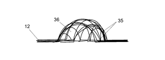
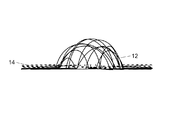
好ましくは、複数の層は、球体、立方体、直方体又は多面体等の3次元幾何学的形状として構成可能である。 Preferably, the plurality of layers can be configured as a three-dimensional geometric shape such as a sphere, a cube, a rectangular parallelepiped or a polyhedron.
好ましくは、構造手段は、少なくとも1つの多孔性部材を保持及び/又は支持する手段を備える。保持とは、多孔性部材を直接的に当接、保持することによって、又は多孔性部材を当接、保持する第2の構造体上で作用させることによって、所定の位置に維持することを意味する。 Preferably, the structural means include means for holding and / or supporting at least one porous member. Retention means maintaining a predetermined position by directly abutting and holding the porous member or by acting on a second structure that abuts and holds the porous member. do.
好ましくは、構造手段は、構造体をもたらし、少なくとも1つの多孔性部材を支持し得る構造板、構造箱、構造枠、留め具及び/若しくは他の適切な幾何学的構成又はそれらの組合せを画成する。 Preferably, the structural means depict structural plates, structural boxes, structural frames, fasteners and / or other suitable geometric configurations or combinations thereof that can provide the structure and support at least one porous member. To be done.
理想的には、多孔性部材保持手段は、構造棒を備える。 Ideally, the porous member holding means comprises a structural rod.
好ましくは、構造棒は、0.1から10mmの間の直径/幅を含む。 Preferably, the structural rod comprises a diameter / width between 0.1 and 10 mm.
一実施形態では、構造棒は、0.5から5mmの間の直径/幅を含む。 In one embodiment, the structural rod comprises a diameter / width between 0.5 and 5 mm.
理想的には、構造棒は、約1mmの直径/幅を含む。 Ideally, the structural rods would include a diameter / width of about 1 mm.
別の実施形態では、構造棒は、0.1から1mmの間の直径/幅を含む。 In another embodiment, the structural rod comprises a diameter / width between 0.1 and 1 mm.
理想的には、構造棒は、約0.4mmの直径/幅を含む。 Ideally, the structural rods would include a diameter / width of about 0.4 mm.
好ましくは、構造棒は、約0.39mmの平均直径/幅を含む。 Preferably, the structural rod comprises an average diameter / width of about 0.39 mm.
理想的には、構造棒は、離間している。 Ideally, the structural rods are separated.
理想的には、構造手段、最も好ましくは構造棒は、ポリマー物質を含む。 Ideally, the structural means, most preferably the structural rods, will contain a polymeric material.
理想的には、構造手段、最も好ましくは構造棒は、フルオロポリマーを含む。 Ideally, the structural means, most preferably the structural rods, comprises a fluoropolymer.
理想的には、構造手段、最も好ましくは構造棒は、ポリテトラフルオロエチレン(PTFE)、最も好ましくは、延伸PTFE(ePTFE)を含む。 Ideally, the structural means, most preferably structural rods, comprises polytetrafluoroethylene (PTFE), most preferably stretched PTFE (ePTFE).
好ましくは、構造棒は、ポリマー棒である。 Preferably, the structural rod is a polymer rod.
好ましくは、構造棒は、フルオロポリマー棒である。 Preferably, the structural rod is a fluoropolymer rod.
好ましくは、構造棒は、ePTFEから形成される。 Preferably, the structural rod is formed from ePTFE.
有利には、ePTFEは、PTFEと比較すると可撓性であるため、構造棒及び構造枠は、可撓性で、扱いやすい。 Advantageously, since ePTFE is more flexible than PTFE, the structural rods and frames are flexible and easy to handle.
理想的には、構造棒は、ePTFE棒である。 Ideally, the structural rod is an ePTFE rod.
理想的には、構造棒は、円形又は卵形断面を有する。 Ideally, the structural rod has a circular or oval cross section.
一実施形態では、構造棒は、メッシュとして構成される。 In one embodiment, the structural rods are configured as a mesh.
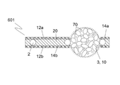
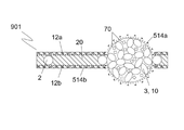
理想的には、構造枠は、2つの群の構造棒を備える。 Ideally, the structural frame comprises two groups of structural rods.
理想的には、構造枠は、第1の群の構造棒と第2の群の構造棒とを備える。 Ideally, the structural frame comprises a first group of structural rods and a second group of structural rods.
好ましくは、第1の群の構造棒は、離間平行構成で複数の構造棒を備える。 Preferably, the structural rods of the first group include a plurality of structural rods in a separated parallel configuration.
理想的には、第2の群の構造棒は、離間平行構成で複数の構造棒を備える。 Ideally, the second group of structural rods comprises a plurality of structural rods in a separated parallel configuration.
好ましくは、第1の群の構造棒は、第2の群の構造棒に直交して配置される。 Preferably, the structural rods of the first group are arranged orthogonally to the structural rods of the second group.
好ましくは、構造棒は、網状である。 Preferably, the structural rods are reticulated.
理想的には、構造棒は網状であり、一方の群の離間構造棒は、もう一方の群の離間構造棒の上に重なる及び/又はもう一方の群の離間構造棒と絡合する。 Ideally, the structural rods are reticulated, with one group of isolation rods overlapping and / or the other group of isolation rods entwined.
好ましくは、第1の群の構造棒及び/又は第2の群の構造棒の構造棒の間の間隔は、0.1から10mmの間である。 Preferably, the distance between the structural rods of the first group and / or the structural rods of the second group is between 0.1 and 10 mm.
理想的には、第1の群の構造棒及び/又は第2の群の構造棒の構造棒の間の間隔は、0.5から5mmの間である。 Ideally, the spacing between the structural rods of the first group and / or the structural rods of the second group is between 0.5 and 5 mm.
好ましくは、第1の群の構造棒及び/又は第2の群の構造棒の構造棒の間の間隔は、2から4mmの間である。 Preferably, the distance between the structural rods of the first group and / or the structural rods of the second group is between 2 and 4 mm.
理想的には、第1の群の構造棒及び/又は第2の群の構造棒の構造棒の間の間隔は、約3mmである。 Ideally, the distance between the structural rods of the first group and / or the structural rods of the second group is about 3 mm.
理想的には、第1の群の構造棒及び/又は第2の群の構造棒の構造棒の間の間隔は、0.5から5mmの間であり、これにより、複数の開口を有するメッシュ網を画成し、各開口は、0.25から25mm2の間の面積を有する。 Ideally, the spacing between the structural rods of the first group and / or the structural rods of the second group is between 0.5 and 5 mm, which allows the mesh to have multiple openings. The mesh is defined and each opening has an area between 0.25 and 25 mm 2.
好ましくは、第1の群の構造棒及び/又は第2の群の構造棒の構造棒の間の間隔は、2から4mmの間であり、これにより、複数の開口を有するメッシュ網を画成し、各開口は、4から16mm2の間の面積を有する。 Preferably, the spacing between the structural rods of the first group and / or the structural rods of the second group is between 2 and 4 mm, thereby defining a mesh net with a plurality of openings. Each opening has an area between 4 and 16 mm 2.
好ましくは、第1の群の構造棒及び/又は第2の群の構造棒の構造棒の間の間隔は、約3mmであり、これにより、複数の開口を有するメッシュ網を画成し、各開口は、約9mm2の面積を有する。 Preferably, the spacing between the structural rods of the first group and / or the structural rods of the second group is about 3 mm, thereby defining a mesh net with a plurality of openings, respectively. The opening has an area of about 9 mm 2.
一実施形態では、複数のメッシュ網は、メッシュ網の層をもたらすように構成される。 In one embodiment, the plurality of mesh nets are configured to provide a layer of mesh nets.
理想的には、複数のメッシュ網は、格子構造として構成される。 Ideally, the mesh network is configured as a lattice structure.
理想的には、少なくとも1つの多孔性部材は、メッシュ網の開口内に配置できるようにサイズ決定される。 Ideally, at least one porous member is sized so that it can be placed within the opening of the mesh mesh.
理想的には、少なくとも1つの多孔性部材をメッシュ網の開口内に配置した際、メッシュ網は、多孔性部材と当接する。 Ideally, when at least one porous member is placed within the opening of the mesh net, the mesh net comes into contact with the porous member.
好ましくは、メッシュ網と多孔性部材との間の当接により、多孔性部材をメッシュ網内に保持する。 Preferably, the porous member is held in the mesh net by abutting between the mesh net and the porous member.
一実施形態では、少なくとも1つの多孔性部材は、締まり嵌めを介してメッシュ網内に保持される。 In one embodiment, at least one porous member is held in the mesh net via a tight fit.
好ましくは、少なくとも1つの多孔性部材は、生体親和性物質及び/又は生体安定物質から形成される。 Preferably, at least one porous member is formed from a biocompatible material and / or a biostable material.
有利には、半透過性装置は、臨床での使用に適している。 Advantageously, the semi-permeable device is suitable for clinical use.
好ましくは、少なくとも1つの多孔性部材は、少なくとも1つのポリマー物質、最も好ましくは少なくとも1つの熱可塑性ポリマー物質を含む。 Preferably, the at least one porous member comprises at least one polymeric material, most preferably at least one thermoplastic polymeric material.
好ましくは、少なくとも1つの多孔性部材は、緩く圧縮した粉体の焼結から形成される。 Preferably, at least one porous member is formed from the sintering of loosely compressed powder.
理想的には、緩く圧縮される粉体は、熱可塑性ポリマーである。 Ideally, the loosely compressed powder is a thermoplastic polymer.
有利には、この方法は、半透過性装置の特性を調節するように修正できる。例えば、粒径は、多孔性部材を通る流体の移動速度に影響を与える。 Advantageously, this method can be modified to adjust the properties of the translucent device. For example, the particle size affects the rate of movement of the fluid through the porous member.
好ましくは、少なくとも1つの多孔性部材は、一緒に付着及び/又は焼結した複数の粒子を含む。 Preferably, the at least one porous member comprises a plurality of particles adhered and / or sintered together.
理想的には、複数の粒子は、一緒に付着及び/又は焼結され、粒子間の間隙は、孔径を画成する。 Ideally, the particles are adhered and / or sintered together and the gaps between the particles define the pore size.
有利には、この間隙により、多孔性部材の透過率を向上させる。 Advantageously, this gap improves the transmittance of the porous member.
理想的には、孔径は、製造条件及び粒径に応じて修正できる。 Ideally, the pore size can be modified depending on the manufacturing conditions and particle size.
好ましくは、孔径は、250μm以下である。 Preferably, the pore size is 250 μm or less.
好ましくは、孔径は、125μm以下である。 Preferably, the pore size is 125 μm or less.
好ましくは、孔径は、75μm以下である。 Preferably, the pore size is 75 μm or less.
好ましくは、孔径は、50μm以下である。 Preferably, the pore size is 50 μm or less.
有利には、50μmを超える寸法を有する物質は、少なくとも1つの多孔性部材を通じてろ過できない。小さな粉体の粒径により、より小さな粒子間の間隔及びより小さな全体孔径がもたらされることは理解されよう。このことにより、孔径の平均断面積を低減し、多孔性部材、したがって半透過性装置を通る流れの速度を低減する。多孔性部材(複数可)の製造方法は、半透過性装置に所望の特性をもたらすように調節できる。 Advantageously, substances having dimensions greater than 50 μm cannot be filtered through at least one porous member. It will be appreciated that the particle size of the smaller powders results in smaller inter-particle spacing and smaller overall pore size. This reduces the average cross-sectional area of the pore size and reduces the velocity of the flow through the porous member and thus the translucent device. The method of making the porous member (s) can be adjusted to provide the semi-transparent device with the desired properties.
好ましくは、少なくとも1つの多孔性部材は、3次元幾何学的形状である。 Preferably, the at least one porous member has a three-dimensional geometric shape.
一実施形態では、少なくとも1つの多孔性部材は、形状が球形、ほぼ球形若しくは偏平の球体、球形キャップ、半球体、卵形体、立方体又は直方体である。 In one embodiment, the at least one porous member is a spherical, substantially spherical or flat sphere in shape, a spherical cap, a hemisphere, an oval, a cube or a rectangular parallelepiped.
代替的に、少なくとも1つの多孔性部材は、円板形状である。 Alternatively, at least one porous member is disk-shaped.
一実施形態では、構造手段は、一平面を画成する。 In one embodiment, the structural means define a plane.
本実施形態では、多孔性部材は、多孔性部材の最も短い寸法が構造手段の平面に実質的に直交するように、構造手段に対して配置される。 In this embodiment, the porous member is arranged relative to the structural means such that the shortest dimension of the porous member is substantially orthogonal to the plane of the structural means.
理想的には、多孔性部材は、約1.5mmの直径又は幅を含む。 Ideally, the porous member comprises a diameter or width of about 1.5 mm.
好ましくは、多孔性部材は、構造手段の厚さよりも大きい厚さを有する。 Preferably, the porous member has a thickness greater than the thickness of the structural means.
有利には、概して、多孔性部材が構造手段と相互作用できるという条件で、構造手段よりも大きい厚さを伴うあらゆる3次元幾何学的形状を使用できる。 Advantageously, in general, any three-dimensional geometry with a greater thickness than the structural means can be used, provided that the porous member can interact with the structural means.
理想的には、多孔性部材は、0.25mm以上の厚さを有する。 Ideally, the porous member has a thickness of 0.25 mm or more.
好ましくは、多孔性部材は、0.4mm以上の厚さを有する。 Preferably, the porous member has a thickness of 0.4 mm or more.
理想的には、多孔性部材は、0.75mm以上の厚さを有する。 Ideally, the porous member has a thickness of 0.75 mm or more.
一実施形態では、多孔性部材は、約1mmの厚さを有する。 In one embodiment, the porous member has a thickness of about 1 mm.
半透過性装置は、一連の形状及びサイズの多孔性部材を備え得ることは理解されよう。 It will be appreciated that a semi-transparent device may include a series of porous members of a shape and size.
一実施形態では、少なくとも1つの多孔性部材は、0.1から10mmの間でサイズ決定され、最も好ましくは、少なくとも1つの多孔性部材は、球形、ほぼ球形若しくは偏平の球体、球形キャップ、半球体、卵形体又は円板形状であり、0.1から10mmの間の直径/幅を有する。 In one embodiment, the at least one porous member is sized between 0.1 and 10 mm, and most preferably the at least one porous member is a spherical, nearly spherical or flat sphere, spherical cap, hemisphere. It is body, oval or disc-shaped and has a diameter / width between 0.1 and 10 mm.
一実施形態では、少なくとも1つの多孔性部材は、0.5から8mmの間でサイズ決定され、最も好ましくは、少なくとも1つの多孔性部材は、球形、ほぼ球形若しくは偏平の球体、球形キャップ、半球体、卵形体又は円板形状であり、0.5から8mmの間の直径/幅を有する。 In one embodiment, the at least one porous member is sized between 0.5 and 8 mm, and most preferably the at least one porous member is a spherical, nearly spherical or flat sphere, spherical cap, hemisphere. It is body, oval or disc-shaped and has a diameter / width between 0.5 and 8 mm.
理想的には、少なくとも1つの多孔性部材は、1から5mmの間でサイズ決定され、最も好ましくは、少なくとも1つの多孔性部材は、球形、ほぼ球形若しくは偏平の球体、球形キャップ、半球体、卵形体又は円板形状であり、1から5mmの間の直径/幅を有する。 Ideally, at least one porous member is sized between 1 and 5 mm, and most preferably at least one porous member is a spherical, nearly spherical or flat sphere, a spherical cap, a hemisphere. It is oval or disc-shaped and has a diameter / width between 1 and 5 mm.
理想的には、少なくとも1つの多孔性部材は、約3mmでサイズ決定され、最も好ましくは、少なくとも1つの多孔性部材は、球形、ほぼ球形若しくは偏平の球体、球形キャップ、半球体、卵形体又は円板形状であり、約3mmの直径/幅を有する。 Ideally, the at least one porous member is sized to about 3 mm, and most preferably the at least one porous member is a spherical, nearly spherical or flat sphere, a spherical cap, a hemisphere, an oval or It is disk-shaped and has a diameter / width of about 3 mm.
理想的には、少なくとも1つの多孔性部材は、構造手段の平面から、平面の上及び/又は下に延出する。 Ideally, at least one porous member extends above and / or below the plane of the structural means.
好ましくは、少なくとも1つの多孔性部材は、構造手段に対して隆起した外形を有する。 Preferably, the at least one porous member has a raised outer shape with respect to the structural means.
理想的には、少なくとも1つの多孔性部材は、構造手段の平面から少なくとも0.05mm延出する。 Ideally, at least one porous member extends at least 0.05 mm from the plane of the structural means.
一実施形態では、少なくとも1つの多孔性部材は、構造手段の平面から少なくとも0.5mm延出する。 In one embodiment, the at least one porous member extends at least 0.5 mm from the plane of the structural means.
理想的には、少なくとも1つの多孔性部材は、構造手段の平面から約1mm延出する。 Ideally, at least one porous member extends about 1 mm from the plane of the structural means.
有利には、一実施形態では、少なくとも1つの多孔性部材は、3mmの直径/幅を有し、構造棒は、約1mmの直径/幅を有するため、少なくとも1つの多孔性部材が構造手段の平面から、構造手段の両側で約1mm延出する。このことにより、半透過性装置の表面積を増大させ、大きなろ過表面をもたらす。更に、構造手段内の多孔性部材がドーム形状であることにより、物質が沈澱しないようにする。というのは、物質が傾き、ドーム形状の表面から転がり落ちるためである。 Advantageously, in one embodiment, the at least one porous member has a diameter / width of 3 mm and the structural rod has a diameter / width of about 1 mm, so that at least one porous member is a structural means. Extend about 1 mm from the plane on both sides of the structural means. This increases the surface area of the semi-permeable device and results in a large filtration surface. Further, the dome shape of the porous member in the structural means prevents the substance from precipitating. This is because the material tilts and rolls off the dome-shaped surface.
別の実施形態では、少なくとも1つの多孔性部材は、構造手段の平面から約0.3mm延出する。 In another embodiment, the at least one porous member extends about 0.3 mm from the plane of the structural means.
有利には、本実施形態では、多孔性部材は、構造手段の表面とほぼ面一である。半透過性装置の厚さは、構造手段の厚さに近いか又は等しく、このことにより、より見た目がよい製品をもたらす。更に、半透過性装置をヒト又は動物の体内に植え込む場合、多孔性部材が構造手段の平面を越えて延在することが最小化され、半透過性装置は、植え込み部位から過度に突出しない。このことにより、レシピエントにより多大な快適さをもたらし得る。 Advantageously, in this embodiment, the porous member is substantially flush with the surface of the structural means. The thickness of the semi-transparent device is close to or equal to the thickness of the structural means, which results in a better looking product. Further, when the semi-permeable device is implanted in the human or animal body, the porous member extends beyond the plane of the structural means is minimized and the semi-permeable device does not excessively project from the implantation site. This can provide greater comfort to the recipient.
一実施形態では、半透過性装置は、1つ又は複数の化学物質を含む。 In one embodiment, the semi-permeable device comprises one or more chemicals.
理想的には、半透過性装置は、1つ又は複数の可溶性化学物質粒子を含む。 Ideally, the semi-permeable device comprises one or more soluble chemical particles.
好ましくは、少なくとも1つの多孔性部材は、1つ又は複数の可溶性化学物質粒子を含む。 Preferably, the at least one porous member comprises one or more soluble chemical particles.
一実施形態では、可溶性粒子は、結晶粒子である。 In one embodiment, the soluble particles are crystalline particles.
理想的には、可溶性粒子は、多孔性部材の外部及び/又は内部/孔表面上に配設される。 Ideally, the soluble particles are disposed on the outside and / or inside / pore surface of the porous member.
好ましくは、1つ又は複数の化学物質は、少なくとも1つの薬理学的薬剤及び/又は抗菌剤を含む。 Preferably, the one or more chemicals comprises at least one pharmacological and / or antibacterial agent.
一実施形態では、1つ又は複数の化学物質は、担体物質である。 In one embodiment, one or more chemicals are carrier substances.
有利には、半透過性装置は、薬剤を溶出するように構成できる。他の薬剤溶出材料の調製と比較すると、薬剤をポリマーに結合させる必要はなく、比較的、製造方法は、著しく迅速で、単純である。更に、薬のみをポリマーと反応させる必要はない。単に、多孔性部材を、薬を含有する溶液に露出又は浸漬し、乾燥させるだけでよい。溶媒は蒸発し、溶質薬はポリマーの物理的隙間の中で結晶化する。半透過性装置を医療現場で使用する場合、可溶性粒子は、徐々に溶解し、1つ又は複数の化学物質を放出する。担体の添加を使用し、放出速度を制御できる。この特徴を使用し、半透過性装置の抗菌特性を更に向上させる又はレシピエントに治療をもたらすことができ、薬の投与及び薬溶出材料に更なる若しくは代替的な費用対効果のよい解決策をもたらす。更に、多孔性部材の孔径及び空隙の体積は、製造方法の変更によって調節可能である。この調節を使用し、多孔性部材内に含み得る抗生物質等の更なる化学物質の量、及び/又は多孔性部材から周囲媒体への溶出速度を増大又は減少させることができる。 Advantageously, the semi-permeable device can be configured to elute the drug. Compared to the preparation of other drug eluting materials, the drug does not need to be attached to the polymer and the manufacturing method is relatively fast and simple. Moreover, it is not necessary to react the drug alone with the polymer. The porous member may simply be exposed or immersed in a solution containing the drug and dried. The solvent evaporates and the solute crystallizes in the physical interstices of the polymer. When a semi-permeable device is used in a medical setting, the soluble particles gradually dissolve and release one or more chemicals. The addition of a carrier can be used to control the release rate. This feature can be used to further improve the antibacterial properties of the semi-permeable device or provide treatment to the recipient, providing additional or alternative cost-effective solutions to drug administration and drug elution materials. Bring. Further, the pore diameter and the volume of the voids of the porous member can be adjusted by changing the manufacturing method. This adjustment can be used to increase or decrease the amount of additional chemicals, such as antibiotics, that may be contained within the porous member and / or the rate of elution from the porous member into the surrounding medium.
理想的には、可溶性粒子が溶解するにつれて、孔径は増大する。 Ideally, the pore size increases as the soluble particles dissolve.
有利には、半透過性装置を臨床現場で使用する場合、レシピエント上又はレシピエント体内に挿入した後、半透過性装置の透過率は、可溶性粒子が溶解するにつれて経時的に増大する。 Advantageously, when the semi-permeable device is used in clinical practice, the permeability of the semi-permeable device increases over time as the soluble particles dissolve, after insertion on or into the recipient.
理想的には、半透過性装置は、複数の多孔性部材を備える。 Ideally, the semi-permeable device comprises a plurality of porous members.
理想的には、複数の多孔性部材は、構造手段上又は構造手段内に散在する状態で位置する。 Ideally, the plurality of porous members are located scattered on or within the structural means.
理想的には、複数の多孔性部材は、構造手段上又は構造手段内に離間関係で位置する。 Ideally, the plurality of porous members are located on the structural means or in the structural means in a separated relationship.
好ましくは、複数の多孔性部材は、構造枠のメッシュ網上又はメッシュ網内に離間関係で位置する。 Preferably, the plurality of porous members are spaced apart from each other on or within the mesh mesh of the structural frame.
理想的には、複数の多孔性部材は、構造手段上又は構造手段内にあるパターンで配置される。 Ideally, the plurality of porous members are arranged in a pattern on or within the structural means.
理想的には、複数の多孔性部材は、構造枠内の開口に隣接して、構造枠内又は構造枠上に配置され、開口には多孔性部材が一切ない。 Ideally, the plurality of porous members are arranged in or on the structural frame adjacent to the opening in the structural frame, and the opening has no porous member at all.
好ましくは、複数の多孔性部材は、構造手段内に列で配置される。 Preferably, the plurality of porous members are arranged in rows within the structural means.
好ましくは、複数の多孔性部材は、構造枠のメッシュ網の各列における1つおきの開口が多孔性部材を収容するように、構造枠内に列で配置される。 Preferably, the plurality of porous members are arranged in rows within the structural frame such that every other opening in each row of the mesh net of the structural frame accommodates the porous members.
好ましくは、複数の多孔性部材は、格子じまパターンで構造枠内に配置され、構造枠のメッシュ網の各列における1つおきの開口が多孔性部材を収容し、当該列の上又は下の列が同様のパターンを収容するが、当該列に対してずれており、複数の多孔性部材が、互いに側方又は長尺方向に隣接するのではなく、対角関係でメッシュ網内に配置されるようにする。 Preferably, the plurality of porous members are arranged in the structural frame in a grid stripe pattern, and every other opening in each row of the mesh net of the structural frame accommodates the porous members and is above or below the row. Rows accommodate similar patterns, but offset relative to the rows, with multiple porous members placed diagonally within the mesh network rather than adjacent to each other laterally or longitudinally. To be done.
理想的には、半透過性装置は、ろ過手段を備える。 Ideally, the translucent device is equipped with filtration means.
一実施形態では、ろ過手段は、構造手段によって設けられる。 In one embodiment, the filtration means are provided by structural means.
理想的には、ろ過手段は、物質の粒子を液体からろ過できる。 Ideally, the filtration means can filter particles of a substance from a liquid.
好ましくは、ろ過手段は、1.0μm未満のサイズの粒子又は微生物が少なくとも1つの多孔性部材に進入するのを除外できる。 Preferably, the filtration means can exclude particles or microorganisms having a size of less than 1.0 μm from entering at least one porous member.
理想的には、ろ過手段は、間隔を有するろ過ウェブを備え、間隔は、2.0μm以下である。 Ideally, the filtration means would include an spaced filtration web with an interval of 2.0 μm or less.
理想的には、ろ過手段は、間隔を有するろ過ウェブを備え、間隔は、1.0μm以下である。 Ideally, the filtration means would include an spaced filtration web with an interval of 1.0 μm or less.
好ましくは、ろ過手段は、間隔を有するろ過ウェブを備え、間隔は、0.5μm以下である。 Preferably, the filtration means comprises a filtration web with an interval, the interval being 0.5 μm or less.
有利には、0.5μm以下のろ過ウェブの間隔により、透過率とろ過能力との間の申し分のない兼ね合いが取られ、黄色ブドウ球菌及び他の関連病原体を含む細菌がウェブを通過しないようにするが、ウェブを通る流体の許容可能な流速を維持する。ろ過ウェブのこの薄さ(例えば、0.1〜0.3μm)により、<0.5μmの直径を有する粒子を通過可能にする。 Advantageously, a filtration web spacing of 0.5 μm or less provides a perfect trade-off between permeability and filtration capacity to prevent bacteria, including Staphylococcus aureus and other related pathogens, from passing through the web. However, maintain an acceptable flow rate of fluid through the web. This thinness of the filtration web (eg, 0.1 to 0.3 μm) allows particles with a diameter of <0.5 μm to pass through.
一実施形態では、ろ過手段は、間隔を有するろ過ウェブを備え、間隔は、0.2μm以下である。 In one embodiment, the filtration means comprises a filtration web with an interval of 0.2 μm or less.
有利には、ろ過手段は、ガス、水及び溶解物質に対して透過性であるが、大型粒子及び細菌に対しては透過性ではない。 Advantageously, the filtration means is permeable to gas, water and lysing substances, but not to large particles and bacteria.
好ましくは、ろ過手段は、最も好ましくはろ過ウェブは、構造手段及び/又は少なくとも1つの多孔性部材の1つの表面上に配置される。 Preferably, the filtration means, most preferably the filtration web, is placed on one surface of the structural means and / or at least one porous member.
一実施形態では、ろ過手段は、最も好ましくはろ過ウェブは、構造手段及び/又は少なくとも1つの多孔性部材の複数の表面上に配置される。 In one embodiment, the filtration means, most preferably the filtration web, is placed on multiple surfaces of the structural means and / or at least one porous member.
好ましくは、ろ過ウェブは、少なくとも1つのポリマー物質を含む。 Preferably, the filtration web comprises at least one polymeric substance.
理想的には、ろ過ウェブは、電界紡糸によって形成される。 Ideally, the filtration web is formed by electrospinning.
好ましくは、ろ過ウェブは、ポリマーの電界紡糸から形成される。 Preferably, the filtration web is formed from electrospinning of a polymer.
好ましくは、ろ過ウェブは、複数のろ過ウェブ繊維を備える。 Preferably, the filtered web comprises a plurality of filtered web fibers.
繊維とは、あらゆる糸状形態を意味し、小繊維及び細糸を含む。 Fiber means any filamentous form, including fibrils and fine threads.
好ましくは、ろ過ウェブは、不規則に配置した複数のろ過ウェブ繊維を備える。 Preferably, the filtration web comprises a plurality of irregularly arranged filtration web fibers.
理想的には、ろ過ウェブは、互いに重ねて配置され、間に間隔を有する複数のろ過ウェブ繊維を備える。 Ideally, the filtration webs are arranged on top of each other and include a plurality of filtration web fibers with spacing between them.
理想的には、ろ過ウェブは、互いに重ねて配置され、間に間隔を有する複数のろ過ウェブ繊維を備え、間隔は、2.0μm以下である。 Ideally, the filter webs are placed on top of each other and include a plurality of filter web fibers with spacing between them, with a spacing of 2.0 μm or less.
理想的には、ろ過ウェブは、互いに重ねて配置され、間に間隔を有する複数のろ過ウェブ繊維を備え、間隔は、1.0μm以下である。 Ideally, the filter webs are placed on top of each other and include a plurality of filter web fibers with spacing between them, with a spacing of 1.0 μm or less.
理想的には、ろ過ウェブは、互いに重ねて配置され、間に間隔を有する複数のろ過ウェブ繊維を備え、間隔は、0.5μm以下である。 Ideally, the filter webs are placed on top of each other and feature a plurality of filter web fibers with spacing between them, with a spacing of 0.5 μm or less.
理想的には、ろ過ウェブは、互いに重ねて配置され、間に間隔を有する複数のろ過ウェブ繊維を備え、間隔は、0.2μm以下である。 Ideally, the filter webs are placed on top of each other and feature a plurality of filter web fibers with spacing between them, with a spacing of 0.2 μm or less.
好ましくは、ろ過手段は、生体親和性及び/又は生体安定である。 Preferably, the filtration means is biocompatible and / or biostable.
有利には、ろ過手段は、臨床での使用に適している。 Advantageously, the filtration means are suitable for clinical use.
好ましくは、ろ過ウェブ繊維は、ポリマー繊維である。 Preferably, the filtered web fiber is a polymer fiber.
理想的には、ろ過ウェブの電界紡糸中、ろ過ウェブ繊維の平均直径/幅は、シリンジ装置の変更によって制御できる。 Ideally, during electrospinning of the filtered web, the average diameter / width of the filtered web fibers can be controlled by changing the syringe device.
理想的には、ろ過手段は、フッ素原子を含有しないポリマー物質から少なくとも部分的に形成される。 Ideally, the filtration means is at least partially formed from a fluoropolymer-free polymeric material.
有利には、ろ過手段は、パーフルオロカーボンに対する親和性を有さない。 Advantageously, the filtration means have no affinity for perfluorocarbons.
理想的には、ろ過手段は、ポリウレタンから少なくとも部分的に形成される。 Ideally, the filtration means is at least partially formed from polyurethane.
好ましくは、ろ過手段は、電界紡糸ポリウレタンから少なくとも部分的に形成される。 Preferably, the filtration means is at least partially formed from electrospun polyurethane.
好ましくは、ろ過ウェブ繊維の間の間隔のサイズは、製造工程を介して及び製造後の延伸を通じて制御できる。 Preferably, the size of the spacing between the filtered web fibers can be controlled through the manufacturing process and through post-manufacturing stretching.
好ましくは、ろ過ウェブ繊維は、0.01から100μmの間の平均直径/幅を有する。 Preferably, the filtered web fibers have an average diameter / width between 0.01 and 100 μm.
好ましくは、ろ過ウェブ繊維は、0.01から10μmの間の平均直径/幅を有する。 Preferably, the filtered web fibers have an average diameter / width between 0.01 and 10 μm.
好ましくは、ろ過ウェブ繊維は、約0.1の平均直径/幅を有する。 Preferably, the filtered web fibers have an average diameter / width of about 0.1.
一実施形態では、ろ過手段は、構造手段及び/又は少なくとも1つの多孔性部材にわたって置かれた状態及び/又は延伸された状態で形成される。 In one embodiment, the filtration means are formed in a state of being placed and / or stretched over a structural means and / or at least one porous member.
構造手段が平坦である一実施形態では、ろ過手段は、構造手段の少なくとも両方の平坦表面上に配置され、構造手段は、ろ過手段によって挟まれる。 In one embodiment in which the structural means are flat, the filtering means is placed on at least both flat surfaces of the structural means, and the structural means are sandwiched by the filtering means.
代替的に、ろ過手段は、ろ過手段が構造手段の全て又は一部によって挟まれるように、構造手段内/構造手段間に配置できる。 Alternatively, the filtration means can be arranged within / between the structural means such that the filtration means is sandwiched by all or part of the structural means.
一実施形態では、ろ過ウェブ繊維の間の間隔は、少なくとも1つの多孔性部材において又はその周囲で、構造手段における又はその周囲のろ過ウェブ繊維の間の間隔よりも広い。 In one embodiment, the spacing between the filtered web fibers is greater in or around the at least one porous member than between the filtered web fibers in or around the structural means.
理想的には、ろ過ウェブは、互いに重ねて配置され、間に間隔を有する複数のろ過ウェブ繊維を備え、間隔は、2.0μm以下である。 Ideally, the filter webs are placed on top of each other and include a plurality of filter web fibers with spacing between them, with a spacing of 2.0 μm or less.
理想的には、ろ過ウェブは、互いに重ねて配置され、間に間隔を有する複数のろ過ウェブ繊維を備え、間隔は、1.0μm以下である。 Ideally, the filter webs are placed on top of each other and include a plurality of filter web fibers with spacing between them, with a spacing of 1.0 μm or less.
理想的には、ろ過ウェブは、互いに重ねて配置され、間に間隔を有する複数のろ過ウェブ繊維を備え、間隔は、0.5μm以下である。 Ideally, the filter webs are placed on top of each other and feature a plurality of filter web fibers with spacing between them, with a spacing of 0.5 μm or less.
理想的には、ろ過ウェブは、互いに重ねて配置され、間に間隔を有する複数のろ過ウェブ繊維を備え、間隔は、0.2μm以下である。 Ideally, the filter webs are placed on top of each other and feature a plurality of filter web fibers with spacing between them, with a spacing of 0.2 μm or less.
好ましくは、ろ過手段は、330℃以下の溶融点を有する。 Preferably, the filtration means has a melting point of 330 ° C. or lower.
理想的には、ろ過手段は、200℃以下の溶融点を有する。 Ideally, the filtration means has a melting point of 200 ° C. or lower.
理想的には、ろ過手段は、150℃以下の溶融点を有する。 Ideally, the filtration means has a melting point of 150 ° C. or lower.
理想的には、ろ過手段は、100℃以下の溶融点を有する。 Ideally, the filtration means has a melting point of 100 ° C. or lower.
有利には、ろ過手段の一部を溶融させ、構造手段及び/又は半透過性装置の他の構成要素の部品に接着させるか、ろ過手段の一部分を溶融させ、ろ過手段の別の部分に接着できる。 Advantageously, one part of the filtration means is melted and adhered to the components of the structural means and / or other components of the translucent device, or one part of the filtration means is melted and adhered to another part of the filtration means. can.
好ましくは、半透過性装置は、自己洗浄手段を備える。 Preferably, the semi-permeable device comprises self-cleaning means.
自己洗浄とは、ファウリングをもたらす物質を反発することを意味する。有利には、自己洗浄手段は、半透過性装置のファウリング速度を減少させるか、又はファウリングを完全になくす。 Self-cleaning means repelling substances that cause fouling. Advantageously, the self-cleaning means reduces the fouling rate of the semi-permeable device or eliminates fouling altogether.
一実施形態では、自己洗浄手段は、構造手段によって設けられる。 In one embodiment, the self-cleaning means is provided by structural means.
理想的には、自己洗浄手段は、自己洗浄ウェブを備える。 Ideally, the self-cleaning means comprises a self-cleaning web.
理想的には、自己洗浄手段、最も好ましくは自己洗浄ウェブは、ろ過手段及び/又は少なくとも1つの多孔性部材の1つの表面上に配置される。 Ideally, the self-cleaning means, most preferably the self-cleaning web, is placed on one surface of the filtering means and / or at least one porous member.
理想的には、自己洗浄手段、最も好ましくは自己洗浄ウェブは、ろ過手段及び/又は少なくとも1つの多孔性部材の複数の表面上に配置される。 Ideally, the self-cleaning means, most preferably the self-cleaning web, are placed on multiple surfaces of the filtering means and / or at least one porous member.
一実施形態では、自己洗浄手段は、多孔性部材の一部の表面上に配置されるが、全ての多孔性部材の表面上に配置されない。 In one embodiment, the self-cleaning means is located on the surface of some of the porous members, but not on the surface of all the porous members.
別の実施形態では、自己洗浄手段、最も好ましくは自己洗浄ウェブは、構造手段の1つの表面上に配置される。 In another embodiment, the self-cleaning means, most preferably the self-cleaning web, is placed on one surface of the structural means.
好ましくは、自己洗浄手段、最も好ましくは自己洗浄ウェブは、構造手段の複数の表面上に配置される。 Preferably, the self-cleaning means, most preferably the self-cleaning web, are placed on a plurality of surfaces of the structural means.
構造手段が平坦である一実施形態では、自己洗浄手段は、構造手段の少なくとも両方の平坦表面上に配置され、構造手段は、自己洗浄手段によって挟まれる。 In one embodiment in which the structural means are flat, the self-cleaning means are placed on at least both flat surfaces of the structural means, and the structural means are sandwiched by the self-cleaning means.
代替的に、自己洗浄手段は、自己洗浄手段が構造手段の全て又は一部によって挟まれるように、構造手段内/構造手段間に位置できる。 Alternatively, the self-cleaning means can be located within / between the structural means such that the self-cleaning means is sandwiched by all or part of the structural means.
本実施形態では、自己洗浄手段によって覆われていない構造手段の部分は、ファウリングを受ける可能性があり、このため、半透過性装置は、部分的にしか自己洗浄式ではない可能性があることは理解されよう。 In this embodiment, parts of the structural means that are not covered by the self-cleaning means may undergo fouling, so that the semi-permeable device may only be partially self-cleaning. It will be understood.
別の実施形態では、ろ過手段、最も好ましくはろ過ウェブは、自己洗浄手段及び/又は少なくとも1つの多孔性部材の1つの表面上に配置される。 In another embodiment, the filtering means, most preferably the filtering web, is placed on one surface of the self-cleaning means and / or at least one porous member.
好ましくは、ろ過手段、最も好ましくはろ過ウェブは、自己洗浄手段及び/又は少なくとも1つの多孔性部材の複数の表面上に配置される。 Preferably, the filtration means, most preferably the filtration web, are placed on a plurality of surfaces of the self-cleaning means and / or at least one porous member.
理想的には、ろ過手段の少なくとも一部は、自己洗浄手段及び/又は構造手段の少なくとも一部に接着される。 Ideally, at least a portion of the filtration means is adhered to at least a portion of the self-cleaning means and / or the structural means.
理想的には、ろ過手段の少なくとも一部は、自己洗浄手段及び/又は構造手段の少なくとも一部に、最も好ましくは一緒に押圧及び/又は溶融した構成要素によって結合される。 Ideally, at least a portion of the filtering means is attached to at least a portion of the self-cleaning means and / or structural means, most preferably together by a pressed and / or melted component.
有利には、ろ過手段は、自己洗浄手段及び構造手段を一緒に維持することによって、更なる構造を半透過性装置にもたらす。 Advantageously, the filtration means brings additional structure to the semi-permeable device by keeping the self-cleaning means and the structural means together.
代替的に、ろ過手段に加えて又はろ過手段の代わりに、接着性溶融物質及び/又は機械式留め具を設け、自己洗浄手段の部品を一緒に維持する及び/又は自己洗浄手段と構造手段とを一緒に維持できる。 Alternatively, in addition to or in place of the filtration means, an adhesive melt and / or mechanical fastener is provided to keep the parts of the self-cleaning means together and / or with the self-cleaning means and structural means. Can be maintained together.
一実施形態では、半透過性装置は、自己洗浄手段、構造手段及び/又はろ過手段を一緒に保持する手段を備える。 In one embodiment, the semi-permeable device comprises means for holding self-cleaning means, structural means and / or filtration means together.
理想的には、自己洗浄手段、構造手段及び/又はろ過手段を一緒に保持する手段は、留め具、機械式固定手段、接着剤、又は自己洗浄手段、構造手段及び/若しくはろ過手段に嵌合される他のそのような手段を備える。 Ideally, the means for holding the self-cleaning means, structural means and / or filtering means together fits into fasteners, mechanical fixing means, adhesives, or self-cleaning means, structural means and / or filtering means. Provide other such means to be done.
好ましくは、自己洗浄手段、最も好ましくは自己洗浄ウェブは、少なくとも1つのポリマー物質を含む。 Preferably, the self-cleaning means, most preferably the self-cleaning web, comprises at least one polymeric substance.
理想的には、自己洗浄ウェブは、電界紡糸によって形成される。 Ideally, the self-cleaning web is formed by electrospinning.
好ましくは、自己洗浄ウェブは、ポリマーの電界紡糸によって形成される。 Preferably, the self-cleaning web is formed by electrospinning a polymer.
好ましくは、自己洗浄ウェブは、複数の自己洗浄ウェブ繊維を備える。 Preferably, the self-cleaning web comprises a plurality of self-cleaning web fibers.
好ましくは、自己洗浄ウェブは、不規則に配置した複数の自己洗浄ウェブ繊維を備える。 Preferably, the self-cleaning web comprises a plurality of irregularly arranged self-cleaning web fibers.
理想的には、自己洗浄ウェブは、互いに重ねて配置され、間に間隔を有する複数の自己洗浄ウェブ繊維を備える。 Ideally, the self-cleaning webs are arranged on top of each other and include a plurality of self-cleaning web fibers with spacing between them.
好ましくは、間隔は、液体、最も好ましくはパーフルオロカーボン液体の毛管作用を可能にするように生成される。 Preferably, the spacing is generated to allow capillary action of the liquid, most preferably the perfluorocarbon liquid.
理想的には、自己洗浄ウェブは、互いに重ねて配置され、間に間隔を有する複数の自己洗浄ウェブ繊維を備え、間隔は、2.0μm以下である。 Ideally, the self-cleaning webs are placed on top of each other, with a plurality of self-cleaning web fibers spaced between them, with a spacing of 2.0 μm or less.
理想的には、自己洗浄ウェブは、互いに重ねて配置され、間に間隔を有する複数の自己洗浄ウェブ繊維を備え、間隔は、1.0μm以下である。 Ideally, the self-cleaning webs are placed on top of each other, with a plurality of self-cleaning web fibers spaced between them, with a spacing of 1.0 μm or less.
理想的には、自己洗浄ウェブは、互いに重ねて配置され、間に間隔を有する複数の自己洗浄ウェブ繊維を備え、間隔は、0.5μm以下である。 Ideally, the self-cleaning webs are placed on top of each other, with a plurality of self-cleaning web fibers spaced in between, with a spacing of 0.5 μm or less.
有利には、自己洗浄ウェブが潤滑液体で処理されていない一実施形態では、0.5μm以下の自己洗浄ウェブの間隔により、透過率とろ過能力との間の申し分のない兼ね合いが取られ、黄色ブドウ球菌及び他の関連病原体を含む細菌がウェブを通過しないようにするが、ウェブを通る流体の許容可能な流速を維持する。理想的には、自己洗浄ウェブは、互いに重ねて配置され、間に間隔を有する複数の自己洗浄ウェブ繊維を備え、間隔は、0.2μm以下である。 Advantageously, in one embodiment where the self-cleaning web is not treated with a lubricating liquid, a spacing of 0.5 μm or less of the self-cleaning web provides a perfect trade-off between permeability and filtration capacity, yellow. Prevents bacteria, including Staphylococcus aureus and other related pathogens, from passing through the web, but maintains an acceptable flow rate of fluid through the web. Ideally, the self-cleaning webs are placed on top of each other, with a plurality of self-cleaning web fibers spaced between them, with a spacing of 0.2 μm or less.
好ましくは、自己洗浄手段は、生体親和性及び/又は生体安定である。 Preferably, the self-cleaning means is biocompatible and / or biostable.
有利には、自己洗浄手段は、臨床での使用に適している。 Advantageously, self-cleaning means are suitable for clinical use.
好ましくは、自己洗浄ウェブ繊維は、ポリマー繊維である。 Preferably, the self-cleaning web fiber is a polymer fiber.
理想的には、自己洗浄ウェブ繊維の平均直径/幅は、製造工程の間に制御できる。 Ideally, the average diameter / width of the self-cleaning web fibers can be controlled during the manufacturing process.
好ましくは、自己洗浄ウェブ繊維は、0.01から100μmの間の平均直径/幅を有する。 Preferably, the self-cleaning web fibers have an average diameter / width between 0.01 and 100 μm.
好ましくは、自己洗浄ウェブ繊維は、0.01から10μmの間の平均直径/幅を有する。 Preferably, the self-cleaning web fibers have an average diameter / width between 0.01 and 10 μm.
好ましくは、自己洗浄ウェブ繊維は、約0.1の直径/幅を有する。 Preferably, the self-cleaning web fibers have a diameter / width of about 0.1.
理想的には、自己洗浄手段は、フッ素原子を含有するポリマー物質から少なくとも部分的に形成される。 Ideally, the self-cleaning means is at least partially formed from a polymeric material containing fluorine atoms.
有利には、自己洗浄手段は、パーフルオロカーボンに対する親和性を有する。 Advantageously, the self-cleaning means have an affinity for perfluorocarbons.
理想的には、自己洗浄手段は、PTFEから少なくとも部分的に形成される。 Ideally, the self-cleaning means is at least partially formed from PTFE.
好ましくは、自己洗浄手段は、延伸PTFE又は電界紡糸PTFE(esPTFE)から少なくとも部分的に形成される。 Preferably, the self-cleaning means is at least partially formed from drawn PTFE or electrospun PTFE (esPTFE).
有利には、PTFEは、オムニフォビックであり、ファウリングをもたらし得る疎水性物質及び親水性物質の両方を反発する。 Advantageously, PTFE is omniphobic and repels both hydrophobic and hydrophilic substances that can result in fouling.
好ましくは、自己洗浄ウェブ繊維の間の間隔のサイズは、製造工程を介して及び伸長を通じて制御できる。 Preferably, the size of the spacing between the self-cleaning web fibers can be controlled through the manufacturing process and through elongation.
理想的には、自己洗浄ウェブは、ろ過手段及び/又は少なくとも1つの多孔性部材にわたって置かれた及び/又は伸長された状態で、形成される。 Ideally, the self-cleaning web is formed in a state of being placed and / or stretched over the filtration means and / or at least one porous member.
一実施形態では、自己洗浄ウェブは、構造手段及び/又は少なくとも1つの多孔性部材にわたって置かれた及び/又は延伸された状態で、形成される。 In one embodiment, the self-cleaning web is formed in a state of being laid and / or stretched over structural means and / or at least one porous member.
有利には、自己洗浄手段は、ろ過手段の一部を周囲環境から隔離することによって、ろ過手段の少なくとも一部が劣化しないようにする。 Advantageously, the self-cleaning means isolates a portion of the filtering means from the surrounding environment so that at least a portion of the filtering means does not deteriorate.
一実施形態では、半透過性装置は、少なくとも1つの補助物質を含む。 In one embodiment, the semi-permeable device comprises at least one auxiliary substance.
理想的には、少なくとも1つの補助物質は、潤滑剤を含む。 Ideally, at least one auxiliary substance comprises a lubricant.
好ましくは、自己洗浄手段は、少なくとも1つの補助物質を含む。 Preferably, the self-cleaning means comprises at least one auxiliary substance.
理想的には、少なくとも1つの補助物質は、疎水性又はオムニフォビックである。 Ideally, at least one auxiliary substance is hydrophobic or omniphobic.
理想的には、潤滑剤は、疎水性又はオムニフォビックである。 Ideally, the lubricant is hydrophobic or omniphobic.
有利には、潤滑剤のオムニフォビック性により、疎水性物質及び親水性物質の両方を反発し、これにより、ファウリングの可能性をなくし、バイオフィルムの生成又は組織内部成長を防止する。更に有利には、バイオフィルムの生成は、抗菌物質を一切使用せずに防止でき、したがって、半透過性装置の使用は、いくつかの抗菌物質の使用に起因する合併症、及び/又は抗微生物薬耐性細菌の出現に寄与しない。 Advantageously, the omniphobic nature of the lubricant repels both hydrophobic and hydrophilic substances, thereby eliminating the possibility of fouling and preventing biofilm formation or tissue internal growth. Even more advantageously, the formation of biofilms can be prevented without the use of any antibacterial substances, so the use of semi-permeable devices is a complication due to the use of some antibacterial substances and / or antimicrobials. Does not contribute to the emergence of drug-resistant bacteria.
好ましくは、少なくとも1つの補助物質は、自己洗浄ウェブ及び/又は支持枠に対する親和性を有する。 Preferably, the at least one auxiliary material has an affinity for the self-cleaning web and / or support frame.
好ましくは、少なくとも1つの補助物質は、パーフルオロカーボン液体を含む。 Preferably, the at least one auxiliary substance comprises a perfluorocarbon liquid.
理想的には、パーフルオロカーボン液体は、パーフルオロポリエーテル(PFPE)、パーフルオロペルヒドロフェナントレン(PFPH)、パーフルオロデカリン(PFD)及び/又は他のパーフルオロカーボン化合物を含む。 Ideally, the perfluorocarbon liquid comprises perfluoropolyether (PFPE), perfluoroperhydrophenanthrene (PFPH), perfluorodecalin (PFD) and / or other perfluorocarbon compounds.
有利には、パーフルオロカーボンは、化学的に比較的不活性であり、PTFE、ePTFE及び電界紡糸PTFEに対して化学的親和性を有する。支持枠及び/又は自己洗浄ウェブがPTFEから形成される一実施形態では、潤滑剤は、これらの構成要素に対して天然の親和性を有する。パーフルオロカーボンは、医学的消費者製品及び獣医学的消費者製品の両方で使用されている。PFPHは、ヒトの網膜裂孔の修復、並びに口紅、グロス及びアイシャドー等の化粧品(例えば、Tefpoly(商標)、The Innovation Company、フランス、ドルー)で使用されており、PFDは、代替血液として研究されている。 Advantageously, perfluorocarbons are chemically relatively inert and have a chemical affinity for PTFE, ePTFE and electrospun PTFE. In one embodiment in which the support frame and / or self-cleaning web is formed from PTFE, the lubricant has a natural affinity for these components. Perfluorocarbons are used in both medical and veterinary consumer products. PFPH has been used in the repair of human retinal detachments and in cosmetics such as lipstick, gloss and eyeshadow (eg, Tefpoly ™, The Innovation Company, Dreux, France), and PFD has been studied as a blood substitute. ing.
好ましくは、自己洗浄ウェブは、少なくとも1つの補助物質で飽和される。 Preferably, the self-cleaning web is saturated with at least one auxiliary material.
好ましくは、少なくとも1つの補助物質は、毛管作用によって自己洗浄ウェブ全体を通じて分散される。 Preferably, at least one auxiliary substance is dispersed throughout the self-cleaning web by capillary action.
理想的には、少なくとも1つの補助物質は、毛管作用によって自己洗浄ウェブ全体を通じて維持される。 Ideally, at least one auxiliary substance is maintained throughout the self-cleaning web by capillary action.
一実施形態では、構造手段は、少なくとも1つの補助物質で飽和される。 In one embodiment, the structural means are saturated with at least one auxiliary material.
一実施形態では、自己洗浄ウェブ繊維の間の間隔は、少なくとも1つの多孔性部材において又はその周囲で、構造手段及び/又はろ過手段における又はその周囲の自己洗浄ウェブ繊維の間の間隔よりも広い。 In one embodiment, the spacing between the self-cleaning web fibers is wider than the spacing between the self-cleaning web fibers in or around at least one porous member and / or in the structural means and / or filtration means. ..
好ましくは、少なくとも1つの多孔性部材における、少なくとも1つの多孔性部材の周囲又は少なくとも1つの多孔性部材を覆う自己洗浄ウェブ繊維の間の間隔は、大きすぎて少なくとも1つの補助物質の毛管吸い上げを支持できない。 Preferably, in at least one porous member, the spacing between the perimeter of the at least one porous member or the self-cleaning web fibers covering the at least one porous member is too large to suck up the capillary of at least one auxiliary substance. I can't support it.
有利には、少なくとも1つの補助物質は、少なくとも1つの多孔性部材を覆って配置されていない。このことは、水及び溶解物質が移動し、少なくとも1つの多孔性部材に入り、少なくとも1つの多孔性部材を通るのを可能にする。 Advantageously, at least one auxiliary material is not disposed overlying at least one porous member. This allows water and lysing substances to move into at least one porous member and pass through at least one porous member.
一実施形態では、少なくとも1つの補助物質は、十分な量で構造手段全体に存在し、少なくとも1つの補助物質の分量が、構造手段がゆがんでいる、変形及び/又は屈曲している際に構造手段全体を通じて再分配され、半透過性装置の表面の一部に注入される少なくとも1つの補助物質が、屈曲によって減少しないようにする。 In one embodiment, at least one auxiliary material is present throughout the structural means in sufficient quantity, and the amount of at least one auxiliary material is structural when the structural means is distorted, deformed and / or bent. At least one auxiliary material that is redistributed throughout the means and injected into a portion of the surface of the semi-permeable device is prevented from being reduced by bending.
理想的には、半透過性装置がゆがんでいる、変形及び/又は屈曲している場合、潤滑剤は、構造手段の周囲に再分配される。 Ideally, if the semi-permeable device is distorted, deformed and / or bent, the lubricant will be redistributed around the structural means.
有利には、このことにより、潤滑剤が半透過性装置の表面上に常に存在し、潤滑剤が与える滑りやすさが屈曲又は変形によって減少しないことを保証する。 Advantageously, this ensures that the lubricant is always present on the surface of the semi-permeable device and that the slipperiness provided by the lubricant is not reduced by bending or deformation.
理想的には、構造手段は、潤滑剤槽をもたらし、必要な際に自己洗浄ウェブに潤滑剤を補給するようにする。 Ideally, the structural means would provide a lubricant tank to lubricate the self-cleaning web when needed.
別の実施形態では、自己洗浄手段は、間隙を備え、間隙は、構造手段内の少なくとも1つの多孔性部材のサイズ及び場所に対応する。 In another embodiment, the self-cleaning means comprises a gap, which corresponds to the size and location of at least one porous member within the structural means.
有利には、少なくとも1つの多孔性部材は、自己洗浄手段によって覆われず、これにより、水及び溶解物質が移動し、少なくとも1つの多孔性部材に入り、少なくとも1つの多孔性部材を通るのを可能にする。更に有利には、臨床現場において半透過性装置をMAVIEDを覆うように使用する場合、多孔性部材を介して半透過性装置にわたりイオンを通過させることが可能であり、MAVIEDは、半透過性装置によって保護されているにもかかわらず、機能を保持できる。半透過性装置の機能により、微生物及び小繊維組織がMAVIEDの周囲に蓄積されないようにする。 Advantageously, at least one porous member is not covered by self-cleaning means, which allows water and lysing material to move into at least one porous member and pass through at least one porous member. to enable. More advantageously, when the semi-permeable device is used to cover the MAVID in clinical practice, it is possible to allow ions to pass through the semi-permeable device via a porous member, which is a semi-permeable device. Despite being protected by, it can retain its functionality. The function of the semi-permeable device prevents microbial and fibrillar tissue from accumulating around the MAVID.
理想的には、間隙は、少なくとも1つの補助物質が間隙を乗り越えないようにするのに十分に大きい。 Ideally, the gap is large enough to prevent at least one auxiliary material from crossing the gap.
一実施形態では、間隙は、連続する少なくとも1つの補助物質内で対応する間隙をもたらす。 In one embodiment, the gap provides a corresponding gap within at least one contiguous auxiliary material.
理想的には、間隙は、少なくとも1つの多孔性部材のサイズにほぼ等しいか、又は少なくとも1つの多孔性部材よりも小さい。 Ideally, the gap is approximately equal to or smaller than the size of at least one porous member.
理想的には、間隙は、少なくとも1つの多孔性部材の幅及び/又は直径にほぼ等しい幅及び/又は直径を有する。 Ideally, the gap has a width and / or diameter approximately equal to the width and / or diameter of at least one porous member.
好ましくは、間隙は、1から5mmの間の幅及び/又は直径を有する。 Preferably, the gap has a width and / or diameter between 1 and 5 mm.
理想的には、間隙は、約3mmの幅及び/又は直径を有する。 Ideally, the gap has a width and / or diameter of about 3 mm.
本発明の第2の態様によれば、臨床、農業、工業及び/又は環境の現場において使用され、少なくとも1つの多孔性部材を備える半透過性装置を提供し、少なくとも1つの多孔性部材は、添加剤を含み得る。 According to a second aspect of the present invention, there is provided a semi-permeable device for use in clinical, agricultural, industrial and / or environmental settings with at least one porous member, the at least one porous member. May include additives.
理想的には、添加剤は、1つ又は複数の可溶性化学物質粒子を含む。 Ideally, the additive comprises one or more soluble chemical particles.
理想的には、半透過性装置は、複数の多孔性部材を備える。 Ideally, the semi-permeable device comprises a plurality of porous members.
好ましくは、半透過性装置は、構造手段上に配置される及び/又は構造手段内に配置される及び/又は構造手段によって支持される複数の多孔性部材を備える。 Preferably, the semi-permeable device comprises a plurality of porous members arranged on and / or within the structural means and / or supported by the structural means.
理想的には、半透過性装置は、生体安定及び/又は生体親和性材料から形成される。 Ideally, the semi-permeable device is formed from a biostable and / or biocompatible material.
有利には、半透過性装置は、レシピエント上又はレシピエント体内で1つ又は複数の化学物質の制御された徐放をもたらすように、レシピエントに対して局所的に施されるか又はレシピエントに外科的に挿入できる。 Advantageously, the semi-permeable device is applied topically to the recipient or to provide a controlled sustained release of one or more chemicals on or within the recipient. Can be surgically inserted into the ent.
本発明の第3の態様によれば、臨床、農業、工業及び/又は環境の現場において使用される半透過性装置の製造方法を提供し、方法は、構造手段及び少なくとも1つの多孔性部材を形成することと、構造手段によって支持されるように少なくとも1つの多孔性部材を配置することとを含む。 According to a third aspect of the present invention, there is provided a method of manufacturing a semi-permeable device used in clinical, agricultural, industrial and / or environmental settings, the method comprising structural means and at least one porous member. It involves forming and arranging at least one porous member to be supported by structural means.
好ましくは、少なくとも1つの多孔性部材は、構造手段内又は構造手段上に配置される。 Preferably, at least one porous member is placed in or on the structural means.
一実施形態では、方法は、構造手段を単層として形成することを含む。 In one embodiment, the method comprises forming structural means as a single layer.
別の実施形態では、方法は、構造手段を複数の層として形成することを含む。 In another embodiment, the method comprises forming structural means as multiple layers.
理想的には、方法は、構造棒を形成することを含む。 Ideally, the method involves forming a structural rod.
好ましくは、方法は、0.1から10mmの間の直径/幅を有する構造棒を形成することを含む。 Preferably, the method comprises forming a structural rod having a diameter / width between 0.1 and 10 mm.
好ましくは、方法は、0.5から5mmの間の直径/幅を有する構造棒を形成することを含む。 Preferably, the method comprises forming a structural rod having a diameter / width between 0.5 and 5 mm.
好ましくは、方法は、約1mmの直径/幅を有する構造棒を形成することを含む。 Preferably, the method comprises forming a structural rod having a diameter / width of about 1 mm.
理想的には、方法は、構造枠、最も好ましくは構造棒をフルオロポリマーから形成することを含む。 Ideally, the method comprises forming a structural frame, most preferably a structural rod, from a fluoropolymer.
理想的には、方法は、構造枠、最も好ましくは構造棒をPTFEから形成することを含む。 Ideally, the method comprises forming a structural frame, most preferably a structural rod, from PTFE.
好ましくは、方法は、構造棒を伸張し、伸張又は延伸PTFEを形成することを含む。 Preferably, the method comprises stretching the structural rod to form stretched or stretched PTFE.
有利には、このことにより、構造棒の横方向での可撓性を向上させるが、長軸方向での強度を保持する。 Advantageously, this improves the lateral flexibility of the structural rods, but retains the strength in the longitudinal direction.
理想的には、方法は、円形又は卵形断面を有するように構造棒を形成することを含む。 Ideally, the method comprises forming a structural rod to have a circular or oval cross section.
理想的には、方法は、複数の構造棒を形成することを含む。 Ideally, the method involves forming multiple structural rods.
好ましくは、方法は、第1の群の構造棒及び第2の群の構造棒を形成することを含む。 Preferably, the method comprises forming a first group of structural rods and a second group of structural rods.
理想的には、方法は、複数の構造棒を一緒に織り、網状メッシュを形成することを含む。 Ideally, the method involves weaving multiple structural rods together to form a reticulated mesh.
好ましくは、方法は、第1の群の構造棒及び第2の群の構造棒を一緒に織り、網状メッシュを形成することを含み、第1の群の構造棒は、平行構成で配置され、第2の群の構造棒は、第1の群の構造棒に直交する平行構成で配置される。 Preferably, the method comprises weaving the structural rods of the first group and the structural rods of the second group together to form a mesh, in which the structural rods of the first group are arranged in a parallel configuration. The structural rods of the second group are arranged in a parallel configuration orthogonal to the structural rods of the first group.
理想的には、方法は、複数の構造棒を絡合することを含む。 Ideally, the method involves entwining multiple structural rods.
理想的には、方法は、第1の群の構造棒を第2の群の構造棒と絡合することを含む。 Ideally, the method comprises entwining a first group of structural rods with a second group of structural rods.
好ましくは、方法は、第1の群の構造棒の間の間隔及び/又は第2の群の構造棒の間の間隔が0.1から10mmの間であるように間隔を配置することを含む。 Preferably, the method comprises arranging the spacing so that the spacing between the structural rods in the first group and / or the spacing between the structural rods in the second group is between 0.1 and 10 mm. ..
好ましくは、方法は、第1の群の構造棒の間の間隔及び/又は第2の群の構造棒の間の間隔が0.5から5mmの間であるように間隔を配置することを含む。 Preferably, the method comprises arranging the spacing so that the spacing between the structural rods in the first group and / or the spacing between the structural rods in the second group is between 0.5 and 5 mm. ..
好ましくは、方法は、第1の群の構造棒の間の間隔及び/又は第2の群の構造棒の間の間隔が2から4mmの間であるように間隔を配置することを含む。 Preferably, the method comprises arranging the spacing so that the spacing between the structural rods in the first group and / or the spacing between the structural rods in the second group is between 2 and 4 mm.
好ましくは、方法は、第1の群の構造棒の間の間隔及び/又は第2の群の構造棒の間の間隔が約3mmであるように間隔を配置することを含む。 Preferably, the method comprises arranging the spacing so that the spacing between the structural rods in the first group and / or the spacing between the structural rods in the second group is about 3 mm.
理想的には、方法は、第1の群の構造棒の間の間隔及び/又は第2の群の構造棒の間の間隔が0.5から5mmの間であるように配置することを含み、これにより、複数の開口を有するメッシュ網を画成し、開口は、0.25から25mm2の間の面積を有する。 Ideally, the method comprises placing the spacing between the structural rods of the first group and / or the spacing between the structural rods of the second group between 0.5 and 5 mm. This defines a mesh net with a plurality of openings, the openings having an area between 0.25 and 25 mm 2.
理想的には、方法は、第1の群の構造棒の間の間隔及び/又は第2の群の構造棒の間の間隔が2から4mmの間であるように配置することを含み、これにより、複数の開口を有するメッシュ網を画成し、開口は、4から16mm2の間の面積を有する。 Ideally, the method comprises placing the spacing between the structural rods of the first group and / or the spacing between the structural rods of the second group between 2 and 4 mm. Defines a mesh net with a plurality of openings, the openings having an area between 4 and 16 mm 2.
理想的には、方法は、第1の群の構造棒の間の間隔及び/又は第2の群の構造棒の間の間隔が約3mmであるように配置することを含み、これにより、複数の開口を有するメッシュ網を画成し、開口は、約9mm2の面積を有する。 Ideally, the method comprises arranging the spacing between the structural rods of the first group and / or the spacing between the structural rods of the second group to be about 3 mm, thereby a plurality. A mesh net with an opening is defined, and the opening has an area of about 9 mm 2.
一実施形態では、方法は、複数のメッシュ網を生成することと、格子構造体として配置することとを含む。 In one embodiment, the method comprises generating a plurality of mesh nets and arranging them as a grid structure.
理想的には、方法は、生体親和性物質及び/又は生体安定物質から少なくとも1つの多孔性部材を製造することを含む。 Ideally, the method comprises producing at least one porous member from a biocompatible material and / or a biostable material.
理想的には、方法は、少なくとも1つのポリマー物質から少なくとも1つの多孔性部材を製造することを含む。 Ideally, the method comprises producing at least one porous member from at least one polymeric material.
好ましくは、方法は、少なくとも1つの熱可塑性ポリマー物質から少なくとも1つの多孔性部材を製造することを含む。 Preferably, the method comprises making at least one porous member from at least one thermoplastic polymer material.
理想的には、方法は、緩く圧縮した粉体を焼結することによって少なくとも1つの多孔性部材を製造することを含む。 Ideally, the method comprises producing at least one porous member by sintering a loosely compressed powder.
理想的には、方法は、緩く圧縮した熱可塑性ポリマー粉体を焼結することによって少なくとも1つの多孔性部材を製造することを含む。 Ideally, the method comprises producing at least one porous member by sintering loosely compressed thermoplastic polymer powder.
理想的には、方法は、複数の粒子を一緒に接着又は焼結することによって少なくとも1つの多孔性部材を製造することを含み、複数の粒子の間の間隙は、ある孔径を画定する。 Ideally, the method comprises producing at least one porous member by adhering or sintering multiple particles together, and the gaps between the particles define a pore size.
好ましくは、方法は、125μm以下の孔径を有する少なくとも1つの多孔性部材を製造することを含む。 Preferably, the method comprises producing at least one porous member having a pore size of 125 μm or less.
好ましくは、方法は、75μm以下の孔径を有する少なくとも1つの多孔性部材を製造することを含む。 Preferably, the method comprises producing at least one porous member having a pore size of 75 μm or less.
好ましくは、方法は、50μm以下の孔径を有する少なくとも1つの多孔性部材を製造することを含む。 Preferably, the method comprises producing at least one porous member having a pore size of 50 μm or less.
理想的には、方法は、3次元幾何学的形状を有する少なくとも1つの多孔性部材を製造することを含む。 Ideally, the method comprises producing at least one porous member having a three-dimensional geometry.
理想的には、方法は、少なくとも1つの多孔性部材を、球形、ほぼ球形若しくは偏平の球体、球形キャップ、半球体、卵形体、立方体、直方体又は円板形状の形状であるように製造することを含む。 Ideally, the method is to manufacture at least one porous member in the shape of a sphere, nearly spherical or flat sphere, spherical cap, hemisphere, oval, cube, rectangular parallelepiped or disc shape. including.
理想的には、方法は、少なくとも1つの多孔性部材を、0.1から10mmの間でサイズ決定し、最も好ましくは、球形、ほぼ球形若しくは偏平の球体、卵形体又は円板形状であり、0.1から10mmの間の直径/幅を有するように製造することを含む。 Ideally, the method is to size at least one porous member between 0.1 and 10 mm, most preferably spherical, nearly spherical or flat sphere, oval or disc shaped. Includes manufacturing to have a diameter / width between 0.1 and 10 mm.
理想的には、方法は、少なくとも1つの多孔性部材を、0.5から8mmの間でサイズ決定し、最も好ましくは、球形、ほぼ球形若しくは偏平の球体、卵形体又は円板形状であり、0.5から8mmの間の直径/幅を有するように製造することを含む。 Ideally, the method is to size at least one porous member between 0.5 and 8 mm, most preferably spherical, nearly spherical or flat sphere, oval or disc shaped. Includes manufacturing to have a diameter / width between 0.5 and 8 mm.
理想的には、方法は、少なくとも1つの多孔性部材を、1から5mmの間でサイズ決定し、最も好ましくは、球形、ほぼ球形若しくは偏平の球体、卵形体又は円板形状であり、1から5mmの間の直径/幅を有するように製造することを含む。 Ideally, the method size at least one porous member between 1 and 5 mm, most preferably spherical, nearly spherical or flat sphere, oval or disc shaped, from 1. Includes manufacturing to have a diameter / width between 5 mm.
理想的には、方法は、少なくとも1つの多孔性部材を、約3mmでサイズ決定し、最も好ましくは、球形、ほぼ球形若しくは偏平の球体、卵形体又は円板形状であり、約3mmの直径/幅を有するように製造することを含む。 Ideally, the method is to size at least one porous member at about 3 mm, most preferably spherical, nearly spherical or flat sphere, oval or disc shaped, with a diameter of about 3 mm /. Includes manufacturing to have width.
一実施形態では、方法は、多孔性シートを製造し、シートの部分を穴あけする及び/又は打ち抜くことを含み、穴をあけた又は打ち抜いたシートは、多孔性部材を形成する。 In one embodiment, the method comprises producing a porous sheet and drilling and / or punching a portion of the sheet, the punched or punched sheet forming a porous member.
一実施形態では、方法は、構造枠及び/又は少なくとも1つの多孔性部材上及び/又は内に添加剤を形成又は添加することを含む。 In one embodiment, the method comprises forming or adding an additive on and / or within a structural frame and / or at least one porous member.
理想的には、方法は、1つ又は複数の化学物質を含有する溶液中に構造枠及び/又は少なくとも1つの多孔性部材を露出することを含む。 Ideally, the method comprises exposing the structural frame and / or at least one porous member in a solution containing one or more chemicals.
理想的には、方法は、構造枠及び/又は少なくとも1つの多孔性部材を乾燥させることを含む。 Ideally, the method comprises drying the structural frame and / or at least one porous member.
有利には、溶媒が少なくとも1つの多孔性部材から蒸発するにつれて、溶質は、1つ又は複数の化学物質形態を含有する状態で結晶化する。 Advantageously, as the solvent evaporates from at least one porous member, the solute crystallizes in a state containing one or more chemical forms.
理想的には、方法は、構造枠上又は内に少なくとも1つの多孔性部材を配置することを含む。 Ideally, the method comprises placing at least one porous member on or within a structural frame.
好ましくは、方法は、構造枠のメッシュ網の開口内に少なくとも1つの多孔性部材を挿入することを含む。 Preferably, the method comprises inserting at least one porous member into the opening of the mesh mesh of the structural frame.
理想的には、方法は、構造枠のメッシュ網の個別開口内に複数の多孔性部材を挿入することを含む。 Ideally, the method involves inserting multiple porous members within the individual openings of the mesh mesh of the structural frame.
好ましくは、方法は、構造枠のメッシュ網内に少なくとも1つの多孔性部材を挿入することを含み、少なくとも1つの多孔性部材が構造枠の平面から0.5mm延出するようにする。 Preferably, the method comprises inserting at least one porous member into the mesh network of the structural frame so that the at least one porous member extends 0.5 mm from the plane of the structural frame.
理想的には、方法は、構造枠上又は構造枠内に散在する状態で複数の多孔性部材を配置することを含む。 Ideally, the method comprises arranging a plurality of porous members scattered on or within the structural frame.
理想的には、方法は、構造枠上又は構造枠内に離間関係で複数の多孔性部材を配置することを含む。 Ideally, the method comprises arranging a plurality of porous members on or within the structural frame in a spaced relationship.
理想的には、方法は、構造枠のメッシュ網上又はメッシュ網内に離間関係で複数の多孔性部材を配置することを含む。 Ideally, the method comprises arranging a plurality of porous members in a spaced relationship on or within the mesh mesh of the structural frame.
理想的には、方法は、構造枠上又は構造枠内に、あるパターンで複数の多孔性部材を配置することを含む。 Ideally, the method comprises arranging a plurality of porous members in a pattern on or within the structural frame.
理想的には、方法は、複数の多孔性部材を、構造枠内の開口に隣接して、構造枠内又は構造枠上に配置することを含み、開口には多孔性部材が一切ない。 Ideally, the method comprises placing a plurality of porous members in or on the structural frame adjacent to the openings in the structural frame, the openings being free of any porous members.
理想的には、方法は、構造枠内に列で複数の多孔性部材を配置することを含む。 Ideally, the method comprises arranging a plurality of porous members in rows within the structural frame.
理想的には、方法は、複数の多孔性部材を、構造枠のメッシュ網の列における1つおきの開口が多孔性部材を収容するように、構造枠内に列で配置することを含む。 Ideally, the method comprises arranging a plurality of porous members in rows within the structural frame such that every other opening in the row of mesh mesh of the structural frame accommodates the porous members.
理想的には、方法は、複数の多孔性部材を構造枠内に列で配置することを含み、構造枠のメッシュ網の列における1つおきの開口が多孔性部材を収容し、当該列の上又は下の列が同様のパターンを収容するが、当該列に対してずれており、複数の多孔性部材が、互いに側方又は長尺方向に隣接するのではなく、対角関係でメッシュ網内に配置されるようにする。 Ideally, the method comprises arranging multiple porous members in a row within the structural frame, with every other opening in the row of mesh meshes of the structural frame accommodating the porous members in the row. The upper or lower row accommodates a similar pattern, but is offset relative to the row, and the multiple porous members are meshed diagonally rather than laterally or longitudinally adjacent to each other. Be placed inside.
好ましくは、方法は、ろ過手段の製造を含む。 Preferably, the method comprises the manufacture of filtration means.
理想的には、方法は、ろ過ウェブの製造を含む。 Ideally, the method comprises the production of a filtered web.
好ましくは、方法は、電界紡糸によるろ過ウェブの製造を含む。 Preferably, the method comprises the production of a filtered web by electrospinning.
好ましくは、方法は、ポリマーを電界紡糸することによるろ過ウェブの製造を含む。 Preferably, the method comprises the production of a filtered web by electrospinning the polymer.
好ましくは、方法は、生体親和性/生体安定ポリマーを電界紡糸することによるろ過ウェブの製造を含む。 Preferably, the method comprises the production of a filtered web by electrospinning a biocompatible / biostable polymer.
理想的には、方法は、ろ過ウェブの形状、サイズ及び/又は構成を変更するため、電界紡糸工程を調節することを含む。 Ideally, the method involves adjusting the electrospinning process to change the shape, size and / or configuration of the filtration web.
理想的には、方法は、ろ過ウェブの形状、サイズ及び/又は構成を変更するため、電界紡糸工程のシリンジ構成を調節することを含む。 Ideally, the method involves adjusting the syringe configuration of the electrospinning process to change the shape, size and / or configuration of the filtration web.
好ましくは、方法は、ろ過ウェブの形状、サイズ及び/又は構成を変更するため、シリンジ構成の針サイズを調節することを含む。 Preferably, the method comprises adjusting the needle size of the syringe configuration to change the shape, size and / or configuration of the filtration web.
理想的には、方法は、ろ過ウェブの形状、サイズ及び/又は構成を変更するため、収集板の形状、サイズ又は設定を調節することを含む。 Ideally, the method comprises adjusting the shape, size or setting of the collection plate to change the shape, size and / or configuration of the filtration web.
好ましくは、方法は、ろ過ウェブの形状、サイズ及び/又は構成を変更するため、電界紡糸工程の電流特性を調節することを含む。 Preferably, the method comprises adjusting the current characteristics of the electrospinning process to change the shape, size and / or configuration of the filtration web.
好ましくは、方法は、複数のろ過ウェブ繊維を生成するため、ポリマーを電界紡糸することによってろ過ウェブを製造することを含む。 Preferably, the method comprises producing a filtered web by electrospinning a polymer to produce a plurality of filtered web fibers.
好ましくは、方法は、複数のろ過ウェブ繊維を不規則に配置した状態で生成するため、ポリマーを電界紡糸することによってろ過ウェブを製造することを含む。 Preferably, the method comprises producing a filtered web by electrospinning a polymer in order to produce a plurality of filtered web fibers in an irregular arrangement.
理想的には、方法は、2.0μm以下の間隔でろ過ウェブを製造することを含む。 Ideally, the method comprises producing filtered webs at intervals of 2.0 μm or less.
理想的には、方法は、1.0μm以下の間隔でろ過ウェブを製造することを含む。 Ideally, the method comprises producing filtration webs at intervals of 1.0 μm or less.
理想的には、方法は、0.5μm以下の間隔でろ過ウェブを製造することを含む。 Ideally, the method comprises producing filtered webs at intervals of 0.5 μm or less.
理想的には、方法は、0.2μm以下の間隔でろ過ウェブを製造することを含む。 Ideally, the method comprises producing filtered webs at intervals of 0.2 μm or less.
理想的には、方法は、ろ過ウェブの間隔を調節するため、電界紡糸工程を調節することを含む。 Ideally, the method involves adjusting the electrospinning process to adjust the spacing of the filtration webs.
理想的には、方法は、ろ過ウェブの間隔を調節するため、ろ過ウェブを伸張することを含む。 Ideally, the method involves stretching the filtration webs to adjust the spacing of the filtration webs.
好ましくは、方法は、ろ過手段、最も好ましくはろ過ウェブを、構造枠及び/又は少なくとも1つの多孔性部材の1つの表面上に配置することを含む。 Preferably, the method comprises placing a filtration means, most preferably a filtration web, on one surface of a structural frame and / or at least one porous member.
一実施形態では、方法は、ろ過手段、最も好ましくはろ過ウェブを、構造枠及び/又は少なくとも1つの多孔性部材の複数の表面上に配置することを含む。 In one embodiment, the method comprises placing a filtration means, most preferably a filtration web, on a plurality of surfaces of a structural frame and / or at least one porous member.
理想的には、方法は、構造枠及び/又は少なくとも1つの多孔性部材にわたってろ過手段を形成する、置く及び/又は伸張することを含む。 Ideally, the method comprises forming, placing and / or stretching the filtration means across the structural frame and / or at least one porous member.
理想的には、方法は、構造枠及び/又は少なくとも1つの多孔性部材にわたってろ過手段を形成する、置く及び/又は伸張することを含み、ろ過ウェブ繊維の間の間隔が、少なくとも1つの多孔性部材において又は少なくとも1つの多孔性部材の周囲で、構造枠における又は構造枠の周囲のろ過ウェブ繊維の間の間隔よりも広いようにする。 Ideally, the method comprises forming, placing and / or stretching the filtration means across the structural frame and / or at least one porosity member, with the spacing between the filtration web fibers being at least one porosity. In the member or around at least one porous member, it should be wider than the spacing between the filtered web fibers in or around the structural frame.
好ましくは、方法は、自己洗浄手段の製造を含む。 Preferably, the method comprises the manufacture of self-cleaning means.
理想的には、方法は、自己洗浄ウェブの製造を含む。 Ideally, the method comprises the production of a self-cleaning web.
好ましくは、方法は、少なくとも1つのポリマー物質から自己洗浄手段を形成することを含む。 Preferably, the method comprises forming a self-cleaning means from at least one polymeric substance.
理想的には、方法は、材料を電界紡糸することによって、自己洗浄手段、最も好ましくは自己洗浄ウェブを製造することを含み、最も好ましくは、材料はポリマーである。 Ideally, the method comprises producing a self-cleaning means, most preferably a self-cleaning web, by electrospinning the material, most preferably the material being a polymer.
好ましくは、方法は、PTFEの電界紡糸による自己洗浄ウェブの製造を含む。 Preferably, the method comprises the production of a self-cleaning web by electrospinning of PTFE.
理想的には、方法は、自己洗浄ウェブの形状、サイズ及び/又は構成を変更するため、電界紡糸工程を調節することを含む。 Ideally, the method involves adjusting the electrospinning process to change the shape, size and / or configuration of the self-cleaning web.
理想的には、方法は、自己洗浄ウェブの形状、サイズ及び/又は構成を変更するため、電界紡糸工程のシリンジ構成を調節することを含む。 Ideally, the method involves adjusting the syringe configuration of the electrospinning process to change the shape, size and / or configuration of the self-cleaning web.
好ましくは、方法は、自己洗浄ウェブの形状、サイズ及び/又は構成を変更するため、シリンジ構成の針サイズを調節することを含む。 Preferably, the method comprises adjusting the needle size of the syringe configuration to change the shape, size and / or configuration of the self-cleaning web.
理想的には、方法は、自己洗浄ウェブの形状、サイズ及び/又は構成を変更するため、収集板の形状、サイズ又は設定を調節することを含む。 Ideally, the method comprises adjusting the shape, size or setting of the collection plate to change the shape, size and / or configuration of the self-cleaning web.
好ましくは、方法は、自己洗浄ウェブの形状、サイズ及び/又は構成を変更するため、電界紡糸工程の電流特性を調節することを含む。 Preferably, the method comprises adjusting the current characteristics of the electrospinning process to change the shape, size and / or configuration of the self-cleaning web.
理想的には、方法は、自己洗浄ウェブの形状、サイズ及び/又は構成を変更するため、自己洗浄ウェブを伸張することを含む。 Ideally, the method involves stretching the self-cleaning web to change the shape, size and / or configuration of the self-cleaning web.
理想的には、方法は、自己洗浄ウェブの間隔を変更するため、自己洗浄ウェブを伸張することを含む。 Ideally, the method involves stretching the self-cleaning web to change the spacing of the self-cleaning web.
好ましくは、方法は、複数の自己洗浄ウェブ繊維から自己洗浄ウェブを製造することを含む。 Preferably, the method comprises producing a self-cleaning web from a plurality of self-cleaning web fibers.
理想的には、方法は、互いに重ねて配置され、間に間隔を有する状態で、複数の自己洗浄ウェブ繊維から自己洗浄ウェブを形成することを含む。 Ideally, the method comprises forming a self-cleaning web from a plurality of self-cleaning web fibers that are placed on top of each other and spaced apart from each other.
理想的には、方法は、液体、最も好ましくはパーフルオロカーボン液体の毛管作用を可能にするように、自己洗浄ウェブ繊維の間の間隔を調節することを含む。 Ideally, the method comprises adjusting the spacing between the self-cleaning web fibers to allow capillary action of the liquid, most preferably the perfluorocarbon liquid.
理想的には、方法は、複数の自己洗浄ウェブ繊維を、互いに重ねて、間に間隔を有する状態で配置することを含み、間隔は、2.0μm以下である。 Ideally, the method comprises stacking a plurality of self-cleaning web fibers on top of each other with a spacing between them, with a spacing of 2.0 μm or less.
理想的には、方法は、複数の自己洗浄ウェブ繊維を、互いに重ねて、間に間隔を有する状態で配置することを含み、間隔は、1.0μm以下である。 Ideally, the method comprises stacking a plurality of self-cleaning web fibers on top of each other with a spacing between them, with a spacing of 1.0 μm or less.
理想的には、方法は、複数の自己洗浄ウェブ繊維を、互いに重ねて、間に間隔を有する状態で配置することを含み、間隔は、0.5μm以下である。 Ideally, the method comprises stacking a plurality of self-cleaning web fibers on top of each other and arranging them with an interval between them, with an interval of 0.5 μm or less.
理想的には、方法は、複数の自己洗浄ウェブ繊維を、互いに重ねて、間に間隔を有する状態で配置することを含み、間隔は、0.2μm以下である。 Ideally, the method comprises stacking a plurality of self-cleaning web fibers on top of each other and arranging them with an interval between them, with an interval of 0.2 μm or less.
理想的には、方法は、自己洗浄手段、最も好ましくは自己洗浄ウェブを、ろ過手段及び/又は少なくとも1つの多孔性部材の1つの表面上に配置することを含む。 Ideally, the method comprises placing a self-cleaning means, most preferably a self-cleaning web, on one surface of the filtering means and / or at least one porous member.
理想的には、方法は、自己洗浄手段、最も好ましくは自己洗浄ウェブを、ろ過手段及び/又は少なくとも1つの多孔性部材の複数の表面上に配置することを含む。 Ideally, the method comprises placing a self-cleaning means, most preferably a self-cleaning web, on a plurality of surfaces of the filtering means and / or at least one porous member.
一実施形態では、方法は、自己洗浄手段、最も好ましくは自己洗浄ウェブを、構造手段の1つの表面上に配置することを含む。 In one embodiment, the method comprises placing a self-cleaning means, most preferably a self-cleaning web, on one surface of the structural means.
好ましくは、方法は、自己洗浄手段、最も好ましくは自己洗浄ウェブを、構造手段の複数の表面上に配置することを含む。 Preferably, the method comprises placing a self-cleaning means, most preferably a self-cleaning web, on multiple surfaces of the structural means.
別の実施形態では、方法は、ろ過手段、最も好ましくはろ過ウェブを、自己洗浄手段及び/又は少なくとも1つの多孔性部材の1つの表面上に配置することを含む。 In another embodiment, the method comprises placing a filtration means, most preferably a filtration web, on one surface of a self-cleaning means and / or at least one porous member.
好ましくは、方法は、ろ過手段、最も好ましくはろ過ウェブを、自己洗浄手段及び/又は少なくとも1つの多孔性部材の複数の表面上に配置することを含む。 Preferably, the method comprises placing the filtration means, most preferably the filtration web, on a plurality of surfaces of the self-cleaning means and / or at least one porous member.
理想的には、方法は、ろ過手段及び/又は少なくとも1つの多孔性部材にわたって自己洗浄ウェブを形成する、置く及び/又は伸張することを含む。 Ideally, the method comprises forming, placing and / or stretching a self-cleaning web across the filtration means and / or at least one porous member.
理想的には、方法は、少なくとも1つの多孔性部材にわたって自己洗浄ウェブを形成する、置く及び/又は伸張することを含み、自己洗浄ウェブ内の間隙が、少なくとも1つの多孔性部材において又はその周囲で、構造枠及び/又はろ過手段における又はその周囲での間隙よりも広いようにする。 Ideally, the method comprises forming, placing and / or stretching a self-cleaning web over at least one porous member, with gaps within the self-cleaning web in or around at least one porous member. And should be wider than the gap in or around the structural frame and / or filtration means.
一実施形態では、方法は、構造枠上又は内の少なくとも1つの多孔性部材のサイズ及び位置に対応する状態で、自己洗浄手段内に間隙をあける又はそれ以外の方法で間隙を形成することを含む。 In one embodiment, the method comprises making a gap in the self-cleaning means or otherwise forming a gap in a state corresponding to the size and position of at least one porous member on or within the structural frame. include.
一実施形態では、方法は、構造枠及び/又は少なくとも1つの多孔性部材にわたって自己洗浄ウェブを形成する、置く及び/又は伸張することを含む。 In one embodiment, the method comprises forming, placing and / or stretching a self-cleaning web over a structural frame and / or at least one porous member.
一実施形態では、方法は、自己洗浄手段、ろ過手段及び/又は構造手段を一緒に保持するため、自己洗浄手段、ろ過手段及び/又は構造手段に接着剤、留め具及び/又は機械式固定手段を適用することを含む。 In one embodiment, the method attaches, fasteners and / or mechanical fixing means to the self-cleaning means, filtering means and / or structural means to hold the self-cleaning means, filtering means and / or structural means together. Including applying.
別の実施形態では、方法は、半透過性装置を加熱することを含む。 In another embodiment, the method comprises heating a semi-permeable device.
理想的には、方法は、自己洗浄手段、ろ過手段及び/又は構造手段を加熱することを含む。 Ideally, the method comprises heating self-cleaning means, filtering means and / or structural means.
好ましくは、方法は、自己洗浄手段、ろ過手段及び/又は構造手段を、少なくともろ過手段の溶融点まで加熱することを含む。 Preferably, the method comprises heating the self-cleaning means, the filtering means and / or the structural means to at least the melting point of the filtering means.
好ましくは、方法は、自己洗浄手段、ろ過手段及び/又は構造手段を、少なくともポリウレタンの溶融点まで加熱することを含む。 Preferably, the method comprises heating the self-cleaning means, the filtering means and / or the structural means to at least the melting point of the polyurethane.
理想的には、方法は、自己洗浄手段、ろ過手段及び/又は構造手段を少なくとも60℃まで加熱することを含む。 Ideally, the method comprises heating self-cleaning means, filtering means and / or structural means to at least 60 ° C.
有利には、これにより、構造手段及び/又は自己洗浄手段上でろ過手段を溶融し、これらの構成要素を一緒に保持する。 Advantageously, this melts the filtration means on the structural means and / or the self-cleaning means and holds these components together.
理想的には、方法は、半透過性装置を冷却することを含む。 Ideally, the method involves cooling the translucent device.
好ましくは、方法は、少なくとも1つの補助物質を準備することを含み、少なくとも1つの補助物質は、半透過性装置に添加される。 Preferably, the method comprises preparing at least one auxiliary substance, the at least one auxiliary substance being added to the semi-permeable device.
理想的には、方法は、少なくとも1つの補助物質を構造手段、少なくとも1つの多孔性部材、ろ過手段及び/又は自己洗浄手段に添加することを含む。 Ideally, the method comprises adding at least one auxiliary material to the structural means, at least one porous member, filtering means and / or self-cleaning means.
好ましくは、方法は、構造手段、少なくとも1つの多孔性部材、ろ過手段及び/又は自己洗浄手段を少なくとも1つの補助物質に浸漬することを含む。 Preferably, the method comprises immersing the structural means, at least one porous member, filtering means and / or self-cleaning means in at least one auxiliary material.
理想的には、方法は、自己洗浄ウェブ及び/又は構造手段を少なくとも1つの補助物質で飽和することを含む。 Ideally, the method comprises saturating the self-cleaning web and / or structural means with at least one auxiliary material.
好ましくは、方法は、半透過性装置から外被を形成することを含み、外被は、MAVIEDと共に使用される。 Preferably, the method comprises forming a jacket from a semi-permeable device, which is used with MAVID.
理想的には、方法は、2つ以上の半透過性装置を形成し、これらを接合することを含む。 Ideally, the method comprises forming two or more translucent devices and joining them together.
好ましくは、方法は、MAVIEDと共に使用される1つの外被を形成するため、2つ以上の半透過性装置を接合することを含む。 Preferably, the method comprises joining two or more translucent devices to form one jacket used with MAVID.
好ましくは、方法は、MAVIEDと共に使用される1つの外被を形成するため、溶融、締め付け又は他の適切な接合手段によって2つ以上の半透過性装置を接合することを含む。 Preferably, the method comprises joining two or more translucent devices by melting, tightening or other suitable joining means to form one jacket used with MAVID.
好ましくは、方法は、MAVIEDと共に使用される1つの外被を形成するため、溶融ポリマーを2つ以上の半透過性装置の少なくとも一部に施すことによって2つ以上の半透過性装置を接合することを含む。 Preferably, the method joins two or more semi-permeable devices by applying a molten polymer to at least a portion of the two or more semi-permeable devices to form one jacket used with MAVID. Including that.
理想的には、方法は、補強手段を外被に嵌合することを含む。 Ideally, the method involves fitting the reinforcing means to the jacket.
好ましくは、方法は、封止手段を外被に嵌合することを含む。 Preferably, the method comprises fitting the sealing means to the jacket.
本発明の第4の態様によれば、臨床、農業、工業及び/又は環境の現場において使用する半透過性装置の製造方法を提供し、方法は、多孔性部材上又は内に添加剤を与えることを含む。 According to a fourth aspect of the present invention, there is provided a method of manufacturing a semi-permeable device for use in clinical, agricultural, industrial and / or environmental settings, the method of providing an additive on or in a porous member. Including that.
好ましくは、方法は、複数の多孔性部材上又は複数の多孔性部材内に添加剤を与えることを含む。 Preferably, the method comprises applying the additive on or in the plurality of porous members.
好ましくは、方法は、多孔性部材を、1つ又は複数の添加剤を含有する溶液に露出することを含む。 Preferably, the method comprises exposing the porous member to a solution containing one or more additives.
理想的には、方法は、溶液の溶媒を蒸発させるか又は加熱を通じて蒸発を積極的に促進することを含む。 Ideally, the method comprises evaporating the solvent of the solution or actively promoting evaporation through heating.
好ましくは、方法は、構造手段内に複数の多孔性部材を配置することを含む。 Preferably, the method comprises placing a plurality of porous members within the structural means.
本発明の第5の態様によれば、MAVIEDと共に使用される外被を提供し、外被は、少なくとも1つの半透過性装置から少なくとも部分的に形成され、少なくとも1つの半透過性装置は、構造手段と、少なくとも1つの多孔性部材とを備え、少なくとも1つの多孔性部材は、構造手段上又は内に位置する。 According to a fifth aspect of the invention, a jacket for use with MAVID is provided, the jacket is at least partially formed from at least one semi-transparent device, and at least one semi-permeable device. It comprises a structural means and at least one porous member, the at least one porous member located on or within the structural means.
有利には、植え込む間、MAVIEDの余剰リード長さ部は、リードにわたる小繊維又は組織の内部成長の危険性を伴わずに、リードが上にある構成で外被内に巻くことができる。 Advantageously, during implantation, the excess lead length portion of the MAVID can be wound inside the jacket in a configuration with the leads on top, without the risk of internal growth of fibrils or tissue over the leads.
理想的には、外被は、パルス生成器を受けるようにサイズ決定される。 Ideally, the jacket is sized to receive a pulse generator.
好ましくは、外被は、実質的に長方形の周辺部及び/又は半円形周辺部を備える。 Preferably, the jacket comprises a substantially rectangular and / or semi-circular perimeter.
理想的には、外被は、隣接する2つの離間する層を備え、側部分を形成する。 Ideally, the jacket comprises two flanking layers adjacent to each other, forming a side portion.
理想的には、外被は、パルス生成器を受ける空洞を備える。 Ideally, the jacket comprises a cavity that receives the pulse generator.
一実施形態では、外被は、単一の折り畳まれた半透過性装置を備える。 In one embodiment, the jacket comprises a single folded translucent device.
別の実施形態では、外被は、一緒に接合した複数の半透過性装置を備える。 In another embodiment, the jacket comprises a plurality of semi-transparent devices joined together.
好ましくは、外被は、複数の半透過性装置を備え、複数の半透過性装置は、それらの縁部周囲で少なくとも部分的に一緒に接合される。 Preferably, the jacket comprises a plurality of semi-transparent devices, the plurality of semi-transparent devices being joined together at least partially around their edges.
有利には、半透過性装置は、自己洗浄性であり、バイオフィルムの生成又は組織内部成長を阻止することによって微生物の感染から保護する。 Advantageously, the semi-permeable device is self-cleaning and protects against microbial infection by blocking biofilm formation or tissue internal growth.
理想的には、外被は、外被の少なくとも一部を封止する封止手段を備える。 Ideally, the jacket comprises sealing means that seals at least a portion of the jacket.
好ましくは、封止手段は、少なくとも1つの封止部材を備える。 Preferably, the sealing means comprises at least one sealing member.
理想的には、少なくとも1つの封止部材は、少なくとも1つの半透過性装置の上に配置される。 Ideally, at least one sealing member is placed on top of at least one translucent device.
理想的には、少なくとも1つの封止部材は、少なくとも1つの半透過性装置の縁部分に沿って延在する状態で配置される。 Ideally, at least one sealing member is arranged extending along the edge of at least one semi-transparent device.
好ましくは、封止手段は、2つの相対する封止部材を備える。 Preferably, the sealing means comprises two opposing sealing members.
理想的には、2つの相対する封止部材は、互いに係合するように形成される。 Ideally, the two opposing sealing members are formed to engage with each other.
理想的には、2つの相対する封止部材は、これらを一緒に押圧することによって互いに係合するように形成される。 Ideally, the two opposing sealing members are formed to engage with each other by pressing them together.
好ましくは、封止部材は、雄封止部材と雌封止部材とを備える。 Preferably, the sealing member includes a male sealing member and a female sealing member.
理想的には、雌封止部材は、開口又は溝を備え、開口又は溝は、雄封止部材を受け、締まり嵌めで保持するようにサイズ決定される。 Ideally, the female encapsulation member comprises an opening or groove, and the opening or groove is sized to receive and hold the male encapsulation member in a tight fit.
好ましくは、封止部材が一緒に押圧され、封止部を形成している場合、封止部材を引き離し、これにより、封止部を解放できる。 Preferably, when the sealing members are pressed together to form the sealing portion, the sealing member can be pulled apart, thereby releasing the sealing portion.
理想的には、封止手段は、2つの封止手段を互いに接近させ、外被を少なくとも部分的に封止する閉鎖手段を備える。 Ideally, the sealing means comprises a closing means that brings the two sealing means close to each other and seals the jacket at least partially.
理想的には、封止手段は、PTFEから少なくとも部分的に形成される。 Ideally, the sealing means is at least partially formed from PTFE.
好ましくは、封止手段は、ePTFEから少なくとも部分的に形成される。 Preferably, the sealing means is at least partially formed from ePTFE.
理想的には、少なくとも1つの封止部材は、PTFE、最も好ましくはePTFEから形成される。 Ideally, at least one sealing member is formed from PTFE, most preferably ePTFE.
理想的には、封止手段は、補強部材を備える。 Ideally, the sealing means comprises a reinforcing member.
好ましくは、補強部材は、2つの相対する封止部材の長さ部に沿ったある点で、2つの相対する封止部材を一緒に維持する。 Preferably, the reinforcing member maintains the two opposing sealing members together at a point along the length of the two opposing sealing members.
理想的には、補強部材は、2つの相対する封止部材の端部で又は端部周辺で、2つの相対する封止部材を一緒に維持する。 Ideally, the stiffener maintains the two opposing sealing members together at or around the ends of the two opposing sealing members.
理想的には、外被は、出口点を備える。 Ideally, the jacket has an exit point.
好ましくは、出口点は、少なくとも1つの封止部材の端部又は端部周辺に位置する。 Preferably, the exit point is located at or around the end of at least one sealing member.
好ましくは、出口点は、外被内側から外被外側にリードが通過することを可能にするようにサイズ決定される。 Preferably, the exit points are sized to allow the leads to pass from the inside of the jacket to the outside of the jacket.
理想的には、出口点は、側部分に位置する。 Ideally, the exit point is located in the lateral portion.
有利には、使用に際し、リードは、外被の側部から突出し、上部又は底部からは突出しない。更に、余剰リード長さ部は、リードが上にある構成で外被に挿入できる。半透過性装置は、リードを組織内部成長から保護し、修正及び抜き取り手順を単純にする。 Advantageously, in use, the leads project from the sides of the jacket and not from the top or bottom. Further, the surplus lead length portion can be inserted into the jacket in a configuration in which the lead is on the top. The semi-permeable device protects the leads from internal tissue growth and simplifies modification and extraction procedures.
理想的には、外被は、出口点又は出口点周囲に延在部分を備える。 Ideally, the jacket has an outlet point or an extension around the exit point.
好ましくは、使用に際し、延在部分は、リードの長さ部に沿って延在する。 Preferably, in use, the extending portion extends along the length of the lead.
有利には、縫合糸を延在部分の周囲に施し、外被を封止できる。 Advantageously, sutures can be applied around the extending portion to seal the jacket.
理想的には、外被は、リード固着デバイスに適合する。 Ideally, the jacket fits into a lead-fixed device.
本発明の第6の態様によれば、MAVIEDと共に使用される半透過性装置を提供し、半透過性装置は、水及び溶解物質に対して透過性であるが、病原菌に対して不透過性であり、半透過性装置は、半透過性装置を通じて帯電粒子を通過可能にするように適応可能である。 According to a sixth aspect of the present invention, a semi-permeable device for use with MAVID is provided, the semi-permeable device being permeable to water and soluble substances, but impermeable to pathogens. The semi-transparent device is adaptable to allow charged particles to pass through the semi-transparent device.
理想的には、半透過性装置は、少なくとも1つの多孔性部材を備える。 Ideally, the semi-permeable device comprises at least one porous member.
好ましくは、半透過性装置は、構造手段を備える。 Preferably, the semi-transparent device comprises structural means.
理想的には、半透過性装置は、自己洗浄手段を備える。 Ideally, the translucent device is equipped with self-cleaning means.
好ましくは、半透過性装置は、2つ以上の自己洗浄手段を一緒に接合する手段を備える。 Preferably, the semi-permeable device comprises means for joining two or more self-cleaning means together.
好ましくは、接合手段は、溶融プラスチック、最も好ましくはポリウレタンを含む。 Preferably, the bonding means comprises molten plastic, most preferably polyurethane.
本発明の第7の態様によれば、臨床、農業、工業及び/又は環境の現場において使用される半透過性装置を提供し、半透過性装置は、構造手段と、ろ過手段及び/又は自己洗浄手段とを備える。 According to a seventh aspect of the present invention, there is provided a semi-permeable device used in clinical, agricultural, industrial and / or environmental settings, where the semi-permeable device is a structural means and a filtering means and / or self. Provided with cleaning means.
本発明の第8の態様によれば、臨床、農業、工業及び/又は環境の現場において使用され、構造手段を備える半透過性装置を提供し、構造手段は、潤滑流体に親和性を有する材料から少なくとも部分的に形成され、潤滑流体を注入できるように適合され、半透過性装置は、構造手段の少なくとも一部を通じた潤滑流体の移動を防止又は制限する手段と共に配置される。 According to an eighth aspect of the present invention, a semi-permeable device used in clinical, agricultural, industrial and / or environmental settings and equipped with structural means is provided, the structural means being a material having an affinity for a lubricating fluid. Formed from, at least partially, and adapted to allow the lubricating fluid to be injected, the semi-permeable device is arranged with means to prevent or limit the movement of the lubricating fluid through at least a portion of the structural means.
有利には、潤滑流体を構造手段に施した際、構造手段を通じた潤滑流体の移動は制限され、半透過性装置上に、潤滑流体の存在が完全にない又は実質的にない領域がある。 Advantageously, when the lubricating fluid is applied to the structural means, the movement of the lubricating fluid through the structural means is restricted, and there are areas on the semi-permeable device where the lubricating fluid is completely absent or substantially absent.
理想的には、構造手段は、多孔性である。 Ideally, the structural means is porous.
有利には、構造手段の孔には、潤滑流体又は構造手段の材料に対して親和性を有するあらゆる流体を注入できる。パーフルオロカーボン液体等の潤滑流体を構造手段に施すことによって、ファウリングが生じる可能性を防止する。しかし、このことは、構造手段を空気、水及び溶解物質に対して不透過性にもするため、イオン電流が半透過性装置を通過する必要がある場合(例えば、MAVIED使用において)等、ある程度の透過率を必要とする一部の使用法には適用可能ではない。 Advantageously, the pores of the structural means can be injected with a lubricating fluid or any fluid that has an affinity for the material of the structural means. By applying a lubricating fluid such as a perfluorocarbon liquid to the structural means, the possibility of fouling is prevented. However, this also makes the structural means impermeable to air, water and solubles, to some extent, such as when an ionic current needs to pass through a semi-permeable device (eg, in MAVID use). It is not applicable to some usages that require the transparency of.
理想的には、構造手段の少なくとも一部を通じた潤滑流体の移動を防止又は制限する手段が配置され、この手段は、空気、水及び溶解物質等の流体が構造手段を通じて移動するのを可能にする1つ又は複数の通路を有する。 Ideally, a means is provided to prevent or limit the movement of the lubricating fluid through at least a portion of the structural means, which allows fluids such as air, water and lysates to move through the structural means. Has one or more passages.
構造手段の少なくとも一部を通じた潤滑流体の移動を防止又は制限する手段は、少なくとも1つの多孔性部材を備える。 Means that prevent or limit the movement of the lubricating fluid through at least a portion of the structural means include at least one porous member.
代替又は追加として、構造手段の少なくとも一部を通じた潤滑流体の移動を防止又は制限する手段は、少なくとも1つの実質的に中空の部材を備え、中空の部材は、構造手段の一方の側に配置可能な第1の開口と、構造手段のもう一方の側に配置可能な第2の開口とを有する。 Alternatively or additionally, the means for preventing or limiting the movement of the lubricating fluid through at least a portion of the structural means comprises at least one substantially hollow member, the hollow member located on one side of the structural means. It has a possible first opening and a second opening that can be located on the other side of the structural means.
理想的には、実質的に中空の部材は、管である。 Ideally, the substantially hollow member is a tube.
好ましくは、実質的に中空の部材は、1つ又は複数のポリマー物質、例えば、ポリウレタン(PU)、フッ素化エチレンプロピレン(FEP)及び/又はPTFEから少なくとも部分的に形成される。 Preferably, the substantially hollow member is at least partially formed from one or more polymeric materials, such as polyurethane (PU), fluorinated ethylenepropylene (FEP) and / or PTFE.
理想的には、実質的に中空の部材は、PTFE等の比較的硬いポリマー物質から少なくとも部分的に形成される。 Ideally, the substantially hollow member is formed at least partially from a relatively hard polymeric material such as PTFE.
有利には、このことにより、実質的に中空の部材が使用中に容易に崩壊し、これにより通路を遮断するのを防止する。 Advantageously, this prevents the substantially hollow member from easily collapsing during use, thereby blocking the passage.
理想的には、実質的に中空の部材は、硬い最内部分とあまり硬くない最外部分とを有する状態で形成される。 Ideally, a substantially hollow member is formed with a hard innermost portion and a less rigid outermost portion.
好ましくは、実質的に中空の部材は、FEP若しくはPU等の可撓性物質又は比較的低い溶融点を有する(即ち、PTFEの溶融点よりも低い)物質から形成される最外部分を備える。 Preferably, the substantially hollow member comprises an outermost portion formed of a flexible material such as FEP or PU or a material having a relatively low melting point (ie, lower than the melting point of PTFE).
有利には、最外部分は、構造手段に統合できる。 Advantageously, the outermost part can be integrated into the structural means.
理想的には、構造手段は、1つ又は複数の層、最も好ましくはePTFEの1つ又は複数の層から形成される。 Ideally, the structural means are formed from one or more layers, most preferably one or more layers of ePTFE.
好ましくは、構造手段は、ePTFEの第1の層と第2の層とを備える。 Preferably, the structural means comprises a first layer and a second layer of ePTFE.
理想的には、第1の層は、第2の層に対して、第1の層の小繊維の長尺方向が第2の層の小繊維の長尺方向とずれるように配置される。 Ideally, the first layer is arranged such that the long direction of the fibrils of the first layer deviates from the long direction of the fibrils of the second layer with respect to the second layer.
好ましくは、第1の層は、第2の層に対して、第1の層の小繊維の長尺方向が第2の層の小繊維の長尺方向に対して傾斜するように配置される。 Preferably, the first layer is arranged such that the longitudinal direction of the fibrils of the first layer is inclined with respect to the second layer with respect to the longitudinal direction of the fibrils of the second layer. ..
理想的には、第1の層は、第2の層に対して、第1の層の小繊維の長尺方向が第2の層の小繊維の長尺方向に対して、平行に若しくは直交して延在するか、又は平行と直交との間のあらゆる角度で延在するように配置される。 Ideally, the first layer should have the long direction of the fibrils of the first layer parallel or orthogonal to the long direction of the fibrils of the second layer with respect to the second layer. It either extends or is arranged to extend at any angle between parallel and orthogonal.
最も好ましくは、第1の層は、第2の層に対して、第1の層の小繊維の長尺方向が第2の層の小繊維の長尺方向に対して直交して延在するように配置される。 Most preferably, the first layer extends with respect to the second layer so that the long direction of the fibrils of the first layer is orthogonal to the long direction of the fibrils of the second layer. Arranged like this.
ePTFEの引張り強さは、ePTFE小繊維の向きに対し、ePTFEに作用する力の方向に応じて変化する。第1の層の小繊維が第2の層の小繊維に直交して延びるように第1の層及び第2の層を配置することによって、構造手段の引張り強さは均一であり、構造手段に作用するあらゆる破壊的な力の方向にかかわらず、容易に変形することがない。 The tensile strength of ePTFE changes according to the direction of the force acting on ePTFE with respect to the direction of the ePTFE fibrils. By arranging the first layer and the second layer so that the fibrils of the first layer extend orthogonally to the fibrils of the second layer, the tensile strength of the structural means is uniform, and the structural means It does not deform easily regardless of the direction of any destructive force acting on it.
好ましくは、構造手段を複数のePTFE層から形成する場合、各層は、一緒に結合される。 Preferably, when the structural means are formed from multiple ePTFE layers, the layers are bonded together.
延伸PTFE層は、層を一緒に押圧することによって一緒に結合できる。代替的に、FEP等の結合ポリマーを層の間に置くことができ、層を一緒に押圧すると、軟質ポリマーが各層内の小繊維の間の間隙を充填し、層を一緒に結合し、これにより、結合ポリマーが層の間に延在する。追加又は代替として、熱を加えて結合ポリマーを溶融させ、構造手段の層を一緒に結合できる。 The stretched PTFE layers can be bonded together by pressing the layers together. Alternatively, a binding polymer such as FEP can be placed between the layers, and when the layers are pressed together, the soft polymer fills the gaps between the fibrils within each layer, binding the layers together, which Allows the binding polymer to extend between the layers. As an addition or alternative, heat can be applied to melt the bonded polymer and the layers of structural means can be bonded together.
理想的には、構造手段の少なくとも一部を通じた潤滑流体の移動を防止又は制限する手段は、構造手段内、最も好ましくは構造手段によって保持される。 Ideally, the means for preventing or restricting the movement of the lubricating fluid through at least a portion of the structural means are held within the structural means, most preferably by the structural means.
好ましくは、構造手段の少なくとも一部を通じた潤滑流体の移動を防止又は制限する手段は、構造手段の第1の層と第2の層との間に配設される。 Preferably, the means for preventing or restricting the movement of the lubricating fluid through at least a portion of the structural means is disposed between the first and second layers of the structural means.
好ましくは、構造手段の少なくとも一部を通じた潤滑流体の移動を防止又は制限する手段は、構造手段の主平面から少なくとも1つの方向で延在する。 Preferably, the means for preventing or restricting the movement of the lubricating fluid through at least a portion of the structural means extends in at least one direction from the main plane of the structural means.
有利には、このことにより、構造手段の平面内に裂け目をもたらし、パーフルオロカーボン液体の毛管作用が、潤滑流体の移動を防止又は制限する手段に達した際に中断される。 Advantageously, this creates a rift in the plane of the structural means and interrupts the capillary action of the perfluorocarbon liquid when it reaches a means of preventing or limiting the movement of the lubricating fluid.
理想的には、構造手段内の小繊維の間の間隔は、2.0μm以下、最も好ましくは1.0μm以下である。 Ideally, the spacing between the fibrils within the structural means is 2.0 μm or less, most preferably 1.0 μm or less.
理想的には、構造手段の少なくとも一部を通じた潤滑流体の移動を防止又は制限する手段は、構造手段の細孔内に位置する障壁を含む。 Ideally, the means for preventing or restricting the movement of the lubricating fluid through at least a portion of the structural means includes a barrier located within the pores of the structural means.
理想的には、障壁は、PU又はFEP等のポリマーを間隙内に押圧及び/又は熱溶融することによって設けられる。 Ideally, the barrier is provided by pressing and / or heat melting a polymer such as PU or FEP into the gap.
有利には、潤滑流体の移動は、障壁の存在によって制限される。 Advantageously, the movement of the lubricating fluid is restricted by the presence of barriers.
好ましくは、実質的に中空の部材は、突縁を有し、突縁は、構造手段の第1の層と第2の層との間に配設されるように適合される。 Preferably, the substantially hollow member has a ridge and the ridge is adapted to be disposed between the first and second layers of the structural means.
理想的には、突縁は、構造手段の小繊維の間の間隔を充填するように熱溶融及び/又は押圧でき、これにより、潤滑流体の移動に対する障壁をもたらす。 Ideally, the ridges can be thermally melted and / or pressed to fill the gaps between the fibrils of the structural means, thereby providing a barrier to the movement of the lubricating fluid.
理想的には、実質的に中空の部材の最外部分は、構造手段の小繊維の間の間隔を充填するように熱溶融及び/又は押圧でき、これにより、潤滑流体の移動に対する障壁をもたらす。 Ideally, the outermost portion of the substantially hollow member can be thermally melted and / or pressed to fill the spacing between the fibrils of the structural means, thereby providing a barrier to the movement of the lubricating fluid. ..
好ましくは、実質的に中空の部材の最外部分は、構造手段内に延在し、これにより、実質的に中空の部材を構造手段内に保持し、構造手段を通る潤滑流体の移動に対する障壁をもたらすように配置される。 Preferably, the outermost portion of the substantially hollow member extends within the structural means, thereby retaining the substantially hollow member within the structural means and a barrier to the movement of the lubricating fluid through the structural means. Is arranged to bring about.
理想的には、構造手段は、構造手段の少なくとも一部を通じた潤滑流体の移動を防止又は制限する手段の通路の開口にわたり延在する。 Ideally, the structural means extend over the opening of the passage of the means to prevent or limit the movement of the lubricating fluid through at least a portion of the structural means.
有利には、実質的に中空の部材又はそれ以外のものによってもたらされる潤滑流体の移動に対する障壁は、潤滑流体が構造手段の一部を通って延在し、通路を越えて延在しないようにする。構造手段が多孔性であるため、空気及び水等の流体が通路を通じて移動するのを可能にする。一実施形態では、構造手段は、病原菌が通路を通じて移動するのを防止するろ過器として更に働く。半透過性装置は、潤滑流体に浸漬すると、これにより、(潤滑剤によってもたらされる)自己洗浄性で、空気又は水に対して透過性であるが、構造手段の最小孔径を超えるサイズの粒子及び病原菌に対しては不透過性でもある。 Advantageously, the barrier to the movement of the lubricating fluid provided by a substantially hollow member or otherwise is such that the lubricating fluid extends through some of the structural means and does not extend beyond the passage. do. The porous nature of the structural means allows fluids such as air and water to move through the passages. In one embodiment, the structural means further acts as a filter that prevents pathogens from moving through the passage. When immersed in a lubricating fluid, the semi-permeable device is self-cleaning (provided by the lubricant) and permeable to air or water, but with particles sized beyond the minimum pore size of the structural means. It is also impermeable to pathogens.
好ましくは、半透過性装置、最も好ましくは構造手段は、潤滑流体を含み、最も好ましくは、潤滑流体は、パーフルオロカーボン液体である。 Preferably, the semi-permeable device, most preferably the structural means, comprises a lubricating fluid, most preferably the lubricating fluid is a perfluorocarbon liquid.
好ましくは、構造手段の少なくとも一部を通じた潤滑流体の移動を防止又は制限する手段の少なくとも一部、最も好ましくは通路は、添加剤を含み、可能な添加剤の非限定的な例には、1つ又は複数の可溶性化学物質粒子、並びに/又は活性炭等の水及び/若しくは空気浄化物質を含む。 Preferably, at least a portion, most preferably a passage, of the means for preventing or limiting the movement of the lubricating fluid through at least a portion of the structural means comprises an additive, and non-limiting examples of possible additives include. Includes one or more soluble chemical particles and / or water and / or air purifying substances such as activated carbon.
理想的には、構造手段の少なくとも一部を通じた潤滑流体の移動を防止又は制限する手段の部分は、少なくとも部分的に親水性である。 Ideally, the portion of the means that prevents or limits the movement of the lubricating fluid through at least a portion of the structural means is at least partially hydrophilic.
有利には、水は、通路を越えて延在する構造手段の部分から反発されず、このため、水は、通路を通じて移動できる。通路を越えて延在する構造手段は、(例えば水酸基の添加による)化学修飾PTFE、熱処理PTFE、又は親水性PU等の代替ポリマー親水性物質から形成できる。 Advantageously, the water is not repelled by the portion of the structural means that extends beyond the passage so that the water can move through the passage. Structural means extending across the passage can be formed from alternative polymeric hydrophilic materials such as chemically modified PTFE, heat treated PTFE, or hydrophilic PU (eg, by the addition of hydroxyl groups).
理想的には、半透過性装置は、レシピエントへの植え込み、MAVIEDでの使用、外傷用包帯としての使用、顔マスクとしての使用、水ろ過器としての使用、若しくは空気ろ過器としての使用に適応可能であるか又は適合される。 Ideally, the translucent device should be used as a recipient implant, MAVIED, traumatic bandage, face mask, water filter, or air filter. Applicable or adapted.
有利には、半透過性装置は、自己洗浄式及び透過性の両方であり、したがって、広範囲の使用法を有する。外傷用包帯として、半透過性装置は、病原菌が傷に接近しないようにするが、通気性があり、空気が傷に接近可能である。更に、潤滑流体を注入すると、レシピエントの細胞が包帯に接着しない。包帯を変える際に、細胞が包帯と共に離れるため、新たに生成された細胞が剥がれることは、従来の包帯ではよく見られる問題である。多くの公知のマスクは、メッシュ・サイズが大きすぎ、マスクを通じた病原菌の移動を防止できないが、このメッシュ・サイズは、小さくするとユーザの呼吸を制限するため、小さくすることはできない。公知のマスクは、ファウリングを受けやすく、これにより、感染源として作用することがある。半透過性装置は、空気が半透過性装置を通じて移動するのを可能にするが、病原菌の移動を可能にせず、潤滑流体を注入するとファウリングを阻止するため、公知の顔マスクに対して有利である。水ろ過器は、古いろ過器を捨て、新しいきれいなろ過器と交換することにより、定期的に交換しなければならない。半透過性装置は、ファウリングを阻止するため、必要な際に容易に拭き掃除できる。水ろ過器として使用する場合、ろ過器は、従来技術の水ろ過器よりも長い使用期間を有する。同様に、ろ過器を時々交換しなければならないという、同様の問題が空気ろ過器にも生じる一方で、本出願の半透過性装置は、空気ろ過器として使用する場合、捨てるのではなく、容易に掃除できる。 Advantageously, the semi-permeable device is both self-cleaning and permeable and therefore has a wide range of uses. As a traumatic bandage, a semi-permeable device keeps pathogens away from the wound, but is breathable and air is accessible to the wound. In addition, when the lubricating fluid is injected, the recipient's cells do not adhere to the bandage. The detachment of newly generated cells as the cells separate with the bandage when the bandage is changed is a common problem with conventional bandages. Many known masks have too large a mesh size to prevent the transfer of pathogens through the mask, but this mesh size cannot be reduced because reducing it limits the user's breathing. Known masks are susceptible to fouling, which can act as a source of infection. The semi-permeable device allows air to move through the semi-permeable device, but does not allow the movement of pathogens and injects a lubricating fluid to prevent fouling, which is advantageous over known facial masks. Is. Water filters must be replaced on a regular basis by discarding the old filter and replacing it with a new, clean filter. The translucent device prevents fouling and can be easily wiped and cleaned when needed. When used as a water filter, the filter has a longer shelf life than conventional water filters. Similarly, the semi-permeable device of the present application is easy to use as an air filter, rather than thrown away, while the same problem arises with air filters that the filter must be replaced from time to time. Can be cleaned.
本発明の第9の態様によれば、臨床、農業、工業及び/又は環境の現場において使用する半透過性装置を製造する方法を提供し、方法は、構造手段を形成することを含み、構造手段は、潤滑流体に親和性を有し、潤滑流体を注入できるように適合され、方法は、構造手段の少なくとも一部を通じた潤滑流体の移動を防止又は制限する手段を配置することを更に含む。 According to a ninth aspect of the present invention, there is provided a method of manufacturing a semi-permeable device for use in clinical, agricultural, industrial and / or environmental settings, the method comprising forming a structural means, the structure. The means have an affinity for the lubricating fluid and are adapted to allow the lubricating fluid to be injected, and the method further comprises arranging means to prevent or limit the movement of the lubricating fluid through at least a portion of the structural means. ..
理想的には、方法は、構造手段が多孔性であるか又は多孔性材料から構造手段を形成するように、構造手段を形成することを含む。 Ideally, the method comprises forming structural means such that the structural means are porous or form structural means from a porous material.
好ましくは、方法は、構造手段の少なくとも一部を通じた潤滑流体の移動を防止又は制限する手段を設ける又は形成することを含み、この手段は、1つ又は複数の通路を有する状態で配置され、空気、水及び溶解物質等の流体が構造手段を通じて移動するのを可能にする。 Preferably, the method comprises providing or forming means for preventing or restricting the movement of the lubricating fluid through at least a portion of the structural means, the means being arranged with one or more passages. Allows fluids such as air, water and solubles to move through structural means.
一実施形態では、方法は、少なくとも1つの多孔性部材を設けることを含み、少なくとも1つの多孔性部材は、潤滑流体が構造手段を通じて移動するのを防止又は制限するように適合される。 In one embodiment, the method comprises providing at least one porous member, the at least one porous member being adapted to prevent or limit the movement of the lubricating fluid through structural means.
代替的又は追加的には、方法は、実質的に中空の部材、例えば、管を形成又は設けることを含み、実質的に中空の部材は、潤滑流体が構造手段を通じて移動するのを防止又は制限するように適合可能であり、実質的に中空の部材は、構造手段の一方の側に配置可能である第1の開口と、構造手段のもう一方の側に配置可能である第2の開口とを有する。 Alternatively or additionally, the method comprises forming or providing a substantially hollow member, such as a pipe, which prevents or limits the movement of the lubricating fluid through structural means. A first opening that can be placed on one side of the structural means and a second opening that can be placed on the other side of the structural means. Has.
理想的には、方法は、1つ又は複数のポリマー物質、例えば、ポリウレタン(PU)、フッ素化エチレンプロピレン(FEP)及び/又はPTFEから実質的に中空の部材を形成することを含む。 Ideally, the method comprises forming a substantially hollow member from one or more polymeric materials, such as polyurethane (PU), fluorinated ethylene propylene (FEP) and / or PTFE.
好ましくは、方法は、硬質内壁と可撓性外壁とを有する実質的に中空の部材を形成することを含む。 Preferably, the method comprises forming a substantially hollow member having a rigid inner wall and a flexible outer wall.
理想的には、方法は、PTFEから形成した内壁及び/又はPU若しくはFEPから形成した外壁を有する実質的に中空の部材を形成することを含む。 Ideally, the method comprises forming a substantially hollow member having an inner wall formed of PTFE and / or an outer wall formed of PU or FEP.
好ましくは、方法は、1つ又は複数の突縁を有する実質的に中空の部材を形成することを含み、1つ又は複数の突縁は、構造手段の層の間に統合できる。 Preferably, the method comprises forming a substantially hollow member having one or more ridges, which can be integrated between layers of structural means.
理想的には、方法は、最初に、構造手段の第1の層を設けることによって半透過性装置を形成することを含み、第1の層は、第1の方向で延在する小繊維を有する。 Ideally, the method would first include forming a semi-permeable device by providing a first layer of structural means, the first layer of fibrils extending in the first direction. Have.
好ましくは、方法は、1つ又は複数の多孔性部材及び/又は実質的に中空の部材を第1の層の上に置くことを含む。 Preferably, the method comprises placing one or more porous members and / or substantially hollow members on top of the first layer.
理想的には、方法は、1つ又は複数の多孔性部材及び/又は実質的に中空の部材にわたり構造手段の第2の層を置くことを含み、第2の層は、第2の方向で延在する小繊維を有する。 Ideally, the method comprises placing a second layer of structural means over one or more porous members and / or substantially hollow members, with the second layer in the second direction. It has extending fibrils.
好ましくは、方法は、第2の方向が第1の方向に平行である若しくは直交するように、又は平行と直交との間の角度にあるように、第1の層を第2の層に対して配置することとを含む。 Preferably, the method sets the first layer relative to the second layer so that the second direction is parallel or orthogonal to the first direction, or at an angle between parallel and orthogonal. Includes arranging.
最も好ましくは、方法は、第2の方向が第1の方向に直交するように、第1の層を第2の層に対して配置することを含む。 Most preferably, the method comprises arranging the first layer relative to the second layer so that the second direction is orthogonal to the first direction.
理想的には、方法は、第1の層及び第2の層を一緒に封止することを含む。 Ideally, the method comprises sealing the first layer and the second layer together.
好ましくは、方法は、第1の層及び第2の層を一緒に押圧することによって第1の層及び第2の層を封止することを含む。 Preferably, the method comprises sealing the first and second layers by pressing the first and second layers together.
好ましくは、方法は、可撓性であるか若しくは溶解できるFEP又はUP等の材料を第1の層と第2の層との間に置き、構造手段を押圧又は熱処理することによって第1の層及び第2の層を一緒に封止することを含む。 Preferably, the method is to place a flexible or soluble material such as FEP or UP between the first layer and the second layer and press or heat treat the structural means to the first layer. And the second layer is sealed together.
好ましくは、方法は、実質的に中空の部材において又はその周囲で構造手段を押圧又は熱処理することを含む。 Preferably, the method comprises pressing or heat treating the structural means in or around a substantially hollow member.
理想的には、方法は、多孔性及び/又は親水性部分を構造手段に設け、多孔性及び/又は親水性部分は、構造手段の少なくとも一部を通じた潤滑流体の移動を防止又は制限する手段の通路の開口にわたり延在する。 Ideally, the method would provide the structural means with a porous and / or hydrophilic moiety, the porous and / or hydrophilic moiety being a means of preventing or limiting the movement of the lubricating fluid through at least a portion of the structural means. Extends over the opening of the aisle.
好ましくは、方法は、構造手段に潤滑流体、最も好ましくはパーフルオロカーボン液体を注入することを含む。 Preferably, the method comprises injecting a lubricating fluid, most preferably a perfluorocarbon liquid, into the structural means.
理想的には、方法は、添加剤を配設することを含み、非限定例は、1つ又は複数の可溶性化学物質粒子及び/又は活性炭を、構造手段の少なくとも一部を通じた潤滑流体の移動を防止又は制限する手段の通路内に含む。 Ideally, the method comprises disposing of additives, in which a non-limiting example is the transfer of a lubricating fluid through at least some of the structural means, with one or more soluble chemical particles and / or activated carbon. Included in the passage of means to prevent or limit.
理想的には、方法は、レシピエントへの植え込み、MAVIEDでの使用、外傷用包帯としての使用、顔マスクとしての使用、水ろ過器としての使用、若しくは空気ろ過器としての使用に半透過性装置を適合することを含む。 Ideally, the method is semi-permeable to recipient implantation, MAVID use, traumatic bandage use, face mask use, water filter use, or air filter use. Including adapting the device.
本発明の第10の態様によれば、MAVIEDと共に使用される外被を提供し、外被は、少なくとも1つの半透過性装置から少なくとも部分的に形成され、少なくとも1つの透過性装置は、構造手段を備え、構造手段は、潤滑流体に親和性を有する材料から少なくとも部分的に形成され、潤滑流体を注入できるように適合され、半透過性装置は、構造手段の少なくとも一部を通じた潤滑流体の移動を防止又は制限する手段と共に配置される。 According to a tenth aspect of the invention, a jacket for use with MAVID is provided, the jacket is at least partially formed from at least one semi-permeable device, and at least one permeable device is structural. The structural means are at least partially formed from a material that has an affinity for the lubricating fluid and are adapted to allow the lubricating fluid to be injected, and the semi-permeable device is the lubricating fluid through at least a portion of the structural means. It is placed with means to prevent or limit the movement of the fluid.
本発明の一態様に適用可能な任意の特徴を任意の組合せで、任意の数で使用できることは了解されよう。更に、任意の特徴は、本発明の他の態様のいずれかと共に任意の組合せで、任意の数で使用することもできる。このことは、限定はしないが、本出願の特許請求の範囲において、任意の請求項への従属請求項が、任意の他の請求項に対する従属請求項として使用されることを含む。 It will be appreciated that any feature applicable to one aspect of the invention can be used in any combination and in any number. Furthermore, any feature can be used in any combination and in any number with any of the other aspects of the invention. This includes, but is not limited to, in the claims of the present application, a dependent claim to any claim is used as a dependent claim to any other claim.
次に、添付の図面を参照しながら本発明を説明する。添付の図面は、単に例として、本発明による装置の12の実施形態を示す。 Next, the present invention will be described with reference to the accompanying drawings. The accompanying drawings show 12 embodiments of the device according to the invention, merely as an example.
図面では、本発明による半透過性装置が示される。図1から図3は、半透過性装置及びその構成要素の第1の実施形態を示し、半透過性装置は、全体が参照数字1によって示される。半透過性装置は、構造枠2と、構造枠2内に配置される複数の多孔性部材3とを有する。構造枠2は、複数の構造棒4から形成される単層枠である。構造棒4は、第1の群の構造棒5及び第2の群の構造棒6として配置され、各群の構造棒5、6は、離間平行関係で配置される複数の構造棒を有する。第1の群の構造棒5及び第2の群の構造棒6の構造棒4の間の間隔は、3mmである。第1の群の構造棒5は、第2の群の構造棒6に直交して配置され、第1の群の構造棒5及び第2の群の構造棒6は、一緒に織られ、正方形形状の開口9を有するメッシュ網8を形成し、正方形形状の開口9はそれぞれ、約9mm2の面積を有する(図2を参照)。構造棒2は、円形断面及び約1mmの直径を有し、ePTFEから形成される。
The drawings show a semi-transparent device according to the present invention. 1 to 3 show a first embodiment of a semi-transparent device and its components, the semi-transparent device as a whole being represented by
図3は、多孔性部材3の拡大図を示す。多孔性部材3は、ほぼ球形であり、約3mmの直径を有し、多孔性部材3がメッシュ網8内で開口9内に位置することを可能にする。多孔性部材3がメッシュ網8の開口9内に位置する際、構造棒4は、多孔性部材3を構造枠内に押圧、維持、保持する。多孔性部材3は、ポリプロピレンから形成され、小さな緩く圧縮したポリプロピレン粒子10を一緒に焼結することによって製造される。このことにより、孔として働く粒子の間に間隙をもたらし、水及び溶解物質が多孔性部材3に入り、多孔性部材3を通過することを可能にする。多孔性部材3の孔径は、様々であるが、50μm以下である。多孔性部材3は、構造枠3内に配置され、構造枠の平面から、構造枠の各側に1mm延出する。
FIG. 3 shows an enlarged view of the
図4は、参照数字103によって示される代替多孔性部材を示す。多孔性部材103は、切頭球形又は球形キャップである。多孔性部材103は、例えば、球形多孔性部材3と同じように形成し、次に、一部分を除去できる。多孔性部材103は、構造枠内に配置され、多孔性部材103の平坦表面の平面は、枠の平面と平行であり、丸い表面は、枠の反対表面で、構造枠の平面を越えて延在する。平坦な円形表面は、1.4mmの半径を有する。
FIG. 4 shows an alternative porous member represented by
図5は、参照数字203によって示される更なる代替多孔性部材を示す。多孔性部材203は、円板形状であり、例えば、図3のように球形多孔性部材を作製し、2つの部分を除去するか、又は多孔性シートを作製し、丸い多孔性部材を打ち抜くことによって形成でき、丸い多孔性部材は、1.5mmの半径及び1mmの厚さを有する。平坦表面の平面は、構造枠内に配置されると、構造枠の平面と平行である。
FIG. 5 shows an additional alternative porous member represented by
図6に示すように、複数の多孔性部材3は、構造枠2のメッシュ網8の各列における1つおきの開口が多孔性部材3を収容するように、当該列の上又は下の列が同様のパターンを収容するが、当該列に対してずれているように、構造枠2内に列で散在する状態で構造枠2内に位置し、複数の多孔性部材3が、互いに側方又は長尺方向に隣接するのではなく、対角関係でメッシュ網8内に配置されるようにする。
As shown in FIG. 6, the plurality of
半透過性装置1は、ろ過装置11を更に有し、ろ過装置11は、間隔を伴う2つのろ過ウェブ12a、12bを有する(図1を参照)。ろ過ウェブ12a、12bは、ポリウレタンの電界紡糸によって形成され、ろ過ウェブ繊維を形成し、ろ過ウェブ繊維は、不規則に配置され、重なり、間に間隔を有する。間隔は、0.2μm以下であり、これにより、0.2μmよりも大きい直径を有するあらゆる物質をろ過して除去する。ろ過ウェブ12a、12bは、構造枠2及び多孔性部材3の表面上に配置され、構造枠2及び多孔性部材3の表面にわたりぴったりと伸張される。ろ過装置11は、構造枠2の両側に配置され、二重層効果をもたらす。図1は、半透過性装置1の展開図を示し、説明の目的で、下側ろ過ウェブ12bは、構造枠2から離れて位置する。
The
使用に際し、半透過性装置1は、臨床、農業、工業又は環境の現場において、ろ過膜として使用できる。例えば、半透過性装置1は、容器の上に配置し、ろ過すべき流体を半透過性装置1の一方の側に添加できる。ろ過ウェブ12a、12bの孔は、1μm未満にサイズ決定されるため、1μmよりも大きいあらゆる物質は、流体を半透過性装置1を通してろ過すると、半透過性装置1の一方の側に保持される。半透過性装置1は、容易に取り外し、洗浄でき、多孔性部材3は、半透過性装置1の表面に粗面をもたらし、物質が半透過性装置1の表面にわたり沈澱しないようにする。
In use, the
図7に示す本発明の第2の実施形態では、全体が参照数字201によって示される半透過性装置が示され、半透過性装置は、多孔性部材3を伴う構造枠2を有し、多孔性部材3は、粒子10から形成される。半透過性装置201は、多孔性部材3内に位置する可溶性抗菌粒子70を更に有する。半透過性装置201は、構造枠2の各側に配置された2つのろ過ウェブ12a、12bと2つの自己洗浄ウェブ14a、14bとを更に有し、二重層効果をもたらす。自己洗浄ウェブ14a、14bは、PTFEの電界紡糸によって形成され、自己洗浄ウェブ繊維を形成し、自己洗浄ウェブ繊維は、不規則に配置され、重なり、間に間隔を有する。自己洗浄ウェブ14a、14bは、自己洗浄ウェブ繊維の間の間隔の制御を通じて、毛管作用を介して潤滑剤を受け入れ、吸い上げるように適合される。半透過性装置201は、半透過性装置201の1つの表面にパーフルオロカーボン液体20を更に有する。パーフルオロカーボン液体20は、自己洗浄ウェブ14aを通じて分散される。自己洗浄ウェブ14aは、PTFEから形成されるため、パーフルオロカーボン液体20は、自己洗浄ウェブ14aに対する天然の親和性を有する。更に、自己洗浄ウェブ14aの間隔は、パーフルオロカーボン液体20の毛管吸い上げ、半透過性装置201の表面にわたる分散を可能にするようにサイズ決定される。しかし、ろ過ウェブ12aは、フッ素原子を一切含有せず、パーフルオロカーボン液体のイオン親和性により、パーフルオロカーボン液体がろ過ウェブ12aを通じて分散しないようにする。自己洗浄ウェブ14aは、多孔性部材3の場所に間隙を含む。したがって、パーフルオロカーボン液体20のいずれも、多孔性部材3の表面を越えて延在しない。水及び溶解物質は、自己洗浄ウェブ14a内にパーフルオロカーボン液体20が存在する場合でさえ、ろ過ウェブ12a、12b及び多孔性部材3に入り、通過できる。
In the second embodiment of the present invention shown in FIG. 7, a semi-transparent device as a whole represented by
使用に際し、半透過性装置201は、臨床、農業、工業及び/又は環境の現場において、ろ過膜として使用できる。例えば、半透過性装置201は、容器の上に配置でき、パーフルオロカーボン液体20を含有する自己洗浄ウェブ14aは、容器の外側に向けられる。ろ過すべき流体を半透過性装置201のこの側に添加できる。ろ過ウェブ12aは、1μm未満のサイズの物質が半透過性装置201に入らないようにする障壁として働き、パーフルオロカーボン液体20のオムニフォビック性により、大部分の物質、例えば、ファウリングの一因となる親水性物質及び疎水性物質を半透過性装置201の表面から反発する。
In use, the
図8に示す本発明の第3の実施形態では、全体が参照数字301によって示される半透過性装置が示される。第3の実施形態301は、第2の実施形態201と同様であるが、多孔性部材が球形キャップ多孔性部材103という点で異なる。使用に際し、多孔性部材103の平坦表面を有する半透過性装置301の表面は、MAVIEDの平坦表面等の平坦表面に当接するように向けることができ、多孔性部材103の丸い部分は、平坦表面から突出する状態で配置される。丸い部分により、ファウリングの防止に役立つ一方で、平坦部分は、半透過性装置301を表面に対して適切に置くことを可能にし、半透過性装置301を表面に固着させるのを助け得る。更に、多孔性部材103は、円板形状多孔性部材203よりも大きな内部空隙体積を有する。しかし、多孔性シートを打ち抜くだけでよい円板形状多孔性部材203ほど製造が技術的に簡単ではない場合がある。
In the third embodiment of the invention shown in FIG. 8, a semi-transparent device as a whole is represented by
図9に示す本発明の第4の実施形態では、全体が参照数字401によって示される半透過性装置が示される。第4の実施形態401は、第2の実施形態201と同様であるが、多孔性部材が円板形状多孔性部材203という点で異なる。使用に際し、半透過性装置401の両方の平坦表面は、一方の表面がパーフルオロカーボン層20を有することを除いて同一である。多孔性部材203の両方の平坦表面は、ほぼ面一であり、構造枠2の平坦表面からわずかにずれているにすぎない。半透過性装置401の厚さは、構造枠2の厚さに近いか又は等しい。
In a fourth embodiment of the invention shown in FIG. 9, a semi-transparent device as a whole is represented by
図10に示す本発明の第5の実施形態では、全体が参照数字501によって示される半透過性装置が示され、半透過性装置は、多孔性部材3を伴う構造枠2を有し、多孔性部材3は、粒子10から形成される。半透過性装置501は、多孔性部材3内に位置する可溶性抗菌粒子70を更に有する。半透過性装置501は、構造枠2の各側に配置された2つのろ過ウェブ12a、12bと2つの自己洗浄ウェブ514a、514bとを更に有し、二重層効果をもたらす。半透過性装置501は、半透過性装置501の1つの表面にパーフルオロカーボン液体20を更に有する。パーフルオロカーボン液体20は、自己洗浄ウェブ514aを通じて分散される。本実施形態では、自己洗浄ウェブ514a、514bは、多孔性部材3を越えて延在する。伸張により、自己洗浄ウェブ514aと514bとの間の間隔は、多孔性部材3の周囲で、構造枠20の開口に位置する自己洗浄ウェブ14aと14bとの間の間隔よりも大きい。多孔性部材3における自己洗浄ウェブ14a、14bの間隔が増大すると、多孔性部材3における、毛管作用による自己洗浄ウェブ514a、514bを通じたパーフルオロカーボン液体20の分散を防止する。したがって、パーフルオロカーボン液体20のいずれも、多孔性部材3の表面を越えて延在しない。水及び溶解物質は、自己洗浄ウェブ514a内にパーフルオロカーボン液体20が存在する場合でさえ、ろ過ウェブ12a、12b、自己洗浄ウェブ514a、514b及び多孔性部材3に入り、通過できる。
In a fifth embodiment of the invention shown in FIG. 10, a semi-transparent device as a whole represented by
使用に際し、半透過性装置501は、臨床、農業、工業及び/又は環境の現場において、ろ過膜として使用できる。例えば、半透過性装置501は、容器の上に配置でき、パーフルオロカーボン液体20を含有する自己洗浄ウェブ14aは、容器の外側に向けられる。ろ過すべき流体を半透過性装置501のこの側に添加できる。ろ過ウェブ12a及び自己洗浄ウェブ514aは、1μm未満のサイズの物質が半透過性装置501に入らないようにする物理的障壁として働き、パーフルオロカーボン液体20のオムニフォビック性により、大部分の物質を半透過性装置501の表面から反発する。
In use, the
図11に示す本発明の第6の実施形態では、全体が参照数字601によって示される半透過性装置が示される。構造枠2、ろ過ウェブ12a、12b、自己洗浄ウェブ14a、14b及び多孔性部材3は、第2の実施形態201(図7)のものと同じである。第6の実施形態601は、パーフルオロカーボン液体20が構造枠2全体にわたって位置し、半透過性装置601の両側に、自己洗浄ウェブ14a、14bの両方を通じて存在する。自己洗浄ウェブ14a、14bは、多孔性部材3の場所に間隙を含むため、パーフルオロカーボン液体20は、多孔性部材3の表面を越えて延在しない。。構造枠2は、パーフルオロカーボン液体20が枯渇した際に半透過性装置601の表面でパーフルオロカーボン液体20を補充する槽として働く。
In the sixth embodiment of the invention shown in FIG. 11, a semi-transparent device as a whole is represented by
使用に際し、半透過性装置601は、臨床、農業、工業及び/又は環境の現場において、ろ過膜として使用できる。例えば、半透過性装置601は、容器の上に配置でき、自己洗浄ウェブ14a又は自己洗浄ウェブ14bは、容器の外側に向けられる。ろ過すべき流体を半透過性装置601のこの側に添加できる。ろ過ウェブ12a又は12bは、1μm未満のサイズの物質が半透過性装置301に入らないようにする物理的障壁として働き、パーフルオロカーボン液体20のオムニフォビック性により、パーフルオロカーボンに対する親和性がない全ての物質を半透過性装置601の表面から反発する。
In use, the
図12に示す本発明の第7の実施形態では、全体が参照数字701によって示される半透過性装置が示される。第7の実施形態701は、第3の実施形態301(図8)と同様であるが、パーフルオロカーボン液体20が構造枠2全体にわたって位置し、半透過性装置701の両側に、自己洗浄ウェブ14a、14bの両方を通じて存在するという点で異なる。
In a seventh embodiment of the invention shown in FIG. 12, a semi-transparent device as a whole is represented by
図13に示す本発明の第8の実施形態では、全体が参照数字801によって示される半透過性装置が示される。第8の実施形態801は、第4の実施形態401(図9)と同様であるが、パーフルオロカーボン液体20が構造枠2全体にわたって位置し、半透過性装置801の両側に、自己洗浄ウェブ14a、14bの両方を通じて存在するという点で異なる。使用に際し、半透過性装置801は、両方の平坦表面上に自己洗浄特性を有し、したがって、自己洗浄が両方の表面上で望ましい場合、両方向に向けることができる。第8の実施形態は、図16に更に示される。
In the eighth embodiment of the invention shown in FIG. 13, a semi-transparent device as a whole is represented by
図14に示す本発明の第9の実施形態では、全体が参照数字901によって示される半透過性装置が示される。半透過性装置901は、図10に示す第5の実施形態501と同様であるが、パーフルオロカーボン液体20が構造枠2全体にわたって延在し、半透過性装置801の両側に、自己洗浄ウェブ14a、14bの両方を通じて存在するという点で異なる。使用中、半透過性装置901は、臨床、農業、工業及び/又は環境の現場において、ろ過膜として使用できる。例えば、半透過性装置901は、容器の上に配置でき、自己洗浄ウェブ14a又は自己洗浄ウェブ14bは、容器の外側に向けられる。ろ過すべき流体を半透過性装置901のこの側に添加できる。ろ過ウェブ12a又は12b及び自己洗浄ウェブ14a又は14bは、1μm未満のサイズの物質が半透過性装置901に入らないようにする物理的障壁として働き、パーフルオロカーボン液体20のオムニフォビック性により、大部分の物質を半透過性装置901の表面から反発する。
In the ninth embodiment of the invention shown in FIG. 14, a semi-transparent device as a whole is represented by
図15に示す本発明の第10の実施形態では、構造枠2及びパーフルオロカーボン液体20を伴う半透過性装置1001が示される。第10の実施形態は、第9の実施形態(図14)と同様であるが、可溶性抗菌粒子70がないという点で異なる。図示のように、構造枠2が屈曲すると、パーフルオロカーボン液体は再分配される。半透過性装置1001の湾曲部の外周部は、矢印30の方向で伸張する一方で、湾曲部の内周部は、矢印31の方向で収縮する。湾曲部の内側周辺部における収縮は、構造枠のこの部分の体積を縮小させ、矢印32の方向でパーフルオロカーボン液体20を湾曲部の外周部に強制的に再分配させ、これにより、構造枠20が屈曲した際でさえ湾曲部の外周部がパーフルオロカーボン液体20によって潤滑されたままにすることを保証する。
In the tenth embodiment of the present invention shown in FIG. 15, a
図17から図19は、現場で出現するような、本発明による、球形又は半球状多孔性部材3にわたるろ過ウェブ12を説明の目的で示す。ろ過ウェブ12は、複数のろ過ウェブ繊維35を備え、複数のろ過ウェブ繊維35は、電界紡糸ポリウレタンから形成され、間隙は、孔36を画成する。孔のサイズは1μmを超えず、したがって、1μmを超える寸法を有する物質がろ過ウェブ12を通過するのを防止する。図20から図22は、現場で出現するような、本発明による、円板形状多孔性部材203にわたるろ過ウェブ12を説明の目的で示す。
17 to 19 show the
図23から図25は、現場で出現するような、本発明による、多孔性部材3にわたるろ過ウェブ12及び自己洗浄ウェブ514を説明の目的で示す。本発明の第1の実施形態、第5の実施形態、第9の実施形態及び第10の実施形態によれば、この構成では、自己洗浄ウェブ514は、ろ過ウェブ12を越えて延在する。自己洗浄ウェブ514は、自己洗浄ウェブ繊維38から形成され、自己洗浄ウェブ繊維38は、孔39を有する電界紡糸PTFEから形成される。自己洗浄ウェブ514の孔径は、多孔性部材の周囲ではより大きく、このことにより、毛管作用を介する潤滑剤の吸い上げを防止し、多孔性部材の表面に水及び溶解物質の通過がないままにする。図26から図29は、現場で出現するような、本発明による、多孔性部材3にわたるろ過ウェブ12及び自己洗浄ウェブ14を説明の目的で示す。本発明の第2の実施形態、第3の実施形態、第4の実施形態、第6の実施形態、第7の実施形態、及び第8の実施形態によれば、この構成では、自己洗浄ウェブ14は、多孔性部材を収容するようにサイズ決定した間隙を有する。
23 to 25 show the
図30及び図32は、参照数字1101によって示される本発明の第11の実施形態を示し、図32は、参照数字1201によって示される第12の実施形態を示す。これらの半透過性装置1101、1201のそれぞれは、構造装置1102、1202を有し、構造装置1102、1202は、一緒に押圧したePTFEの第1の層1102a、1202a及び第2の層1102b、1202bから形成される。図32に示すように、第1の層1102a内に黒実線で表される小繊維の長尺方向は、第2の層1102bの小繊維の長尺方向に直交し、これにより、構造装置1102に均一な引張り強さをもたらす。ePTFE小繊維の間の間隔は、0.5μm以下であり、病原菌が第1の層又は第2の層1102a、1202a、1102b、1202bを通じて移動しないようにする。半透過性装置1101、1201は、複数の管1103、1203を有し、複数の管1103、1203は、第1の層1102a、1202aと第2の層1102b、1202bとの間に延在する。管1103、1203は、構造装置1102、1202を通じた潤滑流体の移動に対する障壁をもたらす一方で、空気、水及び溶解物質等の流体が管1103、1203の内部を介して構造装置1102、1202にわたり移動するのを可能にする。
30 and 32 show an eleventh embodiment of the invention represented by
各管1103、1203は、PTFE内部円筒体1180、1280及びFEPコーティング1181、1281から形成される。第11の実施形態では、管1103はそれぞれ、突縁1182を有し、突縁1182は、管1103の基部周囲に延在し、構造装置1102の第1の層1102aと第2の層1102bとの間を嵌合するようにサイズ決定される。製造中、FEPコーティング1181、1281は、構造装置1102の小繊維の間の間隔内に延在し、これにより、構造装置1102を通る潤滑流体の移動に対する障壁をもたらす。FEPコーティングは、第1の層1102a及び第2の層1102bをFEP内に押圧することによって、又は熱を加えてFEPを間隙内に溶融することによって、間隙内に延在できる。PTFE小繊維の間の間隙を充填し、潤滑流体に対する障壁をもたらし得るという条件で、FEPに対する代替材料を使用できる。第11の実施形態の管1103は、3mmの直径及び1mmの高さを有する状態でサイズ決定され、第1の層1102aの主平面のみから延在するように配置される。第2の層1102bは、これにより平坦であり、第2の層1102bの主平面から延在する突出部を伴わない。第12の実施形態1201が3mmの直径及び2mmの高さを有する管と共に構成されるのとは対照的に、約1mmの高さの各管は、構造装置1202の両側で延出し、対称的な半透過性装置1201をもたらす。
Each
構造装置1102、1202は、管1103、1203の開口を越えて延在する。しかし、管1103、1203のコーティング1181、1281がもたらす障壁は、あらゆる潤滑流体が管1103、1203の側及び管1103、1203の開口を越えて辿らないようにする。これにより、開口は、潤滑流体を半透過性装置1101、1201に加えた際に潤滑流体が一切ないままであり、水又は空気等の流体は、半透過性装置1101、1201を自由に通過できる。管1103、1203を越えて延在する構造手段の部分は、(例えば水酸基の添加による)化学修飾PTFE、熱処理PTFEから形成できるか、又は親水性PU等の代替ポリマー親水性物質から形成でき、親水性、及び中を通過する水の移動を保証する。構造装置1102、1202には、パーフルオロカーボン液体20を更に注入し、構造装置1102、1202を自己洗浄式にする。管1103、1203は、可溶性抗菌物質粒子70を含有するが、あらゆる所望の物質を管1103、1203内に閉じ込めてよいことに留意されたい。例えば、薬物を半透過性装置1101、1201に挿入し、外傷用包帯又は他の臨床的な使用として使用するか、又は半透過性装置1101、1201を空気若しくは水のろ過器として使用する場合、活性炭を挿入できる。半透過性装置1101、1201は、上記と同様の様式で使用できる。
Structural devices 1102 and 1202 extend beyond the openings of
本発明は、半透過性装置1を製造する方法も提供する。第1の実施形態の製造は、構造棒4から構造枠2を形成することを含む。まず、構造棒4は、PTFEを伸張して細長い棒にすることによって形成する。次に、構造棒4を一緒に編み合わせて単層メッシュ網8を形成する。第1の群の構造棒5は、互いに離間し、平行であり、第2の群の構造棒6は、互いに離間し、平行であり、第1の群の構造棒5は、第2の群の構造棒6に直交して配置される。メッシュ網8は、多孔性部材3を受ける開口9を有する。
The present invention also provides a method for manufacturing a
多孔性部材3は、緩く圧縮したポリプロピレン粒子を一緒に焼結し、3mmの直径及び50μm以下の孔径を有する粗い球形多孔性部材3を形成することによって形成される。次に、図6に示すように、多孔性部材3をメッシュ網8の開口9に挿入する。多孔性部材3は、多孔性部材3を開口8に押圧することによって配置され、多孔性部材3が構造枠2によって保持されるようにする。多孔性部材3は、各多孔性部材8の一部分が構造枠2の平面の上下に0.5から1mm延在する程度に挿入される。方法は、1つおきの開口9をあいたままにして、多孔性部材3を列で配置することを含む。隣接する列は、同じパターンを有するが、両側の列に対して多孔性部材8が、長軸方向又は側方に隣接するのではなく、対角関係でずれる。
The
次に、方法は、ポリウレタンを電界紡糸し、不規則に配置されたろ過ウェブ繊維35を生成することによる、ろ過ウェブ12の製造を含み、ろ過ウェブ繊維35は、図17から図22に示すような孔を画成する間隙36を間に有する。製造工程は、ろ過ウェブ12を構造枠2に施した後に1μm以下の孔径をもたらすように制御される。次に、ろ過ウェブ12は、多孔性部材3を有する構造枠2にわたり置かれる。次に、更なるろ過ウェブ12を同様に作製し、半透過性装置1の相互に相対する側で、構造枠2及び多孔性部材にわたり置き、二重層効果をもたらす。
The method then comprises the production of the filtered
多孔性部材3、103、203にわたり延在する自己洗浄ウェブ514を有する実施形態、即ち、第5の実施形態、第9の実施形態及び第10の実施形態は、PTFEを電界紡糸して不規則に配置された自己洗浄ウェブ繊維38を生成することにより自己洗浄ウェブ514を製造することによって生成され、自己洗浄ウェブ繊維38は、図23から図25に示すような孔を画成する間隙39を間に有する。製造工程は、自己洗浄ウェブ繊維38の間の間隔が潤滑剤の毛管吸い上げを可能にするのに適していることを保証するように制御される。次に、自己洗浄ウェブ514は、ろ過ウェブ12、及び多孔性部材3を有する構造枠2にわたり置かれる。自己洗浄ウェブ514を多孔性部材3にわたり伸張すると、自己洗浄ウェブ繊維38の間の間隔が増大し、潤滑剤が、毛管作用によって多孔性部材3で自己洗浄ウェブ514を通じて分散する可能性を低減する又はなくす。次に、更なる自己洗浄ウェブ514を同様に作製し、半透過性装置1の相互に相対する側で、ろ過ウェブ514、構造枠2及び多孔性部材3にわたり置き、二重層効果をもたらす。
The embodiment having the self-cleaning
図7に示す第2の実施形態の製造は、第1の実施形態の製造と同じステップを伴い、構造枠2内の多孔性部材3の場所に対応して、自己洗浄ウェブ14a、14b内に穴をあける更なるステップを含む。自己洗浄ウェブ14a、14bを構造枠2に追加する際、自己洗浄ウェブ14a、14bは多孔性部材3を覆わない。更なるステップは、半透過性装置201を抗菌物質溶液に露出し、乾燥させ、可溶性粒子70を形成することを含む。また更なるステップは、パーフルオロカーボン液体20を自己洗浄ウェブ14aに添加することを含む。
The production of the second embodiment shown in FIG. 7 involves the same steps as the production of the first embodiment, and corresponds to the location of the
図8に示す第3の実施形態の製造は、第2の実施形態の製造と同じステップを含むが、球形多孔性部材3は、球形キャップ多孔性部材103と取り替えられる。第4の実施形態(図9)の製造は、第2の実施形態(図7)及び第3の実施形態(図8)の製造と同じであるが、円板形状多孔性部材203が使用される。図10に示す第5の実施形態の製造は、上記で説明したものであり、半透過性装置501の1つの表面上にパーフルオロカーボン液体20を自己洗浄ウェブ514aに添加する更なるステップを含む。図11の第6の実施形態の製造は、第2の実施形態(図7)の製造と同じステップを含むが、装置601をパーフルオロカーボン液体で飽和させることを含み、パーフルオロカーボン液体が構造枠2及び自己洗浄ウェブ14a、14b並びに半透過性装置601の両表面全体を通じて存在するようにする。図12に示す第7の実施形態の製造は、第6の実施形態の製造と同じステップを含むが、球形多孔性部材3は、球形キャップ多孔性部材103と取り替えられる。第8の実施形態(図13)の製造は、第6の実施形態(図11)及び第7の実施形態(図12)の製造と同じであるが、円板形状多孔性部材203が使用される。図14に示す第9の実施形態の製造は、第5の実施形態(図10)の製造と同じステップを含むが、パーフルオロカーボン液体20は、構造枠2全体を通じて、自己洗浄ウェブ514a、514b両方の上に添加される。図15に示す第10の実施形態の製造は、第9の実施形態(図14)の製造と同じステップを含むが、可溶性抗菌粒子70は含まれない。
The production of the third embodiment shown in FIG. 8 includes the same steps as the production of the second embodiment, but the spherical
第11の実施形態及び第12の実施形態は、同様に製造される。最初に、管1103、1203は、細長いPTFE管を形成し、FEP外側コーティングをPTFE管上に熱収縮させることによって調製される。管は、3mmの直径を有し、所望の高さの複数の管1103、1203に切断する。次に、第2のePTFE層1102b、1202bを準備し、管1103、1203は、構造装置1102、1202の内部の一部を形成する所望の場所に配置する。0.5μmの最大孔径を有するePTFEが選択される。というのは、このePTFEは、黄色ブドウ球菌等の病原菌が透過不可能であるためである。次に、可溶性抗菌物質70を管1103、1203内に配設する。次に、第1のePTFE層1102a、1102bを第2の層1102b、1202b及び管1103、1203にわたり施し、第2の層1102b、1202b及び管1103、1203上に押圧する。管1103、1203のFEPは、構造装置の孔(即ち、ePTFEの小繊維の間の間隙)内に広がり、潤滑流体の移動に対する障壁をもたらす。最後に、構造装置1102、1202には、パーフルオロカーボン液体20を浸漬させ、構造装置1102、1202を自己洗浄式にする。
The eleventh embodiment and the twelfth embodiment are manufactured in the same manner. First,
半透過性装置の例示的な使用を、図33から図39に示し、第8の実施形態型の2つの半透過性装置801a、801bは、外被50を形成するように構成され、外被50は、MAVIED52を収容し、レシピエントに挿入されるように形成される。半透過性装置801a、801bは、構造枠(図示せず)及び構造枠内に位置する多孔性部材(図示せず)を有する。外被50は、パルス生成器と同様の形状として形成され、図36から図38に示すように、半円部分53と、長方形部分654と、パルス生成器56を受ける空洞55とを有する。2つの半透過性装置801a、801bは、側部分57を形成する縁部の回りで接合される。外被50は、外被50を封止する封止装置58を更に有する。封止装置58は、半透過性装置51a、51bのそれぞれの後縁部分に沿って延在し、2つの相対する封止部材59a、59bを含み、封止部材59a、59bは、各半透過性装置801a、801b上に位置し、ePTFEから形成し、一緒に押圧して外被50を封止できる。一方の封止部材59aは、溝が封止部材59aの長さ部に沿って延在する雌封止部材であり、長さ部は、雄封止部材59bを受けるようにサイズ決定される(図39)。封止部材59a、59bは、外被50を封止、開封するそれぞれの必要に応じて一緒に押圧又は引き離し得る。
Illustrative use of the semi-transparent device is shown in FIGS. 33-39, the two
封止装置58は、補強部材60を更に含み、補強部材60は、2つの封止部材59a、59bの一端に位置し、2つの封止部材59a、59bを一緒に維持する。補強部材60は、外被50の構造に更なる強度をもたらし、2つの半透過性装置801a、801bが容易に引き離されないようにする。外被50は、出口点61を更に有し、出口点61は、2つの封止部材59a、59bの端部における側部分57に位置し、リード62が空洞55の内側から外被50の外側に通過するのを可能にする。外被50は、延在部分63を更に有し、延在部分63は、空洞55から延出し、リード62の長さ部に沿って延在するように適合される。
The sealing
使用に際し、図36から図38に示すように、パルス生成器56は、外被50の空洞55に挿入され、パルス生成器56の余剰リード長さ部も、パルス生成器56の上部又は底部で、空洞55内で折り畳まれている。リード62は、外被50の延在部分63に沿って延在し、出口点61から延出する状態で配置される。外被50は、封止装置58の動作によって封止される。具体的には、2つの封止部材59a、59bを押圧して封止装置58を閉鎖する。最後に、縫合糸65を延在部分63の周囲に結び、これにより、外被を封止する。次に、外被50をレシピエントに挿入できる。半透過性装置801a、801bの半透過性のために、水及び溶解物質が外被に進入することは可能であるが、病原菌の進入を防止する。したがって、パルス生成器は、外被にわたり電流を供給する。半透過性装置801a、801bの自己洗浄装置により、外被50表面上への病原菌の接着又は組織の生成を防止する。
In use, as shown in FIGS. 36-38, the
本発明の上述の説明において、別段に記載されていない限り、パラメータの許容範囲の上限値又は下限値に対する代替値は、値の1つが他の値よりもかなりより好ましいという指摘と共に開示された場合、より好ましい代替値と、あまり好ましくない代替値との間にあるパラメータの各中間値自体が、あまり好ましくない値よりも好ましく、また、あまり好ましくない値と中間値との間にある各値よりも好ましいことの暗示的な記述であると解釈されたい。 In the above description of the present invention, unless otherwise stated, alternative values to the upper or lower limits of the permissible range of parameters are disclosed with the indication that one of the values is significantly more preferred than the other. , Each intermediate value of the parameter between the more preferred alternative value and the less favorable alternative value itself is more preferable than the less favorable value, and more than each intermediate value between the less favorable value and the intermediate value. Should also be interpreted as an implied statement of preference.
上記の説明で開示される特徴、又は特定の形態若しくは開示する機能を実施する手段の観点から表現される以下の図面、又は開示する結果を達成する方法若しくは工程は、適宜、個別に、又はそのような特徴のあらゆる組合せで利用し、添付の特許請求の範囲で画成される多様な形態で本発明を実現できる。 The following drawings, expressed in terms of the features disclosed in the above description, or in terms of means of performing a particular form or function to be disclosed, or methods or steps for achieving the disclosed results, are as appropriate, individually or individually. The present invention can be realized in various forms defined by the appended claims by utilizing any combination of such features.
Claims (39)
前記構造手段は、潤滑流体に親和性を有する材料から少なくとも部分的に形成され、潤滑流体を注入できるように適合され、
前記半透過性装置は、前記構造手段の少なくとも一部を通じた前記潤滑流体の移動を防止又は制限する手段と共に構成され、
前記構造手段の少なくとも一部を通じた前記潤滑流体の移動を防止又は制限する前記手段は、前記構造手段を通じた空気、水及び溶解物質等の流体の移動を可能にする1つ又は複数の通路を有する状態で構成される、
半透過性装置。 A semi-permeable device with structural means used in clinical, agricultural, industrial and / or environmental settings.
The structural means are at least partially formed from a material that has an affinity for the lubricating fluid and are adapted to allow the lubricating fluid to be injected.
The semi-permeable device is configured with means for preventing or restricting the movement of the lubricating fluid through at least a portion of the structural means.
The means for preventing or restricting the movement of the lubricating fluid through at least a portion of the structural means provides one or more passages that allow the movement of fluids such as air, water and lysing substances through the structural means. Consists of having
Semi-transparent device.
Claims that are applicable or suitable for implantation in recipients, use in MAVIED, use as traumatic bandages, use as face masks, use as water filters, or use as air filters The semi-transparent device according to any one of Items 1 to 38.
Applications Claiming Priority (5)
| Application Number | Priority Date | Filing Date | Title |
|---|---|---|---|
| GB1807322.1 | 2018-05-03 | ||
| GBGB1807322.1A GB201807322D0 (en) | 2018-05-03 | 2018-05-03 | A semipermeable arrangement and method of manufacture |
| GB1812846.2 | 2018-08-07 | ||
| GBGB1812846.2A GB201812846D0 (en) | 2018-05-03 | 2018-08-07 | A semipermeable arrangement and method of manufacture |
| PCT/EP2019/061465 WO2019211479A2 (en) | 2018-05-03 | 2019-05-03 | A semipermeable arrangement |
Publications (2)
| Publication Number | Publication Date |
|---|---|
| JP2021522071A true JP2021522071A (en) | 2021-08-30 |
| JPWO2019211479A5 JPWO2019211479A5 (en) | 2022-05-09 |
Family
ID=62598141
Family Applications (1)
| Application Number | Title | Priority Date | Filing Date |
|---|---|---|---|
| JP2021510546A Pending JP2021522071A (en) | 2018-05-03 | 2019-05-03 | Semi-transparent device |
Country Status (7)
| Country | Link |
|---|---|
| US (1) | US20210236995A1 (en) |
| EP (1) | EP3796992A2 (en) |
| JP (1) | JP2021522071A (en) |
| CN (1) | CN112384293A (en) |
| CA (1) | CA3120219A1 (en) |
| GB (2) | GB201807322D0 (en) |
| WO (1) | WO2019211479A2 (en) |
Families Citing this family (1)
| Publication number | Priority date | Publication date | Assignee | Title |
|---|---|---|---|---|
| WO2021219886A1 (en) * | 2020-04-30 | 2021-11-04 | Lau Ernest Wai Yin | An article of personal protective equipment with a pump |
Citations (1)
| Publication number | Priority date | Publication date | Assignee | Title |
|---|---|---|---|---|
| JPH04122412A (en) * | 1990-09-12 | 1992-04-22 | Hitachi Ltd | Method and equipment for dissolving oxygen |
Family Cites Families (11)
| Publication number | Priority date | Publication date | Assignee | Title |
|---|---|---|---|---|
| JPS641216U (en) * | 1987-06-16 | 1989-01-06 | ||
| JPH0433859Y2 (en) * | 1987-06-16 | 1992-08-13 | ||
| DE19544912A1 (en) * | 1995-12-01 | 1997-06-05 | Gore W L & Ass Gmbh | PTFE body made of microporous polytetrafluoroethylene with filler and process for its production |
| DE60124876T2 (en) * | 2000-01-03 | 2007-06-28 | Biomed Sciences Inc. | WOUND ASSOCIATION, MANUFACTURING METHOD AND ARTICLES OBTAINABLE THEREFROM |
| JP3851864B2 (en) * | 2002-10-23 | 2006-11-29 | 住友電工ファインポリマー株式会社 | Porous multilayer hollow fiber and filtration module provided with the porous multilayer hollow fiber |
| US8075669B2 (en) * | 2007-04-23 | 2011-12-13 | Gore Enterprise Holdings, Inc. | Composite material |
| US8193406B2 (en) * | 2007-05-17 | 2012-06-05 | Ut-Battelle, Llc | Super-hydrophobic bandages and method of making the same |
| KR20110120202A (en) * | 2009-02-16 | 2011-11-03 | 스미토모덴코파인폴리머 가부시키가이샤 | Porous multilayer filter and method for producing same |
| JP6388541B2 (en) * | 2012-01-10 | 2018-09-12 | プレジデント アンド フェローズ オブ ハーバード カレッジ | Surface modification for fluid and solid resilience |
| US9522072B2 (en) * | 2013-03-15 | 2016-12-20 | W. L. Gore & Associates, Inc. | Porous materials having a fibrillar microstructure and a fracturable coating |
| JP6862642B2 (en) * | 2015-10-15 | 2021-04-21 | 住友電工ファインポリマー株式会社 | Semipermeable membrane and method for manufacturing semipermeable membrane |
-
2018
- 2018-05-03 GB GBGB1807322.1A patent/GB201807322D0/en not_active Ceased
- 2018-08-07 GB GBGB1812846.2A patent/GB201812846D0/en not_active Ceased
-
2019
- 2019-05-03 CN CN201980045157.7A patent/CN112384293A/en active Pending
- 2019-05-03 US US17/052,629 patent/US20210236995A1/en not_active Abandoned
- 2019-05-03 EP EP19734690.1A patent/EP3796992A2/en not_active Withdrawn
- 2019-05-03 WO PCT/EP2019/061465 patent/WO2019211479A2/en unknown
- 2019-05-03 CA CA3120219A patent/CA3120219A1/en active Pending
- 2019-05-03 JP JP2021510546A patent/JP2021522071A/en active Pending
Patent Citations (1)
| Publication number | Priority date | Publication date | Assignee | Title |
|---|---|---|---|---|
| JPH04122412A (en) * | 1990-09-12 | 1992-04-22 | Hitachi Ltd | Method and equipment for dissolving oxygen |
Also Published As
| Publication number | Publication date |
|---|---|
| EP3796992A2 (en) | 2021-03-31 |
| WO2019211479A2 (en) | 2019-11-07 |
| CA3120219A1 (en) | 2019-11-07 |
| GB201812846D0 (en) | 2018-09-19 |
| WO2019211479A3 (en) | 2020-01-09 |
| US20210236995A1 (en) | 2021-08-05 |
| GB201807322D0 (en) | 2018-06-20 |
| CN112384293A (en) | 2021-02-19 |
Similar Documents
| Publication | Publication Date | Title |
|---|---|---|
| JP5566911B2 (en) | Bioabsorbable composite scaffold of fiber microspheres for wound treatment | |
| EP2897661B1 (en) | Drug-eluting rotational spun coatings and methods of use | |
| KR102178233B1 (en) | Biomedical patches with spatially arranged fibers | |
| CN103442741B (en) | There is the absorbable tissue repair device of fast treating agent | |
| KR101813300B1 (en) | Implantable medical devices having microporous surface layers and method for reducing foreign body response to the same | |
| EP1570806B1 (en) | Prosthetic patch, method for its manufacture and its use in surgery | |
| EP2642960B1 (en) | Wound dressing for negative pressure therapy | |
| US5686090A (en) | Multi-layered implant | |
| JP2019048104A (en) | Absorbent substrates for harvesting skin grafts | |
| EP2002853A2 (en) | Biocompatible implant system and method | |
| CN103228229B (en) | There is the implantable cell device of support and radial diffusion support | |
| KR101150964B1 (en) | Antibacterial wound dressing laminate and method of preparing the same | |
| EP3206725B1 (en) | "device for wound dressing" | |
| WO2006032497A1 (en) | Antimicrobial implant with a flexible porous structure | |
| DE102008037888A1 (en) | Wound care articles comprising textile ribbons having fibers with gel-forming properties and fibers having non-gelling properties | |
| JP2023174811A (en) | Drug therapy delivery systems and methods | |
| RU2578458C2 (en) | Multilayer wound dressing with multiple function nanomembranes and related products | |
| DE102012025125A1 (en) | Absorbent body for the therapeutic treatment of a wound by means of negative pressure | |
| JP2021522071A (en) | Semi-transparent device | |
| DE102012025124A1 (en) | Absorbent body for the therapeutic treatment of a wound by means of negative pressure | |
| DE102004062798A1 (en) | Flat implant and method for its production | |
| JP6722310B2 (en) | Medical patch with spatially arranged fibers | |
| WO2020176923A1 (en) | An attachment means for attaching a medical device to tissue, a system for attaching a medical device to tissue, a medical device having an attachment means, a method of attaching a medical device to tissue, and a method of manufacturing an attachment means. | |
| KR101168121B1 (en) | Fabrication Method of Artificial Bone using Extrusion, Electrospinning and Slurry |
Legal Events
| Date | Code | Title | Description |
|---|---|---|---|
| A521 | Request for written amendment filed |
Free format text: JAPANESE INTERMEDIATE CODE: A523 Effective date: 20220425 |
|
| A621 | Written request for application examination |
Free format text: JAPANESE INTERMEDIATE CODE: A621 Effective date: 20220426 |
|
| A521 | Request for written amendment filed |
Free format text: JAPANESE INTERMEDIATE CODE: A523 Effective date: 20220427 |
|
| A977 | Report on retrieval |
Free format text: JAPANESE INTERMEDIATE CODE: A971007 Effective date: 20230130 |
|
| A131 | Notification of reasons for refusal |
Free format text: JAPANESE INTERMEDIATE CODE: A131 Effective date: 20230131 |
|
| A601 | Written request for extension of time |
Free format text: JAPANESE INTERMEDIATE CODE: A601 Effective date: 20230419 |
|
| A02 | Decision of refusal |
Free format text: JAPANESE INTERMEDIATE CODE: A02 Effective date: 20231003 |