JP2021521959A - Systems and methods for elongated devices - Google Patents
Systems and methods for elongated devices Download PDFInfo
- Publication number
- JP2021521959A JP2021521959A JP2020558890A JP2020558890A JP2021521959A JP 2021521959 A JP2021521959 A JP 2021521959A JP 2020558890 A JP2020558890 A JP 2020558890A JP 2020558890 A JP2020558890 A JP 2020558890A JP 2021521959 A JP2021521959 A JP 2021521959A
- Authority
- JP
- Japan
- Prior art keywords
- image
- catheter
- distal end
- imaging
- imaging device
- Prior art date
- Legal status (The legal status is an assumption and is not a legal conclusion. Google has not performed a legal analysis and makes no representation as to the accuracy of the status listed.)
- Pending
Links
- 238000000034 method Methods 0.000 title description 102
- 238000003384 imaging method Methods 0.000 claims abstract description 158
- 210000003484 anatomy Anatomy 0.000 claims abstract description 61
- 239000000523 sample Substances 0.000 claims description 132
- 238000001574 biopsy Methods 0.000 claims description 38
- 238000010191 image analysis Methods 0.000 claims description 10
- 210000003109 clavicle Anatomy 0.000 claims description 3
- 238000000315 cryotherapy Methods 0.000 claims 1
- 230000008569 process Effects 0.000 description 40
- 238000002604 ultrasonography Methods 0.000 description 25
- 238000003780 insertion Methods 0.000 description 24
- 230000037431 insertion Effects 0.000 description 24
- 230000033001 locomotion Effects 0.000 description 20
- 238000012800 visualization Methods 0.000 description 15
- 210000001519 tissue Anatomy 0.000 description 13
- 239000000835 fiber Substances 0.000 description 12
- 238000002591 computed tomography Methods 0.000 description 8
- 238000012014 optical coherence tomography Methods 0.000 description 8
- 238000001931 thermography Methods 0.000 description 8
- 238000005259 measurement Methods 0.000 description 7
- 239000013307 optical fiber Substances 0.000 description 7
- 230000000007 visual effect Effects 0.000 description 7
- 230000001276 controlling effect Effects 0.000 description 6
- 210000000056 organ Anatomy 0.000 description 6
- 238000003860 storage Methods 0.000 description 6
- 239000012636 effector Substances 0.000 description 5
- 238000002594 fluoroscopy Methods 0.000 description 5
- 210000002216 heart Anatomy 0.000 description 5
- 210000004072 lung Anatomy 0.000 description 5
- 239000003550 marker Substances 0.000 description 5
- 238000012545 processing Methods 0.000 description 5
- 230000000712 assembly Effects 0.000 description 4
- 238000000429 assembly Methods 0.000 description 4
- 210000001072 colon Anatomy 0.000 description 4
- 238000010586 diagram Methods 0.000 description 4
- 210000000936 intestine Anatomy 0.000 description 4
- 210000003734 kidney Anatomy 0.000 description 4
- 238000002595 magnetic resonance imaging Methods 0.000 description 4
- 239000002071 nanotube Substances 0.000 description 4
- 238000001356 surgical procedure Methods 0.000 description 4
- 230000001225 therapeutic effect Effects 0.000 description 4
- 238000011282 treatment Methods 0.000 description 4
- 239000002131 composite material Substances 0.000 description 3
- 238000012937 correction Methods 0.000 description 3
- 230000003287 optical effect Effects 0.000 description 3
- 230000037361 pathway Effects 0.000 description 3
- 230000029058 respiratory gaseous exchange Effects 0.000 description 3
- 230000004044 response Effects 0.000 description 3
- 239000004065 semiconductor Substances 0.000 description 3
- 230000003213 activating effect Effects 0.000 description 2
- 238000005452 bending Methods 0.000 description 2
- 210000004556 brain Anatomy 0.000 description 2
- 238000004891 communication Methods 0.000 description 2
- 150000001875 compounds Chemical class 0.000 description 2
- 230000000875 corresponding effect Effects 0.000 description 2
- 230000005672 electromagnetic field Effects 0.000 description 2
- 238000002675 image-guided surgery Methods 0.000 description 2
- 230000007246 mechanism Effects 0.000 description 2
- 230000000241 respiratory effect Effects 0.000 description 2
- 238000002560 therapeutic procedure Methods 0.000 description 2
- 239000011165 3D composite Substances 0.000 description 1
- 241001164374 Calyx Species 0.000 description 1
- 241001465754 Metazoa Species 0.000 description 1
- 206010028980 Neoplasm Diseases 0.000 description 1
- 238000001069 Raman spectroscopy Methods 0.000 description 1
- 206010039897 Sedation Diseases 0.000 description 1
- 208000002847 Surgical Wound Diseases 0.000 description 1
- 238000002679 ablation Methods 0.000 description 1
- 230000002411 adverse Effects 0.000 description 1
- 239000010868 animal carcass Substances 0.000 description 1
- 210000001557 animal structure Anatomy 0.000 description 1
- 230000005540 biological transmission Effects 0.000 description 1
- 210000000988 bone and bone Anatomy 0.000 description 1
- 230000000747 cardiac effect Effects 0.000 description 1
- 230000008859 change Effects 0.000 description 1
- 238000006243 chemical reaction Methods 0.000 description 1
- 238000004140 cleaning Methods 0.000 description 1
- 230000002596 correlated effect Effects 0.000 description 1
- 230000003111 delayed effect Effects 0.000 description 1
- 238000003745 diagnosis Methods 0.000 description 1
- 210000002249 digestive system Anatomy 0.000 description 1
- 230000000694 effects Effects 0.000 description 1
- 230000006870 function Effects 0.000 description 1
- 238000002329 infrared spectrum Methods 0.000 description 1
- 238000007689 inspection Methods 0.000 description 1
- 230000003434 inspiratory effect Effects 0.000 description 1
- 230000002262 irrigation Effects 0.000 description 1
- 238000003973 irrigation Methods 0.000 description 1
- 238000000608 laser ablation Methods 0.000 description 1
- 230000003902 lesion Effects 0.000 description 1
- 238000002324 minimally invasive surgery Methods 0.000 description 1
- 238000012544 monitoring process Methods 0.000 description 1
- 238000005457 optimization Methods 0.000 description 1
- 230000008447 perception Effects 0.000 description 1
- 230000000737 periodic effect Effects 0.000 description 1
- 230000036316 preload Effects 0.000 description 1
- 238000002601 radiography Methods 0.000 description 1
- 238000001454 recorded image Methods 0.000 description 1
- 238000011084 recovery Methods 0.000 description 1
- 210000005227 renal system Anatomy 0.000 description 1
- 210000004994 reproductive system Anatomy 0.000 description 1
- 230000000284 resting effect Effects 0.000 description 1
- 238000005070 sampling Methods 0.000 description 1
- 230000036280 sedation Effects 0.000 description 1
- 230000035945 sensitivity Effects 0.000 description 1
- 238000001228 spectrum Methods 0.000 description 1
- 230000001131 transforming effect Effects 0.000 description 1
- 238000002211 ultraviolet spectrum Methods 0.000 description 1
- 230000002792 vascular Effects 0.000 description 1
- 238000001429 visible spectrum Methods 0.000 description 1
Images


Classifications
-
- A—HUMAN NECESSITIES
- A61—MEDICAL OR VETERINARY SCIENCE; HYGIENE
- A61B—DIAGNOSIS; SURGERY; IDENTIFICATION
- A61B90/00—Instruments, implements or accessories specially adapted for surgery or diagnosis and not covered by any of the groups A61B1/00 - A61B50/00, e.g. for luxation treatment or for protecting wound edges
- A61B90/36—Image-producing devices or illumination devices not otherwise provided for
- A61B90/37—Surgical systems with images on a monitor during operation
-
- A—HUMAN NECESSITIES
- A61—MEDICAL OR VETERINARY SCIENCE; HYGIENE
- A61B—DIAGNOSIS; SURGERY; IDENTIFICATION
- A61B1/00—Instruments for performing medical examinations of the interior of cavities or tubes of the body by visual or photographical inspection, e.g. endoscopes; Illuminating arrangements therefor
-
- A—HUMAN NECESSITIES
- A61—MEDICAL OR VETERINARY SCIENCE; HYGIENE
- A61B—DIAGNOSIS; SURGERY; IDENTIFICATION
- A61B10/00—Other methods or instruments for diagnosis, e.g. instruments for taking a cell sample, for biopsy, for vaccination diagnosis; Sex determination; Ovulation-period determination; Throat striking implements
- A61B10/02—Instruments for taking cell samples or for biopsy
- A61B10/0233—Pointed or sharp biopsy instruments
-
- A—HUMAN NECESSITIES
- A61—MEDICAL OR VETERINARY SCIENCE; HYGIENE
- A61B—DIAGNOSIS; SURGERY; IDENTIFICATION
- A61B17/00—Surgical instruments, devices or methods, e.g. tourniquets
- A61B17/00234—Surgical instruments, devices or methods, e.g. tourniquets for minimally invasive surgery
-
- A—HUMAN NECESSITIES
- A61—MEDICAL OR VETERINARY SCIENCE; HYGIENE
- A61B—DIAGNOSIS; SURGERY; IDENTIFICATION
- A61B17/00—Surgical instruments, devices or methods, e.g. tourniquets
- A61B17/34—Trocars; Puncturing needles
- A61B17/3403—Needle locating or guiding means
-
- A—HUMAN NECESSITIES
- A61—MEDICAL OR VETERINARY SCIENCE; HYGIENE
- A61B—DIAGNOSIS; SURGERY; IDENTIFICATION
- A61B18/00—Surgical instruments, devices or methods for transferring non-mechanical forms of energy to or from the body
- A61B18/02—Surgical instruments, devices or methods for transferring non-mechanical forms of energy to or from the body by cooling, e.g. cryogenic techniques
-
- A—HUMAN NECESSITIES
- A61—MEDICAL OR VETERINARY SCIENCE; HYGIENE
- A61B—DIAGNOSIS; SURGERY; IDENTIFICATION
- A61B18/00—Surgical instruments, devices or methods for transferring non-mechanical forms of energy to or from the body
- A61B18/04—Surgical instruments, devices or methods for transferring non-mechanical forms of energy to or from the body by heating
- A61B18/12—Surgical instruments, devices or methods for transferring non-mechanical forms of energy to or from the body by heating by passing a current through the tissue to be heated, e.g. high-frequency current
- A61B18/14—Probes or electrodes therefor
- A61B18/1492—Probes or electrodes therefor having a flexible, catheter-like structure, e.g. for heart ablation
-
- A—HUMAN NECESSITIES
- A61—MEDICAL OR VETERINARY SCIENCE; HYGIENE
- A61B—DIAGNOSIS; SURGERY; IDENTIFICATION
- A61B34/00—Computer-aided surgery; Manipulators or robots specially adapted for use in surgery
- A61B34/20—Surgical navigation systems; Devices for tracking or guiding surgical instruments, e.g. for frameless stereotaxis
-
- A—HUMAN NECESSITIES
- A61—MEDICAL OR VETERINARY SCIENCE; HYGIENE
- A61B—DIAGNOSIS; SURGERY; IDENTIFICATION
- A61B34/00—Computer-aided surgery; Manipulators or robots specially adapted for use in surgery
- A61B34/30—Surgical robots
-
- A—HUMAN NECESSITIES
- A61—MEDICAL OR VETERINARY SCIENCE; HYGIENE
- A61B—DIAGNOSIS; SURGERY; IDENTIFICATION
- A61B8/00—Diagnosis using ultrasonic, sonic or infrasonic waves
- A61B8/12—Diagnosis using ultrasonic, sonic or infrasonic waves in body cavities or body tracts, e.g. by using catheters
-
- A—HUMAN NECESSITIES
- A61—MEDICAL OR VETERINARY SCIENCE; HYGIENE
- A61B—DIAGNOSIS; SURGERY; IDENTIFICATION
- A61B8/00—Diagnosis using ultrasonic, sonic or infrasonic waves
- A61B8/42—Details of probe positioning or probe attachment to the patient
- A61B8/4245—Details of probe positioning or probe attachment to the patient involving determining the position of the probe, e.g. with respect to an external reference frame or to the patient
-
- A—HUMAN NECESSITIES
- A61—MEDICAL OR VETERINARY SCIENCE; HYGIENE
- A61B—DIAGNOSIS; SURGERY; IDENTIFICATION
- A61B90/00—Instruments, implements or accessories specially adapted for surgery or diagnosis and not covered by any of the groups A61B1/00 - A61B50/00, e.g. for luxation treatment or for protecting wound edges
- A61B90/36—Image-producing devices or illumination devices not otherwise provided for
- A61B90/361—Image-producing devices, e.g. surgical cameras
-
- A—HUMAN NECESSITIES
- A61—MEDICAL OR VETERINARY SCIENCE; HYGIENE
- A61M—DEVICES FOR INTRODUCING MEDIA INTO, OR ONTO, THE BODY; DEVICES FOR TRANSDUCING BODY MEDIA OR FOR TAKING MEDIA FROM THE BODY; DEVICES FOR PRODUCING OR ENDING SLEEP OR STUPOR
- A61M25/00—Catheters; Hollow probes
- A61M25/0021—Catheters; Hollow probes characterised by the form of the tubing
- A61M25/0023—Catheters; Hollow probes characterised by the form of the tubing by the form of the lumen, e.g. cross-section, variable diameter
- A61M25/0026—Multi-lumen catheters with stationary elements
-
- A—HUMAN NECESSITIES
- A61—MEDICAL OR VETERINARY SCIENCE; HYGIENE
- A61M—DEVICES FOR INTRODUCING MEDIA INTO, OR ONTO, THE BODY; DEVICES FOR TRANSDUCING BODY MEDIA OR FOR TAKING MEDIA FROM THE BODY; DEVICES FOR PRODUCING OR ENDING SLEEP OR STUPOR
- A61M5/00—Devices for bringing media into the body in a subcutaneous, intra-vascular or intramuscular way; Accessories therefor, e.g. filling or cleaning devices, arm-rests
- A61M5/178—Syringes
- A61M5/31—Details
- A61M5/32—Needles; Details of needles pertaining to their connection with syringe or hub; Accessories for bringing the needle into, or holding the needle on, the body; Devices for protection of needles
-
- G—PHYSICS
- G06—COMPUTING; CALCULATING OR COUNTING
- G06T—IMAGE DATA PROCESSING OR GENERATION, IN GENERAL
- G06T7/00—Image analysis
- G06T7/0002—Inspection of images, e.g. flaw detection
- G06T7/0012—Biomedical image inspection
- G06T7/0014—Biomedical image inspection using an image reference approach
-
- G—PHYSICS
- G06—COMPUTING; CALCULATING OR COUNTING
- G06T—IMAGE DATA PROCESSING OR GENERATION, IN GENERAL
- G06T7/00—Image analysis
- G06T7/70—Determining position or orientation of objects or cameras
- G06T7/73—Determining position or orientation of objects or cameras using feature-based methods
- G06T7/74—Determining position or orientation of objects or cameras using feature-based methods involving reference images or patches
-
- A—HUMAN NECESSITIES
- A61—MEDICAL OR VETERINARY SCIENCE; HYGIENE
- A61B—DIAGNOSIS; SURGERY; IDENTIFICATION
- A61B17/00—Surgical instruments, devices or methods, e.g. tourniquets
- A61B2017/00743—Type of operation; Specification of treatment sites
- A61B2017/00809—Lung operations
-
- A—HUMAN NECESSITIES
- A61—MEDICAL OR VETERINARY SCIENCE; HYGIENE
- A61B—DIAGNOSIS; SURGERY; IDENTIFICATION
- A61B17/00—Surgical instruments, devices or methods, e.g. tourniquets
- A61B17/34—Trocars; Puncturing needles
- A61B17/3403—Needle locating or guiding means
- A61B2017/3413—Needle locating or guiding means guided by ultrasound
-
- A—HUMAN NECESSITIES
- A61—MEDICAL OR VETERINARY SCIENCE; HYGIENE
- A61B—DIAGNOSIS; SURGERY; IDENTIFICATION
- A61B18/00—Surgical instruments, devices or methods for transferring non-mechanical forms of energy to or from the body
- A61B2018/00571—Surgical instruments, devices or methods for transferring non-mechanical forms of energy to or from the body for achieving a particular surgical effect
- A61B2018/00577—Ablation
-
- A—HUMAN NECESSITIES
- A61—MEDICAL OR VETERINARY SCIENCE; HYGIENE
- A61B—DIAGNOSIS; SURGERY; IDENTIFICATION
- A61B34/00—Computer-aided surgery; Manipulators or robots specially adapted for use in surgery
- A61B34/10—Computer-aided planning, simulation or modelling of surgical operations
- A61B2034/101—Computer-aided simulation of surgical operations
- A61B2034/105—Modelling of the patient, e.g. for ligaments or bones
-
- A—HUMAN NECESSITIES
- A61—MEDICAL OR VETERINARY SCIENCE; HYGIENE
- A61B—DIAGNOSIS; SURGERY; IDENTIFICATION
- A61B34/00—Computer-aided surgery; Manipulators or robots specially adapted for use in surgery
- A61B34/20—Surgical navigation systems; Devices for tracking or guiding surgical instruments, e.g. for frameless stereotaxis
- A61B2034/2046—Tracking techniques
- A61B2034/2051—Electromagnetic tracking systems
-
- A—HUMAN NECESSITIES
- A61—MEDICAL OR VETERINARY SCIENCE; HYGIENE
- A61B—DIAGNOSIS; SURGERY; IDENTIFICATION
- A61B34/00—Computer-aided surgery; Manipulators or robots specially adapted for use in surgery
- A61B34/20—Surgical navigation systems; Devices for tracking or guiding surgical instruments, e.g. for frameless stereotaxis
- A61B2034/2046—Tracking techniques
- A61B2034/2059—Mechanical position encoders
-
- A—HUMAN NECESSITIES
- A61—MEDICAL OR VETERINARY SCIENCE; HYGIENE
- A61B—DIAGNOSIS; SURGERY; IDENTIFICATION
- A61B34/00—Computer-aided surgery; Manipulators or robots specially adapted for use in surgery
- A61B34/20—Surgical navigation systems; Devices for tracking or guiding surgical instruments, e.g. for frameless stereotaxis
- A61B2034/2046—Tracking techniques
- A61B2034/2061—Tracking techniques using shape-sensors, e.g. fiber shape sensors with Bragg gratings
-
- A—HUMAN NECESSITIES
- A61—MEDICAL OR VETERINARY SCIENCE; HYGIENE
- A61B—DIAGNOSIS; SURGERY; IDENTIFICATION
- A61B34/00—Computer-aided surgery; Manipulators or robots specially adapted for use in surgery
- A61B34/20—Surgical navigation systems; Devices for tracking or guiding surgical instruments, e.g. for frameless stereotaxis
- A61B2034/2046—Tracking techniques
- A61B2034/2063—Acoustic tracking systems, e.g. using ultrasound
-
- A—HUMAN NECESSITIES
- A61—MEDICAL OR VETERINARY SCIENCE; HYGIENE
- A61B—DIAGNOSIS; SURGERY; IDENTIFICATION
- A61B34/00—Computer-aided surgery; Manipulators or robots specially adapted for use in surgery
- A61B34/30—Surgical robots
- A61B2034/301—Surgical robots for introducing or steering flexible instruments inserted into the body, e.g. catheters or endoscopes
-
- A—HUMAN NECESSITIES
- A61—MEDICAL OR VETERINARY SCIENCE; HYGIENE
- A61B—DIAGNOSIS; SURGERY; IDENTIFICATION
- A61B90/00—Instruments, implements or accessories specially adapted for surgery or diagnosis and not covered by any of the groups A61B1/00 - A61B50/00, e.g. for luxation treatment or for protecting wound edges
- A61B90/36—Image-producing devices or illumination devices not otherwise provided for
- A61B90/361—Image-producing devices, e.g. surgical cameras
- A61B2090/3614—Image-producing devices, e.g. surgical cameras using optical fibre
-
- A—HUMAN NECESSITIES
- A61—MEDICAL OR VETERINARY SCIENCE; HYGIENE
- A61B—DIAGNOSIS; SURGERY; IDENTIFICATION
- A61B90/00—Instruments, implements or accessories specially adapted for surgery or diagnosis and not covered by any of the groups A61B1/00 - A61B50/00, e.g. for luxation treatment or for protecting wound edges
- A61B90/36—Image-producing devices or illumination devices not otherwise provided for
- A61B2090/364—Correlation of different images or relation of image positions in respect to the body
- A61B2090/367—Correlation of different images or relation of image positions in respect to the body creating a 3D dataset from 2D images using position information
-
- A—HUMAN NECESSITIES
- A61—MEDICAL OR VETERINARY SCIENCE; HYGIENE
- A61B—DIAGNOSIS; SURGERY; IDENTIFICATION
- A61B90/00—Instruments, implements or accessories specially adapted for surgery or diagnosis and not covered by any of the groups A61B1/00 - A61B50/00, e.g. for luxation treatment or for protecting wound edges
- A61B90/36—Image-producing devices or illumination devices not otherwise provided for
- A61B90/37—Surgical systems with images on a monitor during operation
- A61B2090/371—Surgical systems with images on a monitor during operation with simultaneous use of two cameras
-
- A—HUMAN NECESSITIES
- A61—MEDICAL OR VETERINARY SCIENCE; HYGIENE
- A61B—DIAGNOSIS; SURGERY; IDENTIFICATION
- A61B90/00—Instruments, implements or accessories specially adapted for surgery or diagnosis and not covered by any of the groups A61B1/00 - A61B50/00, e.g. for luxation treatment or for protecting wound edges
- A61B90/36—Image-producing devices or illumination devices not otherwise provided for
- A61B90/37—Surgical systems with images on a monitor during operation
- A61B2090/376—Surgical systems with images on a monitor during operation using X-rays, e.g. fluoroscopy
-
- A—HUMAN NECESSITIES
- A61—MEDICAL OR VETERINARY SCIENCE; HYGIENE
- A61B—DIAGNOSIS; SURGERY; IDENTIFICATION
- A61B90/00—Instruments, implements or accessories specially adapted for surgery or diagnosis and not covered by any of the groups A61B1/00 - A61B50/00, e.g. for luxation treatment or for protecting wound edges
- A61B90/36—Image-producing devices or illumination devices not otherwise provided for
- A61B90/37—Surgical systems with images on a monitor during operation
- A61B2090/378—Surgical systems with images on a monitor during operation using ultrasound
- A61B2090/3782—Surgical systems with images on a monitor during operation using ultrasound transmitter or receiver in catheter or minimal invasive instrument
- A61B2090/3784—Surgical systems with images on a monitor during operation using ultrasound transmitter or receiver in catheter or minimal invasive instrument both receiver and transmitter being in the instrument or receiver being also transmitter
-
- A—HUMAN NECESSITIES
- A61—MEDICAL OR VETERINARY SCIENCE; HYGIENE
- A61B—DIAGNOSIS; SURGERY; IDENTIFICATION
- A61B34/00—Computer-aided surgery; Manipulators or robots specially adapted for use in surgery
- A61B34/30—Surgical robots
- A61B34/35—Surgical robots for telesurgery
-
- G—PHYSICS
- G06—COMPUTING; CALCULATING OR COUNTING
- G06T—IMAGE DATA PROCESSING OR GENERATION, IN GENERAL
- G06T2207/00—Indexing scheme for image analysis or image enhancement
- G06T2207/10—Image acquisition modality
- G06T2207/10068—Endoscopic image
-
- G—PHYSICS
- G06—COMPUTING; CALCULATING OR COUNTING
- G06T—IMAGE DATA PROCESSING OR GENERATION, IN GENERAL
- G06T2207/00—Indexing scheme for image analysis or image enhancement
- G06T2207/30—Subject of image; Context of image processing
- G06T2207/30004—Biomedical image processing
- G06T2207/30021—Catheter; Guide wire
Abstract
医療システムは、カテーテルと、プロセッサとを含む。カテーテルは、第1のチャネルと、カテーテル基準系と関連付けられる遠位端部分とを含む。プロセッサは、患者解剖学的構造内のカテーテルによって提供される第1の撮像デバイスによって取り込まれる第1の画像を受信し、患者解剖学的構造の外側から第2の撮像デバイスによって取り込まれる患者解剖学的構造の第2の画像を受信する、ように構成される。第2の画像は、カテーテルと、第1の撮像デバイスとを含む。プロセッサは、更に、第2の画像に基づいて第1の撮像デバイスとカテーテルの遠位端との間の相対的な姿勢を決定し、第1の画像内の標的構造と関連付けられる標的場所を決定し、相対的な姿勢に基づいて第1の画像と関連付けられる画像基準系内の標的場所をカテーテル基準系に変換する、ように構成される。 The medical system includes a catheter and a processor. The catheter comprises a first channel and a distal end portion associated with a catheter reference system. The processor receives the first image captured by the first imaging device provided by the catheter within the patient anatomy and the patient anatomy captured by the second imaging device from outside the patient anatomy. It is configured to receive a second image of the anatomy. The second image includes a catheter and a first imaging device. The processor further determines the relative orientation between the first imaging device and the distal end of the catheter based on the second image and determines the target location associated with the target structure in the first image. It is configured to convert the target location in the image reference system associated with the first image to the catheter reference system based on the relative posture.
Description
(関連出願の参照)
本出願は、2018年4月25日に出願された米国仮出願第62/662,440号の利益を主張し、その全文を参照によって本明細書に援用する。
(Refer to related applications)
This application claims the interests of US Provisional Application No. 62 / 662,440 filed April 25, 2018, the full text of which is incorporated herein by reference.
本開示は、操縦可能な細長いデバイスを制御するシステム及び方法に向けられている。 The present disclosure is directed to systems and methods for controlling maneuverable elongated devices.
最小侵襲医療技法は、医療処置中に損傷を受ける組織の量を減らし、それによって、患者の回復時間、不快感、有害な副作用を減らすことを意図している。そのような最小侵襲技術は、患者解剖学的構造にある自然開口部を通じて或いは1つ又はそれよりも多くの外科的切開部を通じて実施されることがある。操作者は、これらの自然開口部又は切開部を通じて、標的組織場所に到達するために、(外科的、診断的、治療的、又は生検的器具を含む)最小侵襲医療器具を挿入することがある。1つのそのような最小侵襲技法の1つは、解剖学的通路に挿入されて、患者解剖学的構造内の関心領域に向かって進められる(ナビゲートされる)ことができる、可撓性カテーテルのような、可撓性及び/又は操縦可能な細長いデバイスを使用することである。標的組織場所に到達するのを助けるために、医療器具の場所及び動きは、患者解剖学的構造の術前又は術中画像と相関させられることがある。画像と相関させられる画像誘導器具を用いるならば、器具は、肺、結腸、腸、腎臓、心臓、循環系などのような解剖学的系内の、自然な又は外科的に作られた通路を進む(ナビゲートする)ことがある。しかしながら、最小侵襲医療デバイスは、例えば、標的組織場所が、最小侵襲医療デバイスを導入する通路の表面の下に位置するときには、標的組織場所を識別するのに十分な撮像能力を操作者(例えば、外科医又は他の医療従事者)に必ずしも提供するとは限らない。 Minimally invasive medical techniques are intended to reduce the amount of tissue damaged during a medical procedure, thereby reducing patient recovery time, discomfort, and adverse side effects. Such minimally invasive techniques may be performed through natural openings in the patient's anatomy or through one or more surgical incisions. Through these natural openings or incisions, the operator may insert minimally invasive medical devices (including surgical, diagnostic, therapeutic, or biopsy devices) to reach the target tissue location. be. One such minimally invasive technique is a flexible catheter that can be inserted into the anatomical passage and advanced (navigated) towards the area of interest within the patient's anatomy. To use flexible and / or maneuverable elongated devices such as. To help reach the target tissue location, the location and movement of the medical device may be correlated with preoperative or intraoperative images of the patient's anatomy. If an image-guided device that correlates with the image is used, the device navigates a natural or surgically created passage within an anatomical system such as the lungs, colon, intestines, kidneys, heart, circulatory system, etc. You may move forward (navigate). However, the minimally invasive medical device provides sufficient imaging capability to identify the target tissue location, for example, when the target tissue location is below the surface of the passage into which the minimally invasive medical device is introduced (eg,). Not necessarily provided to surgeons or other healthcare professionals).
従って、最小侵襲医療技法の間に操作者を助けるために、標的組織場所の改良されたリアルタイム視覚化を提供することが有利である。 Therefore, it is advantageous to provide improved real-time visualization of the target tissue location to assist the operator during minimally invasive medical techniques.
本発明の実施形態は、本記述に続く請求項によって最良に要約される。 The embodiments of the present invention are best summarized by the claims that follow this description.
幾つかの実施形態と一致して、方法がコンピューティングシステムによって実行される。方法は、患者解剖学的構造の内側の撮像プローブから解剖学的構造の第1の画像を受信することを含む。第1の画像は、画像基準系を有する。撮像プローブは、カテーテルの遠位端を越えて遠位に延出可能である。カテーテルの遠位端は、カテーテル基準系を有する。方法は、第1の外部撮像デバイスから患者解剖学的構造の第1の外部画像を受信することを更に含む。第1の外部画像は、カテーテルと、撮像プローブとを含む。方法は、第1の外部画像に基づいて撮像プローブとカテーテルの遠位端との間の相対的な姿勢を決定すること、第1の画像中の標的構造と関連付けられる標的場所を決定すること、及び相対的な姿勢に基づいて画像基準系内の標的場所をカテーテル基準系に変換することを更に含む。 Consistent with some embodiments, the method is performed by a computing system. The method comprises receiving a first image of the anatomy from an imaging probe inside the patient's anatomy. The first image has an image reference system. The imaging probe can extend distally beyond the distal end of the catheter. The distal end of the catheter has a catheter reference system. The method further comprises receiving a first external image of the patient's anatomy from the first external imaging device. The first external image includes a catheter and an imaging probe. The method determines the relative orientation between the imaging probe and the distal end of the catheter based on a first external image, determines the target location associated with the target structure in the first image, And further include transforming the target location within the imaging reference system into a catheter reference system based on relative posture.
幾つかの実施形態と一致して、医療システムが、第1のチャネルと、遠位端部分とを含む、カテーテルを含む。遠位端部分は、カテーテル基準系と関連付けられる。医療システムは、プロセッサを更に含む。プロセッサは、患者解剖学的構造内のカテーテルによって提供される第1の撮像デバイスによって取り込まれる第1の画像を受信し、患者解剖学的構造の外側から第2の撮像デバイスによって取り込まれる患者解剖学的構造の第2の画像を受信する、ように構成される。第2の画像は、カテーテルと、第1の撮像デバイスとを含む。プロセッサは、第2の画像に基づいて、第1の撮像デバイスとカテーテルの遠位端との間の相対的な姿勢を決定し、第1の画像中の標的構造と関連付けられる標的場所を決定し、相対的な姿勢に基づいて第1の画像と関連付けられる画像基準系内の標的場所をカテーテル基準系に変換する、ように更に構成される。 Consistent with some embodiments, the medical system comprises a catheter comprising a first channel and a distal end portion. The distal end is associated with the catheter reference system. The medical system further includes a processor. The processor receives the first image captured by the first imaging device provided by the catheter within the patient anatomy and the patient anatomy captured by the second imaging device from outside the patient anatomy. It is configured to receive a second image of the anatomy. The second image includes a catheter and a first imaging device. Based on the second image, the processor determines the relative orientation between the first imaging device and the distal end of the catheter and determines the target location associated with the target structure in the first image. It is further configured to transform the target location in the image reference system associated with the first image based on the relative posture into a catheter reference system.
前述の一般的な記述及び以下の詳細な記述は、本質的に例示的かつ説明的であり、本開示の範囲を制限することなく本開示の理解を提供することを意図することが理解されるべきである。その点に関して、本開示の追加的な態様、構成、及び利点は、以下の詳細な記述から当業者に明らかであろう。 It is understood that the general description described above and the detailed description below are exemplary and descriptive in nature and are intended to provide an understanding of the disclosure without limiting the scope of the disclosure. Should be. In that regard, additional aspects, configurations, and advantages of the present disclosure will be apparent to those skilled in the art from the detailed description below.
本開示の実施形態及びそれらの利点は、以下の詳細な記述を参照することによって最良に理解される。同等の参照番号は、図のうちの1つ又はそれよりも多くの図に図示される同等の要素を識別するために使用され、それらの中の表示は、本開示の実施形態を図示する目的のためのものであり、それらを限定する目的のためのものでないことが理解されるべきである。 The embodiments of the present disclosure and their advantages are best understood by reference to the detailed description below. Equivalent reference numbers are used to identify equivalent elements illustrated in one or more of the figures, the indications therein being intended to illustrate embodiments of the present disclosure. It should be understood that it is for, not for the purpose of limiting them.
以下の記述では、本開示と矛盾しない幾つかの実施形態を記載する特定の詳細が説明される。実施形態の完全な理解を提供するために、多数の具体的な詳細が説明される。しかしながら、幾つかの実施形態は、これらの特定の詳細の一部又は全部を伴わずに実施されてよいことが、当業者に明らかであろう。本明細書に開示する具体的な実施形態は例示的であるが、限定的でないことを意味する。当業者は、本明細書に具体的に記載していないが本開示の範囲及び精神内にある他の要素を認識することがある。加えて、不要な反復を避けるために、1つの実施形態に関連して示し且つ記載する1つ又はそれよりも多くの構成は、他のことが特に記載されない限り或いは1つ又はそれよりも多くの構成が実施形態を非機能的にしない限り、他の実施形態に組み込まれてよい。 The following description describes specific details that describe some embodiments that are consistent with the present disclosure. A number of specific details are provided to provide a complete understanding of the embodiments. However, it will be apparent to those skilled in the art that some embodiments may be practiced without some or all of these particular details. The specific embodiments disclosed herein are exemplary, but are meant to be non-limiting. One of ordinary skill in the art may recognize other elements not specifically described herein but within the scope and spirit of the present disclosure. In addition, to avoid unnecessary repetition, one or more configurations shown and described in relation to one embodiment may be one or more unless otherwise specified. May be incorporated into other embodiments as long as the configuration of is not non-functional.
幾つかの例において、よく知られている方法、手順、構成要素(コンポーネント)、及び回路は、実施形態の態様を不要に不明瞭にしないよう、詳細に記載されない。 In some examples, well-known methods, procedures, components, and circuits are not described in detail so as not to unnecessarily obscure aspects of the embodiment.
この開示は、様々な器具及び器具の一部分を、三次元空間におけるそれらの状態に関して記載する。本明細書で使用するとき、「位置(position)」という用語は、三次元空間(例えば、デカルトx、y、及びz座標に沿う3つの並進自由度)における物体又は物体の一部分の場所を指す。本明細書で使用するとき、「向き(orientation)」という用語は、物体又は物体の一部分の回転配置(3つの回転自由度、例えば、ロール、ピッチ、及びヨー)を指す。本明細書で使用するとき、「姿勢(pose)」という用語は、少なくとも1つの並進自由度における物体又は物体の一部分の位置を指し、少なくとも1つの回転自由度(最大で6つの自由度)における物体又は物体の一部分の向きを指す。本明細書で使用するとき、「形状(shape)」という用語は、物体に沿って測定される姿勢、位置、又は向きのセットを指す。 This disclosure describes various instruments and parts of the instruments with respect to their state in three-dimensional space. As used herein, the term "position" refers to the location of an object or part of an object in three-dimensional space (eg, three translational degrees of freedom along the Cartesian x, y, and z coordinates). .. As used herein, the term "orientation" refers to the rotational arrangement of an object or a portion of an object (three degrees of freedom of rotation, such as roll, pitch, and yaw). As used herein, the term "pose" refers to the position of an object or part of an object in at least one translational degree of freedom and in at least one rotational degree of freedom (up to six degrees of freedom). Refers to the orientation of an object or part of an object. As used herein, the term "shape" refers to a set of attitudes, positions, or orientations measured along an object.
図1は、幾つかの実施形態に従った遠隔操作医療システム100の簡略図である。幾つかの実施形態において、遠隔操作医療システム100は、例えば、外科的、診断的、治療的、又は生検的処置における使用に適している。本明細書において、幾つかの実施形態は、そのような処置に関して提供されるが、医療的又は外科的器具及び医療的又は外科的方法へのいかなる言及も非限定的である。本明細書に記載のシステム、器具、及び方法は、動物、人間の死体、動物の死体、人間又は動物の解剖学的構造の一部分、非外科的診断、ならびに産業システム及び汎用ロボット又は遠隔操作システムに使用されてよい。
FIG. 1 is a simplified diagram of a remote controlled
図1に示すように、医療システム100は、一般的に、患者Pに対して様々な処置を行う際に医療器具104を作動させるためのマニピュレータアセンブリ102を含む。マニピュレータアセンブリ102は、遠隔操作アセンブリ、非遠隔操作アセンブリ、又は動力化されることがあり且つ/或いは遠隔操作されることがある選択自由度と動力化されないことがあり且つ/或いは遠隔操作されないことがある選択自由度とを備えるハイブリッドの遠隔操作及び非遠隔操作アセンブリであってよい。マニピュレータアセンブリ102は、手術台Tに又はその付近に取り付けられる。マスタアセンブリ106は、操作者(例えば、図1に図示する外科医、臨床医、又は医師)が、介入部位を調べて、マニピュレータアセンブリ102を制御することを可能にする。
As shown in FIG. 1, the
マスタアセンブリ106は、通常、患者Pが配置される手術台の側面のような、手術台Tと同じ部屋に配置される、操作者コンソールに配置されてよい。しかしながら、操作者Oは、患者Pと異なる部屋又は全く異なる建物に配置されることができることが理解されるべきである。マスタアセンブリ106は、一般的に、マニピュレータアセンブリ102を制御するための1つ又はそれよりも多くの制御デバイスを含む。制御デバイスは、ジョイスティック、トラックボール、データグローブ、トリガガン、手動コントローラ、音声認識デバイス、身体運動又は存在センサ、及び/又は同等物のような、任意の数の様々な入力デバイスを含んでよい。器具104を直接的に制御しているという強い感覚を操作者Oに提供するために、制御デバイスは、関連する医療器具104と同じ自由度を備えてよい。このようにして、制御デバイスは、テレプレゼンス又は制御デバイスが医療器具104と一体的であるという知覚を操作者Oに提供する。
The
幾つかの実施形態において、制御デバイスは、関連する医療器具104よりも多い又は少ない自由度を有して、操作者Oに依然としてテレプレゼンスを提供することがある。幾つかの実施形態において、制御デバイスは、任意的に、6自由度で動く手動入力デバイスであってよく、手動入力デバイスは、器具を作動させる(例えば、把持ジョーを閉じる、電極に電位を印加する、医薬治療を給送する、且つ/或いは同等のことを行う)ための、作動可能なハンドルを含んでもよい。
In some embodiments, the control device may still provide telepresence to operator O with more or less degrees of freedom than the associated
マニピュレータアセンブリ102は、医療器具104を支持し、1つ又はそれよりも多くの非サーボ制御リンク(例えば、一般的にセットアップ構造と呼ばれる、手作業で位置付けられて、所定の場所にロックされることがある、1つ又はそれよりも多くのリンク)、及び/又は1つ又はそれよりも多くのサーボ制御リンク(例えば、制御システムからのコマンドに応答して制御されてよい1つ又はそれよりも多くのリンク)、及びマニピュレータの運動学的構造を含んでよい。マニピュレータアセンブリ102は、任意的に、制御システム(例えば、制御システム112)からのコマンドに応答して医療器具104への入力を駆動する複数のアクチュエータ又はモータを含んでよい。アクチュエータは、任意的に、医療器具104に連結されるときに医療器具104を自然に又は外科的に作られた解剖学的開口部に前進させることがある駆動システムを含んでよい。他の駆動システムは、3つの程度の線形運動(例えば、X、Y、Zデカルト軸に沿う線形運動)及び3つの程度の回転運動(例えば、X、Y、Zデカルト軸についての回転)を含む複数の自由度において医療器具104の遠位端を移動させてよい。加えて、アクチュエータを用いて、生検デバイス及び/又は同等物のジョー内で組織を把持するための医療器具104の関節作動可能なエンドエフェクタを作動させることができる。レゾルバ、エンコーダ、ポテンショメータ、及び他の機構のようなアクチュエータ位置センサは、モータシャフトの回転及び向きを記述するセンサデータを医療システム100に提供してよい。この位置センサデータは、アクチュエータによって操作される物体の動きを決定するために使用されてよい。
The
遠隔操作医療システム100は、マニピュレータアセンブリ102の器具に関する情報を受信するための1つ又はそれよりも多くのサブシステムを備えるセンサシステム108を含んでよい。そのようなサブシステムは、位置/場所センサシステム(例えば、電磁(EM)センサシステム)、医療器具104を構成することがある可撓性本体(フレキシブル本体)に沿う遠位端及び/又は1つ又はそれよりも多くのセグメントの位置、向き、速さ、速度、姿勢、及び/又は形状を決定するための形状センサシステム、及び/又は医療器具104の遠位端から画像を取り込むための視覚化システム(visualization system)を含んでよい。
The remote controlled
遠隔操作医療システム100は、センサシステム108のサブシステムによって生成される医療機器104及び手術部位の画像又は表現を表示するためのディスプレイシステム110を含んでもよい。ディスプレイシステム110及びマスタアセンブリ106は、操作者Oがテレプレゼンスの知覚を伴って医療器具104及びマスタアセンブリ106を制御し得るように方向付けられてよい。
The remote controlled
幾つかの実施形態において、医療器具104は、(以下でより詳細に議論する)視覚化システムを有してよく、視覚化システムは、手術部位の同時の又はリアルタイムの画像を記録し、ディスプレイシステム110の1つ又はそれよりも多くのディスプレイのような、医療システム100の1つ又はそれよりも多くのディスプレイを通じて、画像を操作者又は操作者Oに提供する、視認スコープアセンブリ(viewing scope assembly)を含んでよい。同時画像は、例えば、手術部位内に位置付けられる内視鏡によって取り込まれる二次元又は三次元画像であってよい。幾つかの実施形態において、視覚化システムは、医療器具104に一体的に又は取り外し可能に連結されてよい内視鏡構成要素を含む。しかしながら、幾つかの実施形態では、別個のマニピュレータアセンブリに取り付けられる別個の内視鏡を医療器具104と共に用いて、手術部位を撮像してよい。視覚化システムは、制御システム112のプロセッサを含むことがある1つ又はそれよりも多くのコンピュータプロセッサと相互作用するか或いはさもなければそれ(それら)によって実行される、ハードウェア、ファームウェア、ソフトウェア、又はそれらの組み合わせとして実装されてよい。
In some embodiments, the
ディスプレイシステム110は、視覚化システムによって取り込まれる医療器具及び手術部位の画像を表示してもよい。幾つかの例において、遠隔操作医療システム100は、医療器具の相対的な位置が操作者Oの両眼及び両手の相対的な位置に類似するように、医療器具104及びマスタアセンブリ106の制御装置を構成してよい。このようにして、操作者Oは、あたかも実質的に真の存在(true presence)において作業空間を見るかのように、医療器具104及び手動制御装置を操作することができる。真の存在とは、画像の提示が、医療器具104を物理的に操作している医師の視点をシミュレートする真の透視画像であることを意味する。
The
幾つかの例において、ディスプレイシステム110は、コンピュータ断層撮影(CT)、磁気共鳴映像(MRI)、蛍光透視、サーモグラフィ、超音波、光干渉断層撮影(OCT)、熱撮像、インピーダンス撮像、レーザ撮像、ナノチューブX線撮像、及び/又は同等物のような、撮像技術からの画像データを用いて、術前又は術中に記録される手術部位の画像を提示してよい。術前又は術中画像データは、二次元、三次元、又は(例えば、時間ベース又は速度ベースの情報を含む)四次元画像として、及び/又は術前又は術中画像データセットから作成されるモデルからの画像として提示されてよい。
In some examples, the
幾つかの実施形態では、しばしば画像誘導外科的処置の目的のために、ディスプレイシステム110は、医療器具104の実際の場所が術前又は同時画像/モデルと位置合わせされる(すなわち、動的に参照される)仮想ナビゲーション画像を表示してよい。これは医療器具104の観点から内部手術部位の仮想画像を操作者Oに提示するために行われてよい。幾つかの例において、視点は、医療器具104の先端からのものであってよい。医療器具104の先端の画像及び/又は他のグラフィカル又は英数字インジケータを仮想画像上に重ね合わせて、操作者Oが医療器具104を制御するのを助けてよい。幾つかの例において、医療器具104は、仮想画像内で見えないことがある。
In some embodiments, often for the purpose of image-guided surgical procedures, the
幾つかの実施形態において、ディスプレイシステム110は、外部視点から手術部位内の医療器具104の仮想画像を操作者Oに提示するために、医療器具104の実際の場所が術前又は同時画像と位置合わせされる仮想ナビゲーション画像を表示してよい。医療器具104の一部分の画像又は他のグラフィカル又は英数字インジケータを仮想画像上に重ね合わせて、医療器具104の制御において操作者Oを助けてよい。本明細書に記載するように、データポイントの視覚的表現は、ディスプレイシステム110に描画(レンダリング)されてよい。例えば、測定されたデータポイント、移動させられたデータポイント、位置合わせされたデータポイント、及び本明細書に記載する他のデータポイントは、視覚的表現においてディスプレイシステム110に表示されてよい。データポイントは、ディスプレイシステム110上の複数のポイント又はドットによって、或いはデータポイントのセットに基づいて作成されるメッシュ又はワイヤモデルのような描画(レンダリング)されたモデルとして、ユーザインターフェースにおいて視覚的に表現されてよい。幾つかの例において、データポイントは、それらが表すデータに従ってカラーコード化されてよい。幾つかの実施形態では、各処理操作がデータポイントを変更するために実施された後に、視覚的表現がディスプレイシステム110においてリフレッシュされてよい。
In some embodiments, the
遠隔操作医療システム100は、制御システム112を含んでもよい。制御システム112は、少なくとも1つのメモリと、医療器具104、マスタアセンブリ106、センサシステム108、及びディスプレイシステム110の間の制御を行うための少なくとも1つのコンピュータプロセッサ(図示せず)とを含む。制御システム112は、ディスプレイシステム110に情報を提供するための命令を含む、本明細書に開示する態様に従って記載する方法の一部又は全部を実施するためのプログラムされた命令(例えば、命令を格納する非一時的な機械可読媒体)も含む。制御システム112は、図1の簡略化された概略図において単一のブロックとして示されているが、システムは、2つ又はそれよりも多くのデータ処理回路を含んでよく、処理の1つの部分は、マニピュレータアセンブリ102上で又はマニピュレータアセンブリ102に隣接して任意的に実行され、処理の別の部分は、マスタアセンブリ106で実行される、及び/又は他のことである。制御システム112のプロセッサは、本明細書に開示し且つ以下により詳細に記載するプロセスに対応する命令を含む命令を実行してよい。任意の多種多様な集中型又は分散型データ処理アーキテクチャが使用されてよい。同様に、プログラムされた命令は、多数の別個のプログラム又はサブルーチンとして実装されてよく、或いはそれらは本明細書に記載する遠隔操作システムの多数の他の態様に統合されてよい。1つの実施形態において、制御システム112は、Bluetooth(登録商標)、IrDA、HomeRF、IEEE802.11、DECT、及びWireless Telemetryのような、無線通信プロトコルをサポートする。
The remote controlled
幾つかの実施形態において、制御システム112は、医療器具104からの力及び/又はトルクフィードバックを受信してよい。フィードバックに応答して、制御システム112は、マスタアセンブリ106に信号を送信してよい。幾つかの例において、制御システム112は、マニピュレータアセンブリ102の1つ又はそれよりも多くのアクチュエータに命令して、医療器具104を移動させてよい。医療器具104は、患者Pの身体にある開口部を介して患者Pの身体内の内部手術部位内に延びてよい。任意の適切な従来的な及び/又は特殊化されたアクチュエータが使用されてよい。幾つかの例において、1つ又はそれよりも多くのアクチュエータは、マニピュレータアセンブリ102から分離されてよく、或いはマニピュレータアセンブリ102と一体にされてよい。幾つかの実施形態において、1つ又はそれよりも多くのアクチュエータ及びマニピュレータアセンブリ102は、患者P及び手術台Tに隣接して位置付けられる遠隔操作カートの一部として提供される。
In some embodiments, the
制御システム112は、任意的に、画像誘導外科的処置の間に医療器具104を制御するときに操作者Oにナビゲーション支援を提供するために、仮想視覚化システムを更に含んでよい。仮想視覚化システムを使用する仮想ナビゲーションは、取得した解剖学的通路の術前又は術中データセットの参照に基づいてよい。仮想視覚化システムは、コンピュータ断層撮影(CT)、磁気共鳴映像(MRI)、蛍光透視、サーモグラフィ、超音波、光干渉断層撮影(OCT)、熱撮像、インピーダンス撮像、レーザ撮像、ナノチューブX線撮像、及び/又は同等のことのような、撮像技術を用いて撮像される手術部位の画像を処理する。手動入力との組み合わせにおいて使用されてよいソフトウェアを用いて、記録された画像を、部分的又は全体的な解剖学的臓器又は解剖学的領域のセグメント化された二次元又は三次元の複合表現に変換してよい。画像データセットは、複合表現と関連付けらる。複合表現及び画像データセットは、通路の様々な場所よび形状並びにそれらの接続性を記述する。複合表現を生成するために使用される画像は、臨床処置中に術前又は術中に記録されてよい。幾つかの実施形態において、仮想視覚化システムは、標準的表現(すなわち、患者特異的でない表現)又は標準的表現及び患者特異的データのハイブリッドを用いてよい。複合表現及び複合表現によって生成された仮想画像は、運動の1つ又はそれよりも多くの段階(例えば、肺の吸気/呼気サイクル)の間の変形可能な解剖学的領域の静止姿勢を表すことがある。
The
仮想ナビゲーション処置の間に、センサシステム108を用いて、患者Pの解剖学的構造に対する医療器具104の近似場所を計算してよい。その場所を用いて、患者Pの解剖学的構造のマクロレベル(外部)トラッキング(追跡)画像及び患者Pの解剖学的構造の仮想内部画像の両方を生成することができる。システムは、1つ又はそれよりも多くの電磁センサ、光ファイバセンサ、及び/又は他のセンサを実装して、仮想視覚化システムからの術前記録外科画像のような術前記録外科画像と共に医療器具を位置合わせ及び表示してよい。例えば、その全文を参照によって本明細書に援用する、(「Systems and Methods of Registration for Image Guided Surgery」を開示する)(2016年12月1日に公開された)特許文献1は、そのような1つのシステムを開示している。遠隔操作医療システム100は、照明システム、操縦制御システム、洗浄システム、及び/又は吸引システムのような、任意的な操作及び支持システム(図示せず)を更に含んでよい。幾つかの実施形態において、遠隔操作医療システム100は、1つよりも多くのマニピュレータアセンブリ及び/又は1つよりも多くのマスタアセンブリを含んでよい。遠隔操作マニピュレータアセンブリの正確な数は、他の要因の中でも、外科的処置及び手術室内の空間的制約に依存する。マスタアセンブリ106は、同じ場所に配置されてよく、或いは別個の場所に位置付けられてよい。複数のマスタアセンブリは、1人よりも多くの操作者が1つ又はそれよりも多くの遠隔操作マニピュレータアセンブリを様々な組み合わせにおいて制御することを可能にする。
During the virtual navigation procedure, the
図2Aは、幾つかの実施形態に従った医療器具システム200の簡略図である。幾つかの実施形態において、医療器具システム200は、遠隔操作医療システム100で実行される画像誘導医療処置において医療器具104として使用されてよい。幾つかの例において、医療器具システム200は、非遠隔操作探索的処置のために、或いは内視鏡のような従来的な手動操作医療器具を含む処置において使用されてよい。任意的に、医療器具システム200は、患者Pのような患者の解剖学的通路内の場所に対応するデータポイントのセットを収集する(すなわち、測定する)ために使用されてよい。
FIG. 2A is a simplified view of the
医療器具システム200は、駆動ユニット204に連結される、可撓性カテーテルのような、細長いデバイス202を含む。細長いデバイス202は、近位端217と、遠位端又は先端部分218とを有する、可撓性本体216を含む。幾つかの実施態様において、可撓性本体216は、約3mmの外径を有する。他の可撓性本体の外径は、より大きくてもより小さくてもよい。
The
医療器具システム200は、以下に更に詳細に記載するように、1つ又はそれよりも多くのセンサ及び/又は撮像デバイスを使用して、可撓性本体216に沿う1つ又はそれよりも多くのセグメント224及び/又は遠位端218の位置、向き、速さ、速度、姿勢、及び/又は形状を決定するためのトラッキングシステム230を更に含む。遠位端218と近位端217との間の可撓性本体216の全長は、セグメント224に効果的に分割されてよい。トラッキングシステム230は、任意的に、図1の制御システム112のプロセッサを含んでよい1つ又はそれよりも多くのコンピュータプロセッサと相互作用するか或いはさもなければそれ(それら)によって実行される、ハードウェア、ファームウェア、ソフトウェア、又はそれらの組み合わせとして実装されてよい。
The
トラッキングシステム230は、任意的に、形状センサ222を使用して、遠位端218及び/又はセグメント224の1つ又はそれよりも多くをトラッキングしてよい。形状センサ222は、任意的に、可撓性本体216と整列させられる(例えば、内部チャネル(図示せず)内に設けられる、或いは外部に取り付けられる)光ファイバを含んでよい。1つの実施形態において、光ファイバは、約200μmの直径を有する。他の実施形態において、寸法は、より大きくてもより小さくてもよい。形状センサ222の光ファイバは、可撓性本体216の形状を決定するための光ファイバ曲げセンサを形成する。1つの代替では、ファイバブラッググレーティングを含む光ファイバが、1つ又はそれよりも多くの次元において構造のひずみ測定値を提供するために使用される。三次元における光ファイバの形状及び相対的な位置をモニタリング(監視)するための様々なシステム及び方法は、(「Fiber optic position and shape sensing device and method relating thereto」を開示する)(2005年7月13日に出願された)特許文献2、(「Fiber-optic shape and relative position sensing」を開示する)(2004年7月16日に出願された)特許文献3、及び(「Optical Fibre Bend Sensor」を開示する)(1998年6月17日に出願された)特許文献4に記載されており、それらは全て文献の全文を参照によって本明細書に援用する。幾つかの実施形態におけるセンサは、レイリー散乱、ラマン散乱、ブリユアン散乱、及び蛍光散乱のような、他の適切なひずみ感知技法を利用してよい。幾つかの実施形態において、細長いデバイスの形状は、他の技法を用いて決定されてよい。例えば、可撓性本体216の遠位端姿勢の履歴を使用して、時間間隔に亘る可撓性本体216の形状を再構成することができる。幾つかの実施形態において、トラッキングシステム230は、位置センサシステム220を使用して遠位端218を任意的に及び/又は追加的にトラッキングしてよい。位置センサシステム220は、外部的に生成される電磁場に曝されることがある1つ又はそれよりも多くの導電性コイルを含む位置センサシステム220を備えるEMセンサシステムの構成要素であってよい。その場合、EMセンサシステムの各コイルは、外部的に生成される電磁場に対するコイルの位置及び向きに依存する特性を有する誘導電気信号を生成する。幾つかの実施形態において、位置センサシステム220は、6自由度、例えば、3つの位置座標X、Y、Z、並びに基点のピッチ、ヨー、及びロールを示す3つの配向角、又は5つの自由度、例えば、3つの位置座標X、Y、Z、並びに基点のピッチ及びヨーを示す2つの配向角を測定するように構成及び位置決めされてよい。位置センサシステムの更なる記述は、(「Six-Degree of Freedom Tracking System Having a Passive Transponder on the Object Being Tracked」を開示する)(1999年8月11日に出願された)特許文献5に提供されており、その全文を参照によって本明細書に援用する。
The
幾つかの実施形態において、トラッキングシステム230は、代替的に及び/又は追加的に、呼吸のような交互運動のサイクルに沿う器具システムの既知のポイントについて格納された履歴的な姿勢、位置、又は向きデータに依存してよい。この格納されたデータは、可撓性本体216に関する形状情報を開発するために使用されてよい。幾つかの例では、位置センサ220内のセンサに類似する電磁(EM)センサのような一連の位置センサ(図示せず)が、可撓性本体216に沿って位置付けられてよく、次に、形状感知のために使用されてよい。幾つかの例では、特に解剖学的通路が一般的に静止的であるならば、処置中に取られるこれらのセンサのうちの1つ又はそれよりも多くのセンサからのデータの履歴を使用して、細長いデバイス202の形状を表現してよい。
In some embodiments, the
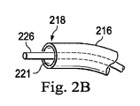
可撓性本体216は、医療器具226を受け入れるようなサイズ及び形状とされたチャネル221を含む。図2Bは、幾つかの実施形態に従って延在させられた医療器具226を備える可撓性本体216の簡略図である。幾つかの実施形態において、医療器具226は、手術、生検、切除(アブレーション)、照明、洗浄、又は吸引のような処置のために使用されてよい。医療器具226は、可撓性本体216のチャネル221を通じて展開されることができ、解剖学的構造内の標的場所で使用されることができる。医療器具226は、例えば、画像キャプチャプローブ、生検機器、レーザ切除ファイバ、及び/又は他の外科的、診断的、又は治療的ツールを含んでよい。医療器具は、メス、鈍らブレード、光ファイバ、電極、及び/又は同等物のような、単一の作業部材を有するエンドエフェクタを含んでよい。他のエンドエフェクタは、例えば、鉗子、グラスパ(把持器)、はさみ、クリップアプライヤ、及び/又は同等物を含んでよい。他のエンドエフェクタは、電気外科手術電極、トランスデューサ、センサ、及び/又は同等物のような、電気的に活性化されたエンドエフェクタを更に含んでよい。様々な実施形態において、医療器具226は、標的解剖学的場所から試料組織又は細胞のサンプリングを除去するために使用されてよい生検器具である。医療器具226は、同様に可撓性本体216内の画像キャプチャプローブと共に使用されてよい。様々な実施形態において、医療器具226は、表示のために視覚化システム231によって処理される且つ/或いは遠位端218及び/又はセグメント224の1つ又はそれよりも多くのトラッキングをサポートするようトラッキングシステム230に提供される(ビデオ画像を含む)画像を取り込むために可撓性本体216の遠位端218に又はその付近に立体視又は平面視カメラを備える遠位部分を含む、画像キャプチャプローブであってよい。画像キャプチャプローブは、取り込んだ画像データを送信するためにカメラに連結されるケーブルを含んでよい。幾つかの例において、画像キャプチャ器具は、視覚化システム231に連結するファイバスコープのような光ファイバ束であってよい。画像キャプチャ器具は、例えば、可視スペクトル、赤外スペクトル、及び/又は紫外スペクトルのうちの1つ又はそれよりも多くの画像データを取り込む、単一又は複数スペクトルであってよい。代替的に、医療器具226自体が画像キャプチャプローブであってよい。医療器具226は、処置を行うためにチャネル221の開口から前進させられ、次に、処置が完了したときに、チャネル内に後退させられてよい。医療器具226は、可撓性本体216の近位端217から或いは可撓性本体216に沿う別の任意的な器具ポート(図示せず)から取り外されてよい。
The
医療器具226は、追加的に、医療器具226の遠位端を制御可能に曲げるために、その近位端と遠位端との間に延在する、ケーブル、リンケージ(リンク装置)、又は他の作動制御装置(図示せず)を収容してよい。操縦可能な器具は、(「Articulated Surgical Instrument for Performing Minimally Invasive Surgery with Enhanced Dexterity and Sensitivity」を開示する)(2005年10月4日に出願された)特許文献6及び(「Passive Preload and Capstan Drive for Surgical Instruments」を開示する)(2008年9月30日に出願された)特許文献7に詳細に記載されており、それらの全文を参照によって本明細書に援用する。
The
可撓性本体216は、例えば、遠位端218の破点線描写219によって示すように、遠位端218を制御可能に曲げるために駆動ユニット204と遠位端218との間に延在する、ケーブル、リンケージ、又は他の操縦制御装置(図示せず)も収容してよい。幾つかの例では、少なくとも4つのケーブルが、遠位端218のピッチを制御するための独立的な「上下」操縦と、遠位端281のヨーを制御するための「左右」操縦とを提供するために使用される。操縦可能な細長いデバイスは、(「Catheter with Removable Vision Probe」を開示する)(2011年10月14日に出願された)特許文献8に詳細に記載されており、その全文を参照によって本明細書に援用する。医療器具システム200が遠隔操作アセンブリによって作動させられる実施形態において、駆動ユニット204は、遠隔操作アセンブリのアクチュエータのような駆動要素に取り外し可能に連結し、そのような駆動要素から電力を受け取る、駆動入力を含んでよい。幾つかの実施形態において、医療器具システム200は、医療器具システム200の動きを手動制御するための、把持機能、手動アクチュエータ、又は他の構成要素を含んでよい。細長いデバイス202は、操縦可能であってよく、或いは、代替的に、システムは、遠位端218の曲げの操作者制御のための一体化された機構を備えずに操縦不能であってい。幾つかの例において、医療器具を展開して、標的手術場所で使用することができる、1つ又はそれよりも多くの管腔が、可撓性本体216の壁に画定される。
The
幾つかの実施形態において、医療器具システム200は、肺の検査、診断、生検、又は治療における使用のための、気管支鏡又は気管支カテーテルのような、可撓気管支器具を含んでよい。医療器具システム200は、結腸、腸、腎臓及び腎杯、脳、心臓、血管系を含む循環系、及び/又は同等器官を含む、様々な解剖学的系のいずれかにおける、自然に又は外科的に作られた接続された通路を介した、他の組織のナビゲーション及び治療にも適している。
In some embodiments, the
追跡システム230からの情報は、ナビゲーションシステム232に送信され、ナビゲーションシステム232で、視覚化システム231からの情報及び/又は術前に得られたモデル(例えば、患者解剖学的構造の解剖学的構造モデル)と組み合わされて、医師又は他の操作者にリアルタイムの位置情報を提供する。幾つかの例において、リアルタイム位置情報は、医療器具システム200の制御における使用のために、図1のディスプレイシステム110に表示されてよい。幾つかの例において、図1の制御システム116は、医療器具システム200を位置決めするためのフィードバックとして位置情報を利用してよい。手術用器具を外科画像と位置合わせし且つ表示するために光ファイバセンサを使用するための様々なシステムが、「Medical System Providing Dynamic Registration of a Model of an Anatomic Structure for Image-Guided Surgery」を開示する2011年5月13日に出願された特許文献9に提供されており、その全文を参照によって本明細書に援用する。
Information from the
幾つかの例において、医療器具システム200は、図1の医療システム100内で遠隔操作されてよい。幾つかの実施形態において、図1のマニピュレータアセンブリ102は、直接操作者制御と置換されてよい。幾つかの例では、直接操作者制御は、器具の手持ち操作のための様々なハンドル及び操作者インターフェースを含んでよい。
In some examples, the
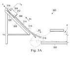
図3A及び図3Bは、幾つかの実施形態に従った挿入アセンブリに取り付けられた医療器具を含む患者座標空間の簡略化された側面図である。図3A及び図3Bに示すように、外科環境300は、図1の台Tに位置付けられた患者Pを含む。患者Pは、患者の大きな移動が鎮静、拘束、及び/又は他の手段によって制限されるという意味において、手術環境内で静止的であってよい。患者Pの呼吸及び心臓の動きを含む周期的な解剖学的な動きは、患者が息を止めて呼吸の動きを一時的に停止させることを求められない限り、継続することがある。従って、幾つかの実施形態において、データは、特定の呼吸相で集められ、その位相でタグ付けされ、識別されてよい。幾つかの実施形態において、データが収集される位相は、患者Pから収集される生理学的情報から推測されてよい。外科環境300内で、点収集器具304(point gathering instrument)が、器具キャリッジ306に連結される。幾つかの実施形態において、点収集器具304は、EMセンサ、形状センサ、及び/又は他のセンサモダリティを使用してよい。器具キャリッジ306は、外科環境300内に固定された挿入ステージ308に取り付けられる。代替的に、挿入ステージ308は、可動であってよいが、外科環境300内に(例えば、トラッキングセンサ又は他のトラッキングデバイスを介して)既知の位置を有してよい。器具キャリッジ306は、挿入運動(すなわち、A軸に沿う動き)、任意的に、ヨー、ピッチ、及びロールを含む多方向における細長いデバイス310の遠位端318の動きを制御するために点収集器具304に連結する、マニピュレータアセンブリ(例えば、マニピュレータアセンブリ102)の構成要素であってよい。器具キャリッジ306又は挿入ステージ308は、挿入ステージ308に沿う器具キャリッジ306の動きを制御するサーボモータ(図示せず)のようなアクチュエータを含んでよい。
3A and 3B are simplified side views of the patient coordinate space including the medical device attached to the insertion assembly according to some embodiments. As shown in FIGS. 3A and 3B, the
細長いデバイス310は、器具本体312に連結される。器具本体312は、器具キャリッジ306に対して連結され且つ固定される。幾つかの実施形態では、光ファイバ形状センサ314が、器具本体312上で近位点316に固定される。幾つかの実施形態において、光ファイバ形状センサ314の近位点316は、器具本体312と共に移動可能であってよいが、近位点316の場所は、(例えば、トラッキングセンサ又は他のトラッキングデバイスを介して)知られていることがある。形状センサ314は、近位点316から細長いデバイス310の遠位端318のような別の点への形状を測定する。点収集装置304は、医療器具システム200と実質的に類似してよい。
The
位置測定デバイス320が、器具本体312が挿入軸Aに沿って挿入ステージ308上を移動するときに、器具本体312の位置に関する情報を提供する。位置測定デバイス320は、器具キャリッジ306の動き、結果的に、器具本体312の動きを制御するアクチュエータの回転及び/又は向きを決定する、レゾルバ、エンコーダ、ポテンショメータ、及び/又は他のセンサを含んでよい。幾つかの実施態様において、挿入ステージ308は、直線的である。幾つかの実施形態において、挿入ステージ308は、湾曲させられてよく、或いは湾曲区画と線形区画との組み合わせを有してよい。
The
図3Aは、挿入ステージ308に沿った後退位置にある器具本体312及び器具キャリッジ306を示している。この後退位置において、近位点316は、軸A上の位置L0にある。挿入ステージ308に沿うこの位置において、近位点316の場所のA成分は、挿入ステージ308上の器具キャリッジ306、よって、近位点316の位置を記述するベース基準を提供するために、ゼロ及び/又は別の基準値に設定されてよい。器具本体312及び器具キャリッジ306のこの後退位置に伴って、細長いデバイス310の遠位端318は、患者Pの入口オリフィスの正に内側に位置付けられることがある。また、この位置において、位置測定デバイス320は、ゼロ及び/又は別の基準値(例えば、I=0)に設定されてよい。図3Bにおいて、器具本体312及び器具キャリッジ306は、挿入ステージ308の線形トラックに沿って前進し、細長いデバイス310の遠位端318は患者P内に前進している。この前進位置において、近位点316は、軸A上の位置L1にある。幾つかの例では、挿入ステージ308に沿う器具キャリッジ306の動きを制御する1つ又はそれよりも多くのアクチュエータ及び/又は器具キャリッジ306及び/又は挿入ステージ308と関連付けられた1つ又はそれよりも多くの位置センサからのエンコーダ及び/又は他の位置データを用いて位置L0に対する近位点316の位置Lxを決定する。幾つかの例において、位置Lxは、細長いデバイス310の遠位端318が患者Pの解剖学的構造の通路内に挿入される距離又は挿入深さのインジケータとして更に使用されてよい。
FIG. 3A shows the
図4、図5、図6、図7、図8、図9、及び図10を参照すると、幾つかの実施形態において、標的構造の場所は、カテーテル内に統合される或いはカテーテルによって送達される撮像プローブ(例えば、超音波プローブ)を使用して確認/決定されてよい。様々な実施形態において、標的構造場所を決定及び/又は確認するための超音波技術の使用は、小さな直径(例えば、約10mm以下)の結節に向けられた生検又は他の巣状療法(focal therapies)におけるより高い精度を可能にすることがある。図4、図5、及び図6は、撮像プローブ又はツールのいずれかを挿入するために使用されてよいチャネルを含むカテーテルを図示している。図7、図8、及び図9は、撮像プローブ及びツールを同時に提供するように構成されたカテーテルを図示している。図10は、撮像プローブを使用して標的構造の場所を決定するための方法を図示している。 With reference to FIGS. 4, 5, 6, 7, 8, 9, and 10, in some embodiments, the location of the target structure is integrated within or delivered by the catheter. It may be confirmed / determined using an imaging probe (eg, an ultrasonic probe). In various embodiments, the use of ultrasound techniques to determine and / or confirm the location of the target structure is a biopsy or other focal therapy directed to a nodule of small diameter (eg, about 10 mm or less). May allow higher accuracy in therapies). 4, 5, and 6 illustrate a catheter containing a channel that may be used to insert either an imaging probe or a tool. 7, 8 and 9 illustrate catheters configured to provide imaging probes and tools simultaneously. FIG. 10 illustrates a method for locating a target structure using an imaging probe.
図4の例は、標的構造PM(例えば、腫瘍、病変、結節)及び付近の解剖学的通路402の仮想画像400を図示している。通路402は、通路壁404を含む。通路402は、座標系(Xp、Yp、Zp)を備える患者基準系(patient reference frame)内に配置される。患者基準系は、固定的な基準系(すなわち、医療処置中に移動しない基準系)であってよい。(例えば、術前又は術中モデリングから得られる)複数の通路402の画像は、図1を参照して前述した方法を使用して患者基準系に位置合わせされてよい。標的構造PMの場所は、術前又は術中撮像内で決定され、よって、患者基準系内で知られる。この実施形態において、解剖学的通路は、肺の気管支通路であるが、この開示のシステム及び方法は、結腸、腸、腎臓、心臓、及び/又は類似器官のような解剖学的構造を含む、循環系、消化系、腎系、及び生殖器系のような、解剖学的系における他の自然に又は外科的に作られた通路における使用に適することがある。
The example of FIG. 4, the target structure P M (e.g., tumors, lesions, nodules) illustrates a
(可撓性本体216に実質的に類似する)可撓性カテーテル本体408は、標的構造へのアクセスを可能にするカテーテル駐機場所(park location)にナビゲートされて(進められて)よい。カテーテルは、カテーテルの遠位端部分が標的構造に向かう方向に照準される(pointed)ことを可能にする向きにおいて、カテーテル駐機位置に位置付けられてよい。このようにして、可撓性カテーテル本体408を通じて挿入されるツールは、標的構造への照準ベクトル(pointing vector)に沿って挿入される。カテーテルは、例えば、視覚内視鏡、EMセンサ、及び/又は光ファイバ形状ベースのナビゲーション技法を用いて、ナビゲートされてよい。可撓性カテーテル本体408を通じて撮像プローブ406を挿入することができる。1つの実施形態において、撮像プローブ406は、超音波プローブ406である。超音波プローブ406は、側面向き(side-facing)トランスデューサ、前方向き(forward-facing)トランスデューサ、湾曲トランスデューサ、半径方向トランスデューサ、及び/又は同等物のような、超音波トランスデューサを使用してよい。ある例において、超音波プローブは、トランスデューサの回転軸に対して概ね垂直な方向における撮像のための回転超音波トランスデューサを含む、側面撮像トランスデューサを使用する。側面撮像(side-imaging)プローブは、撮像平面412に沿う断面(すなわち、半径方向)画像を生成する。任意的に、超音波プローブ406は、図4に示すように、交換可能でありよりもむしろ、カテーテルと一体的であってよい。カテーテル基準系及び座標系(Xc、Yc、Zc)が、カテーテル408の遠位端部分410に画定され、図1を参照して前述した方法を用いて患者座標系と位置合わせされる。図4の実施形態において、トランスデューサの回転軸は、カテーテル基準系のZc方向に概ね沿っている。
The flexible catheter body 408 (substantially similar to the flexible body 216) may be navigated (advanced) to a catheter park location that allows access to the target structure. The catheter may be positioned in the catheter parking position in an orientation that allows the distal end portion of the catheter to be pointed towards the target structure. In this way, the tool inserted through the
幾つかの態様では、側面撮像プローブが、解剖学的通路の外側に位置する組織を含む、回転軸から半径方向距離にある組織の画像を生成する。他の実施形態では、前方視(forward-looking)超音波プローブを使用して撮像トランスデューサの遠位の組織を撮像してよい。超音波プローブは、狭い解剖学的通路をナビゲートするために比較的小さくてよい。例えば、超音波プローブは、約1.4mmの遠位端直径を有してよい。 In some embodiments, the lateral imaging probe produces an image of tissue at a radial distance from the axis of rotation, including tissue located outside the anatomical passage. In other embodiments, a forward-looking ultrasound probe may be used to image the tissue distal to the imaging transducer. The ultrasonic probe may be relatively small for navigating narrow anatomical passages. For example, the ultrasonic probe may have a distal end diameter of about 1.4 mm.
図5は、図4に示す撮像平面412内の超音波プローブ406によって生成された画像500を図示している。画像500は、基準座標系及び座標系(XI、YI、ZI)を有する。標的構造502(PI)は、画像基準系内で識別される。それは、例えば、臨床医によって、画像分析アルゴリズムによって、又はこれら2つの組み合わせによって識別されてよい。超音波スキャンは、呼吸サイクル及び/又は心サイクルのためにゲート化されてよい。画像500は、二次元であるが、三次元画像が、複数の二次元超音波スキャンから構築されてよい。画像基準系内の標的構造PIの場所と関連付けられるデータが、カテーテル座標系又は(カテーテル座標系と位置合わせされた)患者座標系にPPとして変換される。超音波プローブによって決定された標的構造PPの場所は、補正ベクトル414を決定するために、カテーテル又は患者基準系内の術前又は術中撮像から決定された標的構造PMの場所と比較されてよい。補正ベクトル414は、標的構造PMの場所と標的構造PPの場所との間のオフセット値である。
FIG. 5 illustrates the
様々な実施形態では、画像座標系をカテーテル座標系に変換するために、画像座標系とカテーテル座標系との間の相対的な三次元姿勢が決定される。幾つかの実施形態において、それは撮像プローブ及びカテーテル上のセンサによって直接的に測定される。そのようなセンサは、EMセンサ、光ファイバ形状センサ、又は同等物を含んでよい。撮像プローブ及びカテーテル上のセンサは、同じタイプである必要はない。 In various embodiments, the relative three-dimensional orientation between the image coordinate system and the catheter coordinate system is determined in order to transform the image coordinate system into the catheter coordinate system. In some embodiments, it is measured directly by an imaging probe and a sensor on the catheter. Such sensors may include EM sensors, fiber optic shape sensors, or equivalents. The imaging probe and the sensor on the catheter do not have to be of the same type.
幾つかの実施形態において、画像座標系(XI、YI、ZI)とカテーテル座標系(XC、YC、ZC)との間の相対的な姿勢は、撮像プローブがカテーテルの先端を越えて直線的に延び、カテーテル端の姿勢が知られていると仮定すると、カテーテル座標系に対する画像座標系の挿入長L及び/又はロール角を測定することによって計算されることができる。幾つかの実施形態において、相対的な姿勢は、カテーテル遠位端に対する標的の相対的な位置の仮定(例えば、カテーテル端は標的を指している)に基づいて決定される。それらの実施形態において、カテーテルによって送達される撮像プローブは、カテーテルの照準方向に沿って位置すると仮定され、よって、カテーテル遠位端からの距離のみが決定される必要がある。そのような距離は、仮定された距離であってよく、或いは外部撮像を用いて決定されてよい。一例では、(例えば、取り込んだ超音波画像から)カテーテル基準系内の標的場所及び画像基準系内の標的場所を決定した後に、画像基準系とカテーテル基準系との間の変換が決定されてよい。 In some embodiments, the relative orientation between the image coordinate system (XI, YI, ZI) and the catheter coordinate system (XC, YC, ZC) is such that the imaging probe is linear across the tip of the catheter. Assuming it extends and the orientation of the catheter end is known, it can be calculated by measuring the insertion length L and / or roll angle of the image coordinate system relative to the catheter coordinate system. In some embodiments, the relative posture is determined based on the assumption of the relative position of the target with respect to the distal end of the catheter (eg, the end of the catheter pointing to the target). In those embodiments, the imaging probe delivered by the catheter is assumed to be located along the aiming direction of the catheter, so only the distance from the distal end of the catheter needs to be determined. Such a distance may be the assumed distance or may be determined using external imaging. In one example, the conversion between the image reference system and the catheter reference system may be determined after determining the target location within the catheter reference system and the target location within the image reference system (eg, from the captured ultrasound image). ..
幾つかの例において、挿入長Lは、例えば、エンコーダ又はステッピングモータを用いて決定されてよい。ロール角は、様々な技法を用いて決定されてよい。例えば、超音波プローブは、カテーテルにキー止めされる(keyed)ロールアライメント構成(ロール整列構成)を含んでよく、その場合、ロールアライメント構成は、超音波プローブに、カテーテルを通じて延びるカテーテルロール軸(Zc)についての固定的な向きを維持させる。ロールアライメント構成は、画像基準系及び座標系(XI、YI、ZI)のロール角が、カテーテル基準系及び座標系(XC、YC、ZC)に対して位置合わせされることを可能にする。幾つかの実施形態において、ロールアライメント構成は、カテーテル内の同様に形作られたチャネルと整合する(match)ようにキー止めされた成形突起(shaped protrusion)である。代替的な実施形態において、ロールアライメント構成は、カテーテル内の突起と整合するように形作られたチャネルであってよい。1つよりも多くのロールアライメント構成を用いて、カテーテルロール軸についての固定的な向きにプローブを維持してよい。別の代替的な実施形態において、カテーテル座標系に対する画像座標系のロール角は、患者解剖学的構造の外側に配置されるロールセンサによって決定されてよい。更に別の代替的な実施形態において、ロール角は、撮像プローブによって記録された画像内のカテーテルに対する既知の角度を有する1つ又はそれよりも多くのマーカ又は他の構成によって決定されてよい。例えば、構成又はマーカは、カテーテルの周囲に配置されてよく、カテーテルに対するコントラスト(例えば、超音波コントラスト)を有してよい。別の代替的な実施形態において、組み合わせられたロール及び挿入長は、カテーテルの近位端の周りのプローブ上のパターンを観察することによって、或いはプローブの近位端の周りのカテーテル上のパターンを観察することによって決定されてよい。様々な位置合わせ技法(例えば、オプティカルフロー(optical flow))を用いて、画像座標系及びカテーテル座標系を位置合わせしてよい。 In some examples, the insertion length L may be determined using, for example, an encoder or a stepper motor. The roll angle may be determined using a variety of techniques. For example, the ultrasonic probe may include a roll alignment configuration that is keyed to the catheter, in which case the roll alignment configuration extends to the ultrasound probe through the catheter roll axis (Zc). ) To maintain a fixed orientation. The roll alignment configuration is such that the roll angles of the image reference system and the coordinate system ( XI , Y I , Z I ) are aligned with respect to the catheter reference system and the coordinate system (X C , Y C , Z C). To enable. In some embodiments, the roll alignment configuration is a shaped protrusion that is keyed to match a similarly shaped channel within the catheter. In an alternative embodiment, the roll alignment configuration may be a channel shaped to align with a protrusion in the catheter. More than one roll alignment configuration may be used to maintain the probe in a fixed orientation with respect to the catheter roll axis. In another alternative embodiment, the roll angle of the image coordinate system relative to the catheter coordinate system may be determined by a roll sensor located outside the patient anatomy. In yet another alternative embodiment, the roll angle may be determined by one or more markers or other configurations having a known angle with respect to the catheter in the image recorded by the imaging probe. For example, the configuration or marker may be placed around the catheter and may have contrast to the catheter (eg, ultrasonic contrast). In another alternative embodiment, the combined roll and insertion length can be observed by observing the pattern on the probe around the proximal end of the catheter, or by observing the pattern on the catheter around the proximal end of the catheter. It may be determined by observing. Various alignment techniques (eg, optical flow) may be used to align the image coordinate system and the catheter coordinate system.
図6を参照すると、幾つかの実施形態において、画像座標系とカテーテル座標系との間の相対的な姿勢は、1つ又はそれよりも多くの外部画像を用いて決定され、その場合、各外部画像は、カテーテル画像と、撮像プローブ画像とを含む。そのような外部画像は、コンピュータ断層撮影(CT)、磁気共鳴映像(MRI)、蛍光透視、サーモグラフィ、超音波、光干渉断層撮影(OCT)、熱撮像、インピーダンス撮像、レーザ撮像、ナノチューブX線撮像、及び/又は同等物(例えば、蛍光透視)によって提供されてよい。図6の例では、ディスプレイシステム110が、外部蛍光透視撮像デバイスからの患者解剖学的構造の同時の又はリアルタイムの外部画像602を表示する。外部画像602は、カテーテル408、超音波プローブ406、及び患者解剖学的構造内の骨(例えば、肋骨604−1、604−2)の画像を含む。幾つかの実施形態では、操作者が、(例えば、入力デバイスを用いて)入力を提供して、超音波プローブ406及びカテーテル408の遠位端410の場所位置を識別してよい。図6の例において、ディスプレイシステム110は、タッチスクリーンを含み、操作者は、タッチスクリーンを使用して、外部画像602内で(例えば、マーカ「X」を使用することによって)カテーテル408の遠位端410を識別してよく、(例えば、マーカ「Δ」を使用することによって)超音波プローブ406を識別してよい。操作者は、ボタン606を選択することによって、識別された場所を制御システムに送信してよい。
Referring to FIG. 6, in some embodiments, the relative orientation between the image coordinate system and the catheter coordinate system is determined using one or more external images, in which case each The external image includes a catheter image and an imaging probe image. Such external images include computed tomography (CT), magnetic resonance imaging (MRI), fluorescence fluoroscopy, thermography, ultrasound, optical coherence tomography (OCT), thermal imaging, impedance imaging, laser imaging, and nanotube X-ray imaging. , And / or an equivalent (eg, fluoroscopy). In the example of FIG. 6, the
幾つかの実施形態において、制御システムは、画像602を分析して画像602内の超音波プローブ406及びカテーテル408の遠位端410の位置を自動的に検出する画像分析アルゴリズムを使用することによって、画像座標系とカテーテル座標系との間の相対的な姿勢を決定してよい。幾つかの例では、画像602内の既知の解剖学的ランドマーク寸法(例えば、連続する鎖骨604−1及び604−2の間の距離d1)を用いて、画像602内の超音波プローブ406及びカテーテル408の遠位端410の位置の間の距離d2を決定してよい。
In some embodiments, the control system uses an image analysis algorithm that analyzes
幾つかの実施態様では、2つ又はそれよりも多くの外部画像を用いて、超音波プローブ406及びガイドカテーテル408の遠位端410の場所及び/又は相対的な位置を決定する。2つ又はそれよりも多くの外部画像を使用することによって、超音波プローブ406とカテーテル408とを含む患者解剖学的構造の三次元画像が、各外部画像上の超音波プローブ406及びカテーテル408の遠位端410の場所に基づいて複数の二次元外部画像から構築されてよい。各外部画像上の超音波プローブ406及びカテーテル408の遠位端410の場所は、操作者入力又は制御システムによって実行されるデジタル画像処理のいずれかに基づいて識別されてよい。幾つかの実施態様において、2つ又はそれよりも多くの外部画像は、異なる視野方向から同じ外部撮像デバイス(例えば、蛍光透視撮像デバイス)によって提供される。代替的な実施形態において、2つ又はそれよりも多くの外部画像は、異なる撮像技術(コンピュータ断層撮影(CT)、磁気共鳴映像(MRI)、蛍光透視、サーモグラフィ、超音波、光干渉断層撮影(OCT)、熱撮像、インピーダンス撮像、レーザ撮像、又はナノチューブX線撮像など)を用いて、2つ又はそれよりも多くの外部撮像デバイスで提供される。
In some embodiments, two or more external images are used to determine the location and / or relative position of the
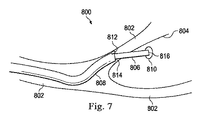
図7、図8、及び図9を参照すると、幾つかの実施形態において、カテーテルは、ツールと同時に撮像プローブ(例えば、超音波プローブ)を提供してよい。それらの実施形態において、撮像プローブからの第1の画像は、ツール及び標的構造の両方を含むことがあり、それは標的構造及びツールの先端の位置を確認又は決定するために使用されてよい。幾つかの実施形態では、ツールの先端の追加的な場所データが、標的構造の場所を決定するために用いられることがある第1の画像以外のソース(例えば、患者解剖学的構造の外部画像、カテーテルの遠位端の既知の姿勢)に基づいて決定されてよい。撮像プローブからの第1の画像及びツールの先端の場所データを用いることによって、標的構造の位置は、医療処置(例えば、生検、切除など)の間に決定されることがある。一例では、患者解剖学的構造の仮想視覚化画像が、生検処置の間に操作者に提供されてよく、それは生検器具の画像及び標的構造の画像を含み、標的構造内への生検器具の挿入の視覚化を提供する。 With reference to FIGS. 7, 8 and 9, in some embodiments, the catheter may provide an imaging probe (eg, an ultrasound probe) at the same time as the tool. In those embodiments, the first image from the imaging probe may include both the tool and the target structure, which may be used to locate or determine the position of the target structure and the tip of the tool. In some embodiments, additional location data at the tip of the tool may be used to determine the location of the target structure from a source other than the first image (eg, an external image of the patient's anatomy). , Known posture at the distal end of the catheter). By using the first image from the imaging probe and the location data of the tip of the tool, the location of the target structure may be determined during the medical procedure (eg, biopsy, excision, etc.). In one example, a virtual visualization image of the patient's anatomy may be provided to the operator during the biopsy procedure, which includes an image of the biopsy instrument and an image of the target structure, and a biopsy into the target structure. Provides visualization of instrument insertion.
図7の例を参照すると、標的構造810及び付近の解剖学的通路802の仮想画像800が図示されている。通路802は、通路壁804を含む。図7に示すように、生検器具806は、生検処置中にカテーテル808のチャネルに挿入される。カテーテル808は、標的構造810へのアクセスを提供する位置及び/又は向きに操縦される。カテーテルの操縦は、カテーテルの能動的な操縦制御によって直接的に或いは操縦可能な生検器具806をナビゲートすることによって間接的に達成されてよい。生検器具806は、カテーテル808から解剖学的通路802の壁804を通じて標的構造810に接触するように延出されて、組織サンプルが採取されることが可能にされるが、幾つかの例では、生検器具860の延出は、カテーテル808の遠位端814が適切に位置決めされるまで遅らされてよい。代替的な例において、生検器具806は、切除ツール又は解剖ツールのような治療デバイスと置換されてよい。
With reference to the example of FIG. 7, a
図7の例において、カテーテル808は、カテーテル808の遠位端814に統合された撮像プローブ812(例えば、超音波プローブ)を含む。代替的な実施形態では、撮像プローブ(例えば、超音波プローブ)は、カテーテルの第2のチャネルを通して同時に挿入されてよい一方で、生検器具は、カテーテルの第1のチャネルを通じて挿入される。撮像プローブ812は、生検器具806及び標的構造810の術中及びリアルタイムの画像を取得するために通路802内に配置される。様々な実施形態において、生検器具806及び標的構造810のそれらの画像は、撮像プローブ812によって取り込まれた画像を位置合わせし、且つ/或いは標的構造810、生検器具806及び生検器具806のツール先端816に対して撮像プローブ812を局所化することを更に支援するために使用されてよい。
In the example of FIG. 7, the
図7の例において、撮像プローブ812は、前方向き超音波プローブであり、それは撮像プローブ812の遠位にある(例えば、生検器具806が標的構造810を貫通するときの)標的構造810及び生検器具806の両方の画像を取り込むために用いられる。代替的な実施形態において、撮像プローブ812は、側面撮像プローブ812の撮像平面(例えば、図4の撮像プローブ406の撮像平面412)に沿う断面(すなわち、半径方向)画像を生成することによって、標的構造810及び生検器具806の両方の画像を取り込むための側面撮像プローブを含む。様々な実施形態では、超音波プローブを使用することによって、解剖学的通路の外側に位置する物体(例えば、標的構造810、生検器具806の一部分)の画像が取り込まれることがある。
In the example of FIG. 7, the
図8の例を参照すると、図7に示す前方向き超音波プローブ812によって生成された画像850を図示している。画像850は、画像基準系及び座標系(XI、YI、ZI)を有し、標的構造810の画像と、ツール先端816を含む生検器具806の画像とを含む。様々な実施形態において、標的構造810、生検器具806、及びツール先端816は、画像基準系内で識別される。それらは、例えば、操作者(例えば、臨床医)によって、画像分析アルゴリズムによって、或いはこれらの2つの組み合わせによって識別されてよい。画像850は、二次元であるが、三次元画像が、複数の2次元超音波画像から構築されてよい。画像基準系内のツール先端816及び標的構造810の場所と関連付けられるデータが、カテーテル座標系又は(カテーテル座標系と位置合わせされた)患者座標系に変換される。カテーテル座標系又は患者座標系内の標的構造810及びツール先端816の場所データは、ディスプレイシステム110上で視覚的仮想化画像を提供するために用いられてよい。
With reference to the example of FIG. 8, the
様々な実施形態では、撮像プローブ812によって提供される画像850に基づいて決定されるツール先端816の第1の場所データに加えて、ソース(例えば、カテーテル808の遠位端814の既知の姿勢、外部撮像デバイスからの外部画像)に基づいてツール先端816の第2の場所データを用いて、標的構造810の場所を決定してよい。幾つかの実施形態において、ツール先端816のそのような第2の場所データは、カテーテル808の遠位端814の既知の姿勢に基づいて決定される。例えば、ツール先端816の第2の場所データは、ツール先端816がカテーテル808の遠位端814と同じ方向に沿っていることを示してよい。更に、例えば、ツール先端816の第2の位置データは、ツール先端816がカテーテル808の遠位端814から所定の距離(例えば、15mm)にあることを示してよい。
In various embodiments, in addition to the first location data of the
図9を参照すると、幾つかの実施形態では、ツール先端816の第2の場所データが、外部撮像デバイスによって提供される患者解剖学的構造の外部画像に基づいて決定されてよい。図9は、外部透視撮像デバイスからの患者解剖学的構造の同時又はリアルタイムの外部画像902を表示するディスプレイシステム110を図示している。外部画像902は、カテーテル808、カテーテル808の遠位端814に統合された超音波プローブ812、生検器具806、及び生検器具806のツール先端816の画像を含む。
Referring to FIG. 9, in some embodiments, the second location data of the
幾つかの実施形態において、操作者(例えば、臨床医)は、外部画像902中のカテーテル808の遠位端814及びツール先端816の場所を識別するよう(例えば、入力デバイスを用いて)入力を提供してよい。図9の例において、ディスプレイシステム110は、タッチスクリーンを含み、操作者は、タッチスクリーンを用いて、外部画像902上で(例えば、マーカ「X」を用いて)カテーテル808の遠位端814の場所を識別し、(例えば、マーカ「Δ」を用いて)ツール先端816の場所を識別してよい。次に、操作者は、(例えば、ボタン906を用いて)識別された場所を制御システムに提出してよい。
In some embodiments, the operator (eg, a clinician) inputs (eg, using an input device) to identify the location of the
幾つかの実施形態において、制御システムは、画像分析アルゴリズムを使用することによって、外部画像902中のカテーテル808の遠位端814及びツール先端816の場所を識別してよい。例えば、画像分析アルゴリズムを使用して、外部画像902中のカテーテル808の遠位端814及びツール先端816を自動的に検出してよい。幾つかの例において、外部画像902中の既知の解剖学的ランドマーク寸法(例えば、連続する鎖骨904−1及び904−2の間の距離d3)を使用して、カテーテル808の遠位端814とツール先端816との間の距離d4を決定してよい。
In some embodiments, the control system may identify the location of the
図10の例を参照すると、幾つかの実施形態に従った撮像プローブを使用して標的構造場所を決定する方法1000が例示されている。方法1000は、一連の操作又はプロセス1002乃至1014として図示されている。例示のプロセス1002乃至1014の全てが、方法1000の全ての実施形態において実施されることがあるとは限らない。加えて、図10に明示的に示されていない1つ又はそれよりも多くのプロセスが、プロセス1002乃至1014の前に、後に、間に、或いはそれらの一部として含められてよい。幾つかの実施形態において、プロセスのうちの1つ又はそれよりも多くは、少なくとも部分的に、非一時的な有形の機械可読媒体に格納される実行可能なコードの形態で実装されてよく、実行可能なコードは、1つ又はそれよりも多くのプロセッサ(例えば、制御システム112のプロセッサ)によって実行されるときに、1つ又はそれよりも多くのプロセッサにプロセスのうちの1つ又はそれよりも多くを実行させることがある。
With reference to the example of FIG. 10, a
方法1000は、プロセス1002で開始し、プロセス1002では、解剖学的構造の第1の画像が患者解剖学的構造の内側に配置される撮像プローブ(例えば、超音波プローブ)から受信される。幾つかの実施態様では、図4に示すように、撮像プローブ406は、カテーテル408の遠位端410を越えて遠位に延出可能である。プロセス1002で、制御システム112が、図4の撮像プローブ406から標的構造PIを含む解剖学的構造の図5の画像500を受信する。代替的な実施形態では、図7に示すように、撮像プローブ812は、カテーテル808と一体化され、カテーテル808の遠位端812に配置される。プロセス1002で、制御システム112が、図7の撮像プローブ806によって取り込まれる標的構造810を含む解剖学的構造の図8の画像850を受信する。更に他の代替的な実施形態では、撮像プローブが、カテーテルの第2のチャネルを通じて同時に挿入されてよい一方で、器具(例えば、生検器具)は、カテーテルの第1のチャネルを通じて挿入される。
プロセス1004で、制御システム112は、患者解剖学的構造の外側に位置する外部撮像デバイスから患者解剖学的構造の1つ又はそれよりも多くの外部画像を受信し、その場合、そのような外部画像は、カテーテル、撮像プローブ、及び/又は器具の画像を含む。幾つかの実施形態では、図6に示すように、制御システム112は、患者解剖学的構造の外側に配置される外部撮像デバイスから図6の1つ又はそれよりも多くの外部画像602を受信する。外部画像の各々は、カテーテル408の画像と、図4の撮像プローブ406の画像とを含む。幾つかの実施形態では、図9に示すように、制御システム112が、患者解剖学的構造の外側に配置される外部撮像デバイスから図9の1つ又はそれよりも多くの外部画像902を受信する。外部画像902の各々は、カテーテル808の画像、撮像プローブ812の画像、及び図8のツール806を含む。
In
次に、方法1000は、プロセス1010に進み、プロセス1010では、撮像プローブと関連付けられる画像基準系とカテーテルの遠位端と関連付けられるカテーテル基準系との間の相対的な姿勢が決定される。そのような相対的な姿勢は、画像基準系の第1の画像中の標的構造及び器具(例えば、ツール先端)の場所データをカテーテル基準系に変換するために使用されてよい。幾つかの実施形態において、相対的な姿勢は、撮像プローブ及びカテーテル上のセンサによって直接的に測定されてよい。そのようなセンサは、EMセンサ、光ファイバ形状センサ、又は同等物を含んでよい。代替的な実施形態において、相対的な姿勢は、(例えば、患者解剖学的構造に対する異なる視野方向を有する外部撮像デバイスによって提供される)2つ又はそれよりも多くの外部画像を使用することによって決定されてよい。それらの実施形態において、撮像プローブ及びカテーテルの両方の三次元位置が、2つ又はそれよりも多くの外部画像を使用して決定されてよく、相対的な姿勢は、撮像プローブ及びカテーテルのそれらの三次元位置を使用して決定されてよい。
幾つかの実施形態において、プロセス1010は、1つ又はそれよりも多くの外部画像に基づいて撮像プローブとカテーテルの遠位端との間の相対的な位置を決定するためにプロセス1006を使用し、撮像プローブとカテーテルの遠位端との間の相対的な向きを決定するためにプロセス1008を使用する。それらの実施形態において、プロセス1010は、プロセス1006で決定される相対的な位置及びプロセス1008で決定される相対的な向きを使用して相対的な姿勢を決定する。
In some embodiments,
幾つかの実施形態では、プロセス1006で、撮像プローブとカテーテルの遠位端との間の相対的な位置が、撮像プローブとカテーテルの遠位端との間の一定の距離(例えば、15mm)を仮定することによって並びに撮像プローブがカテーテルの遠位端と同じ向きに沿っていると仮定することによって提供される。別の代替的な実施形態では、図6及び図9に示すように、撮像プローブとカテーテルの遠位端との間の相対的な位置は、(例えば、操作者入力、画像分析アルゴリズム、及び/又はそれらの組み合わせを用いて)1つ又はそれよりも多くの外部画像に基づいて決定される。例えば、図6に示すように、外部画像602中のカテーテル408の遠位端410及び撮像プローブ406の位置は、操作者入力、画像分析アルゴリズム、及び/又はそれらの組み合わせによって識別されてよい。
In some embodiments, in
プロセス1008で、撮像プローブとカテーテルの遠位端との間の相対的な向きが決定される。幾つかの実施形態では、プロセス1008で、カテーテルは、カテーテル駐機場所にナビゲーションされ、カテーテル駐機場所で、カテーテルの遠位端は、解剖学的ランドマーク(例えば、分岐)と整列させられる。それらの実施形態では、撮像プローブとカテーテルの遠位端との間の相対的な向きは、(例えば、操作者入力、画像分析アルゴリズム、及び/又はそれらの組み合わせを用いて)撮像プローブからの第1の画像中に検出される同じ解剖学的ランドマークに基づいて決定される。代替的な実施形態において、撮像プローブは、固定的な向きを維持するためにカテーテル内に直接的に統合される。ある例において、撮像プローブは、カテーテルの遠位端で埋め込まれてよい。別の例において、撮像プローブは、撮像プローブにカテーテルを通じて延びるカテーテルロール軸(Zc)についての固定的な向きを維持させるために、カテーテルにキー止めされるロールアライメント構成を含んでよい。更に別の例において、撮像プローブは、少なくとも部分的に、カテーテルに対して回転可能に固定される(例えば、キー止めされる)シースによって取り囲まれる。キー止めされるシースは、第1の画像中に識別可能な領域を生成するための1つ又はそれよりも多くのマーカ(例えば、エコー発生構成)を含んでよく、次に、それは撮像プローブとカテーテルの遠位端との間の基準ロール角として使用されてよい。更に他の代替的な実施形態では、撮像プローブとカテーテルとの間のロール角が、患者解剖学的構造の外側に配置されるロールセンサを使用して決定されてよい。別の実施形態において、カテーテルは、標的が画像のほぼ中央にあるように方向付けられる。その実施形態において、カテーテルは、標的がカテーテルシャフトに沿って真っ直ぐ前方にあり、撮像プローブとカテーテルの遠位端との間の相対的な向きが必要とされないように、方向付けられる。
In
プロセス1012で、撮像プローブ及びツールを(例えば、生検中に)同時に提供するカテーテルについて、ツールの先端についての第1の場所データ及び第2の場所データが決定される。図8に示すように、ツール先端の第1の場所データは、図7の撮像プローブ812によって提供される画像850を使用して決定される。図9に示すように、ツール先端の第2の場所データは、(例えば、操作者入力、画像分析アルゴリズム、及び/又はそれらの組み合わせを使用して)外部撮像デバイスによって提供される外部画像902に基づいて決定される。
In
プロセス1014で、カテーテル基準系及び/又は患者基準系内の標的構造の場所データは、画像基準系内の標的構造の場所データ、撮像プローブとカテーテルの遠位端との間の相対的な姿勢、第1のツール先端場所データ、第2のツール先端場所データ、及び/又はそれらの組み合わせに基づいて決定されてよい。例えば、第1の画像中の標的構造の場所データは、相対的な姿勢に基づいて画像基準系からカテーテル基準系に変換されてよい。更に、例えば、カテーテル基準系内の標的構造の場所データは、患者基準系に変換されてよい。カテーテル基準系及び/又は患者基準系内の標的構造のそれらの場所データを使用して、標的構造を含む患者解剖学的構造の仮想視覚化画像を操作者に提供してよい。
In
図11、図12A、図12B、図13及び図14を参照すると、様々な視覚的仮想化画像が、カテーテル基準系及び/又は患者基準系内の標的構造の場所データを用いて操作者に提供されてよい。図11は、撮像プローブからの第1の画像に基づいて決定される標的構造の場所データを使用して、ディスプレイシステム上に仮想視覚化画像中の標的構造を提示する方法1100を例示している。図12A〜図12Bは、患者解剖学的構造の解剖学的モデルにおける標的構造の仮想表現を含む、様々な仮想視覚化画像を図示している。図13及び図14は、患者解剖学的構造の外部画像中の標的構造の仮想表現を含む様々な仮想視覚化画像を図示している。
With reference to FIGS. 11, 12A, 12B, 13 and 14, various visual virtualization images are provided to the operator using location data of the target structure in the catheter reference system and / or the patient reference system. May be done. FIG. 11 illustrates a
図11を参照すると、撮像プローブからの第1の画像に基づいて決定される標的構造の場所データを使用してディスプレイシステム上に仮想視覚化画像内の標的構造を提示する方法1100が例示されている。方法1100は、一連の操作又はプロセス1102乃至1110として例示されている。例示のプロセス1102乃至1110の全てが、方法1100の全ての実施形態で実施されることがあるとは限らない。加えて、図11に明示的に例示されていない1つ又はそれよりも多くのプロセスが、プロセス1102乃至1110の前に、後に、間に、或いはその一部として含められてよい。幾つかの実施形態では、1つ又はそれよりも多くのプロセスが、少なくとも部分的に、非一時的な有形の機械可読媒体に格納される実行可能なコードの形態で実装されてよく、実行可能なコードは、1つ又はそれよりも多くのプロセッサ(例えば、制御システム112のプロセッサ)によって実行されるときに、1つ又はそれよりも多くのプロセッサにプロセスのうちの1つ又はそれよりも多くを実行させることがある。
Referring to FIG. 11, a
方法1100は、プロセス1102で開始し、プロセス1102では、視覚化基準系(例えば、解剖学的モデルと関連付けられたモデル基準系又は外部画像と関連付けられた患者基準系)に変換された標的構造の場所データが受信される。視覚化基準系内の標的構造の場所データは、方法1000において記載したように、撮像プローブによって提供される画像に基づいて決定されてよい。
プロセス1104で、幾つかの実施形態では、患者解剖学的構造の患者解剖学的モデルの画像と標的構造の画像とを含む仮想視覚化画像が、操作者に提供される。それらの実施形態において、視覚化基準系は、モデル基準系である。図12Aを参照すると、幾つかの例において、仮想視覚化画像は、解剖学的モデルの全体的眺望(ビュー)を含む。具体的には、図12Aに図示するように、幾つかの例において、ディスプレイシステム110は、患者解剖学的構造の仮想視覚化画像1202を、通路を含む解剖学的モデル1204として表示する。解剖学的モデル1204は、前述のように外部撮像ソースを用いて収集される術前又は術中から生成されることができる。仮想視覚化画像1202は、追加的に、モデル基準系内の標的構造1214の場所データを使用して、標的構造1214の同時の、更新された、又はリアルタイムの画像の視覚的表現を提供することができる。幾つかの実施形態において、標的構造1214の画像は、撮像プローブによって提供される複数の画像を使用して生成される三次元画像である。撮像プローブによって提供される1つ又はそれよりも多くの画像に基づいて仮想視覚化画像1202内の正しい場所及び向きを備える標的構造1214の画像を投影することによって、仮想視覚化画像1202は、病変が位置した標的構造の場所の改良された空間認識を操作者に提供する。加えて、仮想視覚化画像1202は、解剖学的モデル1204の通路1208内のカテーテル1206及びカテーテル1206の遠位端1210から延びるツール1212の同時の又はリアルタイムの仮想画像を含むことができる。
In
図12Bに示すように、幾つかの例において、ディスプレイシステム110は、図12Aの解剖学的モデル1204の通路1208の内部図を含む患者解剖学的構造の同時又はリアルタイムの仮想視覚化画像1250を表示する。仮想視覚化画像1250は、カテーテル1206及びカテーテル1206の遠位端1210から延びるツール1212の仮想画像を提供する。
As shown in FIG. 12B, in some examples, the
プロセス1106で、幾つかの実施形態において、仮想視覚化画像は、撮像プローブによって提供される画像に基づいて決定される標的構造の更新された標的場所を含む患者解剖学的構造の解剖学的モデル上の画像を含む。そのような更新された標的場所は、更に、標的構造への最適なアクセスのためのより良好な照準方向(aiming direction)を提供することがある。
In
幾つかの実施形態では、プロセス1106で、仮想視覚化画像は、撮像プローブによって提供される画像に基づいて標的構造への最適なアクセスのための最適なカテーテル駐機場所の表示(indication)を含む。幾つかの実施形態において、最適なカテーテル駐機場所は、撮像プローブが通路1208の複数の異なる場所(例えば、標的構造の画像を取り込むことを可能にする通路1208のセグメントの異なる場所)及び/又は異なる向きにあるときに撮像プローブによって取り込まれる複数の順次的な画像に基づいて決定される。それらの順次的な画像の各々について、標的構造表面積測定が(例えば、画像のピクセルの総数に亘る標的構造ピクセル数の比を使用して)計算される。幾つかの実施形態において、標的構造表面積測定値は、撮像プローブを、標的構造表面積測定値を最大化する最適な姿勢に導くことがある。幾つかの実施形態では、(例えば、生検を実施するための)最適なカテーテル駐機場所及び/又は最適なカテーテルの向きが、最適な撮像プローブの姿勢に基づいて決定される。
In some embodiments, in
幾つかの実施形態において、自動化された最適化は、標的構造表面積測定値に基づいて決定されるカテーテル駆動経路を生成するために使用されてよい。カテーテル駆動経路は、最適な標的構造表面積測定を達成するために標的構造表面積測定の勾配に沿ってカテーテルを駆動することを可能にする。幾つかの例では、最適なカテーテル駐機場所及び最適なカテーテルの向きを使用して、領域内のカテーテルの先端を用いた自動スキャニングを駆動することができる。 In some embodiments, automated optimizations may be used to generate catheter drive pathways that are determined based on target structural surface area measurements. The catheter drive path allows the catheter to be driven along the gradient of the target structure surface area measurement to achieve optimal target structure surface area measurement. In some examples, optimal catheter parking location and optimal catheter orientation can be used to drive automatic scanning with the tip of the catheter within the region.
プロセス1108で、患者解剖学的構造の外側の外部撮像デバイスからの外部画像と標的構造の画像とを含む仮想視覚化画像が、操作者に提供される。標的構造の画像が、患者基準系内の標的構造の場所データを用いて仮想視覚化画像内に提供される。例えば、図13に示すように、ディスプレイシステム110が、生検中のリアルタイムの外部画像1302を含む仮想視覚化画像1300を含む。リアルタイムの外部画像1302は、カテーテル808の画像、カテーテル808の遠位端814に統合された撮像プローブ812、ツール806、及びツール先端816を含む。標的構造1304の画像が、患者基準系内の撮像プローブによって提供される標的構造の場所データを使用して、仮想視覚化画像中に提供される。図13の例では、生検中の標的構造1304内へのツール先端816の挿入の仮想視覚化は、標的構造1304及びツール先端816の両方の画像を取り込む撮像プローブを使用することによって実現される。
In
プロセス1110で、撮像プローブの場所データに基づく基準カテーテル画像及び患者解剖学的構造の外側の外部撮像デバイスからの外部画像を含む仮想視覚化画像が、操作者に提供される。図14の例では、ディスプレイシステム110が、仮想視覚化画像1402を含む。仮想視覚化画像1402は、カテーテル1406のリアルタイム画像を含む、生検中のリアルタイム外部画像1404を含む。プロセス1110で、撮像プローブがカテーテルのチャネルから除去され、ツール1410(例えば、生検針)がそのチャネルに挿入される。図14の例では、標的構造1408の画像が、患者基準系内の標的構造の場所データに基づいて外部画像1404中に提供される。更に、カテーテル1412の基準画像が、撮像プローブが標的構造の画像を取り込むように駆動されるときに、撮像プローブ及びカテーテルの事前収集場所データに基づいて、外部画像1404中に提供される。
In
この開示のシステム及び方法は、肺の接続された気管支通路のために使用されることがある。システム及び方法は、結腸、腸、腎臓、脳、心臓、循環系、又は同等器官を含む、様々な解剖学的系のいずれかにおいて、自然に又は外科的に作られた接続された通路を介して、他の組織のナビゲーション及び治療にも適することがある。システム及び方法は、器官のトレース可能な表面の周りのナビゲーションにも適することがある。この開示の方法及び実施形態は、非外科用途にも適している。 The systems and methods of this disclosure may be used for the connected bronchial passages of the lungs. Systems and methods are provided through connected pathways created naturally or surgically in any of a variety of anatomical systems, including the colon, intestine, kidneys, brain, heart, circulatory system, or equivalent organs. It may also be suitable for navigation and treatment of other tissues. Systems and methods may also be suitable for navigation around traceable surfaces of organs. The methods and embodiments of this disclosure are also suitable for non-surgical applications.
本発明の実施形態における1つ又はそれよりも多くの要素は、制御システム112のようなコンピュータシステムのプロセッサ上で実行するようソフトウェアにおいて実装されてよい。ソフトウェアにおいて実装されるとき、本発明の実施形態の要素は、本質的に、必要なタスクを実行するコードセグメントである。プログラム又はコードセグメントは、伝送媒体又は通信リンクを通じて搬送波に具現化されるコンピュータデータ信号によってダウンロードされてよいプロセッサ可読記憶媒体又はデバイスに格納されることができる。プロセッサ可読記憶デバイスは、光媒体、半導体媒体、及び磁気媒体を含む、情報を格納することができる任意の媒体を含んでよい。プロセッサ可読記憶デバイスの例は、電子回路、半導体デバイス、半導体メモリデバイス、読出し専用記憶装置(ROM)、フラッシュメモリ、消去可能プログラマブル読出し専用記憶装置(EPROM)、フロッピーディスケット、CD−ROM、光ディスク、ハードディスク、又は他の記憶デバイスを含む。コードセグメントは、インターネット、イントラネットなどのような、コンピュータネットワークを介してダウンロードされてよい。
One or more elements in the embodiments of the present invention may be implemented in software to run on the processor of a computer system such as
提示されるプロセス及びディスプレイは、本来的には、如何なる特定のコンピュータ又は他の装置にも関連しない場合があることに留意のこと。様々な汎用システムが、本明細書中の教示に従ったプログラムと共に使用されてよく、或いは記載の動作を実行するためにより特殊化された装置を構築することが便利なことが分かる場合がある。様々なこれらのシステムのための所要の構造は、請求項中に要素として現れる。加えて、本発明の実施形態は、如何なる特定のプログラミング言語をも参照して記載されない。様々なプログラミング言語を使用して本明細書に記載の本発明の教示を実装してよいことが理解されるであろう。 Note that the processes and displays presented may not be inherently relevant to any particular computer or other device. Various general purpose systems may be used with programs according to the teachings herein, or it may be useful to build more specialized devices to perform the described operations. The required structures for the various these systems appear as elements in the claims. In addition, embodiments of the present invention are not described with reference to any particular programming language. It will be appreciated that various programming languages may be used to implement the teachings of the invention described herein.
本発明の特定の例示的な実施形態が添付の図面に記載され且つ示されているが、そのような実施形態は例示であるに過ぎず、広範な本発明を限定するものではないこと、及び本発明の実施形態は、図示及び記載の特定の構成及び配置に限定されないことが理解されるべきである。何故ならば、様々な端お修正が当業者の心に思い浮かぶことがあるからである。 Although certain exemplary embodiments of the invention are described and shown in the accompanying drawings, such embodiments are merely exemplary and are not intended to limit the broader invention, and It should be understood that embodiments of the present invention are not limited to the particular configurations and arrangements shown and described. This is because various edge corrections may come to the minds of those skilled in the art.
Claims (14)
プロセッサとを含み、該プロセッサは、
患者解剖学的構造内に前記カテーテルによって提供される第1の撮像デバイスによって取り込まれる第1の画像を受信し、
前記患者解剖学的構造の外側から第2の撮像デバイスによって取り込まれる、前記カテーテルと、前記第1の撮像デバイスとを含む、前記患者解剖学的構造の第2の画像を受信し、
該第2の画像に基づいて前記第1の撮像デバイスと前記カテーテルの前記遠位端との間の相対的な姿勢を決定し、
前記第1の画像中の標的構造と関連付けられる標的場所を決定し、且つ
前記相対的な姿勢に基づいて前記第1の画像と関連付けられる画像基準系内の前記標的場所を前記カテーテル基準系に変換する、
ように構成される、
医療システム。 With a catheter, which includes a first channel and a distal end portion, the distal end portion is associated with a catheter reference system.
Including a processor, which processor
Upon receiving the first image captured by the first imaging device provided by the catheter within the patient's anatomy,
A second image of the patient anatomy, including the catheter and the first imaging device, captured by the second imaging device from outside the patient anatomy is received.
Based on the second image, the relative orientation between the first imaging device and the distal end of the catheter is determined.
Determine the target location associated with the target structure in the first image and convert the target location in the image reference system associated with the first image to the catheter reference system based on the relative posture. do,
Is configured as
Medical system.
前記第1の画像中の前記ツールのツール先端のツール先端場所を決定し、
該ツール先端場所を前記画像基準系から前記カテーテル基準系に変換する、
ように構成される、
請求項5に記載の医療システム。 The processor
The location of the tool tip of the tool tip in the first image is determined.
Convert the tool tip location from the image reference system to the catheter reference system.
Is configured as
The medical system according to claim 5.
前記第2の画像を用いて前記カテーテルの前記遠位端と前記第1の撮像デバイスとの間の第1の距離を決定する、
ように構成される、
請求項1又は2乃至7のいずれか1項に記載の医療システム。 To determine the relative posture, the processor
The second image is used to determine a first distance between the distal end of the catheter and the first imaging device.
Is configured as
The medical system according to any one of claims 1 or 2 to 7.
前記患者解剖学的構造の外側から第3の撮像デバイスによって取り込まれる、前記カテーテルと、前記第1の撮像デバイスとを含む、前記患者解剖学的構造の第3の画像を受信し、且つ
前記第2の画像及び前記第3の画像に基づいて前記第1の撮像デバイスと前記カテーテルの前記遠位端との間の相対的な位置を決定する、
ように構成される、
請求項11に記載の医療システム。
To determine the relative posture, the processor
A third image of the patient anatomy, including the catheter and the first imaging device, captured by the third imaging device from outside the patient anatomy is received and said. Based on the second image and the third image, the relative position between the first imaging device and the distal end of the catheter is determined.
Is configured as
The medical system according to claim 11.
Priority Applications (1)
| Application Number | Priority Date | Filing Date | Title |
|---|---|---|---|
| JP2023127865A JP2023133606A (en) | 2018-04-25 | 2023-08-04 | Systems and methods related to elongate devices |
Applications Claiming Priority (3)
| Application Number | Priority Date | Filing Date | Title |
|---|---|---|---|
| US201862662440P | 2018-04-25 | 2018-04-25 | |
| US62/662,440 | 2018-04-25 | ||
| PCT/US2019/028617 WO2019209767A1 (en) | 2018-04-25 | 2019-04-23 | Systems and methods related to elongate devices |
Related Child Applications (1)
| Application Number | Title | Priority Date | Filing Date |
|---|---|---|---|
| JP2023127865A Division JP2023133606A (en) | 2018-04-25 | 2023-08-04 | Systems and methods related to elongate devices |
Publications (1)
| Publication Number | Publication Date |
|---|---|
| JP2021521959A true JP2021521959A (en) | 2021-08-30 |
Family
ID=66677209
Family Applications (2)
| Application Number | Title | Priority Date | Filing Date |
|---|---|---|---|
| JP2020558890A Pending JP2021521959A (en) | 2018-04-25 | 2019-04-23 | Systems and methods for elongated devices |
| JP2023127865A Pending JP2023133606A (en) | 2018-04-25 | 2023-08-04 | Systems and methods related to elongate devices |
Family Applications After (1)
| Application Number | Title | Priority Date | Filing Date |
|---|---|---|---|
| JP2023127865A Pending JP2023133606A (en) | 2018-04-25 | 2023-08-04 | Systems and methods related to elongate devices |
Country Status (6)
| Country | Link |
|---|---|
| US (1) | US20210100627A1 (en) |
| EP (1) | EP3784161A1 (en) |
| JP (2) | JP2021521959A (en) |
| KR (1) | KR20210005901A (en) |
| CN (1) | CN112004496A (en) |
| WO (1) | WO2019209767A1 (en) |
Families Citing this family (12)
| Publication number | Priority date | Publication date | Assignee | Title |
|---|---|---|---|---|
| US11642182B2 (en) * | 2016-09-27 | 2023-05-09 | Brainlab Ag | Efficient positioning of a mechatronic arm |
| US20210401399A1 (en) * | 2020-06-26 | 2021-12-30 | Xenter, Inc. | Nanoparticle-based imaging and therapy |
| KR102423825B1 (en) * | 2020-07-14 | 2022-07-22 | 서울대학교병원 | Processing Method for Tailored Laser Ablation System and Automatic Laser Ablation Device using it |
| US11844567B2 (en) | 2020-08-28 | 2023-12-19 | Biosense Webster (Israel) Ltd. | Fitting and directing an expandable catheter based on automatic pulmonary veins anatomical characterization |
| DE102020212086A1 (en) * | 2020-09-25 | 2022-03-31 | Siemens Healthcare Gmbh | Determining the quality of a positioning of an object introduced into a patient's body |
| CN112741692B (en) * | 2020-12-18 | 2021-12-14 | 上海卓昕医疗科技有限公司 | Rapid navigation method and system for realizing device navigation to target tissue position |
| CN113017702B (en) * | 2021-03-05 | 2022-07-08 | 深圳英美达医疗技术有限公司 | Method and system for identifying extension length of small probe of ultrasonic endoscope and storage medium |
| EP4304484A1 (en) * | 2021-03-10 | 2024-01-17 | Intuitive Surgical Operations, Inc. | Systems and methods for registering intraoperative image data |
| US11857273B2 (en) * | 2021-07-06 | 2024-01-02 | Globus Medical, Inc. | Ultrasonic robotic surgical navigation |
| CN114452508B (en) * | 2021-10-20 | 2024-01-23 | 上海微创微航机器人有限公司 | Catheter motion control method, interventional operation system, electronic device, and storage medium |
| EP4292510A1 (en) | 2022-06-16 | 2023-12-20 | Lys Medical SA | Navigation catheter assembly with endoscopic vision probe |
| US11950765B1 (en) | 2023-04-29 | 2024-04-09 | Syncrobotix, Inc. | Highly maneuverable surgical catheter and bronchoscope |
Citations (3)
| Publication number | Priority date | Publication date | Assignee | Title |
|---|---|---|---|---|
| JP2009297346A (en) * | 2008-06-16 | 2009-12-24 | Fujifilm Corp | Ultrasonic observation apparatus, ultrasonic endoscopic apparatus, image processing method, and image processing program |
| US20140187949A1 (en) * | 2012-12-31 | 2014-07-03 | Intuitive Surgical Operations, Inc. | Systems and Methods For Interventional Procedure Planning |
| JP2017515613A (en) * | 2014-02-25 | 2017-06-15 | ジョイントポイント,インコーポレイテッド | System and method for intraoperative image analysis |
Family Cites Families (19)
| Publication number | Priority date | Publication date | Assignee | Title |
|---|---|---|---|---|
| FR2567149B1 (en) | 1984-07-06 | 1986-12-05 | Solvay | PROCESS FOR THE EXTRACTION OF POLY-BETA-HYDROXYBUTYRATES USING A SOLVENT FROM AN AQUEOUS SUSPENSION OF MICROORGANISMS |
| DE4227800C2 (en) * | 1991-08-21 | 1996-12-19 | Toshiba Kawasaki Kk | Thrombus-releasing treatment device |
| US5740808A (en) * | 1996-10-28 | 1998-04-21 | Ep Technologies, Inc | Systems and methods for guilding diagnostic or therapeutic devices in interior tissue regions |
| US5797849A (en) * | 1995-03-28 | 1998-08-25 | Sonometrics Corporation | Method for carrying out a medical procedure using a three-dimensional tracking and imaging system |
| US5792135A (en) | 1996-05-20 | 1998-08-11 | Intuitive Surgical, Inc. | Articulated surgical instrument for performing minimally invasive surgery with enhanced dexterity and sensitivity |
| US6380732B1 (en) | 1997-02-13 | 2002-04-30 | Super Dimension Ltd. | Six-degree of freedom tracking system having a passive transponder on the object being tracked |
| EP0900048B1 (en) * | 1997-02-25 | 2005-08-24 | Biosense Webster, Inc. | Image-guided thoracic therapy apparatus |
| GB9713018D0 (en) | 1997-06-20 | 1997-08-27 | Secr Defence | Optical fibre bend sensor |
| US20040034297A1 (en) * | 2002-08-13 | 2004-02-19 | General Electric Company | Medical device positioning system and method |
| US8364242B2 (en) * | 2007-05-17 | 2013-01-29 | General Electric Company | System and method of combining ultrasound image acquisition with fluoroscopic image acquisition |
| US9161817B2 (en) * | 2008-03-27 | 2015-10-20 | St. Jude Medical, Atrial Fibrillation Division, Inc. | Robotic catheter system |
| US8460236B2 (en) * | 2010-06-24 | 2013-06-11 | Hansen Medical, Inc. | Fiber optic instrument sensing system |
| US8900131B2 (en) * | 2011-05-13 | 2014-12-02 | Intuitive Surgical Operations, Inc. | Medical system providing dynamic registration of a model of an anatomical structure for image-guided surgery |
| CN103619278B (en) * | 2011-06-17 | 2016-08-24 | 皇家飞利浦有限公司 | The system guiding injection during endoscopic surgery |
| US9592095B2 (en) * | 2013-05-16 | 2017-03-14 | Intuitive Surgical Operations, Inc. | Systems and methods for robotic medical system integration with external imaging |
| US20150305612A1 (en) * | 2014-04-23 | 2015-10-29 | Mark Hunter | Apparatuses and methods for registering a real-time image feed from an imaging device to a steerable catheter |
| KR102557820B1 (en) | 2015-05-22 | 2023-07-21 | 인튜어티브 서지컬 오퍼레이션즈 인코포레이티드 | System and method of correlation compensation in image-guided surgery |
| US9675319B1 (en) * | 2016-02-17 | 2017-06-13 | Inneroptic Technology, Inc. | Loupe display |
| US20180064415A1 (en) * | 2016-09-07 | 2018-03-08 | Siemens Medical Solutions Usa, Inc. | Acoustic ablation assisted intra-cardiac echocardiography catheter |
-
2019
- 2019-04-23 KR KR1020207033475A patent/KR20210005901A/en unknown
- 2019-04-23 EP EP19727765.0A patent/EP3784161A1/en active Pending
- 2019-04-23 US US17/044,354 patent/US20210100627A1/en active Pending
- 2019-04-23 JP JP2020558890A patent/JP2021521959A/en active Pending
- 2019-04-23 CN CN201980027428.6A patent/CN112004496A/en active Pending
- 2019-04-23 WO PCT/US2019/028617 patent/WO2019209767A1/en unknown
-
2023
- 2023-08-04 JP JP2023127865A patent/JP2023133606A/en active Pending
Patent Citations (3)
| Publication number | Priority date | Publication date | Assignee | Title |
|---|---|---|---|---|
| JP2009297346A (en) * | 2008-06-16 | 2009-12-24 | Fujifilm Corp | Ultrasonic observation apparatus, ultrasonic endoscopic apparatus, image processing method, and image processing program |
| US20140187949A1 (en) * | 2012-12-31 | 2014-07-03 | Intuitive Surgical Operations, Inc. | Systems and Methods For Interventional Procedure Planning |
| JP2017515613A (en) * | 2014-02-25 | 2017-06-15 | ジョイントポイント,インコーポレイテッド | System and method for intraoperative image analysis |
Also Published As
| Publication number | Publication date |
|---|---|
| CN112004496A (en) | 2020-11-27 |
| WO2019209767A1 (en) | 2019-10-31 |
| KR20210005901A (en) | 2021-01-15 |
| EP3784161A1 (en) | 2021-03-03 |
| JP2023133606A (en) | 2023-09-22 |
| US20210100627A1 (en) | 2021-04-08 |
Similar Documents
| Publication | Publication Date | Title |
|---|---|---|
| US20240041531A1 (en) | Systems and methods for registering elongate devices to three-dimensional images in image-guided procedures | |
| US11636597B2 (en) | Systems and methods for using registered fluoroscopic images in image-guided surgery | |
| US20220378517A1 (en) | Systems and methods for intelligently seeding registration | |
| CN110225710B (en) | System and method for registration of image-guided procedures | |
| JP6797834B2 (en) | Alignment systems and methods for image-guided surgery | |
| JP6772180B2 (en) | Alignment compensation system and method in image-guided surgery | |
| KR102475654B1 (en) | Systems And Methods For Interventional Procedure Planning | |
| US20210100627A1 (en) | Systems and methods related to elongate devices | |
| JP2017528211A (en) | System and method for adaptive input mapping | |
| US20230000354A1 (en) | Systems and methods for medical procedures using optical coherence tomography sensing | |
| US20210259783A1 (en) | Systems and Methods Related to Registration for Image Guided Surgery | |
| US20230030727A1 (en) | Systems and methods related to registration for image guided surgery | |
| US20220054202A1 (en) | Systems and methods for registration of patient anatomy | |
| US20220142714A1 (en) | Systems for enhanced registration of patient anatomy |
Legal Events
| Date | Code | Title | Description |
|---|---|---|---|
| A621 | Written request for application examination |
Free format text: JAPANESE INTERMEDIATE CODE: A621 Effective date: 20220415 |
|
| A131 | Notification of reasons for refusal |
Free format text: JAPANESE INTERMEDIATE CODE: A131 Effective date: 20221220 |
|
| A521 | Request for written amendment filed |
Free format text: JAPANESE INTERMEDIATE CODE: A523 Effective date: 20230317 |
|
| A02 | Decision of refusal |
Free format text: JAPANESE INTERMEDIATE CODE: A02 Effective date: 20230404 |
|
| A521 | Request for written amendment filed |
Free format text: JAPANESE INTERMEDIATE CODE: A523 Effective date: 20230804 |
|
| A911 | Transfer to examiner for re-examination before appeal (zenchi) |
Free format text: JAPANESE INTERMEDIATE CODE: A911 Effective date: 20230815 |
|
| A912 | Re-examination (zenchi) completed and case transferred to appeal board |
Free format text: JAPANESE INTERMEDIATE CODE: A912 Effective date: 20231027 |