JP2021520258A - Methods and devices for the treatment of respiratory illness - Google Patents
Methods and devices for the treatment of respiratory illness Download PDFInfo
- Publication number
- JP2021520258A JP2021520258A JP2020554417A JP2020554417A JP2021520258A JP 2021520258 A JP2021520258 A JP 2021520258A JP 2020554417 A JP2020554417 A JP 2020554417A JP 2020554417 A JP2020554417 A JP 2020554417A JP 2021520258 A JP2021520258 A JP 2021520258A
- Authority
- JP
- Japan
- Prior art keywords
- trigger
- oxygen
- signal
- pressure
- pressure signal
- Prior art date
- Legal status (The legal status is an assumption and is not a legal conclusion. Google has not performed a legal analysis and makes no representation as to the accuracy of the status listed.)
- Pending
Links
- 238000000034 method Methods 0.000 title claims abstract description 87
- 230000000241 respiratory effect Effects 0.000 title claims description 31
- QVGXLLKOCUKJST-UHFFFAOYSA-N atomic oxygen Chemical compound [O] QVGXLLKOCUKJST-UHFFFAOYSA-N 0.000 claims abstract description 318
- 239000001301 oxygen Substances 0.000 claims abstract description 318
- 229910052760 oxygen Inorganic materials 0.000 claims abstract description 318
- 239000007789 gas Substances 0.000 claims abstract description 168
- 230000000694 effects Effects 0.000 claims abstract description 72
- 230000001105 regulatory effect Effects 0.000 claims abstract description 29
- 230000035945 sensitivity Effects 0.000 claims abstract description 16
- IJGRMHOSHXDMSA-UHFFFAOYSA-N Atomic nitrogen Chemical compound N#N IJGRMHOSHXDMSA-UHFFFAOYSA-N 0.000 claims description 52
- 238000007906 compression Methods 0.000 claims description 43
- 230000006835 compression Effects 0.000 claims description 43
- 230000003434 inspiratory effect Effects 0.000 claims description 26
- 229910052757 nitrogen Inorganic materials 0.000 claims description 26
- 239000003463 adsorbent Substances 0.000 claims description 25
- 238000012544 monitoring process Methods 0.000 claims description 23
- 230000036387 respiratory rate Effects 0.000 claims description 21
- 238000000926 separation method Methods 0.000 claims description 18
- 230000007423 decrease Effects 0.000 claims description 13
- 238000004364 calculation method Methods 0.000 claims description 9
- 238000001514 detection method Methods 0.000 claims description 9
- 230000004044 response Effects 0.000 claims description 7
- 238000001914 filtration Methods 0.000 claims description 6
- 230000001276 controlling effect Effects 0.000 claims description 5
- 230000000737 periodic effect Effects 0.000 claims description 5
- 230000001143 conditioned effect Effects 0.000 claims description 4
- 230000000052 comparative effect Effects 0.000 claims 1
- 238000010586 diagram Methods 0.000 abstract description 12
- 230000003044 adaptive effect Effects 0.000 abstract description 2
- 239000003570 air Substances 0.000 description 103
- 230000006870 function Effects 0.000 description 44
- 230000029058 respiratory gaseous exchange Effects 0.000 description 27
- 210000000214 mouth Anatomy 0.000 description 19
- 230000008859 change Effects 0.000 description 18
- 238000001816 cooling Methods 0.000 description 14
- 210000001331 nose Anatomy 0.000 description 14
- 238000005516 engineering process Methods 0.000 description 13
- 239000000203 mixture Substances 0.000 description 12
- 230000002829 reductive effect Effects 0.000 description 11
- 238000009423 ventilation Methods 0.000 description 10
- 230000000977 initiatory effect Effects 0.000 description 9
- 230000033001 locomotion Effects 0.000 description 9
- 230000008569 process Effects 0.000 description 8
- 230000009467 reduction Effects 0.000 description 7
- 238000012546 transfer Methods 0.000 description 7
- 239000012080 ambient air Substances 0.000 description 6
- 230000008901 benefit Effects 0.000 description 6
- 230000007774 longterm Effects 0.000 description 6
- 238000012790 confirmation Methods 0.000 description 5
- 239000012530 fluid Substances 0.000 description 5
- 238000005273 aeration Methods 0.000 description 4
- 239000010419 fine particle Substances 0.000 description 4
- 230000017525 heat dissipation Effects 0.000 description 4
- 230000036039 immunity Effects 0.000 description 4
- 239000000463 material Substances 0.000 description 4
- 238000005259 measurement Methods 0.000 description 4
- 229910052751 metal Inorganic materials 0.000 description 4
- 239000002184 metal Substances 0.000 description 4
- 238000012986 modification Methods 0.000 description 4
- 230000004048 modification Effects 0.000 description 4
- 238000012545 processing Methods 0.000 description 4
- 230000009469 supplementation Effects 0.000 description 4
- 230000004913 activation Effects 0.000 description 3
- 238000004422 calculation algorithm Methods 0.000 description 3
- 238000009472 formulation Methods 0.000 description 3
- 230000000670 limiting effect Effects 0.000 description 3
- 238000004519 manufacturing process Methods 0.000 description 3
- 230000000007 visual effect Effects 0.000 description 3
- XKRFYHLGVUSROY-UHFFFAOYSA-N Argon Chemical compound [Ar] XKRFYHLGVUSROY-UHFFFAOYSA-N 0.000 description 2
- 241000894006 Bacteria Species 0.000 description 2
- CURLTUGMZLYLDI-UHFFFAOYSA-N Carbon dioxide Chemical compound O=C=O CURLTUGMZLYLDI-UHFFFAOYSA-N 0.000 description 2
- 208000006545 Chronic Obstructive Pulmonary Disease Diseases 0.000 description 2
- HBBGRARXTFLTSG-UHFFFAOYSA-N Lithium ion Chemical compound [Li+] HBBGRARXTFLTSG-UHFFFAOYSA-N 0.000 description 2
- 208000001705 Mouth breathing Diseases 0.000 description 2
- 239000011358 absorbing material Substances 0.000 description 2
- 230000009471 action Effects 0.000 description 2
- 229910045601 alloy Inorganic materials 0.000 description 2
- 239000000956 alloy Substances 0.000 description 2
- 229910000323 aluminium silicate Inorganic materials 0.000 description 2
- 239000000428 dust Substances 0.000 description 2
- 238000005538 encapsulation Methods 0.000 description 2
- 239000000284 extract Substances 0.000 description 2
- 230000020169 heat generation Effects 0.000 description 2
- 229910001416 lithium ion Inorganic materials 0.000 description 2
- 210000004072 lung Anatomy 0.000 description 2
- 230000007246 mechanism Effects 0.000 description 2
- 150000002739 metals Chemical class 0.000 description 2
- 230000003287 optical effect Effects 0.000 description 2
- 239000004033 plastic Substances 0.000 description 2
- 238000010926 purge Methods 0.000 description 2
- 238000001179 sorption measurement Methods 0.000 description 2
- 238000003860 storage Methods 0.000 description 2
- 239000010936 titanium Substances 0.000 description 2
- XLYOFNOQVPJJNP-UHFFFAOYSA-N water Chemical compound O XLYOFNOQVPJJNP-UHFFFAOYSA-N 0.000 description 2
- 239000010457 zeolite Substances 0.000 description 2
- 238000012935 Averaging Methods 0.000 description 1
- 241001631457 Cannula Species 0.000 description 1
- 229910000975 Carbon steel Inorganic materials 0.000 description 1
- RYGMFSIKBFXOCR-UHFFFAOYSA-N Copper Chemical compound [Cu] RYGMFSIKBFXOCR-UHFFFAOYSA-N 0.000 description 1
- 206010011224 Cough Diseases 0.000 description 1
- 229910000570 Cupronickel Inorganic materials 0.000 description 1
- 201000003883 Cystic fibrosis Diseases 0.000 description 1
- MYMOFIZGZYHOMD-UHFFFAOYSA-N Dioxygen Chemical compound O=O MYMOFIZGZYHOMD-UHFFFAOYSA-N 0.000 description 1
- 206010061818 Disease progression Diseases 0.000 description 1
- 206010014561 Emphysema Diseases 0.000 description 1
- 230000005355 Hall effect Effects 0.000 description 1
- 240000007839 Kleinhovia hospita Species 0.000 description 1
- 206010067171 Regurgitation Diseases 0.000 description 1
- 208000004756 Respiratory Insufficiency Diseases 0.000 description 1
- 206010038687 Respiratory distress Diseases 0.000 description 1
- XUIMIQQOPSSXEZ-UHFFFAOYSA-N Silicon Chemical compound [Si] XUIMIQQOPSSXEZ-UHFFFAOYSA-N 0.000 description 1
- RTAQQCXQSZGOHL-UHFFFAOYSA-N Titanium Chemical compound [Ti] RTAQQCXQSZGOHL-UHFFFAOYSA-N 0.000 description 1
- 238000010521 absorption reaction Methods 0.000 description 1
- 230000003213 activating effect Effects 0.000 description 1
- 229910052782 aluminium Inorganic materials 0.000 description 1
- XAGFODPZIPBFFR-UHFFFAOYSA-N aluminium Chemical compound [Al] XAGFODPZIPBFFR-UHFFFAOYSA-N 0.000 description 1
- 230000003321 amplification Effects 0.000 description 1
- 238000004458 analytical method Methods 0.000 description 1
- 238000013459 approach Methods 0.000 description 1
- 229910052786 argon Inorganic materials 0.000 description 1
- 238000003491 array Methods 0.000 description 1
- 230000000712 assembly Effects 0.000 description 1
- 238000000429 assembly Methods 0.000 description 1
- 230000033228 biological regulation Effects 0.000 description 1
- 206010006475 bronchopulmonary dysplasia Diseases 0.000 description 1
- 239000001569 carbon dioxide Substances 0.000 description 1
- 229910002092 carbon dioxide Inorganic materials 0.000 description 1
- 239000010962 carbon steel Substances 0.000 description 1
- 230000002612 cardiopulmonary effect Effects 0.000 description 1
- 238000006243 chemical reaction Methods 0.000 description 1
- 208000023819 chronic asthma Diseases 0.000 description 1
- 238000002485 combustion reaction Methods 0.000 description 1
- 230000001010 compromised effect Effects 0.000 description 1
- 239000012141 concentrate Substances 0.000 description 1
- 239000010949 copper Substances 0.000 description 1
- 229910052802 copper Inorganic materials 0.000 description 1
- YOCUPQPZWBBYIX-UHFFFAOYSA-N copper nickel Chemical compound [Ni].[Cu] YOCUPQPZWBBYIX-UHFFFAOYSA-N 0.000 description 1
- 230000001186 cumulative effect Effects 0.000 description 1
- 230000003247 decreasing effect Effects 0.000 description 1
- 230000001934 delay Effects 0.000 description 1
- 230000001419 dependent effect Effects 0.000 description 1
- 238000009795 derivation Methods 0.000 description 1
- 239000002274 desiccant Substances 0.000 description 1
- 238000013461 design Methods 0.000 description 1
- 230000001627 detrimental effect Effects 0.000 description 1
- 238000003745 diagnosis Methods 0.000 description 1
- 230000005750 disease progression Effects 0.000 description 1
- 238000006073 displacement reaction Methods 0.000 description 1
- 230000009977 dual effect Effects 0.000 description 1
- 239000006260 foam Substances 0.000 description 1
- 230000030279 gene silencing Effects 0.000 description 1
- 238000009434 installation Methods 0.000 description 1
- 238000009413 insulation Methods 0.000 description 1
- 238000012886 linear function Methods 0.000 description 1
- 239000007788 liquid Substances 0.000 description 1
- 239000002808 molecular sieve Substances 0.000 description 1
- 210000003928 nasal cavity Anatomy 0.000 description 1
- 230000008518 non respiratory effect Effects 0.000 description 1
- 238000003199 nucleic acid amplification method Methods 0.000 description 1
- 238000010943 off-gassing Methods 0.000 description 1
- 238000002640 oxygen therapy Methods 0.000 description 1
- 230000036961 partial effect Effects 0.000 description 1
- 239000002245 particle Substances 0.000 description 1
- 230000037361 pathway Effects 0.000 description 1
- 230000000704 physical effect Effects 0.000 description 1
- 229920000642 polymer Polymers 0.000 description 1
- 229920001296 polysiloxane Polymers 0.000 description 1
- 238000003825 pressing Methods 0.000 description 1
- 239000000047 product Substances 0.000 description 1
- 238000011084 recovery Methods 0.000 description 1
- 201000004193 respiratory failure Diseases 0.000 description 1
- 208000023504 respiratory system disease Diseases 0.000 description 1
- 230000000284 resting effect Effects 0.000 description 1
- 230000002441 reversible effect Effects 0.000 description 1
- 229910052594 sapphire Inorganic materials 0.000 description 1
- 239000010980 sapphire Substances 0.000 description 1
- 229920006395 saturated elastomer Polymers 0.000 description 1
- 230000011664 signaling Effects 0.000 description 1
- 229910052710 silicon Inorganic materials 0.000 description 1
- 239000010703 silicon Substances 0.000 description 1
- 201000002859 sleep apnea Diseases 0.000 description 1
- URGAHOPLAPQHLN-UHFFFAOYSA-N sodium aluminosilicate Chemical compound [Na+].[Al+3].[O-][Si]([O-])=O.[O-][Si]([O-])=O URGAHOPLAPQHLN-UHFFFAOYSA-N 0.000 description 1
- 239000010935 stainless steel Substances 0.000 description 1
- 229910001220 stainless steel Inorganic materials 0.000 description 1
- 230000003068 static effect Effects 0.000 description 1
- 239000000126 substance Substances 0.000 description 1
- 239000013589 supplement Substances 0.000 description 1
- 230000001502 supplementing effect Effects 0.000 description 1
- 230000001360 synchronised effect Effects 0.000 description 1
- 238000002560 therapeutic procedure Methods 0.000 description 1
- 229910052719 titanium Inorganic materials 0.000 description 1
- 230000001960 triggered effect Effects 0.000 description 1
Images


Classifications
-
- A—HUMAN NECESSITIES
- A61—MEDICAL OR VETERINARY SCIENCE; HYGIENE
- A61M—DEVICES FOR INTRODUCING MEDIA INTO, OR ONTO, THE BODY; DEVICES FOR TRANSDUCING BODY MEDIA OR FOR TAKING MEDIA FROM THE BODY; DEVICES FOR PRODUCING OR ENDING SLEEP OR STUPOR
- A61M16/00—Devices for influencing the respiratory system of patients by gas treatment, e.g. mouth-to-mouth respiration; Tracheal tubes
- A61M16/06—Respiratory or anaesthetic masks
- A61M16/0666—Nasal cannulas or tubing
- A61M16/0672—Nasal cannula assemblies for oxygen therapy
- A61M16/0677—Gas-saving devices therefor
-
- A—HUMAN NECESSITIES
- A61—MEDICAL OR VETERINARY SCIENCE; HYGIENE
- A61M—DEVICES FOR INTRODUCING MEDIA INTO, OR ONTO, THE BODY; DEVICES FOR TRANSDUCING BODY MEDIA OR FOR TAKING MEDIA FROM THE BODY; DEVICES FOR PRODUCING OR ENDING SLEEP OR STUPOR
- A61M16/00—Devices for influencing the respiratory system of patients by gas treatment, e.g. mouth-to-mouth respiration; Tracheal tubes
- A61M16/10—Preparation of respiratory gases or vapours
- A61M16/1005—Preparation of respiratory gases or vapours with O2 features or with parameter measurement
- A61M16/101—Preparation of respiratory gases or vapours with O2 features or with parameter measurement using an oxygen concentrator
-
- A—HUMAN NECESSITIES
- A61—MEDICAL OR VETERINARY SCIENCE; HYGIENE
- A61M—DEVICES FOR INTRODUCING MEDIA INTO, OR ONTO, THE BODY; DEVICES FOR TRANSDUCING BODY MEDIA OR FOR TAKING MEDIA FROM THE BODY; DEVICES FOR PRODUCING OR ENDING SLEEP OR STUPOR
- A61M16/00—Devices for influencing the respiratory system of patients by gas treatment, e.g. mouth-to-mouth respiration; Tracheal tubes
- A61M16/021—Devices for influencing the respiratory system of patients by gas treatment, e.g. mouth-to-mouth respiration; Tracheal tubes operated by electrical means
- A61M16/022—Control means therefor
- A61M16/024—Control means therefor including calculation means, e.g. using a processor
-
- A—HUMAN NECESSITIES
- A61—MEDICAL OR VETERINARY SCIENCE; HYGIENE
- A61M—DEVICES FOR INTRODUCING MEDIA INTO, OR ONTO, THE BODY; DEVICES FOR TRANSDUCING BODY MEDIA OR FOR TAKING MEDIA FROM THE BODY; DEVICES FOR PRODUCING OR ENDING SLEEP OR STUPOR
- A61M16/00—Devices for influencing the respiratory system of patients by gas treatment, e.g. mouth-to-mouth respiration; Tracheal tubes
- A61M16/20—Valves specially adapted to medical respiratory devices
- A61M16/201—Controlled valves
- A61M16/202—Controlled valves electrically actuated
- A61M16/203—Proportional
- A61M16/204—Proportional used for inhalation control
-
- B—PERFORMING OPERATIONS; TRANSPORTING
- B01—PHYSICAL OR CHEMICAL PROCESSES OR APPARATUS IN GENERAL
- B01D—SEPARATION
- B01D53/00—Separation of gases or vapours; Recovering vapours of volatile solvents from gases; Chemical or biological purification of waste gases, e.g. engine exhaust gases, smoke, fumes, flue gases, aerosols
- B01D53/02—Separation of gases or vapours; Recovering vapours of volatile solvents from gases; Chemical or biological purification of waste gases, e.g. engine exhaust gases, smoke, fumes, flue gases, aerosols by adsorption, e.g. preparative gas chromatography
- B01D53/04—Separation of gases or vapours; Recovering vapours of volatile solvents from gases; Chemical or biological purification of waste gases, e.g. engine exhaust gases, smoke, fumes, flue gases, aerosols by adsorption, e.g. preparative gas chromatography with stationary adsorbents
- B01D53/0407—Constructional details of adsorbing systems
- B01D53/0415—Beds in cartridges
-
- B—PERFORMING OPERATIONS; TRANSPORTING
- B01—PHYSICAL OR CHEMICAL PROCESSES OR APPARATUS IN GENERAL
- B01D—SEPARATION
- B01D53/00—Separation of gases or vapours; Recovering vapours of volatile solvents from gases; Chemical or biological purification of waste gases, e.g. engine exhaust gases, smoke, fumes, flue gases, aerosols
- B01D53/02—Separation of gases or vapours; Recovering vapours of volatile solvents from gases; Chemical or biological purification of waste gases, e.g. engine exhaust gases, smoke, fumes, flue gases, aerosols by adsorption, e.g. preparative gas chromatography
- B01D53/04—Separation of gases or vapours; Recovering vapours of volatile solvents from gases; Chemical or biological purification of waste gases, e.g. engine exhaust gases, smoke, fumes, flue gases, aerosols by adsorption, e.g. preparative gas chromatography with stationary adsorbents
- B01D53/047—Pressure swing adsorption
-
- G—PHYSICS
- G16—INFORMATION AND COMMUNICATION TECHNOLOGY [ICT] SPECIALLY ADAPTED FOR SPECIFIC APPLICATION FIELDS
- G16H—HEALTHCARE INFORMATICS, i.e. INFORMATION AND COMMUNICATION TECHNOLOGY [ICT] SPECIALLY ADAPTED FOR THE HANDLING OR PROCESSING OF MEDICAL OR HEALTHCARE DATA
- G16H40/00—ICT specially adapted for the management or administration of healthcare resources or facilities; ICT specially adapted for the management or operation of medical equipment or devices
- G16H40/60—ICT specially adapted for the management or administration of healthcare resources or facilities; ICT specially adapted for the management or operation of medical equipment or devices for the operation of medical equipment or devices
-
- A—HUMAN NECESSITIES
- A61—MEDICAL OR VETERINARY SCIENCE; HYGIENE
- A61M—DEVICES FOR INTRODUCING MEDIA INTO, OR ONTO, THE BODY; DEVICES FOR TRANSDUCING BODY MEDIA OR FOR TAKING MEDIA FROM THE BODY; DEVICES FOR PRODUCING OR ENDING SLEEP OR STUPOR
- A61M16/00—Devices for influencing the respiratory system of patients by gas treatment, e.g. mouth-to-mouth respiration; Tracheal tubes
- A61M16/0051—Devices for influencing the respiratory system of patients by gas treatment, e.g. mouth-to-mouth respiration; Tracheal tubes with alarm devices
-
- A—HUMAN NECESSITIES
- A61—MEDICAL OR VETERINARY SCIENCE; HYGIENE
- A61M—DEVICES FOR INTRODUCING MEDIA INTO, OR ONTO, THE BODY; DEVICES FOR TRANSDUCING BODY MEDIA OR FOR TAKING MEDIA FROM THE BODY; DEVICES FOR PRODUCING OR ENDING SLEEP OR STUPOR
- A61M16/00—Devices for influencing the respiratory system of patients by gas treatment, e.g. mouth-to-mouth respiration; Tracheal tubes
- A61M16/20—Valves specially adapted to medical respiratory devices
- A61M16/201—Controlled valves
- A61M16/202—Controlled valves electrically actuated
-
- A—HUMAN NECESSITIES
- A61—MEDICAL OR VETERINARY SCIENCE; HYGIENE
- A61M—DEVICES FOR INTRODUCING MEDIA INTO, OR ONTO, THE BODY; DEVICES FOR TRANSDUCING BODY MEDIA OR FOR TAKING MEDIA FROM THE BODY; DEVICES FOR PRODUCING OR ENDING SLEEP OR STUPOR
- A61M16/00—Devices for influencing the respiratory system of patients by gas treatment, e.g. mouth-to-mouth respiration; Tracheal tubes
- A61M16/20—Valves specially adapted to medical respiratory devices
- A61M16/208—Non-controlled one-way valves, e.g. exhalation, check, pop-off non-rebreathing valves
-
- A—HUMAN NECESSITIES
- A61—MEDICAL OR VETERINARY SCIENCE; HYGIENE
- A61M—DEVICES FOR INTRODUCING MEDIA INTO, OR ONTO, THE BODY; DEVICES FOR TRANSDUCING BODY MEDIA OR FOR TAKING MEDIA FROM THE BODY; DEVICES FOR PRODUCING OR ENDING SLEEP OR STUPOR
- A61M16/00—Devices for influencing the respiratory system of patients by gas treatment, e.g. mouth-to-mouth respiration; Tracheal tubes
- A61M16/0003—Accessories therefor, e.g. sensors, vibrators, negative pressure
- A61M2016/0015—Accessories therefor, e.g. sensors, vibrators, negative pressure inhalation detectors
- A61M2016/0018—Accessories therefor, e.g. sensors, vibrators, negative pressure inhalation detectors electrical
- A61M2016/0024—Accessories therefor, e.g. sensors, vibrators, negative pressure inhalation detectors electrical with an on-off output signal, e.g. from a switch
-
- A—HUMAN NECESSITIES
- A61—MEDICAL OR VETERINARY SCIENCE; HYGIENE
- A61M—DEVICES FOR INTRODUCING MEDIA INTO, OR ONTO, THE BODY; DEVICES FOR TRANSDUCING BODY MEDIA OR FOR TAKING MEDIA FROM THE BODY; DEVICES FOR PRODUCING OR ENDING SLEEP OR STUPOR
- A61M16/00—Devices for influencing the respiratory system of patients by gas treatment, e.g. mouth-to-mouth respiration; Tracheal tubes
- A61M16/0003—Accessories therefor, e.g. sensors, vibrators, negative pressure
- A61M2016/0027—Accessories therefor, e.g. sensors, vibrators, negative pressure pressure meter
-
- A—HUMAN NECESSITIES
- A61—MEDICAL OR VETERINARY SCIENCE; HYGIENE
- A61M—DEVICES FOR INTRODUCING MEDIA INTO, OR ONTO, THE BODY; DEVICES FOR TRANSDUCING BODY MEDIA OR FOR TAKING MEDIA FROM THE BODY; DEVICES FOR PRODUCING OR ENDING SLEEP OR STUPOR
- A61M16/00—Devices for influencing the respiratory system of patients by gas treatment, e.g. mouth-to-mouth respiration; Tracheal tubes
- A61M16/0003—Accessories therefor, e.g. sensors, vibrators, negative pressure
- A61M2016/003—Accessories therefor, e.g. sensors, vibrators, negative pressure with a flowmeter
-
- A—HUMAN NECESSITIES
- A61—MEDICAL OR VETERINARY SCIENCE; HYGIENE
- A61M—DEVICES FOR INTRODUCING MEDIA INTO, OR ONTO, THE BODY; DEVICES FOR TRANSDUCING BODY MEDIA OR FOR TAKING MEDIA FROM THE BODY; DEVICES FOR PRODUCING OR ENDING SLEEP OR STUPOR
- A61M16/00—Devices for influencing the respiratory system of patients by gas treatment, e.g. mouth-to-mouth respiration; Tracheal tubes
- A61M16/10—Preparation of respiratory gases or vapours
- A61M16/1005—Preparation of respiratory gases or vapours with O2 features or with parameter measurement
- A61M2016/102—Measuring a parameter of the content of the delivered gas
- A61M2016/1025—Measuring a parameter of the content of the delivered gas the O2 concentration
-
- A—HUMAN NECESSITIES
- A61—MEDICAL OR VETERINARY SCIENCE; HYGIENE
- A61M—DEVICES FOR INTRODUCING MEDIA INTO, OR ONTO, THE BODY; DEVICES FOR TRANSDUCING BODY MEDIA OR FOR TAKING MEDIA FROM THE BODY; DEVICES FOR PRODUCING OR ENDING SLEEP OR STUPOR
- A61M2205/00—General characteristics of the apparatus
- A61M2205/18—General characteristics of the apparatus with alarm
-
- A—HUMAN NECESSITIES
- A61—MEDICAL OR VETERINARY SCIENCE; HYGIENE
- A61M—DEVICES FOR INTRODUCING MEDIA INTO, OR ONTO, THE BODY; DEVICES FOR TRANSDUCING BODY MEDIA OR FOR TAKING MEDIA FROM THE BODY; DEVICES FOR PRODUCING OR ENDING SLEEP OR STUPOR
- A61M2205/00—General characteristics of the apparatus
- A61M2205/33—Controlling, regulating or measuring
- A61M2205/3331—Pressure; Flow
- A61M2205/3334—Measuring or controlling the flow rate
-
- A—HUMAN NECESSITIES
- A61—MEDICAL OR VETERINARY SCIENCE; HYGIENE
- A61M—DEVICES FOR INTRODUCING MEDIA INTO, OR ONTO, THE BODY; DEVICES FOR TRANSDUCING BODY MEDIA OR FOR TAKING MEDIA FROM THE BODY; DEVICES FOR PRODUCING OR ENDING SLEEP OR STUPOR
- A61M2205/00—General characteristics of the apparatus
- A61M2205/33—Controlling, regulating or measuring
- A61M2205/3368—Temperature
- A61M2205/3372—Temperature compensation
-
- A—HUMAN NECESSITIES
- A61—MEDICAL OR VETERINARY SCIENCE; HYGIENE
- A61M—DEVICES FOR INTRODUCING MEDIA INTO, OR ONTO, THE BODY; DEVICES FOR TRANSDUCING BODY MEDIA OR FOR TAKING MEDIA FROM THE BODY; DEVICES FOR PRODUCING OR ENDING SLEEP OR STUPOR
- A61M2205/00—General characteristics of the apparatus
- A61M2205/33—Controlling, regulating or measuring
- A61M2205/3375—Acoustical, e.g. ultrasonic, measuring means
-
- A—HUMAN NECESSITIES
- A61—MEDICAL OR VETERINARY SCIENCE; HYGIENE
- A61M—DEVICES FOR INTRODUCING MEDIA INTO, OR ONTO, THE BODY; DEVICES FOR TRANSDUCING BODY MEDIA OR FOR TAKING MEDIA FROM THE BODY; DEVICES FOR PRODUCING OR ENDING SLEEP OR STUPOR
- A61M2205/00—General characteristics of the apparatus
- A61M2205/35—Communication
- A61M2205/3546—Range
- A61M2205/3569—Range sublocal, e.g. between console and disposable
-
- A—HUMAN NECESSITIES
- A61—MEDICAL OR VETERINARY SCIENCE; HYGIENE
- A61M—DEVICES FOR INTRODUCING MEDIA INTO, OR ONTO, THE BODY; DEVICES FOR TRANSDUCING BODY MEDIA OR FOR TAKING MEDIA FROM THE BODY; DEVICES FOR PRODUCING OR ENDING SLEEP OR STUPOR
- A61M2205/00—General characteristics of the apparatus
- A61M2205/35—Communication
- A61M2205/3576—Communication with non implanted data transmission devices, e.g. using external transmitter or receiver
- A61M2205/3584—Communication with non implanted data transmission devices, e.g. using external transmitter or receiver using modem, internet or bluetooth
-
- A—HUMAN NECESSITIES
- A61—MEDICAL OR VETERINARY SCIENCE; HYGIENE
- A61M—DEVICES FOR INTRODUCING MEDIA INTO, OR ONTO, THE BODY; DEVICES FOR TRANSDUCING BODY MEDIA OR FOR TAKING MEDIA FROM THE BODY; DEVICES FOR PRODUCING OR ENDING SLEEP OR STUPOR
- A61M2205/00—General characteristics of the apparatus
- A61M2205/35—Communication
- A61M2205/3576—Communication with non implanted data transmission devices, e.g. using external transmitter or receiver
- A61M2205/3592—Communication with non implanted data transmission devices, e.g. using external transmitter or receiver using telemetric means, e.g. radio or optical transmission
-
- A—HUMAN NECESSITIES
- A61—MEDICAL OR VETERINARY SCIENCE; HYGIENE
- A61M—DEVICES FOR INTRODUCING MEDIA INTO, OR ONTO, THE BODY; DEVICES FOR TRANSDUCING BODY MEDIA OR FOR TAKING MEDIA FROM THE BODY; DEVICES FOR PRODUCING OR ENDING SLEEP OR STUPOR
- A61M2205/00—General characteristics of the apparatus
- A61M2205/36—General characteristics of the apparatus related to heating or cooling
- A61M2205/3606—General characteristics of the apparatus related to heating or cooling cooled
-
- A—HUMAN NECESSITIES
- A61—MEDICAL OR VETERINARY SCIENCE; HYGIENE
- A61M—DEVICES FOR INTRODUCING MEDIA INTO, OR ONTO, THE BODY; DEVICES FOR TRANSDUCING BODY MEDIA OR FOR TAKING MEDIA FROM THE BODY; DEVICES FOR PRODUCING OR ENDING SLEEP OR STUPOR
- A61M2205/00—General characteristics of the apparatus
- A61M2205/42—Reducing noise
-
- A—HUMAN NECESSITIES
- A61—MEDICAL OR VETERINARY SCIENCE; HYGIENE
- A61M—DEVICES FOR INTRODUCING MEDIA INTO, OR ONTO, THE BODY; DEVICES FOR TRANSDUCING BODY MEDIA OR FOR TAKING MEDIA FROM THE BODY; DEVICES FOR PRODUCING OR ENDING SLEEP OR STUPOR
- A61M2205/00—General characteristics of the apparatus
- A61M2205/50—General characteristics of the apparatus with microprocessors or computers
-
- A—HUMAN NECESSITIES
- A61—MEDICAL OR VETERINARY SCIENCE; HYGIENE
- A61M—DEVICES FOR INTRODUCING MEDIA INTO, OR ONTO, THE BODY; DEVICES FOR TRANSDUCING BODY MEDIA OR FOR TAKING MEDIA FROM THE BODY; DEVICES FOR PRODUCING OR ENDING SLEEP OR STUPOR
- A61M2205/00—General characteristics of the apparatus
- A61M2205/58—Means for facilitating use, e.g. by people with impaired vision
- A61M2205/587—Lighting arrangements
-
- A—HUMAN NECESSITIES
- A61—MEDICAL OR VETERINARY SCIENCE; HYGIENE
- A61M—DEVICES FOR INTRODUCING MEDIA INTO, OR ONTO, THE BODY; DEVICES FOR TRANSDUCING BODY MEDIA OR FOR TAKING MEDIA FROM THE BODY; DEVICES FOR PRODUCING OR ENDING SLEEP OR STUPOR
- A61M2205/00—General characteristics of the apparatus
- A61M2205/82—Internal energy supply devices
- A61M2205/8206—Internal energy supply devices battery-operated
- A61M2205/8212—Internal energy supply devices battery-operated with means or measures taken for minimising energy consumption
-
- A—HUMAN NECESSITIES
- A61—MEDICAL OR VETERINARY SCIENCE; HYGIENE
- A61M—DEVICES FOR INTRODUCING MEDIA INTO, OR ONTO, THE BODY; DEVICES FOR TRANSDUCING BODY MEDIA OR FOR TAKING MEDIA FROM THE BODY; DEVICES FOR PRODUCING OR ENDING SLEEP OR STUPOR
- A61M2230/00—Measuring parameters of the user
- A61M2230/40—Respiratory characteristics
- A61M2230/42—Rate
-
- A—HUMAN NECESSITIES
- A61—MEDICAL OR VETERINARY SCIENCE; HYGIENE
- A61M—DEVICES FOR INTRODUCING MEDIA INTO, OR ONTO, THE BODY; DEVICES FOR TRANSDUCING BODY MEDIA OR FOR TAKING MEDIA FROM THE BODY; DEVICES FOR PRODUCING OR ENDING SLEEP OR STUPOR
- A61M2230/00—Measuring parameters of the user
- A61M2230/63—Motion, e.g. physical activity
-
- B—PERFORMING OPERATIONS; TRANSPORTING
- B01—PHYSICAL OR CHEMICAL PROCESSES OR APPARATUS IN GENERAL
- B01D—SEPARATION
- B01D2253/00—Adsorbents used in seperation treatment of gases and vapours
- B01D2253/10—Inorganic adsorbents
- B01D2253/106—Silica or silicates
- B01D2253/108—Zeolites
-
- B—PERFORMING OPERATIONS; TRANSPORTING
- B01—PHYSICAL OR CHEMICAL PROCESSES OR APPARATUS IN GENERAL
- B01D—SEPARATION
- B01D2253/00—Adsorbents used in seperation treatment of gases and vapours
- B01D2253/10—Inorganic adsorbents
- B01D2253/116—Molecular sieves other than zeolites
-
- B—PERFORMING OPERATIONS; TRANSPORTING
- B01—PHYSICAL OR CHEMICAL PROCESSES OR APPARATUS IN GENERAL
- B01D—SEPARATION
- B01D2256/00—Main component in the product gas stream after treatment
- B01D2256/12—Oxygen
-
- B—PERFORMING OPERATIONS; TRANSPORTING
- B01—PHYSICAL OR CHEMICAL PROCESSES OR APPARATUS IN GENERAL
- B01D—SEPARATION
- B01D2257/00—Components to be removed
- B01D2257/10—Single element gases other than halogens
- B01D2257/102—Nitrogen
-
- B—PERFORMING OPERATIONS; TRANSPORTING
- B01—PHYSICAL OR CHEMICAL PROCESSES OR APPARATUS IN GENERAL
- B01D—SEPARATION
- B01D2259/00—Type of treatment
- B01D2259/40—Further details for adsorption processes and devices
- B01D2259/40007—Controlling pressure or temperature swing adsorption
- B01D2259/40009—Controlling pressure or temperature swing adsorption using sensors or gas analysers
-
- B—PERFORMING OPERATIONS; TRANSPORTING
- B01—PHYSICAL OR CHEMICAL PROCESSES OR APPARATUS IN GENERAL
- B01D—SEPARATION
- B01D2259/00—Type of treatment
- B01D2259/40—Further details for adsorption processes and devices
- B01D2259/402—Further details for adsorption processes and devices using two beds
-
- B—PERFORMING OPERATIONS; TRANSPORTING
- B01—PHYSICAL OR CHEMICAL PROCESSES OR APPARATUS IN GENERAL
- B01D—SEPARATION
- B01D2259/00—Type of treatment
- B01D2259/45—Gas separation or purification devices adapted for specific applications
- B01D2259/4533—Gas separation or purification devices adapted for specific applications for medical purposes
-
- B—PERFORMING OPERATIONS; TRANSPORTING
- B01—PHYSICAL OR CHEMICAL PROCESSES OR APPARATUS IN GENERAL
- B01D—SEPARATION
- B01D2259/00—Type of treatment
- B01D2259/45—Gas separation or purification devices adapted for specific applications
- B01D2259/4541—Gas separation or purification devices adapted for specific applications for portable use, e.g. gas masks
Abstract
【解決手段】方法(単数又は複数)及び装置により、濃縮ガス(例えば、適応されるトリガ生成を用いて酸素濃縮器(100)により生成されたガス)の放出の制御が可能になる。ボーラス放出は、生成されたトリガ信号に応答し得る。トリガ信号は、トリガ閾の評価によって生成され得る。トリガ閾は、圧力センサからの圧力信号(例えば、調節された圧力信号)から導出又は計算され得る。圧力信号が気道圧力を示すか又はユーザに起因する気道圧力の変化を示すように、圧力センサは、ユーザの気道へ空気圧的に連通され得る。トリガ信号は、圧力信号とトリガ閾との間の比較から生成され得る。トリガ閾は、トリガ生成感度を適合させるように、活動信号(例えば、圧力信号から計算されたもの)を用いて導出され得る。【選択図】図7Methods (s) and devices allow control of the release of concentrated gases (eg, gases produced by an oxygen concentrator (100) with adaptive trigger generation). The bolus emission can respond to the generated trigger signal. The trigger signal can be generated by evaluating the trigger threshold. The trigger threshold can be derived or calculated from a pressure signal from a pressure sensor (eg, a regulated pressure signal). The pressure sensor can be pneumatically communicated to the user's airway so that the pressure signal indicates airway pressure or changes in airway pressure due to the user. The trigger signal can be generated from a comparison between the pressure signal and the trigger threshold. The trigger threshold can be derived using an activity signal (eg, calculated from a pressure signal) to match the trigger generation sensitivity. [Selection diagram] FIG. 7
Description
本技術は、パルス酸素供給の効率を高める等の、酸素濃縮器(例えば、ポータブルな酸素濃縮器)の制御動作(単数又は複数)等の、呼吸器疾患治療のための方法及び装置に主に関する。 The present technology is primarily related to methods and devices for the treatment of respiratory diseases, such as control operations (s) of oxygen concentrators (eg, portable oxygen concentrators), such as increasing the efficiency of pulsed oxygen supply. ..
(関連出願の相互参照)
本出願は、2018年4月6日に出願されたオーストラリア仮出願第2018901147号の恩恵を主張する。本明細書中、同文献の開示内容全体を参考のため援用する。
(Cross-reference of related applications)
This application claims the benefits of Australian Provisional Application No. 2018901147 filed on April 6, 2018. The entire disclosure of this document is incorporated herein by reference.
(関連技術の説明)
長期酸素治療(LTOT:Long Term Oxygen Therapy)の一環として酸素補給を必要とするユーザが、多数存在している。現在、LTOTを利用している大多数のユーザは、一般的な慢性閉塞性肺疾患(COPD:Chronic Obstructive Pulmonary Disease)のカテゴリー下において診断される。その一般的診断を挙げると、慢性喘息、肺気腫及び他のいくつかの心肺状態等の一般的疾病がある。他にも、酸素補給を必要とするユーザがおり、例えば、肥満の人が高い活動レベルを維持するために利用したり、或いは嚢胞性繊維症又は気管支肺異形成症の幼児が利用したりする場合もある。
(Explanation of related technologies)
There are many users who require oxygen supplementation as part of Long Term Oxygen Therapy (LTOT). Currently, the vast majority of users using LTOT are diagnosed under the general Chronic Obstructive Pulmonary Disease (COPD) category. Its general diagnosis includes common illnesses such as chronic asthma, emphysema and some other cardiopulmonary conditions. Other users require oxygen supplementation, such as for obese people to maintain high levels of activity, or for infants with cystic fibrosis or bronchopulmonary dysplasia. In some cases.
医師は、これらのユーザのために、酸素濃縮器又は医療用酸素のポータブルタンクを処方し得る。一般的には、特定の連続的酸素流量が処方される(例えば、1リットル/分(LPM)、2LPM、3LPM等)。この分野における専門家によれば、これらのユーザが運動を行うと、疾病進行の抑制、生活の質の向上及びユーザ寿命の延びという長期的恩恵が得られることも判明している。しかし、トレッドミル及び据え置き式自転車等の定位置型の運動は、これらのユーザにとって激し過ぎる。そのため、可動性の必要性が、長く認識されている。最近まで、小型の圧縮酸素タンクの利用により、この可動性が促進されている。これらのタンクの不利な点として、酸素量が有限である点と、(ドーリーホイール付きのカート上に取り付けた際に)重量が約50ポンドであり高重量である点がある。 Physicians may prescribe an oxygen concentrator or a portable tank of medical oxygen for these users. Generally, a particular continuous oxygen flow rate is prescribed (eg, 1 liter / min (LPM), 2 LPM, 3 LPM, etc.). Experts in the field have also found that exercise by these users has the long-term benefits of controlling disease progression, improving quality of life and extending user lifespan. However, fixed-position exercises such as treadmills and stationary bicycles are too intense for these users. Therefore, the need for mobility has long been recognized. Until recently, the use of small compressed oxygen tanks has facilitated this mobility. The disadvantages of these tanks are the finite amount of oxygen and the high weight of about 50 pounds (when mounted on a cart with dolly wheels).
酸素濃縮器は、呼吸不全に罹患しているユーザへの酸素補給を供給するために、約50年間利用されている。これらの流量を提供するために使用されている従来の酸素濃縮器の場合、嵩高くかつ高重量であるため、酸素濃縮器を装着しながら通常の歩行活動を行うことは、困難かつ非現実的である。最近、大型の定置型家庭用酸素濃縮器の製造会社は、ポータブルな酸素濃縮器(POC:Portable Oxygen Concentrator)の開発を開始している。POCの利点として、理論的には酸素をエンドレスに供給できる点がある。これらのデバイスを可動性のために小型にするために、酸素富化ガス生成に必要な多様なシステムが高密度化されている。 Oxygen concentrators have been used for about 50 years to provide oxygen supplements to users suffering from respiratory failure. The bulky and heavy weight of conventional oxygen concentrators used to provide these flows makes it difficult and impractical to perform normal walking activities while wearing the oxygen concentrator. Is. Recently, manufacturers of large stationary household oxygen concentrators have begun developing portable oxygen concentrators (POCs). The advantage of POC is that it can theoretically supply oxygen endlessly. In order to make these devices compact for mobility, the various systems required for oxygen-enriched gas generation have been densified.
重量、サイズ及び消費電力を最小限にするためには、ポータブルな酸素濃縮器は、生成された酸素の使用をできるたけ効率化する必要が有る。これは、パルス酸素供給(POD:Pulsed Oxygen Delivery)又は要求酸素供給として公知のモードにおいて、吸息開始の検出とタイミングを合わせたパルス又はボーラスとして酸素を送達することにより、達成され得る。PODが連続的な流れ送達よりも高効率である理由として、呼息時に送達される酸素が無駄になる点がある。 To minimize weight, size and power consumption, portable oxygen concentrators need to make the use of the oxygen produced as efficient as possible. This can be achieved by delivering oxygen as a pulse or bolus timed with the detection of inspiration initiation in a mode known as Pulsed Oxygen Delivery (POD) or Required Oxygen Delivery. The reason why POD is more efficient than continuous flow delivery is that the oxygen delivered at exhalation is wasted.
PODモード治療において、各吸気の開始が検出されると、酸素のボーラス放出がトリガされる。典型的には、これは、酸素供給導管と流体連通している圧力センサによって生成された圧力信号の分析によって行われる。吸気開始時における導管圧力は周囲空気を下回るため、この信号は、圧力の急低下の検出のために用いられる。この目的のためのアルゴリズムは、できるだけ短いトリガ待ち時間でリアルタイムに動作し、多様な信号強度レベル及び信号対ノイズ比で確実に機能することが求められている。 In POD mode therapy, the detection of the start of each inspiration triggers the bolus release of oxygen. Typically, this is done by analyzing the pressure signal generated by the pressure sensor that communicates with the oxygen supply conduit. This signal is used to detect a sudden drop in pressure, as the conduit pressure at the start of inspiration is below the ambient air. Algorithms for this purpose are required to operate in real time with the shortest possible trigger latency and to work reliably with varying signal strength levels and signal-to-noise ratios.
従来のPODをトリガするアルゴリズムは、圧力信号とトリガ閾との比較に基づいている。トリガ閾の値は、固定してもよいし、或いは複数の所定の値から手動で選択可能にしてもよい。所定のトリガ閾の値は、典型的には−1mmH2Oの程度で高感度である。感度が高くなると、ノイズに対する耐性は逆に低くなり、トリガ閾の値の大きさの低下と相関する。
Traditional algorithms that trigger a POD are based on a comparison of a pressure signal with a trigger threshold. The value of the trigger threshold may be fixed or may be manually selectable from a plurality of predetermined values. The value of the predetermined trigger threshold is typically sensitive to the extent of -
しかし、ユーザ活動(例えば、歩行)時において、圧力信号に追加のノイズが捕獲された場合、偽トリガ(すなわち、吸気開始と一致しないトリガ)の率の増加に繋がり得る。これは、例えば、粗い面上において転がされるトロリー上に配置された移動車両内においてPOCが用いられる場合、又は導管が周期的に衝突を受けるか、或いは揺さぶられる場合等、他の外部ノイズ又は振動の存在時においても発生し得る。偽トリガが発生すると、酸素を浪費し、よって効率低下に繋がる。加えて、吸気が長い場合、従来のアルゴリズムでは、トリガが2回行われ得る。第2のトリガは、吸気において時期が遅すぎることが多いため、第2のボーラス送達が無駄になる。 However, during user activity (eg, walking), the capture of additional noise in the pressure signal can lead to an increased rate of false triggers (ie, triggers that do not coincide with the start of inspiration). This can be due to other external noise, such as when POC is used in a moving vehicle placed on a trolley that is rolled on a rough surface, or when a conduit is periodically hit or shaken. Or it can occur even in the presence of vibration. When a false trigger occurs, oxygen is wasted, which leads to a decrease in efficiency. In addition, if the intake is long, the conventional algorithm can trigger twice. The second trigger is often too late for inspiration, thus wasting a second bolus delivery.
逆に、いくつかのシナリオにおいて、吸気開始を信頼性良く検出するには、圧力信号が固定閾(単数又は複数)に対して弱すぎる結果となる。これらのシナリオの例を以下に挙げると、(a)毎分換気量が低い呼吸時(例えば、小柄なユーザの睡眠時)、(b)睡眠時の口呼吸、及び(c)カニューレのずれである。これらのシナリオにおいては、必要なボーラスが送達されず、治療の有効性が損なわれる。 Conversely, in some scenarios, the pressure signal results in being too weak for a fixed threshold (s) for a reliable detection of inspiratory initiation. Examples of these scenarios include (a) low ventilation per minute during breathing (eg, during the sleep of a small user), (b) mouth breathing during sleep, and (c) cannula shift. be. In these scenarios, the required bolus is not delivered and the effectiveness of treatment is compromised.
そのため、POD治療のトリガ生成を向上させる必要がある。 Therefore, it is necessary to improve the trigger generation of POD treatment.
(技術の要旨)
本発明の例示的な方法及び装置は、呼吸障害に対する治療の制御を含み得る。本発明において、パルス酸素放出の制御が用いられ得る。いくつかの例において、パルス酸素放出の制御のために、例えば弁起動のための制御信号の生成により、閾が提供され得る。トリガ生成のための閾は、適応的なものであり、患者の活動レベルの低下に伴ってトリガ感度が高くなり、及び/又はその逆になる(すなわち、患者の活動レベルの上昇に伴ってトリガ感度が低下する)ように、ユーザの気道圧力を示す信号の特性に基づいて繰り返し計算される。開示の方法は、トリガ信号生成後の各呼吸も任意選択的に監視し得、呼息発生までは後続のトリガ信号の生成を許可しない。
(Summary of technology)
The exemplary methods and devices of the present invention may include control of treatment for respiratory distress. Control of pulsed oxygen release can be used in the present invention. In some examples, a threshold may be provided for the control of pulsed oxygen release, eg by the generation of a control signal for valve activation. The threshold for trigger generation is adaptive, with increasing trigger sensitivity as the patient's activity level decreases and / or vice versa (ie, triggering as the patient's activity level increases. It is iteratively calculated based on the characteristics of the signal indicating the user's airway pressure so that the sensitivity is reduced). The disclosed method can optionally monitor each breath after the trigger signal is generated and does not allow the subsequent generation of the trigger signal until the exhalation occurs.
本技術のいくつかのバージョンは、酸素濃縮器からの酸素富化ガスのボーラス放出を制御するためのトリガ信号を発生させる方法を含み得る。本方法は、ユーザの気道圧力を示す圧力信号からトリガ閾を計算することを含み得る。本方法は、圧力信号をトリガ閾と比較することを含み得る。本方法は、比較に基づいて、ボーラス放出の制御のためのトリガ信号を生成することを含み得る。 Several versions of the technique may include a method of generating a trigger signal to control the bolus release of an oxygen-enriched gas from an oxygen concentrator. The method may include calculating the trigger threshold from a pressure signal indicating the user's airway pressure. The method may include comparing the pressure signal to the trigger threshold. The method may include generating a trigger signal for controlling bolus emission based on comparison.
いくつかのバージョンにおいて、トリガ閾を計算することは、圧力信号から活動信号を計算することを含み得る。活動信号は、呼吸活動以外の活動を示し得る。トリガ閾を計算することは、活動信号中の活動の示度の上昇に伴って、トリガ閾の感度を低下させることを含み得る。トリガ閾の感度を低下させることは、トリガ閾を負方向により大きくすることを含み得る。トリガ閾を計算することは、活動信号中の活動の示度の低下に伴ってトリガ閾の感度を上昇させることを含み得る。トリガ閾の感度を上昇させることは、トリガ閾を負方向により小さくすることを含み得る。 In some versions, calculating the trigger threshold may include calculating the activity signal from the pressure signal. Activity signals can indicate activities other than respiratory activity. Calculating the trigger threshold may include desensitizing the trigger threshold as the degree of activity in the activity signal increases. Decreasing the sensitivity of the trigger threshold may include increasing the trigger threshold in the negative direction. Calculating the trigger threshold may include increasing the sensitivity of the trigger threshold as the degree of activity in the activity signal decreases. Increasing the sensitivity of the trigger threshold may include making the trigger threshold smaller in the negative direction.
いくつかのバージョンにおいて、活動の示度は、活動信号の値の窓の関数として導出され得る。窓の持続時間は、トリガ閾がそのトリガ閾の値の平均を超えた時点以降の時間の関数として変化し得る。時間の関数は、窓の持続時間を短縮するように構成され得る。時間の関数は、窓の持続時間を限界まで漸増させるようにさらに構成され得る。 In some versions, the activity reading can be derived as a function of the window of activity signal values. The duration of a window can vary as a function of time since the time when the trigger threshold exceeds the average of its trigger threshold values. The function of time can be configured to reduce the duration of the window. The function of time can be further configured to taper the duration of the window to the limit.
いくつかのバージョンにおいて、トリガ閾を計算することは、(a)スケーリング定数及び(b)活動信号の値の窓の最大値の関数に従ってトリガ閾を設定することを含み得る。関数は、スケーリング定数及び最大値を乗算することと、関数の値の符号を反転させることとを含み得る。本方法は、スケーリング定数を最大値で変化させることをさらに含み得る。本方法は、スケーリング定数をユーザの呼吸速度に応じて変化させることをさらに含み得る。活動信号を計算することは、圧力信号をハイパスフィルタリングすることを含み得る。圧力信号をトリガ閾と比較することは、圧力信号が少なくともトリガ確認期間にわたって連続的にトリガ閾を下回るかを決定することを含み得る。トリガ信号を生成させることは、ブール(Boolean)トリガ信号をアサートすることを含み得る。本方法は、ユーザの呼気を検出することをさらに含み得る。ブールトリガ信号のアサーションは、ブールトリガ信号の最終アサーション以降の呼気検出を条件とし得る。呼気を検出することは、圧力信号が最短呼気期間にわたって呼気閾を上回り続けているかを決定することを含み得る。ブールトリガ信号のアサーションは、ブールトリガ信号の最終アサーション以降の時間がボーラス間の最短時間を超えることを条件とし得る。ブールトリガ信号のアサーションは、現在の吸気の持続時間が最短吸気時間を超えることを条件とし得る。本方法は、最短吸気時間を最近の平均吸気時間の関数として計算することをさらに含み得る。最短吸気時間を計算することは、最小値と最大値との間の値を選択することを含み得る。最小値及び最大値のうち少なくとも1つは、最近の平均吸気時間に応じて増加し得る。 In some versions, calculating the trigger threshold may include (a) setting the trigger threshold according to a function of the scaling constant and (b) the maximum value of the window of activity signal values. The function can include multiplying the scaling constant and the maximum value and inverting the sign of the value of the function. The method may further include changing the scaling constant by the maximum value. The method may further include varying the scaling constants according to the user's respiratory rate. Computing the activity signal can include high-pass filtering the pressure signal. Comparing the pressure signal to the trigger threshold may include determining whether the pressure signal is continuously below the trigger threshold for at least the trigger confirmation period. Generating a trigger signal can include asserting a Boolean trigger signal. The method may further include detecting the user's breath. The assertion of the Boolean trigger signal may be conditional on the detection of exhaled breath after the final assertion of the Boolean trigger signal. Detecting exhaled breath may include determining whether the pressure signal continues to exceed the expiratory threshold over the shortest expiratory period. The assertion of the Boolean trigger signal may be conditioned on the time since the last assertion of the Boolean trigger signal exceeds the shortest time between boluses. The assertion of the Boolean trigger signal can be conditional on the duration of the current inspiration exceeding the shortest inspiratory time. The method may further include calculating the shortest inspiratory time as a function of the recent average inspiratory time. Calculating the shortest inspiratory time may include choosing a value between the minimum and maximum values. At least one of the minimum and maximum values can increase depending on the recent average inspiratory time.
いくつかのバージョンにおいて、圧力信号は、調節された圧力信号であり得る。本方法は、測定された圧力信号に対するボーラス放出の効果を除去するために、ボーラス放出と一致する測定された圧力信号の少なくとも1つの期間が調節された圧力信号の値を計算することにより、調節された圧力信号を生成することをさらに含み得る。調節された圧力信号の値を計算することは、ボーラス放出前の最後に測定された圧力値とボーラス放出後の第1の測定された圧力値との間に補間することを含み得る。調節された圧力信号の値を計算することは、第1の測定された圧力値の後に発生し得る調節された圧力信号のセトリング期間について値を補間することをさらに含み得る。調節された圧力信号は、(a)極めて短い持続時間の大きさの大きいインパルスの除去と、(b)周期的デバイスノイズの除去とのうち片方又は双方を達成させるようにフィルタリングによって生成され得る。調節された圧力信号は、酸素濃縮器の温度を補償することにより、生成され得る。温度を補償することは、酸素濃縮器の温度を示す信号からの圧力オフセットを計算することを含む。本方法は、ボーラス放出の連続する時点からユーザの呼吸速度を推定することをさらに含み得る。本方法は、ユーザの吸気時間を推定することをさらに含み得る。 In some versions, the pressure signal can be a regulated pressure signal. The method adjusts by calculating the value of the pressure signal adjusted for at least one period of the measured pressure signal that coincides with the bolus emission in order to eliminate the effect of the bolus emission on the measured pressure signal. It may further include generating a pressure signal. Calculating the value of the adjusted pressure signal may include interpolating between the last measured pressure value before the bolus release and the first measured pressure value after the bolus release. Calculating the value of the regulated pressure signal may further include interpolating the value for the settling period of the regulated pressure signal that may occur after the first measured pressure value. The regulated pressure signal can be generated by filtering to achieve one or both of (a) removal of large impulses of very short duration and (b) removal of periodic device noise. A regulated pressure signal can be generated by compensating for the temperature of the oxygen concentrator. Compensating for temperature involves calculating the pressure offset from the signal indicating the temperature of the oxygen concentrator. The method may further include estimating the user's respiratory rate from successive time points of bolus release. The method may further include estimating the user's inspiratory time.
本技術のいくつかのバージョンは、コンピュータにより読出し可能な命令が符号化された、コンピュータ可読媒体を含み得る。コンピュータにより読出し可能な命令が酸素濃縮器のコントローラによって実行されると、コントローラは、本明細書中に記載の方法のうち何れか(例えば、本明細書中に記載のトリガ生成方法の態様のうち何れかを含むこと)を行う。 Some versions of the technique may include a computer-readable medium in which instructions readable by a computer are encoded. When a computer-readable instruction is executed by the controller of the oxygen concentrator, the controller will perform any of the methods described herein (eg, among aspects of the trigger generation method described herein). Including either).
本技術のいくつかのバージョンは、ポータブルな酸素濃縮器を含み得る。ポータブルな酸素濃縮器は、出口を含み得る。出口は、送達デバイスとの空気圧接続に適し得る。送達デバイスは、使用時において酸素富化ガスをユーザへ送達させるように構成され得る。ポータブルな酸素濃縮器は、ガス分離吸着剤を含む、1つ以上の、又は少なくとも2つのキャニスタを含み得る。ガス分離吸着剤は、酸素富化ガスを生成するように、キャニスタ(単数又は複数)中の空気から少なくとも一定の窒素のガス分離のために構成され得る。ポータブルな酸素濃縮器は、コンプレッサを含み得る圧縮システムを含んでもよい。コンプレッサは、ガス分離の促進のために動作時に空気を圧縮するように、キャニスタのうち少なくとも1つへ接続される。ポータブルな酸素濃縮器は、使用中に1つ以上のキャニスタ内で生成された酸素富化ガスを蓄積するために、1つ以上のキャニスタに結合されたアキュムレータを含み得る。アキュムレータは、出口へ空気圧接続され得る。ポータブルな酸素濃縮器は、1つ以上のセンサを含み得る。ポータブルな酸素濃縮器は、1つ以上のプロセッサを備えたもののような、コントローラと、コントローラへ接続された1組の弁とを含み得る。コントローラは、酸素富化ガスをアキュムレータ中に生成するために、1組の弁の動作を制御するように構成され得る。コントローラは、生成された酸素富化ガスをアキュムレータから少なくとも1つのボーラスとして放出することを制御するように構成され得る。コントローラは、本明細書中に記載のコンピュータ可読媒体(単数又は複数)の何れか(例えば、本明細書中に記載のトリガ生成方法の態様の何れかを含むこと)によって動作するように、さらに構成され得る。 Several versions of the technology may include a portable oxygen concentrator. A portable oxygen concentrator may include an outlet. The outlet may be suitable for pneumatic connection with the delivery device. The delivery device may be configured to deliver the oxygen-enriched gas to the user during use. The portable oxygen concentrator may include one or more, or at least two canisters, including a gas-separated adsorbent. The gas separation adsorbent can be configured for gas separation of at least constant nitrogen from the air in the canister (s) so as to produce an oxygen enriched gas. The portable oxygen concentrator may include a compression system that may include a compressor. The compressor is connected to at least one of the canisters to compress the air during operation to facilitate gas separation. A portable oxygen concentrator may include an accumulator coupled to one or more canisters to accumulate the oxygen enriched gas produced in one or more canisters during use. The accumulator can be pneumatically connected to the outlet. A portable oxygen concentrator may include one or more sensors. A portable oxygen concentrator may include a controller and a set of valves connected to the controller, such as those with one or more processors. The controller may be configured to control the operation of a set of valves in order to produce an oxygen-enriched gas in the accumulator. The controller may be configured to control the release of the generated oxygen-enriched gas from the accumulator as at least one bolus. The controller is further adapted to operate on any of the computer-readable media (s) described herein (eg, including any of the aspects of the trigger generation method described herein). Can be configured.
本技術のいくつかのバージョンは、酸素濃縮器用に適応されるトリガ生成システムを含み得る。本システムは、ユーザの気道圧力を示す圧力信号からトリガ閾を繰り返し計算するように構成された閾モジュールを含み得る。本システムは、トリガモジュールを含み得る。トリガモジュールは、圧力信号をトリガ閾と比較するように、構成され得る。トリガモジュールは、ボーラス放出を制御するためのトリガ信号を比較に基づいて生成するように構成され得る。 Several versions of the technology may include a trigger generation system adapted for oxygen concentrators. The system may include a threshold module configured to iteratively calculate the trigger threshold from a pressure signal indicating the user's airway pressure. The system may include a trigger module. The trigger module can be configured to compare the pressure signal with the trigger threshold. The trigger module may be configured to generate a trigger signal for controlling bolus emission based on comparison.
適応されるトリガ生成システムのいくつかのバージョンにおいて、圧力信号は、調節された圧力信号であり得る。本システムは、圧力モジュールをさらに含み得る。圧力モジュールは、測定された圧力信号に対するボーラス放出の効果を除去するために、ボーラス放出と一致する測定された圧力信号の少なくとも1つの期間を調節することにより調節された圧力信号を生成するように、構成される。本システムは、温度信号を生成するように構成された温度センサをさらに含み得る。圧力モジュールは、酸素濃縮器の温度の補償のために、調節された圧力信号を、温度信号を用いて補償するように構成され得る。本システムは、ボーラス放出の連続する時点からユーザの1つ以上の呼吸パラメータを計算するように構成された監視モジュールをさらに含み得る。 In some versions of the applied trigger generation system, the pressure signal can be a regulated pressure signal. The system may further include a pressure module. The pressure module now produces a regulated pressure signal by adjusting at least one period of the measured pressure signal that coincides with the bolus discharge in order to eliminate the effect of the bolus emission on the measured pressure signal. , Consists of. The system may further include a temperature sensor configured to generate a temperature signal. The pressure module may be configured to compensate the regulated pressure signal with the temperature signal for compensation of the temperature of the oxygen concentrator. The system may further include a monitoring module configured to calculate one or more respiratory parameters of the user from successive time points of bolus release.
本技術のいくつかのバージョンは、本明細書中に記載のトリガ生成システムを含み得る酸素濃縮器を含めてもよい。 Some versions of the technique may include an oxygen concentrator that may include the trigger generation system described herein.
本技術のいくつかのバージョンは、酸素濃縮器用に適応されるトリガ生成システムを含み得る。本システムは、ユーザの気道圧力を示す圧力信号からトリガ閾を繰り返し計算する手段を含み得る。システムは、圧力信号をトリガ閾と比較する手段を含み得る。本システムは、酸素のボーラス放出を制御するためのトリガ信号を比較に基づいて生成する手段を含み得る。 Several versions of the technology may include a trigger generation system adapted for oxygen concentrators. The system may include means of iteratively calculating the trigger threshold from a pressure signal indicating the user's airway pressure. The system may include means to compare the pressure signal with the trigger threshold. The system may include means for comparatively generating trigger signals to control the bolus release of oxygen.
本技術の利点は、当業者にとって、以下の実施形態の詳細な説明の恩恵及び添付図面の参照により、明らかになる。 The advantages of this technique will be apparent to those skilled in the art by benefiting from the detailed description of the embodiments below and by reference to the accompanying drawings.
本技術は、多様な改変例及び代替形態が可能であるが、その特定の実施形態を図面中に例示的に示し、本明細書中において詳述する。しかし、図面及びその詳細な説明は、本技術を開示の特定の形態に限定することを意図していないことが理解されるべきである。反対に、添付の特許請求の範囲によって定義されるとおりの本技術の精神及び範囲に含まれるすべての修正、等価物、及び代替物を網羅することが意図されていることも理解されるべきである。 A variety of modifications and alternatives are possible in this technique, but specific embodiments thereof are exemplified in the drawings and detailed in the present specification. However, it should be understood that the drawings and their detailed description are not intended to limit the present technology to any particular form of disclosure. Conversely, it should also be understood that it is intended to cover all modifications, equivalents, and alternatives contained within the spirit and scope of the technology as defined by the appended claims. be.
本技術は、特定のデバイス又は方法に限定されず、当然ながらそのようなデバイス又は方法は異なり得ることが理解される。本明細書中に用いられる用語は、特定の実施形態を説明することのみを目的とし、限定的なものではないことも理解されるべきである。見出しは、ひとえに編成目的のためのものであり、記載又は特許請求の範囲を限定又は解釈するためのものを意図していない。本明細書中及び添付の特許請求の範囲において用いられるように、単数形である「a」、「an」及び「the」は、他に明記無き限り、単数形及び複数形を含む。さらに、本出願全体において、「may」という用語は、必須の意味(すなわち、必要である)を持つものとしてではなく、許容的な意味(すなわち、可能性がある、可能である)を持つものとして用いられる。「include」という用語及びその派生形は、「〜を非限定的に含む」ということを意味する。 It is understood that the art is not limited to any particular device or method, and of course such devices or methods may differ. It should also be understood that the terms used herein are for the purpose of describing particular embodiments only and are not limiting. The headings are for organizational purposes only and are not intended to limit or interpret the scope of the description or claims. As used herein and in the appended claims, the singular forms "a", "an" and "the" include the singular and plural forms unless otherwise stated. Moreover, throughout this application, the term "may" has an acceptable meaning (ie, possible, possible) rather than an essential meaning (ie, necessary). Used as. The term "incude" and its derivatives mean "contains non-limitingly".
本明細書中用いられる「接続される」という用語は、1つ以上の物体又はコンポーネント間の直接的接続又は間接的接続(例えば、1つ以上の介在的接続)を意味する。「接続される」という言い回しは、物体又はコンポーネントが直接相互接続されるような物体又はコンポーネント間の直接的接続を意味する。本明細書中において用いられるように、デバイス「を得る」という言い回しは、当該デバイスを購入又は構築したことを意味する。 As used herein, the term "connected" means a direct or indirect connection (eg, one or more intervening connections) between one or more objects or components. The phrase "connected" means a direct connection between objects or components such that the objects or components are directly interconnected. As used herein, the phrase "obtaining" a device means purchasing or building the device.
酸素濃縮器は、圧力スイング吸着法(PSA:Pressure Swing Adsorption)を利用している。圧力スイング吸着法においては、コンプレッサを用いて、ガス分離吸着剤の粒子を含むキャニスタ内のガス圧力が増加され得る。圧力増加に伴って、ガス中の特定の分子が、ガス分離吸着剤に吸収され得る。加圧条件下においてキャニスタ内のガスの一部が除去されると、吸収されなかった分子が吸収された分子から分離される。ガス分離吸着剤は、圧力低減によって再生され得、その結果、吸着剤からの分子吸収が逆転する。酸素濃縮器についてのさらなる詳細について、例えば米国公開特許出願第20090065007号(公開日:2009年3月12日、タイトル「Oxygen Concentrator Apparatus and Method」)に記載がある。本明細書中、同文献を参考のため援用する。 The oxygen concentrator uses the Pressure Swing Adsorption method (PSA). In the pressure swing adsorption method, a compressor can be used to increase the gas pressure in the canister containing the particles of the gas separation adsorbent. As the pressure increases, certain molecules in the gas can be absorbed by the gas-separated adsorbent. When some of the gas in the canister is removed under pressurized conditions, the unabsorbed molecules are separated from the absorbed molecules. The gas-separated adsorbent can be regenerated by reducing the pressure, resulting in reversal of molecular absorption from the adsorbent. Further details about the oxygen concentrator can be found, for example, in US Publication Patent Application No. 20090065007 (Published March 12, 2009, title "Oxygen Concentrator MFP and Method"). In the present specification, this document is incorporated for reference.
周囲空気は、およそ78%の窒素及び21%の酸素を一般的に含み、そのバランスの内訳は、アルゴン、二酸化炭素、水蒸気及び他の微量気体である。酸素よりも窒素をより吸着するガス分離吸着剤の層を含む容器内を、例えば空気等のガス混合物を加圧下で通過させると、窒素の一部又は全体は、この層中に残留し、容器から流出したガスは、酸素を豊富に含むようになる。この層が窒素吸収能力の限界に到達した場合、圧力低下によりこの層を再生することができ、これにより、吸収された窒素が放出される。その後、別の酸素富化ガスの生成サイクルに対して準備が完了する。2個のキャニスタシステム中のキャニスタを交互に用いることにより、1つのキャニスタにより酸素を収集し、他方のキャニスタをパージする(その結果、窒素からの酸素分離が連続的に行われる)。このようにして、ユーザへの酸素補給等の多様な用途のために、酸素を空気から蓄積することができる。 Ambient air generally contains approximately 78% nitrogen and 21% oxygen, the balance of which is argon, carbon dioxide, water vapor and other trace gases. When a gas mixture such as air is passed under pressure through a container containing a layer of a gas-separating adsorbent that adsorbs nitrogen more than oxygen, part or all of the nitrogen remains in this layer and the container. The gas spilled from the gas will be rich in oxygen. When this layer reaches the limit of its ability to absorb nitrogen, the pressure drop allows it to regenerate, which releases the absorbed nitrogen. It is then ready for another oxygen-enriched gas production cycle. By alternating the canisters in the two canister systems, one canister collects oxygen and the other canister is purged (resulting in continuous oxygen separation from nitrogen). In this way, oxygen can be stored from the air for a variety of uses, such as supplementing the user with oxygen.
図1は、一実施例による酸素濃縮器100の概略図である。酸素濃縮器100は、空気流から酸素を濃縮させて、酸素富化ガスをユーザへ提供し得る。本明細書中用いられるように、「酸素富化ガス」は、少なくとも約50%の酸素、少なくとも約60%の酸素、少なくとも約70%の酸素、少なくとも約80%の酸素、少なくとも約90%の酸素、少なくとも約95%の酸素、少なくとも約98%の酸素、又は少なくとも約99%の酸素を含む。
FIG. 1 is a schematic view of an
酸素濃縮器100は、ポータブルな酸素濃縮器であり得る。例えば、酸素濃縮器100の重量及びサイズは、酸素濃縮器を手で持ち運びができ、及び/又は、キャリーケースに入れて持ち運びできるような重量及びサイズになり得る。一実施例において、酸素濃縮器100の重量は、約20ポンド未満、約15ポンド未満、約10ポンド未満又は約5ポンド未満である。一実施例において、酸素濃縮器100の容量は、約1000立方インチ未満、約750立方インチ未満、約500立方インチ未満、約250立方インチ未満、又は約200立方インチ未満である。
The
周囲空気からの酸素収集は、ガス分離吸着剤を含むキャニスタ302及び304中の周囲空気の加圧によって行われ得る。酸素濃縮器中において有用に用いられるガス分離吸着剤は、少なくとも窒素を空気流から分離させて、酸素富化ガスを生成することができる。ガス分離吸着剤の例を挙げると、空気流からの窒素分離が可能な分子ふるいがある。酸素濃縮器内において用いられ得る吸着剤の例を非限定的に挙げると、高圧下における空気流中の酸素からの窒素分離を行うゼオライト(天然)又は合成結晶質アルミノ珪酸塩がある。利用可能な合成結晶質アルミノ珪酸塩の例を非限定的に以下に挙げると、OXYSIV吸着剤(入手元:UOPLLC、デスプレーンズ、IW)、SYLOBEAD吸着剤(入手元:W.R.Grace&Co、コロンビア、MD)、SILIPORITE吸着剤(入手元:CECAS.A.、パリ、フランス)、ZEOCHEM吸着剤(入手元:ZeochemAG、ウエーティコン、スイス);及びAgLiLSX吸着剤(入手元:Air Products and Chemicals、Inc.、アレンタウン、PA)である。
Oxygen collection from the ambient air can be performed by pressurizing the ambient air in the
図1に示すように、空気は、空気の入口105を通じて酸素濃縮器へ進入し得る。空気は、圧縮システム200により空気の入口105中へ引き込まれ得る。圧縮システム200は、酸素濃縮器の周囲から空気を引き込み、この空気を圧縮し得、これにより、圧縮空気をキャニスタ302及び304の一方又は双方の内部へ強制移動させ得る。一実施例において、入口マフラー108は、圧縮システム200によって空気が酸素濃縮器中へ引き込まれる際に発生する音を低減するように、空気の入口105へ接続され得る。一実施例において、入口マフラー108は、湿気及び音吸収マフラーであり得る。例えば、吸水材(例えば、ポリマー吸水材又はゼオライト材料)は、流入する空気からの水分の吸収と、空気の入口105中へ進入する空気音の低減とをどちらとも行うために用いられ得る。
As shown in FIG. 1, air can enter the oxygen concentrator through the
圧縮システム200は、空気を圧縮することが可能な1つ以上のコンプレッサを含み得る。圧縮システム200によって生成された加圧空気は、キャニスタ302及び304の一方又は双方の内部へ強制移動させられ得る。いくつかの実施例において、周囲空気は、キャニスタ内においておよそ13〜20ポンド/平方インチ(psi)の範囲において加圧され得る。キャニスタ内に配置されるガス分離吸着剤の種類に応じて、他の圧力を用いてもよい。
The
キャニスタ302には、入口弁122及び出口弁132が接続され、キャニスタ304には、入口弁124及び出口弁134がそれぞれ接続される。図1に示すように、入口弁122はキャニスタ302へ接続され、入口弁124はキャニスタ304へ接続される。出口弁132はキャニスタ302へ接続され、出口弁134はキャニスタ304へ接続される。入口弁122、124は、圧縮システム200から各キャニスタへの空気の通過の制御するために用いられる。出口弁132、134は、通気プロセス時において各キャニスタからのガスの放出のために用いられる。いくつかの実施例において、入口弁122、124及び出口弁132、134は、シリコンプランジャー電磁弁であり得る。しかし、他の種類の弁を用いてもよい。プランジャー弁の場合、静音性があり、かつずれが小さい点において、他の種類の弁よりも有利である。
An
いくつかの実施例において、2段弁作動電圧が、入口弁122、124、出口弁132、134の制御のために用いられ得る。例えば、入口弁を開口させるために、高電圧(例えば、24V)が入口弁へ印加され得る。次に、電圧を(例えば7V)へ低下させると、入口弁の開口状態が維持される。弁開口状態を維持するための電圧が低いほど、使用電力も低くなり得る(電力=電圧×電流)。このように電圧が低下すると、発熱及び消費電力が最小化され、電池からのランタイムが延びる。弁への電力が断ち切られると、弁はバネ作用によって閉鎖する。いくつかの実施例において、電圧は、必ずしも段階的応答ではない時間の関数として印加され得る(例えば、初期24V〜最終7Vの曲線状の下方電圧である)。
In some embodiments, the two-stage valve working voltage can be used to control the
一実施例において、加圧空気は、キャニスタ302又は304のうち1つの内部へ送られ、他方のキャニスタは通気される。例えば、使用時に、入口弁122は開口され、入口弁124は閉鎖される。圧縮システム200からの加圧空気は、キャニスタ302中へ強制移動させられる一方、キャニスタ304中への進入が入口弁124によって抑止される。一実施例において、コントローラ400は、これらの弁122、124、132及び134へ電気的に接続される。コントローラ400は、メモリ420中に保存されたプログラム命令を実行することが可能なプロセッサ410を1つ以上含む。これらのプログラム命令は、本明細書中により詳細に記載の方法のような、酸素濃縮器の動作に用いられる多様な事前に規定された方法を行うように、動作することができる。コントローラ400は、入口弁122及び124を相互に逆位相で動作させる(すなわち、入口弁122又は124のうち一方が開口しているとき、他方の弁が閉鎖している)ためのプログラム命令を含み得る。キャニスタ302の加圧時において、出口弁132は閉鎖され、出口弁134は開口される。入口弁と同様に、出口弁132及び134は、相互に逆位相に動作される。いくつかの実施例において、電圧、ならびに入力弁及び出力弁の開口に用いられる電圧の継続期間は、コントローラ400によって制御され得る。
In one embodiment, pressurized air is delivered to the interior of one of the
チェック弁142は、キャニスタ302へ接続され、チェック弁144は、キャニスタ304へそれぞれ接続される。チェック弁142及び144は一方向弁であり、キャニスタの加圧及び通気時に発生する圧力差によって受動的に動作させられる。チェック弁142及び144は、キャニスタの加圧時に生成された酸素がキャニスタから流動すること及び酸素又は他の任意のガスのキャニスタ内への逆流を抑止することを行うように、キャニスタへ接続される。このようにして、チェック弁142及び144は、加圧時において各キャニスタからの酸素富化ガスの流出を可能にする一方向弁として機能する。
The
本明細書中用いられるように、「チェック弁」という用語は、流体(気体又は液体)の一方向への流動を可能にし、かつ流体の逆流を抑止する弁を指す。利用に適したチェック弁の例を以下に非限定的に挙げると、ボールチェック弁、ダイヤフラムチェック弁、バタフライチェック弁、スイングチェック弁、ダックビル弁、及びリフトチェック弁である。圧力下において、加圧周囲空気中の窒素分子は、加圧されたキャニスタ内のガス分離吸着剤によって吸収される。圧力増加に伴って、キャニスタ内のガスに含まれる酸素が多くなるまで、より多くの窒素が吸収される。吸収されなかったガス分子(主に酸素)は、圧力がキャニスタへ接続されたチェック弁の抵抗を充分圧倒するくらいの点に到達するまで、加圧されたキャニスタから流動する。一実施例において、前方方向におけるチェック弁の圧力降下は、1psi未満である。逆方向における破壊圧力は、100psiを超える。しかし、1つ以上のコンポーネントの変更により、これらの弁の動作パラメータも変化することが理解されるべきである。順流圧力が増加すると、酸素富化ガス生成が一般的に低下する。逆流のための破壊圧力が低下した場合又は低すぎる値に設定された場合、酸素富化ガス圧力も概して低下する。 As used herein, the term "check valve" refers to a valve that allows a fluid (gas or liquid) to flow in one direction and prevents backflow of the fluid. Examples of check valves suitable for use are, but are not limited to, ball check valves, diaphragm check valves, butterfly check valves, swing check valves, duckbill valves, and lift check valves. Under pressure, nitrogen molecules in the pressurized ambient air are absorbed by the gas-separated adsorbent in the pressurized canister. As the pressure increases, more nitrogen is absorbed until the gas in the canister contains more oxygen. The unabsorbed gas molecules (mainly oxygen) flow from the pressurized canister until the pressure reaches a point where it sufficiently overwhelms the resistance of the check valve connected to the canister. In one embodiment, the pressure drop of the check valve in the forward direction is less than 1 psi. The breaking pressure in the reverse direction exceeds 100 psi. However, it should be understood that changes in one or more components also change the operating parameters of these valves. As the forward pressure increases, oxygen-enriched gas production generally decreases. If the breaking pressure due to regurgitation drops or is set to a value that is too low, the oxygen-enriched gas pressure also generally drops.
例示的な実施例において、キャニスタ302は、圧縮システム200中において生成されてキャニスタ302中に送られた圧縮空気によって加圧される。キャニスタ302の加圧時において、入口弁122は開口され、出口弁132は閉鎖され、入口弁124は閉鎖され、出口弁134は開口される。出口弁132が閉鎖されると、出口弁134が開口され、これにより、キャニスタ302の加圧時におけるキャニスタ304の実質的な同時通気が可能になる。キャニスタ内の圧力がチェック弁142を開口させるのに充分になるまで、キャニスタ302が加圧される。キャニスタ302中に生成された酸素富化ガスは、チェック弁を通じて流出し、一実施例において、アキュムレータ106中において収集される。
In an exemplary embodiment, the
一定期間後、ガス分離吸着剤は窒素で飽和することになり、有意な量の窒素を流入する空気から分離させることができなくなる。このポイントは、所定の時間の酸素富化ガス生成後に到達することが多い。上述した実施例において、キャニスタ302中のガス分離吸着剤がこの飽和点に到達すると、圧縮空気の流入が停止され、キャニスタ302が通気されて、窒素が除去される。通気時において、入口弁122は閉鎖され、出口弁132は開口される。キャニスタ302の通気時において、キャニスタ304への加圧により、酸素富化ガスの生成を上述した方法と同じ方法で行う。キャニスタ304の加圧は、出口弁134及び開口部入口弁124の閉鎖によって達成される。酸素富化ガスは、チェック弁144を通じてキャニスタ304から流出する。
After a period of time, the gas-separated adsorbent becomes saturated with nitrogen, making it impossible to separate a significant amount of nitrogen from the inflowing air. This point is often reached after oxygen enriched gas production for a predetermined time. In the above-described embodiment, when the gas separation adsorbent in the
キャニスタ302の通気時において、出口弁132を開口させて、加圧ガス(主に窒素)を、濃縮器出口130を通じてキャニスタから流出させる。一実施例において、通気ガスを、マフラー133を通じて方向付けることにより、キャニスタからの加圧ガスの放出に起因して発生するノイズを低減することができる。ガスがキャニスタ302から放出されると、キャニスタ内の圧力が低下するため、窒素がガス分離吸着剤から脱着される。放出された窒素が出口130を通じてキャニスタから流出すると、キャニスタは、空気流からの酸素の分離が更新された状態にリセットされる。マフラー133は、酸素濃縮器から流出したガスの音を消音するための連続気泡発泡体(又は別の材料)を含み得る。いくつかの実施例において、空気入力及びガス出力のための消音コンポーネント/技術の組み合わせにより、酸素濃縮器を、50デシベルを下回る音レベルにおいて動作させることが可能になり得る。
When the
キャニスタの通気時において、窒素のうち少なくとも大部分が除去されることは有利である。一実施例において、キャニスタが再利用されて空気からの酸素を分離する前に、キャニスタ内の窒素のうち少なくとも約50%、少なくとも約60%、少なくとも約70%、少なくとも約80%、少なくとも約90%、少なくとも約95%、少なくとも約98%又は実質的に全てが除去される。いくつかの実施例において、他方のキャニスタからキャニスタ内へ導入された酸素を豊富に含む流れを用いて、キャニスタから窒素をさらに除去する。 It is advantageous that at least most of the nitrogen is removed when the canister is aerated. In one embodiment, at least about 50%, at least about 60%, at least about 70%, at least about 80%, at least about 90 of the nitrogen in the canister before it is reused to separate oxygen from the air. %, At least about 95%, at least about 98%, or virtually all is removed. In some embodiments, an oxygen-rich stream introduced from the other canister into the canister is used to further remove nitrogen from the canister.
例示的な実施例において、キャニスタ304から窒素が通気されると、酸素富化ガスの一部がキャニスタ302からキャニスタ304へ移動され得る。キャニスタ304の通気時における酸素富化ガスのキャニスタ302から304への移動により、キャニスタからの窒素(及び他のガス)のさらなる除去が支援される。一実施例において、酸素富化ガスは、2つのキャニスタ間の流れ抵抗器151、153及び155を通じて移動し得る。流れ抵抗器151は、トリクル流れ抵抗器であり得る。流れ抵抗器151は、例えば0.009Dの流れ抵抗器であり得る(例えば、流れ抵抗器の半径0.009インチは、内部の管の直径未満である)。流れ抵抗器153及び155は、0.013Dの流れ抵抗器であり得る。他の種類及びサイズの流れ抵抗器も企図され、キャニスタの接続に用いられる特定の構成及び配管に応じて用いられ得る。いくつかの実施例において、流れ抵抗器は、圧入型流れ抵抗器であり得、各管中の直径を狭くすることにより、空気の流れを制限する。いくつかの実施例において、圧入型流れ抵抗器は、サファイア、金属又はプラスチック製であり得る(他の材料も企図される)。
In an exemplary embodiment, when nitrogen is aerated from the
酸素富化ガスの流れは、弁152及び154の利用によっても制御される。弁152及び154は、通気プロセス時において短い継続期間にわたって開口され得(及び他の場合に閉鎖され得)、これにより、パージされているキャニスタからの過度の酸素損失を回避する。他の継続期間も、企図される。例示的な実施例において、キャニスタ302は通気され、キャニスタ304中において生成された酸素富化ガスの一部をキャニスタ302中に送ることにより、キャニスタ302をパージすることが望ましい。酸素富化ガスの一部は、キャニスタ304が加圧されると、キャニスタ302の通気時において流れ抵抗器151を通じてキャニスタ302中へ移動する。さらなる酸素富化ガスが、キャニスタ304から弁154及び流れ抵抗器155を通じてキャニスタ302中へ送られる。弁152は、移動過程時において閉鎖させたままでもよいし、或いは、さらなる酸素富化ガスが必要な場合は開口させたままでもよい。適切な流れ抵抗器151及び155の選択と、弁154の開口部の制御とにより、制御された量の酸素富化ガスをキャニスタ304から302へ送ることが可能になる。一実施例において、制御された量の酸素富化ガスとは、キャニスタ302をパージするため及びキャニスタ302の通気弁132を通じた酸素富化ガスの損失を最小化するために充分な量である。一実施例において、キャニスタ302の通気に述べているが、同じプロセスを流れ抵抗器151、弁152及び流れ抵抗器153を用いたキャニスタ304の通気のために用いることが可能であることが理解されるべきである。
The flow of oxygen-enriched gas is also controlled by the use of
一対の同等な通気弁152、154が、流れ抵抗器153及び155と協働することにより、これら2つのキャニスタ間の気流バランスが最適化される。その結果、キャニスタのうち他方からの酸素富化ガスによるキャニスタの通気のための制御の向上が可能になる。また、これら2つのキャニスタ間の流れ方向も向上する。流れ弁152、154は、2方向弁として動作し得るが、このような弁を通じた流量は、弁を通過する流体の方向によって異なることが分かっている。例えば、キャニスタ304から弁152を通じてキャニスタ302へ流動する酸素富化ガスの流量は、キャニスタ302から弁152を通じてキャニスタ304へ流れる酸素富化ガスの流量よりも高い。単一の弁が用いられた場合、キャニスタ間において送られる酸素富化ガスは最終的に過度に多くなるか又は少なくなり、時間の経過に伴って、キャニスタからは異なる量の酸素富化ガスが生成され始める。対向する弁及び流れ抵抗器を平行な空気通路上において用いると、2つのキャニスタ間の酸素の流れパターンが均等化され得る。このような流れの均等化により、一定量の酸素を複数のサイクルにわたってユーザへ利用可能にすることが可能になり得、また、他方のキャニスタをパージするための酸素量の予測も可能になり得る。いくつかの実施例において、空気通路に絞り弁を設けなくてもよいが、或いは、弁に内蔵型の抵抗を設けるか又は空気通路そのものの半径を小さくして抵抗を提供するようにしてもよい。
A pair of
場合によっては、酸素濃縮器を一定期間にわたって停止してもよい。酸素濃縮器を停止した場合、圧縮システムからの断熱が失われるため、キャニスタの内部温度が低下し得る。温度が低下すると、キャニスタ内を閉めるガス量が低下する。キャニスタが低温になると、キャニスタ内が負圧になり得る。キャニスタに繋がる弁及びキャニスタから延びる弁(例えば、弁122、124、132及び134)は、気密的にシールされるのではなく、動的にシールされる。そのため、停止後、圧力差に対応する際に外部空気がキャニスタに進入し得る。キャニスタ内に外部空気が進入した場合、キャニスタ内において空気が低温になるにつれて外部空気からの湿気が凝縮し得る。キャニスタ内の水分が凝縮すると、ガス分離吸着剤が徐々に劣化し得、ガス分離吸着剤の酸素富化ガス生成能力が徐々に低下する。
In some cases, the oxygen concentrator may be shut down for a period of time. If the oxygen concentrator is shut down, the insulation from the compression system will be lost and the internal temperature of the canister may drop. As the temperature drops, the amount of gas that closes the inside of the canister decreases. When the canister becomes cold, the pressure inside the canister can become negative. The valves leading to and extending from the canister (eg,
一実施例において、双方のキャニスタを停止前に加圧することにより、酸素濃縮器の停止後に外部空気がキャニスタに進入する事態を回避することができる。キャニスタを正圧下において保存することにより、キャニスタ内の空気の内部圧力により、弁を気密的に閉鎖された位置へ強制移動させることができる。一実施例において、停止時におけるキャニスタ内の圧力は、少なくとも周囲圧力よりも高くすべきである。本明細書中用いられるように、「周囲圧力」という用語は、酸素濃縮器が配置されている雰囲気の圧力を指す(例えば、室内の圧力、室外の圧力、飛行機内の圧力)。実施例において、停止時におけるキャニスタ内の圧力は、少なくとも標準的気圧よりも高い(すなわち、760mmHg(Torr)、1atm、101325Paよりも高い)。一実施例において、停止時におけるキャニスタ内の圧力は、少なくとも周囲圧力の約1.1倍であり、少なくとも周囲圧力の約1.5倍であるか、又は少なくとも周囲圧力の約2倍である。 In one embodiment, by pressurizing both canisters before stopping, it is possible to avoid a situation in which external air enters the canister after the oxygen concentrator is stopped. By storing the canister under positive pressure, the internal pressure of the air in the canister can force the valve to move to an airtightly closed position. In one embodiment, the pressure in the canister at rest should be at least higher than the ambient pressure. As used herein, the term "ambient pressure" refers to the pressure of the atmosphere in which the oxygen concentrator is located (eg, indoor pressure, outdoor pressure, pressure inside an airplane). In the embodiment, the pressure in the canister at rest is at least higher than standard air pressure (ie, higher than 760 mmHg (Torr), 1 atm, 101325 Pa). In one embodiment, the pressure in the canister at rest is at least about 1.1 times the ambient pressure, at least about 1.5 times the ambient pressure, or at least about twice the ambient pressure.
一実施例において、加圧空気を圧縮システムから各キャニスタ内へ方向付けて全ての弁を閉鎖させて、加圧空気をキャニスタ内に閉じ込めることにより、キャニスタの加圧を達成することができる。例示的な実施例において、停止シーケンスが開始されると、入口弁122及び124が開口され、出口弁132及び134は閉鎖される。入口弁122及び124は、共通導管によって接合されるため、キャニスタ302、304の双方を空気として加圧することができ、及び/又は、1つのキャニスタからの酸素富化ガスを他方のキャニスタへ移動させることができる。この状況は、圧縮システムと2つの入口弁との間の経路においてこのような移動が行われた場合に発生し得る。酸素濃縮器は、交互の加圧/通気モードにおいて動作するため、キャニスタのうち少なくとも1つを任意の所与の時期において加圧状態にする必要がある。別の実施例において、圧力は、圧縮システム200の動作によって各キャニスタ内において増加され得る。入口弁122及び124が開口されると、キャニスタ302及び304間の圧力が均等化されるが、何れかのキャニスタ内の均等化された圧力は、停止時に空気がキャニスタに進入する事態を抑止するのには不十分であり得る。キャニスタへの空気進入を確実に抑止するために、双方のキャニスタ内の圧力を少なくとも周囲圧力を超えるレベルまで増加させるだけの充分な時間にわたって圧縮システム200を動作させることができる。キャニスタの加圧方法に関わらず、キャニスタが加圧された後、入口弁122及び124は閉鎖されるため、加圧空気はキャニスタ内に閉じ込められ、その結果、停止期間時においてキャニスタへの空気進入が抑止される。
In one embodiment, pressurization of the canister can be achieved by directing pressurized air from the compression system into each canister, closing all valves, and confining the pressurized air in the canister. In an exemplary embodiment, when the stop sequence is initiated, the
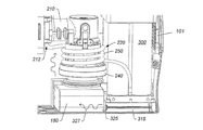
図2を参照して、酸素濃縮器100の実施例が図示される。酸素濃縮器100は、圧縮システム200と、キャニスタアセンブリ300と、外側ハウジング170内に配置された電源180とを含む。入口101を外側ハウジング170内に設けることにより、周囲からの空気が酸素濃縮器100に進入することが可能になる。入口101により、区画内への空気の流入が可能になるため、区画内のコンポーネントの冷却が支援される。電源180により、酸素濃縮器100の電力源が得られる。圧縮システム200により、入口105及びマフラー108を通じて空気が引き込まれる。マフラー108により、圧縮システムによって引き込まれる空気のノイズが低減され得、流入する空気から水分を除去するための乾燥剤材料も含み得る。酸素濃縮器100は、酸素濃縮器からの空気及び他のガスの通気に用いられるファン172をさらに含み得る。
An embodiment of the
[圧縮システム]
いくつかの実施例において、圧縮システム200は、1つ以上のコンプレッサを含む。別の実施例において、圧縮システム200は、キャニスタシステム300の全キャニスタに接続された単一のコンプレッサを含む。図3A及び図3Bに戻って、コンプレッサ210及びモータ220を含む圧縮システム200が図示されている。モータ220は、コンプレッサ210へ接続され、圧縮機構の動作のための動作力をコンプレッサへ提供する。例えば、モータ220は、回転コンポーネントを提供するモータであり得る。この回転コンポーネントにより、空気を圧縮させるコンプレッサのコンポーネントの周期的運動が発生する。コンプレッサ210がピストン型コンプレッサである場合、モータ220により、コンプレッサ210のピストンの往復運動を発生させる動作力が得られる。ピストンの往復運動により、圧縮空気がコンプレッサ210によって生成される。圧縮空気の圧力は、コンプレッサの動作速度(例えば、ピストンの往復運動速度)によって部分的に推定され得る。そのため、モータ220は、可変速モータであり得、コンプレッサ210によって生成される空気の圧力を動的に制御するために、多様な速度において動作することができる。
[Compression system]
In some embodiments, the
一実施例において、コンプレッサ210は、ピストンを有する単一のヒートウォブル型コンプレッサを含む。他の種類のコンプレッサも用いられ得る(例えば、ダイヤフラムコンプレッサ及び他の種類のピストンコンプレッサ)。モータ220は、DC又はACモータであり得、コンプレッサ210の圧縮コンポーネントへ動作力を提供する。モータ220は、一実施例において、ブラシレスDCモータであり得る。モータ220は、可変速モータであり得、コンプレッサ210の圧縮コンポーネントを可変速において動作させることができる。図1に示すように、モータ220は、コントローラ400へ接続され得る。コントローラ400は、モータ動作の制御のために、動作信号をモータへ送る。例えば、コントローラ400は、モータをオンにすること、モータをオフにすること、及びモータの動作速度を設定することを行うための信号をモータ220へ送り得る。
In one embodiment, the
圧縮システム200は、実質的な熱を本質的に生成する。熱は、モータ220による電力消費及び動力から機械運動への変換によって発生する。コンプレッサ210は、空気圧縮によるコンプレッサコンポーネントの移動に対する抵抗増加に起因して熱を発生させる。コンプレッサ210による空気の断熱圧縮によっても、熱が本質的に発生される。そのため、空気の連続的加圧により、封入容器中に熱が発生する。さらに、電源180は、圧縮システム200への給電時において熱を生成し得る。さらに、酸素濃縮器のユーザは、屋内よりも高温であり得る外気温において条件付きではない環境(例えば、屋外)においてデバイスを動作させ得るため、流入する空気は既に加熱状態になる。
The
酸素濃縮器100内において熱が発生すると、問題になり得る。リチウムイオン電池は、長寿命及び軽量であるため、主に酸素濃縮器の電源として用いられる。しかし、リチウムイオン・バッテリーパックの場合、高温において危険であり、危険な高温の電源が検出された場合にシステムを停止させるための安全制御が酸素濃縮器100内において用いられる。さらに、酸素濃縮器100の内部温度の上昇に伴って、濃縮器によって発生される酸素量が低下し得る。その部分的な原因として、高温における所与の量の空気中の酸素が低下する点がある。酸素生成量が所定量を下回ると、酸素濃縮器100は自動停止し得る。
The generation of heat in the
酸素濃縮器はコンパクトであるため、放熱は困難であり得る。典型的な解決方法を挙げると、1つ以上のファンの使用により封入容器中に冷却空気の流れを発生させる方法がある。しかし、このような解決方法の場合、電源からさらに電力が必要になるため、酸素濃縮器のポータブル利用時間が短くなる。一実施例において、受動的な冷却システムは、モータ220によって生成される機械的動力を利用するために用いられ得る。図3A及び図3Bを参照して、圧縮システム200は、外部回転電機子230を有するモータ220を含む。詳細には、モータ220(例えば、DCモータ)の外部回転電機子230は、電機子を駆動する定常場の周囲を包囲する。モータ220は、システム全体への熱に大きく貢献するため、モータから熱を引き出し、封入容器から掃き出すと有用である。外部高速回転に起因して、モータの主要なコンポーネントとその周囲の空気とのの相対速度が高くなる。電機子の表面積は、内部に取り付けられた場合よりも、外部に取り付けられた場合に大きくなる。熱交換速度は表面積及び速度の二乗に比例するため、外部に取り付けられた、より大型の表面積電機子を用いた場合、モータ220からの放熱能力が増加する。電機子を外部に取り付けられたときの冷却効率の利得により、1つ以上の冷却ファンを無くすことができるため、酸素濃縮器の内部を適切な温度範囲内に維持しつつ、重量及び消費電力が低減する。さらに、外部に取り付けられた電機子が回転すると、モータの近隣の空気が動くため、さらなる冷却が実行される。
Due to the compact size of the oxygen concentrator, heat dissipation can be difficult. A typical solution is to use one or more fans to create a flow of cooling air in the encapsulation vessel. However, such a solution requires more power from the power source, which shortens the portable use time of the oxygen concentrator. In one embodiment, a passive cooling system can be used to harness the mechanical power generated by the
その上、外部回転電機子によりモータ効率が支援され得、熱の発生が低減する。外部回転電機子を有するモータは、内燃機関中において機能するフライホイールと同様に動作する。モータがコンプレッサを駆動させる際、回転に対する抵抗は、低圧力において低くなる。圧縮空気の圧力が高くなると、モータ回転に対する抵抗が高くなる。その結果、モータは、一貫して理想的な回転安定性を維持できなくなり、コンプレッサの圧力要求に応じてサージ及び低速化が発生する。このようなモータのサージ及びその後の低速化の傾向は、非効率であり、そのため熱の原因となる。外部回転電機子を用いた場合、モータの角運動量が大きくなるため、モータの可変抵抗の補償が支援される。モータの仕事量が大きくなくて済むため、モータから発生する熱が低下し得る。 Moreover, the external rotating armature can support the motor efficiency and reduce heat generation. A motor with an external rotating armature operates like a flywheel that functions in an internal combustion engine. When the motor drives the compressor, the resistance to rotation is low at low pressures. The higher the pressure of the compressed air, the higher the resistance to motor rotation. As a result, the motor cannot consistently maintain ideal rotational stability, resulting in surges and slowdowns in response to compressor pressure requirements. Such motor surges and subsequent slowdown tendencies are inefficient and therefore cause heat. When an external rotating armature is used, the angular momentum of the motor becomes large, so that compensation for the variable resistance of the motor is supported. Since the workload of the motor does not have to be large, the heat generated from the motor can be reduced.
一実施例において、空気移動デバイス240を外部回転電機子230へ接続させることにより、冷却効率がさらに増加し得る。一実施例において、空気移動デバイス240を外部回転電機子230へ接続させる際には、外部回転電機子の回転により空気移動デバイスが気流を発生させて、この気流がモータの少なくとも一部へ移動するように、接続が行われる。一実施例において、空気移動デバイスは、電機子へ接続された1つ以上のファンブレードを含む。一実施例において、空気移動デバイスが外部回転電機子の運動により回転する羽根車として機能するように、複数のファンブレードが環状リング内に配置され得る。図3A及び図3Bに示すように、空気移動デバイス240は、モータと整列した様態で外部回転電機子230の外面へ取り付けられ得る。空気移動デバイスを電機子に取り付けることにより、気流を外部回転電機子の主要部分へ方向付けることが可能になり、これにより、使用時における冷却効果が可能になる。一実施例において、空気移動デバイスにより、外部回転電機子の大部分が空気流路中に配置されるように、気流が方向付けられる。
In one embodiment, the cooling efficiency can be further increased by connecting the
さらに、図3A及び図3Bを参照して、コンプレッサ210によって加圧された空気は、コンプレッサ出口212においてコンプレッサ210から流出する。コンプレッサ出口導管250は、圧縮空気をキャニスタシステム300へ移動させるように、コンプレッサ出口212へ接続される。上述したように、空気が圧縮されると、空気の温度が上昇する。このような温度上昇は、酸素濃縮器の効率にとって有害であり得る。加圧空気の温度を低下させるために、コンプレッサ出口導管250が、空気移動デバイス240によって生成される空気流路中に配置される。コンプレッサ出口導管250の少なくとも一部は、モータ220の近隣に配置され得る。そのため、空気移動デバイスによって生成された気流が、モータ220及びコンプレッサ出口導管250と接触し得る。一実施例において、コンプレッサ出口導管250の大部分が、モータ220の近隣に配置される。一実施例において、図3Bに示すように、コンプレッサ出口導管250は、モータ220の周囲に渦巻き状にされる。
Further, with reference to FIGS. 3A and 3B, the air pressurized by the
一実施例において、コンプレッサ出口導管250は、熱交換金属によって構成される。熱交換金属の例を非限定的に挙げると、アルミニウム、炭素鋼、ステンレススチール、チタン、銅、銅ニッケル合金又はこれらの金属の組み合わせから形成される他の合金がある。よって、コンプレッサ出口導管250は、空気圧縮に本質的に起因する熱を除去する熱交換器として機能し得る。圧縮空気からの熱除去により、所与の圧力における所与の量の分離の数が増加する。その結果、各圧力スイングサイクル時において各キャニスタが発生することが可能な酸素量が増加し得る。
In one embodiment, the
本明細書中に記載の放熱機構は、受動的なものであるか、又は、酸素濃縮器100に必要な要素を利用する。よって、例えば、さらなる電力を必要とするシステムを用いること無く、放熱の増加が可能になり得る。さらなる電力が不要になるため、バッテリーパックのランタイム増加が可能になり得、酸素濃縮器のサイズ及び重量の最小化が可能になり得る。同様に、さらなるボックスファン又は冷却ユニットの利用も不要になり得る。このような追加機能を排除することで、酸素濃縮器の重量及び消費電力を削減することができる。
The heat dissipation mechanism described herein is either passive or utilizes the elements required for the
上述したように、空気の断熱圧縮に起因して、空気温度が上昇する。キャニスタシステム300中のキャニスタの通気時において、キャニスタから放出されるガスの圧力が低下する。キャニスタ内のガスの断熱減圧に起因して、ガスが通気されることによりガス温度が低下する。一実施例において、キャニスタシステム300からの冷却された通気ガスは、電源180及び圧縮システム200へ方向付けられる。一実施例において、キャニスタシステム300のベース315は、通気ガスをキャニスタから受領する。通気ガス327は、ベース315を通じてベースの出口325及び電源180へ方向付けられる。通気ガスは、上述したようにガス減圧によって冷却されるため、電源へ冷却を受動的に提供する。圧縮システムが動作すると、空気移動デバイスは、冷却された通気ガスを収集し、ガスを圧縮システム200のモータへ方向付ける。ファン172は、圧縮システム200上の通気ガスをハウジング170から方向付けることも支援し得る。このようにして、電池からのさらなる電力要求を全く必要とすること無く、さらなる冷却を得ることが可能になり得る。
As mentioned above, the air temperature rises due to the adiabatic compression of the air. When the canister in the
[出口システム]
キャニスタのうち1つ以上へ接続された出口システムは、酸素富化ガスをユーザへ提供する1つ以上の導管を含む。一実施例において、キャニスタ302及び304の何れかの内部において生成された酸素富化ガスは、図1に概略的に示すように、チェック弁142及び144それぞれを通じてアキュムレータ106中に収集される。キャニスタから流出した酸素富化ガスは、酸素のアキュムレータ106中に収集された後、ユーザへ提供され得る。いくつかの実施例において、チューブにアキュムレータ106を接続することにより、酸素富化ガスをユーザへ提供することができる。酸素富化ガスは、酸素富化ガスをユーザの口腔及び/又は鼻へ移動させる気道送達デバイスを通じてユーザへ提供され得る。一実施例において、出口は、酸素をユーザの鼻及び/又は口腔へ方向付けるチューブを含み得る。このチューブは、ユーザの鼻へ直接接続されていない場合がある。
[Exit system]
The outlet system connected to one or more of the canisters includes one or more conduits that provide the oxygen enriched gas to the user. In one embodiment, the oxygen enriched gas produced inside any of the
図4Aを参照して、酸素濃縮器のための出口システムの実施例の概略図が図示されている。アキュムレータ106からユーザへの酸素富化ガスの放出を制御するように、供給弁160が出口チューブへ接続され得る。一実施例において、供給弁160は、電磁駆動プランジャー弁である。ユーザへの酸素富化ガス送達を制御するように、コントローラ400により供給弁160が作動される。供給弁160の作動は、圧力スイング吸着法プロセスとタイミングを合わせられるか又は同期されない。その代わりに、作動は、以下に述べるようにユーザの呼吸と同期される。いくつかの実施例において、供給弁160は、酸素富化ガスの供給のために臨床的に有効な振幅プロファイル(amplitude profile)を確立させるための連続値作動を有し得る。
A schematic diagram of an embodiment of an outlet system for an oxygen concentrator is illustrated with reference to FIG. 4A. A
アキュムレータ106中の酸素富化ガスは、図4Aに示すように、供給弁160を通じて膨張チャンバ162中へ移動する。一実施例において、膨張チャンバは、このチャンバを通過するガスの酸素濃度を決定するために使用することができる1つ以上のデバイスを含み得る。膨張チャンバ162中の酸素富化ガスは、供給弁160によるアキュムレータからのガス放出を通じて短時間で蓄積した後、小型オリフィス流れ抵抗器175を通じて流量センサ185へと流動し、その後、微粒子フィルタ187へと流動する。流れ抵抗器175は、0.025Dの流れ抵抗器であり得る。他の種類及びサイズの流れ抵抗器が用いられてもよい。いくつかの実施例において、ハウジング中の空気通路の直径は、ガス流制限のために限定され得る。流量センサ185は、導管内を流動するガスのレートを推定することが可能な任意のセンサであり得る。微粒子フィルタ187は、ユーザへの酸素富化ガス送達の前の細菌、埃、細粒微粒子等のフィルタリングのために用いられ得る。酸素富化ガスは、フィルタ187を通じてコネクタ190へ移動する。コネクタ190は、酸素富化ガスを、送達導管192を介してユーザへ送り、圧力センサ194へ送る。
The oxygen-enriched gas in the
出口通路の流体力学を供給弁160のプログラムされた作動と組み合わせることにより、酸素のボーラスの供給を正確なタイミングで行うことが可能になり得、また、ユーザの肺中への高速送達を、過度の浪費無しに確保することが可能な振幅プロファイルも得られる。ボーラス送達をこのように行うことが可能になると、所与の呼吸パターンを有する安静時のユーザに対するパルス化送達モードにおいて要求される、処方された連続的流量と、治療的に相当するボーラス量との間に線形関係が可能になり得る。例えば、連続流れ処方のエミュレーションに必要なボーラスの合計量は、以下に等しくすることができ、処方された連続流量の各LPMに対して11mL(すなわち、1LPMの処方に対して11mL、2LPMの処方に対して22mL、3LPMの処方に対して33mL、4LPMの処方に対して44mL、5LPMの処方に対して55mL等)である。この量を、主にLPM等価ボーラス容量と呼ぶ。LPM等価は、構造設計、配管サイズ、チャンバサイズ等の差によって酸素濃縮器間において異なり得ることが、理解されるべきである。LPM等価は、ユーザの呼吸パターン(例えば、呼吸速度)によっても異なる。
By combining the fluid dynamics of the outlet passage with the programmed operation of the
膨張チャンバ162は、1つ以上の酸素センサを含み得る。これらの酸素センサは、上記チャンバを通過するガスの酸素濃度を決定するように適合される。一実施例において、膨張チャンバ162を通過するガスの酸素濃度は、酸素センサ165を用いて推定される。酸素センサは、ガス中の酸素を検出することが可能なデバイスである。酸素センサの例を非限定的に挙げると、超音波酸素センサ、電気酸素センサ、及び光学酸素センサがある。一実施例態において、酸素センサ165は、超音波酸素センサであり、超音波放出体166及び超音波受信器168を含む。いくつかの実施例において、超音波放出体166は、複数の超音波放出体を含み得、超音波受信器168は、複数の超音波受信器を含み得る。複数の放出体又は受信器を有する実施例において、複数の超音波放出体及び複数の超音波受信器は、軸方向に(例えば、軸整列に対して垂直であり得るガス混合物流路にわたって)整列され得る。
The
使用時において、(放出体166からの)超音波をチャンバ162中に配置された酸素富化ガスを通じて受信器168へ方向付ける。超音波センサアセンブリは、ガス混合物を通過する音の速度を検出して、ガス混合物の組成を決定するように構成され得る(例えば、音の速度は、窒素及び酸素において異なる)。2つのガスの混合物において、混合物を有する通過する音の速度は、混合物中の各ガスの相対的量に比例する中間値であり得る。使用時において、受信器168における音は、放出体166から送られる音と若干逆位相をとる。この位相変化は、ガス媒体の音の速度がワイヤを通じた電子パルスの高速に比べて相対的に低速であることに起因する。次に、この位相変化は、放出体と受信器との間の距離及び膨張チャンバを通過する音の速度に比例する。この箱中のガスの密度に起因して、この箱を通過する音の速度が影響を受け、密度は、箱中の酸素対窒素の比に比例する。そのため、位相変化を用いて、膨張チャンバ中の酸素濃度を測定することができる。このようにして、アキュムレータ中の酸素の相対的濃度を、アキュムレータを通過する検出された音波の1つ以上の特性の関数として推定することができる。
In use, the ultrasonic waves (from the ejector 166) are directed to the
いくつかの実施例において、複数の放出体166及び受信器168が用いられ得る。放出体166及び受信器168からの読み取り値の平均化により、乱流系に固有であり得る誤差をキャンセルすることができる。いくつかの実施例において、通過時間を測定すること及び測定された通過時間を他のガス及び/又はガス混合物の所定の通過時間と比較することにより、他のガスの存在の検出も可能であり得る。
In some embodiments,
例えば放出体166と受信器168との間に数個の音波サイクルが可能になるように放出体166と受信器168との間の距離を増加させることにより、超音波センサシステムの感度の増加が可能になり得る。いくつかの実施例において、少なくとも2つの音サイクルが存在する場合、2つの時点における固定基準に相対する位相変化の測定により、トランスデューサの構造的変化による影響を低減させることができる。早期の位相変化を後期の位相変化から減算すると、膨張チャンバ162の熱膨張に起因する変化を低減又はキャンセルすることができる。放出体166と受信器168との間の距離の変化に起因する変化は、測定インターバルとほぼ同じであり得る一方、酸素濃度の変化に起因する変化は累積的であり得る。いくつかの実施例において、後期において測定された変化測定に介在サイクル数が乗算され得、2つの隣接するサイクル間の変化と比較され得る。膨張チャンバ中の酸素の感知についてのさらなる詳細について、例えば米国公開特許出願第20090065007号(公開日:2009年3月12日、タイトル:「Oxygen Concentrator Apparatus and Method」)に記載がある。本明細書中、同文献を参考のため援用する。
Increasing the distance between the
流量センサ185は、出口システム中を流れるガスの流量の決定に用いられ得る。利用可能な流量センサの例を以下に非限定的に挙げると、ダイヤフラム又はベローズ流量計、ロータリ−流量計(例えば、ホール効果流量計)、タービン流量計、オリフィス流量計、及び超音波流量計である。流量センサ185は、コントローラ400へ接続され得る。出口システム中を流れるガスのレートは、ユーザの呼吸量の示度であり得る。出口システム中を流れるガスの流量の変化を用いて、ユーザの呼吸速度を決定することも可能であり得る。コントローラ400は、供給弁160の作動を制御するための制御信号又はトリガ信号を生成し得る。このような制御供給弁の作動の制御は、(例えばボーラス放出について本明細書中に記載される制御方法の何れかの実施により流量センサ185によって推定され、及び/又は他のセンサ信号に基づき得るような)ユーザの呼吸速度及び/又は呼吸量に基づき得る。
The
いくつかの実施例において、超音波センサシステム165及び例えば流量センサ185により、提供される酸素の実際の測定量が得られ得る。例えば、流量センサ185は、提供されるガス量を(流量に基づいて)測定することができ、超音波センサシステム165は、提供されるガス量の酸素濃度を提供し得る。コントローラ400は、これらの2つの測定を共に用いて、ユーザへ提供される実際の酸素量の概算を決定することができる。
In some embodiments, an
酸素富化ガスは、流量センサ185を通じてフィルタ187へ移動する。フィルタ187により、細菌、埃、細粒微粒子等が除去された後、酸素富化ガスがユーザへ提供される。フィルタリングされた酸素富化ガスは、フィルタ187を通じて、コネクタ190へ移動する。コネクタ190は、フィルタ187の出口を圧力センサ194及び送達導管192へ接続させる「Y字型」コネクタであり得る。圧力センサ194は、導管192を通じてユーザへ移動するガスの圧力を監視するように用いられ得る。いくつかの実施例において、圧力センサ194は、感知面へ付加される正圧又は負圧の量に比例する信号を生成するように構成され得る。圧力センサ194によって感知される圧力の変化は、以下に述べるように、ユーザの呼吸速度及び吸気開始(トリガインスタントとも呼ばれる)を決定するために使用され得る。コントローラ400は、呼吸速度及び/又はユーザの吸息の開始に基づいて、供給弁160の作動を制御し得る。一実施例において、コントローラ400は、流量センサ185と圧力センサ194との何れか、若しくは両方ともから提供される情報に基づいて、供給弁160の作動を制御し得る。
The oxygen-enriched gas moves to the
酸素富化ガスは、導管192を通じてユーザへ提供され得る。一実施例において、導管192は、シリコーンチューブであり得る。導管192は、図4B及び図4Cに示すように、気道送達デバイス196によってユーザへ接続され得る。気道送達デバイス196は、酸素富化ガスを鼻腔又は口腔へ提供することが可能な任意のデバイスであり得る。気道接続部材の例を以下に非限定的に挙げると、鼻マスク、鼻枕、鼻プロング、鼻カニューレ、及びマウスピースである。鼻カニューレ気道送達デバイスを図4Bに示す。使用時に、酸素濃縮器100からの酸素富化ガスは、導管192及び気道送達デバイス196を通じてユーザへ提供される。気道送達デバイス196は、ユーザが周囲からの空気を呼吸することを可能にしつつユーザへの酸素富化ガス送達を可能にするように、ユーザの気道の近隣(例えば、ユーザの口及び/又は鼻の近隣)に配置される。
The oxygen enriched gas may be provided to the user through the
別の実施例において、酸素富化ガスをユーザへ提供するために、マウスピースが用いられ得る。図4Cに示すように、マウスピース198は、酸素濃縮器100へ接続され得る。マウスピース198を酸素富化ガスのユーザへの提供のために用いられる唯一のデバイスにしてもよいし、或いは、マウスピースを鼻送達デバイス(例えば、鼻カニューレ)と組み合わせて用いてもよい。図4Cに示すように、酸素富化ガスが気道送達デバイス196及びマウスピース198双方を通じてユーザへ提供され得る。
In another embodiment, a mouthpiece can be used to provide the oxygen-enriched gas to the user. As shown in FIG. 4C, the
マウスピース198を、ユーザの口内に取り外し可能に配置することができる。一実施例において、マウスピース198を、ユーザの口中の1本以上の歯へ取り外し可能に接続することができる。使用時に、酸素富化ガスは、ユーザの口中へマウスピースを介して方向付けられる。マウスピース198は、ユーザの歯に適合するように成型されたナイトガードマウスピースであり得る。或いは、マウスピースは、下顎再配置デバイスであり得る。一実施例において、少なくともマウスピースの大部分は、使用時においてユーザの口中に配置される。
The
使用時に、マウスピースの近隣において圧力変化が検出されると、酸素富化ガスがマウスピース198へ方向付けられ得る。一実施例において、マウスピース198は、圧力センサへ接続され得る。ユーザがユーザの口腔を通じて空気を吸息すると、圧力センサ194は、マウスピースの近隣の圧力降を検出し得る。酸素濃縮器100のコントローラ400により、吸息開始時におけるユーザへの酸素富化ガスのボーラス放出が制御され得る。例えば、これは、ボーラス放出の制御信号、又は供給弁160を制御するトリガ信号を生成させることにより遂行される。
Oxygen enriched gas can be directed to the
個人の典型的な呼吸時において、吸息は、鼻を通じて、口腔を通じて、或いは、鼻及び口腔双方を通じて行われ得る。さらに、呼吸は、多様な要素に応じて、1つの通路から別の通路へ変化し得る。例えば、より活発な活動時において、ユーザは、鼻を通じた呼吸を、口を通じた呼吸(或いは口及び鼻を通じた呼吸)へ切り換え得る。単一の送達モード(鼻又は口)に依存するシステムの場合、監視された経路を通じた呼吸が停止した場合に適切に機能できなくなり得る。例えば、ユーザへの酸素富化ガス提供のために鼻カニューレが用いられる場合、吸息開始を決定するために、吸息センサ(例えば、圧力センサ又は流量センサ)が鼻カニューレへ接続される。ユーザが鼻を通じた呼吸を停止し、口を通じた呼吸に切り換えると、鼻カニューレからのフィードバックが無いため、酸素濃縮器100は、いつ酸素富化ガスを提供すればよいのかわからなくなり得る。このような状況下において、酸素濃縮器100は、吸息センサがユーザの吸息を検出するまで、流量を増加させ、及び/又は酸素富化ガスの提供頻度を増加させ得る。ユーザが呼吸モードの切り換えを頻繁に行うと、デフォルトの酸素富化ガス提供モードに起因して、酸素濃縮器100の作動頻度が高くなり、その結果、システムのポータブル利用時間が制限される。
In the typical breathing of an individual, inspiration can be done through the nose, through the oral cavity, or both through the nose and oral cavity. In addition, breathing can change from one passage to another, depending on various factors. For example, during more active activity, the user may switch breathing through the nose to breathing through the mouth (or breathing through the mouth and nose). For systems that rely on a single mode of delivery (nose or mouth), they may fail to function properly if breathing through the monitored pathway is stopped. For example, if a nasal cannula is used to provide oxygen enriched gas to the user, an inspiratory sensor (eg, a pressure sensor or flow sensor) is connected to the nasal cannula to determine inspiration initiation. When the user stops breathing through the nose and switches to breathing through the mouth, the
一実施例において、ユーザへの酸素富化ガス提供に用いられる気道送達デバイス196(例えば、鼻カニューレ)と共に用いられるマウスピース198が、図4Cに示される。マウスピース198及び気道送達デバイス196はどちらとも、吸息センサへ接続される。一実施例において、マウスピース198及び気道送達デバイス196は、同一の吸息センサへ接続される。別の実施例において、マウスピース198及び気道送達デバイス196は、異なる吸息センサへ接続される。何れかの実施例において、吸息センサ(単数又は複数)は、それから吸息開始を口又は鼻から検出し得る。酸素濃縮器100は、近隣において吸息開始が検出されたデバイス(すなわち、マウスピース198又は気道送達デバイス196)へ酸素富化ガスを提供するように構成され得る。或いは、何れかのデバイスの近隣において吸息開始が検出された場合、酸素富化ガスをマウスピース198及び気道送達デバイス196双方へ提供してもよい。例えば図4Cに示すような2重送達システムを用いると、睡眠中のユーザにとって特に有用であり得、鼻呼吸/口呼吸間の切り換えを意識的努力無く遂行し得る。
In one embodiment, a
[コントローラシステム]
酸素濃縮器100の動作は、本明細書中に記載のような酸素濃縮器100の多様なコンポーネントへ接続されている内部のコントローラ400を用いて自動的に行われ得る。図1に示すように、コントローラ400は、1つ以上のプロセッサ410及び内部メモリ420を含む。酸素濃縮器100の動作及び監視に用いられる方法は、メモリ420中に保存されたプログラム命令又はコントローラ400へ接続されたキャリア媒体によって実施され得、1つ以上のプロセッサ410によって実行され得る。メモリ媒体は、多様な種類のメモリデバイス又は記憶装置のうち何れかを含み得る。「メモリ媒体」という用語は、インストール媒体を含むことを意図する(例えば、コンパクトディスクリードオンリーメモリ(CD−ROM)、フロッピーディスク(登録商標)、又はテープデバイス;コンピュータシステムメモリ又はランダムアクセスメモリ(例えば、ダイナミックランダムアクセスメモリ(DRAM)、ダブルデータレート(DDR)ランダムアクセスメモリ(RAM)、スタティックランダムアクセスメモリ(SRAM)、拡張データアウトランダムアクセスメモリ(EDORAM)、ランダムアクセスメモリ(RAM));又は不揮発性メモリ(例えば、磁気媒体(例えば、ハードドライブ又は光学記憶装置)))。メモリ媒体は、他の種類のメモリ又はその組み合わせも含み得る。加えて、メモリ媒体は、内部においてプログラムが実行される第1のコンピュータ中に配置してもよいし、或いは、ネットワーク(例えば、インターネット)を介して第1のコンピュータへ接続された第2の異なるコンピュータ中に配置してもよい。後者の場合、第2のコンピュータは、第1のコンピュータによって実行されるプログラム命令を提供し得る。「メモリ媒体」という用語は、異なる場所(例えば、ネットワークを介して接続された異なるコンピュータ中)に常駐し得る2つ以上のメモリ媒体を含み得る。
[Controller system]
The operation of the
いくつかの実施例において、コントローラ400は、プロセッサ410を含む。プロセッサ410は、例えば、1つ以上のフィールドプログラマブルゲートアレイ(FPGA:Field Programmable Gate Array)、酸素濃縮器100中に配置された回路基板上に設けられたマイクロコントローラ等を含む。プロセッサ410は、メモリ420中に保存されたプログラミング命令を実行することができる。いくつかの実施例において、プログラミング命令は、プロセッサの外部のメモリに別個にアクセスできない(すなわち、メモリ420は、プロセッサ410の内部に設けられ得る)ように、プロセッサ410中に構築され得る。
In some embodiments, the
プロセッサ410は、酸素濃縮器100の多様なコンポーネントへ接続され得る(例を非限定的に挙げると、圧縮システム200、システム中を流れる流体の制御に用いられる弁のうち1つ以上(例えば、弁122、124、132、134、152、154、160)、酸素センサ165、圧力センサ194、流量センサ185、温度センサ(図示省略)、ファン、及び電気制御が可能な他の任意のコンポーネント)。いくつかの実施例において、別個のプロセッサ(及び/又はメモリ)が、これらのコンポーネントのうち1つ以上へ接続され得る。
The
コントローラ400は、酸素濃縮器100を動作させるように構成(例えば、プログラム)され、酸素濃縮器100を故障状態について監視するようにさらに構成される。例えば、一実施例において、コントローラ400は、システムが動作しており、かつ所定の期間にわたってユーザにより呼吸が検出されない場合に警告をトリガするように、プログラムされる。例えば、コントローラ400が75秒間の期間にわたって呼吸を検出しない場合、警告LEDが点灯され、及び/又は可聴警告が発生し得る。例えば睡眠時無呼吸エピソード時にユーザの呼吸が本当に止まった場合、この警告はユーザを覚醒させるのに充分であり得、これにより、ユーザの呼吸を再開させる。この呼吸活動は、コントローラ400がこの警告機能をリセットするのに充分であり得る。或いは、送達導管192がユーザから取り外されたときにシステムがオンのまま放置されてしまう場合、この警告は、ユーザに酸素濃縮器100をオフにするよう促すためのリマインダとして機能し得る。
The
コントローラ400は、酸素センサ165へさらに接続され得、膨張チャンバ162を通過する酸素富化ガスの酸素濃度の連続的又は定期的監視のためにプログラムされ得る。最小酸素濃度閾値は、ユーザに対し酸素濃度低下について警告するためのLED視覚警告及び/又は可聴警告をコントローラが点灯するように、コントローラ400内にプログラムされ得る。
The
コントローラ400は、内部の電源180にも接続され、この内部の電源180の充電レベルを監視することが可能である。最小電圧及び/又は現在の閾値は、コントローラ400内にプログラムされてもよく、コントローラがユーザに対して電力低下状態について警告するためのLED視覚警告及び/又は可聴警告を点灯することができる。これらの警告の起動は、間欠的に行ってもよいし、或いは、電池の利用可能な充電がゼロに近づくにつれて頻度を上げて行ってもよい。
The
コントローラ400により実施可能なさらなる機能について、本開示の他の部分に詳細の記載がある。
Further functions that can be performed by the
[外側ハウジング、コントロールパネル]
図5は、酸素濃縮器100の外側ハウジング170の実施例を示す。いくつかの実施例において、外側ハウジング170は、軽量プラスチックを含み得る。外側ハウジングは、圧縮システムの入口105と、冷却システムの受動的な入口101と、外側ハウジング170の各端部における出口173と、出口ポート174と、コントロールパネル600とを含む。入口101及び出口173により、冷却空気がハウジングに進入し、ハウジングを通過し、ハウジング170内から流出して、酸素濃縮器100の冷却を支援することができる。圧縮システムの入口105により、圧縮システム内への空気進入が可能になる。出口ポート174は、酸素濃縮器100によって生成された酸素富化ガスをユーザへ提供するための導管を取り付けるために用いられる。
[Outer housing, control panel]
FIG. 5 shows an example of the
コントロールパネル600は、ユーザとコントローラ400との間のインターフェースとして機能して、ユーザが酸素濃縮器100の所定の動作モードを開始すること及びシステムの状態を監視することを可能にする。充電をする入力ポート605は、コントロールパネル600内に配置され得る。図6は、コントロールパネル600の一実施例を示す。
The
いくつかの実施例において、コントロールパネル600は、酸素濃縮器100のための多様な動作モードを起動するためのボタンを含み得る。例えば、コントロールパネル600は、電源ボタン610、投与量のボタン620〜626、活性モードのボタン630、スリープモードのボタン635、及び電池チェックのボタン650を含み得る。いくつかの実施例において、これらのボタンのうち1つ以上は、各LEDを有し得る。このLEDは、各ボタンが押圧されたときに発光し得(各ボタンが再度押圧されたときに電力オフにされ得る)。電源ボタン610は、システムの電力をオン又はオフにさせ得る。システムをオフにするために電源ボタン610が起動されると、コントローラ400は、システムを停止状態にさせるための停止シーケンスを開始し得る(例えば、双方のキャニスタが加圧された状態)。投与量のボタン620、622、624及び626により、酸素富化ガスの処方された連続流量の選択が可能になる(例えば、ボタン620により1LPM、ボタン622により2LPM、ボタン624により3LPM、及びボタン626により4LPM)。ユーザが通常時に酸素濃縮器100を用いる場所よりも高い場所にユーザが行く場合、高度ボタン640が選択され得る。高度モードの起動に応答して行われる酸素濃縮器100による調節について、本明細書中より詳細に説明する。
In some embodiments, the
電池チェックのボタン650が電池チェックルーチンを酸素濃縮器100内において開始すると、相対的な残留電池電力LED655がコントロールパネル600上において発光される。
When the
検出された呼吸速度又は深さを閾値に比較することにより推定されるようにユーザの活動が比較的低い場合(例えば、熟睡時、座位時)において、ユーザの呼吸速度又は深さが低くなるときがある。ユーザの活動が比較的高い場合(例えば、歩行時、運動時)において、ユーザの呼吸速度又は深さが高くなるときがある。活性/スリープモードは自動的に推定され得、及び/又は活性モードの場合はボタン630を、そして、スリープモードの場合はボタン635を押圧することにより、ユーザが各活性モード又はスリープモードを手動で指示することができる。活性モード又はスリープモードの起動に応答して行われる酸素濃縮器100による調節について、本明細書中より詳細に説明する。
When the user's activity is relatively low (eg, during deep sleep, sitting) and the user's breathing rate or depth is low, as estimated by comparing the detected respiratory rate or depth to a threshold. There is. When the user's activity is relatively high (eg, walking, exercising), the user's breathing speed or depth may be high. The active / sleep mode can be estimated automatically and / or by pressing
[酸素富化ガスの放出制御方法]
酸素濃縮器100の主な用途として、ユーザへの酸素補給がある。一般的に、提供されるべき酸素補給の流量が、医師によって推定される。典型的な処方された酸素補給の連続流量は、約1LPM〜約10LPMの範囲であり得る。最も一般的な処方連続流量は、1LPM、2LPM、3LPM及び4LPMである。一般的に、パルス化酸素デバイスにおいては、ユーザへの酸素富化ガスの提供は、ユーザ用に処方された連続流量をエミュレートするように、呼吸サイクルと同期して十分な量で行われる。本明細書中用いられるように、「呼吸サイクル」という用語は、吸息の後に呼息が続くことを指す。
[Oxygen-enriched gas release control method]
The main use of the
生成する必要のある酸素富化ガスの量を最小化し、処方された連続流量をエミュレートするために、コントローラ400は、(パルス酸素供給(POD)又は要求酸素供給として公知の治療モードに従って)酸素富化ガス放出をユーザの吸息と同期させるようにプログラムされ得る。ユーザの吸息時にユーザへの酸素富化ガスのボーラス放出を行うと、例えばユーザの呼息時に酸素放出を行わない(電力要求がさらに低下する)ことにより、不要な酸素発生を回避することができる。要求酸素量を低減することにより、酸素濃縮器100に要求される空気圧縮の量を有効に低減することができる(その後、コンプレッサからの電力需要を低減することができる)。
To minimize the amount of oxygen-enriched gas that needs to be produced and to emulate a prescribed continuous flow rate, the
酸素濃縮器100によって生成された酸素富化ガスは、酸素のアキュムレータ106中に保存され、ユーザの吸息時においてユーザへ放出される。酸素濃縮器100によって提供される酸素富化ガス量は、供給弁160によって部分的に制御される。一実施例において、供給弁160の開口は、コントローラ400によって推定されたような適切な量の酸素富化ガスをユーザに提供することができるだけの充分な量の時間の間に行われる。ユーザの処方連続流量のエミュレートに必要な酸素量を最小限にするために、ユーザの吸息の開始の検出時において、酸素富化ガスをボーラスとして提供される。例えば、酸素富化ガスのボーラスは、ユーザ吸息の最初の数ミリ秒において供給され得る。
The oxygen-enriched gas produced by the
一実施例において、圧力センサ194は、ユーザの吸息開始を決定するように、用いられ得る。例えば、ユーザの吸気は、圧力センサ194の利用によって検出され得る。使用時において、酸素富化ガスを提供するための導管192が、気道送達デバイス196及び/又は198を通じてユーザの鼻及び/又は口へ接続される。よって、導管192中の圧力は、ユーザの気道圧力を示す。吸息開始時において、ユーザは、鼻及び/又は口を通じて空気を体内へ引き込むことを開始する。空気が引き込まれる際、送達導管端部において引き込まれる空気のベンチュリ作用に部分的に起因して、導管端部において負圧が発生する。コントローラ400は、圧力センサ194からの圧力信号を分析して、圧力の低下を検出し、吸気開始を示す。吸気開始が検出されると、例えば、弁のために生成された制御信号に応答して、供給弁160は、開口されて、酸素富化ガスのボーラスをアキュムレータ106から放出する。圧力の正の変化又は上昇は、ユーザの呼息を示し、概して酸素富化ガス放出が中止されたときである。一実施例において、正圧変化が感知されると、例えば、供給弁に対する発生された制御信号に応答して、次の吸息開始まで制御弁160は閉鎖される。或いは、ボーラス継続期間として知られる所定のインターバルの後、供給弁160は、閉鎖され得る。隣接する吸息開始間のインターバルを測定することにより、ユーザの呼吸速度が推定され得る。吸息開始時とその後の呼息開始時との間のインターバルを測定することにより、ユーザの吸気時間が推定され得る。
In one embodiment, the
他の実施例において、圧力センサ194は、感知導管内に配置され得る。感知導管は、ユーザの気道と空気圧で連通するが、送達導管192から別個に設けられる。よって、このような実施例において、圧力センサ194からの圧力信号も、ユーザの気道圧力を示す。
In another embodiment, the
いくつかの実施例において、圧力センサ194の感度は、特に圧力センサ194が酸素濃縮器100内に配置されかつ酸素濃縮器100をユーザへ接続させる導管192を通じて圧力差が検出された場合、圧力センサ194のユーザからの物理的距離によって影響を受け得る。いくつかの実施例において、圧力センサ194は、酸素富化ガスのユーザへの提供に用いられる気道送達デバイス196内に配置され得る。圧力センサ194からの信号は、酸素濃縮器100中のコントローラ400へ有線的に又はテレメトリを通じて(例えば、ブルートゥース(登録商標)又は他の無線技術を通じて)電子的に提供され得る。
In some embodiments, the sensitivity of the
いくつかの実施例において、ユーザの現在の活動水準(例えば、検出されたユーザの現在の呼吸速度を用いて推定されたもの)が所定の閾値を超える場合、コントローラ400は、酸素濃縮器100の送達能力を超えている旨をユーザに警告するための警告(例えば、視覚及び/又は音声)が実装され得る。例えば、閾値は、1分あたり40回(BPM:Breaths Per Minute)の呼吸に設定され得る。
In some embodiments, if the user's current activity level (eg, estimated using the detected user's current respiratory rate) exceeds a predetermined threshold, the
[PODのトリガリング]
図7は、適応されるトリガ生成システム700の一例を示すブロック図である。適応されるトリガ生成システム700は、本技術の1つの実施例によるユーザへの送達のために酸素濃縮器100からの酸素のボーラス放出をトリガするように構成される。このシステム700の多様なモジュール710、720、730及び740は、システムの処理コンポーネントとして実施してもよいし、或いは、他の場合にメモリ420中に保存されたプログラム命令として符号化し、コントローラ400によって実施してもよい。
[POD triggering]
FIG. 7 is a block diagram showing an example of an applied
多様なモジュールの機能は、以下に述べるようなものであり得るが、他の実施例において、モジュール間に異なって分配してもよい。 The functionality of the various modules may be as described below, but in other embodiments they may be distributed differently among the modules.
システム700は、圧力モジュール710を含み得る。圧力モジュール710は、以下のうち何れか又は全てを入力として受信するように構成されてもよい。すなわち、圧力センサ194からの生の圧力信号P、供給弁160の制御のためにコントローラ400によって生成された弁制御信号パルス、及び(任意選択的に)酸素濃縮器100中の温度センサからの温度信号Tを入力として受信するように構成されてもよい。圧力モジュール710の機能は、生の圧力信号がユーザの気道圧力をより高精度に示すように生の圧力信号を調節することである。圧力モジュール710は、圧力センサ194が送達導管192内にある実施例において各ボーラス放出の結果、生の圧力信号中に含まれる圧力パルス(単数又は複数)又は圧力効果(単数又は複数)を除去することにより、この機能を行う。温度信号Tを設けることにより、圧力モジュール710は、圧力センサ194の温度感度が高い場合に温度変化に起因して発生し得る、生の圧力信号Pの(熱又は他の)任意のオフセットドリフトを除去することにより、温度変化を補償することができる。圧力モジュール710は、生の圧力信号Pに対してノイズ低減フィルタリングも行う。圧力モジュール710は、「調節された(adjusted)」圧力信号Padjを時間tの関数として出力する。圧力モジュール710について、以下により詳細に説明する。
The
上記システム700は、閾モジュール720をさらに含み得る。閾モジュール720の機能は、圧力モジュール710からの調節された圧力信号Padjを監視し、適切なトリガ閾hを時間tの関数として繰り返し決定することである。閾モジュール720について、以下により詳細に説明する。
The
上記システム700は、トリガモジュール730をさらに含み得る。トリガモジュール730の機能は、閾モジュール720からのトリガ閾hを圧力モジュール710からの調節された圧力信号Padjへ適用して、(例えば、ブール)信号トリガを生成することである。この信号は、吸気開始の示度として認識され得る。信号トリガは、上述したボーラス放出制御又はトリガ信号として用いられ得る。トリガモジュール730は、監視モジュール740から受信された1つ以上の呼吸パラメータを用いて自身の機能を果たすことも任意選択的に可能である。トリガモジュール730について、以下により詳細に説明する。
The
上記システム700は、監視モジュール740をさらに含み得る。監視モジュール740の1つの機能として、(例えば、ユーザの気道圧力を示す圧力モジュール710からの調節された圧力信号Padjの監視)及びトリガモジュール730からのトリガ信号により、ユーザの気道圧力を監視することがある。監視モジュール740は、例えば、圧力及び/又は吸気開始情報に基づいて(例えば、調整された圧力信号及び/又はトリガ信号に基づいて)、ユーザの1つ以上の呼吸パラメータ、例えば、ユーザの呼吸速度Rを計算してもよい。これらの呼吸パラメータのうち1つ以上は、トリガモジュール730へ送られ得る。監視モジュール740によって生成された呼吸パラメータを、トリガ生成システム700の外部のモジュール(ボーラス調節スキーム及びユーザデータ報告を含む)へ提供してもよい。監視モジュール740について、以下により詳細に説明する。
The
いくつかの実施例において、モジュール710〜740は、以下に述べる場合を除いて、100Hz〜1kHzの範囲の所定の「リアルタイム」サンプルレートと同期して動作する。圧力信号P及び温度信号Tは、少なくともリアルタイムレートでその各センサによって生成される。 In some embodiments, modules 710-740 operate in synchronization with a given "real-time" sample rate in the range of 100 Hz to 1 kHz, except as described below. The pressure signal P and the temperature signal T are generated by each of the sensors at least at a real-time rate.
以下の記載において、符号規約については、吸気時において圧力信号Pは負であるとみなされ、呼息時に正であるとみなされるものとされる。しかし、いくつかの実施例において、特定の範囲(例えば、正の値又は負の値)を維持するためにこのような信号伝達を反転させ、及び/又は、他の場合に調節し、同じ結果を達成するために適用することができる。 In the following description, with respect to the sign convention, the pressure signal P is considered negative at the time of inspiration and positive at the time of exhalation. However, in some embodiments, such signaling is inverted and / or otherwise adjusted to maintain a particular range (eg, positive or negative values), resulting in the same result. Can be applied to achieve.
図8は、本技術による図7のシステム700の圧力モジュール710に類似する圧力モジュール800の1つの実施例を示すブロック図である。圧力モジュール800は、入力圧力センサ194からの生の圧力信号Pと、供給弁160の制御のためのコントローラ400によって生成された弁制御信号パルスと、(任意選択的に)酸素濃縮器100中の温度センサからの温度信号Tとを入力として取得する。圧力モジュール800中の任意選択的要素は、鎖線の輪郭で示されている。
FIG. 8 is a block diagram showing an embodiment of a
温度信号Tが存在する場合、圧力モジュール800は、例えばノイズ低減のためにフィルタ810を温度信号Tへ適用することにより、信号をフィルタリングし得る。1つの実施例において、ノイズ低減フィルタ810は、3点メディアンフィルタである。次に、オフセット計算モジュール820は、圧力オフセットΔPを基準温度Trefに関連する温度変化の関数として計算し得る。このような基準温度Trefは、の較正又は動作時に(又は実行が無い場合は電源オン時に)温度信号又は温度センサを用いて決定/測定される温度であり得る。1つの実施例において、圧力オフセットΔPは、温度変化の線形関数として計算される。
![]()
![]()
ここで、Kは、例えば温度単位を圧力単位へ変換するための補償係数である。別の実施例において、オフセット計算モジュール820は、T及びTrefに基づいた事前較正されたルックアップテーブルから圧力オフセットΔPを取り出す。
Here, K is, for example, a compensation coefficient for converting a temperature unit into a pressure unit. In another embodiment, the offset
温度信号Tが存在しない場合に適した別の実施例において、生の圧力信号Pの監視により、圧力オフセットΔPを推定することができる。推定された圧力オフセットΔPという値は、生の圧力信号Pから減算した場合に、平均持続時間TIの期間にわたって、生の圧力信号Pが(吸気を示す)負になり、平均持続時間TEの期間にわたって(吸気を示す)正になる値である。ここで、TI及びTEは、吸気時間対呼気時間の既知の比I:Eをとる。換言すると、推定された圧力オフセットΔPは、生の圧力がΔPを超える期間及び生の圧力がΔPを下回る期間が所定のI:E比を満たすように、選択される。I:E比は、ほとんどのユーザにおいて1.1〜1.4の範囲内である。呼吸拘束下にあるユーザ(例えば、状態の悪いCOPD患者)の場合、I:E比は1:1に近く、リラックスした健常のユーザの場合、I:E比は1:4まで高くなる。 In another embodiment suitable in the absence of the temperature signal T, the pressure offset ΔP can be estimated by monitoring the raw pressure signal P. A value of the estimated pressure offset ΔP, when subtracted from the raw pressure signal P, over a period of average duration T I, the raw pressure signal P (indicating an intake) becomes negative, the mean duration T E It is a value that becomes positive (indicating inspiration) over the period of. Here, T I and T E are known ratio I of the intake time to expiration time: take E. In other words, the estimated pressure offset ΔP is selected such that the period during which the raw pressure exceeds ΔP and the period during which the raw pressure falls below ΔP satisfies the predetermined I: E ratio. The I: E ratio is in the range of 1.1 to 1.4 for most users. For users under respiratory restraint (eg, poorly conditioned COPD patients), the I: E ratio is close to 1: 1 and for relaxed, healthy users, the I: E ratio is as high as 1: 4.
次に、生の圧力信号Pに対し、(例えば圧力オフセットΔPの減算により)生の圧力信号の調節のために圧力オフセットΔPを適用することにより、温度補償モジュール830において温度補償が行われ得る。次に、圧力モジュール800は、酸素濃縮器100の電気系統内における切り換えに起因する極めて短い持続時間の大きな大きさのノイズインパルスを除去するために、例えば、ノイズ低減フィルタ840を補償された圧力へ適用することにより、補償された圧力信号を(任意選択的に)フィルタリングし得る。1つの実施例において、このフィルタ840は、この目的のために3点メディアンフィルタを含む。周期的デバイスノイズ(例えば、高周波コンプレッサ)及び酸素濃縮器100の電気系統から発生したPSAノイズの除去のために、このフィルタ840は、圧力信号P(例えば、補償された圧力信号)も平滑化し得る。1つの実施例において、このフィルタ840は、この目的のために24点移動平均フィルタを含む。
Temperature compensation can then be performed in the
ボーラス送達時において、送達導管192内において感知されるようなユーザの気道圧力は、ボーラスの圧力によってマスクされる。ボーラス送達の期間は、生成された弁制御信号の放出動作とほぼ一致する。そのため、ボーラス除去モジュール850は、(a)(例えば、弁制御信号パルスのアサーションによって示されるような)ボーラス送達期間、及び、任意選択的に(b)その後のセトリング期間時のユーザの気道圧力をより高精度に示す調節された圧力値Padjを計算し得る。例えば、圧力パルスは、圧力センサからの信号中に示される圧力を一時的に上昇させ得る。そのため、圧力信号に対するボーラスの影響又は効果(例えば、圧力効果)を除去するように、圧力信号を調節することができる。いくつかのバージョンにおいて、このモジュール850のこのようなボーラス除去計算において、ボーラス送達前の最終圧力値P0及びボーラス送達後の第1の圧力値P1及び任意選択的にセトリング期間の間の圧力値の補間が行われ得る。このようなセトリング期間は、任意選択的に1つの実施例において約200msに設定してもよいし、或いは他の場合に100〜600msの範囲に設定してもよい。1つの実施例において、以下の式によれば、P0とP1との間の補間は線形である。

ここで、T0は、ボーラス送達の開始時間であり、Tは、ボーラス及びセトリング期間の合計持続時間である。他の場合において、Padjは、(任意選択的に)フィルタリングされ、(任意選択的に)温度補償された圧力信号Pである。セトリング期間は、ボーラス終了と、圧力信号が患者気道圧力まで再度安定する時間との間の期間であり、ボーラスの最大圧力及び量、気道送達デバイス196の物理的特性、及び供給弁160の動作速度等の要素に依存し得る。1つの実施例において、セトリング期間は、およそ500ミリ秒(例えば、501ミリ秒)である。他の実施例において、圧力信号Pの監視により、セトリング期間を動的に推定することができる。別の実施例において、セトリング期間は、「学習回路」機能によって設定され得る。「学習回路」機能は、ボーラス送達から圧力信号が再度安定するまでの時間を決定することにより、このような期間を測定するように動作する。
Here, T 0 is the start time of bolus delivery, and T is the total duration of the bolus and settling period. In other cases, Padj is a (arbitrarily) filtered and (arbitrarily) temperature-compensated pressure signal P. The settling period is the period between the end of the bolus and the time it takes for the pressure signal to stabilize again to the patient's airway pressure, the maximum pressure and amount of the bolus, the physical properties of the
他の実施例において、補間は、非線形カーブフィッティング、時系列予測又は呼吸信号モデル化によって達成され得る。 In other embodiments, interpolation can be achieved by nonlinear curve fitting, time series prediction or respiratory signal modeling.
上記システム700の調節された圧力計算動作は、スパートとして行われ得る。この点について、この送達及び/又はセトリング期間時において、P1は、まだ、知られていないため、調節された圧力Padjの計算に起因して、ボーラス送達及びセトリング期間時に一次停止/待機が発生し得る。そのため、上記システム700の動作は、このインターバルにおいて中止され得る。ボーラス送達及びセトリング期間の完了後、調節された圧力信号Padjの推定値をリアルタイムよりも高速に処理することで、上記システム700が短いインターバルの後にリアルタイムに追いつくことが可能になる。調節された圧力信号Padjの値がリアルタイムのN倍の速度で計算された場合、上記システム700は、ボーラス送達及びセトリング期間の持続時間のおよそ1/(N−1)番目後にリアルタイムに追いつく。1つの実施例において、Nは20である。
The regulated pressure calculation operation of the
別の実施例において、ボーラス送達時において圧力信号の調節は行われず、ボーラス送達期間におけるさらなる処理は省略されるだけである。このような実施例において、任意のモジュールが欠測期間について補償され、調節された圧力信号Padjの処理再開前に任意のフィルタを安定させるためのインターバルが設けられる。 In another embodiment, no pressure signal is adjusted during bolus delivery and only further processing during bolus delivery is omitted. In such an embodiment, any module is compensated for the missing period and an interval is provided to stabilize any filter before resuming processing of the adjusted pressure signal Padj.
いくつかの実施例において、ボーラス除去モジュール850は省略され得る。例えば、圧力センサ194が別個の感知導管内に配置された実施例において、ボーラス除去モジュール850は省略され得る。
In some embodiments, the
図9は、本技術による図7のシステム700の閾モジュール720に類似する閾モジュール900の1つの実施例を示すブロック図である。上述したように、閾モジュール900の機能は、圧力信号(例えば、圧力モジュール710からの調節された圧力信号Padj)を監視し、現在時間tにおける適切なトリガ閾hを決定することである。
FIG. 9 is a block diagram showing an embodiment of a
閾モジュール900は、例えば、入力信号(例えば、調節された圧力信号Padj)からの活動信号a(t)を生成又は抽出するように構成された活動推定モジュール910又はサブモジュール(例えば、1つ以上のフィルタ(単数又は複数))を有し得る。呼吸速度等の呼吸パラメータと対照的に、このようなモジュールは、ユーザ活動(すなわち、呼吸活動以外の活動)を示す出力を生成し得る。例えば、1つの実施例において、活動推定モジュール910は、適切なカットオフ周波数(例えば、10Hz)を用いた2次バターワース(Butterworth)ハイパスフィルタを用いたモジュールであり得る。フィルタ及びカットオフは、信号からの呼吸活動を省略することにより呼吸以外のユーザ活動を示す出力を生成するように、選択され得る。本例において生成されるように、a(t)の値が高いほど、典型的にはユーザ活動が高いことを意味するが、他のノイズ源も示すことができる。
The
次に、閾モジュール900の閾更新モジュール920は、最近の活動a(t)に従ってトリガ閾hを(例えば、繰り返し)調節し得る。例えば、活動が上昇した場合、ノイズ耐性を上昇させる(すなわち、ボーラスをトリガする感度を低下させる)ように、トリガ閾hを調節することができる(例えば、閾をより負になるように調節することができる)。同様に、活動が低下した場合、ノイズ耐性を低下させる(すなわち、ボーラスをトリガする感度を上昇させる)ように、トリガ閾hを調節することができる(例えば、閾をより負にならないように調節することができる)。よって、適応されるトリガ生成システム700のノイズ耐性は、例えば特定の信号期間(例えば、窓)からの入力信号(例えば、気道圧力信号)中に反映される活動レベルに概ね追随する。例えば、閾hは、入力信号の1つ以上の期間からの1つ以上の値の関数(例えば、最大、最小及び/又は平均)として繰り返し設定され得る。閾更新モジュール920の1つの実施例において、トリガ閾hは、a(t)の最近の値の窓Wにわたる活動a(t)の最大値amaxに設定され得、スケーリング定数Kによって乗算され得る。スケーリング定数Kは、トリガ閾hを負にするために例えば以下の関数に従って符号が負に反転され得る。
いくつかの実施例において、スケーリング定数Kは、1.2に固定される。 In some embodiments, the scaling constant K is fixed at 1.2.
他の実施例において、スケーリング定数Kは、最大活動amaxによって異なる(例えば、最大活動amaxの関数となる)。1つのこのような実施例において、活動レベルが低い場合、スケーリング定数Kは1.5に設定され、その後、1まで低下して、高レベルの活動における増幅を減衰させる。図11は、この実施例による最大活動amaxの関数としてのスケーリング定数Kの値を示すグラフである。 In another embodiment, the scaling constant K depends on the maximum activity a max (eg, it is a function of the maximum activity a max). In one such embodiment, when the activity level is low, the scaling constant K is set to 1.5 and then lowered to 1 to attenuate the amplification at the high level of activity. FIG. 11 is a graph showing the value of the scaling constant K as a function of the maximum activity a max according to this embodiment.
さらに他の実施例において、スケーリング定数Kは、ユーザの呼吸速度Rに応じて変化し、例えば低呼吸速度(例えば、およそ4〜10呼吸/分)におけるK=2を速い呼吸速度(例えば、低呼吸速度よりも高い速度)における1まで低下させる。このような実施例の意図として、得られたトリガ遅延(下記を参照)に起因してボーラス放出が有効になるのに遅すぎる場合にノイズに対する耐性無しに済ませることがある。 In yet another embodiment, the scaling constant K varies with the user's respiration rate R, for example, K = 2 at a low respiration rate (eg, about 4-10 respirations / minute) and a fast respiration rate (eg, low). Reduce to 1 at a rate higher than the respiratory rate). The intent of such an embodiment is to eliminate noise immunity if the resulting trigger delay (see below) causes the bolus emission to be effective too late.
いくつかの実施例において、短期圧力センサオフセットエラーを取り扱うために、閾hが最小閾値hminにより維持又は制限される(例えば、より負の値になる)ように、閾調節を制限することができる。最小閾hminは、センサ性能及び分解能によって制限される。いくつかの実施例において、最小閾hminは、最大の予測される短期及び未修正の長期オフセットエラーよりも大きい。長期オフセットエラーは、間欠的センサ較正により例えば電源オン時に修正され得、その場合、最小閾hminの値の選択時に最大の未修正の長期オフセットエラーを考慮するだけで済む。一例において、最小閾hminは、−0.01〜−0.5mmH2Oの範囲内である(例えば、−0.15mmH2O)。 In some embodiments, limiting the threshold adjustment so that the threshold h is maintained or limited by the minimum threshold h min (eg, to a more negative value) to handle short-term pressure sensor offset errors. can. The minimum threshold h min is limited by sensor performance and resolution. In some embodiments, the minimum threshold h min is greater than the maximum predicted short-term and uncorrected long-term offset error. Long-term offset errors can be corrected by intermittent sensor calibration, for example at power-on, in which case it is only necessary to consider the maximum uncorrected long-term offset error when selecting a value for the minimum threshold h min. In one example, the minimum threshold h min is in the range −0.01 to −0.5 mmH 2 O (eg −0.15 mmH 2 O).
いくつかの実施例において、hminの値は、(負方向(すなわち、より大きく負になるように))最後の較正成功以降の時間の関数として増加される。これにより、較正時における最大性能が可能になり、長期オフセットドリフトの危険性のあるデバイスについて最適な(しかし、必然的に低下する)性能が支援される。 In some embodiments, the value of h min is increased as a function of the time since the last successful calibration (in the negative direction (ie, to be greater and more negative)). This allows for maximum performance during calibration and supports optimal (but inevitably reduced) performance for devices at risk of long-term offset drift.
いくつかの実施例において、閾hが最大閾値hmaxによって維持又は制限される(例えば、最大閾値hmaxよりも負にならない)ように閾調節を制限することができ、これにより、調節された圧力信号上のノイズが大きな期間において吸気が欠損する(偽の負)可能性を低下させることができる。1つのこのような実施例において、最大閾値hmaxは、最小調節された圧力Padjの一部として計算され得る。 In some embodiments, the threshold h is maintained or limited by the maximum threshold h max (e.g., not negative than the maximum threshold value h max) so can limit閾調clause, thereby, it is adjusted It is possible to reduce the possibility of intake loss (false negative) during periods of high noise on the pressure signal. In one such embodiment, the maximum threshold h max can be calculated as part of the minimum adjusted pressure Padj.
窓Wの持続時間wは、(例えば、10秒又は(例えば約5〜15秒の範囲内の)他の時間値に)固定され得る。この点について、窓の持続時間は、任意の所与の閾決定において考慮される活動信号のデータ量(又は値)に関する。いくつかのバージョンにおいて、窓は、(例えば、窓を、活動信号、圧力信号及び/又はトリガ閾の関数として調節することにより)窓調整モジュール930により調節することが可能である。例えば、窓調整モジュール930は、例えば(例えば活動信号中に存在し得る咳又はカニューレ隆起に起因する)ノイズ増加短期の個別エピソードからの急速な回復を可能にするような閾を得るために、窓を一時的に短くし得る(すなわち、wを低減させ得る)。1つの実施例において、窓持続時間wは、tLの関数であり得る。ここで、tL(例えば、秒)は、トリガ閾hが最近の平均(例えば、計算されたトリガ閾h値の最近の平均)を有意な差だけ超えた時点以降の時間であり、短期の個別のエピソードのノイズ増加を示す。1つの実施例において、関数は、tLから一定の時間(例えば、1)を減算した値であり、最近の平均は、移動平均(例えば、5秒の移動平均)、有意な差は、0.7mmH2O又は(例えば、約0.4又は0.10mmH2Oの範囲内の)他の値である。
The duration w of the window W can be fixed (eg, to a time value of 10 seconds or other time value (eg, within the range of about 5-15 seconds)). In this regard, the duration of the window relates to the amount (or value) of activity signal data considered in any given threshold determination. In some versions, the window can be adjusted by the window adjustment module 930 (eg, by adjusting the window as a function of activity signal, pressure signal and / or trigger threshold). For example, the
図12は、窓持続時間の調整関数の別の実施例を例示するグラフである。図12において、窓持続時間wは、トリガ閾移動域(すなわち、トリガ閾が有意な差だけ最近の平均を超えた)以降の時間tL(単位:秒)の関数としてプロットされる。窓持続時間は、例えばこの関数によって、移動域の直後の下限(例えば、3秒)から約15秒後の上限(例えば、10秒)へ漸増する。図12は、窓持続時間の段階的増加を示すが、この増加は、平滑な線形増加又は非線形増加であってもよい。典型的には、このような増加は、通常持続時間を低減させる移動域が無い場合に繰り返し発生し得る。 FIG. 12 is a graph illustrating another embodiment of the window duration adjustment function. In FIG. 12, the window duration w is plotted as a function of time t L (unit: seconds) after the trigger threshold movement region (ie, the trigger threshold exceeds the recent average by a significant difference). The window duration is gradually increased by this function, for example, from the lower limit immediately after the moving range (for example, 3 seconds) to the upper limit after about 15 seconds (for example, 10 seconds). FIG. 12 shows a gradual increase in window duration, which may be a smooth linear or non-linear increase. Typically, such an increase can occur repeatedly in the absence of a range of movement that normally reduces duration.
何れの場合も、窓調整モジュール930は、窓持続時間wを最小制限と最大制限との間(例えば、下限3秒と上限10秒との間)に維持する。
In either case, the
閾更新モジュール920及び窓調整モジュール930は、低速で作動し得、例えば、トリガ閾h及び窓持続時間wを2Hzにおいて更新する。
The
任意選択的に、活動信号a(t)は、ユーザの活動の示度(例えば、歩行数、運動期間の強度及び持続時間及び活動種類)を報告するためにさらに処理され得る。 Optionally, the activity signal a (t) can be further processed to report the user's activity intensity (eg, number of walks, intensity and duration of exercise period and activity type).
閾モジュール720の別の実施例において、閾hは、調節された圧力信号Padjのピーク値の最近の平均(例えば、調節された圧力信号Padjの窓Wの値からのもの)の比率として計算され得る。
In another embodiment of the
上述したように、トリガモジュール730の機能は、閾モジュール720からのトリガ閾hを圧力モジュール710からの調節された圧力信号Padjへ適用して、ボーラス放出制御又はトリガ信号(例えば、ブール吸気開始信号トリガ)を生成することである。本例において、このようなトリガ信号はブールであり得るが、トリガ信号は、ボーラス放出のため(例えば、開始及び/又は終了のため)に任意のデバイス(例えば、制御弁)を(例えば、比例的に)動作させるか又はその動作を発生させるために、他の場合に任意の種類の信号(例えば、比例する制御信号又は他の制御信号)であり得ることが理解される。そのため、制御信号の生成は、圧力信号(例えば、調節された圧力信号Padj)及び可変閾(例えば、トリガ閾h)の1つ以上の比較に基づき得る。1つの実施例において、以下のブール式が真である場合、トリガ(すなわち、ボーラスを放出させる制御信号)がアサートされ、
(a)調節された圧力信号Padjが、(負)トリガ閾hを少なくとも(1つの実施例において3msに等しい)トリガ確認期間にわたって連続的に下回り、又は最近のインターバル(例えば、500ms)内においてこれを行い、
(b)トリガの最終アサーション以降の時間が、(1つの実施例において1秒に等しい)ブラックアウト期間を超え、
(c)トリガの最終アサーション以降に呼気が検出され、及び、
(d)現在の吸気の開始以降の経過時間Tiが、最短吸気時間値Timinを超えている。
As described above, the function of the
(A) The regulated pressure signal Padj continuously falls below the (negative) trigger threshold h for at least a trigger confirmation period (equal to 3 ms in one embodiment), or within a recent interval (eg, 500 ms). Do this and
(B) The time since the last assertion of the trigger exceeds the blackout period (equal to 1 second in one embodiment).
(C) Exhalation is detected after the final assertion of the trigger, and
(D) The elapsed time Ti since the start of the current inspiration exceeds the shortest inspiratory time value Timin.
図10は、トリガモジュール730のこの実施例による上記のブール式を達成するための例示的なプロセス1000の模式図である。ブロック1010において、例えば調節された圧力Padjが閾hを連続的にトリガ確認期間にわたって下回るかを決定する比較を行う。これは、上記の条件(a)の第1の部分を示し得る。トリガ確認期間が増加すると、トリガモジュール730のノイズに対する耐性が増加するが、吸気開始検出の待ち時間(遅延)も増加する。1つの実施例において、トリガ確認期間は、最近の吸気時間、圧力信号対ノイズ比、及び/又は最近の圧力信号移動域の大きさに基づいて、例えば3ms〜25msの範囲内になるように調節され得る。これにより、トリガモジュール730が(ボーラスの「有効性」を確保できるくらいに充分に早期にトリガ生成しつつ)ノイズについて偽トリガを生成する事態が回避される(「有効性」とは、ボーラス全体が呼息開始前にデッドスペースを通過し、肺に到達することを意味するものとして理解される)。よって、ガス交換に貢献することが可能になる。目安として、ボーラス送達を有効にするには、ボーラス送達を吸気時間の60%までに完了させる必要がある。
FIG. 10 is a schematic diagram of an
ブロック1020は、上記の条件(a)の第2の部分を示す。未決定の吸気は、非ゼロ値を有する「トリガラッチ」タイマーに相当する。トリガラッチタイマーは、以下に述べるように、再度開始以降の経過時間をカウントダウンする。トリガラッチタイマーが未だゼロにカウントダウンされていない場合、ブロック1020は真に戻る。1つの実施例において、トリガラッチタイマーは、500msの値で再度開始される。
ブロック1030は、条件(b)を示す。ブロック1030において、前回のトリガのアサーションによって再度開始された意向の経過時間をカウントダウンする「ブラックアウトタイマー」の値を確認する。ブラックアウトタイマーがゼロまでカウントダウンした場合、ブロック1030は真に戻る。1つの実施例において、ブラックアウトタイマーは、1秒の値で再度開始する。ブロック1030において、ボーラス送達速度をブラックアウトタイマー再開始値(ボーラス間の最短時間)の逆数に等しい最大値(例えば、60/分)に制限する。
ブロック1040は、条件(c)を示す。ブロック1040において、exp信号が監視モジュール740によってアサートされたかを確認する(下記参照)。トリガモジュール730は、ブロック1050により、トリガのアサーションによりexp信号をクリアする。ブロック1040により、吸気毎に行われるトリガのアサーションが1回だけになることが保証される。
ブロック1040が真に戻った後、トリガモジュール730は、トリガラッチタイマーを再開始する(ブロック1020)。
After
ブロック1050は、条件(d)を示す。ブロック1050は、時間が利用可能である場合に吸気開始を確認する時間を増加させることによりさらなる検出ロバストネスを提供するための最小値Timinだけ、各ボーラスの開始を遅延させる。ブロック1050は、最小値Timinを1つ以上の呼吸パラメータ及び/又は活動パラメータの関数として(例えば、最近の平均吸気時間Timin及び/又は最大活動amax(式(4))として)計算し得る。最近の平均吸気時間Timinは、監視モジュール740によって提供され得る(下記参照)。
いくつかの実施例において、ユーザの呼吸速度が最小値(例えば、0ms)まで上昇すると、最小値Timinを低下させることができる。このような低下は、吸気の有効部分内のボーラス送達のための時間が最小であるときに、実施することができる。呼吸速度の低下時又は最大活動amaxの増加時において、最小値Timinを例えば最大値まで増加させることができる。このような最大値は、例えば1つの実施例において100msまで又はおよそ80〜120msの値であり得る。 In some embodiments, increasing the user's respiratory rate to a minimum value (eg, 0 ms) can reduce the minimum value Timin. Such a reduction can be performed when the time for bolus delivery within the effective portion of inspiration is minimal. The minimum value Timin can be increased, for example, to the maximum value when the respiratory rate decreases or the maximum activity a max increases. Such maximum values can be, for example, up to 100 ms or approximately 80-120 ms in one embodiment.
1つのこのような実施例において、Timinは、最小値dfloorと最大値dceilとの間の線形補間により補間パラメータkに基づいて計算することができる。
ここで、kは、最大活動amaxと線形に関連する。
すなわち、最大活動amaxの増加に伴って、Timinが最大値dceilに向って増加する。最小値及び最大値は、最近の平均吸気時間Timeanに依存し得る。
他の実施例において、Timinは、呼吸速度低下に向けた呼吸速度エントレインメントを促進させるように、インターバル[dfloor、dceil]内においてランダムに選択してもよいし、或いはインターバル[dfloor、dceil]にわたって漸増させてもよい。これらの目的のため、所与の呼吸速度及びよって例えばボーラスの持続時間Tパルスが得られると、遅延増加のためにdceilの導出を変更することが可能になる。
上述したように、監視モジュール740は、ユーザの1つ以上の呼吸パラメータも計算し得る。1つの実施例において、監視モジュールは、ユーザの呼吸速度Rを最近の呼吸持続時間の逆数として推定する。呼吸持続時間は、信号トリガがアサートされたときの連続的瞬間の間のインターバルの長さである。最近の呼吸持続時間は、直近の呼吸持続時間の移動平均として推定され得る。1つの実施例において、最近の呼吸持続時間の計算のために、3つの直近の呼吸持続時間の平均をとる。信号トリガのアサーションが行われた後、その都度呼吸速度推定値Rが更新され得る。(8BPMに対応する)7.5秒間にわたって呼吸が検出されない場合、最近の呼吸持続時間は、デフォルト値である(20BPMに対応する)3秒へリセットされる。これにより、信号損失の際に依存モジュールが(極めて低い呼吸速度ではなく)典型的呼吸速度へデフォルトすることが保証される。
As mentioned above, the
監視モジュール740は、ユーザの吸気時間TIも推定し得る。これは、圧力モジュール710からの調節された圧力信号Padj分析により、行われ得る。1つの実施例において、吸気時間TIは、調節された圧力Padjが連続的にゼロを下回り続ける持続時間である。別の実施例において、信号トリガのアサーション時において、監視モジュール740は、Padjの最近の履歴を評価して、実際の吸気開始を決定する。調節された圧力Padjが最小持続時間にわたって(呼気の開始を示す)ゼロを超えた(例えば、250ms)後、監視モジュール740は、Padjの最近の履歴を評価して、実際の呼息開始を決定する。吸気時間TIは、吸息開始と呼息開始間のインターバルの長さである。
監視モジュール740は、吸気時間TIのいくつかの最近の値の平均もとって、最近の平均吸気時間Timeanを計算し得る。
監視モジュール740は、呼気も検出し得る。1つの実施例において、調節された圧力信号Padjが(1つの実施例において250msに等しい)最短呼気期間にわたって呼気閾を上回り続ける場合、監視モジュール740は、呼気を示すブール信号expをアサートする。別の実施例において、監視モジュール740は、最近の呼吸持続時間の比率(例えば、time_since_last_trigger/recent_breath_duration)とした前回のトリガアサーション以降の時間に従って、呼吸フェーズの推定を決定する。決定された呼吸フェーズ推定が0.5未満である場合、適用される呼気閾は、最小閾hminである。決定された呼吸フェーズ推定が0.5を上回る場合、呼気閾は、最小閾hminの負になる。これにより、流れが大きく制限されている場合の偽検出発生を低減させつつ、鼻及び口両方の呼気の確実な検出を支援することができる。
The
[一般的注意事項]
本開示において、特定の米国特許、米国特許出願及び他の文献(例えば、論文)を参考のため援用する。しかし、このような米国特許、米国特許出願及び他の文献の本文を、そのような本文と本明細書中に記載の他の記載及び図面との間に矛盾が存在しない範囲内において、参考のためひとえに援用する。そのような矛盾が生じた場合、そのような参考のため援用された米国特許、米国特許出願及び他の文献中のそのような矛盾のある記載は全て、本特許中において参考のため特定的に援用されない。
[General precautions]
In this disclosure, certain US patents, US patent applications and other documents (eg, treatises) are incorporated for reference. However, the text of such U.S. patents, U.S. patent applications and other documents may be referenced to the extent that there is no conflict between such text and the other statements and drawings described herein. I will use it for the sake of it. If such inconsistencies arise, all such inconsistent statements in U.S. patents, U.S. patent applications and other documents incorporated for such reference are specifically for reference in this patent. Not used.
本技術の多様な態様のさらなる改変例及び代替的実施形態は、当業者にとって本記載に鑑みて明らかになり得る。よって、本記載は、あくまで例示的なものとして解釈されるべきであり、本技術を実行する一般的様態を当業者に教示する目的のためのものである。本明細書中に図示及び記載された本技術の形態は、実施形態としてとられるべきであることが理解されるべきである。本技術の本記載の恩恵に鑑みれば当業者にとって全て明らかであるように、要素及び材料は、本明細書中に例示及び記載したものにおいて代替可能であり、部分及びプロセスは逆転され得、本技術の特定の特徴は独立的に利用され得る。添付の特許請求の範囲に記載のような本技術の意図及び範囲から逸脱すること無く、本明細書中に記載の要素において変更が可能であり得る。 Further modifications and alternative embodiments of various aspects of the technique will be apparent to those skilled in the art in light of the present description. Therefore, this description should be construed as exemplary only and is for the purpose of teaching those skilled in the art the general mode of performing the art. It should be understood that the embodiments of the art illustrated and described herein should be taken as embodiments. As is all apparent to those skilled in the art in view of the benefits described herein, the elements and materials are substitutable in those exemplified and described herein, the parts and processes can be reversed, and the present invention. Certain features of the technology can be used independently. Modifications may be made in the elements described herein without departing from the intent and scope of the technology as described in the appended claims.
100…酸素濃縮器
101、105…入口
106…アキュムレータ
108…入口マフラー
122、124…入口弁
130…濃縮器出口
132…弁
133…マフラー
134…出口弁
142、144…チェック弁
151、153、155…流れ抵抗器
152、154…弁
160…供給弁
162…チャンバ
165…酸素センサ
166…超音波放出体
168…受信器
170…外側ハウジング
172…ファン
173、325…出口
174…出口ポート
175…小型オリフィス流れ抵抗器
180…電源
185…流量センサ
187…フィルタ
190…コネクタ
192…導管
194…圧力センサ
196…気道送達デバイス
198…マウスピース
200…圧縮システム
210…コンプレッサ
212…コンプレッサ出口
220…モータ
230…外部回転電機子
240…空気移動デバイス
250…コンプレッサ出口導管
300…キャニスタシステム
302、304…キャニスタ
315…ベース
327…ガス
400…コントローラ
410…プロセッサ
420…メモリ
600…コントロールパネル
605…入力ポート
610…電源ボタン
620、622、624、626、630、635、640、650…ボタン
655…LED
700…トリガ生成システム
710…圧力モジュール
720…閾モジュール
730…トリガモジュール
740…監視モジュール
800…圧力モジュール
810…ノイズ低減フィルタ
820…オフセット計算モジュール
830…温度補償モジュール
840…ノイズ低減フィルタ
850…ボーラス除去モジュール
900…閾モジュール
910…活動推定フィルタ
920…閾更新モジュール
930…窓調整モジュール
1000…例示的なプロセス
1010、1020、1030、1040、1050…ブロック
100 ...
132 ... valve
133 ...
151, 153, 155 ... Flow resistor
152, 154 ...
700 ...
Claims (42)
ユーザの気道圧力を示す圧力信号からトリガ閾を計算することと、
前記圧力信号を前記トリガ閾と比較することと、
比較に基づいて、ボーラス放出の制御のための前記トリガ信号を生成することと、を含む、方法。 A method of generating a trigger signal to control the bolus release of oxygen-enriched gas from an oxygen concentrator.
Calculating the trigger threshold from a pressure signal that indicates the user's airway pressure,
Comparing the pressure signal with the trigger threshold
A method comprising generating said trigger signal for control of bolus emission, based on comparison.
送達デバイスとの空気圧接続に適しており、前記送達デバイスが使用時において酸素富化ガスをユーザへ送達させる、出口と、
ガス分離吸着剤を含む少なくとも2つのキャニスタであって、前記ガス分離吸着剤が、前記酸素富化ガスを生成するように、前記少なくとも2つのキャニスタ内の空気から少なくとも一定の窒素のガス分離のために構成される、少なくとも2つのキャニスタと、
前記ガス分離の促進のために動作時に空気を圧縮させるように前記キャニスタのうち少なくとも1つへ接続されたコンプレッサを含む圧縮システムと、
前記キャニスタのうち1つ以上へ接続されて、1つ以上の前記キャニスタ内で生成された前記酸素富化ガスを使用時に蓄積し、前記出口へ空気圧的に接続される、アキュムレータと、
1つ以上のセンサと、
1つ以上のプロセッサを含むコントローラ、及び前記コントローラへ接続された1組の弁と、を含み、
前記コントローラは、(a)前記酸素富化ガスを前記アキュムレータ中に生成することと、(b)前記生成された酸素富化ガスを前記アキュムレータから少なくとも1つのボーラスとして放出することと、を行うために前記1組の弁の動作を制御するように構成され、
前記コントローラは、請求項35に記載のコンピュータ可読媒体によって動作するように構成される、
酸素濃縮器。 A portable oxygen concentrator
An outlet that is suitable for pneumatic connection with a delivery device and that delivers an oxygen-enriched gas to the user when the delivery device is in use.
At least two canisters containing a gas separation adsorbent for gas separation of at least constant nitrogen from the air in the at least two canisters so that the gas separation adsorbent produces the oxygen enriched gas. Consists of at least two canisters and
A compression system comprising a compressor connected to at least one of the canisters to compress air during operation to facilitate gas separation.
An accumulator that is connected to one or more of the canisters, accumulates the oxygen-enriched gas generated in the one or more canisters during use, and is pneumatically connected to the outlet.
With one or more sensors
Includes a controller containing one or more processors, and a set of valves connected to said controller.
To perform (a) generate the oxygen-enriched gas in the accumulator and (b) release the generated oxygen-enriched gas from the accumulator as at least one bolus. Is configured to control the operation of the pair of valves.
The controller is configured to operate on the computer-readable medium of claim 35.
Oxygen concentrator.
ユーザの気道圧力を示す圧力信号からトリガ閾を繰り返し計算するように構成された閾モジュールと、
前記圧力信号を前記トリガ閾と比較することと、ボーラス放出を制御するためのトリガ信号を比較に基づいて生成することと、を遂行するように構成された、トリガモジュールと、を含む、
トリガ生成システム。 A trigger generation system adapted to oxygen concentrators
A threshold module configured to iteratively calculate the trigger threshold from a pressure signal that indicates the user's airway pressure.
A trigger module configured to perform comparison of the pressure signal with the trigger threshold and generation of a trigger signal for controlling bolus emission based on the comparison.
Trigger generation system.
ユーザの気道圧力を示す圧力信号からトリガ閾を繰り返し計算する手段と、
前記圧力信号を前記トリガ閾と比較する手段と、
酸素のボーラス放出を制御するためのトリガ信号を比較に基づいて生成する手段と、を含む、
トリガ生成システム。 A trigger generation system adapted to oxygen concentrators
A means of repeatedly calculating the trigger threshold from a pressure signal indicating the user's airway pressure,
Means for comparing the pressure signal with the trigger threshold and
Comparative means of generating a trigger signal to control the bolus release of oxygen, including.
Trigger generation system.
Applications Claiming Priority (3)
| Application Number | Priority Date | Filing Date | Title |
|---|---|---|---|
| AU2018901147A AU2018901147A0 (en) | 2018-04-06 | Methods and apparatus for treating a respiratory disorder | |
| AU2018901147 | 2018-04-06 | ||
| PCT/AU2019/050302 WO2019191814A1 (en) | 2018-04-06 | 2019-04-05 | Methods and apparatus for treating a respiratory disorder |
Publications (2)
| Publication Number | Publication Date |
|---|---|
| JP2021520258A true JP2021520258A (en) | 2021-08-19 |
| JPWO2019191814A5 JPWO2019191814A5 (en) | 2022-04-13 |
Family
ID=68099664
Family Applications (1)
| Application Number | Title | Priority Date | Filing Date |
|---|---|---|---|
| JP2020554417A Pending JP2021520258A (en) | 2018-04-06 | 2019-04-05 | Methods and devices for the treatment of respiratory illness |
Country Status (4)
| Country | Link |
|---|---|
| US (1) | US20210093824A1 (en) |
| EP (1) | EP3773848A4 (en) |
| JP (1) | JP2021520258A (en) |
| WO (1) | WO2019191814A1 (en) |
Families Citing this family (11)
| Publication number | Priority date | Publication date | Assignee | Title |
|---|---|---|---|---|
| WO2017004404A1 (en) | 2015-06-30 | 2017-01-05 | Vapotherm, Inc. | Nasal cannula for continuous and simultaneous delivery of aerosolized medicament and high flow therapy |
| US11724056B2 (en) | 2017-09-08 | 2023-08-15 | Vapotherm, Inc. | Birfurcated cannula device |
| EP3948975A1 (en) * | 2019-04-01 | 2022-02-09 | Inogen, Inc. | Compact portable oxygen concentrator |
| EP3990076A1 (en) | 2019-06-28 | 2022-05-04 | Vapotherm, Inc. | Variable geometry cannula |
| WO2021062214A1 (en) | 2019-09-26 | 2021-04-01 | Vapotherm, Inc. | Internal cannula mounted nebulizer |
| US20210220599A1 (en) * | 2020-01-21 | 2021-07-22 | Wearair Ventures, Inc. | Efficient enriched oxygen airflow systems and methods |
| WO2021194426A1 (en) * | 2020-03-27 | 2021-09-30 | ResMed Asia Pte. Ltd. | Breath detection with movement compensation |
| US20230112963A1 (en) * | 2020-03-27 | 2023-04-13 | ResMed Asia Pte. Ltd. | Power management in portable oxygen concentrators |
| CN115916310A (en) * | 2020-04-08 | 2023-04-04 | 瑞思迈亚洲私人有限公司 | Method and apparatus for providing a concentrated therapeutic gas for respiratory disorders |
| US20230218843A1 (en) * | 2020-06-12 | 2023-07-13 | RFDesign Pty Ltd | Medical ventilator |
| WO2022067061A1 (en) * | 2020-09-25 | 2022-03-31 | Vapotherm, Inc. | Breath sensing with remote pressure sensor |
Citations (1)
| Publication number | Priority date | Publication date | Assignee | Title |
|---|---|---|---|---|
| JP2015531308A (en) * | 2012-10-12 | 2015-11-02 | イノヴァ ラボ,インコーポレイテッド | Methods and systems for oxygen-enriched gas delivery |
Family Cites Families (13)
| Publication number | Priority date | Publication date | Assignee | Title |
|---|---|---|---|---|
| US5632269A (en) * | 1989-09-22 | 1997-05-27 | Respironics Inc. | Breathing gas delivery method and apparatus |
| US5890490A (en) * | 1996-11-29 | 1999-04-06 | Aylsworth; Alonzo C. | Therapeutic gas flow monitoring system |
| US6626175B2 (en) * | 2000-10-06 | 2003-09-30 | Respironics, Inc. | Medical ventilator triggering and cycling method and mechanism |
| WO2005118038A2 (en) * | 2004-06-04 | 2005-12-15 | Inogen, Inc. | Systems and methods for delivering therapeutic gas to patients |
| EP1761742A1 (en) * | 2004-06-28 | 2007-03-14 | Inogen, Inc. | Conserver design for a therapeutic breathing gas system |
| GB0418996D0 (en) * | 2004-08-25 | 2004-09-29 | Boc Group Plc | Oxygen administration apparatus |
| JP2008517638A (en) * | 2004-10-12 | 2008-05-29 | エアーセップ・コーポレーション | Oxygen concentrator with variable temperature and pressure detection control means |
| US20090065007A1 (en) | 2007-09-06 | 2009-03-12 | Wilkinson William R | Oxygen concentrator apparatus and method |
| CN104812300B (en) * | 2012-09-19 | 2017-11-24 | 瑞思迈传感器技术有限公司 | System and method for determining sleep stage |
| EP3578220B1 (en) * | 2012-10-12 | 2023-05-24 | Inova Labs, Inc. | Oxygen concentrator systems and methods |
| NZ769319A (en) * | 2014-10-24 | 2022-08-26 | Resmed Inc | Respiratory pressure therapy system |
| CN109069030B (en) * | 2016-02-18 | 2021-10-19 | 皇家飞利浦有限公司 | Enhancing respiratory parameter estimation and asynchronous detection algorithms via use of central venous pressure manometry |
| US11458274B2 (en) * | 2016-05-03 | 2022-10-04 | Inova Labs, Inc. | Method and systems for the delivery of oxygen enriched gas |
-
2019
- 2019-04-05 JP JP2020554417A patent/JP2021520258A/en active Pending
- 2019-04-05 WO PCT/AU2019/050302 patent/WO2019191814A1/en active Application Filing
- 2019-04-05 EP EP19781501.2A patent/EP3773848A4/en active Pending
- 2019-04-05 US US17/042,609 patent/US20210093824A1/en active Pending
Patent Citations (1)
| Publication number | Priority date | Publication date | Assignee | Title |
|---|---|---|---|---|
| JP2015531308A (en) * | 2012-10-12 | 2015-11-02 | イノヴァ ラボ,インコーポレイテッド | Methods and systems for oxygen-enriched gas delivery |
Also Published As
| Publication number | Publication date |
|---|---|
| EP3773848A1 (en) | 2021-02-17 |
| WO2019191814A1 (en) | 2019-10-10 |
| EP3773848A4 (en) | 2022-01-05 |
| US20210093824A1 (en) | 2021-04-01 |
Similar Documents
| Publication | Publication Date | Title |
|---|---|---|
| JP2021520258A (en) | Methods and devices for the treatment of respiratory illness | |
| JP7028852B2 (en) | Methods and systems for oxygen-enriched gas delivery | |
| JP7086146B2 (en) | Oxygen concentrator system and method | |
| JP6336991B2 (en) | Oxygen concentrator duplex system and method | |
| US11911568B2 (en) | Methods and apparatus for treating a respiratory disorder | |
| US20230112963A1 (en) | Power management in portable oxygen concentrators | |
| US20230077034A1 (en) | Methods and apparatus for treating a respiratory disorder | |
| WO2021056065A1 (en) | Methods and apparatus for control of an oxygen concentrator | |
| US20220096780A1 (en) | Methods and apparatus for treating a respiratory disorder | |
| US20220379066A1 (en) | Methods and apparatus for control of oxygen concentrator | |
| US20230112985A1 (en) | Breath detection with movement compensation | |
| JP2023521979A (en) | Methods and apparatus for providing concentrated therapeutic gas for respiratory disorders |
Legal Events
| Date | Code | Title | Description |
|---|---|---|---|
| A521 | Request for written amendment filed |
Free format text: JAPANESE INTERMEDIATE CODE: A523 Effective date: 20201221 |
|
| A521 | Request for written amendment filed |
Free format text: JAPANESE INTERMEDIATE CODE: A523 Effective date: 20220405 |
|
| A621 | Written request for application examination |
Free format text: JAPANESE INTERMEDIATE CODE: A621 Effective date: 20220405 |
|
| A131 | Notification of reasons for refusal |
Free format text: JAPANESE INTERMEDIATE CODE: A131 Effective date: 20221108 |
|
| A601 | Written request for extension of time |
Free format text: JAPANESE INTERMEDIATE CODE: A601 Effective date: 20230203 |
|
| A521 | Request for written amendment filed |
Free format text: JAPANESE INTERMEDIATE CODE: A523 Effective date: 20230407 |
|
| A131 | Notification of reasons for refusal |
Free format text: JAPANESE INTERMEDIATE CODE: A131 Effective date: 20230421 |
|
| A601 | Written request for extension of time |
Free format text: JAPANESE INTERMEDIATE CODE: A601 Effective date: 20230721 |
|
| A02 | Decision of refusal |
Free format text: JAPANESE INTERMEDIATE CODE: A02 Effective date: 20231110 |