JP2021517850A - Devices and methods for removing substances from patients - Google Patents

Devices and methods for removing substances from patients Download PDF

Info

Publication number
JP2021517850A
JP2021517850A JP2021500017A JP2021500017A JP2021517850A JP 2021517850 A JP2021517850 A JP 2021517850A JP 2021500017 A JP2021500017 A JP 2021500017A JP 2021500017 A JP2021500017 A JP 2021500017A JP 2021517850 A JP2021517850 A JP 2021517850A
Authority
JP
Japan
Prior art keywords
filament
distal opening
catheter
concave portion
open position
Prior art date
Legal status (The legal status is an assumption and is not a legal conclusion. Google has not performed a legal analysis and makes no representation as to the accuracy of the status listed.)
Pending
Application number
JP2021500017A
Other languages
Japanese (ja)
Other versions
JPWO2019178165A5 (en
Inventor
ガンバ ジョージ
ガンバ ジョージ
ソーベージョー エリック
ソーベージョー エリック
シャーラー マイケル
シャーラー マイケル
Original Assignee
エクストラクト メディカル,インコーポレイティド
Priority date (The priority date is an assumption and is not a legal conclusion. Google has not performed a legal analysis and makes no representation as to the accuracy of the date listed.)
Filing date
Publication date
Application filed by エクストラクト メディカル,インコーポレイティド, エクストラクト メディカル,インコーポレイティド filed Critical エクストラクト メディカル,インコーポレイティド
Publication of JP2021517850A publication Critical patent/JP2021517850A/en
Publication of JPWO2019178165A5 publication Critical patent/JPWO2019178165A5/ja
Pending legal-status Critical Current

Links

Images

Classifications

    • AHUMAN NECESSITIES
    • A61MEDICAL OR VETERINARY SCIENCE; HYGIENE
    • A61BDIAGNOSIS; SURGERY; IDENTIFICATION
    • A61B17/00Surgical instruments, devices or methods, e.g. tourniquets
    • A61B17/22Implements for squeezing-off ulcers or the like on the inside of inner organs of the body; Implements for scraping-out cavities of body organs, e.g. bones; Calculus removers; Calculus smashing apparatus; Apparatus for removing obstructions in blood vessels, not otherwise provided for
    • A61B17/221Gripping devices in the form of loops or baskets for gripping calculi or similar types of obstructions
    • AHUMAN NECESSITIES
    • A61MEDICAL OR VETERINARY SCIENCE; HYGIENE
    • A61BDIAGNOSIS; SURGERY; IDENTIFICATION
    • A61B17/00Surgical instruments, devices or methods, e.g. tourniquets
    • A61B17/00234Surgical instruments, devices or methods, e.g. tourniquets for minimally invasive surgery
    • A61B2017/00358Snares for grasping
    • AHUMAN NECESSITIES
    • A61MEDICAL OR VETERINARY SCIENCE; HYGIENE
    • A61BDIAGNOSIS; SURGERY; IDENTIFICATION
    • A61B17/00Surgical instruments, devices or methods, e.g. tourniquets
    • A61B17/22Implements for squeezing-off ulcers or the like on the inside of inner organs of the body; Implements for scraping-out cavities of body organs, e.g. bones; Calculus removers; Calculus smashing apparatus; Apparatus for removing obstructions in blood vessels, not otherwise provided for
    • A61B17/22031Gripping instruments, e.g. forceps, for removing or smashing calculi
    • A61B2017/22034Gripping instruments, e.g. forceps, for removing or smashing calculi for gripping the obstruction or the tissue part from inside
    • AHUMAN NECESSITIES
    • A61MEDICAL OR VETERINARY SCIENCE; HYGIENE
    • A61BDIAGNOSIS; SURGERY; IDENTIFICATION
    • A61B17/00Surgical instruments, devices or methods, e.g. tourniquets
    • A61B17/22Implements for squeezing-off ulcers or the like on the inside of inner organs of the body; Implements for scraping-out cavities of body organs, e.g. bones; Calculus removers; Calculus smashing apparatus; Apparatus for removing obstructions in blood vessels, not otherwise provided for
    • A61B17/221Gripping devices in the form of loops or baskets for gripping calculi or similar types of obstructions
    • A61B2017/2215Gripping devices in the form of loops or baskets for gripping calculi or similar types of obstructions having an open distal end

Abstract

収容要素は、除去のために血管内の物質を捕捉するために使用される。収容要素は、血管を通って前進する間、拘束カテーテル内に配置されている。フィラメントは、収容要素に連結され、収容要素を開放/閉鎖するのを補助する。Containment elements are used to capture material in blood vessels for removal. The containment element is placed within the restraint catheter while advancing through the vessel. The filament is attached to the accommodating element and assists in opening / closing the accommodating element.

Description

関連出願の相互参照
本出願は、2018年3月12日に出願された、「治療装置及び方法」と題する、米国仮特許出願第62/641,948号、及び、2019年1月17日に出願された、「治療装置及び方法」と題する、米国仮特許出願第62/793,498号の優先権を主張する。これらは、参照によって、その全体が本明細書に組み込まれる。
Cross-reference to related applications This application was filed on March 12, 2018, entitled "Therapeutic Devices and Methods," US Provisional Patent Application No. 62 / 641,948, and January 17, 2019. Claims the priority of US Provisional Patent Application No. 62 / 793,498, entitled "Therapeutic Devices and Methods" filed. These are incorporated herein by reference in their entirety.

本明細書で言及される全ての刊行物及び特許出願は、個々の刊行物又は特許出願が、その全体が参照によって組み込まれることが、具体的、かつ、個別に示されているかのように、その全体が参照により本明細書に組み込まれる。 All publications and patent applications referred to herein are as if each publication or patent application is specifically and individually indicated to be incorporated by reference in its entirety. The whole is incorporated herein by reference.

本開示は、一般的に、外科の分野、より具体的には、画像下治療の分野に関連する。本明細書に記載されているのは、患者から物質を除去するための装置及び方法である。 The present disclosure is generally relevant in the field of surgery, more specifically in the field of interventional radiology. Described herein are devices and methods for removing substances from a patient.

血栓塞栓性血餅摘出のための塞栓除去装置の安全かつ迅速な使用において、低侵襲性血管内技術が最前線に来ている。現在、採用されている装置は、一般的に、バルーン、捕捉器具、吸引、及び、ワイヤ回収器具の組み合わせを使用して血餅を摘出する。これらの器具は、血餅に付着し、血管腔を通じて体外に引っ張ることによって、生体内で血餅を除去しようとする。これらの器具では、通常は、血栓は完全には収容できておらず、血餅の断片が壊れると、血流中の新しい塞栓になる可能性がある。すなわち、既存の装置は、通常、血管腔内の血栓の部分的又は完全な露出を保っており、血餅摘出を試みたときに、「むき出しの血栓」は、患者を不注意な抹消塞栓、非標的領域塞栓、又は、不完全な血栓摘出に陥らせるかもしれない、断片化又は部分的な血餅の脱落の脅威をもたらす。 Minimally invasive intravascular technology is at the forefront of the safe and rapid use of embolectomy devices for thromboembolic clot removal. The devices currently employed generally use a combination of balloon, trapping device, suction, and wire recovery device to remove the blood clot. These instruments try to remove the blood clot in vivo by attaching to the blood clot and pulling it out of the body through the vascular lumen. These devices usually do not completely contain the thrombus, and a broken piece of blood clot can become a new embolus in the bloodstream. That is, existing devices usually maintain partial or complete exposure of the thrombus in the vascular lumen, and when attempting to remove the clot, a "bare thrombus" causes the patient to inadvertently peripheral embolize, It poses a threat of fragmentation or partial clot shedding that may lead to non-target area embolism or incomplete thrombectomy.

さらに、血餅除去中の血餅が生じた血管内の血流を制限するために、多くの手順は、血餅摘出中の遠位血餅断片化を排除するように、順行性流れを最小化する、バルーン支援近位血管閉塞といった様々な流れ停止技術を利用する。機械的又は補助吸引技術は、血餅摘出中に潜在的な塞栓性破片を捕捉するために、バルーンフロー拘束カテーテルを介して、しばしば同時に利用される。しかしながら、脳動脈における完全な血流停止は、頭蓋内の広範な側副血行路(例:大脳動脈輪)によって、困難なことが多く、頸動脈循環における近位血流停止及び吸引の有効性及び有用性が制限される。限られた血流でさえ、摘出中に血餅の断片化及び遠位移動の重大なリスクを生み出し得る。 In addition, in order to limit blood flow in the blood vessels in which the clot was formed during clot removal, many procedures follow an antegrade flow to eliminate distal clot fragmentation during clot removal. Utilize various flow arrest techniques such as minimization and balloon-assisted proximal vascular occlusion. Mechanical or assisted suction techniques are often used simultaneously via a balloon flow restraint catheter to capture potential embolic debris during clot removal. However, complete cessation of blood flow in the cerebral arteries is often difficult due to the extensive collateral circulation within the skull (eg, the Circle of Willis), and the effectiveness of proximal blood flow cessation and aspiration in carotid circulation. And its usefulness is limited. Even limited blood flow can create a significant risk of clot fragmentation and distal migration during removal.

血栓塞栓症を隔離し、かつ、血管流路から除外することによって、ステント回収器内に捕捉された血餅を完全に包み込むことは、塞栓症のリスクを排除又は著しく低減するであろう。 Complete encapsulation of the trapped blood clot in the stent collector by isolating and excluding thromboembolism from the vascular channel would eliminate or significantly reduce the risk of embolism.

本発明は、血管から物質を除去するための装置及び方法を志向する。具体的な適用では、脳血管系から物質を捕捉し、かつ、除去するために、装置及び方法が使用される。装置は、折り畳まれ、かつ、送達カテーテルに装填される捕捉要素を含む。捕捉要素は、それから、除去するための物質を受け取って、かつ、含むための位置に展開される。除去される物質と係合し、物質を捕捉要素へ移動させることを補助するために、血餅回収要素(ステント回収器のような)を使用することができる。 The present invention is directed to devices and methods for removing substances from blood vessels. In specific applications, devices and methods are used to capture and remove substances from the cerebrovascular system. The device includes a capture element that is folded and loaded into the delivery catheter. The capture element is then deployed in a position to receive and contain the material to be removed. A clot recovery element (such as a stent collector) can be used to engage the substance to be removed and assist in moving the substance to the capture element.

捕捉要素は、血管系を通って前進するときに、送達カテーテルのチャンバ(管腔であり得る)の内側に含まれる。捕捉要素は、遠位端部に遠位開口部と、遠位開口部から近位側に延出する側壁と、を有する。遠位開口部は、材料を受け入れるために開位置へ移動される。遠位開口部は、以下に説明する本発明の態様を定義するために使用される外周を画定する。 The capture element is contained inside the chamber (which can be the lumen) of the delivery catheter as it advances through the vasculature. The capture element has a distal opening at the distal end and a side wall extending proximally from the distal opening. The distal opening is moved to the open position to receive the material. The distal opening defines the perimeter used to define aspects of the invention described below.

第1のフィラメントは、捕捉要素を操作するために、捕捉要素に連結される。捕捉要素は、物質が除去される場所又はその近くに配置されると、捕捉要素をチャンバの外側の位置に移動させることによって、捕捉要素は、チャンバから解放される。捕捉要素は、送達カテーテル及び/又は捕捉要素を操作することによって、チャンバから移動されてもよい。 The first filament is coupled to the capture element to manipulate the capture element. When the capture element is placed at or near where the material is removed, the capture element is released from the chamber by moving the capture element to a position outside the chamber. The capture element may be moved out of the chamber by manipulating the delivery catheter and / or the capture element.

捕捉要素が解放されると、第1のフィラメントは、遠位開口部の開位置を支持し得る。例えば、第1のフィラメントは、開位置を支持する所定の形状を有してもよい。所定の形状は、捕捉要素によって画定される長手方向軸に沿って見たときに、開位置の遠位開口部の周りに、少なくとも120度、少なくとも150度、又は、少なくとも260度の範囲で延出されてもよい。第1のフィラメントの所定の形状は、捕捉要素が解放されたときに、遠位開口部を支持し、かつ、開位置へ移動させる第1の凹形状部分(長手方向軸に対面する)を形成してもよい。第1の凹形状部分は、一般的に、付勢されていない位置において、第1のアームと45度から135度の角度を形成する平面内に置かれてもよい。捕捉要素が閉鎖しているときに、平面は、第1のアームと135度から180度の角度を形成する。 When the trapping element is released, the first filament may support the open position of the distal opening. For example, the first filament may have a predetermined shape that supports the open position. The predetermined shape extends in the range of at least 120 degrees, at least 150 degrees, or at least 260 degrees around the distal opening in the open position when viewed along the longitudinal axis defined by the capture element. It may be issued. The predetermined shape of the first filament forms a first concave portion (facing the longitudinal axis) that supports the distal opening and moves it to the open position when the trapping element is released. You may. The first concave portion may generally be placed in an unbulging position in a plane forming an angle of 45 to 135 degrees with the first arm. When the capture element is closed, the plane forms an angle of 135 to 180 degrees with the first arm.

別の言い方をすれば、凹形状部分は、遠位開口部を開位置へ向けて付勢するように、凹形状部分は、遠位開口部の付勢されていない形状よりも大きい形状を有している。凹形状部分が、遠位開口部を開位置へ向けて付勢するように、凹形状部分は、捕捉要素の開位置によって拘束されてもよい。 In other words, the concave portion has a larger shape than the unbulged shape of the distal opening, just as the concave portion urges the distal opening toward the open position. is doing. The concave portion may be constrained by the open position of the capture element so that the concave portion urges the distal opening towards the open position.

捕捉要素が解放され、遠位開口部が開放している場合、物質は、それから、(ステント回収器といった血餅係合要素と)係合され、かつ、遠位開口部を通って捕捉要素に入る。第1のフィラメントは、捕捉要素が解放位置へ移動するとき、及び、捕捉要素が閉鎖されるときに、第1のフィラメントが捕捉要素に対して近位側へ移動するように、送達カテーテルに連結され得る。送達カテーテルを有する第1のフィラメントの操作は、患者の外側へ延出するための張力要素を必要とするシステムを超える利点を提供する(例えば、張力要素が、延出する血管に加えられるよりも低い力をもたらす、近位端部で必要とされる低い張力とされる)。もちろん、第1のフィラメントは、また、患者の外側へ延出すると共に、本発明の多くの態様から逸脱することなく、送達カテーテルとは独立して操作されてもよい。 If the trapping element is released and the distal opening is open, the material is then engaged (with a blood clot engaging element such as a stent collector) and through the distal opening into the trapping element. come in. The first filament is coupled to the delivery catheter such that the first filament moves proximally to the capture element when the capture element moves to the release position and when the capture element is closed. Can be done. Manipulation of the first filament with the delivery catheter provides advantages over systems that require a tension element to extend outward of the patient (eg, rather than a tension element being applied to the extending vessel). The low tension required at the proximal end, which results in low force). Of course, the first filament may also extend outward of the patient and be operated independently of the delivery catheter without departing from many aspects of the invention.

物質が、捕捉要素内に含まれると、捕捉要素が、除去、及び/又は、患者から除去するための送達カテーテル又は別のカテーテル又はシースへ移動されるときに、物質が遠位開口を通って逃げることを防ぐために、捕捉要素は、遠位開口部のサイズが縮小される閉鎖位置へ移動される。遠位開口部は、第1のフィラメントに張力をかけることによって、閉鎖されてもよい。第1のフィラメントは、両方とも張力がかけられている第1のアーム及び第2のアームを有してもよい。第1のアーム及び第2のアームは、それぞれ、凹形状部分の第1の端部及び第2の端部から延出されてもよい。本発明の更なる態様は、第1のフィラメント及び捕捉要素の様々な位置、並びに、上記の基本的な方法のステップを参照して説明される。 Once the substance is contained within the capture element, the substance passes through the distal opening when the capture element is removed and / or transferred to a delivery catheter or another catheter or sheath for removal from the patient. To prevent escape, the capture element is moved to a closed position where the size of the distal opening is reduced. The distal opening may be closed by applying tension to the first filament. The first filament may both have a tensioned first arm and a second arm. The first arm and the second arm may extend from the first end and the second end of the concave portion, respectively. Further embodiments of the present invention will be described with reference to the various locations of the first filament and capture element, as well as the steps of the basic method described above.

捕捉要素及び第1のフィラメントが、血管を通って前進するとき、第1のフィラメントは、送達カテーテルの内側の捕捉要素の遠位端から延出する第1の先端部分を有してもよい。第1の先端部分は、開位置に移動するときに、開位置において、捕捉要素の遠位端から、遠位開口部の外周の有効直径の少なくとも30%、又は、少なくとも50%の延出する長さ(第1のループを形成し得る)を有してもよい。第1の先端部分は、捕捉要素への留め具がなくてもよく、捕捉要素が解放されるときに(及び、遠位開口部が開位置へ向けて移動している間に)、捕捉要素の遠位端部から少なくとも1.5mm遠位側へ延出されてもよい。先端部分に関連する「ループ」という用語は、閉ループを必要とせず、かつ、単に、送達要素の遠位端部から外側へ延出する両端部を有するセグメントを必要とする。本明細書で使用される場合、有効直径は、遠位開口部(外周によって制限された領域)又は他の参照領域又は断面と同じ面積を有する円の等価直径である。 As the capture element and the first filament advance through the blood vessel, the first filament may have a first tip portion extending from the distal end of the capture element inside the delivery catheter. The first tip extends from the distal end of the capture element in the open position by at least 30% or at least 50% of the effective diameter of the outer circumference of the distal opening when moving to the open position. It may have a length (which can form a first loop). The first tip may be without fasteners to the capture element and when the capture element is released (and while the distal opening is moving towards the open position), the capture element. It may extend at least 1.5 mm distally from the distal end of the. The term "loop" associated with the tip portion does not require a closed loop and simply requires a segment with both ends extending outward from the distal end of the delivery element. As used herein, the effective diameter is the equivalent diameter of a circle having the same area as the distal opening (area limited by the perimeter) or other reference area or cross section.

第1のフィラメントは、送達カテーテルによって血管系を通って前進するときに、比較的遠位側の位置に配置されてもよい。第1のフィラメントは、捕捉要素の遠位端部の10cm以内に配置された第1のフィラメントの長さである、作動長さを画定する。第1のフィラメントの作動長さは、第1のアーム、第2のアーム、及び、凹形状部分を含むが、いくつかの実施形態では、1つのアームだけを含んでもよく、本発明の範囲から逸脱することなく凹形状部分を省略してもよい。第1のフィラメントの作動長さは、捕捉要素が折り畳み位置から解放位置へ移動するときに、開位置における遠位開口部の有効直径の70%未満しか変化しない。 The first filament may be placed in a relatively distal position as it advances through the vasculature by the delivery catheter. The first filament defines the working length, which is the length of the first filament located within 10 cm of the distal end of the capture element. The working length of the first filament includes a first arm, a second arm, and a concave portion, but in some embodiments, only one arm may be included, from the scope of the invention. The concave portion may be omitted without deviation. The working length of the first filament changes by less than 70% of the effective diameter of the distal opening in the open position as the capture element moves from the folded position to the open position.

第1のフィラメント(及び、任意で第1の先端部分)は、又は、フィラメントが解放位置へ移動するときに、捕捉要素の側壁の内面と係合してもよい。第1のフィラメントは、また、少なくとも2cmの長手方向長さにわたって側壁の内面に外向きの力を加える(及ぼす)ことができ、長手方向軸に沿って見たときに少なくとも180度の角度で内面に接触してもよい。 The first filament (and optionally the first tip portion) may engage with the inner surface of the side wall of the capture element as the filament moves to the release position. The first filament can also apply (apply) an outward force to the inner surface of the sidewall over a longitudinal length of at least 2 cm, and the inner surface at an angle of at least 180 degrees when viewed along the longitudinal axis. May be in contact with.

第1のアーム及び第2のアームに張力をかけることによって、捕捉要素を閉鎖すると、遠位開口部のサイズを小さくするために、凹状部分が変形する。凹形状部分は、超弾性状態に変形された超弾性材料で形成され得る場合に、弾性変形されてもよい。遠位開口部の有効直径は、閉鎖位置へ移動したときに、サイズが少なくとも80%減少してもよい(、かつ、閉鎖位置では1mm以下とされてもよい)。 Closing the capture element by applying tension to the first and second arms causes the concave portion to deform in order to reduce the size of the distal opening. The concave portion may be elastically deformed if it can be formed of a superelastic material that has been deformed into a superelastic state. The effective diameter of the distal opening may be reduced by at least 80% in size when moved to the closed position (and may be 1 mm or less in the closed position).

第1のフィラメント(特に、第1のアーム及び第2のアーム)に張力をかけることは、また、遠位端部の側壁の一部を反転させ得る。側壁を反転させることは、側壁に囲まれた位置へ、遠位開口部を、近位側に移動する。遠位開口部を閉鎖位置へ向けて付勢するために、半径方向内向きの力が、側壁を通って伝達される反転部分に加えらるように、側壁は、反転することに抵抗し得る。 Tensioning the first filaments, especially the first and second arms, can also invert a portion of the side wall at the distal end. Inverting the side wall moves the distal opening proximally to a position surrounded by the side wall. The sidewalls can resist inversion so that a radial inward force is applied to the inversion portion transmitted through the sidewalls to urge the distal opening towards the closed position. ..

捕捉要素の側壁は、また、拡張可能部分を含んでもよい。拡張可能部分は、少なくとも10mmの長さであり、かつ、捕捉要素の遠位端部から10mm以内とされてよい。拡張可能部分は、捕捉要素を閉鎖するために、第1のフィラメントに張力をかけるときに、血管壁に半径方向外向きの力を及ぼすことができる。拡張可能部分は、側壁の物理的特性及び形状によって、自然に外側に付勢されてもよい。代わりに、第1のフィラメントは、側壁及び遠位開口部を開位置へ移動及び/又は補助してもよい。 The side wall of the capture element may also include an expandable portion. The expandable portion may be at least 10 mm long and within 10 mm of the distal end of the capture element. The expandable portion can exert a radial outward force on the vessel wall when tensioning the first filament to close the capture element. The expandable portion may be naturally urged outward due to the physical properties and shape of the sidewalls. Alternatively, the first filament may move and / or assist the sidewall and distal openings to the open position.

拡張可能部分は、拡張可能部分の有効直径が少なくとも10%増加するように、付勢されていない形状を越えて、第1のフィラメントによって拡張され得る。別の言い方をすれば、捕捉要素が、閉鎖位置へ移動すると、第1のフィラメントは、拡張可能部分に外向きの力を及ぼすように張力がかけられると共に、血管壁への半径方向外向きの力を少なくとも10%増加させることができる。捕捉要素の側壁は、また、捕捉要素が閉じられたときに長さが減少する遠位部分を有してもよい。遠位部分は、遠位端から10mm延出されてもよく、かつ、捕捉要素が閉鎖位置へ移動すると、長手方向に少なくとも20%長さが減少されてもよい。遠位部分は、また、以下に説明される拡張可能部分に従って拡張することができる。 The expandable portion can be expanded by the first filament beyond the unbulging shape so that the effective diameter of the expandable portion is increased by at least 10%. In other words, when the capture element moves to the closed position, the first filament is tensioned to exert an outward force on the expandable portion and is radial outward to the vessel wall. The force can be increased by at least 10%. The side wall of the capture element may also have a distal portion that decreases in length when the capture element is closed. The distal portion may extend 10 mm from the distal end and may be reduced in length by at least 20% in the longitudinal direction as the capture element moves to the closed position. The distal portion can also be dilated according to the expandable portion described below.

いくつかの実施形態では、第1の凹形状部分は、第1のアームだけが閉ループから延出する閉ループを形成してもよい。他の実施形態では、第2のフィラメントが捕捉要素と連結されてもよい。第2のフィラメントは、第1のフィラメントとして全ての特徴、態様及び用途を有してもよく、そのような特徴、態様及び用途の全ては、第2のフィラメントに組み込まれる。例えば、第2のフィラメントは、第1のフィラメントの第1の先端部分の特徴、特徴及び用途のいずれかを有し得る第2の先端部分を有し得る。第2のフィラメントは、第1のフィラメントと連結されてもよく、第1のフィラメントと一体的に形成されてもよい。第2のフィラメントによって形成される第1の凹形状部分及び第2の凹形状部分は、捕捉要素が開位置にあるとき、それぞれ90度から180度延出されてもよい。 In some embodiments, the first concave portion may form a closed loop in which only the first arm extends out of the closed loop. In other embodiments, the second filament may be coupled to the capture element. The second filament may have all the features, aspects and uses as the first filament, and all such features, aspects and uses are incorporated into the second filament. For example, the second filament may have a second tip portion that may have any of the features, features and uses of the first tip portion of the first filament. The second filament may be connected to the first filament or may be integrally formed with the first filament. The first concave portion and the second concave portion formed by the second filament may extend 90 to 180 degrees, respectively, when the capture element is in the open position.

上記は要約であり、詳細に限定されてもよい。本技術の他の態様、特徴、及び利点と同様に、上記の態様は、明細書、特許請求の範囲、及び、添付の図面を参照して、様々な実施形態に関連して以下に説明される。 The above is a summary and may be limited in detail. Similar to other aspects, features, and advantages of the art, the above aspects are described below in relation to various embodiments with reference to the specification, claims, and accompanying drawings. NS.

図1は、装置の実施形態を等角図で示す。FIG. 1 shows an embodiment of the device in an isometric view. 図2Aは、フィラメントの所定の形状の第1実施形態を示す。FIG. 2A shows a first embodiment of a predetermined shape of the filament. 図2Bは、フィラメントの所定の形状の第2実施形態を示す。FIG. 2B shows a second embodiment of a predetermined shape of the filament. 図2Cは、フィラメントの所定の形状の第3実施形態を示す。FIG. 2C shows a third embodiment of a predetermined shape of the filament. 図2Dは、フィラメントの所定の形状の第4実施形態を示す。FIG. 2D shows a fourth embodiment of a predetermined shape of the filament. 図2Eは、フィラメントの所定の形状の第1実施形態を示す。FIG. 2E shows a first embodiment of a predetermined shape of the filament. 図2Fは、フィラメントの所定の形状の第1実施形態を示す。FIG. 2F shows a first embodiment of a predetermined shape of the filament. 図2Gは、フィラメントの所定の形状の第1実施形態を示す。FIG. 2G shows a first embodiment of a predetermined shape of the filament. 図2Hは、フィラメントの所定の形状の第1実施形態を示す。FIG. 2H shows a first embodiment of a predetermined shape of the filament. 図2Iは、フィラメントの所定の形状の第1実施形態を示す。FIG. 2I shows a first embodiment of a predetermined shape of the filament. 図2Jは、フィラメントの所定の形状の第1実施形態を示す。FIG. 2J shows a first embodiment of a predetermined shape of the filament. 図2Kは、フィラメントの所定の形状の第1実施形態を示す。FIG. 2K shows a first embodiment of a predetermined shape of the filament. 図3は、収容要素の遠位端部の詳細図を示す。FIG. 3 shows a detailed view of the distal end of the containment element. 図4Aは、血餅を含む血管の内側における中間カテーテルを示す。FIG. 4A shows an intermediate catheter inside a blood vessel containing a blood clot. 図4Bは、血餅を横断するマイクロカテーテルを示す。FIG. 4B shows a microcatheter traversing the blood clot. 図4Cは、後退されたマイクロカテーテル及び血餅が係合した血餅係合要素を示す。FIG. 4C shows a clot engaging element with a retracted microcatheter and clot engaged. 図4Dは、後退された中間カテーテル及び所定の位置の拘束カテーテルを示す。FIG. 4D shows a retracted intermediate catheter and a constrained catheter in place. 図4Eは、後退されようとする拘束カテーテル及び部分的に展開された収容要素を示す。FIG. 4E shows a restraint catheter that is about to be retracted and a partially deployed containment element. 図4Fは、さらに後退された拘束カテーテル及びさらに展開された収容要素を示す。FIG. 4F shows a further retracted restraint catheter and a further deployed containment element. 図4Gは、さらに後退された拘束カテーテル及びさらに展開された収容要素を示す。FIG. 4G shows a further retracted restraint catheter and a further deployed containment element. 図4Hは、完全に後退された拘束カテーテル及び完全に展開された収容要素を示す。FIG. 4H shows a fully retracted restraint catheter and a fully deployed containment element. 図4Iは、収容要素に部分的に後退された血餅係合要素及び血餅を示す。FIG. 4I shows a clot engaging element and a clot partially retracted into the containment element. 図4Jは、収容要素に完全に後退された血餅係合要素及び血餅を示す。FIG. 4J shows a clot engaging element and a clot that is completely retracted into the containment element. 図4Kは、部分的に閉鎖された収容要素の遠位端部を示す。FIG. 4K shows the distal end of a partially closed containment element. 図4Lは、さらに閉鎖された収容要素の遠位端部を示す。FIG. 4L shows the distal end of the further closed containment element. 図4Mは、反転された収容要素の遠位端部を示す。FIG. 4M shows the distal end of the inverted containment element. 図4Nは、さらに反転された収容要素の遠位端部を示す。FIG. 4N shows the distal end of the further inverted containment element. 図4Oは、後退されたマイクロカテーテル及び血餅係合要素を示す。FIG. 4O shows a retracted microcatheter and clot engagement element. 図4Pは、血管から後退されようとしている拘束カテーテル及び収容要素を示す。FIG. 4P shows a restraint catheter and containment element that is about to retract from a blood vessel. 図5Aは、開放した収容要素の遠位端部の詳細図を示す。FIG. 5A shows a detailed view of the distal end of the open containment element. 図5Bは、部分的に閉鎖された収容要素の遠位端部の詳細図を示す。FIG. 5B shows a detailed view of the distal end of the partially closed containment element. 図5Cは、さらに閉鎖された収容要素の遠位端部の詳細図を示す。FIG. 5C shows a detailed view of the distal end of the further closed containment element. 図5Dは、反転された収容要素の遠位端部の詳細図を示す。FIG. 5D shows a detailed view of the distal end of the inverted containment element. 図5Eは、さらに反転された収容要素の遠位端部の詳細図を示す。FIG. 5E shows a detailed view of the distal end of the further inverted containment element. 図6Aは、吸引カテーテルを有する装置の実施形態を示す。FIG. 6A shows an embodiment of a device having a suction catheter. 図6Bは、血餅へ向けて前進させた吸引カテーテルを示す。FIG. 6B shows a suction catheter advanced towards the blood clot. 図6Cは、吸引カテーテルへ向けて引き寄せられる血餅を示す。FIG. 6C shows a blood clot that is drawn towards the suction catheter. 図6Dは、収容要素に後退された吸引カテーテル及び血餅を示す。FIG. 6D shows a suction catheter and blood clot retracted into the containment element. 図6Eは、部分的に閉鎖された収容要素の遠位端部を示す。FIG. 6E shows the distal end of a partially closed containment element. 図6Fは、さらに閉鎖された収容要素の遠位端部を示す。FIG. 6F shows the distal end of the further closed containment element. 図6Gは、反転された収容要素の遠位端部を示す。FIG. 6G shows the distal end of the inverted containment element. 図6Hは、さらに反転された収容要素の遠位端部を示す。FIG. 6H shows the distal end of the further inverted containment element. 図7Aは、拘束カテーテルを示す。FIG. 7A shows a restraint catheter. 図7Bは、拘束カテーテルの外側へ前進するフィラメントを示す。FIG. 7B shows a filament advancing outward of the restraint catheter. 図7Cは、拘束カテーテルの外側へさらに前進するフィラメントを示す。FIG. 7C shows a filament further advancing outward of the restraint catheter. 図7Dは、拘束要素の外側へ前進する収容要素を示す。FIG. 7D shows a containment element that advances outward of the constraint element. 図7Eは、収容要素の開放した遠位端部を形成するフィラメント示す。FIG. 7E shows the filament forming the open distal end of the containment element. 図7Fは、拘束要素の外側へさらに前進する収容要素を示す。FIG. 7F shows a containment element that advances further outward of the constraint element. 図7Gは、拘束要素の外側へさらに前進する収容要素を示す。FIG. 7G shows a containment element that advances further outward of the constraint element. 図8Aは、拘束カテーテル内の斜め平面フィラメント外周部を有する実施形態を示す。FIG. 8A shows an embodiment having an oblique planar filament perimeter within the restraint catheter. 図8Bは、拘束カテーテルから展開された斜め平面フィラメント外周部を有する実施形態を示す。FIG. 8B shows an embodiment having an oblique planar filament outer periphery unfolded from a restraint catheter. 図9Aは、シミュレートされた血管内の内側における本発明の装置の一部の実施形態を示す。FIG. 9A shows some embodiments of the device of the invention inside a simulated blood vessel. 図9Bは、部分的に閉鎖されると共に後退された収容要素の遠位端部を示す。FIG. 9B shows the distal end of the containment element that is partially closed and retracted. 図9Cは、さらに閉鎖されると共に後退された収容要素の遠位端部を示す。FIG. 9C shows the distal end of the containment element further closed and retracted. 図9Dは、さらに閉鎖されると共に後退された収容要素の遠位端部を示す。FIG. 9D shows the distal end of the containment element further closed and retracted. 図9Eは、実質的に閉鎖されている装置の遠位端部を有する収容要素を示す。FIG. 9E shows a containment element having a distal end of a device that is substantially closed. 図9Fは、収容要素の斜視図を示す。FIG. 9F shows a perspective view of the accommodating element. 図10Aは、中間カテーテルの内側の収容要素の実施形態を示す。FIG. 10A shows an embodiment of the containment element inside the intermediate catheter. 図10Bは、後退された中間カテーテル及び閉鎖された遠位開口部を有する収容要素を示す。FIG. 10B shows a containment element with a retracted intermediate catheter and a closed distal opening. 図10Cは、後退された中間カテーテル及び開放された遠位開口部を有する収容要素を示す。FIG. 10C shows a containment element with a retracted intermediate catheter and an open distal opening. 図11Aは、血餅を有する血管及び血管の内部の中間カテーテルを示す。FIG. 11A shows a blood vessel with a blood clot and an intermediate catheter inside the blood vessel. 図11Bは、中間カテーテルから延出するマイクロカテーテル及び血餅を横断するガイドワイヤを示す。FIG. 11B shows a microcatheter extending from an intermediate catheter and a guide wire traversing the clot. 図11Cは、血餅を横断するマイクロカテーテルを示す。FIG. 11C shows a microcatheter traversing the blood clot. 図11Dは、患者から除去されたガイドワイヤを示す。FIG. 11D shows a guide wire removed from the patient. 図11Eは、マイクロカテーテルに挿入されると共に血餅を横断するステント回収器を示す。FIG. 11E shows a stent collector that is inserted into a microcatheter and traverses the clot. 図11Fは、後退されたマイクロカテーテル及び血餅を捕捉するステント回収器を示す。FIG. 11F shows a retracted microcatheter and a stent collector that captures blood clots. 図11Gは、患者から除去された中間カテーテル及びマイクロカテーテルを示す。FIG. 11G shows an intermediate catheter and a microcatheter removed from the patient. 図11Hは、血管に挿入された中間カテーテル及び中間カテーテルの内側の収容要素を示す。FIG. 11H shows an intermediate catheter inserted into a blood vessel and an inner containment element of the intermediate catheter. 図11Iは、後退された中間カテーテル及び血管の内側の開放した構成における収容要素を示す。FIG. 11I shows a retracted intermediate catheter and a containment element in an open configuration inside the vessel. 図11Jは、ステント回収器及び収容要素の内側へ引っ張られた血餅を示す。FIG. 11J shows a blood clot pulled inward of the stent collector and containment element. 図11Kは、閉鎖した構成における収容要素を示す。FIG. 11K shows the containment elements in a closed configuration. 図12Aは、開位置における遠位開口部を有するフィラメントカテーテルを有する装置の実施形態を示す。FIG. 12A shows an embodiment of a device having a filament catheter with a distal opening in the open position. 図12Bは、閉鎖位置における遠位開口部を有するフィラメントカテーテルを有する装置の実施形態を示す。FIG. 12B shows an embodiment of a device having a filament catheter with a distal opening in a closed position. 図13Aは、開位置におけるフラップを有する装置の実施形態を示す。FIG. 13A shows an embodiment of a device having flaps in the open position. 図13Bは、部分的な閉鎖位置におけるフラップを有する装置の実施形態を示す。FIG. 13B shows an embodiment of a device having flaps in a partially closed position. 図13Cは、閉鎖位置におけるフラップを有する装置の実施形態を示す。FIG. 13C shows an embodiment of a device having flaps in a closed position. 図13Dは、開位置における多重フラップを有する装置の実施形態を示す。FIG. 13D shows an embodiment of an apparatus having multiple flaps in the open position. 図14Aは、拘束位置におけるフィラメント超過長さを有する装置の実施形態を示す。FIG. 14A shows an embodiment of an apparatus having an excess filament length at the restraint position. 図14Aは、展開位置におけるフィラメント超過長さを有する装置の実施形態を示す。FIG. 14A shows an embodiment of an apparatus having an excess filament length in the unfolded position. 図14Cは、閉鎖位置におけるフィラメント超過長さを有する装置の実施形態を示す。FIG. 14C shows an embodiment of an apparatus having an excess filament length in the closed position.

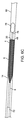
図1には、血管から物質を収容及び除去するための装置2が示されている。装置2は、収容要素4と、第1のフィラメント6と、拘束カテーテル8と、を含む。装置2は、拘束カテーテル8によって拘束されていない収容要素4を有する展開された構成で、一般的に示されており、第1のフィラメントは、有意な張力がかかっていない。装置2の様々な構成及び手順のステップは、以下でより詳細に説明される。本発明の態様は、単一の又は限られた数の実施形態を参照して説明されるが、すべての特徴、態様、及び、方法は、明示的に言及又は記載されていない場合でも、本明細書に記載の全ての適用可能な実施形態に組み込まれることが理解される。 FIG. 1 shows a device 2 for accommodating and removing substances from blood vessels. The device 2 includes a containment element 4, a first filament 6, and a restraint catheter 8. The device 2 is generally shown in an unfolded configuration with a containment element 4 that is not constrained by the restraint catheter 8, and the first filament is not significantly tensioned. The various configuration and procedural steps of device 2 are described in more detail below. Aspects of the invention are described with reference to a single or limited number of embodiments, but all features, embodiments, and methods are described, even if not explicitly mentioned or described. It is understood to be incorporated into all applicable embodiments described herein.

収容要素4は、血管直径部分10と、それらの間に近位漏斗領域14を有する小直径部分12と、を有する。収容要素4は、遠位端部16へ向けて第1のフィラメント6に接続され、近位端部18へ向けて拘束カテーテル8に接続されている。遠位端部へ向かう第1のフィラメント6の接続は、近位側張力が、第1のフィラメント6に加えられると、収容要素4の遠位開口部20のサイズが、図5Aの開位置から図5Eの閉鎖位置まで減少しており、かつ、以下に説明するように近位側へ移動することもできる。開位置は、遠位開口部20の外周を画定する。拘束カテーテル8は、収容要素4の長さに沿って軸方向にスライドしてもよく、収容要素4を収縮させると共に、収容要素4をチャンバ22(管腔24であり得る)内に配置するように構成される。以下の画像に示されるように、拘束カテーテル8が、収容要素4上を遠位側へスライドすると、血管系を通して送達するために拘束カテーテル8の内側に収容要素4を装填するように、収容要素4は収縮すると共に、拘束カテーテル8に入る。収容要素4の全体は、拘束カテーテル8の内側に適合してもよい。拘束カテーテル8が、収容要素4に対して近位側へ移動されると、収容要素4は、拘束カテーテル8の外側へ延出するように構成されており、かつ、物質を取り除くために、収容要素4を所望の場所又はその近くに展開することができるように、制限されない形状によって画定されるように延出してもよい。収容要素4は、本明細書に詳述されるように、血餅回収装置が通過することができる管腔7を有する。 Containment element 4 has a vessel diameter portion 10 and a small diameter portion 12 having a proximal funnel region 14 between them. The containment element 4 is connected to the first filament 6 towards the distal end 16 and to the restraint catheter 8 towards the proximal end 18. The connection of the first filament 6 towards the distal end is such that when proximal tension is applied to the first filament 6, the size of the distal opening 20 of the containment element 4 is increased from the open position of FIG. 5A. It has been reduced to the closed position in FIG. 5E and can also be moved to the proximal side as described below. The open position defines the outer circumference of the distal opening 20. The restraint catheter 8 may slide axially along the length of the containment element 4 so that the containment element 4 contracts and the containment element 4 is placed in the chamber 22 (which can be the lumen 24). It is composed of. As shown in the image below, the containment element so that the restraint catheter 8 slides distally over the containment element 4 and loads the containment element 4 inside the restraint catheter 8 for delivery through the vascular system. 4 contracts and enters the restraint catheter 8. The entire containment element 4 may fit inside the restraint catheter 8. When the restraint catheter 8 is moved proximal to the containment element 4, the containment element 4 is configured to extend outward of the containment catheter 8 and is contained to remove material. The element 4 may be extended to be defined by an unrestricted shape so that it can be deployed at or near the desired location. Containment element 4 has a lumen 7 through which the clot collecting device can pass, as detailed herein.

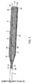
拘束カテーテル8は、チャンバ22内に配置されると共に、折り畳み位置に保持された収容要素4を有しており、血管を通って前進する。収容要素4は、物質を取り囲むと共に、収容する遠位開口部20から近位側へ延出する側壁26を有する。第1のフィラメント6は、本明細書に記載されるように収容要素4を操作するために収容要素4に連結されている。第1のフィラメント6は、また、収容要素4が、拘束カテーテル8のチャンバ22内側で折り畳まれているときに、折り畳み位置に置かれている。第1のフィラメント6は、凹形状部分34の第1の端部32に連結された第1のアーム28と、凹形状部分34の第2の端部36に連結された第2のアーム30と、を含んでもよい。凹形状部分34は、収容要素4によって画定される長手方向軸線LAに対面している。本明細書で使用される場合、長手方向軸線LAは、側壁26の幾何学的中心において収容要素4の形状に従い、湾曲又はセグメント化された線形断面といった任意の形状をとることができ、かつ、使用中の収容要素4の付勢されていない形状よりもむしろ、実質的に血管系の形状によってもよい。凹形状部分34は、以下でさらに詳細に説明するように、遠位開口部20の開位置を支持してもよい。 The restraint catheter 8 has a containment element 4 that is located in the chamber 22 and held in the folded position and advances through the blood vessel. The containment element 4 has a side wall 26 that surrounds the material and extends proximally from the distal opening 20 that contains the material. The first filament 6 is coupled to the containment element 4 for manipulating the containment element 4 as described herein. The first filament 6 is also placed in the folded position when the containment element 4 is folded inside the chamber 22 of the restraint catheter 8. The first filament 6 includes a first arm 28 connected to the first end 32 of the concave portion 34 and a second arm 30 connected to the second end 36 of the concave portion 34. , May be included. The concave portion 34 faces the longitudinal axis LA defined by the accommodating element 4. As used herein, the longitudinal axis LA can take any shape, such as a curved or segmented linear cross section, according to the shape of the containment element 4 at the geometric center of the side wall 26. It may be substantially the shape of the vasculature, rather than the unbulging shape of the containment element 4 in use. The concave portion 34 may support the open position of the distal opening 20, as described in more detail below.

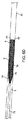
収容要素4及び第1のフィラメント6は、折り畳み位置において収容要素4の遠位端部16から延出する第1の先端部分38を有する第1のフィラメント6を伴って、血管を通って前進してもよい。第1の先端部分38は、収容要素4の遠位端部16から、開位置における遠位開口部20の外周Pの有効直径EDの少なくとも30%、又は、少なくとも50%を延出する長さLを有し得る。第1の先端部分38は、収容要素4への留め具を有してなくてもよく、折り畳み位置において収容要素4の遠位端部16から少なくとも1.5mm遠位側へ延出してもよい。第1の先端部分38は、収容要素4の遠位端部16を越えて延出する第1のループ40を形成してもよい。 The containment element 4 and the first filament 6 advance through the blood vessel with the first filament 6 having a first tip 38 extending from the distal end 16 of the containment element 4 in the folded position. You may. The first tip 38 extends from the distal end 16 of the containment element 4 by at least 30% or at least 50% of the effective diameter ED of the outer circumference P of the distal opening 20 in the open position. May have L. The first tip 38 may not have a clasp to the containment element 4 and may extend at least 1.5 mm distal to the distal end 16 of the containment element 4 in the folded position. .. The first tip 38 may form a first loop 40 extending beyond the distal end 16 of the containment element 4.

収容要素4は、また、折り畳まれたときに、比較的遠位位置に配置される作動長さWLを画定する第1のフィラメント6を有して、血管系を通じて前進してもよい。作動長さWLは、収容要素4の遠位端部16の10cm以内に配置された第1のフィラメント6の長さとして定義される。例えば、作業長さWLは、第1のアーム28と、第2のアーム30と、遠位端部16の10cm以内の凹形状部分34と、の組み合わせた長さを含んでもよい。本発明の一態様では、第1のフィラメント6の作動長さWLは、収容要素4が折り畳み位置から解放位置へ移動するときに、開位置における遠位開口部20の有効直径EDの70%未満しか変化しない。特定の実施形態では、作業長さWLは、折り畳まれた位置で約11.5cmとされており、遠位開口部20が開放しているときは約11.5cmとされていてもよい。 The containment element 4 may also have a first filament 6 defining an operating length WL that is located relatively distally when folded and may advance through the vasculature. The working length WL is defined as the length of the first filament 6 located within 10 cm of the distal end 16 of the containment element 4. For example, the working length WL may include a combined length of the first arm 28, the second arm 30, and the concave portion 34 of the distal end 16 within 10 cm. In one aspect of the invention, the working length WL of the first filament 6 is less than 70% of the effective diameter ED of the distal opening 20 in the open position as the accommodating element 4 moves from the folded position to the open position. Only changes. In certain embodiments, the working length WL is about 11.5 cm at the folded position and may be about 11.5 cm when the distal opening 20 is open.

第1の先端部分38及び作動長さWLは、両方とも、収容要素4を解放するために作動長さWLの一部として遠位側へ引っ張らなければならない第1のフィラメント6の必要とされる長さを短縮することに寄与する。遠位側へ引き出される第1のフィラメント6の必要な長さは、第1のフィラメント6が、収容要素4を解放すると共に、遠位開口部20を閉じるときに、拘束カテーテル8と共に、収容要素4に対して近位側へ移動するように、第1のフィラメント6を拘束カテーテル8に連結することによって、さらに短縮されてもよい。この方法で第1のフィラメント6(具体的には第1のアーム28及び第2のアーム30)を拘束カテーテル8に連結することは、第1のフィラメント6は、多くの従来の装置のように患者の外側へ完全に延出する必要がないため、操作しなければならない第1のフィラメント6の必要とされる長さをさらに短縮する。もちろん、第1のフィラメント6は、また、本発明の多くの態様から逸脱することなく、拘束カテーテル8から独立すると共に、患者の外に延出することができる。 Both the first tip 38 and the working length WL are required of the first filament 6 which must be pulled distally as part of the working length WL to release the containment element 4. Contributes to shortening the length. The required length of the first filament 6 drawn distally is that when the first filament 6 releases the containment element 4 and closes the distal opening 20, the containment element, along with the restraint catheter 8. It may be further shortened by connecting the first filament 6 to the restraint catheter 8 so that it moves proximally to 4. Connecting the first filament 6 (specifically, the first arm 28 and the second arm 30) to the restraint catheter 8 in this way allows the first filament 6 to be like many conventional devices. The required length of the first filament 6 that must be manipulated is further reduced because it does not have to extend completely out of the patient. Of course, the first filament 6 can also be independent of the restraint catheter 8 and extend out of the patient without departing from many aspects of the invention.

収容要素4は、収容要素4、拘束カテーテル8、又はその両方を移動することによって、チャンバ22の外側の解放位置へ移動される。第1のフィラメント6は、収容要素4がチャンバ22の外側に移動/配置されるのと同時に、遠位開口部20が開位置に移動する間、解放位置へ移動されてもよい。側壁26及び遠位開口部20の開口部の同時解放は、第1のフィラメント6(具体的には、第1のアーム28及び第2のアーム30の近位端部)を上記のように拘束カテーテル8に連結することによって達成されてもよい。代わりに、遠位開口部20は、本発明の多くの態様から逸脱することなく、収容要素4が解放された後に、第1のフィラメント6又は他の何らかの構造を使用して別個に開かれてもよい。したがって、本発明の態様は、今説明したように、開位置を支持するための第1のフィラメント6を提供するが、開位置は、本発明による任意の適切な方法で達成されてもよい。 The containment element 4 is moved to an open position outside the chamber 22 by moving the containment element 4, the restraint catheter 8, or both. The first filament 6 may be moved to the open position while the distal opening 20 is moved to the open position at the same time that the accommodating element 4 is moved / placed outside the chamber 22. Simultaneous release of the openings of the side wall 26 and the distal opening 20 constrains the first filament 6 (specifically, the proximal ends of the first arm 28 and the second arm 30) as described above. It may be achieved by connecting to the catheter 8. Instead, the distal opening 20 is opened separately using a first filament 6 or some other structure after the containment element 4 has been released, without departing from many aspects of the invention. May be good. Thus, aspects of the invention provide a first filament 6 for supporting the open position, as just described, but the open position may be achieved by any suitable method according to the invention.

自然な付勢されていない形状(例えば、凹形状部分34の形状)が遠位開口部20の開位置を支持するように、第1のフィラメント6は、収容要素4に配置かつ連結され得る。例えば、第1のフィラメント6は、収容要素4の開位置を支持するフィラメント外周部48を画定する所定の形状46を有してもよい。所定の形状46は、長手方向軸線LAに沿って見たときに、開位置において遠位開口部20の周りに少なくとも120度、少なくとも150度、又は、少なくとも260度にわたって延出することができる。別の言い方をすれば、第1のフィラメント6は、収容要素4が解放されたときに、遠位開口部20を支持すると共に、開位置へ移動させる第1の凹形状部分34(長手方向軸線LAに面するように配向される)を形成してもよい。さらに別の言い方をすれば、凹形状部分34は、凹形状部分34が、遠位開口部20を開位置へ向けて付勢するように、遠位開口部20の付勢されていない形状よりも大きい形状を有している。さらに別の言い方をすれば、凹形状部分34は、凹形状部分34が、遠位開口部20を開位置へ向けて付勢するように、収容要素4の開位置によって拘束されてもよい。第1の先端部分38は、凹形状部分34といった所定の形状を形成してもよい。第1の凹形状部分34は、一般的に、図9Aに示されるように、付勢されていない位置で第1のアーム28と45度から135度の角度Aを形成する平面Pの内部に置かれてもよい。収容要素4が閉鎖されると、平面Pは、第1のアーム28と135度から180度の角度Aを形成する。第1の凹形状部分34は、また、図9Aに示されるように、収容要素4が解放位置にあるときに、遠位開口部20を開位置へ向かって移動させる閉ループ50を形成してもよい。 The first filament 6 may be arranged and coupled to the accommodating element 4 so that a naturally unbulging shape (eg, the shape of the concave portion 34) supports the open position of the distal opening 20. For example, the first filament 6 may have a predetermined shape 46 that defines a filament outer peripheral portion 48 that supports the open position of the accommodating element 4. The predetermined shape 46 can extend around the distal opening 20 in the open position over at least 120 degrees, at least 150 degrees, or at least 260 degrees when viewed along the longitudinal axis LA. In other words, the first filament 6 supports the distal opening 20 and moves it to the open position when the accommodating element 4 is released, the first concave portion 34 (longitudinal axis). (Oriented to face LA) may be formed. In other words, the concave portion 34 is more than the unbulged shape of the distal opening 20 such that the concave portion 34 urges the distal opening 20 toward the open position. Also has a large shape. In other words, the concave portion 34 may be constrained by the open position of the accommodating element 4 so that the concave portion 34 urges the distal opening 20 toward the open position. The first tip portion 38 may form a predetermined shape such as a concave portion 34. The first concave portion 34 is generally inside a plane P forming an angle A of 45 to 135 degrees with the first arm 28 at an unbulging position, as shown in FIG. 9A. It may be placed. When the containment element 4 is closed, the plane P forms an angle A of 135 to 180 degrees with the first arm 28. The first concave portion 34 may also form a closed loop 50 that moves the distal opening 20 towards the open position when the accommodating element 4 is in the open position, as shown in FIG. 9A. good.

収容要素4が第1のフィラメント6によって開放されると、第1の先端部分38は、収容要素4内へ移動して凹形状部分34を形成してもよく、あるいは、収容要素4内に移動して血管の内面52と係合してもよい。さらに、第1のフィラメント6は、解放位置において、物質が遠位開口部20を通って収容要素4へ移動されるときに、装置2を固定するのを補助する収容要素4の少なくとも2cmの長手方向長さにわたって側壁26の内面52に外向きの力を加えてもよい。第1のフィラメント6は、また、長手方向軸線LAに沿って見たときに、少なくとも180度の角度範囲にわたって内面52に外向きの力を加えてもよい。第1のフィラメント6(例えば、第1のアーム28及び第2のアーム30)も実質的に真っ直ぐとされてもよく、本発明の多くの態様から逸脱することなく、側壁26に外向きの力を加えてもよい。 When the accommodating element 4 is opened by the first filament 6, the first tip portion 38 may move into the accommodating element 4 to form a concave portion 34, or move into the accommodating element 4. It may engage with the inner surface 52 of the blood vessel. In addition, the first filament 6 is at least 2 cm in length of the containment element 4 that assists in fixing the device 2 as the material is moved through the distal opening 20 to the containment element 4 in the open position. An outward force may be applied to the inner surface 52 of the side wall 26 over the directional length. The first filament 6 may also exert an outward force on the inner surface 52 over an angular range of at least 180 degrees when viewed along the longitudinal axis LA. The first filament 6 (eg, the first arm 28 and the second arm 30) may also be substantially straight, and an outward force on the side wall 26 without departing from many aspects of the invention. May be added.

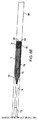
遠位開口部20が開位置にあると、係合し、必要に応じて、除去されるべき物質を取り除くために、血餅係合要素58(機械的又は吸引係合といった任意の適切な方法で係合することができる)が使用される。物質は、それから、血餅係合要素58、収容要素4、第1のフィラメント6、又は、それらの任意の組み合わせを操作することによって、遠位開口部20を通過して収容要素4に入る。 When the distal opening 20 is in the open position, any suitable method such as a clot engagement element 58 (mechanical or suction engagement) to engage and, if necessary, remove the substance to be removed. Can be engaged with) is used. The material then enters the containment element 4 through the distal opening 20 by manipulating the clot engagement element 58, the containment element 4, the first filament 6, or any combination thereof.

除去されるべき物質が収容要素4内に含まれた後、収容要素4は、第1のフィラメント6(例えば、第1のアーム28及び第2のアーム30)に張力をかけることによって閉鎖される。遠位開口部20は、有効直径EDが少なくとも80%減少するように、開位置からサイズを縮小されてもよい。言い換えれば、閉鎖位置における有効直径EDは1mm以下とされてもよい。凹形状部分34は、また、第1のフィラメント6が遠位開口部20を閉鎖するように引っ張られたときに、変形されてもよい。(凹形状部分34などの)第1のフィラメント6は、遠位開口部20が閉鎖されときに、弾性的に変形する超弾性材料で形成されてもよい。凹形状部分34は、また、塑性変形されてもよく、又は、本発明の態様から逸脱することなく、単純な張力要素とされてもよい。 After the material to be removed is contained within the containment element 4, the containment element 4 is closed by applying tension to the first filament 6 (eg, the first arm 28 and the second arm 30). .. The distal opening 20 may be reduced in size from the open position so that the effective diameter ED is reduced by at least 80%. In other words, the effective diameter ED at the closed position may be 1 mm or less. The concave portion 34 may also be deformed when the first filament 6 is pulled to close the distal opening 20. The first filament 6 (such as the concave portion 34) may be made of a superelastic material that elastically deforms when the distal opening 20 is closed. The concave portion 34 may also be plastically deformed or may be a simple tension element without departing from aspects of the invention.

収容要素4の側壁26は、また、遠位開口部20が閉じられたときに、血管80と係合するように拡張することができる拡張可能部分60を含んでもよい。拡張可能部分60は、少なくとも10mmの長さとされてもよく、収容要素4の遠位端部16から10mm以内とされてもよい。拡張可能部分60は、収容要素4が第1のフィラメント6に張力をかけることによって閉鎖されるときに、血管壁に半径方向外向きの力を及ぼしてもよい。拡張可能部分60は、第1のフィラメント6によって付勢されていない形状を越えて拡張されてもよく、例えば、拡張可能部分60に沿った側壁26の有効直径EDは、付勢されていない状態と比較して少なくとも10%増加されてもよい。別の言い方をすれば、収容要素4が閉鎖位置へ移動されると、第1のフィラメント6は、血管壁への半径方向外向きの力を少なくとも10%増加させる、外向きの力を拡張可能部分60へ引き起こす。 The side wall 26 of the containment element 4 may also include an expandable portion 60 that can be expanded to engage the blood vessel 80 when the distal opening 20 is closed. The expandable portion 60 may be at least 10 mm long and may be within 10 mm of the distal end 16 of the containment element 4. The expandable portion 60 may exert a radial outward force on the vessel wall when the accommodating element 4 is closed by applying tension to the first filament 6. The expandable portion 60 may be extended beyond the shape not urged by the first filament 6, for example, the effective diameter ED of the side wall 26 along the expandable portion 60 is not urged. May be increased by at least 10% as compared to. In other words, when the containment element 4 is moved to the closed position, the first filament 6 can expand the outward force, which increases the radial outward force on the vessel wall by at least 10%. Cause to part 60.

収容要素4の側壁26は、また、収容要素4が閉鎖されるときに、長さが減少する遠位部分DPを有してもよい。遠位部分DPは、遠位端部16から10mm延出されてもよく、収容要素4が閉鎖位置へ移動すると、長手方向に少なくとも20%長さが減少してもよい。遠位部分DPは、また、拡張可能部分60に従って拡張してもよく、拡張可能部分60と完全に又は部分的に同一の広がりを有してもよい。 The side wall 26 of the containment element 4 may also have a distal portion DP that decreases in length when the containment element 4 is closed. The distal portion DP may extend 10 mm from the distal end 16 and may be reduced in length by at least 20% in the longitudinal direction as the containment element 4 moves to the closed position. The distal portion DP may also expand according to the expandable portion 60 and may have exactly the same extent as the expandable portion 60.

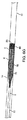
第1のフィラメント6は、また、遠位開口部20が閉鎖されたときに、近位側へ移動してもよく、また、図9Aから図9Fに示されるように、遠位開口部20を近位側へ移動させてもよい。第1のフィラメント6は、第1のフィラメント6が、拘束カテーテル8によって操作され、かつ、収容要素4が解放され、かつ、閉鎖されたときに、拘束カテーテル8と共に、収容要素4に対して近位側へ移動するように、拘束カテーテル8に連結されてもよい。このようにして、第1のフィラメント6は、拘束カテーテル8によって操作され、第1のフィラメント6の長さの減少、及び、おそらく第1のフィラメント6に張力をかけるときの血管80への力の減少といった、本明細書に記載の利点を提供する。 The first filament 6 may also move to the proximal side when the distal opening 20 is closed, and may open the distal opening 20 as shown in FIGS. 9A-9F. It may be moved to the proximal side. The first filament 6 is close to the containment element 4 together with the restraint catheter 8 when the first filament 6 is manipulated by the restraint catheter 8 and the containment element 4 is released and closed. It may be connected to the restraint catheter 8 so as to move to the position side. In this way, the first filament 6 is manipulated by the restraint catheter 8 to reduce the length of the first filament 6 and possibly the force on the blood vessel 80 when tensioning the first filament 6. It provides the advantages described herein, such as reduction.

遠位開口部20が閉鎖されると、側壁26は、遠位開口部20を側壁26によって囲まれる位置へ移動させる(長手方向軸線LAに沿って見たとき)、逆方向部分IPを形成してもよい。側壁26は、また、遠位開口部20を閉鎖位置へ向けて付勢するために、(側壁26を通って伝達される)反転部分IPに半径方向内向きの力を加えてもよい。遠位開口部20は、また、閉鎖位置へ移動するときに、反転してもよく、又は、側壁26の遠位端部の小さな部分を反転しないままとしてもよい。 When the distal opening 20 is closed, the side wall 26 moves the distal opening 20 to a position surrounded by the side wall 26 (when viewed along the longitudinal axis LA) to form a reverse partial IP. You may. The side wall 26 may also apply a radial inward force to the inverted portion IP (transmitted through the side wall 26) to urge the distal opening 20 towards the closed position. The distal opening 20 may also be inverted as it moves to the closed position, or the small portion of the distal end of the side wall 26 may remain uninverted.

装置2は、また、図2Kに示されるように、収容要素4と連結された第2のフィラメント6Aを含んでもよい、ここで、同じ又は類似の参照番号は、第1のフィラメントと同じ又は類似の特徴を指し、全ての関連する特徴は、前述のように、これに組み込まれる。第2のフィラメント6Aは、折り畳み位置において、収容要素4の遠位端部16を越えて遠位側へ延出する第2の先端部分42を有してもよい。第2の先端部分42は、収容要素4の遠位端部16から少なくとも1.5mm延出する。第2の先端部分38Aは、収容要素4の遠位端部16から延出する長さを有しており、これは、開位置における遠位開口部20の外周の有効直径の少なくとも30%とされ、少なくとも50%とされてもよい。 The device 2 may also include a second filament 6A coupled to the accommodating element 4, where the same or similar reference numbers are the same or similar to the first filament, as shown in FIG. 2K. Refers to the features of, and all related features are incorporated therein, as described above. The second filament 6A may have a second tip portion 42 that extends distally beyond the distal end portion 16 of the containment element 4 in the folded position. The second tip portion 42 extends at least 1.5 mm from the distal end portion 16 of the containment element 4. The second tip 38A has a length extending from the distal end 16 of the containment element 4, which is at least 30% of the effective diameter of the outer circumference of the distal opening 20 in the open position. And may be at least 50%.

第2のフィラメント6Aは、第1のフィラメント6と連結されてもよく、第1のフィラメント6と一体的に形成されてもよい。第2のフィラメント6Aは、収容要素4が開位置にあるときに、第2の凹形状部分34Aを形成してもよい。第2の凹形状部分34Aは、また、遠位開口部20を開位置へ向けて移動する。第1の凹形状部分34及び第2の凹形状部分34Aは、収容要素4が開位置に位置しており、かつ、長手方向軸線LAに沿って見たときに、それぞれ90度から180度延出してもよい。 The second filament 6A may be connected to the first filament 6 or may be integrally formed with the first filament 6. The second filament 6A may form a second concave portion 34A when the accommodating element 4 is in the open position. The second concave portion 34A also moves the distal opening 20 towards the open position. The first concave portion 34 and the second concave portion 34A extend 90 to 180 degrees, respectively, when the accommodating element 4 is located in the open position and when viewed along the longitudinal axis LA. You may put it out.

本発明の構成要素の特定の態様を説明し、これらの態様、特徴、及び方法のステップは、上記のように明示的に提供されていなくても、全ての適用可能な実施形態に組み込まれる。 Specific aspects of the components of the invention are described, and the steps of these aspects, features, and methods are incorporated into all applicable embodiments, even if not explicitly provided as described above.

収容要素4は、任意の数の構造とされてよい。いくつかの実施形態では、収容要素4は、編組、レーザーカットステント、織り構造等といった、半径方向に拡張可能な要素とされてもよい。他の実施形態では、収容要素4は、非準拠の可撓性バッグ又はPET材料又はPTFE材料といった布とされてもよい。他の実施形態では、容器材料は、物質が引き込まれるときに伸長及び拡張してもよい、ポリウレタン、シリコン等の準拠材料とされてもよい。さらに、他の実施形態では、血管材料は、複数の構造の組み合わせとされてもよい。例えば、収容要素4は、特定の領域にバッグ構造を有し、他の領域に編組構造を有してもよい。 The accommodating elements 4 may have any number of structures. In some embodiments, the containment element 4 may be a radially expandable element such as a braid, a laser cut stent, a woven structure, or the like. In other embodiments, the containment element 4 may be a non-compliant flexible bag or cloth such as PET or PTFE material. In other embodiments, the container material may be a compliant material such as polyurethane, silicone, etc., which may stretch and expand as the material is drawn in. Furthermore, in other embodiments, the vascular material may be a combination of multiple structures. For example, the accommodating element 4 may have a bag structure in a specific area and a braided structure in another area.

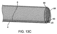
いくつかの実施形態では、収容要素4は、取り付けられた膜又は布を有するフレームである。フレームは、拘束カテーテル8の外側へ送達されると半径方向に拡張する、ニチノール又はステンレス鋼又はプラスチック構成要素から構成されてもよい。例えば、フレームは、レーザー切断され、拘束されていないときに、拡張するように形状が設定されたニチノール管とされてもよい。局所的な流れ止めを提供し、一旦収容要素4内に入ると血餅を収容する、又は、その両方を提供するために、PTFEグラフト材料又は他の任意の膜材料といった布がフレームに接続されてもよい。いくつかの実施形態では、収容要素4は、編組要素とフレーム要素との組み合わせとされてもよい。例えば、小さなワイヤーブレードは、フレーム構造にわたって、あるいは、フレーム構造の内面と外面の両方で、延出してもよい。 In some embodiments, the accommodating element 4 is a frame with an attached membrane or cloth. The frame may be composed of a nitinol or stainless steel or plastic component that expands radially when delivered to the outside of the restraint catheter 8. For example, the frame may be a Nitinol tube shaped to expand when laser cut and unconstrained. A cloth, such as a PTFE graft material or any other membrane material, is attached to the frame to provide a local flow stop and / or both to contain the clot once inside the containment element 4. You may. In some embodiments, the containment element 4 may be a combination of a braided element and a frame element. For example, the small wire blades may extend over the frame structure or on both the inner and outer surfaces of the frame structure.

いくつかの実施形態では、収容要素4は、編組線構造である。編組ワイヤは、ニチノール、ステンレス鋼、コバルトクロム、PETといったプラスチック、又は任意の他の適切な材料であってもよい。編組ワイヤは、白金コアを有するニチノールワイヤといった透視下で可視化することを許容する放射性不透過性要素を含んでいてもよい。代わりに、収容要素4は、可視化を可能にする連結マーカーを有していてもよい。編組ワイヤの数は、12本から128本の間、又は、32本から64本の間とされてよい。編組の角度は、100度から200度の間、又は、120度から160度の間とされてよい。ブレードワイヤの直径は、0.0001インチ(″)から0.0050インチ(″)の間、又は、0.0005インチ(″)から0.0020インチ(″)の間とされてもよい。代わりに、編組ワイヤは、非円形とされてもよく、楕円形、平面、又は、長方形のリボンとされてもよい。編組形状は、収容要素4が、伸長したときに直径が減少し、圧縮したときに直径が増加する、中国のフィンガートラップのように作用することを許容してもよい。このことは、装置2が人体から引き出されるときに、サイズを減少させることを許容し、かつ、フィラメントを通じるといった、圧縮荷重がその一部に付与されるときに、血管80に対して自己を固定することを許容するといった利点を提供してもよい。 In some embodiments, the containment element 4 is a braided line structure. The braided wire may be plastic such as nitinol, stainless steel, cobalt chrome, PET, or any other suitable material. The braided wire may include a radioactive opaque element that allows visualization under fluoroscopy, such as a nitinol wire with a platinum core. Alternatively, the containment element 4 may have a linking marker that allows visualization. The number of braided wires may be between 12 and 128, or between 32 and 64. The braid angle may be between 100 and 200 degrees, or between 120 and 160 degrees. The diameter of the blade wire may be between 0.0001 inch (″) and 0.0050 inch (″), or between 0.0005 inch (″) and 0.0020 inch (″). Alternatively, the braided wire may be non-circular, oval, flat, or rectangular ribbon. The braided shape may allow the accommodating element 4 to act like a Chinese finger trap, which decreases in diameter when stretched and increases in diameter when compressed. This allows the device 2 to be reduced in size as it is pulled out of the human body, and also self with respect to the blood vessel 80 when a compressive load, such as through a filament, is applied to a portion thereof. It may provide the advantage of allowing fixation.

いくつかの実施形態では、収容要素4は、所定の温度において、他の構成要素がその動きを制限していないときに、自然に取られ、制限されておらず、かつ、付勢されていない形状である所定の形状46を有する。所定の形状46は、異なる温度で異なる形状とされてもよく、本明細書で使用されるように、通常の体温で画定されるものとする。例えば、収容要素4は、ニチノール線からなる編組構造とされてもよい。ニチノール編組は、収容要素4が、制限されていない画定された形状を有する、形状設定熱処理を通じて所定の形状46が与えられてもよい。いくつかの実施形態では、収容要素4は、制限されない形状では、血管の寸法を塞ぐために拡張してもよいように構成されている。例えば、中大脳動脈(MCA)の適用では、収容要素4は、4mmと10mmの間の直径に拡張するように構成されてもよい。MCAが4mmの平均内径を有すると仮定すると、収容要素4は、血管80の内膜壁に接触するまで拡張する。収容要素4が、空気中で6mmの直径まで拡張するように設計されている場合、収容要素4は、血管の壁に少量から中程度の大きさの半径方向の圧力を提供してもよい。収容要素4の非拘束の直径を変化することによって、血管に及ぼされる半径方向の力の大きさが調節されてもよい。さらに、収容要素4の特性を変化させることによって、半径方向の拡張力が調節されてもよい。例えば、収容要素4が編組構造である場合、血管上の所望の半径方向の力を増減させるために、以下のパラメータが変更されてもよい:編組角度、編組端の数、編組材料、編組線の直径、編組線の断面形状、編組被覆等。所望の半径方向の力は、異なる血管及び異なる解剖学的位置に対して異なっていてもよい。いくつかの実施形態では、収容要素4は、その長さに沿って変化する直径又は断面の輪郭を有する。例えば、非拘束の直径は、1つ又は複数の位置において8mmであってもよく、1つ又は複数の位置において4mmであってもよい。さらに、収容要素4の断面の輪郭は、図示されているように、一般的に、円形でなくてもよい。断面の輪郭は、卵形、三角形、長方形、又は、他の任意の輪郭であってもよく、収容要素4の軸方向の長さに沿って変化してもよい。例えば、いくつかの位置では、輪郭は、長軸が血管80と親密に接触し、短軸が血管80と接触しない、一般的な楕円形とされてもよい。他の位置では、断面の輪郭は、全周が血管壁と接触していない円形とされてもよい。任意の数の異なる形状及び構成が企図され得る。 In some embodiments, the accommodating element 4 is naturally taken, unrestricted, and unerected at a given temperature when other components do not restrict its movement. It has a predetermined shape 46 which is a shape. The predetermined shape 46 may have different shapes at different temperatures and shall be defined at normal body temperature as used herein. For example, the accommodating element 4 may have a braided structure made of nitinol wire. The nitinol braid may be given the given shape 46 through a shape-setting heat treatment, where the accommodating element 4 has an unrestricted and defined shape. In some embodiments, the containment element 4 is configured so that, in an unrestricted shape, it may be expanded to block the dimensions of the blood vessel. For example, in the application of the Middle Ecerebral Artery (MCA), the containment element 4 may be configured to extend to a diameter between 4 mm and 10 mm. Assuming the MCA has an average inner diameter of 4 mm, the containment element 4 expands until it contacts the intima wall of blood vessel 80. If the containment element 4 is designed to extend to a diameter of 6 mm in air, the containment element 4 may provide a small to moderate amount of radial pressure on the walls of the vessel. By varying the unconstrained diameter of the containment element 4, the magnitude of the radial force exerted on the vessel may be adjusted. Further, the radial expansion force may be adjusted by changing the characteristics of the accommodating element 4. For example, if the accommodating element 4 is a braided structure, the following parameters may be modified to increase or decrease the desired radial force on the vessel: braid angle, number of braid ends, braid material, braid line. Diameter, cross-sectional shape of braided wire, braided coating, etc. The desired radial force may be different for different vessels and different anatomical positions. In some embodiments, the containment element 4 has a diameter or cross-sectional contour that varies along its length. For example, the unconstrained diameter may be 8 mm at one or more positions and 4 mm at one or more positions. Further, the cross-sectional contour of the accommodating element 4 generally does not have to be circular, as shown. The contour of the cross section may be oval, triangular, rectangular, or any other contour, and may vary along the axial length of the containment element 4. For example, at some positions, the contour may be a general ellipse with the major axis in close contact with the blood vessel 80 and the minor axis not in contact with the blood vessel 80. At other positions, the contour of the cross section may be circular with no contact with the vessel wall all around. Any number of different shapes and configurations can be contemplated.

他の実施形態では、収容要素4は、収容要素4が、収容要素4自体に接続してもよいし、接続していなくてもよいロールアップされた表面を表してもよいことを意味する、完全に管状の構造でなくてもよい。例えば、収容要素4は、実質的に円形状を形成するために圧延されるが、2つの圧延された端部が互いに接続してもよいし、接続していなくてもよい材料の平らなシート上のレーザー切断パターンで構成されてもよい。 In another embodiment, the accommodating element 4 means that the accommodating element 4 may or may not be connected to the accommodating element 4 itself to represent a rolled-up surface. It does not have to be a completely tubular structure. For example, the accommodating element 4 is rolled to form a substantially circular shape, but a flat sheet of material in which the two rolled ends may or may not be connected to each other. It may be composed of the above laser cutting pattern.

収容要素4は、遠位方向から収容要素4内への物質の通過を許容する、遠位端部に向けた遠位開口部20を有する。遠位開口部20は、非拘束の形状において、収容要素4の側壁26と同じ直径となるように構成されてもよい。遠位開口部20は、遠位開口部20の縁に沿って遠位開口外周部64を画定する。他の実施形態では、遠位開口部20は、収容要素4の遠位端部16が外側又は内側に先細り形状になるような非限定的な形状であるときに、収容要素4の側壁26よりも大きくても、又は、小さくてもよい。収容要素4の遠位端部16において、収容要素4が外向きに先細り形状になっている場合、このことは、収容要素4内への物質の円滑な進入を容易にし、それらを後退する構成要素から血餅が押しのけられる可能性を減少させ得る。収容要素4の遠位端部16において収容要素4が内向きに先細り形状になっている場合、このことは、以下でより詳細に説明されるように、フィラメント6が張力をかけられているときに収容要素4の閉鎖が促進されてもよい。遠位開口部20は、遠位開口部20が内在する血管80の断面積とほぼ同じ断面積を有してもよい。例えば、5mmの血管80において、収容要素4の断面積は、展開された構成において、10mmから30mm、又は、18mmから22mmの間とされてもよい。収容要素4の遠位開口部20の大きさは、同様に、フィラメント外周部48の形状及び大きさによって部分的に画定されてもよい。例えば、フィラメント外周部48は、収容要素4の遠位開口部20に内向き又は外向きの半径方向の力を与えるようなものとされてもよい。他の実施形態では、フィラメント6は、いくつかの位置において、半径方向内向きの力を与え、他の位置において、半径方向外向きの力を与えてもよい。いくつかの実施形態では、収容要素4は、可撓性袋材料であり、フィラメント外周部48は、遠位開口部20のサイズ及び形状を完全に画定する。 The containment element 4 has a distal opening 20 towards the distal end that allows the passage of material from the distal direction into the containment element 4. The distal opening 20 may be configured in an unconstrained form to have the same diameter as the side wall 26 of the containment element 4. The distal opening 20 defines a distal opening perimeter 64 along the edge of the distal opening 20. In another embodiment, the distal opening 20 is more than the side wall 26 of the containment element 4 when the distal end 16 of the containment element 4 has a non-limiting shape such that it tapers outward or inward. May be large or small. At the distal end 16 of the containment element 4, if the containment element 4 is tapered outward, this facilitates the smooth entry of material into the containment element 4 and retracts them. It can reduce the chances of blood clots being pushed out of the element. If the accommodating element 4 is tapered inward at the distal end 16 of the accommodating element 4, this is when the filament 6 is tensioned, as described in more detail below. The closure of the containment element 4 may be promoted. The distal opening 20 may have approximately the same cross-sectional area as the cross-sectional area of the blood vessel 80 in which the distal opening 20 resides. For example, in a 5 mm blood vessel 80, the cross-sectional area of the containment element 4 may be between 10 mm 2 to 30 mm 2 or 18 mm 2 to 22 mm 2 in the unfolded configuration. Similarly, the size of the distal opening 20 of the containment element 4 may be partially defined by the shape and size of the filament outer peripheral 48. For example, the filament outer peripheral portion 48 may be such that an inward or outward radial force is applied to the distal opening 20 of the accommodating element 4. In other embodiments, the filament 6 may exert a radial inward force at some positions and a radial outward force at other positions. In some embodiments, the accommodating element 4 is a flexible bag material and the filament perimeter 48 completely defines the size and shape of the distal opening 20.

完全に展開された場合、収容要素4は、アプリケーションに応じて1cmから30cmの長さを有してもよい。MCAアプリケーションにおいて、収容要素4は、4cmから16cm又は5cmの10cmの間の長さを有してもよい。標準的なステント回収器は、3cmから5cmの長さを有する。それゆえ、血餅係合要素が同様の長さである場合、血餅係合要素を完全に捕捉すると共に収容するためには、収容要素4の長さは7cmのオーダーとされてもよい。しかしながら、示されるように、血餅係合要素は、必ずしも収容要素4によって完全に捕捉される必要はない。いずれにしても、拘束されていないときの収容要素4の長さを7cmと仮定すると、収容要素4は、拘束要素内にあるときには14cmの長さを有していてもよい。このことは、収容要素4の長さが放射状に拘束されるにつれて増加する、一般的にフォアショートニングング(foreshortening)と呼ばれるものである。 When fully deployed, the containment element 4 may have a length of 1 cm to 30 cm, depending on the application. In MCA applications, the accommodating element 4 may have a length between 4 cm and 16 cm or 5 cm, 10 cm. A standard stent collector has a length of 3 cm to 5 cm. Therefore, if the clot engaging elements are of similar length, the length of the containing element 4 may be on the order of 7 cm in order to completely capture and contain the clot engaging elements. However, as shown, the clot engagement element does not necessarily have to be completely captured by the containment element 4. In any case, assuming that the length of the accommodating element 4 when not constrained is 7 cm, the accommodating element 4 may have a length of 14 cm when inside the constraining element. This is what is commonly referred to as foreshortening, where the length of the containment element 4 increases as it is radially constrained.

収容要素4は、コーティング108といった血管内の部分的又は完全な局所的な流れ止めを提供する特徴を有してもよい。収容要素4が編組である実施形態では、コーティング108は、シリコンのような浸漬コーティング又はスペイド(spayed)コーティング108とされてもよい。シリコンは、0.0001インチ(″)の厚さから0.0050インチ(″)の厚さの間、又は、0.0005インチ(″)の厚さから0.0010インチ(″)の厚さの間とされてもよい。シリコンは、血流が制限されるように、編組の一部を覆うことによって、血管80内の局所的な流れの停止を提供してもよい。さらに、コーティング108は、装置2によって捕捉される血餅物質をより良好に含んでおくといった、更なる利点を提供してもよい。例えば、収容要素4が、血管80内に展開されたときに、血管80と親密に接触している収容要素4を、血液が通過することができないため、血流が血管80内で停止するように、収容要素4は、その全長に沿って被覆されてもよい。いくつかの実施形態では、コーティング108は、血管の全体的又は部分的な断面が血流を遮断するような、近位漏斗のように収容要素4の一部のみを覆ってもよい。他の実施形態では、コーティング108は、収容要素4の全体にわたってもよい。代わりに、収容要素4が編組である実施形態では、ブレード窓又はブレードワイヤ間の空間は、局所的な流れの停止又は流れの減少を提供するほど小さくてもよい。例えば、編組窓が十分に小さい場合、このことは、覆う必要がなくても局所的な流れ止めを提供してもよい。いくつかの実施形態では、編組が、血流を実質的に減少するが、完全には停止させないためのフィルタとして機能するように、血液の特定の成分が、編組を通過することを許容することが望ましいかもしれない。 Containment element 4 may have features such as coating 108 that provide partial or complete local flow arrest within the blood vessel. In embodiments where the containment element 4 is braided, the coating 108 may be a dip coating such as silicon or a spayed coating 108. Silicon is between 0.0001 inch (″) thick and 0.0050 inch (″) thick, or 0.0005 inch (″) thick and 0.0010 inch (″) thick. It may be between. Silicone may provide local flow arrest within vessel 80 by covering a portion of the braid so that blood flow is restricted. In addition, coating 108 may provide additional advantages, such as better inclusion of clot material captured by device 2. For example, when the accommodating element 4 is deployed in the blood vessel 80, blood cannot pass through the accommodating element 4 which is in close contact with the blood vessel 80, so that the blood flow is stopped in the blood vessel 80. In addition, the accommodating element 4 may be covered along its entire length. In some embodiments, the coating 108 may cover only part of the containment element 4, such as a proximal funnel, where the entire or partial cross section of the vessel blocks blood flow. In other embodiments, the coating 108 may span the entire containment element 4. Alternatively, in embodiments where the containment element 4 is braided, the space between the blade windows or blade wires may be small enough to provide local flow arrest or flow reduction. For example, if the braided window is small enough, this may provide a local flow stop without the need for covering. In some embodiments, allowing certain components of blood to pass through the braid so that the braid acts as a filter to substantially reduce blood flow but not stop it completely. May be desirable.

収容要素4は、1つ以上のコーティング108を含んでもよい。いくつかの実施形態では、収容要素4は、収容要素4が拘束カテーテル8内を摺動する際に、収容要素4の摩擦を低減するために、PTFE又は他のコーティング材料のような親水性コーティング108を有してもよい。コーティング108は、収容要素4の展開を促進するために、収容要素4の外表面に塗布されてもよく、又は、収容要素4の管腔を通るマイクロカテーテル74のような他の構成要素の移動を促進するために内面52に塗布されてもよい。他の実施形態では、コーティング108は、活性薬剤成分(API)を血管又は局所的な生体構造に送達するための薬剤コーティングとされてもよい。このことは、組織プラスミノゲン活性化剤(tPa)といった薬剤を含んでもよい。これらは、シリコンコーティングのような流れ止めを提供するコーティング108とは別個のものであってもよく、又は、これに加えてもよい。例えば、収容要素4は、流れ止めを提供するシリコンコーティング108を有してもよく、さらに、潤滑性を提供するための親水性コーティングを有してもよい。 The accommodating element 4 may include one or more coatings 108. In some embodiments, the containment element 4 is a hydrophilic coating, such as PTFE or other coating material, to reduce friction on the containment element 4 as the containment element 4 slides within the restraint catheter 8. It may have 108. The coating 108 may be applied to the outer surface of the containment element 4 to facilitate the deployment of the containment element 4, or the movement of other components such as the microcatheter 74 through the lumen of the containment element 4. May be applied to the inner surface 52 to promote. In other embodiments, the coating 108 may be a drug coating for delivering an active drug component (API) to a blood vessel or local biostructure. This may include agents such as tissue plasminogen activator (tPa). These may be separate from or in addition to the coating 108, which provides a flow stop, such as a silicone coating. For example, the accommodating element 4 may have a silicone coating 108 that provides a flow stop and may further have a hydrophilic coating that provides lubricity.

局所的な流れ止めは、流れが逆流する可能性があるので、血餅78が、遠位塞栓のリスクが低減された状態にあるように、血管からの逆行性の側副血流を有利に促進してもよい。さらに、このことは、収容要素4を通じて、又は、拘束カテーテル8を通じて、といった装置2の一部を通じて造影剤を注入することを許容してもよく、このことは、造影剤を運び去るための流れがないので、血管内の血栓の識別を促進してもよい。代わりに、装置2は、組織プラスミノゲン活性化剤(tPa)といった治療剤を注入するために使用されてもよい。 Local deprivation favors retrograde collateral blood flow from blood vessels so that clot 78 is in a state of reduced risk of distal embolism, as flow can regurgitate. It may be promoted. Further, this may allow injection of the contrast medium through a portion of the device 2, such as through the containment element 4 or through the restraint catheter 8, which is a flow for carrying the contrast medium away. Therefore, the identification of thrombi in blood vessels may be facilitated. Alternatively, device 2 may be used to inject a therapeutic agent such as tissue plasminogen activator (tPa).

収容要素4の近位端部18は、小直径部分12まで減少してもよい。いくつかの実施形態では、小直径部分12は、収容要素4の所定の形状によって画定される。例えば、収容要素4がニチノールで構成されている場合、収容要素4の形状設定構成は、その近位端部18に、小直径部分12を含んでもよい。他の実施形態では、小直径部分12は、必ずしも所定の形状46によって画定されるのではなく、拘束カテーテル8の拘束によって画定されてもよい。小直径部分12は、拘束カテーテル8の管腔24内に収まるような大きさとされてよい。小直径部分12の内径は、また、その中のカテーテル及びワイヤの通過を許容するようなサイズとされてもよい。ステント回収器を展開するために使用されるマイクロカテーテル74は、0.010インチ(″)から0.040インチ(″)の外径のオーダーとされてもよい。吸引によって血餅をつかむために使用される吸引カテーテルは、0.020インチ(″)から0.070インチ(″)の外径のオーダーとされてもよい。それゆえ、小直径部分12の内径は、0.010インチ(″)から0.080インチ(″)のオーダーであってもよいし、0.025インチ(″)から0.060インチ(″)のオーダーであってもよい。このことは、収容要素4が展開される前後に、他の構成要素が、収容要素4の管腔を通過することが許容されてもよい。 The proximal end 18 of the containment element 4 may be reduced to the small diameter portion 12. In some embodiments, the small diameter portion 12 is defined by a predetermined shape of the containment element 4. For example, if the accommodating element 4 is composed of nitinol, the shaping configuration of the accommodating element 4 may include a small diameter portion 12 at its proximal end 18. In other embodiments, the small diameter portion 12 is not necessarily defined by the predetermined shape 46, but may be defined by the restraint of the restraint catheter 8. The small diameter portion 12 may be sized to fit within the lumen 24 of the restraint catheter 8. The inner diameter of the small diameter portion 12 may also be sized to allow passage of catheters and wires therein. The microcatheter 74 used to deploy the stent collector may be on the order of an outer diameter of 0.010 inch (″) to 0.040 inch (″). The suction catheter used to grab the clot by suction may be on the order of an outer diameter of 0.020 inch (″) to 0.070 inch (″). Therefore, the inner diameter of the small diameter portion 12 may be on the order of 0.010 inch (″) to 0.080 inch (″) or 0.025 inch (″) to 0.060 inch (″). It may be an order of. This may allow other components to pass through the lumen of the containment element 4 before and after the containment element 4 is deployed.

収容要素4の近位端部18は、拘束カテーテル8を通って、拘束カテーテル8及びフィラメントに対する相対位置を変化させるように操作することができる、患者の外側へと連続してもよい。いくつかの実施形態では、収容要素4の近位端部は、収容要素4を軸方向又は回転方向に前進及び後退させることができる、カテーテル又は他の適切な構造に移行してもよい。収容要素4のカテーテル部分は、患者の外側から延出してもよく、ユーザ、送達機構、又は、ロボットのいずれかによって操作されてもよい。収容要素4の近位端部18は、収容要素4の管腔を通じて吸引が達成され得るような、真空源に接続されてもよい。連続する説明に示されるように、吸引手段は、収容要素4内に血栓を引き込み、そうでなければ、遠位側の血流を抑制するために使用されてもよい。 The proximal end 18 of the containment element 4 may be continuous to the outside of the patient through the restraint catheter 8 so that it can be manipulated to change its position relative to the restraint catheter 8 and the filament. In some embodiments, the proximal end of the containment element 4 may transition to a catheter or other suitable structure capable of axially or rotationally retracting the containment element 4. The catheter portion of the containment element 4 may extend from the outside of the patient and may be operated by either the user, the delivery mechanism, or the robot. The proximal end 18 of the containment element 4 may be connected to a vacuum source such that suction can be achieved through the lumen of the containment element 4. As shown in the continuation of the description, the suction means may be used to draw a thrombus into the containment element 4 and otherwise suppress blood flow on the distal side.

図1へ戻ると、拘束カテーテル8も示されている。拘束カテーテル8は、カテーテルの分野において存在する任意の数の材料及び構造で構成されてもよい。いくつかの実施形態では、拘束カテーテル8は、PTFE製の内側ライナ及びPebax製の外側ジャケットを有するステンレス鋼ブレード強化カテーテルとされてもよい。任意の数の他の適切な構造及び材料が存在してもよい。拘束カテーテル8の構造及び材料は、所望の剛性及び力の伝達を達成するために、その長さに沿って変化してもよい。MCAの適用例では、拘束カテーテル8は、理想的には、大脳動脈内に配置された中間カテーテル72を通じて送達されてもよい。血栓除去術で使用される中間カテーテル72の内径は、典型的には0.04インチ(″)から0.08インチ(″)のオーダーである。それゆえ、拘束カテーテル8の外径は、0.04インチ(″)から0.08インチ(″)のオーダーとされてもよく、0.05インチ(″)から0.06インチ(″)のオーダーとされてもよい。拘束カテーテル8の内径は、収容要素4を含めて遠位側へ送達される、その中のカテーテル及びワイヤの通過を許容するサイズとされてもよい。それゆえ、拘束カテーテル8の内径は、0.010インチ(″)から0.080インチ(″)のオーダーとされてもよく、0.025インチ(″)から0.060インチ(″)のオーダーとされてもよい。拘束カテーテル8は、収容要素4の拘束カテーテル8への出入りの移動を促進する、フレア状又は収縮状の遠位端部16を有していてもよい。例えば、拘束カテーテル8の遠位端部16の直径は、収容要素4が先細り部分によって拘束カテーテル8内へ容易に引き込まれるように、0.001インチ(″)から0.020インチ(″)のフレア状とされてもよい。 Returning to FIG. 1, the restraint catheter 8 is also shown. The restraint catheter 8 may be composed of any number of materials and structures that exist in the field of catheters. In some embodiments, the restraint catheter 8 may be a stainless steel blade reinforced catheter with an inner liner made of PTFE and an outer jacket made of Pebag. Any number of other suitable structures and materials may be present. The structure and material of the restraint catheter 8 may vary along its length to achieve the desired stiffness and force transfer. In MCA applications, the restraint catheter 8 may ideally be delivered through an intermediate catheter 72 located within the cerebral artery. The inner diameter of the intermediate catheter 72 used in thrombectomy is typically on the order of 0.04 inch (″) to 0.08 inch (″). Therefore, the outer diameter of the restraint catheter 8 may be on the order of 0.04 inch (″) to 0.08 inch (″), from 0.05 inch (″) to 0.06 inch (″). It may be an order. The inner diameter of the restraint catheter 8 may be sized to allow passage of the catheter and wire within it delivered to the distal side, including the containment element 4. Therefore, the inner diameter of the restraint catheter 8 may be on the order of 0.010 inch (″) to 0.080 inch (″), and may be on the order of 0.025 inch (″) to 0.060 inch (″). May be. The restraint catheter 8 may have a flared or contracted distal end 16 that facilitates the movement of the containment element 4 in and out of the restraint catheter 8. For example, the diameter of the distal end 16 of the restraint catheter 8 is 0.001 inch (″) to 0.020 inch (″) so that the containment element 4 is easily pulled into the restraint catheter 8 by the taper portion. It may be flared.

拘束カテーテル8は、患者の外側へ延出してもよく、本明細書に詳細に記載された動作を通じて、他の構成要素に対して相対的に装置2を案内するために、ユーザによって操作されてもよい。いくつかの実施形態では、拘束カテーテル8は、1つのカテーテルだけが存在するような中間カテーテル72と同じとされてもよい。いくつかの実施形態では、拘束カテーテル8は、収容要素4に対する拘束カテーテル8の近位側の動きが、収容要素4を展開するだけでなく、拘束カテーテル8を後退させる際に、フィラメント6に張力をかける方法で、収容要素4の遠位開口部20を閉鎖させるように、フィラメント6の一部又はフィラメントに接続されてもよい。この点については、以下でより詳細に説明する。 The restraint catheter 8 may extend outside the patient and is manipulated by the user to guide the device 2 relative to other components through the actions detailed herein. May be good. In some embodiments, the restraint catheter 8 may be the same as the intermediate catheter 72 such that only one catheter is present. In some embodiments, the restraint catheter 8 tensions the filament 6 when the proximal movement of the restraint catheter 8 with respect to the containment element 4 not only deploys the containment element 4 but also retracts the restraint catheter 8. It may be connected to a part of the filament 6 or the filament so as to close the distal opening 20 of the accommodating element 4. This point will be described in more detail below.

図1に戻ると、フィラメント6も示されている。フィラメント6は、収容要素4の管腔を通って延出する第1のアーム28及び第2のアーム30を有しており、収容要素4の遠位端部16へ向けて、フィラメント外周部48に接続されている。フィラメント6は、ユーザ、展開機構、又は、ロボットによって操作され得るように、組立品を通って、かつ、患者の外側へ延出してもよい。代わりに、フィラメント6は、収容要素4に対する拘束カテーテル8の相対的な動きが、フィラメント6から張力を適用するか、又は、除去し得るように、拘束カテーテル8のような装置2の内側の別の構成要素と接続されてもよい。フィラメント6は、モノフィラメント6のワイヤとされてもよく、任意の数の他の構造とされてもよい。例えば、フィラメント6は、本明細書に記載された材料のいずれかからなる小コイルとされてもよい。代わりに、フィラメント6は、ポリプロピレン又はポリエステルといった縫合材料とされてもよい。フィラメント6の材料及び構造は、フィラメント6の長さに沿って変化してもよく、その全長に沿って必ずしも同じである必要はない。いくつかの実施形態では、材料は丸線であり、他の実施形態では、スネアは、長方形、卵形、シートといった任意の数の断面のコイル又はフィラメント6とされてもよい。さらに、スネアのフィラメント6の断面形状及び断面積は、スネアの長さに沿って変化してもよい。いくつかの実施形態では、フィラメント6は、複数の材料で構成されている。例えば、フィラメント6の一部分は、縫合糸のように可撓性であってもよく、他の部分はニチノールのように弾性とされてもよい。いくつかの実施形態では、フィラメント6は、直径が0.0005インチ(″)から0.0100インチ(″)又は0.001インチ(″)から0.0040インチ(″)であるニチノールワイヤの一片である。代わりに、フィラメント6は、ステンレス鋼、タングステン、コバルトクロム、プラスチック、又は、他の任意の適切な材料とされてもよい。フィラメント6は、フィラメント外周部48に円等の所定の形状を有するように、形状設定されてもよい。 Returning to FIG. 1, filament 6 is also shown. The filament 6 has a first arm 28 and a second arm 30 extending through the lumen of the accommodating element 4, and the filament outer peripheral portion 48 toward the distal end 16 of the accommodating element 4. It is connected to the. The filament 6 may extend through the assembly and out of the patient so that it can be manipulated by the user, deployment mechanism, or robot. Instead, the filament 6 is separated from the inside of the device 2 such as the restraint catheter 8 so that the relative movement of the restraint catheter 8 with respect to the containment element 4 can apply or remove tension from the filament 6. May be connected to the components of. The filament 6 may be a wire of the monofilament 6 or may have any number of other structures. For example, the filament 6 may be a small coil made of any of the materials described herein. Alternatively, the filament 6 may be a suture material such as polypropylene or polyester. The material and structure of the filament 6 may vary along the length of the filament 6 and may not necessarily be the same along its overall length. In some embodiments, the material is a round wire, and in other embodiments, the snare may be a coil or filament 6 of any number of cross sections, such as a rectangle, an oval, or a sheet. Further, the cross-sectional shape and cross-sectional area of the snare filament 6 may change along the length of the snare. In some embodiments, the filament 6 is composed of a plurality of materials. For example, one portion of the filament 6 may be flexible, such as suture, and the other portion may be elastic, such as nitinol. In some embodiments, the filament 6 is a piece of nitinol wire that is 0.0005 inch (″) to 0.0100 inch (″) or 0.001 inch (″) to 0.0040 inch (″) in diameter. Is. Alternatively, the filament 6 may be made of stainless steel, tungsten, cobalt chromium, plastic, or any other suitable material. The filament 6 may be shaped so that the outer peripheral portion 48 of the filament has a predetermined shape such as a circle.

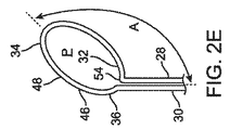
今、図2Aから図2Hに戻ると、フィラメント6の様々な所定の形状46が示されている。これは、任意の可能な形状の網羅的なリストであることを意図したものではなく、単に、フィラメント6を構成し得る様々な形状を示すことを意図したものである。図2Aには、円形のフィラメント外周部48を有するフィラメント6が示されている。フィラメント外周部48は、一般的に、円形又は卵形とされてもよい。フィラメント外周部48は、フィラメント6の屈曲部を通じて、第1のアーム28及び第2のアーム28へ移行する。第1のアーム28及び第2のアーム28は、フィラメント外周部48によって画定される平面からほぼ垂直に延出する。図示されるように、フィラメント外周部48は、収容要素4上の遠位開口部20の位置と略同位置に位置してもよく、それゆえ、フィラメント外周部48は、血管80の内面とほぼ同じである輪郭を画定してもよい。図2Aでは、フィラメント外周部48は、第1のアーム28及び第2のアーム30が近接しているような約330度から約360度の円周とされている。図2Bでは、フィラメント外周部48は、第1のアーム28と第2のアーム30のためのフィラメント屈曲部54の間に隙間があるような、約200度から約330度のオーダー以下及び同一であるかもしれない包含された円周を有する円弧を画定している。図2Cでは、フィラメント外周部48は、フィラメント外周部48の重なりがあるように、360度から540度のオーダーである包含された円周を有する円弧を画定している。図2D及び2Eにおいて、フィラメント外周部48は、血管80の長手方向軸に対して実質的に垂直ではない平面を画定する。フィラメント外周部48は、血管80の中心軸に対して斜めになっている平面を画定する楕円形とされている。本実施形態の適用は、後続の図において、より詳細に説明される。図2Dでは、フィラメント屈曲部54は、フィラメント外周部48の近位側部分に位置し、図2Eでは、フィラメント屈曲部54は、フィラメント外周部48の遠位側部分に位置する。図2Fでは、フィラメント外周部48は、その輪郭上にニップル102の特徴を有する。ニップル102の特徴は、遠位開口部20を緊密に閉鎖することを促進してもよい、窮屈な半径にフィラメント6を曲げることができる特定の位置を提供することによって、フィラメント6に張力がかかっているときに、遠位開口部20を閉鎖することを促進してもよい。図2Gにおいて、フィラメント外周部48は、ループ状端部106への収容要素4の編み込み及び編み出しを促進することができる起伏のある輪郭104を有する。図2Hにおいて、フィラメント外周部48は、フィラメント外周部48が、遠位開口部20の一部のみを取り囲むように、70度から200度の包含された円周を有する円弧を画定している。図2Iでは、第1のアーム28及び第2のアーム30は、フィラメント外周部48に近接するフィラメント接合部100で接合されている。図2Jでは、第1のアーム28及び第2のアーム30は、フィラメント外周部48から近位側にさらに離れたフィラメント接合部100において接合されている。これらの実施形態では、近位方向へ延出する単一のフィラメント6だけが設けられてもよく、それゆえ、張力をかけて配置される必要がある。図2Kでは、個々のフィラメント外周部48を有する2つの別個のフィラメント6要素が設けられている。2つのフィラメントは、それぞれ第1のアーム28及び第2のアーム30を有する。この実施形態では、遠位開口部20が閉鎖するときに、遠位開口部20が一般的に同心のままであってもよいように、フィラメント6に張力がかけられた状態で配置されているときに、収容要素4の軸外荷重は、小さくされてもよい。任意の数の他のフィラメント6の構成及び形状が企図され得る。いくつかの実施形態では、フィラメント6は、第1のアーム28だけを有してもよく、フィラメント外周部48は、外周の一部を通って終端してもよい。そのような実施形態では、フィラメント外周部48の端部は、収容要素4の一部と接続されていてもよい。他の実施形態では、収容要素4の遠位端部16に接続する2つ以上のフィラメント6が設けられてもよい。各フィラメント6の遠位端部は、収容要素4の遠位端部16に張力をかけるために、独立して又は互いに連動して作動させることができる一連のプルワイヤが存在するように、収容要素4の遠位端部16の周りにループするフックを形成してもよい。他の実施形態では、フィラメント6は、一般的に直線ワイヤである、所定の形状46を有していてもよく、収容要素4の遠位端部16の形状によって図2Aから図2Kに示される形状のうちの1つに拘束される、所定の形状46を有していてもよい。例えば、フィラメント6は、収容要素4に通されてもよく、それゆえ、収容要素4に連結されているという性質上、図2Aから図2Kに示される形状のうちの1つに似た形状に保持されている。 Now, returning from FIG. 2A to FIG. 2H, various predetermined shapes 46 of the filament 6 are shown. This is not intended to be an exhaustive list of any possible shapes, but merely to indicate the various shapes that may make up the filament 6. FIG. 2A shows a filament 6 having a circular filament outer peripheral portion 48. The filament outer peripheral portion 48 may be generally circular or oval. The filament outer peripheral portion 48 moves to the first arm 28 and the second arm 28 through the bent portion of the filament 6. The first arm 28 and the second arm 28 extend substantially vertically from the plane defined by the filament outer peripheral portion 48. As shown, the filament outer circumference 48 may be located substantially at the same position as the distal opening 20 on the containment element 4, and therefore the filament outer circumference 48 is approximately the same as the inner surface of the blood vessel 80. The same contour may be defined. In FIG. 2A, the outer peripheral portion 48 of the filament has a circumference of about 330 degrees to about 360 degrees such that the first arm 28 and the second arm 30 are close to each other. In FIG. 2B, the filament outer peripheral portion 48 is less than or equal to the order of about 200 degrees to about 330 degrees and is identical such that there is a gap between the filament bending portion 54 for the first arm 28 and the second arm 30. It defines an arc with an inclusive circumference that may be present. In FIG. 2C, the filament outer peripheral portion 48 defines an arc having an included circumference on the order of 360 to 540 degrees so that the filament outer peripheral portion 48 overlaps. In FIGS. 2D and 2E, the filament outer circumference 48 defines a plane that is not substantially perpendicular to the longitudinal axis of the blood vessel 80. The filament outer peripheral portion 48 has an elliptical shape that defines a plane that is oblique to the central axis of the blood vessel 80. The application of this embodiment will be described in more detail in subsequent figures. In FIG. 2D, the filament bending portion 54 is located on the proximal side portion of the filament outer peripheral portion 48, and in FIG. 2E, the filament bending portion 54 is located on the distal side portion of the filament outer peripheral portion 48. In FIG. 2F, the filament outer peripheral portion 48 has the characteristics of the nipple 102 on its contour. A feature of the nipple 102 is that the filament 6 is tensioned by providing a specific position in which the filament 6 can be bent to a cramped radius, which may facilitate tight closure of the distal opening 20. The closure of the distal opening 20 may be facilitated while the nipple is closed. In FIG. 2G, the filament outer peripheral portion 48 has an undulating contour 104 capable of facilitating the weaving and knitting of the accommodating element 4 into the looped end 106. In FIG. 2H, the filament outer peripheral portion 48 defines an arc having an inclusive circumference of 70 to 200 degrees so that the filament outer peripheral portion 48 surrounds only a part of the distal opening 20. In FIG. 2I, the first arm 28 and the second arm 30 are joined by a filament joining portion 100 close to the filament outer peripheral portion 48. In FIG. 2J, the first arm 28 and the second arm 30 are joined at the filament joining portion 100 further away from the filament outer peripheral portion 48 on the proximal side. In these embodiments, only a single filament 6 extending proximally may be provided and therefore needs to be placed under tension. In FIG. 2K, two separate filament 6 elements with individual filament perimeters 48 are provided. The two filaments have a first arm 28 and a second arm 30, respectively. In this embodiment, the filament 6 is arranged under tension so that the distal openings 20 may generally remain concentric when the distal openings 20 are closed. Occasionally, the off-axis load of the accommodating element 4 may be reduced. The configuration and shape of any number of other filaments 6 can be contemplated. In some embodiments, the filament 6 may have only the first arm 28, and the filament outer circumference 48 may be terminated through a portion of the outer circumference. In such an embodiment, the end of the filament outer peripheral 48 may be connected to a portion of the accommodating element 4. In other embodiments, two or more filaments 6 may be provided that connect to the distal end 16 of the containment element 4. The distal end of each filament 6 has a containment element such that there is a series of pullwires that can be actuated independently or in conjunction with each other to tension the distal end 16 of the containment element 4. A hook may be formed that loops around the distal end 16 of 4. In other embodiments, the filament 6 may have a predetermined shape 46, which is generally a straight wire, and is shown in FIGS. 2A-2K by the shape of the distal end 16 of the accommodating element 4. It may have a predetermined shape 46 that is constrained to one of the shapes. For example, the filament 6 may be threaded through the accommodating element 4 and therefore resembles one of the shapes shown in FIGS. 2A-2K due to the nature of being connected to the accommodating element 4. It is being held.

収容要素4は、任意の数の方法でフィラメント6に接続されてもよい。収容要素4が、布又は袋材料とされた、いくつかの実施形態では、収容要素4の遠位端部16は、熱シール若しくは接着剤、又は、他の任意の適切な方法を使用して、フィラメント6の周りに巻き付けられ、フィラメント6自体に接着されてもよい。代わりに、フィラメント6は、収容要素の一部を通じて、織り込んでもよい。いくつかの実施形態では、収容要素4は、レーザー切断されたステント構造を含んでもよい。ステントは、フィラメント6が織り通すように構成された遠位端部の穴といった特徴を含んでもよい。いくつかの実施形態では、収容要素4は、編組構造とされており、フィラメント6は、収容要素4の遠位端部16の近く、又は、遠位端部16に、編組又はループ状の端部106を織り込んでもよい。遠位開口外周部62とフィラメント外周部48とは、装置2が展開され、開放した構成とされているようないくつかの構成では、一般的に同じとされてよい。拘束された構成又は閉鎖した構成のような他の構成では、遠位開口外周部62とフィラメント外周部48とは、異なる形状及び長さとされている。 The accommodating element 4 may be connected to the filament 6 in any number of ways. In some embodiments where the containment element 4 is a cloth or bag material, the distal end 16 of the containment element 4 is heat-sealed or glued, or using any other suitable method. , Wrapped around the filament 6 and adhered to the filament 6 itself. Alternatively, the filament 6 may be woven through some of the containment elements. In some embodiments, the containment element 4 may include a laser-cut stent structure. The stent may include features such as a hole at the distal end configured to allow the filament 6 to interweave. In some embodiments, the accommodating element 4 has a braided structure and the filament 6 has a braided or looped end near or at the distal end 16 of the accommodating element 4. Part 106 may be woven. The distal opening perimeter 62 and the filament perimeter 48 may generally be the same in some configurations where the device 2 is deployed and open. In other configurations, such as constrained or closed configurations, the distal opening perimeter 62 and the filament perimeter 48 have different shapes and lengths.

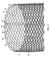
図3において、収容要素4の一実施形態の遠位端部16の詳細図が示されている。収容要素4は、編組ワイヤで構成されている。ワイヤは、収容要素4の一端でループ状の端部106を有して終端することによって示されるように、それ自体に二重に戻ってもよい。例えば、収容要素4の一端において、編組ワイヤは、製造中にポストに巻き付けられ、その後、既に作成された編組の上にワイヤを編み戻すことにより、ループ状の端部106を形成してもよい。このようにして、ループ状の端部106は、血管内に傷を付けない端部を提供するとともに、フィラメント6が編み込み得る場所を提供する。フィラメント外周部48は、フィラメント6が張力を受けると、財布の紐又は引き紐のように収容要素4の遠位開口部20を収縮させるように、これらの編組されたループ状端部106を通って織られてもよい。フィラメント6は、各ループ状端部106を前後に通って編み込んでもよく、又は、他の全てのループ状端部106を通って編み込んでもよく、任意の編み込みパターンで編み込んでもよい。例えば、フィラメント6は、互いに90度離れた位置にある編み込まれたループ状端部106の4箇所のみを通って織ってもよい。編み込み特性は、収容要素4が一旦展開されると、収容要素4の遠位開口部20を開くのに必要な摩擦を決定してもよい。収容要素4の半径方向の拡張力が、フィラメント6が開くにつれて拡張するフィラメント6の摩擦に容易に打ち勝つことができるように、編み込まれたループ状端部106の数を制限することによって、フィラメント6と編組との間の摩擦を減少させることが有利となる場合がある。いくつかの実施形態では、フィラメント外周部48は、遠位端部において360度巻き取ることができる。他の実施形態では、フィラメント6は、それ自体を横切って、360度から720度の間で包み込むことができる。他の実施形態では、フィラメント6は、収容要素4の遠位端部16の一部だけがフィラメント6を包み込むように、90度から360度の間だけで包み込んでもよい。他の実施形態では、フィラメント6は、1つ又は2つのループ状端部106のような収容要素4の小さな部分だけに取り付けられている。また、フィラメント6は、遠位端部16から近位側に戻る単一のワイヤだけを有してもよい。フィラメント6は、遠位端部16でループを形成してもよいが、2つのフィラメント6が遠位端部16を収縮させる必要がないように、それ自体に戻って接続してもよい。任意の数のフィラメント6が使用され、収容要素4に接続されてもよく、独立して又は連動して作動してもよい。 FIG. 3 shows a detailed view of the distal end 16 of an embodiment of containment element 4. The accommodating element 4 is composed of braided wires. The wire may double back to itself, as indicated by terminating with a looped end 106 at one end of the containment element 4. For example, at one end of the containment element 4, the braided wire may be wound around a post during manufacturing and then braided back onto the already created braid to form a looped end 106. .. In this way, the looped end 106 provides an intact end within the blood vessel and a place where the filament 6 can be braided. The filament outer circumference 48 passes through these braided looped ends 106 so that when the filament 6 is tensioned, it contracts the distal opening 20 of the containment element 4 like a purse string or drawstring. May be woven. The filament 6 may be woven through each looped end 106 back and forth, or may be woven through all other looped ends 106, or may be woven in any braided pattern. For example, the filament 6 may be woven through only four locations of woven looped ends 106 that are 90 degrees apart from each other. The braided property may determine the friction required to open the distal opening 20 of the accommodating element 4 once the accommodating element 4 has been deployed. The filament 6 by limiting the number of braided looped ends 106 so that the radial expansion force of the accommodating element 4 can easily overcome the friction of the filament 6 expanding as the filament 6 opens. It may be advantageous to reduce the friction between the and the braid. In some embodiments, the filament outer circumference 48 can be wound 360 degrees at the distal end. In another embodiment, the filament 6 can wrap across itself between 360 and 720 degrees. In other embodiments, the filament 6 may be wrapped only between 90 and 360 degrees so that only a portion of the distal end 16 of the accommodating element 4 wraps the filament 6. In other embodiments, the filament 6 is attached only to a small portion of the accommodating element 4, such as one or two looped ends 106. Also, the filament 6 may have only a single wire returning from the distal end 16 to the proximal side. The filament 6 may form a loop at the distal end 16, but may be connected back to itself so that the two filaments 6 do not need to contract the distal end 16. Any number of filaments 6 may be used and connected to the accommodating element 4 or may operate independently or in conjunction.

いくつかの実施形態では、第1のアーム28及び第2のアーム30は、収容要素4の軸方向の長さに沿った収容要素4の部分を織り交ぜてもよい。これによって、アーム28、30は、収容要素4内で動く、他の構成要素の邪魔にならないように、収容要素4の側壁26に拘束された状態を維持してもよい。さらに、フィラメント6を収容要素4の側壁26に拘束しておくことは、遠位開口部20に加えられる力を近位方向ではなく半径方向に向けることによって、遠位開口部20の閉鎖が容易にされてもよい。他の実施形態では、第1のアーム28及び第2のアーム30は、収容要素4の側壁26を通って織り込まず、自由に残されている。この実施形態では、第1のアーム28及び第2のアーム30は、側壁26に対して付勢したままであるように所定の形状46を介して構成されていてもよく、又は、任意の数の他の形状をとるように構成されていてもよい。 In some embodiments, the first arm 28 and the second arm 30 may interweave portions of the accommodating element 4 along the axial length of the accommodating element 4. As a result, the arms 28 and 30 may remain constrained to the side wall 26 of the containment element 4 so as not to interfere with other components moving within the containment element 4. Further, constraining the filament 6 to the side wall 26 of the accommodating element 4 facilitates closure of the distal opening 20 by directing the force applied to the distal opening 20 in the radial direction rather than in the proximal direction. May be made. In another embodiment, the first arm 28 and the second arm 30 are not woven through the side wall 26 of the accommodating element 4 and are left free. In this embodiment, the first arm 28 and the second arm 30 may be configured via a predetermined shape 46 so as to remain urged against the side wall 26, or any number. It may be configured to take other shapes.

収容要素4及びフィラメント6は、これらが展開されたときに、収容要素4が制限されず、フィラメント6がかなりの量の近位側張力を受けないように構成されている。この状態では、収容要素4の遠位開口部20は開放されており、遠位方向から血餅78の物質を受け取るように配置されている。遠位開口外周部及びフィラメント外周部48は、この位置において、一般的に同じ形状及び長さとされてよい。それから、張力がフィラメント6に加えられると、フィラメント外周部48及び遠位開口部20は、近位側への移動を開始してもよい。遠位開口部20は、追加の張力がフィラメント6に加えられると、収縮して閉じるように構成されている。このようにして、遠位開口部20の閉鎖は、フィラメント6に加えられた張力によって作動する。遠位開口外周部Pは、フィラメント外周部48が、同じ固定された長さである間に、編組のループ状の端部が互いに近づくにつれて長さが減少してもよい。しかしながら、遠位開口外周部62が占めるフィラメント外周部48の量は、より少ない。例えば、展開された構成では、遠位開口外周部62は、フィラメント外周部48の約60%から100%又は約80%から100%と重なってもよい。閉鎖した構成では、遠位開口外周部62は、フィラメント外周部48の約1%から約30%又は約5%から約15%と重なってもよい。フィラメント外周部48は、同じ固定された長さのままであるが、その形状は変化しており、その一部だけが遠位開口外周部62と重なっている。 The accommodating element 4 and the filament 6 are configured such that when they are unfolded, the accommodating element 4 is not restricted and the filament 6 is not subjected to a significant amount of proximal lateral tension. In this state, the distal opening 20 of the containment element 4 is open and is arranged to receive the substance of the blood clot 78 from the distal direction. The distal opening perimeter and the filament perimeter 48 may generally have the same shape and length at this position. Then, when tension is applied to the filament 6, the filament outer peripheral 48 and the distal opening 20 may begin to move proximally. The distal opening 20 is configured to contract and close when additional tension is applied to the filament 6. In this way, the closure of the distal opening 20 is actuated by the tension applied to the filament 6. The distal opening perimeter P may decrease in length as the looped ends of the braid approach each other while the filament perimeter 48 has the same fixed length. However, the amount of the filament outer peripheral portion 48 occupied by the distal opening outer peripheral portion 62 is smaller. For example, in the unfolded configuration, the distal opening perimeter 62 may overlap about 60% to 100% or about 80% to 100% of the filament perimeter 48. In a closed configuration, the distal opening perimeter 62 may overlap with about 1% to about 30% or about 5% to about 15% of the filament perimeter 48. The filament outer circumference 48 remains the same fixed length, but its shape has changed, and only a portion of it overlaps the distal opening outer circumference 62.

いくつかの実施形態では、遠位開口部20の開口は、フィラメント6からの張力の除去によって作動されてもよい。張力が除去されると、フィラメント6は、その所定の形状46に戻ってもよく、同様に、収容要素4は、その制限されない所定の形状に戻ってもよい。そのようにして、遠位開口部20は、開位置へ戻ってもよい。他の実施形態では、一旦、遠位開口部20が、フィラメント6に張力を加える手段によって閉鎖されると、遠位開口部20は、フィラメント6への張力の解放されたときには開かない。この態様では、装置2は、張力がかけられると、一般的に、閉鎖した遠位開口部20にロックされ、張力が除去されても、遠位開口部20が開くことを許容しない。 In some embodiments, the opening of the distal opening 20 may be actuated by removing tension from the filament 6. When the tension is removed, the filament 6 may return to its predetermined shape 46, and similarly, the accommodating element 4 may return to its unrestricted predetermined shape. In that way, the distal opening 20 may return to the open position. In another embodiment, once the distal opening 20 is closed by means of applying tension to the filament 6, the distal opening 20 does not open when the tension on the filament 6 is released. In this aspect, the device 2 is generally locked to the closed distal opening 20 when tension is applied and does not allow the distal opening 20 to open even when the tension is removed.

他の実施形態では、フィラメント外周部48は、収容要素4の遠位端部16から実質的に離れた位置に配置されてもよい。例えば、編組のループ状の端部を通してフィラメント6を織るのではなく、フィラメント6は、その軸方向の長さに沿って収容要素4の任意の部分を通して織られてもよい。いくつかの実施形態では、フィラメント外周部48は、必ずしも収容要素4上の任意の特徴を通って織られていなくてもよい。例えば、フィラメント外周部48は、主に、収容要素4の外面上に存在してもよく、財布の紐のように締め付けるのではなく、収容要素4の軸方向長さに沿った所与の位置で単に編組の外側をつまむだけであってもよい。そのような実施形態において、第1のアーム28及び第2のアーム28は、依然として、収容要素4の一部を貫通して、収容要素4の内部管腔に入り込んでもよい。遠位開口部20及び遠位開口外周部62は、フィラメント外周部48の位置によって画定されてもよく、装置2の遠位端部16によって画定されてもよい。 In other embodiments, the filament outer circumference 48 may be located substantially distant from the distal end 16 of the containment element 4. For example, instead of weaving the filament 6 through the looped ends of the braid, the filament 6 may be woven through any portion of the containment element 4 along its axial length. In some embodiments, the filament perimeter 48 does not necessarily have to be woven through any feature on the containment element 4. For example, the filament outer circumference 48 may be located primarily on the outer surface of the accommodating element 4 and at a given position along the axial length of the accommodating element 4 rather than tightening like a purse string. You may simply pinch the outside of the braid with. In such an embodiment, the first arm 28 and the second arm 28 may still penetrate a portion of the containment element 4 and enter the internal lumen of the containment element 4. The distal opening 20 and the distal opening perimeter 62 may be defined by the position of the filament perimeter 48 or by the distal end 16 of the device 2.

フィラメント6は、一般的に、収容要素4の遠位開口部20をしっかりつかむスネア型機構として本明細書に記載されているが、任意の他の型及び閉鎖機構が企図されてもよい。例えば、収容要素4は、その遠位端部に、1つ又は複数のフィラメントに連結された1つ又は複数のフラップ88を含んでもよい。1つ又は複数のフラップ88は、フラップが倒れて、かつ、遠位開口部20を制限するように、フィラメントに張力をかけることによって内側に折り畳まれてもよい。他の実施形態では、収容要素4の遠位開口部20を収縮させるために、ねじり機構が使用されてもよい。例えば、収容要素4の遠位端部16は、収容要素4の本体が時計回りに捩じられている間、概ね静止した状態で保持されてもよい。このようにして、収容要素4の遠位端部16は、遠位開口部20を収縮させると共に閉鎖してもよい。任意の数の他の閉鎖機構が企図されてもよい。 The filament 6 is generally described herein as a snare-type mechanism that firmly grips the distal opening 20 of the containment element 4, but any other type and closure mechanism may be contemplated. For example, the containment element 4 may include one or more flaps 88 connected to one or more filaments at its distal end. One or more flaps 88 may be folded inward by applying tension to the filament so that the flaps collapse and limit the distal opening 20. In other embodiments, a twisting mechanism may be used to contract the distal opening 20 of the containment element 4. For example, the distal end 16 of the containment element 4 may be held in a generally stationary state while the body of the containment element 4 is twisted clockwise. In this way, the distal end 16 of the containment element 4 may contract and close the distal opening 20. Any number of other closure mechanisms may be contemplated.

今、図4Aから図4Pに戻ると、装置2の第1の実施形態が示されている。図4Aには、中間カテーテル72が、血餅を含む血管内に示されている。中間カテーテル72は、使用される解剖学的位置に応じて、0.010インチ(″)から0.500インチ(″)の間の外径、又は、0.050インチ(″)から0.110インチ(″)の間の外径のような任意の標準的なサイズとされてよい。中間カテーテル72は、Pebax、ポリイミド、PEEK、多層編組複合体、又は、任意の他の適切な材料又は組成物といった、そのようなカテーテルに使用される任意の典型的な材料から構成されてもよい。示された血管は、中大脳動脈(MCA)などの脳動脈、又は、ヒト若しくは動物の体内の任意の他の血管とされてもよい。中間カテーテル72のサイズは、示されるように、血管80のサイズ及び収容要素4の拡張されたサイズに依存してもよい。より大きな血管80は、度々より大きなカテーテルサイズを必要とするが、より小さな血管80は、度々より小さなカテーテルサイズを必要とする。中間カテーテル72は、血餅78の近位側、かつ、本発明の装置2の他の部分を展開する位置に配置される。 Now, returning from FIG. 4A to FIG. 4P, the first embodiment of the device 2 is shown. In FIG. 4A, the intermediate catheter 72 is shown in the blood vessel containing the blood clot. The intermediate catheter 72 has an outer diameter between 0.010 inch (″) and 0.500 inch (″), or 0.050 inch (″) to 0.110, depending on the anatomical position used. It may be of any standard size, such as an outer diameter between inches (″). The intermediate catheter 72 may be composed of any typical material used for such catheters, such as Pebag, polyimide, PEEK, multi-layer braided composites, or any other suitable material or composition. .. The blood vessels shown may be cerebral arteries such as the middle cerebral artery (MCA), or any other blood vessel in the human or animal body. The size of the intermediate catheter 72 may depend on the size of the blood vessel 80 and the expanded size of the containment element 4, as shown. Larger vessels 80 often require larger catheter sizes, while smaller vessels 80 often require smaller catheter sizes. The intermediate catheter 72 is located proximal to the blood clot 78 and at a position where the other portion of the device 2 of the present invention is unfolded.

図4Bでは、マイクロカテーテル74は、血餅78を横断している。マイクロカテーテル74は、0.010インチ(″)から0.080インチ(″)といった任意の適切なサイズとされてもよい。マイクロカテーテル74で血餅78を横断する前に、ガイドワイヤ又は他のそのような要素が含まれてもよく、血餅を横断してマイクロカテーテル74を案内するために使用されてもよい。いくつかの実施形態では、ガイドワイヤが必要とされてもよいが、他の実施形態ではガイドワイヤは必要ではない。ガイドワイヤが使用される場合、ガイドワイヤは、マイクロカテーテル74が血餅を横切ると引き抜かれることが多く、それから、血餅係合要素は、マイクロカテーテル74が血餅を横切っている間にマイクロカテーテル74の中に挿入されてもよい。これによって、血餅係合要素58は、マイクロカテーテル74が引き出されたときに最適な位置にあるように、血餅78を横断して配置される。 In FIG. 4B, the microcatheter 74 crosses the blood clot 78. The microcatheter 74 may be of any suitable size, from 0.010 inch (″) to 0.080 inch (″). A guide wire or other such element may be included prior to traversing the clot 78 with the microcatheter 74 and may be used to guide the microcatheter 74 across the clot. Guide wires may be required in some embodiments, but not in other embodiments. When a guide wire is used, the guide wire is often pulled out as the microcatheter 74 crosses the clot, and then the clot engaging element is the microcatheter while the microcatheter 74 crosses the clot. It may be inserted in 74. Thereby, the clot engaging element 58 is positioned across the clot 78 so that it is in an optimal position when the microcatheter 74 is pulled out.

図4Cでは、マイクロカテーテル74が引き抜かれると共に、血餅係合要素58が残され、血餅と係合する。血餅係合要素58は、示されているように、ステント回収器タイプの設計とされてもよいが、血餅を近位側へ引っ張るのに適した任意の他の要素とされてもよい。示された実施形態では、血餅係合要素58は、拘束されていないときに、血餅78と係合することを許容するように、半径方向外側へ拡張し、かつ、血餅係合要素58が後退されたときに、近位側へ引っ張る、一連の支柱又は織込み要素を有する。他の実施形態では、血餅係合要素58は、血餅係合要素58を後退させるときに、血餅係合要素58と共に血餅78を近位側へ引っ張るように、血餅78に対して遠位側へ膨らんでいるバルーンである。他の実施形態では、血餅係合要素58は、展開されたときに、同様に血餅78と係合し、血餅の異なる領域にそれ自身を固定するような渦巻形状を有するニチノールワイヤである。他の任意の数の血餅係合要素58が考えられる。 In FIG. 4C, the microcatheter 74 is pulled out, leaving the clot engaging element 58 to engage the clot. The clot engagement element 58 may be a stent collector type design, as shown, but may be any other element suitable for pulling the clot proximally. .. In the embodiments shown, the clot engaging element 58 extends radially outwardly to allow engagement with the clot 78 when unrestrained, and the clot engaging element. It has a series of stanchions or braided elements that pull proximally when the 58 is retracted. In another embodiment, the clot engaging element 58 relative to the clot 78 so as to pull the clot 78 proximally along with the clot engaging element 58 when retracting the clot engaging element 58. It is a balloon that bulges to the distal side. In another embodiment, the clot engagement element 58 is a nitinol wire having a spiral shape that, when unfolded, also engages the clot 78 and anchors itself to different regions of the clot. be. Any number of other clot engaging elements 58 are conceivable.

図4Dでは、中間カテーテル72が引き出されて、収容要素4を拘束する拘束カテーテル8が露出している。いくつかの実施形態では、拘束カテーテル8は必要なく、中間カテーテル72は、拘束カテーテル8と共に示されるように、それが後退されたときに、収容要素4が展開されるように、収容要素4を拘束することができる。いくつかの実施形態では、収容要素4を有する拘束カテーテル8は、マイクロカテーテル74のナビゲーション及び送達の間は、中間カテーテル72内にあり、他の実施形態では、ナビゲーションの間のいくつかの時点及び血餅係合要素58が展開された後に、中間カテーテル72の内側の位置へ前進する。 In FIG. 4D, the intermediate catheter 72 is pulled out to expose the restraint catheter 8 that constrains the containment element 4. In some embodiments, the restraint catheter 8 is not required and the intermediate catheter 72 has the containment element 4 so that when it is retracted, the containment element 4 is deployed, as shown with the restraint catheter 8. Can be restrained. In some embodiments, the restraint catheter 8 with the containment element 4 is within the intermediate catheter 72 during navigation and delivery of the microcatheter 74, and in other embodiments at several time points and during navigation. After the clot engagement element 58 is deployed, it advances to a position inside the intermediate catheter 72.

図4Eから図4Hは、血管内に展開された収容要素4を示す。図4Eでは、拘束カテーテル8が後退し始められ、収容要素4の遠位端部16が展開される。フィラメント外周部48及び収容要素4の遠位端部16の初期展開ステップは、図7Aから図7Gを参照して、より詳細に示される。 4E-4H show the containment element 4 deployed within the blood vessel. In FIG. 4E, the restraint catheter 8 begins to retract and the distal end 16 of the containment element 4 is unfolded. The initial deployment steps of the filament outer circumference 48 and the distal end 16 of the containment element 4 are shown in more detail with reference to FIGS. 7A-7G.

図4Eから図4Hに示された実施形態では、MCA内に展開されたときに、血管壁と均一に接触するように、収容要素4は、3mmから6mmの比較的一貫した非拘束の直径と大きさとを有している。図4Eでは、収容要素4は、部分的に展開され、フィラメント外周部48が、収容要素4の遠位端部16に存在する。フィラメント外周部48によって形成される平面は、血管80の長手方向軸に対して概ね垂直である。 In the embodiments shown in FIGS. 4E-4H, the containment element 4 has a relatively consistent, unconstrained diameter of 3 mm to 6 mm so that it makes uniform contact with the vessel wall when deployed within the MCA. Has a size. In FIG. 4E, the accommodating element 4 is partially unfolded and the filament outer peripheral portion 48 is present at the distal end portion 16 of the accommodating element 4. The plane formed by the filament outer peripheral portion 48 is substantially perpendicular to the longitudinal axis of the blood vessel 80.

図4Fでは、収容要素4は、拘束カテーテル8の外側にさらに展開されている。図示されているように、収容要素4が拘束カテーテル8から出てくると、血管80に対して自己拡張する。他の実施形態では、収容要素4は、バルーン、所定の印加温度で遷移するニチノールのような形状記憶材料、又は、他の任意の手段を使用して能動的に拡張されてもよい。例えば、いくつかの実施形態では、収容要素4が血管内で能動的に拡張される前に、拘束カテーテル8が完全に引っ込んでいてもよい。フィラメント外周部48は、拘束カテーテル8から出てきて、収容要素4が開いた状態で血管80内に自動的に拡張する。いくつかの実施形態では、フィラメント外周部48は、完全に又は部分的に閉鎖した構成で拘束カテーテル8から出てきてもよく、それから、一旦所定の位置で開かれてもよい In FIG. 4F, the containment element 4 is further extended to the outside of the restraint catheter 8. As shown, when the containment element 4 emerges from the restraint catheter 8, it self-expands with respect to the vessel 80. In other embodiments, the containment element 4 may be actively expanded using a balloon, a shape memory material such as nitinol transitioning at a predetermined applied temperature, or any other means. For example, in some embodiments, the restraint catheter 8 may be fully retracted before the containment element 4 is actively dilated within the blood vessel. The filament outer peripheral portion 48 emerges from the restraint catheter 8 and automatically expands into the blood vessel 80 with the containment element 4 open. In some embodiments, the filament perimeter 48 may emerge from the restraint catheter 8 in a completely or partially closed configuration and then may be opened once in place.

図4Gでは、収容要素4は、拘束カテーテル8がさらに引っ込んでいるため、さらに展開される。いくつかの実施形態では、拘束カテーテル8は、収容要素4を展開するために後退する。他の実施形態では、収容要素4は、拘束カテーテル8の外側へ前進してもよい。他の実施形態では、拘束カテーテル8を後退させることと収容要素4を前進させることとの組み合わせがあってもよい。実際、示されているように、収容要素4の軸方向の長さは、収容要素4が拘束カテーテル8内にあるときにはかなり長くなる。それゆえ、収容要素4が、拘束カテーテル8を後退させることによって、展開されるとき、収容要素4の遠位端部16が固定位置に留まるようにするためには、収容要素4の近位端部を前進させなければならない。収容要素4は、展開されるときに血管80と接触していてもよいので、血管80を傷つけないように、血管80と接触している任意の領域を静止させたままにしておくことが有利である。それゆえ、拘束カテーテル8の後退は、収容要素4の近位端部18の前進を伴ってもよい。 In FIG. 4G, the containment element 4 is further expanded as the restraint catheter 8 is further retracted. In some embodiments, the restraint catheter 8 retracts to deploy the containment element 4. In other embodiments, the containment element 4 may advance outward of the restraint catheter 8. In other embodiments, there may be a combination of retracting the restraint catheter 8 and advancing the containment element 4. In fact, as shown, the axial length of the containment element 4 is considerably longer when the containment element 4 is within the restraint catheter 8. Therefore, in order for the containment element 4 to retain the distal end 16 of the containment element 4 in a fixed position when deployed by retracting the restraint catheter 8, the proximal end of the containment element 4 The department must move forward. Since the containment element 4 may be in contact with the blood vessel 80 when deployed, it is advantageous to keep any region in contact with the blood vessel 80 stationary so as not to damage the blood vessel 80. Is. Therefore, the retraction of the restraint catheter 8 may be accompanied by the advancement of the proximal end 18 of the containment element 4.

図4Hでは、収容要素4は完全に展開された状態で示されている。拘束カテーテル8は、収容要素4の近位漏斗領域14が露出するのに十分遠くまで後退している。近位漏斗領域14は、収容要素4が、血管直径部分10の近位端部18において有する所定の形状であってもよい。近位漏斗領域14は、血管直径部分10を、拘束カテーテル8内に収まる小直径部分12へ向けて先細りにする。近位漏斗領域14は、収容要素4が展開されている間に自然に漏斗形状で拘束カテーテル8から出てもよいので、必要とされない場合があることに留意すべきである。議論されるように、近位漏斗領域14は、血管80内の局所的な流れの停止を提供してもよい。いくつかの実施形態では、ユーザは、収容要素4を展開する長さを選択してもよい。例えば、小さな血餅を捕捉する場合には、収容要素4の血管直径部分10の1/4から1/2だけが展開されてもよい。より長い血餅78の他の場合には、血管直径部分10の全長が展開されてもよい。収容要素4の量は、ユーザによって選択可能であってもよい。 In FIG. 4H, the containment element 4 is shown in a fully unfolded state. The restraint catheter 8 retracts far enough to expose the proximal funnel region 14 of the containment element 4. The proximal funnel region 14 may have a predetermined shape that the containment element 4 has at the proximal end 18 of the vessel diameter portion 10. The proximal funnel region 14 tapers the vessel diameter portion 10 towards the small diameter portion 12 that fits within the restraint catheter 8. It should be noted that the proximal funnel region 14 may not be needed as it may spontaneously exit the restraint catheter 8 in a funnel shape while the containment element 4 is deployed. As discussed, the proximal funnel region 14 may provide a local flow arrest within the vessel 80. In some embodiments, the user may choose the length to deploy the containment element 4. For example, when capturing a small blood clot, only 1/4 to 1/2 of the vessel diameter portion 10 of the containment element 4 may be unfolded. In other cases of the longer blood clot 78, the full length of the vessel diameter portion 10 may be expanded. The amount of accommodating element 4 may be selectable by the user.

図4Hに示すように、マイクロカテーテル74は、装置2内に残っていてもよく、処置中の任意の時点で患者から取り外されてもよい。いくつかの実施形態では、マイクロカテーテル74は、血餅係合要素を所定の位置に維持しながら取り外すことを許容するモノレールカテーテルである。他の実施形態では、マイクロカテーテル74は、所定の位置に保持されたままであり、一旦血餅が収容要素4の内側に捕捉されると、後続のステップで血餅係合要素58を被覆するために使用されてもよい。 As shown in FIG. 4H, the microcatheter 74 may remain in device 2 or be removed from the patient at any time during the procedure. In some embodiments, the microcatheter 74 is a monorail catheter that allows the clot engagement element to be removed while being held in place. In another embodiment, the microcatheter 74 remains held in place to cover the clot engaging element 58 in subsequent steps once the clot is trapped inside the containment element 4. May be used for.

図4Iでは、血餅78を有する血餅係合要素58は、収容要素4の遠位開口部20へ向けて引き出される。血餅係合要素58が収容要素4の遠位開口部20に達すると、血餅係合要素58は、収容要素4の中に入る。収容要素4の遠位端部16は、血餅係合要素58がスムーズに入り、入るときに収容要素4のどの部分にも引っ掛からないようにするように、その所定の形状によって、又は、フィラメント外周部48からの半径方向の力によって、外向きに広がってもよい。代わりに、収容要素4の遠位端部16は、部分的に収縮してもよい。 In FIG. 4I, the clot engaging element 58 with the clot 78 is pulled towards the distal opening 20 of the containment element 4. When the clot engagement element 58 reaches the distal opening 20 of the containment element 4, the clot engagement element 58 enters the containment element 4. The distal end 16 of the containment element 4 may be in its predetermined shape or filament so that the clot engagement element 58 enters smoothly and does not get caught in any part of the containment element 4 as it enters. It may spread outward by a radial force from the outer peripheral portion 48. Alternatively, the distal end 16 of the containment element 4 may partially contract.

図4Jでは、血餅係合要素58は、全体が収容要素4の内側にあるように引き出されている。血餅係合要素58のいくつかの実施形態では、収容要素4の外側に構成要素を残していてもよい。一つの重要な側面は、血餅係合要素58の一部が収容要素4の外側に残っていても、患者から引き出される血餅78の大部分又は全部が収容要素4の内側にあることである。例えば、血餅係合要素58は、血餅78を収容要素4の内側に引き込むが、これ自体は収容要素4の内側に完全には入らないバルーンであってもよい。いくつかの実施形態では、血餅係合要素58、ガイドワイヤ、マイクロカテーテル74、又は、任意の他の構造の一部は、遠位開口部20に対して遠位のままであってもよい。このようにして、遠位開口部20が完全に又は大部分が閉じているとき、装置は、遠位開口部の遠位端部を越えて進められてもよい。例えば、血餅78を有する血餅係合要素58を収容要素4の内側へ後退させた後、遠位開口部20は、本明細書に記載されているように曝露されてもよいが、血餅係合要素58の一部が遠位側に残った状態で曝露されてもよい。それから、ユーザは、再び血餅係合要素58を収縮させ、遠位開口部20を越えてマイクロカテーテルを前進させるために、マイクロカテーテル74を使用してもよい。このようにして、血餅係合要素58は、最初に引き込めなかった血餅78の追加の一片と係合するために再び使用されてもよい。このような実施形態は、血餅係合要素58が、ステント回収器又は吸引カテーテル76である場合に使用することができる。遠位開口部20は、フィラメント6上の張力を解放することによって開くことができ、追加の血餅78物質を、収容要素4内に引き込むことができる。この手順は、必要に応じて何度でも繰り返されてもよく、かなりの量の血餅78を除去する場合、又は、例えば、血餅78の断片のみを係合させることができる場合に有用である。 In FIG. 4J, the blood clot engaging element 58 is pulled out so as to be entirely inside the accommodating element 4. In some embodiments of the clot engaging element 58, components may be left outside the containment element 4. One important aspect is that most or all of the clot 78 drawn from the patient is inside the containment element 4, even though some of the clot engagement element 58 remains outside the containment element 4. be. For example, the clot engaging element 58 may be a balloon that pulls the clot 78 inside the containment element 4, but does not itself completely enter the inside of the containment element 4. In some embodiments, the clot engagement element 58, guidewire, microcatheter 74, or any other part of the structure may remain distal to the distal opening 20. .. In this way, when the distal opening 20 is completely or largely closed, the device may be advanced beyond the distal end of the distal opening. For example, after retracting the clot engaging element 58 with the clot 78 inward of the containment element 4, the distal opening 20 may be exposed as described herein, but with blood. It may be exposed with a part of the rice cake engaging element 58 remaining on the distal side. The user may then use the microcatheter 74 to again contract the clot engaging element 58 and advance the microcatheter beyond the distal opening 20. In this way, the clot engagement element 58 may be used again to engage an additional piece of clot 78 that was not initially retracted. Such an embodiment can be used when the clot engaging element 58 is a stent collector or a suction catheter 76. The distal opening 20 can be opened by releasing tension on the filament 6 to draw additional clot 78 material into the containment element 4. This procedure may be repeated as many times as needed and is useful when removing a significant amount of clot 78 or, for example, when only fragments of clot 78 can be engaged. be.

図5Aから図5Eでは、遠位開口部20の閉鎖中の収容要素4の遠位端部16及びフィラメント外周部48は、より詳細に示されている。図5Eでは、収容要素4は、遠位開口部20と共に、血餅係合要素58が収容要素4の内部に引き出され得る開放した構成で示されている。 In FIGS. 5A-5E, the distal end 16 and the filament perimeter 48 of the containment element 4 during closure of the distal opening 20 are shown in more detail. In FIG. 5E, the containment element 4, along with the distal opening 20, is shown in an open configuration in which the clot engaging element 58 can be pulled out into the containment element 4.

図4Kでは、収容要素4の遠位開口部20が閉鎖し始める。示された実施形態では、近位張力が、第1のアーム28又は第2のアーム30又はその両方に適用される。この張力は、アーム28、30にわたって等しくすることができ、又は、異なる張力とすることができる。いくつかの実施形態では、第1のアーム28だけが張力を受け、他の実施形態では両アームが張力を受ける。フィラメント6の張力は、収容要素4の遠位端部16に近位方向の力を与える。この力は、収容要素4の圧縮荷重に変換されてもよい。フィラメント6に近位荷重が及ぼされる間、フィラメント外周部48は近位側へ移動し始め、形状を変化させる。さらに、収容要素4の遠位端部16及び遠位開口部20は、フィラメント6を通じて加えられる近位側の力の結果として、近位方向に移動し始める。編組構造は、締め付けられたときに直径が増加し、長くなったときに直径が減少するように設計されてもよい。収容要素4が、織物又は編組構造である実施形態では、収容要素4の遠位端部16が近位側へ移動すると、収容要素4は、放射状に拡張してもよい。ある時点で、半径方向の拡張は、血管80によって拘束されてもよく、収容要素4は、その後、血管80に半径方向外向きの力を付与してもよい。収容要素4が血管80と既に近接している、いくつかの実施形態では、収容要素4は、圧縮荷重の下に置かれたときに実質的に拡張することはなく、むしろ放射状の外向きの力を直接的に付与してもよい。いくつかの実施形態では、遠位端部16のような収容要素4の一部だけが、半径方向に拡張すると共に、半径方向の外向きの力を付与してもよく、他の実施形態では、収容要素4のかなりの部分がそのようにしてもよい。外向きの力は、収容要素4の少なくとも一部を血管80に固定することを促進し、収容要素4が近位側へ移動することを防止してもよい。このようにして、フィラメント6に加えられる張力は、遠位開口部20を閉鎖できるように、収容要素4を血管80に対して遠位側に固定してもよい。収容要素4が血管80によって拘束されると共に固定されていない場合、遠位開口部20が閉鎖している間に、遠位端部を支持するための反力を付与する部材又は構成要素が存在しなければならない。いくつかの実施形態では、これは、圧縮荷重を支持するための構造及びフレームを有する収容要素4自体とされてもよい。これは、収容要素4のフレーム化された構成の場合にも当てはまってもよい。代わりに、追加のカテーテル又は支持構造は、遠位開口部20が閉鎖している間、遠位端部を保持するための反力を提供してもよい。以下にさらに詳細に示されるいくつかの実施形態では、フィラメント6は、そのような機能を提供することができるフィラメントカテーテル82によって支持されてもよい。本明細書に記載された収容要素4の編組構造の利点は、装置2自体が血管80に固定され、フィラメント6に張力が加えられたときにのみ固定されるので、装置2は、非常に柔軟性があり、剛性又は剛性のある構成要素が不要であることである。 In FIG. 4K, the distal opening 20 of the containment element 4 begins to close. In the embodiments shown, the proximal tension is applied to the first arm 28 and / or the second arm 30. This tension can be equal across the arms 28, 30, or can be different tensions. In some embodiments, only the first arm 28 is tensioned and in other embodiments both arms are tensioned. The tension of the filament 6 exerts a proximal force on the distal end 16 of the accommodating element 4. This force may be converted into the compressive load of the accommodating element 4. While the filament 6 is subjected to the proximal load, the filament outer peripheral portion 48 begins to move to the proximal side and changes its shape. In addition, the distal end 16 and distal opening 20 of the containment element 4 begin to move proximally as a result of the proximal force applied through the filament 6. The braided structure may be designed so that the diameter increases when tightened and decreases when lengthened. In embodiments where the containment element 4 is a woven or braided structure, the containment element 4 may expand radially as the distal end 16 of the containment element 4 moves proximally. At some point, the radial dilation may be constrained by the vessel 80, and the containment element 4 may then exert a radial outward force on the vessel 80. In some embodiments where the containment element 4 is already in close proximity to the vessel 80, the containment element 4 does not substantially expand when placed under a compressive load, but rather radially outwardly. The force may be applied directly. In some embodiments, only a portion of the containment element 4, such as the distal end 16, may extend radially and exert an outward force in the radial direction, in other embodiments. , A significant portion of the containment element 4 may do so. The outward force may facilitate the fixation of at least a portion of the containment element 4 to the vessel 80 and prevent the containment element 4 from moving proximally. In this way, the tension applied to the filament 6 may fix the containment element 4 distal to the blood vessel 80 so that the distal opening 20 can be closed. If the containment element 4 is constrained and not fixed by the blood vessel 80, there is a member or component that provides a reaction force to support the distal end while the distal opening 20 is closed. Must. In some embodiments, this may be the containment element 4 itself, which has a structure and frame to support compressive loads. This may also be true for the framed configuration of containment element 4. Alternatively, an additional catheter or support structure may provide a reaction force to hold the distal end while the distal opening 20 is closed. In some embodiments shown in more detail below, the filament 6 may be supported by a filament catheter 82 capable of providing such a function. The advantage of the braided structure of the containment element 4 described herein is that the device 2 itself is fixed to the blood vessel 80 and is only fixed when tension is applied to the filament 6, so that the device 2 is very flexible. There is no need for rigid or rigid components.

図5Bでは、フィラメント外周部48が遠位開口部20を収縮し始めている状態の、遠位端部16の詳細図が示されている。見られるように、固定長さを維持したフィラメント外周部48は、遠位開口外周部62の長さが減少するように、近位側へ移動している。編組のループ状の端部106は、プルワイヤを有する財布の紐のように収縮されている。より多くの張力が加えられるにつれて、遠位開口外周部62は、フィラメント外周部48のより小さい部分を占めるようになる。 FIG. 5B shows a detailed view of the distal end 16 with the filament outer circumference 48 beginning to contract the distal opening 20. As can be seen, the filament outer peripheral portion 48, which maintains a fixed length, is moved to the proximal side so that the length of the distal opening outer peripheral portion 62 is reduced. The looped end 106 of the braid is contracted like a purse string with a pull wire. As more tension is applied, the distal opening perimeter 62 occupies a smaller portion of the filament perimeter 48.

図4L及び図5Cでは、フィラメント6に追加の張力が加えられ、遠位開口部20がさらに収縮している。収容要素4の遠位端部16及びフィラメント外周部48は、さらに近位側へ移動している。図4M及び図5Dでは、フィラメント外周部48及び遠位開口部20は、これらが収容要素4の側壁26内にあるように、さらに近位側へ移動している。遠位開口外周部62は、ここでは、その極めて遠位側の端部において、元々のフィラメント外周部48の小部分を占めている。フィラメント外周部48が近位側へ移動し、収容要素4の一部が血管80によって固定されると、収容要素4は反転される。図4N及び図5Eでは、フィラメント外周部48及び遠位開口部20は、さらに近位側へ移動している。フィラメント外周部48は、要素にわたる張力によって、所定の形状46から細長いループへと形状が変化している。いくつかの実施形態では、遠位開口部20は、一般的に血管80と同心であり、他の実施形態では、遠位開口部20は、加えられる力によって決定される任意の方法で、軸又は角度を有してもよい。 In FIGS. 4L and 5C, additional tension is applied to the filament 6 and the distal opening 20 is further contracted. The distal end 16 and the filament outer circumference 48 of the containment element 4 have moved further proximally. In FIGS. 4M and 5D, the filament outer periphery 48 and the distal opening 20 are further moved to the proximal side so that they are within the side wall 26 of the containment element 4. The distal opening perimeter 62 now occupies a small portion of the original filament perimeter 48 at its very distal end. When the filament outer peripheral portion 48 moves to the proximal side and a part of the accommodating element 4 is fixed by the blood vessel 80, the accommodating element 4 is inverted. In FIGS. 4N and 5E, the filament outer peripheral portion 48 and the distal opening 20 are further moved to the proximal side. The shape of the filament outer peripheral portion 48 changes from a predetermined shape 46 to an elongated loop due to tension over the elements. In some embodiments, the distal opening 20 is generally concentric with the blood vessel 80, and in other embodiments, the distal opening 20 is axial in any way determined by the force applied. Alternatively, it may have an angle.

閉鎖した構成にあるときの遠位開口部の断面積は、0から1.0mmの間、又は、0.01から0.2mmの間とされてよい。遠位開口部20は、血餅78の任意の部分が収容要素4から出てくることを防ぐために、大部分が閉鎖されなければならない。遠位開口部20は、編組収容要素4のループ状端部106の間の空間によって形成される。閉鎖した構成では、ループ化された端部106は、遠位開口部20の有効な遠位開口外周部62が、開放形状から著しく減少するように、互いに近くで束ねられる。例えば、装置2が、大脳動脈への適用で使用されており、直径5mmの血管内に展開される場合、収容要素4が、展開されたときの遠位開口部20の周囲は、10mmから20mmの間、又は、14mmから17mmの間とされてよい。遠位開口部20が、閉鎖した構成へ移行したときに、遠位開口部20の周囲は、0.01mmから5mmの間、又は、0.5mmから2mmの間とされてよい。遠位開口外周部62は、張力がかかったフィラメント外周部48の一部のみによって占められており、フィラメント外周部48の大部分は、遠位開口部20の近位側にある。ここでの、遠位開口部20の構成の形状は、必ずしも円形ではなく、実際には円形ではない可能性が高い。この形状は、馬蹄形若しくは半月形のような形状であってもよく、又は、円弧若しくは曲がったワイヤの任意の部分であってもよい。 The cross-sectional area of the distal opening in the closed configuration may be between 0 and 1.0 mm 2 or between 0.01 and 0.2 mm 2. The distal opening 20 must be largely closed to prevent any portion of the clot 78 from coming out of the containment element 4. The distal opening 20 is formed by the space between the looped ends 106 of the braided housing element 4. In the closed configuration, the looped ends 106 are bundled close to each other so that the effective distal opening perimeter 62 of the distal opening 20 is significantly reduced from the open shape. For example, if device 2 is used in a cerebral artery application and is deployed within a blood vessel with a diameter of 5 mm, the circumference of the distal opening 20 when the containment element 4 is deployed is 10 mm to 20 mm. It may be between 14 mm and 17 mm. When the distal opening 20 transitions to a closed configuration, the perimeter of the distal opening 20 may be between 0.01 mm and 5 mm, or between 0.5 mm and 2 mm. The distal opening perimeter 62 is occupied by only a portion of the tensioned filament perimeter 48, and most of the filament perimeter 48 is proximal to the distal opening 20. Here, the shape of the configuration of the distal opening 20 is not necessarily circular, and it is highly possible that it is not actually circular. This shape may be horseshoe-shaped or crescent-shaped, or it may be an arc or any part of a bent wire.

図5Eでは、収容要素4の遠位端部16は、収容要素4の内側において、さらに近位側へ移動したように反転して示されている。フィラメント6の張力は、遠位端部16を近位側へ引っ張り、遠位開口部20を閉鎖した状態に固定する。 In FIG. 5E, the distal end 16 of the containment element 4 is shown inverted inside the containment element 4 as if it had moved further proximally. The tension of the filament 6 pulls the distal end 16 to the proximal side and fixes the distal opening 20 in a closed state.

いくつかの実施形態では、フィラメント6は、拘束カテーテル8をさらに引き込み、フィラメント6が遠位端部16で閉鎖できるように、拘束カテーテル8に接続されている。このような実施形態では、ユーザは、収容要素4を展開し、それから、遠位開口部20を収縮させるために、1つの構成要素、この場合は拘束カテーテル8を収縮させるだけでよい。図4Jから図4Nは、フィラメント6が、張力がかかった状態に置かれると、近位側へ移動する拘束カテーテル8を示しており、このような構成を示している。このような構成は、ユーザインタフェース及び装置2の簡略化のための利点を提供することができる。いくつかの実施形態では、血餅係合要素58又は中間カテーテル72は、上述したような同様の機能を実施するために、フィラメント6と同様に接続されていてもよい。他の実施形態では、カテーテル及び要素の相対的な動きを処理するハンドピースが人体の外側に存在してもよい。例えば、ユーザによるシリンジ型の動き又はトリガ型の動きは、本明細書に記載されているように、装置2がその相対的な動きを介することを生じさせてもよい。このようにして、ユーザは、どの構成要素を移動させるかを考える必要はなく、むしろ、単純なインターフェースを作動させるだけで、様々な段階を経て移動することができる。 In some embodiments, the filament 6 is connected to the restraint catheter 8 so that the restraint catheter 8 is further retracted and the filament 6 can be closed at the distal end 16. In such an embodiment, the user only needs to unfold the containment element 4 and then contract one component, in this case the restraint catheter 8, in order to contract the distal opening 20. 4J to 4N show a restraint catheter 8 that moves proximally when the filament 6 is placed in a tensioned state, showing such a configuration. Such a configuration can provide advantages for simplifying the user interface and device 2. In some embodiments, the clot engagement element 58 or intermediate catheter 72 may be connected similarly to the filament 6 to perform similar functions as described above. In other embodiments, a handpiece that handles the relative movement of the catheter and elements may be present outside the human body. For example, a syringe-type or trigger-type movement by the user may cause the device 2 to mediate its relative movement, as described herein. In this way, the user does not have to think about which component to move, but rather can move through various steps simply by activating a simple interface.

図4Oでは、血餅係合要素58は、収容要素4内に血餅78の大部分を残して人体から取り外されている。いくつかの実施形態では、このステップは実行されず、装置2全体が人体から取り外されると、血餅係合要素58は、収容要素4に対する相対的な位置を維持することができる。 In FIG. 4O, the blood clot engaging element 58 is removed from the human body, leaving most of the blood clot 78 in the containment element 4. In some embodiments, this step is not performed and the clot engagement element 58 can maintain its position relative to the containment element 4 when the entire device 2 is removed from the human body.

図4Pでは、装置2は、近位側へ引っ張ることによって、人体からの取り外しが始まる。示された実施形態では、収容要素4は、張力下に置かれると直径が減少する編組である。それゆえ、収容要素4は、示されているように伸び、必要に応じて、他のカテーテルへさらに引っ張ることができる。この時点で、血餅78は、収容要素4内に完全に収容されており、引き込まれるにつれて遠位側で塞栓を起こすことはない。収容要素4及び装置2は、体内から取り除くために、必要に応じて引き伸ばされてもよい。いくつかの実施形態では、一旦フィラメント6が引っ張られて、収容要素4の遠位開口部20が収縮すると、フィラメント6内の張力が低減される、又は、除去されても、フィラメント6は、再び大きくは開かない。これは、フィラメント外周部48を閉鎖した状態にロックする装置2の内部のロック機構によって引き起こされてもよく、又は、単に、フィラメント外周部48が一度閉鎖した状態では開かないようにするシステム内の摩擦に起因してもよい。代わりに、収容要素4の遠位開口部20は、フィラメント6が弛緩すると、自動的に開いてもよい。いくつかの実施形態では、装置2が人体から取り外された後、遠位開口部20は、開かれてもよく、装置2は、追加の血餅78及び異物のために再び使用されてもよい。 In FIG. 4P, the device 2 begins to be removed from the human body by pulling it to the proximal side. In the embodiment shown, the accommodating element 4 is a braid whose diameter decreases when placed under tension. Therefore, the containment element 4 can be extended as shown and further pulled to another catheter if necessary. At this point, the clot 78 is completely contained within the containment element 4 and does not embolize distally as it is retracted. The containment element 4 and the device 2 may be stretched as needed to remove them from the body. In some embodiments, once the filament 6 is pulled and the distal opening 20 of the accommodating element 4 contracts, the tension in the filament 6 is reduced or removed, but the filament 6 is again It doesn't open wide. This may be caused by a locking mechanism inside the device 2 that locks the filament outer circumference 48 in a closed state, or simply prevents the filament outer circumference 48 from opening once closed. It may be due to friction. Alternatively, the distal opening 20 of the containment element 4 may open automatically as the filament 6 relaxes. In some embodiments, the distal opening 20 may be opened after the device 2 has been removed from the human body, and the device 2 may be used again for additional blood clots 78 and foreign bodies. ..

図6Aから図6Hでは、装置2の代替的な実施形態が示されている。この実施形態では、血餅係合要素58は、ステント回収器ではなく、吸引カテーテル76である。図6Aでは、収容要素4は血管内に展開されているが、マイクロカテーテル74又はステント回収器は、必ずしも血餅を横断しない。その代わりに、吸引カテーテル76が、装置2の管腔内に存在し、前進されてもよい。吸引カテーテル76は、カテーテルの技術に熟練した者に知られている材料又は構造のいずれかで構成されてもよい。外径は、0.02インチ(″)から0.080インチ(″)のオーダーとされてよく、収容要素4の管腔内に収まるように大きさが決められている。吸引カテーテル76は、吸引カテーテル76の遠位端部に吸引を提供する患者の外部又は内部の真空源に接続されていてもよい。吸引カテーテル76は、大脳動脈内に近位又は逆行的に流れるような血液を吸引するために使用することができる。さらに、吸引カテーテル76内の吸引手段は、血餅78又は異物を係合させて除去するために使用することができる。 6A-6H show alternative embodiments of device 2. In this embodiment, the clot engaging element 58 is a suction catheter 76 rather than a stent collector. In FIG. 6A, the containment element 4 is deployed within the blood vessel, but the microcatheter 74 or stent collector does not necessarily cross the clot. Alternatively, the suction catheter 76 may be present in the lumen of device 2 and advanced. The suction catheter 76 may be constructed of any material or structure known to those skilled in catheter technology. The outer diameter may be on the order of 0.02 inch (″) to 0.080 inch (″) and is sized to fit within the lumen of the containment element 4. The suction catheter 76 may be connected to a vacuum source external or internal to the patient that provides suction to the distal end of the suction catheter 76. The suction catheter 76 can be used to suck blood that flows proximally or retrogradely into the cerebral artery. Further, the suction means in the suction catheter 76 can be used to engage and remove the blood clot 78 or foreign matter.

図6Bでは、吸引カテーテル76は、血餅78に向かって遠位側へ進んでいる。図6Cでは、血餅78に適用される吸引手段は、血餅78を吸引カテーテル76に向かって引き寄せてもよく、又は、代わりに、吸引が適用される前に、吸引カテーテル76を血餅78に向けてずっと前進させてもよい。図6Dでは、吸引カテーテル76は、血餅78が収容要素4内に収容されるように、血餅78と共に収容要素4内に引き出される。いくつかの実施形態では、血餅78は、複数の断片になっていてもよく、又は、吸引及び引き込みの間にバラバラになっていてもよい。このような場合、吸引カテーテル76は、収容要素4から遠位側へ複数回延出して、血餅78の新たな断片と係合してもよい。血餅78は、収容要素4内に引き込まれ、次いで、吸引を解放するか、又は、吸引カテーテル76を介して正圧を提供して血餅78を取り除くことによって、吸引カテーテル76から外れることができる。代わりに、収容要素4の遠位開口部20は、本明細書に記載されているように部分的に閉鎖することができ、吸引カテーテル76を再び遠位側へ延出して別の血餅78と係合させることを許容しながら、血餅78を収容要素4の内側に保持する方法として使用される。 In FIG. 6B, the suction catheter 76 advances distally toward the blood clot 78. In FIG. 6C, the suction means applied to the clot 78 may pull the clot 78 towards the suction catheter 76, or instead, pull the suction catheter 76 into the clot 78 before suction is applied. You may move forward all the way towards. In FIG. 6D, the suction catheter 76 is pulled out into the containment element 4 together with the blood clot 78 so that the clot 78 is contained within the containment element 4. In some embodiments, the clot 78 may be in pieces or in pieces during aspiration and withdrawal. In such cases, the suction catheter 76 may extend distally from the containment element 4 multiple times to engage a new fragment of the blood clot 78. The clot 78 can be retracted into the containment element 4 and then disengaged from the suction catheter 76 by releasing suction or providing positive pressure via the suction catheter 76 to remove the clot 78. can. Alternatively, the distal opening 20 of the containment element 4 can be partially closed as described herein, with the suction catheter 76 extending distally again to another clot 78. It is used as a method of holding the blood clot 78 inside the containment element 4 while allowing it to engage with.

図6Eでは、フィラメント6には、張力がかかり、遠位開口部20が閉鎖し始めると共に、近位側に引っ込んでもよい。図6Fでは、フィラメント6は、さらに張力がかけられ、遠位開口部20はさらに閉鎖する。この状態では、吸引カテーテル76は、収容要素4から延出し、別の血餅76と係合するために遠位側へ前進してもよい。そのような実施形態では、ガイドワイヤ又はマイクロカテーテル74は、吸引カテーテル76が遠位開口部20を横切ることができるように、遠位開口部20に対して遠位側に残されていてもよい。新しい血餅78を収容要素4内に引き込む前に、フィラメント6上の張力を解放することによって、遠位開口部20を必要に応じて開放してもよい。遠位開口部20が部分的に又は完全に開放している間、収容要素4内に任意のはがれた血餅の断片を保持するために、収容要素4を介して吸引が適用されてもよい。図6Gでは、遠位開口部20は、収容要素4の内側で反転している。図6Hでは、遠位開口部20は、さらに反転され、フィラメント外周部48に沿って近位側へ移動される。 In FIG. 6E, the filament 6 may be tensioned so that the distal opening 20 begins to close and retracts to the proximal side. In FIG. 6F, the filament 6 is further tensioned and the distal opening 20 is further closed. In this state, the suction catheter 76 may extend from the containment element 4 and advance distally to engage another clot 76. In such an embodiment, the guidewire or microcatheter 74 may be left distal to the distal opening 20 so that the suction catheter 76 can cross the distal opening 20. .. The distal opening 20 may be opened as needed by releasing tension on the filament 6 prior to drawing the new blood clot 78 into the containment element 4. Aspiration may be applied through the containment element 4 to hold any detached clot fragment within the containment element 4 while the distal opening 20 is partially or completely open. .. In FIG. 6G, the distal opening 20 is inverted inside the containment element 4. In FIG. 6H, the distal opening 20 is further inverted and moved proximally along the filament outer circumference 48.

いくつかの実施形態では、別個の吸引カテーテル76は必要とされない。吸引手段は、流れが遠位開口部20から方向づけられるように、収容要素4の管腔に適用することができる。収容要素4は、吸引が適用されるときに、血餅78が収容要素4の内部に吸引されるように、血餅78のちょうど近位側に配置され得る。本明細書に記載された実施形態のいずれかにおいて、吸引手段は、要素のいずれかに適用されてもよい。例えば、真空源は、拘束カテーテル8、収容要素4、マイクロカテーテル74、吸引カテーテル、中間カテーテル72、又は他の任意の構成要素に流体的に接続されてもよい。 In some embodiments, a separate suction catheter 76 is not required. The suction means can be applied to the lumen of containment element 4 so that the flow is directed from the distal opening 20. The containment element 4 may be placed just proximal to the clot 78 so that the clot 78 is aspirated inside the containment element 4 when aspiration is applied. In any of the embodiments described herein, the suction means may be applied to any of the elements. For example, the vacuum source may be fluidly connected to a restraint catheter 8, a containment element 4, a microcatheter 74, a suction catheter, an intermediate catheter 72, or any other component.

次に図7Aから図7Gに戻ると、収容要素4が拘束カテーテル8から展開された状態で、装置2の一実施形態が、より詳細に示されている。図7Aでは、拘束カテーテル8は、遠位端部を有して示されている。前述したように、拘束カテーテル8は、別個のカテーテルとされてもよく、中間カテーテル72、又は、装置2の内部の任意の他のカテーテルとされてもよい。図7Bでは、収容要素4は、展開を開始する。フィラメント6の第1の先端部分38は、「うさぎの耳」構成で示されているように、拘束カテーテル8から出始めている。「うさぎの耳」という用語は、図7Bから図7Dに示された形状を説明することを意図しているが、この用語は、同じことを達成し得る他の形状又は構成に限定されるべきではない。図7Cでは、フィラメント6の第1の先端部分38は、拘束カテーテル8からさらに出て、外側に折り畳み始める。第1の先端部分38は、ウサギの耳に似た第1のループ40を形成する。第2の先端部分42も、また、存在し、第1の先端部分38と共に移動してもよい。図7Dにおいて、収容要素4の編組は、示されているように展開を開始する。収容要素4の遠位端部16が、わずかに開放し始めると、第1のループ40内のフィラメント6の長さが、遠位端部のフィラメント外周部48となり始める。図7Eでは、収容要素4は、さらに展開され、遠位端部は、拘束カテーテル8の内側の拘束された形状から実質的に開放されている。この時点で、以前は「うさぎの耳」形状内にあったフィラメント6の長さの大部分が、収容要素4の遠位端部16におけるワイヤのフィラメント外周部48となっている。収容要素4の遠位端部16には、有意な余剰なフィラメント6の長さはなく、収容要素4の遠位端部16は、主に開放した構成で展開されており、収縮された構成ではない。図7Fでは、収容要素4はさらに展開されている。 Next, returning from FIG. 7A to FIG. 7G, one embodiment of the device 2 is shown in more detail with the containment element 4 deployed from the restraint catheter 8. In FIG. 7A, the restraint catheter 8 is shown with a distal end. As mentioned above, the restraint catheter 8 may be a separate catheter, an intermediate catheter 72, or any other catheter inside the device 2. In FIG. 7B, the containment element 4 begins to deploy. The first tip 38 of the filament 6 begins to emerge from the restraint catheter 8 as shown in the "rabbit ear" configuration. The term "rabbit ears" is intended to describe the shapes shown in FIGS. 7B-7D, but the term should be limited to other shapes or configurations that can achieve the same. is not it. In FIG. 7C, the first distal end portion 38 of the filament 6 further exits the restraint catheter 8 and begins to fold outward. The first tip 38 forms a first loop 40 that resembles a rabbit ear. The second tip portion 42 is also present and may move with the first tip portion 38. In FIG. 7D, the braid of containment element 4 begins unfolding as shown. When the distal end 16 of the containment element 4 begins to open slightly, the length of the filament 6 in the first loop 40 begins to become the filament outer circumference 48 at the distal end. In FIG. 7E, the containment element 4 is further expanded and the distal end is substantially free from the restrained shape inside the restraint catheter 8. At this point, most of the length of the filament 6, previously within the "rabbit ear" shape, is the filament outer circumference 48 of the wire at the distal end 16 of the containment element 4. The distal end 16 of the containment element 4 does not have a significant excess filament 6 length, and the distal end 16 of the containment element 4 is deployed in a predominantly open configuration and has a contracted configuration. is not it. In FIG. 7F, the containment element 4 is further expanded.

図7Gでは、収容要素4は、大部分が展開されている。収容要素4の遠位端部16におけるフィラメント外周部48は、開放した構成にあり、アーム28、30は、収容要素4の内面上を走行し、拘束カテーテル8の中に入る。この時点で、血餅係合要素58は、遠位端部16において収容要素4内に引き込まれ得る。 In FIG. 7G, the containment element 4 is mostly unfolded. The filament outer peripheral portion 48 at the distal end portion 16 of the accommodating element 4 is in an open configuration, and the arms 28 and 30 run on the inner surface of the accommodating element 4 and enter into the restraint catheter 8. At this point, the clot engaging element 58 can be retracted into the containment element 4 at the distal end 16.

フィラメントの「うさぎの耳」の形状は、収容要素4が開放された遠位端部16と共に展開されてもよい一実施形態であるため、重要であるかもしれない。本明細書で使用されるように、「うさぎの耳」は、先端部分38の特定の態様を指し、全ての組み合わせ及び特徴は、いずれか一方からの不可欠な特徴なしに共有されるものとする。すなわち、「うさぎの耳」のすべての特徴は、閉ループ50を含む必要はなく、また、それらの特徴は、先端部分38の任意の態様と共に、独立して使用されるために、1つも含む必要はない。別の言い方をすれば、用語は、一方若しくは他方の必要性、又は、一方の特徴から他方の特徴への必要性のいずれかの必要性を暗示することなく、交換可能とされてよい。収容要素4が、拘束カテーテル8内にあるとき、遠位開口部20は、展開された後に開放しているときよりも、はるかに小さい。例えば、拘束カテーテル8内にあるとき、遠位開口部20は、展開され、かつ、開放しているときに、直径5.0mmとされているのと比べて、直径1.0mmとされてもよい。この例では、直径及び周長の5倍の増加を表す。それゆえ、フィラメント外周部48が収容要素4の周囲の周りに延出しているため、遠位端部16におけるフィラメント6の長さも同様に5倍に増加しなければならない。いくつかの実施形態では、遠位端部16におけるフィラメント6は、より多くのフィラメント6を遠位側へ引っ張ることによって、単に長さを増やすことができる。しかしながら、より多くのフィラメント6を遠位側へ引っ張るのに必要な力は、収容要素4の開放力と比較して有意なものになり得る。例えば、収容要素4が、公称5mmの直径を有する編組の形状設定である場合、1mmの拘束カテーテル8から展開されると、遠位端部を開こうとする所定の半径方向の力を有するであろう。しかしながら、この力は、特に、装置2が、解剖学的制約のために、長い又は湾曲している場合には、より多くのフィラメント6を遠位側へ引っ張るのに十分ではないかもしれない。それゆえ、遠位端部16は、遠位端部におけるフィラメント6の長さの増加について別の考慮がなされない限り、展開されたときに完全に開放しないかもしれない。「うさぎの耳」は、収容要素4の遠位端部16において余剰なフィラメント長さの量を保持する。それゆえ、収容要素4が展開されるとき、遠位端部16におけるフィラメント外周部48は、開放された円形の形状を形成することができる。これは、フィラメント6が、円形などの所定の形状46に形状設定されている実施形態において特に関連する。フィラメント6が、フィラメント外周部48から装置2の長手方向の長さに沿って戻るアーム28、30へと遷移する90度のフィラメント屈曲部54は、装置2が展開されているときと拘束されているときとでは、収容要素4に対して実質的に移動しない。フィラメント外周部48の長さは、代わりに「ウサギの耳」形状に変形し、次いで、収容要素4の端部から遠位側へ延出する先端部分38を有する拘束カテーテル8によって拘束される。いくつかの実施形態では、フィラメント6の周囲の形状設定のプロファイルは、「うさぎの耳」形状又は類似の形状を促す特徴を含むことができる。例えば、フィラメント外周部48は、主に円形であってもよいが、追加的に、図2F及び図2Gに示されるように、ループ経路によって画定される、半径方向外側に延びる小さなニップル102を有してもよい。これにより、「うさぎの耳」が拘束カテーテル8内で拘束されるときに、曲がるための特定の場所を提供してもよい。図7Aから図7Gは、「うさぎの耳」の形状を示しているが、単一のループ、複数のループ、又は、拘束されたときにフィラメントの長さを占める任意の他の形状など、任意の数の他の形状が企図されてもよい。 The "rabbit ear" shape of the filament may be important as it is an embodiment in which the containment element 4 may be deployed with the open distal end 16. As used herein, "rabbit ear" refers to a particular aspect of tip 38, all combinations and features shall be shared without essential features from either one. .. That is, not all features of the "rabbit ear" need to include the closed loop 50, and any of those features need to include one for independent use with any aspect of the tip 38. There is no. In other words, the terms may be interchangeable without implying the need for either one or the other, or one feature to the other. When the containment element 4 is within the restraint catheter 8, the distal opening 20 is much smaller than when it is open after being deployed. For example, when in the restraint catheter 8, the distal opening 20 may be 1.0 mm in diameter as compared to 5.0 mm in diameter when deployed and open. good. In this example, it represents a five-fold increase in diameter and perimeter. Therefore, since the filament outer circumference 48 extends around the perimeter of the accommodating element 4, the length of the filament 6 at the distal end 16 must also be increased five-fold. In some embodiments, the filament 6 at the distal end 16 can simply increase in length by pulling more filament 6 to the distal side. However, the force required to pull more filament 6 distally can be significant compared to the opening force of the accommodating element 4. For example, if the containment element 4 has a braided shape setting with a nominal diameter of 5 mm, it will have a predetermined radial force to open the distal end when deployed from the 1 mm restraint catheter 8. There will be. However, this force may not be sufficient to pull more filament 6 distally, especially if the device 2 is long or curved due to anatomical constraints. Therefore, the distal end 16 may not fully open when deployed unless another consideration is given to the increase in filament 6 length at the distal end. The "rabbit ear" retains an amount of excess filament length at the distal end 16 of the containment element 4. Therefore, when the accommodating element 4 is deployed, the filament perimeter 48 at the distal end 16 can form an open circular shape. This is particularly relevant in embodiments where the filament 6 is shaped into a predetermined shape 46, such as a circle. The 90-degree filament bent portion 54 at which the filament 6 transitions from the filament outer peripheral portion 48 to the arms 28 and 30 that return along the longitudinal length of the device 2 is constrained when the device 2 is deployed. When it is present, it does not substantially move with respect to the accommodating element 4. The length of the filament outer circumference 48 is instead transformed into a "rabbit ear" shape and then constrained by a restraint catheter 8 having a tip portion 38 extending distally from the end of the containment element 4. In some embodiments, the profile of the shape setting around the filament 6 can include features that facilitate a "rabbit ear" shape or similar shape. For example, the filament outer circumference 48 may be predominantly circular, but additionally has a small radial outward extending nipple 102 defined by a loop path, as shown in FIGS. 2F and 2G. You may. This may provide a specific place for bending when the "rabbit ear" is constrained within the restraint catheter 8. 7A-7G show the shape of a "rabbit ear", but may be a single loop, multiple loops, or any other shape that occupies the length of the filament when constrained. Other shapes of the number of may be conceived.

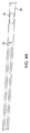
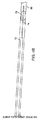
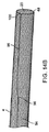
他の実施形態では、フィラメント6の長さの余剰量は、任意の数の他の場所で折り畳まれるか、又は、束ねられる。図14Aから図14Cでは、そのような装置2の一実施形態が示されている。図14Aでは、収容要素4が拘束された構成で示されている。拘束カテーテル8は、示されていないが、収容要素4がカテーテルの内側で半径方向に拘束されていることが理解されよう。示されているように、収容要素4の遠位開口部20は比較的小さい。フィラメント外周部48から近位側へ延びる単一のアーム28が存在するように、図2I及び図2Jにも記載されているようなフィラメント接合部100を有するフィラメント6が存在する。フィラメント外周部48は、非拘束時には一般的に円形の所定の形状46を有するが、示されている拘束された構成では、フィラメント外周部48は、細長いループ形状を有する。フィラメント外周部48は、収容要素4の長手方向軸線LAの所与の長さに沿って延びており、これは、制約されていないときには、フィラメント外周部48の周長の約半分の長さである。例えば、フィラメント外周部48の直径が5mmである場合、示されているように延出したときのフィラメント外周部48の長手方向長さは、約6mmから約9mmとされてよい。遠位アーム98は、拘束カテーテル8の内側に折り畳まれてフィラメント余剰長さ96の領域に移行し、それから、フィラメント近位アーム94に移行する。図示されるように、フィラメント余剰長さ96は、フィラメント外周部48がその拘束されていない形状に拡張するときに、フィラメント余剰長さ96を利用することができるように、拘束カテーテル8の内側に折り畳まれて格納される。図2Bでは、収容要素4及びフィラメント外周部48は、拘束カテーテル8の外側に展開されている。フィラメント外周部48は、収容要素4の長手方向軸線LAの非常に短い長さを延ばしている。例えば、フィラメント外周部48は、約0mmから約3mm、又は、約0.25mmから約1mmだけ延ばしてもよい。この結果、フィラメント接合部100は、拘束された形状におけるフィラメント外周部48の長手方向の長さと展開された形状におけるフィラメント6の長手方向の長さとの間のおよそ差の分だけ遠位側へ進む。例えば、これは、約1mmから約9mm、又は、約3mmから約6mmであってもよい。それから、フィラメント余剰長さ96は、展開されてもよく、フィラメント近位アーム94の実質的な動きなしに、フィラメント遠位アーム98の延出を許容する。折り畳まれたフィラメント余剰長さ96は、付加的な構成要素及び潜在的に堅い折り返し(tight trun)を通って延出するフィラメント近位アーム94が実質的に移動する必要がないので、フィラメント遠位アーム98を引っ張る摩擦力を最小化することを可能にする。それゆえ、フィラメント6又は収容要素4又はその両方の半径方向の開放力は、大きな摩擦力を克服する必要がなく、これらの開放した展開位置を達成してもよい。折り畳まれたフィラメント余剰長さ96は、カテーテルのいずれかの中の任意の位置に存在してもよいが、収容要素4の内側に最適に適用されてもよく、本明細書の他の場所で説明されるように、収容要素4の遠位端部16へ向けて、より最適に適用されてもよい。作業長WLに関連する特徴は、本発明の関連する態様として、特徴の任意のサブセットに組み合わせてもよく、そのような全ての組み合わせ及びサブセットの組み合わせは、本発明のさらなる態様として明示的に提供される。例えば、作業長に関して上述した全ての特徴が、折り畳まれたフィラメント6に等しく適用されるように、折り畳まれたフィラメント6が遠位端部から10mm以内に配置されていることは、明示的には記載されていないが、明示的に提供される。別の例として、図14は、余剰長さが、遠位部分に沿ったものであってもよく、かつ、フィラメント余剰長さ96のための平坦なZ形状部分を形成する第1の折り目及び第2の折り目によって形成されてもよいことを示している。図14Cでは、装置2は、近位アーム28が、張力がかけられた状態で配置された、閉鎖した構成で示されている。フィラメント余剰長さ96は、図示されているよりも多く真っすぐにしてもよいが、閉鎖した構成におけるフィラメント6の形状は、独特であり、拘束された位置におけるフィラメント6の形状とは異なることに留意すべきである。 
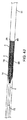
In other embodiments, the excess length of filament 6 is folded or bundled at any number of other locations. 14A-14C show one embodiment of such a device 2. In FIG. 14A, the containment element 4 is shown in a constrained configuration. Restraint catheter 8 is not shown, but it will be appreciated that the containment element 4 is radially constrained inside the catheter. As shown, the distal opening 20 of the containment element 4 is relatively small. There is a filament 6 having a filament junction 100 as also shown in FIGS. 2I and 2J, just as there is a single arm 28 extending proximally from the filament outer circumference 48. The filament outer circumference 48 generally has a predetermined circular shape 46 when unconstrained, whereas in the constrained configuration shown, the filament outer circumference 48 has an elongated loop shape. The filament outer circumference 48 extends along a given length of the longitudinal axis LA of the accommodating element 4, which, when unconstrained, is approximately half the circumference of the filament outer circumference 48. be. For example, when the diameter of the filament outer peripheral portion 48 is 5 mm, the longitudinal length of the filament outer peripheral portion 48 when extended as shown may be about 6 mm to about 9 mm. The distal arm 98 folds inside the restraint catheter 8 and transitions to the region of filament excess length 96 and then to the filament proximal arm 94. As shown, the filament surplus length 96 is provided inside the restraint catheter 8 so that the filament surplus length 96 can be utilized when the filament perimeter 48 expands into its unconstrained shape. Folded and stored. In FIG. 2B, the containment element 4 and the filament outer peripheral portion 48 are deployed outside the restraint catheter 8. The filament outer peripheral portion 48 extends a very short length of the longitudinal axis LA of the accommodating element 4. For example, the filament outer peripheral portion 48 may be extended from about 0 mm to about 3 mm, or from about 0.25 mm to about 1 mm. As a result, the filament junction 100 advances distally by approximately the difference between the longitudinal length of the filament outer peripheral 48 in the constrained shape and the longitudinal length of the filament 6 in the unfolded shape. .. For example, this may be from about 1 mm to about 9 mm, or from about 3 mm to about 6 mm. The filament surplus length 96 may then be deployed, allowing extension of the filament distal arm 98 without substantial movement of the filament proximal arm 94. The folded filament excess length 96 is distal to the filament because the filament proximal arm 94 extending through additional components and potentially tight truns does not have to move substantially. It makes it possible to minimize the frictional force that pulls the arm 98. Therefore, the radial opening forces of the filament 6 and / or the accommodating elements 4 do not have to overcome the large frictional forces and may achieve these open deployment positions. The folded filament excess length 96 may be present at any location within any of the catheters, but may be optimally applied to the inside of the containment element 4 and elsewhere herein. As described, it may be applied more optimally towards the distal end 16 of the containment element 4. Features associated with working length WL may be combined with any subset of features as a relevant aspect of the invention, all such combinations and combinations of subsets are expressly provided as a further aspect of the invention. Will be done. For example, it is explicitly stated that the folded filament 6 is located within 10 mm of the distal end so that all the features described above with respect to working length apply equally to the folded filament 6. Not listed, but provided explicitly. As another example, FIG. 14 shows a first crease and a first crease in which the surplus length may be along the distal portion and forms a flat Z-shaped portion for the filament surplus length 96. It shows that it may be formed by the second crease. In FIG. 14C, device 2 is shown in a closed configuration in which the proximal arm 28 is placed in a tensioned state. The extra filament length 96 may be more straight than shown, but note that the shape of the filament 6 in the closed configuration is unique and different from the shape of the filament 6 in the constrained position. Should.

いくつかの実施形態では、収容要素4が拘束カテーテル8内にあるときのフィラメント外周部48の形状は、遠位開口部20が閉鎖しているときのフィラメント外周部48の形状とは異なる。それゆえ、フィラメント外周部48は、少なくとも3つの独特な形状を経ている。第1に、収容要素4が拘束カテーテル8の内部にあるとき、フィラメント外周部48は、「うさぎの耳」のように見えるかもしれない形状、又はフィラメント余剰長さ96が考慮される他の任意の形状にある。これには、以下でより詳細に説明する斜行平面構成が含まれる。第2に、収容要素4が開放展開した構成にあるとき、フィラメント外周部48は、遠位開口部20の外周を形成し、これは一般的に円形とされている。フィラメント外周部48は、この時点で、この所定の形状46にあるか、又はこれに近い形状であってもよい。第3に、フィラメント6は、張力がかけられた状態にあり、かつ、遠位開口部20が閉鎖しているとき、フィラメント外周部48は、細長いループ又は引き伸ばされたゴムバンドに似ており、フィラメント外周部48は、フィラメント外周部48の遠位端部が遠位開口部20の、円形であってもよいし、円形でなくてもよい、小さな外周を形成する。フィラメント外周部48は、装置2の通常の使用中に、これら3つの形状の間で遷移する。具体的には、第1の形状及び第3の形状は、収容要素4が拘束カテーテル8の内部にあるときのフィラメント外周部48の形状は、遠位開口部20が閉鎖しているときの形状と必ずしも同じではないことを意味する独特な形状である。 In some embodiments, the shape of the filament perimeter 48 when the containment element 4 is within the restraint catheter 8 is different from the shape of the filament perimeter 48 when the distal opening 20 is closed. Therefore, the filament outer peripheral portion 48 undergoes at least three unique shapes. First, when the containment element 4 is inside the restraint catheter 8, the filament perimeter 48 may look like a "rabbit ear", or any other optional filament excess length 96 is considered. It is in the shape of. This includes oblique plane configurations described in more detail below. Second, when the accommodating element 4 is in an openly deployed configuration, the filament perimeter 48 forms the perimeter of the distal opening 20, which is generally circular. The filament outer peripheral portion 48 may have a shape that is or is close to the predetermined shape 46 at this time. Third, when the filament 6 is in a tensioned state and the distal opening 20 is closed, the filament outer circumference 48 resembles an elongated loop or stretched rubber band. The filament outer peripheral portion 48 forms a small outer circumference in which the distal end of the filament outer peripheral portion 48 may or may not be circular of the distal opening 20. The filament outer circumference 48 transitions between these three shapes during normal use of the device 2. Specifically, the first shape and the third shape are the shape of the filament outer peripheral portion 48 when the accommodating element 4 is inside the restraint catheter 8, and the shape when the distal opening 20 is closed. It is a unique shape that means that it is not necessarily the same as.

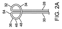
図8A及び図8Bでは、直径の変化を考慮した別の実施形態が示されている。いくつかの実施形態では、フィラメントの長さの問題に対処する他の設計が利用されてもよい。フィラメント外周部48は、一般的に、平面を形成する。平面は、図4Aから図4Pに示されるように、収容要素4の長手方向軸線LAに対して垂直である垂直平面66であってもよく、又は、平面は、長手方向軸線LAに対して斜めであってもよい。図8Bでは、平面は、垂直平面66から約30度の斜角64によって傾斜している。フィラメント外周部48は、楕円又は類似の形状を形成し、一方の遠地点(apogee)で遠位部分を有し、他方の遠地点で近位部分を有する。この設計の利点は、図8Aに示すように、収容要素4が拘束カテーテル8の内側に拘束されると、長さが増加することである。それゆえ、フィラメント外周部48が斜行していると、半径方向に拘束されると共に斜行する量が増加するため、長さが増加する。従って、フィラメント余剰長さ96は、展開時のより大きな直径から、拘束時のより長い長さに変換される。これは、収容要素4の遠位端部16が一旦展開されると開くことができるように、フィラメント6が遠位方向に移動する必要がないといった、上記で特定された同じ問題に対処する。拘束された形状から展開された形状に変更するのに必要なフィラメント余剰長さは、遠位端部に既に存在しており、アーム28、30は、遠位側へ相当量引っ張られる必要はない。さらに、斜めの遠位端開口部を有することは、血餅係合要素58を収容要素4内に導くための利点を提供し得る。いくつかの実施形態では、ループ状端部のクラウンを有する収容要素4の遠位端部16もまた、その長手方向軸線LAに対して斜めになっているが、他の実施形態では、フィラメント外周部48は、遠位端部が長手方向軸線LAに対してまだ垂直である間に、収容要素4の編組に、単に斜めに通しているだけである。スネアが垂直平面66に対して斜めになる量は、2度から60度の間とされてもよく、10度から30度の間とされてもよい。図8A及び図8Bに示される実施形態が、アーム28、30の一方又は両方に張力をかけることによって閉鎖した構成にあるとき、閉鎖した形状は、本明細書に示され、説明される他の実施形態に類似しているように見えてもよい。意味するところは、閉鎖した構成におけるフィラメント外周部48の形状は、拘束された構成におけるフィラメント外周部48の形状と必ずしも同じではないということを意味する。 8A and 8B show another embodiment that takes into account changes in diameter. In some embodiments, other designs that address filament length issues may be utilized. The filament outer peripheral portion 48 generally forms a flat surface. The plane may be a vertical plane 66 perpendicular to the longitudinal axis LA of the accommodating element 4, or the plane is oblique to the longitudinal axis LA, as shown in FIGS. 4A-4P. It may be. In FIG. 8B, the plane is tilted from the vertical plane 66 by an oblique angle 64 of about 30 degrees. The filament outer circumference 48 forms an ellipse or similar shape, having a distal portion at one apogee and a proximal portion at the other apogee. The advantage of this design is that the length increases when the containment element 4 is constrained inside the restraint catheter 8, as shown in FIG. 8A. Therefore, when the outer peripheral portion 48 of the filament is skewed, the length is increased because the amount of skewing is increased while being constrained in the radial direction. Therefore, the filament surplus length 96 is converted from a larger diameter at unfolding to a longer length at rest. This addresses the same problem identified above, such that the filament 6 does not need to move distally so that the distal end 16 of the containment element 4 can be opened once deployed. The extra filament length required to change from the constrained shape to the unfolded shape is already present at the distal end and the arms 28, 30 do not need to be pulled significantly to the distal side. .. In addition, having an oblique distal end opening may provide the advantage of guiding the clot engaging element 58 into the containment element 4. In some embodiments, the distal end 16 of the containment element 4 having the crown of the looped end is also slanted with respect to its longitudinal axis LA, but in other embodiments the filament perimeter The portion 48 simply passes diagonally through the braid of the containment element 4 while the distal end is still perpendicular to the longitudinal axis LA. The amount at which the snare is slanted with respect to the vertical plane 66 may be between 2 and 60 degrees, or between 10 and 30 degrees. When the embodiment shown in FIGS. 8A and 8B is in a configuration that is closed by applying tension to one or both of the arms 28, 30, the closed shape is the other that is shown and described herein. It may appear to be similar to an embodiment. This means that the shape of the filament outer peripheral portion 48 in the closed configuration is not necessarily the same as the shape of the filament outer peripheral portion 48 in the constrained configuration.

いくつかの実施形態では、フィラメント外周部48は、単一の平面を画定せず、代わりに、より複雑な三次元形状とされてもよい。例えば、フィラメント外周部48は、収容要素4の長手方向軸線LAに対して斜めになっている部分と、異なる角度又は向きで斜めになっている他の部分と、を有していてもよい。フィラメント外周部48は、近位又は遠位に延出する突起を有してもよい。フィラメント外周部48は、単一の平面によって拘束されない。 In some embodiments, the filament perimeter 48 does not define a single plane and may instead have a more complex three-dimensional shape. For example, the filament outer peripheral portion 48 may have a portion that is slanted with respect to the longitudinal axis LA of the accommodating element 4 and another portion that is slanted at a different angle or direction. The filament outer peripheral portion 48 may have protrusions extending proximally or distally. The filament outer circumference 48 is not constrained by a single plane.

図9Aから図9Fでは、収容要素4の遠位開口部20の閉鎖がより詳細に示されている。収容要素4は、5mmの血管の内側にある。これらの図では、血餅78及び血餅係合要素58は図示されていないが、このステップの間、収容要素4の内側にあるであろう。図9Aでは、収容要素4の遠位端部16は、収容要素4の内部に引き込まれるべき血餅係合要素58を受け取ることができるように、一般的に、開放されている。フィラメント外周部48は開放した形状であり、アーム28、30には、ほとんど又は全く張力がかからなくてもよい。一旦、血餅78及び血餅係合要素58が収容要素4の内側に入ると、図9Bに示すように、アーム28、30に張力をかけることができ、これによって、編組が束になって放射状に拡張するときに、収容要素4の遠位端部16を近位側へ移動させることができる。フィラメント6が近位側へ引っ張られると、収容要素4の遠位開口部20は、実質的に閉鎖する。図9Cに見られるように、円形のフィラメント外周部48の形状設定のプロファイルは、フィラメント外周部48のわずかな量だけが、閉鎖された遠位開口部20に残り、遠位開口外周部62が有意に減少するように、さらに引き込まれ、かつ、延伸される。 In FIGS. 9A-9F, the closure of the distal opening 20 of the containment element 4 is shown in more detail. Containment element 4 is inside a 5 mm blood vessel. In these figures, the clot 78 and the clot engaging element 58 are not shown, but will be inside the containment element 4 during this step. In FIG. 9A, the distal end 16 of the containment element 4 is generally open so that the clot engagement element 58 to be drawn into the containment element 4 can be received. The outer peripheral portion 48 of the filament has an open shape, and the arms 28 and 30 may be subjected to little or no tension. Once the blood clot 78 and the blood clot engaging element 58 are inside the accommodating element 4, tension can be applied to the arms 28, 30 as shown in FIG. 9B, whereby the braid is bundled. The distal end 16 of the containment element 4 can be moved proximally when expanding radially. When the filament 6 is pulled proximally, the distal opening 20 of the containment element 4 is substantially closed. As can be seen in FIG. 9C, the profile of the circular filament outer circumference 48 is such that only a small amount of the filament outer circumference 48 remains in the closed distal opening 20 and the distal opening outer circumference 62 It is further drawn in and stretched so that it is significantly reduced.

図9Dでは、フィラメントアーム28、30は、さらに近位側へ引っ張られ、収容要素4の遠位開口部20も同様に近位側へ移動し、さらに、これ自体の内側で折り返される。図9Eでは、遠位端部16は、さらに折り返される。これは、いくつかの実施形態では必要とされるかもしれないが、他の実施形態では、より少ない張力が、アーム28、30に必要とされる。重要な態様は、血餅78の粒子が、収容要素4から抜け出ないことである。 In FIG. 9D, the filament arms 28, 30 are pulled further proximally, the distal opening 20 of the containment element 4 is similarly moved proximally, and is further folded back inside itself. In FIG. 9E, the distal end 16 is further folded back. This may be required in some embodiments, but in other embodiments less tension is required for the arms 28, 30. An important aspect is that the particles of blood clot 78 do not escape from the containment element 4.

図9Fでは、収容要素4は、収縮した遠位端部を有して、血管80から取り外された状態が、示されている。見られるように、一般的に、遠位開口部には、血餅78の更なる塞栓を許容するための開口部は、存在しない。フィラメント6は、編組の全てのループ状端部106が互いに近接するように、パース糸として遠位開口部20を実質的に閉鎖している。 FIG. 9F shows that the containment element 4 has a contracted distal end and is removed from the blood vessel 80. As can be seen, there is generally no opening in the distal opening to allow further embolization of the clot 78. The filament 6 substantially closes the distal opening 20 as a perspective yarn such that all the looped ends 106 of the braid are in close proximity to each other.

他の実施形態では、フィラメントカテーテル82が、装置2に含まれる。フィラメントカテーテル82は、いくつかの利点を提供することができる。第1に、フィラメント6が、しっかりつかまれている間、装置2に軸方向の支持体を提供することができる。支持体は、遠位開口部20の閉鎖中に装置2の遠位端部16を固定した位置に保持してもよい。第2に、血管内の収容要素4の展開及び収縮を促進することができる。収容要素4が、編組である構成において、フィラメント6のカテーテルは、編組を延伸し、編組に遠位側へ作用する張力を加えることによって、その直径を減少させるために使用することができる。第3に、アーム28、30を収容要素4の内側又は外側にあるように拘束しておくことができる。 In another embodiment, the filament catheter 82 is included in device 2. The filament catheter 82 can provide several advantages. First, it is possible to provide the device 2 with an axial support while the filament 6 is firmly gripped. The support may hold the distal end 16 of the device 2 in a fixed position while the distal opening 20 is closed. Second, it can promote the deployment and contraction of the containment element 4 in the blood vessel. In a configuration in which the containment element 4 is a braid, the catheter of the filament 6 can be used to stretch the braid and reduce its diameter by applying a distal acting tension to the braid. Third, the arms 28, 30 can be constrained to be inside or outside the accommodating element 4.

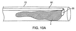
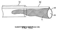
図10Aは、中間カテーテル72及び遠位開口部20の内側のフィラメントカテーテル82を閉鎖した構成で示している。収容要素4は、この構成では完全に中間カテーテル72の内側にあり、中間カテーテル72は、この構成では対象とする血管80へ前進させることができる。本実施形態では、フィラメントカテーテル82は、収容要素4の外部に示されている。代わりに、フィラメントカテーテル82は、収容要素4の管腔の内側にあり得る。図10Bでは、フィラメントカテーテル82が同じ位置に留まっている間に、中間カテーテル72が後退している。代わりに、中間カテーテル72が同じ位置に留まっている間に、フィラメントカテーテル82を前進させることができる。フィラメント外周部48は、中間カテーテル72の端部から遠位側にあり、収容要素4の近位端部が、未だ中間カテーテル72の内側にある閉鎖した構成のままである。遠位開口部20の閉鎖量は、図示されているものよりも少なくてもよく、又は、多くてもよいことに留意すべきである。例えば、遠位開口部20は、フィラメント外周部48における収容要素4が、それ自体に接触し、かつ、遠位開口部20において完全又は部分的なシールを形成するように、より多く閉鎖することができる。図10Cでは、フィラメント6は前進しており、遠位開口部20は、開放した構成にある。フィラメント外周部48は、凡そ血管の直径の大きさに開いており、それゆえ、血管も同様に開いている。 FIG. 10A shows a configuration in which the intermediate catheter 72 and the filament catheter 82 inside the distal opening 20 are closed. The containment element 4 is completely inside the intermediate catheter 72 in this configuration, which allows the intermediate catheter 72 to advance to the vessel 80 of interest in this configuration. In this embodiment, the filament catheter 82 is shown outside the containment element 4. Alternatively, the filament catheter 82 may be inside the lumen of containment element 4. In FIG. 10B, the intermediate catheter 72 is retracted while the filament catheter 82 remains in the same position. Alternatively, the filament catheter 82 can be advanced while the intermediate catheter 72 remains in the same position. The filament outer circumference 48 is distal to the end of the intermediate catheter 72, and the proximal end of the containment element 4 still remains in a closed configuration inside the intermediate catheter 72. It should be noted that the amount of closure of the distal opening 20 may be less or more than that shown. For example, the distal opening 20 is more closed so that the accommodating element 4 at the filament outer circumference 48 contacts itself and forms a complete or partial seal at the distal opening 20. Can be done. In FIG. 10C, the filament 6 is advanced and the distal opening 20 is in an open configuration. The filament outer circumference 48 is open approximately to the size of the diameter of the blood vessel, and therefore the blood vessel is open as well.

図11Aから図11Kに戻ると、本発明の装置2及び方法の使用が示される。図11Aから図11Fは、血栓摘出手順において現在実践されているかもしれないことに類似した一連のステップを示す。図11Aでは、中大脳動脈のような血管80の内部に血餅78が示されている。中間カテーテル72は、示されているように、対象とする血管80へ前進されている。図11Bでは、マイクロカテーテル74が前進され、ガイドワイヤ84が、血餅78を横断するように前進されている。図11Cでは、マイクロカテーテル74は、ガイドワイヤ84に続いて、血餅78を横断する。造影剤は、蛍光透視法で、その位置を確認するために、これらのステップにおいてマイクロカテーテル74を介して注入されてもよい。ガイドワイヤ84は、図11Dにおいてマイクロカテーテル74から取り外される。FIG11Eでは、ステント回収器のような血餅係合要素58が、その先端が、マイクロカテーテル74の端部から遠位側に延びるまでマイクロカテーテル74内に挿入される。図11Fでは、マイクロカテーテル74は、引っ込んでおり、ステント回収器は、血餅78の中に拡張し、血餅78がステント回収器で引っ張られるように、血餅78を掴む。典型的な血栓摘出術の手順では、ステント回収器は、マイクロカテーテル及び中間カテーテル72と共に引っ張られるようになっている。これらのカテーテルは、血管を通って、頸動脈内のシリコンバルーンカテーテルに引き込まれることができる。このことは、血餅を除去することができるが、上述のように、血餅の断片化及び遠位塞栓を生じさせ得る。 Returning from FIG. 11A to FIG. 11K, the use of the device 2 and method of the present invention is shown. 11A-11F show a series of steps similar to those currently practiced in the thrombectomy procedure. In FIG. 11A, a blood clot 78 is shown inside a blood vessel 80 such as the middle cerebral artery. The intermediate catheter 72 is advanced to the vessel of interest 80, as shown. In FIG. 11B, the microcatheter 74 is advanced and the guide wire 84 is advanced so as to traverse the blood clot 78. In FIG. 11C, the microcatheter 74 traverses the blood clot 78 following the guide wire 84. The contrast agent may be injected via the microcatheter 74 in these steps to locate it by fluorescence fluoroscopy. The guide wire 84 is removed from the microcatheter 74 in FIG. 11D. In FIG11E, a clot engaging element 58, such as a stent collector, is inserted into the microcatheter 74 until its tip extends distally from the end of the microcatheter 74. In FIG. 11F, the microcatheter 74 is retracted and the stent collector expands into the clot 78 and grabs the clot 78 so that the clot 78 is pulled by the stent collector. In a typical thrombectomy procedure, the stent collector is pulled along with the microcatheter and intermediate catheter 72. These catheters can be drawn through the blood vessels into a silicone balloon catheter within the carotid artery. This can remove the clot, but can result in clot fragmentation and distal embolism, as described above.

図11Gから図11Kは、血餅係合要素58及びむき出しの非被覆血餅78を、血管80を介して引き抜くことに関連する問題を低減することができる、本発明の装置2及び方法の一部の実施形態の用途を示す。 11G to 11K show one of the devices 2 and methods of the invention that can reduce the problems associated with pulling out the clot engaging element 58 and the bare uncoated clot 78 through the blood vessel 80. The use of the embodiment of the part is shown.

図11Gでは、中間カテーテル72及びマイクロカテーテル74は、血餅78を有する血管80内にステント回収器を残して除去される。カテーテル及びワイヤの交換を容易にするために、本明細書に記載されたカテーテルのいずれかについて、オーバーザワイヤカテーテル(over-the-wire catheters)の代わりにモノレール型カテーテル(例えば、ラピッドエクスチェンジ(Rapid Exchange))を使用することができる。代わりに、中間カテーテル72は、血餅78及びステント回収器に近位側の位置に残されてもよい。この実施形態では、装置2は、既存の中間カテーテル72に供給され、説明した手順の残りのステップに従うことができる。 In FIG. 11G, the intermediate catheter 72 and the microcatheter 74 are removed leaving a stent collector in the blood vessel 80 with the blood clot 78. To facilitate catheter and wire exchange, for any of the catheters described herein, instead of over-the-wire catheters, monorail catheters (eg, Rapid Exchange). )) Can be used. Alternatively, the intermediate catheter 72 may be left in a position proximal to the clot 78 and the stent collector. In this embodiment, the device 2 is fed to the existing intermediate catheter 72 and can follow the remaining steps of the procedure described.

図11Hでは、新しい中間カテーテル72又は装置2を有する既設の中間カテーテル72が、ステント回収器ワイヤ上に挿入され、対象とする血管へと前進する。説明したように、モノレール型のカテーテルが使用されてもよい。少なくともいくつかの実施形態では、ステント回収器ワイヤは、ワイヤが収容要素4の管腔を通って延びるように、収容要素の近位端部における穴を通って挿入される。他の実施形態では、穴は、収容要素4が吹き流しのように閉鎖した端部に来ないように、かなり大きくてもよい。フィラメント6は、中間カテーテル72内にあり、閉鎖した構成にある。 In FIG. 11H, an existing intermediate catheter 72 with a new intermediate catheter 72 or device 2 is inserted onto the stent collector wire and advances into the vessel of interest. As described, a monorail catheter may be used. In at least some embodiments, the stent collector wire is inserted through a hole at the proximal end of the containment element such that the wire extends through the lumen of the containment element 4. In other embodiments, the holes may be fairly large so that the containment element 4 does not come to a closed end like a windsock. The filament 6 is in the intermediate catheter 72 and is in a closed configuration.

図11Iでは、中間カテーテル72が後退し、収容要素4が血管80の内部で開放されている。フィラメント外周部48は、血管80の内径に接近するように手動で又は自動的に拡張する。いくつかの実施形態では、収容要素4又はフィラメント6は、血餅の遠位塞栓を、さらに防止するために、血管を通る血流を有意に減少させるか又は閉塞させる。血管の完全閉塞又は部分的閉塞は、さらに、頸動脈内での吸引又はシリコンバルーンカテーテルの必要性を抑制することができる。他の実施形態では、収容要素4は、血流をわずかに制限するだけでもよい。フィラメント外周部48及び遠位開口部20は、図示されているよりも多く開いていてもよく、又は、少なく開いていてもよい。例えば、フィラメント外周部48は、血管80に正の半径方向の力を提供し、流れの停止をさらに確実にするために開くことができる。 In FIG. 11I, the intermediate catheter 72 retracts and the containment element 4 is open inside the blood vessel 80. The filament outer circumference 48 is manually or automatically expanded to approach the inner diameter of the blood vessel 80. In some embodiments, the containment element 4 or filament 6 significantly reduces or occludes blood flow through the blood vessel to further prevent distal embolization of the clot. Complete or partial occlusion of blood vessels can further reduce the need for suction or silicone balloon catheters within the carotid artery. In other embodiments, the containment element 4 may only slightly restrict blood flow. The filament outer peripheral 48 and the distal opening 20 may be more open or less open than shown. For example, the filament outer circumference 48 can provide a positive radial force to the blood vessel 80 and can be opened to further ensure flow arrest.

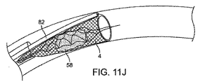
図11Jでは、ステント回収器及び血餅78は、遠位開口部20を通って収容要素4内に引き込まれる。フィラメント外周部48は、対象とする血管80の直径に近似していてもよいので、ステント回収器及び血餅78が引き込まれる漏斗のように作用する。血餅78は、完全に収容要素4内にある。いくつかの実施形態では、収容要素4は、その長さの一部に沿ってフィラメントカテーテル82に接続されている。例えば、収容要素4の近位端部は、自由に浮遊しないようにフィラメントカテーテル82に接続されてもよい。代わりに、収容要素4の全長は、フィラメントカテーテル82に接続されていてもよく、又は、一体化されてもよい。 In FIG. 11J, the stent collector and blood clot 78 are pulled into the containment element 4 through the distal opening 20. Since the filament outer peripheral portion 48 may be close to the diameter of the blood vessel 80 of interest, it acts like a stent collector and a funnel into which the blood clot 78 is drawn. The blood clot 78 is completely within the containment element 4. In some embodiments, the containment element 4 is connected to the filament catheter 82 along a portion of its length. For example, the proximal end of the containment element 4 may be connected to the filament catheter 82 so that it does not float freely. Alternatively, the overall length of the containment element 4 may be connected to or integrated with the filament catheter 82.

図11Kでは、装置2の端部のフィラメント外周部48は、アーム28、30を引っ張ることによって閉じられている。それゆえ、収容要素4の遠位開口部20は接近されており、血餅78は、収容要素4の内側に完全に収容される。この時点で、血餅78を有する装置2を血管80から引き抜くことができ、血餅が含まれているので、遠位塞栓の可能性が減少されてもよい。その後、装置2を患者から引き抜くことができる。 In FIG. 11K, the filament outer peripheral portion 48 at the end of the device 2 is closed by pulling the arms 28 and 30. Therefore, the distal opening 20 of the containment element 4 is in close proximity and the clot 78 is completely contained within the containment element 4. At this point, the device 2 having the blood clot 78 can be withdrawn from the blood vessel 80 and contains the blood clot, which may reduce the possibility of distal embolization. The device 2 can then be pulled out of the patient.

図12A及び12Bでは、装置2の代替的な実施形態が示されている。これらの実施形態では、フィラメント6は、収容要素4の外側にあり、さらに、フィラメントカテーテル82内に転送されている。フィラメントカテーテル82は、張力がフィラメント6に加えられ、遠位開口部20が閉鎖されているときに、収容要素4の遠位端部16を所定の位置に保持することができる。さらに、フィラメントカテーテル82は、フィラメントカテーテル82を静止させた状態で収容要素4の近位端部を引っ張ることによって、又は、近位端部を静止させた状態でフィラメントカテーテル82を有する収容要素4の遠位端部16を押すことによって、又は、その中のいくつかの組み合わせによって、収容要素4を延伸させることができるように、収容要素4の遠位端部16に張力を与えることができる。フィラメントカテーテル82は、ニチノール、ステンレス鋼、Pebax、PEEK、編組ポリイミド複合体、又は、他の任意の適切な構造のような、任意の適切なカテーテル又はチューブ材料で構成されてもよい。いくつかの実施形態では、フィラメントカテーテル82は、閉じられた巻きコイルであり得る。いくつかの実施形態では、各アーム28、30のためのフィラメントカテーテル82が存在する。フィラメントカテーテル82は、図12A及び図12Bにおいて収容要素4の外側に示されているが、収容要素4の内径の内側にあってもよい。 12A and 12B show alternative embodiments of device 2. In these embodiments, the filament 6 is on the outside of the containment element 4 and is further transferred into the filament catheter 82. The filament catheter 82 can hold the distal end 16 of the containment element 4 in place when tension is applied to the filament 6 and the distal opening 20 is closed. Further, the filament catheter 82 is a housing element 4 having the filament catheter 82 by pulling the proximal end of the containment element 4 with the filament catheter 82 stationary or with the proximal end stationary. Tension can be applied to the distal end 16 of the containment element 4 so that the containment element 4 can be stretched by pushing the distal end 16 or by some combination therein. The filament catheter 82 may be constructed from any suitable catheter or tube material, such as nitinol, stainless steel, Pebag, PEEK, braided polyimide composites, or any other suitable structure. In some embodiments, the filament catheter 82 can be a closed winding coil. In some embodiments, there is a filament catheter 82 for each arm 28, 30. The filament catheter 82 is shown outside the containment element 4 in FIGS. 12A and 12B, but may be inside the inner diameter of the containment element 4.

図10、図11及び図12は、互いに組み込まれた特徴を有する類似の装置を示す。例えば、両図とも、収容要素4が、拘束カテーテル8への留め具を設けておらず、中間カテーテル72が、第1のフィラメント6が第2の管腔を通って延びている、第2の管腔を有することを示している。さらに、両方の装置は、拘束カテーテル8の管腔24に配置された中間カテーテル72を示し、中間カテーテル72は、拘束カテーテル8に対して移動可能であり、その結果、相対運動は、収容要素4を解放位置に移動させることができる(拘束カテーテル8に対して中間カテーテル72を遠位側へ移動させる)。装置2は、図10及び図11の装置2が中間カテーテル72への留め具がないという、いくつかの点で異なるが、図12では、収容要素4は、少なくとも5mmの長さのために中間カテーテル72に連結されている。 10, 11 and 12 show similar devices with features incorporated into each other. For example, in both figures, the containment element 4 does not provide a clasp to the restraint catheter 8, and the intermediate catheter 72 has a second filament 6 extending through a second lumen. It shows that it has a lumen. Further, both devices show an intermediate catheter 72 located in the lumen 24 of the restraint catheter 8, which is movable relative to the restraint catheter 8, so that the relative movement is the containment element 4. Can be moved to the release position (move the intermediate catheter 72 distal to the restraint catheter 8). Device 2 differs in some respects that device 2 in FIGS. 10 and 11 does not have a clasp to the intermediate catheter 72, whereas in FIG. 12, the containment element 4 is intermediate due to a length of at least 5 mm. It is connected to the catheter 72.

図10から図12は、フィラメント6が、本明細書に記載された他の実施形態のいずれかの特徴を含んでもよい実施形態を示す。例えば、フィラメント6は、収容要素4が拘束カテーテル8に取り付けられていなくても、上述した方法で拘束カテーテル8からまだ出てくる先端部分を有していてもよい。もちろん、反転部分のような特徴は、図10Aから図10Cの実施形態には黙示的に含まれないが、閉鎖位置の特徴は、図10Aから図12の実施形態には暗黙的に含まれるであろう。また、簡潔さのために、装置に係る請求項に類似した方法に係る請求項を考慮する際に、いくつかの請求項が省略されていること、及び、その逆も理解されよう。従って、そのように欠落している方法に係る請求項又は装置に係る請求項のいずれかは、具体的に請求されていなくても、依然として本発明の一部を形成する。 10 to 12 show embodiments in which the filament 6 may include features of any of the other embodiments described herein. For example, the filament 6 may have a tip portion that still emerges from the restraint catheter 8 as described above, even if the accommodating element 4 is not attached to the restraint catheter 8. Of course, features such as inverted portions are not implicitly included in the embodiments of FIGS. 10A-10C, but features of the closed position are implicitly included in the embodiments of FIGS. 10A-12. There will be. It will also be appreciated that some claims are omitted and vice versa when considering claims for methods similar to those for devices for the sake of brevity. Therefore, either the claims relating to such a missing method or the claims relating to the apparatus still form part of the present invention, even if not specifically claimed.

図13Aから図13Bでは、装置2及び方法の一実施形態が示されている。図13Aでは、遠位開口部20を有する収容要素4が示されている。収容要素4は、編組構造、ステント構造、フレームケージ構造、又は、任意の他の適切な構造とされてもよい。収容要素4は、一般的に管形状であり、遠位開口部20を有する遠位端部と、少なくとも1つのフラップ88と、を有する。フラップ88は、遠位開口部20を越えて遠位側に延び、屈曲領域86を有する一片である。フィラメント6は、フィラメント6の接続部においてフラップ88に取り付けられている。フィラメント6は、ステンレス鋼、ニチノール、プラスチック、又は縫合糸のようなワイヤとされてよい。フィラメント6は、図示されているような接続部90によって、又は、溶接、熱接着、機械的延伸加工、又は、任意の他の適切なプロセスによって、フラップ88に接続されてもよい。図13Aでは、フラップ88は非作動状態にあり、アーム28には最小限の張力がある。それゆえ、遠位開口部20は、一般的に開いており、遠位開口部20を通して血餅78又は他の物質を受け取り得る。ユーザが、収容要素4の内部に物質を収容する準備ができたとき、張力がアーム28に加えられてもよい。この張力は、フラップ88を屈曲領域86周りに曲げるようにする力を、フラップ88に生じさせる。図13Bでは、フラップ88は、約30度回転され、それによって、遠位開口部20を部分的に閉鎖している。図13Cでは、追加の張力がアーム28に加えられ、遠位開口部20は、主に、回転して所定の位置に屈曲したフラップ88によって覆われている。いくつかの実施形態では、フラップ88は、収容要素4(一体的に形成された)と同じ材料で構成されてもよい。代わりに、フラップ88は、屈曲領域86において収容要素4に接続される別個の構成要素とされてもよい。この接続は、フラップ88が屈曲領域86について回転することが主に自由であるようなヒンジ式接続(例えば、生活用のヒンジ(living hinge))とされてもよい。いくつかの実施形態では、アーム28が、張力がかかった状態にあるときに、フラップ88がつぶれないように、より剛性の高い材料がフラップ88に適用されてもよい。これは、フラップ88に布又はプラスチックを加えることを含めてもよい。図13Dでは、1つ以上のフラップ88を有する代替的な実施形態が示されている。3つのフラップ88は、各々が、それ自身のフィラメント6を有して示されているが、1個から10個のフラップ又は2個から4個のフラップの間など、任意の数の他のフラップ88が企図されてもよい。フィラメント6は、同時に又は個別に張力をかけてもよい。従って、任意の数の折り畳みパターンが企図され得る。フラップ88は、収容要素4の長手方向軸線LAで合致する解剖学的バルブフラップのように作用してもよい。フラップ88は必ずしも対称である必要はなく、各々が独特な形状とされてもよい。フラップ88の形状は、全てのフラップ88が閉鎖したときに、収容要素4の遠位開口部20が大部分覆われ、収容要素4の内側の物質が所定の位置に捕捉されるように設計されてもよい。 13A to 13B show an embodiment of the device 2 and the method. FIG. 13A shows a containment element 4 having a distal opening 20. The containment element 4 may be a braided structure, a stent structure, a frame cage structure, or any other suitable structure. The accommodating element 4 is generally tubular and has a distal end with a distal opening 20 and at least one flap 88. The flap 88 is a piece that extends distally beyond the distal opening 20 and has a flexion region 86. The filament 6 is attached to the flap 88 at the connection of the filament 6. The filament 6 may be a wire such as stainless steel, nitinol, plastic, or suture. The filament 6 may be connected to the flap 88 by a connection 90 as shown, or by welding, thermal bonding, mechanical stretching, or any other suitable process. In FIG. 13A, the flap 88 is inactive and the arm 28 has minimal tension. Therefore, the distal opening 20 is generally open and may receive clot 78 or other material through the distal opening 20. Tension may be applied to the arm 28 when the user is ready to contain the material inside the containment element 4. This tension creates a force on the flap 88 that causes the flap 88 to bend around the flexion region 86. In FIG. 13B, the flap 88 is rotated about 30 degrees, thereby partially closing the distal opening 20. In FIG. 13C, additional tension is applied to the arm 28 and the distal opening 20 is primarily covered by a flap 88 that rotates and bends in place. In some embodiments, the flap 88 may be constructed of the same material as the containment element 4 (integrally formed). Alternatively, the flap 88 may be a separate component connected to the containment element 4 in the flexion region 86. This connection may be a hinged connection (eg, a living hinge) such that the flap 88 is primarily free to rotate about the flexion region 86. In some embodiments, a more rigid material may be applied to the flap 88 so that the flap 88 does not collapse when the arm 28 is under tension. This may include adding cloth or plastic to the flap 88. FIG. 13D shows an alternative embodiment with one or more flaps 88. The three flaps 88 are shown, each with its own filament 6, but any number of other flaps, such as between 1 to 10 flaps or between 2 and 4 flaps. 88 may be intended. The filament 6 may be tensioned simultaneously or individually. Therefore, any number of folding patterns can be conceived. The flap 88 may act like an anatomical valve flap that matches the longitudinal axis LA of the containment element 4. The flaps 88 do not necessarily have to be symmetrical and each may have a unique shape. The shape of the flaps 88 is designed so that when all flaps 88 are closed, the distal opening 20 of the containment element 4 is largely covered and the material inside the containment element 4 is trapped in place. You may.

本明細書に記載された実施形態のいずれかにおいて、吸引手段は、血餅78の捕捉をさらに支援するために、装置2の内側に追加的に適用されてもよい。吸引手段は、中間カテーテル72、拘束カテーテル8、収容要素4、又は、フィラメント6のカテーテルに接続されてもよい。吸引手段が、収容要素4に適用される実施形態では、血餅78の断片が収容要素4の内部に吸い込まれてもよい。吸引手段は、血流が近位側へ行くように血流を逆転させる。これは、吸引が血餅78の遠位側からのみ来るように、装置2が局所的な流れの停止を提供し、血餅78が分裂しても遠位側で塞栓しないことを確実にするような実施形態において特に有用であり得る。吸引手段は、血餅係合要素58が展開され、それから、収容要素4の内側に引っ込んでいるときにように、上記で概説された手順の特定のステップの間に適用され得る。代わりに、吸引の使用により、血餅係合要素58の必要性が省略されてもよい。吸引手段は、別個の回収器を使用することなく、収容要素4内に血餅78を吸引するために使用されてもよい。他の実施形態では、攪拌機構が、血餅を分解するために使用されてもよく、吸引手段は、それから、分解された断片を収容要素4の内側に吸引する。撹拌機は、血栓に接触し、血栓を吸い上げることができる、より小さな断片に分割する、回転又は軸方向に摺動する要素のような機械的なものであってもよい。代わりに、撹拌機は、血餅が分解するような振動的又は超音波的なものとされてもよい。吸引手段は、装置2に接続されたシリンジ又は真空源の使用によって達成されてもよい。いくつかの実施形態では、吸引カテーテル76は、血餅78を分断することが可能な、接続された破砕チップ(morcellating tip)を有する。吸引カテーテル76は、血餅78を収容要素4内に引き込み、そして遠位開口部20を閉鎖することができる。破砕チップは、吸引カテーテル76を介して吸引することができる、より小さな断片に血餅を乳化又は分解するために使用することができる。血餅78の物質が、収容要素4の内側に、もはや存在しなくなると、遠位開口部20を開くことができ、吸引カテーテル76は、さらに多くの血餅78と係合するように前進することができる。この手順は、任意の回数繰り返すことができる。いくつかの実施形態では、同じ手順が、ステント回収器に使用される。 In any of the embodiments described herein, the suction means may be additionally applied to the inside of the device 2 to further assist in the capture of the clot 78. The suction means may be connected to an intermediate catheter 72, a restraint catheter 8, a containment element 4, or a filament 6 catheter. In embodiments where the suction means is applied to the containment element 4, fragments of the blood clot 78 may be sucked into the containment element 4. The suction means reverses the blood flow so that the blood flow is proximal. This ensures that device 2 provides a local flow stop so that suction comes only from the distal side of the clot 78 and that the clot 78 does not embolize distally when it splits. It can be particularly useful in such embodiments. The suction means can be applied during the specific steps of the procedure outlined above, such as when the clot engaging element 58 is deployed and then retracted inside the containment element 4. Alternatively, the use of suction may omit the need for the clot engaging element 58. The suction means may be used to suck the blood clot 78 into the containment element 4 without using a separate collector. In other embodiments, a stirring mechanism may be used to break down the clot, and the suction means then sucks the broken down pieces inside the containment element 4. The stirrer may be mechanical, such as a rotating or axially sliding element that can contact the thrombus and suck up the thrombus, split it into smaller pieces. Alternatively, the stirrer may be oscillating or ultrasonic, such that the clot breaks down. The suction means may be achieved by the use of a syringe or vacuum source connected to the device 2. In some embodiments, the suction catheter 76 has a connected morcellating tip capable of disrupting the blood clot 78. The suction catheter 76 can pull the clot 78 into the containment element 4 and close the distal opening 20. The crushed tip can be used to emulsify or break down the clot into smaller pieces that can be aspirated via the suction catheter 76. When the substance of the clot 78 is no longer present inside the containment element 4, the distal opening 20 can be opened and the suction catheter 76 advances to engage more clots 78. be able to. This procedure can be repeated any number of times. In some embodiments, the same procedure is used for the stent collector.

他の実施形態では、収容要素4は、本明細書に記載されたフィラメント6のような能動的な閉鎖要素を持たず、代わりに、受動的に閉鎖されていてもよい。収容要素4は、図示されたように、長管に形状設定されていてもよいが、遠位端部16では、収容要素4が展開されたときに、収容要素4は収縮した形状に戻っていてもよい。別個のフレーム要素は、収容要素4の内側に後退された血餅係合要素58を受け入れる準備ができたときに、収容要素4を積極的に開いた状態で保持するために使用されてもよい。一旦収容要素4の内側に入ると、フレームは、収容要素4がその形状設定のプロファイルに戻って収縮することを許容するために、軸方向に移動され得る。これは、フレーム要素を遠位側及び近位側へスライドさせることによって、収容要素4の遠位端部16の開閉を許容してもよい。 In other embodiments, the accommodating element 4 does not have an active closing element such as the filament 6 described herein and may instead be passively closed. The accommodating element 4 may be shaped into a long tube as shown, but at the distal end 16, the accommodating element 4 returns to its contracted shape when the accommodating element 4 is unfolded. You may. A separate frame element may be used to actively hold the containment element 4 open when it is ready to receive the clot engagement element 58 retracted inside the containment element 4. .. Once inside the accommodating element 4, the frame can be moved axially to allow the accommodating element 4 to contract back to its shaping profile. It may allow the opening and closing of the distal end 16 of the containment element 4 by sliding the frame element distally and proximally.

いくつかの実施形態では、装置2は、本明細書に記載された装置の全部又は一部だけを含んでもよい。例えば、装置2は、ステント回収器又は吸引カテーテルのような血餅係合要素58を含んでもよい。代わりに、装置2は、収容要素4及びフィラメント6だけを含んでもよく、装置2は、既存の市販の利用可能なステント回収器と共に使用されてもよい。そのような実施形態では、収容要素4及びフィラメント6は、そのような回収器を受け入れるような大きさとされてもよい。装置2は、ステント回収器が展開され、かつ、血餅を捕捉した後に、体内に挿入されてもよい。このようにして、他の血餅係合要素を使用することを含む、血餅を捕捉するための独立したシステムである。本明細書に記載された装置の任意の数の他の構成が企図される。 In some embodiments, device 2 may include all or part of the devices described herein. For example, device 2 may include a clot engaging element 58, such as a stent collector or suction catheter. Alternatively, the device 2 may include only the containment element 4 and the filament 6, and the device 2 may be used in conjunction with an existing commercially available stent collector. In such embodiments, the containment element 4 and filament 6 may be sized to accommodate such a collector. The device 2 may be inserted into the body after the stent collector has been deployed and the blood clot has been captured. In this way, it is an independent system for capturing clots, including the use of other clot engaging elements. Any other configuration of any number of devices described herein is contemplated.

装置2は、任意のタイプの血栓切除術、塞栓切除術、又は、身体又は血管の任意の部分における異物、結石又は組織除去のためのプラットフォームとして機能する様々な形状及びサイズを有することができる。装置2は、動脈、静脈、尿管、気道、胆管、材料の回収のための中空粘性を含む任意のサイズのチューブまたは血管に対して、レオロジカテーテル(rheolytic catheters)、吸引装置、捕捉器具、フォガティバルーン(Fogarty balloon)のようなバルーン、ワイヤースネア、ステント回収器といった遠位装置を配置するための近位支持を提供してもよい。 The device 2 can have various shapes and sizes that serve as a platform for any type of thrombectomy, embolectomy, or removal of foreign bodies, stones or tissues in any part of the body or blood vessels. Device 2 is for arteries, veins, ureters, airways, bile ducts, tubes or blood vessels of any size, including hollow viscous for material recovery, rheolytic catheters, suction devices, capture devices, fogati. Proximal supports for placing distal devices such as balloons such as Fogarty balloons, wire snares, and stent collectors may be provided.


本明細書内に記載された装置及び方法は、任意の数の他の外科的処置で使用されてもよい。例えば、末梢血栓(peripheral blood clots)は、同様に、そのようなシステムを用いて除去されてもよい。任意の数の他の好適な用途は、管状の収容空間内、又は、非管状又は非収容空間内であっても、組織、異物、結石又は他の物体の収容除去のために、そのような装置2を使用してもよい。

The devices and methods described herein may be used in any number of other surgical procedures. For example, peripheral blood clots may be removed using such a system as well. Any number of other suitable uses are such for containment and removal of tissues, foreign bodies, stones or other objects, even within tubular or non-tubular or non-tubular containment spaces. Device 2 may be used.

様々な構成要素及び部品に適用される名称及びラベルは、本発明の装置及び方法の範囲を限定するものと考えるべきではない。例えば、本明細書で使用されるフィラメントという用語は、スネア、ワイヤ、リボン、コイル、細長い部材、又は、他の任意の適切な用語と互換的に使用することができる。カテーテルという用語は、遠位端部及び近位端部が、そこを通って延びる管腔を有する細長い部材を説明するために使用される。中間カテーテル、拘束カテーテル、フィラメントカテーテル、ガイドカテーテル、及び、マイクロカテーテルという用語は、しばしば互換的に使用され得る。収容要素という用語は、しばしば、バッグ、含有要素、容器要素、パウチ、又は任意の他の適切な用語と互換的に使用され得る。遠位開口部の開放に言及するとき、解放する、展開する、解放する、拡張するといった用語は、互換的に使用されてもよい。遠位開口部の閉鎖に言及するとき、締め付ける、閉鎖する、拘束する、潰れる、圧縮する、罠で捉える(cinching, closing, constraining, collapsing, constricting or snaring)、又は、他の任意の適切な用語がしばしば互換的に使用され得る。カテーテル、血管、又はフィラメントによる収容要素の半径方向の拘束に言及する場合、拘束、制限、包含、又は、拘束(constraining, restricting, containing or constricting)という用語もしばしば互換的に使用され得る。フィラメント外周部という用語は、凹形状部分と互換的に使用されてもよい。 The names and labels applied to the various components and components should not be considered to limit the scope of the devices and methods of the invention. For example, the term filament as used herein can be used interchangeably with snares, wires, ribbons, coils, elongated members, or any other suitable term. The term catheter is used to describe an elongated member with a lumen in which the distal and proximal ends extend through it. The terms intermediate catheter, restraint catheter, filament catheter, guide catheter, and microcatheter can often be used interchangeably. The term containment element can often be used interchangeably with bag, containing element, container element, pouch, or any other suitable term. When referring to the opening of a distal opening, the terms release, deploy, release, and dilate may be used interchangeably. When referring to the closure of the distal opening, tightening, closing, restraining, crushing, compressing, trapping (cinching, closing, constraining, collapsing, constricting or snaring), or any other suitable term. Can often be used interchangeably. When referring to radial constraints of containment elements by catheters, vessels, or filaments, the terms constraining, restricting, containing or constricting may also be used interchangeably. The term filament outer circumference may be used interchangeably with the concave portion.

様々な方法及び装置の実施形態が、特定のバージョンを参照して本明細書に詳細に記載されているが、他のバージョン、実施形態、使用方法、及び、これらの組み合わせも可能であることを理解すべきである。それゆえ、添付の特許請求の範囲の精神及び範囲は、本明細書に含まれる実施形態の記載に限定されるべきではない。 Although embodiments of various methods and devices are described in detail herein with reference to specific versions, other versions, embodiments, methods of use, and combinations thereof are also possible. Should be understood. Therefore, the spirit and scope of the appended claims should not be limited to the description of the embodiments contained herein.

Claims (160)

血管内の物質を捕捉するためのシステムであって、
チャンバを有する拘束カテーテルと、
遠位端に遠位開口部を有する収容要素であって、
前記収容要素は、前記遠位開口部から近位側に延出する側壁も有しており、
前記収容要素は、前記拘束カテーテルのチャンバの内側で折り畳み位置に収容されており、
前記収容要素は、前記折り畳み位置から、前記収容要素が前記チャンバの外側に配置される解放位置へ、前記チャンバに対して移動可能とされており、
前記遠位開口部は、前記遠位開口部の外周を画定する開位置を有しており、除去される物質は、前記開位置において前記遠位開口部を通過する、
前記収容要素は、前記解放位置において、長手方向位置を画定し、
前記収容要素は、前記解放位置から、前記遠位開口部のサイズが前記開位置から縮小されている閉鎖位置へ、移動可能とされている、収容要素と、
前記収容要素と連結された第1のフィラメントであって、前記第1のフィラメントは、前記収容要素が前記チャンバの内部に収容されている折り畳み位置から、前記収容要素が前記チャンバの外側に配置されている解放位置まで移動可能とされており、前記第1のフィラメントは、また、前記遠位開口部のサイズを前記開位置から閉鎖位置へ縮小する前記閉鎖位置へ移動可能とされている、第1のフィラメントと、
を備える、システム。
A system for capturing substances in blood vessels,
A restraint catheter with a chamber and
A containment element with a distal opening at the distal end,
The accommodating element also has a side wall extending proximally from the distal opening.
The containment element is housed in a folded position inside the chamber of the restraint catheter.
The accommodating element is movable relative to the chamber from the folded position to an open position where the accommodating element is located outside the chamber.
The distal opening has an open position that defines the outer circumference of the distal opening, and the material to be removed passes through the distal opening at the open position.
The accommodating element defines a longitudinal position at the release position.
The containment element is movable from the open position to a closed position where the size of the distal opening is reduced from the open position.
A first filament coupled to the accommodating element, wherein the accommodating element is disposed outside the chamber from a folding position where the accommodating element is accommodated inside the chamber. The first filament is also movable to the closed position, which reduces the size of the distal opening from the open position to the closed position. 1 filament and
The system.
血餅係合要素をさらに備えており、
前記拘束カテーテルは、前記チャンバを形成する管腔を有しており、
前記血餅係合要素は、前記管腔を通じて延出すると共に、前記収容要素の前記遠位開口部を越えた作業位置まで、前記収容要素を通って移動可能とされている、
請求項1に記載のシステム。
It also has a blood clot engaging element,
The restraint catheter has a lumen that forms the chamber.
The clot engaging element extends through the lumen and is movable through the containment element to a working position beyond the distal opening of the containment element.
The system according to claim 1.
前記血餅係合要素は、ステント回収器である、請求項1に記載のシステム。 The system according to claim 1, wherein the blood clot engaging element is a stent collector. 前記血餅係合要素は、吸引カテーテルである、請求項1に記載のシステム。 The system according to claim 1, wherein the blood clot engaging element is a suction catheter. 前記第1のフィラメントは、前記折り畳み位置において、第1の先端部分を有しており、前記第1の先端部分は、前記折り畳み位置における前記収容要素の前記遠位端から延出している、請求項1に記載のシステム。 The first filament has a first tip portion in the folded position, the first tip portion extending from the distal end of the accommodating element in the folded position, claim. Item 1. The system according to item 1. 前記第1のフィラメントの前記第1の先端部分は、前記収容要素の前記遠位端から延出する長さを有しており、該長さは、前記開位置における前記遠位開口部の前記外周の有効直径の少なくとも30%とされている、請求項5に記載のシステム。 The first tip portion of the first filament has a length extending from the distal end of the accommodating element, which length is the length of the distal opening in the open position. The system of claim 5, wherein the effective diameter of the outer circumference is at least 30%. 前記第1のフィラメントの前記第1の先端部分は、前記収容要素の前記遠位端から延出する長さを有しており、該長さは、前記開位置における前記遠位開口部の前記外周の有効直径の少なくとも50%とされている、請求項5に記載のシステム。 The first tip portion of the first filament has a length extending from the distal end of the accommodating element, which length is the length of the distal opening in the open position. The system of claim 5, wherein the effective diameter of the outer circumference is at least 50%. 前記第1の先端部分は、前記折り畳み位置における前記収容要素への留め具がない、請求項5に記載のシステム。 The system of claim 5, wherein the first tip portion does not have a clasp to the accommodating element in the folded position. 前記第1の先端部分は、前記折り畳み位置における前記収容要素の前記遠位端から少なくとも1.5mm遠位側に延出する、請求項5に記載のシステム。 The system of claim 5, wherein the first tip extends at least 1.5 mm distal to the distal end of the accommodating element in the folded position. 前記第1の先端部分は、前記収容要素の前記遠位端を越えて延出する第1のループを形成する、請求項5に記載のシステム。 The system of claim 5, wherein the first tip portion forms a first loop that extends beyond the distal end of the containment element. 前記第1の先端部分は、前記収容要素が前記解放位置にあるときに、前記遠位開口部を前記開位置へ向けて移動する凹形状部分を形成する、請求項5に記載のシステム。 The system of claim 5, wherein the first tip portion forms a concave portion that moves the distal opening towards the open position when the accommodating element is in the open position. 前記第1のフィラメントの前記第1の先端部分は、該フィラメントが前記折り畳み位置から前記解放位置へ移動するときに、前記収容要素の内部へ移動すると共に、前記収容要素の内面と係合する、請求項5に記載のシステム。 The first tip portion of the first filament moves into the accommodating element and engages with the inner surface of the accommodating element as the filament moves from the folded position to the unfolded position. The system according to claim 5. 前記第1の先端部分は、前記解放位置において、内面に外向きの力を加える、請求項5に記載のシステム。 The system according to claim 5, wherein the first tip portion applies an outward force to the inner surface at the release position. 前記第1のフィラメントは、前記解放位置における、前記側壁の内面に外向きの力を加える、請求項1に記載のシステム。 The system of claim 1, wherein the first filament exerts an outward force on the inner surface of the side wall at the release position. 前記第1のフィラメントは、前記解放位置における前記収容要素の少なくとも2cmの長手方向の長さにわたって、前記側壁の前記内面に外向きの力を加える、請求項14に記載のシステム。 14. The system of claim 14, wherein the first filament exerts an outward force on the inner surface of the sidewall over at least 2 cm of longitudinal length of the accommodating element in the release position. 前記第1のフィラメントは、長手方向軸に沿って見たときに、少なくとも180度の角度にわたって、前記側壁の前記内面に外向きの力を加える、請求項14に記載のシステム。 14. The system of claim 14, wherein the first filament exerts an outward force on the inner surface of the sidewall over an angle of at least 180 degrees when viewed along a longitudinal axis. 前記第1のフィラメントの該先端部分は、前記収容要素が前記解放位置にあるときに、前記遠位開口部を前記開位置へ向けて移動する凹形状部分を形成する、請求項5に記載のシステム。 5. The fifth aspect of claim 5, wherein the tip portion of the first filament forms a concave portion that moves the distal opening towards the open position when the accommodating element is in the open position. system. 前記第1のフィラメントは、前記収容要素の遠位端の10cm以内に配置された前記第1のフィラメントの長さである作動長さを画定する、請求項1に記載のシステム。 The system of claim 1, wherein the first filament defines an operating length that is the length of the first filament located within 10 cm of the distal end of the accommodating element. 前記第1のフィラメントの前記作動長さは、第1のアーム、第2のアーム、並びに、第1の端部及び第2の端部を有する凹形状部分を含んでおり、前記第1のアームは、前記凹形状部分の前記第1の端部から延出し、前記第2のアームは、前記凹形状部分の前記第2の端部から延出する、請求項18に記載のシステム。 The working length of the first filament includes a first arm, a second arm, and a concave portion having a first end and a second end, the first arm. 18. The system of claim 18, wherein the concave portion extends from the first end, and the second arm extends from the second end of the concave portion. 前記第1のフィラメントの作動長さは、前記収容要素が前記折り畳み位置から前記解放位置へ移動するときに、前記開位置における前記遠位開口部の有効直径の70%未満しか変化しない、請求項18に記載のシステム。 Claim that the working length of the first filament changes by less than 70% of the effective diameter of the distal opening in the open position as the accommodating element moves from the folded position to the released position. 18. The system according to 18. 前記第1のフィラメントは、閉鎖位置へ移動可能であり、前記第1のフィラメントは、前記収容要素に連結されており、前記収容要素を閉鎖位置へ移動させる、請求項1に記載のシステム。 The system according to claim 1, wherein the first filament is movable to a closed position, the first filament is connected to the accommodating element, and the accommodating element is moved to the closed position. 前記第1のフィラメントは、前記閉鎖位置に移動するときに、近位側に移動し、前記遠位開口部は、前記収容要素が前記閉鎖位置へ移動するときに、サイズが減少する、請求項1に記載のシステム。 The first filament moves proximally as it moves to the closed position, and the distal opening decreases in size as the containment element moves to the closed position, claim. The system according to 1. 前記第1のフィラメントは前記拘束カテーテルに連結され、前記第1のフィラメントは、前記拘束カテーテルの近位側移動によって近位側へ移動される、請求項1に記載のシステム。 The system of claim 1, wherein the first filament is coupled to the restraint catheter and the first filament is moved proximally by proximal movement of the restraint catheter. 前記第1のフィラメントは、前記閉鎖位置に移動するときに、近位側へ移動する凹形状部分を有しており、前記遠位開口部は、前記収容要素が前記閉鎖位置へ移動するときに、サイズが減少する、請求項1に記載のシステム。 The first filament has a concave portion that moves proximally when moving to the closed position, and the distal opening is when the accommodating element moves to the closed position. The system of claim 1, wherein the size is reduced. 前記遠位開口部は、前記閉鎖位置へ移動するときに、近位側へ移動する、請求項1に記載のシステム。 The system of claim 1, wherein the distal opening moves proximally as it moves to the closed position. 前記第1のフィラメントは、前記閉鎖位置へ移動すると共に、長手方向軸に沿って見たときに、前記遠位開口部を、前記側壁によって囲まれた位置へ移動する、反転部分が形成されるように、前記収容要素に連結されている、請求項1に記載のシステム。 The first filament moves to the closed position and forms an inverted portion that moves the distal opening to a position surrounded by the side wall when viewed along the longitudinal axis. The system according to claim 1, which is connected to the containing element as described above. 前記収容要素の前記側壁は、開口端部を前記閉鎖位置へ向けて付勢するために、前記側壁を通って伝達される前記反転部分に、半径方向内向きの力を加える、請求項1に記載のシステム。 The side wall of the accommodating element applies a radial inward force to the inverted portion transmitted through the side wall in order to bias the open end toward the closed position. Described system. 前記第1のフィラメントは、凹形状部分の自然な付勢されていない形状が、前記遠位開口部の前記開位置を支持するように、前記収容要素に配置されると共に連結された前記凹形状部分を含む所定の形状を有する、請求項1に記載のシステム。 The first filament is the concave shape in which the naturally unbulging shape of the concave portion is arranged and connected to the accommodating element so as to support the open position of the distal opening. The system according to claim 1, which has a predetermined shape including a portion. 前記第1のフィラメントは、前記開位置において長手方向軸に沿って見たときに、少なくとも150度の範囲で延出する凹形状部分を含む、請求項1に記載のシステム。 The system of claim 1, wherein the first filament comprises a concave portion extending in a range of at least 150 degrees when viewed along a longitudinal axis in the open position. 前記凹形状部分は、前記凹形状部分が、前記遠位開口部を前記開位置へ向けて付勢するように、前記収容要素の前記遠位開口部の付勢されていない形状よりも大きい形状を有する、請求項1に記載のシステム。 The concave portion has a shape larger than the unbulged shape of the distal opening of the accommodating element so that the concave portion urges the distal opening toward the open position. The system according to claim 1. 前記凹形状部分は、前記凹形状部分が、前記遠位開口部を前記開位置へ向けて付勢するように、前記開位置における前記遠位開口部に、前記収容要素によって拘束されている、請求項1に記載のシステム。 The concave portion is constrained by the accommodating element to the distal opening in the open position so that the concave portion urges the distal opening toward the open position. The system according to claim 1. 前記第1のフィラメントは、前記遠位開口部において前記収容要素に連結され、前記第1のフィラメントは、長手方向軸に沿って見たときに、前記遠位開口部の少なくとも120度の範囲で延出する、請求項1に記載のシステム。 The first filament is connected to the accommodating element at the distal opening and the first filament is at least 120 degrees of the distal opening when viewed along the longitudinal axis. The system according to claim 1, which is postponed. 前記第1のフィラメントは、前記遠位開口部において前記収容要素に連結され、前記第1のフィラメントは、長手方向軸に沿って見たときに、前記遠位開口部の少なくとも260度の範囲で延出する、請求項1に記載のシステム。 The first filament is connected to the accommodating element at the distal opening and the first filament is at least 260 degrees of the distal opening when viewed along the longitudinal axis. The system according to claim 1, which is postponed. 第2のフィラメントが、前記収容要素に連結されている、請求項1に記載のシステム。 The system of claim 1, wherein the second filament is coupled to the accommodating element. 前記第2のフィラメントは、前記折り畳み位置にある前記収容要素の遠位端部を越えて延出する第2の先端部分を有する、請求項34に記載のシステム。 34. The system of claim 34, wherein the second filament has a second tip that extends beyond the distal end of the accommodating element in the folded position. 前記第2のフィラメントは、前記収容要素が前記チャンバの内側の前記折り畳み位置にあるときに、前記収容要素の遠位端部を越えて遠位側へ延出する第2の先端部分を有する、請求項34に記載のシステム。 The second filament has a second tip portion that extends distally beyond the distal end of the accommodating element when the accommodating element is in the folded position inside the chamber. The system according to claim 34. 前記第2の先端部分は、前記収容要素の前記遠位端部から少なくとも1.5mm延出する、請求項36に記載のシステム。 36. The system of claim 36, wherein the second tip extends at least 1.5 mm from the distal end of the containment element. 前記第2のフィラメントの前記第2の先端部分は、前記収容要素の前記遠位端部から延出する長さを有しており、該長さは、前記開位置における前記遠位開口部の外周の有効直径の少なくとも30%である、請求項36に記載のシステム。 The second tip portion of the second filament has a length extending from the distal end of the accommodating element, which length of the distal opening in the open position. 36. The system of claim 36, which is at least 30% of the effective diameter of the outer circumference. 前記第2のフィラメントの前記第2の先端部分は、前記収容要素の前記遠位端部から延出する長さを有しており、該長さは、前記開位置における前記遠位開口部の外周の有効直径の少なくとも50%である、請求項36に記載のシステム。 The second tip portion of the second filament has a length extending from the distal end of the accommodating element, which length of the distal opening in the open position. 36. The system of claim 36, which is at least 50% of the effective diameter of the outer circumference. 前記第2のフィラメントは、前記第1のフィラメントに連結されている、請求項34に記載のシステム。 34. The system of claim 34, wherein the second filament is coupled to the first filament. 前記第2のフィラメントは、前記第1のフィラメントと一体に形成されている、請求項34に記載のシステム。 34. The system of claim 34, wherein the second filament is integrally formed with the first filament. 前記第2のフィラメントは、前記収容要素の遠位端部を越えて延出する第2のループを形成する、請求項34に記載のシステム。 34. The system of claim 34, wherein the second filament forms a second loop that extends beyond the distal end of the accommodating element. 前記第1のフィラメントは、前記収容要素が前記開位置にあるときに、第1の凹形状部分を形成し、前記第1の凹形状部分は、前記遠位開口部を前記開位置へ向けて移動し、
前記第2のフィラメントは、前記収容要素が前記開位置にあるときに、第2の凹形状部分を形成し、前記第2の凹形状部分は、前記遠位開口部を前記開位置へ向けて移動する、請求項34に記載のシステム。
The first filament forms a first concave portion when the accommodating element is in the open position, and the first concave portion directs the distal opening to the open position. Move and
The second filament forms a second concave portion when the accommodating element is in the open position, and the second concave portion directs the distal opening to the open position. The system of claim 34, which moves.
前記第1の凹形状部分は、前記収容要素が前記開位置にあるときにおいて、長手方向軸に沿って見たときに、90度から180度延出し、
前記第2の凹形状部分は、前記収容要素が前記開位置にあるときにおいて、長手方向軸に沿って見たときに、90度から180度延出する、請求項34に記載のシステム。
The first concave portion extends 90 to 180 degrees when viewed along the longitudinal axis when the accommodating element is in the open position.
34. The system of claim 34, wherein the second concave portion extends 90 to 180 degrees when viewed along a longitudinal axis when the accommodating element is in the open position.
第1の凹形状部分は、前記収容要素が前記解放位置にあるときに、前記遠位開口部を前記開位置へ向けて移動する閉ループを形成する、請求項1に記載のシステム。 The system of claim 1, wherein the first concave portion forms a closed loop that moves the distal opening towards the open position when the accommodating element is in the open position. 前記第1のフィラメントは、第1の凹形状部分から延出する第1のアームを有し、前記第1のアームは、前記遠位開口部を前記閉鎖位置へ移動するように張力がかけられている、請求項1に記載のシステム。 The first filament has a first arm extending from a first concave portion, the first arm being tensioned to move the distal opening to the closed position. The system according to claim 1. 前記凹形状部分は、一般的に、付勢されていない位置にある前記第1の凹形状部分を有して、前記第1のアームと45度から135度の角度を形成する平面にある、請求項46に記載のシステム。 The concave portion generally has the first concave portion in an unbulging position and is in a plane forming an angle of 45 to 135 degrees with the first arm. The system according to claim 46. 前記平面は、前記閉鎖位置において、前記第1のアームと135度から180度の角度を形成する、請求項46に記載のシステム。 46. The system of claim 46, wherein the plane forms an angle of 135 to 180 degrees with the first arm in the closed position. 前記第1のフィラメントは、前記収容要素が前記開位置にあるときに、長手方向軸に対面して配向された第1の凹形状部分を有する、請求項1に記載のシステム。 The system of claim 1, wherein the first filament has a first concave portion oriented facing a longitudinal axis when the accommodating element is in the open position. 前記収容要素の前記側壁は、遠位端部から10mm延出する遠位部分を有しており、前記収容要素が前記開位置から前記閉鎖位置へ移動すると、前記遠位部分の長さは、長手方向に少なくとも20%減少する、請求項1に記載のシステム。 The side wall of the containment element has a distal portion extending 10 mm from the distal end, and when the containment element moves from the open position to the closed position, the length of the distal portion is increased. The system of claim 1, wherein the system is reduced by at least 20% in the longitudinal direction. 前記遠位開口部は、前記開位置から前記閉鎖位置までに、サイズが少なくとも80%減少する有効直径を有する、請求項1に記載のシステム。 The system of claim 1, wherein the distal opening has an effective diameter that is reduced in size by at least 80% from the open position to the closed position. 前記遠位開口部は、前記閉鎖位置において、1mm以下とされている有効直径を有する、請求項1に記載のシステム。 The system of claim 1, wherein the distal opening has an effective diameter of 1 mm or less in the closed position. 前記閉鎖位置へ移動すると、前記遠位開口部が反転する、請求項1に記載のシステム。 The system of claim 1, wherein when moved to the closed position, the distal opening is inverted. 前記収容要素の前記側壁は、少なくとも10mmの長さであり、かつ、前記収容要素の遠位端部から10mm以内にある拡張可能部分を含む。請求項1に記載のシステム。 The sidewall of the containment element includes an expandable portion that is at least 10 mm long and is within 10 mm of the distal end of the containment element. The system according to claim 1. 前記拡張可能部分は、血管壁に半径方向外向きの力を及ぼす、請求項1に記載のシステム。 The system according to claim 1, wherein the expandable portion exerts a radial outward force on the blood vessel wall. 前記側壁の拡張可能部分は、前記拡張可能部分の付勢されていない形状を越えて前記第1のフィラメントに張力をかけることによって拡張される、請求項1に記載のシステム。 The system according to claim 1, wherein the expandable portion of the side wall is expanded by applying tension to the first filament beyond the unbulging shape of the expandable portion. 前記側壁の前記拡張可能部分は、付勢されていない形状において、有効直径を少なくとも10%増加させる、請求項1に記載のシステム。 The system of claim 1, wherein the expandable portion of the side wall increases the effective diameter by at least 10% in an unbulging shape. 前記拡張可能部分は、付勢されていない形状と比較して、前記側壁の内面にかかる外向きの力を少なくとも10%増加させる、請求項1に記載のシステム。 The system of claim 1, wherein the expandable portion increases an outward force exerted on the inner surface of the sidewall by at least 10% as compared to an unbulging shape. 前記拡張可能部分の有効直径が少なくとも10%増加するように、前記拡張可能部分は、前記第1のフィラメントによって付勢されていない形状を越えて拡張されている、請求項1に記載のシステム。 The system of claim 1, wherein the expandable portion is extended beyond a shape that is not urged by the first filament so that the effective diameter of the expandable portion is increased by at least 10%. 前記第1のフィラメントは、前記収容要素が前記閉鎖位置へ移動するときに、前記拡張可能部分において前記側壁の内面に外向きの力を及ぼすように張力がかけられ、外向きの力は、前記血管壁の半径方向外向きの力を少なくとも10%増加させる、請求項1に記載のシステム。 The first filament is tensioned to exert an outward force on the inner surface of the side wall at the expandable portion when the accommodating element moves to the closed position, and the outward force is the outward force. The system of claim 1, wherein the radial outward force of the vessel wall is increased by at least 10%. 前記第1のフィラメントは、前記収容要素の近位端から遠位側へ延出する細長い第1のアームを有する、請求項1に記載のシステム。 The system of claim 1, wherein the first filament has an elongated first arm that extends distally from the proximal end of the containment element. 前記第1のフィラメントが前記閉鎖位置へ移動されると、前記第1のアームに張力がかかる、請求項61に記載のシステム。 16. The system of claim 61, wherein when the first filament is moved to the closed position, tension is applied to the first arm. 前記第1のアームは、前記遠位開口部の前記開位置を支持する凹形状部分と連結されており、前記第1のフィラメントが、前記閉鎖位置へ移動されたときに、前記第1のアームは、前記凹形状部分を変形させるように、張力がかけられる。請求項61に記載のシステム。 The first arm is connected to a concave portion of the distal opening that supports the open position, and when the first filament is moved to the closed position, the first arm. Is tensioned so as to deform the concave portion. The system according to claim 61. 前記第1のフィラメントが、前記閉鎖位置へ移動すると、前記第1のアームに張力がかかり、凹形状部分が変形する、請求項61に記載のシステム。 The system according to claim 61, wherein when the first filament moves to the closed position, tension is applied to the first arm and the concave portion is deformed. 前記第1のフィラメントは、第1の端部及び第2の端部を有する凹形状部分を有しており、前記第1のフィラメントは、前記凹形状部分の前記第1の端部に連結された第1のアームと、前記凹形状部分の前記第2の端部に連結された第2のアームと、を有する、請求項1に記載のシステム。 The first filament has a concave portion having a first end and a second end, and the first filament is connected to the first end of the concave portion. The system according to claim 1, further comprising a first arm and a second arm connected to the second end of the concave portion. 前記第1のフィラメントは、前記閉鎖位置へ移動するときに、弾性変形する凹形状部分を有する、請求項1に記載のシステム。 The system of claim 1, wherein the first filament has a concave portion that elastically deforms when moved to the closed position. 前記収容要素は、織り込みメッシュを含む、請求項1に記載のシステム。 The system of claim 1, wherein the accommodating element comprises a woven mesh. 前記収容要素は、管腔を有しており、前記第1のフィラメントは、前記収容要素の前記管腔を通って延出する、請求項1に記載のシステム。 The system of claim 1, wherein the containment element has a lumen and the first filament extends through the lumen of the containment element. 前記収容要素は、前記拘束カテーテルへの留め具がない、請求項1に記載のシステム。 The system of claim 1, wherein the containment element has no fasteners to the restraint catheter. 管腔を有する前記拘束カテーテルと、
二次管腔を有するフィラメントカテーテルと、
前記フィラメントカテーテルの前記二次管腔を通って延出する弾性フィラメントと、
を、さらに備えており、
前記フィラメントカテーテルは、前記拘束カテーテルの前記管腔に配置されており、前記フィラメントカテーテルは、前記収容要素が前記解放位置へ移動するときに、前記拘束カテーテルに対して移動可能とされている、請求項1に記載のシステム。
With the restraint catheter having a lumen,
A filament catheter with a secondary lumen and
An elastic filament extending through the secondary lumen of the filament catheter and
, And more
The filament catheter is located in the lumen of the restraint catheter, and the filament catheter is movable with respect to the restraint catheter when the accommodating element moves to the release position. Item 1. The system according to item 1.
前記収容要素は、前記フィラメントカテーテルを前記拘束カテーテルに対して遠位側へ移動することによって、前記解放位置へ移動する、請求項1に記載のシステム。 The system of claim 1, wherein the containment element moves to the release position by moving the filament catheter distal to the restraint catheter. 前記収容要素は、前記フィラメントカテーテルへの留め具がない、請求項1に記載のシステム。 The system of claim 1, wherein the accommodating element has no fasteners to the filament catheter. 前記収容要素は、少なくとも5mmの長さで前記フィラメントカテーテルと連結されている、請求項1に記載のシステム。 The system of claim 1, wherein the containment element is coupled to the filament catheter to a length of at least 5 mm. 前記第1のフィラメントは、遠位部分に沿って余剰長さを有しており、前記余剰長さは、前記第1のフィラメントの第1の折り目及び第2の折り目によって形成され、長手方向に延出するセグメントを有する平坦なZ形状を形成する、請求項1に記載のシステム。 The first filament has a surplus length along the distal portion, the surplus length being formed by the first and second creases of the first filament and in the longitudinal direction. The system of claim 1, wherein a flat Z-shape with extending segments is formed. 血管内の物質を捕捉する方法であって、
チャンバを有する拘束カテーテルを、前記チャンバの内部に配置された収容要素を備えて、血管を通って前進させるステップであって、
前記収容要素は、遠位端部において遠位開口部を有しており、
前記収容要素は、前記遠位開口部から近位側に延出する側壁も有しており、
前記収容要素は、折り畳み位置において前記収容要素のチャンバの内側に収容されており、
第1のフィラメントは、前記収容要素に連結されると共に、折り畳み位置にある、ステップと、
前記収容要素を前記チャンバから解放するステップであって、前記収容要素は、前記折り畳み位置から、前記収容要素が前記チャンバの外側に配置される解放位置へ移動し、前記遠位開口部は、前記遠位開口部の外周を画定する開位置を有しており、前記第1のフィラメントは、前記収容要素が前記チャンバの外側に配置されているときに、解放位置へ移動する、ステップと、
除去される前記物質は、前記開位置における前記遠位開口部を通じて通過するステップであって、前記収容要素は、前記解放位置における長手方向軸を画定する、ステップと、
前記収容要素を、前記解放位置から、前記遠位開口部のサイズが、開位置から減少される、閉鎖位置へ移動するステップであって、前記第1のフィラメントは、前記遠位開口部のサイズが、前記開位置から前記閉鎖位置にかけて減少する、前記閉鎖位置へ移動する、ステップと、
を備える、方法。
A method of capturing substances in blood vessels
A step of advancing a restraint catheter having a chamber through a blood vessel with a containment element disposed inside the chamber.
The accommodating element has a distal opening at the distal end and
The accommodating element also has a side wall extending proximally from the distal opening.
The containment element is housed inside the chamber of the containment element in the folded position.
The first filament is connected to the accommodating element and is in the folded position with the step.
In the step of releasing the accommodating element from the chamber, the accommodating element moves from the folded position to an open position where the accommodating element is located outside the chamber, and the distal opening is said. The step and the step, which has an open position defining the outer periphery of the distal opening, moves to the release position when the containment element is located outside the chamber.
The material being removed is a step of passing through the distal opening in the open position, wherein the accommodating element defines a longitudinal axis in the open position.
The step of moving the containment element from the open position to the closed position where the size of the distal opening is reduced from the open position, wherein the first filament is the size of the distal opening. Is reduced from the open position to the closed position, moves to the closed position, and
A method.
前記前進させるステップは、前記チャンバを形成する管腔を有する前記収容要素を備えて実行される、請求項75に記載の方法。 75. The method of claim 75, wherein the advancing step is performed with said containment element having a lumen forming the chamber. 前記通過するステップは、前記物質が前記遠位開口部を通過すると共に、前記収容要素に入るときに、前記物質と係合する血餅係合要素を備えて実行される、請求項75に記載の方法。 75. The step of passing is performed with a clot engaging element that engages the substance as it passes through the distal opening and enters the containing element. the method of. 前記通過するステップは、ステント回収器である血餅係合要素を備えて実行される、請求項75に記載の方法。 The method of claim 75, wherein the step through is performed with a clot engaging element that is a stent collector. 前記通過するステップは、吸引カテーテルである血餅係合要素を備えて実行される、請求項75に記載の方法。 The method of claim 75, wherein the step through is performed with a clot engaging element that is a suction catheter. 前記前進させるステップは、前記折り畳み位置において、第1の先端部分を有する前記第1のフィラメントを備えて実行されており、前記第1の先端部分は、前記折り畳み位置における前記収容要素の前記遠位端部から延出している、請求項75に記載の方法。 The advancing step is performed in the folded position with the first filament having a first tip portion, the first tip portion being said distal to the accommodating element in the folded position. The method of claim 75, which extends from the end. 前記前進させるステップは、前記収容要素の前記遠位端部から延出する長さを有する前記第1のフィラメントの前記第1の先端部分を備えて実行され、該長さは、前記開位置における前記遠位開口部の外周の有効直径の少なくとも30%である、請求項80に記載の方法。 The advancing step is performed with the first tip portion of the first filament having a length extending from the distal end of the containment element, the length being in the open position. 80. The method of claim 80, which is at least 30% of the effective diameter of the outer periphery of the distal opening. 前記前進させるステップは、前記収容要素の前記遠位端部から延出する長さを有する前記第1のフィラメントの前記第1の先端部分を備えて実行され、該長さは、前記開位置における前記遠位開口部の外周の有効直径の少なくとも50%である、請求項80に記載の方法。 The advancing step is performed with the first tip portion of the first filament having a length extending from the distal end of the containment element, the length being in the open position. 80. The method of claim 80, which is at least 50% of the effective diameter of the outer periphery of the distal opening. 前記前進させるステップは、前記折り畳み位置における前記収容要素への留め具がない、前記第1の先端部分を備えて実行される、請求項80に記載の方法。 80. The method of claim 80, wherein the advancing step is performed with the first tip portion without fasteners to the accommodating element in the folded position. 前記前進させるステップは、前記折り畳み位置における前記収容要素の前記遠位端部から1.5mm遠位側に延出する前記第1の先端部分を備えて実行される、請求項80に記載の方法。 80. The method of claim 80, wherein the advancing step is performed with the first tip portion extending 1.5 mm distal to the distal end of the accommodating element in the folded position. .. 前記前進させるステップは、前記収容要素の前記遠位端部を越えて延出する第1のループを形成する、前記第1の先端部分を備えて実行される、請求項80に記載の方法。 80. The method of claim 80, wherein the advancing step is performed with the first tip portion forming a first loop extending beyond the distal end of the containment element. 前記解放するステップは、前記収容要素が前記解放位置にあるときに、前記遠位開口部を前記開位置へ向けて移動する凹形状部分を形成する、前記第1の先端部分を備えて実行される、請求項80に記載の方法。 The release step is performed with the first tip portion forming a concave portion that moves the distal opening towards the open position when the accommodating element is in the release position. The method according to claim 80. 前記解放するステップは、該フィラメントが前記折り畳み位置から前記解放位置へ移動するときに、前記収容要素の内部へ移動すると共に、前記収容要素の前記側壁の内面に係合する、前記第1のフィラメントの前記第1の先端部分を備えて実行される、請求項80に記載の方法。 The release step is the first filament that, as the filament moves from the folded position to the release position, moves into the containment element and engages the inner surface of the side wall of the containment element. 80. The method of claim 80, which is carried out with the first tip portion of the above. 前記解放するステップは、前記解放位置において、前記側壁の内面に外向きの力を加える、前記第1の先端部分を備えて実行される、請求項80に記載の方法。 80. The method of claim 80, wherein the releasing step is performed with the first tip portion applying an outward force to the inner surface of the side wall at the releasing position. 前記解放するステップは、前記解放位置において、前記側壁の内面に外向きの力を加える、前記第1のフィラメントを備えて実行される、請求項75に記載の方法。 75. The method of claim 75, wherein the releasing step is performed with the first filament applying an outward force to the inner surface of the side wall at the releasing position. 前記解放するステップは、前記解放位置における前記収容要素の少なくとも2cmの長手方向の長さにわたって、前記側壁の内面に外向きの力を加える、前記第1のフィラメントを備えて実行される、請求項75に記載の方法。 The release step is performed with the first filament applying an outward force to the inner surface of the side wall over at least 2 cm of longitudinal length of the accommodating element in the release position. 75. 前記解放するステップは、長手方向軸に沿って見たときに、少なくとも180度の角度範囲にわたって、前記側壁の内面に外向きの力を加える、前記第1のフィラメントを備えて実行される、請求項75に記載の方法。 The release step is performed with said first filament that exerts an outward force on the inner surface of the side wall over an angular range of at least 180 degrees when viewed along the longitudinal axis. Item 75. 前記解放するステップは、前記収容要素が前記解放位置にあるときに、前記遠位開口部を前記開位置へ向けて移動する凹形状部分を形成する、前記第1のフィラメントの該先端部分を備えて実行される、請求項75に記載の方法。 The release step comprises the tip portion of the first filament that forms a concave portion that moves the distal opening towards the open position when the accommodating element is in the release position. 75. The method of claim 75. 前記解放するステップは、前記収容要素の遠位端の10cm以内に配置された前記第1のフィラメントの長さである作動長さを画定する、前記第1のフィラメントを備えて実行される、請求項75に記載の方法。 The release step is performed with the first filament, defining an operating length that is the length of the first filament located within 10 cm of the distal end of the accommodating element. Item 75. 前記解放するステップは、第1のアーム、第2のアーム、並びに、第1の端部及び第2の端部を有する凹形状部分を含んでおり、前記第1のアームは、前記第1の端部から延出し、前記第2のアームは前記凹形状部分の前記第2の端部から延出する、前記第1のフィラメントの前記作動長さを備えて実行される、請求項93に記載の方法。 The releasing step includes a first arm, a second arm, and a concave portion having a first end and a second end, wherein the first arm is the first arm. 93. the method of. 前記解放するステップは、前記収容要素が前記折り畳み位置から前記解放位置へ移動するときに、前記開位置における前記遠位開口部の有効直径の70%未満しか変化しない、前記第1のフィラメントの前記作動長さを備えて実行される、請求項93に記載の方法。 The release step is the said of the first filament, wherein as the accommodating element moves from the folded position to the released position, it changes less than 70% of the effective diameter of the distal opening in the open position. 93. The method of claim 93, which is performed with an operating length. 前記解放するステップは、前記閉鎖位置へ移動する、前記第1のフィラメントを備えて実行され、前記第1のフィラメントは、前記収容要素を閉鎖位置へ移動させる、前記収容要素に連結される、請求項75に記載の方法。 The releasing step is performed with the first filament moving to the closed position, the first filament being coupled to the containing element, moving the containing element to the closing position, claiming. Item 75. 前記移動するステップは、前記閉鎖位置へ移動するときに、近位側に移動する前記第1のフィラメントを備えて実行され、前記遠位開口部は、前記収容要素が前記閉鎖位置へ移動するときに、サイズが減少する、請求項75に記載の方法。 The moving step is performed with the first filament moving proximally as it moves to the closed position, and the distal opening is when the accommodating element moves to the closed position. The method of claim 75, wherein the size is reduced. 前記移動するステップは、前記拘束カテーテルに連結された前記第1のフィラメントを備えて実行され、前記第1のフィラメントは、前記閉鎖位置へ移動するときに、前記拘束カテーテルの近位側移動によって近位側へ移動される、請求項75に記載の方法。 The moving step is performed with the first filament coupled to the restraint catheter, which is closer by proximal movement of the restraint catheter as it moves to the closed position. The method of claim 75, which is moved to the rank side. 前記移動するステップは、前記閉鎖位置に移動するときに、近位側へ移動する凹形状部分を有する、前記第1のフィラメントを備えて実行され、前記遠位開口部は、前記収容要素が前記閉鎖位置へ移動するときに、サイズが減少する、請求項75に記載の方法。 The moving step is performed with said first filament having a concave portion that moves proximally when moving to the closed position, the distal opening being said to have the containment element said. The method of claim 75, wherein the size is reduced when moving to a closed position. 前記移動するステップは、前記閉鎖位置へ移動するときに、近位方向へ移動する前記遠位開口部を備えて実行される、請求項75に記載の方法。 75. The method of claim 75, wherein the moving step is performed with the distal opening moving proximally as it moves to the closed position. 前記移動するステップは、前記閉鎖位置へ移動すると共に、長手方向軸に沿って見たときに、前記遠位開口部が、前記側壁によって囲まれた位置へ移動する反転部分が形成されるように、前記収容要素に連結されている、前記第1のフィラメントを備えて実行される、請求項75に記載の方法。 The moving step moves to the closed position and forms an inverted portion that moves the distal opening to a position surrounded by the side wall when viewed along the longitudinal axis. 75. The method of claim 75, which is performed with the first filament coupled to the containment element. 前記移動するステップは、開口端部を前記閉鎖位置へ向けて付勢するために、前記側壁を通って伝達される前記反転部分に、半径方向内向きの力を加える、前記収容要素の前記側壁を備えて実行される、請求項101に記載の方法。 The moving step applies a radial inward force to the inverted portion transmitted through the sidewall to urge the open end towards the closure position, the sidewall of the accommodating element. 101. The method of claim 101. 前記解放するステップは、凹形状部分の自然な付勢されていない形状が、前記遠位開口部の前記開位置を支持するように、前記収容要素に配置されると共に連結された前記凹形状部分を含む所定の形状を有する、前記第1のフィラメントを備えて実行される、請求項75に記載の方法。 The releasing step is the concave portion that is arranged and connected to the accommodating element such that the naturally unbulging shape of the concave portion supports the open position of the distal opening. 75. The method of claim 75, which is carried out with the first filament having a predetermined shape comprising. 前記解放するステップは、前記開位置において長手方向軸に沿って見たときに、少なくとも150度の範囲で延出する凹形状部分を含む、前記第1のフィラメントを備えて実行される、請求項75に記載の方法。 The release step is performed with said first filament, including a concave portion extending in a range of at least 150 degrees when viewed along a longitudinal axis in the open position. 75. 前記解放するステップは、凹形状部分が、前記遠位開口部を前記開位置へ向けて付勢するように、前記収容要素における前記遠位開口部の付勢されていない形状よりも大きい形状を有する、該凹形状部分を備えて実行される、請求項75に記載の方法。 The releasing step has a shape in which the concave portion is larger than the unbulged shape of the distal opening in the accommodating element so that the distal opening is urged towards the open position. The method of claim 75, which is carried out with the concave portion having. 前記解放するステップは、凹形状部分が、前記遠位開口部を前記開位置へ向けて付勢するように、前記開位置における前記遠位開口部に、前記収容要素によって拘束されている、該凹形状部分を備えて実行される、請求項75に記載の方法。 The release step is constrained by the accommodating element to the distal opening in the open position so that the concave portion urges the distal opening towards the open position. The method of claim 75, which is performed with a concave portion. 前記解放するステップは、前記遠位開口部において前記収容要素に連結された、前記第1のフィラメントを備えて実行され、前記第1のフィラメントは、長手方向軸に沿って見たときに、前記遠位開口部の少なくとも120度の範囲で延出する、請求項75に記載の方法。 The releasing step is performed with the first filament coupled to the accommodating element at the distal opening, said first filament when viewed along the longitudinal axis. 75. The method of claim 75, which extends within a range of at least 120 degrees of the distal opening. 前記解放するステップは、前記遠位開口部において前記収容要素に連結された、前記第1のフィラメントを備えて実行され、前記第1のフィラメントは、長手方向軸に沿って見たときに、前記遠位開口部の少なくとも260度の範囲で延出する、請求項75に記載の方法。 The releasing step is performed with the first filament coupled to the accommodating element at the distal opening, said first filament when viewed along the longitudinal axis. 75. The method of claim 75, which extends within a range of at least 260 degrees of the distal opening. 前記前進させるステップは、前記収容要素に連結された第2のフィラメントを備えて実行される、請求項75に記載の方法。 75. The method of claim 75, wherein the advancing step is performed with a second filament coupled to the accommodating element. 前記前進させるステップは、前記折り畳み位置にある前記収容要素の前記遠位端部を越えて延出する第2の先端部分を有する、第2のフィラメントを備えて実行される、請求項109に記載の方法。 10. The step of advancing is performed with a second filament having a second tip portion extending beyond the distal end of the accommodating element in the folded position, claim 109. the method of. 前記前進させるステップは、前記収容要素が前記チャンバの内側の前記折り畳み位置にあるときに、前記収容要素の前記遠位端部を越えて遠位側へ延出する第2の先端部分を有する、第2のフィラメントを備えて実行される、請求項109に記載の方法。 The advancing step has a second tip portion that extends distally beyond the distal end of the containment element when the containment element is in the folded position inside the chamber. 10. The method of claim 109, which is performed with a second filament. 前記前進させるステップは、前記収容要素の前記遠位端部から少なくとも1.5mm延出する、第2の先端部分を備えて実行される、請求項109に記載の方法。 10. The method of claim 109, wherein the advancing step is performed with a second tip portion extending at least 1.5 mm from the distal end of the containment element. 前記前進させるステップは、前記収容要素の前記遠位端部から延出する長さを有する前記第2のフィラメントの第2の先端部分を備えて実行され、該長さは、前記開位置における前記遠位開口部の外周の有効直径の少なくとも30%である、請求項109に記載の方法。 The advancing step is performed with a second tip portion of the second filament having a length extending from the distal end of the containment element, the length being said in the open position. 10. The method of claim 109, which is at least 30% of the effective diameter of the outer periphery of the distal opening. 前記前進させるステップは、前記収容要素の前記遠位端部から延出する長さを有する前記第2のフィラメントの第2の先端部分を備えて実行され、該長さは、前記開位置における前記遠位開口部の外周の有効直径の少なくとも50%である、請求項109に記載の方法。 The advancing step is performed with a second tip portion of the second filament having a length extending from the distal end of the containment element, the length being said in the open position. 10. The method of claim 109, which is at least 50% of the effective diameter of the outer periphery of the distal opening. 前記前進させるステップは、前記第1のフィラメントに連結されている、前記第2のフィラメントを備えて実行される、請求項109に記載の方法。 10. The method of claim 109, wherein the advancing step is performed with the second filament coupled to the first filament. 前記前進させるステップは、前記第1のフィラメントと一体に形成されている、前記第2のフィラメントを備えて実行される、請求項109に記載の方法。 10. The method of claim 109, wherein the advancing step is performed with the second filament, which is formed integrally with the first filament. 前記解放するステップは、前記収容要素が前記開位置にあるときに、第1の凹形状部分を形成する、前記第1のフィラメントを備えて実行され、前記第1の凹形状部分は、前記遠位開口部を前記開位置へ向けて移動し、前記第2のフィラメントは、前記収容要素が前記開位置にあるときに、第2の凹形状部分を形成し、前記第2の凹形状部分は、前記遠位開口部を前記開位置へ向けて移動する、請求項109に記載の方法。 The releasing step is performed with the first filament forming the first concave portion when the accommodating element is in the open position, the first concave portion being said far away. The position opening is moved toward the open position, and the second filament forms a second concave portion when the accommodating element is in the open position, and the second concave portion is formed. The method of claim 109, wherein the distal opening is moved towards the open position. 前記解放するステップは、前記収容要素が前記開位置にあるときにおいて、長手方向軸に沿って見たときに、90度から180度延出する、第1の凹形状部分を備えて実行され、第2の凹形状部分は、前記収容要素が前記開位置にあるときにおいて、長手方向軸に沿って見たときに、90度から180度延出する、請求項109に記載の方法。 The releasing step is performed with a first concave portion extending 90 to 180 degrees when viewed along the longitudinal axis when the accommodating element is in the open position. The method of claim 109, wherein the second concave portion extends 90 to 180 degrees when viewed along the longitudinal axis when the accommodating element is in the open position. 前記解放するステップは、前記収容要素が前記解放位置にあるときに、前記遠位開口部を前記開位置へ向けて移動する閉ループを形成する、第1の凹形状部分を備えて実行される、請求項75に記載の方法。 The release step is performed with a first concave portion that forms a closed loop that moves the distal opening towards the open position when the containment element is in the release position. The method according to claim 75. 前記移動するステップは、凹形状部分から延出する第1のアームを有する、前記第1のフィラメントを備えて実行され、前記第1のアームは、前記遠位開口部を前記閉鎖位置へ移動するように張力がかけられている、請求項75に記載の方法。 The moving step is performed with the first filament having a first arm extending from the concave portion, the first arm moving the distal opening to the closed position. 75. The method of claim 75, wherein tension is applied so as to. 前記前進させるステップは、凹形状部分と、前記凹形状部分から延出する第1のアームと、を有する、前記第1のフィラメントを備えて実行され、該凹形状部分は、一般的に、付勢されていない位置にある第1の凹形状部分を有して、第1のアームと45度から135度の角度を形成する平面にある、請求項75に記載の方法。 The advancing step is performed with the first filament having a concave portion and a first arm extending from the concave portion, the concave portion generally being attached. 75. The method of claim 75, wherein the method of claim 75 has a first concave portion in an unforced position and is in a plane forming an angle of 45 to 135 degrees with the first arm. 前記移動するステップは、前記閉鎖位置において、前記第1のアームと135度から180度の角度を形成する、前記平面を備えて実行される、請求項121に記載の方法。 12. The method of claim 121, wherein the moving step is performed with the plane forming an angle of 135 to 180 degrees with the first arm in the closed position. 前記解放するステップは、前記開位置において、前記収容要素に対面する凹形状部分へ方向づけられた、第1の凹形状部分を備えて実行される、請求項75に記載の方法。 75. The method of claim 75, wherein the releasing step is performed in the open position with a first concave portion oriented towards a concave portion facing the accommodating element. 前記移動するステップは、前記遠位端部から10mm延出する遠位部分を有する、前記収容要素の前記側壁を備えて実行され、前記収容要素が前記開位置から前記閉鎖位置へ移動すると、前記遠位部分の長さは、長手方向に少なくとも20%減少する、請求項75に記載の方法。 The moving step is performed with the side wall of the containment element having a distal portion extending 10 mm from the distal end, and when the containment element moves from the open position to the closed position, said The method of claim 75, wherein the length of the distal portion is reduced by at least 20% in the longitudinal direction. 前記移動するステップは、前記開位置から前記閉鎖位置までに、サイズが少なくとも80%減少する有効直径を有する、前記遠位開口部を備えて実行される、請求項75に記載の方法。 75. The method of claim 75, wherein the moving step is performed with the distal opening having an effective diameter that reduces size by at least 80% from the open position to the closed position. 前記移動するステップは、前記閉鎖位置において、有効直径が1mm以下とされている、前記遠位開口部を備えて実行される、請求項75に記載の方法。 75. The method of claim 75, wherein the moving step is performed in the closed position with the distal opening having an effective diameter of 1 mm or less. 前記移動するステップは、前記閉鎖位置へ移動すると反転する、前記遠位開口部を備えて実行される、請求項75に記載の方法。 75. The method of claim 75, wherein the moving step is performed with the distal opening that flips upon moving to the closed position. 前記移動するステップは、少なくとも10mmの長さであり、かつ、前記収容要素の前記遠位端部から10mm以内に位置する拡張可能部分を含む、前記収容要素の前記側壁を備えて実行される、請求項75に記載の方法。 The moving step is performed with the sidewall of the containment element, including an expandable portion that is at least 10 mm long and is located within 10 mm of the distal end of the containment element. The method according to claim 75. 前記移動するステップは、血管壁に半径方向外向きの力を及ぼす、拡張可能部分を備えて実行される、請求項75に記載の方法。 75. The method of claim 75, wherein the moving step is performed with an expandable portion that exerts a radial outward force on the vessel wall. 前記移動するステップは、付勢されていない形状を越えて拡張可能部分を拡張するために、前記第1のフィラメントに張力をかけることによって拡張される、前記側壁の該拡張可能部分を備えて実行される、請求項75に記載の方法。 The moving step is performed with the expandable portion of the side wall that is expanded by applying tension to the first filament to extend the expandable portion beyond the unbulging shape. The method of claim 75. 前記移動するステップは、付勢されていない形状において、少なくとも10%増加する有効直径を画定する、前記側壁の拡張可能部分を備えて実行される、請求項75に記載の方法。 75. The method of claim 75, wherein the moving step is performed with an expandable portion of the sidewall that defines an effective diameter that increases by at least 10% in an unbulging shape. 拡張可能部分は、付勢されていない形状と比較して、前記側壁の内面にかかる外向きの力を少なくとも10%増加させる、請求項75に記載の方法。 75. The method of claim 75, wherein the expandable portion increases the outward force exerted on the inner surface of the sidewall by at least 10% as compared to the unbulging shape. 拡張可能部分の有効直径が少なくとも10%増加するように、前記拡張可能部分は、前記第1のフィラメントによって付勢されていない形状を越えて拡張されている、請求項75に記載の方法。 75. The method of claim 75, wherein the expandable portion is extended beyond a shape that is not urged by the first filament so that the effective diameter of the expandable portion is increased by at least 10%. 前記第1のフィラメントは、前記収容要素が前記閉鎖位置へ移動するときに、拡張可能部分において前記側壁の内面に外向きの力を及ぼすように張力がかけられ、外向きの力は、血管壁の半径方向外向きの力を少なくとも10%増加させる、請求項75に記載の方法。 The first filament is tensioned to exert an outward force on the inner surface of the side wall at the expandable portion as the accommodating element moves to the closed position, the outward force exerting an outward force on the vessel wall. 75. The method of claim 75, which increases the radial outward force of the. 前記前進させるステップは、第1のアームを有する、前記第1のフィラメントを備えて実行される、請求項75に記載の方法。 75. The method of claim 75, wherein the advancing step is performed with said first filament having a first arm. 前記移動するステップは、前記第1のフィラメントが前記閉鎖位置へ移動されると、張力がかかる、第1のアームを備えて実行される、請求項75に記載の方法。 75. The method of claim 75, wherein the moving step is performed with a first arm that is tensioned when the first filament is moved to the closed position. 前記解放するステップは、前記第1のフィラメントの凹形状部分と連結された、第1のアームを備えて実行され、前記凹形状部分は、前記遠位開口部の前記開位置を支持しており、
前記移動するステップは、前記第1のフィラメントが前記閉鎖位置へ移動されると、前記凹形状部分を変形させるように、張力がかけられる、前記第1のアームを備えて実行される、請求項75に記載の方法。
The releasing step is performed with a first arm connected to the concave portion of the first filament, the concave portion supporting the open position of the distal opening. ,
The moving step is performed with the first arm, which is tensioned to deform the concave portion when the first filament is moved to the closed position. 75.
前記前進させるステップは、第1の端部及び第2の端部を含む凹形状部分を有する、前記第1のフィラメントを備えて実行されており、前記第1のフィラメントは、前記凹形状部分の前記第1の端部に連結された第1のアームと、前記凹形状部分の前記第2の端部に連結された第2のアームと、を有する、請求項75に記載の方法。 The advancing step is performed with the first filament having a concave portion including a first end and a second end, wherein the first filament is of the concave portion. The method of claim 75, comprising a first arm connected to the first end and a second arm connected to the second end of the concave portion. 前記移動するステップは、前記凹形状部分を前記閉鎖位置へ向けて変形させるように、張力がかけられた、前記第1のフィラメントの前記第1のアーム及び前記第2のアームを備えて実行され、前記凹形状部分は、前記遠位開口部のサイズを減少させるために、前記凹形状部分の角度範囲が、少なくとも50%減少するように、変形されている、請求項138に記載の方法。 The moving step is performed with the first arm and the second arm of the first filament tensioned to deform the concave portion towards the closed position. 138. The method of claim 138, wherein the concave portion is deformed so that the angular range of the concave portion is reduced by at least 50% in order to reduce the size of the distal opening. 前記移動するステップは、前記閉鎖位置へ移動するときに、弾性変形する凹形状部分を備えて実行される、請求項75に記載の方法。 The method of claim 75, wherein the moving step is performed with a concave portion that elastically deforms when moving to the closed position. 前記前進させるステップは、織り込みメッシュを含む、前記収容要素を備えて実行されている、請求項75に記載の方法。 75. The method of claim 75, wherein the advancing step is performed with said containment element, including a woven mesh. 前記収容要素は、管腔を有しており、前記第1のフィラメントは、前記拘束カテーテルを通って延出する、請求項75に記載の方法。 The method of claim 75, wherein the containment element has a lumen and the first filament extends through the restraint catheter. 前記収容要素は、前記拘束カテーテルへの留め具がない、請求項75に記載の方法。 75. The method of claim 75, wherein the containment element has no fasteners to the restraint catheter. 二次管腔を有するフィラメントカテーテルと、
管腔を有する前記拘束カテーテルと、
前記フィラメントカテーテルの前記二次管腔を通って延出する弾性フィラメントと、
を、さらに備えており、
前記フィラメントカテーテルは、前記拘束カテーテルの前記管腔に配置されており、前記フィラメントカテーテルは、前記収容要素が前記解放位置へ移動するときに、前記拘束カテーテルに対して移動可能とされている、請求項75に記載の方法。
A filament catheter with a secondary lumen and
With the restraint catheter having a lumen,
An elastic filament extending through the secondary lumen of the filament catheter and
, And more
The filament catheter is located in the lumen of the restraint catheter, and the filament catheter is movable with respect to the restraint catheter when the accommodating element moves to the release position. Item 75.
前記フィラメントカテーテルを前記拘束カテーテルに対して遠位側へ移動することによって、前記収容要素は、前記解放位置へ移動する、請求項75に記載の方法。 75. The method of claim 75, wherein the containment element is moved to the release position by moving the filament catheter distal to the restraint catheter. 前記収容要素は、前記フィラメントカテーテルへの留め具がない、請求項75に記載の方法。 75. The method of claim 75, wherein the containment element has no fasteners to the filament catheter. 前記収容要素は、少なくとも5mmの長さで前記フィラメントカテーテルと連結されている、請求項75に記載の方法。 75. The method of claim 75, wherein the containment element is coupled to the filament catheter to a length of at least 5 mm. 前記第1のフィラメントは、遠位部分に沿って余剰長さを有しており、前記余剰長さは、前記第1のフィラメントの第1の折り目及び第2の折り目によって形成され、長手方向に延出するセグメントを有する平坦なZ形状を形成する、請求項75に記載の方法。 The first filament has a surplus length along the distal portion, the surplus length being formed by the first and second creases of the first filament and in the longitudinal direction. The method of claim 75, wherein a flat Z-shape with extending segments is formed. 前記第1のフィラメントに連結された、少なくとも1つのフラップを備える、請求項1に記載のシステム。 The system of claim 1, comprising at least one flap coupled to the first filament. 前記少なくとも1つのフラップは、折り畳み位置において、前記遠位開口部を通過して遠位側へ延出し、前記少なくとも1つのフラップは、屈曲領域を有する、請求項1に記載のシステム。 The system of claim 1, wherein the at least one flap extends distally through the distal opening in a folded position, and the at least one flap has a flexion region. 前記第1のフィラメントは、フィラメント接続部で前記フラップに取り付けられている、請求項1に記載のシステム。 The system of claim 1, wherein the first filament is attached to the flap at a filament connection. 前記第1のフィラメント6は、ステンレス鋼、ニチノール、プラスチック、及び縫合糸からなる材料から選択されたワイヤとされている、請求項1に記載のシステム。 The system of claim 1, wherein the first filament 6 is a wire selected from a material made of stainless steel, nitinol, plastic, and suture. 前記少なくとも1つのフラップは、前記第1のフィラメントに低張力で非作動状態とされており、前記遠位開口部20は、物質を受容するために、前記開位置にある、請求項1に記載のシステム。 The first aspect of claim 1, wherein the at least one flap is inactive with low tension on the first filament and the distal opening 20 is in the open position to receive material. System. 前記第1のフィラメントは、前記少なくとも1つのフラップに、屈曲領域の周りで曲がるような力を生じさせるために、張力がかけられる、請求項1に記載のシステム。 The system of claim 1, wherein the first filament is tensioned to generate a bending force on the at least one flap around the flexion region. 前記第1のフィラメントは、前記少なくとも1つのフラップが回転し、屈曲領域が、前記少なくとも1つのフラップを固定された位置に屈曲させることを許容するときに、アーム及び前記遠位開口部を覆う前記フラップに適用するように張力がかけられる、請求項1に記載のシステム。 The first filament covers the arm and the distal opening when the at least one flap rotates and the bending region allows the at least one flap to bend to a fixed position. The system of claim 1, wherein tension is applied to apply to the flaps. 前記少なくとも1つのフラップは、前記収容要素と一体に形成された材料を含む、請求項1に記載のシステム。 The system of claim 1, wherein the at least one flap comprises a material formed integrally with the accommodating element. 前記フラップは、前記フラップが、主に、屈曲領域の周りを自由に回転することができるように、前記屈曲領域において前記収容要素に接続されて、ヒンジ接続を形成する、別個の構成要素とされている、請求項1に記載のシステム。 The flap is a separate component that is connected to the accommodating element in the flexed region to form a hinge connection, primarily so that the flap can freely rotate around the flexed region. The system according to claim 1. 前記フラップは、リビングヒンジを形成する第1のフィラメントを有する、前記収容要素に連結される、請求項1に記載のシステム。 The system of claim 1, wherein the flap is coupled to the accommodating element having a first filament that forms a living hinge. 前記フラップは、前記フラップによって形成されたループを囲むための布又はプラスチックの少なくとも1つを含む、請求項1に記載のシステム。 The system of claim 1, wherein the flap comprises at least one of a cloth or plastic for surrounding the loop formed by the flap. 前記収容要素の長手方向軸で出会う、解剖学的バルブフラップのように機能する、3つのフラップを備えた、請求項1に記載のシステム。 The system of claim 1, comprising three flaps that act like anatomical valve flaps that meet on the longitudinal axis of the containment element.
JP2021500017A 2018-03-12 2019-03-12 Devices and methods for removing substances from patients Pending JP2021517850A (en)

Applications Claiming Priority (5)

Application Number Priority Date Filing Date Title
US201862641948P 2018-03-12 2018-03-12
US62/641,948 2018-03-12
US201962793498P 2019-01-17 2019-01-17
US62/793,498 2019-01-17
PCT/US2019/021943 WO2019178165A1 (en) 2018-03-12 2019-03-12 Devices and methods for removing material from a patient

Publications (2)

Publication Number Publication Date
JP2021517850A true JP2021517850A (en) 2021-07-29
JPWO2019178165A5 JPWO2019178165A5 (en) 2022-03-23

Family

ID=67908099

Family Applications (1)

Application Number Title Priority Date Filing Date
JP2021500017A Pending JP2021517850A (en) 2018-03-12 2019-03-12 Devices and methods for removing substances from patients

Country Status (6)

Country Link
US (3) US10624659B2 (en)
EP (1) EP3764922A4 (en)
JP (1) JP2021517850A (en)
CN (1) CN112384152A (en)
IL (1) IL277002A (en)
WO (1) WO2019178165A1 (en)

Families Citing this family (38)

* Cited by examiner, † Cited by third party
Publication number Priority date Publication date Assignee Title
US10265086B2 (en) 2014-06-30 2019-04-23 Neuravi Limited System for removing a clot from a blood vessel
US11771446B2 (en) * 2020-10-19 2023-10-03 Anaconda Biomed, S.L. Thrombectomy system and method of use
WO2017058296A1 (en) * 2015-09-30 2017-04-06 Blockade Medical, LLC Treatment systems processes and devices addressing cerebral vasospasm/vasoconstriction
JP7012655B2 (en) 2016-02-24 2022-01-28 インセプト、リミテッド、ライアビリティ、カンパニー Flexible enhanced neurovascular catheter
WO2018129194A1 (en) 2017-01-06 2018-07-12 Incept, Llc Thromboresistant coatings for aneurysm treatment devices
CN112384152A (en) 2018-03-12 2021-02-19 爱创医药公司 Device and method for removing substance from a patient
US11395665B2 (en) 2018-05-01 2022-07-26 Incept, Llc Devices and methods for removing obstructive material, from an intravascular site
CN112203593A (en) 2018-05-01 2021-01-08 因赛普特有限责任公司 Device and method for removing occlusive material from an intravascular site
US11517335B2 (en) 2018-07-06 2022-12-06 Incept, Llc Sealed neurovascular extendable catheter
US11471582B2 (en) 2018-07-06 2022-10-18 Incept, Llc Vacuum transfer tool for extendable catheter
WO2020087009A1 (en) 2018-10-26 2020-04-30 Progressive NEURO, Inc. Apparatus, system, and method for vasculature obstruction removal
US11253279B2 (en) 2018-11-15 2022-02-22 Progressive NEURO, Inc. Apparatus, system, and method for vasculature obstruction removal
US11197685B2 (en) 2018-11-15 2021-12-14 Progressive NEURO, Inc. Apparatus, system, and method for vasculature obstruction removal
EP3908211A4 (en) 2019-01-08 2022-08-31 Progressive Neuro, Inc. Apparatus, system, and method for vasculature obstruction removal
US10555802B1 (en) * 2019-03-07 2020-02-11 John H. Shadduck Urologic stents and methods of use
US11766539B2 (en) 2019-03-29 2023-09-26 Incept, Llc Enhanced flexibility neurovascular catheter
US11724069B2 (en) 2019-04-30 2023-08-15 Covidien Lp Catheter including contractible electroactive elements
WO2021016241A1 (en) * 2019-07-22 2021-01-28 Boston Scientific Scimed, Inc. System, device and method for treatment of hemorrhoids
AU2020366348A1 (en) 2019-10-15 2022-05-12 Imperative Care, Inc. Systems and methods for multivariate stroke detection
US11839725B2 (en) 2019-11-27 2023-12-12 Neuravi Limited Clot retrieval device with outer sheath and inner catheter
US11779364B2 (en) 2019-11-27 2023-10-10 Neuravi Limited Actuated expandable mouth thrombectomy catheter
JP2023507553A (en) 2019-12-18 2023-02-24 インパラティブ、ケア、インク. Methods and systems for treating venous thromboembolism
US11633272B2 (en) 2019-12-18 2023-04-25 Imperative Care, Inc. Manually rotatable thrombus engagement tool
US11457936B2 (en) 2019-12-18 2022-10-04 Imperative Care, Inc. Catheter system for treating thromboembolic disease
US11944327B2 (en) 2020-03-05 2024-04-02 Neuravi Limited Expandable mouth aspirating clot retrieval catheter
EP4117762A4 (en) 2020-03-10 2024-05-08 Imperative Care Inc Enhanced flexibility neurovascular catheter
US11883043B2 (en) 2020-03-31 2024-01-30 DePuy Synthes Products, Inc. Catheter funnel extension
US11759217B2 (en) 2020-04-07 2023-09-19 Neuravi Limited Catheter tubular support
WO2021242963A1 (en) * 2020-05-27 2021-12-02 Xtract Medical, Inc. Devices and methods for removing material from a patient
US11207497B1 (en) 2020-08-11 2021-12-28 Imperative Care, Inc. Catheter with enhanced tensile strength
US11872359B2 (en) 2020-11-12 2024-01-16 Covidien Lp Expandable-tip aspiration guide catheter
US11872354B2 (en) 2021-02-24 2024-01-16 Neuravi Limited Flexible catheter shaft frame with seam
US11717603B2 (en) 2021-04-27 2023-08-08 Contego Medical, Inc. Thrombus aspiration system and methods for controlling blood loss
CN117241748A (en) * 2021-05-03 2023-12-15 瓦斯科尔勒治疗股份有限公司 Axially elongated thrombus capture system, tensioning system and expandable funnel catheter
US11937839B2 (en) 2021-09-28 2024-03-26 Neuravi Limited Catheter with electrically actuated expandable mouth
US20230132996A1 (en) * 2021-10-28 2023-05-04 Neuravi Limited Bevel tip expandable mouth catheter with reinforcing ring
US20230137418A1 (en) * 2021-11-03 2023-05-04 Neuravi Limited Super-bore catheter with braid supported flared tip
US20230140794A1 (en) * 2021-11-03 2023-05-04 Neuravi Limited Catheter with low-shear tip

Citations (8)

* Cited by examiner, † Cited by third party
Publication number Priority date Publication date Assignee Title
US20010051810A1 (en) * 1998-02-10 2001-12-13 Dubrul William Richard Tissue separation medical device and method
JP2002502626A (en) * 1998-02-10 2002-01-29 アーテミス・メディカル・インコーポレイテッド Supplementary device and method of using the same
US20060047286A1 (en) * 2004-08-31 2006-03-02 Stephen West Clot retrieval device
US20060195137A1 (en) * 2000-06-29 2006-08-31 Concentric Medical, Inc. A Delaware Corporation Systems, methods and devices for removing obstructions from a blood vessel
WO2007110864A2 (en) * 2006-03-27 2007-10-04 Tel Hashomer Medical Research Infrastructure And Services Ltd. Intraluminal mass collector
US20110060212A1 (en) * 2008-02-22 2011-03-10 Micro Therapeutics, Inc. Methods and apparatus for flow restoration
US20140025083A1 (en) * 2005-02-28 2014-01-23 Boston Scientific Scimed, Inc. Distal release retrieval assembly and related methods of use
US20160220265A1 (en) * 2007-10-12 2016-08-04 NexGen Medical Systems Incorporated, Thrombus removal system and process

Family Cites Families (19)

* Cited by examiner, † Cited by third party
Publication number Priority date Publication date Assignee Title
US5480404A (en) * 1993-06-16 1996-01-02 Ethicon, Inc. Surgical tissue retrieval instrument
EP0934092A4 (en) 1997-03-06 2008-03-26 Boston Scient Scimed Inc Distal protection device and method
US5814064A (en) * 1997-03-06 1998-09-29 Scimed Life Systems, Inc. Distal protection device
US9498604B2 (en) 1997-11-12 2016-11-22 Genesis Technologies Llc Medical device and method
US6824545B2 (en) * 2000-06-29 2004-11-30 Concentric Medical, Inc. Systems, methods and devices for removing obstructions from a blood vessel
US6663650B2 (en) 2000-06-29 2003-12-16 Concentric Medical, Inc. Systems, methods and devices for removing obstructions from a blood vessel
DE10242444A1 (en) * 2002-09-11 2004-04-01 pfm Produkte für die Medizin AG extractor
US7273469B1 (en) 2003-12-31 2007-09-25 Advanced Cardiovascular Systems, Inc. Modified needle catheter for directional orientation delivery
US20050228417A1 (en) 2004-03-26 2005-10-13 Teitelbaum George P Devices and methods for removing a matter from a body cavity of a patient
WO2010010545A1 (en) 2008-07-22 2010-01-28 Neuravi Limited Clot capture systems and associated methods
US9402707B2 (en) * 2008-07-22 2016-08-02 Neuravi Limited Clot capture systems and associated methods
BR112013030183A2 (en) 2011-05-23 2017-12-05 Lazarus Effect Inc interventional medical device for recovering and securing an obstruction within a vessel lumen, method of securing an obstruction within a vessel, method of preparing a retrieval device, medical device retrieval system, for securing an obstruction within a lumen and for use with a catheter configured to be navigated through the vasculature, interventional medical device to secure a retrieval device having one or more obstructions located therein for removal of a body and stent retrieval device to expand against one or more occlusive bodies in a vasculature
US20140257362A1 (en) 2013-03-07 2014-09-11 St. Jude Medical, Cardiology Division, Inc. Filtering and removing particulates from bloodstream
EP3331458B1 (en) * 2015-08-06 2020-05-27 KP Medcure, Inc. Axially lengthening thrombus capture system
US10092324B2 (en) * 2015-09-04 2018-10-09 The Trustees Of The University Of Pennsylvania Systems and methods for percutaneous removal of objects from an internal body space
US10722256B2 (en) * 2015-09-28 2020-07-28 Gyrus Acmi, Inc. Stone collection device
WO2017072663A1 (en) 2015-10-26 2017-05-04 Ronen Jaffe A catheter and a retrieval system using the catheter
CN112384152A (en) 2018-03-12 2021-02-19 爱创医药公司 Device and method for removing substance from a patient
CA3119221A1 (en) 2018-11-13 2020-05-22 Anaconda Biomed, Sl A thrombectomy system and methods of extracting a thrombus from a thrombus site in a blood vessel of a patient

Patent Citations (10)

* Cited by examiner, † Cited by third party
Publication number Priority date Publication date Assignee Title
US20010051810A1 (en) * 1998-02-10 2001-12-13 Dubrul William Richard Tissue separation medical device and method
JP2002502626A (en) * 1998-02-10 2002-01-29 アーテミス・メディカル・インコーポレイテッド Supplementary device and method of using the same
US20060195137A1 (en) * 2000-06-29 2006-08-31 Concentric Medical, Inc. A Delaware Corporation Systems, methods and devices for removing obstructions from a blood vessel
US20060047286A1 (en) * 2004-08-31 2006-03-02 Stephen West Clot retrieval device
JP2006068527A (en) * 2004-08-31 2006-03-16 Cordis Neurovascular Inc Clot retrieval device
US20140025083A1 (en) * 2005-02-28 2014-01-23 Boston Scientific Scimed, Inc. Distal release retrieval assembly and related methods of use
WO2007110864A2 (en) * 2006-03-27 2007-10-04 Tel Hashomer Medical Research Infrastructure And Services Ltd. Intraluminal mass collector
US20160220265A1 (en) * 2007-10-12 2016-08-04 NexGen Medical Systems Incorporated, Thrombus removal system and process
US20110060212A1 (en) * 2008-02-22 2011-03-10 Micro Therapeutics, Inc. Methods and apparatus for flow restoration
JP2011512900A (en) * 2008-02-22 2011-04-28 マイクロ セラピューティクス, インコーポレイテッド Method and apparatus for restoring blood flow

Also Published As

Publication number Publication date
CN112384152A (en) 2021-02-19
US11589882B2 (en) 2023-02-28
US10624659B2 (en) 2020-04-21
EP3764922A4 (en) 2022-01-12
WO2019178165A1 (en) 2019-09-19
US20200253624A1 (en) 2020-08-13
EP3764922A1 (en) 2021-01-20
US20190298396A1 (en) 2019-10-03
IL277002A (en) 2020-10-29
US20230165600A1 (en) 2023-06-01

Similar Documents

Publication Publication Date Title
JP2021517850A (en) Devices and methods for removing substances from patients
US11963689B2 (en) Retrieval system
JP7271614B2 (en) Pre-installed inverted tractor thrombectomy apparatus and method
US10722257B2 (en) Retrieval of material from vessel lumens
JP6553761B2 (en) Reverse delivery device and method for prosthesis
JP6105078B2 (en) Percutaneous transluminal angioplasty device
US7056328B2 (en) Apparatus for capturing objects beyond an operative site utilizing a capture device delivered on a medical guide wire
US7537601B2 (en) Apparatus for capturing objects beyond an operative site utilizing a capture device delivered on a medical guide wire
KR20190137007A (en) Aneurysm device and delivery system
JP2006525082A (en) Distal protection device
US11684379B2 (en) Retrieval of material from vessel lumens
JP2009517124A (en) Percutaneous transluminal angioplasty device with integrated embolic filter
JP2004261235A (en) Medical wire device
US10258358B2 (en) Clot retrieval system
US11129630B2 (en) Retrieval of material from vessel lumens
JP2013154183A (en) Percutaneous intravascular blood vessel formation device having integrated embolic filter
US11191555B2 (en) Retrieval of material from vessel lumens
CN111683604A (en) Thrombus clearing catheter and use method
US20180325535A1 (en) Retrieval of material from vessel lumens

Legal Events

Date Code Title Description
A521 Request for written amendment filed

Free format text: JAPANESE INTERMEDIATE CODE: A523

Effective date: 20220314

A621 Written request for application examination

Free format text: JAPANESE INTERMEDIATE CODE: A621

Effective date: 20220314

A977 Report on retrieval

Free format text: JAPANESE INTERMEDIATE CODE: A971007

Effective date: 20230131

A131 Notification of reasons for refusal

Free format text: JAPANESE INTERMEDIATE CODE: A131

Effective date: 20230221

A601 Written request for extension of time

Free format text: JAPANESE INTERMEDIATE CODE: A601

Effective date: 20230518

A02 Decision of refusal

Free format text: JAPANESE INTERMEDIATE CODE: A02

Effective date: 20231010