JP2021185564A - Method of embedding elongate susceptor within thermoplastic body and system performing the method - Google Patents
Method of embedding elongate susceptor within thermoplastic body and system performing the method Download PDFInfo
- Publication number
- JP2021185564A JP2021185564A JP2021076991A JP2021076991A JP2021185564A JP 2021185564 A JP2021185564 A JP 2021185564A JP 2021076991 A JP2021076991 A JP 2021076991A JP 2021076991 A JP2021076991 A JP 2021076991A JP 2021185564 A JP2021185564 A JP 2021185564A
- Authority
- JP
- Japan
- Prior art keywords
- elongated susceptor
- thermoplastic
- susceptor
- elongated
- heating
- Prior art date
- Legal status (The legal status is an assumption and is not a legal conclusion. Google has not performed a legal analysis and makes no representation as to the accuracy of the status listed.)
- Pending
Links
- 229920001169 thermoplastic Polymers 0.000 title claims abstract description 144
- 239000004416 thermosoftening plastic Substances 0.000 title claims abstract description 144
- 238000000034 method Methods 0.000 title claims abstract description 120
- 238000010438 heat treatment Methods 0.000 claims abstract description 93
- 238000003825 pressing Methods 0.000 claims abstract description 44
- 238000013519 translation Methods 0.000 claims description 27
- 238000002844 melting Methods 0.000 claims description 23
- 230000008018 melting Effects 0.000 claims description 23
- 239000012815 thermoplastic material Substances 0.000 claims description 18
- 238000009499 grossing Methods 0.000 claims description 17
- 238000001816 cooling Methods 0.000 claims description 15
- 238000009933 burial Methods 0.000 claims description 11
- 239000000463 material Substances 0.000 claims description 11
- 239000000615 nonconductor Substances 0.000 claims description 8
- 230000006698 induction Effects 0.000 claims description 7
- 238000012546 transfer Methods 0.000 claims description 5
- 239000004020 conductor Substances 0.000 claims description 3
- 239000003302 ferromagnetic material Substances 0.000 claims description 3
- 239000002184 metal Substances 0.000 claims description 3
- 230000037361 pathway Effects 0.000 abstract 1
- 230000014616 translation Effects 0.000 description 23
- 230000006870 function Effects 0.000 description 11
- 230000005672 electromagnetic field Effects 0.000 description 9
- 239000000155 melt Substances 0.000 description 9
- 230000014509 gene expression Effects 0.000 description 8
- 238000010586 diagram Methods 0.000 description 6
- 238000006073 displacement reaction Methods 0.000 description 5
- 230000005291 magnetic effect Effects 0.000 description 5
- 230000001939 inductive effect Effects 0.000 description 3
- 239000004696 Poly ether ether ketone Substances 0.000 description 2
- 229920002530 polyetherether ketone Polymers 0.000 description 2
- 239000002861 polymer material Substances 0.000 description 2
- 230000007704 transition Effects 0.000 description 2
- 230000000712 assembly Effects 0.000 description 1
- 238000000429 assembly Methods 0.000 description 1
- 230000006399 behavior Effects 0.000 description 1
- 230000005540 biological transmission Effects 0.000 description 1
- 238000007796 conventional method Methods 0.000 description 1
- 239000003989 dielectric material Substances 0.000 description 1
- 238000002513 implantation Methods 0.000 description 1
- 239000004033 plastic Substances 0.000 description 1
- 229920000642 polymer Polymers 0.000 description 1
- 238000012545 processing Methods 0.000 description 1
- 239000003381 stabilizer Substances 0.000 description 1
Images


Classifications
-
- B—PERFORMING OPERATIONS; TRANSPORTING
- B29—WORKING OF PLASTICS; WORKING OF SUBSTANCES IN A PLASTIC STATE IN GENERAL
- B29C—SHAPING OR JOINING OF PLASTICS; SHAPING OF MATERIAL IN A PLASTIC STATE, NOT OTHERWISE PROVIDED FOR; AFTER-TREATMENT OF THE SHAPED PRODUCTS, e.g. REPAIRING
- B29C65/00—Joining or sealing of preformed parts, e.g. welding of plastics materials; Apparatus therefor
- B29C65/02—Joining or sealing of preformed parts, e.g. welding of plastics materials; Apparatus therefor by heating, with or without pressure
- B29C65/04—Dielectric heating, e.g. high-frequency welding, i.e. radio frequency welding of plastic materials having dielectric properties, e.g. PVC
-
- B—PERFORMING OPERATIONS; TRANSPORTING
- B29—WORKING OF PLASTICS; WORKING OF SUBSTANCES IN A PLASTIC STATE IN GENERAL
- B29C—SHAPING OR JOINING OF PLASTICS; SHAPING OF MATERIAL IN A PLASTIC STATE, NOT OTHERWISE PROVIDED FOR; AFTER-TREATMENT OF THE SHAPED PRODUCTS, e.g. REPAIRING
- B29C43/00—Compression moulding, i.e. applying external pressure to flow the moulding material; Apparatus therefor
- B29C43/32—Component parts, details or accessories; Auxiliary operations
- B29C43/52—Heating or cooling
-
- B—PERFORMING OPERATIONS; TRANSPORTING
- B29—WORKING OF PLASTICS; WORKING OF SUBSTANCES IN A PLASTIC STATE IN GENERAL
- B29C—SHAPING OR JOINING OF PLASTICS; SHAPING OF MATERIAL IN A PLASTIC STATE, NOT OTHERWISE PROVIDED FOR; AFTER-TREATMENT OF THE SHAPED PRODUCTS, e.g. REPAIRING
- B29C70/00—Shaping composites, i.e. plastics material comprising reinforcements, fillers or preformed parts, e.g. inserts
- B29C70/68—Shaping composites, i.e. plastics material comprising reinforcements, fillers or preformed parts, e.g. inserts by incorporating or moulding on preformed parts, e.g. inserts or layers, e.g. foam blocks
- B29C70/82—Forcing wires, nets or the like partially or completely into the surface of an article, e.g. by cutting and pressing
-
- B—PERFORMING OPERATIONS; TRANSPORTING
- B29—WORKING OF PLASTICS; WORKING OF SUBSTANCES IN A PLASTIC STATE IN GENERAL
- B29C—SHAPING OR JOINING OF PLASTICS; SHAPING OF MATERIAL IN A PLASTIC STATE, NOT OTHERWISE PROVIDED FOR; AFTER-TREATMENT OF THE SHAPED PRODUCTS, e.g. REPAIRING
- B29C35/00—Heating, cooling or curing, e.g. crosslinking or vulcanising; Apparatus therefor
- B29C35/02—Heating or curing, e.g. crosslinking or vulcanizing during moulding, e.g. in a mould
- B29C35/0272—Heating or curing, e.g. crosslinking or vulcanizing during moulding, e.g. in a mould using lost heating elements, i.e. heating means incorporated and remaining in the formed article
-
- B—PERFORMING OPERATIONS; TRANSPORTING
- B29—WORKING OF PLASTICS; WORKING OF SUBSTANCES IN A PLASTIC STATE IN GENERAL
- B29C—SHAPING OR JOINING OF PLASTICS; SHAPING OF MATERIAL IN A PLASTIC STATE, NOT OTHERWISE PROVIDED FOR; AFTER-TREATMENT OF THE SHAPED PRODUCTS, e.g. REPAIRING
- B29C65/00—Joining or sealing of preformed parts, e.g. welding of plastics materials; Apparatus therefor
- B29C65/02—Joining or sealing of preformed parts, e.g. welding of plastics materials; Apparatus therefor by heating, with or without pressure
- B29C65/34—Joining or sealing of preformed parts, e.g. welding of plastics materials; Apparatus therefor by heating, with or without pressure using heated elements which remain in the joint, e.g. "verlorenes Schweisselement"
- B29C65/36—Joining or sealing of preformed parts, e.g. welding of plastics materials; Apparatus therefor by heating, with or without pressure using heated elements which remain in the joint, e.g. "verlorenes Schweisselement" heated by induction
-
- B—PERFORMING OPERATIONS; TRANSPORTING
- B29—WORKING OF PLASTICS; WORKING OF SUBSTANCES IN A PLASTIC STATE IN GENERAL
- B29C—SHAPING OR JOINING OF PLASTICS; SHAPING OF MATERIAL IN A PLASTIC STATE, NOT OTHERWISE PROVIDED FOR; AFTER-TREATMENT OF THE SHAPED PRODUCTS, e.g. REPAIRING
- B29C65/00—Joining or sealing of preformed parts, e.g. welding of plastics materials; Apparatus therefor
- B29C65/02—Joining or sealing of preformed parts, e.g. welding of plastics materials; Apparatus therefor by heating, with or without pressure
- B29C65/44—Joining a heated non plastics element to a plastics element
-
- B—PERFORMING OPERATIONS; TRANSPORTING
- B29—WORKING OF PLASTICS; WORKING OF SUBSTANCES IN A PLASTIC STATE IN GENERAL
- B29C—SHAPING OR JOINING OF PLASTICS; SHAPING OF MATERIAL IN A PLASTIC STATE, NOT OTHERWISE PROVIDED FOR; AFTER-TREATMENT OF THE SHAPED PRODUCTS, e.g. REPAIRING
- B29C65/00—Joining or sealing of preformed parts, e.g. welding of plastics materials; Apparatus therefor
- B29C65/78—Means for handling the parts to be joined, e.g. for making containers or hollow articles, e.g. means for handling sheets, plates, web-like materials, tubular articles, hollow articles or elements to be joined therewith; Means for discharging the joined articles from the joining apparatus
- B29C65/7802—Positioning the parts to be joined, e.g. aligning, indexing or centring
- B29C65/7805—Positioning the parts to be joined, e.g. aligning, indexing or centring the parts to be joined comprising positioning features
-
- B—PERFORMING OPERATIONS; TRANSPORTING
- B29—WORKING OF PLASTICS; WORKING OF SUBSTANCES IN A PLASTIC STATE IN GENERAL
- B29C—SHAPING OR JOINING OF PLASTICS; SHAPING OF MATERIAL IN A PLASTIC STATE, NOT OTHERWISE PROVIDED FOR; AFTER-TREATMENT OF THE SHAPED PRODUCTS, e.g. REPAIRING
- B29C70/00—Shaping composites, i.e. plastics material comprising reinforcements, fillers or preformed parts, e.g. inserts
- B29C70/88—Shaping composites, i.e. plastics material comprising reinforcements, fillers or preformed parts, e.g. inserts characterised primarily by possessing specific properties, e.g. electrically conductive or locally reinforced
- B29C70/882—Shaping composites, i.e. plastics material comprising reinforcements, fillers or preformed parts, e.g. inserts characterised primarily by possessing specific properties, e.g. electrically conductive or locally reinforced partly or totally electrically conductive, e.g. for EMI shielding
- B29C70/885—Shaping composites, i.e. plastics material comprising reinforcements, fillers or preformed parts, e.g. inserts characterised primarily by possessing specific properties, e.g. electrically conductive or locally reinforced partly or totally electrically conductive, e.g. for EMI shielding with incorporated metallic wires, nets, films or plates
-
- B—PERFORMING OPERATIONS; TRANSPORTING
- B29—WORKING OF PLASTICS; WORKING OF SUBSTANCES IN A PLASTIC STATE IN GENERAL
- B29C—SHAPING OR JOINING OF PLASTICS; SHAPING OF MATERIAL IN A PLASTIC STATE, NOT OTHERWISE PROVIDED FOR; AFTER-TREATMENT OF THE SHAPED PRODUCTS, e.g. REPAIRING
- B29C73/00—Repairing of articles made from plastics or substances in a plastic state, e.g. of articles shaped or produced by using techniques covered by this subclass or subclass B29D
- B29C73/04—Repairing of articles made from plastics or substances in a plastic state, e.g. of articles shaped or produced by using techniques covered by this subclass or subclass B29D using preformed elements
- B29C73/10—Repairing of articles made from plastics or substances in a plastic state, e.g. of articles shaped or produced by using techniques covered by this subclass or subclass B29D using preformed elements using patches sealing on the surface of the article
-
- B—PERFORMING OPERATIONS; TRANSPORTING
- B29—WORKING OF PLASTICS; WORKING OF SUBSTANCES IN A PLASTIC STATE IN GENERAL
- B29C—SHAPING OR JOINING OF PLASTICS; SHAPING OF MATERIAL IN A PLASTIC STATE, NOT OTHERWISE PROVIDED FOR; AFTER-TREATMENT OF THE SHAPED PRODUCTS, e.g. REPAIRING
- B29C73/00—Repairing of articles made from plastics or substances in a plastic state, e.g. of articles shaped or produced by using techniques covered by this subclass or subclass B29D
- B29C73/24—Apparatus or accessories not otherwise provided for
- B29C73/30—Apparatus or accessories not otherwise provided for for local pressing or local heating
- B29C73/34—Apparatus or accessories not otherwise provided for for local pressing or local heating for local heating
-
- H—ELECTRICITY
- H05—ELECTRIC TECHNIQUES NOT OTHERWISE PROVIDED FOR
- H05B—ELECTRIC HEATING; ELECTRIC LIGHT SOURCES NOT OTHERWISE PROVIDED FOR; CIRCUIT ARRANGEMENTS FOR ELECTRIC LIGHT SOURCES, IN GENERAL
- H05B6/00—Heating by electric, magnetic or electromagnetic fields
- H05B6/02—Induction heating
- H05B6/10—Induction heating apparatus, other than furnaces, for specific applications
- H05B6/105—Induction heating apparatus, other than furnaces, for specific applications using a susceptor
-
- B—PERFORMING OPERATIONS; TRANSPORTING
- B29—WORKING OF PLASTICS; WORKING OF SUBSTANCES IN A PLASTIC STATE IN GENERAL
- B29C—SHAPING OR JOINING OF PLASTICS; SHAPING OF MATERIAL IN A PLASTIC STATE, NOT OTHERWISE PROVIDED FOR; AFTER-TREATMENT OF THE SHAPED PRODUCTS, e.g. REPAIRING
- B29C35/00—Heating, cooling or curing, e.g. crosslinking or vulcanising; Apparatus therefor
- B29C35/02—Heating or curing, e.g. crosslinking or vulcanizing during moulding, e.g. in a mould
- B29C35/08—Heating or curing, e.g. crosslinking or vulcanizing during moulding, e.g. in a mould by wave energy or particle radiation
- B29C35/0805—Heating or curing, e.g. crosslinking or vulcanizing during moulding, e.g. in a mould by wave energy or particle radiation using electromagnetic radiation
- B29C2035/0811—Heating or curing, e.g. crosslinking or vulcanizing during moulding, e.g. in a mould by wave energy or particle radiation using electromagnetic radiation using induction
-
- B—PERFORMING OPERATIONS; TRANSPORTING
- B29—WORKING OF PLASTICS; WORKING OF SUBSTANCES IN A PLASTIC STATE IN GENERAL
- B29C—SHAPING OR JOINING OF PLASTICS; SHAPING OF MATERIAL IN A PLASTIC STATE, NOT OTHERWISE PROVIDED FOR; AFTER-TREATMENT OF THE SHAPED PRODUCTS, e.g. REPAIRING
- B29C43/00—Compression moulding, i.e. applying external pressure to flow the moulding material; Apparatus therefor
- B29C43/02—Compression moulding, i.e. applying external pressure to flow the moulding material; Apparatus therefor of articles of definite length, i.e. discrete articles
- B29C43/18—Compression moulding, i.e. applying external pressure to flow the moulding material; Apparatus therefor of articles of definite length, i.e. discrete articles incorporating preformed parts or layers, e.g. compression moulding around inserts or for coating articles
- B29C2043/181—Compression moulding, i.e. applying external pressure to flow the moulding material; Apparatus therefor of articles of definite length, i.e. discrete articles incorporating preformed parts or layers, e.g. compression moulding around inserts or for coating articles encapsulated
- B29C2043/182—Compression moulding, i.e. applying external pressure to flow the moulding material; Apparatus therefor of articles of definite length, i.e. discrete articles incorporating preformed parts or layers, e.g. compression moulding around inserts or for coating articles encapsulated completely
-
- B—PERFORMING OPERATIONS; TRANSPORTING
- B29—WORKING OF PLASTICS; WORKING OF SUBSTANCES IN A PLASTIC STATE IN GENERAL
- B29C—SHAPING OR JOINING OF PLASTICS; SHAPING OF MATERIAL IN A PLASTIC STATE, NOT OTHERWISE PROVIDED FOR; AFTER-TREATMENT OF THE SHAPED PRODUCTS, e.g. REPAIRING
- B29C43/00—Compression moulding, i.e. applying external pressure to flow the moulding material; Apparatus therefor
- B29C43/32—Component parts, details or accessories; Auxiliary operations
- B29C43/52—Heating or cooling
- B29C2043/525—Heating or cooling at predetermined points for local melting, curing or bonding
-
- B—PERFORMING OPERATIONS; TRANSPORTING
- B29—WORKING OF PLASTICS; WORKING OF SUBSTANCES IN A PLASTIC STATE IN GENERAL
- B29C—SHAPING OR JOINING OF PLASTICS; SHAPING OF MATERIAL IN A PLASTIC STATE, NOT OTHERWISE PROVIDED FOR; AFTER-TREATMENT OF THE SHAPED PRODUCTS, e.g. REPAIRING
- B29C43/00—Compression moulding, i.e. applying external pressure to flow the moulding material; Apparatus therefor
- B29C43/02—Compression moulding, i.e. applying external pressure to flow the moulding material; Apparatus therefor of articles of definite length, i.e. discrete articles
- B29C43/18—Compression moulding, i.e. applying external pressure to flow the moulding material; Apparatus therefor of articles of definite length, i.e. discrete articles incorporating preformed parts or layers, e.g. compression moulding around inserts or for coating articles
-
- B—PERFORMING OPERATIONS; TRANSPORTING
- B29—WORKING OF PLASTICS; WORKING OF SUBSTANCES IN A PLASTIC STATE IN GENERAL
- B29C—SHAPING OR JOINING OF PLASTICS; SHAPING OF MATERIAL IN A PLASTIC STATE, NOT OTHERWISE PROVIDED FOR; AFTER-TREATMENT OF THE SHAPED PRODUCTS, e.g. REPAIRING
- B29C70/00—Shaping composites, i.e. plastics material comprising reinforcements, fillers or preformed parts, e.g. inserts
- B29C70/68—Shaping composites, i.e. plastics material comprising reinforcements, fillers or preformed parts, e.g. inserts by incorporating or moulding on preformed parts, e.g. inserts or layers, e.g. foam blocks
- B29C70/70—Completely encapsulating inserts
-
- B—PERFORMING OPERATIONS; TRANSPORTING
- B29—WORKING OF PLASTICS; WORKING OF SUBSTANCES IN A PLASTIC STATE IN GENERAL
- B29K—INDEXING SCHEME ASSOCIATED WITH SUBCLASSES B29B, B29C OR B29D, RELATING TO MOULDING MATERIALS OR TO MATERIALS FOR MOULDS, REINFORCEMENTS, FILLERS OR PREFORMED PARTS, e.g. INSERTS
- B29K2701/00—Use of unspecified macromolecular compounds for preformed parts, e.g. for inserts
- B29K2701/12—Thermoplastic materials
-
- B—PERFORMING OPERATIONS; TRANSPORTING
- B29—WORKING OF PLASTICS; WORKING OF SUBSTANCES IN A PLASTIC STATE IN GENERAL
- B29K—INDEXING SCHEME ASSOCIATED WITH SUBCLASSES B29B, B29C OR B29D, RELATING TO MOULDING MATERIALS OR TO MATERIALS FOR MOULDS, REINFORCEMENTS, FILLERS OR PREFORMED PARTS, e.g. INSERTS
- B29K2705/00—Use of metals, their alloys or their compounds, for preformed parts, e.g. for inserts
-
- B—PERFORMING OPERATIONS; TRANSPORTING
- B29—WORKING OF PLASTICS; WORKING OF SUBSTANCES IN A PLASTIC STATE IN GENERAL
- B29L—INDEXING SCHEME ASSOCIATED WITH SUBCLASS B29C, RELATING TO PARTICULAR ARTICLES
- B29L2007/00—Flat articles, e.g. films or sheets
- B29L2007/002—Panels; Plates; Sheets
-
- B—PERFORMING OPERATIONS; TRANSPORTING
- B29—WORKING OF PLASTICS; WORKING OF SUBSTANCES IN A PLASTIC STATE IN GENERAL
- B29L—INDEXING SCHEME ASSOCIATED WITH SUBCLASS B29C, RELATING TO PARTICULAR ARTICLES
- B29L2031/00—Other particular articles
- B29L2031/30—Vehicles, e.g. ships or aircraft, or body parts thereof
- B29L2031/3076—Aircrafts
- B29L2031/3082—Fuselages
-
- B—PERFORMING OPERATIONS; TRANSPORTING
- B29—WORKING OF PLASTICS; WORKING OF SUBSTANCES IN A PLASTIC STATE IN GENERAL
- B29L—INDEXING SCHEME ASSOCIATED WITH SUBCLASS B29C, RELATING TO PARTICULAR ARTICLES
- B29L2031/00—Other particular articles
- B29L2031/30—Vehicles, e.g. ships or aircraft, or body parts thereof
- B29L2031/3076—Aircrafts
- B29L2031/3085—Wings
Landscapes
- Engineering & Computer Science (AREA)
- Mechanical Engineering (AREA)
- Chemical & Material Sciences (AREA)
- Composite Materials (AREA)
- Physics & Mathematics (AREA)
- Electromagnetism (AREA)
- Health & Medical Sciences (AREA)
- Oral & Maxillofacial Surgery (AREA)
- Thermal Sciences (AREA)
- Lining Or Joining Of Plastics Or The Like (AREA)
- General Induction Heating (AREA)
- Shaping Of Tube Ends By Bending Or Straightening (AREA)
Abstract
Description
本開示は、概して、熱可塑性ボディに長状サセプタを埋設するための方法、及び/又はその方法を実行するシステムに関する。 The present disclosure generally relates to a method for embedding an elongated susceptor in a thermoplastic body and / or a system performing the method.
熱可塑性パッチパネルは、航空機などの基礎構造体を組み立てるため、及び/又は基礎構造体の損傷領域を修理するために、基礎構造体に接合することができる。熱可塑性パッチパネルは、多くの場合、熱可塑性ボディと、当該熱可塑性ボディに埋設された複数本の長状サセプタとを含む。複数本の長状サセプタを誘導加熱して、熱可塑性ボディを少なくとも部分的に軟化及び溶融することにより、熱可塑性ボディを基礎構造体に取り付けることができる。熱可塑性ボディを冷却すると、当該熱可塑性ボディが基礎構造体に接合し、これによって組み立て及び/又は修理が行われる。 Thermoplastic patch panels can be joined to foundation structures to assemble foundation structures such as aircraft and / or to repair damaged areas of the foundation structure. A thermoplastic patch panel often includes a thermoplastic body and a plurality of elongated susceptors embedded in the thermoplastic body. The thermoplastic body can be attached to the foundation structure by inducing and heating a plurality of elongated susceptors to soften and melt the thermoplastic body at least partially. When the thermoplastic body is cooled, the thermoplastic body is joined to the foundation structure, which is assembled and / or repaired.
いくつかの用途においては、比較的薄い熱可塑性パッチパネルを利用することが望ましい場合がある。いくつかのこのような例において、熱可塑性ボディの厚みは、複数本の長状サセプタの直径などの特徴的な横断面長と同様であるか、或いはほんの僅かに大きい。いくつかのこのような例において、熱可塑性ボディは、非常に高い潜在応力を有する場合や、加熱により変形する場合がある。 For some applications, it may be desirable to utilize relatively thin thermoplastic patch panels. In some such examples, the thickness of the thermoplastic body is similar to or only slightly larger than the characteristic cross-sectional length, such as the diameter of multiple elongated susceptors. In some such examples, the thermoplastic body may have very high latent stresses or may be deformed by heating.
上記の例において、熱可塑性パッチパネルを生成するための従来の方法は、効果的でなかったり、許容できないほど熱可塑性ボディを変形させたり、熱可塑性ボディを損傷したりする可能性がある。したがって、熱可塑性ボディに長状サセプタを埋設するための方法、及び/又はその方法を実行するシステムの改善が必要とされている。 In the above example, conventional methods for producing thermoplastic patch panels may be ineffective, unacceptably deform the thermoplastic body, or damage the thermoplastic body. Therefore, there is a need to improve the method for embedding the elongated susceptor in the thermoplastic body and / or the system for performing the method.
本明細書においては、熱可塑性ボディに長状サセプタを埋設するための方法、及び当該方法を実行するシステムが開示される。上記方法は、前記長状サセプタを、取付ツールのガイド構造体から前記取付ツールのボディ接触構造体へと延伸させ、前記長状サセプタの延伸部分が、前記ガイド構造体と前記ボディ接触構造体との間に延在するようにすることを含む。上記方法はまた、前記長状サセプタのセグメントを加熱して、当該長状サセプタの被加熱部分を形成することを含む。前記加熱は、前記取付ツールの加熱構造体を使用して、前記熱可塑性ボディの溶融温度を超えるセグメント温度まで加熱を行うことを含む。上記方法はまた、前記長状サセプタの前記被加熱部分における先頭領域を押圧して、前記熱可塑性ボディのボディ表面を介して、前記熱可塑性ボディに前記先頭領域を押し込むことを含む。前記押圧は、前記ボディ接触構造体を使用して押圧することを含む。上記方法はまた、前記ボディ表面に沿って規定された前記長状サセプタの埋設経路に沿って、前記ボディ接触構造体及び前記取付ツールのうちの少なくとも一方を機能的に並進させることを含む。前記機能的な並進は、前記押圧及び前記延伸と同時に実行され、前記ボディ接触構造体を使用して前記ボディ表面を平滑化することを含む。 This specification discloses a method for embedding an elongated susceptor in a thermoplastic body and a system for carrying out the method. In the above method, the elongated susceptor is stretched from the guide structure of the mounting tool to the body contact structure of the mounting tool, and the stretched portion of the elongated susceptor is formed by the guide structure and the body contact structure. Includes making it extend between. The method also comprises heating a segment of the elongated susceptor to form a heated portion of the elongated susceptor. The heating includes heating to a segment temperature above the melting temperature of the thermoplastic body using the heating structure of the mounting tool. The method also comprises pressing the head region of the elongated susceptor in the heated portion to push the head region into the thermoplastic body through the body surface of the thermoplastic body. The pressing includes pressing using the body contact structure. The method also comprises functionally translating at least one of the body contact structure and the mounting tool along the embedding path of the elongated susceptor defined along the body surface. The functional translation is performed at the same time as the pressing and the stretching and includes smoothing the body surface using the body contact structure.
上記システムは、取付ツールと、並進構造体と、コントローラとを含む。前記取付ツールは、前記長状サセプタを誘導するよう構成されたガイド構造体と、前記熱可塑性ボディのボディ表面に接触するよう構成されたボディ接触構造体と、前記長状サセプタのセグメントを加熱するよう構成された加熱構造体と、を含む。前記並進構造体は、前記長状サセプタの埋設経路に沿って、前記取付ツール及び前記熱可塑性ボディを互いに対して機能的に並進させるよう構成されている。前記コントローラは、上記方法に従って、前記取付ツール及び前記並進構造体の動作を制御するようプログラムされている。 The system includes a mounting tool, a translational structure, and a controller. The mounting tool heats a guide structure configured to guide the elongated susceptor, a body contact structure configured to contact the body surface of the thermoplastic body, and a segment of the elongated susceptor. A heating structure configured to include, and. The translational structure is configured to functionally translate the mounting tool and the thermoplastic body with respect to each other along the embedding path of the elongated susceptor. The controller is programmed to control the operation of the mounting tool and the translational structure according to the method.
図1〜8には、本開示による、基礎構造体80、熱可塑性修理システム68、熱可塑性ボディに一本の長状サセプタを埋設するためのシステム10、及び/又は方法200の例示的且つ非排他的な例が示されている。同様の目的、又は少なくとも実質的に同様の目的を果たす要素には、図1〜8の各図において同様の符号を付しており、これらの要素については、本明細書において、図1〜8の全てを参照して詳しく説明されているわけではない。同様に、図1〜8の各図において、全ての要素について符号を付しているわけではないが、これらの要素に関連付けられた参照符号は、本明細書中で一貫して使用している。図1〜8のうちの1つ以上を参照して本明細書で説明する要素、コンポーネント、及び/又は特異部は、本開示の範囲を逸脱することなく、図1〜8のいずれにも包含及び/又は利用することが可能である。
FIGS. 1-8 are exemplary and non-exemplary of the
概して、ある実施形態(すなわち、ある特定の実施形態)に含まれる可能性が高い要素は、実線で示しており、ある実施形態において任意である要素は、破線で示している。ただし、実線で示した要素が全ての実施形態において必須というわけではなく、本開示の範囲を逸脱することなく、実線で示した要素を特定の実施形態から省くことも可能である。 In general, the elements that are likely to be included in an embodiment (ie, a particular embodiment) are indicated by solid lines, and the optional elements in certain embodiments are indicated by dashed lines. However, the elements shown by the solid line are not essential in all embodiments, and it is possible to omit the elements shown by the solid line from the specific embodiment without departing from the scope of the present disclosure.
図1は、本開示による、熱可塑性パッチパネル90と共に利用可能な航空機82の形態の基礎構造体80の例を示す概略図である。図1に示すように、航空機82は、1つ以上の熱可塑性パッチパネル90を含み、熱可塑性パッチパネル90は、航空機82の任意の適切なコンポーネント及び/又は構造体に取り付け、接合、及び/又は関連付けられる。具体的な例において、1つ以上の熱可塑性パッチパネル90は、航空機の胴体、翼、エンジン、安定板、及び/又は尾部に取り付け、接合、及び/又は関連付けられている。
FIG. 1 is a schematic diagram showing an example of a
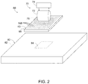
図2及び3は、本開示による、システム及び/又は方法を利用して形成可能な熱可塑性パッチパネル90とともに利用可能な熱可塑性修理システム68の例を示す概略図である。図2及び3に示すように、熱可塑性修理システム68は、熱可塑性パッチパネル90を誘導加熱するよう構成された誘導加熱アセンブリ70を含む。具体的な一例において、誘導加熱アセンブリ70は、電磁石72と電源74とを含む。電源74は、電磁石72に対して、交流電流又は高周波交流電流を供給するよう構成することができる。図2に示すように、電磁石72は、交流電流を受けて、磁場、すなわち高周波磁場76を生成することができる。磁場76は、熱可塑性パッチパネル90の熱可塑性ボディ40に埋設された複数本168の長状サセプタ内に電流を誘導することにより、熱可塑性パッチパネルを加熱することができる。
2 and 3 are schematic views showing an example of a
その後、図2に示す構成から図3に示す構成への移行によって示すように、熱可塑性パッチパネル90が、基礎構造体80に取り付けられるか、或いはこれに接触する。熱可塑性パッチパネル90は、冷却されると、基礎構造体80に接合及び/又は付着する。いくつかの例においては、図2に破線で示すように、基礎構造体80は、損傷領域84を含みうる。いくつかのこのような例においては、図3に示すように、熱可塑性パッチパネル90を利用して、損傷領域84を覆ったり修理したりしてもよい。
The
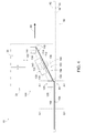
図4及び5は、本開示による、熱可塑性ボディ40に一本168の長状サセプタ154を埋設するためのシステム10の例を示す概略図である。図4及び5に示すように、システム10は、取付ツール100と、並進構造体20と、コントローラ30とを含む。取付ツール100は、長状サセプタ154を誘導するよう構成されたガイド構造体110を含む。取付ツール100はまた、熱可塑性ボディ40のボディ表面42に接触するよう構成されたボディ接触構造体120を含む。取付ツール100は、加熱構造体130をさらに含み、当該加熱構造体は、例えば、長状サセプタ154の被加熱部分164を形成及び/又は生成するために、長状サセプタのセグメント163を加熱するよう構成されている。
4 and 5 are schematic views showing an example of a
並進構造体20は、取付ツール100及び熱可塑性ボディ40を、相対的に、及び/又は、長状サセプタ154の埋設経路60に沿って、機能的に並進させるよう構成されている。コントローラ30は、システム10の少なくとも一部の動作を制御するよう適合、構成、設計、及び/又はプログラムされている。例として、コントローラ30は、取付ツール100及び/又は並進構造体20の動作を制御するようプログラムされてもよい。これは、本明細書で詳述される方法200における任意の適切なステップに従って、及び/又はこれを利用して、システム10の一部の動作を制御することを含みうる。
The
システム10の動作中、図8の方法200を参照して本明細書で詳述するように、また、図4及び5に示すように、ガイド構造体110から、及び/又はボディ接触構造体120へ向かって、長状サセプタ154を延ばして、当該長状サセプタの延伸部分156が、ガイド構造体とボディ接触構造体との間に延在するようにしてもよい。さらに、加熱構造体130は、長状サセプタ154のセグメント163を加熱して、当該長状サセプタの被加熱部分164を形成及び/又は生成することができる。セグメント163及び被加熱部分164は、延伸部分156の一部である。言い換えれば、加熱構造体130は、延伸部分156の少なくとも一部を加熱するよう構成することができる。さらに、ボディ接触構造体120は、熱可塑性ボディ40のボディ表面42を介して、当該熱可塑性ボディ内に被加熱部分164の先頭領域166を押し込むことができる。
During operation of the
被加熱部分164は、熱可塑性ボディ40の溶融温度よりも高いセグメント温度まで加熱されうる。このため、被加熱部分164と熱可塑性ボディ40との間の接触により、熱エネルギーが、当該被加熱部分から熱可塑性ボディに伝達され、この結果として、熱可塑性ボディの溶融領域44が溶融される。
The
これと同時に、ガイド構造体110、ボディ接触構造体120、及び/又は取付ツール100が、熱可塑性ボディ40に対して、及び/又は長状サセプタ154の埋設経路60に沿って機能的に並進される。この処理により、一本168の長状サセプタ154が、熱可塑性ボディ40内に、及び/又は埋設経路60に沿って埋設される。言い換えれば、熱可塑性ボディ40に対して、ガイド構造体110、ボディ接触構造体120、及び/又は取付ツール100を機能的に並進させる間、長状サセプタ154は、ガイド構造体110、及び/又はボディ接触構造体120から連続的に延伸されるとともに、加熱構造体130によって加熱され、これによって、一本168の長状サセプタが、埋設経路60に沿って熱可塑性ボディ40に埋設される。
At the same time, the
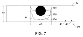
図4及び5の線A−Aに沿った概略断面図である図6に示すように、ボディ表面42を介して、及び/又は熱可塑性ボディ40内に長状サセプタ154を押し込むことにより、熱可塑性材料48の変位部分50が形成及び/又は生成される。変位部分50により、熱可塑性ボディ40のボディ表面42に許容できない粗さ及び/又は凹凸が生じる可能性がある。この点を考慮して、図6に示す構成から、図4及び5に示す線B−Bに沿った概略断面図である図7に示す構成への移行によって示されるように、ボディ接触構造体120は、ボディ表面上を機能的に並進しながら、ボディ表面42を平滑化することができる。
As shown in FIG. 6, which is a schematic cross-sectional view taken along the line AA of FIGS. 4 and 5, heat is generated by pushing the
より概括的に図4及び5を再び参照すると、ガイド構造体110は、ボディ接触構造体120へ、及び/又は埋設経路60に沿って、長状サセプタ154を案内及び/又は誘導するよう適合、構成、設計、及び/又は構築された任意の適切な構造を含みうる。これは、ボディ表面42へ向かって、及び/又はこれに接触するように長状サセプタ154を正確に誘導して、熱可塑性ボディ40に複数本168の長状サセプタを正確に埋設することを可能及び/又は容易にすることを含みうる。ガイド構造体110の例には、チューブ112及び/又はチャネル114が含まれる。
With reference to FIGS. 4 and 5 more generally, the
ボディ接触構造体120は、ボディ表面42に接触したり、ボディ表面42を介して熱可塑性ボディ40に長状サセプタ154を押し込んだり、ボディ表面42を平滑化したりするよう適合、構成、設計、及び/又は構築された任意の適切な構造を含みうる。これは、ボディ表面42を介して長状サセプタ154を正確に誘導して、熱可塑性ボディ40に複数本168の長状サセプタ154を正確に埋設することを可能及び/又は容易にすることを含みうる。ボディ接触構造体120の例には、ボディ接触面、平滑面、円弧面、及び/又はローラが含まれる。いくつかの例において、ボディ接触面120は、長状サセプタ154を受容及び/又は誘導するよう構成可能な溝126を含みうる。いくつかのこのような例において、ボディ接触構造体120は、溝付ボディ接触面、溝付平滑面、溝付円弧面、及び/又は溝付ローラを含みうる。
The
取付ツール100のいくつかの例においては、図4に示すように、ボディ接触構造体120は、単一のボディ接触構造体120を含みうる。単一のボディ接触構造体120は、ガイド構造体110から長状サセプタ154の延伸部分156を受容して、ボディ表面42を介して先頭領域166を押し込むとともに、ボディ表面42を平滑化するよう構成することができる。
In some examples of the mounting
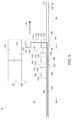
取付ツール100のいくつかの例においては、図5に示すように、ボディ接触構造体120は、先頭ボディ接触構造体122と、当該先頭ボディ接触構造体から離間した後方ボディ接触構造体124とを含む。いくつかのこのような例において、ガイド構造体110は、先頭ボディ接触構造体を含みうる。
In some examples of the mounting
いくつかのこのような例において、ガイド構造体110は、先頭ボディ接触構造体122から分離、区別、及び/又は離間していてもよい。これらの例において、長状サセプタ154の延伸部分156の先頭領域160は、ガイド構造体110と先頭ボディ接触構造体122との間に延在していてもよく、長状サセプタ154の延伸部分156の後方領域162は、先頭ボディ接触構造体122と後方ボディ接触構造体124との間に延在していてもよい。これらの例において、先頭ボディ接触構造体122は、ボディ表面42を介して、及び/又は熱可塑性ボディ40内に、長状サセプタ154を押し込んでもよく、後方ボディ接触構造体124は、ボディ表面42を平滑化してもよい。
In some such examples, the
加熱構造体130は、長状サセプタ154のセグメント163を加熱したり、長状サセプタ154の被加熱部分164を形成及び/又は生成したりするよう適合、構成、設計、及び/又は構築された任意の適切な構造を含みうる。いくつかの例において、加熱構造体130は、長状サセプタ154のセグメント163を電気的に加熱するよう構成されてもよい。一例として、加熱構造体130は、例えば、長状サセプタのセグメント163を抵抗加熱するために、長状サセプタ154のセグメント163に電流134を供給するよう構成された電力源132を含みうる。いくつかのこのような例において、電流134は、長状サセプタ154内において、ガイド構造体110とボディ接触構造体120との間、ガイド構造体110と先頭ボディ接触構造体122との間、及び/又は先頭ボディ接触構造体122と後方ボディ接触構造体124との間を流れる。
The
いくつかの例において、加熱構造体130は、長状サセプタ154のセグメント163を誘導加熱するよう構成される。一例として、加熱構造体130は、電磁石136と、高周波交流電源140とを含んでもよい。このような例において、高周波交流電源140は、電磁石136に高周波交流電流を供給するよう構成されてもよく、電磁石136は、高周波交流電流を受けて、高周波電磁場138を生成してもよい。高周波電磁場は、長状サセプタ154のセグメント163内に電流を誘導することにより、当該長状サセプタのセグメントを加熱することができる。
In some examples, the
図4及び5に破線で示すように、取付ツール100は、長状サセプタ源150を含んでもよいし、これに関連付けられてもよい。長状サセプタ源150が設けられる場合、当該長状サセプタ源150は、ガイド構造体110に長状サセプタ154を供給するよう構成することができる。長状サセプタ源150の例には、長状サセプタ材料のスプール152が含まれる。
As shown by the dashed lines in FIGS. 4 and 5, the mounting
並進構造体20は、取付ツール100及び熱可塑性ボディ40を互いに対して機能的に並進、移動、及び/又は回転させるよう適合、構成、設計、及び/又は構築された任意の適切な構造を含みうる。これは、熱可塑性ボディ40に対する取付ツール100の機能的な並進、移動、及び/又は回転を含んでもよいし、取付ツール100に対する熱可塑性ボディ40の機能的な並進、移動、及び/又は回転を含んでもよい。並進構造体20の例には、モータ、電気モータ、ステッパモータ、ギアアセンブリ、リニアアクチュエータ、回転アクチュエータ、並進ステージ(translation stage)、2次元並進ステージ、及び/又は3次元並進ステージが含まれる。
The
コントローラ30は、取付ツール100及び/又は並進構造体20などの、システム10における少なくとも1つの他のコンポーネントの動作を制御するよう適合、構成、設計、及び/又はプログラムされた任意の適切な構造を含みうる。これは、本明細書で詳述される方法200における任意の適切なステップに従って、システム10の少なくとも1つの他のコンポーネントを制御することを含みうる。コントローラ30の例には、電子コントローラ、専用コントローラ、特殊用途コントローラ、パーソナルコンピュータ、特殊用途コンピュータ、ディスプレイデバイス、ロジックデバイス、メモリデバイス、及び/又はコンピュータ可読記憶媒体を有するメモリデバイスが含まれる。
The
コンピュータ可読記憶媒体が設けられる場合、本明細書において、当該媒体は、非一時的コンピュータ可読記憶媒体とも呼ばれる。この非一時的コンピュータ可読記憶媒体は、コンピュータにより実行可能な命令、プログラム、及び/又はコードを包含、定義、格納、及び/又は保存していてもよく、これらのコンピュータ実行可能命令は、方法200における任意の適切な部分又は組の実行をシステム10に指示するものであってもよい。このような非一時的コンピュータ可読記憶媒体の例には、CD−ROM、ディスク、ハードドライブ、フラッシュメモリなどが含まれる。本明細書において、コンピュータ実行可能命令を有するストレージ、メモリ、デバイス、及び/又は媒体、並びに、本開示による、コンピュータで実施可能な方法及びその他の方法は、米国特許法の第101条に従って特許可能とみなされる要旨の範囲内であると考えられる。
When a computer-readable storage medium is provided, the medium is also referred to herein as a non-temporary computer-readable storage medium. This non-temporary computer-readable storage medium may contain, define, store, and / or store instructions, programs, and / or codes that can be executed by a computer, and these computer-executable instructions are described in
熱可塑性ボディ40は、複数本168の長状サセプタ154を受容可能な、及び/又は熱可塑性パッチパネル90に利用可能な、任意の適切な構造体及び/又は材料を含みうる。熱可塑性ボディ40の例には、熱可塑性材料48のシートが含まれる。熱可塑性ボディ40は、任意の適切な熱可塑性材料48を含んでもよいし、これによって形成されてよく、そのような熱可塑性材料の例としては、ポリマー材料やポリエーテルエーテルケトンが含まれる。
The
いくつかの例において、熱可塑性ボディ40の厚みは、ボディ表面42に垂直な方向で測定した場合、比較的薄い。例えば、図6及び7に示すように、熱可塑性ボディ40の厚み52は、少なくとも0.01ミリメートル(mm)、少なくとも0.02mm、少なくとも0.03mm、少なくとも0.04mm、少なくとも0.05mm、少なくとも0.075mm、少なくとも0.1mm、少なくとも0.2mm、少なくとも0.3mm、少なくとも0.4mm、少なくとも0.5mm、最大で2.5mm、最大で2mm、最大で1.5mm、最大で1mm、最大で0.9mm、最大で0.8mm、最大で0.7mm、最大で0.6mm、最大で0.5mm、最大で0.4mm、最大で0.3mm、最大で0.2mm、最大で0.1mm、及び/又は最大で0.05mmであってもよい。
In some examples, the thickness of the
いくつかの例において、厚み52は、長状サセプタ154の直径などの、最大サセプタ横断面長158の閾値倍よりも小さくてもよい。閾値倍の例には、10倍、8倍、6倍、5倍、4倍、3倍、2倍、1.5倍、又は1倍が含まれる。
In some examples, the
長状サセプタ154は、ガイド構造体110とボディ接触構造体120との間に延在し、加熱構造体130によって加熱され、及び/又はボディ接触構造体120によりボディ表面42を介して押圧される、任意の適切な構造体及び/又は材料を含みうる。いくつかの例において、長状サセプタ154は、高周波磁場を吸収するとともに、当該磁場により熱を発生させるよう構成されたサセプタ材料を含んでもよいし、これによって形成されてよい。いくつかの例において、長状サセプタ154は、導電性材料、金属、及び/又は強磁性材料を含みうる。いくつかの例において、長状サセプタ154は、長状ワイヤを含みうる。いくつかのこのような例において、長状ワイヤは、当該長状ワイヤの外面を覆う電気絶縁体を含みうる。電気絶縁体の例には、誘電材料及び/又はポリマーが含まれる。
The
図8は、本開示による、熱可塑性ボディに長状サセプタを埋設するための方法200を示すフローチャートである。方法200は、210において長状サセプタを延伸させることと、220において長状サセプタのセグメントを加熱することとを含む。方法200はまた、230において長状サセプタの被加熱部分における先頭領域を押圧することと、240において埋設経路に沿って機能的に並進させることとを含む。方法200はまた、250において溶融領域を冷却すること、及び/又は260において方法の少なくとも一部を繰り返すことを含みうる。
FIG. 8 is a flowchart showing a
210において長状サセプタを延伸させることは、取付ツールのガイド構造体から、及び/又は取付ツールのボディ接触構造体に向かって、長状サセプタを延伸させることを含みうる。これは、長状サセプタの延伸部分がガイド構造体とボディ接触構造体との間に延在するように、長状サセプタを延伸させることを含みうる。いくつかの例において、210における延伸は、長状サセプタ源から延伸させることを含みうる。長状サセプタ源の例は、図4及び5に示す長状サセプタ源150を参照して本明細書に開示されている。長状サセプタの例は、図4〜7に示す長状サセプタ154を参照して本明細書に開示されている。ガイド構造体の例は、図4及び5に示すガイド構造体110を参照して本明細書に開示されている。
Stretching the elongated susceptor at 210 may include stretching the elongated susceptor from the guide structure of the mounting tool and / or towards the body contact structure of the mounting tool. This may include stretching the elongated susceptor such that the stretched portion of the elongated susceptor extends between the guide structure and the body contact structure. In some examples, stretching at 210 may include stretching from an elongated susceptor source. Examples of elongated susceptor sources are disclosed herein with reference to the elongated
いくつかの例において、240において機能的に並進させる間、又は少なくとも機能的に並進させる間、210における延伸は、長状サセプタの延伸部分を、その長軸に沿って連続的に移動させることを含みうる。言い換えれば、連続的に移動させることは、取付ツールに対して長状サセプタの延伸部分を連続的に移動させることを含みうる。さらに言い換えれば、210における延伸は、例えば230における押圧の工程中に、長状サセプタの所定領域が熱可塑性ボディに埋設される前に、当該長状サセプタの所定領域を、ガイド構造体からボディ接触構造体に搬送することを含みうる。 In some examples, while functionally translating at 240, or at least functionally translating, stretching at 210 causes the stretched portion of the elongated susceptor to move continuously along its long axis. Can include. In other words, continuous movement may include continuously moving the stretched portion of the elongated susceptor with respect to the mounting tool. In other words, stretching at 210 brings the predetermined region of the elongated susceptor into body contact from the guide structure, for example, during the pressing step at 230, before the predetermined region of the elongated susceptor is embedded in the thermoplastic body. It may include transporting to a structure.
いくつかの例において、ボディ接触構造体は、後方ボディ接触構造体と、当該後方ボディ接触構造体から離間した先頭ボディ接触構造体とを含みうる。後方ボディ接触構造体、及び先頭ボディ接触構造体の例は、図5に示す後方ボディ接触構造体124、及び先頭ボディ接触構造体122を参照して本明細書に開示されている。いくつかのこのような例において、ガイド構造体は、先頭ボディ接触構造体を含む。
In some examples, the body contact structure may include a rear body contact structure and a leading body contact structure separated from the rear body contact structure. Examples of the rear body contact structure and the head body contact structure are disclosed herein with reference to the rear
このような例において、先頭ボディ接触構造体は、ガイド構造体とは区別されていてもよいし、離間していてもよい。このような例において、210における延伸は、長状サセプタの延伸部分における先頭領域を、ガイド構造体から先頭ボディ接触構造体まで延伸させることを含みうる。このような例において、210における延伸は、上記構成に加えて、又はこれに代えて、長状サセプタの延伸部分の後方領域を、先頭ボディ接触構造体から後方ボディ接触構造体まで延伸させることを含みうる。いくつかのこのような例において、230における押圧は、先頭ボディ接触構造体で押圧することを含みうる。いくつかのこのような例において、240における機能的な並進は、後方ボディ接触構造体を使用してボディ表面を平滑化することを含みうる。 In such an example, the head body contact structure may be distinct or separated from the guide structure. In such an example, stretching at 210 may include stretching the head region in the stretched portion of the elongated susceptor from the guide structure to the head body contact structure. In such an example, stretching at 210, in addition to or instead of the above configuration, stretches the posterior region of the stretched portion of the elongated susceptor from the head body contact structure to the rear body contact structure. Can include. In some such examples, pressing at 230 may include pressing with a head body contact structure. In some such examples, functional translation in 240 may include smoothing the body surface using a rear body contact structure.
長状サセプタの延伸部分は、ガイド構造体とボディ接触構造体との間、ガイド構造体と先頭ボディ接触構造体との間、ガイド構造体と後方ボディ接触構造体との間、及び/又は先頭ボディ接触構造体と後方ボディ接触構造体との間などで測定される延伸部分長を有するか、或いはこれを規定してもよい。延伸部分長の例には、少なくとも0.5mm、少なくとも1mm、少なくとも2mm、少なくとも3mm、少なくとも4mm、少なくとも5mm、少なくとも6mm、少なくとも7mm、少なくとも8mm、少なくとも9mm、少なくとも10mm、最大で25mm、最大で20mm、最大で18mm、最大で16mm、最大で14mm、最大で12mm、最大で10mm、最大で8mm、及び/又は最大で6mmの長さが含まれる。いくつかの例において、延伸部分は、アスペクト比を有するか、或いはこれを規定しており、このアスペクト比は、長状サセプタの、直径及び/又は特徴的な直径などの、特徴的な横断面長に対する延伸部分長の比として規定される。アスペクト比の例には、少なくとも5、少なくとも10、少なくとも15、少なくとも20、少なくとも25、少なくとも30、少なくとも35、少なくとも40、少なくとも45、少なくとも50、最大で100、最大で90、最大で80、最大で70、最大で60、最大で50、最大で40、最大で30、最大で20、及び/又は最大で10のアスペクト比が含まれる。 The stretched portion of the elongated susceptor is between the guide structure and the body contact structure, between the guide structure and the head body contact structure, between the guide structure and the rear body contact structure, and / or the head. It may have or may have a stretched portion length measured, such as between the body contact structure and the rear body contact structure. Examples of stretched portion lengths are at least 0.5 mm, at least 1 mm, at least 2 mm, at least 3 mm, at least 4 mm, at least 5 mm, at least 6 mm, at least 7 mm, at least 8 mm, at least 9 mm, at least 10 mm, up to 25 mm, up to 20 mm. Includes lengths up to 18 mm, up to 16 mm, up to 14 mm, up to 12 mm, up to 10 mm, up to 8 mm, and / or up to 6 mm. In some examples, the stretched portion has or defines an aspect ratio, which is the characteristic cross-section of the elongated susceptor, such as diameter and / or characteristic diameter. It is defined as the ratio of the stretched portion length to the length. Examples of aspect ratios are at least 5, at least 10, at least 15, at least 20, at least 25, at least 30, at least 35, at least 40, at least 45, at least 50, up to 100, up to 90, up to 80, up. Includes 70, up to 60, up to 50, up to 40, up to 30, up to 20, and / or up to 10 aspect ratios.
210における延伸は、方法200における任意の適切なタイミング及び/又は順序で実行することができる。例えば、210における延伸は、220における加熱、230における押圧、240における機能的な並進、及び/又は250における冷却と少なくとも部分的に同時に、及び/又はこれらの間に実行することができる。
Stretching at 210 can be performed at any suitable timing and / or sequence in
220において長状サセプタのセグメントを加熱することは、長状サセプタのセグメントを、熱可塑性ボディの溶融温度よりも高いセグメント温度まで加熱することを含みうる。これに加えて、又はこれに代えて、220における加熱は、長状サセプタのセグメントを加熱して、当該長状サセプタの被加熱部分を形成及び/又は生成することを含んでもよい。長状サセプタの被加熱部分は、長状サセプタの延伸部分の一部を含みうる。言い換えれば、220における加熱は、長状サセプタの延伸部分における任意の領域を加熱することを含みうる。 Heating the segment of the elongated susceptor at 220 may include heating the segment of the elongated susceptor to a segment temperature higher than the melting temperature of the thermoplastic body. In addition to or instead of this, heating at 220 may include heating a segment of the elongated susceptor to form and / or produce a heated portion of the elongated susceptor. The heated portion of the elongated susceptor may include a portion of the stretched portion of the elongated susceptor. In other words, heating at 220 may include heating any region in the stretched portion of the elongated susceptor.
220における加熱は、任意の適切な態様で実現可能である。例えば、220における加熱は、図4及び5に示す加熱構造体130などの、加熱構造体を使用して、介して、及び/又は利用して加熱することを含みうる。いくつかのこのような例において、加熱構造体は、ボディ接触構造体とは離間及び/又は区別されてもよい。
The heating in 220 is feasible in any suitable manner. For example, heating in 220 may include heating through and / or utilizing a heating structure, such as the
いくつかの例においては、上述したように、長状サセプタは、当該長状サセプタの外面を覆う電気絶縁体を含みうる。このような例において、220における加熱は、電気絶縁体を溶融することなく加熱することを含みうる。 In some examples, as described above, the elongated susceptor may include an electrical insulator covering the outer surface of the elongated susceptor. In such an example, heating at 220 may include heating the electrical insulator without melting.
220における加熱は、方法200における任意の適切なタイミング及び/又は順序で実行可能である。例えば、220における加熱は、210における延伸、230における押圧、240における機能的な並進、及び/又は250における冷却と少なくとも部分的に同時に、及び/又はこれらの間に実行することができる。
The heating in 220 can be performed at any suitable timing and / or sequence in
いくつかの例において、220における加熱は、長状サセプタのセグメントを電気的に加熱することを含みうる。いくつかのこのような例において、電気的に加熱することは、例えば、長状サセプタのセグメントに電流を供給して、長状サセプタのセグメントを抵抗加熱することを含みうる。いくつかのこのような例において、加熱構造体は、長状サセプタのセグメントに電流を供給するよう構成された電源を含みうる。いくつかのこのような例において、220における加熱は、ガイド構造体とボディ接触構造体との間、及び/又は先頭ボディ接触構造体と後方ボディ接触構造体との間において、長状サセプタのセグメントに電流を流すことを含みうる。 In some examples, heating at 220 may include electrically heating a segment of the elongated susceptor. In some such examples, electrical heating may include, for example, applying an electric current to the segment of the elongated susceptor to resist heat the segment of the elongated susceptor. In some such examples, the heating structure may include a power source configured to supply an electric current to a segment of the elongated susceptor. In some such examples, heating at 220 is a segment of the elongated susceptor between the guide structure and the body contact structure and / or between the front body contact structure and the rear body contact structure. Can include passing an electric current through.
いくつかの例において、220における加熱は、長状サセプタのセグメントを誘導加熱することを含みうる。いくつかのこのような例において、誘導加熱は、長状サセプタのセグメントに高周波電磁場を印加することを含みうる。いくつかのこのような例において、加熱アセンブリは、電磁石と、高周波交流電源とを含みうる。いくつかのこのような例において、220における加熱は、高周波交流電源を使用して、電磁石に高周波電流を供給することと、前記高周波電流を受けて、電磁石を使用して高周波電磁場を生成することとを含みうる。 In some examples, heating at 220 may include induction heating a segment of elongated susceptor. In some such examples, induction heating may include applying a high frequency electromagnetic field to the segment of the elongated susceptor. In some such examples, the heating assembly may include an electromagnet and a high frequency AC power supply. In some such examples, heating at 220 uses a high frequency AC power source to supply a high frequency current to the electromagnet and receives the high frequency current to generate a high frequency electromagnetic field using the electromagnet. And can be included.
いくつかの例において、220における加熱は、閾値加熱時間よりも短い時間で、周囲温度から及び/又はセグメント温度まで、長状サセプタのセグメントを加熱することを含みうる。閾値加熱時間の例には、少なくとも0.01秒、少なくとも0.05秒、少なくとも0.1秒、少なくとも0.2秒、少なくとも0.3秒、少なくとも0.4秒、少なくとも0.5秒、少なくとも0.6秒、少なくとも0.7秒、少なくとも0.8秒、少なくとも0.9秒、少なくとも1秒、最大で5秒、最大で4秒、最大で3秒、最大で2秒、最大で1.5秒、最大で1秒、最大で0.8秒、及び/又は、最大で0.6秒の閾値加熱時間が含まれる。このように長状サセプタのセグメントを比較的急速に加熱することにより、取付ツールの残り部分、及び/又は熱可塑性ボディを不要に及び/又は予想外に加熱する可能性を低減し、熱可塑性ボディが変形する可能性を低減することができる。 In some examples, heating at 220 may include heating the segment of the elongated susceptor from ambient temperature and / or to segment temperature in a time shorter than the threshold heating time. Examples of threshold heating times are at least 0.01 seconds, at least 0.05 seconds, at least 0.1 seconds, at least 0.2 seconds, at least 0.3 seconds, at least 0.4 seconds, at least 0.5 seconds, At least 0.6 seconds, at least 0.7 seconds, at least 0.8 seconds, at least 0.9 seconds, at least 1 second, up to 5 seconds, up to 4 seconds, up to 3 seconds, up to 2 seconds, up to Includes threshold heating times of 1.5 seconds, up to 1 second, up to 0.8 seconds, and / or up to 0.6 seconds. This relatively rapid heating of the segment of the elongated susceptor reduces the possibility of unnecessary and / or unexpected heating of the rest of the mounting tool and / or the thermoplastic body. Can be reduced from the possibility of deformation.
230において長状サセプタの被加熱部分における先頭領域を押圧することは、熱可塑性ボディのボディ表面を介して、及び/又は熱可塑性ボディに、先頭領域を押し込むことを含みうる。230における押圧は、少なくとも部分的に、或いは完全に、熱可塑性ボディに先頭領域を埋設することを含みうる。これに加えて、又はこれに代えて、230における押圧は、少なくとも部分的に、或いは完全に、熱可塑性ボディに先頭領域を封入することを含みうる。 Pressing the head region in the heated portion of the elongated susceptor at 230 may include pushing the head region through and / or into the thermoplastic body through the body surface of the thermoplastic body. Pressing at 230 may include, at least partially or completely, embedding a leading region in the thermoplastic body. In addition to, or in lieu of, the pressing at 230 may include at least partially or completely enclosing the head region in the thermoplastic body.
230における押圧は、任意の適切な態様で実現可能である。一例として、230における押圧は、ボディ接触構造体及び/又は先頭ボディ接触構造体が設けられている場合、これらを使用して、介して、及び/又は利用して、押圧することを含みうる。 The pressing at 230 can be realized in any suitable manner. As an example, pressing at 230 may include pressing through and / or utilizing body contact structures and / or head body contact structures, if provided.
いくつかの例において、230における押圧は、長状サセプタの被加熱部分からの熱伝達、及び/又は熱可塑性ボディ内への熱伝達を介するなどして、熱可塑性ボディの溶融領域を溶融することを含みうる。溶融領域の例は、図4〜7に示す溶融領域44を参照して本明細書に開示されている。いくつかの例において、溶融領域は、比較的小さくてもよいし、溶融領域の少なくとも1つの寸法は、長状サセプタの対応する寸法に相当していてもよい。
In some examples, the pressing at 230 melts the molten region of the thermoplastic body, such as through heat transfer from the heated portion of the elongated susceptor and / or heat transfer into the thermoplastic body. Can include. Examples of melted regions are disclosed herein with reference to the melted
一例として、溶融領域は、例えば、溶融領域の長軸に垂直に測定される最大溶融領域横断面長(maximum melt region transverse cross-sectional extent)を有するか、或いはこれを規定していてもよい。最大溶融領域横断面長の例は、図6及び7において符号46で示されている。同様に、長状サセプタの被加熱部分における先頭領域は、最大サセプタ横断面長を規定していてもよく、当該横断面長は、溶融領域の長軸、及び/又は長状サセプタの長軸に垂直に測定される。最大サセプタ横断面長の例は、図6及び7において符号158で示されている。このような例において、溶融は、最大サセプタ横断面長に対する最大溶融領域横断面長の比が、少なくとも1.1、少なくとも1.25、少なくとも1.5、少なくとも1.75、少なくとも2、最大で5、最大で4、最大で3、最大で2.5、最大で2、及び/又は最大で1.5である溶融を含みうる。言い換えれば、230における押圧により、熱可塑性ボディの一部のみが局所的に溶融されるため、熱可塑性ボディの損傷や熱可塑性ボディの変形が生じる可能性を低減することができる。これに加えて、又はこれに代えて、局所的に溶融することにより、熱可塑性ボディの厚みが、最大サセプタ横断面長の閾値倍よりも小さい場合であっても、熱可塑性ボディに長状サセプタを埋設することが可能になる。閾値倍の例は、本明細書に開示されている。
As an example, the melt region may, for example, have or specify a maximum melt region transverse cross-sectional extent, which is measured perpendicular to the long axis of the melt region. An example of the maximum melt region cross-sectional length is indicated by
230における押圧は、方法200における任意の適切なタイミング及び/又は順序で実行可能である。例えば、230における押圧は、210における延伸、220における加熱、240における機能的な並進、及び/又は250における冷却と少なくとも部分的に同時に、及び/又はこれらの間に実行することができる。
The presses at 230 can be performed at any suitable timing and / or sequence in
240において埋設経路に沿って機能的に並進させることは、長状サセプタの埋設経路に沿って、ガイド構造体、ボディ接触構造体、及び/又は取付ツールを機能的に並進させることを含みうる。埋設経路は、熱可塑性ボディのボディ表面に沿って規定されてもよいし、熱可塑性ボディ内の、長状サセプタに適した好ましい位置、又は長状サセプタの埋設長に適した好ましい位置を規定していてもよい。埋設経路の例は、図4及び5に示す埋設経路60を参照して本明細書に開示されている。240における機能的な並進は、並進構造体を使用して、介して、及び/又は利用して機能的に並進させることを含みうる。このような並進構造体の例は、図4及び5に示す並進構造体20を参照して本明細書に開示されており、任意の適切な態様で実現可能である。例えば、240における機能的な並進は、熱可塑性ボディに対して取付ツールを移動させること、及び/又は取付ツールに対して熱可塑性ボディを移動させることを含む。
Functional translation along the burial path at 240 may include functional translation of the guide structure, body contact structure, and / or mounting tool along the burial path of the elongated susceptor. The burial path may be defined along the body surface of the thermoplastic body, or may define a preferred location within the thermoplastic body for the elongated susceptor, or a preferred location for the burial length of the elongated susceptor. May be. Examples of buried routes are disclosed herein with reference to the buried
240における機能的な並進は、上記構成に加えて、又はこれに代えて、ボディ接触構造体などを使用して、ボディ表面を平滑化することを含んでもよい。一例として、図6に示すとともに、同図を参照して本明細書で詳述するように、230における押圧は、熱可塑性材料の一部を変位させて、例えば変位部分50などの、熱可塑性ボディのボディ表面から、及び/又はその上方から延びる変位部分を形成してもよい。このような例においては、平滑化は、図6に示す構成から図7に示す構成に示すように、熱可塑性材料の変位部分を少なくとも部分的に平面化すること、熱可塑性ボディのボディ表面を少なくとも部分的に平坦化すること、及び/又は熱可塑性ボディのボディ表面に向かって熱可塑性材料の変位部分を押圧することを含みうる。
The functional translation in 240 may include, in addition to, or in lieu of, smoothing the body surface using a body contact structure or the like. As an example, as shown in FIG. 6 and as detailed herein with reference to the same figure, the pressing at 230 displaces a portion of the thermoplastic material and is thermoplastic, for example the
240における機能的な並進は、方法200における任意の適切なタイミング及び/又は順序で実行可能である。例えば、240における機能的な並進は、210における延伸、220における加熱、230における押圧、及び/又は250における冷却と少なくとも部分的に同時に、及び/又はこれらの間に実行することができる。
The functional translation in 240 can be performed in any suitable timing and / or order in
250における溶融領域の冷却は、溶融領域を冷却して、溶融領域を硬化させること、及び/又は熱可塑性ボディに埋設された一本の長状サセプタを維持することを含みうる。250における冷却は、任意の適切な態様で実現可能であり、例えば、溶融領域から、熱可塑性ボディを囲む周囲環境、及び/又は熱可塑性ボディ内部への熱エネルギーの自然対流、強制対流、及び/又は伝達などによって実現可能である。 Cooling the melt region at 250 may include cooling the melt region to cure the melt region and / or maintaining a single elongated susceptor embedded in the thermoplastic body. Cooling at 250 is feasible in any suitable manner, eg, natural convection, forced convection, and / or natural convection of thermal energy from the molten region into the ambient environment surrounding the thermoplastic body and / or into the interior of the thermoplastic body. Or it can be realized by transmission or the like.
250における冷却は、方法200における任意の適切なタイミング及び/又は順序で実行可能である。例えば、250における冷却は、210における延伸、220における加熱、230における押圧、及び/又は240における機能的な並進と少なくとも部分的に同時に、及び/又はこれらの間に実行することができる。これに加えて、又はこれに代えて、熱可塑性ボディにおける所与の溶融領域に関して、250における冷却は、230における押圧の後、及び/又は平滑化した後に実行してもよい。
Cooling at 250 can be performed at any suitable timing and / or sequence in
260における方法の少なくとも一部の繰り返しは、任意の適切な順序で方法200の任意の適切な1つ以上のステップを繰り返すことを含みうる。例えば、260における繰り返しは、熱可塑性材料に対して、及び/又はこの内部に複数本の長状サセプタを埋設するために、210における延伸、220における加熱、230における押圧、240における機能的な並進、及び/又は250における冷却を複数回繰り返すことを含む。いくつかのこのような例において、260における繰り返しは、長状サセプタを切断して、熱可塑性材料に対して、及び/又はこの内部に、複数本の異なる、別個の、及び/又は離間した長状サセプタを埋設することをさらに含む。
At least some iterations of the method in 260 may include repeating any suitable one or more steps of
本明細書において詳述するように、本開示によるシステム及び方法は、従来の処理では困難な状況において、熱可塑性ボディに長状サセプタを埋設すること、及び/又は熱可塑性パッチパネルを形成することを可能及び/又は容易にすることができる。一例として、本開示のシステム及び方法は、所望の誘導加熱特性を有する熱可塑性パッチパネルを形成及び/又は画定するために、所与の熱可塑性ボディ内に複数本の長状サセプタを正確に配置及び/又は位置決めすることを可能及び/又は容易にすることができる。これは、様々な間隔及び/又は様々なサセプタ長で、複数本の長状サセプタを埋設することを含みうる。これに加えて、又はこれに代えて、本開示のシステム及び方法は、熱可塑性ボディに歪み及び/又は変形を生じさせることなく、210における延伸、220における加熱、230における押圧、240における機能的な並進、及び/又は250における冷却の実行を可能及び/又は容易にすることができる。 As detailed herein, the systems and methods according to the present disclosure are to embed an elongated susceptor in a thermoplastic body and / or to form a thermoplastic patch panel in situations where conventional processing is difficult. Can be made possible and / or facilitated. As an example, the systems and methods of the present disclosure precisely place multiple elongated susceptors within a given thermoplastic body to form and / or define a thermoplastic patch panel with the desired induction heating properties. And / or positioning can be possible and / or facilitated. This may include burying multiple elongated susceptors at different intervals and / or different susceptor lengths. In addition to, or in lieu of, the systems and methods of the present disclosure provide stretching at 210, heating at 220, pressing at 230, functional at 240, without causing strain and / or deformation of the thermoplastic body. Translation and / or cooling at 250 can be performed and / or facilitated.
本開示による発明の要旨の例示的且つ非排他的な例は、以下に列記の付記に記載されている。 Illustrative and non-exclusive examples of the gist of the invention according to the present disclosure are set forth in the appendices listed below.
付記A1.熱可塑性ボディに長状サセプタを埋設するための方法であって、
前記長状サセプタを、任意で、取付ツールのガイド構造体から前記取付ツールのボディ接触構造体へと延伸させ、前記長状サセプタの延伸部分が、前記ガイド構造体と前記ボディ接触構造体との間に延在するようにし、
任意で、前記取付ツールの加熱構造体を使用して、前記熱可塑性ボディの溶融温度を超えるセグメント温度まで前記長状サセプタのセグメントを加熱して前記長状サセプタの被加熱部分を形成し、その際、任意の構成として、前記被加熱部分は、前記長状サセプタの前記延伸部分の一部であり、
任意で、前記ボディ接触構造体を使用して、前記長状サセプタの前記被加熱部分における先頭領域を押圧して、前記熱可塑性ボディのボディ表面を介して、前記熱可塑性ボディに前記先頭領域を押し込み、
前記押圧及び前記延伸と同時に、前記長状サセプタの埋設経路に沿って、前記ガイド構造体、前記ボディ接触構造体、及び前記取付ツールのうちの少なくとも1つを機能的に並進させ、その際、任意の構成として、前記埋設経路は、前記ボディ表面に沿って規定されており、さらに、任意の構成として、前記機能的な並進は、任意で前記ボディ接触構造体を使用して、前記ボディ表面を平滑化することを含む、方法。
Appendix A1. A method for embedding a long susceptor in a thermoplastic body.
The elongated susceptor is optionally stretched from the guide structure of the mounting tool to the body contact structure of the mounting tool, and the stretched portion of the elongated susceptor is formed between the guide structure and the body contact structure. Make it extend in between
Optionally, the heating structure of the mounting tool is used to heat the segment of the elongated susceptor to a segment temperature that exceeds the melting temperature of the thermoplastic body to form the heated portion of the elongated susceptor. When, as an arbitrary configuration, the heated portion is a part of the stretched portion of the elongated susceptor.
Optionally, the body contact structure is used to press the head region of the elongated susceptor in the heated portion to provide the head region to the thermoplastic body via the body surface of the thermoplastic body. Push in,
Simultaneously with the pressing and stretching, at least one of the guide structure, the body contact structure, and the mounting tool is functionally translated along the embedding path of the elongated susceptor. As an optional configuration, the burial path is defined along the body surface, and further, as an optional configuration, the functional translation is optionally using the body contact structure to the body surface. A method that involves smoothing.
付記A2.前記延伸は、長状サセプタ源から延伸させることを含む、付記A1に記載の方法。 Appendix A2. The method according to Appendix A1, wherein the stretching comprises stretching from a long susceptor source.
付記A3.前記長状サセプタ源は、長状サセプタ材料のスプールを含む、付記A2に記載の方法。 Appendix A3. The method of Appendix A2, wherein the elongated susceptor source comprises a spool of elongated susceptor material.
付記A4.前記延伸は、少なくとも前記機能的な並進を行う間、前記長状サセプタの長軸に沿って前記長状サセプタの前記延伸部分を連続的に移動させることを含む、付記A1〜A3のいずれかに記載の方法。 Appendix A4. The stretching is one of Supplementary A1 to A3, which comprises continuously moving the stretched portion of the elongated susceptor along the major axis of the elongated susceptor, at least during the functional translation. The method described.
付記A5.前記連続的な移動は、前記長状サセプタの前記延伸部分を前記取付ツールに対して連続的に移動させることを含む、付記A4に記載の方法。 Appendix A5. The method according to Appendix A4, wherein the continuous movement comprises continuously moving the stretched portion of the elongated susceptor with respect to the mounting tool.
付記A6.前記ガイド構造体は、チューブ及びチャネルのうちの少なくとも一方を含む、付記A1〜A5のいずれかに記載の方法。 Appendix A6. The method according to any of Supplementary A1 to A5, wherein the guide structure comprises at least one of a tube and a channel.
付記A7.前記ガイド構造体は、前記ボディ接触構造体に対して前記長状サセプタを正確に配置するよう構成されている、付記A1〜A6のいずれかに記載の方法。 Appendix A7. The method according to any of Supplementary A1 to A6, wherein the guide structure is configured to accurately arrange the elongated susceptor with respect to the body contact structure.
付記A8.前記ボディ接触構造体は、後方ボディ接触構造体と、当該後方ボディ接触構造体から離間した先頭ボディ接触構造体とを含む、付記A1〜A7のいずれかに記載の方法。 Appendix A8. The method according to any of Supplementary A1 to A7, wherein the body contact structure includes a rear body contact structure and a head body contact structure separated from the rear body contact structure.
付記A9.前記ガイド構造体は、前記ボディ接触構造体を含む、付記A8に記載の方法。 Appendix A9. The method according to Appendix A8, wherein the guide structure includes the body contact structure.
付記A10.前記前方ボディ接触構造体は、前記ガイド構造体とは異なるものであり、前記延伸は、前記長状サセプタの前記延伸部分における先頭領域を前記ガイド構造体から前記先頭ボディ接触構造体まで延伸させることと、前記長状サセプタの前記延伸部分における後方領域を前記先頭ボディ接触構造体から前記後方ボディ接触構造体まで延伸させることと、を含む、付記A8又はA9に記載の方法。 Appendix A10. The front body contact structure is different from the guide structure, and the stretching extends the head region of the stretched portion of the elongated susceptor from the guide structure to the head body contact structure. A8 or A9, wherein the rear region of the stretched portion of the elongated susceptor is stretched from the head body contact structure to the rear body contact structure.
付記A11.前記押圧は、前記先頭ボディ接触構造体を使用して押圧することを含む、付記A10に記載の方法。 Appendix A11. The method of Appendix A10, wherein the pressing comprises using the leading body contact structure for pressing.
付記A12.前記平滑化は、前記後方ボディ接触構造体を使用して平滑化することを含む、付記A10又はA11に記載の方法。 Appendix A12. The method according to Appendix A10 or A11, wherein the smoothing comprises smoothing using the rear body contact structure.
付記A13.前記長状サセプタの前記延伸部分は、延伸部分長を規定している、付記A1〜A12のいずれかに記載の方法。 Appendix A13. The method according to any of Supplementary A1 to A12, wherein the stretched portion of the elongated susceptor defines the stretched portion length.
付記A14.前記延伸は、前記延伸部分長が、
(i)少なくとも0.5ミリメートル(mm)、少なくとも1mm、少なくとも2mm、少なくとも3mm、少なくとも4mm、少なくとも5mm、少なくとも6mm、少なくとも7mm、少なくとも8mm、少なくとも9mm、又は少なくとも10mmになるように延伸させること、及び
(ii)最大で25mm、最大で20mm、最大で18mm、最大で16mm、最大で14mm、最大で12mm、最大で10mm、最大で8mm、又は最大で6mmになるように延伸させること、のうちの少なくともいずれか一方を満たすように延伸させることを含む、付記A13に記載の方法。
Appendix A14. In the stretching, the stretching portion length is
(I) Stretching to at least 0.5 mm (mm), at least 1 mm, at least 2 mm, at least 3 mm, at least 4 mm, at least 5 mm, at least 6 mm, at least 7 mm, at least 8 mm, at least 9 mm, or at least 10 mm. And (ii) stretching to a maximum of 25 mm, a maximum of 20 mm, a maximum of 18 mm, a maximum of 16 mm, a maximum of 14 mm, a maximum of 12 mm, a maximum of 10 mm, a maximum of 8 mm, or a maximum of 6 mm. The method according to Appendix A13, which comprises stretching to satisfy at least one of the above.
付記A15.前記延伸は、延伸部分のアスペクト比が、
(i)少なくとも5、少なくとも10、少なくとも15、少なくとも20、少なくとも25、少なくとも30、少なくとも35、少なくとも40、少なくとも45、又は少なくとも50になるように延伸させること、
(ii)最大で100、最大で90、最大で80、最大で70、最大で60、最大で50、最大で40、最大で30、最大で20、又は最大で10になるように延伸させること、のうちの少なくともいずれか一方を満たすように延伸させることを含む、付記A13又はA14に記載の方法。
Appendix A15. In the stretching, the aspect ratio of the stretched portion is
(I) Stretching to at least 5, at least 10, at least 15, at least 20, at least 25, at least 30, at least 35, at least 40, at least 45, or at least 50.
(Ii) Stretching to a maximum of 100, a maximum of 90, a maximum of 80, a maximum of 70, a maximum of 60, a maximum of 50, a maximum of 40, a maximum of 30, a maximum of 20, or a maximum of 10. The method according to Supplementary A13 or A14, which comprises stretching to satisfy at least one of the above.
付記A16.前記加熱は、前記長状サセプタの前記セグメントを電気的に加熱することを含む、付記A1〜A15のいずれかに記載の方法。 Appendix A16. The method according to any of Supplementary A1 to A15, wherein the heating comprises electrically heating the segment of the elongated susceptor.
付記A17.前記加熱は、前記長状サセプタの前記セグメントに電流を供給して、前記長状サセプタの前記セグメントを抵抗加熱することを含む、付記A16に記載の方法。 Appendix A17. The method according to Appendix A16, wherein the heating comprises supplying an electric current to the segment of the elongated susceptor to resistance-heat the segment of the elongated susceptor.
付記A18.前記加熱構造体は、電力源を含む、付記A16又はA17に記載の方法。 Appendix A18. The method according to Supplementary A16 or A17, wherein the heating structure includes a power source.
付記A19.前記加熱は、任意で前記長状サセプタの前記セグメントを介して、
(i)前記ガイド構造体と前記ボディ接触構造体との間、及び
(ii)先頭ボディ接触構造体と後方ボディ接触構造体との間、のうちの少なくとも一方に電流を流すことを含む、付記A16〜A18のいずれかに記載の方法。
Appendix A19. The heating is optionally via the segment of the elongated susceptor.
Addendum, which comprises passing an electric current between (i) the guide structure and the body contact structure, and (ii) between the front body contact structure and the rear body contact structure. The method according to any one of A16 to A18.
付記A20.前記加熱は、前記長状サセプタの前記セグメントを誘導加熱することを含む、付記A1〜A19のいずれかに記載の方法。 Appendix A20. The method according to any of Supplementary A1 to A19, wherein the heating comprises induction heating the segment of the elongated susceptor.
付記A21.前記加熱は、前記長状サセプタの前記セグメントに高周波電磁場を印加することを含む、付記A20に記載の方法。 Appendix A21. The method according to Appendix A20, wherein the heating comprises applying a high frequency electromagnetic field to the segment of the elongated susceptor.
付記A22.前記加熱アセンブリは、電磁石と高周波交流電源とを含み、前記方法は、前記高周波交流電源を使用して、前記電磁石に高周波電流を供給することと、前記高周波電流を受けて、前記電磁石を使用して高周波電磁場を生成することと、を含む、付記A20又はA21に記載の方法。 Appendix A22. The heating assembly includes an electromagnetic field and a high frequency AC power source, and the method uses the high frequency AC power source to supply a high frequency current to the electric magnet and receives the high frequency current to use the electric magnet. A20 or A21 of the appendix, comprising the generation of a high frequency electromagnetic field.
付記A23.前記加熱アセンブリは、前記ボディ接触構造体から離間している、付記A20〜A22のいずれかに記載の方法。 Appendix A23. The method according to any of Supplementary A20 to A22, wherein the heating assembly is separated from the body contact structure.
付記A24.前記加熱は、閾値加熱時間よりも短い時間で、周囲温度から前記セグメント温度まで前記長状サセプタの前記セグメントを加熱することを含む、付記A1〜A23のいずれかに記載の方法。 Appendix A24. The method according to any of Supplementary A1 to A23, wherein the heating comprises heating the segment of the elongated susceptor from the ambient temperature to the segment temperature in a time shorter than the threshold heating time.
付記A25.前記閾値加熱時間は、
(i)少なくとも0.01秒、少なくとも0.05秒、少なくとも0.1秒、少なくとも0.2秒、少なくとも0.3秒、少なくとも0.4秒、少なくとも0.5秒、少なくとも0.6秒、少なくとも0.7秒、少なくとも0.8秒、少なくとも0.9秒、又は少なくとも1秒、及び
(ii)最大で5秒、最大で4秒、最大で3秒、最大で2秒、最大で1.5秒、最大で1秒、最大で0.8秒、又は最大で0.6秒、のうちのいずれか一方である、付記A1〜A24のいずれかに記載の方法。
Appendix A25. The threshold heating time is
(I) At least 0.01 seconds, at least 0.05 seconds, at least 0.1 seconds, at least 0.2 seconds, at least 0.3 seconds, at least 0.4 seconds, at least 0.5 seconds, at least 0.6 seconds , At least 0.7 seconds, at least 0.8 seconds, at least 0.9 seconds, or at least 1 second, and (ii) up to 5 seconds, up to 4 seconds, up to 3 seconds, up to 2 seconds, up to 2 seconds The method according to any one of the appendices A1 to A24, which is any one of 1.5 seconds, a maximum of 1 second, a maximum of 0.8 seconds, and a maximum of 0.6 seconds.
付記A26.前記押圧は、少なくとも部分的に、或いは完全に、前記熱可塑性ボディに前記長状サセプタの前記被加熱部分における前記先頭領域を埋設することを含む、付記A1〜A25のいずれかに記載の方法。 Appendix A26. The method according to any of Supplementary A1 to A25, wherein the pressing comprises at least partially or completely embedding the leading region of the heated portion of the elongated susceptor in the thermoplastic body.
付記A27.前記押圧は、前記熱可塑性ボディに前記長状サセプタの前記被加熱部分における前記先頭領域を封入することを含む、付記A1〜A26のいずれかに記載の方法。 Appendix A27. The method according to any of Supplementary A1 to A26, wherein the pressing comprises enclosing the head region of the heated portion of the elongated susceptor in the thermoplastic body.
付記A28.前記押圧は、前記長状サセプタの前記被加熱部分からの熱伝達を介して、前記熱可塑性ボディの溶融領域を溶融することを含む、付記A1〜A27のいずれかに記載の方法。 Appendix A28. The method according to any of Supplementary A1 to A27, wherein the pressing comprises melting a molten region of the thermoplastic body via heat transfer from the heated portion of the elongated susceptor.
付記A29.前記平滑化の後に、前記溶融領域を冷却して、前記溶融領域を硬化させるとともに、前記熱可塑性ボディに埋設された一本の長状サセプタを維持することとをさらに含む、付記A28に記載の方法。 Appendix A29. 20. A28, further comprising cooling the melted region to cure the melted region and maintaining a single elongated susceptor embedded in the thermoplastic body after the smoothing. Method.
付記A30.前記溶融領域は、前記溶融領域の長軸に垂直に測定される最大溶融領域横断面長を規定しており、前記長状サセプタの前記被加熱部分における前記先頭領域は、前記溶融領域の前記長軸に垂直に測定される最大サセプタ横断面長を規定しており、前記溶融は、前記最大サセプタ横断面長に対する前記最大溶融領域横断面長の割合が、
(i)少なくとも1.1、少なくとも1.25、少なくとも1.5、少なくとも1.75、又は少なくとも2、及び
(ii)最大で5、最大で4、最大で3、最大で2.5、最大で2、又は最大で1.5のうちのいずれか一方となるように溶融を行うことを含む、付記A28又はA29に記載の方法。
Appendix A30. The melting region defines the maximum melt region cross-sectional length measured perpendicular to the long axis of the melting region, and the head region in the heated portion of the elongated susceptor is the length of the melting region. The maximum susceptor cross-sectional length measured perpendicular to the axis is defined, and the melting is the ratio of the maximum melting region cross-sectional length to the maximum susceptor cross-sectional length.
(I) at least 1.1, at least 1.25, at least 1.5, at least 1.75, or at least 2, and (ii) up to 5, up to 4, up to 3, up to 2.5, up to The method according to Supplementary A28 or A29, which comprises melting so as to be either 2 or 1.5 at the maximum.
付記A31.前記機能的な並進は、
(i)前記熱可塑性ボディに対して前記取付ツールを移動させること、及び
(ii)前記取付ツールに対して前記熱可塑性ボディを移動させること、のうちの少なくともいずれか一方を含む、付記A1〜A30のいずれかに記載の方法。
Appendix A31. The functional translation is
Appendix A1 to include at least one of (i) moving the mounting tool to the thermoplastic body and (ii) moving the thermoplastic body to the mounting tool. The method according to any one of A30.
付記A32.前記押圧は、前記熱可塑性ボディを形成する熱可塑性材料の一部を変位させて、前記熱可塑性ボディの前記ボディ表面から延びる変位部分を形成することを含む、付記A1〜A31のいずれかに記載の方法。 Appendix A32. The pressing is described in any of Annex A1 to A31, comprising displace a portion of the thermoplastic material forming the thermoplastic body to form a displaced portion of the thermoplastic body extending from the body surface. the method of.
付記A33.前記平滑化は、
(i)前記熱可塑性材料の前記変位部分を少なくとも部分的に平面化すること、
(ii)前記熱可塑性ボディの前記ボディ表面を少なくとも部分的に平坦化すること、及び
(iii)前記熱可塑性ボディの前記ボディ表面に向かって前記熱可塑性材料の前記変位部分を押圧すること、のうちの少なくとも1つを含む、付記A32に記載の方法。
Appendix A33. The smoothing is
(I) Flattening the displaced portion of the thermoplastic material at least partially.
(Ii) flattening the body surface of the thermoplastic body at least partially, and (iii) pressing the displaced portion of the thermoplastic material against the body surface of the thermoplastic body. The method according to Appendix A32, which comprises at least one of them.
付記A34.前記長状サセプタは、高周波電磁場を吸収するとともに、当該電磁場により熱を生成するよう構成されたサセプタ材料を含む、付記A1〜A33のいずれかに記載の方法。 Appendix A34. The method according to any one of Annex A1 to A33, wherein the elongated susceptor includes a susceptor material configured to absorb a high frequency electromagnetic field and generate heat by the electromagnetic field.
付記A35.前記長状サセプタは、導電性材料、金属、及び強磁性材料のうちの少なくとも1つを含む、付記A1〜A34のいずれかに記載の方法。 Appendix A35. The method according to any of Supplementary A1 to A34, wherein the elongated susceptor comprises at least one of a conductive material, a metal, and a ferromagnetic material.
付記A36.前記長状サセプタは、長状ワイヤを含む、付記A1〜A35のいずれかに記載の方法。 Appendix A36. The method according to any of Supplementary A1 to A35, wherein the elongated susceptor includes an elongated wire.
付記A37.前記長状サセプタは、当該長状サセプタの外面を覆う電気絶縁体を含む、付記A1〜A36のいずれかに記載の方法。 Appendix A37. The method according to any of Supplementary A1 to A36, wherein the elongated susceptor includes an electrical insulator that covers the outer surface of the elongated susceptor.
付記A38.前記電気絶縁体を溶融することなく前記加熱を行うことを含む、付記A37に記載の方法。 Appendix A38. The method according to Appendix A37, which comprises performing the heating without melting the electrical insulator.
付記A39.前記熱可塑性ボディに歪みを生じさせることなく、少なくとも前記延伸、前記加熱、前記押圧、前記機能的な並進、及び前記平滑化を行うことを含む、付記A1〜A38のいずれかに記載の方法。 Appendix A39. The method according to any of Supplementary A1 to A38, which comprises performing at least the stretching, the heating, the pressing, the functional translation, and the smoothing without causing distortion in the thermoplastic body.
付記A40.前記熱可塑性ボディは、熱可塑性材料のシートである、付記A1〜A39のいずれかに記載の方法。 Appendix A40. The method according to any one of the appendices A1 to A39, wherein the thermoplastic body is a sheet of a thermoplastic material.
付記A41.前記ボディ表面と反対側のボディ表面との間で測定される前記熱可塑性ボディの厚みは、
(i)少なくとも0.01mm、少なくとも0.02mm、少なくとも0.03mm、少なくとも0.04mm、少なくとも0.05mm、少なくとも0.075mm、少なくとも0.1mm、少なくとも0.2mm、少なくとも0.3mm、少なくとも0.4mm、又は少なくとも0.5mm、及び
(ii)最大で2.5mm、最大で2mm、最大で1.5mm、最大で1mm、最大で0.9mm、最大で0.8mm、最大で0.7mm、最大で0.6mm、最大で0.5mm、最大で0.4mm、最大で0.3mm、最大で0.2mm、最大で0.1mm、又は最大で0.05mm、のうちの少なくともいずれか一方である、付記A1〜A40のいずれかに記載の方法。
Appendix A41. The thickness of the thermoplastic body measured between the body surface and the opposite body surface is
(I) At least 0.01 mm, at least 0.02 mm, at least 0.03 mm, at least 0.04 mm, at least 0.05 mm, at least 0.075 mm, at least 0.1 mm, at least 0.2 mm, at least 0.3 mm, at least 0 .4 mm, or at least 0.5 mm, and (ii) up to 2.5 mm, up to 2 mm, up to 1.5 mm, up to 1 mm, up to 0.9 mm, up to 0.8 mm, up to 0.7 mm At least one of a maximum of 0.6 mm, a maximum of 0.5 mm, a maximum of 0.4 mm, a maximum of 0.3 mm, a maximum of 0.2 mm, a maximum of 0.1 mm, or a maximum of 0.05 mm. On the other hand, the method according to any one of Supplementary A1 to A40.
付記A42.前記熱可塑性ボディの厚みは、前記長状サセプタの最大サセプタ横断面長の閾値倍よりも小さい、付記A1〜A41のいずれかに記載の方法。 Appendix A42. The method according to any of Supplementary A1 to A41, wherein the thickness of the thermoplastic body is smaller than a threshold value of the maximum cross-sectional length of the susceptor of the long susceptor.
付記A43.前記閾値倍は、10倍、8倍、6倍、5倍、4倍、3倍、2倍、1.5倍、又は1倍である、付記A42に記載の方法。 Appendix A43. The method according to Supplementary A42, wherein the threshold value is 10 times, 8 times, 6 times, 5 times, 4 times, 3 times, 2 times, 1.5 times, or 1 time.
付記A44.前記熱可塑性ボディは、熱可塑性材料、ポリマー材料、及びポリエーテルエーテルケトンのうちの少なくとも1つによって形成される、付記A1〜A43のいずれかに記載の方法。 Appendix A44. The method according to any of Supplementary A1 to A43, wherein the thermoplastic body is formed of at least one of a thermoplastic material, a polymer material, and a polyetheretherketone.
付記A45.少なくとも前記延伸、前記加熱、前記押圧、及び前記機能的な並進を複数回繰り返すことによって、前記熱可塑性材料に複数本の長状サセプタを埋設することをさらに含む、付記A1〜A44のいずれかに記載の方法。 Appendix A45. Any of Supplementary A1 to A44, further comprising embedding a plurality of elongated susceptors in the thermoplastic material by repeating at least the stretching, the heating, the pressing, and the functional translation a plurality of times. The method described.
付記B1.熱可塑性ボディに一本の長状サセプタを埋設するためのシステムであって、
(i)前記長状サセプタを誘導するよう構成されたガイド構造体、
(ii)前記熱可塑性ボディのボディ表面に接触するよう構成されたボディ接触構造体、及び
(iii)前記長状サセプタのセグメントを加熱するよう構成された加熱構造体、を含む取付ツールと、
前記長状サセプタの埋設経路に沿って、前記取付ツール及び前記熱可塑性ボディを互いに対して機能的に並進させるよう構成された並進構造体と、
付記A1〜A45のいずれかに記載の方法に従って、前記取付ツール及び前記並進構造体の動作を制御するようプログラムされたコントローラと、を含む、システム。
Appendix B1. A system for embedding a single elongated susceptor in a thermoplastic body.
(I) A guide structure configured to guide the elongated susceptor,
A mounting tool comprising (iii) a body contact structure configured to contact the body surface of the thermoplastic body, and (iii) a heating structure configured to heat a segment of the elongated susceptor.
A translational structure configured to functionally translate the mounting tool and the thermoplastic body with respect to each other along the burial path of the elongated susceptor.
A system comprising the mounting tool and a controller programmed to control the operation of the translational structure according to the method of any of Supplementary A1 to A45.
本明細書において、「選択的」又は「選択的に」という用語が、装置の1つ以上のコンポーネント又は要素の、動作、動き、構成、又はその他の働きを修飾している場合は、そのような特定の動作、動き、構成又はその他の働きが、装置の態様又は1つ以上のコンポーネントをユーザが操作したことの直接又は間接的な結果であることを意味する。 As used herein, if the term "selective" or "selectively" modifies the behavior, movement, configuration, or other function of one or more components or elements of a device, such It means that a particular action, movement, configuration or other function is a direct or indirect result of a user manipulating an aspect of the device or one or more components.
本明細書において、「適合された」及び「構成された」という用語は、要素、コンポーネント、又はその他の構成要素が、所定の機能を行うように設計及び/又は意図されていることを意味する。従って、「適合された」及び「構成された」という用語の使用は、ある要素、コンポーネント、又はその他の構成要素が、単に所定の機能を行うことが「できる」ということを意味すると解釈されるべきではなく、当該要素、コンポーネント、及び/又はその他の構成要素が、その機能を行うために、具体的に、選択、作製、実施、利用、プログラム化、及び/又は設計されていることを意味すると解釈されるべきである。また、特定の機能を行うように適合されていると説明された要素、コンポーネント、及び/又はその他の構成要素は、これに加え、或いはこれに代えて、当該機能を行うよう構成されていると説明することもでき、その逆の場合も成立し、いずれも本開示の範囲内である。同様に、特定の機能を実行するよう構成されていると説明された構成要素は、これに加え、或いはこれに代えて、当該機能を実行するよう動作すると説明することもできる。 As used herein, the terms "fitted" and "configured" mean that an element, component, or other component is designed and / or intended to perform a given function. .. Therefore, the use of the terms "fitted" and "constructed" is construed to mean that an element, component, or other component is simply "capable" to perform a given function. It should not, but means that the element, component, and / or other component is specifically selected, manufactured, implemented, utilized, programmed, and / or designed to perform its function. Should be interpreted as. Also, elements, components, and / or other components described as being adapted to perform a particular function are configured to perform that function in addition to or in place of this. It can be explained and vice versa, both of which are within the scope of the present disclosure. Similarly, a component described as being configured to perform a particular function may be described as acting to perform the function in addition to or in place of it.
本明細書において、1つ以上の対象物に言及した「少なくとも1つ」なる表現は、対象物のリストにおける1つ以上の対象物から選択された少なくとも1つの対象物を意味すると理解されるべきであり、必ずしも対象物のリストに具体的に列記された全ての対象物の各々を少なくとも1つ含むものではなく、また、リストにある対象物のいかなる組み合わせも排除するものでもない。この定義によれば、「少なくとも1つの」なる表現が関連付けられている対象物のリストに具体的に明記された対象物以外の対象物が、これらの具体的に明記されたものに対する関連の有無にかかわらず、任意で存在する、ということも可能になる。したがって、非限定的な例として、「A及びBのうちの少なくとも一方」(又は、同様の意味合いで、「A又はBのうちの少なくとも一方」又は、同様の意味合いで「A及び/又はBのうちの少なくとも一方」)という表現は、一実施形態においては、少なくとも1つの、任意で2以上を含むAであって、Bが存在しない(任意でB以外の対象物を含む)ことを指す場合があり、別の実施形態においては、少なくとも1つの、任意で2以上を含むBであって、Aが存在しない(任意でA以外の対象物を含む)ことを指す場合があり、さらに別の実施形態においては、少なくとも1つの、任意で2以上を含むAと、少なくとも1つの、任意で2以上を含むB(任意でその他の対象物を含む)とを指す場合がある。すなわち、「少なくとも1つ」、「1つ以上」、並びに「及び/又は」なる表現は、開放型(open-ended)の表現であり、連言的機能と選言的機能の両方を有する。例えば、「A、B、及びCのうちの少なくとも1つ」、「A、B、又はCのうちの少なくとも1つ」、「A、B、及びCのうちの1つ以上」、「A、B、又はCのうちの1つ以上」、「A、B、及び/又はC」は、Aだけ、Bだけ、Cだけ、AとBの両方、AとCの両方、BとCの両方、AとBとCの全て、そして、任意で、上記のいずれかと少なくとも1つの他の対象物との組み合わせ、を意味しうる。 As used herein, the expression "at least one" referring to one or more objects should be understood to mean at least one object selected from one or more objects in the list of objects. It does not necessarily include at least one of each of all the objects specifically listed in the list of objects, nor does it exclude any combination of objects in the list. According to this definition, objects other than those specifically specified in the list of objects to which the expression "at least one" is associated are related to these specifically specified objects. Regardless, it is also possible that it exists arbitrarily. Thus, as a non-limiting example, "at least one of A and B" (or, in a similar sense, "at least one of A or B", or, in a similar sense, "A and / or B". The expression "at least one of them"), in one embodiment, means that A includes at least one, optionally two or more, and B does not exist (optionally includes an object other than B). In another embodiment, B may include at least one, optionally two or more, and may indicate that A does not exist (optionally includes an object other than A), and yet another. In embodiments, it may refer to A containing at least one, optionally two or more, and B, optionally including at least one, optionally two or more (including optionally other objects). That is, the expressions "at least one", "one or more", and "and / or" are open-ended expressions and have both a conjunctive function and a disjunctive function. For example, "at least one of A, B, and C", "at least one of A, B, or C", "one or more of A, B, and C", "A, "One or more of B, or C", "A, B, and / or C" are A only, B only, C only, both A and B, both A and C, both B and C. , A, B and C, and optionally any combination of any of the above with at least one other object.
本明細書に開示した、種々の装置の要素及び方法のステップが、本開示による装置及び方法の全てに必要というわけではなく、本開示は、本明細書で開示した種々の要素及びステップの新規且つ非自明の組み合わせ及び部分的組み合わせを全て含むものである。また、本明細書に開示した種々の要素及びステップのうちの1つ又は複数は、開示された装置又は方法の全体とは切り離された独立した発明の要旨を規定する場合がある。したがって、そのような発明の要旨は、本明細書に明確に開示した特定の装置及び方法と関連付けられている必要はなく、本明細書に明確に開示されていない装置及び/又は方法に有用性を見出すかもしれない。 Not all of the various device elements and methods disclosed herein are required for all of the devices and methods according to the present disclosure, and the present disclosure is new to the various elements and steps disclosed herein. Moreover, it includes all non-trivial combinations and partial combinations. Also, one or more of the various elements and steps disclosed herein may provide an independent gist of an invention that is separate from the whole disclosed device or method. Accordingly, the gist of such invention need not be associated with the particular device and method expressly disclosed herein and is useful for devices and / or methods not expressly disclosed herein. You may find out.
本明細書において、「例えば」なる表現、「例として」なる表現、及び/又は単に「例」なる用語が、本開示の1つ以上のコンポーネント、特徴、詳細事項、構造、実施形態、及び/又は方法に関連して用いられている場合、これらの表現は、説明されているコンポーネント、特徴、詳細事項、構造、実施形態、及び/又は方法が、本開示によるコンポーネント、特徴、詳細事項、構造、実施形態、及び/又は方法の例示的且つ非排他的な例であるということを意図している。したがって、説明されているコンポーネント、特徴、詳細事項、構造、実施形態、及び/又は方法は、限定を課すこと、必須であること、又は排他的/包括的であることを意図するものではない。また、構造的及び/又は機能的に類似及び/又は均等であるコンポーネント、特徴、詳細事項、構造、実施形態、及び/又は方法を含む他のコンポーネント、特徴、詳細事項、構造、実施形態、及び/又は方法も、本開示の範囲に含まれる。 As used herein, the expression "eg", the expression "as an example", and / or simply the term "example" are used in one or more components, features, details, structures, embodiments, and / of the present disclosure. Or, when used in connection with a method, these representations are such that the components, features, details, structures, embodiments, and / or methods described are the components, features, details, structures according to the present disclosure. , Embodiments, and / or intended to be exemplary and non-exclusive examples of methods. Accordingly, the components, features, details, structures, embodiments, and / or methods described are not intended to impose limitations, be mandatory, or be exclusive / inclusive. Also, other components, features, details, structures, embodiments, including components, features, details, structures, embodiments, and / or methods that are structurally and / or functionally similar and / or equivalent. / Or methods are also included within the scope of this disclosure.
本明細書において、「少なくとも実質的に」なる表現が、程度や関係を修飾するときは、当該程度又は関係が記載どおり「実質的」な場合だけでなく、当該程度や関係が完全である場合も含まれる。当該程度又は関係が実質的であるとは、当該程度又は関係の少なくとも75%に相当する場合を含む。例えば、ある物体が実質的に所与の材料から構成される場合、その物体の少なくとも75%が当該材料で構成されることを含み、加えて、その物体が完全に全て当該材料で構成される場合も含む。他の例を挙げると、第1長さが第2長さと実質的に同じ長さであるとは、第1長さが、第2長さの75%までである場合を含み、また、第1長さが第2長さと同じである場合も含む。 In the present specification, when the expression "at least substantially" modifies a degree or relationship, it is not only when the degree or relationship is "substantial" as described, but also when the degree or relationship is complete. Is also included. The term "substantial" of such degree or relationship includes cases corresponding to at least 75% of the degree or relationship. For example, if an object is composed substantially of a given material, it includes that at least 75% of the object is made of that material, plus the object is entirely made of that material. Including cases. As another example, the fact that the first length is substantially the same as the second length includes the case where the first length is up to 75% of the second length, and the first length. It also includes the case where one length is the same as the second length.
Claims (20)
前記長状サセプタを、取付ツールのガイド構造体から前記取付ツールのボディ接触構造体へと延伸させ、前記長状サセプタの延伸部分が、前記ガイド構造体と前記ボディ接触構造体との間に延在するようにし、
前記取付ツールの加熱構造体を使用して、前記熱可塑性ボディの溶融温度を超えるセグメント温度まで前記長状サセプタのセグメントを加熱して前記長状サセプタの被加熱部分を形成し、
前記ボディ接触構造体を使用して、前記長状サセプタの前記被加熱部分における先頭領域を押圧して、前記熱可塑性ボディのボディ表面を介して、前記熱可塑性ボディに前記先頭領域を押し込み、
前記押圧及び前記延伸と同時に、前記長状サセプタの埋設経路に沿って、前記ボディ接触構造体及び前記取付ツールのうちの少なくとも一方を機能的に並進させ、その際、前記埋設経路は、前記ボディ表面に沿って規定されており、さらに、前記機能的な並進は、前記ボディ接触構造体を使用して、前記ボディ表面を平滑化することを含む、方法。 A method for embedding a long susceptor in a thermoplastic body.
The elongated susceptor is stretched from the guide structure of the mounting tool to the body contact structure of the mounting tool, and the stretched portion of the elongated susceptor extends between the guide structure and the body contact structure. To be there
Using the heating structure of the mounting tool, the segment of the elongated susceptor is heated to a segment temperature above the melting temperature of the thermoplastic body to form the heated portion of the elongated susceptor.
Using the body contact structure, the head region of the elongated susceptor in the heated portion is pressed to push the head region into the thermoplastic body through the body surface of the thermoplastic body.
Simultaneously with the pressing and stretching, at least one of the body contact structure and the mounting tool is functionally translated along the embedding path of the elongated susceptor, wherein the embedding path is the body. A method defined along a surface, further comprising smoothing the body surface using the body contact structure, said functional translation.
(i)前記熱可塑性材料の前記変位部分を少なくとも部分的に平面化すること、
(ii)前記熱可塑性ボディの前記ボディ表面を少なくとも部分的に平坦化すること、及び
(iii)前記熱可塑性ボディの前記ボディ表面に向かって前記熱可塑性材料の前記変位部分を押圧すること、のうちの少なくとも1つを含む、請求項1〜12のいずれかに記載の方法。 The pressing involves displacementing a portion of the thermoplastic material forming the thermoplastic body to form a displaced portion of the thermoplastic body extending from the body surface, the smoothing.
(I) Flattening the displaced portion of the thermoplastic material at least partially.
(Ii) flattening the body surface of the thermoplastic body at least partially, and (iii) pressing the displaced portion of the thermoplastic material against the body surface of the thermoplastic body. The method of any of claims 1-12, comprising at least one of them.
(i)前記長状サセプタを誘導するよう構成されたガイド構造体、
(ii)前記熱可塑性ボディのボディ表面に接触するよう構成されたボディ接触構造体、及び
(iii)前記長状サセプタのセグメントを加熱するよう構成された加熱構造体、を含む取付ツールと、
前記長状サセプタの埋設経路に沿って、前記取付ツール及び前記熱可塑性ボディを互いに対して機能的に並進させるよう構成された並進構造体と、
請求項1〜19のいずれかに記載の方法に従って、前記取付ツール及び前記並進構造体の動作を制御するようプログラムされたコントローラと、を含む、システム。 A system for embedding a single elongated susceptor in a thermoplastic body.
(I) A guide structure configured to guide the elongated susceptor,
A mounting tool comprising (iii) a body contact structure configured to contact the body surface of the thermoplastic body, and (iii) a heating structure configured to heat a segment of the elongated susceptor.
A translational structure configured to functionally translate the mounting tool and the thermoplastic body with respect to each other along the burial path of the elongated susceptor.
A system comprising the mounting tool and a controller programmed to control the operation of the translational structure according to any of claims 1-19.
Applications Claiming Priority (2)
| Application Number | Priority Date | Filing Date | Title |
|---|---|---|---|
| US16/878,333 | 2020-05-19 | ||
| US16/878,333 US11648741B2 (en) | 2020-05-19 | 2020-05-19 | Methods of embedding an elongate susceptor within a thermoplastic body |
Publications (2)
| Publication Number | Publication Date |
|---|---|
| JP2021185564A true JP2021185564A (en) | 2021-12-09 |
| JP2021185564A5 JP2021185564A5 (en) | 2024-05-07 |
Family
ID=74666432
Family Applications (1)
| Application Number | Title | Priority Date | Filing Date |
|---|---|---|---|
| JP2021076991A Pending JP2021185564A (en) | 2020-05-19 | 2021-04-30 | Method of embedding elongate susceptor within thermoplastic body and system performing the method |
Country Status (4)
| Country | Link |
|---|---|
| US (1) | US11648741B2 (en) |
| EP (1) | EP3912789B1 (en) |
| JP (1) | JP2021185564A (en) |
| CN (1) | CN113681905A (en) |
Cited By (1)
| Publication number | Priority date | Publication date | Assignee | Title |
|---|---|---|---|---|
| WO2023084964A1 (en) | 2021-11-15 | 2023-05-19 | 日本トムソン株式会社 | Bearing |
Family Cites Families (40)
| Publication number | Priority date | Publication date | Assignee | Title |
|---|---|---|---|---|
| US2539690A (en) * | 1947-01-07 | 1951-01-30 | Us Rubber Co | Method of providing plastic sheets with inlaid stripes |
| DE2012783C3 (en) * | 1970-03-18 | 1974-05-09 | Siemens Ag, 1000 Berlin Und 8000 Muenchen | Device for forming workpieces by underwater spark discharge |
| BE792013A (en) * | 1971-11-29 | 1973-05-28 | Saint Gobain | MANUFACTURING OF SHEET GLASSES WITH THIN WIRES IN THE INTERLAYER |
| FR2547345B1 (en) | 1983-06-10 | 1986-11-14 | Boussois Sa | GLAZING READY FOR INSTALLATION IN PARTICULAR FOR AUTOMOTIVE |
| GB8410765D0 (en) * | 1984-04-27 | 1984-06-06 | Glynwed Tubes & Fittings | Fusion pad |
| NL8602469A (en) * | 1986-09-30 | 1988-04-18 | Wavin Bv | METHOD AND APPARATUS AND EXTRUSION HEAD FOR MANUFACTURING WELDING TUBES AND WELDING FITTINGS FROM THERMOPLASTIC MATERIAL USING EXTRUDER USING A FIRST TUBE PART. |
| US4824497A (en) * | 1987-05-06 | 1989-04-25 | Minigrip, Inc. | Attachment of a thermoplastic extruded fastener to a non-extensible web |
| GB8719430D0 (en) * | 1987-08-17 | 1987-09-23 | Glynwed Tubes & Fittings | Manufacturing electrofusion coupler |
| US4865674A (en) | 1988-10-06 | 1989-09-12 | Elkhart Products Corporation | Method of connecting two thermoplastic pipes using a barbed metal welding sleeve |
| US4978825A (en) | 1989-11-08 | 1990-12-18 | Northrop Corporation | Thermoplastic composite induction welder |
| JP2895176B2 (en) * | 1990-07-30 | 1999-05-24 | 味の素株式会社 | Easy tearable film and pouch made therefrom |
| DE4101984C2 (en) * | 1991-01-24 | 1995-02-09 | Ver Glaswerke Gmbh | Device for depositing and fixing a resistance wire on a thermoplastic carrier film for producing an electrically heatable laminated glass pane |
| US5259051A (en) * | 1992-08-28 | 1993-11-02 | At&T Bell Laboratories | Optical fiber interconnection apparatus and methods of making interconnections |
| DE4332320C1 (en) * | 1993-09-23 | 1995-05-04 | Ver Glaswerke Gmbh | Method for producing a laminated glass pane with inserted antenna wires |
| US5756973A (en) | 1995-06-07 | 1998-05-26 | The Boeing Company | Barbed susceptor for improviing pulloff strength in welded thermoplastic composite structures |
| US5708251A (en) * | 1995-10-30 | 1998-01-13 | Compucraft Ltd. | Method for embedding resistance heating wire in an electrofusion saddle coupler |
| FR2742691B1 (en) | 1995-12-22 | 1998-01-23 | Etex De Rech Tech Soc | THERMOPLASTIC CONNECTING ELEMENT FOR JOINING PARTS BY WELDING ACCORDING TO AN OPEN JUNCTION SURFACE |
| US5868886A (en) | 1995-12-22 | 1999-02-09 | Alston; Mark S. | Z-pin reinforced bonded composite repairs |
| US5876540A (en) | 1996-05-31 | 1999-03-02 | The Boeing Company | Joining composites using Z-pinned precured strips |
| US5980665A (en) | 1996-05-31 | 1999-11-09 | The Boeing Company | Z-pin reinforced bonds for connecting composite structures |
| US7069637B2 (en) * | 1997-12-24 | 2006-07-04 | Msa Engineering Systems Limited | Wirelaying tool |
| DE10125570B4 (en) * | 2001-05-25 | 2008-09-25 | Ticona Gmbh | Method for connecting printed conductors to plastic surfaces |
| JP2006302605A (en) * | 2005-04-19 | 2006-11-02 | Koito Mfg Co Ltd | Manufacturing method of lighting fixture for vehicle, and lighting fixture for vehicle |
| US20070102486A1 (en) * | 2005-10-24 | 2007-05-10 | Checkpoint Systems, Inc. | Wire embedded bridge |
| DE102006001777B4 (en) | 2006-01-12 | 2008-01-31 | Ses Rfid Solutions Gmbh | Method for generating a spatial image with a transponder |
| WO2008021471A1 (en) * | 2006-08-16 | 2008-02-21 | High Impact Technology, L.L.C. | Embedded-object, composite-material product-making methodology, and products produced thereby |
| US20080128078A1 (en) | 2006-12-01 | 2008-06-05 | The Boeing Company | Curie temperature controlled induction heating |
| GB0712430D0 (en) * | 2007-06-27 | 2007-08-08 | Msa Engineering Systems Ltd | Wirelaying apparatus and wirelaying method |
| WO2009076749A1 (en) * | 2007-12-17 | 2009-06-25 | Magna International Inc. | System and method for placing a resistive implant for welding assemblies of plastic components |
| DE102009047671A1 (en) | 2009-12-08 | 2011-06-09 | Airbus Operations Gmbh | A method for bonding a fiber composite component to a structural component of an aircraft and spacecraft and a corresponding arrangement |
| US10518490B2 (en) | 2013-03-14 | 2019-12-31 | Board Of Regents, The University Of Texas System | Methods and systems for embedding filaments in 3D structures, structural components, and structural electronic, electromagnetic and electromechanical components/devices |
| US8741091B2 (en) | 2012-04-26 | 2014-06-03 | Richard Hardy | Method for thermoplastic welding and welded composite structures |
| US10160172B2 (en) | 2014-08-06 | 2018-12-25 | GM Global Technology Operations LLC | Mechanical interlocking realized through induction heating for polymeric composite repair |
| US9336588B2 (en) | 2014-10-01 | 2016-05-10 | The Boeing Company | Joint assemblies and method of inspecting thereof |
| EP3345712B1 (en) | 2015-04-29 | 2019-10-02 | Airbus Defence and Space GmbH | Ceramic component containing at least one of multidimensional structured connection section and method for the production thereof |
| US9604403B1 (en) | 2016-02-04 | 2017-03-28 | The Boeing Company | Method of proving the quality of a bond |
| ITUA20163322A1 (en) * | 2016-05-10 | 2017-11-10 | Marcolin S P A | PROCEDURE FOR REALIZING AN AUCTION OF A FRAME OF GLASSES AND AUCTION OF A FRAME OF GLASSES OBTAINED THROUGH THIS PROCEDURE |
| US11317515B2 (en) * | 2016-09-06 | 2022-04-26 | Board Of Regents, The University Of Texas System | Wire embedding system with a curved delivery path |
| US10792885B2 (en) | 2018-10-15 | 2020-10-06 | The Boeing Company | Thermoplastic assemblies, methods of defining thermoplastic assemblies, and aircraft including the thermoplastic assemblies and/or manufactured utilizing the methods |
| US11498293B2 (en) * | 2019-12-18 | 2022-11-15 | The Boeing Company | Method and apparatus for forming a composite fuselage structure |
-
2020
- 2020-05-19 US US16/878,333 patent/US11648741B2/en active Active
-
2021
- 2021-02-10 EP EP21156427.3A patent/EP3912789B1/en active Active
- 2021-03-05 CN CN202110243202.9A patent/CN113681905A/en active Pending
- 2021-04-30 JP JP2021076991A patent/JP2021185564A/en active Pending
Cited By (1)
| Publication number | Priority date | Publication date | Assignee | Title |
|---|---|---|---|---|
| WO2023084964A1 (en) | 2021-11-15 | 2023-05-19 | 日本トムソン株式会社 | Bearing |
Also Published As
| Publication number | Publication date |
|---|---|
| CN113681905A (en) | 2021-11-23 |
| US11648741B2 (en) | 2023-05-16 |
| US20210362438A1 (en) | 2021-11-25 |
| EP3912789B1 (en) | 2023-09-20 |
| EP3912789A1 (en) | 2021-11-24 |
Similar Documents
| Publication | Publication Date | Title |
|---|---|---|
| ES2715480T3 (en) | Integrated smart susceptor heater blanket and vacuum bag deployment system for large reduction of composite lining laminate | |
| JP2021185564A (en) | Method of embedding elongate susceptor within thermoplastic body and system performing the method | |
| Takashima et al. | Pneumatic artificial rubber muscle using shape-memory polymer sheet with embedded electrical heating wire | |
| US4334142A (en) | Skin effect pipe heating system utilizing convective and conductive heat transfer | |
| US8344298B2 (en) | Process of measuring the temperature of coil end part and the stator core | |
| US8454340B1 (en) | Heat treated formation of tubular articles | |
| CN103962437B (en) | The power-actuated metal material plastic molding method of a kind of electromagnetism | |
| JP2018126052A (en) | Method for producing electric drive machine, and electric drive machine | |
| CN105163881B (en) | Spinning thickens forming method and spinning thickens shaped device | |
| CN104684594A (en) | Tube and steerable introduction element comprising the tube | |
| US20120200178A1 (en) | Linear motor actuator | |
| US10163551B2 (en) | Methods of manufacturing a coated conducting wire assembly | |
| WO2009119447A1 (en) | Tire vulcanizer | |
| CN101909839A (en) | System and method for forming polymer | |
| Manzolaro et al. | Thermal–electric numerical simulation of a surface ion source for the production of radioactive ion beams | |
| JP5960227B2 (en) | Manufacturing method of electrothermal actuator | |
| CN104575862A (en) | Method for forming and annealing insulated conductor | |
| DE502009000324D1 (en) | Electric tube heating cartridge | |
| GB2557347A (en) | Salient pole rotors and methods for winding rotor coils thereon | |
| KR101811674B1 (en) | Induction heating apparatus for adhesion of object, Adhesion method for object and Manufacturing method for shoes using the same | |
| BR102017006614A2 (en) | METHOD AND CURE SYSTEM FOR CURING A THERMICALLY CURVABLE MATERIAL WITHIN A CAVITY | |
| JP5184219B2 (en) | Forming method of meander winding coil | |
| Zlobina et al. | Numerical modelling of an innovative induction heating technique for aluminium extrusion process | |
| CN105705254A (en) | Method of manufacturing a polymer-insulated conductor | |
| CN105773958A (en) | Non-contact heating and rolling sewing device |
Legal Events
| Date | Code | Title | Description |
|---|---|---|---|
| A521 | Request for written amendment filed |
Free format text: JAPANESE INTERMEDIATE CODE: A523 Effective date: 20240423 |
|
| A621 | Written request for application examination |
Free format text: JAPANESE INTERMEDIATE CODE: A621 Effective date: 20240423 |