JP2021176216A - Driver in lphcsl transmission system - Google Patents
Driver in lphcsl transmission system Download PDFInfo
- Publication number
- JP2021176216A JP2021176216A JP2020081228A JP2020081228A JP2021176216A JP 2021176216 A JP2021176216 A JP 2021176216A JP 2020081228 A JP2020081228 A JP 2020081228A JP 2020081228 A JP2020081228 A JP 2020081228A JP 2021176216 A JP2021176216 A JP 2021176216A
- Authority
- JP
- Japan
- Prior art keywords
- transistor
- lphcsl
- cmos
- driver
- transmission
- Prior art date
- Legal status (The legal status is an assumption and is not a legal conclusion. Google has not performed a legal analysis and makes no representation as to the accuracy of the status listed.)
- Granted
Links
- 230000005540 biological transmission Effects 0.000 title claims abstract description 52
- 238000000034 method Methods 0.000 claims abstract description 23
- 238000010586 diagram Methods 0.000 abstract description 7
- 238000013016 damping Methods 0.000 description 2
- 239000000284 extract Substances 0.000 description 2
- 230000001105 regulatory effect Effects 0.000 description 2
- 230000036039 immunity Effects 0.000 description 1
Images

Landscapes
- Logic Circuits (AREA)
- Dc Digital Transmission (AREA)
Abstract
【課題】 スイッチングのタイミング調整が不要になり、構造も簡素化できるLPHCSL伝送方式におけるドライバを提供する。
【解決手段】 LPHCSL伝送方式におけるドライバであって、PMOSトランジスタTr1とNMOSトランジスタTr2とを組み合わせたスイッチング素子であり、その第1の出力端子OUT1に第1の伝送線路が接続される第1のCMOS型トランジスタ5と、第1のCMOS型トランジスタ5と同構成のスイッチング素子であり、その第2の出力端子OUT2に第2の伝送線路が接続される第2のCMOS型トランジスタ6と、第1および第2のCMOS型トランジスタ5,6に所定電圧の電力を供給する電圧レギュレータ1と、第1のCMOS型トランジスタ5のスイッチングのためのスイッチング信号を供給する第1のプリバッファ3と、第2のCMOS型トランジスタ6のスイッチングのためのスイッチング信号を供給する第2のプリバッファ4とを有する。
【選択図】 図1
PROBLEM TO BE SOLVED: To provide a driver in an LPHCSL transmission system which eliminates the need for switching timing adjustment and can simplify the structure.
SOLUTION: This is a driver in an LPHCSL transmission method, which is a switching element in which a NMOS transistor Tr1 and an NMOS transistor Tr2 are combined, and a first CMOS in which a first transmission line is connected to a first output terminal OUT1 thereof. The type transistor 5, the second CMOS type transistor 6 which is a switching element having the same configuration as the first CMOS type transistor 5 and the second transmission line is connected to the second output terminal OUT2, the first and the first A voltage regulator 1 that supplies power of a predetermined voltage to the second CMOS type transistors 5 and 6, a first prebuffer 3 that supplies a switching signal for switching of the first CMOS type transistor 5, and a second It has a second prebuffer 4 that supplies a switching signal for switching the CMOS transistor 6.
[Selection diagram] Fig. 1
Description
本発明はLPHCSL伝送方式におけるドライバに関する。 The present invention relates to a driver in an LPHCSL transmission system.
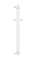
比較的長距離の高速な通信では、ノイズ耐性などにすぐれる差動信号を利用した差動伝送方式が汎用されている。差動伝送方式に用いる差動信号には各種規格があるが、その一種としてのHCSL(High-speed current steering logic)方式が古くから提案されている。これを、図4に示す。同図中、01はHCSL方式のドライバ、02は信号を受けるLSIで形成したレシーバで、これらドライバ01とレシーバ02との間を伝送線路(特性インピーダンスZ0=50Ω)03,04で接続している。
For high-speed communication over a relatively long distance, a differential transmission method using a differential signal having excellent noise immunity is widely used. There are various standards for differential signals used in the differential transmission method, and the HCSL (High-speed current steering logic) method as one of them has been proposed for a long time. This is shown in FIG. In the figure, 01 is an HCSL type driver, 02 is a receiver formed by an LSI that receives signals, and these
ここで、HCSL伝送方式に用いるドライバ01は、基本的に電流ソース型、すなわち出力がハイ・インピーダンスであって、終端抵抗(ほとんどの場合は50Ω)R01,R02に対して約0.75Vの信号振幅が得られるような電流が交互に切替えて供給される。そして、終端抵抗R01,R02を、レシーバ02に近接したボード上に配設することで、不要な反射を可及的に抑制する構成となっている。それでも、リンギングなどが発生することがあるので、ドライバ出力の間近にも、20〜30Ω程度のダンピング抵抗R03,R04を配設することが推奨されている。
Here, the
上述のHCSL方式に対し、LPHCSL(Low power high-speed current steering logic)方式では、図5に示すように、ドライバ01の出力側を、HCSL方式の電流ソース型から、線路03,04の特性インピーダンス(殆どの場合は50Ω)に出力抵抗が整合したプシュプルバッファに変更する一方、レシーバ02側には終端抵抗を配置せずハイ・インピーダンスとすることで敢えて信号反射を起こし、レシーバ02端に現れる電圧振幅が、ドライバ01から発射する出力振幅の2倍になるようにする。ここで、レシーバ02側からドライバ01側に戻る反射波は、ドライバ01の出力抵抗が線路03,04の特性インピーダンスZ0とインピーダンス整合しているので、そこで吸収される。この結果、ボード上では、終端抵抗やダンピング抵抗が不要となり、部品点数が削減される。また、HCSL方式における終端抵抗R03,R04(図01参照)でのDC的な電流消費が無い分、低消費電流化を図ることができる。
In contrast to the above-mentioned HCSL method, in the LPHCSL (Low power high-speed current steering logic) method, as shown in FIG. 5, the output side of the
LPHCSL方式を採用する従来技術に係る差動伝送方式を開示する文献として特許文献1が公知となっている。ここで、特許文献1に開示する伝送方式では、2個一組で交互にスイッチング動作する4個二組のトランジスタがいずれもnチャンネルのMOSトランジスタで形成してある。このため、2個づつ交互に各MOSトランジスタを動作させるための電圧を生成するには、一方の組および他方の組に独立にスイッチング電圧を供給する2個のプリバッファ回路が必要になる。 Patent Document 1 is known as a document that discloses a differential transmission method according to a prior art that employs the LPHCSL method. Here, in the transmission method disclosed in Patent Document 1, two sets of four transistors that alternately switch in pairs are formed of n-channel MOS transistors. Therefore, in order to generate a voltage for operating each MOS transistor alternately by two, two prebuffer circuits that independently supply a switching voltage to one set and the other set are required.
この結果、2個のプリバッファ回路からは、2種類の動作信号が正確なタイミングで生成されるように、厳密なタイミング調整を行う必要がある。 As a result, it is necessary to perform strict timing adjustment so that two types of operation signals are generated from the two prebuffer circuits at accurate timings.
この結果、特許文献1等に開示する従来のLPHCSL方式では、2個のプリバッファ回路間のタイミング調整等に手間がかかり、またこれに伴う構成が複雑になるという課題があった。 As a result, in the conventional LPHCSL method disclosed in Patent Document 1 and the like, there is a problem that it takes time and effort to adjust the timing between the two prebuffer circuits and the configuration associated therewith becomes complicated.
本発明は、上記従来技術に鑑み、スイッチングのタイミング調整が不要になり、構造も簡素化できるLPHCSL伝送方式におけるドライバを提供することを目的とする。 In view of the above prior art, an object of the present invention is to provide a driver in an LPHCSL transmission system that does not require switching timing adjustment and can simplify the structure.
上記目的を達成する本発明の第1の態様は、
LPHCSL伝送方式におけるドライバであって、
PMOSトランジスタとNMOSトランジスタとを組み合わせたスイッチング素子であり、その第1の出力端子に第1の伝送線路が接続される第1のCMOS型トランジスタと、
前記第1のCMOS型トランジスタと同様構成のスイッチング素子であり、その第2の出力端子に第2の伝送線路が接続される第2のCMOS型トランジスタと、
前記第1および第2のCMOS型トランジスタに所定電圧の電力を供給する電圧レギュレータと、
前記第1のCMOS型トランジスタのスイッチングのためのスイッチング信号を供給する第1のプリバッファと、
前記第2のCMOS型トランジスタのスイッチングのためのスイッチング信号を供給する第2のプリバッファと、
を有することを特徴とする。
The first aspect of the present invention that achieves the above object is
A driver in the LPHCSL transmission system
A switching element that is a combination of a MOSFET transistor and an NMOS transistor, and a first CMOS type transistor to which a first transmission line is connected to its first output terminal.
A second CMOS transistor which is a switching element having the same configuration as the first CMOS transistor and whose second output terminal is connected to a second transmission line.
A voltage regulator that supplies power of a predetermined voltage to the first and second CMOS transistors,
A first prebuffer that supplies a switching signal for switching the first CMOS transistor,
A second prebuffer that supplies a switching signal for switching the second CMOS transistor,
It is characterized by having.
本発明の第2の態様は、
第1の態様に記載するLPHCSL伝送方式におけるドライバにおいて、
前記第1および第2のCMOS型トランジスタと前記第1および第2の出力端子との間に所定抵抗値の第1の抵抗素子および第2の抵抗素子をそれぞれ並列に接続したことを特徴とする。
A second aspect of the present invention is
In the driver in the LPHCSL transmission method described in the first aspect,
A first resistance element having a predetermined resistance value and a second resistance element are connected in parallel between the first and second CMOS transistors and the first and second output terminals, respectively. ..
本発明の第3の態様は、
第1または第2の態様に記載するLPHCSL伝送方式において、
前記第1および第2のプリバッファは、CMOS型トランジスタで形成したことを特徴とする。
A third aspect of the present invention is
In the LPHCSL transmission method according to the first or second aspect,
The first and second prebuffers are characterized in that they are formed of CMOS type transistors.
本発明の第4の態様は、
第1〜第3の態様に記載するLPHCSL伝送方式において、
前記プリバッファは、
一方の入力端子にイネーブルラインの出力を入力し、他方の入力端子に伝送信号を入力するとともに、前記第1または第3のトランジスタのゲートにスイッチング信号を供給するナンド回路と、
一方の入力端子に前記イネーブルラインの出力をインバータで反転して入力し、他方の入力端子に前記伝送信号を入力するとともに、前記第2または第4のトランジスタのゲートにスイッチング信号を供給するノア回路と、
を有することを特徴とする。
A fourth aspect of the present invention is
In the LPHCSL transmission method described in the first to third aspects,
The prebuffer is
A Nando circuit that inputs the output of the enable line to one input terminal, inputs a transmission signal to the other input terminal, and supplies a switching signal to the gate of the first or third transistor.
A Noah circuit that inverts the output of the enable line with an inverter and inputs it to one input terminal, inputs the transmission signal to the other input terminal, and supplies a switching signal to the gate of the second or fourth transistor. When,
It is characterized by having.
本発明の第5の態様は、
第4の態様に記載するLPHCSL伝送方式において、
前記第1および第2の抵抗素子に直列にn型のMOSトランジスタを接続し、該MOSトランジスタのゲートに前記イネーブルラインの出力を入力するように構成したことを特徴とする。
A fifth aspect of the present invention is
In the LPHCSL transmission method described in the fourth aspect,
An n-type MOS transistor is connected in series with the first and second resistance elements, and the output of the enable line is input to the gate of the MOS transistor.
本発明によれば所定の伝送信号を生成する2個一組のトランジスタをCMOS型トランジスタで形成したので、当該CMOS型トランジスタを形成するPMOSトランジスタとNMOSトランジスタを動作させるプリバッファは、1個で済む。この結果、プリバッファは、従来技術のように、2種類の動作信号が正確なタイミングで生成されるように、厳密なタイミング調整を行う必要はなく、これに伴う構成の簡素化も実現し得る。 According to the present invention, since a set of two transistors that generate a predetermined transmission signal is formed of a CMOS type transistor, only one prebuffer is required to operate the epitaxial transistor and the NMOS transistor that form the CMOS type transistor. .. As a result, the pre-buffer does not need to perform strict timing adjustment so that two types of operation signals are generated at accurate timings as in the prior art, and the configuration can be simplified accordingly. ..
以下、本発明の実施の形態を図面に基づき詳細に説明する。 Hereinafter, embodiments of the present invention will be described in detail with reference to the drawings.
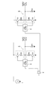
図1は、本発明の実施の形態に係るLPHCSL伝送方式におけるドライバを示すブロック図である。同図に示すように、本形態に係るドライバは、調整電圧VREGが所定電圧(例えば、1.5v)に調整された電圧レギュレータ1、逆論理の2種類の2値信号を生成する信号生成部2、第1および第2のプリバッファ3,4、第1および第2のCMOS型トランジスタ5,6、第1および第2の出力端子OUT1,OUT2を有している。そして、電圧レギュレータ1から供給する調整電圧VREGを第1および第2のCMOS型トランジスタ5,6のスイッチング動作によりオン、オフさせて逆位相の2種類の伝送信号を生成し、第1および第2の出力端子OUT1,OUT2に接続する第1および第2の伝送路(いずれも図示せず;以下同じ)を介し受信端に向けて差動伝送する。
FIG. 1 is a block diagram showing a driver in the LPHCSL transmission method according to the embodiment of the present invention. As shown in the figure, the driver according to this embodiment is a signal generator that generates two types of binary signals, a voltage regulator 1 in which a regulated voltage V REG is adjusted to a predetermined voltage (for example, 1.5 v) and an inverse logic. It has
さらに詳言すると、第1のCMOS型トランジスタ5は、PMOSトランジスタTr1とNMOSトランジスタTr2からなるスイッチング素子であり、その出力側が第1の出力端子OUT1を介して第1の伝送路に接続されている。また、第2のCMOS型トランジスタ6は、PMOSトランジスタTr3とNMOSトランジスタTr4からなるスイッチング素子であり、その出力側が第2の出力端子OUT2を介して第2の伝送路に接続されている。
More specifically, the
ここで、第1および第3のPMOSトランジスタTr1,Tr3のオン抵抗は、第1および第3のPMOSトランジスタTr1,Tr3のトランジスタサイズと、これらにそれぞれ直列に接続された調整抵抗素子R3,R5により100オームになるように調整されている。同様に、第2および第4のNMOSトランジスタTr2,Tr4のオン抵抗は、第2および第4のNMOSトランジスタTr2,Tr4のトランジスタサイズと、これらにそれぞれ直列接続された調整抵抗素子R4,R6により100オームになるように調整されている。 Here, the on-resistance of the first and third epitaxial transistors Tr1 and Tr3 is determined by the transistor sizes of the first and third epitaxial transistors Tr1 and Tr3 and the adjusting resistance elements R3 and R5 connected in series to these, respectively. It is adjusted to be 100 ohms. Similarly, the on-resistance of the second and fourth NMOS transistors Tr2 and Tr4 is 100 due to the transistor size of the second and fourth NMOS transistors Tr2 and Tr4 and the adjustment resistance elements R4 and R6 connected in series to them, respectively. Adjusted to be ohms.
さらに、第1および第2のCMOS型トランジスタ5,6と第1および第2の出力端子OUT1,OUT2との間には所定抵抗値(本例では100オーム)の第1の抵抗素子R1および第2の抵抗素子R2がそれぞれ並列に接続してある。
Further, a first resistance element R1 and a first resistance element R1 having a predetermined resistance value (100 ohms in this example) between the first and
本形態において、第1の抵抗素子R1および第2の抵抗素子R2を並列に接続することは必須ではない。出力インピーダンスの整合および波形振幅の調整を適切に実現することができれば、第1および第2の抵抗素子R1,R2を省略することができる場合がある。すなわち、次の条件が成立する場合である。 In this embodiment, it is not essential to connect the first resistance element R1 and the second resistance element R2 in parallel. If matching of output impedance and adjustment of waveform amplitude can be appropriately realized, the first and second resistance elements R1 and R2 may be omitted. That is, the following conditions are satisfied.
第1および第2の抵抗素子R1,R2の抵抗値(R1,R2)=Z0・(VREG−Vswing)(オーム)・・・(式1)、として決定される。
ここで、
Z0;第1および第2の出力端子OUT1,OUT2に接続される第1および第2の伝送線路の特性インピーダンス、
VREG;電圧レギュレータ1から供給する調整電圧、
Vswing;第1および第2の伝送線路のレシーバ側で要求される信号電圧振幅である。
It is determined as the resistance values (R1, R2) of the first and second resistance elements R1 and R2 = Z 0 · (V REG −V swing ) (ohm) ... (Equation 1).
here,
Z 0 ; Characteristic impedance of the first and second transmission lines connected to the first and second output terminals OUT1 and OUT2,
V REG ; Adjusted voltage supplied from voltage regulator 1,
V swing : The signal voltage amplitude required on the receiver side of the first and second transmission lines.
第1および第2の抵抗素子R1,R2が不要な場合とは、この部分の抵抗値が無限大、すなわち前記式(1)において、(VREG=Vswing)となる場合である。かかる条件は、本形態(特性インピーダンスZ0=50(オーム))の場合、第1および第2の抵抗素子R1,R2の抵抗値がそれぞれ50(オーム)のときに成立する。 The case where the first and second resistance elements R1 and R2 are unnecessary is a case where the resistance value of this portion is infinite, that is, (V REG = V swing ) in the above equation (1). This condition is satisfied in the case of the present embodiment (characteristic impedance Z 0 = 50 (ohms)) when the resistance values of the first and second resistance elements R1 and R2 are 50 (ohms), respectively.
本形態は、Z0=50(オーム)、VREG=1.5(v)、Vswing=0.75(v)の場合であるが、同様の場合で、Z0=50(オーム)、Vswing=0.75(v)に対して、例えばVREG=1.2(v)と設定すると、PMOSトランジスタTr1,Tr3およびNMOSトランジスタTr2,Tr4のオン抵抗は80オーム、第1および第2の抵抗素子R1,R2の抵抗は約133(オーム)となるように設計する。このとき、消費電流は前述の場合よりも最大で約2(mA)削減される。このようにVREGを削減すると、電流は削減し得るが、第1および第3のPMOSトランジスタTr1,Tr3ならびに第2および第4のNMOSトランジスタTr2,Tr4のスイッチングスピードが遅くなり波形が鈍るとともに、特に第1および第3のPMOSトランジスタTr1、Tr3側で所定のオン抵抗を得ることが困難になってくるので、VREG=1.2〜1.5(v)程度が好適である。 This embodiment is the case of Z 0 = 50 (ohms), V REG = 1.5 (v), V swing = 0.75 (v), but in the same case, Z 0 = 50 (ohms), For example, when V REG = 1.2 (v) is set for V swing = 0.75 (v), the on-resistance of the epitaxial transistors Tr1 and Tr3 and the NMOS transistors Tr2 and Tr4 is 80 ohms, and the first and second The resistance elements R1 and R2 of the above are designed to be about 133 (ohms). At this time, the current consumption is reduced by about 2 (mA) at the maximum as compared with the above case. By reducing V REG in this way, the current can be reduced, but the switching speeds of the first and third MOSFET transistors Tr1 and Tr3 and the second and fourth NMOS transistors Tr2 and Tr4 become slower, the waveform becomes dull, and the waveform becomes dull. In particular, since it becomes difficult to obtain a predetermined on-resistance on the first and third MOSFET transistors Tr1 and Tr3, V REG = 1.2 to 1.5 (v) is preferable.
同様に、特性インピーダンスZ0=75(オーム)の伝送線路の系統に適用する場合の例としては、Z0=75(オーム)、VREG=1.5V、Vswing=0.75Vとすると、PMOSトランジスタTr1,Tr3およびNMOSトランジスタTr2,Tr4のオン抵抗は150(オーム)、第1および第2の抵抗素子R1,R2の抵抗は約150(オーム)となるように設計すれば良い。 Similarly, as an example of application to a transmission line system with characteristic impedance Z 0 = 75 (ohms), if Z 0 = 75 (ohms), V REG = 1.5V, and V swing = 0.75V, It may be designed so that the on-resistance of the epitaxial transistors Tr1 and Tr3 and the NMOS transistors Tr2 and Tr4 is 150 (ohms), and the resistance of the first and second resistance elements R1 and R2 is about 150 (ohms).
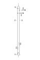
次に、第1および第2のプリバッファ3,4の具体例に関して説明する。図2は、図1に示すドライバのプリバッファ部分を抽出し、その具体例を示すブロック図である。なお、本図では第1の出力端子OUT1側(プリバッファ3側)のみを示す。出力端子OUT2側(プリバッファ4側)は同構成であるので説明を省略する。
Next, specific examples of the first and second prebuffers 3 and 4 will be described. FIG. 2 is a block diagram showing a specific example of extracting the prebuffer portion of the driver shown in FIG. In this figure, only the first output terminal OUT1 side (
本例に示す第1のプリバッファ3は、第3のCMOS型トランジスタ7で形成してある。かかる第1のプリバッファ3は、PMOSトランジスタTr5およびNMOSトランジスタ6のそれぞれのドレインにオン抵抗調整用の抵抗素子が付いているが、出力バッファ形式としては単純なCMOS型出力バッファとして構成してある。このため、プリバッファとしても非常に単純なCMOS型出力バッファ用のもので済んでしまう。最も単純なものは、インバータである。
The
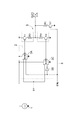
図3は、図1に示すドライバのプリバッファ部分を抽出し、その他の具体例を示すブロック図である。なお、本図でも第1の出力端子OUT1側(プリバッファ3側)のみを示す。
FIG. 3 is a block diagram in which the prebuffer portion of the driver shown in FIG. 1 is extracted and other specific examples are shown. In this figure as well, only the first output terminal OUT1 side (
本例は、出力端子OUT1に得られる出力をトライステート(Hi‐Z)とする場合である。本例におけるバッファ3は、ナンド回路3Aおよびノア回路3Bを有している。ここで、ナンド回路3Aは、一方の入力端子にイネーブルライン8の出力を入力し、他方の入力端子に伝送信号Sを入力する。そして、第1のトランジスタTr1のゲートにナンド回路3Aの出力であるスイッチング信号を供給する。
In this example, the output obtained at the output terminal OUT1 is set to the tri-state (Hi-Z). The
一方、ノア回路3Cは、一方の入力端子にイネーブルライン8の出力をインバータ3Bで反転させて入力し、他方の入力端子に伝送信号Sを入力する。そして、第2のトランジスタTr2のゲートにノア回路3Cの出力であるスイッチング信号を供給する。
On the other hand, the
本形態において、所望のトライステートは、第1の抵抗素子R1に直列にn型のMOSトランジスタTr7を接続し、このMOSトランジスタTr7のゲートにイネーブルライン8の出力を入力するように構成することでも実現できる。
In the present embodiment, the desired tri-state can also be configured by connecting an n-type MOS transistor Tr7 in series with the first resistance element R1 and inputting the output of the
1 電圧レギュレータ
3 第1のプリバッファ
3A ナンド回路
3B インバータ
3C NOR回路
4 第2のプリバッファ
5 第1のCMOS型トランジスタ
6 第2のCMOS型トランジスタ
7 第3のCMOS型トランジスタ
8 イネーブルライン
S 伝送信号
Tr1 PMOSトランジスタ
Tr2 NMOSトランジスタ
Tr7 NMOSトランジスタ
OUT1 第1の出力端子
OUT2 第2の出力端子
R1 第1の抵抗素子
R2 第2の抵抗素子
1
Claims (5)
PMOSトランジスタとNMOSトランジスタとを組み合わせたスイッチング素子であり、その第1の出力端子に第1の伝送線路が接続される第1のCMOS型トランジスタと、
前記第1のCMOS型トランジスタと同様構成のスイッチング素子であり、その第2の出力端子に第2の伝送線路が接続される第2のCMOS型トランジスタと、
前記第1および第2のCMOS型トランジスタに所定電圧の電力を供給する電圧レギュレータと、
前記第1のCMOS型トランジスタのスイッチングのためのスイッチング信号を供給する第1のプリバッファと、
前記第2のCMOS型トランジスタのスイッチングのためのスイッチング信号を供給する第2のプリバッファと、
を有することを特徴とするLPHCSL伝送方式におけるドライバ。 A driver in the LPHCSL transmission system
A switching element that is a combination of a MOSFET transistor and an NMOS transistor, and a first CMOS type transistor to which a first transmission line is connected to its first output terminal.
A second CMOS transistor which is a switching element having the same configuration as the first CMOS transistor and whose second output terminal is connected to a second transmission line.
A voltage regulator that supplies power of a predetermined voltage to the first and second CMOS transistors,
A first prebuffer that supplies a switching signal for switching the first CMOS transistor,
A second prebuffer that supplies a switching signal for switching the second CMOS transistor,
A driver in an LPHCSL transmission system, characterized in that it has.
前記第1および第2のCMOS型トランジスタと前記第1および第2の出力端子との間に所定抵抗値の第1の抵抗素子および第2の抵抗素子をそれぞれ並列に接続したことを特徴とするLPHCSL伝送方式におけるドライバ。 In the driver in the LPHCSL transmission method according to claim 1,
A first resistance element having a predetermined resistance value and a second resistance element are connected in parallel between the first and second CMOS transistors and the first and second output terminals, respectively. Driver in LPHCSL transmission method.
前記第1および第2のプリバッファは、CMOS型トランジスタで形成したことを特徴とするLPHCSL伝送方式におけるドライバ。 In the LPHCSL transmission method according to claim 1 or 2.
The first and second prebuffers are drivers in the LPHCSL transmission system, characterized in that they are formed of CMOS type transistors.
前記プリバッファは、
一方の入力端子にイネーブルラインの出力を入力し、他方の入力端子に伝送信号を入力するとともに、前記第1または第3のトランジスタのゲートにスイッチング信号を供給するナンド回路と、
一方の入力端子に前記イネーブルラインの出力をインバータで反転して入力し、他方の入力端子に前記伝送信号を入力するとともに、前記第2または第4のトランジスタのゲートにスイッチング信号を供給するノア回路と、
を有することを特徴とするLPHCSL伝送方式におけるドライバ。 In the LPHCSL transmission method according to claim 2 or 3.
The prebuffer is
A Nando circuit that inputs the output of the enable line to one input terminal, inputs a transmission signal to the other input terminal, and supplies a switching signal to the gate of the first or third transistor.
A Noah circuit that inverts the output of the enable line with an inverter and inputs it to one input terminal, inputs the transmission signal to the other input terminal, and supplies a switching signal to the gate of the second or fourth transistor. When,
A driver in an LPHCSL transmission system, characterized in that it has.
前記第1および第2の抵抗素子に直列にn型のMOSトランジスタを接続し、該MOSトランジスタのゲートに前記イネーブルラインの出力を入力するように構成したことを特徴とするLPHCSL伝送方式におけるドライバ。 In the LPHCSL transmission method according to claim 4,
A driver in an LPHCSL transmission system, wherein an n-type MOS transistor is connected in series with the first and second resistance elements, and the output of the enable line is input to the gate of the MOS transistor.
Priority Applications (1)
| Application Number | Priority Date | Filing Date | Title |
|---|---|---|---|
| JP2020081228A JP7043541B2 (en) | 2020-05-01 | 2020-05-01 | Driver in LPHCSL transmission method |
Applications Claiming Priority (1)
| Application Number | Priority Date | Filing Date | Title |
|---|---|---|---|
| JP2020081228A JP7043541B2 (en) | 2020-05-01 | 2020-05-01 | Driver in LPHCSL transmission method |
Publications (2)
| Publication Number | Publication Date |
|---|---|
| JP2021176216A true JP2021176216A (en) | 2021-11-04 |
| JP7043541B2 JP7043541B2 (en) | 2022-03-29 |
Family
ID=78300521
Family Applications (1)
| Application Number | Title | Priority Date | Filing Date |
|---|---|---|---|
| JP2020081228A Active JP7043541B2 (en) | 2020-05-01 | 2020-05-01 | Driver in LPHCSL transmission method |
Country Status (1)
| Country | Link |
|---|---|
| JP (1) | JP7043541B2 (en) |
Cited By (2)
| Publication number | Priority date | Publication date | Assignee | Title |
|---|---|---|---|---|
| CN116760402A (en) * | 2023-06-14 | 2023-09-15 | 成都电科星拓科技有限公司 | An LP-HCSL type output drive circuit and chip |
| CN118677427A (en) * | 2024-08-23 | 2024-09-20 | 成都电科星拓科技有限公司 | LPHCSL circuit with automatic output impedance adjusting function |
Citations (4)
| Publication number | Priority date | Publication date | Assignee | Title |
|---|---|---|---|---|
| JP2002237748A (en) * | 2001-02-13 | 2002-08-23 | Kawasaki Microelectronics Kk | Buffer circuit |
| US20060066354A1 (en) * | 2004-09-24 | 2006-03-30 | Ics Inc. | Low power outpur driver |
| JP2006191482A (en) * | 2005-01-07 | 2006-07-20 | Nec Micro Systems Ltd | Driver circuit |
| US9692394B1 (en) * | 2016-03-25 | 2017-06-27 | Integrated Device Technology, Inc. | Programmable low power high-speed current steering logic (LPHCSL) driver and method of use |
-
2020
- 2020-05-01 JP JP2020081228A patent/JP7043541B2/en active Active
Patent Citations (4)
| Publication number | Priority date | Publication date | Assignee | Title |
|---|---|---|---|---|
| JP2002237748A (en) * | 2001-02-13 | 2002-08-23 | Kawasaki Microelectronics Kk | Buffer circuit |
| US20060066354A1 (en) * | 2004-09-24 | 2006-03-30 | Ics Inc. | Low power outpur driver |
| JP2006191482A (en) * | 2005-01-07 | 2006-07-20 | Nec Micro Systems Ltd | Driver circuit |
| US9692394B1 (en) * | 2016-03-25 | 2017-06-27 | Integrated Device Technology, Inc. | Programmable low power high-speed current steering logic (LPHCSL) driver and method of use |
Cited By (2)
| Publication number | Priority date | Publication date | Assignee | Title |
|---|---|---|---|---|
| CN116760402A (en) * | 2023-06-14 | 2023-09-15 | 成都电科星拓科技有限公司 | An LP-HCSL type output drive circuit and chip |
| CN118677427A (en) * | 2024-08-23 | 2024-09-20 | 成都电科星拓科技有限公司 | LPHCSL circuit with automatic output impedance adjusting function |
Also Published As
| Publication number | Publication date |
|---|---|
| JP7043541B2 (en) | 2022-03-29 |
Similar Documents
| Publication | Publication Date | Title |
|---|---|---|
| US7408387B2 (en) | Output buffer circuit with control circuit for changing resistance of output resistor pair | |
| TW423217B (en) | Low voltage differential signaling driver with pre-emphasis circuit | |
| KR102003926B1 (en) | de-emphasis buffer circuit | |
| CN103582853B (en) | Single-ended configurable multi-mode driver | |
| US6294932B1 (en) | Input circuit, output circuit, input-output circuit and method of processing input signals | |
| US6313662B1 (en) | High speed low voltage differential signal driver having reduced pulse width distortion | |
| KR101290080B1 (en) | A pre-emphasis circuit and differential current signaling system having the same | |
| JP4937609B2 (en) | Output buffer circuit, differential output buffer circuit and transmission method | |
| JP2783183B2 (en) | Output circuit | |
| US7109759B2 (en) | Voltage mode current-assisted pre-emphasis driver | |
| CN101868914A (en) | Differential receiver with voltage drop | |
| US6975141B2 (en) | LVDS driver for small supply voltages | |
| JP4992555B2 (en) | Low voltage differential signal driver, method and system for driving low voltage differential signal | |
| JP7043541B2 (en) | Driver in LPHCSL transmission method | |
| JP2000022516A (en) | Driver circuit device | |
| KR100454796B1 (en) | Semiconductor integrated circuit | |
| US6509765B1 (en) | Selectable resistor and/or driver for an integrated circuit with a linear resistance | |
| JP2004112453A (en) | Signal transmission equipment | |
| JP2004312614A (en) | Semiconductor device | |
| JP5059580B2 (en) | Termination circuit | |
| KR100801058B1 (en) | Signal transfer circuitry for reducing skew, signal transfer methods and systems having such circuits | |
| JP4454013B2 (en) | Differential output circuit | |
| GB2404799A (en) | An IC output driver with selectable logic format and adjustable output capacitance for impedance matching or EMI reduction | |
| US8174291B1 (en) | Buffer circuit with improved duty cycle distortion and method of using the same | |
| JP2939241B2 (en) | Input interface circuit |
Legal Events
| Date | Code | Title | Description |
|---|---|---|---|
| A621 | Written request for application examination |
Free format text: JAPANESE INTERMEDIATE CODE: A621 Effective date: 20210714 |
|
| A871 | Explanation of circumstances concerning accelerated examination |
Free format text: JAPANESE INTERMEDIATE CODE: A871 Effective date: 20210714 |
|
| A131 | Notification of reasons for refusal |
Free format text: JAPANESE INTERMEDIATE CODE: A131 Effective date: 20210810 |
|
| A601 | Written request for extension of time |
Free format text: JAPANESE INTERMEDIATE CODE: A601 Effective date: 20211002 |
|
| A521 | Request for written amendment filed |
Free format text: JAPANESE INTERMEDIATE CODE: A523 Effective date: 20211208 |
|
| TRDD | Decision of grant or rejection written | ||
| A01 | Written decision to grant a patent or to grant a registration (utility model) |
Free format text: JAPANESE INTERMEDIATE CODE: A01 Effective date: 20220315 |
|
| A61 | First payment of annual fees (during grant procedure) |
Free format text: JAPANESE INTERMEDIATE CODE: A61 Effective date: 20220316 |
|
| R150 | Certificate of patent or registration of utility model |
Ref document number: 7043541 Country of ref document: JP Free format text: JAPANESE INTERMEDIATE CODE: R150 |
|
| S531 | Written request for registration of change of domicile |
Free format text: JAPANESE INTERMEDIATE CODE: R313531 |
|
| R350 | Written notification of registration of transfer |
Free format text: JAPANESE INTERMEDIATE CODE: R350 |
|
| R250 | Receipt of annual fees |
Free format text: JAPANESE INTERMEDIATE CODE: R250 |