JP2021159110A - Charged particle beam irradiation device - Google Patents
Charged particle beam irradiation device Download PDFInfo
- Publication number
- JP2021159110A JP2021159110A JP2020060893A JP2020060893A JP2021159110A JP 2021159110 A JP2021159110 A JP 2021159110A JP 2020060893 A JP2020060893 A JP 2020060893A JP 2020060893 A JP2020060893 A JP 2020060893A JP 2021159110 A JP2021159110 A JP 2021159110A
- Authority
- JP
- Japan
- Prior art keywords
- charged particle
- particle beam
- energy
- irradiation
- unit
- Prior art date
- Legal status (The legal status is an assumption and is not a legal conclusion. Google has not performed a legal analysis and makes no representation as to the accuracy of the status listed.)
- Pending
Links
- 239000002245 particle Substances 0.000 title claims abstract description 467
- 230000032258 transport Effects 0.000 claims abstract description 95
- 239000001064 degrader Substances 0.000 claims abstract description 53
- 238000009826 distribution Methods 0.000 claims abstract description 32
- 239000006185 dispersion Substances 0.000 claims description 10
- 238000004904 shortening Methods 0.000 abstract description 4
- 230000000052 comparative effect Effects 0.000 description 32
- XLYOFNOQVPJJNP-UHFFFAOYSA-N water Substances O XLYOFNOQVPJJNP-UHFFFAOYSA-N 0.000 description 22
- 210000004894 snout Anatomy 0.000 description 20
- 206010028980 Neoplasm Diseases 0.000 description 18
- 230000001678 irradiating effect Effects 0.000 description 18
- 238000010586 diagram Methods 0.000 description 9
- 238000011144 upstream manufacturing Methods 0.000 description 8
- 150000002500 ions Chemical class 0.000 description 5
- 230000007246 mechanism Effects 0.000 description 5
- 238000000034 method Methods 0.000 description 5
- 230000001133 acceleration Effects 0.000 description 4
- 239000007789 gas Substances 0.000 description 3
- 229910052757 nitrogen Inorganic materials 0.000 description 3
- 230000005855 radiation Effects 0.000 description 3
- 238000002560 therapeutic procedure Methods 0.000 description 3
- XKRFYHLGVUSROY-UHFFFAOYSA-N Argon Chemical compound [Ar] XKRFYHLGVUSROY-UHFFFAOYSA-N 0.000 description 2
- IJGRMHOSHXDMSA-UHFFFAOYSA-N Atomic nitrogen Chemical compound N#N IJGRMHOSHXDMSA-UHFFFAOYSA-N 0.000 description 2
- 238000005452 bending Methods 0.000 description 2
- 230000007423 decrease Effects 0.000 description 2
- 238000001514 detection method Methods 0.000 description 2
- 230000004048 modification Effects 0.000 description 2
- 238000012986 modification Methods 0.000 description 2
- 230000002093 peripheral effect Effects 0.000 description 2
- 230000009471 action Effects 0.000 description 1
- 230000004913 activation Effects 0.000 description 1
- 229910052786 argon Inorganic materials 0.000 description 1
- QVGXLLKOCUKJST-UHFFFAOYSA-N atomic oxygen Chemical compound [O] QVGXLLKOCUKJST-UHFFFAOYSA-N 0.000 description 1
- 201000011510 cancer Diseases 0.000 description 1
- 230000008859 change Effects 0.000 description 1
- 238000005520 cutting process Methods 0.000 description 1
- 230000000694 effects Effects 0.000 description 1
- 238000010894 electron beam technology Methods 0.000 description 1
- 238000005286 illumination Methods 0.000 description 1
- 238000009434 installation Methods 0.000 description 1
- 229910052756 noble gas Inorganic materials 0.000 description 1
- 229910052760 oxygen Inorganic materials 0.000 description 1
- 239000001301 oxygen Substances 0.000 description 1
- 230000008569 process Effects 0.000 description 1
Images


Classifications
-
- A—HUMAN NECESSITIES
- A61—MEDICAL OR VETERINARY SCIENCE; HYGIENE
- A61N—ELECTROTHERAPY; MAGNETOTHERAPY; RADIATION THERAPY; ULTRASOUND THERAPY
- A61N5/00—Radiation therapy
- A61N5/10—X-ray therapy; Gamma-ray therapy; Particle-irradiation therapy
- A61N5/1042—X-ray therapy; Gamma-ray therapy; Particle-irradiation therapy with spatial modulation of the radiation beam within the treatment head
- A61N5/1043—Scanning the radiation beam, e.g. spot scanning or raster scanning
-
- A—HUMAN NECESSITIES
- A61—MEDICAL OR VETERINARY SCIENCE; HYGIENE
- A61N—ELECTROTHERAPY; MAGNETOTHERAPY; RADIATION THERAPY; ULTRASOUND THERAPY
- A61N5/00—Radiation therapy
- A61N5/10—X-ray therapy; Gamma-ray therapy; Particle-irradiation therapy
- A61N5/1042—X-ray therapy; Gamma-ray therapy; Particle-irradiation therapy with spatial modulation of the radiation beam within the treatment head
- A61N5/1045—X-ray therapy; Gamma-ray therapy; Particle-irradiation therapy with spatial modulation of the radiation beam within the treatment head using a multi-leaf collimator, e.g. for intensity modulated radiation therapy or IMRT
-
- A—HUMAN NECESSITIES
- A61—MEDICAL OR VETERINARY SCIENCE; HYGIENE
- A61N—ELECTROTHERAPY; MAGNETOTHERAPY; RADIATION THERAPY; ULTRASOUND THERAPY
- A61N5/00—Radiation therapy
- A61N5/10—X-ray therapy; Gamma-ray therapy; Particle-irradiation therapy
-
- A—HUMAN NECESSITIES
- A61—MEDICAL OR VETERINARY SCIENCE; HYGIENE
- A61N—ELECTROTHERAPY; MAGNETOTHERAPY; RADIATION THERAPY; ULTRASOUND THERAPY
- A61N5/00—Radiation therapy
- A61N5/10—X-ray therapy; Gamma-ray therapy; Particle-irradiation therapy
- A61N5/103—Treatment planning systems
-
- A—HUMAN NECESSITIES
- A61—MEDICAL OR VETERINARY SCIENCE; HYGIENE
- A61N—ELECTROTHERAPY; MAGNETOTHERAPY; RADIATION THERAPY; ULTRASOUND THERAPY
- A61N5/00—Radiation therapy
- A61N5/10—X-ray therapy; Gamma-ray therapy; Particle-irradiation therapy
- A61N5/1048—Monitoring, verifying, controlling systems and methods
-
- A—HUMAN NECESSITIES
- A61—MEDICAL OR VETERINARY SCIENCE; HYGIENE
- A61N—ELECTROTHERAPY; MAGNETOTHERAPY; RADIATION THERAPY; ULTRASOUND THERAPY
- A61N5/00—Radiation therapy
- A61N5/10—X-ray therapy; Gamma-ray therapy; Particle-irradiation therapy
- A61N5/1077—Beam delivery systems
-
- A—HUMAN NECESSITIES
- A61—MEDICAL OR VETERINARY SCIENCE; HYGIENE
- A61N—ELECTROTHERAPY; MAGNETOTHERAPY; RADIATION THERAPY; ULTRASOUND THERAPY
- A61N5/00—Radiation therapy
- A61N5/10—X-ray therapy; Gamma-ray therapy; Particle-irradiation therapy
- A61N5/1077—Beam delivery systems
- A61N5/1081—Rotating beam systems with a specific mechanical construction, e.g. gantries
-
- G—PHYSICS
- G21—NUCLEAR PHYSICS; NUCLEAR ENGINEERING
- G21K—TECHNIQUES FOR HANDLING PARTICLES OR IONISING RADIATION NOT OTHERWISE PROVIDED FOR; IRRADIATION DEVICES; GAMMA RAY OR X-RAY MICROSCOPES
- G21K1/00—Arrangements for handling particles or ionising radiation, e.g. focusing or moderating
- G21K1/02—Arrangements for handling particles or ionising radiation, e.g. focusing or moderating using diaphragms, collimators
-
- G—PHYSICS
- G21—NUCLEAR PHYSICS; NUCLEAR ENGINEERING
- G21K—TECHNIQUES FOR HANDLING PARTICLES OR IONISING RADIATION NOT OTHERWISE PROVIDED FOR; IRRADIATION DEVICES; GAMMA RAY OR X-RAY MICROSCOPES
- G21K1/00—Arrangements for handling particles or ionising radiation, e.g. focusing or moderating
- G21K1/08—Deviation, concentration or focusing of the beam by electric or magnetic means
- G21K1/093—Deviation, concentration or focusing of the beam by electric or magnetic means by magnetic means
-
- G—PHYSICS
- G21—NUCLEAR PHYSICS; NUCLEAR ENGINEERING
- G21K—TECHNIQUES FOR HANDLING PARTICLES OR IONISING RADIATION NOT OTHERWISE PROVIDED FOR; IRRADIATION DEVICES; GAMMA RAY OR X-RAY MICROSCOPES
- G21K5/00—Irradiation devices
- G21K5/04—Irradiation devices with beam-forming means
-
- G—PHYSICS
- G21—NUCLEAR PHYSICS; NUCLEAR ENGINEERING
- G21K—TECHNIQUES FOR HANDLING PARTICLES OR IONISING RADIATION NOT OTHERWISE PROVIDED FOR; IRRADIATION DEVICES; GAMMA RAY OR X-RAY MICROSCOPES
- G21K5/00—Irradiation devices
- G21K5/10—Irradiation devices with provision for relative movement of beam source and object to be irradiated
-
- A—HUMAN NECESSITIES
- A61—MEDICAL OR VETERINARY SCIENCE; HYGIENE
- A61N—ELECTROTHERAPY; MAGNETOTHERAPY; RADIATION THERAPY; ULTRASOUND THERAPY
- A61N5/00—Radiation therapy
- A61N5/10—X-ray therapy; Gamma-ray therapy; Particle-irradiation therapy
- A61N2005/1085—X-ray therapy; Gamma-ray therapy; Particle-irradiation therapy characterised by the type of particles applied to the patient
- A61N2005/1087—Ions; Protons
-
- A—HUMAN NECESSITIES
- A61—MEDICAL OR VETERINARY SCIENCE; HYGIENE
- A61N—ELECTROTHERAPY; MAGNETOTHERAPY; RADIATION THERAPY; ULTRASOUND THERAPY
- A61N5/00—Radiation therapy
- A61N5/10—X-ray therapy; Gamma-ray therapy; Particle-irradiation therapy
- A61N2005/1092—Details
- A61N2005/1095—Elements inserted into the radiation path within the system, e.g. filters or wedges
Abstract
Description
本発明は、荷電粒子線照射装置に関する。 The present invention relates to a charged particle beam irradiator.
荷電粒子線照射装置として、例えば特許文献1に示すものが知られている。荷電粒子線照射装置は、荷電粒子を加速して荷電粒子線を生成する加速器と、回転軸周りに回転可能な回転部を有すると共に加速器で生成された荷電粒子線を照射する照射部と、加速器から照射部へ荷電粒子線を輸送する輸送部と、を備える。特許文献1の図4に示す荷電粒子線照射装置は、照射部の上部に、荷電粒子線のエネルギーを選択する選択部(ESS:Energy Selection System)を備えている。特許文献1の選択部は、荷電粒子線のエネルギーを低減させるディグレーダと、荷電粒子線の運動量幅を制限するために1対の偏向電磁石及びスリットと、コリメータとを有する。
As a charged particle beam irradiation device, for example, the one shown in
ここで、特許文献1の図4に示す構成では、スリットにより、荷電粒子線のブラッグピークが細くなる。このため、拡大ブラッグピークの形成に必要な荷電粒子線のエネルギーの数が増え、荷電粒子線のエネルギーを切り替える回数が増大し、荷電粒子線の照射時間が長くなってしまうという問題がある。
Here, in the configuration shown in FIG. 4 of
そこで、本発明は、荷電粒子線の照射時間を短くすることができる荷電粒子線照射装置を提供することを目的とする。 Therefore, an object of the present invention is to provide a charged particle beam irradiation device capable of shortening the irradiation time of the charged particle beam.
本発明に係る荷電粒子線照射装置は、荷電粒子線を照射する荷電粒子線照射装置であって、荷電粒子を加速して荷電粒子線を生成する加速器と、回転軸線周りに回転可能な回転部を有すると共に加速器で生成された荷電粒子線を照射する照射部と、照射部の外部に設けられ加速器で生成された荷電粒子線のエネルギーを減少させるディグレーダを有すると共に、加速器で生成された荷電粒子線を照射部へ輸送する輸送部と、を備え、輸送部は、ディグレーダによりエネルギーが減少した荷電粒子線のエネルギー分布を維持したまま当該荷電粒子線を照射部に輸送する。 The charged particle beam irradiator according to the present invention is a charged particle beam irradiator that irradiates a charged particle beam, and is an accelerator that accelerates charged particles to generate a charged particle beam and a rotating portion that can rotate around a rotation axis. It also has an irradiation unit that irradiates the charged particle beam generated by the accelerator, and a degrader that is provided outside the irradiation unit and reduces the energy of the charged particle beam generated by the accelerator. The transport unit includes a transport unit that transports the beam to the irradiation unit, and the transport unit transports the charged particle beam to the irradiation unit while maintaining the energy distribution of the charged particle beam whose energy has been reduced by the degrader.
本発明に係る荷電粒子線照射装置は、照射部の外側の輸送部に、荷電粒子線のエネルギーを減少させるディグレーダが配置される。輸送部は、ディグレーダによりエネルギーが減少した荷電粒子線のエネルギー分布を維持したまま当該荷電粒子線を照射部に輸送する。これにより、輸送部は、荷電粒子線のエネルギーの中から特定の範囲のエネルギーを選択する選択部を設けることなく、当該荷電粒子線をディグレーダから照射部に輸送することができる。従って、選択部を設けた場合に比べて、荷電粒子線のブラッグピークが太くなり、拡大ブラッグピークの形成に必要な荷電粒子線のエネルギーの数が減少し、荷電粒子線のエネルギーを切り替える回数が減少する。以上より、荷電粒子線の照射時間を短くすることができる。 In the charged particle beam irradiation device according to the present invention, a degrader that reduces the energy of the charged particle beam is arranged in a transport portion outside the irradiation portion. The transport unit transports the charged particle beam to the irradiation unit while maintaining the energy distribution of the charged particle beam whose energy has been reduced by the degrader. As a result, the transport unit can transport the charged particle beam from the degrader to the irradiation unit without providing a selection unit for selecting an energy in a specific range from the energy of the charged particle beam. Therefore, the Bragg peak of the charged particle beam becomes thicker, the number of energy of the charged particle beam required to form the enlarged Bragg peak decreases, and the number of times the energy of the charged particle beam is switched is reduced as compared with the case where the selection unit is provided. Decrease. From the above, the irradiation time of the charged particle beam can be shortened.
本発明に係る荷電粒子線照射装置において、輸送部は、ディグレーダと照射部との間に設けられ荷電粒子線の形状、大きさ及び発散を調整するコリメータを有してもよい。この場合、コリメータは、ディグレーダを通過した荷電粒子線の形状及び発散を調整することができ、荷電粒子線のエネルギー分布を維持させたままディグレーダから照射部まで輸送することができる。 In the charged particle beam irradiation device according to the present invention, the transport unit may have a collimeter provided between the degrader and the irradiation unit to adjust the shape, size and divergence of the charged particle beam. In this case, the collimeter can adjust the shape and divergence of the charged particle beam that has passed through the degrader, and can transport the charged particle beam from the degrader to the irradiation unit while maintaining the energy distribution of the charged particle beam.
本発明に係る荷電粒子線照射装置において、輸送部は、ディグレーダによりエネルギーが減少した荷電粒子線が通過可能な口径を有してもよい。この場合、輸送部は、荷電粒子線に対して特定の範囲のエネルギーを選択することなく、荷電粒子線のエネルギー分布を維持させたままディグレーダから照射部まで輸送することができる。 In the charged particle beam irradiation device according to the present invention, the transport unit may have a diameter through which the charged particle beam whose energy has been reduced by the degrader can pass. In this case, the transport unit can transport the charged particle beam from the degrader to the irradiation unit while maintaining the energy distribution of the charged particle beam without selecting energy in a specific range.
本発明に係る荷電粒子線照射装置において、ディグレーダは、荷電粒子線の運動量分散が6%未満となるように加速器で生成された荷電粒子線のエネルギーを減少させてもよい。ディグレーダにより荷電粒子線のエネルギーを減少させれば減少させるほど荷電粒子線のエネルギー分布は大きく広がる。ディグレーダは、荷電粒子線の運動量分散が6%未満となるようにすることで、荷電粒子線のエネルギー分布の広がりを抑えることができる。このとき、輸送部は、荷電粒子線に対して特定の範囲のエネルギーを選択することなく、荷電粒子線のエネルギー分布を維持させたままディグレーダから照射部まで輸送することができる。 In the charged particle beam irradiator according to the present invention, the degrader may reduce the energy of the charged particle beam generated by the accelerator so that the momentum dispersion of the charged particle beam is less than 6%. The more the energy of the charged particle beam is reduced by the degrader, the wider the energy distribution of the charged particle beam becomes. The degrader can suppress the spread of the energy distribution of the charged particle beam by making the momentum dispersion of the charged particle beam less than 6%. At this time, the transport unit can transport the charged particle beam from the degrader to the irradiation unit while maintaining the energy distribution of the charged particle beam without selecting energy in a specific range.
本発明に係る荷電粒子線照射装置において、照射部は、荷電粒子線を走査する走査電磁石と、走査電磁石により走査された荷電粒子線が通過するダクトと、及びダクトを通過した荷電粒子線を検出するモニタとをさらに有し、ダクトの内部は大気曝露されていてもよい。この場合、走査電磁石からモニタへ向けてダクト内を通過する荷電粒子線のビームは、ダクトの内部の大気(空気)によって散乱する。これにより、荷電粒子線のビームの横断面形状の対称性が崩れないように抑えられる。よって、照射部は、荷電粒子線のビームを適切な範囲に照射することができる。 In the charged particle beam irradiating device according to the present invention, the irradiation unit detects a scanning electromagnet that scans the charged particle beam, a duct through which the charged particle beam scanned by the scanning electromagnet passes, and a charged particle beam that has passed through the duct. The inside of the duct may be exposed to the air. In this case, the beam of charged particle beams passing through the duct from the scanning electromagnet toward the monitor is scattered by the atmosphere (air) inside the duct. As a result, the symmetry of the cross-sectional shape of the beam of the charged particle beam is suppressed so as not to be broken. Therefore, the irradiation unit can irradiate the beam of the charged particle beam in an appropriate range.
本発明に係る荷電粒子線照射装置において、輸送部は、荷電粒子線を収束させて荷電粒子線の運動量分散を調整する六極磁石又は六極成分を持つ偏向磁石を有してもよい。この場合、輸送部は、通過する荷電粒子線のエネルギー分布に合わせて荷電粒子線の形状を整えることができ、荷電粒子線を加速器から照射部まで適切に輸送することができる。 In the charged particle beam irradiating device according to the present invention, the transport unit may have a hexapole magnet or a deflecting magnet having a hexapole component that converges the charged particle beam to adjust the momentum dispersion of the charged particle beam. In this case, the transport unit can adjust the shape of the charged particle beam according to the energy distribution of the passing charged particle beam, and can appropriately transport the charged particle beam from the accelerator to the irradiation unit.
本発明によれば、荷電粒子線の照射時間を短くすることができる荷電粒子線照射装置を提供することができる。 According to the present invention, it is possible to provide a charged particle beam irradiation device capable of shortening the irradiation time of the charged particle beam.
以下、本発明に係る荷電粒子線照射装置の好適な実施形態について図面を参照しながら説明する。なお、図面の説明において同一の要素には同一の符号を付し、重複する説明を省略する。本実施形態では、荷電粒子線照射装置を荷電粒子線治療装置とした場合について説明する。荷電粒子線治療装置は、例えばがん治療に適用されるものであり、患者の体内の腫瘍(照射目標物)に対して、陽子ビームなどの荷電粒子線を照射する装置である。 Hereinafter, a preferred embodiment of the charged particle beam irradiation device according to the present invention will be described with reference to the drawings. In the description of the drawings, the same elements are designated by the same reference numerals, and duplicate description will be omitted. In this embodiment, a case where the charged particle beam irradiation device is a charged particle beam therapy device will be described. The charged particle beam therapy device is applied to, for example, cancer treatment, and is a device that irradiates a tumor (irradiation target) in a patient's body with a charged particle beam such as a proton beam.
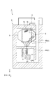
本実施形態の荷電粒子線照射装置の概略構成について説明する。図1は、本発明の一実施形態に係る荷電粒子線照射装置の平面視における配置図である。図1に示されるように、荷電粒子線照射装置1は、荷電粒子線を生成する加速器2と、治療台16上の患者15に対して任意の方向から荷電粒子線を照射する回転自在の照射部3と、加速器2で生成された荷電粒子線を照射部3へ輸送する輸送部4とを備えている。また、荷電粒子線照射装置1の各機器は、例えば、一階建ての建屋6の部屋の中に設置されている。
The schematic configuration of the charged particle beam irradiation device of this embodiment will be described. FIG. 1 is a layout view of a charged particle beam irradiation device according to an embodiment of the present invention in a plan view. As shown in FIG. 1, the charged
照射部3は、治療台16を取り囲むように設けられたガントリ5(回転部の一例)に取り付けられている。照射部3は、ガントリ5によって治療台16の周りに回転可能とされている。ガントリ5は、回転軸線周りに回転可能である。輸送部4は、加速器2からガントリ5へ荷電粒子線を輸送する外部経路4Aと、ガントリ5内において照射部3まで荷電粒子線を輸送する内部経路4Bと、を有する。外部経路4Aは、ガントリ5の後端側から、ガントリ5内に進入する。そして、内部経路4Bは、偏向電磁石7で外周側に荷電粒子線の軌道を変更した後、偏向電磁石8(六極磁石又は六極成分を持つ偏向磁石の一例)で荷電粒子線の軌道を大きく曲げて、外周側から照射部3に進入する。
The
図2は、図1の荷電粒子線照射装置の照射部付近の概略構成図である。なお、以下の説明においては、「X軸方向」、「Y軸方向」、「Z軸方向」という語を用いて説明する。「X軸方向」とは、照射部3の基軸AXに沿った方向であり、荷電粒子線Bの照射の深さ方向である。なお、「基軸AX」の詳細については後述する。図2では、基軸AXに沿って荷電粒子線Bが照射されている様子を示している。「Y軸方向」とは、X軸方向と直交する平面内における一の方向である。「Z軸方向」とは、X軸方向と直交する平面内においてY軸方向と直交する方向である。
FIG. 2 is a schematic configuration diagram of the vicinity of the irradiation portion of the charged particle beam irradiation device of FIG. In the following description, the terms "X-axis direction", "Y-axis direction", and "Z-axis direction" will be used. The "X-axis direction" is a direction along the base axis AX of the
図1及び図2を参照して、本実施形態に係る荷電粒子線照射装置1の詳細な構成について説明する。荷電粒子線照射装置1はスキャニング法に係る照射装置である。なお、スキャニング方式は特に限定されず、ラインスキャニング、ラスタースキャニング、スポットスキャニング等を採用してよい。荷電粒子線照射装置1は、加速器2、照射部3及び輸送部4の他に、制御部80と、治療計画装置90とを備えている。
A detailed configuration of the charged particle
加速器2は、荷電粒子を加速して予め設定されたエネルギーの荷電粒子線Bを生成する装置である。加速器2で生成された荷電粒子線Bは、輸送部4によって形成された軌道を通り、照射部3まで誘導される。加速器2として、例えば、サイクロトロン、シンクロサイクロトロン、ライナック等が挙げられる。本実施形態における加速器2として予め定めたエネルギーの荷電粒子線Bを出射するサイクロトロンを採用する。加速器2は、内部でイオン(荷電粒子)を加速平面上で周回させながら加速させる真空容器21、真空容器21内にイオンを供給するイオン源(不図示)を備えている。真空容器21は輸送部4の外部経路4Aに連絡している。真空容器21内で周回する荷電粒子線Bは、デフレクタ22で周回軌道から取り出されて輸送部4の外部経路4Aに供給される。なお、加速器2の加速平面は水平方向(X軸方向及びY軸方向)へ広がる。加速平面の中心を中心点CP2とする(図1参照)。真空容器21のZ軸方向に延びる中心線は中心点CP2を通過する。加速器2は、制御部80に接続されており、供給される電流が制御される。
The
図1に示すように、輸送部4は、照射部3の外部に設けられ加速器2で生成された荷電粒子線Bのエネルギーを減少させるエネルギーディグレーダ43(ディグレーダの一例)を有すると共に、加速器2で生成された荷電粒子線Bを照射部3へ輸送する。また、輸送部4は、エネルギーディグレーダ43と照射部3との間に設けられ荷電粒子線Bの形状、大きさ及び発散を調整するコリメータ44を有する。輸送部4の外部経路4Aは、上流側から順に、四極電磁石41と、ステアリング電磁石42と、エネルギーディグレーダ43と、コリメータ44と、四極電磁石41と、ビームストッパ45と、を備える。四極電磁石41は、荷電粒子線Bを収束させて荷電粒子線の形状を整えるための電磁石である。ステアリング電磁石42は、荷電粒子線の軌道を修正するための電磁石である。エネルギーディグレーダ43は、荷電粒子線のエネルギーを全体的に減少させて飛程を調整する機構である。コリメータ44は、荷電粒子線の形状を成形し、荷電粒子線の大きさ(サイズ)を調整し、荷電粒子線の発散を調整する。ビームストッパ45は、荷電粒子線の出射と停止を切り替える機構である。輸送部4の内部経路4Bは、上述のように偏向電磁石7,8を有する。
As shown in FIG. 1, the
照射部3は、加速器2で生成された荷電粒子線Bを照射する。具体的には、図2に示すように、照射部3は、患者15の体内の腫瘍(被照射体)14に対し、荷電粒子線Bを照射するものである。荷電粒子線Bとは、電荷をもった粒子を高速に加速したものであり、例えば陽子線、重粒子(重イオン)線、電子線等が挙げられる。具体的に、照射部3は、イオン源(不図示)で生成した荷電粒子を加速する加速器2から出射されて輸送部4で輸送された荷電粒子線Bを腫瘍14へ照射する装置である。照射部3は、走査電磁石10、ダクト11、ドーズモニタ12(モニタの一例)、ポジションモニタ13a,13b(モニタの一例)、コリメータ17、及びスノートディグレーダ30を備えている。走査電磁石10、ダクト11、各モニタ12,13a,13b、コリメータ17及びスノートディグレーダ30は、収容体としての照射ノズル9に収容されている。このように、照射ノズル9に各主構成要素を収容することによって照射部3が構成されている。なお、上述の要素に加えて、走査電磁石10の上流側に六極磁石又は六極成分を持つ偏向磁石、及びプロファイルモニタを設けてよい。また、ドーズモニタ12及びポジションモニタ13a,13bは省略してもよい。
The
走査電磁石10は、Y軸方向走査電磁石10a及びZ軸方向走査電磁石10bを含む。Y軸方向走査電磁石10a及びZ軸方向走査電磁石10bは、それぞれ一対の電磁石から構成され、制御部80から供給される電流に応じて一対の電磁石間の磁場を変化させ、当該電磁石間を通過する荷電粒子線Bを走査する。走査電磁石10によってY軸方向走査電磁石10aは、Y軸方向に荷電粒子線Bを走査し、Z軸方向走査電磁石10bは、Z軸方向に荷電粒子線Bを走査する。これらの走査電磁石10は、基軸AX上であって、加速器2よりも荷電粒子線Bの下流側にこの順で配置されている。なお、走査電磁石10は、治療計画装置90で予め計画された走査経路で荷電粒子線Bが照射されるように、荷電粒子線Bを走査する。
The
ダクト11は、基軸AX上であって走査電磁石10に対して下流側に配置されている。ダクト11は、走査電磁石10により走査された荷電粒子線Bを、ダクト11に対して下流に配置されているドーズモニタ12に誘導する。ダクト11は、例えば、基軸AXの上流から下流に向かって広がる円錐台形を呈する。ダクト11は、基軸AXに沿って貫通している。ダクト11の内部は、大気曝露されている。すなわち、ダクト11は、その内部に大気(空気)を含む。大気(空気)は、例えば、窒素及び酸素を含む。ダクト11は、例えば、その内部が大気曝露されている。このとき、照射ノズル9の内部のすべてが大気曝露されていてもよく、ダクト11の内部のみが大気曝露されるように構成されていてもよい。
The
ドーズモニタ12は、基軸AX上であってダクト11に対して下流側に配置されている。ポジションモニタ13a,13bは、荷電粒子線Bのビーム形状及び位置を検出監視する。ポジションモニタ13a,13bは、基軸AX上であって、ドーズモニタ12よりも荷電粒子線Bの下流側に配置されている。各モニタ12,13a,13bは、検出した検出結果を制御部80に出力する。
The dose monitor 12 is arranged on the base axis AX and downstream of the
スノートディグレーダ30は、通過する荷電粒子線Bのエネルギーを低下させて当該荷電粒子線Bの飛程のシフトを行う。本実施形態では、スノートディグレーダ30は、照射ノズル9の先端部9aに設けられている。なお、照射ノズル9の先端部9aとは、荷電粒子線Bの下流側の端部である。スノートディグレーダ30は、例えば、水等価厚さ約10cmである。
The snout degrader 30 reduces the energy of the passing charged particle beam B to shift the range of the charged particle beam B. In the present embodiment, the
コリメータ17は、少なくとも走査電磁石10よりも荷電粒子線Bの下流側に設けられ、荷電粒子線Bの一部を遮蔽し、一部を通過させる部材である。ここでは、コリメータ17は、ポジションモニタ13a,13bの下流側に設けられている。コリメータ17は、当該コリメータ17を移動させるコリメータ駆動部18に接続されている。
The
制御部80は、例えばCPU、ROM、及びRAM等により構成されている。この制御部80は、各モニタ12,13a,13bから出力された検出結果に基づいて、加速器2、走査電磁石10、及びコリメータ駆動部18を制御する。
The
また、荷電粒子線照射装置1の制御部80は、荷電粒子線治療の治療計画を行う治療計画装置90と接続されている。治療計画装置90は、治療前に患者15の腫瘍14をCT等で測定し、腫瘍14の各位置における線量分布(照射すべき荷電粒子線の線量分布)を計画する。具体的には、治療計画装置90は、腫瘍14に対して治療計画マップを作成する。治療計画装置90は、作成した治療計画マップを制御部80へ送信する。治療計画装置90が作成した治療計画マップでは、荷電粒子線Bがどのような走査経路を描くかが計画されている。
Further, the
スキャニング方式による荷電粒子線Bの照射を行う場合、腫瘍14をX軸方向に複数の層に仮想的に分割し、一の層において荷電粒子線を治療計画において定めた走査経路に従うように走査して照射する。そして、当該一の層における荷電粒子線Bの照射が完了した後に、隣接する次の層における荷電粒子線Bの照射を行う。
When irradiating the charged particle beam B by the scanning method, the
スキャニング方式による荷電粒子線の照射を行う場合、まず、加速器2から荷電粒子線Bを出射する。出射された荷電粒子線Bは、走査電磁石10の制御によって治療計画において定めた走査経路に従うように走査される。これにより、荷電粒子線Bは、腫瘍14に対してZ軸方向に設定された一の層における照射範囲内を走査されつつ照射されることとなる。一の層に対する照射が完了したら、次の層へ荷電粒子線Bを照射する。
When irradiating a charged particle beam by a scanning method, first, the charged particle beam B is emitted from the
制御部80の制御に応じた走査電磁石10の荷電粒子線照射イメージについて、図3(a)及び(b)を参照して説明する。図3は、腫瘍に対して設定された層を示す図である。図3(a)は、深さ方向において複数の層に仮想的にスライスされた被照射体を、図3(b)は、深さ方向から見た一の層における荷電粒子線の走査イメージを、それぞれ示している。
The charged particle beam irradiation image of the
図3(a)に示すように、被照射体は照射の深さ方向において複数の層に仮想的にスライスされており、本例では、深い(荷電粒子線Bの飛程が長い)層から順に、層L1、層L2、…層Ln−1、層Ln、層Ln+1、…層LN−1、層LNとN層に仮想的にスライスされている。また、図3(b)に示すように、荷電粒子線Bは、走査経路TLに沿ったビーム軌道を描きながら、連続照射(ラインスキャニング又はラスタースキャニング)の場合は層Lnの走査経路TLに沿って連続的に照射され、スポットスキャニングの場合は層Lnの複数の照射スポットに対して照射される。荷電粒子線Bは、Z軸方向に延びる走査経路TL1に沿って照射され、走査経路TL2に沿ってY軸方向に僅かにシフトし、隣の走査経路TL1に沿って照射される。このように、制御部80に制御された照射部3から出射した荷電粒子線Bは、走査経路TL上を移動する。
As shown in FIG. 3A, the irradiated body is virtually sliced into a plurality of layers in the irradiation depth direction, and in this example, from the deep layer (the range of the charged particle beam B is long). In this order, the layers L 1 , the layer L 2 , ... the layer L n-1 , the
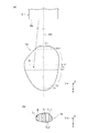
図4は、照射部の基軸について説明するための概略図である。図4を参照して、照射部3の「基軸AX」について説明する。基軸AXは、照射部3が荷電粒子線Bの照射を行うときの基準となる仮想的な基準線である。治療計画装置90が治療計画を行うときにスキャニングのパターンを作成する際にも、基軸AXを基準として治療計画を行う。例えば、図3(a)に示す層を設定する場合、各層は、基軸AXと垂直な面とする。また、Y軸方向への移動量、及びZ軸方向への移動量を設定する際も、基軸AXの位置を基準にする。図4(a)に示すように、基軸AXは、ガントリ5の中心線CLと直交し、且つ中心線CLを通過する。基軸AXは、ガントリ5の中心線CL上のアイソセンターACを通過する。図4(b)に示すように、ガントリ5を回転させて照射部3をアイソセンターAC周りに回転させた場合、照射部3の位置によらず、基軸AXは、ガントリ5上のアイソセンターACを通過する。なお、XYZ座標系は、基軸AXの向きによって変化する相対座標系である。図4では、基軸AXが鉛直方向に延びている状態におけるXYZ座標系が示されている。また、前述の図1においては、照射部3の様子を示すために基軸AXが水平方向に延びている状態を示している。従って、図1では、当該状態に対応したXYZ座標系が示されている。
FIG. 4 is a schematic view for explaining the basic axis of the irradiation unit. The “base axis AX” of the
次に、図5を参照して、本実施形態に係る荷電粒子線照射装置1において照射される荷電粒子線Bのエネルギー分布について説明する。
Next, with reference to FIG. 5, the energy distribution of the charged particle beam B irradiated by the charged particle
図5は、本発明の一実施形態に係る荷電粒子線照射装置において生成される荷電粒子線のエネルギー分布を示すグラフである。図5に示すグラフの縦軸は存在確率を示し、横軸は運動量の大きさを示す。荷電粒子線Bのうち、加速器2において生成される荷電粒子線B1は、例えば、230MeV程度である。荷電粒子線B1のエネルギー分布は、運動量の広がりが小さい。すなわち、荷電粒子線B1の運動量の平均値から離れた運動量を有する荷電粒子線B1の存在確率は、荷電粒子線B1の運動量の平均値近傍の荷電粒子線B1の存在確率に比べて著しく小さい。ここで、運動量の広がりが大きいとは、運動量の平均値における存在確率が小さく、様々な運動量を有する荷電粒子線の存在確率が大きいことを示す。本実施形態の荷電粒子線照射装置1では、荷電粒子線Bのうち、加速器2から出射された荷電粒子線B1をエネルギーディグレーダ43によりエネルギーを減少させた荷電粒子線B2は、エネルギーが減少したことにより荷電粒子線B1に比べて運動量の広がりが大きくなる。荷電粒子線B2の運動量の広がりとして、例えば、荷電粒子線B2の運動量分散は6%未満である。また、荷電粒子線B2の運動量分散は5%以下であってもよく、4%以下、3%以下又は2%以下であってもよい。このとき、荷電粒子線B2は、例えば、110MeVである。なお、運動量分散とは、荷電粒子線Bのエネルギーに対応する運動量の分散の値である。
FIG. 5 is a graph showing the energy distribution of charged particle beams generated in the charged particle beam irradiation device according to the embodiment of the present invention. The vertical axis of the graph shown in FIG. 5 indicates the existence probability, and the horizontal axis indicates the magnitude of momentum. Of the charged particle beams B, the charged particle beam B 1 generated by the
輸送部4は、エネルギーディグレーダ43によりエネルギーが減少した荷電粒子線B2のエネルギー分布を維持したまま当該荷電粒子線B2を照射部3に輸送する。具体的に、輸送部4には、外部経路4A及び内部経路4Bの何れの箇所にも運動量分析スリット(例えば図7に示す運動量分析スリット157)などのように、エネルギー分布を調整するような部材が設けられていない。なお、荷電粒子線B2は、エネルギーディグレーダ43を通過した後は、照射部3内のスノートディグレーダ30で、初めてエネルギー分布に対する影響を受ける。従って、照射部3内においても、スノートディグレーダ30よりも上流側の経路には、運動量分析スリットなどのように、エネルギー分布に影響を与える部材が設けられていない。なお、輸送部4が複数段階のエネルギーディグレーダ43を有する場合は、輸送部4は、最も下流側に配置されたエネルギーディグレーダ43を通過した荷電粒子線B2のエネルギー分布を維持する。
The transport unit 4 transports the charged particle beam B 2 to the
荷電粒子線Bの運動量の広がりが大きくなれば大きくなるほど(エネルギーが小さくなれば小さくなるほど)、輸送部4を通る荷電粒子線Bのビーム径は大きくなる。このため、荷電粒子線B2のビーム径は、荷電粒子線B1のビーム径に比べて大きい。輸送部4は、エネルギーディグレーダ43によりエネルギーが減少した荷電粒子線B2が通過可能な口径を有する。輸送部4は、少なくともエネルギーディグレーダ43の下流において荷電粒子線B2が通過可能な口径を有する。これにより、輸送部4は、荷電粒子線B2のエネルギーの選択を行うことなく加速器2からガントリ5に向けて荷電粒子線B2を輸送することができる。このとき、荷電粒子線照射装置1は、例えば、輸送部4の外部経路4Aを加速器2からガントリ5に向けて直線状に延在させることができる。
The larger the spread of the momentum of the charged particle beam B (the smaller the energy), the larger the beam diameter of the charged particle beam B passing through the
輸送部4内における荷電粒子線B2は荷電粒子線B1に比べて運動量の広がりが大きいこと、及び、運動量によって軌道がわずかに異なることから、荷電粒子線B2のビームの横断面形が非対称になる可能性がある。荷電粒子線B2のビームの横断面形における対称性を確保するため、輸送部4は、荷電粒子線B2の形状、大きさ及び発散を調整するコリメータ44の他に、荷電粒子線B2を収束させて荷電粒子線B2の形状を整える六極磁石又は六極成分を持つ偏向磁石を有する。例えば、輸送部4の内部経路4Bに設けられる偏向電磁石8は、六極成分を持つ偏向磁石である。
Since the charged particle beam B 2 in the
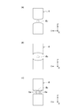
図6に示すように、偏向電磁石8は、六極成分を出すために様々な形状を取り得る。図6(a)、図6(b)及び図6(c)は、荷電粒子線B2の経路に直行する断面における概略断面図である。図6(a)は、本発明の一実施形態に係る荷電粒子線照射装置の輸送部における凸状の六極成分を持つ偏向磁石の概略構成図である。図6(a)に示すように、偏向電磁石8は、例えば、荷電粒子線B2が通過する空間に向かって凸状に膨らむ形状を有する。図6(b)は、本発明の一実施形態に係る荷電粒子線照射装置の輸送部における凹状の六極成分を持つ偏向磁石の概略構成図である。図6(b)に示すように、偏向電磁石8は、例えば、荷電粒子線B2が通過する空間に対して凹状に窪む形状を有していてもよい。図6(c)は、本発明の一実施形態に係る荷電粒子線照射装置の輸送部における補助コイルを有する六極成分を持つ偏向磁石の概略構成図である。図6(c)に示すように、偏向電磁石8は、例えば、荷電粒子線B2が通過する空間において、補正コイル8aを有していてもよい。
As shown in FIG. 6, the
上述のように、偏向電磁石8が六極成分を持つ偏向磁石であることで、運動量により異なる軌道を補正し、荷電粒子線B2のビームの横断面形の対称性を確保することができる。輸送部4は、通過する荷電粒子線B2のエネルギー分布に合わせて荷電粒子線B2の形状を整えることができ、荷電粒子線B2を加速器2から照射部3まで適切に輸送することができる。輸送部4において、偏向電磁石7も六極磁石又は六極成分を持つ偏向磁石であってもよい。
As described above, since the
輸送部4から照射部3に至った荷電粒子線B2は、大気曝露されている(内部に空気を含む)ダクト11を通ることで、散乱する。ダクトの内部が真空の状態又は希ガスで充填されている状態であって空気を含まない状態と比べて、ダクト11が大気曝露されている(空気を含む)ことで荷電粒子線B2はより散乱し、荷電粒子線B2のビームの横断面形状の対称性が確保される。
The charged particle beam B 2 from the
次に、本実施形態に係る荷電粒子線照射装置1の作用・効果について、比較例1に係る荷電粒子線照射装置100と比較しながら説明する。比較例1において、同一名称であり符号のみ異なる装置の機能は、実施形態と同様とする。
Next, the action / effect of the charged particle
図7は、比較例1に係る荷電粒子線照射装置の輸送部に設けられた選択部の構成を示す拡大図である。選択部150は、ESS(Energy Selection System)と称される機構である。例えば、照射部103の上側にESSの一部が搭載されるような構成とは異なり、選択部150の全構成要素が、室内遮蔽壁を隔てて、加速器102が配置されている空間に配置されている。選択部150の構成要素は、照射部103及びガントリ105が配置されている空間には配置されていない。
FIG. 7 is an enlarged view showing the configuration of a selection unit provided in the transport unit of the charged particle beam irradiation device according to Comparative Example 1. The
輸送部104に設けられた選択部150の詳細な構成について説明する。なお、輸送部104を構成する輸送管145に対して、選択部150の各構成要素が設けられる。第1の直線部141に設けられる選択部150は、上流側から順に、四極電磁石151と、ステアリング電磁石152と、エネルギーディグレーダ153と、四極電磁石151と、コリメータ154と、ビームストッパ155と、を備える。四極電磁石151は、荷電粒子線を収束させて荷電粒子線の形状を整えるための電磁石である。ステアリング電磁石152は、荷電粒子線の軌道を修正するための電磁石である。エネルギーディグレーダ153は、荷電粒子線のエネルギーを全体的に減少させて飛程を調整する機構である。エネルギーディグレーダ153は、例えば、加速器102から出射された荷電粒子線B1を70MeVまで減少させた荷電粒子線B3とする(図5参照)。このとき、荷電粒子線B3は、エネルギーが減少したことにより、荷電粒子線B1及び荷電粒子線B2に比べて運動量の広がりが大きくなる。荷電粒子線B3の運動量の広がりとして、例えば、荷電粒子線B3の運動量分散が6%以上となる。コリメータ154は、荷電粒子線の形状、大きさ及び発散を調整する。コリメータ154は、荷電粒子線の形状を成形し、荷電粒子線の大きさ(サイズ)を調整し、荷電粒子線の発散を調整する。ビームストッパ155は、荷電粒子線の出射と停止を切り替える機構である。
The detailed configuration of the
曲部143に設けられた選択部150は、上流側から順に、偏向電磁石156Aと、四極電磁石151と、運動量分析スリット157と、四極電磁石151と、偏向電磁石156Bと、を備える。運動量分析スリット157の前後には、それぞれ複数の四極電磁石151が設けられてもよい。偏向電磁石156Aは、第1の直線部141から輸送された荷電粒子線の軌道を曲げる電磁石である。荷電粒子線は、エネルギーによってどの程度曲がるかが異なっている。従って、偏向電磁石156Aで荷電粒子線を曲げて運動量分析スリット157を通すことで、所望のエネルギーの荷電粒子線を選択することができる。輸送部104のエネルギーディグレーダ153より下流において運動量分析スリット157まで輸送された荷電粒子線B3は、運動量分析スリット157により、荷電粒子線B3のエネルギー分布のうち、ピーク付近の領域(図5の領域E1参照)以外のエネルギーを削った状態となる。すなわち、運動量分析スリット157を通過することで、荷電粒子線B3は、エネルギー分布において領域E1の範囲の荷電粒子線(以下、荷電粒子線B4)となり、下流に輸送される。
The
そして、偏向電磁石156Bは、選択したエネルギーの荷電粒子線B4を第2の直線部142へ向かうように軌道を曲げる。曲部143は、二セットの偏向電磁石156A,156Bのみを有し、偏向電磁石156A,156B間には、他のセットの偏向電磁石を有していない。なお、偏向電磁石が連続して配置される場合は、一セットの偏向電磁石とみなす。すなわち、偏向電磁石156Aが、連続する複数の偏向電磁石に分割されている場合は、一セットの偏向電磁石と見なす。曲部143のうち、偏向電磁石156A,156B間の領域は、直線状に延びる直線部となるが、当該直線部は、第1の直線部141よりも短い。
Then, the
第2の直線部142に設けられた選択部150は、上流側から順に、四極電磁石151と、ステアリング電磁石152と、を備える。なお、第2の直線部142のうち、室内遮蔽壁に埋設される部分には、選択部150の構成要素は設けられていない。比較例1の荷電粒子線照射装置100において、ダクトの内部は真空であり、スノートディグレーダの水等価厚さは約4cmである。以上のことから、比較例1の荷電粒子線照射装置100において、加速器102により生成された荷電粒子線B1はエネルギーディグレーダ153によりエネルギーが減少することで荷電粒子線B3となる。比較例1の荷電粒子線照射装置100において、荷電粒子線B3は運動量分析スリット157によりエネルギー分布が領域E1の範囲に限定された荷電粒子線B4となる。比較例1の荷電粒子線照射装置100において、荷電粒子線B4は、スノートディグレーダまで輸送される。
The
比較例1の荷電粒子線照射装置100は所望のエネルギーの荷電粒子線を選択するため、輸送部104は曲部143を有する必要がある。輸送部104が大きく回り込んでいることによって、比較例1の荷電粒子線照射装置100において、加速器102、照射部103、及び輸送部104を配置するための設備のフットプリントが大きくなるという問題が生じる。これに対し、本実施形態の荷電粒子線照射装置1は、輸送部4において選択部150を設ける必要がないため、輸送部4を配置する環境に応じた形状に自在に変えることができ、例えば、輸送部4を直線状にすることができる。これにより、本実施形態の荷電粒子線照射装置1は、比較例1の荷電粒子線照射装置100に比べて、フットプリントを適切に小さくすることができる。荷電粒子線照射装置1は、装置全体を小型化し、設置面積を小さくすることができる。
Since the charged particle
次に、照射時間を短くすることについて図8を用いて説明する。図8(a)は、本発明の一実施形態に係る荷電粒子線照射装置により出射される荷電粒子線のブラッグピークを示すグラフである。図8(b)は、比較例1に係る荷電粒子線照射装置により出射される荷電粒子線のブラッグピークを示すグラフである。すなわち、図8(b)は、本実施形態の荷電粒子線照射装置1により出射される荷電粒子線よりエネルギーの小さい荷電粒子線のブラッグピークを示すグラフである。図8(a)及び図8(b)の各グラフの縦軸は線量であり、横軸は体内深さである。図8(a)及び図8(b)に示すように、被照射体(腫瘍14)は患者15の体内の一部に位置している。本実施形態の荷電粒子線照射装置1及び変形例の荷電粒子線照射装置では、様々な体内深さでピークを有するブラッグピークを示す複数の荷電粒子線Bを照射することで、拡大ブラッグピークを形成する。ここで、ブラッグピークとは、入射エネルギーに応じた特定の深さにて最大の放射線量放出して止まる荷電粒子線の特性であり、拡大ブラッグピークとは、複数の異なるエネルギーに対応したブラッグピークを被照射体の深さ方向に重ね合わせ、被照射体に所望の線量を付与するように調整したものを示す。
Next, shortening the irradiation time will be described with reference to FIG. FIG. 8A is a graph showing the Bragg peak of the charged particle beam emitted by the charged particle beam irradiator according to the embodiment of the present invention. FIG. 8B is a graph showing the Bragg peak of the charged particle beam emitted by the charged particle beam irradiator according to Comparative Example 1. That is, FIG. 8B is a graph showing the Bragg peak of a charged particle beam having a smaller energy than the charged particle beam emitted by the charged
本実施形態の荷電粒子線B2は、比較例1の荷電粒子線B4に比べて1回の荷電粒子線Bあたりの運動量分散が大きいため(エネルギー幅が大きいため)、本実施形態の荷電粒子線B2のブラッグピークは比較例1の荷電粒子線B4のブラッグピークより太くなる。このため、本実施形態の荷電粒子線照射装置1は、比較例1の荷電粒子線照射装置100に比べて、同一の拡大ブラッグピークを形成するのに必要なブラッグピークを有する荷電粒子線Bのエネルギーの数を少なくすることができる。これにより、荷電粒子線照射装置1の制御部80は、比較例1の荷電粒子線照射装置100の制御部に比べて、荷電粒子線Bのエネルギーを切り替える回数が減少する。荷電粒子線照射装置1は、比較例1の荷電粒子線照射装置100に比べて荷電粒子線Bの照射時間を短くすることができる。
Since the charged particle beam B 2 of the present embodiment has a larger momentum dispersion per charged particle beam B than the charged particle beam B 4 of Comparative Example 1 (because the energy width is large), the charge of the present embodiment is charged. The Bragg peak of the particle beam B 2 is thicker than the Bragg peak of the charged particle beam B 4 of Comparative Example 1. Therefore, the charged particle
ここで、比較例1の荷電粒子線照射装置100において、エネルギーディグレーダ153の通過後の荷電粒子線を、荷電粒子線B3の代わりに、本実施形態の荷電粒子線照射装置1における荷電粒子線B2と同一のエネルギーの荷電粒子線とする場合を考える。当該荷電粒子線照射装置を比較例2の荷電粒子線照射装置とし、スノートディグレーダの水等価厚さを適宜変更する。この場合、比較例2のエネルギーディグレーダを通過した後の荷電粒子線B2は、運動量分析スリットによりエネルギー分布が領域E1の範囲に限定された荷電粒子線B5となる。このため、本実施形態の荷電粒子線照射装置1の照射部3における荷電粒子線B2は、照射部における荷電粒子線B5に比べて、運動量の広がりが大きい。本実施形態の荷電粒子線照射装置1における荷電粒子線B2のブラッグピークは、比較例2の荷電粒子線照射装置における荷電粒子線B5のブラッグピークに比べて太くなる。このため、運動量分析スリット157を設けない本実施形態の荷電粒子線照射装置1は、比較例2の荷電粒子線照射装置に比べて荷電粒子線Bの照射時間を短くすることができる。
Here, in the charged particle
以上のように、本実施形態に係る荷電粒子線照射装置1の輸送部4は、荷電粒子線B2のエネルギーの中から特定の範囲のエネルギーを選択する運動量分析スリットを設けることなく、当該荷電粒子線B2をエネルギーディグレーダ43から照射部3に輸送することができる。特に、従って、運動量分析スリットを設けた場合(比較例1,2)の荷電粒子線B4,B5に比べて、本実施形態の荷電粒子線B2は、ブラッグピークが太くなる。したがって、荷電粒子線照射装置1において、拡大ブラッグピークの形成に必要な荷電粒子線Bのエネルギーの数が減少し、荷電粒子線Bのエネルギーを切り替える回数が減少する。以上より、荷電粒子線照射装置1は、荷電粒子線Bの照射時間を短くすることができる。
As described above, the
また、本実施形態に係る荷電粒子線照射装置1は、特許文献1のようにガントリ5内に運動量分析スリットを設けていない。運動量分析スリットがガントリ内に収納されていた場合、運動量分析スリットで停止した陽子線から不要な中性子線が発生するため、患者への不要な中性子線量が増えることが考えられる。しかしながら、本実施形態の荷電粒子線照射装置1は運動量分析スリットを有していないため、不要な中性子線の発生を抑えることができる。
Further, the charged particle
また、本実施形態に係る荷電粒子線照射装置1において、コリメータ44は、エネルギーディグレーダ43を通過した荷電粒子線Bの形状、大きさ及び発散を調整することができ、荷電粒子線Bのエネルギー分布を維持させたままエネルギーディグレーダ43から照射部3まで輸送することができる。このとき、コリメータ44により荷電粒子線Bの形状、大きさ及び発散が調整されるため、荷電粒子線Bは、例えばコリメータ44より下流の照射部3のダクト11に当たることなくダクト11の内部を通過することができる。
Further, in the charged particle
また、本実施形態に係る荷電粒子線照射装置1において、輸送部4は、荷電粒子線B2が通過可能な口径を有しているため、輸送部4は、荷電粒子線B2に対して特定の範囲のエネルギーを選択することなく、荷電粒子線B2のエネルギー分布を維持させたままエネルギーディグレーダ43から照射部3まで輸送することができる。
Further, in the charged particle
本実施形態の荷電粒子線照射装置1のスノートディグレーダ30は、比較例1の荷電粒子線照射装置100のスノートディグレーダに比べて水等価厚さが大きい。これは、荷電粒子線B2が荷電粒子線B4に比べてエネルギーが大きいため、患者15の浅い部位に位置する腫瘍14(被照射体)に照射可能なようにするためである。
The snout degrader 30 of the charged
本実施形態の荷電粒子線照射装置1のエネルギーディグレーダ43は、荷電粒子線B2の運動量分散が6%未満となるようにすることで、荷電粒子線B3に比べて荷電粒子線B2のエネルギー分布の広がりを抑えることができる。ここで、本実施形態の荷電粒子線照射装置1において、照射部3の荷電粒子線を、荷電粒子線B2の代わりに、比較例1の荷電粒子線照射装置1における運動量分析スリット157の上流の荷電粒子線B3と同一のエネルギーの荷電粒子線とする場合を考える。当該荷電粒子線照射装置を変形例(本発明の他の実施形態)の荷電粒子線照射装置とし、スノートディグレーダの水等価厚さを適宜変更する。上述の通り、荷電粒子線B3の運動量分散は6%以上である。この場合、荷電粒子線B2に比べて運動量の広がりが大きい荷電粒子線B3、すなわち荷電粒子線B2に比べてビーム径が大きい荷電粒子線B3が輸送部内を通過する。従って、荷電粒子線B3を採用した場合は、荷電粒子線B2の場合より輸送部の口径を大きくする必要がある。また、荷電粒子線B2に比べてビーム径が大きい荷電粒子線B3は、輸送部の下流の偏向電磁石、又は照射部のダクトに当たって消失した場合、変形例の荷電粒子線照射装置が放射化する可能性又は不要な放射線量を増加させる可能性がある。当該可能性を抑制するため、荷電粒子線B3を採用した場合は、荷電粒子線B2の場合より変形例の荷電粒子線照射装置のダクト及び偏向電磁石などを十分に大きくする必要がある。
Energy degrader 43 of the charged particle
以上より、本実施形態の荷電粒子線照射装置1は、エネルギーディグレーダ43の下流の荷電粒子線Bを、運動量分散が6%未満の荷電粒子線B2とすることで、変形例の荷電粒子線照射装置に比べて設備の巨大化を抑えることができ、フットプリントを適切に小さくすることができる。また、本実施形態の荷電粒子線照射装置1は、変形例の荷電粒子線照射装置に比べて、設備の巨大化を抑えつつ、設備の放射化及び不要な放射線量を抑制することができる。
Thus, the charged particle
なお、変形例の荷電粒子線照射装置は、輸送部において選択部150を設ける必要がないため、比較例1の荷電粒子線照射装置100に比べて輸送部4を配置する環境に応じた形状に自在に変えることができる。例えば、変形例の荷電粒子線照射装置においても、輸送部4を直線状にすることができる。これにより、変形例の荷電粒子線照射装置は、比較例1の荷電粒子線照射装置100に比べて、フットプリントを適切に小さくすることができる。また、変形例の荷電粒子線照射装置の照射部における荷電粒子線B3のブラッグピークは、比較例1の照射部における荷電粒子線B4のブラッグピークより太くなる。これにより、変形例の荷電粒子線照射装置は、比較例1の荷電粒子線照射装置100に比べて荷電粒子線Bの照射時間を短くすることができる。
Since it is not necessary to provide the
ここで、例示として、各エネルギーの荷電粒子線B(陽子線)の飛程についてまとめる。60MeVの荷電粒子線Bの飛程は3cm、70MeVの荷電粒子線Bの飛程は4cm、110MeVの荷電粒子線Bの飛程は9cmである。水に向けて荷電粒子線Bを出射させた場合、水深4cmにおける各エネルギーの荷電粒子線B(陽子線)のビーム径を例示する。60MeVの荷電粒子線Bは、水深4cmまで届かない。70MeVの荷電粒子線Bの水深4cmにおけるビーム径は10mmである。110MeVの荷電粒子線Bの水深4cmにおけるビーム径は、スノートディグレーダ30の水等価厚さを5cmと設定したとき、7mmである。
Here, as an example, the range of the charged particle beam B (proton beam) of each energy is summarized. The range of the 60 MeV charged particle beam B is 3 cm, the range of the 70 MeV charged particle beam B is 4 cm, and the range of the 110 MeV charged particle beam B is 9 cm. When the charged particle beam B is emitted toward water, the beam diameter of the charged particle beam B (proton beam) of each energy at a water depth of 4 cm is illustrated. The charged particle beam B of 60 MeV does not reach the water depth of 4 cm. The beam diameter of the 70 MeV charged particle beam B at a water depth of 4 cm is 10 mm. The beam diameter of the 110 MeV charged particle beam B at a water depth of 4 cm is 7 mm when the water equivalent thickness of the
続いて、水に向けて荷電粒子線Bを出射させた場合、水深2cmにおける各エネルギーの荷電粒子線B(陽子線)のビーム径を例示する。60MeVの荷電粒子線Bの水深2cmにおけるビーム径は、スノートディグレーダの水等価厚さを1cmと設定したとき、11mmでありうる。70MeVの荷電粒子線Bの水深2cmにおけるビーム径は、スノートディグレーダの水等価厚さを2cmと設定したとき、10mmである。110MeVの荷電粒子線Bの水深2cmにおけるビーム径は、スノートディグレーダ30の水等価厚さを7cmと設定したとき、7mmである。スノートディグレーダ30の厚みを荷電粒子線Bのエネルギーの大きさごとに変更することで、荷電粒子線Bに対する水深を統一することができる。
Subsequently, when the charged particle beam B is emitted toward water, the beam diameter of the charged particle beam B (proton beam) of each energy at a water depth of 2 cm is illustrated. The beam diameter of the 60 MeV charged particle beam B at a water depth of 2 cm can be 11 mm when the water equivalent thickness of the snout grader is set to 1 cm. The beam diameter of the 70 MeV charged particle beam B at a water depth of 2 cm is 10 mm when the water equivalent thickness of the snout grader is set to 2 cm. The beam diameter of the 110 MeV charged particle beam B at a water depth of 2 cm is 7 mm when the water equivalent thickness of the
以上の結果から、複数の異なるエネルギーを有する荷電粒子線Bにおいて、同一の水深でのビームサイズは、110MeVの荷電粒子線Bに対してスノートディグレーダ30の水等価厚さを適宜設定したときが最も小さくなる。これにより、荷電粒子線B2の出射対象が浅い領域に位置する場合、80MeV以上150MeV以下のエネルギーを有する荷電粒子線B2にスノートディグレーダ30を組み合わせた条件で出射した方が、荷電粒子線B2より低いエネルギーの荷電粒子線B(例えば70MeV)に比べてビーム径が小さくなる。このため、荷電粒子線照射装置1は、患者15の腫瘍14(被照射体)が浅い領域に位置する場合、当該腫瘍14の位置、大きさ又は形状に合わせて、例えば、80MeV以上150MeV以下の荷電粒子線B2を照射することができる。なお、荷電粒子線照射装置1は、腫瘍14(被照射体)が浅い領域に位置する場合、例えば、90MeV以上150MeV以下の荷電粒子線B2を照射してもよく、100MeV以上150MeV以下の荷電粒子線B2を照射してもよく、110MeV以上150MeV以下の荷電粒子線B2を照射してもよい。また、腫瘍14(被照射体)が深い領域に位置する場合等において、荷電粒子線照射装置1は、例えば、150MeV以上の荷電粒子線B2を照射してもよい。
From the above results, in the charged particle beam B having a plurality of different energies, the beam size at the same water depth is when the water equivalent thickness of the
また、変形例の輸送部において荷電粒子線B1から荷電粒子線B3までエネルギーを下げる場合に比べて、本実施形態の輸送部4において荷電粒子線B1から荷電粒子線B2までエネルギーを下げる割合は小さい。このため、本実施形態において、加速器2から照射部3までの輸送部4における荷電粒子線Bの輸送過程におけるエネルギーの輸送効率は、変形例のエネルギーの輸送効率に比べて高くなる。本実施形態において、ガントリ5内のアイソセンターACでのビーム電流は、変形例のアイソセンターでのビーム電流に比べて上昇し、患者15の腫瘍14(被照射体)に対する照射時間を短くすることができる。
Further, as compared with the case where the energy is reduced from the charged particle beam B 1 to the charged particle beam B 3 in the transport section of the modified example, the energy is transferred from the charged particle beam B 1 to the charged particle beam B 2 in the transport section 4 of the present embodiment. The rate of lowering is small. Therefore, in the present embodiment, the energy transport efficiency in the transport process of the charged particle beam B in the
本実施形態の荷電粒子線照射装置1の荷電粒子線B2は、比較例1の荷電粒子線B4及び比較例2の荷電粒子線B5のように運動量分析スリット157においてエネルギーの選択が行われていないため、照射部3内でビームの横断面形状の対称性が確保できない可能性がある。しかしながら、荷電粒子線B2は、照射部3のダクト11内を通過するときに、ダクト11の内部の大気(空気)によって散乱する。これにより、荷電粒子線照射装置1が運動量分析スリット(選択部)を有しない場合であっても、荷電粒子線B2のビームの横断面形状の対称性が確保される。よって、照射部3は、荷電粒子線B2のビームを適切な範囲に照射することができる。
The charged particle beam B 2 of the charged
輸送部4の内部経路4Bは、荷電粒子線B2を収束させて荷電粒子線B2の形状を整える六極成分を持つ偏向磁石(偏向電磁石8)を有する。このため、輸送部4の内部経路4Bは、通過する荷電粒子線B2のエネルギー分布に合わせて荷電粒子線B2の形状を整えることができ、荷電粒子線B2を加速器2から照射部3まで適切に輸送することができる。
本発明は、上述の実施形態に限定されるものではない。 The present invention is not limited to the above-described embodiment.
例えば、エネルギーディグレーダ43は、荷電粒子線Bの運動量分散が6%以上となるように加速器で生成された荷電粒子線Bのエネルギーを減少させてもよい。このとき、輸送部4の各部位は、荷電粒子線Bが通過可能な口径を有する。コリメータ44は、エネルギーディグレーダ43と照射部3との間に設けられなくてもよい。このとき、輸送部4の各部位は、荷電粒子線Bが通過可能な口径を有する。ダクト11の内部は真空であってもよく、ダクト11の内部に希ガスが充填されていてもよい。希ガスは、例えばアルゴンガスである。輸送部4の内部経路4Bに位置する偏向電磁石8は、六極磁石又は六極成分を持つ偏向磁石でなくてもよい。
For example, the energy degrader 43 may reduce the energy of the charged particle beam B generated by the accelerator so that the momentum dispersion of the charged particle beam B is 6% or more. At this time, each part of the
また、建屋6の構造や、各構成要素のレイアウトは、本発明の趣旨を逸脱しない範囲で、適宜変更してもよい。 Further, the structure of the building 6 and the layout of each component may be appropriately changed as long as the gist of the present invention is not deviated.
1…荷電粒子線照射装置、2…加速器、3…照射部、4…輸送部、5…ガントリ(回転部の一例)、8…偏向電磁石(六極磁石又は六極成分を持つ偏向磁石の一例)、10…走査電磁石、11…ダクト、12…ドーズモニタ(モニタの一例)、13a,13b…ポジションモニタ(モニタの一例)、43…エネルギーディグレーダ(ディグレーダの一例)、44…コリメータ、B,B1,B2,B3,B4,B5…荷電粒子線。 1 ... Charged particle beam irradiation device, 2 ... Accelerator, 3 ... Irradiation section, 4 ... Transport section, 5 ... Gantry (an example of rotating section), 8 ... Deflection electromagnet (an example of a hexapole magnet or a deflection magnet having a hexapole component) ), 10 ... scanning electromagnet, 11 ... duct, 12 ... dose monitor (example of monitor), 13a, 13b ... position monitor (example of monitor), 43 ... energy degrader (example of degrader), 44 ... collimeter, B, B 1 , B 2 , B 3 , B 4 , B 5 ... Charged particle beam.
Claims (6)
荷電粒子を加速して前記荷電粒子線を生成する加速器と、
回転軸線周りに回転可能な回転部を有すると共に前記加速器で生成された前記荷電粒子線を照射する照射部と、
前記照射部の外部に設けられ前記加速器で生成された前記荷電粒子線のエネルギーを減少させるディグレーダを有すると共に、前記加速器で生成された前記荷電粒子線を前記照射部へ輸送する輸送部と、を備え、
前記輸送部は、前記ディグレーダによりエネルギーが減少した前記荷電粒子線のエネルギー分布を維持したまま当該荷電粒子線を前記照射部に輸送する、
荷電粒子線照射装置。 It is a charged particle beam irradiator that irradiates a charged particle beam.
An accelerator that accelerates charged particles to generate the charged particle beam,
An irradiation unit that has a rotating unit that can rotate around the axis of rotation and irradiates the charged particle beam generated by the accelerator.
A transport unit provided outside the irradiation unit and having a degrader for reducing the energy of the charged particle beam generated by the accelerator and transporting the charged particle beam generated by the accelerator to the irradiation unit. Prepare,
The transport unit transports the charged particle beam to the irradiation unit while maintaining the energy distribution of the charged particle beam whose energy has been reduced by the degrader.
Charged particle beam irradiation device.
前記ダクトの内部は大気曝露されている、請求項1〜4の何れか一項に記載の荷電粒子線照射装置。 The irradiation unit further includes a scanning electromagnet that scans the charged particle beam, a duct through which the charged particle beam scanned by the scanning electromagnet passes, and a monitor that detects the charged particle beam that has passed through the duct. Have and
The charged particle beam irradiation device according to any one of claims 1 to 4, wherein the inside of the duct is exposed to the atmosphere.
Priority Applications (5)
| Application Number | Priority Date | Filing Date | Title |
|---|---|---|---|
| JP2020060893A JP2021159110A (en) | 2020-03-30 | 2020-03-30 | Charged particle beam irradiation device |
| KR1020210038424A KR20210122128A (en) | 2020-03-30 | 2021-03-25 | Irradiation apparatus of charged particle ray |
| TW110111122A TWI771964B (en) | 2020-03-30 | 2021-03-26 | Charged particle beam irradiation device |
| US17/217,546 US20210299480A1 (en) | 2020-03-30 | 2021-03-30 | Charged particle beam irradiation apparatus |
| CN202110337554.0A CN113470863A (en) | 2020-03-30 | 2021-03-30 | Charged particle beam irradiation apparatus |
Applications Claiming Priority (1)
| Application Number | Priority Date | Filing Date | Title |
|---|---|---|---|
| JP2020060893A JP2021159110A (en) | 2020-03-30 | 2020-03-30 | Charged particle beam irradiation device |
Publications (2)
| Publication Number | Publication Date |
|---|---|
| JP2021159110A true JP2021159110A (en) | 2021-10-11 |
| JP2021159110A5 JP2021159110A5 (en) | 2023-02-03 |
Family
ID=77855143
Family Applications (1)
| Application Number | Title | Priority Date | Filing Date |
|---|---|---|---|
| JP2020060893A Pending JP2021159110A (en) | 2020-03-30 | 2020-03-30 | Charged particle beam irradiation device |
Country Status (5)
| Country | Link |
|---|---|
| US (1) | US20210299480A1 (en) |
| JP (1) | JP2021159110A (en) |
| KR (1) | KR20210122128A (en) |
| CN (1) | CN113470863A (en) |
| TW (1) | TWI771964B (en) |
Families Citing this family (2)
| Publication number | Priority date | Publication date | Assignee | Title |
|---|---|---|---|---|
| WO2022271662A1 (en) * | 2021-06-21 | 2022-12-29 | ProNova Solutions, LLC | Energy selection system for compact proton therapy |
| CN115006747B (en) * | 2022-08-09 | 2022-10-25 | 合肥中科离子医学技术装备有限公司 | Superconducting rotating gantry and proton treatment apparatus |
Family Cites Families (11)
| Publication number | Priority date | Publication date | Assignee | Title |
|---|---|---|---|---|
| JPH11142600A (en) * | 1997-11-12 | 1999-05-28 | Mitsubishi Electric Corp | Charged particle beam irradiation device and irradiation method |
| WO2011048088A1 (en) * | 2009-10-23 | 2011-04-28 | Ion Beam Applications | Gantry comprising beam analyser for use in particle therapy |
| WO2012008025A1 (en) * | 2010-07-14 | 2012-01-19 | 三菱電機株式会社 | Particle beam irradiation device, and particle beam treatment device |
| JP5907862B2 (en) * | 2012-04-27 | 2016-04-26 | 三菱電機株式会社 | Particle beam rotation irradiation equipment |
| JP6121748B2 (en) * | 2013-02-22 | 2017-04-26 | 株式会社東芝 | Ion accelerator and medical device |
| JP6109702B2 (en) * | 2013-10-15 | 2017-04-05 | 住友重機械工業株式会社 | Charged particle beam irradiation equipment |
| JP6169254B2 (en) * | 2014-03-25 | 2017-07-26 | 三菱電機株式会社 | Circular accelerator, operation method of circular accelerator, and particle beam therapy system |
| WO2015151275A1 (en) * | 2014-04-04 | 2015-10-08 | 三菱電機株式会社 | Particle therapy device |
| CN109224317B (en) * | 2017-07-11 | 2022-02-18 | 住友重机械工业株式会社 | Charged particle beam therapy device |
| CN109260606A (en) * | 2017-07-17 | 2019-01-25 | 住友重机械工业株式会社 | Charged particle beam treatment system |
| US20190030373A1 (en) * | 2017-07-27 | 2019-01-31 | Sumitomo Heavy Industries, Ltd. | Charged particle beam treatment system |
-
2020
- 2020-03-30 JP JP2020060893A patent/JP2021159110A/en active Pending
-
2021
- 2021-03-25 KR KR1020210038424A patent/KR20210122128A/en active Search and Examination
- 2021-03-26 TW TW110111122A patent/TWI771964B/en active
- 2021-03-30 CN CN202110337554.0A patent/CN113470863A/en active Pending
- 2021-03-30 US US17/217,546 patent/US20210299480A1/en active Pending
Also Published As
| Publication number | Publication date |
|---|---|
| US20210299480A1 (en) | 2021-09-30 |
| CN113470863A (en) | 2021-10-01 |
| KR20210122128A (en) | 2021-10-08 |
| TW202135888A (en) | 2021-10-01 |
| TWI771964B (en) | 2022-07-21 |
Similar Documents
| Publication | Publication Date | Title |
|---|---|---|
| US8153989B2 (en) | Charged particle beam irradiating apparatus | |
| CN109499019B (en) | Compact proton therapy system with energy selection onboard a rotatable gantry | |
| JP4339904B2 (en) | Particle beam therapy system | |
| TWI771964B (en) | Charged particle beam irradiation device | |
| JP2014127377A (en) | Particle beam therapy system | |
| JP2009039219A (en) | Irradiation system and method for charged particle beam | |
| JP2012099354A (en) | Particle accelerator and bnct device | |
| CN107789746B (en) | Charged particle beam therapy device and ridge filter | |
| JP6657015B2 (en) | Charged particle beam therapy system | |
| CN109224317B (en) | Charged particle beam therapy device | |
| JP7165499B2 (en) | Charged particle beam therapy system | |
| JP6787771B2 (en) | Charged particle beam therapy device | |
| JP2006208200A (en) | Charged particle beam irradiation system | |
| JP6640997B2 (en) | Particle therapy equipment | |
| WO2021049131A1 (en) | Particle beam irradiation system and particle beam irradiation facility | |
| TWI827314B (en) | Particle therapy device | |
| JP2019191031A (en) | Particle beam irradiation device, and particle beam treatment system | |
| EP4052758A1 (en) | Charged particle beam irradiation system | |
| JP2018143659A (en) | Charged particle beam treatment device | |
| JP2018196625A (en) | Charged particle beam treatment apparatus | |
| JP2004121654A (en) | Apparatus for irradiating electric charged particle for medical use | |
| US20230319973A1 (en) | Accelerator and particle beam transport systems and methods | |
| WO2018181595A1 (en) | Charged particle beam treatment device | |
| JP2009207581A (en) | Radiotherapy apparatus | |
| JP2022152591A (en) | Particle beam medical treatment device and accelerator |
Legal Events
| Date | Code | Title | Description |
|---|---|---|---|
| A621 | Written request for application examination |
Free format text: JAPANESE INTERMEDIATE CODE: A621 Effective date: 20230118 |
|
| A521 | Request for written amendment filed |
Free format text: JAPANESE INTERMEDIATE CODE: A523 Effective date: 20230126 |
|
| A131 | Notification of reasons for refusal |
Free format text: JAPANESE INTERMEDIATE CODE: A131 Effective date: 20231128 |
|
| A521 | Request for written amendment filed |
Free format text: JAPANESE INTERMEDIATE CODE: A523 Effective date: 20240125 |