JP2021138245A - Vehicle control device and vehicle control method - Google Patents
Vehicle control device and vehicle control method Download PDFInfo
- Publication number
- JP2021138245A JP2021138245A JP2020036604A JP2020036604A JP2021138245A JP 2021138245 A JP2021138245 A JP 2021138245A JP 2020036604 A JP2020036604 A JP 2020036604A JP 2020036604 A JP2020036604 A JP 2020036604A JP 2021138245 A JP2021138245 A JP 2021138245A
- Authority
- JP
- Japan
- Prior art keywords
- lane
- vehicle
- mode
- lane change
- traffic
- Prior art date
- Legal status (The legal status is an assumption and is not a legal conclusion. Google has not performed a legal analysis and makes no representation as to the accuracy of the status listed.)
- Granted
Links
Images


Classifications
-
- B—PERFORMING OPERATIONS; TRANSPORTING
- B60—VEHICLES IN GENERAL
- B60W—CONJOINT CONTROL OF VEHICLE SUB-UNITS OF DIFFERENT TYPE OR DIFFERENT FUNCTION; CONTROL SYSTEMS SPECIALLY ADAPTED FOR HYBRID VEHICLES; ROAD VEHICLE DRIVE CONTROL SYSTEMS FOR PURPOSES NOT RELATED TO THE CONTROL OF A PARTICULAR SUB-UNIT
- B60W30/00—Purposes of road vehicle drive control systems not related to the control of a particular sub-unit, e.g. of systems using conjoint control of vehicle sub-units, or advanced driver assistance systems for ensuring comfort, stability and safety or drive control systems for propelling or retarding the vehicle
- B60W30/18—Propelling the vehicle
- B60W30/18009—Propelling the vehicle related to particular drive situations
- B60W30/18163—Lane change; Overtaking manoeuvres
-
- B—PERFORMING OPERATIONS; TRANSPORTING
- B60—VEHICLES IN GENERAL
- B60W—CONJOINT CONTROL OF VEHICLE SUB-UNITS OF DIFFERENT TYPE OR DIFFERENT FUNCTION; CONTROL SYSTEMS SPECIALLY ADAPTED FOR HYBRID VEHICLES; ROAD VEHICLE DRIVE CONTROL SYSTEMS FOR PURPOSES NOT RELATED TO THE CONTROL OF A PARTICULAR SUB-UNIT
- B60W10/00—Conjoint control of vehicle sub-units of different type or different function
- B60W10/20—Conjoint control of vehicle sub-units of different type or different function including control of steering systems
-
- B—PERFORMING OPERATIONS; TRANSPORTING
- B60—VEHICLES IN GENERAL
- B60W—CONJOINT CONTROL OF VEHICLE SUB-UNITS OF DIFFERENT TYPE OR DIFFERENT FUNCTION; CONTROL SYSTEMS SPECIALLY ADAPTED FOR HYBRID VEHICLES; ROAD VEHICLE DRIVE CONTROL SYSTEMS FOR PURPOSES NOT RELATED TO THE CONTROL OF A PARTICULAR SUB-UNIT
- B60W30/00—Purposes of road vehicle drive control systems not related to the control of a particular sub-unit, e.g. of systems using conjoint control of vehicle sub-units, or advanced driver assistance systems for ensuring comfort, stability and safety or drive control systems for propelling or retarding the vehicle
- B60W30/08—Active safety systems predicting or avoiding probable or impending collision or attempting to minimise its consequences
-
- B—PERFORMING OPERATIONS; TRANSPORTING
- B60—VEHICLES IN GENERAL
- B60W—CONJOINT CONTROL OF VEHICLE SUB-UNITS OF DIFFERENT TYPE OR DIFFERENT FUNCTION; CONTROL SYSTEMS SPECIALLY ADAPTED FOR HYBRID VEHICLES; ROAD VEHICLE DRIVE CONTROL SYSTEMS FOR PURPOSES NOT RELATED TO THE CONTROL OF A PARTICULAR SUB-UNIT
- B60W30/00—Purposes of road vehicle drive control systems not related to the control of a particular sub-unit, e.g. of systems using conjoint control of vehicle sub-units, or advanced driver assistance systems for ensuring comfort, stability and safety or drive control systems for propelling or retarding the vehicle
- B60W30/14—Adaptive cruise control
- B60W30/143—Speed control
-
- B—PERFORMING OPERATIONS; TRANSPORTING
- B60—VEHICLES IN GENERAL
- B60W—CONJOINT CONTROL OF VEHICLE SUB-UNITS OF DIFFERENT TYPE OR DIFFERENT FUNCTION; CONTROL SYSTEMS SPECIALLY ADAPTED FOR HYBRID VEHICLES; ROAD VEHICLE DRIVE CONTROL SYSTEMS FOR PURPOSES NOT RELATED TO THE CONTROL OF A PARTICULAR SUB-UNIT
- B60W40/00—Estimation or calculation of non-directly measurable driving parameters for road vehicle drive control systems not related to the control of a particular sub unit, e.g. by using mathematical models
- B60W40/02—Estimation or calculation of non-directly measurable driving parameters for road vehicle drive control systems not related to the control of a particular sub unit, e.g. by using mathematical models related to ambient conditions
- B60W40/06—Road conditions
-
- B—PERFORMING OPERATIONS; TRANSPORTING
- B60—VEHICLES IN GENERAL
- B60W—CONJOINT CONTROL OF VEHICLE SUB-UNITS OF DIFFERENT TYPE OR DIFFERENT FUNCTION; CONTROL SYSTEMS SPECIALLY ADAPTED FOR HYBRID VEHICLES; ROAD VEHICLE DRIVE CONTROL SYSTEMS FOR PURPOSES NOT RELATED TO THE CONTROL OF A PARTICULAR SUB-UNIT
- B60W60/00—Drive control systems specially adapted for autonomous road vehicles
- B60W60/001—Planning or execution of driving tasks
-
- B—PERFORMING OPERATIONS; TRANSPORTING
- B60—VEHICLES IN GENERAL
- B60W—CONJOINT CONTROL OF VEHICLE SUB-UNITS OF DIFFERENT TYPE OR DIFFERENT FUNCTION; CONTROL SYSTEMS SPECIALLY ADAPTED FOR HYBRID VEHICLES; ROAD VEHICLE DRIVE CONTROL SYSTEMS FOR PURPOSES NOT RELATED TO THE CONTROL OF A PARTICULAR SUB-UNIT
- B60W2520/00—Input parameters relating to overall vehicle dynamics
- B60W2520/10—Longitudinal speed
Abstract
Description
本発明は、自動車線変更を実行する車両制御装置及び車両制御方法に関する。 The present invention relates to a vehicle control device and a vehicle control method for executing a lane change.
近年、自車両の一部の走行制御を運転者の意図にかかわらず実行する運転支援車両、及び、自車両の全ての走行制御を運転者の意図にかかわらず実行する自動運転車両が開発されている。運転支援及び自動運転は、車両側で状況判断を行うことが容易である場合に可能とされ、車両側で状況判断を行うことが困難である場合に不可とされる。特許文献1には、自動運転区間において、交通情報を考慮して自動運転が可能か否かを判定する自動運転支援システムが示される。 In recent years, a driving support vehicle that executes a part of the driving control of the own vehicle regardless of the driver's intention and an automatic driving vehicle that executes all the driving control of the own vehicle regardless of the driver's intention have been developed. There is. Driving assistance and automatic driving are possible when it is easy for the vehicle to judge the situation, and not when it is difficult for the vehicle to judge the situation. Patent Document 1 discloses an automatic driving support system that determines whether or not automatic driving is possible in consideration of traffic information in an automatic driving section.
第1車線と、第2車線と、第3車線又は路肩と、が隣接する道路で、第3車線又は路肩に交通規制物(パイロン、発煙筒等)が置かれる場合がある。このような状況において、交通規制物が置かれた場所の先では更に第2車線の通行が規制されている可能性がある。自車両は、第1車線から第2車線に車線変更した後に、第2車線の交通規制に遭遇すると、再び第1車線に戻らなければならない。しかし、その段階では既に第1車線が渋滞し、自車両が第1車線に戻りにくくなっている可能性がある。 On a road where the first lane, the second lane, and the third lane or the shoulder are adjacent to each other, a traffic regulation object (pylon, smoke bomb, etc.) may be placed on the third lane or the shoulder. In such a situation, there is a possibility that the traffic in the second lane is further restricted beyond the place where the traffic regulation object is placed. If the vehicle encounters traffic restrictions in the second lane after changing lanes from the first lane to the second lane, it must return to the first lane again. However, at that stage, the first lane may already be congested, making it difficult for the vehicle to return to the first lane.
本発明はこのような課題を考慮してなされたものであり、交通規制物が置かれた状況で適切な車線を選択することができる車両制御装置及び車両制御方法を提供することを目的とする。 The present invention has been made in consideration of such a problem, and an object of the present invention is to provide a vehicle control device and a vehicle control method capable of selecting an appropriate lane in a situation where a traffic regulated object is placed. ..
本発明の一態様は、
自車両の周囲の状況を認識する外界認識部と、
前記外界認識部の認識結果に基づいて、前記自車両の走行速度と操舵を制御して自動車線変更を実行する車線変更制御部と、
を備え、第1車線と、第2車線と、第3車線又は路肩と、が隣接する道路で、前記自車両に前記第1車線から前記第2車線への前記自動車線変更を実行する車両制御装置であって、
通行を規制する交通規制物が前記第3車線又は前記路肩に置かれており、前記外界認識部が前記交通規制物を認識する場合に、
前記車線変更制御部は、前記自動車線変更を制限する。
One aspect of the present invention is
The outside world recognition unit that recognizes the surrounding situation of the own vehicle,
Based on the recognition result of the outside world recognition unit, the lane change control unit that controls the traveling speed and steering of the own vehicle to execute the lane change,
A vehicle control that executes the lane change from the first lane to the second lane on the own vehicle on a road adjacent to the first lane, the second lane, and the third lane or the shoulder. It ’s a device,
When a traffic-restricted object that regulates traffic is placed in the third lane or the shoulder of the road, and the outside world recognition unit recognizes the traffic-restricted object,
The lane change control unit limits the lane change.
本発明の別の態様は、
自車両の周囲の状況を認識する外界認識ステップと、
前記外界認識ステップの認識結果に基づいて、前記自車両の走行速度と操舵を制御して自動車線変更を実行する車線変更制御ステップと、
を備え、第1車線と、第2車線と、第3車線又は路肩と、が隣接する道路で、前記自車両に前記第1車線から前記第2車線への前記自動車線変更を実行する車両制御方法であって、
通行を規制する交通規制物が前記第3車線又は前記路肩に置かれており、前記外界認識ステップで前記交通規制物を認識する場合に、
前記車線変更制御ステップでは、前記自動車線変更を制限する。
Another aspect of the present invention is
The outside world recognition step that recognizes the surrounding situation of the own vehicle,
Based on the recognition result of the outside world recognition step, the lane change control step that controls the traveling speed and steering of the own vehicle to execute the lane change, and the lane change control step.
A vehicle control that executes the lane change from the first lane to the second lane on the own vehicle on a road adjacent to the first lane, the second lane, and the third lane or the shoulder. The way,
When a traffic-restricted object that restricts traffic is placed in the third lane or the shoulder of the road, and the traffic-restricted object is recognized in the outside world recognition step, the traffic-restricted object is recognized.
The lane change control step limits the lane change.
本発明によれば、交通規制物が置かれた状況で適切な車線を選択することができる。 According to the present invention, it is possible to select an appropriate lane in a situation where a traffic regulated object is placed.
以下、本発明に係る車両制御装置及び車両制御方法について、好適な実施形態を挙げ、添付の図面を参照して詳細に説明する。 Hereinafter, the vehicle control device and the vehicle control method according to the present invention will be described in detail with reference to the accompanying drawings with reference to suitable embodiments.
[1.車両制御装置10の構成]
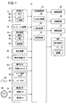
図1を用いて車両制御装置10の構成について説明する。車両制御装置10は、自車両120(図3)に設けられる。車両制御装置10は、自車両120の走行速度及び操舵の制御を、運転者の意図にかかわらずに実行する、所謂運転支援の機能を有する。
[1. Configuration of vehicle control device 10]
The configuration of the
車両制御装置10は、主制御装置12と、主制御装置12に対して各種情報を入力する入力装置群と、主制御装置12が出力する各種情報に基づいて自車両120を動作させる出力装置群と、を有する。入力装置群には、外界センサ14と、ナビゲーション装置16と、測位装置18と、受信装置20と、車体挙動センサ22と、操作センサ24と、乗員センサ26と、が含まれる。出力装置群には、駆動装置28と、制動装置30と、操舵装置32と、HMI34と、が含まれる。
The
[1.1.入力装置群の構成]
外界センサ14には、複数のカメラ40と、複数のレーダ42と、複数のLiDAR44と、が含まれる。カメラ40は、自車両120の周辺を撮影し、画像情報を主制御装置12に出力する。レーダ42とLiDAR44は、自車両120の周辺の物標を検知し、検知情報を主制御装置12に出力する。
[1.1. Input device group configuration]
The
ナビゲーション装置16は、GPSを使用して自車両120の位置を測定し、自車両120の位置から運転者が指定する目的地までの走行予定経路を生成する。ナビゲーション装置16は、生成された走行予定経路を示す経路情報を主制御装置12に出力する。
The
測位装置18は、GNSS46とIMU48と地図DB50とを有する。測位装置18は、GNSS46とIMU48を使用して自車両120の位置を測定し、自車両120の位置を示す自車位置情報を主制御装置12に出力する。また、測位装置18は、地図DB50に格納される地図情報を主制御装置12に出力する。なお、地図DB50に格納される地図情報は、ナビゲーション装置16に格納される地図情報よりも高精度であり、様々な情報(レーン単位の情報等)を含む。
The
受信装置20には、第1〜第3受信端末(不図示)が含まれる。第1受信端末は、放送局が放送する広域情報を受信する。第2受信端末は、道路130(図3)に設置される路側機が送信するローカル情報を受信する。第3受信端末は、他車両122(図3)が送信する他車情報を受信する。第1〜第3受信端末は、受信した各種情報を主制御装置12に出力する。
The
車体挙動センサ22には、自車両120の挙動(走行速度、加減速度、ヨーレート等)を測定するための各センサが含まれる。各センサは、検知した各種情報を主制御装置12に出力する。
The vehicle
操作センサ24には、自動化スイッチ52と、モード選択スイッチ54と、レバーセンサ56と、が含まれる。自動化スイッチ52は、運転者が行うスイッチ操作に応じて、走行速度と操舵のいずれかの制御の自動化又は自動化の解除を指示する指示情報を主制御装置12に出力する。モード選択スイッチ54は、運転者が行うスイッチ操作に応じて、複数の運転モード(下記[2]参照)のうちのいずれが選択されたかを示す選択情報を主制御装置12に出力する。レバーセンサ56は、ウインカーレバー58の操作位置を検知し、ウインカーレバー58の操作位置を示す操作位置情報を主制御装置12に出力する。また、操作センサ24には、操作子(アクセルペダル、ブレーキペダル、ステアリングホイール64)の操作量を検出する各種センサが含まれる。
The
乗員センサ26には、接触センサ60と、乗員カメラ62と、が含まれる。接触センサ60は、ステアリングホイール64に設けられる静電容量センサ又は圧力センサである。接触センサ60は、ステアリングホイール64に対する運転者の把持状態(接触状態)を検知し、検知情報を主制御装置12に出力する。乗員カメラ62は、運転者を撮影し、画像情報を主制御装置12に出力する。
The
[1.2.主制御装置12の構成]
主制御装置12は、ECUにより構成される。主制御装置12は、入出力装置66と、演算装置68と、記憶装置70と、を有する。入出力装置66は、A/D変換回路と通信インターフェース等を有する。演算装置68は、例えばCPU等のプロセッサを有する。演算装置68は、記憶装置70に記憶されるプログラムを実行することにより各種機能を実現する。演算装置68の各種機能については下記[1.4]で説明する。記憶装置70は、RAM及びROM等を有する。記憶装置70は、各種プログラムと、演算装置68が行う処理で使用される閾値等の数値情報を記憶する。
[1.2. Configuration of main controller 12]
The
[1.3.出力装置群の構成]
駆動装置28は、駆動力出力ECUと、駆動力出力ECUの制御対象(いずれも不図示)と、を有する。駆動装置28は、主制御装置12が出力する指示情報(駆動指示)に応じて駆動力を調整する。
[1.3. Output device group configuration]
The
制動装置30は、制動ECUと、制動ECUの制御対象(いずれも不図示)と、を有する。制動装置30は、主制御装置12が出力する指示情報(制動指示)に応じて制動力を調整する。
The
操舵装置32は、EPS(電動パワーステアリング)ECUと、EPSECUの制御対象(いずれも不図示)と、を有する。操舵装置32は、主制御装置12が出力する指示情報(操舵指示)に応じて操舵量を調整する。
The
HMI34には、表示装置72と、オーディオ装置74と、が含まれる。表示装置72は、主制御装置12が出力する指示情報(報知指示)に応じて映像を出力する。オーディオ装置74は、主制御装置12が出力する指示情報(報知指示)に応じて音声を出力する。
The
[1.4.演算装置68の各種機能]
図2を用いて演算装置68が実現する各種機能について説明する。演算装置68は、制御状態設定部76と、手動制御部78と、外界認識部80と、自車位置認識部82と、乗員状態判定部84と、行動計画部86と、車両制御部88と、報知制御部90として機能する。行動計画部86と車両制御部88は、まとめて車線変更制御部92と称される。
[1.4. Various functions of arithmetic unit 68]
Various functions realized by the
制御状態設定部76は、各種の走行制御(走行速度の制御及び操舵の制御)を、自動化スイッチ52で行われる操作に応じて、手動制御と自動制御のいずれで実行するかを決める。また、制御状態設定部76は、走行制御の自動化の程度を決める。例えば、制御状態設定部76は、自動化の程度を複数の運転モードの中から選択して設定する。本実施形態で実行される運転モードに関しては、下記[2]で説明する。
The control
手動制御部78は、操作センサ24が出力する操作子(アクセルペダル、ブレーキペダル、ステアリングホイール64)の操作量に従い手動制御に関わる走行制御を行う。手動制御部78は、手動制御に関わる指示情報(駆動指示、制動指示、操舵指示)を駆動装置28と制動装置30と操舵装置32に出力する。
The
外界認識部80は、外界センサ14が出力する画像情報及び検知情報に基づいて自車両120の周囲の状況を認識する。自車位置認識部82は、測位装置18が出力する自車位置情報及び地図情報に基づいて自車両120の位置を認識する。乗員状態判定部84は、接触センサ60が出力する検知情報に基づいてステアリングホイール64に対する運転者の把持状態(接触しているか否か)を判定する。また、乗員状態判定部84は、乗員カメラ62が出力する画像情報に基づいて運転者の周辺監視状態(前方を見ているか否か、眼を開けているか否か)を認識する。
The outside
行動計画部86は、外界認識部80の認識結果及び自車位置認識部82の認識結果に基づいて自動制御に関わる行動計画を立てる。例えば、行動計画部86は、自車両120の周辺の静的情報と動的情報を含むローカルマップ(ダイナミックマップ)を生成する。そして、行動計画部86は、ローカルマップと自車両120の状態(走行速度、舵角、走行位置)とに基づいて最適な行動を判断し、その行動を実現するための走行速度及び走行軌道を求める。
The
車両制御部88は、行動計画に従い自動制御に関わる走行制御を行う。例えば、車両制御部88は、行動計画部86により求められた走行速度で自車両120を走行させるための加減速度を演算する。また、車両制御部88は、行動計画部86により求められた走行軌道に沿って自車両120を走行させるための舵角を演算する。車両制御部88は、自動制御に関わる指示情報(駆動指示、制動指示、操舵指示)を駆動装置28と制動装置30と操舵装置32に出力する。報知制御部90は、行動計画において報知が生じる場合に、指示情報(報知指示)をHMI34に出力する。
The
[2.運転モード]
運転モードは、所謂自動運転レベルに対応して設定される。例えば、自動運転レベルには、レベル0(L0)と、レベル1(L1)と、レベル2A(L2A)と、レベル2Bと、レベル3が含まれる。各レベルの定義は次の通りである。なお、以下の説明にいて、ACCというのはアダプティブクルーズコントロールを意味し、LKASというのは車線維持支援システムを意味する。
L0:運転支援が実質的に行われない。
L1:運転支援のうち、ACCとLKASのいずれか一方が実行される。
L2A:運転支援のうち、ACCとLKASの双方が実行される。
L2B:運転支援のうち、ACCとLKASの双方が実行され、且つ、運転者はステアリングホイール64を把持する必要がない。
L3:運転操作に関する運転者の義務がL2Bよりも緩和される。
L0、L1、L2A、L2B、L3の順で自動化の程度は高くなる。本実施形態では、L2Aを第1モードと称し、L2Bを第2モードと称する。
[2. Operation mode]
The operation mode is set corresponding to the so-called automatic operation level. For example, the automatic operation level includes level 0 (L0), level 1 (L1), level 2A (L2A), level 2B, and level 3. The definition of each level is as follows. In the following explanation, ACC means adaptive cruise control, and LKAS means lane keeping support system.
L0: Driving support is practically not provided.
L1: Of the driving support, either ACC or LKAS is executed.
L2A: Of the driving assistance, both ACC and LKAS are executed.
L2B: Of the driving assistance, both ACC and LKAS are executed, and the driver does not need to grip the
L3: The driver's duty regarding driving operation is relaxed as compared with L2B.
The degree of automation increases in the order of L0, L1, L2A, L2B, and L3. In the present embodiment, L2A is referred to as a first mode, and L2B is referred to as a second mode.
また、車両制御装置10は、自動化された車線変更、所謂自動車線変更も行う。以下では、説明の便宜のため、自動車線変更をALCと称する。
The
[3.本実施形態の概要]
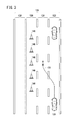
図3を用いて本実施形態の概要を説明する。図3に示される道路130には、一方側(図3等の右側)から他方側(図3等の左側)に向かって第1車線132と、第2車線134と、第3車線136と、路肩138と、がその順番で隣接して並ぶ。なお、第3車線136が存在せず、その位置に路肩138があってもよい。
[3. Outline of this embodiment]
The outline of the present embodiment will be described with reference to FIG. The
本実施形態では、自車両120が第1車線132を走行し、更に第1車線132から第2車線134へのALCを実行する場面を想定する。図3に示されるように、第3車線136(又は第3車線136の代わりにある路肩138)に交通規制物、例えばパイロン146又は発煙筒等が置かれている場合に、車線変更制御部92は、ALCを制限する。ALCの制限というのは、ALCの中止を意味する。図3に示されるように、車線変更制御部92は、第3車線136にパイロン146が置かれていない場合に、ALC軌道150を生成してALCを実行する。一方、車線変更制御部92は、第3車線136にパイロン146が置かれている場合に、ALCを中止する(図3の×印)。
In the present embodiment, it is assumed that the
[4.車両制御装置10が行う処理]
[4.1.主処理]
図4を用いて車両制御装置10が行う主処理を説明する。図4に示される主処理は、少なくともALCに関する運転支援機能が作動している状態で、所定時間毎に実行される。なお、入力装置群(外界センサ14、ナビゲーション装置16、測位装置18、受信装置20、車体挙動センサ22、操作センサ24、乗員センサ26)は、適当なタイミングで各種情報を取得し、取得した情報を主制御装置12に出力している。
[4. Processing performed by the vehicle control device 10]
[4.1. Main processing]
The main processing performed by the
ステップS1において、行動計画部86は、ALCを実行可能か否か判定する。例えば、行動計画部86は、目的地に到達するためにALCが必要であると判断する場合であり、且つ、ALCを実行することができる環境である場合に、ALCを実行可能である旨の判定をする。ALCを実行することができる環境というのは、例えば、第2車線134に他車両122が認識されない状況である。また、行動計画部86は、レバーセンサ56が第2車線134側へのウインカーレバー58の操作を検知する場合であり、且つ、ALCを実行することができる環境である場合にも、ALCを実行可能である旨の判定をする。ALCを実行可能である場合(ステップS1:YES)、処理はステップS2に移行する。一方、ALCを実行可能でない場合(ステップS1:NO)、1サイクル分の主処理は終了する。
In step S1, the
ステップS2において、行動計画部86は、運転者の意図に応じたALCか否かを判定する。運転者の意図に応じたALCでない場合(ステップS2:NO)、すなわち運転者の意図にかかわらず実行されるALCである場合、処理はステップS3に移行する。一方、運転者の意図に応じたALCである場合(ステップS2:YES)、処理はステップS6に移行する。
In step S2, the
ステップS3において、行動計画部86は、第1車線132から第2車線134へのALCか否かを判定する。第1車線132から第2車線134へのALCである場合(ステップS3:YES)、処理はステップS4に移行する。一方、第1車線132から第2車線134へのALCでない場合(ステップS3:NO)、処理はステップS6に移行する。
In step S3, the
ステップS4において、行動計画部86は、外界認識部80の認識結果に基づいて第3車線136に交通規制物があるか否かを判定する。例えば、外界認識部80は、高さと模様と色の情報に基づいてパイロン146を認識する。更に、行動計画部86は、外界認識部80が、第3車線136が延びる方向に沿って一定間隔で配置される複数(所定数)のパイロン146を認識する場合に、第3車線136に交通規制物がある旨の判定をする。言い換えると、行動計画部86は、外界認識部80が、所定数未満のパイロン146を認識する場合に、第3車線136に交通規制物はない旨の判定をする。第3車線136に交通規制物がある場合(ステップS4:YES)、処理はステップS5に移行する。一方、第3車線136に交通規制物がない場合(ステップS4:NO)、処理はステップS6に移行する。
In step S4, the
ステップS5において、車両制御部88は、ALCを制限、ここでは中止する。ステップS5の処理が終了すると、1サイクルの主処理は終了する。
In step S5, the
ステップS6において、車両制御部88は、ALCを実行する。ステップS6の処理が終了すると、1サイクルの主処理は終了する。
In step S6, the
[4.2.ALC中止後の第1処理]
車両制御装置10は、第1処理のステップS5の処理と共に、図5に示される第1処理を行ってもよい。
[4.2. First treatment after ALC is stopped]
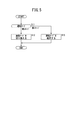
The
ステップS11において、制御状態設定部76は、その時点で設定されている運転モードが第1モードと第2モードのいずれであるかを判定する。運転モードが第2モードである場合、すなわちステアリングホイール64の把持を必要としない運転モードである場合(ステップS11:第2モード)、処理はステップS12に移行する。一方、運転モードが第1モードである場合、すなわちステアリングホイール64の把持を必要とする運転モードである場合(ステップS11:第1モード)、処理はステップS13に移行する。
In step S11, the control
ステップS12において、制御状態設定部76は、運転モードを第2モードから第1モードに切り換える。ステップS12が終了すると、第1処理は終了する。
In step S12, the control
ステップS13において、制御状態設定部76は、運転モードを第1モードに維持する。ステップS13が終了すると、第1処理は終了する。
In step S13, the control
[4.3.ALC中止後の第2処理]
車両制御装置10は、図5に示される第1処理で運転モードを第2モードから第1モードに切り換えた場合(ステップS12)、その後に、図6に示される第2処理を行ってもよい。
[4.3. Second treatment after ALC is stopped]
When the
ステップS21において、制御状態設定部76は、外界認識部80の認識結果に基づいて第3車線136(又は第3車線136の代わりにある路肩138)に交通規制物があるか否かを判定する。例えば、外界認識部80が所定時間以上、第3車線136に交通規制物を認識しない場合に、制御状態設定部76は、第3車線136に交通規制物がないと判定する。第3車線136に交通規制物がある場合(ステップS21:YES)、すなわち自車両120がパイロン146等の設置区間を走行している場合、処理はステップS22に移行する。一方、第3車線136に交通規制物がない場合(ステップS21:NO)、すなわち自車両120がパイロン146等の設置区間を通過した場合、処理はステップS23に移行する。
In step S21, the control
ステップS22において、制御状態設定部76は、運転モードを維持する。このとき、運転モードは第1モードである。ステップS22が終了すると、処理はステップS21に戻る。
In step S22, the control
ステップS23において、報知制御部90は、報知指示をHMI34に出力する。HMI34は、報知指示に応じて、運転者に対してステアリングホイール64を把持するように促す。制御状態設定部76は、乗員センサ26の出力に基づいて運転者がステアリングホイール64を把持したか否かを確認する。そして、制御状態設定部76は、把持を確認した場合に、運転モードを第1モードから第2モードに戻す。ステップS23が終了すると、第2処理は終了する。一方、制御状態設定部76は、把持を確認できない場合に、運転モードを自動化の度合いが低い別モードに切り換える。
In step S23, the notification control unit 90 outputs a notification instruction to the
なお、制御状態設定部76は、第2処理中に、モード選択スイッチ54が運転モードを第2モードに切り換える選択情報を出力したとしても、第2モードへの切り換えを行わない。
Note that the control
[5.実施形態から得られる技術的思想]
上記実施形態及び変形例から把握しうる技術的思想について、以下に記載する。
[5. Technical Thought Obtained from the Embodiment]
The technical ideas that can be grasped from the above embodiments and modifications are described below.
本発明の一態様は、
自車両120の周囲の状況を認識する外界認識部80と、
前記外界認識部80の認識結果に基づいて、前記自車両120の走行速度と操舵を制御して自動車線変更を実行する車線変更制御部92と、
を備え、第1車線132と、第2車線134と、第3車線136又は路肩138と、が隣接する道路130で、前記自車両120に前記第1車線132から前記第2車線134への前記自動車線変更を実行する車両制御装置10であって、
通行を規制する交通規制物(パイロン146等)が前記第3車線136又は前記路肩138に置かれており、前記外界認識部80が前記交通規制物を認識する場合に、
前記車線変更制御部92は、前記自動車線変更を制限する。
One aspect of the present invention is
The outside
Based on the recognition result of the outside
On the
When a traffic-restricted object (
The lane
上記構成においては、交通規制物が第3車線136又は路肩138の内部に置かれる場合に、第1車線132から第2車線134への自動車線変更が制限される。この場合、仮に自車両120の前方で第3車線136又は路肩138に加えて第2車線134が交通規制されても、第1車線132で走行する自車両120は車線変更をする必要がない。このため、運転者は、車線変更後に必要となる再度の車線変更の可否を気にすることなく乗車することができる。このように、上記構成によれば、交通規制物が置かれた状況で適切な車線を選択することができる。
In the above configuration, when the traffic regulation object is placed inside the
本発明の一態様において、
前記自動車線変更には、
運転者の意図にかかわらず実行される第1車線変更と、
前記運転者の意図によって実行される第2車線変更と、があり、
前記車線変更制御部92は、前記外界認識部80が前記交通規制物(パイロン146等)を認識する場合であっても、前記自動車線変更が前記第2車線変更である場合には、前記第2車線変更を実行してもよい。
In one aspect of the invention
To change the lane,
The first lane change, which is carried out regardless of the driver's intention,
There is a second lane change, which is carried out according to the driver's intention.
The lane
上記構成においては、運転者の意図よって実行される自動車線変更は制限されない。このため、上記構成によれば、運転者の意図に応じて自車両120を走行させることができる。
In the above configuration, the lane change performed by the driver's intention is not limited. Therefore, according to the above configuration, the
本発明の一態様において、
前記自車両120の走行速度又は操舵の制御の自動化の状態を複数の運転モードの中から選択して設定する制御状態設定部76を備え、
前記運転モードとしては、第1モードと、前記第1モードよりも自動化の度合いが高い第2モードと、があり、
前記制御状態設定部76が前記第2モードを設定している状態で、前記外界認識部80が前記交通規制物(パイロン146等)を認識する場合に、前記制御状態設定部76は、前記運転モードを前記第2モードから前記第1モードに切り換えてもよい。
In one aspect of the invention
A control
The operation mode includes a first mode and a second mode in which the degree of automation is higher than that of the first mode.
When the outside
上記構成によれば、状況に応じた運転モードで自車両120を走行させることが可能である。
According to the above configuration, it is possible to drive the
本発明の一態様において、
前記運転モードが前記第2モードから前記第1モードに切り換えられた後に、前記外界認識部80が前記交通規制物(パイロン146等)を認識しなくなる場合に、
前記制御状態設定部76は、前記運転モードを前記第1モードから前記第2モードに戻してもよい。
In one aspect of the invention
When the outside
The control
上記構成によれば、状況に応じた運転モードで車両を走行させることが可能である。 According to the above configuration, it is possible to drive the vehicle in a driving mode according to the situation.
本発明の一態様において、
前記制御状態設定部76が前記第1モードを設定している状態で、前記外界認識部80が前記交通規制物(パイロン146等)を認識する場合に、前記制御状態設定部76は、前記運転モードを前記第1モードから前記第2モードに切り換えなくてもよい。
In one aspect of the invention
When the outside
本発明の一態様において、
前記第1モードは、ステアリングホイール64の把持を必要とする前記運転モードであり、
前記第2モードは、前記ステアリングホイール64の把持を必要としない前記運転モードであってもよい。
In one aspect of the invention
The first mode is the operation mode that requires the
The second mode may be the operation mode that does not require gripping the
本発明の一態様において、
前記交通規制物は、前記道路130が延びる方向に沿って一定間隔で配置される複数のパイロン146であってもよい。
In one aspect of the invention
The traffic control object may be a plurality of pylon 146s arranged at regular intervals along the direction in which the
本発明の一態様において、
前記外界認識部80は、高さと模様と色の情報に基づいて前記パイロン146を認識してもよい。
In one aspect of the invention
The outside
本発明の別の態様は、
自車両120の周囲の状況を認識する外界認識ステップと、
前記外界認識ステップの認識結果に基づいて、前記自車両120の走行速度と操舵を制御して自動車線変更を実行する車線変更制御ステップと、
を備え、第1車線132と、第2車線134と、第3車線136又は路肩138と、が隣接する道路130で、前記自車両120に前記第1車線132から前記第2車線134への前記自動車線変更を実行する車両制御方法であって、
通行を規制する交通規制物(パイロン146等)が前記第3車線136又は前記路肩138に置かれており、前記外界認識ステップで前記交通規制物を認識する場合に、
前記車線変更制御ステップでは、前記自動車線変更を制限する。
Another aspect of the present invention is
The outside world recognition step that recognizes the surrounding situation of the
Based on the recognition result of the outside world recognition step, the lane change control step that controls the traveling speed and steering of the
On the
When a traffic-restricted object (
The lane change control step limits the lane change.
なお、本発明に係る車両制御装置及び車両制御方法は、前述の実施形態に限らず、本発明の要旨を逸脱することなく、種々の構成を採り得ることはもちろんである。 It should be noted that the vehicle control device and the vehicle control method according to the present invention are not limited to the above-described embodiments, and it goes without saying that various configurations can be adopted without departing from the gist of the present invention.
64…ステアリングホイール 76…制御状態設定部
80…外界認識部 92…車線変更制御部
120…自車両 130…道路
132…第1車線 134…第2車線
136…第3車線 138…路肩
146…パイロン(交通規制物)
64 ...
本発明の一態様は、
自車両の周囲の状況を認識する外界認識部と、
前記外界認識部の認識結果に基づいて、前記自車両の走行速度と操舵を制御して自動車線変更を実行する車線変更制御部と、
を備え、第1車線と、第2車線と、第3車線又は路肩と、が隣接する道路で、前記第1車線から前記第2車線への前記自動車線変更を実行する車両制御装置であって、
通行を規制する交通規制物が前記第3車線又は前記路肩に置かれており、前記外界認識部が前記交通規制物を認識する場合に、
前記車線変更制御部は、前記自動車線変更を制限する。
One aspect of the present invention is
The outside world recognition unit that recognizes the surrounding situation of the own vehicle,
Based on the recognition result of the outside world recognition unit, the lane change control unit that controls the traveling speed and steering of the own vehicle to execute the lane change,
The provided, the first lane, the second lane, and the third lane or shoulder, in the road are adjacent, there the vehicle control device for executing the car line changes to the second lane from the previous SL first lane hand,
When a traffic-restricted object that regulates traffic is placed in the third lane or the shoulder of the road, and the outside world recognition unit recognizes the traffic-restricted object,
The lane change control unit limits the lane change.
本発明の別の態様は、
自車両の周囲の状況を認識する外界認識ステップと、
前記外界認識ステップの認識結果に基づいて、前記自車両の走行速度と操舵を制御して自動車線変更を実行する車線変更制御ステップと、
を備え、第1車線と、第2車線と、第3車線又は路肩と、が隣接する道路で、前記第1車線から前記第2車線への前記自動車線変更を実行する車両制御方法であって、
通行を規制する交通規制物が前記第3車線又は前記路肩に置かれており、前記外界認識ステップで前記交通規制物を認識する場合に、
前記車線変更制御ステップでは、前記自動車線変更を制限する。
Another aspect of the present invention is
The outside world recognition step that recognizes the surrounding situation of the own vehicle,
Based on the recognition result of the outside world recognition step, the lane change control step that controls the traveling speed and steering of the own vehicle to execute the lane change, and the lane change control step.
The provided, the first lane, the second lane, and the third lane or shoulder, in the road are adjacent, there the vehicle control method for executing the car line changes to the second lane from the previous SL first lane hand,
When a traffic-restricted object that restricts traffic is placed in the third lane or the shoulder of the road, and the traffic-restricted object is recognized in the outside world recognition step, the traffic-restricted object is recognized.
The lane change control step limits the lane change.
[4.2.ALC中止後の第1処理]
車両制御装置10は、主処理のステップS5の処理と共に、図5に示される第1処理を行ってもよい。
[4.2. First treatment after ALC is stopped]
The
本発明の一態様は、
自車両120の周囲の状況を認識する外界認識部80と、
前記外界認識部80の認識結果に基づいて、前記自車両120の走行速度と操舵を制御して自動車線変更を実行する車線変更制御部92と、
を備え、第1車線132と、第2車線134と、第3車線136又は路肩138と、が隣接する道路130で、前記第1車線132から前記第2車線134への前記自動車線変更を実行する車両制御装置10であって、
通行を規制する交通規制物(パイロン146等)が前記第3車線136又は前記路肩138に置かれており、前記外界認識部80が前記交通規制物を認識する場合に、
前記車線変更制御部92は、前記自動車線変更を制限する。
One aspect of the present invention is
The outside
Based on the recognition result of the outside
Comprising a
When a traffic-restricted object (
The lane
本発明の一態様において、
前記自動車線変更には、
前記外界認識部80による認識結果に基づいて、前記車線変更制御部92が車線変更を計画し、車線変更を実行する第1車線変更と、
前記自車両の運転者の意図によって車線変更を実行する第2車線変更と、があり、
前記車線変更制御部92は、前記外界認識部80が前記交通規制物(パイロン146等)を認識する場合であっても、前記自動車線変更が前記第2車線変更である場合には、前記第2車線変更を実行してもよい。
In one aspect of the invention
To change the lane,
Based on the recognition result by the external
There is a second lane change that executes a lane change according to the intention of the driver of the own vehicle.
The lane
本発明の一態様において、
前記自車両120の走行速度又は操舵の制御の自動化の状態を複数の運転モードの中から選択して設定する制御状態設定部76を備え、
前記運転モードとしては、第1モードと、前記第1モードよりも運転者に課されるタスクが軽度な第2モードと、があり、
前記制御状態設定部76が前記第2モードを設定している状態で、前記外界認識部80が前記交通規制物(パイロン146等)を認識する場合に、前記制御状態設定部76は、前記運転モードを前記第2モードから前記第1モードに切り換えてもよい。
In one aspect of the invention
A control
The operation mode includes a first mode and a second mode in which the task imposed on the driver is lighter than that of the first mode.
When the outside
本発明の一態様において、
前記第1モードは、ステアリングホイール64の操作または把持を必要とする前記運転モードであり、
前記第2モードは、前記ステアリングホイール64の操作または把持を必要としない前記運転モードであってもよい。
In one aspect of the invention
The first mode is the operation mode that requires the operation or grip of the
The second mode may be the operation mode that does not require the operation or grip of the
本発明の別の態様は、
自車両120の周囲の状況を認識する外界認識ステップと、
前記外界認識ステップの認識結果に基づいて、前記自車両120の走行速度と操舵を制御して自動車線変更を実行する車線変更制御ステップと、
を備え、第1車線132と、第2車線134と、第3車線136又は路肩138と、が隣接する道路130で、前記第1車線132から前記第2車線134への前記自動車線変更を実行する車両制御方法であって、
通行を規制する交通規制物(パイロン146等)が前記第3車線136又は前記路肩138に置かれており、前記外界認識ステップで前記交通規制物を認識する場合に、
前記車線変更制御ステップでは、前記自動車線変更を制限する。
Another aspect of the present invention is
The outside world recognition step that recognizes the surrounding situation of the
Based on the recognition result of the outside world recognition step, the lane change control step that controls the traveling speed and steering of the
Comprising a
When a traffic-restricted object (
The lane change control step limits the lane change.
Claims (9)
前記外界認識部の認識結果に基づいて、前記自車両の走行速度と操舵を制御して自動車線変更を実行する車線変更制御部と、
を備え、第1車線と、第2車線と、第3車線又は路肩と、が隣接する道路で、前記自車両に前記第1車線から前記第2車線への前記自動車線変更を実行する車両制御装置であって、
通行を規制する交通規制物が前記第3車線又は前記路肩に置かれており、前記外界認識部が前記交通規制物を認識する場合に、
前記車線変更制御部は、前記自動車線変更を制限する、車両制御装置。 The outside world recognition unit that recognizes the surrounding situation of the own vehicle,
Based on the recognition result of the outside world recognition unit, the lane change control unit that controls the traveling speed and steering of the own vehicle to execute the lane change,
A vehicle control that executes the lane change from the first lane to the second lane on the own vehicle on a road adjacent to the first lane, the second lane, and the third lane or the shoulder. It ’s a device,
When a traffic-restricted object that regulates traffic is placed in the third lane or the shoulder of the road, and the outside world recognition unit recognizes the traffic-restricted object,
The lane change control unit is a vehicle control device that limits the lane change.
前記自動車線変更には、
運転者の意図にかかわらず実行される第1車線変更と、
前記運転者の意図によって実行される第2車線変更と、があり、
前記車線変更制御部は、前記外界認識部が前記交通規制物を認識する場合であっても、前記自動車線変更が前記第2車線変更である場合には、前記第2車線変更を実行する、車両制御装置。 The vehicle control device according to claim 1.
To change the lane,
The first lane change, which is carried out regardless of the driver's intention,
There is a second lane change, which is carried out according to the driver's intention.
The lane change control unit executes the second lane change when the lane change is the second lane change even when the outside world recognition unit recognizes the traffic restricted object. Vehicle control device.
前記自車両の走行速度又は操舵の制御の自動化の状態を複数の運転モードの中から選択して設定する制御状態設定部を備え、
前記運転モードとしては、第1モードと、前記第1モードよりも自動化の度合いが高い第2モードと、があり、
前記制御状態設定部が前記第2モードを設定している状態で、前記外界認識部が前記交通規制物を認識する場合に、前記制御状態設定部は、前記運転モードを前記第2モードから前記第1モードに切り換える、車両制御装置。 The vehicle control device according to claim 1.
It is provided with a control state setting unit that selects and sets the state of automation of the running speed or steering control of the own vehicle from a plurality of operation modes.
The operation mode includes a first mode and a second mode in which the degree of automation is higher than that of the first mode.
When the control state setting unit sets the second mode and the outside world recognition unit recognizes the traffic restricted object, the control state setting unit changes the operation mode from the second mode to the above. A vehicle control device that switches to the first mode.
前記運転モードが前記第2モードから前記第1モードに切り換えられた後に、前記外界認識部が前記交通規制物を認識しなくなる場合に、
前記制御状態設定部は、前記運転モードを前記第1モードから前記第2モードに戻す、車両制御装置。 The vehicle control device according to claim 3.
When the outside world recognition unit does not recognize the traffic regulated object after the operation mode is switched from the second mode to the first mode.
The control state setting unit is a vehicle control device that returns the operation mode from the first mode to the second mode.
前記制御状態設定部が前記第1モードを設定している状態で、前記外界認識部が前記交通規制物を認識する場合に、前記制御状態設定部は、前記運転モードを前記第1モードから前記第2モードに切り換えない、車両制御装置。 The vehicle control device according to claim 3.
When the control state setting unit sets the first mode and the outside world recognition unit recognizes the traffic restricted object, the control state setting unit changes the operation mode from the first mode to the above. A vehicle control device that does not switch to the second mode.
前記第1モードは、ステアリングホイールの把持を必要とする前記運転モードであり、
前記第2モードは、前記ステアリングホイールの把持を必要としない前記運転モードである、車両制御装置。 The vehicle control device according to claim 3.
The first mode is the operation mode that requires gripping the steering wheel.
The second mode is a vehicle control device which is the operation mode that does not require gripping the steering wheel.
前記交通規制物は、前記道路が延びる方向に沿って一定間隔で配置される複数のパイロンである、車両制御装置。 The vehicle control device according to claim 1.
The traffic control object is a vehicle control device which is a plurality of pylon arranged at regular intervals along the direction in which the road extends.
前記外界認識部は、高さと模様と色の情報に基づいて前記パイロンを認識する、車両制御装置。 The vehicle control device according to claim 7.
The outside world recognition unit is a vehicle control device that recognizes the pylon based on height, pattern, and color information.
前記外界認識ステップの認識結果に基づいて、前記自車両の走行速度と操舵を制御して自動車線変更を実行する車線変更制御ステップと、
を備え、第1車線と、第2車線と、第3車線又は路肩と、が隣接する道路で、前記自車両に前記第1車線から前記第2車線への前記自動車線変更を実行する車両制御方法であって、
通行を規制する交通規制物が前記第3車線又は前記路肩に置かれており、前記外界認識ステップで前記交通規制物を認識する場合に、
前記車線変更制御ステップでは、前記自動車線変更を制限する、車両制御方法。 The outside world recognition step that recognizes the surrounding situation of the own vehicle,
Based on the recognition result of the outside world recognition step, the lane change control step that controls the traveling speed and steering of the own vehicle to execute the lane change, and the lane change control step.
A vehicle control that executes the lane change from the first lane to the second lane on the own vehicle on a road adjacent to the first lane, the second lane, and the third lane or the shoulder. The way,
When a traffic-restricted object that restricts traffic is placed in the third lane or the shoulder of the road, and the traffic-restricted object is recognized in the outside world recognition step, the traffic-restricted object is recognized.
In the lane change control step, a vehicle control method for limiting the lane change.
Priority Applications (3)
| Application Number | Priority Date | Filing Date | Title |
|---|---|---|---|
| JP2020036604A JP6946495B2 (en) | 2020-03-04 | 2020-03-04 | Vehicle control device and vehicle control method |
| US17/190,008 US11440550B2 (en) | 2020-03-04 | 2021-03-02 | Vehicle control device and vehicle control meihod |
| CN202110240643.3A CN113428148B (en) | 2020-03-04 | 2021-03-04 | Vehicle control device and vehicle control method |
Applications Claiming Priority (1)
| Application Number | Priority Date | Filing Date | Title |
|---|---|---|---|
| JP2020036604A JP6946495B2 (en) | 2020-03-04 | 2020-03-04 | Vehicle control device and vehicle control method |
Publications (2)
| Publication Number | Publication Date |
|---|---|
| JP2021138245A true JP2021138245A (en) | 2021-09-16 |
| JP6946495B2 JP6946495B2 (en) | 2021-10-06 |
Family
ID=77556421
Family Applications (1)
| Application Number | Title | Priority Date | Filing Date |
|---|---|---|---|
| JP2020036604A Active JP6946495B2 (en) | 2020-03-04 | 2020-03-04 | Vehicle control device and vehicle control method |
Country Status (3)
| Country | Link |
|---|---|
| US (1) | US11440550B2 (en) |
| JP (1) | JP6946495B2 (en) |
| CN (1) | CN113428148B (en) |
Families Citing this family (1)
| Publication number | Priority date | Publication date | Assignee | Title |
|---|---|---|---|---|
| JP7241046B2 (en) * | 2020-03-16 | 2023-03-16 | 本田技研工業株式会社 | Mobile body control device, mobile body and mobile body control method |
Citations (3)
| Publication number | Priority date | Publication date | Assignee | Title |
|---|---|---|---|---|
| JP2018025976A (en) * | 2016-08-10 | 2018-02-15 | トヨタ自動車株式会社 | Automatic driving system and automatic driving vehicle |
| WO2018216194A1 (en) * | 2017-05-26 | 2018-11-29 | 本田技研工業株式会社 | Vehicle control system and vehicle control method |
| JP2019131107A (en) * | 2018-02-01 | 2019-08-08 | トヨタ自動車株式会社 | Automatic drive system |
Family Cites Families (26)
| Publication number | Priority date | Publication date | Assignee | Title |
|---|---|---|---|---|
| US20140257686A1 (en) * | 2013-03-05 | 2014-09-11 | GM Global Technology Operations LLC | Vehicle lane determination |
| JP6318741B2 (en) | 2014-03-18 | 2018-05-09 | アイシン・エィ・ダブリュ株式会社 | Automatic driving support system, automatic driving support method, and computer program |
| CN107111742B (en) * | 2014-08-18 | 2021-04-02 | 无比视视觉技术有限公司 | Identification and prediction of lane restrictions and construction areas in navigation |
| JP2017142145A (en) * | 2016-02-10 | 2017-08-17 | 株式会社ゼンリン | Lane change assist device, vehicle control device, and method therefor |
| JP2017165296A (en) * | 2016-03-17 | 2017-09-21 | 株式会社日立製作所 | Automatic operation control system |
| US20180113450A1 (en) * | 2016-10-20 | 2018-04-26 | Toyota Motor Engineering & Manufacturing North America, Inc. | Autonomous-mode traffic lane selection based on traffic lane congestion levels |
| JP6547970B2 (en) * | 2016-12-26 | 2019-07-24 | トヨタ自動車株式会社 | Vehicle lane change support device |
| JP6579334B2 (en) * | 2016-12-26 | 2019-09-25 | トヨタ自動車株式会社 | Vehicle lane change support device |
| KR20180099280A (en) * | 2017-02-28 | 2018-09-05 | 삼성전자주식회사 | Method and device to generate virtual lane |
| JP2018140750A (en) * | 2017-02-28 | 2018-09-13 | 三菱自動車工業株式会社 | Automatic driving device of vehicle |
| US9988048B1 (en) * | 2017-03-03 | 2018-06-05 | GM Global Technology Operations LLC | Lane detection systems and methods |
| DE102018107502A1 (en) * | 2017-03-31 | 2018-10-04 | Ford Global Technologies, Llc | Lane change assistant |
| DE102018107341A1 (en) * | 2017-03-31 | 2018-10-04 | Ford Global Technologies, Llc | LANE CHANGE GUIDE |
| JP6704890B2 (en) * | 2017-11-08 | 2020-06-03 | 本田技研工業株式会社 | Vehicle control device, vehicle control method, and program |
| JP6868122B2 (en) * | 2017-11-30 | 2021-05-12 | 本田技研工業株式会社 | Vehicle control device, vehicle with it, and control method |
| JP7085859B2 (en) * | 2018-02-23 | 2022-06-17 | 本田技研工業株式会社 | Vehicle control unit |
| US11069245B2 (en) * | 2018-05-14 | 2021-07-20 | Toyota Jidosha Kabushiki Kaisha | Lane change timing indicator |
| WO2019231456A1 (en) * | 2018-05-31 | 2019-12-05 | Nissan North America, Inc. | Probabilistic object tracking and prediction framework |
| US10745011B2 (en) * | 2018-05-31 | 2020-08-18 | Nissan North America, Inc. | Predicting yield behaviors |
| US10569773B2 (en) * | 2018-05-31 | 2020-02-25 | Nissan North America, Inc. | Predicting behaviors of oncoming vehicles |
| US10564643B2 (en) * | 2018-05-31 | 2020-02-18 | Nissan North America, Inc. | Time-warping for autonomous driving simulation |
| US20200097010A1 (en) * | 2018-09-21 | 2020-03-26 | Luminar Technologies, Inc. | Autonomous vehicle technology for facilitating safe stopping according to hybrid paths |
| US10843693B2 (en) * | 2018-10-18 | 2020-11-24 | Robert Bosch Gmbh | System and method for rear collision avoidance |
| US10906549B2 (en) * | 2018-12-07 | 2021-02-02 | Nio Usa, Inc. | Systems and methods of autonomously controlling vehicle lane change maneuver |
| JP2020158048A (en) * | 2019-03-28 | 2020-10-01 | 本田技研工業株式会社 | Vehicle control device, vehicle control method, and program |
| US11688155B2 (en) * | 2020-01-06 | 2023-06-27 | Luminar, Llc | Lane detection and tracking techniques for imaging systems |
-
2020
- 2020-03-04 JP JP2020036604A patent/JP6946495B2/en active Active
-
2021
- 2021-03-02 US US17/190,008 patent/US11440550B2/en active Active
- 2021-03-04 CN CN202110240643.3A patent/CN113428148B/en active Active
Patent Citations (3)
| Publication number | Priority date | Publication date | Assignee | Title |
|---|---|---|---|---|
| JP2018025976A (en) * | 2016-08-10 | 2018-02-15 | トヨタ自動車株式会社 | Automatic driving system and automatic driving vehicle |
| WO2018216194A1 (en) * | 2017-05-26 | 2018-11-29 | 本田技研工業株式会社 | Vehicle control system and vehicle control method |
| JP2019131107A (en) * | 2018-02-01 | 2019-08-08 | トヨタ自動車株式会社 | Automatic drive system |
Also Published As
| Publication number | Publication date |
|---|---|
| CN113428148B (en) | 2022-07-29 |
| US11440550B2 (en) | 2022-09-13 |
| CN113428148A (en) | 2021-09-24 |
| JP6946495B2 (en) | 2021-10-06 |
| US20210276559A1 (en) | 2021-09-09 |
Similar Documents
| Publication | Publication Date | Title |
|---|---|---|
| CN110050301B (en) | Vehicle control device | |
| US9714036B2 (en) | Autonomous driving device | |
| CN110678372B (en) | Vehicle control device | |
| JP7260503B2 (en) | Vehicle control device and vehicle control method | |
| CN115158354A (en) | Driving assistance method, driving assistance device, and driving assistance system | |
| JPWO2018230376A1 (en) | Travel control device | |
| CN111565992A (en) | Vehicle control device | |
| CN111469848A (en) | Vehicle control device | |
| JP2019144691A (en) | Vehicle control device | |
| JP7093738B2 (en) | Vehicle control unit | |
| CN116507537A (en) | Vehicle guidance system and method for operating a driving function in accordance with driver data | |
| JP6946496B2 (en) | Vehicle control device and vehicle control method | |
| JP6946495B2 (en) | Vehicle control device and vehicle control method | |
| JP2021138243A (en) | Vehicle control device and vehicle control method | |
| US20190256098A1 (en) | Vehicle control device | |
| JP7308880B2 (en) | VEHICLE CONTROL DEVICE, VEHICLE CONTROL METHOD, AND PROGRAM | |
| JP7220192B2 (en) | VEHICLE CONTROL DEVICE, VEHICLE CONTROL METHOD, AND PROGRAM | |
| JP7076492B2 (en) | Vehicle control device and vehicle control method | |
| CN116323360A (en) | Vehicle guidance system and method for operating a driving function in different driving modes | |
| CN116323355A (en) | Vehicle guidance system and method for automatic start of vehicle | |
| CN116390877A (en) | Vehicle guidance system and method for operating a driving function when actuating an accelerator pedal | |
| JP2022152607A (en) | Driving support device, driving support method, and program | |
| JP7002580B2 (en) | Vehicle control device and vehicle control method | |
| JP7105268B2 (en) | Vehicle control device and vehicle control method | |
| JP7132447B1 (en) | VEHICLE CONTROL DEVICE, VEHICLE CONTROL METHOD, AND PROGRAM |
Legal Events
| Date | Code | Title | Description |
|---|---|---|---|
| A621 | Written request for application examination |
Free format text: JAPANESE INTERMEDIATE CODE: A621 Effective date: 20201127 |
|
| A521 | Request for written amendment filed |
Free format text: JAPANESE INTERMEDIATE CODE: A523 Effective date: 20210409 |
|
| A131 | Notification of reasons for refusal |
Free format text: JAPANESE INTERMEDIATE CODE: A131 Effective date: 20210601 |
|
| A521 | Request for written amendment filed |
Free format text: JAPANESE INTERMEDIATE CODE: A523 Effective date: 20210730 |
|
| TRDD | Decision of grant or rejection written | ||
| A01 | Written decision to grant a patent or to grant a registration (utility model) |
Free format text: JAPANESE INTERMEDIATE CODE: A01 Effective date: 20210907 |
|
| A61 | First payment of annual fees (during grant procedure) |
Free format text: JAPANESE INTERMEDIATE CODE: A61 Effective date: 20210915 |
|
| R150 | Certificate of patent or registration of utility model |
Ref document number: 6946495 Country of ref document: JP Free format text: JAPANESE INTERMEDIATE CODE: R150 |