JP2021136845A - Vehicle drive device - Google Patents
Vehicle drive device Download PDFInfo
- Publication number
- JP2021136845A JP2021136845A JP2020033949A JP2020033949A JP2021136845A JP 2021136845 A JP2021136845 A JP 2021136845A JP 2020033949 A JP2020033949 A JP 2020033949A JP 2020033949 A JP2020033949 A JP 2020033949A JP 2021136845 A JP2021136845 A JP 2021136845A
- Authority
- JP
- Japan
- Prior art keywords
- electric machine
- rotary electric
- opening
- inverter
- bus bar
- Prior art date
- Legal status (The legal status is an assumption and is not a legal conclusion. Google has not performed a legal analysis and makes no representation as to the accuracy of the status listed.)
- Pending
Links
Images

Classifications
-
- Y—GENERAL TAGGING OF NEW TECHNOLOGICAL DEVELOPMENTS; GENERAL TAGGING OF CROSS-SECTIONAL TECHNOLOGIES SPANNING OVER SEVERAL SECTIONS OF THE IPC; TECHNICAL SUBJECTS COVERED BY FORMER USPC CROSS-REFERENCE ART COLLECTIONS [XRACs] AND DIGESTS
- Y02—TECHNOLOGIES OR APPLICATIONS FOR MITIGATION OR ADAPTATION AGAINST CLIMATE CHANGE
- Y02T—CLIMATE CHANGE MITIGATION TECHNOLOGIES RELATED TO TRANSPORTATION
- Y02T10/00—Road transport of goods or passengers
- Y02T10/60—Other road transportation technologies with climate change mitigation effect
- Y02T10/72—Electric energy management in electromobility
Landscapes
- Inverter Devices (AREA)
- Arrangement Or Mounting Of Propulsion Units For Vehicles (AREA)
- Electric Propulsion And Braking For Vehicles (AREA)
Abstract
【課題】部材の増加やケースの大型化を抑制して、適切に回転電機とインバータ装置とを電気的に接続する構造を備えた車両用駆動装置を実現する。【解決手段】端子台5は、端子台5の第1端子部58と回転電機側バスバー8とを固定するための固定部材48の挿入方向に沿った方向である第1方向X視で、第1端子部58が第1開口部21を通して視認可能であり、端子台5の第2端子部57とインバータ側バスバー7とを固定するための固定部材47の挿入方向に沿った方向である第2方向Y視で、第2端子部57が第2開口部31を通して視認可能であるように、回転電機収容室20とインバータ収容室30とを連通する連通部に配置されている。【選択図】図1PROBLEM TO BE SOLVED: To realize a drive device for a vehicle having a structure for appropriately electrically connecting a rotary electric machine and an inverter device by suppressing an increase in the number of members and an increase in the size of a case. SOLUTION: A terminal block 5 is a first direction X-viewing which is a direction along an insertion direction of a fixing member 48 for fixing a first terminal portion 58 of the terminal block 5 and a bus bar 8 on a rotary electric machine side. The first terminal portion 58 is visible through the first opening 21, and is a second direction along the insertion direction of the fixing member 47 for fixing the second terminal portion 57 of the terminal block 5 and the inverter side bus bar 7. The second terminal portion 57 is arranged in a communication portion that communicates the rotary electric machine accommodating chamber 20 and the inverter accommodating chamber 30 so that the second terminal portion 57 can be visually recognized through the second opening 31 in the direction Y. [Selection diagram] Fig. 1
Description
本発明は、回転電機とその回転電機を駆動制御するインバータ装置とを備えた車両用駆動装置に関する。 The present invention relates to a vehicle drive device including a rotary electric machine and an inverter device for driving and controlling the rotary electric machine.
国際公開第2019/076696号には、回転電機と、インバータ装置とを備えた車両用駆動装置が開示されている。インバータ装置は、回転電機の軸心に交差する方向(径方向)に配置されている。インバータ装置と回転電機とを電気的に接続する接続部材は、回転電機の軸方向端部よりも外側(いわゆる側方)を通って配置されている。回転電機及びインバータ装置は、回転電機収容室及びインバータ収容室が形成されたケースに収容されている。インバータ装置と回転電機とを電気的に接続する接続部材は、回転電機の軸方向端部におけるケースの開口部に設置され、回転電機収容室からの導体と、インバータ収容室からの導体とを電気的に接続している。この開口部は、例えばサービスカバーと称されるカバーによって閉じられる。 International Publication No. 2019/076966 discloses a vehicle drive device including a rotary electric machine and an inverter device. The inverter device is arranged in a direction (diameter direction) intersecting the axis of the rotary electric machine. The connecting member that electrically connects the inverter device and the rotary electric machine is arranged so as to pass outside (so-called side) from the axial end portion of the rotary electric machine. The rotary electric machine and the inverter device are housed in a case in which the rotary electric machine accommodating chamber and the inverter accommodating chamber are formed. A connecting member that electrically connects the inverter device and the rotary electric machine is installed in the opening of the case at the axial end of the rotary electric machine, and electrically connects the conductor from the rotary electric machine accommodation chamber and the conductor from the inverter accommodation chamber. Is connected. This opening is closed, for example, by a cover called a service cover.
上記のようにサービスカバーなどを用いる場合、カバー部材や締結部材などの部材の増加や、組み付け時の工数の増加、車両駆動装置を収容するケースの大型化などにつながる可能性がある。 When a service cover or the like is used as described above, it may lead to an increase in members such as a cover member and a fastening member, an increase in man-hours at the time of assembly, and an increase in the size of a case for accommodating a vehicle drive device.
上記背景に鑑みて、部材の増加やケースの大型化を抑制して、適切に回転電機とインバータ装置とを電気的に接続する構造を備えた車両用駆動装置の実現が望まれる。 In view of the above background, it is desired to realize a vehicle drive device having a structure for appropriately electrically connecting a rotary electric machine and an inverter device while suppressing an increase in the number of members and an increase in the size of the case.
上記に鑑みた車両用駆動装置は、車輪の駆動力源となる回転電機と、前記回転電機を駆動制御するインバータ装置と、前記回転電機のステータコイルに接続される回転電機側バスバーと、前記インバータ装置に接続されるインバータ側バスバーと、前記回転電機側バスバーと前記インバータ側バスバーとを電気的に接続する端子台と、前記インバータ装置及び前記回転電機を収容するケースと、を備え、前記端子台は、前記回転電機側バスバーが接続される第1端子部と前記インバータ側バスバーが接続される第2端子部とを備え、前記ケースは、前記回転電機を収容する回転電機収容室と、前記インバータ装置を収容するインバータ収容室とを備え、前記回転電機収容室と前記インバータ収容室とを区画する隔壁に、前記回転電機収容室と前記インバータ収容室とを連通する連通部を備え、前記端子台は、前記連通部に配置され、前記ケースは、前記回転電機収容室に収容する前記回転電機を挿通可能な第1開口部と、前記第1開口部を覆う第1カバー部と、前記インバータ収容室に収容する前記インバータ装置を挿通可能な第2開口部と、前記第2開口部を覆う第2カバー部と、を備え、前記端子台は、前記端子台が前記連通部に配置された状態で、前記第1端子部と前記回転電機側バスバーとを固定するための固定部材の挿入方向に沿った方向である第1方向視で、前記第1端子部が前記第1開口部を通して視認可能であり、前記第2端子部と前記インバータ側バスバーとを固定するための固定部材の挿入方向に沿った方向である第2方向視で、前記第2端子部が前記第2開口部を通して視認可能であるように、記連通部に配置されている。 In view of the above, the vehicle drive device includes a rotary electric machine that is a driving force source for wheels, an inverter device that drives and controls the rotary electric machine, a rotary electric machine side bus bar connected to the stator coil of the rotary electric machine, and the inverter. The terminal stand includes an inverter-side bus bar connected to the device, a terminal block for electrically connecting the rotary electric machine side bus bar and the inverter-side bus bar, and a case for accommodating the inverter device and the rotary electric machine. Is provided with a first terminal portion to which the rotary electric machine side bus bar is connected and a second terminal portion to which the inverter side bus bar is connected, and the case includes a rotary electric machine accommodating chamber for accommodating the rotary electric machine and the inverter. The terminal sill is provided with an inverter accommodating chamber for accommodating the device, and a partition partition for partitioning the rotary electric machine accommodating chamber and the inverter accommodating chamber is provided with a communication portion for communicating the rotary electric machine accommodating chamber and the inverter accommodating chamber. Is arranged in the communication portion, and the case includes a first opening through which the rotary electric machine accommodated in the rotary electric machine accommodating chamber can be inserted, a first cover portion covering the first opening, and the inverter accommodating portion. A second opening through which the inverter device accommodated in the chamber can be inserted and a second cover portion that covers the second opening are provided, and the terminal block is in a state in which the terminal block is arranged in the communication portion. Then, the first terminal portion can be visually recognized through the first opening in the first directional view, which is the direction along the insertion direction of the fixing member for fixing the first terminal portion and the rotary electric machine side bus bar. The second terminal portion is visible through the second opening in the second directional view, which is the direction along the insertion direction of the fixing member for fixing the second terminal portion and the inverter side bus bar. As shown in, it is arranged in the inverter.
この構成によれば、第1端子部が第1開口部を通して視認可能であることにより、第1開口部から適切に第1端子部に回転電機側バスバーを固定することができる。ケースには、回転電機やインバータ装置を収容するための開口が必要であり、例えば、回転電機を挿通可能な第1開口部は、回転電機を回転電機収容室に収容するために用いられ、第1カバー部により塞がれる開口である。従って、ケースに配線のための開口を別途設けることなく、回転電機側バスバーの配線を行うことができる。同様に、第2端子部が第2開口部を通して視認可能であることにより、第2開口部から適切に第2端子部にインバータ側バスバーを固定することができる。インバータ装置を挿通可能な第2開口部は、例えば、インバータ装置をインバータ収容室に収容するために用いられ、第2カバー部により塞がれる開口である。従って、ケースに配線のための開口を別途設けることなく、インバータ側バスバーの配線を行うことができる。即ち、本実施形態によれば、回転電機やインバータ装置などをケース1に収容するための開口(第1開口部、第2開口部等)とは別に、回転電機とインバータ装置とを電気的に接続するための専用の開口を設けることなく、回転電機とインバータ装置とを電気的に接続することができる。従って、そのような専用の開口を設けることによる部材の増加、加工コストの増加、組み立てコストの増加、ケースの体格の大型化などが抑制される。即ち、本構成によれば、部材の増加やケースの大型化を抑制して、適切に回転電機とインバータ装置とを電気的に接続する構造を備えた車両用駆動装置を提供することができる。
According to this configuration, since the first terminal portion is visible through the first opening portion, the rotary electric machine side bus bar can be appropriately fixed from the first opening portion to the first terminal portion. The case needs an opening for accommodating the rotary electric machine and the inverter device. For example, the first opening through which the rotary electric machine can be inserted is used for accommodating the rotary electric machine in the rotary electric machine accommodating chamber. 1 An opening that is closed by a cover portion. Therefore, it is possible to wire the bus bar on the rotary electric machine side without separately providing an opening for wiring in the case. Similarly, since the second terminal portion is visible through the second opening portion, the inverter-side bus bar can be appropriately fixed from the second opening portion to the second terminal portion. The second opening through which the inverter device can be inserted is, for example, an opening used for accommodating the inverter device in the inverter accommodating chamber and closed by the second cover portion. Therefore, the inverter-side bus bar can be wired without separately providing an opening for wiring in the case. That is, according to the present embodiment, the rotary electric machine and the inverter device are electrically separated from the openings (first opening, second opening, etc.) for accommodating the rotary electric machine, the inverter device, and the like in the
車両用駆動装置のさらなる特徴と利点は、図面を参照して説明する実施形態についての以下の記載から明確となる。 Further features and advantages of the vehicle drive will be clarified from the following description of embodiments described with reference to the drawings.
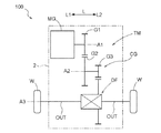
以下、本発明の実施形態について図面を参照して説明する。ここでは、図6のスケルトン図に示すように、車両用駆動装置100が、一対の車輪Wの駆動力源となる回転電機MGと、カウンタギヤ機構CGと、回転電機MGから伝達される駆動力を一対の出力部材OUTを介して一対の車輪Wに分配する差動歯車機構DF(出力用差動歯車装置)とを備えている形態を例示する。つまり、本実施形態では、駆動力源としての回転電機MGと車輪Wに駆動連結された出力部材OUTとを結ぶ動力伝達経路に、回転電機MGの側から順に、伝達機構TM(ベルトやチェーンなどの伝導部材なども含む)として、カウンタギヤ機構CG、差動歯車機構DFが設けられている形態を例示する。しかし、車両用駆動装置100は、カウンタギヤ機構CGや差動歯車機構DFを備えなくてもよく、回転電機MGを備えて構成されていればよい。本実施形態では、図6に示すように、回転電機MGの軸心(第1軸A1)と、カウンタギヤ機構CGの軸心(第2軸A2)と、差動歯車機構DFの軸心(第3軸A3)とが、互いに平行な別軸に配置されている。第1軸A1、第2軸A2、及び第3軸A3は、互いに異なる仮想軸であり、互いに平行に配置されている。
Hereinafter, embodiments of the present invention will be described with reference to the drawings. Here, as shown in the skeleton diagram of FIG. 6, the
以下の説明では、上記の軸(A1〜A3)に平行な方向を、車両用駆動装置100の「軸方向L」とする。そして、軸方向Lの一方側を軸方向第1側L1、他方側を軸方向第2側L2とする。図6に示す例では、回転電機MGに対して軸方向第2側L2に伝達機構TMが配置されている。また、上記の第1軸A1、第2軸A2、及び第3軸A3のそれぞれに直交する方向を、各軸を基準とした「径方向」とする。なお、どの軸を基準とするかを区別する必要がない場合やどの軸を基準とするかが明らかである場合には、単に「径方向」と記す場合がある。尚、以下の説明では、各部材についての方向や位置等に関する用語は、製造上許容され得る誤差による差異を有する状態をも含む概念である。また、各部材についての方向は、それらが車両用駆動装置100に組み付けられた状態での方向を表す。
In the following description, the direction parallel to the above axes (A1 to A3) is referred to as the "axial direction L" of the
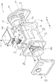
図1に示すように、車両用駆動装置100は、回転電機MG、当該回転電機MGを駆動制御するインバータ装置INV、出力部材OUT、及び伝達機構TMが収容されたケース1を備えている。尚、出力部材OUTは、少なくとも一部がケース1に収容されていればよい。ケース1には、回転電機MG、出力部材OUT、伝達機構TMを含む駆動機構を収容する駆動機構収容室としての回転電機収容室20、及びインバータ装置INVを収容するインバータ収容室30が形成されている。上述したように、本実施形態では、車両用駆動装置100は、少なくとも回転電機MGを備えて構成されていればよく、駆動機構を収容する駆動機構収容室を回転電機収容室20と称して説明する。
As shown in FIG. 1, the
また、以下では、ケース1において回転電機収容室20を形成する部分を回転電機収容部2と称し、ケース1においてインバータ収容室30を形成する部分をインバータ収容部3と称する。本実施形態では、回転電機収容部2及びインバータ収容部3を備えたケース1の本体部14は、1つの部材で構成されている。このようなケース1の本体部14は、好適には、回転電機収容室20を囲む周壁部23を備えた回転電機収容部2と、インバータ収容室30を囲む側壁部33を備えたインバータ収容部3とが一体的に形成された鋳造体である。そして、本実施形態では、ケース1は、本体部14と、当該本体部14に取り付けられる第1カバー部11、第2カバー部12、及び、第3カバー部13を備えている。
Further, in the following, the portion forming the rotary electric
図1に示すように、回転電機収容部2は、軸方向Lに開口した筒状に形成されている。軸方向第1側L1の開口は第1開口部21であり、軸方向第2側L2の開口は第3開口部25である(第2開口部31については後述する。)。第1開口部21には第1カバー部11が取り付けられ、第3開口部25には第3カバー部13が取り付けられる(第2カバー部12(図2等参照)については後述する。)。第1カバー部は、ケース1における回転電機収容部2の軸方向第1側L1の端部に形成された第1開口部21を塞ぐカバー部材である。第3カバー部13は、ケース1における回転電機収容部2の軸方向第2側L2の端部に形成された第3開口部25を塞ぐカバー部材である。回転電機収容部2の軸方向Lの両側の端部に形成された開口は、いずれも回転電機収容室20に連通している。回転電機収容室20は、周壁部23と、第1カバー部11と、第3カバー部13と、後述する隔壁10とによって囲まれた空間として形成されている。
As shown in FIG. 1, the rotary electric
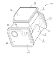
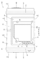
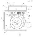
図1に示すように、インバータ収容部3は、径方向において回転電機収容部2に隣室して配置されている。インバータ収容部3において回転電機収容部2に隣室する側には、回転電機収容部2の周壁部23から径方向に延びるように側壁部33が形成されている。インバータ収容部3において回転電機収容部2に隣室する側とは反対側には、第2開口部31が形成されており、図2に示すように、当該第2開口部31を塞ぐように第2カバー部12が取り付けられている。また、インバータ収容部3において回転電機収容部2に隣室する側には、後述する隔壁10が位置している。インバータ収容室30は、側壁部33と、第2カバー部12と、隔壁10とによって囲まれた空間として形成されている。
As shown in FIG. 1, the
尚、これらの他に、ケース1に対して、当該ケース1とは別体の補助的なケース部材が取り付けられていても良い。そして、補助的なケース部材により、回転電機MG及びインバータ装置INV以外の構成要素が収容される収容室が形成されていても良い。このような収容室に収容される構成要素としては、例えば、上述したような伝達機構TMの他、オイルポンプ、補器類等、車両用駆動装置100の各種構成要素が対象となり得る。
In addition to these, an auxiliary case member separate from the
上述したように、ケース1は、回転電機収容室20を形成する回転電機収容部2と、インバータ収容室30を形成するインバータ収容部3とを備えている。また、本実施形態では、ケース1の本体部14は、1つの部材で構成されている。インバータ収容室30と回転電機収容室20とは、それぞれ独立した空間として形成されており、ケース1は、インバータ収容室30と回転電機収容室20とを区画する隔壁10を備えている(図4等参照)。
As described above, the
尚、ケース1の本体部14が、複数の部材で構成されていても良い。図示は省略するが、例えば、回転電機収容室20が形成された駆動機構ケースと、インバータ収容室30が形成されたインバータケースとが、結合されて1つの本体部14を構成する形態であってもよい。この場合、駆動機構ケースとインバータケースとが対向する側における駆動機構ケースの壁部(例えば周壁部23)及びインバータケースの壁部(例えば側壁部33に交差するように形成された底壁部)の少なくとも一方がインバータ収容室30と回転電機収容室20とを区画する隔壁10に相当する。
The
回転電機MGは、複数相の交流(例えば3相交流)により動作する回転電機(Motor/Generator)であり、電動機としても発電機としても機能することができる。回転電機MGは、図7を参照して後述するように、高圧バッテリBH(高圧直流電源)から電力の供給を受けて力行し、又は、車両の慣性力により発電した電力を高圧バッテリBHに供給する(回生する)。高圧バッテリBHは、例えば、ニッケル水素電池やリチウムイオン電池などの二次電池(バッテリ)や、電気二重層キャパシタなどにより構成されている。回転電機MGが、車両の駆動力源の場合、高圧バッテリBHは、大電圧大容量の直流電源であり、定格の電源電圧は、例えば200〜400[V]である。尚、図7に示す低圧バッテリBL(低圧直流電源)は、高圧バッテリBHよりも低電圧(例えば12〜24[V])の電源である。 The rotary electric machine MG is a rotary electric machine (Motor / Generator) that operates by a plurality of phases of alternating current (for example, three-phase alternating current), and can function as both an electric motor and a generator. As will be described later with reference to FIG. 7, the rotary electric machine MG receives electric power from the high-voltage battery BH (high-voltage direct current power supply) and powers it, or supplies electric power generated by the inertial force of the vehicle to the high-voltage battery BH. To (regenerate). The high-pressure battery BH is composed of, for example, a secondary battery (battery) such as a nickel hydrogen battery or a lithium ion battery, an electric double layer capacitor, or the like. When the rotary electric machine MG is the driving force source of the vehicle, the high-voltage battery BH is a DC power source having a large voltage and a large capacity, and the rated power supply voltage is, for example, 200 to 400 [V]. The low-voltage battery BL (low-voltage DC power supply) shown in FIG. 7 is a power supply having a lower voltage (for example, 12 to 24 [V]) than the high-voltage battery BH.
回転電機MGは、ケース1などに固定されたステータと、当該ステータの径方向内側に回転自在に支持されたロータとを有する。ステータは、ステータコアとステータコアに巻き回されたステータコイル81(図7参照)とを含み、ロータは、ロータコアとロータコアに配置された永久磁石とを含む。回転電機MGのロータは、入力ギヤG1(図6参照)に駆動連結されている。
The rotary electric machine MG has a stator fixed to a
図6に示すように、入力ギヤG1は、カウンタギヤ機構CGに駆動連結されている。本実施形態では、カウンタギヤ機構CGは、軸部材によって連結された2つのギヤ(カウンタドリブンギヤG2,カウンタドライブギヤG3)を有する。カウンタドリブンギヤG2は入力ギヤG1に噛み合い、カウンタドライブギヤG3は、差動歯車機構DFの差動入力ギヤG4に噛み合っている。差動歯車機構DFは、出力部材OUTを介して車輪Wに駆動連結されている。差動歯車機構DFは、互いに噛合する複数の傘歯車を含んで構成され、差動入力ギヤG4に入力される回転及びトルクを、一対の出力部材OUTを介して各出力部材OUTに連結された車輪W(即ち、左右2つの車輪W)に分配して伝達する。これにより、車両用駆動装置100は、回転電機MGのトルクを車輪Wに伝達して車両を走行させることができる。
As shown in FIG. 6, the input gear G1 is drive-connected to the counter gear mechanism CG. In the present embodiment, the counter gear mechanism CG has two gears (counter driven gear G2 and counter drive gear G3) connected by a shaft member. The counter-driven gear G2 meshes with the input gear G1, and the counter drive gear G3 meshes with the differential input gear G4 of the differential gear mechanism DF. The differential gear mechanism DF is drive-connected to the wheel W via the output member OUT. The differential gear mechanism DF is configured to include a plurality of bevel gears that mesh with each other, and the rotation and torque input to the differential input gear G4 are connected to each output member OUT via a pair of output members OUT. It is distributed and transmitted to the wheels W (that is, the two left and right wheels W). As a result, the
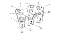
図7に示すように、回転電機MGは、インバータ装置INVにより駆動制御される。本実施形態では、このインバータ装置INVもケース1内のインバータ収容部3に収容されている(図1、図4等参照)。インバータ装置INVは、直流電力と複数相の交流電力との間で電力を変換するインバータ回路60を備えている。本実施形態では、交流の回転電機MG及び高圧バッテリBHに接続されて、複数相(ここではU相、V相、W相の3相)の交流と直流との間で電力を変換するインバータ回路60を例示する。インバータ回路60は、複数のスイッチング素子を有して構成され、高圧バッテリBHに接続されると共に、交流の回転電機MGに接続されて直流と複数相の交流(ここでは3相交流)との間で電力を変換する。インバータ側バスバー7と回転電機側バスバー8とは、図5に例示するような端子台5を介して接続されている。この端子台5は、図4等に示すように、回転電機収容室20とインバータ収容室30とを区画する隔壁10を貫通して回転電機収容室20とインバータ収容室30とを連通する連通部15に配置されている。本実施形態では、端子台5は、回転電機MGの径方向Rに沿って隔壁10を貫通して配置されている。
As shown in FIG. 7, the rotary electric machine MG is driven and controlled by the inverter device INV. In the present embodiment, the inverter device INV is also housed in the
回転電機収容室20には、端子台5において、回転電機側バスバー8が接続される第1端子部58(図1、図2、図7等参照)が位置し、インバータ収容室30には、端子台5において、インバータ側バスバー7が接続される第2端子部57(図1、図3、図7等参照)が位置している。第1端子部58と第2端子部57とは、端子台5の内部で電気的に接続されている(図2、図7参照)。
In the rotary electric
インバータ回路60は、上段側スイッチング素子と下段側スイッチング素子との直列回路により構成された交流1相分のアームを複数本(ここでは3本)備えている。スイッチング素子には、IGBT(Insulated Gate Bipolar Transistor)やパワーMOSFET(Metal Oxide Semiconductor Field Effect Transistor)やSiC−MOSFET(Silicon Carbide - Metal Oxide Semiconductor FET)やSiC−SIT(SiC - Static Induction Transistor)、GaN−MOSFET(Gallium Nitride - MOSFET)などの高周波での動作が可能なパワー半導体素子を適用すると好適である。図7に示すように、本実施形態では、スイッチング素子としてIGBTが用いられる形態を例示している。本実施形態では、フリーホイールダイオードも含め、インバータ回路60が1つのパワーモジュール(半導体モジュール)に一体化されてスイッチング素子モジュールが構成されている。 The inverter circuit 60 includes a plurality of (here, three) arms for one AC phase configured by a series circuit of the upper switching element and the lower switching element. Switching elements include IGBT (Insulated Gate Bipolar Transistor), Power MOSFET (Metal Oxide Semiconductor Field Effect Transistor), SiC-MOSFET (Silicon Carbide --Metal Oxide Semiconductor FET), SiC-SIT (SiC --Static Induction Transistor), and GaN- It is preferable to apply a power semiconductor element capable of operating at high frequencies such as MOSFET (Gallium Nitride-MOSFET). As shown in FIG. 7, in this embodiment, an embodiment in which an IGBT is used as a switching element is illustrated. In the present embodiment, the inverter circuit 60 including the freewheel diode is integrated into one power module (semiconductor module) to form a switching element module.
インバータ回路60の直流側には、直流リンク電圧(インバータ回路60の直流側の正極電源ラインPと負極電源ラインNとの間の電圧)を平滑する直流リンクコンデンサ64(平滑コンデンサ)が備えられている。直流リンクコンデンサ64は、回転電機MGの消費電力の変動に応じて変動する直流電圧(直流リンク電圧)を安定化させる。
The DC side of the inverter circuit 60 is provided with a DC link capacitor 64 (smoothing capacitor) that smoothes the DC link voltage (voltage between the positive power supply line P and the negative power supply line N on the DC side of the inverter circuit 60). There is. The
図7に示すように、インバータ回路60は、インバータ制御装置65(M-CTRL)により制御される。インバータ制御装置65は、マイクロコンピュータ等の論理回路を中核部材として構築されている。インバータ制御装置65は、回転電機MGの目標トルクに基づいて、ベクトル制御法を用いた電流フィードバック制御を行って、インバータ回路60を介して回転電機MGを制御する。回転電機MGの目標トルクは、例えば、車両内の上位の制御装置の1つである車両制御装置91(VCL-CTRL)等の他の制御装置等から要求信号として提供される。回転電機MGの各相のステータコイル81を流れる実電流は電流センサ84により検出される。また、回転電機MGのロータの各時点での磁極位置は、例えばレゾルバなどの回転センサ83により検出される。インバータ装置INVには、電流センサ84及び回転センサ83による検出結果が伝達される。
As shown in FIG. 7, the inverter circuit 60 is controlled by the inverter control device 65 (M-CTRL). The
インバータ制御装置65は、電流センサ84及び回転センサ83の検出結果を用いて、電流フィードバック制御を実行する。インバータ制御装置65は、電流フィードバック制御のために種々の機能部を有して構成されており、各機能部は、マイクロコンピュータ等のハードウエアとソフトウエア(プログラム)との協働により実現される。電流フィードバック制御については、公知であるのでここでは詳細な説明は省略する。
The
動作電圧が例えば5[V]や3.3[V]のマイクロコンピュータ等を中核として構成された車両制御装置91やインバータ制御装置65は、低圧バッテリBLから電力を供給されて動作する低圧系回路である。このため、インバータ制御装置65には、各スイッチング素子に対するスイッチング制御信号(IGBTの場合、ゲート駆動信号)の駆動能力(例えば電圧振幅や出力電流など、後段の回路を動作させる能力)をそれぞれ高めて中継する駆動回路が備えられている。つまり、インバータ回路60を構成する各スイッチング素子の制御端子(例えばIGBTのゲート端子)は、駆動回路を介してインバータ制御装置65の中核となるマイクロコンピュータ等に接続されており、それぞれ個別にスイッチング制御される。インバータ制御装置65は、単数又は複数の配線基板を備えて構成されている。
The
インバータ装置INVは、上述したようなインバータ制御装置65、直流リンクコンデンサ64、インバータ回路60(パワーモジュール)を含んで構成されている。上記のとおり、本実施形態では、インバータ回路60は、当該インバータ回路60を構成する複数のスイッチング素子とそれらを接続する配線を備えたスイッチング素子モジュールにより構成されている。また、図7には、インバータ装置INVと回転電機MGとを接続する回転電機側バスバー8を流れる電流を、電流センサ84が検出する形態を例示しており、電流センサ84はインバータ装置INVとは別に配置されている。しかし、電流センサ84がインバータ装置INVの内部に配置され、インバータ側バスバー7を流れる電流を検出する形態であってもよい。また、電流センサ84は、インバータ側バスバー7と回転電機側バスバー8とを接続する端子台5に配置されて、交流電流を検出する形態であってもよい。
The inverter device INV includes an
図5に示すように、端子台5は、回転電機側バスバー8が接続される第1端子部58とインバータ側バスバー7が接続される第2端子部57とを備えている。また、端子台5は、当該端子台5を隔壁10(本実施形態では、インバータ収容室30を形成する底壁部)に固定するための固定部55を備えている。また、端子台5は、隔壁10を貫通する連通部15の内壁に当接して、当該連通部15を封止する封止部材53を備えている。連通部15は、回転電機収容室20とインバータ収容室30とを連通しているが、連通部15に端子台5が配置されることで、回転電機収容室20とインバータ収容室30とが連通する状態が解消される。これにより、回転電機収容室20とインバータ収容室30とは互いに独立した空間となる。
As shown in FIG. 5, the
第1端子部58には、図1及び図5に示すような第1方向Xを挿入方向として挿入される第1固定部材48を用いて、回転電機側バスバー8が固定される。第2端子部57には、図1及び図5に示すような第2方向Yを挿入方向として挿入される第2固定部材47を用いて、インバータ側バスバー7が固定される。そのため、端子台5は、端子台5が連通部15に配置された状態で、第1端子部58と回転電機側バスバー8とを固定するための第1固定部材48の挿入方向に沿った方向である第1方向X視で、第1端子部58が第1開口部21を通して視認可能であるように、連通部15に配置されている。また、端子台5は、端子台5が連通部15に配置された状態で、第2端子部57とインバータ側バスバー7とを固定するための第2固定部材47の挿入方向に沿った方向である第2方向Y視で、第2端子部57が第2開口部31を通して視認可能であるように、連通部15に配置されている。尚、本実施形態では、固定部材(48,47)は、端子部(58,57)と螺合するネジ等の締結部材である。
The rotary electric machine
ここで、「端子台5が開口部を介して視認可能」とは、端子部とバスバーとを固定するための固定部材の挿入方向の延長線が、開口部(開口面)を通るように、端子台5が配置されている状態を言う。具体的には、第1端子部58と回転電機側バスバー8とを固定するための第1固定部材48の挿入方向の延長線(第1方向Xに沿うと共に第1端子部58を通る直線)が、第1開口部21の開口面である第1開口面P1と交差する状態を言う。また、第2端子部57とインバータ側バスバー7とを固定するための第2固定部材47の挿入方向の延長線(第2方向Yに沿うと共に第2端子部57を通る直線)が、第2開口部31の開口面である第2開口面P2と交差する状態を言う。
Here, "the
第1端子部58が第1開口部21を通して視認可能であることにより、第1開口部21から工具等を利用して、適切に第1固定部材48により、第1端子部58に回転電機側バスバー8を固定することができる。本実施形態において、第1開口部21は、回転電機MGを回転電機収容室20に収容するための開口であり第1カバー部11により塞がれる開口である。従って、ケース1に配線のための開口を別途設けることなく、回転電機側バスバー8の配線を行うことができる。
Since the first
同様に、第2端子部57が第2開口部31を通して視認可能であることにより、第2開口部31から工具等を利用して、適切に第2固定部材47により、第2端子部57にインバータ側バスバー7を固定することができる。本実施形態において、第2開口部31は、図1に示すように、インバータ装置INVをインバータ収容室30に収容するための開口であり、第2カバー部12により塞がれる開口である。従って、ケース1に配線のための開口を別途設けることなく、インバータ側バスバー7の配線を行うことができる。
Similarly, since the
即ち、本実施形態によれば、ケース1に収容される収容物(回転電機MGやインバータ装置INVなど)をケース1に収容するための開口(第1開口部21、第2開口部31等)とは別に、回転電機MGとインバータ装置INVとを電気的に接続するための専用の開口を設けることなく、回転電機MGとインバータ装置INVとを電気的に接続することができる。従って、そのような専用の開口を設けることによる部材の増加、加工コストの増加、組み立てコストの増加、ケース1の体格の大型化などが抑制される。
That is, according to the present embodiment, there are openings (
また、図1等に示すように、端子台5が連通部15に配置された状態で、回転電機側バスバー8は、第1端子部58よりも第1開口部21の側に配置されている。隔壁10に取り付けられた端子台5は、ケース1に固定されており、回転電機側バスバー8は、固定された端子台5に対して第1固定部材48により固定される。第1固定部材48は、ケース1の外側からケース1の内側に向かって挿入する方が、作業効率が良い。回転電機側バスバー8が第1端子部58よりも第1開口部21の側に配置されていると、ケース1の外側から第1方向Xに沿って、第1固定部材48、回転電機側バスバー8、第1端子部58の順に並ぶことになる。従って、第1端子部58に対して円滑に回転電機側バスバー8を固定することができる。
Further, as shown in FIG. 1 and the like, the rotary electric machine
また、図1等に示すように、端子台5が連通部15に配置された状態で、インバータ側バスバー7は、第2端子部57よりも第2開口部31の側に配置されている。隔壁10に取り付けられた端子台5は、ケース1に固定されており、インバータ側バスバー7は、固定された端子台5に対して第2固定部材47により固定される。第2固定部材47は、ケース1の外側からケース1の内側に向かって挿入する方が、作業効率が良い。インバータ側バスバー7が第2端子部57よりも第2開口部31の側に配置されていると、ケース1の外側から第2方向Yに沿って、第2固定部材47、インバータ側バスバー7、第2端子部57の順に並ぶことになる。従って、第2端子部57に対して円滑にインバータ側バスバー7を固定することができる。
Further, as shown in FIG. 1 and the like, the inverter side bus bar 7 is arranged closer to the
図1、図3、図4等に示すように、第1開口部21及び第2開口部31は、第1開口部21の開口面である第1開口面P1と、第2開口部31の開口面である第2開口面P2とが直交するように形成されている。例えば、第1開口面P1と第2開口面P2とをほぼ平行に配置した場合、それぞれの開口面積を広く確保すると、第1開口面P1と第2開口面P2とが並ぶ方向にケース1が大型化することになる。、第1開口面P1と第2開口面P2とが直交するように形成することで、本実施形態のように、第1開口面P1と第2開口面P2とをケース1の本体部14の異なる方向を向く面に配置することができ、ケース1が大型化することを抑制することができる。
As shown in FIGS. 1, 3, 4, 4 and the like, the
また、本実施形態では、第1開口部21の開口面である第1開口面P1は、回転電機MGの軸心である第1軸A1に直交する方向に沿うように配置されている。上述したように、第1方向Xは第1開口面P1に交差する方向であり、好ましくは、第1方向Xは第1開口面P1に直交する。第1開口面P1が第1軸A1に直交していると、第1方向Xと第1軸A1とがほぼ平行することになり、第1固定部材48による回転電機側バスバー8の固定を円滑に行うことができる。
Further, in the present embodiment, the first opening surface P1 which is the opening surface of the
〔その他の実施形態〕
以下、その他の実施形態について説明する。尚、以下に説明する各実施形態の構成は、それぞれ単独で適用されるものに限られず、矛盾が生じない限り、他の実施形態の構成と組み合わせて適用することも可能である。
[Other Embodiments]
Hereinafter, other embodiments will be described. The configurations of the respective embodiments described below are not limited to those applied independently, and can be applied in combination with the configurations of other embodiments as long as there is no contradiction.
(1)上記においては、第1開口部21の開口面である第1開口面P1と、第2開口部31の開口面である第2開口面P2とが直交するように形成されている形態を例示して説明した。しかし、このような形態には限定されず、第1開口面P1と第2開口面P2とが平行、或いは、直交以外の角度で交差する向きに配置されていてもよい。例えば、第1開口面P1と第2開口面P2とが30〜60°程度の角度で交差する向きに配置されていても良い。
(1) In the above, the first opening surface P1 which is the opening surface of the
(2)上記においては、第1開口面P1が、回転電機MGの軸心である第1軸A1に直交する方向に沿う形態を例示して説明した。しかし、第1固定部材48を円滑に挿入することが可能であれば、第1開口面P1が第1軸A1に直交していなくてもよい。例えば、第1開口面P1と第1軸A1とが30〜60°程度の角度で交差していても良い。
(2) In the above, the form in which the first opening surface P1 is along the direction orthogonal to the first axis A1 which is the axis of the rotary electric machine MG has been illustrated and described. However, if the first fixing
(3)上記においては、端子台5の端子部(58,57)よりも開口部(21,31)の側にバスバー(8,7)が配置されている形態を例示して説明した。しかし、バスバー(8,7)よりも開口部(21,31)の側に端子台5の端子部(58,57)が配置される形態であってもよい。上記においては、ネジなどの締結部材を固定部材(48,47)として、バスバー(8,7)を固定する形態を例示しており、締結作業は開口部(21,31)の側から行う方が円滑であるという観点より、端子部(58,57)よりも開口部(21,31)の側にバスバー(8,7)が配置されている形態を例示した。しかし、クリップ等、端子部(58,57)とバスバー(8,7)とを挟み込んで固定するような固定部材を用いるような場合などでは、バスバー(8,7)よりも開口部(21,31)の側に端子台5の端子部(58,57)が配置されていてもよい。当然ながら、ネジなどの締結部材が固定部材(48,47)の場合も、作業性が損なわれなければ、バスバー(8,7)よりも開口部(21,31)の側に端子台5の端子部(58,57)が配置されていてもよい。
(3) In the above, the embodiment in which the bus bar (8, 7) is arranged closer to the opening (21, 31) than the terminal portion (58, 57) of the
〔実施形態の概要〕
以下、上記において説明した車両用駆動装置(100)の概要について簡単に説明する。
[Outline of Embodiment]
Hereinafter, the outline of the vehicle drive device (100) described above will be briefly described.
1つの態様として、車両用駆動装置(100)は、車輪(W)の駆動力源となる回転電機(MG)と、前記回転電機(MG)を駆動制御するインバータ装置(INV)と、前記回転電機(MG)のステータコイル(81)に接続される回転電機側バスバー(8)と、前記インバータ装置(INV)に接続されるインバータ側バスバー(7)と、前記回転電機側バスバー(8)と前記インバータ側バスバー(7)とを電気的に接続する端子台(5)と、前記インバータ装置(INV)及び前記回転電機(MG)を収容するケース(1)と、を備え、前記端子台(5)は、前記回転電機側バスバー(8)が接続される第1端子部(58)と前記インバータ側バスバー(7)が接続される第2端子部(57)とを備え、前記ケース(1)は、前記回転電機(MG)を収容する回転電機収容室(20)と、前記インバータ装置(INV)を収容するインバータ収容室(30)とを備え、前記回転電機収容室(20)と前記インバータ収容室(20)とを区画する隔壁(10)に、前記回転電機収容室(20)と前記インバータ収容室(30)とを連通する連通部(15)を備え、前記端子台(5)は、前記連通部(15)に配置され、前記ケース(1)は、前記回転電機収容室(20)に収容する前記回転電機(MG)を挿通可能な第1開口部(21)と、前記第1開口部(21)を覆う第1カバー部(11)と、前記インバータ収容室(30)に収容する前記インバータ装置(INV)を挿通可能な第2開口部(31)と、前記第2開口部(31)を覆う第2カバー部(12)と、を備え、前記端子台(5)は、前記端子台(5)が前記連通部(15)に配置された状態で、前記第1端子部(58)と前記回転電機側バスバー(8)とを固定するための固定部材(48)の挿入方向に沿った方向である第1方向(X)視で、前記第1端子部(58)が前記第1開口部(21)を通して視認可能であり、前記第2端子部(57)と前記インバータ側バスバー(7)とを固定するための固定部材(47)の挿入方向に沿った方向である第2方向(Y)視で、前記第2端子部(57)が前記第2開口部(31)を通して視認可能であるように、記連通部(15)に配置されている。 In one embodiment, the vehicle drive device (100) includes a rotary electric machine (MG) that is a driving force source for the wheels (W), an inverter device (INV) that drives and controls the rotary electric machine (MG), and the rotation. The rotary electric machine side bus bar (8) connected to the stator coil (81) of the electric machine (MG), the inverter side bus bar (7) connected to the inverter device (INV), and the rotary electric machine side bus bar (8). A terminal block (5) for electrically connecting the inverter-side bus bar (7) and a case (1) for accommodating the inverter device (INV) and the rotary electric machine (MG) are provided. The case (1) includes a first terminal portion (58) to which the rotary electric machine side bus bar (8) is connected and a second terminal portion (57) to which the inverter side bus bar (7) is connected. ) Provide a rotary electric machine accommodating chamber (20) for accommodating the rotary electric machine (MG) and an inverter accommodating chamber (30) for accommodating the inverter device (INV). The partition wall (10) that separates the inverter accommodating chamber (20) is provided with a communication portion (15) that communicates the rotary electric machine accommodating chamber (20) and the inverter accommodating chamber (30), and the terminal block (5). Is arranged in the communication portion (15), and the case (1) has a first opening (21) through which the rotary electric machine (MG) housed in the rotary electric machine accommodating chamber (20) can be inserted, and the case (1). A first cover portion (11) that covers the first opening (21), a second opening (31) through which the inverter device (INV) accommodated in the inverter accommodation chamber (30) can be inserted, and the second opening. A second cover portion (12) that covers the opening portion (31) is provided, and the terminal block (5) is the first in a state where the terminal block (5) is arranged in the communication portion (15). The first terminal portion (58) is viewed in the first direction (X), which is a direction along the insertion direction of the fixing member (48) for fixing the terminal portion (58) and the rotary electric machine side bus bar (8). ) Is visible through the first opening (21), and the direction along the insertion direction of the fixing member (47) for fixing the second terminal portion (57) and the inverter side bus bar (7). The second terminal portion (57) is arranged in the communication portion (15) so that the second terminal portion (57) can be visually recognized through the second opening portion (31) in the second direction (Y) view.
この構成によれば、第1端子部(58)が第1開口部(21)を通して視認可能であることにより、第1開口部(21)から適切に第1端子部(58)に回転電機側バスバー(8)を固定することができる。ケース(1)には、回転電機(MG)やインバータ装置(INV)を収容するための開口が必要であり、例えば、回転電機(MG)を挿通可能な第1開口部(21)は、回転電機(MG)を回転電機収容室(20)に収容するために用いられ、第1カバー部(11)により塞がれる開口である。従って、ケース(1)に配線のための開口を別途設けることなく、回転電機側バスバー(8)の配線を行うことができる。同様に、第2端子部(57)が第2開口部(31)を通して視認可能であることにより、第2開口部(31)から適切に第2端子部(57)にインバータ側バスバー(7)を固定することができる。インバータ装置(INV)を挿通可能な第2開口部(31)は、例えば、インバータ装置(INV)をインバータ収容室(30)に収容するために用いられ、第2カバー部(12)により塞がれる開口である。従って、ケース(1)に配線のための開口を別途設けることなく、インバータ側バスバー(7)の配線を行うことができる。即ち、本実施形態によれば、回転電機(MG)やインバータ装置(INV)などをケース1に収容するための開口(第1開口部(21)、第2開口部(31)等)とは別に、回転電機(MG)とインバータ装置(INV)とを電気的に接続するための専用の開口を設けることなく、回転電機(MG)とインバータ装置(INV)とを電気的に接続することができる。従って、そのような専用の開口を設けることによる部材の増加、加工コストの増加、組み立てコストの増加、ケース(1)の体格の大型化などが抑制される。即ち、本構成によれば、部材の増加やケース(1)の大型化を抑制して、適切に回転電機(MG)とインバータ装置(INV)とを電気的に接続する構造を備えた車両用駆動装置(100)を提供することができる。
According to this configuration, since the first terminal portion (58) is visible through the first opening portion (21), the rotating electric machine side is appropriately transferred from the first opening portion (21) to the first terminal portion (58). The bus bar (8) can be fixed. The case (1) needs to have an opening for accommodating the rotary electric machine (MG) and the inverter device (INV). For example, the first opening (21) through which the rotary electric machine (MG) can be inserted rotates. It is an opening used for accommodating an electric machine (MG) in a rotary electric machine accommodating chamber (20) and closed by a first cover portion (11). Therefore, the wiring of the rotary electric machine side bus bar (8) can be performed without separately providing an opening for wiring in the case (1). Similarly, since the second terminal portion (57) is visible through the second opening portion (31), the inverter-side bus bar (7) is appropriately connected from the second opening portion (31) to the second terminal portion (57). Can be fixed. The second opening (31) through which the inverter device (INV) can be inserted is used, for example, for accommodating the inverter device (INV) in the inverter accommodating chamber (30), and is closed by the second cover portion (12). It is an invoice. Therefore, the inverter side bus bar (7) can be wired without separately providing an opening for wiring in the case (1). That is, according to the present embodiment, what are the openings (first opening (21), second opening (31), etc.) for accommodating the rotary electric machine (MG), the inverter device (INV), and the like in the
ここで、車両用駆動装置(100)は、前記第1開口部(21)の開口面(P1)と、前記第2開口部(31)の開口面(P2)とが直交するように形成されていると好適である。 Here, the vehicle drive device (100) is formed so that the opening surface (P1) of the first opening (21) and the opening surface (P2) of the second opening (31) are orthogonal to each other. It is preferable to have.
第1開口部(21)の開口面(P1)と、第2開口部(31)の開口面(P2)とが直交することにより、これらの開口面をケース(1)の異なる方向を向く面に配置することができる。従って、第1開口部(21)と第2開口部(31)とのそれぞれの開口面積を広く確保しつつ、ケース(1)が大型化することを抑制することができる。 The opening surface (P1) of the first opening (21) and the opening surface (P2) of the second opening (31) are orthogonal to each other, so that these opening surfaces face different directions of the case (1). Can be placed in. Therefore, it is possible to prevent the case (1) from becoming large while ensuring a wide opening area for each of the first opening (21) and the second opening (31).
また、車両用駆動装置(100)は、前記第1開口部(21)の開口面(P1)が、前記回転電機(MG)の軸心(A1)に直交する方向に沿うように配置されていると好適である。 Further, in the vehicle drive device (100), the opening surface (P1) of the first opening (21) is arranged so as to be perpendicular to the axis (A1) of the rotary electric machine (MG). It is preferable to have it.
第1開口部(21)を通して第1端子部(58)が視認可能な方向である第1方向(X)は、第1開口部(21)の開口面(P1)に交差する方向である。第1開口面(P1)が回転電機(MG)の軸心(A1)に直交していると、当該軸心(A1)と第1方向(X)とが平行状(平行又は平行に近い角度)となり、固定部材(48)による端子台(5)への回転電機側バスバー(8)の固定を円滑に行うことができる。 The first direction (X), which is the direction in which the first terminal portion (58) is visible through the first opening (21), is the direction that intersects the opening surface (P1) of the first opening (21). When the first opening surface (P1) is orthogonal to the axis (A1) of the rotary electric machine (MG), the axis (A1) and the first direction (X) are parallel (parallel or nearly parallel). ), And the rotary electric machine side bus bar (8) can be smoothly fixed to the terminal block (5) by the fixing member (48).
また、車両用駆動装置(100)は、前記第2端子部(57)よりも前記第2開口部(31)の側に前記インバータ側バスバー(7)が配置されていると好適である。 Further, in the vehicle drive device (100), it is preferable that the inverter side bus bar (7) is arranged closer to the second opening (31) than the second terminal portion (57).
インバータ側バスバー(7)の固定部材(47)は、ケース(1)の外側からケース(1)の内側に向かって挿入する方が、作業効率が良い。インバータ側バスバー(7)が第2端子部(57)よりも第2開口部(31)の側に配置されていると、ケース(1)の外側から第2方向(Y)に沿って、第2固定部材(47)、インバータ側バスバー(7)、第2端子部(57)の順に並ぶことになる。従って、第2端子部(57)に対して円滑にインバータ側バスバー(7)を固定することができる。 It is more efficient to insert the fixing member (47) of the inverter-side bus bar (7) from the outside of the case (1) toward the inside of the case (1). When the inverter side bus bar (7) is arranged closer to the second opening (31) than the second terminal portion (57), the second direction (Y) is taken from the outside of the case (1). 2 The fixing member (47), the inverter side bus bar (7), and the second terminal portion (57) are arranged in this order. Therefore, the inverter-side bus bar (7) can be smoothly fixed to the second terminal portion (57).
また、車両用駆動装置(100)は、前記第1端子部(58)よりも前記第1開口部(21)の側に前記回転電機側バスバー(8)が配置されていると好適である。 Further, in the vehicle drive device (100), it is preferable that the rotary electric machine side bus bar (8) is arranged closer to the first opening (21) than the first terminal portion (58).
回転電機側バスバー(8)の固定部材(48)は、ケース(1)の外側からケース(1)の内側に向かって挿入する方が、作業効率が良い。回転電機側バスバー(8)が第1端子部(58)よりも第1開口部(21)の側に配置されていると、ケース(1)の外側から第1方向(X)に沿って、第1固定部材(48)、回転電機側バスバー(8)、第1端子部(58)の順に並ぶことになる。従って、第1端子部(58)に対して円滑に回転電機側バスバー(8)を固定することができる。 It is more efficient to insert the fixing member (48) of the rotary electric machine side bus bar (8) from the outside of the case (1) toward the inside of the case (1). When the rotary electric machine side bus bar (8) is arranged closer to the first opening (21) than the first terminal portion (58), from the outside of the case (1) along the first direction (X), The first fixing member (48), the bus bar (8) on the rotary electric machine side, and the first terminal portion (58) are arranged in this order. Therefore, the rotary electric machine side bus bar (8) can be smoothly fixed to the first terminal portion (58).
1:ケース
2:回転電機収容部
3:インバータ収容部
5:端子台
7:インバータ側バスバー
8:回転電機側バスバー
10:隔壁
11:第1カバー部
12:第2カバー部
20:回転電機収容室
30:インバータ収容室
47:第2固定部材(第2端子部とインバータ側バスバーとを固定するための固定部材)
48:第1固定部材(第1端子部と回転電機側バスバーとを固定するための固定部材)
57:第2端子部
58:第1端子部
81:ステータコイル
100:車両用駆動装置
A1:第1軸(回転電機の軸心)
INV:インバータ装置
MG:回転電機
P1:第1開口面(第1開口部の開口面)
P2:第2開口面(第2開口部の開口面)
W:車輪
X:第1方向
Y:第2方向
1: Case 2: Inverter accommodating part 3: Inverter accommodating part 5: Terminal block 7: Inverter side bus bar 8: Rotating electric machine side bus bar 10: Partition 11: First cover part 12: Second cover part 20: Rotating electric machine accommodating room 30: Inverter accommodating chamber 47: Second fixing member (fixing member for fixing the second terminal portion and the bus bar on the inverter side)
48: First fixing member (fixing member for fixing the first terminal portion and the bus bar on the rotary electric machine side)
57: 2nd terminal part 58: 1st terminal part 81: Stator coil 100: Vehicle drive device A1: 1st shaft (axis center of rotary electric machine)
INV: Inverter device MG: Rotating electric machine P1: First opening surface (opening surface of the first opening)
P2: Second opening surface (opening surface of the second opening)
W: Wheel X: 1st direction Y: 2nd direction
Claims (5)
前記回転電機を駆動制御するインバータ装置と、
前記回転電機のステータコイルに接続される回転電機側バスバーと、
前記インバータ装置に接続されるインバータ側バスバーと、
前記回転電機側バスバーと前記インバータ側バスバーとを電気的に接続する端子台と、
前記インバータ装置及び前記回転電機を収容するケースと、を備え、
前記端子台は、前記回転電機側バスバーが接続される第1端子部と前記インバータ側バスバーが接続される第2端子部とを備え、
前記ケースは、前記回転電機を収容する回転電機収容室と、前記インバータ装置を収容するインバータ収容室とを備え、
前記回転電機収容室と前記インバータ収容室とを区画する隔壁に、前記回転電機収容室と前記インバータ収容室とを連通する連通部を備え、
前記端子台は、前記連通部に配置され、
前記ケースは、前記回転電機収容室に収容する前記回転電機を挿通可能な第1開口部と、前記第1開口部を覆う第1カバー部と、前記インバータ収容室に収容する前記インバータ装置を挿通可能な第2開口部と、前記第2開口部を覆う第2カバー部と、を備え、
前記端子台は、
前記端子台が前記連通部に配置された状態で、前記第1端子部と前記回転電機側バスバーとを固定するための固定部材の挿入方向に沿った方向である第1方向視で、前記第1端子部が前記第1開口部を通して視認可能であり、
前記第2端子部と前記インバータ側バスバーとを固定するための固定部材の挿入方向に沿った方向である第2方向視で、前記第2端子部が前記第2開口部を通して視認可能であるように、
前記連通部に配置されている、車両用駆動装置。 The rotating electric machine that is the driving force source for the wheels,
An inverter device that drives and controls the rotary electric machine,
The bus bar on the rotary electric machine side connected to the stator coil of the rotary electric machine,
The inverter side bus bar connected to the inverter device and
A terminal block that electrically connects the rotary electric machine side bus bar and the inverter side bus bar,
The inverter device and the case for accommodating the rotary electric machine are provided.
The terminal block includes a first terminal portion to which the rotary electric machine side bus bar is connected and a second terminal portion to which the inverter side bus bar is connected.
The case includes a rotary electric machine accommodating chamber for accommodating the rotary electric machine and an inverter accommodating chamber for accommodating the inverter device.
The partition wall that separates the rotary electric machine accommodating chamber and the inverter accommodating chamber is provided with a communication portion that communicates the rotary electric machine accommodating chamber and the inverter accommodating chamber.
The terminal block is arranged in the communication portion and is arranged.
The case inserts a first opening through which the rotary electric machine accommodated in the rotary electric machine accommodating chamber can be inserted, a first cover portion covering the first opening, and the inverter device accommodated in the inverter accommodating chamber. A possible second opening and a second cover portion covering the second opening are provided.
The terminal block
With the terminal block arranged in the communication portion, the first directional view is a direction along the insertion direction of the fixing member for fixing the first terminal portion and the rotary electric machine side bus bar. One terminal portion is visible through the first opening,
The second terminal portion is visible through the second opening in the second directional view, which is the direction along the insertion direction of the fixing member for fixing the second terminal portion and the inverter side bus bar. NS,
A vehicle drive device arranged in the communication portion.
Priority Applications (1)
| Application Number | Priority Date | Filing Date | Title |
|---|---|---|---|
| JP2020033949A JP2021136845A (en) | 2020-02-28 | 2020-02-28 | Vehicle drive device |
Applications Claiming Priority (1)
| Application Number | Priority Date | Filing Date | Title |
|---|---|---|---|
| JP2020033949A JP2021136845A (en) | 2020-02-28 | 2020-02-28 | Vehicle drive device |
Publications (1)
| Publication Number | Publication Date |
|---|---|
| JP2021136845A true JP2021136845A (en) | 2021-09-13 |
Family
ID=77661890
Family Applications (1)
| Application Number | Title | Priority Date | Filing Date |
|---|---|---|---|
| JP2020033949A Pending JP2021136845A (en) | 2020-02-28 | 2020-02-28 | Vehicle drive device |
Country Status (1)
| Country | Link |
|---|---|
| JP (1) | JP2021136845A (en) |
-
2020
- 2020-02-28 JP JP2020033949A patent/JP2021136845A/en active Pending
Similar Documents
| Publication | Publication Date | Title |
|---|---|---|
| JP7665949B2 (en) | Vehicle drive device | |
| JP7435728B2 (en) | Vehicle drive system | |
| US10259310B2 (en) | Vehicle drive device | |
| JP7448032B2 (en) | Vehicle drive system | |
| EP1643619B1 (en) | Coil for rotating electrical machine | |
| KR20150135784A (en) | Vehicle drive device | |
| JP7761079B2 (en) | Vehicle drive unit | |
| JP7513197B2 (en) | Vehicle drive device | |
| JP2024000539A (en) | Electric drive assembly system, vehicle, and method for assembling an electric drive assembly system | |
| WO2023054437A1 (en) | Vehicle drive device | |
| JP7758093B2 (en) | Terminal structure of electrical equipment | |
| JP2021136845A (en) | Vehicle drive device | |
| JP2021125919A (en) | Vehicle driving device | |
| WO2024195427A1 (en) | Drive device | |
| JP2022083789A (en) | Power system | |
| EP4477475B1 (en) | Terminal structure of electric apparatus | |
| US20240322548A1 (en) | Busbar unit | |
| JP2024000540A (en) | Electric drive assembly system, vehicle and method for assembling electric drive assembly system | |
| JP2025152680A (en) | Vehicle powertrain structure |
Legal Events
| Date | Code | Title | Description |
|---|---|---|---|
| A711 | Notification of change in applicant |
Free format text: JAPANESE INTERMEDIATE CODE: A712 Effective date: 20210423 |