JP2021136825A - Motor device and electric pump - Google Patents
Motor device and electric pump Download PDFInfo
- Publication number
- JP2021136825A JP2021136825A JP2020033329A JP2020033329A JP2021136825A JP 2021136825 A JP2021136825 A JP 2021136825A JP 2020033329 A JP2020033329 A JP 2020033329A JP 2020033329 A JP2020033329 A JP 2020033329A JP 2021136825 A JP2021136825 A JP 2021136825A
- Authority
- JP
- Japan
- Prior art keywords
- motor
- control device
- heat radiating
- radiating member
- circuit board
- Prior art date
- Legal status (The legal status is an assumption and is not a legal conclusion. Google has not performed a legal analysis and makes no representation as to the accuracy of the status listed.)
- Granted
Links
- 239000000853 adhesive Substances 0.000 claims description 28
- 230000001070 adhesive effect Effects 0.000 claims description 28
- 230000005855 radiation Effects 0.000 abstract 3
- 230000002093 peripheral effect Effects 0.000 description 32
- 230000017525 heat dissipation Effects 0.000 description 8
- 239000011347 resin Substances 0.000 description 6
- 229920005989 resin Polymers 0.000 description 6
- 229920001187 thermosetting polymer Polymers 0.000 description 6
- XAGFODPZIPBFFR-UHFFFAOYSA-N aluminium Chemical compound [Al] XAGFODPZIPBFFR-UHFFFAOYSA-N 0.000 description 4
- 229910052782 aluminium Inorganic materials 0.000 description 4
- 239000003990 capacitor Substances 0.000 description 4
- 230000000694 effects Effects 0.000 description 3
- 238000004512 die casting Methods 0.000 description 2
- 239000000463 material Substances 0.000 description 2
- 238000000034 method Methods 0.000 description 2
- 238000004804 winding Methods 0.000 description 2
- 238000007796 conventional method Methods 0.000 description 1
- 238000001816 cooling Methods 0.000 description 1
- 230000005669 field effect Effects 0.000 description 1
- 238000009499 grossing Methods 0.000 description 1
- 238000010438 heat treatment Methods 0.000 description 1
- 238000012986 modification Methods 0.000 description 1
- 230000004048 modification Effects 0.000 description 1
Images
Landscapes
- Details Of Reciprocating Pumps (AREA)
- Connection Of Motors, Electrical Generators, Mechanical Devices, And The Like (AREA)
Abstract
Description
本発明は、モータ装置及び電動ポンプに関するものである。 The present invention relates to a motor device and an electric pump.
例えば、自動車に搭載されているミッション等の油圧装置にオイルを供給するために、電動ポンプを用いることがある。また、電動ポンプの制御を行う制御装置を電動ポンプと一体的に構成して、装置全体の小型化を図ったものがある。このような電動ポンプは、モータ部と、このモータ部の回転軸に連結されモータ部と同軸上に配置されたポンプ部と、モータ部の駆動制御を行う制御装置と、を主構成としている。 For example, an electric pump may be used to supply oil to a hydraulic device such as a mission mounted on an automobile. Further, there is a device in which a control device for controlling the electric pump is integrally configured with the electric pump to reduce the size of the entire device. Such an electric pump mainly includes a motor unit, a pump unit connected to the rotation shaft of the motor unit and arranged coaxially with the motor unit, and a control device for driving control of the motor unit.
モータ部は、制御性の良い、いわゆるブラシレスモータが用いられることが一般的である。ブラシレスモータは、巻線が巻装されたステータを備えている。制御装置は、IC素子やスイッチング素子が実装された回路基板(制御基板)を有している。そして、外部電源(バッテリ)からの電流が、回路基板に実装されたIC素子やスイッチング素子によって所定のタイミングでモータ部の巻線に供給される。これにより、モータ部の回転が制御され、電動ポンプから吐出されるオイルの流量が制御される。 As the motor unit, a so-called brushless motor having good controllability is generally used. Brushless motors include a stator with windings wound around it. The control device has a circuit board (control board) on which an IC element and a switching element are mounted. Then, the current from the external power supply (battery) is supplied to the winding of the motor unit at a predetermined timing by the IC element or switching element mounted on the circuit board. As a result, the rotation of the motor unit is controlled, and the flow rate of the oil discharged from the electric pump is controlled.
ところで、電動ポンプとして、モータ部と回路基板とを有する機電一体モータであって、モータ部と回路基板とが同一方向からハウジングに組み付けられるものが知られている。この電動ポンプは、例えばカバーをハウジングに取り付ける前に、カバーの凸部(すなわち、裏面)に熱硬化性粘弾性樹脂が塗布される。塗布された熱硬化性粘弾性樹脂が硬化する前に、カバーがハウジングに取り付けられる。この状態において、塗布された熱硬化性粘弾性樹脂が制御装置(具体的には、回路基板の発熱素子)に接触する。熱硬化性粘弾性樹脂が硬化することにより放熱部材となる。よって、発熱素子が発生した熱を、放熱部材からカバーに伝え、カバーから外部に放熱できる(例えば、特許文献1参照)。 By the way, as an electric pump, there is known a mechatronic integrated motor having a motor unit and a circuit board, in which the motor unit and the circuit board are assembled to the housing from the same direction. In this electric pump, for example, before attaching the cover to the housing, a thermosetting viscoelastic resin is applied to the convex portion (that is, the back surface) of the cover. The cover is attached to the housing before the applied thermosetting viscoelastic resin cures. In this state, the applied thermosetting viscoelastic resin comes into contact with the control device (specifically, the heat generating element of the circuit board). When the thermosetting viscoelastic resin is cured, it becomes a heat radiating member. Therefore, the heat generated by the heat generating element can be transferred from the heat radiating member to the cover and radiated to the outside from the cover (see, for example, Patent Document 1).
しかしながら、上述の従来技術にあっては、カバーの裏面に熱硬化性粘弾性樹脂が塗布されている。このため、カバーを組み付ける際に、熱硬化性粘弾性樹脂(すなわち、放熱部材)が制御装置に接触されているか否かを目視により確認できないという課題があった。 However, in the above-mentioned conventional technique, the thermosetting viscoelastic resin is applied to the back surface of the cover. Therefore, when assembling the cover, there is a problem that it is not possible to visually confirm whether or not the thermosetting viscoelastic resin (that is, the heat radiating member) is in contact with the control device.
そこで、本発明は、組み付ける際に、放熱部材が制御装置に接触されているか否かを目視により確認できるモータ装置及び電動ポンプを提供する。 Therefore, the present invention provides a motor device and an electric pump that can visually confirm whether or not the heat radiating member is in contact with the control device when assembling.
上記の課題を解決するために、本発明に係るモータ装置は、モータと、前記モータの駆動制御を行う制御装置と、前記モータを収容するモータ収容部、及び前記制御装置を収容する制御装置収容部が一体化されたハウジングと、を備え、前記ハウジングは、前記制御装置収容部に対して前記モータ収容部の反対側に前記モータ及び前記制御装置を受け入れる開口部を有し、前記モータ収容部と前記制御装置収容部との間に設けられ、前記制御装置の一部に接触する放熱部材を備えたことを特徴とする。 In order to solve the above problems, the motor device according to the present invention includes a motor, a control device for driving and controlling the motor, a motor accommodating unit for accommodating the motor, and a control device accommodating the control device. The housing includes a housing in which the portions are integrated, and the housing has an opening for receiving the motor and the control device on the opposite side of the motor accommodating portion with respect to the control device accommodating portion, and the motor accommodating portion. It is characterized by being provided between the control device and the control device accommodating portion and provided with a heat radiating member that comes into contact with a part of the control device.
上記構成において、前記ハウジングは、前記モータ収容部と前記制御装置収容部との間に段差面を有し、前記段差面は、前記放熱部材を取り付ける支持面を有していてもよい。 In the above configuration, the housing may have a stepped surface between the motor accommodating portion and the control device accommodating portion, and the stepped surface may have a support surface on which the heat radiating member is attached.
上記構成において、前記放熱部材は、前記制御装置に設けられた発熱素子に接着剤を介して接触されてもよい。 In the above configuration, the heat radiating member may be brought into contact with a heat generating element provided in the control device via an adhesive.
上記構成において、前記放熱部材は板状に形成され、外周に沿って形成された溝部を有してもよい。 In the above configuration, the heat radiating member may be formed in a plate shape and may have a groove formed along the outer periphery.
上記構成において、前記制御装置は、前記発熱素子が実装された回路基板を備え、前記回路基板は、前記回路基板の厚さ方向からみて前記放熱部材と重なる箇所の一部に形成された凹部を有してもよい。 In the above configuration, the control device includes a circuit board on which the heat generating element is mounted, and the circuit board has a recess formed in a part of a portion overlapping the heat radiating member when viewed from the thickness direction of the circuit board. You may have.
上記構成において、前記モータはブラシレスモータであり、前記放熱部材は、軸方向からみて、前記モータのステータと重なる位置に少なくとも一部が配置されてもよい。 In the above configuration, the motor is a brushless motor, and at least a part of the heat radiating member may be arranged at a position overlapping with the stator of the motor when viewed from the axial direction.
本発明に係る電動ポンプは、上記モータ装置によって駆動されるポンプ部を備えたことを特徴とする。 The electric pump according to the present invention is characterized by including a pump unit driven by the motor device.
本発明によれば、モータ収容部と制御装置収容部との間に放熱部材を配置することにより、組み付ける際に、放熱部材が制御装置に接触されているか否かを目視により確認できる。 According to the present invention, by arranging the heat radiating member between the motor accommodating portion and the control device accommodating portion, it is possible to visually confirm whether or not the heat radiating member is in contact with the control device at the time of assembling.
次に、本発明の実施形態を図面に基づいて説明する。 Next, an embodiment of the present invention will be described with reference to the drawings.
<電動ポンプ>
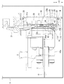
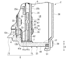
図1は、電動ポンプ1の制御装置5を破断した側面図である。図2は、図1のII部を拡大した断面図である。
図1、図2に示すように、電動ポンプ1は、例えば図示しない自動車に搭載されているミッション等の油圧装置にオイルを供給する。電動ポンプ1は、オイルOが貯留されているオイルタンクTの内部に配置されている。電動ポンプ1は、モータ装置2と、モータ装置2と一体化され、モータ装置2によって駆動されるポンプ部3と、を備えている。
<Electric pump>
FIG. 1 is a side view of the
As shown in FIGS. 1 and 2, the electric pump 1 supplies oil to a hydraulic device such as a mission mounted on an automobile (not shown), for example. The electric pump 1 is arranged inside the oil tank T in which the oil O is stored. The electric pump 1 includes a
<モータ装置>
モータ装置2は、モータ部(請求項におけるモータに相当)4と、モータ部4を駆動させるための制御装置5と、モータ部4及び制御装置5を収容するハウジング6と、制御装置5及びモータ部4の間に設けられた放熱部材(ヒートシンク)7と、を備えている。
<Motor device>
The
ハウジング6は、例えばアルミダイキャストで成形されている。ハウジング6は、モータ収容部11を形成するモータケース12と、制御装置収容部14を形成する制御ケース15と、が一体に構成されている。モータ収容部11には、モータ部4が収容されている。制御装置収容部14には、制御装置5が収容されている。
ハウジング6には、制御装置収容部14においてモータ収容部11の反対側に開口部17が形成されている。この開口部17からモータ収容部11及び制御装置収容部14に、モータ部4及び制御装置5が、モータ部4の回転軸線C方向にそれぞれ重なるように収容されている。モータケース12及び制御ケース15についての詳細は後述する。
The
In the
モータ部4は、いわゆるブラシレスモータである。モータ部4は、モータケース12の内部に収容されたステータ21(図4参照)、及びステータ21に対して回転自在に支持されたロータ22(図4参照)と、を備えている。
モータケース12は、例えば有底筒状に形成され、軸方向がモータ部4(すなわち、ロータ22)の回転軸線Cと一致している。電動ポンプ1は、ロータ22の回転軸線Cが水平方向に沿う向きでオイルタンクTの内部に配置されている。そして、モータ装置2の一部(図1では回転軸線Cを中心に略下半分)が、オイルOに浸漬されている。
The motor unit 4 is a so-called brushless motor. The motor unit 4 includes a stator 21 (see FIG. 4) housed inside the
The
なお、以下の説明では、回転軸線C方向を単に軸方向と称し、ロータ22の回転方向を周方向と称し、軸方向及び周方向に直交する方向を径方向と称する。また、以下の説明では、オイルタンクTに電動ポンプ1を配置した向きで水平方向と平行で、かつ軸方向と直交する方向をX方向、上下方向と一致する方向をY方向等と表現する場合がある。
In the following description, the rotation axis C direction is simply referred to as an axial direction, the rotation direction of the
<ポンプ部>
ポンプ部3は、モータケース12の底部12aに取り付けられている。ポンプ部3は、モータ部4のロータ22に回転軸23(双方、図4参照)を介して接続されている。このロータ22が回転することにより、ポンプ部3が駆動される。ポンプ部3が駆動されることにより、オイルタンクTに貯留されたオイルOが圧送され、さらにミッション等の油圧装置にオイルOが供給される。
<Pump section>
The
<制御装置>
次に、モータ装置2の制御装置5について説明する。
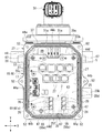
図3は、モータ装置2のカバー38を取り外した状態をハウジング6の開口部17側からみた平面図である。
図1から図3に示すように、制御装置5は、制御ケース15の内部に収容され、制御ケース15に支持された回路基板25と、回路基板25に実装されたFET(Field Effect Transistor:電界効果トランジスタ)等のスイッチング素子(請求項における発熱素子に相当)26、コンデンサ27、及びチョークコイル28と、を主構成としている。ポンプ部3、モータ部4、及び制御装置5は、軸方向に並んで配置されている。
<Control device>
Next, the
FIG. 3 is a plan view of the state in which the
As shown in FIGS. 1 to 3, the
<回路基板>
回路基板25は、対向する第1面25a、及び第2面25bを有する板状に形成されている。回路基板25は、各面25a,25bに直交する法線方向が軸方向に沿うように、かつ第1面25aがモータ部4側を向き、第2面25bがカバー38側を向くように配置されている。
<Circuit board>
The
また、回路基板25は、軸方向からみてY方向に長い略長方形状に形成されている。回路基板25の外形状は、モータケース12の外形状よりも大きい。より具体的には、回路基板25は、X方向で対向する第1辺25c及び第2辺25dと、Y方向で対向する第3辺25e及び第4辺25fと、を有している。第3辺25eは上側に配置され、第4辺25fは下側に配置されている。
Further, the
回路基板25の第3辺25eの近傍には、コネクタ31が接続されている。コネクタ31には、図示しない外部電源が接続される。また、回路基板25の第1面25a及び第2面25bには、図示しないパターンが形成されている。このパターンを被覆するように、全体に絶縁被膜であるレジストが形成されている。回路基板25のパターンには、コネクタ31が電気的に接続されているとともに、モータ部4におけるステータ21に巻回されたコイル24の端末部が接続されている。
A
回路基板25の第2面25bには、第4辺25f寄りの部位で、X方向の略中央の部位にスイッチング素子26が複数(本実施形態では6個)実装されている。例えば、スイッチング素子26は、X方向に2列で、Y方向に沿って3個ずつ配置されている。スイッチング素子26は、モータ部4のコイル24に供給する電流を制御する。
回路基板25の第1面25aには、スイッチング素子26と対向する位置に、レジストを除去してなるレジスト除去部(請求項における制御装置の一部に相当)33が複数(本実施形態では6個)形成されている。
A plurality of switching elements 26 (six in this embodiment) are mounted on the
On the
また、回路基板25の第2面25bには、スイッチング素子26とは反対側の第3辺25e寄りの半分に、複数(本実施形態では6個)のコンデンサ27と、雑防素子としての1つのチョークコイル28と、が実装されている。コンデンサ27は、回路基板25に印加される電圧の平滑化を行う素子として機能する。
Further, on the
さらに、回路基板25の第4辺25fには、凹部35が溝や切欠等により形成されている。凹部35は、第4辺25fのうち、X方向において2列に配置されたスイッチング素子26とスイッチング素子26との間に位置する。凹部35は、第4辺25fに開口し、第3辺25e側に向けて凹状に形成されている。回路基板25の第4辺25fに凹部35を形成する理由についての詳細は後述する。
Further, a
<制御ケース>
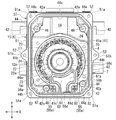
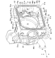
図4は、制御装置5のカバー38及び回路基板25を取り外した状態をハウジング6の開口部17側からみた平面図である。図5は、ハウジング6を開口部17側からみた斜視図である。
図2、図4、図5に示すように、制御ケース15は、モータケース12のモータ開口部12bに一体成形されている。制御ケース15は、モータ部4とは反対側に開口部17(すなわち、ハウジング6の開口部)を有する箱状のケース本体37と、ケース本体37の開口部17を閉塞する板状のカバー38と、を備えている。カバー38は、ボルト39によってケース本体37に取り付けられている。
<Control case>
FIG. 4 is a plan view of the state in which the
As shown in FIGS. 2, 4, and 5, the
また、ケース本体37に、回路基板25が収容されている。つまり、ケース本体37は、軸方向からみてその外形状がモータケース12の外形状よりも大きい。ケース本体37の底部41は、モータケース12のモータ開口部12bに対応する大部分が開口されている。これによりケース本体37の内部(すなわち、制御装置収容部14)とモータケース12の内部(すなわち、モータ収容部11)とが連通されている。
Further, the
ケース本体37は、モータケース12のモータ開口部12bに一体に形成された底部41と、底部41に一体に形成された複数(本実施形態では4個)の取付ボス42と、回路基板25に対して底部41と反対側に形成された開口部17と、を有する。
底部41は、モータ収容部11と制御装置収容部14との間に形成され、制御装置収容部14に対向する段差面41aを有する。すなわち、段差面41aは、モータ収容部11と制御装置収容部14との間に形成されている。段差面41aは、ケース本体37の周壁44から制御装置収容部14に向けて張り出されている。段差面41aは、内周辺41bが軸方向においてモータケース12の内周面12cより径方向に大きな円形に形成されている。
The
The
ケース本体37の周壁44は、回路基板25(図3参照)の外形状に対応するように形成されている。すなわち周壁44は、X方向で対向する第1内側面44a、及び第2内側面44bと、Y方向で対向する第3内側面44c、及び第4内側面44dと、を有する。
また、周壁44は、第1内側面44a及び第3内側面44cが交差する第1交差内面44eと、第3内側面44c及び第2内側面44bが交差する第2交差内面44fと、第2内側面44b及び第4内側面44dが交差する第3交差内面44gと、第4内側面44d及び第1内側面44aが交差する第4交差内面44hと、を有する。
The
Further, the
第4内側面44dの近傍で、かつ、第3交差内面44g寄りにおいて、段差面41aに支持面41cを有する。支持面41cには放熱部材7が取り付けられている。放熱部材7についての詳細は後述する。
また、段差面41aにおいて、第1交差内面44e、第2交差内面44f、第3交差内面44g、及び第4交差内面44hの近傍に取付ボス42が一体に形成されている。取付ボス42は、軸方向の端面42aが開口部17に対向して配置され、端面42aに雌ネジ部46が形成されている。
A
Further, on the
ケース本体37の制御装置収容部14に回路基板25が収容された状態において、取付ボス42の端面42aに回路基板25が当接される。端面42aの雌ネジ部46にボルト47がねじ結合されることにより、複数の取付ボス42(すなわち、ケース本体37)に回路基板25(図3参照)が取り付けられている。
The
図3に示すように、ケース本体37の周壁44において、第1内側面44aは、回路基板25の第1辺25cに沿ってY方向に配置されている。第2内側面44bは、回路基板25の第2辺25dに沿ってY方向に配置されている。第3内側面44cは、回路基板25の第3辺25eに対して上方へ間隔をおいてX方向に配置されている。第4内側面44dは、回路基板25の第4辺25fにX方向に沿っている。
As shown in FIG. 3, in the
第3内側面44cが回路基板25の第3辺25eに対して上方へ間隔をおいて配置されることにより、第3内側面44c及び第3辺25e間に空間49が形成されている。この空間49に、コネクタ31の一部が露出されている。この露出された空間49は、コネクタ31の各主端子31aや、モータ部4のコイル24(双方、図4参照)と回路基板25との接続作業用窓として利用される。
A
図2、図4、図5に示すように、ケース本体37の周壁44のうち、開口部17側の開口端部51は、軸方向からみて略四角形状に形成されている。このため、開口端部51の四隅51aは、軸方向でカバー38の側からみて第1交差内面44e、第2交差内面44f、第3交差内面44g及び第4交差内面44hから大きく張り出されている。
また、開口端部51は、Y方向に延びる直線部の中央に張出部51bが形成されている。張出部51bは、第1内側面44a及び第2内側面44bから大きく張り出されている。四隅51a及び張出部51bに、雌ネジ部52が形成されている。これら雌ネジ部52に、ボルト39がねじ結合されることにより、ケース本体37にカバー38が取り付けられている。
As shown in FIGS. 2, 4, and 5, of the
Further, the
<放熱部材>
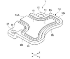
図6は、放熱部材7を示す斜視図である。
図2、図4、図6に示すように、支持面41cに、放熱部材7が一対のボルト55で取り付けられている。放熱部材7は、外周56が第1周辺56a、第2周辺56b、第3周辺56c、及び第4周辺56dにより、軸方向からみて、例えばアルミ材で略四角形の板状に形成されている。
<Heat dissipation member>
FIG. 6 is a perspective view showing the
As shown in FIGS. 2, 4, and 6, the
第1周辺56aは、第1内側面44aに対してX方向に間隔をおいてY方向に沿って配置されている。第2周辺56bは、第2内側面44bに対してX方向に間隔をおいてY方向に沿って配置されている。第3周辺56cは、第1周辺56aのうち第3内側面44c側の端部と、第2周辺56bのうち第3内側面44c側の端部とに接続されている。第3周辺56cは、ロータ22に取り付けられたセンサマグネット70を避けるように、ロータ22の外周面22aに沿って円弧状に形成されている。
The first peripheral 56a is arranged along the Y direction at intervals in the X direction with respect to the first
第4周辺56dは、第1周辺56aのうち第4内側面44d側の端部と、第2周辺56bのうち第4内側面44d側の端部とに接続されている。第4周辺56dは、第4内側面44dの近傍においてX方向に沿って配置されている。すなわち、放熱部材7は、周壁44の第4内側面44dに近接した状態に支持されている。
The fourth peripheral 56d is connected to the end of the first peripheral 56a on the fourth
放熱部材7は、平坦に形成された接触部61と、X方向において接触部61の両側に形成された一対の取付部62と、接触部61の外周に沿って形成された溝部63と、を有する。一対の取付部62は、第1周辺56aと第4周辺56dとの角部、及び第2周辺56bと第4周辺56dとの角部に形成されている。一対の取付部62は、軸方向において、接触部61に対してモータ部4側に凹むように段差状に形成され、取付孔64が貫通されている。
The
段差面41aの支持面41cには、一対の取付孔64に対応する位置に、図示しない一対の雌ねじ部が形成されている。支持面41cに一対の取付部62が接触された状態において、一対の取付孔64に差し込んだボルト55が一対の雌ねじ部にねじ結合されている。これにより、放熱部材7は、軸方向において、モータ収容部11のモータ部4と制御装置収容部14の制御装置5(図3参照)との間に設けられている。
A pair of female threaded portions (not shown) are formed on the
また、取付部62は、接触部61に対してモータ部4側に凹むように段差状に形成されている。このため、ボルト55が雌ねじ部にねじ結合された状態において、ボルト55の頭部55aは、接触部61のうち回路基板25側の面(以下、接触面という)61aに対して、軸方向においてモータ部4側に逃がすように配置されている。
Further, the mounting
さらに、制御装置5とモータ部4との間に放熱部材7が設けられた状態において、接触部61は、軸方向からみて、モータ部4のステータ21と重なる位置に設けられている。また、接触部61は、接触面61aが回路基板25の第2面25bのうちレジスト除去部33に対向するように配置されている。接触面61aには、制御装置5の組付けの際に接着剤67が塗布される。
接触面61aには、外周に沿って溝部63が形成されている。溝部63は、接触面61aに開口する断面U字状に形成されている。
Further, in a state where the
A
接触面61aに接着剤67が塗布され、制御装置5が取付ボス42にボルト47で取り付けられることにより、接着剤67がレジスト除去部33に接着されている。このため、接触面61aは、軸方向において接着剤67を介してレジスト除去部33(すなわち、回路基板25)に接触されている。
回路基板25には、レジスト除去部33と対向する第2面25bの位置に、スイッチング素子26が実装されている。これにより、接触面61aは、軸方向において接着剤67やレジスト除去部33を介してスイッチング素子26に接触されている。
The adhesive 67 is applied to the
On the
溝部63は、接着剤67によって接触面61aとレジスト除去部33とを接続した際の接着剤67の余剰分が流れ込む凹部として機能する。接着剤67は、絶縁性を有し、かつ熱伝導性を有する。つまり接着剤67は、回路基板25(スイッチング素子26)の熱を放熱部材7に伝達するのを促進させる熱伝達部材である。
The
ここで、図3に示すように、回路基板25の第4辺25fには、X方向において2列に配置されたスイッチング素子26とスイッチング素子26との間に凹部35が形成されている。すなわち、凹部35は、軸方向において(回路基板25の厚さ方向において)、接触面61aに対して重なる位置に配置されている。このため、レジスト除去部33に接着剤67を介して放熱部材7が接触され、回路基板25の陰に放熱部材7が隠された状態において、放熱部材7に塗布した接着剤67を凹部35からハウジング6の開口部17の側に露出させることができる。
Here, as shown in FIG. 3, recesses 35 are formed on the fourth side 25f of the
<モータ装置の組付け工程>
次に、モータ装置2の組付付け工程を図2から図4に基づいて説明する。
図4に示すように、ハウジング6の開口部17からモータ部4をモータケース12に収容する。モータ部4を収容した後、段差面41aの支持面41cに、放熱部材7を開口部17から一対のボルト55で取り付ける。放熱部材7は、接触部61が軸方向においてステータ21と重なる位置に配置され、接触面61a及び溝部63が開口部17側を向いて配置される。放熱部材7は、周壁44の第4内側面44dに近接した状態に支持される。
ここで、放熱部材7は、軸方向から見て、ステータ21と重なる位置(すなわち、投影面)に設けられている。これにより、モータ装置2の小型化を図ることができる。
<Assembly process of motor device>
Next, the assembly process of the
As shown in FIG. 4, the motor portion 4 is housed in the
Here, the
また、図2に示すように、モータケース12のモータ収容部11と制御ケース15の制御装置収容部14との間は、例えば、一般に利用されていないデッドスペースである。これにより、デッドスペースを利用して放熱部材7を配置でき、モータ装置2の小型化を図ることができる。
Further, as shown in FIG. 2, the space between the
さらに、段差面41aの支持面41cに放熱部材7を取り付けることにより、放熱部材7をハウジング6と別部材で構成できる。このため、放熱部材7をハウジング6と一体に成形する場合に、例えばアンダーカットになってしまう位置に放熱部材7を設けることができる。このように、放熱部材7をハウジング6と別部材で構成することにより、例えば、放熱部材7のレイアウトをモータ装置2の他部品に対して効率的に設定できる。
すなわち、例えば、ハウジング6等に備えられる他の機能部位や、ハウジング6の加工性の観点等により放熱部材として使用できない領域に影響されることなく、放熱部材7のレイアウトを効率的に設定できる。加えて、放熱部材7のレイアウトを効率的に設定することにより、例えば放熱部材7で放熱するスイッチング素子26のレイアウトの自由度を高めることができる。
Further, by attaching the
That is, for example, the layout of the
図2から図4に示すように、段差面41aの支持面41cに放熱部材7を取り付けた状態において、接触面61aに接着剤67を塗布する。ハウジング6の開口部17から回路基板25を制御ケース15の制御装置収容部14に収容し、回路基板25の第1面25aを取付ボス42の端面42aに配置する。配置した回路基板25を複数のボルト47で回路基板25を取付ボス42の端面42aに組み付ける。
As shown in FIGS. 2 to 4, the adhesive 67 is applied to the
ここで、放熱部材7は、周壁44の第4内側面44dに近接した状態に支持されている。このため、開口部17からケース本体37に回路基板25を組み付ける際に、放熱部材7にレジスト除去部33が接触されているか否かを、回路基板25の第4辺25fと周壁44の第4内側面44dとの間の隙間から目視により容易に確認できる。これにより、モータ装置2の生産性を向上できる。
Here, the
また、接触面61aに接着剤67が塗布されている。このため、取付ボス42に回路基板25を組み付けた状態において、接着剤67にレジスト除去部33が接着され、レジスト除去部33に接着剤67を介して接触面61aが接触される。このため、レジスト除去部33(すなわち、スイッチング素子26)に放熱部材7により余分な接圧をかけることなく、スイッチング素子26に放熱部材7を接触させることができる。これにより、スイッチング素子26(すなわち、制御装置5)の品質を向上でき、モータ装置2の生産性を向上できる。
Further, the adhesive 67 is applied to the
さらに、回路基板25の第4辺25fには、凹部35が形成されている。凹部35は、軸方向において、接触面61a(すなわち、接着剤67)に対して重なる位置に配置される。このため、放熱部材7が回路基板25の陰に隠された状態において、凹部35からハウジング6の開口部17の側に接着剤67を露出させることができる。
これにより、制御装置5(すなわち、モータ装置2)を組み付ける際に、回路基板25に接着剤67を介して放熱部材7が接触された状態において、接触面61aに塗布した接着剤67の有無を、凹部35から目視により確認できる。
Further, a
As a result, when the control device 5 (that is, the motor device 2) is assembled, the presence or absence of the adhesive 67 applied to the
加えて、放熱部材7が板状に形成され、放熱部材7の接触面61aには外周に沿って溝部63が形成されている。このため、接触面61aに塗布した接着剤67を溝部63で保持し、接触面61a(すなわち、放熱部材7)から接着剤67が漏れることを防止できる。これにより、スイッチング素子26に接着剤67を介して放熱部材7を良好に接触させることができる。
In addition, the
また、取付部62は、接触面61aに対してモータ部4側に凹むように段差状に形成されている。このため、放熱部材7をボルト55で取り付けた状態において、ボルト55の頭部55aを接触面61aに対して、モータ部4側に逃がすことができる。これにより、回路基板25を取付ボス42に組み付けた状態において、回路基板25がボルト55の頭部55aに当たることを防止できる。
Further, the mounting
<モータ装置の放熱作用>
次に、図1から図4に基づいてモータ装置2の放熱作用を説明する。
なお、制御装置5の駆動による発熱素子として、スイッチング素子26、コンデンサ27、チョークコイル28等が考えられるが、放熱作用の理解を容易にするために、スイッチング素子26を代表例として説明する。
<Heat dissipation effect of motor device>
Next, the heat dissipation action of the
As the heat generating element driven by the
図2、図3に示すように、制御装置5を駆動することにより、スイッチング素子26が発熱する。スイッチング素子26が実装されている回路基板25のうち、第1面25aには、スイッチング素子26と対向する位置に、レジスト除去部33が形成されている。レジスト除去部33は、接着剤67を介して放熱部材7の接触面61aに確実に接触されている。このため、スイッチング素子26に発生した熱は、接着剤67を経て接触面61aに速やかに伝達される。
As shown in FIGS. 2 and 3, the switching
図2、図4に示すように、接触部61に伝達された熱は、接触部61を経て一対の取付部62に伝達される。一対の取付部62は、支持面41cに接触されている。また、一対のボルト55は、支持面41cの雌ねじ部にねじ結合されている。支持面41cは底部41に形成されている。
このため、一対の取付部62に伝達された熱は、一対の取付部62や一対のボルト55を経て底部41に伝達される。底部41に伝達された熱は、ケース本体37やモータケース12(すなわち、ハウジング6)に伝達される。ケース本体37やモータケース12に伝達された熱は、ケース本体37やモータケース12から外部に放熱される。これにより、制御装置5の放熱性を高めることができる。
As shown in FIGS. 2 and 4, the heat transferred to the
Therefore, the heat transferred to the pair of mounting
また、放熱部材7は、例えばアルミ材で形成されている。ハウジング6は、例えばアルミダイキャストで成形されている。これにより、放熱部材7及びハウジング6の熱伝達性を向上させることができ、制御装置5の放熱性をさらに高めることができる。
Further, the
ところで、図1に示すように、電動ポンプ1は、オイルOが貯留されているオイルタンクTの内部に配置されている。電動ポンプ1は、回転軸線Cが水平方向に沿う向きで配置されており、略下半分がオイルOに浸漬される。このため、制御ケース15の回路基板25の下半部や放熱部材7もオイルOに浸漬される。この結果、オイルOによって、回路基板25や放熱部材7の冷却が促進される。また、コネクタ31は上方に配置されているので、コネクタ31にオイルOが飛散してしまうことを極力抑えることができる。
By the way, as shown in FIG. 1, the electric pump 1 is arranged inside the oil tank T in which the oil O is stored. The electric pump 1 is arranged so that the rotation axis C is oriented along the horizontal direction, and a substantially lower half thereof is immersed in the oil O. Therefore, the lower half of the
なお、本発明は上述の実施形態に限られるものではなく、本発明の趣旨を逸脱しない範囲において、上述の実施形態に種々の変更を加えたものを含む。
例えば、上記実施形態では、放熱部材7をハウジング6と別部材で構成した例について説明した。しかしながらこれに限られるものではなく、例えば、放熱部材7をハウジング6やカバー38と一体に構成してもよい。
The present invention is not limited to the above-described embodiment, and includes various modifications to the above-described embodiment without departing from the spirit of the present invention.
For example, in the above embodiment, an example in which the
上述の実施形態では、制御装置5とモータ部4との間に設けられた状態において、軸方向からみて、モータ部4のステータ21と重なる位置に放熱部材7の接触部61が配置されている場合について説明した。しかしながら、モータ部4のステータ21と重なる位置に少なくとも放熱部材7の接触部61が配置されていればよく、放熱部材7のその他の箇所もモータ部4のステータ21と重なる位置に配置されてもよい。
In the above-described embodiment, the
上述の実施形態では、ケース本体37は、モータ収容部11と制御装置収容部14との間に形成され、制御装置収容部14に対向する段差面41aを有する場合について説明した。段差面41aの支持面41cに、放熱部材7が設けられている場合について説明した。しかしながらこれに限られるものではなく、モータ収容部11と制御装置収容部14との間で、回路基板25に接着剤67を介して放熱部材7が接触されるように、放熱部材7が設けられていればよい。
In the above-described embodiment, the case where the case
1…電動ポンプ、2…モータ装置、3…ポンプ部、4…モータ部(モータ)、5…制御装置、6…ハウジング、7…放熱部材、11…モータ収容部、14…制御装置収容部、17…開口部、21…ステータ、25…回路基板、26…スイッチング素子(発熱素子)、33…レジスト除去部(制御装置の一部)、35…凹部、41…底部、41a…段差面、41c…支持面、63…溝部、67…接着剤 1 ... Electric pump, 2 ... Motor device, 3 ... Pump section, 4 ... Motor section (motor), 5 ... Control device, 6 ... Housing, 7 ... Heat dissipation member, 11 ... Motor housing section, 14 ... Control device housing section, 17 ... opening, 21 ... stator, 25 ... circuit board, 26 ... switching element (heating element), 33 ... resist removing part (part of control device), 35 ... recess, 41 ... bottom, 41a ... stepped surface, 41c ... Support surface, 63 ... Groove, 67 ... Adhesive
Claims (7)
前記モータの駆動制御を行う制御装置と、
前記モータを収容するモータ収容部、及び前記制御装置を収容する制御装置収容部が一体化されたハウジングと、
を備え、
前記ハウジングは、前記制御装置収容部に対して前記モータ収容部の反対側に前記モータ及び前記制御装置を受け入れる開口部を有し、
前記モータ収容部と前記制御装置収容部との間に設けられ、前記制御装置の一部に接触する放熱部材を備えた
ことを特徴とするモータ装置。 With the motor
A control device that controls the drive of the motor and
A housing in which a motor accommodating portion for accommodating the motor and a control device accommodating portion for accommodating the control device are integrated.
With
The housing has an opening for receiving the motor and the control device on the opposite side of the motor housing with respect to the control device housing.
A motor device provided between the motor accommodating portion and the control device accommodating portion and provided with a heat radiating member that comes into contact with a part of the control device.
前記段差面は、前記放熱部材を取り付ける支持面を有することを特徴とする請求項1に記載のモータ装置。 The housing has a stepped surface between the motor accommodating portion and the control device accommodating portion.
The motor device according to claim 1, wherein the stepped surface has a support surface on which the heat radiating member is attached.
ことを特徴とする請求項1又は請求項2に記載のモータ装置。 The motor device according to claim 1 or 2, wherein the heat radiating member is in contact with a heat generating element provided in the control device via an adhesive.
前記回路基板は、前記回路基板の厚さ方向からみて前記放熱部材と重なる箇所の一部に形成された凹部を有することを特徴とする請求項3又は請求項4に記載のモータ装置。 The control device includes a circuit board on which the heat generating element is mounted.
The motor device according to claim 3 or 4, wherein the circuit board has a recess formed in a part of a portion overlapping the heat radiating member when viewed from the thickness direction of the circuit board.
前記放熱部材は、軸方向からみて、前記モータのステータと重なる位置に少なくとも一部が配置されていることを特徴とする請求項1から請求項5のいずれか1項に記載のモータ装置。 The motor is a brushless motor
The motor device according to any one of claims 1 to 5, wherein at least a part of the heat radiating member is arranged at a position overlapping the stator of the motor when viewed from the axial direction.
Priority Applications (1)
| Application Number | Priority Date | Filing Date | Title |
|---|---|---|---|
| JP2020033329A JP7389680B2 (en) | 2020-02-28 | 2020-02-28 | Motor device and electric pump |
Applications Claiming Priority (1)
| Application Number | Priority Date | Filing Date | Title |
|---|---|---|---|
| JP2020033329A JP7389680B2 (en) | 2020-02-28 | 2020-02-28 | Motor device and electric pump |
Publications (2)
| Publication Number | Publication Date |
|---|---|
| JP2021136825A true JP2021136825A (en) | 2021-09-13 |
| JP7389680B2 JP7389680B2 (en) | 2023-11-30 |
Family
ID=77661867
Family Applications (1)
| Application Number | Title | Priority Date | Filing Date |
|---|---|---|---|
| JP2020033329A Active JP7389680B2 (en) | 2020-02-28 | 2020-02-28 | Motor device and electric pump |
Country Status (1)
| Country | Link |
|---|---|
| JP (1) | JP7389680B2 (en) |
Cited By (3)
| Publication number | Priority date | Publication date | Assignee | Title |
|---|---|---|---|---|
| WO2023117784A1 (en) * | 2021-12-21 | 2023-06-29 | Vitesco Technologies GmbH | Housing device for a fluid pump |
| US12355338B2 (en) | 2023-07-03 | 2025-07-08 | Mitsuba Corporation | Motor device and oil pump device |
| US12597827B2 (en) | 2023-07-03 | 2026-04-07 | Mitsuba Corporation | Control device, motor device, and oil pump device |
Citations (5)
| Publication number | Priority date | Publication date | Assignee | Title |
|---|---|---|---|---|
| JPH08298761A (en) * | 1995-04-25 | 1996-11-12 | Shibaura Eng Works Co Ltd | Brushless DC motor |
| JP2004158814A (en) * | 2002-09-13 | 2004-06-03 | Hitachi Kokusai Electric Inc | Heat dissipating mounting structure of heating element |
| JP2013176193A (en) * | 2012-02-24 | 2013-09-05 | Mitsubishi Electric Corp | Mechatronic integrated drive device |
| JP2013211938A (en) * | 2012-03-30 | 2013-10-10 | Hitachi Automotive Systems Ltd | On-vehicle motor and electrically driven power steering motor using the same |
| JP2015136280A (en) * | 2013-12-20 | 2015-07-27 | アスモ株式会社 | Electric pump |
-
2020
- 2020-02-28 JP JP2020033329A patent/JP7389680B2/en active Active
Patent Citations (5)
| Publication number | Priority date | Publication date | Assignee | Title |
|---|---|---|---|---|
| JPH08298761A (en) * | 1995-04-25 | 1996-11-12 | Shibaura Eng Works Co Ltd | Brushless DC motor |
| JP2004158814A (en) * | 2002-09-13 | 2004-06-03 | Hitachi Kokusai Electric Inc | Heat dissipating mounting structure of heating element |
| JP2013176193A (en) * | 2012-02-24 | 2013-09-05 | Mitsubishi Electric Corp | Mechatronic integrated drive device |
| JP2013211938A (en) * | 2012-03-30 | 2013-10-10 | Hitachi Automotive Systems Ltd | On-vehicle motor and electrically driven power steering motor using the same |
| JP2015136280A (en) * | 2013-12-20 | 2015-07-27 | アスモ株式会社 | Electric pump |
Cited By (3)
| Publication number | Priority date | Publication date | Assignee | Title |
|---|---|---|---|---|
| WO2023117784A1 (en) * | 2021-12-21 | 2023-06-29 | Vitesco Technologies GmbH | Housing device for a fluid pump |
| US12355338B2 (en) | 2023-07-03 | 2025-07-08 | Mitsuba Corporation | Motor device and oil pump device |
| US12597827B2 (en) | 2023-07-03 | 2026-04-07 | Mitsuba Corporation | Control device, motor device, and oil pump device |
Also Published As
| Publication number | Publication date |
|---|---|
| JP7389680B2 (en) | 2023-11-30 |
Similar Documents
| Publication | Publication Date | Title |
|---|---|---|
| JP6271968B2 (en) | Electric motor and electric pump | |
| US20130195696A1 (en) | Electric pump | |
| JP6492935B2 (en) | Controller-integrated rotating electrical machine | |
| JP7389680B2 (en) | Motor device and electric pump | |
| CN102019611B (en) | Electric power tool | |
| KR102221809B1 (en) | Motor integrated with control unit and water pump having the same | |
| WO2014104121A1 (en) | Electric motor and electric pump | |
| KR101910337B1 (en) | Electric motor with a power output stage and with efficient heat transport and method | |
| WO2015093138A1 (en) | Mechatronic driver and method for manufacturing same | |
| JP2019075872A (en) | Control function-provided actuator and electric pump | |
| US10117347B2 (en) | Accommodation device for electronic parts | |
| US11962229B2 (en) | Motor, fan, air conditioner, and manufacturing method of motor | |
| US20180062478A1 (en) | Motor | |
| JP6183288B2 (en) | Electric compressor | |
| JP6251920B2 (en) | Electric motor and electric pump | |
| JP2012110177A (en) | Electric pump | |
| JP6505311B2 (en) | Motor and ventilation fan | |
| JP2014161209A (en) | Electric motor and electric pump | |
| JP2005176451A (en) | Brushless motor | |
| US10894559B2 (en) | Power unit for an electrical steering system | |
| JP2017229124A (en) | DC brushless motor and ventilation fan | |
| JP2021097500A (en) | Motor and electric pump | |
| JP5713646B2 (en) | Electric pump | |
| JP7282612B2 (en) | Control device and motor device | |
| JP2020136534A (en) | Control device, motor device and electric pump |
Legal Events
| Date | Code | Title | Description |
|---|---|---|---|
| A621 | Written request for application examination |
Free format text: JAPANESE INTERMEDIATE CODE: A621 Effective date: 20220829 |
|
| A977 | Report on retrieval |
Free format text: JAPANESE INTERMEDIATE CODE: A971007 Effective date: 20230531 |
|
| A131 | Notification of reasons for refusal |
Free format text: JAPANESE INTERMEDIATE CODE: A131 Effective date: 20230606 |
|
| A521 | Request for written amendment filed |
Free format text: JAPANESE INTERMEDIATE CODE: A523 Effective date: 20230727 |
|
| TRDD | Decision of grant or rejection written | ||
| A01 | Written decision to grant a patent or to grant a registration (utility model) |
Free format text: JAPANESE INTERMEDIATE CODE: A01 Effective date: 20231107 |
|
| A61 | First payment of annual fees (during grant procedure) |
Free format text: JAPANESE INTERMEDIATE CODE: A61 Effective date: 20231117 |
|
| R150 | Certificate of patent or registration of utility model |
Ref document number: 7389680 Country of ref document: JP Free format text: JAPANESE INTERMEDIATE CODE: R150 |