JP2021136820A - Clamp and attachment/detachment method of clamp - Google Patents
Clamp and attachment/detachment method of clamp Download PDFInfo
- Publication number
- JP2021136820A JP2021136820A JP2020033196A JP2020033196A JP2021136820A JP 2021136820 A JP2021136820 A JP 2021136820A JP 2020033196 A JP2020033196 A JP 2020033196A JP 2020033196 A JP2020033196 A JP 2020033196A JP 2021136820 A JP2021136820 A JP 2021136820A
- Authority
- JP
- Japan
- Prior art keywords
- clamp
- mounting
- detent
- wire harness
- hole
- Prior art date
- Legal status (The legal status is an assumption and is not a legal conclusion. Google has not performed a legal analysis and makes no representation as to the accuracy of the status listed.)
- Granted
Links
Images

Landscapes
- Installation Of Indoor Wiring (AREA)
- Clamps And Clips (AREA)
Abstract
【課題】ワイヤハーネスを固定するクランプが回転することを防止し、ワイヤハーネスの配策経路を適切に規定すること。【解決手段】クランプ1は、取り付け部12を有する基体部10と、回り止め部33を有するカバー部30と、基体部10及びカバー部30を連結するヒンジ部20と、を備え、取り付け部12は、取り付け用孔101に挿入された状態において回転させられることにより、取り付け用孔101から取り外し可能とされており、クローズ状態において、基体部10及びカバー部30間にはワイヤハーネスを保持する保持空間50が形成されており、取り付け部12及び回り止め部33は、互いに同じ方向に延びており、取り付け部12が取り付け用孔101に挿入され、回り止め部33が回り止め用孔102に挿入されることにより、基体部10及びカバー部30が取り付け基板100に取り付け可能とされている。【選択図】図1An object of the present invention is to prevent a clamp that fixes a wire harness from rotating and appropriately define a wiring route for the wire harness. A clamp 1 includes a base part 10 having a mounting part 12, a cover part 30 having a rotation stop part 33, and a hinge part 20 connecting the base part 10 and the cover part 30. can be removed from the mounting hole 101 by being rotated while inserted into the mounting hole 101. In the closed state, there is a holder for holding the wire harness between the base portion 10 and the cover portion 30. A space 50 is formed, the attachment part 12 and the rotation stopper part 33 extend in the same direction, and the attachment part 12 is inserted into the attachment hole 101 and the rotation prevention part 33 is inserted into the rotation prevention hole 102. By doing so, the base portion 10 and the cover portion 30 can be attached to the mounting board 100. [Selection diagram] Figure 1
Description
本発明は、クランプ及びクランプの着脱方法に関する。 The present invention relates to a clamp and a method of attaching and detaching the clamp.
電力供給及び信号伝達を行うワイヤハーネスの配策経路を規定するクランプが知られている(例えば特許文献1参照)。クランプによってワイヤハーネスが固定されると共に、ワイヤハーネスを固定したクランプが基板(例えばエンジンの一部)に取り付けられることにより、ワイヤハーネスの配策経路が規定される。 Clamps that define the arrangement route of wire harnesses that supply power and transmit signals are known (see, for example, Patent Document 1). The wire harness is fixed by the clamp, and the clamp that fixes the wire harness is attached to the substrate (for example, a part of the engine), so that the arrangement route of the wire harness is defined.
クランプは、例えば取り付け相手部品(例えばインタークーラ―)が故障、不良の場合やワイヤハーネスの交換時等に基板から取り外されるが、このような場合に破損することなく、取り外された後においても再利用されることが好ましい。例えば、クランプを回転させることにより基板から取り外す方法では、クランプを取り外す際にクランプが破損しないため、クランプの再利用が可能となる。しかしながら、クランプの回転が可能な態様では、クランプを基板に取り付けている状態においてもクランプが回転し、ワイヤハーネスの配策経路を適切に規定できないことが考えられる。 The clamp is removed from the board when, for example, the mounting partner part (for example, the intercooler) is out of order or defective, or when the wire harness is replaced. It is preferable to be used. For example, in the method of removing the clamp from the substrate by rotating the clamp, the clamp is not damaged when the clamp is removed, so that the clamp can be reused. However, in a mode in which the clamp can be rotated, it is conceivable that the clamp rotates even when the clamp is attached to the substrate, and the arrangement path of the wire harness cannot be properly defined.
本発明は上記実情に鑑みてなされたものであり、ワイヤハーネスの再利用時等においてクランプが破損することを防止すると共に、ワイヤハーネスを固定するクランプが回転することを防止し、ワイヤハーネスの配策経路を適切に規定することを目的とする。 The present invention has been made in view of the above circumstances, and prevents the clamp from being damaged when the wire harness is reused, and also prevents the clamp for fixing the wire harness from rotating, and arranges the wire harness. The purpose is to properly define the route.
本発明の一態様に係るクランプは、ワイヤハーネスを保持した状態で基板に取り付け可能に構成されたクランプであって、基板の取り付け用孔に挿入可能に構成された取り付け部を有する基体部と、基板の回り止め用孔に挿入可能に構成された回り止め部を有するカバー部と、基体部及びカバー部を連結するヒンジ構造のヒンジ部と、を備え、取り付け部は、取り付け用孔に挿入された状態において回転させられることにより、取り付け用孔から取り外し可能とされており、ヒンジ部を支点にカバー部が基体部方向に回転し基体部にカバー部が接続されたクローズ状態において、基体部及びカバー部間にはワイヤハーネスを保持する保持空間が形成されており、取り付け部及び回り止め部は、互いに同じ方向に延びており、取り付け部が取り付け用孔に挿入され、回り止め部が回り止め用孔に挿入されることにより、基体部及びカバー部が基板に取り付け可能とされている。 The clamp according to one aspect of the present invention is a clamp configured to be mountable on a substrate while holding a wire harness, and has a base portion having a mounting portion configured to be insertable into a mounting hole of the substrate, and a base portion. A cover portion having a detent portion configured to be inserted into the detent hole of the substrate and a hinge portion having a hinge structure for connecting the base portion and the cover portion are provided, and the mounting portion is inserted into the mounting hole. It is removable from the mounting hole by being rotated in the state of being A holding space for holding the wire harness is formed between the cover portions, and the mounting portion and the detent portion extend in the same direction to each other, the mounting portion is inserted into the mounting hole, and the detent portion is detented. By being inserted into the hole, the base portion and the cover portion can be attached to the substrate.
本発明の一態様に係るクランプでは、クローズ状態において、取り付け部が取り付け用孔に挿入されると共に、回り止め部が回り止め用孔に挿入されることによって、基体部及びカバー部が基板に取り付け可能とされている。ここで、本発明の一態様に係るクランプでは、取り付け用孔に挿入された取り付け部が回転することによって、取り付け部が取り付け用孔から取り外し可能とされているが、クローズ状態において取り付け部及び回り止め部の双方が孔部に挿入されている場合においては、回り止め部によって取り付け部の回転動作が規制される。具体的には、取り付け部が回転するようにクランプが回転させられると、回り止め部が回り止め用孔の内表面に当たり、取り付け部の更なる回転動作が規制される。このことにより、クローズ状態においては、クランプが回転することが防止され、保持空間において保持されたワイヤハーネスの配策経路を適切に規定することができる。また、クランプの取り付け部が回転することにより基板からクランプを取り外す構成とすることにより、ワイヤハーネスの再利用時等においてクランプが破損することを防止することができる。 In the clamp according to one aspect of the present invention, in the closed state, the mounting portion is inserted into the mounting hole and the detent portion is inserted into the detent hole, so that the base portion and the cover portion are mounted on the substrate. It is possible. Here, in the clamp according to one aspect of the present invention, the mounting portion can be removed from the mounting hole by rotating the mounting portion inserted into the mounting hole, but the mounting portion and rotation in the closed state. When both of the stoppers are inserted into the holes, the detents regulate the rotational movement of the attachment. Specifically, when the clamp is rotated so that the mounting portion rotates, the detent portion hits the inner surface of the detent hole, and further rotation operation of the mounting portion is restricted. As a result, in the closed state, the clamp is prevented from rotating, and the arrangement route of the wire harness held in the holding space can be appropriately defined. Further, by removing the clamp from the substrate by rotating the mounting portion of the clamp, it is possible to prevent the clamp from being damaged when the wire harness is reused.
本発明の一態様に係るクランプの着脱方法は、保持空間においてワイヤハーネスが保持されるように、ヒンジ部を支点にカバー部を基体部方向に回転させ、基体部にカバー部が接続されたクローズ状態として、ワイヤハーネスにクランプを取り付ける工程と、取り付け用孔に取り付け部を挿入すると共に回り止め用孔に回り止め部を挿入し、基板にクランプを取り付ける工程と、ヒンジ部を支点にカバー部を基体部から離間する方向に回転させ、保持空間が開放されたオープン状態として、ワイヤハーネスをクランプから取り外す工程と、取り付け用孔に挿入された取り付け部を回転させることにより、取り付け用孔から取り付け部を取り外し、基板からクランプを取り外す工程と、を含む。 In the method of attaching / detaching the clamp according to one aspect of the present invention, the cover portion is rotated toward the base portion with the hinge portion as a fulcrum so that the wire harness is held in the holding space, and the cover portion is connected to the base portion. As a state, the process of attaching the clamp to the wire harness, the process of inserting the attachment part into the attachment hole, inserting the detent part into the detent hole, and attaching the clamp to the board, and the cover part with the hinge part as the fulcrum. By rotating the wire harness in the direction away from the base portion to open the holding space and removing the wire harness from the clamp and rotating the mounting portion inserted into the mounting hole, the mounting portion is separated from the mounting hole. Includes the steps of removing and removing the clamp from the substrate.
このような着脱方法によれば、クローズ状態とされたクランプが基板に取り付けられた状態においては、上述したように、取り付け部及び回り止め部の双方が孔部に挿入されており、回り止め部によって取り付け部の回転動作が規制される。このことにより、クローズ状態においては、クランプが回転することが防止され、保持空間において保持されたワイヤハーネスの配策経路を適切に規定することができる。そして、オープン状態とされてワイヤハーネスをクランプから取り外した状態においては、取り付け部のみが孔部に挿入されており、取り付け部を回転させて取り付け用孔から取り外すことが可能となるので、容易にクランプを取り外すことができると共に、再利用可能な状態でクランプを取り外すことができる。 According to such an attachment / detachment method, when the clamp in the closed state is attached to the substrate, both the attachment portion and the detent portion are inserted into the holes as described above, and the detent portion is formed. Restricts the rotational movement of the mounting part. As a result, in the closed state, the clamp is prevented from rotating, and the arrangement route of the wire harness held in the holding space can be appropriately defined. Then, in the state where the wire harness is removed from the clamp in the open state, only the mounting portion is inserted into the hole portion, and the mounting portion can be rotated and removed from the mounting hole, so that it can be easily removed. The clamp can be removed and the clamp can be removed in a reusable state.
本発明によれば、ワイヤハーネスを固定するクランプが回転することを防止し、ワイヤハーネスの配策経路を適切に規定することができる。 According to the present invention, it is possible to prevent the clamp for fixing the wire harness from rotating and to appropriately define the arrangement route of the wire harness.
以下、実施形態に係るクランプ及びクランプの着脱方法について、図面を参照して説明する。なお、以下の説明において、同一又は相当要素には同一符号を付し、重複する説明を省略する。 Hereinafter, the clamp and the method of attaching / detaching the clamp according to the embodiment will be described with reference to the drawings. In the following description, the same or equivalent elements will be designated by the same reference numerals, and duplicate description will be omitted.
[クランプ]
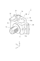
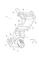
図1は、実施形態に係るクランプ1のクローズ状態を模式的に示す斜視図である。図2は、実施形態に係るクランプ1のオープン状態を模式的に示す斜視図である。クランプ1は、電力供給及び信号伝達を行うワイヤハーネス(不図示。以下同様)の配策経路を規定する部材である。クランプ1は、ワイヤハーネスを保持(固定)した状態で、後述する車両150の取り付け基板100(図3参照。例えばエンジンの一部)に取り付け可能に構成されている。図1及び図2に示されるように、クランプ1は、基体部10と、ヒンジ部20と、カバー部30と、を備えている。なお、以下では、オープン状態(図2参照)において基体部10、ヒンジ部20、及びカバー部30が並ぶ方向をX方向、クローズ状態(図1参照)において基体部10及びカバー部30が対向する方向をY方向、図中の上下方向をZ方向として説明する場合がある。
[Clamp]
FIG. 1 is a perspective view schematically showing a closed state of the
基体部10は、本体部11と、取り付け部12と、側壁部13と、区画部14と、を含んで構成されている。
The
本体部11は、略平板状の部分である。本体部11は、クローズ状態(図1参照)において、X方向に延びており、Y方向においてカバー部30の本体部31(後述)に対向している。本体部11は、クローズ状態においてカバー部30の本体部31に対向する面(裏面)の一部が曲面11aとされている。クローズ状態においては、曲面11aと、本体部31の曲面31a(後述)と、区画部14とで区画される領域が、ワイヤハーネスを保持する保持空間50とされる。このように、基体部10及びカバー部30間にはワイヤハーネスを保持する保持空間50が形成されている。保持空間50は、平面視すると、例えば略円形に形成されている。
The
取り付け部12は、取り付け基板100の取り付け用孔101(図3及び図4参照)に挿入可能に構成された円柱状の部分である。取り付け部12は、本体部11の表面(曲面11aとは反対側の面)の略中央部分からY方向に延びている。取り付け部12の外表面には雄ねじが形成されている。取り付け部12は、取り付け用孔101(図3及び図3参照)に挿入されることのみにより(回転等の動作を行うことなく)、取り付け用孔101に取り付けられる。取り付け部12は、取り付け用孔101に挿入されて取り付けられた状態において、回転させられることにより、取り付け用孔101から取り外し可能とされている。
The
側壁部13(図2参照)は、本体部11のX方向端部(詳細には、本体部11がヒンジ部20に連続する側とは反対側のX方向端部)に連続すると共にY方向(詳細には、取り付け部12が延びる方向とは反対の方向)に延びる壁部である。側壁部13は、クローズ状態において、カバー部30の側壁部32(後述)と接続(嵌合)される。このように、クローズ状態とは、ヒンジ部20を支点に基体部10方向に回転したカバー部30が基体部10に接続された状態である。クローズ状態では、保持空間50においてワイヤハーネスが保持可能とされている。
The side wall portion 13 (see FIG. 2) is continuous with the X-direction end portion of the main body portion 11 (specifically, the X-direction end portion on the side opposite to the side where the
区画部14は、本体部11の裏面側からY方向(詳細には、側壁部13と同じ方向)に延びる壁部である。区画部14は、クローズ状態において、曲面11a及び本体部31の曲面31a(後述)に連続するように設けられており、ワイヤハーネスが保持される保持空間50を区画する部分である。
The
ヒンジ部20は、基体部10及びカバー部30を連結するヒンジ構造の部分である。より詳細には、ヒンジ部20は、基体部10の本体部11及びカバー部30の本体部31を連結する部分である。基体部10及びカバー部30は、ヒンジ部20を支点にして相手方(カバー部30であれば基体部10)に近づく方向、又は、相手方から離間する方向に回転可能とされている。
The
カバー部30は、本体部31と、側壁部32と、回り止め部33と、を含んで構成されている。
The
本体部31は、略平板状の部分である。本体部31は、クローズ状態(図1参照)において、X方向に延びており、Y方向において基体部10の本体部11に対向している。本体部31は、クローズ状態において基体部10の本体部11に対向する面の一部が曲面31aとされている。上述したように、曲面31aは、クローズ状態において保持空間50を区画する。
The
側壁部32は、本体部31のX方向端部(詳細には、本体部31がヒンジ部20に連続する側とは反対側のX方向端部)に連続すると共にY方向に延びる壁部である。側壁部32は、クローズ状態において、基体部10の側壁部13と接続(嵌合)される。
The
回り止め部33は、取り付け基板100の回り止め用孔102(図3及び図4参照)に挿入可能に構成された円柱状の部分である。回り止め部33は、側壁部32のZ方向端部(上端)からY方向に延びている。回り止め部33の径は、取り付け部12の径よりも小さい。クローズ状態において、取り付け部12及び回り止め部33は、互いに同じ方向に延びている。回り止め部33は、クローズ状態において、取り付け部12が取り付け用孔101に挿入されるのと同時に、回り止め用孔102に挿入される。このように、取り付け部12が取り付け用孔101に挿入され、回り止め部33が回り止め用孔102に挿入されることにより、基体部10及びカバー部30が取り付け基板100に取り付けられる。回り止め部33は、取り付け部12が取り付け用孔101に挿入された状態において回転させられると、回り止め用孔102の内表面に当たり、取り付け部12が更に回転することを抑止する機能を有する。
The
[取り付け基板]
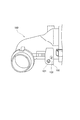
図3は、実施形態係る取り付け基板100を備えた車両150を模式的に示す斜視図である。図4は、実施形態に係る取り付け基板100を模式的に示す斜視図である。図3に示されるように、取り付け基板100は、車両150に設けられている。取り付け基板100は、車両150においてワイヤハーネスを固定したい場所に設けられている。
[Mounting board]
FIG. 3 is a perspective view schematically showing a
図4に示されるように、取り付け基板100には、取り付け用孔101と、回り止め用孔102とが形成されている。取り付け用孔101及び回り止め用孔102は、それぞれ、クローズ状態において取り付け部12及び回り止め部33が同時に挿入可能となる位置に形成されている。
As shown in FIG. 4, the mounting
取り付け用孔101は、取り付け部12が挿入される孔(ナット)である。取り付け用孔101の径は、取り付け部12の径に対応した大きさとされている。取り付け用孔101の内表面には、取り付け部12の雄ねじに対応するように雌ねじが形成されている。回り止め用孔102は、回り止め部33が挿入される孔である。回り止め用孔102の径は、回り止め部33の径に対応した大きさとされている。
The mounting
[クランプの着脱方法]
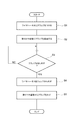
次に、クランプ1の着脱工程(着脱方法)について、図5を参照して説明する。図5は、クランプの着脱工程(着脱方法)を示すフローチャートである。図5に示す各工程のうち、ステップS1及びステップS2はクランプ1の取り付けに係る工程であり、ステップS4及びステップS5はクランプ1の取り外しにかかわる工程である。
[How to attach / detach the clamp]
Next, the attachment / detachment step (attachment / detachment method) of the
図5に示されるように、最初にワイヤハーネスにクランプ1を取り付ける(ステップS1:ワイヤハーネスにクランプを取り付ける工程)。具体的には、クランプ1の保持空間50においてワイヤハーネスが保持されるように、ヒンジ部20を支点にカバー部30を基体部10方向に回転させ、基体部10にカバー部30が接続されたクローズ状態(図1参照)として、ワイヤハーネスにクランプ1を取り付ける。
As shown in FIG. 5, the
つづいて、取り付け基板100にクランプ1を取り付ける(ステップS2:基板にクランプを取り付ける工程)。具体的には、取り付け用孔101に取り付け部12を挿入すると共に、回り止め用孔102に回り止め部33を挿入し、取り付け基板100にクランプ1を取り付ける。クランプ1が取り付けられた後は、何らかの事情(例えばワイヤハーネスを交換する等)が生じるまでは、クランプ1が取り付け基板100に取り付けられた状態とされる。この状態においては、仮に取り付け部12が回転しそうになった(或いは少し回転した)場合であっても、回り止め部33が、更なる回転動作を抑止することができる。
Subsequently, the
その後、クランプ1を取り外すと判断された場合(ステップS3=YES)には、ワイヤハーネスをクランプ1から取り外す(ステップS4:ワイヤハーネスをクランプから取り外す工程)。具体的には、ヒンジ部20を支点にカバー部30を基体部10から離間する方向に回転させ、保持空間50が開放されたオープン状態として、ワイヤハーネスをクランプ1から取り外す。クローズ状態からオープン状態とする際には、回り止め用孔102から回り止め部33が抜かれる。
After that, when it is determined to remove the clamp 1 (step S3 = YES), the wire harness is removed from the clamp 1 (step S4: step of removing the wire harness from the clamp). Specifically, the
つづいて、取り付け基板100からクランプ1を取り外す(ステップS5:基板からクランプを取り外す工程)。具体的には、取り付け用孔101に挿入された取り付け部12を回転させることにより、取り付け用孔101から取り付け部12を取り外し、取り付け基板100からクランプ1を取り外す。以上が、クランプ1の着脱工程(着脱方法)である。
Subsequently, the
[作用効果]
次に、本実施形態に係るクランプ1及びクランプ1の着脱方法の作用効果について説明する。
[Action effect]
Next, the operation and effect of the
本実施形態に係るクランプ1は、ワイヤハーネスを保持した状態で取り付け基板100に取り付け可能に構成されたクランプであって、取り付け基板100の取り付け用孔101に挿入可能に構成された取り付け部12を有する基体部10と、取り付け基板100の回り止め用孔102に挿入可能に構成された回り止め部33を有するカバー部30と、基体部10及びカバー部30を連結するヒンジ構造のヒンジ部20と、を備え、取り付け部12は、取り付け用孔101に挿入された状態において回転させられることにより、取り付け用孔101から取り外し可能とされており、ヒンジ部20を支点にカバー部30が基体部10方向に回転し基体部10にカバー部30が接続されたクローズ状態において、基体部10及びカバー部30間にはワイヤハーネスを保持する保持空間50が形成されており、取り付け部12及び回り止め部33は、互いに同じ方向に延びており、取り付け部12が取り付け用孔101に挿入され、回り止め部33が回り止め用孔102に挿入されることにより、基体部10及びカバー部30が取り付け基板100に取り付け可能とされている。
The
本実施形態に係るクランプ1では、クローズ状態において、取り付け部12が取り付け用孔101に挿入されると共に、回り止め部33が回り止め用孔102に挿入されることによって、基体部10及びカバー部30が取り付け基板100に取り付け可能とされている。ここで、本実施形態に係るクランプ1では、取り付け用孔101に挿入された取り付け部12が回転することによって、取り付け部12が取り付け用孔101から取り外し可能とされているが、クローズ状態において取り付け部12及び回り止め部33の双方が孔部に挿入されている場合においては、回り止め部33によって取り付け部12の回転動作が規制される。具体的には、取り付け部が回転するようにクランプが回転させられると、回り止め部が回り止め用孔の内表面に当たり、取り付け部の更なる回転動作が規制される。このことにより、クローズ状態においては、クランプ1が回転することが防止され、保持空間50において保持されたワイヤハーネスの配策経路を適切に規定することができる。
In the
本実施形態に係るクランプ1の着脱方法は、保持空間50においてワイヤハーネスが保持されるように、ヒンジ部20を支点にカバー部30を基体部10方向に回転させ、基体部10にカバー部30が接続されたクローズ状態として、ワイヤハーネスにクランプ1を取り付ける工程と、取り付け用孔101に取り付け部12を挿入すると共に回り止め用孔102に回り止め部33を挿入し、取り付け基板100にクランプ1を取り付ける工程と、ヒンジ部20を支点にカバー部30を基体部10から離間する方向に回転させ、保持空間50が開放されたオープン状態として、ワイヤハーネスをクランプ1から取り外す工程と、取り付け用孔101に挿入された取り付け部12を回転させることにより、取り付け用孔101から取り付け部12を取り外し、取り付け基板100からクランプ1を取り外す工程と、を含む。
In the method of attaching / detaching the
このような着脱方法によれば、クローズ状態とされたクランプ1が取り付け基板100に取り付けられた状態においては、上述したように、取り付け部12及び回り止め部33の双方が孔部に挿入されており、回り止め部33によって取り付け部12の回転動作が規制される。このことにより、クローズ状態においては、クランプ1が回転することが防止され、保持空間50において保持されたワイヤハーネスの配策経路を適切に規定することができる。そして、オープン状態とされてワイヤハーネスをクランプ1から取り外した状態においては、取り付け部12のみが孔部に挿入されており、取り付け部12を回転させて取り付け用孔101から取り外すことが可能となるので、容易にクランプ1を取り外すことができると共に、再利用可能な状態でクランプ1を取り外すことができる。
According to such an attachment / detachment method, when the
1…クランプ、10…基体部、12…取り付け部、20…ヒンジ部、30…カバー部、33…回り止め部33、50…保持空間、100…取り付け基板、101…取り付け用孔、102…回り止め用孔。
1 ... Clamp, 10 ... Base part, 12 ... Mounting part, 20 ... Hinge part, 30 ... Cover part, 33 ...
Claims (2)
前記基板の取り付け用孔に挿入可能に構成された取り付け部を有する基体部と、
前記基板の回り止め用孔に挿入可能に構成された回り止め部を有するカバー部と、
前記基体部及び前記カバー部を連結するヒンジ構造のヒンジ部と、を備え、
前記取り付け部は、前記取り付け用孔に挿入された状態において回転させられることにより、前記取り付け用孔から取り外し可能とされており、
前記ヒンジ部を支点に前記カバー部が前記基体部方向に回転し前記基体部に前記カバー部が接続されたクローズ状態において、
前記基体部及び前記カバー部間には前記ワイヤハーネスを保持する保持空間が形成されており、
前記取り付け部及び前記回り止め部は、互いに同じ方向に延びており、
前記取り付け部が前記取り付け用孔に挿入され、前記回り止め部が前記回り止め用孔に挿入されることにより、前記基体部及び前記カバー部が前記基板に取り付け可能とされている、クランプ。 A clamp configured to be mounted on a board while holding a wire harness.
A base portion having a mounting portion configured to be inserted into the mounting hole of the substrate, and a base portion.
A cover portion having a detent portion configured to be inserted into the detent hole of the substrate, and a cover portion.
A hinge portion having a hinge structure for connecting the base portion and the cover portion is provided.
The mounting portion is removable from the mounting hole by being rotated while being inserted into the mounting hole.
In a closed state in which the cover portion rotates toward the base portion and the cover portion is connected to the base portion with the hinge portion as a fulcrum.
A holding space for holding the wire harness is formed between the base portion and the cover portion.
The mounting portion and the detent portion extend in the same direction as each other.
A clamp in which the base portion and the cover portion can be attached to the substrate by inserting the mounting portion into the mounting hole and inserting the detent portion into the detent hole.
前記保持空間において前記ワイヤハーネスが保持されるように、前記ヒンジ部を支点に前記カバー部を前記基体部方向に回転させ、前記基体部に前記カバー部が接続されたクローズ状態として、前記ワイヤハーネスに前記クランプを取り付ける工程と、
前記取り付け用孔に前記取り付け部を挿入すると共に前記回り止め用孔に前記回り止め部を挿入し、前記基板に前記クランプを取り付ける工程と、
前記ヒンジ部を支点に前記カバー部を前記基体部から離間する方向に回転させ、前記保持空間が開放されたオープン状態として、前記ワイヤハーネスを前記クランプから取り外す工程と、
前記取り付け用孔に挿入された前記取り付け部を回転させることにより、前記取り付け用孔から前記取り付け部を取り外し、前記基板から前記クランプを取り外す工程と、を含むクランプの着脱方法。 The method for attaching / detaching a clamp according to claim 1.
The cover portion is rotated toward the base portion with the hinge portion as a fulcrum so that the wire harness is held in the holding space, and the cover portion is connected to the base portion in a closed state. And the process of attaching the clamp to
A step of inserting the mounting portion into the mounting hole, inserting the detent portion into the detent hole, and mounting the clamp on the substrate.
A step of removing the wire harness from the clamp by rotating the cover portion in a direction away from the base portion with the hinge portion as a fulcrum to open the holding space.
A method for attaching / detaching a clamp, comprising a step of removing the mounting portion from the mounting hole by rotating the mounting portion inserted into the mounting hole and removing the clamp from the substrate.
Priority Applications (1)
| Application Number | Priority Date | Filing Date | Title |
|---|---|---|---|
| JP2020033196A JP7383526B2 (en) | 2020-02-28 | 2020-02-28 | Clamps and how to attach and detach them |
Applications Claiming Priority (1)
| Application Number | Priority Date | Filing Date | Title |
|---|---|---|---|
| JP2020033196A JP7383526B2 (en) | 2020-02-28 | 2020-02-28 | Clamps and how to attach and detach them |
Publications (2)
| Publication Number | Publication Date |
|---|---|
| JP2021136820A true JP2021136820A (en) | 2021-09-13 |
| JP7383526B2 JP7383526B2 (en) | 2023-11-20 |
Family
ID=77661918
Family Applications (1)
| Application Number | Title | Priority Date | Filing Date |
|---|---|---|---|
| JP2020033196A Active JP7383526B2 (en) | 2020-02-28 | 2020-02-28 | Clamps and how to attach and detach them |
Country Status (1)
| Country | Link |
|---|---|
| JP (1) | JP7383526B2 (en) |
Citations (5)
| Publication number | Priority date | Publication date | Assignee | Title |
|---|---|---|---|---|
| JPS60146388U (en) * | 1984-03-09 | 1985-09-28 | 三菱電機株式会社 | Wiring clamper |
| JPS6432982U (en) * | 1987-08-24 | 1989-03-01 | ||
| JPH0735884U (en) * | 1993-12-10 | 1995-07-04 | トヨタ車体株式会社 | Clamp made of synthetic resin |
| JP2000009262A (en) * | 1998-06-22 | 2000-01-11 | Kitagawa Ind Co Ltd | Fixture |
| JP2001266970A (en) * | 2000-03-23 | 2001-09-28 | Yazaki North America Inc | Ground device for coaxial cable |
-
2020
- 2020-02-28 JP JP2020033196A patent/JP7383526B2/en active Active
Patent Citations (5)
| Publication number | Priority date | Publication date | Assignee | Title |
|---|---|---|---|---|
| JPS60146388U (en) * | 1984-03-09 | 1985-09-28 | 三菱電機株式会社 | Wiring clamper |
| JPS6432982U (en) * | 1987-08-24 | 1989-03-01 | ||
| JPH0735884U (en) * | 1993-12-10 | 1995-07-04 | トヨタ車体株式会社 | Clamp made of synthetic resin |
| JP2000009262A (en) * | 1998-06-22 | 2000-01-11 | Kitagawa Ind Co Ltd | Fixture |
| JP2001266970A (en) * | 2000-03-23 | 2001-09-28 | Yazaki North America Inc | Ground device for coaxial cable |
Also Published As
| Publication number | Publication date |
|---|---|
| JP7383526B2 (en) | 2023-11-20 |
Similar Documents
| Publication | Publication Date | Title |
|---|---|---|
| JP6119787B2 (en) | Circuit board posture maintenance structure for case body | |
| KR20000047992A (en) | Vibration welding apparatus | |
| JP2021136820A (en) | Clamp and attachment/detachment method of clamp | |
| JP2018023240A (en) | Rotary electric machine and rotary electric machine terminal box | |
| JP4222219B2 (en) | Electrical junction box for automobiles | |
| JP2008265360A (en) | Battery pedestal fixing structure in construction machine | |
| JP2005229761A (en) | Electrical connection box for automobile | |
| US7243418B2 (en) | Apparatus and method for opening a sealed module containing a circuit board | |
| JP5432622B2 (en) | Wiring fixture mounting body and its mounting method | |
| JP5090226B2 (en) | Board case for gaming machines | |
| JP6372039B2 (en) | Electronic equipment | |
| JP2019030177A (en) | Attachment structure of wire harness attachment component | |
| JP2019082039A (en) | Bolt securing fixture of viscoelastic damper on vibration damping device and assembly method thereof | |
| JP2007120672A (en) | Vibration isolating mount | |
| JP6421381B2 (en) | Electronic equipment | |
| KR100466519B1 (en) | Structure for mounting in vehicle | |
| JP2005271740A (en) | Glove box structure | |
| JP7284680B2 (en) | stud clip | |
| JP5172413B2 (en) | Board case for gaming machines | |
| JP5298727B2 (en) | Solar cell module connection cable | |
| JP2010154724A (en) | Joint for clamp | |
| TW201836452A (en) | Member and mounting aid and method for welding the same | |
| JP2008016333A (en) | Method and structure of mounting base board with hdmi connector | |
| JPS5926615Y2 (en) | Printed wiring board holding device | |
| JP5002679B2 (en) | Electronic device manufacturing method and component mounting method |
Legal Events
| Date | Code | Title | Description |
|---|---|---|---|
| A621 | Written request for application examination |
Free format text: JAPANESE INTERMEDIATE CODE: A621 Effective date: 20221207 |
|
| A977 | Report on retrieval |
Free format text: JAPANESE INTERMEDIATE CODE: A971007 Effective date: 20231024 |
|
| TRDD | Decision of grant or rejection written | ||
| A01 | Written decision to grant a patent or to grant a registration (utility model) |
Free format text: JAPANESE INTERMEDIATE CODE: A01 Effective date: 20231107 |
|
| A61 | First payment of annual fees (during grant procedure) |
Free format text: JAPANESE INTERMEDIATE CODE: A61 Effective date: 20231108 |
|
| R150 | Certificate of patent or registration of utility model |
Ref document number: 7383526 Country of ref document: JP Free format text: JAPANESE INTERMEDIATE CODE: R150 |