JP2021136815A - Mold forming system for motor stator - Google Patents
Mold forming system for motor stator Download PDFInfo
- Publication number
- JP2021136815A JP2021136815A JP2020033107A JP2020033107A JP2021136815A JP 2021136815 A JP2021136815 A JP 2021136815A JP 2020033107 A JP2020033107 A JP 2020033107A JP 2020033107 A JP2020033107 A JP 2020033107A JP 2021136815 A JP2021136815 A JP 2021136815A
- Authority
- JP
- Japan
- Prior art keywords
- axis direction
- processed
- resin
- station
- mold
- Prior art date
- Legal status (The legal status is an assumption and is not a legal conclusion. Google has not performed a legal analysis and makes no representation as to the accuracy of the status listed.)
- Pending
Links
Images


Classifications
-
- H—ELECTRICITY
- H02—GENERATION; CONVERSION OR DISTRIBUTION OF ELECTRIC POWER
- H02K—DYNAMO-ELECTRIC MACHINES
- H02K15/00—Processes or apparatus specially adapted for manufacturing, assembling, maintaining or repairing of dynamo-electric machines
- H02K15/12—Impregnating, moulding insulation, heating or drying of windings, stators, rotors or machines
-
- H—ELECTRICITY
- H02—GENERATION; CONVERSION OR DISTRIBUTION OF ELECTRIC POWER
- H02K—DYNAMO-ELECTRIC MACHINES
- H02K15/00—Processes or apparatus specially adapted for manufacturing, assembling, maintaining or repairing of dynamo-electric machines
- H02K15/10—Applying solid insulation to windings, stators or rotors, e.g. applying insulating tapes
- H02K15/105—Applying solid insulation to windings, stators or rotors, e.g. applying insulating tapes to the windings
Landscapes
- Engineering & Computer Science (AREA)
- Manufacturing & Machinery (AREA)
- Power Engineering (AREA)
- Manufacture Of Motors, Generators (AREA)
Abstract
Description
本発明は、モータ用ステータのモールド成形システムに関する。 The present invention relates to a molding system for a stator for a motor.
従来、モータ用ステータの製造に際し、複数枚の環状の電磁鋼板を積層して形成されるコアの内周部に間隔を存して設けられた複数のスロットに巻回されるコイルをコアに固定するために、コイル間に絶縁性樹脂を充填して成形するモールド成形が、モールド成形ラインで行われている。 Conventionally, in the manufacture of a stator for a motor, a coil wound in a plurality of slots provided at intervals on the inner peripheral portion of a core formed by laminating a plurality of annular electromagnetic steel sheets is fixed to the core. In order to do so, molding is performed on the molding line by filling the coils with an insulating resin and molding.
モータ用ステータのモールド成形ラインに適用されるモールド成形システムは、一般に、コアに筒状のフレームを外嵌したZ軸方向に長手のステータ組立体を搬送する搬送手段と、この搬送手段の搬送経路に沿って間隔を存して、ステータ組立体を加熱する予熱ステーションと、ステータ組立体のコイル間に、熱硬化型で液状の絶縁性樹脂を注入する樹脂注入ステーションと、ステータ組立体を再度加熱して注入した絶縁性樹脂を硬化させる樹脂硬化ステーションとを備えている。 A molding system applied to a molding line of a stator for a motor generally includes a transport means for transporting a stator assembly long in the Z-axis direction in which a tubular frame is externally fitted to a core, and a transport path of the transport means. A preheating station that heats the stator assembly, a resin injection station that injects a thermosetting liquid insulating resin between the coils of the stator assembly, and a stator assembly that heats the stator assembly again. It is equipped with a resin curing station that cures the injected insulating resin.
樹脂注入ステーションでは、ステータ組立体のフレームとの間に絶縁性樹脂注入用のキャビティを形成するために、Z軸方向に長手の胴部を有するモールド型が用いられる。このモールド型は、その胴部がステータ組立体のコアに内挿されてステータ組立体にセットされる(例えば、特許文献1参照)。 In the resin injection station, a mold having a body elongated in the Z-axis direction is used in order to form a cavity for injecting an insulating resin with the frame of the stator assembly. The body of this mold is inserted into the core of the stator assembly and set in the stator assembly (see, for example, Patent Document 1).
絶縁性樹脂は、ステータ組立体のフレームとモールド型との間に形成されたキャビティ内に加圧されて注入されるが、キャビティ内の空気の一部が、注入される絶縁性樹脂に気泡として混入して残存する虞がある。そこで、気泡の残存を防止するために、フレームのZ軸方向一端面に、モールド型との間に密閉空間を形成すると共に、この密閉空間をキャビティに連通させる減圧用治具を取り付け、減圧用治具に接続されて密閉空間に連通する管路に設けられた真空ポンプを作動させて、密閉空間を減圧することが提案されている(例えば、特許文献2参照)。 The insulating resin is pressurized and injected into the cavity formed between the frame of the stator assembly and the mold, and a part of the air in the cavity is injected into the injected insulating resin as bubbles. There is a risk of mixing and remaining. Therefore, in order to prevent the remaining air bubbles, a closed space is formed between the frame and the mold on one end surface in the Z-axis direction, and a decompression jig for communicating this closed space with the cavity is attached for decompression. It has been proposed to operate a vacuum pump provided in a pipeline connected to a jig and communicating with a closed space to reduce the pressure in the closed space (see, for example, Patent Document 2).
しかし、樹脂注入ステーションに搬送されるステータ組立体は、予熱ステーションで約100℃に加熱されているため、モールド型の胴部をステータ組立体のコアに内挿すると共に、減圧用治具を密閉空間が形成されるようにフレームに取り付けるという一連の工程を短時間で行うのは決して容易ではない。このことから、樹脂注入ステーションで行う工程を簡略化しつつ、絶縁性樹脂の注入を気泡が混入することなく行うことができるモータ用ステータのモールド成形システムの開発が求められている。 However, since the stator assembly transported to the resin injection station is heated to about 100 ° C. at the preheating station, the molded body is inserted into the core of the stator assembly and the decompression jig is sealed. It is not easy to perform a series of steps of attaching to the frame so that a space is formed in a short time. For this reason, there is a demand for the development of a molding system for a stator for a motor that can inject an insulating resin without mixing air bubbles while simplifying the process performed at the resin injection station.
本発明は、以上の点に鑑み、樹脂注入ステーションで行う工程を簡略化しつつ、絶縁性樹脂の注入を気泡が混入することなく行うことができるモータ用ステータのモールド成形システムを提供することをその課題としている。 In view of the above points, it is an object of the present invention to provide a molding system for a stator for a motor, which can perform the injection of an insulating resin without mixing air bubbles while simplifying the process performed at the resin injection station. It is an issue.
上記課題を解決するために、本発明は、複数枚の環状の電磁鋼板を積層して形成されるコアと、このコアの内周部に間隔を存して設けられた複数のスロットに巻回されたコイルと、コアに外嵌した筒状のフレームとを有するステータ組立体のコアに、Z軸方向に長手の胴部とこの胴部のZ軸方向下端から外方に延在させた鍔部とを有するモールド型の胴部を内挿し、ステータ組立体のフレームとモールド型との間にキャビティを形成して被処理体とし、この被処理体を搬送する搬送手段と、この搬送手段の搬送経路に沿って間隔を存して配置された、被処理体を加熱する予熱ステーションと、被処理体のキャビティ内に、熱硬化型で液状の絶縁性樹脂を注入する樹脂注入ステーションと、被処理体を再度加熱して注入した絶縁性樹脂を硬化させる樹脂硬化ステーションとを備えたモータ用ステータのモールド成形システムであって、予熱ステーション及び樹脂硬化ステーションは、Z軸方向下面が開放された、断熱性を有する筐体と、この筐体をZ軸方向に上下動させる駆動手段と、ステータ組立体のコイルに交流電流を給電する給電手段とを備え、被処理体にZ軸方向上方から筐体を被せた状態で給電手段からステータ組立体のコイルに交流電流を給電して被処理体を加熱し、樹脂注入ステーションは、予熱ステーションで加熱された被処理体を内部に格納して大気圧より低い圧力に減圧可能な真空チャンバと、真空チャンバの内部に設けられた、注入ノズルを有する絶縁性樹脂の供給手段とを備え、真空チャンバの内部に格納した被処理体のキャビティ内に、被処理体よりもZ軸方向上方に位置させた注入ノズルから絶縁性樹脂を減圧下で注入することを特徴とする。 In order to solve the above problems, the present invention winds a core formed by laminating a plurality of annular electromagnetic steel plates and a plurality of slots provided at intervals on the inner peripheral portion of the core. A collar extending outward from the Z-axis long body and the lower end of the body in the Z-axis direction in the core of the stator assembly having the formed coil and the tubular frame fitted to the core. A body portion of a mold mold having a portion is inserted, and a cavity is formed between the frame of the stator assembly and the mold mold to form a processed body. A preheating station that heats the object to be processed, and a resin injection station that injects a heat-curable liquid insulating resin into the cavity of the object to be processed, which are arranged at intervals along the transport path. A molding system for a stator for a motor provided with a resin curing station for curing the injected insulating resin by reheating the processed body. The preheating station and the resin curing station have the lower surface open in the Z-axis direction. It is provided with a heat-insulating housing, a driving means for moving the housing up and down in the Z-axis direction, and a power feeding means for supplying an AC current to the coil of the stator assembly. With the body covered, an AC current is supplied from the power feeding means to the coil of the stator assembly to heat the object to be processed, and the resin injection station stores the object to be processed heated by the preheating station inside and atmospheric pressure. It is provided with a vacuum chamber capable of reducing the pressure to a lower pressure, and an insulating resin supply means having an injection nozzle provided inside the vacuum chamber, and is placed in the cavity of the object to be processed stored inside the vacuum chamber. It is characterized in that the insulating resin is injected under reduced pressure from an injection nozzle located above the processed body in the Z-axis direction.
本発明によれば、モールド成形の対象物である被処理体が、ステータ組立体とモールド型とによって構成されるため、従来、樹脂注入ステーションで行っていた、ステータ組立体にモールド型をセットする工程を省略することができる。また、樹脂注入ステーションでは、予熱ステーションで加熱された被処理体をそのままの状態で真空チャンバの内部に格納して、キャビティ内の空気の排気とキャビティ内への絶縁性樹脂の注入とを行うことができる。従って、樹脂注入ステーションで行う工程が簡略化されると共に、絶縁性樹脂の注入を気泡が混入することなく行うことができる。 According to the present invention, since the object to be molded, which is the object of molding, is composed of the stator assembly and the mold, the mold is set in the stator assembly, which has been conventionally performed at the resin injection station. The step can be omitted. Further, in the resin injection station, the object to be processed heated by the preheating station is stored inside the vacuum chamber as it is, and the air in the cavity is exhausted and the insulating resin is injected into the cavity. Can be done. Therefore, the process performed at the resin injection station can be simplified, and the insulating resin can be injected without air bubbles being mixed.
また、被処理体にモールド型が含まれても、予熱ステーション及び樹脂硬化ステーションでは、被処理体にZ軸方向上方から断熱性を有する筐体を被せるため、ステータ組立体のコイルに交流電流を給電することによって、被処理体全体が均一且つ効率よく加熱される。被処理体にモールド型が組み込まれることによる加熱への弊害はない。むしろ、ステータ組立体とモールド型との温度に差がないため、樹脂注入ステーションではキャビティ内の隅々にまで絶縁性樹脂をスムーズに注入することができる。 Further, even if the object to be processed includes a mold, in the preheating station and the resin curing station, an alternating current is applied to the coil of the stator assembly in order to cover the object to be processed with a housing having heat insulating properties from above in the Z-axis direction. By supplying power, the entire object to be processed is heated uniformly and efficiently. There is no adverse effect on heating due to the incorporation of the mold into the object to be processed. Rather, since there is no difference in temperature between the stator assembly and the mold, the resin injection station can smoothly inject the insulating resin into every corner of the cavity.
本発明においては、前記真空チャンバの内部に前記搬送手段の一部が載置されるターンテーブルが設けられ、このターンテーブルを回転させながら前記注入ノズルから前記絶縁性樹脂を前記被処理体の前記キャビティ内に注入することが望ましい。これによれば、ターンテーブルの回転によってキャビティ内への絶縁性樹脂の注入効率を向上させることができる。このため、真空チャンバの内部に設ける絶縁性樹脂の供給手段の簡略化を図ることができる。 In the present invention, a turntable on which a part of the transport means is placed is provided inside the vacuum chamber, and the insulating resin is applied from the injection nozzle to the object to be processed while rotating the turntable. It is desirable to inject into the cavity. According to this, the efficiency of injecting the insulating resin into the cavity can be improved by rotating the turntable. Therefore, it is possible to simplify the means for supplying the insulating resin provided inside the vacuum chamber.
また、本発明においては、前記モールド型の前記胴部の外周面部は、ショットピーニングされた基部外周面に無電解めっきによるめっき層が設けられて形成されていることが望ましい。これによれば、モールド型は、モータ用ステータのモールド成形での繰返しの使用に十分耐え得るものになる。 Further, in the present invention, it is desirable that the outer peripheral surface portion of the body portion of the mold mold is formed by providing a plating layer by electroless plating on the outer peripheral surface portion of the base portion that has been shot peened. According to this, the mold mold can sufficiently withstand repeated use in molding the motor stator.
さらに、本発明においては、前記被処理体と前記搬送手段との間に搬送パレットが介在し、この搬送パレットは、前記搬送手段に載置される平板状の本体を備え、この本体の中央部に開孔がZ軸方向上下に貫通して開設されると共に、開孔の外側に位置する本体のZ軸方向上面に、このZ軸方向上面内で開孔の中心を通る放射方向の直線上に延びる複数の断熱材が、開孔の周方向に間隔を存して設けられ、これらの断熱材に被処理体がZ軸上方から載置されることが望ましい。これによれば、予熱ステーション及び樹脂硬化ステーションで加熱した被処理体から熱が搬送パレットの本体に伝導するのを防止することができる。また、モールド成形後の冷却時に、搬送パレットの本体の開孔を通じてモールド型の胴部の内部に空気等の冷媒を吹き入れて被処理体をその内部から強制冷却することができ、被処理体の冷却時間を短縮することができる。 Further, in the present invention, a transport pallet is interposed between the object to be processed and the transport means, and the transport pallet includes a flat plate-shaped main body mounted on the transport means, and a central portion of the main body. The hole is opened vertically through the hole in the Z-axis direction, and on the upper surface of the main body located outside the hole in the Z-axis direction, on a straight line in the radial direction passing through the center of the hole in the upper surface in the Z-axis direction. It is desirable that a plurality of heat insulating materials extending to the above are provided at intervals in the circumferential direction of the opening, and the object to be processed is placed on these heat insulating materials from above the Z axis. According to this, it is possible to prevent heat from being conducted to the main body of the transport pallet from the object to be processed heated by the preheating station and the resin curing station. Further, at the time of cooling after molding, a refrigerant such as air can be blown into the inside of the body of the mold through the opening of the main body of the transport pallet to forcibly cool the object to be processed from the inside, and the object to be processed can be cooled. Cooling time can be shortened.
図1を参照して、本実施形態のモータ用ステータのモールド成形システムを説明する。モールド成形システムは、被処理体Wを搬送する搬送手段Caと、搬送手段Caの搬送経路rに沿って間隔を存して配置された、予熱ステーションPHと、樹脂注入ステーションIと、樹脂硬化ステーションCuとを備えている。 The molding system of the stator for a motor of this embodiment will be described with reference to FIG. The molding system includes a transport means Ca that transports the object W to be processed, a preheating station PH, a resin injection station I, and a resin curing station that are arranged at intervals along the transport path r of the transport means Ca. It is equipped with Cu.
搬送手段Caには、ローラコンベアが採用されている。このローラコンベアは、駆動源(図示省略)からの駆動力を受けてローラが回転することによって、被処理体Wを搬送経路rに沿って移動させる。ローラコンベア上には、被処理体Wをスムーズに搬送するための搬送パレットPlが載置され、搬送パレットPlは、被処理体Wと搬送手段Caとの間に介在している。 A roller conveyor is adopted as the transport means Ca. In this roller conveyor, the object W to be processed is moved along the transport path r by rotating the rollers in response to a driving force from a drive source (not shown). A transport pallet Pl for smoothly transporting the object to be processed W is placed on the roller conveyor, and the transport pallet Pl is interposed between the object to be processed W and the transport means Ca.
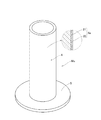
被処理体Wは、ステータ組立体SAとモールド型Moとから構成される。ステータ組立体SAは、複数枚の環状の電磁鋼板(図示省略)を積層して形成されたコア1と、コア1の内周部に間隔を存して設けられた複数のスロット1aに巻回されたコイル2と、Z軸方向に長手で筒状のフレーム3とを備えている。ステータ組立体SAでは、フレーム3は、コア1に焼嵌めによって外嵌している。
The body W to be processed is composed of a stator assembly SA and a mold Mo. The stator assembly SA is wound around a core 1 formed by laminating a plurality of annular electromagnetic steel sheets (not shown) and a plurality of
モールド型Moは、中空な金型であり、Z軸方向に長手の胴部4と、胴部4のZ軸方向下端から外方のX−Y平面内で延在させた鍔部5とを有している。被処理体Wでは、モールド型Moの胴部4をステータ組立体SAのコア1に内挿して、ステータ組立体SAのフレーム3とモールド型Moとの間に、熱硬化型で液状の絶縁性樹脂を注入するためのキャビティcが形成されている。具体的には、フレーム3のZ軸方向下端面がモールド型Moの鍔部5のZ軸方向上端面に載置されて、キャビティcが、フレーム3と、モールド型Moの胴部4及び鍔部5とによって画成されている。
The mold mold Mo is a hollow mold, and has a
図2を参照して、搬送パレットPlは、図1に示す搬送手段Caとしてのローラコンベア上に載置される平板状の本体6を備えている。本体6は、アルミニウム製であり、平面形状は12角形である。本体6には、中央部に開孔6aがZ軸方向上下に貫通して開設されている。開孔6aの平面形状は円形である。また、本体6には、開孔6aの外側のZ軸方向上面6bに、開孔6aの中心を通る放射方向の直線上に延びる断熱材7が、周方向に間隔を存して複数設けられている。断熱材7は、エポキシガラスマット製であり、平面形状は長方形である。断熱材7は、開孔6aの中心を通る放射方向の直線上に延びる複数の断熱材7が、開孔6aの周方向に間隔を存して設けられている。具体的には、計6本の断熱材7の各一つが、開孔6aの中心と本体6の外周縁に位置する一辺の中点とを結ぶ直線上に延び、一辺おきに配置されている。断熱材7は、ボルト及びナットによって本体6に締結されている。
With reference to FIG. 2, the transport pallet Pl includes a flat plate-shaped
また、搬送パレットPlには、本体6のZ軸方向上面6bで、断熱材7が設けられていない部分の外周端部に、一対の取っ手8,8が対向して設けられている。取っ手8,8は、ボルト及びナットで本体6に締結され、ジブクレーン等の吊り下げ装置が備えるフック等を取っ手8,8に掛けて所定の場所への搬送が可能になっている。尚、取っ手8,8は、図1では図示省略している。
Further, the transport pallet Pl is provided with a pair of
図1に示す被処理体Wは、搬送パレットPlの複数の断熱材7にZ軸方向上方から載置され、モールド型Moの鍔部5のZ軸方向下面が各断熱材7のZ軸方向上面と面接触する。搬送パレットPlへの被処理体Wの載置は位置決めされるようになっていて、載置状態では、搬送パレットPlの本体6に開設された開孔6aとモールド型Moの胴部4の内部が連通する。
The object W to be processed shown in FIG. 1 is placed on a plurality of
図1及び図3を参照して、予熱ステーションPHは、Z軸方向下面が開放された、断熱性を有する筐体9と、筐体9をZ軸方向に上下動させる駆動手段10(図1では図示省略)と、ステータ組立体SAのコイル2に交流電流を供給する給電手段とを備えている。給電手段は、交流電源11aと、交流電源11aからコイル2への交流電流の給電を制御する制御手段11bと、コネクタ11cと、交流電源11aと制御手段11bとの間及び交流電源11aとコネクタ11cとの間の配線とを含む。尚、図3では、搬送手段Caとしてのローラコンベアを図示省略している。
With reference to FIGS. 1 and 3, the preheating station PH includes a housing 9 having a heat insulating property in which the lower surface in the Z-axis direction is open, and a driving means 10 for moving the housing 9 up and down in the Z-axis direction (FIG. 1). It is provided with (not shown) and a power feeding means for supplying an alternating current to the
筐体9は、上壁部9a及び周壁部9bを有している。また、コネクタ11cは、周壁部9bのZ軸方向下端部に設けられ、コイル2のZ軸方向下端部に設けられたコネクタ(図示省略)と接続可能になっている。被処理体Wを予熱する際には、駆動手段10を作動させて筐体9を、Z軸方向下方に移動させ、予熱ステーションPHに搬送されて停止している被処理体WにZ軸方向上方から被せる。また、筐体9の周壁部9bのZ軸方向下端面を搬送プレートPの本体6のZ軸方向下端面と同一平面上に配置する。この状態では、被処理体Wは、搬送パレットPlと共に、筐体9の内部に挿入される。そして、コネクタ11cをコイル2のコネクタと接続する。
The housing 9 has an
制御手段11bを介して交流電源11aから交流電流をコイル2に給電すると、コイル2が発熱し、その熱が、筐体9の内部でコア1、フレーム3及びモールド型Moに伝導して、コア1、フレーム3及びモールド型Moが加熱される。このとき、筐体9の内部の空気も加熱されるが、加熱された空気は筐体9の外部に流出しにくくなっている。また、モールド型Moと、搬送パレットPlの本体6との間に断熱材7が介在しているため、モールド型Moから搬送パレットPlへの熱伝導は起こらない。従って、ステータ組立体SAのコイル2に交流電流を給電することによって、被処理体Wの全体が均一且つ効率よく加熱される。
When an alternating current is supplied to the
図4を参照して、予熱ステーションPHで被処理体Wを加熱したときの試験例を示す。図3に示すように、ステータ組立体SAのコア1、コイル2、フレーム3及びモールド型Moの夫々に温度センサ12を取り付け、各温度センサ12を交流電源11aを介して制御手段11bと接続して、コア1、コイル2、フレーム3及びモールド型Moの夫々の温度を測定した。温度センサ12の取付部位は、コイル2では、コネクタ側の上端部とコネクタから半周離れた対向側の上端部とし、モールド型Moでは胴部4の内部の上端部とした。また、図示省略しているが、フレーム3では下端部とした。
With reference to FIG. 4, a test example when the object W to be processed is heated at the preheating station PH is shown. As shown in FIG. 3, a
制御手段11bによって交流電源11aから周波数590Hz、電力1690Wの高周波電力を投入して、コイル2に23Aの交流電流を給電した。図4に示すように、20分30秒後にコイル2のコネクタ側の上端部の温度が150℃に到達したため、制御手段11bよってコイル2への交流電流の給電を停止した。交流電流の給電中は、熱容量等の相違に起因する温度分布が、コア1、コイル2、フレーム3及びモールド型Moに現れたが、交流電流の給電を停止してから約10分後には、コア1、コイル2、フレーム3及びモールド型Moの各温度が110℃に収束し、この温度の収束状態は、筐体9を被処理体Wに被せている状態では継続した。被処理体Wにモールド型Moが組み込まれることによる加熱への弊害は認められない。以下では、コイル2への交流電流の給電を停止するときのコイル2の温度を第1所定温度、コイル2への交流電流の給電を停止後、コア1、コイル2、フレーム3及びモールド型Moの各温度が収束するときの温度を第2所定温度と記す。第2温度は、従来のモータ用ステータのモールド成形において、ステータ組立体SAの予熱温度とされる温度と同一である。
A high-frequency power having a frequency of 590 Hz and a power of 1690 W was input from the
また、上記試験例から、コイル2を第1所定温度に加熱した後、交流電流の給電を停止し、コア1、コイル2、フレーム3及びモールド型Moの全てが、第2所定温度(予熱温度)になるまで放置することで、コイル2への交流電流の給電時間は短くて済み、加熱効率が良好であることが確認される。
Further, from the above test example, after heating the
予熱ステーションPHで被処理体Wの加熱が完了すると、図3に示す駆動手段10を作動させて筐体9をZ軸方向上方に移動させ、被処理体Wを露出させる。そして、図1に示すように、ローラコンベアの搬送経路rに沿って、第2所定温度(予熱温度)に加熱された被処理体Wを樹脂注入ステーションIに搬送する。この時、後続の被処理体Wが予熱ステーションPHに搬送される。 When the heating of the object W to be processed is completed at the preheating station PH, the drive means 10 shown in FIG. 3 is operated to move the housing 9 upward in the Z-axis direction to expose the object W to be processed. Then, as shown in FIG. 1, the object W heated to the second predetermined temperature (preheating temperature) is conveyed to the resin injection station I along the transfer path r of the roller conveyor. At this time, the subsequent object W to be processed is conveyed to the preheating station PH.
樹脂注入ステーションIは、真空チャンバ13と、真空チャンバ13の内部に設けられた、絶縁性樹脂の供給手段14とを備えている。真空チャンバ13は、予熱ステーションPHで第2所定温度(予熱温度)に加熱された被処理体Wを内部に格納して大気圧よりも低い圧力に減圧する。この減圧のために、真空チャンバ13には、真空チャンバ13の内部に連通する排気路が接続され、排気路の途中に真空ポンプ15が設けられている。真空ポンプ15が作動すると、真空チャンバ13の内部の空気等が排気路を通じて排気され、真空ポンプ15の内部が減圧される。真空チャンバ13には、第2所定温度(予熱温度)に加熱された被処理体Wを内部に搬入する搬入孔13aと、キャビティc内への絶縁性樹脂の注入後に被処理体Wを真空チャンバ13の外部に搬出する搬出孔13bとが設けられている。搬入孔13a及び搬出孔13bの夫々には、真空チャンバ13の内部を外部と遮断して密閉するドア13c,13cが設けられている。また、真空チャンバ13の内部には、被処理体Wをローラコンベアの一部に載置したままの状態で格納するためのターンテーブル16が設けられている。ターンテーブル16の中央部には、真空チャンバ13の底壁部13dをZ軸方向に貫通してZ軸方向下方に延びる回転軸17が設けられている。真空チャンバ13の底壁部13dで回転軸17が貫通する部分には、真空チャンバ13の内部の気密性を保持しながら回転軸17を支持する、磁性流体シール等を有する軸受18が設けられている。そして、樹脂注入ステーションIは、ターンテーブル16を回転させる、モータ19、減速機等を有する回転手段を備えている。
The resin injection station I includes a
絶縁性樹脂の供給手段14は、真空チャンバ13の内部でZ軸方向下方に延びる第1ガイド14aと、X−Y平面内で直線状に延びる第2ガイド14bとを備えている。また、絶縁性樹脂の供給手段14は、第2ガイド14bの長手方向に沿って移動可能で、被処理体Wのキャビティcの上方に位置して絶縁性樹脂をキャビティc内に注入する注入ノズル14cと、キャビティc内での絶縁性樹脂の液面を検知する液面センサ14dとを備えている。このような供給手段14には、真空チャンバ13の外部に設置された、液状の絶縁性樹脂を貯留したタンクから絶縁性樹脂が供給されるようにしている。第2ガイド14bは、図示省略の駆動手段によって第1ガイド14aに沿ってZ軸方向に上下動可能であり、注入ノズル14cの第2ガイド14bの長手方向に沿った移動も図示省略の駆動手段によって実現される。このような供給手段14は、被処理体Wを真空チャンバ13の内部に格納する際に、被処理体Wとは接触しない位置に配置されている。液面センサ14dの検知信号は、図示省略の制御手段に出力され、制御手段は、その検知信号を受けて供給手段14による絶縁性樹脂の注入を制御する。尚、絶縁性樹脂には、エポキシ樹脂、フェノール樹脂、不飽和ポリエステル樹脂等の熱硬化型で絶縁性を有する樹脂の中から適宜なものを選択して採用することができる。
The insulating resin supply means 14 includes a
樹脂注入ステーションIで被処理体Wのキャビティc内に絶縁性樹脂を注入する際には、まず、ドア13cを開けて真空チャンバ13の搬入孔13aを開放し、予熱ステーションPHで第2所定温度(予熱温度)に加熱された被処理体Wを搬送経路rに沿ってローラコンベアの一部と共に移動させる。この移動によって、ローラコンベアの一部は、真空チャンバ13の内部に設けられたターンテーブル16のZ軸方向上端面に載置され、被処理体Wが真空チャンバ13の内部に格納される。次いで、ドア13cを閉め、真空チャンバ13の内部を気密にした後、真空ポンプ15を作動させ、真空チャンバ13の内部の空気等を外部に排気して、真空チャンバ13の内部を大気圧よりも低い圧力に減圧する。このときの真空チャンバ13の内部の圧力としては、400hPa程度が例示される。減圧後、絶縁性樹脂の供給手段14を作動させ、注入ノズル14cを被処理体WのキャビティcのZ軸方向上方に配置する。そして、モータ19を備えた回転手段を作動させ、回転軸17を回転させることによってターンテーブル16を回転させる。このターンテーブル16の回転によって、被処理体Wは、ローラコンベアの一部と共にターンテーブル16の回転方向と同一方向に回転する。また、被処理体Wの回転と同時に注入ノズル14cから液状の絶縁性樹脂をキャビティc内に注入する。注入ノズル14cは、キャビティcの上方で被処理体Wの径方向に移動する。即ち、注入ノズル14cは、モールド型Moの胴部4の外周面とフレーム3の内周面との間を移動する。この注入ノズル14cの移動は、第2ガイド14bの長手方向一方の往動又は往復動のどちらでも構わない。液面センサ14dによって、制御手段に予め設定された液面に到達したことが検知されると、供給手段14による絶縁性樹脂の供給が停止し、回転手段も停止してターンテーブル16の回転が停止する。
When injecting the insulating resin into the cavity c of the object to be processed W at the resin injection station I, first, the
このように、樹脂注入ステーションIでは、従来行っていた、ステータ組立体SAにモールド型Moをセットする工程を省略することができる。また、樹脂注入ステーションIでは、予熱ステーションPHで第2所定温度(予熱温度)に加熱された被処理体Wをそのままの状態で真空チャンバ13の内部に格納して、キャビティc内の空気の排気とキャビティc内への絶縁性樹脂の注入とを行うことができる。従って、樹脂注入ステーションIで行う工程が簡略化されると共に、絶縁性樹脂の注入を気泡が混入することなく行うことができる。また、ターンテーブル16の回転によってキャビティc内への絶縁性樹脂の注入効率を向上させることができる。このため、真空チャンバ13の内部に設ける絶縁性樹脂の供給手段14の簡略化を図ることができる。さらに、樹脂注入ステーションIでの耐熱性樹脂の注入時間は、キャビティcの容量によって異なるが、減圧下で且つターンテーブル16を回転させながら絶縁性樹脂をキャビティc内に注入するため、従来よりも短縮する。例えば、注入開始から約10分程度で絶縁性樹脂の注入を完了させることが可能である。そして、ステータ組立体SAとモールド型Moとの温度に差がないため、絶縁性樹脂をキャビティc内の隅々にまでスムーズに注入することができる。
As described above, in the resin injection station I, the conventional step of setting the mold Mo on the stator assembly SA can be omitted. Further, in the resin injection station I, the object W heated to the second predetermined temperature (preheating temperature) in the preheating station PH is stored in the
樹脂注入ステーションIでの絶縁性樹脂のキャビティc内への注入が完了すると、真空チャンバ13の内部が大気に開放され、ドア13cが開き、搬出孔13bを介して被処理体Wがローラコンベアの一部と共に真空チャンバ13の外部に取り出される。この時、後続の第2所定温度(予熱温度)に加熱された被処理体Wが、予熱ステーションPHから樹脂注入ステーションIに搬送される。
When the injection of the insulating resin into the cavity c at the resin injection station I is completed, the inside of the
樹脂注入ステーションIでキャビティc内に注入された絶縁性樹脂は液状であり、液状の絶縁性樹脂RRを硬化させるために、被処理体Wは、樹脂硬化ステーションCuへ搬送経路rに沿って搬送される。樹脂硬化ステーションCuは、予熱ステーションPHが備えている、図3に示す筐体9、駆動手段10及び給電手段(交流電源11a、制御手段11b、コネクタ11c、配線等)と同一のものを備えている。即ち、樹脂硬化ステーションCuで行う液状の絶縁性樹脂RRの硬化の際にも、駆動手段10を作動させて筐体9を、Z軸方向下方に移動させ、樹脂硬化ステーションCuに搬送されて停止している被処理体WにZ軸方向上方から被せて、筐体9の周壁部9bのZ軸方向下端面を搬送プレートPlの本体6のZ軸方向下端面と同一平面上に配置する。そして、コネクタ11cをコイル2のコネクタと接続し、制御手段11bを介して交流電源11aから交流電流をコイル2に給電する。交流電流が給電されてコイル2が発熱し、その熱が、筐体9の内部でコア1、フレーム3及びモールド型Moに伝導する。伝導する熱の一部は、液状の絶縁性樹脂RRにも伝導し、コア1、フレーム3及びモールド型Moが再度加熱されて液状の絶縁性樹脂RRが加熱される。従って、熱硬化型で液状の絶縁性樹脂RRの硬化反応が生起される。
The insulating resin injected into the cavity c at the resin injection station I is liquid, and in order to cure the liquid insulating resin RR, the object W to be processed is transported to the resin curing station Cu along the transport path r. Will be done. The resin curing station Cu includes the same housing 9, drive means 10, and power supply means (
一方、樹脂硬化ステーションCuが、予熱ステーションPHと異なる点は、加熱時間である。予熱ステーションPHの加熱時間は、被処理体Wが第2所定温度(予熱温度)になるまでであり、短時間であるが、樹脂硬化ステーションCuでは、液状の絶縁性樹脂RRが完全に硬化するまで継続して行う必要がある。しかし、樹脂硬化ステーションCuでの加熱時間は、従来の加熱時間とほぼ同じである約90分程度を実験で確認している。 On the other hand, the difference between the resin curing station Cu and the preheating station PH is the heating time. The heating time of the preheating station PH is until the object W to be treated reaches the second predetermined temperature (preheating temperature), which is a short time. However, in the resin curing station Cu, the liquid insulating resin RR is completely cured. It is necessary to continue until. However, it has been confirmed by experiments that the heating time at the resin curing station Cu is about 90 minutes, which is almost the same as the conventional heating time.
このように、樹脂硬化ステーションCuの設置する加熱装置には、予熱ステーションPHに設置する加熱装置と同一のものを採用することができる。このため、本実施形態のモータ用ステータのモールド成形システムは、予熱ステーションPH及び樹脂硬化ステーションCuに設置する加熱装置を共通化することができるという点においても有利である。 As described above, as the heating device installed in the resin curing station Cu, the same heating device as the heating device installed in the preheating station PH can be adopted. Therefore, the molding system for the motor stator of the present embodiment is also advantageous in that the heating devices installed in the preheating station PH and the resin curing station Cu can be shared.
樹脂硬化ステーションCuで液状の絶縁性樹脂RRが硬化して固化した絶縁性樹脂SRになると、被処理体Wの加熱を完了し、図3に示す駆動手段10によって筐体9をZ軸方向上方に移動させ、被処理体Wを露出させる。そして、ローラコンベアの搬送経路rに沿って、被処理体Wを冷却するために搬送する。この時、後続の被処理体Wが樹脂硬化ステーションCuに搬送される。 When the liquid insulating resin RR is cured at the resin curing station Cu to become the solidified insulating resin SR, the heating of the object W to be processed is completed, and the housing 9 is moved upward in the Z-axis direction by the driving means 10 shown in FIG. To expose the object W to be processed. Then, the object W to be processed is conveyed to be cooled along the transfer path r of the roller conveyor. At this time, the subsequent object W to be processed is conveyed to the resin curing station Cu.
被処理体Wの冷却は、常温になるまで放冷してもよいが、本実施形態のモータ用ステータのモールド成形システムでは、搬送パレットPlの本体6の開孔6aとモールド型Moの胴部4の内部とが連通していることから、空気等の冷媒を開孔6aから胴部4のZ軸方向上端に向けて吹き入れて、被処理体Wをその内部から強制冷却することができる。この場合、放冷する場合よりも被処理体Wの冷却時間を短縮することができる。被処理体Wが常温にまで冷却されると、固化した絶縁性樹脂SRによってコイル1間が固定されたステータ組立体SAをZ軸方向上方に引き上げ、モールド型Moから取り外す。ステータ組立体SAが取り外されたモールド型Moは、モータ用ステータのモールド成形に再利用される。
The object W to be processed may be cooled until it reaches room temperature, but in the molding system of the stator for the motor of the present embodiment, the
ところで、冷却後にステータ組立体SAをモールド型Moから取り外す際に、モールド型Moの胴部4の外周面が固化した絶縁性樹脂SRと擦れてモールド型Moの胴部4の外周面が摩損したり、傷付いたりなどしてモールド型Moを再利用することができなくなる虞がある。この問題を解消するために、図5に示すように、胴部4の外周面部4aが、ショットピーニングされた基部外周面20に無電電解めっきによるめっき層21を設けて形成されたモールド型Moを採用することができる。
By the way, when the stator assembly SA is removed from the mold Mo after cooling, the outer peripheral surface of the
モールド型Moの胴部4の基部外周面部は、ショットピーニングによって加工硬化すると共に、耐摩擦性が向上する。また、ショットピーニングの際の圧縮応力がモールド型Moの胴部4の基部外周面部に残留するため、モールド型Moの胴部4の基部外周面部の疲労強度が高くなる。さらに、モールド型Moの胴部4の基部外周面20は微細な凹凸が形成された面になるため、無電解めっきによって形成されるめっき層21の密着性が向上し、めっき層21の剥離等の不具合が生じ難くなる。そして、めっき層21は、硬質であると共に、耐蝕性を有する。従って、冷却後にステータ組立体SAをモールド型Moから取り外す際に、モールド型Moの胴部4の外周面部4aが固化した絶縁性樹脂SRと擦れても、外周面部4aに摩損や傷付き等が発生するのを抑制することができる。このため、モールド型Moは、モータ用ステータのモールド成形での繰返しの使用に十分耐え得る。尚、めっき層21を形成する主成分としてはニッケルが好ましく例示される。
The outer peripheral surface portion of the base portion of the
以上、本発明を一実施形態に関して説明したが、本発明は上記実施形態に限定されない。例えば、搬送手段Caをはじめ、筐体9をZ方向に上下動させる駆動手段10、真空チャンバ13及び供給手段14の構成及び構造、また、搬送パレットPlの形状や大きさ、絶縁性樹脂の種類等の細部については様々な態様のものを採用することができる。
Although the present invention has been described above with respect to one embodiment, the present invention is not limited to the above embodiment. For example, the configuration and structure of the transport means Ca, the drive means 10 for moving the housing 9 up and down in the Z direction, the
Ca…搬送手段、r…搬送経路、PH…予熱ステーション、I…樹脂注入ステーション、Cu…樹脂硬化ステーション、W…被処理体、SA…ステータ組立体、Mo…モールド型、c…キャビティ、Pl…搬送パレット、1…コア、1a…スロット、2…コイル、3…フレーム、4…モールド型Moの胴部、4a…胴部4の外周面部、5…モールド型Moの鍔部、6…搬送パレットPlの本体、6a…本体6の開孔、6b…開孔6aの外側に位置する本体6のZ軸方向上面、7…断熱材、9…筐体、10…駆動手段、11a…給電手段の一部である交流電源、11b…給電手段の一部である制御手段、11c…給電手段の一部であるコネクタ、13…真空チャンバ、14…絶縁性樹脂の供給手段、14c…注入ノズル、16…ターンテーブル、20…胴部4の外周面部4aがショットピーニングされた基部外周面、21…めっき層。
Ca ... transport means, r ... transport path, PH ... preheating station, I ... resin injection station, Cu ... resin curing station, W ... object to be processed, SA ... stator assembly, Mo ... mold type, c ... cavity, Pl ... Conveying pallet, 1 ... Core, 1a ... Slot, 2 ... Coil, 3 ... Frame, 4 ... Molded Mo body, 4a ...
Claims (4)
予熱ステーション及び樹脂硬化ステーションは、Z軸方向下面が開放された、断熱性を有する筐体と、この筐体をZ軸方向に上下動させる駆動手段と、ステータ組立体のコイルに交流電流を給電する給電手段とを備え、被処理体にZ軸方向上方から筐体を被せた状態で給電手段からステータ組立体のコイルに交流電流を給電して被処理体を加熱し、
樹脂注入ステーションは、予熱ステーションで加熱された被処理体を内部に格納して大気圧より低い圧力に減圧可能な真空チャンバと、真空チャンバの内部に設けられた、注入ノズルを有する絶縁性樹脂の供給手段とを備え、真空チャンバの内部に格納した被処理体のキャビティ内に、被処理体よりもZ軸方向上方に位置させた注入ノズルから絶縁性樹脂を減圧下で注入することを特徴とするモータ用ステータのモールド成形システム。 A core formed by laminating a plurality of annular electromagnetic steel plates, a coil wound in a plurality of slots provided at intervals on the inner peripheral portion of the core, and a tubular shape outerly fitted to the core. Into the core of the stator assembly having the frame, a molded body having a body long in the Z-axis direction and a collar extending outward from the lower end of the body in the Z-axis direction is inserted. A cavity is formed between the frame of the stator assembly and the mold to form a processed body, and the transport means for transporting the workpiece and the transport means for transporting the workpiece are arranged at intervals along the transport path of the transport means. In addition, a preheating station that heats the object to be treated, a resin injection station that injects a thermosetting liquid insulating resin into the cavity of the object to be processed, and an insulating resin that is injected by heating the object to be processed again. It is a molding system of a stator for a motor equipped with a resin curing station for curing a resin.
The preheating station and the resin curing station supply an alternating current to a housing having a heat insulating property in which the lower surface in the Z-axis direction is open, a driving means for moving the housing up and down in the Z-axis direction, and a coil of the stator assembly. The object to be processed is heated by supplying an alternating current from the power supply means to the coil of the stator assembly in a state where the object to be processed is covered with the housing from above in the Z-axis direction.
The resin injection station is composed of a vacuum chamber in which the object to be treated heated by the preheating station is stored inside and can be depressurized to a pressure lower than atmospheric pressure, and an insulating resin having an injection nozzle provided inside the vacuum chamber. It is characterized by having a supply means and injecting an insulating resin under reduced pressure from an injection nozzle located above the object to be processed in the Z-axis direction into the cavity of the object to be processed stored inside the vacuum chamber. Molding system for stators for motors.
Priority Applications (2)
| Application Number | Priority Date | Filing Date | Title |
|---|---|---|---|
| JP2020033107A JP2021136815A (en) | 2020-02-28 | 2020-02-28 | Mold forming system for motor stator |
| CN202110081742.1A CN113328593A (en) | 2020-02-28 | 2021-01-21 | Molding system for stator of motor |
Applications Claiming Priority (1)
| Application Number | Priority Date | Filing Date | Title |
|---|---|---|---|
| JP2020033107A JP2021136815A (en) | 2020-02-28 | 2020-02-28 | Mold forming system for motor stator |
Publications (1)
| Publication Number | Publication Date |
|---|---|
| JP2021136815A true JP2021136815A (en) | 2021-09-13 |
Family
ID=77413521
Family Applications (1)
| Application Number | Title | Priority Date | Filing Date |
|---|---|---|---|
| JP2020033107A Pending JP2021136815A (en) | 2020-02-28 | 2020-02-28 | Mold forming system for motor stator |
Country Status (2)
| Country | Link |
|---|---|
| JP (1) | JP2021136815A (en) |
| CN (1) | CN113328593A (en) |
Cited By (2)
| Publication number | Priority date | Publication date | Assignee | Title |
|---|---|---|---|---|
| KR20230139971A (en) * | 2022-03-29 | 2023-10-06 | 주식회사 신라공업 | Epoxy molding device of stator and epoxy molding method using the same |
| KR20250089112A (en) * | 2023-12-11 | 2025-06-18 | 주식회사 신라공업 | A stator insulation configuration for an epoxy impregnation motor-based actuator and its insulation method |
Family Cites Families (5)
| Publication number | Priority date | Publication date | Assignee | Title |
|---|---|---|---|---|
| JP5308867B2 (en) * | 2009-02-26 | 2013-10-09 | 信越化学工業株式会社 | Rotating plate for permanent magnet rotating machine and method for manufacturing permanent magnet rotating machine |
| CN202389599U (en) * | 2011-11-03 | 2012-08-22 | 庞永清 | Electromagnetic ejector of carrier-based aircraft |
| IT201700014643A1 (en) * | 2017-02-10 | 2018-08-10 | I M A Industria Macch Automatiche S P A In Sigla Ima S P A | Manufacturing group for filling containers and packaging line comprising this manufacturing group. |
| JP6943743B2 (en) * | 2017-12-05 | 2021-10-06 | トヨタ自動車株式会社 | Manufacturing method of stator for motor |
| JP6914533B2 (en) * | 2018-02-15 | 2021-08-04 | 株式会社ナカリキッドコントロール | Resin molding method, jig, and resin molding equipment |
-
2020
- 2020-02-28 JP JP2020033107A patent/JP2021136815A/en active Pending
-
2021
- 2021-01-21 CN CN202110081742.1A patent/CN113328593A/en active Pending
Cited By (4)
| Publication number | Priority date | Publication date | Assignee | Title |
|---|---|---|---|---|
| KR20230139971A (en) * | 2022-03-29 | 2023-10-06 | 주식회사 신라공업 | Epoxy molding device of stator and epoxy molding method using the same |
| KR102653256B1 (en) * | 2022-03-29 | 2024-04-01 | 주식회사 신라공업 | Epoxy molding device of stator and epoxy molding method using the same |
| KR20250089112A (en) * | 2023-12-11 | 2025-06-18 | 주식회사 신라공업 | A stator insulation configuration for an epoxy impregnation motor-based actuator and its insulation method |
| KR102863182B1 (en) | 2023-12-11 | 2025-09-23 | 주식회사 신라공업 | A stator insulation configuration for an epoxy impregnation motor-based actuator and its insulation method |
Also Published As
| Publication number | Publication date |
|---|---|
| CN113328593A (en) | 2021-08-31 |
Similar Documents
| Publication | Publication Date | Title |
|---|---|---|
| CA2699387C (en) | Method and apparatus for resin transfer molding composite parts | |
| CN101548453B (en) | Stator coil heating device and heating method | |
| KR100473071B1 (en) | A heating apparatus for a green tire | |
| JP2021136815A (en) | Mold forming system for motor stator | |
| JP6914533B2 (en) | Resin molding method, jig, and resin molding equipment | |
| US12597833B2 (en) | Cooling apparatus for laminated motor core manufacturing process | |
| JPH0214730A (en) | Method and apparatus for gas circulation of autoclave | |
| JP2001079850A (en) | Method and apparatus for vulcanizing tire | |
| JP3914379B2 (en) | Raw tire preheating method and apparatus | |
| KR102784427B1 (en) | Transfer jig for manufacturing rotor core of motor | |
| KR102804439B1 (en) | Cooling apparatus for laminated motor core manufacturing process | |
| KR20120111132A (en) | Curing process of pressure or vacuum for pressure vessel of wet filament winding | |
| CN104690986B (en) | Hybrid microwave heating and pressurizing device | |
| JP2017128012A (en) | Autoclave molding method, autoclave molding device and manufacturing method of molding block used therefor | |
| US11548205B2 (en) | Post curing process for composite parts produced by filament winding manufacturing process | |
| US20220118724A1 (en) | Cooling method for autoclave molding apparatus | |
| CN112821688B (en) | Motor stator transport tray | |
| US20240250588A1 (en) | Installation and method for producing laminated cores, bonded over their entire surface, for an electrical machine | |
| JP3961081B2 (en) | Heating method for laminate of unvulcanized rubber and metal plate | |
| JP6724335B2 (en) | Molding method and molding apparatus for resin molded product using thermosetting resin | |
| KR102782817B1 (en) | Cooling apparatus for laminated motor core manufacturing process | |
| KR102506598B1 (en) | High pressure gas cylinder coating device | |
| KR101517547B1 (en) | System and method for heating cylinder block liner | |
| CN118879986B (en) | Magnetic field heat treatment furnace and heat treatment method | |
| JP2006289995A (en) | Green tire preheating method and apparatus therefor |