JP2021136810A - vehicle - Google Patents
vehicle Download PDFInfo
- Publication number
- JP2021136810A JP2021136810A JP2020032897A JP2020032897A JP2021136810A JP 2021136810 A JP2021136810 A JP 2021136810A JP 2020032897 A JP2020032897 A JP 2020032897A JP 2020032897 A JP2020032897 A JP 2020032897A JP 2021136810 A JP2021136810 A JP 2021136810A
- Authority
- JP
- Japan
- Prior art keywords
- storage device
- power storage
- vehicle
- power
- control unit
- Prior art date
- Legal status (The legal status is an assumption and is not a legal conclusion. Google has not performed a legal analysis and makes no representation as to the accuracy of the status listed.)
- Pending
Links
Images


Classifications
-
- Y—GENERAL TAGGING OF NEW TECHNOLOGICAL DEVELOPMENTS; GENERAL TAGGING OF CROSS-SECTIONAL TECHNOLOGIES SPANNING OVER SEVERAL SECTIONS OF THE IPC; TECHNICAL SUBJECTS COVERED BY FORMER USPC CROSS-REFERENCE ART COLLECTIONS [XRACs] AND DIGESTS
- Y02—TECHNOLOGIES OR APPLICATIONS FOR MITIGATION OR ADAPTATION AGAINST CLIMATE CHANGE
- Y02E—REDUCTION OF GREENHOUSE GAS [GHG] EMISSIONS, RELATED TO ENERGY GENERATION, TRANSMISSION OR DISTRIBUTION
- Y02E60/00—Enabling technologies; Technologies with a potential or indirect contribution to GHG emissions mitigation
- Y02E60/10—Energy storage using batteries
-
- Y—GENERAL TAGGING OF NEW TECHNOLOGICAL DEVELOPMENTS; GENERAL TAGGING OF CROSS-SECTIONAL TECHNOLOGIES SPANNING OVER SEVERAL SECTIONS OF THE IPC; TECHNICAL SUBJECTS COVERED BY FORMER USPC CROSS-REFERENCE ART COLLECTIONS [XRACs] AND DIGESTS
- Y02—TECHNOLOGIES OR APPLICATIONS FOR MITIGATION OR ADAPTATION AGAINST CLIMATE CHANGE
- Y02T—CLIMATE CHANGE MITIGATION TECHNOLOGIES RELATED TO TRANSPORTATION
- Y02T10/00—Road transport of goods or passengers
- Y02T10/60—Other road transportation technologies with climate change mitigation effect
- Y02T10/62—Hybrid vehicles
-
- Y—GENERAL TAGGING OF NEW TECHNOLOGICAL DEVELOPMENTS; GENERAL TAGGING OF CROSS-SECTIONAL TECHNOLOGIES SPANNING OVER SEVERAL SECTIONS OF THE IPC; TECHNICAL SUBJECTS COVERED BY FORMER USPC CROSS-REFERENCE ART COLLECTIONS [XRACs] AND DIGESTS
- Y02—TECHNOLOGIES OR APPLICATIONS FOR MITIGATION OR ADAPTATION AGAINST CLIMATE CHANGE
- Y02T—CLIMATE CHANGE MITIGATION TECHNOLOGIES RELATED TO TRANSPORTATION
- Y02T10/00—Road transport of goods or passengers
- Y02T10/60—Other road transportation technologies with climate change mitigation effect
- Y02T10/70—Energy storage systems for electromobility, e.g. batteries
-
- Y—GENERAL TAGGING OF NEW TECHNOLOGICAL DEVELOPMENTS; GENERAL TAGGING OF CROSS-SECTIONAL TECHNOLOGIES SPANNING OVER SEVERAL SECTIONS OF THE IPC; TECHNICAL SUBJECTS COVERED BY FORMER USPC CROSS-REFERENCE ART COLLECTIONS [XRACs] AND DIGESTS
- Y02—TECHNOLOGIES OR APPLICATIONS FOR MITIGATION OR ADAPTATION AGAINST CLIMATE CHANGE
- Y02T—CLIMATE CHANGE MITIGATION TECHNOLOGIES RELATED TO TRANSPORTATION
- Y02T10/00—Road transport of goods or passengers
- Y02T10/60—Other road transportation technologies with climate change mitigation effect
- Y02T10/7072—Electromobility specific charging systems or methods for batteries, ultracapacitors, supercapacitors or double-layer capacitors
Landscapes
- Hybrid Electric Vehicles (AREA)
- Charge And Discharge Circuits For Batteries Or The Like (AREA)
- Secondary Cells (AREA)
- Electric Propulsion And Braking For Vehicles (AREA)
Abstract
【課題】車両に搭載されたバッテリの内部抵抗を、分極の影響を抑制した状態で測定することができる車両を提供する。【解決手段】車両は、電力を充放電可能な蓄電装置10と、蓄電装置10に電力を供給可能な発電装置12と、蓄電装置10から供給される電力によって駆動する駆動装置13と、蓄電装置10に入出力する電流を検知する検知部と、発電装置12および駆動装置13の駆動を制御する制御部9と、備えた車両であって、車両が停止すると、制御部9は、停止時よりも前の時点から停止時までの測定期間における充電量および放電量の差分を算出し、車両が停止すると、制御部9は、測定期間において放電量が充電量よりも多い場合には、差分の大きさの電流量を蓄電装置10に供給し、測定期間において充電量が放電量よりも多い場合には、差分の大きさの電流量を蓄電装置10から放電させる。【選択図】図1PROBLEM TO BE SOLVED: To provide a vehicle capable of measuring the internal resistance of a battery mounted on a vehicle in a state where the influence of polarization is suppressed. A vehicle includes a power storage device 10 capable of charging and discharging power, a power generation device 12 capable of supplying power to the power storage device 10, a drive device 13 driven by power supplied from the power storage device 10, and a power storage device. A vehicle equipped with a detection unit that detects currents input and output to 10 and a control unit 9 that controls the drive of the power generation device 12 and the drive device 13. When the vehicle stops, the control unit 9 starts from the time of stop. Also, when the vehicle stops, the control unit 9 calculates the difference between the charge amount and the discharge amount in the measurement period from the previous time point to the stop time, and if the discharge amount is larger than the charge amount in the measurement period, the difference is calculated. A large amount of current is supplied to the power storage device 10, and when the charge amount is larger than the discharge amount during the measurement period, the current amount of the difference magnitude is discharged from the power storage device 10. [Selection diagram] Fig. 1
Description
本開示は、車両に関する。 The present disclosure relates to vehicles.
特許第3122751号公報(特許文献1)には、車両の停止状態を確認し、その直後の車両加速状態におけるバッテリからの放電電流とこの時のバッテリ電圧を検出して、これら放電電流とバッテリ電圧よりバッテリの内部抵抗を算出することが開示されている。 In Japanese Patent No. 3122751 (Patent Document 1), the stopped state of the vehicle is confirmed, the discharge current from the battery in the vehicle acceleration state immediately after that and the battery voltage at this time are detected, and the discharge current and the battery voltage are detected. It is disclosed to calculate the internal resistance of the battery.
特許文献1では、車両停止時には放電電流は常にゼロであるから、その直後の加速時にバッテリ分極の影響を受けることなく、常に再現性の良い放電電流−バッテリ電圧の特性(I−V特性)を得ることができ、バッテリの内部抵抗を精度よく求めることができるとされている。 In Patent Document 1, since the discharge current is always zero when the vehicle is stopped, the discharge current-battery voltage characteristic (IV characteristic) with good reproducibility is always provided without being affected by the battery polarization during the acceleration immediately after that. It is said that it can be obtained and the internal resistance of the battery can be obtained accurately.
しかし、車両が停止する前において、車両の加速に際して、バッテリから大きな電力が放電される場合には、バッテリの分極の影響が大きくなる。同様に、車両停止する少し前に蓄電装置が外部電力によって充電されている場合においても、バッテリの分極の影響が大きくなる。このように、バッテリの内部抵抗を精度良く検出するには、改良の余地があった。 However, if a large amount of electric power is discharged from the battery when the vehicle is accelerated before the vehicle stops, the influence of the polarization of the battery becomes large. Similarly, even when the power storage device is charged by external electric power shortly before the vehicle stops, the influence of the polarization of the battery becomes large. As described above, there is room for improvement in order to accurately detect the internal resistance of the battery.
本開示は、上記のような課題に鑑みてなされたものであって、その目的は、車両に搭載されたバッテリの内部抵抗を、分極の影響を抑制した状態で測定することができる車両を提供することである。 The present disclosure has been made in view of the above problems, and an object of the present invention is to provide a vehicle capable of measuring the internal resistance of a battery mounted on a vehicle in a state where the influence of polarization is suppressed. It is to be.
車両は、電力を充放電可能な蓄電装置と、蓄電装置に電力を供給可能な発電装置と、蓄電装置から供給される電力によって駆動する駆動装置と、蓄電装置に入出力する電流を検知する検知部と、発電装置および駆動装置の駆動を制御する制御部と、備えた車両であって、車両が停止すると、制御部は、停止時よりも前の時点から停止時までの測定期間における充電量および放電量の差分を算出し、車両が停止すると、制御部は、測定期間において放電量が充電量よりも多い場合には、差分の大きさの電流量を蓄電装置に供給し、測定期間において充電量が放電量よりも多い場合には、差分の大きさの電流量を蓄電装置から放電させる。 The vehicle detects a power storage device that can charge and discharge power, a power generation device that can supply power to the power storage device, a drive device that is driven by the power supplied from the power storage device, and a current that is input to and discharged from the power storage device. A vehicle equipped with a unit, a control unit that controls the drive of the power generation device and the drive device, and when the vehicle stops, the control unit charges the amount of charge in the measurement period from the time before the stop to the stop. And when the difference between the discharge amounts is calculated and the vehicle stops, if the discharge amount is larger than the charge amount during the measurement period, the control unit supplies the current amount with the magnitude of the difference to the power storage device during the measurement period. When the charge amount is larger than the discharge amount, the current amount having a large difference is discharged from the power storage device.
上記車両によれば、車両が停車した状態において蓄電装置の分極状態を解消または低減することができ、蓄電装置の内部抵抗を精度よく測定することができる。 According to the vehicle, the polarization state of the power storage device can be eliminated or reduced when the vehicle is stopped, and the internal resistance of the power storage device can be measured accurately.
本開示に係る車両によれば、車両に搭載されたバッテリの内部抵抗を、分極の影響を抑制した状態で測定することができる。 According to the vehicle according to the present disclosure, the internal resistance of the battery mounted on the vehicle can be measured in a state where the influence of polarization is suppressed.
図1から図3を用いて、本実施の形態に係る車両1について説明する。図1から図3に示す構成のうち、同一または実質的に同一の構成については、同一の符号を付して重複した説明を省略する。 The vehicle 1 according to the present embodiment will be described with reference to FIGS. 1 to 3. Of the configurations shown in FIGS. 1 to 3, the same or substantially the same configuration is designated by the same reference numerals and duplicated description will be omitted.
図1は、本実施の形態に係る車両1を模式的に示すブロック図である。車両1は、制御部9と、蓄電装置10と、PCU(Power Control Unit)11と、回転電機12,13と、動力分割機構14と、エンジン15と、車軸16と、駆動輪17と、監視ユニット18とを備える。
FIG. 1 is a block diagram schematically showing a vehicle 1 according to the present embodiment. The vehicle 1 monitors the
蓄電装置10は、充放電可能な二次電池である。蓄電装置10の詳細な構成については、後述する。
The
PCU11は、昇圧コンバータ19およびインバータ20を含む。PCU11は、蓄電装置10と、回転電機12および回転電機13に電気的に接続されている。
The PCU 11 includes a
動力分割機構14は、エンジン15の出力軸と回転電機12のロータとを機械的に接続している。動力分割機構14は、エンジン15の動力を回転電機12および車軸16に伝達する。
The
回転電機12はPCU11に電気的に接続されている。回転電機12は、発電装置として機能する。回転電機12はエンジン15からの動力によって発電し、PCU11のインバータ20は回転電機12から供給される交流電力を直流電力に変換する。昇圧コンバータ19は、インバータ20から供給された直流電力を調圧して、蓄電装置10を充電する。
The rotary
回転電機13は、駆動装置として機能する。回転電機13はPCU11から供給される交流電力によって動力を発生する。回転電機13の動力は、車軸16に伝達される。なお、たとえば、車両1が坂道などを下る場合などにおいては、回転電機13は発電する。車軸16は、駆動輪17に接続されている。車軸16には、車速センサが設けられており、この車速センサ21は制御部9に車速値VSを送信している。
The rotary
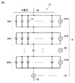
図2は、蓄電装置10および監視ユニット18を模式的に示す模式図である。蓄電装置10は、複数の電池ブロック30A〜30Mを含む。各電池ブロック30A〜30Mは、互いに電気的に直列に接続されている。
FIG. 2 is a schematic view schematically showing the
各電池ブロック30A〜30Mは、互いに電気的に並列に接続された複数の電池セル31を含む。なお、電池セル31は、リチウムイオン電池である。リチウムイオン電池は、金属製のケースと、ケース内に収容された電極体と、ケース内に収容された電解液とを含む。電極体は、負極と、セパレータと、正極とを含む。
Each
負極は、金属箔と、金属箔の表面に形成された正極合材層とを含む。正極は、金属箔と、金属箔に形成された正極合材層とを含む。ここで、電池セル31に充電が継続的に行われたり、放電が継続的に行われたりすると、正極合材層内、負極合材層内および電解液内におけるリチウム塩の拡散に偏りが生じ、分極が生じる。
The negative electrode includes a metal foil and a positive electrode mixture layer formed on the surface of the metal foil. The positive electrode includes a metal foil and a positive electrode mixture layer formed on the metal foil. Here, when the
蓄電装置10には、電力線35,36が接続されている。監視ユニット18は、電流センサ40と、複数の電圧センサ41A〜41Mと、温度センサ42とを含む。
電流センサ40は電力線35に設けられている。電流センサ40は蓄電装置10に入出力する電流を検知している。電流センサ40は検知した電流値IBを制御部9に送信している。
The
電圧センサ41A〜41Mは、各電池ブロック30A〜30Mに設けられている。たとえば、電圧センサ41Aは、電池ブロック30Aに設けられており、電池ブロック30Aの電圧を検知している。同様に他の電圧センサ41B〜41Mは、電池ブロック30B〜30Mの電圧を検知している。電圧センサ41A〜41Mは、制御部9に測定した電圧値VBA〜VBMを入力する。温度センサ42は、測定した温度値TBを制御部9に送信する。
The
制御部9は、電圧値VBA〜VBMと、電流値IBの積算値と、温度値TBなどに基づいて、蓄電装置10のSOCを算出している。
The
そして、制御部9は、各電池ブロック30A〜30Mの内部抵抗を算出する。たとえば、電池ブロック30Aの内部抵抗を算出する際には、電流値IBと、電圧値VBAとから電池ブロック30Aの電流−電圧特性(I−V特性)を算出する。そして、電池ブロック30AのI−V特性の傾きから電池ブロック30Aの内部抵抗RAを算出する。
Then, the
同様に、電池ブロック30B〜30Mの内部抵抗RB〜RMを算出して、制御部9は各電池ブロック30A〜30Mの内部抵抗RA〜RMを算出する。このようにして、制御部9は蓄電装置10の内部抵抗を算出する。
Similarly, the internal resistances RB to RM of the battery blocks 30B to 30M are calculated, and the
ここで、たとえば、電池ブロック30Aにおいて、1つの電池セル31が断線したとすると、他の電池セル31に電流が集中する。断線していない電池セル31に電流が集中すると、電池セル31の発熱量が多くなり、電池セル31の温度が高くなる。電池セル31の温度が高くなると、電池セル31の劣化が進行し易い。
Here, for example, in the
その結果、たとえば、放電時において、断線していない電池セル31のSOCが早期に低下して、走行距離が短くなるおそれがある。また、充電時には、断線していない電池セル31のSOCが高くなり易く、過充電される可能性が高くなる。
As a result, for example, at the time of discharging, the SOC of the
そのため、各電池ブロック30A〜30Mの内部抵抗RA〜RMを精度よく算出することが求められている。
Therefore, it is required to accurately calculate the internal resistances RA to RM of each
しかし、蓄電装置10が充放電を繰り返す過程において、充電量が多い場合や放電量が多い場合には、各電池セル31において分極が発生するおそれがある。各電池セル31において分極が発生すると、各電池ブロック30A〜30Mの内部抵抗RA〜RMが変動する。
However, in the process of repeating charging and discharging of the
そこで、本実施の形態に係る車両1においては、内部抵抗RA〜RMを算出する前において、各電池セル31において生じた分極を解消または低減させた後に、各内部抵抗RA〜RMを算出する。
Therefore, in the vehicle 1 according to the present embodiment, the internal resistances RA to RM are calculated after the polarization generated in each
図3は、各電池セル31の分極を低減させて、各内部抵抗RA〜RMを算出する制御を示すフロー図である。なお、図3において、「Step」を「S」と省略して記載している。当該フローは、車両1が起動中において繰り返し実行される。制御部9は、車速値VSが0(km/h)であるかを判断する(Step10)。車速値VSが0(km/h)のときには、回転電機12の駆動は停止している。
FIG. 3 is a flow chart showing control for calculating each internal resistance RA to RM by reducing the polarization of each
ここで、車両1が車速値VSが0(km/h)であると判断した時点を停止時点T0とする。停止時点T0から所定期間PP前の時点を所定時点T1とする。所定時点T1から停止時点T0までの期間を測定期間MPとする。 Here, the time when the vehicle 1 determines that the vehicle speed value VS is 0 (km / h) is set as the stop time T0. The time point from the stop time point T0 to the time point before the predetermined time period PP is defined as the predetermined time point T1. The period from the predetermined time point T1 to the stop time point T0 is defined as the measurement period MP.
そして、制御部9は、車速値VSが0(km/h)でないと判断すると(Step10にて、No)、制御部9は当該フローを終えて、再度、当該フローを繰り返す。制御部9は、車速値VSが0(km/h)であると判断すると(Step10にて、Yes)、制御部9は、測定期間MPにおける充電量および放電量の差分である電流量CVを算出する(Step12)。
Then, when the
そして、制御部9は、測定期間MPにおいて、充電量よりも放電量の方が多いか否かを判断する(Step14)。制御部9は、放電量の方が多いと判断すると(Step14にてYes)、制御部9は、電流量CVの大きさの電流量を蓄電装置10に充電する(Step16)。
Then, the
具体的には、制御部9はエンジン15を駆動させて回転電機12を発電させる。そして、制御部9はPCU11を駆動させて、回転電機12からの交流電力を直流電力に変換して、蓄電装置10を充電する。測定期間MPにおいて放電量が多い場合において、蓄電装置10を充電すると、各電池セル31に生じている分極を低減または解消することができる。
Specifically, the
制御部9は、充電量が放電量以上であると判断すると(Step14にてNo)、制御部9は、電流量CVの大きさの電流量を蓄電装置10から放電させる(Step18)。
When the
具体的には、制御部9は、PCU11を駆動させて、回転電機13にd軸電流を供給する。その一方で、q軸電流を0(A)とする。q軸電流を0(A)とすることで、回転電機13は駆動力を発生しない。
Specifically, the
測定期間MPにおいて充電量が多い場合において、蓄電装置10を放電させることで、各電池セル31に生じている分極を低減させることができる。
When the amount of charge is large during the measurement period MP, the polarization generated in each
制御部9は、電流量CVを蓄電装置10に充電(Step16)、または、電流量CVを蓄電装置10から放電(Step18)した後、内部抵抗を測定する(Step20)。
The
制御部9は、回転電機13に電流を供給する。この際、q軸電流を0(A)とし、d軸電流を供給する。q軸電流が0(A)であるため、回転電機13は動力を発生しない。
The
そして、制御部9は、d軸電流を変動させることで、各電池ブロック30A〜30MのI−V特性を算出し、各内部抵抗RA〜RMを算出する。ここで、各電池セル31の分極状態が解消または低減されているので、精度の高い内部抵抗RA〜RMを測定することができる。
Then, the
分極状態における電池セル31においては、I−V特性が一次特性となり難い一方で、分極状態が解消された電池セル31においては、I−V特性が一次特性となりやすい。その結果、各電池ブロック30A〜30MにおけるI−V特性の傾きから精度の高い内部抵抗RA〜RMを算出することができる。
In the
所定時点T1は、各種の時点を採用することができる。たとえば、電池セル31の分極状態を解消または低減させた時点、充放電が30分程度なされていなかった時点などを採用することができる。なお、「30分程度」とは、電池セル31が充放電なされないことにより、リチウム塩の偏りが解消される時間の例示である。
As the predetermined time point T1, various time points can be adopted. For example, a time when the polarized state of the
また、所定時点T1としては、上記のように分極状態に着目した時点でなくてもよい。たとえば、停止時点T0から一律決めた期間(たとえば、5分)に設定してもよい。 Further, the predetermined time point T1 does not have to be the time point focusing on the polarization state as described above. For example, it may be set to a uniformly determined period (for example, 5 minutes) from the stop time T0.
なお、車両1がプラグインハイブリッド車両である場合には、CSモードに移行した後であって所定期間経過後に、図3に示すStep16およびStep18を実行するようにするのが好ましい。充電ステーションから供給される電力で蓄電装置10を充電した後においては、充電量の方が多くなっており、充電直後において、電池セル31の分極を解消する制御を実行したのでは、外部充電した電力を放電することになるためである。そのため、CDモードのときには、Step16およびStep18を実行されない。
When the vehicle 1 is a plug-in hybrid vehicle, it is preferable to execute
今回開示された実施の形態はすべての点で例示であって制限的なものではないと考えられるべきである。本発明の範囲は請求の範囲によって示され、請求の範囲と均等の意味および範囲内でのすべての変更が含まれることが意図される。 It should be considered that the embodiments disclosed this time are exemplary in all respects and not restrictive. The scope of the present invention is indicated by the claims and is intended to include all modifications within the meaning and scope equivalent to the claims.
1 車両、9 制御部、10 蓄電装置、12,13 回転電機、14 動力分割機構、15 エンジン、16 車軸、17 駆動輪、18 監視ユニット、19 昇圧コンバータ、20 インバータ、30A,30B,30M 電池ブロック、31 電池セル、35,36 電力線、40 電流センサ、41A,41B,41M 電圧センサ、42 温度センサ、CV 電流量、IB 電流値、MP 測定期間、PP 所定期間、RA,RB,RM 内部抵抗、T0 停止時点、T1 所定時点、TB 温度値、VBA,VBM 電圧値、VS 車速値。 1 vehicle, 9 control unit, 10 power storage device, 12, 13 rotating electric machine, 14 power split mechanism, 15 engine, 16 axles, 17 drive wheels, 18 monitoring unit, 19 boost converter, 20 inverter, 30A, 30B, 30M battery block , 31 Battery cell, 35, 36 power line, 40 current sensor, 41A, 41B, 41M voltage sensor, 42 temperature sensor, CV current amount, IB current value, MP measurement period, PP predetermined period, RA, RB, RM internal resistance, T0 stop time, T1 predetermined time, TB temperature value, VBA, VBM voltage value, VS vehicle speed value.
Claims (1)
前記蓄電装置に電力を供給可能な発電装置と、
前記蓄電装置から供給される電力によって駆動する駆動装置と、
前記蓄電装置に入出力する電流を検知する検知部と、
前記発電装置および前記駆動装置の駆動を制御する制御部と、
備えた車両であって、
前記車両が停止すると、前記制御部は、停止時よりも前の時点から停止時までの測定期間における充電量および放電量の差分を算出し、
前記車両が停止すると、前記制御部は、前記測定期間において前記放電量が前記充電量よりも多い場合には、前記差分の大きさの電流量を前記蓄電装置に供給し、前記測定期間において前記充電量が前記放電量以上である場合には、前記差分の大きさの電流量を前記蓄電装置から放電させる、車両。 A power storage device that can charge and discharge electric power,
A power generation device capable of supplying electric power to the power storage device and
A drive device driven by electric power supplied from the power storage device and
A detector that detects the current input / output to and from the power storage device, and
A control unit that controls the drive of the power generation device and the drive device, and
It ’s a equipped vehicle
When the vehicle stops, the control unit calculates the difference between the charge amount and the discharge amount in the measurement period from the time before the stop to the stop.
When the vehicle is stopped, the control unit supplies a current amount having a magnitude of the difference to the power storage device when the discharge amount is larger than the charge amount in the measurement period, and the control unit supplies the current amount with the magnitude of the difference to the power storage device during the measurement period. A vehicle that discharges a current amount having a magnitude of the difference from the power storage device when the charge amount is equal to or more than the discharge amount.
Priority Applications (1)
| Application Number | Priority Date | Filing Date | Title |
|---|---|---|---|
| JP2020032897A JP2021136810A (en) | 2020-02-28 | 2020-02-28 | vehicle |
Applications Claiming Priority (1)
| Application Number | Priority Date | Filing Date | Title |
|---|---|---|---|
| JP2020032897A JP2021136810A (en) | 2020-02-28 | 2020-02-28 | vehicle |
Publications (1)
| Publication Number | Publication Date |
|---|---|
| JP2021136810A true JP2021136810A (en) | 2021-09-13 |
Family
ID=77661891
Family Applications (1)
| Application Number | Title | Priority Date | Filing Date |
|---|---|---|---|
| JP2020032897A Pending JP2021136810A (en) | 2020-02-28 | 2020-02-28 | vehicle |
Country Status (1)
| Country | Link |
|---|---|
| JP (1) | JP2021136810A (en) |
-
2020
- 2020-02-28 JP JP2020032897A patent/JP2021136810A/en active Pending
Similar Documents
| Publication | Publication Date | Title |
|---|---|---|
| US9475480B2 (en) | Battery charge/discharge control device and hybrid vehicle using the same | |
| US10859632B2 (en) | Secondary battery system and SOC estimation method for secondary battery | |
| US10569660B2 (en) | Systems and methods for battery state-of-health monitoring | |
| CN108819731B (en) | Charge rate estimation method and vehicle-mounted battery system | |
| CN101573628B (en) | Control device of power storage device and vehicle | |
| JP4670831B2 (en) | Battery capacity detection method and apparatus for electric vehicle and electric vehicle maintenance method | |
| US8000915B2 (en) | Method for estimating state of charge of a rechargeable battery | |
| JP4722976B2 (en) | Storage capacity controller | |
| JPH10290535A (en) | Battery charger | |
| JP6879136B2 (en) | Charge / discharge control device for secondary batteries | |
| US10557891B2 (en) | Battery system and control method thereof | |
| JP4043977B2 (en) | Secondary battery internal resistance detection device and internal resistance detection method | |
| JP2018179684A (en) | Device for estimating deterioration state of secondary battery, battery system including the same, and electric vehicle | |
| JP6409272B2 (en) | Charge state estimation device | |
| JP2018155706A (en) | Device for estimating degradation state of secondary battery, battery system having the same, and electric vehicle | |
| JP4810417B2 (en) | Remaining capacity calculation device for power storage device | |
| JP3692192B2 (en) | Battery remaining capacity detector | |
| CN111551861A (en) | Battery system and SOC estimation method of secondary battery | |
| JP2022115363A (en) | battery system | |
| JP2021136810A (en) | vehicle | |
| JP6658321B2 (en) | Battery system | |
| JP2009290984A (en) | Charge/discharge controller for vehicle battery | |
| JP2019106794A (en) | Secondary battery system | |
| JP2022094446A (en) | Control device for secondary battery | |
| JP2021136809A (en) | Control device of electric vehicle |