JP2009290984A - Charge/discharge controller for vehicle battery - Google Patents
Charge/discharge controller for vehicle battery Download PDFInfo
- Publication number
- JP2009290984A JP2009290984A JP2008140568A JP2008140568A JP2009290984A JP 2009290984 A JP2009290984 A JP 2009290984A JP 2008140568 A JP2008140568 A JP 2008140568A JP 2008140568 A JP2008140568 A JP 2008140568A JP 2009290984 A JP2009290984 A JP 2009290984A
- Authority
- JP
- Japan
- Prior art keywords
- voltage
- battery
- temperature
- discharge
- charge
- Prior art date
- Legal status (The legal status is an assumption and is not a legal conclusion. Google has not performed a legal analysis and makes no representation as to the accuracy of the status listed.)
- Granted
Links
Images


Classifications
-
- Y—GENERAL TAGGING OF NEW TECHNOLOGICAL DEVELOPMENTS; GENERAL TAGGING OF CROSS-SECTIONAL TECHNOLOGIES SPANNING OVER SEVERAL SECTIONS OF THE IPC; TECHNICAL SUBJECTS COVERED BY FORMER USPC CROSS-REFERENCE ART COLLECTIONS [XRACs] AND DIGESTS
- Y02—TECHNOLOGIES OR APPLICATIONS FOR MITIGATION OR ADAPTATION AGAINST CLIMATE CHANGE
- Y02E—REDUCTION OF GREENHOUSE GAS [GHG] EMISSIONS, RELATED TO ENERGY GENERATION, TRANSMISSION OR DISTRIBUTION
- Y02E60/00—Enabling technologies; Technologies with a potential or indirect contribution to GHG emissions mitigation
- Y02E60/10—Energy storage using batteries
-
- Y—GENERAL TAGGING OF NEW TECHNOLOGICAL DEVELOPMENTS; GENERAL TAGGING OF CROSS-SECTIONAL TECHNOLOGIES SPANNING OVER SEVERAL SECTIONS OF THE IPC; TECHNICAL SUBJECTS COVERED BY FORMER USPC CROSS-REFERENCE ART COLLECTIONS [XRACs] AND DIGESTS
- Y02—TECHNOLOGIES OR APPLICATIONS FOR MITIGATION OR ADAPTATION AGAINST CLIMATE CHANGE
- Y02T—CLIMATE CHANGE MITIGATION TECHNOLOGIES RELATED TO TRANSPORTATION
- Y02T10/00—Road transport of goods or passengers
- Y02T10/60—Other road transportation technologies with climate change mitigation effect
- Y02T10/62—Hybrid vehicles
-
- Y—GENERAL TAGGING OF NEW TECHNOLOGICAL DEVELOPMENTS; GENERAL TAGGING OF CROSS-SECTIONAL TECHNOLOGIES SPANNING OVER SEVERAL SECTIONS OF THE IPC; TECHNICAL SUBJECTS COVERED BY FORMER USPC CROSS-REFERENCE ART COLLECTIONS [XRACs] AND DIGESTS
- Y02—TECHNOLOGIES OR APPLICATIONS FOR MITIGATION OR ADAPTATION AGAINST CLIMATE CHANGE
- Y02T—CLIMATE CHANGE MITIGATION TECHNOLOGIES RELATED TO TRANSPORTATION
- Y02T10/00—Road transport of goods or passengers
- Y02T10/60—Other road transportation technologies with climate change mitigation effect
- Y02T10/70—Energy storage systems for electromobility, e.g. batteries
Abstract
Description
本発明は、複数の単電池を直列に接続して構成される組電池を複数有し、これらの組電池を更に直列に接続して構成される車両用電池の充放電制御装置に関する。 The present invention relates to a charging / discharging control device for a vehicle battery that includes a plurality of assembled batteries configured by connecting a plurality of single cells in series, and further configured by connecting these assembled batteries in series.
車両を駆動する電動機に電力を供給する電力源として、電池が用いられる。この電池は、複数の単電池を直列に接続して構成される組電池を複数有し、これらの組電池を更に直列に接続して構成される。この構成により、電池は、電動機が必要とする高電圧を確保し、電動機に電力を供給している。 A battery is used as a power source that supplies power to an electric motor that drives the vehicle. This battery includes a plurality of assembled batteries configured by connecting a plurality of single cells in series, and is configured by further connecting these assembled batteries in series. With this configuration, the battery secures a high voltage required by the electric motor and supplies electric power to the electric motor.
このような電池は、過充電及び過放電に弱く、定められた電圧の範囲内で使用しないと電池内部の材料が分解して容量が著しく減少したり、異常に発熱するなどして使用できなくなるおそれがある。そこで、電池が過充電及び過放電にならないように、電圧の上限値及び下限値を明確に規定して、電圧がそれらの範囲内となるように電圧を制御する技術が知られている。 Such a battery is vulnerable to overcharge and overdischarge, and if it is not used within the specified voltage range, the material inside the battery will be decomposed and the capacity will be significantly reduced, or it will become abnormally hot and unusable. There is a fear. Thus, a technique is known in which the upper limit value and the lower limit value of the voltage are clearly defined so that the battery does not become overcharged and overdischarged, and the voltage is controlled so that the voltage falls within those ranges.
下記特許文献1には、単位セル(単電池)ごとに電圧検出器が取り付けられており、単位セルが電圧異常、すなわち過充電及び過放電状態になったことを検出し、この検出結果に基づいて充放電の制限を行うように制御する技術が記載されている。 In Patent Document 1 below, a voltage detector is attached to each unit cell (single cell), and it is detected that the unit cell is in an abnormal voltage state, that is, overcharge and overdischarge, and based on the detection result. Thus, there is described a technique for controlling charging and discharging to be limited.
上記特許文献1においては、単電池ごとに対応する電圧検出器により単電池の電圧を検出するので、単電池ごとの電圧異常を把握することができる。しかしながら、単電池ごとに電圧検出器を取り付けるとなると、システムが複雑になり、コスト増にもなってしまう。 In Patent Document 1, since the voltage of the unit cell is detected by the voltage detector corresponding to each unit cell, it is possible to grasp the voltage abnormality for each unit cell. However, if a voltage detector is attached to each cell, the system becomes complicated and the cost increases.
一方、システムを簡易にするために、単電池ごとに電圧検出器を取り付けるのではなく、組電池ごとに電圧検出器を取り付けて組電池ごとの電圧を検出する方法が考えられる。この方法においては、組電池の電圧から組電池を構成する単電池の平均電圧を算出することができる。しかしながら、組電池内の各単電池においてばらつきが生じた電圧をそれぞれ検出することができない。したがって、単電池の電圧異常を正確に検出することができず、結果として電池が劣化及び故障してしまうという問題があった。 On the other hand, in order to simplify the system, a method of detecting a voltage for each assembled battery by attaching a voltage detector for each assembled battery instead of attaching a voltage detector for each single battery is conceivable. In this method, the average voltage of the cells constituting the assembled battery can be calculated from the voltage of the assembled battery. However, it is not possible to detect voltages in which variations occur in the individual cells in the assembled battery. Therefore, the voltage abnormality of the unit cell cannot be detected accurately, and as a result, there is a problem that the battery deteriorates and breaks down.
本発明の目的は、簡易な構造で、単電池の電圧異常を正確に検出し、この検出結果に基づいて電池の充放電を制御することができる車両用電池の充放電制御装置を提供することにある。 An object of the present invention is to provide a vehicle battery charging / discharging control device capable of accurately detecting voltage abnormality of a single cell with a simple structure and controlling the charging / discharging of the battery based on the detection result. It is in.
本発明は、複数の単電池を直列に接続して構成される組電池を複数有し、これらの組電池を更に直列に接続して構成される車両用電池の充放電制御装置において、電池の電流を検出する電流検出手段と、組電池の電圧を検出する電圧検出手段と、組電池内の代表の単電池の温度を検出する温度検出手段と、検出した温度と検出した電流と組電池内の単電池間で生じる温度差とに基づいて組電池内の単電池間の電圧差を推定する電圧差推定手段と、推定した電圧差と検出した電圧とに基づいて組電池内における単電池の最高電圧と最低電圧とを算出する電圧算出手段と、電圧算出手段の算出結果に基づいて電池の充放電を制御する制御手段と、を有することを特徴とする。 The present invention has a plurality of assembled batteries configured by connecting a plurality of single cells in series, and in a vehicle battery charge / discharge control device configured by further connecting these assembled batteries in series. Current detection means for detecting current, voltage detection means for detecting the voltage of the assembled battery, temperature detection means for detecting the temperature of a representative unit cell in the assembled battery, detected temperature, detected current, and in the assembled battery Voltage difference estimating means for estimating the voltage difference between the single cells in the assembled battery based on the temperature difference generated between the single cells of the battery, and the single cell in the assembled battery based on the estimated voltage difference and the detected voltage It has a voltage calculation means for calculating the maximum voltage and the minimum voltage, and a control means for controlling charge / discharge of the battery based on the calculation result of the voltage calculation means.
また、前記制御手段は、電圧算出手段により算出された最高電圧が上限値を超える場合、電池の充電を禁止するように制御することができる。 Further, the control means can perform control so as to prohibit charging of the battery when the maximum voltage calculated by the voltage calculation means exceeds the upper limit value.
さらに、前記制御手段は、電圧手段により算出された最低電圧が下限値未満の場合、電池の放電を禁止するように制御することができる。 Further, the control means can perform control so as to prohibit the discharge of the battery when the minimum voltage calculated by the voltage means is less than the lower limit value.
本発明の車両用電池の充放電制御装置によれば、簡易な構造で、単電池の電圧異常を正確に検出し、この検出結果に基づいて電池の充放電を制御することができる。 According to the charging / discharging control device for a vehicle battery of the present invention, it is possible to accurately detect a voltage abnormality of the single cell with a simple structure, and to control charging / discharging of the battery based on the detection result.
以下、本発明に係る車両用電池の充放電制御装置の実施形態について、図面に従って説明する。なお、本発明に係る実施形態では、電動機の出力により走行する車両の一例としてハイブリッド車両を挙げ、これに搭載される電池の充放電制御装置について説明する。 DESCRIPTION OF EMBODIMENTS Hereinafter, embodiments of a charge / discharge control device for a vehicle battery according to the present invention will be described with reference to the drawings. In the embodiment according to the present invention, a hybrid vehicle is taken as an example of a vehicle that travels by the output of an electric motor, and a charge / discharge control device for a battery mounted on the hybrid vehicle will be described.
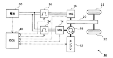
まず、本実施形態に車両用電池の充放電制御装置を搭載するハイブリッド車両10の構成について、図1を用いて説明する。ハイブリッド車両10は、原動機として内燃機関(以下、エンジンと記す)12と、第一の電動機(以下、第一MGと記す)14と、第二の電動機(以下、第二MGと記す)16とを有する。原動機12,14,16には、これらの動力を分配、統合する動力分配統合機構18が接続されている。動力分配統合機構18には、減速機構20を介して駆動輪22が接続されている。各原動機12,14,16の動力は、動力分配統合機構18により統合された後、減速機構20を介して駆動輪22に伝達され、ハイブリッド車両10が走行する。
First, the structure of the
ハイブリッド車両10は、エンジン12と第一及び第二MG14,16の出力を制御することにより、様々な態様の走行を行うことができる。例えば、エンジン12または第二MG16のどちらか一方で走行する、エンジン12と第二MG16とを協調して走行する、またエンジン12の出力の一部により第一MG14で発電を行うなど様々な態様の走行を行うことができる。さらに、減速時において、駆動輪22から入力されるハイブリッド車両10の運動エネルギにより第二MG16で回生発電を行うこともできる。
The
第一及び第二MG14,16は、発電機として機能するとともに、電動機として機能する同期モータである。第一及び第二MG14,16は、第一及び第二インバータ24,26を介して電池30に接続される。電池30は、充放電可能な二次電池、例えばニッケル水素二次電池またはリチウムイオン二次電池などで構成される。電池30に蓄えられる電力は、第一及び第二インバータ24,26により直流電流から三相交流電流に変換された後に、第一及び第二MG14,16に供給されて、これらのMG14,16を駆動する。また、回生時に第一及び第二MG14,16で発電された電力は、第一及び第二インバータ24,26により三相交流電流から直流電流に変換された後に、電池30に送られて蓄えられる。このように、第一及び第二MG14,16は、電動機および発電機として機能することができる。
The first and
ハイブリッド車両10は、車両の状態と運転者の要求とに基づき運転を行なうよう制御する電子制御装置(ECU)40を有する。電子制御装置40は、CPUを中心とするマイクロプロセッサとして構成されており、CPUのほかに処理プログラムを記憶するROM(図示せず)と、データを一時的に記憶するRAM(図示せず)とを備える。なお、電子制御装置40は、本発明に係る充放電制御装置に対応する装置であり、これを以降、単に制御装置40と記す。
The
制御装置40には、エンジン12、第一及び第二MG14,16、第一及び第二インバータ24,26、そして電池30が接続されている。エンジン12には、このエンジン12の運転状態を検出するセンサ、例えば回転速度センサ(図示せず)が設けられており、このセンサから信号が制御装置40に入力される。第一及び第二MG14,16には、これらのMG14,16の運転状態を検出するセンサ、例えば回転速度センサ(図示せず)が設けられており、このセンサから信号が制御装置40に入力される。電池30には、この電池30の状態を検出する各種センサが設けられている。各種センサについては、図2を用いて後述する。各種センサから信号が制御装置40に入力される。
The
制御装置40は、上述した信号に基づき車両の状態を判断する。そして、制御装置40は、この車両の状態と運転者の要求とを総合して、原動機の駆動力を決定し、エンジン12と第一及び第二インバータ24,26に制御信号を出力する。これにより、エンジン12と第一及び第二MG14,16の出力配分が最適に制御される。なお、運転者の要求は、運転者が操作する入力手段、例えばイグニッションスイッチ、アクセルペダル、ブレーキペダル、およびシフトレバーから送られる信号に基づき判断される。
The
次に、電池30の概略構成について図2を用いて説明する。電池30は、複数の単電池32を直列接続して構成される組電池34を複数有し、これらの組電池34を更に直列に接続している。すなわち、電池30は、直列接続された組電池34に含まれる単電池32をすべて直列接続している。単電池32をすべて直列接続することにより、電池30は、第一及び第二MG14,16が必要とする高電圧を確保している。
Next, a schematic configuration of the
電池30には、この電池30の状態を検出する各種センサが設けられている。各種センサは、電圧検出器50、温度検出器52、そして電流検出器54である。電圧検出器50は、組電池34の端子電圧を検出するセンサであり、各組電池34に対応して設けられる。温度検出器52は、組電池34内の代表の単電池32の温度を検出するセンサであり、各組電池34に対応して設けられる。電流検出器54は、電池30の電流を検出するセンサであり、電池30内の回路に設けられる。
The
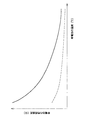
一般的な電池の充放電特性について図3,4を用いて説明する。図3は、放電時における単電池の電圧の時間変化の様子を示す図である。図4は、単電池の内部抵抗と単電池の温度との関係を示す図である。なお、これらの図においては、電池の充放電のうち放電を一例として挙げ、これの特性について説明するが、充電の特性も同様である。 The charge / discharge characteristics of a general battery will be described with reference to FIGS. FIG. 3 is a diagram showing a state of the time change of the voltage of the single cell during discharge. FIG. 4 is a diagram showing the relationship between the internal resistance of the cell and the temperature of the cell. In these figures, discharge is taken as an example of charging / discharging of the battery and the characteristics thereof will be described, but the charging characteristics are also the same.
図3において、放電時における複数の単電池の時間変化が符号60で示す曲線で表される。なお、単電池の個数は、例えば4個とする。放電開始からの経過時間が短い区間においては、各単電池の電圧がほぼ同じ傾向で低下する。すなわち、単電池間の電圧差は極めて小さい。一方、放電開始からの経過時間が短い区間より長くなると、各単電池の温度などの差により、それらの電圧に差が生じ易くなる。その結果、図3に示すように、4個の単電池は符号60a〜60dの曲線のように分かれて、それぞれに電圧が低下する。ここで、図3に示すように、符号60aの曲線の電圧低下が最も緩く、次に符号60bの曲線、そして符号60cの曲線と続いて電圧低下が大きくなり、符号60dの曲線の電圧低下が最も著しいことが分かる。これらの単電池の電圧を平均した曲線を符号62の破線で示す。一定時間経過後(曲線の右端)、各単電池の平均電圧である曲線62が電圧の下限値以上の範囲にあっても、曲線60dが電圧の下限値以下になっている。したがって、複数の単電池の平均電圧と下限値とを比較して平均電圧が下限値以上であったとしても、一部の単電池の電圧が下限値以下になってしまうことが分かる。なお、充電の場合は、これとは逆に、充電開始からの経過時間が長い場合、複数の単電池の平均電圧と上限値とを比較して平均電圧が上限値以下であったとしても、一部の単電池の電圧が上限値を超えてしまう。
In FIG. 3, the time change of the plurality of single cells at the time of discharging is represented by a curve indicated by
このように、複数の単電池を長い時間継続して充放電する場合、単電池の温度などの差により、通常、各単電池の電圧に差が生じてしまう。よって、組電池の端子電圧から組電池を構成する複数の単電池の平均電圧を算出し、この平均電圧が上下限値の範囲内になるように充放電制御したとしても、一部の単電池の電圧が上限値を超えたり下限値未満になったりする可能性がある。 Thus, when charging / discharging a several cell continuously for a long time, a difference will arise in the voltage of each cell normally by the difference of the temperature etc. of a cell. Therefore, even if the average voltage of the plurality of single cells constituting the assembled battery is calculated from the terminal voltage of the assembled battery and the charge / discharge control is performed so that the average voltage is within the range of the upper and lower limit values, some of the single cells May exceed the upper limit value or less than the lower limit value.
一般的に、単電池の内部抵抗は単電池の温度に依存する。すなわち単電池を流れる電流が一定である場合、単電池の電圧は単電池の温度に依存する。図4は、放電時における単電池の内部抵抗とその温度を示す図である。破線の曲線は、比較的放電時間が短いときの単電池の内部抵抗の特性を示す。この曲線では、単電池の温度が高いときは、内部抵抗が小さく、単電池の温度が低くなるにつれて、内部抵抗が大きくなることが分かる。実線の曲線は、破線の曲線より放電時間が長いときの単電池の内部抵抗の特性を示す。この曲線も、破線の曲線と同様に、単電池の温度が高いときは、内部抵抗が小さく、単電池の温度が低くなるにつれて、内部抵抗が大きくなることが分かる。また、実線の曲線は破線の曲線より、単電池の温度が低くなるにつれて内部抵抗がより大きく傾向にある。言い換えれば、放電時間が長いときのほうが、単電池の内部抵抗は温度に依存する傾向が大きくなる。なお、この特性は充電時においても同様であり、充電時間が長いときのほうが単電池の内部抵抗は温度に依存する傾向が大きくなる。 In general, the internal resistance of a single cell depends on the temperature of the single cell. That is, when the current flowing through the cell is constant, the voltage of the cell depends on the temperature of the cell. FIG. 4 is a diagram showing the internal resistance and temperature of the unit cell during discharge. The dashed curve indicates the characteristics of the internal resistance of the unit cell when the discharge time is relatively short. From this curve, it can be seen that the internal resistance is small when the temperature of the unit cell is high, and the internal resistance increases as the temperature of the unit cell decreases. The solid line curve shows the characteristics of the internal resistance of the unit cell when the discharge time is longer than that of the broken line curve. Similarly to the dashed curve, this curve also shows that when the cell temperature is high, the internal resistance is small, and as the cell temperature decreases, the internal resistance increases. Also, the solid curve tends to have a higher internal resistance as the temperature of the unit cell becomes lower than the dashed curve. In other words, when the discharge time is long, the internal resistance of the unit cell tends to depend on temperature. This characteristic is the same at the time of charging. The longer the charging time, the greater the tendency of the internal resistance of the unit cell depending on the temperature.
このように、単電池の内部抵抗は、充放電時間が長い場合、単電池の温度に依存する傾向が大きくなる。組電池を構成する複数の単電池は、その配置等により単電池間の温度差が生じる可能性がある。そうすると、充放電時間が長く、かつ単電池間に温度差が生じると、単電池間の内部抵抗に差が生じる。この結果、図3に示すように、各単電池の電圧に差が生じることになる。 Thus, the internal resistance of the unit cell tends to depend on the temperature of the unit cell when the charge / discharge time is long. A plurality of unit cells constituting the assembled battery may cause a temperature difference between the unit cells due to their arrangement or the like. Then, when the charge / discharge time is long and a temperature difference occurs between the single cells, a difference occurs in the internal resistance between the single cells. As a result, as shown in FIG. 3, a difference occurs in the voltage of each unit cell.
次に、放電時における温度ごとの単電池の電圧特性について図5,6を用いて説明する。図5は、電流値が例えば6.5Aのとき、図6は、電流値が例えば13Aのときのものを示す。図5,6に示される複数の曲線は、単電池の温度がそれぞれ異なるものである。すなわち、符号64aの曲線が−15℃、符号64bが−20℃、符号64cが−25℃、符号64dが−30℃、符号64eが−35℃のものを示す。なお、本実施形態においては、一例として組電池間の単電池の温度のばらつきを5℃、すなわち単電池間の温度差を5℃とした場合について説明する。しかし、これに限定されずに単電池間の温度差を5℃より大きい、または小さい値を設計値として採用することができる。
Next, the voltage characteristics of the unit cell for each temperature during discharging will be described with reference to FIGS. FIG. 5 shows a case where the current value is, for example, 6.5A, and FIG. 6 shows a case where the current value is, for example, 13A. The plurality of curves shown in FIGS. 5 and 6 are different in cell temperature. That is, the curve of
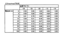
図5,6に示されるように、温度が低い単電池のほうが、温度が高い単電池より電圧低下が著しいことが分かる。ここで、組電池内の単電池間の温度差を例えば5℃とした場合、ある単電池より5℃低い単電池の電圧が下限値に到達した時点におけるある単電池とそれより5℃低い単電池の電圧差をΔVとする。この電圧差ΔVは、単電池の温度と電流に大きく依存する。この結果をまとめたものを図7に示す。 As shown in FIGS. 5 and 6, it can be seen that the voltage drop is more remarkable in the unit cell having a lower temperature than the unit cell having a higher temperature. Here, when the temperature difference between the single cells in the assembled battery is set to 5 ° C., for example, the single cell at the time when the voltage of the single cell 5 ° C. lower than the certain cell reaches the lower limit value and the single cell 5 ° C. lower than that. Let the voltage difference of the battery be ΔV. This voltage difference ΔV greatly depends on the temperature and current of the unit cell. A summary of the results is shown in FIG.
なお、充電の場合は、図示しないが、図5,6とは逆に、温度が高い単電池のほうが、温度が低い単電池より電圧上昇が著しいことが分かる。また、組電池内の単電池間の温度差を例えば5℃とした場合、ある単電池より5℃高い単電池の電圧が上限値に到達した時点におけるある単電池とそれより5℃高い単電池の電圧差をΔVとする。この電圧差ΔVは、単電池の温度と電流に大きく依存する。この結果をまとめたものを図8に示す。 In the case of charging, although not shown in the figure, it can be seen that, contrary to FIGS. 5 and 6, the unit cell having a higher temperature has a higher voltage rise than the unit cell having a lower temperature. Further, when the temperature difference between the single cells in the assembled battery is, for example, 5 ° C., a single cell at the time when the voltage of the single cell 5 ° C. higher than a certain single cell reaches the upper limit value and a single cell 5 ° C. higher than that Is a voltage difference ΔV. This voltage difference ΔV greatly depends on the temperature and current of the unit cell. A summary of the results is shown in FIG.
図7,8は、組電池内の単電池間の温度差を5℃にした場合における、単電池の温度TBと電流IBから単電池間の電圧差ΔVを実験的に求めたマップである。図7は、放電時における単電池間の電圧差ΔVminを、単電池の温度TBと電流IBから求めたマップであり、図8は、充電時における単電池間の電圧差ΔVmaxを、単電池の温度TBと電流IBから求めたマップである。これらのマップは、後述する制御装置40の制御動作において、単電池の温度TBと電流IBから単電池間の電圧差ΔVmax,ΔVminを推定するときに用いられる。
7 and 8 are maps obtained by experimentally determining the voltage difference ΔV between the single cells from the temperature TB and the current IB of the single cells when the temperature difference between the single cells in the assembled battery is 5 ° C. FIG. 7 is a map in which the voltage difference ΔVmin between the single cells at the time of discharging is obtained from the temperature TB and the current IB of the single cells. FIG. 8 shows the voltage difference ΔVmax between the single cells at the time of charging. It is the map calculated | required from temperature TB and electric current IB. These maps are used in estimating the voltage differences ΔVmax and ΔVmin between the single cells from the temperature TB and the current IB of the single cells in the control operation of the
次に、本発明に係る実施形態であって、単電池32の電圧に基づいて電池30の充放電を制御する制御装置40の制御動作について図9のフローチャートを用いて説明する。
Next, the control operation of the
まず、制御装置40には、電圧検出器50が検出した組電池34の端子間の電圧VBと、温度検出器50が検出した組電池34内の代表の単電池32の温度TBと、電流検出器54が検出した電池30の電流IBとが入力される(ステップS101)。
First, the
次に、温度TBと電流IBとから単電池30間の電圧差ΔVmax,ΔVminをマップから推定する(ステップS102)。電圧差ΔVmax,ΔVminは、単電池30間の平均電圧値からのばらつきを示す。充電時においては、電圧差ΔVmaxをマップΔVmax*mapから推定し、放電時においては、電圧差ΔVminをマップΔVmin*mapから推定する。なお、マップは、例えば図7,8に示すものであり、制御装置40のROMに予め記憶されている。また、マップは、組電池内の単電池間で生じる温度差が5℃と仮定したものであるが、この温度差より高いまたは低い温度差のものを用いることもできる。
Next, voltage differences ΔVmax and ΔVmin between the
そして、組電池34内の単電池32の最高電圧Vmaxと最低電圧Vminを算出する(ステップS103)。充電時においては、最高電圧Vmaxを算出し、放電時においては、最低電圧Vminを算出する。最高電圧Vmaxは次の式により算出される。
Vmax=VB/N+ΔVmax ・・・(式1)
一方、最低電圧Vminは次の式により算出される。
Vmin=VB/N−ΔVmin ・・・(式2)
ここで、Nは、一つの組電池34を構成する単電池32の個数である。
And the highest voltage Vmax and the lowest voltage Vmin of the
Vmax = VB / N + ΔVmax (Formula 1)
On the other hand, the minimum voltage Vmin is calculated by the following equation.
Vmin = VB / N−ΔVmin (Expression 2)
Here, N is the number of
次に、ステップS103において算出された最高電圧Vmaxと設定された上限値Vupperとを比較し(ステップS104)、最高電圧Vmaxが上限値Vupper超えた場合、充電を禁止するように制御する(ステップS105)。一方、最高電圧Vmaxが上限値Vupper以下の場合、現状維持としステップS106に進む。この動作により、いずれの単電池30の電圧も上限値及び下限値を超えないような制御が可能となる。
Next, the maximum voltage Vmax calculated in step S103 is compared with the set upper limit value Vupper (step S104), and if the maximum voltage Vmax exceeds the upper limit value Vupper, control is performed to prohibit charging (step S105). ). On the other hand, if the maximum voltage Vmax is equal to or lower than the upper limit value Vupper, the current state is maintained and the process proceeds to step S106. By this operation, it is possible to control such that the voltage of any
そして、ステップS103において算出された最低電圧Vminと設定された下限値Vlowerとを比較し(ステップS106)、最低電圧Vminが下限値Vlower未満の場合、放電を禁止するように制御する(ステップS107)。一方、最低電圧Vminが下限値Vlower以上の場合、現状維持とし、動作が終了する。 Then, the lowest voltage Vmin calculated in step S103 is compared with the set lower limit value Vlower (step S106), and if the lowest voltage Vmin is less than the lower limit value Vlower, control is performed to inhibit discharge (step S107). . On the other hand, when the minimum voltage Vmin is equal to or higher than the lower limit value Vlower, the current state is maintained and the operation ends.
本実施形態によれば、単電池32ごとの電圧を検出することなくそれらを構成する組電池34の端子電圧VBを検出するだけで、単電池32の最高電圧Vmax及び最低電圧Vminを算出することができるので、電圧検出のシステムを簡易な構造にすることができる。また、算出された最高電圧Vmax及び最低電圧Vminに基づいて上下限の範囲を判断することにより、単電池32の電圧異常を正確に検出することができ、この検出結果に基づいて電池30の充放電を適正に制御することができる。
According to the present embodiment, the maximum voltage Vmax and the minimum voltage Vmin of the
10 ハイブリッド車両、30 電池、32 単電池、34 組電池、40 制御装置、50 電圧検出器、52 温度検出器、54 電流検出器。
DESCRIPTION OF
Claims (3)
電池の電流を検出する電流検出手段と、
組電池の電圧を検出する電圧検出手段と、
組電池内の代表の単電池の温度を検出する温度検出手段と、
検出した温度と検出した電流と組電池内の単電池間で生じる温度差とに基づいて組電池内の単電池間の電圧差を推定する電圧差推定手段と、
推定した電圧差と検出した電圧とに基づいて組電池内における単電池の最高電圧と最低電圧とを算出する電圧算出手段と、
電圧算出手段の算出結果に基づいて電池の充放電を制御する制御手段と、
を有することを特徴とする車両用電池の充放電制御装置。 In a charging / discharging control device for a vehicle battery having a plurality of assembled batteries configured by connecting a plurality of single cells in series, and further connecting these assembled batteries in series,
Current detection means for detecting the current of the battery;
Voltage detection means for detecting the voltage of the assembled battery;
Temperature detecting means for detecting the temperature of a representative unit cell in the assembled battery;
Voltage difference estimation means for estimating a voltage difference between the single cells in the assembled battery based on the detected temperature, the detected current, and the temperature difference generated between the single cells in the assembled battery;
Voltage calculating means for calculating the highest voltage and the lowest voltage of the cells in the assembled battery based on the estimated voltage difference and the detected voltage;
Control means for controlling charge / discharge of the battery based on the calculation result of the voltage calculation means;
A vehicle battery charge / discharge control device comprising:
前記制御手段は、電圧算出手段により算出された最高電圧が上限値を超える場合、電池の充電を禁止するように制御することを特徴とする車両用電池の充放電制御装置。 In the vehicle battery charge / discharge control device according to claim 1,
The vehicle battery charging / discharging control apparatus, wherein the control means performs control so as to prohibit charging of the battery when the maximum voltage calculated by the voltage calculating means exceeds an upper limit value.
前記制御手段は、電圧手段により算出された最低電圧が下限値未満の場合、電池の放電を禁止するように制御することを特徴とする車両用電池の充放電制御装置。 In the vehicle battery charge / discharge control device according to claim 1 or 2,
The vehicle battery charge / discharge control apparatus according to claim 1, wherein the control means controls the battery discharge to be prohibited when the minimum voltage calculated by the voltage means is less than a lower limit value.
Priority Applications (1)
| Application Number | Priority Date | Filing Date | Title |
|---|---|---|---|
| JP2008140568A JP5092903B2 (en) | 2008-05-29 | 2008-05-29 | Vehicle battery charge / discharge control device |
Applications Claiming Priority (1)
| Application Number | Priority Date | Filing Date | Title |
|---|---|---|---|
| JP2008140568A JP5092903B2 (en) | 2008-05-29 | 2008-05-29 | Vehicle battery charge / discharge control device |
Publications (2)
| Publication Number | Publication Date |
|---|---|
| JP2009290984A true JP2009290984A (en) | 2009-12-10 |
| JP5092903B2 JP5092903B2 (en) | 2012-12-05 |
Family
ID=41459612
Family Applications (1)
| Application Number | Title | Priority Date | Filing Date |
|---|---|---|---|
| JP2008140568A Active JP5092903B2 (en) | 2008-05-29 | 2008-05-29 | Vehicle battery charge / discharge control device |
Country Status (1)
| Country | Link |
|---|---|
| JP (1) | JP5092903B2 (en) |
Cited By (4)
| Publication number | Priority date | Publication date | Assignee | Title |
|---|---|---|---|---|
| EP2339546A1 (en) | 2009-12-22 | 2011-06-29 | Laurel Precision Machines Co. Ltd. | Coin processing apparatus |
| JP2011229353A (en) * | 2010-04-23 | 2011-11-10 | Panasonic Corp | Power supply unit |
| EP2712046A4 (en) * | 2011-05-16 | 2016-05-18 | Hitachi Automotive Systems Ltd | Battery control device |
| CN111142024A (en) * | 2018-11-05 | 2020-05-12 | 湖南中车时代电动汽车股份有限公司 | Method and device for detecting unbalance fault of battery monomer |
Citations (2)
| Publication number | Priority date | Publication date | Assignee | Title |
|---|---|---|---|---|
| JPH08140206A (en) * | 1994-11-09 | 1996-05-31 | Fuji Heavy Ind Ltd | Battery managing method for electric motor vehicle |
| JP2007226992A (en) * | 2006-02-21 | 2007-09-06 | Nissan Motor Co Ltd | Battery pack control device and battery pack control method |
-
2008
- 2008-05-29 JP JP2008140568A patent/JP5092903B2/en active Active
Patent Citations (2)
| Publication number | Priority date | Publication date | Assignee | Title |
|---|---|---|---|---|
| JPH08140206A (en) * | 1994-11-09 | 1996-05-31 | Fuji Heavy Ind Ltd | Battery managing method for electric motor vehicle |
| JP2007226992A (en) * | 2006-02-21 | 2007-09-06 | Nissan Motor Co Ltd | Battery pack control device and battery pack control method |
Cited By (5)
| Publication number | Priority date | Publication date | Assignee | Title |
|---|---|---|---|---|
| EP2339546A1 (en) | 2009-12-22 | 2011-06-29 | Laurel Precision Machines Co. Ltd. | Coin processing apparatus |
| JP2011229353A (en) * | 2010-04-23 | 2011-11-10 | Panasonic Corp | Power supply unit |
| EP2712046A4 (en) * | 2011-05-16 | 2016-05-18 | Hitachi Automotive Systems Ltd | Battery control device |
| CN111142024A (en) * | 2018-11-05 | 2020-05-12 | 湖南中车时代电动汽车股份有限公司 | Method and device for detecting unbalance fault of battery monomer |
| CN111142024B (en) * | 2018-11-05 | 2022-03-22 | 湖南中车时代电动汽车股份有限公司 | Method and device for detecting unbalance fault of battery monomer |
Also Published As
| Publication number | Publication date |
|---|---|
| JP5092903B2 (en) | 2012-12-05 |
Similar Documents
| Publication | Publication Date | Title |
|---|---|---|
| US8237398B2 (en) | Electric system, charging device and charging method for electric system for discharging of a power storage mechanism for resetting a state of a charge | |
| US8643332B2 (en) | Battery system and method for detecting internal short circuit in battery system | |
| US9849793B2 (en) | Electrical storage system for vehicle | |
| JP4116609B2 (en) | Power supply control device, electric vehicle and battery control unit | |
| US8497661B2 (en) | Equalization device, equalization processing program, battery system, electric vehicle and equalization processing method | |
| US9973018B2 (en) | Electric storage system | |
| US8742718B2 (en) | Charging apparatus for vehicle | |
| US20100241376A1 (en) | Control apparatus and control method for secondary battery | |
| US20110148361A1 (en) | Battery system and method for detecting current restriction state in a battery system | |
| WO2013051104A1 (en) | Electrical charging control apparatus and electrical charging method | |
| JP5470829B2 (en) | Discrimination device for discriminating the state of a lithium ion battery | |
| JP2011087428A (en) | Power supply, vehicle equipped with the same, and charge/discharge control method of power supply | |
| US20110115435A1 (en) | Charge control device and vehicle equipped with the same | |
| EP3245096A1 (en) | Method and arrangement for determining a value of the state of energy of a battery in a vehicle | |
| JPWO2013035511A1 (en) | Vehicle battery control device | |
| WO2012101667A1 (en) | Power storage system | |
| JP2010035350A (en) | Method of controlling charge and discharge of battery in power supply device of hybrid car | |
| JP2010066229A (en) | Device and method for detecting failure of battery | |
| JP6834757B2 (en) | Battery system | |
| JP2005261034A (en) | Controller of electric storage mechanism | |
| JP6451582B2 (en) | Charge / discharge control device for power storage device | |
| JP5092903B2 (en) | Vehicle battery charge / discharge control device | |
| US11198368B2 (en) | Vehicular charging control system | |
| JP6713283B2 (en) | Power storage device, transportation device, and control method | |
| JP5772209B2 (en) | Charge / discharge control device for power storage device and electric vehicle equipped with the same |
Legal Events
| Date | Code | Title | Description |
|---|---|---|---|
| A621 | Written request for application examination |
Free format text: JAPANESE INTERMEDIATE CODE: A621 Effective date: 20101006 |
|
| A977 | Report on retrieval |
Free format text: JAPANESE INTERMEDIATE CODE: A971007 Effective date: 20120531 |
|
| A131 | Notification of reasons for refusal |
Free format text: JAPANESE INTERMEDIATE CODE: A131 Effective date: 20120605 |
|
| A521 | Written amendment |
Free format text: JAPANESE INTERMEDIATE CODE: A523 Effective date: 20120802 |
|
| TRDD | Decision of grant or rejection written | ||
| A01 | Written decision to grant a patent or to grant a registration (utility model) |
Free format text: JAPANESE INTERMEDIATE CODE: A01 Effective date: 20120821 |
|
| A01 | Written decision to grant a patent or to grant a registration (utility model) |
Free format text: JAPANESE INTERMEDIATE CODE: A01 |
|
| A61 | First payment of annual fees (during grant procedure) |
Free format text: JAPANESE INTERMEDIATE CODE: A61 Effective date: 20120903 |
|
| R151 | Written notification of patent or utility model registration |
Ref document number: 5092903 Country of ref document: JP Free format text: JAPANESE INTERMEDIATE CODE: R151 |
|
| FPAY | Renewal fee payment (event date is renewal date of database) |
Free format text: PAYMENT UNTIL: 20150928 Year of fee payment: 3 |