JP2021133574A - Ink jet recording device - Google Patents
Ink jet recording device Download PDFInfo
- Publication number
- JP2021133574A JP2021133574A JP2020030490A JP2020030490A JP2021133574A JP 2021133574 A JP2021133574 A JP 2021133574A JP 2020030490 A JP2020030490 A JP 2020030490A JP 2020030490 A JP2020030490 A JP 2020030490A JP 2021133574 A JP2021133574 A JP 2021133574A
- Authority
- JP
- Japan
- Prior art keywords
- carriage
- recording head
- recording
- ink
- sensor
- Prior art date
- Legal status (The legal status is an assumption and is not a legal conclusion. Google has not performed a legal analysis and makes no representation as to the accuracy of the status listed.)
- Pending
Links
- 238000001514 detection method Methods 0.000 claims abstract description 11
- 230000008531 maintenance mechanism Effects 0.000 claims description 16
- 238000007599 discharging Methods 0.000 abstract description 2
- 238000000034 method Methods 0.000 description 22
- 238000012423 maintenance Methods 0.000 description 7
- 230000006870 function Effects 0.000 description 4
- 230000007246 mechanism Effects 0.000 description 3
- 238000009434 installation Methods 0.000 description 2
- 239000004566 building material Substances 0.000 description 1
- 238000006243 chemical reaction Methods 0.000 description 1
- 238000010586 diagram Methods 0.000 description 1
- 238000001035 drying Methods 0.000 description 1
- 230000000694 effects Effects 0.000 description 1
Images


Abstract
Description
本発明は、記録ヘッドを移動させつつ記録媒体に画像を記録するインクジェット記録装置に関する。 The present invention relates to an inkjet recording device that records an image on a recording medium while moving a recording head.
記録媒体に向かってインクを吐出して画像を記録するインクジェット記録装置が知られている。インクジェット記録装置としては、フルライン方式とシリアルスキャン方式との2方式のいずれかが採用されている。フルライン方式では、記録媒体の記録領域の幅方向の全体をカバーする長さを有する記録ヘッドを備え、記録ヘッドに形成された複数のノズルから記録媒体にインクを吐出することにより、記録媒体の記録面に画像を記録する。シリアルスキャン方式では、記録媒体の記録領域の幅方向に短い記録ヘッドを備え、この記録ヘッドを記録領域の幅方向にキャリッジで移動させつつ、複数のノズルから記録媒体にインクを吐出することにより、記録媒体の記録面に画像を記録する。なお、いずれの方式においても、記録媒体は記録領域の幅方向に対して直交する方向に搬送されているが、シリアルスキャン方式の記録装置には、記録媒体の搬送を行わず、記録媒体を特定の位置に固定した状態で画像を記録するものもある。 An inkjet recording device that ejects ink toward a recording medium and records an image is known. As the inkjet recording apparatus, one of two methods, a full-line method and a serial scan method, is adopted. In the full-line system, a recording head having a length that covers the entire recording area of the recording medium in the width direction is provided, and ink is ejected from a plurality of nozzles formed in the recording head to the recording medium to form a recording medium. The image is recorded on the recording surface. In the serial scan method, a recording head short in the width direction of the recording area of the recording medium is provided, and ink is ejected from a plurality of nozzles to the recording medium while the recording head is moved by a carriage in the width direction of the recording area. The image is recorded on the recording surface of the recording medium. In any of the methods, the recording medium is conveyed in a direction orthogonal to the width direction of the recording area, but the serial scan type recording device does not convey the recording medium and specifies the recording medium. Some record images while they are fixed at the position of.
ここで、フルライン方式では、記録ヘッドが装置本体内で固定されていることから、同様に固定されているインクタンクからインクを供給すればよく、そのインクタンクにインクカートリッジを着脱するなどしてインクを補充することができる。 Here, in the full-line method, since the recording head is fixed in the main body of the apparatus, ink may be supplied from the similarly fixed ink tank, and an ink cartridge may be attached to or detached from the ink tank. Ink can be replenished.
これに対して、シリアルスキャン方式では、記録媒体の記録領域の幅方向に往復移動するキャリッジに記録ヘッドとインクタンクを搭載し、一体的に移動させる方式を採用して、インクタンクを着脱可能に構成することでインクの補充を実現している。例えば、特許文献1に記載のインクジェット記録装置では、非記録時にホームボジションに位置するキャリッジに記録ヘッドおよびインクタンクが搭載されており、ホームポジションに対応する位置に設けられた開口部(開閉蓋)からインクタンクの交換が行われている。 On the other hand, in the serial scan method, the recording head and the ink tank are mounted on a carriage that reciprocates in the width direction of the recording area of the recording medium, and the ink tank is detachable by adopting a method of moving them integrally. Ink replenishment is realized by configuring. For example, in the inkjet recording apparatus described in Patent Document 1, a recording head and an ink tank are mounted on a carriage located in a home position during non-recording, and an opening (opening / closing lid) provided at a position corresponding to the home position. The ink tank is being replaced.
ところで、フルライン方式では、記録ヘッドが装置本体内で固定されていることから、インクジェット記録装置の輸送時に記録ヘッドを固定部材などにより仮固定する必要はなく、設置後のセットアップ時に記録ヘッドを移動させる必要もない。 By the way, in the full-line method, since the recording head is fixed inside the main body of the device, it is not necessary to temporarily fix the recording head with a fixing member or the like when transporting the inkjet recording device, and the recording head is moved during setup after installation. There is no need to let it.
これに対して、シリアルスキャン方式では、記録ヘッドが装置本体内で移動することから、インクジェット記録装置の輸送時に記録ヘッドを固定部材により仮固定する必要がある。特許文献1は仮固定に関して何も言及していないが、シリアルスキャン方式の記録装置では、一般的にキャリッジから記録ヘッドやインクタンクが取り外され、キャリッジが装置本体に仮固定されている場合が多い。このため、このシリアルスキャン方式の記録装置では、設置後のセットアップの際にキャリッジを固定している固定部材を取り除き、記録ヘッドやインクタンクが取り付けられる位置へキャリッジを移動させる必要がある。 On the other hand, in the serial scan method, since the recording head moves in the main body of the apparatus, it is necessary to temporarily fix the recording head with a fixing member when the inkjet recording apparatus is transported. Although Patent Document 1 does not mention anything about temporary fixing, in a serial scan type recording device, the recording head and the ink tank are generally removed from the carriage, and the carriage is temporarily fixed to the device body in many cases. .. Therefore, in this serial scan type recording device, it is necessary to remove the fixing member fixing the carriage at the time of setup after installation and move the carriage to a position where the recording head or the ink tank is attached.
このように、シリアルスキャン方式の記録装置では、セットアップ時に、記録ヘッドやインクタンクを取り付けるためにキャリッジを移動させる必要があり、時間を要していた。また、セットアップ時に固定部材を外し忘れた状態で電源を投入すると、キャリッジの移動が固定部材により邪魔されてエラーが発生したり、負荷が掛かって駆動系を破損させてしまう場合があった。 As described above, in the serial scan type recording device, it is necessary to move the carriage in order to attach the recording head and the ink tank at the time of setup, which takes time. Further, if the power is turned on with the fixing member forgotten to be removed during setup, the movement of the carriage may be hindered by the fixing member to cause an error, or a load may be applied to damage the drive system.
そこで、本発明は、輸送時に固定されたキャリッジに、時間を要することなくかつ安全に記録ヘッドやインクタンクを取り付けてセットアップを完了させることが可能なインクジェット記録装置を提供することを目的としている。 Therefore, an object of the present invention is to provide an inkjet recording apparatus capable of safely attaching a recording head or an ink tank to a carriage fixed at the time of transportation to complete a setup.
上記課題を解決するインクジェット記録装置の発明の一態様は、インクを吐出する記録ヘッドと、前記記録ヘッドにインクを供給するインクタンクと、前記記録ヘッドと前記インクタンクを保持するキャリッジと、前記キャリッジの所定方向における位置を検出するエンコーダと、前記キャリッジが前記所定方向における所定位置に位置することを検出するセンサと、を備え、前記エンコーダと前記センサの検出情報に基づいて前記キャリッジを移動させつつ、前記記録ヘッドからインクを吐出させて記録媒体に画像を記録するインクジェット記録装置であって、前記センサによって検出された前記キャリッジの前記所定位置が、前記インクタンクを含むカートリッジを交換可能とする前記キャリッジの交換停止位置、および前記キャリッジを固定部材で固定する前記キャリッジの固定位置、になるように構成されていることを特徴とするものである。 One aspect of the invention of the inkjet recording apparatus that solves the above problems is a recording head that ejects ink, an ink tank that supplies ink to the recording head, a carriage that holds the recording head and the ink tank, and the carriage. The carriage is provided with an encoder that detects a position in a predetermined direction and a sensor that detects that the carriage is located at a predetermined position in the predetermined direction, while moving the carriage based on the detection information of the encoder and the sensor. An inkjet recording device that ejects ink from the recording head and records an image on a recording medium, wherein the predetermined position of the carriage detected by the sensor makes it possible to replace a cartridge including the ink tank. It is characterized in that it is configured to be a replacement stop position of the carriage and a fixed position of the carriage for fixing the carriage with a fixing member.
本発明の一態様によれば、キャリッジの固定位置とインクタンクを取り付ける交換停止位置が、キャリッジの動作基準となる位置を決定する所定位置に設けられているので、セットアップの際に記録ヘッドやインクタンクを取り付けるためにキャリッジを移動させる必要がない。また、固定部材を外すことなく電源が投入されたとしても、キャリッジが移動を開始することもない。 According to one aspect of the present invention, the fixed position of the carriage and the replacement stop position for attaching the ink tank are provided at predetermined positions that determine the position that serves as the operation reference of the carriage, so that the recording head and the ink are provided during setup. There is no need to move the carriage to install the tank. Further, even if the power is turned on without removing the fixing member, the carriage does not start moving.
したがって、時間を要することなくかつ安全にセットアップ作業を完了することが可能なインクジェット記録装置を提供することができる。 Therefore, it is possible to provide an inkjet recording device that can safely complete the setup work without requiring time.
以下、図面を参照して、本発明の実施形態について詳細に説明する。図1〜図10は本発明の一実施形態に係るインクジェット記録装置を示す図である。 Hereinafter, embodiments of the present invention will be described in detail with reference to the drawings. 1 to 10 are views showing an inkjet recording device according to an embodiment of the present invention.
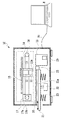
図1〜図3において、記録装置10は、情報処理するPCなどのホスト装置HがプリンタケーブルHcを介して各種情報をやり取り可能に接続されている。記録装置10は、後述の制御ユニット50のインターフェイスコントローラ55(図5を参照)にプリンタケーブルHcが接続されてプリンタとして機能する。
In FIGS. 1 to 3, the
記録装置10は、外装カバー10c内の記録ヘッド11が載置台21上に載置されたカット紙のプリンタ用紙などの記録媒体に対して相対移動しつつインクを吐出することによりホスト装置Hから受け取る各種画像データを記録する。記録装置10は、後述の制御ユニット50により統括制御されることにより載置台21上の記録媒体の上面の所定範囲を記録面として所望の画像を記録する印刷処理を施す。
The
ここで、載置台21上では、外装カバー10cに形成されている隙間から記録媒体として突き当たるまで差し込まれるカット紙がセットセンサ25により検出される。なお、本実施形態では、載置台21にセットされるカット紙の上面側の一部領域に、例えば、住所等の定型の画像などを記録する場合を一例として説明するが、これに限るものではない。例えば、建材などの硬質のプレート等を記録媒体として載置台21にセットして画像を記録してもよい。また、記録ヘッド11を主走査方向に移動させつつ、カット紙やロール紙などをその直交方向の副走査方向に搬送する機能を備えて、紙面の全面または一部に所望の画像を記録するプリンタの場合にも、本実施形態である後述の機構を適用してもよい。
Here, on the mounting table 21, the
記録ヘッド11は、インクジェット記録方式を採用してノズルから各色インクを粒状のインク滴として吐出する、不図示のインク吐出機構を各色毎に備えて構築されている。記録ヘッド11は、下面のノズル形成面11aにインクを吐出する複数のノズルが形成されて配列されることにより下方の載置台21上に位置する記録媒体の記録面に画像を記録する動作を実行する。記録ヘッド11は、交換用扉(開閉部材)10dを開くことで開放される開口部からキャリッジ13に交換可能に装着されている(図2を参照)。また、インクタンク12も、記録ヘッド11が装着されたキャリッジ13に交換可能に装着されている(図3を参照)。このように、記録ヘッドとインクタンクは別々に交換できるように構成されている。記録ヘッド11には、交換用扉10dが閉止された後、インクタンク12からインクが供給(補充)される。
The
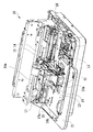
この記録装置10は、図4に示すように、載置台21上に載置された不動の記録媒体を押さえ部材20により押さえることにより位置決めして、その状態で記録ヘッド11を一方向に相対移動させる。その押さえ部材20は、一方向に移動する記録ヘッド11の下方に開口する露出穴20aが形成されて、位置決めする記録媒体の記録領域にインクを吐出して画像を形成して記録することを可能にしている。
As shown in FIG. 4, the
このことから、記録ヘッド11は、記録媒体に対する移動方向の記録領域よりも短い長さで、その移動方向に対する直交方向の記録領域をカバーする幅のノズル列がノズル形成面11aに配列されている。このため、記録ヘッド11は、後述のリニアエンコーダ15の検出情報に基づいて一方向に往復移動しつつ載置台21上の記録媒体に向けてインクを吐出するシリアルスキャン(連続直線走査)方式で動作して画像を記録領域に記録する。なお、押さえ部材20の露出穴20aは、記録ヘッド11により画像を記録する記録媒体の記録領域よりも広めに開口するように形成されている。
For this reason, in the
ここで、記録ヘッド11は、ノズル形成面11aのノズルに連通するインク流路内に設置されている不図示の電熱変換素子(ヒータ)に通電して瞬間的に気泡を発生させることで、そのノズルからインク滴を吐出させる、所謂サーマル方式を採用している。この記録ヘッド11は、サーマル方式に限らず、例えば、インク流路の容量を瞬間的に変化させる圧電素子(ピエゾ素子)を設置して、そのノズルからインク滴を吐出させる所謂、ピエゾ方式を採用してもよいことはいうまでもない。
Here, the
また、記録ヘッド11は、イエロー(Y)、マゼンタ(M)、シアン(C)およびブラック(K)の各ノズルに、各色毎のインクタンク12から各色インクが供給されて移動方向順に吐出することによりフルカラー画像を形成して記録する。なお、記録ヘッド11は、所望のインク色で画像を形成することによりモノクロなどの単色画像などを記録することもでき、また、ブラックなどの単色のインクを搭載するモノクロ専用機などとしてもよい。
Further, the
また、記録装置10には、図3および図4に示すように、記録ヘッド11の移動方向において、載置台21の隣接位置にメンテナンス機構19が設置されている。メンテナンス機構19は、載置台21を超える位置まで移動した記録ヘッド11のノズル形成面11aに不図示のキャップ部材を密着させてポンプモータ29で減圧することにより、ノズル内から少量のインクを吸引してリフレッシュさせる機能を有している。記録ヘッド11は、メンテナンス機構19のキャップ部材内に少量のインクを予備吐出することでインク品質を回復することもできる。このメンテナンス機構19は、インクの吸引・吐出後に相対移動する記録ヘッド11のノズル形成面11aに付着するインクを掻き落としてクリーニングする不図示のブレードも有している。記録ヘッド11は、メンテナンス機構19のキャップ部材をノズル形成面11aに装着させて待機することにより無用な付着物や乾燥の促進をできるだけ回避することができる。このように、メンテナンス機構19は複雑な処理を行うことから、不用意に触れると破損することがある。また、メンテナンス機構19に触れると手にインクが付着して装置本体を汚損してしまう可能性が高いことから、メンテナンス機構19は、ユーザーが直接触れないようにカバー(例えば、外装カバー10c等)で覆うことが好ましい。
Further, as shown in FIGS. 3 and 4, the
載置台21は、記録ヘッド11の移動方向と平行な上面側の水平面21aを記録ヘッド11側の押さえ部材20に押し付ける、または離隔させるように、下部に連結されているリフトモータ22を正逆駆動させることにより上昇または降下される。載置台21は、リフトモータ22周りの複数個所に配置されているスプリング23により上方に付勢されることにより、載置(セット)されている記録媒体を記録ヘッド11側の押さえ部材20に均等に押し付ける。載置台21は、水平面21a上に載置された記録媒体を支持しつつ押さえ部材20に押し付けることにより記録ヘッド11に対する相対位置を位置決め保持する。この載置台21は、記録装置10の本体内に配置されているセットセンサ25により水平面21a上にセットされる記録媒体が検出されたときに、その記録媒体を押さえ部材20に押し付けて位置決めするように上昇する。
The mounting table 21 drives the
詳細には、載置台21は、水平面21a上に差し込まれて載置された記録媒体がセットセンサ25により検出されたときに、リフトモータ22により上昇されて記録ヘッド11側の押さえ部材20に所望の圧力で押し付けられて記録媒体を位置決め保持する。この動作後に、載置台21は、水平面21a上の記録媒体を回収可能にリフトモータ22により降下されて次の記録媒体の載置を待機する。なお、載置台21は、外装カバー10c内から外部に引き出して記録媒体を載置した後に押し込む構造にしてもよく、この載置台21の端面をセットセンサ25が検出しつつ他の制御信号により画像の記録動作を開始するようにしてもよい。この場合、載置台21は、押さえ部材20の露出穴20aが画像を記録する範囲(領域)として記録媒体にセット位置を示す印が形成するなどしてもよい。
Specifically, the mounting table 21 is lifted by the
そして、記録装置10は、所定方向(以下、水平方向ともいう)に往復(正逆)移動するキャリッジ13を備えている。記録ヘッド11は、そのキャリッジ13にインクタンク12と一体または別個に着脱自在に装着される。記録ヘッド11は、キャリッジ13が水平方向に正逆移動することにより載置台21上の記録媒体に画像を記録し、また、載置台21に隣接するメンテナンス機構19による処理位置に移動する。
The
キャリッジ13は、上下のガイドレール16a、16bに水平方向に移動自在に支持されて、キャリッジモータ17の駆動軸17aとプーリ18とに巻き掛けられている周回ベルト14に取り付けられている。キャリッジ13は、リニアスケール15aにおける位置を読み取るリニアエンコーダ15により水平方向の移動位置を検出されつつ水平移動する。キャリッジ13は、後述する所定の動作、例えば、記録ヘッド11が押さえ部材20の露出穴20aの一端部側から記録媒体に画像を記録する動作等を行う際、キャリッジ基準センサ35により検出される後述の所定位置を各種動作の基準にして移動する。すなわち、周回ベルト14やキャリッジモータ17やリニアエンコーダ15などが移動機構を構成する。
The
ところで、記録装置10は、図5に示すように、制御ユニット50のCPU51により統括制御される。CPU51は、インターフェイスコントローラ55と共に、プログラムROM52、ワークRAM53およびイメージメモリ54が接続されて各種制御処理を実行する。プログラムROM52は、CPU51が利用する各種制御プログラムを格納されている。ワークRAM53は、CPU51が制御プログラムを実行する際、各種の取得情報や制御情報を一時的に記憶して保持するワークエリアとして機能する。イメージメモリ54は、ホスト装置Hから受け取る画像データを各色毎のビットマップ形式にして画像形成可能に格納する。
By the way, as shown in FIG. 5, the
CPU51は、印字ヘッド制御回路56を介して記録ヘッド11との間で各種情報をやり取り可能に接続されて、その駆動を制御する。CPU51は、出力ポート57を介してモータ制御部58により駆動を制御するキャリッジモータ17やリフトモータ22やポンプモータ29が接続されて、それらの駆動を制御する。CPU51は、入力ポート59を介してエンコーダ15、セットセンサ25およびキャリッジ基準センサ35など後述のセンサをも含むセンサ群60と接続されて、それらセンサ情報を取得する。
The
このCPU51は、プログラムROM52内の制御プラグラムに従ってワークRAM53を利用しつつセンサ群60やホスト装置Hからの取得情報などに基づいてイメージメモリ54内に格納する画像データを記録媒体に記録する制御処理を実行する。CPU51は、キャリッジ13の位置をリニアエンコーダ15の検出情報に基づいて把握することにより記録ヘッド11の移動・停止と共にインクの吐出による画像記録を含む各種動作を実行する。
The
具体的には、図6に示すように、CPU51は、電源投入毎に、キャリッジ基準センサ35により検出される所定位置にキャリッジ13を移動させて、リニアエンコーダ15が検出するリニアスケール15aにおける基準位置Pbを設定する。ただし、キャリッジ13は、セットアップ時に所定位置に停止しているため電源が投入されても移動せず、そのまま基準位置Pbが設定される。なお、キャリッジ13が所定位置にいることをキャリッジ基準センサ35が検出できる領域としては、ある程度マージンを持たせてもよく、例えば、図6に示す固定範囲Pwに該当する幅のマージンを設けてもよい。CPU51は、記録ヘッド11の装着を確認する所定タイミングに、リニアエンコーダ15によるリニアスケール15aの検出情報に基づいてキャリッジ13をその基準位置Pbから予め設定されているメンテナンス位置(待機位置)Pmに移動させて待機させる。以下では、「リニアエンコーダ15によるリニアスケール15aの検出情報など」と特に記載することなく省略して説明する。
Specifically, as shown in FIG. 6, the
例えば、CPU51は、画像の記録命令を受けたとき、キャリッジ13をメンテナンス位置Pmより基準位置Pbに向かう方向に移動させて開始位置Psから記録ヘッド11による画像の記録動作を開始させて終了位置Peへの到達時に往路での動作を終了する。その後、キャリッジ13は副走査方向へ移動する。CPU51は、キャリッジ13を終了位置Peから戻る方向に移動させつつ記録ヘッド11による画像の記録動作を行って開始位置Psに到達したときに復路での動作を終了して1枚の記録媒体(カット紙)への画像の印刷記録処理を完了する。そして、CPU51は、次の記録媒体への画像の記録命令が残っている場合には、セットセンサ25による検出情報に基づいて同様の画像の記録動作を繰り返す。また、CPU51は、その記録命令の処理が完了した後には、キャリッジ13をメンテナンス位置Pmに移動させて記録ヘッド11のノズル形成面11aにキャップ部材を密着させて待機させる。この記録命令の前後に、CPU51は、適宜に、ポンプモータ29によるインクの吸引や記録ヘッド11のインクの予備吐出など行ってインク品質を回復などさせ待機する。なお、前述したようにメンテナンス機構19に不用意に触れると破損したり、装置本体をインクで汚損する可能性があるので、メンテナンス機構19を配置する位置(メンテナンス位置Pm)は、キャリッジの所定位置(基準位置Pb)から離すことが好ましい。具体的には、メンテナンス機構19を配置する位置と、キャリッジの所定位置とを、記録動作が行なわれる範囲を挟んで互いに反対側に配置することがより好ましい。
For example, when the
また、CPU51は、インク切れ発生でインクタンクの交換命令を受けたとき、キャリッジ13を交換停止位置Pc(基準位置Pbと共通する位置)に移動させて不図示のディスプレイなどに交換指示メッセージを表示出力する。この後に、CPU51は、交換用扉10dの開閉を図1に図示する開閉センサ27が検出するとともに、インクタンク12の装着(図2を参照)を不図示のセンサが検出するときに、キャリッジ13をメンテナンス位置Pmに移動させる。このとき、CPU51は、記録ヘッド11にインクタンク12からインクを供給して補充するとともに、ノズル形成面11aにキャップ部材を密着させてインクの予備吐出など行って記録動作を再開可能に準備する。この後に、CPU51は、記録命令が完了していないときには、その記録動作を再開する一方、記録命令が完了しているときには、そのまま待機する。
Further, when the
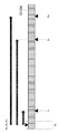
ところで、記録装置10は、購入時に、図7に示すように固定部材99が取り付けられている。この時、キャリッジ13は、キャリッジ基準センサ35が検出する基準位置Pbを固定位置Pf(図6に図示)とした位置に停止しており、記録ヘッド11およびインクタンク12が外された状態で固定部材99によって移動不能に固定されている。このため、記録装置10は、購入後のセッティング時に、図8および図9に示すように、交換用扉10dを開閉して固定部材99を外した後に、記録ヘッド11がインクタンク12と共に取り付けられる(図10を参照)。この後の電源投入で、CPU51は、記録ヘッド11の装着と交換用扉10dの閉止を検出し、その後キャリッジ基準センサ35によるキャリッジ13の検出位置を基準位置Pbに設定して、キャリッジ13をメンテナンス位置Pmに移動させ記録ヘッド11の待機動作を実行する。なお、キャリッジ13はキャリッジ基準センサ35による検出位置Pbに固定部材99によって固定されていればよく、固定部材99は固定範囲Pw(図6に図示)の範囲で固定可能になっている。また、キャリッジ13の各種位置は固定部材99に限らず、テープ固定される形態にも適用してもよい。
By the way, the
キャリッジ13は、購入後のセットアップ時やインクタンク12の交換時には、固定位置Pfや交換停止位置Pcと共通する所定位置(基準位置Pb)に停止している。したがって、セットアップ時にキャリッジ13を移動させる必要がなく、ヘッド11やインクタンク12を取り付けて素早くセットアップを行うことができる。また、セットアップ作業中に固定部材99を取り外さずに電源が投入されたとしても、不用意にキャリッジ13が移動を開始することがないので、故障(エラーや損傷)してしまうことを回避できる。なお、固定位置Pfが、基準位置Pbや交換停止位置Pcと異なる位置に設けられていると、キャリッジの固定部材を外した後に、キャリッジの動作基準となる位置決めを行うため、或いはヘッドやインクタンクを取り付けるためにキャリッジを移動させる必要があり、少なくとも、セットアップに要する時間は長くなる。
The
このように、本実施形態のシリアルスキャン方式を採用するインクジェット記録装置10においては、セットアップ作業を細心の注意を払うことなく、スムーズかつ安全に完了することができる。
As described above, in the
ここで、本実施形態の他の態様としては、図示することは省略するが、記録ヘッド11とインクタンク12を一体化したカートリッジとし、これらを一体的にキャリッジ13に着脱できるように構成してもよい。
Here, as another aspect of the present embodiment, although not shown, a cartridge in which the
また、キャリッジ13の基準位置Pbと交換停止位置Pcと固定位置Pfは、図6に示すような左側に限らず右側(本記録装置10を正面から見た場合に右側)に配置してもよい。この場合、メンテナンス位置(待機位置)Pmは、本記録装置10を正面から見た場合に左側に配置してもよい。
Further, the reference position Pb, the replacement stop position Pc, and the fixed position Pf of the
また、キャリッジ基準センサ35は、キャリッジの移動方向(主走査方向)の所定位置に設けられているが、センサをキャリッジに設け、所定位置にセンサフラグを設けても良い。
Further, although the
また、キャリッジ13の所定方向における位置を検出するために使用したリニアエンコーダ15は、ロータリーエンコーダに変更してもよい。さらに、キャリッジモータ17をパルスモータに変更して、エンコーダを使わずに、パルスモータのパルス数に基づいて、キャリッジ13の所定方向における位置決めを行ってもよい。
Further, the
本発明の範囲は、図示され記載された例示的な実施形態に限定されるものではなく、本発明が目的とするものと均等な効果をもたらすすべての実施形態をも含む。さらに、本発明の範囲は、各請求項により画される発明の特徴の組み合わせに限定されるものではなく、すべての開示されたそれぞれの特徴のうち特定の特徴のあらゆる所望する組み合わせによって画されうる。 The scope of the present invention is not limited to the exemplary embodiments illustrated and described, but also includes all embodiments that provide an effect equal to that intended by the present invention. Furthermore, the scope of the present invention is not limited to the combination of the features of the invention defined by each claim, but may be defined by any desired combination of the specific features of all the disclosed features. ..
10……記録装置
10c……外装カバー
10d……交換用扉
11……記録ヘッド
11a……ノズル形成面
12……インクタンク
13……キャリッジ
14……周回ベルト
15……リニアエンコーダ
19……メンテナンス機構
21……載置台
27……開閉センサ
35……キャリッジ基準センサ
51……CPU
60……センサ群
99……固定部材
H……ホスト装置
Pb……基準位置
Pc……交換停止位置
Pf……固定位置
Pm……メンテナンス位置
10 ……
60 ...
Claims (5)
前記記録ヘッドにインクを供給するインクタンクと、
前記記録ヘッドと前記インクタンクを保持するキャリッジと、
前記キャリッジの所定方向における位置を検出するエンコーダと、
前記キャリッジが前記所定方向における所定位置に位置することを検出するセンサと、を備え、
前記エンコーダと前記センサの検出情報に基づいて前記キャリッジを移動させつつ、前記記録ヘッドからインクを吐出させて記録媒体に画像を記録するインクジェット記録装置であって、
前記センサによって検出された前記キャリッジの前記所定位置が、
前記インクタンクを含むカートリッジを交換可能とする前記キャリッジの交換停止位置、および前記キャリッジを固定部材で固定する前記キャリッジの固定位置、になるように構成されている
ことを特徴とするインクジェット記録装置。 A recording head that ejects ink and
An ink tank that supplies ink to the recording head and
A carriage that holds the recording head and the ink tank,
An encoder that detects the position of the carriage in a predetermined direction and
A sensor that detects that the carriage is located at a predetermined position in the predetermined direction is provided.
An inkjet recording device that ejects ink from the recording head and records an image on a recording medium while moving the carriage based on the detection information of the encoder and the sensor.
The predetermined position of the carriage detected by the sensor is
An inkjet recording apparatus characterized in that it is configured to be a replacement stop position of the carriage that allows the cartridge including the ink tank to be replaced and a fixed position of the carriage that fixes the carriage with a fixing member.
前記カバーは、前記キャリッジの前記所定位置を外部に向けて開放する開口部を有し、前記開口部には開閉部材が取り付けられていることを特徴とする請求項1に記載のインクジェット記録装置。 A cover for accommodating the recording head, the ink tank, the carriage, the encoder, and each part of the device including the sensor.
The inkjet recording apparatus according to claim 1, wherein the cover has an opening that opens the predetermined position of the carriage toward the outside, and an opening / closing member is attached to the opening.
前記メンテナンス機構が配置されている位置と、前記キャリッジの前記所定位置とが、前記キャリッジの前記所定方向における前記記録ヘッドの記録動作を行う移動範囲を挟んで互いに反対側に位置するように配置されていることを特徴とする請求項1から請求項3のいずれか1項に記載のインクジェット記録装置。 Further equipped with a maintenance mechanism for maintaining the recording head,
The position where the maintenance mechanism is arranged and the predetermined position of the carriage are arranged so as to be located on opposite sides of the moving range in which the recording operation of the recording head is performed in the predetermined direction of the carriage. The inkjet recording apparatus according to any one of claims 1 to 3, wherein the inkjet recording apparatus is characterized by the above.
前記記録ヘッドにインクを供給するインクタンクと、
前記記録ヘッドと前記インクタンクを保持するキャリッジと、
前記キャリッジを所定方向に移動させるパルスモータと、
前記キャリッジが前記所定方向における所定位置に位置することを検出するセンサと、を備え、
前記パルスモータと前記センサの検出情報に基づいて前記キャリッジを移動させつつ、前記記録ヘッドからインクを吐出させて記録媒体に画像を記録するインクジェット記録装置であって、
前記センサによって検出された前記キャリッジの前記所定位置が、
前記インクタンクを含むカートリッジを交換可能とする前記キャリッジの交換停止位置、および前記キャリッジを固定部材で固定する前記キャリッジの固定位置、になるように構成されている
ことを特徴とするインクジェット記録装置。 A recording head that ejects ink and
An ink tank that supplies ink to the recording head and
A carriage that holds the recording head and the ink tank,
A pulse motor that moves the carriage in a predetermined direction,
A sensor that detects that the carriage is located at a predetermined position in the predetermined direction is provided.
An inkjet recording device that ejects ink from the recording head and records an image on a recording medium while moving the carriage based on the detection information of the pulse motor and the sensor.
The predetermined position of the carriage detected by the sensor is
An inkjet recording apparatus characterized in that it is configured to be a replacement stop position of the carriage that allows the cartridge including the ink tank to be replaced and a fixed position of the carriage that fixes the carriage with a fixing member.
Priority Applications (1)
| Application Number | Priority Date | Filing Date | Title |
|---|---|---|---|
| JP2020030490A JP2021133574A (en) | 2020-02-26 | 2020-02-26 | Ink jet recording device |
Applications Claiming Priority (1)
| Application Number | Priority Date | Filing Date | Title |
|---|---|---|---|
| JP2020030490A JP2021133574A (en) | 2020-02-26 | 2020-02-26 | Ink jet recording device |
Publications (2)
| Publication Number | Publication Date |
|---|---|
| JP2021133574A true JP2021133574A (en) | 2021-09-13 |
| JP2021133574A5 JP2021133574A5 (en) | 2023-02-16 |
Family
ID=77659823
Family Applications (1)
| Application Number | Title | Priority Date | Filing Date |
|---|---|---|---|
| JP2020030490A Pending JP2021133574A (en) | 2020-02-26 | 2020-02-26 | Ink jet recording device |
Country Status (1)
| Country | Link |
|---|---|
| JP (1) | JP2021133574A (en) |
-
2020
- 2020-02-26 JP JP2020030490A patent/JP2021133574A/en active Pending
Similar Documents
| Publication | Publication Date | Title |
|---|---|---|
| US20100231634A1 (en) | Ejection Surface Cleaning Apparatus, Liquid Ejection Apparatus and Ejection Surface Cleaning Method | |
| JP6222965B2 (en) | Recording apparatus and recording apparatus control method | |
| US20140152745A1 (en) | Image forming apparatus | |
| JP6896503B2 (en) | Inkjet recording device | |
| JP2007261127A (en) | Ink supply system, ink tank and printer | |
| JP2006088617A (en) | Inkjet recorder | |
| US20160152033A1 (en) | Liquid Ejecting Apparatus, Ultrasonic Cleaning Device, and Ultrasonic Cleaning Method | |
| JP6896502B2 (en) | Inkjet recording device and processing liquid holding unit | |
| US9409400B2 (en) | Image forming apparatus configured to include nozzle face capping control | |
| JP5463610B2 (en) | Inkjet printer | |
| JP2021133574A (en) | Ink jet recording device | |
| JP2017052161A (en) | Liquid discharge device | |
| US8672446B2 (en) | Image forming apparatus including recording head for ejecting liquid droplets | |
| JP5299099B2 (en) | Inkjet recording head unit and inkjet recording apparatus | |
| JPH10286976A (en) | Ink jet recorder | |
| US6170946B1 (en) | Image forming device | |
| JP2001347651A (en) | Ink jet recording apparatus | |
| JP2006198924A (en) | Inkjet recorder, control method, program, and recording medium | |
| JP4670274B2 (en) | RECORDING MEDIUM CONVEYING BODY OF LIQUID EJECTING DEVICE, LIQUID EJECTING DEVICE | |
| JP4658392B2 (en) | Inkjet recording device | |
| JP4630558B2 (en) | Recording apparatus and recovery control method | |
| JP2011161762A (en) | Inkjet recorder and reserve discharging method | |
| JP2006264205A (en) | Image forming device | |
| KR20190002707A (en) | Printing subassembly | |
| JP2006062127A (en) | Cleaning method |
Legal Events
| Date | Code | Title | Description |
|---|---|---|---|
| A521 | Request for written amendment filed |
Free format text: JAPANESE INTERMEDIATE CODE: A523 Effective date: 20230208 |
|
| A621 | Written request for application examination |
Free format text: JAPANESE INTERMEDIATE CODE: A621 Effective date: 20230208 |
|
| A977 | Report on retrieval |
Free format text: JAPANESE INTERMEDIATE CODE: A971007 Effective date: 20231122 |
|
| A131 | Notification of reasons for refusal |
Free format text: JAPANESE INTERMEDIATE CODE: A131 Effective date: 20231205 |