JP2021129796A - Game machine - Google Patents
Game machine Download PDFInfo
- Publication number
- JP2021129796A JP2021129796A JP2020026792A JP2020026792A JP2021129796A JP 2021129796 A JP2021129796 A JP 2021129796A JP 2020026792 A JP2020026792 A JP 2020026792A JP 2020026792 A JP2020026792 A JP 2020026792A JP 2021129796 A JP2021129796 A JP 2021129796A
- Authority
- JP
- Japan
- Prior art keywords
- game
- display
- state
- effect
- displayed
- Prior art date
- Legal status (The legal status is an assumption and is not a legal conclusion. Google has not performed a legal analysis and makes no representation as to the accuracy of the status listed.)
- Withdrawn
Links
- 230000008859 change Effects 0.000 claims description 169
- 230000007423 decrease Effects 0.000 abstract description 29
- 230000000694 effects Effects 0.000 description 1473
- 238000000034 method Methods 0.000 description 724
- 230000008569 process Effects 0.000 description 709
- 230000009467 reduction Effects 0.000 description 477
- 238000003860 storage Methods 0.000 description 188
- 238000012790 confirmation Methods 0.000 description 160
- 238000012545 processing Methods 0.000 description 142
- 238000004519 manufacturing process Methods 0.000 description 104
- 238000012986 modification Methods 0.000 description 90
- 230000004048 modification Effects 0.000 description 90
- 230000008901 benefit Effects 0.000 description 50
- 230000007704 transition Effects 0.000 description 47
- 238000011084 recovery Methods 0.000 description 44
- 230000001965 increasing effect Effects 0.000 description 30
- 230000006870 function Effects 0.000 description 29
- 239000000872 buffer Substances 0.000 description 28
- 230000015654 memory Effects 0.000 description 28
- 230000002829 reductive effect Effects 0.000 description 25
- 238000004904 shortening Methods 0.000 description 23
- 238000001514 detection method Methods 0.000 description 22
- 238000010586 diagram Methods 0.000 description 22
- 230000004044 response Effects 0.000 description 21
- 208000019901 Anxiety disease Diseases 0.000 description 18
- 230000036506 anxiety Effects 0.000 description 18
- 238000007781 pre-processing Methods 0.000 description 16
- 230000001960 triggered effect Effects 0.000 description 16
- OMFRMAHOUUJSGP-IRHGGOMRSA-N bifenthrin Chemical compound C1=CC=C(C=2C=CC=CC=2)C(C)=C1COC(=O)[C@@H]1[C@H](\C=C(/Cl)C(F)(F)F)C1(C)C OMFRMAHOUUJSGP-IRHGGOMRSA-N 0.000 description 15
- 230000014759 maintenance of location Effects 0.000 description 15
- 239000012536 storage buffer Substances 0.000 description 14
- 238000004458 analytical method Methods 0.000 description 12
- 238000010304 firing Methods 0.000 description 11
- 238000013461 design Methods 0.000 description 10
- 230000002542 deteriorative effect Effects 0.000 description 10
- 208000001613 Gambling Diseases 0.000 description 9
- 239000011521 glass Substances 0.000 description 9
- 238000009795 derivation Methods 0.000 description 8
- 230000005540 biological transmission Effects 0.000 description 7
- 230000006866 deterioration Effects 0.000 description 7
- 230000008450 motivation Effects 0.000 description 7
- 238000005259 measurement Methods 0.000 description 6
- 238000007792 addition Methods 0.000 description 5
- 238000012805 post-processing Methods 0.000 description 5
- 238000004891 communication Methods 0.000 description 4
- 230000001747 exhibiting effect Effects 0.000 description 4
- 230000006872 improvement Effects 0.000 description 4
- 230000009471 action Effects 0.000 description 3
- 238000013459 approach Methods 0.000 description 3
- 230000002844 continuous effect Effects 0.000 description 3
- 238000005520 cutting process Methods 0.000 description 3
- 230000003247 decreasing effect Effects 0.000 description 3
- 230000029087 digestion Effects 0.000 description 3
- 230000033001 locomotion Effects 0.000 description 3
- 238000003825 pressing Methods 0.000 description 3
- 230000005856 abnormality Effects 0.000 description 2
- 238000004590 computer program Methods 0.000 description 2
- 238000011161 development Methods 0.000 description 2
- 238000003745 diagnosis Methods 0.000 description 2
- 238000005401 electroluminescence Methods 0.000 description 2
- 230000002708 enhancing effect Effects 0.000 description 2
- 230000014509 gene expression Effects 0.000 description 2
- 230000001788 irregular Effects 0.000 description 2
- 230000001737 promoting effect Effects 0.000 description 2
- 230000001360 synchronised effect Effects 0.000 description 2
- 238000012360 testing method Methods 0.000 description 2
- QNRATNLHPGXHMA-XZHTYLCXSA-N (r)-(6-ethoxyquinolin-4-yl)-[(2s,4s,5r)-5-ethyl-1-azabicyclo[2.2.2]octan-2-yl]methanol;hydrochloride Chemical compound Cl.C([C@H]([C@H](C1)CC)C2)CN1[C@@H]2[C@H](O)C1=CC=NC2=CC=C(OCC)C=C21 QNRATNLHPGXHMA-XZHTYLCXSA-N 0.000 description 1
- 241000675108 Citrus tangerina Species 0.000 description 1
- 241000722921 Tulipa gesneriana Species 0.000 description 1
- 230000004397 blinking Effects 0.000 description 1
- 239000004020 conductor Substances 0.000 description 1
- 238000010924 continuous production Methods 0.000 description 1
- 239000004148 curcumin Substances 0.000 description 1
- 238000005034 decoration Methods 0.000 description 1
- 230000003111 delayed effect Effects 0.000 description 1
- 230000008034 disappearance Effects 0.000 description 1
- 239000000284 extract Substances 0.000 description 1
- 238000005286 illumination Methods 0.000 description 1
- 230000002452 interceptive effect Effects 0.000 description 1
- 230000000670 limiting effect Effects 0.000 description 1
- 239000004973 liquid crystal related substance Substances 0.000 description 1
- 230000007774 longterm Effects 0.000 description 1
- 239000000203 mixture Substances 0.000 description 1
- 238000012544 monitoring process Methods 0.000 description 1
- 230000000717 retained effect Effects 0.000 description 1
- 239000002151 riboflavin Substances 0.000 description 1
- 229920003002 synthetic resin Polymers 0.000 description 1
- 239000000057 synthetic resin Substances 0.000 description 1
Images


Abstract
Description
本発明は、パチンコ遊技機等の遊技機に関する。 The present invention relates to a gaming machine such as a pachinko gaming machine.
遊技機として、遊技球などの遊技媒体を発射装置によって遊技領域に発射し、遊技領域に設けられている入賞口などの入賞領域に遊技媒体が入賞して実行条件(始動条件)が成立すると、複数種類の識別情報(以下、表示図柄)を可変表示装置にて可変表示し、その表示結果により所定の遊技価値を付与するか否かを決定する、いわゆる可変表示ゲームによって遊技興趣を高めたパチンコ遊技機がある。こうしたパチンコ遊技機では、可変表示ゲームにおける表示図柄の可変表示が完全に停止した際の停止図柄態様が特定表示態様となったときに、遊技者にとって有利な有利状態(大当り遊技状態)となる。大当り遊技状態では、大入賞口が開放状態となるラウンド遊技を所定の上限回数まで繰り返し実行可能となっている。 As a gaming machine, when a gaming medium such as a gaming ball is launched into the gaming area by a launching device, the gaming medium wins a prize in a winning area such as a winning opening provided in the gaming area, and an execution condition (starting condition) is satisfied. Pachinko that enhances the interest of the game by a so-called variable display game in which a plurality of types of identification information (hereinafter referred to as display symbols) are variably displayed on a variable display device and whether or not to give a predetermined game value is determined based on the display result. There is a game machine. In such a pachinko gaming machine, when the stop symbol mode when the variable display of the display symbol in the variable display game is completely stopped becomes the specific display mode, the pachinko gaming machine becomes an advantageous state (big hit game state) that is advantageous to the player. In the big hit game state, the round game in which the big winning opening is open can be repeatedly executed up to a predetermined upper limit number of times.
このような遊技機として、ラウンド数の表示切り替えタイミングよりも大入賞口の開放を早い遊技機が提案されている(例えば、特許文献1参照)。 As such a gaming machine, a gaming machine has been proposed in which the opening of the large winning opening is earlier than the timing of switching the display of the number of rounds (see, for example, Patent Document 1).
しかしながら、特許文献1に記載の遊技機では、ラウンド数の表示が行われる前に遊技媒体を発射してしまった場合における大入賞口への入賞の可能性は高まるものの、好適に獲得出玉数を表示するという観点からすると未だ十分ではなく、遊技者に不安感を与え遊技興趣を低下させてしまうおそれがあった。
However, in the gaming machine described in
本発明は、上記実状に鑑みてなされたものであり、遊技興趣の低下を防止することのできる遊技機の提供を目的とする。 The present invention has been made in view of the above circumstances, and an object of the present invention is to provide a gaming machine capable of preventing a decline in the interest in gaming.
上記目的を達成するため、本発明に係る遊技機は、第1識別情報の可変表示および第2識別情報の可変表示を実行し、特定表示結果(例えば、大当り図柄)が導出表示されたときに有利な有利状態(例えば、大当り遊技状態)に制御可能な遊技機であって、
表示手段(例えば画像表示装置5への表示内容を指示する演出制御用CPU120など)と、
遊技媒体が入賞容易な第1状態と、遊技媒体が入賞不能または困難な第2状態とに変化可能な可変入賞手段(例えば特別可変入賞球装置7など)と、
前記有利状態に制御されているときに、前記可変入賞手段を前記第2状態から前記第1状態に変化させた後に前記第2状態へと変化させるラウンド遊技を複数回実行可能な制御手段(例えばラウンド遊技を行うCPU103など)と、を備え、
前記表示手段は、
前記可変入賞手段へ遊技媒体が入賞したことで付与された遊技用価値の付与量に関する付与量表示を表示可能であり(例えば獲得数表示を行うなど)、
複数回の前記ラウンド遊技のうち最初の前記ラウンド遊技が行われるときに、前記可変入賞手段が前記第2状態から前記第1状態へと変化した後の所定期間経過後に前記付与量表示を表示し(例えば第1ラウンドにおいて、大入賞口が開放状態となった後所定期間経過後に獲得数表示を行うなど)、
前記所定期間内に遊技媒体が前記可変入賞手段に入賞しない場合は、前記所定期間経過後に前記付与量表示として前記遊技用価値が付与されていないことに対応する所定表示を表示し(例えば獲得数表示として「0000」を表示するなど)、
前記所定期間内に遊技媒体が前記可変入賞手段に入賞した場合は、前記所定期間経過後に前記付与量表示として前記所定表示とは異なる特定表示を表示し(例えば獲得数表示として「0015」を表示するなど)、
さらに、
通常状態よりも可変表示が実行されやすい特別状態(例えば、時短状態)に制御可能な状態制御手段(例えば、図8−17に示すように、遊技制御用マイクロコンピュータ100におけるステップ100IWS166、ステップ100IWS173を実行する部分、図8−19に示すように、遊技制御用マイクロコンピュータ100におけるステップ100IWS537を実行する部分)と、可変表示が実行されることにもとづいて数値情報を更新可能な更新手段(例えば、図8−13に示すように、遊技制御用マイクロコンピュータ100におけるステップ100IWS71を実行する部分)と、を備え、状態制御手段は、更新手段が更新した数値情報が特別回数に対応する特定値となることによって特別条件が成立したときに特別状態に制御可能であり(例えば、図8−13に示すように、遊技制御用マイクロコンピュータ100におけるステップ100IWS74、ステップ100IWS75を実行する部分、図8−17に示すように、遊技制御用マイクロコンピュータ100におけるステップ100IWS172、ステップ100IWS173を実行する部分)、更新手段は、第1識別情報の可変表示が実行される場合と第2識別情報の可変表示が実行される場合とで数値情報を更新する(例えば、図8−13に示すように、遊技制御用マイクロコンピュータ100におけるステップ100IWS71を実行する部分)、ことを特徴とする。
ことを特徴とする。
In order to achieve the above object, the gaming machine according to the present invention executes the variable display of the first identification information and the variable display of the second identification information, and when the specific display result (for example, a jackpot symbol) is derived and displayed. A gaming machine that can be controlled to an advantageous advantageous state (for example, a jackpot gaming state).
Display means (for example, an
A variable winning means (for example, a special variable winning ball device 7) capable of changing the game medium into a first state in which the game medium is easy to win and a second state in which the game medium is impossible or difficult to win.
A control means (for example, a control means capable of executing a round game in which the variable winning means is changed from the second state to the first state and then changed to the second state a plurality of times when the variable winning means is controlled to the advantageous state. CPU103 that performs round games, etc.)
The display means
It is possible to display the grant amount display regarding the grant amount of the game value given by the game medium winning the variable winning means (for example, displaying the number of acquisitions).
When the first round game of the plurality of round games is performed, the grant amount display is displayed after a predetermined period of time has elapsed after the variable winning means changes from the second state to the first state. (For example, in the first round, the number of winnings is displayed after a predetermined period has passed after the big winning opening is opened),
If the game medium does not win the variable winning means within the predetermined period, a predetermined display corresponding to the fact that the game value is not given is displayed as the grant amount display after the lapse of the predetermined period (for example, the number of acquisitions). Display "0000" as a display, etc.),
When the game medium wins the variable winning means within the predetermined period, a specific display different from the predetermined display is displayed as the grant amount display after the lapse of the predetermined period (for example, "0015" is displayed as the acquisition number display. Etc.),
Moreover,
It is characterized by that.
このような構成によれば、所定期間内に入賞した場合に特定表示を行うため、遊技者に不安感を与えることなく遊技興趣の低下を防止することができる。遊技者の救済を好適に実現できる。具体的には、遊技状態が変化して、いずれの識別情報の可変表示が実行される状況であっても数値情報の更新が継続するので遊技者が救済されやすくなり、遊技の意欲を高めることができる。 According to such a configuration, since the specific display is performed when a prize is won within a predetermined period, it is possible to prevent a deterioration of the game interest without giving anxiety to the player. Relief of the player can be preferably realized. Specifically, even if the game state changes and the variable display of any identification information is executed, the numerical information is continuously updated, so that the player can be easily rescued and the motivation for the game is increased. Can be done.
また、後述する発明を実施するための形態には、以下の手段Aに係る発明が含まれる。従来より遊技機において特開2005−95449号公報に示されているような、通常状態よりも可変表示が実行されやすい特別状態に制御可能な遊技機が知られている。例えば、特許文献1には、通常の遊技状態で実行された特図ゲームの回数(可変表示の実行回数)が1000回(特別回数)に達しても大当り(有利状態)が発生しないときには(特別条件の成立)、遊技状態が確変状態に制御され、特図ゲームの結果として大当りとすることが決定される確率が1/100程度に高められ、以降の特図ゲームでは大当りが発生しやすくなることが記載されている。また、特許文献1には、通常の遊技状態で特図ゲームの回数(可変表示の実行回数)が1000回に達しても大当りが生じなかったときに、確変状態の代わりに時短状態を発生させるものとしてもよいことが記載されている。
In addition, the embodiment for carrying out the invention described later includes the invention according to the following means A. Conventionally, there are known gaming machines that can be controlled to a special state in which variable display is more likely to be executed than in a normal state, as shown in Japanese Patent Application Laid-Open No. 2005-95449. For example, in
しかし、従来の遊技機では、可変表示の実行回数が特別回数に達するときや、その前後の期間における興趣の検討が不十分であった。 However, with conventional gaming machines, it has been insufficient to examine the interests when the number of times the variable display is executed reaches a special number or during the period before and after that.
そこで、この発明は、興趣に富む遊技機を提供することを目的とする。 Therefore, it is an object of the present invention to provide a game machine rich in interest.
(手段A)この発明による遊技機は、第1識別情報の可変表示および第2識別情報の可変表示を実行し、特定表示結果(例えば、大当り図柄)が導出表示されたときに有利な有利状態(例えば、大当り遊技状態)に制御可能な遊技機であって、通常状態よりも可変表示が実行されやすい特別状態(例えば、時短状態)に制御可能な状態制御手段(例えば、図12−17に示すように、遊技制御用マイクロコンピュータ100におけるステップ100IWS166、ステップ100IWS173を実行する部分、図12−19に示すように、遊技制御用マイクロコンピュータ100におけるステップ100IWS537を実行する部分)と、可変表示が実行されることにもとづいて数値情報を更新可能な更新手段(例えば、図12−13に示すように、遊技制御用マイクロコンピュータ100におけるステップ100IWS71を実行する部分)と、を備え、状態制御手段は、更新手段が更新した数値情報が、可変表示の実行回数としての特別回数に対応する特定値となることによって特別条件が成立したときに特別状態に制御可能であり(例えば、図12−13に示すように、遊技制御用マイクロコンピュータ100におけるステップ100IWS74、ステップ100IWS75を実行する部分、図12−17に示すように、遊技制御用マイクロコンピュータ100におけるステップ100IWS170、ステップ100IWS173を実行する部分)、更新手段は、第1識別情報の可変表示が実行される場合と第2識別情報の可変表示が実行される場合とで数値情報を更新し(例えば、図12−13に示すように、遊技制御用マイクロコンピュータ100におけるステップ100IWS71を実行する部分)、可変表示が実行されているときに所定示唆演出(例えば、予告演出)を実行可能な所定示唆演出実行手段(例えば、図12−49に示すように、演出制御用CPU120におけるステップ108IWS811を実行する部分)と、特別条件が成立したことにもとづいて、特別状態の制御が開始される旨を報知する特別報知演出(例えば、図12−52(C1),(C2)に示すように背景画像が変化する、図12−53(B)に示すように変動開始時にブラックアウトする、図12−54(C)に示すように変動終了時にブラックアウトする等)を実行可能な特別報知演出実行手段と(例えば、図12―23に示すように、演出制御用CPU120がステップ100IWS638を実行する部分)、をさらに備え、所定示唆演出実行手段は、特別条件が成立する前の期間において、所定示唆演出を実行する割合が共通である(例えば、図12―44に示すように、演出制御用CPU120がステップ108IWS802Aを実行する部分。図12−50参照)。
そのような構成によれば、特別報知演出が突然実行されることにより遊技者に意外性を与えて、興趣を向上させることができる。
(Means A) The gaming machine according to the present invention executes variable display of the first identification information and variable display of the second identification information, and is in an advantageous state when a specific display result (for example, a jackpot symbol) is derived and displayed. A state control means (for example, FIG. 12-17) that is a game machine that can be controlled to (for example, a big hit game state) and can be controlled to a special state (for example, a time saving state) in which variable display is more likely to be executed than a normal state. As shown, step 100IWS166 in the
According to such a configuration, the player can be surprised by suddenly executing the special notification effect, and the interest can be improved.
尚、この発明は、この発明の請求項に記載された発明特定事項のみを有するものであって良いし、この発明の請求項に記載された発明特定事項とともに該発明特定事項以外の構成を有するものであっても良い。 The present invention may have only the invention-specific matters described in the claims of the present invention, and has a configuration other than the invention-specific matters together with the invention-specific matters described in the claims of the present invention. It may be a thing.
(基本説明)
まず、パチンコ遊技機1の基本的な構成及び制御(一般的なパチンコ遊技機の構成及び制御でもある。)について説明する。
(Basic explanation)
First, the basic configuration and control of the pachinko gaming machine 1 (also the configuration and control of a general pachinko gaming machine) will be described.
(パチンコ遊技機1の構成等)
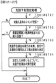
図1は、パチンコ遊技機1の正面図であり、主要部材の配置レイアウトを示す。パチンコ遊技機(遊技機)1は、大別して、遊技盤面を構成する遊技盤(ゲージ盤)2と、遊技盤2を支持固定する遊技機用枠(台枠)3とから構成されている。遊技盤2には、遊技領域が形成され、この遊技領域には、遊技媒体としての遊技球が、所定の打球発射装置から発射されて打ち込まれる。
(Configuration of
FIG. 1 is a front view of the
なお、特別図柄の「可変表示」とは、例えば、複数種類の特別図柄を変動可能に表示することである(後述の他の図柄についても同じ)。変動としては、複数の図柄の更新表示、複数の図柄のスクロール表示、1以上の図柄の変形、1以上の図柄の拡大/縮小などがある。特別図柄や後述の普通図柄の変動では、複数種類の特別図柄又は普通図柄が更新表示される。後述の飾り図柄の変動では、複数種類の飾り図柄がスクロール表示又は更新表示されたり、1以上の飾り図柄が変形や拡大/縮小されたりする。なお、変動には、ある図柄を点滅表示する態様も含まれる。可変表示の最後には、表示結果として所定の特別図柄が停止表示(導出または導出表示などともいう)される(後述の他の図柄の可変表示についても同じ)。なお、可変表示を変動表示、変動と表現する場合がある。 The "variable display" of the special symbol is, for example, to display a plurality of types of special symbols in a variable manner (the same applies to other symbols described later). Fluctuations include update display of a plurality of symbols, scroll display of a plurality of symbols, deformation of one or more symbols, enlargement / reduction of one or more symbols, and the like. When the special symbol or the ordinary symbol described later is changed, a plurality of types of special symbols or ordinary symbols are updated and displayed. In the variation of the decorative symbol described later, a plurality of types of decorative symbols are scrolled or updated, and one or more decorative symbols are deformed or enlarged / reduced. The variation also includes a mode in which a certain symbol is blinked and displayed. At the end of the variable display, a predetermined special symbol is stopped and displayed (also referred to as derivation or derivation display) as a display result (the same applies to the variable display of other symbols described later). The variable display may be expressed as a variable display or a variable display.
なお、第1特別図柄表示装置4Aにおいて可変表示される特別図柄を「第1特図」ともいい、第2特別図柄表示装置4Bにおいて可変表示される特別図柄を「第2特図」ともいう。また、第1特図を用いた特図ゲームを「第1特図ゲーム」といい、第2特図を用いた特図ゲームを「第2特図ゲーム」ともいう。なお、特別図柄の可変表示を行う特別図柄表示装置は1種類であってもよい。
The special symbol variably displayed on the first special
遊技盤2における遊技領域の中央付近には画像表示装置5が設けられている。画像表示装置5は、例えばLCD(液晶表示装置)や有機EL(Electro Luminescence)等から構成され、各種の演出画像を表示する。画像表示装置5は、プロジェクタおよびスクリーンから構成されていてもよい。画像表示装置5には、各種の演出画像が表示される。
An
例えば、画像表示装置5の画面上では、第1特図ゲームや第2特図ゲームと同期して、特別図柄とは異なる複数種類の装飾識別情報としての飾り図柄(数字などを示す図柄など)の可変表示が行われる。ここでは、第1特図ゲームまたは第2特図ゲームに同期して、「左」、「中」、「右」の各飾り図柄表示エリア5L、5C、5Rにおいて飾り図柄が可変表示(例えば上下方向のスクロール表示や更新表示)される。なお、同期して実行される特図ゲームおよび飾り図柄の可変表示を総称して単に可変表示ともいう。
For example, on the screen of the
画像表示装置5の画面上には、実行が保留されている可変表示に対応する保留表示や、実行中の可変表示に対応するアクティブ表示を表示するための表示エリアが設けられていてもよい。保留表示およびアクティブ表示を総称して可変表示に対応する可変表示対応表示ともいう。
On the screen of the
保留されている可変表示の数は保留記憶数ともいう。第1特図ゲームに対応する保留記憶数を第1保留記憶数、第2特図ゲームに対応する保留記憶数を第2保留記憶数ともいう。第1保留記憶数と第2保留記憶数との合計を合計保留記憶数ともいう。 The number of variable displays on hold is also called the number of stored items on hold. The number of reserved storage corresponding to the first special figure game is also referred to as the first reserved storage number, and the number of reserved storage corresponding to the second special figure game is also referred to as the second reserved storage number. The total of the first reserved storage number and the second reserved storage number is also referred to as the total reserved storage number.
遊技盤2の所定位置には、複数のLEDを含んで構成された第1保留表示器25Aと第2保留表示器25Bとが設けられている。第1保留表示器25Aは、LEDの点灯個数によって、第1保留記憶数を表示する。第2保留表示器25Bは、LEDの点灯個数によって、第2保留記憶数を表示する。
At a predetermined position of the
画像表示装置5の下方には入賞球装置6Aが設けられており、該入賞球装置6Aの右側方には、可変入賞球装置6Bが設けられている。
A winning
入賞球装置6Aは、例えば所定の玉受部材によって常に遊技球が進入可能な一定の開放状態に保たれる第1始動入賞口を形成する。第1始動入賞口に遊技球が進入したときには、所定個(例えば3個)の賞球が払い出されるとともに、第1特図ゲームが開始され得る。
The winning
可変入賞球装置6B(普通電動役物)は、ソレノイド81(図3参照)によって閉鎖状態と開放状態とに変化する第2始動入賞口を形成する。可変入賞球装置6Bは、例えば、一対の可動翼片を有する電動チューリップ型役物を備え、ソレノイド81がオフ状態であるときに可動翼片が垂直位置となることにより、当該可動翼片の先端が入賞球装置6Aに近接し、第2始動入賞口に遊技球が進入しない閉鎖状態になる(第2始動入賞口が閉鎖状態になるともいう。)。その一方で、可変入賞球装置6Bは、ソレノイド81がオン状態であるときに可動翼片が傾動位置となることにより、第2始動入賞口に遊技球が進入できる開放状態になる(第2始動入賞口が開放状態になるともいう。)。第2始動入賞口に遊技球が進入したときには、所定個(例えば3個)の賞球が払い出されるとともに、第2特図ゲームが開始され得る。なお、可変入賞球装置6Bは、閉鎖状態と開放状態とに変化するものであればよく、電動チューリップ型役物を備えるものに限定されない。
The variable winning
遊技盤2の所定位置(図1に示す例では、遊技領域の左下方3箇所と可変入賞球装置6Bの上方1箇所)には、所定の玉受部材によって常に一定の開放状態に保たれる一般入賞口10が設けられる。この場合には、一般入賞口10のいずれかに進入したときには、所定個数(例えば3個)の遊技球が賞球として払い出される。
A predetermined ball receiving member always keeps a constant open state at a predetermined position of the game board 2 (in the example shown in FIG. 1, three places on the lower left of the game area and one place on the upper side of the variable winning
入賞球装置6Aと可変入賞球装置6Bとの間には、大入賞口を有する特別可変入賞球装置7が設けられている。特別可変入賞球装置7は、ソレノイド82(図3参照)によって開閉駆動される大入賞口扉を備え、その大入賞口扉によって開放状態と閉鎖状態とに変化する特定領域としての大入賞口を形成する。
A special variable winning
一例として、特別可変入賞球装置7では、大入賞口扉用(特別電動役物用)のソレノイド82がオフ状態であるときに大入賞口扉が大入賞口を閉鎖状態として、遊技球が大入賞口に進入(通過)できなくなる。その一方で、特別可変入賞球装置7では、大入賞口扉用のソレノイド82がオン状態であるときに大入賞口扉が大入賞口を開放状態として、遊技球が大入賞口に進入しやすくなる。
As an example, in the special variable winning
大入賞口に遊技球が進入したときには、所定個数(例えば15個)の遊技球が賞球として払い出される。大入賞口に遊技球が進入したときには、例えば第1始動入賞口や第2始動入賞口および一般入賞口10に遊技球が進入したときよりも多くの賞球が払い出される。
When a game ball enters the large prize opening, a predetermined number (for example, 15) of game balls are paid out as prize balls. When a game ball enters the large winning opening, more prize balls are paid out than when the game ball enters, for example, the first starting winning opening, the second starting winning opening, and the general winning
一般入賞口10を含む各入賞口に遊技球が進入することを「入賞」ともいう。特に、始動口(第1始動入賞口、第2始動入賞口)への入賞を始動入賞ともいう。
The entry of a game ball into each winning opening including the general winning
遊技盤2の所定位置(図1に示す例では、遊技領域の左下方)には、普通図柄表示器20が設けられている。一例として、普通図柄表示器20は、7セグメントのLEDなどからなり、特別図柄とは異なる複数種類の普通識別情報としての普通図柄の可変表示を行う。普通図柄は、「0」〜「9」を示す数字や「−」などの点灯パターンなどにより表される。普通図柄には、LEDを全て消灯したパターンが含まれてもよい。このような普通図柄の可変表示は、普図ゲームともいう。
A
画像表示装置5の右方には、遊技球が通過可能な通過ゲート41が設けられている。遊技球が通過ゲート41を通過したことに基づき、普図ゲームが実行される。
A passing
普通図柄表示器20の下方には、普図保留表示器25Cが設けられている。普図保留表示器25Cは、例えば4個のLEDを含んで構成され、実行が保留されている普図ゲームの数である普図保留記憶数をLEDの点灯個数により表示する。
Below the
遊技盤2の表面には、上記の構成以外にも、遊技球の流下方向や速度を変化させる風車および多数の障害釘が設けられている。遊技領域の最下方には、いずれの入賞口にも進入しなかった遊技球が取り込まれるアウト口が設けられている。
In addition to the above configuration, the surface of the
遊技機用枠3の左右上部位置には、効果音等を再生出力するためのスピーカ8L、8Rが設けられている。遊技機用枠3における画像表示装置5の上方位置にはメインランプ9aが設けられており、該メインランプ9aの左右には、遊技領域を包囲するように枠ランプ9bが設けられている。当該枠ランプ9bは、図示するように、左側下部分の左下ランプ9bL1と左側上部分の左上ランプ9bL2と、右側下部分の右下ランプ9bR1と右側上部分の右上ランプ9bR2とがある。更に、遊技盤2における特別可変入賞球装置7の近傍位置にはアタッカランプ9cが設けられている。また、スピーカ8L、8R部分には、それぞれに対応してスピーカランプ9eL、9eRが設けられている。遊技盤2における画像表示装置5の下方位置には表示装置下ランプ9fが設けられており、表示装置下ランプ9fは、図示するように、左側表示装置下ランプ9fLと右側表示装置下ランプ9fRとがある。また、遊技領域の左下方3箇所に設けられた一般入賞口10の近傍には一般入賞口近傍ランプ9gが設けられている。
遊技盤2の所定位置(図1では画像表示装置5の上方位置)には、演出に応じて動作する可動体32が設けられている。また、可動体32には、可動体ランプ9dが設けられている。該可動体ランプ9dと前述したメインランプ9a、枠ランプ9b、アタッカランプ9c、スピーカランプ9eL、9eR、表示装置下ランプ9f、一般入賞口近傍ランプ9gとは纏めて遊技効果ランプ9と呼称する場合がある。尚、これらメインランプ9a、枠ランプ9b、アタッカランプ9c、可動体ランプ9d、スピーカランプ9eL、9eR、表示装置下ランプ9f、一般入賞口近傍ランプ9gは、LEDを含んで構成されている。
At a predetermined position of the game board 2 (upper position of the
遊技機用枠3の右下部位置には、遊技球を打球発射装置により遊技領域に向けて発射するために遊技者等によって操作される打球操作ハンドル(操作ノブ)30が設けられている。
At the lower right position of the
遊技領域の下方における遊技機用枠3の所定位置には、賞球として払い出された遊技球や所定の球貸機により貸し出された遊技球を、打球発射装置へと供給可能に保持(貯留)する打球供給皿(上皿)が設けられている。上皿の下方には、上皿満タン時に賞球が払い出される打球供給皿(下皿)が設けられている。
At a predetermined position of the
遊技領域の下方における遊技機用枠3の所定位置には、遊技者が把持して傾倒操作が可能なスティックコントローラ31Aが取り付けられている。スティックコントローラ31Aには、遊技者が押下操作可能なトリガボタンが設けられている。スティックコントローラ31Aに対する操作は、コントローラセンサユニット35A(図3参照)により検出される。
A
遊技領域の下方における遊技機用枠3の所定位置には、遊技者が押下操作などにより所定の指示操作を可能なプッシュボタン31Bが設けられている。プッシュボタン31Bに対する操作は、プッシュセンサ35B(図3参照)により検出される。
A
パチンコ遊技機1では、遊技者の動作(操作等)を検出する検出手段として、スティックコントローラ31Aやプッシュボタン31Bが設けられるが、これら以外の検出手段が設けられていてもよい。
In the
図2は、パチンコ遊技機1の背面斜視図である。パチンコ遊技機1の背面には、基板ケース201に収納された主基板11が搭載されている。主基板11には、設定キー51や設定切替スイッチ52が設けられている。設定キー51は、設定変更状態または設定確認状態に切り替えるための錠スイッチとして機能する。設定切替スイッチ52は、設定変更状態において大当りの当選確率や出玉率等の設定値を変更するための設定スイッチとして機能する。設定キー51や設定切替スイッチ52は、例えば電源基板17の所定位置といった、主基板11の外部に取り付けられてもよい。
FIG. 2 is a rear perspective view of the
主基板11の背面中央には、表示モニタ29が配置され、表示モニタ29の側方には表示切替スイッチ31が配置されている。表示モニタ29は、例えば7セグメントのLED表示装置を用いて、構成されていればよい。表示モニタ29および表示切替スイッチ31は、遊技機用枠3を開放した状態で遊技盤2の裏面側を視認した場合に、主基板11を視認する際の正面に配置されている。
A display monitor 29 is arranged in the center of the back surface of the
表示モニタ29は、例えば連比や役比、ベースなどの入賞情報を表示可能である。連比は、賞球合計数のうち大入賞口(アタッカー)への入賞による賞球数が占める割合である。役比は、賞球合計数のうち第2始動入賞口(電チュー)への入賞による賞球数と大入賞口(アタッカー)への入賞による賞球数が占める割合である。ベースは、打ち出した遊技球数に対する賞球合計数が占める割合である。設定変更状態や設定確認状態であるときに、表示モニタ29は、パチンコ遊技機1における設定値を表示可能である。表示モニタ29は、設定変更状態や設定確認状態であるときに、変更や確認の対象となる設定値などを表示可能であればよい。
The display monitor 29 can display winning information such as a continuous ratio, a combination ratio, and a base. The ream ratio is the ratio of the number of prize balls by winning a prize to the big prize opening (attacker) to the total number of prize balls. The role ratio is the ratio of the number of prize balls by winning the second starting winning opening (Denchu) and the number of winning balls by winning the big winning opening (attacker) to the total number of prize balls. The base is the ratio of the total number of prize balls to the number of game balls launched. The display monitor 29 can display the set value in the
設定キー51や設定切替スイッチ52は、遊技機用枠3を閉鎖した状態であるときに、パチンコ遊技機1の正面側から操作が不可能となっている。遊技機用枠3には、ガラス窓を有するガラス扉枠3aが回動可能に設けられ、ガラス扉枠3aにより遊技領域を開閉可能に構成されている。ガラス扉枠3aを閉鎖したときに、ガラス窓を通して遊技領域を透視可能である。
The setting
パチンコ遊技機1において、縦長の方形枠状に形成された外枠1aの右端部には、セキュリティカバー500Aが取り付けられている。セキュリティカバー500Aは、遊技機用枠3を閉鎖したときに、設定キー51や設定切替スイッチ52を含む基板ケース201の右側部を、背面側から被覆する。セキュリティカバー500Aは、短片500Aaおよび長片500Abを含む略L字状の部材であり、透明性を有する合成樹脂により構成されていればよい。
In the
(遊技の進行の概略)
パチンコ遊技機1が備える打球操作ハンドル30への遊技者による回転操作により、遊技球が遊技領域に向けて発射される。遊技球が通過ゲート41を通過すると、普通図柄表示器20による普図ゲームが開始される。なお、前回の普図ゲームの実行中の期間等に遊技球が通過ゲート41を通過した場合(遊技球が通過ゲート41を通過したが当該通過に基づく普図ゲームを直ちに実行できない場合)には、当該通過に基づく普図ゲームは所定の上限数(例えば4)まで保留される。
(Outline of the progress of the game)
The game ball is launched toward the game area by the rotation operation of the
この普図ゲームでは、特定の普通図柄(普図当り図柄)が停止表示されれば、普通図柄の表示結果が「普図当り」となる。その一方、確定普通図柄として、普図当り図柄以外の普通図柄(普図ハズレ図柄)が停止表示されれば、普通図柄の表示結果が「普図ハズレ」となる。「普図当り」となると、可変入賞球装置6Bを所定期間開放状態とする開放制御が行われる(第2始動入賞口が開放状態になる)。
In this normal symbol game, if a specific normal symbol (design per normal symbol) is stopped and displayed, the display result of the normal symbol becomes "per normal symbol". On the other hand, if a normal symbol other than a normal symbol (a common symbol lost symbol) is stopped and displayed as a confirmed normal symbol, the display result of the normal symbol becomes "normal symbol lost". When it becomes "per normal drawing", the opening control is performed so that the variable winning
入賞球装置6Aに形成された第1始動入賞口に遊技球が進入すると、第1特別図柄表示装置4Aによる第1特図ゲームが開始される。
When the game ball enters the first starting winning opening formed in the winning
可変入賞球装置6Bに形成された第2始動入賞口に遊技球が進入すると、第2特別図柄表示装置4Bによる第2特図ゲームが開始される。
When the game ball enters the second starting winning opening formed in the variable winning
なお、特図ゲームの実行中の期間や、後述する大当り遊技状態や小当り遊技状態に制御されている期間に、遊技球が始動入賞口へ進入(入賞)した場合(始動入賞が発生したが当該始動入賞に基づく特図ゲームを直ちに実行できない場合)には、当該進入に基づく特図ゲームは所定の上限数(例えば4)までその実行が保留される。 In addition, when the game ball enters (wins) the start winning opening during the period during which the special figure game is being executed or during the period controlled by the big hit game state or the small hit game state described later (although the start prize has occurred). If the special figure game based on the start winning cannot be executed immediately), the execution of the special figure game based on the approach is suspended up to a predetermined upper limit (for example, 4).
特図ゲームにおいて、確定特別図柄として特定の特別図柄(大当り図柄、例えば「7」、後述の大当り種別に応じて実際の図柄は異なる。)が停止表示されれば、「大当り」となり、大当り図柄とは異なる所定の特別図柄(小当り図柄、例えば「2」)が停止表示されれば、「小当り」となる。また、大当り図柄や小当り図柄とは異なる特別図柄(ハズレ図柄、例えば「−」)が停止表示されれば「ハズレ」となる。 In the special symbol game, if a specific special symbol (big hit symbol, for example, "7", the actual symbol differs depending on the jackpot type described later) is stopped and displayed as a confirmed special symbol, it becomes a "big hit" and a jackpot symbol. If a predetermined special symbol (small hit symbol, for example, "2") different from the above is stopped and displayed, it becomes "small hit". Further, if a special symbol (missing symbol, for example, "-") different from the big hit symbol or the small hit symbol is stopped and displayed, it becomes "missing".
特図ゲームでの表示結果が「大当り」になった後には、遊技者にとって有利な有利状態として大当り遊技状態に制御される。特図ゲームでの表示結果が「小当り」になった後には、小当り遊技状態に制御される。 After the display result in the special figure game becomes "big hit", it is controlled to the big hit game state as an advantageous state advantageous for the player. After the display result in the special figure game becomes "small hit", it is controlled to the small hit game state.
大当り遊技状態では、特別可変入賞球装置7により形成される大入賞口が所定の態様で開放状態となる。当該開放状態は、所定期間(例えば29.5秒間や1.8秒間)の経過タイミングと、大入賞口に進入した遊技球の数が所定個数(例えば10個)に達するまでのタイミングと、のうちのいずれか早いタイミングまで継続される。前記所定期間は、1ラウンドにおいて大入賞口を開放することができる上限期間であり、以下、開放上限期間ともいう。このように大入賞口が開放状態となる1のサイクルをラウンド(ラウンド遊技)という。大当り遊技状態では、当該ラウンドが所定の上限回数(15回や2回)に達するまで繰り返し実行可能となっている。
In the big hit game state, the big winning opening formed by the special variable winning
大当り遊技状態においては、遊技者は、遊技球を大入賞口に進入させることで、賞球を得ることができる。従って、大当り遊技状態は、遊技者にとって有利な状態である。大当り遊技状態におけるラウンド数が多い程、また、開放上限期間が長い程遊技者にとって有利となる。大当り遊技状態においては、特別可変入賞球装置7により形成される大入賞口へ遊技球を入賞させるよう、右側の遊技領域へと遊技球を発射する所謂右打ちが行われればよい。
In the big hit game state, the player can obtain the prize ball by letting the game ball enter the big prize opening. Therefore, the jackpot gaming state is an advantageous state for the player. The larger the number of rounds in the jackpot game state and the longer the open upper limit period, the more advantageous it is for the player. In the big hit game state, a so-called right-handed hit that launches the game ball into the game area on the right side may be performed so that the game ball is won in the big prize opening formed by the special variable winning
なお、「大当り」には、大当り種別が設定されている。例えば、大入賞口の開放態様(ラウンド数や開放上限期間)や、大当り遊技状態後の遊技状態(通常状態、時短状態、確変状態など)を複数種類用意し、これらに応じて大当り種別が設定されている。大当り種別として、多くの賞球を得ることができる大当り種別や、賞球の少ない大当り種別、または、ほとんど賞球を得ることができない大当り種別が設けられていてもよい。 A jackpot type is set for "big hit". For example, multiple types of opening modes (number of rounds and opening upper limit period) of the big winning opening and game states after the big hit game state (normal state, time saving state, probability change state, etc.) are prepared, and the big hit type is set according to these. Has been done. As the jackpot type, a jackpot type in which many prize balls can be obtained, a jackpot type in which few prize balls are obtained, or a jackpot type in which almost no prize balls can be obtained may be provided.
小当り遊技状態では、特別可変入賞球装置7により形成される大入賞口が所定の開放態様で開放状態となる。例えば、小当り遊技状態では、一部の大当り種別のときの大当り遊技状態と同様の開放態様(大入賞口の開放回数が上記ラウンド数と同じであり、かつ、大入賞口の閉鎖タイミングも同じ等)で大入賞口が開放状態となる。なお、大当り種別と同様に、「小当り」にも小当り種別を設けてもよい。
In the small hit game state, the large winning opening formed by the special variable winning
大当り遊技状態が終了した後は、上記大当り種別に応じて、時短状態や確変状態に制御されることがある。 After the jackpot game state is completed, it may be controlled to a time saving state or a probability change state according to the jackpot type.
時短状態では、平均的な特図変動時間(特図を変動させる期間)を通常状態よりも短縮させる制御(時短制御)が実行される。時短状態では、平均的な普図変動時間(普図を変動させる期間)を通常状態よりも短縮させたり、普図ゲームで「普図当り」となる確率を通常状態よりも向上させる等により、第2始動入賞口に遊技球が進入しやすくなる制御(高開放制御、高ベース制御)も実行される。時短状態は、特別図柄(特に第2特別図柄)の変動効率が向上する状態であるので、遊技者にとって有利な状態である。 In the time saving state, control (time saving control) is executed in which the average special figure fluctuation time (period in which the special figure is changed) is shortened as compared with the normal state. In the time-saving state, the average fluctuation time of the normal map (the period during which the normal map is changed) is shortened from the normal state, and the probability of becoming a "normal map hit" in the normal map game is improved from the normal state. Controls (high opening control, high base control) that make it easier for the game ball to enter the second starting winning opening are also executed. The time saving state is a state in which the fluctuation efficiency of the special symbol (particularly the second special symbol) is improved, which is advantageous for the player.
確変状態(確率変動状態)では、時短制御に加えて、表示結果が「大当り」となる確率が通常状態よりも高くなる確変制御が実行される。確変状態は、特別図柄の変動効率が向上することに加えて「大当り」となりやすい状態であるので、遊技者にとってさらに有利な状態である。 In the probability variation state (probability fluctuation state), in addition to the time saving control, the probability variation control in which the probability that the display result becomes a "big hit" is higher than in the normal state is executed. The probabilistic state is a state that is more advantageous for the player because it is a state in which a “big hit” is likely to occur in addition to improving the fluctuation efficiency of the special symbol.
時短状態や確変状態は、所定回数の特図ゲームが実行されたことと、次回の大当り遊技状態が開始されたこと等といった、いずれか1つの終了条件が先に成立するまで継続する。所定回数の特図ゲームが実行されたことが終了条件となるものを、回数切り(回数切り時短、回数切り確変等)ともいう。 The time saving state and the probability change state continue until any one of the end conditions such as the execution of the special figure game a predetermined number of times and the start of the next big hit game state are satisfied first. A game whose end condition is that the special figure game has been executed a predetermined number of times is also referred to as a number-cutting (time-cutting time reduction, number-cutting probability change, etc.).
通常状態とは、遊技者にとって有利な大当り遊技状態等の有利状態、時短状態、確変状態等の特別状態以外の遊技状態のことであり、普図ゲームにおける表示結果が「普図当り」となる確率および特図ゲームにおける表示結果が「大当り」となる確率などのパチンコ遊技機1が、パチンコ遊技機1の初期設定状態(例えばシステムリセットが行われた場合のように、電源投入後に所定の復帰処理を実行しなかったとき)と同一に制御される状態である。
The normal state is a gaming state other than a special state such as an advantageous state such as a big hit gaming state, a time saving state, or a probability change state, which is advantageous for the player, and the display result in the normal drawing game is "normal drawing hit". The
確変制御が実行されている状態を高確状態、確変制御が実行されていない状態を低確状態ともいう。時短制御が実行されている状態を高ベース状態、時短制御が実行されていない状態を低ベース状態ともいう。これらを組み合わせて、時短状態は低確高ベース状態、確変状態は高確高ベース状態、通常状態は低確低ベース状態などともいわれる。高確状態かつ低ベース状態は高確低ベース状態ともいう。 The state in which the probability change control is executed is also called a high probability state, and the state in which the probability change control is not executed is also called a low probability state. The state in which the time saving control is executed is also called a high base state, and the state in which the time saving control is not executed is also called a low base state. By combining these, it is also called a low-accuracy high-base state in the time-saving state, a high-accuracy high-base state in the probabilistic state, and a low-accuracy low-base state in the normal state. The high-accuracy state and low-base state are also called the high-accuracy low-base state.
小当り遊技状態が終了した後は、遊技状態の変更が行われず、特図ゲームの表示結果が「小当り」となる以前の遊技状態に継続して制御される(但し、「小当り」発生時の特図ゲームが、上記回数切りにおける上記所定回数目の特図ゲームである場合には、当然遊技状態が変更される)。なお、特図ゲームの表示結果として「小当り」がなくてもよい。 After the small hit game state ends, the game state is not changed, and the game state is continuously controlled to the game state before the display result of the special figure game becomes "small hit" (however, "small hit" occurs. If the special figure game at the time is the special figure game of the predetermined number of times in the above number of times cut, the game state is naturally changed). It should be noted that there may be no "small hit" as the display result of the special figure game.
なお、遊技状態は、大当り遊技状態中に遊技球が特定領域(例えば、大入賞口内の特定領域)を通過したことに基づいて、変化してもよい。例えば、遊技球が特定領域を通過したとき、その大当り遊技状態後に確変状態に制御してもよい。
(演出の進行など)
The game state may change based on the fact that the game ball has passed through a specific area (for example, a specific area in the big winning opening) during the big hit game state. For example, when the game ball passes through a specific area, it may be controlled to a probabilistic state after the big hit game state.
(Progress of production, etc.)
パチンコ遊技機1では、遊技の進行に応じて種々の演出(遊技の進行状況を報知したり、遊技を盛り上げたりする演出)が実行される。当該演出について以下説明する。なお、当該演出は、画像表示装置5に各種の演出画像を表示することによって行われるが、当該表示に加えて、または当該表示に代えて、スピーカ8L、8Rからの音声出力、遊技効果ランプ9の点灯や消灯、可動体32の動作、あるいは、これらの一部または全部を含む任意の演出装置を用いた演出として行われてもよい。
In the
遊技の進行に応じて実行される演出として、画像表示装置5に設けられた「左」、「中」、「右」の飾り図柄表示エリア5L、5C、5Rでは、第1特図ゲームまたは第2特図ゲームが開始されることに対応して、飾り図柄の可変表示が開始される。第1特図ゲームや第2特図ゲームにおいて表示結果(確定特別図柄ともいう。)が停止表示されるタイミングでは、飾り図柄の可変表示の表示結果となる確定飾り図柄(3つの飾り図柄の組合せ)も停止表示(導出)される。
As an effect executed according to the progress of the game, in the decorative
飾り図柄の可変表示が開始されてから終了するまでの期間では、飾り図柄の可変表示の態様が所定のリーチ態様となる(リーチが成立する)ことがある。ここで、リーチ態様とは、画像表示装置5の画面上にて停止表示された飾り図柄が後述の大当り組合せの一部を構成しているときに未だ停止表示されていない飾り図柄については可変表示が継続している態様などのことである。
In the period from the start to the end of the variable display of the decorative symbol, the variable display mode of the decorative symbol may be a predetermined reach mode (reach is established). Here, the reach mode is a variable display of a decorative symbol that has not yet been stopped and displayed when the decorative symbol that has been stopped and displayed on the screen of the
また、飾り図柄の可変表示中に上記リーチ態様となったことに対応してリーチ演出が実行される。パチンコ遊技機1では、演出態様に応じて表示結果(特図ゲームの表示結果や飾り図柄の可変表示の表示結果)が「大当り」となる割合(大当り信頼度、大当り期待度とも呼ばれる。)が異なる複数種類のリーチ演出が実行される。リーチ演出には、例えば、ノーマルリーチと、ノーマルリーチよりも大当り信頼度の高いスーパーリーチと、がある。
In addition, the reach effect is executed in response to the above-mentioned reach mode during the variable display of the decorative symbol. In the
特図ゲームの表示結果が「大当り」となるときには、画像表示装置5の画面上において、飾り図柄の可変表示の表示結果として、予め定められた大当り組合せとなる確定飾り図柄が導出される(飾り図柄の可変表示の表示結果が「大当り」となる)。一例として、「左」、「中」、「右」の飾り図柄表示エリア5L、5C、5Rにおける所定の有効ライン上に同一の飾り図柄(例えば、「7」等)が揃って停止表示される。
When the display result of the special figure game is "big hit", a fixed decorative symbol that is a predetermined jackpot combination is derived as a display result of variable display of the decorative symbol on the screen of the image display device 5 (decoration). The display result of the variable display of the symbol is "big hit"). As an example, the same decorative symbols (for example, "7") are aligned and stopped and displayed on predetermined effective lines in the decorative
大当り遊技状態の終了後に確変状態に制御される「確変大当り」である場合には、奇数の飾り図柄(例えば、「7」等)が揃って停止表示され、大当り遊技状態の終了後に確変状態に制御されない「非確変大当り(通常大当り)」である場合には、偶数の飾り図柄(例えば、「6」等)が揃って停止表示されるようにしてもよい。この場合、奇数の飾り図柄を確変図柄、偶数の飾り図柄を非確変図柄(通常図柄)ともいう。非確変図柄でリーチ態様となった後に、最終的に「確変大当り」となる昇格演出を実行するようにしてもよい。 In the case of a "probability change jackpot" that is controlled to a probability change state after the end of the jackpot game state, an odd number of decorative symbols (for example, "7") are aligned and displayed as a stop, and the probability change state is entered after the end of the jackpot game state. In the case of an uncontrolled "non-probability variable jackpot (normal jackpot)", an even number of decorative symbols (for example, "6") may be aligned and displayed as a stop. In this case, the odd-numbered decorative symbol is also referred to as a probabilistic symbol, and the even-numbered decorative symbol is also referred to as a non-probable variable symbol (normal symbol). After the non-probability pattern becomes the reach mode, the promotion effect that finally becomes the "probability big hit" may be executed.
特図ゲームの表示結果が「小当り」となるときには、画像表示装置5の画面上において、飾り図柄の可変表示の表示結果として、予め定められた小当り組合せとなる確定飾り図柄(例えば、「1 3 5」等)が導出される(飾り図柄の可変表示の表示結果が「小当り」となる)。一例として、「左」、「中」、「右」の飾り図柄表示エリア5L、5C、5Rにおける所定の有効ライン上にチャンス目を構成する飾り図柄が停止表示される。なお、特図ゲームの表示結果が、一部の大当り種別(小当り遊技状態と同様の態様の大当り遊技状態の大当り種別)の「大当り」となるときと、「小当り」となるときとで、共通の確定飾り図柄が導出表示されてもよい。
When the display result of the special figure game is "small hit", a fixed decorative symbol (for example, "for example," 1 3 5 ”etc.) Is derived (the display result of the variable display of the decorative pattern is a“ small hit ”). As an example, the decorative symbols constituting the chance eyes are stopped and displayed on the predetermined effective lines in the decorative
特図ゲームの表示結果が「ハズレ」となる場合には、飾り図柄の可変表示の態様がリーチ態様とならずに、飾り図柄の可変表示の表示結果として、非リーチ組合せの確定飾り図柄(「非リーチハズレ」ともいう。)が停止表示される(飾り図柄の可変表示の表示結果が「非リーチハズレ」となる)ことがある。また、表示結果が「ハズレ」となる場合には、飾り図柄の可変表示の態様がリーチ態様となった後に、飾り図柄の可変表示の表示結果として、大当り組合せでない所定のリーチ組合せ(「リーチハズレ」ともいう)の確定飾り図柄が停止表示される(飾り図柄の可変表示の表示結果が「リーチハズレ」となる)こともある。 When the display result of the special figure game is "missing", the variable display mode of the decorative symbol is not the reach mode, and the variable display result of the decorative symbol is a fixed decorative symbol of a non-reach combination ("" (Also referred to as "non-reach loss") may be stopped and displayed (the display result of the variable display of the decorative pattern may be "non-reach loss"). If the display result is "missing", after the variable display mode of the decorative symbol becomes the reach mode, the display result of the variable display of the decorative symbol is a predetermined reach combination ("reach loss") that is not a jackpot combination. The fixed decorative symbol (also referred to as) may be stopped and displayed (the display result of the variable display of the decorative symbol may be "reach loss").
パチンコ遊技機1が実行可能な演出には、上記の可変表示対応表示(保留表示やアクティブ表示)を表示することも含まれる。また、他の演出として、例えば、大当り信頼度を予告する予告演出等が飾り図柄の可変表示中に実行される。予告演出には、実行中の可変表示における大当り信頼度を予告する予告演出や、実行前の可変表示(実行が保留されている可変表示)における大当り信頼度を予告する先読予告演出がある。先読予告演出として、可変表示対応表示(保留表示やアクティブ表示)の表示態様を通常とは異なる態様に変化させる演出が実行されるようにしてもよい。
The effect that the
また、画像表示装置5において、飾り図柄の可変表示中に飾り図柄を一旦仮停止させた後に可変表示を再開させることで、1回の可変表示を擬似的に複数回の可変表示のように見せる擬似連演出を実行するようにしてもよい。
Further, in the
大当り遊技状態中にも、大当り遊技状態を報知する大当り中演出が実行される。大当り中演出としては、ラウンド数を報知する演出や、大当り遊技状態の価値が向上することを示す昇格演出が実行されてもよい。また、小当り遊技状態中にも、小当り遊技状態を報知する小当り中演出が実行される。なお、小当り遊技状態中と、一部の大当り種別(小当り遊技状態と同様の態様の大当り遊技状態の大当り種別で、例えばその後の遊技状態を高確状態とする大当り種別)での大当り遊技状態とで、共通の演出を実行することで、現在が小当り遊技状態中であるか、大当り遊技状態中であるかを遊技者に分からないようにしてもよい。そのような場合であれば、小当り遊技状態の終了後と大当り遊技状態の終了後とで共通の演出を実行することで、高確状態であるか低確状態であるかを識別できないようにしてもよい。 Even during the big hit game state, the big hit middle effect that notifies the big hit game state is executed. As the big hit middle effect, an effect of notifying the number of rounds and a promotion effect indicating that the value of the big hit gaming state is improved may be executed. Further, even during the small hit game state, the small hit medium effect for notifying the small hit game state is executed. It should be noted that the big hit game during the small hit game state and in some big hit types (the big hit type in the big hit game state in the same mode as the small hit game state, for example, the big hit type in which the subsequent game state is a highly accurate state). By executing a common effect depending on the state, the player may not know whether the player is currently in the small hit game state or the big hit game state. In such a case, by executing a common effect after the end of the small hit game state and after the end of the big hit game state, it is not possible to distinguish between the high accuracy state and the low accuracy state. You may.
また、例えば特図ゲーム等が実行されていないときには、画像表示装置5にデモ(デモンストレーション)画像が表示される(客待ちデモ演出が実行される)。 Further, for example, when a special figure game or the like is not executed, a demo (demonstration) image is displayed on the image display device 5 (a customer waiting demo effect is executed).
(基板構成)
パチンコ遊技機1には、例えば図3に示すような主基板11、演出制御基板12、音声制御基板13、ランプ制御基板14、中継基板15などが搭載されている。その他にも、パチンコ遊技機1の背面には、例えば払出制御基板、情報端子基板、発射制御基板などといった、各種の基板が配置されている。さらには、電源基板17も搭載されている。各種制御基板は、導体パターンが形成されて電気部品を実装可能なプリント配線板などの電子回路基板だけでなく、電子回路基板に電気部品が実装されて特定の電気的機能を実現するように構成された電子回路実装基板を含む概念である。
(Board configuration)
For example, the
パチンコ遊技機1では、商用電源などの外部電源におけるAC100Vといった交流電源からの電力を、電源基板17により主基板11や演出制御基板12などの各種制御基板を含めた電気部品に供給可能である。電源基板17は、例えば交流(AC)を直流(DC)に変換するための整流回路、所定の直流電圧を特定の直流電圧(例えば直流12Vや直流5Vなど)に変換するための電源回路などを備えている。
In the
主基板11は、メイン側の制御基板であり、パチンコ遊技機1における上記遊技の進行(特図ゲームの実行(保留の管理を含む)、普図ゲームの実行(保留の管理を含む)、大当り遊技状態、小当り遊技状態、遊技状態など)を制御する機能を有する。主基板11は、遊技制御用マイクロコンピュータ100、スイッチ回路110、ソレノイド回路111などを有する。
The
主基板11に搭載された遊技制御用マイクロコンピュータ100は、例えば1チップのマイクロコンピュータであり、ROM(Read Only Memory)101と、RAM(Random Access Memory)102と、CPU(Central Processing Unit)103と、乱数回路104と、I/O(Input/Output port)105とを備える。
The
CPU103は、ROM101に記憶されたプログラムを実行することにより、遊技の進行を制御する処理(主基板11の機能を実現する処理)を行う。このとき、ROM101が記憶する各種データ(後述の変動パターン、後述の演出制御コマンド、後述の各種決定を行う際に参照される各種テーブルなどのデータ)が用いられ、RAM102がメインメモリとして使用される。RAM102は、その一部または全部がパチンコ遊技機1に対する電力供給が停止しても、所定期間記憶内容が保存されるバックアップRAMとなっている。なお、ROM101に記憶されたプログラムの全部または一部をRAM102に展開して、RAM102上で実行するようにしてもよい。
The
乱数回路104は、遊技の進行を制御するときに使用される各種の乱数値(遊技用乱数)を示す数値データを更新可能にカウントする。遊技用乱数は、CPU103が所定のコンピュータプログラムを実行することで更新されるもの(ソフトウェアで更新されるもの)であってもよい。
The
I/O105は、例えば各種信号(後述の検出信号)が入力される入力ポートと、各種信号(第1特別図柄表示装置4A、第2特別図柄表示装置4B、普通図柄表示器20、第1保留表示器25A、第2保留表示器25B、普図保留表示器25Cなどを制御(駆動)する信号、ソレノイド駆動信号)を伝送するための出力ポートとを含んで構成される。
The I /
スイッチ回路110は、遊技球検出用の各種スイッチ(ゲートスイッチ21、始動口スイッチ(第1始動口スイッチ22Aおよび第2始動口スイッチ22B)、カウントスイッチ23)からの検出信号(遊技球が通過または進入してスイッチがオンになったことを示す検出信号など)を取り込んで遊技制御用マイクロコンピュータ100に伝送する。検出信号の伝送により、遊技球の通過または進入が検出されたことになる。
The
スイッチ回路110には、電源基板17からのリセット信号、電源断信号、クリア信号が取り込まれて遊技制御用マイクロコンピュータ100に伝送される。リセット信号は、遊技制御用マイクロコンピュータ100などの制御回路を動作停止状態とするための動作停止信号であり、電源監視回路、ウォッチドッグタイマ内蔵IC、システムリセットICのいずれかを用いて出力可能であればよい。電源断信号は、パチンコ遊技機1において用いられる所定電源電圧が所定値を超えるとオフ状態となり、所定電源電圧が所定値以下になった期間が電断基準時間以上まで継続したときにオン状態となる。クリア信号は、例えば電源基板17に設けられたクリアスイッチに対する押下操作などに応じてオン状態となる。
The reset signal, power cutoff signal, and clear signal from the
ソレノイド回路111は、遊技制御用マイクロコンピュータ100からのソレノイド駆動信号(例えば、ソレノイド81やソレノイド82をオンする信号など)を、普通電動役物用のソレノイド81や大入賞口扉用のソレノイド82に伝送する。
The
主基板11には、表示モニタ29、表示切替スイッチ31、設定キー51、設定切替スイッチ52、扉開放センサ90が接続されている。扉開放センサ90は、ガラス扉枠3aを含めた遊技機用枠3の開放を検知する。
A
主基板11(遊技制御用マイクロコンピュータ100)は、遊技の進行の制御の一部として、遊技の進行に応じて演出制御コマンド(遊技の進行状況等を指定(通知)するコマンド)を演出制御基板12に供給する。主基板11から出力された演出制御コマンドは、中継基板15により中継され、演出制御基板12に供給される。当該演出制御コマンドには、例えば主基板11における各種の決定結果(例えば、特図ゲームの表示結果(大当り種別を含む。)、特図ゲームを実行する際に使用される変動パターン(詳しくは後述))、遊技の状況(例えば、可変表示の開始や終了、大入賞口の開放状況、入賞の発生、保留記憶数、遊技状態)、エラーの発生等を指定するコマンド等が含まれる。
The main board 11 (
演出制御基板12は、主基板11とは独立したサブ側の制御基板であり、演出制御コマンドを受信し、受信した演出制御コマンドに基づいて演出(遊技の進行に応じた種々の演出であり、可動体32の駆動、エラー報知、電断復旧の報知等の各種報知を含む)を実行する機能を有する。
The
演出制御基板12には、演出制御用CPU120と、ROM121と、RAM122と、表示制御部123と、乱数回路124と、I/O125とが搭載されている。
The
演出制御用CPU120は、ROM121に記憶されたプログラムを実行することにより、表示制御部123とともに演出を実行するための処理(演出制御基板12の上記機能を実現するための処理であり、実行する演出の決定等を含む)を行う。このとき、ROM121が記憶する各種データ(各種テーブルなどのデータ)が用いられ、RAM122がメインメモリとして使用される。
The
演出制御用CPU120は、コントローラセンサユニット35Aやプッシュセンサ35Bからの検出信号(遊技者による操作を検出したときに出力される信号であり、操作内容を適宜示す信号)に基づいて演出の実行を表示制御部123に指示することもある。
The
表示制御部123は、VDP(Video Display Processor)、CGROM(Character Generator ROM)、VRAM(Video RAM)などを備え、演出制御用CPU120からの演出の実行指示に基づき、演出を実行する。
The
表示制御部123は、演出制御用CPU120からの演出の実行指示に基づき、実行する演出に応じた映像信号を画像表示装置5に供給することで、演出画像を画像表示装置5に表示させる。表示制御部123は、さらに、演出画像の表示に同期した音声出力や、遊技効果ランプ9の点灯/消灯を行うため、音指定信号(出力する音声を指定する信号)を音声制御基板13に供給したり、ランプ信号(ランプの点灯/消灯態様を指定する信号)をランプ制御基板14に供給したりする。また、表示制御部123は、可動体32を動作させる信号を当該可動体32または当該可動体32を駆動する駆動回路に供給する。
The
音声制御基板13は、スピーカ8L、8Rを駆動する各種回路を搭載しており、当該音指定信号に基づきスピーカ8L、8Rを駆動し、当該音指定信号が指定する音声をスピーカ8L、8Rから出力させる。
The
ランプ制御基板14は、遊技効果ランプ9を駆動する各種回路を搭載しており、当該ランプ信号に基づき遊技効果ランプ9を駆動し、当該ランプ信号が指定する態様で遊技効果ランプ9を点灯/消灯する。このようにして、表示制御部123は、音声出力、ランプの点灯/消灯を制御する。
The
なお、音声出力、ランプの点灯/消灯の制御(音指定信号やランプ信号の供給等)、可動体32の制御(可動体32を動作させる信号の供給等)は、演出制御用CPU120が実行するようにしてもよい。
The
乱数回路124は、各種演出を実行するために使用される各種の乱数値(演出用乱数)を示す数値データを更新可能にカウントする。演出用乱数は、演出制御用CPU120が所定のコンピュータプログラムを実行することで更新されるもの(ソフトウェアで更新されるもの)であってもよい。
The
演出制御基板12に搭載されたI/O125は、例えば主基板11などから伝送された演出制御コマンドを取り込むための入力ポートと、各種信号(映像信号、音指定信号、ランプ信号)を伝送するための出力ポートとを含んで構成される。
The I /
演出制御基板12、音声制御基板13、ランプ制御基板14といった、主基板11以外の基板をサブ基板ともいう。パチンコ遊技機1のようにサブ基板が機能別に複数設けられていてもよいし、1のサブ基板が複数の機能を有するように構成してもよい。
Boards other than the
(動作)
次に、パチンコ遊技機1の動作(作用)を説明する。
(motion)
Next, the operation (action) of the
(主基板11の主要な動作)
まず、主基板11における主要な動作を説明する。パチンコ遊技機1に対して電力供給が開始されると、遊技制御用マイクロコンピュータ100が起動し、CPU103によって遊技制御メイン処理が実行される。図4は、主基板11におけるCPU103が実行する遊技制御メイン処理を示すフローチャートである。
(Main operation of main board 11)
First, the main operations on the
図4に示す遊技制御メイン処理において、CPU103は、まず、割込禁止に設定する(ステップS1)。続いて、必要な初期設定を行う(ステップS2)。初期設定には、スタックポインタの設定、内蔵デバイス(CTC(カウンタ/タイマ回路)、パラレル入出力ポート等)のレジスタ設定、RAM102をアクセス可能状態にする設定等が含まれる。
In the game control main process shown in FIG. 4, the
次いで、復旧条件が成立したか否かを判定する(ステップS3)。復旧条件は、クリア信号がオフ状態であり、バックアップデータがあり、バックアップRAMが正常である場合に、成立可能である。パチンコ遊技機1の電力供給が開始されたときに、例えば電源基板17に設けられたクリアスイッチが押下操作されていれば、オン状態のクリア信号が遊技制御用マイクロコンピュータ100に入力される。このようなオン状態のクリア信号が入力されている場合には、ステップS3にて復旧条件が成立していないと判定すればよい。バックアップデータは、遊技制御用のバックアップRAMとなるRAM102に保存可能であればよい。ステップS3では、バックアップデータの有無やデータ誤りの有無などを確認あるいは検査して、復旧条件が成立し得るか否かを判定すればよい。
Next, it is determined whether or not the recovery condition is satisfied (step S3). The recovery condition can be satisfied when the clear signal is off, there is backup data, and the backup RAM is normal. When the power supply of the
復旧条件が成立した場合には(ステップS3;Yes)、復旧処理(ステップS4)を実行した後に、設定確認処理(ステップS5)を実行する。ステップS4の復旧処理により、RAM102の記憶内容に基づいて作業領域の設定が行われる。RAM102に記憶されたバックアップデータを用いて作業領域を設定することで、電力供給が停止したときの遊技状態に復旧し、例えば特別図柄の変動中であった場合には、停止前の状態から特別図柄の変動を再開可能であればよい。
If the recovery condition is satisfied (step S3; Yes), the recovery process (step S4) is executed, and then the setting confirmation process (step S5) is executed. By the recovery process in step S4, the work area is set based on the stored contents of the
復旧条件が成立しなかった場合には(ステップS3;No)、初期化処理(ステップS6)を実行した後に、設定変更処理(ステップS7)を実行する。ステップS6の初期化処理は、RAM102に記憶されるフラグ、カウンタ、バッファをクリアするクリア処理を含み、クリア処理の実行により作業領域に初期値が設定される。
If the recovery condition is not satisfied (step S3; No), the setting change process (step S7) is executed after the initialization process (step S6) is executed. The initialization process of step S6 includes a clear process for clearing the flags, counters, and buffers stored in the
ステップS5の設定確認処理では、予め定められた設定確認条件が成立したか否かを判定する。設定確認条件は、例えば電力供給が開始されたときに、扉開放センサ90からの検出信号がオン状態であるとともに設定キー51がオン操作されている場合に成立する。ステップS5の設定確認処理が実行されるのは、ステップS3において、クリア信号がオフ状態であることを含めた復旧条件が成立した場合である。したがって、設定確認条件が成立し得るのは、クリア信号がオフ状態である場合となるので、クリア信号がオフ状態であることも、設定確認条件に含めることができる。
In the setting confirmation process of step S5, it is determined whether or not the predetermined setting confirmation condition is satisfied. The setting confirmation condition is satisfied, for example, when the detection signal from the
ステップS5の設定確認処理において設定確認条件が成立した場合には、パチンコ遊技機1において設定されている設定値を確認可能な設定確認状態となり、主基板11から演出制御基板12に対して、設定確認開始コマンドが送信される。設定確認状態においては、パチンコ遊技機1にて設定されている設定値を表示モニタ29の表示により確認することが可能となっている。設定確認状態を終了するときには、主基板11から演出制御基板12に対して、設定確認終了コマンドが送信される。
When the setting confirmation condition is satisfied in the setting confirmation process in step S5, the setting confirmation state in which the setting value set in the
パチンコ遊技機1が設定確認状態であるときには、パチンコ遊技機1における遊技の進行を停止させる遊技停止状態としてもよい。遊技停止状態であるときには、打球操作ハンドルの操作による遊技球の発射、各種スイッチによる遊技球の検出などが停止され、また、第1特別図柄表示装置4Aや第2特別図柄表示装置4B、普通図柄表示器20において、ハズレ図柄などを停止表示したり、ハズレ図柄とは異なる遊技停止状態に対応した表示が行われたりするように制御すればよい。設定確認状態が終了するときには、これに伴う遊技停止状態も終了すればよい。
When the
ステップS7の設定変更処理では、予め定められた設定変更条件が成立したか否かを判定する。設定変更条件は、例えば電力供給が開始されたときに、扉開放センサ90からの検出信号がオン状態であるとともに設定キー51がオン操作されている場合に成立する。設定変更条件は、クリア信号がオン状態であることを含んでいてもよい。
In the setting change process of step S7, it is determined whether or not the predetermined setting change condition is satisfied. The setting change condition is satisfied, for example, when the detection signal from the
ステップS7の設定変更処理において設定変更条件が成立した場合には、パチンコ遊技機1において設定されている設定値を変更可能な設定変更状態となり、主基板11から演出制御基板12に対して、設定変更開始コマンドが送信される。設定変更状態においては、表示モニタ29に設定値が表示され、設定切替スイッチ52の操作を検出するごとに表示モニタ29に表示している数値を順次更新して表示する。その後、設定キー51が遊技場の係員などによる操作でオフとなったことに基づいて、表示モニタ29に表示されている設定値をRAM102のバックアップ領域に格納(更新記憶)するとともに、表示モニタ29を消灯させる。設定変更状態を終了するときには、主基板11から演出制御基板12に対して、設定変更終了コマンドが送信される。
When the setting change condition is satisfied in the setting change process of step S7, the setting value set in the
パチンコ遊技機1が設定変更状態であるときには、設定確認状態であるときと同様に、パチンコ遊技機1を遊技停止状態としてもよい。設定変更状態が終了するときには、これに伴う遊技停止状態も終了すればよい。
When the
演出制御基板12側では、設定確認開始コマンドや設定変更開始コマンドを受信すると、設定確認中である旨や設定変更中である旨を報知する制御が行われてもよい。例えば、画像表示装置5において所定の画像を表示したり、スピーカ8L、8Rから所定の音を出力したり、遊技効果ランプ9といった発光部材を所定の態様により発光させたりしてもよい。
When the
クリア信号は、例えば電源基板17に設けられたクリアスイッチの押下操作などによりオン状態となる。したがって、電力供給が開始されたときに、扉開放センサ90からの検出信号がオンであるとともに設定キー51がオンである場合には、クリアスイッチがオンであればステップS6の初期化処理とともにステップS7の設定変更処理が実行されて設定変更状態に制御可能となり、クリアスイッチがオフであればステップS4の復旧処理とともにステップS5の設定確認処理が実行されて設定確認状態に制御可能となる。電力供給が開始されたときに、扉開放センサ90からの検出信号がオフである場合、または設定キー51がオフである場合には、クリアスイッチがオンであればステップS6の初期化処理が実行される一方で設定変更状態には制御されず、クリアスイッチがオフであればステップS4の復旧処理が実行される一方で設定確認状態には制御されない。
The clear signal is turned on by, for example, pressing the clear switch provided on the
設定確認処理または設定変更処理を実行した後に、CPU103は、乱数回路104を初期設定する乱数回路設定処理を実行する(ステップS8)。そして、所定時間(例えば2ms)毎に定期的にタイマ割込がかかるように遊技制御用マイクロコンピュータ100に内蔵されているCTCのレジスタの設定を行い(ステップS9)、割込みを許可する(ステップS10)。その後、ループ処理に入る。以後、所定時間(例えば2ms)ごとにCTCから割込み要求信号がCPU103へ送出され、CPU103は定期的にタイマ割込み処理を実行することができる。
After executing the setting confirmation process or the setting change process, the
こうした遊技制御メイン処理を実行したCPU103は、CTCからの割込み要求信号を受信して割込み要求を受け付けると、図5のフローチャートに示す遊技制御用タイマ割込み処理を実行する。図5に示す遊技制御用タイマ割込み処理を開始すると、CPU103は、まず、所定のスイッチ処理を実行することにより、スイッチ回路110を介してゲートスイッチ21、第1始動口スイッチ22A、第2始動口スイッチ22B、カウントスイッチ23といった各種スイッチからの検出信号の受信の有無を判定する(ステップS21)。続いて、所定のメイン側エラー処理を実行することにより、パチンコ遊技機1の異常診断を行い、その診断結果に応じて必要ならば警告を発生可能とする(ステップS22)。この後、所定の情報出力処理を実行することにより、例えばパチンコ遊技機1の外部に設置されたホール管理用コンピュータに供給される大当り情報(大当りの発生回数等を示す情報)、始動情報(始動入賞の回数等を示す情報)、確率変動情報(確変状態となった回数等を示す情報)などのデータを出力する(ステップS23)。
When the
情報出力処理に続いて、主基板11の側で用いられる遊技用乱数の少なくとも一部をソフトウェアにより更新するための遊技用乱数更新処理を実行する(ステップS24)。この後、CPU103は、特別図柄プロセス処理を実行する(ステップS25)。CPU103がタイマ割込み毎に特別図柄プロセス処理を実行することにより、特図ゲームの実行および保留の管理や、大当り遊技状態や小当り遊技状態の制御、遊技状態の制御などが実現される。
Following the information output process, a game random number update process for updating at least a part of the game random numbers used on the
特別図柄プロセス処理に続いて、普通図柄プロセス処理が実行される(ステップS26)。CPU103がタイマ割込み毎に普通図柄プロセス処理を実行することにより、ゲートスイッチ21からの検出信号に基づく(通過ゲート41に遊技球が通過したことに基づく)普図ゲームの実行および保留の管理や、「普図当り」に基づく可変入賞球装置6Bの開放制御などを可能にする。普図ゲームの実行は、普通図柄表示器20を駆動することにより行われ、普図保留表示器25Cを点灯させることにより普図保留数を表示する。
Following the special symbol process processing, the normal symbol process processing is executed (step S26). By executing the normal symbol process processing for each timer interrupt, the
普通図柄プロセス処理を実行した後、遊技制御用タイマ割込み処理の一部として、電断が発生したときの処理、賞球を払い出すための処理等などが行われてもよい。その後、CPU103は、コマンド制御処理を実行する(ステップS27)。CPU103は、上記各処理にて演出制御コマンドを送信設定することがある。ステップS27のコマンド制御処理では、送信設定された演出制御コマンドを演出制御基板12などのサブ側の制御基板に対して伝送させる処理が行われる。コマンド制御処理を実行した後には、割込みを許可してから、遊技制御用タイマ割込み処理を終了する。
After executing the normal symbol process process, as a part of the game control timer interrupt process, a process when a power failure occurs, a process for paying out a prize ball, and the like may be performed. After that, the
図6は、特別図柄プロセス処理として、図5に示すステップS25にて実行される処理の一例を示すフローチャートである。この特別図柄プロセス処理において、CPU103は、まず、始動入賞判定処理を実行する(ステップS101)。
FIG. 6 is a flowchart showing an example of the process executed in step S25 shown in FIG. 5 as the special symbol process process. In this special symbol process process, the
始動入賞判定処理では、始動入賞の発生を検出し、RAM102の所定領域に保留情報を格納し保留記憶数を更新する処理が実行される。始動入賞が発生すると、表示結果(大当り種別を含む)や変動パターンを決定するための乱数値が抽出され、保留情報として記憶される。また、抽出した乱数値に基づいて、表示結果や変動パターンを先読判定する処理が実行されてもよい。保留情報や保留記憶数を記憶した後には、演出制御基板12に始動入賞の発生、保留記憶数、先読判定等の判定結果を指定するための演出制御コマンドを送信するための送信設定が行われる。こうして送信設定された始動入賞時の演出制御コマンドは、例えば特別図柄プロセス処理が終了した後、図4に示すステップS27のコマンド制御処理が実行されることなどにより、主基板11から演出制御基板12に対して伝送される。
In the start winning determination process, a process of detecting the occurrence of a start winning, storing the hold information in a predetermined area of the
ステップS101にて始動入賞判定処理を実行した後、CPU103は、RAM102に設けられた特図プロセスフラグの値に応じて、ステップS110〜S120の処理のいずれかを選択して実行する。なお、特別図柄プロセス処理の各処理(ステップS110〜S120)では、各処理に対応した演出制御コマンドを演出制御基板12に送信するための送信設定が行われる。
After executing the start winning determination process in step S101, the
ステップS110の特別図柄通常処理は、特図プロセスフラグの値が“0”(初期値)のときに実行される。この特別図柄通常処理では、保留情報の有無などに基づいて、第1特図ゲームまたは第2特図ゲームを開始するか否かの判定が行われる。また、特別図柄通常処理では、表示結果決定用の乱数値に基づき、特別図柄や飾り図柄の表示結果を「大当り」または「小当り」とするか否かや「大当り」とする場合の大当り種別を、その表示結果が導出表示される以前に決定(事前決定)する。さらに、特別図柄通常処理では、決定された表示結果に対応して、特図ゲームにおいて停止表示させる確定特別図柄(大当り図柄や小当り図柄、ハズレ図柄のいずれか)が設定される。その後、特図プロセスフラグの値が“1”に更新され、特別図柄通常処理は終了する。なお、第2特図を用いた特図ゲームが第1特図を用いた特図ゲームよりも優先して実行されるようにしてもよい(特図2優先消化ともいう)。また、第1始動入賞口および第2始動入賞口への遊技球の入賞順序を記憶し、入賞順に特図ゲームの開始条件を成立させるようにしてもよい(入賞順消化ともいう)。 The special symbol normal processing in step S110 is executed when the value of the special symbol process flag is “0” (initial value). In this special symbol normal processing, it is determined whether or not to start the first special figure game or the second special figure game based on the presence or absence of the pending information. In addition, in the special symbol normal processing, whether or not the display result of the special symbol or decorative symbol is set to "big hit" or "small hit" based on the random value for determining the display result, and the big hit type when the display result is set to "big hit". Is determined (predetermined) before the display result is derived and displayed. Further, in the special symbol normal processing, a definite special symbol (either a big hit symbol, a small hit symbol, or a lost symbol) to be stopped and displayed in the special symbol game is set according to the determined display result. After that, the value of the special symbol process flag is updated to "1", and the special symbol normal processing ends. The special figure game using the second special figure may be executed with priority over the special figure game using the first special figure (also referred to as special figure 2 priority digestion). Further, the winning order of the game balls to the first starting winning opening and the second starting winning opening may be memorized, and the starting condition of the special figure game may be satisfied in the winning order (also referred to as winning order digestion).
乱数値に基づき各種の決定を行う場合には、ROM101に格納されている各種のテーブル(乱数値と比較される決定値が決定結果に割り当てられているテーブル)が参照される。主基板11における他の決定、演出制御基板12における各種の決定についても同じである。演出制御基板12においては、各種のテーブルがROM121に格納されている。
When making various determinations based on the random number values, various tables stored in the ROM 101 (tables in which the determination values to be compared with the random number values are assigned to the determination results) are referred to. The same applies to other decisions on the
ステップS111の変動パターン設定処理は、特図プロセスフラグの値が“1”のときに実行される。この変動パターン設定処理には、表示結果を「大当り」または「小当り」とするか否かの事前決定結果等に基づき、変動パターン決定用の乱数値を用いて変動パターンを複数種類のいずれかに決定する処理などが含まれている。変動パターン設定処理では、変動パターンを決定したときに、特図プロセスフラグの値が“2”に更新され、変動パターン設定処理は終了する。 The variation pattern setting process in step S111 is executed when the value of the special figure process flag is “1”. In this fluctuation pattern setting process, one of a plurality of types of fluctuation patterns is set using a random value for determining the fluctuation pattern based on a preliminary determination result of whether or not the display result is a "big hit" or a "small hit". The process of deciding on is included. In the variation pattern setting process, when the variation pattern is determined, the value of the special figure process flag is updated to "2", and the variation pattern setting process ends.
変動パターンは、特図ゲームの実行時間(特図変動時間)(飾り図柄の可変表示の実行時間でもある)や、飾り図柄の可変表示の態様(リーチの有無等)、飾り図柄の可変表示中の演出内容(リーチ演出の種類等)を指定するものであり、可変表示パターンとも呼ばれる。 The fluctuation pattern includes the execution time of the special symbol game (special symbol fluctuation time) (which is also the execution time of the variable display of the decorative symbol), the mode of the variable display of the decorative symbol (presence or absence of reach, etc.), and the variable display of the decorative symbol. It specifies the content of the effect (type of reach effect, etc.), and is also called a variable display pattern.
ステップS112の特別図柄変動処理は、特図プロセスフラグの値が“2”のときに実行される。この特別図柄変動処理には、第1特別図柄表示装置4Aや第2特別図柄表示装置4Bにおいて特別図柄を変動させるための設定を行う処理や、その特別図柄が変動を開始してからの経過時間を計測する処理などが含まれている。また、計測された経過時間が変動パターンに対応する特図変動時間に達したか否かの判定も行われる。そして、特別図柄の変動を開始してからの経過時間が特図変動時間に達したときには、特図プロセスフラグの値が“3”に更新され、特別図柄変動処理は終了する。
The special symbol variation process in step S112 is executed when the value of the special symbol process flag is “2”. In this special symbol change processing, the first special
ステップS113の特別図柄停止処理は、特図プロセスフラグの値が“3”のときに実行される。この特別図柄停止処理には、第1特別図柄表示装置4Aや第2特別図柄表示装置4Bにて特別図柄の変動を停止させ、特別図柄の表示結果となる確定特別図柄を停止表示(導出)させるための設定を行う処理が含まれている。そして、表示結果が「大当り」である場合には特図プロセスフラグの値が“4”に更新される。その一方で、大当りフラグがオフであり、表示結果が「小当り」である場合には、特図プロセスフラグの値が“8”に更新される。また、表示結果が「ハズレ」である場合には、特図プロセスフラグの値が“0”に更新される。表示結果が「小当り」または「ハズレ」である場合、時短状態や確変状態に制御されているときであって、回数切りの終了成立する場合には、遊技状態も更新される。特図プロセスフラグの値が更新されると、特別図柄停止処理は終了する。
The special symbol stop process in step S113 is executed when the value of the special symbol process flag is “3”. In this special symbol stop process, the first special
ステップS114の大当り開放前処理は、特図プロセスフラグの値が“4”のときに実行される。この大当り開放前処理には、表示結果が「大当り」となったことなどに基づき、大当り遊技状態においてラウンドの実行を開始して大入賞口を開放状態とするための設定を行う処理などが含まれている。大入賞口を開放状態とするときには、大入賞口扉用のソレノイド82に対してソレノイド駆動信号を供給する処理が実行される。このときには、例えば大当り種別がいずれであるかに対応して、大入賞口を開放状態とする開放上限期間や、ラウンドの上限実行回数を設定する。これらの設定が終了すると、特図プロセスフラグの値が“5”に更新され、大当り開放前処理は終了する。 The jackpot release preprocessing in step S114 is executed when the value of the special figure process flag is “4”. This big hit pre-opening process includes a process of setting to open the big winning opening by starting the execution of the round in the big hit game state based on the display result being "big hit". It has been. When the large winning opening is opened, a process of supplying a solenoid drive signal to the solenoid 82 for the large winning opening door is executed. At this time, for example, the upper limit period for opening the big winning opening and the upper limit number of executions for the round are set according to which type of jackpot is used. When these settings are completed, the value of the special figure process flag is updated to "5", and the jackpot release preprocessing ends.
ステップS115の大当り開放中処理は、特図プロセスフラグの値が“5”のときに実行される。この大当り開放中処理には、大入賞口を開放状態としてからの経過時間を計測する処理や、その計測した経過時間やカウントスイッチ23によって検出された遊技球の個数などに基づいて、大入賞口を開放状態から閉鎖状態に戻すタイミングとなったか否かを判定する処理などが含まれている。そして、大入賞口を閉鎖状態に戻すときには、大入賞口扉用のソレノイド82に対するソレノイド駆動信号の供給を停止させる処理などを実行した後、特図プロセスフラグの値が“6”に更新し、大当り開放中処理を終了する。
The process of opening the jackpot in step S115 is executed when the value of the special figure process flag is “5”. In this big hit opening process, the big winning opening is based on the process of measuring the elapsed time since the big winning opening is opened, the measured elapsed time, the number of game balls detected by the
ステップS116の大当り開放後処理は、特図プロセスフラグの値が“6”のときに実行される。この大当り開放後処理には、大入賞口を開放状態とするラウンドの実行回数が設定された上限実行回数に達したか否かを判定する処理や、上限実行回数に達した場合に大当り遊技状態を終了させるための設定を行う処理などが含まれている。そして、ラウンドの実行回数が上限実行回数に達していないときには、特図プロセスフラグの値が“5”に更新される一方、ラウンドの実行回数が上限実行回数に達したときには、特図プロセスフラグの値が“7”に更新される。特図プロセスフラグの値が更新されると、大当り解放後処理は終了する。 The post-processing after opening the jackpot in step S116 is executed when the value of the special figure process flag is “6”. In this post-opening process of the jackpot, a process of determining whether or not the number of executions of the round that opens the jackpot has reached the set upper limit execution number, and a jackpot game state when the upper limit execution number is reached. It includes processing to make settings to terminate. Then, when the number of round executions has not reached the upper limit, the value of the special figure process flag is updated to "5", while when the number of round executions reaches the upper limit, the special figure process flag is set. The value is updated to "7". When the value of the special figure process flag is updated, the post-launch processing is completed.
ステップS117の大当り終了処理は、特図プロセスフラグの値が“7”のときに実行される。この大当り終了処理には、大当り遊技状態の終了を報知する演出動作としてのエンディング演出が実行される期間に対応した待ち時間が経過するまで待機する処理や、大当り遊技状態の終了に対応して確変制御や時短制御を開始するための各種の設定を行う処理などが含まれている。こうした設定が行われたときには、特図プロセスフラグの値が“0”に更新され、大当り終了処理は終了する。 The jackpot end processing of step S117 is executed when the value of the special figure process flag is “7”. In this jackpot end process, there is a process of waiting until the waiting time corresponding to the period in which the ending effect as an effect action for notifying the end of the jackpot game state is executed, and a probability change corresponding to the end of the jackpot game state. It includes processing to make various settings to start control and time reduction control. When such a setting is made, the value of the special figure process flag is updated to "0", and the jackpot end processing ends.
ステップS118の小当り開放前処理は、特図プロセスフラグの値が“8”のときに実行される。この小当り開放前処理には、表示結果が「小当り」となったことに基づき、小当り遊技状態において大入賞口を開放状態とするための設定を行う処理などが含まれている。このときには、特図プロセスフラグの値が“9”に更新され、小当り開放前処理は終了する。 The small hit release preprocessing in step S118 is executed when the value of the special figure process flag is “8”. This small hit pre-opening process includes a process of setting the large winning opening to be open in the small hit game state based on the display result being "small hit". At this time, the value of the special figure process flag is updated to "9", and the small hit release preprocessing ends.
ステップS119の小当り開放中処理は、特図プロセスフラグの値が“9”のときに実行される。この小当り開放中処理には、大入賞口を開放状態としてからの経過時間を計測する処理や、その計測した経過時間などに基づいて、大入賞口を開放状態から閉鎖状態に戻すタイミングとなったか否かを判定する処理などが含まれている。大入賞口を閉鎖状態に戻して小当り遊技状態の終了タイミングとなったときには、特図プロセスフラグの値が“10”に更新され、小当り開放中処理は終了する。 The small hit opening process in step S119 is executed when the value of the special figure process flag is “9”. In this small hit opening process, it is the timing to measure the elapsed time from the opening state of the big winning opening and to return the big winning opening from the open state to the closed state based on the measured elapsed time. It includes processing to determine whether or not it is. When the big winning opening is returned to the closed state and the end timing of the small hit game state is reached, the value of the special figure process flag is updated to "10", and the processing during the small hit opening process ends.
ステップS120の小当り終了処理は、特図プロセスフラグの値が“10”のときに実行される。この小当り終了処理には、小当り遊技状態の終了を報知する演出動作が実行される期間に対応した待ち時間が経過するまで待機する処理などが含まれている。ここで、小当り遊技状態が終了するときには、小当り遊技状態となる以前のパチンコ遊技機1における遊技状態を継続させる。小当り遊技状態の終了時における待ち時間が経過したときには、特図プロセスフラグの値が“0”に更新され、小当り終了処理は終了する。
The small hit end process in step S120 is executed when the value of the special figure process flag is “10”. The small hit end process includes a process of waiting until a waiting time corresponding to a period in which the effect operation for notifying the end of the small hit game state is executed has elapsed. Here, when the small hit gaming state ends, the gaming state in the
パチンコ遊技機1は、設定値に応じて大当りの当選確率や出玉率が変わる構成とされている。例えば、特別図柄プロセス処理の特別図柄通常処理において、設定値に応じた表示結果判定テーブル(当選確率)を用いることにより、大当りの当選確率や出玉率が変わるようになっている。例えば設定値は1〜6の6段階からなり、6が最も大当りの当選確率が高く、6、5、4、3、2、1の順に値が小さくなるほど大当りの当選確率が低くなる。この例において、設定値として6が設定されている場合には遊技者にとって最も有利度が高く、6、5、4、3、2、1の順に値が小さくなるほど有利度が段階的に低くなる。設定値に応じて大当りの当選確率が変われば、出玉率も設定値に応じて変わってもよい。大当りの当選確率は設定値にかかわらず一定であるのに対し、大当り遊技状態におけるラウンド数が設定値に応じて変わってもよい。パチンコ遊技機1は、遊技者にとっての有利度が異なる複数の設定値のうちいずれかを設定可能に構成されていればよい。パチンコ遊技機1において設定されている設定値は、主基板11の側から演出制御基板12の側へ設定値指定コマンドが送信されることにより通知される。
The
図7は、表示結果判定テーブルの構成例を示している。図7(A)は、変動特図が第1特図である場合に用いられる第1特図用表示結果判定テーブルの構成例を示し、図7(B)は、変動特図が第2特図である場合に用いられる第2特図用表示結果判定テーブルの構成例を示している。表示結果判定テーブルは、ROM101に記憶されているデータの集まりである。表示結果判定テーブルでは、設定値に応じて、乱数値MR1と比較される当り判定値が特別図柄の可変表示結果である特図表示結果に割り当てられている。乱数値MR1は、表示結果決定用の乱数値であり、0〜65535の範囲でランダムに値が更新される。表示結果判定テーブルとして、第1特図と第2特図とで共通の表示結果判定テーブルを用いるようにしてもよい。
FIG. 7 shows a configuration example of the display result determination table. FIG. 7A shows a configuration example of the display result determination table for the first special figure used when the variable special figure is the first special figure, and FIG. 7B shows the second special figure of the variable special figure. A configuration example of the display result determination table for the second special figure used in the case of the figure is shown. The display result determination table is a collection of data stored in the
表示結果判定テーブルにおいては、遊技状態が確変状態(高確状態)であるときに、通常状態または時短状態(低確状態)であるときよりも多くの判定値が、「大当り」の特図表示結果に割り当てられている。これにより、パチンコ遊技機1において確変制御が行われる確変状態といった高確状態であるときには、通常状態または時短状態といった低確状態であるときに比べて、大当り遊技状態に制御すると決定される確率が高くなる。
In the display result judgment table, when the game state is in the probability change state (high probability state), more judgment values than in the normal state or the time saving state (low probability state) are displayed as a special figure of "big hit". Assigned to the result. As a result, when the
第1特図用表示結果判定テーブルにおいては、遊技状態や設定値にかかわらず、特図表示結果を「小当り」として小当り遊技状態に制御すると決定される確率が同一値となるように判定値が割り当てられている。第2特図用表示結果判定テーブルにおいては、遊技状態や設定値にかかわらず、特図表示結果を「小当り」として小当り遊技状態に制御すると決定される確率が第1特図用表示結果判定テーブルとは異なる同一値となるように判定値が割り当てられている。なお、設定値に応じて特図表示結果を「小当り」として小当り遊技状態に制御すると決定される確率を異ならせてもよい。変動特図にかかわらず特図表示結果を「小当り」として小当り遊技状態に制御すると決定される確率を同一確率としてもよい。 In the display result determination table for the first special figure, it is determined that the probability of being determined to control the special figure display result as a "small hit" to the small hit game state is the same regardless of the game state or the set value. A value has been assigned. In the display result determination table for the second special figure, the probability that the special figure display result is determined to be controlled to the small hit game state as a "small hit" is the display result for the first special figure regardless of the game state or the set value. Judgment values are assigned so that they have the same value as the judgment table. It should be noted that the probability of being determined to control the small hit game state with the special figure display result as "small hit" may be different according to the set value. Regardless of the variable special figure, the probability that the special figure display result is determined to be controlled to the small hit gaming state as "small hit" may be the same probability.
第1特図用表示結果判定テーブルおよび第2特図用表示結果判定テーブルでは、遊技状態が通常状態または時短状態の場合に、当り判定値のうち1020から1237までの範囲が、設定値にかかわらず大当りを判定するための大当り判定値の共通数値範囲に設定されている。設定値が1の場合は、1020から1237までが「大当り」に割り当てられ、大当りを判定するための大当り判定値の共通数値範囲のみが設定されている一方で、設定値2〜設定値6の場合は、大当り判定値の共通数値範囲から連続するように、1238から各設定値に応じた数値範囲が大当り判定値の非共通数値範囲に設定されている。
In the display result judgment table for the first special figure and the display result judgment table for the second special figure, when the game state is the normal state or the time saving state, the range from 1020 to 1237 of the hit judgment values is irrespective of the set value. It is set in the common numerical range of the big hit judgment value for judging the big hit. When the set value is 1, 1020 to 1237 are assigned to "big hit", and while only the common numerical range of the big hit judgment value for judging the big hit is set, the
第1特図用表示結果判定テーブルおよび第2特図用表示結果判定テーブルでは、遊技状態が確変状態の場合に、当り判定値のうち1020から1346までの範囲が、設定値にかかわらず大当りを判定するための大当り判定値の共通数値範囲に設定されている。設定値が1の場合は、1020から1346までが「大当り」に割り当てられることで、大当りを判定するための大当り判定値の共通数値範囲のみが設定され、その一方で、設定値2〜設定値6の場合は、大当り判定値の共通数値範囲から連続するように、1346から各設定値に応じた数値範囲が大当り判定値の非共通数値範囲に設定される。
In the display result judgment table for the first special figure and the display result judgment table for the second special figure, when the game state is the probability change state, the range from 1020 to 1346 of the hit judgment values is a big hit regardless of the set value. It is set in the common numerical range of the jackpot judgment value for judgment. When the set value is 1, 1020 to 1346 are assigned to the "big hit", so that only the common numerical range of the big hit judgment value for judging the big hit is set, while the
第1特図用表示結果判定テーブルでは、遊技状態が通常状態または時短状態である場合に、当り判定値のうち32767から33094までの範囲が、設定値にかかわらず小当りを判定するための小当り判定値の共通数値範囲に設定されている。小当り判定値は、設定値が1〜6のいずれである場合にも、大当り判定値の共通数値範囲および非共通数値範囲とは異なる数値範囲に設定されている。これにより、小当り判定値の数値範囲が各設定値に応じて変化する大当り判定値の範囲に重複することが防止されている。 In the display result determination table for the first special figure, when the game state is the normal state or the time saving state, the range from 32767 to 33094 of the hit judgment values is small for judging the small hit regardless of the set value. It is set in the common numerical range of the hit judgment value. The small hit determination value is set to a numerical range different from the common numerical range and the non-common numerical range of the big hit determination value regardless of the set value of 1 to 6. This prevents the numerical range of the small hit determination value from overlapping with the range of the large hit determination value that changes according to each set value.
第1特図用表示結果判定テーブルでは、遊技状態が確変状態である場合に、遊技状態が通常状態または時短状態である場合と同じく、当り判定値のうち32767から33094までの範囲が、設定値にかかわらず小当りを判定するための小当り判定値の共通数値範囲に設定されている。小当り判定値は、設定値が1〜6のいずれである場合にも、大当り判定値の共通数値範囲および非共通数値範囲とは異なる数値範囲に設定されている。これにより、小当り判定値の数値範囲が各設定値に応じて変化する大当り判定値の範囲に重複することが防止されている。 In the display result determination table for the first special figure, when the gaming state is in the probabilistic state, the range from 32767 to 33094 of the hit determination values is the set value as in the case where the gaming state is the normal state or the time saving state. Regardless of, it is set in the common numerical range of the small hit judgment value for judging the small hit. The small hit determination value is set to a numerical range different from the common numerical range and the non-common numerical range of the big hit determination value regardless of the set value of 1 to 6. This prevents the numerical range of the small hit determination value from overlapping with the range of the large hit determination value that changes according to each set value.
第2特図用表示結果判定テーブルでは、遊技状態が通常状態または時短状態である場合に、当り判定値のうち32767から33421までの範囲が、設定値にかかわらず小当りを判定するための小当り判定値の共通数値範囲に設定されている。小当り判定値は、設定値が1〜6のいずれである場合にも、大当り判定値の共通数値範囲および非共通数値範囲とは異なる数値範囲に設定されている。これにより、小当り判定値の数値範囲が各設定値に応じて変化する大当り判定値の範囲に重複することが防止されている。 In the display result determination table for the second special figure, when the gaming state is the normal state or the time saving state, the range from 32767 to 33421 of the hit judgment values is small for judging the small hit regardless of the set value. It is set in the common numerical range of the hit judgment value. The small hit determination value is set to a numerical range different from the common numerical range and the non-common numerical range of the big hit determination value regardless of the set value of 1 to 6. This prevents the numerical range of the small hit determination value from overlapping with the range of the large hit determination value that changes according to each set value.
第2特図用表示結果判定テーブルでは、遊技状態が確変状態である場合に、遊技状態が通常状態または時短状態である場合と同じく、当り判定値のうち32767から33421までの範囲が、設定値にかかわらず小当りを判定するための小当り判定値の共通数値範囲に設定されている。小当り判定値は、設定値が1〜6のいずれである場合にも、大当り判定値の共通数値範囲および非共通数値範囲とは異なる数値範囲に設定されている。これにより、小当り判定値の数値範囲が各設定値に応じて変化する大当り判定値の範囲に重複することが防止されている。 In the display result determination table for the second special figure, when the gaming state is the probabilistic state, the range from 32767 to 33421 of the hit determination values is the set value as in the case where the gaming state is the normal state or the time saving state. Regardless of, it is set in the common numerical range of the small hit judgment value for judging the small hit. The small hit determination value is set to a numerical range different from the common numerical range and the non-common numerical range of the big hit determination value regardless of the set value of 1 to 6. This prevents the numerical range of the small hit determination value from overlapping with the range of the large hit determination value that changes according to each set value.
パチンコ遊技機1に設定可能な設定値は、5個以下や7個以上であってもよい。パチンコ遊技機1に設定される設定値が小さいほど遊技者にとって有利となるようにしてもよい。パチンコ遊技機1に設定される設定値に応じて遊技性が変化するようにしてもよい。例えば、パチンコ遊技機1に設定される設定値が1である場合は、通常状態での大当り確率が1/320、確変状態が65%の割合でループする遊技性(いわゆる確変ループタイプ)とし、パチンコ遊技機1に設定されている設定値が2である場合は、通常状態での大当り確率が1/200、大当り遊技中に遊技球が、特別可変入賞球装置7の内部に設けられた所定スイッチを通過することに基づいて大当り遊技終了後の遊技状態を確変状態に制御する一方で、変動特図に応じて大当り遊技中に遊技球が所定スイッチを通過する割合が異なる遊技性(いわゆるV確変タイプ)とし、パチンコ遊技機1に設定されている設定値が3である場合は、大当り確率が1/320で小当り確率が1/50であり、高ベース中(時短制御中)に遊技球が特別可変入賞球装置7の内部に設けられた所定スイッチを通過することに基づいて大当り遊技状態に制御する遊技性(いわゆる1種2種混合タイプ)としてもよい。パチンコ遊技機1に設定されている設定値が1〜3のいずれかである場合は遊技性が同一であるが、これら設定値が1〜3のいずれかである場合よりも大当り確率や小当り確率が高い一方で大当り遊技中に獲得可能な賞球数が少ない設定(例えば、パチンコ遊技機1に設定されている設定値が4〜6のいずれかである場合)を設けてもよい。設定値に応じて遊技性を変化させる場合は、共通のスイッチを異なる用途に使用してもよい。具体的には、設定値が1〜3の場合は、特別可変入賞球装置7内に設けられた所定スイッチを演出用スイッチ(遊技球が所定領域を通過する毎に所定の演出を実行するためのスイッチ)として使用し、設定値が4〜6の場合は、所定スイッチを遊技用スイッチ(遊技球が所定スイッチを通過したことに基づいて遊技状態を確変状態や大当り遊技状態に制御するためのスイッチ)として使用してもよい。
The set value that can be set in the
大当り種別は、大当り種別判定テーブルにおける判定値の割当てに基づいて、設定値に応じて異なる割合で決定されてもよい。あるいは、大当り種別は、設定値にかかわらず共通の割合で決定されてもよい。変動パターンは、変動パターン判定テーブルにおける判定値の割当てに基づいて、設定値に応じて異なる割合で決定されてもよい。あるいは、変動パターンは、設定値にかかわらず共通の割合で決定されてもよい。設定値に応じてノーマルリーチやスーパーリーチの実行割合が異なることで、ノーマルリーチやスーパーリーチが実行される頻度により設定値が示唆されてもよい。あるいは、設定値にかかわらずノーマルリーチやスーパーリーチの実行割合は共通であってもよい。その他、設定値に応じて、異なる割合で任意の設定示唆演出を実行可能としたものであってもよい。 The jackpot type may be determined at a different ratio depending on the set value based on the allocation of the determination value in the jackpot type determination table. Alternatively, the jackpot type may be determined at a common ratio regardless of the set value. The variation pattern may be determined at a different ratio depending on the set value based on the allocation of the determination values in the variation pattern determination table. Alternatively, the fluctuation pattern may be determined at a common ratio regardless of the set value. Since the execution rate of normal reach or super reach differs depending on the set value, the set value may be suggested by the frequency of execution of normal reach or super reach. Alternatively, the execution rate of normal reach and super reach may be the same regardless of the set value. In addition, it may be possible to execute an arbitrary setting suggestion effect at different ratios according to the set value.
(演出制御基板12の主要な動作)
次に、演出制御基板12における主要な動作を説明する。演出制御基板12では、電源基板等から電源電圧の供給を受けると、演出制御用CPU120が起動して、図8のフローチャートに示すような演出制御メイン処理を実行する。図8に示す演出制御メイン処理を開始すると、演出制御用CPU120は、まず、所定の初期化処理を実行して(ステップS71)、RAM122のクリアや各種初期値の設定、また演出制御基板12に搭載されたCTC(カウンタ/タイマ回路)のレジスタ設定等を行う。また、初期動作制御処理を実行する(ステップS72)。初期動作制御処理では、可動体32を駆動して初期位置に戻す制御、所定の動作確認を行う制御といった可動体32の初期動作を行う制御が実行される。
(Main operation of production control board 12)
Next, the main operation of the
その後、タイマ割込みフラグがオンとなっているか否かの判定を行う(ステップS73)。タイマ割込みフラグは、例えばCTCのレジスタ設定に基づき、所定時間(例えば2ミリ秒)が経過するごとにオン状態にセットされる。このとき、タイマ割込みフラグがオフであれば(ステップS73;No)、ステップS73の処理を繰り返し実行して待機する。 After that, it is determined whether or not the timer interrupt flag is turned on (step S73). The timer interrupt flag is set to the ON state every time a predetermined time (for example, 2 milliseconds) elapses, based on the register setting of the CTC, for example. At this time, if the timer interrupt flag is off (step S73; No), the process of step S73 is repeatedly executed and waits.
また、演出制御基板12の側では、所定時間が経過するごとに発生するタイマ割込みとは別に、主基板11からの演出制御コマンドを受信するための割込みが発生する。この割込みは、例えば主基板11からの演出制御INT信号がオン状態となることにより発生する割込みである。演出制御INT信号がオン状態となることによる割込みが発生すると、演出制御用CPU120は、自動的に割込み禁止に設定するが、自動的に割込み禁止状態にならないCPUを用いている場合には、割込み禁止命令(DI命令)を発行することが望ましい。演出制御用CPU120は、演出制御INT信号がオン状態となることによる割込みに対応して、例えば所定のコマンド受信割込み処理を実行する。このコマンド受信割込み処理では、I/O125に含まれる入力ポートのうちで、中継基板15を介して主基板11から送信された制御信号を受信する所定の入力ポートより、演出制御コマンドを取り込む。このとき取り込まれた演出制御コマンドは、例えばRAM122に設けられた演出制御コマンド受信用バッファに格納する。その後、演出制御用CPU120は、割込み許可に設定してから、コマンド受信割込み処理を終了する。
Further, on the
ステップS73にてタイマ割込みフラグがオンである場合には(ステップS73;Yes)、タイマ割込みフラグをクリアしてオフ状態にするとともに(ステップS74)、コマンド解析処理を実行する(ステップS75)。コマンド解析処理では、例えば主基板11の遊技制御用マイクロコンピュータ100から送信されて演出制御コマンド受信用バッファに格納されている各種の演出制御コマンドを読み出した後に、その読み出された演出制御コマンドに対応した設定や制御などが行われる。例えば、どの演出制御コマンドを受信したかや演出制御コマンドが特定する内容等を演出制御プロセス処理等で確認できるように、読み出された演出制御コマンドをRAM122の所定領域に格納したり、RAM122に設けられた受信フラグをオンしたりする。また、演出制御コマンドが遊技状態を特定する場合、遊技状態に応じた背景の表示を表示制御部123に指示してもよい。
If the timer interrupt flag is on in step S73 (step S73; Yes), the timer interrupt flag is cleared and turned off (step S74), and the command analysis process is executed (step S75). In the command analysis process, for example, after reading various effect control commands transmitted from the
ステップS75にてコマンド解析処理を実行した後には、演出制御プロセス処理を実行する(ステップS76)。演出制御プロセス処理では、例えば画像表示装置5の表示領域における演出画像の表示動作、スピーカ8L、8Rからの音声出力動作、遊技効果ランプ9および装飾用LEDといった装飾発光体における点灯動作、可動体32の駆動動作といった、各種の演出装置を動作させる制御が行われる。また、各種の演出装置を用いた演出動作の制御内容について、主基板11から送信された演出制御コマンド等に応じた判定や決定、設定などが行われる。
After executing the command analysis process in step S75, the effect control process process is executed (step S76). In the effect control process process, for example, an effect image display operation in the display area of the
ステップS76の演出制御プロセス処理に続いて、演出用乱数更新処理が実行され(ステップS77)、演出制御基板12の側で用いられる演出用乱数の少なくとも一部がソフトウェアにより更新される。その後、ステップS73の処理に戻る。ステップS73の処理に戻る前に、他の処理が実行されてもよい。
Following the effect control process process in step S76, the effect random number update process is executed (step S77), and at least a part of the effect random numbers used on the
図9は、演出制御プロセス処理として、図8のステップS76にて実行される処理の一例を示すフローチャートである。図9に示す演出制御プロセス処理において、演出制御用CPU120は、まず、先読予告設定処理を実行する(ステップS161)。先読予告設定処理では、例えば、主基板11から送信された始動入賞時の演出制御コマンドに基づいて、先読予告演出を実行するための判定や決定、設定などが行われる。また、当該演出制御コマンドから特定される保留記憶数に基づき保留表示を表示するための処理が実行される。
FIG. 9 is a flowchart showing an example of the process executed in step S76 of FIG. 8 as the effect control process process. In the effect control process process shown in FIG. 9, the
ステップS161の処理を実行した後、演出制御用CPU120は、例えばRAM122に設けられた演出プロセスフラグの値に応じて、以下のようなステップS170〜S177の処理のいずれかを選択して実行する。
After executing the process of step S161, the
ステップS170の可変表示開始待ち処理は、演出プロセスフラグの値が“0”(初期値)のときに実行される処理である。この可変表示開始待ち処理は、主基板11から可変表示の開始を指定するコマンドなどを受信したか否かに基づき、画像表示装置5における飾り図柄の可変表示を開始するか否かを判定する処理などを含んでいる。画像表示装置5における飾り図柄の可変表示を開始すると判定された場合、演出プロセスフラグの値を“1”に更新し、可変表示開始待ち処理を終了する。
The variable display start waiting process in step S170 is a process executed when the value of the effect process flag is “0” (initial value). This variable display start waiting process is a process of determining whether or not to start the variable display of the decorative symbol on the
ステップS171の可変表示開始設定処理は、演出プロセスフラグの値が“1”のときに実行される処理である。この可変表示開始設定処理では、演出制御コマンドにより特定される表示結果や変動パターンに基づいて、飾り図柄の可変表示の表示結果(確定飾り図柄)、飾り図柄の可変表示の態様、リーチ演出や各種予告演出などの各種演出の実行の有無やその態様や実行開始タイミングなどを決定する。そして、その決定結果等を反映した演出制御パターン(表示制御部123に演出の実行を指示するための制御データの集まり)を設定する。その後、設定した演出制御パターンに基づいて、飾り図柄の可変表示の実行開始を表示制御部123に指示し、演出プロセスフラグの値を“2”に更新し、可変表示開始設定処理を終了する。表示制御部123は、飾り図柄の可変表示の実行開始の指示により、画像表示装置5において、飾り図柄の可変表示を開始させる。
The variable display start setting process in step S171 is a process executed when the value of the effect process flag is “1”. In this variable display start setting process, the display result of the variable display of the decorative symbol (fixed decorative symbol), the mode of the variable display of the decorative symbol, the reach effect, and various types are based on the display result and the variation pattern specified by the effect control command. It is determined whether or not various effects such as a notice effect are executed, their modes, and the execution start timing. Then, an effect control pattern (a collection of control data for instructing the
ステップS172の可変表示中演出処理は、演出プロセスフラグの値が“2”のときに実行される処理である。この可変表示中演出処理において、演出制御用CPU120は、表示制御部123を指示することで、ステップS171にて設定された演出制御パターンに基づく演出画像を画像表示装置5の表示画面に表示させることや、可動体32を駆動させること、音声制御基板13に対する指令(効果音信号)の出力によりスピーカ8L、8Rから音声や効果音を出力させること、ランプ制御基板14に対する指令(電飾信号)の出力により遊技効果ランプ9や装飾用LEDを点灯/消灯/点滅させることといった、飾り図柄の可変表示中における各種の演出制御を実行する。こうした演出制御を行った後、例えば演出制御パターンから飾り図柄の可変表示終了を示す終了コードが読み出されたこと、あるいは、主基板11から確定飾り図柄を停止表示させることを指定するコマンドを受信したことなどに対応して、飾り図柄の表示結果となる確定飾り図柄を停止表示させる。確定飾り図柄を停止表示したときには、演出プロセスフラグの値が“3”に更新され、可変表示中演出処理は終了する。
The variable display effect process in step S172 is a process executed when the value of the effect process flag is “2”. In this variable display effect processing, the
ステップS173の特図当り待ち処理は、演出プロセスフラグの値が“3”のときに実行される処理である。この特図当り待ち処理において、演出制御用CPU120は、主基板11から大当り遊技状態または小当り遊技状態を開始することを指定する演出制御コマンドの受信があったか否かを判定する。そして、大当り遊技状態または小当り遊技状態を開始することを指定する演出制御コマンドを受信したきに、そのコマンドが大当り遊技状態の開始を指定するものであれば、演出プロセスフラグの値を“6”に更新する。これに対して、そのコマンドが小当り遊技状態の開始を指定するものであれば、演出プロセスフラグの値を小当り中演出処理に対応した値である“4”に更新する。また、大当り遊技状態または小当り遊技状態を開始することを指定するコマンドを受信せずに、当該コマンドの受信待ち時間が経過したときには、特図ゲームにおける表示結果が「ハズレ」であったと判定して、演出プロセスフラグの値を初期値である“0”に更新する。演出プロセスフラグの値を更新すると、特図当り待ち処理を終了する。
The special figure hit waiting process in step S173 is a process executed when the value of the effect process flag is “3”. In this special figure hit waiting process, the
ステップS174の小当り中演出処理は、演出プロセスフラグの値が“4”のときに実行される処理である。この小当り中演出処理において、演出制御用CPU120は、例えば小当り遊技状態における演出内容に対応した演出制御パターン等を設定し、その設定内容に基づく小当り遊技状態における各種の演出制御を実行する。また、小当り中演出処理では、例えば主基板11から小当り遊技状態を終了することを指定するコマンドを受信したことに対応して、演出プロセスフラグの値を小当り終了演出に対応した値である“5”に更新し、小当り中演出処理を終了する。
The small hit medium effect process in step S174 is a process executed when the value of the effect process flag is “4”. In this small hit medium effect process, the
ステップS175の小当り終了演出処理は、演出プロセスフラグの値が“5”のときに実行される処理である。この小当り終了演出処理において、演出制御用CPU120は、例えば小当り遊技状態の終了などに対応した演出制御パターン等を設定し、その設定内容に基づく小当り遊技状態の終了時における各種の演出制御を実行する。その後、演出プロセスフラグの値を初期値である“0”に更新し、小当り終了演出処理を終了する。
The small hit end effect process in step S175 is a process executed when the value of the effect process flag is “5”. In this small hit end effect process, the
ステップS176の大当り中演出処理は、演出プロセスフラグの値が“6”のときに実行される処理である。この大当り中演出処理において、演出制御用CPU120は、例えば大当り遊技状態における演出内容に対応した演出制御パターン等を設定し、その設定内容に基づく大当り遊技状態における各種の演出制御を実行する。また、大当り中演出処理では、例えば主基板11から大当り遊技状態を終了することを指定するコマンドを受信したことに対応して、演出プロセスフラグの値をエンディング演出処理に対応した値である“7”に更新し、大当り中演出処理を終了する。
The jackpot effect process in step S176 is a process executed when the value of the effect process flag is “6”. In this big hit middle effect processing, the
ステップS177のエンディング演出処理は、演出プロセスフラグの値が“7”のときに実行される処理である。このエンディング演出処理において、演出制御用CPU120は、例えば大当り遊技状態の終了などに対応した演出制御パターン等を設定し、その設定内容に基づく大当り遊技状態の終了時におけるエンディング演出の各種の演出制御を実行する。その後、演出プロセスフラグの値を初期値である“0”に更新し、エンディング演出処理を終了する。
The ending effect process of step S177 is a process executed when the value of the effect process flag is “7”. In this ending effect processing, the
(基本説明の変形例)
この発明は、上記基本説明で説明したパチンコ遊技機1に限定されず、本発明の趣旨を逸脱しない範囲で、様々な変形および応用が可能である。
(Modified example of basic explanation)
The present invention is not limited to the
上記基本説明のパチンコ遊技機1は、入賞の発生に基づいて所定数の遊技媒体を景品として払い出す払出式遊技機であったが、遊技媒体を封入し入賞の発生に基づいて得点を付与する封入式遊技機であってもよい。
The
特別図柄の可変表示中に表示されるものは1種類の図柄(例えば、「−」を示す記号)だけで、当該図柄の表示と消灯とを繰り返すことによって可変表示を行うようにしてもよい。さらに可変表示中に当該図柄が表示されるものも、可変表示の停止時には、当該図柄が表示されなくてもよい(表示結果としては「−」を示す記号が表示されなくてもよい)。 Only one type of symbol (for example, a symbol indicating "-") is displayed during the variable display of the special symbol, and the variable display may be performed by repeating the display and extinguishing of the symbol. Further, even if the symbol is displayed during the variable display, the symbol may not be displayed when the variable display is stopped (the symbol indicating "-" may not be displayed as the display result).
上記基本説明では、遊技機としてパチンコ遊技機1を示したが、メダルが投入されて所定の賭け数が設定され、遊技者による操作レバーの操作に応じて複数種類の図柄を回転させ、遊技者によるストップボタンの操作に応じて図柄を停止させたときに停止図柄の組合せが特定の図柄の組み合わせになると、所定数のメダルが遊技者に払い出されるゲームを実行可能なスロット機(例えば、ビッグボーナス、レギュラーボーナス、RT、AT、ART、CZ(以下、ボーナス等)のうち1以上を搭載するスロット機)にも本発明を適用可能である。
In the above basic explanation, the
本発明を実現するためのプログラムおよびデータは、パチンコ遊技機1に含まれるコンピュータ装置などに対して、着脱自在の記録媒体により配布・提供される形態に限定されるものではなく、予めコンピュータ装置などの有する記憶装置にインストールしておくことで配布される形態を採っても構わない。さらに、本発明を実現するためのプログラムおよびデータは、通信処理部を設けておくことにより、通信回線等を介して接続されたネットワーク上の、他の機器からダウンロードすることによって配布する形態を採っても構わない。
The program and data for realizing the present invention are not limited to the form of being distributed and provided by the detachable recording medium to the computer device included in the
そして、ゲームの実行形態も、着脱自在の記録媒体を装着することにより実行するものだけではなく、通信回線等を介してダウンロードしたプログラムおよびデータを、内部メモリ等に一旦格納することにより実行可能とする形態、通信回線等を介して接続されたネットワーク上における、他の機器側のハードウェア資源を用いて直接実行する形態としてもよい。さらには、他のコンピュータ装置等とネットワークを介してデータの交換を行うことによりゲームを実行するような形態とすることもできる。 The game can be executed not only by attaching a detachable recording medium, but also by temporarily storing the programs and data downloaded via the communication line or the like in the internal memory or the like. It may be executed directly using the hardware resources of other devices on the network connected via a communication line or the like. Further, the game can be executed by exchanging data with another computer device or the like via a network.
なお、本明細書において、演出の実行割合などの各種割合の比較の表現(「高い」、「低い」、「異ならせる」などの表現)は、一方が「0%」の割合であることを含んでもよい。例えば、一方が「0%」の割合で、他方が「100%」の割合または「100%」未満の割合であることも含む。 In this specification, one of the expressions for comparison of various ratios such as the execution ratio of the production (expressions such as "high", "low", and "differentiate") is "0%". It may be included. For example, one may have a percentage of "0%" and the other may have a percentage of "100%" or less than "100%".
(特徴部042AKに関する説明)
次に、本実施の形態の特徴部042AKにおける遊技機につき、図10−1〜図10−21を参照して説明する。本実施の形態の特徴部042AKにおけるパチンコ遊技機1は、最初のラウンド遊技においてアタッカーが開放状態となった所定期間後に獲得出玉数の表示を開始するもので、所定期間内にアタッカーに入賞しなかった場合には獲得出玉数が増加していないことを示す所定表示を行い、当該所定期間内にアタッカーに入賞した場合には所定表示とは異なる特定表示を行う。以下、このような特徴を有する特徴部042AKにおけるパチンコ遊技機1について説明する。なお、上記基本説明で説明した部分と同様の部分については説明を省略するものとする。
(Explanation of feature 042AK)
Next, the gaming machine in the feature unit 042AK of the present embodiment will be described with reference to FIGS. 10-1 to 10-21. The
図10−1は、パチンコ遊技機1の正面図であり、メインランプ9a、枠ランプ9b(左下ランプ9bL1、左上ランプ9bL2、右下ランプ9bR1、右上ランプ9bR2)、アタッカランプ9c、可動体ランプ9d、スピーカランプ9eL、9eR、表示装置下ランプ9f(左側表示装置下ランプ9fL、右側表示装置下ランプ9fR)、一般入賞口近傍ランプ9gといった遊技効果ランプ9を全て点灯させた場合の点灯例を示す図である。本実施の形態の特徴部042AKでは、詳しくは後述するが、メインランプ9a、枠ランプ9b(左下ランプ9bL1、左上ランプ9bL2、右下ランプ9bR1、右上ランプ9bR2)、アタッカランプ9c、可動体ランプ9d、スピーカランプ9eL、9eR、表示装置下ランプ9f(左側表示装置下ランプ9fL、右側表示装置下ランプ9fR)、一般入賞口近傍ランプ9gといった遊技効果ランプ9について、左下方から右下方へと順次点灯させることで右打ちすべきことを遊技者に示唆することが可能である。
FIG. 10-1 is a front view of the
図10−2は、特別図柄停止処理として、図6のステップS113にて実行される処理の一例を示すフローチャートである。図10−2に示す特別図柄停止処理において、CPU103は、まず、大当りフラグがオンであるか否かを判定する(ステップ042AKS001)。このとき、大当りフラグがオンであれば(ステップ042AKS001;Yes)、大当り開始時演出待ち時間を設定する(ステップ042AKS002)。例えば、ステップ042AKS002の処理では、大当り開始時演出待ち時間に対応して予め定められたタイマ初期値が、RAM102に設けられた遊技制御プロセスタイマにセットされればよい。
FIG. 10-2 is a flowchart showing an example of the process executed in step S113 of FIG. 6 as the special symbol stop process. In the special symbol stop process shown in FIG. 10-2, the
ステップ042AKS002の処理に続いて、当り開始指定コマンドを主基板11から演出制御基板12に対して送信するための設定を行う(ステップ042AKS003)。例えば、ステップ042AKS003の処理では、当り開始指定コマンドを送信するために予め用意された当り開始指定コマンドテーブルのROM101における記憶アドレスを示す設定データが、送信コマンドバッファにおいて送信コマンドポインタによって指定されたバッファ領域に格納されればよい。その後、大当りフラグをクリアしてオフ状態とする(ステップ042AKS004)。また、確変状態や時短状態を終了するための設定を行う(ステップ042AKS005)。例えば、ステップ042AKS005では、確変フラグや時短フラグをクリアしてオフ状態とする処理や、確変状態や時短状態における特図ゲームの実行回数をカウントするための特図変動回数カウンタをクリアする処理などが実行されればよい。そして、特別図柄プロセスフラグの値を大入賞口開放前処理に対応した値である“4”に更新してから(ステップ042AKS006)、特別図柄停止処理を終了する。
Following the process of step 042AKS002, a setting for transmitting a hit start designation command from the
ステップ042AKS001にて大当りフラグがオフである場合には(ステップ042AKS001;No)、小当りフラグがオンであるか否かを判定する(ステップ042AKS007)。このとき、小当りフラグがオンであれば(ステップ042AKS007;No)、小当り開始時演出待ち時間を設定する(ステップ042AKS008)。例えば、ステップ042AKS008の処理では、小当り開始時演出待ち時間に対応して予め定められたタイマ初期値が、遊技制御プロセスタイマにセットされればよい。 If the big hit flag is off in step 042AKS001 (step 042AKS001; No), it is determined whether or not the small hit flag is on (step 042AKS007). At this time, if the small hit flag is on (step 042AKS007; No), the effect waiting time at the start of the small hit is set (step 042AKS008). For example, in the process of step 042AKS008, a predetermined timer initial value corresponding to the effect waiting time at the start of the small hit may be set in the game control process timer.
ステップ042AKS008の処理に続いて、ステップ042AKS003の処理と同様に、当り開始指定コマンドを主基板11から演出制御基板12に対して送信するための設定を行う(ステップ042AKS009)。その後、小当りフラグをクリアしてオフ状態とする(ステップ042AKS010)。そして、特図プロセスフラグの値を小当り開放前処理に対応した値である“8”に更新する(ステップ042AKS011)。
Following the process of step 042AKS008, the setting for transmitting the hit start designation command from the
また、ステップ042AKS007にて小当りフラグがオフである場合には(ステップ042AKS007;No)、特図プロセスフラグの値を特別図柄通常処理に対応した値である“0”に更新する(ステップ042AKS012)。ステップ042AKS011、ステップ042AKS012の処理のいずれかを実行した後には、確変状態や時短状態を終了させるか否かの判定を行う(ステップ042AKS013)。例えば、ステップ042AKS003の処理では、特図変動回数カウンタの値(特図変動回数カウント値)を、例えば1減算または1加算するなどして更新し、更新後の特図変動回数カウント値が所定の特別遊技状態終了判定値と合致するか否かの判定が行われる。このとき、特別遊技状態終了判定値と合致すれば、確変フラグや時短フラグをクリアしてオフ状態とすることなどにより、確変状態や時短状態を終了して通常状態に制御すればよい。他方、特別遊技状態終了判定値と合致しなければ、確変フラグや時短フラグの状態を維持して、ステップ042AKS013の処理を終了すればよい。こうした確変状態や時短状態の終了判定を実行した後には、特別図柄停止処理が終了する。なお、特図変動回数カウント値に基づく終了判定は、時短状態である場合のみ行うようにして、確変状態については、次に可変表示結果が「大当り」となるまで継続されるようにしてもよい。あるいは、例えばRAM102に設けられたランダムカウンタから、確変状態終了判定用の乱数値を示す数値データを抽出し、予めROM101などに格納された確変状態終了決定テーブルを参照することにより、確変状態を終了するか否かの判定を行うようにしてもよい。
If the small hit flag is off in step 042AKS007 (step 042AKS007; No), the value of the special figure process flag is updated to "0", which is a value corresponding to the special symbol normal processing (step 042AKS012). .. After executing any of the processes of step 042AKS011 and step 042AKS012, it is determined whether or not to end the probability change state or the time saving state (step 042AKS013). For example, in the process of step 042AKS003, the value of the special figure fluctuation count counter (special figure fluctuation count value) is updated by, for example, 1 subtraction or 1 addition, and the updated special figure fluctuation count value is predetermined. It is determined whether or not it matches the special game state end determination value. At this time, if it matches the special game state end determination value, the probability change state or the time reduction state may be ended and the normal state may be controlled by clearing the probability change flag or the time reduction flag to turn it off. On the other hand, if it does not match the special game state end determination value, the state of the probability change flag and the time reduction flag may be maintained, and the process of step 042AKS013 may be completed. After executing the end determination of the probability change state or the time saving state, the special symbol stop process ends. It should be noted that the end determination based on the special figure fluctuation count value may be performed only when the time is shortened, and the probability variation state may be continued until the next variable display result becomes a "big hit". .. Alternatively, for example, the probability change state is terminated by extracting numerical data indicating a random value for determining the probability change state end from a random counter provided in the
図10−3は、大当り開放前処理として、図6のステップS114にて実行される処理の一例を示すフローチャートである。図10−3に示す大当り開放前処理において、CPU103は、まず、大当り開始時フラグがオンであるか否かを判定する(ステップ042AKS021)。ここで、大当り開始時フラグは、図6に示すステップS113の特別図柄停止処理にて、大当りフラグがオンであることに対応してオン状態にセットされる。ステップ042AKS021にて大当り開始時フラグがオンであれば(ステップ042AKS021;Yes)、大当り開始時演出の待機中であるか否かを判定する(ステップ042AKS022)。一例として、図3に示すステップS113の特別図柄停止処理では、特図プロセスフラグの値を“4”に更新するときに、大当り開始時演出待ち時間に対応して予め定められたタイマ初期値が遊技制御プロセスタイマにセットされる。この場合、ステップS312の処理では、遊技制御プロセスタイマ値が所定の待機時間経過判定値(例えば「0」など)と合致しないことに対応して、大当り開始時演出の待機中であると判定し、合致したことに対応して、大当り開始時演出の待機中ではないと判定すればよい。
FIG. 10-3 is a flowchart showing an example of the process executed in step S114 of FIG. 6 as the big hit opening pre-process. In the jackpot opening preprocessing shown in FIG. 10-3, the
ステップ042AKS022にて大当り開始時演出の待機中であればステップ042AKS022;Yes)、例えば遊技制御プロセスタイマ値を1減算するなどして更新した後(ステップ042AKS023)、大当り開放前処理を終了する。これに対して、ステップ042AKS022にて大当り開始時演出の待機中ではない場合には(ステップ042AKS022;No)、大当り開始時フラグをクリアするとともに(ステップ042AKS024)、大入賞口開放回数カウンタをクリアして(ステップ042AKS025)、RAM102に記憶されている大当り種別バッファ値を読み出し(ステップ042AKS026)、大当り種別バッファ値に対応した開放制御パターンを設定する。本実施の形態の特徴部042AKでは、大当り種別に関わらず共通の開放制御パターンが設定されるが、例えば、「突確」の大当り種別がある場合には、「確変」や「非確変」の大当り種別とは異なる開放制御パターンに設定されればよい。また、「確変」や「非確変」の大当り種別であっても、例えば「確変1」と「確変2」の大当り種別で異なる開放制御パターンに設定されるなど、大当り種別に応じて異なる開放制御パターンに設定されてもよい。
If the jackpot start effect is waiting in step 042AKS022, step 042AKS022; Yes), for example, after updating by subtracting 1 from the game control process timer value (step 042AKS023), the jackpot opening pre-processing ends. On the other hand, if the jackpot start production is not waiting in step 042AKS022 (step 042AKS022; No), the jackpot start flag is cleared (step 042AKS024), and the jackpot opening count counter is cleared. (Step 042AKS025), the jackpot type buffer value stored in the
ステップ042AKS026の処理を実行した後には、次回のラウンドにて大入賞口を開放するまでの待機中(次回開放待機中)であるか否かを判定する(ステップ042AKS027)。一例として、ステップ042AKS027の処理では、遊技制御プロセスタイマ値が次回開放待機終了判定値と合致するか否かの判定を行い、合致しなければ次回開放待機中であると判定する一方で、合致すれば次回開放待機中ではないと判定すればよい。ステップ042AKS027にて次回開放待機中であれば(ステップ042AKS027;Yes)、ステップ042AKS023に進んで遊技制御プロセスタイマ値の更新を行う。なお、ステップ042AKS023にて更新される遊技制御プロセスタイマ値は、図10−2に示すステップ042AKS002にて大当り開始時待ち時間としてセットされた時間、または図6のステップS116の大当り開放後処理にて各ラウンド間のインターバル時間としてセットされた時間である。 After executing the process of step 042AKS026, it is determined whether or not the player is waiting for opening the large winning opening in the next round (waiting for the next opening) (step 042AKS027). As an example, in the process of step 042AKS027, it is determined whether or not the game control process timer value matches the next open waiting end determination value, and if it does not match, it is determined that the next open wait end is in progress, but if they match. If this is the case, it may be determined that the device is not waiting for opening next time. If the next opening standby is in step 042AKS027 (step 042AKS027; Yes), the process proceeds to step 042AKS023 to update the game control process timer value. The game control process timer value updated in step 042AKS023 is the time set as the waiting time at the start of the jackpot in step 042AKS002 shown in FIG. 10-2, or the post-processing after opening the jackpot in step S116 of FIG. This is the time set as the interval time between each round.
ステップ042AKS027にて次回開放待機中ではないと判定された場合には(ステップ042AKS027;No)、設定した開放制御パターンと大入賞口開放回数カウンタにおけるカウント値に対応して、大入賞口を開放するための設定を行う(ステップ042AKS028)。一例として、ステップ042AKS028の処理では、大入賞口開放時間に対応して予め定められたタイマ初期値が、遊技制御プロセスタイマにセットされることなどにより、特別可変入賞球装置7が形成する大入賞口を開放状態とする時間の上限である大入賞口開放時間が設定される。また、例えば所定のソレノイド回路を介して所定の大入賞口扉用ソレノイドに対するソレノイド駆動信号が出力開始とされることなどにより、大入賞口を開放状態とするための大入賞口扉用ソレノイドをオン状態とする設定が行われる。
If it is determined in step 042AKS027 that the next opening is not waiting (step 042AKS027; No), the large winning opening is opened according to the set opening control pattern and the count value in the large winning opening opening counter. (Step 042AKS028). As an example, in the process of step 042AKS028, a large prize formed by the special variable winning
このときには、例えば大入賞口開放回数カウンタにおけるカウント値が「1」〜「15」のいずれのときにおいても、大入賞口開放時間として29.5秒間に対応するタイマ初期値が、遊技制御プロセスタイマにセットされる。 At this time, for example, when the count value in the large winning opening opening counter is any of "1" to "15", the timer initial value corresponding to 29.5 seconds as the large winning opening opening time is the game control process timer. Is set to.
そして、CPU103は、演出制御基板12に対して大入賞口開放中指定コマンドを送信するための設定を行う(ステップ042AKS029)。ステップ042AKS029の処理を実行した後には、大入賞口開放回数カウント値を1加算するなどして更新するとともに(ステップ042AKS030)、特図プロセスフラグの値を大当り開放中処理に対応した値である“5”に更新してから(ステップ042AKS031)、大入賞口開放前処理を終了する。
Then, the
図10−4は、大当り開放中処理として、図6のステップS115にて実行される処理の一例を示すフローチャートである。図10−4に示す大当り開放中処理において、CPU103は、まず、例えばカウントスイッチ23がオンになったか否かを判定することなどにより、大入賞口への遊技球の入賞があったか否かを判定する(ステップ042AKS041)。ステップ042AKS041にて大入賞口への遊技球の入賞がなければ(ステップ042AKS041;No)、ステップ042AKS044の処理へと進む。
FIG. 10-4 is a flowchart showing an example of the process executed in step S115 of FIG. 6 as the process during the opening of the jackpot. In the process during the jackpot opening shown in FIG. 10-4, the
これに対して、ステップ042AKS041にて大入賞口への遊技球の入賞があれば(ステップ042AKS041;Yes)、CPU103は、入賞個数カウント値を1加算して更新するとともに、遊技球が大入賞口へ入賞したことを示す入賞指定コマンドを主基板11から演出制御基板12に対して送信する設定を行う(ステップ042AKS042)。そして、CPU103は、更新後の入賞個数カウント値が所定数(例えば10個)になっているか否かを判定する(ステップ042AKS043)。入賞個数カウント値が所定数になっていなければ(ステップ042AKS043;No)、遊技制御プロセスタイマ値を1減算して更新した後(ステップ042AKS044)、例えば遊技制御プロセスタイマ値が29.5秒間に対応するタイマ値に合致したか否かなどに応じて、大入賞口を開放してから29.5秒間が経過したか否かを判定する(ステップ042AKS045)。このとき、29.5秒間が経過していなければ(ステップ042AKS045;No)、そのまま大入賞口開放中処理を終了する。
On the other hand, if there is a winning of the game ball to the big winning opening in step 042AKS041 (step 042AKS041; Yes), the
ステップ042AKS043にて更新後の入賞個数カウント値が所定数になっていると判定された場合や(ステップ042AKS043;Yes)、ステップ042AKS045にて大入賞口を開放してから29.5秒間が経過したと判別された場合(ステップ042AKS043;Yes)、例えば所定のソレノイド回路を介して所定の大入賞口扉用ソレノイドに対するソレノイド駆動信号を出力停止とすることなどにより、大入賞口を閉鎖状態とするための大入賞口扉用ソレノイドをオフ状態とする設定を行うとともに(ステップ042AKS046)、入賞個数カウント値をクリアする(ステップ042AKS047)。 When it is determined in step 042AKS043 that the updated winning number count value is a predetermined number (step 042AKS043; Yes), or 29.5 seconds have passed since the large winning opening was opened in step 042AKS045. When it is determined (step 042AKS043; Yes), for example, the output of the solenoid drive signal to the predetermined solenoid for the winning opening door is stopped via the predetermined solenoid circuit to close the winning opening. The solenoid for the large winning opening door is set to be turned off (step 042AKS046), and the winning number count value is cleared (step 042AKS047).
ステップ042AKS047の処理を実行した後には、演出制御基板12に対して大入賞口開放後指定コマンドを送信するための設定を行うとともに(ステップ042AKS048)、特図プロセスフラグの値を大入賞口開放後処理に対応した値である“6”に更新してから(ステップ042AKS049)、大当り開放中処理を終了する。 After executing the process of step 042AKS047, the setting for transmitting the designated command after opening the large winning opening is made to the effect control board 12 (step 042AKS048), and the value of the special figure process flag is set after opening the large winning opening. After updating to "6", which is a value corresponding to the processing (step 042AKS049), the processing during the jackpot opening is terminated.
このように、図10−2に示す特別図柄停止処理、図10−3に示す大当り開放前処理、図10−4に示す大当り開放中処理など(大当り開放後処理や大当り終了処理なども含む)が実行されることで、当り開始指定コマンド、大入賞口開放中指定コマンド、入賞指定コマンドおよび大入賞口開放後指定コマンドなどといった各種演出制御コマンドの送信設定が行われる。そして、図5のステップS27のコマンド制御処理が実行され、送信設定された演出制御コマンドが演出制御基板12などのサブ側の制御基板に対して伝送されることで、演出制御基板12の側では、大当りの開始や大入賞口の開放(ラウンドの開始)や閉鎖(ラウンドの終了)、大入賞口への入賞や大当りの終了などといった各タイミングを把握している。
In this way, the special symbol stop processing shown in FIG. 10-2, the jackpot opening pre-processing shown in FIG. 10-3, the jackpot opening processing shown in FIG. 10-4, etc. (including the jackpot opening post-processing and the jackpot end processing). Is executed to set transmission of various effect control commands such as a winning start designation command, a large winning opening open designation command, a winning designation command, and a large winning opening post-opening designation command. Then, the command control process of step S27 in FIG. 5 is executed, and the effect control command set to be transmitted is transmitted to the control board on the sub side such as the
図10−5は、各種表示処理として、図9のステップS176の大当り中演出処理内で行われる処理の一例を示すフローチャートである。図10−5に示す各種表示処理において、演出制御用CPU120は、まず、当り終了指定コマンドを受信したか否かを判定する(ステップ042AKS051)。当該当り終了指定コマンドは、図6のステップS116の大当り開放後処理において、大入賞口を開放状態とするラウンドの実行回数が設定された上限実行回数に達したと判定された場合に、主基板11の側から送信されるコマンドであり、大当り中演出を終了させエンディング演出を実行させるためのコマンドである。
FIG. 10-5 is a flowchart showing an example of processing performed in the jackpot middle effect processing of step S176 of FIG. 9 as various display processing. In the various display processes shown in FIG. 10-5, the
当り終了指定コマンドを受信していないと判定した場合(ステップ042AKS051;No)、演出制御用CPU120は、第nRを開始してから所定期間が経過したか否か(第nR所定期間経過)、を判定する(ステップ042AKS052)。なお、nはラウンド数を示す変数であり、初期値を「1」として後述するステップ042AKS066の処理にて順次1ずつ加算され、ステップ042AKS068にて「1」にクリアされる。所定期間は0.6秒であり、ラウンド遊技の開始とともにタイマ値としてセットされ、当該タイマ値が「0」となることで第nRのラウンド開始から所定期間が経過したと判定すればよい。より具体的には、大入賞口が完全に開放状態となったこと(大入賞口扉が完全に開放状態となる位置へと移動したと検知したこと)に対応して主基板11の側から大入賞口開放中指定コマンドが送信され、当該コマンドを受信したタイミングから所定期間のタイマ値のカウントを開始すればよい。
When it is determined that the hit end designation command has not been received (step 042AKS051; No), the
なお、本実施の形態の特徴部042AKでは、後述するように、第1ラウンドのラウンド遊技が開始されてから所定期間経過後に、獲得出玉数の表示である獲得数表示やラウンド数を示すラウンド表示が行われる。演出制御基板12の側では、大当たりとなってから終了するまでの期間(ファンファーレからエンディングまでの期間)、大入賞口に遊技球が入賞したことを示す入賞指定コマンドを受信する度に、獲得数を15加算する処理を継続して行っている。演出制御基板12の側では、当該入賞指定コマンドを受信した場合、まずコマンドを解析し、獲得数を加算し、当該加算した獲得数を表示する、という一連の処理を行う必要があり、入賞から表示までに所定の期間を要する。そのため、所定期間を短くしすぎると、第1ラウンドのラウンド遊技が開始されてから当該所定期間が経過するまでの入賞について、当該一連の処理が間に合わず、獲得数表示として「0000」が表示され、入賞したにも関わらず「0015」が表示される処理が追いつかないことがある(「0000」が表示された後に「0015」となってしまい、遊技者に違和感を与えてしまう)。そのため、本実施の形態の特徴部042AKでは、所定期間として0.6秒を設け、開放タイミングにおいて大入賞口上部に存在する遊技球が、当該開放からラウンド数の表示が出るまでに入賞した場合に、獲得数表示として「0000」が表示されることなく直接「0015」と表示される期間を確保している。一方で、本実施の形態の特徴部042AKでは、所定期間を、連続して発射した場合の発射間隔と同一の0.6秒としており、発射してから大入賞口に入賞するまでの期間を考慮しても、連続して発射された遊技球が大入賞口に入賞するまでに要する時間間隔は発射間隔となる。そのため、大入賞口が開放されてから獲得数表示が行われるまでに当該大入賞口に入賞する個数が1個となる。したがって、獲得数表示やラウンド数表示が行われる前の状態における入賞数が多くなることで、ラウンド数表示が開始されたタイミングにおける獲得数表示が多くなり遊技者に違和感を与えてしまうことを防止することができる。なお、本実施の形態の特徴部042AKにおける所定期間は発射間隔と同一の0.6秒である例を示したが、所定期間は0.6秒に限られず、適宜変更可能であってよい。
In addition, in the feature unit 042AK of the present embodiment, as will be described later, after a predetermined period has elapsed from the start of the round game of the first round, the number of acquired balls is displayed and the number of rounds is indicated. The display is done. On the side of the
第nRを開始してから所定期間が経過していないと判定した場合(ステップ042AKS052;No)、演出制御用CPU120は、n=1であるか否か、すなわち第1ラウンドであるか否かを判定する(ステップ042AKS053)。nはラウンド数を示す変数で、RAM122の所定領域に記憶されており、上述したように初期値を「1」として、ステップ042AKS066の処理にて順次1ずつ加算され、ステップ042AKS068にて「1」にクリアされる。ステップ042AKS053の処理では、nの値を確認することで、n=1であるか否かを判定する。
When it is determined that the predetermined period has not elapsed since the start of the nR (step 042AKS052; No), the
n=1であると判定した場合(ステップ042AKS053;Yes)、演出制御用CPU120は、遊技者に対し右打ちすべきことを示唆する右打ち演出を行うとともに、大当り遊技状態となったことを示唆するファンファーレ演出の動作制御を行う(ステップ042AKS054)。一方、n≠1であると判定した場合(ステップ042AKS053;No)、演出制御用CPU120は、第n−1Rに対応するラウンド数表示と、獲得数表示と、を行うとともに、当該第n−1Rの大当り中演出の動作制御を行う(ステップ042AKS055)。ステップ042AKS055の処理では、例えば、n=2の場合、第1ラウンドであることを示すラウンド表示と、獲得数表示を行うとともに、第1ラウンドに対応する大当り中演出の動作制御を行う。ステップ042AKS055の処理では、大当り中演出として、所定の画像を画像表示装置5に表示し、遊技効果ランプ9を当該大当り中演出に応じたパターンで発光させるとともにスピーカ8L、8Rから所定の楽曲や音声を出力する演出が行われればよい。大当り中演出中における遊技効果ランプ9の発光パターンは予め設定されていればよい。
When it is determined that n = 1 (step 042AKS053; Yes), the
ステップ042AKS054またはステップ042AKS055の処理を実行した後、演出制御用CPU120は、入賞指定コマンドを受信したか否か、すなわち大入賞口へ遊技球が入賞したか否かを判定する(ステップ042AKS056)。なお、当該ステップ042AKS056の処理では、第nRを開始してから所定期間までの入賞について判定している。入賞指定コマンドを受信していない場合(ステップ042AKS056;No)、演出制御用CPU120は、そのまま各種表示処理を終了する。
After executing the process of step 042AKS054 or step 042AKS055, the
入賞指定コマンドを受信した場合、すなわち第nRを開始してから所定期間までに大入賞口への入賞があった場合(ステップ042AKS056;Yes)、演出制御用CPU120は、獲得出玉数のカウント値を「15」加算する(ステップ042AKS057)。なお、獲得出玉数のカウント値はRAM122の所定領域に、初期値を「0」として予め記憶されており、当該ステップ042AKS057の処理や後述するステップ042AKS063の処理により「15」加算される。当該獲得出玉数は、所謂連荘中は継続してカウントされ、可変表示結果が「大当り」となることなく時短制御が終了したタイミング、すなわち連荘の終了タイミングにおいて「0」にクリアされる。ステップ042AKS057の処理を実行した後、演出制御用CPU120は、アタッカランプ9cを発光させるとともに、当該入賞に対応した入賞音を出力する(ステップ042AKS058)。なお、ステップ042AKS058の処理におけるアタッカランプ9cの発光(ステップ042AKS064も同様)は、例えば大当り中演出において発光する当該アタッカランプ9c以外の遊技効果ランプ9の単位時間あたりの発光回数よりも多い態様(入賞したことを報知する態様)で発光する。したがって、遊技球が大入賞口に入賞したことを視認しやすくなり遊技興趣を向上させることができる。なお、アタッカランプ9cの発光についても、入賞時と大当り中演出時とで、入賞時の方が単位時間あたりの発光回数が多い態様であってよい。なお、大入賞口に遊技球が入賞した場合、所定期間内の入賞であるか否かに関わらずアタッカランプ9cを発光させることに加え、入賞音を出力する。したがって遊技球が大入賞口に入賞したことを認識しやすくなり遊技興趣を向上させることができる。
When the winning designation command is received, that is, when the winning opening is won by the predetermined period from the start of the nR (step 042AKS056; Yes), the
ステップ042AKS058の処理を実行した後、演出制御用CPU120は、ステップ042AKS053と同様に、n=1であるか否かを、すなわち第1ラウンド(第1R)であるか否かを判定する(ステップ042AKS059)。n=1であれば、すなわち第1ラウンドであれば(ステップ042AKS059;Yes)、そのまま各種表示処理を終了する。一方、n≠1であれば、すなわち第1ラウンドでなければ(ステップ042AKS059;No)、ステップ042AKS057にて加算した獲得出玉数のカウント値を表示し(獲得数表示を行い)、獲得数を更新表示してから(ステップ042AKS060)、各種表示処理を終了する。なお、本実施の形態の特徴部042AKでは、ステップ042AKS060の処理において獲得数更新表示を行う際に、ステップ042AKS057にて加算した獲得出玉数のカウント値をそのまま表示するのではなく、図10−12(a−23)に示すようにカウントアップする表示(獲得数が増加することの報知表示)を行ってから当該獲得数表示を行う。そのため、獲得出玉数が増加することが遊技者に認識しやすくなり、遊技興趣を向上させることができる。
After executing the process of step 042AKS058, the
図10−5のステップ042AKS052において第nRを開始してから所定期間が経過したと判定した場合(ステップ042AKS052;Yes)、演出制御用CPU120は、第nRに対応するラウンド数表示と、獲得数表示と、を行うとともに、当該第nRの大当り中演出の動作制御を行う(ステップ042AKS061)。n=1の場合、すなわち第1ラウンドである場合、当該ステップ042AKS061にて初めてラウンド数表示と獲得数表示が行われることとなる。この場合、所定期間経過前の入賞があれば当該ステップ042AKS061では獲得数更新表示を行う。具体的に、所定期間経過前に大入賞口へ遊技球が入賞した場合にはステップ042AKS057にて獲得数が「15」加算されていることから、ステップ042AKS061では、図10−11(a−20)に示すようにカウントアップする表示(獲得数が増加することの報知表示)を行ってから図10−11(a−21)に示すように、今回の大当りにおいて獲得数が増加していないことを示す所定表示とは別の(特定表示としての)獲得数表示(「0015」の表示)を行う(連荘中であれば、前回大当り時の獲得数に「15」を加算した表示をカウントアップの後に行えばよい)。一方、所定期間経過前に大入賞口へ遊技球が入賞していない場合は、獲得数が「0」のまま、今回の大当りにおいて獲得数が増加していないことから、図10−11(a−22)に示すように、所定表示として、獲得数が増加していないことを示す獲得数表示(「0000」の表示)を行う(連荘中であれば前回大当り時の獲得数のままの表示を行えばよい)。なお、獲得数が増加していないことを示す獲得数表示(所定表示)としては「0000」の他、例えば「−−−−」や、「未増加」といったように、数字以外の表示を行うようにしてもよい。また、ステップ042AKS061では、大当り中演出として、所定の画像を画像表示装置5に表示し、遊技効果ランプ9を当該大当り中演出に応じたパターンで発光させるとともにスピーカ8L、8Rから所定の楽曲や音声を出力する演出が行われればよい。大当り中演出中における遊技効果ランプ9の発光パターンは予め設定されていればよい。このように、大入賞口が開放状態となってからの所定期間中、すなわち獲得数表示が行われていない状況では、遊技球が大入賞口へ入賞した際にアタッカランプ9cが点灯するのみであるものの、当該所定期間経過後の獲得数表示が行われている状況では、複遊技機用枠3に設けられている演出効果ランプ9と遊技盤2に設けられている演出効果ランプ9を交互に点灯させ、所定期間中よりも多くの演出効果ランプ9の発光を行う。したがって、所定期間内に入賞した場合に特定表示を行うため、遊技者に不安感を与えることなく遊技興趣の低下を防止することができるとともに、所定期間後の獲得数表示が行われた以降の演出を盛り上げることができ遊技興趣を向上させることができる。また、大当り中演出の実行タイミングと同様のタイミングで演出効果ランプ9を発光させるため、大当り中演出が実行されたタイミングにおいて一気に演出を盛り上げることができ遊技興趣を向上させることができる。
When it is determined in step 042AKS052 of FIG. 10-5 that a predetermined period has elapsed since the start of the nR (step 042AKS052; Yes), the
ステップ042AKS061の処理を実行した後、演出制御用CPU120は、入賞指定コマンドを受信したか否か、すなわち大入賞口へ遊技球が入賞したか否かを判定する(ステップ042AKS062)。入賞指定コマンドを受信した場合、すなわち大入賞口への入賞があった場合(ステップ042AKS062;Yes)、演出制御用CPU120は、獲得出玉数のカウント値を「15」加算し(ステップ042AKS063)、アタッカトランプ9cを発光させるとともに、当該入賞に対応した入賞音を出力し、カウントアップする表示(獲得数が増加することの報知表示)を行ってから当該獲得数表示を行う獲得数更新表示を行う(ステップ042AKS064)。
After executing the process of step 042AKS061, the
ステップ042AKS064の処理を実行した後、またはステップ042AKS062にて入賞指定コマンドを受信していない場合(ステップ042AKS062;No)、演出制御用CPU120は、第nRの次のラウンドである第n+1Rが開始したか否かを判定する(ステップ042AKS065)。ステップ042AKS065では、例えば、主基板11の側から第n+1Rの開始を示す大入賞口開放中指定コマンドを受信したか否かにより判定すればよい。第n+1Rが開始していない場合、すなわち大入賞口開放中指定コマンドを受信しておらず第nRのままである場合(ステップ042AKS065;No)、演出制御用CPU120は、そのまま各種表示処理を終了する。一方、第n+1Rが開始した場合、すなわち第n+1Rの開始を示す大入賞口開放中指定コマンドを受信した場合(ステップ042AKS065;Yes)、nを「1」加算してから(ステップ042AKS066)各種表示処理を終了する。例えば、n=1、すなわち第1ラウンドである場合、ステップ042AKS066にてn=2となる。なお、n=2であり第2ラウンドであるものの、所定期間が経過するまでは、ステップ042AKS052および053にてNoと判定され、ステップ042AKS055にて、第n−1Rである第1ラウンドに対応するラウンド表示が行われ、所定期間経過後に第nRである第2ラウンドに対応するラウンド表示が行われる(ステップ042AKS052にてYesと判定された後ステップ042AKS061の処理にて表示される)。
After executing the process of step 042AKS064, or when the prize designation command is not received in step 042AKS062 (step 042AKS062; No), has the
ステップ042AKS051にて当り終了指定コマンドを受信したと判定した場合(ステップ042AKS051;Yes)、演出制御用CPU120は、エンディング演出を行うためにラウンドに対応した大当り中演出を終了させる設定を行うとともに(ステップ042AKS067)、nを1にクリアして(ステップ042AKS068)各種表示処理を終了する。
When it is determined in step 042AKS051 that the hit end designation command has been received (step 042AKS051; Yes), the
続いて、ラウンド数表示や獲得数表示などの表示タイミングや演出動作例を、図10−6〜図10−14を参照して具体的に説明する。なお、図示する例では、連荘中ではなく、所謂初当たり(1回目の大当り)である場合について示している。 Subsequently, display timings such as round number display and acquisition number display and examples of effect operations will be specifically described with reference to FIGS. 10-6 to 10-14. In the illustrated example, the case of the so-called first hit (first big hit) is shown, not in the consecutive villas.
図10−6は、大入賞口の開放タイミングや各種表示のタイミング等を示すタイミングチャートである。図10−7〜図10−14は、画像表示装置5における演出動作表示例や大入賞口の開閉状態、および各種ランプの点灯状況を示す図である。図10−6および図10−7(a−1)に示すように大当りを構成する飾り図柄の組合せが停止表示すると大当り遊技状態となる。この段階では、図10−7(b−1)に示すように大入賞口は閉鎖状態である。また、大当りとなったことを遊技者に報知するため、図10−7(c−1)に示すように、メインランプ9a、枠ランプ9b、アタッカランプ9c、可動体ランプ9d、スピーカランプ9eL、9eR、表示装置下ランプ9f、一般入賞口近傍ランプ9gといった各種演出効果ランプ9が点灯状態となる。図示する例では、上段を遊技機用枠3に設けられている演出効果ランプ9、下段を遊技盤2に設けられている演出効果ランプ9としている。
FIG. 10-6 is a timing chart showing the opening timing of the large winning opening, the timing of various displays, and the like. 10-7 to 10-14 are diagrams showing an example of an effect operation display in the
大当りとなると、図10−6に示すように、第1ラウンドの所定期間が終了するまでの期間、右打ちすべきことを遊技者に報知する右打ち演出とファンファーレ演出が行われる(図10−5のステップ042AKS054)。なお、図10−6に示す大当りから第1R開始までの期間は、所定期間よりも十分に長い期間である。具体的には、まず、図10−7(a−2)に示すようにファンファーレの演出画像が画像表示装置5に表示され、これとともに、図10−7(c−2)に示すように、全ての演出効果ランプ9が一旦消灯する。そして、左下側から左上側、中央部分、右上側、そして右下側といった順に演出効果ランプ9を点灯させるとともに、画像表示装置に「右打ち」を大きく表示する右打ち演出を行う。なお、図10−7(a−2)に示す画像表示装置5の右上部分に表示されている小さな右打ち表示については、大当り遊技状態中継続して表示されればよい。
When it becomes a big hit, as shown in FIG. 10-6, a right-handed effect and a fanfare effect are performed to notify the player that the player should hit right until the predetermined period of the first round ends (Fig. 10-). Step 042AKS054) of
具体的に、右打ち演出では、図10−7(a−3)〜図10−10(a−19)に示すように、画像表示装置5において、ファンファーレ画像に重畳して「右打ち」の表示が継続して行われる。そのため、以下では演出効果ランプ9の点灯順序について説明する。右打ち演出が開始されると、図10−7(c−3)に示すように、遊技領域の左下方に設けられた一般入賞口近傍ランプ9gがまず点灯し、続いて図10−7(c−4)に示すように左側下部分の枠ランプ9である左下ランプ9bL1が点灯する。続いて図10−7(c−5)に示すように、遊技盤2における画像表示装置5の下方位置に設けられた表示装置下ランプ9fのうち、左側表示装置下ランプ9fLが点灯し、その後図10−7(c−6)に示すように左側上部分の枠ランプ9である左上ランプ9bL2が点灯し、図10−8(c−7)に示すようにスピーカ8L部分に対応するスピーカランプ9eLが点灯する。このように、パチンコ遊技機1の左下側から左上側に向かって順に演出効果ランプ9が点灯する。なお、図10−8(b−7)に示すように、大入賞口は閉鎖状態であることから、発射された遊技媒体はこの段階では大入賞口に入賞しないものとなっている。図10−8(b−7)に示す例では、発射された遊技球が大入賞口扉の上部分の第2経路を通過して排出経路へ導かれている例を示している。
Specifically, in the right-handed effect, as shown in FIGS. 10-7 (a-3) to 10-10 (a-19), in the
次に、図10−8(c−8)に示すように、遊技盤2の中央上部分に設けられた可動体32に対応する可動体ランプ9dが点灯し、図10−8(c−9)に示すように、遊技機用枠3における画像表示装置5の上方位置のメインランプ9が点灯することで、パチンコ遊技機1の中央上部分に設けられた演出効果ランプ9が点灯する。
Next, as shown in FIG. 10-8 (c-8), the
次に、図10−8(c−10)に示すようにスピーカ8R部分に対応するスピーカランプ9eRが点灯し、その後図10−8(c−11)に示すように、右側上部分の枠ランプ9である右上ランプ9bR2が点灯し、図10−8(c−12)に示すように、遊技盤2における画像表示装置5の下方位置に設けられた表示装置下ランプ9fのうち、右側表示装置下ランプ9fRが点灯する。続いて図10−9(c−13)に示すように右側下部分の枠ランプ9である右下ランプ9bR1が点灯し、特別可変入賞球装置7の近傍位置に設けられたアタッカランプ9cが点灯する。このように、パチンコ遊技機1の右上側から右下側に向かって順に演出効果ランプ9が点灯する。これにより、パチンコ遊技機1の左下側から左上側、そして中央部分、続いて右上側から右下側に向かって順に演出効果ランプ9が点灯することで、演出効果ランプ9において遊技者に右打ちを示唆する右打ち演出が行われることとなる。なお、この例では、遊技機用枠3に設けられた演出効果ランプ9と遊技盤2に設けられた演出効果ランプ9との両方を用いて右打ちを示唆する例を示したが、いずれかであってもよい。また、遊技機用枠3に設けられた演出効果ランプ9のみで左下側から中央、右下側方向へ点灯させるとともに、遊技盤2に設けられた演出効果ランプ9のみで左下側から中央、右下側方向へ点灯させるなど、両方をそれぞれ独立して、同時または時間差をつけて点灯させてもよい。
Next, the speaker lamp 9eR corresponding to the
演出効果ランプ9における右打ち演出が終了した後は、図10−9(c−15)に示すように、全ての演出効果ランプ9を消灯させる。なお、図10−9(a−15)に示すように、画像表示装置5における右打ち表示は継続して行われる(右打ち演出自体は実行中である)。
After the right-handed effect of the
次に、図10−6に示すように大入賞口の開放タイミングとなると、第1Rが開始され、図10−10(b−16)に示すように、大入賞口が開放される。この段階では、図10−10(a−16)に示すように画像表示装置5における右打ち表示は継続して行われ、所定期間が経過するまで、図10−10(c−16)に示すように、全ての演出効果ランプ9は消灯したままである(図10−10(a−19)および(c−19)まで同様である)。全ての演出効果ランプ9を消灯させなくとも、光度や輝度、照度といった指標のいずれかを通常よりも低い態様としてもよい。なお、また、図10−10(b−16)に示すように、大入賞口が開放された後についても、所定期間が経過するまで、図10−7(c−3)〜図10−9(c−13)に示すように演出効果ランプ9を順次点灯させて右打ちを示唆してもよい。この場合、大入賞口の開放前よりも各演出効果ランプの点灯速度を早くしてもよい(点灯期間を短くし、かつ推移する速度を早くしてもよい)。また、当該大入賞口が開放された後に演出効果ランプ9を順次点灯させて右打ちを示唆する場合、最後に点灯するアタッカランプ9cの点灯後は、図10−9(c−15)に示すように消灯させず、そのまま点灯状態としてもよい。これによれば、大入賞口が開放状態となったことを遊技者に意識付けることができる。
Next, when the opening timing of the large winning opening is reached as shown in FIG. 10-6, the first R is started, and the large winning opening is opened as shown in FIG. 10-10 (b-16). At this stage, right-handed display on the
そして、図10−10(b−17)に示すように大入賞口が完全に開放されると、当該第1Rに対応した所定期間としての0.6秒のカウントが開始され、図10−10(b−18)に示すように遊技球が大入賞口に入賞すると、カウントスイッチ23によって遊技球が検出され、主基板11の側から演出制御基板12の側へ入賞指定コマンドが送信される。なお、第1Rが開始される前(大入賞口が開放状態となる前)に右打ち演出が行われることで発射された遊技球(早打ちされた遊技球)についても、大入賞口が開放状態となるタイミングにおいて当該大入賞口の上部に存在すれば、第1Rに対応した所定期間内に入賞可能となる。当該演出制御基板12の側では、図10−5のステップ042AKS058の処理により、図10−10(b−18)に示すように入賞音が出力されるとともに、図10−10(c−18)に示すように、入賞したことを報知する態様でアタッカランプ9cが点灯する。なお、上述したように、当該アタッカランプ9cの発光は、例えば大当り中演出において発光する当該アタッカランプ9c以外の遊技効果ランプ9の単位時間あたりの発光回数よりも多い態様で発光する。なお、図10−10(b−18)に示す例では、発射された遊技球が大入賞口方向の経路である第1経路を通過して、カウントスイッチ23が設けられた入賞経路へ導かれている例を示している。なお、特別可変入賞球装置7は、大入賞口扉部分に存在する遊技球がカウントスイッチ23によって検出されるまでの時間が所定期間である0.6秒以下となるよう構成されている。そのため、大入賞口上部に存在する遊技球が大入賞口開放から所定期間内にカウントスイッチ23により検出される可能性を高めることができ、遊技者に不安感を与えることなく遊技興趣の低下を防止することができる。
Then, as shown in FIG. 10-10 (b-17), when the large winning opening is completely opened, the count of 0.6 seconds as a predetermined period corresponding to the first R is started, and FIG. 10-10 When the game ball wins the large winning opening as shown in (b-18), the game ball is detected by the
図10−10(b−18)に示すように遊技球が大入賞口に入賞した後、または図10−10(b−17)に示す状態から入賞せずに時間が経過し、図10−10(a−19)、(b−19)および(c−19)に示すように所定期間が経過すると、図10−6に示すように、第1Rに対応するラウンド数表示および大当り中演出の実行タイミングとなるとともに、獲得数表示の実行タイミングとなるため、図10−5のステップ042AKS061の処理が実行される。 After the game ball has won the big prize opening as shown in FIG. 10-10 (b-18), or after the state shown in FIG. 10-10 (b-17) has not been won, time has passed, and FIG. 10- When the predetermined period elapses as shown in 10 (a-19), (b-19) and (c-19), as shown in FIG. 10-6, the number of rounds corresponding to the 1st R is displayed and the jackpot medium effect is produced. Since it is the execution timing and the execution timing of the acquisition number display, the process of step 042AKS061 in FIG. 10-5 is executed.
具体的に、図10−10(b−18)に示すように遊技球が所定期間経過前に大入賞口に入賞した場合には、図10−11(a−20)に示すように、第1ラウンドであることを示す「1R」のラウンド数表示が行われるとともに、カウントアップ表示が行われる。また、これらの表示と同タイミングにて大当り中演出(第1R中演出)として、図10−11(a−20)に示すように、大当りを構成する飾り図柄を表示や「BOUNUS中」の表示、およびキャラクタが表示される。なお、大当り中演出(第1R中演出)として表示される大当りを構成する飾り図柄や「BOUNUS中」の表示については、図示は省略しているが(後述する図10−20も同様)、図10−21に示すように右打ちすべきことを示唆する態様で表示される。具体的に、図10−21(A−1)に示すように、ファンファーレや右打ち演出が行われ、大入賞口が開放されてから所定期間が経過すると、大当り中演出として、図10−21(A−2)に示すように、大当りを構成する飾り図柄である「7」の図柄が正面を向いた態様で表示されるとともに、「BOUNUS中」の表示のうちの「B」の上部に星形の画像が表示される。次に図10−21(A−3)に示すように、大当りを構成する飾り図柄である「7」の図柄が右奥方向へと傾いた態様となり、「BOUNUS中」の表示のうちの「O」の上部に星形の画像が移行する。続いて図10−21(A−4)に示すように、大当りを構成する飾り図柄である「7」の図柄が正面を向き、「BOUNUS中」の表示のうちの「N」の上部に星形の画像が移行する。その後図10−21(A−5)に示すように、大当りを構成する飾り図柄である「7」の図柄が左奥方向へと傾いた態様となり、「BOUNUS中」の表示のうちの「U」の上部に星形の画像が移行する。そして図10−21(A−6)に示すように、再度大当りを構成する飾り図柄である「7」の図柄が正面を向き、「BOUNUS中」の表示のうちの「S」の上部に星形の画像が移行し、図10−21(A−2)へ戻る。このように、大当り中演出では、大当りを構成する飾り図柄を右奥方向、正面、左奥方向へと動作させるとともに、「BOUNUS中」の表示の左の文字から右方向へと星形の画像を移行させることで右打ちすべきことを遊技者に示唆している。大当りを構成する飾り図柄の動作表示や星形の画像の移行表示をエフェクト表示と言い、エフェクト表示には、この他にも、例えば時計回りで所定の画像が回転表示したり、キャラクタが徐々に右方向を向くなどの表示が含まれる。すなわち、当該エフェクト表示は右打ちを示唆する態様で表示されればよい。これによれば、エフェクト表示により右打ちすべきことが示唆され、右打ちを認識しやすくさせることができる。 Specifically, when the game ball wins the large winning opening before the lapse of a predetermined period as shown in FIG. 10-10 (b-18), as shown in FIG. 10-11 (a-20), the first The number of rounds of "1R" indicating that it is one round is displayed, and the count-up display is performed. Further, at the same timing as these displays, as a big hit middle effect (1st R middle effect), as shown in FIG. 10-11 (a-20), a decorative pattern constituting the big hit is displayed and "BOUNUS" is displayed. , And the character are displayed. It should be noted that the decorative symbols constituting the jackpot and the display of "during BOUNUS" displayed as the jackpot middle production (1st R middle production) are not shown (the same applies to FIGS. 10-20 described later). It is displayed in a manner suggesting that it should be right-handed as shown in 10-21. Specifically, as shown in FIG. 10-21 (A-1), when a fanfare or a right-handed effect is performed and a predetermined period elapses after the big winning opening is opened, the big hit medium effect is shown in FIG. 10-21. As shown in (A-2), the design of "7", which is a decorative design constituting the jackpot, is displayed in a front-facing manner, and is displayed above "B" in the "BOUNUS" display. A star-shaped image is displayed. Next, as shown in FIG. 10-21 (A-3), the design of "7", which is a decorative design constituting the jackpot, is tilted toward the right back, and "in BOUNUS" is displayed. The star-shaped image shifts to the upper part of "O". Subsequently, as shown in FIG. 10-21 (A-4), the symbol "7", which is a decorative symbol constituting the jackpot, faces the front, and a star is placed above the "N" in the "BOUNUUS" display. The shape image shifts. After that, as shown in FIG. 10-21 (A-5), the design of "7", which is a decorative design constituting the jackpot, is inclined toward the left back direction, and "U" in the display of "BOUNUS" is displayed. The star-shaped image shifts to the top of. Then, as shown in FIG. 10-21 (A-6), the symbol "7", which is the decorative symbol constituting the jackpot again, faces the front, and the star is above the "S" in the "BOUNUUS" display. The image of the shape shifts and returns to FIG. 10-21 (A-2). In this way, in the big hit medium production, the decorative patterns that make up the big hit are operated in the right back direction, the front, and the left back direction, and a star-shaped image is displayed from the left character of the "BOUNUS middle" display to the right. It suggests to the player that he should hit right by shifting. The operation display of the decorative pattern that composes the jackpot and the transition display of the star-shaped image are called effect display. In addition to this, for example, a predetermined image is rotated clockwise or the character is gradually displayed. Includes indications such as pointing to the right. That is, the effect display may be displayed in a manner suggesting right-handed striking. According to this, it is suggested that the right-handed hit should be made by the effect display, and the right-handed hit can be easily recognized.
なお、大当り中演出では、図10−11(c−20)に示すように、当該大当り中演出に応じて予め設定された発光パターンに従って演出効果ランプ9が点灯する。なお、この例では、遊技機用枠3に設けられている演出効果ランプ9と遊技盤2に設けられている演出効果ランプ9とを交互に点灯させる発光パターンが設定されているものとする。そして、図10−11(a−21)に示すように、獲得数表示として「0015」が表示される。このように、大入賞口が開放状態となり所定期間が経過するまでは、図10−9(c−16)〜(c−19)に示すように、演出効果ランプ9を発光させず、図10−11(c−20)や(c−22)に示すように、所定期間経過後の獲得数表示が表示されてから演出効果ランプ9を発光させる。したがって、遊技者に早打ちを抑制させ発射タイミングを促進することができる。
In the jackpot effect, as shown in FIG. 10-11 (c-20), the
一方、遊技球が大入賞口に入賞することなく所定期間が経過した場合、図10−11(a−22)に示すように、カウントアップ表示が行われることなく、獲得数表示として「0000」が表示される。なお、1ラウンドであることを示す「1R」のラウンド数表示が行われる点や、大当り中演出(第1R中演出)として、大当りを構成する飾り図柄を表示や「BOUNUS中」の表示、およびキャラクタが表示される点、および大当り中演出に応じて予め設定された発光パターンに従って演出効果ランプ9が点灯する点については入賞したか否かに関わらず共通である。
On the other hand, when the predetermined period elapses without the game ball winning the big prize opening, as shown in FIG. 10-11 (a-22), the count-up display is not performed and the number of acquisitions is displayed as "0000". Is displayed. In addition, the point that the number of rounds of "1R" indicating that it is one round is displayed, and as the big hit middle production (1st R middle production), the decorative symbols constituting the big hit are displayed, "BOUNUS" is displayed, and The point that the character is displayed and the point that the
次に、時間が経過して、図10−12(b−23)に示すように、第1Rにおいて10個目の遊技球が大入賞口に入賞すると、大入賞口を開放することができる上限期間となる。なお、当該入賞に伴い、図10−5に示すステップ042AKS064の処理が実行され、図10−12(a−23)に示すようにカウントアップ表示が行われ、図10−12(a−24)に示すように「0150」の獲得数表示が行われる。また、当該入賞に伴い、図10−12(b−23)に示すように入賞音が出力され、大当り中演出に対応した演出効果ランプ9の点灯に加えて、図10−12(c−23)に示すように、入賞したことを報知する態様でアタッカランプ9cが点灯する。なお、大入賞口を開放することができる上限期間については、10個の遊技球が入賞するのに所定期間経過後からカウントしても十分な期間となっている。具体的に、上限期間は開放後29.5秒であり、所定期間経過後であっても28.9秒間となっている。連続発射間隔は0.6秒であることから、10個の入賞は十分に可能な期間となっている。したがって、入賞について十分な時間が担保されているため遊技者に安心感を与えることができる。
Next, as time elapses, as shown in FIG. 10-12 (b-23), when the tenth game ball wins the big winning opening in the first R, the upper limit at which the big winning opening can be opened. It will be a period. Along with the winning, the process of step 042AKS064 shown in FIG. 10-5 is executed, the count-up display is performed as shown in FIG. 10-12 (a-23), and FIG. 10-12 (a-24). As shown in the above, the number of acquired "0150" is displayed. Further, along with the winning, a winning sound is output as shown in FIG. 10-12 (b-23), and in addition to lighting the
第1Rにおいて10個目の遊技球が大入賞口に入賞すると、大入賞口を開放することができる上限期間となることから、図10−12(b−24)に示すように大入賞口が閉鎖状態となるよう制御される。その後、図10−6に示す第2Rが開始されるまでの期間、図10−12(b−25)に示すように大入賞口は完全に閉鎖状態に制御される。一方、第2Rの所定期間が経過するまで(n=2となってから所定期間が経過するまで)は、図10−12(a−25)に示すように、第1Rに対応するラウンド数表示、大当り中演出が継続して行われ(獲得数表示については入賞に応じて更新表示される)、図10−12(c−25)に示すように演出効果ランプ9が大当り中演出に対応して点灯する。
When the 10th game ball wins the big prize opening in the 1st R, the maximum period during which the big winning opening can be opened is reached. Therefore, as shown in FIG. 10-12 (b-24), the large winning opening is opened. It is controlled to be closed. After that, during the period until the second R shown in FIG. 10-6 is started, the large winning opening is controlled to be completely closed as shown in FIG. 10-12 (b-25). On the other hand, until the predetermined period of the second R elapses (from the time when n = 2 until the predetermined period elapses), as shown in FIG. 10-12 (a-25), the number of rounds corresponding to the first R is displayed. , The big hit production is continuously performed (the number of acquisitions is updated and displayed according to the winning), and the
なお、第1Rにおいて10個目の遊技球が大入賞口に入賞して上限期間となった場合には大入賞口が閉鎖状態となるよう制御されるが、この際、11個目の遊技球が10個目の遊技球に続けて大入賞口へ入賞する所謂オーバー入賞が発生する場合がある。当該オーバー入賞においても、図10−12(a−23)に示すようにカウントアップ表示が行われ、「0165」の獲得数表示が行われればよい。この場合、10個目の入賞に応じたカウントアップ表示と獲得数表示の後に、続けて当該オーバー入賞に対応するカウントアップ表示と獲得数表示が行われるものの、図10−12(b−25)に示すように大入賞口が完全に閉鎖されてから、第2Rに対応する開放状態となる前までの期間内に当該オーバー入賞に対応するカウントアップ表示と獲得数表示が完了する。そのため、第1Rにおいてオーバー入賞が発生したことを遊技者は認識しやすく、遊技興趣を向上させることができる。また、第1ラウンドに対応する開放における獲得数表示の更新が第2ラウンドに対応した開放における獲得数表示の更新と重複しないため、いずれラウンドの開放に対応した入賞であるかを判別することが容易となる。また、オーバー入賞に対応する入賞音については、通常の入賞音とは異なる音(オーバー入賞音)であってもよい。この場合、カウント値が上限値である「10」を越えた入賞である場合に当該オーバー入賞音を出力すればよい。また、アタッカランプ9cについても、通常の入賞態様の発光とは異なり、オーバー入賞に対応した態様で発光させてもよい。
In the 1st R, when the 10th game ball wins the big winning opening and the upper limit period is reached, the big winning opening is controlled to be closed. At this time, the 11th game ball is controlled. In some cases, a so-called over-winning may occur in which the player wins a prize in the large winning opening following the tenth game ball. Even in the over-winning, the count-up display is performed as shown in FIG. 10-12 (a-23), and the number of acquired "0165" may be displayed. In this case, after the count-up display and the number of winnings are displayed according to the tenth prize, the count-up display and the number of winnings corresponding to the over-winning are displayed, but FIG. 10-12 (b-25). As shown in the above, the count-up display and the number of winnings display corresponding to the over-winning are completed within the period from the time when the large winning opening is completely closed to the time before the opening state corresponding to the second R is reached. Therefore, it is easy for the player to recognize that the over-winning has occurred in the first round, and the game interest can be improved. In addition, since the update of the number of acquisitions display in the opening corresponding to the first round does not overlap with the update of the number of acquisitions in the opening corresponding to the second round, it is possible to determine which prize will be awarded corresponding to the opening of the round. It will be easy. Further, the winning sound corresponding to the over winning sound may be a sound different from the normal winning sound (over winning sound). In this case, when the winning value exceeds the upper limit value "10", the over winning sound may be output. Further, the
そして、第2ラウンドに対応して図10−6に示すように大入賞口が再度開放状態となるタイミングとなり、図10−13(b−26)に示すように大入賞口が再度開放状態となるよう制御される。この際には、図10−5のステップ042AKS065にてYesと判定され、すなわち第n+1Rの開始を示す大入賞口開放中指定コマンドが受信され、042AKS066の処理が実行されることでn=2となる。この段階では、図10−5のステップ042AKS055の処理が実行されるため、図10−13(a−26)や(c−26)に示すように、第1Rに対応する大当り中演出やラウンド数表示が行われる(図10−6も参照)。 Then, corresponding to the second round, the timing is such that the large winning opening is opened again as shown in FIG. 10-6, and the large winning opening is opened again as shown in FIG. 10-13 (b-26). Is controlled to be. At this time, Yes is determined in step 042AKS065 of FIG. 10-5, that is, a command indicating the start of the n + 1R is received, and the process of 042AKS066 is executed, so that n = 2. Become. At this stage, since the process of step 042AKS055 in FIG. 10-5 is executed, as shown in FIGS. 10-13 (a-26) and (c-26), the big hit medium effect and the number of rounds corresponding to the first R The display is made (see also Figure 10-6).
次に、大入賞口が完全に開放状態となり図10−13(b−27)に示すように、遊技球が大入賞口に入賞すると、第1Rのときとは異なり、図10−5のステップ042AKS060の処理にて、図10−13(a−27)に示すようにカウントアップ表示が行われ、図10−13(a−28)に示すように「0165」の獲得数表示が行われる。また、当該入賞に伴い、図10−13(b−27)に示すように入賞音が出力され、大当り中演出に対応した演出効果ランプ9の点灯に加えて、図10−13(c−27)に示すようにアタッカランプ9cが点灯する。このように、第1R以外のラウンドでは、所定期間中の入賞であっても当該所定期間中に獲得数が更新表示される。そして、第2Rの所定期間が経過すると、図10−5のステップ042AKS061の処理が実行されるため、図10−14(a−30)に示すように、第2ラウンドであることを示す「2R」のラウンド数表示が行われ、第2Rに対応した大当り中演出が実行される。なお、この場合、第1ラウンドである「1R」のラウンド数表示のうち「1」の数字が「2」に変更される。すなわち、「R」については第1ラウンドから継続して表示されている。また、第2Rの所定期間が経過するまでは「1R」の表示が継続して表示されている。また、この実施の形態の特徴部042AKでは、ラウンド数に関わらず共通の大当り中演出を実行する(演出効果ランプ9の点灯制御についても同様である)例を示しているが、各ラウンドにおいて実行される大当り中演出を異ならせてもよい。なお、演出効果ランプ9の点灯についても同様である。このように、第2ラウンドであることを示すラウンド数表示が行われる前に大入賞口が開放状態となることから、第1ラウンドから連続して発射し続けた遊技者の遊技球を早い段階で大入賞口に入賞させることができる。そのため、複数回のラウンド遊技の各ラウンドで、ラウンド表示よりも早く開放された大入賞口に、連続して発射された遊技球を入賞させる可能性を高めることができる。
Next, when the big winning opening is completely opened and the game ball wins the big winning opening as shown in FIG. 10-13 (b-27), the step of FIG. 10-5 is different from the case of the 1st R. In the process of 042AKS060, the count-up display is performed as shown in FIG. 10-13 (a-27), and the number of acquired "0165" is displayed as shown in FIG. 10-13 (a-28). Further, along with the winning, a winning sound is output as shown in FIG. 10-13 (b-27), and in addition to lighting the
一方で、図10−13(a−26)、(b−26)、(c−26)に示すように第2Rに対応して大入賞口が開放制御され、図10−13(a−29)、(b−29)、(c−29)に示すように大入賞口が完全に開放状態となってから遊技球が入賞することなく所定期間経過した場合、図10−14(a−31)、(b−31)、(c−31)に示すように、第1Rにて獲得した獲得数表示をそのまま継続して行う。以降は、予め決定された最終ラウンドまで同様の処理を行い、図10−5のステップ042AKS051にて当り終了指定コマンドを受信したと判定すると、エンディング演出を行うためにラウンドに対応した大当り中演出を終了させる設定を行う。このように、第2ラウンド以降については、所定期間中に入賞しなかった場合には、前回のラウンドにて表示されていた獲得数表示を継続して表示する一方、所定期間中に入賞した場合には、前回のラウンドにて表示されていた獲得数表示に当該獲得出玉数を加算して表示する。したがって、第2ラウンド以降においても大入賞口への入賞を認識しやすくすることができる。 On the other hand, as shown in FIGS. 10-13 (a-26), (b-26), and (c-26), the large winning opening is controlled to be open corresponding to the second R, and FIG. 10-13 (a-29). ), (B-29), and (c-29) show that when a predetermined period has passed without the game ball winning after the large winning opening is completely opened, FIG. 10-14 (a-31). ), (B-31), and (c-31), the number of acquisitions acquired in the first R is continuously displayed as it is. After that, the same processing is performed until the final round determined in advance, and when it is determined that the hit end designation command has been received in step 042AKS051 of FIG. Set to end. In this way, for the second and subsequent rounds, if the prize is not won during the predetermined period, the number of winnings displayed in the previous round is continuously displayed, while the prize is won during the predetermined period. Is displayed by adding the number of acquired balls to the number of acquired balls displayed in the previous round. Therefore, even after the second round, it is possible to easily recognize the winning of the big winning opening.
なお、例えば最終ラウンドにおいて10個目の遊技球が大入賞口に入賞して上限期間となった場合には大入賞口が閉鎖状態となるよう制御されるが、この際、11個目の遊技球が図10−15に示すように、特別可変入賞球装置7(より具体的には大入賞扉とガラス扉枠3aとの間)に挟まった状態のまま大当り遊技状態が終了することがある。この場合、次に大当りとなった場合における第1Rの開始時(第1Rに対応する大入賞口開放時)に、当該遊技球が大入賞口に入賞することとなり、第1Rの所定期間中における遊技球の入賞が発生する。この場合についても、図10−10(c−18)に示すようにアタッカランプ9cを入賞したことを報知する態様で点灯させ、当該所定期間の経過後に、図10−11(a−20)および(a−21)に示すように、カウントアップ表示を行ってから獲得数表示として「0015」を表示すればよい。また、このような場合、発射した遊技球が所定期間中にさらに入賞する可能性(2球目が入賞する可能性)があり、その場合には、当該所定期間経過後に、図10−11(a−20)および(a−21)に示すように、カウントアップ表示を行ってから、獲得数表示として「0000」や「0015」は表示せずに直接「0030」を表示すればよい。これによれば、遊技者に意外性を与えることができ、遊技興趣を向上させることができる。
For example, in the final round, when the 10th game ball wins the big winning opening and the upper limit period is reached, the big winning opening is controlled to be closed. At this time, the 11th game is played. As shown in FIG. 10-15, the big hit game state may end while the ball is sandwiched between the special variable winning ball device 7 (more specifically, between the big winning door and the
以上説明したように、この実施の形態における特徴部042AKのパチンコ遊技機1によれば、以下の効果を奏することができる。
As described above, according to the
演出制御用CPU120は、大入賞口が開放状態となり第1ラウンドが開始された後の所定期間後に図10−5のステップ042AKS061の処理にて獲得数表示を行う。そして、第1ラウンドが開始された後の所定期間内に遊技球が大入賞口に入賞しない場合には、当該所定期間後に、当該獲得数が増加していないことを示す所定表示を行い、第1ラウンドが開始された後の所定期間内に遊技球が大入賞口に入賞した場合には、当該所定期間後に、所定表示とは異なる特定表示としての獲得数表示を行う。これによれば、所定期間内に入賞した場合に特定表示を行うため、遊技者に不安感を与えることなく遊技興趣の低下を防止することができる。
The
また、演出制御用CPU120は、第1ラウンドが開始された後の所定期間内に遊技球が大入賞口に入賞した場合、所定表示としての「0000」の獲得数表示を行うことなく、直接特定表示としての「0015」の獲得数表示を表示する。これによれば、遊技者に混乱を与えることを防ぎ遊技興趣の低下を防止することができる。
Further, when the game ball wins the large winning opening within a predetermined period after the first round is started, the
また、演出制御用CPU120は、第1ラウンドが開始された後の所定期間内に遊技球が大入賞口に入賞した場合、獲得数が増加することの報知表示としてのカウントアップ表示を行ってから、特定表示としての「0015」の獲得数表示を表示する。これによれば、入賞があり獲得数が増加することを認識しやすくすることができる。
In addition, the
また、演出制御用CPU120は、大入賞口が開放状態となったことに対応して主基板11の側から送信された大入賞口開放中指定コマンドを受信したタイミングから所定期間のタイマ値のカウントを開始し、所定期間経過後に獲得数表示を行う。これによれば、所定期間を好適にカウントし、所定期間内に入賞した場合に特定表示を行うため、遊技者に不安感を与えることなく遊技興趣の低下を防止することができる。
Further, the
また、パチンコ遊技機1は、大入賞口扉を閉鎖状態とすることで、発射された遊技球を大入賞口扉の上部分の第2経路を通過させて排出経路へと導く一方で、大入賞口扉を開放状態とすることで、発射された遊技球を、第1経路を通過させ大入賞口へと導き、カウントスイッチ23によって検出させる。そして、当該特別可変入賞球装置7は、大入賞口扉部分に存在する遊技球がカウントスイッチ23によって検出されるまでの時間が、所定期間である0.6秒以下となるよう構成されている。これによれば、大入賞口上部に存在する遊技球が大入賞口開放から所定期間内にカウントスイッチ23により検出される可能性を高めることができ、遊技者に不安感を与えることなく遊技興趣の低下を防止することができる。
In addition, the
また、演出制御用CPU120は、図10−6に示すように、大当りとなってから大入賞口が開放状態となるまでの間に、図10−7(a−3)に示すように右打ち演出を行うことで遊技者に右打ちすべきことを表示する。これによれば、大当り中に発射すべき遊技領域が示唆されるため、遊技方法が認識しやすくなり遊技興趣を向上させることができる。
Further, as shown in FIG. 10-6, the
大入賞口の開放状態とは、当該大入賞口が完全に開放状態となったこと、すなわち大入賞口扉が完全に開放状態となる位置へと移動した状態であり、当該大入賞口扉が完全に開放状態となる位置へと移動したと検知したことに対応して主基板11の側から大入賞口開放中指定コマンドが送信される。これによれば、大入賞口が完全に開放状態となってから所定期間をカウントするため、遊技者に不安感を与えることなく遊技興趣の低下を防止することができる。
The open state of the large winning opening is a state in which the large winning opening is completely open, that is, the large winning opening is moved to a position where the large winning opening is completely open, and the large winning opening is opened. A command for specifying that the large winning opening is open is transmitted from the side of the
また、第1Rが開始される前(大入賞口が開放状態となる前)に右打ち演出が行われることで発射された遊技球(早打ちされた遊技球)についても、大入賞口が開放状態となるタイミングにおいて当該大入賞口の上部に存在すれば、第1Rに対応した所定期間内に入賞可能であり、演出制御用CPU120は、当該所定期間内に入賞した場合、当該所定期間後に、特定表示としての獲得数表示を行う。これによれば、早打ちされた遊技球が無駄になることを防止できる。 In addition, the big winning opening is also open for the game ball (early hit game ball) that was launched by performing the right-handed effect before the first R is started (before the big winning opening is open). If it exists in the upper part of the large winning opening at the timing, it is possible to win a prize within a predetermined period corresponding to the first R. The number of acquisitions is displayed as a display. According to this, it is possible to prevent the game ball hit early from being wasted.
また、例えば最終ラウンドにおいて10個目の遊技球が大入賞口に入賞して上限期間となった場合には大入賞口が閉鎖状態となるよう制御されるが、この際、11個目の遊技球が図10−15に示すように、特別可変入賞球装置7(より具体的には大入賞扉とガラス扉枠3aとの間)に挟まった状態のまま大当り遊技状態が終了することがある。この場合、次に大当りとなった場合における第1Rの開始時(第1Rに対応する大入賞口開放時)に、当該遊技球が大入賞口に入賞することとなり、第1Rの所定期間中における遊技球の入賞が発生し、演出制御用CPU120は、当該所定期間経過後に特定表示としての獲得数表示を行う。これによれば、イレギュラーな事象が発生した場合における遊技者が感じる不満を防止することができる。
Further, for example, in the final round, when the 10th game ball wins the big winning opening and the upper limit period is reached, the big winning opening is controlled to be closed. At this time, the 11th game is played. As shown in FIG. 10-15, the big hit game state may end while the ball is sandwiched between the special variable winning ball device 7 (more specifically, between the big winning door and the
また、演出制御用CPU120は、大入賞口が閉鎖状態から開放状態となるまでの間、大当り遊技状態となったことを示唆するファンファーレ演出を実行可能である。そして、大入賞口が開放状態となり所定期間が経過した後は、獲得数表示とともにラウンド数表示を行い、ラウンド遊技に対応した大当り中演出を実行可能である。これによれば、演出にメリハリをつけ遊技興趣を向上させることができる。
In addition, the
また、演出制御用CPU120は、図10−10(b−18)に示すように、大入賞口が開放状態となってからの所定期間中に、当該大入賞口に遊技球が入賞した場合、図10−10(c−18)に示すようにアタッカランプ9cを点灯させる。また、図10−12(b−23)に示すように、当該所定期間以外に当該大入賞口に遊技球が入賞した場合についても、図10−12(c−23)に示すようにアタッカランプ9cを点灯させる。これによれば、所定期間内に入賞した場合に特定表示を行うため、遊技者に不安感を与えることなく遊技興趣の低下を防止することができるとともに、所定期間内に入賞したことが視認しやすくなる。
Further, as shown in FIG. 10-10 (b-18), the
また、演出制御用CPU120は、図10−5のステップ042AKS058の処理におけるアタッカランプ9cの発光(ステップ042AKS064も同様)を、例えば大当り中演出において発光する当該アタッカランプ9c以外の遊技効果ランプ9の単位時間あたりの発光回数よりも多い態様(入賞したことを報知する態様)で発光させる。これによれば、遊技球が大入賞口に入賞したことを視認しやすくなり遊技興趣を向上させることができる。
Further, the
また、演出制御用CPU120は、図10−10(b−18)に示すように、大入賞口が開放状態となってからの所定期間中に当該大入賞口に遊技球が入賞した場合、当該入賞に対応した入賞音を出力する。また、図10−12(b−23)に示すように、当該所定期間以外に当該大入賞口に遊技球が入賞した場合についても、当該入賞に対応した入賞音を出力する。これによれば、遊技球が大入賞口に入賞したことを認識しやすくなり遊技興趣を向上させることができる。
Further, as shown in FIG. 10-10 (b-18), the
また、演出制御用CPU120は、第1ラウンド以降のラウンドについても、当該ラウンドが開始された後の所定期間後に、図10−5のステップ042AKS061の処理にて、当該ラウンドに対応したラウンド数表示を行う。これによれば、所定期間内に入賞した場合に特定表示を行うため、遊技者に不安感を与えることなく遊技興趣の低下を防止することができるとともに、複数回のラウンド遊技の各ラウンドで、ラウンド表示よりも早く開放された大入賞口に、連続して発射された遊技球を入賞させる可能性を高めることができる。
Further, the
また、演出制御用CPU120は、第2ラウンド以降のラウンド遊技が行われるときに、大入賞口が開放状態となった後の所定期間内に遊技媒体が当該大入賞口に入賞しない場合は、図10−14(a−31)に示すように、前回のラウンド遊技において表示されていた獲得数表示を継続して表示する一方で、当該所定期間内に遊技媒体が当該大入賞口に入賞した場合は、図10−14(a−30)に示すように、前回のラウンド遊技において表示されていた獲得数表示から、当該入賞に対応して付与された獲得出玉数を加算して表示する。これによれば、第2ラウンド以降においても大入賞口への入賞を認識しやすくすることができる。
Further, the
また、演出制御用CPU120は、例えばオーバー入賞が発生した場合においても、図10−12(a−23)に示すようにカウントアップ表示が行われ、「0165」の獲得数表示が行う。この場合、10個目の入賞に応じたカウントアップ表示と獲得数表示の後に、続けて当該オーバー入賞に対応するカウントアップ表示と獲得数表示が行われるものの、図10−12(b−25)に示すように大入賞口が完全に閉鎖されてから、第2Rに対応する開放状態となる前までの期間内に当該オーバー入賞に対応するカウントアップ表示と獲得数表示が完了する。これによれば、一の開放時における獲得数表示の更新が次の開放時における獲得数表示の更新と重複しないため、いずれの開放に対応した入賞であるかを判別することが容易となる。
Further, the
また、演出制御用CPU120は、大入賞口が開放状態となってからの所定期間中、すなわち獲得数表示が行われていない状況では、図10−10(c−18)に示すように、遊技球が大入賞口へ入賞した際にアタッカランプ9cが点灯するのみであるものの、当該所定期間経過後の獲得数表示が行われている状況では、例えば図10−11(c−20)や(c−21)に示すように、複遊技機用枠3に設けられている演出効果ランプ9と遊技盤2に設けられている演出効果ランプ9を交互に点灯させ、所定期間中よりも多くの演出効果ランプ9の発光を行う。これによれば、所定期間内に入賞した場合に特定表示を行うため、遊技者に不安感を与えることなく遊技興趣の低下を防止することができるとともに、所定期間後の獲得数表示が行われた以降の演出を盛り上げることができ遊技興趣を向上させることができる。
Further, in the
また、演出制御用CPU120は、図10−6に示すように第1ラウンドの開始前に右打ち演出とファンファーレ演出を実行可能であり、また、大入賞口が開放された後についても、所定期間が経過するまで、図10−7(c−3)〜図10−9(c−13)に示すように演出効果ランプ9を順次点灯させて右打ちを示唆してもよく、所定期間経過後については、例えば図10−11(c−20)や(c−21)に示すように、複遊技機用枠3に設けられている演出効果ランプ9と遊技盤2に設けられている演出効果ランプ9を交互に点灯させる。これによれば、演出効果ランプ9を用いて右打ちを示唆することができる。また、当該大入賞口が開放された後に演出効果ランプ9を順次点灯させて右打ちを示唆する場合、最後に点灯するアタッカランプ9cの点灯後は、図10−9(c−15)に示すように消灯させず、そのまま点灯状態としてもよく、これによれば、大入賞口が開放状態となったことを遊技者に意識付けることができる。
Further, as shown in FIG. 10-6, the
また、大入賞口を開放することができる上限期間については、10個の遊技球が入賞するのに所定期間経過後からカウントしても十分な期間となっている。これによれば、入賞について十分な時間が担保されているため遊技者に安心感を与えることができる。 In addition, the upper limit period during which the large winning opening can be opened is a sufficient period even if it is counted after the lapse of a predetermined period for 10 game balls to win a prize. According to this, it is possible to give the player a sense of security because sufficient time is secured for winning.
また、演出制御用CPU120は、大入賞口が開放状態となり所定期間が経過するまで、すなわち獲得数表示が行われるまでは、図10−9(c−16)〜(c−19)に示すように、演出効果ランプ9を発光させず、図10−11(c−20)や(c−22)に示すように、所定期間経過後の獲得数表示が表示されてから演出効果ランプ9を発光させる。これによれば、遊技者に早打ちを抑制させ発射タイミングを促進することができる。
Further, the
また、演出制御用CPU120は、図10−11(c−20)や(c−22)に示すように、所定期間経過後の大当り中演出の実行タイミングと同様のタイミングで演出効果ランプ9を発光させる。これによれば、大当り中演出が実行されたタイミングにおいて一気に演出を盛り上げることができ遊技興趣を向上させることができる。
Further, as shown in FIGS. 10-11 (c-20) and (c-22), the
また、演出制御用CPU120は、図10−21に示すように、獲得数表示が行われるタイミングにおいて、大当りを構成する飾り図柄や星型の画像を移行表示させるエフェクト表示を、右打ちを示唆する態様で行う。これによれば、エフェクト表示により右打ちすべきことが示唆され、遊技者に右打ちすべきことを認識しやすくさせることができる。
Further, as shown in FIG. 10-21, the
(特徴部042AKの変形例)
上記実施の形態では、図10−9(a−15)、(b−15)、(c−15)に示すように、演出効果ランプ9が順に点灯することで右打ちすべきことを示唆する演出効果ランプ9による右打ち演出が終了した後は、全ての演出効果ランプ9を消灯させる例を示したが、これは一例である。例えば、図10−9(a−15)、(b−15)、(c−15)に示す状態の後に、図10−16(a−16A)、(b−16A)、(c−16A)に示す状態に移行し、大入賞口が開放状態となるタイミング(図10−16(b−16A))において図10−16(c−16A)に示すように、特別可変入賞球装置7の近傍位置に設けられたアタッカランプ9cを点灯させてもよい。これによれば、大入賞口が開放状態となることを遊技者に容易に視認させることができる。なお、アタッカランプ9cは、所定期間が経過するまで、または開放期間中、継続して点灯すればよい。
(Modification example of feature part 042AK)
In the above embodiment, as shown in FIGS. 10-9 (a-15), (b-15), and (c-15), the
また、上記実施の形態では、第1ラウンドから第2ラウンドへとラウンド表示を更新する際、第1ラウンドである「1R」のラウンド数表示のうち「1」の数字が「2」に変更され、「R」については第1ラウンドから継続して表示されるとともに第2Rの所定期間が経過するまでは「1R」の表示が継続して表示されている例を示したが、これは一例である。例えば、図10−17に示すように、第1ラウンドに対応する開放状態の終了、すなわち大入賞口が閉鎖状態になったタイミングにおいて「1R」の表示のうちの「1」の表示を消去し、「R」の表示のみとしてもよい。そして、第2Rの所定期間が経過したタイミングで「2」の表示を行い、第2ラウンドであることを示す「2R」のラウンド表示を行うようにしてもよい。なお、第2ラウンド以降についても同様である。これによれば、各ラウンドの終了を視認することができ、遊技にメリハリをつけることができる。 Further, in the above embodiment, when the round display is updated from the first round to the second round, the number of "1" in the number of rounds of "1R" which is the first round is changed to "2". , "R" is continuously displayed from the first round, and "1R" is continuously displayed until the predetermined period of the second R elapses, but this is just an example. be. For example, as shown in FIG. 10-17, the display of "1" in the display of "1R" is deleted at the end of the open state corresponding to the first round, that is, at the timing when the large winning opening is closed. , "R" may be displayed only. Then, "2" may be displayed at the timing when the predetermined period of the second R has elapsed, and the round display of "2R" indicating that it is the second round may be performed. The same applies to the second and subsequent rounds. According to this, the end of each round can be visually recognized, and the game can be sharpened.
また、上記実施の形態では、大入賞口を開放することができる上限期間となる入賞個数が10個である(上限入賞数が10である)例を示したが、例えば、上限入賞を1とし、ラウンド数の表示前の所定期間中に2個入ったらオーバー入賞になるようにしてもよい。この場合、所定期間中のオーバー入賞の入賞音として、通常の入賞音とは異なる音(オーバー入賞音)を出力するとともに、アタッカランプ9cについてもオーバー入賞の発生を示す態様で発光させればよい。
Further, in the above embodiment, an example is shown in which the number of winnings that is the upper limit period during which the large winning opening can be opened is 10 (the upper limit winning number is 10). For example, the upper limit winning is set to 1. , If two pieces are entered during the predetermined period before the number of rounds is displayed, an over prize may be given. In this case, as the over-winning winning sound during the predetermined period, a sound different from the normal winning sound (over-winning sound) may be output, and the
また、上記実施の形態では、獲得数表示について、大入賞口への遊技球の入賞をカウントする例を示したが、これに加え、大当り中における一般入賞口10への入賞についてもカウントしてもよい。なお、大当り中は右打ちが行われることから、当該入賞する一般入賞口については可変入賞球装置6Bの上方に設けられた一般入賞口10となる。図10−18は、大当り中における一般入賞口10への入賞についてもカウントする場合における各種表示処理の一例を示すフローチャートである。なお、図10−5と同様の部分については説明を省略する。
Further, in the above embodiment, an example of counting the winning of the game ball to the big winning opening is shown for displaying the number of acquisitions, but in addition to this, the winning to the general winning
図10−18に示す各種表示処理では、ステップ042AKS056にて入賞指定コマンドを受信していないと判定した場合(ステップ042AKS056;No)、さらに一般入賞口10へ遊技球が入賞したことを示す一般入賞指定コマンドを受信したか否かを判定する(ステップ042AKS081)。そして、一般入賞指定コマンドを受信した場合、すなわち一般入賞口10への入賞があった場合(ステップ042AKS081;Yes)、演出制御用CPU120は、獲得出玉数のカウント値を「3」加算する(ステップ042AKS082)。ステップ042AKS082の処理を実行した後、または一般入賞指定コマンドを受信していない場合、すなわち一般入賞口10への入賞もない場合(ステップ042AKS081;No)、ステップ042AKS059の処理に移行する。なお、一般入賞口10への入賞に伴い、当該一般入賞口10に遊技球が入賞したことを示す入賞音(大入賞口に入賞した場合とは異なる入賞音)を出力してもよい。
In the various display processes shown in FIGS. 10-18, when it is determined in step 042AKS056 that the prize designation command has not been received (step 042AKS056; No), a general prize indicating that the game ball has won a prize in the
また、図10−18に示す各種表示処理では、ステップ042AKS062にて入賞指定コマンドを受信していないと判定した場合(ステップ042AKS062;No)、さらに一般入賞口10へ遊技球が入賞したことを示す一般入賞指定コマンドを受信したか否かを判定する(ステップ042AKS083)。そして、一般入賞指定コマンドを受信した場合、すなわち一般入賞口10への入賞があった場合(ステップ042AKS083;Yes)、演出制御用CPU120は、獲得出玉数のカウント値を「3」加算し(ステップ042AKS083)、獲得数を更新表示する(ステップ042AKS085)。ステップ042AKS085における獲得数更新表示を行う際においても、カウントアップする表示(獲得数が増加することの報知表示)を行ってから当該獲得数表示を行う。ステップ042AKS085の処理を実行した後、または一般入賞指定コマンドを受信していない場合、すなわち一般入賞口10への入賞もない場合(ステップ042AKS083;No)、ステップ042AKS065の処理に移行する。なお、一般入賞口10への入賞に伴い、当該一般入賞口10に遊技球が入賞したことを示す入賞音(大入賞口に入賞した場合とは異なる入賞音)を出力してもよい。
Further, in the various display processes shown in FIGS. 10-18, when it is determined in step 042AKS062 that the winning designation command has not been received (step 042AKS062; No), it further indicates that the game ball has won the general winning
続いて一般入賞口10への入賞についてもカウントする場合の演出動作例等について、図10−19および図10−20を参照して説明する。図10−19および図10−20は、画像表示装置5における演出動作表示例や大入賞口の開閉状態、および各種ランプの点灯状況を示す図である。図10−19に示す(a−16)、(b−16)、(c−16)、(a−17)、(b−17)、(c−17)は、図10−10に示す(a−16)、(b−16)、(c−16)、(a−17)、(b−17)、(c−17)と同様である。図示するように大入賞口が開放状態となると所定期間としての0.6秒のカウントが開始される。遊技球が一般入賞口10へ入賞すると、図10−19(a−18A)、(b−18A)、(c−18A)に示す状態に移行する。そして、 図10−19(b−18A)に示すように遊技球が一般入賞口10に入賞した後、または図10−19(b−17)に示す状態から遊技球が大入賞口にも一般入賞口10にも入賞せずに時間が経過し、図10−19(a−19A)、(b−19A)および(c−19A)に示すように所定期間が経過すると、遊技球が一般入賞口10へ入賞した場合には、図10−20(a−20A)、(b−20A)、(c−20A)に示す状態に移行し、図10−20(a−20A)に示すように、第1ラウンドであることを示す「1R」のラウンド数表示が行われるとともに、カウントアップ表示が行われる。また、これらの表示と同タイミングにて大当り中演出(第1R中演出)として、図10−20(a−20A)に示すように、大当りを構成する飾り図柄を表示や「BOUNUS中」の表示、およびキャラクタが表示される。大当り中演出では、図10−20(c−20A)に示すように、当該大当り中演出に応じて予め設定された発光パターンに従って演出効果ランプ9が点灯する。そして、図10−20(a−21A)に示すように、獲得数表示として「0003」が表示される。
Subsequently, an example of the effect operation in the case of counting the winning of the general winning
一方、遊技球が一般入賞口10に入賞することなく所定期間が経過した場合、図10−20(a−22A)に示すように、カウントアップ表示が行われることなく、獲得数表示として「0000」が表示される。なお、1ラウンドであることを示す「1R」のラウンド数表示が行われる点や、大当り中演出(第1R中演出)として、大当りを構成する飾り図柄を表示や「BOUNUS中」の表示、およびキャラクタが表示される点、および大当り中演出に応じて予め設定された発光パターンに従って演出効果ランプ9が点灯する点については入賞したか否かに関わらず共通である。
On the other hand, when the predetermined period elapses without the game ball winning the general winning
このように、第1ラウンドの開始時において大入賞口が開放状態となってからの所定期間中に一般入賞口10に遊技球が入賞した場合においても、上記実施の形態と同様に、当該所定期間の経過後に、当該一般入賞口10への入賞に対応して、獲得数表示として「0003」の表示が行われる。また、当該所定期間中に一般入賞口10にも遊技球が入賞しない場合には、賞球が付与されていないことを示す所定表示としての「0000」を表示する。したがって、所定期間中に一般入賞口10に入賞した遊技球についても当該入賞に対応した獲得数表示が行われるため、遊技者に不安を与えることを防止することができる。
As described above, even when the game ball wins the general winning
(特徴部042AKに係る手段の説明)
(1)特徴部042AKに係る遊技機は、
遊技者にとって有利な有利状態に制御可能な遊技機(例えばパチンコ遊技機1など)であって、
表示手段(例えば画像表示装置5への表示内容を指示する演出制御用CPU120など)と、
遊技媒体が入賞容易な第1状態と、遊技媒体が入賞不能または困難な第2状態とに変化可能な可変入賞手段(例えば特別可変入賞球装置7など)と、
前記有利状態に制御されているときに、前記可変入賞手段を前記第2状態から前記第1状態に変化させた後に前記第2状態へと変化させるラウンド遊技を複数回実行可能な制御手段(例えばラウンド遊技を行うCPU103など)と、を備え、
前記表示手段は、
前記可変入賞手段へ遊技媒体が入賞したことで付与された遊技用価値の付与量に関する付与量表示を表示可能であり(例えば獲得数表示を行うなど)、
複数回の前記ラウンド遊技のうち最初の前記ラウンド遊技が行われるときに、前記可変入賞手段が前記第2状態から前記第1状態へと変化した後の所定期間経過後に前記付与量表示を表示し(例えば第1ラウンドにおいて、大入賞口が開放状態となった後所定期間経過後に獲得数表示を行うなど)、
前記所定期間内に遊技媒体が前記可変入賞手段に入賞しない場合は、前記所定期間経過後に前記付与量表示として前記遊技用価値が付与されていないことに対応する所定表示を表示し(例えば獲得数表示として「0000」を表示するなど)、
前記所定期間内に遊技媒体が前記可変入賞手段に入賞した場合は、前記所定期間経過後に前記付与量表示として前記所定表示とは異なる特定表示を表示する(例えば獲得数表示として「0015」を表示するなど)、
ことを特徴とする。
(Explanation of Means Related to Feature 042AK)
(1) The gaming machine related to the feature unit 042AK is
A gaming machine (for example, pachinko gaming machine 1) that can be controlled to an advantageous state that is advantageous to the player.
Display means (for example, an
A variable winning means (for example, a special variable winning ball device 7) capable of changing the game medium into a first state in which the game medium is easy to win and a second state in which the game medium is impossible or difficult to win.
A control means (for example, a control means capable of executing a round game in which the variable winning means is changed from the second state to the first state and then changed to the second state a plurality of times when the variable winning means is controlled to the advantageous state. CPU103 that performs round games, etc.)
The display means
It is possible to display the grant amount display regarding the grant amount of the game value given by the game medium winning the variable winning means (for example, displaying the number of acquisitions).
When the first round game of the plurality of round games is performed, the grant amount display is displayed after a predetermined period of time has elapsed after the variable winning means changes from the second state to the first state. (For example, in the first round, the number of winnings is displayed after a predetermined period has passed after the big winning opening is opened),
If the game medium does not win the variable winning means within the predetermined period, a predetermined display corresponding to the fact that the game value is not given is displayed as the grant amount display after the lapse of the predetermined period (for example, the number of acquisitions). Display "0000" as a display, etc.),
When the game medium wins the variable winning means within the predetermined period, a specific display different from the predetermined display is displayed as the grant amount display after the lapse of the predetermined period (for example, "0015" is displayed as the acquisition number display. Etc.),
It is characterized by that.
このような構成によれば、所定期間内に入賞した場合に特定表示を行うため、遊技者に不安感を与えることなく遊技興趣の低下を防止することができる。 According to such a configuration, since the specific display is performed when a prize is won within a predetermined period, it is possible to prevent a deterioration of the game interest without giving anxiety to the player.
(2)上記(1)に記載の遊技機において、
前記表示手段は、前記所定期間内に遊技媒体が前記可変入賞手段に入賞した場合、前記所定表示を表示せずに前記特定表示を表示する(例えば「0000」を表示するとこなく「0015」を表示するなど)、
ようにしてもよい。
(2) In the gaming machine described in (1) above,
When the game medium wins the variable winning means within the predetermined period, the display means displays the specific display without displaying the predetermined display (for example, "0015" is displayed instead of displaying "0000". Display etc.),
You may do so.
このような構成によれば、遊技者に混乱を与えることを防ぎ遊技興趣の低下を防止することができる。 According to such a configuration, it is possible to prevent the player from being confused and to prevent the game from being enjoyed.
(3)上記(1)または(2)に記載の遊技機において、
前記表示手段は、前記所定期間内に遊技媒体が前記可変入賞手段に入賞した場合、前記遊技用価値が付与されていることを示すカウントアップ表示を行ってから、前記特定表示として付与された前記遊技用価値に応じた表示を行う(例えば獲得数が増加することの報知表示であるカウントアップ表示を行ってから「0015」を表示するなど)、
ようにしてもよい。
(3) In the gaming machine according to (1) or (2) above.
When the game medium wins the variable winning means within the predetermined period, the display means performs a count-up display indicating that the game value is given, and then the display means is given as the specific display. Display according to the value for the game (for example, "0015" is displayed after the count-up display, which is a notification display that the number of acquisitions is increasing), is displayed.
You may do so.
このような構成によれば、入賞があり獲得数が増加することを認識しやすくすることができる。 With such a configuration, it is possible to easily recognize that there is a prize and the number of acquisitions increases.
(4)上記(1)〜(3)のいずれか1つに記載の遊技機において、
前記表示手段は、前記可変入賞手段が前記第2状態から前記第1状態へ変化したことを示すコマンドの受信後の前記所定期間経過後に前記付与量表示の表示を開始する(例えば主基板11の側から送信された大入賞口開放中指定コマンドを受信したタイミングから所定期間のタイマ値のカウントを開始するなど)、
ようにしてもよい。
(4) In the gaming machine according to any one of (1) to (3) above.
The display means starts displaying the grant amount display after the elapse of the predetermined period after receiving the command indicating that the variable winning means has changed from the second state to the first state (for example, on the main board 11). Starting counting the timer value for a predetermined period from the timing when the specified command is received during the opening of the large winning opening sent from the side),
You may do so.
このような構成によれば、所定期間を好適にカウントし、所定期間内に入賞した場合に特定表示を行うため、遊技者に不安感を与えることなく遊技興趣の低下を防止することができる。 According to such a configuration, since the predetermined period is suitably counted and the specific display is performed when the prize is won within the predetermined period, it is possible to prevent the player from deteriorating the interest in the game without giving anxiety to the player.
(5)上記(1)〜(4)のいずれか1つに記載の遊技機において、
前記可変入賞手段は、前記第1状態となることで遊技媒体を入賞経路へ導く第1経路(例えば大入賞口扉を開放状態とすることで、発射された遊技球を、第1経路を通過させ大入賞口へと導くなど)と、前記第2状態となることで遊技媒体を排出経路へ導く第2経路(例えば大入賞口扉を閉鎖状態とすることで、発射された遊技球を大入賞口扉の上部分の第2経路を通過させて排出経路へと導くなど)とを含む経路形成手段と、前記入賞経路内に形成され遊技媒体の入賞を検知する検知手段(例えばカウントスイッチ23など)と、を含み、
遊技媒体が前記経路形成手段から前記検知手段までの時間が前記所定期間内である(例えば特別可変入賞球装置7は、大入賞口扉部分に存在する遊技球がカウントスイッチ23によって検出されるまでの時間が、所定期間である0.6秒以下となるよう構成されているなど)、
ようにしてもよい。
(5) In the gaming machine according to any one of (1) to (4) above.
The variable winning means passes through the first path (for example, by opening the large winning opening door, the launched game ball passes through the first path) that guides the game medium to the winning path in the first state. (For example, leading to the big winning opening) and the second path leading the game medium to the discharge path in the second state (for example, by closing the big winning opening door, the launched game ball is made large. A route forming means including a second path of the upper part of the winning opening door to lead to a discharge path, and a detecting means formed in the winning path to detect the winning of the game medium (for example, the count switch 23). Etc.), including,
The time from the path forming means to the detection means of the game medium is within the predetermined period (for example, in the special variable winning
You may do so.
このような構成によれば、大入賞口上部に存在する遊技球が大入賞口開放から所定期間内に検知される可能性を高めることができ、遊技者に不安感を与えることなく遊技興趣の低下を防止することができる。 According to such a configuration, it is possible to increase the possibility that the game ball existing in the upper part of the big winning opening is detected within a predetermined period from the opening of the big winning opening, and the player can enjoy the game without giving anxiety. It is possible to prevent a decrease.
(6)上記(1)〜(5)のいずれか1つに記載の遊技機において、
前記有利状態に制御されてから前記可変入賞手段が前記第1状態となるよりも前に、遊技者に操作を促進する操作促進表示を行う(例えば大当りとなってから大入賞口が開放状態となるまでの間に、図10−7(a−3)に示すように右打ち演出を行うことで遊技者に右打ちすべきことを表示するなど)、
ようにしてもよい。
(6) In the gaming machine according to any one of (1) to (5) above.
After being controlled to the advantageous state and before the variable winning means becomes the first state, an operation promotion display for promoting the operation is performed to the player (for example, the big winning opening is opened after the big hit. In the meantime, as shown in FIG. 10-7 (a-3), a right-handed effect is performed to indicate to the player that the player should be right-handed),
You may do so.
このような構成によれば、有利状態中に行うべき操作が示唆されるため、遊技方法が認識しやすくなり遊技興趣を向上させることができる。 According to such a configuration, since the operation to be performed during the advantageous state is suggested, the game method can be easily recognized and the game interest can be improved.
(7)上記(1)〜(6)のいずれか1つに記載の遊技機において、
前記第1状態は、前記可変入賞手段に含まれる可変入賞扉が完全に開放された状態である(例えば大入賞口の開放状態とは、当該大入賞口が完全に開放状態となったこと、すなわち大入賞口扉が完全に開放状態となる位置へと移動した状態であり、当該大入賞口扉が完全に開放状態となる位置へと移動したと検知したことに対応して主基板11の側から大入賞口開放中指定コマンドが送信されるなど)、
ようにしてもよい。
(7) In the gaming machine according to any one of (1) to (6) above.
The first state is a state in which the variable winning door included in the variable winning means is completely opened (for example, the open state of the large winning opening means that the large winning opening is completely open. That is, the
You may do so.
このような構成によれば、大入賞口が完全に開放状態となってから所定期間をカウントするため、遊技者に不安感を与えることなく遊技興趣の低下を防止することができる。 According to such a configuration, since the predetermined period is counted after the large winning opening is completely opened, it is possible to prevent the player from deteriorating the interest in the game without giving anxiety to the player.
(8)上記(1)〜(7)のいずれか1つに記載の遊技機において、
前記有利状態における最初の前記ラウンド遊技が開始されるよりも前に、前記操作促進表示が行われることで発射された遊技媒体が前記可変入賞手段に入賞した場合に、前記所定期間経過後に前記特定表示を表示する(例えば第1Rが開始される前に右打ち演出が行われることで発射された遊技球が、大入賞口が開放状態となるタイミングに入賞可能であり、当該所定期間内に入賞した場合、所定期間後に特定表示としての獲得数表示を行うなど)、
ようにしてもよい。
(8) In the gaming machine according to any one of (1) to (7) above.
When the game medium launched by performing the operation promotion display wins the variable winning means before the first round game in the advantageous state is started, the identification is performed after the lapse of the predetermined period. Display the display (for example, a game ball launched by performing a right-handed effect before the start of the 1st R can win a prize at the timing when the large winning opening is opened, and wins within the predetermined period. If so, the number of acquisitions will be displayed as a specific display after a predetermined period),
You may do so.
このような構成によれば、ラウンド遊技が開始されるよりも前に発射された遊技媒体が無駄になることを防止できる。 With such a configuration, it is possible to prevent the game medium launched before the start of the round game from being wasted.
(9)上記(1)〜(8)のいずれか1つに記載の遊技機において、
前記有利状態における複数回の前記ラウンド遊技のうちの最後の前記ラウンド遊技において、前記可変入賞手段が前記第1状態から前記第2状態に変化するときに遊技媒体を挟んだ状態で前記有利状態が終了し(例えば最終ラウンドにおいて11個目の遊技球が図10−15に示すように、特別可変入賞球装置7(より具体的には大入賞扉とガラス扉枠3aとの間)に挟まった状態のまま大当り遊技状態が終了するなど)、
前記有利状態に再度制御されたときにおける最初の前記ラウンド遊技において前記可変入賞手段が前記第2状態から前記第1状態に変化することで前記挟んだ状態の遊技媒体が前記可変入賞手段に入賞した場合に、前記所定期間経過後に前記特定表示を表示する(例えば次に大当りとなった場合における第1Rの開始時に当該遊技球が大入賞口に入賞し、所定期間経過後に特定表示としての獲得数表示を行うなど)、
ようにしてもよい。
(9) In the gaming machine according to any one of (1) to (8) above.
In the last round game of the plurality of round games in the advantageous state, when the variable winning means changes from the first state to the second state, the advantageous state is held with the game medium sandwiched between them. Finished (for example, in the final round, the eleventh game ball was sandwiched between the special variable winning ball device 7 (more specifically, between the large winning door and the
In the first round game when the advantageous state is controlled again, the variable winning means changes from the second state to the first state, so that the game medium in the sandwiched state wins the variable winning means. In this case, the specific display is displayed after the lapse of the predetermined period (for example, the game ball wins the big prize opening at the start of the first R in the case of the next big hit, and the number of acquisitions as the specific display after the lapse of the predetermined period. Display etc.),
You may do so.
このような構成によれば、イレギュラーな事象が発生した場合における遊技者が感じる不満を防止することができる。 According to such a configuration, it is possible to prevent the dissatisfaction felt by the player when an irregular event occurs.
(10)上記(1)〜(9)のいずれか1つに記載の遊技機において、
前記有利状態に制御され、前記可変入賞手段が前記第2状態から前記第1状態に変化するまでの間、前記有利状態に制御されたことを示唆する示唆演出を実行可能であり(例えば大入賞口が閉鎖状態から開放状態となるまでの間、大当り遊技状態となったことを示唆するファンファーレ演出を実行可能であるなど)、前記所定期間経過後の前記付与量表示の表示開始とともに、実行されている前記ラウンド遊技を特定可能なラウンド遊技表示と前記ラウンド遊技に対応したラウンド中演出を実行可能である(例えば大入賞口が開放状態となり所定期間が経過した後、獲得数表示とともにラウンド数表示を行い、ラウンド遊技に対応した大当り中演出を実行可能であるなど)、
(10) In the gaming machine according to any one of (1) to (9) above.
It is possible to execute a suggestion effect that is controlled to the advantageous state and suggests that the variable winning means is controlled to the advantageous state until the variable winning means changes from the second state to the first state (for example, a large prize). From the closed state to the open state of the mouth, it is possible to execute a fanfare effect suggesting that the game is in a big hit game state), and it is executed when the display of the given amount display is started after the lapse of the predetermined period. It is possible to execute a round game display that can identify the round game and a production during the round corresponding to the round game (for example, after the large winning opening is open and a predetermined period has passed, the number of rounds is displayed together with the number of acquisitions. It is possible to perform a big hit production corresponding to round games, etc.),
このような構成によれば、演出にメリハリをつけ遊技興趣を向上させることができる。 According to such a configuration, it is possible to improve the game entertainment by adding sharpness to the production.
(特徴部043AKに係る手段の説明)
特徴部042AKは、下記の特徴部043AKを含んでいる。
(1)特徴部043AKに係る遊技機は、
遊技者にとって有利な有利状態に制御可能な遊技機(例えばパチンコ遊技機1など)であって、
表示手段(例えば画像表示装置5への表示内容を指示する演出制御用CPU120など)と、
遊技媒体が入賞容易な第1状態と、遊技媒体が入賞不能または困難な第2状態とに変化可能な可変入賞手段(例えば特別可変入賞球装置7など)と、
前記有利状態に制御されているときに、前記可変入賞手段を前記第2状態から前記第1状態に変化させた後に前記第2状態へと変化させるラウンド遊技を複数回実行可能な制御手段(例えばラウンド遊技を行うCPU103など)と、を備え、
前記表示手段は、
前記可変入賞手段へ遊技媒体が入賞したことで付与された遊技用価値の付与量に関する付与量表示を表示可能であり(例えば獲得数表示を行うなど)、
複数回の前記ラウンド遊技のうち最初の前記ラウンド遊技が行われるときに、前記可変入賞手段が前記第2状態から前記第1状態へと変化した後の所定期間経過後に前記付与量表示を表示し(例えば第1ラウンドにおいて、大入賞口が開放状態となった後所定期間経過後に獲得数表示を行うなど)、
前記所定期間内に遊技媒体が前記可変入賞手段に入賞しない場合は、前記所定期間経過後に前記付与量表示として前記遊技用価値が付与されていないことに対応する所定表示を表示し(例えば獲得数表示として「0000」を表示するなど)、
前記所定期間内に遊技媒体が前記可変入賞手段に入賞した場合は、前記所定期間経過後に前記付与量表示として前記所定表示とは異なる特定表示を表示し(例えば獲得数表示として「0015」を表示するなど)、
発光手段(例えば演出効果ランプ9など)と、
前記発光手段を制御する発光制御手段(例えば演出制御用CPU120など)と、をさらに備え、
前記発光制御手段は、前記所定期間経過後に遊技媒体が前記可変入賞手段に入賞した場合と、前記所定期間経過前に遊技媒体が前記可変入賞手段に入賞した場合とで、遊技媒体が入賞したことに対応する発光パターンで前記発光手段の制御を行う(例えば大入賞口に遊技球が入賞した場合、所定期間内の入賞であるか否かに関わらずアタッカランプ9cを発光させるなど)、
ことを特徴とする。
(Explanation of Means Related to Feature 043AK)
The feature unit 042AK includes the following feature unit 043AK.
(1) The gaming machine related to the feature unit 043AK is
A gaming machine (for example, pachinko gaming machine 1) that can be controlled to an advantageous state that is advantageous to the player.
Display means (for example, an
A variable winning means (for example, a special variable winning ball device 7) capable of changing the game medium into a first state in which the game medium is easy to win and a second state in which the game medium is impossible or difficult to win.
A control means (for example, a control means capable of executing a round game in which the variable winning means is changed from the second state to the first state and then changed to the second state a plurality of times when the variable winning means is controlled to the advantageous state. CPU103 that performs round games, etc.)
The display means
It is possible to display the grant amount display regarding the grant amount of the game value given by the game medium winning the variable winning means (for example, displaying the number of acquisitions).
When the first round game of the plurality of round games is performed, the grant amount display is displayed after a predetermined period of time has elapsed after the variable winning means changes from the second state to the first state. (For example, in the first round, the number of winnings is displayed after a predetermined period has passed after the big winning opening is opened),
If the game medium does not win the variable winning means within the predetermined period, a predetermined display corresponding to the fact that the game value is not given is displayed as the grant amount display after the lapse of the predetermined period (for example, the number of acquisitions). Display "0000" as a display, etc.),
When the game medium wins the variable winning means within the predetermined period, a specific display different from the predetermined display is displayed as the grant amount display after the lapse of the predetermined period (for example, "0015" is displayed as the acquisition number display. Etc.),
Light emitting means (for example, effect lamp 9) and
A light emitting control means (for example, a production control CPU 120) for controlling the light emitting means is further provided.
In the light emission control means, the game medium wins a prize when the game medium wins the variable winning means after the lapse of the predetermined period and when the game medium wins the variable winning means before the lapse of the predetermined period. The light emitting means is controlled by the light emitting pattern corresponding to (for example, when a game ball wins a prize in the large winning opening, the
It is characterized by that.
このような構成によれば、所定期間内に入賞した場合に特定表示を行うため、遊技者に不安感を与えることなく遊技興趣の低下を防止することができるとともに、所定期間内に入賞したことが視認しやすくなる。 According to such a configuration, since the specific display is performed when the prize is won within the predetermined period, it is possible to prevent the player from deteriorating the interest in the game without giving anxiety to the player, and the prize is won within the predetermined period. Is easier to see.
(2)上記(1)に記載の遊技機において、
前記発光手段は、前記可変入賞手段に遊技媒体が入賞したときに発光する前記可変入賞手段の近傍に位置する特定発光手段(例えばアタッカランプ9cなど)と、該特定発光手段以外の所定発光手段(例えばアタッカランプ9c以外の演出効果ランプ9など)と、を含み、
前記可変入賞手段に遊技媒体が入賞したときの前記特定発光手段の発光は、前記所定発光手段の発光よりも単位時間あたりの発光回数が多い(例えばステップ042AKS058の処理におけるアタッカランプ9cの発光(ステップ042AKS064も同様)を、大当り中演出において発光する当該アタッカランプ9c以外の遊技効果ランプ9の単位時間あたりの発光回数よりも多い態様(入賞したことを報知する態様)で発光させるなど)、
ようにしてもよい。
(2) In the gaming machine described in (1) above,
The light emitting means includes a specific light emitting means (for example, an
The light emission of the specific light emitting means when the game medium wins the variable winning means has a larger number of light emission per unit time than the light emission of the predetermined light emitting means (for example, the light emission of the
You may do so.
この構成によれば、遊技球が大入賞口に入賞したことを視認しやすくなり遊技興趣を向上させることができる。 According to this configuration, it becomes easy to visually recognize that the game ball has won the big prize opening, and it is possible to improve the game interest.
(3)上記(1)または(2)に記載の遊技機において、
音出力手段(例えばスピーカ8L、8Rなど)をさらに備え、
前記音出力手段は、
前記可変入賞手段に遊技媒体が入賞したときに入賞に対応する入賞音を出力し、
前記所定期間経過後に遊技媒体が前記可変入賞手段に入賞した場合も、前記所定期間経過前に遊技媒体が前記可変入賞手段に入賞した場合も、前記入賞音を出力する(例えば大入賞口に遊技球が入賞した場合、所定期間内の入賞であるか否かに関わらず入賞音を出力するなど)、
ようにしてもよい。
(3) In the gaming machine according to (1) or (2) above.
Further equipped with sound output means (for example,
The sound output means
When the game medium wins a prize in the variable winning means, a winning sound corresponding to the winning is output.
When the game medium wins the variable winning means after the lapse of the predetermined period, or when the game medium wins the variable winning means before the lapse of the predetermined period, the winning sound is output (for example, the game is played in the large winning opening). When the ball wins, the winning sound is output regardless of whether the winning is within the specified period),
You may do so.
この構成によれば、遊技球が大入賞口に入賞したことを認識しやすくなり遊技興趣を向上させることができる。 According to this configuration, it becomes easy to recognize that the game ball has won the big prize opening, and it is possible to improve the game interest.
(特徴部044AKに係る手段の説明)
特徴部042AKは、下記の特徴部044AKを含んでいる。
(1)特徴部044AKに係る遊技機は、
遊技者にとって有利な有利状態に制御可能な遊技機(例えばパチンコ遊技機1など)であって、
表示手段(例えば画像表示装置5への表示内容を指示する演出制御用CPU120など)と、
遊技媒体が入賞容易な第1状態と、遊技媒体が入賞不能または困難な第2状態とに変化可能な可変入賞手段(例えば特別可変入賞球装置7など)と、
前記有利状態に制御されているときに、前記可変入賞手段を前記第2状態から前記第1状態に変化させた後に前記第2状態へと変化させるラウンド遊技を複数回実行可能な制御手段(例えばラウンド遊技を行うCPU103など)と、を備え、
前記表示手段は、
前記可変入賞手段へ遊技媒体が入賞したことで付与された遊技用価値の付与量に関する付与量表示を表示可能であり(例えば獲得数表示を行うなど)、
実行されている前記ラウンド遊技を特定可能なラウンド遊技表示を表示可能であり(例えばラウンド数表示を行うなど)、
複数回の前記ラウンド遊技のうち最初の前記ラウンド遊技が行われるときに、前記可変入賞手段が前記第2状態から前記第1状態へと変化した後の所定期間経過後に前記付与量表示と該最初の前記ラウンド遊技に対応する前記ラウンド遊技表示とを表示し(例えば第1ラウンドにおいて、大入賞口が開放状態となった後所定期間経過後にラウンド数表示と獲得数表示を行うなど)、
複数回の前記ラウンド遊技のうち2回目以降の前記ラウンド遊技が行われるときに、前記可変入賞手段が前記第2状態から前記第1状態へと変化した後の前記所定期間経過後に該2回目以降の前記ラウンド遊技に対応する前記ラウンド遊技表示を表示し(例えば第2ラウンドにおいて、大入賞口が開放状態となった後所定期間経過後にラウンド数表示を行うなど)、
前記所定期間内に遊技媒体が前記可変入賞手段に入賞しない場合は、前記所定期間経過後に前記付与量表示として前記遊技用価値が付与されていないことに対応する所定表示を表示し(例えば獲得数表示として「0000」を表示するなど)、
前記所定期間内に遊技媒体が前記可変入賞手段に入賞した場合は、前記所定期間経過後に前記付与量表示として前記所定表示とは異なる特定表示を表示する(例えば獲得数表示として「0015」を表示するなど)、
ことを特徴とする。
(Explanation of Means Concerning Feature 044AK)
The feature unit 042AK includes the following feature unit 044AK.
(1) The gaming machine related to the feature unit 044AK is
A gaming machine (for example, pachinko gaming machine 1) that can be controlled to an advantageous state that is advantageous to the player.
Display means (for example, an
A variable winning means (for example, a special variable winning ball device 7) capable of changing the game medium into a first state in which the game medium is easy to win and a second state in which the game medium is impossible or difficult to win.
A control means (for example, a control means capable of executing a round game in which the variable winning means is changed from the second state to the first state and then changed to the second state a plurality of times when the variable winning means is controlled to the advantageous state. CPU103 that performs round games, etc.)
The display means
It is possible to display the grant amount display regarding the grant amount of the game value given by the game medium winning the variable winning means (for example, displaying the number of acquisitions).
It is possible to display a round game display that can identify the round game being executed (for example, display the number of rounds).
When the first round game of the plurality of round games is performed, the grant amount display and the first after a predetermined period has elapsed after the variable winning means changes from the second state to the first state. The round game display corresponding to the round game is displayed (for example, in the first round, the number of rounds and the number of acquisitions are displayed after a predetermined period has elapsed after the large winning opening is opened).
When the second and subsequent round games are performed out of the plurality of round games, the second and subsequent round games have elapsed after the predetermined period has elapsed after the variable winning means has changed from the second state to the first state. The round game display corresponding to the round game is displayed (for example, in the second round, the number of rounds is displayed after a predetermined period has elapsed after the large winning opening is opened).
If the game medium does not win the variable winning means within the predetermined period, a predetermined display corresponding to the fact that the game value is not given is displayed as the grant amount display after the lapse of the predetermined period (for example, the number of acquisitions). Display "0000" as a display, etc.),
When the game medium wins the variable winning means within the predetermined period, a specific display different from the predetermined display is displayed as the grant amount display after the lapse of the predetermined period (for example, "0015" is displayed as the acquisition number display. Etc.),
It is characterized by that.
この構成によれば、所定期間内に入賞した場合に特定表示を行うため、遊技者に不安感を与えることなく遊技興趣の低下を防止することができるとともに、複数回のラウンド遊技の各ラウンドで、ラウンド表示よりも早く開放された大入賞口に、連続して発射された遊技球を入賞させる可能性を高めることができる。 According to this configuration, since a specific display is performed when a prize is won within a predetermined period, it is possible to prevent a deterioration in the game interest without giving anxiety to the player, and in each round of a plurality of round games. , It is possible to increase the possibility of winning consecutively fired game balls in the large winning opening opened earlier than the round display.
(2)上記(1)に記載の遊技機において、
前記2回目以降の前記ラウンド遊技が行われるときに、前記可変入賞手段が前記第2状態から前記第1状態へと変化した後の所定期間内に遊技媒体が前記可変入賞手段に入賞しない場合は、前回の前記ラウンド遊技において表示されていた前記付与量表示を継続して表示し(例えば第2ラウンド以降のラウンド遊技が行われるときに、大入賞口が開放状態となった後の所定期間内に遊技媒体が当該大入賞口に入賞しない場合は、図10−14(a−31)に示すように、前回のラウンド遊技において表示されていた獲得数表示を継続して表示するなど)、
前記2回目以降の前記ラウンド遊技が行われるときに、前記可変入賞手段が前記第2状態から前記第1状態へと変化した後の所定期間内に遊技媒体が前記可変入賞手段に入賞した場合は、前回の前記ラウンド遊技において表示されていた前記付与量表示から、該入賞に対応して付与された前記遊技用価値に応じた付与量を加算して表示する(例えば所定期間内に遊技媒体が当該大入賞口に入賞した場合は、図10−14(a−30)に示すように、前回のラウンド遊技において表示されていた獲得数表示から、当該入賞に対応して付与された獲得出玉数を加算して表示するなど)、
ようにしてもよい。
(2) In the gaming machine described in (1) above,
When the second and subsequent round games are performed, if the game medium does not win the variable winning means within a predetermined period after the variable winning means changes from the second state to the first state. , The grant amount display displayed in the previous round game is continuously displayed (for example, within a predetermined period after the large winning opening is opened when the second and subsequent round games are performed). If the game medium does not win the big prize opening, as shown in FIG. 10-14 (a-31), the number of acquisitions displayed in the previous round game is continuously displayed, etc.),
When the second and subsequent round games are performed, if the game medium wins the variable winning means within a predetermined period after the variable winning means changes from the second state to the first state. , From the grant amount display displayed in the previous round game, the grant amount corresponding to the game value given in response to the winning is added and displayed (for example, the game medium is displayed within a predetermined period). When a prize is won in the large winning opening, as shown in FIG. 10-14 (a-30), the winning balls given in response to the winning from the number of winnings displayed in the previous round game are displayed. Add numbers and display),
You may do so.
この構成によれば、2回目以降のラウンド遊技においても大入賞口への入賞を認識しやすくすることができる。 According to this configuration, it is possible to easily recognize the winning of the large winning opening even in the second and subsequent round games.
(3)上記(1)または(2)に記載の遊技機において、
前記表示手段は、前記可変入賞手段に遊技媒体が入賞したことに応じて、表示中の前記付与量表示を更新表示可能であり、
前記付与量表示の更新表示は、一旦前記可変入賞手段が前記第1状態から前記第2状態となった後、再度前記第1状態となるまでに終了する(例えば大入賞口が完全に閉鎖されてから、第2Rに対応する開放状態となる前までの期間内に当該オーバー入賞に対応するカウントアップ表示と獲得数表示が完了するなど)、
ようにしてもよい。
(3) In the gaming machine according to (1) or (2) above.
The display means can update and display the grant amount display being displayed in response to the game medium winning the variable winning means.
The update display of the grant amount display is completed until the variable winning means changes from the first state to the second state and then changes to the first state again (for example, the large winning opening is completely closed). After that, the count-up display and the number of acquisitions corresponding to the over-winning will be completed within the period before the open state corresponding to the 2nd R),
You may do so.
この構成によれば、一の開放時における獲得数表示の更新が次の開放時における獲得数表示の更新と重複しないため、いずれの開放に対応した入賞であるかを判別することが容易となる。 According to this configuration, since the update of the acquisition number display at the time of one opening does not overlap with the update of the acquisition number display at the next opening, it becomes easy to determine which opening corresponds to the winning. ..
(特徴部045AKに係る手段の説明)
特徴部042AKは、下記の特徴部045AKを含んでいる。
(1)特徴部045AKに係る遊技機は、
遊技者にとって有利な有利状態に制御可能な遊技機(例えばパチンコ遊技機1など)であって、
表示手段(例えば画像表示装置5への表示内容を指示する演出制御用CPU120など)と、
遊技媒体が入賞容易な第1状態と、遊技媒体が入賞不能または困難な第2状態とに変化可能な可変入賞手段(例えば特別可変入賞球装置7など)と、
前記有利状態に制御されているときに、前記可変入賞手段を前記第2状態から前記第1状態に変化させた後に前記第2状態へと変化させるラウンド遊技を複数回実行可能な制御手段(例えばラウンド遊技を行うCPU103など)と、を備え、
前記表示手段は、
前記可変入賞手段へ遊技媒体が入賞したことで付与された遊技用価値の付与量に関する付与量表示を表示可能であり(例えば獲得数表示を行うなど)、
複数回の前記ラウンド遊技のうち最初の前記ラウンド遊技が行われるときに、前記可変入賞手段が前記第2状態から前記第1状態へと変化した後の所定期間経過後に前記付与量表示を表示し(例えば第1ラウンドにおいて、大入賞口が開放状態となった後所定期間経過後に獲得数表示を行うなど)、
前記所定期間内に遊技媒体が前記可変入賞手段に入賞しない場合は、前記所定期間経過後に前記付与量表示として前記遊技用価値が付与されていないことに対応する所定表示を表示し(例えば獲得数表示として「0000」を表示するなど)、
前記所定期間内に遊技媒体が前記可変入賞手段に入賞した場合は、前記所定期間経過後に前記付与量表示として前記所定表示とは異なる特定表示を表示し(例えば獲得数表示として「0015」を表示するなど)、
複数の発光手段(例えば演出効果ランプ9など)と、
前記発光手段を制御する発光制御手段(例えば演出制御用CPU120など)と、をさらに備え、
前記発光制御手段は、前記可変入賞手段が前記第1状態であって前記所定期間経過後の前記付与量表示が表示されているときの方が、前記可変入賞手段が前記第1状態であって前記所定期間経過前の前記付与量表示が表示されていないときよりも多くの前記発光手段を発光させる制御を行う(例えば所定期間中、すなわち獲得数表示が行われていない状況では、図10−10(c−18)に示すように、遊技球が大入賞口へ入賞した際にアタッカランプ9cが点灯するのみであるものの、当該所定期間経過後の獲得数表示が行われている状況では、例えば図10−11(c−20)や(c−21)に示すように、複遊技機用枠3に設けられている演出効果ランプ9と遊技盤2に設けられている演出効果ランプ9を交互に点灯させ、所定期間中よりも多くの演出効果ランプ9の発光を行うなど)、
ことを特徴とする。
(Explanation of Means Concerning Feature 045AK)
The feature unit 042AK includes the following feature unit 045AK.
(1) The gaming machine related to the feature unit 045AK is
A gaming machine (for example, pachinko gaming machine 1) that can be controlled to an advantageous state that is advantageous to the player.
Display means (for example, an
A variable winning means (for example, a special variable winning ball device 7) capable of changing the game medium into a first state in which the game medium is easy to win and a second state in which the game medium is impossible or difficult to win.
A control means (for example, a control means capable of executing a round game in which the variable winning means is changed from the second state to the first state and then changed to the second state a plurality of times when the variable winning means is controlled to the advantageous state. CPU103 that performs round games, etc.)
The display means
It is possible to display the grant amount display regarding the grant amount of the game value given by the game medium winning the variable winning means (for example, displaying the number of acquisitions).
When the first round game of the plurality of round games is performed, the grant amount display is displayed after a predetermined period of time has elapsed after the variable winning means changes from the second state to the first state. (For example, in the first round, the number of winnings is displayed after a predetermined period has passed after the big winning opening is opened),
If the game medium does not win the variable winning means within the predetermined period, a predetermined display corresponding to the fact that the game value is not given is displayed as the grant amount display after the lapse of the predetermined period (for example, the number of acquisitions). Display "0000" as a display, etc.),
When the game medium wins the variable winning means within the predetermined period, a specific display different from the predetermined display is displayed as the grant amount display after the lapse of the predetermined period (for example, "0015" is displayed as the acquisition number display. Etc.),
With a plurality of light emitting means (for example, effect lamp 9),
A light emitting control means (for example, a production control CPU 120) for controlling the light emitting means is further provided.
The light emission control means is such that the variable winning means is in the first state when the variable winning means is in the first state and the grant amount display after the lapse of the predetermined period is displayed. Control is performed so that the light emitting means emits light more than when the imparted amount display is not displayed before the elapse of the predetermined period (for example, during the predetermined period, that is, in a situation where the acquired number display is not performed, FIG. 10- As shown in 10 (c-18), the
It is characterized by that.
このような構成によれば、所定期間内に入賞した場合に特定表示を行うため、遊技者に不安感を与えることなく遊技興趣の低下を防止することができるとともに、所定期間後の獲得数表示が行われた以降の演出を盛り上げることができ遊技興趣を向上させることができる。 According to such a configuration, since the specific display is performed when the prize is won within the predetermined period, it is possible to prevent the player from deteriorating the interest in the game without giving anxiety to the player, and the number of acquisitions after the predetermined period is displayed. It is possible to liven up the production after the event is performed and improve the game entertainment.
(2)上記(1)に記載の遊技機において、
前記有利状態に制御されてから前記可変入賞手段が前記第1状態となるよりも前に、遊技者に操作を促進する操作促進表示を表示可能であり(例えば右打ち表示を行うなど)、
前記発光手段は、前記可変入賞手段に遊技媒体が入賞したときに発光する前記可変入賞手段の近傍に位置する特定発光手段(例えばアタッカランプ9cなど)と、該特定発光手段以外の所定発光手段(例えばアタッカランプ9c以外の演出効果ランプ9など)と、を含み、
前記可変入賞手段が前記第1状態である場合、前記所定期間経過前の前記付与量表示が表示されていないときは前記特定発光手段を発光させつつ前記所定発光手段を前記操作促進表示に対応した発光パターンで発光させ、前記所定期間経過後の前記付与量表示が表示されているときは前記特定発光手段および前記所定発光手段を前記ラウンド遊技に対応した発光パターンで発光させる(例えば大入賞口が開放された後に、所定期間が経過するまで、図10−7(c−3)〜図10−9(c−13)に示すように演出効果ランプ9を順次点灯させて右打ちを示唆し、所定期間経過後については、例えば図10−11(c−20)や(c−21)に示すように、複遊技機用枠3に設けられている演出効果ランプ9と遊技盤2に設けられている演出効果ランプ9を交互に点灯させ、当該大入賞口が開放された後に演出効果ランプ9を順次点灯させて右打ちを示唆する場合、最後に点灯するアタッカランプ9cの点灯後は、図10−9(c−15)に示すように消灯させず、そのまま点灯状態とするなど)、
ようにしてもよい。
(2) In the gaming machine described in (1) above,
It is possible to display an operation promotion display for promoting the operation to the player (for example, right-handed display) after the variable winning means is controlled to the advantageous state and before the variable winning means is in the first state.
The light emitting means includes a specific light emitting means (for example, an
When the variable winning means is in the first state, when the given amount display before the elapse of the predetermined period is not displayed, the predetermined light emitting means corresponds to the operation promotion display while emitting the specific light emitting means. The light is emitted in a light emitting pattern, and when the given amount display after the elapse of the predetermined period is displayed, the specific light emitting means and the predetermined light emitting means are made to emit light in a light emitting pattern corresponding to the round game (for example, the big winning opening). After being opened, the
You may do so.
この構成によれば、所定発光手段を用いて操作を促進することができるとともに、可変入賞手段が第1状態となったことを遊技者に意識付けることができる。 According to this configuration, the operation can be promoted by using the predetermined light emitting means, and the player can be made aware that the variable winning means is in the first state.
(3)上記(1)または(2)に記載の遊技機において、
前記ラウンド遊技は、遊技媒体が特定数入賞することで一の前記ラウンド遊技が終了し、次の前記ラウンド遊技へと移行し(例えば10個の遊技球が入賞することで大入賞口を開放することができる上限期間となるなど)、
前記所定期間経過後から前記可変入賞手段が前記第2状態となるまでの時間は、遊技媒体が前記特定数入賞可能な十分な時間である(例えば大入賞口を開放することができる上限期間については、10個の遊技球が入賞するのに所定期間経過後からカウントしても十分な期間であるなど)、
ようにしてもよい。
(3) In the gaming machine according to (1) or (2) above.
In the round game, when a specific number of game media wins, one of the round games ends, and the game shifts to the next round game (for example, when 10 game balls win, the big winning opening is opened. It will be the upper limit period that can be done, etc.),
The time from the lapse of the predetermined period until the variable winning means enters the second state is a sufficient time for the game medium to win the specific number (for example, the upper limit period during which the large winning opening can be opened). Is a sufficient period to count 10 game balls after a predetermined period has passed),
You may do so.
この構成によれば、入賞について十分な時間が担保されているため遊技者に安心感を与えることができる。 According to this configuration, a sufficient time is secured for winning, so that the player can feel reassured.
(4)上記(1)に記載の遊技機において、
前記ラウンド遊技は、遊技媒体が特定数入賞することで一の前記ラウンド遊技が終了し、次の前記ラウンド遊技へと移行し(例えば10個の遊技球が入賞することで大入賞口を開放することができる上限期間となるなど)、
前記所定期間経過後から前記可変入賞手段が前記第2状態となるまでの時間は、遊技媒体が前記特定数入賞可能な十分な時間であり(例えば大入賞口を開放することができる上限期間については、10個の遊技球が入賞するのに所定期間経過後からカウントしても十分な期間であるなど)、
前記可変入賞手段が前記第1状態である場合、前記所定期間経過前の前記付与量表示が表示されていないときは前記発光手段の発光を制限し、前記所定期間経過後の前記付与量表示が表示されてから前記発光手段を発光させる(例えば大入賞口が開放状態となり所定期間が経過するまで、すなわち獲得数表示が行われるまでは、図10−9(c−16)〜(c−19)に示すように、演出効果ランプ9を発光させず、図10−11(c−20)や(c−22)に示すように、所定期間経過後の獲得数表示が表示されてから演出効果ランプ9を発光させるなど)、
ようにしてもよい。
(4) In the gaming machine described in (1) above,
In the round game, when a specific number of game media wins, one of the round games ends, and the game shifts to the next round game (for example, when 10 game balls win, the big winning opening is opened. It will be the upper limit period that can be done, etc.),
The time from the lapse of the predetermined period until the variable winning means enters the second state is a sufficient time for the game medium to win the specific number (for example, the upper limit period during which the large winning opening can be opened). Is a sufficient period to count 10 game balls after a predetermined period has passed),
When the variable winning means is in the first state, the light emission of the light emitting means is restricted when the given amount display before the elapse of the predetermined period is not displayed, and the given amount display after the elapse of the predetermined period is displayed. After the display, the light emitting means is made to emit light (for example, until the large winning opening is opened and a predetermined period elapses, that is, until the number of winnings is displayed, FIGS. 10-9 (c-16) to (c-19). ), The
You may do so.
この構成によれば、遊技者に早打ちを抑制させ発射タイミングを促進することができる。 According to this configuration, it is possible to prevent the player from hitting quickly and promote the firing timing.
(5)上記(4)に記載の遊技機において、
前記有利状態に制御され、前記可変入賞手段が前記第2状態から前記第1状態に変化するまでの間、前記有利状態に制御されたことを示唆する示唆演出を実行可能であり(例えばファンファーレ演出を実行可能であるなど)、前記所定期間経過後の前記付与量表示の表示開始とともに、実行されている前記ラウンド遊技を特定可能なラウンド遊技表示と前記ラウンド遊技に対応したラウンド中演出を実行可能であり(例えばラウンド数表示、獲得数表示、および大当り中演出を所定期間の経過後に行うなど)、
前記ラウンド中演出の実行タイミングと同様のタイミングで前記発光手段を発光させる(例えば図10−11(c−20)や(c−22)に示すように、大当り中演出の実行タイミングと同様のタイミングで演出効果ランプ9を発光させるなど)、
ようにしてもよい。
(5) In the gaming machine described in (4) above,
It is possible to execute a suggestion effect that is controlled to the advantageous state and suggests that the variable winning means is controlled to the advantageous state until the variable winning means changes from the second state to the first state (for example, a fanfare effect). Is possible, etc.), and at the same time as the display of the grant amount display after the lapse of the predetermined period is started, it is possible to execute the round game display that can identify the round game being executed and the production during the round corresponding to the round game. (For example, the number of rounds is displayed, the number of acquisitions is displayed, and the big hit production is performed after a predetermined period of time).
The light emitting means is made to emit light at the same timing as the execution timing of the effect during the round (for example, as shown in FIGS. 10-11 (c-20) and (c-22), the timing is the same as the execution timing of the effect during the big hit. (For example, make the
You may do so.
この構成によれば、ラウンド中演出が実行されたタイミングにおいて一気に演出を盛り上げることができ遊技興趣を向上させることができる。 According to this configuration, the production can be excited at once at the timing when the production is executed during the round, and the game entertainment can be improved.
(6)上記(1)〜(5)のいずれか1つに記載の遊技機において、
遊技媒体が入賞可能な一般入賞手段(例えば一般入賞口10など)をさらに備え、
前記表示手段は、
前記一般入賞手段へ遊技媒体が入賞したことで付与された遊技用価値の付与量を前記付与量表示として表示可能であり(例えば一般入賞口10への入賞に対応して、獲得数表示を表示するなど)、
前記所定期間内に遊技媒体が前記一般入賞手段に入賞しない場合は、前記所定期間経過後に前記付与量表示として前記遊技用価値が付与されていないことに対応する所定表示を表示し(例えば所定期間中に一般入賞口10に遊技球が入賞しない場合には、賞球が付与されていないことを示す所定表示としての「0000」を表示するなど)、
前記所定期間内に遊技媒体が前記一般入賞手段に入賞した場合は、前記所定期間経過後に前記付与量表示として前記一般入賞手段に入賞したことに対応する表示を行う(例えば大入賞口が開放状態となってからの所定期間中に一般入賞口10に遊技球が入賞した場合、当該所定期間の経過後に、当該一般入賞口10への入賞に対応して、獲得数表示として「0003」の表示を行うなど)、
ようにしてもよい。
(6) In the gaming machine according to any one of (1) to (5) above.
Further equipped with general winning means (for example, general winning opening 10) capable of winning a game medium,
The display means
It is possible to display the amount of the game value given by the game medium winning the general winning means as the given amount display (for example, the winning number display is displayed corresponding to the winning to the general winning opening 10). Etc.),
When the game medium does not win the general prize means within the predetermined period, a predetermined display corresponding to the fact that the game value is not given is displayed as the grant amount display after the lapse of the predetermined period (for example, the predetermined period). If the game ball does not win in the general winning
When the game medium wins the general winning means within the predetermined period, a display corresponding to winning the general winning means is displayed as the grant amount display after the lapse of the predetermined period (for example, the large winning opening is open). If a game ball wins in the general winning
You may do so.
この構成によれば、所定期間中の一般入賞手段への入賞についても、一般入賞手段に入賞したことに対応する表示を行うため、遊技者に不安を与えることを防止することができる。 According to this configuration, even when the general winning means is won during the predetermined period, the display corresponding to the winning of the general winning means is displayed, so that it is possible to prevent the player from being anxious.
(7)上記(1)〜(6)のいずれか1つに記載の遊技機において、
前記可変入賞手段は遊技領域における所定領域に設けられ(例えば特別可変入賞球装置7が右側の遊技領域に設けられているなど)、
前記表示手段は、
前記付与量表示と同様のタイミングで第1画像(例えば大当りを構成する飾り図柄など)を表示可能であり、
前記第1画像は前記有利状態中における前記付与量表示と同様のタイミングでエフェクト表示され(例えば大当りを構成する飾り図柄を動作させるエフェクト表示を行うなど)、
前記エフェクト表示を、前記所定領域を示唆する態様にて表示する(例えばエフェクト表示として大当りを構成する飾り図柄を右奥方向、正面、左奥方向へと動作させ右打ちを示唆する態様で表示するなど)、
ようにしてもよい。
(7) In the gaming machine according to any one of (1) to (6) above.
The variable winning means is provided in a predetermined area in the game area (for example, a special variable winning
The display means
It is possible to display the first image (for example, a decorative pattern constituting a big hit) at the same timing as the above-mentioned grant amount display.
The first image is effect-displayed at the same timing as the grant amount display in the advantageous state (for example, an effect display for operating a decorative symbol constituting a big hit is performed).
The effect display is displayed in a mode suggesting the predetermined area (for example, as an effect display, the decorative symbols constituting the jackpot are operated in the right-back direction, the front, and the left-back direction to display the effect display in a mode suggesting right-handed striking. Such),
You may do so.
この構成によれば、エフェクト表示により発射すべき遊技領域が示唆され、遊技者に発射すべき遊技領域を認識しやすくさせることができる。 According to this configuration, the effect display suggests a game area to be fired, and it is possible to make it easier for the player to recognize the game area to be fired.
本発明は、以上に説明したものに限られるものではない。また、その具体的な構成は上述の実施形態や後述の他の形態例に加えて、本発明の要旨を逸脱しない範囲における変更や追加があっても本発明に含まれる。 The present invention is not limited to those described above. Further, the specific configuration is included in the present invention even if there are changes or additions within a range that does not deviate from the gist of the present invention, in addition to the above-described embodiment and other embodiment examples described later.
また、上述した実施の形態及び各変形例に示した構成、後述の形態例及び各変形例に示した構成のうち、全部または一部の構成を任意に組み合わせることとしてもよい。 Further, all or a part of the configurations shown in the above-described embodiment and each modification, and the configurations shown in the following embodiment and each modification may be arbitrarily combined.
なお、今回開示された上述の実施形態及び後述の形態はすべての点で例示であって制限的なものではないと考えられるべきである。本発明の範囲は上述の説明及び後述の説明ではなく特許請求の範囲によって示され、特許請求の範囲と均等の意味および範囲内での全ての変更が含まれることが意図される。 It should be noted that the above-described embodiment and the following-described embodiment disclosed this time are exemplary in all respects and are not considered to be restrictive. The scope of the present invention is shown not by the above description and the description below but by the scope of claims, and is intended to include all modifications within the meaning and scope equivalent to the scope of claims.
本発明の遊技機としては、他にも、第1識別情報の可変表示および第2識別情報の可変表示を実行し、特定表示結果(例えば、大当り図柄)が導出表示されたときに有利な有利状態(例えば、大当り遊技状態)に制御可能な遊技機であって、
表示手段(例えば画像表示装置5への表示内容を指示する演出制御用CPU120など)と、
遊技媒体が入賞容易な第1状態と、遊技媒体が入賞不能または困難な第2状態とに変化可能な可変入賞手段(例えば特別可変入賞球装置7など)と、
前記有利状態に制御されているときに、前記可変入賞手段を前記第2状態から前記第1状態に変化させた後に前記第2状態へと変化させるラウンド遊技を複数回実行可能な制御手段(例えばラウンド遊技を行うCPU103など)と、を備え、
前記表示手段は、
前記可変入賞手段へ遊技媒体が入賞したことで付与された遊技用価値の付与量に関する付与量表示を表示可能であり(例えば獲得数表示を行うなど)、
複数回の前記ラウンド遊技のうち最初の前記ラウンド遊技が行われるときに、前記可変入賞手段が前記第2状態から前記第1状態へと変化した後の所定期間経過後に前記付与量表示を表示し(例えば第1ラウンドにおいて、大入賞口が開放状態となった後所定期間経過後に獲得数表示を行うなど)、
前記所定期間内に遊技媒体が前記可変入賞手段に入賞しない場合は、前記所定期間経過後に前記付与量表示として前記遊技用価値が付与されていないことに対応する所定表示を表示し(例えば獲得数表示として「0000」を表示するなど)、
前記所定期間内に遊技媒体が前記可変入賞手段に入賞した場合は、前記所定期間経過後に前記付与量表示として前記所定表示とは異なる特定表示を表示し(例えば獲得数表示として「0015」を表示するなど)、
さらに、
通常状態よりも可変表示が実行されやすい特別状態(例えば、時短状態)に制御可能な状態制御手段(例えば、図8−17に示すように、遊技制御用マイクロコンピュータ100におけるステップ100IWS166、ステップ100IWS173を実行する部分、図8−19に示すように、遊技制御用マイクロコンピュータ100におけるステップ100IWS537を実行する部分)と、可変表示が実行されることにもとづいて数値情報を更新可能な更新手段(例えば、図8−13に示すように、遊技制御用マイクロコンピュータ100におけるステップ100IWS71を実行する部分)と、を備え、状態制御手段は、更新手段が更新した数値情報が特別回数に対応する特定値となることによって特別条件が成立したときに特別状態に制御可能であり(例えば、図8−13に示すように、遊技制御用マイクロコンピュータ100におけるステップ100IWS74、ステップ100IWS75を実行する部分、図8−17に示すように、遊技制御用マイクロコンピュータ100におけるステップ100IWS172、ステップ100IWS173を実行する部分)、更新手段は、第1識別情報の可変表示が実行される場合と第2識別情報の可変表示が実行される場合とで数値情報を更新する(例えば、図8−13に示すように、遊技制御用マイクロコンピュータ100におけるステップ100IWS71を実行する部分)遊技機が挙げられる。
The gaming machine of the present invention also has an advantage when the first identification information is variablely displayed and the second identification information is variablely displayed and a specific display result (for example, a jackpot symbol) is derived and displayed. A gaming machine that can be controlled to a state (for example, a jackpot gaming state).
Display means (for example, an
A variable winning means (for example, a special variable winning ball device 7) capable of changing the game medium into a first state in which the game medium is easy to win and a second state in which the game medium is impossible or difficult to win.
A control means (for example, a control means capable of executing a round game in which the variable winning means is changed from the second state to the first state and then changed to the second state a plurality of times when the variable winning means is controlled to the advantageous state. CPU103 that performs round games, etc.)
The display means
It is possible to display the grant amount display regarding the grant amount of the game value given by the game medium winning the variable winning means (for example, displaying the number of acquisitions).
When the first round game of the plurality of round games is performed, the grant amount display is displayed after a predetermined period of time has elapsed after the variable winning means changes from the second state to the first state. (For example, in the first round, the number of winnings is displayed after a predetermined period has passed after the big winning opening is opened),
If the game medium does not win the variable winning means within the predetermined period, a predetermined display corresponding to the fact that the game value is not given is displayed as the grant amount display after the lapse of the predetermined period (for example, the number of acquisitions). Display "0000" as a display, etc.),
When the game medium wins the variable winning means within the predetermined period, a specific display different from the predetermined display is displayed as the grant amount display after the lapse of the predetermined period (for example, "0015" is displayed as the acquisition number display. Etc.),
Moreover,
Step 100 IWS166 and step 100IWS173 in the
このような構成によれば、所定期間内に入賞した場合に特定表示を行うため、遊技者に不安感を与えることなく遊技興趣の低下を防止することができる。また、遊技者の救済を好適に実現できる。具体的には、遊技状態が変化して、いずれの識別情報の可変表示が実行される状況であっても数値情報の更新が継続するので遊技者が救済されやすくなり、遊技の意欲を高めることができる。 According to such a configuration, since the specific display is performed when a prize is won within a predetermined period, it is possible to prevent a deterioration of the game interest without giving anxiety to the player. In addition, the relief of the player can be preferably realized. Specifically, even if the game state changes and the variable display of any identification information is executed, the numerical information is continuously updated, so that the player can be easily rescued and the motivation for the game is increased. Can be done.
つまり、可変入賞手段が第2状態から第1状態へと変化した後の所定期間経過後に付与量表示として所定表示(所定期間内に入賞しなかった場合)あるいは特殊表示(所定期間内に入賞した場合)が表示されることにより好適に付与量表示が行われて遊技興趣の低下を防止できるとともに、第1識別情報の可変表示が実行される場合と第2識別情報の可変表示が実行される場合とで数値情報が更新されるため、例えば第1識別情報の可変表示と第2識別情報の可変表示のいずれか一方が実行されたときのみ数値情報を更新するようにした場合よりも数値情報が特別回数に到達しやすくなって遊技者が救済されやすくなるので、遊技意欲を高めることができる。すなわち、遊技場に設置したときに遊技者の興味をひきやすく遊技者の遊技意欲を向上できる遊技機を提供することができる。 That is, after a predetermined period has elapsed after the variable winning means has changed from the second state to the first state, a predetermined display (when the prize is not won within the predetermined period) or a special display (winning within the predetermined period) is displayed as the grant amount display. When) is displayed, the amount of grant can be preferably displayed to prevent a decrease in the interest in the game, and the first variable display of the identification information and the variable display of the second identification information are executed. Since the numerical information is updated depending on the case, for example, the numerical information is updated only when either the variable display of the first identification information or the variable display of the second identification information is executed. However, it becomes easier for the player to reach the special number of times and the player is more likely to be rescued, so that the motivation for playing can be increased. That is, it is possible to provide a gaming machine that can easily attract the interest of the player when installed in the amusement park and can improve the player's motivation to play.
また、付与量表示は大当り中の可変入賞手段への入賞だけではなく、特別状態中の普通電動入賞口(電チュー)への入賞に対する表示を実行してもよい。そうすることで、特別状態中において普通電動入賞口(電チュー)への入賞数にも注目させることができ興趣が向上する。 In addition, the amount of grant may be displayed not only for winning the variable winning means during the big hit, but also for winning the winning at the ordinary electric winning opening (electric chew) in the special state. By doing so, it is possible to pay attention to the number of winnings in the ordinary electric winning opening (electric chew) in the special state, and the interest is improved.
また、付与量表示の表示態様を大当りの種類や大当りに制御されたタイミングによって異ならせるようにしてもよい。そうすることで、大当りの種類やタイミングにも注目させることができ興趣が向上する。 Further, the display mode of the grant amount display may be different depending on the type of jackpot and the timing controlled by the jackpot. By doing so, it is possible to pay attention to the type and timing of the jackpot, and the interest is improved.
さらに、興趣を向上させることが可能な遊技機の他の一例として、第1識別情報の可変表示および第2識別情報の可変表示を実行し、特定表示結果(例えば、大当り図柄)が導出表示されたときに有利な有利状態(例えば、大当り遊技状態)に制御可能な遊技機であって、通常状態よりも可変表示が実行されやすい特別状態(例えば、時短状態)に制御可能な状態制御手段(例えば、図12−17に示すように、遊技制御用マイクロコンピュータ100におけるステップ100IWS166、ステップ100IWS173を実行する部分、図12−19に示すように、遊技制御用マイクロコンピュータ100におけるステップ100IWS537を実行する部分)と、可変表示が実行されることにもとづいて数値情報を更新可能な更新手段(例えば、図12−13に示すように、遊技制御用マイクロコンピュータ100におけるステップ100IWS71を実行する部分)と、を備え、状態制御手段は、更新手段が更新した数値情報が、可変表示の実行回数としての特別回数に対応する特定値となることによって特別条件が成立したときに特別状態に制御可能であり(例えば、図12−13に示すように、遊技制御用マイクロコンピュータ100におけるステップ100IWS74、ステップ100IWS75を実行する部分、図12−17に示すように、遊技制御用マイクロコンピュータ100におけるステップ100IWS170、ステップ100IWS173を実行する部分)、更新手段は、第1識別情報の可変表示が実行される場合と第2識別情報の可変表示が実行される場合とで数値情報を更新し(例えば、図12−13に示すように、遊技制御用マイクロコンピュータ100におけるステップ100IWS71を実行する部分)、可変表示が実行されているときに所定示唆演出(例えば、予告演出)を実行可能な所定示唆演出実行手段(例えば、図12−49に示すように、演出制御用CPU120におけるステップ108IWS811を実行する部分)と、特別条件が成立したことにもとづいて、特別状態の制御が開始される旨を報知する特別報知演出(例えば、図12−52(C1),(C2)に示すように背景画像が変化する、図12−53(B)に示すように変動開始時にブラックアウトする、図12−54(C)に示すように変動終了時にブラックアウトする等)を実行可能な特別報知演出実行手段と(例えば、図12―23に示すように、演出制御用CPU120がステップ100IWS638を実行する部分)、をさらに備え、所定示唆演出実行手段は、特別条件が成立する前の期間において、所定示唆演出を実行する割合が共通である(例えば、図12―44に示すように、演出制御用CPU120がステップ108IWS802Aを実行する部分。図12−50参照)遊技機が挙げられる。以下にこの遊技機の形態例を他の形態例として説明する。
Further, as another example of the gaming machine capable of improving the interest, the variable display of the first identification information and the variable display of the second identification information are executed, and the specific display result (for example, the jackpot symbol) is derived and displayed. A state control means (for example, a state control means that can be controlled to an advantageous state (for example, a big hit game state) that can be controlled to a special state (for example, a time saving state) in which variable display is more likely to be executed than a normal state. For example, as shown in FIG. 12-17, a portion for executing step 100IWS166 and step 100IWS173 in the
(他の形態例) (Example of other forms)
(動作)
次に、パチンコ遊技機1の動作(作用)を説明する。
(motion)
Next, the operation (action) of the
(主基板11の主要な動作)
まず、主基板11における主要な動作を説明する。パチンコ遊技機1に対して電力供給が開始されると、遊技制御用マイクロコンピュータ100が起動し、CPU103によって遊技制御メイン処理が実行される。図11は、主基板11におけるCPU103が実行する遊技制御メイン処理を示すフローチャートである。
(Main operation of main board 11)
First, the main operations on the
図11に示す遊技制御メイン処理では、CPU103は、まず、割込禁止に設定する(ステップS901)。続いて、必要な初期設定を行う(ステップS902)。初期設定には、スタックポインタの設定、内蔵デバイス(CTC(カウンタ/タイマ回路)、パラレル入出力ポート等)のレジスタ設定、RAM102をアクセス可能状態にする設定等が含まれる。
In the game control main process shown in FIG. 11, the
次いで、クリアスイッチからの出力信号がオンであるか否かを判定する(ステップS903)。クリアスイッチは、例えば電源基板に搭載されている。クリアスイッチがオンの状態で電源が投入されると、出力信号(クリア信号)が入力ポートを介して遊技制御用マイクロコンピュータ100に入力される。クリアスイッチからの出力信号がオンである場合(ステップS903;Yes)、初期化処理(ステップS908)を実行する。初期化処理では、CPU103は、RAM102に記憶されるフラグ、カウンタ、バッファをクリアするRAMクリア処理を行い、作業領域に初期値を設定する。
Next, it is determined whether or not the output signal from the clear switch is ON (step S903). The clear switch is mounted on the power supply board, for example. When the power is turned on with the clear switch turned on, an output signal (clear signal) is input to the
また、CPU103は、初期化を指示する演出制御コマンドを演出制御基板12に送信する(ステップS909)。演出制御用CPU120は、当該演出制御コマンドを受信すると、例えば画像表示装置5において、遊技機の制御の初期化がなされたことを報知するための画面表示を行う。
Further, the
クリアスイッチからの出力信号がオンでない場合には(ステップS903;No)、RAM102(バックアップRAM)にバックアップデータが保存されているか否かを判定する(ステップS4)。不測の停電等(電断)によりパチンコ遊技機1への電力供給が停止したときには、CPU103は、当該電力供給の停止によって動作できなくなる直前に、電源供給停止時処理を実行する。この電源供給停止時処理では、RAM102にデータをバックアップすることを示すバックアップフラグをオンする処理、RAM102のデータ保護処理等が実行される。データ保護処理には、誤り検出符号(チェックサム、パリティビット等)の付加、各種データをバックアップする処理が含まれる。バックアップされるデータには、遊技を進行するための各種データ(各種フラグ、各種タイマの状態等を含む)の他、バックアップフラグの状態や誤り検出符号も含まれる。ステップS4では、バックアップフラグがオンであるか否かを判定する。バックアップフラグがオフでRAM102にバックアップデータが記憶されていない場合(ステップS904;No)、初期化処理(ステップS8)を実行する。
If the output signal from the clear switch is not on (step S903; No), it is determined whether or not the backup data is stored in the RAM 102 (backup RAM) (step S4). When the power supply to the
RAM102にバックアップデータが記憶されている場合(ステップS904;Yes)、CPU103は、バックアップしたデータのデータチェックを行い(誤り検出符号を用いて行われる)、データが正常か否かを判定する(ステップS5)。ステップS5では、例えば、パリティビットやチェックサムにより、RAM102のデータが、電力供給停止時のデータと一致するか否かを判定する。これらが一致すると判定された場合、RAM102のデータが正常であると判定する。
When the backup data is stored in the RAM 102 (step S904; Yes), the
RAM102のデータが正常でないと判定された場合(ステップS905;No)、内部状態を電力供給停止時の状態に戻すことができないので、初期化処理(ステップS908)を実行する。
If it is determined that the data in the
RAM102のデータが正常であると判定された場合(ステップS905;Yes)、CPU103は、主基板11の内部状態を電力供給停止時の状態に戻すための復旧処理(ステップS906)を行う。復旧処理では、CPU103は、RAM102の記憶内容(バックアップしたデータの内容)に基づいて作業領域の設定を行う。これにより、電力供給停止時の遊技状態に復旧し、特別図柄の変動中であった場合には、後述の遊技制御用タイマ割込み処理の実行によって、復旧前の状態から特別図柄の変動が再開されることになる。
When it is determined that the data in the
そして、CPU103は、電断からの復旧を指示する演出制御コマンドを演出制御基板12に送信する(ステップS907)。これに合わせて、バックアップされている電断前の遊技状態を指定する演出制御コマンドや、特図ゲームの実行中であった場合には当該実行中の特図ゲームの表示結果を指定する演出制御コマンドを送信するようにしてもよい。これらコマンドは、後述の特別図柄プロセス処理で送信設定されるコマンドと同じコマンドを使用できる。演出制御用CPU120は、電断からの復旧時を特定する演出制御コマンドを受信すると、例えば画像表示装置5において、電断からの復旧がなされたこと又は電断からの復旧中であることを報知するための画面表示を行う。演出制御用CPU120は、演出制御コマンドに基づいて、適宜の画面表示を行うようにしてもよい。
Then, the
復旧処理または初期化処理を終了して演出制御基板12に演出制御コマンドを送信した後には、CPU103は、乱数回路104を初期設定する乱数回路設定処理を実行する(ステップS10)。そして、所定時間(例えば2ms)毎に定期的にタイマ割込がかかるように遊技制御用マイクロコンピュータ100に内蔵されているCTCのレジスタの設定を行い(ステップS9011)、割込みを許可する(ステップS9012)。その後、ループ処理に入る。以後、所定時間(例えば2ms)ごとにCTCから割込み要求信号がCPU103へ送出され、CPU103は定期的にタイマ割込み処理を実行することができる。
After the restoration process or the initialization process is completed and the effect control command is transmitted to the
次に、この実施の形態の特徴部108IWにおける実施例1に係る遊技機につき、図12−1〜図12−47を参照して説明する。 Next, the gaming machine according to the first embodiment in the feature unit 108IW of this embodiment will be described with reference to FIGS. 12-1 to 12-47.
(盤面構成)
図12−1は、特徴部108IWにおけるパチンコ遊技機の正面図である。特徴部108IWにおけるパチンコ遊技機1では、図1に示したパチンコ遊技機1の盤面構成に加えて、図12−1に示すように、普図保留表示器25Cの下方に右打ちLED100IW10が設けられている。また、図12−1に示すように、画像表示装置5の右方に右打ち報知LED100IW20が設けられている。
(Board composition)
FIG. 12-1 is a front view of the pachinko gaming machine in the feature portion 108IW. In the
また、図12−1に示すように、画像表示装置5の左方および右方にそれぞれ第4図柄表示器100IW21a,21bが設けられている。このうち、画像表示装置5の左方に設けられた第4図柄表示器100IW21aは、第1特別図柄の変動表示に同期して第4図柄の変動表示を実行する表示器である。また、画像表示装置5の右方に設けられた第4図柄表示器100IW21bは、第2特別図柄の変動表示に同期して第4図柄の変動表示を実行する表示器である。本例では、第4図柄表示器100IW21a,21bは、それぞれ上下に配置された2つのLEDで構成され、それら2つのLEDが交互に点灯および消灯を繰り返すことによって第4図柄の変動表示が実行される。
Further, as shown in FIG. 12-1, the fourth symbol display devices 100IW21a and 21b are provided on the left side and the right side of the
また、図12−1に示すように、本特徴部108IWにおけるパチンコ遊技機1では、図1に示した通過ゲート41に代えて、画像表示装置5の右方に、遊技球が通過可能な通過ゲート100IW41が設けられている。本特徴部108IWでは、遊技球が通過ゲート100IW41を通過したことに基づき、普図ゲームが実行される。従って、本特徴部108IWでは、確変状態や時短状態においては、普図当り確率が高まるのであるから、遊技領域の右方を狙って発射操作(右打ち操作)を行った方が有利である。一方、本特徴部108IWでは、通常状態においては、遊技領域の左方を狙って発射操作(左打ち操作)を行った方が有利である。
Further, as shown in FIG. 12-1, in the
(大当り確率、時短はずれ確率)
図12−2および図12−3は、設定値ごとの大当り確率および時短はずれ確率を説明するための説明図である。このうち、図12−2は、第1特別図柄の変動表示が実行される場合の大当り確率および時短はずれ確率を示している。また、図12−3は、第2特別図柄の変動表示が実行される場合の大当り確率および時短はずれ確率を示している。本例では、遊技者にとって有利度が異なる(本例では、大当り確率が異なる)複数の設定値のうちいずれかの設定値に設定可能に構成されており、パチンコ遊技機1への電源投入時に設定確認処理や設定変更処理を実行し、現在の設定値を確認したり設定値を変更したりすることが可能である。また、図12−2および図12−3に示すように、本例では、設定値「1」〜「6」の6段階に設定変更可能に構成する場合が示されている。なお、6段階に設定変更可能である場合にかぎらず、例えば、2〜5段階に設定変更可能に構成したり、7段階以上に設定変更可能に構成したりしてもよい。
(Big hit probability, time saving loss probability)
12-2 and 12-3 are explanatory diagrams for explaining the jackpot probability and the time saving loss probability for each set value. Of these, FIG. 12-2 shows the jackpot probability and the time saving loss probability when the variation display of the first special symbol is executed. Further, FIG. 12-3 shows the jackpot probability and the time saving loss probability when the variation display of the second special symbol is executed. In this example, it is configured so that it can be set to any of a plurality of setting values having different advantages for the player (in this example, the jackpot probability is different), and when the power is turned on to the
図12−2(A)および図12−3(A)に示すように、第1特別図柄の変動表示を実行する場合および第2特別図柄の変動表示を実行する場合ともに、非確変状態(低確率状態(通常状態や時短状態))では、設定値「1」の場合が大当り確率「205/65536」と最も低く(約1/319)、遊技者にとって最も不利な設定となっている。そして、設定値「2」、設定値「3」、設定値「4」、設定値「5」の順に大当り確率が高くなり、設定値「6」の場合が大当り確率「242/65536」と最も高く(約1/270)、遊技者にとって最も有利な設定となっている。 As shown in FIGS. 12-2 (A) and 12-3 (A), the non-probability change state (low) is performed both when the variable display of the first special symbol is executed and when the variable display of the second special symbol is executed. In the probability state (normal state or time saving state), the setting value "1" is the lowest with the jackpot probability "205/65536" (about 1/319), which is the most disadvantageous setting for the player. Then, the jackpot probability increases in the order of the set value "2", the set value "3", the set value "4", and the set value "5", and the jackpot probability "242/65536" is the highest when the set value is "6". It is high (about 1/270), which is the most advantageous setting for the player.
また、図12−2(B)および図12−3(B)に示すように、第1特別図柄の変動表示を実行する場合および第2特別図柄の変動表示を実行する場合ともに、確変状態(高確率状態)では、設定値「1」の場合が大当り確率「2050/65536」と最も低く(約1/32)、遊技者にとって最も不利な設定となっている。そして、設定値「2」、設定値「3」、設定値「4」、設定値「5」の順に大当り確率が高くなり、設定値「6」の場合が大当り確率「2420/65536」と最も高く(約1/27)、遊技者にとって最も有利な設定となっている。また、図12−2および図12−3に示すように、本例では、確変状態では、非確変状態と比較して大当り確率が10倍に高められている。 Further, as shown in FIGS. 12-2 (B) and 12-3 (B), the probability change state (probability change state) in both the case of executing the variable display of the first special symbol and the case of executing the variable display of the second special symbol. In the high probability state), the case where the set value is "1" is the lowest (about 1/32) with the jackpot probability "2050/65536", which is the most disadvantageous setting for the player. Then, the jackpot probability increases in the order of the set value "2", the set value "3", the set value "4", and the set value "5", and the jackpot probability "2420/65536" is the highest when the set value is "6". It is high (about 1/27), which is the most advantageous setting for the player. Further, as shown in FIGS. 12-2 and 12-3, in this example, the jackpot probability is increased 10 times in the probabilistic state as compared with the non-probability state.
また、図12−2に示すように、第1特別図柄の変動表示を実行する場合には、設定値「1」〜「6」のいずれであるかに関係なく(さらに、確変状態であるか非確変状態であるかに関係なく)、時短はずれ確率が「164/65536」と一定である(約1/400)。また、図12−3に示すように、第2特別図柄の変動表示を実行する場合には、設定値「1」〜「6」のいずれであるかに関係なく(さらに、確変状態であるか非確変状態であるかに関係なく)、時短はずれ確率が「328/65536」と一定である(約1/200)。すなわち、本例では、時短はずれ判定用の判定値は、設定値によらず共通である。 Further, as shown in FIG. 12-2, when the variable display of the first special symbol is executed, it does not matter which of the set values "1" to "6" is set (furthermore, whether it is in a probabilistic state). Regardless of whether it is in a non-probability state), the time saving loss probability is constant as "164/65536" (about 1/400). Further, as shown in FIG. 12-3, when the variation display of the second special symbol is executed, it does not matter which of the set values "1" to "6" is set (furthermore, whether it is in a probabilistic state). Regardless of whether it is in a non-probability state), the time saving loss probability is constant as "328/65536" (about 1/200). That is, in this example, the determination value for determining the time reduction is the same regardless of the set value.
上記のように設定値に応じて大当り確率を異ならせる一方で時短はずれ確率は一定となるように構成する場合であっても、図12−2および図12−3に示すように、時短なしはずれ確率を設定値「1」〜「6」で異ならせることによって、設定値ごとの判定値数が整合するように構成すればよい。 As shown in FIGS. 12-2 and 12-3, even when the jackpot probability is different depending on the set value as described above and the time reduction probability is set to be constant, no time reduction is lost. By making the probabilities different for the set values "1" to "6", the number of determined values for each set value may be matched.
なお、さらに小当り遊技状態に制御可能に構成してもよい。小当りも決定可能に構成する場合、例えば、設定値「1」〜「6」のいずれであるかに関係なく、小当り確率が一定となるように構成すればよい。 In addition, it may be configured to be controllable to a small hit game state. When the small hit is also determinable, for example, the small hit probability may be constant regardless of any of the set values "1" to "6".
また、小当りも決定可能に構成する場合、小当りを契機として時短状態に制御する時短付き小当りがあるように構成してもよい。 Further, when the small hit is also configured to be determinable, it may be configured so that there is a small hit with a time reduction that is controlled to a time reduction state triggered by the small hit.
なお、図12−2および図12−3に示した例は一例であり、大当り確率や時短はずれ確率の設定の仕方として様々な態様が考えられる。例えば、本例では、図12−2および図12−3に示すように、第1特別図柄の変動表示を実行する場合には時短はずれ確率が約1/400であり、第2特別図柄の変動表示を実行する場合には時短はずれ確率が約1/200である場合を示したが、逆に、第1特別図柄の変動表示を実行する場合には時短はずれ確率が約1/200であり、第2特別図柄の変動表示を実行する場合には時短はずれ確率が約1/400であるように構成してもよい。 The examples shown in FIGS. 12-2 and 12-3 are examples, and various modes can be considered as methods for setting the jackpot probability and the time saving loss probability. For example, in this example, as shown in FIGS. 12-2 and 12-3, when the variation display of the first special symbol is executed, the time saving loss probability is about 1/400, and the variation of the second special symbol. When the display is executed, the case where the time saving loss probability is about 1/200 is shown, but conversely, when the variable display of the first special symbol is executed, the time saving loss probability is about 1/200. When executing the variation display of the second special symbol, the time saving loss probability may be configured to be about 1/400.
(大当り種別判定テーブル)
図12−4は、ROM101に記憶されている大当り種別判定テーブルを示す説明図である。このうち、図12−4(A)は、第1特別図柄用の大当り種別判定テーブルの具体例を示している。また、図12−4(B)は、第2特別図柄用の大当り種別判定テーブルの具体例を示している。
(Big hit type judgment table)
FIG. 12-4 is an explanatory diagram showing a jackpot type determination table stored in the
図12−4(A)に示すように、第1特別図柄用の大当り種別判定テーブルは、可変表示結果を大当り図柄にする旨の判定がなされたときに、種別判定用の乱数にもとづいて、大当りの種別を「通常大当り」、「確変大当り」、または「突然確変大当り」のいずれかに決定するために参照されるテーブルである。 As shown in FIG. 12-4 (A), the jackpot type determination table for the first special symbol is based on a random number for type determination when it is determined that the variable display result is a jackpot symbol. It is a table referred to for determining the type of jackpot to be either "normal jackpot", "probability change jackpot", or "sudden probability variation jackpot".
図12−4(B)に示すように、第2特別図柄用の大当り種別判定テーブルは、可変表示結果を大当り図柄にする旨の判定がなされたときに、種別判定用の乱数にもとづいて、大当りの種別を「通常大当り」、「確変大当り」、または「突然確変大当り」のいずれかに決定するために参照されるテーブルである。 As shown in FIG. 12-4 (B), the jackpot type determination table for the second special symbol is based on a random number for type determination when it is determined that the variable display result is a jackpot symbol. It is a table referred to for determining the type of jackpot to be either "normal jackpot", "probability change jackpot", or "sudden probability variation jackpot".
「通常大当り」とは、15ラウンドの大当り遊技状態に制御し、その大当り遊技状態の終了後に時短状態に移行させる大当りである。時短状態に移行すると、100回の変動表示を終了するか、次の大当りが発生するまで時短状態を維持する。 The "normal jackpot" is a jackpot that is controlled to a jackpot game state of 15 rounds and shifts to a time saving state after the end of the jackpot game state. When the state shifts to the time saving state, the time saving state is maintained until the fluctuation display of 100 times is finished or the next big hit occurs.
「確変大当り」とは、15ラウンドの大当り遊技状態に制御し、その大当り遊技状態の終了後に確変状態に移行させる大当りである。確変状態に移行すると、100回の変動表示を終了するか、次の大当りが発生するまで確変状態を維持する。なお、本例では、確変状態に制御される場合には時短状態にも制御される。 The "probability change jackpot" is a jackpot that controls the jackpot game state of 15 rounds and shifts to the probability variation state after the end of the jackpot game state. When the state shifts to the probabilistic state, the probabilistic state is maintained until the fluctuation display of 100 times is completed or the next big hit occurs. In this example, when it is controlled to the probabilistic state, it is also controlled to the time saving state.
「突然確変大当り」とは、2ラウンドの大当り遊技状態に制御し、その大当り遊技状態の終了後に確変状態に移行させる大当りである。確変状態に移行すると、100回の変動表示を終了するか、次の大当りが発生するまで確変状態を維持する。なお、本例では、確変状態に制御される場合には時短状態にも制御される。 The "sudden probability change jackpot" is a jackpot that controls the jackpot game state of two rounds and shifts to the probability change state after the end of the jackpot game state. When the state shifts to the probabilistic state, the probabilistic state is maintained until the fluctuation display of 100 times is completed or the next big hit occurs. In this example, when it is controlled to the probabilistic state, it is also controlled to the time saving state.
なお、本例では、「通常大当り」および「確変大当り」となる場合には、大当り遊技中の15ラウンドの各ラウンドにおいて、29秒間を経過するか所定数(本例では、10個)の遊技球が入賞するまで大入賞口が開放状態に制御される(従って、大入賞口の長期間の開放が15回行われる)。一方、「突然確変大当り」となる場合には、大当り遊技の2ラウンドの各ラウンドにおいて、極めて短い0.5秒間にわたって大入賞口が開放状態に制御される(従って、大入賞口の短期間の開放が2回行われる)。従って、「突然確変大当り」となる場合には、実質的に大入賞口への入賞は殆ど期待できず、確変状態に突然移行したように見せることができる。 In this example, in the case of "normal jackpot" and "probability variable jackpot", 29 seconds have passed or a predetermined number (10 in this example) of games in each of the 15 rounds during the jackpot game. The large winning opening is controlled to be open until the ball wins (therefore, the long-term opening of the large winning opening is performed 15 times). On the other hand, in the case of a "sudden change jackpot", the jackpot is controlled to be open for an extremely short 0.5 seconds in each of the two rounds of the jackpot game (hence, a short period of time for the jackpot). Opening is done twice). Therefore, in the case of a "sudden change jackpot", it is practically impossible to expect a prize in the big prize opening, and it can be made to appear as if the player suddenly changed to the probability change state.
図12−4(A)に示すように、本例では、第1特別図柄の変動表示が実行されて大当りとなる場合には、40%の確率で「通常大当り」と決定され、40%の確率で「確変大当り」と決定され、20%の確率で「突然確変大当り」と決定される。また、図12−4(B)に示すように、本例では、第2特別図柄の変動表示が実行されて大当りとなる場合には、40%の確率で「通常大当り」と決定され、55%の確率で「確変大当り」と決定され、5%の確率で「突然確変大当り」と決定される。 As shown in FIG. 12-4 (A), in this example, when the variation display of the first special symbol is executed and a big hit is obtained, it is determined as a "normal big hit" with a probability of 40%, and 40%. It is determined to be a "probability change jackpot" with a probability, and is determined to be a "sudden change jackpot" with a probability of 20%. Further, as shown in FIG. 12-4 (B), in this example, when the variation display of the second special symbol is executed and a big hit is obtained, it is determined as a "normal big hit" with a probability of 40%, 55. With a% probability, it is determined as a "probability change jackpot", and with a 5% probability, it is determined as a "sudden change jackpot".
(時短種別判定テーブル)
図12−5は、ROM101に記憶されている時短種別判定テーブルを示す説明図である。このうち、図12−5(A)は、第1特別図柄用の時短種別判定テーブルの具体例を示している。また、図12−5(B)は、第2特別図柄用の時短種別判定テーブルの具体例を示している。
(Time saving type judgment table)
FIG. 12-5 is an explanatory diagram showing a time saving type determination table stored in the
図12−5(A)に示すように、第1特別図柄用の大当り種別判定テーブルは、可変表示結果を時短はずれ図柄にする旨の判定がなされたときに、種別判定用の乱数にもとづいて、時短種別を「時短はずれA」、「時短はずれB」、または「時短はずれC」のいずれかに決定するために参照されるテーブルである。 As shown in FIG. 12-5 (A), the jackpot type determination table for the first special symbol is based on a random number for type determination when it is determined that the variable display result is a symbol that is out of time. , It is a table referred to for determining the time saving type as one of "time saving loss A", "time saving loss B", or "time saving loss C".
図12−5(B)に示すように、第2特別図柄用の大当り種別判定テーブルは、可変表示結果を時短はずれ図柄にする旨の判定がなされたときに、種別判定用の乱数にもとづいて、時短種別を「時短はずれA」、「時短はずれB」、または「時短はずれC」のいずれかに決定するために参照されるテーブルである。 As shown in FIG. 12-5 (B), the jackpot type determination table for the second special symbol is based on a random number for type determination when it is determined that the variable display result is a symbol that is out of time. , It is a table referred to for determining the time saving type as one of "time saving loss A", "time saving loss B", or "time saving loss C".
図12−5(A),(B)に示すように、本例では、第1特別図柄の変動表示が実行されて時短はずれとなる場合、および第2特別図柄の変動表示が実行されて時短はずれとなる場合のいずれにおいても、1/3の確率で「時短はずれA」と決定され、1/3の確率で「時短はずれB」と決定され、1/3の確率で「時短はずれC」と決定される。 As shown in FIGS. 12-5 (A) and 12-5 (B), in this example, when the variation display of the first special symbol is executed and the time is out of time, and when the variation display of the second special symbol is executed and the time is shortened. In any case of loss, there is a 1/3 chance that it will be determined as "time reduction A", a 1/3 probability that it will be determined as "time reduction B", and a 1/3 probability that it will be "time reduction C". Is decided.
なお、図12−5に示した例は一例では、時短種別の決定の仕方として様々な態様が考えられる。例えば、第1特別図柄の変動表示で時短はずれと決定する場合には「時短はずれC」の決定確率を高くする一方で、第2特別図柄の変動表示で時短はずれと決定する場合には「時短はずれA」の決定確率を高くするなど、第1特別図柄の変動表示を実行する場合と第2特別図柄の変動表示を実行する場合とで時短種別の決定割合を異ならせてもよい。 In the example shown in FIG. 12-5, various modes can be considered as a method of determining the time saving type. For example, when the variation display of the first special symbol is determined to be out of time, the probability of determining "time reduction out of C" is increased, while when the variation display of the second special symbol is determined to be out of time, "time reduction is out". The determination ratio of the time saving type may be different between the case of executing the variable display of the first special symbol and the case of executing the variable display of the second special symbol, such as increasing the determination probability of "missing A".
また、例えば、救済時短経由の時短状態中も時短はずれを決定可能に構成する場合、時短はずれとなっても一律に時短回数カウンタなどを上書きしないように構成してもよいし、時短はずれ図柄の種類によって時短回数カウンタなどを上書きする場合と上書きしない場合とがあるように構成してもよい。 Further, for example, when the time reduction is configured so that the time reduction can be determined even during the time reduction state via the relief time reduction, the time reduction counter or the like may be uniformly configured so as not to be overwritten even if the time reduction is lost, or the time reduction deviation symbol may be configured. Depending on the type, the time reduction counter or the like may be overwritten or not overwritten.
図12−6は、時短種別を説明するための説明図である。図12−6に示すように、本例では、通常状態中では、「時短はずれA」となる場合に時短回数100回の時短状態に制御され、「時短はずれB」となる場合に時短回数50回の時短状態に制御され、「時短はずれC」となる場合に時短回数30回の時短状態に制御される。また、時短状態中では、「時短はずれA」となる場合に次回大当りとなるまで時短状態に制御され、「時短はずれB」となる場合に時短回数200回の時短状態に制御され、「時短はずれC」となる場合に時短回数100回の時短状態に制御される。また、通常状態および時短状態中において、救済時短となる場合に、時短回数800回の時短状態に制御される。 FIG. 12-6 is an explanatory diagram for explaining the time saving type. As shown in FIG. 12-6, in this example, in the normal state, when the time reduction is "A", the time reduction is controlled to 100 times, and when the time reduction is "B", the time reduction is 50. It is controlled to the time saving state of 30 times, and when it becomes "time saving out of C", it is controlled to the time saving state of 30 times. Further, in the time saving state, when "time saving loss A" occurs, the time saving state is controlled until the next big hit, and when "time saving loss B" occurs, the time saving state is controlled to 200 times, and "time saving loss". When it becomes "C", it is controlled to the time saving state of 100 times of time saving. Further, in the normal state and the time saving state, when the relief time is shortened, the time saving state is controlled to 800 times.
なお、本例では、後述するように、確変状態中では時短はずれと決定される場合はない。また、本例では、後述するように、救済時短による時短状態中でも時短はずれと決定される場合はない。また、本例では、後述するように、救済時短により時短回数800回の時短状態に制御された後、800回の変動表示を終了しても大当りが発生しなかった場合には、再び救済時短により時短回数800回の時短状態(救済時短)に制御される。そのため、救済時短による時短回数は、実質的に次回の大当りが発生するまでとなる。 In this example, as will be described later, the time reduction may not be determined in the probabilistic state. Further, in this example, as will be described later, there is no case where the time reduction is determined to be out of time even in the time reduction state due to the relief time reduction. Further, in this example, as will be described later, if a big hit does not occur even after finishing the variation display of 800 times after being controlled to the time saving state of 800 times by the relief time saving, the relief time is shortened again. It is controlled to a time saving state (relief time saving) of 800 times. Therefore, the number of time reductions due to the relief time reduction is substantially until the next big hit occurs.
ここで、設定値毎の救済時短到達率について説明する。救済時短到達率とは、救済時短を経由した時短状態に制御される割合である。救済時短を経由した時短状態は、大当り遊技状態に制御されることなくn回(本例では800回)の変動を行うことにより制御されるものであるから、救済時短到達率Kは、以下のようにして算出できる。
K=(1−ML)n={(P−1)÷P}n
(K=救済時短到達率、P=大当り確率MLの分母、n=作動回数)
Here, the relief time reduction arrival rate for each set value will be described. The relief time reduction arrival rate is the rate controlled to the time reduction state via the relief time reduction. Since the time saving state via the relief time saving is controlled by fluctuating n times (800 times in this example) without being controlled by the jackpot game state, the relief time saving arrival rate K is as follows. It can be calculated in this way.
K = (1-ML) n = {(P-1) ÷ P} n
(K = Relief time reduction arrival rate, P = Big hit probability ML denominator, n = Number of operations)
具体的には、例えば、設定値「1」であれば大当り確率MLが約1/319であるから救済時短到達率Kは8.1%となり、設定値「2」であれば大当り確率MLが約1/310であるから救済時短到達率Kは7.5%となり、設定値「3」であれば大当り確率MLが約1/300であるから救済時短到達率Kは6.9%となり、設定値「4」であれば大当り確率MLが約1/290であるから救済時短到達率Kは6.3%となり、設定値「5」であれば大当り確率MLが約1/280であるから救済時短到達率Kは5.7%となり、設定値「6」であれば大当り確率MLが約1/270であるから救済時短到達率Kは5.1%となる。 Specifically, for example, if the set value is "1", the jackpot probability ML is about 1/319, so the relief time reduction arrival rate K is 8.1%, and if the set value is "2", the jackpot probability ML is Since it is about 1/310, the relief time reduction arrival rate K is 7.5%, and if the set value is "3", the jackpot probability ML is about 1/300, so the relief time reduction arrival rate K is 6.9%. If the set value is "4", the jackpot probability ML is about 1/290, so the relief time reduction arrival rate K is 6.3%, and if the set value is "5", the jackpot probability ML is about 1/280. The relief time reduction arrival rate K is 5.7%, and if the set value is "6", the jackpot probability ML is about 1/270, so the relief time reduction arrival rate K is 5.1%.
このように、大当り確率が低い設定値である程、救済時短到達率が高くなっている。これにより、大当り確率が低い設定値であっても遊技者を救済することができる。 In this way, the lower the jackpot probability is, the higher the relief time reduction arrival rate is. As a result, the player can be rescued even if the set value has a low jackpot probability.
また、時短はずれとなる場合の時短回数の制御の仕方は、図12−6に示したものにかぎられない。例えば、同じ時短はずれ図柄が導出表示される場合であっても、通常状態中と時短状態中とで時短回数100回で同じであるように制御するように構成してもよい。また、例えば、同じ時短はずれ図柄が導出表示される場合であっても、通常状態中であれば時短回数100回に制御され、時短状態中であれば時短回数0回に制御される(すなわち、時短状態から通常状態に転落する)ように構成してもよい。そのように時短はずれとなる場合の時短回数の制御の仕方として様々な態様が考えられる。 Further, the method of controlling the number of time reductions in the case of a time reduction deviation is not limited to that shown in FIG. 12-6. For example, even when the same time-saving out-of-time symbol is derived and displayed, it may be configured to control so that the number of time-savings is 100 times in the normal state and the time-saving state. Further, for example, even when the same time saving out-of-time symbol is derived and displayed, the time saving number is controlled to 100 times in the normal state, and the time saving number is controlled to 0 times in the time saving state (that is,). It may be configured to fall from the time saving state to the normal state). Various modes can be considered as a method of controlling the number of time reductions in the case where the time reduction is lost.
(変動パターンテーブル)
図12−7および図12−8は、特徴部108IWにおける変動パターンテーブルの具体例を示す説明図である。このうち、図12−7(A)は、大当り用の変動パターンテーブルAの具体例を示している。また、図12−7(B)は、通常状態時のはずれ用の変動パターンテーブルBの具体例を示している。また、図12−7(C)は、大当り経由で制御された時短状態時のはずれ用の変動パターンテーブルCの具体例を示している。また、図12−7(D)は、時短はずれ経由で制御された時短状態時のはずれ用の変動パターンテーブルDの具体例を示している。
(Variation pattern table)
12-7 and 12-8 are explanatory views showing a specific example of the fluctuation pattern table in the feature unit 108IW. Of these, FIG. 12-7 (A) shows a specific example of the fluctuation pattern table A for big hits. Further, FIG. 12-7 (B) shows a specific example of the variation pattern table B for deviation in the normal state. Further, FIG. 12-7 (C) shows a specific example of the variation pattern table C for the deviation in the time saving state controlled via the jackpot. Further, FIG. 12-7 (D) shows a specific example of the variation pattern table D for the time saving state, which is controlled via the time saving time loss.
また、図12−8(E)は、救済時短経由で制御された時短状態時のはずれ用の変動パターンテーブルEの具体例を示している。また、図12−8(F),(G)は、救済時短となる直前10変動以内のはずれ用の変動パターンテーブルF,Gの具体例を示している。このうち、図12−8(F)に示す変動パターンテーブルFは、保留記憶数(例えば、合算保留記憶数)が3以下である場合に選択される救済時短直前用の変動パターンテーブルである。また、図12−8(G)に示す変動パターンテーブルFは、保留記憶数(例えば、合算保留記憶数)が4以上である場合に選択される救済時短直前用の変動パターンテーブルである。 Further, FIG. 12-8 (E) shows a specific example of the variation pattern table E for the deviation in the time saving state controlled via the relief time saving. Further, FIGS. 12-8 (F) and 12-8 (G) show specific examples of fluctuation pattern tables F and G for deviation within 10 fluctuations immediately before the relief time is shortened. Of these, the fluctuation pattern table F shown in FIG. 12-8 (F) is a fluctuation pattern table for immediately before the relief time reduction, which is selected when the number of reserved storages (for example, the total number of reserved storages) is 3 or less. Further, the fluctuation pattern table F shown in FIG. 12-8 (G) is a fluctuation pattern table for immediately before the relief time reduction, which is selected when the number of reserved storages (for example, the total number of reserved storages) is 4 or more.
また、図12−8(H)は、確変状態時のはずれ用の変動パターンテーブルHの具体例を示している。ただし、本例では、確変状態や時短状態であっても、保留記憶数が1以上でない場合(保留記憶がない場合)には、変動パターンテーブルBを用いて変動パターンが決定される。 Further, FIG. 12-8 (H) shows a specific example of the variation pattern table H for deviation in the probabilistic state. However, in this example, even in the probabilistic change state or the time saving state, when the number of reserved storages is not 1 or more (when there is no reserved storage), the fluctuation pattern is determined using the fluctuation pattern table B.
また、図12−8(I)は、救済時短となる変動表示のはずれ用の変動パターンテーブルIの具体例を示している。また、図12−8(J)は、救済時短となる変動表示の大当り用の変動パターンテーブルJの具体例を示している。 Further, FIG. 12-8 (I) shows a specific example of the fluctuation pattern table I for removing the fluctuation display that shortens the relief time. Further, FIG. 12-8 (J) shows a specific example of the fluctuation pattern table J for the jackpot of the fluctuation display that shortens the relief time.
図12−7(A)に示すように、本例では、大当りとなる場合には、変動パターンとして、変動パターンPB2−1(ノーマルリーチ)、変動パターンPB2−2(スーパーリーチα)、変動パターンPB2−3(スーパーリーチβ)のいずれかに決定される。 As shown in FIG. 12-7 (A), in this example, in the case of a big hit, the fluctuation patterns include the fluctuation pattern PB2-1 (normal reach), the fluctuation pattern PB2-2 (super reach α), and the fluctuation pattern PB2. It is determined to be one of -3 (super reach β).
また、図12−7(B)に示すように、本例では、通常状態時にはずれとなる場合には、変動パターンとして、変動パターンPA1−1(通常変動)、変動パターンPA2−1(ノーマルリーチ)、変動パターンPA2−2(スーパーリーチα)、変動パターンPA2−3(スーパーリーチβ)のいずれかに決定される。 Further, as shown in FIG. 12-7 (B), in this example, when the deviation occurs in the normal state, the fluctuation patterns include the fluctuation pattern PA1-1 (normal fluctuation) and the fluctuation pattern PA2-1 (normal reach). , The fluctuation pattern PA2-2 (super reach α) and the fluctuation pattern PA2-3 (super reach β) are determined.
また、図12−7(C)に示すように、本例では、大当り経由で制御された時短状態時にはずれとなる場合には、変動パターンとして、変動パターンPA1−2(超短縮変動)、変動パターンPA1−3(短縮変動)、変動パターンPA2−1(ノーマルリーチ)、変動パターンPA2−2(スーパーリーチα)、変動パターンPA2−3(スーパーリーチβ)のいずれかに決定される。 Further, as shown in FIG. 12-7 (C), in this example, when there is a deviation in the time saving state controlled via the jackpot, the fluctuation patterns include the fluctuation pattern PA1-2 (ultra-shortening fluctuation) and the fluctuation. It is determined to be one of pattern PA1-3 (shortening variation), variation pattern PA2-1 (normal reach), variation pattern PA2-2 (super reach α), and variation pattern PA2-3 (super reach β).
また、図12−7(D)に示すように、本例では、時短はずれ経由で制御された時短状態時にはずれとなる場合には、変動パターンとして、変動パターンPA1−2(超短縮変動)、変動パターンPA1−3(短縮変動)、変動パターンPA2−1(ノーマルリーチ)、変動パターンPA2−2(スーパーリーチα)、変動パターンPA2−3(スーパーリーチβ)のいずれかに決定される。 Further, as shown in FIG. 12-7 (D), in this example, when the deviation occurs in the time reduction state controlled via the time reduction deviation, the fluctuation pattern PA1-2 (ultra-shortening fluctuation), It is determined to be one of the fluctuation pattern PA1-3 (shortening fluctuation), the fluctuation pattern PA2-1 (normal reach), the fluctuation pattern PA2-2 (super reach α), and the fluctuation pattern PA2-3 (super reach β).
また、図12−8(E)に示すように、本例では、救済時短経由で制御された時短状態時にはずれとなる場合には、変動パターンとして、変動パターンPA1−4(極超短縮変動)、変動パターンPA2−1(ノーマルリーチ)、変動パターンPA2−2(スーパーリーチα)、変動パターンPA2−3(スーパーリーチβ)のいずれかに決定される。 Further, as shown in FIG. 12-8 (E), in this example, when there is a deviation in the time saving state controlled via the relief time saving, the fluctuation pattern PA1-4 (extremely shortened fluctuation) is used as the fluctuation pattern. , The fluctuation pattern PA2-1 (normal reach), the fluctuation pattern PA2-2 (super reach α), and the fluctuation pattern PA2-3 (super reach β) are determined.
図12−7(C)、図12−7(D)、および図12−8(E)に示すように、本例では、時短状態時には、変動パターンPA1−2(超短縮変動)や、変動パターンPA1−3(短縮変動)、変動パターンPA1−4(極超短縮変動)が決定される割合が高く、通常状態時と比べて平均した変動時間が短くなっている。さらに、同じ時短状態時であっても、時短はずれ経由で制御された時短状態時には、大当り経由で制御された時短状態時と比べて、変動パターンPA1−2(超短縮変動)の選択確率が80%と高くなっており、平均した変動時間が短くなっている。また、救済時短経由で制御された時短状態時には、変動パターンPA1−4(極超短縮変動)の選択割合が99%と高くなっており、時短はずれ経由や大当り経由で制御された時短状態時と比べて、さらに平均した変動時間が短くなっている。このような構成により、変動表示の実行回数が所定回数(本例では900回)に達して救済時短となった場合(すなわち長期間大当りが発生していない場合)には、変動パターンPA1−4(極超短縮変動)により変動表示が実行される割合が高くなり、次の大当りに制御されるまでの期間が短縮されることになるため、興趣の低下を抑えることができる。 As shown in FIGS. 12-7 (C), 12-7 (D), and 12-8 (E), in this example, the fluctuation pattern PA1-2 (ultra-shortening fluctuation) and fluctuations occur in the time-saving state. The rate at which the pattern PA1-3 (shortening fluctuation) and the fluctuation pattern PA1-4 (extremely shortened fluctuation) are determined is high, and the average fluctuation time is shorter than in the normal state. Further, even in the same time saving state, in the time saving state controlled via the time saving deviation, the selection probability of the fluctuation pattern PA1-2 (ultra-shortening fluctuation) is 80 as compared with the time saving state controlled via the jackpot. It is as high as%, and the average fluctuation time is short. In addition, in the time saving state controlled via the relief time saving, the selection ratio of the fluctuation pattern PA1-4 (extremely shortened fluctuation) is as high as 99%, which is the same as in the time saving state controlled via the time saving deviation or the jackpot. In comparison, the average fluctuation time is even shorter. With such a configuration, when the number of executions of the fluctuation display reaches a predetermined number of times (900 times in this example) and the relief time is shortened (that is, when a big hit does not occur for a long period of time), the fluctuation pattern PA1-4 (Extremely shortened fluctuation) increases the rate at which the fluctuation display is executed, and shortens the period until the next big hit is controlled, so that the decline in interest can be suppressed.
また、図12−7(C)、図12−7(D)、および図12−8(E)に示すように、本例では、と比べて、変動パターンPA1−2(超短縮変動)の選択確率が80%と高くなっており、平均した変動時間が短くなっている。また、救済時短経由で制御された時短状態時には、時短はずれ経由または大当り経由で制御された時短状態時とは異なり、変動パターンPA2−2(スーパーリーチα)や変動パターンPA2−3(スーパーリーチβ)に決定される場合はなく、スーパーリーチが実行される場合はない。すなわち、救済時短経由で制御された時短状態時には、時短はずれ経由または大当り経由で制御された時短状態時とは異なり、はずれ時にスーパーリーチが実行される場合がなく、平均した変動時間が短くなっている。このような構成により、変動表示の実行回数が所定回数(本例では900回)に達して救済時短となった場合(すなわち長期間大当りが発生していない場合)には、スーパーリーチではずれとはならないため、興趣の低下を抑えることができる。また、次の大当りに制御されるまでの期間が短縮されることになるため、興趣の低下を抑えることができる。なお、本例では、救済時短経由で制御された時短状態においては、はずれ時にスーパーリーチが実行されないが、実行されるように構成してもよい。例えば、救済時短経由で制御された時短状態においては、時短はずれ経由または大当り経由で制御された時短状態時よりも、低い割合で、はずれ時にスーパーリーチが実行されるようにしてもよい。このような構成により、変動表示の実行回数が所定回数(本例では900回)に達して救済時短となった場合(すなわち長期間大当りが発生していない場合)には、スーパーリーチではずれとなるとなる割合が低くなるため、興趣の低下を抑えることができる。 Further, as shown in FIGS. 12-7 (C), 12-7 (D), and 12-8 (E), the variation pattern PA1-2 (ultra-shortened variation) is compared with that of this example. The selection probability is as high as 80%, and the average fluctuation time is short. Further, in the time saving state controlled via the relief time saving, the fluctuation pattern PA2-2 (super reach α) and the fluctuation pattern PA2-3 (super reach β) are different from the time saving state controlled via the time saving loss or the jackpot. ) Will not be determined and Super Reach will not be performed. That is, in the time saving state controlled via the relief time saving, unlike the time saving state controlled via the time saving loss or the jackpot, the super reach is not executed at the time of the loss, and the average fluctuation time becomes shorter. There is. With such a configuration, when the number of times the variable display is executed reaches a predetermined number of times (900 times in this example) and the relief time is shortened (that is, when a big hit has not occurred for a long period of time), the super reach will be missed. Therefore, it is possible to suppress the decline in interest. In addition, since the period until the next big hit is controlled is shortened, it is possible to suppress a decline in interest. In this example, in the time saving state controlled via the relief time saving, the super reach is not executed at the time of disconnection, but it may be configured to be executed. For example, in the time saving state controlled via the relief time saving, the super reach may be executed at a lower rate than in the time saving state controlled via the time saving loss or the jackpot. With such a configuration, when the number of times the variable display is executed reaches a predetermined number of times (900 times in this example) and the relief time is shortened (that is, when a big hit has not occurred for a long period of time), the super reach will be missed. Since the ratio of becoming is low, it is possible to suppress the decline in interest.
また、図12−8(F)に示すように、本例では、救済時短となる直前10変動以内にはずれとなる場合には、保留記憶数(例えば、合算保留記憶数)が3以下であれば、変動パターンとして、変動パターンPA1−3(短縮変動)、または変動パターンPA2−1(ノーマルリーチ)のいずれかに決定され、変動パターンPA1−3(短縮変動)に決定される確率が95%と高くなっている。また、図12−8(G)に示すように、本例では、救済時短となる直前10変動以内にはずれとなる場合には、保留記憶数(例えば、合算保留記憶数)が4以上であれば、変動パターンとして、変動パターンPA1−1(通常変動)、または変動パターンPA2−1(ノーマルリーチ)のいずれかに決定され、変動パターンPA1−1(通常変動)に決定される確率が95%と高くなっている。 Further, as shown in FIG. 12-8 (F), in this example, if the time is out of the range within 10 fluctuations immediately before the relief time is shortened, the number of reserved storages (for example, the total number of reserved storages) is 3 or less. For example, the fluctuation pattern is determined to be either fluctuation pattern PA1-3 (shortening fluctuation) or fluctuation pattern PA2-1 (normal reach), and the probability of being determined to fluctuation pattern PA1-3 (shortening fluctuation) is 95%. It's getting higher. Further, as shown in FIG. 12-8 (G), in this example, if the time is out of the range within 10 fluctuations immediately before the relief time is shortened, the number of reserved storages (for example, the total number of reserved storages) is 4 or more. For example, the fluctuation pattern is determined to be either the fluctuation pattern PA1-1 (normal fluctuation) or the fluctuation pattern PA2-1 (normal reach), and the probability of being determined to the fluctuation pattern PA1-1 (normal fluctuation) is 95%. It's getting higher.
また、図12−8(F),(G)に示すように、救済時短となる直前10変動以内にはずれとなる場合には、変動パターンPA2−2(スーパーリーチα)や変動パターンPA2−3(スーパーリーチβ)に決定される場合はなく、スーパーリーチが実行される場合はない。このような構成により、救済時短となる直前の期間においてスーパーリーチの変動表示が実行されたものの大当りとならないときの興趣の低下を抑えることができる。なお、救済時短となる直前10変動以内にはずれとなる場合にも、変動パターンPA2−2(スーパーリーチα)や変動パターンPA2−3(スーパーリーチβ)に決定されるようにしてもよい。例えば、救済時短となる直前10変動以内においては、救済時短となる直前10変動より前の期間(すなわち図12−7(C)に示す変動パターンテーブルCを用いる期間)よりも、低い割合で、はずれ時に変動パターンPA2−2(スーパーリーチα)や変動パターンPA2−3(スーパーリーチβ)に決定されるようにしてもよい。 Further, as shown in FIGS. 12-8 (F) and 12-8 (G), if the deviation is within 10 fluctuations immediately before the relief time is shortened, the fluctuation pattern PA2-2 (super reach α) or the fluctuation pattern PA2-3 It is not determined to be (Super Reach β), and Super Reach is not executed. With such a configuration, it is possible to suppress a decrease in interest when the variable display of the super reach is executed in the period immediately before the relief time is shortened but the jackpot is not obtained. In addition, even if the deviation occurs within 10 fluctuations immediately before the relief time is shortened, the fluctuation pattern PA2-2 (super reach α) or the fluctuation pattern PA2-3 (super reach β) may be determined. For example, within 10 fluctuations immediately before the relief time is shortened, the rate is lower than the period before the 10 fluctuations immediately before the relief time (that is, the period using the fluctuation pattern table C shown in FIG. 12-7 (C)). At the time of disconnection, the fluctuation pattern PA2-2 (super reach α) or the fluctuation pattern PA2-3 (super reach β) may be determined.
また、図12−8(H)に示すように、本例では、確変状態時にはずれとなる場合には、変動パターンとして、変動パターンPA1−2(超短縮変動)、変動パターンPA2−1(ノーマルリーチ)、変動パターンPA2−2(スーパーリーチα)、変動パターンPA2−3(スーパーリーチβ)のいずれかに決定される。 Further, as shown in FIG. 12-8 (H), in this example, when the deviation occurs in the probabilistic state, the fluctuation patterns include the fluctuation pattern PA1-2 (ultra-shortening fluctuation) and the fluctuation pattern PA2-1 (normal reach). ), The fluctuation pattern PA2-2 (super reach α), and the fluctuation pattern PA2-3 (super reach β).
図12−8(H)に示すように、本例では、確変状態時には、90%の高い確率で変動パターンPA1−2(超短縮変動)が決定され、時短状態時よりもさらに平均した変動時間が短くなっている。 As shown in FIG. 12-8 (H), in this example, the fluctuation pattern PA1-2 (ultra-shortened fluctuation) is determined with a high probability of 90% in the probabilistic state, and the average fluctuation time is further averaged than in the time-shortened state. Is getting shorter.
また、図12−8(I)に示すように、本例では救済時短となる変動表示であって、はずれとなる場合には、変動パターンとして、変動パターンPA3−1(突入はずれ)に決定される。すなわち、変動パターンPA3−1(突入はずれ)は、救済時短とならない変動表示には用いられず、救済時短となる変動表示(はずれ)にのみ用いられる救済時短時専用の変動パターンである。本例では、変動パターンが変動パターンPA3−1(突入はずれ)に決定された場合には、後述するように、時短状態(すなわち救済時短)に制御される旨を報知する時短突入演出(例えば、図12−38(G),(H)参照)が実行される。このような構成により、救出時短となって時短状態に制御されることを遊技者に明確に報知することができるとともに、救出時短となった際の興趣を向上させることができる。 Further, as shown in FIG. 12-8 (I), in this example, the variation display is such that the relief time is shortened, and if it is out of alignment, the variation pattern is determined to be the variation pattern PA3-1 (rushing out). NS. That is, the variation pattern PA3-1 (rushing off) is a variation pattern dedicated to the relief time reduction, which is not used for the variation display that does not result in the relief time reduction, but is used only for the variation display (disappearance) that results in the relief time reduction. In this example, when the fluctuation pattern is determined to be the fluctuation pattern PA3-1 (rushing off), as will be described later, a time saving rushing effect (for example, a time saving rushing effect) for notifying that the fluctuation pattern is controlled to the time saving state (that is, the relief time saving) is performed. (See FIGS. 12-38 (G) and (H)) is executed. With such a configuration, it is possible to clearly notify the player that the rescue time is shortened and the time is controlled to be shortened, and it is possible to improve the interest when the rescue time is shortened.
また、図12−8(J)に示すように、本例では救済時短となる変動表示であって、大当りはずれとなる場合には、変動パターンとして、変動パターンPA3−2(突入見せかけ大当り)決定される。すなわち、変動パターンPA3−2(突入見せかけ大当り)は、救済時短とならない変動表示には用いられず、救済時短となる変動表示(大当り)にのみ用いられる救済時短時専用の変動パターンである。本例では、変動パターンPA3−2(突入見せかけ大当り)に決定された場合には、後述するように、時短状態(すなわち救済時短)に制御される旨を報知する時短突入演出(例えば、図12−38(G),(H)参照)と共通の態様の演出(例えば、図12−41(G’)参照)を実行した後に、大当りとなることを報知する演出(例えば、図12−41(H’)参照)が実行される。このような構成により、遊技者が救済時短となったことを一旦認識した後に、大当りとなることが報知されるため、遊技者に意外性を与えることができ、興趣を向上させることができる。 Further, as shown in FIG. 12-8 (J), in this example, if the relief time is shortened and the jackpot is missed, the fluctuation pattern PA3-2 (rushing pretending jackpot) is determined as the fluctuation pattern. Will be done. That is, the fluctuation pattern PA3-2 (rushing fake jackpot) is a fluctuation pattern dedicated to the relief time reduction, which is not used for the fluctuation display that does not result in the relief time reduction, but is used only for the fluctuation display (big hit) that results in the relief time reduction. In this example, when the fluctuation pattern PA3-2 (rushing masquerading jackpot) is determined, the time saving rushing effect (for example, FIG. 12) is notified that the time saving state (that is, the relief time saving) is controlled, as will be described later. -38 (G), (H)) and the same mode of effect (see, for example, FIG. 12-41 (G')), and then an effect of notifying that a big hit will occur (for example, FIG. 12-41). (See (H')) is executed. With such a configuration, after the player once recognizes that the relief time has been shortened, it is notified that a big hit will occur, so that the player can be surprised and the interest can be improved.
なお、図12−7および図12−8に示した変動パターンテーブルの設定の仕方は一例であり、様々な態様が考えられる。例えば、時短状態中に時短はずれとなって再び時短状態に制御される場合には、図12−7(C)に示す大当り経由で制御された時短状態時のはずれ用の変動パターンテーブルCと同じテーブルを用いて変動パターンを決定するように構成してもよい。 The method of setting the fluctuation pattern table shown in FIGS. 12-7 and 12-8 is an example, and various modes can be considered. For example, when the time reduction state occurs and the time reduction state is controlled again during the time reduction state, it is the same as the variation pattern table C for the time reduction state controlled via the jackpot shown in FIG. 12-7 (C). The table may be used to determine the variation pattern.
また、例えば、時短はずれとなった場合のうち次回大当りまで時短状態継続となる場合(本例では、時短状態中に時短はずれAとなる場合)のみ、図12−7(C)に示す大当り経由で制御された時短状態時のはずれ用の変動パターンテーブルCと同じテーブルを用いて変動パターンを決定するように構成してもよい。 Further, for example, only when the time saving state is continued until the next big hit among the cases where the time saving is lost (in this example, when the time saving is lost A during the time saving state), via the big hit shown in FIG. 12-7 (C). The fluctuation pattern may be determined by using the same table as the fluctuation pattern table C for the deviation in the time saving state controlled by.
また、本例では、図12−8(E)に示すように、救済時短経由の時短状態中は1.5秒の極超短縮変動の変動パターンPA1−4の選択割合が高く、変動表示の消化速度が早いことから、実行可能な予告演出や先読み予告演出の種類が少ない。例えば、救済時短経由の時短状態中である場合には、画像表示装置5の表示画面の端部においてエフェクト画像を表示する演出や、ランプやLEDを点灯させる演出、所定の演出音や通常とは異なる変動停止音を出力する演出などが実行される。
Further, in this example, as shown in FIG. 12-8 (E), the selection ratio of the fluctuation pattern PA1-4 of the extremely shortened fluctuation of 1.5 seconds is high during the time saving state via the relief time saving, and the fluctuation display is displayed. Since the digestion speed is fast, there are few types of feasible advance notice effects and look-ahead advance notice effects. For example, when the time is shortened via the relief time saving, the effect image is displayed at the edge of the display screen of the
また、本例では、救済時短経由の時短状態中専用の変動パターンテーブルEを設ける場合を示しているが、救済時短経由の時短状態中専用の変動パターンテーブルEを設けず、例えば、大当り経由の時短状態中の変動パターンテーブルC(図12−7(C)参照)を用いて変動パターンを決定するように構成してもよい。 Further, in this example, the case where the fluctuation pattern table E dedicated to the time saving state via the relief time saving is provided, but the fluctuation pattern table E dedicated to the time saving state via the relief time saving is not provided, for example, via the jackpot. The fluctuation pattern may be determined by using the fluctuation pattern table C (see FIG. 12-7 (C)) in the time saving state.
また、本例では、救済時短となるまでの残りの変動回数が10回以下となると変動パターンテーブルF,G(図12−8(F),(G)参照)に切り替える場合を示しているが、そのような態様にかぎられない。例えば、救済時短となるまでの残り変動回数が少なくなるに従って徐々にリーチ割合が少なくなるように変動パターンテーブルを切り替えるように構成してもよいし、残り変動回数100回や200回など区切りの回数の場合のみ変動パターンテーブルを切り替えて残り変動回数を示唆可能に構成してもよい。 Further, in this example, when the number of remaining fluctuations until the relief time is shortened is 10 or less, the case of switching to the fluctuation pattern tables F and G (see FIGS. 12-8 (F) and (G)) is shown. , Not limited to such aspects. For example, the fluctuation pattern table may be switched so that the reach ratio gradually decreases as the number of remaining fluctuations until the relief time is shortened, or the number of divisions such as 100 or 200 remaining fluctuations. Only in the case of, the fluctuation pattern table may be switched so that the remaining number of fluctuations can be suggested.
また、本例では、大当り経由の時短状態と、はずれ時短経由の時短状態と、救済時短経由の時短状態とで、異なる変動パターンテーブルを用いる(すなわち平均した変動時間が異なる)ように構成されているが、そのような態様にかぎられない。例えば、いずれの場合も同じ変動パターンテーブルを用いる(すなわち平均した変動時間が同じとなる)ようにしてもよいし、救済時短経由の時短状態の方が、大当り経由やはずれ時短経由の時短状態よりも、平均した変動時間が長くなるようにしてもよい。 Further, in this example, different fluctuation pattern tables are used (that is, the average fluctuation time is different) depending on the time saving state via the jackpot, the time saving state via the missed time saving, and the time saving state via the relief time saving. However, it is not limited to such an aspect. For example, the same fluctuation pattern table may be used in both cases (that is, the average fluctuation time is the same), and the time saving state via the relief time saving is better than the time saving state via the jackpot or the missed time saving. However, the average fluctuation time may be long.
(演出制御コマンド)
図12−9および図12−10は、演出制御用CPU120に送出される演出制御コマンドの内容の一例を示す説明図である。図12−9および図12−10に示す例において、コマンド80XX(H)は、特別図柄の可変表示に対応して画像表示装置5において可変表示される飾り図柄の変動パターンを指定する演出制御コマンド(変動パターンコマンド)である。なお、変動パターンを指定する演出制御コマンドは、変動開始を指定するためのコマンドでもある。従って、演出制御用CPU120は、コマンド80XX(H)のいずれかを受信すると、画像表示装置5において飾り図柄の可変表示を開始するように制御する。
(Direction control command)
12-9 and 12-10 are explanatory views showing an example of the contents of the effect control command sent to the
コマンド9000(H)は、変動パターンコマンドで指定する飾り図柄の可変表示の表示結果をはずれ(時短なし)とすることを指定する演出制御コマンド(表示結果1指定コマンド)(はずれ指定コマンド))である。
Command 9000 (H) is an effect control command (
コマンド9001(H)は、変動パターンコマンドで指定する飾り図柄の可変表示の表示結果を時短はずれAとすることを指定する演出制御コマンド(表示結果2指定コマンド)(時短はずれA指定コマンド))である。コマンド9002(H)は、変動パターンコマンドで指定する飾り図柄の可変表示の表示結果を時短はずれBとすることを指定する演出制御コマンド(表示結果3指定コマンド)(時短はずれB指定コマンド))である。コマンド9003(H)は、変動パターンコマンドで指定する飾り図柄の可変表示の表示結果を時短はずれCとすることを指定する演出制御コマンド(表示結果4指定コマンド)(時短はずれC指定コマンド))である。
The command 9001 (H) is an effect control command (
コマンド9004(H)は、変動パターンコマンドで指定する飾り図柄の可変表示の表示結果を通常大当りとすることを指定する演出制御コマンド(表示結果5指定コマンド(通常大当り指定コマンド))である。コマンド9005(H)は、変動パターンコマンドで指定する飾り図柄の可変表示の表示結果を確変大当りとすることを指定する演出制御コマンド(表示結果6指定コマンド(確変大当り指定コマンド))である。コマンド9006(H)は、変動パターンコマンドで指定する飾り図柄の可変表示の表示結果を突然確変大当りとすることを指定する演出制御コマンド(表示結果7指定コマンド(突然確変大当り指定コマンド))である。
The command 9004 (H) is an effect control command (
コマンド95XX(H)は、救済時短となるまでの残りの変動回数(126回以下の回数)を指定する演出制御コマンド(救済時短回数1指定コマンド)である。本例では、救済時短回数1指定コマンドのEXTデータに救済時短となるまでの残りの変動回数(126回以下の回数)に応じた値がセットされる。例えば、救済時短となるまでの残りの変動回数が1回である場合には、救済時短回数1指定コマンドとしてコマンド9501(H)が送信され、残りの変動回数が126回である場合には、救済時短回数1指定コマンドとしてコマンド957E(H)が送信される。なお、本例では、救済時短となるまでの残りの変動回数が127回以上の回数である場合には、EXTデータに最大値の7F(H)がセットされ、救済時短回数1指定コマンドとして一律にコマンド957F(H)が送信される。
The command 95XX (H) is an effect control command (relief
コマンド96XX(H)は、救済時短となるまでの残りの変動回数(100回単位の回数)を指定する演出制御コマンド(救済時短回数2指定コマンド)である。本例では、救済時短回数2指定コマンドのEXTデータに救済時短となるまでの残りの変動回数(100回単位の回数)に応じた値がセットされる。例えば、救済時短となるまでの残りの変動回数が100回である場合には、救済時短回数2指定コマンドとしてコマンド9601(H)が送信され、残りの変動回数が800回である場合には、救済時短回数1指定コマンドとしてコマンド9608(H)が送信される。
The command 96XX (H) is an effect control command (relief
コマンド97XX(H)は、電源復旧時の救済時短となるまでの残りの変動回数(100回単位の回数)を指定する演出制御コマンド(復旧時救済時短回数指定コマンド)である。本例では、電源復旧時に復旧時救済時短回数指定コマンドのEXTデータに救済時短となるまでの残りの変動回数に応じた値がセットされて送信される。例えば、電源復旧時に救済時短となるまでの残りの変動回数が100回以下である場合には、復旧時救済時短回数指定コマンドとしてコマンド9701(H)が送信され、残りの変動回数が701回以上かつ800回以下である場合には、復旧時救済時短回数指定コマンドとしてコマンド9708(H)が送信される。 The command 97XX (H) is an effect control command (command for specifying the number of times of relief time for restoration) that specifies the number of remaining fluctuations (the number of times in units of 100 times) until the relief time is shortened at the time of power restoration. In this example, when the power is restored, the EXT data of the command for specifying the number of times of relief time for restoration is set with a value corresponding to the number of remaining fluctuations until the time for relief is shortened and transmitted. For example, when the number of remaining fluctuations until the relief time is shortened at the time of power restoration is 100 times or less, the command 9701 (H) is transmitted as a command for specifying the number of relief time reductions at the time of restoration, and the remaining number of fluctuations is 701 times or more. If the number of times is 800 or less, the command 9708 (H) is transmitted as a command for specifying the number of times of relief time for restoration.
なお、本例では、救済時短となるまでの残りの変動回数を1回単位で特定可能に送信できるのは126回までで、127回以上の残り回数である場合には100回単位で特定可能に送信する場合を示しているが、そのような態様にかぎられない。例えば、2つのコマンドを組み合わせて送信して、127回以上の残り回数の場合であっても1回単位で特定可能に送信できるようにしてもよい。 In this example, the remaining number of fluctuations until the relief time is shortened can be specified in units of 126 times, and when the remaining number of times is 127 times or more, it can be specified in units of 100 times. However, it is not limited to such a mode. For example, two commands may be combined and transmitted so that even if the remaining number of times is 127 or more, the two commands can be identifiable and transmitted in units of one time.
コマンドA000(H)は、第1特別図柄の可変表示の停止を特定可能であるとともに図柄確定期間が20秒であることを特定可能な演出制御コマンド(第1図柄確定A指定コマンド)である。コマンドA001(H)は、第1特別図柄の可変表示の停止を特定可能であるとともに図柄確定期間が10秒であることを特定可能な演出制御コマンド(第1図柄確定B指定コマンド)である。コマンドA002(H)は、第1特別図柄の可変表示の停止を特定可能であるとともに図柄確定期間が0.5秒であることを特定可能な演出制御コマンド(第1図柄確定C指定コマンド)である。 The command A000 (H) is an effect control command (first symbol confirmation A designation command) that can specify the stop of the variable display of the first special symbol and can specify that the symbol confirmation period is 20 seconds. The command A001 (H) is an effect control command (first symbol confirmation B designation command) that can specify the stop of the variable display of the first special symbol and can specify that the symbol confirmation period is 10 seconds. Command A002 (H) is an effect control command (first symbol confirmation C designation command) that can specify the stop of the variable display of the first special symbol and that the symbol confirmation period is 0.5 seconds. be.
コマンドA100(H)は、第2特別図柄の可変表示の停止を特定可能であるとともに図柄確定期間が20秒であることを特定可能な演出制御コマンド(第2図柄確定A指定コマンド)である。コマンドA101(H)は、第2特別図柄の可変表示の停止を特定可能であるとともに図柄確定期間が10秒であることを特定可能な演出制御コマンド(第2図柄確定B指定コマンド)である。コマンドA102(H)は、第2特別図柄の可変表示の停止を特定可能であるとともに図柄確定期間が0.5秒であることを特定可能な演出制御コマンド(第2図柄確定C指定コマンド)である。 The command A100 (H) is an effect control command (second symbol confirmation A designation command) that can specify the stop of the variable display of the second special symbol and that the symbol confirmation period is 20 seconds. The command A101 (H) is an effect control command (second symbol confirmation B designation command) that can specify the stop of the variable display of the second special symbol and that the symbol confirmation period is 10 seconds. The command A102 (H) is an effect control command (second symbol confirmation C designation command) that can specify the stop of the variable display of the second special symbol and that the symbol confirmation period is 0.5 seconds. be.
コマンドB000(H)は、大当り遊技の開始を指定する演出制御コマンド(大当り開始指定コマンド:ファンファーレ指定コマンド)である。コマンドB001(H)は、大当り遊技の終了を指定する演出制御コマンド(大当り終了指定コマンド:エンディング指定コマンド)である。 The command B000 (H) is an effect control command (big hit start designation command: fanfare designation command) for designating the start of the jackpot game. The command B001 (H) is an effect control command (big hit end designation command: ending designation command) for designating the end of the jackpot game.
コマンドB1XX(H)は、大当り遊技中のラウンド中の表示を指定する演出制御コマンド(大入賞口開放中表示コマンド)である。なお、「XX」に表示するラウンド数が設定される。コマンドB2XX(H)は、大当り遊技中のラウンド後の表示(ラウンド間のインターバルの表示)を指定する演出制御コマンド(大入賞口開放後表示コマンド)である。 The command B1XX (H) is an effect control command (display command during opening of the big winning opening) for designating the display during the round during the big hit game. The number of rounds to be displayed in "XX" is set. The command B2XX (H) is an effect control command (display command after opening the big winning opening) that specifies the display after the round (display of the interval between rounds) during the big hit game.
コマンドB400(H)は、大入賞口に遊技球が入賞したことを指定する演出制御コマンド(大入賞口入賞指定コマンド)である。 The command B400 (H) is an effect control command (a command for designating a prize in the prize opening) for designating that the game ball has won a prize in the prize opening.
コマンドC000(H)は、第1保留記憶数が1増加したことを指定する演出制御コマンド(第1保留記憶数加算指定コマンド)である。コマンドC001(H)は、第2保留記憶数が1増加したことを指定する演出制御コマンド(第2保留記憶数加算指定コマンド)である。コマンドC100(H)は、第1保留記憶数が1減少したことを指定する演出制御コマンド(第1保留記憶数減算指定コマンド)である。コマンドC101(H)は、第2保留記憶数が1減少したことを指定する演出制御コマンド(第2保留記憶数減算指定コマンド)である。 The command C000 (H) is an effect control command (first hold storage number addition designation command) for designating that the first hold storage number has been increased by 1. The command C001 (H) is an effect control command (second hold storage number addition designation command) for designating that the second hold storage number has been increased by 1. The command C100 (H) is an effect control command (first hold storage number subtraction designation command) for designating that the first hold storage number has decreased by one. The command C101 (H) is an effect control command (second hold storage number subtraction designation command) for designating that the second hold storage number has decreased by 1.
コマンドE000(H)は、遊技状態が通常状態に制御されることを指定する演出制御コマンド(通常状態指定コマンド)である。コマンドE001(H)は、大当り遊技終了時に遊技状態が時短状態に制御されることを指定する演出制御コマンド(時短状態A指定コマンド)である。コマンドE002(H)は、時短はずれ時に遊技状態が時短状態に制御されることを指定する演出制御コマンド(時短状態B指定コマンド)である。コマンドE003(H)は、救済時短時に遊技状態が時短状態に制御されることを指定する演出制御コマンド(時短状態C指定コマンド)である。コマンドE004(H)は、遊技状態が確変状態に制御されることを指定する演出制御コマンド(確変状態指定コマンド)である。 The command E000 (H) is an effect control command (normal state designation command) that specifies that the gaming state is controlled to the normal state. The command E001 (H) is an effect control command (time saving state A designation command) that specifies that the game state is controlled to the time saving state at the end of the big hit game. The command E002 (H) is an effect control command (time saving state B designation command) that specifies that the gaming state is controlled to the time saving state when the time saving is lost. The command E003 (H) is an effect control command (time reduction state C designation command) that specifies that the game state is controlled to the time reduction state at the time of relief time reduction. The command E004 (H) is an effect control command (probability change state specification command) that specifies that the game state is controlled to the probability change state.
コマンドE100(H)は、右打ち報知を開始することを指定する演出制御コマンド(右打ち報知開始指定コマンド)である。コマンドE101(H)は、右打ち報知を終了することを指定する演出制御コマンド(右打ち報知終了指定コマンド)である。 The command E100 (H) is an effect control command (right-handed notification start designation command) for designating the start of right-handed notification. The command E101 (H) is an effect control command (right-handed notification end designation command) for designating the end of the right-handed notification.
コマンドF000(H)は、客待ちデモンストレーションの表示を開始することを指定する演出制御コマンド(客待ちデモ指定コマンド)である。客待ちデモ指定コマンドは、例えば、図柄確定期間の終了時および大当り遊技の終了時に、保留記憶が記憶されていない場合(すなわち合算保留記憶数が0の場合)に送信される。また、客待ちデモ指定コマンドは、例えば、電源投入時にも送信される(初期化処理および復旧処理のいずれが実行される場合にも送信される)。また、例えば、設定変更処理を実行する設定変更モードまたは設定確認処理を実行する設定確認モードに移行される場合には、各モードの終了後に設定値指定コマンドが送信され、その後、客待ちデモ指定コマンドが送信される。なお、復旧処理または設定確認処理が実行される場合には、大当り遊技、小当り遊技および特図ゲームがいずれも実行されていないときであって、かつ保留記憶が記憶されていないときに、客待ちデモ指定コマンドが送信される。後述するように、演出制御用CPU120は、客待ちデモ指定コマンドを受信した場合には、始動入賞時の演出制御コマンド等の他のコマンドを受信することなく10秒が経過すると、救済時短機能が搭載されていることを示すテロップ表示を開始する(本例では抽選によりテロップ表示を行うか否かを決定する)。また、客待ちデモ指定コマンドを受信してから他のコマンドを受信することなく3分が経過すると、デモンストレーションムービーの再生を行う。
The command F000 (H) is an effect control command (customer waiting demo designation command) that specifies to start displaying the customer waiting demonstration. The customer waiting demo designation command is transmitted, for example, when the hold storage is not stored (that is, when the total number of hold storages is 0) at the end of the symbol confirmation period and the end of the jackpot game. The customer waiting demo designation command is also transmitted, for example, when the power is turned on (it is transmitted regardless of whether the initialization process or the recovery process is executed). In addition, for example, when shifting to the setting change mode for executing the setting change process or the setting confirmation mode for executing the setting confirmation process, a setting value specification command is sent after each mode is completed, and then a customer waiting demo is specified. The command is sent. When the recovery process or the setting confirmation process is executed, the customer is not executing the big hit game, the small hit game, or the special figure game, and the hold memory is not stored. The wait demo specification command is sent. As will be described later, when the
コマンドF1XX(H)は、設定されている設定値を指定する演出制御コマンド(設定値指定コマンド)である。なお、「XX」には設定値に相当する値が設定される。 The command F1XX (H) is an effect control command (setting value designation command) for designating a set setting value. A value corresponding to the set value is set in "XX".
演出制御基板12に搭載されている演出制御用CPU120(具体的には、演出制御用CPU120)は、主基板11に搭載されている遊技制御用マイクロコンピュータ100から上述した演出制御コマンドを受信すると図12−9および図12−10に示された内容に応じて画像表示装置5の表示状態を変更するとともに、ランプの表示状態を変更し、音声制御基板13に対して音番号データを出力する。なお、図12−9および図12−10に示された演出制御コマンド以外の演出制御コマンドも主基板11から演出制御基板12に送信される。例えば、大当り遊技に関するより詳細な演出制御コマンドや遊技状態を示す演出制御コマンド(例えば、初期化コマンドを示す演出制御コマンド)も主基板11から演出制御基板12に送信される。
When the effect control CPU 120 (specifically, the effect control CPU 120) mounted on the
(遊技制御メイン処理)
図12−11は、特徴部108IWにおける遊技制御メイン処理を示すフローチャートである。本例において、ステップS1〜S7の処理、ステップS8〜S9の処理、およびステップS10〜S12の処理は、図11で示したそれらの処理と同様である。
(Game control main processing)
FIG. 12-11 is a flowchart showing the game control main process in the feature unit 108IW. In this example, the processes of steps S1 to S7, the processes of steps S8 to S9, and the processes of steps S10 to S12 are the same as those processes shown in FIG.
本例では、ステップS7において電断からの復旧を指示する演出制御コマンドを送信すると、CPU103は、救済時短となるまでの残りの変動回数をカウントするための救済時短回数カウンタの値を確認し、現在の救済時短回数カウンタの値に応じた値をセットして復旧時救済時短回数指定コマンドを演出制御用CPU120に送信する制御を行う(ステップ100IWS11)。例えば、現在の救済時短回数カウンタの値が100以下である場合には、CPU10は、復旧時救済時短回数指定コマンドとしてコマンド9701(H)を送信する制御を行う。また、例えば、現在の救済時短回数カウンタの値が701以上かつ800以下である場合には、CPU10は、復旧時救済時短回数指定コマンドとしてコマンド9708(H)を送信する制御を行う。従って、本例では、遊技機への電源投入時にRAMクリア処理が実行されず復旧処理が実行された場合には、復旧時救済時短回数指定コマンドが送信されて、現在の救済時短までの残りの変動回数が通知される。また、復旧処理により復旧された保留記憶(すなわち電断前に記憶されていた保留記憶)にもとづいて変動表示が実行されることによって、救済時短となり得る。このような構成により、電断前に救済時短となる変動表示に対応する保留記憶が記憶されている状況において、電断が発生した際の遊技者の不利益の発生を抑えることができる。
In this example, when the effect control command instructing the recovery from the power failure is transmitted in step S7, the
なお、本例では、電断復旧時に復旧時のコマンドとは別に復旧時救済時短回数指定コマンドを送信する場合を示しているが、そのような態様にかぎられない。例えば、ステップS7で送信される復旧時のコマンド(例えば、電源投入指定コマンド)のEXTデータに救済時短となるまでの残り回数に応じた値をセットして送信するように構成してもよい。 In this example, a case is shown in which a command for specifying the number of times of relief time for recovery is transmitted separately from the command for recovery at the time of power failure recovery, but the present invention is not limited to such a mode. For example, the EXT data of the recovery command (for example, the power-on designation command) transmitted in step S7 may be configured to be set with a value corresponding to the remaining number of times until the relief time is shortened and transmitted.
また、ステップS9において初期化を指示する演出制御コマンドを送信すると、CPU103は、救済時短回数カウンタに「800」をセットする(ステップ100IWS12)。従って、本例では、遊技機への電源投入時にRAMクリア処理が実行された場合には、救済時短回数カウンタに「800」がセットされる。すなわち、本例では、遊技機への電源投入時にRAMクリア処理が実行された後、800回の変動表示を実行しても大当りも時短はずれも発生しなかった場合には、救済時短となり時短状態に制御されることになる。なお、本例では、ステップS9において送信する初期化を指示する演出制御コマンドにもとづいて、救済時短回数カウンタにセットする初期値を特定可能である。
Further, when the effect control command instructing the initialization is transmitted in step S9, the
なお、本例では、遊技機への電源投入時にRAMクリア処理が実行されたときに救済時短回数カウンタに「800」をセットして初期設定する場合を示しているが、そのような態様にかぎらず、RAMクリア処理が実行されたときに救済時短回数カウンタの初期設定を行わないように構成してもよい。例えば、RAMクリア処理が実行されたときに、時短状態であることを示す時短フラグA〜Cや、時短状態中の変動表示の実行回数をカウントするための時短回数カウンタ、保留記憶を初期化する一方で、救済時短回数カウンタの値を復旧するようにしてもよい。そのように構成すれば、前日の救済時短回数カウンタの値の続きの状態から遊技を開始できるので、救済時短となるまでの投資額を減らすことができ、遊技者にとって不利にならないように構成することができる。また、意図的に救済時短回数カウンタが初期化されることを防ぐことができ、遊技者に対する救済度合いを高めることができる。 In this example, when the RAM clear process is executed when the power is turned on to the gaming machine, "800" is set in the relief time reduction counter to make the initial setting, but only in such a mode. Instead, it may be configured not to perform the initial setting of the relief time reduction counter when the RAM clear processing is executed. For example, when the RAM clear process is executed, the time saving flags A to C indicating that the time saving state is executed, the time saving number counter for counting the number of executions of the variation display during the time saving state, and the hold storage are initialized. On the other hand, the value of the relief time reduction counter may be restored. With such a configuration, the game can be started from the state where the value of the relief time reduction counter on the previous day is continued, so that the investment amount until the relief time is shortened can be reduced and the player is not disadvantaged. be able to. In addition, it is possible to prevent the relief time reduction counter from being intentionally initialized, and it is possible to increase the degree of relief for the player.
また、上記のように構成する場合、クリアスイッチのオンを検出(ステップS3のY)してRAMクリア処理が実行されたときにのみ救済時短回数カウンタの初期設定を行わないように構成し、RAM異常を検出(ステップS4,S5のN)してRAMクリア処理が実行されたときには、救済時短回数カウンタの初期設定を行うように構成してもよい。 Further, in the case of the above configuration, the relief time reduction counter is not initially set only when the ON of the clear switch is detected (Y in step S3) and the RAM clear processing is executed, and the RAM is configured. When an abnormality is detected (N in steps S4 and S5) and the RAM clear process is executed, the relief time reduction counter may be initially set.
(特別図柄通常処理)
図12−12および図12−13は、特別図柄プロセス処理における特別図柄通常処理(ステップS110)を示すフローチャートである。特別図柄通常処理において、CPU103は、合算保留記憶数の値を確認する(ステップ100IWS51)。具体的には、第1保留記憶数と第2保留記憶数との合計数をカウントするための合算保留記憶数カウンタのカウント値を確認する。合算保留記憶数が0でなければ、CPU103は、第2保留記憶数が0であるか否かを確認する(ステップ100IWS52)。具体的には、第2保留記憶数をカウントするための第2保留記憶数カウンタの値が0であるか否かを確認する。第2保留記憶数が0でなければ、CPU103は、特別図柄ポインタ(第1特別図柄について特別図柄プロセス処理を行っているのか第2特別図柄について特別図柄プロセス処理を行っているのかを示すフラグ)に「第2」を示すデータを設定する(ステップ100IWS53)。第2保留記憶数が0であれば(すなわち、第1保留記憶数のみが溜まっている場合)には、CPU103は、特別図柄ポインタに「第1」を示すデータを設定する(ステップ100IWS54)。
(Special design normal processing)
12-12 and 12-13 are flowcharts showing a special symbol normal process (step S110) in the special symbol process process. In the special symbol normal processing, the
この特徴部108IWでは、ステップ100IWS52〜S54の処理が実行されることによって、第1特別図柄の変動表示に対して、第2特別図柄の変動表示が優先して実行される。言い換えれば、第2特別図柄の変動表示を開始させるための第2の開始条件が第1特別図柄の変動表示を開始させるための第1の開始条件に優先して成立するように制御される。 In the feature unit 108IW, by executing the processes of steps 100IWS52 to S54, the variation display of the second special symbol is preferentially executed with respect to the variation display of the first special symbol. In other words, the second start condition for starting the variable display of the second special symbol is controlled to be satisfied in preference to the first start condition for starting the variable display of the first special symbol.
なお、本例で示した態様にかぎらず、例えば、第1始動入賞口および第2始動入賞口に遊技球が入賞した順に第1特別図柄の変動表示および第2特別図柄の変動表示を実行するように構成してもよい。 Not limited to the mode shown in this example, for example, the variation display of the first special symbol and the variation display of the second special symbol are executed in the order in which the game ball wins the first start winning opening and the second starting winning opening. It may be configured as follows.
次いで、CPU103は、RAM102において、特別図柄ポインタが示す方の保留記憶数=1に対応する保存領域に格納されている各乱数値を読み出してRAM102の乱数バッファ領域に格納する(ステップ100IWS55)。具体的には、CPU103は、特別図柄ポインタが「第1」を示している場合には、第1保留記憶数バッファにおける第1保留記憶数=1に対応する保存領域に格納されている各乱数値を読み出してRAM102の乱数バッファ領域に格納する。また、CPU103は、特別図柄ポインタが「第2」を示している場合には、第2保留記憶数バッファにおける第2保留記憶数=1に対応する保存領域に格納されている各乱数値を読み出してRAM102の乱数バッファ領域に格納する。
Next, the
そして、CPU103は、特別図柄ポインタが示す方の保留記憶数カウンタのカウント値を1減算し、かつ、各保存領域の内容をシフトする(ステップ100IWS56)。具体的には、CPU103は、特別図柄ポインタが「第1」を示している場合には、第1保留記憶数カウンタのカウント値を1減算し、かつ、第1保留記憶数バッファにおける各保存領域の内容をシフトする。また、特別図柄ポインタが「第2」を示している場合に、第2保留記憶数カウンタのカウント値を1減算し、かつ、第2保留記憶数バッファにおける各保存領域の内容をシフトする。
Then, the
すなわち、CPU103は、特別図柄ポインタが「第1」を示している場合に、RAM102の第1保留記憶数バッファにおいて第1保留記憶数=n(n=2,3,4)に対応する保存領域に格納されている各乱数値を、第1保留記憶数=n−1に対応する保存領域に格納する。また、特別図柄ポインタが「第2」を示す場合に、RAM102の第2保留記憶数バッファにおいて第2保留記憶数=n(n=2,3,4)に対応する保存領域に格納されている各乱数値を、第2保留記憶数=n−1に対応する保存領域に格納する。
That is, when the special symbol pointer indicates "first", the
よって、各第1保留記憶数(または、各第2保留記憶数)に対応するそれぞれの保存領域に格納されている各乱数値が抽出された順番は、常に、第1保留記憶数(または、第2保留記憶数)=1,2,3,4の順番と一致するようになっている。 Therefore, the order in which each random number value stored in each storage area corresponding to each first reserved storage number (or each second reserved storage number) is always extracted is the first reserved storage number (or each second reserved storage number). The order of the second reserved memory) = 1, 2, 3, 4 is matched.
そして、CPU103は、合算保留記憶数の値を1減らす。すなわち、合算保留記憶数カウンタのカウント値を1減算する(ステップ100IWS57)。なお、CPU103は、カウント値が1減算される前の合算保留記憶数カウンタの値をRAM102の所定の領域に保存する。
Then, the
次いで、CPU103は、乱数バッファ領域から当り判定用乱数を読み出し(ステップ100IWS61)、大当り判定モジュールを実行する(ステップ100IWS62)。なお、この場合、CPU103は、始動入賞判定処理(ステップS101)で抽出し第1保留記憶バッファや第2保留記憶バッファにあらかじめ格納した当り判定用乱数を読み出し、大当り判定を行う。大当り判定モジュールは、あらかじめ決められている大当り判定値(図12−2および図12−3参照)と当り判定用乱数とを比較し、それらが一致したら大当りとすることに決定する処理を実行するプログラムである。すなわち、大当り判定の処理を実行するプログラムである。この場合、CPU103は、確変状態であることを示す確変フラグがセットされていなければ(低確率状態であれば)、低確率用の大当り判定値(図12−2(A)および図12−3(A)参照)を用いて大当り判定を行う。また、CPU103は、確変フラグがセットされていれば(高確率状態であれば)、高確率用の大当り判定値(図12−2(B)および図12−3(B)参照)を用いて大当り判定を行う。CPU103は、当り判定用乱数の値が図12−2および図12−3に示すいずれかの大当り判定値に一致すると、特別図柄に関して大当りとすることに決定する。
Next, the
大当りとすることに決定した場合には(ステップ100IWS63のY)、CPU103は、大当りであることを示す大当りフラグをセットする(ステップ100IWS64)。そして、CPU103は、乱数バッファ領域に格納された種別判定用乱数の値と一致する値に対応した種別(通常大当りや、確変大当り、突然確変大当り)を大当りの種別に決定する(ステップ100IWS65)。なお、この場合、CPU103は、始動入賞判定処理(ステップS101)で抽出し第1保留記憶バッファや第2保留記憶バッファにあらかじめ格納した種別判定用乱数を読み出し、大当り種別の決定を行う。そして、ステップ100IWS84に移行する。
When it is decided to make a big hit (Y in step 100IWS63), the
一方、大当りとすることに決定しなかった場合には(ステップ100IWS63のN)、CPU103は、時短状態中の変動表示の実行回数をカウントするための時短回数カウンタの値が0であるか否かを確認する(ステップ100IWS66)。時短回数カウンタの値が0でなければ、CPU103は、時短回数カウンタの値を1減算し(ステップ100IWS67)、減算後の時短回数カウンタの値が0となっているか否かを確認する(ステップ100IWS68)。減算後の時短回数カウンタの値が0となっていれば、CPU103は、変動終了時に時短状態を終了することを示す時短終了フラグをセットする(ステップ100IWS69)。
On the other hand, if it is not decided to make a big hit (N in step 100IWS63), the
なお、本例では、ステップ100IWS70以降の救済時短までの変動回数のカウント処理の前にステップ100IWS66〜S69を実行して時短回数カウンタの減算処理を行う場合を示しているが、そのような処理態様にかぎられない。例えば、ステップ100IWS70以降の救済時短までの変動回数のカウント処理を実行した後に時短回数カウンタの減算処理を実行するように構成してもよい。この場合、例えば、救済時短となる変動表示である場合には、時短回数カウンタに「800」をセット(ステップ100IWS172参照)した後に減算処理を実行してしまうと時短回数カウンタの値が1余分に減算されてしまうことから、救済時短となる変動表示では減算処理の後に再び時短回数カウンタの値を1加算するように構成してもよい。また、あらかじめ時短回数カウンタに1多い「901」をセットするように構成してもよい。
In this example, steps 100IWS66 to S69 are executed before the count processing of the number of fluctuations up to the relief time reduction after step 100IWS70 to perform the subtraction processing of the time reduction counter. I can't be limited. For example, it may be configured to execute the subtraction process of the time reduction counter after executing the counting process of the number of fluctuations up to the relief time reduction after
次いで、CPU103は、救済時短回数カウンタの値が0であるか否かを確認する(ステップ100IWS70)。救済時短回数カウンタの値が0であれば、ステップ100IWS79に移行する。救済時短回数カウンタの値が0でなければ、CPU103は、救済時短回数カウンタの値を1減算する(ステップ100IWS71)。なお、本例では、ステップ100IWS71の処理が実行されることによって、遊技状態が通常状態、時短状態、または確変状態のいずれであるかに関係なく、一律に救済時短回数カウンタの値が更新される。また、本例では、ステップ100IWS71の処理が実行されることによって、第1特別図柄の変動表示が実行される場合であるか第2特別図柄の変動表示が実行される場合であるかに関係なく、一律に救済時短回数カウンタの値が更新される。
Next, the
次いで、CPU103は、減算後の救済時短回数カウンタの値が127以上であるか否かを確認する(ステップ100IWS72)。減算後の救済時短回数カウンタの値が126以下であれば(ステップ100IWS72のN)、CPU103は、救済時短回数カウンタの値に応じた値をEXTデータにセットして、救済時短回数1指定コマンドを演出制御用CPU120に送信する制御を行う(ステップ100IWS73)。例えば、救済時短回数カウンタの値が1である場合には、CPU103は、救済時短回数1指定コマンドとしてコマンド9501(H)を送信する制御を行う。また、救済時短回数カウンタの値が126である場合には、CPU103は、救済時短回数1指定コマンドとしてコマンド957E(H)を送信する制御を行う。
Next, the
次いで、CPU103は、減算後の救済時短回数カウンタの値が0となっているか否かを確認する(ステップ100IWS74)。減算後の救済時短回数カウンタの値が0となっていなければ、ステップ100IWS79に移行する。減算後の救済時短回数カウンタの値が0となっていれば、CPU103は、救済時短が発生したことにもとづき変動終了時に時短状態に制御することを示す救済時短決定フラグをセットする(ステップ100IWS75)。そして、ステップ100IWS84に移行する。
Next, the
一方、減算後の救済時短回数カウンタの値が127以上であれば(ステップ100IWS72のY)、CPU103は、EXTデータとして一律に7F(H)をセットして、救済時短回数1指定コマンドとしてコマンド957F(H)を演出制御用CPU120に送信する制御を行う(ステップ100IWS76)。次いで、CPU103は、救済時短までの残りの変動回数が100回単位の回数(本例では、100回、200回、300回、400回、500回、600回、700回、または800回)となっているか否かを確認する(ステップ100IWS77)。なお、救済時短までの残りの変動回数が100回単位の回数となっているか否かは、救済時短回数カウンタの値を確認することにより判定できる。救済時短までの残りの変動回数が100回単位の回数となっていれば、CPU103は、救済時短回数カウンタの値に応じた値をEXTデータにセットして、救済時短回数2指定コマンドを演出制御用CPU120に送信する制御を行う(ステップ100IWS78)。例えば、救済時短回数カウンタの値が100である場合には、CPU103は、救済時短回数2指定コマンドとしてコマンド9601(H)を送信する制御を行う。また、救済時短回数カウンタの値が800である場合には、CPU103は、救済時短回数2指定コマンドとしてコマンド9608(H)を送信する制御を行う。そして、ステップ100IWS79に移行する。
On the other hand, if the value of the relief time reduction counter after subtraction is 127 or more (Y in step 100IWS72), the
なお、本例では、遊技制御用マイクロコンピュータ100(具体的には、CPU103)側で救済時短までの残り変動回数をカウントし、救済時短回数1指定コマンドや救済時短回数2指定コマンドを送信する場合を示しているが、そのような態様にかぎられない。例えば、演出制御用CPU120側で救済時短までの残り変動回数をカウントして後述する煽り演出やカウントダウン演出、エフェクト演出を実行するように構成してもよい。
In this example, when the game control microcomputer 100 (specifically, CPU 103) counts the number of remaining fluctuations up to the relief time reduction and transmits the relief
また、例えば、後述するように救済時短となったタイミングで救済時短回数カウンタの設定(「800」をセット)も行い、救済時短を連続して発生可能な構成においては、1回目に救済時短となったときのみ救済時短回数1指定コマンドや救済時短回数2指定コマンドを送信するように構成し、2回目以降に救済時短となったときには救済時短回数1指定コマンドや救済時短回数2指定コマンドを送信しないように構成してもよい。
Further, for example, as will be described later, the relief time reduction counter is set (set to "800") at the timing when the relief time is shortened, and in a configuration in which the relief time reduction can be continuously generated, the relief time reduction is set to the first time. It is configured to send the relief
次いで、CPU103は、救済時短経由で制御された時短状態であることを示す時短フラグCがセットされているか否かを確認する(ステップ100IWS79)。時短フラグCがセットされていれば(すなわち、救済時短経由の時短状態であれば)、ステップ100IWS84に移行する。本例では、ステップ100IWS79の処理が実行されることによって、救済時短経由の時短状態中である場合には、ステップ100IWS81の以降の時短はずれの判定処理を行うことなく、そのまま時短なしのはずれとすることに決定される。
Next, the
なお、救済時短経由の時短状態中だけでなく、大当り経由の時短中および時短はずれ経由の時短状態中も含めて時短状態中は一律に時短はずれと決定しないように構成してもよい。すなわち、時短フラグCがセットされている場合だけでなく、時短フラグAや時短フラグBがセットされている場合も、一律にステップ100IWS81以降の時短はずれの判定処理を行わないようにし、そのまま時短なしのはずれとすることに決定してもよい。
In addition to the time saving state via the relief time saving, the time saving state may be uniformly determined not to be determined as the time saving state during the time saving state including the time saving state via the jackpot and the time saving state via the time saving loss. That is, not only when the time saving flag C is set, but also when the time saving flag A and the time saving flag B are set, the time saving deviation determination process after
また、逆に、救済時短経由の時短状態中であっても、ステップ100IWS81以降の処理を実行して時短はずれを決定可能に構成してもよい。また、同じ変動表示で救済時短と時短はずれとが両方発生する場合があるように構成してもよい。この場合、例えば、救済時短を優先して時短状態に制御するように構成してもよいし、時短はずれを優先した時短状態に制御するように構成してもよい。 Further, conversely, even during the time saving state via the relief time saving, the processing after step 100IWS81 may be executed so that the time saving deviation can be determined. Further, the same variation display may be configured so that both the relief time reduction and the time reduction deviation may occur. In this case, for example, it may be configured to give priority to the relief time saving and control it to the time saving state, or it may be configured to control the time saving time loss to give priority to the time saving state.
時短フラグCがセットされていなければ(すなわち、救済時短経由の時短状態でなければ)、CPU103は、確変フラグがセットされているか否かを確認する(ステップ100IWS80)。確変フラグがセットされていれば(すなわち、確変状態であれば)、ステップ100IWS84に移行する。本例では、ステップ100IWS80の処理が実行されることによって、確変状態中である場合には、ステップ100IWS81の以降の時短はずれの判定処理を行うことなく、そのまま時短なしのはずれとすることに決定される。
If the time saving flag C is not set (that is, the time saving state via the relief time saving is not set), the
確変フラグがセットされていなければ(すなわち、確変状態でなければ)、CPU103は、時短はずれとするか否かを決定するための時短はずれ判定テーブルを用いて、時短はずれ判定用乱数にもとづく抽選処理を行い、時短はずれとするか否かを決定する(ステップ100IWS81)。この場合、特別図柄ポインタの値が「第1」を示している場合には、第1特別図柄用の時短はずれ判定テーブルを選択し、約1/400の確率で時短はずれとすることに決定する(図12−2参照)。また、特別図柄ポインタの値が「第2」を示している場合には、第2特別図柄用の時短はずれ判定テーブルを選択し、約1/200の確率で時短はずれとすることに決定する(図12−3参照)。
If the probability change flag is not set (that is, if it is not in the probability change state), the
時短はずれとすることに決定した場合には(ステップ100IWS82のY)、CPU103は、乱数バッファ領域に格納された種別判定用乱数の値と一致する値に対応した種別(時短はずれAや、時短はずれB、時短はずれC)を時短はずれの種別に決定する(ステップ100IWS83)。なお、この場合、CPU103は、始動入賞判定処理(ステップS101)で抽出し第1保留記憶バッファや第2保留記憶バッファにあらかじめ格納した種別判定用乱数を読み出し、時短種別の決定を行う。そして、ステップ100IWS84に移行する。
When it is decided to be out of time (Y in step 100IWS82), the
なお、ステップ100IWS83では、ステップ100IWS65の大当り種別判定で用いられる種別判定用乱数と共通の種別判定用乱数を用いて時短種別判定が行われる。さらに、小当りも判定するように構成するとともに小当り種別も判定するように構成する場合には、大当り種別判定および時短種別判定に加えて小当り種別判定においても共通の種別判定用乱数を用いて判定処理を行うように構成すればよい。 In step 100IWS83, the time saving type determination is performed using the type determination random number used in the jackpot type determination in step 100IWS65 and the common type determination random number. Furthermore, when the small hit type is also determined and the small hit type is also determined, a common type determination random number is used in the small hit type determination in addition to the large hit type determination and the time saving type determination. It may be configured to perform the determination process.
次いで、CPU103は、大当り種別および時短種別の決定結果に応じた特別図柄の停止図柄を決定する(ステップ100IWS84)。この場合、例えば、通常大当りとすることに決定した場合には特別図柄の停止図柄を「3」と決定し、確変大当りとすることに決定した場合には特別図柄の停止図柄を「7」と決定し、突然確変大当りとすることに決定した場合には特別図柄の停止図柄を「9」と決定し、時短はずれAとすることに決定した場合には特別図柄の停止図柄を「2」と決定し、時短はずれBとすることに決定した場合には特別図柄の停止図柄を「4」と決定し、時短はずれCとすることに決定した場合には特別図柄の停止図柄を「6」と決定し、はずれ(時短なし)とすることに決定した場合には特別図柄の停止図柄を「−」と決定する。また、CPU103は、決定した特別図柄の停止図柄をRAM102に設けられた停止図柄記憶領域に記憶させる(ステップ100IWS85)。
Next, the
そして、CPU103は、特別図柄プロセスフラグの値を変動パターン設定処理(ステップS111)に対応した値に更新する(ステップ100IWS86)。
Then, the
(変動パターン設定処理)
図12−14は、特別図柄プロセス処理における変動パターン設定処理(ステップS111)を示すフローチャートである。変動パターン設定処理において、遊技制御用マイクロコンピュータ100(具体的には、CPU103)は、まず、大当りフラグがセットされているか否かを確認する(ステップ100IWS1701)。大当りフラグがセットされていれば、CPU103は、救済時短回数カウンタの値が0であるか否かを確認する(ステップ100IWS1701A)。救済時短回数カウンタの値が0である場合(すなわち救済時短となる変動表示であって、大当りとなる場合)には、CPU103は、変動パターンを決定するためのテーブルとして、図12−8(J)に示す救済時短変動大当り用の変動パターンテーブルJを選択する(ステップ100IWS1701B)。救済時短回数カウンタの値が0ではない場合には、CPU103は、変動パターンを決定するためのテーブルとして、図12−7(A)に示す大当り用の変動パターンテーブルAを選択する(ステップ100IWS1702)。
(Variation pattern setting process)
FIG. 12-14 is a flowchart showing a variation pattern setting process (step S111) in the special symbol process process. In the variation pattern setting process, the game control microcomputer 100 (specifically, the CPU 103) first confirms whether or not the jackpot flag is set (step 100IWS1701). If the jackpot flag is set, the
大当りフラグがセットされていなければ(すなわち、はずれであれば)、CPU103は、救済時短回数カウンタの値が0であるか否かを確認する(ステップ100IWS1702A)。救済時短回数カウンタの値が0である場合(すなわち救済時短となる変動表示であって、はずれとなる場合)には、CPU103は、変動パターンを決定するためのテーブルとして、図12−8(I)に示す救済時短変動はずれ用の変動パターンテーブルIを選択する(ステップ100IWS1702B)。救済時短回数カウンタの値が0ではない場合には、CPU103は、救済時短回数カウンタの値が10以下であるか否かを確認する(ステップ100IWS1703)。救済時短回数カウンタの値が10以下であれば(すなわち、救済時短となるまでの残りの変動回数が10回以下となっていれば)、CPU103は、合算保留記憶数カウンタの値が3以下となっているか否かを確認する。なお、本例で示した態様にかぎらず、例えば、第1保留記憶数カウンタや第2保留記憶数カウンタの値が3以下となっているか否かを確認するように構成してもよい。
If the jackpot flag is not set (that is, if it is off), the
合算保留記憶数カウンタの値が3以下となっていれば(ステップ100IWS1704のY)、CPU103は、変動パターンを決定するためのテーブルとして、図12−8(F)に示す救済時短直前のはずれ用の変動パターンテーブルFを選択する(ステップ100IWS1705)。合算保留記憶数カウンタの値が4以上となっていれば(ステップ100IWS1704のN)、CPU103は、変動パターンを決定するためのテーブルとして、図12−8(G)に示す救済時短直前のはずれ用の変動パターンテーブルGを選択する(ステップ100IWS1706)。
If the value of the total pending storage counter is 3 or less (Y in step 100IWS1704), the
救済時短回数カウンタの値が10以下でなければ(ステップ100IWS1703のN)、CPU103は、確変フラグがセットされているか否かを確認する(ステップ100IWS1707)。確変フラグがセットされていれば(すなわち、確変状態であれば)、CPU103は、変動パターンを決定するためのテーブルとして、図12−8(H)に示す確変状態時のはずれ用の変動パターンテーブルHを選択する(ステップ100IWS1708)。ただし、この場合、CPU103は、合算保留記憶数カウンタの値を確認し、合算保留記憶数カウンタの値が1以上であることを条件に変動パターンテーブルHを選択し、合算保留記憶数カウンタの値が0であれば(すなわち、保留記憶がなければ)、図12−7(B)に示す通常状態時のはずれ用の変動パターンテーブルBを選択する。
If the value of the relief time reduction counter is not 10 or less (N in step 100IWS1703), the
確変フラグがセットされていなければ、CPU103は、大当り経由で制御された時短状態であることを示す時短フラグAがセットされているか否かを確認する(ステップ100IWS1709)。時短フラグAがセットされていれば(すなわち、大当り経由で制御された時短状態であれば)、CPU103は、変動パターンを決定するためのテーブルとして、図12−7(C)に示す大当り経由で制御された時短状態時のはずれ用の変動パターンテーブルCを選択する(ステップ100IWS1710)。ただし、この場合、CPU103は、合算保留記憶数カウンタの値を確認し、合算保留記憶数カウンタの値が1以上であることを条件に変動パターンテーブルCを選択し、合算保留記憶数カウンタの値が0であれば(すなわち、保留記憶がなければ)、図12−7(B)に示す通常状態時のはずれ用の変動パターンテーブルBを選択する。
If the probability change flag is not set, the
時短フラグAがセットされていなければ、CPU103は、時短はずれ経由で制御された時短状態であることを示す時短フラグBがセットされているか否かを確認する(ステップ100IWS1711)。時短フラグBがセットされていれば(すなわち、時短はずれ経由で制御された時短状態であれば)、CPU103は、変動パターンを決定するためのテーブルとして、図12−7(D)に示す時短はずれ経由で制御された時短状態時のはずれ用の変動パターンテーブルDを選択する(ステップ100IWS1712)。ただし、この場合、CPU103は、合算保留記憶数カウンタの値を確認し、合算保留記憶数カウンタの値が1以上であることを条件に変動パターンテーブルDを選択し、合算保留記憶数カウンタの値が0であれば(すなわち、保留記憶がなければ)、図12−7(B)に示す通常状態時のはずれ用の変動パターンテーブルBを選択する。
If the time saving flag A is not set, the
時短フラグBがセットされていなければ、CPU103は、救済時短経由で制御された時短状態であることを示す時短フラグCがセットされているか否かを確認する(ステップ100IWS1713)。時短フラグCがセットされていれば(すなわち、救済時短経由で制御された時短状態であれば)、CPU103は、変動パターンを決定するためのテーブルとして、図12−8(E)に示す救済時短経由で制御された時短状態時のはずれ用の変動パターンテーブルEを選択する(ステップ100IWS1714)。
If the time saving flag B is not set, the
時短フラグCもセットされていなければ(すなわち、通常状態であれば)、CPU103は、変動パターンを決定するためのテーブルとして、図12−7(B)に示す通常状態時のはずれ用の変動パターンテーブルBを選択する(ステップ100IWS1715)。
If the time saving flag C is not set (that is, in the normal state), the
次に、CPU103は、ステップ100IWS1701B,S1702,S1702B,S1705,S1706,S1708,S1710,S1712,S1714,S1715にて使用することに決定した変動パターンテーブルと、第1特別図柄判定用バッファに格納されている変動パターン決定用乱数とにもとづいて、図12−7および図12−8に示した変動パターンのいずれとするのかを決定する(ステップ100IWS1716)。本例では、変動パターンを決定することによって、第1特別図柄や第2特別図柄の変動時間が決定される。なお、変動時間を決定したあと、決定した変動時間が設定されている変動パターンを複数の変動パターンの中から選択するようにしてもよい。
Next, the
変動パターンを決定すると、CPU103は、決定した変動パターンを示す変動パターンコマンドを演出制御用CPU120に送信する制御を行う(ステップ100IWS1717)。
When the variation pattern is determined, the
また、ステップ100IWS1716にて第1特別図柄や第2特別図柄の変動時間(変動パターン)を決定すると、CPU103は、決定した変動時間を示す変動時間データを変動時間タイマに設定して変動時間の計測を開始するとともに(ステップ100IWS1718)、第1特別図柄表示装置4Aでの第1特別図柄の変動表示または第2特別図柄表示装置4Bでの第2特別図柄の変動表示を開始する(ステップ100IWS1719)。そして、CPU103は、特別図柄プロセスフラグの値を特別図柄変動処理に対応した値に更新する(ステップ100IWS1720)。
Further, when the fluctuation time (fluctuation pattern) of the first special symbol or the second special symbol is determined in step 100IWS1716, the
(特別図柄変動処理)
図12−15は、特別図柄プロセス処理における特別図柄変動処理(ステップS112)を示すフローチャートである。特別図柄変動処理において、遊技制御用マイクロコンピュータ100(具体的には、CPU103)は、まず、まだ送信していなければ、大当りとするか否かの決定結果、大当り種別の決定結果、および時短種別の決定結果にもとづいて、いずれかの表示結果指定コマンド(表示結果1指定コマンド〜表示結果7指定コマンド)を演出制御用CPU120に対して送信する制御を行う(ステップ100IWS1121)。
(Special symbol variation processing)
FIG. 12-15 is a flowchart showing a special symbol variation process (step S112) in the special symbol process process. In the special symbol variation processing, the game control microcomputer 100 (specifically, the CPU 103) first determines whether or not to make a big hit, the big hit type determination result, and the time saving type if it has not been transmitted yet. Based on the determination result of, one of the display result designation commands (
次いで、CPU103は、変動時間タイマを1減算し(ステップ100IWS1122)、変動時間タイマがタイムアウトしたら(ステップ100IWS1123)、CPU103は、時短はずれとすることに決定した場合であるか否かを確認する(ステップ100IWS1124)。なお、時短はずれとすることに決定した場合であるか否かは、例えば、ステップ100IWS85で停止図柄記憶領域に記憶した特別図柄の停止図柄を確認することにより判定できる。
Next, the
時短はずれとすることに決定した場合であれば、CPU103は、右打ちLED100IW10の点灯を開始する制御を行う(ステップ100IWS1125)。また、CPU103は、右打ち報知開始指定コマンドを演出制御用CPU120に送信する制御を行う(ステップ100IWS1126)。
If it is determined that the time is out of time, the
ステップ100IWS1125の処理が実行されることによって、本例では、時短はずれ図柄が導出表示される場合には、その図柄確定期間の開始時に右打ちLED100IW10の点灯が開始される。 By executing the process of step 100IWS1125, in this example, when the time-saving out-of-time symbol is derived and displayed, the right-handed LED 100IW10 is started to light at the start of the symbol determination period.
次いで、CPU103は、時短フラグAまたは時短フラグBがセットされているか否かを確認する(ステップ100IWS1127)。時短フラグAおよび時短フラグBのいずれもセットされていなければ(すなわち、通常状態であれば)、CPU103は、第1特別図柄や第2特別図柄の停止図柄の確定表示期間を計測するための図柄確定期間タイマに「20秒」に応じた値をセットする(ステップ100IWS1128)。また、CPU103は、図柄確定期間が20秒であることを特定可能な第1図柄確定A指定コマンドまたは第2図柄確定A指定コマンドを演出制御用CPU120に送信する制御を行う(ステップ100IWS1129)。この場合、特別図柄ポインタの値が「第1」を示す値である場合には第1図柄確定A指定コマンドを送信する制御を行い、特別図柄ポインタの値が「第2」を示す値である場合には第2図柄確定A指定コマンドを送信する制御を行う。そして、ステップ100IWS1139に移行する。
Next, the
時短フラグAまたは時短フラグBがセットされていれば(すなわち、時短状態であれば)、CPU103は、第1特別図柄や第2特別図柄の停止図柄の確定表示期間を計測するための図柄確定期間タイマに「10秒」に応じた値をセットする(ステップ100IWS1130)。また、CPU103は、図柄確定期間が10秒であることを特定可能な第1図柄確定B指定コマンドまたは第2図柄確定B指定コマンドを演出制御用CPU120に送信する制御を行う(ステップ100IWS1131)。この場合、特別図柄ポインタの値が「第1」を示す値である場合には第1図柄確定B指定コマンドを送信する制御を行い、特別図柄ポインタの値が「第2」を示す値である場合には第2図柄確定B指定コマンドを送信する制御を行う。そして、ステップ100IWS1139に移行する。
If the time saving flag A or the time saving flag B is set (that is, in the time saving state), the
時短はずれとすることに決定した場合でなければ(ステップ100IWS1124のN)、CPU103は、救済時短決定フラグがセットされているか否かを確認する(ステップ100IWS1132)。救済時短決定フラグがセットされていれば、CPU103は、右打ちLED100IW10の点灯を開始する制御を行う(ステップ100IWS1133)。また、CPU103は、右打ち報知開始指定コマンドを演出制御用CPU120に送信する制御を行う(ステップ100IWS1134)。
Unless it is determined to be out of time (N in step 100IWS1124), the
ステップ100IWS1133の処理が実行されることによって、本例では、救済時短となる場合には、その図柄確定期間の開始時に右打ちLED100IW10の点灯が開始される。 By executing the process of step 100IWS1133, in this example, when the relief time is shortened, the right-handed LED 100IW10 is started to light at the start of the symbol determination period.
次いで、CPU103は、第1特別図柄や第2特別図柄の停止図柄の確定表示期間を計測するための図柄確定期間タイマに「20秒」に応じた値をセットする(ステップ100IWS1135)。また、CPU103は、図柄確定期間が20秒であることを特定可能な第1図柄確定A指定コマンドまたは第2図柄確定A指定コマンドを演出制御用CPU120に送信する制御を行う(ステップ100IWS1136)。この場合、特別図柄ポインタの値が「第1」を示す値である場合には第1図柄確定A指定コマンドを送信する制御を行い、特別図柄ポインタの値が「第2」を示す値である場合には第2図柄確定A指定コマンドを送信する制御を行う。そして、ステップ100IWS1139に移行する。
Next, the
救済時短決定フラグがセットされていなければ(ステップ100IWS1132のN)、CPU103は、第1特別図柄や第2特別図柄の停止図柄の確定表示期間を計測するための図柄確定期間タイマに「0.5秒」に応じた値をセットする(ステップ100IWS1137)。また、CPU103は、図柄確定期間が0.5秒であることを特定可能な第1図柄確定C指定コマンドまたは第2図柄確定C指定コマンドを演出制御用CPU120に送信する制御を行う(ステップ100IWS1138)。この場合、特別図柄ポインタの値が「第1」を示す値である場合には第1図柄確定C指定コマンドを送信する制御を行い、特別図柄ポインタの値が「第2」を示す値である場合には第2図柄確定C指定コマンドを送信する制御を行う。そして、ステップ100IWS1139に移行する。
If the relief time reduction determination flag is not set (N in step 100IWS1132), the
そして、CPU103は、特別図柄プロセスフラグの値を特別図柄停止処理(ステップS113)に対応した値に更新する(ステップ100IWS1139)。
Then, the
(特別図柄停止処理)
図12−16および図12−17は、特別図柄プロセス処理における特別図柄停止処理(ステップS113)を示すフローチャートである。特別図柄停止処理において、CPU103は、まず、図柄確定期間タイマの値を1減算し(ステップ100IWS131)、減算後の図柄確定期間タイマの値が0となっているか否かを確認する(ステップ100IWS132)。
(Special symbol stop processing)
12-16 and 12-17 are flowcharts showing a special symbol stop process (step S113) in the special symbol process process. In the special symbol stop processing, the
減算後の図柄確定期間タイマの値が0となっていなければ(すなわち、まだ第1特別図柄や第2特別図柄の停止図柄の確定表示期間を終了していなければ)、特別図柄停止処理を終了する。減算後の図柄確定期間タイマの値が0となっていれば(すなわち、第1特別図柄や第2特別図柄の停止図柄の確定表示期間を終了していれば)、CPU103は、大当りフラグがセットされているか否かを確認する(ステップ100IWS133)。大当りフラグがセットされている場合には、CPU103は、セットされていれば、確変フラグや、時短フラグA、時短フラグB、時短フラグC、確変状態中の変動表示の実行回数をカウントするための確変回数カウンタ、時短状態中の変動表示の実行回数をカウントするための時短回数カウンタをリセットする(ステップ100IWS134)。
If the value of the symbol confirmation period timer after subtraction is not 0 (that is, if the confirmation display period of the stop symbol of the first special symbol or the second special symbol has not ended), the special symbol stop process is terminated. do. If the value of the symbol confirmation period timer after subtraction is 0 (that is, if the confirmation display period of the stop symbol of the first special symbol or the second special symbol has ended), the jackpot flag is set in the
次いで、CPU103は、救済時短回数カウンタに「800」をセットする(ステップ100IWS135)。従って、本例では、大当りを契機として救済時短回数カウンタに「800」がセットされ、大当り遊技終了後に800回の変動表示を実行しても次の大当りも時短はずれも発生しなかった場合には、救済時短となり時短状態に制御されることになる。
Next, the
なお、本例では、ステップ100IWS135の処理を実行することによって、大当りとなった場合に、その大当りのファンファーレ期間の開始時に救済時短回数カウンタに「800」をセットして初期設定する場合を示しているが、そのような態様にかぎられない。例えば、大当り遊技のラウンド中に救済時短回数カウンタに「800」をセットしてもよく、大当り遊技のエンディング期間の開始時や終了時に救済時短回数カウンタに「800」をセットして初期設定するように構成してもよい。
In this example, when a big hit is obtained by executing the process of
次いで、CPU103は、右打ちLED100IW10の点灯を開始する制御を行う(ステップ100IWS136)。また、CPU103は、右打ち報知開始指定コマンドを演出制御用CPU120に送信する制御を行う(ステップ100IWS137)。
Next, the
次いで、CPU103は、大当り開始指定コマンドを演出制御用CPU120に対して送信する制御を行う(ステップ100IWS138)。次いで、CPU103は、特別可変入賞球装置7を開状態に制御するまでの大入賞口開放前時間(ファンファーレ時間)を計測するための大入賞口開放前時間タイマをセットする(ステップ100IWS139)。そして、CPU103は、特別図柄プロセスフラグの値を大当り開放前処理(ステップS144)に対応した値に更新する(ステップ100IWS140)。
Next, the
大当りフラグがセットされていなければ(ステップ100IWS133のN)、CPU103は、時短終了フラグがセットされているか否かを確認する(ステップ100IWS141)。時短終了フラグがセットされていれば、CPU103は、時短終了フラグをリセットする(ステップ100IWS142)。次いで、CPU103は、時短フラグCがセットされているか否かを確認する(ステップ100IWS143)。時短フラグCがセットされていれば、CPU103は、救済時短回数カウンタに「800」をセットする(ステップ100IWS144)。
If the jackpot flag is not set (N in step 100IWS133), the
本例では、後述するように、救済時短となった場合には時短回数800回の時短状態に制御される(ステップ100IWS172,S173参照)。ステップ100IWS143,S144の処理が実行されることによって、本例では、救済時短を契機として時短状態に制御された場合には、その後、大当りや時短はずれとなることなく800回の変動表示を実行したことを契機として救済時短回数カウンタに「800」がセットされる。そして、その後、800回の変動表示を実行しても次の大当りや時短はずれが発生しなかった場合には、2回目の救済時短となり時短状態に制御されることになる。なお、本例では、救済時短を契機とする時短状態においては時短はずれが発生しないが、発生する場合があるとともに発生時には救済時短回数カウンタの値がリセットされる(すなわち「800」がセットされる)ようにしてもよい。
In this example, as will be described later, when the relief time is shortened, the time reduction state is controlled to 800 times (see steps 100IWS172 and S173). By executing the processes of
次いで、CPU103は、セットされているいずれかの時短フラグ(時短フラグA〜Cのいずれか)をリセットし、時短状態を終了する(ステップ100IWS145)。そして、ステップ100IWS150に移行する。
Next, the
時短終了フラグがセットされていなければ(ステップ100IWS141のN)、CPU103は、確変回数カウンタの値が0であるか否かを確認する(ステップ100IWS146)。確変回数カウンタの値が0であれば、ステップ100IWS153に移行する。確変回数カウンタの値が0でなければ、CPU103は、確変回数カウンタの値を1減算し(ステップ100IWS147)、減算後の確変回数カウンタの値が0となっているか否かを確認する(ステップ100IWS148)。減算後の確変回数カウンタの値が0となっていれば、CPU10は、確変フラグおよび時短フラグAをリセットし、確変状態を終了する(ステップ100IWS149)。そして、ステップ100IWS150に移行する。
If the time saving end flag is not set (N in step 100IWS141), the
次いで、CPU103は、右打ちLED100IW10の点灯を終了する制御を行う(ステップ100IWS150)。また、CPU103は、右打ち報知終了指定コマンドを演出制御用CPU120に送信する制御を行う(ステップ100IWS151)。また、CPU103は、通常状態指定コマンドを演出制御用CPU120に送信する制御を行う(ステップ100IWS152)。そして、ステップ100IWS153に移行する。
Next, the
なお、本例では、ステップ100IWS141〜S152の処理が実行されることによって、時短最終変動や確変最終変動において図柄確定期間の終了時に通常状態に移行するとともに右打ち報知を終了する場合を示しているが、そのような態様にかぎられない。例えば、時短最終変動や確変最終変動において変動開始時や図柄確定期間の開始時に通常状態に移行して右打ち報知を終了するように構成してもよい。 In this example, by executing the processes of steps 100IWS141 to S152, the time saving final variation and the probability variation final variation shift to the normal state at the end of the symbol determination period and end the right-handed notification. However, it is not limited to such an aspect. For example, in the time saving final fluctuation or the probability variation final fluctuation, the right-handed notification may be terminated by shifting to the normal state at the start of the fluctuation or the start of the symbol fixing period.
また、本例では、確変最終変動において確変状態を終了するとともに時短状態も終了する場合を示しているが、そのような態様にかぎらず、確変状態のみを終了して時短状態は継続するように構成してもよい。 Further, in this example, the case where the probabilistic state is terminated and the time saving state is also terminated in the probabilistic final variation is shown, but not limited to such a mode, only the probabilistic state is terminated and the time saving state is continued. It may be configured.
次いで、CPU103は、時短はずれとすることに決定した場合であるか否かを確認する(ステップ100IWS153)。なお、時短はずれとすることに決定した場合であるか否かは、例えば、ステップ100IWS85で停止図柄記憶領域に記憶した特別図柄の停止図柄を確認することにより判定できる。
Next, the
時短はずれとすることに決定した場合であれば、CPU103は、時短フラグAまたは時短フラグBがセットされているか否かを確認する(ステップ100IWS154)。時短フラグAおよび時短フラグBのいずれもセットされていなければ(すなわち、通常状態であれば)、CPU103は、時短はずれAであれば(ステップ100IWS155のY)、時短回数カウンタに「100」をセットする(ステップ100IWS156)。そして、ステップ100IWS165に移行する。
If it is determined that the time reduction is off, the
時短はずれAでなければ、CPU103は、時短はずれBであれば(ステップ100IWS157のY)、時短回数カウンタに「50」をセットする(ステップ100IWS158)。そして、ステップ100IWS165に移行する。
If it is not the time reduction A, the
時短はずれBでもなければ(すなわち、時短はずれCであれば)、CPU103は、時短回数カウンタに「30」をセットする(ステップ100IWS159)。そして、ステップ100IWS165に移行する。
If it is not the time reduction B (that is, if it is the time reduction C), the
時短フラグAまたは時短フラグBがセットされていれば(すなわち、時短状態であれば)、CPU103は、時短はずれAであれば(ステップ100IWS160のY)、時短回数カウンタの値を0にリセットする(ステップ100IWS161)。そして、ステップ100IWS165に移行する。
If the time saving flag A or the time saving flag B is set (that is, in the time saving state), the
時短はずれAでなければ、CPU103は、時短はずれBであれば(ステップ100IWS162のY)、時短回数カウンタに「200」をセットする(ステップ100IWS163)。そして、ステップ100IWS165に移行する。
If it is not the time reduction A, the
時短はずれBでもなければ(すなわち、時短はずれCであれば)、CPU103は、時短回数カウンタに「100」をセットする(ステップ100IWS164)。そして、ステップ100IWS165に移行する。
If it is not the time reduction B (that is, if it is the time reduction C), the
次いで、CPU103は、セットされていれば、時短フラグAをリセットする(ステップ100IWS165)。また、CPU103は、時短フラグBをセットし、時短状態に制御する(ステップ100IWS166)。
Next, the
次いで、CPU103は、救済時短回数カウンタに「800」をセットする(ステップ100IWS167)。従って、本例では、時短はずれを契機として救済時短回数カウンタに「800」がセットされ、時短はずれ後に800回の変動表示を実行しても次の大当りも時短はずれも発生しなかった場合には、救済時短となり時短状態に制御されることになる。
Next, the
次いで、CPU103は、時短状態B指定コマンドを演出制御用CPU120に送信する制御を行う(ステップ100IWS168)。
Next, the
ステップ100IWS166,S168の処理が実行されることによって、本例では、時短はずれ図柄が導出表示された場合には、その図柄確定期間の終了時に時短状態に制御されるとともに、時短状態B指定コマンドが送信されることによって時短はずれ経由の時短状態に応じた背景画像に切り替えられる。 By executing the processing of steps 100IWS166 and S168, in this example, when the time saving out-of-time symbol is derived and displayed, the time saving state is controlled at the end of the symbol confirmation period, and the time saving state B designation command is issued. By being transmitted, the background image can be switched according to the time saving state via the time saving deviation.
時短はずれとすることに決定した場合でなければ(ステップ100IWS153のN)、CPU103は、救済時短決定フラグがセットされているか否かを確認する(ステップ100IWS170)。救済時短決定フラグがセットされていれば、CPU103は、救済時短決定フラグをリセットし(ステップ100IWS171)、時短回数カウンタに「800」をセットする(ステップ100IWS172)とともに、救済時短回数カウンタに「800」をセットする(ステップ100IWS172A)。また、CPU103は、時短フラグCをセットし、時短状態に制御する(ステップ100IWS173)。また、CPU103は、時短状態C指定コマンドを演出制御用CPU120に送信する制御を行う(ステップ100IWS174)。
Unless it is determined to be out of time (N in step 100IWS153), the
なお、本例では、救済時短となったタイミングで時短状態に制御するとともに救済時短回数カウンタの設定(「800」をセット)も行うことにより救済時短を連続して発生させることが可能となり、救済時短が一度発生すれば大当りが発生するまで時短状態を継続するように構成しているが、そのような態様にかぎられない。例えば、救済時短となったタイミングでは時短状態に制御するだけで救済時短回数カウンタの設定は行わず、その後、800回の変動表示を終了して通常状態に制御するタイミングで救済時短回数カウンタを設定する(ステップ100IWS144参照)ようにしてもよい。
In this example, the relief time can be continuously generated by controlling the time reduction state at the timing when the relief time is shortened and setting the relief time reduction counter ("800" is set). Once the time reduction occurs, it is configured to continue the time reduction state until a big hit occurs, but it is not limited to such a mode. For example, at the timing when the relief time is shortened, the relief time reduction counter is not set only by controlling the time reduction state, and then the relief time reduction counter is set at the timing when the fluctuation display of 800 times is finished and the normal state is controlled. (See
また、本例では、救済時短回数カウンタを設定する際に「800」をセットし、変動表示を実行するごとに救済時短回数カウンタの値を1ずつ減算して救済時短回数カウンタの値が「0」となったことにもとづいて救済時短を発生させる場合を示しているが、そのような態様にかぎられない。例えば、救済時短回数カウンタを設定する際に「0」をセットし、変動表示を実行するごとに救済時短回数カウンタの値を1ずつ加算して救済時短回数カウンタの値が「800」となったことにもとづいて救済時短を発生させるように構成してもよい。 Further, in this example, "800" is set when setting the relief time reduction counter, and the value of the relief time reduction counter is subtracted by 1 each time the fluctuation display is executed, and the value of the relief time reduction counter is "0". However, it is not limited to such a mode. For example, "0" is set when setting the relief time reduction counter, and the value of the relief time reduction counter is added by 1 each time the fluctuation display is executed, and the value of the relief time reduction counter becomes "800". Based on this, it may be configured to generate a reduction in relief time.
また、本例では、救済時短となる場合に図柄確定期間として通常よりも長い20秒間をセットしてモード移行演出などの演出期間を確保する場合を示したが、図柄確定期間中は画像表示装置5において飾り図柄を表示せず、小図柄のみを表示して、その小図柄が演出役物などにより隠蔽されることがないように構成してもよい。 Further, in this example, when the relief time is shortened, a case is shown in which 20 seconds longer than usual is set as the symbol confirmation period to secure an effect period such as a mode transition effect, but the image display device is used during the symbol determination period. In 5, the decorative symbol may not be displayed, but only the small symbol may be displayed so that the small symbol is not concealed by the effecting object or the like.
また、本例では、ステップ100IWS172の処理が実行されることによって、救済時短が発生するまでの変動回数と同じ800回を時短回数としてセットする場合を示しているが、そのような態様にかぎられない。例えば、ステップ100IWS172において時短回数カウンタに「800」よりも大きい値をセットしてもよいし、少ない値をセットしてもよい。 Further, in this example, by executing the process of step 100IWS172, 800 times, which is the same as the number of fluctuations until the relief time reduction occurs, is set as the time reduction number, but it is limited to such a mode. No. For example, in step 100IWS172, a value larger than "800" may be set in the time reduction counter, or a value smaller than "800" may be set.
また、ステップ100IWS172において、複数種類の時短回数に応じた値を時短回数カウンタにセット可能に構成してもよい。例えば、1回目に救済時短となった場合には時短回数カウンタに「100」をセットし、2回目に救済時短となった場合には時短回数カウンタに「800」をセットするように構成してもよい。 Further, in step 100IWS172, a value corresponding to a plurality of types of time reduction times may be set in the time reduction counter. For example, when the relief time is shortened for the first time, "100" is set in the time reduction counter, and when the relief time is shortened for the second time, "800" is set in the time reduction counter. May be good.
また、例えば、乱数にもとづく抽選処理を行って時短回数を決定するように構成し、ステップ100IWS172において、抽選処理で決定した時短回数に応じた値を時短回数カウンタにセットするように構成してもよい。この場合、例えば、時短回数として、10%の確率で100回と決定し、90%の確率で800回と決定するように構成してもよい。また、時短回数を抽選処理により決定する場合、大当り種別や時短種別の決定に用いる種別判定用乱数を兼用で用いて時短回数を決定してもよいし、専用の乱数を用いて時短回数を決定してもよい。 Further, for example, a lottery process based on a random number may be performed to determine the number of time reductions, and in step 100IWS172, a value corresponding to the number of time reductions determined in the lottery process may be set in the time reduction counter. good. In this case, for example, the number of time reductions may be determined to be 100 times with a probability of 10% and 800 times with a probability of 90%. When determining the number of time reductions by lottery processing, the number of time reductions may be determined by using the type determination random number used for determining the jackpot type and the time reduction type, or the number of time reductions may be determined using a dedicated random number. You may.
そして、CPU103は、特別図柄プロセスフラグの値を特別図柄通常処理(ステップS110)に対応した値に更新する(ステップ100IWS175)。
Then, the
(外部出力信号)
図12−18は、パチンコ遊技機1から外部出力される外部出力信号の例を示す説明図である。図12−18に示すように、本例では、外部出力信号として、大当り1信号、大当り2信号、大当り3信号、大当り4信号、および変動停止信号が出力される。このうち、大当り1信号は、大当り遊技中に外部出力される信号である。また、大当り2信号は、大当り遊技中および時短状態中に外部出力される信号である。また、大当り3信号は、時短はずれの図柄確定期間中に外部出力される信号である。また、大当り4信号は、救済時短となった変動表示の図柄確定期間中に外部出力される信号である。また、変動停止信号は、図柄確定期間の開始時に外部出力される信号である。
(External output signal)
FIG. 12-18 is an explanatory diagram showing an example of an external output signal output externally from the
本例では、大当り遊技終了時に時短状態に移行される場合に加えて、時短はずれ図柄が導出表示された場合にも時短状態に移行される場合があるので、時短はずれ図柄が導出表示された場合には、その図柄確定期間の終了時に大当り2信号の外部出力が開始される。また、救済時短となった場合にも時短状態に移行される場合があるので、救済時短となる変動表示のはずれ図柄が導出表示された場合には、その図柄確定期間の終了時に大当り2信号の外部出力が開始される。
In this example, in addition to the case where the game is shifted to the time saving state at the end of the big hit game, the time saving out-of-time symbol may be derived and displayed even when the time-saving out-of-time symbol is derived and displayed. At the end of the symbol determination period, the external output of the
なお、大当り3信号および大当り4信号は、図柄確定期間中だけでなく大当り遊技中も出力するように構成してもよい。また、本例では、時短はずれとなった場合と救済時短となった場合とで別々の外部出力信号(大当り3信号と大当り4信号)を出力する場合を示しているが、兼用の外部出力信号を出力するように構成してもよい。
The
また、大当り3信号や大当り4信号は、図柄確定期間中の変動停止信号を出力した後のタイミングで出力するように構成してもよい。
Further, the
例えば、はずれ図柄の図柄確定期間の開始時に変動停止信号を出力し、変動停止信号を出力した後の図柄確定期間中に大当り3信号を出力するようにしてもよいし、救済時短となる変動表示の図柄確定期間の開始時に変動停止信号を出力し、変動停止信号を出力した後の図柄確定期間中に大当り4信号を出力するようにしてもよい。このような構成により、変動停止信号と大当り3信号または大当り4信号とを同時に出力する場合に外部で信号の取りこぼしが発生することを回避することができる。
For example, a fluctuation stop signal may be output at the start of the symbol confirmation period of the missing symbol, and three jackpot signals may be output during the symbol confirmation period after the fluctuation stop signal is output, or a variation display that shortens the relief time. The fluctuation stop signal may be output at the start of the symbol confirmation period, and four jackpot signals may be output during the symbol confirmation period after the fluctuation stop signal is output. With such a configuration, when the fluctuation stop signal and the
また、大当り3信号は、時短はずれ経由の時短状態中も継続して出力するように構成してもよい。また、大当り4信号は、救済時短経由の時短状態中も継続して出力するように構成してもよい。そのように構成すれば、時短状態中もその時短の種類を好適に判別可能とすることができる。
Further, the
(大当り終了処理)
図12−19は、特別図柄プロセス処理における大当り終了処理(ステップS117)を示すフローチャートである。大当り終了処理において、CPU103は、大当り終了表示タイマが設定されているか否か確認し(ステップ100IWS531)、大当り終了表示タイマが設定されている場合には、ステップ100IWS535に移行する。大当り終了表示タイマが設定されていない場合には、CPU103は、大当りフラグをリセットし(ステップ100IWS532)、大当り終了指定コマンドを送信する制御を行う(ステップ100IWS533)。そして、CPU103は、大当り終了表示タイマに、画像表示装置5において大当り終了表示が行われている時間(大当り終了表示時間)に対応する表示時間に相当する値を設定し(ステップ100IWS534)、処理を終了する。
(Big hit end processing)
FIG. 12-19 is a flowchart showing a jackpot end process (step S117) in the special symbol process process. In the jackpot end processing, the
ステップ100IWS535では、CPU103は、大当り終了表示タイマの値を1減算する。そして、CPU103は、大当り終了表示タイマの値が0になっているか否か、すなわち大当り終了表示時間が経過したか否か確認する(ステップ100IWS536)。経過していなければ処理を終了する。
In
大当り終了表示時間が経過していれば(ステップ100IWS536のY)、CPU103は、時短フラグAをセットし、時短状態に制御する(ステップ100IWS537)。次いで、CPU103は、今回終了する大当りが通常大当りであるか否かを確認する(ステップ100IWS538)。なお、通常大当りであるか否かは、例えば、ステップ100IWS85で停止図柄記憶領域に記憶した特別図柄の停止図柄を確認することにより判定できる。通常大当りであれば、CPU103は、時短回数カウンタに「100」をセットする(ステップ100IWS539)。また、CPU103は、時短状態A指定コマンドを演出制御用CPU120に送信する制御を行う(ステップ100IWS540)。
If the jackpot end display time has elapsed (Y in step 100IWS536), the
通常大当りでなければ(すなわち、確変大当りまたは突然確変大当りであれば)、CPU103は、確変フラグをセットし、確変状態に制御する(ステップ100IWS541)。また、CPU103は、確変回数カウンタに「100」をセットする(ステップ100IWS542)。また、CPU103は、確変状態指定コマンドを演出制御用CPU120に送信する制御を行う(ステップ100IWS543)。
If it is not a normal jackpot (that is, if it is a probability variation jackpot or a sudden probability variation jackpot), the
そして、CPU103は、特別図柄プロセスフラグの値を、特別図柄通常処理(ステップS110)に応じた値に更新する(ステップ100IWS544)。
Then, the
(状態遷移)
次に、本特徴部108IWにおける状態遷移について説明する。図12−20は、本特徴部108IWにおける状態遷移を説明するための状態遷移図である。図12−20に示すように、通常状態において、確変大当りまたは突然確変大当りとなった場合には確変状態に制御され(ステップ100IWS541〜S542参照)、通常大当りとなった場合には時短状態A(大当り経由の時短状態)に制御される(ステップ100IWS537〜S539参照)。また、通常状態において、はずれとなる場合であっても、時短はずれ図柄が導出表示される場合には時短状態B(時短はずれ経由の時短状態)に制御される(ステップ100IWS166参照)。さらに、はずれとなる場合であっても、救済時短となった場合(RAMクリア処理後や、大当りまたは時短はずれ後、次の大当りや時短はずれが発生することなく、変動回数が800回に到達した場合)には時短状態C(救済時短経由の時短状態)に制御される(ステップ100IWS173参照)。
(state change)
Next, the state transition in the feature unit 108IW will be described. FIG. 12-20 is a state transition diagram for explaining the state transition in the feature unit 108IW. As shown in FIG. 12-20, in the normal state, when a probability variation jackpot or a sudden probability variation jackpot occurs, the probability variation state is controlled (see steps 100IWS541 to S542), and when a normal jackpot occurs, the time saving state A (see steps 100IWS541 to S542). It is controlled to (time saving state via jackpot) (see steps 100IWS537 to S539). Further, in the normal state, even if the symbol is out of time, it is controlled to the time saving state B (time saving state via the time saving deviation) when the time saving out-of-time symbol is derived and displayed (see step 100IWS166). Furthermore, even if the time is lost, the number of fluctuations has reached 800 times without the next big hit or time saving loss occurring after the RAM clear processing or after the big hit or time saving loss. In the case), it is controlled to the time saving state C (time saving state via the relief time saving) (see step 100IWS173).
また、図12−20に示すように、確変状態において、確変大当りまたは突然確変大当りとなった場合には再び確変状態に制御され(ステップ100IWS541〜S542参照)、通常大当りとなった場合には時短状態A(大当り経由の時短状態)に制御される(ステップ100IWS537〜S539参照)。一方、確変状態においては時短はずれ図柄が導出表示される場合はなく(ステップ100IWS80のY参照)、救済時短となる場合もない。また、確変状態において、大当りが発生することなく100回の変動表示を終了した場合には通常状態に制御される(ステップ100IWS146〜S149参照)。 Further, as shown in FIG. 12-20, in the probability change state, when the probability change big hit or the sudden probability change big hit occurs, the probability change state is controlled again (see steps 100IWS541 to S542), and when the normal big hit occurs, the time is shortened. It is controlled to state A (time saving state via jackpot) (see steps 100IWS537 to S539). On the other hand, in the probabilistic state, the time saving out-of-time symbol is not derived and displayed (see Y in step 100IWS80), and the relief time is not shortened. Further, in the probabilistic state, when the fluctuation display of 100 times is completed without the occurrence of a big hit, it is controlled to the normal state (see steps 100IWS146 to S149).
また、図12−20に示すように、時短状態Aにおいて、確変大当りまたは突然確変大当りとなった場合には確変状態に制御され(ステップ100IWS541〜S542参照)、通常大当りとなった場合には再び時短状態A(大当り経由の時短状態)に制御される(ステップ100IWS537〜S539参照)。また、時短状態Aにおいて、はずれとなる場合であっても、時短はずれ図柄が導出表示される場合には時短状態B(時短はずれ経由の時短状態)に制御される(ステップ100IWS166参照)。また、時短状態Aにおいて、大当りが発生することなく100回の変動表示を終了した場合には通常状態に制御される(ステップ100IWS66〜S69,S145参照)。一方、時短状態Aにおいて救済時短となる場合はない。 Further, as shown in FIG. 12-20, in the time saving state A, when the probability change big hit or the sudden probability change big hit occurs, the probability change state is controlled (see steps 100IWS541 to S542), and when the normal big hit occurs again. It is controlled to the time saving state A (time saving state via the jackpot) (see steps 100IWS537 to S539). Further, in the time saving state A, even if it is out of time, it is controlled to the time saving state B (time saving state via the time saving out) when the time saving out-of-time symbol is derived and displayed (see step 100IWS166). Further, in the time saving state A, when the fluctuation display of 100 times is completed without the occurrence of a big hit, it is controlled to the normal state (see steps 100IWS66 to S69 and S145). On the other hand, in the time saving state A, the relief time may not be shortened.
また、図12−20に示すように、時短状態Bにおいて、確変大当りまたは突然確変大当りとなった場合には確変状態に制御され(ステップ100IWS541〜S542参照)、通常大当りとなった場合には時短状態A(大当り経由の時短状態)に制御される(ステップ100IWS537〜S539参照)。また、時短状態Bにおいて、はずれとなる場合であっても、時短はずれ図柄が導出表示される場合には再び時短状態B(時短はずれ経由の時短状態)に制御される(ステップ100IWS166参照)。また、時短状態Aにおいて、大当りが発生することなく30回、50回、100回、または200回の変動表示を終了した場合には通常状態に制御される(ステップ100IWS66〜S69,S145参照)。ただし、時短状態中に時短はずれAとなって時短状態Bに制御された場合には、次回の大当りが発生するまで時短状態Bが継続される(ステップ100IWS160,S161参照)。一方、時短状態Bにおいて救済時短となる場合はない。 Further, as shown in FIG. 12-20, in the time saving state B, when a probability variation jackpot or a sudden probability variation jackpot occurs, the probability variation state is controlled (see steps 100IWS541 to S542), and when a normal jackpot occurs, the time reduction occurs. It is controlled to state A (time saving state via jackpot) (see steps 100IWS537 to S539). Further, in the time saving state B, even if the time saving state B is out of order, when the time saving out-of-time symbol is derived and displayed, the time saving state B (time saving state via the time saving out of time) is controlled again (see step 100IWS166). Further, in the time saving state A, when the variation display of 30, 50, 100, or 200 times is completed without the occurrence of a big hit, it is controlled to the normal state (see steps 100IWS66 to S69 and S145). However, if the time reduction state is controlled to the time reduction state B due to the time reduction loss A during the time reduction state, the time reduction state B is continued until the next big hit occurs (see steps 100IWS160 and S161). On the other hand, there is no case where the relief time is shortened in the time saving state B.
また、図12−20に示すように、時短状態Cにおいて、確変大当りまたは突然確変大当りとなった場合には確変状態に制御され(ステップ100IWS541〜S542参照)、通常大当りとなった場合には時短状態A(大当り経由の時短状態)に制御される(ステップ100IWS537〜S539参照)。一方、時短状態Cにおいては時短はずれ図柄が導出表示される場合はない(ステップ100IWS79のY参照)。また、時短状態Cにおいて、大当りが発生することなく800回の変動表示を終了した場合には、再び時短状態C(救済時短経由の時短状態)に制御される(ステップ100IWS170〜S173参照)。 Further, as shown in FIG. 12-20, in the time saving state C, when a probability variation jackpot or a sudden probability variation jackpot occurs, the probability variation state is controlled (see steps 100IWS541 to S542), and when a normal jackpot occurs, the time reduction occurs. It is controlled to state A (time saving state via jackpot) (see steps 100IWS537 to S539). On the other hand, in the time saving state C, the time saving out-of-time symbol is not derived and displayed (see Y in step 100IWS79). Further, in the time saving state C, when the variation display of 800 times is completed without the occurrence of a big hit, the time saving state C (time saving state via the relief time saving) is controlled again (see steps 100IWS170 to S173).
なお、本例では、時短状態A中に時短はずれ図柄が導出表示された場合に一律に時短状態Bに移行する場合を示しているが、そのような制御態様にかぎられない。例えば、現在の時短回数の残り回数と決定した時短種別に対応した時短回数とを比較し、現在の時短回数の残り回数の方が多ければ、そのまま現在の時短状態Aを継続するように構成してもよい。 In this example, when the time saving out-of-time symbol is derived and displayed in the time saving state A, the case is uniformly shifted to the time saving state B, but the control mode is not limited to such a control mode. For example, the remaining number of times of the current time reduction is compared with the number of time reductions corresponding to the determined time reduction type, and if the remaining number of times of the current time reduction is larger, the current time reduction state A is configured to continue as it is. You may.
なお、本例では、時短状態B中に通常大当りが発生した場合に一律に時短状態Aに移行する場合を示しているが、そのような制御態様にかぎられない。例えば、現在の時短回数の残り回数と通常大当り対応した時短回数(本例では、100回)とを比較し、現在の時短回数の残り回数の方が多ければ、そのまま現在の時短状態Bを継続するように構成してもよい。 In this example, when a normal jackpot occurs during the time saving state B, the case where the time saving state A is uniformly shifted is shown, but the control mode is not limited to such a control mode. For example, the remaining number of times of the current time reduction is compared with the number of time reductions corresponding to the normal jackpot (100 times in this example), and if the remaining number of times of the current time reduction is larger, the current time reduction state B is continued as it is. It may be configured to do so.
また、本例では、時短状態C中には時短はずれ図柄が導出表示される場合はない(ステップ100IWS79のY参照)ように構成する場合を示しているが、そのような態様にかぎらず、例えば、時短状態C中であっても時短はずれと決定可能に構成してもよい。 Further, in this example, a case is shown in which the time saving out-of-time symbol is not derived and displayed in the time saving state C (see Y in step 100IWS79), but the present invention is not limited to such a mode, for example. , Even in the time saving state C, it may be configured so that it can be determined that the time saving is out.
また、本例では、確変状態に制御されると、100回の変動表示を実行したことにもとづいて確変状態を終了する場合を示しているが、そのような態様にかぎられない。例えば、変動表示ごとに確変状態を終了するか否かを抽選処理により決定するように構成し、確変状態を終了すると決定したことにもとづいて確変状態を終了するように構成してもよい。
Further, in this example, when the probability change state is controlled, the case where the probability change state is terminated based on the execution of the
(演出制御メイン処理)
次に、演出制御手段の動作について説明する。図12−21は、特徴部108IWにおける演出制御メイン処理の具体例を示すフローチャートである。図12−21において、ステップS71〜S76の処理は、図6で示したそれらの処理と同様である。
(Main processing of production control)
Next, the operation of the effect control means will be described. FIG. 12-21 is a flowchart showing a specific example of the effect control main process in the feature unit 108IW. In FIG. 12-21, the processes of steps S71 to S76 are the same as those processes shown in FIG.
次いで、演出制御用CPU120は、小図柄プロセス処理を実行する(ステップ087IWS701)。本例では、ステップ087IWS701の小図柄プロセス処理が実行されることによって、画像表示装置5において、飾り図柄の変動表示とは別に、第1特別図柄および第2特別図柄の変動表示と同期して、画像表示装置5において、左中右の飾り図柄を縮小した態様の小図柄の変動表示が実行される。
Next, the
次いで、演出制御用CPU120は、第4図柄プロセス処理を実行する(ステップ100IWS702)。本例では、ステップ100IWS702の第4図柄プロセス処理が実行されることによって、画像表示装置5において、飾り図柄の変動表示とは別に、第1特別図柄および第2特別図柄の変動表示と同期して第4図柄の変動表示が実行される。なお、本例では、第1特別図柄の変動表示が実行される場合には、画像表示装置5の左方に設けられた第4図柄表示器100IW21aにおいて第4図柄の変動表示が実行される。また、第2特別図柄の変動表示が実行される場合には、画像表示装置5の右方に設けられた第4図柄表示器100IW21bにおいて第4図柄の変動表示が実行される。
Next, the
そして、ステップS77の処理は、図6で示したステップS77の処理と同様である。 The process of step S77 is the same as the process of step S77 shown in FIG.
第4図柄の変動表示が実行される場合には、第4図柄表示器100IW21a,21bにおいて、上下に配置された2つのLEDが交互に点灯および消灯を繰り返すことによって第4図柄の変動表示が実行される。 When the variation display of the fourth symbol is executed, the variation display of the fourth symbol is executed by alternately turning on and off the two LEDs arranged above and below on the fourth symbol display 100IW21a and 21b. Will be done.
また、変動時間を終了した場合には、図柄確定期間の開始時に第4図柄の停止図柄を確定表示させる。この場合、大当りとなる場合には大当り図柄として上下に配置された2つのLEDが赤色で点灯された状態で停止表示される。また、時短はずれとなる場合には時短はずれ図柄として上下に配置された2つのLEDが青色で点灯された状態で停止表示される。また、はずれ(時短なし)となる場合にははずれ図柄(時短なし)として上下に配置された2つのLEDが消灯された状態で停止表示される。 When the fluctuation time is completed, the stop symbol of the fourth symbol is confirmed and displayed at the start of the symbol determination period. In this case, in the case of a big hit, the two LEDs arranged one above the other as the big hit symbol are stopped and displayed in a state of being lit in red. In addition, when the time reduction is lost, the two LEDs arranged above and below as the time reduction deviation symbol are stopped and displayed in a state of being lit in blue. In addition, when the LED is off (no time reduction), the two LEDs arranged above and below are turned off as an out-of-order design (no time reduction), and the stop display is displayed.
なお、第4図柄の停止図柄の態様は、本例で示した態様にかぎらず、例えば、大当り種別や時短種別も区別可能な態様で第4図柄の停止図柄を導出表示するように構成してもよい。 The mode of the stop symbol of the fourth symbol is not limited to the mode shown in this example, and for example, the stop symbol of the fourth symbol is derived and displayed in a mode in which the jackpot type and the time saving type can be distinguished. May be good.
また、本例では、第4図柄の時短はずれ図柄として専用の図柄を設ける場合を示しているが、そのような態様にかぎらず、大当りの場合と時短はずれの場合とで第4図柄の停止図柄を共通の図柄としてもよい。 Further, in this example, the case where a dedicated symbol is provided as the time-saving out-of-time symbol of the fourth symbol is shown, but it is not limited to such a mode, and the stop symbol of the fourth symbol is provided in the case of a big hit and the case of time-saving out of time. May be used as a common pattern.
(コマンド解析処理)
次に、演出制御手段の動作について説明する。図12−22〜図12−23は、コマンド解析処理(ステップS75)の具体例を示すフローチャートである。主基板11から受信された演出制御コマンドは受信コマンドバッファに格納されるが、コマンド解析処理では、演出制御用CPU120は、コマンド受信バッファに格納されているコマンドの内容を確認する。
(Command analysis processing)
Next, the operation of the effect control means will be described. 12-22 to 12-23 are flowcharts showing a specific example of the command analysis process (step S75). The effect control command received from the
コマンド解析処理において、演出制御用CPU120は、まず、コマンド受信バッファに受信コマンドが格納されているか否か確認する(ステップ100IWS611)。格納されているか否かは、コマンド受信個数カウンタの値と読出ポインタとを比較することによって判定される。両者が一致している場合が、受信コマンドが格納されていない場合である。コマンド受信バッファに受信コマンドが格納されている場合には、演出制御用CPU120は、コマンド受信バッファから受信コマンドを読み出す(ステップ100IWS612)。なお、読み出したら読出ポインタの値を+2しておく(ステップ100IWS613)。+2するのは2バイト(1コマンド)ずつ読み出すからである。
In the command analysis process, the
受信した演出制御コマンドが変動パターンコマンドであれば(ステップ100IWS614)、演出制御用CPU120は、受信した変動パターンコマンドを、RAM122に形成されている変動パターンコマンド格納領域に格納する(ステップ100IWS615)。そして、変動パターンコマンド受信フラグをセットする(ステップ100IWS616)。
If the received effect control command is a variation pattern command (step 100IWS614), the
受信した演出制御コマンドが表示結果指定コマンドであれば(ステップ100IWS617)、演出制御用CPU120は、受信した表示結果指定コマンドを、RAM122に形成されている表示結果指定コマンド格納領域に格納する(ステップ100IWS618)。
If the received effect control command is a display result specification command (step 100IWS617), the
受信した演出制御コマンドがいずれかの図柄確定指定コマンド(第1図柄確定A指定コマンド、第1図柄確定B指定コマンド、第1図柄確定C指定コマンド、第2図柄確定A指定コマンド、第2図柄確定B指定コマンド、第2図柄確定C指定コマンド)であれば(ステップ100IWS619)、演出制御用CPU120は、受信した図柄確定指定コマンドに応じた確定コマンド受信フラグをセットする(ステップ100IWS620)。例えば、第1図柄確定A指定コマンドを受信した場合には、第1確定Aコマンド受信フラグをセットする。また、例えば、第1図柄確定B指定コマンドを受信した場合には、第1確定Bコマンド受信フラグをセットする。また、例えば、第1図柄確定C指定コマンドを受信した場合には、第1確定Cコマンド受信フラグをセットする。また、例えば、第2図柄確定A指定コマンドを受信した場合には、第2確定Aコマンド受信フラグをセットする。また、例えば、第2図柄確定B指定コマンドを受信した場合には、第2確定Bコマンド受信フラグをセットする。また、例えば、第2図柄確定C指定コマンドを受信した場合には、第2確定Cコマンド受信フラグをセットする。
The received effect control command is one of the symbol confirmation command (1st symbol confirmation A designation command, 1st symbol confirmation B designation command, 1st symbol confirmation C designation command, 2nd symbol confirmation A designation command, 2nd symbol confirmation If it is (B designation command, second symbol confirmation C designation command) (step 100IWS619), the
受信した演出制御コマンドが大当り開始指定コマンドであれば(ステップ100IWS621)、演出制御用CPU120は、大当り開始指定コマンド受信フラグをセットする(ステップ100IWS622)。受信した演出制御コマンドが大当り終了指定コマンドであれば(ステップ100IWS623)、演出制御用CPU120は、大当り終了指定コマンド受信フラグをセットする(ステップ100IWS624)。
If the received effect control command is a jackpot start designation command (step 100IWS621), the
受信した演出制御コマンドが救済時短回数1指定コマンドであれば(ステップ100IWS625)、演出制御用CPU120は、受信した救済時短回数1指定コマンドを、RAM122に形成されている救済時短回数1指定コマンド格納領域に格納する(ステップ100IWS626)。
If the received effect control command is a
受信した演出制御コマンドが救済時短回数2指定コマンドであれば(ステップ100IWS627)、演出制御用CPU120は、受信した救済時短回数2指定コマンドを、RAM122に形成されている救済時短回数2指定コマンド格納領域に格納する(ステップ100IWS628)。
If the received effect control command is a
受信した演出制御コマンドが復旧時救済時短回数指定コマンドであれば(ステップ100IWS629)、演出制御用CPU120は、受信した復旧時救済時短回数指定コマンドにもとづいて、画像表示装置5において、救済時短までの回数に応じた初期出目を表示する制御を行う(ステップ100IWS630)。例えば、受信した復旧時救済時短回数指定コマンドのEXTデータが「01(H)」である場合(救済時短となるまでの残り変動回数が100回以下である場合)、初期出目として「112」と表示し、救済時短となるまでの残り変動回数が100回以下であることを示唆する。また、例えば、受信した復旧時救済時短回数指定コマンドのEXTデータが「02(H)」である場合(救済時短となるまでの残り変動回数が101回以上かつ200回以下である場合)、初期出目として「223」と表示し、救済時短となるまでの残り変動回数が101回以上かつ200回以下であることを示唆する。また、例えば、受信した復旧時救済時短回数指定コマンドのEXTデータが「08(H)」である場合(救済時短となるまでの残り変動回数が701回以上かつ800回以下である場合)、初期出目として「889」と表示し、救済時短となるまでの残り変動回数が701回以上かつ800回以下であることを示唆する。
If the received effect control command is a recovery time reduction time reduction command (step 100IWS629), the
なお、電源復旧時に残り変動回数を示唆する初期出目を表示する場合にかぎらず、例えば、電源復旧後1回目の変動表示において、救済時短となるまでの残り変動回数を示唆する表示を行ったり、残り変動回数を示唆する図柄の組み合わせを表示したりしてもよい。また、例えば、電源復旧後1〜100変動以内に、救済時短となるまでの残り変動回数を示唆する表示を行ったり、残り変動回数を示唆する図柄の組み合わせを表示したりするなど、電源復旧後比較的早い段階で示唆表示を行うように構成してもよい。また、初期出目による救済時短となるまでの残り変動回数の示唆を行わないように構成してもよい(例えば、後述する実施例2の構成においては、初期出目による救済時短となるまでの残り変動回数の示唆を行わないようにしてもよい)。 It should be noted that not only when the initial result suggesting the remaining number of fluctuations is displayed at the time of power restoration, for example, in the first variation display after power restoration, a display suggesting the remaining number of fluctuations until the relief time is shortened is displayed. , A combination of symbols suggesting the number of remaining fluctuations may be displayed. Further, for example, within 1 to 100 fluctuations after the power restoration, a display suggesting the remaining number of fluctuations until the relief time is shortened, a combination of symbols suggesting the remaining fluctuations, and the like are displayed after the power restoration. The suggestion display may be configured at a relatively early stage. Further, it may be configured so as not to suggest the number of remaining fluctuations until the relief time is shortened by the initial roll (for example, in the configuration of Example 2 described later, the relief time is shortened by the initial roll). It is possible not to suggest the number of remaining fluctuations).
受信した演出制御コマンドが通常状態指定コマンドであれば(ステップ100IWS631)、演出制御用CPU120は、画像表示装置5において、通常状態に応じた背景画像(例えば、海モードに応じた青色の背景画像)に切り替える制御を行う(ステップ100IWS632)。
If the received effect control command is a normal state specification command (step 100IWS631), the
受信した演出制御コマンドが時短状態A指定コマンドであれば(ステップ100IWS633)、演出制御用CPU120は、画像表示装置5において、時短状態A(大当り経由の時短状態)に応じた背景画像(例えば、夕日モードに応じた黄色の背景画像)に切り替える制御を行う(ステップ100IWS634)。
If the received effect control command is a time saving state A designation command (step 100IWS633), the
受信した演出制御コマンドが時短状態B指定コマンドであれば(ステップ100IWS635)、演出制御用CPU120は、画像表示装置5において、時短状態B(時短はずれ経由の時短状態)に応じた背景画像(例えば、森林モードに応じた緑色の背景画像)に切り替える制御を行う(ステップ100IWS636)。
If the received effect control command is a time saving state B designation command (step 100IWS635), the
受信した演出制御コマンドが時短状態C指定コマンドであれば(ステップ100IWS637)、演出制御用CPU120は、画像表示装置5において、時短状態C(救済時短経由の時短状態)に応じた背景画像(例えば、みかん畑モードに応じた橙色の背景画像)に切り替える制御を行う(ステップ100IWS638)。
If the received effect control command is a time saving state C designation command (step 100IWS637), the
本例では、ステップ100IWS633〜S638の処理が実行されることによって、同じ時短状態であっても、大当り経由の時短状態、時短はずれ経由の時短状態、または救済時短経由の時短状態のいずれであるかに応じて異なる背景画像を表示する。このような構成により、遊技状態の違いを遊技者に明確に報知することができ、興趣を向上させることができる。 In this example, by executing the processes of steps 100IWS633 to S638, even in the same time saving state, which of the time saving state via the jackpot, the time saving state via the time saving loss, and the time saving state via the relief time saving is performed. Display different background images depending on. With such a configuration, it is possible to clearly notify the player of the difference in the gaming state, and it is possible to improve the interest.
なお、本例で示した態様にかぎらず、大当り経由の時短状態、時短はずれ経由の時短状態、または救済時短経由の時短状態のいずれであるかに関係なく、共通の背景画像を表示するように構成してもよい。例えば、ステップ100IW634とステップ100IWS636とステップ100IWS638とで共通の背景画像を表示して、大当り経由の時短状態と時短はずれ経由の時短状態と救済時短経由の時短状態とで共通の背景画像を表示するように構成してもよい。 Not limited to the mode shown in this example, the common background image is displayed regardless of whether the time saving state is via the jackpot, the time saving state via the time saving loss, or the time saving state via the relief time saving. It may be configured. For example, a common background image may be displayed in step 100IW634, step 100IWS636, and step 100IWS638, and a common background image may be displayed in the time saving state via the jackpot, the time saving state via the time saving loss, and the time saving state via the relief time saving. It may be configured as.
受信した演出制御コマンドが確変状態指定コマンドであれば(ステップ100IWS639)、演出制御用CPU120は、画像表示装置5において、確変状態に応じた背景画像(例えば、炎モードに応じた赤色の背景画像)に切り替える制御を行う(ステップ100IWS640)。
If the received effect control command is a probability change state specification command (step 100IWS639), the
受信した演出制御コマンドが右打ち報知開始指定コマンドであれば(ステップ100IWS641)、演出制御用CPU120は、右打ち報知LED100IW20の点灯を開始する制御を行う(ステップ100IWS642)。なお、本例では、右打ち報知開始指定コマンドは、時短はずれ図柄が導出表示される場合や救済時短となる場合には、その図柄確定期間の開始時に送信されるので(ステップ100IWS1126,S1134参照)、図柄確定期間の開始時に右打ち報知LED100IW20の点灯が開始される。
If the received effect control command is a right-handed notification start designation command (step 100IWS641), the
受信した演出制御コマンドが右打ち報知終了指定コマンドであれば(ステップ100IWS643)、演出制御用CPU120は、右打ち報知LED100IW20の点灯を終了する制御を行う(ステップ100IWS644)。
If the received effect control command is a right-handed notification end designation command (step 100IWS643), the
受信した演出制御コマンドがその他のコマンドであれば、演出制御用CPU120は、受信した演出制御コマンドを記憶したり、受信した演出制御コマンドに応じたフラグをセットしたりする処理を実行する(ステップ100IWS645)。例えば、大入賞口入賞指定コマンドを受信した場合であれば、大入賞口に入賞したことを示す大入賞口入賞フラグをセットする。そして、ステップ100IWS611に移行する。
If the received effect control command is another command, the
(客待ちデモ演出制御処理)
図12−24は、客待ちデモ演出制御処理を示すフローチャートである。上述したように、本例では、図柄確定期間の終了時および大当り遊技の終了時に、保留記憶が記憶されていない場合(すなわち合算保留記憶数が0の場合)に、主基板11から演出制御基板12に対して客待ちデモ指定コマンドが送信される。
(Customer waiting demo production control process)
FIG. 12-24 is a flowchart showing a customer waiting demo effect control process. As described above, in this example, when the hold storage is not stored at the end of the symbol determination period and the end of the jackpot game (that is, when the total number of hold storages is 0), the effect control board from the main board 11 A customer waiting demo designation command is transmitted to 12.
客待ちデモ指定コマンドを受信した場合、演出制御用CPU120は、客待ちデモ指定コマンドを受信してから、始動入賞時の演出制御コマンド等の他のコマンドを受信することなく、10秒が経過すると(ステップ105IWS250のY)、テロップ表示実行抽選処理を実行する(ステップ105IWS251)。
When the customer waiting demo designation command is received, the
本例では、変動表示が行われていない期間において、救済時短機能を搭載していることを示すテロップ表示を行うことが可能である。ステップ105IWS251では、テロップ表示を行うか否かを抽選により決定する。
In this example, it is possible to display a telop indicating that the relief time saving function is installed during the period when the variable display is not performed. In
図12−25は、テロップ表示実行抽選テーブルおよびテロップ態様決定抽選テーブルの具体例を示す説明図である。図12−25のうち、図12−25(A)は、設定値が「1」に設定されているときに用いるテロップ表示実行抽選テーブルであり、図12−25(B)は、設定値が「6」に設定されているときに用いるテロップ表示実行抽選テーブルである。 FIG. 12-25 is an explanatory diagram showing a specific example of the telop display execution lottery table and the telop mode determination lottery table. Of FIGS. 12-25, FIG. 12-25 (A) is a telop display execution lottery table used when the set value is set to "1", and FIG. 12-25 (B) shows the set value is set. It is a telop display execution lottery table used when it is set to "6".
図12−25(A),(B)に示すように、本例では、救済時短までの残り回数によって、客待ち中にテロップ表示を行う割合が異なるように構成されている。このような構成により、客待ち中のテロップ表示の有無によって救済時短までの残り回数を示唆することができる。 As shown in FIGS. 12-25 (A) and 12-25 (B), in this example, the ratio of displaying the telop while waiting for a customer differs depending on the number of times remaining until the relief time is shortened. With such a configuration, it is possible to suggest the remaining number of times until the relief time is shortened depending on the presence or absence of the telop display while waiting for the customer.
また、図12−25(A),(B)に示すように、本例では、設定値によって、客待ち中にテロップ表示を行う割合が異なるように構成されている。このような構成により、客待ち中のテロップ表示の有無によって有利な設定値に設定されているかを示唆することができる。 Further, as shown in FIGS. 12-25 (A) and 12-25 (B), in this example, the ratio of displaying the telop while waiting for a customer differs depending on the set value. With such a configuration, it can be suggested whether the set value is set to be advantageous depending on the presence or absence of the telop display while waiting for the customer.
なお、図12−25には、説明を簡略化するために、設定値1と設定値6の例が示されているが、各設定値に対応するテーブルを設けるようにしてもよいし、複数の設定値(例えば、設定値1〜3)に対応するテーブルを設けるようにしてもよい。
In addition, in FIG. 12-25, an example of the
テロップ表示を実行すると決定すると(ステップ105IWS252のY)、演出制御用CPU120は、テロップ表示態様決定抽選処理を実行する(ステップ105IWS253)。そして、テロップ表示を開始する(ステップ105IWS254)。
When it is determined to execute the telop display (Y in step 105IWS252), the
本例では、赤色の演出態様と青色の演出態様とによりテロップ表示を行うことが可能である。ステップ105IWS253では、テロップ表示の演出態様を抽選により決定する。
In this example, the telop display can be performed by the red effect mode and the blue effect mode. In
図12−25(C)は、設定値が「1」に設定されているときに用いるテロップ態様決定抽選テーブルであり、図12−25(D)は、設定値が「6」に設定されているときに用いるテロップ態様決定抽選テーブルである。 FIG. 12-25 (C) is a telop mode determination lottery table used when the set value is set to "1", and FIG. 12-25 (D) shows the set value set to "6". It is a telop mode determination lottery table used when there is.
図12−25(C),(D)に示すように、本例では、救済時短までの残り回数によって、客待ち中に表示されるテロップ表示の演出態様が異なるように構成されている。このような構成により、客待ち中のテロップ表示の演出態様によって救済時短までの残り回数を示唆することができる。 As shown in FIGS. 12-25 (C) and 12-25 (D), in this example, the effect mode of the telop display displayed while waiting for a customer differs depending on the number of times remaining until the relief time is shortened. With such a configuration, it is possible to suggest the remaining number of times until the relief time is shortened depending on the effect mode of the telop display waiting for the customer.
また、図12−25(C),(D)に示すように、本例では、設定値によって、客待ち中に表示されるテロップ表示の演出態様の割合が異なるように構成されている。このような構成により、客待ち中のテロップ表示の演出態様によって有利な設定値に設定されているかを示唆することができる。 Further, as shown in FIGS. 12-25 (C) and 12-25 (D), in this example, the ratio of the telop display effect mode displayed while waiting for a customer is configured to be different depending on the set value. With such a configuration, it can be suggested whether the set value is set to be advantageous depending on the effect mode of the telop display waiting for the customer.
そして、客待ちデモ指定コマンドを受信してから、始動入賞時の演出制御コマンド等の他のコマンドを受信することなく、3分が経過すると(ステップ105IWS255のY)、演出制御用CPU120は、デモンストレーションムービーの再生を行う(ステップ105IWS256)。
Then, after 3 minutes have passed without receiving other commands such as the effect control command at the time of starting winning after receiving the customer waiting demo designation command (Y in step 105IWS255), the
なお、客待ち中のテロップ表示やデモンストレーションムービーの再生は、始動入賞時の演出制御コマンド等を受信したときに終了する。 It should be noted that the telop display and the reproduction of the demonstration movie waiting for the customer are terminated when the production control command or the like at the time of the start winning is received.
図12−26は、テロップ表示の演出態様の具体例を説明するための説明図である。図12−26に示す例では、(A)(B)(C)の順、または(A)(D)(E)の順に画面が遷移する。 FIG. 12-26 is an explanatory diagram for explaining a specific example of the effect mode of the telop display. In the example shown in FIGS. 12-26, the screens change in the order of (A), (B), (C), or (A), (D), and (E).
図12−26(A)に示すように、図柄確定期間が経過した時点で保留記憶が記憶されていなければ、主基板11から演出制御基板12に対して客待ちデモ指定コマンドが送信される。
As shown in FIG. 12-26 (A), if the hold storage is not stored when the symbol determination period elapses, the customer waiting demo designation command is transmitted from the
そして、演出制御基板12側で客待ちデモ指定コマンドを受信してから、始動入賞時の演出制御コマンド等の他のコマンドを受信することなく、10秒が経過し、客待ち中のテロップ表示を行うと決定すると、画像表示装置5において、救済時短機能を搭載していることを示すテロップ表示が表示される。
Then, after receiving the customer waiting demo designation command on the
このとき、青色の演出態様によりテロップ表示を表示することに決定されている場合には、縁が青色のテロップ表示108IW001が表示される(図12−26(B)の例では、縁が白抜きの態様となっている)。また、赤色の演出態様によりテロップ表示を表示することに決定されている場合には、縁が赤色のテロップ表示108IW002が表示される(図12−26(D)の例では、縁が黒塗りの態様となっている)。 At this time, if it is determined to display the telop display according to the blue effect mode, the telop display 108IW001 with a blue edge is displayed (in the example of FIG. 12-26 (B), the edge is white. It is in the form of). Further, when it is determined to display the telop display according to the red effect mode, the telop display 108IW002 with a red edge is displayed (in the example of FIG. 12-26 (D), the edge is painted black. It is an aspect).
そして、演出制御基板12側で客待ちデモ指定コマンドを受信してから、始動入賞時の演出制御コマンド等の他のコマンドを受信することなく、3分が経過すると、画像表示装置5において、デモンストレーションムービーの再生が行われる。なお、図12−26(C),(E)に示すように、デモンストレーションムービーの再生中もテロップ表示は継続して表示される。
Then, after 3 minutes have passed without receiving other commands such as the production control command at the time of starting winning after receiving the customer waiting demo designation command on the
(先読予告設定処理)
図12−27は、図7に示された演出制御プロセス処理における先読予告設定処理(ステップS161)を示すフローチャートである。
(Read-ahead notice setting process)
FIG. 12-27 is a flowchart showing a read-ahead notice setting process (step S161) in the effect control process process shown in FIG. 7.
本例では、特別図柄プロセス処理における始動入賞判定処理(ステップS101)では、始動入賞の発生を検出し、RAM102の所定領域に保留情報を格納し保留記憶数を更新する処理が実行される。始動入賞が発生すると、表示結果(大当り種別を含む)や変動パターンを決定するための乱数値が抽出され、保留情報として記憶される。また、抽出した乱数値に基づいて、表示結果や変動パターンを先読み判定する処理が実行される。そして、保留情報や保留記憶数を記憶した後には、演出制御基板12に始動入賞の発生、保留記憶数、先読み判定等の判定結果を指定するための演出制御コマンドを送信するための送信設定が行われる。こうして送信設定された始動入賞時の演出制御コマンドは、例えば特別図柄プロセス処理が終了した後、図4に示すステップS27のコマンド制御処理が実行されることなどにより、主基板11から演出制御基板12に対して伝送される。
In this example, in the start winning determination process (step S101) in the special symbol process process, a process of detecting the occurrence of the start winning, storing the hold information in a predetermined area of the
先読予告設定処理(ステップS161)では、例えば、主基板11から送信された始動入賞時の演出制御コマンドに基づいて、先読み予告演出を実行するための判定や決定、設定などが行われる。
In the look-ahead notice setting process (step S161), for example, a determination, determination, and setting for executing the look-ahead notice effect are performed based on the effect control command at the time of starting winning, which is transmitted from the
例えば、図12−27に示すように、演出制御用CPU120は、始動入賞時の演出制御コマンド(例えば、始動入賞の発生、保留記憶数、先読み判定等の判定結果を指定するための演出制御コマンド)を受信しているか否かを確認する(ステップ108IWS701)。
For example, as shown in FIGS. 12-27, the
始動入賞時の演出制御コマンドを受信している場合には、演出制御用CPU120は、新たに始動入賞時の演出制御コマンドを受信した保留記憶を含む保留記憶数が救済時短までの残り回数よりも多いか否かを判定する(ステップ108IWS702)。すなわち、始動入賞の発生によって新たに記憶された保留記憶に対応する変動表示が救済時短となった後に実行されるものであるか否かを判定する。そして、保留記憶数が救済時短までの残り回数よりも多くない場合、すなわち始動入賞の発生によって新たに記憶された保留記憶に対応する変動表示が救済時短となった後に実行されるものである場合には、先読予告設定処理を終了する。
When the effect control command at the time of starting prize is received, the
本例では、ステップ108IWS702の処理を実行することにより、救済時短となる前に記憶された保留記憶に対応する変動表示のうち、救済時短となるときの変動表示を予告対象とする先読み予告演出を実行可能である一方、救済時短となるときの変動表示より後の変動表示を予告対象とする先読み予告演出の実行を制限する。すなわち、遊技状態が変化する救済時短を跨いで先読み予告演出を実行することを制限するように構成されている。このような構成により、制御処理の煩雑化を回避することができるとともに、演出内容に矛盾が生じることを回避することができる。 In this example, by executing the process of step 108IWS702, among the variable displays corresponding to the reserved storage stored before the relief time is shortened, the look-ahead notice effect for which the variable display when the relief time is shortened is targeted for advance notice is performed. While it is feasible, it restricts the execution of the look-ahead notice effect that targets the variable display after the variable display when the relief time is shortened. That is, it is configured to limit the execution of the look-ahead notice effect across the relief time reduction in which the game state changes. With such a configuration, it is possible to avoid complicating the control process and avoid inconsistency in the production contents.
保留記憶数が救済時短までの残り回数よりも多い場合、すなわち始動入賞の発生によって新たに記憶された保留記憶に対応する変動表示が救済時短となる前に実行されるものである場合には、演出制御用CPU120は、先読み予告演出の実行の有無、実行する場合の演出種別および演出態様を決定する(ステップ108IWS703)。
When the number of reserved memories is larger than the number of remaining times until the rescue time is shortened, that is, when the variable display corresponding to the newly stored reserved memory due to the occurrence of the start winning is executed before the rescue time is shortened. The
図12−28は、先読予告演出実行決定テーブル、先読予告演出種別決定テーブルおよび先読予告演出態様決定テーブルの具体例を示す説明図である。ステップ108IWS703では、図12−28に示す各テーブルを用いて先読み予告演出の実行の有無、実行する場合の演出種別および演出態様を決定する。
FIG. 12-28 is an explanatory diagram showing specific examples of the pre-reading advance notice effect execution decision table, the pre-read notice effect type determination table, and the pre-read notice effect mode determination table. In
具体的には、遊技状態が時短状態Cとは異なる状態である場合には、図12−28(A)に示す先読予告演出実行決定テーブルを用いて、先読み予告演出の実行の有無を決定し、遊技状態が時短状態Cである場合には、図12−28(B)に示す先読予告演出実行決定テーブルを用いて、先読み予告演出の実行の有無を決定する。 Specifically, when the game state is different from the time saving state C, it is determined whether or not to execute the look-ahead notice effect using the look-ahead notice effect execution decision table shown in FIG. 12-28 (A). Then, when the game state is the time saving state C, the presence / absence of execution of the look-ahead notice effect is determined using the look-ahead notice effect execution determination table shown in FIG. 12-28 (B).
図12−28(A),(B)に示すように、本例では、表示結果が大当りとなる場合とはずれとなる場合とのいずれの場合にも、先読み予告演出を実行可能であり、大当りとなる場合の方が、はずれとなる場合よりも、先読み予告演出を実行する割合が高くなるように構成されている。よって、先読み予告演出が実行されることにより、大当りとなる期待度が高いことが示唆されることになる。 As shown in FIGS. 12-28 (A) and 12-28 (B), in this example, the pre-reading notice effect can be executed in both the case where the display result is a big hit and the case where the display result is a big hit, and the big hit. In the case of, the rate of executing the look-ahead notice effect is higher than in the case of being out of order. Therefore, it is suggested that the expectation of becoming a big hit is high by executing the look-ahead notice effect.
このような構成において、さらに、図12−28(A),(B)に示すように、時短状態Cの方が、時短状態C以外の遊技状態のときよりも、表示結果がはずれとなる場合に、先読み予告演出を実行する割合が低くなるように構成されている。このような構成により、時短状態Cの場合(すなわち長期間大当りが発生していない場合)には、先読み予告演出が実行されたものの大当りとならないときの興趣の低下を抑えることができる。 In such a configuration, further, as shown in FIGS. 12-28 (A) and 12-28 (B), the display result is different in the time saving state C than in the gaming state other than the time saving state C. In addition, it is configured so that the ratio of executing the look-ahead notice effect is low. With such a configuration, in the case of the time saving state C (that is, when the big hit has not occurred for a long period of time), it is possible to suppress a decrease in interest when the pre-reading notice effect is executed but the big hit does not occur.
ステップ108IWS703において、先読み予告演出の実行を決定すると、遊技状態が時短状態Cとは異なる状態である場合には、図12−28(C)に示す先読予告演出種別決定テーブルを用いて、実行する先読み予告演出の演出種別を決定し、遊技状態が時短状態Cである場合には、図12−28(D)に示す先読予告演出種別決定テーブルを用いて、実行する先読み予告演出の演出種別を決定する。具体的には、演出種別として、チャンス目演出と保留変化演出とのいずれかに決定する。
When the execution of the look-ahead notice effect is determined in
チャンス目演出は、先読み予告演出の対象となる変動表示の前に実行される変動表示の表示結果がチャンス目(本例では「778」)となることによって、先読み予告演出の対象となる変動表示が大当りとなることを示唆する演出である。チャンス目演出では、例えば、表示結果がチャンス目(本例では「778」)となるか否かを煽る演出が実行される。また、例えば、赤色の演出態様によりチャンス目演出が実行される場合には、赤色のチャンス目(本例では「778」)が停止表示され、青色の演出態様によりチャンス目演出が実行される場合には、青色のチャンス目(本例では「778」)が停止表示される。 The chance eye effect is a variable display that is the target of the look-ahead notice effect because the display result of the variable display that is executed before the variable display that is the target of the look-ahead notice effect is the chance eye (“778” in this example). Is a production that suggests that is a big hit. In the chance eye effect, for example, an effect of inciting whether or not the display result is the chance eye (“778” in this example) is executed. Further, for example, when the chance eye effect is executed by the red effect mode, the red chance eye (“778” in this example) is stopped and displayed, and the chance eye effect is executed by the blue effect mode. The blue chance eye (“778” in this example) is stopped and displayed.
保留変化演出は、先読み予告演出の対象となる変動表示に対応する保留表示が通常態様とは異なる表示態様により表示されることにより、先読み予告演出の対象となる変動表示が大当りとなることを示唆する演出である。また、例えば、赤色の演出態様により保留変化演出が実行される場合には、赤色の保留表示が表示され、青色の演出態様により保留変化演出が実行される場合には、青色の保留表示が表示される。 The hold change effect suggests that the change display that is the target of the look-ahead notice effect becomes a big hit because the hold display corresponding to the change display that is the target of the look-ahead notice effect is displayed in a display mode different from the normal mode. It is a production to do. Further, for example, when the hold change effect is executed by the red effect mode, the red hold display is displayed, and when the hold change effect is executed by the blue effect mode, the blue hold display is displayed. Will be done.
図12−29は、先読み予告演出の各演出種別の具体例を説明するための説明図である。図12−29のうち、図12−29(A1)〜(E1)は、チャンス目演出の具体例を示すものであり、図12−29(A2)〜(B2)は、保留変化演出の具体例を示すものである。 FIG. 12-29 is an explanatory diagram for explaining a specific example of each effect type of the look-ahead notice effect. Of FIGS. 12-29, FIGS. 12-29 (A1) to (E1) show specific examples of the chance eye effect, and FIGS. 12-29 (A2) to (B2) show specific examples of the pending change effect. It shows an example.
先読み予告演出として、チャンス目演出が実行される場合には、図12−29(A1)に示すように一の変動表示が開始された後、図12−29(B1),(C1)に示すように、左右の飾り図柄が停止表示される。そして、図12−29(D1)に示すように、中央の飾り図柄が、チャンス目「778」となる「7」と、チャンス目「778」とはならない「6」とのいずれで停止するかを煽る演出が実行される。その後、図12−29(E1)に示すように、中央の飾り図柄が「7」が停止して、チャンス目「778」が停止表示されると、保留記憶のうちに大当りとなる変動表示に対応する保留記憶が存在する可能性が示唆されることになる。なお、煽る演出が実行された後に、チャンス目「778」とは異なる図柄(例えば、「768」など)が停止表示される場合があるようにしてもよい。 When the chance eye effect is executed as the look-ahead notice effect, it is shown in FIGS. 12-29 (B1) and (C1) after one variation display is started as shown in FIG. 12-29 (A1). As shown, the left and right decorative patterns are stopped and displayed. Then, as shown in FIG. 12-29 (D1), whether the decorative symbol in the center stops at "7", which is the chance eye "778", or "6", which is not the chance eye "778". The production that incites is executed. After that, as shown in FIG. 12-29 (E1), when the decorative symbol in the center stops at "7" and the chance eye "778" is stopped and displayed, the variable display becomes a big hit in the reserved memory. It will be suggested that there may be a corresponding hold memory. In addition, after the fanning effect is executed, a symbol different from the chance eye "778" (for example, "768") may be stopped and displayed.
先読み予告演出として、保留変化演出が実行される場合には、図12−29(A2),(B2)に示すように、始動入賞が発生したときに、新たな保留表示が通常態様とは異なる表示態様(例えば赤色)で表示され、当該保留表示に対応する保留記憶にもとづいて大当りとなる変動表示が実行される可能性が示唆されることになる。本例では、保留表示の表示態様はアクティブ表示の表示態様として引き継がれる。なお、保留変化演出については、図12−29に示す態様に限らず、新たな保留表示が通常態様により表示され、その後、対応する保留表示およびアクティブ表示の表示が終了するまでの任意のタイミングにおいて通常態様とは異なる表示態様に変化するようにしてもよい。 When the hold change effect is executed as the look-ahead notice effect, as shown in FIGS. 12-29 (A2) and (B2), when the start winning is generated, the new hold display is different from the normal mode. It is displayed in a display mode (for example, red), and it is suggested that a variable display that is a big hit may be executed based on the hold storage corresponding to the hold display. In this example, the display mode of the hold display is inherited as the display mode of the active display. The hold change effect is not limited to the mode shown in FIGS. 12-29, and at any timing from the display of the new hold display in the normal mode to the end of the corresponding hold display and active display display. It may be changed to a display mode different from the normal mode.
図12−30は、大当り経由の時短状態と救済経由の時短状態とにおける変動期間と先読み予告演出の実行期間とを説明するためのタイムチャートである。図12−30のうち、図12−30(A)は、大当り経由の時短状態における変動期間と先読み予告演出の実行期間とを説明するためのタイムチャートであり、図12−30(B)は、救済経由の時短状態における変動期間と先読み予告演出の実行期間とを説明するためのタイムチャートである。図12−30(A),(B)に示す例では、同じタイミングで始動入賞が発生するものとする。 FIG. 12-30 is a time chart for explaining the fluctuation period and the execution period of the look-ahead notice effect in the time saving state via the jackpot and the time saving state via the relief. Of FIGS. 12-30, FIG. 12-30 (A) is a time chart for explaining the fluctuation period in the time saving state via the jackpot and the execution period of the look-ahead notice effect, and FIG. 12-30 (B) is , It is a time chart for explaining the fluctuation period in the time saving state via relief and the execution period of the look-ahead notice effect. In the examples shown in FIGS. 12-30 (A) and 12-30 (B), it is assumed that the starting prizes are generated at the same timing.
図12−30(A)に示すように、先読み予告演出としてチャンス目演出を実行する場合には、始動入賞が発生した時点から先読み対象の変動表示が開始されるまでに実行される変動表示において、チャンス目図柄が停止するか否かを煽る演出が実行され、その後チャンス目図柄が停止表示される。このような煽る演出が含まれるため、チャンス目演出を実行する場合には、少なくとも一の変動表示中に所定期間(例えば、2秒間)の実行期間を確保する必要がある。 As shown in FIG. 12-30 (A), when the chance eye effect is executed as the look-ahead notice effect, in the variable display executed from the time when the start winning prize is generated to the start of the variable display of the look-ahead target. , The effect of inciting whether or not the chance symbol is stopped is executed, and then the chance symbol is stopped and displayed. Since such a fanning effect is included, when executing the chance eye effect, it is necessary to secure an execution period of a predetermined period (for example, 2 seconds) during at least one variation display.
一方、図12−30(A)に示すように、先読み予告演出として、保留変化演出を実行する場合には、始動入賞が発生したタイミング、または始動入賞が発生した時点から先読み対象の変動表示が終了するまでの複数の変動表示に亘る任意のタイミングにおいて、保留表示(またはアクティブ表示)の表示態様が変化する。そして、変化後の表示態様による保留表示およびアクティブ表示の表示は、先読み対象の変動表示が終了するまで継続される実行される。すなわち、保留変化演出を実行する場合には、始動入賞が発生した時点から先読み対象の変動表示が終了するまでの任意のタイミングで実行することができ、さらに先読み対象の変動表示が終了するまで継続することができる。 On the other hand, as shown in FIG. 12-30 (A), when the hold change effect is executed as the look-ahead notice effect, the change display of the look-ahead target is displayed from the timing when the start prize occurs or the time when the start prize occurs. The display mode of the hold display (or active display) changes at an arbitrary timing over a plurality of variable displays until the end. Then, the display of the hold display and the display of the active display according to the display mode after the change is continuously executed until the variable display of the look-ahead target is completed. That is, when the hold change effect is executed, it can be executed at any timing from the time when the start winning is generated until the variation display of the look-ahead target ends, and continues until the variation display of the look-ahead target ends. can do.
このように、先読み予告演出でも、チャンス目演出と保留変化演出とでは、実行期間が異なる。すなわち、チャンス目演出が一の変動表示中の所定期間(例えば、2秒間)において実行されるのに対し、保留変化演出は複数の変動表示に亘って実行される。 In this way, even in the look-ahead advance notice effect, the execution period differs between the chance eye effect and the hold change effect. That is, the chance eye effect is executed in a predetermined period (for example, 2 seconds) during one variation display, while the hold change effect is executed over a plurality of variation displays.
また、上述したように、大当り経由の時短状態においては、はずれ時に極超短縮変動(1.5秒)は実行されず、主として短縮変動(5秒)が実行されるが、救済経由の時短状態においては、はずれ時に主として極超短縮変動(1.5秒)が実行される。そのため、図12−30に示すように、救済経由の時短状態においては、チャンス目演出を実行する期間を確保することが困難である。 Further, as described above, in the time saving state via the jackpot, the ultra-super shortening fluctuation (1.5 seconds) is not executed at the time of disconnection, and the shortening fluctuation (5 seconds) is mainly executed, but the time saving state via relief is executed. In, the extremely ultra-shortening fluctuation (1.5 seconds) is mainly executed at the time of disconnection. Therefore, as shown in FIG. 12-30, it is difficult to secure a period for executing the chance eye effect in the time saving state via the relief.
そこで、本例では、図12−28(C),(D)に示すように、大当り経由の時短状態においては、先読み予告演出として、チャンス目演出と保留変化演出との両方を実行可能である一方、救済経由の時短状態においては、先読み予告演出として、チャンス目演出の実行を制限し、保留変化演出のみ実行可能としている。このような構成により、遊技状態に応じて好適に先読み予告演出を実行することができる。 Therefore, in this example, as shown in FIGS. 12-28 (C) and 12-28 (D), both the chance eye effect and the hold change effect can be executed as the look-ahead notice effect in the time saving state via the big hit. On the other hand, in the time-saving state via relief, as a look-ahead notice effect, the execution of the chance eye effect is restricted, and only the hold change effect can be executed. With such a configuration, it is possible to suitably execute the look-ahead notice effect according to the game state.
また、ステップ108IWS703において、先読み予告演出の実行を決定すると、遊技状態が時短状態Cとは異なる状態である場合には、図12−28(E)に示す先読予告演出態様決定テーブルを用いて、実行する先読み予告演出の演出態様を決定し、遊技状態が時短状態Cである場合には、図12−28(D)に示す先読予告演出種別決定テーブルを用いて、実行する先読み予告演出の演出種別を決定する。具体的には、赤色の演出態様と青色の演出態様とのいずれかに決定する。 Further, when the execution of the look-ahead notice effect is determined in step 108IWS703, if the game state is different from the time saving state C, the look-ahead notice effect mode determination table shown in FIG. 12-28 (E) is used. , The effect mode of the look-ahead advance notice effect to be executed is determined, and when the game state is the time saving state C, the look-ahead advance notice effect to be executed is executed using the look-ahead advance notice effect type determination table shown in FIG. 12-28 (D). Determine the production type of. Specifically, it is determined to be either a red effect mode or a blue effect mode.
図12−28(E),(F)に示すように、本例では、赤色の演出態様と、青色の演出態様とにより先読み予告演出を実行可能であり、大当りとなる場合の方が、はずれとなる場合よりも、赤色の演出態様により先読み予告演出を実行する割合が高くなるように構成されている。よって、赤色の演出態様の先読み予告演出が実行されることにより、大当りとなる期待度が高いことが示唆されることになる。 As shown in FIGS. 12-28 (E) and 12-28 (F), in this example, the pre-reading notice effect can be executed by the red effect mode and the blue effect mode, and the case of a big hit is out of order. It is configured so that the ratio of executing the look-ahead notice effect is higher depending on the red effect mode than in the case of. Therefore, it is suggested that the expectation of a big hit is high by executing the pre-reading advance notice effect of the red effect mode.
このような構成において、さらに、図12−28(E),(F)に示すように、時短状態Cのときには、赤色の演出態様でのみ先読み予告演出を実行するように構成されている。このような構成により、時短状態Cの場合(すなわち長期間大当りが発生していない場合)には、大当り期待度が低い青色の演出態様により先読み予告演出が実行されるときの興趣の低下を抑えることができる。なお、本例では、時短状態Cのときには、赤色の演出態様でのみ先読み予告演出を実行するが、はずれ時には99%の割合で先読み予告演出を実行しない。そのため、赤色の演出態様で先読み予告演出が実行されたものの表示結果がはずれと場合が頻発しないように構成されている。 In such a configuration, as shown in FIGS. 12-28 (E) and 12-28 (F), in the time saving state C, the pre-reading advance notice effect is executed only in the red effect mode. With such a configuration, in the case of the time saving state C (that is, when the big hit has not occurred for a long period of time), the deterioration of the interest when the pre-reading notice effect is executed is suppressed by the blue effect mode in which the big hit expectation is low. be able to. In this example, in the time saving state C, the look-ahead notice effect is executed only in the red effect mode, but when the time is off, the look-ahead notice effect is not executed at a rate of 99%. Therefore, although the pre-reading notice effect is executed in the red effect mode, the display result is configured so as not to occur frequently.
本例では、図12−28に示すような決定割合とすることにより、時短状態Cである場合(すなわち長期間大当りが発生していない場合)と、時短状態Cではない場合とで、先読み予告演出の実行割合や、演出種別および演出態様の割合を異ならせることができ、興趣を向上させることができる。 In this example, by setting the determination ratio as shown in FIG. 12-28, a look-ahead notice is given depending on whether the time saving state C (that is, no big hit has occurred for a long period of time) or the time saving state C. The execution ratio of the production, the production type, and the ratio of the production mode can be different, and the interest can be improved.
なお、本例では、後述するように、救済時短となるまでの残りの変動回数が10回以下となると、予告演出の実行を制限する(期待度が高い予告演出のみを実行しないようにしてもよい)ように構成しているが、先読み予告演出についても実行を制限する(例えば、実行割合を低下させる(または実行しない)ようにしてもよい。この場合、はずれの場合の先読み予告演出の実行割合を低下させる(または実行しない)ように構成してもよいし、期待度が高い種別の先読み予告演出の実行割合を低下させる(または実行しない)ようにしてもよい。 In this example, as will be described later, when the number of remaining fluctuations until the relief time is shortened is 10 times or less, the execution of the advance notice effect is restricted (even if only the advance notice effect with high expectation is not executed). Although it is configured to be good), the execution of the pre-reading notice effect may also be restricted (for example, the execution rate may be reduced (or not executed). In this case, the pre-reading notice effect is executed in the case of a loss. It may be configured to reduce (or not execute) the ratio, or may reduce (or not execute) the execution ratio of the pre-reading advance notice effect of the type with high expectation.
また、図12−28に示す例に限らず、例えば、時短状態Cであっても、大当りや時短はずれとなる変動表示が実行される場合には、先読み予告演出の実行を制限しないようにしてもよい。 Further, not limited to the example shown in FIGS. 12-28, for example, even in the time saving state C, when the variable display that is a big hit or the time saving is executed, the execution of the look-ahead notice effect is not restricted. May be good.
ステップ108IWS704の処理が終了すると、演出制御用CPU120は、決定した内容にもとづいて先読み予告演出の実行設定を行う(ステップ108IWS704)。例えば、チャンス目演出を実行すると決定した場合には、ステップ108IWS704において、チャンス目演出の実行設定として、チャンス目フラグをセットする。そして、後述する可変表示開始設定処理のステップ108IWS809〜S810において、チャンス目フラグがセットされている場合に、チャンス目演出を含むプロセステーブルを選択することにより、チャンス目演出を実行する。なおチャンス目フラグは、先読み対象となる変動表示の直前の変動表示が実行されるとリセットされる。
When the process of step 108IWS704 is completed, the
また、例えば、保留変化演出を実行すると決定した場合には、ステップ108IWS704において、始動入賞時のコマンドに対応する保留表示の表示態様を変化させることにより、保留変化演出を実行する。 Further, for example, when it is determined to execute the hold change effect, the hold change effect is executed by changing the display mode of the hold display corresponding to the command at the time of starting winning in step 108IWS704.
(可変表示開始設定処理)
図12−31は、図7に示された演出制御プロセス処理における可変表示開始設定処理(ステップS171)を示すフローチャートである。可変表示開始設定処理において、演出制御用CPU120は、まず、変動パターンコマンド格納領域から変動パターンコマンドを読み出す(ステップ100IWS801)。次いで、演出制御用CPU120は、ステップ100IWS801で読み出した変動パターンコマンド、および表示結果指定コマンド格納領域に格納されているデータ(すなわち、受信した表示結果指定コマンド)に応じて飾り図柄の表示結果(停止図柄)を決定する(ステップ100IWS802)。すなわち、演出制御用CPU120によってステップ100IWS802の処理が実行されることによって、可変表示パターン決定手段が決定した可変表示パターン(変動パターン)に応じて、識別情報の可変表示の表示結果(飾り図柄の停止図柄)を決定する表示結果決定手段が実現される。なお、変動パターンコマンドで擬似連が指定されている場合には、演出制御用CPU120は、ステップ100IWS802において、擬似連中の仮停止図柄としてチャンス目図柄(例えば、「223」や「445」のように、リーチとならないものの大当り図柄と1つ図柄がずれている図柄の組み合わせ)も決定する。なお、演出制御用CPU120は、決定した飾り図柄の停止図柄を示すデータを飾り図柄表示結果格納領域に格納する。なお、ステップ100IWS802において、演出制御用CPU120は、受信した変動パターンコマンドにもとづいて大当りであるか否かを判定し、変動パターンコマンドのみにもとづいて飾り図柄の停止図柄を決定するようにしてもよい。
(Variable display start setting process)
FIG. 12-31 is a flowchart showing the variable display start setting process (step S171) in the effect control process process shown in FIG. 7. In the variable display start setting process, the
ステップ100IWS802では、演出制御用CPU120は、受信した表示結果指定コマンドが「通常大当り」を示している場合には、演出制御用CPU120は、停止図柄として3図柄が同じ偶数図柄で揃った飾り図柄の組合せ(通常大当り図柄)を決定する。また、受信した表示結果指定コマンドが「確変大当り」を示している場合には、演出制御用CPU120は、停止図柄として3図柄が同じ奇数図柄で揃った飾り図柄の組合せ(確変大当り図柄)を決定する。また、受信した表示結果指定コマンドが「突然確変大当り」を示している場合には、演出制御用CPU120は、停止図柄として「135」の飾り図柄の組合せ(突然確変大当り図柄)を決定する。
In
そして、「はずれ」の場合には、上記以外の飾り図柄の組み合わせを決定する。ただし、リーチ演出を伴う場合には、左右の2図柄が揃った飾り図柄の組み合わせを決定する。また、はずれであっても、「時短はずれ」である場合には、特殊図柄(例えば、星図柄)を含むはずれ図柄の飾り図柄の組み合わせを決定する。なお、時短種別に応じて異なる特殊図柄(例えば、ハート型図柄や菱形図柄)を含むはずれ図柄の飾り図柄の組み合わせを決定するように構成してもよい。また、チャンス目演出の実行設定が行われている場合には、チャンス目図柄(本例では「778」)の飾り図柄の組み合わせを決定する。 Then, in the case of "off", a combination of decorative patterns other than the above is determined. However, when accompanied by a reach effect, a combination of decorative symbols in which the two left and right symbols are aligned is determined. Further, even if it is out of order, if it is "out of time saving", the combination of the decorative symbols of the out of place symbol including the special symbol (for example, the star symbol) is determined. It should be noted that the combination of decorative symbols of the out-of-order symbols including different special symbols (for example, heart-shaped symbols and rhombic symbols) may be determined according to the time saving type. Further, when the execution setting of the chance eye effect is set, the combination of the decorative symbols of the chance eye symbol (“778” in this example) is determined.
演出制御用CPU120は、例えば、停止図柄を決定するための乱数を抽出し、飾り図柄の組合せを示すデータと数値とが対応付けられている停止図柄決定テーブルを用いて、飾り図柄の停止図柄を決定する。すなわち、抽出した乱数に一致する数値に対応する飾り図柄の組合せを示すデータを選択することによって停止図柄を決定する。
The
なお、飾り図柄についても、大当りを想起させるような停止図柄(左中右が全て同じ図柄で揃った図柄の組み合わせ)を大当り図柄という。また、大当り図柄ののうち、確変大当りを想起させるような停止図柄(左中右が全て同じ奇数図柄で揃った図柄の組み合わせ)を確変大当り図柄という。また、大当り図柄ののうち、通常大当り(非確変大当り)を想起させるような停止図柄(左中右が全て同じ偶数図柄で揃った図柄の組み合わせ)を非確変大当り図柄という。また、はずれを想起させるような停止図柄をはずれ図柄という。 As for the decorative symbols, the stop symbol (a combination of symbols with the same symbol on the left, middle, and right) reminiscent of a jackpot is called a jackpot symbol. In addition, among the jackpot symbols, the stop symbol (combination of symbols in which the left, middle, and right are all the same odd-numbered symbols) reminiscent of the probabilistic jackpot is called the probabilistic jackpot symbol. In addition, among the jackpot symbols, a stop symbol (a combination of symbols in which the left, middle, and right are all the same even-numbered symbols) reminiscent of a normal jackpot (non-probability variation jackpot) is called a non-probability variation jackpot symbol. In addition, a stop symbol that reminds us of an outlier is called an outlier symbol.
次いで、演出制御用CPU120は、変動表示中に実行する予告演出の実行設定を行う(ステップ108IWS802A)。予告演出として、例えば、変動開始後にカウントダウンが開始され、カウント数が「0」になったときに大当り期待度を示唆する演出画像が表示されるタイマ演出を実行可能とし、ステップ108IWS802Aでは、タイマ演出の実行設定を行うようにしてもよい。
Next, the
図12−32は、予告演出実行決定テーブルおよび予告演出態様決定テーブルの具体例を示す説明図である。ステップ108IWS802Aでは、救済時短までの残り回数が10回を超えている場合には、図12−32(A)に示す予告演出実行決定テーブルを用いて予告演出の実行の有無を決定し、救済時短までの残り回数が10回以下の場合には、図12−32(B)に示す予告演出実行決定テーブルを用いて予告演出の実行の有無を決定する。また、予告演出を実行すると決定すると、救済時短までの残り回数が10を超えている場合には、図12−32(C)に示す予告演出態様決定テーブルを用いて予告演出の演出態様を決定し、救済時短までの残り回数が10以下の場合には、図12−32(D)に示す予告演出態様決定テーブルを用いて予告演出の態様を決定する。 FIG. 12-32 is an explanatory diagram showing a specific example of the advance notice effect execution determination table and the advance notice effect mode determination table. In step 108IWS802A, when the number of times remaining until the relief time reduction exceeds 10 times, the presence or absence of execution of the advance notice effect is determined using the advance notice effect execution determination table shown in FIG. 12-32 (A), and the relief time reduction is performed. When the number of remaining times up to is 10 or less, it is determined whether or not the advance notice effect is executed by using the advance notice effect execution determination table shown in FIG. 12-32 (B). Further, when it is decided to execute the advance notice effect, if the number of remaining times until the relief time is shortened exceeds 10, the effect form of the advance notice effect is determined using the advance notice effect mode determination table shown in FIG. 12-32 (C). Then, when the number of remaining times until the relief time is shortened is 10 or less, the mode of the notice effect is determined using the notice effect mode determination table shown in FIG. 12-32 (D).
図12−32(A),(B)に示すように、本例では、表示結果が大当りとなる場合とはずれとなる場合とのいずれの場合にも、予告演出を実行可能であり、大当りとなる場合の方が、はずれとなる場合よりも、予告演出を実行する割合が高くなるように構成されている。よって、予告演出が実行されることにより、大当りとなる期待度が高いことが示唆されることになる。 As shown in FIGS. 12-32 (A) and 12-32 (B), in this example, the advance notice effect can be executed in both the case where the display result is a big hit and the case where the display result is a big hit. It is configured so that the rate of executing the advance notice effect is higher in the case of becoming than in the case of being out of order. Therefore, it is suggested that the high expectation of a big hit is high by executing the advance notice effect.
このような構成において、さらに、図12−32(A),(B)に示すように、救済時短となる前の所定期間(本例では、救済時短までの残り回数が10以下の期間)の方が、該所定期間の前の期間(本例では、救済時短までの残り回数が10を超えている期間)よりも、表示結果がはずれとなる場合に、予告演出を実行する割合が低くなるように構成されている。このような構成により、救済時短となる前の所定期間(本例では、救済時短までの残り回数が10以下の期間であって、後述するカウントダウン演出やエフェクト演出が実行される期間)において予告演出が実行されたものの大当りとならないときの興趣の低下を抑えることができる。 In such a configuration, as shown in FIGS. 12-32 (A) and 12-32 (B), a predetermined period before the relief time is shortened (in this example, the remaining number of times until the relief time is 10 or less). In this case, the rate of executing the advance notice effect is lower than the period before the predetermined period (in this example, the period in which the remaining number of times until the relief time is shortened exceeds 10) when the display result is out of alignment. It is configured as follows. With such a configuration, the advance notice effect is given in a predetermined period before the relief time is shortened (in this example, the remaining number of times until the relief time is 10 or less, and the countdown effect and the effect effect described later are executed). It is possible to suppress the decline in interest when the game is executed but it does not become a big hit.
また、救済時短となる前の所定期間(本例では、救済時短までの残り回数が10以下の期間)においては、後述するカウントダウン演出やエフェクト演出が実行されるが、このときに予告演出としてタイマ演出を実行することを制限することにより、カウンタを示す数値が複数表示されることを避けることができ、互いに妨げとなることを防止することができる。 Further, in the predetermined period before the relief time is shortened (in this example, the remaining number of times until the relief time is 10 or less), the countdown effect and the effect effect described later are executed. At this time, the timer is used as a notice effect. By limiting the execution of the effect, it is possible to avoid displaying a plurality of numerical values indicating the counters, and it is possible to prevent them from interfering with each other.
図12−32(C),(D)に示すように、本例では、赤色の演出態様(例えば、赤色の演出画像が表示される)と、青色の演出態様(例えば、青色の演出画像が表示される)とにより予告演出を実行可能であり、大当りとなる場合の方が、はずれとなる場合よりも、赤色の演出態様により予告演出を実行する割合が高くなるように構成されている。よって、赤色の演出態様の予告演出が実行されることにより、大当りとなる期待度が高いことが示唆されることになる。 As shown in FIGS. 12-32 (C) and 12-32 (D), in this example, a red effect mode (for example, a red effect image is displayed) and a blue effect mode (for example, a blue effect image are displayed). The notice effect can be executed by (displayed), and the rate of executing the notice effect according to the red effect mode is higher in the case of a big hit than in the case of the loss. Therefore, it is suggested that the expectation of a big hit is high by executing the advance notice effect of the red effect mode.
このような構成において、さらに、図12−32(C),(D)に示すように、救済時短となる前の所定期間(本例では、救済時短までの残り回数が10以下の期間)の方が、該所定期間の前の期間(本例では、救済時短までの残り回数が10を超えている期間)よりも、表示結果がはずれとなる場合に、赤色の演出態様により予告演出を実行する割合が低くなるように構成されている。このような構成により、救済時短となる前の所定期間(本例では、救済時短までの残り回数が10以下の期間)において赤色の演出態様により予告演出が実行されたものの大当りとならないときの興趣の低下を抑えることができる。 In such a configuration, as shown in FIGS. 12-32 (C) and 12-32 (D), a predetermined period before the relief time is shortened (in this example, the remaining number of times until the relief time is 10 or less). If the display result is different from the period before the predetermined period (in this example, the period in which the remaining number of times until the relief time is shortened exceeds 10), the advance notice effect is executed by the red effect mode. It is configured so that the ratio of doing so is low. With such a configuration, the interest when the notice effect is executed in the red effect mode in the predetermined period before the relief time is shortened (in this example, the remaining number of times until the relief time is 10 or less) is not a big hit. Can be suppressed.
なお、大当り期待度が異なる複数種別の予告演出を実行可能に構成している場合には、大当り期待度が高い種別の予告演出(例えば、大当り期待度が5段階に分類される場合には、大当り期待度が4段階目以上の種別の予告演出)のみ、救済時短となる前の所定期間(本例では、救済時短までの残り回数が10以下の期間)において、実行を制限するようにしてもよい。 In addition, when a plurality of types of notice effects having different jackpot expectations are configured to be executable, a notice effect of a type with a high jackpot expectation (for example, when the jackpot expectation is classified into 5 stages, it is possible to execute the notice effect. Only the notice production of the type with the jackpot expectation of the 4th stage or higher) is restricted in the predetermined period before the relief time is shortened (in this example, the remaining number of times until the relief time is 10 or less). May be good.
また、図12−32に示す例に限らず、例えば、救済時短までの残り回数が10以下であっても、大当りや時短はずれとなる変動表示が実行される場合には、予告演出の実行を制限しないようにしてもよい。 Further, not limited to the example shown in FIGS. 12-32, for example, even if the number of remaining times until the relief time reduction is 10 or less, when a variable display that is a big hit or a time reduction is executed, the advance notice effect is executed. You may not limit it.
また、上述したように、本例では、時短状態Cの場合には、先読み予告演出の実行を制限するように構成しているが、予告演出についても実行を制限する(例えば、実行割合を低下させる(または実行しない)ようにしてもよい。この場合、はずれの場合の予告演出の実行割合を低下させる(または実行しない)ように構成してもよいし、期待度が高い種別の予告演出の実行割合を低下させる(または実行しない)ようにしてもよい。 Further, as described above, in this example, in the case of the time saving state C, the execution of the pre-reading advance notice effect is restricted, but the execution of the advance notice effect is also restricted (for example, the execution rate is lowered). It may be set (or not executed). In this case, it may be configured to reduce (or not execute) the execution rate of the advance notice effect in the case of a loss, or it may be configured to reduce (or not execute) the advance notice effect of a type with high expectation. The execution rate may be reduced (or not executed).
次いで、演出制御用CPU120は、救済時短となるまでの残りの変動回数が100回、200回、300回、400回、500回、600回、700回、または800回であるか否かを確認する(ステップ100IWS803)。なお、救済時短となるまでの残りの変動回数が100回、200回、300回、400回、500回、600回、700回、または800回であるか否かは、例えば、救済時短回数2指定コマンドを受信しているか否かを確認することにより判定できる。
Next, the
救済時短となるまでの残りの変動回数が100回、200回、300回、400回、500回、600回、700回、または800回であれば、演出制御用CPU120は、救済時短となるまでの残りの変動回数に応じた煽り演出を含むプロセステーブルを選択する(ステップ100IWS804)。例えば、受信した救済時短回数2指定コマンドのEXTデータが「01(H)」である場合(救済時短となるまでの残り変動回数が100回である場合)、残りの変動回数「100回」に応じた煽り演出を含むプロセステーブルを選択する。また、例えば、受信した救済時短回数2指定コマンドのEXTデータが「08(H)」である場合(救済時短となるまでの残り変動回数が800回である場合)、残りの変動回数「800回」に応じた煽り演出を含むプロセステーブルを選択する。そして、ステップ108IWS812に移行する。
If the remaining number of fluctuations until the relief time is shortened is 100 times, 200 times, 300 times, 400 times, 500 times, 600 times, 700 times, or 800 times, the
救済時短となるまでの残りの変動回数が100回、200回、300回、400回、500回、600回、700回、および800回のいずれでもなければ、演出制御用CPU120は、救済時短となるまでの残りの変動回数が0となっているか否かを確認する(ステップ108IWS805)。なお、救済時短となるまでの残りの変動回数が0となっているか否かは、例えば、受信した救済時短回数1指定コマンドのEXTデータの値が0となっているか否かを確認することにより判定できる。
If the number of remaining fluctuations until the relief time is shortened is not 100, 200, 300, 400, 500, 600, 700, or 800, the
救済時短となるまでの残りの変動回数が0となっている場合には、演出制御用CPU120は、表示結果が大当りであるか否かを確認する(ステップ108IWS806A)。表示結果が大当りではない場合には、演出制御用CPU120は、救済時短により時短状態に制御されることを報知する時短突入演出を含むプロセステーブルを選択する(ステップ100IWS806B)。このような構成により、救済時短として時短状態に制御されることを時短突入演出により遊技者に明確に報知することができ、救済時短となる際の興趣を向上させることができる。
When the number of remaining fluctuations until the relief time is shortened is 0, the
一方、表示結果が大当りである場合には、演出制御用CPU120は、時短突入演出と共通の態様の演出を実行した後に大当りとなることを報知する時短突入見せかけ演出を含むプロセステーブルを選択する(ステップ100IWS806C)。そして、ステップ108IWS812に移行する。このような構成により、遊技者が救済時短となるまで残り変動回数が0となったことを一旦認識した後に、大当りとなることが報知されるため、遊技者に意外性を与えることができ、興趣を向上させることができる。
On the other hand, when the display result is a big hit, the
なお、本例では、救済時短の変動回数に到達したときに表示結果が大当りとなる場合には、専用の救済時短変動大当り用変動パターンを用いて時短突入見せかけ演出が実行されるが、そのような態様にかぎらず、例えば、救済時短の変動回数に到達したとき以外では実行されない、3つの飾り図柄が揃ったまま変動する全回転演出(すなわち大当り確定となる)が実行されるようにしてもよい。このように構成することにより、遊技者に意外性や特別感を与えることができ、興趣を向上させることができる。 In this example, when the display result becomes a big hit when the number of fluctuations of the relief time reduction is reached, the time reduction rushing pretending effect is executed using the special relief time reduction fluctuation big hit fluctuation pattern. For example, even if the full rotation effect (that is, the jackpot is confirmed) that fluctuates while the three decorative symbols are aligned is executed, which is not executed except when the number of fluctuations of the relief time reduction is reached. good. With such a configuration, it is possible to give the player a sense of surprise and special feeling, and it is possible to improve the interest.
また、例えば、救済時短の変動回数に到達したときに表示結果が大当りとなる場合に、通常と同様の大当り用の変動パターンを用いるようにしてもよいし、変動時間が短いリーチ演出を指定する変動パターンを用いるように構成してもよい。 Further, for example, when the display result becomes a big hit when the number of fluctuations of the relief time reduction is reached, the same fluctuation pattern for big hits as usual may be used, or a reach effect with a short fluctuation time is specified. It may be configured to use a variation pattern.
また、本例では、救済時短の変動回数に到達したときに表示結果がはずれとなる場合には、専用の救済時短変動はずれ用変動パターンが用いられるが、そのような態様にかぎらず、例えば、通常と同様のはずれ用の変動パターンを用いるようにしてもよいし、変動時間が短いリーチ演出を指定する変動パターンを用いるように構成してもよい。このように構成することにより、救済時短の変動回数に到達するときと到達する前とで変動パターンを共通化することができ、データ容量を削減することができる。なお、この場合には、図柄確定期間を経過すると、時短状態Cに移行され、画像表示装置5において、時短状態C(救済時短経由の時短状態)に応じた背景画像(本例では、橙色の表示色の背景画像)に切り替えられる(ステップ078IWS638参照)ため、この背景画像の変化によって救済時短により時短状態に制御されることを報知することができる。
Further, in this example, when the display result is out of order when the number of fluctuations in the relief time reduction is reached, a dedicated variation pattern for the relief time reduction deviation is used. A fluctuation pattern for deviation similar to the usual one may be used, or a fluctuation pattern that specifies a reach effect with a short fluctuation time may be used. With this configuration, the fluctuation pattern can be shared between when the number of fluctuations in the relief time reduction is reached and before it is reached, and the data capacity can be reduced. In this case, when the symbol determination period elapses, the time saving state C is entered, and the background image (in this example, the orange color) corresponding to the time saving state C (the time saving state via the relief time saving) is displayed on the
救済時短となるまでの残りの変動回数が0となっていない場合には、演出制御用CPU120は、救済時短となるまでの残りの変動回数が10回以下となっているか否かを確認する(ステップ108IWS807)。なお、救済時短となるまでの残りの変動回数が10回以下となっているか否かは、例えば、受信した救済時短回数1指定コマンドのEXTデータの値が10以下となっているか否かを確認することにより判定できる。
When the remaining number of fluctuations until the relief time is shortened is not 0, the
救済時短となるまでの残りの変動回数が10回以下となっていれば、演出制御用CPU120は、救済時短となるまでの残りの変動回数に応じたカウントダウン演出およびエフェクト演出を含むプロセステーブルを選択する(ステップ108IWS808)。例えば、受信した救済時短回数1指定コマンドのEXTデータが「0A(H)」である場合(救済時短となるまでの残り変動回数が10回である場合)、救済時短となるまでのカウント数「10」に応じたカウントダウン演出およびエフェクト演出を含むプロセステーブルを選択する。また、例えば、受信した救済時短回数1指定コマンドのEXTデータが「01(H)」である場合(救済時短となるまでの残り変動回数が1回である場合)、救済時短となるまでのカウント数「1」に応じたカウントダウン演出およびエフェクト演出を含むプロセステーブルを選択する。そして、ステップ108IWS812に移行する。
If the number of remaining fluctuations until the relief time is shortened is 10 or less, the
本例では、救済変動となるまでの残りの変動回数が10回以下となっているときには、カウントダウン演出およびエフェクト演出が実行されるように構成されている。このような構成により、遊技者に救済変動となることを期待させることができ、興趣を向上させることができる。また、救済変動となる直前で遊技者が遊技を終了することによる遊技者の不利益の発生を抑制することができる。 In this example, when the number of remaining fluctuations until the relief fluctuation is 10 or less, the countdown effect and the effect effect are executed. With such a configuration, it is possible to expect the player to change the relief, and it is possible to improve the interest. In addition, it is possible to suppress the occurrence of a disadvantage for the player due to the player ending the game immediately before the relief change.
なお、本例では、救済時短回数1指定コマンドや救済時短回数2指定コマンドのEXTデータにもとづいて救済時短となるまでの残りの変動回数を判定して、煽り演出やカウントダウン演出を実行する場合を示しているが、そのような態様にかぎられない。例えば、背景画像を指定する背景指定コマンドを送信するように構成する場合、背景指定コマンドのEXTデータに救済時短となるまでの残りの変動回数に応じた値をセットして送信するように構成してもよい。そして、演出制御用CPU120側では、受信した背景指定コマンドのEXTデータにもとづいて残りの変動回数を判定して、煽り演出やカウントダウン演出を実行するように構成してもよい。
In this example, the remaining number of fluctuations until the relief time is shortened is determined based on the EXT data of the relief
また、本例では、救済変動となるまでの残りの変動回数が10回以下となっているときには、必ずカウントダウン演出およびエフェクト演出が実行されるように構成されているが、抽選により実行するか否かを決定するようにしてもよい。また、例えば、救済変動となるまでの残りの変動回数が10回以下となっていないときに、いわゆるガセのカウントダウン演出およびエフェクト演出(例えば、カウントダウン演出およびエフェクト演出と共通の態様により実行されるが、カウント数「0」に応じたカウントダウン演出およびエフェクト演出まで継続して実行されることなく、途中で中断される。図12−42参照)を抽選により実行するか否かを決定するようにしてもよい。この場合には、救済変動となるまでの残りの変動回数が10回以下となっているときの方が、10回以下となっていないときよりも、カウントダウン演出およびエフェクト演出(本物と偽物とを含む)が実行される割合が高くなるようにしてもよい。このような構成により、遊技者に救済変動となることを期待させることができ、興趣を向上させることができる。また、救済変動となる直前で遊技者が遊技を終了することによる遊技者の不利益の発生を抑制することができる。 Further, in this example, when the remaining number of fluctuations until the relief fluctuation is 10 or less, the countdown effect and the effect effect are always executed, but whether or not to execute by lottery. You may decide whether or not. Further, for example, when the number of remaining fluctuations until the relief fluctuation is not 10 times or less, the so-called Gase countdown effect and effect effect (for example, the countdown effect and the effect effect are executed in the same manner as the effect effect). , The countdown effect and the effect effect according to the count number "0" are not continuously executed, but are interrupted in the middle. (See FIG. 12-42). May be good. In this case, when the number of remaining fluctuations until the relief fluctuation is 10 times or less, the countdown effect and the effect effect (genuine and fake) are compared to when the number of fluctuations is not 10 times or less. Including) may be executed at a higher rate. With such a configuration, it is possible to expect the player to change the relief, and it is possible to improve the interest. In addition, it is possible to suppress the occurrence of a disadvantage for the player due to the player ending the game immediately before the relief change.
救済時短となるまでの残りの変動回数が10回以下でもなければ(ステップ108IWS807のN)、演出制御用CPU120は、チャンス目演出の実行設定が行われているか否かを確認し(ステップ108IWS809)、チャンス目演出の実行設定が行われている場合には、演出制御用CPU120は、チャンス目演出(チャンス目となるか否かを煽る演出を含む)を含むプロセステーブルを選択する(ステップ108IWS810)。なお、チャンス目演出の実行設定が行われていない場合に、チャンス目となるか否かを煽る演出を実行した後にチャンス目図柄が停止表示されない演出(いわゆるガセのチャンス目演出)を抽選により実行するか否かを決定するようにしてもよい。
If the number of remaining fluctuations until the relief time is shortened is not 10 times or less (N in step 108IWS807), the
チャンス目演出の実行設定がされていない場合には、演出制御用CPU120は、変動パターンに応じたプロセステーブルを選択する(ステップ108IWS811)。そして、ステップ108IWS812に移行する。
When the execution setting of the chance eye effect is not set, the
次いで、演出制御用CPU120は、選択したプロセステーブルのプロセスデータ1におけるプロセスタイマをスタートさせる(ステップ108IWS812)。
Next, the
プロセステーブルとは、演出制御用CPU120が演出装置の制御を実行する際に参照するプロセスデータが設定されたテーブルである。すなわち、演出制御用CPU120は、プロセステーブルに設定されているプロセスデータに従って画像表示装置5等の演出装置(演出用部品)の制御を行う。プロセステーブルは、プロセスタイマ設定値と表示制御実行データ、ランプ制御実行データおよび音番号データの組み合わせが複数集まったデータで構成されている。表示制御実行データには、飾り図柄の可変表示の可変表示時間(変動時間)中の変動態様を構成する各変動の態様を示すデータ等が記載されている。具体的には、画像表示装置5の表示画面の変更に関わるデータが記載されている。また、プロセスタイマ設定値には、その変動の態様での変動時間が設定されている。演出制御用CPU120は、プロセステーブルを参照し、プロセスタイマ設定値に設定されている時間だけ表示制御実行データに設定されている変動の態様で飾り図柄を表示させる制御を行う。また、プロセステーブルは、演出制御基板12におけるROMに格納されている。また、プロセステーブルは、各変動パターンに応じて用意されている。
The process table is a table in which process data to be referred to when the
なお、リーチ演出を伴う変動パターンについて演出制御を実行する場合に用いられるプロセステーブルには、変動開始から所定時間が経過したときに左図柄を停止表示させ、さらに所定時間が経過すると右図柄を停止表示させることを示すプロセスデータが設定されている。なお、停止表示させる図柄をプロセステーブルに設定するのではなく、決定された停止図柄、擬似連や滑り演出における仮停止図柄に応じて、図柄を表示するための画像を合成して生成するようにしてもよい。 In the process table used when executing the effect control for the fluctuation pattern accompanied by the reach effect, the left symbol is stopped and displayed when a predetermined time elapses from the start of the fluctuation, and the right symbol is stopped when the predetermined time elapses. Process data indicating that it is to be displayed is set. In addition, instead of setting the symbol to be stopped and displayed in the process table, the image for displaying the symbol is synthesized and generated according to the determined stop symbol, the pseudo-ream, and the temporary stop symbol in the sliding effect. You may.
また、演出制御用CPU120は、プロセスデータ1の内容(表示制御実行データ1、ランプ制御実行データ1、音番号データ1)に従って演出装置(演出用部品としての画像表示装置5、演出用部品としての各種ランプおよび演出用部品としてのスピーカ8L,8R)の制御を実行する(ステップ108IWS813)。例えば、画像表示装置5において変動パターンに応じた画像を表示させるために、表示制御部123に指令を出力する。また、各種ランプを点灯/消灯制御を行わせるために、ランプ制御基板14に対して制御信号(ランプ制御実行データ)を出力する。また、スピーカ8L,8Rからの音声出力を行わせるために、音声制御基板13に対して制御信号(音番号データ)を出力する。
Further, the
なお、この特徴部108IWでは、演出制御用CPU120は、変動パターンコマンドに1対1に対応する変動パターンによる飾り図柄の可変表示が行われるように制御するが、演出制御用CPU120は、変動パターンコマンドに対応する複数種類の変動パターンから、使用する変動パターンを選択するようにしてもよい。
In the feature unit 108IW, the
次いで、演出制御用CPU120は、変動時間タイマに、変動パターンコマンドで特定される変動時間に相当する値を設定する(ステップ108IWS814)。
Next, the
そして、演出制御用CPU120は、演出制御プロセスフラグの値を可変表示中演出処理(ステップS172)に対応した値にする(ステップ108IWS815)。
Then, the
(可変表示中演出処理)
図12−33および図12−34は、図7に示された演出制御プロセス処理における可変表示中演出処理(ステップS172)を示すフローチャートである。可変表示中演出処理において、演出制御用CPU120は、まず、プロセスタイマの値を1減算するとともに(ステップ100IWS841)、変動時間タイマの値を1減算する(ステップ100IWS842)。プロセスタイマがタイムアウトしたら(ステップ100IWS843)、プロセスデータの切替を行う。すなわち、プロセステーブルにおける次に設定されているプロセスタイマ設定値をプロセスタイマに設定する(ステップ100IWS844)。また、その次に設定されている表示制御実行データ、ランプ制御実行データおよび音番号データにもとづいて演出装置に対する制御状態を変更する(ステップ100IWS845)。
(Variable display during production processing)
12-33 and 12-34 are flowcharts showing the variable display during effect processing (step S172) in the effect control process process shown in FIG. 7. In the variable display effect processing, the
次いで、演出制御用CPU120は、第1図柄確定A指定コマンドまたは第2図柄確定A指定コマンドを受信したか否かを確認する(ステップ100IWS846)。具体的には、コマンド解析処理において第1確定Aコマンド受信フラグまたは第2確定Aコマンド受信フラグがセットされているか否かを確認する。第1図柄確定A指定コマンドまたは第2図柄確定A指定コマンドを受信していれば、演出制御用CPU120は、モード移行演出(時短状態(時短モード)に移行することを報知する演出)および右打ち報知に応じたプロセステーブルを選択する(ステップ100IWS847)。次いで、演出制御用CPU120は、選択したプロセステーブルのプロセスデータ1におけるプロセスタイマをスタートさせる(ステップ100IWS848)。また、演出制御用CPU120は、プロセスデータ1の内容(表示制御実行データ1、ランプ制御実行データ1、音番号データ1)に従って演出装置(演出用部品としての画像表示装置5、演出用部品としての各種ランプおよび演出用部品としてのスピーカ8L,8R)の制御を実行する(ステップ100IWS849)。また、演出制御用CPU120は、演出制御手段側で図柄確定期間を計測するための確定演出期間タイマに20秒に応じた値をセットする(ステップ100IWS850)。そして、ステップ100IWS862に移行する。
Next, the
なお、本例では、第1図柄確定A指定コマンドまたは第2図柄確定A指定コマンドを受信した場合には、通常状態中に時短はずれとなった場合と救済時短となった場合とがあるのであるが、ステップ100IWS847では、通常状態中に時短はずれとなった場合には時短はずれ用のモード移行演出および右打ち報知に応じたプロセステーブルを選択し、救済時短となった場合には救済時短用のモード移行演出および右打ち報知に応じたプロセステーブルを選択する。なお、救済時短となって第1図柄確定A指定コマンドまたは第2図柄確定A指定コマンドを受信した場合であるか否かは、例えば、受信した救済時短回数1指定コマンドのEXTデータが「00(H)」となっているか否かを確認することにより判定できる。
In this example, when the first symbol confirmation A designation command or the second symbol confirmation A designation command is received, the time reduction may be delayed or the relief time may be shortened during the normal state. However, in step 100IWS847, when the time reduction is lost during the normal state, the process table corresponding to the mode transition effect for the time reduction deviation and the right-handed notification is selected, and when the relief time is shortened, the relief time is shortened. Select the process table according to the mode transition effect and right-handed notification. Whether or not the first symbol confirmation A designation command or the second symbol confirmation A designation command is received as the relief time is shortened is determined by, for example, the EXT data of the received relief
第1図柄確定A指定コマンドおよび第2図柄確定A指定コマンドのいずれも受信していなければ、演出制御用CPU120は、第1図柄確定B指定コマンドまたは第2図柄確定B指定コマンドを受信したか否かを確認する(ステップ100IWS851)。具体的には、コマンド解析処理において第1確定Bコマンド受信フラグまたは第2確定Bコマンド受信フラグがセットされているか否かを確認する。第1図柄確定B指定コマンドまたは第2図柄確定B指定コマンドを受信していれば、演出制御用CPU120は、継続演出(時短状態が継続することを報知する演出)に応じたプロセステーブルを選択する(ステップ100IWS852)。次いで、演出制御用CPU120は、選択したプロセステーブルのプロセスデータ1におけるプロセスタイマをスタートさせる(ステップ100IWS853)。また、演出制御用CPU120は、プロセスデータ1の内容(表示制御実行データ1、ランプ制御実行データ1、音番号データ1)に従って演出装置(演出用部品としての画像表示装置5、演出用部品としての各種ランプおよび演出用部品としてのスピーカ8L,8R)の制御を実行する(ステップ100IWS854)。また、演出制御用CPU120は、演出制御手段側で図柄確定期間を計測するための確定演出期間タイマに10秒に応じた値をセットする(ステップ100IWS855)。そして、ステップ100IWS862に移行する。
If neither the first symbol confirmation A designation command nor the second symbol confirmation A designation command has been received, whether or not the
第1図柄確定B指定コマンドおよび第2図柄確定B指定コマンドのいずれも受信していなければ、演出制御用CPU120は、第1図柄確定C指定コマンドまたは第2図柄確定C指定コマンドを受信したか否かを確認する(ステップ100IWS856)。具体的には、コマンド解析処理において第1確定Cコマンド受信フラグまたは第2確定Cコマンド受信フラグがセットされているか否かを確認する。第1図柄確定C指定コマンドまたは第2図柄確定C指定コマンドを受信していれば、ステップ100IWS858に移行する。
If neither the first symbol confirmation B designation command nor the second symbol confirmation B designation command has been received, whether or not the
第1図柄確定C指定コマンドおよび第2図柄確定C指定コマンドのいずれも受信していなければ、演出制御用CPU120は、変動時間タイマがタイムアウトしているか否かを確認する(ステップ100IWS857)。変動時間タイマがタイムアウトしていなければ、処理を終了する。
If neither the first symbol confirmation C designation command nor the second symbol confirmation C designation command has been received, the
第1図柄確定C指定コマンドまたは第2図柄確定C指定コマンドを受信した場合(ステップ100IWS856のY)、または変動時間タイマがタイムアウトしている場合(ステップ100IWS857のY)、演出制御用CPU120は、通常の図柄確定表示に応じたプロセステーブルを選択する(ステップ100IWS858)。次いで、演出制御用CPU120は、選択したプロセステーブルのプロセスデータ1におけるプロセスタイマをスタートさせる(ステップ100IWS859)。また、演出制御用CPU120は、プロセスデータ1の内容(表示制御実行データ1、ランプ制御実行データ1、音番号データ1)に従って演出装置(演出用部品としての画像表示装置5、演出用部品としての各種ランプおよび演出用部品としてのスピーカ8L,8R)の制御を実行する(ステップ100IWS860)。また、演出制御用CPU120は、演出制御手段側で図柄確定期間を計測するための確定演出期間タイマに0.5秒に応じた値をセットする(ステップ100IWS861)。そして、ステップ100IWS862に移行する。
When the first symbol confirmation C designation command or the second symbol confirmation C designation command is received (Y in step 100IWS856), or when the fluctuation time timer has timed out (Y in step 100IWS857), the
なお、本例では、図柄確定指定コマンドを受信した場合に加えて、変動時間タイマがタイムアウトした場合にも(ステップ100IWS857参照)、ステップ100IWS858以降の処理に移行して図柄確定期間に移行するのであるが、通常は図柄確定指定コマンドを取りこぼさなければ、ステップ100IWS857でYと判定されてステップ100IWS858以降の処理に移行する場合はない。 In this example, in addition to the case where the symbol confirmation designation command is received, even when the fluctuation time timer times out (see step 100IWS857), the process shifts to the processing after step 100IWS858 and shifts to the symbol confirmation period. However, normally, if the symbol confirmation designation command is not missed, it is determined as Y in step 100IWS857 and the process does not shift to the processing after step 100IWS858.
そして、演出制御用CPU120は、演出制御プロセスフラグの値を特図当り待ち処理(ステップS173)に応じた値に更新する(ステップ100IWS862)。
Then, the
(特図当り待ち処理)
図12−35は、図7に示された演出制御プロセス処理における特図当り待ち処理(ステップS173)を示すフローチャートである。特図当り待ち処理において、演出制御用CPU120は、まず、確定演出期間タイマの値を1減算し(ステップ100IWS871)、減算後の確定演出期間タイマの値がタイムアウトしているか否かを確認する(ステップ100IWS872)。減算後の確定演出期間タイマの値がタイムアウトしていなければ、プロセスタイマの値を1減算し(ステップ100IWS873)、プロセスデータnの内容(表示制御実行データn、ランプ制御実行データn、音番号データn)に従って演出装置(演出用部品としての画像表示装置5、演出用部品としての各種ランプおよび演出用部品としてのスピーカ8L,8R)の制御を実行する(ステップ100IWS874)。
(Waiting processing per special figure)
FIG. 12-35 is a flowchart showing a special figure hit waiting process (step S173) in the effect control process process shown in FIG. 7. In the special figure hit waiting process, the
また、演出制御用CPU120は、プロセスタイマがタイムアウトしたら(ステップ100IWS875)、プロセスデータの切替を行う(ステップ100IWS876)。また、演出制御用CPU120は、プロセステーブルにおける次に設定されているプロセスタイマ設定値をプロセスタイマに設定し、プロセスタイマをスタートさせる(ステップ087IWS877)。
Further, when the process timer times out (step 100IWS875), the
次いで、演出制御用CPU120は、飾り図柄の停止図柄の確定表示中であるか否かを確認する(ステップ100IWS878)。飾り図柄の停止図柄の確定表示中であれば、そのまま処理を終了する。飾り図柄の停止図柄の確定表示中でなければ、演出制御用CPU120は、決定されている停止図柄(はずれ図柄(時短なし)、時短はずれ図柄、大当り図柄)を停止表示させる制御を行う(ステップ100IWS879)。
Next, the
ステップ100IWS879の処理で大当り図柄を停止表示した場合には(ステップ100IWS880のY)、演出制御用CPU120は、大当り図柄を確定表示したことを示す大当り停止フラグをセットする(ステップ100IWS881)。そして、処理を終了する。
When the jackpot symbol is stopped and displayed in the process of step 100IWS879 (Y in step 100IWS880), the
減算後の確定演出期間タイマの値がタイムアウトしていれば(すなわち、図柄確定期間を経過していれば)、演出制御用CPU120は、大当り停止フラグがセットされているか否かを確認する(ステップ100IWS882)。大当り停止フラグがセットされていれば、演出制御用CPU120は、大当り開始指定コマンドを受信したか否かを確認する(ステップ100IWS883)。なお、大当り開始指定コマンドを受信したか否かは、例えば、大当り開始指定コマンド受信フラグ(ステップ100IWS622参照)がセットされているか否かを確認することにより判定できる。大当り開始指定コマンドを受信していなければ、そのまま処理を終了する。
If the value of the fixed effect period timer after subtraction has timed out (that is, if the symbol fixed period has elapsed), the
大当り開始指定コマンドを受信していれば、演出制御用CPU120は、大当り停止フラグをリセットする(ステップ100IWS884)。次いで、演出制御用CPU120は、モード移行演出(確変状態(確変モード)や時短状態(時短モード)に移行することを報知する演出)および右打ち報知を含む大当り中演出に応じたプロセステーブルを選択する(ステップ100IWS885)。そして、演出制御用CPU120は、プロセスタイマ設定値をプロセスタイマに設定することによってプロセスタイマをスタートさせ(ステップ100IWS886)、プロセスデータ1の内容(表示制御実行データ1、ランプ制御実行データ1、音番号データ1)に従って演出装置(演出用部品としての画像表示装置5、演出用部品としての各種ランプ、および演出用部品としてのスピーカ27)の制御を実行する(ステップ100IWS887)。
If the jackpot start designation command is received, the
そして、演出制御用CPU120は、演出制御プロセスフラグの値を大当り中演出処理に応じた値に更新する(ステップ100IWS888)。
Then, the
大当り停止フラグがセットされていなければ(すなわち、はずれ図柄(時短なし)または時短はずれ図柄を停止表示した場合であれば)、演出制御用CPU120は、演出制御プロセスフラグの値を可変表示開始待ち処理(ステップS170)に応じた値に更新する(ステップ100IWS889)。
If the jackpot stop flag is not set (that is, when the missed symbol (no time reduction) or the missed symbol is stopped and displayed), the
(演出実行タイミング)
次に、救済時短となる変動表示を実行する際の演出の実行タイミングについて説明する。図12−36は、救済時短となる変動表示を実行する際の演出の実行タイミングを説明するためのタイミングチャートである。図12−36に示すように、救済時短となる変動表示の直前の変動表示(救済時短回数カウンタの値が1)では、特別図柄および飾り図柄の変動表示を終了し、はずれ図柄(時短なし)が停止表示されると、0.5秒間の図柄確定期間にわたってはずれ図柄(時短なし)が確定表示される(ステップ100IWS1137参照)。次いで、変動表示の開始時に救済時短回数カウンタの値が0となり救済時短となる変動表示(ステップ100IWS74,S75参照)では、特別図柄の変動表示中に画像表示装置5において時短突入演出が実行される(ステップ108IWS806B参照)。そして、特別図柄の変動表示を終了し、はずれ図柄(時短なし)が停止表示されると、20秒間の図柄確定期間にわたってはずれ図柄(時短なし)が確定表示される(ステップ100IWS1135参照)。また、図柄確定期間において、図12−36に示すように、画像表示装置5においてモード移行演出が実行される(ステップ100IWS847参照)。次いで、図柄確定期間中において所定期間(例えば、10秒)が経過すると、図12−36に示すように、画像表示装置5において、右打ち報知が開始される(ステップ100IWS847参照)。次いで、図柄確定期間を経過すると、時短状態Cに移行され、図12−36に示すように、画像表示装置5において、時短状態C(救済時短経由の時短状態)に応じた背景画像(本例では、橙色の表示色の背景画像)に切り替えられる(ステップ100IWS638参照)。このような構成により、通常状態で時短状態(救済時短)の制御が開始される旨を報知するための期間を確保することができ、遊技状態を切り替える際の演出の明確化が図れるとともに、興趣を向上させることができる。
(Direction execution timing)
Next, the execution timing of the effect when executing the variable display that shortens the relief time will be described. FIG. 12-36 is a timing chart for explaining the execution timing of the effect when the variable display that shortens the relief time is executed. As shown in FIGS. 12-36, in the variation display immediately before the variation display that shortens the relief time (the value of the relief time reduction counter is 1), the variation display of the special symbol and the decorative symbol is finished, and the missing symbol (no time reduction). When is stopped and displayed, the out-of-order symbol (no time reduction) is confirmed and displayed over the symbol confirmation period of 0.5 seconds (see step 100IWS1137). Next, in the variation display (see steps 100IWS74 and S75) in which the value of the relief time reduction counter becomes 0 at the start of the variation display and the relief time is shortened, the time reduction rush effect is executed in the
(演出例)
次に、救済時短である時短状態Cに移行するまでの演出態様の具体例について説明する。図12−37〜図12−40は、時短状態に移行するまでの演出態様の具体例を説明するための説明図である。なお、図12−37〜図12−40において、(A)(B)(C)の順に演出画面が遷移する。
(Production example)
Next, a specific example of the effect mode until the transition to the time saving state C, which is the relief time saving, will be described. 12-37 to 12-40 are explanatory views for explaining a specific example of the effect mode until the time saving state is entered. In addition, in FIGS. 12-37 to 12-40, the effect screens transition in the order of (A), (B), and (C).
図12−37(A)に示すように、救済時短までの残り変動回数が100回転ごとに図柄の停止時に表示される。本例では、画像表示装置5において、飾り図柄100IW100が画面中央に表示され、右上に小図柄100IW101が表示される。そして、例えば、救済時短への移行まで残り800回転のときに、飾り図柄100IW100および小図柄100IW101が停止してはずれ図柄(本例では、「134」の図柄の組み合わせ)が導出表示されたとする。このとき、左上方に「あと800回転で救済時短開始!」という残り回転数表示100IW102が表示される。また、このとき、救済時短に関する説明(例えば、救済時短機能や救済時短での演出の説明)がテロップ表示100IW103により画面の下方に表示される。このような構成により、救済時短を備えた遊技機の仕様について遊技者の理解度を高めることができる。
As shown in FIG. 12-37 (A), the remaining number of fluctuations until the relief time is shortened is displayed every 100 rotations when the symbol is stopped. In this example, in the
また、図12−37(B)に示すように、例えば、救済時短への移行まで残り700回転のときに、飾り図柄100IW100および小図柄100IW101が停止してはずれ図柄(本例では、「423」の図柄の組み合わせ)が導出表示されたとする。このとき、図12−37(A)と同様に、左上方に「あと700回転で救済時短開始!」という残り回転数表示100IW102が表示される。また、このとき、救済時短に関する説明(例えば、救済時短機能や救済時短での演出の説明)がテロップ表示100IW103により画面の下方に表示される。 Further, as shown in FIG. 12-37 (B), for example, when the remaining 700 rotations until the transition to the relief time reduction, the decorative symbol 100IW100 and the small symbol 100IW101 stop and the symbol is off (in this example, "423"). (Combination of symbols) is derived and displayed. At this time, similarly to FIG. 12-37 (A), the remaining rotation number display 100IW102 is displayed in the upper left, which says "Relief time reduction starts with 700 rotations left!". Further, at this time, the explanation regarding the relief time reduction (for example, the explanation of the relief time reduction function and the effect of the relief time reduction) is displayed at the lower part of the screen by the telop display 100IW103.
なお、本例では、図12−37(A),(B)に示すように、救済時短までの残り変動回数を示唆する煽り演出を100変動ごとに毎回実行する場合を示しているが、そのような態様にかぎられない。例えば、救済時短までの残り回数が400回〜800回までは煽り演出を実行せず、残り回数が300回以下(従って、残り回数が300回、200回、100回)のときに煽り演出を実行するように構成してもよい。 In this example, as shown in FIGS. 12-37 (A) and 12-37 (B), a case is shown in which a fanning effect suggesting the number of remaining fluctuations until the relief time is shortened is executed every 100 fluctuations. It is not limited to such an aspect. For example, when the remaining number of times until the relief time is shortened is 400 to 800 times, the fanning effect is not executed, and when the remaining number of times is 300 times or less (hence, the remaining number of times is 300 times, 200 times, 100 times), the fanning effect is performed. It may be configured to run.
また、その残り変動回数となったときに必ず煽り演出を実行するのではなく、例えば、救済時短回数2指定コマンドを受信すると、乱数にもとづく抽選処理を行い、煽り演出を実行すると決定した場合に図12−37(A),(B)に示す態様で煽り演出を実行するように構成してもよい。また、この場合、救済時短となるまでの残り変動回数が少なくなるに従って煽り演出の実行割合が高くなるように構成することが望ましい。
In addition, instead of always executing the fanning effect when the remaining number of fluctuations is reached, for example, when a command for specifying the number of times of
そして、図12−37(C)〜図12−38(E)に示すように、救済時短への移行まで残り10回転以降は、残りの回転数に応じたカウントダウン表示100IW104Aが画面中央に表示される。例えば、カウントダウン表示100IW104Aでは、図柄の変動表示が終了して図柄が停止するたびに「10」から「1」までカウントダウンする様子が表示される。なお、各図でははずれ図柄(本例では、「653」「844」「123」の図柄の組み合わせ)が導出表示された例を示している。 Then, as shown in FIGS. 12-37 (C) to 12-38 (E), the countdown display 100IW104A according to the remaining number of revolutions is displayed in the center of the screen after the remaining 10 revolutions until the transition to the relief time reduction. NS. For example, in the countdown display 100IW104A, a state of counting down from "10" to "1" is displayed every time the variation display of the symbol ends and the symbol stops. It should be noted that each figure shows an example in which the out-of-order symbols (in this example, a combination of the symbols of "653", "844", and "123") are derived and displayed.
また、図12−37(C)〜図12−38(E)に示すように、救済時短への移行まで残り10回転以降は、残りの回転数に応じた範囲のエフェクト表示100IW104Bが表示される。本例では、残りの回転数が少なくなるにつれて(すなわち救済時短が近づくにつれて)、エフェクト表示100IW104Bが表示される範囲が広くなる(表示される数が多くなる)ように表示される。 Further, as shown in FIGS. 12-37 (C) to 12-38 (E), the effect display 100IW104B in the range corresponding to the remaining rotation speed is displayed after the remaining 10 rotations until the transition to the relief time reduction. .. In this example, as the remaining number of revolutions decreases (that is, as the relief time shortens approach), the range in which the effect display 100IW104B is displayed becomes wider (the number displayed increases).
そして、図12−38(E)に示すように、救済時短への移行まで残り1回転になり、飾り図柄100IW100および小図柄100IW101の変動表示し、図柄が停止してはずれ図柄(本例では、「123」の図柄の組み合わせ)が導出表示されたとする。 Then, as shown in FIG. 12-38 (E), there is only one rotation remaining until the transition to the relief time reduction, the decorative symbol 100IW100 and the small symbol 100IW101 are displayed in a variable manner, and the symbol is stopped and the symbol is out of alignment (in this example, the symbol is out of alignment). It is assumed that the combination of the symbols of "123") is derived and displayed.
次いで、図12−38(F)に示すように、救済時短への移行まで残り0回転になり、飾り図柄100IW100および小図柄100IW101の変動表示(すなわち救済時短となる変動表示)が開始されると、図12−38(G)に示すように、時短状態(救済時短)に制御される旨を報知する時短突入演出が開始され、画像表示装置5において時短突入演出表示100IW104Cが表示される。このような構成により、時短状態(救済時短)に制御されることを遊技者に明確に報知することができ、時短状態(救済時短)となった際の興趣を向上させることができる。
Then, as shown in FIG. 12-38 (F), the remaining 0 rotations are reached until the transition to the relief time reduction, and the variation display of the decorative symbol 100IW100 and the small symbol 100IW101 (that is, the variation display that shortens the relief time) is started. As shown in FIG. 12-38 (G), the time saving rushing effect for notifying that the time saving state (relief time saving) is controlled is started, and the time saving rushing effect display 100IW104C is displayed on the
また、図12−38(G)に示すように、時短突入演出が開始されると、飾り図柄100IW100が表示されず、小図柄100IW101のみが表示される。そして、図12−38(H)に示すように、図柄の停止時に飾り図柄100IW100が表示されず、小図柄100IW101(本例では、「254」の図柄の組み合わせ)のみが導出表示される。 Further, as shown in FIG. 12-38 (G), when the time saving rush effect is started, the decorative symbol 100IW100 is not displayed, and only the small symbol 100IW101 is displayed. Then, as shown in FIG. 12-38 (H), the decorative symbol 100IW100 is not displayed when the symbol is stopped, and only the small symbol 100IW101 (in this example, the combination of the symbols of "254") is derived and displayed.
なお、時短突入演出において、プリペイドカード取り忘れの注意喚起報知や、のめり込み防止注意喚起報知といった、一般的に初当りのエンディング期間で行われる報知を行うようにしてもよいし、遊技機メーカのロゴを表示するようにしてもよい。この場合、時短突入演出における報知時には、初当りのエンディング期間における報知時と共通の態様で行う報知するようにしてもよいし、簡略化した態様で報知するようにしてもよい。また、これらの報知について、時短突入演出では行わず、救済時短により時短状態に移行した後、一回目の大当りのエンディング期間で行うようにしてもよい。 In addition, in the time-saving rushing effect, notifications that are generally performed during the ending period of the first hit, such as a warning notification for forgetting to remove the prepaid card and a warning notification for preventing immersiveness, may be performed, or the logo of the pachinko / pachislot machine manufacturer. May be displayed. In this case, the notification in the time-saving rush effect may be performed in the same manner as the notification in the ending period of the first hit, or may be notified in a simplified manner. Further, these notifications may not be performed in the time saving rush effect, but may be performed in the ending period of the first big hit after shifting to the time saving state due to the relief time saving.
そして、図12−39(I)に示すように、図柄の確定期間に移行すると、「激熱!」というモード演出開始表示100IW105が表示され、モード移行演出が開始される。なお、以降、モード移行演出でも、飾り図柄100IW100は表示されず、小図柄100IW101のみが表示される。 Then, as shown in FIG. 12-39 (I), when the symbol determination period is entered, the mode effect start display 100IW105 saying "super heat!" Is displayed, and the mode transition effect is started. After that, even in the mode transition effect, the decorative symbol 100IW100 is not displayed, and only the small symbol 100IW101 is displayed.
次いで、図12−39(J)に示すように、モード移行演出が開始されると、プッシュボタン31B(図12−1参照)を操作(押下)することを示唆する操作示唆画像100IW106が表示される。例えば、操作示唆画像100IW106では、プッシュボタン31Bの押下を促す画像とともに「押せ」という文字が表示される。
Next, as shown in FIG. 12-39 (J), when the mode transition effect is started, the operation suggestion image 100IW106 suggesting that the
そして、図12−39(K)に示すように、操作示唆画像100IW106が表示されたときにプッシュボタン31Bが操作されるか、または、操作示唆画像100IW106の表示から所定時間が経過すると、「V STOCK×1」という文字表示100IW107が表示され、救済時短が開始することが報知される。また、右打ちを指示する右打ち指示表示100IW108が小図柄100IW101の隣に表示される。
Then, as shown in FIG. 12-39 (K), when the
なお、本例では、大当りとなった場合にも図12−39(K)と同様に「V STOCK×1」という文字表示を表示する演出を実行するように構成することができる。この場合、例えば、遊技制御用マイクロコンピュータ100(具体的には、CPU103)は、始動入賞判定処理(ステップS101)において、大当りとなるか否かや変動パターン種別の先読み判定処理を行い、先読み判定結果を特定可能な先読み判定結果指定コマンドを送信する。そして、演出制御用CPU120は、受信した先読み判定結果指定コマンドにもとづいて、図12−39(K)と同様の態様の演出(いわゆる保留連演出)を実行する。例えば、受信した先読み判定結果指定コマンドにもとづいて、保留記憶の中に大当りとなるものが1つあると特定した場合には、「V STOCK×1」という文字表示を表示することにより保留連演出を実行する。また、例えば、受信した先読み判定結果指定コマンドにもとづいて、保留記憶の中に大当りとなるものが2つあると特定した場合には、「V STOCK×2」という文字表示を表示することにより保留連演出を実行する。
In this example, even if a big hit occurs, it is possible to execute an effect of displaying the character display of "V STOCK x 1" as in FIG. 12-39 (K). In this case, for example, the game control microcomputer 100 (specifically, the CPU 103) performs a look-ahead determination process of whether or not a big hit is obtained and a variation pattern type look-ahead determination process in the start winning prize determination process (step S101). Sends a look-ahead judgment result specification command that can specify the result. Then, the
一方、救済時短となった場合には、その後、救済時短経由の時短状態中には変動時間が1.5秒と極めて短い変動表示が実行される割合が高い(図12−8(E)参照)のであるから、変動表示の消化が極めて早く、比較的早いタイミングで大当りが発生しやすい。そのため、救済時短となった変動表示(本例では、図柄確定期間)においては、特に先読み判定結果を確認することなく、図12−39(K)に示す「V STOCK×1」という文字表示を表示する演出が実行される。従って、図12−39(K)に示す「V STOCK×1」という文字表示を表示する演出は、擬似的な保留連演出と同様の態様の演出になっているとともに、救済時短となったことを報知する演出になっている。 On the other hand, when the relief time is shortened, there is a high ratio that the fluctuation display with an extremely short fluctuation time of 1.5 seconds is executed during the time reduction state via the relief time reduction (see FIG. 12-8 (E)). ), Therefore, the variable display is extremely quickly digested, and a big hit is likely to occur at a relatively early timing. Therefore, in the variable display (in this example, the symbol confirmation period) in which the relief time is shortened, the character display of "V STOCK x 1" shown in FIG. 12-39 (K) is displayed without confirming the look-ahead determination result. The effect to be displayed is executed. Therefore, the effect of displaying the character display of "V STOCK x 1" shown in FIG. 12-39 (K) has the same aspect as the pseudo hold continuous effect, and the relief time is shortened. It is a production to notify.
「V STOCK×1」という文字表示100IW107の表示タイミングから右打ち指示表示100IW108の表示を開始する場合を示したが、右打ち指示表示100IW108の表示開始タイミングは、本例で示したものにかぎられない。例えば、図12−38(H)に示す停止図柄の確定表示のタイミングから右打ち指示表示100IW108の表示を開始してもよく、様々な態様が考えられる。 The case where the display of the right-handed instruction display 100IW108 is started from the display timing of the character display 100IW107 of "V STOCK x 1" is shown, but the display start timing of the right-handed instruction display 100IW108 is limited to the one shown in this example. No. For example, the display of the right-handed instruction display 100IW108 may be started from the timing of the final display of the stop symbol shown in FIG. 12-38 (H), and various modes are conceivable.
そして、図12−39(L)に示すように、救済時短での演出モードを選択するモード選択画面100IW109が表示される。例えば、モードA〜Dのうちのいずれかを選択する画面が表示される。モードの選択はスティックコントローラ31Aの操作によりカーソルを移動させることにより行われ、プッシュボタン31Bの操作により確定する。なお、演出モードを選択せずに所定時間が経過したときはカーソルが一致している演出モードに自動的に確定する。また、モード選択画面100IW109が表示されているときも、右打ち指示表示100IW108が小図柄100IW101の隣に表示されたままとなる。
Then, as shown in FIG. 12-39 (L), the mode selection screen 100IW109 for selecting the effect mode for shortening the relief time is displayed. For example, a screen for selecting one of modes A to D is displayed. The mode is selected by moving the cursor by operating the
そして、図12−40(M)に示すように、演出モードの選択が終了すると、救済時短が開始されることを報知する開始報知画面100IW110が表示される。例えば、「救済短突入」という文字が表示される。そして、次変動が開始されると時短状態Cに移行し、救済時短が開始される。 Then, as shown in FIG. 12-40 (M), when the selection of the effect mode is completed, the start notification screen 100IW110 for notifying that the relief time reduction is started is displayed. For example, the words "relief short rush" are displayed. Then, when the next fluctuation is started, the state shifts to the time saving state C, and the relief time saving is started.
次に、時短突入見せかけ演出の演出態様について説明する。図12−41は、時短突入見せかけ演出の演出態様の具体例を説明するための説明図である。図12−41に示す例は、図12−37(A)〜(D)の例に続いて行われるものである。 Next, the production mode of the time-saving rushing pretending effect will be described. FIG. 12-41 is an explanatory diagram for explaining a specific example of the effect mode of the time-saving rushing masquerade effect. The example shown in FIGS. 12-41 follows the example of FIGS. 12-37 (A) to (D).
図12−41(E)に示すように、救済時短への移行まで残り1回転になり、飾り図柄100IW100および小図柄100IW101の変動表示し、図柄が停止してはずれ図柄(本例では、「123」の図柄の組み合わせ)が導出表示されたとする。 As shown in FIG. 12-41 (E), there is only one rotation left until the transition to the relief time reduction, the decorative symbol 100IW100 and the small symbol 100IW101 are displayed in a variable manner, and the symbol stops and comes off (in this example, "123". ”) Is derived and displayed.
次いで、図12−41(F’)に示すように、救済時短への移行まで残り0回転になり、飾り図柄100IW100および小図柄100IW101の変動表示が開始される。なお、この変動表示は、救済時短が成立するものではあるが、表示結果が大当りである。そのため、表示結果が導出表示された後には、救済時短により時短状態に移行することはなく、大当り遊技に移行することになる。 Then, as shown in FIG. 12-41 (F'), the remaining 0 rotations are reached until the transition to the relief time reduction, and the variable display of the decorative symbol 100IW100 and the small symbol 100IW101 is started. In this variable display, the relief time is shortened, but the display result is a big hit. Therefore, after the display result is derived and displayed, it does not shift to the time saving state due to the relief time saving, but shifts to the big hit game.
次いで、図12−41(G’)に示すように、時短突入見せかけ演出が開始され、画像表示装置5において時短突入演出と共通の態様の時短突入演出表示100IW104Cが表示される。なお、図12−41(G’)に示すように、時短突入見せかけ演出が開始されると、時短突入演出が開始されたときと同様に、飾り図柄100IW100が表示されず、小図柄100IW101のみが表示される。
Next, as shown in FIG. 12-41 (G'), the time-saving rushing effect pretending effect is started, and the time-saving rushing effect display 100IW104C having the same mode as the time-saving rushing effect is displayed on the
そして、図12−41(H)に示すように、時短突入演出表示100IW104Cの表示が終了すると、図柄の停止時に飾り図柄100IW100が表示されず、小図柄100IW101(本例では、「254」の図柄の組み合わせ)のみが導出表示される。飾り図柄100IW100および小図柄100IW101の変動表示が停止して、大当り図柄(本例では、「777」の図柄の組み合わせ)が導出表示される。その後、大当り遊技に移行する。このような構成により、遊技者が救済時短の成立を一旦認識した後に、大当りとなることが報知されるため、遊技者に意外性を与えることができ、興趣を向上させることができる。 Then, as shown in FIG. 12-41 (H), when the display of the time saving rush effect display 100IW104C is completed, the decorative symbol 100IW100 is not displayed when the symbol is stopped, and the small symbol 100IW101 (in this example, the symbol "254") is not displayed. Only the combination of) is derived and displayed. The variable display of the decorative symbol 100IW100 and the small symbol 100IW101 is stopped, and the jackpot symbol (in this example, the combination of the symbols of "777") is derived and displayed. After that, it shifts to the big hit game. With such a configuration, after the player once recognizes the establishment of the relief time reduction, it is notified that a big hit will be made, so that the player can be surprised and the interest can be improved.
なお、本特徴部108IWの構成を、小当り遊技中に役物中の特定領域(V入賞領域)に遊技球が入賞(V入賞)したことにもとづいて大当り遊技に制御する役物遊技も実行可能に構成した遊技機に適用する場合には、救済時短となる変動表示の表示結果が小当りとなるときに、時短突入見せかけ演出を実行して、小当りとなることを報知するようにしてもよい。 It should be noted that the character game that controls the configuration of the feature unit 108IW to the big hit game based on the game ball winning (V winning) in the specific area (V winning area) in the character during the small hit game is also executed. When applied to a game machine that is configured to be possible, when the display result of the variable display that shortens the relief time is a small hit, a time saving rush pretending effect is executed to notify that the small hit is achieved. May be good.
次に、いわゆるガセのカウントダウン演出およびエフェクト演出の演出態様について説明する。図12−42は、いわゆるガセのカウントダウン演出およびエフェクト演出の演出態様の具体例を説明するための説明図である。 Next, a mode of producing the so-called Gase countdown effect and effect effect will be described. FIG. 12-42 is an explanatory diagram for explaining a specific example of the effect mode of the so-called Gase countdown effect and effect effect.
図12−42(A)〜(C)に示すように、救済時短への移行まで残り49回転となる時点で、いわゆるガセのカウントダウン演出が実行されることにより、残りの回転数が10回の場合に応じたカウントダウン表示100IW104Aが画面中央に表示される。そして、図柄の変動表示が終了して図柄が停止するたびに「10」からカウントダウンする様子が表示される。 As shown in FIGS. 12-42 (A) to (C), when the remaining 49 rotations are reached until the transition to the relief time reduction, the so-called Gase countdown effect is executed, so that the remaining rotation speed is 10 times. A countdown display 100IW104A according to the case is displayed in the center of the screen. Then, every time the variation display of the symbol ends and the symbol stops, a state of counting down from "10" is displayed.
また、図12−42(A)〜(C)に示すように、救済時短への移行まで残り49回転となる時点で、いわゆるガセのエフェクト演出が実行されることにより、残りの回転数が10回の場合に応じた範囲のエフェクト表示100IW104Bが表示される。そして、図柄の変動表示が終了して図柄が停止するたびに、エフェクト表示100IW104Bが表示される範囲が広くなる(表示される数が多くなる)ように表示される。 Further, as shown in FIGS. 12-42 (A) to (C), when the remaining 49 rotations are reached until the transition to the relief time reduction, the so-called Gase effect effect is executed, so that the remaining rotation speed is 10. The effect display 100IW104B in the range corresponding to the number of times is displayed. Then, each time the variation display of the symbol ends and the symbol stops, the effect display 100IW104B is displayed so that the display range becomes wider (the number of the symbols displayed increases).
そして、図12−42(E)に示すように、カウントダウン表示100IW104Aおよびエフェクト表示100IW104Bは、救済時短への移行まで残りの回転数が1回の場合に応じた態様で表示される前に、表示が終了される。このとき、救済時短への移行まで残りの回転数は0ではないため、時短突入演出が実行されることもない。 Then, as shown in FIG. 12-42 (E), the countdown display 100IW104A and the effect display 100IW104B are displayed before the remaining number of revolutions is displayed in a mode corresponding to one time until the transition to the relief time reduction. Is terminated. At this time, since the remaining number of revolutions is not 0 until the transition to the relief time reduction, the time reduction rush effect is not executed.
図12−42に示すような、いわゆるガセのカウントダウン演出およびエフェクト演出を実行可能に構成する場合には、図12−37(A),(B)に示すような、救済時短までの残り変動回数を示唆する煽り演出を実行しないようにしてもよい。このような構成により、カウントダウン表示100IW104Aやエフェクト表示100IW104Bが表示されたときに、本物か偽物かを簡単に見分けられないようにすることができる。 When the so-called Gase countdown effect and effect effect as shown in FIGS. 12-42 are configured to be executable, the number of remaining fluctuations until the relief time is shortened as shown in FIGS. 12-37 (A) and 12-37 (B). You may not perform the fanning effect that suggests. With such a configuration, when the countdown display 100IW104A or the effect display 100IW104B is displayed, it is possible to make it difficult to easily distinguish between genuine and fake.
なお、本例では、図柄の停止時に救済時短までの残り回転数や救済時短での演出の説明、カウントダウン表示を行っているが、図柄の変動開始時や変動中に行ってよい。 In this example, when the symbol is stopped, the remaining number of rotations until the relief time is shortened, the effect of the relief time is explained, and the countdown is displayed, but it may be performed at the start of the fluctuation of the symbol or during the fluctuation.
また、本例では、救済時短となる変動表示において図柄確定期間を20秒間確保してモード移行演出や右打ち報知を実行する場合を示しているが、図柄確定期間は通常の0.5秒のままでモード移行演出などを行うことなく、そのまま救済時短経由の時短状態に移行するように構成してもよい。 Further, in this example, a case is shown in which a symbol confirmation period is secured for 20 seconds and a mode transition effect or a right-handed notification is executed in a variable display in which the relief time is shortened, but the symbol confirmation period is normally 0.5 seconds. It may be configured to shift to the time saving state via the relief time saving as it is without performing the mode transition effect.
また、本例では、RAMクリア処理の実行時や大当り時、時短はずれ時に救済時短回数カウンタを「800」に初期設定する場合を示しているが、例えば、ストーリー系の演出(例えば、ストーリーリーチ演出や、高速変動とするかなどのストーリー)を実行するように構成する場合、そのストーリーの選択バッファやストーリーカウンタもクリアするように構成してもよい。また、救済時短の発動時にストーリーを設定可能に構成したり、遊技状態に応じて異なるストーリーを設定可能に構成したりしてもよい。 Further, in this example, the case where the relief time reduction count is initially set to "800" when the RAM clear processing is executed, when the jackpot is hit, or when the time reduction is lost is shown. Or, when it is configured to execute a story such as whether to make it fluctuate at high speed, it may be configured to clear the selection buffer and the story counter of the story. In addition, a story may be configured to be settable when the relief time is activated, or a different story may be configured to be settable according to the game state.
(変形例1)
上記の特徴部108IWでは、救済時短となる変動表示において図柄確定期間として通常の0.5秒間よりも長い20秒間を設定し、その図柄確定期間においてモード移行演出や右打ち報知を実行する場合を示したが、そのような処理態様にかぎられない。例えば、図柄確定期間としては通常と同様に0.5秒間を設定し、その後、次変動を開始するまでの延期期間を設け、その延期期間においてモード移行演出や右打ち報知を実行するように構成してもよい。以下、次変動を開始するまでの延期期間を設けてモード移行演出や右打ち報知を実行する変形例1について説明する。
(Modification example 1)
In the above-mentioned feature unit 108IW, in the variable display that shortens the relief time, a symbol confirmation period of 20 seconds, which is longer than the normal 0.5 second, is set, and a mode transition effect or a right-handed notification is executed during the symbol confirmation period. Although shown, it is not limited to such a processing mode. For example, the symbol confirmation period is set to 0.5 seconds as usual, and then a postponement period until the start of the next fluctuation is provided, and the mode transition effect and the right-handed notification are executed during the postponement period. You may. Hereinafter, a modified example 1 in which a mode transition effect and a right-handed notification are executed with a postponement period until the start of the next fluctuation will be described.
図12−43は、変形例1における特別図柄プロセス処理の一例を示すフローチャートである。図12−43に示すように、変形例1では、特別図柄プロセス処理において、図5に示した処理に加えて、次変動延期処理(ステップ100IWS114)が含まれる。なお、変形例1において、始動入賞判定処理(ステップ100IWS101)は、図5に示した始動入賞判定処理(ステップ101)と同様の処理が実行される。 FIG. 12-43 is a flowchart showing an example of the special symbol process processing in the first modification. As shown in FIGS. 12-43, in the modified example 1, in addition to the process shown in FIG. 5, the next fluctuation postponement process (step 100 IWS114) is included in the special symbol process process. In the first modification, the start winning determination process (step 100 IWS101) is executed in the same manner as the start winning determination process (step 101) shown in FIG.
変形例1において、特別図柄通常処理(ステップ100IWS110)は、特図プロセスフラグの値が“0”のときに実行される。また、変動パターン設定処理(ステップ100IWS111)は、特図プロセスフラグの値が“1”のときに実行される。また、特別図柄変動処理(ステップ100IWS112)は、特図プロセスフラグの値が“2”のときに実行される。また、特別図柄停止処理(ステップ100IWS113)は、特図プロセスフラグの値が“3”のときに実行される。 In the first modification, the special symbol normal processing (step 100IWS110) is executed when the value of the special symbol process flag is “0”. Further, the fluctuation pattern setting process (step 100IWS111) is executed when the value of the special figure process flag is “1”. Further, the special symbol variation process (step 100IWS112) is executed when the value of the special symbol process flag is “2”. Further, the special symbol stop processing (step 100IWS113) is executed when the value of the special symbol process flag is “3”.
また、次変動延期処理(ステップ100IWS114)は、特図プロセスフラグの値が“4”のときに実行される。 Further, the next fluctuation postponement process (step 100 IWS114) is executed when the value of the special figure process flag is “4”.
また、大当り開放前処理(ステップ100IWS115)は、特図プロセスフラグの値が“5”のときに実行される。また、大当り開放中処理(ステップ100IWS116)は、特図プロセスフラグの値が“6”のときに実行される。また、大当り開放後処理(ステップ100IWS117)は、特図プロセスフラグの値が“7”のときに実行される。また、大当り終了処理(ステップ100IWS118)は、特図プロセスフラグの値が“8”のときに実行される。 Further, the jackpot opening preprocessing (step 100IWS115) is executed when the value of the special figure process flag is “5”. Further, the jackpot opening process (step 100IWS116) is executed when the value of the special figure process flag is “6”. Further, the jackpot release post-processing (step 100IWS117) is executed when the value of the special figure process flag is “7”. Further, the jackpot end processing (step 100IWS118) is executed when the value of the special figure process flag is “8”.
また、小当り開放前処理(ステップ100IWS119)は、特図プロセスフラグの値が“9”のときに実行される。また、小当り開放中処理(ステップ100IWS120)は、特図プロセスフラグの値が“10”のときに実行される。また、小当り終了処理(ステップ100IWS121)は、特図プロセスフラグの値が“11”のときに実行される。 Further, the small hit opening pre-processing (step 100IWS119) is executed when the value of the special figure process flag is “9”. Further, the small hit opening process (step 100 IWS120) is executed when the value of the special figure process flag is “10”. Further, the small hit end process (step 100 IWS121) is executed when the value of the special figure process flag is “11”.
変形例1では、特別図柄通常処理(ステップ100IWS110)および変動パターン設定処理(ステップ100IWS111)は、図5で示した特別図柄通常処理(ステップS110)および変動パターン設定処理(ステップS111)の処理と同様である。また、変形例1では、特別図柄変動処理(ステップ100IWS112)および特別図柄停止処理(ステップ100IWS113)において、救済時短となった場合であっても図柄確定期間として通常と同じ0.5秒間をセットし、第1図柄確定C指定コマンドまたは第2図柄確定C指定コマンドを送信する点で、図5で示した特別図柄変動処理(ステップS112)および特別図柄停止処理(ステップS113)とは異なっている。 In the first modification, the special symbol normal process (step 100IWS110) and the variation pattern setting process (step 100IWS111) are the same as the processes of the special symbol normal process (step S110) and the variation pattern setting process (step S111) shown in FIG. Is. Further, in the modified example 1, in the special symbol variation processing (step 100IWS112) and the special symbol stop processing (step 100IWS113), the same 0.5 seconds as usual is set as the symbol determination period even when the relief time is shortened. , The first symbol confirmation C designation command or the second symbol confirmation C designation command is transmitted, which is different from the special symbol variation processing (step S112) and the special symbol stop processing (step S113) shown in FIG.
なお、変形例1において、大当り開放前処理(ステップ100IWS115)〜小当り終了処理(ステップ100IWS121)は、図5に示した大当り開放前処理(ステップS114)〜小当り終了処理(ステップS120)の処理と同様である。 In the first modification, the big hit opening pre-processing (step 100IWS115) to the small hit end processing (step 100IWS121) are the processes of the big hit opening pre-processing (step S114) to the small hit end processing (step S120) shown in FIG. Is similar to.
図12−44は、変形例1における特別図柄停止処理(ステップ100IWS113)を示すフローチャートである。変形例1において、特別図柄停止処理のステップ100IWS131〜S171の処理は、図12−16および図12−17に示したそれらの処理と同様である。変形例1では、ステップ100IWS171で救済時短決定フラグをリセットすると、CPU103は、次変動を開始するまでの延期期間を計測するための延期期間計測タイマに所定の延期期間(本例では、20秒間)に相当する値をセットする(ステップ100IWS171A)。そして、CPU103は、特別図柄プロセスフラグの値を次変動延期処理(ステップ100IWS114)に対応した値に更新する(ステップ100IWS171B)。なお、ステップ100IWS175の処理は、図12−17に示した処理と同様である。
FIG. 12-44 is a flowchart showing the special symbol stop processing (
図12−45は、変形例1における次変動延期処理(ステップ100IWS114)を示すフローチャートである。次変動延期処理において、CPU103は、まず、延期期間計測タイマの値を1減算し(ステップ100IWS191)、減算後の延期期間計測タイマの値が0となっているか否かを確認する(ステップ100IWS192)。減算後の延期期間計測タイマの値が0となっていなければ、処理を終了する。
FIG. 12-45 is a flowchart showing the next fluctuation postponement process (step 100 IWS 114) in the first modification. In the next fluctuation postponement process, the
減算後の延期期間計測タイマの値が0となっていれば、CPU103は、時短回数カウンタに「800」をセットする(ステップ100IWS193)とともに、救済時短回数カウンタに「800」をセットする(ステップ100IWS193A)。また、CPU103は、時短フラグCをセットし、時短状態に制御する(ステップ100IWS194)。また、CPU103は、時短状態C指定コマンドを演出制御用CPU120に送信する制御を行う(ステップ100IWS195)。
If the value of the postponement period measurement timer after subtraction is 0, the
そして、CPU103は、特別図柄プロセスフラグの値を特別図柄通常処理(ステップ100IWS110)に対応した値に更新する(ステップ100IWS196)。
Then, the
なお、変形例1では、次変動延期処理において、次変動を開始するまでの延期期間(本例では、20秒間)を経過したタイミングで時短状態に移行する場合を示しているが、そのような態様にかぎられない。例えば、次変動延期処理において右打ち報知を行うとともに、次変動を開始するまでの延期期間の開始時や延期期間の途中で時短状態に移行するように構成してもよい。すなわち、次変動延期処理において時短状態に制御するととともに右打ち報知に行うように構成してもよいし、時短状態には制御せずに右打ち報知のみを行うように構成してもよく、様々な態様が考えられる。 In the modified example 1, in the next fluctuation postponement processing, a case is shown in which the time is shortened at the timing when the postponement period (20 seconds in this example) until the start of the next fluctuation has elapsed. It is not limited to the aspect. For example, in the next fluctuation postponement process, right-handed notification may be performed, and the time may be shortened at the start of the postponement period until the start of the next fluctuation or in the middle of the postponement period. That is, in the next fluctuation postponement process, it may be configured to control the time saving state and perform right-handed notification, or it may be configured to perform only right-handed notification without controlling the time saving state. Aspects are conceivable.
また、変形例1では、次変動延期処理において延期期間として一律に20秒間を計測する場合を示したが、そのような態様にかぎられない。例えば、救済時短となったタイミングで救済時短回数カウンタの設定(「800」をセット)も行い、救済時短を連続して発生可能に構成する場合、通常状態中に救済時短となった場合と時短状態中に救済時短となった場合とで異なる延期期間を設定してもよい。例えば、時短状態中に救済時短となる場合には、通常状態中に救済時短となる場合と比較して短い延期期間を設定して次変動延期処理において計測し、2回目以降の救済時短となる場合には延期期間が短くなるように構成してもよい。 Further, in the modified example 1, the case where 20 seconds is uniformly measured as the postponement period in the next fluctuation postponement processing is shown, but it is not limited to such a mode. For example, when the relief time reduction counter is set ("800" is set) at the timing when the relief time is shortened and the relief time reduction is configured to be continuously generated, the relief time reduction is performed during the normal state and the time reduction is performed. A different postponement period may be set depending on the case where the relief time is shortened during the state. For example, when the relief time is shortened during the time reduction state, a shorter postponement period is set as compared with the case where the relief time is shortened during the normal state, and the measurement is performed in the next fluctuation postponement process, and the relief time is shortened for the second and subsequent times. In some cases, the postponement period may be shortened.
また、次変動延期処理の実行中は画像表示装置5において飾り図柄を表示せず、小図柄のみを表示して、その小図柄が演出役物などにより隠蔽されることがないように構成してもよい。
Further, during the execution of the next fluctuation postponement process, the
また、変形例1では救済時短となる場合に次変動延期処理を実行して次変動を開始するまでの期間を延長する場合を示したが、そのような態様にかぎらず、時短はずれの変動表示においても適用し、変形例1と同様の次変動延期処理を実行して次変動を開始するまでの期間を延長するように構成してもよい。 Further, in the modified example 1, when the relief time is shortened, the case where the next fluctuation postponement process is executed to extend the period until the next fluctuation is started is shown, but the variation display of the time reduction is not limited to such a mode. Also, it may be configured to extend the period until the next fluctuation is started by executing the next fluctuation postponement processing similar to the first variation.
また、上記のように、時短はずれの変動表示においても適用する場合、図12−17で示したステップ100IWS154〜S168の処理も次変動延期処理で実行するように構成してもよい。そのように構成すれば、時短はずれとなる場合の変動表示の図柄確定期間を通常の変動表示と同じ0.5秒間に共通化することができ、右打ち報知などに関する処理も救済時短などの場合と同じプロセスにおいて実行することができる。 Further, as described above, when applied to the variation display of the time saving deviation, the processing of steps 100IWS154 to S168 shown in FIGS. 12-17 may also be configured to be executed in the next variation postponement processing. With such a configuration, the symbol confirmation period of the fluctuation display when the time reduction is lost can be shared to 0.5 seconds, which is the same as the normal fluctuation display, and the processing related to right-handed notification can also be performed in the case of relief time reduction. Can be run in the same process as.
図12−46は、変形例1における救済時短となる変動表示を実行する際の演出の実行タイミングを説明するためのタイミングチャートである。図12−46に示すように、変形例1では、救済時短となる変動表示の直前の変動表示(救済時短回数カウンタの値が1)では、特別図柄および飾り図柄の変動表示を終了し、はずれ図柄(時短なし)が停止表示されると、0.5秒間の図柄確定期間にわたってはずれ図柄(時短なし)が確定表示される(ステップ100IWS1137参照)。次いで、変動表示の開始時に救済時短回数カウンタの値が0となり救済時短となる変動表示(ステップ100IWS74,S75参照)では、特別図柄の変動表示中に画像表示装置5において時短突入演出が実行される(ステップ108IWS806B参照)。そして、特別図柄の変動表示を終了し、はずれ図柄(時短なし)が停止表示されると、通常と同じ0.5秒間の図柄確定期間にわたってはずれ図柄(時短なし)が確定表示される(ステップ078IWS1135参照)。次いで、0.5秒間の図柄確定期間を終了すると、図12−46に示すように、20秒間の次変動延期期間に移行する(ステップ100IWS114参照)。そして、次変動延期期間において、図12−46に示すように、画像表示装置5においてモード移行演出が実行される。次いで、次変動延期期間中において所定期間(例えば、10秒)が経過すると、図12−46に示すように、画像表示装置5において、右打ち報知が開始される。次いで、次変動延期期間を経過すると、時短状態Cに移行され、図12−46に示すように、画像表示装置5において、時短状態C(救済時短経由の時短状態)に応じた背景画像(本例では、橙色の表示色の背景画像)に切り替えられる。
FIG. 12-46 is a timing chart for explaining the execution timing of the effect when the variable display that shortens the relief time in the first modification is executed. As shown in FIGS. 12-46, in the modified example 1, in the variation display immediately before the variation display in which the relief time is shortened (the value of the relief time reduction counter is 1), the variation display of the special symbol and the decorative symbol is terminated and the pattern is removed. When the symbol (no time reduction) is stopped and displayed, the out-of-order symbol (no time reduction) is confirmed and displayed over the symbol confirmation period of 0.5 seconds (see step 100IWS1137). Next, in the variation display (see steps 100IWS74 and S75) in which the value of the relief time reduction counter becomes 0 at the start of the variation display and the relief time is shortened, the time reduction rush effect is executed in the
変形例1のように構成する場合には、はずれ図柄の図柄確定期間の開始時に変動停止信号を出力し、図柄確定期間を経過した後、次変動延期処理の開始時(すなわち次変動延期期間の開始時)に、大当り4信号を出力するようにしてもよい。ここでの大当り4信号は、救済時短となった変動表示の図柄確定期間後、次変動延期期間中に外部出力される信号となる。このような構成により、変動停止信号と大当り4信号とを同時に出力する場合に外部で信号の取りこぼしが発生することを回避することができる。 In the case of the configuration as in the first modification, the fluctuation stop signal is output at the start of the symbol confirmation period of the outlier symbol, and after the symbol confirmation period has elapsed, the next fluctuation postponement process is started (that is, the next fluctuation postponement period). At the start), 4 jackpot signals may be output. The four jackpot signals here are signals that are output externally during the next fluctuation postponement period after the fluctuation display symbol determination period in which the relief time is shortened. With such a configuration, it is possible to avoid an external signal omission when the fluctuation stop signal and the four jackpot signals are output at the same time.
また、変形例1のように構成する場合には、次変動延期処理の開始時(すなわち次変動延期期間の開始時)に、遊技者が右打ちを行うと想定される遊技状態中であることを示す試験信号や外部出力信号を出力するようにしてもよいし、右打ち報知を開始するようにしてもよい。このような構成により、適切なタイミングで右打ちに関する信号の出力や右打ち報知を行うことができる。 Further, in the case of the configuration as in the modified example 1, at the start of the next fluctuation postponement process (that is, at the start of the next fluctuation postponement period), the player is in a gaming state in which it is assumed that the player makes a right-handed strike. A test signal or an external output signal indicating the above may be output, or a right-handed notification may be started. With such a configuration, it is possible to output a signal related to right-handed strike and to notify right-handed strike at an appropriate timing.
(変形例2〜4)
また、上記の特徴部108IWでは、救済時短にもとづき制御された時短状態中には一律に変動パターンテーブルE(図12−8(E)参照)を選択して1.5秒の高速変動の変動表示を実行する場合を示しているが、そのような態様にかぎられない。以下、救済時短にもとづく時短状態中の変動パターンの選択方法を異ならせる変形例2〜4について説明する。図12−47は、変形例8−37は、救済時短にもとづく時短状態中の変動パターンの選択方法の変形例2〜4を説明するための説明図である。
(
Further, in the above-mentioned feature unit 108IW, the fluctuation pattern table E (see FIG. 12-8 (E)) is uniformly selected during the time saving state controlled based on the relief time saving, and the fluctuation of the high speed fluctuation of 1.5 seconds is performed. The case where the display is executed is shown, but it is not limited to such an aspect. Hereinafter,
まず、図12−47(A)を用いて、変形例2における救済時短にもとづく時短状態中の変動パターンの選択方法について説明する。上記の特徴部108IWでは、RAMクリア処理後に(大当りや時短はずれとなることなく)800回の変動表示を実行する場合であるか、大当りまたは時短はずれとなった後に(次の大当りや時短はずれとなることなく)800回の変動表示を実行する場合であるかを区別することなく、一律に救済時短となる10変動前から変動パターンテーブルF,G(図12−8(F),(G)参照)を選択し5秒または12秒の変動表示を高い割合で実行してカウントダウン演出およびエフェクト演出を実行し、救済時短となって時短状態に制御された後は一律に変動パターンテーブルE(図12−8(E)参照)を選択し1.5秒の高速変動の変動表示を実行するように構成しているが、そのような態様にかぎられない。
First, with reference to FIG. 12-47 (A), a method of selecting a fluctuation pattern in the time saving state based on the relief time saving in the
例えば、図12−47の変形例2で示すように、RAMクリア処理後に800回の変動表示を実行して救済時短となる場合については、救済時短となる10変動前から1変動前であっても変動パターンテーブルB(図12−7(B)参照)を選択して通常と同様の変動表示を実行し、救済時短にもとづき時短状態に制御された後は変動パターンテーブルC(図12−7(C)参照)を選択して大当り経由時の時短状態と同様の変動パターンを選択して5秒の変動表示を高い割合で実行するように構成してもよい。
For example, as shown in the second modification of FIG. 12-47, when the relief time is shortened by executing the
また、例えば、図12−47の変形例3で示すように、大当りとなった後に800回の変動表示を実行して救済時短となる場合について、その800回目の変動表示を実行する際に変動パターンテーブルI(図12−8(I)参照)から救済時短変動はずれ用の変動パターン(例えば、変動パターンPA3−1)を選択して、変動時間が25秒間の変動表示を実行する。なお、上記の特徴部108IWでは、変動表示中に時短突入演出を実行し、図柄確定期間においてモード移行演出や右打ち報知を実行するように構成しているが、例えば、25秒間の変動表示中においてモード移行演出や右打ち報知を実行するように構成してもよい(従って、この場合、図柄確定期間は通常と同様に0.5秒間確保すればよい)。
Further, for example, as shown in the modified example 3 of FIG. 12-47, in the case where the relief time is shortened by executing the
なお、図12−47の変形例2や変形例3では、RAMクリア処理後に救済時短となる場合と大当り後に救済時短となる場合とで、救済時短となる変動表示における変動パターンの選択割合と異ならせて演出を異ならせることができるとともに、救済時短経由の時短状態に移行した後の変動表示における変動パターンの選択割合と異ならせて演出を異ならせることができる。
In addition, in the
また、例えば、図12−47の変形例4で示すように、救済時短となる10変動前から1変動前であっても変動パターンテーブルB(図12−7(B)参照)を選択して通常と同様の変動表示を実行し、1回目の救済時短にもとづく時短状態中は変動パターンテーブルC(図12−7(C)参照)を選択して大当り経由時の時短状態と同様の変動パターンを選択して5秒の変動表示を高い割合で実行し、2回目の救済時短にもとづく時短状態中において変動パターンテーブルE(図12−8(E)参照)を選択し1.5秒の高速変動の変動表示を実行するように構成してもよい。
(実施例2)
Further, for example, as shown in the modified example 4 of FIG. 12-47, the fluctuation pattern table B (see FIG. 12-7 (B)) is selected even before the 10 fluctuations to 1 fluctuation, which shortens the relief time. Perform the same fluctuation display as usual, select the fluctuation pattern table C (see Fig. 12-7 (C)) during the time reduction state based on the first relief time reduction, and select the fluctuation pattern similar to the time reduction state when passing through the jackpot. Select to execute a 5-second variation display at a high rate, select the variation pattern table E (see FIG. 12-8 (E)) during the time reduction state based on the second relief time reduction, and select a high speed of 1.5 seconds. It may be configured to perform a variation display of the variation.
(Example 2)
次に、この実施の形態の特徴部108IWにおける実施例2に係る遊技機につき、図12−48〜図12−54を参照して説明する。なお、実施例2については、主として実施例1と相違する部分について説明する。 Next, the gaming machine according to the second embodiment in the feature unit 108IW of this embodiment will be described with reference to FIGS. 12-48 to 12-54. In addition, about Example 2, the part which is different from Example 1 will be mainly described.
実施例2では、原則的に救済時短となるまでの残りの変動回数や救済時短が近いことは示唆されない。そのため、実施例2では、実施例1の図12−8(F)に示すような変動パターンテーブルFや、図12−8(G)に示すような変動パターンテーブルGのように、救済時短直前用の変動パターンテーブルは設けられていない。すなわち、救済時短直前のみ図12−8(F),(G)に示す変動パターンテーブルを用いて変動パターンを決定すれば、変動パターンの傾向によって、救済時短直前であることを遊技者に気づかれてしまう可能性があるが、そのような変動パターンテーブルを用いないことで、気づかれてしまうことを防ぐことができる。 In Example 2, in principle, it is not suggested that the remaining number of fluctuations until the relief time is shortened and the relief time is close. Therefore, in the second embodiment, as in the fluctuation pattern table F as shown in FIG. 12-8 (F) of the first embodiment and the fluctuation pattern table G as shown in FIG. 12-8 (G), immediately before the relief time is shortened. There is no variable pattern table for this. That is, if the fluctuation pattern is determined using the fluctuation pattern table shown in FIGS. 12-8 (F) and 12-8 (G) only immediately before the relief time reduction, the player notices that it is immediately before the relief time reduction due to the tendency of the fluctuation pattern. However, by not using such a fluctuation pattern table, it is possible to prevent it from being noticed.
また、実施例2では、救済時短となる変動表示には、救済時短時の専用変動パターンではなく、救済時短とならない変動表示でも用いられる変動パターン(例えば、変動パターンPA1−1(通常変動))が用いられる。そのため、実施例2では、実施例1の図12−8(I)に示すような変動パターンテーブルIや、図12−8(J)に示すような変動パターンテーブルJのように、救済時短となるときの変動用の変動パターンテーブルは設けられていない。このような構成により、救済時短となるときと救済時短となる前とで変動パターンの共通化を図ることができ、データ容量を削減することができる。 Further, in the second embodiment, the variation display in which the relief time is shortened is not a dedicated variation pattern in the relief time reduction, but a variation pattern used in the variation display in which the relief time is not shortened (for example, variation pattern PA1-1 (normal variation)). Is used. Therefore, in the second embodiment, the relief time is shortened as in the fluctuation pattern table I as shown in FIG. 12-8 (I) of the first embodiment and the fluctuation pattern table J as shown in FIG. 12-8 (J). There is no variation pattern table for variation when it becomes. With such a configuration, it is possible to standardize the fluctuation pattern when the relief time is shortened and before the relief time is shortened, and the data capacity can be reduced.
(実施例2における変動パターン設定処理)
次に、実施例2における変動パターン設定処理について説明する。図12−48は、実施例2における変動パターン設定処理(ステップS111)を示すフローチャートである。変動パターン設定処理において、遊技制御用マイクロコンピュータ100(具体的には、CPU103)は、まず、大当りフラグがセットされているか否かを確認する(ステップ100IWS1701)。大当りフラグがセットされていれば、CPU103は、変動パターンを決定するためのテーブルとして、図12−7(A)に示す大当り用の変動パターンテーブルAを選択する(ステップ100IWS1702)。
(Variation pattern setting process in Example 2)
Next, the fluctuation pattern setting process in the second embodiment will be described. FIG. 12-48 is a flowchart showing the fluctuation pattern setting process (step S111) in the second embodiment. In the variation pattern setting process, the game control microcomputer 100 (specifically, the CPU 103) first confirms whether or not the jackpot flag is set (step 100IWS1701). If the jackpot flag is set, the
大当りフラグがセットされていなければ(すなわち、はずれであれば)、CPU103は、確変フラグがセットされているか否かを確認する(ステップ100IWS1707)。確変フラグがセットされていれば(すなわち、確変状態であれば)、CPU103は、変動パターンを決定するためのテーブルとして、図12−8(H)に示す確変状態時のはずれ用の変動パターンテーブルHを選択する(ステップ100IWS1708)。ただし、この場合、CPU103は、合算保留記憶数カウンタの値を確認し、合算保留記憶数カウンタの値が1以上であることを条件に変動パターンテーブルHを選択し、合算保留記憶数カウンタの値が0であれば(すなわち、保留記憶がなければ)、図12−7(B)に示す通常状態時のはずれ用の変動パターンテーブルBを選択する。
If the jackpot flag is not set (that is, if it is off), the
確変フラグがセットされていなければ、CPU103は、大当り経由で制御された時短状態であることを示す時短フラグAがセットされているか否かを確認する(ステップ100IWS1709)。時短フラグAがセットされていれば(すなわち、大当り経由で制御された時短状態であれば)、CPU103は、変動パターンを決定するためのテーブルとして、図12−7(C)に示す大当り経由で制御された時短状態時のはずれ用の変動パターンテーブルCを選択する(ステップ100IWS1710)。ただし、この場合、CPU103は、合算保留記憶数カウンタの値を確認し、合算保留記憶数カウンタの値が1以上であることを条件に変動パターンテーブルCを選択し、合算保留記憶数カウンタの値が0であれば(すなわち、保留記憶がなければ)、図12−7(B)に示す通常状態時のはずれ用の変動パターンテーブルBを選択する。
If the probability change flag is not set, the
時短フラグAがセットされていなければ、CPU103は、時短はずれ経由で制御された時短状態であることを示す時短フラグBがセットされているか否かを確認する(ステップ100IWS1711)。時短フラグBがセットされていれば(すなわち、時短はずれ経由で制御された時短状態であれば)、CPU103は、変動パターンを決定するためのテーブルとして、図12−7(D)に示す時短はずれ経由で制御された時短状態時のはずれ用の変動パターンテーブルDを選択する(ステップ100IWS1712)。ただし、この場合、CPU103は、合算保留記憶数カウンタの値を確認し、合算保留記憶数カウンタの値が1以上であることを条件に変動パターンテーブルDを選択し、合算保留記憶数カウンタの値が0であれば(すなわち、保留記憶がなければ)、図12−7(B)に示す通常状態時のはずれ用の変動パターンテーブルBを選択する。
If the time saving flag A is not set, the
時短フラグBがセットされていなければ、CPU103は、救済時短経由で制御された時短状態であることを示す時短フラグCがセットされているか否かを確認する(ステップ100IWS1713)。時短フラグCがセットされていれば(すなわち、救済時短経由で制御された時短状態であれば)、CPU103は、変動パターンを決定するためのテーブルとして、図12−8(E)に示す救済時短経由で制御された時短状態時のはずれ用の変動パターンテーブルEを選択する(ステップ100IWS1714)。
If the time saving flag B is not set, the
時短フラグCもセットされていなければ(すなわち、通常状態であれば)、CPU103は、変動パターンを決定するためのテーブルとして、図12−7(B)に示す通常状態時のはずれ用の変動パターンテーブルBを選択する(ステップ100IWS1715)。
If the time saving flag C is not set (that is, in the normal state), the
次に、CPU103は、ステップ100IWS1702,S1708,S1710,S1712,S1714,S1715にて使用することに決定した変動パターンテーブルと、第1特別図柄判定用バッファに格納されている変動パターン決定用乱数とにもとづいて、図12−7および図12−8に示した変動パターンのいずれとするのかを決定する(ステップ100IWS1716)。
Next, the
変動パターンを決定すると、CPU103は、決定した変動パターンを示す変動パターンコマンドを演出制御用CPU120に送信する制御を行う(ステップ100IWS1717)。
When the variation pattern is determined, the
また、ステップ100IWS1716にて第1特別図柄や第2特別図柄の変動時間(変動パターン)を決定すると、CPU103は、決定した変動時間を示す変動時間データを変動時間タイマに設定して変動時間の計測を開始するとともに(ステップ100IWS1718)、第1特別図柄表示装置4Aでの第1特別図柄の変動表示または第2特別図柄表示装置4Bでの第2特別図柄の変動表示を開始する(ステップ100IWS1719)。そして、CPU103は、特別図柄プロセスフラグの値を特別図柄変動処理に対応した値に更新する(ステップ100IWS1720)。
Further, when the fluctuation time (fluctuation pattern) of the first special symbol or the second special symbol is determined in step 100IWS1716, the
(実施例2における客待ちデモ演出制御処理)
上述したように、実施例2では、原則的に救済時短となるまでの残りの変動回数や救済時短が近いことは示唆されない。そのため、客待ちデモ指定コマンドを受信したことにもとづいて救済時短機能を備えていることを示すテロップ表示は行われるが(図12−26参照)、このテロップ表示の実行の有無や演出態様によって救済時短となるまでの残りの変動回数や救済時短が近いことは示唆されない。すなわち、実施例2では、客待ちデモ指定コマンドを受信したことにもとづいて、常に共通の態様により救済時短を説明するテロップ表示が行われる。
(Customer waiting demo production control process in Example 2)
As described above, in Example 2, in principle, it is not suggested that the remaining number of fluctuations until the relief time is shortened and the relief time is close. Therefore, a telop display indicating that the rescue time saving function is provided is performed based on the reception of the customer waiting demo designation command (see Fig. 12-26), but the relief is performed depending on whether or not this telop display is executed and the production mode. It is not suggested that the remaining number of fluctuations until the time is shortened and the relief time is close. That is, in the second embodiment, based on the reception of the customer waiting demo designation command, the telop display for explaining the relief time reduction is always performed in a common manner.
なお、実施例2においても、テロップ表示の実行の有無や演出態様によって救済時短となるまでの残りの変動回数や救済時短が近いことを示唆可能としてもよい。ただし、救済時短となる前の所定期間(例えば、残り変動回数が10回以下の期間)においては、それ以前の期間よりも、テロップ表示の実行が制限される(例えば、実行割合が低下する、または実行しない)ようにすることが望ましい。このように構成することにより、救済時短となったときに背景画像の変化(すなわち救済時短による時短制御が開始される旨の報知)が突然実行されることになるため、遊技者に意外性を与えて、興趣を向上させることができる。 Also in the second embodiment, it may be possible to suggest that the remaining number of fluctuations until the relief time is shortened and the relief time reduction are close depending on whether or not the telop display is executed and the effect mode. However, in the predetermined period before the relief time is shortened (for example, the period in which the remaining number of fluctuations is 10 or less), the execution of the telop display is restricted (for example, the execution rate decreases) as compared with the period before that. Or do not do it). With this configuration, when the relief time is shortened, the background image is suddenly changed (that is, the notification that the time reduction control by the relief time is started) is suddenly executed, which surprises the player. It can be given to improve the interest.
(実施例2における可変表示開始設定処理)
次に、実施例2における可変表示開始設定処理について説明する。図12−49は、実施例2における可変表示開始設定処理(ステップS171)を示すフローチャートである。可変表示開始設定処理において、演出制御用CPU120は、まず、変動パターンコマンド格納領域から変動パターンコマンドを読み出す(ステップ100IWS801)。次いで、演出制御用CPU120は、ステップ100IWS801で読み出した変動パターンコマンド、および表示結果指定コマンド格納領域に格納されているデータ(すなわち、受信した表示結果指定コマンド)に応じて飾り図柄の表示結果(停止図柄)を決定する(ステップ100IWS802)。
(Variable display start setting process in Example 2)
Next, the variable display start setting process in the second embodiment will be described. FIG. 12-49 is a flowchart showing the variable display start setting process (step S171) in the second embodiment. In the variable display start setting process, the
次いで、演出制御用CPU120は、変動表示中に実行する予告演出の実行設定を行う(ステップ108IWS802A)。予告演出として、例えば、変動開始後にカウントダウンが開始され、カウント数が「0」になったときに大当り期待度を示唆する演出画像が表示されるタイマ演出を実行可能とし、ステップ108IWS802Aでは、タイマ演出の実行設定を行うようにしてもよい。
Next, the
図12−50は、実施例2における予告演出実行決定テーブルおよび予告演出態様決定テーブルの具体例を示す説明図である。実施例2のステップ108IWS802Aでは、救済時短までの残り回数に関わらず、図12−50(A)に示す予告演出実行決定テーブルを用いて予告演出の実行の有無を決定する。また、予告演出を実行すると決定すると、図12−50(B)に示す予告演出態様決定テーブルを用いて予告演出の演出態様を決定する。 FIG. 12-50 is an explanatory diagram showing a specific example of the advance notice effect execution determination table and the advance notice effect mode determination table in the second embodiment. In step 108IWS802A of the second embodiment, whether or not the advance notice effect is executed is determined by using the advance notice effect execution determination table shown in FIG. 12-50 (A) regardless of the number of remaining times until the relief time is shortened. Further, when it is determined that the advance notice effect is to be executed, the effect mode of the advance notice effect is determined using the advance notice effect mode determination table shown in FIG. 12-50 (B).
実施例2では、図12−50(A),(B)に示すように、救済時短までの残り回数がいずれの場合にも、予告演出の実行の有無と実行する場合の演出態様とが、共通の割合により決定されるように構成されている。また、実施例2でも、実施例1と同様に、救済時短となって時短状態Cに移行されると、画像表示装置5において、時短状態C(救済時短経由の時短状態)に応じた背景画像(本例では、橙色の表示色の背景画像)に切り替えられるように構成されている(ステップ078IWS638参照)。このような構成により、背景画像の変化(すなわち救済時短による時短制御が開始される旨の報知)が突然実行されることになるため、遊技者に意外性を与えて、興趣を向上させることができる。
In the second embodiment, as shown in FIGS. 12-50 (A) and 12-50, regardless of the number of times remaining until the relief time is shortened, whether or not the advance notice effect is executed and the effect mode when the advance notice effect is executed are determined. It is configured to be determined by a common ratio. Further, also in the second embodiment, as in the first embodiment, when the relief time is shortened and the time saving state C is shifted, the background image corresponding to the time saving state C (time saving state via the relief time saving) is displayed in the
上述したように、実施例2では、原則的に救済時短となるまでの残りの変動回数や救済時短が近いことは示唆されないため、救済時短となるまでの残り変動回数に応じた煽り演出や、カウントダウン演出、エフェクト演出を実行するための処理や、救済時短までの回数に応じた初期出目を表示するための処理は省略される。 As described above, in the second embodiment, in principle, it is not suggested that the remaining number of fluctuations until the relief time is shortened and the relief time is close. The process for executing the countdown effect and the effect effect, and the process for displaying the initial result according to the number of times until the relief time is shortened are omitted.
なお、実施例2においても、救済時短となるまでの残り変動回数に応じた煽り演出や、カウントダウン演出、エフェクト演出を実行可能としてもよい。ただし、救済時短となる前の所定期間(例えば、残り変動回数が10回以下の期間)においては、それ以前の期間よりも、煽り演出や、カウントダウン演出、エフェクト演出の実行が制限される(例えば、実行割合が低下する、または実行しない)ようにすることが望ましい。このように構成することにより、背景画像の変化(すなわち救済時短による時短制御が開始される旨の報知)が突然実行されることになるため、遊技者に意外性を与えて、興趣を向上させることができる。 In addition, also in Example 2, it may be possible to execute a fanning effect, a countdown effect, and an effect effect according to the number of remaining fluctuations until the relief time is shortened. However, in the predetermined period before the relief time is shortened (for example, the period in which the remaining number of fluctuations is 10 or less), the execution of the fanning effect, the countdown effect, and the effect effect is restricted (for example). , The execution rate is reduced or not executed). With this configuration, the change in the background image (that is, the notification that the time reduction control by the relief time reduction is started) is suddenly executed, so that the player is surprised and the interest is improved. be able to.
また、上述したように、実施例2では、救済時短となる変動表示には、救済時短時の専用変動パターンではなく、救済時短とならない変動表示でも用いられる変動パターン(例えば、変動パターンPA1−1(通常変動))が用いられる。そのため、実施例2では、時短突入演出や時短突入見せかけ演出を実行するための処理は省略される。このような構成により、例えば、変動パターンPA1−1(通常変動)の変動表示が行われた後に、背景画像の変化(すなわち救済時短による時短制御が開始される旨の報知)が突然実行されることになるため、遊技者に意外性を与えて、興趣を向上させることができる。 Further, as described above, in the second embodiment, the variation display in which the relief time is shortened is not a dedicated variation pattern in the relief time reduction, but a variation pattern used in the variation display in which the relief time is not shortened (for example, the variation pattern PA1-1). (Normal variation)) is used. Therefore, in the second embodiment, the process for executing the time-saving rushing effect and the time-saving rushing masquerading effect is omitted. With such a configuration, for example, after the fluctuation display of the fluctuation pattern PA1-1 (normal fluctuation) is performed, the change of the background image (that is, the notification that the time reduction control by the relief time reduction is started) is suddenly executed. Therefore, it is possible to give the player unexpectedness and improve the interest.
次いで、演出制御用CPU120は、変動パターンに応じたプロセステーブルを選択する(ステップ108IWS811)。そして、ステップ108IWS812に移行する。
Next, the
次いで、演出制御用CPU120は、選択したプロセステーブルのプロセスデータ1におけるプロセスタイマをスタートさせる(ステップ108IWS812)。
Next, the
次いで、演出制御用CPU120は、変動時間タイマに、変動パターンコマンドで特定される変動時間に相当する値を設定する(ステップ108IWS814)。
Next, the
そして、演出制御用CPU120は、演出制御プロセスフラグの値を可変表示中演出処理(ステップS172)に対応した値にする(ステップ108IWS815)。
Then, the
(実施例2における演出実行タイミング)
次に、実施例2における救済時短となる変動表示を実行する際の演出の実行タイミングについて説明する。図12−51は、実施例2における救済時短となる変動表示を実行する際の演出の実行タイミングを説明するためのタイミングチャートである。
(Production execution timing in Example 2)
Next, the execution timing of the effect when executing the variable display that shortens the relief time in the second embodiment will be described. FIG. 12-51 is a timing chart for explaining the execution timing of the effect when the variable display that shortens the relief time in the second embodiment is executed.
図12−51に示すように、救済時短となる変動表示の直前の変動表示(救済時短回数カウンタの値が1)では、特別図柄および飾り図柄の変動表示が開始されてから特図変動時間(例えば12秒)が経過すると終了し、はずれ図柄(時短なし)が停止表示されると、0.5秒間の図柄確定期間にわたってはずれ図柄(時短なし)が確定表示される(ステップ100IWS1137参照)。次いで、変動表示の開始時に救済時短回数カウンタの値が0となり救済時短となる変動表示(ステップ100IWS74,S75参照)でも、直前の変動表示と同様に、特別図柄および飾り図柄の変動表示が開始されてから特図変動時間(例えば12秒)が経過すると終了し、はずれ図柄(時短なし)が停止表示されると、0.5秒間の図柄確定期間にわたってはずれ図柄(時短なし)が確定表示される(ステップ100IWS1137参照)。そして、図柄確定期間を経過すると、時短状態Cに移行され、図12−51に示すように、画像表示装置5において、時短状態C(救済時短経由の時短状態)に応じた背景画像(本例では、橙色の表示色の背景画像)に切り替えられる(ステップ100IWS638参照)。このような構成により、遊技者に意外性を与えることができるとともに、演出が煩雑化してしまうことを防ぐことができる。また、遊技状態の変化を遊技者に明確に報知することができ、救済時短となった際の興趣を向上させることができる。
As shown in FIGS. 12-51, in the fluctuation display immediately before the fluctuation display that shortens the relief time (the value of the relief time reduction counter is 1), the special symbol fluctuation time (the special symbol fluctuation time () after the fluctuation display of the special symbol and the decorative symbol is started. When (for example, 12 seconds) elapses, it ends, and when the out-of-order symbol (no time reduction) is stopped and displayed, the out-of-order symbol (no time reduction) is confirmed and displayed over the symbol confirmation period of 0.5 seconds (see step 100IWS1137). Next, in the variation display (see steps 100IWS74 and S75) in which the value of the relief time reduction counter becomes 0 at the start of the variation display and the relief time is shortened, the variation display of the special symbol and the decorative symbol is started as in the immediately preceding variation display. When the special symbol fluctuation time (for example, 12 seconds) elapses, the missed symbol (no time reduction) is stopped and displayed, and the missing symbol (no time reduction) is confirmed and displayed over the symbol confirmation period of 0.5 seconds. (See
また、図12−51に示すように、時短状態Cに移行してから所定回(例えば3回)の変動表示が実行される期間において、右打ち報知が実行される(図12−52(C1)参照)。このような構成により、時短状態Cへの移行に関する演出が煩雑になることを抑えながらも、右打ちを行う遊技状態であることを遊技者に認識させることができ、遊技者の不利益の発生を抑えることができる。 Further, as shown in FIG. 12-51, the right-handed notification is executed during the period in which the variation display is executed a predetermined number of times (for example, three times) after the transition to the time saving state C (FIG. 12-52 (C1). )reference). With such a configuration, it is possible to make the player recognize that the game state is a right-handed game while suppressing the production related to the transition to the time saving state C from becoming complicated, and the player is disadvantaged. Can be suppressed.
(実施例2における演出例)
次に、実施例2における救済時短である時短状態Cに移行するまでの演出態様の具体例について説明する。図12−52は、時短状態に移行するまでの演出態様の具体例を説明するための説明図である。なお、図12−52において、(A)(B)(C)の順に演出画面が遷移する。
(Example of production in Example 2)
Next, a specific example of the effect mode until the transition to the time saving state C, which is the relief time saving in the second embodiment, will be described. FIG. 12-52 is an explanatory diagram for explaining a specific example of the effect mode until the state shifts to the time saving state. In addition, in FIG. 12-52, the effect screen changes in the order of (A), (B), and (C).
実施例2では、図12−52(A)に示すように、救済時短となる変動表示が開始されて特図変動時間(例えば12秒)が経過すると、図12−52(B)に示すように、飾り図柄100IW100および小図柄100IW101がはずれ図柄の組み合わせで導出表示される。 In the second embodiment, as shown in FIG. 12-52 (A), when the variation display for shortening the relief time is started and the special figure variation time (for example, 12 seconds) elapses, as shown in FIG. 12-52 (B). In addition, the decorative symbol 100IW100 and the small symbol 100IW101 are derived and displayed in a combination of the outlier symbols.
そして、図柄確定期間が経過して次の変動表示が開始されると、図12−52(C1)に示すように、画像表示装置5において、時短状態C(救済時短経由の時短状態)に応じた背景画像(本例では、橙色の表示色の背景画像)に切り替えられるとともに、右打ち報知が実行される。
Then, when the symbol determination period elapses and the next variation display is started, as shown in FIG. 12-52 (C1), the
なお、図柄確定期間が経過した時点で保留記憶が記憶されていない場合には、図12−52(C2)に示すように、客待ちデモ指定コマンドを受信したことにもとづいて、画像表示装置5において、時短状態C(救済時短経由の時短状態)に応じた背景画像(本例では、橙色の表示色の背景画像)に切り替えられるとともに、右打ち報知が実行されるようにしてもよい。
If the hold storage is not stored when the symbol confirmation period has elapsed, the
また、図12−52(C1),(C2)に示すタイミングにおいて、図12−37(A),(B)に示すようなテロップ表示100IW103による救済時短に関する説明(例えば、救済時短機能や救済時短での演出の説明)を行うようにしてもよい。また、救済時短となるまでの残りの変動回数や救済時短が近いことを示唆する演出は実行しないが、任意のタイミングで、図12−37(A),(B)に示すようなテロップ表示100IW103を表示するようにしてもよい。そのような構成によれば、遊技機の仕様について遊技者の理解度を高めることができる。 Further, at the timing shown in FIGS. 12-52 (C1) and (C2), the explanation regarding the relief time reduction by the telop display 100IW103 as shown in FIGS. 12-37 (A) and (B) (for example, the relief time reduction function and the relief time reduction) (Explanation of the production in) may be performed. Further, although the effect suggesting that the remaining number of fluctuations until the relief time is shortened and the relief time is near is not executed, the telop display 100IW103 as shown in FIGS. May be displayed. According to such a configuration, it is possible to enhance the player's understanding of the specifications of the gaming machine.
図12−52に示すような構成により、背景画像の変化(すなわち救済時短による時短制御が開始される旨の報知)が突然実行されることになるため、遊技者に意外性を与えて、興趣を向上させることができる。 With the configuration shown in FIGS. 12-52, the change in the background image (that is, the notification that the time reduction control by the relief time reduction is started) is suddenly executed. Can be improved.
また、遊技状態の変化を遊技者に明確に報知することができ、救済時短が成立した際の興趣を向上させることができる。また、救済時短が成立するときと成立する前とで変動パターンの共通化を図ることができ、データ容量を削減することができる。 In addition, the change in the gaming state can be clearly notified to the player, and the interest when the relief time is shortened can be improved. In addition, it is possible to standardize the fluctuation pattern when the relief time reduction is established and before it is established, and the data capacity can be reduced.
なお、実施例2における救済時短である時短状態Cに移行するまでの演出態様は、図12−52に示すものに限られない。例えば、図12−53に示す変形例1や、図12−53に示す変形例2のようなものであってもよい。
It should be noted that the effect mode until the transition to the time saving state C, which is the relief time saving in the second embodiment, is not limited to that shown in FIGS. 12-52. For example, the
(実施例2における演出例[変形例1])
図12−53は、実施例2の変形例1における救済時短に移行するまでの演出態様の具体例を説明するための説明図である。
(Production example in Example 2 [Modification example 1])
FIG. 12-53 is an explanatory diagram for explaining a specific example of the effect mode until the relief time is shortened in the modified example 1 of the second embodiment.
図12−53に示す変形例1では、図12−53(A)に示すように、救済時短となる変動表示の直前の変動表示が停止された後、救済時短となる変動表示が開始されると、図12−53(B)に示すように、画像表示装置5において直前に表示されていた演出表示(例えば、飾り図柄100IW100など)を視認困難とする時短突入演出(ブラックアウト演出)が実行される。
In the
そして、特図変動時間(例えば12秒)が経過すると、図12−53(C)に示すように、ブラックアウト状態が解消されるとともに、飾り図柄100IW100および小図柄100IW101がはずれ図柄の組み合わせで導出表示される。 Then, when the special symbol fluctuation time (for example, 12 seconds) elapses, as shown in FIG. 12-53 (C), the blackout state is eliminated, and the decorative symbol 100IW100 and the small symbol 100IW101 are derived by a combination of the outlier symbols. Is displayed.
そして、図柄確定期間が経過して次の変動表示が開始されると、図12−53(D)に示すように、画像表示装置5において、時短状態C(救済時短経由の時短状態)に応じた背景画像(本例では、橙色の表示色の背景画像)に切り替えられるとともに、右打ち報知が実行される。なお、ブラックアウト状態が解消される図12−53(C)のタイミングにおいて、時短状態(救済時短)の制御が開始される旨を報知する画像表示や演出音の出力などが行われるようにしてもよい。
Then, when the symbol determination period elapses and the next variation display is started, as shown in FIG. 12-53 (D), the
このような構成により、遊技者に意外性を与えることができ、興趣を向上させることができる。なお、図12−53に示すような演出は、例えば、可変表示開始設定処理において、救済時短となる変動表示であるときに、時短突入演出(ブラックアウト演出)を含むプロセステーブルを選択することにより実現することができる。 With such a configuration, it is possible to give the player unexpectedness and improve the interest. Note that the effect shown in FIGS. 12-53 can be obtained by selecting, for example, a process table including a time reduction rush effect (blackout effect) in the variable display start setting process when the variable display is a relief time reduction. It can be realized.
(実施例2における演出例[変形例2])
図12−54は、実施例2の変形例2における救済時短に移行するまでの演出態様の具体例を説明するための説明図である。
(Production example in Example 2 [Modification 2])
FIG. 12-54 is an explanatory diagram for explaining a specific example of the effect mode until the relief time is shortened in the modified example 2 of the second embodiment.
図12−54に示す変形例2では、図12−54(A)に示すように、救済時短となる変動表示が開始されて、特図変動時間(例えば、12秒)のうちの所定期間(例えば、8秒)が経過すると、図12−54(B)に示すように、画像表示装置5において、飾り図柄100IW100がはずれ図柄の組み合わせで仮停止表示される。ただし、図12−54(B)に示すタイミングでは、特図変動時間が経過していないため、小図柄100IW101は変動表示している。
In the modified example 2 shown in FIG. 12-54, as shown in FIG. 12-54 (A), the variation display that shortens the relief time is started, and a predetermined period (for example, 12 seconds) of the special figure variation time (for example, 12 seconds) is started. For example, after 8 seconds), as shown in FIGS. 12-54 (B), the decorative symbol 100IW100 is temporarily stopped and displayed in the
そして、図12−54(C)に示すように、画像表示装置5において、直前に表示されていた演出表示(例えば、飾り図柄100IW100など)を視認困難とする時短突入演出(ブラックアウト演出)が実行される。また、時短突入演出(ブラックアウト演出)が実行されている状態で特図変動時間が経過し、小図柄100IW101がはずれ図柄の組み合わせで導出表示される。時短突入演出(ブラックアウト演出)は、図柄確定期間も継続して実行される。
Then, as shown in FIG. 12-54 (C), in the
そして、図柄確定期間が経過して次の変動表示が開始されると、図12−54(D)に示すように、画像表示装置5において、ブラックアウト状態が解消されるとともに、時短状態C(救済時短経由の時短状態)に応じた背景画像(本例では、橙色の表示色の背景画像)に切り替えられる。また、図12−54(D)に示すように、右打ち報知が実行される。
Then, when the symbol determination period elapses and the next variation display is started, as shown in FIG. 12-54 (D), the blackout state is eliminated in the
このような構成により、遊技者に意外性を与えることができ、興趣を向上させることができる。なお、図12−53に示すような演出は、例えば、可変表示開始設定処理において、救済時短となる変動表示であるときに、時短突入演出(ブラックアウト演出)を含むプロセステーブルを選択することにより実現することができる。 With such a configuration, it is possible to give the player unexpectedness and improve the interest. Note that the effect shown in FIGS. 12-53 can be obtained by selecting, for example, a process table including a time reduction rush effect (blackout effect) in the variable display start setting process when the variable display is a relief time reduction. It can be realized.
なお、図12−53(C),(D)、図12−54(C),(D)等のタイミングにおいて、図12−37(A),(B)に示すようなテロップ表示100IW103による救済時短に関する説明(例えば、救済時短機能や救済時短での演出の説明)を行うようにしてもよい。そのような構成によれば、遊技機の仕様について遊技者の理解度を高めることができる。 Relief by the telop display 100IW103 as shown in FIGS. 12-37 (A) and 12-37 (B) at the timings of FIGS. 12-53 (C), (D), 12-54 (C), (D), etc. An explanation regarding the time reduction (for example, an explanation of the relief time reduction function and the effect of the relief time reduction) may be given. According to such a configuration, it is possible to enhance the player's understanding of the specifications of the gaming machine.
上記に示した特徴部108IWの実施例1では、救済時短となる前の期間(例えば救済変動となるまでの残り変動回数が10以下の期間)において、スーパーリーチとなる変動パターンに決定することと、予告演出を実行すると決定することとが制限されるように構成される一方、実施例2では、いずれも制限されないように構成されているが、これらを組み合わせて、例えば、救済時短となる前の期間(例えば救済変動となるまでの残り変動回数が10以下の期間)においては、例えば、変動パターンPA1−1(通常変動)に決定し、予告演出のうち期待度があまり高くない種別の予告演出を実行可能とするようにしてもよい。すなわち、スーパーリーチとなる変動パターンに決定することを制限するとともに、予告演出のうち期待度が高い種別の予告演出を実行することを制限するようにしてもよい。 In Example 1 of the feature unit 108IW shown above, in the period before the relief time is shortened (for example, the period in which the number of remaining fluctuations until the relief fluctuation is 10 or less), the fluctuation pattern that becomes the super reach is determined. , The decision to execute the advance notice effect is restricted, while in the second embodiment, none of them is restricted. However, by combining these, for example, before the relief time is shortened. In the period of (for example, the period in which the number of remaining fluctuations until the relief fluctuation is 10 or less), for example, the fluctuation pattern PA1-1 (normal fluctuation) is determined, and the notice of the type in which the degree of expectation is not so high among the notice effects is determined. The production may be made feasible. That is, it is possible to limit the determination of the fluctuation pattern that becomes the super reach, and also limit the execution of the notice effect of the type with high expectation among the advance notice effects.
また、上記に示した特徴部108IWおよび各変形例では、救済時短となるまでの残りの変動回数や救済時短が近いことを示唆する演出(救済示唆演出ともいう)として、煽り演出やカウントダウン演出、エフェクト演出が実行されたり、救済時短までの回数に応じた初期出目や客待ち中のテロップ表示(例えば、図12−26に示すテロップ表示108IW101)が表示されたりするが、そのような態様にかぎられない。例えば、変動表示中や変動停止中の任意のタイミングにおいて、可動体32を動作させる動作演出や、装飾用LED等の発光体を特定態様(例えばレインボーに発光させる)とする発光演出、可動体32やスティックコントローラ31A、プッシュボタン31B等を振動させる振動演出等の実行頻度や実行態様によって、救済時短となるまでの残りの変動回数や救済時短が近いことが示唆されるようにしてもよい。
Further, in the feature portion 108IW and each modification shown above, as an effect suggesting that the remaining number of fluctuations until the relief time is shortened and the relief time reduction are close (also referred to as a relief suggestion effect), a fanning effect or a countdown effect, The effect effect is executed, and the initial appearance and the telop display waiting for the customer (for example, the telop display 108IW101 shown in FIGS. 12-26) are displayed according to the number of times until the relief time is shortened. Not limited. For example, an operation effect of operating the movable body 32 at an arbitrary timing during the fluctuation display or a fluctuation stop, a light emission effect in which a light emitting body such as a decorative LED is made to emit light in a specific mode (for example, a rainbow is made to emit light), or a movable body 32. Depending on the execution frequency and execution mode of the vibration effect that vibrates the
また、上記に示した特徴部108IWおよび各変形例では、電源投入時に送信される演出制御コマンド(例えば、電断からの復旧を指示する演出制御コマンドや、初期化を指示する演出制御コマンド)を、演出制御基板12側で正常に受信できなかった場合(例えば、コマンド取りこぼしや、コマンド化けが発生した場合)には、遊技状態を指定するコマンドや変動パターンを指定するコマンド等にもとづいて、通常の演出は実行可能とするものの、救済時短となるまでの残りの変動回数や救済時短が近いことを示唆する救済示唆演出は実行しないようにしてもよい(なお、一度大当りが発生した後は実行可能としてよい)。このような構成により、誤った救済示唆演出により遊技者に期待を持たせてしまうことを防ぐことができる。
Further, in the feature unit 108IW and each modification shown above, an effect control command (for example, an effect control command instructing recovery from a power failure or an effect control command instructing initialization) transmitted when the power is turned on is transmitted. , When the effect cannot be received normally on the
また、上記に示した特徴部108IWおよび各変形例では、救済時短までの変動回数を指定する救済時短回数1指定コマンドや救済時短回数2指定コマンド(本例では変動表示が実行される度に送信される)を正常に受信できなかった場合には、救済示唆演出を実行しないようにしてもよい。この場合には、救済時短回数1指定コマンドや救済時短回数2指定コマンドを正常に受信できなかった変動表示中のみ救済示唆演出を実行しないようにしてもよいし、次の大当りが発生するまで救済示唆演出を実行しないようにしてもよい。また、例えば、正常に受信できなかった場合には、救済時短となる残りの変動回数が多いこと(すなわち救済時短近くないこと)を示唆する演出態様や実行割合で救済示唆演出を実行するようにしてもよい。このような構成により、誤った救済示唆演出により遊技者に期待を持たせてしまうことを防ぐことができる。
Further, in the feature unit 108IW and each modification shown above, the relief
また、上記に示した特徴部108IWおよび各変形例では、変動表示結果にもとづいて大当り遊技に制御する遊技機に適用する場合を示したが、そのような態様にかぎられない。例えば、小当り遊技中に役物中の特定領域(V入賞領域)に遊技球が入賞(V入賞)したことにもとづいて大当り遊技に制御する役物遊技も実行可能に構成した遊技機に、上記に示した特徴部108IWおよび各変形例で示した救済時短経由の時短状態に制御する構成を適用してもよい。 Further, in the feature portion 108IW and each modification shown above, a case where the application is applied to a gaming machine that controls a jackpot game based on a variation display result is shown, but the present invention is not limited to such an aspect. For example, in a gaming machine configured to be able to execute a character game that controls a big hit game based on a game ball winning (V prize) in a specific area (V winning area) in the character during a small hit game. The configuration for controlling the feature portion 108IW shown above and the time saving state via the relief time saving shown in each modification may be applied.
また、上記に示した特徴部108IWおよび各変形例では、救済時短となるまでの変動回数が800回で固定である場合を示したが、そのような態様にかぎられない。例えば、RAMクリア処理実行時であるか大当り発生時であるかに応じて救済時短回数カウンタにセットする値を「800」または「900」に切り替えたり、ランダムに救済時短回数カウンタにセットする値を「800」または「900」に切り替えたりしてもよい。 Further, in the feature portion 108IW and each modification shown above, the case where the number of fluctuations until the relief time is shortened is fixed at 800 times is shown, but it is not limited to such a mode. For example, the value set in the relief time reduction counter may be switched to "800" or "900" depending on whether the RAM clear processing is executed or the jackpot occurs, or the value set in the relief time reduction counter at random may be set. It may be switched to "800" or "900".
なお、上記に示した特徴部108IWおよび各変形例では、救済時短の発生のたびに時短フラグCをセットする場合を示したが、そのような態様に限られない。例えば、再度移行した2回目の救済時短でセットする時短フラグ(第4数値)は1回目の救済時短にセットする時短フラグ(第3数値)と、を異ならせてもよい。 In the feature portion 108IW and each modification shown above, the case where the time saving flag C is set each time the relief time saving occurs is shown, but the present invention is not limited to such a mode. For example, the time saving flag (fourth numerical value) set in the second relief time saving that has been transferred again may be different from the time saving flag (third numerical value) set in the first relief time saving.
なお、上記に示した特徴部108IWおよび各変形例では、大当り後の時短状態と救済時短とで異なる演出(変動パターン)とする場合を示したが、そのような態様に限られない。例えば、大当り後の時短状態と救済時短とで同一の演出(変動パターン)としてもよい。具体的には、大当り後の時短状態の終了間際と救済時短の開始間際として同一の報知(図12−39(K)の報知や、将来的な大当り獲得を示唆する報知など)を行ってもよい。 In addition, in the feature portion 108IW and each modification shown above, the case where the time saving state after the big hit and the relief time saving have different effects (variation patterns) is shown, but the present invention is not limited to such a mode. For example, the time saving state after the big hit and the relief time saving may have the same effect (variation pattern). Specifically, even if the same notification (notification shown in FIG. 12-39 (K), notification suggesting future big hit acquisition, etc.) is given as the end of the time saving state after the big hit and the start of the relief time reduction. good.
なお、上記に示した特徴部108IWおよび各変形例では、時短はずれの時短状態と救済時短とで異なる演出(変動パターン)とする場合を示したが、そのような態様に限られない。例えば、時短はずれの時短状態と救済時短とで同一の演出(変動パターン)としてもよい。具体的には、時短はずれの時短状態の終了間際と救済時短の開始間際として同一の報知(図12−39(K)の報知や、将来的な大当り獲得を示唆する報知など)を行ってもよい。 In addition, in the feature portion 108IW and each modification shown above, the case where the effect (variation pattern) is different between the time reduction state of the time reduction and the relief time reduction is shown, but the present invention is not limited to such a mode. For example, the same effect (variation pattern) may be used for the time saving state where the time saving is off and the relief time saving. Specifically, even if the same notification (notification shown in FIG. 12-39 (K), notification suggesting future jackpot acquisition, etc.) is performed as the end of the time reduction state that is out of the time reduction and the start of the relief time reduction. good.
以上に説明したように、本特徴部108IWおよび各変形例には、以下に示す(手段1A)〜(手段8A)に示す遊技機の構成が開示されている。 As described above, the features 108IW and each of the modified examples disclose the configurations of the gaming machines shown in the following (means 1A) to (means 8A).
(手段1A)第1識別情報の可変表示および第2識別情報の可変表示を実行し、特定表示結果(例えば、大当り図柄)が導出表示されたことにもとづいて有利な有利状態(例えば、大当り遊技状態)に制御可能な遊技機であって、通常状態よりも可変表示が実行されやすい特別状態(例えば、時短状態)に制御可能な状態制御手段(例えば、図12−17に示すように、遊技制御用マイクロコンピュータ100におけるステップ100IWS166、ステップ100IWS173を実行する部分、図12−19に示すように、遊技制御用マイクロコンピュータ100におけるステップ100IWS537を実行する部分)と、可変表示が実行されることにもとづいて数値情報を更新可能な更新手段(例えば、図12−13に示すように、遊技制御用マイクロコンピュータ100におけるステップ100IWS71を実行する部分)と、を備え、状態制御手段は、更新手段が更新した数値情報が、可変表示の実行回数としての特別回数に対応する特定値となることによって特別条件が成立したときに特別状態に制御可能であり(例えば、図12−13に示すように、遊技制御用マイクロコンピュータ100におけるステップ100IWS74、ステップ100IWS75を実行する部分、図12−17に示すように、遊技制御用マイクロコンピュータ100におけるステップ100IWS170、ステップ100IWS173を実行する部分)、更新手段は、第1識別情報の可変表示が実行される場合と第2識別情報の可変表示が実行される場合とで数値情報を更新し(例えば、図12−13に示すように、遊技制御用マイクロコンピュータ100におけるステップ100IWS71を実行する部分)、可変表示が実行されているときに所定示唆演出(例えば、予告演出)を実行可能な所定示唆演出実行手段(例えば、図12−49に示すように、演出制御用CPU120におけるステップ108IWS811を実行する部分)と、特別条件が成立したことにもとづいて、特別状態の制御が開始される旨を報知する特別報知演出(例えば、図12−52(C1),(C2)に示すように背景画像が変化する、図12−53(B)に示すように変動開始時にブラックアウトする、図12−54(C)に示すように変動終了時にブラックアウトする等)を実行可能な特別報知演出実行手段と(例えば、図12―23に示すように、演出制御用CPU120がステップ100IWS638を実行する部分)、をさらに備え、所定示唆演出実行手段は、特別条件が成立する前の期間において、所定示唆演出を実行する割合が共通である(例えば、図12―44に示すように、演出制御用CPU120がステップ108IWS802Aを実行する部分。図12−50参照)。そのような構成によれば、特別報知演出が突然実行されることにより遊技者に意外性を与えて、興趣を向上させることができる。
(Means 1A) An advantageous advantageous state (for example, a jackpot game) based on the fact that the variable display of the first identification information and the variable display of the second identification information are executed and the specific display result (for example, a jackpot symbol) is derived and displayed. A game machine that can be controlled to a state) and can be controlled to a special state (for example, a time saving state) in which variable display is more likely to be executed than a normal state (for example, as shown in FIG. 12-17). Based on the execution of step 100IWS166 and step 100IWS173 in the
(手段2A)手段1Aにおいて、特別報知演出実行手段は、特別条件が成立する可変表示が開始されるときに、特別報知演出を実行可能であり、特別報知演出は、表示手段において特別報知演出が開始される前に表示されている演出表示を視認困難とする態様である(例えば、図12−53(B)に示すように変動開始時にブラックアウトする)。そのような構成によれば、遊技者に意外性を与えることができ、興趣を向上させることができる。 (Means 2A) In the means 1A, the special notification effect executing means can execute the special notification effect when the variable display in which the special condition is satisfied is started, and the special notification effect is the special notification effect in the display means. This is an embodiment in which it is difficult to visually recognize the effect display displayed before the start (for example, blackout is performed at the start of the fluctuation as shown in FIG. 12-53 (B)). According to such a configuration, it is possible to give the player unexpectedness and improve the interest.
(手段3A)手段1Aにおいて、第1識別情報の可変表示および第2識別情報の可変表示に対応する演出用識別情報(例えば、飾り図柄)の可変表示を実行可能な演出用可変表示実行手段を備え、特別報知演出実行手段は、特別条件が成立する可変表示が終了するときに、特別報知演出を実行可能であり、特別報知演出は、演出用識別情報を視認困難とする態様である(例えば、図12−54(C)に示すように変動終了時にブラックアウトする)。そのような構成によれば、遊技者に意外性を与えることができ、興趣を向上させることができる。 (Means 3A) In the means 1A, an effect variable display executing means capable of executing a variable display of the effect identification information (for example, a decorative symbol) corresponding to the variable display of the first identification information and the variable display of the second identification information. The special notification effect executing means can execute the special notification effect when the variable display in which the special condition is satisfied ends, and the special notification effect is an embodiment in which the identification information for the effect is difficult to see (for example). , Black out at the end of the fluctuation as shown in FIG. 12-54 (C)). According to such a configuration, it is possible to give the player unexpectedness and improve the interest.
(手段4A)手段1Aにおいて、特別報知演出実行手段は、特別条件が成立する可変表示より後の可変表示が実行されているときに、特別報知演出を実行可能であり、特別報知演出は、表示手段における背景表示を特別状態に対応する背景表示に変更する態様である(例えば、図12−52(C1)に示すように次の変動表示が実行されるときに背景画像(橙)が表示される)。そのような構成によれば、遊技者に意外性を与えることができ、興趣を向上させることができる。また、演出が煩雑化してしまうことを防ぐことができる。
(
(手段5A)手段1Aから手段4Aのいずれかにおいて、特別条件が成立したことにもとづく特別状態に関する説明演出を実行可能な説明演出実行手段を備える(例えば、図12−52(C1),(C2)、図12−53(D)、図12−54(D)に示すタイミングにおいて、図12−37(A),(B)に示すようなテロップ表示100IW103による説明を行う)。そのような構成によれば、遊技機の仕様について遊技者の理解度を高めることができる。 (Means 5A) In any one of means 1A to 4A, an explanatory effect executing means capable of executing an explanatory effect relating to a special state based on the establishment of a special condition is provided (for example, FIGS. 12-52 (C1), (C2). ), At the timing shown in FIGS. 12-53 (D) and 12-54 (D), the telop display 100IW103 as shown in FIGS. 12-37 (A) and 12-37 (B) will be described). According to such a configuration, it is possible to enhance the player's understanding of the specifications of the gaming machine.
(手段6A)手段1Aから手段5Aのいずれかにおいて、複数の可変表示パターンから可変表示パターンを決定する可変表示パターン決定手段(例えば、遊技制御用マイクロコンピュータ100が、図12−48に示す変動パターン設定処理を実行する部分)を備え、可変表示パターン決定手段は、特別条件が成立するときに、特別条件が成立する前においても決定可能な可変表示パターン(例えば、変動パターンPA1−1(通常変動))に決定し、特別報知演出実行手段は、特別条件が成立する可変表示の表示結果として非特定表示結果(例えば、はずれ図柄)が導出表示された後に、特別報知演出を実行可能である。そのような構成によれば、特別条件の成立により特別状態に制御されていることを遊技者に報知することができるとともに、遊技状態の変化を遊技者に明確に報知することができ、特別条件が成立した際の興趣を向上させることができる。
(
(手段7A)手段1Aから手段6Aのいずれかにおいて、始動条件が成立するとともに開始条件が成立することにもとづいて可変表示を実行可能な可変表示実行手段(例えば、遊技制御用マイクロコンピュータ100がステップS112を実行する部分)と、始動条件が成立したが開始条件が成立しないときに可変表示に関する情報を保留情報として記憶可能な保留記憶手段(例えば、第1保留記憶数バッファおよび第2保留記憶数バッファ)と、電力供給が停止しても更新手段が更新する数値情報と保留記憶手段が記憶する保留情報とを保持可能なバックアップ記憶手段(例えば、RAM102)と、所定条件が成立したときに、バックアップ記憶手段の記憶内容を初期化する初期化処理を実行可能な初期化手段(例えば、遊技制御用マイクロコンピュータ100がステップS8を実行する部分)と、電力供給が開始されたときに、バックアップ記憶手段の記憶内容にもとづいて更新手段が更新する数値情報と保留記憶手段が記憶する保留情報とを復旧する復旧処理を実行可能な復旧手段(例えば、遊技制御用マイクロコンピュータ100がステップS6を実行する部分)と、を備える。そのような構成によれば、初期化処理により制御の最適化を図りつつ、電力供給が停止する前に特別回数目の可変表示に対応する保留記憶が記憶されている状況において、電断が発生した際の遊技者の不利益の発生を抑えることができる。
(Means 7A) In any of the means 1A to the
(手段8A)手段1Aから手段6Aのいずれかにおいて、特別状態に制御されていることを特定可能な特別状態情報(例えば、時短フラグA〜Cの状態)を記憶可能な状態記憶手段と、特別状態において可変表示が実行された回数を特定可能な実行回数情報(例えば、時短回数カウンタの値)を記憶可能な実行回数記憶手段と、電力供給が停止しても特別状態情報と実行回数情報と数値情報とを保持可能なバックアップ記憶手段(例えば、RAM102)と、所定条件が成立したときに、バックアップ記憶手段の記憶内容を初期化する初期化処理を実行可能な初期化手段(例えば、遊技制御用マイクロコンピュータ100がステップS8を実行する部分)と、を備え、初期化手段は、所定条件が成立したときに、バックアップ記憶手段により特別状態情報と実行回数情報と数値情報とが保持されている場合に、初期化処理において、該特別状態情報と該実行回数情報とを初期化する一方、該数値情報を初期化しない(例えば、時短フラグA〜Cの状態と時短回数カウンタの値とを初期化する一方、救済時短回数カウンタの値は初期化しない(すなわち電断前の値を設定する))。そのような構成によれば、意図的に数値情報が初期化されることを防ぐことができ、遊技者に対する救済度合いを高めることができる。
(Means 8A) In any of the means 1A to the
また、本特徴部108IWおよび各変形例には、以下に示す(手段1B)〜(手段5B)に示す遊技機の構成が開示されている。 Further, the features 108IW and each modification disclose the configurations of the gaming machines shown in the following (means 1B) to (means 5B).
(手段1B)第1識別情報の可変表示および第2識別情報の可変表示を実行し、特定表示結果(例えば、大当り図柄)が導出表示されたことにもとづいて有利な有利状態(例えば、大当り遊技状態)に制御可能な遊技機であって、通常状態よりも可変表示が実行されやすい特別状態(例えば、時短状態)に制御可能な状態制御手段(例えば、図12−17に示すように、遊技制御用マイクロコンピュータ100におけるステップ100IWS166、ステップ100IWS173を実行する部分、図12−19に示すように、遊技制御用マイクロコンピュータ100におけるステップ100IWS537を実行する部分)と、可変表示が実行されることにもとづいて数値情報を更新可能な更新手段(例えば、図12−13に示すように、遊技制御用マイクロコンピュータ100におけるステップ100IWS71を実行する部分)と、所定可変表示パターンと該所定可変表示パターンよりも可変表示期間が長い特定可変表示パターン(例えば、変動パターンPA2−2(スーパーリーチα)や変動パターンPA2−3(スーパーリーチβ))とを含む複数の可変表示パターンから可変表示パターンを決定する可変表示パターン決定手段(例えば、遊技制御用マイクロコンピュータ100が、図12−14に示す変動パターン設定処理を実行する部分)と、を備え、状態制御手段は、更新手段が更新した数値情報が、可変表示の実行回数としての特別回数に対応する特定値となることによって特別条件が成立したときに特別状態に制御可能であり(例えば、図12−13に示すように、遊技制御用マイクロコンピュータ100におけるステップ100IWS74、ステップ100IWS75を実行する部分、図12−17に示すように、遊技制御用マイクロコンピュータ100におけるステップ100IWS170、ステップ100IWS173を実行する部分)、更新手段は、第1識別情報の可変表示が実行される場合と第2識別情報の可変表示が実行される場合とで数値情報を更新し(例えば、図12−13に示すように、遊技制御用マイクロコンピュータ100におけるステップ100IWS71を実行する部分)、可変表示パターン決定手段は、可変表示の表示結果が特定表示結果となる場合と特定表示結果とならない場合とのいずれの場合にも、特定可変表示パターンに決定可能であり(例えば、図12−7(A),(B)に示すように、変動パターンPA2−2(スーパーリーチα)や変動パターンPA2−3(スーパーリーチβ)は、大当りの場合とはずれの場合とのいずれの場合にも決定され得る)、可変表示の表示結果が特定表示結果となる場合に、所定可変表示パターンよりも特定可変表示パターンに決定する割合が高く(例えば、図12−7(A)に示すように、変動パターンPA2−2(スーパーリーチα)や変動パターンPA2−3(スーパーリーチβ)は、変動パターンPA1−1(通常変動)よりも、大当りの場合に決定される割合が高い)、特別条件が成立する前の所定期間の方が、該所定期間の前の期間よりも、可変表示の表示結果が特定表示結果とならない場合に、特定可変表示パターンに決定する割合が低い(例えば、図12−8(F),(G)に示すように、救済時短となる直前においては、変動パターンPA2−2(スーパーリーチα)や変動パターンPA2−3(スーパーリーチβ)に決定する割合が低い)。そのような構成によれば、特別条件が成立する前の所定期間において特定可変表示パターンによる可変表示が実行されたものの特定表示結果が導出表示されないときの興趣の低下を抑えることができる。
(Means 1B) An advantageous advantageous state (for example, a jackpot game) based on the fact that the variable display of the first identification information and the variable display of the second identification information are executed and the specific display result (for example, a jackpot symbol) is derived and displayed. A game machine that can be controlled to a state) and can be controlled to a special state (for example, a time saving state) in which variable display is more likely to be executed than a normal state (for example, as shown in FIG. 12-17). Based on the execution of step 100IWS166 and step 100IWS173 in the
(手段2B)手段1Bにおいて、特別条件の成立に関連する示唆演出(例えば、カウントダウン演出やエフェクト演出、客待ち中のテロップ表示)を実行可能な示唆演出実行手段を備え、示唆演出実行手段は、特別条件が成立する前の所定期間の方が、該所定期間の前の期間よりも、示唆演出を実行する割合が高い(例えば、図12−31に示すように、演出用制御CPU120がステップ108IWS807〜S809を実行する部分。また、演出用制御CPU120が105IWS251を実行する部分)。そのような構成によれば、遊技者に特別条件の成立を期待させることができ、興趣を向上させることができる。また、特別条件が成立する直前で遊技者が遊技を終了することによる遊技者の不利益の発生を抑制することができる。
(Means 2B) The means 1B includes a suggestion effect execution means capable of executing a suggestion effect (for example, a countdown effect, an effect effect, a telop display waiting for a customer) related to the establishment of a special condition, and the suggestion effect execution means is provided. In the predetermined period before the special condition is satisfied, the ratio of executing the suggestion effect is higher than in the period before the predetermined period (for example, as shown in FIG. 12-31, the
(手段3B)手段1Bまたは手段2Bにおいて、特別条件が成立したことにもとづく特別状態に関する説明演出(例えば、図12−37(A),(B)に示すようにテロップ表示100IW103による説明を行う)を実行可能な説明演出実行手段(例えば、図12−31に示すように、演出制御用CPU120がステップ108IWS803〜S804を実行する部分)を備える。そのような構成によれば、遊技機の仕様について遊技者の理解度を高めることができる。
(Means 3B) In means 1B or means 2B, an explanatory effect regarding a special state based on the establishment of a special condition (for example, as shown in FIGS. 12-37 (A) and 12-37 (B), a telop display 100IW103 is used for explanation). (For example, as shown in FIGS. 12-31, the portion where the
(手段4B)手段1Bから手段3Bのいずれかにおいて、可変表示が実行されているときに特定表示結果が導出表示されることを予告する予告演出(例えば、タイマ演出)を実行可能な予告演出実行手段を備え、予告演出実行手段は、可変表示の表示結果が特定表示結果となる場合と特定表示結果とならない場合とのいずれの場合にも、予告演出を実行可能であり、可変表示の表示結果が特定表示結果となる場合の方が、特定表示結果とならない場合よりも、予告演出を実行する割合が高く、特別条件が成立する前の所定期間(例えば、救済時短までの残り回数が10以下の期間)の方が、該所定期間の前の期間よりも、可変表示の表示結果が特定表示結果とならない場合に、予告演出を実行する割合が低い(例えば、図12−31に示すように、演出制御用CPU120がステップ108IWS802Aを実行する部分。図12−32(A),(B)参照)。そのような構成によれば、特別条件が成立する前の所定期間において予告演出が実行されたものの特定表示結果が導出表示されないときの興趣の低下を抑えることができる。
(
(手段5B)手段1Bから手段4Bのいずれかにおいて、可変表示が実行されているときに特定表示結果が導出表示されることを予告する予告演出(例えば、タイマ演出)を実行可能な予告演出実行手段を備え、予告演出実行手段は、可変表示の表示結果が特定表示結果となる場合と特定表示結果とならない場合とのいずれの場合にも、特定態様(例えば、演出態様「赤」)と所定態様(例えば、演出態様「青」)とにより予告演出を実行可能であり、可変表示の表示結果が特定表示結果となる場合に、所定態様よりも特定態様により予告演出を実行する割合が高く、特別条件が成立する前の所定期間(例えば、救済時短までの残り回数が10以下の期間)の方が、該所定期間の前の期間よりも、可変表示の表示結果が特定表示結果とならない場合に、特定態様により予告演出を実行する割合が低い(例えば、図12−31に示すように、演出制御用CPU120がステップ108IWS802Aを実行する部分。図12−32(C),(D)参照)。そのような構成によれば、特別条件が成立する前の所定期間において特定態様により予告演出が実行されたものの特定表示結果が導出表示されないときの興趣の低下を抑えることができる。
(Means 5B) Execution of a notice effect (for example, a timer effect) capable of executing a notice effect (for example, a timer effect) for notifying that a specific display result is derived and displayed when the variable display is being executed in any of the means 1B to the
また、本特徴部108IWおよび各変形例には、以下に示す(手段1C)〜(手段8C)に示す遊技機の構成が開示されている。 Further, the features 108IW and each modification disclose the configurations of the gaming machines shown in the following (means 1C) to (means 8C).
(手段1C)第1識別情報の可変表示および第2識別情報の可変表示を実行し、特定表示結果(例えば、大当り図柄)が導出表示されたことにもとづいて有利な有利状態(例えば、大当り遊技状態)に制御可能な遊技機であって、通常状態よりも可変表示が実行されやすい特別状態(例えば、時短状態)に制御可能な状態制御手段(例えば、図12−17に示すように、遊技制御用マイクロコンピュータ100におけるステップ100IWS166、ステップ100IWS173を実行する部分、図12−19に示すように、遊技制御用マイクロコンピュータ100におけるステップ100IWS537を実行する部分)と、可変表示が実行されることにもとづいて数値情報を更新可能な更新手段(例えば、図12−13に示すように、遊技制御用マイクロコンピュータ100におけるステップ100IWS71を実行する部分)と、特殊可変表示パターン(例えば、変動パターンPA3−1(突入はずれ))を含む複数の可変表示パターンから可変表示パターンを決定する可変表示パターン決定手段(例えば、遊技制御用マイクロコンピュータ100が、図12−14に示す変動パターン設定処理を実行する部分)と、を備え、状態制御手段は、更新手段が更新した数値情報が、可変表示の実行回数としての特別回数に対応する特定値となることによって特別条件が成立したときに特別状態に制御可能であり(例えば、図12−13に示すように、遊技制御用マイクロコンピュータ100におけるステップ100IWS74、ステップ100IWS75を実行する部分、図12−17に示すように、遊技制御用マイクロコンピュータ100におけるステップ100IWS170、ステップ100IWS173を実行する部分)、更新手段は、第1識別情報の可変表示が実行される場合と第2識別情報の可変表示が実行される場合とで数値情報を更新し(例えば、図12−13に示すように、遊技制御用マイクロコンピュータ100におけるステップ100IWS71を実行する部分)、可変表示パターン決定手段は、特別条件が成立するときに、特殊可変表示パターンに決定可能であり、特別条件が成立する前において、特殊可変表示パターンに決定せず(例えば、図12−14に示すように、遊技制御用マイクロコンピュータ100におけるステップ108IWS1701A,S1701Bを実行する部分)、特殊可変表示パターンによる可変表示が実行されているときに、特別状態に制御される旨を報知する特定報知演出を実行可能な特定報知演出実行手段(例えば、図12−31に示すように、遊技制御用マイクロコンピュータ100におけるステップ108IWS806Bを実行する部分。図12−38(G),(H)参照)をさらに備える。そのような構成によれば、特別条件の成立により特別状態に制御されることを遊技者に明確に報知することができ、特別条件が成立した際の興趣を向上させることができる。
(Means 1C) An advantageous advantageous state (for example, a jackpot game) based on the fact that the variable display of the first identification information and the variable display of the second identification information are executed and the specific display result (for example, a jackpot symbol) is derived and displayed. A game machine that can be controlled to a state) and can be controlled to a special state (for example, a time saving state) in which variable display is more likely to be executed than a normal state (for example, as shown in FIG. 12-17). Based on the execution of step 100IWS166 and step 100IWS173 in the
(手段2C)手段1Cにおいて、特定報知演出実行手段は、特別条件が成立する可変表示が実行され、該可変表示の表示結果として非特定表示結果が導出表示されるときに、特定報知演出を実行可能であり、特別条件が成立する可変表示が実行され、該可変表示の表示結果として特定表示結果が導出表示されるときに、特定報知演出と共通の態様の演出を実行した後に、特定表示結果が導出表示される旨を報知する特殊報知演出を実行可能な特殊報知演出実行手段(例えば、図12−31に示すように、遊技制御用マイクロコンピュータ100におけるステップ108IWS806Cを実行する部分。図12−41(G’),(H’)参照)を備える。そのような構成によれば、遊技者が特別条件の成立を一旦認識した後に、有利状態に制御されることが報知されるため、遊技者に意外性を与えることができ、興趣を向上させることができる。
(Means 2C) In the means 1C, the specific notification effect executing means executes the specific notification effect when the variable display in which the special condition is satisfied is executed and the non-specific display result is derived and displayed as the display result of the variable display. When the variable display that is possible and the special condition is satisfied is executed and the specific display result is derived and displayed as the display result of the variable display, the specific display result is executed after the effect of the same mode as the specific notification effect is executed. (For example, as shown in FIG. 12-31, a portion for executing
(手段3C)手段1Cまたは手段2Cにおいて、特別条件が成立する可変表示が実行され、該可変表示の表示結果として特定表示結果が導出表示されるときに、特別条件が成立する前には実行されない態様により特定表示結果が導出表示される旨を報知する所定報知演出(例えば、全回転演出)を実行可能な所定報知演出実行手段を備える。そのような構成によれば、遊技者に意外性や特別感を与えることができ、興趣を向上させることができる。 (Means 3C) In means 1C or means 2C, when the variable display in which the special condition is satisfied is executed and the specific display result is derived and displayed as the display result of the variable display, it is not executed before the special condition is satisfied. A predetermined notification effect execution means capable of executing a predetermined notification effect (for example, full rotation effect) for notifying that the specific display result is derived and displayed depending on the mode is provided. According to such a configuration, it is possible to give the player a sense of surprise and special feeling, and it is possible to improve the interest.
(手段4C)手段1Cまたは手段2Cにおいて、特別条件が成立する可変表示が実行され、該可変表示の表示結果として特定表示結果が導出表示されるときに、特別条件が成立する前と共通の態様により特定表示結果が導出表示される旨を報知する報知演出を実行可能な報知演出実行手段(例えば、救済時短回数カウンタの値が0の場合にも、値が0ではない場合と同様に、変動パターンPB2−2(スーパーリーチα)や変動パターンPB2−3(スーパーリーチβ)に決定されることによって実現される)を備える。そのような構成によれば、特別条件が成立するときと成立する前とで可変表示パターンを共通化することができ、データ容量を削減することができる。 (Means 4C) In the means 1C or the means 2C, when the variable display in which the special condition is satisfied is executed and the specific display result is derived and displayed as the display result of the variable display, the mode common to that before the special condition is satisfied. A notification effect execution means capable of executing a notification effect for notifying that a specific display result is derived and displayed (for example, even when the value of the relief time reduction counter is 0, the value varies as in the case where the value is not 0. It is provided with a pattern PB2-2 (super reach α) and a fluctuation pattern PB2-3 (realized by being determined by super reach β)). According to such a configuration, the variable display pattern can be shared between when the special condition is satisfied and before it is satisfied, and the data capacity can be reduced.
(手段5C)手段1Cから手段4Cのいずれかにおいて、特別条件が成立するときの可変表示の表示結果の表示期間(例えば、20秒)は、特別条件が成立する前の可変表示の表示結果の表示期間(例えば、0.5秒)よりも長く(例えば、図12−15に示すように、遊技制御用マイクロコンピュータ100がステップ100IWS1135を実行する部分。図12−36参照)、特別条件が成立するときの可変表示の表示結果の表示期間において、特別状態の制御が開始される旨を報知する報知演出(例えば、モード移行演出)を実行可能な報知演出実行手段(例えば、図12−33に示すように、演出制御用CPU120がステップ100IWS847を実行する部分)を備える。そのような構成によれば、通常状態で報知演出を実行するための期間を確保することができ、遊技状態を切り替える際の演出の明確化が図れるとともに、興趣を向上させることができる。
(
(手段6C)手段1Cから手段5Cのいずれかにおいて、特別条件が成立するときの可変表示の表示結果の表示期間の開始時に、該表示期間の開始に対応する特定信号(例えば、変動停止信号)を出力し、該特定信号を出力した後に、特別状態の制御に対応する特別信号(例えば、大当り4信号)を出力する信号出力手段を備える(例えば、図12−18参照)。そのような構成によれば、特定信号と特別信号とを同時に出力する場合に外部で信号の取りこぼしが発生することを回避することができる。
(Means 6C) At the start of the display period of the display result of the variable display when the special condition is satisfied in any of the means 1C to the
(手段7C)手段6Cにおいて、信号出力手段は、特別条件が成立するときの可変表示の表示結果の表示期間が経過した後に実行される特別処理(例えば、図12−45に示す次変動延期処理)の開始時に、特別信号を出力する。そのような構成によれば、特定信号と特別信号とを同時に出力する場合に外部で信号の取りこぼしが発生することを回避することができる。 (Means 7C) In the means 6C, the signal output means performs a special process (for example, the next fluctuation postponement process shown in FIGS. 12-45) executed after the display period of the display result of the variable display when the special condition is satisfied has elapsed. ) Is started, a special signal is output. According to such a configuration, when a specific signal and a special signal are output at the same time, it is possible to avoid an external signal omission.
(手段8C)手段1Cから手段6Cのいずれかにおいて、特定経路(例えば、左打ちによる経路)を通過する遊技媒体が通過可能な位置に設けられた第1通過領域(例えば、第1始動入賞口)と、特別経路(例えば、右打ちによる経路)を通過する遊技媒体が通過可能な位置に設けられた第2通過領域(例えば、第2始動入賞口)と、識別情報の可変表示として、第1始動条件が成立することにもとづく第1識別情報の可変表示と、第2始動条件が成立することにもとづく第2識別情報の可変表示と、を実行可能な可変表示実行手段(例えば、遊技制御用マイクロコンピュータ100がステップS112を実行する部分)と、特別経路へ向けて遊技媒体を発射すべき旨を特定可能な特別出力(例えば、遊技者が右打ちを行うと想定される遊技状態中であることを示す試験信号または外部出力信号の出力や、右打ちを行う状態であることの報知)を実行可能な特別出力手段と、を備え、第1始動条件は、第1通過領域を遊技媒体が通過することにもとづいて成立し、第2始動条件は、第2通過領域を遊技媒体が通過することにもとづいて成立し、特別出力手段は、特別条件が成立するときの可変表示の表示結果の表示期間が経過した後に実行される特別処理(例えば、図12−45に示す次変動延期処理)の開始時に、特別出力を実行可能である。そのような構成によれば、適切なタイミングで特別経路へ向けて遊技媒体を発射すべき旨を特定可能な特別出力を実行することができる。
(Means 8C) In any of means 1C to means 6C, a first passage area (for example, a first start winning opening) provided at a position where a game medium passing through a specific route (for example, a left-handed route) can pass. ), A second passage area (for example, a second start winning opening) provided at a position where a game medium passing through a special route (for example, a right-handed route) can pass, and a second as a variable display of identification information. Variable display execution means (for example, game control) capable of executing variable display of the first identification information based on the satisfaction of one start condition and variable display of the second identification information based on the satisfaction of the second start condition (for example, game control). A part where the
また、本特徴部108IWおよび各変形例には、以下に示す(手段1D)〜(手段5D)に示す遊技機の構成が開示されている。 Further, the features 108IW and each modification disclose the configurations of the gaming machines shown in the following (means 1D) to (means 5D).
(手段1D)第1識別情報の可変表示および第2識別情報の可変表示を実行し、特定表示結果(例えば、大当り図柄)が導出表示されたことにもとづいて有利な有利状態(例えば、大当り遊技状態)に制御可能な遊技機であって、通常状態よりも可変表示が実行されやすい特別状態(例えば、時短状態)に制御可能な状態制御手段(例えば、図12−17に示すように、遊技制御用マイクロコンピュータ100におけるステップ100IWS166、ステップ100IWS173を実行する部分、図12−19に示すように、遊技制御用マイクロコンピュータ100におけるステップ100IWS537を実行する部分)と、可変表示が実行されることにもとづいて数値情報を更新可能な更新手段(例えば、図12−13に示すように、遊技制御用マイクロコンピュータ100におけるステップ100IWS71を実行する部分)と、複数の可変表示パターンから可変表示パターンを決定する可変表示パターン決定手段(例えば、遊技制御用マイクロコンピュータ100が、図12−48に示す変動パターン設定処理を実行する部分)と、を備え、状態制御手段は、更新手段が更新した数値情報が、可変表示の実行回数としての特別回数に対応する特定値となることによって特別条件が成立したときに特別状態に制御可能であり(例えば、図12−13に示すように、遊技制御用マイクロコンピュータ100におけるステップ100IWS74、ステップ100IWS75を実行する部分、図12−17に示すように、遊技制御用マイクロコンピュータ100におけるステップ100IWS170、ステップ100IWS173を実行する部分)、更新手段は、第1識別情報の可変表示が実行される場合と第2識別情報の可変表示が実行される場合とで数値情報を更新し(例えば、図12−13に示すように、遊技制御用マイクロコンピュータ100におけるステップ100IWS71を実行する部分)、可変表示パターン決定手段は、特別条件が成立するときに、特別条件が成立する前においても決定可能な可変表示パターン(例えば、変動パターンPA1−1(通常変動))に決定し、特別条件が成立する可変表示の表示結果として非特定表示結果(例えば、はずれ図柄)が導出表示された後に、特別状態の制御が開始される旨を報知する特別報知演出(例えば、救済時短に対応する背景画像(橙)の表示)を実行可能な特別報知演出実行手段(例えば、演出制御用CPU120がステップ100IWS638を実行する部分)をさらに備える。そのような構成によれば、遊技状態の変化を遊技者に明確に報知することができ、特別条件が成立した際の興趣を向上させることができる。また、特別条件が成立するときと成立する前とで可変表示パターンの共通化を図ることができ、データ容量を削減することができる。
(Means 1D) An advantageous advantageous state (for example, a jackpot game) based on the fact that the variable display of the first identification information and the variable display of the second identification information are executed and the specific display result (for example, a jackpot symbol) is derived and displayed. A game machine that can be controlled to a state) and can be controlled to a special state (for example, a time saving state) in which variable display is more likely to be executed than a normal state (for example, as shown in FIG. 12-17). Based on the execution of step 100IWS166 and step 100IWS173 in the
(手段2D)手段1Dにおいて、始動条件が成立するとともに開始条件が成立することにもとづいて可変表示を実行可能な可変表示実行手段(例えば、遊技制御用マイクロコンピュータ100がステップS112を実行する部分)と、始動条件が成立したが開始条件が成立しないときに可変表示に関する情報を保留情報として記憶可能な保留記憶手段(例えば、第1保留記憶数バッファや第2保留記憶数バッファ)と、保留記憶手段に記憶された保留情報に対応する可変表示を予告対象とする先読み予告演出(例えば、チャンス目演出や保留変化演出)を実行可能な先読み予告実行手段と、を備え、先読み予告実行手段は、特別条件が成立する前に記憶された保留情報に対応する可変表示のうち、特別条件が成立するときの可変表示を予告対象とする先読み予告演出を実行可能である一方、特別条件が成立する可変表示より後の可変表示を予告対象とする先読み予告演出の実行を制限する(例えば、図12−27に示すように、演出制御用CPU120がステップ108IWS702を実行する部分)。そのような構成によれば、制御処理が複雑化してしまうことを回避することができるとともに、演出内容に矛盾が生じることを回避することができる。
(Means 2D) In the means 1D, a variable display executing means capable of executing a variable display based on the establishment of the start condition and the establishment of the start condition (for example, a portion where the
(手段3D)手段1Dまたは手段2Dにおいて、特別報知演出実行手段は、特別条件が成立する可変表示より後の可変表示が実行されているときに、特別報知演出を実行可能であり、特別報知演出は、表示手段における背景表示を特別状態に対応する背景表示に変更する態様である(例えば、図12−52(C1)参照)。そのような構成によれば、遊技者に意外性を与えて興趣を向上させることができるとともに、演出が煩雑化してしまうことを防ぐことができる。 (Means 3D) In the means 1D or the means 2D, the special notification effect executing means can execute the special notification effect when the variable display after the variable display for which the special condition is satisfied is executed, and the special notification effect can be executed. Is an embodiment in which the background display in the display means is changed to the background display corresponding to the special state (see, for example, FIG. 12-52 (C1)). According to such a configuration, it is possible to give the player unexpectedness and improve the interest, and it is possible to prevent the production from becoming complicated.
(手段4D)手段1Dから手段3Dのいずれかにおいて、特別条件の成立に関連する示唆演出(例えば、カウントダウン演出やエフェクト演出、客待ち中のテロップ表示など)を実行可能な示唆演出実行手段を備え、示唆演出実行手段は、特別条件が成立する前の所定期間において、示唆演出の実行を制限する。そのような構成によれば、特別報知演出が突然実行されることになるため、遊技者に意外性を与えて興趣を向上させることができる。 (Means 4D) A suggestion effect execution means capable of executing a suggestion effect (for example, a countdown effect, an effect effect, a telop display waiting for a customer, etc.) related to the establishment of a special condition is provided in any of the means 1D to the means 3D. , The suggestion effect execution means restricts the execution of the suggestion effect in a predetermined period before the special condition is satisfied. According to such a configuration, since the special notification effect is suddenly executed, it is possible to give the player unexpectedness and improve the interest.
(手段5D)手段1Dから手段4Dのいずれかにおいて、特別条件が成立したことにもとづく特別状態に関する説明演出を実行可能な説明演出実行手段(例えば、図12−52(C1),(C2)、図12−53(D)、図12−54(D)に示すタイミングにおいて、図12−37(A),(B)に示すようなテロップ表示100IW103による説明を行う)を備える。そのような構成によれば、遊技機の仕様について遊技者の理解度を高めることができる。 (Means 5D) An explanatory effect executing means (for example, FIGS. 12-52 (C1), (C2)) capable of executing an explanatory effect relating to a special state based on the establishment of a special condition in any of the means 1D to the means 4D. At the timings shown in FIGS. 12-53 (D) and 12-54 (D), the telop display 100IW103 as shown in FIGS. 12-37 (A) and 12-37 (B) will be described). According to such a configuration, it is possible to enhance the player's understanding of the specifications of the gaming machine.
また、本特徴部108IWおよび各変形例には、以下に示す(手段1E)〜(手段4E)に示す遊技機の構成が開示されている。 Further, the features 108IW and each modification disclose the configurations of the gaming machines shown in the following (means 1E) to (means 4E).
(手段1E−1)第1識別情報の可変表示および第2識別情報の可変表示を実行し、特定表示結果(例えば、大当り図柄)が導出表示されたことにもとづいて有利な有利状態(例えば、大当り遊技状態)に制御可能な遊技機であって、通常状態よりも可変表示が実行されやすい特別状態(例えば、時短状態)に制御可能な状態制御手段(例えば、図12−17に示すように、遊技制御用マイクロコンピュータ100におけるステップ100IWS166、ステップ100IWS173を実行する部分、図12−19に示すように、遊技制御用マイクロコンピュータ100におけるステップ100IWS537を実行する部分)と、可変表示が実行されることにもとづいて数値情報を更新可能な更新手段(例えば、図12−13に示すように、遊技制御用マイクロコンピュータ100におけるステップ100IWS71を実行する部分)と、所定可変表示パターンと該所定可変表示パターンよりも可変表示期間が短縮された短縮可変表示パターン(例えば、変動パターンPA1−4(極超短縮変動))とを含む複数の可変表示パターンから可変表示パターンを決定する可変表示パターン決定手段(例えば、遊技制御用マイクロコンピュータ100が、図12−14に示す変動パターン設定処理を実行する部分)と、を備え、状態制御手段は、可変表示の表示結果として特定表示結果が導出表示されたことにもとづいて有利状態に制御された後に特別状態に制御可能であり(例えば、図12−19に示すように、遊技制御用マイクロコンピュータ100がステップ100IWS537を実行する部分)、更新手段が更新した数値情報が、可変表示の実行回数としての特別回数に対応する特定値となることによって特別条件が成立したときに特別状態に制御可能であり(例えば、図12−13に示すように、遊技制御用マイクロコンピュータ100におけるステップ100IWS74、ステップ100IWS75を実行する部分、図12−17に示すように、遊技制御用マイクロコンピュータ100におけるステップ100IWS170、ステップ100IWS173を実行する部分)、更新手段は、第1識別情報の可変表示が実行される場合と第2識別情報の可変表示が実行される場合とで数値情報を更新し(例えば、図12−13に示すように、遊技制御用マイクロコンピュータ100におけるステップ100IWS71を実行する部分)、可変表示パターン決定手段は、特別条件が成立したときに制御される特別状態の方が、有利状態に制御された後に制御される特別状態よりも、可変表示の表示結果が非特定表示結果となる場合に短縮可変表示パターンに決定する割合が高い(例えば、図12−14に示すように、遊技制御用マイクロコンピュータ100におけるステップ108IWS1714を実行する部分。図12−7(C),図12−8(E)参照)。そのような構成によれば、可変表示の実行回数が特定回数に達した場合には、短縮可変表示パターンにより可変表示が実行される割合が高くなり、次の有利状態に制御されるまでの期間が短縮されることになるため、興趣の低下を抑えることができる。
(Means 1E-1) An advantageous advantageous state (for example,) based on the fact that the variable display of the first identification information and the variable display of the second identification information are executed and the specific display result (for example, a jackpot symbol) is derived and displayed. As shown in FIG. 12-17, which is a game machine that can be controlled to a jackpot game state) and can be controlled to a special state (for example, a time saving state) in which variable display is more likely to be executed than in a normal state. , Step 100IWS166 in the
(手段1E−2)第1識別情報の可変表示および第2識別情報の可変表示を実行し、特定表示結果(例えば、大当り図柄)が導出表示されたことにもとづいて有利な有利状態(例えば、大当り遊技状態)に制御可能な遊技機であって、通常状態よりも可変表示が実行されやすい特別状態(例えば、時短状態)に制御可能な状態制御手段(例えば、図12−17に示すように、遊技制御用マイクロコンピュータ100におけるステップ100IWS166、ステップ100IWS173を実行する部分、図12−19に示すように、遊技制御用マイクロコンピュータ100におけるステップ100IWS537を実行する部分)と、可変表示が実行されることにもとづいて数値情報を更新可能な更新手段(例えば、図12−13に示すように、遊技制御用マイクロコンピュータ100におけるステップ100IWS71を実行する部分)と、リーチ演出の実行に対応する特定可変表示パターン(例えば、変動パターンPA2−2(スーパーリーチα)や変動パターンPA2−3(スーパーリーチβ))を含む複数の可変表示パターンから可変表示パターンを決定する可変表示パターン決定手段(例えば、遊技制御用マイクロコンピュータ100が、図12−14に示す変動パターン設定処理を実行する部分)と、を備え、状態制御手段は、可変表示の表示結果として特定表示結果が導出表示されたことにもとづいて有利状態に制御された後に特別状態に制御可能であり(例えば、図12−19に示すように、遊技制御用マイクロコンピュータ100がステップ100IWS537を実行する部分)、更新手段が更新した数値情報が、可変表示の実行回数としての特別回数に対応する特定値となることによって特別条件が成立したときに特別状態に制御可能であり(例えば、図12−13に示すように、遊技制御用マイクロコンピュータ100におけるステップ100IWS74、ステップ100IWS75を実行する部分、図12−17に示すように、遊技制御用マイクロコンピュータ100におけるステップ100IWS170、ステップ100IWS173を実行する部分)、更新手段は、第1識別情報の可変表示が実行される場合と第2識別情報の可変表示が実行される場合とで数値情報を更新し(例えば、図12−13に示すように、遊技制御用マイクロコンピュータ100におけるステップ100IWS71を実行する部分)、可変表示パターン決定手段は、特別条件が成立したときに制御される特別状態の方が、有利状態に制御された後に制御される特別状態よりも、可変表示の表示結果が非特定表示結果となる場合に特定可変表示パターンに決定する割合が低い(例えば、図12−14に示すように、遊技制御用マイクロコンピュータ100におけるステップ108IWS1714を実行する部分。図12−7(C),図12−8(E)参照)。そのような構成によれば、可変表示の実行回数が特定回数に達した場合には、特定可変表示パターンによる可変表示の表示結果が非特定表示結果となる割合が低くなるため、興趣の低下を抑えることができる。
(Means 1E-2) An advantageous advantageous state (for example,) based on the fact that the variable display of the first identification information and the variable display of the second identification information are executed and the specific display result (for example, a jackpot symbol) is derived and displayed. As shown in FIG. 12-17, which is a game machine that can be controlled to a jackpot game state) and can be controlled to a special state (for example, a time saving state) in which variable display is more likely to be executed than in a normal state. , Step 100IWS166 in the
(手段2E)手段1Eにおいて、有利状態に制御された後に制御される特別状態と、特別条件が成立したときに制御される特別状態とで、表示手段において異なる背景表示を表示可能な背景表示手段(例えば、図12−23に示すように、演出制御用CPU120におけるステップ100IWS634,S638を実行する部分)を備える。そのような構成によれば、遊技状態の違いを遊技者に明確に報知することができ、興趣を向上させることができる。
(Means 2E) In the means 1E, a background display means capable of displaying different background displays in the display means depending on the special state controlled after being controlled to the advantageous state and the special state controlled when the special condition is satisfied. (For example, as shown in FIG. 12-23, a portion for executing
(手段3E)手段1Eまたは手段2Eにおいて、始動条件が成立するとともに開始条件が成立することにもとづいて可変表示を実行可能な可変表示実行手段(例えば、遊技制御用マイクロコンピュータ100がステップS112を実行する部分)と、始動条件が成立したが開始条件が成立しないときに可変表示に関する情報を保留情報として記憶可能な保留記憶手段(例えば、第1保留記憶数バッファや第2保留記憶数バッファ)と、保留記憶手段に記憶された保留情報に対応する可変表示を予告対象とする先読み予告演出(例えば、チャンス目演出や保留変化演出)を実行可能な先読み予告実行手段と、を備え、先読み予告実行手段は、有利状態に制御された後に制御される特別状態と、特別条件が成立したときに制御される特別状態とで、先読み予告演出を実行する割合と、複数種類のうちのいずれの先読み予告演出を実行するかの割合と、が異なる(例えば、図12−27に示すように、演出制御用CPU120がステップ108IWS703を実行する部分。図12−28(A),(B)参照)。そのような構成によれば、有利状態に制御された後に制御される特別状態と、特別条件が成立したときに制御される特別状態とで、先読み予告演出の実行頻度と実行される種類とを異ならせることができ、興趣を向上させることができる。
(Means 3E) In the means 1E or the means 2E, a variable display executing means (for example, a game control microcomputer 100) that can execute a variable display based on the establishment of the start condition and the establishment of the start condition (for example, the
(手段4E)手段1Eから手段3Eのいずれかにおいて、始動条件が成立するとともに開始条件が成立することにもとづいて可変表示を実行可能な可変表示実行手段(例えば、遊技制御用マイクロコンピュータ100がステップS112を実行する部分)と、始動条件が成立したが開始条件が成立しないときに可変表示に関する情報を保留情報として記憶可能な保留記憶手段(例えば、第1保留記憶数バッファや第2保留記憶数バッファ)と、保留記憶手段に記憶された保留情報に対応する可変表示を予告対象とする先読み予告演出(例えば、チャンス目演出や保留変化演出)を実行可能な先読み予告実行手段と、を備え、先読み予告実行手段は、特別条件が成立する前に記憶された保留情報に対応する可変表示のうち、特別条件が成立するときの可変表示を予告対象とする先読み予告演出を実行可能である一方、特別条件が成立する可変表示より後の可変表示を予告対象とする先読み予告演出の実行を制限する(例えば、図12−27に示すように、演出制御用CPU120がステップ108IWS702を実行する部分)。そのような構成によれば、制御処理の煩雑化を回避することができるとともに、演出内容に矛盾が生じることを回避することができる。
(Means 4E) In any of the means 1E to the means 3E, the variable display executing means (for example, the
また、本特徴部108IWおよび各変形例には、以下に示す(手段1a)〜(手段10a)に示す遊技機の構成が開示されている。 Further, the features 108IW and each modification disclose the configurations of the gaming machines shown in the following (means 1a) to (means 10a).
(手段1a)第1識別情報の可変表示および第2識別情報の可変表示を実行し、特定表示結果(例えば、大当り図柄)が導出表示されたことにもとづいて有利な有利状態(例えば、大当り遊技状態)に制御可能な遊技機であって、通常状態よりも可変表示が実行されやすい特別状態(例えば、時短状態)に制御可能な状態制御手段(例えば、図12−17に示すように、遊技制御用マイクロコンピュータ100におけるステップ100IWS166、ステップ100IWS173を実行する部分、図12−19に示すように、遊技制御用マイクロコンピュータ100におけるステップ100IWS537を実行する部分)と、可変表示が実行されることにもとづいて数値情報を更新可能な更新手段(例えば、図12−13に示すように、遊技制御用マイクロコンピュータ100におけるステップ100IWS71を実行する部分)と、を備え、状態制御手段は、更新手段が更新した数値情報が特別回数に対応する特定値となることによって特別条件が成立したときに特別状態に制御可能であり(例えば、図12−13に示すように、遊技制御用マイクロコンピュータ100におけるステップ100IWS74、ステップ100IWS75を実行する部分、図12−17に示すように、遊技制御用マイクロコンピュータ100におけるステップ100IWS172、ステップ100IWS173を実行する部分)、更新手段は、第1識別情報の可変表示が実行される場合と第2識別情報の可変表示が実行される場合とで数値情報を更新する(例えば、図12−13に示すように、遊技制御用マイクロコンピュータ100におけるステップ100IWS71を実行する部分)ことを特徴とする。そのような構成によれば、遊技者の救済を好適に実現できる。具体的には、遊技状態が変化して、いずれの識別情報の可変表示が実行される状況であっても数値情報の更新が継続するので遊技者が救済されやすくなり、遊技の意欲を高めることができる。
(
なお、本例では、大当りが発生したときに救済時短回数カウンタに初期値をセットする場合を示しているが、そのような態様にかぎられない。例えば、複数種類の大当り(時短が付与されない大当り、遊技球の獲得数が少ない大当り、第2特別図柄での大当りなど)を設け、一部の大当りについては救済時短回数カウンタの初期値をセットしないように構成してもよい。 In this example, the case where the initial value is set in the relief time reduction counter when a big hit occurs is shown, but it is not limited to such a mode. For example, multiple types of jackpots (big hits that are not given time reduction, jackpots with a small number of game balls acquired, jackpots with the second special symbol, etc.) are provided, and the initial value of the relief time reduction counter is not set for some jackpots. It may be configured as follows.
なお、本例では、通常状態では主に第1特別図柄を変動する場合を示しているが、そのような態様にかぎられない。例えば、保留記憶の数を増やして通常状態で第1特別図柄と第2特別図柄のいずれも変動するように構成してもよい。 In this example, the case where the first special symbol is mainly changed in the normal state is shown, but it is not limited to such a mode. For example, the number of reserved memories may be increased so that both the first special symbol and the second special symbol fluctuate in the normal state.
(手段2a)手段1aにおいて、特別条件は、可変表示の表示結果として特定表示結果とは異なる所定表示結果(例えば、はずれ図柄)が特別回数連続して導出表示されたことにもとづいて成立する(例えば、例えば、図12−13に示すように、遊技制御用マイクロコンピュータ100におけるステップ100IWS63、ステップ100IWS71、ステップ100IWS74、ステップ100IWS75を実行する部分、図12−17に示すように、遊技制御用マイクロコンピュータ100におけるステップ100IWS172、ステップ100IWS173を実行する部分)ように構成されていてもよい。そのような構成によれば、遊技者にとって不利な表示結果が連続して導出表示されたときに救済されるので、遊技の興趣の低下を抑制できる。
(Means 2a) In the
(手段3a)手段1aまたは手段2aにおいて、更新手段は、通常状態とは異なる状態(例えば、確変状態、時短状態)においても可変表示が実行された場合に数値情報を更新する(例えば、図12−17に示すように、遊技制御用マイクロコンピュータ100におけるステップ100IWS173を実行する部分)ように構成されていてもよい。そのような構成によれば、遊技者の救済を好適に実現できる。具体的には、数値情報の更新が公平に行われるとともに、一旦特別状態に制御された後も再度特別状態に制御できるので、実質的に有利状態に制御されるまで特別状態に制御可能であり、これにより、遊技者の投資を抑制でき、遊技者にとって不利になることを防止できる。
(
なお、本例では、低確率低ベース(通常状態)、高確率高ベース(確変状態)、低確率高ベース(時短状態)で救済時短回数カウンタを更新する場合を示しているが、そのような態様にかぎられない。例えば、低確率低ベース(通常状態)、高確率高ベース(確変状態)、低確率高ベース(時短状態)、高確率低ベース(潜伏確変)の4状態の全てで救済時短回数カウンタを更新するように構成してもよい。この場合、確変状態において通常状態への転落抽選を実行する遊技機にも適用することが可能である。 In this example, the case where the relief time reduction counter is updated based on the low probability low base (normal state), the high probability high base (probability variation state), and the low probability high base (time reduction state) is shown. It is not limited to the aspect. For example, the relief time reduction counter is updated in all four states of low probability low base (normal state), high probability high base (probability change state), low probability high base (time reduction state), and high probability low base (latent probability change). It may be configured as follows. In this case, it can be applied to a gaming machine that executes a lottery for falling to a normal state in a probabilistic state.
なお、本例では、第2特別図柄を優先消化する場合を示しているが、そのような態様にかぎられない。例えば、第1始動入賞口に可変入賞球装置6Bを設けるとともに、小当りが頻発する高確率低ベース(小当りRUSH)を設ける、遊技球の入賞順に消化する、第1特別図柄と第2特別図柄が同時変動するように構成してもよい。
In this example, the case where the second special symbol is preferentially digested is shown, but it is not limited to such a mode. For example, a variable winning
なお、本例では、第1特別図柄と第2特別図柄を設ける場合を示しているが、そのような態様にかぎられない。例えば、第1特別図柄のみを設けるように構成してもよい。 In this example, the case where the first special symbol and the second special symbol are provided is shown, but the present invention is not limited to such a mode. For example, it may be configured to provide only the first special symbol.
(手段4a)手段1aから手段3aのいずれかにおいて、更新手段は、所定条件が成立したときに数値情報を初期値に設定する(例えば、図12−16に示すように、遊技制御用マイクロコンピュータ100におけるステップ100IWS135を実行する部分、ステップ100IWS144を実行する部分、図12−17に示すように、遊技制御用マイクロコンピュータ100におけるステップ100IWS167を実行する部分)ように構成されていてもよい。そのような構成によれば、有利状態に制御されたときは遊技者にとって有利な状況となり、遊技者を救済する必要がなくなるので、必要以上に射幸性が高くなることを防止できる。
(Means 4a) In any of
(手段5a)手段4aにおいて、所定条件は、有利状態に制御されることである(例えば、図12−16に示すように、遊技制御用マイクロコンピュータ100におけるステップ100IWS135を実行する部分)ように構成されていてもよい。そのような構成によれば、有利状態に制御されたときは遊技者にとって有利な状況となり、遊技者を救済する必要がなくなるので、必要以上に射幸性が高くなることを防止できる。
(Means 5a) In the means 4a, a predetermined condition is controlled to an advantageous state (for example, as shown in FIG. 12-16, a portion for executing
(手段6a)手段4aにおいて、状態制御手段は、通常状態において特定表示結果とは異なる特別表示結果(例えば、時短はずれ)が導出表示されたときに特別状態に制御可能であり(例えば、図12−17に示すように、遊技制御用マイクロコンピュータ100におけるステップ100IWS166を実行する部分)、所定条件は、特別表示結果が導出表示されることである(例えば、図12−17に示すように、遊技制御用マイクロコンピュータ100におけるステップ100IWS167を実行する部分)ように構成されていてもよい。そのような構成によれば、特別状態に制御されたときは遊技者にとって有利な状況となり、遊技者を救済する必要がなくなるので、必要以上に射幸性が高くなることを防止できる。
(Means 6a) In the means 4a, the state control means can control the special state when a special display result (for example, a time saving deviation) different from the specific display result is derived and displayed in the normal state (for example, FIG. 12). As shown in -17, the portion of the
(手段7a)手段4aにおいて、所定条件は、可変表示が特別回数実行されることである(例えば、図12−16に示すように、遊技制御用マイクロコンピュータ100におけるステップ100IWS144を実行する部分)ように構成されていてもよい。そのような構成によれば、実質的に、次回の有利状態まで特別状態に制御することが可能になるので、遊技者の救済度合いを高めることができる。
(Means 7a) In the means 4a, the predetermined condition is that the variable display is executed a special number of times (for example, as shown in FIG. 12-16, the portion where the
(手段8a)手段4aにおいて、電力供給が停止されているときに、電力供給が停止しても更新手段が更新する数値情報を保持可能なバックアップ記憶手段(例えば、RAM102)を備え、更新手段は、特定条件が成立(例えば、初期化処理の実行)したときにバックアップ記憶手段が保持している数値情報を初期値に設定し(例えば、図12−11に示すように、遊技制御用マイクロコンピュータ100におけるステップ100IWS12を実行する部分)、所定条件は、特定条件が成立することである(例えば、図12−11に示すように、遊技制御用マイクロコンピュータ100におけるステップ100IWS8およびステップ100IWS12を実行する部分)ように構成されていてもよい。そのような構成によれば、遊技場において初期化を行ったときに、特別回数までの数値情報が保持されてしまうと遊技場にとって不利益になりすぎる可能性があるので、遊技場にとって運用しやすくすることができる。
(Means 8a) The means 4a includes a backup storage means (for example, RAM 102) capable of holding numerical information to be updated by the update means even if the power supply is stopped when the power supply is stopped. , Set the numerical information held by the backup storage means to the initial value when a specific condition is satisfied (for example, execution of the initialization process) (for example, as shown in FIG. 12-11, the game control microcomputer. (Part of executing step 100IWS12 in 100), a predetermined condition is that a specific condition is satisfied (for example, as shown in FIG. 12-11, a part of executing step 100IWS8 and step 100IWS12 in the
(手段9a)手段1aから手段8aのいずれかにおいて、可変表示に対応した演出制御手段(例えば、図7に示すように、演出制御用CPU120におけるステップS170〜S172を実行する部分)を備え、状態制御手段は、特別回数の可変表示が実行されたことにもとづいて特別回数以上の特定期間の特別状態に制御可能であり(例えば、図12−13に示すように、遊技制御用マイクロコンピュータ100におけるステップ100IWS74、ステップ100IWS75を実行する部分、図12−17に示すように、遊技制御用マイクロコンピュータ100におけるステップ100IWS172を実行する部分)、特別状態において特別回数の可変表示が実行されたことにもとづいて再度特定期間の特別状態に制御可能であり(例えば、図12−13に示すように、遊技制御用マイクロコンピュータ100におけるステップ100IWS74、ステップ100IWS75を実行する部分、図12−17に示すように、遊技制御用マイクロコンピュータ100におけるステップ100IWS172を実行する部分)、演出制御手段は、第1回数目の特定期間と第2回数目の特定期間とで異なる演出を実行する(例えば、図12−47の変形例4に示す部分)ように構成されていてもよい。そのような構成によれば、第2回数目の特定期間において特別状態に制御されているときには長期にわたって有利状態に制御されていない状況なので、可変表示の実行時間を短縮するなどの手段を講じることにより演出態様に変化を加えることによって、遊技の興趣が低下することを抑制することができる。
(
(手段10a)手段1aから手段8aのいずれかにおいて、可変表示に対応した演出制御手段(例えば、図7に示すように、演出制御用CPU120におけるステップS170〜S172を実行する部分)を備え、状態制御手段は、特別回数の可変表示が実行されたことにもとづいて特別回数以上の特定期間の特別状態に制御可能であり(例えば、図12−13に示すように、遊技制御用マイクロコンピュータ100におけるステップ100IWS74、ステップ100IWS75を実行する部分、図12−17に示すように、遊技制御用マイクロコンピュータ100におけるステップ100IWS172を実行する部分)、特別状態において特別回数の可変表示が実行されたことにもとづいて再度特定期間の特別状態に制御可能であり(例えば、図12−13に示すように、遊技制御用マイクロコンピュータ100におけるステップ100IWS74、ステップ100IWS75を実行する部分、図12−17に示すように、遊技制御用マイクロコンピュータ100におけるステップ100IWS172を実行する部分)、演出制御手段は、第1回数目の特定期間と第2回数目の特定期間とで共通の演出を実行する(例えば、図12−47の変形例2および変形例3に示す部分)ように構成されていてもよい。そのような構成によれば、第2回数目の特定期間において特別状態に制御されているときには長期にわたって有利状態に制御されていない状況なので、あえて同一の演出を実行することで長期にわたって有利状態に制御されていない状況であることを必要以上に遊技者に意識させないようにすることができ、遊技の興趣が低下することを抑制することができる。
(Means 10a) In any of the
また、本特徴部108IWおよび各変形例には、以下に示す(手段1b−1)、(手段1b−2)〜(手段5b)に示す遊技機の構成が開示されている。 Further, in the present feature portion 108IW and each modification, the configurations of the gaming machines shown in the following (means 1b-1), (means 1b-2) to (means 5b) are disclosed.
(手段1b−1)第1識別情報の可変表示および第2識別情報の可変表示を実行し、特定表示結果(例えば、大当り図柄)が導出表示されたことにもとづいて有利な有利状態(例えば、大当り遊技状態)に制御可能な遊技機であって、第1経路(例えば、左打ちによる経路)と第2経路(例えば、右打ちによる経路)とに遊技媒体を打ち分け可能な遊技領域と、通常状態よりも可変表示が実行されやすい特別状態(例えば、時短状態)に制御可能な状態制御手段(例えば、図12−17に示すように、遊技制御用マイクロコンピュータ100におけるステップ100IWS166、ステップ100IWS173を実行する部分、図12−19に示すように、遊技制御用マイクロコンピュータ100におけるステップ100IWS537を実行する部分)と、可変表示が実行されることにもとづいて数値情報を更新可能な更新手段(例えば、図12−13に示すように、遊技制御用マイクロコンピュータ100におけるステップ100IWS71を実行する部分)と、可変表示の制御と有利状態の制御とを含む複数種類の処理を実行するために必要となる遊技進行状態を示すデータ値を更新し、該データ値に対応する処理を実行する処理実行手段(例えば、図5に示すように、遊技制御用マイクロコンピュータ100におけるステップS25を実行する部分)と、を備え、状態制御手段は、更新手段が更新した数値情報が特別回数に対応する特定値となることによって特別条件が成立したときに特別状態に制御可能であり(例えば、図12−13に示すように、遊技制御用マイクロコンピュータ100におけるステップ100IWS74、ステップ100IWS75を実行する部分、図12−17に示すように、遊技制御用マイクロコンピュータ100におけるステップ100IWS172、ステップ100IWS173を実行する部分)、更新手段は、第1識別情報の可変表示が実行される場合と第2識別情報の可変表示が実行される場合とで数値情報を更新し(例えば、図12−13に示すように、遊技制御用マイクロコンピュータ100におけるステップ100IWS71を実行する部分)、処理実行手段は、データ値が第1数値のときに可変表示に関する第1処理を実行し(例えば、図5に示すように、遊技制御用マイクロコンピュータ100におけるステップS110〜S113を実行する部分)、データ値が第1数値と異なる第2数値のときに有利状態に関する第2処理を実行し(例えば、図5に示すように、遊技制御用マイクロコンピュータ100におけるステップS114〜S117を実行する部分)、データ値が第1数値および第2数値と異なる第3数値のときに状態制御手段が特別条件の成立にもとづく特別状態に制御するための第3処理を実行し(例えば、図12−43に示すように、遊技制御用マイクロコンピュータ100におけるステップ100IWS114を実行する部分)、通常状態においては第1経路へ遊技媒体を発射して遊技が行われ、特別状態においては第2経路へ遊技媒体を発射して遊技が行われ、第3処理の実行中において第2経路へ遊技媒体を発射すべき旨の発射促進報知を実行する発射促進報知手段(図12−46参照)を備えたことを特徴とする。そのような構成によれば、新たな機能が搭載されて仕様が複雑になったとしても好適な制御を可能にすることができる。例えば、特別状態に制御される前に第2経路への発射促進報知を行うことにより、特別状態に制御されるときに早めに発射促進報知に関する演出などを実行することができる。
(Means 1b-1) An advantageous advantageous state (for example,) based on the fact that the variable display of the first identification information and the variable display of the second identification information are executed and the specific display result (for example, a jackpot symbol) is derived and displayed. A gaming area that is a game machine that can be controlled to a jackpot game state) and can divide the game medium into a first path (for example, a left-handed path) and a second path (for example, a right-handed path). Step 100 IWS166 and step 100IWS173 in the
(手段1b−2)第1識別情報の可変表示および第2識別情報の可変表示を実行し、特定表示結果(例えば、大当り図柄)が導出表示されたことにもとづいて有利な有利状態(例えば、大当り遊技状態)に制御可能な遊技機であって、通常状態よりも可変表示が実行されやすい特別状態(例えば、時短状態)に制御可能な状態制御手段(例えば、図12−17に示すように、遊技制御用マイクロコンピュータ100におけるステップ100IWS166、ステップ100IWS173を実行する部分、図12−19に示すように、遊技制御用マイクロコンピュータ100におけるステップ100IWS537を実行する部分)と、可変表示が実行されることにもとづいて数値情報を更新可能な更新手段(例えば、図12−13に示すように、遊技制御用マイクロコンピュータ100におけるステップ100IWS71を実行する部分)と、可変表示の制御と有利状態の制御とを含む複数種類の処理を実行するために必要となる遊技進行状態を示すデータ値を更新し、該データ値に対応する処理を実行する処理実行手段(例えば、図5に示すように、遊技制御用マイクロコンピュータ100におけるステップS25を実行する部分)と、を備え、状態制御手段は、更新手段が更新した数値情報が特別回数に対応する特定値となることによって特別条件が成立したときに特別状態に制御可能であり(例えば、図12−13に示すように、遊技制御用マイクロコンピュータ100におけるステップ100IWS74、ステップ100IWS75を実行する部分、図12−17に示すように、遊技制御用マイクロコンピュータ100におけるステップ100IWS172、ステップ100IWS173を実行する部分)、更新手段は、第1識別情報の可変表示が実行される場合と第2識別情報の可変表示が実行される場合とで数値情報を更新し(例えば、図12−13に示すように、遊技制御用マイクロコンピュータ100におけるステップ100IWS67を実行する部分)、処理実行手段は、データ値が第1数値のときに可変表示に関する第1処理を実行し(例えば、図5に示すように、遊技制御用マイクロコンピュータ100におけるステップS110〜S113を実行する部分)、データ値が第1数値と異なる第2数値のときに有利状態に関する第2処理を実行し(例えば、図5に示すように、遊技制御用マイクロコンピュータ100におけるステップS114〜S117を実行する部分)、データ値が第1数値および第2数値と異なる第3数値のときに状態制御手段が特別条件の成立にもとづく特別状態に制御するための第3処理を実行し(例えば、図12−43に示すように、遊技制御用マイクロコンピュータ100におけるステップ100IWS114を実行する部分)、第3処理の実行中に特別状態に制御されることを報知する報知演出を実行する演出実行手段(図12−46参照)を備えたことを特徴とする。そのような構成によれば、新たな機能が搭載されて仕様が複雑になったとしても好適な制御を可能にすることができる。例えば、特別状態に制御される前に第2経路への発射促進報知を行うことにより、特別状態に制御されるときに早めに発射促進報知に関する演出などを実行することができる。
(Means 1b-2) An advantageous advantageous state (for example,) based on the fact that the variable display of the first identification information and the variable display of the second identification information are executed and the specific display result (for example, a jackpot symbol) is derived and displayed. As shown in FIG. 12-17, which is a game machine that can be controlled to a jackpot game state) and can be controlled to a special state (for example, a time saving state) in which variable display is more likely to be executed than in a normal state. , Step 100IWS166 in the
なお、本例では、大当りに関する処理を優先する場合を示しているが、そのような態様にかぎられない。例えば、変動表示に関する処理や救済時短に関する処理を優先するように構成してもよい。 In this example, the case where the processing related to the big hit is prioritized is shown, but it is not limited to such a mode. For example, it may be configured to give priority to the process related to the variable display and the process related to the relief time reduction.
なお、本例では、第3処理である次変動延期処理において右打ち報知する場合を示しているが、そのような態様にかぎられない。例えば、右打ち報知を行わずに時短状態に移行することを示唆するモード移行演出のみを実行するように構成してもよい。 In this example, the case of right-handed notification in the next fluctuation postponement processing, which is the third processing, is shown, but it is not limited to such a mode. For example, it may be configured to execute only the mode transition effect suggesting the transition to the time saving state without performing the right-handed notification.
(手段2b)手段1b−1、手段1b−2において、処理実行手段は、特別条件が成立する可変表示において特定表示結果が導出表示される場合は第1処理の後に第2処理を実行する(例えば、図12−16に示すように、遊技制御用マイクロコンピュータ100におけるステップ100IWS133でYのときは、ステップ100IWS140を実行し、ステップ100IWS114が実行されない部分)ように構成されていてもよい。そのような構成によれば、有利状態の制御を優先するので、遊技者にとって不利な結果にならず、遊技の興趣の低下を抑制できる。
(Means 2b) In the means 1b-1 and the means 1b-2, the processing executing means executes the second processing after the first processing when the specific display result is derived and displayed in the variable display in which the special condition is satisfied (means 2b). For example, as shown in FIG. 12-16, when step 100IWS133 in the
(手段3b)手段1b−1、手段1b−2または手段2bにおいて、更新手段は、可変表示が開始されるときに数値情報を更新し(例えば、図12−13に示すように、遊技制御用マイクロコンピュータ100におけるステップ100IWS71を実行する部分)、処理実行手段は、更新手段が更新した数値情報が特定値となったときに特別情報を第1情報から第2情報に変更し(例えば、図12−17に示すように、遊技制御用マイクロコンピュータ100におけるステップ100IWS173を実行する部分)、状態制御手段が特別状態に制御するときに特別情報を第2情報から第1情報に変更し(例えば、図12−16に示すように、遊技制御用マイクロコンピュータ100におけるステップ100IWS145を実行する部分)、特別情報が第1情報のときと第2情報のときとで異なる処理を実行する(例えば、例えば、図12−14に示すように、遊技制御用マイクロコンピュータ100におけるステップ100IWS1714を実行する部分)ように構成されていてもよい。そのような構成によれば、特別情報の管理により、特別状態に移行させる処理を好適に実行できる。
(Means 3b) In means 1b-1, means 1b-2 or means 2b, the updating means updates the numerical information when the variable display is started (for example, as shown in FIG. 12-13, for game control. (Part of executing
(手段4b)手段3bにおいて、可変表示の可変表示パターンを決定する可変表示パターン決定手段(例えば、図5に示すように、遊技制御用マイクロコンピュータ100におけるステップS111を実行する部分)を備え、可変表示パターン決定手段は、特別情報が第1情報のときと第2情報のときとで異なる可変表示パターンに決定する(例えば、図12−14に示すように、遊技制御用マイクロコンピュータ100におけるステップ100IWS1714を実行する部分)ように構成されていてもよい。そのような構成によれば、特別回数の可変表示が実行されたときに好適に演出を実行できる。
(Means 4b) Means 3b includes variable display pattern determining means for determining a variable display pattern for variable display (for example, as shown in FIG. 5, a portion that executes step S111 in the game control microcomputer 100) and is variable. The display pattern determining means determines a variable display pattern that differs depending on whether the special information is the first information or the second information (for example, as shown in FIG. 12-14,
(手段5b)手段3bにおいて、可変表示の可変表示パターンを決定する可変表示パターン決定手段(例えば、図5に示すように、遊技制御用マイクロコンピュータ100におけるステップS111を実行する部分)を備え、可変表示パターン決定手段は、特別情報が第1情報のときと第2情報のときとで表示結果の確定時間が異なる可変表示パターンに決定する(例えば、図12−15に示すように、遊技制御用マイクロコンピュータ100におけるステップ100IWS1128、ステップ100IWS1130を実行する部分)ように構成されていてもよい。そのような構成によれば、特別回数の可変表示が実行されたときに好適に演出を実行できる。 (Means 5b) Means 3b includes variable display pattern determining means for determining a variable display pattern for variable display (for example, as shown in FIG. 5, a portion for executing step S111 in the game control microcomputer 100) and is variable. The display pattern determining means determines a variable display pattern in which the confirmation time of the display result differs depending on whether the special information is the first information or the second information (for example, as shown in FIGS. 12-15, for game control. It may be configured to execute step 100IWS1128 and step 100IWS1130 in the microcomputer 100). According to such a configuration, the effect can be suitably executed when the variable display of a special number of times is executed.
また、本特徴部108IWおよび各変形例には、以下に示す(手段1c)〜(手段6c)に示す遊技機の構成が開示されている。 Further, the features 108IW and each modification disclose the configurations of the gaming machines shown in the following (means 1c) to (means 6c).
(手段1c)第1識別情報の可変表示および第2識別情報の可変表示を実行し、特定表示結果(例えば、大当り図柄)が導出表示されたことにもとづいて有利な有利状態(例えば、大当り遊技状態)に制御可能な遊技機であって、遊技の制御を行うことが可能な遊技制御手段(例えば、図5に示すように、演出制御用CPU120におけるステップS25を実行する部分)と、可変表示に対応した演出を制御する演出制御手段(例えば、図7に示すように、演出制御用CPU120におけるステップS170〜S172を実行する部分、図12−31に示すように、演出制御用CPU120におけるステップ108IWS811を実行する部分)と、を備え、遊技制御手段は、通常状態よりも可変表示が実行されやすい特別状態(例えば、時短状態)に制御可能な状態制御手段(例えば、図12−17に示すように、遊技制御用マイクロコンピュータ100におけるステップ100IWS166、ステップ100IWS173を実行する部分、図12−19に示すように、遊技制御用マイクロコンピュータ100におけるステップ100IWS537を実行する部分)と、可変表示が実行されることにもとづいて数値情報を更新可能な更新手段(例えば、図12−13に示すように、遊技制御用マイクロコンピュータ100におけるステップ100IWS71を実行する部分)と、状態制御手段が制御している状態を特定可能な状態情報を制御する状態情報制御手段と、を含み、状態制御手段は、可変表示の表示結果として特定表示結果が導出表示されたことにもとづいて有利状態に制御された後に特別状態に制御可能であり(例えば、図12−12に示すように、遊技制御用マイクロコンピュータ100におけるステップ100IWS64を実行する部分)、更新手段が更新した数値情報が特別回数に対応する特定値となることによって特別条件が成立したときに特別状態に制御可能であり(例えば、図12−13に示すように、遊技制御用マイクロコンピュータ100におけるステップ100IWS74、ステップ100IWS75を実行する部分、図12−17に示すように、遊技制御用マイクロコンピュータ100におけるステップ100IWS172、ステップ100IWS173を実行する部分)、更新手段は、第1識別情報の可変表示が実行される場合と第2識別情報の可変表示が実行される場合とで数値情報を更新し(例えば、図12−13に示すように、遊技制御用マイクロコンピュータ100におけるステップ100IWS71を実行する部分)、状態情報制御手段は、通常状態のときに状態情報を第1数値とし(例えば、図12−16に示すように、遊技制御用マイクロコンピュータ100におけるステップ100IWS145、ステップ100IWS149を実行する部分、すなわち時短フラグAもCもセットされておらず、それぞれに対応するデータが「0」)、可変表示の表示結果として特定表示結果が導出表示されたことにもとづいて有利状態に制御された後に特別状態に制御されたときに状態情報を第2数値とし(例えば、図12−19に示すように、遊技制御用マイクロコンピュータ100におけるステップ100IWS537を実行する部分、すなわち時短フラグAがセットされており、時短フラグAに対応するデータが「1」)、特別条件が成立したことにもとづいて特別状態に制御されたときは状態情報を第1数値および第2数値と異なる第3数値とし(例えば、図12−17に示すように、遊技制御用マイクロコンピュータ100におけるステップ100IWS173を実行する部分、すなわち時短フラグCがセットされており、時短フラグCに対応するデータが「1」)、遊技制御手段は、演出制御手段に特定情報を送信可能であり、特別状態であるときに、状態情報が第2数値である場合と第3数値である場合と、に応じた特定情報を送信可能である(例えば、図12−10に示す部分、図12−19に示すように、遊技制御用マイクロコンピュータ100におけるステップ100IWS540を実行する部分、図12−17に示すように、遊技制御用マイクロコンピュータ100におけるステップ100IWS174を実行する部分)ことを特徴とする。そのような構成によれば、新たな機能が搭載されて仕様が複雑になったとしても好適な制御を可能にすることができる。例えば、異なる遊技状態を好適に識別できるので制御が容易になり、その際に特定情報も変更すれば、演出制御手段が異なる演出を実行する場合は好適に演出を実行できる。
(Means 1c) An advantageous advantageous state (for example, a jackpot game) based on the fact that the variable display of the first identification information and the variable display of the second identification information are executed and the specific display result (for example, a jackpot symbol) is derived and displayed. A game control means (for example, as shown in FIG. 5, a portion that executes step S25 in the effect control CPU 120) that is a game machine that can be controlled to a state) and can control the game, and a variable display. (For example, as shown in FIG. 7, a portion of the
なお、本例では、特定情報として、時短状態A指定コマンドや時短状態C指定コマンドを送信する場合を示したが、そのような態様にかぎられない。例えば、背景指定コマンドや変動パターンコマンドを、大当り経由の時短状態中や、時短はずれ経由の時短状態中、救済時短経由の時短状態中であることを特定可能な態様で送信するように構成してもよい。また、例えば、大当りとなるときに遊技状態に応じて異なる態様で大当り開始指定コマンド(ファンファーレ指定コマンド)や大当り終了指定コマンド(エンディング指定コマンド)を送信し、いずれのコマンドを受信したかに応じてファンファーレ期間やエンディング期間が変化するように構成してもよい。 In this example, the case where the time saving state A designation command and the time saving state C designation command are transmitted as specific information is shown, but the present invention is not limited to such a mode. For example, the background specification command and the fluctuation pattern command are configured to be transmitted in a mode that can be identified as being in the time saving state via the jackpot, the time saving state via the time saving loss, or the time saving state via the relief time saving. May be good. In addition, for example, when a big hit occurs, a big hit start designation command (fanfare designation command) or a jackpot end designation command (ending designation command) is transmitted in different modes depending on the game state, and depending on which command is received. It may be configured so that the fanfare period and the ending period change.
(手段2c)手段1cにおいて、状態情報制御手段は、特別条件が成立したことにもとづいて特別状態に制御された後に再度特別条件が成立したときは状態情報を第1数値、第2数値および第3数値と異なる第4数値とする(例えば、遊技制御用マイクロコンピュータ100におけるステップ100IWS166を実行する部分)ように構成されていてもよい。そのような構成によれば、新たな機能が搭載されて仕様が複雑になったとしても好適な制御を可能にすることができる。例えば、異なる遊技状態を好適に識別できるので制御が容易になり、その際に特定情報も変更すれば、演出制御手段が異なる演出を実行する場合は好適に演出を実行できる。
(Means 2c) In the means 1c, when the special condition is satisfied again after the state information control means is controlled to the special state based on the establishment of the special condition, the state information is subjected to the first numerical value, the second numerical value, and the second numerical value. It may be configured to have a fourth numerical value different from the third numerical value (for example, a portion for executing
(手段3c)手段1cまたは手段2cにおいて、演出制御手段は、状態制御手段が、特定表示結果が導出表示されたことにもとづいて特別状態に制御したときと、状態制御手段が、特別条件が成立したことにもとづいて特別状態に制御したときと、で異なる演出を実行可能である(例えば、演出制御用CPU120は、ステップ100IWS634,S638を実行する部分)ように構成されていてもよい。そのような構成によれば、特別条件が成立して制御された特別状態での可変表示を効率良く消化できるので、状況に応じた演出を実行することが可能になり、遊技の興趣を向上させることができる。
(Means 3c) In the means 1c or the means 2c, the effect control means controls the state control means to a special state based on the derivation and display of the specific display result, and the state control means satisfies the special condition. The effect may be different from that when the special state is controlled based on the above (for example, the
(手段4c)手段1cから手段3cのいずれかにおいて、演出制御手段は、状態制御手段が、特定表示結果が導出表示されたことにもとづいて特別状態に制御したときと、状態制御手段が、特別条件が成立したことにもとづいて特別状態に制御したときと、で共通の演出を実行可能である(例えば、演出制御用CPU120は、ステップ100IWS634とステップ100IWS638とで共通の背景画像を表示する)ように構成されていてもよい。そのような構成によれば、特別条件が成立して制御された特別状態での演出を毎回同一にすることが可能になり、これにより、新規の演出を必要としないので開発費の増大を防止するとともに、遊技者を混乱させないので遊技の興趣を向上させることができる。
(Means 4c) In any of the means 1c to the means 3c, the effect control means controls the state control means to a special state based on the derivation and display of the specific display result, and the state control means is special. It is possible to execute a common effect when the condition is controlled based on the condition being satisfied (for example, the
(手段5c)手段1cから手段4cのいずれかにおいて、状態制御手段は、通常状態において特定表示結果とは異なる特別表示結果(例えば、時短はずれ)が導出表示されたときに特別状態に制御可能であり(例えば、図12−17に示すように、遊技制御用マイクロコンピュータ100におけるステップ100IWS166を実行する部分)、演出制御手段は、状態制御手段が、特別表示結果が導出表示されたことにもとづいて特別状態に制御したときと、状態制御手段が、特別条件が成立したことにもとづいて特別状態に制御したときと、で異なる演出を実行可能である(例えば、演出制御用CPU120は、ステップ100IWS636,S638を実行する部分)ように構成されていてもよい。そのような構成によれば、特別条件が成立して制御された特別状態での可変表示を効率良く消化できるので、状況に応じた演出を実行することが可能になり、遊技の興趣を向上させることができる。
(Means 5c) In any of the means 1c to the means 4c, the state control means can control the special state when a special display result (for example, a time saving deviation) different from the specific display result is derived and displayed in the normal state. Yes (for example, as shown in FIG. 12-17, the part that executes step 100IWS166 in the game control microcomputer 100), the effect control means is based on the fact that the state control means derives and displays the special display result. It is possible to execute different effects depending on whether the state control means is controlled to the special state or the state control means is controlled to the special state based on the establishment of the special condition (for example, the
(手段6c)手段1cから手段4cのいずれかにおいて状態制御手段は、通常状態において特定表示結果とは異なる特別表示結果が導出表示されたときに特別状態に制御可能であり、演出制御手段は、状態制御手段が、特別表示結果が導出表示されたことにもとづいて特別状態に制御したときと、状態制御手段が、特別条件が成立したことにもとづいて特別状態に制御したときと、で共通の演出を実行可能である(例えば、演出制御用CPU120は、ステップ100IWS636とステップ100IWS638とで共通の背景画像を表示する)ように構成されていてもよい。そのような構成によれば、特別条件が成立して制御された特別状態での演出を毎回同一にすることが可能になり、これにより、新規の演出を必要としないので開発費の増大を防止するとともに、遊技者を混乱させないので遊技の興趣を向上させることができる。
(Means 6c) In any of the means 1c to the means 4c, the state control means can control the special state when a special display result different from the specific display result is derived and displayed in the normal state, and the effect control means can control the effect. It is common when the state control means controls the special state based on the fact that the special display result is derived and displayed, and when the state control means controls the special state based on the satisfaction of the special condition. The effect may be executed (for example, the
また、本特徴部108IWおよび各変形例には、以下に示す(手段1d)〜(手段4d)に示す遊技機の構成が開示されている。 Further, the features 108IW and each modification disclose the configurations of the gaming machines shown in the following (means 1d) to (means 4d).
(手段1d)第1識別情報の可変表示および第2識別情報の可変表示を実行し、特定表示結果(例えば、大当り図柄)が導出表示されたことにもとづいて有利な有利状態(例えば、大当り遊技状態)に制御可能な遊技機であって、遊技の制御を行うことが可能な遊技制御手段(例えば、図5に示すように、演出制御用CPU120におけるステップS25を実行する部分)と、可変表示に対応した演出を制御する演出制御手段(例えば、図7に示すように、演出制御用CPU120におけるステップS170〜S172を実行する部分、図12−31に示すように、演出制御用CPU120におけるステップ108IWS811を実行する部分)と、を備え、遊技制御手段は、通常状態よりも可変表示が実行されやすい特別状態(例えば、時短状態)に制御可能な状態制御手段(例えば、図12−17に示すように、遊技制御用マイクロコンピュータ100におけるステップ100IWS166、ステップ100IWS173を実行する部分、図12−19に示すように、遊技制御用マイクロコンピュータ100におけるステップ100IWS537を実行する部分)と、可変表示が実行されることにもとづいて数値情報を更新可能な更新手段(例えば、図12−13に示すように、遊技制御用マイクロコンピュータ100におけるステップ100IWS71を実行する部分)と、電力供給が停止されているときに、可変表示の実行回数に関する数値情報を保持可能なバックアップ記憶手段(例えば、RAM102)と、を含み、状態制御手段は、更新手段が更新した数値情報が特別回数に対応する特定値となることによって特別条件が成立したときに特別状態に制御可能であり(例えば、図12−13に示すように、遊技制御用マイクロコンピュータ100におけるステップ100IWS74、ステップ100IWS75を実行する部分、図12−17に示すように、遊技制御用マイクロコンピュータ100におけるステップ100IWS172、ステップ100IWS173を実行する部分)、更新手段は、第1識別情報の可変表示が実行される場合と第2識別情報の可変表示が実行される場合とで数値情報を更新し(例えば、図12−13に示すように、遊技制御用マイクロコンピュータ100におけるステップ100IWS71を実行する部分)、遊技制御手段は、電力供給が開始されたときに所定情報を演出制御手段に送信可能であり(例えば、図12−11に示すように、遊技制御用マイクロコンピュータ100におけるステップ100IWS11を実行する部分)、演出制御手段は、所定情報を受信したことにもとづいて、電力供給が開始された後の所定期間において可変表示の実行回数に関する示唆演出を実行可能である(例えば、図12−22に示すように、演出制御用CPU120におけるステップ100IWS630を実行する部分)ことを特徴とする。そのような構成によれば、新たな機能が搭載されて仕様が複雑になったとしても好適な制御を可能にすることができる。例えば、遊技者に遊技場の営業開始から遊技を行わせる動機を与えることになり、遊技機の稼働率を上昇させることができる。
(Means 1d) An advantageous advantageous state (for example, a jackpot game) based on the fact that the variable display of the first identification information and the variable display of the second identification information are executed and the specific display result (for example, a jackpot symbol) is derived and displayed. A game control means (for example, as shown in FIG. 5, a portion that executes step S25 in the effect control CPU 120) that is a game machine that can be controlled to a state) and can control the game, and a variable display. (For example, as shown in FIG. 7, a portion of the
なお、本例では、可変表示の実行回数に関する示唆演出として初期出目を示しているが、そのような態様にかぎられない。例えば、背景の変化、100回転までの変動中演出、デモ画面やメニュー画面での表示による示唆演出を実行するように構成してもよい。 In this example, the initial appearance is shown as a suggestion effect regarding the number of times the variable display is executed, but the present invention is not limited to such an aspect. For example, it may be configured to execute a change in the background, an effect during fluctuation up to 100 rotations, and a suggestion effect by displaying on a demo screen or a menu screen.
なお、初期化を指定するコマンド(図12−12のS9)を送信したときに、演出制御用CPU120は救済時短までの回数を初期値として認識して演出を実行するように構成してもよい。
When a command for specifying initialization (S9 in FIG. 12-12) is transmitted, the
(手段2d)手段1dにおいて、遊技制御手段は、電力供給が開始されたときにバックアップ記憶手段が保持している数値情報を特定可能な特定情報を演出制御手段に送信可能である(例えば、図12−11に示すように、遊技制御用マイクロコンピュータ100におけるステップ100IWS11を実行する部分)ように構成されていてもよい。そのような構成によれば、新たな機能が搭載されて仕様が複雑になったとしても好適な制御を可能にすることができる。例えば、遊技者に遊技場の営業開始から遊技を行わせる動機を与えることになり、遊技機の稼働率を上昇させるとともに処理負担の増加を抑えることができる。
(Means 2d) In the means 1d, the game control means can transmit specific information that can identify the numerical information held by the backup storage means to the effect control means when the power supply is started (for example, FIG. As shown in 12-11, the
なお、本例では、復旧時に救済時短回数カウンタの値を特定可能なコマンドを送信する場合を示しているが、そのような態様にかぎられない。例えば、100回転単位で1〜99回転が特定可能、100〜199回転が特定可能、・・・500〜599回転が特定可能というように所定範囲であることを特定可能なコマンドを送信する、救済時短回数カウンタの値が128以上は特定不能であるが127以下は特定可能なコマンドを送信するように構成してもよい。 In this example, a command that can specify the value of the relief time reduction counter is transmitted at the time of recovery, but the present invention is not limited to such a mode. For example, 1 to 99 rotations can be specified in 100 rotation units, 100 to 199 rotations can be specified, ... 500 to 599 rotations can be specified, and so on. If the value of the time reduction counter is 128 or more, it cannot be specified, but if it is 127 or less, a identifiable command may be transmitted.
(手段3d)手段1dまたは手段2dにおいて、遊技制御手段は、可変表示が実行されたことに関連して特定情報を演出制御手段に送信可能であり(例えば、図12−14に示すように、遊技制御用マイクロコンピュータ100におけるステップ100IWS1717を実行する部分)、演出制御手段は、特別条件の成立にもとづいて特別状態に制御されることに関連する特別演出を特定情報にもとづいて実行可能であり(例えば、図12−31に示すように、演出制御用CPU120におけるステップ100IWS804を実行する部分)、特定情報として、可変表示の実行回数と特別回数との差分が所定値以下であることを特定可能な第1特定情報(例えば、図12−9に示すように、救済時短回数1指定コマンド)と、可変表示の実行回数と特別回数との差分が所定値より大きいことを特定可能な第2特定情報と、を含む(例えば、図12−9に示すように、救済時短回数2指定コマンド)ように構成されていてもよい。そのような構成によれば、新たな機能が搭載されて仕様が複雑になったとしても好適な制御を可能にすることができる。例えば、遊技者に機能の示唆を定期的に行うことにより、知らずに損失を与えるリスクを低減するとともに特定情報に関する処理を好適に実現できる。
(Means 3d) In means 1d or means 2d, the game control means can transmit specific information to the effect control means in connection with the execution of the variable display (for example, as shown in FIG. 12-14). (Part of executing
なお、本例では、可変表示の実行回数と特別回数との差分が所定値より大きいときに第2特定情報である救済時短回数2指定コマンドを送信する場合を示しているが、そのような態様にかぎられない。例えば、可変表示の実行回数と特別回数との差分が所定値より大きいときに第2特定情報である救済時短回数2指定コマンドを送信しないように構成してもよい。
In this example, when the difference between the number of times the variable display is executed and the number of special times is larger than a predetermined value, the second specific information, the rescue
(手段4d)手段1dから手段3dのいずれかにおいて、演出制御手段は、特別回数より少ない第1所定回数の可変表示が実行されたことにもとづいて特別条件が成立したときに特別状態に制御されることを示唆する示唆演出を実行可能であり(例えば、図12−33に示すように、演出制御用CPU120におけるステップ100IWS847を実行する部分、図12−39(I)〜図12−40(M))、特別回数の可変表示が実行されるよりも前に第1所定回数より少ない第2所定回数の可変表示が実行される毎に示唆演出を実行可能である(例えば、図12−31に示すように、演出制御用CPU120におけるステップ100IWS804を実行する部分、図12−37(A)〜図12−38(F))ように構成されていてもよい。そのような構成によれば、新たな機能が搭載されて仕様が複雑になったとしても好適な制御を可能にすることができる。例えば、遊技者に機能の示唆を定期的に行うことにより、知らずに損失を与えるリスクを低減できる。
(Means 4d) In any of means 1d to means 3d, the effect control means is controlled to a special state when a special condition is satisfied based on the execution of the first predetermined number of variable displays less than the special number of times. It is possible to execute a suggestion effect suggesting that (for example, as shown in FIGS. 12-33, a portion of the
なお、本例では、救済時短回数カウンタのカウント値にもとづいて演出を実行する場合を示しているが、そのような態様にかぎられない。例えば、救済時短回数カウンタをリセットした後に演出制御用CPU120が変動回数をカウントして演出を実行するように構成してもよい。
In this example, the case where the effect is executed based on the count value of the relief time reduction counter is shown, but the present invention is not limited to such a mode. For example, the
また、本特徴部108IWおよび各変形例には、以下に示す(手段1e−1)、(手段1e−2)に示す遊技機の構成が開示されている。 Further, the features 108IW and each modification disclose the configurations of the gaming machines shown in (means 1e-1) and (means 1e-2) shown below.
(手段1e−1)第1識別情報の可変表示および第2識別情報の可変表示を実行し、特定表示結果(例えば、大当り図柄)が導出表示されたことにもとづいて有利な有利状態(例えば、大当り遊技状態)に制御可能な遊技機であって、遊技の制御を行うことが可能な遊技制御手段(例えば、図5に示すように、演出制御用CPU120におけるステップS25を実行する部分)と、可変表示に対応した演出を制御する演出制御手段(例えば、図7に示すように、演出制御用CPU120におけるステップS170〜S172を実行する部分、図12−31に示すように、演出制御用CPU120におけるステップ108IWS811を実行する部分)と、を備え、遊技制御手段は、通常状態よりも可変表示が実行されやすい特別状態(例えば、時短状態)に制御可能な状態制御手段(例えば、図12−17に示すように、遊技制御用マイクロコンピュータ100におけるステップ100IWS166、ステップ100IWS173を実行する部分、図12−19に示すように、遊技制御用マイクロコンピュータ100におけるステップ100IWS537を実行する部分)と、可変表示が実行されることにもとづいて数値情報を更新可能な更新手段(例えば、図12−13に示すように、遊技制御用マイクロコンピュータ100におけるステップ100IWS71を実行する部分)と、電力供給が停止されているときに、可変表示の実行回数に関する数値情報を保持可能なバックアップ記憶手段(例えば、RAM102)と、所定条件が成立したときに、所定表示結果が連続して導出表示された回数に関する情報を含むバックアップ記憶手段の記憶内容を初期化可能な初期化手段(例えば、図12−14に示すように、遊技制御用マイクロコンピュータ100におけるステップS8を実行する部分)と、を含み、状態制御手段は、更新手段が更新した数値情報が特別回数に対応する特定値となることによって特別条件が成立したときに特別状態に制御可能であり(例えば、図12−13に示すように、遊技制御用マイクロコンピュータ100におけるステップ100IWS74、ステップ100IWS75を実行する部分、図12−17に示すように、遊技制御用マイクロコンピュータ100におけるステップ100IWS172、ステップ100IWS173を実行する部分)、更新手段は、第1識別情報の可変表示が実行される場合と第2識別情報の可変表示が実行される場合とで数値情報を更新し(例えば、図12−13に示すように、遊技制御用マイクロコンピュータ100におけるステップ100IWS71を実行する部分)、演出制御手段は、バックアップ記憶手段の記憶内容が初期化された後に特定表示結果が導出表示されるよりも前に特別条件の成立にもとづいて状態制御手段により特別状態に制御されるときと、バックアップ記憶手段の記憶内容が初期化された後に特定表示結果が導出表示されてから特別条件の成立にもとづいて状態制御手段により特別状態に制御されるときと、において特別状態に制御されるときに異なる演出を実行する(例えば、図12−47の変形例2および変形例3に示す部分)ことを特徴とする。そのような構成によれば、新たな機能が搭載されて仕様が複雑になったとしても好適な制御を可能にすることができる。例えば、バックアップ記憶手段の記憶内容が初期化されたことを把握できるので、設定値の推測などの要素が増えて遊技の興趣を向上させることができる。
(Means 1e-1) An advantageous advantageous state (for example,) based on the fact that the variable display of the first identification information and the variable display of the second identification information are executed and the specific display result (for example, a jackpot symbol) is derived and displayed. A game machine that can be controlled to a jackpot game state) and a game control means capable of controlling the game (for example, as shown in FIG. 5, a portion that executes step S25 in the effect control CPU 120). The effect control means for controlling the effect corresponding to the variable display (for example, as shown in FIG. 7, the portion of the
(手段1e−2)第1識別情報の可変表示および第2識別情報の可変表示を実行し、特定表示結果(例えば、大当り図柄)が導出表示されたことにもとづいて有利な有利状態(例えば、大当り遊技状態)に制御可能な遊技機であって、遊技の制御を行うことが可能な遊技制御手段(例えば、図5に示すように、演出制御用CPU120におけるステップS25を実行する部分)と、可変表示に対応した演出を制御する演出制御手段(例えば、図7に示すように、演出制御用CPU120におけるステップS170〜S172を実行する部分、図12−31に示すように、演出制御用CPU120におけるステップ108IWS811を実行する部分)と、を備え、遊技制御手段は、通常状態よりも可変表示が実行されやすい特別状態(例えば、時短状態)に制御可能な状態制御手段(例えば、図12−17に示すように、遊技制御用マイクロコンピュータ100におけるステップ100IWS166、ステップ100IWS173を実行する部分、図12−19に示すように、遊技制御用マイクロコンピュータ100におけるステップ100IWS537を実行する部分)と、可変表示が実行されることにもとづいて数値情報を更新可能な更新手段(例えば、図12−13に示すように、遊技制御用マイクロコンピュータ100におけるステップ100IWS71を実行する部分)と、電力供給が停止されているときに、可変表示の実行回数に関する数値情報を保持可能なバックアップ記憶手段(例えば、RAM102)と、所定条件が成立したときに、所定表示結果が連続して導出表示された回数に関する情報を含むバックアップ記憶手段の記憶内容を初期化可能な初期化手段(例えば、図12−14に示すように、遊技制御用マイクロコンピュータ100におけるステップS8を実行する部分)と、を含み、状態制御手段は、更新手段が更新した数値情報が特別回数に対応する特定値となることによって特別条件が成立したときに特別状態に制御可能であり(例えば、図12−13に示すように、遊技制御用マイクロコンピュータ100におけるステップ100IWS74、ステップ100IWS75を実行する部分、図12−17に示すように、遊技制御用マイクロコンピュータ100におけるステップ100IWS172、ステップ100IWS173を実行する部分)、更新手段は、第1識別情報の可変表示が実行される場合と第2識別情報の可変表示が実行される場合とで数値情報を更新し(例えば、図12−13に示すように、遊技制御用マイクロコンピュータ100におけるステップ100IWS71を実行する部分)、演出制御手段は、バックアップ記憶手段の記憶内容が初期化された後に特定表示結果が導出表示されるよりも前に特別条件の成立にもとづいて状態制御手段により特別状態に制御されるときと、バックアップ記憶手段の記憶内容が初期化された後に特定表示結果が導出表示されてから特別条件の成立にもとづいて状態制御手段により特別状態に制御されるときと、において特別状態に制御された後に異なる演出を実行する(例えば、図12−47の変形例2および変形例3に示す部分)ことを特徴とする。そのような構成によれば、新たな機能が搭載されて仕様が複雑になったとしても好適な制御を可能にすることができる。例えば、バックアップ記憶手段の記憶内容が初期化されたことを把握できるので、設定値の推測などの要素が増えて遊技の興趣を向上させることができる。
(Means 1e-2) An advantageous advantageous state (for example,) based on the fact that the variable display of the first identification information and the variable display of the second identification information are executed and the specific display result (for example, a jackpot symbol) is derived and displayed. A game machine that can be controlled to a jackpot game state) and a game control means capable of controlling the game (for example, as shown in FIG. 5, a portion that executes step S25 in the effect control CPU 120). The effect control means for controlling the effect corresponding to the variable display (for example, as shown in FIG. 7, the portion of the
なお、本例では、RAMクリア後は変動パターンテーブルBのみを用いる場合を示しているが、そのような態様にかぎられない。例えば、大当り後と同様に複数の変動パターンテーブルと用いるように構成してもよい。 In this example, the case where only the fluctuation pattern table B is used after the RAM is cleared is shown, but it is not limited to such a mode. For example, it may be configured to be used with a plurality of fluctuation pattern tables as in the case of after a big hit.
なお、本特徴部108IWおよび各変形例において、以下の(手段1f)〜(手段15h)に示す遊技機の構成を適用してもよい。 The configuration of the gaming machine shown in the following (means 1f) to (means 15h) may be applied to the feature portion 108IW and each modification.
(手段1f)第1識別情報の可変表示および第2識別情報の可変表示を実行し、特定表示結果が導出表示されたことにもとづいて有利な有利状態に制御可能な遊技機であって、通常状態よりも可変表示が実行されやすい特別状態に制御可能な状態制御手段と、可変表示が実行されることにもとづいて数値情報を更新可能な更新手段と、を備え、状態制御手段は、可変表示の表示結果として特定表示結果が導出表示されたことにもとづいて有利状態に制御された後に特別状態に制御可能であり、更新手段が更新した数値情報が、可変表示の実行回数としての特別回数に対応する特定値となることによって特別条件が成立したときに特別状態に制御可能であり、更新手段は、第1識別情報の可変表示が実行される場合と第2識別情報の可変表示が実行される場合とで数値情報を更新し、有利状態は、特定有利状態と特別有利状態とを含む複数種類あり、複数種類のうちのいずれの有利状態に制御されるかにより、該有利状態に制御された後に制御される特別状態の有利度が異なり、特別有利状態に制御された後に制御される特別状態の有利度は、特定有利状態に制御された後に制御される特別状態の有利度よりも高く、特別条件が成立したときに制御される特別状態の有利度は、特定有利状態に制御された後に制御される特別状態の有利度よりも高い。そのような構成によれば、遊技者の救済度合いを高めることができる。 (Means 1f) A gaming machine capable of executing variable display of the first identification information and variable display of the second identification information, and controlling to an advantageous advantageous state based on the derivation display of the specific display result, which is usually The state control means includes a state control means capable of controlling a special state in which variable display is more easily executed than a state, and an update means capable of updating numerical information based on the execution of variable display. The state control means is a variable display. It is possible to control to a special state after being controlled to an advantageous state based on the fact that the specific display result is derived and displayed as the display result of, and the numerical information updated by the updating means becomes the special number of times the variable display is executed. It is possible to control the special state when the special condition is satisfied by becoming the corresponding specific value, and the updating means executes the variable display of the first identification information and the variable display of the second identification information. Numerical information is updated depending on the case, and there are a plurality of types of advantageous states including a specific advantageous state and a special advantageous state, and the advantageous state is controlled depending on which of the plurality of types is controlled. The advantage of the special state controlled after is different, and the advantage of the special state controlled after being controlled to the special advantageous state is higher than the advantage of the special state controlled after being controlled to the specific advantageous state. , The advantage of the special state controlled when the special condition is satisfied is higher than the advantage of the special state controlled after being controlled to the specific advantageous state. According to such a configuration, the degree of relief of the player can be increased.
なお、本特徴部108IWおよび各変形例において、手段1fの遊技機を適用するには、例えば、特別有利状態を確変大当り、特定有利状態を通常大当りとし、確変時短後の時短状態を通常大当り後の時短状態よりも有利度を高くし、救済時短の時短状態は通常大当り後の時短状態よりも有利度を高くするように構成すればよい。 In order to apply the gaming machine of the means 1f in the feature unit 108IW and each modification, for example, the special advantageous state is the probability variation jackpot, the specific advantage state is the normal jackpot, and the time reduction state after the probability variation time reduction is the normal jackpot. The advantage may be higher than the time saving state of, and the time saving state of the relief time saving may be configured to have a higher advantage than the time saving state after the normal big hit.
(手段2f)手段1fにおいて、第1識別情報の可変表示を契機として有利状態に制御されるときと、第2識別情報の可変表示を契機として有利状態に制御されるときとで、有利状態に制御された後に特別有利度の特別状態に制御される割合が異なり、第1識別情報の可変表示を契機として有利状態に制御されるときと、第2識別情報の可変表示を契機として有利状態に制御されるときとで、特別条件が成立するための可変表示の実行回数が特別回数で共通である。そのような構成によれば、第1識別情報の可変表示を行う場合と第2識別情報の可変表示を行う場合とで異なる遊技性を発揮することにより興趣を高めつつ、第1識別情報の可変表示を行う場合と第2識別情報の可変表示を行う場合とで特別回数が共通であることにより射幸性が過度に高まることを抑制することができる。 (Means 2f) In the means 1f, the advantageous state is obtained when the first identification information is controlled in an advantageous state triggered by the variable display and when the second identification information is controlled in an advantageous state triggered by the variable display. After being controlled, the ratio of being controlled to the special state of the special advantage is different, and when the control is performed in the advantageous state triggered by the variable display of the first identification information, and when the variable display of the second identification information is triggered, the advantageous state is set. The number of times the variable display is executed for satisfying the special condition is the same as when it is controlled. According to such a configuration, the first identification information is variable while enhancing the interest by exhibiting different playability between the case where the first identification information is variablely displayed and the case where the second identification information is variablely displayed. Since the special number of times is common between the case of displaying and the case of performing variable display of the second identification information, it is possible to suppress an excessive increase in gambling.
なお、本特徴部108IWおよび各変形例において、手段2fの遊技機を適用するには、例えば、大当り後の時短状態での特別有利度(次回大当りまで時短継続)になる割合を第1特別図柄と第2特別図柄とで異ならせ、第1特別図柄にもとづいて大当りに制御されるときと第2特別図柄にもとづいて大当りに制御されるときとで救済時短に制御される条件となる800回の変動回数が共通になるように構成すればよい。 In order to apply the gaming machine of the means 2f to the feature unit 108IW and each modification, for example, the ratio of the special advantage in the time saving state after the big hit (the time saving continues until the next big hit) is set to the first special symbol. And the 2nd special symbol are different, and 800 times, which is a condition to be controlled in a short relief time depending on whether the jackpot is controlled based on the 1st special symbol or the jackpot based on the 2nd special symbol. It suffices to configure so that the number of fluctuations of is common.
(手段3f)手段1fまたは手段2fにおいて、有利状態に制御される確率が第1確率である不利設定値と、第1確率よりも有利状態に制御される確率が高い第2確率である有利設定値とを含む複数の設定値のうちからいずれかの設定値を設定可能な設定手段を備え、不利設定値に設定されている方が、有利設定値に設定されているよりも、特別条件が成立しやすく、特別条件が成立したときに制御される特別状態の有利度は、有利状態に制御された後に制御される特別状態の有利度よりも高い。そのような構成によれば、不利設定値が設定されているときであっても、特別条件が成立したときに制御される特別状態の有利度は、有利状態に制御された後に制御される特別状態の有利度よりも高いことにより、より効果的に遊技者を救済することができる。 (Means 3f) In means 1f or means 2f, a disadvantage setting value in which the probability of being controlled in an advantageous state is the first probability, and an advantage setting in which the probability of being controlled in an advantageous state is higher than the first probability. A setting means that can set one of a plurality of setting values including a value is provided, and a setting that is set to a disadvantage setting value has a special condition rather than a setting value that is set to an advantage setting value. The advantage of the special state, which is easy to hold and is controlled when the special condition is satisfied, is higher than the advantage of the special state controlled after being controlled to the advantageous state. According to such a configuration, even when the disadvantage setting value is set, the advantage of the special state controlled when the special condition is satisfied is controlled after being controlled to the advantageous state. By being higher than the advantage of the state, the player can be rescued more effectively.
なお、本特徴部108IWおよび各変形例において、手段3fの遊技機を適用するには、例えば、遊技者にとって有利度が異なる(本例では、大当り確率が異なる)複数の設定値のうちいずれかの設定値に設定可能にし、パチンコ遊技機1への電源投入時に設定確認処理や設定変更処理を実行し、現在の設定値を確認したり設定値を変更したりすることが可能にする。例えば、設定値「1」〜「6」の6段階に設定変更可能にする。そして、不利な設定(例えば「1」)に設定されている方が、有利な設定値(例えば「6」)に設定されているよりも、救済時短に制御される条件となる変動回数を少なくし、救済時短での有利度を大当り後の時短状態の有利度よりも高くなるように構成すればよい。なお、不利な設定(例えば「1」)に設定されている方が、有利な設定値(例えば「6」)に設定されているよりも、救済時短到達率が高く、救済時短は、常に時短回数800回(実質次回大当りまで)となるため、大当り経由の時短状態(例えば、通常大当り後には時短回数100回となる)よりも有利度が高くなるものであってもよい。
In order to apply the gaming machine of the means 3f to the feature unit 108IW and each modification, for example, any one of a plurality of set values having different advantages for the player (in this example, the jackpot probability is different). It is possible to set the set value of, and execute the setting confirmation process and the setting change process when the power of the
(手段4f)手段1fから手段3fのいずれかにおいて、有利状態に制御される確率が異なる複数の設定値のうちからいずれかの設定値を設定可能な設定手段を備え、有利状態に制御された後に複数種類のうちのいずれの有利度の特別状態に制御されるかが、いずれの設定値が設定されているときも共通であり、特別条件が成立したときに制御される特別状態の有利度は、いずれの設定値が設定されているときにも共通である。そのような構成によれば、設定される設定値による射幸性の向上を抑制することができ、健全な遊技性を実現することができる。 (Means 4f) In any of means 1f to means 3f, a setting means capable of setting any of a plurality of set values having different probabilities of being controlled in an advantageous state is provided, and the set value is controlled in an advantageous state. Which of the multiple types of special states will be controlled later is the same regardless of which setting value is set, and the special state advantage that is controlled when the special condition is satisfied. Is common when any setting value is set. According to such a configuration, it is possible to suppress the improvement of gambling due to the set value, and it is possible to realize sound playability.
なお、本特徴部108IWおよび各変形例において、手段4fの遊技機を適用するには、例えば、遊技者にとって有利度が異なる(本例では、大当り確率が異なる)複数の設定値のうちいずれかの設定値に設定可能にし、パチンコ遊技機1への電源投入時に設定確認処理や設定変更処理を実行し、現在の設定値を確認したり設定値を変更したりすることが可能にする。例えば、設定値「1」〜「6」の6段階に設定変更可能にする。そして、大当り後に複数種類の時短状態のいずれに制御されるかをいずれの設定値が設定されているときにも共通にし、救済時短での有利度もいずれの設定値が設定されているときにも共通にするように構成すればよい。
In order to apply the gaming machine of the means 4f to the feature unit 108IW and each modification, for example, any one of a plurality of set values having different advantages for the player (in this example, the jackpot probability is different). It is possible to set the set value of, and execute the setting confirmation process and the setting change process when the power of the
(手段5f)手段1fから手段4fのいずれかにおいて、第1識別情報の可変表示を契機として有利状態に制御されるときと、第2識別情報の可変表示を契機として有利状態に制御されるときとで、複数種類のうちのいずれの有利状態に制御されるかの割合が異なり、第1識別情報の可変表示に対応して特別条件が成立するときと、第2識別情報の可変表示に対応して特別条件が成立するときとで、特別条件が成立した後に制御される特別状態の有利度が共通である。そのような構成によれば、第1識別情報の可変表示を行う場合と第2識別情報の可変表示を行う場合とで異なる遊技性を発揮しつつも、特別条件が成立したときに制御される特別状態の有利度は、いずれの設定値が設定されているときにも共通であることにより射幸性の向上を抑制しつつ、適切な救済度合いとすることができる。 (Means 5f) In any of the means 1f to the means 4f, when the first identification information is controlled in an advantageous state triggered by the variable display, and when the second identification information is controlled in an advantageous state triggered by the variable display. The ratio of which of the multiple types is controlled to the advantageous state is different, and it corresponds to the case where the special condition is satisfied corresponding to the variable display of the first identification information and the variable display of the second identification information. Then, when the special condition is satisfied, the advantage of the special state controlled after the special condition is satisfied is the same. According to such a configuration, while exhibiting different playability between the case where the first identification information is variably displayed and the case where the second identification information is variably displayed, it is controlled when a special condition is satisfied. Since the advantage of the special state is common regardless of which set value is set, it is possible to obtain an appropriate degree of relief while suppressing the improvement of gambling.
なお、本特徴部108IWおよび各変形例において、手段5fの遊技機を適用するには、例えば、第1特別図柄により大当りが発生するときと、第2特別図柄により大当りが発生するときとで、通常大当りと確変大当りのそれぞれに制御される割合を異ならせ、第1特別図柄にもとづいて救済時短に制御されるときと第2特別図柄にもとづいて救済時短に制御されるときとで救済時短での有利度が共通になるように構成すればよい。 In order to apply the gaming machine of the means 5f in the feature unit 108IW and each modification, for example, when a big hit is generated by the first special symbol and when a big hit is generated by the second special symbol. The ratios controlled for the normal jackpot and the probabilistic jackpot are different, and the relief time is shortened depending on whether the relief time is controlled based on the first special symbol or the second special symbol. It suffices to configure so that the advantages of are common.
(手段6f)手段1fから手段5fのいずれかにおいて、所定可変表示パターンと該所定可変表示パターンよりも可変表示期間が短縮された短縮可変表示パターンとを含む複数の可変表示パターンから可変表示パターンを決定する可変表示パターン決定手段を備え、可変表示パターン決定手段は、特別条件が成立したときに制御される特別状態の方が、有利状態に制御された後に制御される特別状態よりも、可変表示の表示結果が非特定表示結果となる場合に、短縮可変表示パターンに決定する割合が高い。そのような構成によれば、興趣の低下を抑制することができる。 (Means 6f) In any of means 1f to means 5f, a variable display pattern is obtained from a plurality of variable display patterns including a predetermined variable display pattern and a shortened variable display pattern in which the variable display period is shorter than that of the predetermined variable display pattern. A variable display pattern determining means for determining is provided, and the variable display pattern determining means has a variable display in a special state controlled when a special condition is satisfied, rather than a special state controlled after being controlled in an advantageous state. When the display result of is a non-specific display result, the ratio of determining the shortened variable display pattern is high. With such a configuration, it is possible to suppress a decline in interest.
なお、本特徴部108IWおよび各変形例において、手段6fの遊技機は、例えば、図12−8(E)の変動パターンテーブルEを用いる構成にもとづく。 In addition, in this feature part 108IW and each modification, the gaming machine of means 6f is based on, for example, the configuration which uses the variation pattern table E of FIG. 12-8 (E).
(手段7f)手段1fから手段6fのいずれかにおいて、リーチ演出の実行に対応する特定可変表示パターンを含む複数の可変表示パターンから可変表示パターンを決定する可変表示パターン決定手段を備え、可変表示パターン決定手段は、特別条件が成立したときに制御される特別状態の方が、有利状態に制御された後に制御される特別状態よりも、可変表示の表示結果が非特定表示結果となる場合に、特定可変表示パターンに決定する割合が低い。そのような構成によれば、興趣の低下を抑制することができる。 (Means 7f) In any one of means 1f to means 6f, a variable display pattern determining means for determining a variable display pattern from a plurality of variable display patterns including a specific variable display pattern corresponding to execution of a reach effect is provided, and a variable display pattern is provided. The determination means is that the special state controlled when the special condition is satisfied is a non-specific display result when the display result of the variable display is a non-specific display result than the special state controlled after being controlled to the advantageous state. The ratio of determining the specific variable display pattern is low. With such a configuration, it is possible to suppress a decline in interest.
なお、本特徴部108IWおよび各変形例において、手段7fの遊技機は、例えば、図12−8(E)の変動パターンテーブルEを用いる構成にもとづく。 In addition, in this feature part 108IW and each modification, the gaming machine of means 7f is based on, for example, the configuration which uses the variation pattern table E of FIG. 12-8 (E).
(手段8f)手段1fから手段7fのいずれかにおいて、更新手段は、特別状態において可変表示が実行されることにもとづいて数値情報とは異なる特定数値情報を更新可能であり、状態制御手段は、特別情報を設定することにより特別状態に制御可能であるとともに、該特別情報の設定を解除することにより特別状態を終了可能であり、特別状態において特定数値情報が所定回数に対応する所定値となったことにもとづいて特別状態を終了し、電力供給が停止しても更新手段が更新する数値情報および特定数値情報と、特別情報の設定情報とを保持可能なバックアップ記憶手段と、所定条件が成立したときに、バックアップ記憶手段の記憶内容を初期化可能な初期化手段と、を備え、初期化手段は、所定条件が成立したときに、特別情報の設定情報と特定数値情報とを初期化し、数値情報を初期化しない。そのような構成によれば、所定条件が成立した場合にも、遊技者の救済度合いを高めることができる。 (Means 8f) In any of means 1f to means 7f, the updating means can update specific numerical information different from the numerical information based on the variable display being executed in the special state, and the state controlling means can update the specific numerical information. It is possible to control the special state by setting the special information, and it is possible to end the special state by canceling the setting of the special information. In the special state, the specific numerical information becomes a predetermined value corresponding to a predetermined number of times. Based on this, a backup storage means capable of holding numerical information and specific numerical information updated by the updating means even if the special state is terminated and the power supply is stopped, and setting information of the special information, and a predetermined condition are satisfied. When the backup storage means is provided with an initialization means capable of initializing the stored contents of the backup storage means, the initialization means initializes the setting information of special information and the specific numerical information when a predetermined condition is satisfied. Do not initialize numerical information. According to such a configuration, the degree of relief of the player can be increased even when a predetermined condition is satisfied.
なお、本特徴部108IWおよび各変形例において、手段8fの遊技機は、例えば、図12−11に示す初期化処理において、時短フラグA〜Cと時短回数カウンタの値とを初期化する一方、救済時短回数カウンタの値は初期化しないように構成すればよい。 In the feature unit 108IW and each modification, the gaming machine of the means 8f initializes the time saving flags A to C and the value of the time saving number counter in the initialization process shown in FIG. 12-11, for example. The value of the relief time reduction counter may be configured so as not to be initialized.
(手段1g)第1識別情報の可変表示および第2識別情報の可変表示を実行し、特定表示結果が導出表示されたことにもとづいて有利な有利状態に制御可能な遊技機であって、通常状態よりも可変表示が実行されやすい特別状態に制御可能な状態制御手段と、可変表示が実行されることにもとづいて数値情報を更新可能な更新手段と、始動条件が成立するとともに開始条件が成立することにもとづいて可変表示を実行可能な可変表示実行手段と、始動条件が成立したが開始条件が成立しないときに可変表示に関する情報を保留情報として記憶可能な保留記憶手段と、電力供給が停止されているときに、数値情報と保留情報とを保持可能なバックアップ記憶手段と、所定条件が成立したときに、バックアップ記憶手段の記憶内容を初期化可能な初期化手段と、電力供給が開始されたときに、バックアップ記憶手段の記憶内容にもとづいて更新手段が更新する数値情報と保留記憶手段が記憶する保留情報とを復旧する復旧制御を実行可能な復旧手段と、を備え、状態制御手段は、更新手段が更新した数値情報が、可変表示の実行回数としての特別回数に対応する特定値となることによって特別条件が成立したときに特別状態に制御可能であり、復旧制御が実行された後、復旧された保留情報に対応する可変表示の実行にもとづいて特別条件が成立したときに特別状態に制御可能であり、更新手段は、第1識別情報の可変表示が実行される場合と第2識別情報の可変表示が実行される場合とで数値情報を更新する。そのような構成によれば、初期化による制御の最適化を図りつつ、遊技者の不利益の発生を抑制することができる。 (Means 1g) A gaming machine capable of executing variable display of the first identification information and variable display of the second identification information, and controlling to an advantageous advantageous state based on the derivation display of the specific display result, which is usually A state control means that can control a special state in which variable display is easier to execute than a state, an update means that can update numerical information based on the execution of variable display, and a start condition are satisfied and a start condition is satisfied. Variable display execution means that can execute variable display based on the above, hold storage means that can store information about variable display as hold information when the start condition is satisfied but the start condition is not satisfied, and power supply is stopped. When the data is set, the backup storage means that can hold the numerical information and the hold information, the initialization means that can initialize the stored contents of the backup storage means when a predetermined condition is satisfied, and the power supply are started. The state control means is provided with a recovery means capable of executing recovery control for recovering the numerical information updated by the update means and the hold information stored in the hold storage means based on the stored contents of the backup storage means. , The numerical information updated by the update means becomes a specific value corresponding to the special number of times the variable display is executed, so that the special state can be controlled when the special condition is satisfied, and after the recovery control is executed. , It is possible to control the special state when the special condition is satisfied based on the execution of the variable display corresponding to the recovered pending information, and the updating means is the case where the variable display of the first identification information is executed and the second. Numerical information is updated when variable display of identification information is executed. According to such a configuration, it is possible to suppress the occurrence of disadvantages of the player while optimizing the control by initialization.
なお、本特徴部108IWおよび各変形例において、手段1gの遊技機を適用するには、例えば、初期化処理を実行するときは救済時短カウンタと保留記憶をリセットする一方で、電断復旧時は救済時短カウンタと保留記憶を復旧し、復旧時の保留記憶に対応する変動表示が800変動目になって救済時短に制御される条件が成立したときに救済時短に制御可能となるように構成すればよい。 In order to apply the game machine of the means 1g in the feature unit 108IW and each modification, for example, the relief time reduction counter and the hold memory are reset when the initialization process is executed, while the power failure is restored. The relief time reduction counter and the hold memory are restored, and when the fluctuation display corresponding to the hold memory at the time of restoration becomes the 800th fluctuation and the condition for controlling the relief time reduction is satisfied, the relief time reduction can be controlled. Just do it.
(手段2g)手段1gにおいて、第1識別情報の可変表示を契機として有利状態に制御されるときと、第2識別情報の可変表示を契機として有利状態に制御されるときとで、有利状態に制御された後に特別有利度の特別状態に制御される割合が異なり、第1識別情報の可変表示を契機として有利状態に制御されるときと、第2識別情報の可変表示を契機として有利状態に制御されるときとで、特別条件が成立するための可変表示の実行回数が特別回数で共通である。そのような構成によれば、第1識別情報の可変表示を行う場合と第2識別情報の可変表示を行う場合とで異なる遊技性を発揮することにより興趣を高めつつ、第1識別情報の可変表示を行う場合と第2識別情報の可変表示を行う場合とで特別回数が共通であることにより射幸性が過度に高まることを抑制することができる。 (Means 2g) In the means 1g, the advantageous state is obtained when the first identification information is controlled in an advantageous state triggered by the variable display and when the second identification information is controlled in an advantageous state triggered by the variable display. After being controlled, the ratio of being controlled to the special state of the special advantage is different, and when the control is performed in the advantageous state triggered by the variable display of the first identification information, and when the variable display of the second identification information is triggered, the advantageous state is set. The number of times the variable display is executed for satisfying the special condition is the same as when it is controlled. According to such a configuration, the first identification information is variable while enhancing the interest by exhibiting different playability between the case where the first identification information is variablely displayed and the case where the second identification information is variablely displayed. Since the special number of times is common between the case of displaying and the case of performing variable display of the second identification information, it is possible to suppress an excessive increase in gambling.
なお、本特徴部108IWおよび各変形例において、手段2gの遊技機を適用するには、例えば、大当り後の時短状態での特別有利度(次回大当りまで時短継続)になる割合を第1特別図柄と第2特別図柄とで異ならせ、第1特別図柄にもとづいて大当りに制御されるときと第2特別図柄にもとづいて大当りに制御されるときとで、救済時短に制御される条件となる変動回数が共通になるように構成すればよい。 In addition, in order to apply the gaming machine of means 2g in this feature unit 108IW and each modification, for example, the ratio of the special advantage in the time saving state after the big hit (the time saving continues until the next big hit) is set to the first special symbol. And the second special symbol are different, and when the jackpot is controlled based on the first special symbol and when the jackpot is controlled based on the second special symbol, the variation that is the condition for controlling the relief time is shortened. It may be configured so that the number of times is common.
(手段3g)手段1gまたは手段2gにおいて、有利状態に制御される確率が第1確率である不利設定値と、第1確率よりも有利状態に制御される確率が高い第2確率である有利設定値とを含む複数の設定値のうちからいずれかの設定値を設定可能な設定手段を備え、不利設定値に設定されている方が、有利設定値に設定されているよりも、特別条件が成立しやすく、特別条件が成立したときに制御される特別状態の有利度は、有利状態に制御された後に制御される特別状態の有利度よりも高い。そのような構成によれば、不利設定値が設定されているときであっても、特別条件が成立したときに制御される特別状態の有利度は、有利状態に制御された後に制御される特別状態の有利度よりも高いことにより、より効果的に遊技者を救済することができる。 (Means 3g) In the means 1g or the means 2g, the disadvantage setting value in which the probability of being controlled in the advantageous state is the first probability and the advantage setting in which the probability of being controlled in the advantageous state is higher than the first probability. A setting means that can set one of a plurality of setting values including a value is provided, and a setting that is set to a disadvantage setting value has a special condition rather than a setting value that is set to an advantage setting value. The advantage of the special state, which is easy to hold and is controlled when the special condition is satisfied, is higher than the advantage of the special state controlled after being controlled to the advantageous state. According to such a configuration, even when the disadvantage setting value is set, the advantage of the special state controlled when the special condition is satisfied is controlled after being controlled to the advantageous state. By being higher than the advantage of the state, the player can be rescued more effectively.
なお、本特徴部108IWおよび各変形例において、手段3gの遊技機を適用するには、例えば、遊技者にとって有利度が異なる(本例では、大当り確率が異なる)複数の設定値のうちいずれかの設定値に設定可能にし、パチンコ遊技機1への電源投入時に設定確認処理や設定変更処理を実行し、現在の設定値を確認したり設定値を変更したりすることが可能にする。例えば、設定値「1」〜「6」の6段階に設定変更可能にする。そして、不利な設定(例えば「1」)に設定されている方が、有利な設定値(例えば「6」)に設定されているよりも、救済時短までの変動回数を少なくし、救済時短での有利度を大当り後の時短状態の有利度よりも高くなるように構成すればよい。なお、不利な設定(例えば「1」)に設定されている方が、有利な設定値(例えば「6」)に設定されているよりも、はずれとなる確率が高いのであるから救済時短となりやすく、救済時短は、常に時短回数800回(実質次回大当りまで)となるため、大当り経由の時短状態(例えば、通常大当り後には時短回数100回となる)よりも有利度が高くなるものであってもよい。
In order to apply the gaming machine of the means 3g in the feature unit 108IW and each modification, for example, any one of a plurality of set values having different advantages for the player (in this example, the jackpot probability is different). It is possible to set the setting value of, and execute the setting confirmation process and the setting change process when the power of the
(手段4b)手段1gから手段3gのいずれかにおいて、有利状態に制御される確率が異なる複数の設定値のうちからいずれかの設定値を設定可能な設定手段を備え、有利状態に制御された後に複数種類のうちのいずれの有利度の特別状態に制御されるかが、いずれの設定値が設定されているときも共通であり、特別条件が成立したときに制御される特別状態の有利度は、いずれの設定値が設定されているときにも共通である。そのような構成によれば、設定される設定値による射幸性の向上を抑制することができ、健全な遊技性を実現することができる。 (Means 4b) In any of means 1g to means 3g, a setting means capable of setting any of a plurality of setting values having different probabilities of being controlled in an advantageous state is provided, and the means is controlled in an advantageous state. Which of the multiple types of special states will be controlled later is the same regardless of which setting value is set, and the special state advantage that is controlled when the special condition is satisfied. Is common when any setting value is set. According to such a configuration, it is possible to suppress the improvement of gambling due to the set value, and it is possible to realize sound playability.
なお、本特徴部108IWおよび各変形例において、手段4gの遊技機を適用するには、例えば、遊技者にとって有利度が異なる(本例では、大当り確率が異なる)複数の設定値のうちいずれかの設定値に設定可能にし、パチンコ遊技機1への電源投入時に設定確認処理や設定変更処理を実行し、現在の設定値を確認したり設定値を変更したりすることが可能にする。例えば、設定値「1」〜「6」の6段階に設定変更可能にする。そして、大当り後に複数種類の時短状態のいずれに制御されるかをいずれの設定値が設定されているときにも共通にし、救済時短での有利度もいずれの設定値が設定されているときにも共通にするように構成すればよい。
In order to apply the gaming machine of the means 4g in the feature unit 108IW and each modification, for example, any one of a plurality of set values having different advantages for the player (in this example, the jackpot probability is different). It is possible to set the set value of, and execute the setting confirmation process and the setting change process when the power of the
(手段5g)手段1gから手段4gのいずれかにおいて、第1識別情報の可変表示を契機として有利状態に制御されるときと、第2識別情報の可変表示を契機として有利状態に制御されるときとで、複数種類のうちのいずれの有利状態に制御されるかの割合が異なり、第1識別情報の可変表示に対応して特別条件が成立するときと、第2識別情報の可変表示に対応して特別条件が成立するときとで、特別条件が成立した後に制御される特別状態の有利度が共通である。そのような構成によれば、第1識別情報の可変表示を行う場合と第2識別情報の可変表示を行う場合とで異なる遊技性を発揮しつつも、特別条件が成立したときに制御される特別状態の有利度は、いずれの設定値が設定されているときにも共通であることにより射幸性の向上を抑制しつつ、適切な救済度合いとすることができる。 (Means 5g) In any of the means 1g to the means 4g, when the first identification information is controlled in an advantageous state triggered by the variable display and when the second identification information is controlled in an advantageous state triggered by the variable display. The ratio of which of the multiple types is controlled to the advantageous state is different, and it corresponds to the case where the special condition is satisfied corresponding to the variable display of the first identification information and the variable display of the second identification information. Then, when the special condition is satisfied, the advantage of the special state controlled after the special condition is satisfied is the same. According to such a configuration, while exhibiting different playability between the case where the first identification information is variably displayed and the case where the second identification information is variably displayed, it is controlled when a special condition is satisfied. Since the advantage of the special state is common regardless of which set value is set, it is possible to obtain an appropriate degree of relief while suppressing the improvement of gambling.
なお、本特徴部108IWおよび各変形例において、手段5gの遊技機を適用するには、例えば、第1特別図柄により大当りが発生するときと、第2特別図柄により大当りが発生するときとで、通常大当りと確変大当りのそれぞれに制御される割合を異ならせ、第1特別図柄にもとづいて救済時短に制御されるときと第2特別図柄にもとづいて救済時短に制御されるときとで救済時短での有利度が共通になるように構成すればよい。 In addition, in order to apply the gaming machine of means 5g in this feature part 108IW and each modification, for example, when the big hit is generated by the first special symbol and when the big hit is generated by the second special symbol. The ratios controlled for the normal jackpot and the probabilistic jackpot are different, and the relief time is shortened depending on whether the relief time is controlled based on the first special symbol or the second special symbol. It suffices to configure so that the advantages of are common.
(手段6g)手段1gから手段5gのいずれかにおいて、所定可変表示パターンと該所定可変表示パターンよりも可変表示期間が短縮された短縮可変表示パターンとを含む複数の可変表示パターンから可変表示パターンを決定する可変表示パターン決定手段を備え、可変表示パターン決定手段は、特別条件が成立したときに制御される特別状態の方が、有利状態に制御された後に制御される特別状態よりも、可変表示の表示結果が非特定表示結果となる場合に、短縮可変表示パターンに決定する割合が高い。そのような構成によれば、興趣の低下を抑制することができる。 (Means 6g) In any of the means 1g to the means 5g, a variable display pattern is obtained from a plurality of variable display patterns including a predetermined variable display pattern and a shortened variable display pattern in which the variable display period is shorter than that of the predetermined variable display pattern. A variable display pattern determining means for determining is provided, and the variable display pattern determining means has a variable display in a special state controlled when a special condition is satisfied, rather than a special state controlled after being controlled in an advantageous state. When the display result of is a non-specific display result, the ratio of determining the shortened variable display pattern is high. With such a configuration, it is possible to suppress a decline in interest.
なお、本特徴部108IWおよび各変形例において、手段6gの遊技機は、例えば、図12−8(E)の変動パターンテーブルEを用いる構成にもとづく。 In addition, in this feature part 108IW and each modification, the gaming machine of means 6g is based on, for example, the configuration which uses the variation pattern table E of FIG. 12-8 (E).
(手段7g)手段1gから手段6gのいずれかにおいて、リーチ演出の実行に対応する特定可変表示パターンを含む複数の可変表示パターンから可変表示パターンを決定する可変表示パターン決定手段を備え、可変表示パターン決定手段は、特別条件が成立したときに制御される特別状態の方が、有利状態に制御された後に制御される特別状態よりも、可変表示の表示結果が非特定表示結果となる場合に、特定可変表示パターンに決定する割合が低い。そのような構成によれば、興趣の低下を抑制することができる。 (Means 7g) In any one of the means 1g to the means 6g, a variable display pattern determining means for determining a variable display pattern from a plurality of variable display patterns including a specific variable display pattern corresponding to the execution of the reach effect is provided, and the variable display pattern is provided. The determination means is that the special state controlled when the special condition is satisfied is a non-specific display result when the display result of the variable display is a non-specific display result than the special state controlled after being controlled to the advantageous state. The ratio of determining the specific variable display pattern is low. With such a configuration, it is possible to suppress a decline in interest.
なお、本特徴部108IWおよび各変形例において、手段7gの遊技機は、例えば、図12−8(E)の変動パターンテーブルEを用いる構成にもとづく。 In addition, in this feature part 108IW and each modification, the gaming machine of means 7g is based on the structure which uses the variation pattern table E of FIG. 12-8 (E), for example.
(手段8g)手段1gから手段7gのいずれかにおいて、更新手段は、特別状態において可変表示が実行されることにもとづいて数値情報とは異なる特定数値情報を更新可能であり、状態制御手段は、特別情報を設定することにより特別状態に制御可能であるとともに、該特別情報の設定を解除することにより特別状態を終了可能であり、特別状態において特定数値情報が所定回数に対応する所定値となったことにもとづいて特別状態を終了し、電力供給が停止しても更新手段が更新する数値情報および特定数値情報と、特別情報の設定情報とを保持可能なバックアップ記憶手段と、所定条件が成立したときに、バックアップ記憶手段の記憶内容を初期化可能な初期化手段と、を備え、初期化手段は、所定条件が成立したときに、特別情報の設定情報と特定数値情報とを初期化し、数値情報を初期化しない。そのような構成によれば、所定条件が成立した場合にも、遊技者の救済度合いを高めることができる。 (Means 8g) In any of the means 1g to the means 7g, the updating means can update specific numerical information different from the numerical information based on the variable display being executed in the special state, and the state controlling means can update the specific numerical information. It is possible to control the special state by setting the special information, and it is possible to end the special state by canceling the setting of the special information. In the special state, the specific numerical information becomes a predetermined value corresponding to a predetermined number of times. Based on this, a backup storage means capable of holding numerical information and specific numerical information updated by the updating means even if the special state is terminated and the power supply is stopped, and setting information of the special information, and a predetermined condition are satisfied. When the backup storage means is provided with an initialization means capable of initializing the stored contents of the backup storage means, the initialization means initializes the setting information of special information and the specific numerical information when a predetermined condition is satisfied. Do not initialize numerical information. According to such a configuration, the degree of relief of the player can be increased even when a predetermined condition is satisfied.
なお、本特徴部108IWおよび各変形例において、手段8gの遊技機は、例えば、図12−11に示す初期化処理において、時短フラグA〜Cと時短回数カウンタの値とを初期化する一方、救済時短回数カウンタの値は初期化しないように構成すればよい。 In addition, in this feature unit 108IW and each modification, the gaming machine of means 8g initializes the time saving flags A to C and the value of the time saving number counter in the initialization process shown in FIG. 12-11, for example. The value of the relief time reduction counter may be configured so as not to be initialized.
(手段1h)第1識別情報の可変表示および第2識別情報の可変表示を実行し、特定表示結果が導出表示されたことにもとづいて有利な有利状態に制御可能な遊技機であって、通常状態よりも可変表示が実行されやすい特別状態に制御可能な状態制御手段と、可変表示が実行されることにもとづいて数値情報を更新可能な更新手段と、を備え、状態制御手段は、更新手段が更新した数値情報が、可変表示の実行回数としての特別回数に対応する特定値となることによって特別条件が成立したときに特別状態に制御可能であり、更新手段は、第1識別情報の可変表示が実行される場合と第2識別情報の可変表示が実行される場合とで数値情報を更新し、特別条件の成立に関連する示唆演出を実行可能な示唆演出実行手段をさらに備え、示唆演出実行手段は、可変表示の実行回数に応じて、複数の演出態様のうちのいずれにより示唆演出を実行するかの割合が異なり、示唆演出の演出態様は、特別条件が成立するまでの期間を示唆する態様である。そのような構成によれば、示唆演出の演出態様に注目させて興趣を向上できるとともに、遊技機の稼働を促進することができる。 (Means 1h) A gaming machine capable of executing variable display of the first identification information and variable display of the second identification information, and controlling to an advantageous advantageous state based on the derivation display of the specific display result, which is usually The state control means includes a state control means capable of controlling a special state in which variable display is more easily executed than a state, and an update means capable of updating numerical information based on the execution of variable display. The state control means is an update means. The numerical information updated by is a specific value corresponding to the special number of times of execution of the variable display, so that the special state can be controlled when the special condition is satisfied, and the updating means is the variable of the first identification information. Numerical information is updated depending on whether the display is executed or the variable display of the second identification information is executed, and the suggestion effect execution means capable of executing the suggestion effect related to the establishment of the special condition is further provided, and the suggestion effect is provided. The execution means differs in the ratio of which of the plurality of effect modes the suggestion effect is executed according to the number of times the variable display is executed, and the effect mode of the suggestion effect suggests the period until the special condition is satisfied. It is a mode to do. According to such a configuration, it is possible to improve the interest by paying attention to the production mode of the suggestion effect, and to promote the operation of the gaming machine.
なお、本特徴部108IWおよび各変形例において、手段1hの遊技機を適用するには、例えば、救済時短に制御される条件となる変動回数を示唆する態様のカウントダウン演出を実行するか否かの割合を救済時短カウンタのカウント値に応じて変化させるように構成すればよい。また、手段1hの遊技機は、例えば、図12−25に示すテーブルを用いて、客待ち中のテロップ表示の実行の有無と演出態様とを決定する構成により実現することができる。 In addition, in order to apply the gaming machine of the means 1h in the feature unit 108IW and each modification, for example, whether or not to execute a countdown effect in an aspect suggesting the number of fluctuations which is a condition to be controlled in the relief time reduction. The ratio may be changed according to the count value of the relief time reduction counter. Further, the gaming machine of the means 1h can be realized by, for example, using the table shown in FIGS. 12-25 to determine whether or not the telop display while waiting for a customer is executed and the effect mode.
(手段2h)手段1hにおいて、示唆演出の演出態様は、特別条件が成立するまでの可変表示の実行回数を特定可能な態様である。そのような構成によれば、特別条件が成立するまでの可変表示の実行回数を遊技者に明確に報知することができる。 (Means 2h) In the means 1h, the effect mode of the suggestion effect is a mode in which the number of times the variable display is executed until the special condition is satisfied can be specified. According to such a configuration, the player can be clearly notified of the number of times the variable display is executed until the special condition is satisfied.
なお、本特徴部108IWおよび各変形例において、手段2hの遊技機は、例えば、救済時短に制御される条件となる変動回数を示唆する態様のカウントダウン演出を実行することにもとづく。 It should be noted that, in the feature unit 108IW and each modification, the gaming machine of the means 2h is based on, for example, executing a countdown effect of an aspect suggesting the number of fluctuations which is a condition controlled to shorten the relief time.
(手段3h)手段1hまたは手段2hにおいて、示唆演出は、特定画像を表示する演出であり、特定画像は、色および大きさの少なくともいずれかが異なる複数の態様により表示され、いずれの態様で表示されるかにより示唆する特別条件が成立するまでの期間が異なる。そのような構成によれば、特定画像の態様に注目させて興趣を向上させることができる。 (Means 3h) In the means 1h or the means 2h, the suggestion effect is an effect of displaying a specific image, and the specific image is displayed in a plurality of modes in which at least one of a color and a size is different, and is displayed in any of the modes. The period until the suggested special conditions are met differs depending on whether or not it is done. According to such a configuration, it is possible to improve the interest by paying attention to the aspect of the specific image.
なお、本特徴部108IWおよび各変形例において、手段3hの遊技機は、例えば、図12−25に示すテーブルを用いて、客待ち中のテロップ表示の実行の有無と演出態様を決定する構成にもとづく。また、手段3hの遊技機を適用するために、例えば、カウントダウン演出の画像においてカウントダウンする数字の色や大きさが救済時短カウンタのカウント値に応じて異なるように構成してもよい。 In addition, in this feature unit 108IW and each modification, the gaming machine of means 3h is configured to determine whether or not to execute the telop display while waiting for customers and the mode of production by using, for example, the table shown in FIG. 12-25. Originally. Further, in order to apply the gaming machine of the means 3h, for example, the color and size of the numbers to be counted down in the image of the countdown effect may be configured to be different according to the count value of the relief time reduction counter.
(手段4h)手段1hから手段3hのいずれかにおいて、始動条件が成立するとともに開始条件が成立することにもとづいて可変表示を実行可能な可変表示実行手段と、始動条件が成立したが開始条件が成立しないときに可変表示に関する情報を保留情報として記憶可能な保留記憶手段と、可変表示が実行されておらず保留記憶手段に保留記憶が記憶されていないときに、所定画像を表示可能な所定画像表示手段と、を備え、示唆演出実行手段は、所定画像が表示されているときに、示唆演出を実行可能であり、特別条件が成立するまでの可変表示の実行回数に応じて、所定画像が表示されているときに、示唆演出を実行する割合が異なる。そのような構成によれば、示唆演出の実行の有無に注目させて興趣を向上させることができるとともに、遊技機の稼働を促進することができる。 (Means 4h) In any of the means 1h to the means 3h, the variable display executing means capable of executing the variable display based on the establishment of the start condition and the establishment of the start condition, and the start condition are satisfied but the start condition is satisfied. A hold storage means that can store information related to variable display as hold information when it is not established, and a predetermined image that can display a predetermined image when the hold storage is not executed and the hold storage means does not store the variable display. The suggestion effect execution means can execute the suggestion effect when the predetermined image is displayed, and the predetermined image is displayed according to the number of times the variable display is executed until the special condition is satisfied. When displayed, the rate at which the suggestion effect is executed is different. According to such a configuration, it is possible to improve the interest by paying attention to whether or not the suggestion effect is executed, and it is possible to promote the operation of the gaming machine.
なお、本特徴部108IWおよび各変形例において、手段4hの遊技機は、例えば、図12−25に示すテーブルを用いて、客待ち中のテロップ表示の実行の有無を決定する構成にもとづく。 In the feature unit 108IW and each modification, the gaming machine of the means 4h is based on, for example, using the table shown in FIG. 12-25 to determine whether or not to execute the telop display while waiting for a customer.
(手段5h)手段1hから手段4hのいずれかにおいて、始動条件が成立するとともに開始条件が成立することにもとづいて可変表示を実行可能な可変表示実行手段と、始動条件が成立したが開始条件が成立しないときに可変表示に関する情報を保留情報として記憶可能な保留記憶手段と、可変表示が実行されておらず保留記憶手段に保留記憶が記憶されていないときに、所定画像を表示可能な所定画像表示手段と、を備え、示唆演出実行手段は、所定画像が表示されているときに、示唆演出を実行可能であり、特別条件が成立するまでの可変表示の実行回数に応じて、所定画像が表示されているときに、所定態様により示唆演出を実行する割合が異なる。そのような構成によれば、示唆演出の態様の有無に注目させて興趣を向上させることができるとともに、遊技機の稼働を促進することができる。 (Means 5h) In any of the means 1h to the means 4h, the variable display executing means capable of executing the variable display based on the establishment of the start condition and the establishment of the start condition, and the start condition are satisfied but the start condition is satisfied. A hold storage means that can store information related to variable display as hold information when it is not established, and a predetermined image that can display a predetermined image when the hold storage is not executed and the hold storage means does not store the variable display. The suggestion effect execution means can execute the suggestion effect when the predetermined image is displayed, and the predetermined image is displayed according to the number of times the variable display is executed until the special condition is satisfied. When displayed, the ratio of executing the suggestion effect differs depending on the predetermined mode. According to such a configuration, it is possible to improve the interest by paying attention to the presence or absence of the mode of suggestive effect, and it is possible to promote the operation of the gaming machine.
なお、本特徴部108IWおよび各変形例において、手段5hの遊技機は、例えば、図12−25に示すテーブルを用いて、客待ち中のテロップ表示の演出態様を決定する構成にもとづく。 In addition, in this feature part 108IW and each modification, the gaming machine of means 5h is based on, for example, using the table shown in FIG. 12-25 to determine the production mode of the telop display while waiting for customers.
(手段6h)手段1hから手段5hのいずれかにおいて、始動条件が成立するとともに開始条件が成立することにもとづいて可変表示を実行可能な可変表示実行手段と、始動条件が成立したが開始条件が成立しないときに可変表示に関する情報を保留情報として記憶可能な保留記憶手段と、可変表示が実行されておらず保留記憶手段に保留記憶が記憶されていないときに、所定画像を表示可能な所定画像表示手段と、を備え、示唆演出実行手段は、所定画像が表示されているときに、操作手段が操作されたことの検出と所定領域を遊技媒体が通過したことの検出との少なくともいずれかが行われたことにもとづいて、示唆演出を実行可能である。そのような構成によれば、実際に遊技を行う遊技者に対して示唆演出を行うことができ、遊技機の稼働を促進することができる。 (Means 6h) In any of the means 1h to the means 5h, the variable display executing means capable of executing the variable display based on the establishment of the start condition and the establishment of the start condition, and the start condition are satisfied but the start condition is satisfied. A hold storage means that can store information related to variable display as hold information when it is not established, and a predetermined image that can display a predetermined image when the hold storage is not executed and the hold storage means does not store the variable display. The suggestion effect executing means includes at least one of the detection that the operation means is operated and the detection that the game medium has passed through the predetermined area when the predetermined image is displayed. Suggestive effects can be performed based on what has been done. According to such a configuration, it is possible to give a suggestion effect to the player who actually plays the game, and it is possible to promote the operation of the game machine.
なお、本特徴部108IWおよび各変形例において、手段6hの遊技機を適用するには、例えば、デモ状態に移行したときに、打球操作ハンドル(操作ノブ)30の操作または始動口で遊技球が検出された場合に、救済時短までの残り回数を示唆するテロップ表示を実行するように構成すればよい。 In order to apply the gaming machine of the means 6h in the feature unit 108IW and each modification, for example, when the demo state is entered, the gaming ball is operated by the operation of the ball striking operation handle (operation knob) 30 or at the starting port. When it is detected, it may be configured to execute a telop display suggesting the remaining number of times until the relief time is shortened.
(手段7h)手段1hから手段6hのいずれかにおいて、有利状態に制御される確率が異なる複数の設定値のうちからいずれかの設定値を設定可能な設定手段を備え、示唆演出実行手段は、いずれの設定値に設定されているかに応じて、示唆演出を実行する割合が異なる。そのような構成によれば、示唆演出の実行の有無に注目させることにより興趣を向上させることができるとともに、設定値が示唆されることにより遊技機の稼働を促進することができる。 (Means 7h) In any of the means 1h to the means 6h, a setting means capable of setting any of a plurality of setting values having different probabilities of being controlled in an advantageous state is provided, and the suggestion effect executing means is provided. The ratio of executing the suggestion effect differs depending on which set value is set. According to such a configuration, it is possible to improve the interest by paying attention to whether or not the suggestion effect is executed, and it is possible to promote the operation of the gaming machine by suggesting the set value.
なお、本特徴部108IWおよび各変形例において、手段7hは、図12−25に示すテーブルを用いて、客待ち中のテロップ表示の実行の有無を決定する構成にもとづく。 In addition, in this feature part 108IW and each modification, means 7h is based on the structure which determines whether or not the telop display while waiting for a customer is executed by using the table shown in FIG. 12-25.
(手段8h)手段1hから手段7hのいずれかにおいて、有利状態に制御される確率が異なる複数の設定値のうちからいずれかの設定値を設定可能な設定手段を備え、示唆演出実行手段は、いずれの設定値に設定されているかに応じて、特定態様により示唆演出を実行する割合が異なる。そのような構成によれば、示唆演出の態様に注目させることにより興趣を向上させることができるとともに、設定値が示唆されることにより遊技機の稼働を促進することができる。 (Means 8h) In any of the means 1h to the means 7h, a setting means capable of setting any of a plurality of setting values having different probabilities of being controlled in an advantageous state is provided, and the suggestion effect executing means is provided. Depending on which set value is set, the ratio of executing the suggestion effect differs depending on the specific mode. According to such a configuration, it is possible to improve the interest by paying attention to the mode of the suggestion effect, and it is possible to promote the operation of the gaming machine by suggesting the set value.
なお、本特徴部108IWおよび各変形例において、手段8hは、図12−25に示すテーブルを用いて、客待ち中のテロップ表示の実行の有無と演出態様とを決定する構成にもとづく。 In addition, in this feature part 108IW and each modification, means 8h is based on the structure which determines whether or not the telop display is executed while waiting for a customer, and the effect mode, using the table shown in FIG. 12-25.
(手段9h)手段1hから手段6hのいずれかにおいて、有利状態に制御される確率が異なる複数の設定値のうちからいずれかの設定値を設定可能な設定手段と、設定されている設定値を示唆する設定示唆演出を実行可能な設定示唆演出実行手段と、を備え、設定示唆演出実行手段は、いずれの設定値に設定されているかに応じて、設定示唆演出を実行する割合が異なり、示唆演出実行手段は、いずれの設定値に設定されている場合にも、示唆演出を実行する割合が共通である。そのような構成によれば、示唆演出の実行の有無に注目させることにより興趣を向上させることができるとともに、制御の複雑化を抑制することができる。 (Means 9h) In any of the means 1h to the means 6h, a setting means capable of setting any set value from a plurality of set values having different probabilities of being controlled in an advantageous state, and a set value set. The setting suggestion effect execution means that can execute the suggestion suggestion effect and the setting suggestion effect execution means are provided, and the ratio of executing the setting suggestion effect differs depending on which setting value is set, and the suggestion is made. The effect execution means has a common ratio of executing the suggestion effect regardless of which set value is set. According to such a configuration, it is possible to improve the interest by paying attention to the presence or absence of execution of the suggestion effect, and it is possible to suppress the complexity of control.
なお、本特徴部108IWおよび各変形例において、手段9hの遊技機を適用するには、例えば、遊技者にとって有利度が異なる(本例では、大当り確率が異なる)複数の設定値のうちいずれかの設定値に設定可能にし、パチンコ遊技機1への電源投入時に設定確認処理や設定変更処理を実行し、現在の設定値を確認したり設定値を変更したりすることが可能にする。例えば、設定値「1」〜「6」の6段階に設定変更可能にする。そして、設定値を示唆する演出(例えば、設定値に応じて実行割合が異なる演出)を実行可能とする一方で、いずれの設定値が設定されている場合にも客待ち中のテロップ表示の実行割合が共通になるように構成すればよい。
In order to apply the gaming machine of the means 9h to the feature unit 108IW and each modification, for example, any one of a plurality of set values having different advantages for the player (in this example, the jackpot probability is different). It is possible to set the set value of, and execute the setting confirmation process and the setting change process when the power of the
(手段10h)手段1hから手段6h、および手段9hのいずれかにおいて、有利状態に制御される確率が異なる複数の設定値のうちからいずれかの設定値を設定可能な設定手段と、設定されている設定値を示唆する設定示唆演出を実行可能な設定示唆演出実行手段と、を備え、設定示唆演出実行手段は、いずれの設定値に設定されているかに応じて、特定態様により設定示唆演出を実行する割合が異なり、示唆演出実行手段は、いずれの設定値に設定されている場合にも、特定態様により示唆演出を実行する割合が共通である。そのような構成によれば、示唆演出の態様に注目させることにより興趣を向上させることができるとともに、制御の複雑化を抑制することができる。 (Means 10h) In any of the means 1h to the means 6h and the means 9h, a setting means capable of setting any of a plurality of setting values having different probabilities of being controlled in an advantageous state is set. The setting suggestion effect executing means that can execute the setting suggestion effect that suggests the set value is provided, and the setting suggestion effect execution means performs the setting suggestion effect according to a specific mode according to which setting value is set. The ratio of execution is different, and the ratio of executing the suggestion effect is the same regardless of which set value is set for the suggestion effect execution means. According to such a configuration, it is possible to improve the interest by paying attention to the mode of the suggestion effect, and it is possible to suppress the complication of control.
なお、本特徴部108IWおよび各変形例において、手段10hの遊技機を適用するには、例えば、遊技者にとって有利度が異なる(本例では、大当り確率が異なる)複数の設定値のうちいずれかの設定値に設定可能にし、パチンコ遊技機1への電源投入時に設定確認処理や設定変更処理を実行し、現在の設定値を確認したり設定値を変更したりすることが可能にする。例えば、設定値「1」〜「6」の6段階に設定変更可能にする。そして、設定値を示唆する演出(例えば、設定値に応じて実行割合が異なる演出)を実行可能とする一方で、いずれの設定値が設定されている場合にも赤色の演出態様による客待ち中のテロップ表示の実行割合が共通になるように構成すればよい。
In order to apply the gaming machine of the means 10h to the feature unit 108IW and each modification, for example, any one of a plurality of set values having different advantages for the player (in this example, the jackpot probability is different). It is possible to set the set value of, and execute the setting confirmation process and the setting change process when the power of the
(手段11h)手段1hから手段10hのいずれかにおいて、示唆演出実行手段は、電力供給が開始されたときに初期化処理が実行された場合と復旧処理が実行された場合とで、電力供給が開始された後の特定期間において示唆演出を実行する割合が異なる。そのような構成によれば、示唆演出の実行の有無に注目させることにより興趣を向上させることができるとともに、遊技機の稼働を促進することができる。 (Means 11h) In any of the means 1h to the means 10h, the suggestion effect executing means supplies power depending on whether the initialization process is executed when the power supply is started and the recovery process is executed. The rate at which the suggestion effect is executed in a specific period after the start is different. According to such a configuration, it is possible to improve the interest by paying attention to whether or not the suggestion effect is executed, and it is possible to promote the operation of the gaming machine.
なお、本特徴部108IWおよび各変形例において、手段11cの遊技機を適用するには、例えば、初期化処理後と電断復旧後とで客待ち中のテロップ表示やカウントダウン演出の実行割合が異なるように構成すればよい。 In order to apply the gaming machine of the means 11c in the feature unit 108IW and each modification, for example, the execution ratio of the telop display and the countdown effect waiting for customers differs between after the initialization process and after the power failure is restored. It may be configured as follows.
(手段12h)手段1hから手段11hのいずれかにおいて、特殊可変表示パターンを含む複数の可変表示パターンから可変表示パターンを決定する可変表示パターン決定手段を備え、可変表示パターン決定手段は、特別条件が成立するときに、特殊可変表示パターンに決定可能であり、特別条件が成立する前において、特殊可変表示パターンに決定せず、特殊可変表示パターンによる可変表示が実行されているときに、特別状態に制御される旨を報知する特定報知演出を実行可能な特定報知演出実行手段をさらに備える。そのような構成によれば、特別条件の成立により特別状態に制御されることを遊技者に報知できるとともに、遊技状態の変化を遊技者に明確に報知でき、特別条件が成立した際の興趣を向上させることができる。 (Means 12h) In any one of means 1h to 11h, a variable display pattern determining means for determining a variable display pattern from a plurality of variable display patterns including a special variable display pattern is provided, and the variable display pattern determining means has special conditions. When the special variable display pattern is satisfied, the special variable display pattern can be determined, and before the special condition is satisfied, the special variable display pattern is not determined, and when the variable display by the special variable display pattern is executed, the special state is set. Further provided is a specific notification effect execution means capable of executing a specific notification effect for notifying the fact that it is controlled. According to such a configuration, it is possible to notify the player that the special condition is controlled by the establishment of the special condition, and it is possible to clearly notify the player of the change in the gaming state. Can be improved.
なお、本特徴部108IWおよび各変形例において、手段12hの遊技機は、例えば、図12−8(I)に示す救済時短変動はずれ用パターンテーブルを用いる構成にもとづく。 In the feature portion 108IW and each modification, the gaming machine of the means 12h is based on, for example, a configuration using the relief time saving variation deviation pattern table shown in FIG. 12-8 (I).
(手段13h)手段1hから手段12hのいずれかにおいて、所定可変表示パターンと該所定可変表示パターンよりも可変表示期間が長い特定可変表示パターンとを含む複数の可変表示パターンから可変表示パターンを決定する可変表示パターン決定手段を備え、可変表示パターン決定手段は、可変表示の表示結果が特定表示結果となる場合と特定表示結果とならない場合とのいずれの場合にも、特定可変表示パターンに決定可能であり、可変表示の表示結果が特定表示結果となる場合に、所定可変表示パターンよりも特定可変表示パターンに決定する割合が高く、特別条件が成立する前の所定期間の方が、該所定期間の前の期間よりも、可変表示の表示結果が特定表示結果とならない場合に、特定可変表示パターンに決定する割合が低い。そのような構成によれば、興趣の低下を抑制することができる。 (Means 13h) In any of the means 1h to the means 12h, a variable display pattern is determined from a plurality of variable display patterns including a predetermined variable display pattern and a specific variable display pattern having a longer variable display period than the predetermined variable display pattern. A variable display pattern determining means is provided, and the variable display pattern determining means can determine a specific variable display pattern regardless of whether the variable display display result is a specific display result or not. Yes, when the display result of the variable display is a specific display result, the ratio of determining the specific variable display pattern is higher than that of the predetermined variable display pattern, and the predetermined period before the special condition is satisfied is the predetermined period. When the display result of the variable display does not become the specific display result, the ratio of determining the specific variable display pattern is lower than that of the previous period. With such a configuration, it is possible to suppress a decline in interest.
なお、本特徴部108IWおよび各変形例において、手段13hの遊技機は、例えば、図12−8(F),(G)に示す変動パターンテーブルを用いる構成にもとづく。 In the feature unit 108IW and each modification, the gaming machine of the means 13h is based on, for example, a configuration using the variation pattern table shown in FIGS. 12-8 (F) and 12-8 (G).
(手段14h)手段1hから手段13hのいずれかにおいて、可変表示が実行されているときに特定表示結果が導出表示されることを予告する予告演出を実行可能な予告演出実行手段を備え、予告演出実行手段は、可変表示の表示結果が特定表示結果となる場合と特定表示結果とならない場合とのいずれの場合にも、予告演出を実行可能であり、可変表示の表示結果が特定表示結果となる場合の方が、特定表示結果とならない場合よりも、予告演出を実行する割合が高く、特別条件が成立する前の所定期間の方が、該所定期間の前の期間よりも、可変表示の表示結果が特定表示結果とならない場合に、予告演出を実行する割合が低い。そのような構成によれば、興趣の低下を抑制することができる。 (Means 14h) In any one of the means 1h to the means 13h, a notice effect executing means capable of executing a notice effect for notifying that a specific display result is derived and displayed when the variable display is being executed is provided, and the notice effect is provided. The execution means can execute the advance notice effect in both the case where the display result of the variable display becomes the specific display result and the case where the display result of the variable display does not become the specific display result, and the display result of the variable display becomes the specific display result. In the case, the ratio of executing the advance notice effect is higher than in the case where the specific display result is not obtained, and the variable display is displayed in the predetermined period before the special condition is satisfied than in the period before the predetermined period. When the result is not a specific display result, the ratio of executing the advance notice effect is low. With such a configuration, it is possible to suppress a decline in interest.
なお、本特徴部108IWおよび各変形例において、手段14hの遊技機は、例えば、図12−32に示すテーブルを用いて、予告演出の実行の有無を決定する構成にもとづく。 In addition, in this feature part 108IW and each modification, the gaming machine of means 14h is based on the structure which determines whether or not the advance notice effect is executed, for example, by using the table shown in FIG. 12-32.
(手段15h)手段1hから手段14hのいずれかにおいて、可変表示が実行されているときに特定表示結果が導出表示されることを予告する予告演出を実行可能な予告演出実行手段を備え、予告演出実行手段は、可変表示の表示結果が特定表示結果となる場合と特定表示結果とならない場合とのいずれの場合にも、特定態様と所定態様とにより予告演出を実行可能であり、可変表示の表示結果が特定表示結果となる場合に、所定態様よりも特定態様により予告演出を実行する割合が高く、特別条件が成立する前の所定期間の方が、該所定期間の前の期間よりも、可変表示の表示結果が特定表示結果とならない場合に、特定態様により予告演出を実行する割合が低い。そのような構成によれば、興趣の低下を抑制することができる。 (Means 15h) In any of the means 1h to the means 14h, a notice effect executing means capable of executing a notice effect for notifying that a specific display result is derived and displayed when the variable display is being executed is provided, and the notice effect is provided. The execution means can execute the advance notice effect depending on the specific mode and the predetermined mode regardless of whether the display result of the variable display is the specific display result or not, and the variable display is displayed. When the result is a specific display result, the ratio of executing the advance notice effect in the specific mode is higher than that in the predetermined mode, and the predetermined period before the special condition is satisfied is more variable than the period before the predetermined period. When the display result of the display does not become the specific display result, the ratio of executing the advance notice effect according to the specific mode is low. With such a configuration, it is possible to suppress a decline in interest.
なお、本特徴部108IWおよび各変形例において、手段15hの遊技機は、例えば、図12−32に示すテーブルを用いて、予告演出の実行の有無と演出態様とを決定する構成にもとづく。 In the feature unit 108IW and each modification, the gaming machine of the means 15h is based on, for example, using the table shown in FIGS. 12-32 to determine whether or not the advance notice effect is executed and the effect mode.
1 … パチンコ遊技機
11 … 主基板
12 … 演出制御基板
1 ...
Claims (1)
表示手段と、
遊技媒体が入賞容易な第1状態と、遊技媒体が入賞不能または困難な第2状態とに変化可能な可変入賞手段と、
前記有利状態に制御されているときに、前記可変入賞手段を前記第2状態から前記第1状態に変化させた後に前記第2状態へと変化させるラウンド遊技を複数回実行可能な制御手段と、を備え、
前記表示手段は、
前記可変入賞手段へ遊技媒体が入賞したことで付与された遊技用価値の付与量に関する付与量表示を表示可能であり、
複数回の前記ラウンド遊技のうち最初の前記ラウンド遊技が行われるときに、前記可変入賞手段が前記第2状態から前記第1状態へと変化した後の所定期間経過後に前記付与量表示を表示し、
前記所定期間内に遊技媒体が前記可変入賞手段に入賞しない場合は、前記所定期間経過後に前記付与量表示として前記遊技用価値が付与されていないことに対応する所定表示を表示し、
前記所定期間内に遊技媒体が前記可変入賞手段に入賞した場合は、前記所定期間経過後に前記付与量表示として前記所定表示とは異なる特定表示を表示し、
前記所定期間内に遊技媒体が前記可変入賞手段に入賞した場合、前記遊技用価値が付与されていることを示すカウントアップ表示を行ってから、前記特定表示として付与された前記遊技用価値に応じた表示を行い、
さらに、
通常状態よりも可変表示が実行されやすい特別状態に制御可能な状態制御手段と、
可変表示が実行されることにもとづいて数値情報を更新可能な更新手段と、を備え、
前記状態制御手段は、前記更新手段が更新した数値情報が特別回数に対応する特定値となることによって特別条件が成立したときに前記特別状態に制御可能であり、
前記更新手段は、前記第1識別情報の可変表示が実行される場合と前記第2識別情報の可変表示が実行される場合とで数値情報を更新する、
ことを特徴とする遊技機。 A gaming machine capable of executing variable display of the first identification information and variable display of the second identification information, and controlling to an advantageous advantageous state when the specific display result is derived and displayed.
Display means and
A variable winning means that can change the game medium into a first state in which the game medium is easy to win and a second state in which the game medium is impossible or difficult to win.
A control means capable of executing a round game in which the variable winning means is changed from the second state to the first state and then changed to the second state a plurality of times when the variable winning means is controlled to the advantageous state. With
The display means
It is possible to display the grant amount display regarding the grant amount of the game value given by the game medium winning the variable winning means.
When the first round game of the plurality of round games is performed, the grant amount display is displayed after a predetermined period has elapsed after the variable winning means changes from the second state to the first state. ,
If the game medium does not win the variable winning means within the predetermined period, a predetermined display corresponding to the fact that the game value is not given is displayed as the grant amount display after the lapse of the predetermined period.
When the game medium wins the variable winning means within the predetermined period, a specific display different from the predetermined display is displayed as the grant amount display after the lapse of the predetermined period.
When the game medium wins the variable winning means within the predetermined period, a count-up display indicating that the game value is given is displayed, and then according to the game value given as the specific display. Display
Moreover,
A state control means that can control a special state in which variable display is easier to execute than the normal state,
It is equipped with an update means that can update numerical information based on the execution of variable display.
The state control means can control the special state when a special condition is satisfied by the numerical information updated by the update means becoming a specific value corresponding to a special number of times.
The updating means updates the numerical information depending on whether the variable display of the first identification information is executed or the variable display of the second identification information is executed.
A gaming machine characterized by that.
Priority Applications (1)
| Application Number | Priority Date | Filing Date | Title |
|---|---|---|---|
| JP2020026792A JP2021129796A (en) | 2020-02-20 | 2020-02-20 | Game machine |
Applications Claiming Priority (1)
| Application Number | Priority Date | Filing Date | Title |
|---|---|---|---|
| JP2020026792A JP2021129796A (en) | 2020-02-20 | 2020-02-20 | Game machine |
Publications (2)
| Publication Number | Publication Date |
|---|---|
| JP2021129796A true JP2021129796A (en) | 2021-09-09 |
| JP2021129796A5 JP2021129796A5 (en) | 2023-05-17 |
Family
ID=77551558
Family Applications (1)
| Application Number | Title | Priority Date | Filing Date |
|---|---|---|---|
| JP2020026792A Withdrawn JP2021129796A (en) | 2020-02-20 | 2020-02-20 | Game machine |
Country Status (1)
| Country | Link |
|---|---|
| JP (1) | JP2021129796A (en) |
Citations (6)
| Publication number | Priority date | Publication date | Assignee | Title |
|---|---|---|---|---|
| JP2015029691A (en) * | 2013-08-02 | 2015-02-16 | ダイコク電機株式会社 | Game machine |
| JP2019088370A (en) * | 2017-11-13 | 2019-06-13 | 株式会社ソフイア | Game machine |
| JP2019115747A (en) * | 2019-03-28 | 2019-07-18 | 株式会社サンセイアールアンドディ | Game machine |
| JP2019195565A (en) * | 2018-05-11 | 2019-11-14 | 株式会社三共 | Game machine |
| JP2020026791A (en) * | 2018-08-13 | 2020-02-20 | 現代自動車株式会社Hyundai Motor Company | Method and device for correcting influence to fuel injection exerted by pressure wave |
| JP2020026790A (en) * | 2018-08-16 | 2020-02-20 | 中島 俊之 | Three-split joint magnet repulsive scroll rotor with two grooves faced at 90 degrees |
-
2020
- 2020-02-20 JP JP2020026792A patent/JP2021129796A/en not_active Withdrawn
Patent Citations (6)
| Publication number | Priority date | Publication date | Assignee | Title |
|---|---|---|---|---|
| JP2015029691A (en) * | 2013-08-02 | 2015-02-16 | ダイコク電機株式会社 | Game machine |
| JP2019088370A (en) * | 2017-11-13 | 2019-06-13 | 株式会社ソフイア | Game machine |
| JP2019195565A (en) * | 2018-05-11 | 2019-11-14 | 株式会社三共 | Game machine |
| JP2020026791A (en) * | 2018-08-13 | 2020-02-20 | 現代自動車株式会社Hyundai Motor Company | Method and device for correcting influence to fuel injection exerted by pressure wave |
| JP2020026790A (en) * | 2018-08-16 | 2020-02-20 | 中島 俊之 | Three-split joint magnet repulsive scroll rotor with two grooves faced at 90 degrees |
| JP2019115747A (en) * | 2019-03-28 | 2019-07-18 | 株式会社サンセイアールアンドディ | Game machine |
Similar Documents
| Publication | Publication Date | Title |
|---|---|---|
| JP2021023693A (en) | Game machine | |
| JP7229900B2 (en) | game machine | |
| JP2021023694A (en) | Game machine | |
| JP2021023692A (en) | Game machine | |
| JP2021023695A (en) | Game machine | |
| JP7229895B2 (en) | game machine | |
| JP2021112381A (en) | Game machine | |
| JP7229897B2 (en) | game machine | |
| JP7229896B2 (en) | game machine | |
| JP2021115195A (en) | Game machine | |
| JP2021020023A (en) | Game machine | |
| JP2021112383A (en) | Game machine | |
| JP2021115375A (en) | Game machine | |
| JP2021129790A (en) | Game machine | |
| JP2021129783A (en) | Game machine | |
| JP2021115194A (en) | Game machine | |
| JP2021132777A (en) | Game machine | |
| JP2021129796A (en) | Game machine | |
| JP2021129795A (en) | Game machine | |
| JP2021129794A (en) | Game machine | |
| JP2021112382A (en) | Game machine | |
| JP7430544B2 (en) | gaming machine | |
| JP7366772B2 (en) | gaming machine | |
| JP7366773B2 (en) | gaming machine | |
| JP7229898B2 (en) | game machine |
Legal Events
| Date | Code | Title | Description |
|---|---|---|---|
| A621 | Written request for application examination |
Free format text: JAPANESE INTERMEDIATE CODE: A621 Effective date: 20221110 |
|
| A521 | Request for written amendment filed |
Free format text: JAPANESE INTERMEDIATE CODE: A523 Effective date: 20230509 |
|
| A131 | Notification of reasons for refusal |
Free format text: JAPANESE INTERMEDIATE CODE: A131 Effective date: 20230704 |
|
| A521 | Request for written amendment filed |
Free format text: JAPANESE INTERMEDIATE CODE: A523 Effective date: 20230831 |
|
| A131 | Notification of reasons for refusal |
Free format text: JAPANESE INTERMEDIATE CODE: A131 Effective date: 20231003 |
|
| A521 | Request for written amendment filed |
Free format text: JAPANESE INTERMEDIATE CODE: A523 Effective date: 20231128 |
|
| A131 | Notification of reasons for refusal |
Free format text: JAPANESE INTERMEDIATE CODE: A131 Effective date: 20240109 |
|
| A761 | Written withdrawal of application |
Free format text: JAPANESE INTERMEDIATE CODE: A761 Effective date: 20240229 |