JP2021113643A - Electric substrate, and freezer in which electric substrate is mounted - Google Patents
Electric substrate, and freezer in which electric substrate is mounted Download PDFInfo
- Publication number
- JP2021113643A JP2021113643A JP2020006745A JP2020006745A JP2021113643A JP 2021113643 A JP2021113643 A JP 2021113643A JP 2020006745 A JP2020006745 A JP 2020006745A JP 2020006745 A JP2020006745 A JP 2020006745A JP 2021113643 A JP2021113643 A JP 2021113643A
- Authority
- JP
- Japan
- Prior art keywords
- power supply
- relay
- power
- circuit
- electric
- Prior art date
- Legal status (The legal status is an assumption and is not a legal conclusion. Google has not performed a legal analysis and makes no representation as to the accuracy of the status listed.)
- Pending
Links
- 239000000758 substrate Substances 0.000 title claims abstract description 11
- 238000010586 diagram Methods 0.000 description 14
- 230000005540 biological transmission Effects 0.000 description 5
- 239000003507 refrigerant Substances 0.000 description 5
- 239000003990 capacitor Substances 0.000 description 2
- 238000009499 grossing Methods 0.000 description 2
- 230000003213 activating effect Effects 0.000 description 1
- 238000001816 cooling Methods 0.000 description 1
- 238000010438 heat treatment Methods 0.000 description 1
- 238000012986 modification Methods 0.000 description 1
- 230000004048 modification Effects 0.000 description 1
Images


Classifications
-
- F—MECHANICAL ENGINEERING; LIGHTING; HEATING; WEAPONS; BLASTING
- F24—HEATING; RANGES; VENTILATING
- F24F—AIR-CONDITIONING; AIR-HUMIDIFICATION; VENTILATION; USE OF AIR CURRENTS FOR SCREENING
- F24F11/00—Control or safety arrangements
- F24F11/88—Electrical aspects, e.g. circuits
-
- F—MECHANICAL ENGINEERING; LIGHTING; HEATING; WEAPONS; BLASTING
- F24—HEATING; RANGES; VENTILATING
- F24F—AIR-CONDITIONING; AIR-HUMIDIFICATION; VENTILATION; USE OF AIR CURRENTS FOR SCREENING
- F24F11/00—Control or safety arrangements
- F24F11/89—Arrangement or mounting of control or safety devices
Landscapes
- Engineering & Computer Science (AREA)
- Chemical & Material Sciences (AREA)
- Combustion & Propulsion (AREA)
- Mechanical Engineering (AREA)
- General Engineering & Computer Science (AREA)
- Air Conditioning Control Device (AREA)
Abstract
Description
冷凍装置の制御基板に通信線を介して接続される電気基板、およびその電気基板を搭載した冷凍装置に関する。 The present invention relates to an electric board connected to a control board of a refrigerating device via a communication line, and a refrigerating device equipped with the electric board.
従来、マルチ型空気調和機においては、電源が遮断された室内ユニットは、室外ユニットから伝送線を介して供給される電力によって、電動膨張弁の開度を所定の開度へ制御している。例えば、特許文献1(特開2013−40698号公報)に開示されているマルチ型空気調和機では、室外ユニットと接続された通信線を一定時間のみ非常用電源の供給線として利用し、電源遮断された室内ユニットの電動膨張弁の開度を所定の開度へ制御している。 Conventionally, in a multi-type air conditioner, the indoor unit whose power supply is cut off controls the opening degree of the electric expansion valve to a predetermined opening degree by the electric power supplied from the outdoor unit via the transmission line. For example, in the multi-type air conditioner disclosed in Patent Document 1 (Japanese Unexamined Patent Publication No. 2013-40698), the communication line connected to the outdoor unit is used as an emergency power supply line only for a certain period of time to shut off the power supply. The opening degree of the electric expansion valve of the indoor unit is controlled to a predetermined opening degree.
それゆえ、当該室内ユニットの電源遮断が発生してからその室内ユニット側コントローラの動作不能電圧に至るまでの間に、室外ユニット側コントローラに対して電源遮断が発生したことを示す信号を送信し、それを受信した室外ユニット側コントローラは、他の通常運転中の室内ユニットに対して上記一定時間のみ通信を休止させる旨の信号を送信する必要がある。 Therefore, a signal indicating that the power cutoff has occurred is transmitted to the outdoor unit side controller between the time when the power supply cutoff of the indoor unit occurs and the inoperable voltage of the indoor unit side controller is reached. Upon receiving this, the outdoor unit side controller needs to transmit a signal to the other indoor units during normal operation to suspend communication only for the above-mentioned fixed time.
このように、特許文献1に開示されている室内ユニットでは、一つの室内ユニットに電源遮断が発生した際に電源遮断が発生していない室内ユニットへも影響がある。それゆえ、室内ユニットへの電源遮断が発生した場合でも、通常運転中の室内ユニットに対して一定時間通信を休止させる必要のないようにする、という課題が存在する。 As described above, in the indoor unit disclosed in Patent Document 1, when a power cutoff occurs in one indoor unit, the indoor unit in which the power supply cutoff does not occur is also affected. Therefore, even if the power to the indoor unit is cut off, there is a problem that it is not necessary to suspend the communication with the indoor unit during normal operation for a certain period of time.
第1観点に係る電気基板は、第1電源と接続された冷凍装置の室内ユニットの制御基板と、通信線を介して電気的に接続された電気基板である。電気基板は、第2電源とさらに接続されている。電気基板は、リレーを備える。リレーは、第1電源から制御基板に電力が供給されないときに、第2電源からの電力供給に切り換える。 The electric board according to the first aspect is an electric board electrically connected to a control board of an indoor unit of a refrigerating apparatus connected to a first power source via a communication line. The electrical board is further connected to the second power source. The electrical board comprises a relay. The relay switches to power supply from the second power supply when power is not supplied from the first power supply to the control board.
この電気基板では、室内ユニットの制御基板に適切に電力を供給することができる。「電気基板は、第2電源とさらに接続されている。」には、電気基板に第2電源が搭載されていることも含まれる。 With this electric board, electric power can be appropriately supplied to the control board of the indoor unit. “The electric board is further connected to the second power source” also includes that the second power source is mounted on the electric board.
第2観点に係る電気基板は、第1観点に係る電気基板である。冷凍装置は、室内ユニットと、室内ユニットと電気的に接続された室外ユニットとを含む。第2電源の電力は、室外ユニットからの供給電力である。 The electric board according to the second aspect is an electric board according to the first aspect. The refrigerating device includes an indoor unit and an outdoor unit that is electrically connected to the indoor unit. The electric power of the second power source is the electric power supplied from the outdoor unit.
第3観点に係る電気基板は、第1観点又は第2観点に係る電気基板であって、切換回路をさらに備える。切換回路は、第2電源と電気的に接続される第1状態および電気的に接続されない第2状態のいずれかに切り換えられる。第1電源から制御基板に電力が供給されないときに、リレーによって切換回路が第1状態に切り換えられる。 The electric board according to the third aspect is the electric board according to the first aspect or the second aspect, and further includes a switching circuit. The switching circuit is switched between a first state that is electrically connected to the second power source and a second state that is not electrically connected. When power is not supplied from the first power supply to the control board, the switching circuit is switched to the first state by the relay.
第4観点に係る電気基板は、第3観点に係る電気基板であって、スイッチをさらに備える。スイッチは、第1電源から制御基板に電力が供給されていないとき、リレーへの通電をオンまたはオフして、切換回路を第1状態へ切り換えさせる。 The electric board according to the fourth aspect is the electric board according to the third aspect, and further includes a switch. When the power is not supplied from the first power supply to the control board, the switch turns on or off the energization of the relay to switch the switching circuit to the first state.
この電気基板では、スイッチが、第1電源からの電力供給の有無に応じてリレーへの通電・非通電を行うので、構成が簡素化し、低コスト化を図ることができる。 In this electric board, the switch energizes and de-energizes the relay according to the presence or absence of power supply from the first power source, so that the configuration can be simplified and the cost can be reduced.
第5観点に係る電気基板は、第4観点に係る電気基板である。スイッチは、第1電源から電力が供給されている間はオンしてリレーに通電する。また、スイッチは、第1電源から電力が供給されないときはオフしてリレーへの通電を遮断する。 The electric board according to the fifth aspect is the electric board according to the fourth aspect. The switch is turned on while power is being supplied from the first power source to energize the relay. Further, the switch is turned off when power is not supplied from the first power source to cut off the energization of the relay.
この電気基板では、第1電源から電力供給されているときにスイッチがオンしてリレーへの通電を行うという構成によって、簡単で且つ部品点数が少ない回路を実現することができる。 In this electric board, a circuit that is simple and has a small number of parts can be realized by a configuration in which a switch is turned on to energize a relay when power is supplied from the first power supply.
第6観点に係る電気基板は、第3観点から第5観点のいずれか1つに係る電気基板である。リレーは、リレーコイルと、リレースイッチとを有する。リレースイッチは、リレーコイルへの通電がオンまたはオフのときに切換回路を第1状態へ切り換える。 The electric board according to the sixth viewpoint is an electric board according to any one of the third to fifth viewpoints. The relay has a relay coil and a relay switch. The relay switch switches the switching circuit to the first state when the relay coil is energized on or off.
この電気基板では、論理回路を必要とせず、コイルとスイッチからなる汎用の機械式リレーを用いることができるので、コスト増を抑制することができる。 Since this electric board does not require a logic circuit and a general-purpose mechanical relay including a coil and a switch can be used, it is possible to suppress an increase in cost.
第7観点に係る電気基板は、第1観点から第6観点のいずれか1つに係る電気基板である。電気基板は、制御基板と分離されている。 The electric board according to the seventh aspect is an electric board according to any one of the first to sixth aspects. The electrical board is separated from the control board.
この電気基板では、電気基板を制御基板から分離独立させたことにより、電気基板の後付けが可能となる。それゆえ、当該電気基板を搭載していない室内ユニットにも搭載可能となる。 In this electric board, since the electric board is separated and independent from the control board, the electric board can be retrofitted. Therefore, it can be mounted on an indoor unit on which the electric board is not mounted.
第8観点に係る冷凍装置は、第1観点から第7観点のいずれか1つに係る電気基板を搭載した冷凍装置である。 The refrigerating apparatus according to the eighth aspect is a refrigerating apparatus equipped with an electric substrate according to any one of the first to seventh aspects.
第9観点に係る冷凍装置は、第8観点に係る電気基板を搭載した冷凍装置である。冷凍装置は、室外ユニットおよび室外ユニットに接続される複数の室内ユニットを含む。複数の室内ユニットのうち、いずれか1つの室内ユニットの制御基板に第1電源からの電力が供給されないときに、リレーによって第2電源からの電力供給に切り換えられる。 The refrigerating apparatus according to the ninth aspect is a refrigerating apparatus equipped with an electric substrate according to the eighth aspect. The refrigerating device includes an outdoor unit and a plurality of indoor units connected to the outdoor unit. When the power from the first power supply is not supplied to the control board of any one of the plurality of indoor units, the power supply from the second power supply is switched by the relay.
(1)空調機100の概要
図1は、本開示の一実施形態に係る電気基板が搭載されている冷凍装置である空調機100の構成図である。また、図2は、空調機100の電気回路のブロック図である。
(1) Outline of
先ず、図1において、空調機100は、利用側ユニットである室内ユニット1と熱源側ユニットである室外ユニット2とによって構成されている。
First, in FIG. 1, the
室内ユニット1が、例えば、テナントの各部屋に据え付けられ、各室内ユニット1は冷媒連絡配管によって室外ユニット2と接続されている。
The indoor unit 1 is installed in each room of the tenant, for example, and each indoor unit 1 is connected to the
空調機100は、圧縮機15、四路切換弁16,室外熱交換器17、減圧機構としての室外膨張弁18、室内膨張弁20及び室内熱交換器13が、冷媒配管によって環状に接続された冷媒回路10を有している。
In the
(1−1)室内ユニット1
冷媒回路10のうち、室内膨張弁20および室内熱交換器13が室内ユニット1に属している。また、室内ユニット1には、室内ファン14が搭載されている。室内ファン14は、室内熱交換器13への空気の流れを生成する。
(1-1) Indoor unit 1
Of the
図2において、室内ユニット1には、室内制御用電源25、室内通信回路35、極性補正回路37、室内マイクロコンピュータ45、切換回路75および第2電源102が搭載されている。室内制御用電源25および室内通信回路35はともに室内マイクロコンピュータ45に接続されている。
In FIG. 2, the indoor unit 1 includes an indoor
室内制御用電源25は、交流電源である第1電源101から電源ライン801,802を介して電力を受け、そこから制御用電圧を生成し、その制御用電圧を室内マイクロコンピュータ45に供給している。第1電源101は、AC220Vの商用電源である。
The indoor
室内通信回路35は、室内ユニット1が室外ユニット2と通信を行う際に使用される。
The
極性補正回路37は、室外ユニット2からの信号を伝送する正極信号線と負極信号線とが極性を間違えて結線されても、正極信号は正極出力線へ、負極信号は負極出力線へ出力されるように切り換えることができる。
In the
室内マイクロコンピュータ45は、室内膨張弁20の開度、室内ファン14の運転周波数などの制御を行う。
The
室内制御用電源25と第1電源101との間にはブレーカ71が介在している。例えば、複数のテナントそれぞれに空調機100の室内ユニット1が据え付けられている場合において、任意のテナントを使用しないときにはブレーカ71によって、第1電源101から室内ユニット1への電力供給が遮断される。
A
また、室内ユニット1には、第1電源101からの電力が遮断されたときに、第1電源101からの電力供給が遮断されたことを検知し、第1電源101とは別の電源である第2電源102からの電力供給に切り換える切換回路75とが搭載されている。
Further, when the power from the
室内ユニット1は、第1制御基板81と、第1制御基板81とは異なる第1電気基板91とを有している。
The indoor unit 1 has a
室内制御用電源25、室内通信回路35および室内マイクロコンピュータ45は、第1制御基板81に実装されている。また、極性補正回路37、切換回路75および第2電源102は、第1電気基板91に実装されている。
The indoor
(1−2)室外ユニット2
冷媒回路10のうちの圧縮機15、四路切換弁16,室外熱交換器17、及び室外膨張弁18が室外ユニット2に属している。また、室外ユニット2には、室外ファン19が搭載されている。室外ファン19は、室外熱交換器17への空気の流れを生成する。
(1-2)
Of the
また、図2に示すように、室外ユニット2には、室外制御用電源26、室外通信回路36、極性補正回路38、室外マイクロコンピュータ46および直流電源回路72が搭載されている。室外制御用電源26および室外通信回路36はともに室外マイクロコンピュータ46に接続されている。
Further, as shown in FIG. 2, the
室外制御用電源26は、3相交流電源111から電源ライン811、812、813を介して電力を受け、そこから制御用電圧を生成し、その制御用電圧を室外マイクロコンピュータ46に供給している。交流電源111は、AC380Vの商用電源である。ライン814は、アース線である。
The outdoor
室外通信回路36は、室外ユニット2が室内ユニット1と通信を行う際に使用される。
The
極性補正回路38は、室外通信回路36からの信号を伝送する正極信号線と負極信号線とが極性を間違えて結線されても、正極信号は正極出力線へ、負極信号は負極出力線へ出力されるように切り換えることができる。
The polarity correction circuit 38 outputs the positive electrode signal to the positive electrode output line and the negative electrode signal to the negative electrode output line even if the positive electrode signal line and the negative electrode signal line that transmit the signal from the
室外マイクロコンピュータ46は、圧縮機15の運転周波数、四路切換弁16の切換動作、室外膨張弁18の開度、室外ファン19の運転周波数などの制御を行う。
The
室外ユニット2は、第2制御基板82と、第2制御基板82とは異なる第2電気基板92とを有している。
The
室外制御用電源26、室外通信回路36および室外マイクロコンピュータ46は、第2制御基板82に実装されている。また、極性補正回路38および直流電源回路72は第2電気基板92に実装されている。
The outdoor
(2)第1電気基板91
第1電気基板91には、極性補正回路37、および切換回路75が実装されている。
(2) First
A
本実施形態では、室内ユニット1の第1電気基板91は、第1制御基板81と別個の基板としているが、統合して1つの基板としてもよい。
In the present embodiment, the first
(2−1)極性補正回路37
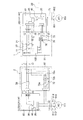
図3は、極性補正回路37の回路図である。図3において、第1コネクタCN1の第1端子N1aは第1入力線11と繋がっている。また、第1コネクタCN1の第2端子N1bは第2入力線12と繋がっている。第1端子N1aには正極信号F1の通信線が接続され、第2端子N2bには負極信号F2の通信線が接続される。
(2-1)
FIG. 3 is a circuit diagram of the
極性補正回路37は、切換リレー30、第1回路41、第2回路42、第1分圧回路51、第2分圧回路52、リレー駆動回路53およびコンパレータ55を含んでいる。
The
極性補正回路37の機能は、切換リレー30を用いて、第1入力線11が正極のときには第1入力線11と第1出力線21とを接続し且つ第2入力線12と第2出力線22とを接続し、第1入力線11が負極のときには第1入力線11と第2出力線22とを接続し且つ第2入力線12と第1出力線21とを接続することである。
The function of the
極性補正回路37を搭載する目的は、室内ユニット1と室外ユニット2との間を通信線で繋ぐ際に、サービスパーソンが通信線の配線を間違う可能性があるので、通信線の配線間違いが生じても正しく通信が行われることである。
The purpose of mounting the
(2−1−1)切換リレー30
切換リレー30は、リレーコイル31と接点切換機構32とを有している。接点切換機構32は、リレーコイル31に通電されている間、第1接点C1aおよび第2接点C2aを閉にし、同時に第3接点C1bおよび第4接点C2bを開にすることができる。
(2-1-1)
The switching
また、接点切換機構32は、リレーコイル31に通電されていない間、第1接点C1aおよび第2接点C2aを開にし、同時に第3接点C1bおよび第4接点C2bを閉にすることができる。
Further, the
(2−1−2)第1回路41
第1回路41は、第1入力線11と第1出力線21とを接続し、第2入力線12と第2出力線22とを接続する。
(2-1-2)
The
第1回路41には、第1入力線11と第1出力線21とを接続する配線の途中に、切換リレー30の第1接点C1aが設けられている。第1接点C1aが閉のときに第1入力線11と第1出力線21とが接続され、第1接点C1aが開のときに第1入力線11と第1出力線21との接続が解除される。
In the
また、第1回路41には、第2入力線12と第2出力線22とを接続する配線の途中に、切換リレー30の第2接点C2aが設けられている。第2接点C2aが閉のときに第2入力線12と第2出力線22とが接続され、第2接点C2aが開のときに第2入力線12と第2出力線22との接続が解除される。
Further, in the
(2−1−3)第2回路42
第2回路42は、第1入力線11と第2出力線22とを接続し、第2入力線12と第1出力線21とを接続する。
(2-1-3)
The
第2回路42には、第1入力線11と第2出力線22とを接続する配線の途中に、切換リレー30の第3接点C1bが設けられている。第3接点C1bが閉のときに第1入力線11と第2出力線22とが接続され、第3接点C1bが開のときに第1入力線11と第2出力線22との接続が解除される。
The
また、第2回路42には、第2入力線12と第1出力線21とを接続する配線の途中に、切換リレー30の第4接点C2bが設けられている。第4接点C2bが閉のときに第2入力線12と第1出力線21とが接続され、第4接点C2bが開のときに第2入力線12と第1出力線21との接続が解除される。
Further, in the
(2−1−4)第1分圧回路51
第1分圧回路51は、第1入力線11との接続点S11から第2入力線12との接続点S12に向かって、第1ダイオードD11、第1抵抗R11および第2抵抗R12が直列に接続されている。
(2-1-4) First
In the first
第1ダイオードD11のアノードが接続点S11に接続され、カソードが第1抵抗R11の一端に接続されているので、接続点S11から接続点S12に向かう方向が第1ダイオードD11の順方向である。 Since the anode of the first diode D11 is connected to the connection point S11 and the cathode is connected to one end of the first resistor R11, the direction from the connection point S11 to the connection point S12 is the forward direction of the first diode D11.
したがって、第1入力線11が正極で且つ第2入力線12が負極のとき、接続点S11から接続点S12に向かって、第1抵抗R11および第2抵抗R12それぞれの両端に、第1抵抗R11および第2抵抗R12の抵抗値比に応じた電圧降下が生じる。
Therefore, when the
第1抵抗R11と第2抵抗R12との接続点Q12は、後に説明するコンパレータ55の反転入力端子に接続されている。
The connection point Q12 between the first resistor R11 and the second resistor R12 is connected to the inverting input terminal of the
(2−1−5)第2分圧回路52
第2分圧回路52は、第2入力線12との接続点S21から第1入力線11との接続点S22に向かって、第2ダイオードD21、第3抵抗R21および第4抵抗R22が直列に接続されている。
(2-1-5) Second
In the second
第2ダイオードD21のアノードが接続点S21に接続され、カソードが第3抵抗R21の一端に接続されているので、接続点S21から接続点S22に向かう方向が第2ダイオードD21の順方向である。 Since the anode of the second diode D21 is connected to the connection point S21 and the cathode is connected to one end of the third resistor R21, the direction from the connection point S21 to the connection point S22 is the forward direction of the second diode D21.
したがって、第2入力線12が正極で且つ第1入力線11が負極のとき、接続点S21から接続点S22に向かって、第3抵抗R21および第4抵抗R22それぞれの両端に、第3抵抗R21および第4抵抗R22の抵抗値比に応じた電圧降下が生じる。
Therefore, when the
第3抵抗R21と第4抵抗R22との接続点Q22は、後に説明するコンパレータ55の非反転入力端子に接続されている。
The connection point Q22 between the third resistor R21 and the fourth resistor R22 is connected to the non-inverting input terminal of the
(2−1−6)リレー駆動回路53
リレー駆動回路53は、トランジスタTra含んでいる。トランジスタTraは、ベースに所定の正電圧が印加されている間、コレクタとエミッタ間が導通して、リレーコイル31に駆動電圧E1が印加される。
(2-1-6)
The
リレーコイル31に駆動電圧E1が印加されている間は、リレーコイル31に通電されるので、第1回路41に設けられた第1接点C1aおよび第2接点C2aは閉となり、同時に第2回路42に設けられた第3接点C1bおよび第4接点C2bは開となる。
While the drive voltage E1 is applied to the
リレーコイル31に駆動電圧E1が印加されていないときは、リレーコイル31に通電されないので、第1回路41に設けられた第1接点C1aおよび第2接点C2aは開となり、同時に第2回路42に設けられた第3接点C1bおよび第4接点C2bは閉となる。
When the drive voltage E1 is not applied to the
(2−1−7)コンパレータ55
コンパレータ55は、反転入力端子に入力される電圧(以後、第1電圧V1という。)と、非反転入力端子に入力される電圧(以後、第2電圧V2という。)を比較して、第2電圧V2>第1電圧V1のとき、出力端子から所定の出力電圧Vout=E2を出力する。一方、第2電圧V2<第1電圧V1のとき、出力端子から出力電圧Vout=0Vを出力する。
(2-1-7)
The
したがって、第2電圧V2>第1電圧V1のとき、出力端子から所定の出力電圧Vout=E2を出力され、それがトランジスタTraのベースに印加されている間、コレクタとエミッタ間が導通して、リレーコイル31に駆動電圧E1が印加される。E1=E2であってもよい。
Therefore, when the second voltage V2> the first voltage V1, a predetermined output voltage Vout = E2 is output from the output terminal, and while it is applied to the base of the transistor Tra, the collector and the emitter are electrically connected. The drive voltage E1 is applied to the
本実施形態では、第1抵抗R11と第2抵抗R12との接続点Q12がコンパレータ55の反転入力端子に接続されており、反転入力端子は第5抵抗R15を介してグランドGNDに接続されているので、第1電圧V1は第1抵抗R11と第2抵抗R12との接続点Q12とグランドGNDとの電位差である。
In the present embodiment, the connection point Q12 between the first resistor R11 and the second resistor R12 is connected to the inverting input terminal of the
また、第3抵抗R21と第4抵抗R22との接続点Q22がコンパレータ55の非反転入力端子に接続されており、非反転入力端子は第6抵抗R26を介してグランドGNDに接続されているので、第2電圧V2は第3抵抗R21と第4抵抗R22との接続点Q22とグランドGNDとの電位差である。
Further, since the connection point Q22 between the third resistor R21 and the fourth resistor R22 is connected to the non-inverting input terminal of the
(2−2)切換回路75
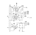
図4は、切換回路75の回路図である。図4において、切換回路75は、オン・オフリレー76、第1切換回路77a、第2切換回路77b、第3切換回路77c、フォトカプラ78およびリレー駆動回路79を含んでいる。切換回路75の機能は、フォトカプラ78を用いて第1電源101からの電力供給の有無を検出し、第1電源101からの電力供給がないときにオン・オフリレー76を用いて第1電源101とは別の電源である第2電源102から第1制御基板81に電力を供給することである。
(2-2)
FIG. 4 is a circuit diagram of the switching
(2−2−1)オン・オフリレー76
本実施形態では、切換回路75は2つのオン・オフリレー76を有している。オン・オフリレー76の個数は、任意に設定することができる。オン・オフリレー76は、リレーコイル76aとリレースイッチ76bとを有している。
(2-2-1) On / off
In this embodiment, the switching
リレースイッチ76bは、リレーコイル76aに通電されている間、第1接点S1aおよび第2接点S2aを閉にし、同時に第3接点S1bおよび第4接点S2bを開にすることができる。
The
また、リレースイッチ76bは、リレーコイル76aに通電されていない間、第1接点S1aおよび第2接点S2aを開にし、同時に第3接点S1bおよび第4接点S2bを閉にすることができる。
Further, the
(2−2−2)第1切換回路77a
第1切換回路77aは、オン・オフリレー76の第3接点S1bが閉のときだけ、第1直流電源Eaと第3コネクタCN3の第1端子N3aとの間を導通させ、第1制御基板81に第1直流電源Eaからの電力を供給する。
(2-2-2)
The
(2−2−3)第2切換回路77b
第2切換回路77bは、オン・オフリレー76の第4接点S2bが閉のときだけ、第2直流電源Ebと第3コネクタCN3の第2端子N3bとの間を導通させ、第1制御基板81に第2直流電源Ebの電力を供給する。
(2-2-3)
The
(2−2−4)第3切換回路77c
第3切換回路77cは、オン・オフリレー76の第3接点S1bが閉のときだけ、第3直流電源Ecと第3コネクタCN3の第3端子N3cとの間を導通させ、第1制御基板81に第3直流電源Ecの電力を供給する。
(2-2-4)
The
(2−2−5)フォトカプラ78
図4に示すように、フォトカプラ78は、フォトダイオード78aとフォトトランジスタ78bとからなる絶縁スイッチである。コネクタCN5の第1端子N5aはフォトカプラ78のフォトダイオード78aのアノードと繋がっている。また、コネクタCN5の第2端子N5bはフォトカプラ78のフォトダイオード78aのカソードと繋がっている。
(2-2-5)
As shown in FIG. 4, the
第1端子N5aには電源ライン801の分岐電線が接続され、第2端子N5bには電源ライン802の分岐電線が接続される。
The branch wire of the
フォトダイオード78aの両端には、並列に整流回路73が接続されている。整流回路73は、第1電源101の交流電圧を、ダイオードDaおよび平滑コンデンサCaで整流し、分圧抵抗Ra,Rbによって、フォトダイオード78aを発光させために適した直流電圧を生成する。
A
(2−2−6)リレー駆動回路79
図4に示すように、リレー駆動回路79はトランジスタTrb含んでいる。トランジスタTrbは、ベースに所定の正電圧が印加されている間、コレクタとエミッタ間が導通して、リレーコイル76aに駆動電源Edの電圧が印加される。
(2-2-6)
As shown in FIG. 4, the
リレーコイル76aに駆動電源Edの電圧が印加されている間は、リレーコイル76aに通電されるので、第1切換回路77aおよび第3切換回路77cに設けられた第3接点S1bと、第2切換回路77bに設けられた第4接点S2bとが開となる。それゆえ、第1直流電源Ea、第2直流電源Ebおよび第3直流電源Ecの電力は第1制御基板81に供給されない。
While the voltage of the drive power supply Ed is applied to the
一方、リレーコイル76aに駆動電源Edの電圧が印加されていないときは、リレーコイル76aに通電されないので、第1切換回路77aおよび第3切換回路77cに設けられた第3接点S1bと、第2切換回路77bに設けられた第4接点S2bとが閉となる。それゆえ、第1直流電源Ea、第2直流電源Ebおよび第3直流電源Ecの電力が第1制御基板81に供給される。
On the other hand, when the voltage of the drive power supply Ed is not applied to the
(2−2−7)第2電源102
図2に示すように、第2電源102は、室外ユニット2の直流電源回路72で生成された直流電圧を通信線L1,L2を介して導入し、第1制御基板81の第1直流電源Ea、第2直流電源Ebおよび第3直流電源Ecそれぞれに必要な電圧を提供する。
(2-2-7)
As shown in FIG. 2, the
第2電源102と第1制御基板81とは、第1制御基板81に第1電源101から電力が供給されている間は、切換回路75によって遮断されており、第1電源101から電力が供給されなくなったとき、切換回路75によって両者は接続される。
The
これによる利点は、室内ユニット1において、第1電源101からの電力供給が遮断された後、電動膨張弁である室内膨張弁20の開度は電力供給が遮断される前の運転モードに基づいて調整されることである。例えば、冷房運転であった場合は室内膨張弁の開度は閉にし、暖房運転であった場合には僅かに開にする。室内マイクロコンピュータ45が起動することによってこれらの制御が適正に実行される。
The advantage of this is that in the indoor unit 1, after the power supply from the
(3)第2電気基板92
図2に示すように、第2電気基板92には、極性補正回路38および直流電源回路72が実装されている。
(3) Second
As shown in FIG. 2, the polarity correction circuit 38 and the DC
本実施形態では、室外ユニット2の第2電気基板92は、第2制御基板82と別個の基板としているが、統合して1つの基板としてもよい。
In the present embodiment, the second
(3−1)極性補正回路38
極性補正回路38は、室外通信回路36からの信号を伝送する正極信号線と負極信号線とが極性を間違えて結線されても、正極信号は正極出力線へ、負極信号は負極出力線へ出力されるように切り換える回路である。
(3-1) Polarity correction circuit 38
The polarity correction circuit 38 outputs the positive electrode signal to the positive electrode output line and the negative electrode signal to the negative electrode output line even if the positive electrode signal line and the negative electrode signal line that transmit the signal from the
極性補正回路38の回路構成は、図3で示した極性補正回路37の回路構成と同じであるので、ここでは説明を省略する。
Since the circuit configuration of the polarity correction circuit 38 is the same as the circuit configuration of the
(3−2)直流電源回路72
直流電源回路72は、室内ユニット1の第1電気基板91に実装された第2電源102に供給する直流電圧を生成する回路である。
(3-2) DC
The DC
直流電源回路72は、3相交流電源111の電源ライン811、812、813のうち1つから交流電圧を導入し、フィルタ回路72a、整流回路72bおよび平滑コンデンサ72cを介して直流電圧を生成する。
The DC
図2に示すように、直流電源回路72で生成された直流電圧は、室外通信回路36から正極信号F1と負極信号F2と重畳された状態で送信される。正極信号F1は通信線L1を介して、負極信号F2は通信線L2を介して室内ユニット1へ伝送される。
As shown in FIG. 2, the DC voltage generated by the DC
(4)極性補正回路37、38の動作
ここでは、極性補正回路37,38の動作を、室内ユニット1の極性補正回路37を例に説明する。
(4) Operation of
(4−1)第1入力線11が正極、第2入力線12が負極のとき
正極信号F1が伝送される信号線および負極信号F2が伝送される通信線が正しく接続されている場合、正極信号F1は、通信線L1および第1コネクタCN1の第1端子N1aを介して第1入力線11に入力される。また、負極信号F2は、通信線L2および第1コネクタCN1の第2端子N1bを介して第2入力線12に入力される。
(4-1) When the
図5は、正極信号F1が第1入力線11に入力され、負極信号F2が第2入力線12に入力されているときの、正極信号F1および負極信号F2の伝送経路を矢印で示した極性補正回路図である。
FIG. 5 shows the polarities of the transmission paths of the positive electrode signal F1 and the negative electrode signal F2 when the positive electrode signal F1 is input to the
図5において、第1分圧回路51の接続点S11に正電圧が印加されるので、接続点S11から接続点S12に向かって、第1抵抗R11および第2抵抗R12それぞれの両端に、第1抵抗R11および第2抵抗R12の抵抗値比に応じた電圧降下が生じる。
In FIG. 5, since a positive voltage is applied to the connection point S11 of the first
また、第2分圧回路52の接続点S22にも正電圧が印加されるが、第2ダイオードD21の順方向と逆方向となるため、第3抵抗R21では電圧降下は生じず、第4抵抗R22および第6抵抗R26それぞれの両端に、第4抵抗R22および第6抵抗R26の抵抗値比に応じた電圧降下が生じる。
Further, a positive voltage is also applied to the connection point S22 of the second
この場合において、予め、第2分圧回路52の接続点Q22とグランドGNDからの電位差(V2)が、第1分圧回路51の接続点Q12とグランドGNDとの電位差(V1)よりも大きくなるように、第1抵抗R11、第2抵抗R12、第3抵抗R21、第4抵抗R22および第6抵抗R26の抵抗値が設定されている。
In this case, the potential difference (V2) between the connection point Q22 of the second
コンパレータ55の非反転入力端子にV2(V2>V1)が入力され、反転入力端子にV1が入力されるので、コンパレータ55の出力端子から所定の出力電圧Vout=E2が出力される。
Since V2 (V2> V1) is input to the non-inverting input terminal of the
この出力電圧Voutが、リレー駆動回路53のトランジスタTraのベースに印加され、コレクタとエミッタ間が導通してリレーコイル31に通電されるので、第1回路41に設けられた第1接点C1aおよび第2接点C2aは閉となり、同時に第2回路42に設けられた第3接点C1bおよび第4接点C2bは開となる。
This output voltage Vout is applied to the base of the transistor Tra of the
その結果、第1入力線11が正極のときには第1入力線11と第1出力線21とを接続し且つ第2入力線12と第2出力線22とを接続される。
As a result, when the
(4−2)第1入力線11が負極、第2入力線12が正極のとき
正極信号F1が伝送される信号線および負極信号F2が伝送される通信線が誤って接続されている場合、例えば、正極信号F1が通信線L1および第1コネクタCN1の第2端子N1bを介して第2入力線12に入力された場合である。このとき、負極信号F2は、通信線L2および第1コネクタCN1の第1端子N1aを介して第1入力線11に入力される。
(4-2) When the
図6は、正極信号F1が第2入力線12に入力され、負極信号F2が第1入力線11に入力されているときの、正極信号F1および負極信号F2の伝送経路を矢印で示した極性補正回路図である。
FIG. 6 shows the polarities of the transmission paths of the positive electrode signal F1 and the negative electrode signal F2 when the positive electrode signal F1 is input to the
図6において、第2分圧回路52の接続点S21に正電圧が印加されるので、接続点S21から接続点S22に向かって、第3抵抗R21および第4抵抗R22それぞれの両端に、第3抵抗R21および第4抵抗R22の抵抗値比に応じた電圧降下が生じる。
In FIG. 6, since a positive voltage is applied to the connection point S21 of the second
また、第1分圧回路51の接続点S12にも正電圧が印加されるが、第1ダイオードD11の順方向と逆方向となるため、第1抵抗R11では電圧降下は生じず、第2抵抗R12および第5抵抗R15それぞれの両端に、第2抵抗R12および第5抵抗R15の抵抗値比に応じた電圧降下が生じる。
Further, a positive voltage is also applied to the connection point S12 of the first
この場合において、予め、第1分圧回路51の接続点Q12とグランドGNDからの電位差(V1)が、第2分圧回路52の接続点Q22とグランドGNDとの電位差(V2)よりも大きくなるように、第1抵抗R11、第2抵抗R12、第3抵抗R21、第4抵抗R22および第5抵抗R15の抵抗値が設定されている。
In this case, the potential difference (V1) between the connection point Q12 of the first
コンパレータ55の非反転入力端子にV2(V2<V1)が入力され、反転入力端子にV1が入力されるので、コンパレータ55の出力端子から出力電圧Vout=0が出力される。
Since V2 (V2 <V1) is input to the non-inverting input terminal of the
この出力電圧Vout=0が、リレー駆動回路53のトランジスタTraのベース電圧になるので、コレクタとエミッタ間が導通せず、リレーコイル31には通電されない。そのため、第1回路41に設けられた第1接点C1aおよび第2接点C2aは開となり、同時に第2回路42に設けられた第3接点C1bおよび第4接点C2bは閉となる。
Since this output voltage Vout = 0 becomes the base voltage of the transistor Tra of the
その結果、第1入力線11が負極のときには第1入力線11と第2出力線22とを接続し且つ第2入力線12と第1出力線21とを接続される。
As a result, when the
以上のように、極性補正回路37によって、正極信号F1は常に第1出力線21から出力され、負極信号F2は常に第2出力線22から出力される。
As described above, the
(5)切換回路75の動作
切換回路75の機能は、第1電源101からの電力が遮断されたときに第1電源101からの電力供給が遮断されたことを検知し、第1電源101とは別の電源である第2電源102からの電力に切り換えることである。
(5) Operation of the switching
以下、切換回路75の動作を、第1電源101からの電力供給が遮断されていない場合と、第1電源101からの電力が遮断された場合とに分けて説明する。
Hereinafter, the operation of the switching
(5−1)第1電源101からの電力供給が遮断されていない場合
図7は、第1電源101からの電力供給が遮断されていないときの、切換回路75の状態を示す説明図である。図7では、電流の流れを矢印で表示している。
(5-1) When the power supply from the
図7において、フォトカプラ78のフォトダイオード78aの両端には、第1電源101の交流電圧を整流した直流電圧が順方向に印加され、電流Ifが流れることによってフォトダイオード78aが発光する。
In FIG. 7, a DC voltage obtained by rectifying the AC voltage of the
フォトトランジスタ78bは、フォトダイオード78aの発光を受けてコレクタとエミッタ間が導通し、電流Ioutが流れる。
The
その結果、エミッタとグランドGNDとの間にある抵抗Rcによって、エミッタとグランドGNDとの電位差が生じ、それがリレー駆動回路79のトランジスタTrbのベース電圧となって印加され、ベース電流Ibが流れる。
As a result, the resistance Rc between the emitter and the ground GND causes a potential difference between the emitter and the ground GND, which is applied as the base voltage of the transistor Trb of the
トランジスタTrbは、ベース電圧が印加されているとき、コレクタとエミッタ間が導通して、リレーコイル76aに駆動電源Edの電圧が印加され、リレーコイル76aに電流Icoilが通電される。
When the base voltage is applied to the transistor Trb, the collector and the emitter conduct with each other, the voltage of the drive power supply Ed is applied to the
リレーコイル76aに通電されている間は、第1切換回路77aおよび第3切換回路77cに設けられた第3接点S1bと、第2切換回路77bに設けられた第4接点S2bとが開となるので、第1直流電源Ea、第2直流電源Ebおよび第3直流電源Ecの電力は第1制御基板81に供給されない。
While the
(5−2)第1電源101からの電力供給が遮断された場合
図8は、第1電源101からの電力供給が遮断されているときの、切換回路75の状態を示す説明図である。図8では、電流の流れを矢印で表示している。
(5-2) When the power supply from the
図8において、フォトカプラ78のフォトダイオード78aの両端には、直流電圧が印加されないので、発光しない。それゆえ、フォトトランジスタ78bは、フォトダイオード78aの発光を受けないので、コレクタとエミッタ間が導通しない。その結果、エミッタとグランドGNDとの電位差は生じない。
In FIG. 8, since no DC voltage is applied to both ends of the
トランジスタTrbは、ベース電圧が印加されないので、コレクタとエミッタ間が導通せず、リレーコイル76aに通電されない。
Since the base voltage is not applied to the transistor Trb, the collector and the emitter do not conduct with each other, and the
リレーコイル76aに通電されないので、第1切換回路77aおよび第3切換回路77cに設けられた第3接点S1bと、第2切換回路77bに設けられた第4接点S2bとが閉となり、第1直流電源Ea、第2直流電源Ebおよび第3直流電源Ecの電力は第1制御基板81に供給される。
Since the
(6)特徴
(6−1)
第1電気基板91は、第1制御基板81と通信線を介して電気的に接続された電気基板である。第1制御基板81は、第1電源101と接続された空調機100の室内ユニット1の制御基板である。第1電気基板91は、第2電源102とさらに接続されている。第1電気基板91は、オン・オフリレー76を備える。オン・オフリレー76は、第1電源101から第1制御基板81に電力が供給されないときに、第2電源102からの電力供給に切り換える。その結果、第1電気基板91が、室内ユニット1の第1制御基板81に適切に電力を供給することができる。
(6) Features (6-1)
The first
「第1電気基板91は、第2電源102とさらに接続されている。」には、第1電気基板91に第2電源102が搭載されていることも含まれる。
"The first
(6−2)
空調機100は、室内ユニット1と、室内ユニット1と電気的に接続された室外ユニット2とを含む。第2電源102の電力は、室外ユニット2からの供給電力である。
(6-2)
The
(6−3)
第1電気基板91は、切換回路75をさらに備える。切換回路75は、第2電源102と電気的に接続される第1状態および電気的に接続されない第2状態のいずれかに切り換えられる。第1電源101から第1制御基板81に電力が供給されないときに、オン・オフリレー76によって切換回路75が第1状態に切り換えられる。
(6-3)
The first
(6−4)
第1電気基板91は、スイッチとしてのフォトカプラ78をさらに備える。フォトカプラ78は、第1電源101から第1制御基板81に電力が供給されていないとき、オン・オフリレー76への通電をオンまたはオフして、切換回路75を第1状態へ切り換えさせる。フォトカプラ78が、第1電源101からの電力供給の有無に応じてオン・オフリレー76への通電・非通電を行うので、構成が簡素化し、低コスト化を図ることができる。
(6-4)
The first
(6−5)
フォトカプラ78は、第1電源101から電力が供給されている間はオンしてオン・オフリレー76に通電する。また、フォトカプラ78は、第1電源101から電力が供給されないときはオフしてオン・オフリレー76への通電を遮断する。第1電源101から電力供給されているときにフォトカプラ78がオンしてリレーへの通電を行うという構成によって、簡単で且つ部品点数が少ない回路を実現することができる。
(6-5)
The
(6−6)
この第1電気基板91では、オン・オフリレー76は、リレーコイル76aと、リレースイッチ76bとを有する。リレースイッチ76bは、リレーコイル76aへの通電がオンまたはオフのときに切換回路75を第1状態へ切り換える。この電気基板では、論理回路を必要とせず、リレーコイルとリレースイッチからなる汎用の機械式リレーを用いることができるので、コスト増を抑制することができる。
(6-6)
In the first
(6−7)
この第1電気基板91では、第1電気基板91を第1制御基板81から分離独立させたことにより、第1電気基板91の後付けが可能となる。それゆえ、当該第1電気基板91を搭載していない室内ユニット1にも搭載可能となる。
(6-7)
In the first
(6−8)
第1電気基板91を搭載した空調機100では、室外ユニット2および室外ユニット2に接続される複数の室内ユニット1を含む。複数の室内ユニット1のうち、いずれか1つの室内ユニット1の第1制御基板81に第1電源101からの電力が供給されないときに、オン・オフリレー76によって第2電源102からの電力供給に切り換えられる。
(6-8)
The
以上、本開示の実施形態を説明したが、特許請求の範囲に記載された本開示の趣旨及び範囲から逸脱することなく、形態や詳細の多様な変更が可能なことが理解されるであろう。 Although the embodiments of the present disclosure have been described above, it will be understood that various modifications of the forms and details are possible without departing from the purpose and scope of the present disclosure described in the claims. ..
1 室内ユニット
2 室外ユニット
75 切換回路
76 オン・オフリレー(リレー)
76a リレーコイル
76b リレースイッチ
81 第1制御基板(制御基板)
91 第1電気基板(電気基板)
100 空調機(冷凍装置)
101 第1電源
102 第2電源
1
91 First electric board (electric board)
100 Air conditioner (refrigerator)
101
Claims (9)
前記電気基板は、第2電源とさらに接続されており、
前記第1電源から前記制御基板(81)に電力が供給されないときに、前記第2電源からの電力供給に切り換えるリレー(76)、を備える、
電気基板。 An electric board electrically connected to a control board (81) of an indoor unit of a refrigerating device connected to a first power source via a communication line.
The electric board is further connected to a second power source.
A relay (76) that switches to power supply from the second power supply when power is not supplied from the first power supply to the control board (81) is provided.
Electric board.
前記第2電源の電力は、前記室外ユニットからの供給電力である、
請求項1に記載の電気基板。 The refrigerating device includes the indoor unit and an outdoor unit electrically connected to the indoor unit.
The electric power of the second power source is the electric power supplied from the outdoor unit.
The electric board according to claim 1.
前記第1電源から前記制御基板(81)に電力が供給されないときに、前記リレー(76)によって前記切換回路(75)が前期第1状態に切り換えられる、
請求項1又は請求項2に記載の電気基板。 The electrical board further comprises a switching circuit (75) that switches between a first state that is electrically connected to the second power source and a second state that is not electrically connected.
When power is not supplied from the first power source to the control board (81), the relay (76) switches the switching circuit (75) to the first state in the previous period.
The electric board according to claim 1 or 2.
前記スイッチ(78)は、前記第1電源から前記制御基板(81)に電力が供給されていないとき、前記リレー(76)への通電をオンまたはオフして、前記切換回路(75)を前記第1状態へ切り換えさせる、
請求項3に記載の電気基板。 The electrical board further comprises a switch (78).
When the power is not supplied from the first power source to the control board (81), the switch (78) turns on or off the energization of the relay (76) to switch the switching circuit (75). Switch to the first state,
The electric board according to claim 3.
前記第1電源から電力が供給されている間はオンして前記リレー(76)に通電し、
前記第1電源から電力が供給されないときはオフして前記リレー(76)への通電を遮断する、
請求項4に記載の電気基板。 The switch (78)
While the power is being supplied from the first power source, the relay (76) is energized by turning on the power.
When power is not supplied from the first power source, it is turned off to cut off the energization of the relay (76).
The electric board according to claim 4.
前記リレースイッチ(76)は、前記リレーコイル(76a)への通電がオンまたはオフのときに前記切換回路(75)を前記第1状態へ切り換える、
請求項3から請求項5のいずれか1項に記載の電気基板。 The relay (76) has a relay coil (76a) and a relay switch (76b).
The relay switch (76) switches the switching circuit (75) to the first state when the energization of the relay coil (76a) is on or off.
The electric board according to any one of claims 3 to 5.
請求項1から請求項6のいずれか1項に記載の電気基板。 The electric board is separated from the control board (81).
The electric board according to any one of claims 1 to 6.
冷凍装置。 The electric board according to any one of claims 1 to 7 is mounted.
Refrigerator.
室外ユニットおよび前記室外ユニットに接続される複数の前記室内ユニットを含み、
複数の前記室内ユニットのうち、いずれか1つの室内ユニットの前記制御基板に前記第1電源からの電力が供給されないときに、前記リレー(76)によって前記第2電源からの電力供給に切り換えられる、
冷凍装置。 A refrigerating apparatus equipped with the electric substrate according to claim 8.
Including the outdoor unit and a plurality of the indoor units connected to the outdoor unit.
When the power from the first power supply is not supplied to the control board of any one of the indoor units, the relay (76) switches the power supply from the second power supply.
Refrigerator.
Priority Applications (3)
| Application Number | Priority Date | Filing Date | Title |
|---|---|---|---|
| JP2020006745A JP2021113643A (en) | 2020-01-20 | 2020-01-20 | Electric substrate, and freezer in which electric substrate is mounted |
| PCT/IB2021/050401 WO2021148949A1 (en) | 2020-01-20 | 2021-01-20 | Electrical board and cooling apparatus in which said electrical board has been installed |
| AU2021209426A AU2021209426A1 (en) | 2020-01-20 | 2021-01-20 | Electrical board and cooling apparatus in which said electrical board has been installed |
Applications Claiming Priority (1)
| Application Number | Priority Date | Filing Date | Title |
|---|---|---|---|
| JP2020006745A JP2021113643A (en) | 2020-01-20 | 2020-01-20 | Electric substrate, and freezer in which electric substrate is mounted |
Publications (1)
| Publication Number | Publication Date |
|---|---|
| JP2021113643A true JP2021113643A (en) | 2021-08-05 |
Family
ID=76993298
Family Applications (1)
| Application Number | Title | Priority Date | Filing Date |
|---|---|---|---|
| JP2020006745A Pending JP2021113643A (en) | 2020-01-20 | 2020-01-20 | Electric substrate, and freezer in which electric substrate is mounted |
Country Status (3)
| Country | Link |
|---|---|
| JP (1) | JP2021113643A (en) |
| AU (1) | AU2021209426A1 (en) |
| WO (1) | WO2021148949A1 (en) |
Citations (4)
| Publication number | Priority date | Publication date | Assignee | Title |
|---|---|---|---|---|
| JP2004286238A (en) * | 2003-03-19 | 2004-10-14 | Daikin Ind Ltd | Control circuit of cooling device, and control method of cooling device |
| JP2008057868A (en) * | 2006-08-31 | 2008-03-13 | Daikin Ind Ltd | Air conditioner |
| JP2014196885A (en) * | 2013-03-29 | 2014-10-16 | パナソニック株式会社 | Air conditioning system |
| JP2016220398A (en) * | 2015-05-20 | 2016-12-22 | シャープ株式会社 | Electrical equipment |
-
2020
- 2020-01-20 JP JP2020006745A patent/JP2021113643A/en active Pending
-
2021
- 2021-01-20 AU AU2021209426A patent/AU2021209426A1/en active Pending
- 2021-01-20 WO PCT/IB2021/050401 patent/WO2021148949A1/en active Application Filing
Patent Citations (4)
| Publication number | Priority date | Publication date | Assignee | Title |
|---|---|---|---|---|
| JP2004286238A (en) * | 2003-03-19 | 2004-10-14 | Daikin Ind Ltd | Control circuit of cooling device, and control method of cooling device |
| JP2008057868A (en) * | 2006-08-31 | 2008-03-13 | Daikin Ind Ltd | Air conditioner |
| JP2014196885A (en) * | 2013-03-29 | 2014-10-16 | パナソニック株式会社 | Air conditioning system |
| JP2016220398A (en) * | 2015-05-20 | 2016-12-22 | シャープ株式会社 | Electrical equipment |
Also Published As
| Publication number | Publication date |
|---|---|
| AU2021209426A1 (en) | 2022-06-09 |
| WO2021148949A1 (en) | 2021-07-29 |
Similar Documents
| Publication | Publication Date | Title |
|---|---|---|
| US10132520B2 (en) | Air conditioning system having a microcomputer powered by a relay | |
| KR0156058B1 (en) | Airconditioner | |
| US10852044B1 (en) | Simple low-cost retrofit device and method to replace a variable air flow electronically commutated motor with a permanent split capacitor motor capable of operating at multiple speed settings | |
| AU2017424871B2 (en) | Air conditioner | |
| JP2012107779A (en) | Air conditioner | |
| WO2021148949A1 (en) | Electrical board and cooling apparatus in which said electrical board has been installed | |
| JP2019100655A (en) | Air conditioner, indoor unit and outdoor unit | |
| WO2021148948A1 (en) | Electronic circuit board and refrigeration apparatus equipped with electronic circuit board | |
| EP3517851B1 (en) | Air conditioning device | |
| KR102167330B1 (en) | air conditioner | |
| JP5436881B2 (en) | Air conditioner | |
| JP6567930B2 (en) | Air conditioner | |
| KR102478858B1 (en) | AIR CONDITIONER | |
| JP3815463B2 (en) | Separate air conditioner | |
| JPWO2022239113A5 (en) | ||
| CN210197601U (en) | Air conditioner pressure protection device and air conditioner | |
| KR102214659B1 (en) | Air conditioner | |
| KR20070072259A (en) | Detecting apparatus of line-connecting default for air-conditioner | |
| JP2015145746A (en) | Overvoltage measure circuit and electrical equipment equipped with the same | |
| JP3157381B2 (en) | Air conditioner | |
| EP0742636A2 (en) | Improved interface circuit for use in multi-split air conditioning systems | |
| KR102295972B1 (en) | Air conditioner | |
| CN113038639B (en) | Electric heating switch control circuit and air conditioner with same | |
| JP2859066B2 (en) | Air conditioner | |
| JPH10227506A (en) | Air conditioner |
Legal Events
| Date | Code | Title | Description |
|---|---|---|---|
| A621 | Written request for application examination |
Free format text: JAPANESE INTERMEDIATE CODE: A621 Effective date: 20230118 |
|
| A131 | Notification of reasons for refusal |
Free format text: JAPANESE INTERMEDIATE CODE: A131 Effective date: 20231003 |
|
| A521 | Request for written amendment filed |
Free format text: JAPANESE INTERMEDIATE CODE: A523 Effective date: 20231228 |
|
| A131 | Notification of reasons for refusal |
Free format text: JAPANESE INTERMEDIATE CODE: A131 Effective date: 20240402 |