JP2021094602A - Control method and robot system - Google Patents
Control method and robot system Download PDFInfo
- Publication number
- JP2021094602A JP2021094602A JP2019225198A JP2019225198A JP2021094602A JP 2021094602 A JP2021094602 A JP 2021094602A JP 2019225198 A JP2019225198 A JP 2019225198A JP 2019225198 A JP2019225198 A JP 2019225198A JP 2021094602 A JP2021094602 A JP 2021094602A
- Authority
- JP
- Japan
- Prior art keywords
- speed
- robot
- arm
- upper limit
- robot arm
- Prior art date
- Legal status (The legal status is an assumption and is not a legal conclusion. Google has not performed a legal analysis and makes no representation as to the accuracy of the status listed.)
- Withdrawn
Links
- 238000000034 method Methods 0.000 title claims abstract description 39
- 238000001514 detection method Methods 0.000 claims description 46
- 238000013459 approach Methods 0.000 claims description 10
- 239000003638 chemical reducing agent Substances 0.000 description 17
- 230000005856 abnormality Effects 0.000 description 12
- 238000004891 communication Methods 0.000 description 11
- 239000012636 effector Substances 0.000 description 9
- 238000012544 monitoring process Methods 0.000 description 9
- 230000006870 function Effects 0.000 description 7
- 238000010586 diagram Methods 0.000 description 6
- VYPSYNLAJGMNEJ-UHFFFAOYSA-N silicon dioxide Inorganic materials O=[Si]=O VYPSYNLAJGMNEJ-UHFFFAOYSA-N 0.000 description 6
- 238000012545 processing Methods 0.000 description 3
- 238000004519 manufacturing process Methods 0.000 description 2
- 230000002093 peripheral effect Effects 0.000 description 2
- 230000002159 abnormal effect Effects 0.000 description 1
- 230000000694 effects Effects 0.000 description 1
- 230000005611 electricity Effects 0.000 description 1
- 238000007689 inspection Methods 0.000 description 1
- 239000000463 material Substances 0.000 description 1
- 239000010453 quartz Substances 0.000 description 1
- 230000035945 sensitivity Effects 0.000 description 1
Images


Classifications
-
- B—PERFORMING OPERATIONS; TRANSPORTING
- B25—HAND TOOLS; PORTABLE POWER-DRIVEN TOOLS; MANIPULATORS
- B25J—MANIPULATORS; CHAMBERS PROVIDED WITH MANIPULATION DEVICES
- B25J9/00—Programme-controlled manipulators
- B25J9/16—Programme controls
- B25J9/1628—Programme controls characterised by the control loop
- B25J9/163—Programme controls characterised by the control loop learning, adaptive, model based, rule based expert control
-
- B—PERFORMING OPERATIONS; TRANSPORTING
- B25—HAND TOOLS; PORTABLE POWER-DRIVEN TOOLS; MANIPULATORS
- B25J—MANIPULATORS; CHAMBERS PROVIDED WITH MANIPULATION DEVICES
- B25J9/00—Programme-controlled manipulators
- B25J9/16—Programme controls
- B25J9/1656—Programme controls characterised by programming, planning systems for manipulators
-
- B—PERFORMING OPERATIONS; TRANSPORTING
- B25—HAND TOOLS; PORTABLE POWER-DRIVEN TOOLS; MANIPULATORS
- B25J—MANIPULATORS; CHAMBERS PROVIDED WITH MANIPULATION DEVICES
- B25J9/00—Programme-controlled manipulators
- B25J9/16—Programme controls
- B25J9/1602—Programme controls characterised by the control system, structure, architecture
-
- B—PERFORMING OPERATIONS; TRANSPORTING
- B25—HAND TOOLS; PORTABLE POWER-DRIVEN TOOLS; MANIPULATORS
- B25J—MANIPULATORS; CHAMBERS PROVIDED WITH MANIPULATION DEVICES
- B25J9/00—Programme-controlled manipulators
- B25J9/0081—Programme-controlled manipulators with master teach-in means
-
- B—PERFORMING OPERATIONS; TRANSPORTING
- B25—HAND TOOLS; PORTABLE POWER-DRIVEN TOOLS; MANIPULATORS
- B25J—MANIPULATORS; CHAMBERS PROVIDED WITH MANIPULATION DEVICES
- B25J9/00—Programme-controlled manipulators
- B25J9/16—Programme controls
- B25J9/1694—Programme controls characterised by use of sensors other than normal servo-feedback from position, speed or acceleration sensors, perception control, multi-sensor controlled systems, sensor fusion
-
- G—PHYSICS
- G05—CONTROLLING; REGULATING
- G05B—CONTROL OR REGULATING SYSTEMS IN GENERAL; FUNCTIONAL ELEMENTS OF SUCH SYSTEMS; MONITORING OR TESTING ARRANGEMENTS FOR SUCH SYSTEMS OR ELEMENTS
- G05B19/00—Programme-control systems
- G05B19/02—Programme-control systems electric
- G05B19/42—Recording and playback systems, i.e. in which the programme is recorded from a cycle of operations, e.g. the cycle of operations being manually controlled, after which this record is played back on the same machine
-
- G—PHYSICS
- G05—CONTROLLING; REGULATING
- G05B—CONTROL OR REGULATING SYSTEMS IN GENERAL; FUNCTIONAL ELEMENTS OF SUCH SYSTEMS; MONITORING OR TESTING ARRANGEMENTS FOR SUCH SYSTEMS OR ELEMENTS
- G05B2219/00—Program-control systems
- G05B2219/30—Nc systems
- G05B2219/39—Robotics, robotics to robotics hand
- G05B2219/39438—Direct programming at the console
Abstract
Description
本発明は、制御方法およびロボットシステムに関するものである。 The present invention relates to control methods and robot systems.
近年、工場では人件費の高騰や人材不足により、各種ロボットやそのロボット周辺機器によって、人手で行われてきた作業の自動化が加速している。各種ロボットやそのロボット周辺機器としては、例えば特許文献1に示すようなロボット装置が知られている。 In recent years, due to soaring labor costs and a shortage of human resources in factories, automation of manual work has been accelerated by various robots and their peripheral devices. As various robots and their peripheral devices, for example, a robot device as shown in Patent Document 1 is known.
特許文献1のロボット装置は、ロボットの可動領域に人が侵入したのを検知する侵入検知手段を備えている。そして、ロボットに人が接近した場合、ロボットの動作速度を遅くすることにより、人とロボットとが衝突する可能性を低減している。 The robot device of Patent Document 1 includes an intrusion detection means for detecting an intrusion of a person into a movable area of a robot. When a person approaches the robot, the operating speed of the robot is slowed down to reduce the possibility of the person and the robot colliding with each other.
しかしながら、特許文献1のロボット装置では、人がロボットに接近するたびにロボットの動作速度が遅くなるので、ロボットの作業効率が低下してしまう。 However, in the robot device of Patent Document 1, the operating speed of the robot slows down each time a person approaches the robot, so that the working efficiency of the robot is lowered.
本発明は、前述した課題の少なくとも一部を解決するためになされたものであり、以下により実現することが可能である。 The present invention has been made to solve at least a part of the above-mentioned problems, and can be realized by the following.
本適用例の制御方法は、ロボットアームを有し、動作プログラムを実行する実行モードと、前記動作プログラムを教示する教示モードと、を有する前記ロボットアームの動作モードを実行するロボットシステムの制御方法であって、
前記動作モードが前記実行モードであった場合、前記ロボットアームの動作速度の上限速度を第1速度に設定し、前記動作モードが前記教示モードであった場合、前記上限速度を前記第1速度よりも遅い第2速度に設定することを特徴とする。
The control method of this application example is a control method of a robot system having a robot arm and executing an operation mode of the robot arm having an execution mode for executing an operation program and a teaching mode for teaching the operation program. There,
When the operation mode is the execution mode, the upper limit speed of the operation speed of the robot arm is set to the first speed, and when the operation mode is the teaching mode, the upper limit speed is set to the first speed. It is characterized in that it is set to a slow second speed.
本適用例のロボットシステムは、ロボットアームと、
前記ロボットアームが実行する動作モードに基づいて前記ロボットアームの駆動を制御する駆動制御部と、
前記動作モードに基づいて前記ロボットアームの動作速度の上限速度を設定する速度設定部と、を備え、
前記速度設定部は、前記動作モードが、動作プログラムを実行する実行モードであった場合、前記上限速度を第1速度に設定し、前記動作モードが、前記ロボットに前記動作プログラムを教示する教示モードであった場合、前記上限速度を前記第1速度よりも遅い前記第2速度に設定することを特徴とする。
The robot system of this application example is a robot arm and
A drive control unit that controls the drive of the robot arm based on the operation mode executed by the robot arm.
A speed setting unit for setting an upper limit speed of the operation speed of the robot arm based on the operation mode is provided.
When the operation mode is an execution mode for executing an operation program, the speed setting unit sets the upper limit speed to the first speed, and the operation mode teaches the robot the operation program. If this is the case, the upper limit speed is set to the second speed, which is slower than the first speed.
以下、本発明の制御方法およびロボットシステムを添付図面に示す好適な実施形態に基づいて詳細に説明する。 Hereinafter, the control method and the robot system of the present invention will be described in detail based on the preferred embodiments shown in the accompanying drawings.
<第1実施形態>
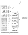
図1は、本発明のロボットシステムの概略構成図である。図2は、図1に示すロボットシステムの機能ブロック図である。図3は、図2に示すロボットシステムのハードウェアの構成例を示すブロック図である。図4は、本発明の制御方法を説明するためのフローチャートである。図5は、ロボットアームの動作を示すグラフであって、縦軸が速度、横軸が時間で表されるグラフである。図6は、ロボットアームの動作を示すグラフであって、縦軸が速度、横軸が時間で表されるグラフである。
<First Embodiment>
FIG. 1 is a schematic configuration diagram of the robot system of the present invention. FIG. 2 is a functional block diagram of the robot system shown in FIG. FIG. 3 is a block diagram showing a configuration example of the hardware of the robot system shown in FIG. FIG. 4 is a flowchart for explaining the control method of the present invention. FIG. 5 is a graph showing the operation of the robot arm, in which the vertical axis represents speed and the horizontal axis represents time. FIG. 6 is a graph showing the operation of the robot arm, in which the vertical axis represents speed and the horizontal axis represents time.
また、図1では、説明の便宜上、互いに直交する3軸として、x軸、y軸およびz軸を図示している。また、以下では、x軸に平行な方向を「x軸方向」とも言い、y軸に平行な方向を「y軸方向」とも言い、z軸に平行な方向を「z軸方向」とも言う。また、以下では、図示された各矢印の先端側を「+(プラス)」、基端側を「−(マイナス)」と言う。また、z軸回りの方向およびz軸に平行な軸回りの方向を「u方向」とも言う。 Further, in FIG. 1, for convenience of explanation, the x-axis, the y-axis, and the z-axis are illustrated as three axes orthogonal to each other. Further, in the following, the direction parallel to the x-axis is also referred to as "x-axis direction", the direction parallel to the y-axis is also referred to as "y-axis direction", and the direction parallel to the z-axis is also referred to as "z-axis direction". Further, in the following, the tip end side of each of the illustrated arrows will be referred to as “+ (plus)”, and the proximal end side will be referred to as “− (minus)”. Further, the direction around the z-axis and the direction around the axis parallel to the z-axis are also referred to as "u-direction".
また、以下では、説明の便宜上、図1中の+z軸方向、すなわち、上側を「上」または「上方」、−z軸方向、すなわち、下側を「下」または「下方」とも言う。また、ロボットアーム20については、図1中の基台21側を「基端」、その反対側、すなわち、エンドエフェクター7側を「先端」と言う。また、図1中のz軸方向、すなわち、上下方向を「鉛直方向」とし、x軸方向およびy軸方向、すなわち、左右方向を「水平方向」とする。
Further, in the following, for convenience of explanation, the + z-axis direction in FIG. 1, that is, the upper side is referred to as "upper" or "upper", and the -z-axis direction, that is, the lower side is also referred to as "lower" or "lower". Regarding the
図1および図2に示すロボットシステム100は、例えば、電子部品および電子機器等のワークの保持、搬送、組立ておよび検査等の作業で用いられる装置である。ロボットシステム100は、ロボット2と、ロボット2に対して動作プログラムを教示する教示装置3と、を備える。また、ロボット2と教示装置3とは、有線または無線により通信可能とされ、その通信は、インターネットのようなネットワークを介してなされてもよい。
The
教示とは、ロボット2に対して動作プログラムを指定することを言い、具体的には、ロボットアーム20の位置、姿勢を制御装置8に入力することを言う。この教示には、直接教示と間接教示とがある。
Teaching means designating an operation program for the
直接教示とは、ロボットアーム20に外力を加えつつロボットアーム20を所定の位置、姿勢に移動させながら、所望のタイミングで受付部4の教示ボタンを操作することにより、ロボットアーム20の位置、姿勢を制御装置8または教示装置3に記憶する、すなわち、動作プログラムを作成することを言う。
Direct teaching refers to the position and posture of the
また、間接教示とは、後述する教示装置3を用いて動作プログラムを作成し、制御装置8の記憶部82または教示装置3の記憶部に記憶することを言う。
Further, indirect teaching means creating an operation program using the teaching device 3 described later and storing it in the
まず、ロボット2について説明する。
ロボット2は、図示の構成では、水平多関節ロボット、すなわち、スカラロボットである。図1に示すように、ロボット2は、基台21と、基台21に接続されたロボットアーム20と、オペレーターからの所定の操作を受け付ける受付部4と、力検出部5と、エンドエフェクター7と、これら各部の作動を制御する制御装置8と、を有する。
First, the
In the illustrated configuration, the
基台21は、ロボットアーム20を支持する部分である。基台21には、後述する制御装置8が内蔵されている。また、基台21の任意の部分には、ロボット座標系の原点が設定されている。
The
ロボットアーム20は、第1アーム22と、第2アーム23と、作業ヘッドである第3アーム24と、を備えている。なお、ロボット2は、図示の構成に限定されず、アームの数は、1つまたは2つであってもよく、4つ以上であってもよい。
The
また、ロボット2は、第1アーム22を基台21に対して回転させる駆動ユニット25と、第2アーム23を第1アーム22に対して回転させる駆動ユニット26と、第3アーム24のシャフト241を第2アーム23に対して回転させるu駆動ユニット27と、シャフト241を第2アーム23に対してz軸方向に移動させるz駆動ユニット28と、角速度センサー29とを備えている。
Further, the
図1および図2に示すように、駆動ユニット25は、第1アーム22の筐体220内に内蔵されており、駆動力を発生するモーター251と、モーター251の駆動力を減速する減速機252と、モーター251または減速機252の回転軸の回転角度を検出する位置センサー253とを有している。
As shown in FIGS. 1 and 2, the
駆動ユニット26は、第2アーム23の筐体230に内蔵されており、駆動力を発生するモーター261と、モーター261の駆動力を減速する減速機262と、モーター261または減速機262の回転軸の回転角度を検出する位置センサー263とを有している。
The
u駆動ユニット27は、第2アーム23の筐体230に内蔵されており、駆動力を発生するモーター271と、モーター271の駆動力を減速する減速機272と、モーター271または減速機272の回転軸の回転角度を検出する位置センサー273とを有している。
The
z駆動ユニット28は、第2アーム23の筐体230に内蔵されており、駆動力を発生するモーター281と、モーター281の駆動力を減速する減速機282と、モーター281または減速機282の回転軸の回転角度を検出する位置センサー283とを有している。
The
モーター251、モーター261、モーター271およびモーター281としては、例えば、ACサーボモーター、DCサーボモーター等のサーボモーターを用いることができる。
As the
また、減速機252、減速機262、減速機272および減速機282としては、例えば、遊星ギア型の減速機、波動歯車装置等を用いることができる。また、位置センサー253、位置センサー263、位置センサー273および位置センサー283は、例えば、角度センサーとすることができる。
Further, as the
駆動ユニット25、駆動ユニット26、u駆動ユニット27およびz駆動ユニット28は、それぞれ、対応する図示しないモータードライバーに接続されており、モータードライバーを介して制御装置8の駆動制御部81により制御される。
The
また、角速度センサー29は、図2に示すように、第2アーム23に内蔵されている。このため、第2アーム23の角速度を検出することができる。この検出した角速度の情報に基づいて、制御装置8は、ロボット2の制御を行う。
Further, as shown in FIG. 2, the
基台21は、例えば、図示しない床面にボルト等によって固定されている。基台21の上端部には第1アーム22が連結されている。第1アーム22は、基台21に対して鉛直方向に沿う第1軸O1回りに回転可能となっている。第1アーム22を回転させる駆動ユニット25が駆動すると、第1アーム22が基台21に対して、u方向、すなわち、第1軸O1回りに水平面内で回転する。また、位置センサー253により、基台21に対する第1アーム22の回転量が検出できるようになっている。
The
また、第1アーム22の先端部には、第2アーム23が連結されている。第2アーム23は、第1アーム22に対して、u方向、すなわち、鉛直方向に沿う第2軸O2回りに回転可能となっている。第1軸O1の軸方向と第2軸O2の軸方向とは同一である。すなわち、第2軸O2は、第1軸O1と平行である。第2アーム23を回転させる駆動ユニット26が駆動すると、第2アーム23が第1アーム22に対して第2軸O2回りに水平面内で回転する。また、位置センサー263により、第1アーム22に対する第2アーム23の駆動量、具体的には、回転量が検出できるようになっている。
A
また、第2アーム23の先端部には、第3アーム24が設置、支持されている。第3アーム24は、シャフト241を有している。シャフト241は、第2アーム23に対して、鉛直方向に沿う第3軸O3回りに回転可能であり、かつ、z軸方向、すなわち、上下方向に移動可能となっている。このシャフト241は、ロボットアーム20の最も先端のアームである。
A
シャフト241を回転させるu駆動ユニット27が駆動すると、シャフト241は、z軸回りに回転する。また、位置センサー273により、第2アーム23に対するシャフト241の回転量が検出できるようになっている。
When the
また、シャフト241をz軸方向に移動させるz駆動ユニット28が駆動すると、シャフト241は、上下方向、すなわち、z軸方向に移動する。また、位置センサー283により、第2アーム23に対するシャフト241のz軸方向の移動量が検出できるようになっている。
Further, when the
また、シャフト241の下端部には、各種のエンドエフェクターが着脱可能に連結される。エンドエフェクターとしては、特に限定されず、例えば、被搬送物を把持するもの、被加工物を加工するもの、検査に使用するもの等が挙げられる。本実施形態では、エンドエフェクター7が着脱可能に連結される。
In addition, various end effectors are detachably connected to the lower end of the
なお、エンドエフェクター7は、本実施形態では、ロボット2の構成要素になっていないが、エンドエフェクター7の一部または全部がロボット2の構成要素になっていてもよい。
Although the
図1に示すように、力検出部5は、ロボット2に加わる力、すなわち、ロボットアーム20および基台21に加わる力を検出するものである。力検出部5は、本実施形態では、基台21の下方に設けられており、基台21を下方から支持している。
As shown in FIG. 1, the force detecting unit 5 detects the force applied to the
力検出部5は、例えば、水晶等の圧電体で構成され、外力を受けると電荷を出力する複数の素子を有する構成とすることができる。また、制御装置8は、この電荷量に応じて、ロボットアーム20が受けた外力に変換することができる。また、このような圧電体であると、設置する向きに応じて、外力を受けた際に電荷を発生させることができる向きを調整可能である。
The force detection unit 5 may be composed of, for example, a piezoelectric material such as quartz, and may have a plurality of elements that output electric charges when an external force is received. Further, the
また、受付部4は、オペレーターの所定の操作を受け付ける部位である。受付部4は、図示はしないが教示ボタンを有している。この教示ボタンは、直接教示を行う場合に用いることができる。教示ボタンは、メカニカルボタンであってもよく、タッチ式のエレクトリックボタンであってもよい。また、教示ボタンの周囲には、機能が異なる他のボタンが設置されていてもよい。
Further, the
図1に示すように、物体検出部6は、ロボット2に近接する人などの物体を検出するセンサーである。物体検出部6としては、例えば、赤外線センサー、静電容量センサー、ミリ波レーダー、レーザーレンジセンサー、カメラ等が挙げられる。物体検出部6により検出対象となる物体は、ロボット2の作業対象であるワーク以外の物体である。
As shown in FIG. 1, the object detection unit 6 is a sensor that detects an object such as a person who is close to the
物体検出部6は、制御装置8の接続部であるセンサーポート86に着脱可能に接続される。物体検出部6がセンサーポート86に接続された接続状態では、ロボット2に対し物体が接近すると、物体が接近したことを示す信号を制御装置8に送信する。なお、接続状態とは、物体検出部6と制御装置8とが通信可能な状態のことを言い、その接続方式は、有線または無線のいずれであってもよい。物体検出部6と制御装置8とが有線通信を行う場合、図示しない信号線のコネクターが差し込まれる部分が接続部であるセンサーポート86となる。一方、物体検出部6と制御装置8とが無線通信を行う場合、信号を送受信する部分が接続部となる。
The object detection unit 6 is detachably connected to the
図示の構成では、物体検出部6は、基台21に内蔵されている。ただし、これに限定されず、物体検出部6は、ロボットアーム20に内蔵されていてもよく、基台21やロボットアーム20から離れた場所、例えば、ロボットアーム20の上方、下方、側方や周囲等に設置されていてもよい。また、物体検出部6の設置個数も特に限定されない。
In the illustrated configuration, the object detection unit 6 is built in the
また、物体検出部6には、物体検出部6に異常が発生しているか否かを検出するための異常センサー60が設けられている。物体検出部6に異常が発生している場合には、異常センサー60がこれを検知し、その旨が制御装置8に通知される。なお、異常としては、物体検出部6またはその周辺の電気系統の異常や、検出センサーの感度の異常等が挙げられる。
Further, the object detection unit 6 is provided with an
次に、制御装置8について説明する。
図1に示すように、制御装置8は、本実施形態では、基台21に内蔵されている。また、図2に示すように、制御装置8は、ロボットアーム20の駆動を制御したり、ロボット2の作動状態が安全であるかを監視したりする機能を有し、ロボット2の各部と電気的に接続されている。制御装置8は、駆動制御部81と、記憶部82と、通信部83と、監視部84と、速度設定部85と、を有する。
Next, the
As shown in FIG. 1, the
これらの各部は、相互に通信可能に接続されている。また、制御装置8は、さらに、前述したセンサーポート86と、教示装置3が接続される接続ポート87と、を有する。
Each of these parts is connected so as to be able to communicate with each other. Further, the
駆動制御部81は、記憶部82に保存された各種プログラム等を実行する。これにより、ロボットアーム20の駆動の制御、各種演算、各種判断等の処理が実現される。
The
記憶部82は、駆動制御部81が実行する動作プログラムを保存する。動作プログラムは、作業内容ごとに用意され、随時更新可能な状態で保存される。また、記憶部82は、動作プログラム以外のデータを保存するようになっていてもよい。動作プログラム以外のデータとしては、例えば、制御装置8の設定情報等が挙げられる。
The
通信部83は、ロボット2の各部、例えば、角速度センサー29、力検出部5、エンドエフェクター7、受付部4および物体検出部6等と通信を行う。
The
監視部84は、後述する設定ステップを実行するのに先立って、接続部であるセンサーポート86に物体検出部6が接続されている接続状態であるか否かを判断する接続判断ステップを行う。この方法としては、例えば、監視部84がセンサーポート86に電気信号を送信し、物体検出部6から電気信号が返ってきたか否かに基づいて判断する方法や、図示しない抵抗器の抵抗値が変化したか否かに基づいて判断する方法等が挙げられる。
そして、監視部84は、このような判断結果を駆動制御部81に通知する。
Prior to executing the setting step described later, the
Then, the
速度設定部85は、取得部としての接続ポート87が教示装置3から取得した動作モードに基づいてロボットアーム20の動作速度の上限速度を設定する。すなわち、接続ポート87が取得した動作モードに応じて、その動作モードにおける上限速度を決定し、記憶部82に記憶する。教示装置3から取得する動作モードには、実行モードおよび教示モードがある。このことに関しては、後に詳述する。
The
なお、ロボットアーム20の上限速度とは、動作プログラムを実行中にロボットアーム20のうち、最も速く移動する部位の速度の上限値のことを言う。すなわち、ロボットアーム20の動作速度が上限速度を超えないように作動するということは、ロボットアーム20のうち、最も速く移動する部位が上限速度を超えないようにロボットアーム20を作動するということである。
The upper limit speed of the
ロボットアームの最も速く移動する部位とは、特に限定されないが、具体的には、制御点TCPまたはロボットアーム20の関節、すなわち、基台21と第1アーム22との連結部分および第1アーム22と第2アーム23との連結部分を指す。
The part of the robot arm that moves fastest is not particularly limited, but specifically, the control point TCP or the joint of the
ロボットシステム100では、これらの部位の少なくとも1か所の上限速度を設定し、その部位が上限速度を超えないように駆動制御部81がロボットアーム20の作動を制御する。図5および図6のグラフは、動作プログラムを示すグラフであって、横軸が時間、縦軸が制御点TCPの移動方向における速度で表されるグラフである。なお、図5中のグラフでは、制御点TCPの位置情報を加味していない。このような動作プログラムを行う場合、上限速度が第3速度V3に設定されていた場合、動作プログラム通りの速度で実行することができる。一方、図6のグラフに示すように、上限速度が第3速度V3よりも低い第1速度V1であった場合、制御点TCPの速度が第1速度V1を超える一部のプログラムPが、第1速度V1を超えないように、すなわち、上限速度である第1速度V1で実行されるように、速度設定部85によって書き換えられる。これにより、制御点TCPの動作速度が制限され、安全性が担保される。
In the
なお、上限速度を第1速度V1に規制することにより、作業にかかる時間が長くなる。すなわち、図示の構成では、第3速度V3を上限速度として作業を行った場合には、所要時間は時間T3であるが、第1速度V1を上限速度として作業を行った場合、所要時間は、時間T3よりも長い時間T1となる。その分、第1速度V1を上限速度として作業を行った場合、安全性は高まる。このような関係は、第1速度V1と、後述する第2速度V2との間でも成り立つ。このように、安全性と、動作プログラム完了までの所要時間、すなわち、作業効率とは、相反する関係である。 By limiting the upper limit speed to the first speed V1, the time required for the work becomes longer. That is, in the illustrated configuration, when the work is performed with the third speed V3 as the upper limit speed, the required time is the time T3, but when the work is performed with the first speed V1 as the upper limit speed, the required time is The time T1 is longer than the time T3. Therefore, when the work is performed with the first speed V1 as the upper limit speed, the safety is enhanced. Such a relationship also holds between the first speed V1 and the second speed V2 described later. In this way, safety and the time required to complete the operation program, that is, work efficiency, are in conflict with each other.
このような駆動制御部81、記憶部82、通信部83、監視部84および速度設定部85は、互いに異なる回路基板に実装されていてもよく、これらのうちの複数が同じ回路基板に実装されていてもよい。なお、これらは、回路基板以外の形態で実装されていてもよい。
Such a
このような制御装置8の機能は、例えば図3に示すハードウェア構成によって実現可能である。
Such a function of the
図3に示す制御装置8は、互いに通信可能に接続された少なくとも1つの第1プロセッサー、メモリー、すなわち、記憶部82および第1外部インターフェースを備えている。
The
このうち、制御装置8の第1プロセッサーとしては、例えばCPU(Central Processing Unit)、FPGA(Field-Programmable Gate Array)、ASIC(Application Specific Integrated Circuit)等が挙げられる。
Among these, examples of the first processor of the
また、記憶部82としては、例えばRAM(Random Access Memory)等の揮発性メモリーや、ROM(Read Only Memory)等の不揮発性メモリー等が挙げられる。なお、メモリーは、非着脱式に限らず、着脱式の外部記憶装置であってもよい。
Further, examples of the
さらに、制御装置8の第1外部インターフェースとしては、各種の通信用コネクターが挙げられる。一例として、USB(Universal Serial Bus)コネクター、RS−232Cコネクター、有線LAN(Local Area Network)等が挙げられる。また、外部インターフェースは、無線LANのような無線通信を可能とする送受信機であってもよい。
Further, as the first external interface of the
また、制御装置8は、前述した構成要素に加えて、さらに他のハードウェア構成要素を備えていてもよい。
Further, the
次に、教示装置3について説明する。
図1〜図3に示すように、教示装置3は、ロボットアーム20の動作プログラムを作成したり、各種設定を入力したりするためのデバイスである。教示装置3としては、例えば、タブレット、パソコン、スマートフォン、ティーチングペンダント等のデバイスを用いることができる。
Next, the teaching device 3 will be described.
As shown in FIGS. 1 to 3, the teaching device 3 is a device for creating an operation program of the
また、教示装置3は、図示の構成では、タブレット型のデバイスであり、表示画面31を有する。この表示画面31は、タッチ式パネルでもあり、操作部も兼ねている。オペレーターは、表示画面31を操作して、実行モード、教示モードが選択できる。この選択は、例えば、図示はしないが、表示画面31に表示された「実行モードボタン」、「教示モードボタン」をタッチすることにより行うことができる。
Further, the teaching device 3 is a tablet-type device in the illustrated configuration, and has a
実行モードは、所定の動作プログラムを再生、すなわち、実行してロボット2を駆動するモードである。実行モードで実行される動作プログラムは、教示装置3によって教示された動作プログラムや、ネットワーク等を介して取得した動作プログラム等が挙げられる。
The execution mode is a mode in which a predetermined operation program is reproduced, that is, executed to drive the
教示モードは、前述したように、教示装置3を用いて教示を行う間接教示モードと、オペレーターがロボットアーム20に外力を加えて教示を行う直接教示モードと、を有する。
As described above, the teaching mode includes an indirect teaching mode in which teaching is performed using the teaching device 3, and a direct teaching mode in which the operator applies an external force to the
オペレーターは、このような教示装置3を用いてロボット2の動作プログラムを作成、入力し、記憶部32または記憶部82に記憶する。これにより、前述した間接教示モードが行われる。なお、オペレーターは、間接教示を行う際、教示装置3を持ったままロボット2の近傍にてロボット2を間近で視認しながら行ったり、離れた場所で行ったりすることがある。
The operator creates and inputs an operation program of the
このような教示装置3の機能は、例えば図3に示すハードウェア構成によって実現可能である。 Such a function of the teaching device 3 can be realized by, for example, the hardware configuration shown in FIG.
図3に示す教示装置3は、互いに通信可能に接続された少なくとも1つの第2プロセッサー、表示部31、メモリーである記憶部32および第2外部インターフェースを備えている。
The teaching device 3 shown in FIG. 3 includes at least one second processor, a
このうち、教示装置3の第2プロセッサーとしては、例えばCPU(Central Processing Unit)、FPGA(Field-Programmable Gate Array)、ASIC(Application Specific Integrated Circuit)等が挙げられる。 Among these, examples of the second processor of the teaching device 3 include a CPU (Central Processing Unit), an FPGA (Field-Programmable Gate Array), an ASIC (Application Specific Integrated Circuit), and the like.
また、記憶部32としては、例えばRAM(Random Access Memory)等の揮発性メモリーや、ROM(Read Only Memory)等の不揮発性メモリー等が挙げられる。なお、メモリーは、非着脱式に限らず、着脱式の外部記憶装置であってもよい。
Further, examples of the
さらに、第2外部インターフェースとしては、各種の通信用コネクターが挙げられる。一例として、USB(Universal Serial Bus)コネクター、RS−232Cコネクター、有線LAN(Local Area Network)等が挙げられる。また、外部インターフェースは、無線LANのような無線通信を可能とする送受信機であってもよい。 Further, as the second external interface, various communication connectors can be mentioned. Examples include a USB (Universal Serial Bus) connector, an RS-232C connector, a wired LAN (Local Area Network), and the like. Further, the external interface may be a transmitter / receiver capable of wireless communication such as a wireless LAN.
また、教示装置3は、前述した構成要素に加えて、さらに他のハードウェア構成要素を備えていてもよい。 Further, the teaching device 3 may further include other hardware components in addition to the above-mentioned components.
このようなロボットシステム100では、オペレーターが入力した動作モードに関する情報を、制御装置8の取得部である接続ポート87が取得し、記憶部82に記憶する。そして、速度設定部85は、取得した動作モードに応じて上限速度を設定する。具体的には、速度設定部85は、接続ポート87が取得した動作モードが、動作プログラムを実行する実行モードであった場合、上限速度を第1速度V1に設定する。また、速度設定部85は、接続ポート87が取得した動作モードが、ロボット2に動作プログラムを教示する教示モードであった場合、上限速度を第1速度V1よりも遅い第2速度V2に設定する。
In such a
このような構成によれば、教示モードのようなロボット2とオペレーターとの距離が比較的近くなる場合を想定して、上限速度が第2速度V2に設定され、実行モードのように、ある程度の安全性を確保しつつも、作業効率を高める必要がある場合には、上限速度が第2速度V2よりも速い第1速度V1に設定される。すなわち、取得した動作モードに応じて、安全性を最優先として駆動するか、必要最低限の安全性を確保しつつ作業効率を高めるよう駆動するかを設定することができる。よって、取得した動作モードに寄らず、安全性を十分に確保し、かつ、作業効率を高めることができる。
According to such a configuration, the upper limit speed is set to the second speed V2 assuming that the distance between the
なお、前述したように、第1速度V1は、制御点TCPまたはロボットアーム20の関節の最大速度のことであり、100mm/秒以上500mm/秒以下であるのが好ましく、150mm/秒以上450mm/秒以下であるのがより好ましい。
As described above, the first speed V1 is the maximum speed of the joint of the control point TCP or the
また、第2速度V2は、第1速度V1と同様に、制御点TCPまたはロボットアーム20の関節の最大速度のことであり、10mm/秒以上100mm/秒未満であるのが好ましく、20mm/秒以上50mm/秒以下であるのがより好ましい。
Further, the second speed V2 is the maximum speed of the joint of the control point TCP or the
第1速度V1および第2速度V2をこのような数値範囲に設定することにより、取得した動作モードに寄らず、安全性をより確実に確保し、かつ、作業効率をより確実に高めることができる。 By setting the first speed V1 and the second speed V2 in such a numerical range, safety can be ensured more reliably and work efficiency can be improved more reliably regardless of the acquired operation mode. ..
このような第1速度V1および第2速度V2の値は、予め記憶部82に記憶されていてもよく、教示装置3またはその他のデバイスから適宜設定可能であってもよい。
Such values of the first speed V1 and the second speed V2 may be stored in the
また、ロボットアーム20は、第1軸O1回りに回転する第1アーム22と、第1アーム22に接続され、第1軸O1と平行な第2軸O2回りに回転する第2アーム23と、第2アーム23に接続され、第1軸O1と平行な第3軸O3回りに回転するとともに、第3軸O3に沿って移動する第3アーム24と、を備える。そして、第1アーム22の回転の上限速度は、第2アーム23の回転の上限速度よりも遅いのが好ましい。これにより、制御点TCPの移動速度の寄与率が大きい第1アーム22の回転の上限速度を抑制しつつ、第2アーム23を第1アーム22の回転の上限速度よりも早く回転させることが可能となる。よって、安全性を確保しつつ、作業効率をさらに効果的に高めることができる。
Further, the
以上説明したように、ロボットシステム100は、ロボットアーム20と、ロボットアーム20が実行する動作モードに基づいてロボットアーム20の駆動を制御する駆動制御部81と、動作モードに基づいてロボットアーム20の動作速度の上限速度を設定する速度設定部85と、を備える。また、速度設定部85は、動作モードが、動作プログラムを実行する実行モードであった場合、上限速度を第1速度V1に設定し、動作モードが、ロボット2に動作プログラムを教示する教示モードであった場合、上限速度を第1速度V1よりも遅い第2速度V2に設定する。これにより、取得した動作モードに応じて、安全性を最優先として駆動するか、必要最低限の安全性を確保しつつ作業効率を高めるよう駆動するかを設定することができる。よって、取得した動作モードに寄らず、安全性を十分に確保し、かつ、作業効率を高めることができる。
As described above, the
次に、ロボットシステム100の制御方法の一例を、図4に示すフローチャートに基づいて説明する。なお、以下で説明するステップは、制御装置8が行うが、教示装置3と分担して行ってもよい。
Next, an example of the control method of the
まず、ステップS100において、ロボットシステム100の電源をONにする。すなわち、制御装置8および教示装置3の電源をONにする。ここで、オペレーターが教示装置3を用いて、動作モードを入力する。
First, in step S100, the power of the
次いで、ステップS101において、教示装置3から動作モードの情報、すなわち、動作モードが実行モードか教示モードかを取得し、記憶部82に取り込む。このステップS101が、動作モードを取得する取得ステップである。
Next, in step S101, the operation mode information, that is, whether the operation mode is the execution mode or the teaching mode is acquired from the teaching device 3, and is taken into the
次いで、ステップS102において、センサーポート86に物体検出部6が接続されているか否かを判断する。この判断の方法としては、前述したように、監視部84がセンサーポート86に電気信号を送信し、物体検出部6から電気信号が返ってきたか否かに基づいて判断する方法や、図示しない抵抗器の抵抗値が変化したか否かに基づいて判断する方法等が挙げられる。このステップS102は、接続判断ステップである。
Next, in step S102, it is determined whether or not the object detection unit 6 is connected to the
ステップS102において、接続されていないと判断した場合、後述するように、ステップS110に移行する。 If it is determined in step S102 that the connection is not established, the process proceeds to step S110 as described later.
ステップS102において、接続されていると判断した場合、ステップS103において、物体検出部6に異常が有るか否かを判断する。この判断は、異常センサー60からの信号に基づいてなされる。ステップS103において、物体検出部6に異常が有ると判断した場合、後述するように、ステップS111に移行する。
If it is determined in step S102 that the connection is made, it is determined in step S103 whether or not there is an abnormality in the object detection unit 6. This determination is made based on the signal from the
ステップS103において、物体検出部6に異常が無いと判断した場合、ステップS104において、物体検出部6から取得した検出結果に基づいて、ロボット2に接近する物体の有無を判断する。このステップS104が、接近判断ステップである。ステップS104において、ロボット2に接近する物体が有ると判断した場合、後述するステップS112に移行する。
When it is determined in step S103 that there is no abnormality in the object detection unit 6, the presence or absence of an object approaching the
ステップS104において、ロボット2に接近する物体が無いと判断した場合、ステップS105において、ロボット2に接近する物体が無いことを駆動制御部81に通知する。次いで、ステップS106において、駆動制御部81に、通常モードで駆動する旨を支持する。
When it is determined in step S104 that there is no object approaching the
この通常モードとは、ロボットアーム20の上限速度を、第1速度V1よりも早い第3速度V3としてロボットアーム20を駆動するモードのことを言う。すなわち、ロボット2に物体、特に、人等の物体が接近していないので、通常の速度でロボットアーム20を駆動することが可能である。このように人がロボット2の近くにいなければ、通常の上限速度でロボットアーム20を駆動することにより、作業効率が低下するのを防止することができる。
This normal mode refers to a mode in which the
なお、通常モードは、実行モード、教示モードのいずれでも適用される。ステップS106では、ステップS101において入力された動作モードに応じて実行モードおよび教示モードを実行するよう駆動制御部81に指示を出す。そして、ステップS107において、上限速度を第3速度V3に設定し、その設定で駆動制御部81が動作プログラムを実行する。
The normal mode is applied to either the execution mode or the teaching mode. In step S106, the
そして、ステップS108において、ロボットシステム100の電源OFFを行うか否かを判断する。すなわち、オペレーターから電源OFFにする指示があったか否かを判断する。ステップS108において、電源OFFを行うと判断した場合、ステップS109において、ロボットシステム100の電源をOFFにする。一方、ステップS109において、電源をOFFにしないと判断した場合、ステップS103に戻り、以下のステップを順次繰り返す。
Then, in step S108, it is determined whether or not to turn off the power of the
ここで、ステップS102において、センサーポート86に物体検出部6が接続されていないと判断した場合、ステップS110に移行する。ステップS110では、センサーポート86に物体検出部6が未接続である旨を駆動制御部81に通知する。そして、ステップS113に移行する。
Here, if it is determined in step S102 that the object detection unit 6 is not connected to the
また、ステップS103において、センサーポート86に接続されている物体検出部6に異常が有ると判断した場合、ステップS111に移行する。ステップS111では、センサーポート86に接続されている物体検出部6に異常がある旨を駆動制御部81に通知する。そして、ステップS113に移行する。
If it is determined in step S103 that the object detection unit 6 connected to the
ステップS113では、現在選択されている動作モードが実行モードか教示モードかを判断する。この判断は、ステップS101において、教示装置3から取得した動作モードに基づいて行われる。ステップS113において、実行モードと判断した場合、ステップS114において、ロボットアーム20の上限速度を第1速度V1に設定する。そして、ステップS115において、上限速度を第1速度V1として実行モードを実行する。
In step S113, it is determined whether the currently selected operation mode is the execution mode or the teaching mode. This determination is made based on the operation mode acquired from the teaching device 3 in step S101. If the execution mode is determined in step S113, the upper limit speed of the
一方、ステップS113において、教示モードと判断した場合、ステップS116において、ロボットアーム20の上限速度を第1速度V1よりも遅い第2速度に設定する。そして、ステップS117において、上限速度を第2速度V2として教示モードを実行する。
On the other hand, when the teaching mode is determined in step S113, the upper limit speed of the
このようなステップS114およびステップS116が、ロボットアーム20の動作速度の上限値を設定する設定ステップである。
Such steps S114 and S116 are setting steps for setting the upper limit value of the operating speed of the
この設定ステップでは、前述したように、制御点TCPの上限速度またはロボットアーム20の関節の回転の上限速度を設定する。制御点TCPおよびロボットアーム20の間接は、ロボット2の中でも最も速度が速くなりやすい部位である。このような部位に対し上限速度を設定し、実行することにより、安全性をより確実に確保することができる。
In this setting step, as described above, the upper limit speed of the control point TCP or the upper limit speed of the rotation of the joint of the
これらステップS115およびステップS117を実行した後、前述したステップS108に移行し、以下のステップを繰り返す。 After executing these steps S115 and S117, the process proceeds to step S108 described above, and the following steps are repeated.
以上説明したように、本発明の制御方法は、ロボットアーム20を有し、動作プログラムを実行する実行モードと、動作プログラムを教示する教示モードと、を有するロボットアーム20の動作モードを実行するロボットシステム100の制御方法である。また、本発明の制御方法では、動作モードが実行モードであった場合、ロボットアーム20の動作速度の上限速度を第1速度V1に設定し、動作モードが教示モードであった場合、上限速度を第1速度V1よりも遅い第2速度V2に設定する。これにより、取得した動作モードに応じて、安全性を最優先として駆動するか、必要最低限の安全性を確保しつつ作業効率を高めるよう駆動するかを設定することができる。よって、取得した動作モードに寄らず、安全性を十分に確保し、かつ、作業効率を高めることができる。
As described above, the control method of the present invention is a robot having a
また、制御方法は、ロボット2の動作モードを取得する取得ステップと、前記取得ステップで特定した前記動作モードに応じて、前記ロボットアームの動作速度の上限速度を設定する設定ステップと、を有する。
Further, the control method includes an acquisition step for acquiring the operation mode of the
また、設定ステップを実行する前に、ロボットシステム100に、ロボット2に接近する物体を検出する物体検出部6が接続されているか否かを判断する接続判断ステップを有し、接続判断ステップにおいて、ロボットシステム100に物体検出部6が接続されてないと判断した場合、設定ステップを実行する。すなわち、ロボット2に物体が接近したか否かを検出できない場合に、設定ステップを行う。これにより、安全性をさらに高めることができる。
Further, before executing the setting step, the
また、接続判断ステップにおいて、ロボットシステム100に物体検出部6が接続されていると判断した場合、物体検出部6の検出結果に基づいて、ロボットに接近する物体が存在するか否かを判断する接近判断ステップを実行する。これにより、ロボット2に物体が接近したことを検出することができる。
Further, in the connection determination step, when it is determined that the object detection unit 6 is connected to the
また、接近判断ステップにおいて、ロボット2に接近する物体が存在すると判断した場合、設定ステップを実行する。これにより、安全性を高めることができる。
Further, in the approach determination step, when it is determined that an object approaching the
また、接近判断ステップにおいて、ロボット2に接近する物体が存在しないと判断した場合、ロボットアーム20の上限速度を第1速度V1よりも速い第3速度V3に設定する。これにより、安全を確認したうえで、第3速度V3でロボットアーム20を駆動することができ、作業効率を高めることができる。
Further, in the approach determination step, when it is determined that there is no object approaching the
以上、本発明の制御方法およびロボットシステムを図示の実施形態に基づいて説明したが、本発明は、これに限定されるものではなく、各工程の要件は、同様の機能を有する任意の工程に置換することができる。また、ロボットシステムの各部の構成は、同様の機能を有する任意の構成のものに置換することができる。また、制御方法およびロボットシステムには、それぞれ他の任意の構成物、工程が付加されていてもよい。 Although the control method and the robot system of the present invention have been described above based on the illustrated embodiment, the present invention is not limited to this, and the requirements of each step are any step having the same function. Can be replaced. Further, the configuration of each part of the robot system can be replaced with an arbitrary configuration having the same function. Further, other arbitrary components and processes may be added to the control method and the robot system, respectively.
2…ロボット、3…教示装置、4…受付部、5…力検出部、6…物体検出部、7…エンドエフェクター、8…制御装置、20…ロボットアーム、21…基台、22…第1アーム、23…第2アーム、24…第3アーム、25…駆動ユニット、26…駆動ユニット、27…u駆動ユニット、28…z駆動ユニット、29…角速度センサー、31…表示画面、32…記憶部、60…異常センサー、81…駆動制御部、82…記憶部、83…通信部、84…監視部、85…速度設定部、86…センサーポート、87…接続ポート、100…ロボットシステム、220…筐体、230…筐体、241…シャフト、251…モーター、252…減速機、253…位置センサー、261…モーター、262…減速機、263…位置センサー、271…モーター、272…減速機、273…位置センサー、281…モーター、282…減速機、283…位置センサー、O1…第1軸、O2…第2軸、O3…第3軸、P…プログラム、TCP…制御点、V1…第1速度、V2…第2速度、V3…第3速度 2 ... Robot, 3 ... Teaching device, 4 ... Reception unit, 5 ... Force detection unit, 6 ... Object detection unit, 7 ... End effector, 8 ... Control device, 20 ... Robot arm, 21 ... Base, 22 ... First Arm, 23 ... 2nd arm, 24 ... 3rd arm, 25 ... drive unit, 26 ... drive unit, 27 ... u drive unit, 28 ... z drive unit, 29 ... angular speed sensor, 31 ... display screen, 32 ... storage unit , 60 ... Abnormal sensor, 81 ... Drive control unit, 82 ... Storage unit, 83 ... Communication unit, 84 ... Monitoring unit, 85 ... Speed setting unit, 86 ... Sensor port, 87 ... Connection port, 100 ... Robot system, 220 ... Housing, 230 ... Housing, 241 ... Shaft, 251 ... Motor, 252 ... Reducer, 253 ... Position sensor, 261 ... Motor, 262 ... Reducer, 263 ... Position sensor, 271 ... Motor, 272 ... Reducer, 273 ... Position sensor, 281 ... Motor, 282 ... Reducer, 283 ... Position sensor, O1 ... 1st axis, O2 ... 2nd axis, O3 ... 3rd axis, P ... Program, TCP ... Control point, V1 ... 1st speed , V2 ... 2nd speed, V3 ... 3rd speed
Claims (9)
前記動作モードが前記実行モードであった場合、前記ロボットアームの動作速度の上限速度を第1速度に設定し、前記動作モードが前記教示モードであった場合、前記上限速度を前記第1速度よりも遅い第2速度に設定することを特徴とする制御方法。 A control method for a robot system that executes an operation mode of the robot arm having a robot arm and having an execution mode for executing an operation program and a teaching mode for teaching the operation program.
When the operation mode is the execution mode, the upper limit speed of the operation speed of the robot arm is set to the first speed, and when the operation mode is the teaching mode, the upper limit speed is set to the first speed. A control method characterized in that the second speed is set to a slower second speed.
前記取得ステップで特定した前記動作モードに応じて、前記ロボットアームの動作速度の上限速度を設定する設定ステップと、を有する請求項1に記載の制御方法。 The acquisition step of acquiring the operation mode of the robot, and
The control method according to claim 1, further comprising a setting step of setting an upper limit speed of the operating speed of the robot arm according to the operation mode specified in the acquisition step.
前記接続判断ステップにおいて、前記ロボットシステムに前記物体検出部が接続されていないと判断した場合、前記設定ステップを実行する請求項2に記載の制御方法。 Before executing the setting step, the robot system has a connection determination step for determining whether or not an object detection unit for detecting an object approaching the robot is connected to the robot system.
The control method according to claim 2, wherein when it is determined in the connection determination step that the object detection unit is not connected to the robot system, the setting step is executed.
前記ロボットアームが実行する動作モードに基づいて前記ロボットアームの駆動を制御する駆動制御部と、
前記動作モードに基づいて前記ロボットアームの動作速度の上限速度を設定する速度設定部と、を備え、
前記速度設定部は、前記動作モードが、動作プログラムを実行する実行モードであった場合、前記上限速度を第1速度に設定し、前記動作モードが、前記ロボットに前記動作プログラムを教示する教示モードであった場合、前記上限速度を前記第1速度よりも遅い前記第2速度に設定することを特徴とするロボットシステム。 With the robot arm
A drive control unit that controls the drive of the robot arm based on the operation mode executed by the robot arm.
A speed setting unit for setting an upper limit speed of the operation speed of the robot arm based on the operation mode is provided.
When the operation mode is an execution mode for executing the operation program, the speed setting unit sets the upper limit speed to the first speed, and the operation mode teaches the robot the operation program. If this is the case, the robot system is characterized in that the upper limit speed is set to the second speed, which is slower than the first speed.
前記第1アームの回転の上限速度は、前記第2アームの回転の上限速度よりも遅い請求項8に記載のロボットシステム。 The robot arm is connected to a first arm that rotates around a first axis, a second arm that is connected to the first arm and rotates around a second axis that is parallel to the first axis, and a second arm. A third arm that rotates around a third axis parallel to the first axis and moves along the third axis is provided.
The robot system according to claim 8, wherein the upper limit speed of rotation of the first arm is slower than the upper limit speed of rotation of the second arm.
Priority Applications (3)
| Application Number | Priority Date | Filing Date | Title |
|---|---|---|---|
| JP2019225198A JP2021094602A (en) | 2019-12-13 | 2019-12-13 | Control method and robot system |
| CN202011426866.0A CN112975946B (en) | 2019-12-13 | 2020-12-09 | Control method and robot system |
| US17/118,910 US11628563B2 (en) | 2019-12-13 | 2020-12-11 | Control method and robot system |
Applications Claiming Priority (1)
| Application Number | Priority Date | Filing Date | Title |
|---|---|---|---|
| JP2019225198A JP2021094602A (en) | 2019-12-13 | 2019-12-13 | Control method and robot system |
Publications (2)
| Publication Number | Publication Date |
|---|---|
| JP2021094602A true JP2021094602A (en) | 2021-06-24 |
| JP2021094602A5 JP2021094602A5 (en) | 2022-11-21 |
Family
ID=76317155
Family Applications (1)
| Application Number | Title | Priority Date | Filing Date |
|---|---|---|---|
| JP2019225198A Withdrawn JP2021094602A (en) | 2019-12-13 | 2019-12-13 | Control method and robot system |
Country Status (3)
| Country | Link |
|---|---|
| US (1) | US11628563B2 (en) |
| JP (1) | JP2021094602A (en) |
| CN (1) | CN112975946B (en) |
Family Cites Families (11)
| Publication number | Priority date | Publication date | Assignee | Title |
|---|---|---|---|---|
| JP4014662B2 (en) | 1995-09-18 | 2007-11-28 | ファナック株式会社 | Robot teaching operation panel |
| US7391178B2 (en) | 2002-07-18 | 2008-06-24 | Kabushiki Kaisha Yaskawa Denki | Robot controller and robot system |
| JP2004243427A (en) | 2003-02-12 | 2004-09-02 | Yaskawa Electric Corp | Robot control device and robot control method |
| JP4347313B2 (en) | 2006-02-23 | 2009-10-21 | ファナック株式会社 | Robot teaching operation panel |
| JP2011020188A (en) * | 2009-07-14 | 2011-02-03 | Seiko Epson Corp | Robot device and robot device control method |
| CN104870147B (en) * | 2012-08-31 | 2016-09-14 | 睿信科机器人有限公司 | The system and method for robot security's work |
| US9914216B2 (en) * | 2012-11-09 | 2018-03-13 | Abb Schweiz Ag | Robot control with improved safety |
| CN104626171A (en) * | 2015-01-07 | 2015-05-20 | 北京卫星环境工程研究所 | Mechanical arm collision detection and response method based on six-dimensional force sensor |
| JP2017052016A (en) * | 2015-09-07 | 2017-03-16 | セイコーエプソン株式会社 | Robot, control device and robot system |
| JP6496353B2 (en) * | 2017-05-18 | 2019-04-03 | ファナック株式会社 | Robot system |
| JP7225560B2 (en) * | 2018-04-26 | 2023-02-21 | セイコーエプソン株式会社 | CONTROL DEVICE, ROBOT SYSTEM, AND DISPLAY CONTROL METHOD |
-
2019
- 2019-12-13 JP JP2019225198A patent/JP2021094602A/en not_active Withdrawn
-
2020
- 2020-12-09 CN CN202011426866.0A patent/CN112975946B/en active Active
- 2020-12-11 US US17/118,910 patent/US11628563B2/en active Active
Also Published As
| Publication number | Publication date |
|---|---|
| US11628563B2 (en) | 2023-04-18 |
| CN112975946A (en) | 2021-06-18 |
| US20210178577A1 (en) | 2021-06-17 |
| CN112975946B (en) | 2023-10-27 |
Similar Documents
| Publication | Publication Date | Title |
|---|---|---|
| CN107921624B (en) | Industrial remote operation robot system | |
| US10350768B2 (en) | Control device, robot, and robot system | |
| JP6328599B2 (en) | Robot manual feed device that calculates the operable range of the robot | |
| US10166673B2 (en) | Portable apparatus for controlling robot and method thereof | |
| CN106891321B (en) | Working device | |
| CN106493711B (en) | Control device, robot, and robot system | |
| US20180085920A1 (en) | Robot control device, robot, and robot system | |
| JP2017205819A (en) | Robot, control device and robot system | |
| EP3409427B1 (en) | Control device, robot and control method | |
| JP2017007010A (en) | Robot, control device, and robot system | |
| JP2021094602A (en) | Control method and robot system | |
| JP6409605B2 (en) | Robot system | |
| JP6958091B2 (en) | Robot system and robot control method | |
| US11213959B2 (en) | Identification number setting system, identification number setting method, and robot system | |
| JP7415447B2 (en) | robot system | |
| US11577381B2 (en) | Teaching apparatus, robot system, and teaching program | |
| US20210154845A1 (en) | Teaching apparatus, control method, and teaching program | |
| JP2022049897A (en) | Control method of robot and robot system | |
| US11400584B2 (en) | Teaching method | |
| CN113905857A (en) | Teaching system | |
| CN114683276A (en) | Robot system |
Legal Events
| Date | Code | Title | Description |
|---|---|---|---|
| RD07 | Notification of extinguishment of power of attorney |
Free format text: JAPANESE INTERMEDIATE CODE: A7427 Effective date: 20200821 |
|
| RD04 | Notification of resignation of power of attorney |
Free format text: JAPANESE INTERMEDIATE CODE: A7424 Effective date: 20210914 |
|
| RD03 | Notification of appointment of power of attorney |
Free format text: JAPANESE INTERMEDIATE CODE: A7423 Effective date: 20211101 |
|
| A521 | Request for written amendment filed |
Free format text: JAPANESE INTERMEDIATE CODE: A523 Effective date: 20221111 |
|
| A621 | Written request for application examination |
Free format text: JAPANESE INTERMEDIATE CODE: A621 Effective date: 20221111 |
|
| A977 | Report on retrieval |
Free format text: JAPANESE INTERMEDIATE CODE: A971007 Effective date: 20230927 |
|
| A131 | Notification of reasons for refusal |
Free format text: JAPANESE INTERMEDIATE CODE: A131 Effective date: 20231017 |
|
| A761 | Written withdrawal of application |
Free format text: JAPANESE INTERMEDIATE CODE: A761 Effective date: 20231218 |