JP2021084192A - robot - Google Patents

robot Download PDF

Info

Publication number
JP2021084192A
JP2021084192A JP2019215801A JP2019215801A JP2021084192A JP 2021084192 A JP2021084192 A JP 2021084192A JP 2019215801 A JP2019215801 A JP 2019215801A JP 2019215801 A JP2019215801 A JP 2019215801A JP 2021084192 A JP2021084192 A JP 2021084192A
Authority
JP
Japan
Prior art keywords
axis
arm
mounting
mounting portion
base
Prior art date
Legal status (The legal status is an assumption and is not a legal conclusion. Google has not performed a legal analysis and makes no representation as to the accuracy of the status listed.)
Withdrawn
Application number
JP2019215801A
Other languages
Japanese (ja)
Other versions
JP2021084192A5 (en
Inventor
小松 大介
Daisuke Komatsu
大介 小松
俊雄 田中
Toshio Tanaka
俊雄 田中
Current Assignee (The listed assignees may be inaccurate. Google has not performed a legal analysis and makes no representation or warranty as to the accuracy of the list.)
Seiko Epson Corp
Original Assignee
Seiko Epson Corp
Priority date (The priority date is an assumption and is not a legal conclusion. Google has not performed a legal analysis and makes no representation as to the accuracy of the date listed.)
Filing date
Publication date
Application filed by Seiko Epson Corp filed Critical Seiko Epson Corp
Priority to JP2019215801A priority Critical patent/JP2021084192A/en
Publication of JP2021084192A publication Critical patent/JP2021084192A/en
Publication of JP2021084192A5 publication Critical patent/JP2021084192A5/ja
Withdrawn legal-status Critical Current

Links

Images

Abstract

To provide a robot capable of selecting an installation position of an imaging portion.SOLUTION: A robot is equipped with a pedestal, a first arm that is connected to the pedestal and rotated about a first axis, a second arm that is connected to the first arm, has a base extending in a direction crossing the first axis and a cover member having an opening and covering the base, and rotates about a second axis in parallel with the first axis, a third arm that is connected to the second arm, rotates about a third axis in parallel with the first axis, and moves along the third axis, and an installation member that has a first installing portion and a second installing portion arranged at different positions from each other and detachably installed with an imaging portion. The installation member is fixed to the base through the opening so that the first installing portion and the second installing portion are positioned outside of the cover member.SELECTED DRAWING: Figure 3

Description

本発明は、ロボットに関するものである。 The present invention relates to a robot.

近年、工場では人件費の高騰や人材不足により、各種ロボットやそのロボット周辺機器によって、人手で行われてきた作業の自動化が加速している。例えば、特許文献1に記載されているロボットは、ロボットアームと、ロボットアームの先端部に設けられた吸着ノズルと、ロボットアームの先端部に設置されたカメラと、を有する。ロボットは、カメラが撮像した画像に基づいてロボットアームの作動を制御し、各種作業を行う。 In recent years, due to soaring labor costs and a shortage of human resources in factories, automation of manual work has been accelerated by various robots and their peripheral devices. For example, the robot described in Patent Document 1 has a robot arm, a suction nozzle provided at the tip of the robot arm, and a camera installed at the tip of the robot arm. The robot controls the operation of the robot arm based on the image captured by the camera and performs various operations.

また、特許文献1に記載されているロボットでは、ロボットアームの先端部に設置された板金にカメラが固定されている。 Further, in the robot described in Patent Document 1, the camera is fixed to a sheet metal installed at the tip of the robot arm.

特開2012−240166号公報Japanese Unexamined Patent Publication No. 2012-240166

しかしながら、特許文献1に記載されているロボットでは、カメラを設置可能な位置は、一か所であり、カメラを設置する位置を選択することができない。このため、ロボットアームの動作内容によっては、カメラがロボットアームやロボットの周辺機器に接触してしまうおそれがある。 However, in the robot described in Patent Document 1, the position where the camera can be installed is one, and the position where the camera is installed cannot be selected. Therefore, depending on the operation content of the robot arm, the camera may come into contact with the robot arm or the peripheral device of the robot.

本発明は、前述した課題の少なくとも一部を解決するためになされたものであり、以下により実現することが可能である。 The present invention has been made to solve at least a part of the above-mentioned problems, and can be realized by the following.

本適用例のロボットは、基台と、
前記基台に接続され、第1軸回りに回動する第1アームと、
前記第1アームに接続され、前記第1軸と交わる方向に延在するベースと、開口を有し、前記ベースを覆うカバー部材と、を有し、前記第1軸と平行な第2軸回りに回動する第2アームと、
前記第2アームに接続され、前記第1軸と平行な第3軸回りに回動し、かつ、前記第3軸に沿って移動する第3アームと、
互いに異なる位置に設置され、撮像部が着脱可能に装着される第1装着部および第2装着部を有する装着用部材と、を備え、
前記装着用部材は、前記第1装着部および前記第2装着部が前記カバー部材の外側に位置するように前記開口を通って前記ベースに固定されることを特徴とする。
The robot in this application example is a base and
A first arm connected to the base and rotating around the first axis,
Around a second axis that is connected to the first arm and extends in a direction intersecting the first axis, has an opening, and has a cover member that covers the base, and is parallel to the first axis. The second arm that rotates to
A third arm connected to the second arm, rotating around a third axis parallel to the first axis, and moving along the third axis.
A mounting member having a first mounting portion and a second mounting portion, which are installed at different positions from each other and to which the imaging unit is detachably mounted, is provided.
The mounting member is characterized in that the first mounting portion and the second mounting portion are fixed to the base through the opening so as to be located outside the cover member.

本発明のロボットの第1実施形態を示す側面図である。It is a side view which shows 1st Embodiment of the robot of this invention. 図1に示すロボットシステムのブロック図である。It is a block diagram of the robot system shown in FIG. 図1に示すロボットの第2アームの内部を示す側面図である。It is a side view which shows the inside of the 2nd arm of the robot shown in FIG. 図1に示すロボットの第2アームの斜視図である。It is a perspective view of the 2nd arm of the robot shown in FIG. 図1に示すロボットの第2アームの斜視図である。It is a perspective view of the 2nd arm of the robot shown in FIG. 図1に示すロボットが備える装着用部材の斜視図である。It is a perspective view of the mounting member included in the robot shown in FIG. 図6に示す装着用部材の装着部の縦断面図である。It is a vertical cross-sectional view of the mounting part of the mounting member shown in FIG. 本発明のロボットの第2実施形態が備える装着用部材の装着部の縦断面図である。It is a vertical cross-sectional view of the mounting part of the mounting member included in the second embodiment of the robot of the present invention. 本発明のロボットの第3実施形態が備える先端側装着用部材の斜視図である。It is a perspective view of the tip side mounting member included in the 3rd Embodiment of the robot of this invention.

以下、本発明のロボットを添付図面に示す好適な実施形態に基づいて詳細に説明する。
<第1実施形態>
図1は、本発明のロボットの第1実施形態を示す側面図である。図2は、図1に示すロボットシステムのブロック図である。図3は、図1に示すロボットの第2アームの内部を示す側面図である。図4は、図1に示すロボットの第2アームの斜視図である。図5は、図1に示すロボットの第2アームの斜視図である。図6は、図1に示すロボットが備える装着用部材の斜視図である。図7は、図6に示す装着用部材の装着部の縦断面図である。
Hereinafter, the robot of the present invention will be described in detail based on the preferred embodiments shown in the accompanying drawings.
<First Embodiment>
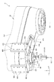
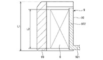
FIG. 1 is a side view showing a first embodiment of the robot of the present invention. FIG. 2 is a block diagram of the robot system shown in FIG. FIG. 3 is a side view showing the inside of the second arm of the robot shown in FIG. FIG. 4 is a perspective view of the second arm of the robot shown in FIG. FIG. 5 is a perspective view of the second arm of the robot shown in FIG. FIG. 6 is a perspective view of a mounting member included in the robot shown in FIG. FIG. 7 is a vertical cross-sectional view of the mounting portion of the mounting member shown in FIG.

また、図1〜図4では、説明の便宜上、互いに直交する3軸として、x軸、y軸およびz軸を図示している。また、以下では、x軸に平行な方向を「x軸方向」とも言い、y軸に平行な方向を「y軸方向」とも言い、z軸に平行な方向を「z軸方向」とも言う。また、以下では、図示された各矢印の先端側を「+(プラス)」、基端側を「−(マイナス)」と言う。また、z軸回りの方向およびz軸に平行な軸回りの方向を「u軸方向」とも言う。 Further, in FIGS. 1 to 4, for convenience of explanation, the x-axis, the y-axis, and the z-axis are illustrated as three axes orthogonal to each other. Further, in the following, the direction parallel to the x-axis is also referred to as "x-axis direction", the direction parallel to the y-axis is also referred to as "y-axis direction", and the direction parallel to the z-axis is also referred to as "z-axis direction". Further, in the following, the tip end side of each of the illustrated arrows will be referred to as “+ (plus)”, and the proximal end side will be referred to as “− (minus)”. Further, the direction around the z-axis and the direction around the axis parallel to the z-axis are also referred to as "u-axis directions".

また、以下では、説明の便宜上、図1中の+z軸方向、すなわち、上側を「上」、−z軸方向、すなわち、下側を「下」とも言う。また、ロボットアーム20については、図1中の基台21側を「基端」、その反対側、すなわち、エンドエフェクター7側を「先端」と言う。また、図1中のz軸方向、すなわち、上下方向を「鉛直方向」とし、x軸方向およびy軸方向、すなわち、左右方向を「水平方向」とする。 Further, in the following, for convenience of explanation, the + z-axis direction in FIG. 1, that is, the upper side is referred to as “upper”, and the −z-axis direction, that is, the lower side is also referred to as “lower”. Regarding the robot arm 20, the base 21 side in FIG. 1 is referred to as a “base end”, and the opposite side, that is, the end effector 7 side is referred to as a “tip”. Further, the z-axis direction in FIG. 1, that is, the vertical direction is defined as the "vertical direction", and the x-axis direction and the y-axis direction, that is, the left-right direction is defined as the "horizontal direction".

図1および図2に示すロボットシステム100は、例えば、電子部品および電子機器等のワークの保持、搬送、組立ておよび検査等の作業で用いられる装置である。ロボットシステム100は、ロボット2と、エンドエフェクター7と、制御装置8と、を備えている。 The robot system 100 shown in FIGS. 1 and 2 is an apparatus used for operations such as holding, transporting, assembling, and inspecting workpieces such as electronic parts and electronic devices. The robot system 100 includes a robot 2, an end effector 7, and a control device 8.

また、図示の構成では、制御装置8は、ロボット2の基台21に内蔵されているが、これに限定されず、例えば、基台21の外側に配置されていてもよい。この場合、ロボット2と制御装置8とは、有線通信で接続されていてもよく、また、無線通信で接続されていてもよい。 Further, in the illustrated configuration, the control device 8 is built in the base 21 of the robot 2, but the present invention is not limited to this, and for example, the control device 8 may be arranged outside the base 21. In this case, the robot 2 and the control device 8 may be connected by wire communication or may be connected by wireless communication.

ロボット2は、水平多関節ロボット、すなわち、スカラロボットである。
図1〜図4に示すように、ロボット2は、基台21と、第1アーム22と、第2アーム23と、作業ヘッドである第3アーム24と、力検出部5と、を備えている。第1アーム22、第2アーム23および第3アーム24等によりロボットアーム20が構成される。
The robot 2 is a horizontal articulated robot, that is, a SCARA robot.
As shown in FIGS. 1 to 4, the robot 2 includes a base 21, a first arm 22, a second arm 23, a third arm 24 which is a work head, and a force detecting unit 5. There is. The robot arm 20 is composed of the first arm 22, the second arm 23, the third arm 24, and the like.

また、ロボット2は、第1アーム22を基台21に対して回転させる駆動ユニット25と、第2アーム23を第1アーム22に対して回転させる駆動ユニット26と、第3アーム24のシャフト241を第2アーム23に対して回転させるu駆動ユニット27と、シャフト241を第2アーム23に対してz軸方向に移動させるz駆動ユニット28と、角速度センサー29とを備えている。 Further, the robot 2 includes a drive unit 25 that rotates the first arm 22 with respect to the base 21, a drive unit 26 that rotates the second arm 23 with respect to the first arm 22, and a shaft 241 of the third arm 24. It is provided with a u drive unit 27 for rotating the shaft 241 with respect to the second arm 23, a z drive unit 28 for moving the shaft 241 with respect to the second arm 23 in the z-axis direction, and an angular velocity sensor 29.

図1および図2に示すように、駆動ユニット25は、第1アーム22の筐体220内に内蔵されており、駆動力を発生するモーター251と、モーター251の駆動力を減速する減速機252と、モーター251または減速機252の回転軸の回転角度を検出する位置センサー253とを有している。 As shown in FIGS. 1 and 2, the drive unit 25 is built in the housing 220 of the first arm 22, and has a motor 251 that generates a driving force and a speed reducer 252 that reduces the driving force of the motor 251. And a position sensor 253 that detects the rotation angle of the rotation shaft of the motor 251 or the speed reducer 252.

駆動ユニット26は、第2アーム23に内蔵されており、駆動力を発生するモーター261と、モーター261の駆動力を減速する減速機262と、モーター261または減速機262の回転軸の回転角度を検出する位置センサー263とを有している。 The drive unit 26 is built in the second arm 23, and determines the rotation angles of the motor 261 that generates the driving force, the speed reducer 262 that reduces the driving force of the motor 261 and the rotation shaft of the motor 261 or the speed reducer 262. It has a position sensor 263 to detect.

u駆動ユニット27は、第2アーム23に内蔵されており、駆動力を発生するモーター271と、モーター271の駆動力を減速する減速機272と、モーター271または減速機272の回転軸の回転角度を検出する位置センサー273とを有している。 The u drive unit 27 is built in the second arm 23, and has a motor 271 that generates a driving force, a speed reducer 272 that reduces the driving force of the motor 271, and a rotation angle of the rotation shaft of the motor 271 or the speed reducer 272. It has a position sensor 273 to detect the above.

z駆動ユニット28は、第2アーム23に内蔵されており、駆動力を発生するモーター281と、モーター281の駆動力を減速する減速機282と、モーター281または減速機282の回転軸の回転角度を検出する位置センサー283とを有している。 The z drive unit 28 is built in the second arm 23, and has a motor 281 that generates a driving force, a speed reducer 282 that reduces the driving force of the motor 281, and a rotation angle of the rotation shaft of the motor 281 or the speed reducer 282. It has a position sensor 283 for detecting the above.

モーター251、モーター261、モーター271およびモーター281としては、例えば、ACサーボモーター、DCサーボモーター等のサーボモーターを用いることができる。 As the motor 251 and the motor 261 and the motor 271 and the motor 281, for example, a servomotor such as an AC servomotor or a DC servomotor can be used.

また、減速機252、減速機262、減速機272および減速機282としては、例えば、遊星ギア型の減速機、波動歯車装置等を用いることができる。また、位置センサー253、位置センサー263、位置センサー273および位置センサー283は、例えば、角度センサーとすることができる。 Further, as the speed reducer 252, the speed reducer 262, the speed reducer 272, and the speed reducer 282, for example, a planetary gear type speed reducer, a wave gear device, or the like can be used. Further, the position sensor 253, the position sensor 263, the position sensor 273 and the position sensor 283 can be, for example, an angle sensor.

駆動ユニット25、駆動ユニット26、u駆動ユニット27およびz駆動ユニット28は、それぞれ、対応する図示しないモータードライバーに接続されており、モータードライバーを介して制御装置8により制御される。なお、各減速機は省略されていてもよい。 The drive unit 25, the drive unit 26, the u drive unit 27, and the z drive unit 28 are each connected to a corresponding motor driver (not shown) and are controlled by the control device 8 via the motor driver. Each speed reducer may be omitted.

また、角速度センサー29は、第2アーム23に内蔵されている。このため、第2アーム23の角速度を検出することができる。この検出した角速度の情報に基づいて、制御装置8は、ロボット2の制御を行う。また、角速度センサー29は、駆動ユニット26〜28よりも−y軸側、すなわち、基台21の遠位側に設置されている。 Further, the angular velocity sensor 29 is built in the second arm 23. Therefore, the angular velocity of the second arm 23 can be detected. Based on the detected angular velocity information, the control device 8 controls the robot 2. Further, the angular velocity sensor 29 is installed on the −y axis side of the drive units 26 to 28, that is, on the distal side of the base 21.

基台21は、例えば、図示しない床面にボルト等によって固定されている。基台21の上端部には第1アーム22が連結されている。第1アーム22は、基台21に対して鉛直方向に沿う第1軸O1回りに回転可能となっている。第1アーム22を回転させる駆動ユニット25が駆動すると、第1アーム22が基台21に対して第1軸O1回りに水平面内で回転する。また、位置センサー253により、基台21に対する第1アーム22の回転量が検出できるようになっている。 The base 21 is fixed to a floor surface (not shown) with bolts or the like, for example. The first arm 22 is connected to the upper end of the base 21. The first arm 22 is rotatable around the first axis O1 along the vertical direction with respect to the base 21. When the drive unit 25 that rotates the first arm 22 is driven, the first arm 22 rotates in a horizontal plane around the first axis O1 with respect to the base 21. Further, the position sensor 253 can detect the amount of rotation of the first arm 22 with respect to the base 21.

また、第1アーム22の先端部には、第2アーム23が連結されている。第2アーム23は、第1アーム22に対して鉛直方向に沿う第2軸O2回りに回転可能となっている。第1軸O1の軸方向と第2軸O2の軸方向とは同一である。すなわち、第2軸O2は、第1軸O1と平行である。第2アーム23を回転させる駆動ユニット26が駆動すると、第2アーム23が第1アーム22に対して第2軸O2回りに水平面内で回転する。また、位置センサー263により、第1アーム22に対する第2アーム23の駆動、具体的には、回転量が検出できるようになっている。 A second arm 23 is connected to the tip of the first arm 22. The second arm 23 is rotatable around the second axis O2 along the vertical direction with respect to the first arm 22. The axial direction of the first axis O1 and the axial direction of the second axis O2 are the same. That is, the second axis O2 is parallel to the first axis O1. When the drive unit 26 that rotates the second arm 23 is driven, the second arm 23 rotates in a horizontal plane around the second axis O2 with respect to the first arm 22. Further, the position sensor 263 can detect the drive of the second arm 23 with respect to the first arm 22, specifically, the amount of rotation.

また、第2アーム23の可動範囲、すなわち、回転可能な範囲は、後述する装着用部材9に装着された保護部材93が図1に示す配管800および配管支持部900と接触しない程度であるのが好ましい。なお、配管800および配管支持部900は、中空であり、後述する配線群300を含む複数の配線を挿通する部分である。 Further, the movable range of the second arm 23, that is, the rotatable range is such that the protective member 93 mounted on the mounting member 9 described later does not come into contact with the pipe 800 and the pipe support portion 900 shown in FIG. Is preferable. The pipe 800 and the pipe support portion 900 are hollow, and are portions through which a plurality of wires including a wiring group 300, which will be described later, are inserted.

図3に示すように、第2アーム23は、ベース231と、ベース231に支持される駆動ユニット26、u駆動ユニット27、z駆動ユニット28および角速度センサー29と、これらを覆うカバー部材232と、を有する。また、駆動ユニット26、u駆動ユニット27、z駆動ユニット28および角速度センサー29は、−y軸側からこの順で並んで設置される。 As shown in FIG. 3, the second arm 23 includes a base 231, a drive unit 26 supported by the base 231, a u drive unit 27, a z drive unit 28, an angular velocity sensor 29, a cover member 232 for covering the base 231 and a cover member 232 for covering the base 231. Has. Further, the drive unit 26, the u drive unit 27, the z drive unit 28, and the angular velocity sensor 29 are installed side by side in this order from the −y axis side.

ベース231は、例えば、各種金属材料、各種硬質樹脂材料等で構成された剛体である。ベース231は、第3軸O3と交わる方向、すなわち、y軸方向に延在している。また、ベース231は、u駆動ユニット27が配置される凹部230Cを有している。凹部230Cは、−z軸側の一部が−z軸側に開放しており、この解放した部分に回転支持部材242が埋設され、シャフト241が挿通されている。 The base 231 is, for example, a rigid body made of various metal materials, various hard resin materials, and the like. The base 231 extends in the direction intersecting the third axis O3, that is, in the y-axis direction. Further, the base 231 has a recess 230C in which the u drive unit 27 is arranged. A part of the recess 230C on the −z axis side is open to the −z axis side, and a rotation support member 242 is embedded in the opened portion, and the shaft 241 is inserted through the recess 230C.

図3に示すように、u駆動ユニット27は、前述したモーター271、減速機272および位置センサー273に加え、プーリー275を有する。これらは、位置センサー273、モーター271、減速機272およびプーリー275の順で+z軸側から配置され、凹部230Cの底部に固定されている。プーリー275は、減速機272のコアに固定されており、モーター271の回転力が減速機272で減速されて、プーリー275に伝達される。 As shown in FIG. 3, the u drive unit 27 has a pulley 275 in addition to the motor 271, the speed reducer 272 and the position sensor 273 described above. These are arranged in the order of the position sensor 273, the motor 271, the reduction gear 272, and the pulley 275 from the + z axis side, and are fixed to the bottom of the recess 230C. The pulley 275 is fixed to the core of the speed reducer 272, and the rotational force of the motor 271 is decelerated by the speed reducer 272 and transmitted to the pulley 275.

また、プーリー275は、ベルト274によってシャフト241に設けられたスプラインナット244の内輪244Aと連結されている。ベルト274は、プーリー275および内輪244Aに掛け回された無端ベルトであり、その内側、すなわち、プーリー275および内輪244A側に図示しない歯を有する。ベルト274の歯が、プーリー275および内輪244Aの露出した部分の図示しない歯とそれぞれ噛合している。 Further, the pulley 275 is connected to the inner ring 244A of the spline nut 244 provided on the shaft 241 by the belt 274. The belt 274 is an endless belt hung around the pulley 275 and the inner ring 244A, and has teeth (not shown) on the inside thereof, that is, on the pulley 275 and the inner ring 244A side. The teeth of the belt 274 mesh with the teeth of the pulley 275 and the exposed portion of the inner ring 244A, respectively, which are not shown.

このようなu駆動ユニット27では、モーター271の回転力が減速機272およびプーリー275を介してベルト274に伝達され、ベルト274が回転する。このベルト274の回転により、その回転力がスプラインナット244を介してシャフト241に伝達される。この回転力が内輪244Aの内周部およびシャフト241の図示しないスプライン溝を介してシャフト241に伝達され、シャフト241がu軸方向に移動する、すなわち、回転することができる。 In such a u drive unit 27, the rotational force of the motor 271 is transmitted to the belt 274 via the speed reducer 272 and the pulley 275, and the belt 274 rotates. By the rotation of the belt 274, the rotational force is transmitted to the shaft 241 via the spline nut 244. This rotational force is transmitted to the shaft 241 via the inner peripheral portion of the inner ring 244A and the spline groove of the shaft 241 (not shown), and the shaft 241 can move in the u-axis direction, that is, rotate.

図3に示すように、z駆動ユニット28は、前述したモーター281、減速機282および位置センサー283に加え、プーリー285を有する。これらは、位置センサー283、モーター281、プーリー285および減速機282の順で+z軸側から配置されている。プーリー285は、減速機282のコアに固定されており、モーター281の回転力が減速機282で減速されて、プーリー285に伝達される。また、減速機282が、ベース231に固定されている。 As shown in FIG. 3, the z drive unit 28 has a pulley 285 in addition to the motor 281, the speed reducer 282, and the position sensor 283 described above. These are arranged in the order of the position sensor 283, the motor 281, the pulley 285, and the speed reducer 282 from the + z axis side. The pulley 285 is fixed to the core of the speed reducer 282, and the rotational force of the motor 281 is decelerated by the speed reducer 282 and transmitted to the pulley 285. Further, the speed reducer 282 is fixed to the base 231.

また、プーリー285は、ベルト284によってシャフト241に設けられたボールねじナット243の内輪243Aの露出した部分と連結されている。ベルト284は、プーリー285および内輪243Aに掛け回された無端ベルトであり、その内側、すなわち、プーリー285および内輪243A側に図示しない歯を有する。ベルト284の歯が、プーリー285および内輪243Aの図示しない歯とそれぞれ噛合している。 Further, the pulley 285 is connected to the exposed portion of the inner ring 243A of the ball screw nut 243 provided on the shaft 241 by the belt 284. The belt 284 is an endless belt hung around the pulley 285 and the inner ring 243A, and has teeth (not shown) on the inside thereof, that is, on the pulley 285 and the inner ring 243A side. The teeth of the belt 284 mesh with the teeth of the pulley 285 and the inner ring 243A, respectively, which are not shown.

このようなz駆動ユニット28では、モーター281の回転力が減速機282およびプーリー285を介してベルト284に伝達され、ベルト284が回転する。このベルト284の回転により、その回転力がボールねじナット243の内輪243Aを介してシャフト241に伝達される。この回転力が内輪243Aの内周部およびシャフト241のボールねじ溝によって方向が変換され、シャフト241がz軸方向に移動する、すなわち、上下動することができる。 In such a z drive unit 28, the rotational force of the motor 281 is transmitted to the belt 284 via the speed reducer 282 and the pulley 285, and the belt 284 rotates. By the rotation of the belt 284, the rotational force is transmitted to the shaft 241 via the inner ring 243A of the ball screw nut 243. The direction of this rotational force is changed by the inner peripheral portion of the inner ring 243A and the ball screw groove of the shaft 241 so that the shaft 241 can move in the z-axis direction, that is, move up and down.

図1および図3に示すように、カバー部材232は、ベース231、駆動ユニット26、u駆動ユニット27、z駆動ユニット28および角速度センサー29等を覆い、これらを保護する機能を有する。また、カバー部材232は、ベース231よりも軟質な材料で構成されている。この材料としては、例えば、各種樹脂材料が挙げられる。 As shown in FIGS. 1 and 3, the cover member 232 has a function of covering the base 231, the drive unit 26, the u drive unit 27, the z drive unit 28, the angular velocity sensor 29, and the like, and protecting them. Further, the cover member 232 is made of a material softer than the base 231. Examples of this material include various resin materials.

このように、カバー部材232は、ベース231よりも軟質である。これにより、ベース231が露出する構成に比べ、安全性を高めることができる。 As described above, the cover member 232 is softer than the base 231. As a result, the safety can be improved as compared with the configuration in which the base 231 is exposed.

また、カバー部材232は、−z軸側の壁部に開口233を有する。この開口233は、貫通孔であり、ベース231の延在方向、すなわち、y軸方向に沿って延在する長孔で構成されている。開口233は、後述する装着用部材9が通過する部分であるとともに、第3アーム24のシャフト241を挿通する部分である。 Further, the cover member 232 has an opening 233 in the wall portion on the −z axis side. The opening 233 is a through hole, and is composed of an elongated hole extending along the extending direction of the base 231, that is, the y-axis direction. The opening 233 is a portion through which the mounting member 9, which will be described later, passes, and a portion through which the shaft 241 of the third arm 24 is inserted.

このように、第3アーム24は、開口233を通る。これにより、後述する装着用部材9をベース231に固定するための機能と、第3アーム24を挿通するための機能とを備えることとなる。よって、これらを別途設ける構成に比べ、簡素な構成とすることができる。 In this way, the third arm 24 passes through the opening 233. As a result, it is provided with a function for fixing the mounting member 9 described later to the base 231 and a function for inserting the third arm 24. Therefore, the configuration can be simplified as compared with the configuration in which these are separately provided.

また、図4および図5に示すように、開口233の第3アーム24を挿通する部分以外は、カバー部材234により覆われている。これにより、防水性を高めることができる。なお、図3では、カバー部材234を省略している。 Further, as shown in FIGS. 4 and 5, the portion of the opening 233 through which the third arm 24 is inserted is covered with the cover member 234. Thereby, the waterproof property can be improved. In FIG. 3, the cover member 234 is omitted.

また、図1に示すように、カバー部材232の+y軸側の外面には、受付部4が設けられている。受付部4は、図示しない複数のボタン等を有し、オペレーターからの入力を受け付ける機能を有している。また、複数のボタンには、ロボットアーム20の動作を教示する教示ボタンが含まれる。なお、例えばタッチパネルを用いる場合には、受付部4は、ユーザーの指のタッチパネルへの接触等を検知する入力検知部としての機能を有する。 Further, as shown in FIG. 1, a reception portion 4 is provided on the outer surface of the cover member 232 on the + y-axis side. The reception unit 4 has a plurality of buttons and the like (not shown) and has a function of receiving input from an operator. Further, the plurality of buttons include a teaching button for teaching the operation of the robot arm 20. When a touch panel is used, for example, the reception unit 4 has a function as an input detection unit for detecting contact of a user's finger with the touch panel.

また、図3に示すように、第2アーム23の先端部には、第3アーム24が設置されている。第3アーム24は、シャフト241と、シャフト241を回転可能に支持する回転支持部材242とを有する。 Further, as shown in FIG. 3, a third arm 24 is installed at the tip of the second arm 23. The third arm 24 has a shaft 241 and a rotation support member 242 that rotatably supports the shaft 241.

シャフト241は、第2アーム23に対して、鉛直方向に沿う第3軸O3回りに回転可能であり、かつ、上下方向に移動可能、すなわち、昇降可能となっている。このシャフト241は、ロボットアーム20の第3アームであり、ロボットアーム20の最も先端のアームである。 The shaft 241 can rotate about the third axis O3 along the vertical direction with respect to the second arm 23, and can move in the vertical direction, that is, can move up and down. The shaft 241 is the third arm of the robot arm 20, and is the most advanced arm of the robot arm 20.

また、シャフト241の長手方向の途中には、ボールねじナット243と、スプラインナット244と、が設置されており、シャフト241は、これらによって支持されている。これらボールねじナット243およびスプラインナット244は、この順で+z軸側から離間して配置されている。 Further, a ball screw nut 243 and a spline nut 244 are installed in the middle of the shaft 241 in the longitudinal direction, and the shaft 241 is supported by these. The ball screw nut 243 and the spline nut 244 are arranged apart from the + z-axis side in this order.

ボールねじナット243は、内輪243Aと、内輪243Aの外周側に同心的に配置された外輪243Bとを有する。これら内輪243Aおよび外輪243Bの間には、図示しない複数のボールが配置されており、ボールの移動とともに内輪243Aおよび外輪243Bは、互いに相対的に回転する。 The ball screw nut 243 has an inner ring 243A and an outer ring 243B concentrically arranged on the outer peripheral side of the inner ring 243A. A plurality of balls (not shown) are arranged between the inner ring 243A and the outer ring 243B, and the inner ring 243A and the outer ring 243B rotate relative to each other as the balls move.

また、内輪243Aは、外輪243Bから露出した部分を有し、この露出した部分に後述するベルト284が掛け回されている。また、内輪243Aは、その内部にシャフト241を挿通し、後述するように、シャフト241をz軸方向に沿って移動可能に支持している。また、外輪243Bは、ベース231に固定されている。 Further, the inner ring 243A has a portion exposed from the outer ring 243B, and a belt 284 described later is hung around the exposed portion. Further, the inner ring 243A has a shaft 241 inserted therein and supports the shaft 241 so as to be movable along the z-axis direction as described later. Further, the outer ring 243B is fixed to the base 231.

スプラインナット244は、内輪244Aと、内輪244Aの外周側に同心的に配置された外輪244Bとを有する。これら内輪244Aおよび外輪244Bの間には、図示しない複数のボールが配置されており、ボールの移動とともに内輪244Aおよび外輪244Bは、互いに相対的に回転する。 The spline nut 244 has an inner ring 244A and an outer ring 244B concentrically arranged on the outer peripheral side of the inner ring 244A. A plurality of balls (not shown) are arranged between the inner ring 244A and the outer ring 244B, and the inner ring 244A and the outer ring 244B rotate relative to each other as the balls move.

また、内輪244Aは、外輪244Bから露出した部分を有し、この露出した部分に後述するベルト274が掛け回されている。また、内輪244Aは、その内部にシャフト241を挿通し、シャフト241をz軸回り、すなわち、u軸方向に回転可能に支持している。また、外輪244Bは、後述するベース231の凹部230Cに固定されている。 Further, the inner ring 244A has a portion exposed from the outer ring 244B, and a belt 274 described later is hung around the exposed portion. Further, the inner ring 244A has a shaft 241 inserted therein and supports the shaft 241 so as to be rotatable around the z-axis, that is, in the u-axis direction. Further, the outer ring 244B is fixed to the recess 230C of the base 231 described later.

また、スプラインナット244の−z軸側には、回転支持部材242が設置されている。この回転支持部材242は、外筒245と、外筒245の内側に設けられた回転体246と、を有する。外筒245は、ベース231に固定されている。一方、回転体246は、シャフト241には固定されているが、シャフト241とともにz軸回りに回転可能に外筒245に支持されている。 Further, a rotation support member 242 is installed on the −z axis side of the spline nut 244. The rotation support member 242 has an outer cylinder 245 and a rotating body 246 provided inside the outer cylinder 245. The outer cylinder 245 is fixed to the base 231. On the other hand, the rotating body 246 is fixed to the shaft 241 but is supported by the outer cylinder 245 so as to be rotatable around the z-axis together with the shaft 241.

シャフト241を回転させるu駆動ユニット27が駆動すると、シャフト241は、z軸回りに正逆回転、すなわち、回転する。また、位置センサー273により、第2アーム23に対するシャフト241の回転量が検出できるようになっている。 When the u drive unit 27 that rotates the shaft 241 is driven, the shaft 241 rotates forward and reverse, that is, rotates about the z-axis. Further, the position sensor 273 can detect the amount of rotation of the shaft 241 with respect to the second arm 23.

また、シャフト241をz軸方向に移動させるz駆動ユニット28が駆動すると、シャフト241は、上下方向、すなわち、z軸方向に移動する。また、位置センサー283により、第2アーム23に対するシャフト241のz軸方向の移動量が検出できるようになっている。 Further, when the z drive unit 28 that moves the shaft 241 in the z-axis direction is driven, the shaft 241 moves in the vertical direction, that is, in the z-axis direction. Further, the position sensor 283 can detect the amount of movement of the shaft 241 with respect to the second arm 23 in the z-axis direction.

また、シャフト241の先端部には、各種のエンドエフェクターが着脱可能に連結される。エンドエフェクターとしては、特に限定されず、例えば、被搬送物を把持するもの、被加工物を加工するもの、検査に使用するもの等が挙げられる。 In addition, various end effectors are detachably connected to the tip of the shaft 241. The end effector is not particularly limited, and examples thereof include those that grip an object to be transported, those that process an object to be processed, those used for inspection, and the like.

なお、エンドエフェクター7は、本実施形態では、ロボット2の構成要素になっていないが、エンドエフェクター7の一部または全部がロボット2の構成要素になっていてもよい。また、エンドエフェクター7は、本実施形態では、ロボットアーム20の構成要素になっていないが、エンドエフェクター7の一部または全部がロボットアーム20の構成要素になっていてもよい。 Although the end effector 7 is not a component of the robot 2 in the present embodiment, a part or all of the end effector 7 may be a component of the robot 2. Further, although the end effector 7 is not a component of the robot arm 20 in the present embodiment, a part or all of the end effector 7 may be a component of the robot arm 20.

また、本実施形態では、エンドエフェクター7は、ロボットアーム20に対して着脱可能であるが、これに限定されず、例えば、エンドエフェクター7は、ロボットアーム20から離脱不能になっていてもよい。
なお、図3では、エンドエフェクター7の図示を省略している。
Further, in the present embodiment, the end effector 7 can be attached to and detached from the robot arm 20, but the present invention is not limited to this, and for example, the end effector 7 may be inseparable from the robot arm 20.
In FIG. 3, the end effector 7 is not shown.

また、図1に示すように、力検出部5は、ロボット2に加わる力、すなわち、ロボットアーム20および基台21に加わる力を検出するものである。力検出部5は、本実施形態では、基台21の下方、すなわち、−z軸側に設けられており、基台21を下方から支持している。 Further, as shown in FIG. 1, the force detecting unit 5 detects the force applied to the robot 2, that is, the force applied to the robot arm 20 and the base 21. In the present embodiment, the force detecting unit 5 is provided below the base 21, that is, on the −z axis side, and supports the base 21 from below.

力検出部5は、例えば、水晶等の圧電体で構成され、外力を受けると電荷を出力する複数の素子を有する構成とすることができる。また、制御装置8は、この電荷量に応じて、ロボットアーム20が受けた外力に変換することができる。また、このような圧電体であると、設置する向きに応じて、外力を受けた際に電荷を発生させる向きを調整可能である。 The force detection unit 5 may be composed of, for example, a piezoelectric material such as quartz, and may have a plurality of elements that output electric charges when an external force is received. Further, the control device 8 can convert the external force received by the robot arm 20 according to the amount of electric charge. Further, with such a piezoelectric body, the direction in which an electric charge is generated when an external force is received can be adjusted according to the direction in which the piezoelectric body is installed.

なお、力検出部5の設置位置は、図示の構成に限定されず、例えば、シャフト241の先端に設置されていてもよい。 The installation position of the force detection unit 5 is not limited to the configuration shown in the figure, and may be installed at the tip of the shaft 241 for example.

撮像部6は、例えば、複数の画素を有するCCD(Charge Coupled Device)イメージセンサーで構成された撮像素子と、レンズ等を含む光学系と、を有する。撮像部6は、撮像対象等からの光をレンズによって撮像素子の受光面で結像させて、光を電気信号に変換し、その電気信号を制御装置8へと出力する。そして、制御装置8は、この電気信号、すなわち、撮像結果に基づいて、ロボットアーム20の駆動を制御する。なお、撮像素子は、撮像機能を有する構成であれば、前述の構成に限定されず他の構成であってもよい。なお、「対象」としては、ワークや、工具や、その他の物体等の障害物のことを言う。 The image pickup unit 6 includes, for example, an image pickup element composed of a CCD (Charge Coupled Device) image sensor having a plurality of pixels, and an optical system including a lens and the like. The image pickup unit 6 forms an image of light from an image pickup target or the like on the light receiving surface of the image pickup element with a lens, converts the light into an electric signal, and outputs the electric signal to the control device 8. Then, the control device 8 controls the drive of the robot arm 20 based on this electric signal, that is, the imaging result. The image sensor is not limited to the above-mentioned configuration as long as it has an imaging function, and may have another configuration. The "object" refers to an obstacle such as a work, a tool, or another object.

図1および図2に示すように、制御装置8は、本実施形態では、基台21に内蔵されている。また、図2に示すように、制御装置8は、ロボット2の駆動を制御する機能を有し前述したロボット2の各部と電気的に接続されている。制御装置8は、CPU(Central Processing Unit)81と、記憶部82と、通信部83と、を有する。これらの各部は、例えばバスを介して相互に通信可能に接続されている。 As shown in FIGS. 1 and 2, the control device 8 is built in the base 21 in this embodiment. Further, as shown in FIG. 2, the control device 8 has a function of controlling the drive of the robot 2 and is electrically connected to each part of the robot 2 described above. The control device 8 includes a CPU (Central Processing Unit) 81, a storage unit 82, and a communication unit 83. Each of these parts is communicably connected to each other via, for example, a bus.

CPU81は、記憶部82に記憶されている各種プログラム等を読み出し、実行する。CPU81で生成された指令信号は、通信部83を介してロボット2に送信される。これにより、ロボットアーム20が所定の作業を実行することができる。 The CPU 81 reads and executes various programs and the like stored in the storage unit 82. The command signal generated by the CPU 81 is transmitted to the robot 2 via the communication unit 83. As a result, the robot arm 20 can perform a predetermined work.

記憶部82は、CPU81が実行可能な各種プログラム等を保存する。記憶部82としては、例えば、RAM(Random Access Memory)等の揮発性メモリー、ROM(Read Only Memory)等の不揮発性メモリー、着脱式の外部記憶装置等が挙げられる。 The storage unit 82 stores various programs and the like that can be executed by the CPU 81. Examples of the storage unit 82 include a volatile memory such as a RAM (Random Access Memory), a non-volatile memory such as a ROM (Read Only Memory), and a detachable external storage device.

通信部83は、例えば有線LAN(Local Area Network)、無線LAN等の外部インターフェースを用いてロボット2の各部および他の機器、例えば、教示装置との間でそれぞれ信号の送受信を行う。教示装置としては、例えば、タブレット、スマートフォン、パソコン、ティーチングペンダント等が挙げられる。 The communication unit 83 transmits and receives signals to and from each unit of the robot 2 and other devices, for example, a teaching device, using an external interface such as a wired LAN (Local Area Network) or a wireless LAN. Examples of the teaching device include tablets, smartphones, personal computers, teaching pendants, and the like.

次に、装着用部材9について説明する。
図3〜図6に示すように、装着用部材9は、撮像部6を、カバー部材232の外側に設置するための部材である。装着用部材9は、ベース231に固定される固定部91と、撮像部6が着脱可能に装着される複数の装着部92と、保護部材93と、緩衝部材94と、を有する。
Next, the mounting member 9 will be described.
As shown in FIGS. 3 to 6, the mounting member 9 is a member for installing the image pickup unit 6 on the outside of the cover member 232. The mounting member 9 includes a fixing portion 91 fixed to the base 231, a plurality of mounting portions 92 to which the imaging unit 6 is detachably mounted, a protective member 93, and a cushioning member 94.

図4〜図6に示すように、固定部91は、ベース231に固定された状態において、+y軸側に位置する第1固定部91Aと、+x軸側に位置する第2固定部91Bと、−x軸側に位置する第3固定部91Cと、を有し、全体形状がU字状をなす剛体で構成されている。また、固定部91をベースに固定した際、第3アーム24のシャフト241は、第1固定部91A〜第3固定部91Cの間の空間に位置する。すなわち、空間は、第3アーム24を挿通する挿通部として機能する。 As shown in FIGS. 4 to 6, the fixing portion 91 includes a first fixing portion 91A located on the + y-axis side and a second fixing portion 91B located on the + x-axis side in a state of being fixed to the base 231. It is composed of a rigid body having a third fixed portion 91C located on the −x axis side and having a U-shaped overall shape. Further, when the fixing portion 91 is fixed to the base, the shaft 241 of the third arm 24 is located in the space between the first fixing portion 91A and the third fixing portion 91C. That is, the space functions as an insertion portion through which the third arm 24 is inserted.

このように、装着用部材9は、第3アーム24を通る挿通部としての空間を有する。これにより、装着用部材9をベース231に固定した際、装着用部材9が第3アーム24の動作を阻害するのを防止することができる。また、装着部92に装着された撮像部6の光軸を可及的に第3軸O3に近づけることができる。 As described above, the mounting member 9 has a space as an insertion portion passing through the third arm 24. This makes it possible to prevent the mounting member 9 from hindering the operation of the third arm 24 when the mounting member 9 is fixed to the base 231. In addition, the optical axis of the imaging unit 6 mounted on the mounting unit 92 can be as close as possible to the third axis O3.

第1固定部91Aは、ベース231に固定された状態において、x軸方向に沿って延在する長尺状をなしている。第2固定部91Bは、第1固定部91Aの一端部、すなわち、+y軸側の端部から延出している。第2固定部91Bは、ベース231に固定された状態において、y軸方向に沿って延在する長尺状をなしている。第3固定部91Cは、第1固定部91Aの他端部、すなわち、−y軸側の端部から延出している。第3固定部91Cは、ベース231に固定された状態において、y軸方向に沿って延在する長尺状をなしている。 The first fixing portion 91A has a long shape extending along the x-axis direction in a state of being fixed to the base 231. The second fixing portion 91B extends from one end of the first fixing portion 91A, that is, the end on the + y-axis side. The second fixing portion 91B has a long shape extending along the y-axis direction in a state of being fixed to the base 231. The third fixing portion 91C extends from the other end of the first fixing portion 91A, that is, the end on the −y axis side. The third fixing portion 91C has a long shape extending along the y-axis direction in a state of being fixed to the base 231.

また、第1固定部91Aは、+z軸側に突出した突出部911Aを有する。また、第1固定部91Aは、突出部911Aに対応する部分に貫通孔912Aを有する。また、第2固定部91Bは、+z軸側に突出した突出部911Bを有する。また、第2固定部91Bは、突出部911Bに対応する部分に貫通孔912Bを有する。また、第3固定部91Cは、+z軸側に突出した突出部911Cを有する。また、第3固定部91Cは、突出部911Cに対応する部分に貫通孔912Cを有する。 Further, the first fixed portion 91A has a protruding portion 911A protruding toward the + z axis side. Further, the first fixing portion 91A has a through hole 912A in a portion corresponding to the protruding portion 911A. Further, the second fixed portion 91B has a protruding portion 911B protruding toward the + z axis side. Further, the second fixing portion 91B has a through hole 912B in a portion corresponding to the protruding portion 911B. Further, the third fixed portion 91C has a protruding portion 911C protruding toward the + z axis side. Further, the third fixing portion 91C has a through hole 912C in a portion corresponding to the protruding portion 911C.

これら貫通孔912A〜貫通孔912Cは、例えば、ネジ、ボルト等の固定部材200を挿通する部分である。これにより、貫通孔912A、貫通孔912Bおよび貫通孔912Cを挿通して固定部材200をベース231に固定することができる。よって、固定部91をベース231に安定的に固定することができる。 These through holes 912A to 912C are portions through which fixing members 200 such as screws and bolts are inserted. As a result, the fixing member 200 can be fixed to the base 231 by inserting the through hole 912A, the through hole 912B, and the through hole 912C. Therefore, the fixing portion 91 can be stably fixed to the base 231.

また、突出部911A〜突出部911Cを有することにより、固定部91をベース231に固定した状態では、固定部91の、装着部92が装着される部分が、開口233の外側に位置することとなる。よって、装着部92をカバー部材232の外側に配置することができる。また、装着部92の着脱操作を容易に行うことができる。 Further, by having the projecting portions 911A to 911C, when the fixing portion 91 is fixed to the base 231 the portion of the fixing portion 91 to which the mounting portion 92 is mounted is located outside the opening 233. Become. Therefore, the mounting portion 92 can be arranged outside the cover member 232. In addition, the mounting portion 92 can be easily attached and detached.

このような第1固定部91A、第2固定部91Bおよび第3固定部91Cには、それぞれ、1つの装着部92を着脱可能に装着することができる。この着脱機構は、図示の構成では、ネジ、ボルト等の固定部材400を用いた構成である。ただし、この構成に限定されず、例えば、磁石による固定や、任意の着脱機構を用いてもよい。 One mounting portion 92 can be detachably mounted on each of the first fixing portion 91A, the second fixing portion 91B, and the third fixing portion 91C. In the illustrated configuration, this attachment / detachment mechanism uses a fixing member 400 such as a screw or a bolt. However, the present invention is not limited to this configuration, and for example, fixing with a magnet or an arbitrary attachment / detachment mechanism may be used.

なお、以下では、一例として、図6に示すように、第1固定部91Aおよび第2固定部91Bに装着部92が装着されている状態を例に挙げて説明する。なお、以下では、第1固定部91Aに装着されている装着部92を第1装着部である装着部92Aとし、第2固定部91Bに装着されている装着部92を第2装着部である装着部92Bとして説明する。なお、装着部が3つ以上設置される場合、これらのうちの任意の2つが第1装着部および第2装着部となる。 In the following, as an example, as shown in FIG. 6, a state in which the mounting portion 92 is mounted on the first fixing portion 91A and the second fixing portion 91B will be described as an example. In the following, the mounting portion 92 mounted on the first fixing portion 91A is referred to as the mounting portion 92A which is the first mounting portion, and the mounting portion 92 mounted on the second fixing portion 91B is the second mounting portion. This will be described as the mounting portion 92B. When three or more mounting portions are installed, any two of these are the first mounting portion and the second mounting portion.

このように装着用部材9は、ベース231に固定される固定部91を有する。そして、第1装着部である装着部92Aおよび第2装着部である装着部92Bは、固定部91に対し着脱可能に接続される。これにより、撮像部6を設置しない箇所の装着部92を離脱させることができる。よって、撮像部6が装着されていない装着部92がロボットアーム20の作動時に他の部位と干渉するのを防止することができる。 In this way, the mounting member 9 has a fixing portion 91 fixed to the base 231. Then, the mounting portion 92A which is the first mounting portion and the mounting portion 92B which is the second mounting portion are detachably connected to the fixing portion 91. As a result, the mounting portion 92 at the location where the imaging unit 6 is not installed can be detached. Therefore, it is possible to prevent the mounting unit 92, to which the imaging unit 6 is not mounted, from interfering with other parts when the robot arm 20 is operated.

装着部92Aおよび装着部92Bは、互いに異なる位置に設置されている。本実施形態では、装着部92Aは、第2アーム23の+y軸側に設置され、装着部92Bは、第2アーム23の+x軸側に設置される。 The mounting portion 92A and the mounting portion 92B are installed at different positions from each other. In the present embodiment, the mounting portion 92A is installed on the + y-axis side of the second arm 23, and the mounting portion 92B is installed on the + x-axis side of the second arm 23.

すなわち、第1装着部である装着部92Aは、ベース231の延在方向において、第3軸O3に対して第2軸O2が位置する位置とは反対側に設置され、第2装着部である装着部92Bは、ベース231の延在方向における側方とに設置可能である。これにより、ロボットアーム20の動作に応じて、第2アーム23の先端側に撮像部6を設置するか、第2アーム23の側方に撮像部6を設置するかを選択することができる。 That is, the mounting portion 92A, which is the first mounting portion, is installed on the side opposite to the position where the second axis O2 is located with respect to the third axis O3 in the extending direction of the base 231 and is the second mounting portion. The mounting portion 92B can be installed sideways in the extending direction of the base 231. Thereby, depending on the operation of the robot arm 20, it is possible to select whether to install the image pickup unit 6 on the tip side of the second arm 23 or to install the image pickup unit 6 on the side of the second arm 23.

また、装着部92Aおよび装着部92Bは、同様の構成であるため、以下、装着部92Aを代表的に説明する。 Further, since the mounting portion 92A and the mounting portion 92B have the same configuration, the mounting portion 92A will be described below as a representative.

装着部92Aは、剛体であり、互いに直交する2つの板状部である第1板状部921および第2板状部922を有する。すなわち、第1装着部である装着部92Aおよび第2装着部である装着部92Bは、それぞれ、互いに交わる方向に配置される第1板状部921および第2板状部922を有する。これにより、固定部91から離間した位置に安定的に撮像部6を設置することができる。 The mounting portion 92A is a rigid body and has two plate-shaped portions orthogonal to each other, a first plate-shaped portion 921 and a second plate-shaped portion 922. That is, the mounting portion 92A which is the first mounting portion and the mounting portion 92B which is the second mounting portion have a first plate-shaped portion 921 and a second plate-shaped portion 922 which are arranged in the directions where they intersect each other, respectively. As a result, the imaging unit 6 can be stably installed at a position separated from the fixed unit 91.

第1板状部921は、固定部91がベース231に固定された状態において、z軸方向を厚さ方向とする向きとなる。この第1板状部921は、固定部91に着脱可能に固定される部分である。 The first plate-shaped portion 921 has a direction in which the z-axis direction is the thickness direction in a state where the fixing portion 91 is fixed to the base 231. The first plate-shaped portion 921 is a portion that is detachably fixed to the fixing portion 91.

第2板状部922は、固定部91がベース231に固定された状態において、z軸方向と交わる方向、すなわち、y軸方向を厚さ方向とする向きとなる。なお、装着部92Bでは、第2板状部922は、固定部91がベース231に固定された状態において、x軸方向を厚さ方向とする向きとなる。 The second plate-shaped portion 922 has a direction in which the fixing portion 91 is fixed to the base 231 and the direction intersects the z-axis direction, that is, the y-axis direction is the thickness direction. In the mounting portion 92B, the second plate-shaped portion 922 is oriented so that the x-axis direction is the thickness direction in a state where the fixing portion 91 is fixed to the base 231.

第2板状部922の外側の面、すなわち、カバー部材232と遠位側の面には、撮像部6が着脱可能に固定される。第2板状部922には、複数のネジ孔923が設けられている。本実施形態では、ネジ孔923は、8つ設けられている。また、4つのネジ孔923がz軸方向に並んだ列状をなしており、この列が2列設けられている。これらのネジ孔923から複数選択して撮像部6をネジ止めすることができる。また、z軸方向のどの位置のネジ孔923を使用するかを選択することにより、第2板状部922に対する撮像部6の装着位置を調整することができる。すなわち、本実施形態では、各ネジ孔923が、装着位置を調整する装着位置調整機構として機能する。 The imaging unit 6 is detachably fixed to the outer surface of the second plate-shaped portion 922, that is, the cover member 232 and the distal surface. The second plate-shaped portion 922 is provided with a plurality of screw holes 923. In this embodiment, eight screw holes 923 are provided. Further, four screw holes 923 are arranged in a row in the z-axis direction, and two rows are provided. A plurality of these screw holes 923 can be selected and the imaging unit 6 can be screwed. Further, the mounting position of the imaging unit 6 with respect to the second plate-shaped portion 922 can be adjusted by selecting the position of the screw hole 923 in the z-axis direction. That is, in the present embodiment, each screw hole 923 functions as a mounting position adjusting mechanism for adjusting the mounting position.

換言すれば、装着用部材9は、撮像部6の、第1装着部である装着部92Aおよび第2装着部である装着部92Bに対する第3軸O3に沿った方向、すなわち、z軸方向における装着位置を調整する装着位置調整機構を有する。これにより、例えば、撮像部6のサイズや拡大倍率に応じて所望の高さに撮像部6を装着することができる。 In other words, the mounting member 9 is in the direction along the third axis O3 of the imaging unit 6 with respect to the mounting portion 92A which is the first mounting portion and the mounting portion 92B which is the second mounting portion, that is, in the z-axis direction. It has a mounting position adjustment mechanism that adjusts the mounting position. Thereby, for example, the imaging unit 6 can be mounted at a desired height according to the size and the magnification of the imaging unit 6.

このように、複数の装着部92、本実施形態では、装着部92Aおよび装着部92Bに対し、撮像部6を選択的に装着することができる。これにより、例えば、ロボットアーム20の動作に応じて、撮像部6がロボットアーム20と干渉しにくい位置を選択して撮像部6を装着することができる。また、例えば、ロボットアーム20の動作範囲の周辺の環境に応じて、周辺の物品に撮像部6が干渉しにくい位置を選択して撮像部6を装着することができる。 As described above, the imaging unit 6 can be selectively mounted on the plurality of mounting portions 92, in the present embodiment, the mounting portions 92A and the mounting portion 92B. Thereby, for example, the imaging unit 6 can be mounted by selecting a position where the imaging unit 6 is unlikely to interfere with the robot arm 20 according to the operation of the robot arm 20. Further, for example, the imaging unit 6 can be mounted by selecting a position where the imaging unit 6 is unlikely to interfere with surrounding articles according to the environment around the operating range of the robot arm 20.

また、図示の構成では、装着部92Aに撮像部6が配置され、装着部92Bには、配線群300が固定されている。配線群300は、複数の配線が束ねられたものである。この複数の配線としては、例えば、撮像部6やエンドエフェクター7に電力を供給する配線や、エンドエフェクター7が吸引によりワークを把持する構成であった場合、空気を供給、吸引する配管等が挙げられる。なお、図示の構成では、装着部92Aに撮像部6が設置されているが、装着部92Bの配線群300を省略し、装着部92Bにも撮像部6を装着してもよい。 Further, in the illustrated configuration, the imaging unit 6 is arranged on the mounting unit 92A, and the wiring group 300 is fixed to the mounting unit 92B. The wiring group 300 is a bundle of a plurality of wirings. Examples of the plurality of wirings include wiring for supplying electric power to the imaging unit 6 and the end effector 7, and piping for supplying and sucking air when the end effector 7 is configured to grip the work by suction. Be done. In the illustrated configuration, the imaging unit 6 is installed on the mounting unit 92A, but the wiring group 300 of the mounting unit 92B may be omitted, and the imaging unit 6 may be mounted on the mounting unit 92B as well.

また、装着部92Aおよび装着部92Bには、保護部材93が着脱可能に装着される。保護部材93は、半円筒状をなしている。保護部材93は、装着部92Aに装着された撮像部6を覆って保護する機能や、装着部92Bに固定された配線群300を保護する機能を有する。 Further, the protective member 93 is detachably attached to the attachment portion 92A and the attachment portion 92B. The protective member 93 has a semi-cylindrical shape. The protective member 93 has a function of covering and protecting the image pickup unit 6 mounted on the mounting portion 92A and a function of protecting the wiring group 300 fixed to the mounting portion 92B.

このように、装着用部材9は、第1装着部である装着部92Aまたは第2装着部である装着部92Bに装着された撮像部6を覆う保護部材93を有する。これにより、撮像部6を保護することができる。よって、ロボットアーム20の動作中に撮像部6が外部と直接接触するのを防止することができる。よって、撮像部6は、安定的に撮像を行うことができる。 As described above, the mounting member 9 has a protective member 93 that covers the imaging unit 6 mounted on the mounting portion 92A which is the first mounting portion or the mounting portion 92B which is the second mounting portion. Thereby, the image pickup unit 6 can be protected. Therefore, it is possible to prevent the imaging unit 6 from coming into direct contact with the outside during the operation of the robot arm 20. Therefore, the imaging unit 6 can perform stable imaging.

また、保護部材93は、緩衝機能を有するのが好ましい。すなわち、保護部材93の少なくとも外面は、弾性を有する材料で構成されるのが好ましい。弾性を有する材料としては、例えば、各種ゴム材料、各種樹脂材料等が挙げられる。保護部材93が緩衝機能を有することにより、さらに安全性を高めることができる。 Further, the protective member 93 preferably has a buffering function. That is, at least the outer surface of the protective member 93 is preferably made of an elastic material. Examples of the elastic material include various rubber materials and various resin materials. Since the protective member 93 has a buffering function, safety can be further enhanced.

また、図7に示すように、保護部材93の全長、すなわち、z軸方向の長さL1は、撮像部6の全長、すなわち、z軸方向の長さL2よりも大きい。具体的には、撮像部6の装着部92に対する装着位置に関わらず、保護部材93が撮像部6を覆うことができる。 Further, as shown in FIG. 7, the total length of the protective member 93, that is, the length L1 in the z-axis direction is larger than the total length of the imaging unit 6, that is, the length L2 in the z-axis direction. Specifically, the protective member 93 can cover the imaging unit 6 regardless of the mounting position of the imaging unit 6 with respect to the mounting unit 92.

また、緩衝部材94は、固定部91のうち、装着部92が装着されていない部分に着脱可能に装着される。図示の構成では、緩衝部材94は、第3固定部91Cの−x軸側の面に装着される。緩衝部材94の少なくとも外面は、弾性を有する材料で構成されるのが好ましい。弾性を有する材料としては、例えば、各種ゴム材料、各種樹脂材料等が挙げられる。これにより、第3固定部91Cが外側に露出するのを防止することができる。よって、さらに安全性を高めることができる。 Further, the cushioning member 94 is detachably attached to a portion of the fixed portion 91 to which the attachment portion 92 is not attached. In the illustrated configuration, the cushioning member 94 is mounted on the −x-axis side surface of the third fixing portion 91C. At least the outer surface of the cushioning member 94 is preferably made of an elastic material. Examples of the elastic material include various rubber materials and various resin materials. As a result, it is possible to prevent the third fixing portion 91C from being exposed to the outside. Therefore, the safety can be further improved.

このように、装着用部材9は、固定部91の第1装着部である装着部92Aおよび第2装着部である装着部92Bが装着されていない部分、本実施形態では、第3固定部91Cに着脱可能に装着される緩衝部材94を有する。これにより、第3固定部91Cが外側に露出するのを防止することができる。よって、さらに安全性を高めることができる。 As described above, the mounting member 9 is a portion of the fixing portion 91 in which the mounting portion 92A which is the first mounting portion and the mounting portion 92B which is the second mounting portion are not mounted, and in the present embodiment, the third fixing portion 91C. It has a cushioning member 94 that is detachably attached to the door. As a result, it is possible to prevent the third fixing portion 91C from being exposed to the outside. Therefore, the safety can be further improved.

なお、保護部材93の装着部92に対する着脱機構および緩衝部材94の固定部91に対する着脱機構としては、特に限定されず、例えば、ネジ止め、磁石等、任意の着脱機構を用いることができる。 The attachment / detachment mechanism of the protective member 93 to the mounting portion 92 and the attachment / detachment mechanism of the cushioning member 94 to the fixing portion 91 are not particularly limited, and any attachment / detachment mechanism such as screwing or magnet can be used.

以上説明したように、本発明のロボット2は、基台21と、基台21に接続され、第1軸O1回りに回動する第1アーム22と、第1アーム22に接続され、第1軸O1と交わる方向に延在するベース231と、開口233を有し、ベース231を覆うカバー部材232と、を有し、第1軸O1と平行な第2軸O2回りに回動する第2アーム23と、第2アーム23に接続され、第1軸O1と平行な第3軸O3回りに回動し、かつ、第3軸O3に沿って移動する第3アーム24と、互いに異なる位置に設置され、撮像部6が着脱可能に装着される第1装着部である装着部92Aおよび第2装着部である装着部92Bを有する装着用部材9と、を備える。また、装着用部材9は、第1装着部である装着部92Aおよび第2装着部である装着部92Bがカバー部材232の外側に位置するように開口233を通って231ベースに固定される。これにより、装着部92Aおよび装着部92Bに対し、撮像部6を選択的に装着することができる。よって、例えば、ロボットアーム20の動作に応じて、撮像部6がロボットアーム20と干渉しにくい位置を選択して撮像部6を装着することができる。また、例えば、ロボットアーム20の動作範囲の周辺の環境に応じて、周辺の物品に撮像部6が干渉しにくい位置を選択して撮像部6を装着することができる。 As described above, the robot 2 of the present invention is connected to the base 21, the first arm 22 which is connected to the base 21 and rotates around the first axis O1, and the first arm 22 which is connected to the first arm 22. A second base having a base 231 extending in a direction intersecting the shaft O1 and a cover member 232 having an opening 233 and covering the base 231 and rotating around a second shaft O2 parallel to the first shaft O1. The arm 23 and the third arm 24, which is connected to the second arm 23, rotates around the third axis O3 parallel to the first axis O1, and moves along the third axis O3, are located at different positions from each other. A mounting member 9 having a mounting portion 92A which is a first mounting portion and a mounting portion 92B which is a second mounting portion, which is installed and to which the imaging unit 6 is detachably mounted, is provided. Further, the mounting member 9 is fixed to the 231 base through the opening 233 so that the mounting portion 92A which is the first mounting portion and the mounting portion 92B which is the second mounting portion are located outside the cover member 232. As a result, the imaging unit 6 can be selectively mounted on the mounting unit 92A and the mounting unit 92B. Therefore, for example, the imaging unit 6 can be mounted by selecting a position where the imaging unit 6 is unlikely to interfere with the robot arm 20 according to the operation of the robot arm 20. Further, for example, the imaging unit 6 can be mounted by selecting a position where the imaging unit 6 is unlikely to interfere with surrounding articles according to the environment around the operating range of the robot arm 20.

なお、本実施形態では、装着用部材6には、撮像部6および配線群300が設置されている場合について説明したが、本発明ではこれに限定されず、例えば、近接センサーやエンドエフェクター等を設置してもよい。 In the present embodiment, the case where the image pickup unit 6 and the wiring group 300 are installed in the mounting member 6 has been described, but the present invention is not limited to this, and for example, a proximity sensor, an end effector, or the like may be used. It may be installed.

<第2実施形態>
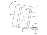
図8は、本発明のロボットの第2実施形態が備える装着用部材の装着部の縦断面図である。
<Second Embodiment>
FIG. 8 is a vertical cross-sectional view of a mounting portion of a mounting member included in the second embodiment of the robot of the present invention.

以下、図8を参照して本発明のロボットの第3実施形態について説明するが、前述した実施形態との相違点を中心に説明し、同様の事項はその説明を省略する。 Hereinafter, a third embodiment of the robot of the present invention will be described with reference to FIG. 8, but the differences from the above-described embodiment will be mainly described, and the same matters will be omitted.

図8に示すように、本実施形態では、装着部92の第1板状部921は、2つの板状部で構成されている。また、各板状部は、蝶番924によって回動可能に連結されている。これにより、各板状部が回動した際、第2板状部922、撮像部6および保護部材93がともに回動することができる。 As shown in FIG. 8, in the present embodiment, the first plate-shaped portion 921 of the mounting portion 92 is composed of two plate-shaped portions. Further, each plate-shaped portion is rotatably connected by a hinge 924. As a result, when each plate-shaped portion rotates, the second plate-shaped portion 922, the imaging unit 6, and the protective member 93 can all rotate.

なお、蝶番924の回動軸は、図6に示す装着部92Aの場合、x軸方向と平行であり、装着部92Bの場合、y軸方向と平行である。 The rotation axis of the hinge 924 is parallel to the x-axis direction in the case of the mounting portion 92A shown in FIG. 6, and is parallel to the y-axis direction in the case of the mounting portion 92B.

このような構成によれば、ロボットアーム20が回転している際、保護部材93に何らかの物体が衝突して保護部材93に外力が加わったとしても、第2板状部922、撮像部6および保護部材93がカバー部材232側、すなわち、図8中矢印方向に変位、すなわち、回動することができる。よって、衝突した物体に過剰な衝撃が加わるのを防止することができ、安全性を高めることができる。また、保護部材93の緩衝作用との相乗効果により、安全性をさらに高めることができる。 According to such a configuration, even if some object collides with the protective member 93 and an external force is applied to the protective member 93 when the robot arm 20 is rotating, the second plate-shaped portion 922, the imaging unit 6 and The protective member 93 can be displaced, that is, rotated on the cover member 232 side, that is, in the direction of the arrow in FIG. Therefore, it is possible to prevent an excessive impact from being applied to the collided object, and it is possible to improve safety. In addition, the safety can be further enhanced by the synergistic effect with the buffering action of the protective member 93.

このように、装着用部材9は、撮像部6を変位可能に支持する。これにより、安全性をさらに高めることができる。 In this way, the mounting member 9 supports the imaging unit 6 in a displaceable manner. As a result, safety can be further enhanced.

なお、装着用部材9が変位する方向は、図示の構成に限定されず、例えば、水平方向であってもよく、鉛直方向であってもよい。これらは、蝶番924に代えて、スライド機構を設けることにより実現することができる。 The direction in which the mounting member 9 is displaced is not limited to the illustrated configuration, and may be, for example, a horizontal direction or a vertical direction. These can be realized by providing a slide mechanism instead of the hinge 924.

<第3実施形態>
図9は、本発明のロボットの第3実施形態が備える先端側装着用部材の斜視図である。
<Third Embodiment>
FIG. 9 is a perspective view of a tip-side mounting member included in the third embodiment of the robot of the present invention.

以下、図9を参照して本発明のロボットの第3実施形態について説明するが、前述した実施形態との相違点を中心に説明し、同様の事項はその説明を省略する。 Hereinafter, a third embodiment of the robot of the present invention will be described with reference to FIG. 9, but the differences from the above-described embodiment will be mainly described, and the same matters will be omitted.

図9に示すように、本実施形態では、ロボット2は、シャフト241の先端部に着脱可能に装着される先端側装着用部材95をさらに有する。 As shown in FIG. 9, in the present embodiment, the robot 2 further includes a tip-side mounting member 95 that is detachably mounted on the tip of the shaft 241.

先端側装着用部材95は、第1板状部951と、第2板状部952とを有する。第1板状部951は、鉛直方向を厚さ方向とする向きでシャフト241に装着される。第1板状部951は、シャフト241を挿通する貫通孔953を有する。 The tip-side mounting member 95 has a first plate-shaped portion 951 and a second plate-shaped portion 952. The first plate-shaped portion 951 is mounted on the shaft 241 in a direction in which the vertical direction is the thickness direction. The first plate-shaped portion 951 has a through hole 953 through which the shaft 241 is inserted.

第2板状部952は、水平方向を厚さ方向とする向きで第1板状部951から鉛直下方に垂設されている。第2板状部952の第1板状部951と反対側の面状には、撮像部6を着脱可能に設置することができる。また、第2板状部952には、前記実施形態で述べた保護部材93が設置される。 The second plate-shaped portion 952 is vertically hung vertically downward from the first plate-shaped portion 951 in a direction in which the horizontal direction is the thickness direction. The imaging unit 6 can be detachably installed on the surface of the second plate-shaped portion 952 opposite to the first plate-shaped portion 951. Further, the protective member 93 described in the above embodiment is installed in the second plate-shaped portion 952.

このような先端側装着用部材95を、前記実施形態で述べた装着用部材9と併用することにより、撮像部6の設置位置の選択肢をさらに増やすことができる。 By using such a tip-side mounting member 95 in combination with the mounting member 9 described in the above embodiment, the options for the installation position of the imaging unit 6 can be further increased.

以上、本発明のロボットを図示の実施形態に基づいて説明したが、本発明は、これに限定されるものではなく、各部の構成は、同様の機能を有する任意の構成のものに置換することができる。また、他の任意の構成物が付加されていてもよい。 The robot of the present invention has been described above based on the illustrated embodiment, but the present invention is not limited to this, and the configuration of each part may be replaced with an arbitrary configuration having the same function. Can be done. Moreover, other arbitrary components may be added.

また、前記実施形態では、ロボットアームの回転軸の数は、3つであるが、本発明では、これに限定されず、ロボットアームの回転軸の数は、例えば、2つ、または、4つ以上でもよい。すなわち、前記実施形態では、アームの数は、3つであるが、本発明では、これに限定されず、アームの数は、例えば、2つ、または、4つ以上でもよい。 Further, in the above-described embodiment, the number of rotation axes of the robot arm is three, but the present invention is not limited to this, and the number of rotation axes of the robot arm is, for example, two or four. The above may be sufficient. That is, in the above embodiment, the number of arms is three, but in the present invention, the number of arms is not limited to this, and the number of arms may be, for example, two or four or more.

2…ロボット、4…受付部、5…力検出部、6…撮像部、7…エンドエフェクター、8…制御装置、9…装着用部材、20…ロボットアーム、21…基台、22…第1アーム、23…第2アーム、24…第3アーム、25…駆動ユニット、26…駆動ユニット、27…u駆動ユニット、28…z駆動ユニット、29…角速度センサー、81…CPU、82…記憶部、83…通信部、91…固定部、91A…第1固定部、91B…第2固定部、91C…第3固定部、92…装着部、92A…装着部、92B…装着部、93…保護部材、94…緩衝部材、95…先端側装着用部材、100…ロボットシステム、200…固定部材、220…筐体、230C…凹部、231…ベース、232…カバー部材、233…開口、234…カバー部材、241…シャフト、242…回転支持部材、243…ボールねじナット、243A…内輪、243B…外輪、244…スプラインナット、244A…内輪、244B…外輪、245…外筒、246…回転体、251…モーター、252…減速機、253…位置センサー、261…モーター、262…減速機、263…位置センサー、271…モーター、272…減速機、273…位置センサー、274…ベルト、275…プーリー、281…モーター、282…減速機、283…位置センサー、284…ベルト、285…プーリー、300…配線群、400…固定部材、800…配管、900…配管支持部、911A…突出部、911B…突出部、911C…突出部、912A…貫通孔、912B…貫通孔、912C…貫通孔、921…第1板状部、922…第2板状部、923…ネジ孔、924…蝶番、951…第1板状部、952…第2板状部、953…貫通孔、O1…第1軸、O2…第2軸、O3…第3軸、L1…長さ、L2…長さ 2 ... Robot, 4 ... Reception part, 5 ... Force detection unit, 6 ... Imaging unit, 7 ... End effector, 8 ... Control device, 9 ... Mounting member, 20 ... Robot arm, 21 ... Base, 22 ... First Arm, 23 ... 2nd arm, 24 ... 3rd arm, 25 ... drive unit, 26 ... drive unit, 27 ... u drive unit, 28 ... z drive unit, 29 ... angular speed sensor, 81 ... CPU, 82 ... storage unit, 83 ... Communication unit, 91 ... Fixed part, 91A ... 1st fixed part, 91B ... 2nd fixed part, 91C ... 3rd fixed part, 92 ... Mounting part, 92A ... Mounting part, 92B ... Mounting part, 93 ... Protective member , 94 ... cushioning member, 95 ... tip side mounting member, 100 ... robot system, 200 ... fixing member, 220 ... housing, 230C ... recess, 231 ... base, 232 ... cover member, 233 ... opening, 234 ... cover member , 241 ... Shaft, 242 ... Rotational support member, 243 ... Ball screw nut, 243A ... Inner ring, 243B ... Outer ring, 244 ... Spline nut, 244A ... Inner ring, 244B ... Outer ring, 245 ... Outer cylinder, 246 ... Rotating body, 251 ... Motor, 252 ... Reducer, 253 ... Position sensor, 261 ... Motor, 262 ... Reducer, 263 ... Position sensor, 271 ... Motor, 272 ... Reducer, 273 ... Position sensor, 274 ... Belt, 275 ... Pulley, 281 ... Motor, 282 ... Reducer, 283 ... Position sensor, 284 ... Belt, 285 ... Pulley, 300 ... Wiring group, 400 ... Fixed member, 800 ... Piping, 900 ... Piping support, 911A ... Protruding part, 911B ... Protruding part, 911C ... protruding part, 912A ... through hole, 912B ... through hole, 912C ... through hole, 921 ... first plate-shaped part, 922 ... second plate-shaped part, 923 ... screw hole, 924 ... hinge, 951 ... first plate Shaped part, 952 ... 2nd plate-shaped part, 953 ... Through hole, O1 ... 1st axis, O2 ... 2nd axis, O3 ... 3rd axis, L1 ... Length, L2 ... Length

Claims (11)

基台と、
前記基台に接続され、第1軸回りに回動する第1アームと、
前記第1アームに接続され、前記第1軸と交わる方向に延在するベースと、開口を有し、前記ベースを覆うカバー部材と、を有し、前記第1軸と平行な第2軸回りに回動する第2アームと、
前記第2アームに接続され、前記第1軸と平行な第3軸回りに回動し、かつ、前記第3軸に沿って移動する第3アームと、
互いに異なる位置に設置され、撮像部が着脱可能に装着される第1装着部および第2装着部を有する装着用部材と、を備え、
前記装着用部材は、前記第1装着部および前記第2装着部が前記カバー部材の外側に位置するように前記開口を通って前記ベースに固定されることを特徴とするロボット。
Base and
A first arm connected to the base and rotating around the first axis,
Around a second axis that is connected to the first arm and extends in a direction intersecting the first axis, has an opening, and has a cover member that covers the base, and is parallel to the first axis. The second arm that rotates to
A third arm connected to the second arm, rotating around a third axis parallel to the first axis, and moving along the third axis.
A mounting member having a first mounting portion and a second mounting portion, which are installed at different positions from each other and to which the imaging unit is detachably mounted, is provided.
The robot is characterized in that the mounting member is fixed to the base through the opening so that the first mounting portion and the second mounting portion are located outside the cover member.
前記第3アームは、前記開口を通る請求項1に記載のロボット。 The robot according to claim 1, wherein the third arm passes through the opening. 前記装着用部材は、前記第3アームが通る挿通部を有する請求項1または2に記載のロボット。 The robot according to claim 1 or 2, wherein the mounting member has an insertion portion through which the third arm passes. 前記装着用部材は、前記ベースに固定される固定部を有し、
前記第1装着部および前記第2装着部は、前記固定部に対し着脱可能に接続される請求項1ないし3のいずれか1項に記載のロボット。
The mounting member has a fixing portion fixed to the base.
The robot according to any one of claims 1 to 3, wherein the first mounting portion and the second mounting portion are detachably connected to the fixed portion.
前記装着用部材は、前記固定部の前記第1装着部および前記第2装着部が装着されていない部分に着脱可能に装着される緩衝部材を有する請求項4に記載のロボット。 The robot according to claim 4, wherein the mounting member has a cushioning member that is detachably mounted on a portion of the fixing portion where the first mounting portion and the second mounting portion are not mounted. 前記第1装着部および前記第2装着部は、それぞれ、互いに交わる方向に配置される第1板状部および第2板状部を有する請求項1ないし5のいずれか1項に記載のロボット。 The robot according to any one of claims 1 to 5, wherein the first mounting portion and the second mounting portion have a first plate-shaped portion and a second plate-shaped portion arranged in a direction in which they intersect with each other, respectively. 前記第1装着部は、前記ベースの延在方向において、前記第3軸に対して前記第2軸が位置する位置とは反対側に設置され、前記第2装着部は、前記ベースの延在方向における側方に設置可能である請求項1ないし6のいずれか1項に記載のロボット。 The first mounting portion is installed in the extending direction of the base on the side opposite to the position where the second axis is located with respect to the third axis, and the second mounting portion extends the base. The robot according to any one of claims 1 to 6, which can be installed laterally in a direction. 前記撮像部の前記第1装着部および前記第2装着部に対する前記第3軸に沿った方向における装着位置を調整する装着位置調整機構を有する請求項1ないし7のいずれか1項に記載のロボット。 The robot according to any one of claims 1 to 7, further comprising a mounting position adjusting mechanism for adjusting a mounting position of the imaging unit in a direction along the third axis with respect to the first mounting portion and the second mounting portion. .. 前記装着用部材は、前記第1装着部または前記第2装着部に装着された前記撮像部を覆う保護部材を有する請求項1ないし8のいずれか1項に記載のロボット。 The robot according to any one of claims 1 to 8, wherein the mounting member has a protective member that covers the first mounting portion or the imaging portion mounted on the second mounting portion. 前記装着用部材は、前記撮像部を変位可能に支持する請求項1ないし9のいずれか1項に記載のロボット。 The robot according to any one of claims 1 to 9, wherein the mounting member supports the imaging unit in a displaceable manner. 前記カバー部材は、前記ベースよりも軟質である請求項1ないし10のいずれか1項に記載のロボット。 The robot according to any one of claims 1 to 10, wherein the cover member is softer than the base.
JP2019215801A 2019-11-28 2019-11-28 robot Withdrawn JP2021084192A (en)

Priority Applications (1)

Application Number Priority Date Filing Date Title
JP2019215801A JP2021084192A (en) 2019-11-28 2019-11-28 robot

Applications Claiming Priority (1)

Application Number Priority Date Filing Date Title
JP2019215801A JP2021084192A (en) 2019-11-28 2019-11-28 robot

Publications (2)

Publication Number Publication Date
JP2021084192A true JP2021084192A (en) 2021-06-03
JP2021084192A5 JP2021084192A5 (en) 2022-11-25

Family

ID=76088693

Family Applications (1)

Application Number Title Priority Date Filing Date
JP2019215801A Withdrawn JP2021084192A (en) 2019-11-28 2019-11-28 robot

Country Status (1)

Country Link
JP (1) JP2021084192A (en)

Cited By (1)

* Cited by examiner, † Cited by third party
Publication number Priority date Publication date Assignee Title
JP7364285B1 (en) 2022-11-11 2023-10-18 高丸工業株式会社 How the robot handling system works

Cited By (1)

* Cited by examiner, † Cited by third party
Publication number Priority date Publication date Assignee Title
JP7364285B1 (en) 2022-11-11 2023-10-18 高丸工業株式会社 How the robot handling system works

Similar Documents

Publication Publication Date Title
US9481085B2 (en) Horizontal articulated robot
US10209152B2 (en) Force sensor unit and robot arm including a wire cable routed from inside a casing to outside of the casing
JP6862854B2 (en) Control device, robot system and screw tightening torque setting method
EP3461599A1 (en) Robot
JP2012127497A (en) Ball joint having passageway for routing cable therethrough
CN107073707B (en) Robot
JP6958200B2 (en) robot
JP2009078312A (en) Articulated robot hand and articulated robot using the same
JP7279180B2 (en) articulated robot
JP6923489B2 (en) Horizontal articulated robot
JP7451889B2 (en) robot
JP2021084192A (en) robot
US11420326B2 (en) Horizontal articulated robot
CN113319848A (en) Robot control method and robot system
US20160306340A1 (en) Robot and control device
KR101801302B1 (en) Robot hand and surface robot system using of the same for working
JP2019010683A (en) Robot control device and robot system
US20200047350A1 (en) Collaborative robot
CN111482947B (en) Horizontal multi-joint robot
CN111745622B (en) robot
JP7069757B2 (en) Horizontal articulated robot
CN112008746A (en) Robot
CN111660293B (en) Horizontal multi-joint robot
WO2022153478A1 (en) Force sensor, collaborative robot, and robot
CN116460827A (en) Robot

Legal Events

Date Code Title Description
A521 Request for written amendment filed

Free format text: JAPANESE INTERMEDIATE CODE: A523

Effective date: 20221116

A621 Written request for application examination

Free format text: JAPANESE INTERMEDIATE CODE: A621

Effective date: 20221116

A131 Notification of reasons for refusal

Free format text: JAPANESE INTERMEDIATE CODE: A131

Effective date: 20230919

A977 Report on retrieval

Free format text: JAPANESE INTERMEDIATE CODE: A971007

Effective date: 20230920

A761 Written withdrawal of application

Free format text: JAPANESE INTERMEDIATE CODE: A761

Effective date: 20231030