JP2012127497A - Ball joint having passageway for routing cable therethrough - Google Patents
Ball joint having passageway for routing cable therethrough Download PDFInfo
- Publication number
- JP2012127497A JP2012127497A JP2011267887A JP2011267887A JP2012127497A JP 2012127497 A JP2012127497 A JP 2012127497A JP 2011267887 A JP2011267887 A JP 2011267887A JP 2011267887 A JP2011267887 A JP 2011267887A JP 2012127497 A JP2012127497 A JP 2012127497A
- Authority
- JP
- Japan
- Prior art keywords
- ball
- passage
- housing
- pin
- head
- Prior art date
- Legal status (The legal status is an assumption and is not a legal conclusion. Google has not performed a legal analysis and makes no representation as to the accuracy of the status listed.)
- Withdrawn
Links
Images


Classifications
-
- F—MECHANICAL ENGINEERING; LIGHTING; HEATING; WEAPONS; BLASTING
- F16—ENGINEERING ELEMENTS AND UNITS; GENERAL MEASURES FOR PRODUCING AND MAINTAINING EFFECTIVE FUNCTIONING OF MACHINES OR INSTALLATIONS; THERMAL INSULATION IN GENERAL
- F16C—SHAFTS; FLEXIBLE SHAFTS; ELEMENTS OR CRANKSHAFT MECHANISMS; ROTARY BODIES OTHER THAN GEARING ELEMENTS; BEARINGS
- F16C11/00—Pivots; Pivotal connections
- F16C11/04—Pivotal connections
- F16C11/06—Ball-joints; Other joints having more than one degree of angular freedom, i.e. universal joints
- F16C11/0619—Ball-joints; Other joints having more than one degree of angular freedom, i.e. universal joints the female part comprising a blind socket receiving the male part
-
- F—MECHANICAL ENGINEERING; LIGHTING; HEATING; WEAPONS; BLASTING
- F16—ENGINEERING ELEMENTS AND UNITS; GENERAL MEASURES FOR PRODUCING AND MAINTAINING EFFECTIVE FUNCTIONING OF MACHINES OR INSTALLATIONS; THERMAL INSULATION IN GENERAL
- F16C—SHAFTS; FLEXIBLE SHAFTS; ELEMENTS OR CRANKSHAFT MECHANISMS; ROTARY BODIES OTHER THAN GEARING ELEMENTS; BEARINGS
- F16C11/00—Pivots; Pivotal connections
- F16C11/04—Pivotal connections
- F16C11/06—Ball-joints; Other joints having more than one degree of angular freedom, i.e. universal joints
- F16C11/0604—Construction of the male part
-
- F—MECHANICAL ENGINEERING; LIGHTING; HEATING; WEAPONS; BLASTING
- F16—ENGINEERING ELEMENTS AND UNITS; GENERAL MEASURES FOR PRODUCING AND MAINTAINING EFFECTIVE FUNCTIONING OF MACHINES OR INSTALLATIONS; THERMAL INSULATION IN GENERAL
- F16C—SHAFTS; FLEXIBLE SHAFTS; ELEMENTS OR CRANKSHAFT MECHANISMS; ROTARY BODIES OTHER THAN GEARING ELEMENTS; BEARINGS
- F16C41/00—Other accessories, e.g. devices integrated in the bearing not relating to the bearing function as such
- F16C41/008—Identification means, e.g. markings, RFID-tags; Data transfer means
-
- G—PHYSICS
- G05—CONTROLLING; REGULATING
- G05G—CONTROL DEVICES OR SYSTEMS INSOFAR AS CHARACTERISED BY MECHANICAL FEATURES ONLY
- G05G9/00—Manually-actuated control mechanisms provided with one single controlling member co-operating with two or more controlled members, e.g. selectively, simultaneously
- G05G9/02—Manually-actuated control mechanisms provided with one single controlling member co-operating with two or more controlled members, e.g. selectively, simultaneously the controlling member being movable in different independent ways, movement in each individual way actuating one controlled member only
- G05G9/04—Manually-actuated control mechanisms provided with one single controlling member co-operating with two or more controlled members, e.g. selectively, simultaneously the controlling member being movable in different independent ways, movement in each individual way actuating one controlled member only in which movement in two or more ways can occur simultaneously
- G05G9/047—Manually-actuated control mechanisms provided with one single controlling member co-operating with two or more controlled members, e.g. selectively, simultaneously the controlling member being movable in different independent ways, movement in each individual way actuating one controlled member only in which movement in two or more ways can occur simultaneously the controlling member being movable by hand about orthogonal axes, e.g. joysticks
-
- Y—GENERAL TAGGING OF NEW TECHNOLOGICAL DEVELOPMENTS; GENERAL TAGGING OF CROSS-SECTIONAL TECHNOLOGIES SPANNING OVER SEVERAL SECTIONS OF THE IPC; TECHNICAL SUBJECTS COVERED BY FORMER USPC CROSS-REFERENCE ART COLLECTIONS [XRACs] AND DIGESTS
- Y10—TECHNICAL SUBJECTS COVERED BY FORMER USPC
- Y10T—TECHNICAL SUBJECTS COVERED BY FORMER US CLASSIFICATION
- Y10T74/00—Machine element or mechanism
- Y10T74/20—Control lever and linkage systems
- Y10T74/20012—Multiple controlled elements
- Y10T74/20201—Control moves in two planes
Abstract
Description
本発明の装置は、ボールジョイント、特にケーブルを通すことを容易にするボールジョイントに関する。 The device of the invention relates to a ball joint, in particular a ball joint that facilitates the passage of cables.
ロボットシステムは、人間が危険または不快な作業環境にさらされ得る領域での使用がますます一般的になっている。このような用途は、爆発物処理、捜索救助活動、有毒な場所での環境分析または検査などを含む。これらのロボットシステムは通常遠隔制御される。ロボットシステムのテレマティック(telematic)制御用制御ユニットは、ボールジョイントを利用することができ、使用者によるボールジョイントの動きが一つまたは複数のセンサにより計測されることができるとともに対応する信号に変換されることができ、この対応する信号は、伝達された信号に従って所望の方法でロボットシステムを動かすようにロボットシステムに伝達される。ケーブルを機構の内部に保持することにより、ケーブルは、物体(または使用者)に引っ掛かることまたは機構の他の部品に挟まれることを避けるので、ケーブルの磨耗を避けるとともに改良された美観を提供する。 Robotic systems are becoming increasingly common in areas where humans can be exposed to dangerous or unpleasant work environments. Such applications include explosives disposal, search and rescue operations, environmental analysis or inspection in toxic locations, and the like. These robot systems are usually remotely controlled. The telematic control unit of the robot system can use a ball joint, and the motion of the ball joint by the user can be measured by one or more sensors and converted into a corresponding signal. The corresponding signal can be transmitted to the robot system to move the robot system in a desired manner in accordance with the transmitted signal. By holding the cable inside the mechanism, the cable avoids being worn by an object (or user) or being pinched by other parts of the mechanism, thus avoiding cable wear and providing an improved aesthetics. .
特許文献1は、電線が通過することを可能にするよう適合されたボールジョイントを開示する。特許文献1に開示されたボールジョイントは、固定サービスマウントに接続された電気的な取付品の姿勢の調整を可能にするために使われる。しかし、このボールジョイントは、非常に限られた可動域しか有さないように設計されているので、多くの用途での使用には適さない。さらに、特許文献1の設計は、ボールの出口におけるケーブルの磨耗増大のために劣っている。ケーブルがボールの後部において出ることのみを可能とし、上部と後部の両方におけるボール材料の切り取りはボールの支持面を減少させ、ボールの磨耗の増大およびより荒いボール回転をもたらす。
U.S. Pat. No. 6,057,051 discloses a ball joint adapted to allow electrical wires to pass through. The ball joint disclosed in
本発明は内部表面を有するソケットを規定するボールハウジングを有するボールジョイントに関係する。 The present invention relates to a ball joint having a ball housing defining a socket having an internal surface.
ボールハウジングは開口および第1通路を有する。ボールピボットがソケット内に配置され、ボールヘッドおよびボールピンを有する。ボールピンは開口を通り抜けて配置される。ボールヘッドの表面は、ソケットの内部表面の少なくとも一部に一致する第1領域とソケットの内部表面に一致しない第2領域とを有する。本発明の一つの態様によれば、第2領域は円錐形である。ソケットに対する開口の角度範囲はボールヘッドに対する第2領域の対応する角度範囲より小さくなり得る。 The ball housing has an opening and a first passage. A ball pivot is disposed in the socket and has a ball head and a ball pin. The ball pin is disposed through the opening. The surface of the ball head has a first region that coincides with at least a portion of the inner surface of the socket and a second region that does not coincide with the inner surface of the socket. According to one aspect of the invention, the second region is conical. The angular range of the opening relative to the socket can be smaller than the corresponding angular range of the second region relative to the ball head.
ボールヘッドは第2領域およびボールピンに接続された第2通路を有し、ボールピンは第2通路およびボールピンの外部表面に接続された第3通路を有する。第1通路は第1の方向に沿って延び、開口は第2の方向を向き、第1の方向および第2の方向は互いに平行ではない(すなわち、交差する)。ある実施形態では、第1の方向と第2の方向とは、互いに対して80度から100度である。 The ball head has a second passage connected to the second region and the ball pin, and the ball pin has a third passage connected to the second passage and the outer surface of the ball pin. The first passage extends along the first direction, the opening faces in the second direction, and the first direction and the second direction are not parallel to each other (ie, intersect). In some embodiments, the first direction and the second direction are between 80 degrees and 100 degrees relative to each other.
リミッタが内部表面の上に延びるソケットの一部として提供されることもできる。リミッタは第1通路に接続する第4通路を有する。ボールジョイントは、ロボットシステムのテレマティック制御用の制御ユニットの一部として含まれることができる。この点に関して、制御ユニットはさらに、ボールジョイント内に配置された一つまたは複数のセンサを有することができる。また、遠隔ロボットシステムと通信するために一つまたは複数のセンサと通信する制御回路が提供される。 A limiter can also be provided as part of the socket extending over the inner surface. The limiter has a fourth passage connected to the first passage. The ball joint can be included as part of a control unit for telematic control of the robot system. In this regard, the control unit can further comprise one or more sensors arranged in the ball joint. Also provided is a control circuit that communicates with one or more sensors for communicating with a remote robot system.
ボールジョイントは、代替的にボールヘッドおよびボールピンを有するボールピボットを含むものとして理解され得る。ボールヘッドは部分的に球形状であるとともにボールピンはボールヘッドにより規定された表面から半径方向に延びる。ボールハウジングは中にボールヘッドが配置されるソケットを規定する。ソケットは、ボールヘッドがその中で3つの独立した直交回転軸周りに回転することを可能にするよう構成される。ボールピン通路がボールピンを通って延びる。ボールハウジング通路がボールハウジングの内部からボールハウジングの外部にボールハウジングの壁を通って延びる。ボールヘッド通路がボールヘッドを通って、ボールピン通路からボールハウジング通路に延びる。ボールヘッド通路は、第1の方向が第2の方向を横切るように、少なくとも第1の方向に延びる第1セクションと第2の方向に延びる第2セクションとを有する。 A ball joint may alternatively be understood as including a ball pivot having a ball head and a ball pin. The ball head is partially spherical and the ball pin extends radially from the surface defined by the ball head. The ball housing defines a socket in which the ball head is disposed. The socket is configured to allow the ball head to rotate about three independent orthogonal axes of rotation therein. A ball pin passage extends through the ball pin. A ball housing passage extends from the interior of the ball housing to the exterior of the ball housing through the wall of the ball housing. A ball head passage extends from the ball pin passage to the ball housing passage through the ball head. The ball head passage has at least a first section extending in the first direction and a second section extending in the second direction such that the first direction crosses the second direction.
ボールヘッド通路の第1セクションはボールピン通路に位置合わせされた開口を有する。第2セクションは、ボールハウジング内部でボールハウジング通路により規定された開口に一致する開口を有する。実施形態によっては、第2セクションは円錐形であり、第1セクションは円錐形の頂点部分において第2セクションに通じるとともに接続する。少なくとも1つのリミッタピンが、リミッタピンがボールヘッド内に規定された中空部内に延び、中空部が第2セクションの一部から形成されるように、ボールハウジングに配置される。リミッタピンは、概してボールハウジング通路に位置合わせされ、ボールハウジングの内部からボールハウジングの外部に延びるリミッタピン通路をさらに有する。実施形態によっては、少なくとも1つの制御ケーブルが、ボールピン通路、ボールヘッド通路、およびボールハウジング通路を通って延びる。 The first section of the ball head passage has an opening aligned with the ball pin passage. The second section has an opening that coincides with the opening defined by the ball housing passage within the ball housing. In some embodiments, the second section is conical, and the first section communicates with and connects to the second section at the apex of the cone. At least one limiter pin is disposed on the ball housing such that the limiter pin extends into a hollow defined in the ball head and the hollow is formed from a portion of the second section. The limiter pin further includes a limiter pin passage that is generally aligned with the ball housing passage and extends from the interior of the ball housing to the exterior of the ball housing. In some embodiments, at least one control cable extends through the ball pin passage, the ball head passage, and the ball housing passage.
ハンドグリップが、ボールヘッドから離れて間隔を空けられたボールピンの近位端部に固定され、実施形態によっては制御ケーブルがボールピン通路からハンドグリップの内部に延びる。一態様によれば、ボールハウジングは、3つの独立した直交回転軸の少なくとも1つに位置合わせされた方向のボールハウジングの直線運動を可能にするよう構成された複数の関節アームに旋回可能に取付けられる。 A hand grip is secured to the proximal end of the ball pin that is spaced apart from the ball head, and in some embodiments, a control cable extends from the ball pin passage to the interior of the hand grip. According to one aspect, the ball housing is pivotally attached to a plurality of articulated arms configured to allow linear movement of the ball housing in a direction aligned with at least one of three independent orthogonal rotational axes. It is done.
実施形態が以下の図面を参照して記述され、同様の符号は図を通して同様の要素を示す。 Embodiments will be described with reference to the following drawings, wherein like numerals indicate like elements throughout the drawings.
本発明が添付の図面を参照して記述され、同様の参照符号は図面を通して類似または均等な要素を示すために使われる。図面は縮尺通りに描かれておらず、これらは本発明を説明するためだけに提供される。本発明の幾つかの態様が、説明のための例示の用途を参照して以下に記載される。多数の具体的な詳細、関係、および方法が本発明の十分な理解を提供するために示されていることを理解すべきである。しかし、当業者は、本発明が一つまたは複数の具体的詳細無しにまたは他の方法で実施できることを、容易に認識するであろう。他の例では、良く知られた構造または動作は、本発明をあいまいにすることを避けるために詳細には示されていない。本発明は、行為または事象の説明された順番に限定されることはなく、ある行為は他の行為または事象と異なる順番でおよび/または他の行為または事象と同時に起こり得る。さらに、全ての説明された行為および事象が本発明に従った方法を実行するために必要とされるわけではない。 The present invention will be described with reference to the accompanying drawings, wherein like reference numerals are used to refer to like or equivalent elements throughout the drawings. The drawings are not drawn to scale and are provided only to illustrate the present invention. Several aspects of the invention are described below with reference to exemplary applications for illustration. It should be understood that numerous specific details, relationships, and methods are set forth in order to provide a thorough understanding of the present invention. However, one skilled in the art will readily recognize that the present invention may be practiced without one or more specific details or in other ways. In other instances, well-known structures or operations have not been shown in detail in order to avoid obscuring the present invention. The invention is not limited to the described order of acts or events, and certain acts may occur in a different order and / or concurrently with other acts or events. Moreover, not all illustrated acts and events are required to implement a methodology in accordance with the present invention.
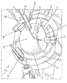
図1および図2を参照すると、本発明を理解するのに有用なボールジョイント1が示される。ボールジョイント1はボールハウジング10を有し、このボールハウジング10は、ボールピボット20を受け入れるように構成されたボールハウジング10内に規定されたソケット11を見せるために図1に部分的に切断されて示される。ソケット11は少なくとも部分的に球形状である。ボールピボット20は、2つの部品、ボールヘッド22とボールピン24とを有する。好適な実施形態では、ボールヘッド22は概して部分的に球形の形状を有する。すなわち、ボールヘッド22の一部が球形状である。ボールヘッド22の外側表面は、半球形状であるとともにハウジング10の内部表面と直接機械的に接触または内部表面に嵌め合う第1領域21を有する。図1に示すように、第1領域21はソケット11の内部表面に概して一致する。ボールヘッド22の外部表面は、内部表面12と接触しないまたは内部表面12に直接嵌め合わず、したがってソケット12の内部表面12に一致しない、第2領域29を有する。この第2領域29は球形状である必要はなく、実施形態によっては凹面あるいは円錐形にすることができる。ボールヘッド22は、ボールハウジング10の内部に規定された少なくとも部分的に球形の内部表面12の接合部内にぴったり合う。ボールハウジング10、ボールヘッド22およびボールピン24はそれぞれ、そこを通ってケーブル2を通すための互いに直列に接続する開放通路14、23および25を有する。つまり、ケーブル2は通路25、23、および14を順番に通過する。
Referring to FIGS. 1 and 2, a
図2に示されるように、ボールピン24の長手方向の長さに略沿った断面図に関して、ボールハウジング10は概してC形状である。したがって、ハウジング10は開口16を有し、実施形態によっては、この開口16は円形であるが、当然のことながら他の形状が使われることもでき、ボールピン24の移動を予め規定された範囲に制限することを望む場合は有用になり得る。ボールピン24は開口16を通って延びる。実施形態によっては、開口16の直径は、ボールヘッド22をソケット11内に保持するためにボールヘッド22の直径より有利に若干小さく形成される。他の実施形態では、開口16のサイズはボールヘッド22の直径より大きく、ボールジョイント1はさらに、開口16の周りに取付けられるとともにボールヘッド22の直径より小さい開口を有する封止カップ(図示せず)を有し得る。さらに他の実施形態では、封止カップはまた、ボールハウジング開口16自体がボールヘッド22の直径より小さい場合にさえ使われることもでき、例えば、それぞれがボールピン24の動きをそれぞれの予め規定された範囲に制限する異なる形状の開口を有する交換可能な封止カップを提供することが好ましくなり得る。実施形態によっては、封止カップはテーパ形状であり得るとともに、ゴミが開口16内に入ることを防ぐ保護カバーを提供するようボールヘッドピン24の側壁と封止するように接続され得る。ボールハウジング開口16、封止カップの開口、またはその両方は、ボールピボット20が開口16、封止カップ、またはその両方により規定された側壁17の範囲内で使用者の要求通りに自由に回転することを可能にする寸法に形成される。
As shown in FIG. 2, with respect to a cross-sectional view generally along the longitudinal length of the
図1に戻って参照すると、内部表面12は、ハウジング10との関連でボールピボット20の動きを容易にするソケット11内部に配置された支持面18(図2に図示せず)により提供され得る。支持面18は、ハウジング10に取り外し可能に接続され得るまたはハウジング10の一体部品であり得る。支持面18は、ボールピボット20とハウジング10との間の摩擦を減らすことができ、部品の摩損を減少させるとともにボールジョイント1の耐用年数を延ばす。好ましくは、支持面18は、ソケット11とボールヘッド22との間に配置された低摩擦ライニングである。しかし、ベアリングや液体などの摩擦を減らす他の既知の手段もまた、摩擦を減らすためにここに開示された装置内に低摩擦ライニング18の代わりにまたは低摩擦ライニング18に加えて使用されることができる。
Referring back to FIG. 1, the
図2を参照すると、ボールハウジング10、ボールヘッド22およびボールピン24はそれぞれ、そこを通ってケーブル2を通すための互いに直列に接続する開放通路14、23および25を有する。ここではボールハウジング通路14と呼ばれるボールハウジング10を貫く通路14は、ソケット11と接続する近位端部14aと外部環境と接続する遠位端部14bとを有する。ボールハウジング通路14は、弾性グロメットまたは同様なものを通じて等、ケーブル2の周りの封止する密着を提供するように構成される。ここではボールピン通路25と呼ばれるボールピン24を貫く通路25は、ボールピン24の一方の端部でボールヘッド22から離れて間隔を空けられた、近位端部25aと、ボールピン24がボールヘッド22と略交わるところに配置される遠位端部25bとを有する。ここではボールヘッド通路23と呼ばれるボールヘッド22を貫く通路23は、近位端部23aを有し、この近位端部23aは、ボールヘッドの表面に略隣接するとともに、ボールピン24がボールヘッド22と交わるところのボールピン通路25の遠位端部25bに略隣接して配置される。ボールヘッド通路23はまた、ボールヘッド22の第2表面29に略隣接する遠位端部23bも有する。
Referring to FIG. 2,
ボールピン通路25の遠位端部25bは、ケーブル2がボールピン通路25からボールヘッド通路23内に通ることを可能にするために、ボールヘッド通路23の近位端部23aに位置合わせされる。ボールヘッド通路23の遠位端部23bから出ると、ケーブル2は、ボールハウジング通路14の近位端部14a内を通り、ボールハウジング通路14を通ってボールハウジング10の外に出る。ボールヘッド通路23とボールハウジング通路14との間に配置された支持表面18または他の構成部品もまた、ボールハウジング通路14に対応するとともに接続するそれぞれの通路を有する。
The
本発明のある実施形態では、ボールピン通路25の直径は全通路25にわたって一定であり、そこを通るケーブルの摩損を最小限に抑えるために、図2に示されたように、通路25はボールピン24の壁に平行にボールピン24の本体に沿って一直線に進むことができる。さらに、グロメットまたは同様なものなどの封止要素が、チリまたはゴミが通路25内に入ることを防ぐために、ボールピン通路25にまたはボールピン通路25の周りに配置されることができる。もちろん、当然のことながら、ボールピン通路25の直径、向きおよび/または形状は、特定の用途に適合するように合わせられることができ、したがって実施形態によって大きく変化することができる。
In one embodiment of the present invention, the diameter of the
本発明のある実施形態では、ボールヘッド通路23は、ボールピボット20の回転によりもたらされ得るケーブル2の張力を最小限に抑えるために、ボールヘッド22の中心を通過するまたはボールヘッド22の中心近くを通る。ボールヘッド通路23のサイズ、向き、および形状もまたボールジョイントの特定の用途に応じて変化することができるが、好適な実施形態では、ボールヘッド通路23は近位端部23aから遠位端部23bまで一定のサイズであるとともに、遠位端部23bはボールヘッド22の表面の第2領域29内に抜ける。
In certain embodiments of the present invention, the
好適な実施形態では、ボールヘッド22の外部表面の第2領域29は第1領域21に対して形状が凹面であり、それにより、第2領域29およびハウジング10の内部表面12により規定されるケーブル格納領域19を形成する。当然のことながら、ケーブル格納領域19の位置は、ボールジョイント20が動くにつれて、ハウジング10に対して変化する。しかし、好適な実施形態では、ボールハウジング通路14の近位端部14aが常に、ケーブル格納領域19と直接連通して保持される。つまり、ボールヘッド22の外部表面の第1領域21は、ボールハウジング通路14の近位端部14aを覆わないまたは当たらないことが好ましい。
In a preferred embodiment, the
当然のことながら、ケーブル格納領域19は、単純にボールヘッド通路23の別のセクションであると考えることができる。例えば、ケーブル格納領域19の角度範囲が、例えば20度より小さい等、比較的小さい場合、ケーブル格納領域19は視覚的にボールヘッド通路23の一部であるように見える。一方、ケーブル格納領域19の角度範囲が、例えば45度を超える等、比較的大きい場合、ボールヘッド通路23は視覚的に第2表面29に接続する開口23bのように見えることができる。以下の議論と一貫性を保つため、ケーブル格納領域19はボールヘッド通路23と異なるものとして扱われるが、これは単に便宜のためである。
Of course, the
好適な実施形態では、ボールピン24は、ボールヘッド22の第1表面21から離れて垂直に、すなわち、球状に形成された第1セクション21の中心3に対して半径方向に延びる。ボールピン通路25は、ボールピン24を通る長手方向の電線管を形成するとともにボールヘッド通路23に直接接続する。好適な実施形態では、ボールヘッド通路23はまた、ボールヘッド22の第1表面21に対して半径方向に沿った電線管を提供し、第2表面29に、従ってケーブル格納領域19に直接接続する。従って、好適な実施形態では、ケーブル格納領域19は、ボールヘッド22の第1表面21の幾何学的中心を含む。しかし、このようになる必要はなく、実施形態によっては、ボールヘッド通路23の中心線は、ボールピン通路25の中心線から角度オフセットを有することもできる。つまり、ボールヘッド通路23の中心線およびボールピン通路25の中心線は平行である必要はない。
In a preferred embodiment, the
第1中心線4は、第2領域29の幾何学的中心および球形の第1領域21の中心3を通過するものとして規定されることができ、ケーブル格納領域19の中心線であると考えられ得る。第2中心線6は、球形の第1領域21の中心3および開口16の幾何学的中心を通過するものとして規定されることができる。したがって、第2中心線6は、開口16がソケット11に対して向く方向であると考えられ得る。好適な実施形態では、ボールピン24が開口16内の中心に置かれたとき、中心線6はボールピン通路25に位置する。様々な実施形態では、ボールピン24が開口16の中心に置かれたとき、ボールピン通路25およびボールヘッド通路23の中心線は第2中心線6上に位置する。しかし、第2領域29は、ボールピン24が開口16の中心に置かれたときに第1中心線4が第2中心線6と平行にならないように構成されることが好ましい。したがって、好適な実施形態では、ボールピン通路25およびボールヘッド通路23の中心線はケーブル格納領域19の中心線と平行ではない。特に好適な実施形態では、ボールピン24の中心線は、ケーブル格納領域19の中心線4から、80度から100度オフセットしている。開口16の中心線6に対するボールハウジング通路14の中心線の角度オフセットが、ケーブル格納領域19に対するボールピン24の角度オフセットと略等しくなることも好ましい。したがって、ボールピン24が開口16内の中心に置かれたとき、このような好適な実施形態において、ボールハウジング通路14がケーブル格納領域の中心線4上に位置する。さらに、ハウジング10内の開口16の角度範囲および第2領域29の対応する角度範囲が、開口16内のボールピン24の位置に関わらず、領域19が開口16に直接接続しないようになることが好ましい。この条件はチリやゴミが開口16を通じて領域19に入ることを防ぐ。
The
限定されない例として、図2は、ボールヘッド通路23が同じように直線のボールピン通路25と一直線にされた直線セクションであり、ケーブル格納領域19が円錐形である実施形態を示す。ここで使われているように、「円錐形」の語は、開口がより大きいところからより小さいところに徐々に先細(テーパ)になる任意の形状として理解されるべきである。テーパは直線状、曲線状、または階段状にすることができるが、限定されるものではない。円錐形ケーブル格納領域19の中心線4は、例えば、通路23、25の中心線6から、80度から100度オフセットしている。
As a non-limiting example, FIG. 2 shows an embodiment in which the
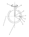
実施形態によっては、ボールジョイント1はさらに、ボールピボット20の回転を制限するための追加的な手段を有する。このような実施形態では、ボールジョイント1は、図1および3に示されるように、リミッタ50を有することができる。リミッタ50は、好ましくは、ボールハウジング10の内部表面12に配置されるまたは内部表面12を通り抜けて配置されるとともにボールジョイントヘッド22の中心3に向かって半径方向内側に延びる。好適な実施形態では、リミッタ50は、ボールハウジング通路14と一直線にされ、したがって通路14と一直線になるそれ自身の対応する通路52を有する。適切なリミッタ50は、ピン、カップ、ノブ、止めネジ(set screw)、ボールハウジング10またはボールヘッド22上の突起、またはそれらの均等物を含むが、これらに限定されるものではない。
In some embodiments, the ball joint 1 further includes additional means for limiting the rotation of the ball pivot 20. In such an embodiment, the ball joint 1 can have a
図3に示されるように、リミッタ50は、ボールヘッド22がソケット11内で回転すること、すなわち、ボールピン24の中心線に沿って延びる第2中心線6周りに矢印Bにより示される方向に回転することを制限または防ぐために、設置されることができる。そのため、リミッタ50は好ましくは、リミッタ通路52を通るケーブル2を保護するために内部表面12の上に延びる。ケーブル2を第2表面29との接触から保護することとボールヘッド22の回転を防ぐこととの両方により、リミッタ50は、ケーブル2の磨耗またはねじれによる予想される損傷を防ぐまたは最小限に抑える。リミッタ50は、ゴミまたはチリがソケット11内に入ることを防ぐために、通路52内のグロメット等、シールを有することができる。
As shown in FIG. 3, the
ここに開示されたボールジョイントは、多くの様々な用途に利用することができる。限定されない例として、これらのボールジョイントは、ロボットシステムのテレマティック制御のための制御ユニットに利用することができる。このようなシステムでは、使用者はボールピボットを動かし、ボールピボットヘッドの移動が計測されるとともに、例えば位置または速度信号等の制御信号に変換される。次に信号は、システムを対応する方法で動かすために、離れたロボットシステムに送られる。 The ball joint disclosed herein can be used in many different applications. As a non-limiting example, these ball joints can be utilized in a control unit for telematic control of a robot system. In such a system, the user moves the ball pivot and the movement of the ball pivot head is measured and converted into a control signal, such as a position or velocity signal, for example. The signal is then sent to the remote robot system to move the system in a corresponding manner.
図1および4を参照すると、本発明の一態様は、例えばロボットシステム等のテレマティック操作のための制御ユニット100を提供する。ここで使われるように、テレマティックの語は、遠隔物体の制御をもたらすことと一体となった遠隔通信装置を介して、計測する、送信する、受信する、または情報を保存することができる任意のシステムまたは技術を含むことができる。制御ユニット100は図1に描かれた実施形態のボールジョイント1を有することができる。上記の特徴に加えて、ボールジョイント1は、ボールハウジング10に対するボールヘッド22の動きを検知または計測するための一つまたは複数のセンサ60を有することができる。好適な実施形態では、ボールジョイント1は、ボールヘッド22の3つの直交方向の動きを検出するために互いに直角に配置された3つのセンサ60を有する。例えば、光学センサ、ローラ−ボール機械センサ、又は同様なもの等任意の適切なセンサ60を利用することができる。そして、センサ60は、制御ユニット100の基部102に配置された制御回路104に電気的に接続される。制御回路104は、一つまたは複数のセンサ60から情報を受信するとともにこの情報を、その次に遠隔ロボットシステム(図示せず)に例えば無線モジュール106等を介して送られる制御信号に変換する
ある実施形態では、ボールジョイント1は関節アーム108に取付けられる。ボールジョイント1のピン24は、グリップ110の動きがボールジョイント1に伝えられるように、グリップ110の遠位端部にしっかりと取付けられる。ボールジョイント1の回転に関する情報および関節アーム108の位置に関する情報がグリップ110の位置データを生成するために有利に使用される。この情報は次に、ロボットシステムを制御するための制御信号を生成するために使用される。
With reference to FIGS. 1 and 4, one aspect of the present invention provides a
グリップ110は概して握りやすくするためにピストルグリップ状に形成されるとともに概してグリップ軸111に沿って並べられた細長い形を有する。剛体支持ブロック112が、グリップ110の上面に取付けられるとともに、ボールピン24がグリップ110の前部からグリップ軸111を概して横切る方向119に延びるようにボールピン24の遠位端部にも固定される。
The
グリップ110は、グリップ110の前部側から延びるとともにボールジョイント1の方を向くトリガ114を有することができる。そのようなものとして、トリガ114は、対応するトリガ軸119に一直線になる方向に移動することができる。トリガ軸119は、トリガ軸119とグリップ軸111とが互いに概して横切るように、グリップ軸111に対して規定される半径方向に位置合わせされる。もちろん、トリガ軸119は、グリップ軸111により規定される線に対して僅かに傾けられるまたは曲げられることができる。また、トリガ114の動きは、完全に直線というよりやや湾曲した経路に沿うことができる。トリガ114は、トリガ114の位置を検出するとともにトリガ114によりもたらされた力を制御する触覚フィードバック機構を有することができる。例えば、処理回路104は、ロボット装置からの信号を受信することができるとともに、これらの信号を基にトリガ114によりもたらされた力を制御することができる。グリップ110はまた、グリップ110の選ばれた位置に制御スイッチ116を有することもできる。
The
例えば、ボタン116信号、トリガ114の位置振動、およびトリガ114の触覚フィードバック制御信号のために使用されるもの等、グリップ110の各構成部品に接続された電線は、ケーブル2を形成するように一緒に束ねられることができる。図1に示されるように、ケーブル2は、ボールジョイント1内の通路25、23および14を有利に通されることができる。その後、ケーブル2は基部102内に制御回路104まで通されることができる。前述の装置の利点は、グリップ110の動きを制限し得る、使用者の服に引っ掛かり得る、あるいは誤用により損傷を受け得る、グリップ110に接続された外部電線または配線が無いことである。
For example, the wires connected to each component of the
ここに記述された手動コントローラ100は、例えば無人地上車両(UGV)等のロボット装置を制御するために使用することができる6自由度(直交するx、y、z軸に沿った直線3自由度、および回転3自由度)を提供する。ロボット装置はまた、ロボットマニピュレータアームを有することもできる。手動コントローラ100は、使用者の入力制御動作を検知するとともに使用者入力信号を制御システムプロセッサに伝える。それに応じて、制御システムプロセッサは、ロボット装置のロボットアームおよび/または把持装置の姿勢を制御するために、動作制御指令信号をロボット装置に伝える。データリンク106が動作制御指令信号を遠くに配置されたロボット装置に伝えるために使用され得る。ユーザインターフェース、制御システムプロセッサ、およびデータリンクは全体で触覚フィードバックを備えるテレマティック制御システムを構成する。
The
Claims (10)
ボールヘッドおよびボールピンを有するボールピボットであって、前記ボールヘッドは部分的に球形状を有するとともに前記ボールピンは前記ボールヘッドにより規定された表面から半径方向に延びる、ボールピボットと;
前記ボールヘッドが中に配置されるソケットを規定するボールハウジングであって、前記ソケットは、前記ボールヘッドがその中で3つの独立した直交回転軸周りに回転することを可能にするよう構成される、ボールハウジングと;
前記ボールピンを通って延びるボールピン通路と;
前記ボールハウジングの内部から前記ボールハウジングの外部に前記ボールハウジングの壁を通って延びる、ボールハウジング通路と;
前記ボールヘッドを通り、前記ボールピン通路から前記ボールハウジング通路に延びる、ボールヘッド通路と;を有し、
前記ボールヘッド通路は、少なくとも第1の方向に延びる第1セクションと、第2の方向に延びる第2セクションとを有し、前記第1の方向は前記第2の方向と平行ではない、
ボールジョイント。 A ball joint through which the cable can pass,
A ball pivot having a ball head and a ball pin, wherein the ball head has a partially spherical shape and the ball pin extends radially from a surface defined by the ball head;
A ball housing defining a socket in which the ball head is disposed, the socket being configured to allow the ball head to rotate about three independent orthogonal axes of rotation therein. A ball housing;
A ball pin passage extending through the ball pin;
A ball housing passage extending from the interior of the ball housing to the exterior of the ball housing through a wall of the ball housing;
A ball head passage extending through the ball head and from the ball pin passage to the ball housing passage;
The ball head passage has at least a first section extending in a first direction and a second section extending in a second direction, the first direction not parallel to the second direction;
Ball joint.
請求項1に記載のボールジョイント。 The first section has an opening aligned with the ball pin passage;
The ball joint according to claim 1.
請求項1に記載のボールジョイント。 The second section has an opening that coincides with an opening defined by the ball housing passage within the ball housing;
The ball joint according to claim 1.
請求項3に記載のボールジョイント。 The second section is conical, and the first section communicates with the second section at an apex portion of the conical shape;
The ball joint according to claim 3.
請求項3に記載のボールジョイント。 And further comprising at least one limiter pin disposed on the ball housing, the limiter pin extending into a hollow defined in the ball head.
The ball joint according to claim 3.
請求項5に記載のボールジョイント。 The hollow portion is formed from a portion of the second section;
The ball joint according to claim 5.
請求項3に記載のボールジョイント。 The limiter pin further includes a limiter pin passage generally aligned with the ball housing passage and extending from the interior of the ball housing to the exterior of the ball housing;
The ball joint according to claim 3.
請求項1に記載のボールジョイント。 Further comprising at least one cable extending through the ball pin passage, the ball head passage, and the ball housing passage;
The ball joint according to claim 1.
請求項8に記載のボールジョイント。 A hand grip secured to a proximal end of the ball pin spaced apart from the ball head, wherein the at least one cable extends from the ball pin passage into the hand grip.
The ball joint according to claim 8.
請求項9に記載のボールジョイント。 The ball housing is pivotally attached to a plurality of articulated arms configured to allow linear motion of the ball housing in a direction aligned with at least one of the three independent orthogonal rotational axes.
The ball joint according to claim 9.
Applications Claiming Priority (2)
| Application Number | Priority Date | Filing Date | Title |
|---|---|---|---|
| US12/963,964 US8602456B2 (en) | 2010-12-09 | 2010-12-09 | Ball joint having a passageway for routing a cable therethrough |
| US12/963,964 | 2010-12-09 |
Publications (1)
| Publication Number | Publication Date |
|---|---|
| JP2012127497A true JP2012127497A (en) | 2012-07-05 |
Family
ID=45092102
Family Applications (1)
| Application Number | Title | Priority Date | Filing Date |
|---|---|---|---|
| JP2011267887A Withdrawn JP2012127497A (en) | 2010-12-09 | 2011-12-07 | Ball joint having passageway for routing cable therethrough |
Country Status (4)
| Country | Link |
|---|---|
| US (1) | US8602456B2 (en) |
| EP (1) | EP2463533B1 (en) |
| JP (1) | JP2012127497A (en) |
| CA (1) | CA2758218A1 (en) |
Cited By (1)
| Publication number | Priority date | Publication date | Assignee | Title |
|---|---|---|---|---|
| KR101539263B1 (en) * | 2014-06-18 | 2015-07-29 | 주식회사 다이아벨 | Ball Joint Hinge |
Families Citing this family (16)
| Publication number | Priority date | Publication date | Assignee | Title |
|---|---|---|---|---|
| US8918214B2 (en) | 2011-01-19 | 2014-12-23 | Harris Corporation | Telematic interface with directional translation |
| US8918215B2 (en) | 2011-01-19 | 2014-12-23 | Harris Corporation | Telematic interface with control signal scaling based on force sensor feedback |
| US9205555B2 (en) | 2011-03-22 | 2015-12-08 | Harris Corporation | Manipulator joint-limit handling algorithm |
| US9026250B2 (en) | 2011-08-17 | 2015-05-05 | Harris Corporation | Haptic manipulation system for wheelchairs |
| US8996244B2 (en) * | 2011-10-06 | 2015-03-31 | Harris Corporation | Improvised explosive device defeat system |
| DE102012012411B4 (en) * | 2012-06-25 | 2014-06-18 | Eads Deutschland Gmbh | Flexible cable routing |
| US8954195B2 (en) | 2012-11-09 | 2015-02-10 | Harris Corporation | Hybrid gesture control haptic system |
| US8965620B2 (en) | 2013-02-07 | 2015-02-24 | Harris Corporation | Systems and methods for controlling movement of unmanned vehicles |
| US9128507B2 (en) | 2013-12-30 | 2015-09-08 | Harris Corporation | Compact haptic interface |
| PL2990005T3 (en) * | 2014-08-31 | 2018-02-28 | Fundacja Rozwoju Kardiochirurgii Im. Prof. Zbigniewa Religi | A manipulator of a medical device |
| JP7244985B2 (en) * | 2017-05-19 | 2023-03-23 | 川崎重工業株式会社 | Operating device and operating system |
| KR101949421B1 (en) * | 2017-07-21 | 2019-02-19 | 중앙대학교 산학협력단 | Joint apparatus for multi degree of freedom applied to robot |
| CN110332222B (en) * | 2019-07-18 | 2024-02-27 | 昆山嘉玮泰传动科技有限公司 | Ball head rotating device |
| CN112260166A (en) * | 2020-09-23 | 2021-01-22 | 安徽华希电力科技有限公司 | Cable testing bridge with be convenient for cable lays structure fast |
| GB2601340A (en) | 2020-11-26 | 2022-06-01 | Aptiv Tech Ltd | An articulated stand for holding an electronic device |
| CN113771085B (en) * | 2021-11-01 | 2023-01-31 | 伯朗特机器人股份有限公司 | Industrial robot joint structure |
Family Cites Families (40)
| Publication number | Priority date | Publication date | Assignee | Title |
|---|---|---|---|---|
| US1317193A (en) * | 1919-02-26 | 1919-09-30 | Clemens A Kiel | Ball-and-socket pipe-joint. |
| US1425635A (en) * | 1921-11-15 | 1922-08-15 | Dod Gerald | Doll head or bearing for drying cylinders |
| US1931122A (en) * | 1929-12-27 | 1933-10-17 | Alemite Corp | Lubricating apparatus |
| US2052069A (en) * | 1934-04-30 | 1936-08-25 | Arras George | Fixture support |
| US2316069A (en) | 1940-08-06 | 1943-04-06 | Hubbard & Co | End fitting for street lights |
| US2511495A (en) * | 1943-09-06 | 1950-06-13 | Lockheed Aircraft Corp | Universal and slip joint |
| US2455334A (en) * | 1944-12-30 | 1948-11-30 | Glenn L Martin Co | Constant volume expansible brake line |
| US2699342A (en) * | 1952-04-10 | 1955-01-11 | Rembrandt Lamp Corp | Spring pressed pivoted fixture joint |
| NL214989A (en) | 1956-03-05 | |||
| US3033596A (en) * | 1960-05-09 | 1962-05-08 | Jerry M Pearring | Cable-passing swivel |
| US3034809A (en) * | 1960-08-08 | 1962-05-15 | Greenberg Harold Jay | Universal ball and socket joint |
| US3186736A (en) * | 1962-10-02 | 1965-06-01 | Warshawsky Jerome | Limited universal swivel joint fittings for electric conduits |
| US3312482A (en) * | 1964-12-14 | 1967-04-04 | Internat Commodities Inc | Swivel assembly rotatable through more than one revolution |
| US3475079A (en) * | 1966-06-09 | 1969-10-28 | Felix J Stricker | Movably supported dispersion viewer |
| US4045054A (en) * | 1972-09-28 | 1977-08-30 | Hydrotech International, Inc. | Apparatus for rigidly interconnecting misaligned pipe ends |
| US3860271A (en) * | 1973-08-10 | 1975-01-14 | Fletcher Rodgers | Ball joint pipe coupling |
| US4619290A (en) * | 1985-01-07 | 1986-10-28 | Rockwell International Corporation | Torqueless fluid connector |
| JPH085018B2 (en) | 1986-02-26 | 1996-01-24 | 株式会社日立製作所 | Remote manipulation method and apparatus |
| US4893981A (en) | 1987-03-26 | 1990-01-16 | Kabushiki Kaisha Komatsu Seisakusho | Master/slave type manipulator |
| US4842308A (en) * | 1988-06-23 | 1989-06-27 | Australux North America Limited | Rotation limiting ball-joint conduit apparatus |
| US5004391A (en) | 1989-08-21 | 1991-04-02 | Rutgers University | Portable dextrous force feedback master for robot telemanipulation |
| US7345672B2 (en) | 1992-12-02 | 2008-03-18 | Immersion Corporation | Force feedback system and actuator power management |
| US5629594A (en) | 1992-12-02 | 1997-05-13 | Cybernet Systems Corporation | Force feedback system |
| US5410232A (en) * | 1992-12-18 | 1995-04-25 | Georgia Tech Research Corporation | Spherical motor and method |
| US5731804A (en) | 1995-01-18 | 1998-03-24 | Immersion Human Interface Corp. | Method and apparatus for providing high bandwidth, low noise mechanical I/O for computer systems |
| US5391014A (en) * | 1993-09-14 | 1995-02-21 | Kalloy Industrial Co., Ltd. | Universally rotatable nipple for a brake cable |
| US5625576A (en) | 1993-10-01 | 1997-04-29 | Massachusetts Institute Of Technology | Force reflecting haptic interface |
| SE504230C2 (en) * | 1995-04-20 | 1996-12-09 | Swedish Control Systems Ab | Measuring device for detecting the rotation of a ball around three mutually orthogonal axes |
| US5825308A (en) | 1996-11-26 | 1998-10-20 | Immersion Human Interface Corporation | Force feedback interface having isotonic and isometric functionality |
| US5905562A (en) | 1996-07-31 | 1999-05-18 | Nidek Co., Ltd. | Ophthalmic apparatus for measuring an eye to be examined |
| US6024576A (en) | 1996-09-06 | 2000-02-15 | Immersion Corporation | Hemispherical, high bandwidth mechanical interface for computer systems |
| US5694013A (en) | 1996-09-06 | 1997-12-02 | Ford Global Technologies, Inc. | Force feedback haptic interface for a three-dimensional CAD surface |
| US6047610A (en) | 1997-04-18 | 2000-04-11 | Stocco; Leo J | Hybrid serial/parallel manipulator |
| US6281651B1 (en) | 1997-11-03 | 2001-08-28 | Immersion Corporation | Haptic pointing devices |
| US6781569B1 (en) | 1999-06-11 | 2004-08-24 | Immersion Corporation | Hand controller |
| EP1279081B1 (en) | 2000-05-01 | 2012-01-04 | iRobot Corporation | Method and system for remote control of mobile robot |
| US20030019511A1 (en) | 2001-07-27 | 2003-01-30 | Liu Lausan Chung-Hsin | Angle adjusting mechanism for hanging parasols |
| KR100507554B1 (en) | 2003-05-21 | 2005-08-17 | 한국과학기술연구원 | Parallel haptic joystick system |
| US7854563B2 (en) * | 2004-10-25 | 2010-12-21 | Taylor Made Group, Llc | Joint system |
| US7618068B2 (en) * | 2007-06-28 | 2009-11-17 | Kadant Johnson, Inc. | Siphon elbow |
-
2010
- 2010-12-09 US US12/963,964 patent/US8602456B2/en active Active
-
2011
- 2011-11-09 CA CA2758218A patent/CA2758218A1/en not_active Abandoned
- 2011-11-24 EP EP11009317.6A patent/EP2463533B1/en active Active
- 2011-12-07 JP JP2011267887A patent/JP2012127497A/en not_active Withdrawn
Cited By (1)
| Publication number | Priority date | Publication date | Assignee | Title |
|---|---|---|---|---|
| KR101539263B1 (en) * | 2014-06-18 | 2015-07-29 | 주식회사 다이아벨 | Ball Joint Hinge |
Also Published As
| Publication number | Publication date |
|---|---|
| US20120150351A1 (en) | 2012-06-14 |
| US8602456B2 (en) | 2013-12-10 |
| CA2758218A1 (en) | 2012-06-09 |
| EP2463533B1 (en) | 2017-08-30 |
| EP2463533A1 (en) | 2012-06-13 |
Similar Documents
| Publication | Publication Date | Title |
|---|---|---|
| JP2012127497A (en) | Ball joint having passageway for routing cable therethrough | |
| CN110248778B (en) | Multi-joint welding robot | |
| US9481085B2 (en) | Horizontal articulated robot | |
| JP6756166B2 (en) | Force sensor unit and robot | |
| US8893577B2 (en) | Umbilical member arrangement unit of robot arm section | |
| JP5187182B2 (en) | Articulated robot | |
| CN110311344B (en) | Cable clamp and robot | |
| JP6073893B2 (en) | Method, control system and motion setting means for programming or setting motion and / or procedure of an industrial robot | |
| EP1591210A1 (en) | Industrial robot having a tool with wireless communication means and autonomous electric-power source | |
| JP2002186629A (en) | Treatment and diagnostic apparatus using position detection device | |
| JP5151514B2 (en) | Industrial robot with striatal guide mechanism | |
| JP2017056507A (en) | Parallel mechanism | |
| JP3929383B2 (en) | Industrial robot camera and force sensor cable processing structure | |
| JPS61241077A (en) | Master manipulator | |
| KR102076907B1 (en) | Robot manipulator | |
| KR102578354B1 (en) | Ceiling-suspended industrial robot | |
| JP2006150496A (en) | Wire-shaped body supporting device for robot, and robot provided with wire-shaped body supporting device | |
| US20170291305A1 (en) | Wire body processing structure for robot | |
| US6105687A (en) | Portable power tool with a power supply line support device | |
| JP2021084192A (en) | robot | |
| CN111843987A (en) | Robot | |
| JP6795988B2 (en) | Robot teaching device and robot teaching method | |
| KR20090084538A (en) | Robot having arms capable of being attached and detached | |
| KR101993410B1 (en) | Robot control system and apparatus using vibration feedback | |
| JP7436241B2 (en) | robot system |
Legal Events
| Date | Code | Title | Description |
|---|---|---|---|
| A761 | Written withdrawal of application |
Free format text: JAPANESE INTERMEDIATE CODE: A761 Effective date: 20121023 |