JP2021083511A - Game machine - Google Patents
Game machine Download PDFInfo
- Publication number
- JP2021083511A JP2021083511A JP2019212743A JP2019212743A JP2021083511A JP 2021083511 A JP2021083511 A JP 2021083511A JP 2019212743 A JP2019212743 A JP 2019212743A JP 2019212743 A JP2019212743 A JP 2019212743A JP 2021083511 A JP2021083511 A JP 2021083511A
- Authority
- JP
- Japan
- Prior art keywords
- special
- game
- control device
- display
- state
- Prior art date
- Legal status (The legal status is an assumption and is not a legal conclusion. Google has not performed a legal analysis and makes no representation as to the accuracy of the status listed.)
- Pending
Links
- 230000002708 enhancing effect Effects 0.000 abstract 1
- 238000000034 method Methods 0.000 description 666
- 230000000694 effects Effects 0.000 description 609
- 230000008569 process Effects 0.000 description 565
- 238000012545 processing Methods 0.000 description 450
- 230000015654 memory Effects 0.000 description 225
- 230000009467 reduction Effects 0.000 description 224
- 230000000875 corresponding effect Effects 0.000 description 223
- 230000007704 transition Effects 0.000 description 205
- 230000029087 digestion Effects 0.000 description 148
- 238000004519 manufacturing process Methods 0.000 description 116
- 230000008859 change Effects 0.000 description 104
- 238000012544 monitoring process Methods 0.000 description 88
- 238000009826 distribution Methods 0.000 description 71
- 238000012790 confirmation Methods 0.000 description 48
- 238000010586 diagram Methods 0.000 description 48
- 238000003860 storage Methods 0.000 description 48
- 238000001514 detection method Methods 0.000 description 46
- 238000005034 decoration Methods 0.000 description 39
- 238000012360 testing method Methods 0.000 description 34
- OMFRMAHOUUJSGP-IRHGGOMRSA-N bifenthrin Chemical compound C1=CC=C(C=2C=CC=CC=2)C(C)=C1COC(=O)[C@@H]1[C@H](\C=C(/Cl)C(F)(F)F)C1(C)C OMFRMAHOUUJSGP-IRHGGOMRSA-N 0.000 description 32
- 238000004458 analytical method Methods 0.000 description 31
- 238000011084 recovery Methods 0.000 description 29
- 230000005856 abnormality Effects 0.000 description 25
- 239000011521 glass Substances 0.000 description 24
- NJPPVKZQTLUDBO-UHFFFAOYSA-N novaluron Chemical compound C1=C(Cl)C(OC(F)(F)C(OC(F)(F)F)F)=CC=C1NC(=O)NC(=O)C1=C(F)C=CC=C1F NJPPVKZQTLUDBO-UHFFFAOYSA-N 0.000 description 21
- 238000006243 chemical reaction Methods 0.000 description 16
- 230000001276 controlling effect Effects 0.000 description 16
- 238000013461 design Methods 0.000 description 16
- 238000010304 firing Methods 0.000 description 16
- 230000004048 modification Effects 0.000 description 16
- 238000012986 modification Methods 0.000 description 16
- 230000009471 action Effects 0.000 description 15
- 230000004397 blinking Effects 0.000 description 14
- 238000007689 inspection Methods 0.000 description 13
- 230000002159 abnormal effect Effects 0.000 description 12
- FFBHFFJDDLITSX-UHFFFAOYSA-N benzyl N-[2-hydroxy-4-(3-oxomorpholin-4-yl)phenyl]carbamate Chemical compound OC1=C(NC(=O)OCC2=CC=CC=C2)C=CC(=C1)N1CCOCC1=O FFBHFFJDDLITSX-UHFFFAOYSA-N 0.000 description 12
- 230000005540 biological transmission Effects 0.000 description 12
- 238000002360 preparation method Methods 0.000 description 12
- 230000004044 response Effects 0.000 description 10
- 230000007423 decrease Effects 0.000 description 9
- 238000004891 communication Methods 0.000 description 8
- 230000006870 function Effects 0.000 description 8
- 230000017105 transposition Effects 0.000 description 6
- 230000003111 delayed effect Effects 0.000 description 5
- 230000007274 generation of a signal involved in cell-cell signaling Effects 0.000 description 5
- 230000010355 oscillation Effects 0.000 description 5
- 238000007781 pre-processing Methods 0.000 description 5
- 238000004904 shortening Methods 0.000 description 5
- 230000004913 activation Effects 0.000 description 4
- 238000004364 calculation method Methods 0.000 description 4
- 239000004973 liquid crystal related substance Substances 0.000 description 4
- 230000008901 benefit Effects 0.000 description 3
- 239000012141 concentrate Substances 0.000 description 3
- 239000006059 cover glass Substances 0.000 description 3
- 239000000284 extract Substances 0.000 description 3
- 230000001151 other effect Effects 0.000 description 3
- 230000001960 triggered effect Effects 0.000 description 3
- 239000003990 capacitor Substances 0.000 description 2
- 239000003795 chemical substances by application Substances 0.000 description 2
- 238000001816 cooling Methods 0.000 description 2
- 239000013256 coordination polymer Substances 0.000 description 2
- 239000013078 crystal Substances 0.000 description 2
- 230000001934 delay Effects 0.000 description 2
- 230000005611 electricity Effects 0.000 description 2
- 238000000605 extraction Methods 0.000 description 2
- 230000012447 hatching Effects 0.000 description 2
- 230000000737 periodic effect Effects 0.000 description 2
- 230000000717 retained effect Effects 0.000 description 2
- 238000005096 rolling process Methods 0.000 description 2
- 239000007787 solid Substances 0.000 description 2
- 102100031786 Adiponectin Human genes 0.000 description 1
- 101000775469 Homo sapiens Adiponectin Proteins 0.000 description 1
- 230000003213 activating effect Effects 0.000 description 1
- 238000013459 approach Methods 0.000 description 1
- 230000015556 catabolic process Effects 0.000 description 1
- 239000003086 colorant Substances 0.000 description 1
- 239000000470 constituent Substances 0.000 description 1
- 230000002844 continuous effect Effects 0.000 description 1
- 238000010924 continuous production Methods 0.000 description 1
- 230000003247 decreasing effect Effects 0.000 description 1
- 230000007812 deficiency Effects 0.000 description 1
- 238000009795 derivation Methods 0.000 description 1
- 238000006073 displacement reaction Methods 0.000 description 1
- 230000002349 favourable effect Effects 0.000 description 1
- 238000007667 floating Methods 0.000 description 1
- 230000014759 maintenance of location Effects 0.000 description 1
- 239000002184 metal Substances 0.000 description 1
- 230000002265 prevention Effects 0.000 description 1
- 238000004886 process control Methods 0.000 description 1
- MCSOAHVAIJXNDN-ZTFGCOKTSA-N ram-322 Chemical compound C1C(=O)CC[C@@]2(O)[C@H]3CC4=CC=C(OC)C(O)=C4[C@]21CCN3C MCSOAHVAIJXNDN-ZTFGCOKTSA-N 0.000 description 1
- 230000033764 rhythmic process Effects 0.000 description 1
- 230000008054 signal transmission Effects 0.000 description 1
- 229920003002 synthetic resin Polymers 0.000 description 1
- 239000000057 synthetic resin Substances 0.000 description 1
- 230000009466 transformation Effects 0.000 description 1
- 239000002023 wood Substances 0.000 description 1
Images


Abstract
Description
本発明は、ゲームを実行可能な遊技制御手段を備える遊技機に関する。 The present invention relates to a gaming machine provided with a gaming control means capable of executing a game.
従来、特定遊技状態を発生可能な遊技機が存在している(例えば、特許文献1)。 Conventionally, there are gaming machines capable of generating a specific gaming state (for example, Patent Document 1).
しかしながら、従来の遊技機において、さらに遊技の興趣を向上させる余地があった。 However, in the conventional gaming machine, there is room for further improving the interest of the game.
そこで、本発明は、遊技の興趣を向上させることを目的とする。 Therefore, an object of the present invention is to improve the interest of the game.
本発明の代表的な一形態では、ゲームを実行可能な遊技制御手段を備える遊技機において、特定遊技状態において開状態と閉状態とに変換可能な変動入賞装置を備え、前記遊技制御手段は、前記特定遊技状態において前記ゲームが特別結果となる場合に遊技者に付与する遊技価値は、前記特定遊技状態の終了後において前記ゲームが前記特別結果となる場合に遊技者に付与する遊技価値と異なる。 In a typical embodiment of the present invention, in a gaming machine provided with a game control means capable of executing a game, a variable winning device capable of converting between an open state and a closed state in a specific gaming state is provided, and the game control means is provided. The game value given to the player when the game has a special result in the specific game state is different from the game value given to the player when the game has the special result after the end of the specific game state. ..
本発明の一形態によれば、遊技の興趣を向上させることできる。 According to one embodiment of the present invention, the interest of the game can be improved.
[第1実施形態]
以下、本発明の好適な実施の形態を図面に基づいて説明する。なお、遊技機の説明にお
ける前後左右とは、遊技中の遊技者から見た方向を指すものとする。
[First Embodiment]
Hereinafter, preferred embodiments of the present invention will be described with reference to the drawings. In the description of the gaming machine, the front, back, left, and right refer to the direction seen by the player during the game.
〔遊技機全体図〕
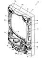
図1は、遊技機を説明する図である。
[Overall view of the gaming machine]
FIG. 1 is a diagram illustrating a gaming machine.
遊技機10は島設備に固定される枠11に、ヒンジを介して開閉回動自在に取り付けら
れる開閉枠を備える。開閉枠は、前面枠12(本体枠)及びガラス枠15によって構成さ
れている。
The
前面枠12には、遊技盤30(図2参照)が配設されるとともに、遊技盤30の前面を
覆うカバーガラス14を有するガラス枠15が取り付けられる。カバーガラス14は、遊
技盤30に形成される遊技領域32(図2参照)を視認可能とする遊技視認領域として機
能する。
A game board 30 (see FIG. 2) is arranged on the
前面枠12及びガラス枠15は、それぞれ個別に開放することが可能となっている。例
えば、ガラス枠15のみを開放することで、遊技盤30の遊技領域32にアクセスするこ
とができる。また、前面枠12をガラス枠15が開放されていない状態で開放することで
、遊技盤30の裏面側に配設された遊技制御装置(主基板)100(図3参照)等にアク
セスすることができる。
The
ガラス枠15のカバーガラス14周囲の縁部分には、種々の枠構成部材が配設されてい
る。
Various frame constituent members are arranged on the edge portion around the
ガラス枠15の上部中央及び左側部には、遊技状態に応じて発光演出可能な装飾装置1
8a,18bが配設されている。装飾装置18a,18bは、内部にLED等の照明部材
を収容しており、遊技状態に応じた発光演出を行う。これら装飾装置18a,18bの内
部に配設される照明部材は、枠装飾装置18(図4参照)の一部を構成している。
In the upper center and the left side of the
8a and 18b are arranged. The
ガラス枠15の上右角部分及び上左角部分には、上スピーカ19aがそれぞれ配設され
る。これら上スピーカ19aとは別に遊技機10の下部には、2つの下スピーカ19bが
設けられている。下スピーカ19bは、ガラス枠15の下左角部分及び前面枠12の下右
角部分に配設されている。これら上スピーカ19a及び下スピーカ19bは、効果音や警
報音、報知音等を発するものである。
An
ガラス枠15の右側部には、遊技機10の上下方向に延設されるとともに、前方(遊技
者側)に向かって突出する突出演出ユニット13が配設されている。突出演出ユニット1
3は、遊技の進行状態に応じて発光演出等を行う演出装置である。突出演出ユニット13
の内部に配設される照明部材も枠装飾装置18(図4参照)の一部を構成している。
On the right side of the
The lighting member arranged inside the frame also constitutes a part of the frame decoration device 18 (see FIG. 4).
ガラス枠15の下部には、遊技球を貯留可能な上皿21を有する上皿ユニットが取り付
けられている。上皿21は、上面が開口した箱状に形成されている。上皿21に貯留され
ている遊技球は、一球ずつ球発射装置(図示省略)に供給される。
An upper plate unit having an
上皿ユニットは、遊技者からの入力操作を受け付ける演出操作装置と、遊技者からの入
力操作を受け付ける球貸操作装置と、遊技状態に応じて発光演出等を行う装飾装置22と
、をさらに備える。
The upper plate unit further includes an effect operation device that receives an input operation from the player, a ball lending operation device that accepts an input operation from the player, and a
演出操作装置は、演出ボタン25にタッチパネル25bを組み込んだ操作装置であり、
遊技者が操作しやすいように上皿ユニットの上部中央に設けられている。
The effect operation device is an operation device in which the
It is provided in the center of the upper part of the upper plate unit so that the player can easily operate it.
遊技者が演出操作装置を操作することによって、表示装置41(図2参照)に表示され
る特図変動表示ゲーム等において遊技者の操作を介入させた演出を行うことができる。例
えば、演出パターン(演出態様)を選択したり、始動記憶に対応する変動表示ゲームの結
果を事前に予告する予告演出を実行したりすることができる。なお、変動表示ゲームには
特図変動表示ゲームが含まれ、単に変動表示ゲームとした場合には、本明細書では特図変
動表示ゲームを指すものとする。
By operating the effect operation device by the player, it is possible to perform an effect in which the player's operation is intervened in the special figure variation display game or the like displayed on the display device 41 (see FIG. 2). For example, it is possible to select an effect pattern (effect mode) or execute a notice effect that announces the result of the variable display game corresponding to the start memory in advance. The variable display game includes a special figure variable display game, and when it is simply a variable display game, it is referred to as a special figure variable display game in this specification.
また、変動表示ゲームの実行中だけでなく、非実行中に遊技者が演出操作装置を操作す
ることによっても演出パターンを変更するようにしてもよい。
Further, the effect pattern may be changed not only during the execution of the variable display game but also by the player operating the effect operation device during the non-execution.
なお、変動表示ゲームが実行される際の遊技状態は、複数の遊技状態からなる。通常遊
技状態(通常状態)とは、特別な遊技状態が発生していない遊技状態である。また、特別
な遊技状態とは、例えば、特定遊技状態としての時短状態や変動表示ゲームにおいて特別
結果(例えば大当り)の発生確率が高い状態(確変状態、確率変動状態)、大当り状態(
特別遊技状態)、小当り遊技状態(小当り状態)である。
The game state when the variable display game is executed consists of a plurality of game states. The normal gaming state (normal state) is a gaming state in which no special gaming state has occurred. Further, the special game state is, for example, a time saving state as a specific game state, a state in which a special result (for example, a big hit) is likely to occur in a variable display game (probability change state, a probability fluctuation state), or a big hit state (a big hit state).
Special game state), small hit game state (small hit state).
ここで、確変状態(特定遊技状態)は、次の大当りが発生するまで継続するもの(ルー
プタイプ)、所定回数の変動表示ゲームが実行されるまで継続するもの(回数切りタイプ
、ST)、及び所定の確率転落抽選に当選するまで継続するもの(転落抽選タイプ)等が
ある。
Here, the probability change state (specific game state) continues until the next big hit occurs (loop type), continues until a predetermined number of variable display games are executed (number cut type, ST), and There are things that continue until a predetermined probability fall lottery is won (fall lottery type).
さらに、確変状態を発生させるか否かを大当り図柄乱数によって決定せずに、大当りが
発生した場合に必ず確変状態を発生させるようにしてもよい。
Further, it may be possible to always generate the probabilistic state when the big hit occurs, instead of determining whether or not to generate the probabilistic state by the big hit symbol random number.
球貸操作装置は、遊技者が遊技球を借りる場合に操作する操作装置であって、上皿ユニ
ットの上部右側に設けられている。球貸操作装置は、球貸ボタン27と、返却ボタン28
と、残高表示部26と、を備えている。球貸ボタン27は遊技球を借りる場合に遊技者が
操作するボタンであり、返却ボタン28は遊技機10に隣接するように配置されるカード
ユニット(図示省略)からプリペイドカード等を排出させる場合に遊技者が操作するボタ
ンである。残高表示部26は、プリペイドカード等の残高が表示される表示領域である。
The ball lending operation device is an operation device operated when a player rents a game ball, and is provided on the upper right side of the upper plate unit. The ball lending operation device includes a
And a
装飾装置22は、内部にLED等の照明部材を収容しており、遊技状態に応じて発光演
出等を行う装置であって、上皿ユニットの前側部分に設けられている。装飾装置22の内
部に配設される照明部材は、枠装飾装置18(図4参照)の一部を構成している。
The
上記した上皿ユニット等を備えるガラス枠15の下方であって、前面枠12の下部には
、球発射装置(図示省略)の動作を制御するための操作ハンドル24と、遊技球を貯留可
能な下皿23とが設けられている。
An operation handle 24 for controlling the operation of the ball launching device (not shown) and a game ball can be stored in the lower part of the
操作ハンドル24は、前面枠12の右下部であって、右側の下スピーカ19bの下方に
配置されている。遊技者が操作ハンドル24を回動操作することによって、球発射装置は
上皿21から供給された遊技球を遊技盤30の遊技領域32に発射する。球発射装置から
発射される遊技球の発射速度は、操作ハンドル24の回動操作量が大きくなるほど速くな
るように設定されている。即ち、球発射装置は、遊技領域に遊技球を発射する勢(速度)
である発射勢を、遊技者による操作ハンドル24の操作に対応して変更でき、発射勢の異
なる種々の発射態様で遊技球を発射できる。発射態様には、遊技領域32の左側において
遊技球を流下させる左打ち(通常打ち)と、遊技領域32の右側において遊技球を流下さ
せる右打ちが含まれる。
The operation handle 24 is located at the lower right of the
The firing force can be changed in response to the operation of the operation handle 24 by the player, and the game ball can be launched in various launch modes having different firing forces. The launch mode includes a left-handed hit (normal hit) in which the game ball is made to flow down on the left side of the
下皿23は、上皿ユニットに対して所定の間隔をあけて、上皿ユニットの下方に配置さ
れている。下皿23は、当該下皿23の底面を上下方向に貫通する球抜き穴23aと、球
抜き穴23aを開閉するための開閉操作部23bと、を有している。遊技者が開閉操作部
23bを操作して、球抜き穴23aを開くことによって、下皿23に貯留されていた遊技
球を球抜き穴23aを通じて外部に排出することができる。
The
〔遊技盤〕
続いて、図2を参照して、遊技機10の遊技盤30について説明する。図2は、遊技機
10に備えられる遊技盤30の正面図である。
[Game board]
Subsequently, the
図2に示すように、遊技盤30は、各種部材の取付ベースとなる平板状の遊技盤本体3
0aを備える。遊技盤本体30aは木製又は合成樹脂製であって、当該遊技盤本体30a
の前面にはガイドレール31で囲まれた遊技領域32が設けられている。遊技機10は、
ガイドレール31で囲まれた遊技領域32内に球発射装置から遊技球を発射して遊技を行
うように構成されている。遊技領域32には遊技球の流下方向を変換する部材として風車
や障害釘等が配設されており、発射された遊技球はこれら部材により転動方向を変えなが
ら遊技領域32を流下する。
As shown in FIG. 2, the
It has 0a. The game board
A
It is configured to launch a game ball from a ball launcher into a
遊技領域32の略中央には、変動表示ゲームの表示領域となる窓部を形成するセンター
ケース(前面構成体)40が取り付けられている。センターケース40に形成された窓部
の後方には、複数の識別情報を変動表示(可変表示)する演出表示装置(変動表示装置)
としての表示装置41が配置されている。表示装置41は、例えば、液晶ディスプレイを
備え、センターケース40の窓部を介して遊技盤30の前面側から表示内容が視認可能と
なるように配置される。なお、表示装置41は、液晶ディスプレイを備えるものに限らず
、ELやCRT等のディスプレイを備えるものであってもよい。
A center case (front component) 40 that forms a window portion that serves as a display area for a variable display game is attached to substantially the center of the
表示装置41の表示画面(表示部)には、複数の変動表示領域が設けられており、各変
動表示領域に識別情報(特別図柄)や変動表示ゲームを演出するキャラクタが表示される
。その他、表示画面には遊技の進行に基づく画像(大当り表示やファンファーレ表示、エ
ンディング表示等)が表示される。
A plurality of variable display areas are provided on the display screen (display unit) of the
また、センターケース40には、遊技領域32を流下する遊技球をセンターケース40
の内側に導くためのワープ通路40eへの流入口40aと、ワープ通路40eを通過した
遊技球が転動可能なステージ部40bとが設けられている。センターケース40のステー
ジ部40bは、始動入賞口36及び普通変動入賞装置37の上方に配置されているため、
ステージ部40b上で転動した遊技球は始動入賞口36又は普通変動入賞装置37に入賞
しやすくなっている。
Further, in the
An inflow port 40a to the warp passage 40e for guiding the inside of the warp passage 40e and a
The game ball that has rolled on the
センターケース40の上部及び右側部には、それぞれ上部演出ユニット40c及び側部
演出ユニット40dが設けられる。上部演出ユニット40c及び側部演出ユニット40d
は、盤装飾装置46(図4参照)及び盤演出装置44(図4参照)の一部を構成している
。
An
Consists of a part of the board decoration device 46 (see FIG. 4) and the board effect device 44 (see FIG. 4).
センターケース40の右側方の遊技領域32には、普通図柄始動ゲート(普図始動ゲー
ト)34が設けられている。普図始動ゲート34の内部には、当該普図始動ゲート34を
通過した遊技球を検出するためのゲートスイッチ(SW)34a(図3参照)が設けられ
ている。遊技領域32内に打ち込まれた遊技球が普図始動ゲート34を通過すると、普図
変動表示ゲームが実行される。
A normal symbol start gate (normal symbol start gate) 34 is provided in the
センターケース40の左下方の遊技領域32には一般入賞口35が配置されており、セ
ンターケース40の右下方の遊技領域32にも一般入賞口35が配置されている。これら
一般入賞口35への遊技球の入賞は、一般入賞口35に備えられた入賞口スイッチ(SW
)35a〜35n(図3参照)によって検出される。
A general winning
) 35a-35n (see FIG. 3).
センターケース40の下方の遊技領域32には、特図変動表示ゲームの開始条件を付与
する始動入賞口(始動口1、第1始動入賞領域)36が設けられる。センターケース40
の右側の遊技領域32において、普図始動ゲート34の下方には第2始動入賞口(始動口
2、第2始動入賞領域)を備えた普通変動入賞装置37(普通電動役物、普電)が設けら
れる。普通変動入賞装置37は、前方へ回動することで、遊技球が流入し易い状態に変換
する可動部材(可動片)37bを備える。可動部材37bが閉状態である場合には遊技球
が普通変動入賞装置37に入賞できないようになっている。遊技球が始動入賞口36又は
普通変動入賞装置37に入賞した場合には、補助遊技として特図変動表示ゲームが実行さ
れる。なお、始動入賞口36には、左打ち時に遊技球が入賞し易くなり、普通変動入賞装
置37には、右打ち時に遊技球が入賞し易くなる。
In the
In the
可動部材37bは、いわゆるベロ型の普通電動役物であり、普図変動表示ゲームの結果
が所定の停止表示態様となった場合に、普電ソレノイド37c(図3参照)を介して動作
して開いて、遊技球が普通変動入賞装置37に流入しやすい開状態(遊技者にとって有利
な入賞容易状態)に変化する。
The
なお、可動部材37bは、後述する遊技制御装置100によって制御される。遊技制御
装置100は、普図変動表示ゲームの変動時間を短縮したり普図変動表示ゲームの当り確
率を通常よりも高確率としたりすることで入賞容易状態の発生頻度を高めたり、特別な遊
技を行わない通常遊技状態で発生する入賞容易状態よりも入賞容易状態の発生時間を長く
したりすることで、前述の特定遊技状態として時短状態(普電サポート状態)を発生させ
る。なお、確変状態(潜伏確変状態を除く)においても、重複して時短状態(普電サポー
ト状態)が発生する。
The
始動入賞口36の右方の遊技領域32には、下大入賞口ソレノイド38b(図7参照)
によって前方から奥側に引っ込むことで大入賞口を開放する下大入賞口を開放するアタッ
カ形式の開閉扉38cを有する第1特別変動入賞装置38(特別電動役物)が設けられて
いる。第1特別変動入賞装置38は、特図変動表示ゲームの結果によって大入賞口を閉じ
た状態(遊技者にとって不利な閉塞状態)から開放状態(遊技者にとって有利な遊技状態
)に変換し、下大入賞口内への遊技球の流入を容易にさせることで、遊技者に所定の遊技
価値(例えば、賞球や大当り終了後の時短回数/確変回数)を付与するようになっている
。なお、下大入賞口内には、当該大入賞口に入った遊技球を検出する検出手段として下大
入賞口スイッチ38a(カウントスイッチ)が配設されている。なお、第1特別変動入賞
装置38には、右打ち時に遊技球が入賞し易くなる。
In the
A first special variable winning device 38 (special electric accessory) having an attacker-type opening /
普通変動入賞装置37の上方の遊技領域32には、上大入賞口ソレノイド39b(図3
参照)によって上端側が右側に倒れる方向に回動することで上大入賞口を開放する開閉扉
39cを有する第2特別変動入賞装置39が設けられている。第2特別変動入賞装置39
は、特図変動表示ゲームの結果によって大入賞口を閉じた状態(遊技者にとって不利な閉
塞状態)から開放状態(遊技者にとって有利な特別遊技状態)に変換し、大入賞口内への
遊技球の流入を容易にさせることで、遊技者に所定の遊技価値(例えば、賞球や大当り終
了後の時短回数/確変回数)を付与するようになっている。なお、大入賞口内には、当該
大入賞口に入った遊技球を検出する検出手段として上大入賞口スイッチ39a(カウント
スイッチ)(図3参照)が配設されている。なお、第2特別変動入賞装置39には、右打
ち時に遊技球が入賞し易くなる。また、下大入賞口スイッチ38aと上大入賞口スイッチ
39aを総称して、大入賞口スイッチ43と呼ぶ。
In the
A second special variable winning
Converts the large winning opening from the closed state (closed state unfavorable to the player) to the open state (special gaming state advantageous to the player) according to the result of the special figure variation display game, and the game ball into the large winning opening. By facilitating the inflow of the game, the player is given a predetermined game value (for example, the number of time reductions / the number of probable changes after the end of the prize ball or the big hit). In the large winning opening, an upper large winning opening switch 39a (count switch) (see FIG. 3) is provided as a detection means for detecting the game ball that has entered the large winning opening. It should be noted that the second special variable winning
第2特別変動入賞装置39の内部には、特定領域86(いわゆるV入賞口)が設けられ
ている。小当りによって開閉扉39cが開放された後に特定領域86(V入賞口)に遊技
球が入球した場合に大当りが確定する。特定領域86は、小当り中にのみ、長時間開放さ
れるなどして遊技球が容易に通過できるようにしてよい。なお、遊技制御装置100は、
特定領域86への遊技球の通過(V入賞)をセンサ(後述の特定領域スイッチ72)等を
介して検知でき、V入賞を検知すると小当り終了後に大当り状態に移行することを確定す
るとともに、後述の演出制御装置300にV入賞があったことを示す情報(特定領域通過
コマンド等)を送信する。そして、演出制御装置300は、V入賞を表示装置41などに
おいて報知できる。
A specific area 86 (so-called V winning opening) is provided inside the second special variable winning
The passage of the game ball to the specific area 86 (V winning) can be detected via a sensor (
即ち、本実施形態では、遊技機10は、いわゆる1種2種混合機(1+2種機)である
。本実施形態では、小当りで第2特別変動入賞装置39が開放されることによって、第2
特別変動入賞装置39内の特定領域86(V入賞口)に遊技球がV入賞して、大当りが発
生する。
That is, in the present embodiment, the
A game ball wins a V in a specific area 86 (V winning opening) in the special variable winning
一般入賞口35、始動入賞口36、普通変動入賞装置37、及び特別変動入賞装置38
、39の大入賞口に遊技球が入賞すると、払出制御装置200(図3参照)は、入賞した
入賞口の種類に応じた数の賞球を払出装置から上皿21に排出する。また、下方の遊技領
域32には、入賞口等に入賞しなかった遊技球を回収するアウト口30bが設けられてい
る。また、一般入賞口35、始動入賞口36、普通変動入賞装置37、及び特別変動入賞
装置38、39やその近傍には、遊技球が入賞した場合などに発光可能なLED(後述の
盤装飾装置46の一部)が配設されている。
General winning
When a game ball wins in the 39 major winning openings, the payout control device 200 (see FIG. 3) discharges a number of prize balls according to the type of the winning winning opening from the payout device to the
また、遊技領域32の外側であって遊技盤本体30aの右下角部には、特図変動表示ゲ
ーム(特図1変動表示ゲーム、特図2変動表示ゲーム)及び普図変動表示ゲームを実行す
る一括表示装置50が設けられている。一括表示装置50は、現在の遊技状態等の情報を
表示する表示部51〜60を備える。
Further, a special figure variation display game (special figure 1 variation display game, special figure 2 variation display game) and a normal figure variation display game are executed in the lower right corner of the game board
一括表示装置50は、7セグメント型の表示器(LEDランプ)等で構成された変動表
示ゲーム用の第1特図変動表示部51(特図1表示器、ランプD1)及び第2特図変動表
示部52(特図2表示器、ランプD2)と、普図変動表示ゲーム用の変動表示部53(普
図表示器、ランプD8、D10、D18)と、各変動表示ゲームの始動(保留)記憶数報
知用の記憶表示部(特図1保留表示器54、特図2保留表示器55、普図保留表示器56
)と、を有している。特図1保留表示器54はランプD11、D12により構成される。
特図2保留表示器55は、ランプD13、D14により構成される。普図保留表示器56
は、ランプD15、D16により構成される。
The
) And. Special figure 1 The hold indicator 54 is composed of lamps D11 and D12.
The special figure 2 hold indicator 55 is composed of lamps D13 and D14. General figure hold indicator 56
Is composed of lamps D15 and D16.
また、一括表示装置50には、右打ち時(右打ちすべき時)又は左打ち時(通常打ち時
)であることを報知する第1遊技状態表示部57(第1遊技状態表示器、ランプD7)、
時短状態が発生すると点灯して時短状態発生を報知する第2遊技状態表示部58(第2遊
技状態表示器、ランプD17)、遊技機10の電源投入時に大当りの確率状態が高確率状
態となっていることを表示する第3遊技状態表示部59(第3遊技状態表示器、確率状態
表示部、ランプD9)、大当り時のラウンド数(特別変動入賞装置38、39の開閉回数
)を表示するラウンド表示部60(ランプD3−D6)が設けられている。
Further, the
When the time saving state occurs, the second game state display unit 58 (second game state display, lamp D17) that lights up to notify the occurrence of the time saving state, and the jackpot probability state becomes a high probability state when the power of the
特図1表示器51と特図2表示器52において、変動表示ゲームは、識別情報(例えば
、中央のセグメント)の点灯消灯(点滅)を繰り返す変動表示によって実行される。なお
、特図1表示器51、特図2表示器52は、このようなセグメント型の表示部に限らず、
複数のLEDの集合体により構成されていてもよいし、変動表示を実行する場合に、表示
器として設けられるすべてのLEDにより全点灯全消灯(全LEDの同時点滅)や、循環
点灯(何れか1のLEDから所定時間毎に所定の順序で点灯し、消灯する)、または複数
のLEDのうちの所定数のLEDによる点灯消灯(点滅)や循環点灯によって行ってもよ
い。普図表示器53においても、変動表示ゲームは、ランプD10、D18の点灯消灯を
繰り返す変動表示(点滅)によって実行される。また、普図表示器53も特図1表示器5
1、特図2表示器52と同様に適宜構成することが可能である。
In the special figure 1 display 51 and the special figure 2
It may be composed of an aggregate of a plurality of LEDs, and when a variable display is executed, all the LEDs provided as a display are turned on and off (all LEDs are blinking at the same time) or circulated on (any of them). It may be turned on and off in a predetermined order at predetermined time intervals from one LED), or may be turned on and off (blinking) or circulated by a predetermined number of LEDs among a plurality of LEDs. Also in the normal diagram display 53, the variation display game is executed by the variation display (blinking) in which the lamps D10 and D18 are repeatedly turned on and off. In addition, the normal figure display 53 is also a special figure 1
1. It can be appropriately configured in the same manner as the special figure 2
ランプ表示装置80は、図柄(後述の第四特別図柄)として点灯表示と消灯表示を繰り
返す変動表示(点滅)を実行するランプ表示部1、2(LED)と、各特図変動表示ゲー
ムの始動(保留)記憶数報知用のランプ表示部3−6(LED)を有する。なお、ランプ
表示装置80は、演出制御装置300(後述)で制御される。
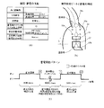
The lamp display device 80 includes
ランプ表示部1、2は、変動表示として所定の点滅周期(例えば200msec(ミリ
秒))で点滅する。一括表示装置50の特図1表示器51、特図2表示器52、普図表示
器53における変動表示の変動時間が遊技制御装置100で計測されるのに対して、ラン
プ表示装置80のランプ表示部1、2の変動時間は演出制御装置300(後述)で計測さ
れる。
The
ランプ表示部3、4(特図1保留LED1、特図1保留LED2)は、消灯状態、点灯
状態、点滅状態の組合せによって、特図1保留数(第1始動記憶数)を表示する。同様に
、ランプ表示部5、6(特図2保留LED1、特図2保留LED2)は、消灯状態、点灯
状態、点滅状態の組合せによって、特図2保留数(第2始動記憶数)を表示する。ランプ
表示部3−6は、大当り発生により保留数の表示を終了するが、大当り状態中以外の場合
(表示装置41で後述のリーチが発生している場合も含む)では、保留数の表示を行う。
The
次に、遊技機10における遊技の流れ、普図変動表示ゲーム及び特図変動表示ゲームの
詳細について説明する。
Next, the flow of the game in the
遊技機10では、図示しない球発射装置から遊技領域32に向けて遊技球が打ち出され
ることによって遊技が行われる。打ち出された遊技球は、遊技領域32内の各所に配置さ
れた障害釘や風車等によって転動方向を変えながら遊技領域32を流下し、普図始動ゲー
ト34、一般入賞口35、始動入賞口36、普通変動入賞装置37、又は特別変動入賞装
置38、39に入賞するか、遊技領域32の最下部に設けられたアウト口30bへ流入し
、遊技領域32から排出される。そして、一般入賞口35、始動入賞口36、普通変動入
賞装置37、又は特別変動入賞装置38、39に遊技球が入賞すると、入賞した入賞口の
種類に応じた数の賞球が払出装置を介して上皿21に排出される。
In the
普図始動ゲート34には、当該普図始動ゲート34を通過した遊技球を検出するゲート
スイッチ34a(図3参照)が設けられている。遊技球が普図始動ゲート34を通過する
と、ゲートスイッチ34aによって検出され、このときに抽出された当り判定用乱数値の
判定結果に基づき普図変動表示ゲームが実行される。
The normal
普図変動表示ゲームを開始できない状態、例えば、既に普図変動表示ゲームが行われて
おり当該普図変動表示ゲームが終了していない場合や、普図変動表示ゲームの結果が当り
となって普通変動入賞装置37が開放状態に変換されている場合に、遊技球が普図始動ゲ
ート34を通過すると、普図始動記憶数(普図保留数)が上限数未満ならば当該記憶数が
加算(+1)される。
When the normal map fluctuation display game cannot be started, for example, when the normal map variable display game has already been played and the normal map variable display game has not ended, or when the result of the normal map variable display game is a hit, it is normal. When the game ball passes through the normal
普図始動記憶(普図保留)には普図変動表示ゲームの当りはずれを決定するための当り
判定用乱数値が記憶されており、この当り判定用乱数値が判定値と一致した場合に、当該
普図変動表示ゲームが当りとなって特定の結果態様(特定結果)が導出される。
The hit judgment random value for determining the hit / miss of the normal figure fluctuation display game is stored in the normal figure start memory (normal figure hold), and when this hit judgment random value matches the judgment value, A specific result mode (specific result) is derived by winning the normal map variation display game.
普図変動表示ゲームは、一括表示装置50に設けられた普図表示器53で実行されるよ
うになっている。普図表示器53は、普通識別情報(普図)として点灯状態の場合に当り
を示し、消灯状態の場合にはずれを示すLEDから構成され、このLEDを点滅表示する
ことで普通識別情報の変動表示を行い、所定の変動表示時間の経過後、LEDを点灯又は
消灯することで結果を表示するようになっている。
The normal map variation display game is executed by the normal map display 53 provided in the
普図始動ゲート34通過時に抽出された普図乱数値が当り値である場合には、普図表示
器53に表示される普通図柄(普図)が当り状態で停止し、当り状態となる。このとき、
普電ソレノイド37c(図3参照)が駆動されることにより、可動部材37bが所定の時
間(例えば3秒間×2回)だけ開状態に変換され、普通変動入賞装置37への遊技球の入
賞が許容される。
When the normal figure random value extracted when passing through the normal
By driving the normal
遊技球の始動入賞口36への入賞及び普通変動入賞装置37への入賞は、始動口1スイ
ッチ36a(図3参照)及び始動口2スイッチ37a(図3参照)によって検出される。
始動入賞口36に入賞した遊技球は特図1変動表示ゲームの始動入賞球として検出され、
所定の上限数を限度に記憶されるとともに、普通変動入賞装置37に入賞した遊技球は特
図2変動表示ゲームの始動入賞球として検出され、所定の上限数を限度に記憶される。
The winning of the game ball to the starting winning opening 36 and the winning of the ordinary variable winning
The game ball that has won the start winning opening 36 is detected as the starting winning ball of the special figure 1 variable display game.
A game ball that has won a prize in the normal
特図変動表示ゲームの始動入賞球の検出時には、大当り乱数値や大当り図柄乱数値、各
変動パターン乱数値等が抽出される。これら乱数値は、遊技制御装置100の特図保留記
憶領域(RAMの一部)に特図始動入賞記憶として各々所定回数分(例えば最大で8回分
)を限度に記憶される。特図始動入賞記憶の記憶数は、一括表示装置50の始動入賞数報
知用の特図1保留表示器54や特図2保留表示器55に表示されるとともに、表示装置4
1の表示画面にも表示される。
When the start winning ball of the special figure fluctuation display game is detected, the jackpot random number value, the jackpot symbol random value, each fluctuation pattern random value, and the like are extracted. These random numbers are stored in the special figure reservation storage area (a part of the RAM) of the
It is also displayed on the display screen of 1.
遊技制御装置100は、始動入賞口36への入賞若しくは第1始動記憶(特図1始動記
憶、特図1保留)に基づいて、特図1表示器51で特図1変動表示ゲームを実行する。ま
た、遊技制御装置100は、普通変動入賞装置37への入賞若しくは第2始動記憶(特図
2始動記憶、特図2保留)に基づいて、特図2表示器52で特図2変動表示ゲームを実行
する。
The
特図1変動表示ゲーム(第1特図変動表示ゲーム)及び特図2変動表示ゲーム(第2特
図変動表示ゲーム)は、特図1表示器51及び特図2表示器52において識別情報(特別
図柄、特図)を変動表示した後に所定の結果態様を停止表示することで行われる。
The special figure 1 variable display game (1st special figure variable display game) and the special figure 2 variable display game (2nd special figure variable display game) have identification information (identification information) on the special figure 1 display 51 and the special figure 2
また、表示装置41では、各特図変動表示ゲームに対応して複数種類の識別情報(例え
ば、数字、記号、キャラクタ図柄など)を変動表示させる飾り特図変動表示ゲームが実行
される。
Further, the
表示装置41における飾り特図変動表示ゲームは、前述した数字等で構成される飾り特
別図柄(識別情報)が左(第一特別図柄)、右(第二特別図柄)、中(第三特別図柄)の
順に変動表示(スクロール表示)を開始して、所定時間後に変動している図柄を順次停止
させて、特図変動表示ゲームの結果を表示することで行われる。また、表示装置41では
、興趣向上のためにキャラクタの出現等の多様な演出表示が行われる。さらに、飾り特図
変動表示ゲームでは、他の飾り特別図柄(識別情報)として、ランプ表示装置80のラン
プ表示部1、2において、点灯表示と消灯表示の繰り返し(点滅)によって第四特別図柄
(第4図柄)が変動する。ランプ表示部1、2の変動表示は、開始から所定時間後に、は
ずれの場合は「消灯」、大当りもしくは小当りの場合は「点灯」で停止する。
In the decorative special symbol variation display game on the
始動入賞口36又は普通変動入賞装置37への遊技球の入賞が所定のタイミングでなさ
れた場合(入賞検出時の大当り乱数値が大当り値である場合)には、特図変動表示ゲーム
の結果として表示図柄により特定の結果態様(特別結果態様)が導出され、大当り状態(
特別遊技状態)となる。これに対応して、表示装置41の表示態様は特別結果態様(例え
ば「7,7,7」等の数字が揃った状態)となる。
When the game ball is won in the starting winning opening 36 or the normal
It becomes a special game state). Correspondingly, the display mode of the
このとき、特別変動入賞装置38、39は、大入賞口ソレノイド(38b、39b)(
図3参照)への通電によって、大入賞口が所定の時間(例えば30秒)だけ閉状態から開
状態に変換される。すなわち、特別変動入賞装置38、39に備えられた大入賞口が所定
の時間又は所定数の遊技球が入賞するまで大きく開き、この間遊技者は多くの遊技球を獲
得することができるという特典が付与される。
At this time, the special variable winning
By energizing (see FIG. 3), the big winning opening is changed from the closed state to the open state for a predetermined time (for example, 30 seconds). That is, the large winning openings provided in the special variable winning
第1始動入賞口36又は普通変動入賞装置37への遊技球の入賞が所定のタイミングで
なされた場合(入賞検出時の大当り乱数値が小当り値である場合)には、特図変動表示ゲ
ームの結果として表示図柄により特定結果態様(小当り結果態様)が導出され、小当り状
態となる。これに対応して、表示装置41の表示態様は小当り結果態様となる。なお、本
実施形態では、小当りの判定にも大当り乱数値が使用されるが、小当り値(小当り判定値
)は、大当り値(大当り判定値)と異なる。
When the game ball is won in the first start winning opening 36 or the normal
このとき、特別変動入賞装置38、39は、大入賞口ソレノイド38b、39b(図3
参照)への通電によって、大入賞口が所定の短時間だけ閉状態から開状態に変換される。
なお、大入賞口の全開放時間は、小当り状態(小当り遊技状態)の方が大当り状態(特別
遊技状態)よりも短いため、小当り状態では大当り状態よりも遊技者が獲得可能な遊技価
値(獲得球数)が少ない。なお、小当り状態と大当り状態では両方とも大入賞口が開放状
態となるが、大当り状態を第1特別遊技状態と呼び、小当り状態を第2特別遊技状態と呼
んでもよい。なお、簡単のため、本実施形態では、小当り状態で特別変動入賞装置39(
上大入賞口)のみが開状態に変換され、大当り状態(小当り中のV入賞による大当り状態
も含む)で特別変動入賞装置38(下大入賞口)のみが開状態に変換される構成を説明す
る。
At this time, the special variable winning
By energizing (see), the big winning opening is changed from the closed state to the open state for a predetermined short time.
Since the full opening time of the big winning opening is shorter in the small hit state (small hit game state) than in the big hit state (special game state), the game that the player can acquire in the small hit state than in the big hit state. The value (number of balls acquired) is small. In both the small hit state and the big hit state, the big winning opening is open, but the big hit state may be called the first special gaming state, and the small hit state may be called the second special gaming state. For the sake of simplicity, in the present embodiment, the special variable winning device 39 (in the small hit state)
Only the upper big winning opening) is converted to the open state, and only the special variable winning device 38 (lower big winning opening) is converted to the open state in the big hit state (including the big hit state due to V winning during the small hit). explain.
ここで、大当りと小当りとの違いについて説明する。 Here, the difference between a big hit and a small hit will be described.
大当りとは条件装置の作動を伴う特別結果であり、小当りとは条件装置の作動を伴わな
い特定結果である。条件装置とは、特図変動表示ゲームで大当りが発生(大当り図柄の停
止表示)した場合に作動するもので、条件装置が作動するとは、例えば大当り状態が発生
して特別電動役物としての特別変動入賞装置38、39を連続して作動させるための特定
のフラグがセットされることを意味する。また、条件装置が作動するとは、特定領域86
への遊技球の通過(V入賞)があったことを意味してもよい。条件装置が作動しないとは
、例えば単に小当り抽選に当選した場合のように上述の特定のフラグがセットされないこ
とを意味する。ただし、本実施形態で後述するように、小当り状態中にV入賞があった場
合には条件装置が作動することになる。なお、「条件装置」は、上記のようなソフトウェ
ア的にオンオフされるフラグのようなソフトウェア手段であっても良いし、電気的にオン
オフされるスイッチのようなハードウェア手段であっても良い。また、「条件装置」は、
その作動が電動役物の連続作動に必要条件とされる装置として、パチンコ遊技機の分野に
おいては一般的に使用されている用語であり、本明細書においても同様の意味を有する用
語として使用している。
A big hit is a special result with the operation of the condition device, and a small hit is a specific result without the operation of the condition device. The condition device operates when a big hit occurs (stop display of the big hit symbol) in the special figure fluctuation display game, and when the condition device operates, for example, a big hit state occurs and it is special as a special electric accessory. This means that a specific flag for continuously operating the variable winning
It may mean that the game ball has passed (V prize). The fact that the condition device does not operate means that the above-mentioned specific flag is not set as in the case of simply winning the small hit lottery. However, as will be described later in this embodiment, if there is a V prize during the small hit state, the condition device will operate. The "conditional device" may be a software means such as a flag that is turned on / off by software as described above, or a hardware means such as a switch that is turned on / off electrically. In addition, "condition device" is
It is a term generally used in the field of pachinko gaming machines as a device whose operation is a necessary condition for continuous operation of an electric accessory, and is also used in the present specification as a term having the same meaning. ing.
具体的には、大当りの場合は、大当りフラグが設定されることにより特別変動入賞装置
が開放されるのに対して、小当りの場合は、小当りフラグが設定されることにより特別変
動入賞装置が開放される。
Specifically, in the case of a big hit, the special variable winning device is opened by setting the big hit flag, whereas in the case of a small hit, the special variable winning device is set by setting the small hit flag. Is released.
なお、特図1表示器51及び特図2表示器52は、別々の表示器として構成してもよい
し同一の表示器として構成してもよいが、各特図変動表示ゲームが同時に実行されないよ
うに設定される。なお、特図2変動表示ゲームは、特図1変動表示ゲームよりも優先して
実行されるようになっており、特図1変動表示ゲームと特図2変動表示ゲームの始動記憶
があり、特図変動表示ゲームの実行が可能な状態になった場合は特図2変動表示ゲームが
実行される(特図2保留優先消化、特図2優先変動)。
The special figure 1 display 51 and the special figure 2
表示装置41における飾り特図変動表示ゲームについては、特図1変動表示ゲームと特
図2変動表示ゲームとを別々の表示装置や別々の表示領域で実行するようにしてもよいし
、同一の表示装置や表示領域で実行するようにしてもよい。この場合、特図1変動表示ゲ
ーム及び特図2変動表示ゲームに対応する飾り特図変動表示ゲームが同時に実行されない
ようにしてよい。
Regarding the decorative special figure variable display game in the
なお、以下の説明において、特図1変動表示ゲームと特図2変動表示ゲームを区別しな
い場合は、単に特図変動表示ゲームと称する。
In the following description, when the special figure 1 variable display game and the special figure 2 variable display game are not distinguished, they are simply referred to as a special figure variable display game.
また、特に限定されるわけではないが、上記始動入賞口36内の始動口1スイッチ36
a、普通変動入賞装置37内の始動口2スイッチ37a、ゲートスイッチ34a、入賞口
スイッチ35a、カウントスイッチ(38a、39a)には、磁気検出用のコイルを備え
該コイルに金属が近接すると磁界が変化する現象を利用して遊技球を検出する非接触型の
磁気近接センサ(以下、近接スイッチと称する)が使用されている。また、遊技機10の
ガラス枠15等に設けられたガラス枠開放検出スイッチ63や前面枠(遊技枠)12等に
設けられた前面枠開放検出スイッチ64(本体枠開放検出スイッチ)には、機械的な接点
を有するマイクロスイッチを用いることができる。
Further, although not particularly limited, the starting
a, The
〔遊技制御装置〕
図3は、遊技機10の遊技制御系のブロック図である。遊技機10は遊技制御装置10
0(主基板)を備え、遊技制御装置100は、遊技を統括的に制御する主制御装置(主基
板)であって、遊技用マイクロコンピュータ(以下、遊技用マイコンと称する)111を
有するCPU部110と、入力ポートを有する入力部120と、出力ポートやドライバな
どを有する出力部130、CPU部110と入力部120と出力部130との間を接続す
るデータバス140などからなる。
[Game control device]
FIG. 3 is a block diagram of the game control system of the
The
CPU部110は、アミューズメントチップ(IC)と呼ばれる遊技用マイコン(CP
U)111と、水晶振動子のような発振子を備え、CPUの動作クロックやタイマ割込み
、乱数生成回路の基準となるクロックを生成する発振回路(水晶発振器)113などを有
する。遊技制御装置100及び該遊技制御装置100によって駆動されるソレノイドやモ
ータなどの電子部品には、電源装置400で生成されたDC32V,DC12V,DC5
Vなど所定のレベルの直流電圧が供給されて動作可能にされる。
The
It includes a U) 111, an oscillator such as a crystal oscillator, and an oscillation circuit (crystal oscillator) 113 that generates an operating clock of a CPU, a timer interrupt, and a clock that serves as a reference for a random number generation circuit. The
A predetermined level of DC voltage such as V is supplied to enable operation.
電源装置400は、24Vの交流電源からDC32Vの直流電圧を生成するACDCコ
ンバータやDC32Vの電圧からDC12V,DC5Vなどのより低いレベルの直流電圧
を生成するDC−DCコンバータなどを有する通常電源部410と、遊技用マイコン11
1の内部のRAMに対して停電時に電源電圧を供給するバックアップ電源部420と、停
電監視回路を有し、遊技制御装置100に停電の発生、回復を知らせる停電監視信号やリ
セット信号などの制御信号を生成して出力する制御信号生成部430などを備える。
The
It has a backup
本実施形態では、電源装置400は、遊技制御装置100と別個に構成されているが、
バックアップ電源部420及び制御信号生成部430は、別個の基板上あるいは遊技制御
装置100と一体、すなわち、主基板上に設けるように構成してもよい。遊技盤30及び
遊技制御装置100は機種変更の際に交換の対象となるので、実施例のように、電源装置
400若しくは主基板とは別の基板にバックアップ電源部420及び制御信号生成部43
0を設けることにより、交換の対象から外しコストダウンを図ることができる。
In the present embodiment, the
The backup
By setting 0, it is possible to exclude from the exchange target and reduce the cost.
バックアップ電源部420は、電解コンデンサのような大容量のコンデンサ1つで構成
することができる。バックアップ電源は、遊技制御装置100の遊技用マイコン111(
特に内蔵RAM)に供給され、停電中あるいは電源遮断後もRAMに記憶されたデータが
保持されるようになっている。制御信号生成部430は、例えば通常電源部410で生成
された32Vの電圧を監視してそれが例えば17V以下に下がると停電発生を検出して停
電監視信号を変化させるとともに、所定時間後にリセット信号を出力する。また、電源投
入時や停電回復時にもその時点から所定時間経過後にリセット信号を出力する。
The backup
In particular, the data supplied to the built-in RAM) and stored in the RAM is retained even during a power failure or power failure. The control
また、遊技制御装置100にはRAM初期化スイッチ112が設けられている。RAM
初期化スイッチ112が押下げられてオン操作されると初期化スイッチ信号が生成され、
これに基づき遊技用マイコン111内のRAM111c及び払出制御装置200内のRA
Mに記憶されている情報を強制的に初期化する処理が行われる。特に限定されるわけでは
ないが初期化スイッチ信号は電源投入時に読み込まれ、停電監視信号は遊技用マイコン1
11が実行するメインプログラムのメインループの中で繰り返し読み込まれる。リセット
信号は強制割込み信号の一種であり、制御システム全体をリセットさせる。
Further, the
When the
Based on this, the RAM 111c in the
The process of forcibly initializing the information stored in M is performed. Although not particularly limited, the initialization switch signal is read when the power is turned on, and the power failure monitoring signal is the
It is repeatedly read in the main loop of the main program executed by 11. A reset signal is a type of forced interrupt signal that resets the entire control system.
また、遊技制御装置100(主基板)は、設定キースイッチ93を備える。設定キース
イッチ93は、操作者の回転操作等によってオンすることによって遊技条件(遊技)に関
する設定に応じた確率設定値(設定値)を変更可能な状態にする。なお、RAM初期化ス
イッチ112は、操作者の操作に応じて確率設定値を変更可能な設定値変更スイッチとし
ても使用可能である。本実施形態では、確率設定値は、大当り確率や小当り確率などの当
選確率を設定するための設定値であるが、確率以外の他の遊技条件(演出など)も確率設
定値に応じて変更可能である。設定キースイッチ93とRAM初期化スイッチ112は、
遊技条件に関する設定(確率設定値)を変更可能な設定変更手段(設定変更装置42)を
構成する。なお、RAM初期化スイッチ112ではなく、他のスイッチが、設定値変更ス
イッチを兼用してもよいし、専用に独自の設定値変更スイッチを設けてもよい。
Further, the game control device 100 (main board) includes a setting
A setting changing means (setting changing device 42) capable of changing the setting (probability setting value) related to the game condition is configured. In addition to the
設定キースイッチ93とRAM初期化スイッチ112は、遊技機10内部の遊技制御装
置100上に設けられることによって、前面枠12(本体枠)が開放されなければ操作で
きない位置(アクセスできない位置)に配置される。即ち、一般の遊技者は、設定キース
イッチ93とRAM初期化スイッチ112にアクセスして操作することができない。
The setting
後述するように、遊技機10の電源投入(停電復旧、復電)の際に、遊技機10は、設
定キースイッチ93とRAM初期化スイッチ112のオン/オフ状態に応じて、確率設定
値を変更可能な設定可変状態(設定変更状態、設定変更モード)、確率設定値を確認可能
な設定確認状態(設定確認モード)などの各種状態に、移行することができる。
As will be described later, when the power of the
本実施形態において、確率設定値は、例えば6段階で規定され、確率設定値1(設定1
)、確率設定値2(設定2)、確率設定値3(設定3)、確率設定値4(設定4)、確率
設定値5(設定5)、確率設定値6(設定6)がある。一般的に、設定1が遊技者に最も
不利な設定であり、設定6が遊技者に最も有利な設定である。設定1、2が低設定であり
、設定3、4が中間の設定(中間設定)であり、設定5、6が高設定である。
In the present embodiment, the probability setting value is defined in, for example, 6 steps, and the probability setting value 1 (setting 1) is defined.
), Probability setting value 2 (setting 2), probability setting value 3 (setting 3), probability setting value 4 (setting 4), probability setting value 5 (setting 5), probability setting value 6 (setting 6). In general, setting 1 is the most unfavorable setting for the player, and setting 6 is the most advantageous setting for the player.
確率設定変更処理では、操作者によってRAM初期化スイッチ112が押下操作される
度に、作業用設定値領域の作業用設定値(設定)が、設定値0(設定1、確率設定値1)
→設定値1(設定2、確率設定値2)→設定値2(設定3、確率設定値3)→設定値3(
設定4、確率設定値4)→設定値4(設定5、確率設定値5)→設定値5(設定6、確率
設定値6)→設定値0(設定1)→設定値1(設定2)→・・・のように変更される。こ
のように、RAM初期化スイッチ112は、設定値変更スイッチとしても機能する。なお
、説明の都合上、設定変更状態(設定変更モード)中に、作業用設定値0〜5をそれぞれ
確率設定値1〜6に対応して設けるが、作業用設定値と確率設定値は同じ数値範囲(即ち
0〜5又は1〜6)に揃えて同じものとして取り扱ってもよい(作業用設定値と確率設定
値を同じ数値にする)。
In the probability setting change process, each time the
→ Setting value 1 (setting 2, probability setting value 2) → Setting value 2 (setting 3, probability setting value 3) → Setting value 3 (setting value 3)
なお、RAM初期化スイッチ112(設定値変更スイッチ)の操作ではなく、設定キー
スイッチ93を所定の位置に回転操作して確率設定値を変更する構成としてもよい。また
、確率設定値は6段階に限られない。そして、選択されている0〜5の作業用設定値に対
応する表示用確率設定値が、例えば4桁の7セグメント型(ドットDpを含めると8セグ
メント型)の表示器である性能表示装置152等に表示される。
Instead of operating the RAM initialization switch 112 (setting value changing switch), the setting
遊技用マイコン111は、CPU(中央処理ユニット:マイクロプロセッサ)111a
、読出し専用のROM(リードオンリメモリ)111b及び随時読出し書込み可能なRA
M(ランダムアクセスメモリ)111cを備える。
The
, Read-only ROM (read-only memory) 111b and RA that can be read and written at any time
It includes M (random access memory) 111c.
ROM111bは、遊技制御のための不変の情報(プログラム、固定データ、各種乱数
の判定値等)を不揮発的に記憶する。RAM111cは、遊技制御時にCPU111aの
作業領域や各種信号や乱数値の記憶領域として利用されるもので、遊技に関する情報(遊
技情報)が記憶され、停電が発生しても記憶された情報の記憶保持が可能な保持記憶手段
となる。ROM111b又はRAM111cとして、EEPROMのような電気的に書換
え可能な不揮発性メモリを用いてもよい。
The ROM 111b non-volatilely stores invariant information (programs, fixed data, determination values of various random numbers, etc.) for game control. The RAM 111c is used as a work area of the CPU 111a and a storage area for various signals and random values during game control. Information on the game (game information) is stored, and the stored information is stored even if a power failure occurs. Is a possible retention and storage means. As the ROM 111b or the RAM 111c, an electrically rewritable non-volatile memory such as EEPROM may be used.
また、ROM111bは、例えば、特図変動表示ゲームの実行時間、演出内容、リーチ
状態の発生の有無などを規定する変動パターン(変動態様)を決定するための変動パター
ンテーブルを記憶している。変動パターンテーブルとは、始動記憶として記憶されている
変動パターン乱数1〜3をCPU111aが参照して変動パターンを決定するためのテー
ブルである。また、変動パターンテーブルには、結果がはずれとなる場合に選択されるは
ずれ変動パターンテーブル、結果が大当りとなる場合に選択される大当り変動パターンテ
ーブル等が含まれる。さらに、これらのパターンテーブルには、リーチ状態となった後の
変動パターンである後半変動パターンを決定するためのテーブル(後半変動グループテー
ブルや後半変動パターン選択テーブル等)、リーチ状態となる前の変動パターンである前
半変動パターンを決定するためのテーブル(前半変動グループテーブルや前半変動パター
ン選択テーブル等)が含まれている。
Further, the ROM 111b stores, for example, a variation pattern table for determining a variation pattern (variation mode) that defines the execution time of the special figure variation display game, the effect content, the presence / absence of the occurrence of the reach state, and the like. The variation pattern table is a table for the CPU 111a to refer to the variation pattern
ここでリーチ(リーチ状態)とは、表示状態が変化可能な表示装置を有し、該表示装置
が時期を異ならせて複数の表示結果を導出表示し、該複数の表示結果が予め定められた特
別結果態様となった場合に、遊技状態が遊技者にとって有利な遊技状態(特別遊技状態)
となる遊技機10において、複数の表示結果の一部がまだ導出表示されていない段階で、
既に導出表示されている表示結果が特別結果態様となる条件を満たしている表示状態をい
う。また、別の表現をすれば、リーチ状態とは、表示装置の変動表示制御が進行して表示
結果が導出表示される前段階にまで達した時点でも、特別結果態様となる表示条件からは
ずれていない表示態様をいう。そして、例えば、特別結果態様が揃った状態を維持しなが
ら複数の変動表示領域による変動表示を行う状態(いわゆる全回転リーチ)もリーチ状態
に含まれる。また、リーチ状態とは、表示装置の表示制御が進行して表示結果が導出表示
される前段階にまで達した時点での表示状態であって、表示結果が導出表示される以前に
決定されている複数の変動表示領域の表示結果の少なくとも一部が特別結果態様となる条
件を満たしている場合の表示状態をいう。
Here, the reach (reach state) has a display device whose display state can be changed, and the display device derives and displays a plurality of display results at different times, and the plurality of display results are predetermined. When the special result mode is adopted, the gaming state is advantageous for the player (special gaming state).
At the stage where some of the plurality of display results have not yet been derived and displayed in the
A display state in which the display result that has already been derived and displayed satisfies the condition for the special result mode. In other words, the reach state is out of the display condition that is the special result mode even when the variable display control of the display device progresses and the display result reaches the stage before the derivation display. Refers to a display mode that does not exist. Further, for example, a state in which variation display is performed by a plurality of variation display areas (so-called full rotation reach) while maintaining a state in which the special result modes are aligned is also included in the reach state. The reach state is a display state at the time when the display control of the display device progresses and reaches the stage before the display result is derived and displayed, and is determined before the display result is derived and displayed. It refers to a display state when at least a part of the display results of a plurality of variable display areas satisfies the condition of the special result mode.
よって、例えば、特図変動表示ゲームに対応して表示装置に表示される飾り特図変動表
示ゲームが、表示装置における左、中、右の変動表示領域の各々で所定時間複数の識別情
報を変動表示した後、左、右、中の順で変動表示を停止して結果態様を表示するものであ
る場合、左、右の変動表示領域で、特別結果態様となる条件を満たした状態(例えば、同
一の識別情報)で変動表示が停止した状態がリーチ状態となる。他に、すべての変動表示
領域の変動表示を一旦停止した時点で、左、中、右のうちいずれか二つの変動表示領域で
特別結果態様となる条件を満たした状態(例えば、同一の識別情報となった状態、ただし
特別結果態様は除く)をリーチ状態とし、リーチ状態から残りの一つの変動表示領域を変
動表示するようにしてもよい。
Therefore, for example, the decorative special figure variation display game displayed on the display device corresponding to the special figure variation display game changes a plurality of identification information for a predetermined time in each of the left, middle, and right variation display areas on the display device. After the display, when the variation display is stopped in the order of left, right, and middle to display the result mode, the left and right variation display areas satisfy the conditions for the special result mode (for example,). The state in which the variable display is stopped with the same identification information) is the reach state. In addition, when the fluctuation display of all the fluctuation display areas is temporarily stopped, the condition of the special result mode in any two of the left, middle, and right fluctuation display areas is satisfied (for example, the same identification information). (However, the special result mode is excluded) may be set as the reach state, and the remaining one variable display area may be variable-displayed from the reach state.
そして、リーチ状態には複数のリーチ演出が含まれ、特別結果態様(大当り態様)が導
出される可能性が異なる(期待度が異なる)リーチ演出の系統(種類)として、ノーマル
リーチ(Nリーチ)、スペシャル1リーチ(SP1リーチ)、スペシャル2リーチ(SP
2リーチ)、スペシャル3リーチ(SP3リーチ)、プレミアリーチが設定されている。
なお、大当りの期待度(期待値)は、リーチなし<ノーマルリーチ<スペシャル1リーチ
<スペシャル2リーチ<スペシャル3リーチ<プレミアリーチの順に高くなるようになっ
ている。また、リーチ状態は、少なくとも特図変動表示ゲームで特別結果態様が導出され
る場合(大当りとなる場合)における変動表示態様に含まれるようになっている。すなわ
ち、特図変動表示ゲームで特別結果態様が導出されないと判定する場合(はずれとなる場
合)における変動表示態様に含まれることもある。よって、リーチ状態が発生した状態は
、リーチ状態が発生しない場合と比較して大当りとなる可能性の高い状態である。
The reach state includes a plurality of reach effects, and as a system (type) of reach effects in which the possibility of deriving a special result mode (big hit mode) is different (expectations are different), normal reach (N reach),
2 reach), special 3 reach (SP3 reach), and premier reach are set.
The expected degree of jackpot (expected value) increases in the order of no reach <normal reach <special 1 reach <special 2 reach <special 3 reach <premier reach. In addition, the reach state is included in the variation display mode at least when the special result mode is derived (when it becomes a big hit) in the special figure variation display game. That is, it may be included in the variation display mode when it is determined that the special result mode is not derived in the special figure variation display game (when it is out of order). Therefore, the state in which the reach state occurs is more likely to be a big hit than the case in which the reach state does not occur.
なお、演出(予告)の期待度は、その演出が選択された場合に大当りになる確率を示唆
し、大当りであるときのその演出の選択率及び大当りでないとき(はずれのとき)のその
演出の選択率などに基づいて算出することができる。
The degree of expectation of the production (notice) suggests the probability of becoming a big hit when the production is selected, and the selection rate of the production when it is a big hit and the selection rate of the production when it is not a big hit (when it is off). It can be calculated based on the selectivity and the like.
CPU111aは、ROM111b内の遊技制御用プログラムを実行して、払出制御装
置200や演出制御装置300に対する制御信号(コマンド)を生成したりソレノイドや
表示装置の駆動信号を生成して出力して遊技機10全体の制御を行う。また、図示しない
が、遊技用マイコン111は、特図変動表示ゲームの大当りを判定するための大当り乱数
や大当りの図柄を決定するための大当り図柄乱数、小当りの図柄を決定するための小当り
図柄乱数、特図変動表示ゲームでの変動パターン(各種リーチやリーチなしの変動表示に
おける変動表示ゲームの実行時間等を含む)を決定するための変動パターン乱数等を生成
するための乱数生成回路と、発振回路113からの発振信号(原クロック信号)に基づい
てCPU111aに対する所定周期(例えば、4msec(ミリ秒))のタイマ割込み信
号や乱数生成回路の更新タイミングを与えるクロックを生成するクロックジェネレータを
備えている。
The CPU 111a executes a game control program in the ROM 111b to generate a control signal (command) for the
また、CPU111aは、特図変動表示ゲームに関する処理において、ROM111b
に記憶されている複数の変動パターンテーブルの中から、いずれか一の変動パターンテー
ブルを取得する。具体的には、CPU111aは、特図変動表示ゲームの遊技結果(大当
りあるいははずれ)や、現在の遊技状態としての特図変動表示ゲームの確率状態(通常確
率状態あるいは高確率状態)、始動記憶数などに基づいて、複数の変動パターンテーブル
の中から、いずれか一の変動パターンテーブルを選択して取得する。ここで、CPU11
1aは、特図変動表示ゲームを実行する場合に、ROM111bに記憶された複数の変動
パターンテーブルのうち、いずれか一の変動パターンテーブルを取得する変動振り分け情
報取得手段をなす。
Further, the CPU 111a is the ROM 111b in the process related to the special figure variation display game.
Acquire any one of the fluctuation pattern tables stored in. Specifically, the CPU 111a determines the game result (big hit or miss) of the special figure variation display game, the probability state (normal probability state or high probability state) of the special figure variation display game as the current game state, and the start memory number. Based on the above, one of the fluctuation pattern tables is selected and acquired from the plurality of fluctuation pattern tables. Here,
1a serves as a variation distribution information acquisition means for acquiring any one of the plurality of variation pattern tables stored in the ROM 111b when the special figure variation display game is executed.
払出制御装置200は、CPU、ROM、RAM、入力インタフェース、出力インタフ
ェース等を備え、遊技制御装置100からの賞球払出し指令(コマンドやデータ)に従っ
て、払出ユニットの払出モータ91を駆動させ、賞球を払い出させるための制御を行う。
また、払出制御装置200は、カードユニット600からの貸球要求信号に基づいて払出
ユニットの払出モータ91を駆動させ、貸球を払い出させるための制御を行う。
The
Further, the
遊技用マイコン111の入力部120には、遊技機に対する電波の発射を検出する電波
センサ62(盤電波センサ)、普図始動ゲート34のゲートスイッチ34a、第1始動入
賞口36内の始動口1スイッチ36a、第2始動入賞口37(普通変動入賞装置)内の始
動口2スイッチ37a、一般入賞口35の入賞口スイッチ35a、特別変動入賞装置38
、39の大入賞口スイッチ43(下大入賞口スイッチ38a、上大入賞口スイッチ39a
)に接続され、これらのスイッチから供給されるハイレベルが11Vでロウレベルが7V
のような負論理の信号が入力され、0V−5Vの正論理の信号に変換するインタフェース
チップ(近接I/F)121が設けられている。
The
, 39 big winning opening switch 43 (lower big winning opening switch 38a, upper big winning opening switch 39a
), And the high level supplied from these switches is 11V and the low level is 7V.
An interface chip (proximity I / F) 121 is provided which receives a negative logic signal such as the above and converts it into a 0V-5V positive logic signal.
さらに、インタフェースチップ(近接I/F)121は、特定領域スイッチ72、残存
球排出口スイッチ73、アウト球検出スイッチ74に接続される。特定領域スイッチ72
は、特定領域86(V入賞口)への遊技球の通過(V入賞)を検出する。残存球排出口ス
イッチ73は、特別変動入賞装置38、39からの遊技球を排出する残存球排出口を通過
した遊技球を検出する。アウト球検出スイッチ74は、アウト口30bを通過する遊技球
のみを検出してもよいし、遊技領域に発射されて遊技を終えた全ての遊技球を検出しても
よい。
Further, the interface chip (proximity I / F) 121 is connected to the
Detects the passage of the game ball (V winning) into the specific area 86 (V winning opening). The remaining ball
近接I/F121の出力は、第2入力ポート123、第3入力ポート124、又は、第
4入力ポート126に供給されデータバス140を介して遊技用マイコン111に読み込
まれる。なお、近接I/F121の出力のうち、ゲートスイッチ34a、始動口1スイッ
チ36a、始動口2スイッチ37a、入賞口スイッチ35a、大入賞口スイッチ43の検
出信号は第3入力ポート124に入力される。
The output of the proximity I /
また、近接I/F121の出力のうち、電波センサ62の検出信号及びセンサやスイッ
チの異常を検出した際に出力される異常検知信号は第2入力ポート123に入力される。
Further, among the outputs of the proximity I /
また、近接I/F121の出力のうち、特定領域スイッチ72、残存球排出口スイッチ
73、又は、アウト球検出スイッチ74の検出信号は第4入力ポート126に入力される
。
Further, among the outputs of the proximity I /
また、第2入力ポート123には、遊技機10の前面枠12等に設けられた不正検出用
の磁気センサスイッチ61の検出信号、遊技機10のガラス枠15等に設けられたガラス
枠開放検出スイッチ63、前面枠12(本体枠)等に設けられた前面枠開放検出スイッチ
64(本体枠開放検出スイッチ)からの信号、遊技機10の振動を検出する振動センサ6
5からの信号が入力される。
Further, the
The signal from 5 is input.
また、第2入力ポート123は、設定キースイッチ93からの設定キースイッチ信号を
取り込んでデータバス140を介して遊技用マイコン111に供給する。
Further, the
また、近接I/F121の出力のうち、第3入力ポート124への出力は、遊技制御装
置100から中継基板70を介して図示しない試射試験装置へも供給されるようになって
いる。さらに、近接I/F121の出力のうち始動口1スイッチ36aと始動口2スイッ
チ37aの検出信号は、第3入力ポート124の他、遊技用マイコン111に入力される
ように構成されている。
Further, among the outputs of the proximity I /
前述のように近接I/F121は、信号のレベル変換機能を有する。このようなレベル
変換機能を可能にするため、近接I/F121には、電源装置400から通常のICの動
作に必要な例えば5Vのような電圧の他に、12Vの電圧が供給されるようになっている
。
As described above, the proximity I /
第3入力ポート124が保持しているデータは、遊技用マイコン111が第3入力ポー
ト124に割り当てられているアドレスをデコードすることによってイネーブル信号CE
2をアサート(有効レベルに変化)することよって、読み出すことができる。第2入力ポ
ート123、第4入力ポート126や後述の第1入力ポート122も同様である。
The data held by the
It can be read by asserting 2 (changing to a valid level). The same applies to the
また、入力部120には、払出制御装置200から出力される枠電波不正信号、払出ビ
ジー信号、払出異常を示すステータス信号、払出前の遊技球の不足を示すシュート球切れ
スイッチ信号、オーバーフローを示すオーバーフロースイッチ信号、操作ハンドル24に
設けられたタッチスイッチの入力に基づくタッチスイッチ信号、RAM初期化スイッチ1
12からの信号を取り込んでデータバス140を介して遊技用マイコン111に供給する
第1入力ポート122が設けられている。オーバーフロースイッチ信号は、下皿23に遊
技球が所定量以上貯留されていること(満杯になったこと)を検出したときに出力される
信号である。枠電波不正信号は前面枠12(本体枠)に設けられた枠電波センサが電波を
検出することに基づき出力される信号であり、払出ビジー信号は払出制御装置200がコ
マンドを受付可能な状態か否かを示す信号である。
Further, the
A
また、入力部120には、電源装置400からの停電監視信号やリセット信号などの信
号を遊技用マイコン111等に入力するためのシュミットバッファ125が設けられてお
り、シュミットバッファ125はこれらの入力信号からノイズを除去する機能を有する。
電源装置400からの停電監視信号は、一旦第1入力ポート122に入力され、データバ
ス140を介して遊技用マイコン111に取り込まれる。つまり、前述の各種スイッチか
らの信号と同等の信号として扱われる。遊技用マイコン111に設けられている外部から
の信号を受ける端子の数には制約があるためである。
Further, the
The power failure monitoring signal from the
一方、シュミットバッファ125によりノイズ除去されたリセット信号RSTは、遊技
用マイコン111に設けられているリセット端子に直接入力されるとともに、出力部13
0の各ポートに供給される。また、リセット信号RSTは出力部130を介さずに直接中
継基板70に出力することで、試射試験装置に出力するために中継基板70のポート(図
示省略)に保持される試射試験信号をオフするように構成されている。
On the other hand, the reset signal RST from which noise has been removed by the
It is supplied to each port of 0. Further, the reset signal RST is output directly to the
また、リセット信号RSTを中継基板70を介して試射試験装置に出力可能に構成する
ようにしてもよい。なお、リセット信号RSTは入力部120の各ポート122,123
,124には供給されない。リセット信号RSTが入る直前に遊技用マイコン111によ
って出力部130の各ポートに設定されたデータはシステムの誤動作を防止するためリセ
ットする必要があるが、リセット信号RSTが入る直前に入力部120の各ポートから遊
技用マイコン111が読み込んだデータは、遊技用マイコン111のリセットによって廃
棄されるためである。
Further, the reset signal RST may be configured to be output to the test firing test apparatus via the
, 124 is not supplied. The data set in each port of the
出力部130には、遊技用マイコン111から演出制御装置300への通信経路及び遊
技用マイコン111から払出制御装置200への通信経路に配されるシュミットバッファ
132が設けられている。遊技制御装置100から演出制御装置300及び払出制御装置
200へは、シリアル通信でデータが送信される。なお、演出制御装置300の側から遊
技制御装置100へ信号を入力できないようにした片方向通信とされている。
The
さらに、出力部130には、データバス140に接続され図示しない認定機関の試射試
験装置へ変動表示ゲームの特図図柄情報を知らせるデータや大当りの確率状態を示す信号
などを中継基板70を介して出力するバッファ133が実装可能に構成されている。バッ
ファ133は遊技店に設置される実機(量産販売品)としてのパチンコ遊技機の遊技制御
装置(主基板)には実装されない部品である。なお、前記近接I/F121から出力され
る始動口スイッチなど加工の必要のないスイッチの検出信号は、バッファ133を通さず
に中継基板70を介して試射試験装置に供給される。
Further, the
一方、磁気センサスイッチ61や電波センサ62のようにそのままでは試射試験装置に
供給できない検出信号は、一旦遊技用マイコン111に取り込まれて他の信号若しくは情
報に加工されて、例えば遊技機が遊技制御できない状態であることを示すエラー信号とし
てデータバス140からバッファ133、中継基板70を介して試射試験装置に供給され
る。
On the other hand, a detection signal that cannot be supplied to the test firing test device as it is, such as the
なお、中継基板70には、バッファ133から出力された信号を取り込んで試射試験装
置に供給するポートや、バッファを介さないスイッチの検出信号の信号線を中継して伝達
するコネクタなどが設けられている。中継基板70上のポートには、遊技用マイコン11
1から出力されるチップイネーブル信号CEも供給され、該信号CEにより選択制御され
たポートの信号が試射試験装置に供給されるようになっている。
The
The chip enable signal CE output from 1 is also supplied, and the signal of the port selectively controlled by the signal CE is supplied to the test firing test apparatus.
また、出力部130には、データバス140に接続され普通変動入賞装置37を開放さ
せるソレノイド(普電ソレノイド)37c、第1特別変動入賞装置38を開放させる下大
入賞口ソレノイド38b(大入賞口ソレノイド1)、第2特別変動入賞装置39を開放さ
せる上大入賞口ソレノイド39b(大入賞口ソレノイド2)、レバーを動作させ特定領域
86を開放させるレバーソレノイド86bの開閉データを出力するための第2出力ポート
134が設けられている。
Further, the
また、出力部130には、一括表示装置50に表示する内容に応じてLEDのアノード
端子が接続されているセグメント線のオン/オフデータを出力するための第3出力ポート
135、一括表示装置50のLEDのカソード端子が接続されているデジット線のオン/
オフデータを出力するための第4出力ポート136が設けられている。
Further, the
A fourth output port 136 for outputting off-data is provided.
また、出力部130には、大当り情報など遊技機10に関する情報を外部情報端子71
に出力するための第5出力ポート137が設けられている。外部情報端子71にはフォト
リレーが備えられ、例えば遊技店に設置された外部装置(情報収集端末や遊技場内部管理
装置(ホールコンピュータ)など)に接続可能であり、遊技機10に関する情報を外部装
置に供給することができるようになっている。また、第5出力ポート137からはシュミ
ットバッファ132を介して払出制御装置200に発射許可信号も出力される。
Further, the
A
さらに、出力部130には、第2出力ポート134から出力される普電ソレノイド37
cや大入賞口ソレノイド38b、39bなどの開閉データ信号を受けてソレノイド駆動信
号を生成し出力する第1ドライバ(駆動回路)138a、第3出力ポート135から出力
される一括表示装置50の電流供給側のセグメント線のオン/オフ駆動信号を出力する第
2ドライバ138b、第4出力ポート136から出力される一括表示装置50の電流引き
込み側のデジット線のオン/オフ駆動信号を出力する第3ドライバ138c、第5出力ポ
ート137から管理装置等の外部装置に供給する外部情報信号を外部情報端子71に出力
する第4ドライバ138dが設けられている。
Further, the
Current supply of the
第1ドライバ138aには、32Vで動作するソレノイドを駆動できるようにするため
、電源電圧としてDC32Vが電源装置400から供給される。また、一括表示装置50
のセグメント線を駆動する第2ドライバ138bには、DC12Vが供給される。デジッ
ト線を駆動する第3ドライバ138cは、表示データに応じたデジット線を電流で引き抜
くためのものであるため、電源電圧は12V又は5Vのいずれであってもよい。
DC32V is supplied from the
DC12V is supplied to the
12Vを出力する第2ドライバ138bによりセグメント線を介してLEDのアノード
端子に電流を流し込み、接地電位を出力する第3ドライバ138cによりカソード端子よ
りデジット線を介して電流を引き抜くことで、ダイナミック駆動方式で順次選択されたL
EDに電源電圧が流れて点灯される。外部情報信号を外部情報端子71に出力する第4ド
ライバ138dは、外部情報信号に12Vのレベルを与えるため、DC12Vが供給され
る。なお、バッファ133や第2出力ポート134、第1ドライバ138a等は、遊技制
御装置100の出力部130、すなわち、主基板ではなく、中継基板70側に設けるよう
にしてもよい。
A dynamic drive system in which a current is passed through the anode terminal of the LED via the segment wire by the
The power supply voltage flows through the ED and it lights up. The
さらに、出力部130には、外部の検査装置500へ各遊技機の識別コードやプログラ
ムなどの情報を送信するためのフォトカプラ139が設けられている。フォトカプラ13
9は、遊技用マイコン111が検査装置500との間でシリアル通信によってデータの送
受信を行えるように双方通信可能に構成されている。なお、かかるデータの送受信は、通
常の汎用マイクロプロセッサと同様に遊技用マイコン111が有するシリアル通信端子を
利用して行われるため、入力ポート122,123,124のようなポートは設けられて
いない。
Further, the
No. 9 is configured so that the
さらに、出力部130には、第2出力ポート134から出力されるシリアルデータ(制
御用データ、点灯パターンデータ、キャラクタコード(文字コード)など)を受けて、性
能表示装置152(状態表示装置)を駆動するドライバ150が設けられている。本実施
形態では、性能表示装置152は、複数(4つ)の7セグメント型(ドットDpを含める
と8セグメント型)の表示器(LEDランプ)からなり、ドライバ150はLEDドライ
バであるが、これに限られるものではない。
Further, the
性能表示装置152は、遊技制御装置100(主基板)上に設けられるものであるが、
他の場所に設けられてもよい。例えば、性能表示装置152は、表示用確率設定値や役物
比率や出玉率や排出球数を表示可能である。
Although the
It may be provided in another place. For example, the
ここで、排出球数は、遊技領域32から排出された遊技球の数(アウト球数とも呼ぶ)
であり、入賞口を通過した遊技球の数(入賞数)とアウト口30bを通過した遊技球の数
との合計である。排出球数は、アウト球検出スイッチ74の信号などをカウント(計数)
することにより取得できる。本実施形態では、入賞口には、一般入賞口35、始動入賞口
36(第1始動入賞口、始動口1)、普通変動入賞装置37(第2始動入賞口、始動口2
)、及び、特別変動入賞装置38、39(大入賞口)が含まれる。
Here, the number of ejected balls is the number of game balls ejected from the game area 32 (also referred to as the number of out balls).
It is the total of the number of game balls that have passed through the winning opening (the number of winnings) and the number of game balls that have passed through the out opening 30b. The number of ejected balls counts the signal of the out
Can be obtained by doing. In the present embodiment, the winning openings include a general winning
), And special variable winning
出玉率は、排出球数(或は発射球数)に対する賞球数の合計の比率(割合)であり、(
獲得球数÷排出球数)×100(%)で計算される。即ち、出玉率は、排出球数100個
当りの獲得球数(賞球数の合計)となる。
The ball output rate is the ratio (ratio) of the total number of prize balls to the number of ejected balls (or the number of launched balls).
It is calculated by multiplying the number of acquired balls by the number of ejected balls (%). That is, the ball output rate is the number of acquired balls (total number of prize balls) per 100 ejected balls.
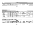
例えば、役物比率は、所定期間(例えば、遊技機10の電源投入から現在まで)に入賞
口に入賞したことで得られた全賞球数(賞球の合計数)のうち、大当り状態中に大入賞口
に入賞したことで得られた賞球数(役物別獲得球数)の割合(%)(=いわゆる連続役物
比率)である。なお、役物比率は、全賞球数のうち、大入賞口に入賞したことで得られた
賞球数(大当り状態中と小当り状態中)の割合(=大入賞口比率)でもよいし、或は、大
入賞口及び普通変動入賞装置37(第2始動入賞口)に入賞したことで得られた賞球数の
割合(=一般的に使用されるいわゆる役物比率(全役物比率))でもよい。
For example, the bonus ratio is in the jackpot state out of the total number of prize balls (total number of prize balls) obtained by winning a prize in the winning opening during a predetermined period (for example, from the power-on of the
〔演出制御装置〕
次に、図4を用いて、演出制御装置300(サブ基板)の構成について説明する。図4
は、遊技機10の演出制御系のブロック図である。
[Production control device]
Next, the configuration of the effect control device 300 (sub-board) will be described with reference to FIG. Figure 4
Is a block diagram of the effect control system of the
演出制御装置300は、遊技用マイコン111と同様にアミューズメントチップ(IC
)からなる主制御用マイコン(CPU)311と、主制御用マイコン311からのコマン
ドやデータに従って表示装置41への映像表示のための画像処理を行うグラフィックプロ
セッサとしてのVDP(Video Display Processor)312と、各種のメロディや効果音
などをスピーカ19から再生させるため音の出力を制御する音源LSI314を備えてい
る。
The
), And VDP (Video Display Processor) 312 as a graphic processor that performs image processing for displaying images on the
主制御用マイコン311には、CPUが実行するプログラムや各種データを格納したP
ROM(プログラマブルリードオンリメモリ)からなるプログラムROM321、作業領
域を提供するRAM322、停電時に電力が供給されなくとも記憶内容を保持可能なFe
RAM323、現在の日時(年月日や曜日、時刻など)を示す情報を生成する計時手段を
なすRTC(リアルタイムクロック)338が接続されている。なお、主制御用マイコン
311の内部にも作業領域を提供するRAMが設けられている。
The
A
また、主制御用マイコン311にはWDT(ウォッチドッグ・タイマ)回路324が接
続されている。主制御用マイコン311は、遊技用マイコン111からのコマンドを解析
し、演出内容を決定してVDP312に出力映像の内容を指示したり、音源LSI314
への再生音の指示、装飾ランプの点灯、モータやソレノイドの駆動制御、演出時間の管理
などの処理を実行する。
A WDT (watchdog timer)
It executes processing such as instructing the playback sound to, turning on the decorative lamp, controlling the drive of the motor and solenoid, and managing the production time.
VDP312には、作業領域を提供するRAM312aや、画像を拡大、縮小処理する
ためのスケーラ312bが設けられている。また、VDP312にはキャラクタ画像や映
像データが記憶された画像ROM325や、画像ROM325から読み出されたキャラク
タなどの画像データを展開したり加工したりするのに使用される超高速なVRAM(ビデ
オRAM)326が接続されている。
The
特に限定されるわけではないが、主制御用マイコン311とVDP312との間は、パ
ラレル方式でデータの送受信が行われるように構成されている。パラレル方式でデータを
送受信することで、シリアルの場合よりも短時間にコマンドやデータを送信することがで
きる。
Although not particularly limited, the
VDP312から主制御用マイコン311へは、表示装置41の映像とガラス枠15や
遊技盤30に設けられている装飾ランプの点灯を同期させるための垂直同期信号VSYN
C、データの送信タイミングを与える同期信号STSが入力される。なお、VDP312
から主制御用マイコン311へは、VRAMへの描画の終了等処理状況を知らせるため割
込み信号INT0〜n及び主制御用マイコン311からのコマンドやデータの受信待ちの
状態にあることを知らせるためのウェイト信号WAITなども入力される。
A vertical synchronization signal VSYNC for synchronizing the image of the
C, the synchronization signal STS that gives the data transmission timing is input. In addition, VDP312
Waits to notify the
演出制御装置300には、LVDS(小振幅信号伝送)方式で表示装置41に送信する
映像信号を生成する信号変換回路313が設けられている。VDP312から信号変換回
路313へは、映像データ、水平同期信号HSYNC及び垂直同期信号VSYNCが入力
されるようになっており、VDP312で生成された映像は、信号変換回路313を介し
て表示装置41に表示される。
The
音源LSI314には音声データが記憶された音声ROM327が接続されている。主
制御用マイコン311と音源LSI314は、アドレス/データバス340を介して接続
されている。また、音源LSI314から主制御用マイコン311へは割込み信号INT
が入力されるようになっている。演出制御装置に300には、ガラス枠15に設けられた
上スピーカ19a及び前面枠12に設けられた下スピーカ19bを駆動するオーディオパ
ワーアンプなどからなるアンプ回路337が設けられており、音源LSI314で生成さ
れた音声はアンプ回路337を介して上スピーカ19a及び下スピーカ19bから出力さ
れる。
An
Is to be entered. The
また、演出制御装置300には、遊技制御装置100から送信されるコマンドを受信す
るインタフェースチップ(コマンドI/F)331が設けられている。コマンドI/F3
31を介して、遊技制御装置100から演出制御装置300に送信された飾り特図保留数
コマンド、飾り特図コマンド、変動コマンド、停止情報コマンド等を、演出制御指令信号
(演出コマンド)として受信する。遊技制御装置100の遊技用マイコン111はDC5
Vで動作し、演出制御装置300の主制御用マイコン311はDC3.3Vで動作するた
め、コマンドI/F331には信号のレベル変換の機能が設けられている。
Further, the
The decorative special figure hold number command, the decorative special figure command, the variation command, the stop information command, etc. transmitted from the
Since the
また、演出制御装置300には、遊技盤30(センターケース40を含む)に設けられ
ているLED(発光ダイオード)を有する盤装飾装置46を駆動制御する盤装飾LED制
御回路332、ガラス枠15に設けられているLED(発光ダイオード)を有する枠装飾
装置(例えば枠装飾装置18等)を駆動制御する枠装飾LED制御回路333、遊技盤3
0(センターケース40を含む)に設けられている盤演出装置44(例えば表示装置41
における演出表示と協働して演出効果を高める可動役物等)を駆動制御する盤演出可動体
制御回路334が設けられている。なお、盤装飾装置46には、前述のランプ表示装置8
0が含まれてよい。
Further, the
Board effect device 44 (for example, display device 41) provided at 0 (including the center case 40)
A board effect movable
0 may be included.
ランプやモータ及びソレノイドなどを駆動制御するこれらの制御回路332〜334は
、アドレス/データバス340を介して主制御用マイコン311と接続されている。なお
、ガラス枠15に設けられているモータ等の枠演出装置を駆動制御する枠演出可動体制御
回路を備えていてもよい。
These
さらに、演出制御装置300には、ガラス枠15に設けられた演出ボタン25に内蔵さ
れている演出ボタンスイッチ25a、演出ボタン25の表面に設けられているタッチパネ
ル25b、盤演出装置44内のモータの初期位置等を検出する演出役物スイッチ47(演
出モータスイッチ)のオン/オフ状態を検出して主制御用マイコン311に検出信号を入
力する機能や、演出制御装置300に設けられた音量調節スイッチ335の状態を検出し
て主制御用マイコン311に検出信号を入力するスイッチ入力回路336が設けられてい
る。
Further, the
電源装置400の通常電源部410は、前述のような構成を有する演出制御装置300
やそれによって制御される電子部品に対して所望のレベルの直流電圧を供給するため、モ
ータやソレノイドを駆動するためのDC32V、液晶パネルからなる表示装置41、モー
タやLEDを駆動するためのDC12V、コマンドI/F331の電源電圧となるDC5
Vの他に、モータやLED、スピーカを駆動するためのDC15Vの電圧を生成するよう
に構成されている。
The normal
DC32V for driving a motor or solenoid, a
In addition to V, it is configured to generate a voltage of DC15V for driving a motor, LED, and speaker.
さらに、主制御用マイコン311として、3.3Vあるいは1.2Vのような低電圧で
動作するLSIを使用する場合には、DC5Vに基づいてDC3.3VやDC1.2Vを
生成するためのDC−DCコンバータが演出制御装置300に設けられる。なお、DC−
DCコンバータは通常電源部410に設けるようにしてもよい。
Further, when an LSI operating at a low voltage such as 3.3V or 1.2V is used as the
The DC converter may be usually provided in the
電源装置400の制御信号生成部430により生成されたリセット信号は、主制御用マ
イコン311に供給され、当該デバイスをリセット状態にする。また、主制御用マイコン
311から出力される形で、VDP312(VDPRESET信号)、音源LSI314
、スピーカを駆動するアンプ回路337(SNDRESET信号)、ランプやモータなど
を駆動制御する制御回路332〜334(IORESET信号)に供給され、これらをリ
セット状態にする。また、演出制御装置300には遊技機10の各所を冷却する冷却FA
N45が接続され、演出制御装置300の電源が投入された状態では冷却FAN45が駆
動するようにされている。
The reset signal generated by the control
, The amplifier circuit 337 (SNDRESET signal) that drives the speaker, and the control circuits 332-334 (IORESET signal) that drive and control the lamp, the motor, and the like are supplied to reset the state. Further, the
The
次に、これらの制御回路において行われる遊技制御について説明する。遊技制御装置1
00の遊技用マイコン111のCPU111aは、普図始動ゲート34に備えられたゲー
トスイッチ34aからの遊技球の検出信号の入力に基づき、普図の当り判定用乱数値を抽
出してROM111bに記憶されている判定値と比較し、普図変動表示ゲームの当り外れ
を判定する。
Next, the game control performed in these control circuits will be described.
The CPU 111a of the
そして、普図表示器53に、識別図柄を所定時間変動表示した後、停止表示する普図変
動表示ゲームを表示する。普図変動表示ゲームの結果が当りの場合は、普図表示器53に
特別の結果態様を表示するとともに、普電ソレノイド37cを動作させ、普通変動入賞装
置37の可動部材37bを所定時間(例えば、3秒間×2回)前述のように開放する制御
を行う。すなわち、遊技制御装置100が、変換部材(可動部材37b)の変換制御を行
う変換制御実行手段をなす。なお、普図変動表示ゲームの結果がはずれの場合は、普図表
示器53にはずれの結果態様を表示する制御を行う。
Then, after displaying the identification symbol on the normal map display 53 in a predetermined time variation, the normal map variation display game in which the identification symbol is stopped and displayed is displayed. When the result of the normal fluctuation display game is a hit, a special result mode is displayed on the normal figure display 53, the normal
また、始動入賞口36に備えられた始動口1スイッチ36aからの遊技球の検出信号の
入力に基づき始動入賞(始動記憶)を記憶し、始動記憶に基づき、特図1変動表示ゲーム
の大当り判定用乱数値を抽出してROM111bに記憶されている判定値と比較し、特図
1変動表示ゲームの当り外れを判定する。
In addition, the start winning (starting memory) is memorized based on the input of the detection signal of the game ball from the starting
また、普通変動入賞装置37に備えられた始動口2スイッチ37aからの遊技球の検出
信号の入力に基づき始動記憶を記憶し、始動記憶に基づき、特図2変動表示ゲームの大当
り判定用乱数値を抽出してROM111bに記憶されている判定値と比較し、特図2変動
表示ゲームの当り外れを判定する。
Further, the start memory is memorized based on the input of the detection signal of the game ball from the
そして、遊技制御装置100のCPU111aは、特図1変動表示ゲームや特図2変動
表示ゲームの判定結果を含む制御信号(演出制御コマンド)を、演出制御装置300に出
力する。そして、特図1表示器51や特図2表示器52に、識別図柄を所定時間変動表示
した後、停止表示する特図変動表示ゲームを表示する。すなわち、遊技制御装置100が
、遊技領域32を流下する遊技球の始動入賞領域(第1始動入賞口36、普通変動入賞装
置37)への入賞に基づき変動表示ゲームの進行制御を行う遊技制御手段をなす。
Then, the CPU 111a of the
また、演出制御装置300は、遊技制御装置100からの制御信号に基づき、表示装置
41で特図変動表示ゲームに対応した飾り特図変動表示ゲームを表示する。さらに、演出
制御装置300は、遊技制御装置100からの制御信号に基づき、演出状態の設定や、ス
ピーカ19a,19bからの音の出力、各種LEDの発光を制御する処理等を行う。すな
わち、演出制御装置300が、遊技(変動表示ゲーム等)に関する演出を制御する演出制
御手段をなす。
Further, the
そして、遊技制御装置100のCPU111aは、特図変動表示ゲームの結果が当りの
場合は、特図1表示器51や特図2表示器52に特別結果態様を表示するとともに、特別
遊技状態を発生させる。特別遊技状態を発生させる処理においては、CPU111aは、
例えば、大入賞口ソレノイド39bにより特別変動入賞装置39の開閉扉39cを開放さ
せ、大入賞口内への遊技球の流入を可能とする制御を行う。
Then, when the result of the special figure variation display game is a hit, the CPU 111a of the
For example, the large winning
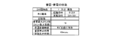
そして、大入賞口に所定個数(例えば、10個)の遊技球が入賞するか、大入賞口の開
放から所定の開放可能時間(例えば、27秒又は0.05秒)が経過するかのいずれかの
条件が達成されるまで大入賞口を開放することを1ラウンド(R)とし、これを所定ラウ
ンド回数(例えば、15回、11回又は2回)継続する(繰り返す)制御(サイクル遊技
)を行う。すなわち、遊技制御装置100が、停止結果態様が特別結果態様となった場合
に、大入賞口を開閉する制御を行う大入賞口開閉制御手段をなす。また、特図変動表示ゲ
ームの結果がはずれの場合は、特図1表示器51や特図2表示器52にはずれの結果態様
を表示する制御を行う。
Then, either a predetermined number (for example, 10) of game balls wins in the big winning opening, or a predetermined opening time (for example, 27 seconds or 0.05 seconds) elapses from the opening of the big winning opening. One round (R) is to open the big winning opening until the above condition is achieved, and this is continued (repeated) a predetermined number of rounds (for example, 15 times, 11 times or 2 times) control (cycle game). I do. That is, the
また、遊技制御装置100は、特図変動表示ゲームの結果態様に基づき、特別遊技状態
の終了後に、遊技状態として高確率状態を発生可能である。高確率状態(確変状態)は、
特図変動表示ゲームにて当り結果となる確率が、通常確率状態と比較して高い状態である
。また、特図1変動表示ゲーム及び特図2変動表示ゲームのどちらの特図変動表示ゲーム
の結果態様に基づき高確率状態となっても、特図1変動表示ゲーム及び特図2変動表示ゲ
ームの両方が高確率状態となる。
Further, the
The probability of a hit result in the special figure fluctuation display game is higher than that of the normal probability state. Further, regardless of which of the special figure 1 variable display game and the special figure 2 variable display game results in a high probability state, the special figure 1 variable display game and the special figure 2 variable display game Both are in a high probability state.
また、遊技制御装置100は、特図変動表示ゲームの結果態様に基づき、特別遊技状態
の終了後に、遊技状態として時短状態(特定遊技状態)を発生可能である。時短状態にお
いては、普図変動表示ゲーム及び普通変動入賞装置37を時短動作状態とする制御を行っ
てよく、特別な遊技を行わない通常遊技状態よりも、単位時間当りの普通変動入賞装置3
7の開放時間が実質的に多くなるように制御するため、普電サポート状態となる。なお、
潜伏確変状態を除く高確率状態(通常の確変状態)でも、重複して時短状態にして普電サ
ポートを実行する。
Further, the
Since the opening time of 7 is controlled so as to be substantially increased, the normal electric support state is set. In addition, it should be noted.
Even in the high-probability state (normal probability-changing state) excluding the latent probability-changing state, the time-saving state is duplicated and the normal electric support is executed.
なお、時短状態においては、特図変動表示ゲームの実行時間(特図変動時間)も通常よ
り短縮され得るようにし、特図変動表示ゲームの時間短縮変動も実行可能である。
In the time saving state, the execution time of the special figure variation display game (special figure variation time) can be shortened as compared with the normal time, and the time reduction variation of the special figure variation display game can also be executed.
また、時短状態においては、普図変動表示ゲームの1回の当り結果に対して、普通変動
入賞装置37の開放回数(普電開放回数)を第1開放回数(例えば2回)よりも多い回数
(例えば、4回)の第2開放回数に設定することが可能である。また、時短状態において
は、普図変動表示ゲームの当り結果となる確率(普図確率、普図当り確率)を通常動作状
態である場合の通常確率(低確率)よりも高い高確率とすることが可能である。
Further, in the time saving state, the number of times the normal
時短状態においては、普図変動時間、普図停止時間、普電開放回数、普電開放時間、普
図確率のいずれか一つ又は複数を変化させることで普通変動入賞装置37を開状態に状態
変換する時間を通常よりも延長するようにする。これにより、時短状態では、特別な遊技
を行わない通常遊技状態よりも普通変動入賞装置37への入賞が容易化して、単位時間当
たりの特図変動表示ゲームの実行回数が当該通常遊技状態よりも増加可能である。また、
変化させるものが異なる複数種類の時短状態を設定することも可能である。また、通常動
作状態において可動部材37bを開放しないように設定(普図確率が0)してもよい。ま
た、当りとなった場合に第1開放態様と第2開放態様のいずれかを選択するようにしても
よい。この場合、第1開放態様と第2開放態様の選択確率を異ならせてもよい。また、高
確率状態と時短状態は、それぞれ独立して発生可能であり、両方を同時に発生することも
可能であるし一方のみを発生させることも可能である。
In the time saving state, the normal
It is also possible to set multiple types of time saving states that change different things. Further, the
〔電源投入時の移行状態〕
前述のように、電源投入時のRAM初期化スイッチ112及び設定キースイッチ93の
オンオフ状態によって、4つの状態(モード)へ移行する。
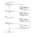
[Transition state when power is turned on]
As described above, the state shifts to four states (modes) depending on the on / off state of the
電源投入時に、RAM初期化スイッチ112と設定キースイッチ93とがオンにされて
いる場合には、確率設定値(設定値)を変更可能な設定可変状態(設定変更状態、設定変
更モード)に移行する(図5BのA1027−A1036と図6B参照)。
When the
次に、電源投入時に、設定キースイッチ93がオンにされているがRAM初期化スイッ
チ112がオフの場合には、確率設定値を確認可能な設定確認状態(設定確認モード)に
移行する(図5BのA1031−A1036と図6B参照)。
Next, when the setting
また、電源投入時に、設定キースイッチ93がオフであるがRAM初期化スイッチ11
2がオンにされている場合には、RAM初期化状態(RAMクリアモード)に移行し、R
AM初期化処理(RAMクリア処理)が実行されて、RAM111cが初期化される(図
5BのA1042−1044参照)。
Further, when the power is turned on, the setting
When 2 is turned on, the state shifts to the RAM initialization state (RAM clear mode), and R
The AM initialization process (RAM clear process) is executed to initialize the RAM 111c (see A1042-1044 in FIG. 5B).
電源投入時に、設定キースイッチ93とRAM初期化スイッチ112とがオフである場
合には、通常復電状態(通常復電モード)に移行し、単に復電されるだけの状態になる。
If the setting
[遊技制御装置の制御]
以下、このような遊技を行う遊技機の制御について説明する。まず、上記遊技制御装置
100の遊技用マイクロコンピュータ(遊技用マイコン)111によって実行される制御
について説明する。遊技用マイコン111による制御処理は、主に図5A及び図5Bに示
すメイン処理と、所定時間周期(例えば4msec)で行われる図9に示すタイマ割込み
処理とからなる。
[Control of game control device]
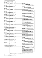
Hereinafter, control of a gaming machine that performs such a game will be described. First, the control executed by the game microcomputer (game microcomputer) 111 of the
〔メイン処理(遊技制御装置)〕
まず、メイン処理について説明する。図5A及び図5Bは、遊技制御装置100による
メイン処理の手順を示すフローチャートである。メイン処理は、電源が投入されることで
開始される。なお、遊技制御装置100が実行する処理のフローチャートにおいて、ステ
ップの符号(番号)は「A****」と表されている。
[Main processing (game control device)]
First, the main process will be described. 5A and 5B are flowcharts showing a procedure of main processing by the
図5Aに示すように、遊技制御装置100は、メイン処理を開始すると、まず、割込み
を禁止する処理を実行する(A1001)。さらに、割込み発生時にレジスタ等の値を退
避する領域の先頭アドレスであるスタックポインタを設定するスタックポインタ設定処理
を実行する(A1002)。
As shown in FIG. 5A, when the
続いて、使用するレジスタバンクとしてレジスタバンク0を指定し(A1003)、所
定のレジスタにRAM先頭アドレスの上位アドレスをセットする(A1004)。例えば
、RAMのアドレスが0000h〜01FFhの範囲である場合に、上位アドレスとして
00hをセットする。
Subsequently, register
次に、遊技制御装置100は、発射禁止の信号を出力して発射許可信号を禁止状態に設
定する(A1005)。発射許可信号は遊技制御装置100と払出制御装置200の少な
くとも一方が発射禁止の信号を出力している場合に禁止状態に設定され、遊技球の発射が
禁止されるようになっている。その後、遊技制御装置100は、設定キースイッチ93と
RAM初期化スイッチ112の状態を読み込む(A1006)。即ち、設定キースイッチ
93とRAM初期化スイッチ112からの信号を読み込む。
Next, the
さらに、遊技制御装置100は、電源ディレイタイマを設定する(A1007)。電源
ディレイタイマに所定の初期値を設定することにより、主制御手段をなす遊技制御装置1
00からの指示に従い種々の制御を行う従制御手段(例えば、払出制御装置200や演出
制御装置300)のプログラムが正常に起動するまで待機するための待機時間(例えば3
秒)が設定される。これにより、電源投入の際に仮に遊技制御装置100が先に立ち上が
って従制御装置(例えば払出制御装置200や演出制御装置300)が立ち上がる前にコ
マンドを従制御装置に送ってしまい、従制御装置がコマンドを取りこぼすことを回避する
ことができる。すなわち、遊技制御装置100が、電源投入時において、主制御手段(遊
技制御装置100)の起動を遅らせて従制御装置(払出制御装置200、演出制御装置3
00等)の起動を待つための所定の待機時間を設定する待機手段をなす。
Further, the
Waiting time (for example, 3) for waiting until the program of the slave control means (for example,
Seconds) is set. As a result, when the power is turned on, the
It serves as a waiting means for setting a predetermined waiting time for waiting for the activation of (00, etc.).
また、電源ディレイタイマの計時は、RAMの正当性判定(チェックサム算出)の対象
とならない記憶領域(正当性判定対象外のRAM領域又はレジスタ等)を用いて行われる
。これにより、RAM領域のチェックサム等のチェックデータを算出する際に、一部のR
AM領域を除外して算出する必要がないため電源投入時の制御が複雑になることを防止す
ることができる。
Further, the timing of the power delay timer is performed using a storage area (RAM area or register, etc. that is not subject to the validity determination) that is not subject to the validity determination (checksum calculation) of the RAM. As a result, when calculating check data such as the checksum of the RAM area, a part of R
Since it is not necessary to exclude the AM region for calculation, it is possible to prevent the control at the time of turning on the power from becoming complicated.
なお、待機時間の開始前に設定キースイッチ93とRAM初期化スイッチ112の状態
を読み込むことで、設定キースイッチ93とRAM初期化スイッチ112の操作を確実に
検出できる。すなわち、待機時間の経過後に設定キースイッチ93とRAM初期化スイッ
チ112の状態を読み込むようにすると、待機時間の経過を待ってから設定キースイッチ
93とRAM初期化スイッチ112を操作したり、電源投入から待機時間の経過まで設定
キースイッチ93とRAM初期化スイッチ112を操作し続けたりする必要がある。しか
し、待機時間の開始前に状態を読み込むことで、このような煩わしい操作を行わなくても
、電源投入時に行った設定キースイッチ93とRAM初期化スイッチ112の操作が受け
付けられないような事態を防止できる。
By reading the states of the setting
電源ディレイタイマを設定すると(A1007)、遊技制御装置100は、待機時間の
計時と、待機時間中における停電の発生を監視する処理とを実行する(A1008からA
1010)。
When the power delay timer is set (A1007), the
1010).
停電監視処理が開始されると、遊技制御装置100は、まず、電源装置400から入力
されている停電監視信号をポート及びデータバスを介して読み込むなどして、停電が発生
しているか否か判定する(A1008)。停電が発生している場合に(A1008の結果
が「Y」)、遊技機の電源が遮断されるまで待機する。
When the power failure monitoring process is started, the
遊技制御装置100は、停電が発生していない場合には(A1008の結果が「N」)
、電源投入ディレイタイマを−1更新し(A1009)、タイマの値が0であるか否かを
判定する(A1010)。タイマの値が0でない場合(A1010の結果が「N」)、す
なわち、待機時間が終了していない場合には、ステップA1008の処理に戻る。
When the
, The power-on delay timer is updated by -1 (A1009), and it is determined whether or not the value of the timer is 0 (A1010). If the value of the timer is not 0 (the result of A1010 is "N"), that is, if the waiting time has not ended, the process returns to step A1008.
すなわち、遊技制御装置100が、所定の待機時間において停電の発生を監視する停電
監視手段をなす。これにより、主制御手段をなす遊技制御装置100の起動を遅らせてい
る期間において発生した停電に対応することが可能となり、電源投入時における不具合に
適切に対処することができる。なお、待機時間の終了まではRAMへのアクセスが許可さ
れておらず、前回の電源遮断時の記憶内容が保持されたままとなっているため、ここでの
停電発生時にはバックアップの処理等は行う必要がない。したがって、待機時間中に停電
が発生してもRAMのバックアップを取る必要がなく、制御の負担を軽減することができ
る。
That is, the
一方、遊技制御装置100は、タイマの値が0である場合(A1010の結果が「Y」
)、すなわち、待機時間が終了した場合には、RAMやEEPROM等の読出し書込み可
能なRWM(リードライトメモリ)のアクセスを許可し(A1011)、全出力ポートに
オフデータを出力(出力が無い状態に設定)する(A1012)。
On the other hand, in the
), That is, when the standby time has expired, access to RWM (read / write memory) such as RAM or EEPROM that can be read and written is permitted (A1011), and off-data is output to all output ports (state where there is no output). (Set to) (A1012).
次に、遊技制御装置100は、シリアルポート(遊技用マイコン111に予め搭載され
ているポートで、本実施形態では、演出制御装置300や払出制御装置200との通信に
使用)を設定する(A1013)。
Next, the
さらに、ここで、性能表示装置152(状態表示装置)を駆動するドライバ150を初
期設定してもよい。遊技制御装置100は、初期設定の内容に対応する制御用データを含
むコマンドを、第2出力ポート134(シリアル通信回路)の送信バッファに書き込んで
ドライバ150に送信する。例えば、遊技制御装置100は、初期設定においてデューテ
ィ比を設定する。デューティ比は、性能表示装置152の各LED(各セグメント)の明
るさに対応する。遊技制御装置100は、初期設定において、性能表示装置152の使用
桁数を設定する。本実施形態では、使用桁数は4である。
Further, here, the
次に、遊技制御装置100は、遊技用マイコン111(クロックジェネレータ)内のタ
イマ割込み信号及び乱数更新トリガ信号(CTC)を発生するCTC(Counter/Timer C
ircuit)回路を起動する(A1014)。なお、CTC回路は、遊技用マイコン111内
のクロックジェネレータに設けられている。クロックジェネレータは、発振回路113か
らの発振信号(原クロック信号)を分周する分周回路と、分周された信号に基づいてCP
U111aに対して所定周期(例えば、4ミリ秒)のタイマ割込み信号及び乱数生成回路
に供給する乱数更新のトリガを与える信号CTCを発生するCTC回路とを備えている。
Next, the
ircuit) Start the circuit (A1014). The CTC circuit is provided in the clock generator in the
The U111a is provided with a timer interrupt signal having a predetermined period (for example, 4 milliseconds) and a CTC circuit that generates a signal CTC that triggers a random number update to be supplied to the random number generation circuit.
続いて、遊技制御装置100は、RAM(ここではRAM111c)の異常を示すRA
M異常フラグをセットする(A1015)。ここでは、一旦、異常前提のフラグを所定の
レジスタにセットしておく。
Subsequently, the
Set the M error flag (A1015). Here, the flag of the assumption of abnormality is once set in a predetermined register.
次に、遊技制御装置100は、RWM内の停電検査領域1の値が正常な停電検査領域チ
ェックデータであるか否かを判定する(A1016)。そして、正常であれば(A101
6の結果が「Y」)、RWM内の停電検査領域2の値が正常な停電検査領域チェックデー
タであるか否かを判定する(A1017)。
Next, the
The result of 6 is “Y”), and it is determined whether or not the value of the power
さらに、遊技制御装置100は、停電検査領域2の値が正常であれば(A1017の結
果が「Y」)、RWM内の所定領域(例えば遊技制御用作業領域)のチェックサムを算出
するチェックサム算出処理を実行し(A1018)、算出されたチェックサムと電源断時
のチェックサムが一致するか否かを判定する(A1019)。チェックサムが一致する場
合には(A1019の結果が「Y」)、RAMは正常であり、RAMの異常を示すRAM
異常フラグをクリアする(A1020)。その後、ステップA1021の処理に移行する
。
Further, if the value of the power
Clear the error flag (A1020). After that, the process proceeds to step A1021.
また、遊技制御装置100は、停電検査領域のチェックデータが正常なデータでないと
判定された場合(A1016の結果が「N」、又は、A1017の結果が「N」)、チェ
ックサムが一致しない場合には(A1019の結果が「N」)、RAM異常フラグをクリ
アすることなく、ステップA1021の処理に移行する。
Further, when the
次に、遊技制御装置100は、設定キースイッチ93及びRAM初期化スイッチ112
の両スイッチがオンであるか否かを判定する(A1021)。遊技制御装置100は、両
スイッチがオンである場合に(A1021の結果が「Y」)、設定可変状態(設定変更モ
ード)に移行し、ステップA1027−A1037の確率設定変更中の処理を実行する。
Next, the
It is determined whether or not both of the switches are on (A1021). When both switches are on (the result of A1021 is "Y"), the
遊技制御装置100は、設定キースイッチ93及びRAM初期化スイッチ112の少な
くとも一方がオフである場合に(A1021の結果が「N」)、RAM(ここではRAM
111c)の異常を示すRAM異常フラグがセットされているか否か判定する(A102
2)。RAM異常フラグがセットされていない場合に(A1022の結果が「N」)、確
率設定変更中フラグがセットされているか否かを判定する(A1023)。確率設定変更
中フラグがセットされていない場合に(A1023の結果が「N」)、ステップA103
1−A1037の確率設定確認中(設定確認状態中、設定確認モード中)の処理、ステッ
プA1041−1044のRAM初期化処理(RAMクリア処理)、又は、ステップA1
041、A1045、A1046の通常の電源投入時(電源復旧時)の処理を実行する。
When at least one of the setting
It is determined whether or not the RAM abnormality flag indicating the abnormality of 111c) is set (A102).
2). When the RAM abnormality flag is not set (the result of A1022 is "N"), it is determined whether or not the probability setting changing flag is set (A1023). When the probability setting changing flag is not set (the result of A1023 is "N"), step A103
1-A1037 Probability Setting confirmation processing (setting confirmation state, setting confirmation mode), RAM initialization processing (RAM clear processing) in steps A1041-144, or step A1
The normal power-on (power restoration) processing of 041, A1045, and A1046 is executed.
遊技制御装置100は、確率設定変更中フラグがセットされている場合に(A1023
の結果が「Y」)、遊技制御装置100(主基板、メイン基板)に異常があったことを報
知するメイン異常エラー報知のコマンドを演出制御装置300に送信する(A1024)
。メイン異常エラー報知のコマンドを受信した演出制御装置300は、遊技制御装置10
0の異常があったことを報知する。
The
The result is "Y"), and a command for notifying the main abnormality error that notifies that the game control device 100 (main board, main board) has an abnormality is transmitted to the effect control device 300 (A1024).
.. The
Notify that there was an abnormality of 0.
続いて、遊技制御装置100は、遊技停止時の7セグ表示データ(図9(C)の「E1
」のエラー表示のデータ)を性能表示装置152で表示するために性能表示装置152の
ドライバ150に出力する(A1025)。そして、外部装置(遊技場内部管理装置(ホ
ールコンピュータ)や情報収集端末など)に異常を知らせるためのセキュリティ信号のオ
ンデータを外部情報端子71に出力する(A1026)。なお、ここで、大当りに関する
情報がRAM111cに残っている場合でも、大当り信号など外部情報端子71への他の
信号はオフ状態に維持される。その後、ステップA1025とA1026の処理を繰り返
して待機し、再度、設定変更の操作(設定キースイッチ93及びRAM初期化スイッチ1
12の両方のオン操作)をして電源が投入されるのを待つ。なお、ステップA1025と
A1026の処理を繰り返して待機して待機している間、割込みは禁止されたままであり
(A1001)、特図1、2ゲーム処理や普図ゲーム処理を実行可能なタイマ割込み処理
(図7)が実行できないため、遊技(特図変動表示ゲーム、普図変動表示ゲーム)は実行
できない。
Subsequently, the
The error display data) is output to the
(Turn on both of 12) and wait for the power to be turned on. While the processes of steps A1025 and A1026 are repeated to wait and wait, the interrupt remains disabled (A1001), and the timer interrupt process capable of executing the special figure 1 and 2 game process and the normal figure game process. Since (Fig. 7) cannot be executed, the game (special figure variation display game, normal figure variation display game) cannot be executed.
このように、設定変更の操作(設定キースイッチ93及びRAM初期化スイッチ112
の両方のオン操作)を実行していないのに、確率設定変更中フラグがセットされている場
合に異常があったとして、A1024−A1026の処理を実行する。例えば、確率設定
変更中(設定変更が完了する前)に電源がオフして再起動した場合などに、設定変更の操
作を実行していないのに、確率設定変更中フラグがセットされることがある。
In this way, the setting change operation (setting
The process of A1024-A1026 is executed, assuming that there is an abnormality when the probability setting changing flag is set even though both of the on-operations) are not executed. For example, when the power is turned off and restarted while the probability setting is being changed (before the setting change is completed), the probability setting changing flag may be set even though the setting change operation has not been executed. is there.
一方、遊技制御装置100は、RAM異常フラグがセットされている場合も(A102
2の結果が「Y」)、遊技制御装置100(メイン基板)に異常があったことを報知する
メイン異常エラー報知のコマンドを演出制御装置300に送信し(A1024)、遊技停
止時の7セグ表示データ(図9(C)の「E1」のエラー表示のデータ)を性能表示装置
152のドライバ150に出力し(A1025)、外部装置にRAM異常を知らせるため
に、セキュリティ信号のオンデータを外部情報端子71に出力する(A1026)。なお
、前述と同様に、大当りに関する情報がRAM111cに残っている場合でも、大当り信
号など外部情報端子71への他の信号はオフ状態に維持される。その後、ステップA10
25とA1026の処理を繰り返して待機する。
On the other hand, in the
The result of 2 is "Y"), a command for notifying the main abnormality error that notifies that there is an abnormality in the game control device 100 (main board) is transmitted to the effect control device 300 (A1024), and 7 segments when the game is stopped. The display data (data of the error display of "E1" in FIG. 9C) is output to the
The processes of 25 and A1026 are repeated to wait.
遊技制御装置100は、設定キースイッチ93及びRAM初期化スイッチ112の両ス
イッチがオンである場合に(A1021の結果が「Y」)、確率設定変更中(設定可変状
態中)の処理を開始して、まず、RAM異常フラグがセットされているか否かを判定する
(A1027)。RAM異常フラグがセットされている場合に(A1027の結果が「Y
」)、確率設定値が正しいものであるか不明であるため、RAM111cの確率設定値領
域に記憶されている確率設定値をクリアし初期値(例えば最低設定値「1」)にしてから
(A1028)、確率設定変更中であることを示す確率設定変更中フラグをセットする(
A1029)。RAM異常フラグがセットされていない場合に(A1027の結果が「N
」)、確率設定値をクリアせずに、確率設定変更中フラグをセットする(A1029)。
次に、確率設定変更中のコマンドを演出制御装置300(演出制御基板)に送信し(A1
030)、ステップA1034の処理に移行する。なお、確率設定変更中のコマンドを受
信した演出制御装置300は、確率設定変更中であることを表示装置41などにおいて報
知する。
When both the setting
”), Since it is unknown whether the probability setting value is correct, the probability setting value stored in the probability setting value area of the RAM 111c is cleared and set to the initial value (for example, the minimum setting value“ 1 ”) (A1028). ), Set the probability setting changing flag indicating that the probability setting is being changed ()
A1029). When the RAM error flag is not set (the result of A1027 is "N".
”), Set the probability setting changing flag without clearing the probability setting value (A1029).
Next, the command for which the probability setting is being changed is transmitted to the effect control device 300 (effect control board) (A1).
030), the process proceeds to step A1034. The
遊技制御装置100は、設定キースイッチ93及びRAM初期化スイッチ112の少な
くとも一方がオフであり(A1021の結果が「N」)、RAM異常フラグがセットされ
ておらず(A1022の結果が「N」)、且つ、確率設定変更中フラグがセットされてい
ない場合に(A1023の結果が「N」)、設定キースイッチ93がオンであるか否かを
判定する(A1031)。設定キースイッチ93がオンである場合に(A1031の結果
が「Y」)、RAM初期化スイッチ112はオフということになり、確率設定確認中(設
定確認状態中)の処理が開始して、確率設定確認中であることを示す確率設定確認中フラ
グをセットする(A1032)。そして、確率設定確認中のコマンドを演出制御装置30
0(演出制御基板)に送信し(A1033)、ステップA1034の処理に移行する。な
お、確率設定変更中のコマンドを受信した演出制御装置300は、確率設定確認中である
ことを表示装置41などにおいて報知する。
In the
It is transmitted to 0 (effect control board) (A1033), and the process proceeds to step A1034. The
ステップA1030又はステップA1033の後に、遊技制御装置100は、確率設定
変更中と確率設定確認中の共通の処理として、ステップA1034からA1040の処理
を実行する。
After step A1030 or step A1033, the
遊技制御装置100は、まず、確率設定変更中と確率設定確認中においてセキュリティ
信号を出力するために、セキュリティ信号制御タイマ領域に128ms(所定時間)をセ
ーブする(A1034)。なお、セキュリティ信号制御タイマのカウントとセキュリティ
信号の出力は、後述の確率設定変更/確認処理(図6B)において実行されるが、確率設
定変更又は確率設定確認が早期に終了した場合には、残りのセキュリティ信号制御タイマ
のカウントとセキュリティ信号の出力は、外部情報編集処理(A1321)で実行される
。確率設定変更中と確率設定確認中において、少なくとも50msは、セキュリティ信号
は出力される。
First, the
次に、遊技制御装置100は、割込みを許可する(A1035)。これにより、タイマ
割込み処理(図7)が実行可能となる。そして、設定キースイッチ93がオフであるか否
かを判定する(A1036)。設定キースイッチ93がオンである場合に(A1036の
結果が「N」)、停電が発生しているか否かを判定する(A1037)。停電が発生して
いない場合に(A1037の結果が「N」)、ステップA1036の処理に戻る。一方、
停電が発生している場合に(A1037の結果が「Y」)、ステップA1055−A10
61の停電発生時の処理を実行する。
Next, the
If there is a power outage (result of A1037 is "Y"), steps A1055-A10
The process when a power failure occurs in 61 is executed.
このように、設定キースイッチ93がオンであり、停電が発生していない限り、確率設
定値を変更可能な設定可変状態(設定変更状態、設定変更モード)、又は、確率設定値を
確認可能な設定確認状態(設定確認モード)が継続される。
In this way, as long as the setting
一方、遊技制御装置100は、設定キースイッチ93がオフである場合に(A1036
の結果が「Y」)、割込みを禁止し(A1038)、報知終了のコマンドを演出制御装置
300(演出制御基板)に送信する(A1039)。なお、報知終了のコマンドを受信し
た演出制御装置300は、確率設定確認中であることの報知又は確率設定変更中であるこ
との報知を終了する。
On the other hand, in the
The result is "Y"), interrupts are prohibited (A1038), and a command to end the notification is transmitted to the effect control device 300 (effect control board) (A1039). The
次に、遊技制御装置100は、確率設定変更中フラグがセットされているか否か、即ち
、これまで確率設定変更中であったか否かを判定する(A1040)。確率設定変更中フ
ラグがセットされている場合に(A1040の結果が「Y」)、即ち、これまで確率設定
変更中であった場合に、ステップA1042−A1044のRAM初期化処理(後述)を
実行する。一方、確率設定変更中フラグがセットされていない場合に(A1040の結果
が「N」)、即ち、これまで確率設定確認中であった場合に、ステップA1045以降の
電源投入時(電源復旧時)の通常の処理を実行する。
Next, the
遊技制御装置100は、設定キースイッチ93がオフである場合に(A1031の結果
が「N」)、RAM初期化スイッチ112がオンであるか否かを判定する(A1041)
。RAM初期化スイッチ112がオンである場合に(A1041の結果が「Y」)、RA
M111cにおいて、確率設定値を記憶するための確率設定値領域以外のRAM領域を0
クリアする(A1042)。即ち、確率設定値領域で記憶されている確率設定値を除いて
、RAM111cに記憶された遊技情報は0クリアされる。さらに、前述の確率設定変更
中フラグもここでクリアされる。また、ここで、確率設定値領域の他に、スタック領域や
未使用領域をクリアしない構成や、性能情報やその表示(性能表示)に関連するワークエ
リア、スタック領域をクリアしない構成も可能である。なお、性能情報は、入賞により得
られた賞球数に基づいて導出されるもので、例えば、出玉率、ベース値(通常遊技状態に
おける出玉率)、役物比率、排出球数などである。
The
.. When the
In M111c, the RAM area other than the probability set value area for storing the probability set value is 0.
Clear (A1042). That is, the game information stored in the RAM 111c is cleared to 0 except for the probability setting value stored in the probability setting value area. Further, the above-mentioned probability setting changing flag is also cleared here. Further, in addition to the probability setting value area, a configuration that does not clear the stack area and the unused area, a work area related to the performance information and its display (performance display), and a configuration that does not clear the stack area are also possible. .. The performance information is derived based on the number of prize balls obtained by winning, for example, the ball output rate, the base value (the ball output rate in the normal game state), the accessory ratio, the number of ejected balls, and the like. is there.
次に、遊技制御装置100は、初期化すべき領域にRAM初期化時の初期値をセーブす
る(A1043)。そして、RAM初期化時のコマンドを演出制御装置300(演出制御
基板)に送信し(A1044)、ステップA1047の処理に移行する。
Next, the
一方、遊技制御装置100は、RAM初期化スイッチ112がオフである場合に(A1
041の結果が「N」)、設定キースイッチ93とRAM初期化スイッチ112が両方と
もオフであるため、通常の電源投入時(電源復旧時)の処理を開始し、停電復旧処理を実
行する(A1045)。例えば、初期化すべき領域に停電復旧時(復電時)の初期値をセ
ーブする。また、前述の確率設定確認中フラグもここでクリアされる。次に、後述の特図
ゲーム処理を合理的に実行するために用意されている処理番号に対応する停電復旧時のコ
マンドを演出制御装置300(演出制御基板)に送信し(A1046)、ステップA10
47の処理に移行する。
On the other hand, in the
Since the result of 041 is "N") and both the setting
It shifts to the process of 47.
なお、ステップA1044の処理で送信されるRAM初期化時のコマンド及びステップ
A1046の処理で送信される停電復旧時のコマンドには、遊技機の種類を示す機種指定
コマンド、特図1、2の保留数を示す飾り特図1保留数コマンド及び飾り特図2保留数コ
マンド、確率の状態(高確率状態又は低確率状態)や時短状態の有無を示す確率情報コマ
ンド、所定の演出モードで特図変動表示ゲームが実行された回数を示す演出回数情報コマ
ンド、電源投入されたこと示す停電復旧コマンドが含まれる。
The command at the time of RAM initialization transmitted in the process of step A1044 and the command at the time of recovery from a power failure transmitted in the process of step A1046 include a model designation command indicating the type of the gaming machine and the hold of special figures 1 and 2. Ornament special figure 1 indicating the number Hold number command and decoration special figure 2 Hold number command, probability information command indicating the presence or absence of a probability state (high probability state or low probability state) or time saving state, special figure change in a predetermined production mode It includes a production count information command that indicates the number of times the display game has been executed, and a power failure recovery command that indicates that the power has been turned on.
さらに、RAM初期化時のコマンド及び停電復旧時のコマンドには、遊技機10の確率
設定値(設定値)の情報である設定値情報(設定情報)を示す設定値情報コマンド(確率
設定値情報コマンド)が含まれる。遊技制御装置100は、電源の復旧(投入)時に、一
度だけ設定値情報コマンドを演出制御装置300に送信するだけでよく、以降、演出制御
装置300は自身が記憶した設定値情報を参照して演出制御を行える。
Further, the command at the time of RAM initialization and the command at the time of power failure recovery include the setting value information command (probability setting value information) indicating the setting value information (setting information) which is the information of the probability setting value (setting value) of the
なお、RAM初期化時のコマンドには、RAM初期化のコマンド(RAMクリアのコマ
ンド)も含まれる。RAM初期化のコマンドを受信した演出制御装置300は、例えば、
表示装置41に客待ちデモを表示し、盤装飾装置46等のLEDとスピーカの音でRAM
初期化(RAMクリア)の報知を30秒間行う。また、停電復旧時のコマンドには、表示
装置41の画面の表示内容を指定する画面指定のコマンドが含まれる。なお、画面指定の
コマンドは、特図1、2について共に普段処理中では(変動中でも当り中でもないとき)
、客待ちデモコマンドであり、それ以外なら復旧画面コマンドである。
The RAM initialization command also includes a RAM initialization command (RAM clear command). The
A customer waiting demo is displayed on the
Notification of initialization (RAM clear) is performed for 30 seconds. Further, the command at the time of power failure recovery includes a screen designation command for designating the display contents of the screen of the
, It is a customer waiting demo command, otherwise it is a recovery screen command.
ステップA1044又はステップA1046の後に、遊技制御装置100は、乱数生成
回路を起動設定する(A1047)。具体的には、乱数生成回路内の所定のレジスタ(C
TC更新許可レジスタ)に乱数生成回路を起動させるためのコード(指定値)の設定など
がCPU111aによって行われる。また、乱数生成回路のハードウェアで生成されるハ
ード乱数(ここでは大当り乱数)のビット転置パターンの設定も行われる。
After step A1044 or step A1046, the
The CPU 111a sets a code (specified value) for activating the random number generation circuit in the TC update permission register). In addition, the bit transposition pattern of the hard random number (here, the jackpot random number) generated by the hardware of the random number generation circuit is also set.
ビット転置パターンとは、抽出した乱数のビット配置(上段のビット転置前の配置)を
、予め定められた順で入れ替えて異なるビット配置(下段のビット転置後の配置)として
格納する際の入れ替え方を定めるパターンである。
The bit transposition pattern is a method of exchanging the extracted random number bits (arrangement before the upper bit transposition) in a predetermined order and storing them as different bit arrangements (arrangement after the lower bit transposition). It is a pattern that determines.
本実施形態では、ビット転置パターンに従い乱数のビットを入れ替えることで、乱数の
規則性を崩すことができるとともに、乱数の秘匿性を高めることができる。なお、ビット
転置パターンは、固定された単一のパターンであってもよいし、予め用意された複数のパ
ターンから選択するようにしてもよい。また、ユーザーが任意に設定できるようにしても
よい。
In the present embodiment, by exchanging the bits of the random number according to the bit transposition pattern, the regularity of the random number can be broken and the confidentiality of the random number can be enhanced. The bit transposition pattern may be a fixed single pattern, or may be selected from a plurality of patterns prepared in advance. In addition, the user may be able to set it arbitrarily.
その後、遊技制御装置100は、電源投入時の乱数生成回路内の所定のレジスタ(ソフ
ト乱数レジスタ1〜n)の値を抽出し、対応する各種初期値乱数(大当り図柄を決定する
大当り図柄乱数の初期値(大当り図柄初期値乱数)、小当り図柄を決定する小当り図柄乱
数の初期値(小当り図柄初期値乱数)(小当りがある場合のみ)、普図の当りを決定する
当り乱数の初期値(当り初期値乱数)、転落抽選で使用する転落抽選乱数の初期値(転落
抽選初期値乱数)等)のスタート値としてRWMの所定領域にセーブし(A1048)、
割込みを許可する(A1049)。本実施形態で使用するCPU111a内の乱数生成回
路においては、電源投入ごとにソフト乱数レジスタの初期値が変わるように構成されてい
るため、この値を各種初期値乱数のスタート値(初期値)とすることで、ソフトウェアで
生成される乱数の規則性を崩すことができ、遊技者による不正な乱数の取得を困難にする
ことができる。
After that, the
Allow interrupts (A1049). In the random number generation circuit in the CPU 111a used in the present embodiment, the initial value of the soft random number register is configured to change each time the power is turned on. Therefore, this value is used as the start value (initial value) of various initial value random numbers. By doing so, the regularity of the random numbers generated by the software can be broken, and it is possible to make it difficult for the player to acquire an illegal random number.
続いて、遊技制御装置100は、各種初期値乱数の値を更新して乱数の規則性を崩すた
めの初期値乱数更新処理を実行する(A1050)。なお、特に限定されるわけではない
が、本実施形態においては、大当り乱数、大当り図柄乱数、当り乱数、転落抽選乱数は乱
数生成回路において生成される乱数を使用して生成するように構成されている。ただし、
大当り乱数はCPUの動作クロックと同等以上の速度のクロックを基にして更新される所
謂「高速カウンタ」であり、大当り図柄乱数、当り乱数、転落抽選乱数はプログラムの処
理単位であるタイマ割込み処理と同周期となるCTC出力(タイマ割込み処理のCTC(
CTC0)とは別のCTC(CTC2))を基にして更新される「低速カウンタ」である
。
Subsequently, the
The jackpot random number is a so-called "high-speed counter" that is updated based on a clock whose speed is equal to or higher than the CPU operating clock, and the jackpot symbol random number, hit random number, and fall lottery random number are timer interrupt processing, which is a processing unit of the program. CTC output with the same cycle (CTC for timer interrupt processing (CTC)
It is a "low speed counter" that is updated based on CTC (CTC2)) that is different from CTC0).
また、大当り図柄乱数、当り図柄乱数、転落抽選乱数においては、乱数が一巡するごと
に各々の初期値乱数(ソフトウェアで生成)を用いてスタート値を変更する所謂「初期値
変更方式」を採用している。なお、前記各乱数は、+1あるいは1によるカウンタ式更新
でもよいし、一巡するまで範囲内のすべての値が重複なくバラバラに出現するランダム式
更新でもよい。つまり、大当り乱数はハードウェアのみで更新される乱数であり、大当り
図柄乱数、当り乱数、転落抽選乱数はハードウェア及びソフトウェアで更新される乱数で
ある。
In addition, for jackpot symbol random numbers, hit symbol random numbers, and fall lottery random numbers, a so-called "initial value change method" is adopted in which the start value is changed using each initial value random number (generated by software) each time the random number makes a round. ing. It should be noted that each of the random numbers may be a counter-type update by +1 or 1, or a random-type update in which all the values in the range appear separately without duplication until one cycle is completed. That is, the jackpot random number is a random number updated only by the hardware, and the jackpot symbol random number, the hit random number, and the fall lottery random number are random numbers updated by the hardware and software.
続いて、遊技制御装置100は、割込みを禁止し(A1051)、性能情報やその表示
(性能表示)を編集する性能表示編集処理を実行する(A1052)。ここで、性能情報
(役物比率や出玉率など)を計算してよい。また、RAM異常フラグがレジスタにセット
されていた場合に、性能情報やその表示(性能表示)に関連するワークエリア、スタック
領域をクリアしてもよい(ステップA1042でクリアされていないなら)。その後、割
込みを許可する(A1053)。これにより、タイマ割込み処理(図7)が実行可能とな
る。
Subsequently, the
次に、遊技制御装置100は、停電が発生しているか否かを判定する(A1054)。
停電が発生していない場合に(A1054の結果が「N」)、ステップA1050の処理
に戻る。これにより、停電が発生するまで、ステップA1050−A1054の処理が繰
り返される。
Next, the
If no power failure has occurred (result of A1054 is “N”), the process returns to step A1050. As a result, the process of steps A1050-A1054 is repeated until a power failure occurs.
停電が発生した場合に(A1054の結果が「Y」)、遊技制御装置100は、停電発
生時の処理を開始し、一旦割込みを禁止し(A1055)、全出力ポートにオフデータを
出力する(1056)。その後、停電検査領域1に停電検査領域チェックデータ1をセー
ブし(A1057)、停電検査領域2に停電検査領域チェックデータ2をセーブする(A
1058)。さらに、RWMの電源遮断時のチェックサムを算出するチェックサム算出処
理を実行し(A1059)、さらに、算出したチェックサムをセーブする(A1060)
。最後に、RWMへのアクセスを禁止する処理を実行し(A1061)、遊技機の電源が
遮断されるまで待機する。
When a power failure occurs (the result of A1054 is "Y"), the
1058). Further, a checksum calculation process for calculating the checksum when the power of the RWM is turned off is executed (A1059), and the calculated checksum is saved (A1060).
.. Finally, a process for prohibiting access to the RWM is executed (A1061), and the machine waits until the power of the gaming machine is turned off.
このように、停電検査領域にチェックデータをセーブするとともに、電源遮断時のチェ
ックサムを算出することで、電源の遮断の前にRWMに記憶されていた情報が正しくバッ
クアップされているか否かを電源再投入時に判断することができる。
In this way, by saving the check data in the power failure inspection area and calculating the checksum when the power is turned off, it is possible to check whether the information stored in the RWM before the power is cut off is correctly backed up. It can be judged at the time of re-input.
〔タイマ割込み処理〕
次に、タイマ割込み処理について説明する。図6Aは、タイマ割込み処理(割込み処理
プログラム)の手順を示すフローチャートである。タイマ割込み処理は、クロックジェネ
レータ内のCTC回路で生成される周期的なタイマ割込み信号がCPU111aに入力さ
れることで開始される。遊技用マイコン111においてタイマ割込みが発生すると、タイ
マ割込み処理が開始される。
[Timer interrupt processing]
Next, timer interrupt processing will be described. FIG. 6A is a flowchart showing the procedure of timer interrupt processing (interrupt processing program). The timer interrupt process is started by inputting a periodic timer interrupt signal generated by the CTC circuit in the clock generator to the CPU 111a. When a timer interrupt occurs in the
タイマ割込み処理が開始されると、遊技制御装置100は、まず、使用するレジスタバ
ンクとしてレジスタバンク1を指定し(A1301)、所定のレジスタにRAM先頭アド
レスの上位アドレスをセットする(A1302)。タイマ割込み処理の開始時にメイン処
理で使用するレジスタバンク0からレジスタバンク1に切り替えることで、メイン処理で
使っているレジスタを退避したのと同等になる。なお、タイマ割込み処理が開始されると
、自動的に割込み禁止状態になる。
When the timer interrupt process is started, the
次に、遊技制御装置100は、各種センサやスイッチからの入力や、信号の取り込み、
すなわち、各入力ポートの状態を読み込む入力処理を実行する(A1303)。次に、確
率設定変更中フラグと確率設定確認中フラグに基づいて、確率設定変更中又は確率設定確
認中であるか否かを判定する(A1304)。確率設定変更中又は確率設定確認中である
場合に(A1304の結果が「Y」)、確率設定値を変更又は確認するための確率設定変
更/確認処理を実行する(A1305)。
Next, the
That is, the input process for reading the state of each input port is executed (A1303). Next, based on the probability setting changing flag and the probability setting checking flag, it is determined whether or not the probability setting is being changed or the probability setting is being confirmed (A1304). When the probability setting is being changed or the probability setting is being confirmed (the result of A1304 is "Y"), the probability setting change / confirmation process for changing or confirming the probability setting value is executed (A1305).
遊技制御装置100は、確率設定変更中でも確率設定確認中でもない場合に(A130
4の結果が「N」)、各種処理でセットされた出力データに基づき、ソレノイド(例えば
大入賞口ソレノイド39b)等のアクチュエータの駆動制御やLEDの駆動制御(発光制
御)などを行うための出力処理を実行する(A1306)。なお、メイン処理におけるス
テップA1005の処理で発射禁止の信号を出力した場合は、この出力処理が行われるこ
とで発射許可の信号が出力され、発射許可信号を許可状態に設定可能な状態とする。
When the
The result of 4 is "N"), and based on the output data set by various processes, the output for performing drive control of actuators such as solenoids (for example, special winning
次に、遊技制御装置100は、各種処理で送信バッファにセットされたコマンドを払出
制御装置200に出力する払出コマンド送信処理を実行し(A1307)、さらに、乱数
更新処理1(A1308)、乱数更新処理2(A1309)を実行する。その後、始動口
1スイッチ36a、始動口2スイッチ37a、入賞口スイッチ35a、大入賞口スイッチ
39aから正常な信号の入力があるか否かの監視や、エラーの監視(前面枠やガラス枠が
開放されていないかなど)を行う入賞口スイッチ/状態監視処理を実行する(A1310
)。
Next, the
).
次に、遊技制御装置100は、大入賞口で遊技球の異常排出が発生中であるか否かを判
定する(A1311)。後述の異常排出監視処理(A1318)によって異常排出発生中
フラグが設定された場合に、異常排出が発生中であると判定できる。異常排出が発生中で
ある場合に(A1311の結果が「Y」)、ステップA1315以降の処理を実行する。
Next, the
遊技制御装置100は、異常排出が発生中でない場合に(A1311の結果が「N」)
、特図変動表示ゲームに関する処理を行う特図ゲーム処理を実行する(A1312a)。
なお、特図ゲーム処理の詳細については後述する。続いて、特別変動入賞装置38の下大
入賞口の開放動作に関する処理を行う役物ゲーム処理を実行する(A1312b)。なお
、役物ゲーム処理の詳細については後述する。
The
, A special figure game process for performing a process related to the special figure variation display game is executed (A1312a).
The details of the special figure game processing will be described later. Subsequently, a character game process for performing a process related to the opening operation of the lower large winning opening of the special variable winning
次に、遊技制御装置100は、普図変動表示ゲームに関する処理を行う普図ゲーム処理
を実行する(A1313)。遊技機10に設けられ、特図変動ゲームの表示や遊技に関す
る各種情報を表示するセグメントLEDを所望の内容を表示するように駆動するセグメン
トLED編集処理を実行する(A1314)。
Next, the
さらに、遊技制御装置100は、磁気センサスイッチ61からの検出信号をチェックし
て異常がないか否かを判定する磁石不正監視処理を実行する(A1315)。さらに、遊
技盤の電波センサ62からの検出信号をチェックして異常がないか否かを判定する電波不
正監視処理(盤電波不正監視処理)を実行する(A1316)。
Further, the
その後、遊技制御装置100は、振動センサ65からの入力に基づいて振動による不正
を監視する振動不正監視処理を実行する(A1317)。次に、大入賞口からの異常排出
を監視する異常排出監視処理を実行する(A1318)。異常排出監視処理では、特別変
動入賞装置39における大入賞口スイッチ39a、特定領域スイッチ72(V入賞口スイ
ッチ)、残存球排出口スイッチ73からの入力に基づいて、特別変動入賞装置39の異常
排出を監視し、異常排出が発生した場合に異常排出発生中フラグが設定される。なお、特
別変動入賞装置39の大入賞口スイッチ39aを通過した遊技球は、特定領域スイッチ7
2(V入賞口スイッチ)又は残存球排出口スイッチ73を通過して排出される。
After that, the
2 (V winning port switch) or the remaining ball
次に、遊技制御装置100は、各種外部装置に出力する信号を出力バッファにセットす
る外部情報編集処理を実行する(A1319)。そして、性能表示装置152の表示を制
御する性能表示モニタ制御処理を実行する(A1320)。その後、タイマ割込み処理を
終了する。
Next, the
なお、タイマ割込み処理のリターンの際、割込み禁止状態の復元やレジスタバンクの指
定の復元は、自動的に行われる構成とするが、使用するCPUによっては、外部情報編集
処理の後に、割込みを許可する処理やレジスタバンクの指定をレジスタバンク0に戻す処
理を行ってもよい。
When returning the timer interrupt processing, the interrupt disabled state is restored and the register bank specification is automatically restored. However, depending on the CPU used, interrupts are permitted after the external information editing processing. Processing or processing to return the designation of the register bank to register
〔確率設定変更/確認処理〕
次に、タイマ割込み処理における確率設定変更/確認処理(A1305)の詳細につい
て説明する。図6Bは、確率設定変更/確認処理の手順を示すフローチャートである。確
率設定変更/確認処理では、確率設定値が変更又は確認できる。
[Probability setting change / confirmation process]
Next, the details of the probability setting change / confirmation process (A1305) in the timer interrupt process will be described. FIG. 6B is a flowchart showing the procedure of the probability setting change / confirmation process. In the probability setting change / confirmation process, the probability setting value can be changed or confirmed.
遊技制御装置100は、まず、確率設定値が正常範囲内であるか否かを判定する(A2
401)。ここでの確率設定値は、RAM111cの確率設定値領域に記憶されている。
The
401). The probability setting value here is stored in the probability setting value area of the RAM 111c.
遊技制御装置100は、確率設定値が正常範囲内である場合に(A2401の結果が「
Y」)、確率設定値に対応する確率設定値表示データを設定して(A2402)、性能表
示装置152にドライバ150を介して出力する(A2404)。確率設定値が正常範囲
内でない場合に(A2401の結果が「N」)、確率設定値表示データとして消灯データ
を設定して(A2403)、性能表示装置152にドライバ150を介して出力する(A
2404)。
When the probability set value is within the normal range, the game control device 100 (the result of A2401 is "
Y ”), the probability setting value display data corresponding to the probability setting value is set (A2402), and the data is output to the
2404).
ここで、確率設定値表示データは、性能表示装置152で表示される表示用確率設定値
のデータであり、確率設定値表示データ領域に記憶されている。なお、ホール関係者等の
混乱を防止するため、確率設定値が異なっても同じ大当り確率(及び小当たり確率)であ
れば、表示用確率設定値を大当り確率(及び小当たり確率)に対応付けて同じにしてよい
。即ち、同じ表示用確率設定値は、同じ大当り確率(及び小当たり確率)を意味してよい
。
Here, the probability set value display data is display probability set value data displayed on the
次に、遊技制御装置100は、セキュリティ信号制御タイマが0でなければ−1更新す
る(A2405)。セキュリティ信号制御タイマは、ステップA1034で設定された1
28ms(所定時間)である。続いて、外部装置(遊技場内部管理装置(ホールコンピュ
ータ)など)に異常を知らせるためのセキュリティ信号のオンデータを外部情報端子71
に出力する(A1026)。なお、ここで、大当り信号など外部情報端子71への他の信
号はオフ状態に維持される。
Next, the
It is 28 ms (predetermined time). Subsequently, the on-data of the security signal for notifying the external device (game hall internal management device (hall computer), etc.) of the abnormality is sent to the
Is output to (A1026). Here, other signals to the
その後、遊技制御装置100は、確率設定変更中フラグがセットされているか否かを判
定する(A2407)。確率設定変更中フラグがセットされていない場合に(A2407
の結果が「N」)、即ち、確率設定確認中である場合に、何もせずに確率設定変更/確認
処理を終了する。
After that, the
The result of is "N"), that is, when the probability setting is being confirmed, the probability setting change / confirmation process is terminated without doing anything.
遊技制御装置100は、確率設定変更中フラグがセットされている場合に(A2407
の結果が「Y」)、即ち、確率設定変更中である場合に、電源投入後の最初のタイマ割込
み処理であるか否かを判定する(A2408)。電源投入後の最初のタイマ割込み処理で
ある場合に(A2408の結果が「Y」)、確率設定変更/確認処理を終了する。これは
、RAM初期化スイッチ112を押しっぱなしだった場合に、意図せずに確率設定値の更
新がされる事態を防止するためである。
The
The result is "Y"), that is, when the probability setting is being changed, it is determined whether or not it is the first timer interrupt process after the power is turned on (A2408). When it is the first timer interrupt process after the power is turned on (the result of A2408 is "Y"), the probability setting change / confirmation process is terminated. This is to prevent a situation in which the probability set value is unintentionally updated when the
遊技制御装置100は、電源投入後の最初のタイマ割込み処理でない場合に(A240
8の結果が「N」)、RAM初期化スイッチ112の入力があるか否かを判定する(A2
409)。RAM初期化スイッチの入力がない場合に(A2409の結果が「N」)、確
率設定変更/確認処理を終了する。
When the
The result of 8 is "N"), and it is determined whether or not there is an input of the RAM initialization switch 112 (A2).
409). When there is no input from the RAM initialization switch (the result of A2409 is "N"), the probability setting change / confirmation process ends.
遊技制御装置100は、RAM初期化スイッチ112の入力がある場合に(A2409
の結果が「Y」)、作業用設定値領域(RAM111c内又はレジスタ)の作業用設定値
を0〜5の範囲で+1更新するとともに、作業用設定値に対応して確率設定値領域の確率
設定値1〜6を+1更新する(A2410)。これにより、RAM初期化スイッチ112
が操作される度に、確率設定値領域の確率設定値が1ずつ更新される。その後、確率設定
変更/確認処理を終了する。なお、設定変更モードに入ったときに作業用設定値を格納す
る作業用設定値領域(RAM111c内又はレジスタ)に、確率設定値領域から読み出し
た確率設定値に対応する値(確率設定値から1減算した値)が格納されてよい。
The
The result is "Y"), the work setting value in the work setting value area (in RAM111c or register) is updated by +1 in the range of 0 to 5, and the probability of the probability setting value area corresponding to the work setting value. The set values 1 to 6 are updated by +1 (A2410). As a result, the
Each time is operated, the probability setting value in the probability setting value area is updated by 1. After that, the probability setting change / confirmation process is terminated. In the work setting value area (RAM111c or register) for storing the work setting value when the setting change mode is entered, a value corresponding to the probability setting value read from the probability setting value area (1 from the probability setting value). The subtracted value) may be stored.
なお、上記では、RAM初期化スイッチ112が操作される度に、作業用設定値の更新
に対応して確率設定値領域の確率設定値を直接更新するようにしたが、RAM111cの
作業用設定値領域に設定変更中の確率設定値(作業用設定値)を記憶するようにし、設定
キースイッチ93がオフになり設定変更作業が完了したときに(A1036の結果が「Y
」)、作業用設定値領域の作業用設定値に対応する値をはじめて確率設定値領域に格納す
るようにしてもよい。このようにすれば、設定変更中に停電が発生した場合(A1037
の結果が「Y」)に、遊技制御や演出制御等に使用される確率設定値(確率設定値領域に
記憶される確率設定値)が意図しない値で変更される事態を防止できる。
In the above, every time the
”), The value corresponding to the work setting value in the work setting value area may be stored in the probability setting value area for the first time. In this way, if a power failure occurs during the setting change (A1037)
It is possible to prevent a situation in which the probability setting value (probability setting value stored in the probability setting value area) used for game control, effect control, etc. is changed to an unintended value in the result of "Y").
〔特図ゲーム処理〕
次に、前述のタイマ割込み処理における特図ゲーム処理(A1312a)の詳細につい
て説明する。図7は、特図ゲーム処理の手順を示すフローチャートである。特図ゲーム処
理では、始動口1スイッチ36a及び始動口2スイッチ37aの入力の監視と、特図変動
表示ゲームに関する処理全体の制御、特図の表示の設定を行う。
[Special game processing]
Next, the details of the special figure game processing (A1312a) in the above-mentioned timer interrupt processing will be described. FIG. 7 is a flowchart showing the procedure of the special figure game processing. In the special figure game process, the inputs of the
遊技制御装置100は、まず、始動口1スイッチ36a及び始動口2スイッチ37aの
入賞を監視する始動口スイッチ監視処理を実行する(A2600)。始動口スイッチ監視
処理では、始動入賞口36、第2始動入賞口をなす普通変動入賞装置37に遊技球が入賞
すると、各種乱数(大当り乱数など)を抽出し、当該入賞に基づく特図変動表示ゲームの
開始前の段階で入賞に基づく遊技結果を事前に判定する遊技結果事前判定を行う。なお、
始動口スイッチ監視処理の詳細については後述する。
First, the
The details of the start port switch monitoring process will be described later.
続いて、特定領域86(V入賞口)への遊技球の入賞(入球)を監視する特定領域スイ
ッチ監視処理を実行する(A2601)。なお、特定領域スイッチ監視処理の詳細につい
ては後述する。
Subsequently, a specific area switch monitoring process for monitoring the winning (winning) of the game ball in the specific area 86 (V winning opening) is executed (A2601). The details of the specific area switch monitoring process will be described later.
次に、遊技制御装置100は、上大入賞口スイッチ監視処理を実行する(A2602)
。上大入賞口スイッチ監視処理では、特別変動入賞装置39内に設けられたカウントスイ
ッチ39aでの遊技球の検出を監視する。
Next, the
.. In the upper prize opening switch monitoring process, the detection of the game ball by the count switch 39a provided in the special variable winning
次に、遊技制御装置100は、特図ゲーム処理タイマが0でなければ−1更新する(1
だけ減算する)(A2603)。特図ゲーム処理タイマは、−1更新によって、タイマ割
込み処理の割込み周期(4msec)の分だけ計時されることになる。なお、特図ゲーム
処理タイマの最小値は0に設定されている。次に、特図ゲーム処理タイマが0であるか否
かを判定する(A2604)。特図ゲーム処理タイマが0でない場合(A2604の結果
が「N」)、ステップA2619の処理に移行する。
Next, the
Only subtract) (A2603). The special figure game processing timer is clocked by the interrupt cycle (4 msec) of the timer interrupt processing by updating -1. The minimum value of the special figure game processing timer is set to 0. Next, it is determined whether or not the special figure game processing timer is 0 (A2604). If the special figure game processing timer is not 0 (the result of A2604 is "N"), the process proceeds to step A2619.
遊技制御装置100は、特図ゲーム処理タイマが0である場合(A2604の結果が「
Y」)、すなわち、タイムアップした又は既にタイムアップしていた場合には、特図ゲー
ム処理番号に対応する処理に分岐させるために参照する特図ゲームシーケンス分岐テーブ
ルをレジスタに設定する(A2605)。さらに、特図ゲームシーケンス分岐テーブルを
用いて特図ゲーム処理番号に対応する処理の分岐先アドレスを取得する(A2606)。
続いて、特図ゲーム処理番号によるサブルーチンコールを行って、特図ゲーム処理番号に
応じたゲーム分岐処理を実行する(A2607)。
In the
Y "), that is, when the time is up or has already been up, the special figure game sequence branch table to be referred to for branching to the process corresponding to the special figure game process number is set in the register (A2605). .. Further, the branch destination address of the process corresponding to the special figure game process number is acquired by using the special figure game sequence branch table (A2606).
Subsequently, a subroutine call is made with the special figure game processing number to execute the game branching process according to the special figure game processing number (A2607).
遊技制御装置100は、ステップA2607にてゲーム処理番号が「0」の場合には、
特図変動表示ゲームの変動開始を監視し、特図変動表示ゲームの変動開始の設定、演出の
設定や、特図変動中処理を行うために必要な情報の設定等を行う特図普段処理を実行する
(A2608)。なお、特図普段処理の詳細については後述する。
When the game processing number is "0" in step A2607, the
Special figure change display Monitors the change start of the game, sets the change start of the special figure change display game, sets the effect, sets the information necessary for processing during the special figure change, etc. Execute (A2608). The details of the special figure normal processing will be described later.
遊技制御装置100は、ステップA2607にてゲーム処理番号が「1」の場合には、
特図の停止表示時間の設定や、特図表示中処理を行うために必要な情報の設定等を行う特
図変動中処理を実行する(A2609)。例えば、特図変動中処理では、特別図柄の停止
を示す図柄停止コマンドや停止図柄パターンに対応する停止表示時間など必要な情報を設
定して、特図表示中処理に係る処理番号「2」を設定し特図ゲーム処理番号領域にセーブ
する。
When the game processing number is "1" in step A2607, the
The special figure changing process for setting the stop display time of the special figure, setting the information necessary for performing the special figure display processing, and the like is executed (A2609). For example, in the special symbol changing process, necessary information such as a symbol stop command indicating the stop of the special symbol and the stop display time corresponding to the stop symbol pattern is set, and the process number "2" related to the special symbol display process is set. Set and save in the special figure game processing number area.
遊技制御装置100は、ステップA2607にてゲーム処理番号が「2」の場合には、
大当り状態又は小当り状態に移行するために必要な情報の設定等を行う特図表示中処理を
実行する(A2610)。例えば、特図表示中処理では、特図変動表示ゲームの結果が大
当りであれば、条件装置が作動中であることを示す条件装置作動情報を条件装置作動情報
領域に設定して特図普段処理に係る処理番号「0」を設定し特図ゲーム処理番号領域にセ
ーブする。特図変動表示ゲームの結果が小当りであれば、小当りファンファーレコマンド
や小当り開放前時間など必要な情報を設定して、小当り開放前処理に係る処理番号「3」
を設定し特図ゲーム処理番号領域にセーブする。特図変動表示ゲームの結果がはずれであ
れば、特図普段処理に係る処理番号「0」を設定し特図ゲーム処理番号領域にセーブする
。
When the game processing number is "2" in step A2607, the
The special figure display processing for setting the information necessary for shifting to the big hit state or the small hit state is executed (A2610). For example, in the special figure display processing, if the result of the special figure fluctuation display game is a big hit, the condition device operation information indicating that the condition device is operating is set in the condition device operation information area, and the special figure normal processing is performed. Set the processing number "0" related to the above and save it in the special figure game processing number area. If the result of the special figure fluctuation display game is a small hit, set necessary information such as the small hit fanfare command and the time before opening the small hit, and process number "3" related to the processing before opening the small hit.
Is set and saved in the special figure game processing number area. If the result of the special figure variation display game is out of order, the process number "0" related to the special figure normal processing is set and saved in the special figure game processing number area.
遊技制御装置100は、ステップA2607にてゲーム処理番号が「3」の場合には、
小当り開放前処理を実行する(A2611)。例えば、小当り開放前処理では、小当りに
よる大入賞口の開放時間(小当り開放時間、例えば1.6秒)を特図ゲーム処理タイマ領
域にセーブし、上大入賞口ソレノイド出力データ領域にオンデータをセーブし、小当り開
放中コマンドを演出コマンドとして設定し、小当り開放中処理に係る処理番号「4」を設
定し特図ゲーム処理番号領域にセーブする。
When the game processing number is "3" in step A2607, the
The small hit opening pre-processing is executed (A2611). For example, in the small hit opening pre-processing, the opening time of the large winning opening due to the small hit (small hit opening time, for example, 1.6 seconds) is saved in the special figure game processing timer area and stored in the upper large winning opening solenoid output data area. The on-data is saved, the small hit opening command is set as an effect command, the processing number "4" related to the small hit opening processing is set, and the game is saved in the special figure game processing number area.
遊技制御装置100は、ステップA2607にてゲーム処理番号が「4」の場合には、
小当り開放中処理を実行する(A2612)。例えば、小当り開放中処理では、小当り残
存球処理時間(例えば3.0秒)を特図ゲーム処理タイマ領域にセーブし、小当り残存球
処理に係る処理番号「5」を設定し特図ゲーム処理番号領域にセーブする。
When the game processing number is "4" in step A2607, the
The small hit opening process is executed (A2612). For example, in the small hit open processing, the small hit remaining ball processing time (for example, 3.0 seconds) is saved in the special figure game processing timer area, and the processing number "5" related to the small hit remaining ball processing is set. Save to the game processing number area.
遊技制御装置100は、ステップA2607にてゲーム処理番号が「5」の場合には、
小当り残存球処理を実行する(A2613)。例えば、小当り残存球処理では、特図普段
処理に係る処理番号「0」を設定し特図ゲーム処理番号領域にセーブする。
When the game processing number is "5" in step A2607, the
The small hit remaining ball processing is executed (A2613). For example, in the small hit remaining ball processing, the processing number “0” related to the special figure normal processing is set and saved in the special figure game processing number area.
特図ゲーム処理番号に基づく処理が終了すると、遊技制御装置100は、特図1表示器
51の変動を制御するための特図1変動制御テーブルを準備した後(A2614)、特図
1表示器51に係る図柄変動制御処理を実行する(A2615)。そして、特図2表示器
52の変動を制御するための特図2変動制御テーブルを準備した後(A2616)、特図
2表示器52に係る図柄変動制御処理を実行する(A2617)。次に、小当り中にレバ
ーソレノイド86bを開放するようにレバーソレノイド86bの開放動作を制御するレバ
ーソレノイド制御処理を実行して、特図ゲーム処理を終了する。
When the processing based on the special figure game processing number is completed, the
〔始動口スイッチ監視処理〕
次に、特図ゲーム処理における始動口スイッチ監視処理(A2600)の詳細について
説明する。図8は、始動口スイッチ監視処理の手順を示すフローチャートである。
[Starting port switch monitoring process]
Next, the details of the start port switch monitoring process (A2600) in the special figure game process will be described. FIG. 8 is a flowchart showing the procedure of the start port switch monitoring process.
遊技制御装置100は、まず、始動入賞口36(始動口1)に対する入賞監視テーブル
を準備し(A2701)、ハード乱数取得処理を実行し(A2702)、始動入賞口36
への入賞があるか否かを判定する(A2703)。始動入賞口36への入賞がない場合(
A2703の結果が「N」)には、ステップA2709以降の処理を実行する。一方、始
動入賞口36への入賞がある場合(A2703の結果が「Y」)、右打ちする遊技状態で
あるか否かを判定する(A2704)。
First, the
It is determined whether or not there is a prize in (A2703). When there is no prize in the starting prize opening 36 (
When the result of A2703 is "N"), the processes after step A2709 are executed. On the other hand, when there is a prize in the start winning opening 36 (the result of A2703 is "Y"), it is determined whether or not the game is in a right-handed gaming state (A2704).
遊技制御装置100は、右打ちする遊技状態でないと判定した場合(A2704の結果
が「N」)、ステップA2707以降の処理を実行する。一方、右打ちする遊技状態であ
る場合(A2704の結果が「Y」)、右打ち指示報知コマンドを演出コマンドとして準
備して(A2705)、演出コマンド設定処理を実行する(A2706)。演出コマンド
設定処理では、シリアル送信バッファに演出コマンドを書き込み、演出コマンドが演出制
御装置300に送信されることになる。
When it is determined that the
即ち、普電サポート状態(時短状態)であれば、変動表示ゲームの確率状態(高確率状
態/低確率状態)にかかわらず、右打ち指示報知コマンドを準備して、演出コマンド設定
処理を実行する。本実施形態の場合、始動入賞口36へは左打ちの方が入賞し易く、普通
変動入賞装置37へは右打ちでないと入賞しない。また、右打ちでないと、遊技球が普図
始動ゲート34を通過しない。したがって、普電サポート状態(時短状態)は、左打ちよ
りも右打ちの方が有利となるが、普電サポート状態中に始動入賞口36に入賞があった場
合(すなわち、普電サポート状態中に左打ちされた場合)には、右打ち指示報知コマンド
を演出制御装置300に送信し、演出制御装置300は、右打ちするよう指示する報知(
警告)を右打ち指示表示によって表示装置41等で実行する。
That is, in the normal electric support state (time saving state), the right-handed instruction notification command is prepared and the effect command setting process is executed regardless of the probability state (high probability state / low probability state) of the variable display game. .. In the case of the present embodiment, it is easier to win a prize in the starting winning opening 36 by hitting the left side, and the normal
Warning) is executed on the
次に、遊技制御装置100は、始動入賞口36(始動口1)による保留の情報を設定す
るテーブルを準備した後(A2707)、特図始動口スイッチ共通処理を実行する(A2
708)。そして、第2始動入賞口(普通変動入賞装置37)に対する入賞監視テーブル
を準備し(A2709)、ハード乱数取得処理を実行し(A2710)、第2始動入賞口
への入賞があるか否かを判定する(A2711)。第2始動入賞口への入賞がない場合(
A2711の結果が「N」)には、始動口スイッチ監視処理を終了する。
Next, the
708). Then, a winning monitoring table for the second starting winning opening (normal variable winning device 37) is prepared (A2709), a hard random number acquisition process is executed (A2710), and whether or not there is a winning in the second starting winning opening is determined. Judgment (A2711). When there is no prize in the 2nd start prize opening (
When the result of A2711 is "N"), the start port switch monitoring process is terminated.
一方、遊技制御装置100は、第2始動入賞口への入賞がある場合(A2711の結果
が「Y」)には、普通電動役物(普通変動入賞装置37)が作動中であるか否か、すなわ
ち、普通変動入賞装置37が作動して遊技球の入賞が可能な開状態となっているか否かを
判定する(A2712)。普通電動役物が作動中である場合(A2712の結果が「Y」
)、ステップA2714の処理に移行する。
On the other hand, in the
), The process proceeds to step A2714.
一方、遊技制御装置100は、普通電動役物が作動中でない場合(A2712の結果が
「N」)、普電不正発生中であるかを判定する(A2713)。普通変動入賞装置37へ
の不正入賞数が不正発生判定個数(例えば5個)以上である場合に普電不正発生中である
と判定する。普通変動入賞装置37は、閉状態では遊技球が入賞不可能であり、開状態で
のみ遊技球が入賞可能である。従って、閉状態で遊技球が入賞した場合は何らかの異常や
不正が発生した場合であり、このような閉状態で入賞した遊技球があった場合はその数を
不正入賞数として計数する。そして、このように計数された不正入賞数が所定の不正発生
判定個数(上限値)以上である場合に不正発生中と判定する。
On the other hand, when the normal electric accessory is not in operation (the result of A2712 is "N"), the
遊技制御装置100は、普電不正発生中でない場合(A2713の結果が「N」)、第
2始動入賞口(普通変動入賞装置37)による保留の情報を設定するテーブルを準備した
後(A2714)、特図始動口スイッチ共通処理を実行し(A2715)、始動口スイッ
チ監視処理を終了する。また、A2713にて、普電不正発生中である(A2713の結
果が「Y」)と判定した場合にも、始動口スイッチ監視処理を終了する。すなわち、第2
始動記憶をそれ以上発生させないようにする。
The
Prevents the start memory from being generated any more.
〔特図始動口スイッチ共通処理〕
次に、始動口スイッチ監視処理における特図始動口スイッチ共通処理(A2708、A
2715)の詳細について説明する。図9は、特図始動口スイッチ共通処理の手順を示す
フローチャートである。特図始動口スイッチ共通処理は、始動口1スイッチ36aや始動
口2スイッチ37aの入力があった場合に、各々の入力について共通して行われる処理で
ある。
[Special figure start port switch common processing]
Next, the special figure start port switch common process (A2708, A) in the start port switch monitoring process.
The details of 2715) will be described. FIG. 9 is a flowchart showing a procedure for common processing of the special drawing start port switch. The special figure start port switch common process is a process that is commonly performed for each input when the
遊技制御装置100は、まず、始動口1スイッチ36a及び始動口2スイッチ37aの
うち、監視対象の始動口スイッチへの入賞の回数に関する情報を遊技機10の外部の管理
装置に対して出力する回数である始動口信号出力回数をロードし(A2901)、ロード
した値を+1更新して(A2902)、出力回数がオーバーフローするか否かを判定する
(A2903)。出力回数がオーバーフローしない場合(A2903の結果が「N」)、
更新後の値をRWMの始動口信号出力回数領域にセーブして(A2904)、ステップA
2905の処理に移行する。一方、出力回数がオーバーフローする場合(A2903の結
果が「Y」)、ステップA2905の処理に移行する。本実施形態では、始動口信号出力
回数領域に「0」から「255」までの値を記憶することができる。そして、ロードした
値が「255」である場合には+1更新によって更新後の値は「0」になり、出力回数が
オーバーフローすると判定するよう構成されている。
First, the
Save the updated value in the RWM start port signal output count area (A2904), and step A.
The process proceeds to 2905. On the other hand, when the number of outputs overflows (the result of A2903 is "Y"), the process proceeds to step A2905. In the present embodiment, a value from "0" to "255" can be stored in the start port signal output frequency region. Then, when the loaded value is "255", the updated value becomes "0" by +1 update, and it is configured to determine that the number of outputs overflows.
次に、遊技制御装置100は、始動口1スイッチ36a及び始動口2スイッチ37aの
うち、監視対象の始動口スイッチに対応する更新対象の特図保留数(始動記憶数)が上限
値(ここでは4)未満か否かを判定する(A2905)。更新対象の特図保留数が上限値
未満でない場合(A2905の結果が「N」)は、特図始動口スイッチ共通処理を終了す
る。また、更新対象の特図保留数が上限値未満(ここでは4)である場合(A2905の
結果が「Y」)は、更新対象の特図保留数(特図1保留数又は特図2保留数)を+1更新
して(A2906)、対象の始動口入賞フラグをセーブする(A2907)。
Next, in the
次に、遊技制御装置100は、監視対象の始動口スイッチ及び特図保留数に対応する乱
数格納領域のアドレスを算出して(A2908)、ステップA2805にて準備した大当
り乱数をRWMの大当り乱数格納領域にセーブする(A2909)。次に、監視対象の始
動口スイッチの検出によって開始する特図変動表示ゲームの大当り図柄乱数を抽出し、R
WMの大当り図柄乱数格納領域にセーブする(A2910)。続いて、監視対象の始動口
スイッチの検出によって開始する特図変動表示ゲームの小当り図柄乱数を抽出し、小当り
図柄乱数格納領域にセーブする(A2911)。
Next, the
Save in the jackpot symbol random number storage area of WM (A2910). Subsequently, the small hit symbol random number of the special figure variation display game started by the detection of the start port switch to be monitored is extracted and saved in the small hit symbol random number storage area (A2911).
なお、本実施形態では、前述のように小当り後に確実にV入賞によって大当りが発生す
るため、小当り図柄乱数を使用しなくてもよく、ステップA2911はオプションであり
実行されなくてもよい。また、特図1変動表示ゲームに小当り結果はないため、監視対象
の始動口スイッチが始動口1スイッチ36aであれば、小当り図柄乱数を抽出しなくても
よい。
In the present embodiment, since the big hit is surely generated by the V winning after the small hit as described above, it is not necessary to use the small hit symbol random number, and step A2911 is optional and may not be executed. Further, since there is no small hit result in the special figure 1 variation display game, if the start port switch to be monitored is the
次に、遊技制御装置100は、変動パターン乱数1から3を対応するRWMの変動パタ
ーン乱数格納領域にセーブして(A2912)、特図保留情報判定処理を実行する(A2
913)。特図保留情報判定処理では、セーブした大当り乱数や大当り図柄乱数に基づく
停止図柄情報に対応する先読み停止図柄コマンドや、セーブした変動パターン乱数1から
3に基づく前半変動番号(リーチ前変動の番号)及び後半変動番号(リーチ後変動の番号
)に対応する先読み変動パターンコマンドを演出コマンドとして設定する。そして、監視
対象の始動口スイッチ及び特図保留数に対応する飾り特図保留数コマンドを演出コマンド
として準備し(A2914)、演出コマンド設定処理(A2915)を実行して、特図始
動口スイッチ共通処理を終了する。
Next, the
913). In the special figure hold information determination process, the look-ahead stop symbol command corresponding to the saved jackpot random number and the stop symbol information based on the jackpot symbol random number, and the first half variation number based on the saved variation pattern
ここで、遊技制御装置100(RAM111c)は、始動入賞口36や普通変動入賞装
置37の始動入賞領域への遊技球の流入に基づき、所定の乱数を抽出し前記変動表示ゲー
ムの実行権利となる始動記憶として所定数を上限に記憶する始動記憶手段をなす。また、
始動記憶手段(遊技制御装置100)は、第1始動入賞口(始動入賞口36)への遊技球
の入賞に基づき抽出した各種の乱数値を、所定数を上限に第1始動記憶として記憶し、第
2始動入賞口(普通変動入賞装置37)への遊技球の入賞に基づき抽出した各種の乱数値
を、所定数を上限に第2始動記憶として記憶する。
Here, the game control device 100 (RAM111c) extracts a predetermined random number based on the inflow of the game ball into the start winning opening 36 and the starting winning area of the normal
The start storage means (game control device 100) stores various random value values extracted based on the winning of the game ball into the first start winning opening (starting winning opening 36) as the first starting memory up to a predetermined number. , Various random value values extracted based on the winning of the game ball to the second starting winning opening (normal variable winning device 37) are stored as the second starting memory up to a predetermined number.
〔特定領域スイッチ監視処理〕
次に、特図ゲーム処理における特定領域スイッチ監視処理(A2601)の詳細につい
て説明する。図10は、特定領域スイッチ監視処理の手順を示すフローチャートである。
[Specific area switch monitoring process]
Next, the details of the specific area switch monitoring process (A2601) in the special figure game process will be described. FIG. 10 is a flowchart showing the procedure of the specific area switch monitoring process.
遊技制御装置100は、まず、小当り中であるか否かを判定する(A3001)。特図
ゲーム処理番号が「4」「5」であれば、小当り中であると判定できる。小当り中である
場合に(A3001の結果が「Y」)、条件装置作動中であるか否かを判定する(A30
02)。条件装置が作動中であることを示す条件装置作動情報が設定されていれば、条件
装置作動中であると判定できる。
The
02). If the condition device operation information indicating that the condition device is operating is set, it can be determined that the condition device is operating.
遊技制御装置100は、条件装置作動中でない場合に(A3002の結果が「N」)、
特定領域スイッチ72に入力があるか否かを判定する(A3003)。特定領域スイッチ
72に入力がある場合に(A3003の結果が「Y」)、即ち、特定領域86への入賞(
V入賞)があった場合に、条件装置が作動中であることを示す条件装置作動情報を条件装
置作動情報領域にセーブして(A3004)、特定領域スイッチ監視処理を終了する。
When the
It is determined whether or not there is an input in the specific area switch 72 (A3003). When there is an input to the specific area switch 72 (the result of A3003 is "Y"), that is, a prize in the specific area 86 (
When there is a V prize), the condition device operation information indicating that the condition device is operating is saved in the condition device operation information area (A3004), and the specific area switch monitoring process is terminated.
小当り中でない場合(A3001の結果が「N」)、条件装置作動中である場合(A3
002の結果が「Y」)、又は、特定領域スイッチ72に入力がない場合に(A3003
の結果が「N」)、何もせずに特定領域スイッチ監視処理を終了する。
When it is not a small hit (the result of A3001 is "N"), when the condition device is operating (A3)
The result of 002 is "Y"), or when there is no input to the specific area switch 72 (A3003).
The result of is "N"), and the specific area switch monitoring process is terminated without doing anything.
〔特図普段処理〕
次に、特図ゲーム処理における特図普段処理(A2608)の詳細について説明する。
図11は、特図普段処理の手順を示すフローチャートである。
[Special figure normal processing]
Next, the details of the special figure normal processing (A2608) in the special figure game processing will be described.
FIG. 11 is a flowchart showing the procedure of the special figure normal processing.
遊技制御装置100は、まず、後述の役物ゲーム処理の役物普段処理中であり、且つ、
大入賞口の残存球カウンタが0であるか否かを判定する(A3200)。役物普段処理中
でないか、又は、大入賞口の残存球カウンタが0でない場合に(A3200の結果が「N
」)、特図変動表示ゲームを開始せずステップA3215の処理に移行する。
First, the
It is determined whether or not the remaining ball counter of the big winning opening is 0 (A3200). When the character is not normally processed or the remaining ball counter of the big winning opening is not 0 (the result of A3200 is "N".
”), The process proceeds to step A3215 without starting the special figure variation display game.
遊技制御装置100は、役物普段処理中であり、且つ、大入賞口の残存球カウンタが0
である場合に(A3200の結果が「Y」)、特図2保留数(第2始動記憶数)が0であ
るか否かを判定する(A3201)。特図2保留数が0である場合(A3201の結果が
「Y」)、特図1保留数(第1始動記憶数)が0であるか否かを判定する(A3206)
。そして、特図1保留数が0である場合(A3206の結果が「Y」)、客待ちデモが開
始済みであるか否かを判定し(A3211)、客待ちデモが開始済みでない場合(A32
11の結果が「N」)は、客待ちデモフラグ領域に客待ちデモ中フラグをセットする(A
3212)。
The
When (A3200 result is “Y”), it is determined whether or not the special figure 2 hold number (second start storage number) is 0 (A3201). When the special figure 2 hold number is 0 (the result of A3201 is “Y”), it is determined whether or not the special figure 1 hold number (first start storage number) is 0 (A3206).
.. Then, when the number of reserved special figures 1 is 0 (the result of A3206 is "Y"), it is determined whether or not the customer waiting demo has started (A3211), and when the customer waiting demo has not started (A32).
When the result of 11 is "N"), the customer waiting demo flag area is set to the customer waiting demo flag area (A).
3212).
続けて、遊技制御装置100は、客待ちデモコマンドを演出コマンドとして準備して(
A3213)、演出コマンド設定処理を行い(A3214)、ステップA3215の処理
に移行する。一方、ステップA3211にて、客待ちデモが開始済みである場合(A32
11の結果が「Y」)、処理番号として特図普段処理に係る「0」を設定し(A3215
)、特図ゲーム処理番号領域に処理番号をセーブして(A3216)、変動図柄判別フラ
グ領域をクリアする(A3217)。そして、大入賞口不正監視期間フラグ領域に不正監
視期間中フラグをセーブして(A3218)、特図普段処理を終了する。
Subsequently, the
A3213), the effect command setting process is performed (A3214), and the process proceeds to step A3215. On the other hand, when the customer waiting demo has already started in step A3211 (A32).
The result of 11 is "Y"), and "0" related to the special figure normal processing is set as the processing number (A3215).
), The processing number is saved in the special figure game processing number area (A3216), and the variable symbol discrimination flag area is cleared (A3217). Then, the flag is saved during the fraud monitoring period in the large winning opening fraud monitoring period flag area (A3218), and the special figure normal processing is terminated.
また、遊技制御装置100は、特図2保留数が0でない場合(A3201の結果が「N
」)、特図2変動開始処理を実行し(A3202)、特図2保留数に対応する飾り特図保
留数コマンド(飾り特図2保留数コマンド)を演出コマンドとして準備して(A3203
)、演出コマンド設定処理を実行する(A3204)。そして、特図2の特図変動中処理
移行設定処理を実行し(A3205)、特図普段処理を終了する。
Further, in the
”), The special figure 2 fluctuation start process is executed (A3202), and the decorative special figure hold number command (decorative special figure 2 hold number command) corresponding to the special figure 2 hold number is prepared as an effect command (A3203).
), The effect command setting process is executed (A3204). Then, the process transition setting process during the change of the special figure 2 of the special figure 2 is executed (A3205), and the normal process of the special figure is terminated.
特図2の特図変動中処理移行設定処理では、処理番号として「1」を設定し特図ゲーム
処理番号領域に処理番号をセーブし、客待ちデモフラグ領域をクリアし、特図2変動制御
フラグ領域に変動中フラグをセーブする。
In the special figure changing process transition setting process of the special figure 2, "1" is set as the processing number, the processing number is saved in the special figure game processing number area, the customer waiting demo flag area is cleared, and the special figure 2 fluctuation control flag is set. Save the fluctuating flag in the area.
また、遊技制御装置100は、特図1保留数が0でない場合(A3206の結果が「N
」)、特図1変動開始処理を実行し(A3207)、特図1保留数に対応する飾り特図保
留数コマンド(飾り特図1保留数コマンド)を演出コマンドとして準備して(A3208
)、演出コマンド設定処理を実行する(A3209)。そして、特図1の特図変動中処理
移行設定処理を実行し(A3210)、特図普段処理を終了する。
Further, in the
”), The special figure 1 fluctuation start process is executed (A3207), and the decorative special figure hold number command (decorative special figure 1 hold number command) corresponding to the special figure 1 hold number is prepared as an effect command (A3208).
), The effect command setting process is executed (A3209). Then, the process transition setting process during the change of the special figure of the special figure 1 is executed (A3210), and the normal process of the special figure is terminated.
特図1の特図変動中処理移行設定処理では、処理番号として「1」を設定し特図ゲーム
処理番号領域に処理番号をセーブし、客待ちデモフラグ領域をクリアし、特図1変動制御
フラグ領域に変動中フラグをセーブする。
In the special figure changing process transition setting process of special figure 1, "1" is set as the processing number, the processing number is saved in the special figure game processing number area, the customer waiting demo flag area is cleared, and the special figure 1 fluctuation control flag is cleared. Save the fluctuating flag in the area.
このように、特図2保留数のチェックを特図1保留数のチェックよりも先に行うことで
、特図2保留数が0でない場合には特図2変動開始処理(A3202)が実行されること
となる。すなわち、特図2変動表示ゲームが特図1変動表示ゲームに優先して実行される
こととなる(特図2保留優先消化)。つまり、遊技制御装置100が、第2始動記憶手段
(遊技制御装置100)に第2始動記憶がある場合には、当該第2始動記憶に基づく変動
表示ゲームを、第1始動記憶に基づく変動表示ゲームよりも優先的に実行する優先制御手
段をなす。なお、特図1変動表示ゲームが特図2変動表示ゲームに優先して実行されるこ
ととする特図1保留優先消化にする場合には、ステップA3201の判定を、特図1保留
数≠0であるか否かを判定すればよい。
In this way, by checking the special figure 2 hold number before the check of the special figure 1 hold number, the special figure 2 fluctuation start process (A3202) is executed when the special figure 2 hold number is not 0. The Rukoto. That is, the special figure 2 variable display game is executed in preference to the special figure 1 variable display game (special figure 2 hold priority digestion). That is, when the
〔特図1変動開始処理〕
次に、特図普段処理における特図1変動開始処理(A3207)の詳細について説明す
る。図12は、特図1変動開始処理の手順を示すフローチャートである。特図1変動開始
処理は、特図1変動表示ゲームの開始時に行う処理である。
[Special Figure 1 Fluctuation Start Processing]
Next, the details of the special figure 1 fluctuation start processing (A3207) in the special figure normal processing will be described. FIG. 12 is a flowchart showing the procedure of the special figure 1 fluctuation start processing. The special figure 1 variation start process is a process performed at the start of the special figure 1 variation display game.
遊技制御装置100は、実行する特図変動表示ゲームの種別(ここでは特図1)を示す
特図1変動フラグを変動図柄判別領域にセーブする(A3401)。続いて、特図1変動
表示ゲームが大当りであるか否かを判別するための大当りフラグ1にはずれ情報や大当り
情報を設定する大当りフラグ1設定処理を実行する(A3402)。大当りフラグ1設定
処理の詳細については後述する。
The
次に、遊技制御装置100は、特図1変動表示ゲームに関する特図1停止図柄(図柄情
報)の設定に係る特図1停止図柄設定処理を実行する(A3403)。特図1停止図柄設
定処理では、はずれ時又は大当り時の停止図柄番号と、この停止図柄番号に対応するはず
れ停止図柄パターン又は大当り停止図柄パターンをセーブする。そして、停止図柄パター
ンに対応する飾り特図コマンドを演出コマンドとして準備して、演出コマンド設定処理を
実行する。また、停止図柄番号に対応するラウンド数情報(ラウンド上限値)と停止図柄
番号に対応する確率変動判定データを取得してセーブする。
Next, the
さらに、遊技制御装置100は、変動パターンを設定するためのパラメータである特図
情報を設定する特図情報設定処理を実行する(A3404)。
Further, the
続いて、遊技制御装置100は、特図1変動表示ゲームの変動パターンの設定に関する
種々の情報を参照するための情報が設定されたテーブルである特図1変動パターン設定情
報テーブルを準備する(A3405)。
Subsequently, the
その後、遊技制御装置100は、特図1変動表示ゲームにおける変動態様である変動パ
ターン(変動パターン番号)を設定する変動パターン設定処理を実行する(A3406)
。次に、遊技制御装置100は、特図1変動表示ゲームの変動開始の情報を設定する変動
開始情報設定処理を実行し(A3407)、特図1変動開始処理を終了する。変動開始情
報設定処理では、変動パターン(変動パターン番号)に対応する変動時間値を取得し、特
図ゲーム処理タイマ領域にセーブする。そして、変動パターン番号に対応する変動コマン
ド(MODE、ACTION)を演出コマンドとして準備して、演出コマンド設定処理を
行う。また、変動開始情報設定処理では、これから開始する特図変動表示ゲームの特図種
別(特図1又は特図2)に係る特図保留数を−1更新する(1だけ減少する)。
After that, the
.. Next, the
〔特図2変動開始処理〕
次に、特図普段処理における特図2変動開始処理(A3202)の詳細について説明す
る。図13は、特図2変動開始処理の手順を示すフローチャートである。特図2変動開始
処理は、特図2変動表示ゲームの開始時に行う処理であって、図12に示した特図1変動
開始処理での処理と同様の処理を、第2始動記憶を対象として行うものである。
[Special figure 2 fluctuation start processing]
Next, the details of the special figure 2 fluctuation start processing (A3202) in the special figure normal processing will be described. FIG. 13 is a flowchart showing the procedure of the special figure 2 fluctuation start processing. The special figure 2 variation start process is a process performed at the start of the special figure 2 variation display game, and is the same process as the process in the special figure 1 variation start process shown in FIG. 12 for the second start memory. It is something to do.
遊技制御装置100は、まず、実行する特図変動表示ゲームの種別(ここでは特図2)
を示す特図2変動フラグを変動図柄判別領域にセーブする(A3501)。続いて、特図
2変動表示ゲームが大当りであるか否かを判別するための大当りフラグ2にはずれ情報や
大当り情報を設定する大当りフラグ2設定処理を実行する(A3502)。
First, the
The special figure 2 fluctuation flag indicating the above is saved in the fluctuation symbol discrimination area (A3501). Subsequently, the
次に、遊技制御装置100は、特図2変動表示ゲームに関する特図2停止図柄(図柄情
報)の設定に係る特図2停止図柄設定処理を実行する(A3503)。さらに、変動パタ
ーンを設定するためのパラメータである特図情報を設定する特図情報設定処理を実行する
(A3504)。続いて、特図2変動表示ゲームの変動パターンの設定に関する種々の情
報を参照するための情報が設定されたテーブルである特図2変動パターン設定情報テーブ
ルを準備する(A3505)。
Next, the
その後、遊技制御装置100は、特図2変動表示ゲームの変動パターンを設定する変動
パターン設定処理を実行する(A3506)。最後に、特図2変動表示ゲームの変動開始
の情報を設定する変動開始情報設定処理を実行し(A3507)、特図2変動開始処理を
終了する。
After that, the
〔大当りフラグ1設定処理〕
次に、特図1変動開始処理における大当りフラグ1設定処理(A3402)の詳細につ
いて説明する。図14は、大当りフラグ1設定処理の手順を示すフローチャートである。
[Big hit
Next, the details of the
遊技制御装置100は、まず、大当りフラグ1領域にはずれ情報をセーブする(A36
01)。次に、RWMの特図1大当り乱数格納領域(保留数1用)から大当り乱数をロー
ドし、準備して(A3602)、当該特図1大当り乱数格納領域(保留数1用)を0クリ
アする(A3603)。なお、保留数1用とは、消化順序が最先(ここでは特図1のうち
で最先)の特図始動記憶についての情報(乱数等)を格納する領域である。その後、準備
した大当り乱数値が大当り判定値と一致するか否かに応じて大当りであるか否かを判定す
る大当り判定処理を実行する(A3604)。
First, the
01). Next, the jackpot random number is loaded from the special figure 1 jackpot random number storage area (for the number of hold 1) of RWM, prepared (A3602), and the special figure 1 jackpot random number storage area (for the number of hold 1) is cleared to 0. (A3603). The number of
遊技制御装置100は、大当り判定処理(A3604)の判定結果が大当りである場合
(A3605の結果が「Y」)、ステップA3601にてはずれ情報をセーブした大当り
フラグ1領域に大当り情報を上書きしてセーブし(A3606)、大当りフラグ1設定処
理を終了する。一方、大当り判定処理(A3605)の判定結果が大当りでない場合(A
3605の結果が「N」)、大当りフラグ1設定処理を終了する。このように、本実施形
態において、特図1変動表示ゲームの結果は、「大当り」及び「はずれ」のうちの何れか
となり、「小当り」はない。
When the determination result of the jackpot determination process (A3604) is a jackpot (the result of A3605 is “Y”), the
The result of 3605 is "N"), and the
〔大当りフラグ2設定処理〕
次に、特図2変動開始処理における大当りフラグ2設定処理(A3502)の詳細につ
いて説明する。図15は、大当りフラグ2設定処理の手順を示すフローチャートである。
この処理は、図14に示した大当りフラグ1設定処理での処理と同様の処理を、第2始動
記憶を対象として行うものである。
[Big hit
Next, the details of the
In this process, the same process as the process in the
遊技制御装置100は、まず、大当りフラグ2領域にはずれ情報をセーブする(A37
01)。次に、RWMの特図2大当り乱数格納領域(保留数1用)から大当り乱数をロー
ドし、準備して(A3702)、当該特図2大当り乱数格納領域(保留数1用)を0クリ
アする(A3703)。なお、保留数1用とは、消化順序が最先(ここでは特図2のうち
で最先)の特図始動記憶についての情報(乱数等)を格納する領域である。その後、準備
した大当り乱数値が小当り判定値と一致するか否かに応じて小当りであるか否かを判定す
る小当り判定処理を実行する(A3704)。
The
01). Next, the jackpot random number is loaded from the special figure 2 big hit random number storage area (for the number of hold 1) of RWM, prepared (A3702), and the special figure 2 big hit random number storage area (for the number of hold 1) is cleared to 0. (A3703). The number of
遊技制御装置100は、小当り判定処理(A3704)の判定結果が小当りである場合
(A3705の結果が「Y」)、ステップA3701にてはずれ情報をセーブした大当り
フラグ2領域に小当り情報を上書きしてセーブし(A3706)、大当りフラグ2設定処
理を終了する。
When the determination result of the small hit determination process (A3704) is a small hit (the result of A3705 is "Y"), the
一方、小当り判定処理(A3704)の判定結果が小当りでない場合(A3705の結
果が「N」)は、オプションで、準備した大当り乱数値が大当り判定値と一致するか否か
に応じて大当りであるか否かを判定する大当り判定処理を実行してもよい(A3707)
。遊技制御装置100は、大当り判定処理(A3707)の判定結果が大当りである場合
(A3708の結果が「Y」)、ステップA3701にてはずれ情報をセーブした大当り
フラグ2領域に大当り情報を上書きしてセーブし(A3709)、大当りフラグ2設定処
理を終了する。一方、大当り判定処理(A3707)の判定結果が大当りでない場合(A
3708の結果が「N」)、大当りフラグ2領域にはずれ情報をセーブしたまま大当りフ
ラグ2設定処理を終了する。
On the other hand, when the judgment result of the small hit judgment process (A3704) is not a small hit (the result of A3705 is "N"), the big hit is optionally prepared depending on whether or not the prepared big hit random value matches the big hit judgment value. A jackpot determination process for determining whether or not is may be executed (A3707).
.. When the determination result of the jackpot determination process (A3707) is a jackpot (the result of A3708 is "Y"), the
The result of 3708 is “N”), and the
このように、本実施形態では、特図2変動表示ゲームの結果は、「小当り」及び「はず
れ」のうちの何れかとなるが、オプションで、特図2変動表示ゲームの結果として「大当
り」を設ける構成も可能である。
As described above, in the present embodiment, the result of the special figure 2 variable display game is either "small hit" or "missing", but as an option, the result of the special figure 2 variable display game is "big hit". It is also possible to provide a configuration.
〔大当り判定処理〕
次に、大当りフラグ1設定処理と大当りフラグ2設定処理等における大当り判定処理(
A3604、A3707)の詳細について説明する。図16Aは、大当り判定処理の手順
を示すフローチャートである。なお、大当り判定処理は、タイマ割込み処理中に実行され
る他の処理における大当り判定処理に共通する処理であり、特図保留情報判定処理などで
も実行される。
[Big hit judgment process]
Next, the jackpot determination process in the
Details of A3604 and A3707) will be described. FIG. 16A is a flowchart showing the procedure of the jackpot determination process. The jackpot determination process is a process common to the jackpot determination process in other processes executed during the timer interrupt process, and is also executed in the special figure hold information determination process and the like.
遊技制御装置100は、まず、大当り判定値の下限判定値を設定し(A3801)、対
象の大当り乱数の値が下限判定値未満であるか否かを判定する(A3802)。なお、大
当りであるとは大当り乱数が大当り判定値と一致することである。大当り判定値は連続す
る複数の値であり、大当り乱数が、大当り判定値の下限の値である下限判定値以上で、か
つ、大当り判定値の上限の値である上限判定値以下である場合に、大当りであると判定さ
れる。
The
遊技制御装置100は、対象の大当り乱数の値が下限判定値未満である場合(A380
2の結果が「Y」)、判定結果としてはずれ(大当り以外)を設定し(A3804)、大
当り判定処理を終了する。
In the
The result of 2 is "Y"), a deviation (other than a big hit) is set as a judgment result (A3804), and the big hit judgment process is completed.
遊技制御装置100は、対象の大当り乱数の値が上限判定値より大きいか否かを判定す
る(A3803)。大当り乱数の値が上限判定値より大きい場合(A3803の結果が「
Y」)、判定結果としてはずれ(大当り以外)を設定する(A3804)。一方、大当り
乱数の値が上限判定値より大きくない場合(A3803の結果が「N」)、判定結果とし
て大当りを設定する(A3805)。判定結果を設定すると、大当り判定処理を終了する
。
The
Y ”), a deviation (other than a big hit) is set as a judgment result (A3804). On the other hand, when the value of the jackpot random number is not larger than the upper limit determination value (the result of A3803 is "N"), the jackpot is set as the determination result (A3805). When the judgment result is set, the jackpot judgment process ends.
〔小当り判定処理〕
次に、大当りフラグ2設定処理における小当り判定処理(A3704)の詳細について
説明する。図16Bは、小当り判定処理の手順を示すフローチャートである。なお、小当
り判定処理は、タイマ割込み処理中に実行される他の処理における小当り判定処理に共通
する処理であり、特図保留情報判定処理などでも実行される。
[Small hit judgment processing]
Next, the details of the small hit determination process (A3704) in the
遊技制御装置100は、まず、対象(特図2)の大当り乱数の値が小当り下限判定値未
満であるか否かを判定する(A3901)。なお、小当りであるとは大当り乱数が小当り
判定値と一致することである。小当り判定値は連続する複数の値であり、大当り乱数が、
小当り判定値の下限の値である小当り下限判定値以上で、かつ、小当り判定値の上限の値
である小当り上限判定値以下である場合に、小当りであると判定される。
The
When it is equal to or more than the small hit lower limit judgment value which is the lower limit value of the small hit judgment value and is equal to or less than the small hit upper limit judgment value which is the upper limit value of the small hit judgment value, it is determined to be a small hit.
当然ながら、同じ特図変動表示ゲームの結果が小当り且つ大当りとなることを避けるべ
く、小当り判定値の範囲(小当り下限判定値と小当り上限判定値の間)は、前述の大当り
判定値の範囲(下限判定値と上限判定値の間)とは重ならない。なお、本実施形態では、
独自に小当り乱数を設けることはせず、小当りの判定にも大当り乱数を利用するが、独自
の小当り乱数を設ける構成も可能である。
As a matter of course, in order to avoid that the result of the same special figure variation display game is a small hit and a big hit, the range of the small hit judgment value (between the small hit lower limit judgment value and the small hit upper limit judgment value) is the above-mentioned big hit judgment. It does not overlap the range of values (between the lower limit judgment value and the upper limit judgment value). In this embodiment, it should be noted that
A small hit random number is not provided independently, and a large hit random number is used for determining a small hit, but a configuration in which an original small hit random number is provided is also possible.
遊技制御装置100は、対象(特図2)の大当り乱数の値が小当り下限判定値未満であ
る場合(A3901の結果が「Y」)、判定結果としてはずれを設定し(A3903)、
小当り判定処理を終了する。
When the value of the big hit random number of the target (special figure 2) is less than the small hit lower limit determination value (the result of A3901 is “Y”), the
The small hit determination process ends.
また、遊技制御装置100は、大当り乱数の値が小当り下限判定値未満でない場合には
(A3901の結果が「N」)、対象(特図2)の大当り乱数の値が小当り上限判定値よ
り大きいか否かを判定する(A3902)。大当り乱数の値が小当り上限判定値より大き
い場合(A3902の結果が「Y」)、判定結果としてはずれを設定する(A3903)
。一方、大当り乱数の値が小当り上限判定値より大きくない場合(A3902の結果が「
N」)、判定結果として小当りを設定する(A3904)。判定結果を設定すると、小当
り判定処理を終了する。なお、本実施形態では、小当り確率が1/8(=12.5%)に
なるように、小当り下限判定値と小当り上限判定値が設定されるが、小当り確率は他の値
でもよい。
Further, in the
.. On the other hand, when the value of the big hit random number is not larger than the small hit upper limit judgment value (the result of A3902 is "
N "), a small hit is set as a determination result (A3904). When the determination result is set, the small hit determination process ends. In the present embodiment, the small hit lower limit judgment value and the small hit upper limit judgment value are set so that the small hit probability becomes 1/8 (= 12.5%), but the small hit probability is another value. But it may be.
〔特図1停止図柄設定処理〕
次に、特図1変動開始処理における特図1停止図柄設定処理(A3403)の詳細につ
いて説明する。図17は、特図1停止図柄設定処理の手順を示すフローチャートである。
[Special figure 1 stop symbol setting process]
Next, the details of the special figure 1 stop symbol setting process (A3403) in the special figure 1 fluctuation start process will be described. FIG. 17 is a flowchart showing the procedure of the special figure 1 stop symbol setting process.
遊技制御装置100は、まず、大当りフラグ1は大当りであるか否か、即ち、大当りフ
ラグ1領域に大当り情報がセーブされているか判定する(A4001)。大当りフラグ1
が大当りである場合(A4001の結果が「Y」)、特図1大当り図柄乱数格納領域(保
留数1用)から大当り図柄乱数をロードする(A4002)。次に、特図1大当り図柄テ
ーブルを設定し(A4003)、ロードした大当り図柄乱数に対応する停止図柄番号を取
得してRWMの特図1停止図柄番号領域にセーブする(A4004)。この処理により特
別結果の種類が選択される。
The
Is a big hit (the result of A4001 is "Y"), the big hit symbol random number is loaded from the special figure 1 big hit symbol random number storage area (for the number of hold 1) (A4002). Next, the special figure 1 jackpot symbol table is set (A4003), the stop symbol number corresponding to the loaded jackpot symbol random number is acquired, and the stop symbol number is saved in the special figure 1 stop symbol number area of the RWM (A4004). This process selects the type of special result.
その後、遊技制御装置100は、特図1大当り停止図柄情報テーブルを設定し(A40
05)、停止図柄番号に対応する停止図柄パターンを取得して停止図柄パターン領域にセ
ーブする(A4006)。停止図柄パターンとは、特図表示器(ここでは特図1表示器5
1)での停止図柄や表示装置41での停止図柄を設定するためのものである。そして、停
止図柄番号に対応するラウンド数上限値情報を取得し、RWMの特図1ラウンド数上限値
情報領域にセーブし(A4007)、停止図柄番号に対応するファンファーレ情報を取得
し、ファンファーレ情報領域にセーブする(A4008)。これらの情報は、特別遊技状
態の実行態様を設定するためのものである。
After that, the
05), the stop symbol pattern corresponding to the stop symbol number is acquired and saved in the stop symbol pattern area (A4006). The stop symbol pattern is a special figure display (here, special figure 1 display 5).
This is for setting the stop symbol in 1) and the stop symbol in the
次に、遊技制御装置100は、停止図柄番号に対応する時間短縮判定データを取得し、
時間短縮判定データ領域にセーブする(A4009)。時間短縮判定データは、大当り終
了後の時短状態の有無(時短あり又は時短なし)の情報を含み、後述の特図1大当り終了
処理と特図2大当り終了処理で使用される。続いて、停止図柄パターン(或は停止図柄番
号、後述の図柄A)に対応する演出モード移行情報をセーブする(A4010)。その後
、ステップA4013の処理に移行する。
Next, the
Save in the time reduction determination data area (A4009). The time reduction determination data includes information on whether or not there is a time reduction state (with or without time reduction) after the end of the big hit, and is used in the special figure 1 big hit end process and the special figure 2 big hit end process described later. Subsequently, the effect mode transition information corresponding to the stop symbol pattern (or stop symbol number, symbol A described later) is saved (A4010). After that, the process proceeds to step A4013.
一方、遊技制御装置100は、大当りフラグ1が大当りでない場合(A4001の結果
が「N」)、はずれ時の停止図柄番号を特図1停止図柄番号領域にセーブし(A4011
)、はずれ停止図柄パターンを停止図柄パターン領域にセーブする(A4012)。その
後、ステップA4013の処理に移行する。
On the other hand, when the
), The detached stop symbol pattern is saved in the stop symbol pattern area (A4012). After that, the process proceeds to step A4013.
遊技制御装置100は、ステップA4010、A4012の後、停止図柄パターンに対
応する飾り特図1コマンドを準備し、演出コマンドとして飾り特図1コマンドを飾り特図
1コマンド領域にセーブする(A4013)。以上の処理により、特図1変動表示ゲーム
の結果に対応した停止図柄が設定される。
After steps A4010 and A4012, the
その後、遊技制御装置100は、演出コマンド設定処理を実行する(A4014)。こ
れにより、飾り特図1コマンドは、演出制御装置300に送信される。
After that, the
次に、遊技制御装置100は、停止図柄番号に対応する図柄データを試験信号出力デー
タ領域にセーブし(A4015)、特図1大当り図柄乱数格納領域(保留数1用)を0ク
リアする(A4016)。その後、特図1停止図柄設定処理を終了する。
Next, the
〔特図2停止図柄設定処理〕
次に、特図2変動開始処理における特図2停止図柄設定処理(A3503)の詳細につ
いて説明する。図18は、特図2停止図柄設定処理の手順を示すフローチャートである。
[Special figure 2 stop symbol setting process]
Next, the details of the special figure 2 stop symbol setting process (A3503) in the special figure 2 fluctuation start process will be described. FIG. 18 is a flowchart showing the procedure of the special figure 2 stop symbol setting process.
遊技制御装置100は、まず、大当りフラグ2は小当りであるか否か、即ち、大当りフ
ラグ2領域に小当り情報がセーブされているか判定する(A4101)。大当りフラグ2
が小当りである場合(A4101の結果が「Y」)、特図2大当り図柄乱数格納領域(保
留数1用)から大当り図柄乱数をロードする(A4102)。次に、特図2大当り図柄テ
ーブルを設定し(A4103)、ロードした大当り図柄乱数に対応する停止図柄番号を取
得してRWMの特図2停止図柄番号領域にセーブする(A4104)。この処理により特
別結果の種類が選択される。
The
Is a small hit (the result of A4101 is "Y"), the big hit symbol random number is loaded from the special figure 2 big hit symbol random number storage area (for the number of hold 1) (A4102). Next, the special figure 2 big hit symbol table is set (A4103), the stop symbol number corresponding to the loaded big hit symbol random number is acquired, and the stop symbol number is saved in the special figure 2 stop symbol number area of the RWM (A4104). This process selects the type of special result.
なお、本実施形態では、小当りで第2特別変動入賞装置39が開放されることによって
遊技球がV入賞し、小当り後にすぐに大当りが発生するため、特図2変動表示ゲームが小
当り(大当りフラグ2が小当り)であっても大当り図柄乱数をロードしている。しかし、
小当り図柄乱数(A2911)をロードし、小当り図柄乱数に対応する停止図柄番号を取
得する構成も可能である。この構成では、V入賞時(図10のA3003の結果が「Y」
となった時)に大当り図柄乱数をロードして停止図柄番号を取得してステップA4107
からA4110からの処理を実行してもよい。
In the present embodiment, the game ball wins a V by opening the second special variable winning
It is also possible to load the small hit symbol random number (A2911) and acquire the stop symbol number corresponding to the small hit symbol random number. In this configuration, when V is won (the result of A3003 in FIG. 10 is "Y"".
(When), the big hit symbol random number is loaded, the stop symbol number is acquired, and step A4107
You may execute the process from A4110.
その後、遊技制御装置100は、特図2大当り停止図柄情報テーブルを設定し(A41
05)、停止図柄番号に対応する停止図柄パターンを取得して停止図柄パターン領域にセ
ーブする(A4106)。停止図柄パターンとは、特図表示器(ここでは特図2表示器5
2)での停止図柄や表示装置41での停止図柄を設定するためのものである。そして、停
止図柄番号に対応するラウンド数上限値情報を取得し、RWMの特図2ラウンド数上限値
情報領域にセーブし(A4107)、停止図柄番号に対応するファンファーレ情報を取得
し、ファンファーレ情報領域にセーブする(A4108)。これらの情報は、特別遊技状
態の実行態様を設定するためのものである。
After that, the
05), the stop symbol pattern corresponding to the stop symbol number is acquired and saved in the stop symbol pattern area (A4106). The stop symbol pattern is a special figure display (here, special figure 2 display 5).
This is for setting the stop symbol in 2) and the stop symbol in the
次に、遊技制御装置100は、停止図柄番号に対応する時間短縮判定データを取得し、
時間短縮判定データ領域にセーブする(A4109)。時間短縮判定データは、大当り終
了後の時短状態の有無(時短あり又は時短なし)の情報を含み、後述の特図1大当り終了
処理と特図2大当り終了処理で使用される。続いて、停止図柄パターン(或は停止図柄番
号、後述の図柄B−G)に対応する演出モード移行情報をセーブする(A4010)。そ
の後、ステップA4114の処理に移行する。
Next, the
Save in the time reduction determination data area (A4109). The time reduction determination data includes information on whether or not there is a time reduction state (with or without time reduction) after the end of the big hit, and is used in the special figure 1 big hit end process and the special figure 2 big hit end process described later. Subsequently, the effect mode transition information corresponding to the stop symbol pattern (or stop symbol number, symbol BG described later) is saved (A4010). After that, the process proceeds to step A4114.
一方、遊技制御装置100は、大当りフラグ2が小当りでない場合(A4101の結果
が「N」)、大当りフラグ2は大当りであるか否か、即ち、大当りフラグ2領域に大当り
情報がセーブされているか判定する(A4111)。小当りフラグ2は大当りである場合
(A4111の結果が「Y」)、ステップA4102以降の処理に移行するが、小当りの
場合と異なる特図2大当り図柄テーブルや特図2大当り停止図柄情報テーブルを使用して
よい。
On the other hand, in the
遊技制御装置100は、小当りフラグ2は大当りでない場合(A4111の結果が「N
」)、はずれ時の停止図柄番号を特図2停止図柄番号領域にセーブし(A4112)、は
ずれ停止図柄パターンを停止図柄パターン領域にセーブする(A4113)。その後、ス
テップA4114の処理に移行する。
In the
”), The stop symbol number at the time of detachment is saved in the special figure 2 stop symbol number area (A4112), and the detached stop symbol pattern is saved in the stop symbol pattern area (A4113). After that, the process proceeds to step A4114.
なお、本実施形態では、特図2変動表示ゲームの結果として「大当り」を設けないため
、ステップA4111の処理はオプションであり実行しなくてもよい。即ち、大当りフラ
グ2が小当りでない場合(A4101の結果が「N」)、ステップA4112の処理に移
行してよい。
In this embodiment, since the "big hit" is not provided as a result of the special figure 2 variable display game, the process of step A4111 is optional and does not have to be executed. That is, when the
遊技制御装置100は、ステップA4110、A4113の後、停止図柄パターンに対
応する飾り特図2コマンドを準備し、演出コマンドとして飾り特図2コマンドを飾り特図
2コマンド領域にセーブする(A4114)。以上の処理により、特図2変動表示ゲーム
の結果に対応した停止図柄が設定される。
After steps A4110 and A4113, the
その後、遊技制御装置100は、演出コマンド設定処理を実行する(A4115)。飾
り特図2コマンドは、演出制御装置300に送信される。
After that, the
次に、遊技制御装置100は、停止図柄番号に対応する図柄データを試験信号出力デー
タ領域にセーブし(A4116)、特図2大当り図柄乱数格納領域(保留数1用)を0ク
リアする(A4117)。また、小当り図柄乱数(A2911)を抽出した場合には、特
図2小当り図柄乱数格納領域(保留数1用)を0クリアしてもよい。その後、特図2停止
図柄設定処理を終了する。
Next, the
このように、遊技制御装置100が、第1始動入賞口36での遊技球の検出に基づいて
変動表示ゲームとして特図1変動表示ゲームを実行し、普通変動入賞装置37での遊技球
の検出に基づいて変動表示ゲームとして特図2変動表示ゲームを実行する変動表示ゲーム
実行手段をなす。また、遊技制御装置100が、判定手段(遊技制御装置100)による
判定結果に基づき変動表示ゲームの実行を制御する変動表示ゲーム実行制御手段をなす。
In this way, the
〔特図情報設定処理〕
次に、特図1変動開始処理と特図2変動開始処理における特図情報設定処理(A340
4、A3504)の詳細について説明する。図19は、特図情報設定処理の手順を示すフ
ローチャートである。本実施形態において、確率状態(低確率/高確率、時短あり/なし
)は変動の振り分けに直接影響せず、遊技制御装置100が管理している演出モードが変
動の振り分けに影響する。演出モードは、確率状態、時短状態の有無、特図変動表示ゲー
ムの進行状況などに応じて、複数の演出モードから一の演出モードが設定されるようにな
っている。なお、確率状態、時短状態の有無、特図変動表示ゲームの進行状況などに基づ
いて直接的に変動の振り分けを行ってもよい。
[Special figure information setting process]
Next, the special figure information setting process (A340) in the special figure 1 fluctuation start process and the special figure 2 fluctuation start process.
4. Details of A3504) will be described. FIG. 19 is a flowchart showing the procedure of the special figure information setting process. In the present embodiment, the probability state (low probability / high probability, with / without time reduction) does not directly affect the distribution of fluctuations, and the effect mode managed by the
遊技制御装置100は、まず、前半変動グループ選択ポインタテーブルを設定して(A
4201)、演出モード情報に対応する前半変動グループ選択ポインタを取得する(A4
202)。次いで、前半変動グループ選択オフセットテーブルを設定して(A4203)
、対象の特図保留数(特図1保留数又は特図2保留数)と停止図柄パターンに対応するオ
フセットデータを取得する(A4204)。
The
4201), the first half variable group selection pointer corresponding to the effect mode information is acquired (A4).
202). Next, the first half variable group selection offset table is set (A4203).
, Acquire the offset data corresponding to the target special figure hold number (special figure 1 hold number or special figure 2 hold number) and the stop symbol pattern (A4204).
次に、遊技制御装置100は、前半変動グループ選択ポインタとオフセットデータを加
算して(A4205)、加算して得た値を変動振分情報1領域にセーブする(A4206
)。これにより変動振分情報1領域には、停止図柄の種類、保留数、及び演出モードに基
づいて生成された変動振分情報1がセーブされる。この変動振分情報1は、前半変動(リ
ーチ開始前までの変動態様)を振り分けるためのテーブルポインタであり、後に変動グル
ープを選択するために用いられる。ただし、機種の仕様次第であるが、保留数が多い時に
変動時間を短くするのははずれの場合のみであるため、はずれ以外の場合には、結果とし
て保留数は前半変動の振り分けに影響しない。なお、変動グループとは複数の変動パター
ンが含まれたもので、変動パターンを決定する際には、まず変動グループを選択し、さら
にこの変動グループの中から一の変動パターンを選択するようになっている。
Next, the
). As a result, the
次に、遊技制御装置100は、後半変動グループ選択ポインタテーブルを設定して(A
4207)、演出モード情報に対応する後半変動グループ選択ポインタを取得する(A4
208)。次いで、後半変動グループ選択オフセットテーブルを設定して(A4209)
、対象の特図保留数と停止図柄パターンに対応するオフセットデータを取得する(A42
10)。
Next, the
4207), the latter half variable group selection pointer corresponding to the effect mode information is acquired (A4).
208). Next, the latter half variable group selection offset table is set (A4209).
, Acquire offset data corresponding to the target number of special symbols held and the stop symbol pattern (A42)
10).
次に、遊技制御装置100は、後半変動グループ選択ポインタとオフセットデータを加
算して(A4211)、加算して得た値を変動振分情報2領域にセーブして(A4212
)、特図情報設定処理を終了する。これにより変動振分情報2領域には、停止図柄の種類
、保留数、及び演出モードに基づいて生成された変動振分情報2がセーブされる。この変
動振分情報2は、後半変動(リーチの種類(リーチなしも含む。))を振り分けるための
テーブルポインタであり、後に変動グループを選択するために用いられる。ただし、はず
れの場合のみ保留数に応じてリーチの発生率が変化する(保留数が多い時にリーチの発生
率が低くなる)ため、はずれ以外の場合には、結果として保留数は後半変動の振り分けに
影響しない。
Next, the
), End the special figure information setting process. As a result, the
〔変動パターン設定処理〕
次に、特図1変動開始処理及び特図2変動開始処理における変動パターン設定処理(A
3406、A3506)の詳細について説明する。図20は、変動パターン設定処理の手
順を示すフローチャートである。
[Variation pattern setting process]
Next, the fluctuation pattern setting processing (A) in the special figure 1 fluctuation start processing and the special figure 2 fluctuation start processing.
The details of 3406 and A3506) will be described. FIG. 20 is a flowchart showing the procedure of the fluctuation pattern setting process.
変動パターンは、特図変動表示ゲームの開始からリーチ状態となるまでの変動態様であ
る前半変動パターンと、リーチ状態となってから特図変動表示ゲームの終了までの変動態
様である後半変動パターンとからなり、先に後半変動パターンを設定してから前半変動パ
ターンを設定する。
The fluctuation patterns are the first half fluctuation pattern, which is the fluctuation mode from the start of the special figure fluctuation display game to the reach state, and the second half fluctuation pattern, which is the fluctuation mode from the reach state to the end of the special figure fluctuation display game. The latter half fluctuation pattern is set first, and then the first half fluctuation pattern is set.
遊技制御装置100は、まず、変動グループ選択アドレステーブルを設定し(A430
1)、変動振分情報2に対応する後半変動グループテーブルのアドレスを取得し、準備し
て(A4302)、対象の変動パターン乱数1格納領域(保留数1用)から変動パターン
乱数1をロードし、準備する(A4303)。本実施形態において、後半変動グループテ
ーブルの構造は、当り用とはずれ用とで構造が異なる。具体的には、当り用は1バイトサ
イズ、はずれ用は2バイトサイズとなっている。はずれの発生率よりも当りの発生率が低
く、1バイトでも足りるため、データ容量の節約の観点から、当り用は1バイトサイズに
なっている。したがって、当り時は、2バイトの変動パターン乱数1の下位の値だけを使
用している。また、当りの発生率よりもはずれの発生率は高く、より多様な演出を出現さ
せたいため、はずれ用は2バイトサイズになっている。
The
1) Obtain the address of the latter half fluctuation group table corresponding to the
そして、遊技制御装置100は、特図変動表示ゲームの結果がはずれであるかを判定し
(A4304)、はずれである場合(A4304の結果が「Y」)、2バイト振り分け処
理(A4305)を行って、ステップA4307の処理に移行する。また、はずれでない
場合(A4304の結果が「N」)、振り分け処理(A4306)を行って、ステップA
4307の処理に移行する。
Then, the
The process proceeds to 4307.
次に、遊技制御装置100は、振り分けられた結果得られた後半変動選択テーブル(後
半変動パターン選択テーブル)のアドレスを取得し、準備して(A4307)、対象の変
動パターン乱数2格納領域(保留数1用)から変動パターン乱数2をロードし、準備する
(A4308)。そして、振り分け処理を実行し(A4309)、振り分けられた結果得
られた後半変動番号を取得し、後半変動番号領域にセーブする(A4310)。この処理
により、後半変動パターンが設定されることとなる。
Next, the
次に、遊技制御装置100は、前半変動グループテーブルを設定し(A4311)、変
動振分情報1と後半変動番号を基にテーブル選択ポインタを算出する(A4312)。そ
して、算出したポインタに対応する前半変動選択テーブル(前半変動パターン選択テーブ
ル)のアドレスを取得し、準備して(A4313)、対象の変動パターン乱数3格納領域
(保留数1用)から変動パターン乱数3をロードし、準備する(A4314)。その後、
振り分け処理(A4315)を行い、振り分けられた結果得られた前半変動番号を取得し
、前半変動番号領域にセーブして(A4316)、変動パターン設定処理を終了する。こ
の処理により、前半変動パターンが設定され、特図変動表示ゲームの変動パターンが設定
されることとなる。すなわち、遊技制御装置100が、ゲームの実行態様である変動パタ
ーンを複数のうちから設定する変動パターン設定手段をなす。
Next, the
The distribution process (A4315) is performed, the first half variation number obtained as a result of the distribution is acquired, saved in the first half variation number area (A4316), and the variation pattern setting process is completed. By this process, the first half fluctuation pattern is set, and the fluctuation pattern of the special figure fluctuation display game is set. That is, the
〔2バイト振り分け処理〕
次に、変動パターン設定処理における2バイト振り分け処理(A4305)の詳細につ
いて説明する。図21は、2バイト振り分け処理の手順を示すフローチャートである。2
バイト振り分け処理は、変動パターン乱数1に基づいて後半変動グループテーブルから特
図変動表示ゲームの後半変動選択テーブルを選択するための処理である。
[2-byte distribution processing]
Next, the details of the 2-byte distribution process (A4305) in the variation pattern setting process will be described. FIG. 21 is a flowchart showing the procedure of the 2-byte distribution process. 2
The byte distribution process is a process for selecting the latter half variation selection table of the special figure variation display game from the latter half variation group table based on the variation pattern
遊技制御装置100は、まず、選択テーブル(A4302にて準備した後半変動グルー
プテーブル)の先頭のデータが振り分けなしのコード(すなわち「0」)であるかをチェ
ックする(A4401)。ここで、後半変動グループテーブルは、少なくとも一の後半変
動選択テーブルと対応付けて所定の振り分け値を記憶しているが、後半変動パターンが「
リーチなし」となる後半変動選択テーブルのみを規定する後半変動グループテーブル(例
えば、結果がはずれの場合の一部の変動グループテーブル)にあっては、振り分けの必要
がないため、振り分け値「0」、すなわち、振り分けなしのコードが先頭に規定されてい
る。
The
In the latter half variable group table (for example, some variable group tables when the result is out of order) that specifies only the latter half variable selection table that is "no reach", there is no need to sort, so the sort value is "0". That is, the code without distribution is specified at the beginning.
そして、遊技制御装置100は、選択テーブル(後半変動グループテーブル)の先頭の
データが振り分けなしのコードである場合(A4402の結果が「Y」)は、振り分けた
結果に対応するデータのアドレスに更新して(A4407)、2バイト振り分け処理を終
了する。一方、選択テーブル(後半変動グループテーブル)の先頭のデータが振り分けな
しのコードでない場合(A4402の結果が「N」)は、選択テーブル(後半変動グルー
プテーブル)に最初に規定されている一の振り分け値を取得する(A4403)。
Then, when the first data in the selection table (second half variation group table) is a code without distribution (the result of A4402 is "Y"), the
続けて、ステップA4303にて準備した乱数値(変動パターン乱数1の値)からステ
ップA4403にて取得した振り分け値を減算して新たな乱数値を算出し(A4404)
、当該算出した新たな乱数値が「0」よりも小さいかを判定する(A4405)。そして
、新たな乱数値が「0」よりも小さくない場合(A4405の結果が「N」)は、次の振
り分け値のアドレスに更新した後(A4406)、ステップA4403の処理に移行して
、それ以降の処理を行う。すなわち、選択テーブル(後半変動グループテーブル)に次に
規定されている振り分け値を取得し(A4403)、その後、前回のステップA4405
にて判定済みの乱数値から振り分け値を減算することで新たな乱数値を算出して(A44
04)、算出した新たな乱数値が「0」よりも小さいか否かを判定する(A4405)。
Subsequently, a new random number value is calculated by subtracting the distribution value acquired in step A4403 from the random number value (value of fluctuation pattern random number 1) prepared in step A4303 (A4404).
, It is determined whether the calculated new random number value is smaller than "0" (A4405). Then, when the new random number value is not smaller than "0" (the result of A4405 is "N"), after updating to the address of the next distribution value (A4406), the process proceeds to step A4403, which is followed by the process. Subsequent processing is performed. That is, the distribution value specified next in the selection table (second half variable group table) is acquired (A4403), and then the previous step A4405 is acquired.
A new random number value is calculated by subtracting the distribution value from the random number value determined in (A44).
04), it is determined whether or not the calculated new random number value is smaller than "0" (A4405).
上記の処理をステップA4405にて新たな乱数値が「0」よりも小さいと判定(A4
405の結果が「Y」)するまで実行する。これにより、選択テーブル(後半変動グルー
プテーブル)に規定されている少なくとも一の後半変動選択テーブルの中から何れか一の
後半変動選択テーブルが選択される。そして、ステップA4405にて、新たな乱数値が
「0」よりも小さいと判定すると(A4405の結果が「Y」)、振り分けた結果に対応
するデータのアドレスに更新して(A4407)、2バイト振り分け処理を終了する。
In step A4405, it is determined that the new random number value is smaller than "0" (A4).
Execute until the result of 405 is "Y"). As a result, any one of the latter half variable selection tables is selected from at least one latter half variable selection table defined in the selection table (second half variable group table). Then, in step A4405, when it is determined that the new random number value is smaller than "0" (the result of A4405 is "Y"), the data is updated to the address of the data corresponding to the sorted result (A4407), and 2 bytes. The sorting process ends.
〔振り分け処理〕
次に、変動パターン設定処理における振り分け処理(A4306、A4309、A43
15)の詳細について説明する。図22は、振り分け処理の手順を示すフローチャートで
ある。振り分け処理は、変動パターン乱数2に基づいて、後半変動選択テーブル(後半変
動パターングループ)から特図変動表示ゲームの後半変動パターンを選択したり、変動パ
ターン乱数3に基づいて、前半変動選択テーブル(前半変動パターングループ)から特図
変動表示ゲームの前半変動パターンを選択したりするための処理である。
[Distribution processing]
Next, the distribution process (A4306, A4309, A43) in the variation pattern setting process.
The details of 15) will be described. FIG. 22 is a flowchart showing the procedure of the sorting process. In the distribution process, the second half fluctuation pattern of the special figure fluctuation display game is selected from the second half fluctuation selection table (second half fluctuation pattern group) based on the fluctuation pattern
遊技制御装置100は、まず、対象の選択テーブル(A4302にて準備した後半変動
グループテーブル、ステップA4307にて準備した後半変動選択テーブル、又はステッ
プA4313にて準備した前半変動選択テーブル)の先頭のデータが振り分けなしのコー
ド(すなわち「0」)であるかをチェックする(A4501)。ここで、後半変動グルー
プテーブル、後半変動選択テーブル、及び前半変動選択テーブルは、少なくとも一の後半
変動選択テーブルや後半変動パターン(後半変動番号)や前半変動パターン(前半変動番
号)と対応付けて所定の振り分け値を記憶しているが、振り分けの必要がない選択テーブ
ルの場合、振り分け値「0」、すなわち、振り分けなしのコードが先頭に規定されている
。
First, the
そして、遊技制御装置100は、対象の選択テーブル(後半変動グループテーブルや後
半変動選択テーブルや前半変動選択テーブル)の先頭のデータが振り分けなしのコードで
ある場合(A4502の結果が「Y」)、振り分けた結果に対応するデータのアドレスに
更新して(A4507)、振り分け処理を終了する。一方、対象の選択テーブル(後半変
動グループテーブルや後半変動選択テーブルや前半変動選択テーブル)の先頭のデータが
振り分けなしのコードでない場合(A4502の結果が「N」)、対象の選択テーブル(
後半変動グループテーブルや後半変動選択テーブルや前半変動選択テーブル)に最初に規
定されている一の振り分け値を取得する(A4503)。
Then, in the
The first distribution value specified in the second half fluctuation group table, the second half fluctuation selection table, and the first half fluctuation selection table) is acquired (A4503).
続けて、遊技制御装置100は、ステップA4303やA4308やA4314にて準
備した乱数値(変動パターン乱数1や変動パターン乱数2や変動パターン乱数3の値)か
らステップA4503にて取得した振り分け値を減算して新たな乱数値を算出し(A45
04)、当該算出した新たな乱数値が「0」よりも小さいかを判定する(A4505)。
そして、新たな乱数値が「0」よりも小さくない場合(A4505の結果が「N」)は、
次の振り分け値のアドレスに更新した後(A4506)、ステップA4503の処理に移
行して、それ以降の処理を行う。
Subsequently, the
04), it is determined whether the calculated new random number value is smaller than "0" (A4505).
Then, when the new random number value is not smaller than "0" (the result of A4505 is "N"),
After updating to the address of the next distribution value (A4506), the process proceeds to the process of step A4503, and the subsequent processes are performed.
すなわち、対象の選択テーブル(後半変動グループテーブルや後半変動選択テーブルや
前半変動選択テーブル)に次に規定されている振り分け値を取得し(A4503)、その
後、前回のステップA4505にて判定済みの乱数値から振り分け値を減算することで新
たな乱数値を算出して(A4504)、算出した新たな乱数値が「0」よりも小さいか否
かを判定する(A4505)。上記の処理をステップA4505にて新たな乱数値が「0
」よりも小さいと判定(A4505の結果が「Y」)するまで実行する。これにより、対
象の選択テーブル(後半変動グループテーブルや後半変動選択テーブルや前半変動選択テ
ーブル)に規定されている少なくとも一の後半変動選択テーブルや後半変動パターン(後
半変動番号)や前半変動パターン(前半変動番号)の中から何れか一の後半変動選択テー
ブルや後半変動パターン(後半変動番号)や前半変動パターン(前半変動番号)が選択さ
れる。
That is, the distribution value specified next in the target selection table (second half fluctuation group table, second half fluctuation selection table, first half fluctuation selection table) is acquired (A4503), and then the randomness determined in the previous step A4505 is acquired. A new random number value is calculated by subtracting the distribution value from the numerical value (A4504), and it is determined whether or not the calculated new random number value is smaller than "0" (A4505). In step A4505, the new random number value is "0" in the above process.
”(The result of A4505 is“ Y ”). As a result, at least one second half fluctuation selection table, second half fluctuation pattern (second half fluctuation number), and first half fluctuation pattern (first half) specified in the target selection table (second half fluctuation group table, second half fluctuation selection table, first half fluctuation selection table) One of the latter half fluctuation selection tables, the second half fluctuation pattern (second half fluctuation number), and the first half fluctuation pattern (first half fluctuation number) is selected from the fluctuation number).
そして、遊技制御装置100は、ステップA4505にて、新たな乱数値が「0」より
も小さいと判定すると(A4505の結果が「Y」)、振り分けた結果に対応するデータ
のアドレスに更新して(A4507)、振り分け処理を終了する。
Then, when the
〔変動開始情報設定処理〕
次に、特図1変動開始処理及び特図2変動開始処理における変動開始情報設定処理(A
3407、A3507)の詳細について説明する。図23は、変動開始情報設定処理の手
順を示すフローチャートである。
[Fluctuation start information setting process]
Next, the fluctuation start information setting processing (A) in the special figure 1 fluctuation start processing and the special figure 2 fluctuation start processing.
The details of 3407 and A3507) will be described. FIG. 23 is a flowchart showing the procedure of the fluctuation start information setting process.
遊技制御装置100は、まず、開始する変動表示ゲームが特図2変動表示ゲームである
か否かを判定する(A4600a)。開始する変動表示ゲームが特図2変動表示ゲームで
なく特図1変動表示ゲームである場合に(A4600aの結果が「N」)、対象の変動パ
ターン乱数1〜3の乱数格納領域をクリアする(A4601)。次に、前半変動時間値テ
ーブルを設定し(A4602)、前半変動番号に対応する前半変動時間値を取得する(A
4603)。さらに、後半変動時間値テーブルを設定し(A4604)、後半変動番号に
対応する後半変動時間値を取得する(A4605)。
The
4603). Further, the latter half fluctuation time value table is set (A4604), and the latter half fluctuation time value corresponding to the latter half fluctuation number is acquired (A4605).
そして、遊技制御装置100は、前半変動時間値と後半変動時間値を加算し(A460
6)、加算値(全変動時間値)を特図ゲーム処理タイマ領域にセーブする(A4607)
。その後、前半変動番号に対応する変動コマンド(MODE)を準備し(A4608)、
後半変動番号に対応する変動コマンド(ACTION)を演出コマンドとして準備して(
A4609)、演出コマンド設定処理を行う(A4610)。次に、開始する変動の図柄
(特図1又は特図2)を示す変動図柄判別フラグに対応する特図保留数を−1更新して(
A4611)、変動図柄判別フラグに対応する乱数格納領域のアドレスを設定する(A4
612)。次いで、乱数格納領域をシフトし(A4613)、シフト後の空き領域をクリ
アして(A4614)、変動開始情報設定処理を終了する。
Then, the
6), save the added value (total variation time value) in the special figure game processing timer area (A4607).
.. After that, prepare a variable command (MODE) corresponding to the first half variable number (A4608), and
Prepare a variable command (ACTION) corresponding to the latter half variable number as a production command (
A4609), the effect command setting process is performed (A4610). Next, the number of special symbol reservations corresponding to the variable symbol discrimination flag indicating the variable symbol (special figure 1 or special figure 2) to be started is updated by -1 (
A4611), the address of the random number storage area corresponding to the variable symbol discrimination flag is set (A4).
612). Next, the random number storage area is shifted (A4613), the free area after the shift is cleared (A4614), and the fluctuation start information setting process is completed.
遊技制御装置100は、まず、開始する変動表示ゲームが特図2変動表示ゲームである
場合に(A4600aの結果が「Y」)、特図2変動表示ゲームの結果が小当り又は大当
りであるか否かを判定する(A4600b)。特図2変動表示ゲームの結果が小当り又は
大当りである場合に(A4600bの結果が「Y」)、開始する変動表示ゲームが特図1
変動表示ゲームである場合と同様にステップA4601以降の処理を実行する。
First, when the variable display game to be started is the special figure 2 variable display game (the result of A4600a is "Y"), the
The processing after step A4601 is executed in the same manner as in the case of the variable display game.
遊技制御装置100は、特図2変動表示ゲームの結果が小当りでもなく大当りでもない
場合(A4600bの結果が「N」)、即ち、特図2変動表示ゲームの結果がはずれ結果
の場合に、大当り終了後の特図2変動回数(特図2変動表示ゲームの実行回数)に対応す
る変動時間値(全変動時間値)を特図ゲーム処理タイマ領域にセーブする(A4615)
。
The
..
従って、特図1変動表示ゲームの変動時間値と、小当り又は大当りの場合の特図2変動
表示ゲームの変動時間値は、振り分け(抽選)で設定され固定されない時間値である一方
、はずれの場合の特図2変動表示ゲームの変動時間値は、大当り終了後の特図2変動回数
ごとに設定される固定時間値となる。即ち、特図2変動表示ゲームの変動時間値は、回転
数制御がなされる。なお、小当り又は大当りの場合の特図2変動表示ゲームの変動時間値
も固定時間値とする構成も可能である。
Therefore, the fluctuation time value of the special figure 1 variable display game and the variable time value of the special figure 2 variable display game in the case of a small hit or a big hit are set by distribution (lottery) and are not fixed, but are out of alignment. The fluctuation time value of the special figure 2 fluctuation display game in the case is a fixed time value set for each special figure 2 fluctuation number after the end of the big hit. That is, the rotation speed is controlled for the fluctuation time value of the special figure 2 fluctuation display game. It is also possible to set the fluctuation time value of the special figure 2 variation display game in the case of a small hit or a big hit to a fixed time value.
その後、遊技制御装置100は、変動時間値に対応した変動コマンド(MODE,AC
TION)を演出コマンドとして準備し、ステップA4610以降の処理を実行する。
After that, the
TION) is prepared as an effect command, and the processes after step A4610 are executed.
なお、後述の変形例のように普電サポートの態様(内容)に関するサポ状態(サポ態様
、普電開放パターン)が可変である場合に、変動時間値は、大当り終了後の特図2変動回
数だけでなく、サポ状態にも対応して設定してもよい。
In addition, when the support state (support mode, normal power opening pattern) regarding the mode (contents) of the normal power support is variable as in the modified example described later, the fluctuation time value is the number of fluctuations in the special figure 2 after the end of the big hit. Not only that, it may be set corresponding to the support state.
以上の処理により、特図変動表示ゲームの開始に関する情報が設定される。すなわち、
遊技制御装置100が、始動記憶手段(遊技制御装置100)に記憶された各種の乱数値
の判定を行う判定手段をなす。また、遊技制御装置100が、始動記憶の判定情報に基づ
いて、変動表示ゲームで実行する識別情報の変動パターンを決定することが可能な変動パ
ターン決定手段をなす。
By the above processing, the information regarding the start of the special figure variation display game is set. That is,
The
そして、これらの特図変動表示ゲームの開始に関する情報は後に演出制御装置300に
送信され、演出制御装置300では、特図変動表示ゲームの開始に関する情報の受信に基
づき、決定された変動パターンに応じて飾り特図変動表示ゲームでの詳細な演出内容を設
定する。これらの特図変動表示ゲームの開始に関する情報としては、始動記憶数(保留数
)に関する情報を含む飾り特図保留数コマンド、停止図柄に関する情報を含む飾り特図コ
マンド、特図変動表示ゲームの変動パターンに関する情報を含む変動コマンドが挙げられ
、この順でコマンドが演出制御装置300に送信される。特に、飾り特図コマンドを変動
コマンドよりも先に送信することで、演出制御装置300での処理を効率よく進めること
ができる。
Then, the information regarding the start of the special figure variation display game is later transmitted to the
〔特図変動中処理〕
次に、特図ゲーム処理における特図変動中処理(A2609)の詳細について説明する
。図24は、特図変動中処理の手順を示すフローチャートである。
[Processing during special figure fluctuation]
Next, the details of the special figure fluctuation processing (A2609) in the special figure game processing will be described. FIG. 24 is a flowchart showing the procedure of the processing during the change of the special figure.
遊技制御装置100は、まず、特図2変動中(特図2変動表示ゲームが実行中)である
か否かを判定する(A4801)。特図2変動中でない場合、即ち、特図1変動中(特図
1変動表示ゲームが実行中)である場合に(A4801の結果が「N」)、停止図柄パタ
ーンに対応する表示時間を設定する(A4802)。
The
一方、遊技制御装置100は、特図2変動中である場合(A4801の結果が「Y」)
、特図2変動表示ゲームのか結果が小当り又は大当りであるか否かを判定する(A480
3)。特図2変動表示ゲームのか結果が小当り又は大当りである場合に(A4803の結
果が「Y」)、停止図柄パターンに対応する表示時間を設定する(A4802)。表示時
間(停止表示時間)は、変動表示ゲームの結果である停止図柄(停止表示)の表示時間で
ある。
On the other hand, when the
, Special figure 2 Whether the variable display game or not the result is a small hit or a big hit (A480)
3). Special Figure 2 When the result of the variable display game is a small hit or a big hit (the result of A4803 is "Y"), the display time corresponding to the stop symbol pattern is set (A4802). The display time (stop display time) is the display time of the stop symbol (stop display) that is the result of the variable display game.
遊技制御装置100は、特図2変動表示ゲームの結果が小当り又は大当りでない場合、
即ち、はずれの場合に(A4803の結果が「N」)、大当り終了後の特図2変動回数(
特図2変動表示ゲームの実行回数)に対応する表示時間を設定する(A4804)。
When the result of the special figure 2 variation display game is not a small hit or a big hit, the
That is, in the case of a loss (the result of A4803 is "N"), the number of fluctuations in Special Figure 2 after the end of the big hit (
The display time corresponding to the special figure 2 (number of times the variable display game is executed) is set (A4804).
従って、特図1変動表示ゲームの表示時間と、小当り又は大当りの場合の特図2変動表
示ゲームの表示時間は、抽選で設定された停止図柄パターンに基づく固定されない時間で
ある一方、はずれの場合の特図2変動表示ゲームの表示時間は、大当り終了後の特図2変
動回数(特図2変動表示ゲームの実行回数)ごとに固定的に設定される。なお、小当り又
は大当りの場合の特図2変動表示ゲームの表示時間も固定的に設定する構成も可能である
。
Therefore, the display time of the special figure 1 variable display game and the display time of the special figure 2 variable display game in the case of a small hit or a big hit are non-fixed times based on the stop symbol pattern set by the lottery, but are out of alignment. The display time of the special figure 2 variable display game in the case is fixedly set for each special figure 2 fluctuation number of times (the number of times of execution of the special figure 2 variable display game) after the end of the big hit. It is also possible to set the display time of the special figure 2 variable display game in the case of a small hit or a big hit in a fixed manner.
なお、後述のように普電サポートの態様(内容)に関するサポ状態(サポ態様、普電開
放パターン)が可変である場合に、表示時間(停止表示時間)は、大当り終了後の特図2
変動回数だけでなく、サポ状態にも対応して設定してもよい。
As will be described later, when the support state (support mode, normal power release pattern) regarding the mode (contents) of the normal power support is variable, the display time (stop display time) is the special figure 2 after the end of the big hit.
It may be set not only according to the number of fluctuations but also according to the support state.
次に、遊技制御装置100は、ステップA4802又はA4804で設定された表示時
間を特図ゲーム処理タイマ領域にセーブする(A4805)。その後、特図表示中処理移
行設定処理を実行する(A4806)。特図表示中処理移行設定処理では、特図表示中処
理に係る処理番号「2」を設定し特図ゲーム処理番号領域に処理番号をセーブし、特図1
表示器51での変動停止に係る停止フラグを特図1変動制御フラグ領域にセーブし、特図
2表示器52での変動停止に係る停止フラグを特図2変動制御フラグ領域にセーブする。
その後、特図変動中処理を終了する。
Next, the
The stop flag related to the fluctuation stop on the display 51 is saved in the special figure 1 fluctuation control flag area, and the stop flag related to the fluctuation stop on the special figure 2
After that, the processing during the special figure change is terminated.
〔特図表示中処理〕
次に、特図ゲーム処理における特図表示中処理(A2610)の詳細について説明する
。図25は、特図表示中処理の手順を示すフローチャートである。図25Aは、特図表示
中処理の前半部分を示し、図25Bは、特図表示中処理の後半部分を示す。
[Processing during special figure display]
Next, the details of the special figure display processing (A2610) in the special figure game processing will be described. FIG. 25 is a flowchart showing the procedure of the process during display of the special figure. FIG. 25A shows the first half part of the special figure display processing, and FIG. 25B shows the second half part of the special figure display processing.
遊技制御装置100は、まず、今回実行したのが特図1の変動であるか否かを判定する
(A5001)。即ち、停止図柄の表示(停止表示)が特図1変動表示ゲームに関するも
のであるか否かを判定する。今回実行したのが特図1の変動である場合に(A5001の
結果が「Y」)、大当りフラグ1をロードし(A5002)、大当りフラグ1領域をクリ
アし(A5003)、ロードした大当りフラグ1は大当りであるか否かを判定する(A5
004)。
The
004).
遊技制御装置100は、ロードした大当りフラグ1は大当りである場合に(A5004
の結果が「Y」)、条件装置が作動中であることを示す条件装置作動情報を条件装置作動
情報領域にセーブし(A5005)、ステップA5006の処理に移行する。ロードした
大当りフラグ1は大当りでない場合に(A5004の結果が「N」)、そのままステップ
A5006の処理に移行する。
In the
The result is “Y”), the condition device operation information indicating that the condition device is operating is saved in the condition device operation information area (A5005), and the process proceeds to step A5006. If the loaded
Move to the processing of A5006.
そして、遊技制御装置100は、特図普段処理移行設定処理1を実行する(A5006
)。特図普段処理移行設定処理1では、特図普段処理に係る処理番号として0を設定し特
図ゲーム処理番号領域に処理番号をセーブし、変動図柄判別フラグ領域をクリアする。そ
の後、特図表示中処理を終了する。
Then, the
). In the special figure normal processing
一方、遊技制御装置100は、今回実行したのが特図2の変動である場合に(A500
1の結果が「N」)、大当りフラグ2をロードし(A5007)、大当りフラグ2領域を
クリアする(A5008)。ロードした大当りフラグ2は大当りであるか否かを判定する
(A5009)。大当りフラグ2は大当りである場合に(A5009の結果が「Y」)、
条件装置が作動中であることを示す条件装置作動情報を条件装置作動情報領域にセーブし
(A5010)、ステップA5006の処理に移行する。大当りフラグ2が大当りでない
場合に(A5009の結果が「N」)、即ち、小当り又ははずれの場合に、ステップA5
011の処理に移行する。
On the other hand, when the
The result of 1 is "N"), the
The condition device operation information indicating that the condition device is operating is saved in the condition device operation information area (A5010), and the process proceeds to step A5006. If the
The process proceeds to 011.
なお、本実施形態では、特図2変動表示ゲームの結果として「大当り」を設けないため
、ステップA5009とA5010の処理はオプションであり実行しなくてもよい。即ち
、ステップ5008の後に、ステップA5011の処理に移行してよい。
In this embodiment, since the "big hit" is not provided as a result of the special figure 2 variable display game, the processes of steps A5009 and A5010 are optional and do not have to be executed. That is, after step 5008, the process of step A5011 may be started.
次に、遊技制御装置100は、大当りフラグ2は小当りであるか否かを判定する(A5
011)。大当りフラグ2は小当りである場合に(A5011の結果が「Y」)、小当り
ファンファーレコマンドを演出コマンドとして準備し(A5012)、演出コマンド設定
処理を実行する(A5013)。そして、飾り特図2コマンド領域から飾り特図2コマン
ドを演出コマンドとしてロードし、準備し(A5014)、演出コマンド設定処理を実行
する(A5015)。その後、小当り開放前処理移行設定処理を実行して(A5016)
、特図表示中処理を終了する。
Next, the
011). When the
, Ends the processing while displaying the special figure.
小当り開放前処理移行設定処理では、小当り開放前処理に係る処理番号として3を設定
し、特図ゲーム処理番号領域に処理番号をセーブし、小当り開放前時間(例えば300m
s)を特図ゲーム処理タイマ領域にセーブする。
In the small hit opening pre-processing transition setting processing, 3 is set as the processing number related to the small hit opening pre-processing, the processing number is saved in the special figure game processing number area, and the time before small hit opening (for example, 300 m) is set.
s) is saved in the special figure game processing timer area.
一方、遊技制御装置100は、大当りフラグ2は小当りである場合、即ち、はずれの場
合に(A5011の結果が「N」)、時間短縮変動回数を更新する時間短縮変動回数更新
処理(A5017)を実行し、演出モードの設定に関する演出モード情報チェック処理を
実行する(A5018)。そして、演出モード番号に対応する切替準備残り回転数(切替
準備残りゲーム数)を設定して(A5019)、演出残り回転数(演出残りゲーム数)と
切替準備残り回転数とが一致するか否かを判定する(A5020)。
On the other hand, in the
なお、切替準備残り回転数は、複数の演出モードのうちの全ての演出モードにおいて異
なる値(回転数)であってもよいし、複数の演出モードのうちの何れかの演出モードにお
いて同一の値(回転数)であってもよいし、複数の演出モードのうちの全ての演出モード
において同一の値(回転数)であってもよい。
The remaining rotation speed for switching preparation may be a different value (rotation speed) in all the production modes among the plurality of production modes, or the same value in any of the plurality of production modes. It may be (rotation speed), or it may be the same value (rotation speed) in all the production modes among the plurality of production modes.
遊技制御装置100は、演出残り回転数と切替準備残り回転数とが一致しない場合(A
5020の結果が「N」)、前述の特図普段処理移行設定処理1を実行し(A5023)
、特図表示中処理を終了する。
In the
The result of 5020 is "N"), and the above-mentioned special figure normal process
, Ends the processing while displaying the special figure.
一方、遊技制御装置100は、演出残り回転数と切替準備残り回転数とが一致する場合
(A5020の結果が「Y」)、演出モード切替準備コマンドを演出コマンドとして準備
して(A5021)、演出コマンド設定処理(A5022)を行った後に、特図普段処理
移行設定処理1を実行し(A5023)、特図表示中処理を終了する。
On the other hand, when the effect remaining rotation speed and the switching preparation remaining rotation speed match (the result of A5020 is "Y"), the
演出モード切替準備コマンドは、演出モードが切り替わる数回転前(数ゲーム前)から
先読み演出を行わないようにするためのコマンドであり、演出モード切替準備コマンドを
演出制御装置300に送信することによって、モードをまたいで演出に矛盾等が生じない
ようにすることができる。なお、本実施形態において、時短回数(後述の時間短縮変動回
数初期値)が所定値(例えば5)以下で少ない場合に、時短状態(普電サポート状態)に
対応する演出モード(時短モード#1)と、普電サポートによって生じた第2始動記憶(
特図2始動記憶、特図2保留)の消化中(時短状態後)に対応する演出モード(残保留消
化モード)において、切替準備残り回転数は0とし、最大限に先読み演出を行ってよい。
The effect mode switching preparation command is a command for preventing the look-ahead effect from being performed several times before the effect mode is switched (several games before), and by transmitting the effect mode switching preparation command to the
In the effect mode (remaining hold digestion mode) corresponding to the digestion (after the time saving state) of the special figure 2 start memory and the special figure 2 hold), the remaining rotation speed of the switching preparation may be set to 0, and the pre-reading effect may be performed to the maximum. ..
〔時間短縮変動回数更新処理〕
次に、特図表示中処理における時間短縮変動回数更新処理(A5017)の詳細につい
て説明する。図26は、時間短縮変動回数更新処理の手順を示すフローチャートである。
[Time reduction fluctuation frequency update process]
Next, the details of the time reduction fluctuation number update process (A5017) in the process during display of the special figure will be described. FIG. 26 is a flowchart showing the procedure of the time reduction variation number update process.
遊技制御装置100は、まず、時間短縮変動回数を−1更新(1だけ減算)し(A52
01)、時間短縮変動回数が0となったか否かを判定する(A5202)。時間短縮変動
回数が0でない場合(A5202の結果が「N」)、すなわち、次の特図変動表示ゲーム
でも時短状態(普電サポート状態)が継続する場合には、時間短縮変動回数更新処理を終
了する。
The
01), it is determined whether or not the number of time reduction fluctuations has become 0 (A5202). If the number of time reduction fluctuations is not 0 (the result of A5202 is "N"), that is, if the time reduction state (Public electricity support state) continues even in the next special figure fluctuation display game, the time reduction fluctuation number update process is performed. finish.
一方、遊技制御装置100は、時間短縮変動回数が0である場合(A5202の結果が
「Y」)、すなわち、今回の特図変動表示ゲームで時短状態が終了する場合には、確率情
報コマンド(時短終了)を演出コマンドとして準備し(A5203)、演出コマンド設定
処理を実行する(A5204)。そして、時短終了に関する信号を外部情報出力データ領
域にセーブし(A5205)、時短終了に関する信号を試験信号出力データ領域にセーブ
する(A5206)。
On the other hand, the
次に、遊技制御装置100は、遊技状態表示番号領域に時短なしの番号をセーブし(A
5207)、普図ゲームモードフラグ領域に低確率フラグをセーブする(A5208)。
そして、停電復旧時送信コマンド領域に確率情報コマンド(通常中)をセーブし(A52
09)、時間短縮変動回数更新処理を終了する。
Next, the
5207), the low probability flag is saved in the normal figure game mode flag area (A5208).
Then, the probability information command (normal) is saved in the transmission command area when the power is restored (A52).
09), the time reduction fluctuation number update process is terminated.
このように、本実施形態において、時短状態では、普図変動表示ゲームの当りになる確
率(普図確率、普図当り確率)が高確率(普図高確率)となり、時短状態以外では、普図
変動表示ゲームの当りになる確率(普図確率、普図当り確率)が低確率(普図低確率)と
なる。
As described above, in the present embodiment, the probability of hitting the normal map fluctuation display game (probability of hitting the normal figure, probability of hitting the normal figure) becomes a high probability (high probability of the normal figure) in the time saving state, and is normal except in the time saving state. The probability of hitting a figure variation display game (probability of hitting a normal figure, probability of hitting a normal figure) becomes a low probability (low probability of a normal figure).
また、時間短縮変動回数更新処理は、特図2変動表示ゲームがはずれの場合(A501
1の結果が「N」)にのみ実行されるため、特図2変動表示ゲームでのみ時間短縮変動回
数を−1更新する。このため、時短状態の終了する時短終了条件は、大当り終了後の特図
2変動回数が所定値(時短回数、時間短縮変動回数初期値)に到達することである。しか
し、特図1変動表示ゲームがはずれの場合にも時間短縮変動回数を−1更新することによ
って、時短終了条件を、大当り終了後の特図1と特図2の合計変動回数(特図1変動表示
ゲームと特図2変動表示ゲームの合計の実行回数)が所定値に到達することとしてもよい
。或は、時短終了条件を、大当り終了後の特図2変動回数が第1所定回数(例えば、5回
)に到達すること、又は、大当り終了後の特図1と特図2の合計変動回数が第2所定回数
(例えば、第1所定値の2倍=10回)に到達することのいずれかが成立することとして
もよい。
In addition, the time reduction variation number update process is performed when the special figure 2 variation display game is out of order (A501).
Since the result of 1 is executed only in "N"), the time reduction variation number is updated by -1 only in the special figure 2 variation display game. Therefore, the time saving end condition for ending the time saving state is that the number of fluctuations in Special Figure 2 after the end of the jackpot reaches a predetermined value (the number of times shortening and the initial value of the number of times shortening fluctuations). However, even if the special figure 1 fluctuation display game is out of order, by updating the time reduction number of fluctuations by -1, the time saving end condition is set to the total number of fluctuations of special figure 1 and special figure 2 after the end of the big hit (special figure 1). The total number of executions of the variable display game and the special figure 2 variable display game) may reach a predetermined value. Alternatively, the time saving end condition is that the number of fluctuations in Special Figure 2 after the end of the jackpot reaches the first predetermined number of times (for example, 5 times), or the total number of fluctuations in Special Figure 1 and Special Figure 2 after the end of the jackpot. May reach any of the second predetermined number of times (for example, twice the first predetermined value = 10 times).
〔演出モード情報チェック処理〕
次に、特図表示中処理における演出モード情報チェック処理(A5018)の詳細につ
いて説明する。図27は、演出モード情報チェック処理の手順を示すフローチャートであ
る。なお、演出モード情報チェック処理は、特図変動表示ゲームの結果がはずれの場合に
実行される。
[Production mode information check processing]
Next, the details of the effect mode information check process (A5018) in the process during display of the special figure will be described. FIG. 27 is a flowchart showing the procedure of the effect mode information check process. The effect mode information check process is executed when the result of the special figure variation display game is out of order.
遊技制御装置100は、まず、次モード移行情報が更新なしコードであるか否かを判定
する(A5401)。次モード移行情報が更新なしコードである場合(A5401の結果
が「Y」)は、演出モード情報チェック処理を終了する。この場合は、実行した特図変動
表示ゲームの回数に応じた演出モードの変更が行われない場合であって、例えば次回の大
当りまで継続する演出モードが選択されている場合である。
The
また、遊技制御装置100は、次モード移行情報が更新なしコードでない場合(A54
01の結果が「N」)は、演出モードの変更までの特図変動表示ゲームの実行可能回数で
ある演出残り回転数を−1更新し(A5402)、演出残り回転数が0となったか否かを
判定する(A5403)。ここで、演出残り回転数は、今回実行したのが主となる特図変
動表示ゲーム(ここでは特図2変動表示ゲーム)である場合にのみ、−1更新されるが、
主ではない変動表示ゲーム(ここでは特図1変動表示ゲーム)である場合も−1更新され
る構成も可能である。
Further, in the
When the result of 01 is "N"), the remaining rotation speed of the production, which is the number of times the special figure variation display game can be executed until the production mode is changed, is updated by -1 (A5402), and whether or not the remaining rotation speed of the production becomes 0. (A5403). Here, the remaining number of rotations of the effect is updated by -1 only when the main special figure variation display game (here, the special figure 2 variation display game) is executed this time.
Even if it is a non-main variable display game (here, the special figure 1 variable display game), a configuration in which -1 is updated is also possible.
遊技状態等に応じて、特図1変動表示ゲームと特図2変動表示ゲームのうち一方の変動
表示ゲームが、主となる変動表示ゲームとして定められている。例えば、主となる変動表
示ゲーム(主変動表示ゲーム)は、特図1変動表示ゲームと特図2変動表示ゲームのうち
頻繁に実行される方であり、主ではない変動表示ゲーム(従変動表示ゲーム)は、特図1
変動表示ゲームと特図2変動表示ゲームのうち頻繁には実行されない方である。なお、遊
技制御装置100及び/又は演出制御装置300は、遊技状態等に応じて、主となる変動
表示ゲームを示す情報(特図1又は特図2)を記憶してもよい。
Depending on the game state and the like, one of the special figure 1 variable display game and the special figure 2 variable display game is defined as the main variable display game. For example, the main variable display game (main variable display game) is the one that is frequently executed among the special figure 1 variable display game and the special figure 2 variable display game, and is not the main variable display game (subordinate variable display game). Game) is special figure 1
The variable display game and the special figure 2 variable display game, which are not frequently executed. The
演出残り回転数が0となっていない場合(A5403の結果が「N」)には、ステップ
A5413の処理に移行する。また、演出残り回転数が0となった場合(A5403の結
果が「Y」)、すなわち次の特図変動表示ゲームから演出モードを変更する場合は、演出
モード情報アドレステーブルを設定し(A5404)、次モード移行情報に対応するテー
ブルのアドレスを取得する(A5405)。
If the remaining rotation speed of the effect is not 0 (the result of A5403 is “N”), the process proceeds to step A5413. Further, when the remaining number of rotations of the effect becomes 0 (the result of A5403 is "Y"), that is, when the effect mode is changed from the next special figure variation display game, the effect mode information address table is set (A5404). , Acquire the address of the table corresponding to the next mode transition information (A5405).
そして、遊技制御装置100は、移行する演出モードの演出モード番号を取得し、RW
M内の演出モード番号領域にセーブして(A5406)、移行する演出モードの演出残り
回転数(初期値)を取得し、RWM内の演出残り回転数領域にセーブして(A5407)
、移行する演出モードの次モード移行情報を取得し、RWM内の次モード移行情報領域に
セーブする(A5408)。
Then, the
Save in the effect mode number area in M (A5406), acquire the effect remaining rotation speed (initial value) of the effect mode to be transferred, and save in the effect remaining rotation speed area in RWM (A5407).
, Acquires the next mode transition information of the effect mode to be shifted, and saves it in the next mode transition information area in the RWM (A5408).
なお、時短状態の終了(時間短縮変動回数=0)によって演出モードを移行する場合に
は、移行する演出モードの演出残り回転数(初期値)を規定の残保留数(例えば4〜9)
に設定してよい。残保留数とは、時短状態終了後に消化される特図2保留(残保留)の数
であり、時短終了後の特図2変動回数である。残保留は、時短状態中の普図当りによって
開放される普通変動入賞装置37への入賞によって生じる。このようにして、残保留(特
図2保留、特図2始動記憶)の消化中に対応する演出モードとして残保留消化モード(図
54)を設定できる。
When the effect mode is shifted by the end of the time saving state (time reduction fluctuation number = 0), the remaining number of rotations (initial value) of the effect mode to be shifted is set to the specified remaining hold number (for example, 4 to 9).
May be set to. The number of remaining hold is the number of special figure 2 hold (remaining hold) that is consumed after the end of the time saving state, and is the number of fluctuations of special figure 2 after the end of the time saving state. The remaining hold is caused by winning the ordinary variable winning
或は、時短状態中の普図当りによって開放される普通変動入賞装置37の開放(後述の
後半開放に対応)が終了した際に演出モードを移行する場合には、移行する演出モードの
演出残り回転数(初期値)をその時点での特図2保留数に設定してよい。これにより、時
短状態中の普図当りによって開放される普通変動入賞装置37の開放が終了した後の特図
2保留の消化中に対応する演出モードとして普電開放終了後モード(図54A)を設定で
きる。さらに、この場合に、時短状態の終了(時間短縮変動回数=0)によって移行する
演出モードの演出残り回転数(初期値)を時短回数に応じた所定値(例えば6から時短回
数を減算した値)に設定して、普電開放終了前モード(図54A)を設定できる。
Alternatively, if the effect mode is changed when the opening of the normal variation winning device 37 (corresponding to the latter half opening described later), which is opened by hitting the normal figure during the time saving state, is completed, the effect remaining of the effect mode to be shifted. The rotation speed (initial value) may be set to the special figure 2 hold number at that time. As a result, the mode after the end of the opening of the normal electric power (FIG. 54A) is set as the effect mode corresponding to the digestion of the special figure 2 hold after the opening of the normal
さらに、時短状態の終了(時間短縮変動回数=0)によって演出モードを切り替える場
合には、移行する演出モードの演出残り回転数(初期値)をその時点での特図2保留数又
は特図2保留数以下の所定数に設定してよい。このようにして、時短終了時の特図2保留
数又は所定数の残保留(特図2保留、特図2始動記憶)の消化中に対応する演出モードと
して時短中発生残保留消化モード(図54B)を設定できる。時短中発生残保留消化モー
ドの後に移行する演出モードの演出残り回転数(初期値)を、規定の残保留数(例えば1
0)から時短中発生残保留消化モードで消化された残保留の数を引いた値(過剰保留数)
に設定できる。このようにして、時短中発生残保留消化モード後の演出モードとして過剰
保留消化モード(図54B)を設定できる。
Further, when the effect mode is switched by the end of the time saving state (time reduction fluctuation number = 0), the effect remaining rotation speed (initial value) of the effect mode to be shifted is set to the special figure 2 hold number or the special figure 2 at that time. It may be set to a predetermined number equal to or less than the number of holds. In this way, as an effect mode corresponding to the digestion of the special figure 2 hold number or the predetermined number of remaining hold (special figure 2 hold, special figure 2 start memory) at the end of the time reduction, the time reduction medium occurrence residual hold digestion mode (Fig. 54B) can be set. Remaining hold during time reduction The remaining number of rotations (initial value) of the effect mode that shifts after the digestion mode is set to the specified number of remaining hold (for example, 1).
0) minus the number of remaining holds digested in the time-saving and medium-time occurrence residual hold digestion mode (excess hold number)
Can be set to. In this way, the excess hold digestion mode (FIG. 54B) can be set as the effect mode after the time saving and medium generation residual hold digestion mode.
その後、遊技制御装置100は、新たに設定された演出モード番号に対応する確率情報
コマンド(確率状態の情報と時短の有無の情報と演出モードの情報を含む)を演出コマン
ドとして準備し(A5409)、準備した確率情報コマンドが停電復旧時送信コマンド領
域の値と一致するか否かを判定する(A5410)。準備した確率情報コマンドが停電復
旧時送信コマンド領域の値と一致する場合(A5410の結果が「Y」)、すなわち確率
の状態が変化していない場合には、ステップA5412の処理に移行する。
After that, the
また、準備した確率情報コマンドが停電復旧時送信コマンド領域の値と一致しない場合
(A5410の結果が「N」)には、準備した確率情報コマンドを停電復旧時送信コマン
ド領域にセーブして(A5411)、確率情報コマンドを演出コマンドとして設定する演
出コマンド設定処理を実行する(A5412)。
If the prepared probability information command does not match the value in the power failure recovery transmission command area (the result of A5410 is "N"), the prepared probability information command is saved in the power failure recovery transmission command area (A5411). ), The effect command setting process for setting the probability information command as the effect command is executed (A5412).
次いで、遊技制御装置100は、演出残り回転数に対応する演出回転数コマンドを演出
コマンドとして準備して(A5413)、演出コマンド設定処理を実行する(A5414
)。これにより、演出制御装置300は、演出残り回転数を取得できる。次に、時間短縮
変動回数に対応する時間短縮変動回数コマンドを演出コマンドとして準備して(A541
5)、演出コマンド設定処理(A5416)を実行する。これにより、演出制御装置30
0は、時間短縮変動回数を取得できる。
Next, the
). As a result, the
5) Execute the effect command setting process (A5416). As a result, the
When 0, the number of time reduction fluctuations can be acquired.
次いで、遊技制御装置100は、ステップA5406で新たな演出モード番号が取得さ
れた場合に、新たな演出モードは左打ちするモードであるか否かを判定し(A5417)
、左打ちするモードでない場合(A5417の結果が「N」)には、演出モード情報チェ
ック処理を終了する。また、左打ちするモードである場合(A5417の結果が「Y」)
には、左打ち指示報知コマンドを演出コマンドとして準備し(A5418)、演出コマン
ド設定処理を実行して(A5419)、演出モード情報チェック処理を終了する。
Next, the
If the mode is not left-handed (the result of A5417 is "N"), the effect mode information check process ends. Also, in the left-handed mode (the result of A5417 is "Y").
To prepare a left-handed instruction notification command as an effect command (A5418), execute an effect command setting process (A5419), and end the effect mode information check process.
なお、演出モード情報チェック処理は、特図2変動表示ゲームがはずれの場合(A50
11の結果が「N」)にのみ実行されるため、特図2変動表示ゲームでのみ演出残り回転
数を−1更新する(A5402)。これにより、特図2変動回数のみに応じて演出モード
を更新できる。しかし、特図1変動表示ゲームがはずれの場合にも演出残り回転数を−1
更新してもよい。このようにすれば、特図1と特図2の合計変動回数(特図1変動表示ゲ
ームと特図2変動表示ゲームの合計の実行回数)に応じて演出モードを更新できる。
The effect mode information check process is performed when the special figure 2 variable display game is out of order (A50).
Since the result of 11 is executed only in "N"), the remaining rotation speed of the effect is updated by -1 only in the special figure 2 variable display game (A5402). As a result, the effect mode can be updated only according to the number of fluctuations in the special figure 2. However, even if the special figure 1 variable display game is out of order, the remaining rotation speed of the production is -1.
You may update. In this way, the effect mode can be updated according to the total number of fluctuations of the special figure 1 and the special figure 2 (the total number of executions of the special figure 1 variable display game and the special figure 2 variable display game).
〔役物ゲーム処理〕
次に、前述のタイマ割込み処理における役物ゲーム処理(A1312b)の詳細につい
て説明する。図28は、役物ゲーム処理の手順を示すフローチャートである。役物ゲーム
処理では、大当り状態に関する処理全体の制御を行う。
[Character game processing]
Next, the details of the accessory game processing (A1312b) in the above-mentioned timer interrupt processing will be described. FIG. 28 is a flowchart showing the procedure of the accessory game processing. In the accessory game process, the entire process related to the jackpot state is controlled.
遊技制御装置100は、まず、下大入賞口スイッチ監視処理を実行する(A5601)
。下大入賞口スイッチ監視処理では、特別変動入賞装置38内に設けられたカウントスイ
ッチ38aでの遊技球の検出を監視する。
First, the
.. In the lower grand prize opening switch monitoring process, the detection of the game ball by the count switch 38a provided in the special variable winning
次に、遊技制御装置100は、役物ゲーム処理タイマが0でなければ−1更新する(1
だけ減算する)(A5602)。役物ゲーム処理タイマは、−1更新によって、タイマ割
込み処理の割込み周期(4msec)の分だけ計時されることになる。なお、役物ゲーム
処理タイマの最小値は0に設定されている。次に、役物ゲーム処理タイマが0であるか否
かを判定する(A5603)。役物ゲーム処理タイマが0でない場合(A5603の結果
が「N」)、役物ゲーム処理を終了する。
Next, the
Only subtract) (A5602). The accessory game processing timer is clocked by the interrupt cycle (4 msec) of the timer interrupt processing by updating -1. The minimum value of the accessory game processing timer is set to 0. Next, it is determined whether or not the accessory game processing timer is 0 (A5603). If the character game processing timer is not 0 (the result of A5603 is "N"), the character game processing ends.
遊技制御装置100は、役物ゲーム処理タイマが0である場合(A5603の結果が「
Y」)、すなわち、タイムアップした又は既にタイムアップしていた場合には、役物ゲー
ム処理番号に対応する処理に分岐させるために参照する役物ゲームシーケンス分岐テーブ
ルをレジスタに設定する(A5604)。さらに、役物ゲームシーケンス分岐テーブルを
用いて役物ゲーム処理番号に対応する処理の分岐先アドレスを取得する(A5605)。
続いて、役物ゲーム処理番号によるサブルーチンコールを行って、役物ゲーム処理番号に
応じたゲーム分岐処理を実行する(A5606)。
In the
Y "), that is, when the time is up or has already been up, the character game sequence branch table to be referred to for branching to the process corresponding to the character game processing number is set in the register (A5604). .. Further, the branch destination address of the process corresponding to the character game processing number is acquired by using the character game sequence branch table (A5605).
Subsequently, a subroutine call is made based on the character game processing number to execute the game branching process according to the character game processing number (A5606).
遊技制御装置100は、ステップA5606にてゲーム処理番号が「0」の場合には、
大当り開始の際の設定などを行う役物普段処理を実行する(A5607)。例えば、役物
普段処理では、所定の場合にファンファーレ中処理に係る処理番号「1」を設定し役物ゲ
ーム処理番号領域にセーブする。なお、役物普段処理の詳細については、図29にて後述
する。
When the game processing number is "0" in step A5606, the
The character that sets the start of the big hit is usually processed (A5607). For example, in the character normal processing, the processing number "1" related to the processing during fanfare is set in a predetermined case and saved in the character game processing number area. The details of the usual processing of the accessory will be described later with reference to FIG. 29.
遊技制御装置100は、ステップA5606にてゲーム処理番号が「1」の場合には、
ファンファーレ中処理を実行する(A5608)。例えば、ファンファーレ中処理では、
インターバル中処理に係る処理番号「2」を設定し役物ゲーム処理番号領域にセーブする
。
When the game processing number is "1" in step A5606, the
The processing during fanfare is executed (A5608). For example, in the processing during fanfare,
The process number "2" related to the process during the interval is set and saved in the accessory game process number area.
遊技制御装置100は、ステップA5606にてゲーム処理番号が「2」の場合には、
インターバル中処理を実行する(A5609)。例えば、インターバル中処理では、ラウ
ンド数を+1更新して、下大入賞口開放時間を役物ゲーム処理タイマ領域にセーブし、下
大入賞口ソレノイド出力データ領域にオンデータをセーブし、ラウンドコマンドを演出コ
マンドとして設定し、大当り開放中処理に係る処理番号「3」を設定し役物ゲーム処理番
号領域にセーブする。
When the game processing number is "2" in step A5606, the
Process during the interval is executed (A5609). For example, in the process during the interval, the number of rounds is updated by +1 and the lower prize opening opening time is saved in the accessory game processing timer area, the on-data is saved in the lower prize opening solenoid output data area, and the round command is issued. Set as an effect command, set the processing number "3" related to the processing during the jackpot opening, and save it in the accessory game processing number area.
遊技制御装置100は、ステップA5606にてゲーム処理番号が「3」の場合には、
大当りラウンドが最終ラウンドでなければインターバルコマンドを設定する一方で最終ラ
ウンドであればエンディングコマンドを設定する処理や、大入賞口残存球処理を行うため
に必要な情報の設定等を行う大当り開放中処理を実行する(A5610)。例えば、大入
賞口開放中処理では、インターバルコマンドやエンディングコマンドなど必要な情報を設
定して、大当り残存球処理に係る処理番号「4」を設定し役物ゲーム処理番号領域にセー
ブする。
When the game processing number is "3" in step A5606, the
If the jackpot round is not the final round, the interval command is set, while if it is the final round, the ending command is set, and the information required to perform the jackpot remaining ball processing is set. Is executed (A5610). For example, in the processing during the opening of the big winning opening, necessary information such as an interval command and an ending command is set, a processing number "4" related to the big hit remaining ball processing is set, and the processing number is saved in the accessory game processing number area.
遊技制御装置100は、ステップA5606にてゲーム処理番号が「4」の場合には、
大当りラウンドが最終ラウンドであれば大入賞口内にある残存球が排出されるための時間
を設定する処理や、大当り終了処理を行うために必要な情報の設定等を行う大当り残存球
処理を実行する(A5611)。例えば、大当り残存球処理では、最終ラウンドでなけれ
ばインターバル時間を役物ゲーム処理タイマ領域にセーブし、インターバル中処理に係る
処理番号「2」を設定し役物ゲーム処理番号領域にセーブする。最終ラウンドであればエ
ンディング時間を役物ゲーム処理タイマ領域にセーブし、大当り終了処理に係る処理番号
「5」を設定し役物ゲーム処理番号領域にセーブする。
When the game processing number is "4" in step A5606, the
If the jackpot round is the final round, the jackpot remaining ball processing for setting the time for the remaining balls in the jackpot to be discharged, setting the information necessary for performing the jackpot end processing, etc. is executed. (A5611). For example, in the jackpot remaining ball processing, the interval time is saved in the accessory game processing timer area if it is not the final round, the processing number “2” related to the processing during the interval is set, and the interval time is saved in the accessory game processing number area. If it is the final round, the ending time is saved in the bonus game processing timer area, the processing number "5" related to the jackpot end processing is set, and the game is saved in the bonus game processing number area.
遊技制御装置100は、ステップA5606にてゲーム処理番号が「5」の場合には、
役物普段処理を実行するために必要な情報の設定等を行う大当り終了処理を実行する(A
5612)。例えば、大当り終了処理では、大当り終了後の時短状態の有無(時短あり又
は時短なし)の情報を含む時間短縮判定データに基づいて、大当り状態終了後の普電サポ
ート状態(時短状態)など必要な情報の設定を行い、役物普段処理に係る処理番号「0」
を設定し役物ゲーム処理番号領域にセーブする。
When the game processing number is "5" in step A5606, the
Execute the jackpot end processing that sets the information necessary for executing the character normal processing (A)
5612). For example, in the big hit end process, it is necessary to have a normal power support state (time reduction state) after the big hit state is completed, based on the time reduction determination data including information on the presence / absence of the time reduction state (with or without time reduction) after the big hit end. Set the information, and the processing number "0" related to the normal processing of the character
Is set and saved in the character game processing number area.
〔役物普段処理〕
次に、前述の役物ゲーム処理における役物普段処理(A5607)の詳細について説明
する。図29は、役物普段処理の手順を示すフローチャートである。
[Usual processing of characters]
Next, the details of the character normal processing (A5607) in the above-mentioned character game processing will be described. FIG. 29 is a flowchart showing the procedure of normal processing of the accessory.
遊技制御装置100は、まず、条件装置が作動中であるか否かを判定する(A5801
)。条件装置作動情報が条件装置作動情報領域にセーブされている場合に(A3004、
A5005、A5010)、即ち、大当りフラグ1或は大当りフラグ2に大当り情報があ
るか、又は、特定領域86(V入賞口)への入賞(特定領域スイッチ72への入力、V入
賞)があった場合に、条件装置が作動中であると判定できる。条件装置が作動中でない場
合に(A5801の結果が「N」)、役物普段処理を終了する。
The
). When the condition device operation information is saved in the condition device operation information area (A3004,
A5005, A5010), that is, the
遊技制御装置100は、条件装置が作動中である場合に(A5801の結果が「Y」)
、ラウンド数上限値情報に対応するラウンド数上限値をラウンド数上限値領域にセーブす
る(A5802)。続いて、ラウンド数上限値情報に対応するラウンドLED出力ポイン
タをラウンドLED出力ポインタ領域にセーブし(A5803)、確率情報コマンド(通
常中)を演出コマンドとして準備し(A5804)、演出コマンド設定処理を実行する(
A5805)。
The
, The round number upper limit value corresponding to the round number upper limit value information is saved in the round number upper limit value area (A5802). Subsequently, the round LED output pointer corresponding to the round number upper limit value information is saved in the round LED output pointer area (A5803), the probability information command (normal) is prepared as an effect command (A5804), and the effect command setting process is performed. Execute(
A5805).
次に、遊技制御装置100は、ファンファーレ情報に対応するファンファーレコマンド
を演出コマンドとして準備し(A5806)、演出コマンド設定処理を実行する(A58
07)。そして、今回大当り又は小当りとなった特図の飾り特図コマンド領域から飾り特
図コマンド(飾り特図1コマンド又は飾り特図2コマンド)をロードし、演出コマンドと
して準備し(A5808)、演出コマンド設定処理を実行する(A5809)。
Next, the
07). Then, load the decoration special figure command (decoration special figure 1 command or decoration special figure 2 command) from the decoration special figure command area of the special figure that became a big hit or a small hit this time, prepare it as a production command (A5808), and produce the production. The command setting process is executed (A5809).
続いて、遊技制御装置100は、条件装置作動情報に対応する信号を外部情報出力デー
タ領域にセーブし(A5810)、条件装置作動情報に対応する信号を試験信号出力デー
タ領域にセーブする(A5811)。そして、ラウンド数領域に初期値をセーブする(A
5812)。初期値は、大当り情報によって条件装置が作動中の場合には0であり、特定
領域86への入賞(V入賞)によって条件装置が作動中の場合には1である。
Subsequently, the
5812). The initial value is 0 when the condition device is operating according to the jackpot information, and 1 when the condition device is operating due to the winning of the specific area 86 (V winning).
次に、遊技制御装置100は、ファンファーレ中処理移行設定処理を実行し(A581
3)、役物普段処理を終了する。例えば、ファンファーレ中処理移行設定処理では、ファ
ンファーレ中処理に係る処理番号として「1」を設定して役物ゲーム処理番号領域に処理
番号をセーブし、ファンファーレ時間を役物ゲーム処理タイマ領域にセーブし、時間短縮
変動回数領域をクリアする。
Next, the
3) Finish the normal processing of the character. For example, in the fanfare processing transition setting processing, "1" is set as the processing number related to the fanfare processing, the processing number is saved in the character game processing number area, and the fanfare time is saved in the character game processing timer area. , Clear the time reduction fluctuation frequency area.
〔大当り終了処理〕
次に、前述の役物ゲーム処理における大当り終了処理(A5612)の詳細について説
明する。図30は、大当り終了処理の手順を示すフローチャートである。
[Big hit end processing]
Next, the details of the jackpot end processing (A5612) in the above-mentioned character game processing will be described. FIG. 30 is a flowchart showing the procedure of the jackpot end processing.
遊技制御装置100は、まず、時間短縮判定データ(A4009、A4109)が、時
短ありのデータであるか否かを判定する(A6001)。時短ありのデータは、大当り状
態終了後に時短状態(普電サポート状態)になることを示す。時短なしのデータは、大当
り状態終了後に時短状態(普電サポート状態)にならないことを示す。
The
遊技制御装置100は、時間短縮判定データが時短なしのデータの場合に、大当り終了
後に通常遊技状態に移行するために大当り終了設定処理1を実行し(A6002)、時間
短縮判定データが時短ありのデータの場合に、大当り終了後に時短状態(普電サポート状
態)に移行するために大当り終了設定処理2を実行する(A6003)。
When the time reduction determination data is data without a time reduction, the
遊技制御装置100は、演出モード情報アドレステーブルを設定し(A6004)、停
止1図柄設定処理又は停止2図柄設定処理で設定した演出モード移行情報(A4010、
A4110)に対応するテーブルのアドレスを取得し(A6005)、大当り状態の終了
後に設定される演出モードの演出モード番号(演出モードの番号)を取得してセーブする
(A6006)。これにより、大当り終了後に移行する演出モードが選択できる。
The
The address of the table corresponding to A4110) is acquired (A6005), and the effect mode number (effect mode number) of the effect mode set after the end of the jackpot state is acquired and saved (A6006). As a result, the effect mode that shifts after the big hit can be selected.
次に、遊技制御装置100は、特別遊技状態の終了後に設定される演出モードの演出残
り回転数(初期値)を取得してセーブする(A6007)。例えば、演出残り回転数(初
期値)は、時短回数(時間短縮変動回数初期値)や、時短回数と規定の残保留数の合計回
数(例えば10回)である。これにより、例えば、大当り終了後に、時短が終了するまで
、又は、残保留に係る特図2変動表示ゲームが全て実行されるまで、同一の演出モードが
継続できる。
Next, the
続いて、遊技制御装置100は、大当り状態終了直後に設定される演出モードの次のモ
ードへの移行の情報である次モード移行情報を取得してセーブする(A6009)。そし
て、特図ゲームモードフラグと今回新たに設定された演出モード番号に対応する確率情報
コマンドを演出コマンドとして準備し(A6009)、準備した確率情報コマンドを停電
復旧時送信コマンド領域にセーブし(A6010)、確率情報コマンドを演出コマンドと
して設定する演出コマンド設定処理を実行する(A6011)。ここで、確率情報コマン
ドには、大当り状態の終了後における確率状態、時短(普電サポート)の有無、演出モー
ドの情報が含まれる。
Subsequently, the
次に、遊技制御装置100は、演出残り回転数に対応する演出回転数コマンドを演出コ
マンドとして準備し(A6012)、演出コマンド設定処理を実行する(A6013)。
そして、時間短縮変動回数(ここでは初期値である時短回数)に対応する時間短縮変動回
数コマンドを演出コマンドとして準備し(A6014)、演出コマンド設定処理を実行す
る(A6015)。
Next, the
Then, a time reduction fluctuation number command corresponding to the time reduction fluctuation number (here, the initial value of the time reduction number) is prepared as an effect command (A6014), and the effect command setting process is executed (A6015).
その後、遊技制御装置100は、演出モード移行情報領域をクリアし(A6016)、
役物普段処理移行設定処理を実行し(A6017)、大当り終了処理を終了する。役物普
段処理移行設定処理では、役物普段処理に移行するために、役物普段処理に係る処理番号
「0」を設定し役物ゲーム処理番号領域に処理番号をセーブし、条件装置作動情報領域を
クリアし、時間短縮判定データ領域をクリアする。
After that, the
The character normal process transition setting process is executed (A6017), and the jackpot end process is terminated. In the character normal processing transition setting process, in order to shift to the character normal processing, the processing number "0" related to the character normal processing is set, the processing number is saved in the character game processing number area, and the condition device operation information. Clear the area and clear the time reduction judgment data area.
〔大当り終了設定処理1〕
次に、大当り終了処理における大当り終了設定処理1(A6002)の詳細について説
明する。図31は、大当り終了設定処理1の手順を示すフローチャートである。
[Big hit end setting process 1]
Next, the details of the jackpot end setting process 1 (A6002) in the jackpot end process will be described. FIG. 31 is a flowchart showing the procedure of the jackpot
遊技制御装置100は、まず、大当りの終了に関する信号を外部情報出力データ領域に
セーブし(A6201)、大当りの終了に関する信号を試験信号出力データ領域にセーブ
し(A6202)、一括表示装置50の第2遊技状態表示部58(ランプD17)の表示
データとして遊技状態表示番号2領域に通常中の番号をセーブする(A6203)。
First, the
次に、遊技制御装置100は、普図ゲームモードフラグ領域に低確率フラグをセーブし
(A6204)、特図ゲームモードフラグ領域に特図時短なしフラグをセーブする(A6
205)。そして、時間短縮変動回数領域をクリアし(A6206)、一括表示装置50
の第1遊技状態表示部57(ランプD7)の表示データとして遊技状態表示番号1領域に
左打ち状態中の番号をセーブし(A6207)、大当り終了設定処理1を終了する。
Next, the
205). Then, the time reduction fluctuation frequency region is cleared (A6206), and the
As the display data of the first game status display unit 57 (lamp D7), the number in the left-handed state is saved in the game
〔大当り終了設定処理2〕
次に、大当り終了処理における大当り終了設定処理2(A6003)の詳細について説
明する。図32は、大当り終了設定処理2の手順を示すフローチャートである。
[Big hit end setting process 2]
Next, the details of the jackpot end setting process 2 (A6003) in the jackpot end process will be described. FIG. 32 is a flowchart showing the procedure of the jackpot
遊技制御装置100は、まず、大当りの終了に関する信号を外部情報出力データ領域に
セーブし(A6401)、大当りの終了に関する信号を試験信号出力データ領域にセーブ
する(A6402)。そして、時短の開始に関する信号を外部情報出力データ領域にセー
ブし(A6403)、時短の開始に関する信号を試験信号出力データ領域にセーブする(
A6404)。
The
A6404).
次に、遊技制御装置100は、一括表示装置50の第2遊技状態表示部58(ランプD
17)の表示データとして遊技状態表示番号2領域に時短中の番号をセーブし(A640
5)、普図ゲームモードフラグ領域に高確率フラグをセーブし(A6406)、特図ゲー
ムモードフラグ領域に特図時短中フラグをセーブする(A6407)。
Next, the
As the display data of 17), the number during the time reduction is saved in the game
5), the high probability flag is saved in the normal figure game mode flag area (A6406), and the special figure time reduction / medium flag is saved in the special figure game mode flag area (A6407).
続いて、遊技制御装置100は、時短終了後に特図2変動表示ゲームが大当りになった
か否か、即ち、残保留に係る特図2変動表示ゲームが大当りになったか否かを判定する(
A6408)。特図1変動表示ゲームが大当りになった場合又は時短状態中に特図2変動
表示ゲームが大当りになった場合に(A6408の結果が「N」)、時間短縮変動回数領
域に停止図柄パターン(或は停止図柄番号、後述の図柄A−F)に対応する時間短縮変動
回数初期値(時短回数)をセーブして(A6409)、ステップA6411以降の処理を
実行する。
Subsequently, the
A6408). When the special figure 1 variable display game becomes a big hit or when the special figure 2 variable display game becomes a big hit during the time saving state (the result of A6408 is "N"), the stop symbol pattern in the time reduction fluctuation number region ( Alternatively, the initial value (time reduction number of times) corresponding to the stop symbol number and the symbols A to F described later) is saved (A6409), and the processing after step A6411 is executed.
遊技制御装置100は、時短終了後に特図2変動表示ゲームが大当りになった場合、即
ち、残保留に係る特図2変動表示ゲームが大当りになった場合に(A6408の結果が「
Y」)、時間短縮変動回数領域に時間短縮変動回数初期値(時短回数、ここでは99)を
セーブする(A6410)。
When the special figure 2 variable display game becomes a big hit after the end of the time reduction, that is, when the special figure 2 variable display game related to the remaining hold becomes a big hit (the result of A6408 is "A6408".
Y ”), the initial value of the number of time reduction fluctuations (time reduction number, 99 in this case) is saved in the time reduction fluctuation number region (A6410).
その後、遊技制御装置100は、停止図柄パターン(或は停止図柄番号、後述の図柄A
−G)に対応して、普電サポートの状態(態様)であるサポ状態(サポ態様、普電開放パ
ターン)の種別をサポ状態領域にセーブする(A6411)。なお、ステップA6411
の処理は、オプションであり、後述の変形例のように普電サポートの態様(内容)に関す
るサポ状態が可変である場合に実行される。
After that, the
-G), the type of the support state (support mode, normal power release pattern), which is the state (mode) of the normal power support, is saved in the support state area (A6411). In addition, step A6411
The processing of is optional and is executed when the support state regarding the mode (content) of the normal power support is variable as in the modified example described later.
次に、遊技制御装置100は、一括表示装置50の第1遊技状態表示部57(ランプD
7)の表示データとして遊技状態表示番号1領域に右打ち状態中の番号をセーブし(A6
412)、右打ち指示報知コマンドを演出コマンドとして準備し(A6413)、演出コ
マンド設定処理を実行し(A6414)、大当り終了設定処理2を終了する。
Next, the
As the display data of 7), the number in the right-handed state is saved in the game
412), the right-handed instruction notification command is prepared as an effect command (A6413), the effect command setting process is executed (A6414), and the jackpot
〔普図ゲーム処理〕
次に、タイマ割込み処理における普図ゲーム処理(A1310)の詳細について説明す
る。図33は、普図ゲーム処理の手順を示すフローチャートである。普図ゲーム処理では
、ゲートスイッチ34aの入力の監視と、普図変動表示ゲームに関する処理全体の制御、
普図の表示の設定等を行う。
[Public map game processing]
Next, the details of the normal figure game processing (A1310) in the timer interrupt processing will be described. FIG. 33 is a flowchart showing the procedure of the normal figure game processing. In the normal map game processing, monitoring the input of the
Set the display of the normal map.
遊技制御装置100は、まず、ゲートスイッチ34aからの入力を監視するゲートスイ
ッチ監視処理を実行する(A7601)。ゲートスイッチ監視処理の詳細については、後
述する。
First, the
続いて、遊技制御装置100は、始動口2スイッチ37aからの入力を監視する普電入
賞スイッチ監視処理を実行する(A7602)。普電入賞スイッチ監視処理の詳細につい
ては、後述する。
Subsequently, the
次に、遊技制御装置100は、普図ゲーム処理タイマが0でなければ−1更新する(1
だけ減算する)(A7603)。なお、普図ゲーム処理タイマの最小値は0に設定されて
いる。そして、遊技制御装置100は、普図ゲーム処理タイマの値が0となったか否かを
判定する(A7604)。
Next, the
Only subtract) (A7603). The minimum value of the normal figure game processing timer is set to 0. Then, the
遊技制御装置100は、普図ゲーム処理タイマの値が0である場合(A7604の結果
が「Y」)、すなわち、タイムアップした又はすでにタイムアップしていた場合には、普
図ゲーム処理番号に対応する処理に分岐させるために参照する普図ゲームシーケンス分岐
テーブルをレジスタに設定する(A7605)。
When the value of the normal figure game processing timer is 0 (the result of A7604 is "Y"), that is, when the time is up or the time is already up, the
さらに、遊技制御装置100は、設定された普図ゲームシーケンス分岐テーブルに基づ
いて普図ゲーム処理番号に対応する処理の分岐先アドレスを取得する(A7606)。そ
して、普図ゲーム処理番号によるサブルーチンコールを行って、普図ゲーム処理番号に応
じたゲーム分岐処理を実行する(A7607)。
Further, the
遊技制御装置100は、ステップA7607にてゲーム処理番号が「0」の場合には、
普図変動表示ゲームの変動開始を監視し、普図変動表示ゲームの変動開始の設定や演出の
設定や、普図変動中処理を行うために必要な情報の設定等を行う普図普段処理を実行する
(A7608)。普図普段処理の詳細については、後述する。
When the game processing number is "0" in step A7607, the
Monitoring the fluctuation start of the normal map fluctuation display game, setting the fluctuation start of the normal map fluctuation display game, setting the effect, setting the information necessary for processing during the normal map fluctuation, etc. Execute (A7608). The details of the normal processing will be described later.
また、遊技制御装置100は、ステップA7607にてゲーム処理番号が「1」の場合
には、普図表示中処理を行うために必要な情報の設定等を行う普図変動中処理を実行する
(A7609)。例えば、普図変動中処理では、普図表示中処理に移行するために、ゲー
ム処理番号として「2」を設定して普図ゲーム処理番号領域にセーブする他、普図表示時
間を普図ゲーム処理タイマ領域にセーブする。
Further, when the game processing number is "1" in step A7607, the
また、遊技制御装置100は、ステップA7607にてゲーム処理番号が「2」の場合
には、普図変動表示ゲームの結果が当りであれば、普電開放時間の設定や、普図当り中処
理を行うために必要な情報の設定等を行う普図表示中処理を実行する(A7610)。例
えば、普図表示中処理では、普図変動表示ゲームの結果が当りの場合に、普図当り中処理
に移行するために、ゲーム処理番号として「3」を設定して普図ゲーム処理番号領域にセ
ーブする一方、はずれの場合に、普図普段処理に移行するために、ゲーム処理番号として
「0」を設定して普図ゲーム処理番号領域にセーブする。
Further, in the
また、遊技制御装置100は、ステップA7607にてゲーム処理番号が「3」の場合
は、普図当り中処理の継続、あるいは普電残存球処理を行うために必要な情報の設定等を
行う普図当り中処理を実行する(A7611)。例えば、普図当り中処理では、所定回数
だけ普通変動入賞装置37を開放するための設定を行った後、普電残存球処理に移行する
ために、ゲーム処理番号として「4」を設定して普図ゲーム処理番号領域にセーブする。
Further, when the game processing number is "3" in step A7607, the
また、遊技制御装置100は、ステップA7607にてゲーム処理番号が「4」の場合
は、普図当り終了処理を行うために必要な情報の設定等を行う普電残存球処理を実行する
(A7612)。例えば、普電残存球処理では、普図当り終了処理に移行するために、ゲ
ーム処理番号として「5」を設定して普図ゲーム処理番号領域にセーブする他、普図エン
ディング時間を普図ゲーム処理タイマ領域にセーブする。
Further, when the game processing number is "4" in step A7607, the
また、遊技制御装置100は、ステップA7607にてゲーム処理番号が「5」の場合
は、普図普段処理(A7608)を行うために必要な情報の設定等を行う普図当り終了処
理を実行する(A7613)。例えば、普図当り終了処理では、普図普段処理に移行する
ために、ゲーム処理番号として「0」を設定して普図ゲーム処理番号領域にセーブする。
Further, when the game processing number is "5" in step A7607, the
その後、遊技制御装置100は、普図表示器53による普通図柄の変動を制御するため
の普図変動制御テーブルを準備する(A7614)。その後、普図表示器53による普通
図柄(普図)の変動の制御に係る図柄変動制御処理を実行し(A7615)、普図ゲーム
処理を終了する。
After that, the
一方、遊技制御装置100は、普図ゲーム処理タイマの値が0でない場合(A7604
の結果が「N」)、すなわち、タイムアップしていない場合には、ステップA7614以
降の処理を実行する。
On the other hand, in the
If the result of is "N"), that is, the time is not up, the processing of step A7614 and subsequent steps is executed.
〔ゲートスイッチ監視処理〕
図34は、ゲートスイッチ監視処理の手順を示すフローチャートである。ゲートスイッ
チ監視処理は、図33に示した普図ゲーム処理におけるステップA7601にて実行され
る。
[Gate switch monitoring process]
FIG. 34 is a flowchart showing the procedure of the gate switch monitoring process. The gate switch monitoring process is executed in step A7601 in the general game game process shown in FIG. 33.
遊技制御装置100は、まず、ゲートスイッチ34aに入力があるか否かを判定する(
A7701)。そして、ゲートスイッチ34aに入力がある場合(A7701の結果が「
Y」)、右打ちする遊技状態であるか否かを判定する(A7702)。右打ちする遊技状
態は、大当り状態、時短状態(普電サポート状態)である。右打ちする遊技状態である場
合(A7702の結果が「Y」)、ステップA7705の処理に移行する。右打ちする遊
技状態でない場合(A7702の結果が「N」)、左打ち指示報知コマンド(左打ち指示
コマンド)を演出コマンドとして準備し(A7703)、演出コマンド設定処理を実行す
る(A7704)。左打ち指示報知コマンドを受信した演出制御装置300は、左打ちす
るよう指示する報知(警告)を左打ち指示表示によって表示装置41等で実行する。
The
A7701). Then, when there is an input to the
Y "), it is determined whether or not the game is in a right-handed gaming state (A7702). The right-handed game state is a big hit state and a time saving state (general electric support state). If the game is in a right-handed game state (the result of A7702 is "Y"), the process proceeds to step A7705. When the game is not in a right-handed game state (the result of A7702 is "N"), a left-handed instruction notification command (left-handed instruction command) is prepared as an effect command (A7703), and an effect command setting process is executed (A7704). The
次に、遊技制御装置100は、普図保留数を取得して当該普図保留数が上限値(本実施
形態では1)未満であるか否かを判定する(A7705)。遊技制御装置100は、普図
保留数が上限値未満である場合には(A7705の結果が「Y」)、普図変動表示ゲーム
の変動中(実行中)又は普図当り状態中であるか否かを判定する(A7706)。普図変
動表示ゲームの変動中でも普図当り状態中でもない場合に(A7706の結果が「N」)
、普図保留数を+1更新する(A7707)。このように、普図変動表示ゲームの変動中
や普図当り状態中でない場合にだけ普図保留数が+1更新され、+1更新されるとすぐに
普図保留は消化されるため、普図保留は実質的に貯まらず普図変動表示ゲームが開始する
直前のみ瞬間的に1となる(普図保留数は実質的に0となる)。
Next, the
, Update the number of reserved figures by +1 (A7707). In this way, the number of reserved figures is updated by +1 only when the game is not changing or the game is not hit, and as soon as the game is updated by +1 the number of reserved figures is exhausted. Is not substantially accumulated and becomes 1 momentarily only immediately before the start of the normal map fluctuation display game (the number of normal map reservations becomes practically 0).
続いて、遊技制御装置100は、更新後の普図保留数に対応する当り乱数格納領域のア
ドレスを算出する(A7708)。そして、当り乱数を抽出してRWMの当り乱数格納領
域にセーブし(A7709)、当り図柄乱数を抽出し、当り図柄乱数格納領域にセーブし
(A7710)、ゲートスイッチ監視処理を終了する。
Subsequently, the
一方、遊技制御装置100は、ゲートスイッチ34aに入力がない場合(A7701の
結果が「N」)、普図保留数が上限値未満でないと判定された場合(A7705の結果が
「N」)、又は、普図変動表示ゲームの変動中又は普図当り状態中である場合には(A7
706の結果が「Y」)、ゲートスイッチ監視処理を終了する。
On the other hand, when the
When the result of 706 is “Y”), the gate switch monitoring process is completed.
〔普電入賞スイッチ監視処理〕
次に、普図ゲーム処理における普電入賞スイッチ監視処理(A7602)の詳細につい
て説明する。図35は、普電入賞スイッチ監視処理の手順を示すフローチャートである。
[Public winning switch monitoring process]
Next, the details of the Fuden winning switch monitoring process (A7602) in the Fuzu game process will be described. FIG. 35 is a flowchart showing the procedure of the Fukuden winning switch monitoring process.
遊技制御装置100は、まず、普図当り中か否か、すなわち、普図変動表示ゲームが当
り状態となって普通変動入賞装置37が所定回数の開放動作を実行中であるか否かを判定
する(A7801)。そして、普図当り中である場合には(A7801の結果が「Y」)
、始動口2スイッチ37aに入力があるか否かを判定する(A7802)。始動口2スイ
ッチ37aに入力がある場合には(A7802の結果が「Y」)、普電カウンタのカウン
ト数を+1更新する(A7803)。
The
, It is determined whether or not there is an input in the
次に、遊技制御装置100は、更新後の普電カウンタのカウント数が上限値(例えば、
10)に達したか否かを判定する(A7804)。そして、カウント数が上限値に達した
場合には(A7804の結果が「Y」)、RWM内の普図当り終了ポインタ領域から当り
終了ポインタ値(例えば、2)をロードし、RWM内の普図当り中制御ポインタ領域にセ
ーブする(A7805)。
Next, in the
It is determined whether or not 10) has been reached (A7804). Then, when the count reaches the upper limit value (the result of A7804 is "Y"), the hit end pointer value (for example, 2) is loaded from the hit end pointer area in the RWM, and the hit end pointer value (for example, 2) is loaded. It is saved in the control pointer area during drawing (A7805).
最後に、普図ゲーム処理タイマをクリアし(A7806)、普電入賞スイッチ監視処理
を終了する。すなわち、普図の当り状態中に上限値以上の普電入賞があった場合には、そ
の時点で普図当り中処理制御ポインタ領域に当り終了の値をセーブし、普通変動入賞装置
37が閉じられて普図の当り状態が途中で終了するようにする。
Finally, the Fuzu game processing timer is cleared (A7806), and the Fuden winning switch monitoring process is completed. That is, if there is a normal electric winning prize equal to or higher than the upper limit value during the hitting state of the normal drawing, the value of the hitting end is saved in the processing control pointer area during the normal drawing at that time, and the normal
一方、遊技制御装置100は、普図当り中でないと判定された場合(A7801の結果
が「N」)、始動口2スイッチ37aに入力がないと判定された場合(A7802の結果
が「N」)、又は、カウント数が上限値に達していないと判定された場合には(A780
4の結果が「N」)、普電入賞スイッチ監視処理を終了する。
On the other hand, when it is determined that the
The result of 4 is "N"), and the Fuden winning switch monitoring process is completed.
〔普図普段処理〕
次に、普図ゲーム処理における普図普段処理(A7608)の詳細について説明する。
図36は、普図普段処理の手順を示すフローチャートである。
[Usually processing]
Next, the details of the normal drawing normal processing (A7608) in the normal drawing game processing will be described.
FIG. 36 is a flowchart showing a procedure for normal processing.
遊技制御装置100は、まず、普図保留数が0であるか否かを判定する(A7901)
。普図保留数が0でない場合には(A7901の結果が「N」)、RWMの普図当り乱数
格納領域(保留数1用)から当り乱数をロードし、RWMの普図当り図柄乱数格納領域(
保留数1用)から当り図柄乱数をロードし、ロードした後の普図当り乱数格納領域(保留
数1用)と普図当り図柄乱数格納領域(保留数1用)を0クリアする(A7902)。さら
に、普図変動表示ゲームにて当り結果となる確率が通常よりも高い普図高確率中(高確率
状態中)であるか否か、すなわち、時短状態(普電サポート状態)であるか否かを判定す
る(A7903)。なお、本実施形態において、当り乱数の範囲は0〜250であり、高
確率中の普図当り確率は251/251であり、低確率中での普図当り確率は0/251
である。なお、これに限られず、低確率中での普図当り確率は、0%より大きい値(例え
ば、2/251(0.8%))でもよい。
The
.. If the number of reserved figures is not 0 (the result of A7901 is "N"), the hit random number is loaded from the random number storage area per RWM (for the number of reservations 1), and the random number storage area per symbol of RWM. (
The hit symbol random number is loaded from (for 1 hold number), and the random number storage area per normal figure (for 1 hold number) and the symbol random number storage area per normal figure (for 1 hold number) after loading are cleared to 0 (A7902). .. Furthermore, whether or not the probability of winning the result in the normal map fluctuation display game is higher than usual in the normal figure high probability (in the high probability state), that is, whether or not the time is shortened (normal power support state). (A7903). In this embodiment, the range of hit random numbers is 0 to 250, the probability of hitting a normal figure in a high probability is 251/251, and the probability of hitting a normal figure in a low probability is 0/251.
Is. Not limited to this, the probability of hitting a normal figure in a low probability may be a value larger than 0% (for example, 2/251 (0.8%)).
遊技制御装置100は、普図高確率中でない場合(A7903の結果が「N」)、普図
低確率中の下限判定値である低確率下限判定値(ここでは251)を設定し(A7904
)、普図高確率中である場合(A7903の結果が「Y」)、普図高確率中の下限判定値
である高確率下限判定値(ここでは0)を設定し(A7905)、ステップA7906の
処理に移行する。
When the
), When the high probability of the normal figure is in progress (the result of A7903 is "Y"), the high probability lower limit judgment value (0 in this case), which is the lower limit judgment value in the high probability of the normal figure, is set (A7905), and step A7906 Move to the processing of.
遊技制御装置100は、当り乱数が上限判定値(ここでは251)以上であるか否か判
定する(A7906)。なお、ここでの上限判定値は、普図高確率中と普図低確率中とで
共通する。当り乱数が上限判定値以上である場合(A7906の結果が「Y」)、即ち、
はずれの場合、ステップA7908の処理に移行する。当り乱数が上限判定値未満である
場合(A7906の結果が「N」)、当り乱数が下限判定値未満であるか否かを判定する
(A7907)。
The
In the case of a loss, the process proceeds to step A7908. When the hit random number is less than the upper limit determination value (the result of A7906 is "N"), it is determined whether or not the hit random number is less than the lower limit determination value (A7907).
遊技制御装置100は、当り乱数が下限判定値未満である場合(A7907の結果が「
Y」)、即ち、はずれの場合、当りフラグ領域にはずれ情報をセーブする(A7908)
。さらに、普図停止図柄番号としてはずれ停止図柄番号を設定し(A7909)、はずれ
図柄情報を普図停止図柄情報領域にセーブし(A7910)、ステップA7914の処理
に移行する。
In the
Y "), that is, in the case of deviation, the deviation information is saved in the hit flag area (A7908).
.. Further, the out-of-order stop symbol number is set as the normal symbol stop symbol number (A7909), the outlier symbol information is saved in the normal symbol stop symbol information area (A7910), and the process proceeds to step A7914.
遊技制御装置100は、当り乱数が下限判定値未満でない場合(A7907の結果が「
N」)、即ち、当りの場合、当りフラグ領域に当り情報をセーブし(A7911)、ロー
ドした当り図柄乱数に対応する当り停止図柄番号を設定し(A7912)、当り停止図柄
番号に対応する当り停止図柄情報を普図停止図柄情報領域にセーブし(A7913)、ス
テップA7914の処理に移行する。なお、ここでは、当り停止図柄(普図当り図柄)は
1種類であるが、後述の変形例では数種類存在してよい。
In the
N "), that is, in the case of a hit, the hit information is saved in the hit flag area (A7911), the hit stop symbol number corresponding to the loaded hit symbol random number is set (A7912), and the hit corresponding to the hit stop symbol number is set. The stop symbol information is saved in the normal symbol stop symbol information area (A7913), and the process proceeds to step A7914. Here, there is only one type of hit stop symbol (normal symbol per symbol), but there may be several types in the modified examples described later.
次に、遊技制御装置100は、停止図柄番号を普図停止図柄領域にセーブし(A791
4)、停止図柄番号を試験信号出力データ領域にセーブし(A7915)、普図当り乱数
格納領域をシフトし(A7916)、シフト後の空き領域を0クリアした後(A7917
)、普図保留数を−1更新する(A7918)。
Next, the
4), save the stop symbol number in the test signal output data area (A7915), shift the random number storage area per normal figure (A7916), and clear the free area after shift to 0 (A7917).
), The number of reserved figures is updated by -1 (A7918).
すなわち、最も古い普図保留数1に関する普図変動表示ゲームが実行されることに伴い
、普図保留数1以降に保留となっている普図保留数2〜4の順位を1つずつ繰り上げる。
この処理により、普図当り乱数格納領域の普図保留数1用の値がクリアされて0になると
ともに、普図保留数が1デクリメントされ0になる。
That is, as the oldest normal
By this processing, the value for the number of reserved numbers of normal figures 1 in the random number storage area per normal figure is cleared and becomes 0, and the number of reserved numbers of normal figures is decremented to 0.
その後、遊技制御装置100は、サポ状態(サポ態様、普電開放パターン)の情報をロ
ードしする(A7919)。なお、ステップA7919の処理は、オプションであり、後
述の変形例のように普電サポートの状態(態様)であるサポ状態が可変である場合に実行
される。
After that, the
次に、遊技制御装置100は、固定の普図変動時間(例えば200msec)を設定し
、普図ゲーム処理タイマ領域にセーブする(A7920)。なお、後述の変形例のように
普電サポートの状態(態様)であるサポ状態(サポ態様、普電開放パターン)が可変であ
る場合に、サポ状態に対応する可変の普図変動時間を設定し、普図ゲーム処理タイマ領域
にセーブする。そして、普図変動中処理移行設定処理を実行し(A7921)、普図普段
処理を終了する。なお、普図変動中処理移行設定処理については後述する。
Next, the
また、遊技制御装置100は、普図保留数が0である場合には(A7901の結果が「
Y」)、普図普段処理に移行するための処理番号として「0」を設定し(A7922)、
処理番号を普図ゲーム処理番号領域にセーブする(A7923)。その後、普電不正監視
期間フラグ領域に不正監視期間中フラグをセーブし(A7924)、普図普段処理を終了
する。
Further, in the
Y ”), set“ 0 ”as the processing number for shifting to normal processing (A7922),
The processing number is saved in the normal map game processing number area (A7923). After that, the flag during the fraud monitoring period is saved in the Fuden fraud monitoring period flag area (A7294), and the normal processing of the normal map is terminated.
〔普図変動中処理移行設定処理〕
図37は、普図変動中処理移行設定処理の手順を示すフローチャートである。普図変動
中処理移行設定処理は、普図普段処理におけるステップA7921にて実行される。
[Processing during fluctuation of general map Transition setting processing]
FIG. 37 is a flowchart showing the procedure of the process transition setting process during the fluctuation of the normal map. The process transition setting process during the fluctuation of the normal map is executed in step A7921 in the normal process of the normal map.
遊技制御装置100は、まず、普図変動中処理に移行するための処理番号として「1」
を設定し(A8101)、処理番号を普図ゲーム処理番号領域にセーブする(A8102
)。
First, the
Is set (A8101), and the processing number is saved in the normal map game processing number area (A8102).
).
その後、遊技制御装置100は、普図変動表示ゲームの開始に関する信号(普通図柄1
変動中信号をオン)を試験信号出力データ領域にセーブし(A8103)、普図変動表示
ゲームが変動中であることを示す変動中フラグを普図変動制御フラグ領域にセーブする(
A8104)。そして、普図表示器の点滅周期のタイマの初期値である点滅制御タイマ初
期値を普図点滅制御タイマ領域にセーブし(A8105)、普図変動図柄番号領域に初期
値(ここでは0)をセーブする(A8106)。その後、普図変動中処理移行設定処理を
終了する。
After that, the
The fluctuating signal is turned on) is saved in the test signal output data area (A8103), and the fluctuating flag indicating that the normal figure fluctuation display game is fluctuating is saved in the normal figure fluctuation control flag area (A8103).
A8104). Then, the initial value of the blinking control timer, which is the initial value of the timer of the blinking cycle of the ordinary figure display, is saved in the ordinary figure blinking control timer area (A8105), and the initial value (here, 0) is set in the ordinary figure fluctuation symbol number area. Save (A8106). After that, the process transition setting process during fluctuation of the normal map is terminated.
〔普図変動中処理〕
次に、普図ゲーム処理における普図変動中処理(A7609)の詳細について説明する
。図38は、普図変動中処理の手順を示すフローチャートである。
[Processing during fluctuation of general map]
Next, the details of the processing during the fluctuation of the normal map (A7609) in the normal map game processing will be described. FIG. 38 is a flowchart showing the procedure of the processing during the fluctuation of the normal map.
遊技制御装置100は、まず、普図表示中処理に移行するための設定処理として処理番
号を「2」に設定し(A8301)、処理番号を普図ゲーム処理番号領域にセーブする(
A8302)。その後、遊技制御装置100は、普図表示器における普図変動表示ゲーム
の結果の表示時間である普図表示時間(普図停止時間、例えば、48msec)を普図ゲ
ーム処理タイマ領域にセーブする(A8303)。
First, the
A8302). After that, the
さらに、遊技制御装置100は、普図の変動終了に関する信号(普通図柄1変動中信号
をオフ)を試験信号出力データ領域にセーブする(A8304)。そして、普図変動表示
ゲームが停止中であることを示す停止フラグを普図変動制御フラグ領域にセーブし(A8
305)、普図変動中処理を終了する。
Further, the
305) Ends the process during the change of the normal map.
〔普図表示中処理〕
次に、普図ゲーム処理における普図表示中処理(A7610)の詳細について説明する
。図39は、普図表示中処理の手順を示すフローチャートである。
[Processing during display of general map]
Next, the details of the normal map display processing (A7610) in the normal map game process will be described. FIG. 39 is a flowchart showing a procedure of processing during display of a normal map.
遊技制御装置100は、まず、普図普段処理にて設定された当りフラグ(当り情報又は
はずれ情報)をロードし(A8401)、RWMの当りフラグ領域をクリアする(A84
02)。そして、ロードされた当りフラグに当り情報が設定されているか否かを判定する
(A8403)。
First, the
02). Then, it is determined whether or not the hit information is set in the loaded hit flag (A8403).
遊技制御装置100は、当りフラグに当り情報が設定されている場合には(A8403
の結果が「Y」)、当り中処理設定テーブルを設定し(A8404)、普図停止図柄情報
に対応する当り開始ポインタ値(ここでは0)を取得し、普図当り中制御ポインタ領域に
セーブする(A8405)。また、普図停止図柄情報に対応する当り終了ポインタ値を取
得し、普図当り終了ポインタ領域にセーブする(A8406)。次いで、普図停止図柄情
報に対応する普電開放時間(例えば3000msec)を取得し、普図ゲーム処理タイマ
領域にセーブする(A8407)。以上の処理により時短状態中での普通変動入賞装置3
7の開放態様が設定され、例えば2回の開放が可能となる。なお、当りの普図停止図柄(
普図当り図柄)は1種類であり、当り開始ポインタ値、当り終了ポインタ値、普電開放時
間は、固定されているが、後述の変形例のように普電サポートに関するサポ状態(サポ態
様、普電開放パターン)が可変である場合に、サポ状態に対応する当り開始ポインタ値、
当り終了ポインタ値、普電開放時間を設定し、普図ゲーム処理タイマ領域にセーブしてよ
い。
When the hit information is set in the hit flag, the
The result of is "Y"), the hit processing setting table is set (A8404), the hit start pointer value (0 in this case) corresponding to the normal figure stop symbol information is acquired, and saved in the normal figure hit control pointer area. (A8405). In addition, the hit end pointer value corresponding to the normal figure stop symbol information is acquired and saved in the normal figure hit end pointer area (A8406). Next, the normal power release time (for example, 3000 msec) corresponding to the normal figure stop symbol information is acquired and saved in the normal figure game processing timer area (A8407). By the above processing, the normal
The opening mode of 7 is set, and for example, it can be opened twice. In addition, the hit normal figure stop symbol (
There is only one type of symbol per normal figure), and the hit start pointer value, hit end pointer value, and normal power release time are fixed, but as in the modified example described later, the support state related to the normal power support (support mode, support mode, When the normal power release pattern) is variable, the hit start pointer value corresponding to the support state,
The hit end pointer value and the normal power release time may be set and saved in the normal figure game processing timer area.
続いて、遊技制御装置100は、普図当り中処理に移行するための処理番号として「3
」を設定し(A8408)、処理番号を普図ゲーム処理番号領域にセーブする(A840
9)。その後、普図変動表示ゲームの当りに関する信号(普通図柄1当り中信号をオン)
と、普電作動開始に関する信号(普通電動役物1作動中信号をオン)を試験信号出力デー
タ領域にセーブする(A8410)。さらに、普電ソレノイドを駆動(オン)する信号を
出力するために普電ソレノイド出力データ領域にオンデータをセーブする(A8411)
。
Subsequently, the
(A8408), and save the processing number in the normal map game processing number area (A840).
9). After that, the signal related to the hit of the normal figure fluctuation display game (the medium signal per normal symbol is turned on).
Then, the signal related to the start of normal electric operation (normal
..
さらに、遊技制御装置100は、普通変動入賞装置37への入賞数を記憶する普電カウ
ント数領域の情報をクリアし(A8412)、普電不正監視期間における普通変動入賞装
置37への入賞数を記憶する普電不正入賞数領域の情報をクリアする(A8413)。最
後に、普通変動入賞装置37の不正監視期間外を規定するフラグを普電不正監視期間フラ
グ領域にセーブする(A8414)。
Further, the
遊技制御装置100は、当りフラグに当り情報が設定されていない場合には(A840
3の結果が「N」)、普図普段処理に移行するための処理番号として「0」を設定し(A
8415)、処理番号を普図ゲーム処理番号領域にセーブする(A8416)。その後、
普電不正監視期間フラグ領域に不正監視期間中フラグをセーブし(A8417)、普図表
示中処理を終了する。
When the hit information is not set in the hit flag, the
The result of 3 is "N"), and "0" is set as the processing number for shifting to normal processing (A).
8415), the processing number is saved in the normal map game processing number area (A8416). afterwards,
The flag during the fraud monitoring period is saved in the normal power fraud monitoring period flag area (A8417), and the processing during the normal map display is terminated.
〔普図当り中処理〕
次に、普図ゲーム処理における普図当り中処理(A7611)の詳細について説明する
。図40は、普図当り中処理の手順を示すフローチャートである。
[Processing during normal drawing]
Next, the details of the normal map hitting process (A7611) in the normal map game process will be described. FIG. 40 is a flowchart showing the procedure of the processing during the normal drawing.
遊技制御装置100は、まず、普図当り中制御ポインタをロードして準備し(A860
1)、ロードされた普図当り中制御ポインタの値が普図当り中制御ポインタ上限値(当り
終了ポインタ値)に達したか否かを判定する(A8602)。
The
1) It is determined whether or not the value of the loaded control pointer per normal map has reached the upper limit value of the control pointer per normal map (hit end pointer value) (A8602).
そして、遊技制御装置100は、普図当り中制御ポインタの値が普図当り中制御ポイン
タ上限値領域の値(当り終了ポインタ値)に達していない場合には(A8602の結果が
「N」)、普図当り中制御ポインタを+1更新する(A8603)。さらに、普電作動移
行設定処理を実行し(A8604)、普図当り中処理を終了する。なお、普電作動移行設
定処理の詳細については後述する。
Then, when the value of the control pointer during normal drawing does not reach the value in the upper limit value area of the control pointer during normal drawing (the hit end pointer value), the game control device 100 (the result of A8602 is "N"). , The control pointer is updated by +1 during normal drawing (A8603). Further, the normal electric operation transition setting process is executed (A8604), and the normal process is terminated. The details of the normal operation transition setting process will be described later.
また、遊技制御装置100は、普図当り中制御ポインタの値が普図当り中制御ポインタ
上限値領域の値(当り終了ポインタ値)に達した場合には(A8602の結果が「Y」)
、ステップA8603における普図当り中処理制御ポインタ領域を更新(+1)する処理
を実行せずに、普電作動移行設定処理を実行し(A8604)、普図当り中処理を終了す
る。
Further, in the
, The normal operation transition setting process is executed (A8604) without executing the process of updating (+1) the normal figure hitting process control pointer area in step A8603, and the normal drawing hitting process is terminated.
〔普電作動移行設定処理〕
次に、普図当り中処理における普電作動移行設定処理(A8604)の詳細について説
明する。図41は、普電作動移行設定処理の手順を示すフローチャートである。普電作動
移行設定処理は、普通変動入賞装置37を開閉するための普電ソレノイド37cの駆動制
御を行う処理であり、制御ポインタの値に応じて処理を分岐するようにしている。
[Public operation transition setting process]
Next, the details of the normal electric operation transition setting process (A8604) in the normal process per figure will be described. FIG. 41 is a flowchart showing the procedure of the normal electric operation transition setting process. The normal electric operation transition setting process is a process of driving and controlling the normal
遊技制御装置100は、まず、制御ポインタ(普図当り中制御ポインタ)の値に応じて
処理を分岐させる(A8701)。なお、ここで、制御ポインタは、ステップA8603
で更新する前の値を使用する。制御ポインタの例は、後述の図56、図72、図73に示
される。制御ポインタの値が偶数の値であった場合には、ステップA8702の処理に移
行して普通変動入賞装置37の閉塞を制御するため、制御ポインタに対応する普通変動入
賞装置37の閉塞後のウェイト時間(普電インターバル時間、例えば60000msec
)を普図ゲーム処理タイマ領域にセーブする(A8702)。なお、後述の変形例のよう
に普電サポートに関するサポ状態(サポ態様、普電開放パターン)が可変である場合に、
サポ状態に対応してウェイト時間(普電インターバル時間)を設定してよい。
First, the
Use the value before updating with. Examples of control pointers are shown in FIGS. 56, 72, and 73, which will be described later. If the value of the control pointer is an even number, the process proceeds to step A8702 to control the blockage of the normal
) Is saved in the normal map game processing timer area (A8702). In addition, when the support state (support mode, normal power opening pattern) related to the normal power support is variable as in the modified example described later,
The wait time (normal train interval time) may be set according to the support state.
さらに、遊技制御装置100は、普電ソレノイド37cをオフさせるために普電ソレノ
イド出力データ領域にオフデータを設定し(A8703)、普電作動移行設定処理を終了
する。
Further, the
また、制御ポインタの値が奇数の値であった場合には、遊技制御装置100は、ステッ
プA8704の処理に移行して普通変動入賞装置37の開放を制御するため、制御ポイン
タに対応する普通変動入賞装置37の開放時間である普電開放時間を普図ゲーム処理タイ
マ領域にセーブする(A8704)。ここでの普電開放時間は、ステップA8407で設
定した値(例えば3000msec)と同じでよい。さらに、普電ソレノイド37cをオ
ンさせるために普電ソレノイド出力データ領域にオンデータを設定し(A8705)、普
電作動移行設定処理を終了する。
Further, when the value of the control pointer is an odd value, the
さらに、制御ポインタの値が当り終了ポインタ値であった場合には、遊技制御装置10
0は、ステップA8706に移行して普通変動入賞装置37の開放制御を終了して普電残
存球処理(A7612)を実行するために、処理番号として「4」を設定し(A8706
)、処理番号を普図ゲーム処理番号領域にセーブする(A8707)。
Further, when the value of the control pointer is the hit end pointer value, the
0 sets "4" as the processing number in order to move to step A8706, end the opening control of the normal
), Save the processing number in the normal map game processing number area (A8707).
続いて、遊技制御装置100は、普電残存球処理時間(例えば600msec)を普図
ゲーム処理タイマ領域にセーブする(A8708)。その後、普電ソレノイド37cをオ
フに設定するために普電ソレノイド出力データ領域にオフデータをセーブし(A8709
)、普電作動移行設定処理を終了する。なお、後述の変形例のように普電サポートに関す
るサポ状態(サポ態様、普電開放パターン)が可変である場合に、サポ状態に対応して普
電残存球処理時間を設定してよい。
Subsequently, the
), Ends the normal operation transition setting process. In addition, when the support state (support mode, normal power opening pattern) related to the normal power support is variable as in the modified example described later, the normal power remaining ball processing time may be set according to the support state.
〔普電残存球処理〕
次に、普図ゲーム処理における普電残存球処理(A7612)の詳細について説明する
。図42は、普電残存球処理の手順を示すフローチャートである。
[Public electric residual ball processing]
Next, the details of the Fuden remaining ball processing (A7612) in the Fuzu game processing will be described. FIG. 42 is a flowchart showing the procedure for processing the remaining spheres of the normal electric power.
遊技制御装置100は、まず、普図当り終了処理に係る処理番号「5」を設定し(A8
901)、処理番号を普図ゲーム処理番号領域にセーブする(A8902)。その後、普
図エンディング時間(例えば、100msec)を普図ゲーム処理タイマ領域にセーブす
る(A8903)。なお、後述の変形例のように普電サポートに関するサポ状態(サポ態
様、普電開放パターン)が可変である場合に、サポ状態に対応して普図エンディング時間
を設定してよい。
First, the
901), the processing number is saved in the normal map game processing number area (A8902). After that, the normal figure ending time (for example, 100 msec) is saved in the normal figure game processing timer area (A8903). In addition, when the support state (support mode, normal power opening pattern) related to the normal power support is variable as in the modified example described later, the normal power figure ending time may be set according to the support state.
さらに、遊技制御装置100は、普通変動入賞装置37の作動終了に関する信号(普通
電動役物1作動中信号をオフ)を試験信号出力データ領域にセーブする(A8904)。
続いて、普通変動入賞装置37への入賞数を計数する普電カウント数領域をクリアし(A
8905)、さらに、普図当り中制御ポインタ領域をクリアする(A8906)。その後
、普図当り終了ポインタ領域をクリアし(A8907)、普電残存球処理を終了する。
Further, the
Then, the normal electric count number area for counting the number of prizes to the normal
8905) Further, the control pointer area is cleared during normal drawing (A8906). After that, the end pointer area per normal figure is cleared (A8907), and the normal electric remaining ball processing is finished.
〔普図当り終了処理〕
次に、普図ゲーム処理における普図当り終了処理(A7613)の詳細について説明す
る。図43は、普図当り終了処理の手順を示すフローチャートである。
[End processing per drawing]
Next, the details of the per-figure end processing (A7613) in the per-figure game processing will be described. FIG. 43 is a flowchart showing the procedure of the end processing per normal drawing.
遊技制御装置100は、まず、普図普段処理に係る処理番号「0」を設定し(A910
1)、さらに、処理番号を普図ゲーム処理番号領域にセーブする(A9102)。その後
、普図変動ゲームの当り終了に関する信号(普通図柄1当り中信号をオフ)を試験信号出
力データ領域にセーブする(A9103)。
First, the
1) Further, the processing number is saved in the normal map game processing number area (A9102). After that, the signal relating to the end of the hit of the normal figure fluctuation game (the middle signal per normal symbol is turned off) is saved in the test signal output data area (A9103).
さらに、遊技制御装置100は、普通変動入賞装置37の不正監視期間を規定するフラ
グ(不正監視期間中フラグ)を普電不正監視期間フラグ領域にセーブし(A9104)、
その後、普図当り終了処理を終了する。
Further, the
After that, the end processing for each normal figure is completed.
[演出制御装置の制御]
以下に、演出制御装置300が演出制御用プログラムによって実行する制御(処理)を
説明する。
[Control of production control device]
The control (process) executed by the
〔メイン処理(演出制御装置)〕
最初に、演出制御装置300によって実行されるメイン処理の詳細を説明する。図44
は、演出制御装置300によって実行されるメイン処理(メインプログラム)の手順を示
すフローチャートである。メイン処理は、遊技機10に電源が投入されると主制御用マイ
コン311(演出用マイコン)によって実行される。なお、演出制御装置300が実行す
る処理のフローチャートにおいて、ステップの符号(番号)は「B****」と表されて
いる。
[Main processing (effect control device)]
First, the details of the main processing executed by the
Is a flowchart showing the procedure of the main process (main program) executed by the
演出制御装置300は、メイン処理の実行が開始されると、まず、割込みを禁止する(
B0001)。次にCPU311及びVDP312の初期設定を実行し(B0002、B
0003)、割込みを許可する(B0004)。割込みが許可されると、遊技制御装置1
00から送信されたコマンドを受信するコマンド受信割込み処理を実行可能な状態となる
。
When the execution of the main process is started, the
B0001). Next, the initial settings of CPU311 and VDP312 are executed (B0002, B).
0003) Allow interrupts (B0004). When the interrupt is enabled, the
The command reception interrupt process for receiving the command transmitted from 00 is ready to be executed.
次に、演出制御装置300は、表示装置41等に表示する表示用データの生成を許可し
(B0005)、乱数生成に用いる乱数シードを設定する(B0006)。そして、初期
化すべき領域に電源投入時の初期値をセーブする(B0007)。
Next, the
続いて、演出制御装置300は、WDT(ウォッチドックタイマ)をクリアする(B0
008)。WDTは、上述したCPU初期設定(B0002)で起動され、CPU311
が正常に動作しているかどうかを監視する。WDTが一定周期を経過してもクリアされな
い場合は、WDTがタイムアップしてCPU311がリセットされる。
Subsequently, the
008). The WDT is started with the above-mentioned CPU initial setting (B0002), and the
Monitor whether is working properly. If the WDT is not cleared even after a certain period of time, the WDT time is up and the
その後、演出制御装置300は、RTC(リアルタイムクロック)338から時刻の情
報を読み込むRTC読込処理を実行する(B0009)。
After that, the
RTC読込処理では、所定の周期(例えば2時間おき)でRTC338から時刻の情報
を読み込む構成としてもよく、ステップB0009へ処理が移行する度に時刻の情報を読
み込む必要はない。演出制御装置300への電源投入(即ち遊技機10への電源投入)の
際に、一度だけ、RTC読込処理を実行する構成としてもよい(RTC読込処理の位置を
変えて、例えばステップB0003とB0004の間で実行してもよい)。演出制御装置
300は、RAM内のタイマ領域に時刻を計時する時刻用タイマ(計時手段)を設定し、
所定の周期でRTC338から時刻の情報を読み込んだ際又は電源投入時に一度だけRT
C338から時刻の情報を読み込んだ際に、時刻用タイマ(計時手段)をRTC338の
時刻に合わせるよう調整してよい。そして、演出制御装置300は、時刻用タイマを使用
して各種処理を実行してもよい。このようにすれば、RTC338から時刻を読み込む処
理の回数を低減でき、CPU311の負荷が減少する。
The RTC reading process may be configured to read the time information from the
RT only once when the time information is read from RTC338 or when the power is turned on at a predetermined cycle.
When the time information is read from C338, the time timer (timekeeping means) may be adjusted to match the time of RTC338. Then, the
次に、演出制御装置300は、遊技者による演出ボタン25の操作信号(演出ボタンス
イッチ25a又はタッチパネル25bの信号)を検出したり、検出した信号に応じて演出
内容(設定)を変更したりする演出ボタン入力処理を実行する(B0010)。続いて、
遊技場(遊技店)の責任者や遊技者等によるLEDや液晶の輝度、音量の変更などの操作
を受け付けるホール・遊技者設定モード処理を実行する(B0011)。ホール・遊技者
設定モード処理において、後述の演出ポイントに応じて、遊技者は演出をカスタマイズす
ることができる。
Next, the
The hall / player setting mode process for accepting operations such as changing the brightness and volume of the LED and the liquid crystal by the person in charge of the game hall (game store) or the player is executed (B0011). In the hall / player setting mode processing, the player can customize the effect according to the effect points described later.
次に、演出制御装置300は、演出ポイントの加算やクリアを実行する演出ポイント制
御処理を実行する(B0012)。演出ポイント制御処理では、演出ポイントの加算対象
となる演出や操作が実行されることで演出ポイントが加算される処理がされ、また、演出
ポイントを次回の遊技に繰り越せるよう遊技終了時などに、例えば、演出ポイントの情報
等を含む情報がQRコード(登録商標)として表示装置41に表示される。例えば、演出
制御装置300は、ホール・遊技者設定モード処理において、QRコード(登録商標)を
表示装置41に表示できる。
Next, the
次に、演出制御装置300は、演出乱数などの乱数を更新するための乱数更新処理を実
行し(B0013)、遊技制御装置100から受信した受信コマンドを解析して対応する
受信コマンドチェック処理を実行する(B0014)。なお、受信コマンドチェック処理
の詳細については、図45にて後述する。
Next, the
続いて、演出制御装置300は、表示装置41で表示される客待ちデモの内容を編集し
て制御する客待ちデモ編集処理を実行し(B0015)、客待ち中の遊技機10の節電状
態を制御する節電制御処理を実行する(B0016)。
Subsequently, the
次に、演出制御装置300は、表示装置41等の表示装置(表示手段)に表示する内容
に合わせて各種データの更新を行ったり、表示装置41に表示する描画を表示フレームバ
ッファに設定したりする演出表示編集処理を実行する(B0017)。このとき設定され
る描画データは、フレーム周期1/30秒(約33.3msec)以内にVDP312が
描画を完了することができるものであれば問題なく表示装置41の画像を更新することが
できる。そして、表示フレームバッファへの描画準備を完了させて描画コマンド準備終了
設定を実行する(B0018)。
Next, the
続いて、演出制御装置300は、フレーム切替タイミングであるか否かを判定する(B
0019)。フレーム切替タイミングでない場合は(B0019の結果が「N」)、フレ
ーム切替タイミングになるまでB0019の処理を繰り返し、フレーム切替タイミングで
ある場合は(B0019の結果が「Y」)、表示装置41への画面描画を指示する(B0
020)。本実施形態のフレーム周期は1/30秒なので、例えば1/60秒(フレーム
周期の1/2)毎の周期的なVブランク(画像更新)が2回実行されるとフレームの切り
替えが行われる。なお、1/60秒で画像を更新せず、さらに間隔を大きくしてもよい。
Subsequently, the
0019). If it is not the frame switching timing (the result of B0019 is "N"), the process of B0019 is repeated until the frame switching timing is reached, and if it is the frame switching timing (the result of B0019 is "Y"), the
020). Since the frame period of this embodiment is 1/30 second, the frame is switched when the periodic V blank (image update) is executed twice every 1/60 second (1/2 of the frame period), for example. .. The image may not be updated in 1/60 seconds, and the interval may be further increased.
また、演出制御装置300は、スピーカ19から出力される音を制御するサウンド制御
処理を実行する(B0021)。
Further, the
また、演出制御装置300は、LED等からなる装飾装置(盤装飾装置46、枠装飾装
置18)を制御する装飾制御処理を実行する(B0022)。装飾制御処理では、例えば
、LED等の装飾装置の輝度制御(発光制御)を実行する。
Further, the
さらに、演出制御装置300は、モータ及びソレノイドで駆動される電動役物などの演
出装置(盤演出装置44)を制御する可動体制御処理を実行する(B0023)。可動体
制御処理では、例えば、モータを駆動する役物動作演出を設定する。
Further, the
そして、演出制御装置300は、前述のB0023の処理を終えると、B0008の処
理に戻る。以降、B0008からB0023までの処理を繰り返す。
Then, when the
〔受信コマンドチェック処理〕
次に、図45を参照して、上述したメイン処理(図44)における受信コマンドチェッ
ク処理(B0014)の詳細について説明する。図45は、演出制御装置300によって
実行される受信コマンドチェック処理の手順を示すフローチャートである。
[Receive command check process]
Next, with reference to FIG. 45, the details of the received command check process (B0014) in the above-mentioned main process (FIG. 44) will be described. FIG. 45 is a flowchart showing the procedure of the received command check process executed by the
演出制御装置300は、まず、遊技制御装置100から受信したコマンド数をチェック
するためにRAMのコマンド受信カウンタ領域のコマンド受信カウンタの値をコマンド受
信数としてロードする(B1101)。そして、コマンド受信数が0でないか否かを判定
する(B1102)。コマンド受信数が0である場合、すなわち、遊技制御装置100か
ら受信したコマンドがない場合には(B1102の結果が「N」)、解析するコマンドが
ないので、受信コマンドチェック処理を終了する。
First, the
一方、演出制御装置300は、コマンド受信数が0でない場合、すなわち、遊技制御装
置100からコマンドを受信している場合には(B1102の結果が「Y」)、コマンド
受信カウンタ領域のコマンド受信カウンタ値をコマンド受信数分減算した後(B1103
)、RAMの受信コマンドバッファの内容を解析用のコマンド領域にコピーする(B11
04)。ここで、受信コマンドバッファはリングバッファなので、バッファ内の内容をコ
マンド領域にコピーする前にコマンド受信数を減算しても問題ない。また、コピー中に新
たにコマンドを受信してもデータが上書きされることはない。
On the other hand, when the number of commands received is not 0, that is, when the command is received from the game control device 100 (the result of B1102 is "Y"), the
), Copy the contents of the receive command buffer of RAM to the command area for analysis (B11)
04). Here, since the received command buffer is a ring buffer, there is no problem even if the number of command received is subtracted before copying the contents in the buffer to the command area. Also, even if a new command is received during copying, the data will not be overwritten.
そして、演出制御装置300は、コマンド読出インデックスを0〜31の範囲で+1更
新(1だけ加算)する(B1105)。受信コマンドバッファは受信したコマンドを32
個まで保存できるよう構成されている。受信したコマンドは、コマンド読出インデックス
0〜31の順に受信コマンドバッファに格納されており、ここではインデックス順に受信
したコマンドを読み出して、解析用のコマンド領域にコピーする。なお、解析用のコマン
ド領域へのコピーが完了したタイミングで、読みだしたコマンド読出インデックスに対応
する受信コマンドバッファの格納領域内はクリアされる。
Then, the
It is configured so that up to one can be saved. The received commands are stored in the received command buffer in the order of the command read
演出制御装置300は、ステップB1101の処理にてロードしたコマンド受信数分の
コマンドのコピーが完了したか否かを判定し(B1106)、コピーが完了していない場
合は(B1106の結果が「N」)、ステップB1104からB1106の処理を繰り返
す。
The
遊技制御装置100から送信されたコマンドを演出制御装置300が受信すると、受信
コマンドバッファに受信したコマンドの内容が保存されると同時にコマンド受信カウンタ
領域のコマンド受信カウンタ値が加算更新される。受信コマンドバッファには32個分の
コマンドを保存することができるが、受信したコマンドの解析は、別途、解析用のコマン
ド領域で行われる。そして、解析用のコマンド領域に受信したコマンドの内容がコピーさ
れると、受信コマンドバッファ及びコマンド受信カウンタ値はクリアされる。このように
、受信コマンドバッファ内で直接解析を行わずに常に空き領域を確保しておくことで、コ
マンドの大量受信に備えることができる。
When the
続いて、演出制御装置300は、コピーが完了した場合には(B1106の結果が「Y
」)、解析用のコマンド領域の受信したコマンド内容をロードし(B1107)、内容を
解析する受信コマンド解析処理を実行する(B1108)。なお、受信コマンド解析処理
の詳細については、次の図46にて後述する。また、解析用のコマンド領域のアドレスを
更新する(B1109)。その後、ステップB1101の処理にてロードしたコマンド受
信数分のコマンドの解析が完了したか否かを判定し(B1110)、解析が完了していな
い場合は(B1110の結果が「N」)、ステップB1107からB1110の処理を繰
り返す。解析が完了した場合には(B1110の結果が「Y」)、受信コマンドチェック
処理を終了する。
Subsequently, when the copy is completed, the effect control device 300 (the result of B1106 is "Y".
”), Load the received command content in the analysis command area (B1107), and execute the received command analysis process to analyze the content (B1108). The details of the received command analysis process will be described later with reference to FIG. 46 below. Also, the address of the command area for analysis is updated (B1109). After that, it is determined whether or not the analysis of the command for the number of received commands loaded in the process of step B1101 is completed (B1110), and if the analysis is not completed (the result of B1110 is "N"), the step. The processing of B1107 to B1110 is repeated. When the analysis is completed (the result of B1110 is "Y"), the reception command check process is terminated.
〔受信コマンド解析処理〕
次に、図46を参照して、前述した受信コマンドチェック処理(図45)における受信
コマンド解析処理(B1108)の詳細について説明する。図46は、演出制御装置30
0によって実行される受信コマンド解析処理の手順を示すフローチャートである。
[Received command analysis processing]
Next, with reference to FIG. 46, the details of the received command analysis process (B1108) in the above-mentioned received command check process (FIG. 45) will be described. FIG. 46 shows the
It is a flowchart which shows the procedure of the received command analysis processing executed by 0.
演出制御装置300は、まず、受信したコマンドの上位バイトをMODE部、下位バイ
トをACTION部(ACT部)として分離する(B1201)。遊技制御装置100か
ら演出制御装置300に送信されるコマンドは、MODE部(MODEコマンド)及びA
CTION部(ACTIONコマンド)によって構成されており、通常、コマンドの種類
を示すMODE部から連続して送信される。従って、受信したコマンドの上位、下位はM
ODE部、ACTION部の順に構成される。
First, the
It is composed of a CTION unit (ACTION command), and is usually continuously transmitted from a MODE unit indicating the type of command. Therefore, the upper and lower levels of the received command are M.
The ODE section and the ACTION section are configured in this order.
次に、演出制御装置300は、MODE部が正常範囲であるか否かを判定する(B12
02)。すなわち、コマンドの種類を示すMODE部が取り得る値(種類を示すコマンド
仕様として割り当てられた値)であるか否かを判定する。そして、MODE部が正常範囲
である場合には(B1202の結果が「Y」)、同様にACTION部が正常範囲である
か否かを判定する(B1203)。すなわち、コマンドの内容(具体的な演出指示等)を
示すACTION部が取り得る値(内容を示すコマンド仕様として割り当てられた値)で
あるか否かを判定する。そして、ACTION部が正常範囲である場合には(B1203
の結果が「Y」)、さらに、MODE部に対するACTION部は正しい組み合せか否か
を判定する(B1204)。すなわち、ACTION部の値が、MODE部によって特定
される種類のコマンドが取り得る値であるのか否かを判定する。そして、正しい組み合せ
である場合には(B1204の結果が「Y」)、B1205以降の処理でコマンドの系統
に応じたコマンド処理を実行する。
Next, the
02). That is, it is determined whether or not the value (value assigned as the command specification indicating the type) that can be taken by the MODE unit indicating the type of the command. Then, when the MODE unit is in the normal range (the result of B1202 is “Y”), it is similarly determined whether or not the ACTION unit is in the normal range (B1203). That is, it is determined whether or not the value (value assigned as the command specification indicating the content) that can be taken by the ACTION unit indicating the content of the command (specific production instruction, etc.) is determined. Then, when the ACTION section is in the normal range (B1203)
The result is "Y"), and the ACTION section for the MODE section determines whether or not the combination is correct (B1204). That is, it is determined whether or not the value of the ACTION section is a value that can be taken by a command of the type specified by the MODE section. Then, if the combination is correct (the result of B1204 is "Y"), the command processing according to the command system is executed in the processing after B1205.
演出制御装置300は、まず、MODE部の値が変動系コマンドの範囲か否かを判定す
る(B1205)。なお、変動系コマンドは、飾り特別図柄の変動パターンなどを指令す
るコマンドであり、例えば変動コマンドがある。そして、MODE部が変動系コマンドを
表す場合には(B1205の結果が「Y」)、変動系コマンド処理を実行し(B1206
)、受信コマンド解析処理を終了する。
The
), Ends the received command analysis process.
演出制御装置300は、MODE部が変動系コマンドを表していない場合には(B12
05の結果が「N」)、次に、MODE部が当り系コマンドの範囲か否かを判定する(B
1207)。なお、当り系コマンドは、大当り中や小当り中の演出に関する動作(ファン
ファーレ画面やラウンド画面の表示など)などを指令するコマンドであり、例えば、ファ
ンファーレ画面を指令するためのファンファーレコマンド、ラウンド画面を指令するため
のラウンドコマンド、インターバル画面を指令するためのインターバルコマンド、エンデ
ィング画面を指令するためのエンディングコマンドなどである。そして、MODE部が当
り系コマンドを表す場合には(B1207の結果が「Y」)、当り系コマンド処理を実行
し(B1208)、受信コマンド解析処理を終了する。
When the MODE unit does not represent a variable command, the
The result of 05 is "N"), and then it is determined whether or not the MODE section is within the range of the hit command (B).
1207). The hit-type command is a command for commanding operations related to the production during a big hit or a small hit (display of a fanfare screen or a round screen, etc.). For example, a fanfare command for commanding a fanfare screen or a round screen is used. These include a round command for commanding, an interval command for commanding an interval screen, and an ending command for commanding an ending screen. Then, when the MODE unit represents a hit command (the result of B1207 is "Y"), the hit command process is executed (B1208), and the received command analysis process is terminated.
演出制御装置300は、MODE部が当り系コマンドを表していない場合には(B12
07の結果が「N」)、次に、MODE部が図柄系コマンドの範囲か否かを判定する(B
1209)。なお、図柄系コマンドには、例えば、停止図柄パターンに対応する飾り特図
1コマンドと飾り特図2コマンドがある。そして、MODE部が図柄系コマンドを表す場
合には(B1209の結果が「Y」)、図柄系コマンド処理を実行し(B1210)、受
信コマンド解析処理を終了する。
When the MODE unit does not represent a hit command, the
The result of 07 is "N"), and then it is determined whether or not the MODE section is within the range of symbol commands (B).
1209). The symbol-based commands include, for example, a decorative special figure 1 command and a decorative special figure 2 command corresponding to the stop symbol pattern. Then, when the MODE unit represents a symbol-based command (the result of B1209 is "Y"), the symbol-based command process is executed (B1210), and the received command analysis process is terminated.
演出制御装置300は、MODE部が図柄系コマンドを表していない場合には(B12
09の結果が「N」)、次に、MODE部が単発系コマンドの範囲か否かを判定する(B
1211)。そして、MODE部が単発系コマンドを表す場合には(B1211の結果が
「Y」)、単発系コマンド処理を実行し(B1212)、受信コマンド解析処理を終了す
る。
When the MODE unit does not represent a symbol-based command, the
The result of 09 is "N"), and then it is determined whether or not the MODE section is within the range of one-shot commands (B).
1211). Then, when the MODE unit represents a single-shot command (the result of B1211 is "Y"), the single-shot command process is executed (B1212), and the received command analysis process is terminated.
演出制御装置300は、MODE部が単発系コマンドを表していない場合には(B12
11の結果が「N」)、次に、MODE部が先読み図柄系コマンドの範囲か否かを判定す
る(B1213)。先読み図柄系コマンドには、例えば、先読み停止図柄コマンドがある
。そして、MODE部が先読み図柄系コマンドを表す場合には(B1213の結果が「Y
」)、先読み図柄系コマンド処理を実行し(B1214)、受信コマンド解析処理を終了
する。
When the MODE unit does not represent a single-shot command, the
The result of 11 is "N"), and then it is determined whether or not the MODE unit is within the range of the look-ahead symbol command (B1213). The look-ahead symbol command includes, for example, a look-ahead stop symbol command. Then, when the MODE section represents a look-ahead symbol command (the result of B1213 is "Y".
”), The look-ahead symbol system command processing is executed (B1214), and the reception command analysis processing is terminated.
演出制御装置300は、MODE部が先読み図柄系コマンドを表していない場合には(
B1213の結果が「N」)、次に、MODE部が先読み変動系コマンドの範囲か否かを
判定する(B1215)。先読み変動系コマンドには、例えば、先読み変動パターンコマ
ンドがある。そして、MODE部が先読み変動系コマンドを表す場合には(B1215の
結果が「Y」)、先読み変動系コマンド処理を実行し(B1216)、受信コマンド解析
処理を終了する。
When the MODE unit does not represent a look-ahead symbol command, the effect control device 300 (
The result of B1213 is "N"), and then it is determined whether or not the MODE section is within the range of the look-ahead variable command (B1215). The look-ahead variation command includes, for example, a look-ahead variation pattern command. Then, when the MODE unit represents a look-ahead variable command (the result of B1215 is "Y"), the look-ahead variable command process is executed (B1216), and the received command analysis process is terminated.
一方、演出制御装置300は、MODE部が先読み変動系コマンドを表していない場合
には(B1215の結果が「N」)、予期しないコマンド(例えば、テストモード中のみ
使用するコマンド)を受信した可能性があるので、受信コマンド解析処理を終了する。ま
た、MODE部が正常範囲でない場合(B1202の結果が「N」)、ACTION部が
正常範囲でない場合(B1203の結果が「N」)、もしくは、MODE部に対するAC
TION部が正しい組合せでない場合も(B1204の結果が「N」)、受信コマンド解
析処理を終了する。
On the other hand, if the MODE unit does not represent a look-ahead variable command (the result of B1215 is "N"), the
Even if the TION unit is not the correct combination (the result of B1204 is "N"), the reception command analysis process is terminated.
〔単発系コマンド処理〕
次に、図47を参照して、前述した受信コマンド解析処理(図46)における単発系コ
マンド処理(B1212)の詳細について説明する。図47は、演出制御装置300によ
って実行される単発系コマンド処理の手順を示すフローチャートである。
[Single-shot command processing]
Next, with reference to FIG. 47, the details of the one-shot command processing (B1212) in the reception command analysis processing (FIG. 46) described above will be described. FIG. 47 is a flowchart showing a procedure of one-shot command processing executed by the
演出制御装置300は、まず、MODE部が遊技機の種類を示す機種指定コマンドを表
すか否かを判定する(B1301)。そして、MODE部が機種指定コマンドを表す場合
には(B1301の結果が「Y」)、遊技機の種類を設定する機種設定処理を実行し(B
1302)、単発系コマンド処理を終了する。
The
1302), the one-shot command processing is terminated.
演出制御装置300は、MODE部が機種指定コマンドを表していない場合には(B1
301の結果が「N」)、次に、MODE部がRAM初期化のコマンドを表すか否かを判
定する(B1303)。そして、MODE部がRAM初期化のコマンドを表す場合には(
B1303の結果が「Y」)、RAM初期化の報知等を行うRAM初期化設定処理を実行
し(B1304)、単発系コマンド処理を終了する。
When the MODE unit does not represent the model designation command, the
The result of 301 is "N"), and then it is determined whether or not the MODE unit represents the RAM initialization command (B1303). And when the MODE part represents the command of RAM initialization, (
The result of B1303 is "Y"), the RAM initialization setting process for notifying the RAM initialization and the like is executed (B1304), and the one-shot command process is terminated.
演出制御装置300は、MODE部がRAM初期化のコマンドを表していない場合には
(B1303の結果が「N」)、次に、MODE部が停電復旧系コマンドを表すか否かを
判定する(B1305)。例えば、停電復旧系コマンドとして、停電復旧コマンドと復旧
画面コマンドがある。そして、MODE部が停電復旧系コマンドを表す場合には(B13
05の結果が「Y」)、停電復旧設定処理を実行し(B1306)、単発系コマンド処理
を終了する。
The
The result of 05 is "Y"), the power failure recovery setting process is executed (B1306), and the single-shot command process is terminated.
演出制御装置300は、MODE部が停電復旧系コマンドを表していない場合には(B
1305の結果が「N」)、次に、MODE部が客待ちデモコマンドを表すか否かを判定
する(B1307)。そして、MODE部が客待ちデモコマンドを表す場合には(B13
07の結果が「Y」)、客待ちデモ設定処理を実行し(B1308)、単発系コマンド処
理を終了する。
When the MODE unit does not represent a power failure recovery system command, the
The result of 1305 is "N"), and then it is determined whether or not the MODE unit represents the customer waiting demo command (B1307). Then, when the MODE section represents a customer waiting demo command (B13)
The result of 07 is "Y"), the customer waiting demo setting process is executed (B1308), and the one-shot command process is terminated.
演出制御装置300は、MODE部が客待ちデモコマンドを表していない場合には(B
1307の結果が「N」)、次に、MODE部が飾り特図1保留数コマンドを表すか否か
を判定する(B1309)。そして、MODE部が飾り特図1保留数コマンドを表す場合
には(B1309の結果が「Y」)、特図1保留情報設定処理を実行し(B1310)、
単発系コマンド処理を終了する。
When the MODE unit does not represent the customer waiting demo command, the
The result of 1307 is "N"), and then it is determined whether or not the MODE section represents the decorative special figure 1 hold number command (B1309). Then, when the MODE section represents the decorative special figure 1 hold number command (the result of B1309 is "Y"), the special figure 1 hold information setting process is executed (B1310).
Terminates single-shot command processing.
演出制御装置300は、MODE部が飾り特図1保留数コマンドを表していない場合に
は(B1309の結果が「N」)、次に、MODE部が飾り特図2保留数コマンドを表す
か否かを判定する(B1311)。そして、MODE部が飾り特図2保留数コマンドを表
す場合には(B1311の結果が「Y」)、特図2保留情報設定処理を実行し(B131
2)、単発系コマンド処理を終了する。
In the
2) End the one-shot command processing.
演出制御装置300は、MODE部が飾り特図2保留数コマンドを表していない場合に
は(B1311の結果が「N」)、次に、MODE部が確率情報コマンドを表すか否かを
判定する(B1313)。そして、MODE部が確率情報コマンドを表す場合には(B1
313の結果が「Y」)、確率情報設定処理を実行し(B1314)、単発系コマンド処
理を終了する。
When the MODE unit does not represent the decorative special figure 2 hold number command (the result of B1311 is "N"), the
The result of 313 is "Y"), the probability information setting process is executed (B1314), and the one-shot command process is terminated.
演出制御装置300は、MODE部が確率情報コマンドを表していない場合には(B1
313の結果が「N」)、次に、MODE部がエラー/不正系のコマンドを表すか否かを
判定する(B1315)。なお、エラー/不正系のコマンドとして、例えば、不正発生コ
マンド、不正解除コマンド、状態オフコマンド、状態オンコマンド、磁石不正報知コマン
ド(磁気エラーコマンド)、盤電波不正報知コマンド(盤電波エラーコマンド)がある。
不正発生コマンドとして、始動口1スイッチ36a、始動口2スイッチ37a、入賞口ス
イッチ35a、大入賞口スイッチ43の信号に基づく不正入賞の発生を示すコマンドがあ
る。不正解除コマンドは、不正の解除を示すコマンドである。入賞口スイッチ/状態監視
処理(A1310)において、不正入賞の発生と不正の解除が監視されて、不正発生コマ
ンドと不正解除コマンドが送信され得る。状態オンコマンドとして、ガラス枠開放検出ス
イッチ63からの信号の発生(ガラス枠開放エラー)や、前面枠開放検出スイッチ64(
本体枠開放検出スイッチ)からの信号の発生(本体枠開放エラー、前面枠開放エラー)を
示すコマンドがある。また、状態オフコマンドは、エラーの不発生を示す。入賞口スイッ
チ/状態監視処理(A1310)において状態オンコマンドと状態オフコマンドが送信さ
れ得る。磁気センサスイッチ61からの検出(磁石不正)があった場合に、磁石不正監視
処理(A1315)において磁石不正報知コマンドが送信される。電波センサ62からの
検出(電波不正)があった場合に、電波不正監視処理(A1316)において盤電波不正
報知コマンドが送信される。
When the MODE unit does not represent the probability information command, the
The result of 313 is "N"), and then it is determined whether or not the MODE section represents an error / invalid command (B1315). Note that, as error / illegal commands, for example, an illegal occurrence command, an illegal release command, a state off command, a state on command, a magnet illegal notification command (magnetic error command), and a panel radio wave illegal notification command (panel radio error command) are available. is there.
As the fraud occurrence command, there is a command indicating the occurrence of fraudulent winning based on the signals of the
There is a command indicating the generation of a signal (main body frame opening error, front frame opening error) from the main body frame opening detection switch). In addition, the status off command indicates that no error has occurred. A status on command and a status off command can be transmitted in the winning opening switch / status monitoring process (A1310). When there is a detection (magnet fraud) from the
そして、MODE部がエラー/不正系のコマンドを表す場合には(B1315の結果が
「Y」)、エラーや不正の報知や報知解除をするためのエラー/不正設定処理を実行し(
B1316)、単発系コマンド処理を終了する。エラー/不正設定処理では、エラーや不
正の報知音を発生するよう設定する。
Then, when the MODE section represents an error / invalid command (the result of B1315 is "Y"), an error / invalid setting process for notifying or canceling the error or invalidity is executed ().
B1316), the one-shot command processing is terminated. In the error / invalid setting process, it is set to generate an error or invalid notification sound.
演出制御装置300は、MODE部がエラー/不正系のコマンドを表していない場合に
は(B1315の結果が「N」)、次に、MODE部が演出モード切替用のコマンド(特
図表示中処理等で設定)を表すか否かを判定する(B1317)。そして、MODE部が
演出モード切替用のコマンドを表す場合には(B1317の結果が「Y」)、演出モード
切替設定処理を実行し(B1318)、単発系コマンド処理を終了する。
In the
演出制御装置300は、MODE部が演出モード切替用のコマンドを表していない場合
には(B1317の結果が「N」)、次に、MODE部がアウト球数を示すアウト球数コ
マンドを表すか否かを判定する(B1319)。そして、MODE部がアウト球数コマン
ドを表す場合には(B1319の結果が「Y」)、アウト球数受信時処理を実行し(B1
320)、単発系コマンド処理を終了する。
When the
320), the one-shot command processing is terminated.
演出制御装置300は、MODE部がアウト球数コマンドを表していない場合には(B
1319の結果が「N」)、次に、MODE部がカウントのコマンド(大入賞口カウント
コマンド)を表すか否かを判定する(B1321)。そして、MODE部が大入賞口スイ
ッチのカウントのコマンドを表す場合には(B1321の結果が「Y」)、カウント情報
設定処理を実行し(B1322)、単発系コマンド処理を終了する。
When the MODE unit does not represent the out-ball number command, the
The result of 1319 is "N"), and then it is determined whether or not the MODE unit represents a count command (large winning opening count command) (B1321). Then, when the MODE unit represents the count command of the large winning opening switch (the result of B1321 is "Y"), the count information setting process is executed (B1322), and the single-shot command process is terminated.
演出制御装置300は、MODE部がカウントのコマンドを表していない場合には(B
1321の結果が「N」)、MODE部が設定値情報コマンド(確率設定値情報コマンド
)を表すか否かを判定する(B1323)。設定値情報コマンドは、図6BのステップA
1046の停電復旧時のコマンド及びステップA1044の処理で送信されるRAM初期
化時のコマンドに含まれる。そして、MODE部が設定値情報コマンドを表す場合には(
B1323の結果が「Y」)、設定値受信時処理を実行し(B1324)、単発系コマン
ド処理を終了する。設定値受信時処理では、設定値(確率設定値)をRAM等の記憶部に
記憶するとともに必要な処理を実行する。
When the MODE unit does not represent a count command, the
The result of 1321 is "N"), and it is determined whether or not the MODE unit represents the set value information command (probability set value information command) (B1323). The set value information command is in step A of FIG. 6B.
It is included in the command at the time of power failure recovery of 1046 and the command at the time of RAM initialization transmitted in the process of step A1044. Then, when the MODE part represents a setting value information command, (
The result of B1323 is "Y"), the processing at the time of receiving the set value is executed (B1324), and the one-shot command processing is terminated. In the set value reception processing, the set value (probability set value) is stored in a storage unit such as a RAM, and necessary processing is executed.
演出制御装置300は、MODE部が設定値情報コマンドを表していない場合には(B
1323の結果が「N」)、MODE部が設定変更系のコマンドを表すか否かを判定する
(B1325)。設定変更系のコマンドとして、例えば、確率設定変更中のコマンド(A
1030)がある。そして、MODE部が設定変更系のコマンドを表す場合には(B13
25の結果が「Y」)、設定変更系情報設定処理を実行し(B1326)、単発系コマン
ド処理を終了する。設定変更系情報設定処理では、設定変更系のコマンドの内容を記憶し
、コマンドに対応する処理を実行する。例えば、確率設定変更中のコマンドを受信した場
合に、設定変更系情報設定処理では、遊技者に設定変更中であること報知する設定変更中
表示を表示装置41に表示する。
When the MODE unit does not represent the set value information command, the
The result of 1323 is "N"), and it is determined whether or not the MODE unit represents a setting change type command (B1325). As a setting change command, for example, a command during probability setting change (A)
There is 1030). Then, when the MODE section represents a setting change type command (B13)
The result of 25 is “Y”), the setting change system information setting process is executed (B1326), and the single-shot system command process is terminated. In the setting change information setting process, the contents of the setting change command are memorized and the process corresponding to the command is executed. For example, when a command for which the probability setting is being changed is received, in the setting change system information setting process, a setting changing display for notifying the player that the setting is being changed is displayed on the
演出制御装置300は、MODE部が設定変更系のコマンドを表していない場合には(
B1325の結果が「N」)、MODE部が設定確認系のコマンドを表すか否かを判定す
る(B1327)。設定確認系のコマンドとして、例えば、確率設定確認中のコマンド(
A1033)がある。そして、MODE部が設定確認系のコマンドを表す場合には(B1
327の結果が「Y」)、設定確認系情報設定処理を実行し(B1328)、単発系コマ
ンド処理を終了する。設定確認系情報設定処理では、設定確認系のコマンドの内容を記憶
し、コマンドに対応する処理を実行する。例えば、確率設定確認中のコマンドを受信した
場合に、設定確認系情報設定処理では、遊技者に設定確認中であること報知する設定確認
中表示を表示装置41に表示する。
When the MODE unit does not represent a setting change system command, the
The result of B1325 is "N"), and it is determined whether or not the MODE unit represents a command of the setting confirmation system (B1327). As a setting confirmation command, for example, a command during probability setting confirmation (
There is A1033). Then, when the MODE section represents a setting confirmation command (B1)
The result of 327 is "Y"), the setting confirmation system information setting process is executed (B1328), and the single-shot system command process is terminated. In the setting confirmation system information setting process, the contents of the setting confirmation system command are memorized and the process corresponding to the command is executed. For example, when a command during probability setting confirmation is received, in the setting confirmation system information setting process, a setting confirmation display for notifying the player that the setting is being confirmed is displayed on the
次に、MODE部が図柄停止のコマンドを表すか否かを判定する(B1329)。なお
、図柄停止のコマンドには、例えば、特図1の図柄停止コマンド(飾り特図1停止コマン
ド)と特図2の図柄停止コマンド(飾り特図2停止コマンド)がある。そして、MODE
部が図柄停止のコマンドを表す場合には(B1329の結果が「Y」)、演出制御装置3
00は、次に、MODE部のコマンドが正常なコマンドであるか否かを判定する(B13
30)。
Next, it is determined whether or not the MODE unit represents a command to stop the symbol (B1329). The symbol stop command includes, for example, a symbol stop command of special figure 1 (decorative special figure 1 stop command) and a symbol stop command of special figure 2 (decorative special figure 2 stop command). And MODE
When the part represents a command to stop the symbol (the result of B1329 is "Y"), the
Next, 00 determines whether or not the command of the MODE section is a normal command (B13).
30).
MODE部のコマンドが正常なコマンドである場合には(B1330の結果が「Y」)
、演出制御装置300は、対応する特図の停止態様を設定し(B1331)、全図柄が停
止した後に遊技状態フラグを通常状態に設定して(B1332)、単発系コマンド処理を
終了する。B1332の処理では、一例として、遊技状態フラグを通常状態に設定してい
るが、本処理が実行されるタイミングによって、遊技状態フラグは、「変動中」「大当り
中」「小当り中」のフラグが設定される。
If the command in the MODE section is a normal command (the result of B1330 is "Y")
, The
一方、MODE部が図柄停止のコマンドを表していない場合(B1329の結果が「N
」)、または、MODE部のコマンドが正常ではない場合(B1330の結果が「N」)
には、演出制御装置300は、単発系コマンド処理を終了する。
On the other hand, when the MODE section does not represent the command to stop the symbol (the result of B1329 is "N".
”) Or when the command in the MODE section is not normal (the result of B1330 is“ N ”).
The
その他、演出制御装置300は、図47には記載されていないコマンドに対する処理を
単発系コマンド処理において実行してよい。例えば、演出制御装置300は、時間短縮変
動回数コマンド、演出回転数コマンド、打ち方指示報知コマンド(左打ち指示報知コマン
ド、右打ち指示報知コマンド)などを遊技制御装置100から受信して、当該コマンドに
対応する処理を行ってよい。演出制御装置300は、時間短縮変動回数コマンド(時間短
縮変動回数)から時短状態における残りの変動回数を取得でき、演出回転数コマンドから
各演出モードの演出残り回転数を取得でき、時短状態における残りの変動回数や各演出モ
ードの演出残り回転数に基づいて演出を設定できる。演出制御装置300は、打ち方指示
報知コマンド(左打ち指示報知コマンド又は右打ち指示報知コマンド)に応じて、打ち方
を指示(示唆)する打ち方指示表示(左打ち指示表示又は右打ち指示表示)を表示装置4
1などにおいて表示(報知)できる。
In addition, the
It can be displayed (notified) at 1 or the like.
〔先読み図柄系コマンド処理〕
次に、図48を参照して、前述した受信コマンド解析処理(図46)における先読み図
柄系コマンド処理(B1214)の詳細について説明する。図48は、演出制御装置30
0によって実行される先読み図柄系コマンド処理の手順を示すフローチャートである。
[Look-ahead design command processing]
Next, with reference to FIG. 48, the details of the look-ahead symbol-based command processing (B1214) in the reception command analysis processing (FIG. 46) described above will be described. FIG. 48 shows the
It is a flowchart which shows the procedure of the look-ahead symbol system command processing executed by 0.
演出制御装置300は、まず、最新保留情報が特図1保留(特図1始動記憶)の情報で
あるか否か、例えば、最新で受信した飾り特図保留数コマンドが飾り特図1保留数コマン
ドであるか否かを判定する(B1601)。最新保留情報が特図1保留の情報である場合
(B1601の結果が「Y」)、先読み図柄系コマンド(先読み停止図柄コマンド)を特
図1保留数に対応する特図1先読み図柄コマンド領域にセーブする(B1602)。
First, the
演出制御装置300は、最新保留情報が特図1保留の情報でない場合(B1601の結
果が「N」)、即ち、最新で受信した飾り特図保留数コマンドが飾り特図2保留数コマン
ドである場合、先読み図柄系コマンド(先読み停止図柄コマンド)を特図2保留数に対応
する特図2先読み図柄コマンド領域にセーブする(B1603)。
In the
演出制御装置300は、ステップB1602とB1603の後、先読み変動系コマンド
の受信待ちであることを示す先読み変動系コマンド受信待ちフラグを設定する(B160
4)。これは、先読み図柄系コマンドと先読み変動系コマンドがセットになっているため
、遊技制御装置100から先読み図柄系コマンドに続いて先読み変動系コマンドが送信さ
れるためである。その後、先読み図柄系コマンド処理を終了する。
After steps B1602 and B1603, the
4). This is because the look-ahead symbol command and the look-ahead variable command are set, and the
〔先読み変動系コマンド処理〕
次に、図49を参照して、前述した受信コマンド解析処理(図46)における先読み変
動系コマンド処理(B1216)の詳細について説明する。図49は、演出制御装置30
0によって実行される先読み変動系コマンド処理の手順を示すフローチャートである。
[Look-ahead variable command processing]
Next, with reference to FIG. 49, the details of the look-ahead variable command process (B1216) in the received command analysis process (FIG. 46) described above will be described. FIG. 49 shows the
It is a flowchart which shows the procedure of the look-ahead variable system command processing executed by 0.
演出制御装置300は、まず、先読み変動系コマンド(先読み変動パターンコマンド)
の受信待ち中であるか否かを判定する(B1701)。前述の先読み変動系コマンド受信
待ちフラグ(B1604)が設定されている場合、先読み変動系コマンドの受信待ち中で
あると判定できる。先読み変動系コマンドの受信待ち中でない場合(B1701の結果が
「N」)、先読み変動系コマンド処理を終了する。先読み変動系コマンドの受信待ち中で
ある場合(B1701の結果が「Y」)、先読み変動系コマンド受信待ちフラグをクリア
する(B1702)。
First, the
(B1701). When the above-mentioned look-ahead variable command reception wait flag (B1604) is set, it can be determined that the read-ahead variable command is waiting to be received. If the read-ahead variable command is not waiting to be received (the result of B1701 is "N"), the look-ahead variable command processing is terminated. When the read-ahead variable command reception waiting flag is being waited for (the result of B1701 is "Y"), the look-ahead variable command reception waiting flag is cleared (B1702).
次に、演出制御装置300(サブ基板)は、最新保留情報の図柄(特図1又は特図2)
の保留数に対応する先読み変動MODE変換テーブルを設定し(B1703)、先読み変
動系コマンドのMODE部に対応してサブ内先読み変動コマンドMODE部を取得する(
B1704)。次に、先読み変動ACT変換テーブルを設定し(B1705)、先読み変
動系コマンドのACTION部(ACT部)に対応するサブ内先読み変動コマンドACT
部を取得する(B1706)。
Next, the effect control device 300 (sub-board) has the latest hold information symbol (special figure 1 or special figure 2).
Set the look-ahead variation MODE conversion table corresponding to the number of holds (B1703), and acquire the look-ahead variation command MODE section in the sub corresponding to the MODE section of the look-ahead variation command (B1703).
B1704). Next, the look-ahead variation ACT conversion table is set (B1705), and the sub-internal look-ahead variation command ACT corresponding to the ACTION section (ACT section) of the look-ahead variation system command is set.
Acquire a part (B1706).
次に、演出制御装置300は、変換後のMODE部とACT部(即ち、サブ内先読み変
動コマンドMODE部とACT部)が共に0以外であるか否かを判定する(B1707)
。なお、正常(有効)なコマンドであれば0以外に変換される。変換後のMODE部、A
CT部が共に0以外である場合(B1707の結果が「Y」)、変換後のMODE部とA
CT部から構成される変換後のコマンドを最新保留情報、保留数に対応する先読み変動コ
マンド領域(特図1先読み変動コマンド領域又は特図2先読み変動コマンド領域)にセー
ブする(B1708)。そして、先読みコマンド整合チェック処理を実行して(B170
9)、変換後のMODE部とACT部の組合せが正常であるか否か判定する(B1710
)。
Next, the
.. If the command is normal (valid), it is converted to a command other than 0. MODE part after conversion, A
When both CT parts are other than 0 (the result of B1707 is "Y"), the converted MODE part and A
The converted command composed of the CT unit is saved in the read-ahead fluctuation command area (special figure 1 look-ahead fluctuation command area or special figure 2 look-ahead fluctuation command area) corresponding to the latest hold information and the number of holds (B1708). Then, the look-ahead command consistency check process is executed (B170).
9), it is determined whether or not the combination of the MODE part and the ACT part after conversion is normal (B1710).
).
なお、保留が変動表示ゲームを開始するときの保留数によって、MODE部に対応する
前半変動の時間が変化する。保留が変動表示ゲームを開始するときに、保留が他になけれ
ば長めの前半変動になり、新たに保留が発生して保留数が多ければ短めの前半変動となる
。従って、前半変動の時間値が遷移しても、演出制御装置300の内部コマンドが同じに
扱えるように、受信した先読み変動系コマンドのMODE部をサブ内先読み変動コマンド
MODE部に変換しておく。
It should be noted that the time of the first half fluctuation corresponding to the MODE section changes depending on the number of holds when the hold is changed and the display game is started. Holds vary When starting a display game, if there are no other holds, the first half will be longer, and if a new hold occurs and the number of holds is large, the first half will be shorter. Therefore, even if the time value of the first half fluctuation is changed, the MODE section of the received look-ahead fluctuation command is converted into the sub-internal look-ahead fluctuation command MODE section so that the internal command of the
また、リーチの種類は保留数に関係ないため、サブ内先読み変動コマンドACT部に対
応する後半変動は保留数に依存しない。しかし、同一系統のリーチにも種類があるため、
仮に先読み変動系コマンドのACT部(後半変動の値)を変換せずに、演出制御装置30
0がそのまま使うと数が多くなりチェックが困難になる。例えば、ノーマルリーチにも、
ノーマルリーチ−1停止はずれ、ノーマルリーチ+1停止はずれなどの種類が存在する。
従って、同一系統のリーチを示すACT部を、同じサブ内先読み変動コマンドACT部に
変換することで、数を減らし、先読みコマンド整合チェック処理等のチェック処理の負担
を軽減する。
Further, since the type of reach is not related to the number of holdings, the latter half fluctuation corresponding to the sub-internal look-ahead fluctuation command ACT section does not depend on the number of holdings. However, because there are different types of reach for the same system,
Temporarily, the
If 0 is used as it is, the number will increase and it will be difficult to check. For example, for normal reach
There are types such as normal reach-1 stop off and normal reach +1 stop off.
Therefore, by converting the ACT unit showing the reach of the same system into the same sub-pre-reading variation command ACT unit, the number is reduced and the burden of the check processing such as the pre-reading command matching check processing is reduced.
次に、演出制御装置300は、変換後のMODE部とACT部(即ち、サブ内先読み変
動コマンドMODE部とACT部)の少なくとも一方が0である場合(B1707の結果
が「N」)、又は、変換後のMODE部とACT部の組合せが正常でない場合(B171
0の結果が「N」)、変換後のコマンドに異常があるとして、先読み変動系コマンド処理
を終了する。
Next, in the
The result of 0 is "N"), and it is assumed that there is an abnormality in the converted command, and the look-ahead variable command processing is terminated.
演出制御装置300は、変換後のMODE部とACT部の組合せが正常である場合(B
1710の結果が「Y」)、先読み対象の保留情報(最新保留の情報)を先読み変動コマ
ンド領域からロードし(B1711)、最新保留の先読み演出に関する先読み抽選処理を
実行する(B1712)。先読み演出としては、例えば、連続予告演出(チャンス目先読
み演出を含む)、先読みゾーン演出、保留変化予告などがある。続いて、最新保留の先読
み演出(保留変化予告等)が発生するか否かを判定する(B1713)。最新保留の先読
み演出が発生する場合(B1713の結果が「Y」)、選出された先読み演出に対応する
ポイント情報を設定する(B1714)。
In the
The result of 1710 is "Y"), the hold information (latest hold information) to be read ahead is loaded from the look-ahead variable command area (B1711), and the look-ahead lottery process related to the look-ahead effect of the latest hold is executed (B1712). The look-ahead effect includes, for example, a continuous advance notice effect (including a chance look-ahead effect), a look-ahead zone effect, and a hold change advance notice. Subsequently, it is determined whether or not the latest hold look-ahead effect (hold change notice, etc.) occurs (B1713). When the latest hold look-ahead effect occurs (the result of B1713 is "Y"), the point information corresponding to the selected look-ahead effect is set (B1714).
次に、演出制御装置300は、発生する先読み演出(保留変化予告等)が直ちに開始す
る演出であるか否か判定する(B1715)。発生する先読み演出が直ちに開始する演出
である場合(B1715の結果が「Y」)、選出された先読み演出に対応する表示を設定
する(B1716)。発生する先読み演出が直ちに開始する演出でない場合(B1715
の結果が「N」)、保留シフトの際(保留表示の移動の際、保留数減少の際)の先読み演
出に対応する表示を設定、保存する(B1717)。そして、先読み変動系コマンド処理
を終了する。
Next, the
The result is "N"), and the display corresponding to the look-ahead effect at the time of the hold shift (when the hold display is moved or when the number of holds is reduced) is set and saved (B1717). Then, the look-ahead variable command processing is terminated.
一方、演出制御装置300は、最新保留の先読み演出が発生しない場合(B1713の
結果が「N」)、そのまま、先読み変動系コマンド処理を終了する。
On the other hand, when the latest hold look-ahead effect does not occur (the result of B1713 is "N"), the
〔図柄系コマンド処理〕
次に、図50を参照して、前述した受信コマンド解析処理(図46)における図柄系コ
マンド処理(B1210)の詳細について説明する。図50は、演出制御装置300によ
って実行される図柄系コマンド処理の手順を示すフローチャートである。
[Design command processing]
Next, with reference to FIG. 50, the details of the symbol-based command processing (B1210) in the reception command analysis processing (FIG. 46) described above will be described. FIG. 50 is a flowchart showing a procedure of symbol-based command processing executed by the
演出制御装置300は、受信した図柄系コマンド(飾り特図1コマンド又は飾り特図2
コマンド)のMODE部に対応する特図種別を設定する(B1801)。特図種別は、特
図1又は特図2である。そして、図柄系コマンドのMODE部とACTION部(ACT
部)の組合せに対応する図柄種別を設定し、RAM等の所定領域にセーブする(B180
2)。ここで、特図1と特図2では、図柄の振分け割合が変わるので、MODE毎にテー
ブルを使用して、図柄種別を設定する。なお、本実施形態において、図柄種別は、はずれ
図柄や、特図1の大当り図柄A、特図2の大当り図柄B−F、残保留(特図2保留)での
大当り図柄Gに対応する。
The
Set the special figure type corresponding to the MODE section of the command) (B1801). The special figure type is special figure 1 or special figure 2. Then, the MODE part and the ACTION part (ACT) of the design command.
Set the symbol type corresponding to the combination of (part) and save it in a predetermined area such as RAM (B180).
2). Here, since the distribution ratio of the symbols changes between the special figure 1 and the special figure 2, the symbol type is set by using the table for each MODE. In the present embodiment, the symbol type corresponds to the out-of-order symbol, the jackpot symbol A of the special figure 1, the jackpot symbol BF of the special figure 2, and the jackpot symbol G in the remaining hold (special figure 2 hold).
〔変動系コマンド処理〕
次に、図51を参照して、前述した受信コマンド解析処理(図46)における変動系コ
マンド処理(B1206)の詳細について説明する。図51は、演出制御装置300によ
って実行される変動系コマンド処理の手順を示すフローチャートである。
[Variable command processing]
Next, with reference to FIG. 51, the details of the variable command processing (B1206) in the reception command analysis processing (FIG. 46) described above will be described. FIG. 51 is a flowchart showing a procedure of variable command processing executed by the
演出制御装置300は、受信した変動系コマンド(変動コマンド)の特図種別(特図1
又は特図2)が未確定であるか否かを判定する(B1901)。特図種別が未確定である
場合(B1901の結果が「Y」)、変動系コマンド処理を終了する。特図種別が未確定
でない場合(B1901の結果が「N」)、受信した変動系コマンドと図柄系コマンドの
組合せをチェックし(B1902)、変動系コマンドと図柄種別が不整合であるか否かを
判定する(B1903)。ここで、不整合とは、はずれの変動系コマンドを受信したのに
大当り図柄の図柄系コマンドを受信していた場合など、演出を行う上で矛盾してしまうこ
とである。変動系コマンドと図柄種別が不整合である場合(B1903の結果が「Y」)
、変動系コマンド処理を終了する。
The
Alternatively, it is determined whether or not the special figure 2) is undecided (B1901). When the special figure type is undecided (the result of B1901 is "Y"), the variable command processing is terminated. If the special symbol type is not undetermined (the result of B1901 is "N"), the combination of the received variable command and symbol command is checked (B1902), and whether the variable command and symbol type are inconsistent. Is determined (B1903). Here, the inconsistency means that there is a contradiction in the production, such as when a design command of a jackpot symbol is received even though a variable command of an outlier is received. When the variable command and the symbol type are inconsistent (the result of B1903 is "Y")
, Ends variable command processing.
演出制御装置300は、変動系コマンドと図柄種別が不整合でない場合(B1903の
結果が「N」)、変動系コマンド(変動コマンド)から変動パターン種別を判別し(B1
904)、変動中の演出である変動演出を設定する変動演出設定処理を実行する(B19
05)。なお、同じ変動系コマンドに対して、複数の演出が存在する。続いて、遊技状態
(P機状態)を示す遊技状態フラグに特図変動中を設定し(B1906)、連続演出等の
先読み演出回数が0でなければ−1更新する(B1907)。
When the variable system command and the symbol type are not inconsistent (the result of B1903 is "N"), the
904), the variable effect setting process for setting the variable effect, which is the effect being changed, is executed (B19).
05). There are multiple effects for the same variable command. Subsequently, the special figure changing is set in the game state flag indicating the game state (P machine state) (B1906), and if the number of pre-reading effects such as continuous effects is not 0, -1 is updated (B1907).
〔変動演出設定処理〕
次に、図52を参照して、前述した変動系コマンド処理(図51)における変動演出設
定処理(B1905)の詳細について説明する。図52は、演出制御装置300によって
実行される変動演出設定処理の手順を示すフローチャートである。
[Variable effect setting process]
Next, with reference to FIG. 52, the details of the variation effect setting process (B1905) in the variation system command process (FIG. 51) described above will be described. FIG. 52 is a flowchart showing a procedure of the variable effect setting process executed by the
演出制御装置300は、まず、変動パターン種別が、リーチなし変動(リーチ状態にな
らない変動)であるか否かを判定する(B2001)。変動パターン種別がリーチなし変
動である場合(B2001の結果が「Y」)、演出ポイントのポイント数、機種コード、
特図種別、演出モード、設定情報(設定値)に対応する前半予告振分グループアドレステ
ーブルを設定し(B2002)、変動系コマンド(変動コマンド)のMODE部と特図種
別の保留数に対応する前半予告振分グループテーブルのアドレスを取得する(B2003
)。リーチなし変動の場合、保留数が多いほど変動時間が短縮されるため、保留数に対応
するテーブルのアドレスを取得している。
First, the
Set the first half notice distribution group address table corresponding to the special figure type, effect mode, and setting information (set value) (B2002), and correspond to the MODE section of the variable command (variable command) and the number of reserved special figure types. Get the address of the first half notice distribution group table (B2003)
). In the case of non-reach fluctuation, the fluctuation time is shortened as the number of holds increases, so the address of the table corresponding to the number of holds is acquired.
演出制御装置300は、変動パターン種別がリーチなし変動でない場合(B2001の
結果が「N」)、即ち、リーチあり変動である場合、演出ポイントのポイント数、機種コ
ード、特図種別、演出モード、図柄種別、設定情報(設定値)に対応する前半予告振分グ
ループアドレステーブルを設定し(B2004)、変動系コマンド(変動コマンド)のM
ODE部と変動パターン種別に対応する前半予告振分グループテーブルのアドレスを取得
する(B2005)。
When the fluctuation pattern type is not reachless fluctuation (the result of B2001 is “N”), that is, when the fluctuation pattern type is reach fluctuation, the
Acquire the address of the first half notice distribution group table corresponding to the ODE section and the fluctuation pattern type (B2005).
演出制御装置300は、ステップB2003、B2005の後、前半変動中(リーチ前
)に出現する予告の抽選を行う(B2006)。続いて、演出ポイントのポイント数、機
種コード、特図種別、演出モード、図柄種別、設定情報(設定値)に対応する後半予告振
分グループアドレステーブルを設定し(B2007)、変動系コマンドのACT部に対応
する後半予告振分グループテーブルのアドレスを取得し(B2008)、後半変動中(リ
ーチ中)に出現する予告の抽選を行う(B2009)。その後、変動系コマンド(変動コ
マンド)のMODE部、ACT部に対応する変動演出の内容を決定する(B2010)。
なお、変動系コマンドから変動時間や主なリーチ内容などがわかる。
The
In addition, the fluctuation time and main reach contents can be known from the fluctuation command.
次に、演出制御装置300は、予告の抽選結果に対応する演出(予告演出)の内容を決
定する(B2011)。その後、リーチ演出等の変動演出や予告演出の内容に応じて、飾
り特図変動表示ゲームの停止図柄を決定する(B2012)。ここで、はずれ図柄の場合
にばらけ目を決定するなど、飾り停止図柄を具体的に決定する。
Next, the
次に、演出制御装置300は、変動演出の表示設定を行い(B2013)、予告演出の
表示設定を行う(B2014)。続いて、特図種別に対応する保留減少の表示設定を行い
、例えば、今回変動する飾り特図に対応する保留表示が減る表示(保留シフトの表示)が
設定される(B2015)。続いて、スピーカの音声による演出態様(音出力態様)を定
める音声番号、装飾装置の発光による演出態様を定める装飾番号を設定する(B2016
)。装飾装置(盤装飾装置46、枠装飾装置18)は、複数の装飾用発光部(装飾LED
等)を有し、装飾番号で定められる発光態様(各LEDの色や発光タイミング等)で発光
する。
Next, the
). The decoration device (
Etc.), and emits light in a light emitting mode (color of each LED, light emitting timing, etc.) defined by a decoration number.
なお、音声番号や装飾番号を演出内容だけでなく設定情報(設定値)に基づいて設定す
ることも可能である。このようにすると、遊技者は、装飾装置の発光態様、即ち、装飾用
発光部(LED)の発光態様から遊技機10の設定情報(設定値)を推測することを楽し
める。
It is also possible to set the voice number and the decoration number based on the setting information (setting value) as well as the effect content. In this way, the player can enjoy inferring the setting information (set value) of the
次に、演出制御装置300は、特図種別に対応する飾り特図変動の表示設定を行い(B
2017)、表示装置41で変動する前述の第一から第三の特別図柄以外に第四特別図柄
(第4図柄、識別情報)に関する第4図柄変動の表示設定を行う(B2018)。なお、
第4図柄変動は、表示装置41以外に設けた前述のランプ表示装置80のランプ表示部1
、2(LED)で表示されてもよいし、表示装置41の表示画面上で実行されてもよい。
Next, the
2017), in addition to the above-mentioned first to third special symbols that fluctuate in the
The fourth symbol variation is the
, 2 (LED) may be displayed, or may be executed on the display screen of the
〔当り系コマンド処理〕
次に、図53を参照して、前述した受信コマンド解析処理(図46)における当り系コ
マンド処理(B1208)の詳細について説明する。図53は、演出制御装置300によ
って実行される当り系コマンド処理の手順を示すフローチャートである。
[Hit system command processing]
Next, with reference to FIG. 53, the details of the hit command process (B1208) in the received command analysis process (FIG. 46) described above will be described. FIG. 53 is a flowchart showing a procedure of hit system command processing executed by the
演出制御装置300は、まず、受信した当り系コマンドのMODE部がファンファーレ
を表すか否かを判定する(B2101)。当り系コマンドのMODE部がファンファーレ
を表す場合(B2101の結果が「Y」)、即ち、当り系コマンドが大当りファンファー
レコマンド又は小当りファンファーレコマンドである場合、ファンファーレ演出を設定す
るためのファンファーレ演出設定処理を実行する(B2102)。また、大当りファンフ
ァーレコマンド又は小当りファンファーレコマンドに対応して、打ち方指示(左打ち指示
又は右打ち指示)の表示を表示装置41などにおいて表示(報知)してよい。なお、ファ
ンファーレコマンドには、今回の大当りのラウンド数上限値の情報が含まれている。続い
て、現在の遊技機10の遊技状態(P機状態)を示す遊技状態フラグにファンファーレ中
を設定し(B2103)、当り系コマンド処理を終了する。なお、ラウンド数上限値は、
図柄系コマンド(停止図柄パターンに対応する飾り特図コマンド)から判定される図柄種
別からも得ることができる。
The
It can also be obtained from the symbol type determined from the symbol command (decorative special symbol command corresponding to the stop symbol pattern).
演出制御装置300は、受信した当り系コマンドのMODE部がファンファーレを表さ
ない場合には(B2101の結果が「N」)、当り系コマンドのMODE部がラウンドを
表すか否かを判定する(B2104)。MODE部がラウンドを表す場合(B2104の
結果が「Y」)、即ち、当り系コマンドがラウンドコマンド又は小当り開放中コマンドで
ある場合、演出制御装置300は、ラウンド演出設定処理を実行し、現在の遊技機10の
遊技状態(P機状態)を示す遊技状態フラグにラウンド中を設定し(B2105、B21
06)、当り系コマンド処理を終了する。
The
06), the hit command processing is terminated.
受信した当り系コマンドのMODE部がラウンドを表さない場合には(B2104の結
果が「N」)、演出制御装置300は、当り系コマンドのMODE部がインターバルを表
すか否かを判定する(B2107)。MODE部がインターバルを表す場合(B2107
の結果が「Y」)、即ち、当り系コマンドがインターバルコマンドである場合、演出制御
装置300は、インターバル演出設定処理を実行し、現在の遊技機10の遊技状態(P機
状態)を示す遊技状態フラグにインターバル中を設定し(B2108、B2109)、当
り系コマンド処理を終了する。
If the MODE section of the received hit command does not represent a round (the result of B2104 is "N"), the
When the result of is "Y"), that is, when the hit system command is an interval command, the
受信した当り系コマンドのMODE部がインターバルを表さない場合には(B2107
の結果が「N」)、演出制御装置300は、当り系コマンドのMODE部がエンディング
を表すか否かを判定する(B2110)。MODE部がエンディングを表す場合(B21
10の結果が「Y」)、即ち、当り系コマンドがエンディングコマンドである場合、演出
制御装置300は、エンディング演出を設定するためのエンディング演出設定処理を実行
し、現在の遊技機10の遊技状態(P機状態)を示す遊技状態フラグにエンディング中を
設定し(B2111、B2112)、当り系コマンド処理を終了する。
If the MODE part of the received hit command does not represent the interval (B2107)
The result is "N"), and the
When the result of 10 is "Y"), that is, when the hit command is the ending command, the
なお、受信した当り系コマンドのMODE部がエンディングを表さない場合には(B2
110の結果が「N」)、演出制御装置300は、いずれの処理も実行せずに、当り系コ
マンド処理を終了する。
If the MODE part of the received hit command does not represent the ending (B2)
The result of 110 is "N"), and the
〔遊技状態遷移図(ゲームフロー)の例〕
図54Aは、第1実施形態における遊技状態の遷移を例示する遊技状態遷移図(ゲーム
フロー)である。遊技状態は、遊技制御装置100の遊技制御によって遷移(移行)する
。遊技状態は、特に、大当りの発生を契機として遷移するものや、所定のゲーム数(回転
数、変動回数)の経過を契機として遷移するものなどが示されている。図54Aにおいて
、それぞれの遊技状態について、大当り確率(特図確率)の状態、普図変動表示ゲームの
当り結果となる確率である普図当り確率(普図確率)の状態、演出モード、主となる変動
表示ゲーム(主変動表示ゲーム、主変動)、右打ち又は左打ちの発射態様などの特徴が示
されている。
[Example of game state transition diagram (game flow)]
FIG. 54A is a game state transition diagram (game flow) illustrating the transition of the game state in the first embodiment. The game state is transitioned (shifted) by the game control of the
なお、演出モード(演出ステージ)は、前述のように、遊技制御装置100が大当り終
了処理(図30)や演出モード情報チェック処理(図27)によって設定することができ
る。しかし、これに限られず、演出制御装置300が、時短回数、規定の残保留数、大当
り終了後の特図2変動表示ゲームの実行回数などに基づいて設定することもできる。
As described above, the effect mode (effect stage) can be set by the
第1実施形態において、遊技状態は、通常遊技状態、特定遊技状態、移行状態が存在す
る。本実施形態において、特定遊技状態は時短状態であるが、特定遊技状態を大当り確率
が高確率状態である確変状態とする構成も可能である。
In the first embodiment, the gaming state includes a normal gaming state, a specific gaming state, and a transition state. In the present embodiment, the specific game state is a time-saving state, but it is also possible to set the specific game state to a probabilistic state in which the jackpot probability is a high probability state.
なお、移行状態において大当り確率と普図当り確率は通常遊技状態と変わらないため、
確率的には移行状態を通常遊技状態に含めてよい。即ち、移行状態を主変動表示ゲームが
特図2変動表示ゲームとなる通常遊技状態とみなしてもよい。しかし、移行状態では、残
保留の消化によって特図2変動表示ゲームが実行されて特図2変動表示ゲームが主変動表
示ゲームとなり、小当りひいては小当り中でのV通過(V入賞口への遊技球の通過、V入
賞)による大当りが、小当り確率(1/8)で発生する。このため、移行状態は、通常よ
りも遊技者に有利な有利状態であり、この観点では通常遊技状態とは区別できる遊技状態
とみなしてもよい。また、移行状態と特定遊技状態(時短状態)とまとめて遊技者に有利
な有利状態としてもよいし、或は、特定遊技状態(時短状態)を第1有利状態とし、移行
状態を第2有利状態としてもよい。
In addition, since the jackpot probability and the normal figure hit probability are the same as in the normal game state in the transition state,
Probabilistically, the transition state may be included in the normal gaming state. That is, the transition state may be regarded as a normal gaming state in which the main variable display game becomes the special figure 2 variable display game. However, in the transition state, the special figure 2 variable display game is executed due to the remaining hold, and the special figure 2 variable display game becomes the main variable display game. A big hit due to the passage of a game ball (V winning) occurs with a small hit probability (1/8). Therefore, the transition state is an advantageous state that is more advantageous to the player than usual, and may be regarded as a gaming state that can be distinguished from the normal gaming state from this viewpoint. Further, the transition state and the specific gaming state (time saving state) may be collectively set as an advantageous state advantageous to the player, or the specific gaming state (time saving state) may be set as the first advantageous state and the transition state may be set as the second advantageous state. It may be in a state.
まず、各遊技状態について説明する。通常遊技状態において、遊技制御装置100は、
大当り確率を低確率とし(特図低確率)、普図当り確率も低確率とする(普図低確率)。
なお、本実施形態では、普図低確率の状態を普電サポートのない状態(サポ無し状態)と
し、普図高確率の状態を普電サポートのある状態(サポ有り状態)とする。従って、本実
施形態では、サポ有り状態での普図当りに起因して普通変動入賞装置37(普電)が開放
されても、開放時に普図低確率となっている場合にはサポ無し状態となる。しかし、これ
に限られず、普通変動入賞装置37の開放中はサポ有り状態とみなす構成も可能である。
First, each game state will be described. In the normal game state, the
The jackpot probability is low (special figure low probability), and the normal figure hit probability is also low (normal figure low probability).
In the present embodiment, a state with a low probability of a normal map is a state without a normal power support (a state without support), and a state with a high probability of a normal figure is a state with a normal power support (a state with support). Therefore, in the present embodiment, even if the normal variable winning device 37 (Public train) is opened due to hitting the normal map in the state with support, if the probability of the normal map is low at the time of opening, the state without support is provided. It becomes. However, the present invention is not limited to this, and a configuration in which it is considered that there is support while the normal
また、通常遊技状態において、演出モードは通常モードである。通常遊技状態において
、第1始動入賞口36への遊技球の入球を容易にする左打ちが、右打ちよりも遊技者にと
って有利となり、遊技球の発射態様として推奨される。推奨される発射態様で遊技球が入
賞し易い主始動領域は第1始動入賞口36となり、主変動表示ゲーム(主変動特図)は特
図1変動表示ゲームとなる。推奨される発射態様で遊技球が入賞し難い従始動領域は普通
変動入賞装置37となり、従変動表示ゲームは特図2変動表示ゲームとなる。
Further, in the normal game state, the effect mode is the normal mode. In the normal gaming state, left-handed, which facilitates the entry of the game ball into the first starting winning opening 36, is more advantageous for the player than right-handed, and is recommended as a mode for launching the game ball. The main starting area where the game ball is likely to win in the recommended firing mode is the first starting winning opening 36, and the main variation display game (main variation special figure) is the special figure 1 variation display game. The sub-starting area in which the game ball is difficult to win in the recommended firing mode is the normal
特定遊技状態(時短状態)において、遊技制御装置100は、大当り確率は低確率状態
であるが、普図当り確率は高確率(普図高確率)となるように制御する。特定遊技状態に
おいて、遊技球の発射態様として、普通変動入賞装置37が開放され易くなり普通変動入
賞装置37を狙う右打ちが推奨される。そのため、特定遊技状態において、主始動領域は
普通変動入賞装置37となり従始動領域は第1始動入賞口36となることから、主変動表
示ゲームは特図2変動表示ゲームとなり、従変動表示ゲームは特図1変動表示ゲームとな
る。
In the specific game state (time saving state), the
また、特定遊技状態において、時短回数が基準回数(ここでは5回)以下である場合(
時短回数≦5)と、基準回数より大きい99回の場合(時短回数=99)がある。時短回
数≦5の場合の演出モードを時短モード#1として、時短回数=99の場合の演出モード
を時短モード#2とし、時短モード#1と時短モード#2の演出の態様を異ならせて遊技
の興趣を向上してよい。なお、基準回数は、例えば、小当り確率1/8の逆数の値(8回
)程度であればよく、7回等でもよい。基準回数が小さいほど、時短モード#1で小当り
(小当り中でのV通過で大当り状態になるもの)が発生し難くなる一方、演出モード#2
との差が大きくなりメリハリがでる。
In addition, in the specific game state, when the number of time reductions is less than or equal to the reference number of times (5 times in this case) (
There are cases where the number of time reductions ≤ 5) and 99 times, which is larger than the reference number of times (time reduction number = 99). The production mode when the number of time reductions ≤ 5 is the time
The difference with and becomes large and sharp.
移行状態は、特定遊技状態(時短状態)の終了後に発生可能な状態である。移行状態に
おいて、特定遊技状態中の普図当りによって開放される普通変動入賞装置37(普電)へ
の入賞によって生じる残保留が消化され、主変動表示ゲームとして特図2変動表示ゲーム
が実行される。移行状態の演出モードは、残保留消化モードである。さらに、残保留消化
モードを、特定遊技状態中の普図当りによる普電の開放が終了する前の普電開放終了前モ
ードと、普電の開放が終了した後の普電開放終了後モードに分けてもよい。普電開放終了
前モードでは、普電を狙う右打ちが推奨され、普電開放終了後モードでは普電が閉鎖され
ているため左打ちが推奨される。
The transition state is a state that can occur after the end of the specific game state (time saving state). In the transition state, the remaining hold caused by winning the normal variable winning device 37 (Public train) released by hitting the normal figure during the specific game state is exhausted, and the special figure 2 variable display game is executed as the main variable display game. To. The effect mode in the transition state is the remaining hold digestion mode. In addition, the remaining hold digestion mode is changed to the mode before the end of the opening of the normal power by hitting the normal power in the specific game state and the mode after the end of the opening of the normal power after the opening of the normal power is completed. You may divide it. In the pre-opening mode, right-handed aiming at the normal power is recommended, and in the post-opening mode, the left-handed shot is recommended because the normal power is closed.
移行状態の演出モードである残保留消化モードを普電開放終了前モードと普電開放終了
後モードに分けると、遊技者は、普電が開放されているか(右打ちすべきか)、閉鎖され
ているか(左打ちすべき)をわかり易くなる。なお、分けない場合には、移行状態を通し
て、残保留が消化中であることが認識し易くなる。
When the remaining hold digestion mode, which is the effect mode of the transition state, is divided into the mode before the end of the opening of the normal power and the mode after the end of the opening of the normal power, the player can either open the normal power (should hit right) or close it. It becomes easy to understand whether it is (should be left-handed). If it is not divided, it becomes easy to recognize that the remaining hold is being digested through the transition state.
また、前述のように、移行状態と特定遊技状態(時短状態)とまとめて遊技者に有利な
有利状態とし、有利状態において、演出モードを分けずに同じ演出モードとしてもよい。
この場合には、特図2変動表示ゲームが主変動表示ゲームとなる有利状態を共通の演出態
様とすることができる。後述のように、残保留の消化で特図の当り(小当り中でのV通過
で大当り)が発生した場合に、特定遊技状態中に特図の当りが発生した場合よりも、遊技
者に付与する遊技価値を大きくすれば、時短状態中であるか残保留の消化中であるか共通
の演出態様から不明であるにもかかわらず大きな遊技価値が得られて、遊技者を喜ばすこ
とができる。なお、ここでは、遊技価値(特典)は、大当り終了後の時短回数や最終的に
得られる大当りの回数などである。
Further, as described above, the transition state and the specific game state (time saving state) may be collectively set as an advantageous state advantageous to the player, and in the advantageous state, the same effect mode may be used without dividing the effect mode.
In this case, the advantageous state in which the special figure 2 variable display game becomes the main variable display game can be set as a common production mode. As will be described later, when a special figure hit occurs due to digestion of the remaining hold (a big hit when passing V during a small hit), the player is more likely to hit the special figure than when a special figure hit occurs during a specific game state. If the game value to be given is increased, a large game value can be obtained even though it is unknown from the common production mode whether the time is shortened or the remaining hold is being digested, and the player can be pleased. .. Here, the game value (privilege) is the number of time reductions after the end of the jackpot, the number of jackpots finally obtained, and the like.
次に、各遊技状態からの遷移(移行)について説明する。まず、通常遊技状態において
、特図変動表示ゲームによって大当り(V入賞によるものではない)が発生すると、大当
り状態の終了後に特定遊技状態に遷移する。
Next, the transition from each gaming state will be described. First, in the normal game state, when a big hit (not due to V winning) is generated by the special figure variation display game, the game transitions to the specific game state after the end of the big hit state.
特定遊技状態において、特図変動表示ゲームによって小当り(V通過で大当り状態にな
るもの)が発生すると、大当り状態の終了後に再び特定遊技状態に戻る。なお、この場合
は、時短モード#1に戻って、遊技価値(特典)としての時短回数は基準回数以下である
(時短回数≦5)。
In the specific game state, when a small hit (a big hit state when passing V) occurs due to the special figure variation display game, the game returns to the specific game state again after the end of the big hit state. In this case, returning to the time
所定の遷移条件が成立した場合に、特定遊技状態から移行状態に遷移する。例えば、こ
の所定の遷移条件は、(i)特定遊技状態における特図2変動表示ゲームの実行回数が時
短回数(第1所定回数)を超えること、及び、(ii)特定遊技状態における特図変動表
示ゲーム(特図1変動表示ゲームと特図2変動表示ゲーム)の合計の実行回数が時短回数
(第1所定回数)よりも大きい第2所定回数(例えば時短回数の2倍)を超えること、(
iii)所定開放回数(例えば2回)の普電開放が終了すること、の何れかが成立するこ
とである。
When a predetermined transition condition is satisfied, the transition state is made from the specific gaming state to the transition state. For example, this predetermined transition condition is that (i) the number of times the special figure 2 variation display game is executed in the specific game state exceeds the number of time reductions (first predetermined number of times), and (ii) the special figure variation in the specific game state. The total number of executions of the display game (special figure 1 variable display game and special figure 2 variable display game) exceeds the second predetermined number of times (for example, twice the time reduction number), which is larger than the time reduction number (first predetermined number of times). (
iii) The end of the public electric opening of a predetermined number of times (for example, twice) is established.
特定遊技状態では、主変動表示ゲームである特図2変動表示ゲームが時短回数実行でき
ることが遊技機10の本来の仕様(性能)であるが、従来の如く、特図変動表示ゲームの
合計の実行回数が時短回数を超えることだけを特定遊技状態からの遷移条件とすると、従
変動表示ゲームである特図1変動表示ゲームが実行された分、遊技機10の本来の仕様か
ら離れてしまう。しかし、2つの条件(i)(ii)を設けることで従変動表示ゲームの
実行分はおまけ(特典)として扱い、遊技者に損をさせることなく本来の仕様で遊技を行
わせることができる。なお、遊技者が普通に遊技すれば、(i)の条件の成立で移行状態
に移行し、(ii)の条件が成立することはまずありえない。(iii)の条件を設けた
理由については図66に関連して後述する。
In the specific game state, it is the original specification (performance) of the
なお、特定遊技状態の時短モード#2では、時短回数99回の特図2変動表示ゲームが
実行されるまで継続可能であるため、ほぼ確実に小当り(V通過で大当り状態になる)が
発生し、大当り状態終了後に再度特定遊技状態(時短モード#1)になる。従って、時短
モード#2は、大当り状態終了後に特定遊技状態が確実に継続する次回継続確定モード(
確定モード)となる。
In addition, in the time saving
Confirmation mode).
移行状態において、特図2変動が終了すると、主変動表示ゲームが特図1変動表示ゲー
ムとなる通常遊技状態に遷移する。一方、移行状態において、小当り(小当り中でのV通
過で大当り状態になる)が発生すると、大当り状態終了後に特定遊技状態の時短モード#
2に遷移して99回の時短回数が付与される。即ち、残保留が消化される移行状態(残保
留消化モード)において小当り(V通過後に大当り)が発生すると、特定遊技状態におい
て小当り(V通過後に大当り)が発生した場合の時短回数(≦5)よりも、時短回数が多
くなり、遊技者に付与する遊技価値が大きくなる。さらに、移行状態(残保留消化モード
)において小当り(V通過後に大当り)が発生すると、次の時短モード#2でほぼ確実に
小当り(V通過後に大当り)が発生するから、合計2回の大当りが遊技価値として確保さ
れる。
In the transition state, when the special figure 2 variation ends, the main variation display game transitions to the normal gaming state of the special figure 1 variation display game. On the other hand, if a small hit (a big hit state is reached by passing V during the small hit) occurs in the transition state, the time saving mode # in the specific game state after the big hit state ends.
The transition to 2 is given 99 times of time saving. That is, when a small hit (big hit after passing V) occurs in the transition state (remaining hold digestion mode) in which the remaining hold is digested, the number of time reductions (≦) when a small hit (big hit after passing V) occurs in the specific game state. Compared to 5), the number of time reductions is increased, and the game value given to the player is increased. Furthermore, if a small hit (big hit after passing V) occurs in the transition state (remaining hold digestion mode), a small hit (big hit after passing V) will almost certainly occur in the next time saving
〔遊技状態遷移図(ゲームフロー)の別例〕
図54Bは、遊技状態の遷移を示す遊技状態遷移図の別例である。なお、図54Bの遊
技状態の遷移は、第2実施形態においても適用することができる。
[Another example of game state transition diagram (game flow)]
FIG. 54B is another example of the game state transition diagram showing the transition of the game state. The transition of the gaming state in FIG. 54B can also be applied in the second embodiment.
図54Bでは、時短終了後に消化される全ての特図2保留である残保留を、所定残保留
(第1残保留)と過剰保留(第2残保留)に分けるとともに、移行状態に対応する演出モ
ードとしての残保留消化モードを、所定残保留が消化される時短中発生残保留消化モード
と、過剰保留が消化される過剰保留消化モードとに分ける。ここで、所定残保留は、時短
中に発生して時短終了後に消化される特図2保留のうちの最初の所定個(当該特図2保留
のうちの全部または一部)であり、過剰保留は、所定残保留の後に消化される特図2保留
(残保留)である。過剰保留消化モードは、例えば、遊技結果を示すリザルト画面を表示
装置41に表示するモードやその他の特殊モードを含んでよい。なお、時短中発生残保留
消化モードと時短モード(時短モード#1又は時短モード#2)は、時短中に発生した特
図2保留を消化する点で共通するため、同じ演出モードとして演出態様を共通にしてもよ
い。
In FIG. 54B, all the remaining hold, which is the special figure 2 hold that is digested after the end of the time reduction, is divided into a predetermined remaining hold (first remaining hold) and an excess hold (second remaining hold), and an effect corresponding to the transition state is produced. The residual hold digestion mode as a mode is divided into a short-time occurrence residual hold digestion mode in which a predetermined residual hold is digested and an excess hold digestion mode in which the excess hold is digested. Here, the predetermined residual hold is the first predetermined piece (all or part of the special figure 2 hold) that occurs during the time reduction and is digested after the end of the time reduction, and is an excessive hold. Is a special figure 2 hold (remaining hold) that is digested after the predetermined remaining hold. The excess hold digestion mode may include, for example, a mode in which a result screen showing a game result is displayed on the
〔図柄に対応する時短回数と規定残保留数〕
図55は、特図変動表示ゲームの当りの種類である図柄に対応する時短回数と規定の残
保留数(規定残保留数)などについて示すテーブルである。図柄は、当りの停止図柄であ
り停止図柄番号と停止図柄パターンの何れに対応させてもよい。(A)は、特図1変動表
示ゲームの当りの図柄に関するものである。(B)の上図は、普図高確率状態中(時短状
態中)における特図2変動表示ゲームの当りの図柄に関するものであり、下図は、普図低
確率状態中における特図2変動表示ゲームの当りの図柄(残保留での当りの図柄)に関す
るものである。
[Number of time reductions corresponding to symbols and number of remaining reserves]
FIG. 55 is a table showing the number of time reductions corresponding to the symbol, which is a hit type of the special figure variation display game, and the specified number of remaining holdings (specified number of remaining holdings). The symbol is a hit stop symbol and may correspond to either the stop symbol number or the stop symbol pattern. (A) relates to the winning symbol of the special figure 1 variable display game. The upper figure of (B) is related to the design of the special figure 2 fluctuation display game in the normal figure high probability state (in the time saving state), and the lower figure is the special figure 2 fluctuation display in the normal figure low probability state. It is related to the winning symbol of the game (the winning symbol in the remaining hold).
図柄Aは、大当り図柄乱数によって決定される停止図柄であり、特図1変動表示ゲーム
の大当りの停止図柄である。図柄B−Fも、大当り図柄乱数によって決定される停止図柄
であるが、普図高確率状態中(時短状態中)における特図2変動表示ゲームの小当りでの
V通過(V入賞)に関する大当りの停止図柄である。図柄Gも、大当り図柄乱数によって
決定される停止図柄であるが、普図低確率状態中における特図2変動表示ゲームの小当り
(残保留での小当り)でのV通過(V入賞)に関する大当りの停止図柄である。なお、大
当り図柄乱数の他に小当り図柄乱数がある場合には、図柄B−Fと図柄Gを、小当り図柄
乱数によって決定される小当りの停止図柄とする構成も可能である。
The symbol A is a stop symbol determined by a big hit symbol random number, and is a jackpot stop symbol of the special figure 1 variable display game. The symbols BF are also stop symbols determined by the jackpot symbol random numbers, but the jackpot related to V passage (V prize) in the small hit of the special figure 2 variable display game in the high probability state (in the time saving state) of the normal figure. It is a stop symbol of. The symbol G is also a stop symbol determined by the big hit symbol random number, but it is related to V passing (V winning) in the small hit (small hit with the remaining hold) of the special figure 2 variable display game in the low probability state of the normal figure. It is a big hit stop symbol. If there is a small hit symbol random number in addition to the big hit symbol random number, it is also possible to configure the symbols BF and the symbol G as the small hit stop symbol determined by the small hit symbol random number.
図柄Aは、振り分け(選択率)が100%であり、特図1変動表示ゲームの大当りの停
止図柄は図柄Aしか存在しない。図柄B−Fは、それぞれ、大当り図柄乱数に対する振り
分けが40%、25%、15%、10%、10%である。図柄Gは、振り分けが100%
である。
The symbol A has a distribution (selection rate) of 100%, and only symbol A exists as a stop symbol for the jackpot of the special figure 1 variable display game. The symbols BF are distributed to the jackpot symbol random numbers at 40%, 25%, 15%, 10%, and 10%, respectively. Design G is 100% sorted
Is.
特図1変動表示ゲームの大当りの種類である図柄Aでは、大当り後の時短回数は1回で
ある。また、図柄Aでは、時短状態終了後に消化される規定(予定)の残保留数は4個で
ある。従って、大当り状態終了後に特図2変動表示ゲームの実行によって消化可能な特図
2保留の合計数は、規定では5(=1+4)になる。図柄Aでは、1/8の小当り確率に
対して、継続率は、{1−(1−1/8)5}×100%=48.7%であり、確定モー
ド移行率は、(1−1/8)×{1−(1−1/8)4}×100%=36.2%となる
。
In symbol A, which is a type of jackpot in the special figure 1 variable display game, the number of time reductions after the jackpot is one. Further, in the symbol A, the number of remaining reservations (planned) to be digested after the end of the time saving state is four. Therefore, the total number of special figure 2 holds that can be digested by executing the special figure 2 variable display game after the jackpot state ends is 5 (= 1 + 4) by default. In symbol A, the continuation rate is {1- (1-1 / 8) 5 } × 100% = 48.7% with respect to the small hit probability of 1/8, and the confirmation mode transition rate is (1). -1/8) x {1- (1-1 / 8) 4 } x 100% = 36.2%.
普図高確率状態中に開始した特図2変動表示ゲームの大当りの種類である図柄B−Fで
は、各々、大当り後の時短回数は5回、4回、3回、2回、1回である。また、図柄B−
Fでは、各々、規定残保留数は、5個、6個、7個、8個、9個である。従って、大当り
状態終了後に特図2変動表示ゲームの実行によって消化可能な特図2保留の合計数は、図
柄B−Fのいずれでも規定では10になる。図柄B−Fでは、1/8の小当り確率に対し
て、各々、継続率は同じであり、{1−(1−1/8)10}×100%=73.7%で
あり、確定モード移行率は、各々、25.0%、32.3%、40.7%、50.3%、
61.2%となる。
In the symbol BF, which is a type of jackpot in the special figure 2 variable display game that started during the high probability state of the normal figure, the number of time reductions after the jackpot is 5, 4, 3, 2, 2, and 1 respectively. is there. In addition, symbol B-
In F, the specified number of pending reservations is 5, 6, 7, 8, and 9, respectively. Therefore, the total number of special figure 2 holds that can be digested by executing the special figure 2 variable display game after the end of the jackpot state is 10 by default in any of the symbols BF. In the symbol BF, the continuation rate is the same for each 1/8 small hit probability, and is {1- (1-1 / 8) 10 } × 100% = 73.7%, which is confirmed. The mode transition rates are 25.0%, 32.3%, 40.7%, 50.3%, respectively.
It will be 61.2%.
普図低確率状態中に開始した特図2変動表示ゲームの大当り(残保留の大当り)の種類
である図柄Gでは、大当り後の時短回数は99回である。また、図柄Gでは、規定残保留
数は4個である。従って、大当り状態終了後に特図2変動表示ゲームの実行によって消化
可能な特図2保留の合計数は103になる。図柄Gでは、1/8の小当り確率に対して、
各々、継続率は略100%であり、確定モード移行率は略0%となる。従って、図柄Gで
は、残保留での大当り終了後には、時短モード#2に移行して確実に再度大当りとなりそ
の後に特定遊技状態(時短状態)が継続する。一方、図柄Gでは確定モード移行率は略0
%であり、特定遊技状態の時短モード#2から大当りを経て時短モード#1に遷移する流
れがほとんどである。
In the symbol G, which is a type of big hit (big hit with remaining hold) in the special figure 2 variable display game started in the low probability state of the normal figure, the number of time reductions after the big hit is 99 times. Further, in the symbol G, the specified number of remaining reservations is four. Therefore, the total number of special figure 2 holds that can be digested by executing the special figure 2 variable display game after the jackpot state ends is 103. In symbol G, for a small hit probability of 1/8,
In each case, the continuation rate is approximately 100%, and the confirmation mode transition rate is approximately 0%. Therefore, in the symbol G, after the end of the big hit with the remaining hold, the mode shifts to the time saving
%, And most of the flow is from the time saving
なお、継続率は、大当り状態終了後の特図2変動表示ゲーム(図柄Aでは5回内、図柄
B−Fでは10回内、図柄Gでは103回内)によって特定遊技状態が継続する確率であ
り、通常遊技状態(通常モード)を経ずに特定遊技状態へ再度突入する確率である。確定
モード移行率は、大当り状態終了後に残保留に基づく特図2変動表示ゲームによって残保
留消化モードから時短モード#2(確定モード、次回継続確定モード)に移行する確率で
ある。
The continuation rate is the probability that the specific game state will continue by the special figure 2 variable display game (within 5 times for symbol A, within 10 times for symbol BF, and within 103 times for symbol G) after the jackpot state ends. Yes, it is the probability of re-entering the specific gaming state without going through the normal gaming state (normal mode). The fixed mode transition rate is the probability of shifting from the remaining hold digestion mode to the time saving mode # 2 (fixed mode, next continuous confirmed mode) by the special figure 2 variable display game based on the remaining hold after the jackpot state ends.
継続率は、大当り状態終了後に消化される特図2保留の合計数(即ち、大当り状態終了
後の特図2変動表示ゲームの実行回数)に依存し、合計数が10である図柄B−Fの場合
の継続率は、合計数が5である図柄Aの場合の継続率よりも大きい。また、図柄B−Fの
順に、時短回数が減少して規定残保留数が増加するのに伴って、確定モード移行率が上昇
する。
The continuation rate depends on the total number of special figure 2 holdes that are consumed after the end of the big hit state (that is, the number of executions of the special figure 2 variable display game after the end of the big hit state), and the total number is 10 symbols BF. The continuation rate in the case of is larger than the continuation rate in the case of the symbol A having a total number of 5. In addition, the fixed mode transition rate increases as the number of time reductions decreases and the specified remaining hold number increases in the order of symbols BF.
以上のように、図柄B−Fにおいて、時短回数は、大当りの種類(特別結果の種類)で
ある図柄に応じて設定されるため、大当り終了後の特定遊技状態が、抽選(振り分け)で
設定されランダムに変化するような可変な時短回数(1〜5)を有して、遊技の興趣が向
上する。さらに、特定遊技状態の終了後に特図2変動表示ゲームが実行される実行回数で
ある残保留数(5〜9)を時短回数に応じて変化させている。従って、残保留数も抽選で
設定されるランダム且つ可変なものとなり、遊技の興趣が向上する。特に、特定遊技状態
での大当りと残保留での大当りとに遊技価値の差を設ける場合には、抽選で設定される残
保留数で遊技者が一喜一憂して遊技の興趣が向上することになる。
As described above, in the symbols BF, the number of time reductions is set according to the symbol which is the type of big hit (type of special result), so that the specific game state after the big hit is set by lottery (distribution). It has a variable number of time reductions (1 to 5) that changes randomly, and the interest of the game is improved. Further, the remaining number of holds (5 to 9), which is the number of times the special figure 2 variable display game is executed after the end of the specific game state, is changed according to the number of time reductions. Therefore, the number of remaining reservations is also random and variable, which is set by lottery, and the fun of the game is improved. In particular, when a difference in game value is provided between the jackpot in a specific game state and the jackpot in the remaining hold, the player will be delighted with the number of remaining holds set in the lottery, and the interest of the game will be improved. ..
また、さらに、特定遊技状態での主変動表示ゲーム(特図2変動表示ゲーム)の当り図
柄B−Fに関して、時短回数と残保留数が可変でも、時短回数と残保留数との合計を一定
(10)にしているため、特定遊技状態の継続率を同じにしつつ、確定モード移行率を可
変にできる。前述のように、時短回数と残保留数との合計の数の特図2変動表示ゲームが
実行される間、即ち、特定遊技状態(時短モード)と移行状態(残保留消化モード)にお
いて同じ演出モードを実行すると、遊技者は時短中なのか残保留消化中なのか見分けにく
くなり、残保留での大当りで大きな遊技価値(99回の時短回数)が得られると驚くこと
になり、遊技の興趣が向上する。
Further, regarding the winning symbols BF of the main variable display game (special figure 2 variable display game) in the specific game state, the total of the time reduction number and the remaining hold number is constant even if the time reduction number and the remaining hold number are variable. Since (10) is set, the confirmation mode transition rate can be made variable while keeping the continuation rate of the specific game state the same. As described above, the same effect is achieved while the special figure 2 variable display game of the total number of the number of time reductions and the remaining number of holdings is executed, that is, in the specific game state (time saving mode) and the transition state (remaining holding digestion mode). When the mode is executed, it becomes difficult for the player to distinguish between the time saving and the remaining hold digestion, and it becomes surprising that a big game value (99 times of time saving number) can be obtained by the big hit with the remaining hold. Is improved.
〔普図変動表示ゲームと普電動作の特徴等〕
図56は、普図変動表示ゲームと普電動作の特徴等ついて示す図である。
[Characteristics of normal map fluctuation display game and normal operation]
FIG. 56 is a diagram showing features and the like of the normal map variation display game and the normal electric operation.
図56(A)のように、普図変動表示ゲームの当り図柄(当り停止図柄、普図当り図柄
)は1種類のみであり、常に同じ普電開放パターンとなり、普図変動表示ゲームの当り状
態において、普通変動入賞装置37(普電)は常に同じタイミングで開放される。
As shown in FIG. 56 (A), there is only one type of hit symbol (hit stop symbol, hit symbol per symbol) in the normal figure fluctuation display game, and the same normal power opening pattern is always used, and the hit state of the normal figure fluctuation display game. In the normal variable winning device 37 (Public train), the normal variable winning device 37 (Public train) is always opened at the same timing.
普図当り確率は、低確率状態で0/251(0%)、高確率状態で251/251(1
00%)である。普図変動表示ゲームは高確率状態では必ず当り、低確率状態では必ずは
ずれるため、ランダム性が排除される。なお、これに限られず、普図当り確率は、低確率
状態(通常遊技状態等)において0%より大きい値(例えば、2/251(0.8%))
でもよい。
The probability of hitting a normal figure is 0/251 (0%) in the low probability state and 251/251 (1) in the high probability state.
00%). Randomness is eliminated because the normal map fluctuation display game always hits in the high probability state and always misses in the low probability state. Not limited to this, the probability of hitting a normal figure is a value larger than 0% in a low probability state (normal game state, etc.) (for example, 2/251 (0.8%)).
It may be.
普図変動表示ゲームの始動記憶数(普図保留数)は実質的に0であり、普図変動表示ゲ
ームの当り状態中(普電動作中)と変動中において、普図始動ゲート34を遊技球が通過
しても普図変動表示ゲームの普図始動記憶は記憶されない。普図変動表示ゲームは停止図
柄の停止表示中においてのみ開始でき、停止表示中に遊技球が普図始動ゲート34を通過
すると普図始動記憶が発生するがすぐに消化されて普図変動表示ゲームが開始する。この
ように普図変動表示ゲームの始動記憶が実質的に貯まらないため、テンポよく普図変動表
示ゲームが実行される。従って、特定遊技状態において、普図変動表示ゲーム又は普電動
作と特図変動表示ゲームとがズレなしで連動し易くなるとともに、攻略の防止にもつなが
る。
The starting memory number (the number of holdings of the normal figure) of the normal figure fluctuation display game is substantially 0, and the normal
普図変動表示ゲームの変動時間である普図変動時間は200msecである。なお、普
図高確率状態で200msecとし、普図低確率状態では200msecよりも長くして
もよい。普図停止時間(普図表示時間)は、48msecである。特定遊技状態(時短状
態、普図高確率状態)において、普図変動表示ゲーム(ひいては普電動作)と特図変動表
示ゲームとをズレなしで連動させるために、普図変動時間と普図停止時間は極力短い時間
であることが好ましい。遊技球の発射速度が1分ごとに100個であると想定すると、普
図始動ゲート34には600msecごとに遊技球が通過可能なため、1回の普図変動表
示ゲームに要する時間、即ち普図変動時間と普図停止時間の合計は、600msecより
小さいことが好ましい。
The fluctuation time of the normal map, which is the fluctuation time of the normal map fluctuation display game, is 200 msec. It should be noted that it may be set to 200 msec in the high probability state of the normal map, and may be longer than 200 msec in the low probability state of the normal map. The normal map stop time (normal map display time) is 48 msec. In a specific game state (time saving state, normal figure high probability state), in order to link the normal figure fluctuation display game (and thus the normal drawing operation) and the special figure fluctuation display game without deviation, the normal figure fluctuation time and the normal figure stop. The time is preferably as short as possible. Assuming that the rate of fire of the game balls is 100 per minute, the game balls can pass through the normal
また、普電の最大カウント数(カウント数上限値)は10である。 Further, the maximum count number (upper limit value of the count number) of Fuden is 10.
図56(B)は、普図始動ゲート34と普通変動入賞装置37(普電)とその周囲の構
成を示す図である。遊技機10は、普電の開放(普電開放)に合わせて右打ちしたほぼ全
ての遊技球が普図始動ゲート34を通過して普電に入賞するための以下の構成を有する。
FIG. 56B is a diagram showing the configuration of the normal
まず、普電開放に合わせた右打ち時に普通変動入賞装置37への入賞率(遊技球1個が
入賞する割合)を一定にするために、遊技球の動きにムラが生じ難い構成として、普図始
動ゲート34と普通変動入賞装置37の周囲の遊技領域32から障害釘32aや構造物が
極力排除される。例えば、遊技領域32において普図始動ゲート34と普通変動入賞装置
37の間や左右に障害釘32aや構造物が配置されない。普図始動ゲート34の略真上に
配置される障害釘32aは、2列で遊技球の通路を形成し、そこから遊技球が外に漏れ難
いようにしている。2列の障害釘32aが形成する当該通路は、構造物によって形成され
る上側の通路32cとなだらかに繋がっている。
First, in order to keep the winning rate (the rate at which one game ball wins) to the normal
また、普図始動ゲート34と普通変動入賞装置37は、普図始動ゲート34を通過した
遊技球がそのまま普通変動入賞装置37に入るような位置関係で配置される。即ち、普通
変動入賞装置37は、普図始動ゲート34の直下に配置される。例えば、普図始動ゲート
34を通過した遊技球が普通変動入賞装置37に到達するまでに、普通変動入賞装置37
が開放されるようにする場合には、普図始動ゲート34と普通変動入賞装置37の間の距
離L(上下方向の中心間の距離)は、遊技球の平均落下速度と1回の普図変動表示ゲーム
に要する時間とを乗算したものより大きくしてもよい。しかし、距離Lは、普図始動ゲー
ト34を通過した遊技球の落下方向が垂直からずれてもそのまま普通変動入賞装置37に
入るような近い距離とする。
Further, the normal-
The distance L (distance between the centers in the vertical direction) between the normal
さらに、普通変動入賞装置37への入賞数にムラが生じ難いように、前述の通り、普通
変動入賞装置37は可動部材37bが前方へ倒れるように回動可能ないわゆるベロ型であ
ることが好ましい。
Further, as described above, the normal
図56(C)は、本実施形態の普通変動入賞装置37(普電)の開放パターン(普電開
放パターン)を示す。普電開放パターンは、一回の普図当りによる普電の動作態様を示す
。大当り状態終了後の普電開放パターンは、大当りの図柄A−G(即ち大当りの種類)に
よらず同じである。なお、四角の枠に囲まれた数字は、普図当り中制御ポインタ(図41
等)の値である。
FIG. 56C shows an opening pattern (general electric opening pattern) of the ordinary variable winning device 37 (general electric power) of the present embodiment. The normal power opening pattern shows the operation mode of the normal power by one hit of the normal power. The normal electric opening pattern after the end of the jackpot state is the same regardless of the jackpot symbols AG (that is, the type of jackpot). In addition, the number surrounded by the square frame is the control pointer during normal drawing (Fig. 41).
Etc.).
本実施形態では、一回の普図当りによる普電開放パターンにおいて、普電は2回開放さ
れる。なお、普電は2回以上の複数回開放されてもよい。普電開放は、普電の閉状態であ
る長時間のインターバルを挟んで前半開放と後半開放に分けられる。インターバルの時間
である普電インターバル時間(ウェイト時間)は60000msecであり、前半開放と
後半開放の普電開放時間は、両方とも、3000msecである。
In the present embodiment, the normal power is opened twice in the normal power opening pattern by one hit of the normal drawing. In addition, the general electric train may be opened a plurality of times of two or more times. The opening of the normal power is divided into the first half opening and the second half opening with a long interval in which the normal power is closed. The general electric interval time (wait time), which is the interval time, is 60,000 msec, and the general electric open time of both the first half open and the second half open is 3000 msec.
例えば、遊技球の発射速度が1分ごとに100個であるとすると、600msecごと
に遊技球が普電に到達するため、3000msecの前半開放の間に5回普電に入賞可能
であり、60000msecのインターバルの後、3000msecの後半開放の間に5
回普電に入賞可能である。前半開放の間に貯めた特図2保留は、60000msecの普
電の閉状態であるインターバルの間に消化して特図2保留数を0にすることができ、その
後の後半開放の間に最大限(ここでは4個)の特図2保留が貯められる。
For example, if the rate of fire of the game balls is 100 per minute, the game balls reach the Fuden every 600 msec, so it is possible to win the Fuden five times during the first half opening of 3000 msec, and 60,000 msec. 5 during the second half opening of 3000 msec after the interval of
It is possible to win a prize in the Kaifuden. The special figure 2 hold accumulated during the first half opening can be digested during the interval of 60,000 msec when the normal power is closed, and the number of special figure 2 hold can be reduced to 0, and the maximum during the subsequent second half opening. Limited number of special figure 2 holds (4 in this case) can be saved.
普電のインターバル中(閉状態中)に、大当り状態終了後の特図2変動表示ゲームの実
行回数が時短回数に到達すると特定遊技状態(時短状態、普図高確率状態、サポ有り状態
)が終了して普図低確率状態(移行状態)となる。そして、前半開放の間に貯めたが時短
状態終了後に消化される特図2保留は残保留となり、加えて、3000msecの後半開
放の間に普電への入賞によって貯まる特図2保留も残保留となる。このように、普図低確
率状態になっても、後半開放によって残保留を多く貯めることができる。
During the interval of the normal train (in the closed state), when the number of executions of the special figure 2 variable display game after the end of the big hit state reaches the time reduction number, the specific game state (time reduction state, normal figure high probability state, support state) is set. It ends and becomes a low probability state (transition state). Then, the special figure 2 hold that was saved during the first half opening but is consumed after the end of the time saving state is left on hold, and in addition, the special figure 2 hold that is saved by winning a prize in the Fuden during the second half opening of 3000 msec is also left on hold. It becomes. In this way, even if the probability of the normal figure is low, a large amount of remaining hold can be accumulated by opening the second half.
以上のように、普図変動表示ゲームの1回の普図当り(特定結果)が導出されることに
よって、普通変動入賞装置37を開状態に複数回変換可能であり、普図変動表示ゲームが
普図当りとなる確率が高確率である高確率状態と低確率である低確率状態の両方で、普通
変動入賞装置37を開状態に変換可能である。従って、普図当りとなる確率が低確率であ
っても、普通変動入賞装置37を開状態に変換でき特図2保留を貯めることができるため
、遊技者を喜ばすことができ遊技の興趣が向上する。
As described above, by deriving one normal figure hit (specific result) of the normal figure fluctuation display game, the normal
さらに、普電の前半開放で特図2保留を貯めインターバルで消化することができるとと
もに、普電の後半開放で特図2保留を再度貯め普電動作終了後に消化することができる。
このため、残保留を特図2保留数の上限値である4よりも多くすることができるとともに
、時短回数を可変にすることによって残保留数も可変にすることができる。
Further, when the first half of the Fuden is opened, the special figure 2 hold can be stored and digested at intervals, and when the second half of the Fuden is opened, the special figure 2 hold can be stored again and digested after the Fuden operation is completed.
Therefore, the number of remaining holds can be made larger than the upper limit of 4 which is the upper limit of the number of holds in FIG. 2, and the number of remaining holds can also be made variable by changing the number of time reductions.
〔タイミングチャート〕
図57−図59は、大当りの後に関して、遊技状態、普図確率(普図当り確率)、普図
状態、普電状態、特図2保留数、特図変動表示ゲーム(特図変動)などを示すタイミング
チャートである。なお、タイミングチャートにおいて右側にいくほど時間が経過する。図
57は、図柄Aの大当りの後に関し、図58は、図柄Bの大当りの後に関し、図59は、
図柄Fの大当りの後に関するものである。
〔Timing chart〕
FIGS. 57-59 show the game state, the probability of the normal figure (probability of hitting the normal figure), the state of the normal figure, the state of the normal electric power, the number of reserved special figures 2 and the game of displaying the special figure variation (variable special figure), etc. It is a timing chart showing. The time elapses toward the right side of the timing chart. 57 is after the jackpot of symbol A, FIG. 58 is after the jackpot of symbol B, and FIG. 59 is.
It is related to after the big hit of the symbol F.
図柄B−Fの大当りの後の様子については、時短回数と規定残保留数が異なることによ
って普図高確率状態(特定遊技状態)から普図低確率状態に変化するタイミングが異なる
だけであるため、図柄Bと図柄Fについてのみを例示している。遊技状態と普図確率の2
つ以外の様子は、図柄B−Fの全てに関して共通する。
As for the state after the big hit of the symbols BF, the timing of changing from the normal figure high probability state (specific game state) to the normal figure low probability state is different only because the number of time reductions and the specified remaining hold number are different. , Only symbol B and symbol F are illustrated. 2 of game status and normal probability
The appearances other than one are common to all of the symbols BF.
また、図57−図59は、普図始動ゲート34(普図ゲート)の遊技球の通過(ゲート
スイッチ34aの検出)と、普通変動入賞装置37(普電)への遊技球の入賞(始動口2
スイッチ37aの検出)もパルスで示す。図57−図59において、普図ゲートの遊技球
の通過、普図状態、普電状態、普電入賞(普電への入賞)の様子や変化については同じで
あり、適宜説明が省略される。
Further, FIGS. 57-59 show the passage of the game ball through the normal figure start gate 34 (normal figure gate) (detection of the
(Detection of switch 37a) is also indicated by a pulse. In FIGS. 57-59, the passage of the game ball at the Fuzu gate, the Fuzu state, the Fuden state, and the state and changes of the Fuden prize (winning to the Fuden) are the same, and the description thereof is omitted as appropriate. ..
図57−図59において、大当り状態の一部として大当りラウンド中(大当り中)と大
当りエンディングが示されている。エンディング演出が実行される大当りエンディングに
おいて、遊技者は、右打ち指示表示に促されるなどして右打ちをすると、普図始動ゲート
34(普図ゲート)を遊技球が通過し(図57の最初のパルスで示す)、普図(普通図柄
)が普図表示器53で変動して普図変動表示ゲームが実行されて、その後停止する。ここ
で、普図の変動開始時に普図低確率状態であるため、はずれ停止する。
In FIGS. 57-59, the jackpot round (during jackpot) and the jackpot ending are shown as part of the jackpot state. In the jackpot ending where the ending effect is executed, when the player makes a right-handed strike, such as when prompted by a right-handed instruction display, the game ball passes through the normal-figure start gate 34 (the normal-figure gate) (the beginning of FIG. 57). (Indicated by the pulse of), the normal figure (ordinary symbol) fluctuates on the normal figure display 53, the normal figure variation display game is executed, and then the game is stopped. Here, since the normal map is in a low probability state at the start of the fluctuation of the normal map, it stops off.
ここでは普図がはずれ停止する際に大当りエンディングが終了して、普図確率の高確率
状態になり、図54Aの特定遊技状態(時短モード#1)に対応して、サポ有りの右打ち
状態になる。サポ有りの右打ち状態(普図高確率状態)の最初に、普図始動ゲート34を
遊技球が通過して、普図の変動が開始する。そして、普図確率100%の高確率状態であ
るため、普図当りとなり普電動作が開始し、前半開放として普電は開放される。普電が開
放された開状態において、普図始動ゲート34を通過した遊技球はそのまま普電に入賞す
る(パルスで示される)。特図2保留が1個発生するとすぐに特図2保留は消化され、特
図2変動表示ゲームが開始されて特図2保留数は0になる。
Here, when the normal figure comes off and stops, the jackpot ending ends, and the normal figure probability becomes a high probability state, and in response to the specific game state (time saving mode # 1) of FIG. 54A, the right-handed state with support become. At the beginning of the right-handed state with support (high probability state of the normal figure), the game ball passes through the normal
前述のように、遊技制御装置100は、特図2変動表示ゲームの変動時間(実行時間)
と停止表示時間を、大当り状態終了からの特図2変動回数(特図2変動表示ゲームの実行
回数)に基づいて制御している(図23の変動開始情報設定処理と図24の特図変動中処
理)。なお、遊技制御装置100は、特図2変動表示ゲームの変動時間と停止表示時間を
、図柄Aの大当り終了後、図柄B−Fの大当り終了後、図柄Gの大当り終了後の3種類で
異なるように設定する。
As described above, the
And the stop display time are controlled based on the number of fluctuations in the special figure 2 from the end of the jackpot state (the number of executions of the special figure 2 variation display game) (variation start information setting process in FIG. 23 and special figure variation in FIG. 24). Medium processing). The
図57の図柄Aの大当りの後においては、1回目の特図2変動表示ゲームが少なくとも
普電動作の終了、即ち、後半開放の終了まで継続するように変動時間が十分長く設定され
ている。1回目の特図2変動表示ゲームの変動時間は、図57では普電動作時間(660
00msec、66秒)と略同一であるが、普電動作時間にマージン(数秒〜十数秒)を
加えたものでもよい。このように、2回の開状態を含む普電動作に対応して(合わせて)
、1回目の特図2変動表示ゲームが実行中となり、この特図2変動表示ゲームの実行中に
特図2保留が上限値である4個貯められる。
After the big hit of symbol A in FIG. 57, the fluctuation time is set sufficiently long so that the first special figure 2 fluctuation display game continues at least until the end of the normal electric operation, that is, the end of the latter half opening. The fluctuation time of the first special figure 2 fluctuation display game is the normal operation time (660) in FIG. 57.
It is substantially the same as 00 msec (66 seconds), but a margin (several seconds to a dozen seconds) may be added to the normal electric operation time. In this way, in response to the normal electric operation including the two open states (together)
The first special figure 2 variable display game is being executed, and four special figure 2 hold, which is the upper limit value, is accumulated during the execution of this special figure 2 variable display game.
図柄Aの大当りの後の時短回数は1回であるため、1回目の特図2変動表示ゲームが終
了すると、特定遊技状態(時短モード)が終了し普図低確率状態になり、移行状態(残保
留消化モード)に遷移する。移行状態(残保留消化モード)では、残保留として4個貯め
た特図2保留に基づく特図2変動表示ゲームが1回目よりもかなり短い変動時間で4回実
行される(2〜5回目の特図2変動表示ゲーム)。この2〜5回目の特図2変動表示ゲー
ムは、いずれも同じ固定の変動時間を有してよい。
Since the number of time reductions after the jackpot of symbol A is one, when the first special figure 2 variable display game ends, the specific game state (time reduction mode) ends, the normal figure low probability state is set, and the transition state (transition state). Transition to the residual hold digestion mode). In the transition state (remaining hold digestion mode), the special figure 2 variable display game based on the special figure 2 hold that has been accumulated as the remaining hold is executed four times in a considerably shorter fluctuation time than the first time (2nd to 5th times). Special figure 2 variable display game). The 2nd to 5th special figure 2 variation display games may all have the same fixed variation time.
図58の図柄Bの大当りの後においては、1回目の特図2変動表示ゲームが少なくとも
普電の前半開放の終了前に開始し終了以降まで継続する。また、1回目の特図2変動表示
ゲームの変動時間は、図58では普電開放時間(3000msec、3秒)と略同一であ
るが、変動時間の詳細については図62に関連して説明する。普電の前半開放に対応して
(合わせて)、1回目の特図2変動表示ゲームが実行中となり、この特図2変動表示ゲー
ムの実行中に特図2保留が上限値である4個貯められる。4個貯めた特図2保留が普電の
閉状態であるインターバル中に全て消化され、インターバル中に、特図2変動表示ゲーム
が1回目よりもかなり短い変動時間で4回実行される(2〜5回目の特図2変動表示ゲー
ム)。この2〜5回目の特図2変動表示ゲームは、いずれも同じ固定の変動時間を有して
よい。
After the big hit of symbol B in FIG. 58, the first special figure 2 variable display game starts at least before the end of the first half opening of the normal train and continues until the end. Further, the fluctuation time of the first special figure 2 fluctuation display game is substantially the same as the normal power opening time (3000 msec, 3 seconds) in FIG. 58, but the details of the fluctuation time will be described in relation to FIG. 62. .. Corresponding to the opening of the first half of the Fuden (together), the first special figure 2 variable display game is running, and during the execution of this special figure 2 variable display game, the special figure 2 hold is the upper limit of 4 pieces. Can be saved. All of the 4 special figure 2 holds are exhausted during the interval when the electric power is closed, and during the interval, the special figure 2 variable display game is executed 4 times with a fluctuation time considerably shorter than the first time (2). ~ 5th special figure 2 variable display game). The 2nd to 5th special figure 2 variation display games may all have the same fixed variation time.
図柄Bの大当りの後の時短回数は5回であるため、5回目の特図2変動表示ゲームが終
了すると、特定遊技状態(時短モード)が終了し普図低確率状態になり、移行状態(残保
留消化モード)に遷移する。移行状態(残保留消化モード)では、後半開放として普電は
開放される。開状態の普電への入賞によって特図2保留が残保留として1個発生するとす
ぐに特図2保留は消化され、6回目の特図2変動表示ゲームが開始されて特図2保留数は
0になる。
Since the number of time reductions after the jackpot of symbol B is 5, when the fifth special figure 2 variable display game ends, the specific game state (time reduction mode) ends, the normal figure low probability state is set, and the transition state (transition state). Transition to the residual hold digestion mode). In the transition state (remaining hold digestion mode), the normal train is released as the second half opening. As soon as one special figure 2 hold occurs as a remaining hold due to winning a prize in the open state, the special figure 2 hold is exhausted, the sixth special figure 2 variable display game is started, and the number of special figure 2 holds is It becomes 0.
普電の後半開放に対応して(合わせて)、6回目の特図2変動表示ゲームが実行中とな
り、この特図2変動表示ゲームの実行中に特図2保留が上限値である4個貯められる。6
回目の特図2変動表示ゲームは少なくとも普電の後半開放の終了前に開始し終了以降まで
継続する。6回目の特図2変動表示ゲームの変動時間は、図58では普電開放時間(30
00msec、3秒)と略同一であるが、詳細については図62に関連して説明する。
Corresponding to the opening of the second half of the Fuden (together), the 6th special figure 2 variable display game is being executed, and during the execution of this special figure 2 variable display game, the special figure 2 hold is the upper limit of 4 pieces. Can be saved. 6
The second special figure 2 variable display game starts at least before the end of the second half of the Fuden and continues until the end. The fluctuation time of the 6th special figure 2 fluctuation display game is the normal power opening time (30) in FIG. 58.
It is substantially the same as 00 msec (3 seconds), but the details will be described in relation to FIG. 62.
6回目の特図2変動表示ゲームの後、残保留として4個貯めた特図2保留に基づく特図
2変動表示ゲームが1回目と6回目よりもかなり短い変動時間で4回実行される(7〜1
0回目の特図2変動表示ゲーム)。このように、6〜10回目の特図2変動表示ゲームに
対応する5個の規定残保留数が実現できる。
After the 6th special figure 2 variable display game, the special figure 2 variable display game based on the special figure 2 hold, which is stored as 4 remaining holds, is executed 4 times in a considerably shorter fluctuation time than the 1st and 6th times ( 7-1
The 0th special figure 2 variable display game). In this way, it is possible to realize the 5 specified remaining hold numbers corresponding to the 6th to 10th special figure 2 variable display games.
7〜10回目の特図2変動表示ゲームは、いずれも同じ固定の短い変動時間を有してよ
く、2〜5回目の特図2変動表示ゲームの変動時間(特に時短状態中の変動時間)と同じ
かより短い固定の変動時間でよい。これにより、テンポよく同じリズムで特図2変動表示
ゲームが実行できるとともに、早く残保留を消化できる。なお、7〜10回目の特図2変
動表示ゲームは、特図2保留を消化するだけで貯めることと関係がないため、変動パター
ンの振り分け(抽選)によって選択されるような可変の変動時間にすると、遊技が単調で
なくなる。また、7〜10回目の特図2変動表示ゲームの変動時間を、2〜5回目の特図
2変動表示ゲームの変動時間(特に時短状態中の変動時間)よりも長くして、ゆっくりと
対応する演出を行うこともできる。
The 7th to 10th special figure 2 fluctuation display games may all have the same fixed short fluctuation time, and the fluctuation time of the 2nd to 5th special figure 2 fluctuation display games (particularly the fluctuation time during the time saving state). A fixed variation time equal to or shorter than is sufficient. As a result, the special figure 2 variable display game can be executed with the same rhythm at a good tempo, and the remaining hold can be quickly exhausted. Since the 7th to 10th special figure 2 fluctuation display games have nothing to do with saving only by digesting the special figure 2 hold, the variable fluctuation time is set to be selected by the distribution of fluctuation patterns (lottery). Then, the game is not monotonous. In addition, the fluctuation time of the 7th to 10th special figure 2 fluctuation display games is made longer than the fluctuation time of the 2nd to 5th special figure 2 fluctuation display games (particularly the fluctuation time during the time saving state), and the response is made slowly. It is also possible to produce a production.
また、普電の後半開放が終了すると、普図当り状態は終了して、普図始動ゲート34(
普図ゲート)の遊技球の通過によって普図変動表示ゲームが実行できるが、普図当り確率
0%の普図低確率状態であるため、普図変動表示ゲームに当り結果は生じない。なお、普
図当り状態の終了後の停止は、普電残存球処理時間と普図エンディング時間に相当する。
In addition, when the opening of the second half of the Fuden is completed, the Fuzu hit state ends, and the Fuzu start gate 34 (
The normal map variation display game can be executed by passing the game ball of the normal map gate), but since the normal map variation display game is in a low probability state with a probability of 0% per normal map, no result is produced in the normal map variation display game. It should be noted that the stop after the end of the normal figure hit state corresponds to the normal electric remaining ball processing time and the normal figure ending time.
図59の図柄Fの大当りの後においては、普図ゲートの遊技球の通過、普図状態、普電
状態、普電入賞、特図2保留数、特図変動表示ゲーム(特図変動)の様子や変化について
は、図58の図柄Bの大当りの後と同じである。しかし、時短回数と規定残保留数が図柄
Bと図柄Fで異なることによって特定遊技状態(普図高確率状態)から移行状態(普図低
確率状態、残保留消化モード)に変化するタイミングが異なる。
After the big hit of the symbol F in FIG. 59, the passing of the game ball of the normal figure gate, the normal figure state, the normal electric state, the general electric prize, the special figure 2 hold number, the special figure fluctuation display game (special figure fluctuation). The appearance and changes are the same as after the jackpot of symbol B in FIG. 58. However, the timing of changing from the specific game state (normal figure high probability state) to the transition state (normal figure low probability state, remaining hold digestion mode) differs because the number of time reductions and the specified remaining hold number differ between symbol B and symbol F. ..
図柄Fの大当りの後において、1回目の特図2変動表示ゲームが終了すると、特定遊技
状態(時短モード)が終了し普図低確率状態になり、移行状態(残保留消化モード)に遷
移する。その後、図柄Bの大当りの後と同様に、9回の特図2変動表示ゲームが実行され
、9個の規定残保留数が実現できる。
After the big hit of symbol F, when the first special figure 2 variable display game ends, the specific game state (time saving mode) ends, the normal figure low probability state is set, and the transition state (remaining hold digestion mode) is entered. .. After that, the special figure 2 variable display game is executed 9 times as in the case after the big hit of the symbol B, and 9 specified remaining hold numbers can be realized.
図58と図59のように、遊技制御装置100は、普電の開状態に対応して特図2変動
表示ゲームを長時間実行し、普電の閉状態(インターバル)に対応して特図2変動表示ゲ
ームを短時間で実行可能である。従って、普電の前半開放で特図2保留を貯めインターバ
ルで消化することができるとともに、普電の後半開放で特図2保留を再度貯め普電動作終
了後に消化することができる。このため、残保留を特図2保留数の上限値である4個より
も多くすることができるとともに、時短回数を可変にすることによって残保留数も可変に
することができる。
As shown in FIGS. 58 and 59, the
なお、図柄Gの大当りの後について図示しないが、例えば、普電動作を繰り返しながら
特図2変動表示ゲームが、図57−図59の2〜5回目、7〜10回目のような短い固定
の変動時間で時短回数(99回)と残保留分(4個)だけ実行されてよい。なお、図柄G
の大当りの後の特図2変動表示ゲームの変動時間は、固定であるとテンポよく特図2変動
表示ゲームが実行でき、固定はなく可変の変動時間とすると遊技が単調でなくなる。
Although not shown after the big hit of the symbol G, for example, the special figure 2 variable display game is a short fixed game such as the 2nd to 5th times and the 7th to 10th times of FIGS. 57-59 while repeating the normal electric operation. It may be executed only for the number of time reductions (99 times) and the remaining hold amount (4 pieces) in the variable time. Design G
If the fluctuation time of the special figure 2 variable display game after the big hit is fixed, the special figure 2 variable display game can be executed at a good tempo, and if there is no fixed and the variable time is variable, the game is not monotonous.
〔ズレ対策〕
ここで、大当り状態終了後における普電開放(普電動作)の開始タイミングと特図2変
動表示ゲームの開始タイミングのズレ対策として、特図2変動表示ゲームと普電動作に関
する適切な時間値について検討する。
[Countermeasures against deviation]
Here, as a countermeasure against the difference between the start timing of the normal power release (normal power operation) and the start timing of the special figure 2 variable display game after the end of the jackpot state, about the appropriate time value for the special figure 2 variable display game and the normal power operation. consider.
図60と図61は、普電開放の開始タイミングと特図2変動表示ゲームの開始タイミン
グのズレ発生の例1と例2を示すタイムチャートである。なお、図60と図61は、図5
8に対応し、図柄B(時短回数5回、規定残保留数5個)の大当りの後の様子を示す。
60 and 61 are time charts showing Examples 1 and 2 in which the start timing of the opening of the normal electric power and the start timing of the special FIG. 2 variable display game are different from each other. Note that FIGS. 60 and 61 are shown in FIG.
Corresponding to No. 8, the state after the big hit of the symbol B (the number of time reductions is 5 times and the specified number of remaining holdings is 5) is shown.
図60において、特定遊技状態の前の大当りエンディング(大当り状態)で普図始動ゲ
ート34(普図ゲート)の遊技球の通過があり普図変動表示ゲーム(はずれ変動)が開始
すると、普図変動表示ゲームは時短状態よりも長い変動時間となる場合がある。この場合
に、特定遊技状態で普図ゲートに次の遊技球の通過があっても普図変動表示ゲームが開始
できずに、さらに次の遊技球の普図ゲートへの通過でようやく普図変動表示ゲーム(当り
変動)が開始して、普電開放の開始タイミングが、大当りエンディング後すぐに開始され
る場合(図58)よりも後ろにズレる(ズレ<1>)。
In FIG. 60, when the game ball of the normal figure start gate 34 (normal figure gate) passes at the big hit ending (big hit state) before the specific game state and the normal figure variation display game (outside variation) starts, the normal figure changes. The display game may have a longer fluctuation time than the time saving state. In this case, even if the next game ball passes through the Fuzu gate in the specific game state, the Fuzu variation display game cannot be started, and the Fuzu variation finally occurs when the next game ball passes through the Fuzu gate. When the display game (hit fluctuation) starts and the start timing of opening the normal power is shifted later than the case where it is started immediately after the big hit ending (FIG. 58) (displacement <1>).
また、図60において、大当りが繰り返される連チャン時などにおいて、大当り状態前
の特図2保留が大当り状態後に持ち越されて、大当り状態が終了すると普電開放を待たず
にすぐに特図2変動表示ゲームが開始される。そして、特図2変動表示ゲームが普電開放
後に開始される場合(図58)よりも、特図2変動表示ゲームの開始タイミングが前にズ
レる(ズレ<2>)。
Further, in FIG. 60, in the case of continuous chan where big hits are repeated, the special figure 2 hold before the big hit state is carried over after the big hit state, and when the big hit state ends, the special figure 2 changes immediately without waiting for the opening of the normal train. The display game starts. Then, the start timing of the special figure 2 variable display game is shifted earlier than the case where the special figure 2 variable display game is started after the normal power is opened (shift <2>).
ズレ<1>とズレ<2>が同時に発生すると、普電開放の開始タイミングに対して、1
回目の特図2変動表示ゲームの開始タイミングが前に大きくズレてしまう(前ズレ)。そ
して、図60のように、6回目の長時間の特図2変動表示ゲームも普電の後半開放から大
きく前にズレて、後半開放中に7回目と8回目の特図2変動表示ゲームが開始してしまい
、後半開放中に図58よりも普電に過剰な入賞が生じて特図2保留が余分に1個発生する
。従って、実際の残保留数が、規定残保留数5個よりも1個多い6個になってしまう。
If the deviation <1> and the deviation <2> occur at the same time, it will be 1 with respect to the start timing of opening the normal power.
Special figure 2 of the second time The start timing of the variable display game is greatly deviated forward (previous deviation). Then, as shown in FIG. 60, the 6th long-time special figure 2 variable display game also deviates greatly forward from the opening of the second half of the normal train, and the 7th and 8th special figure 2 variable display games are played during the latter half opening. It has started, and during the opening of the second half, more prizes are generated in the regular train than in FIG. 58, and one extra special figure 2 hold occurs. Therefore, the actual number of remaining holdings is 6, which is one more than the specified number of remaining holdings of 5.
図61において、大当り状態中やそれ以前に発生した特図1保留が、大当り状態後に持
ち越されて、大当り状態の終了時に特図2保留がないと(特図2保留数=0)、大当り状
態の終了時にすぐに特図1変動表示ゲームが開始されて、特図2変動表示ゲームの開始タ
イミングが普電開放後すぐに開始される場合(図58)よりも後にズレる。
In FIG. 61, if the special figure 1 hold that occurred during or before the big hit state is carried over after the big hit state and there is no special figure 2 hold at the end of the big hit state (special figure 2 hold number = 0), the big hit state. The special figure 1 variable display game is started immediately at the end of, and the start timing of the special figure 2 variable display game is shifted later than the case where the game is started immediately after the opening of the normal train (FIG. 58).
即ち、普電開放の開始タイミングに対して、1回目の特図2変動表示ゲームの開始タイ
ミングが後に大きくズレてしまう(後ズレ)。そして、図61のように、後半開放中に5
回目の特図2変動表示ゲームが実行されるとともに、6回目の長時間の特図2変動表示ゲ
ームが普電の後半開放の開始から大きく後にズレて、後半開放中に貯まる特図2保留が3
個しか貯まらず4個から1個不足する。従って、実際の残保留数が、規定残保留数5個よ
りも1個少ない4個になってしまう。
That is, the start timing of the first special figure 2 variable display game is greatly deviated later than the start timing of the opening of the normal electric power (rear deviation). Then, as shown in FIG. 61, 5 during the latter half opening.
Along with the execution of the 6th special figure 2 variable display game, the 6th long-time special figure 2 variable display game is significantly shifted after the start of the second half opening of the Fuden, and the special figure 2 hold that accumulates during the second half opening is held. 3
Only 4 to 1 are accumulated and 4 to 1 are insufficient. Therefore, the actual number of remaining holdings is 4, which is one less than the specified number of remaining holdings of 5.
特に、本実施形態の特図2保留優先消化(特図2優先変動)と異なり、特図1保留優先
消化の場合には、1回目の特図2変動表示ゲームの開始タイミングが後に大きくズレが生
じてしまう。
In particular, unlike the special figure 2 hold priority digestion (special figure 2 priority change) of the present embodiment, in the case of the special figure 1 hold priority digestion, the start timing of the first special figure 2 change display game is greatly deviated later. It will occur.
図62は、上記の前ズレと後ズレによる特図2保留の過不足を防止して、実際の残保留
数と規定残保留数の相違をなくすズレ対策について説明する図である。図62も、図58
に対応し、図柄B(時短回数5回、規定残保留数5個)の大当りの後の様子を示す。
FIG. 62 is a diagram for explaining a shift countermeasure that prevents excess or deficiency of the special figure 2 hold due to the above-mentioned front shift and rear shift and eliminates the difference between the actual remaining hold number and the specified remaining hold number. FIG. 62 also shows FIG. 58.
Corresponding to, the state after the big hit of the symbol B (the number of times of shortening the time is 5 times and the specified number of remaining holdings is 5) is shown.
ズレ対策として、1回目の特図2変動表示ゲームの変動時間Taを、前半の普電開放時
間にマージン(数秒〜十数秒)を加えた値にする。また、普電インターバル時間Tbを、
特図2変動表示ゲームが短い固定の変動時間で4回変動するに要する時間にマージン(数
秒〜十数秒)を加えた値にする。例えば、この4回変動するに要する時間は、(固定の変
動時間+固定の停止表示時間)×4である。さらに、6回目の特図2変動表示ゲームの変
動時間Tcを後半の普電開放時間よりも大きな値にする。
As a measure against deviation, the fluctuation time Ta of the first special figure 2 fluctuation display game is set to a value obtained by adding a margin (several seconds to a dozen seconds) to the first half of the normal power opening time. In addition, the general electric interval time Tb,
Special Figure 2 Fluctuation display Set the value by adding a margin (several seconds to a dozen seconds) to the time required for the game to fluctuate four times with a short fixed fluctuation time. For example, the time required to fluctuate four times is (fixed fluctuation time + fixed stop display time) × 4. Further, the fluctuation time Tc of the sixth special figure 2 fluctuation display game is set to a value larger than the normal power opening time in the latter half.
図63と図64は、各々、ズレ対策の前ズレに対する効果(効果1)と後ズレに対する
効果(効果2)を示すタイムチャートである。
FIG. 63 and FIG. 64 are time charts showing the effect (effect 1) on the front deviation and the effect (effect 2) on the rear deviation of the deviation countermeasure, respectively.
図63では、1回目の特図2変動表示ゲームの前ズレによって、普電の前半開放が1回
目の特図2変動表示ゲームより遅れても、1回目の特図2変動表示ゲームの変動時間Ta
が、前半開放の普電開放時間(3000msec、3秒)よりもマージン(数秒〜十数秒
)の分だけ長いため、普電の前半開放の遅れを吸収できる。即ち、大当り状態前の特図2
保留の持ち越しによって1回目の特図2変動表示ゲームが大当り状態終了の直後に開始し
て長時間継続する間に、普電の前半開放が行われている。
In FIG. 63, even if the opening of the first half of the normal train is delayed from the first special figure 2 variable display game due to the front deviation of the first special figure 2 variable display game, the variable time of the first special figure 2 variable display game Ta
However, since it is longer by the margin (several seconds to a dozen seconds) than the opening time of the first half of the electric power (3000 msec, 3 seconds), the delay of opening the first half of the ordinary electric power can be absorbed. That is, special figure 2 before the big hit state
Due to the carry-over of the hold, the first half of the Fuden is opened while the first special figure 2 variable display game starts immediately after the end of the jackpot state and continues for a long time.
また、普電の閉状態の期間である普電インターバル時間Tbの間に特図2変動表示ゲー
ムが短い固定の変動時間で4回以上実行される。このため、普電の後半開放が始まるまで
に特図2保留が必ず0個になり、後半開放の1個目の普電への入賞が特図2変動表示ゲー
ムの開始となるため、普電の前半開放の遅れの影響が消される。
Further, during the normal electric interval time Tb, which is the closed period of the general electric power, the special figure 2 variable display game is executed four times or more with a short fixed variable time. For this reason, the special figure 2 hold will always be 0 by the time the second half opening of the Fuden starts, and the winning of the first Fuden in the second half opening will be the start of the special figure 2 variable display game. The effect of the delay in opening the first half of is eliminated.
さらに、6回目の特図2変動表示ゲームの変動時間Tcを後半の普電開放時間よりも大
きな値にするため、特図2保留が上限値の4個まで貯まり、後半開放中に実際の残保留と
規定残保留数が相違することが抑制できる。
Furthermore, in order to make the fluctuation time Tc of the 6th special figure 2 fluctuation display game larger than the normal power opening time in the latter half, the special figure 2 hold is accumulated up to the upper limit of 4, and the actual remaining during the latter half opening. It is possible to suppress the difference between the number of holds and the specified number of remaining holds.
図64では、1回目の特図2変動表示ゲームが後ズレによって普電の前半開放に対して
遅れても、長い普電インターバル時間Tbの間に吸収できる。このため、普電の後半開放
が始まるまでに特図2保留が必ず0個になり、後半開放の1個目の普電への入賞が特図2
変動表示ゲームの開始となるため、1回目の特図2変動表示ゲームの遅れの影響が消され
る。
In FIG. 64, even if the first special figure 2 variable display game is delayed with respect to the opening of the first half of the normal power due to the rear shift, it can be absorbed during the long normal power interval time Tb. For this reason, by the time the second half of the Fuden opens, the number of special figures 2 held will always be 0, and the first prize for the second half of the Fuden will be the special figure 2.
Since the variable display game is started, the influence of the delay of the first special figure 2 variable display game is eliminated.
なお、その他の後ズレの対策として、特図2変動表示ゲームの後ズレが、特定遊技状態
において実行される特図1変動表示ゲームに起因することから、特図1変動表示ゲームの
時間値(変動時間と停止表示時間)を普電の前半開放中に特図2変動表示ゲームが必ず開
始できる超短時間の変動にすることがある。超短時間の変動として、図64と異なり、特
定遊技状態において特図1変動表示ゲームの変動時間を特図2変動表示ゲームの短い固定
の変動時間よりもさらに短くしてもよい。
As another countermeasure against the rearward deviation, since the rearward deviation of the special figure 2 variable display game is caused by the special figure 1 variable display game executed in the specific gaming state, the time value of the special figure 1 variable display game ( (Fluctuation time and stop display time) may be changed to an ultra-short fluctuation so that the special figure 2 fluctuation display game can always be started while the first half of the normal train is open. As the variation in the ultra-short time, unlike FIG. 64, the variation time of the special figure 1 variation display game may be further shorter than the short fixed variation time of the special figure 2 variation display game in the specific gaming state.
また、そもそも、本実施形態では、特図2変動表示ゲームを特図1変動表示ゲームより
も優先して実行する特図2保留優先消化(特図2優先変動)であるため、特定遊技状態に
おいて実行される特図1変動表示ゲームはせいぜい1回程度となるから、特図2保留優先
消化自体が後ズレの対策となっている。
Further, in the first place, in the present embodiment, since the special figure 2 variable display game is executed with priority over the special figure 1 variable display game, the special figure 2 hold priority digestion (special figure 2 priority change) is performed, so that in the specific gaming state. Since the special figure 1 variable display game to be executed is about once at most, the special figure 2 hold priority digestion itself is a countermeasure against the back shift.
〔止め打ち対策〕
図65は、止め打ちによって規定残保留数よりも実際の残保留を増やす方法を説明する
タイムチャートである。図65は、図58に対応し、図柄B(時短回数5回、規定残保留
数5個)の大当りの後の様子を示す。
[Countermeasures against stopping]
FIG. 65 is a time chart illustrating a method of increasing the actual remaining hold from the specified remaining hold number by stopping. FIG. 65 corresponds to FIG. 58 and shows the state after the big hit of the symbol B (the number of time reductions is 5 times and the specified remaining number of holdings is 5).
図64において、普電の前半開放中に止め打ちによって4個しか普電に入賞させず、最
大5個までは入賞させない。即ち、普電の前半開放中に特図2保留を4個だけ発生させ、
最大(規定の時短回数に対応する5個)までは発生させない。このため、規定の時短回数
の5回転目が始まらず、図58や図62と異なり、普電のインターバル中に普図当り確率
が低確率に落ちない。
In FIG. 64, during the opening of the first half of the Fuden, only four Fuden are awarded by stopping, and a maximum of five are not awarded. That is, during the opening of the first half of the Fuden, only four special figures 2 hold were generated.
Do not generate up to the maximum (5 pieces corresponding to the specified number of time reductions). Therefore, the fifth rotation of the specified time reduction number does not start, and unlike FIGS. 58 and 62, the probability of hitting a normal figure does not drop to a low probability during the interval of the normal electric train.
2回目の普電動作(2回目の普図当り)によって、普電の前半開放中に5回目の特図2
変動表示ゲームが始まり、ようやく普図低確率状態になるが、普電はすでに動作している
ため、普電動作は後半開放まで継続してさらに特図2保留を発生できる。このように、止
め打ちによって普図高確率状態が延命されて普電が2回動作するため、残保留数を数個(
ここでは4個)増やせる。
Due to the second Fuden operation (per hit the second Fuden), the fifth special figure 2 while the first half of the Fuden is open.
The variable display game has started, and finally the normal figure low probability state is reached, but since the normal electric is already operating, the normal electric operation can be continued until the latter half of the opening, and the special figure 2 hold can be further generated. In this way, the high-probability state of Fuzu is extended by stopping, and Fuden operates twice, so the number of remaining hold is several (
Here, 4) can be increased.
図66は、止め打ち対策について説明するタイムチャートである。遊技制御装置100
は、特定遊技状態において、1回の普電動作における後半開放が終了したとき(普電動作
が終了したとき)、即ち、規定回数(2回)の普電の開状態が終了したときに、特定遊技
状態を終了させる。例えば、普電残存球処理(図42)或いは普図当り終了処理(図43
)において、時間短縮変動回数を0に設定する処理ステップを設けることによって、遊技
制御装置100は後半開放が終了したとき特定遊技状態を終了させることができる。
FIG. 66 is a time chart illustrating measures against stoppage.
Is when the latter half opening in one normal power operation is completed (when the normal power operation is finished), that is, when the specified number of times (twice) of the open state of the normal power is finished in the specific game state. End the specific game state. For example, the processing of the remaining spheres of the normal power (FIG. 42) or the processing of the end per normal drawing (FIG. 43)
), The
これは、先に図54Aに関連して説明した、特定遊技状態から移行状態に遷移する遷移
条件の(iii)に相当し、遷移条件の(iii)が成立すると特定遊技状態(時短モー
ド)の終了後に移行状態(残保留モード)に遷移する。なお、後半開放の終了によって特
定遊技状態を終了させる際に特図2保留がなければ、移行状態(残保留モード)を飛び越
して図54Aの通常遊技状態(通常モード)に遷移する。
This corresponds to the transition condition (iii) for transitioning from the specific gaming state to the transition state, which was described above in relation to FIG. 54A, and when the transition condition (iii) is satisfied, the specific gaming state (time saving mode) is entered. After the end, the transition state (remaining hold mode) is entered. If there is no special figure 2 hold when ending the specific game state by the end of the latter half opening, the transition state (remaining hold mode) is skipped and the state shifts to the normal game state (normal mode) of FIG. 54A.
このようにすると、図65のように、特図2変動回数は時短回数(ここでは5回)に達
してしていないが、1回の普電動作終了(後半開放終了)を契機に、普図当り確率は低確
率に落ちているため、2回目の普図当りはなく2回目の普電動作もない。このため、止め
打ちの利点がなくなり、遊技者は止め打ちすることがなくなる。
In this way, as shown in FIG. 65, the number of fluctuations in Special Figure 2 has not reached the number of time reductions (5 times in this case), but it is usually triggered by the end of one normal operation (end of opening in the second half). Since the probability of hitting the figure has dropped to a low probability, there is no hit of the second normal figure and there is no second normal electric operation. For this reason, the advantage of stopping is lost, and the player does not stop.
なお、別の止め打ちとして、大当り状態前の特図2保留が大当り状態後に持ち越される
場合に、この特図2保留が全て消化されるまで遊技球を打ち出さないと残保留が増える可
能性がある。この対策として、大当り状態終了後に普図始動ゲート34のゲートスイッチ
34aで遊技球を検出した後に、特図2変動表示ゲームを開始することが挙げられる。
As another stop, if the special figure 2 hold before the big hit state is carried over after the big hit state, the remaining hold may increase unless the game ball is launched until all the special figure 2 hold is exhausted. .. As a countermeasure for this, it is possible to start the special figure 2 variable display game after detecting the game ball with the
〔打ち方指示表示〕
図67は、表示装置41において遊技者に遊技球の発射態様を示唆(指示)する打ち方
指示表示の一例を示す図である。図67のように、打ち方指示表示の態様が段階的に変化
してよい。特に、図67では、右打ち指示表示の態様が段階的に変化する様子を示してい
るが、左打ち指示表示が同様に段階的に変化してもよい。
[How to hit instruction display]
FIG. 67 is a diagram showing an example of a striking instruction display that suggests (instructs) a player how to launch a game ball in the
図67において、大当り中(大当りラウンド中)と普電開放中は、大入賞口(特別変動
入賞装置)と普電(普通変動入賞装置37)が開放されるため、遊技者は右打ちする利益
がある。従って、大当り中(大当りラウンド中)と普電開放中において、演出制御装置3
00は、右打ち指示表示を目立つように大きな態様で表示している。しかし、それ以外の
大当りエンディングや普電のインターバル中(閉状態中)において、右打ち状態中であっ
ても右打ちする利益があまりなく必ずしも右打ちで遊技球を発射する必要がない。このた
め、大当りエンディングや普電のインターバル中において、演出制御装置300は、右打
ち指示表示を目立たない小さな態様で表示している。
In FIG. 67, during the big hit (during the big hit round) and during the opening of the public electric power, the large winning opening (special variable winning device) and the general electric power (ordinary variable winning device 37) are opened, so that the player can make a right-handed profit. There is. Therefore, during the big hit (during the big hit round) and during the opening of the general electric power, the
00 is displayed in a large manner so that the right-handed instruction display is conspicuous. However, during the other big hit endings and the interval of the general train (in the closed state), there is not much profit to hit right even in the right-handed state, and it is not always necessary to shoot the game ball by right-handed. Therefore, during the jackpot ending or the interval of the general electric power, the
普電の前半開放の直前と後半開放の直前に、演出制御装置300は、目立たないように
小さく表示されていた右打ち指示表示の態様を段階的に変化させて、前半開放の開始と後
半開放の開始の際又は直後に目立つように大きな態様で表示する。これにより、遊技者は
、前半開放の前から前半開放に備えて右打ちでの遊技球の打ち出しを開始することができ
るとともに、後半開放の前から後半開放に備えて右打ちでの遊技球の打ち出しを開始する
ことができる。従って、普電の前半開放と後半開放において、普電への入賞を重ねて確実
に規定された個数の特図2保留を貯めることができ、規定の残保留数を達成できる。
Immediately before the opening of the first half and the opening of the second half of the Fuden, the
図68は、打ち方指示表示(ここでは右打ち指示表示)の段階的変化を例示する図であ
る。
FIG. 68 is a diagram illustrating a stepwise change in the striking instruction display (here, the right striking instruction display).
(A)は、図67に示した段階的変化と同じであるが、実線の矢印のように、矢印形状
の右打ち指示表示が、目立たない小さな態様から段階的(3段階)に変化して目立つ大き
な態様になる。なお、逆に、点線の矢印のように、大当りエンディングの直前や普電のイ
ンターバルの直前などに、目立つ大きな態様から段階的(3段階)に変化して目立たない
小さな態様になってもよい。
(A) is the same as the stepwise change shown in FIG. 67, but as shown by the solid line arrow, the right-handed instruction display in the shape of an arrow changes from a small mode that is inconspicuous to a stepwise (three steps). It becomes a conspicuous large aspect. On the contrary, as shown by the dotted arrow, the mode may change from a conspicuous large mode to a stepwise (three stages) to become an inconspicuous small mode immediately before the jackpot ending or just before the interval of the normal train.
(B)では、実線の矢印のように、右打ち指示表示が、目立たない白抜きの態様から多
段階(3段階)で部分的に(徐々に)赤色などで着色されていき、全体的に着色された目
立つ態様になる。逆に、点線の矢印のように、大当りエンディングの直前や普電のインタ
ーバルの直前などに、全体的に着色された目立つ態様から段階的(3段階)に変化して目
立たない白抜きの態様になってもよい。
In (B), as shown by the solid arrow, the right-handed instruction display is partially (gradually) colored in red or the like in multiple stages (3 stages) from an inconspicuous white mode, and as a whole. It becomes a colored and conspicuous aspect. On the contrary, as shown by the dotted arrow, just before the big hit ending or just before the interval of the normal train, the overall colored conspicuous mode changes to a stepwise (3 steps) and inconspicuous white mode. You may become.
(C)では、実線の矢印のように、右打ち指示表示が、目立たない白色(白抜き)の態
様から段階的(3段階)に目立つ色に変化し、青色から黄色を経て、目立つ赤色の態様に
なる。なお、色変化として、淡い色(彩度低い状態)から濃い色(彩度高い状態)へと変
化してもよいし、暗い色(明度の低い状態)から明るい色(明度の高い状態)へと変化し
てもよい。また、逆に、点線の矢印のように、大当りエンディングの直前や普電のインタ
ーバルの直前などに、目立つ赤色の態様から段階的(3段階)に目立たない白色(白抜き
)の態様になってもよい。
In (C), as shown by the solid arrow, the right-handed instruction display changes from an inconspicuous white (white) mode to a stepwise (three-step) conspicuous color, from blue to yellow, and then to a conspicuous red. It becomes an aspect. The color may change from a light color (low saturation state) to a dark color (high saturation state), or from a dark color (low lightness state) to a bright color (high lightness state). May change. On the contrary, as shown by the dotted arrow, immediately before the big hit ending or just before the interval of the normal train, the red mode changes from a conspicuous red mode to a white (white) mode that does not stand out in stages (3 stages). May be good.
〔画面遷移の一例〕
図69Aから図69Dは、第1実施形態に関して、表示装置41の表示画面を時系列で
示した画面遷移図の一例である。表示装置41での演出は、演出制御装置300によって
制御される。なお、図69は、図58(図柄Bでの大当り後)に対応するものである。
[Example of screen transition]
69A to 69D are examples of screen transition diagrams showing the display screens of the
(ア)では、大当り中の最後の大当りラウンド(10R)において、大当りラウンド演
出が実行されている。右打ちする利益があるため、矢印形状の右打ち指示表示551が目
立つ大きな態様で表示されている。
In (a), the jackpot round effect is executed in the final jackpot round (10R) during the jackpot. Since there is a benefit of right-handed hitting, the arrow-shaped right-handed
続いて、(イ)では、最後の大当りラウンドの後の大当りエンディングにおいて、大当
りエンディング演出が実行されている。右打ち状態中であっても右打ちする利益があまり
ないため、右打ち指示表示551が目立たない小さな態様で表示されている。
Subsequently, in (a), the jackpot ending effect is executed in the jackpot ending after the final jackpot round. Since there is not much profit to hit right even in the right-handed state, the right-
次に、(ウ)では、大当りエンディング後の時短状態において、特図変動表示ゲームの
開始前の状態である。演出モードは時短モード#1になっている。表示装置41の表示画
面の右上隅の特図1保留数表示部650と特図2保留数表示部660には、それぞれ、特
図1保留数を示す数字「0」と特図2保留数を示す数字「0」が表示されている。サポ有
りの右打ち状態(普図高確率状態)であり、すぐに普電が開放されるため、右打ち指示表
示551が目立つ大きな態様で表示されている。なお、前述の通り、小さく表示されてい
た右打ち指示表示551の態様を段階的に変化させて大きな態様にしてもよい。
Next, in (c), in the time saving state after the big hit ending, it is the state before the start of the special figure variation display game. The production mode is the time saving
普図始動ゲート34を遊技球が通過して普図の変動が開始するが、普図確率100%の
高確率状態であるため、普図当りとなり普電動作が開始し、前半開放(前半の普電開放)
として普電は開放される。
The game ball passes through the normal
As a result, the public train will be released.
そして、(エ)では、普電の開状態において普図始動ゲート34を通過した遊技球はそ
のまま普電に入賞し、飾り特図2変動表示ゲームが開始されている。飾り特図2変動表示
ゲームの開始時に変動演出設定処理(図52)によって、時短モード#1に対応した演出
が設定されている。
Then, in (d), the game ball that has passed through the
そして、識別情報として飾り特別図柄(大図柄)の変動(↓↓↓)が変動表示領域61
0で実行中となり、識別情報として飾り縮小図柄(小図柄)の変動(↓↓↓)が変動表示
領域615で実行中となる。変動表示領域610の左領域610A、右領域610B、中
領域610Cで、それぞれ、左図柄(飾り第1図柄A)、右図柄(飾り第1図柄B)、中
図柄(飾り第1図柄C)が変動している。各飾り特別図柄(左図柄、右図柄、中図柄)は
、四角形状の枠(枠画像)と数字(数字画像)からなるが、四角形状の枠ではなくキャラ
クタ(キャラクタ画像)でもよい。枠内において、数字の色は、数字以外の部分の色と異
なる。また、(エ)で、各飾り特別図柄は高い移動速度で変動中(高速変動中)であるが
、枠画像(又はキャラクタ画像)を非表示にして(削除して)、数字だけが変動してよい
。また、高速変動中に各飾り特別図柄は半透明で薄く表示されてよい。
Then, as identification information, the fluctuation (↓↓↓) of the decorative special symbol (large symbol) fluctuates.
When it is 0, it is being executed, and as identification information, the variation (↓↓↓) of the decorative reduced symbol (small symbol) is being executed in the
変動表示ゲーム実行前の第2始動記憶(特図2始動記憶)を第2保留表示として表示す
る第2保留表示部530b(待機領域)において、普電への入賞によって保留表示533
(第2保留表示)が瞬間的に表示されるが、すぐに左側の四角形枠の保留消化領域540
に移動(保留シフト)する。保留消化領域540では、実行中の特図変動表示ゲームに係
る変動中保留(この特図変動表示ゲームの実行権利となっていた始動記憶)を示す変動中
保留表示533bが、表示されている。なお、第1始動記憶(特図1始動記憶)を第1保
留表示(第1始動記憶表示)として表示する第1保留表示部530aは、ここでは表示さ
れていない。
Variable display In the second
(2nd hold display) is displayed momentarily, but immediately the
Move to (hold shift). In the
その後、(オ)では、普電の前半開放中に、普電への入賞によって特図2保留が次々に
発生し、第2保留表示部530bに特図2保留に対応する保留表示533が次々に表示さ
れる。そして、特図1保留数表示部650と特図2保留数表示部660には、それぞれ、
特図1保留数を示す数字「0」と特図2保留数を示す数字「3」が表示されている。また
、後の対戦演出(バトル演出)で対戦することになる敵のキャラクタ554(おたまじゃ
くし)が出現するとともに、味方のキャラクタ557も出現する。セリフ演出として、敵
のキャラクタ554のセリフ「勝負だ」が文字表示され、味方のキャラクタ557のセリ
フ「保留増加」が、特図2保留の増加したことに対応して文字表示される。セリフは、音
声としてスピーカから出力されてもよい。
After that, in (e), while the first half of the Fuden was open, the special figure 2 hold was generated one after another due to the winning of the Fuden, and the
The number "0" indicating the number of reservations in Special Figure 1 and the number "3" indicating the number of reservations in Special Figure 2 are displayed. In addition, the enemy character 554 (tadpole) that will be competing in the later battle production (battle production) will appear, and the
そして、(カ)では、特図2保留が上限値である4個貯められたことに対応して、味方
のキャラクタ557のセリフ「充填完了」が文字表示される。特図2保留数表示部660
には、特図2保留数を示す数字「4」が表示されている。
Then, in (f), the line "filling completed" of the
Is displayed with the number "4" indicating the number of reserved special figures 2.
次に、(キ)では、前半開放(前半の普電開放)が終了するとともに、大当り状態終了
後の1回目の特図2変動表示ゲームが終了してはずれ停止図柄「1,8,2」が、変動表
示領域610,615に表示される。普電のインターバル中(閉状態中)になるため、右
打ち状態中であっても右打ちする利益があまりなく、右打ち指示表示551が目立たない
小さな態様で表示される。
Next, in (G), the first half opening (the first half of the normal power opening) is completed, and the first special figure 2 variable display game after the end of the jackpot state is completed, and the out-of-order stop symbol "1,8,2" is completed. Is displayed in the
また、ここで、先読み演出(保留変化予告)として、通常態様の保留表示533が、特
図2保留の変動表示ゲームの大当りになる期待度を示す態様(キャラクタ)に変化して保
留表示533d−533gとなる。例えば、キャラクタの期待度の大きさは、保留表示5
33e>保留表示533d>保留表示533g>保留表示533fとなる。
Further, here, as a look-ahead effect (hold change notice), the
33e>
その後、(ク)では、保留表示533dの特図2保留が消化され、大当り状態終了後の
2回目の特図2変動表示ゲームが、1回目の特図2変動表示ゲームよりもかなり短い変動
時間で普電のインターバル中に実行される。また、特図2保留数表示部660には、特図
2保留数を示す数字「3」が表示されている。さらに、第2保留表示部530bは、右上
側に移動しているが、保留表示533dは消えている。
After that, in (h), the special figure 2 hold of the
保留消化領域540では、保留表示533dに対応する変動中保留表示533bが表示
される。変動中保留表示533b(▽)は、キャラクタを模した保留表示533とは異な
る態様であるが、同じ態様でもよい。異なる態様であると狭い保留消化領域540で変動
中保留表示533bは表示し易く、同じ態様であると待機中(消化前)の保留表示533
と消化中の変動中保留表示533bの関連性がわかり易い。
In the
And the variable
画面の中央では、保留表示533dのキャラクタが味方のキャラクタ557となって、
対戦演出として敵のキャラクタ554を攻撃して(敵のキャラクタ554に作用して)、
ビーム(光線)を敵のキャラクタ554に放射している。普電のインターバル中に出現す
る敵のキャラクタ554は、普電の前半開放中の(オ)(カ)で出現したものであり、演
出の連続性が保たれる。なお、キャラクタ557になるのではなく、キャラクタを模した
保留表示533dが直接的に敵のキャラクタ554に作用して対戦してもよい。この場合
、(ク)において、保留消化領域540と変動中保留表示533bを非表示にする(後述
の(チ)なども同様)。
In the center of the screen, the character on
Attack the enemy character 554 (acting on the enemy character 554) as a battle production,
A beam is radiated to the
その後、(ケ)では、大当り状態終了後の3回目の特図2変動表示ゲームが、2回目の特
図2変動表示ゲームの終了後に、短い変動時間で普電のインターバル中に実行される。保
留消化領域540では、保留表示533eに対応する変動中保留表示533bが表示され
る。また、特図2保留数表示部660には、特図2保留数を示す数字「2」が表示されて
いる。また、第2保留表示部530bから保留表示533eは消えている。
After that, in (ke), the third special figure 2 variable display game after the end of the jackpot state is executed during the interval of the normal train with a short variable time after the end of the second special figure 2 variable display game. In the
画面では、保留表示533eのキャラクタが、味方のキャラクタ557を応援するサブ
キャラクタ558a(助っ人キャラクタ、補助キャラクタ)となって、敵のキャラクタ5
54の攻撃に参加して、味方のキャラクタ557(メインキャラクタ)とともにビーム(
光線、エフェクト)を敵のキャラクタ554に放射している。なお、攻撃に参加した際に
、サブキャラクタ558aのビームの態様は、攻撃に参加したことが認識できるように、
味方のキャラクタ557のビームの態様と異なっている。なお、サブキャラクタ558a
になるのではなく、キャラクタを模した保留表示533eが直接的に敵のキャラクタ55
4に作用して対戦してもよい(以下で、保留表示533f,533gについても同様)。
この場合、(ケ)から(サ)において、保留消化領域540と変動中保留表示533bを
非表示にする(後述の(ツ)から(ト)なども同様)。
On the screen, the character on
Participate in 54 attacks and beam with friendly character 557 (main character)
Light rays, effects) are radiated to the
It is different from the beam mode of the
Instead of becoming, the
You may play against 4 (hereinafter, the same applies to the
In this case, in (K) to (S), the reserved
また、第2保留表示部530bでの保留表示533のキャラクタと、サブキャラクタ5
58は、メインキャラクタであるキャラクタ557よりも目立たないように、例えば、小
さく表示されたり、モノクロや淡い色で表示される。これにより、どのキャラクタがメイ
ンキャラクタであるか認識し易くなる。
Further, the character of the
The 58 is displayed, for example, in a smaller size, in monochrome, or in a light color so as to be less noticeable than the
続いて、(コ)では、大当り状態終了後の4回目の特図2変動表示ゲームが、3回目の特
図2変動表示ゲームの終了後に、短い変動時間で普電のインターバル中に実行される。保
留消化領域540では、保留表示533fに対応する変動中保留表示533bが表示され
る。また、特図2保留数表示部660には、特図2保留数を示す数字「1」が表示されて
いる。また、第2保留表示部530bから保留表示533fは消えている。
Subsequently, in (ko), the fourth special figure 2 variable display game after the end of the jackpot state is executed during the interval of the normal train with a short variable time after the end of the third special figure 2 variable display game. .. In the
画面では、保留表示533fのキャラクタが、味方のキャラクタ557を応援するサブ
キャラクタ558bとなって、敵のキャラクタ554の攻撃に参加して、味方のキャラク
タ557(メインキャラクタ)とサブキャラクタ558aとともにビーム(光線)を敵の
キャラクタ554に放射している。
On the screen, the character on
続いて、(サ)では、大当り状態終了後の5回目の特図2変動表示ゲームが、4回目の特
図2変動表示ゲームの終了後に、短い変動時間で普電のインターバル中に実行される。保
留消化領域540では、保留表示533gに対応する変動中保留表示533bが表示され
る。また、特図2保留数表示部660には、特図2保留数を示す数字「0」が表示されて
いる。また、第2保留表示部530bから保留表示533gは消えている。
Subsequently, in (sa), the fifth special figure 2 variable display game after the end of the jackpot state is executed during the interval of the normal train with a short variable time after the end of the fourth special figure 2 variable display game. .. In the
画面では、保留表示533gのキャラクタが、味方のキャラクタ557を応援するサブ
キャラクタ558cとなって、敵のキャラクタ554の攻撃に参加して、味方のキャラク
タ557(メインキャラクタ)とサブキャラクタ558a,558bとともにビーム(光
線)を敵のキャラクタ554に放射している。
On the screen, the character with the
次に、(シ)では、大当り状態終了後の5回目の特図2変動表示ゲームが終了して、はず
れ停止図柄「7,2,3」が、変動表示領域610,615に表示される。また、これに
より、時短状態(時短モード#1)が終了して、残保留を消化可能な移行状態(普図低確
率状態)になる。その後、後半開放(後半の普電開放)が開始して普電は開放される。
Next, in (shi), the fifth special figure 2 variation display game after the end of the jackpot state is completed, and the missed stop symbols "7, 2, 3" are displayed in the
続いて、(ス)では、普電の開状態において普図始動ゲート34を通過した遊技球はそ
のまま普電に入賞し、飾り特図2変動表示ゲームが開始されている。ここではサポ無しの
右打ち状態(普図低確率状態)であるが、後半開放として普電が開放されるため、右打ち
指示表示551が目立つ大きな態様で表示されている。なお、前述の通り、小さく表示さ
れていた右打ち指示表示551の態様を段階的に変化させて大きな態様にしてもよい。
Subsequently, in (S), the game ball that has passed through the
ここでは、普図高確率の時短状態が終了して、遊技者が普電の開放されていることをよ
く認識できない可能性があるため、「普電を狙え」という文字表示と共に、遊技盤30に
おける普電の位置を模式的に示す普電位置画像561を表示してもよい。
Here, since there is a possibility that the player may not be able to recognize that the normal power is open due to the end of the high-probability normal time saving state, the
なお、以降の(ス)から(ナ)では、時短状態終了後の移行状態において残保留が消化
されることによって、大当り状態終了後の6回目から10回目までの特図2変動表示ゲー
ムが実行される様子を示す。図69Cと図69Dにおいて、移行状態の(ス)から(ナ)
では、前述のように時短状態から遊技者に有利な有利状態が継続しているとして、時短状
態の時短モード#1と同じ演出モード(共通の演出モード)とする。従って、(ス)から
(ナ)では、(エ)から(シ)と同様の演出が実行される。
In the following (s) to (na), the remaining hold is exhausted in the transition state after the end of the time saving state, so that the special figure 2 variable display game from the 6th to the 10th after the end of the big hit state is executed. Show how it is done. In FIGS. 69C and 69D, from (S) to (N) in the transition state.
Then, as described above, assuming that the advantageous state favorable to the player continues from the time saving state, the same effect mode (common effect mode) as the time saving
即ち、普電の後半開放中の(ス)から(ソ)では6回目の特図2変動表示ゲームに対応
して特図2保留(残保留)を4つ貯める演出が実行され、後半開放終了後の(タ)から(
ナ)では7回目から10回目までの特図2変動表示ゲームが実行されつつ、各特図2変動
表示ゲームに対応する対戦演出が実行される。
That is, from (S) to (S) during the second half of the Fuden, the effect of accumulating four special figure 2 hold (remaining hold) is executed in response to the sixth special figure 2 variable display game, and the second half opening ends. From (ta) later (
In na), while the 7th to 10th special figure 2 variable display games are executed, the battle effect corresponding to each special figure 2 variable display game is executed.
このように時短状態と移行状態を同じ演出モードにすると、時短状態中であるか残保留
の消化中であるか共通の演出態様で認識し難い傾向にもかかわらず、残保留の変動表示ゲ
ームの当りで大きな遊技価値が得られることがあり、遊技者を喜ばすことができる。
When the time saving state and the transition state are set to the same production mode in this way, it is difficult to recognize whether the time saving state or the remaining holding is being digested in a common production mode. A big game value may be obtained by hitting, and the player can be pleased.
なお、移行状態において、時短状態の時短モード#1から別の残保留消化モードに切り
替える例については、図69Eと図69Fにおいて後述する。
An example of switching from the time saving
(ス)から(ソ)では、普電の後半開放(後半の普電開放)が維持されるとともに、6
回目の特図2変動表示ゲームが実行され、残保留として特図2保留が増加する。その後、
(タ)から(ナ)では、後半開放で貯まった4個の特図2保留(残保留)が7回目から1
0回目までの特図2変動表示ゲームの実行によって消化される。なお、(ナ)以降に、通
常遊技状態になり、演出モードも通常モードに変化する。
From (S) to (S), the opening of the second half of the Fuden (the opening of the Fuden in the second half) is maintained, and 6
The second special figure 2 variable display game is executed, and the special figure 2 hold is increased as the remaining hold. afterwards,
From (ta) to (na), the four special figure 2 hold (remaining hold) accumulated in the second half opening are 1 from the 7th time.
It is digested by executing the special figure 2 variable display game up to the 0th time. After (na), the normal game state is set, and the effect mode also changes to the normal mode.
なお、普電の後半開放の開始以降において出現する敵のキャラクタ554は、時短状態
の(エ)から(シ)で出現したものであり、時短モード#1との演出の連続性が保たれる
。また、(ス)から(ナ)は、(エ)から(シ)に対応して同様の演出となるが、(セ)
での敵のキャラクタ554のセリフと、味方のキャラクタ557(メインキャラクタ)、
保留表示533のキャラクタなどは、時短モード#1から相違してよい。また、(タ)以
降では、後半開放終了により右打ち状態から左打ち状態に変化し、左打ち指示表示552
が目立たない小さな態様で表示されている。なお、(タ)から(ト)のように特図2保留
が消化されている間は、遊技者が混乱することを防止するために打ち方指示表示(ここで
は左打ち指示表示552)を表示せず、特図2保留が全て消化されて特図1変動表示ゲー
ムが開始可能になった(ナ)以降から打ち方指示表示を表示してよい。
The
The lines of the
The character of the
Is displayed in a small, inconspicuous manner. In addition, while the special figure 2 hold is being digested as shown in (ta) to (g), a striking instruction display (here, left striking instruction display 552) is displayed to prevent the player from being confused. Instead, the hitting instruction display may be displayed after (na) when the special figure 2 hold is completely exhausted and the special figure 1 variable display game can be started.
また、(ニ)から(ネ)は、(ツ)の8回目の特図2変動表示ゲームが小当り(V通過
後に大当り)又は大当りになる場合を示し、(ニ)でSPリーチとなりムービー演出が実
行される。なお、ムービーでは、敵のキャラクタ554(おたまじゃくし)が爆発して消
滅するような演出が行われてよい。
In addition, (d) to (ne) indicate the case where the eighth special figure 2 variable display game of (tsu) becomes a small hit (big hit after passing V) or a big hit, and (d) becomes SP reach and movie production. Is executed. In the movie, the enemy character 554 (tadpole) may explode and disappear.
また、(ニ)で、ムービー演出等の邪魔にならないように、左打ち指示表示552が目
立つ色(赤色)から目立たない色(青色)に変化している。また、(ニ)で、保留表示5
33gの態様を元の態様(▽)に戻してもよい。さらに、(ニ)で、ムービー演出等の邪
魔にならないように、保留表示533、保留消化領域540、変動中保留表示533bを
非表示にしてもよい。
Further, in (d), the left-
The aspect of 33 g may be returned to the original aspect (▽). Further, in (d), the
続いて、(ヌ)では、小当り又は大当りの停止図柄が表示され、(ネ)で小当り又は大
当りのファンファーレ演出が実行される。
Subsequently, in (nu), the stop symbol of the small hit or the big hit is displayed, and in (ne), the fanfare effect of the small hit or the big hit is executed.
以上、図69A−Dを参照して、図柄Bの大当り後の表示装置41での演出の一例につ
いて説明したが、図柄C−Fの大当り後の演出は、時短状態の終了のタイミングが(サ)
よりも前になるだけで図69A−Dと同じ演出が実行される。例えば、図柄Fの大当り後
では、(キ)の時点で時短状態の終了となる。
As described above, an example of the effect of the
The same effect as in FIGS. 69A-D is executed only before. For example, after the big hit of the symbol F, the time saving state ends at the time (g).
また、図柄Aの大当り後では、(エ)から(カ)の特図2保留を貯める演出が、普電の
後半開放の終了(普電動作終了)まで実行され、(キ)から(ソ)までの演出を省略して
、後半開放の終了後に(タ)以降の演出を実行すればよい。また、図柄Gの大当り後では
、例えば、時短状態の終了まで(エ)から(サ)の演出を繰り返せばよい。
In addition, after the big hit of symbol A, the effect of accumulating the special figure 2 hold from (d) to (f) is executed until the end of the second half opening of the normal train (the end of the normal train operation), and from (ki) to (so). It is sufficient to omit the production up to and execute the production after (ta) after the end of the second half opening. Further, after the big hit of the symbol G, for example, the productions (d) to (sa) may be repeated until the end of the time saving state.
〔画面遷移の別例〕
図69Eと図69Fは、第1実施形態に関して、表示装置41の表示画面を時系列で示
した画面遷移図の別例である。図69Eと図69Fの(ス1)から(ネ1)は、前述の図
69Cと図69Dの(ス)から(ネ)を置き換えたものである。この別例も、図58(図
柄Bの大当り後)に対応するものである。
[Another example of screen transition]
69E and 69F are alternative examples of screen transition diagrams showing the display screens of the
移行状態の(ス1)から(ナ1)では、前述の(ス)から(ナ)と異なり、時短状態の
終了後に、演出モードは、時短状態の時短モード#1から異なる残保留消化モード(図5
4A)に変化する。ハッチングで示すように残保留消化モードでは、演出モードの変化に
関連して、時短モード#1と異なる画面背景にしてよい。従って、(ス1)から(ナ1)
では、(エ)から(シ)と異なる態様の演出が実行される。
In the transition state (S1) to (Na1), unlike the above-mentioned (S) to (Na), after the end of the time saving state, the effect mode is different from the time saving
It changes to 4A). As shown by hatching, in the residual hold digestion mode, the screen background may be different from that of the time saving
Then, an effect different from (d) to (shi) is executed.
(ス1)から(ソ1)では、普電の後半開放(後半の普電開放)が維持されるとともに
、6回目の特図2変動表示ゲームが実行され、残保留として特図2保留が増加する。なお
、敵のキャラクタ554は、演出モードの変化に関連して、(ウ)から(サ)の時短モー
ド#1のキャラクタ(おたまじゃくし)から別のキャラクタ(UFO)に変化している。
他は、(ス)から(ソ)と同様である。
From (Su 1) to (So 1), the second half of the Fuden (the second half of the Fuden is open) is maintained, the sixth special figure 2 variable display game is executed, and the special figure 2 hold is held as the remaining hold. To increase. The
Others are the same as (S) to (S).
その後、(タ1)から(ナ1)では、後半開放で貯まった4個の特図2保留(残保留)
が7回目から10回目までの特図2変動表示ゲームの実行によって消化される。なお、(
ナ1)以降に、通常遊技状態になり、演出モードも通常モードに変化する。
After that, from (Ta 1) to (Na 1), the four special figures 2 held in the second half opening (remaining hold)
Is digested by executing the special figure 2 variable display game from the 7th to the 10th time. In addition, (
After 1), it will be in the normal game state, and the production mode will also change to the normal mode.
(タ1)から(ナ1)では、第2保留表示部530bにおける保留表示533d−53
3gを、(タ)から(ナ)と異なって弾丸を模した態様で表示する。そして、(ス1)か
ら(ソ1)で表示された味方のキャラクタ557が、別の味方のキャラクタである戦車の
キャラクタ563に乗り込んで合体し(作用して合体し)、敵のキャラクタ554(UF
O)を弾丸で撃ち落とす演出が実行される。なお、保留変化予告として、第2保留表示部
530bにおける保留表示533d−533gの態様(色、形状、模様等)を大当りの期
待度に応じて変化させてもよい。
In (ta 1) to (na 1), the
3g is displayed in a manner imitating a bullet, unlike (ta) to (na). Then, the
The effect of shooting down O) with a bullet is executed. As a notice of change in hold, the mode (color, shape, pattern, etc.) of the
新しい特図2変動表示ゲームが実行される度に第2保留表示部530bにおける弾丸を
模した保留表示533が消去され、戦車のキャラクタ563で敵のキャラクタ554(U
FO)への砲撃に使用されるかのような演出が実行できる。消去された保留表示533は
、保留消化領域540の変動中保留表示533bになるが、変動中保留表示533b(▽
)は、弾丸を模した保留表示533とは異なる態様である。
Every time a new special figure 2 variable display game is executed, the
You can perform the effect as if it were used for bombarding FO). The erased
) Is a mode different from the
また、(ニ1)から(ネ1)は、保留表示533gの態様を除いて、(ニ)から(ネ)
と同じであるため、説明を省略する。なお、(ニ1)のムービーでは、敵のキャラクタ5
54(UFO)が撃墜されて落下するような演出が行われてよい。
In addition, (d 1) to (ne 1) are from (d) to (ne) except for the aspect of the
Since it is the same as the above, the description thereof will be omitted. In the movie (d1), the
The effect may be such that 54 (UFO) is shot down and falls.
なお、(タ1)以降では、普電の後半開放が終了して左打ちの状態となるため、図54
Aのように、演出モードとしての残保留消化モードは、(ス1)から(ソ1)の普電開放
終了前モードと、(タ1)から(ナ1)(又は(ヌ1))の普電開放終了後モードに分け
られる。このため、(ス1)から(ソ1)の背景画像(ハッチングで示す)と、(タ1)
から(ナ1)(又は(ヌ1))の背景画像(網掛けで示す)等は異なり、別々の演出態様
となる。なお、普電開放終了前モードと普電開放終了後モードとで敵のキャラクタ554
(UFO)を同じにするなど、演出に共通性を持たせてもよい。
In addition, after (Ta 1), since the opening of the latter half of the Fuden is completed and the state is left-handed, FIG. 54
As in A, the remaining hold digestion mode as the production mode is the mode before the end of the opening of the normal power supply from (Su 1) to (So 1) and the mode from (Ta 1) to (Na 1) (or (Nu 1)). It is divided into modes after the end of the opening of the public power. Therefore, the background images (shown by hatching) from (Su 1) to (So 1) and (Ta 1)
The background images (shown by shading) and the like of (na 1) (or (nu 1)) are different, and the production modes are different. In addition, the
The production may have a commonality, such as making the (UFO) the same.
以上の図69E−Fのように、時短状態終了後に普電が開状態に変換される所定状態の
演出態様を、所定状態以外での演出態様とは異ならせる。所定状態以外での演出態様とは
、普電が閉状態となった残保留の消化中の(タ1)から(ナ1)(又は(ヌ1))の演出
態様や、時短状態中の(ウ)から(サ)の演出態様や、大当り状態での演出態様、対戦演
出のないような通常遊技状態(通常モード)での演出態様である。特に、同じ右打ちの状
態でも、時短状態中と異なる演出とすることによって、時短状態終了後に普電が開状態に
なる所定状態を遊技者に認識し易くすることができる。なお、本実施形態と異なって普図
の低確率を0%より大きくする場合(例えば、数%程度)には、通常遊技状態(通常モー
ド)中に普図当りによって普電が開状態に変換される場合があるが、この場合も普電が開
状態に変換される所定状態に含めてもよい。
As shown in FIG. 69E-F above, the effect mode in the predetermined state in which the normal electric power is converted to the open state after the end of the time saving state is different from the effect mode other than the predetermined state. The production mode other than the predetermined state is the production mode from (Ta 1) to (Na 1) (or (Nu 1)) during the digestion of the remaining hold when the normal power is closed, and the production mode during the time saving state ( These are the production modes from c) to (sa), the production mode in the big hit state, and the production mode in the normal game state (normal mode) in which there is no battle production. In particular, even in the same right-handed state, by making the effect different from that in the time-saving state, it is possible to make it easier for the player to recognize a predetermined state in which the normal electric power is opened after the time-saving state ends. In addition, unlike the present embodiment, when the low probability of the normal figure is made larger than 0% (for example, about several%), the normal power is converted to the open state by hitting the normal game during the normal game state (normal mode). However, in this case as well, it may be included in the predetermined state in which the normal power is converted into the open state.
以上、図69E−Fを参照して、図柄Bの大当り後の表示装置41での演出の別例につ
いて説明した。しかし、図柄C−Fの大当り後の演出では、時短状態の終了のタイミング
が(サ)よりも前になるため、(サ)よりも前から残保留消化モードに変化して、保留表
示の態様やキャラクタの態様や画面背景などの演出態様が変わる。(サ)よりも前に、保
留表示の態様やキャラクタの態様を変化させると違和感がある場合には、画面背景だけを
残保留消化モードのものに切り替えればよい。
As described above, another example of the effect on the
また、図柄Aの大当り後では、(エ)から(カ)の特図2保留を貯める演出が、普電の
後半開放の終了(普電動作終了)まで実行され、(キ)から(ソ1)までの演出を省略し
て、後半開放の終了後に(タ1)以降の演出を実行すればよい。また、図柄Gの大当り後
では、例えば、時短状態の終了まで(エ)から(サ)の演出を繰り返せばよい。
In addition, after the big hit of symbol A, the effect of accumulating the special figure 2 hold from (d) to (f) is executed until the end of the second half opening of the normal train (the end of the normal train operation), and from (ki) to (so 1). ) May be omitted, and the effects after (Ta 1) may be executed after the second half opening is completed. Further, after the big hit of the symbol G, for example, the productions (d) to (sa) may be repeated until the end of the time saving state.
[第1実施形態の変形例]
図70から図77を参照して、第1実施形態の変形例について説明する。本変形では、
図柄B−Fにおいて、時短回数が4回で一定となるが、普電サポートの態様に関する状態
であるサポ状態が図柄に応じて異なり、その結果、規定の残保留数(規定残保留数)も図
柄に応じて変化する。
[Modified example of the first embodiment]
A modified example of the first embodiment will be described with reference to FIGS. 70 to 77. In this transformation,
In the symbols BF, the number of time reductions is constant at 4 times, but the support state, which is the state related to the mode of normal power support, differs depending on the symbol, and as a result, the specified remaining hold number (specified remaining hold number) also It changes according to the design.
〔変形例に係る図柄に対応する時短回数と規定残保留数〕
図70は、変形例に関して、特図変動表示ゲームの当りの種類である図柄に対応するサ
ポ状態と時短回数と規定の残保留数などについて示すテーブルである。図柄Aと図柄Gに
関しては、サポ状態Aであることを除いて図55と同様であるため、説明を省略する。
[Number of time reductions corresponding to the symbol related to the modified example and the specified number of remaining reservations]
FIG. 70 is a table showing the support state, the number of time reductions, the specified number of remaining holdings, and the like corresponding to the symbol, which is a hit type of the special figure variation display game, with respect to the modified example. The symbols A and G are the same as those in FIG. 55 except that they are in the support state A, and thus the description thereof will be omitted.
普図高確率状態中に開始した特図2変動表示ゲームの大当りの種類である図柄B−Fで
は、大当りの後の時短回数は4回で一定であるが、図柄B−Fでの大当りの後のサポ状態
は、各々、サポ状態A−Eであり、図柄に対応して変化する。
In symbol BF, which is a type of jackpot in the special figure 2 variable display game that started during the normal high probability state, the number of time reductions after the jackpot is constant at 4 times, but the jackpot in symbol BF is constant. The subsequent support states are the support states AE, respectively, and change according to the symbol.
また、図柄B−Dでは、各々、規定残保留数は、サポ状態に応じて4個、6個、8個で
あるが、図柄Eと図柄Fでは、サポ状態Dとサポ状態Eのためランダムである。従って、
大当り状態終了後に特図2変動表示ゲームの実行によって消化可能な特図2保留の合計数
は、図柄B−Dでは8、10、12になり、図柄Eと図柄Fではランダムである。
Further, in the symbols BD, the specified remaining number of reservations is 4, 6, and 8 depending on the support state, respectively, but in the symbols E and F, the support state D and the support state E are random. Is. Therefore,
The total number of special figure 2 holds that can be digested by executing the special figure 2 variable display game after the jackpot state ends is 8, 10 and 12 for symbols BD, and is random for symbols E and F.
図柄B−Dでは、1/8の小当り確率に対して、継続率は、各々、65.6%、73.
7%、79.9%であり、確定モード移行率は、各々、24.3%、32.3%、38.
5%となる。図柄Eと図柄Fでは、継続率と確定モード移行率はランダムである。継続率
は、大当り状態終了後に消化される特図2保留の合計(即ち、大当り状態終了後の特図2
変動表示ゲームの実行回数)に依存し、図柄B−Dで合計が増加するにつれて、継続率が
大きくなる。また、図柄B−Dで規定残保留数が増加するのに伴って、確定モード移行率
が大きくなる。
In the symbols BD, the continuation rates are 65.6% and 73., respectively, for the 1/8 small hit probability.
It was 7% and 79.9%, and the confirmation mode transition rates were 24.3%, 32.3%, and 38., respectively.
It will be 5%. In symbol E and symbol F, the continuation rate and the confirmation mode transition rate are random. The continuation rate is the total of the special figure 2 hold that is consumed after the big hit state ends (that is, the special figure 2 after the big hit state ends).
Depending on the number of times the variable display game is executed), the continuation rate increases as the total increases in the symbols BD. Further, as the specified remaining number of holdings increases in the symbols BD, the confirmation mode transition rate increases.
このように、大当り(特別結果)の種類(図柄B−F)に応じて、大当り状態の終了後
の普電の動作態様(サポ状態、サポ態様)が異なるため、大当りの種類(図柄B−F)に
応じて、継続率も確定モード移行率も異なり遊技の興趣が向上する。
In this way, the operation mode (support state, support mode) of the hobby after the end of the jackpot state differs depending on the type (symbol B-F) of the jackpot (special result), so that the type of jackpot (symbol B-F) is different. Depending on F), the continuation rate and the confirmation mode transition rate are different, and the interest of the game is improved.
〔変形例に係る普図変動表示ゲームと普電動作の特徴等〕
図71は、変形例に関して、普図変動表示ゲームと普電動作の特徴等ついて示す図であ
る。普図当り確率、普電の最大カウント数、普図停止時間は、図56と同じである。
[Characteristics of the normal map fluctuation display game and normal electric operation related to the modified example]
FIG. 71 is a diagram showing the characteristics of the normal map variation display game and the normal electric operation with respect to the modified example. The probability of hitting a normal map, the maximum number of counts of a normal train, and the stop time of a normal map are the same as in FIG.
普図変動表示ゲームの当り図柄(当り停止図柄、普図当り図柄)は1種類又は複数(こ
こでは4つ)であり、大当りの図柄Eと図柄Fでは複数となるが、その他の大当りの図柄
では1種類となる。
There is one type or multiple (4 in this case) of the hit symbols (hit stop symbol, normal symbol per symbol) in the normal symbol variation display game, and there are multiple hit symbols in the jackpot symbol E and symbol F, but other jackpot symbols. Then there is one type.
普図変動表示ゲームの始動記憶数(普図保留数)は1であり、普図変動表示ゲームの当
り状態中(普電動作中)と変動中においても、普図始動ゲート34を遊技球が通過すると
普図変動表示ゲームの始動記憶が1だけ記憶される。このため、本変形例では、ゲートス
イッチ監視処理(図34)のステップA7706の処理を実行しないようにし、普図変動
表示ゲームの変動中や普図当り状態中である場合でも普図保留数が+1更新できる。
The starting memory number (the number of holdings of the normal figure) of the normal figure fluctuation display game is 1, and the game ball can enter the normal
普図変動表示ゲームの変動時間である普図変動時間は、サポ状態に対応して設定される
。普図停止時間(普図表示時間)は、固定の48msecである。前述のとおり、普図変
動時間と普図停止時間の合計は、600msecより小さいことが好ましい。
The fluctuation time of the normal map, which is the fluctuation time of the game, is set according to the support state. The normal map stop time (normal map display time) is a fixed 48 msec. As described above, the total of the normal map fluctuation time and the normal map stop time is preferably smaller than 600 msec.
〔変形例に係る普電開放パターン〕
図72と図73は、本変形例の普通変動入賞装置37(普電)の開放パターン(普電開
放パターン)を示す。普電開放パターンは、一回の普図当りによる普電の動作態様を示す
。大当り状態終了後に選択される普電開放パターンは、大当りの図柄A−G(即ち大当り
の種類)に依存して異なる。なお、四角の枠に囲まれた数字は、普図当り中制御ポインタ
(図41等)の値である。
[Public opening pattern related to the modified example]
72 and 73 show an opening pattern (general electric opening pattern) of the ordinary variable winning device 37 (general electric power) of this modified example. The normal power opening pattern shows the operation mode of the normal power by one hit of the normal power. The normal electric opening pattern selected after the end of the jackpot state differs depending on the jackpot symbols AG (that is, the type of jackpot). The numbers enclosed in the square frame are the values of the control pointers (FIG. 41, etc.) per normal drawing.
図柄A,B,Gでの大当り状態の終了後において、普電サポートの態様に関する状態は
、サポ状態Aとなる(図70)。図72のように、サポ状態Aの普電開放パターンでは、
一回の普図当りによる普電動作においてインターバルを挟んで普電は2回開放されるにな
る。普電インターバル時間(ウェイト時間)は100msecであり、前半開放と後半開
放の普電開放時間は、両方とも、1300msecである。
After the end of the jackpot state in the symbols A, B, and G, the state related to the mode of the normal electric support becomes the support state A (FIG. 70). As shown in FIG. 72, in the normal power opening pattern in the support state A,
In the operation of the normal power by hitting the normal power once, the normal power is released twice with an interval in between. The normal power interval time (wait time) is 100 msec, and the normal power opening time of both the first half open and the second half open is 1300 msec.
遊技球の発射速度が1分ごとに100個であると想定すると、普電には600msec
ごとに遊技球が入賞可能なため、サポ状態Aでは、一回の普電動作で普電に遊技球が4個
入賞することが想定される。なお、当然ながら、普電に遊技球がうまく入賞しない場合に
は、実際の入賞の個数は、想定される数(ここでは4個)よりも少なくなる。前半開放と
後半開放の普電の総開放時間2600msecは、入賞間隔600msecと想定される
数(ここでは4個)とを乗算したものよりも若干大きく、余裕を持たせてある。
Assuming that the rate of fire of the game balls is 100 per minute, 600 msec for Fuden
Since a game ball can be won for each game, it is assumed that four game balls will be won in the normal power in one normal power operation in the support state A. As a matter of course, if the game balls do not win well in Fuden, the actual number of winnings will be less than the expected number (4 in this case). The total opening time of 2600 msec for the first half open and the second half open is slightly larger than the product of the winning interval of 600 msec and the expected number (4 in this case), so that there is a margin.
図柄Cでの大当り状態の終了後において、普電サポートの態様に関する状態は、サポ状
態Bとなる(図70)。図72のように、サポ状態Bの普電開放パターンでは、一回の普
図当りによる普電動作においてインターバルを挟んで普電は2回開放されるになる。普電
インターバル時間(ウェイト時間)は30000msecであり、前半開放と後半開放の
普電開放時間は、両方とも、1950msecである。
After the end of the jackpot state in symbol C, the state related to the mode of the normal electric support becomes the support state B (FIG. 70). As shown in FIG. 72, in the normal power release pattern of the support state B, the normal power is opened twice with an interval in the normal power operation by one normal power operation. The normal power interval time (wait time) is 30,000 msec, and the normal power opening time of both the first half open and the second half open is 1950 msec.
遊技球の発射速度が1分ごとに100個であると想定すると、普電には600msec
ごとに遊技球が入賞可能なため、サポ状態Bでは、一回の普電動作で普電に遊技球が6個
入賞することが想定される。前半開放と後半開放の普電の総開放時間3900msecは
、入賞間隔600msecと想定される数(ここでは6個)とを乗算したものよりも若干
大きく、余裕を持たせてある。
Assuming that the rate of fire of the game balls is 100 per minute, 600 msec for Fuden
Since a game ball can be won for each game, it is assumed that six game balls will be won in the normal power in one normal power operation in the support state B. The total opening time of 3900 msec for the first half open and the second half open is slightly larger than the product of the winning interval of 600 msec and the expected number (6 in this case), so that there is a margin.
図柄Dでの大当り状態の終了後において、普電サポートの態様に関する状態は、サポ状
態Cとなる(図70)。図72のように、サポ状態Cの普電開放パターンでは、一回の普
図当りによる普電動作においてインターバルを挟んで普電は2回開放されるになる。普電
インターバル時間(ウェイト時間)は30000msecであり、前半開放と後半開放の
普電開放時間は、両方とも、2600msecである。
After the end of the jackpot state in symbol D, the state related to the mode of the normal electric support becomes the support state C (FIG. 70). As shown in FIG. 72, in the normal power release pattern of the support state C, the normal power is opened twice with an interval in the normal power operation by one normal power operation. The normal power interval time (wait time) is 30,000 msec, and the normal power opening time of both the first half open and the second half open is 2600 msec.
遊技球の発射速度が1分ごとに100個であると想定すると、普電には600msec
ごとに遊技球が入賞可能なため、サポ状態Cでは、一回の普電動作で普電に遊技球が8個
入賞することが想定される。前半開放と後半開放の普電の総開放時間5200msecは
、入賞間隔600msecと想定される数(ここでは8個)とを乗算したものよりも若干
大きく、余裕を持たせてある。
Assuming that the rate of fire of the game balls is 100 per minute, 600 msec for Fuden
Since a game ball can be won for each game, it is assumed that eight game balls will be won in the normal power in one normal power operation in the support state C. The total opening time of 5200 msec for the first half open and the second half open is slightly larger than the product of the winning interval of 600 msec and the expected number (8 in this case), so that there is a margin.
以上のように、大当り状態の終了後の特定遊技状態中又は特定遊技状態後における普電
の開状態の期間と閉状態(インターバル)の期間を、大当り(特別結果)の種類である図
柄に応じて変化可能である。従って、時短回数が同じ4回であっても、大当りの図柄に応
じて、規定残保留数ひいては実際の残保留数を変えることができ、遊技のバリエーション
が増えて遊技の興趣が向上する。
As described above, the period of the open state and the period of the closed state (interval) of the normal electric power during the specific gaming state after the end of the jackpot state or after the specific gaming state is set according to the symbol which is the type of the jackpot (special result). Can be changed. Therefore, even if the number of time reductions is the same four times, the specified number of remaining holdings and the actual number of remaining holdings can be changed according to the big hit symbol, and the variation of the game is increased and the interest of the game is improved.
図柄E,Fでの大当り状態の終了後において、普電サポートの態様に関する状態は、サ
ポ状態D,Eとなる(図70)。図73(A)のように、サポ状態D,Eにおいて、普図
変動表示ゲームの当り図柄は、普図当り図柄1〜4の4つがあり、普図当りの度に当り図
柄乱数による振り分け(抽選)で選択される。サポ状態D,Eで普図当り図柄1〜4が選
択された状態を、それぞれ、サポ状態D1,E1、サポ状態D2,E2、サポ状態D3,
E3、サポ状態D4,E4と呼んでよい。
After the end of the jackpot state in the symbols E and F, the states related to the mode of the normal electric support become the support states D and E (FIG. 70). As shown in FIG. 73 (A), in the support states D and E, there are four hit symbols of the normal figure variation display game,
It may be called E3, support state D4, E4.
一回の普図当りによる普電動作において、普図当り図柄1〜4(サポ状態D1−D4,
E1−E4)では、各々、インターバルを挟んで普電は1〜4回開放される普電開放パタ
ーンになる。普図当り図柄1〜4(サポ状態D1−D4,E1−E4)に応じた開放回数
によらず、一回の普電インターバル時間(ウェイト時間)は100msecであり、一回
の普電開放時間は、1500msecである。
In the normal electric operation by one normal figure hit, the
In E1-E4), the normal power is opened 1 to 4 times with an interval in between, respectively. Regardless of the number of times of opening according to the
また、サポ状態D1とサポ状態E1の両方、サポ状態D2とサポ状態E2の両方、サポ
状態D3とサポ状態E3の両方、サポ状態D4とサポ状態E4の両方は、同一の普電開放
パターンである。
Further, both the support state D1 and the support state E1, both the support state D2 and the support state E2, both the support state D3 and the support state E3, and both the support state D4 and the support state E4 have the same normal power opening pattern. is there.
遊技球の発射速度が1分ごとに100個であると想定すると、普電には600msec
ごとに遊技球が入賞可能である。このため、総開放時間に基づいて、一回の普電動作で遊
技球が普電に入賞する個数は、サポ状態D1,E1で2個、サポ状態D2,E2で5個、
サポ状態D3,E3で7個、サポ状態D4,E4で10個と、想定される。なお、当然な
がら、普電に遊技球がうまく入賞しない場合には、実際の入賞の個数は、想定される数よ
りも少なくなる。
Assuming that the rate of fire of the game balls is 100 per minute, 600 msec for Fuden
A game ball can be won for each. Therefore, based on the total opening time, the number of game balls that win a prize in one normal electric operation is 2 in the support states D1 and E1, and 5 in the support states D2 and E2.
It is assumed that there are 7 in the support states D3 and E3 and 10 in the support states D4 and E4. As a matter of course, if the game ball does not win well in Fuden, the actual number of winnings will be less than the expected number.
図73(B)(C)のように、サポ状態Dとサポ状態Eは、当り図柄乱数による振り分
け(抽選)における普図当り図柄1〜4の振り分け率(選択率)だけが異なっている。図
柄Eに対応するサポ状態Dでは、普図当り図柄1〜4の振り分け率(選択率)がそれぞれ
、40%、30%、20%、10%である。図柄Fに対応するサポ状態Eでは、普図当り
図柄1〜4の振り分け率(選択率)がそれぞれ、10%、20%、30%、40%である
。従って、一回の普図当りによる普電動作において、普電の開放回数の平均値が、サポ状
態E(平均値=3回)では、サポ状態D(平均値=2回)よりも大きくなる。
As shown in FIGS. 73 (B) and 73 (C), the support state D and the support state E differ only in the distribution rate (selection rate) of the
このように、大当り(特別結果)が所定の種類(図柄E,F)である場合に、大当り状
態終了後の普電の動作態様を、普図当りの度に複数の動作態様(サポ状態D1−D4,E
1−E4)から振り分け(抽選)によって決定する。従って、大当りが所定の種類(図柄
E,F)であれば、規定された残保留数というものがなく、遊技者は実際の残保留数がい
くつになるのか予想できずに、残保留数に期待感を持って遊技をできるため遊技の興趣が
向上する。
In this way, when the jackpot (special result) is of a predetermined type (designs E, F), the operation mode of the normal electric power after the end of the jackpot state is changed to a plurality of operation modes (support state D1) each time the jackpot is hit. -D4, E
It is decided by sorting (lottery) from 1-E4). Therefore, if the jackpot is of a predetermined type (designs E, F), there is no specified remaining hold number, and the player cannot predict how many remaining hold numbers will actually be, and the remaining hold number will be changed. Since the game can be played with a sense of expectation, the interest of the game is improved.
〔変形例に係るタイミングチャート〕
図74−図76は、本変形例の大当りの後に関して、遊技状態、普図確率(普図当り確
率)、普図状態、普電状態、特図2保留数、特図変動表示ゲーム(特図変動)などを示す
タイミングチャートである。なお、タイミングチャートにおいて右側にいくほど時間が経
過する。図74は、図柄Bでの大当りの後にサポ状態Aになる場合、図75は、図柄Dの
大当りの後にサポ状態Cになる場合、図76は、図柄E(又は図柄F)の大当りの後にサ
ポ状態D(又はサポ状態E)になる場合を例示する。
[Timing chart related to the modified example]
74-76 show the game state, the normal figure probability (normal figure hit probability), the normal figure state, the normal electric state, the special figure 2 hold number, and the special figure fluctuation display game (special figure variation display game) after the big hit of this modified example. It is a timing chart which shows (figure variation) and the like. The time elapses toward the right side of the timing chart. FIG. 74 shows the case where the support state A occurs after the big hit with the symbol B, FIG. 75 shows the case where the support state C occurs after the big hit with the symbol D, and FIG. 76 shows the case where the support state C occurs after the big hit with the symbol E (or symbol F). An example shows a case where the support state D (or the support state E) is established.
また、図74−図76は、普図始動ゲート34(普図ゲート)の遊技球の通過(ゲート
スイッチ34aの検出)と、普通変動入賞装置37(普電)への遊技球の入賞(始動口2
スイッチ37aの検出)もパルスで示す。
Further, FIGS. 74-76 show the passage of the game ball through the normal figure start gate 34 (normal figure gate) (detection of the
(Detection of switch 37a) is also indicated by a pulse.
図74−図76において、1回目の普電動作及びそれに伴う1回目の特図2変動表示ゲ
ームが開始されるまでは、図57−図59までと同様である。
74-76 is the same as in FIGS. 57-59 until the first normal electric operation and the accompanying first special figure 2 variable display game are started.
図74において、図柄Bでの大当りの後に、サポ状態Aでの普電動作(前半開放+イン
ターバル+後半開放)が3回実行され、合計6回普電が開放される。前述のように、遊技
制御装置100は、特図2変動表示ゲームの変動時間(実行時間)と停止表示時間を、大
当り状態終了からの特図2変動回数(特図2変動表示ゲームの実行回数)に基づいて制御
する。そして、サポ状態Aでは、3回目の普電動作(普図当り状態)に合わせて、時短回
数に相当する4回目の特図2変動表示ゲームが実行されるように制御される。なお、普図
当り状態の終了後の停止は、普電残存球処理時間と普図エンディング時間に相当する。
In FIG. 74, after the big hit with the symbol B, the normal power operation (first half open + interval + second half open) in the support state A is executed three times, and the normal power is released a total of six times. As described above, the
特図2保留数は、普電の開放中(開状態)に増加し、普電の閉鎖中(閉状態)に特図2
保留の消化によって減少する傾向となる。
The number of special figures 2 on hold increases while the normal train is open (open state), and when the public train is closed (closed state), special figure 2 is held.
It tends to decrease due to pending digestion.
なお、時短状態中かつ3回目の普電動作中に特図2保留が4個貯められるように、4回
目の特図2変動表示ゲームの変動時間は、1回目から3回目の特図2変動表示ゲームの変
動時間よりも長く且つ1回の普電開放時間(前半開放又は後半開放の時間)よりも長く設
定される。
In addition, the fluctuation time of the 4th special figure 2 fluctuation display game is changed from the 1st to the 3rd special figure 2 so that 4 special figure 2 holds can be accumulated during the time saving state and the 3rd normal electric operation. It is set longer than the fluctuation time of the display game and longer than one normal power opening time (first half opening or second half opening time).
図74では、2回目の普電動作における後半開放の終了に合わせて、4回目の特図2変
動表示ゲームを開始させているが、この後半開放の終了後且つ3回目の普電動作の開始前
であれば4回目の特図2変動表示ゲームをいつ終了してもよい。また、3回目の普電動作
における前半開放の終了に合わせて、4回目の特図2変動表示ゲームを停止させているが
、この前半開放の終了後且つ後半開放の開始前であれば4回目の特図2変動表示ゲームを
いつ終了してもよい。
In FIG. 74, the fourth special figure 2 variable display game is started in accordance with the end of the second half opening in the second normal electric operation, but after the end of the latter half opening and the third normal electric operation is started. If it is before, the fourth special figure 2 variable display game may be ended at any time. In addition, the 4th special figure 2 variable display game is stopped at the end of the first half opening in the 3rd normal electric operation, but if it is after the end of the first half opening and before the start of the second half opening, it is the 4th time. Special Figure 2 The variable display game may be terminated at any time.
そして、時短状態中の普図当りによって開始した3回目の普電動作の終了後に、5回目
の特図2変動表示ゲームが開始されるように制御される。時短状態の終了後に残保留によ
って実行される5〜8回目の特図2変動表示ゲームの変動時間は、時短状態中の1〜3回
目の特図2変動表示ゲームの変動時間以下でよい。これにより、早く残保留を消化できる
。逆に、5〜8回目の特図2変動表示ゲームの変動時間を、時短状態中の1〜3回目の特
図2変動表示ゲームの変動時間よりも長くして、ゆっくりと対応する演出を行うこともで
きる。また、図柄Bでは、規定残保留数は、時短状態中に発生した4個になる。
Then, after the end of the third normal electric operation started by hitting the normal figure in the time saving state, the fifth special figure 2 variable display game is controlled to be started. The fluctuation time of the 5th to 8th special figure 2 variation display games executed by the remaining hold after the end of the time reduction state may be equal to or less than the fluctuation time of the 1st to 3rd special figure 2 variation display games in the time reduction state. As a result, the remaining hold can be quickly consumed. On the contrary, the fluctuation time of the 5th to 8th special figure 2 fluctuation display games is made longer than the fluctuation time of the 1st to 3rd special figure 2 fluctuation display games in the time saving state, and the corresponding effect is slowly performed. You can also do it. Further, in the symbol B, the specified remaining number of holdings is four that occurred during the time saving state.
図75において、図柄Dでの大当りの後に、サポ状態Cでの普電動作(前半開放+イン
ターバル+後半開放)が2回実行され、合計4回普電が開放される。サポ状態Cでは、1
回目の普電動作の後半開放(1回目の後半開放)及び2回目の普電動作の前半開放(2回
目の前半開放)に合わせて、時短回数に相当する4回の特図2変動表示ゲームが実行され
るように制御される。
In FIG. 75, after the big hit with the symbol D, the normal power operation (first half open + interval + second half open) in the support state C is executed twice, and the normal power is released a total of four times. In support state C, 1
Four special figure 2 variable display games corresponding to the number of time reductions according to the second half opening of the second normal power operation (first second half opening) and the first half opening of the second normal power operation (second first half opening) Is controlled to be executed.
なお、時短状態中かつ2回目の普電動作の前半開放中に特図2保留が4個貯められるよ
うに、4回目の特図2変動表示ゲームの変動時間は、1〜3回目の特図2変動表示ゲーム
の変動時間よりも長く且つ1回の普電開放時間よりも長く設定される(図75では普電開
放時間の2倍程度に設定される)。なお、図75では、2回目の普電動作における前半開
放の終了に合わせて、4回目の特図2変動表示ゲームを停止させているが、2回目の前半
開放後に5回目の特図2変動表示ゲームを実行するのであれば、多少ずれてもよい。
In addition, the fluctuation time of the 4th special figure 2 variation display game is the 1st to 3rd special figures so that 4 special figure 2 holds can be accumulated during the time saving state and the first half of the second normal electric operation is open. 2 Fluctuation display It is set longer than the fluctuation time of the game and longer than the one-time normal power opening time (in FIG. 75, it is set to about twice the normal power opening time). In FIG. 75, the fourth special figure 2 variation display game is stopped in accordance with the end of the first half opening in the second normal electric operation, but the fifth special figure 2 variation after the second first half opening. If you are running a display game, it may be slightly off.
特図2保留数は、普電の開放中(開状態)に増加し、普電の閉鎖中(閉状態)に特図2
保留の消化によって減少する傾向となる。
The number of special figures 2 on hold increases while the normal train is open (open state), and when the public train is closed (closed state), special figure 2 is held.
It tends to decrease due to pending digestion.
そして、2回目の前半開放の終了後のインターバル中に、5〜7回目の特図2変動表示
ゲームが開始されるように制御される。その後、時短状態中の普図当りによって開始した
2回目の普電動作における後半開放が、時短状態の終了後に行われ、特図2保留を残保留
として増やしつつ特図2変動表示ゲームを実行する。時短状態の終了後に残保留によって
実行される5回目以降の特図2変動表示ゲームの変動時間を適切に調整すると、時短終了
後に8個の特図2保留(残保留)の消化によって5〜12回目の特図2変動表示ゲームが
実行できる。このようにして、図柄Dでは、規定残保留数は8個になる。
Then, during the interval after the end of the second first half opening, the fifth to seventh special figure 2 variable display games are controlled to be started. After that, the second half opening in the second normal electric operation started by hitting the normal figure in the time saving state is performed after the end of the time saving state, and the special figure 2 variable display game is executed while increasing the special figure 2 hold as the remaining hold. .. If the fluctuation time of the 5th and subsequent special figure 2 fluctuation display games executed by the remaining hold after the end of the time saving state is adjusted appropriately, 5 to 12 will be digested by 8 special figure 2 holdings (remaining hold) after the end of the time saving state. The second special figure 2 variable display game can be executed. In this way, in the symbol D, the specified remaining number of holdings is eight.
なお、早く残保留を消化できるため、5〜12回目の特図2変動表示ゲームの変動時間
は、時短状態中の1〜3回目の特図2変動表示ゲームの変動時間以下でよい。逆に、5〜
12回目の特図2変動表示ゲームの変動時間は、時短状態中の1〜3回目の特図2変動表
示ゲームの変動時間よりも長くして、ゆっくりと演出を行ってもよい。
Since the remaining hold can be quickly exhausted, the fluctuation time of the 5th to 12th special figure 2 variation display games may be less than or equal to the fluctuation time of the 1st to 3rd special figure 2 fluctuation display games in the time saving state. On the contrary, 5 to
The variation time of the twelfth special figure 2 variation display game may be longer than the variation time of the first to third special figure 2 variation display games in the time saving state, and the production may be performed slowly.
なお、図柄Dの場合と同様に、図柄Cについても、普電の動作態様(サポ状態B)に対
応して、特図2変動表示ゲームの変動時間(実行時間)と停止時間を実行回数に応じて変
化させて、残保留数が6個になるようにできる。例えば、図柄Cについて、時短終了後の
普電のインターバル中に開始される特図2変動表示ゲームの数を図柄Dの場合よりも減ら
すことによって、残保留数が6個になる。
As in the case of symbol D, for symbol C as well, the variation time (execution time) and stop time of the special figure 2 variation display game are set as the number of executions according to the operation mode (support state B) of the normal electric power. It can be changed accordingly so that the number of remaining reservations is six. For example, for symbol C, by reducing the number of special figure 2 variable display games started during the interval of the normal train after the end of the time reduction as compared with the case of symbol D, the number of remaining reservations becomes six.
以上のように、特図2変動表示ゲームの実行回数に応じた変動時間(実行時間)と停止
時間のパターンを、普電の動作態様(サポ状態A−C)に応じて設定する。このため、普
電の動作態様(サポ状態A−C)に応じて、残保留数を変化させることができる。
As described above, the pattern of the fluctuation time (execution time) and the stop time according to the number of executions of the special figure 2 variation display game is set according to the operation mode (support state AC) of the normal electric power. Therefore, the number of remaining hold can be changed according to the operation mode (support state A-C) of the normal electric power.
図76において、図柄E又図柄Fはでの大当りの後に、サポ状態D又はサポ状態Eで、
普図当り図柄に応じた普電動作(前半開放+インターバル+後半開放+・・・)がランダ
ムに繰り返され、合計何回か普電が開放される。サポ状態D又はサポ状態Eでは、時短回
数に相当する4回の特図2変動表示ゲームがランダムな普電の開放に合わせて実行される
ように制御することは難しい。
In FIG. 76, the symbol E or the symbol F is in the support state D or the support state E after the big hit in.
The normal power operation (first half open + interval + second half open + ...) is randomly repeated according to the design per normal figure, and the normal power is released several times in total. In the support state D or the support state E, it is difficult to control so that the four special figure 2 variable display games corresponding to the number of time reductions are executed in accordance with the random opening of the normal electric power.
しかし、特図2保留数は、普電の開放中(開状態)に増加し、普電のインターバル中(
閉状態)に特図2保留の消化によって減少する傾向となる。
However, the number of special figures 2 held increases during the opening (open state) of the Fuden, and during the interval of the Fuden (open state).
In the closed state), it tends to decrease due to the digestion of the special figure 2 hold.
なお、時短状態中に特図2保留が4個貯められるように、4回目の特図2変動表示ゲー
ムの変動時間は、1〜3回目の特図2変動表示ゲームの変動時間よりも長く且つ1回の普
電開放時間よりも長く設定される。残保留数は、4回目の特図2変動表示ゲームの変動中
の最後に普図当りとなった場合の普図当り図柄1〜4(サポ状態D1−D4,E1−E4
)に対応する普電動作態様で決まる。図76のように、4回目の特図2変動表示ゲームの
変動中の最後に普図当り図柄4で普図当りとなった場合に、普電の総開放時間が大きいた
め残保留数も大きくなるが、普図当り図柄1で普図当りとなった場合に、普電の総開放時
間が小さいため残保留数も小さくなる。
The fluctuation time of the 4th special figure 2 variation display game is longer than the fluctuation time of the 1st to 3rd special figure 2 variation display games so that 4 special figure 2 hold can be accumulated during the time saving state. It is set longer than the opening time of one public train. The number of remaining holdings is the number of
) Corresponds to the normal operation mode. As shown in Fig. 76, when the 4th special figure 2 variation display game is changed and the
なお、早く残保留を消化できるため、時短状態終了後の5回目以降の特図2変動表示ゲ
ームの変動時間は、時短状態中の1〜3回目の特図2変動表示ゲームの変動時間以下でよ
い。逆に、5回目以降の特図2変動表示ゲームの変動時間は、時短状態中の1〜3回目の
特図2変動表示ゲームの変動時間よりも長くして、ゆっくりと演出を行ってもよい。
In addition, since the remaining hold can be exhausted quickly, the fluctuation time of the special figure 2 variable display game after the fifth time after the end of the time saving state is equal to or less than the fluctuation time of the first to third special figure 2 variable display games in the time saving state. Good. On the contrary, the fluctuation time of the special figure 2 variable display game after the 5th time may be longer than the fluctuation time of the 1st to 3rd special figure 2 variable display games in the time saving state, and the production may be performed slowly. ..
本変形例における前述の前ズレへのズレ対策として、規定残保留数と実際の残保留数を
一致させるために、図柄B−Dの大当り後に関しては、4回目の特図2変動表示ゲーム中
に開始した普電開放(前半開放)が終了するまで、5回目の特図2変動表示ゲームを実行
しないことが挙げられる。前述の後ズレへのズレ対策として、規定残保留数と実際の残保
留数を一致させるために、図柄B−Dの大当り後に関しては、4回目の特図2変動表示ゲ
ーム中の普図当りによる普電の後半開放を、所定回(例えば、図柄Bでは0回、図柄Dで
は2回)の特図2変動表示ゲームが開始されてから実行することが挙げられる。なお、図
柄E,Fの大当り後に関しては、残保留数は規定できずランダムなため、ズレ対策を行わ
なくてよい。逆に、ズレ対策を行わなくてよいため、図柄B−Dに関しても、図柄E,F
と同様に普図当り図柄を4つ設ける構成も可能である。
As a countermeasure against the above-mentioned deviation to the previous deviation in this modification, in order to match the specified remaining reservation number with the actual remaining reservation number, after the big hit of the symbols BD, during the fourth special figure 2 variable display game. It can be mentioned that the fifth special figure 2 variable display game is not executed until the opening of the public electric power (opening in the first half) that started in 1 is completed. As a measure against the deviation after the above-mentioned deviation, in order to match the specified number of remaining holdings with the actual number of remaining holdings, after the big hit of the symbols BD, the regular figure hit in the 4th special figure 2 variable display game. It is possible to execute the latter half opening of the Fuden by after the start of the special figure 2 variable display game of a predetermined number of times (for example, 0 times for symbol B and 2 times for symbol D). After the big hits of symbols E and F, the number of remaining holdings cannot be specified and is random, so it is not necessary to take measures against deviation. On the contrary, since it is not necessary to take measures against deviation, the symbols E and F are also related to the symbols BD.
Similar to the above, it is also possible to provide four symbols per ordinary figure.
以上、各図柄での大当り状態の終了後について説明したが、大当り状態の終了後の4回
目の特図2変動表示ゲーム以外(1〜3回目と5回目以降の特図2変動表示ゲーム)の変
動時間を図柄B−Fに関係なく同じにして、制御を簡単にするとともにROM111bや
RAM111c等において使用する記憶容量を減少してもよい。
The above is the explanation after the end of the big hit state in each symbol, but other than the 4th special figure 2 variable display game after the end of the big hit state (1st to 3rd and 5th and subsequent special figure 2 variable display games). The fluctuation time may be the same regardless of the symbols BF to simplify the control and reduce the storage capacity used in the ROM 111b, the RAM 111c, or the like.
〔変形例に係る画面遷移の一例〕
図77Aと図77Bは、第1実施形態の変形例に関して、表示装置41の表示画面を時
系列で示した画面遷移図の一例である。なお、図77は、図75(図柄Dの大当り後)に
対応するものである。
[Example of screen transition related to modified example]
77A and 77B are examples of screen transition diagrams showing the display screens of the
図69の(ア)から(オ)までと同じ演出が行われた後、時短状態中において、普電の
開状態と閉状態が繰り返されるが、(オ1)のように、普電の閉状態(普電閉鎖中)では
特図2保留が減少してなかなか特図2保留数が4個に到達しない。
After the same production as in (a) to (e) of FIG. 69 is performed, the open state and the closed state of the normal electric power are repeated during the time saving state, but as shown in (e 1), the general electric power is closed. In the state (when the public train is closed), the number of special figure 2 holds decreases and the number of special figure 2 holds does not reach four.
その後、(カ)で時短状態終了の際に特図2保留数が4個に到達し、その後に図69の
(キ)、(ク)と同じ演出が行われる。
After that, at the end of the time saving state in (f), the number of special figures 2 held reaches four, and after that, the same effect as in (ki) and (ku) in FIG. 69 is performed.
次に、(ク1)から(ク4)において、図69の(ク)から(サ)と異なって、第2保
留表示部530b(待機領域)の保留表示533e−533i等のキャラクタが、味方の
キャラクタ557を応援するサブキャラクタではなく、メインキャラクタとして一対一で
次々に敵のキャラクタ554と対戦する。なお、(ク4)の後に、図69の(ツ)以降と
同じ演出が行われ、ここでは第2保留表示部530b(待機領域)の保留表示533e−
533i等のキャラクタが、味方のキャラクタ557を応援するサブキャラクタ558と
して使用される。
Next, in (K1) to (K4), unlike (K) to (Sa) in FIG. 69, characters such as the
A character such as 533i is used as a sub-character 558 that supports a
なお、時短状態終了後に、(ク)から(ク2)の普電の閉状態(普電閉鎖中)では特図
2保留が減少し、(ク3)から(ク4)の普電の開状態(普電開放中)では特図2保留が
増加する。そして、普電の閉状態では、右打ち状態中であっても右打ちする利益があまり
なく、右打ち指示表示551が目立たない小さな態様で表示され、普電の開状態では、右
打ちする利益があるため、右打ち指示表示551が目立つ大きな態様で表示される。
In addition, after the end of the time saving state, the special figure 2 hold decreases from (ku) to (ku 2) when the normal train is closed (when the normal train is closed), and the special figure 2 hold is reduced, and the normal train from (ku 3) to (ku 4) is opened. In the state (while the public train is open), the special figure 2 hold increases. Then, in the closed state of the Fuden, there is not much profit to hit right even in the right-handed state, and the right-
以上、第1実施形態とその変形例について説明したが、特定遊技状態は、時短状態だけ
でなく確変状態(潜伏確変状態を除く)でもよい。また、1種2種混合機(1+2種機)
だけでなく、単に、特定遊技状態(時短状態又は確変状態)を有する1種の遊技機(いわ
ゆるデジパチ)に第1実施形態とその変形例を適用してもよい。確変状態を有する1種の
遊技機では、特に、確変状態終了後の特図低確率でも大当り確率が高い機種(いわゆる甘
デジ、ちょいパチ)について、残保留数に大当りが期待できるため、第1実施形態とその
変形例を適用すると効果が大きい。
Although the first embodiment and its modification have been described above, the specific gaming state may be a probabilistic state (excluding the latent probabilistic state) as well as a time saving state. In addition, 1
Not only that, the first embodiment and a modified example thereof may be simply applied to one type of gaming machine (so-called digi-pachi) having a specific gaming state (time saving state or probabilistic changing state). In one type of gaming machine that has a probabilistic state, a big hit can be expected for the remaining number of pachinko machines, especially for models with a high probability of big hit even with a low probability of special figures after the end of the probabilistic state (so-called Amadeji, a little crack). The effect is great when the embodiment and its modified example are applied.
[第1実施形態の作用・効果]
第1実施形態に係る遊技機10は、ゲーム(特図変動表示ゲーム)を実行可能な遊技制
御手段(例えば遊技制御装置100)を備える。遊技機10は、特定遊技状態(例えば時
短状態又は確変状態)において開状態と閉状態とに変換可能な変動入賞装置(普通変動入
賞装置37、普電)を備える。遊技制御手段(例えば遊技制御装置100)は、変動入賞
装置への入賞によって発生する始動記憶(例えば特図2保留)に基づいてゲーム(例えば
特図2変動表示ゲーム)を実行可能である。特定遊技状態においてゲームが特別結果(例
えば、小当り又は大当り、小当り後のV入賞による大当りも含む)となる場合に遊技者に
付与する遊技価値(例えば時短回数又は確変回数)は、特定遊技状態の終了後においてゲ
ームが特別結果となる場合に遊技者に付与する遊技価値と異なる。
[Action / effect of the first embodiment]
The
このような遊技機10では、特定遊技状態中と特定遊技状態の終了後において、ゲーム
の特別結果で付与する遊技価値に差があるため、特定遊技状態中に発生して特定遊技状態
の終了後にゲームが実行される始動記憶の数に関して遊技者が一喜一憂して、遊技の興趣
が向上することになる。
In such a
第1実施形態に係る遊技機10は、ゲーム(普図変動表示ゲーム)を実行可能な遊技制
御手段(例えば遊技制御装置100)を備える。遊技機10は、ゲーム(普図変動表示ゲ
ーム)の結果が特定結果(普図当り)となる場合に開状態と閉状態とに変換可能な変動入
賞装置(普通変動入賞装置37、普電)を備える。遊技制御手段は、1回の特定結果(普
図当り)が導出されることによって、変動入賞装置を開状態に複数回変換可能であり、ゲ
ームが特定結果(普図当り)となる確率が高確率である高確率状態と低確率である低確率
状態の両方で、変動入賞装置を開状態に変換可能である。
The
このような遊技機10では、ゲームが特定結果(普図当り)となる確率が低確率であっ
ても、変動入賞装置(普通変動入賞装置37、普電)を開状態に変換でき、変動入賞装置
への入賞によって発生する始動記憶(例えば特図2保留)を貯めることができるため、遊
技者を喜ばすことができ、遊技の興趣が向上する。
In such a
第1実施形態に係る遊技機10は、ゲームを実行可能な遊技制御手段(例えば遊技制御
装置100)と、ゲームに関連する演出を実行可能な演出制御手段(例えば演出制御装置
300)と、を備える。遊技機10は、特定遊技状態(例えば時短状態又は確変状態)に
おいて開状態と閉状態とに変換可能な変動入賞装置(普通変動入賞装置37、普電)を備
える。遊技制御手段は、特定遊技状態の終了後においても、変動入賞装置が開状態に変換
される所定状態(例えば普図低確率の右打ち状態)を発生可能であり、演出制御手段は、
所定状態での演出態様を、所定状態以外での演出態様とは異ならせる。
The
The effect mode in the predetermined state is different from the effect mode other than the predetermined state.
このような遊技機10では、特定遊技状態の終了後において、特定遊技状態と同様に変
動入賞装置が開状態に変換される所定状態を、演出上の見た目で特定遊技状態と区別でき
る。また、所定状態に特有の演出態様とすることによって、遊技の興趣を向上できる。
In such a
第1実施形態において、遊技制御手段は、変動入賞装置の開状態に対応してゲーム(特
図変動表示ゲーム)を実行可能である。従って、変動入賞装置の開状態で、ゲーム(特図
変動表示ゲーム)の実行権利となる始動記憶(例えば特図2保留)を消化することなく、
変動入賞装置への入賞によって当該始動記憶を貯めることができる。
In the first embodiment, the game control means can execute a game (special figure variation display game) corresponding to the open state of the variation winning device. Therefore, with the variable winning device open, the start memory (for example, special figure 2 hold), which is the execution right of the game (special figure variable display game), is not exhausted.
The starting memory can be stored by winning a prize in the variable winning device.
第1実施形態において、遊技制御手段は、変動入賞装置の開状態に対応してゲーム(特
図変動表示ゲーム)を長時間で実行し、変動入賞装置の閉状態に対応してゲームを短時間
で実行可能である。従って、特定遊技状態中に変動入賞装置の開状態(例えば前半開放)
で始動記憶(例えば特図2保留)を多く貯め、その後の閉状態(例えばインターバル)で
始動記憶(例えば特図2保留)を多く消化し、特定遊技状態終了後に再度の開状態(例え
ば後半開放)で始動記憶(例えば特図2保留)を多く貯められる。このため、特定遊技状
態終了後に消化される始動記憶の数(残保留数)を、始動記憶数の上限値(例えば4個)
よりも多くすることができる。さらに、残保留数を可変にすることができる。
In the first embodiment, the game control means executes the game (special figure variation display game) for a long time corresponding to the open state of the variable winning device, and short-time the game corresponding to the closed state of the variable winning device. It can be executed with. Therefore, the variable winning device is open during the specific game state (for example, the first half is open).
The start memory (for example, special figure 2 hold) is accumulated a lot, and the start memory (for example, special figure 2 hold) is digested a lot in the closed state (for example, interval) after that, and the open state (for example, the latter half open) is reopened after the end of the specific game state. ), You can save a lot of start-up memory (for example, special figure 2 hold). Therefore, the number of start memories (remaining hold numbers) that are digested after the end of the specific game state is set to the upper limit of the number of start memories (for example, 4).
Can be more than. Furthermore, the number of remaining holds can be made variable.
第1実施形態において、遊技制御手段は、変動入賞装置の開状態の時間よりも長い時間
、変動入賞装置の開状態に対応してゲーム(特図変動表示ゲーム)を実行する。従って、
変動入賞装置の開状態とゲーム(特図変動表示ゲーム)の実行期間(変動時間、変動期間
)がズレても、ズレを吸収でき、実際の残保留数が規定の残保留数に過不足なく一致する
。
In the first embodiment, the game control means executes a game (special figure variation display game) in response to the open state of the variable winning device for a time longer than the open state of the variable winning device. Therefore,
Even if the open state of the variable winning device and the execution period (variable time, variable period) of the game (special figure variable display game) deviate, the discrepancy can be absorbed, and the actual remaining hold number is just the specified remaining hold number. Match.
第1実施形態において、遊技制御手段は、変動入賞装置の閉状態の期間において、ゲー
ム(特図変動表示ゲーム)を所定回数(例えば4回)以上実行可能である。従って、変動
入賞装置の開状態とゲーム(特図変動表示ゲーム)の実行期間(変動時間、変動期間)が
ズレても、ズレを吸収でき、実際の残保留数が規定の残保留数に過不足なく一致する。
In the first embodiment, the game control means can execute the game (special figure variation display game) a predetermined number of times (for example, four times) or more in the closed state of the variation winning device. Therefore, even if the open state of the variable winning device and the execution period (variable time, variable period) of the game (special figure variable display game) deviate, the deviation can be absorbed, and the actual remaining hold number exceeds the specified remaining hold number. Match without any shortage.
第1実施形態において、遊技制御手段は、ゲーム(特図変動表示ゲーム)が所定回数(
例えば時短回数又は確変回数)実行された場合に特定遊技状態が終了するように制御する
。そして、特定遊技状態の終了後に、変動入賞装置への入賞によって発生する始動記憶に
基づくゲームが実行される実行回数(規定の残保留数5〜9)を、所定回数(例えば時短
回数又は確変回数)に応じて変化させる。従って、所定回数を抽選で選択すれば、残保留
数も抽選で設定されるランダム且つ可変なものとなり、残保留数で遊技者が一喜一憂して
遊技の興趣が向上することになる。
In the first embodiment, as the game control means, the game (special figure variation display game) is played a predetermined number of times (
For example, the number of time reductions or the number of probable changes) is controlled so that the specific game state ends when it is executed. Then, after the end of the specific game state, the number of times the game is executed based on the start memory generated by winning the variable winning device (the specified number of remaining
第1実施形態において、遊技制御手段は、ゲーム(特図変動表示ゲーム)が特別結果(
小当り又は大当り)となる場合に遊技者に付与する遊技価値として所定回数(例えば時短
回数又は確変回数)を設定可能であり、所定回数を特別結果の種類(図柄)に応じて設定
する。従って、特別結果に基づく特別遊技状態の終了後の特定遊技状態の所定回数が抽選
(振り分け)で設定され可変(例えば1〜5)となりランダムに変化するようになり、遊
技の興趣が向上する。
In the first embodiment, as the game control means, the game (special figure variation display game) has a special result (
A predetermined number of times (for example, the number of time reductions or the number of probable changes) can be set as the game value to be given to the player in the case of a small hit or a big hit), and the predetermined number of times is set according to the type (design) of the special result. Therefore, the predetermined number of times of the specific game state after the end of the special game state based on the special result is set by lottery (distribution), becomes variable (for example, 1 to 5), and changes randomly, and the interest of the game is improved.
第1実施形態において、遊技制御手段は、特定遊技状態の終了後にゲーム(特図変動表
示ゲーム)が実行される実行回数(規定残保留数)と、所定回数(例えば時短回数又は確
変回数)との合計を一定(例えば10)とする。従って、特定遊技状態の継続率を同じに
しつつ、残保留数を可変にできる。特定遊技状態中と特定遊技状態の終了後にこの一定の
数の特図2変動表示ゲームが実行される間、同じ演出モードを実行すると、遊技者は特定
遊技状態中なのか特定遊技状態の終了後なのか見分けにくくなり、特定遊技状態の終了後
の残保留の大当りで大きな遊技価値が得られると驚くことになり、遊技の興趣が向上する
。
In the first embodiment, the game control means includes the number of times the game (special figure variation display game) is executed after the end of the specific game state (the specified number of remaining holdings) and the predetermined number of times (for example, the number of time reductions or the number of probable changes). Is constant (for example, 10). Therefore, the number of remaining holdings can be changed while keeping the continuation rate of the specific gaming state the same. If the same effect mode is executed while this fixed number of special figure 2 variable display games are executed during the specific game state and after the end of the specific game state, the player is in the specific game state or after the end of the specific game state. It becomes difficult to distinguish between them, and it becomes surprising that a large game value can be obtained by the jackpot of the remaining hold after the end of the specific game state, and the interest of the game is improved.
第1実施形態において、ゲームは、第1のゲーム(特図1変動表示ゲーム)と第2のゲ
ーム(特図2変動表示ゲーム)を含む。遊技制御手段は、所定の入賞領域(例えば始動入
賞口36)への遊技球の入賞によって発生する始動記憶に基づいて第1のゲームを実行可
能であり、変動入賞装置への遊技球の入賞によって発生する始動記憶に基づいて第2のゲ
ームを実行可能である。第2のゲーム(特図2変動表示ゲーム)を第1のゲーム(特図1
変動表示ゲーム)よりも優先して実行可能であるとともに、特定遊技状態において第1の
ゲームが実行される場合には、第2のゲームよりも短い時間で実行される。
In the first embodiment, the game includes a first game (special figure 1 variable display game) and a second game (special figure 2 variable display game). The game control means can execute the first game based on the start memory generated by winning the game ball in the predetermined winning area (for example, the starting winning opening 36), and by winning the game ball in the variable winning device. The second game can be executed based on the starting memory that occurs. The second game (Special Figure 2 variable display game) is replaced by the first game (Special Figure 1)
It can be executed with priority over the variable display game), and when the first game is executed in the specific gaming state, it is executed in a shorter time than the second game.
従って、特定遊技状態において第1のゲーム(特図1変動表示ゲーム)が実行される回
数が少なくなるとともに、特定遊技状態において第1のゲーム(特図1変動表示ゲーム)
が実行されても、第2のゲーム(特図2変動表示ゲーム)の開始が大きく遅れない。
Therefore, the number of times the first game (special figure 1 variable display game) is executed in the specific game state is reduced, and the first game (special figure 1 variable display game) is executed in the specific game state.
Is executed, the start of the second game (special figure 2 variable display game) is not significantly delayed.
第1実施形態において、ゲームは、第1ゲーム(普図変動表示ゲーム)と第2ゲーム(
特図変動表示ゲーム)を含む。遊技制御手段は、所定の領域(普図始動ゲート34)での
遊技球の通過に基づいて第1ゲームを実行可能であり、変動入賞装置(普通変動入賞装置
37、普電)への入賞によって発生する始動記憶に基づいて第2ゲーム(特図変動表示ゲ
ーム)を実行可能である。特定遊技状態において、第1ゲームの実行中、及び、第1ゲー
ムの特定結果によって発生する当り状態中に、所定の領域(普図始動ゲート34)で遊技
球の通過があっても、第1ゲームの実行権利となる始動記憶(普図記憶)を発生させない
。
In the first embodiment, the games are the first game (normal map variation display game) and the second game (
Special figure fluctuation display game) is included. The game control means can execute the first game based on the passage of the game ball in a predetermined area (normal drawing start gate 34), and by winning a prize in the variable winning device (normal
従って、第1ゲーム(普図変動表示ゲーム)は停止表示中においてのみ開始でき、停止
表示中に遊技球が所定の領域(普図始動ゲート34)を通過するとすぐに普図変動表示ゲ
ームが開始する。このように第1ゲーム(普図変動表示ゲーム)の始動記憶(普図記憶)
が実質的に貯まらないため、テンポよく第1ゲーム(普図変動表示ゲーム)が実行される
。このため、特定遊技状態において、第1ゲーム(普図変動表示ゲーム)の当りによる変
動入賞装置の動作と第2ゲーム(特図変動表示ゲーム)とがズレなしで連動し易くなる。
Therefore, the first game (normal map variation display game) can be started only during the stop display, and the normal map variation display game starts as soon as the game ball passes through a predetermined area (general map start gate 34) during the stop display. To do. In this way, the start memory (normal map memory) of the first game (normal map variable display game)
Is practically not accumulated, so the first game (normal map variation display game) is executed at a good tempo. Therefore, in the specific game state, the operation of the variable winning device due to the hit of the first game (normal figure variation display game) and the second game (special figure variation display game) can be easily linked without any deviation.
第1実施形態において、遊技制御手段は、特定遊技状態において変動入賞装置(普通変
動入賞装置37、普電)の開状態が規定回数(例えば2回)終了した場合に、特定遊技状
態を終了させる。従って、止め打ちによって変動入賞装置への入賞数を所定回数(例えば
時短回数又は確変回数)未満として特定遊技状態を延長するような事態を防止できる。さ
らに、延長された特定遊技状態での第1ゲーム(普図変動表示ゲーム)の当りに起因して
変動入賞装置の開状態を余分に増やすことを防止できる。
In the first embodiment, the game control means ends the specific game state when the open state of the variable prize device (normal
第1実施形態において、遊技制御手段は、特別遊技状態の終了からのゲーム(特図変動
表示ゲーム)の実行回数に基づいてゲームの実行時間(変動時間)を制御する。従って、
変動入賞装置の開状態に対応してゲーム(特図変動表示ゲーム)を実行可能となり、変動
入賞装置の開状態で、ゲーム(特図変動表示ゲーム)の実行権利となる始動記憶(例えば
特図2保留)を貯めることができる。
In the first embodiment, the game control means controls the game execution time (variation time) based on the number of times the game (special figure variation display game) is executed from the end of the special game state. Therefore,
The game (special figure variable display game) can be executed in response to the open state of the variable winning device, and the start memory (for example, special figure) that is the right to execute the game (special figure variable display game) when the variable winning device is open. 2 Hold) can be saved.
第1実施形態の変形例に係る遊技機10において、ゲーム(特図変動表示ゲーム)の結
果が特別結果(例えば、小当り又は大当り、小当り後のV入賞による大当りも含む)とな
る場合に、遊技者に有利な特別遊技状態(例えば大当り状態)を発生可能である。遊技機
10は、開状態と閉状態とに変換可能であり、特別遊技状態後の特定遊技状態(例えば時
短状態又は確変状態)において特別遊技状態よりも開状態に変換し易くなる変動入賞装置
(普通変動入賞装置37、普電)を備える。変動入賞装置は、特別結果の種類(図柄)に
応じて特別遊技状態の終了後の動作態様(サポ状態、サポ態様)が異なる。
In the
従って、特別結果の種類(図柄)に応じて、特定遊技状態後のゲーム(特図変動表示ゲ
ーム)の実行回数である残保留数や特定遊技状態の継続率なども特別結果の種類(図柄)
に応じて変化する。このため、特別結果の種類(図柄)に遊技者が注目するようになり、
遊技の興趣も向上する。
Therefore, depending on the type of special result (symbol), the number of remaining holds, which is the number of times the game (special figure variation display game) is executed after the specific game state, the continuation rate of the specific game state, etc. are also the types of special result (symbol).
It changes according to. For this reason, players have come to pay attention to the type of special result (design).
The fun of the game will also improve.
第1実施形態の変形例において、遊技機10はゲーム(特図変動表示ゲーム)を実行可
能な遊技制御手段を備える。遊技制御手段は、特別遊技状態の終了後において、ゲームの
実行回数に応じてゲームの実行時間とゲームの停止時間を設定する。ゲームの実行回数に
応じた実行時間と停止時間のパターンを、変動入賞装置の動作態様(サポ状態A−C)に
応じて設定する。従って、特別結果の種類(図柄)ひいては変動入賞装置の動作態様(サ
ポ状態A−C)に応じて、特定遊技状態の終了後におけるゲーム(特図変動表示ゲーム)
の実行回数である残保留数を変化させることができる。
In the modified example of the first embodiment, the
The number of remaining holds, which is the number of executions of, can be changed.
第1実施形態の変形例において、遊技制御手段は、特別結果が所定の種類(図柄E又は
図柄F)である場合に、特別遊技状態の終了後の変動入賞装置の動作態様を、複数の動作
態様から抽選(普図当り図柄の抽選)によって決定する。従って、特別結果が所定の種類
(図柄E又は図柄F)であれば、規定された残保留数というものがなく、遊技者は実際の
残保留数がいくつになるのか予想できずに、残保留数に期待感を持って遊技をできるため
遊技の興趣が向上する。
In the modified example of the first embodiment, when the special result is a predetermined type (symbol E or symbol F), the game control means performs a plurality of operations of the variable winning device after the end of the special game state. It is decided by lottery (lottery of symbols per ordinary figure) from the aspect. Therefore, if the special result is a predetermined type (symbol E or symbol F), there is no specified remaining hold number, and the player cannot predict how many remaining hold numbers will actually be, and the remaining hold number cannot be predicted. Since the game can be played with a sense of expectation in the number, the interest of the game is improved.
第1実施形態の変形例において、遊技制御手段は、特定遊技状態中又は特定遊技状態後
における変動入賞装置の開状態の期間と閉状態の期間を、特別結果の種類(図柄B−D)
に応じて変化可能である。従って、特別結果の種類(図柄B−D)ひいては普電の動作態
様(サポ状態A−C)に応じて、残保留数を変化させることができる。
In the modified example of the first embodiment, the game control means sets the period of the open state and the period of the closed state of the variable winning device during the specific game state or after the specific game state as the type of special result (symbol BD).
It can be changed according to. Therefore, the number of remaining reservations can be changed according to the type of special result (designs BD) and the operation mode of the normal electric power (support state AC).
[第2実施形態]
図78から図80を参照して、第2実施形態について説明する。なお、以下で述べる以
外の構成は、第1実施形態と同様でよい。また、以下の実施形態では、第1実施形態と同
じ機能を果たす構成には同一の符号を用い、重複する記載を適宜省略して説明する。第2
実施形態は、特定遊技状態としての時短状態(普電サポート状態、電サポ)中または時短
状態後の第2始動記憶に対応する保留表示(始動記憶表示)の表示態様に関する。
[Second Embodiment]
A second embodiment will be described with reference to FIGS. 78 to 80. The configuration other than that described below may be the same as that of the first embodiment. Further, in the following embodiments, the same reference numerals are used for configurations that perform the same functions as those in the first embodiment, and duplicate descriptions will be omitted as appropriate. Second
The embodiment relates to a display mode of a hold display (starting memory display) corresponding to a second start memory during or after a time saving state (normal power support state, electric support) as a specific gaming state.
〔時短状態から時短状態後にかけての画面遷移例〕
図78から図80を参照して、時短状態から時短状態後における第2始動記憶に対応す
る保留表示の表示態様について説明する。
[Example of screen transition from the time saving state to after the time saving state]
With reference to FIGS. 78 to 80, a display mode of the hold display corresponding to the second start memory from the time saving state to the time saving state will be described.
図78は、表示装置41の表示画面を時系列で示した画面遷移図であり、時短状態から
時短状態後の画面遷移の一例(前半)である。また、図79は時短状態から時短状態後の
画面遷移の一例(中盤)であり、図80は時短状態から時短状態後の画面遷移の一例(後
半)である。
FIG. 78 is a screen transition diagram showing the display screen of the
図78の(あ)は、大当り終了後に時短状態になってから、大当り前に発生した第1始
動記憶に基づいて特図1変動表示ゲームが実行されているときの表示装置41の表示画面
である。
(A) of FIG. 78 is a display screen of the
表示装置41の表示画面の中央には、複数の変動表示領域610(左領域610A、右
領域610B、中領域610C)が設けられる。変動表示領域610において、左領域6
10Aには飾り第1図柄A(識別情報、図柄、飾り特別図柄)が、右領域610Bには飾
り第1図柄Bが、中領域610Cには飾り第1図柄Cが、それぞれ大図柄で拡大表示され
、変動表示(「↓↓↓」)される。
A plurality of variable display areas 610 (left
The first decorative symbol A (identification information, symbol, special decorative symbol) is enlarged in 10A, the first decorative symbol B is displayed in the
表示画面の右上隅には、変動表示ゲームが飾り特別図柄(小図柄)によって実行される
変動表示領域615が設けられている。変動表示領域615の小図柄は、通常の変動態様
で変動表示(「↓↓↓」)される。変動表示領域610及び変動表示領域615の変動表
示の結果は、互いに一致する内容となる。また、変動表示ゲームが実行されている場合に
は、表示装置41の表示画面において、変動表示領域610及び変動表示領域615のう
ちの少なくとも1つが表示されるようにする。
In the upper right corner of the display screen, a
なお、時短状態において特図1変動表示ゲームが実行される場合には、変動表示領域6
10の飾り第1図柄A〜Cを表示せずに、右上隅の変動表示領域615で小図柄のみを変
動表示してもよい。このように、時短状態などの特定遊技状態中に、変動表示領域610
の飾り第1図柄A〜Cで特図1変動表示ゲームに係る変動表示を表示させないことによっ
て、通常遊技状態における主となるゲームである特図1変動表示ゲームと、特定遊技状態
における主となるゲームである特図2変動表示ゲームと、遊技者が区別し易くなり、遊技
の興趣を高めることができる。また、時短状態において特図1変動表示ゲームが実行され
る場合には、変動表示領域610の飾り第1図柄A〜Cに直前の停止図柄、すなわち大当
り図柄が表示されたままにしてもよく、デフォルト(初期状態)の図柄(例えば「123
」)等が表示されている状態で待機していてもよい。
When the special figure 1 variable display game is executed in the time saving state, the
10 decorations Only small symbols may be variablely displayed in the
By not displaying the variable display related to the special figure 1 variable display game in the first symbols A to C, the special figure 1 variable display game, which is the main game in the normal game state, and the main game in the specific game state. It becomes easier for the player to distinguish between the special figure 2 variable display game, which is a game, and the game, and the interest of the game can be enhanced. Further, when the special figure 1 variable display game is executed in the time saving state, the immediately preceding stop symbol, that is, the jackpot symbol may be left displayed in the decorative first symbols A to C of the
") Etc. may be displayed while waiting.
また、表示装置41の表示画面の右上隅には、特図1保留数表示部650と特図2保留
数表示部660とが設けられる。特図1保留数表示部650と特図2保留数表示部660
には、それぞれ、特図1保留数を示す数字「1」と特図2保留数を示す数字「0」が表示
されている。
Further, in the upper right corner of the display screen of the
Is displayed with a number "1" indicating the number of reserved special figures 1 and a number "0" indicating the number of reserved special figures 2 respectively.
表示装置41の表示画面の下部には、始動記憶表示領域(特定表示部、特定表示領域)
として、四角枠の保留消化領域640(変動中保留表示領域)と第2保留表示部630b
とが設けられる。
At the bottom of the display screen of the
As a result, the holding digestion area 640 (changing hold display area) and the second
And are provided.
保留消化領域640には、実行中(消化中)の変動表示ゲーム(特図1変動表示ゲーム
)に係る第1始動記憶(特図1保留)に対応する保留表示(始動記憶表示、特図1保留表
示、特図変動中保留表示、特図消化中保留表示)として変動中保留表示633wが表示さ
れる。すなわち、大当り前に発生した第1始動記憶が2つあり、当該2つの第1始動記憶
のうち先に発生した始動記憶(古い始動記憶)に対応する保留表示が、変動中保留表示6
33wに相当する。
In the
It corresponds to 33w.
また、2つの第1始動記憶のうち後に発生した始動記憶(新しい始動記憶)は消化され
ずに待機しており、特図1保留数表示部650の特図1保留数を示す数字が前述のように
「1」となる。なお、第1始動記憶に対応する変動中保留表示633wや、当該変動中保
留表示633wが表示される領域である保留消化領域640は、時短状態においては非表
示にされてもよい。
Further, the start memory (new start memory) generated later of the two first start memories is waiting without being digested, and the number indicating the special figure 1 hold number of the special figure 1 hold
第2保留表示部630bには、発生した第2始動記憶(特図2保留)に対応する保留表
示(始動記憶表示、特図2保留表示、待機中保留表示)が表示される。例えば大当り終了
直後に時短状態になったばかりの図78の(あ)では、第2始動記憶はまだ発生しておら
ず、第2始動記憶に対応する保留表示は表示されていない(0個)。また、時短状態等の
特定遊技状態における主となる変動表示ゲームの始動記憶は第2始動記憶となる。なお、
第1実施形態と同様に、遊技状態等に応じて、特図1変動表示ゲームと特図2変動表示ゲ
ームのうち一方の変動表示ゲームが、主となる変動表示ゲームとして定められている。
The second
Similar to the first embodiment, one of the special figure 1 variable display game and the special figure 2 variable display game is defined as the main variable display game according to the game state and the like.
なお、表示画面の下部の始動記憶表示領域において、第1始動記憶に対応する保留表示
が表示される第1保留表示部630aは非表示になっており、待機中の第1始動記憶に対
応する保留表示は時短状態中に表示されない。他方で、遊技状態が通常遊技状態であると
きには、演出制御装置300は、第2保留表示部630bに代えて、第1保留表示部63
0aを表示画面の下部(特定表示部)に表示できる。すなわち、通常遊技状態における主
となる変動表示ゲームの始動記憶は第1始動記憶となる。
In the start memory display area at the bottom of the display screen, the first
0a can be displayed at the bottom of the display screen (specific display unit). That is, the start memory of the main variable display game in the normal game state is the first start memory.
また、演出制御装置300は、時短状態になってから第2始動記憶が発生するまでの間
、右打ち表示(右打ち指示画像)を表示するようにしてもよい。さらに、第2始動記憶が
発生してからも、右打ち状態のときは右打ち表示を継続して表示してもよい。なお、大当
り遊技(特別遊技)中から遊技者は右打ち遊技を行っているので、演出制御装置300は
、遊技者が左打ちを行わない限りは、右打ち表示を表示しないでもよい。
Further, the
図78の(い)は、第1始動記憶に基づいて図78の(あ)に示すように特図1変動表
示ゲームが実行されてから、第2始動記憶が複数発生したときの表示装置41の表示画面
である。
FIG. 78 (i) is a
普通変動入賞装置37(普通電動役物、普電)の第2始動入賞口(始動口2、第2始動
入賞領域)に遊技球が入賞することによって、第2始動記憶が発生する。その際、例えば
図78の(い)に示すように第2始動記憶が3つ発生した場合には、特図2保留数表示部
660の特図2保留数を示す数字が「3」になるとともに、第2保留表示部630bに保
留表示633x、633y、633zが表示される。
The second start memory is generated when the game ball wins a prize in the second start winning opening (starting
第2保留表示部630bに表示される保留表示633x、633y、633zは、第1
始動記憶に対応する保留表示633wの表示態様(例えば「〇」)とは異なる所定の表示
態様(例えば「▽」)で表示される。なお、第1始動記憶の保留表示と形状(「〇」や「
▽」等)を異ならせる以外にも、所定の表示態様として色や模様(柄)や大きさ等を異な
らせてもよい。したがって、第1始動記憶に対応する保留表示と第2始動記憶に対応する
保留表示とがそれぞれ異なる表示態様で表示されるので、どちらの始動記憶に対応する保
留表示であるかを遊技者が判別し易くなる。
The
It is displayed in a predetermined display mode (for example, "▽") different from the display mode (for example, "○") of the
▽ ”etc.) In addition to different colors, patterns (patterns), sizes, etc., may be different as predetermined display modes. Therefore, since the hold display corresponding to the first start memory and the hold display corresponding to the second start memory are displayed in different display modes, the player can determine which start memory is the hold display. It becomes easier to do.
また、保留表示633x、633y、633zの下部には、これらの保留表示が特別な
保留表示であることを示す所定の表示態様として台座となる長方形の四角枠(例えば「□
」)が表示される。そのため、当該四角枠の台座を遊技者が視認することで、保留表示6
33x、633y、633zが特別な保留表示であることを認識でき、期待感を高めるこ
とができる。当該特別な保留表示は、後述する第1残保留に対応する保留表示となり、当
該特別な保留表示に基づいて変動表示ゲームが実行される際に所定の演出モードに演出が
切り替えられる。なお、図78の(い)や後述する図では、新たに発生した保留表示であ
ることが分かるように、当該保留表示の上部に「new」という説明書きを図示している
が、表示装置41の表示画面上に「new」という文字を実際に表示させて遊技者に新た
な保留表示が発生したことを報知してもよい。
Further, at the lower part of the
") Is displayed. Therefore, when the player visually recognizes the pedestal of the square frame, the
It is possible to recognize that 33x, 633y, and 633z are special hold displays, and it is possible to raise expectations. The special hold display becomes a hold display corresponding to the first remaining hold, which will be described later, and the effect is switched to a predetermined effect mode when the variable display game is executed based on the special hold display. In addition, in (i) of FIG. 78 and the figure described later, the explanatory note "new" is shown at the upper part of the hold display so that it can be seen that the hold display is newly generated, but the
図78の(う)は、図78の(あ)(い)で実行されていた特図1変動表示ゲームが変
動停止したときの表示装置41の表示画面である。
FIG. 78 (c) is a display screen of the
例えば、図78の(う)に示すように、変動表示ゲームがはずれ図柄(例えば「358
」)で変動停止すると、待機中の保留(始動記憶)に応じて次の変動表示ゲームが実行さ
れることになる。また、図78の(う)では、新たに第2始動記憶が発生して、第2保留
表示部630bに保留表示633が表示される。特図2保留数表示部660の特図2保留
数を示す数字は「4」になる。なお、以下の説明では、変動表示ゲームの停止結果は、全
てはずれになるものとして説明する。
For example, as shown in (c) of FIG. 78, the variable display game is out of alignment (for example, "358".
When the fluctuation is stopped at "), the next fluctuation display game is executed according to the waiting hold (starting memory). Further, in FIG. 78 (c), a second start memory is newly generated, and the
また、変動表示ゲームの停止結果が、仮に大当りまたは小当りになる場合には、以下の
説明の途中で大当りや小当りに伴う演出(ファンファーレ演出やV入賞を狙うよう打ち方
指示する演出等)に遷移できるものとする。また、大当りや小当りに伴う演出となる場合
の変動表示ゲームの変動時間値は、はずれとなる場合の変動時間値よりも長め設定され、
演出制御装置300は、当該演出として専用演出を実行できる。また、大当り等やはずれ
となる場合の変動時間値は、固定値(固定の変動時間値)でよい。
In addition, if the stop result of the variable display game is a big hit or a small hit, the effect associated with the big hit or the small hit in the middle of the following explanation (fanfare effect, effect instructing how to hit to aim for V prize, etc.) It shall be possible to transition to. In addition, the fluctuation time value of the fluctuation display game in the case of a production accompanying a big hit or a small hit is set longer than the fluctuation time value in the case of an outlier.
The
また、第2始動記憶が発生するまでに、特図1変動表示ゲームが先に実行されることに
なるので、当該特図1変動表示ゲーム中に第2始動記憶を溜めやすくなる。そのため、所
定の演出モード(所定の演出ステージ)に切り替わった際に、遊技者は、複数の第2始動
記憶による一連の演出(連続演出)を途切れることなく連続して視認し易くなり、遊技の
興趣を高めることができる。さらに、演出制御装置300は、時短状態のときの特図1変
動表示ゲームを短縮変動(固定の変動時間値)で実行する。そのため、特図1変動表示ゲ
ームを間延びしないで変動停止できるので、速やかに特図2変動表示ゲームを開始するこ
とができ、遊技の興趣を高めることができる。
Further, since the special figure 1 variation display game is executed first by the time the second start memory is generated, it becomes easy to accumulate the second start memory during the special figure 1 variation display game. Therefore, when the player switches to the predetermined production mode (predetermined production stage), the player can easily visually recognize a series of productions (continuous productions) by the plurality of second start memories without interruption. It can enhance the interest. Further, the
また、特図1変動表示ゲームが変動停止した際に、待機中の第2始動記憶がある場合に
は、保留消化領域640の四角枠が変化し、第2始動記憶を消化するための専用の枠(例
えば「凸状の台座」)に切り替わる。そのため、次の変動表示ゲームが特図2変動表示ゲ
ームであることを遊技者に認識させ易くでき、期待感を高めることができるので、遊技の
興趣を向上させることができる。
In addition, when the special figure 1 variable display game stops fluctuating, if there is a waiting second start memory, the square frame of the reserved
なお、演出制御装置300は、図78の(う)等では時短状態中に第1保留表示部63
0aを表示していないが、第2保留表示部630bとともに第1保留表示部630aを表
示して、第1始動記憶に対応する保留表示を表示するようにしてもよい。また、保留消化
領域640の表示態様(枠)は、第1始動記憶の保留表示用の表示態様(四角枠、例えば
「□」)と第2始動記憶の保留表示用の表示態様(専用の枠、例えば「凸状の台座」)と
を分けなくてもよく、共通の表示態様、例えば第2始動記憶の保留表示用の表示態様(専
用の枠、例えば「凸状の台座」)で表示してもよい。
It should be noted that the
Although 0a is not displayed, the first
図78の(え)は、特図1変動表示ゲームの後に、第2始動記憶に基づいて特図2変動
表示ゲームが実行されているときの表示装置41の表示画面である。遊技制御装置100
は、待機(記憶)している第1始動記憶よりも第2始動記憶を優先して、特図2変動表示
ゲームを実行することができる(特図2優先変動)。
FIG. 78 (e) is a display screen of the
Can execute the special figure 2 variation display game by giving priority to the second start memory over the waiting (memory) first start memory (special figure 2 priority variation).
特図2変動表示ゲームが実行されると、図78の(え)に示すように、変動表示領域6
10の飾り第1図柄A〜Cや変動表示領域615の小図柄が変動表示(「↓↓↓」)され
る。また、特図2変動表示ゲームが開始される際に、第2保留表示部630bに表示され
ている保留表示633x、633y、633z、633が左側に1つずつ移動(保留シフ
ト)するとともに、第2保留表示部630bの左端の1つの保留表示633xが保留消化
領域640に移動し、保留消化領域640の凸状の台座上に変動中保留表示633xが表
示される。
When the special figure 2 variable display game is executed, as shown in (e) of FIG. 78, the
10 decorations The first symbols A to C and the small symbols in the
また、演出制御装置300は、時短状態中に特図2変動表示ゲームが実行される際に、
時短状態に対応する演出モード(時短モード、時短ステージ)に演出を切り替えることが
できる。なお、時短状態になった際や、時短状態中に最初の変動表示ゲーム、すなわち特
図1変動表示ゲームが実行される際に(図78の(あ))、時短状態に対応する演出モー
ドに演出を切り替えてもよい。
Further, the
The production can be switched to the production mode (time reduction mode, time reduction stage) corresponding to the time reduction state. When the time saving state is reached, or when the first variable display game, that is, the special figure 1 variable display game is executed during the time saving state ((A) in FIG. 78), the effect mode corresponding to the time saving state is set. You may switch the production.
また、図78の(え)では、新たに保留表示633aが発生し、特図2保留数表示部6
60の特図2保留数を示す数字は「4」になる。
Further, in (e) of FIG. 78, a
The number indicating the number of special figures 2 held in 60 is "4".
保留消化領域640の変動中保留表示633xには、例えば、「残り4」という所定の
演出モードの残り回数を遊技者に報知する文字が表示される。なお、図78の(え)に示
すように、残り回数を示す数字を変動中保留表示633xと一体的に表示し、「残り」を
変動中保留表示633xの上部に表示させてもよい。このような表示態様によれば、保留
シフトに合わせて残り回数を示す数字のみを切り替えることができるので、どの変動中保
留表示に対応して表示される数字であるかが分かり易くなり、所定の演出モードの残り回
数を遊技者が正確に把握し易くなる。
In the changing
なお、共通の表示態様で保留消化領域640を表示する場合において、第1始動記憶の
保留表示が保留消化領域640に表示されるときには、「残り4」等の残り回数を報知す
る文字を非表示にしてもよい。また、第1始動記憶の保留表示が保留消化領域640に表
示されるときには、当該残り回数を報知する文字は、半透明やグレー等の目立たない表示
態様にすることで、遊技者が注視し難いように表示してもよい。
In addition, when the
また、例えば本実施形態では時短回数は1回に設定されており、変動中保留表示633
xに対応する特図2変動表示ゲームが変動停止すると、時短状態が終了(時短終了)し、
遊技状態が移行状態に移行する。そして、時短状態中(時短中)に発生したが(記憶され
たが)、時短中に消化されなかった第2始動記憶(特図2保留)は、残保留として時短終
了後の移行状態において消化される。図78の(え)では、残保留に対応する保留表示は
、保留表示633y、633x、633、633aになる。そのため、移行状態では、通
常遊技状態と同様の大当り確率および普図確率となる一方で、残保留の消化によって小当
り確率(例えば1/8)で小当りを発生させやすい有利状態となる。したがって、第1実
施形態と同様に、確率的には移行状態を通常遊技状態に含めてもよいし、有利状態である
ことから通常遊技状態とは区別して扱ってもよい。また、遊技者は、小当り中のV通過(
V入賞口への遊技球の通過、V入賞)によって大当りを発生させることができる(1種2
種混合機)。
Further, for example, in the present embodiment, the number of time reductions is set to 1, and the variable
Special figure 2 corresponding to x When the variable display game stops fluctuating, the time saving state ends (time saving end), and
The game state shifts to the transition state. Then, the second start memory (holding in FIG. 2), which occurred during the time saving state (during the time saving) but was not digested during the time saving, was digested in the transition state after the time saving as the remaining hold. Will be done. In (e) of FIG. 78, the hold display corresponding to the remaining hold is the
A big hit can be generated by passing a game ball through the V winning opening, V winning) (
Seed mixer).
ここで、第1実施形態では、時短終了後に消化される第2始動記憶(特図2保留)を全
て残保留と呼んだが、第2実施形態では、例えば、時短中に発生して時短終了後に消化さ
れる特図2保留を所定残保留(第1残保留、時短中発生残保留)と呼び、時短終了後に発
生する特図2保留を過剰保留(第2残保留、過剰な残保留)と呼んでよい。
Here, in the first embodiment, all the second start memory (holding in FIG. 2) that is digested after the end of the time saving is called the remaining hold, but in the second embodiment, for example, it occurs during the time saving and after the time saving ends. The special figure 2 hold that is digested is called the predetermined remaining hold (first remaining hold, the remaining hold that occurs during the time reduction), and the special figure 2 hold that occurs after the end of the time reduction is called the overhold (second remaining hold, excessive remaining hold). You may call it.
また、例えば、第2実施形態では、時短中に発生して時短終了後に消化される特図2保
留のうち最初の所定個を所定残保留(第1残保留)と呼び、所定残保留の後に消化される
特図2保留を過剰保留(第2残保留)と呼んでもよい。
Further, for example, in the second embodiment, the first predetermined piece of the special figure 2 hold that occurs during the time reduction and is digested after the time reduction ends is called a predetermined remaining hold (first remaining hold), and after the predetermined remaining hold. The special figure 2 hold that is digested may be called an excessive hold (second remaining hold).
所定残保留に係る変動表示ゲームの実行後に、過剰保留に係る変動表示ゲームが実行開
始される際に、所定の演出モード(所定の演出ステージ)から他の演出モードに演出が切
り替えられる。このため、別の言い方では、所定残保留は、所定の演出モード中に変動表
示ゲームが実行される残保留となり、過剰保留は、他の演出モード中に変動表示ゲームが
実行される残保留となる。
After the variable display game related to the predetermined remaining hold is executed, when the variable display game related to the excessive hold is started to be executed, the effect is switched from the predetermined effect mode (predetermined effect stage) to another effect mode. Therefore, in other words, the predetermined remaining hold is the remaining hold in which the variable display game is executed during the predetermined effect mode, and the excessive hold is the remaining hold in which the variable display game is executed during the other effect mode. Become.
例えば、図78の(え)では、時短中に発生し、時短終了後に消化される保留表示63
3y、633x、633、633aが所定残保留(第1残保留、時短中発生残保留)に対
応する保留表示となる。また、この場合の所定残保留(第1残保留、時短中発生残保留)
の数は、例えば4個となる。
For example, in (e) of FIG. 78, a
3y, 633x, 633, and 633a are hold displays corresponding to the predetermined remaining hold (first remaining hold, time-saving and medium-time occurrence remaining hold). In addition, in this case, the predetermined remaining hold (first remaining hold, remaining holding during short working hours)
The number of is, for example, four.
図78の(お)は、時短終了後に、1つ目の第1残保留に基づいて特図2変動表示ゲー
ムが実行されているときの表示装置41の表示画面である。
FIG. 78 (O) is a display screen of the
演出制御装置300は、第1残保留に基づく変動表示ゲームが実行開始される際に、時
短モードから所定の演出モードとして例えば移行状態の時短中発生残保留消化モードに演
出を切り替えることができる。
When the variable display game based on the first residual hold is started to be executed, the
時短中発生残保留消化モードは、時短中に発生し、時短終了後に消化される第1残保留
(所定残保留、時短中発生残保留)を消化するモードである。
The time-saving medium-time generation residual hold digestion mode is a mode for digesting the first residual hold (predetermined residual hold, time-saving medium-time occurrence residual hold) that occurs during the time reduction and is digested after the end of the time reduction.
時短中発生残保留消化モードで所定個(例えば4個)の第1残保留が消化されると、そ
れ以降の保留(過剰保留、第2残保留、過剰な残保留)を消化する過剰保留消化モード(
第1演出)に演出が移行する。
When a predetermined number (for example, 4) of the first residual hold is digested in the time-saving medium-occurrence residual hold digestion mode, the subsequent hold (excess hold, second residual hold, excessive residual hold) is digested. mode(
The production shifts to the first production).
また、これらの時短中発生残保留消化モードと過剰保留消化モードとからなるモードと
して、移行状態の残保留消化モードがある。
In addition, as a mode including these time-saving and medium-occurrence residual hold digestion modes and excess hold digestion modes, there is a transitional residual hold digestion mode.
例えば、所定の演出モードとしての時短中発生残保留消化モードにおける演出は、直前
に実行される時短モードによる演出とストーリーや登場するキャラクタ等が関連する一連
の演出として実行可能である。したがって、時短中に消化される特図第2保留と、時短終
了後に消化される第1残保留とに、基づいて実行される複数の変動表示ゲームに亘って展
開(表示、再生)されるシナリオを一連の演出として遊技者が視認でき、ストーリー性が
深いより複雑な演出を楽しめるようになるので、遊技の興趣を高めることができる。なお
、前述のように移行状態と特定遊技状態といった有利状態における演出モード(時短モー
ド、残保留消化モードの時短中発生残保留消化モード)を分けずに同じ演出モードにして
共通の演出態様としてもよい。
For example, the effect in the time-saving and medium-time generation residual hold digestion mode as a predetermined effect mode can be executed as a series of effects in which the effect in the time-saving mode executed immediately before and the story, the characters appearing, and the like are related. Therefore, a scenario that is developed (displayed and played) over a plurality of variable display games executed based on the special figure 2 hold that is digested during the time reduction and the 1st remaining hold that is digested after the time reduction ends. Can be visually recognized by the player as a series of productions, and more complicated productions with a deep story can be enjoyed, so that the interest of the game can be enhanced. In addition, as described above, the same production mode can be used as a common production mode without separating the production modes (time saving mode, remaining holding digestion mode, remaining holding digestion mode) in the advantageous state such as the transition state and the specific game state. Good.
また、例えば時短終了後に、普通変動入賞装置37の開放、普図変動表示ゲームのさら
なる当り(普図の低確率が0%より大きい場合)等によって普通変動入賞装置37(普電
)の可動部材37bが開いて、遊技球が普通変動入賞装置37に入賞すると、第2残保留
が発生し、図78の(お)に示すように第2残保留に対応する保留表示633bが新たに
表示される(「new」と表示)。なお、時短終了後でも普通変動入賞装置37の開放が
行われる場合とは、例えば、時短終了時点で普通変動入賞装置37の開放中で時短終了後
も開放状態が若干継続する場合や第1実施形態の後半開放の場合である。第2残保留に対
応する保留表示633bは、時短中発生残保留消化モードで所定個(例えば4個)の第1
残保留が消化された後に移行する過剰保留消化モードで、消化されることになる過剰な残
保留である。
In addition, for example, after the end of the time reduction, the movable member of the normal fluctuation winning device 37 (Public) is opened by opening the normal
Excessive hold that will be digested in the overhold digestion mode, in which the residual hold transitions after it has been digested.
第1残保留に対応する保留表示633z、633、633aの下部には、台座となる長
方形の四角枠(例えば「□」)が表示される一方で、第2残保留に対応する保留表示63
3bの下部には、台座となる長方形の四角枠は表示されない。そのため、最後(最新)の
第1残保留に対応する保留表示633aを見分け易くなるので、どこまで所定の演出モー
ドとして時短中発生残保留消化モードによる演出が行われるかを、遊技者に認識させ易く
できる。さらに、最後(最新)の第1残保留に対応する保留表示633aを見分け易くす
るように、保留表示633aの台座には、「Last」という文字を表示することもでき
る。
Hold display corresponding to the first remaining hold While a rectangular square frame (for example, "□") serving as a pedestal is displayed at the lower part of the
At the bottom of 3b, the rectangular frame that serves as the pedestal is not displayed. Therefore, it becomes easy to distinguish the
また、保留消化領域640の変動中保留表示633yに表示される所定の演出モードの
残り回数を遊技者に報知する文字(モード残り回数)は、例えば「残り3」に切り替わる
。そのため、所定の演出モードとして時短中発生残保留消化モードによる演出が後何回行
われるかを、遊技者に認識させ易くできる。
Further, the character (mode remaining number of times) for notifying the player of the remaining number of times of the predetermined effect mode displayed on the holding
図78の(か)は、時短終了後に、2つ目の第1残保留に基づいて特図2変動表示ゲー
ムが実行されているときの表示装置41の表示画面である。
FIG. 78 (?) Is a display screen of the
保留シフトの後、2つ目の第1残保留、すなわち変動中保留表示633zに対応する第
2始動記憶に基づいて特図2変動表示ゲームが実行されると、保留消化領域640の変動
中保留表示633zに表示されるモード残り回数は、例えば「残り2」に切り替わる。ま
た、遊技球が普通変動入賞装置37に入賞すると第2残保留が発生し、当該第2残保留に
対応する保留表示633cが新たに表示される(「new」と表示)。なお、時短終了後
の残保留消化モード(時短中発生残保留消化モードや過剰保留消化モード)では、消化保
留(変動中保留表示)や待機中保留の保留シフト演出を省略するようにしてもよい。
After the hold shift, when the special figure 2 variable display game is executed based on the second first remaining hold, that is, the second start memory corresponding to the changing
図79の(き)は、時短終了後に、3つ目の第1残保留に基づいて特図2変動表示ゲー
ムが実行されているときの表示装置41の表示画面である。
FIG. 79 (ki) is a display screen of the
保留シフトの後、図78の(か)と同様に3つ目の第1残保留、すなわち変動中保留表
示633に対応する第2始動記憶に基づいて特図2変動表示ゲームが実行され、保留消化
領域640の変動中保留表示633に表示されるモード残り回数が例えば「残り1回」に
切り替わる。また、新たな第2残保留に対応する保留表示633dが第2保留表示部63
0bに表示される(「new」と表示)。
After the hold shift, the special figure 2 variable display game is executed and held based on the third first remaining hold, that is, the second start memory corresponding to the changing
Displayed at 0b (displayed as "new").
図79の(く)は、時短終了後に、4つ目の第1残保留に基づいて特図2変動表示ゲー
ムが実行されているときの表示装置41の表示画面である。
FIG. 79 (ku) is a display screen of the
保留シフトの後、4つ目の第1残保留、すなわち変動中保留表示633aに対応する第
2始動記憶に基づいて特図2変動表示ゲームが図78の(か)と同様に実行され、保留消
化領域640の変動中保留表示633aに表示されるモード残り回数が例えば「残り0」
に切り替わる。
After the hold shift, the special figure 2 variable display game is executed and held in the same manner as in FIG. 78 (or) based on the fourth first remaining hold, that is, the second start memory corresponding to the changing
Switch to.
第2保留表示部630bには、3つの第2残保留に対応する保留表示633b、633
c、633dが表示される。特図2保留数表示部660の特図2保留数を示す数字は、「
3」になる。
The second
c and 633d are displayed. The number indicating the special figure 2 hold number of the special figure 2 hold
3 ”.
図79の(け)は、4つ目の第1残保留に基づいて特図2変動表示ゲームが実行され、
図79の(く)の後に第2始動記憶(特図2保留)が発生したときの表示装置41の表示
画面である。
In FIG. 79, the special figure 2 variable display game is executed based on the fourth first remaining hold.
It is a display screen of the
遊技球が普通変動入賞装置37に入賞すると、第2始動記憶の第2残保留が発生し、当
該第2残保留に対応する保留表示633eが新たに表示される(「new」と表示)。ま
た、特図2保留数表示部660の特図2保留数を示す数字は、「4」になる。そして、待
機中の第1残保留は0個になり、第2残保留が4個になる。
When the game ball wins the normal
図79の(こ)は、4つ目の第1残保留に基づいて特図2変動表示ゲームが実行され、
図79の(け)の後にリザルト画面670に遷移したときの表示装置41の表示画面であ
る。
In FIG. 79 (ko), the special figure 2 variable display game is executed based on the fourth first remaining hold.
It is a display screen of the
4つ目の第1残保留、すなわち最後(最新)の第1残保留に基づいて特図2変動表示ゲ
ームが実行され、変動後半になると、演出制御装置300は、表示装置41の表示画面に
所定期間の遊技結果を示すリザルト画面670を表示することができる(リザルト表示)
。なお、4つ目の第1残保留に基づく特図2変動表示ゲームは実行中であり、図79の(
こ)における演出モードは時短中発生残保留消化モードが継続している。なお、これに限
られず、リザルト表示の時点で時短中発生残保留消化モードが終了して他の演出モードで
ある過剰保留消化モードに遷移してもよい。
The special figure 2 variation display game is executed based on the fourth first residual hold, that is, the last (latest) first residual hold, and in the latter half of the variation, the
.. It should be noted that the special figure 2 variable display game based on the fourth 1st remaining hold is being executed, and the (Fig. 79)
As for the production mode in this), the residual digestion mode that occurs during the short time is continued. In addition, the present invention is not limited to this, and at the time of displaying the result, the time-saving and medium-time occurrence residual holding digestion mode may end and the mode may shift to the excessive holding digestion mode which is another effect mode.
このように、演出制御装置300は、時短モードから時短中発生残保留消化モードにお
ける変動表示ゲームが全てはずれ結果となる場合に、最新の第1残保留に基づく変動表示
ゲームの実行途中でリザルト表示を行うことができる。
In this way, the
リザルト画面670には、直近(最新)の大当りで獲得した遊技球数や、初当り(最初
に通常大当り)になってからの一連の大当りで獲得した遊技球数や一連の大当り回数、大
当り内容の内訳(通常大当りや時短中や移行状態中のV入賞による大当り、大当り発生時
の演出内容)等を表示することができる。一連の大当りには、例えば右打ち状態が継続し
ている間に発生した全ての大当りが含まれる。
On the
また、演出制御装置300は、リザルト表示中に変動表示領域610や第2保留表示部
630b、保留消化領域640を非表示にする。したがって、表示画面に大きくリザルト
画面670を表示することができ、遊技者がリザルト画面670を視認し易くなるので、
遊技の興趣を高めることができる。
Further, the
It is possible to enhance the interest of the game.
他方で、変動表示領域615や特図1保留数表示部650、特図2保留数表示部660
の表示は維持されており、遊技者は変動図柄や特図1保留数、特図2保留数を確認するこ
とができる。
On the other hand, the
The display of is maintained, and the player can confirm the variable symbol, the number of special figures 1 reserved, and the number of special figures 2 reserved.
なお、リザルト画面670は、1つ目の(最初の)第2残保留に基づく変動表示ゲーム
が開始されるタイミング(図79の(さ))で表示されるようにしてもよい。また、第2
残保留が待機していない場合には、リザルト画面670は、最後の第1残保留に基づく変
動表示ゲームが変動停止するタイミング(図79の(こ)直後)で非表示にされてもよい
。
The
When the remaining hold is not waiting, the
図79の(さ)は、リザルト表示中に、1つ目の第2残保留に基づいて特図2変動表示
ゲームが実行されているときの表示装置41の表示画面である。
FIG. 79 () is a display screen of the
1つ目の第2残保留に基づいて特図2変動表示ゲームが実行されると、所定の演出モー
ド(時短中発生残保留消化モード)から他の演出モードである過剰保留消化モードに演出
が切り替えられる。また、過剰保留消化モードに演出が切り替えられても、表示装置41
の表示画面にはリザルト画面670の表示が維持される。したがって、リザルト画面67
0に表示される遊技結果を確認するための十分な時間を遊技者が確保することができる。
When the special figure 2 variable display game is executed based on the first second residual hold, the effect is changed from the predetermined effect mode (time saving and medium generation residual hold digestion mode) to the other effect mode, the excess hold digestion mode. Can be switched. Further, even if the effect is switched to the excessive hold digestion mode, the
The display of the
The player can secure a sufficient time for confirming the game result displayed in 0.
また、第2残保留に基づく特図2変動表示ゲームが実行されることで、特図2保留数表
示部660の特図2保留数を示す数字は「3」になる。
Further, by executing the special figure 2 variable display game based on the second remaining hold, the number indicating the special figure 2 hold number of the special figure 2 hold
なお、過剰保留消化モードにおいて、リザルト画面670が表示されている状態をリザ
ルトモードと呼んでもよい。
In the excess hold digestion mode, the state in which the
図79の(し)は、1つ目の第2残保留に基づく特図2変動表示ゲームが変動停止した
ときの表示装置41の表示画面である。
FIG. 79 () is a display screen of the
例えば、1つ目の第2残保留に基づく特図2変動表示ゲームが変動停止するとリザルト
モードが終了して、図79の(し)に示すように、リザルト画面670から表示が切り替
わり、変動表示ゲームがはずれ図柄(例えば「267」)で変動停止する。すなわち、演
出制御装置300は、第2残保留に基づく特図2変動表示ゲームが1回実行されるまで、
リザルト画面670を表示するようにできる。なお、リザルト画面670からの表示の切
り替えタイミング(画面遷移の契機)は、始動入賞口36(第1始動入賞領域、始動口1
)や普通図柄始動ゲート34(普図始動ゲート)に遊技球が入賞または通過したタイミン
グでもよい。
For example, when the special figure 2 variable display game based on the first second remaining hold stops fluctuating, the result mode ends, and as shown in () of FIG. 79, the display is switched from the
The
) Or the normal symbol start gate 34 (normal symbol start gate) may be the timing when the game ball wins or passes.
また、図79の(し)では、リザルト画面670が非表示になるとともに、第1保留表
示部630aと保留消化領域640とが表示される。このように、最後の第1残保留に基
づく変動表示ゲーム中に表示開始されたリザルト画面670は、1つ目の(最初の)第2
残保留に基づく変動表示ゲームが変動停止するタイミングで、非表示にされる。なお、演
出制御装置300は、第1保留表示部630aを表示して待機中の第2残保留を表示する
一方で、リザルト画面670とともに保留消化領域640を非表示にして消化中の第2残
保留(変動中保留表示)を非表示にしてもよい。
Further, in FIG. 79 (), the
Fluctuation display based on remaining hold When the game stops fluctuating, it is hidden. The
図80の(す)は、2つ目の第2残保留に基づいて特図2変動表示ゲームが実行されて
いるときの表示装置41の表示画面である。
FIG. 80 (S) is a display screen of the
演出制御装置300は、過剰保留消化モード中にリザルトモードから特殊モード(専用
モード、特殊ステージ)に演出を切り替えて、リザルト画面670を非表示にし、変動表
示領域610を表示画面に表示する。すなわち、過剰保留消化モードは、リザルトモード
と特殊モードとに分けることができる。
The
特殊モード(専用モード、特殊ステージ)では、第2残保留を消化するための特図2変
動表示ゲームが、通常遊技状態における特図1変動表示ゲームの変動時間の平均値と比べ
て比較的短い変動時間(固定の変動時間値)で実行される。また、特殊モードにおける表
示画面の背景やステージには、通常遊技状態とは異なる専用の背景やステージを用いても
よく、通常遊技状態と同じものを用いてもよい。
In the special mode (dedicated mode, special stage), the special figure 2 variable display game for digesting the second remaining hold is relatively short compared to the average value of the variable time of the special figure 1 variable display game in the normal gaming state. It is executed with a variable time (fixed variable time value). Further, as the background or stage of the display screen in the special mode, a dedicated background or stage different from the normal game state may be used, or the same one as in the normal game state may be used.
また、特殊モードでは、第2保留表示部630bは表示されずに、第1保留表示部63
0aが表示される。そして、表示された第1始動記憶(特図1保留)の保留表示633f
は消化されずに第1保留表示部630aに待機したままであり、非表示の第2始動記憶(
特図2保留)が優先消化される(特図2優先変動)。なお、特図2保留数は、特図2保留
数表示部660に表示されている数字「2」から簡単に確認することができる。
Further, in the special mode, the second
0a is displayed. Then, the
Is not digested and remains on standby in the first
Special figure 2 hold) is preferentially digested (special figure 2 priority change). The number of special figures 2 reserved can be easily confirmed from the number "2" displayed on the special figure 2 reserved
また、保留消化領域640には、2つ目の第2残保留に対応する保留表示633c(例
えば「▽」)が表示される。したがって、第1保留表示部630aの保留表示633fが
保留シフトしないことと、保留消化領域640に第2残保留の保留表示633cが表示さ
れることを、視認した遊技者は、特殊モードで変動中の変動表示ゲームが特図2変動表示
ゲームであることを簡単に認識することができる。このように、特殊モードにおける主と
なる変動表示ゲーム(特図2変動表示ゲーム)の始動記憶は第2始動記憶(特図2保留)
になる。
Further, the
become.
なお、保留消化領域640に表示される第2残保留(変動中保留表示633c)は、非
表示にされてもよく、後述する図87の(す7)に示すように、第1始動記憶(特図1保
留)と同じ表示態様(例えば「〇」)で表示されてもよい。
The second residual hold (changing
図80の(せ)は、3つ目の第2残保留に基づいて特図2変動表示ゲームが実行されて
いるときの表示装置41の表示画面であり、図80の(そ)は、4つ目の第2残保留に基
づいて特図2変動表示ゲームが実行されているときの表示装置41の表示画面である。
FIG. 80 (se) is a display screen of the
図80の(せ)に示すように、3つ目の第2残保留、すなわち変動中保留表示633d
に対応する第2始動記憶に基づいて特図2変動表示ゲームが図80の(す)と同様に実行
され、特図2保留数表示部660に表示されている特図2保留数を示す数字が「1」にな
る。
As shown in FIG. 80, the third second remaining hold, that is, the changing
The special figure 2 variable display game is executed in the same manner as in FIG. 80 based on the second start memory corresponding to, and the number indicating the special figure 2 hold number displayed on the special figure 2 hold
また、図80の(そ)に示すように、4つ目の第2残保留、すなわち変動中保留表示6
33eに対応する第2始動記憶に基づいて特図2変動表示ゲームが同様に実行され、特図
2保留数表示部660の特図2保留数を示す数字が「0」になる。
Further, as shown in FIG. 80 (the), the fourth second remaining hold, that is, the changing
The special figure 2 variable display game is similarly executed based on the second start memory corresponding to 33e, and the number indicating the special figure 2 hold number of the special figure 2 hold
なお、図79の(さ)から図80の(た)に示すリザルトモードや特殊モードにおける
第2残保留に基づく特図2変動表示ゲームは、短縮変動(固定の変動時間値)で実行され
る。
The special figure 2 variation display game based on the second remaining hold in the result mode and the special mode shown in FIGS. 79 (sa) to 80 (ta) is executed with a shortened variation (fixed variation time value). ..
すなわち、第2残保留に基づく特図2変動表示ゲームは、時短中の特図2変動表示ゲー
ム(図78の(え))や、第1残保留に基づく特図2変動表示ゲーム(図78の(お)〜
図79の(こ))と比べて、変動時間が短く早期に終了(変動停止)する。
That is, the special figure 2 variable display game based on the second remaining hold includes the special figure 2 variable display game ((e) in FIG. 78) during the time reduction and the special figure 2 variable display game based on the first remaining hold (FIG. 78). (O) ~
Compared with (ko) in FIG. 79, the fluctuation time is shorter and the fluctuation ends earlier (stop fluctuation).
また、第2残保留に基づく特図2変動表示ゲームは、時短中に実行される特図1変動表
示ゲーム(図78の(あ)〜(う))と比べても変動時間が短く早期に終了する。
In addition, the special figure 2 variable display game based on the second remaining hold has a shorter fluctuation time and is earlier than the special figure 1 variable display game ((a) to (u) in FIG. 78) executed during a short time. finish.
したがって、時短モードや時短中発生残保留消化モードでの一連の演出が終了した後に
、過剰保留消化モード(第1演出)で第2残保留が速やかに消化され、通常モード(第2
演出)に戻ることができる。そのため、移行状態が間延びすることを抑制でき、テンポよ
くゲームを進行できるので、遊技の興趣を高めることができる。
Therefore, after a series of productions in the time saving mode and the time saving medium generation residual holding digestion mode are completed, the second residual holding is quickly digested in the excess holding digestion mode (first production), and the normal mode (second).
You can go back to the production). Therefore, it is possible to suppress the delay of the transition state, and the game can be progressed at a good tempo, so that the interest of the game can be enhanced.
なお、時短中に実行される特図1変動表示ゲームも、時短中の特図2変動表示ゲームや
第1残保留に基づく特図2変動表示ゲームと比べて、変動時間が短く早期に終了する。し
たがって、時短開始時に実行された特図1変動表示ゲームが間延びすることを抑制しつつ
、特図2保留を溜めて、速やか特図2変動表示ゲームを開始できる。そのため、特図2変
動表示ゲームの実行に伴う一連の演出を遊技者が途切れることなく連続して視認し易くな
るので、遊技の興趣を高めることができる。
The special figure 1 variable display game executed during the time reduction also has a shorter fluctuation time and ends earlier than the special figure 2 variable display game during the time reduction and the special figure 2 variable display game based on the first remaining hold. .. Therefore, it is possible to quickly start the special figure 2 variable display game by accumulating the special figure 2 hold while suppressing the delay of the special figure 1 variable display game executed at the start of the time reduction. Therefore, it becomes easy for the player to continuously visually recognize a series of effects accompanying the execution of the special figure 2 variable display game without interruption, so that the interest of the game can be enhanced.
図80の(た)は、4つ目の第2残保留に基づく特図2変動表示ゲームが変動停止した
ときの表示装置41の表示画面である。
FIG. 80 () is a display screen of the
例えば、図80の(た)に示すように、変動表示ゲームがはずれ図柄(例えば「416
」)で変動停止すると、保留消化領域640の変動中保留表示633eが非表示になり、
特図2保留数表示部660の特図2保留数を示す数字は「0」になる。
For example, as shown in () of FIG. 80, the variable display game is out of alignment (for example, "416".
When the fluctuation is stopped at "), the pending
The number indicating the special figure 2 hold number of the special figure 2 hold
第2残保留が全て消化されると、特殊モードが終了し通常モードに演出が切り替わる。
また、表示画面の左上隅には、左打ち表示671(左打ち指示画像)が表示される。左打
ち表示671は、遊技者に左打ちを指示するための表示である。
When all the second remaining hold is exhausted, the special mode ends and the production switches to the normal mode.
In addition, a left-handed display 671 (left-handed instruction image) is displayed in the upper left corner of the display screen. The left-
なお、左打ち表示671は、第2残保留が全て消化されたときに限らず、時短終了後(
図78の(お))に表示されるようにしてもよい。また、左打ち表示671は、リザルト
画面670が表示される図79の(こ)のタイミングや、過剰保留消化モードに演出が切
り替わる図79の(さ)のタイミングや、特殊モードに演出が切り替わる図80の(す)
のタイミングで表示されるようにしてもよい。
The left-
It may be displayed in (O) of FIG. 78. Further, the left-
It may be displayed at the timing of.
図80の(ち)は、第1始動記憶(特図1保留)に基づいて特図1変動表示ゲームが実
行されているときの表示装置41の表示画面である。
FIG. 80 (C) is a display screen of the
保留シフトによって、特図1保留に対応する変動中保留表示633fが第1保留表示部
630aから保留消化領域640へと移動し表示されて、当該特図1保留に基づいて特図
1変動表示ゲームが実行される。
Due to the hold shift, the changing
図80の(つ)は、特図1変動表示ゲームが変動停止したときの表示装置41の表示画
面である。
FIG. 80 (one) is a display screen of the
その後、例えば、図80の(つ)に示すように、変動表示ゲームがはずれ図柄(例えば
「521」)で変動停止すると、特図1保留や特図2保留が全て消化された状態となる。
その後、第1始動記憶または第2始動記憶が発生することで、次の変動表示ゲームが開始
される。
After that, for example, as shown in (1) of FIG. 80, when the variable display game stops fluctuating with an outlier symbol (for example, "521"), the special figure 1 hold and the special figure 2 hold are all digested.
After that, when the first start memory or the second start memory is generated, the next variable display game is started.
なお、普通変動入賞装置37が開放されにくい通常モード(左打ち)時には、第2始動
記憶が発生することは通常難しくなっており、遊技者は第1始動記憶に基づく変動表示ゲ
ームを開始させるために、始動入賞口36(第1始動入賞領域、始動口1)に遊技球を入
賞させることを通常狙うことになる。
In the normal mode (left-handed) in which the normal
また、第1始動記憶が発生することが普通である通常モードで、仮に第2始動記憶が発
生した場合(普図の低確率が0%より大きい場合)には、図79(こ)(さ)のリザルト
表示中や図79(す)〜(そ)の特殊モード中と異なって、演出制御装置300は、第2
保留表示部630bを表示し、発生した第2始動記憶に対応する保留表示を表示してもよ
い。これにより、通常モードで遊技者は第2始動記憶が発生したことを認識できる。
Further, in the normal mode in which the first start memory is usually generated, if the second start memory is generated (when the low probability of the normal figure is larger than 0%), FIG. 79 (ko) ( ) In the result display and in the special mode of FIGS. 79 (s) to (s), the
The
逆に、通常モードで仮に第2始動記憶が発生した場合(普図の低確率が0%より大きい
場合)には、図79(こ)(さ)のリザルト表示中や図79(す)〜(そ)の特殊モード
中と同じく、演出制御装置300は、第2保留表示部630bを表示せず、発生した第2
始動記憶に対応する保留表示を表示しなくてもよい。これにより、通常モードで第2始動
記憶が発生しても、遊技者に違和感を与えない。
On the contrary, if the second start memory occurs in the normal mode (when the low probability of the normal figure is larger than 0%), the result is displayed in FIG. 79 (ko) (sa) or in FIGS. 79 (s) to 79 (s). As in the special mode of (the), the
It is not necessary to display the hold display corresponding to the start memory. As a result, even if the second start memory is generated in the normal mode, the player does not feel uncomfortable.
〔時短100回機における時短状態からの画面遷移例〕
図81を参照して、時短100回機における時短状態からの第2始動記憶に対応する保
留表示の表示態様について説明する。なお、以下の説明では、図78から図80における
内容と同様のものについては適宜省略して説明する。
[Example of screen transition from the time saving state in the time saving 100 times machine]
With reference to FIG. 81, a display mode of the hold display corresponding to the second start memory from the time reduction state in the
図81は、表示装置41の表示画面を時系列で示した画面遷移図であり、時短100回
機における時短状態からの画面遷移の一例である。なお、時短100回機(時短機)は、
時短状態(特定遊技状態)に移行可能な一般的な遊技機で、大当りの後に所定回数(例え
ば100回)の時短状態(普電サポート状態)が発生可能なものをいうものとする。
FIG. 81 is a screen transition diagram showing the display screen of the
It is a general gaming machine capable of shifting to a time-saving state (specific gaming state), and refers to a general gaming machine capable of generating a time-saving state (general-purpose electric support state) a predetermined number of times (for example, 100 times) after a big hit.
図81の(は)は、遊技状態が大当り終了後に時短状態になってから、時短1回目の特
図2変動表示ゲームが実行されているときの表示装置41の表示画面である。
FIG. 81 (ha) is a display screen of the
保留消化領域640は、第2始動記憶を消化するための専用の枠(例えば「凸状の台座
」)に切り替わっており、当該凸状の台座上に、変動中保留表示633vが特図2保留(
第2始動記憶)を示す表示態様(例えば「▽」)で表示されている。
The
It is displayed in a display mode (for example, "▽") indicating the second start memory).
保留消化領域640の変動中保留表示633vには、例えば、「残り99」という時短
モードの残り回数(時短残り回数)を遊技者に報知する文字が表示される。なお、図81
の(は)や後述する図では、時短回数が分かるように、第2保留表示部630bの上部に
「時短x回目」という説明書きを図示しているが、表示装置41の表示画面上に「時短x
回目」という文字を実際に表示させて遊技者に時短回数を報知してもよい。このように時
短回数を報知することで、遊技者が現在何回目の時短状態における変動表示ゲームである
かを認識し易くなり、遊技の興趣を高めることができる。
In the changing
In (ha) and the figure to be described later, an explanatory note of "time reduction x th time" is shown at the upper part of the second
The character "time" may be actually displayed to notify the player of the number of time reductions. By notifying the number of time reductions in this way, it becomes easier for the player to recognize how many times the time reduction state is the variable display game, and the interest of the game can be enhanced.
また、第2保留表示部630bには、第2始動記憶を示す表示態様(例えば「▽」)で
保留表示633uが表示されている。当該保留表示633uの下部には、当該保留表示6
33uが時短中に消化されることを示す所定の表示態様として台座となる長方形の四角形
(例えば「□」)が表示される。そのため、どの保留表示まで時短状態が継続するのかを
遊技者が認識し易くなり、遊技の興趣を高めることができる。
Further, the
A rectangular quadrangle (for example, "□") serving as a pedestal is displayed as a predetermined display mode indicating that 33u is digested in a short time. Therefore, it becomes easy for the player to recognize to which hold display the time saving state continues, and the interest of the game can be enhanced.
図81の(ひ)は、その後、時短状態で特図2変動表示ゲームが繰り返されて、時短9
5回目の特図2変動表示ゲームが実行されているときの表示装置41の表示画面である。
In FIG. 81 (hi), after that, the special figure 2 variable display game is repeated in the time saving state, and the time saving 9
This is a display screen of the
保留消化領域640の変動中保留表示633wには、例えば、「残り5」という時短残
り回数が表示される。また、第2保留表示部630bには、第2始動記憶を示す表示態様
(例えば「▽」)で保留表示633x、633y、633zが表示されている。当該保留
表示633x、633y、633zの下部には、時短中に消化されることを示す所定の表
示態様の台座(例えば「□」)が前述した保留表示633uと同様に表示される。
In the changing
図81の(う2)は、図81の(ひ)で実行されていた特図2変動表示ゲームが変動停
止したときの表示装置41の表示画面である。
FIG. 81 (2) is a display screen of the
例えば、図81の(う2)に示すように、変動表示ゲームがはずれ図柄(例えば「35
8」)で変動停止すると、図78の(う)と同様に、待機中の保留(始動記憶)に応じて
次の変動表示ゲームが実行されることになる。また、図81の(う2)でも、新たに第2
始動記憶が発生して、第2保留表示部630bに保留表示633が表示される。
For example, as shown in (2) of FIG. 81, the variable display game is out of alignment (for example, "35".
When the fluctuation is stopped at 8 ”), the next fluctuation display game is executed according to the hold (starting memory) in standby, as in (c) of FIG. 78. Also, in (U2) of FIG. 81, the second is newly added.
The start memory is generated, and the
また、特図2変動表示ゲームが変動停止した際に、待機中の次の第2始動記憶に基づく
特図2変動表示ゲームが実行されるまでの間、保留消化領域640には変動中保留表示は
表示されずに、第2始動記憶を消化するための専用の枠(例えば「凸状の台座」)のみが
表示される。なお、演出制御装置300は、保留シフトのシフト演出(保留がシフトする
演出)を行ってから、次の第2始動記憶に基づく特図2変動表示ゲームを実行してもよく
、シフト演出を行わずに保留表示を瞬時に次の位置(保留シフト後の位置)に切り替えて
から特図2変動表示ゲームを実行してもよい。なお、変動停止中において、変動中の変動
中保留表示とは色や透明度を異なせた保留表示を保留消化領域640に表示し、次の時短
残り回数(例えば「残り4」)を表示してもよい。
Further, when the special figure 2 variable display game stops fluctuating, the pending
図81の(え2)は、時短96回目の特図2変動表示ゲームが実行されているときの表
示装置41の表示画面である。
FIG. 81 (E2) is a display screen of the
保留消化領域640の変動中保留表示633xには、例えば、「残り4」という時短残
り回数が表示される。また、第2保留表示部630bには、第2始動記憶を示す表示態様
(例えば「▽」)の保留表示633aが新たに表示される。
In the changing
ここで、演出制御装置300は、図81の(え2)に示すように、新たな保留表示63
3aの下部の台座(例えば「□」)に「Last」という時短状態を終了することを報知
する文字を表示することができる。したがって、残り回数を表示した部分を注視しなくて
も、時短終了のタイミングを遊技者が保留表示から認識できるようになるので、遊技の流
れを把握し易くなって遊技の興趣を高めることができる。
Here, as shown in FIG. 81 (E2), the
On the pedestal (for example, "□") at the lower part of 3a, a character "Last" for notifying the end of the time saving state can be displayed. Therefore, the player can recognize the timing of the end of the time reduction from the hold display without paying attention to the part displaying the remaining number of times, so that it becomes easier to grasp the flow of the game and the interest of the game can be enhanced. ..
図81の(お2)は、時短97回目の特図2変動表示ゲームが実行されているときの表
示装置41の表示画面である。
FIG. 81 (2) is a display screen of the
第2保留表示部630bには、第2始動記憶(特図2保留)に対応する保留表示633
bが新たに表示される。当該保留表示633bは、時短状態が終了した後に移行する移行
状態(確率的には通常遊技状態)で消化されることになる残保留(所定残保留、第1残保
留、時短中発生残保留)である。このように、時短残り回数が3回以下になると、時短終
了後に消化される残保留が第2保留表示部630bに溜まり始めることになる。
The second
b is newly displayed. The
なお、時短終了後に消化される残保留は第2始動記憶であり、当該第2始動記憶の大当
り図柄乱数は、第1始動記憶の大当り図柄乱数よりも確変状態の発生する確率が高くなる
有利な振り分けとなっている。そのため、残保留が消化される移行状態中(残保留消化モ
ード中)は、確率的には通常遊技状態であるが遊技者に有利な有利状態であるとも言える
。
The remaining hold that is digested after the end of the time reduction is the second start memory, and the jackpot symbol random number of the second start memory has an advantage that the probability of occurrence of a probability variation state is higher than that of the jackpot symbol random number of the first start memory. It is a distribution. Therefore, during the transition state in which the remaining hold is digested (during the remaining hold digestion mode), it can be said that the game is stochastically a normal game state but an advantageous state that is advantageous to the player.
また、演出制御装置300は、新たに表示される保留表示633bの下部にも所定の表
示態様として台座(例えば「□」)を表示してもよい。このような表示態様によっても、
保留表示633aの下部の台座に「Last」という文字を遊技者が視認でき、時短終了
のタイミングを保留表示から認識することができる。また、時短中に消化される保留と時
短終了後に消化される残保留とで、保留表示の表示態様が同じになり統一性が増すので、
時短モードにおける演出に違和感が生じることを抑制でき、遊技の興趣を高めることがで
きる。
Further, the
The character "Last" can be visually recognized on the pedestal at the bottom of the
It is possible to suppress the occurrence of discomfort in the production in the time saving mode, and it is possible to enhance the interest of the game.
図81の(か2)は、時短98回目の特図2変動表示ゲームが実行されているときの表
示装置41の表示画面である。
FIG. 81 (or 2) is a display screen of the
第2保留表示部630bには、第2始動記憶(特図2保留)に対応する保留表示633
cが新たに表示される。当該保留表示633cも、保留表示633bと同様に残保留であ
る。
The second
c is newly displayed. The
その後、時短99回目の特図2変動表示ゲームが実行されると、表示装置41の表示画
面は、図79の(き)と同様の画面遷移になり、時短100回目では図79の(く)(け
)と同様の画面遷移になる。そして、演出制御装置300は、時短終了後に、図79の(
こ)移行に示すようにリザルト画面670を表示してもよい。
After that, when the special figure 2 variable display game of the 99th time reduction is executed, the display screen of the
This) The
なお、上述した1種2種混合機における図79の(き)〜(け)の画面遷移例では、第
2保留表示部630bに表示される保留表示633b、633c、633d、633eは
、過剰な残保留の第2残保留であると説明した。しかしながら、時短100回機において
図81の(か2)から遷移して図79の(き)〜(け)となる場合には、当該保留表示6
33b、633c、633d、633eは、時短中に発生して時短終了後に消化される第
1残保留(残保留)になる。4個の残保留に基づく特図2変動表示ゲームが時短100回
後に実行可能になるので、遊技者は、合計で104回(100+4回)の特図2変動表示
ゲームを行って大当りを狙うことができ、遊技の興趣を高めることができる。
In addition, in the screen transition example of (ki) to (ke) of FIG. 79 in the above-mentioned
33b, 633c, 633d, and 633e become the first residual hold (remaining hold) that occurs during the time reduction and is digested after the time reduction ends. Since the special figure 2 variable display game based on the four remaining holds can be executed after 100 times of time reduction, the player should aim for a big hit by playing the special figure 2 variable display game 104 times (100 + 4 times) in total. It is possible to enhance the interest of the game.
〔特図2保留表示の変形例における画面遷移例〕
図82、図83を参照して、特図2保留表示の変形例の表示態様として、特図2保留の
全消化までのリザルト表示を継続する表示態様について説明する。なお、以下の図87ま
での変形例は、図78から図80で説明した1種2種混合機(時短回数1回)の遊技機1
0における特図2保留表示の変形例になる。
[Special Figure 2 Screen transition example in the modified example of hold display]
With reference to FIGS. 82 and 83, a display mode in which the result display up to the total digestion of the special figure 2 hold is continued as a display mode of the modified example of the special figure 2 hold display. In the following modification examples up to FIG. 87, the
This is a modified example of the special figure 2 hold display at 0.
図82は、表示装置41の表示画面を時系列で示した画面遷移図であり、特図2保留表
示の変形例における画面遷移の一例(前半)である。図83は、特図2保留表示の変形例
における画面遷移の一例(後半)である。
FIG. 82 is a screen transition diagram showing the display screen of the
図82の(き2)は、時短終了後の時短中発生保留消化モードに、3つ目の第1残保留
に基づいて特図2変動表示ゲームが実行されているときの表示装置41の表示画面である
。
FIG. 82 (ki 2) shows the
保留シフトの後、3つ目の第1残保留(第2始動記憶)の変動中保留表示633に基づ
いて特図2変動表示ゲームが実行されると、保留消化領域640の変動中保留表示633
に表示されるモード残り回数は例えば「残り1」になる。また、特図1保留数表示部65
0の特図1保留数を示す数字は「1」であり、特図2保留数表示部660の特図2保留数
を示す数字は「4」である。すなわち、図82の(き2)では、図79の(き)と同じ特
図1保留数、特図2保留数になっており、待機中の第1残保留が1個、第2残保留が3個
になっている。
After the hold shift, when the special figure 2 change display game is executed based on the
The number of remaining modes displayed in is, for example, "1 remaining". In addition, special figure 1 hold
The number indicating the number of special figure 1 hold of 0 is "1", and the number indicating the number of special figure 2 hold of the special figure 2 hold
ここで、演出制御装置300は、図82の(き2)に示すように、第1残保留の保留表
示633aを表示する一方で、3個の第2残保留の保留表示は表示しない。したがって、
第1残保留(保留表示633a)だけが表示されているので、どの保留が消化されるまで
、所定の演出モード(移行状態の時短中発生残保留消化モード)による演出が実行される
のかを遊技者が把握し易くなり、遊技の興趣を高めることができる。また、実行される演
出との関連性が強い第1残保留のみが表示されるので効果的な演出を行えるとともに、関
連性が弱い第2残保留は非表示になるので演出の妨げとなることを抑制でき遊技者を演出
に集中させ易くできるので、遊技の興趣を高めることができる。
Here, as shown in FIG. 82 (ki 2), the
Since only the first remaining hold (hold
なお、図82の(き2)以降の図において第2残保留の保留表示は表示されていないが
、特図2保留数表示部660に特図2保留数を示す数字「4」が表示されているので、遊
技者は特図2保留数を把握することができる。
Although the hold display of the second remaining hold is not displayed in the figures after (ki 2) of FIG. 82, the number "4" indicating the number of hold of special figure 2 is displayed on the special figure 2 hold
図82の(く2)は、時短終了後に、4つ目の第1残保留に基づいて特図2変動表示が
実行されているときの表示装置41の表示画面である。
FIG. 82 (K2) is a display screen of the
保留シフトの後、4つ目の第1残保留である変動中保留表示633aに基づいて特図2
変動表示ゲームが図82の(き2)と同様に実行され、保留消化領域640の変動中保留
表示633aに表示されるモード残り回数が例えば「残り0」に切り替わる。
After the hold shift, the special figure 2 is based on the changing
The variable display game is executed in the same manner as in (Ki 2) of FIG. 82, and the number of remaining modes displayed on the variable
また、演出制御装置300は、第2残保留の保留表示を第2保留表示部630bに表示
しない状態を維持している。特図2保留数表示部660の特図2保留数を示す数字は、「
3」になる。
Further, the
3 ”.
図82の(け2)は、4つ目の第1残保留に基づいて特図2変動表示ゲームが実行され
、図82の(く2)の後に第2始動記憶(特図2保留)が発生したときの表示装置41の
表示画面である。
In FIG. 82 (Ke 2), the special figure 2 variation display game is executed based on the fourth first remaining hold, and the second start memory (Special figure 2 hold) is displayed after (K2) in FIG. 82. It is a display screen of the
第2始動記憶の第2残保留が発生すると、特図2保留数表示部660の特図2保留数を
示す数字は「4」になる。その際、第2保留表示部630bには保留表示が表示されてい
ないので、第2始動記憶が発生したことが分かり易くなるように、特図2保留数表示部6
60の近くに第2始動記憶が発生したことを報知する文字(例えば「new」という文字
)を表示してもよい。
When the second remaining hold of the second start storage occurs, the number indicating the special figure 2 hold number of the special figure 2 hold
A character (for example, the character "new") for notifying that the second start memory has occurred may be displayed near 60.
図82の(こ2)は、4つ目の第1残保留に基づいて特図2変動表示ゲームが実行され
、図82の(け2)の後にリザルト画面670に遷移したときの表示装置41の表示画面
である。
In FIG. 82 (ko 2), the
4つ目(最後、最新)の第1残保留に基づく特図2変動表示ゲームの変動後半で、演出
制御装置300は、表示装置41の表示画面に所定期間の遊技結果を示すリザルト画面6
70を表示する(リザルト表示)。演出制御装置300は、リザルト画面670を表示す
る一方で、第2残保留の保留表示は第2保留表示部630bに表示しない状態を維持して
いる。したがって、表示画面には、第2残保留の保留表示が表示されなくなり、代わりに
リザルト画面670が大きく表示されるので、当該リザルト画面670を遊技者が視認し
易くなり、遊技の興趣を高めることができる。
In the latter half of the variation of the special figure 2 variation display game based on the fourth (last, latest) first remaining hold, the
70 is displayed (result display). While the
図82の(さ2)は、リザルト表示中に、1つ目の第2残保留に基づいて特図2変動表
示ゲームが実行されているときの表示装置41の表示画面である。
FIG. 82 (Sa 2) is a display screen of the
1つ目の第2残保留に基づく特図2変動表示ゲームの実行に伴い、時短中発生残保留消
化モードから過剰保留消化モード(リザルトモード)に演出が切り替えられる。表示装置
41の表示画面にはリザルト画面670が引き続き表示されている。
With the execution of the special figure 2 variable display game based on the first second residual hold, the effect is switched from the time-saving medium-occurrence residual hold digestion mode to the excess hold digestion mode (result mode). The
図82の(し2)は、1つ目の第2残保留に基づく特図2変動表示ゲームが変動停止し
たときの表示装置41の表示画面である。また、図83の(す2)から(そ2)は、2つ
目から4つ目の第2残保留に基づいて特図2変動表示ゲームが実行されているときの表示
装置41の表示画面である。
FIG. 82 (2) is a display screen of the
本変形例では、例えば1つ目の第2残保留に基づく特図2変動表示ゲームが変動停止し
てもリザルトモードが継続され、図82の(し2)に示すように、リザルト画面670の
表示が維持される。なお、変動表示領域615では、小図柄が変動停止し、はずれ図柄(
例えば「267」)となっている。
In this modification, for example, the result mode is continued even if the special figure 2 fluctuation display game based on the first second remaining hold stops fluctuating, and as shown in (2) of FIG. 82, the
For example, "267").
その後も、2つ目から4つ目の第2残保留に基づいて特図2変動表示ゲームが実行され
る際もリザルトモードが継続されており、図83の(す2)から(そ2)に示すように、
リザルト画面670の表示が維持される。その際、特図2保留数表示部660の特図2保
留数を示す数字は、特図2変動表示ゲームが実行される毎に1つずつ減少し、最終的には
図83の(そ2)に示すように「0」になる。
After that, the result mode is continued even when the special figure 2 variable display game is executed based on the second to fourth second remaining hold, and the result mode is continued from (2) to (2) in FIG. As shown in
The display of the
したがって、第2残保留が全て消化されるまでリザルトモードが維持されることになる
ので、リザルト画面670を確認するための時間を長めに確保することができ、遊技者が
遊技の結果を慌てずにゆっくりと確認できるようになる。また、リザルト画面670を比
較的長めに表示可能になるので、演出制御装置300は、演出内容等のより詳細なデータ
をリザルト画面670に表示するようにしてもよい。
Therefore, since the result mode is maintained until all the second remaining hold is exhausted, it is possible to secure a longer time for confirming the
図82の(た2)は、4つ目の第2残保留に基づく特図2変動表示ゲームが変動停止し
たときの表示装置41の表示画面である。
FIG. 82 (2) is a display screen of the
4つ目の第2残保留に基づく特図2変動表示ゲームが変動停止すると、リザルトモード
が終了して通常モードに演出が切り替わり、リザルト画面670が非表示になる。また、
表示画面の変動表示領域610には、特図2変動表示ゲームのはずれ図柄(例えば「41
6」)が表示される。そして、図80の(た)と同様に、保留消化領域640と第1保留
表示部630aと左打ち表示671とが表示された状態になる。第1保留表示部630a
には、特図1保留に対応する保留表示633fが表示される。
When the special figure 2 variable display game based on the fourth second remaining hold stops fluctuating, the result mode ends, the effect is switched to the normal mode, and the
In the
6 ”) is displayed. Then, similarly to () in FIG. 80, the reserved
The
その後、図82の(ち2)(つ2)では、図80の(ち)(つ)と同様に、第1始動記
憶(特図1保留)に基づいて特図1変動表示ゲームが実行され、はずれ図柄(例えば「5
21」)で変動停止する。
After that, in (chi 2) (tsu 2) of FIG. 82, the special figure 1 variable display game is executed based on the first start memory (special figure 1 hold) as in (chi) (tsu) of FIG. 80. , Out of design (for example, "5"
It stops fluctuating at 21 ").
なお、リザルト画面670の非表示になるタイミングは、4つ目の第2残保留に基づく
特図2変動表示ゲームが変動停止するタイミングに限らず、特図1変動表示ゲームが開始
されるタイミングでもよく、また、両方の条件が成立するタイミングでもよい。
The timing at which the
〔特図2保留表示の変形例2における画面遷移例〕
図84を参照して、特図2保留表示の変形例2の表示態様として、リザルト表示時の表
示態様について説明する。
[Special Figure 2 Screen Transition Example in Modified Example 2 of Hold Display]
With reference to FIG. 84, a display mode at the time of result display will be described as a display mode of the modified example 2 of the special figure 2 hold display.
図84は、表示装置41の表示画面を時系列で示した画面遷移図であり、特図2保留表
示の変形例2における画面遷移の一例である。
FIG. 84 is a screen transition diagram showing the display screen of the
図84の(け)は、時短中発生残保留消化モード中に、4つ目の第1残保留に基づいて
特図2変動表示ゲームが実行される図79の(く)の後に、第2始動記憶(特図2保留)
が発生したときの表示装置41の表示画面であり、図79の(け)と同じものである。第
2始動記憶の第2残保留が発生すると、当該第2残保留に対応する保留表示633eが新
たに表示される(「new」と表示)。
FIG. 84 (ke) shows the second after the (ku) of FIG. 79 in which the special figure 2 variable display game is executed based on the fourth first residual hold during the time-saving medium-occurrence residual hold digestion mode. Start memory (Special Figure 2 hold)
Is the display screen of the
図84の(こ3)は、4つ目の第1残保留に基づいて特図2変動表示ゲームが実行され
、図84の(け)の後にリザルト画面670に遷移したときの表示装置41の表示画面で
ある。
(3) of FIG. 84 shows the
4つ目(最後、最新)の第1残保留に基づいて特図2変動表示ゲームが実行され、変動
後半になると、演出制御装置300はリザルト表示を行う。
The special figure 2 variation display game is executed based on the fourth (last, latest) first remaining hold, and in the latter half of the variation, the
その際、特図2保留表示の変形例2では、演出制御装置300は、リザルト表示中に変
動表示領域610を非表示にする一方で、第2保留表示部630bや保留消化領域640
の表示を維持する。したがって、遊技者は、特図2保留数表示部660と第2保留表示部
630bの保留表示とを視認することで、特図2保留の数を確認できるとともに、当該特
図2保留が第2残保留であることも簡単に確認することができる。
At that time, in the second modification of the special figure 2 hold display, the
Maintain the display of. Therefore, the player can confirm the number of the special figure 2 hold by visually recognizing the hold display of the special figure 2 hold
なお、表示装置41の表示画面の中央には、図79の(こ)と同様に、変動表示領域6
10に代わってリザルト画面670が大きく表示されているので、当該リザルト画面67
0を遊技者が視認し易くなり、遊技の興趣を高めることができる。
In addition, in the center of the display screen of the
Since the
It becomes easier for the player to visually recognize 0, and the interest of the game can be enhanced.
図84の(さ3)は、リザルトモードにおけるリザルト表示中に、1つ目の第2残保留
に基づいて特図2変動表示ゲームが実行されているときの表示装置41の表示画面である
。
FIG. 84 (3) is a display screen of the
表示装置41の表示画面にはリザルト画面670の表示が維持されるとともに、保留消
化領域640の変動中保留表示633bの上部には「終了」という時短中発生残保留消化
モードの終了を報知する文字が表示される。したがって、時短中の特図2保留と第1残保
留とに基づく複数の特図2変動表示ゲームによる一連の演出が終了したことを、遊技者は
容易に認識することができる。
The display of the
また、1つ目の第2残保留が変動中保留表示633bとして保留消化領域640に位置
するとともに、第2保留表示部630bの第2残保留に対応する保留表示633c、63
3d、633eも一つ左に位置する。なお、リザルトモード(過剰保留消化モード)では
、演出制御装置300は、特図2変動表示ゲームの短縮変動(固定の変動時間値)に合わ
せて保留シフトのシフト演出を省略し、第2残保留がより早期に消化されるようにしても
よい。また、演出制御装置300は、保留シフトのシフト演出を省略せずに、遊技者にど
の保留表示が消化されているかを分かり易く表示するようにしてもよい。
Further, the first second remaining hold is located in the
3d and 633e are also located one to the left. In the result mode (excessive hold digestion mode), the
図84の(し3)は、1つ目の第2残保留に基づく特図変動表示ゲームが変動停止した
ときの表示装置41の表示画面である。
FIG. 84 (3) is a display screen of the
例えば、特図2保留表示の変形例2では、1つ目の第2残保留に基づく特図2変動表示
ゲームが変動停止してもリザルトモードは終了せず、図84の(し3)に示すように、リ
ザルト画面670や第2保留表示部630b、保留消化領域640の表示が維持される。
変動表示領域615には、はずれ図柄(例えば「267」)の小図柄が変動停止する。
For example, in the second modification of the special figure 2 hold display, the result mode does not end even if the special figure 2 variable display game based on the first second remaining hold stops fluctuating, and the result mode is shown in (3) of FIG. As shown, the display of the
In the
そして、リザルトモードで第2残保留が全て消化されて、図83の(た2)に示すよう
に、変動表示領域610と第1保留表示部630aが表示されるまで、リザルト画面67
0と同様に、第2保留表示部630bや保留消化領域640の表示も維持される。したが
って、第2残保留が全て消化されるまで、遊技者はどの保留表示が消化されているかを容
易に確認することができる。
Then, in the result mode, the result screen 67 is displayed until the second remaining hold is completely consumed and the
Similar to 0, the display of the second
〔特図2保留表示の変形例3における画面遷移例〕
図85を参照して、特図2保留表示の変形例3の表示態様として、リザルト表示前の表
示態様について説明する。
[Special Figure 2 Screen Transition Example in Modified Example 3 of Hold Display]
With reference to FIG. 85, a display mode before the result display will be described as a display mode of the modified example 3 of the special figure 2 hold display.
図85は、表示装置41の表示画面を時系列で示した画面遷移図であり、特図2保留表
示の変形例3における画面遷移の一例である。
FIG. 85 is a screen transition diagram showing the display screen of the
図85の(き4)は、時短終了後の時短中発生残保留消化モード中に、3つ目の第1残
保留に基づいて特図2変動表示ゲームが実行されているときの表示装置41の表示画面で
ある。
FIG. 85 (ki 4) shows the
図85の(き4)では、第2保留表示部630bの第2残保留に対応する保留表示63
3b、633c、633dは、第1始動記憶(特図1保留)の保留表示と同じ表示態様(
例えば「〇」)で表示される。
In FIG. 85 (ki 4), the
3b, 633c, and 633d have the same display mode (the same display mode as the hold display of the first start memory (holding in FIG. 1)).
For example, it is displayed as "○").
他方で、第1残保留に対応する保留表示633aは、所定の表示態様(例えば「▽」)
で表示され、当該保留表示633aの下部には台座(例えば「□」)が表示される。
On the other hand, the
Is displayed, and a pedestal (for example, "□") is displayed at the lower part of the
図85の(く4)(け4)は、4つ目の第1残保留に基づいて特図変動表示ゲームが実
行されているときの表示装置41の表示画面である。図85の(け4)では、新たな第2
始動記憶(特図2保留)として第2残保留が発生している。図85の(く4)(け4)で
も同様に、第2保留表示部630bの第2残保留に対応する保留表示633b、633c
、633d、633eは、第1始動記憶(特図1保留)の保留表示と同じ表示態様(例え
ば「〇」)で表示される。
(K4) and (K4) of FIG. 85 are display screens of the
A second remaining hold has occurred as a start memory (hold in special figure 2). Similarly, in (ku 4) and (ke 4) of FIG. 85, the hold displays 633b and 633c corresponding to the second remaining hold of the second
, 633d and 633e are displayed in the same display mode (for example, "◯") as the hold display of the first start memory (special figure 1 hold).
したがって、過剰保留消化モード(リザルトモード、特殊モード)で消化される第2残
保留が、その後すぐに移行する通常モードで消化される第1始動記憶の保留表示と同じ表
示態様で表示されることになるので、第2残保留と第1始動記憶の保留表示が異なる表示
態様となることで生じる演出の違和感を抑制することができる。また、第2残保留と第1
始動記憶の保留表示が共通の表示態様で表示されることで変動表示ゲーム中の演出の邪魔
になることも抑制できるので、遊技者が演出に集中し易くなり、遊技の興趣を高めること
ができる。
Therefore, the second residual hold that is digested in the excess hold digestion mode (result mode, special mode) is displayed in the same display mode as the hold display of the first start memory that is digested in the normal mode that shifts immediately thereafter. Therefore, it is possible to suppress a sense of discomfort in the effect caused by the display modes of the second remaining hold and the hold display of the first start memory being different. In addition, the second remaining hold and the first
Since the hold display of the start memory is displayed in a common display mode, it is possible to suppress the obstruction of the production during the variable display game, so that the player can easily concentrate on the production and enhance the interest of the game. ..
その後、演出制御装置300は、過剰保留消化モードのリザルトモードに演出を切り替
えて、図79の(こ)に示すようにリザルト画面670を表示することができる(リザル
ト表示)。
After that, the
〔特図2保留表示の変形例4、5における画面遷移例〕
図86を参照して、特図2保留表示の変形例4、5の表示態様として、リザルト表示後
の表示態様について説明する。
[Special Figure 2 Screen Transition Examples in
With reference to FIG. 86, a display mode after the result display will be described as a display mode of the modified examples 4 and 5 of the special figure 2 hold display.
図86は、表示装置41の表示画面を時系列で示した画面遷移図であり、特図2保留表
示の変形例4、5における画面遷移の一例である。
FIG. 86 is a screen transition diagram showing the display screens of the
図86の(さ)は、リザルトモードにおけるリザルト表示中に、1つ目の第2残保留に
基づいて特図2変動表示ゲームが実行されているときの表示装置41の表示画面であり、
図79の(さ)と同じものである。その後、例えば、特図2保留表示の変形例4の表示態
様では図86の(し5)のように画面遷移し、変形例5の表示態様では図86の(し6)
のように画面遷移する。
FIG. 86 () is a display screen of the
It is the same as (sa) in FIG. 79. After that, for example, in the display mode of the modified example 4 of the special figure 2 hold display, the screen transitions as shown in (5) of FIG. 86, and in the display mode of the modified example 5, (6) of FIG.
The screen transitions like this.
図86の(し5)は、1つ目の第2残保留に基づく特図2変動表示ゲームが変動停止し
たときの、特図2保留表示の変形例4における表示装置41の表示画面である。
FIG. 86 (5) is a display screen of the
図86の(し5)では、第2始動記憶(第2残保留)に基づく保留表示633c、63
3d、633eと、第1始動記憶に基づく保留表示633fとが、共通保留表示部630
cにまとめて表示される。
In (5) of FIG. 86, hold displays 633c and 63 based on the second start memory (second remaining hold).
The 3d, 633e and the
It is displayed collectively in c.
共通保留表示部630cは、第2始動記憶(第2残保留)基づく保留表示および第1始
動記憶に基づく保留表示の共通の保留表示領域である。すなわち、共通保留表示部630
cは、第1保留表示部630aと第2保留表示部630bとを含む表示部である。
The common
c is a display unit including the first
なお、演出制御装置300は、第1始動記憶の保留表示の表示態様(例えば「〇」)と
区別し易くなるように、第2残保留の保留表示を所定の表示態様(例えば「▽」)で表示
することができる。
In addition, the
したがって、このように共通保留表示部630cを用いるとともに複数の表示態様で保
留表示を行うことで、待機中の保留表示の数や種類が分かり易くなって遊技者が遊技の流
れを把握し易くなるので、遊技の興趣を高めることができる。
Therefore, by using the common
図86の(す5)は、その後、2つ目の第2残保留に基づいて特図2変動表示ゲームが
実行されているときの表示装置41の表示画面である。リザルトモードから特殊モード(
専用モード)に演出が切り替わっても、演出制御装置300は、同様に共通保留表示部6
30cを表示して、まとめて保留表示を行うことができる。
FIG. 86 (5) is a display screen of the
Even if the effect is switched to (dedicated mode), the
30c can be displayed and the hold display can be performed collectively.
その後、同様に3つ目、4つ目の第2残保留に基づいて特図変動表示ゲームが実行され
た後、演出制御装置300は、例えば図80の(た)に示すように画面遷移して、特殊モ
ードから通常モードへと演出の切り替えを行うことができる。
After that, similarly, after the special figure variation display game is executed based on the third and fourth second remaining hold, the
他方で、図86の(し6)は、1つ目の第2残保留に基づく特図2変動表示ゲームが変
動停止したときの、特図2保留表示の変形例5における表示装置41の表示画面である。
On the other hand, (6) of FIG. 86 shows the display of the
図86の(し6)では、独立した保留表示領域に区分けされて、第1保留表示部630
aと第2保留表示部630bとが表示画面の下部に同時に表示される。
In FIG. 86 (6), the first hold display unit 630 is divided into independent hold display areas.
a and the second
なお、演出制御装置300は、第1保留表示部630aの表示領域(例えば実線の四角
枠)と区別し易くなるように、第2保留表示部630bの表示領域(例えば破線の四角枠
)を表示することができる。
The
図86の(す6)は、その後、2つ目の第2保留に基づいて特図2変動表示ゲームが実
行されているときの表示装置41の表示画面である。保留表示の移動に合わせて、すなわ
ち特図2保留の数に応じて、独立した保留表示領域における第1保留表示部630aの占
める割合が大きくなり、第2保留表示部630bの占める割合が小さくなる。
FIG. 86 (6) is a display screen of the
したがって、独立した保留表示領域における第1保留表示部630aと第2保留表示部
630bとの占める割合を比較することによっても、待機中の第2残保留の数が分かり易
くなり、遊技者が遊技の流れを把握し易くなるので、遊技の興趣を高めることができる。
Therefore, by comparing the ratio of the first
その後、同様に3つ目、4つ目の第2残保留に基づいて特図変動表示ゲームが実行され
た後、演出制御装置300は、例えば変形例4と同様に、図80の(た)に示すように画
面遷移することができる。
After that, similarly, after the special figure variation display game is executed based on the third and fourth second remaining hold, the
〔特図2保留表示の変形例6における画面遷移例〕
図87を参照して、特図2保留表示の変形例6の表示態様として、リザルト表示後の消
化中保留の表示態様について説明する。
[Special Figure 2 Screen Transition Example in Modified Example 6 of Hold Display]
With reference to FIG. 87, as a display mode of the modified example 6 of the special figure 2 hold display, a display mode of the hold during digestion after the result display will be described.
図87は、表示装置41の表示画面を時系列で示した画面遷移図であり、特図2保留表
示の変形例6における画面遷移の一例である。
FIG. 87 is a screen transition diagram showing the display screen of the
図87の(さ)は、リザルトモードにおけるリザルト表示中に、1つ目の第2残保留に
基づいて特図2変動表示ゲームが実行されているときの表示装置41の表示画面であり、
図79の(さ)と同じものである。また、図87の(し)は、1つ目の第2残保留に基づ
く特図2変動表示ゲームが変動停止したときの表示装置41の表示画面であり、図79の
(し)と同じものである。
FIG. 87 () is a display screen of the
It is the same as (sa) in FIG. 79. Further, () in FIG. 87 is a display screen of the
第2残保留に基づく特図2変動表示ゲームがはずれ図柄(例えば「267」)で変動停
止されると、演出制御装置300は、リザルト表示を終了してリザルト画面670を非表
示にするとともに、当該はずれ図柄が表示される変動表示領域610を表示する。
When the special figure 2 variable display game based on the second remaining hold is stopped fluctuating with an outlier symbol (for example, "267"), the
図87の(す7)は、2つ目の第2残保留に基づいて特図2変動表示ゲームが実行され
ているときの表示装置41の表示画面である。
FIG. 87 (7) is a display screen of the
2つ目の第2残保留に基づいて特図2変動表示ゲームが実行されると、第1保留表示部
630aの第1始動記憶の保留表示633fの位置を変化させずに、保留消化領域640
に変動中保留表示633cを表示する。変動中保留表示633cは、2つ目の第2残保留
に基づく変動中の保留表示である。
When the special figure 2 variable display game is executed based on the second second remaining hold, the
The changing
また、演出制御装置300は、図87の(す7)に示すように、所定の表示態様(例え
ば「▽」)に代えて、第1始動記憶の保留表示と同じ表示態様(例えば「〇」)で、変動
中保留表示633cを表示することができる。
Further, as shown in (7) of FIG. 87, the
このように、第2残保留の変動中保留表示633cを、第1始動記憶の保留表示と同じ
共通の表示態様(例えば「〇」)で表示することによって、第2残保留と第1始動記憶の
変動中保留表示が異なる表示態様となることで生じる演出の違和感を抑制することができ
る。また、第2残保留と第1始動記憶の変動中保留表示が共通の表示態様で表示されるこ
とで変動表示ゲーム中の演出の邪魔になることも抑制できるので、遊技者が演出に集中し
易くなり、遊技の興趣を高めることができる。
In this way, by displaying the changing
その後、同様に3つ目、4つ目の第2残保留に基づいて特図変動表示ゲームが実行され
た後、演出制御装置300は、例えば図80の(た)に示すように画面遷移することがで
きる。
After that, similarly, after the special figure variation display game is executed based on the third and fourth second remaining hold, the
[第2実施形態の作用・効果]
第2実施形態に係る遊技機10は、ゲーム(変動表示ゲーム(特図1変動表示ゲーム、
特図2変動表示ゲーム))を実行可能な遊技制御手段(遊技制御装置100)と、ゲーム
に関連する演出を実行可能な演出制御手段(演出制御装置300)と、演出を表示可能な
表示手段(表示装置41)と、を備える。遊技機10では、遊技制御手段は遊技者に有利
な遊技状態として特定遊技状態(時短状態(時短モード))を発生可能であり、演出制御
手段は、特定遊技状態から通常遊技状態(通常モード)に移行するとき(移行状態(過剰
保留消化モード))、特定遊技状態における主となるゲーム(特図2変動表示ゲーム)の
始動記憶(第2始動記憶)に応じた所定の始動記憶表示(第2残保留の表示)を表示手段
の特定表示部(始動記憶表示領域(保留消化領域640、第1保留表示部630a、第2
保留表示部630b))に表示しない。
[Action / effect of the second embodiment]
The
Special Figure 2 Variable display game))), a game control means (game control device 100) capable of executing a game-related effect, an effect control means (effect control device 300) capable of executing an effect related to the game, and a display means capable of displaying the effect. (Display device 41). In the
It is not displayed on the
このような遊技機10によれば、どの保留が消化されるまで特定遊技状態に対応する演
出(一連の演出)が実行されるのかを、遊技者がより把握し易い表示態様とすることがで
きるので、遊技の興趣を向上させることができる。
According to such a
また、遊技機10は、ゲームの実行権利として始動記憶(第1始動記憶、第2始動記憶
)を記憶可能な始動記憶手段(遊技制御装置100のRAM111c)を備える。演出制
御手段は、特定遊技状態において発生した始動記憶(時短中に消化される第2始動記憶、
第1残保留など)に応じた始動記憶表示(例えば所定の表示態様として台座となる長方形
の四角枠(「□」の表示))を特定表示部に表示可能である。
Further, the
It is possible to display a start memory display (for example, a rectangular square frame serving as a pedestal (display of "□") as a predetermined display mode) according to the first remaining hold, etc. on the specific display unit.
このような遊技機10によれば、複数の表示態様で保留表示が行われるので、保留表示
の数や種類が分かり易くなって遊技者が遊技の流れを把握し易くなるので、遊技の興趣を
向上させることができる。
According to such a
また、遊技機10では、演出制御手段は、特定遊技状態の終了後に、第1演出(過剰保
留消化モード(リザルトモード、特殊モード))とその後の第2演出(通常モード)を実
行し、第2演出は、通常遊技状態における主となるゲーム(特図1変動表示ゲーム)に関
連して実行される。
Further, in the
このような遊技機10によれば、第1始動記憶に基づくゲームと異なる態様で第2始動
記憶に基づくゲームが実行されることになるので、変動中のゲームがどちらの始動記憶に
基づくゲームであるかが遊技者にとって分かり易くなる。その結果、遊技者は有利状態で
あるときのゲームの結果に対して特に期待感を高めることができるので、遊技の興趣を向
上させることができる。
According to such a
また、遊技機10では、演出制御手段は、特定遊技状態において発生した始動記憶に基
づく所定回数(例えば100回)のゲームが完了する際に、演出の態様を切り替え可能(
例えば時短モードから通常モードへの切り替え)であり、所定回数のゲームのうち最後の
ゲームの始動記憶(例えば100回目)に応じた始動記憶表示を特殊な態様で表示する(
例えば下部の台座に「LAST」表示)。
Further, in the
For example, switching from the time saving mode to the normal mode), and the start memory display corresponding to the start memory (for example, the 100th time) of the last game of the predetermined number of games is displayed in a special mode (for example).
For example, "LAST" is displayed on the lower pedestal).
このような遊技機10によれば、遊技者が特定遊技状態の残り回数の表示を注視しなく
ても、特定遊技状態の終了タイミングを保留表示から認識できるようになるので、遊技の
流れを把握し易くなって遊技の興趣を向上させることができる。
According to such a
また、遊技機10では、特定表示部は、ゲームの実行前に始動記憶表示を表示する待機
保留表示領域(第1保留表示部630a、第2保留表示部630b)とゲームの実行中に
始動記憶表示を表示する変動中保留表示領域(保留消化領域640)のうち少なくとも一
つを含む。
Further, in the
このような遊技機10によれば、少なくとも待機保留表示領域または変動中保留表示領
域のどちらかを遊技者が視認することで、どの保留(始動記憶)が消化されるまで特定遊
技状態に対応する演出(一連の演出)が実行されるのかを把握することができるので、遊
技の興趣を向上させることができる。
According to such a
また、遊技機10では、演出制御手段は、特定遊技状態において発生した始動記憶に基
づく所定回数(例えば時短回数(1回)+4回)のゲームが完了する際に、表示手段にお
いて特殊画像(リザルト画面670)を表示可能であり、特定遊技状態における主となる
ゲームの始動記憶が特定遊技状態よりも後に発生しても(第2残保留)、当該始動記憶に
基づくゲームが全て終了するまで特殊画像を継続して表示し、特殊画像の表示中は、ゲー
ムの実行時間が振り分け(抽選)で選択されずに固定されている。
Further, in the
このような遊技機10によれば、特定遊技状態における主となる始動記憶(第2残保留
)が全て消化されるまで特殊画像が継続して表示されているので、変動中のゲームが第1
始動記憶または第2始動記憶のどちらの始動記憶に基づくゲームであるかが遊技者にとっ
て分かり易くなり、遊技の興趣を向上させることができる。
According to such a
It becomes easier for the player to understand whether the game is based on the start memory of the start memory or the second start memory, and the interest of the game can be improved.
また、遊技機10では、演出制御手段は、特定遊技状態において発生して特定遊技状態
の後にゲームが実行される始動記憶(時短中発生保留、第1残保留)に応じた所定の始動
記憶表示(保留消化領域640の変動中保留表示)を、当該始動記憶に基づく全てのゲー
ムが完了するまでのゲーム数(ゲームの実行回数)を示す態様(所定の演出モードの残り
回数を遊技者に報知する文字(例えば「残りx」))にて表示可能である。
Further, in the
このような遊技機10によれば、特定遊技状態において発生して特定遊技状態の後にゲ
ームが実行される始動記憶に基づくゲームが終了するタイミングを遊技者が把握し易くな
るので、遊技の興趣を向上させることができる。
According to such a
また、遊技機10では、特定遊技状態において発生した始動記憶と、特定遊技状態の後
において発生した始動記憶とで、所定の始動記憶表示(第2始動記憶の保留表示(例えば
「▽」))を異なる態様(所定の表示態様(例えば台座となる長方形の四角形「□」)の
有無)で表示する。
Further, in the
このような遊技機10によれば、特定遊技状態において発生した始動記憶を遊技者が容
易に識別できるので、どの保留が消化されるまで特定遊技状態に対応する演出(一連の演
出)が実行されるのかを把握し易くなり、遊技の興趣を向上させることができる。
According to such a
なお、本発明は、以上説明した実施形態に限定されることなく、その技術的思想の範囲
内において種々の変形や変更が可能であり、それらも本発明の技術的範囲に含まれること
が明白である。例えば、時短状態を確変状態に置き換えることも可能である。例えば、複
数の実施形態を組合せることも可能である。また、例えば、本発明を他の種類の遊技機(
スロットマシンなど)に適用することもできる。本発明の範囲は特許請求の範囲によって
示され、特許請求の範囲と均等の意味及び内容の範囲でのすべての変更が含まれることが
意図される。
The present invention is not limited to the embodiments described above, and various modifications and changes can be made within the scope of the technical idea, and it is clear that these are also included in the technical scope of the present invention. Is. For example, it is possible to replace the time saving state with the probabilistic state. For example, it is possible to combine a plurality of embodiments. Also, for example, the present invention may be applied to other types of gaming machines (
It can also be applied to slot machines, etc.). The scope of the present invention is indicated by the claims and is intended to include all modifications within the meaning and content equivalent to the claims.
例えば、上述の実施形態をスロットマシンに適用する場合において、遊技に使用する遊
技媒体は、遊技球に代えてメダル(コイン)になり、賞球数はメダルの払い出し枚数に代
えられる。そして、スロットマシンでは、性能情報としての出玉率(ベース)は、スロッ
トマシンへのメダルの投入枚数に対する払い出し枚数の比率(%)となり、役物比率は、
所定期間に払い出したメダルの枚数のうち、各種ボーナスにより払い出した枚数の比率(
%)となる。
For example, when the above embodiment is applied to a slot machine, the game medium used for the game is a medal (coin) instead of the game ball, and the number of prize balls is replaced with the number of medals paid out. Then, in the slot machine, the payout rate (base) as performance information is the ratio (%) of the number of medals to be paid out to the number of medals inserted into the slot machine, and the accessory ratio is
Ratio of the number of medals paid out in the specified period to the number of medals paid out by various bonuses (
%).
10 遊技機
25 演出ボタン
30 遊技盤
32 遊技領域
34 普図始動ゲート
36 第1始動入賞口(第1始動入賞領域)
37 普通変動入賞装置(第2始動入賞領域)
38 第1特別変動入賞装置
39 第2特別変動入賞装置
40 センターケース
41 表示装置
50 一括表示装置(LED)
86 特定領域86(V入賞口)
100 遊技制御装置(主基板)
200 払出制御装置
300 演出制御装置(サブ基板)
10
37 Ordinary variable winning device (second starting winning area)
38 1st special variable winning
86 Specific area 86 (V winning opening)
100 Game control device (main board)
200
Claims (1)
特定遊技状態において開状態と閉状態とに変換可能な変動入賞装置を備え、
前記遊技制御手段は、
前記特定遊技状態において前記ゲームが特別結果となる場合に遊技者に付与する遊技価値は、前記特定遊技状態の終了後において前記ゲームが前記特別結果となる場合に遊技者に付与する遊技価値と異なることを特徴とする遊技機。
In a gaming machine equipped with a gaming control means capable of executing a game,
Equipped with a variable winning device that can be converted into an open state and a closed state in a specific game state,
The game control means
The game value given to the player when the game has a special result in the specific game state is different from the game value given to the player when the game has the special result after the end of the specific game state. A game machine characterized by that.
Priority Applications (1)
| Application Number | Priority Date | Filing Date | Title |
|---|---|---|---|
| JP2019212743A JP2021083511A (en) | 2019-11-25 | 2019-11-25 | Game machine |
Applications Claiming Priority (1)
| Application Number | Priority Date | Filing Date | Title |
|---|---|---|---|
| JP2019212743A JP2021083511A (en) | 2019-11-25 | 2019-11-25 | Game machine |
Publications (2)
| Publication Number | Publication Date |
|---|---|
| JP2021083511A true JP2021083511A (en) | 2021-06-03 |
| JP2021083511A5 JP2021083511A5 (en) | 2022-11-22 |
Family
ID=76086139
Family Applications (1)
| Application Number | Title | Priority Date | Filing Date |
|---|---|---|---|
| JP2019212743A Pending JP2021083511A (en) | 2019-11-25 | 2019-11-25 | Game machine |
Country Status (1)
| Country | Link |
|---|---|
| JP (1) | JP2021083511A (en) |
Cited By (1)
| Publication number | Priority date | Publication date | Assignee | Title |
|---|---|---|---|---|
| JP7381105B2 (en) | 2021-07-30 | 2023-11-15 | 株式会社サンセイアールアンドディ | gaming machine |
-
2019
- 2019-11-25 JP JP2019212743A patent/JP2021083511A/en active Pending
Cited By (1)
| Publication number | Priority date | Publication date | Assignee | Title |
|---|---|---|---|---|
| JP7381105B2 (en) | 2021-07-30 | 2023-11-15 | 株式会社サンセイアールアンドディ | gaming machine |
Similar Documents
| Publication | Publication Date | Title |
|---|---|---|
| JP2023019201A (en) | game machine | |
| JP7089292B2 (en) | Pachinko machine | |
| JP2021083511A (en) | Game machine | |
| JP2021159176A (en) | Game machine | |
| JP2021078623A (en) | Game machine | |
| JP2021121295A (en) | Game machine | |
| JP2021121299A (en) | Game machine | |
| JP2022131950A (en) | game machine | |
| JP2021083510A (en) | Game machine | |
| JP2021153984A (en) | Game machine | |
| JP2021153983A (en) | Game machine | |
| JP2021078625A (en) | Game machine | |
| JP2021153982A (en) | Game machine | |
| JP2021153981A (en) | Game machine | |
| JP7295578B2 (en) | game machine | |
| JP7251771B2 (en) | game machine | |
| JP7246689B2 (en) | game machine | |
| JP7185896B2 (en) | game machine | |
| JP2021132747A (en) | Game machine | |
| JP2021132746A (en) | Game machine | |
| JP2021121296A (en) | Game machine | |
| JP2021126385A (en) | Game machine | |
| JP2022151353A (en) | game machine | |
| JP2022151342A (en) | game machine | |
| JP2023069942A (en) | game machine |
Legal Events
| Date | Code | Title | Description |
|---|---|---|---|
| A521 | Request for written amendment filed |
Free format text: JAPANESE INTERMEDIATE CODE: A523 Effective date: 20221114 |
|
| A621 | Written request for application examination |
Free format text: JAPANESE INTERMEDIATE CODE: A621 Effective date: 20221114 |
|
| A977 | Report on retrieval |
Free format text: JAPANESE INTERMEDIATE CODE: A971007 Effective date: 20230531 |
|
| A131 | Notification of reasons for refusal |
Free format text: JAPANESE INTERMEDIATE CODE: A131 Effective date: 20230606 |
|
| A02 | Decision of refusal |
Free format text: JAPANESE INTERMEDIATE CODE: A02 Effective date: 20231128 |