JP2021069766A - Game machine - Google Patents
Game machine Download PDFInfo
- Publication number
- JP2021069766A JP2021069766A JP2019198912A JP2019198912A JP2021069766A JP 2021069766 A JP2021069766 A JP 2021069766A JP 2019198912 A JP2019198912 A JP 2019198912A JP 2019198912 A JP2019198912 A JP 2019198912A JP 2021069766 A JP2021069766 A JP 2021069766A
- Authority
- JP
- Japan
- Prior art keywords
- symbol
- game
- decorative
- special symbol
- predetermined
- Prior art date
- Legal status (The legal status is an assumption and is not a legal conclusion. Google has not performed a legal analysis and makes no representation as to the accuracy of the status listed.)
- Pending
Links
- 238000006243 chemical reaction Methods 0.000 claims abstract description 370
- 230000033001 locomotion Effects 0.000 claims abstract description 349
- 230000007935 neutral effect Effects 0.000 claims description 390
- 238000006073 displacement reaction Methods 0.000 claims description 126
- 238000000034 method Methods 0.000 claims description 120
- 238000013459 approach Methods 0.000 claims description 38
- 238000003825 pressing Methods 0.000 abstract description 1356
- 230000000694 effects Effects 0.000 description 1141
- 230000007246 mechanism Effects 0.000 description 206
- 230000007704 transition Effects 0.000 description 158
- 230000002093 peripheral effect Effects 0.000 description 144
- 230000008859 change Effects 0.000 description 123
- 230000001276 controlling effect Effects 0.000 description 117
- 238000003860 storage Methods 0.000 description 106
- 230000008569 process Effects 0.000 description 103
- 238000001514 detection method Methods 0.000 description 76
- 238000004519 manufacturing process Methods 0.000 description 61
- 239000000758 substrate Substances 0.000 description 61
- 230000006870 function Effects 0.000 description 58
- 230000036544 posture Effects 0.000 description 53
- 238000013461 design Methods 0.000 description 51
- 230000004044 response Effects 0.000 description 47
- 230000001976 improved effect Effects 0.000 description 43
- 230000001965 increasing effect Effects 0.000 description 36
- 239000000463 material Substances 0.000 description 35
- 238000012545 processing Methods 0.000 description 35
- 230000006872 improvement Effects 0.000 description 34
- 125000002066 L-histidyl group Chemical group [H]N1C([H])=NC(C([H])([H])[C@](C(=O)[*])([H])N([H])[H])=C1[H] 0.000 description 33
- 238000010438 heat treatment Methods 0.000 description 32
- 210000000245 forearm Anatomy 0.000 description 28
- 239000011347 resin Substances 0.000 description 26
- 229920005989 resin Polymers 0.000 description 26
- 230000002829 reductive effect Effects 0.000 description 24
- 230000008844 regulatory mechanism Effects 0.000 description 23
- 238000012790 confirmation Methods 0.000 description 22
- 239000003086 colorant Substances 0.000 description 21
- 238000005034 decoration Methods 0.000 description 20
- 210000003811 finger Anatomy 0.000 description 20
- 238000012544 monitoring process Methods 0.000 description 20
- 230000009467 reduction Effects 0.000 description 20
- 230000005540 biological transmission Effects 0.000 description 19
- 238000010586 diagram Methods 0.000 description 19
- 210000000707 wrist Anatomy 0.000 description 17
- 230000001174 ascending effect Effects 0.000 description 16
- 230000007423 decrease Effects 0.000 description 16
- 239000011248 coating agent Substances 0.000 description 14
- 238000000576 coating method Methods 0.000 description 14
- 230000036962 time dependent Effects 0.000 description 14
- 241000251468 Actinopterygii Species 0.000 description 12
- 230000036961 partial effect Effects 0.000 description 10
- 238000005520 cutting process Methods 0.000 description 9
- 230000004048 modification Effects 0.000 description 9
- 238000012986 modification Methods 0.000 description 9
- 238000011161 development Methods 0.000 description 8
- 230000018109 developmental process Effects 0.000 description 8
- 238000010304 firing Methods 0.000 description 8
- 210000004247 hand Anatomy 0.000 description 8
- 230000002265 prevention Effects 0.000 description 8
- 238000004891 communication Methods 0.000 description 7
- 230000003247 decreasing effect Effects 0.000 description 7
- 238000009826 distribution Methods 0.000 description 7
- 230000008093 supporting effect Effects 0.000 description 7
- 230000033228 biological regulation Effects 0.000 description 6
- 230000014509 gene expression Effects 0.000 description 6
- 230000003760 hair shine Effects 0.000 description 6
- 102100033029 Carbonic anhydrase-related protein 11 Human genes 0.000 description 5
- 101000867841 Homo sapiens Carbonic anhydrase-related protein 11 Proteins 0.000 description 5
- 101001075218 Homo sapiens Gastrokine-1 Proteins 0.000 description 5
- 239000000203 mixture Substances 0.000 description 5
- 238000002360 preparation method Methods 0.000 description 5
- 230000000630 rising effect Effects 0.000 description 5
- 230000004397 blinking Effects 0.000 description 4
- 239000000872 buffer Substances 0.000 description 4
- 230000009194 climbing Effects 0.000 description 4
- 238000004040 coloring Methods 0.000 description 4
- 230000012447 hatching Effects 0.000 description 4
- 230000001681 protective effect Effects 0.000 description 4
- 238000011084 recovery Methods 0.000 description 4
- 238000011144 upstream manufacturing Methods 0.000 description 4
- 241000282326 Felis catus Species 0.000 description 3
- 230000001678 irradiating effect Effects 0.000 description 3
- 238000007639 printing Methods 0.000 description 3
- 238000005096 rolling process Methods 0.000 description 3
- 230000001360 synchronised effect Effects 0.000 description 3
- 238000002834 transmittance Methods 0.000 description 3
- 239000004925 Acrylic resin Substances 0.000 description 2
- 229920000178 Acrylic resin Polymers 0.000 description 2
- 102100033007 Carbonic anhydrase 14 Human genes 0.000 description 2
- 101000867862 Homo sapiens Carbonic anhydrase 14 Proteins 0.000 description 2
- 230000005856 abnormality Effects 0.000 description 2
- 230000000295 complement effect Effects 0.000 description 2
- 238000009792 diffusion process Methods 0.000 description 2
- 230000008451 emotion Effects 0.000 description 2
- 230000003631 expected effect Effects 0.000 description 2
- PCHJSUWPFVWCPO-UHFFFAOYSA-N gold Chemical compound [Au] PCHJSUWPFVWCPO-UHFFFAOYSA-N 0.000 description 2
- 229910052737 gold Inorganic materials 0.000 description 2
- 239000010931 gold Substances 0.000 description 2
- 238000007562 laser obscuration time method Methods 0.000 description 2
- 239000004973 liquid crystal related substance Substances 0.000 description 2
- NJPPVKZQTLUDBO-UHFFFAOYSA-N novaluron Chemical compound C1=C(Cl)C(OC(F)(F)C(OC(F)(F)F)F)=CC=C1NC(=O)NC(=O)C1=C(F)C=CC=C1F NJPPVKZQTLUDBO-UHFFFAOYSA-N 0.000 description 2
- 230000003287 optical effect Effects 0.000 description 2
- 238000005192 partition Methods 0.000 description 2
- 239000000049 pigment Substances 0.000 description 2
- 230000001105 regulatory effect Effects 0.000 description 2
- 230000000717 retained effect Effects 0.000 description 2
- 230000008054 signal transmission Effects 0.000 description 2
- 229910052709 silver Inorganic materials 0.000 description 2
- 239000004332 silver Substances 0.000 description 2
- 230000008685 targeting Effects 0.000 description 2
- 240000002132 Beaucarnea recurvata Species 0.000 description 1
- 102100033041 Carbonic anhydrase 13 Human genes 0.000 description 1
- VYZAMTAEIAYCRO-UHFFFAOYSA-N Chromium Chemical compound [Cr] VYZAMTAEIAYCRO-UHFFFAOYSA-N 0.000 description 1
- 206010013647 Drowning Diseases 0.000 description 1
- 101000867860 Homo sapiens Carbonic anhydrase 13 Proteins 0.000 description 1
- 241000287127 Passeridae Species 0.000 description 1
- 241000287530 Psittaciformes Species 0.000 description 1
- 241000270666 Testudines Species 0.000 description 1
- 230000002159 abnormal effect Effects 0.000 description 1
- 229920000122 acrylonitrile butadiene styrene Polymers 0.000 description 1
- 230000006399 behavior Effects 0.000 description 1
- 230000008901 benefit Effects 0.000 description 1
- 230000002457 bidirectional effect Effects 0.000 description 1
- 238000004364 calculation method Methods 0.000 description 1
- 230000006835 compression Effects 0.000 description 1
- 238000007906 compression Methods 0.000 description 1
- 239000000470 constituent Substances 0.000 description 1
- 238000013016 damping Methods 0.000 description 1
- 230000005611 electricity Effects 0.000 description 1
- 238000000605 extraction Methods 0.000 description 1
- 210000000887 face Anatomy 0.000 description 1
- 230000008921 facial expression Effects 0.000 description 1
- 230000005484 gravity Effects 0.000 description 1
- 210000003128 head Anatomy 0.000 description 1
- 230000017525 heat dissipation Effects 0.000 description 1
- 230000001939 inductive effect Effects 0.000 description 1
- 238000009434 installation Methods 0.000 description 1
- 230000000670 limiting effect Effects 0.000 description 1
- 230000007257 malfunction Effects 0.000 description 1
- 238000007726 management method Methods 0.000 description 1
- 239000002184 metal Substances 0.000 description 1
- 229910052751 metal Inorganic materials 0.000 description 1
- 210000003205 muscle Anatomy 0.000 description 1
- 238000011017 operating method Methods 0.000 description 1
- 238000007747 plating Methods 0.000 description 1
- 230000002250 progressing effect Effects 0.000 description 1
- 238000002310 reflectometry Methods 0.000 description 1
- 230000035807 sensation Effects 0.000 description 1
- 235000019615 sensations Nutrition 0.000 description 1
- 238000000926 separation method Methods 0.000 description 1
- 230000035939 shock Effects 0.000 description 1
- 238000001179 sorption measurement Methods 0.000 description 1
- 230000003068 static effect Effects 0.000 description 1
- 238000004381 surface treatment Methods 0.000 description 1
- 229920003002 synthetic resin Polymers 0.000 description 1
- 239000000057 synthetic resin Substances 0.000 description 1
- 210000003813 thumb Anatomy 0.000 description 1
- 238000007740 vapor deposition Methods 0.000 description 1
- 238000009423 ventilation Methods 0.000 description 1
- 230000000007 visual effect Effects 0.000 description 1
- 238000010792 warming Methods 0.000 description 1
Images


Abstract
Description
本発明は、弾球遊技機に代表される遊技機に関する。 The present invention relates to a gaming machine represented by a ball gaming machine.
遊技機の代表例としてパチンコ機がある。従来の典型的なパチンコ機において、遊技領域に設けられた始動口に入球し、その入球に応じて行われた抽選において大当りに当選した場合に、通常遊技状態より有利な特別遊技状態に移行する構成が知られている(例えば、特許文献1)。 A pachinko machine is a typical example of a game machine. In a typical conventional pachinko machine, when a ball is entered into a start port provided in a game area and a big hit is won in a lottery performed in response to the entry, a special gaming state that is more advantageous than the normal gaming state is obtained. A transitional configuration is known (eg, Patent Document 1).
しかしながら、従来の遊技機の構成に対しては、様々な工夫がなされているが、未だ改良の余地がある可能性があった。 However, although various measures have been taken for the configuration of the conventional game machine, there is still a possibility that there is room for improvement.
本発明は、上記例示した事情等に鑑みてなされたものであり、遊技者が操作可能な被操作部を好適に動作させることが可能な遊技機を提供することを目的とするものである。 The present invention has been made in view of the above-exemplified circumstances and the like, and an object of the present invention is to provide a gaming machine capable of suitably operating a controlled portion that can be operated by a player.
本発明に係る遊技機は、上記の課題を解決するために、
所定の始動条件が成立した場合に所定の抽選を行う抽選手段と、
該抽選手段による抽選結果が所定の結果である場合に通常遊技状態より有利な特別遊技状態を発生させる遊技制御手段と、
所定の変動表示と前記抽選結果に対応した結果表示とを少なくとも表示可能な表示部と、
遊技者が操作可能な操作手段であって、遊技者の操作によって所定の方向に移動可能な被操作部を備え、当該操作手段が操作されない状態において前記被操作部を所定の中立位置に配置可能な操作手段と、
前記被操作部の位置を変化可能に前記操作手段の動作を制御する動作制御手段であって、前記被操作部の位置を、前記中立位置から前記所定の方向または当該所定の方向とは反対の方向へ変位させる制御を行う動作制御手段と、
前記所定の始動条件が成立した場合に、前記表示部に表示させる変動表示の態様を選定する表示選定手段と、
前記所定の始動条件が成立した場合には、前記表示選定手段により選定された態様による変動表示と前記結果表示とを前記表示部に表示させる制御を行う表示制御手段と、を備え、
前記動作制御手段は、
前記被操作部に対する遊技者の操作力が所定の大きさである場合に、前記被操作部が前記所定の方向に向かって予め定めた移動動作のパターンにて動作する所定の反力を発生させ、
前記被操作部に対する遊技者の操作力が前記大きさとは異なる場合に前記移動動作のパターンにて前記被操作部が動作するように、又は前記移動動作のパターンに前記被操作部の動作が近づくように前記所定の反力とは異なる大きさの反力を発生させる制御を少なくとも実行可能に構成されていることを特徴としている。
The gaming machine according to the present invention is used to solve the above problems.
A lottery means for performing a predetermined lottery when a predetermined start condition is satisfied, and
A game control means that generates a special game state that is more advantageous than the normal game state when the lottery result by the lottery means is a predetermined result.
A display unit capable of displaying at least a predetermined variable display and a result display corresponding to the lottery result, and
An operating means that can be operated by the player and includes an operated portion that can be moved in a predetermined direction by the operation of the player, and the operated portion can be arranged at a predetermined neutral position in a state where the operating means is not operated. Operation method and
An operation control means for controlling the operation of the operating means so that the position of the operated portion can be changed, and the position of the operated portion is set from the neutral position to the predetermined direction or opposite to the predetermined direction. Motion control means that controls displacement in the direction,
A display selection means for selecting a variable display mode to be displayed on the display unit when the predetermined start condition is satisfied.
When the predetermined start condition is satisfied, the display control means for controlling the display of the variation display and the result display according to the mode selected by the display selection means on the display unit is provided.
The motion control means
When the operating force of the player with respect to the operated portion is a predetermined magnitude, a predetermined reaction force is generated in which the operated portion operates in a predetermined movement pattern in the predetermined direction. ,
When the operating force of the player with respect to the operated portion is different from the above-mentioned magnitude, the operated portion operates in the pattern of the moving operation, or the operation of the operated portion approaches the pattern of the moving operation. As described above, it is characterized in that control for generating a reaction force having a magnitude different from the predetermined reaction force is at least feasible.
本発明によれば、遊技者が操作可能な被操作部を好適に動作させることが可能な遊技機を提供することができる。 According to the present invention, it is possible to provide a gaming machine capable of suitably operating a controlled portion that can be operated by a player.
本発明に係る遊技機の実施形態について、遊技機の一種である弾球遊技機の一例としてのパチンコ機100を説明し、その後に変形例や他の種類の遊技機を説明する。まず、パチンコ機100の実施形態について、構造的な構成、電気的な構成、各種の制御処理を順に説明する。
Regarding the embodiment of the gaming machine according to the present invention, the
<構造的な構成>
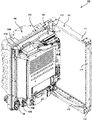
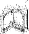
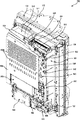
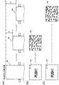
まず、図1から図9を主に参照して、パチンコ機100の構造部分の構成について説明する。図1〜図4は、パチンコ機100の各種状態を示す斜視図であり、図1はパチンコ機100の閉鎖状態を示し、図2は外枠101に対して前ブロック102及び中間ブロック103が一体的に開放されている状態を示し、図3は中間ブロック103に対して前ブロック102が開放されている状態を示し、図4は中間ブロック103に対して後ブロック104が開放されている状態を示している。また、図5は、パチンコ機100の正面図であり、図6は、図5の状態からパチンコ機100の前ブロック102を取り外した状態を示している。なお、各図において各種の配線は省略されており、また、図3及び図6において遊技盤400の構成の一部は省略されている。
<Structural structure>
First, the configuration of the structural portion of the
パチンコ機100は、例えば、図1〜図4に示すように、外枠101と、前ブロック102と、中間ブロック103と、後ブロック104とを備え、これら各部位を所定の操作により相対的に変位可能に構成されている。
For example, as shown in FIGS. 1 to 4, the
外枠101は、パチンコ機100の本体部分を支持する本体支持手段としての機能を有している。外枠101は、例えば、図2に示すように、天板部111、底板部112、左側板部113及び右側板部114が組み付けられた略四辺形状の枠体であり、パチンコ機100を設置する遊技場に設けられた遊技機設置設備(島設備)に嵌め込まれると共に固定具(図示せず)によって強固に固定される。なお、パチンコ機100において外枠101は必須の構成ではなく、外枠101又は外枠101と同一の内形形状を有し、外枠101を除いたパチンコ機100の構成に相当する本体部分を支持する支持機構や、その本体部分を施錠する施錠機構の一部が島設備に備え付けられた構成としても良い。
The
外枠101における左右方向の一方側(左側板部113側)には、中間ブロック支持機構121,122が設けられている。この中間ブロック支持機構121,122によって外枠101と中間ブロック103とが接続(連結)され、パチンコ機100の本体部分が、パチンコ機100の正面視における左右方向の一端側(左側)を回動基端側とし、他端側(右側)を回動先端側として前方へ回動可能に構成されている。
Intermediate
中間ブロック支持機構121,122は、例えば、図1に示すように、外枠101の上端部と下端部とに離間して設けられている。中間ブロック支持機構121,122の各々は、例えば、外枠101に設けられる軸支持部によって、中間ブロック103に設けられる軸部が下側より支持され、軸支持部に設けられる軸孔に軸部が差し込まれた状態とされることにより、回動可能に構成されている。なお、中間ブロック103を含むパチンコ機100の本体部分を回動可能とする構成は、上記構成に限らず、中間ブロック103側に軸孔を設け、外枠101側に軸部を形成するなど、他の構成としても良い。
As shown in FIG. 1, for example, the intermediate
中間ブロック支持機構121,122には、所定の取り外し操作によって外枠101と中間ブロック103との接続状態を解除する機能が設けられ、中間ブロック103を含むパチンコ機100の本体部分が外枠101に対して取り外し可能に取り付けられている。例えば、外枠101に対して中間ブロック103を一定量以上開放し、且つ、上方側へ一定量移動させるという所定の取り外し操作をすることにより、外枠101に対する中間ブロック103の接続状態が解除される。これにより、外枠101に対してパチンコ機100の本体部分が取り外し可能とされている。
The intermediate
中間ブロック103に対して前側には、前ブロック102が重なるようにして配置され、正面視左側に設けられる前ブロック支持機構131,132によって中間ブロック103と前ブロック102とが接続されている。前ブロック支持機構131,132は、中間ブロック支持機構121,122と同様の構成とされ、中間ブロック103に対して前ブロック102を前方へ回動可能に支持し、且つ、所定の取り外し操作により取り外し可能に構成されている。
The
中間ブロック103に対して後側には、後ブロック104が重なるようにして配置され、正面視左側に設けられる後ブロック支持機構136,137(図8参照)によって中間ブロック103と後ブロック104とが接続されている。後ブロック支持機構136,137には、中間ブロック支持機構121,122及び前ブロック支持機構131,132と同様の構成とされ、中間ブロック103に対して後ブロック104を後方へ回動可能に支持し、且つ、所定の取り外し操作により取り外し可能に支持する構成とされている。
The
また、パチンコ機100には、外枠101に対する中間ブロック103の開閉を規制する中間ブロック施錠機構と、中間ブロック103に対する前ブロック102の開閉を規制する前ブロック施錠機構と、中間ブロック施錠機構及び前ブロック施錠機構の解錠や施錠を行うために操作される錠操作機構とが設けられている。また、図3に示すように、中間ブロック103には、前ブロック102の開口を通してパチンコ機100の前面側に露出する錠操作機構としてのキーシリンダ141が設けられている。
Further, the
キーシリンダ141に対する所定の操作として、操作キー(図示せず)による右回転操作をした場合には、中間ブロック103に設けられた中間ブロック施錠機構の可動部143が作動する。これにより、中間ブロック施錠機構の一部として外枠101に設けられた被係合部142と可動部143との係合が解除されて、中間ブロック103は外枠101に対して開閉許容状態となる。
When a clockwise rotation operation is performed using an operation key (not shown) as a predetermined operation for the
一方、キーシリンダ141に対する所定の操作キーによる左回転操作に応じて、中間ブロック103に設けられた前ブロック施錠機構の可動部144が作動する。これにより、前ブロック施錠機構の一部として前ブロック102に設けられた被係合部145と可動部144との係合が解除されて、前ブロック102は中間ブロック103に対して開閉許容状態となる。
On the other hand, the
また、パチンコ機100には、中間ブロック103に対する後ブロック104の開閉を規制する後ブロック開閉規制機構が設けられている。この後ブロック開閉規制機構により、中間ブロック103に対して後ブロック104は、開閉が禁止された状態(開閉禁止状態)と開閉が許容された状態(開閉許容状態)とを所定の操作によって切り替え可能とされている。
Further, the
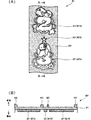
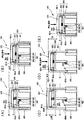
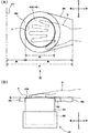
後ブロック開閉規制機構は、例えば、図4に示すように、中間ブロック103に設けられる2つの開閉規制部150A,150Bと、後ブロック104に設けられる1つの開閉規制部150Cとによって構成されている。これら3つの開閉規制部150A〜150Cには、回転操作が可能な回動片151A〜151Cが設けられている。回動片151A〜151Cは、回転操作により、後ブロック104の閉鎖状態において前後に重なるように配置される開口部分との係合状態が変化し、これにより、開閉禁止状態に対応した開閉禁止姿勢と、開閉許容状態に対応した開閉許容姿勢とを切り替え操作可能とされている。全ての回動片151A〜151Cを開閉許容姿勢にすると各回動片151A〜151Cが開口を通過可能となって、後ブロック104が中間ブロック103に対して開閉許容状態となる。なお、開閉禁止姿勢及び開閉許容姿勢としては、開閉禁止状態と開閉許容状態が回動片151A〜151Cの位置及び向きの少なくともいずれかの変化により切り替えられれば良く、一定位置で回転のみする構成としても良いし、一定方向に移動する構成としても良いし、移動と回転との組合せにより動作する構成としても良い。以下、各装置における構成部材が複数の姿勢の間を移行する場合における姿勢の変化についても同様とする。
As shown in FIG. 4, the rear block opening / closing regulating mechanism is composed of, for example, two opening /
3つの回動片151A〜151Cのうち、それらの一部に相当する2つの回動片151A,151Bは、図2に示すように、後ブロック104の開閉禁止状態において後ブロック104に形成された開口を通してパチンコ機100の背面側に露出し、残り部分に相当する1つの回動片151Cは、図6に示すように、中間ブロック103の前側に露出している。このため、パチンコ機100の背面側、又は中間ブロック103の前面側といった一方側からの操作だけでは、全ての回動片151A〜151Cを開閉許容姿勢に切り替えることはできず、これにより、防犯性が高められている。
Of the three
また、パチンコ機100には、中間ブロック103から前ブロック102への遊技球の移動を規制する遊技球移動規制機構が設けられている。遊技球移動規制機構は、例えば、図3及び図6に示すように、中間ブロック103に設けられた流下規制片161と、前ブロック102に設けられた規制変更部162との組合せにより構成され、前ブロック102が位置する前方側へ流下規制片161がコイルバネ(図示せず)により付勢される構成とされている。
Further, the
中間ブロック103に対して前ブロック102が閉鎖された状態(前ブロック102の閉鎖状態)においては、流下規制片161は、遊技球の流下を許容する移動許容状態とされ、具体的には、規制変更部162により中間ブロック103の後方側へ押圧されて押し込まれる。流下規制片161は、移動許容状態において中間ブロック103から前ブロック102に遊技球を誘導するための誘導通路(図示せず)に対して後側にずれて配置される。これにより、前ブロック102の閉鎖状態においては、中間ブロック103から前ブロック102への遊技球の移動が許容される。
In the state where the
一方、中間ブロック103に対して前ブロック102が開放された状態(前ブロック102の開放状態)においては、規制変更部162による流下規制片161の押圧が解除され、前ブロック102の閉鎖状態に比べて流下規制片161が前ブロック102側へ突出する移動禁止状態とされる。流下規制片161は、移動禁止状態において誘導通路内に突出し、下流側への遊技球の流下を阻止する。これにより、中間ブロック103から前ブロック102への遊技球の移動が禁止される。
On the other hand, in the state where the
また、パチンコ機100には、図2に示すように、例えば中間ブロック103の後側であって回動先端側(背面視左側)における下端部に、外枠101に対して中間ブロック103が閉鎖されているか否かを検出する開閉検出スイッチ108が設けられ、また、図3に示すように、例えば中間ブロック103の前側であって回動先端側(正面視右側)における下端部に、中間ブロック103に対して前ブロック102が閉鎖されているか否かを検出する開閉検出スイッチ109が設けられている。
Further, as shown in FIG. 2, in the
次に、前ブロック102、中間ブロック103及び後ブロック104の各構成について順に説明する。
Next, each configuration of the
前ブロック102は、図1及び図3に示すように、パチンコ機100の前面の略全体を形成し、前後方向に厚みを有する略長方形状の部材であり、パチンコ機100の前側表面部分を装飾する前面装飾手段としての機能を有している。前ブロック102は、合成樹脂製の基枠201を主体に構成され、基枠201の前後に複数の機能部品を取り付けて構成されている。基枠201の前面側には、パチンコ機100の前面を形成する前面装飾体210が、前ブロック102の正面視中央部分を含んで形成される開口210Aの外縁に沿って開口210Aを囲った状態にして取り付けられている。前ブロック102を構成する基枠201と前面装飾体210とを組み合わせた状態においては、前面装飾体210が取り付けられた外周部を除いた広範囲にわたって開口210Aが前後方向に貫通形成される。この開口210Aを通じて、前ブロック102の後側に位置する遊技盤400を含む中間ブロック103が遊技者から視認可能に構成されている。
As shown in FIGS. 1 and 3, the
また、前ブロック102には、図1及び図3に示すように、開口210Aを塞ぐように基枠201の背面側に設けられた中央パネル220と、遊技球を貯留する主貯留機構230と、遊技球を貯留する補助貯留機構240と、主貯留機構230に貯留されている遊技球を発射するために遊技者によって操作される発射操作装置250とを備えている。
Further, as shown in FIGS. 1 and 3, the
また、前ブロック102には、図1及び図5に示すように、前面装飾体210の一部として、開口210Aの周縁を囲う開口周縁部211と、開口210Aに対して下側において前方に突出する上側突出部217と、上側突出部217に対して下側に位置して前方に突出する下側突出部218と、下側突出部218の右側であって上側突出部217及び下側突出部218より奥側に位置する概ね平坦な領域で構成されて発射操作装置250が配置される平坦部219とが形成されている。上側突出部217には、主貯留機構230が配置され、下側突出部218には、補助貯留機構240が配置される。
Further, as shown in FIGS. 1 and 5, the
中央パネル220は、基枠201と前面装飾体210とを組み合わせた状態において前後方向に貫通形成される開口210Aを塞ぎつつ後方側を視認可能とするカバー体としての機能を有している。中央パネル220は、例えば、図1及び図3に示すように、基枠201の後方側から取着されるパネル枠221(図3参照)と、パネル枠221の前側に嵌め込まれた光透過性の前方板222(図1参照)と、パネル枠221の後側に前方板222と所定の間隙を隔てて略平行に嵌め込まれた光透過性の後方板223(図3参照)とを備えている。
The
主貯留機構230は、遊技進行に応じて獲得した遊技球や、遊技場から貸し出された遊技球を貯留する機能を有している。主貯留機構230は、例えば、図1に示すように、貯留部231と、球抜き機構(図示せず)と、その球抜き機構を作動させる球抜き操作部材232とを備えている。貯留部231には、パチンコ機100の内部から貯留部231へ遊技球を流入させる流入口231Aと、貯留部231からパチンコ機100の内部へ遊技球を流出させる流出口(図示せず)と、流出口より上流側に形成される放出口(図示せず)とが設けられている。この放出口の開放により貯留部231から遊技球がパチンコ機100の内部に取り込まれることなく遊技者側に放出される。球抜き機構は、遊技球の放出先を、流出口と放出口との間で切り換える機能を有している。
The
遊技進行に応じて獲得した遊技球や、後述する貸出操作装置292に対する貸出操作に応じて貸し出された遊技球は、主に流入口231Aを通して貯留部231に流入する。また、貯留部231は、上方側に開口形成されており、この開口部分を通じて、遊技者が所有する遊技球が手操作により投入されたり、遊技場において貸し出される遊技球が供給されたりする。
The game balls acquired according to the progress of the game and the game balls lent out according to the lending operation to the
貯留部231に流入した遊技球は一列に整列させられながら流出口及び放出口の形成されている側(図1の右上側)へ順次に案内される。球抜き操作部材232に対する球抜き操作(例えば、押下操作)が行われていない場合には遊技球は流出口を通して後述する発射装置330(図3参照)に誘導される。一方、球抜き操作部材232に対する球抜き操作が行われている場合には、遊技球は放出口を通して補助貯留機構240(図1参照)に誘導される。
The game balls that have flowed into the
補助貯留機構240は、図1及び図5に示すように、遊技球の流入口241A,241C(図5参照)及び放出口241B(図1参照)を有する貯留部241と、放出口241Bを開閉させる球抜き機構243と、その球抜き機構243を作動させる球抜き操作部材242とを備えている。遊技進行に応じて獲得した遊技球等は主に主貯留機構230に流入するが貯留部231が満杯であれば流入口241Aを通して貯留部241に流入する。また、球抜き操作部材232に対する球抜き操作に応じても、遊技球は流入口241Cを通して貯留部231から貯留部241に流入する。
As shown in FIGS. 1 and 5, the
貯留部241の底面は放出口241Bに向けて下降傾斜している。球抜き操作部材242に対する球抜き操作(例えば、押圧操作)によって放出口241Bを開放すると、貯留部241に貯留されている全ての遊技球を順次にパチンコ機100の外部に放出できる。なお、球抜き操作部材242に対する球抜き操作によって放出口241Bが完全に開放された場合には、球抜き操作部材242に対する復帰操作(例えば、再度の押圧操作)がなされるまで、その開放状態に維持される。流入口241Aの奥方には貯留部241に過剰に遊技球が貯留されているか否かを検出する球溢れスイッチ249(図10参照)が設けられている。
The bottom surface of the
発射操作装置250は、図1及び図5に示すように、前面装飾体210の平坦部219から前方に突出する台座251と、台座251の周囲に設けられた回動自在な発射ハンドル252と、発射ハンドル252の回転操作量を検出する可変抵抗器253(図10参照)と、発射ハンドル252に遊技者が接触していることを検出する接触センサ254(図10参照)と、発射ハンドル252の回転操作に伴う遊技球の射出を遊技者の操作によって無効化する発射停止スイッチ255(図5参照)とを含んでいる。遊技者によって発射ハンドル252が回転操作されると、その回転操作量に対応する強度で発射装置330(図3参照)から遊技球が遊技盤400(図3参照)に向けて射出される。なお、接触センサ254によって発射ハンドル252と遊技者との接触が検出されていない場合や、発射停止スイッチ255の操作によって発射操作が無効化されている場合には、発射ハンドル252が回転操作されていても発射装置330から遊技球は射出されない。
As shown in FIGS. 1 and 5, the
また、前ブロック102における前面装飾体210の奥方には、枠発光装置271〜275(図10参照)が設けられている。枠発光装置271〜275は、前面装飾体210の開口周縁部211に対して奥側に重なるようにして配置され、基枠201に取り付けられている。開口周縁部211は、図5に示すように、上側中央縁部211Aと、上側中央縁部211Aに対して左右両側に位置する左上側縁部211B及び右上側縁部211Cと、左上側縁部211Bに対して下側に位置する左側縁部211Dと、右上側縁部211Cに対して下側に位置する右側縁部211Eとを発光部として有し、それぞれの発光部に対応して枠発光装置271〜275が設置されている。
Further, a frame light emitting device 271-275 (see FIG. 10) is provided behind the front
枠発光装置271〜275は、上側中央縁部211Aに対応する上中央枠発光装置271と、左上側縁部211Bに対応する左上枠発光装置272と、右上側縁部211Cに対応する右上枠発光装置273と、左側縁部211Dに対応する左側枠発光装置274と、右側縁部211Eに対応する右側枠発光装置275(図10参照)とにより構成されている。枠発光装置271〜275の各々は、1又は複数の発光手段としての発光ダイオード(LED)と、LEDを制御するための抵抗等の電子部品と、これら電子部品を一体化して電気的に接続するプリント基板とを有している。
The frame light emitting devices 271-275 include an upper center frame light emitting device 271 corresponding to the upper
また、前ブロック102には、図5に示すように、例えばその開口周縁部211の上部に、左上音響出力口211Fと、右上音響出力口211Gとが設けられ、また、それら左上音響出力口211F及び右上音響出力口211Gのそれぞれに対応して左上音響装置281及び右上音響装置282(図3及び図10参照)が設けられている。左上音響装置281及び右上音響装置282は、前面装飾体210の開口周縁部211の奥方(後方)に位置するようにして基枠201に取り付けられている。
Further, as shown in FIG. 5, the
また、前ブロック102には、図1に示すように、例えば上側突出部217の上面右側部分に、遊技球貸出装置290が設けられている。遊技球貸出装置290は、パチンコ機100に並んで配置されるカードユニット(図示せず)に投入された紙幣やカード等の残額に応じた数値を表示する度数表示装置291と、遊技球の貸し出しを受ける際に遊技者によって操作される貸出操作装置292と、カードユニットに投入された紙幣やカード等を返却させる際に遊技者によって操作される返却操作装置293とを含んでいる。カードユニットに紙幣やカード等を投入して、それらの金額に対応する数値が度数表示装置291に表示されている有効状態において、貸出操作装置292に対して貸出操作が行われると、貸出操作に応じて所定の個数の遊技球が後ブロック104の払出装置540(図8参照)から貸し出され、遊技球の貸し出しに伴って度数表示装置291の表示が更新される。一方、有効状態において返却操作装置293に対して返却操作が行われると、返却操作に応じて残額に対応する紙幣の等価物や残額を記録したカードがカードユニットから返却される。
Further, as shown in FIG. 1, the
また、前ブロック102には、図1に示すように、遊技者によって発射操作とは別の入力操作が可能な入力操作装置260が設けられている。入力操作装置260は、例えば、押込操作が可能な押圧操作装置261と、回転操作が可能な回転操作装置262と、上下左右の方向操作が可能な選択操作装置263とを備えている。これら操作装置261〜263により、パチンコ機100において実行される演出を選択する演出選択操作や、パチンコ機100の演出を実行する各装置の音量や光量を設定する装置設定操作、或いは、遊技者に関する情報を入力して前回以前の遊技に応じたパチンコ機100の演出を実行可能とする演出設定操作等が実行可能とされ、これら操作を必要に応じて遊技者や遊技場の管理者が実行可能とされている。なお、入力操作装置260において遊技者が接触する入力操作部(例えば、回転操作装置262における円環状の回転操作部)は、モータやソレノイド等の入力操作部駆動手段によって回転、上下動、又は、振動等の動作がパチンコ機100の制御(例えば、副制御基板940(図10参照)の制御)により実行可能に構成されることが好ましく、入力操作の前後、又は、入力操作中のいずれか又は複数のタイミングで入力部分を動作させることにより、入力操作を積極的に促すなど入力操作を伴う演出を多様にすることができる。
Further, as shown in FIG. 1, the
次に、中間ブロック103について説明する。中間ブロック103は、前ブロック102と略同一サイズの略長方形状をした部材であり、前ブロック102と後ブロック104とが取り付けられることにより、パチンコ機100の本体部分を一体化した状態にする機能を有している。中間ブロック103は、基枠301に対して遊技盤400を含む複数の機能部品を取り付けて構成されている。
Next, the
中間ブロック103は、図3及び図4に示すように、開口を有する基枠301と、基枠301の開口を覆いつつ前面側より取着される遊技盤400(図3参照)と、基枠301に対して遊技盤400を回動自在及び着脱自在に支持する遊技盤支持機構と、基枠301に対して遊技盤400の位置を固定する遊技盤固定機構と、遊技盤400に遊技球を射出する発射装置330(図3参照)と、遊技盤400の背面側に装着されて遊技進行を統括的に制御する主制御装置370(図4参照)と、主制御装置370からの命令に基づいて遊技演出や状態報知を制御する副制御装置390(図4参照)とを備えている。
As shown in FIGS. 3 and 4, the
基枠301には、図3に示すように、後述する払出装置540(図8参照)から放出された遊技球を前ブロック102に誘導する誘導通路が内部に形成される誘導通路部301Aと、複数の配線(図示せず)や信号中継装置311が位置する開孔301Bとが設けられている。開孔301Bは、遊技盤400より下側において前後方向に貫通する形状をなし、開孔301Bに挿通される複数の配線は、前ブロック102に設けられる種々の装置(例えば、枠発光装置271〜275、左上音響装置281及び右上音響装置282)と、中間ブロック103の背面側や後ブロック104に設けられる装置(例えば、主制御装置370や副制御装置390)とを電気的に接続するための配線を含み、信号中継装置311は、その配線の一部を中継する中継基板としての機能を有している。
As shown in FIG. 3, the
遊技盤400は、図3に示すように、排出口401A等の遊技球が前後に通過可能な貫通孔を有する平板状の基体401と、基体401の左下から右上に亘り滑らかに湾曲する外レール402と、基体401の右下から左上に亘り滑らかに湾曲する内レール403と、内レール403の左上側の先端に取着された戻り球防止機構404と、外レール402の右上側の先端に取着される反跳防止部材405とを備えている。外レール402は、後述する発射装置330から発射された遊技球を遊技領域内へ誘導するものである。戻り球防止機構404は、外レール402及び内レール403が平行に対向する間部分で形成される発射通路401Bから遊技領域内へ一旦放出された遊技球が発射通路401Bに戻ることを防止する。反跳防止部材405は、遊技盤400の上部中央を越えて右側に向かった遊技球が再び上部中央を経由して左側に戻るような遊技球の大幅な反跳を防止する衝撃吸収性を有し、例えば、制振ゴム等の材料により形成されている。
As shown in FIG. 3, the
前ブロック102の背面側下部には、図3に示すように、戻り球通路部163が形成されている。発射装置330から発射通路401Bの方向へ遊技球を誘導する誘導部材335と外レール402との間には間隙があり、発射装置330から発射されたが戻り球防止機構404を超えるに至らず発射通路401Bを逆戻りする遊技球は、この間隙の下方に配置される戻り球通路部163を介して流入口241A(図5参照)から補助貯留機構240(図5参照)に返却される。
As shown in FIG. 3, a return
戻り球防止機構404を超えて進行した遊技球は、遊技領域に到達し、遊技領域内を自重により落下しながら移動(流下)する。遊技領域は、略円形状の外周形状をなし、遊技球の直径より僅かに大きな前後幅を有する領域を大部分とする形状に区画されている。遊技領域は、概ね、外レール402と内レール403とで外周部分が区画され、前側が中央パネル220の後方板223によって略平面状に区画され、後側が遊技盤400の基体401によって略平面状に区画されている。なお、遊技領域に設けられる各種の構造物については後述する。
The game ball that has advanced beyond the return
発射装置330は、図3に示すように、主貯留機構230に貯留されている遊技球を順次に発射位置に送り出す球送り機構331と、球送り機構331を駆動する球送りソレノイド332(図10参照)と、発射位置に配置された遊技球を射出する発射機構333と、発射機構333を駆動する発射ソレノイド334(図10参照)と、発射機構333から発射された遊技球を遊技盤400の発射通路401Bに誘導する誘導部材335とを備えている。発射装置330は、上述のように発射操作装置250に対する発射操作に応じて作動し、発射操作装置250に対する発射操作に応じて発射ソレノイド334の駆動制御が変化して発射力が調整される。
As shown in FIG. 3, the
主制御装置370は、図4に示すように、主制御基板920(図10参照)と、主制御基板920を収容する2つ割り構造の基板ケース371とを備えている。主制御基板920は、痕跡を残さずには開封できないように封止された透光性を有する基板ケース371の内部に収容されている。
As shown in FIG. 4, the
また、主制御装置370は、遊技盤400の背面側に回動自在に取り付けられている。具体的には、遊技盤400の基体401に対して背面側に取り付け部372が回動可能に連結固定され、その取り付け部372に主制御装置370が取り付けられている。これにより、主制御装置370の背面側(表面側)だけでなく、取り付け部372を回動操作することで主制御装置370の前面側(裏面側)も、遊技盤400に主制御装置370を取り付けたままで容易に確認可能とされている。取り付け部372に対して主制御装置370は、痕跡を残さずには取り外しできないように連結しても良く、主制御装置370の取り外し状況を管理し易くしても良い。
Further, the
副制御装置390は、副制御基板940(図10参照)と、副制御基板940を収容する2つ割り構造の基板ケース391とを備えている。副制御基板940は、例えば、主制御基板920と同様に痕跡を残さずには開封できないように封止された透光性を有する基板ケース391の内部に収容された状態にして遊技盤400の背面側に取り付けられている。
The
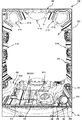
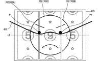
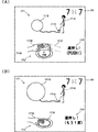
ここで、遊技盤400において、遊技領域に配置される各種の構造物について、図7を主に参照して説明する。図7は、遊技盤400の正面図である。なお、図7においては、装飾図柄表示装置479に表示される装飾図柄の一例を図示している。
Here, various structures arranged in the game area on the
遊技盤400は、図7に示すように、基体401と、遊技球の流下方向や流下速度に変化を与える釘411や風車412等の流下変化部材と、基体401の概ね中央に配置された中央構造体420と、中央構造体420に対して下側に配置された第1特別図柄に係る始動装置(具体的には、上側中始動入賞装置431A及び下側中始動入賞装置431B)と、中央構造体420に対して右下側に配置された第2特別図柄に係る始動装置(具体的には、右始動入賞装置432)と、右始動入賞装置432の下方に配置された大入賞装置433,434(具体的には、下大入賞装置433及び上大入賞装置434)と、右始動入賞装置432の上側(上流側)に配置された普通図柄に係る始動装置436と、遊技盤400の右上側であって上下の大入賞装置433,434に対して上方(上流側)に配置された役連作動装置435と、下側中始動入賞装置431Bの左右両側に配置された一般入賞装置439A,439Bとを備えている。
As shown in FIG. 7, the
また、遊技盤400には、上記した上側中始動入賞装置431A等に対応して遊技球の通過を検出する検出手段としてのスイッチが複数設けられており(図10参照)、各スイッチに対応した所定領域への遊技球の進入が検出可能とされている。例えば、上側中始動入賞装置431Aに進入した遊技球を検出する中始動入賞スイッチ(上側中始動入賞スイッチ441A)、下側中始動入賞装置431Bに進入した遊技球を検出する中始動入賞スイッチ(下側中始動入賞スイッチ441B)、右始動入賞装置432に進入した遊技球を検出する右始動入賞スイッチ442、下大入賞装置433に進入した遊技球を検出する下大入賞スイッチ443、上大入賞装置434に進入した遊技球を検出する上大入賞スイッチ444、役連作動装置435に進入した遊技球を検出する役連作動スイッチ445、始動装置436に進入した遊技球を検出する始動スイッチ446、下大入賞装置433の内部に形成された非特定通路(図示せず)に進入した遊技球を検出する非特定通路スイッチ447、下大入賞装置433の内部に形成された特定通路(図示せず)に進入した遊技球を検出する特定通路スイッチ448、一般入賞装置439A,439Bに進入した遊技球を各々検出する一般入賞スイッチ449A,449B等が遊技盤400に設置されている。
Further, the
また、遊技盤400には、不正防止のために各種センサが設けられており(図10参照)、パチンコ機100に発生した異常を検出可能とされている。例えば、磁気センサ491、振動センサ492、電波センサ493等が遊技盤400に設置されている。
Further, the
中央構造体420及び始動装置436の遊技球の入口部分は入球口を構成し、各入球口に進入した遊技球は遊技領域に放出される。各入賞装置、具体的には、上側中始動入賞装置431A、下側中始動入賞装置431B、右始動入賞装置432、下大入賞装置433、上大入賞装置434及び一般入賞装置439A,439Bの遊技球の入口部分は入賞口を構成し、各入賞口に進入した遊技球は基体401に形成された貫通孔を通して基体401の背面側に形成された回収排出通路(図示せず)に案内される。また、各入賞装置に進入しなかった遊技球は、遊技領域の最下流側部分に設けられる排出口401Aを通して回収排出通路へ案内される。回収排出通路に案内された遊技球は、パチンコ機100から遊技場に設けられた遊技球循環装置(図示せず)に排出される。いずれかの入賞装置に遊技球が進入した場合には、入賞装置の種類に応じた所定の個数の遊技球が払出装置540(図8及び図9参照)から払い出される。
The entrance portion of the game ball of the
なお、各入賞装置は、他の入賞装置と別々に構成されても良いし、2以上の入賞装置(例えば、上側中始動入賞装置431A及び下側中始動入賞装置431B)が一体化された装置によって入賞装置が構成されても良く、また、上側中始動入賞装置431A等の始動装置については必ずしも遊技球が進入した場合に所定の個数の遊技球が払い出される入賞口とする必要はなく、遊技球が払い出されることなく遊技領域に再び放出される入球口としても良い。
Each winning device may be configured separately from other winning devices, or a device in which two or more winning devices (for example, an upper middle
第1特別図柄に係る上側中始動入賞装置431A及び下側中始動入賞装置431B、並びに、一般入賞装置439A及び一般入賞装置439Bの各々は、それらへの遊技球の進入確率を変化させず、進入した遊技球を基体401の背面側へ誘導する。また、第2特別図柄に係る右始動入賞装置432は、その内部への遊技球の進入確率を変化させる機構を有している。なお、遊技球の進入確率を変化させる機構は、第2特別図柄に係る始動装置のみに設ける必要はなく、それに代えて、又は、それに加えて、第1特別図柄に係る始動装置、一般入賞装置439A,439Bのいずれか又は複数に設けても良い。また、遊技球の進入確率を変化させる機構は、電気的に駆動されるソレノイド等の駆動手段により構成しても良いし、所定領域へ入球した遊技球の自重により動作する機構に代表される機械的に動作する機構により構成しても良い。
Each of the upper middle start winning
第2特別図柄に係る右始動入賞装置432は、進入許容姿勢と進入禁止姿勢との間の移行によって、その内部への遊技球の進入確率を変化させる右進入規制機構452と、右進入規制機構452を駆動する右進入規制ソレノイド462(図10参照)とを備えている。右進入規制機構452は、右進入規制ソレノイド462によって駆動される2つの可動片を備えており、右進入規制機構452が進入禁止姿勢である場合には、2つの可動片が進入口(入賞口)を狭窄する(又は閉鎖する)配置をとることによって遊技球は右始動入賞装置432に進入できないが、右進入規制機構452が進入許容姿勢である場合には、2つの可動片がそれらの先端部の間隔が拡大するような配置をとることによって遊技球は右始動入賞装置432に進入できるようになる。右進入規制機構452は、普通図柄に係る始動装置436へ進入した遊技球が始動スイッチ446で検出されることに基づく抽選(以下において「普通図柄抽選」とも称す)で当選した場合に、右進入規制ソレノイド462による駆動に応じて所定の回数及び所定の時間だけ進入許容姿勢に移行する。
The right-starting
下大入賞装置433には、図7に示すように、進入許容姿勢と進入禁止姿勢との間の移行によって、その内部への遊技球の進入を規制する下進入規制機構453と、下進入規制機構453の姿勢を変化させる下進入規制ソレノイド463(図10参照)と、非誘導姿勢と誘導姿勢との間の移行によって、下大入賞装置433に進入した遊技球を非特定通路又は特定通路に振り分ける振分機構(図示せず)と、振分機構の姿勢を変化させて遊技球の誘導先を切り換える切換ソレノイド465(図10参照)とが設けられている。下大入賞装置433の下進入規制機構453が進入禁止姿勢である場合には、下進入規制機構453が進入口(入賞口)を閉鎖することによって遊技球は下大入賞装置433に進入できないが、下進入規制機構453が進入許容姿勢である場合には、下進入規制機構453が進入口を開放することによって遊技球は下大入賞装置433に進入できるようになる。また、下大入賞装置433に進入した遊技球は、振分機構が前方に突出する非誘導姿勢である場合には非特定通路に案内され、振分機構が後方に没入する誘導姿勢である場合には特定通路に誘導される。特定通路、非特定通路及び振分機構は、遊技状態の移行を多様にするために設けられ、特定通路へ遊技球が進入した場合には、遊技者に特典として有利な遊技状態が付与される。
As shown in FIG. 7, the lower
上大入賞装置434には、図7に示すように、進入許容姿勢と進入禁止姿勢との間の移行によって、その内部への遊技球の進入を規制する上進入規制機構454と、上進入規制機構454の姿勢を変化させる上進入規制ソレノイド464(図10参照)とが設けられている。上進入規制機構454が進入禁止姿勢である場合には、上進入規制機構454が進入口(入賞口)を閉鎖することによって遊技球は上大入賞装置434に進入できないが、上進入規制機構454が進入許容姿勢である場合には、上進入規制機構454が進入口を開放することによって遊技球は上大入賞装置434に進入できるようになる。
As shown in FIG. 7, the upper
なお、右進入規制機構452等の内部への遊技球の進入確率を変化させる機構としての進入許容姿勢及び進入禁止姿勢としては、各機構を構成して各装置の入賞口(又は入球口)に遊技球が進入可能な特別状態と、遊技球が進入不能な通常状態とを切り替える動作部材の姿勢変化に対応し、各姿勢に応じて動作部材の位置及び向きの少なくともいずれかが異なるものであれば良い。また、右進入規制機構452等の遊技球の進入確率を変化させる機構として、遊技球が進入不能な状態を通常状態とする必要は必ずしもなく、通常状態においても遊技球の進入を許容し、特別状態においては通常状態より遊技球が進入し易い状態に動作部材の姿勢が変化する構成としても良い。
In addition, as the approach permissible posture and the entry prohibition posture as a mechanism for changing the entry probability of the game ball into the inside of the right
下大入賞装置433及び上大入賞装置434には、大当りの抽選に当選した場合に遊技球が進入可能となる。具体的には、第1特別図柄に係る上側中始動入賞装置431A若しくは下側中始動入賞装置431Bへ進入した遊技球が上側中始動入賞スイッチ441A若しくは下側中始動入賞スイッチ441Bで検出されることに基づく抽選(以下において「第1特別図柄抽選」とも称す)に当選した場合、又は、第2特別図柄に係る右始動入賞装置432へ進入した遊技球が右始動入賞スイッチ442で検出されることに基づく抽選(以下において「第2特別図柄抽選」とも称す)に当選した場合には、下進入規制ソレノイド463又は上進入規制ソレノイド464の少なくとも一方が作動する。この作動によって所定の回数に亘り所定の時間だけ下進入規制機構453又は上進入規制機構454の少なくとも一方が進入許容姿勢をとる。また、振分機構は、下進入規制機構453の進入許容姿勢への移行から所定の時間後に切換ソレノイド465の作動に応じて誘導姿勢に移行し、更に誘導姿勢への移行から所定の時間後に切換ソレノイド465の停止に応じて非誘導姿勢に戻る。
A game ball can enter the lower
役連作動装置435は、下大入賞装置433及び上大入賞装置434が作動を開始するために必要な条件を設定するための装置である。大当りの抽選に当選した後には、役連作動装置435の遊技球の通過を条件として、下大入賞装置433又は上大入賞装置434のいずれかが作動を開始する。このため、遊技者は、大当りに当選した場合、自らの意図するタイミングで特別遊技状態を開始させることができる。なお、必ずしも役連作動装置435の遊技球の通過を条件として、下大入賞装置433又は上大入賞装置434のいずれかが作動を開始する構成とする必要はなく、それに代えて、又は、それに加えて、予め定めた時間の経過により下大入賞装置433又は上大入賞装置434のいずれかが作動を開始する構成としても良い。
The
また、遊技盤400には、図7に示すように、図柄の変動表示や抽選結果を表示する表示装置471〜473と、遊技の保留回数を表示する表示装置476〜478とが一体化された複数の発光部を有する表示器が、遊技盤400の一部に相当する左下部分に設けられている。複数の発光部は、各装置に対応する発光領域に予め区画され、各装置の状態が発光状態によって表示される。
Further, as shown in FIG. 7, the
具体的には、遊技盤400には、第1特別図柄抽選に伴って、第1特別図柄を変動表示したり、第1特別図柄を抽選結果に応じた停止図柄で確定表示したりする第1特別図柄に係る特別図柄表示装置471と、第2特別図柄抽選に伴って、第2特別図柄を変動表示したり、第2特別図柄を抽選結果に応じた停止図柄で確定表示したりする第2特別図柄に係る特別図柄表示装置472と、第1特別図柄に係る単位遊技の保留回数を表示する特別図柄保留表示装置476と、第2特別図柄に係る単位遊技の保留回数を表示する特別図柄保留表示装置477とが設けられている。第1特別図柄に係る単位遊技の権利及び第2特別図柄に係る単位遊技の権利はそれぞれ最大4回まで保留される。ここで、単位遊技とは、1回の始動入賞に基づいて実行される1回分の遊技であり、1回の始動入賞に基づいて実行される抽選の当否判定と、その当否判定に基づいた抽選結果を表示するまでの変動表示の開始から終了までを含む一連の遊技をいう。
Specifically, on the
第1特別図柄に係る単位遊技の権利が最大回数まで保留されている場合には、始動入賞装置431に進入した遊技球が上側中始動入賞スイッチ441A(図10参照)又は下側中始動入賞スイッチ441B(図10参照)によって検出されたとしても第1特別図柄に係る単位遊技の権利は追加されない。同様に、第2特別図柄に係る単位遊技の権利が最大回数まで保留されている場合に、右始動入賞装置432に進入した遊技球が右始動入賞スイッチ442(図10参照)によって検出されたとしても第2特別図柄に係る単位遊技の権利は追加されない。
When the right of the unit game related to the first special symbol is reserved up to the maximum number of times, the game ball that has entered the start winning device 431 is the upper middle start winning switch 441A (see FIG. 10) or the lower middle starting winning switch. Even if it is detected by 441B (see FIG. 10), the right of the unit game related to the first special symbol is not added. Similarly, when the right to the unit game related to the second special symbol is reserved up to the maximum number of times, it is assumed that the game ball that has entered the right
第1特別図柄に係る特別図柄表示装置471及び第2特別図柄に係る特別図柄表示装置472の各々は、複数の発光部で構成されており、主制御基板920(図10参照)によって制御される。第1特別図柄の表示及び第2特別図柄の表示の各々は、複数の発光部の発光パターン(発光色を含む発光状態(消灯、点灯、点滅)の組合せ)によって表現される。第1特別図柄に係る特別図柄保留表示装置476及び第2特別図柄に係る特別図柄保留表示装置477は、2個の単色の発光部の発光状態(消灯、点灯、点滅)の組合せによって保留回数を表示する。
Each of the special
また、遊技盤400には、普通図柄抽選に伴って、普通図柄を変動表示したり、普通図柄を抽選結果に応じた停止図柄で確定表示したりする普通図柄表示装置473と、普通図柄に係る単位遊技の権利の保留回数を表示する普通図柄保留表示装置478とが設けられている。普通図柄に係る単位遊技の権利は最大4回まで保留される。普通図柄に係る単位遊技の権利が最大回数まで保留されている場合には、始動装置436に進入した遊技球が始動スイッチ446によって検出されたとしても普通図柄に係る単位遊技の権利は追加されない。
Further, the
普通図柄表示装置473は、複数の発光部で構成されており、主制御基板920(図10参照)によって制御される。普通図柄は、複数の発光部の発光パターンによって表現される。また、普通図柄保留表示装置478は、2個の単色の発光部の発光状態(消灯、点灯、点滅)の組合せによって保留回数を表示する。
The ordinary
また、遊技盤400には、中央構造体420の後方に重なるようにして、第1特別図柄及び第2特別図柄に係る単位遊技において、装飾図柄を変動表示したり、装飾図柄を確定表示したりする装飾図柄表示装置479が設けられている。
Further, on the
装飾図柄表示装置479は、左右方向に並ぶ3つの図柄表示領域479A,479B,479Cを備えている。図柄表示領域479A,479B,479Cは、いずれも、装飾図柄を変動表示したり確定表示したりする領域である。図柄表示領域479A,479B,479Cのうち、最も左側に位置する図柄表示領域479Aに表示される装飾図柄は、左図柄列を構成し、最も右側に位置する図柄表示領域479Bに表示される装飾図柄は、右図柄列を構成する。また、図柄表示領域479Aと図柄表示領域479Bとの間に位置する図柄表示領域479Cに表示される装飾図柄は、中図柄列を構成する。
The decorative
本実施形態のパチンコ機100においては、装飾図柄表示装置479は、左右方向に並ぶ3つの円筒状のリール(回動体)を備えるリール装置として構成される。当該リール装置の各リールは、それぞれ、副制御基板940によって制御されるモータ(図示せず)によって各々独立して回動可能に構成される。
In the
リール装置を構成する円筒状の各リールは、光透過性の樹脂(例えば、透明な樹脂)により構成される円筒状の本体(以下において「リール本体」とも称す)と、当該リール本体の外周面の周方向に沿って貼着された帯状の図柄シート601(図13参照)とを備えている。図柄シート601には、複数の装飾図柄が所定の順序で長手方向に沿って列状に設けられている。
Each of the cylindrical reels constituting the reel device includes a cylindrical main body (hereinafter, also referred to as a "reel main body") made of a light-transmitting resin (for example, a transparent resin) and an outer peripheral surface of the reel main body. It is provided with a strip-shaped pattern sheet 601 (see FIG. 13) attached along the circumferential direction of the above. The
装飾図柄表示装置479は、各リールを回動させることによって、図柄シート601に設けられている複数の装飾図柄を各図柄表示領域479A,479B,479Cにおいて上から下方向またはその反対方向に移動(スクロール)させることができる。これにより、装飾図柄表示装置479における装飾図柄の変動表示が実現される。なお、装飾図柄表示装置479は、必ずしも複数のリールによって構成する必要はなく、画像を表示可能な液晶表示装置などの他の装置によって構成してもよい。
The decorative
装飾図柄表示装置479による装飾図柄の変動表示及び確定表示は、副制御基板940により制御され、主制御基板920による第1特別図柄や第2特別図柄の変動表示及び確定表示と同期している。装飾図柄の変動表示においては、第1特別図柄や第2特別図柄の変動表示よりも複雑かつ多様な演出が実行される。なお、第1特別図柄や第2特別図柄の変動表示及び確定表示と装飾図柄の変動表示及び確定表示とは、必ずしも完全に一致するタイミングで変動開始したり、確定表示として停止表示をしたりする必要はなく、各タイミングに僅かな時間差を設けつつ略同じタイミングで変動を開始し、略同じタイミングで確定表示が行われる設定としても良い。
The variable display and the final display of the decorative symbol by the decorative
また、遊技盤400は、各種の構造物の裏側に設けられた盤面発光装置490(図10参照)を備えており、盤面発光装置490は、副制御基板940による制御に基づいて遊技進行に伴う各種の発光演出や発光による状態報知を実行する。
Further, the
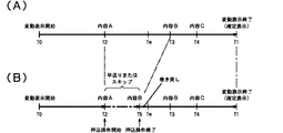
ここで、各種の遊技状態及び遊技状態間の移行について説明する。通常時の遊技状態(以下において「通常遊技状態」とも略記する)は、第1特別図柄、第2特別図柄及び普通図柄の変動表示時間が長い状態(以下において「非時短状態」とも称す)に対応する。 Here, various gaming states and transitions between gaming states will be described. The normal game state (hereinafter, also abbreviated as "normal game state") is a state in which the fluctuation display time of the first special symbol, the second special symbol, and the normal symbol is long (hereinafter, also referred to as "non-time reduction state"). Correspond.
第1特別図柄抽選又は第2特別図柄抽選において大当りに当選した場合には、その当選に基づいて移行する特別遊技状態中に遊技球が特定通路(下大入賞装置433の内部通路)へ進入するか否かに対応して、特別遊技状態後に移行する遊技状態が異なる。特別遊技状態中に遊技球が特定通路へ進入しなかった場合には、第1特別図柄抽選、第2特別図柄及び普通図柄の変動表示時間が非時短状態よりも短い状態(以下において「時短状態」とも称す)であって、かつ、第1特別図柄抽選及び第2特別図柄抽選における大当りの当選確率が通常遊技状態と同一の状態(以下において「低確率状態」とも称す)である遊技状態(以下において「時短遊技状態」とも称す)へ移行する。一方、特別遊技状態中に遊技球が特定通路へ進入した場合には、時短状態であって、かつ、第1特別図柄抽選及び第2特別図柄抽選における大当りの当選確率が通常遊技状態より高い状態(以下において「高確率状態」とも称す)である遊技状態(以下において「確変遊技状態」とも称す)へ移行する。 If a big hit is won in the first special symbol lottery or the second special symbol lottery, the game ball enters the specific passage (internal passage of the lower prize winning device 433) during the special game state that shifts based on the winning. Depending on whether or not, the gaming state that shifts after the special gaming state is different. If the game ball does not enter the specific passage during the special game state, the variation display time of the first special symbol lottery, the second special symbol, and the normal symbol is shorter than the non-time reduction state (hereinafter, "time reduction state"). (Also referred to as "low probability state"), and the winning probability of the jackpot in the first special symbol lottery and the second special symbol lottery is the same as the normal gaming state (hereinafter, also referred to as "low probability state"). In the following, it will also be referred to as the "short-time game state"). On the other hand, when the game ball enters the specific passage during the special game state, the time is shortened and the jackpot winning probability in the first special symbol lottery and the second special symbol lottery is higher than in the normal game state. It shifts to a gaming state (hereinafter also referred to as a "probability changing gaming state") which is (hereinafter also referred to as a "high probability state").
時短遊技状態は、第1特別図柄及び第2特別図柄に係る単位遊技の総数が所定の回数(例えば、50回)となるまで維持されるが、その後は通常遊技状態に戻る。また、確変遊技状態は、第1特別図柄及び第2特別図柄に係る単位遊技の総数が所定の回数(例えば、100回)となるまで維持されるが、その後は通常遊技状態に戻る。 The time-saving game state is maintained until the total number of unit games related to the first special symbol and the second special symbol reaches a predetermined number of times (for example, 50 times), but then returns to the normal game state. Further, the probabilistic gaming state is maintained until the total number of unit games related to the first special symbol and the second special symbol reaches a predetermined number of times (for example, 100 times), but then returns to the normal gaming state.
なお、遊技状態及び遊技状態間の移行について、必ずしも上述した構成とする必要はなく、例えば、高確率状態が次回の大当りの当選まで継続する構成としても良いし、他の内容によって上記遊技状態の少なくとも1つを構成しても良いし、上述した各遊技状態とは別の遊技状態を更に含む構成としても良いし、上述した条件とは異なる条件によって遊技状態間が移行する構成としても良い。 It should be noted that the transition between the gaming state and the gaming state does not necessarily have to be the above-described configuration. For example, the high-probability state may be configured to continue until the next big hit, or the above-mentioned gaming state may be configured depending on other contents. At least one may be configured, a gaming state different from each of the above-mentioned gaming states may be further included, or the gaming states may be shifted under conditions different from the above-mentioned conditions.
次に、遊技盤400の主要な装置の動作について概ね時系列に沿って説明する。主制御基板920においては、特別図柄(第1特別図柄及び第2特別図柄で共通)に係る当選乱数、大当り図柄乱数、停止パターン乱数、各種の変動パターン乱数が生成されており、各種の遊技状態において第1特別図柄に係る始動入賞装置431A,431Bのいずれかに進入した遊技球が中始動入賞スイッチ441A,441B(図10参照)のいずれかによって検出された場合に第1特別図柄の始動入賞となる。第1特別図柄の始動入賞時に、第1特別図柄に係る単位遊技の権利が最大回数まで保留されていない場合には、特別図柄に係る当選乱数、大当り図柄乱数及び停止パターン乱数が取得されて、主制御基板920のRAMの所定の領域に格納される。
Next, the operations of the main devices of the
第1特別図柄の始動入賞に基づいて取得された乱数による単位遊技は、特別遊技状態中でなく、第1特別図柄又は第2特別図柄に係る単位遊技中でもなく、第1特別図柄に係る単位遊技の権利が保留されていない場合には、それらの乱数の格納の直後に開始される。また、特別遊技状態中でない場合であっても、第1特別図柄又は第2特別図柄に係る単位遊技中や第1特別図柄又は第2特別図柄に係る単位遊技の権利が保留されている場合には、今回の入賞より前に保留されていた全ての特別図柄(第1特別図柄及び第2特別図柄)に係る単位遊技の終了後に、今回の始動入賞に基づく単位遊技が開始される。特別遊技状態中に第1特別図柄の始動入賞に基づいて各乱数が取得された場合には、その乱数による単位遊技は、特別遊技状態後において今回の始動入賞より前に保留されていた全ての特別図柄に係る単位遊技の後に開始される。 The unit game with random numbers acquired based on the start prize of the first special symbol is neither in the special game state nor in the unit game related to the first special symbol or the second special symbol, and the unit game related to the first special symbol. If the rights to are not reserved, they are started immediately after the storage of those random numbers. In addition, even when the player is not in the special game state, when the right of the unit game related to the first special symbol or the second special symbol is reserved or the right of the unit game related to the first special symbol or the second special symbol is reserved. Is started after the unit game related to all the special symbols (first special symbol and second special symbol) held before the current prize is completed, the unit game based on the current start prize is started. If each random number is acquired based on the start prize of the first special symbol during the special game state, the unit game by the random number is all held before the current start prize after the special game state. It starts after the unit game related to the special symbol.
また、第1特別図柄の始動入賞に基づいて取得された乱数による単位遊技は、第2特別図柄に係る全ての単位遊技の終了後に開始される。すなわち、今回の始動入賞の後に第2特別図柄の始動入賞に基づいて各乱数が取得された場合には、その第2特別図柄の始動入賞に基づく単位遊技が優先して実行される。なお、必ずしも第2特別図柄の始動入賞に基づく単位遊技が第1特別図柄に係る単位遊技に優先して実行される構成とする必要はなく、始動入賞の順に第1特別図柄と第2特別図柄に係る単位遊技優位制御が実行される構成であっても良いし、2つの特別図柄が択一的でなく同時に変動可能な構成であっても良い。 In addition, the unit game using random numbers acquired based on the start prize of the first special symbol is started after the end of all the unit games related to the second special symbol. That is, when each random number is acquired based on the start prize of the second special symbol after the current start prize, the unit game based on the start prize of the second special symbol is preferentially executed. It should be noted that the unit game based on the start prize of the second special symbol does not necessarily have to be executed in preference to the unit game related to the first special symbol, and the first special symbol and the second special symbol are not necessarily executed in the order of the start prize. The unit game superiority control according to the above may be executed, or the two special symbols may not be alternative and may be variable at the same time.
第1特別図柄の始動入賞に基づく第1特別図柄抽選において大当りに当選している場合には、更に、取得された大当り図柄乱数に基づいて第1特別図柄抽選の大当り当選に対応する停止図柄(大当り図柄)の種類が決定される。この停止図柄の種類と大当りの種類とが対応し、例えば、下進入規制機構453又は上進入規制機構454が進入許容姿勢をとる回数に相当するラウンド数(例えば、6ラウンドと16ラウンド)や、特別遊技状態後に移行する遊技状態(確変遊技状態へ移行させるか否か)といった遊技状態の種類に対応して大当りの種類が複数種類設定され、その種類毎に大当り図柄が設定されている。第1特別図柄抽選において大当りに当選しなかった場合には、大当り図柄とは別のハズレ図柄が停止図柄として設定される。
If a big hit is won in the 1st special symbol lottery based on the start prize of the 1st special symbol, the stop symbol corresponding to the big hit winning of the 1st special symbol lottery based on the acquired big hit symbol random number ( The type of jackpot symbol) is determined. The type of the stop symbol corresponds to the type of the jackpot. For example, the number of rounds (for example, 6 rounds and 16 rounds) corresponding to the number of times that the lower
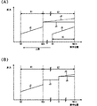
第1特別図柄抽選の後に、現在の遊技状態、抽選結果、停止パターン乱数の値、各種の変動パターン乱数の値、第1特別図柄に係る単位遊技の権利の保留回数に基づいて、第1特別図柄の変動表示時間が決定されると共に、装飾図柄の変動パターンが選択される。装飾図柄の変動パターンには、大別して、第1特別図柄に係る停止図柄(大当り図柄またはハズレ図柄)に対応する装飾図柄が確定表示される前にリーチ表示がなされる変動パターン(以下において「リーチ変動パターン」とも称す)と、第1特別図柄に係る停止図柄がハズレ図柄である場合に対応する装飾図柄が確定表示される前にリーチ表示がなされない変動パターンとがある。 After the first special symbol lottery, the first special is based on the current game state, lottery result, stop pattern random number value, various variable pattern random number values, and the number of times the unit game right related to the first special symbol is held. The variation display time of the symbol is determined, and the variation pattern of the decorative symbol is selected. The variation patterns of the decorative symbols are roughly classified into the variation patterns in which the reach is displayed before the decorative symbols corresponding to the stop symbols (big hit symbols or lost symbols) related to the first special symbol are confirmed and displayed (hereinafter, "reach"). (Also referred to as "variable pattern"), and a variable pattern in which the reach display is not performed before the decorative symbol corresponding to the case where the stop symbol related to the first special symbol is a lost symbol is confirmed and displayed.
なお、「リーチ表示」とは、特別図柄(第1特別図柄、第2特別図柄)に係る単位遊技において装飾図柄の変動表示が開始された後、1の図柄列を除く各図柄列(例えば、左右の各図柄列)にて確定表示された装飾図柄の組合せが大当り図柄となるための条件を満たしており、その後も変動表示が継続される残りの図柄列(例えば、中図柄列)の装飾図柄が確定表示された際の表示結果(すなわち、停止図柄)の次第によって大当り図柄となる可能性があることを遊技者に示唆する表示である。 In addition, "reach display" means each symbol sequence (for example, after the variable display of the decorative symbol is started in the unit game related to the special symbol (first special symbol, second special symbol), except for one symbol sequence (for example). The decoration of the remaining symbol rows (for example, the middle symbol row) in which the combination of the decorative symbols confirmed and displayed in each of the left and right symbol rows) satisfies the condition for becoming a jackpot symbol and the variable display is continued thereafter. It is a display that suggests to the player that there is a possibility of becoming a big hit symbol depending on the display result (that is, the stop symbol) when the symbol is confirmed and displayed.
リーチ表示には、比較的短い変動表示時間(例えば、略25秒〜略30秒)のリーチ表示であるノーマルリーチと、ノーマルリーチより長い変動表示時間(例えば、略60秒〜略180秒)のリーチ表示であるスーパーリーチとが含まれる。なお、リーチ表示の種別は、ノーマルリーチとスーパーリーチとの2種類であることに限らず、スーパーリーチより長い変動表示時間のリーチ表示であるスペシャルリーチなどを含む3種類以上であってもよい。 The reach display includes a normal reach, which is a reach display with a relatively short fluctuation display time (for example, about 25 seconds to about 30 seconds), and a reach display with a fluctuation display time longer than the normal reach (for example, about 60 seconds to about 180 seconds). Includes Super Reach. The types of reach display are not limited to two types, normal reach and super reach, and may be three or more types including special reach, which is a reach display with a variable display time longer than that of super reach.
第1特別図柄の変動表示時間が決定され、当該変動表示時間に対応する装飾図柄の変動パターンが選択された後、第1特別図柄に係る特別図柄表示装置471における第1特別図柄の変動表示及び装飾図柄表示装置479における装飾図柄の変動表示(変動演出)が開始され、第1特別図柄にあっては変動表示時間に亘って一定のパターンによる変動表示が継続され、装飾図柄にあっては変動表示時間に亘って変動パターンに従った変動表示が継続される。その後、変動表示時間の経過に伴って、第1特別図柄に係る停止図柄が確定表示され、また、装飾図柄として第1特別図柄の停止図柄に対応する図柄が確定表示される。第1特別図柄及び装飾図柄の確定表示は少なくとも所定の一定時間に亘って継続される。
After the variation display time of the first special symbol is determined and the variation pattern of the decorative symbol corresponding to the variation display time is selected, the variation display of the first special symbol and the variation display of the first special symbol in the special
第1特別図柄に係る停止図柄が大当り図柄である場合には、第1特別図柄の確定表示後に、遊技状態は特別遊技状態に移行する。特別遊技状態においては、下大入賞装置433の下進入規制機構453及び上大入賞装置434の上進入規制機構454が、大当りの種類に応じた所定の順序で所定の回数だけ進入許容姿勢となる。下進入規制機構453及び上進入規制機構454における各回の進入許容姿勢中において、所定の個数(例えば、8個)の遊技球が大入賞スイッチ443,444によって検出された場合、又は、所定の最大進入許容時間(例えば、29.5秒)が経過した場合には、下進入規制機構453又は上進入規制機構454は進入禁止姿勢に移行する。その後、所定の進入禁止時間の経過後に、再度、下進入規制機構453又は上進入規制機構454のいずれかが進入許容姿勢に復帰する。この進入規制動作が大当りの種類に対応した所定の順序で所定の回数だけ繰り返される。
When the stop symbol related to the first special symbol is a jackpot symbol, the gaming state shifts to the special gaming state after the confirmation display of the first special symbol. In the special gaming state, the lower
下進入規制機構453及び上進入規制機構454は、特別遊技状態中においていずれか一方のみが進入許容姿勢をとる構成とされ、特別遊技状態の開始から所定の待機時間が経過した後(オープニング期間後)に初回の進入許容姿勢に一方が移行する。また、最終回の進入禁止姿勢への復帰から所定の進入禁止時間が経過し、更にその後に所定の待機時間が経過した後(エンディング期間後)に特別遊技状態は終了する。特別遊技状態の終了後には、上述のように、時短遊技状態又は確変遊技状態に移行する。
The lower
各種の遊技状態において、第2特別図柄に係る右始動入賞装置432に進入した遊技球が右始動入賞スイッチ442によって検出された場合に第2特別図柄の始動入賞となる。第2特別図柄の始動入賞に基づく単位遊技の制御は、上述した第1特別図柄に係る制御と同様に実行される。すなわち、第2特別図柄の始動入賞時に第2特別図柄に係る単位遊技の権利が最大回数まで保留されていなければ、特別図柄に係る各乱数が取得されて、この始動入賞に基づく単位遊技が実行される。また、第2特別図柄抽選に応じた停止図柄の決定、第2特別図柄の変動表示時間の決定、当該変動表示時間に対応する装飾図柄の変動パターンの選択、変動表示の実行、及び、遊技状態の移行制御等についても、第1特別図柄に係る制御と同様に実行される。
In various game states, when the game ball that has entered the right
各種の遊技状態において、始動装置436に進入した遊技球が始動スイッチ446によって検出された場合、普通図柄に係る単位遊技の権利が最大回数まで保留されていなければ、普通図柄に係る当選乱数が取得されて、主制御基板920のRAMの所定の領域に格納される。このとき、普通図柄に係る単位遊技中でなければ、その格納の直後に、その取得された普通図柄に係る単位遊技が開始される。一方、普通図柄に係る単位遊技中であれば、既得の普通図柄に係る単位遊技の権利に基づく単位遊技の終了後に、その取得された普通図柄に係る単位遊技が開始される。
In various game states, when a game ball that has entered the
普通図柄に係る単位遊技においては、当選乱数の値に基づいて当選したか否かが判定され、当選した場合には、停止図柄として所定の当り図柄が設定される。一方、普通図柄抽選において当選しなかった場合には、停止図柄として所定のハズレ図柄が設定される。普通図柄抽選後に、普通図柄表示装置473において普通図柄の変動表示が開始され、非時短状態にあっては所定の変動表示時間に亘って一定のパターンによる変動表示が継続され、時短状態にあっては非時短状態よりも短い所定の変動表示時間に亘って一定のパターンによる変動表示が継続される。遊技状態に応じた所定の時間の経過に伴って、普通図柄に係る停止図柄が一定時間に亘って確定表示される。
In the unit game related to the normal symbol, it is determined whether or not the player has won based on the value of the winning random number, and if the unit game is won, a predetermined winning symbol is set as the stop symbol. On the other hand, if the normal symbol lottery is not won, a predetermined lost symbol is set as the stop symbol. After the normal symbol lottery, the fluctuation display of the normal symbol is started on the normal
普通図柄に係る停止図柄が当り図柄である場合には、普通図柄の確定表示後に、右始動入賞装置432の右進入規制機構452が少なくとも1回は進入許容姿勢に移行する。具体的には、非時短状態(通常遊技状態及び特別遊技状態)において当選した場合には、右始動入賞装置432が所定の最大進入許容時間(例えば、略0.1秒)に亘って進入許容状態へ移行し、時短状態(時短遊技状態及び確変遊技状態)における当選の場合には、右始動入賞装置432が非時短状態の場合より長い所定の最大進入許容時間(例えば、略4.8秒)に亘って間欠的に(例えば、3回に分けて)進入許容姿勢に移行する。但し、所定の個数(例えば、10個)の遊技球が右始動入賞スイッチ442によって検出された場合には、右進入規制機構452は最大進入許容時間の経過を待たずに進入禁止姿勢に移行し、また、進入許容姿勢への移行回数が所定の回数に到達していなくても、今回の普通図柄に係る単位遊技における右始動入賞装置432の動作が終了する。
When the stop symbol related to the normal symbol is a hit symbol, the right
次に、本実施形態のパチンコ機100の遊技性について説明する。第2特別図柄抽選を受けるためには、まず、普通図柄抽選において当選しなければならず、更に、その当選に基づく右始動入賞装置432の進入許容状態において遊技球が右始動入賞装置432へ進入しなければならない。通常遊技状態における普通図柄に係る当りの当選確率は時短遊技状態における当選確率と同一であるが、通常遊技状態における当りの当選に基づく右始動入賞装置432の進入許容状態の滞在時間(例えば、略0.1秒)が時短状態における滞在時間(例えば、略4.8秒)に比べて極めて短く設定されているために、通常遊技状態において、第2特別図柄抽選を受けられる単位時間当りの機会は、第1特別図柄抽選を受けられる単位時間当りの機会よりも大幅に小さい。逆に、時短遊技状態や確変遊技状態等の時短状態においては、第2特別図柄抽選を受けられる単位時間当りの機会は、第1特別図柄抽選を受けられる単位時間当りの機会よりも大幅に大きい。
Next, the playability of the
したがって、遊技者は、第1特別図柄抽選において大当りに当選し、その後の特別遊技状態において遊技球を特定通路へ進入させることによる確変遊技状態への移行を目指して遊技する。一方、時短遊技状態及び確変遊技状態においては、各遊技状態が終了する前に第2特別図柄抽選において大当りに当選することを目指して遊技する。 Therefore, the player wins a big hit in the first special symbol lottery, and in the subsequent special game state, the player plays with the aim of shifting to the probabilistic game state by allowing the game ball to enter the specific passage. On the other hand, in the time-saving game state and the probabilistic game state, the game is played with the aim of winning a big hit in the second special symbol lottery before each game state ends.
具体的には、遊技盤400には、遊技球が流下する遊技領域の中央部に中央構造体420が設けられ、主に中央構造体420の左側から遊技球を流下させる遊技手法(左打ち遊技手法)と、主に中央構造体420の右側から遊技球を流下させる遊技手法(右打ち遊技手法)とが選択的に行える構成となっている。遊技者は、通常遊技状態においては、左打ち遊技手法によって遊技を行い、時短遊技状態及び確変遊技状態においては、右打ち遊技手法によって遊技を行う。また、下大入賞装置433及び上大入賞装置434が中央構造体420に対して右側に配置されているので、特別遊技状態においても右打ち遊技手法によって遊技を行う。
Specifically, the
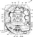
次に、後ブロック104について説明する。図8及び図9は、それぞれ、パチンコ機100を示す背面側斜視図及び背面図である。なお、図8においては、理解の容易のために、外枠101を省略して示している。
Next, the
後ブロック104は、図8及び図9に示すように、基体501に他の部材や装置が取着されて構成されている。この基体501と中間ブロック103とが後ブロック支持機構136,137によって接続されることにより、後ブロック104が中間ブロック103に対して開閉可能に支持されている。
As shown in FIGS. 8 and 9, the
後ブロック104は、遊技球を貯留する球貯留部としての遊技球タンク510と、遊技球タンク510の下流側に連続して遊技球を(例えば、1列に)整流させると共に1段に整列させる球整列部としてのタンクレール520と、タンクレール520の下流側においてタンクレール520から流入した遊技球を誘導する球誘導部としてのケースレール530と、ケースレール530の下流側において遊技球の払い出しや遊技球の貸し出しを実行する払出装置540と、払出装置540の下流側において払出装置540から流出した遊技球を基体501に形成された誘導通路(図示せず)に誘導する球誘導部としての誘導部材550と、払出装置540による遊技球の払い出しや遊技球の貸し出しを制御する払出制御装置560と、外部電力を各種の装置等で必要とする所定の電圧の電力に変換して出力する電力供給手段としての機能と発射操作装置250に対する発射操作に基づく遊技球の射出を主制御基板920と協同して制御する発射制御手段としての機能とを有する電源・発射制御装置570と、払出制御装置560及び遊技球貸出装置290(図1参照)とパチンコ機100の側方に配置されるカードユニット(図示せず)との間の信号を中継する中継装置950とを備えている。
The
基体501は、樹脂(例えば、ABS樹脂)により一体成型されており、前側部分に対応するベース部502と、ベース部502よりも後方に位置した保護カバー部503とを含んでいる。ベース部502は、その上側部分が後ブロック104の外形に沿って略枠状に形成されると共に、下側部分が前後方向に厚みを有する略平坦状に形成されており、他の装置が取り付けられる被取付部としての機能を有している。
The
保護カバー部503は、前後方向に厚みを有する略板状に形成されている。また、保護カバー部503は、中間ブロック103の背面全域を覆う形状でなく、主制御装置370の一部といった頻繁に検査や確認が必要な中間ブロック103の背面における一部をパチンコ機100の背面に露出するための窓部を形成する大きさに設定されている。保護カバー部503の背面には、主制御装置370及び副制御装置390における発熱の放熱性を向上させる機能を有する多数の通気孔503Aが形成されている。
The
遊技球タンク510は、上方に開口した横長の箱型容器であり、その長手方向の一端側に、島設備の球循環装置(図示せず)から供給される遊技球が逐次補給される。遊技球タンク510における遊技球の供給される側と異なる長手方向の一端側には開口(図示せず)が形成されている。遊技球タンク510の底面は長手方向に緩やかに傾斜し、遊技球タンク510に供給された遊技球は開口側に自重によって移動する。また、遊技球タンク510の底面は、長手方向に比して、長手方向と直交する方向(前後方向)にも傾斜し、開口が設けられる側(例えば、前側)に優位に遊技球を誘導する。また、遊技球タンク510の底面には、その上に重なるようにして金属製の帯電防止板(図示せず)が取着され、帯電防止板が接地電位に接続されて遊技球タンク510内及びその下流側の遊技球の静電気が除去される。
The
タンクレール520は、遊技球タンク510の開口が形成される側に取り付けられ、遊技球タンク510の開口を通して遊技球が流入する。タンクレール520は、遊技球が1列に並んで通過する幅を有する略樋状の遊技球の通路を形成する通路形成部材521と、通路形成部材521により形成される通路の上面として次第に高さが低くなる天面部を有してその通路を流下する遊技球を上下に重なった高さから次第に1段の高さに整流する整流部材522とを備えている。タンクレール520により形成される通路は、下流側に向けて緩やかに傾斜しており、遊技球タンク510とは反対側へ遊技球を誘導する。
The
ケースレール530は、タンクレール520の下側に連続するように縦長に形成されており、タンクレール520からの遊技球が流入する。ケースレール530には、遊技球が勢いよく流れないように左右に湾曲しつつ下方に連続している。また、ケースレール530における球通路の途中部分には、球切れを検出するための球切れ検出部539が設けられている。球切れ検出部539には、貯留球スイッチ591(図10参照)が内蔵され、貯留球スイッチ591によって、ケースレール530又はその上流側で球詰り等が発生してケースレール530内に遊技球が正常に補給されていない球切れ状態を検出する。
The
払出装置540は、遊技球を送り出す送出機構と、送出機構を駆動する駆動手段としての払出モータ542(図10参照)と、払出計数スイッチ592(図10参照)とを備えている。払出制御装置560による制御に基づく払出モータ542の作動に応じて、球通路に貯留されている遊技球が下流側へ放出される。放出された遊技球の球通路の通過は、払出計数スイッチ592に検出され、これにより、払出制御装置560(払出制御基板930)が遊技球の払い出し数を計数する。
The
払出制御装置560及び電源・発射制御装置570は、図8及び図9に示すように、後ブロック104の背面側下部に位置するように基体501のベース部502における下部背面に重なるようにして取り付けられている。これら払出制御装置560及び電源・発射制御装置570を含む後ブロック104は、機種変更等において遊技盤400を別の遊技盤に交換した場合にも、継続利用可能とされている。
As shown in FIGS. 8 and 9, the
払出制御装置560は、払出制御基板930(図10参照)と、払出制御基板930を収容する基板ケースとを備え、払出制御基板930は、主制御基板920と同様に、開封の痕跡を残さずに開封できないように封止された基板ケースの内部に収容されている。
The
電源・発射制御装置570は、電源・発射制御基板900(図10参照)と、電源・発射制御基板900を収容する基板ケースとを備え、電源・発射制御基板900は、主制御基板920と同様に、封止された基板ケースの内部に収容されている。
The power supply /
また、図9に示すように、パチンコ機100の背面側には、背面設定スイッチ905が設けられている。背面設定スイッチ905は、本パチンコ機100の出球率を予め定めた複数段階(例えば、6段階や9段階など)のいずれか1段階に設定するための設定操作を有効化するための設定有効化装置である。
Further, as shown in FIG. 9, a
背面設定スイッチ905に所定のキー(図示せず)を挿入して所定位置(本実施形態では、初期位置から時計回りに略90°回転させた位置)まで回転させることで出球率の設定変更を有効化(許容)することができる。出球率の設定変更がこのように有効化された状態で所定の設定操作(本実施形態においては、初期化スイッチ907の押下)を行うことで出球率の設定変更が有効に行われる。
A predetermined key (not shown) is inserted into the
出球率の設定変更が有効に行われた場合、設定された各段階に応じて所定の遊技態様が変更される。つまり、背面設定スイッチ905および初期化スイッチ907の操作による出球率の設定変更は、遊技態様の設定変更であるともいえる。
When the setting change of the ball ejection rate is effectively performed, a predetermined game mode is changed according to each set stage. That is, it can be said that changing the setting of the ball ejection rate by operating the
本実施形態のパチンコ機100においては、出球率の設定変更(すなわち、遊技態様の設定変更)により設定された各段階に応じて、初当り確率(本実施形態においては、第1特別図柄抽選の当選確率)と、確変継続率(本実施形態においては、確変遊技状態において第2特別図柄抽選を経由して特別遊技状態へ移行した場合に当該特別遊技状態後に確変遊技状態に移行する確率)との組み合わせが異なる9種類の遊技態様のいずれかを選択することができる。よって、出球率の設定変更(遊技態様の設定変更)が有効に行われた場合には、設定された段階に応じた初当り確率および継続確率となるよう第1特別図柄抽選および第2特別図柄抽選の各当選確率を変化させる(すなわち、各当選確率に応じた確率抽選データを使用する)ことで出球率の調整が行われる。
In the
具体的に、本実施形態のパチンコ機100においては、初当り確率が大幅に低いが確変継続率が大幅に高いトップタイプと、初当り確率が中程度であり確変継続率も中程度であるミドルタイプと、初当り確率が大幅に低いが確変継続率が大幅に高いボトムタイプとを選択できる。さらに、これらの各タイプにおいて、各タイプの初当り確率が、各タイプ間の初当り確率の幅よりも小幅に細分化された3段階の確率状態(以下、確率設定状態ともいう)、すなわち、3段階の中で初当り確率が最も低い第1段確率と、2番目に低い初当り確率である第2段確率と、初当り確率が最も高い第3段確率とを選択できる。
Specifically, in the
トップタイプにおいて、上下の中始動入賞装置431A,431Bおよび右始動入賞装置432への入賞に伴う賞球数は他のタイプよりも少ないが、下大入賞装置433および上大入賞装置434への入賞に伴う賞球数は他のタイプよりも多くなっている。一方、ボトムタイプにおいて、中始動入賞装置431A,431Bおよび右始動入賞装置432への入賞に伴う賞球数は他のタイプよりも多いが、下大入賞装置433および上大入賞装置434への入賞に伴う賞球数は他のタイプよりも少なくなっている。
In the top type, the number of prize balls associated with winning the upper and lower middle
ここで、トップタイプ、ミドルタイプ、およびボトムタイプのいずれも賞球数は同一の数に設定してもよい。これにより、トップタイプ、ミドルタイプ、およびボトムタイプのいずれの設定であるのか遊技者が賞球数から判定することを不能とし、いずれのタイプであるかの設定を推測する遊技性を長時間にわたって付加することができる。 Here, the number of prize balls may be set to the same for all of the top type, middle type, and bottom type. This makes it impossible for the player to judge from the number of prize balls whether the setting is the top type, the middle type, or the bottom type, and the playability of guessing the setting of which type is made over a long period of time. Can be added.
また、トップタイプ、ミドルタイプ、およびボトムタイプのいずれも確率設定状態の段階に応じて遊技者にとっての利益率は変化するが、いずれのタイプであっても確率設定状態の段階が同一であれば遊技者にとっての利益率は実質的に同一に設定されている。このため、タイプの変更によって確率の設定を変更しても、遊技場側が獲得する一定期間(例えば、1日)当たりの利益は予測しやすく、遊技場の管理をし易くすることができる。 In addition, the profit margin for the player changes depending on the stage of the probability setting state for all of the top type, middle type, and bottom type, but if the stage of the probability setting state is the same for all types. The profit margins for the players are set to be substantially the same. Therefore, even if the probability setting is changed by changing the type, the profit per fixed period (for example, one day) acquired by the game hall side can be easily predicted, and the game field can be easily managed.
なお、出球率の設定変更によって変更する遊技態様としては、上述したような、初当り確率と確変突入率との組合せであることに必ずしも限定される必要はなく、例えば、初当り確率または確変突入率のいずれかであってもよい。また、初当り確率および確変突入率以外の抽選確率、例えば、第1特別図柄抽選または第2特別図柄抽選の当選確率、普通図柄抽選の当選確率や、第1特別図柄抽選または第2特別図柄抽選において小当たりが選択される確率や、確変突入率(本実施形態においては、第2特別図柄抽選での当選を経由する確変遊技状態への突入率)や、特別遊技状態後に移行した確変遊技状態が終了する確率(例えば、確変遊技状態中に図柄の変動表示が実行される毎に行われる転落抽選において確変遊技状態の終了が選択される確率)などであってもよく、これらの各遊技態様の2つ以上の組合せであってもよい。 It should be noted that the game mode to be changed by changing the setting of the ball ejection rate is not necessarily limited to the combination of the first hit probability and the probability variation inrush rate as described above, and for example, the first hit probability or the probability variation. It may be any of the inrush rates. In addition, lottery probabilities other than the first hit probability and the probability variation inrush rate, for example, the winning probability of the first special symbol lottery or the second special symbol lottery, the winning probability of the ordinary symbol lottery, the first special symbol lottery or the second special symbol lottery. The probability that a small hit will be selected, the probability variation inrush rate (in this embodiment, the probability of entering the probability variation game state via winning in the second special symbol lottery), and the probability variation game state that has shifted after the special game state. May end (for example, the probability that the end of the probabilistic game state is selected in the fall lottery performed each time the variable display of the symbol is executed during the probabilistic game state), and each of these game modes It may be a combination of two or more of.
背面設定スイッチ905より上方には、設定表示装置906が設けられている。背面設定スイッチ905の操作によって出球率の設定変更(遊技態様の設定変更)が有効に行われた場合、現在設定されている遊技態様に対応する設定表示情報が設定表示装置906に表示される。設定表示情報は、タイプを表す英字と確率設定状態を表す数字との組み合わせから構成される。本実施形態のパチンコ機100においては、トップタイプ、ミドルタイプ、およびボトムタイプの各タイプを、それぞれ、「T」、「M」および「B」の英字で表す。また、各タイプの確率設定状態は、第1段確率を「1」で表し、第2段確率を「2」で表し、第3段確率を「3」で表す。
A setting
よって、例えば、トップタイプの第1段確率の遊技態様である場合に設定表示装置906に表示される設定表示情報は「T1」であり、ミドルタイプの第3段確率の遊技態様である場合に設定表示装置906に表示される設定表示情報は「M3」であり、ボトムタイプの第2段確率の遊技態様である場合に設定表示装置906に表示される設定表示情報は「B2」である。
Therefore, for example, the setting display information displayed on the
<電気的な構成>
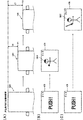
次に、パチンコ機100の電気的構成について説明する。図10は、パチンコ機100の電気的構成を示すブロック図である。パチンコ機100は、図10に示すように、電源・発射制御基板900、電源監視基板910、主制御基板920、払出制御基板930、副制御基板940等の制御回路装置を備えている。なお、図10において、各種の信号を中継するだけの中継回路装置については省略している。以下に、これらの主要な制御回路装置を個別に詳細に説明する。
<Electrical configuration>
Next, the electrical configuration of the
電源・発射制御基板900は、パチンコ機100の各部に電源供給路(図中の破線)を介して所定の電圧の電力を供給する電源部901と、発射操作装置250の操作に応じて発射装置330の駆動を制御する発射制御部902と、初期化スイッチ907からの初期化信号や球溢れスイッチ249からの球溢れ信号を中継する信号中継部903とを備えている。
The power supply /
電源部901は、外部より供給される外部電力(例えば、交流24ボルト)を取り込んで内部電力(例えば、直流24ボルト)に変換すると共に、その内部電力から各種の電力を生成する。電源部901により生成される電力は、各種のソレノイドや各種のモータ等の機器を駆動するための駆動用電圧(例えば、直流12ボルト)の電力、各種のスイッチを駆動したり制御処理を実行したりするための制御用電圧(例えば、直流5ボルト)の電力、主制御基板920のRAMの内容を保持させるためのバックアップ用電圧の電力等を含んでいる。
The
電源部901は、内部電力から生成した各種の電力を、電源監視基板910、主制御基板920、払出制御基板930、副制御基板940等に供給する。具体的には、電源監視基板910に対しては、内部電力、駆動用電圧、制御用電圧及びバックアップ電圧の電力が供給される。主制御基板920に対しては、駆動用電圧、制御用電圧及びバックアップ電圧の電力が供給され、これら電力は、電源監視基板910の電源監視部911を介して供給される。払出制御基板930に対しては、駆動用電圧及び制御用電圧の電力が供給される。副制御基板940に対しては、駆動用電圧及び制御用電圧の電力が供給される。発射制御部902及び信号中継部903に対しては、駆動用電圧及び制御用電圧の電力が供給される。
The
電源部901には、電源スイッチ909が接続されており、電源スイッチ909がオフ状態である場合には外部電力の取り込みが停止される。なお、電源スイッチ909をオフ状態にしたり、電源スイッチ909を介して電源部901に接続される電源プラグ(図示せず)を外部電力の供給コンセント(図示せず)から抜脱したりすることによってパチンコ機100の内部への電力の供給が停止している状態や、外部電力自体の供給が停止している状態を「停電状態」と総称する。
A
電源部901は、停電状態への移行後においても所定の期間にわたり制御用電圧の電力を正常に出力するように構成されている。これによって、主制御基板920は、現在の制御状態に復帰できるように状態を保存して制御を終了させることができる。
The
発射制御部902は、主制御基板920と協同して、発射装置330の球送りソレノイド332及び発射ソレノイド334の駆動を制御する。なお、球送りソレノイド332及び発射ソレノイド334は、所定条件が整っている場合に作動が許可される。具体的には、遊技者が発射ハンドル252(図1参照)に触れていることが接触センサ254からの接触センサ信号に基づいて検知されていること、発射を停止させるための発射停止スイッチ255が操作されていないことを条件に、発射制御部902はオン状態の発射許可信号を主制御基板920に出力する。また、発射許可信号と発射異常信号とに基づいて主制御基板920は発射ソレノイド制御信号及び球送りソレノイド制御信号を発射制御部902に出力する。発射制御部902は、オン状態の球送り制御信号に基づいて球送りソレノイド332を作動させ、オン状態の発射ソレノイド制御信号の受信と可変抵抗器253の抵抗値とに基づいて発射ソレノイド334を作動させる。これによって、発射装置330から可変抵抗器253の抵抗値(発射ハンドル252の回転操作量)に応じた強さで遊技球が順次に発射される。
The
信号中継部903は、初期化スイッチ907が押下された場合に、主制御基板920へオン状態の初期化信号を出力する。主制御基板920においては、オン状態の初期化信号の受信に応じて主制御基板920のRAMに保存された保存情報を初期化する。なお、初期化スイッチ907は、必ずしも信号中継部903を介して主制御基板920に信号を出力する構成とする必要はなく、例えば、初期化スイッチ907を主制御基板920に直接搭載する等して基板ケース371内に初期化スイッチ907が収容される構成としても良く、これにより信号が伝送される区間を狙った不正な信号入力を抑止することができる。
The
また、信号中継部903は、球溢れスイッチ249が遊技球を検出した場合に、主制御基板920へオン状態の球溢れ信号を出力する。主制御基板920においては、オン状態の球溢れ信号の検知に基づいて払出制御基板930に低速払出信号を出力し、低速払出信号を受信した払出制御基板930は、払出モータ542の回転速度(払出装置540からの遊技球の払出速度)を低速化させる。また、主制御基板920は、オフ状態の球溢れ信号の検知に基づいて払出制御基板930に高速払出信号を出力し、高速払出信号を受信した払出制御基板930は、払出モータ542の回転速度を高速化させる。
Further, the
また、図10に示すように、信号中継部903には、背面設定スイッチ905および設定表示装置906が接続されている。信号中継部903は、背面設定スイッチ905が所定のキー(図示せず)により時計回りに略90°回転された場合に主制御基板920へ出力されるオン状態の設定信号を中継する。主制御基板920においては、背面設定スイッチ905からオン状態の設定信号を受信したことに応じて遊技態様の変更を許容する。また、信号中継部903は主制御基板920から設定表示装置906へ出力された設定表示信号を中継する。設定表示装置906は、受信した設定表示信号に対応する設定表示情報を表示する。
Further, as shown in FIG. 10, a
電源監視基板910は、電源・発射制御基板900からの電力供給状態を監視する電源監視部911と、電源・発射制御基板900と主制御基板920との間の電力供給及び各種の信号の伝達を中継する信号中継部912とを含んでいる。電源監視部911は、停電状態への移行に応じて主制御基板920へ停電信号を出力するものでもあり、電源部901から出力される最大電圧である直流安定24ボルトの電圧を監視し、この電圧が22ボルト未満である状態が所定の時間だけ継続した場合に停電状態であると判断して、オン状態の停電信号を主制御基板920へ出力する。主制御基板920は、オン状態の停電信号の受信によって停電状態への移行を認識する。
The power
主制御基板920は、パチンコ機100の動作を統括的に制御する。主制御基板920には、1チップマイコンとしてのMPU(図示せず)が搭載されている。MPUは、演算処理装置としてのCPU(図示せず)と、CPUにより実行される各種の制御プログラムや固定データを記憶したROM(図示せず)と、制御プログラムの実行に際して一時的に各種のデータ等を記憶するRAM(図示せず)とを含んでいる。主制御基板920には、その他、タイマ回路(図示せず)、カウンタ回路(図示せず)、クロック発生回路(図示せず)、信号送受信回路(図示せず)等の各種回路が搭載されている。主制御基板920のRAMは、停電状態への移行後においても電源・発射制御基板900からのバックアップ電圧の電力供給によって内部データを維持(バックアップ)できる構成となっている。
The
払出制御基板930は、主制御基板920からの指示に応じた払出装置540による遊技球の払い出し動作や遊技球貸出装置290の操作に応じた払出装置540による遊技球の貸し出し動作を制御する。払出制御基板930は、主制御基板920と同様に、CPU(図示せず)、ROM(図示せず)及びRAM(図示せず)を含む1チップマイコンとしてのMPU(図示せず)、タイマ回路(図示せず)、カウンタ回路(図示せず)、クロック発生回路(図示せず)、信号送受信回路(図示せず)等の各種回路が搭載されている。
The
払出制御基板930は、他の装置と情報通信可能に接続する接続手段としての入出力ポートが搭載されており、例えば、主制御基板920及び中継装置950とは双方向の情報入出力通信が可能に接続され、開閉検出スイッチ108,109、貯留球スイッチ591、及び、払出計数スイッチ592とは、一方向のみの情報入力通信のみが可能に接続され、払出モータ542とは、一方向のみの情報出力通信のみが可能に接続されている。なお、払出制御基板930のRAMは、主制御基板920のRAMと同様に、停電状態において一定の期間にわたって内部データを維持可能とするバックアップ機能を有する構成としても良いし、主制御基板920のRAMとは異なり、停電状態において内部データを維持しない構成としても良い。
The
副制御基板940は、主制御基板920からの指示に基づいて、各種の演出装置や各種の発光装置や各種の音響装置等の動作を制御する。副制御基板940は、他の装置と情報通信可能に接続する接続手段としての入出力ポートが搭載されており、例えば、主制御基板920とは一方向のみの情報入力通信のみが可能に接続され、入力操作装置260とは双方向に情報通信可能に接続され、装飾図柄表示装置479等とは一方向の情報出力通信のみが可能に接続されている。
The
<各種の制御処理>
次に、主制御基板920によって実行される各種の制御処理について説明する。主制御基板920における制御処理は、大別すると、停電状態からの復帰に伴い起動されるメイン処理と、定期的に(本形態では2ms(ミリ秒)周期で)メイン処理に割込みをかけて実行されるタイマ割込み処理とで構成されている。
<Various control processes>
Next, various control processes executed by the
まず、図11を参照して、主制御基板920によって実行されるメイン処理について説明する。図11は、主制御基板920のメイン処理(図11においては「主制御メイン処理」と略記)を示すフローチャートである。
First, the main process executed by the
主制御基板920のメイン処理において、まず、主制御基板920の立ち上げや各種の情報を初期設定するための一連の制御開始処理(プログラム開始処理S1001〜乱数初期設定処理S1019)が一度だけ実行され、その後は、割込みを禁止する割込み禁止処理S1020と、特別図柄に係る当選乱数初期値カウンタ(RAMの一部の領域)及び大当り図柄乱数初期値カウンタ(RAMの一部の領域)並びに普通図柄に係る当選乱数初期値カウンタ(RAMの一部の領域)の値を更新する乱数初期値更新処理S1021と、変動表示時間(変動時間)や変動パターン等を決定するための第1の変動種別カウンタ〜第4の変動種別カウンタ(RAMの一部の領域)の値を更新する変動用カウンタ更新処理S1022と、割込みを許可する割込み許可処理S1023とが繰り返し実行される。なお、割込み許可処理S1023の前にタイマ割込みの要求が発生した場合には、割込み許可処理S1023の直後にタイマ割込み処理が実行される。
In the main process of the
一連の制御開始処理において、プログラムの実行を制御するスタックポインタ(RAMの一部の領域)に初期値を設定するプログラム開始処理S1001と、割込みモードを設定する割込みモード設定処理S1002と、払出制御基板930及び副制御基板940等が立ち上がるまで所定の時間だけ待機する立上待機処理S1003とが実行される。
In a series of control start processes, a program start process S1001 that sets an initial value in a stack pointer (a part of RAM area) that controls program execution, an interrupt mode setting process S1002 that sets an interrupt mode, and a payout control board. The start-up standby process S1003, which waits for a predetermined time until the 930 and the
立上待機処理S1003の後に、電源・発射制御基板900の背面設定スイッチ905からの設定信号の出力状態の判定処理S2001が行われる。判定処理S2001において、背面設定スイッチ905からの設定信号がオフ状態であると判定された場合には(S2001:N)、電源・発射制御基板900の初期化スイッチ907からの初期化信号の出力状態の判定処理S1004、停電情報(RAMの一部の領域)の値の判定処理S1005、保存情報の記憶状態の判定処理S1007が行われ、これらの判定結果に基づいてRAMの保存情報を消去するか否かが判定される。ここで、保存情報とは、停電前の遊技の状態に復帰させるために必要な情報であって、停電前に遊技の進行に応じて更新されていたRAMの一部の領域に対応し、実行中の単位遊技に関するカウンタの値や、始動入賞によって格納されたカウンタの値等が例示される。
After the start-up standby process S1003, the determination process S2001 of the output state of the setting signal from the
保存情報の記憶状態は、次のように判定される。まず、RAMの所定の範囲の記憶領域に対するチェックサム値を算出して(チェックサム算出処理S1006)、その現在のチェックサム値と前回の停電状態への移行に伴い停電監視処理S1202(図12参照)において算出されたチェックサム値の2の補数であるRAM判定値との排他的論理和が「0」であるか否か(判定処理S1007)が判定され、これにより、現在のチェックサム値と停電状態への移行時のチェックサム値とが同一であるか否かが判定される。 The storage state of the stored information is determined as follows. First, the checksum value for the storage area in a predetermined range of the RAM is calculated (checksum calculation process S1006), and the current checksum value and the power failure monitoring process S1202 (see FIG. 12) are accompanied by the transition to the previous power failure state. ) Is determined whether or not the exclusive OR with the RAM determination value, which is the two's complement of the checksum value calculated in), is “0” (determination process S1007), whereby the current checksum value and the current checksum value are determined. It is determined whether or not the checksum value at the time of transition to the power failure state is the same.
初期化信号がオン状態である場合(S1004:Y)、停電情報が停電状態への移行時に保存情報を保存して終了したことを示す所定の停電値でない場合(S1005:N)、又は、保存情報が正常に保持されていない場合(S1007:N)には、RAMの保存情報を消去するRAMクリア処理S1008が実行される。保存情報が正常に保持されていると判断された後(S1007:Y)、又は、RAMクリア処理S1008が実行された後には、主制御基板920に接続されている各種の装置を初期化するハードウェア初期化処理S1009が実行される。
When the initialization signal is on (S1004: Y), when the power failure information is not a predetermined power failure value indicating that the saved information has been saved and terminated at the time of transition to the power failure state (S1005: N), or saved. When the information is not normally held (S1007: N), the RAM clear process S1008 for erasing the RAM storage information is executed. Hardware that initializes various devices connected to the
ハードウェア初期化処理S1009の後には、停電情報が停電値であるか否かの判定処理S1010が実行される。停電情報が停電値である場合(S1010:N)には、保持情報の復帰を含め各種の情報を初期設定するRAM復帰設定処理S1011と、その設定完了を示す復帰コマンドが設定される(復帰コマンド出力処理S1012)。RAM復帰設定処理S1011における保持情報の復帰によって、前回の停電状態への移行直前の制御状態に主制御基板920の制御状態が復帰する。
After the hardware initialization process S1009, the determination process S1010 for determining whether or not the power failure information is the power failure value is executed. When the power failure information is the power failure value (S1010: N), the RAM recovery setting process S1011 that initially sets various information including the recovery of the retained information and the recovery command indicating the completion of the setting are set (return command). Output processing S1012). By the restoration of the holding information in the RAM restoration setting process S1011, the control state of the
一方、停電情報が停電値でない場合(S1010:Y)には、保持情報の復帰は行わずに各種の情報が初期設定され(RAM初期設定処理S1013)、その設定完了を示す初期化コマンドが出力される(初期化コマンド出力処理S1014)。 On the other hand, when the power failure information is not the power failure value (S1010: Y), various information is initialized (RAM initial setting process S1013) without restoring the retained information, and an initialization command indicating the completion of the setting is output. (Initialization command output process S1014).
なお、RAM復帰設定処理S1011及びRAM初期設定処理S1013において、停電情報は停電値と異なる所定の通電値に設定され、また、前回の停電状態への移行直前において不正検知エラー等の各種のエラー状態が発生していてもそれらのエラー状態は全て解除される。また、主制御基板920から払出制御基板930及び副制御基板940の双方に復帰コマンドか初期化コマンドのいずれかが出力され、復帰コマンド又は初期化コマンドを受信した払出制御基板930及び副制御基板940の各々においても所定の初期化処理が実行される。
In the RAM recovery setting process S1011 and the RAM initial setting process S1013, the power failure information is set to a predetermined energization value different from the power failure value, and various error states such as an error detection error immediately before the transition to the previous power failure state are performed. Even if is occurring, all those error states are cleared. Further, either the return command or the initialization command is output from the
立上時の状況に応じたRAMの初期設定(判定処理S1004〜初期化コマンド出力処理S1014)の後に、前回の停電状態への移行時に条件装置が作動していた場合には、特別遊技状態に復帰させるための準備が行われる(特別遊技状態復帰準備処理S1015)。具体的には、特別遊技状態復帰準備処理S1015においては、条件装置と役物連続作動装置の作動状態が判定され、停電状態時における遊技の状況に対応した処理が、副制御基板940において実行される。
After the initial setting of the RAM according to the situation at the time of startup (determination process S1004 to initialization command output process S1014), if the condition device is operating at the time of the previous transition to the power failure state, the special gaming state is set. Preparations for returning are performed (special game state return preparation process S1015). Specifically, in the special game state return preparation process S1015, the operating state of the condition device and the accessory continuous operation device is determined, and the process corresponding to the game situation at the time of the power failure is executed on the
特別遊技状態復帰準備処理S1015の後には、時短状態フラグが設定されているか否かを判定することにより時短状態であるか非時短状態であるかが判定され(判定処理S1016)、時短状態である場合(S1016:Y)には、時短コマンドが出力される(時短コマンド出力処理S1017)。一方、非時短状態である場合(S1016:N)には、非時短コマンドが出力される(非時短コマンド出力処理S1018)。その後、特別図柄に係る当選乱数カウンタ(RAMの一部の領域)の値が初期化される(乱数初期設定処理S1019)。 After the special game state return preparation process S1015, it is determined whether the time saving state or the non-time saving state is set by determining whether or not the time saving state flag is set (determination process S1016), and the time saving state is set. In the case (S1016: Y), the time saving command is output (time saving command output process S1017). On the other hand, in the non-time saving state (S1016: N), the non-time saving command is output (non-time saving command output process S1018). After that, the value of the winning random number counter (a part of the area of the RAM) related to the special symbol is initialized (random number initial setting process S1019).
一方、判定処理S2001において、背面設定スイッチ905からの設定信号が、背面設定スイッチ905が所定のキーにより操作されていることを示すオン状態であると判定された場合(S2001:Y)、RAM922の実質的に全領域の情報を消去するRAMクリア処理S2002が実行される。具体的には、RAMクリア処理S2002においては、RAM922に格納されている設定対応情報を除く実質的にすべての領域の情報が消去される。
On the other hand, in the determination process S2001, when the setting signal from the
なお、設定対応情報は、予め定めた複数段階(本実施形態においては、9種類)の遊技態様の各々に対応する情報であり、設定中の遊技態様に対応する設定態様情報がRAM922に格納されている。よって、RAMクリア処理S2002により、主制御基板920のRAM922における設定対応情報の記憶領域を除く実質的にすべての領域の情報が消去され、設定変更を許可する状態となる。
The setting correspondence information is information corresponding to each of a predetermined plurality of stages (nine types in this embodiment) of game modes, and the setting mode information corresponding to the game mode being set is stored in the RAM 922. ing. Therefore, the RAM clear processing S2002 erases information in substantially all areas other than the storage area of the setting correspondence information in the RAM 922 of the
設定変更を許可する状態となると、RAM922に格納されている設定対応情報に対応する遊技態様を識別する設定表示信号が設定表示装置906に出力される。設定表示装置906は、主制御基板920から受信した設定表示信号に対応する設定表示情報を表示する。つまり、設定表示装置906には、RAM922に格納されている設定対応情報に対応する設定表示情報が表示される。
When the setting change is permitted, the setting display signal for identifying the game mode corresponding to the setting correspondence information stored in the RAM 922 is output to the
次いで、背面設定スイッチ905からの設定信号がオフ状態となるまで遊技態様の設定を変更する設定変更処理S2003が実行される。なお、背面設定スイッチ905からの設定信号は、背面設定スイッチ905が所定のキーにより操作されていない状態においてオフ状態となる。
Next, the setting change process S2003 for changing the setting of the game mode is executed until the setting signal from the
遊技態様の設定変更は、背面設定スイッチ905が所定のキーにより操作された状態において初期化スイッチ907を押下することによって行われる。具体的に、当該状態において、主制御基板920が初期化スイッチ907の押下に基づく初期化信号を受信する毎に、設定対応情報が順次変更される。具体的には、予め定められた9種類の遊技態様を循環的に選択する順序(例えば、・・・→T1→T2→T3→M1→M2→M3→B1→B2→B3→T1→T2→・・・)が予め決められており、選択される遊技態様は、初期化スイッチ907が押下される毎に当該順序に従って順次変更される。
The setting change of the game mode is performed by pressing the
当該変更が行われる毎に選択中の遊技態様に対応する値が設定対応情報としてRAM922に格納される。RAM922に格納される設定対応情報が変更される毎に、当該設定対応情報に対応する設定表示信号が設定表示装置906に出力され、変更後の設定対応情報に対応する設定表示情報が設定表示装置906に表示される。
Each time the change is made, the value corresponding to the selected game mode is stored in the RAM 922 as the setting correspondence information. Every time the setting correspondence information stored in the RAM 922 is changed, the setting display signal corresponding to the setting correspondence information is output to the
よって、遊技場の管理者等の設定変更者は、背面設定スイッチ905が所定のキーにより操作された状態において、本パチンコ機100に対して設定したい遊技態様を選択されるまで初期化スイッチ907の押下を繰り返した後、上側中始動入賞装置431Aまたは下側中始動入賞装置431Bに遊技球を入賞させることで、遊技態様の選択を完了させることができる。よって、設定変更処理S2003は、初期化スイッチ907の押下による遊技態様の選択後に、中始動入賞装置431A,431Bに遊技球が入賞されたことで終了する。
Therefore, a setting changer such as a game hall administrator can use the
背面設定スイッチ905からの設定信号がオフ状態となった場合(S2004:Y)、遊技態様の設定に係る情報(すなわち、設定対応情報)を除く各種の情報を新たにRAM922に初期設定するRAM変更設定処理S2005が実行される。これにより、実質的に主制御基板920の立ち上げが終了し、RAM922に格納された設定対応情報に対応する遊技態様で遊技が進行することが確定する。
When the setting signal from the
RAM変更設定処理S2005の後、RAM922の設定完了を示す設定済コマンドを払出制御基板930に出力する設定済コマンド出力処理S2006が実行される。払出制御基板930は、主制御基板920が出力した設定済コマンドを受信したことにより、主制御基板920が通常の遊技処理に移行することを認識できると共に、いずれの遊技態様で動作するかを認識できる。設定済コマンド出力処理S2006の後は、特別遊技状態復帰準備処理S1015以降の処理が実行される。
After the RAM change setting process S2005, the set command output process S2006 for outputting the set command indicating the completion of the setting of the RAM 922 to the
次に、図12を参照して、主制御基板920によって実行されるタイマ割込み処理について説明する。図12は、主制御基板920によって実行されるタイマ割込み処理(図中では「主制御割込み処理」と略記)を示したフローチャートである。
Next, the timer interrupt processing executed by the
主制御基板920のタイマ割込み処理では、まず、タイマ割込みを開始させるための割込み開始処理S1201が実行される。具体的には、割込み制御レジスタに所定の値が設定される。これにより、本タイマ割込み以外の割込みが禁止される。その後に、パチンコ機100の遊技の進行制御や各種センサの監視等といった実質的な制御に係る停電監視処理S1202〜外部情報出力処理S1221が順次に実行される。但し、各種の不正の検知に基づいて遊技進行が停止されている場合(S1207:Y)には、制御信号出力処理S1208〜外部情報出力処理S1221は実行されない。最後に、次回のタイマ割込みを許可する割込み許可処理S1222が実行されて、今回のタイマ割込み処理が終了する。以下において、各種の主要な処理について個別に説明する。
In the timer interrupt processing of the
停電監視処理S1202においては、電源監視基板910の電源監視部911から出力されている停電信号の出力状態に基づいて停電情報(RAMの一部の領域)の値が更新される。具体的には停電信号の出力状態が3度に亘り確認され、3度ともオン状態が検出された場合に停電状態であると判定される。この判定において停電状態であると判定されなかった場合には、停電情報は通電値に維持される。
In the power failure monitoring process S1202, the value of the power failure information (a part of the RAM) is updated based on the output state of the power failure signal output from the power
一方、停電監視処理S1202において停電状態であると判定された場合には、以下の処理が実行される。まず、停電情報の値がRAM復帰設定処理S1011又はRAM初期設定処理S1013(図11参照)において設定された通電値から所定の停電値に変更される。また、RAMの所定の範囲の記憶領域に対するチェックサム値を算出し、そのチェックサム値の2の補数をRAM判定値として設定する。これにより、パチンコ機100は、遊技の進行や各種センサの監視等といった実質的な制御を行わない無限ループに入り、RAM判定値が設定された後のRAMの状態がバックアップ電力に基づいて保持される。なお、停電信号の出力状態が3度に亘り確認されるために、停電信号の受信を初めて検知してから、タイマ割込みの各処理は2回に亘り実行される。
On the other hand, when it is determined in the power failure monitoring process S1202 that the power is in a power failure state, the following process is executed. First, the value of the power failure information is changed from the energization value set in the RAM return setting process S1011 or the RAM initial setting process S1013 (see FIG. 11) to a predetermined power failure value. Further, a checksum value for a storage area in a predetermined range of the RAM is calculated, and the 2's complement of the checksum value is set as the RAM determination value. As a result, the
乱数更新処理S1203においては、特別図柄に係る当選乱数カウンタ、大当り図柄乱数カウンタ、停止パターン選択カウンタ及び普通図柄に係る当選乱数カウンタが更新される。具体的には、特別図柄に係る当選乱数カウンタの値が、規定最大値(例えば、「576」)と異なる値である場合には、現在値より「1」だけ大きい値に変更され、特別図柄に係る当選乱数カウンタの値が規定最大値である場合には、規定最小値(「0」)に変更される。但し、変更後の値が特別図柄に係る当選乱数カウンタに対する循環初期値と同一の値となる場合には、特別図柄に係る当選乱数カウンタの値が、特別図柄に係る当選乱数初期値カウンタと同一の値に設定され、また、循環初期値も当選乱数初期値カウンタと同一の値に設定される。 In the random number update process S1203, the winning random number counter related to the special symbol, the jackpot symbol random number counter, the stop pattern selection counter, and the winning random number counter related to the normal symbol are updated. Specifically, when the value of the winning random number counter related to the special symbol is different from the specified maximum value (for example, "576"), the value is changed to a value "1" larger than the current value, and the special symbol is changed. When the value of the winning random number counter related to is the specified maximum value, it is changed to the specified minimum value (“0”). However, if the changed value is the same as the circular initial value for the winning random number counter related to the special symbol, the value of the winning random number counter for the special symbol is the same as the winning random number initial value counter for the special symbol. Is set to the value of, and the circulation initial value is also set to the same value as the winning random number initial value counter.
大当り図柄乱数カウンタ、停止パターン選択カウンタ及び普通図柄に係る当選乱数カウンタについても、特別図柄に係る当選乱数カウンタの場合と同様にして更新される。ただし、各カウンタの規定最大値と規定最小値とにより定められる更新範囲としては各カウンタに固有の値が設定され、複数のカウンタが非同期で更新される構成とされ、各カウンタの循環初期値には各カウンタに固有の初期値カウンタが参照される。例えば、特別図柄に係る当選乱数カウンタと特別図柄に係る当選乱数初期値カウンタとは値の範囲が同一であり、大当り図柄乱数カウンタと大当り図柄乱数初期値カウンタとは値の範囲が同一であり、普通図柄に係る当選乱数カウンタと普通図柄に係る当選乱数初期値カウンタとは値の範囲が同一である。 The jackpot symbol random number counter, the stop pattern selection counter, and the winning random number counter related to the normal symbol are also updated in the same manner as in the case of the winning random number counter related to the special symbol. However, as the update range defined by the specified maximum value and specified minimum value of each counter, a value unique to each counter is set, and multiple counters are configured to be updated asynchronously, and the circulation initial value of each counter is set. Refers to the initial value counter unique to each counter. For example, the winning random number counter related to the special symbol and the winning random number initial value counter related to the special symbol have the same value range, and the jackpot symbol random number counter and the jackpot symbol random number initial value counter have the same value range. The range of values is the same for the winning random number counter related to the normal symbol and the winning random number initial value counter related to the normal symbol.
乱数初期値更新処理S1204においては、特別図柄に係る当選乱数初期値カウンタ、大当り図柄乱数初期値カウンタ及び普通図柄に係る当選乱数初期値カウンタが更新される。具体的には、特別図柄に係る当選乱数初期値カウンタの値が規定最大値(例えば、「576」)と異なる値である場合には、現在値より「1」だけ大きい値に変更され、特別図柄に係る当選乱数初期値カウンタの値が規定最大値である場合には、規定最小値(「0」)に変更される。特別図柄に係る図柄乱数初期値カウンタ及び普通図柄に係る当選乱数初期値カウンタについても、規定最大値や規定最小値がそれらのカウンタに固有の値であること以外は、特別図柄に係る当選乱数初期値カウンタの場合と同様にして更新される。 In the random number initial value update process S1204, the winning random number initial value counter related to the special symbol, the big hit symbol random number initial value counter, and the winning random number initial value counter related to the normal symbol are updated. Specifically, when the value of the winning random number initial value counter related to the special symbol is different from the specified maximum value (for example, "576"), it is changed to a value "1" larger than the current value, which is special. When the value of the winning random number initial value counter related to the symbol is the specified maximum value, it is changed to the specified minimum value (“0”). Regarding the symbol random number initial value counter related to the special symbol and the winning random number initial value counter related to the normal symbol, the winning random number initial value related to the special symbol is also provided except that the specified maximum value and the specified minimum value are values unique to those counters. It is updated in the same way as for the value counter.
変動用カウンタ更新処理S1205においては、変動表示時間(変動時間)や変動パターン等を決定するための第1の変動種別カウンタ〜第4の変動種別カウンタの値が更新される。具体的には、第1の変動種別カウンタの値が規定最大値(例えば、「187」)と異なる値である場合には、現在値より「1」だけ大きい値に変更され、第1の変動種別カウンタの値が規定最大値である場合には、規定最小値(「0」)に変更される。第2の変動種別カウンタ〜第4の変動種別カウンタについても、規定最大値や規定最小値がそれらのカウンタに固有の値であること以外は、第1の変動種別カウンタの場合と同様にして更新される。 In the fluctuation counter update process S1205, the values of the first fluctuation type counter to the fourth fluctuation type counter for determining the fluctuation display time (variation time), the fluctuation pattern, and the like are updated. Specifically, when the value of the first fluctuation type counter is different from the specified maximum value (for example, "187"), the value is changed to a value "1" larger than the current value, and the first fluctuation If the value of the type counter is the specified maximum value, it is changed to the specified minimum value (“0”). The second fluctuation type counter to the fourth fluctuation type counter are also updated in the same manner as in the case of the first fluctuation type counter, except that the specified maximum value and the specified minimum value are unique to those counters. Will be done.
なお、特別図柄及び普通図柄に係る各当選乱数カウンタ、大当り図柄乱数カウンタ、停止パターン選択カウンタ並びに各変動種別カウンタは、必ずしも上記構成とする必要はなく、上記カウンタの少なくとも一部を他の構成としても良く、例えば、初期値カウンタを利用しないで一定の初期値から更新する構成としても良いし、プログラムを利用しないで乱数生成用ICにより構成して必要に応じて値を参照する構成としても良い。 The winning random number counters, jackpot symbol random number counters, stop pattern selection counters, and variable type counters related to the special symbol and the ordinary symbol do not necessarily have the above-mentioned configurations, and at least a part of the above counters has other configurations. For example, it may be configured to update from a constant initial value without using the initial value counter, or it may be configured by a random number generation IC without using a program and the value may be referred to as needed. ..
遊技停止判定処理S1206においては、不正検知情報が不正検知値である場合には、遊技停止値に更新されると共に、遊技進行を停止させるための各種の情報が設定される。一方、不正検知情報が不正検知値でない場合や既に遊技停止値である場合には、遊技進行を停止させるための各処理は実行されずに遊技停止判定処理S1206は終了する。なお、不正検知情報は、不正検知処理S1211において各種の不正の発生が検知された場合に不正検知値に設定される。また、判定処理S1207においては、不正検知情報が遊技停止値であるか否かによって遊技停止中であるか否かが判定される。 In the game stop determination process S1206, when the fraud detection information is a fraud detection value, the fraud detection information is updated to the game stop value, and various information for stopping the game progress is set. On the other hand, if the fraud detection information is not a fraud detection value or is already a game stop value, the game stop determination process S1206 ends without executing each process for stopping the game progress. The fraud detection information is set to a fraud detection value when the occurrence of various frauds is detected in the fraud detection process S1211. Further, in the determination process S1207, it is determined whether or not the game is stopped depending on whether or not the fraud detection information is the game stop value.
制御信号出力処理S1208においては、出力バッファに格納された制御データに基づいて、第1の特別図柄に係る特別図柄表示装置471、第2の特別図柄に係る特別図柄表示装置472及び普通図柄に係る普通図柄表示装置473等の各種の報知装置を制御する信号が出力される。また、出力バッファに格納された制御データに基づいて、球送りソレノイド332、発射ソレノイド334、右進入規制ソレノイド462、下進入規制ソレノイド463、上進入規制ソレノイド464、切換ソレノイド465等の各種のアクチュエータを制御する信号が出力される。
In the control signal output process S1208, the special
スイッチ読込処理S1209においては、中始動入賞スイッチ441A,441B、右始動入賞スイッチ442、下大入賞スイッチ443、上大入賞スイッチ444、役連作動スイッチ445、始動スイッチ446、非特定通路スイッチ447、特定通路スイッチ448、及び、一般入賞スイッチ449A,449Bの各々からの信号状態が読み込まれて、各種のスイッチによる遊技球の検出状態の変化が検知される。
In the switch reading process S1209, the middle start winning switch 441A, 441B, the right
具体的には、スイッチ読込処理S1209において、各種のスイッチからの信号状態が所定の時間間隔を隔てて2度に亘り入力バッファ(RAMの一部の領域)に読み込まれ、各種のスイッチからの信号ごとに、1回目に読み込まれた信号状態(以下において「第1の信号状態」と略記する)と、2回目に読み込まれた信号状態(以下において「第2の信号状態」と略記する)と、前回のタイマ割込みで検知された検出状態(以下において「前回の検出状態」と略記する)とに基づいて、各種のスイッチの検出状態の変化が検知される。そして、各スイッチに対して、前回の検出状態がオフ状態である場合において、第1の信号状態がオン状態であり、第2の信号状態がオン状態である場合には、オン状態移行と判断されて、スイッチの種類に応じた検出フラグ(RAMの一部の領域)が設定される。なお、停電監視処理S1202で説明したように、電源供給が停止したとしても、タイマ割込みの各処理が2回に亘り実行されるために、電源供給が停止した直後に各種のスイッチのオン状態が開始された場合であっても各種のスイッチの検出フラグを正確に設定することができる。 Specifically, in the switch read process S1209, the signal states from the various switches are read into the input buffer (a part of the area of the RAM) twice at predetermined time intervals, and the signals from the various switches are read. The signal state read for the first time (hereinafter abbreviated as "first signal state") and the signal state read for the second time (hereinafter abbreviated as "second signal state"). , Changes in the detection status of various switches are detected based on the detection status detected by the previous timer interrupt (hereinafter abbreviated as "previous detection status"). Then, for each switch, when the previous detection state is the off state, when the first signal state is the on state and the second signal state is the on state, it is determined that the switch is in the on state transition. Then, the detection flag (a part of the area of RAM) corresponding to the type of the switch is set. As described in the power failure monitoring process S1202, even if the power supply is stopped, each process of the timer interrupt is executed twice, so that the various switches are turned on immediately after the power supply is stopped. Even when started, the detection flags of various switches can be set accurately.
タイマ更新処理S1210においては、特別図柄及び普通図柄の変動表示、各遊技状態の制御、及び、不正監視等に使用される各種のタイマ(RAMの所定の領域)が更新される。 In the timer update process S1210, various timers (predetermined areas of RAM) used for variable display of special symbols and normal symbols, control of each game state, fraud monitoring, and the like are updated.
不正検知処理S1211においては、各種の入賞装置に強制的に遊技球を進入させたり、各種の入賞装置を強制的に作動させたりするような不正行為が検知される。具体的には、右始動入賞装置432、下大入賞装置433及び上大入賞装置434の強制的な進入許容姿勢への移動、加振による下大入賞装置433の特定通路への遊技球の誘導、電波による右始動入賞装置432、下大入賞装置433及び上大入賞装置434の強制的な誤作動の誘発、磁気吸着による各種の入賞装置への遊技球の誘導、上側中始動入賞装置431A、下側中始動入賞装置431B、右始動入賞装置432、下大入賞装置433及び上大入賞装置434への異常なタイミングでの遊技球の誘導等の不正行為が行われた可能性の高い状況の発生を検知する。
In the fraud detection process S1211, fraudulent acts such as forcibly entering a game ball into various winning devices or forcibly operating various winning devices are detected. Specifically, the right-starting
入賞検知応答処理S1212においては、遊技盤400に設けられた各種のスイッチによる遊技球の検出に基づく制御が実行される。具体的には、上側中始動入賞スイッチ441A(図10参照)及び下側中始動入賞スイッチ441B(図10参照)による遊技球の検出に基づいて、中始動入賞スイッチ検出フラグが設定されている場合には、中始動入賞カウンタ(RAMの所定の領域)及び第1払出カウンタ(RAMの所定の領域)が更新される。また、右始動入賞スイッチ442(図10参照)による遊技球の検出に基づいて右始動入賞スイッチ検出フラグが設定されている場合には、第1払出カウンタが更新される。また、下大入賞スイッチ443(図10参照)による遊技球の検出に基づいて下大入賞スイッチ検出フラグが設定されている場合や、上大入賞スイッチ444(図10参照)による遊技球の検出に基づいて上大入賞スイッチ検出フラグが設定されている場合には、大入賞カウンタ(RAMの所定の領域)及び第2払出カウンタ(RAMの所定の領域)が更新される。
In the winning detection response process S1212, control based on the detection of the game ball by various switches provided on the
発射制御処理S1213においては、発射装置330による遊技球の発射を制御するための発射関連情報が更新される。具体的には、球送り機構331を駆動する球送りソレノイド332の作動フラグ及び発射機構333を駆動する発射ソレノイド334の作動フラグが更新される。
In the launch control process S1213, the launch-related information for controlling the launch of the game ball by the
入力信号監視処理S1214においては、払出制御基板930を介した開閉検出スイッチ108(図10参照)からの信号の出力状態に基づいて、外枠101(図1及び図2参照)に対して中間ブロック103(図1及び図2参照)が閉鎖されているか否かが検知される。また、払出制御基板930(図10参照)を介した開閉検出スイッチ109からの信号の出力状態に基づいて、中間ブロック103(図2及び図3参照)に対して前ブロック102(図2及び図3参照)が閉鎖されているか否かが検知される。
In the input signal monitoring process S1214, an intermediate block is provided with respect to the outer frame 101 (see FIGS. 1 and 2) based on the output state of the signal from the open / close detection switch 108 (see FIG. 10) via the
払出状態監視処理S1215においては、払出制御基板930から出力される払出制御状態を示す情報が監視され、必要に応じて、払出制御状態に応じた各種の払出状態コマンドが設定される。なお、払出状態コマンドを受信した副制御基板940は、払出状態コマンドの種類に応じた報知を装飾図柄表示装置479、左上音響装置281及び右上音響装置282等に実行させる。
In the payout state monitoring process S1215, the information indicating the payout control state output from the
払出信号出力処理S1216においては、必要に応じて、第1払出カウンタ及び第2払出カウンタの値に基づいて各種の賞球コマンドを設定し、払出制御基板930に出力する。なお、第1払出カウンタ及び第2払出カウンタは、賞球コマンドの設定に応じて更新される。例えば、第1払出カウンタは、1回の入賞に相当する遊技球が検出される毎に1ずつ加算され、その入賞に基づく賞球コマンドが設定される毎に1ずつ減算される。払出制御基板930では、その入賞に対応する数(例えば、3個)の遊技球を払い出す制御を実行する毎に(詳細には、払い出しが完了する少し前に)、主制御基板920に賞球コマンドを要求し、賞球の払い出しが継続している状況においては、主制御基板920から更なる賞球コマンドが出力される。第2払出カウンタは、第1払出カウンタとは賞球数が異なる入賞(例えば、13個)に対応して更新されるカウンタであり、第2払出カウンタの値に基づく賞球コマンドを払出制御基板930が受信した場合には、払出制御基板930は、その賞球コマンドに対応した数分の遊技球を払い出す制御を実行する。
In the payout signal output process S1216, various prize ball commands are set based on the values of the first payout counter and the second payout counter, and are output to the
特別図柄関連処理S1217においては、第1特別図柄に係る単位遊技の権利の保留制御及び第1特別図柄に係る単位遊技の制御が実行される。具体的には、第1特別図柄に係る単位遊技の権利の保留制御において、第1特別図柄に係る特別図柄保留表示装置476の動作制御が実行される。また、第1特別図柄に係る単位遊技の制御において、第1特別図柄に係る特別図柄表示装置471の動作制御が実行され、第1特別図柄抽選において大当りに当選した場合には、下大入賞装置433及び上大入賞装置434の動作制御が更に実行される。
In the special symbol-related process S1217, the holding control of the right of the unit game related to the first special symbol and the control of the unit game related to the first special symbol are executed. Specifically, in the hold control of the right of the unit game related to the first special symbol, the operation control of the special symbol hold display device 476 related to the first special symbol is executed. Further, in the control of the unit game related to the first special symbol, the operation control of the special
また、第1特別図柄に係る単位遊技において、装飾図柄の変動表示および確定表示を装飾図柄表示装置479に表示させるための各情報が選択される。例えば、第1特別図柄に係る単位遊技において装飾図柄表示装置479にて実行する装飾図柄の変動表示の変動パターンが、現在の遊技状態、抽選結果、停止パターン乱数の値、各種の変動パターン乱数の値、第1特別図柄に係る単位遊技の権利の保留回数に基づいて選択される。
Further, in the unit game related to the first special symbol, each information for displaying the variable display and the final display of the decorative symbol on the decorative
また、特別図柄関連処理S1217においては、第2特別図柄に係る単位遊技の権利の保留制御及び第2特別図柄に係る単位遊技の制御が実行される。具体的には、第2特別図柄に係る単位遊技の権利の保留制御において、第2特別図柄に係る特別図柄保留表示装置477の動作制御が実行される。また、第2特別図柄に係る単位遊技の制御において、第2特別図柄に係る特別図柄表示装置472の動作制御が実行され、第2特別図柄抽選において大当りに当選した場合には、下大入賞装置433及び上大入賞装置434の動作制御が更に実行される。
Further, in the special symbol-related processing S1217, the holding control of the right of the unit game related to the second special symbol and the control of the unit game related to the second special symbol are executed. Specifically, in the hold control of the right of the unit game related to the second special symbol, the operation control of the special symbol hold display device 477 related to the second special symbol is executed. Further, in the control of the unit game related to the second special symbol, the operation control of the special
また、第2特別図柄に係る単位遊技において、装飾図柄の変動表示および確定表示を装飾図柄表示装置479に表示させるための各情報が選択される。例えば、第2特別図柄に係る単位遊技において装飾図柄表示装置479にて実行する装飾図柄の変動表示の変動パターンが、現在の遊技状態、抽選結果、停止パターン乱数の値、各種の変動パターン乱数の値、第2特別図柄に係る単位遊技の権利の保留回数に基づいて選択される。
Further, in the unit game related to the second special symbol, each information for displaying the variable display and the final display of the decorative symbol on the decorative
普通図柄関連処理S1218においては、普通図柄に係る単位遊技の権利の保留制御並びに普通図柄に係る単位遊技の制御が実行される。具体的には、普通図柄に係る単位遊技の権利の保留制御において、普通図柄保留表示装置478の動作制御が実行される。また、普通図柄に係る単位遊技の制御において、普通図柄に係る普通図柄表示装置473の動作制御が実行され、普通図柄抽選に当選した場合には更に右始動入賞装置432の動作制御が実行される。
In the normal symbol-related process S1218, the hold control of the right of the unit game related to the normal symbol and the control of the unit game related to the normal symbol are executed. Specifically, in the hold control of the right of the unit game related to the normal symbol, the operation control of the normal symbol hold display device 478 is executed. Further, in the control of the unit game related to the normal symbol, the operation control of the normal
表示制御処理S1219においては、特別図柄関連処理S1217における第1特別図柄に係る特別図柄表示装置471、第2特別図柄に係る特別図柄表示装置472、第1特別図柄に係る特別図柄保留表示装置476及び第2特別図柄に係る特別図柄保留表示装置477等の動作を制御するために更新される各種の情報に基づいて、それらの装置を具体的に作動させるための出力データが合成される。合成された出力データは、次回のタイマ割込みに基づく制御信号出力処理S1208において各装置に出力される。
In the display control process S1219, the special
また、表示制御処理S1219においては、特別図柄関連処理S1217において選択された、装飾図柄の変動表示および確定表示を装飾図柄表示装置479に表示させるための各情報に対応する各種コマンドが設定される。例えば、特別図柄関連処理S1217において選択された変動パターンに対応する変動パターンコマンドが設定される。設定されたコマンドは、次回のタイマ割込みに基づく制御信号出力処理S1208において副制御基板940に出力される。副制御基板940は、主制御基板920から受信したコマンドに基づいて装飾図柄表示装置479を制御する。
Further, in the display control process S1219, various commands corresponding to each information for displaying the variable display and the final display of the decorative symbol selected in the special symbol related process S1217 on the decorative
モータ制御処理S1220においては、各種のモータの動作制御が実行される。外部情報出力処理S1221においては、パチンコ機100に電気的に接続されるデータ表示装置(図示せず)や管理装置(図示せず)等の外部装置に出力する出力データが設定される。
In the motor control process S1220, operation control of various motors is executed. In the external information output process S1221, output data to be output to an external device such as a data display device (not shown) or a management device (not shown) electrically connected to the
<図柄シート>
次に、図13を参照して、図柄シート601の構成について説明する。図13(A)は、図柄シート601の一部を示す正面図であり、図13(B)は、図13(A)のA−A線における図柄シート601の断面図である。なお、図13(B)においては、参考のために、図柄シート601における各面の向きを矢印で示している。
<Design sheet>
Next, the configuration of the
図13(A)および図13(B)に示すように、図柄シート601は、透明などの光透過性(透光性)を有する帯状に延びるシート状の基材611と、基材611の裏面(図柄シート601がリール本体に貼着された状態において当該リール本体の側に向けられる面)に形成された装飾図柄621と、基材611の表面(図柄シート601がリール本体に貼着された状態において外方に向けられる面)に形成された装飾部622とを備えている。
As shown in FIGS. 13 (A) and 13 (B), the
装飾図柄621は、大当り図柄を構成可能な主図柄621Aと、大当り図柄を構成し得ない副図柄621Bとを含む。装飾図柄621は、図柄シート601の長手方向に沿って、主図柄621Aと副図柄621Bとが交互になるよう配列される。
The
主図柄621Aは、数字や数字に対応するキャラクタなど、個別の数値を規定する情報(以下、この情報を「数字情報」)を含む図柄として構成される。例えば、図13(A)に示す例において、主図柄621Aは、「2」や「3」などの数値を示す数字と、各数字に対応するキャラクタ(例えば、「2」に対応するフグや「3」に対応するカメ)との両方を数字情報として含む図柄として構成される。
The
なお、主図柄621Aは、数字情報が、数値を示す数字のみで構成されてもよく、各数値(数字)に対応するキャラクタのみで構成されてもよい。また、主図柄621Aは、その全てが、数値を示す数字のみを数字情報として含む図柄、各数値に対応するキャラクタのみを数字情報として含む図柄、または、数値を示す数字と各数字に対応するキャラクタとの両方を数字情報として含む図柄のいずれかで統一される構成であってもよいし、これらの図柄が混在する構成であってもよい。
In the
主図柄621Aは、例えば、「1」から「9」までの各数値に対応する数字情報を含む図柄として構成される。なお、主図柄621Aは、「1」から「9」までの数値のうち、一部の数値(例えば、「4」)を除く各数値に対応する数字情報を含む図柄であってもよい。
The
大当り図柄は、例えば、各図柄列(左図柄列、右図柄列、中図柄列)における主図柄621Aの所定の組合せ(例えば、同一の主図柄621Aの組合せ)によって構成される。特別図柄(第1特別図柄、第2特別図柄)に係る単位遊技において、第1特別図柄抽選または第2特別図柄抽選に当選している場合、予め設定されている有効ライン上に大当り図柄が停止図柄として確定表示される。
The jackpot symbol is composed of, for example, a predetermined combination of the
「有効ライン」は、装飾図柄による大当り図柄が停止図柄として当該ライン上に表示された場合に遊技状態が特別遊技状態に遷移するラインである。本実施形態のパチンコ機100においては、5つの有効ラインが設定されている。具体的には、3つの水平方向の有効ライン(具体的に、最も上側に位置する上段ライン、最も下側に位置する下段ライン、および上段ラインと下段ラインとの間に位置する中段ライン)と、2つ斜め方向の有効ライン(具体的に、右上がり方向の有効ラインおよび右下がり方向の有効ライン)が設定されている。
The "effective line" is a line in which the gaming state transitions to the special gaming state when the jackpot symbol by the decorative symbol is displayed on the line as a stop symbol. In the
なお、設定される有効ラインの数は、必ずしも5つである必要はなく、1または複数の適宜の数を設定し得る。例えば、上段ライン、下段ライン、および中段ラインによる3つが有効ラインとして設定される構成であってもよいし、中段ラインなど1の有効ラインが設定される構成であってもよい。 The number of effective lines to be set does not necessarily have to be 5, and one or a plurality of appropriate numbers may be set. For example, the upper line, the lower line, and the middle line may be set as three effective lines, or one effective line such as the middle line may be set.
主図柄621Aは、リールを正面視した場合に数字情報の数値が上から下に向けて昇順または降順となるよう図柄シート601に配列される。例えば、本実施形態のパチンコ機100における左図柄列に対応するリールに用いる図柄シート601において、主図柄621Aは、図13(A)に示すように、リールを正面視した場合において数字情報に対応する数値が上から下に向けて昇順となるよう配列される。一方、右図柄列および中図柄列に対応する各リールに用いる図柄シート601において、主図柄621Aは、リールを正面視した場合において数字情報に対応する数値が上から下に向けて降順となるよう配列される。
The
副図柄621Bは、主図柄621Aより小さい、数字情報を含まない所定の絵柄の図柄として構成される。図13(A)に示す例において、副図柄621Bは、星型の絵柄の図柄として構成される。図柄シート601において、副図柄621Bは、2つの主図柄621Aの間に配置される。
The
装飾図柄621(主図柄621A、副図柄621B)は、光透過性を有するインクを用いた印刷によって基材611の裏面側に塗膜形成される。よって、リール本体の内周側に設けられたバックライト(図示せず)を点灯させた場合には、当該バックライトによる光が装飾図柄621および基材611を透過するので、図柄シート601に描かれた装飾図柄621を発光表示させることができる。
The decorative design 621 (
装飾部622は、図柄シート601における装飾図柄621(主図柄621A、副図柄621B)の形成領域より外側に設けられる。装飾部622は、装飾図柄621を着色する少なくとも一部の色に比べて光を反射しやすく構成された色で着色される。なお、「装飾図柄621を着色する少なくとも一部の色」としては、例えば、装飾図柄621に含まれる各主図柄621Aを着色する主要な色(例えば、主図柄621Aにおける最も大きな面積を着色する色)のうち最も光を反射し易い色(例えば、最も明度が高い色)であってもよいし、全ての装飾図柄621を着色する色のうち最も光を反射し易い色であってもよい。
The
また、「光を反射しやすく構成された色」は、例えば、光輝性の有無によって規定されるものであってもよく、色の明度によって規定されるものであってもよい。本実施形態のパチンコ機100においては、例えば、装飾図柄621が、光輝材を含まないインキで着色され、装飾部622が、装飾図柄621を着色する少なくとも一部の色に比べて光を反射しやすく構成された色として、メタリック色(例えば、金色や銀色など)やパール調の色(例えば、パール調の白色など)などの光輝性を有する色で着色される。
Further, the "color configured to easily reflect light" may be defined by, for example, the presence or absence of brilliance, or may be defined by the brightness of the color. In the
あるいは、装飾部622が、装飾図柄621を着色する少なくとも一部の色に比べて光を反射しやすく構成された色として、装飾図柄621を着色する色のうち最も光を反射し易い色に比べて明度が高い色(例えば、白色や淡黄色などの高明度色)で着色される構成であってもよい。
Alternatively, as a color configured in which the
図13(B)に示すように、装飾部622は、光を反射しやすく構成された色のインクを用いた印刷によって基材611の表面側に塗膜形成される。これにより、装飾部622は、基材611の裏面側に形成された装飾図柄621より前方側(表面側)に突出した状態となり、装飾部622を装飾図柄621に対して立体的に設けることができる。なお、装飾部622は、その表面(外方に向けられる面)が平滑な構成であってもよく、その表面が凸凹である構成であってもよく、その表面に平滑な部位と凸凹した部位とが混在する構成であってもよい。
As shown in FIG. 13B, the
次に、以上説明したパチンコ機100の作用及び効果を説明する。
Next, the operation and effect of the
本実施形態のパチンコ機100においては、光透過性(透光性)を有するシート状の基材611の裏面側には装飾図柄621が形成され、当該基材611の表面側であって装飾図柄621の周縁側には装飾部622が形成される。これにより、装飾部622を装飾図柄621に対して立体的に設けることができるので、当該装飾部622による装飾図柄621に対する装飾感を向上させることができる。
In the
特に、装飾部622は、装飾図柄621を着色する少なくとも一部の色に比べて光を反射し易く構成された色で着色されるので、当該装飾部622に華やかさや煌びやかさを付加でき、それによって、当該装飾部622による装飾感をより好適に向上させることができる。
In particular, since the
このように、装飾部622による装飾感の向上によって、当該装飾部622が周縁側に設けられている装飾図柄621に対する注目度を向上させることができ、それによって、遊技機への注目度を向上させることができる。
In this way, by improving the decorative feeling by the
また、装飾図柄表示装置479を構成するリール装置のリールは、基材611と、基材611の裏面側に塗膜形成された装飾図柄621と、基材611の表面側に塗膜形成された装飾部622とを備える図柄シート601をリール本体の外周面に貼着することによって構成されるので、装飾部622による装飾感が向上されたことで、装飾図柄621の変動表示や停止表示(確定表示)に対する注目度を好適に向上させることができる。
Further, the reels of the reel device constituting the decorative
<第2実施形態>
次に、図14を参照して、第2実施形態について説明する。第2実施形態のパチンコ機100においては、所定の状況となった場合に視認可能となる絵柄が図柄シート601に描かれている。
<Second Embodiment>
Next, the second embodiment will be described with reference to FIG. In the
なお、以下の説明において、上述した実施形態(以下では、当該実施形態を「第1実施形態」とも称する)のパチンコ機100における構成と同一の構成については同一の符号を付して説明を省略する。また、第2実施形態として以下に説明する構成を、上述した第1実施形態のパチンコ機100が備える構成に付加してもよいし、上述した第1実施形態のパチンコ機100の一部の構成に代えて備えるようにしてもよい。
In the following description, the same components as those in the
図14(A)から図14(C)は、第2実施形態の装飾図柄表示装置479の正面図である。図14(D)は、各図柄列に対応する図柄シート601の一部を示す正面図である。なお、図14(B)および図14(C)においては、参考のために、設定されている有効ラインの1つである中段ラインL2の位置を一点鎖線により図示している。
14 (A) to 14 (C) are front views of the decorative
本実施形態のパチンコ機100においては、図14(A)に示すように、左図柄列Z1および右図柄列Z2にそれぞれ対応する各リール本体の内周側には、熱源として機能するヒータ650が、後述する絵柄721A,721Bに対して正面視において重なり得る位置に設けられている。
In the
各図柄列Z1,Z2,Z3に対応する図柄シート601には、通常時には視認困難または視認不可能であるがフラッシュ光などの所定の光を当てた場合に当該光が再帰反射されることで視認可能となる絵柄701,702,703が設けられている。絵柄701,702,703は、各図柄列Z1,Z2,Z3に対応する図柄シート601に跨って描かれており、確定表示において所定の主図柄621Aが中段ラインL2上に配置された場合に各絵柄が完成するよう構成される。
The
例えば、図14(B)に示すように、各図柄列Z1,Z2,Z3において数値「7」に対応する数字情報を含む主図柄621Aが中段ラインL2上に配置された状態で確定表示がされた場合(すなわち、数値「7」に対応する主図柄621Aによる大当り図柄が停止図柄となって確定表示された場合)には、左図柄列Z1に対応する図柄シート601に設けられた絵柄701Aと、右図柄列Z2に対応する図柄シート601に設けられた絵柄701Bと、中図柄列Z3に対応する図柄シート601に設けられた絵柄701Cとによって、絵柄701が完成する。
For example, as shown in FIG. 14 (B), in each symbol sequence Z1, Z2, Z3, the
また、図14(C)に示すように、左右の図柄列Z1,Z2において数値「5」に対応する数字情報を含む主図柄621Aが中段ラインL2上に配置されるとともに、中図柄列Z3において数値「9」に対応する数字情報を含む主図柄621Aが中段ラインL2上に配置された状態で確定表示がされた場合には、左図柄列Z1に対応する図柄シート601に設けられた絵柄702Aと、右図柄列Z2に対応する図柄シート601に設けられた絵柄702Bと、中図柄列Z3に対応する図柄シート601に設けられた絵柄702Cとによって、絵柄702が完成する。
Further, as shown in FIG. 14C, the
つまり、変動表示される装飾図柄621の停止順序が、左図柄列Z1、右図柄列Z2、および中図柄列Z3である構成において、左右の図柄列Z1,Z2が数値「5」に対応する数字情報を含む主図柄621Aによって中段ラインL2上にリーチ表示が生じた後、中図柄列Z3の中段ラインL2に数値「9」に対応する数字情報を含む主図柄621Aが停止したことでハズレ図柄(より詳細には、ハズレリーチを構成するハズレ図柄)となった場合に、絵柄702が完成する。
That is, in the configuration in which the stop order of the
また、図14(D)に示す例の図柄シート601においては、左右の図柄列Z1,Z2において数値「9」に対応する数字情報を含む主図柄621Aが中段ラインL2上に配置されるとともに、中図柄列Z3において数値「5」に対応する数字情報を含む主図柄621Aが中段ラインL2上に配置された状態で確定表示がされた場合に、左図柄列Z1に対応する図柄シート601に設けられた絵柄703Aと、右図柄列Z2に対応する図柄シート601に設けられた絵柄703Bと、中図柄列Z3に対応する図柄シート601に設けられた絵柄703Cとによって、絵柄703が完成する。
Further, in the
本実施形態のパチンコ機100において、図柄シート601は、基材611(図13参照)の表面側に装飾部622(図13参照)が形成されない構成とされており、絵柄701などのような、フラッシュ光などの所定の光を当てた場合に当該光が再帰反射されることで視認可能となる絵柄は、基材611の表面側に、再帰反射性を有し、フラッシュ光などを照射した場合に所定の色(例えば、黒色や緑色など)で発光するインクによって形成される。
In the
したがって、確定表示において所定の主図柄621Aが中段ラインL2上に配置され、それによって、所定の絵柄(例えば、絵柄701や絵柄702など)が完成した場合には、カメラによるフラッシュ撮影を行うことで、所定の色で描かれた当該所定の絵柄が写った画像を得ることができる。
Therefore, in the final display, when the predetermined
また、本実施形態のパチンコ機100において、各図柄列Z1,Z2,Z3に対応する図柄シート601には、通常時には視認困難または視認不可能であるが加熱または加温された場合に視認可能となる絵柄721A,721Bが設けられている。
Further, in the
絵柄721A,721Bは、図14(B)に示すように、左右の図柄列Z1,Z2において数値「7」に対応する数字情報を含む主図柄621Aが中段ラインL2上に位置する場合に正面視においてヒータ650に対して重なる位置に設けられる。絵柄721A,721Bは、基材611の表面側に、加熱または加温された場合に無色から所定の色(例えば、ピンク色やオレンジ色など)に変化するインクによって形成される。
As shown in FIG. 14B, the
ヒータ650は、各図柄列Z1,Z2,Z3において数値「7」に対応する数字情報を含む主図柄621Aが中段ラインL2上に配置された状態で確定表示がされた場合(すなわち、数値「7」に対応する主図柄621Aによる大当り図柄が停止図柄となって確定表示された場合)に、副制御基板940による制御によって加熱または加温されるよう構成される。
The
よって、数値「7」に対応する主図柄621Aによる大当り図柄が停止図柄となって確定表示された場合に、絵柄721A,721Bが所定の色で視認可能に現出する。なお、数値「7」に対応する数字情報を含む主図柄621Aが中段ラインL2上に配置された状態で確定表示がされたことでヒータ650の加熱または加温が開始された場合、副制御基板940は、その後に特別図柄の変動表示が開始された場合にヒータ650による加熱または加温を終了する。
Therefore, when the jackpot symbol by the
次に、以上説明したパチンコ機100の作用及び効果を説明する。
Next, the operation and effect of the
本実施形態のパチンコ機100においては、図柄シート601には、通常時には視認困難または視認不可能であるがフラッシュ光などの所定の光を当てた場合に当該光が再帰反射されることで視認可能となる絵柄701,702,703と、通常時には視認困難または視認不可能であるが加熱または加温された場合に視認可能となる絵柄721A,721Bとが設けられているので、異なる状況で異なる絵柄を視認可能に表示することができる。これにより、状況に応じて視認可能となる異なる絵柄によって遊技機への注目度を向上させることができる。
In the
また、本実施形態のパチンコ機100においては、停止図柄が所定のハズレ図柄(例えば、図14(C)に示したハズレ図柄)である場合に、絵柄702のような特定の絵柄を、フラッシュ光の照射(例えば、カメラによるフラッシュ撮影)によって視認可能に現出させることができる。装飾図柄621がハズレ図柄で確定表示された場合、特別図柄(第1特別図柄、第2特別図柄)に係る単位遊技の権利の保留回数がゼロであれば、次に特別図柄(第1特別図柄、第2特別図柄)の始動入賞が生じるまで期間に亘って確定表示されたハズレ図柄の状態が維持される。つまり、当該期間に亘って絵柄702などの特定の絵柄を完成した状態に維持することができる。
Further, in the
よって、特別図柄に係る単位遊技の権利の保留回数がゼロである場合に、装飾図柄621が所定のハズレ図柄で確定表示されたことで完成した特定の絵柄を視認可能な期間を、当該保留回数が1以上である場合に比べて長い期間とすることができる。特定の絵柄を視認可能な期間が長い程、遊技者が当該特定の絵柄を見逃すこと(例えば、フラッシュ撮影を行うためのカメラの準備が間に合わずに当該特定の絵柄を見逃すこと)を抑制できるので、本実施形態のパチンコ機100においては、特別図柄に係る単位遊技の権利の保留回数を増やさないことを楽しむ遊技性を提供することができる。
Therefore, when the number of times the right of the unit game related to the special symbol is held is zero, the number of times of holding the
また、装飾図柄621が所定の大当り図柄で確定表示された場合には、その後に特別遊技状態が発生するので、遊技者は、当該特別遊技状態において大入賞装置433,434に遊技球を入賞させるための操作(発射ハンドル252に対する操作)を優先する傾向にあるため、特定の絵柄を視認可能にするための操作(例えば、フラッシュ撮影をするためのカメラの操作)を行えず、当該特定の絵柄を見逃す可能性もある。これに対し、本実施形態のパチンコ機100においては、特別図柄抽選に当選しなかった場合にも、完成した特定の絵柄(例えば、絵柄702)をフラッシュ光の照射によって視認することが可能であるので、特別図柄抽選に当選しなかった場合であっても特定の絵柄の視認を視認し得る遊技性を提供することができる。
Further, when the
なお、本実施形態により説明したように、フラッシュ光などの所定の光を当てた場合に絵柄701,702,703が視認可能になる構成において、例えば、装飾図柄表示装置479の前方側にステージ670を設けることで、所定の状況下で絵柄701,702,703が視認可能になる遊技性の向上を図ることができる。
As described in the present embodiment, in a configuration in which the
図15は、本実施形態の変形例における装飾図柄表示装置479の正面図である。なお、図15においては、装飾図柄表示装置479の前方側に設けられたステージ670を、その転動面の形状によって簡略的に図示している。また、図15においては、参考のために、ステージ670を転動する遊技球の一例として遊技球P1,P2を図示している。また、図15においては、参考のために、設定されている有効ラインの1つである中段ラインL2の位置を一点鎖線により図示している。
FIG. 15 is a front view of the decorative
図15に示すように、当該変形例においては、装飾図柄表示装置479の前方側にはステージ670が設けられている。ステージ670は、正面視において略W字形状である転動面を備えている。ステージ670の左端側には、中央構造体420の左側を流下する遊技球を当該ステージ670へ誘導可能なワープ通路(図示せず)が設けられており、当該ワープ通路に進入した遊技球をステージ670の左端側に誘導する。
As shown in FIG. 15, in the modified example, a
ステージ670の左端側に進入した遊技球は、ステージ670の転動面に沿って、ステージ670上を左右方向に往復移動する。略W字形状に構成されるステージ670における2つの凹部を、顔を模した絵柄702における目に相当する部分に位置させることで、当該凹部付近を通過する遊技球(例えば、遊技球P1,P2)を目に見立てることが可能となる。
The game ball that has entered the left end side of the
これにより、絵柄702を表示可能になった時期(つまり、左図柄列Z1において数値「5」に対応する数字情報を含む主図柄621Aと、右図柄列Z2において数値「5」に対応する数字情報を含む主図柄621Aと、中図柄列Z3において数値「9」に対応する数字情報を含む主図柄621Aとが中段ラインL2に配置されて絵柄702が完成した場合において、カメラによるフラッシュ撮影を行うタイミングによって絵柄702に目が付加されたかのような面白味のある画像を得ることが可能となる。
As a result, the time when the
また、略W字形状に構成されるステージ670における2つの凹部から排出(落下)した遊技球が通過可能な通路を、当該通過を通過する遊技球が遊技者に視認可能な光透過性(透光性)を有する樹脂によって形成することで、当該凹部から排出された遊技球を涙であるかのように見せることが可能となる。当該通路は、左右に往復しながら下方に向かうジグザグ状の通路にすることで、遊技者が遊技球を視認できる期間を確保することができる。
In addition, light transmission (transparency) that allows the game ball passing through the passage through the passage through which the game ball discharged (falling) from the two recesses of the
<第3実施形態>
次に、図16を参照して、第3実施形態について説明する。第3実施形態のパチンコ機100においては、所定の状況となった場合に視認可能となる絵柄が図柄シート601に描かれた構成を利用して、現在設定されている遊技態様が示唆可能に構成される。
<Third Embodiment>
Next, a third embodiment will be described with reference to FIG. In the
なお、以下の説明において、上述した第1実施形態または第2実施形態のパチンコ機100における構成と同一の構成については同一の符号を付して説明を省略する。また、第3実施形態として以下に説明する構成を、上述した第1実施形態または第2実施形態のパチンコ機100が備える構成に付加してもよいし、上述した第1実施形態または第2実施形態のパチンコ機100の一部の構成に代えて備えるようにしてもよい。
In the following description, the same components as those in the
図16(A)は、リール装置の構成を説明するための概略的な側面図であり、図16(B)から図16(C)は、第3実施形態の装飾図柄表示装置479の正面図である。なお、図16(A)においては、図面の理解を容易にするために、リール本体Rと当該リール本体Rの外周面に貼着される図柄シート601とを離間させて図示している。また、図16(A)においては、参考のために、発光体690による光の照射方向を矢印によって図示するとともに、上段ライン、中段ライン、および下段ラインに位置する装飾図柄621の上下方向の表示範囲を図示している。
16 (A) is a schematic side view for explaining the configuration of the reel device, and FIGS. 16 (B) to 16 (C) are front views of the decorative
また、図16(B)、図16(C)、および図16(D)においては、それぞれ、参考のために、上段ラインL3、中段ラインL2、および下段ラインL1の位置を一点鎖線により図示している。また、図16(B)、図16(C)、および図16(D)においては、図面の理解を容易にするために、絵柄741A,741B,741Cにおける発色の濃さをハッチングの密度によって表している。具体的には、発色が濃いほど密なハッチングを付している。
Further, in FIGS. 16 (B), 16 (C), and 16 (D), the positions of the upper line L3, the middle line L2, and the lower line L1 are shown by alternate long and short dash lines, respectively, for reference. ing. Further, in FIGS. 16 (B), 16 (C), and 16 (D), in order to facilitate understanding of the drawings, the color density in the
本実施形態のパチンコ機100においては、図16(A)に示すように、各図柄列Z1,Z2,Z3にそれぞれ対応する各リール本体Rの内周側には、ヒータ650と同様に熱源として機能するヒータ650A,650B,650Cが設けられている。より詳細には、ヒータ650Aは、上段ラインL3に位置する主図柄621Aに対して正面視において重なる位置に設けられ、ヒータ650Bは、中段ラインL2に位置する主図柄621Aに対して正面視において重なる位置に設けられ、ヒータ650Cは、下段ラインL1に位置する主図柄621Aに対して正面視において重なる位置に設けられる。
In the
ヒータ650A,650B,650Cは、それぞれ、加熱(加温)による温度が異なるヒータとして構成される。具体的に、ヒータ650Aは、ヒータ650A,650B,650Cの中で最も高い温度に加熱可能なヒータであり、ヒータ650Aは、ヒータ650A,650B,650Cの中で二番目に高い温度に加熱可能なヒータであり、ヒータ650Cは、ヒータ650A,650B,650Cの中で最も低い温度に加熱可能なヒータである。なお、ヒータ650A,650B,650Cによる加熱(加温)は、副制御基板940により制御される。
The
本実施形態のパチンコ機100において、各図柄列Z1,Z2,Z3に対応する図柄シート601には、通常時には視認困難または視認不可能であるが加熱または加温された場合に視認可能となる絵柄741A,741B,741Cが設けられている。具体的に、絵柄741Aは、図16(B)に示すように、左図柄列Z1に対応する図柄シート601に設けられた主図柄621Aのうち、数値「7」に対応する数字情報を含む主図柄621Aの周囲を囲う円環形状の絵柄である。
In the
また、絵柄741Bは、図16(B)に示すように、右図柄列Z2に対応する図柄シート601に設けられた主図柄621Aのうち、数値「9」に対応する数字情報を含む主図柄621Aの周囲を囲う円環形状の絵柄である。また、絵柄741Cは、図16(B)に示すように、中図柄列Z3に対応する図柄シート601に設けられた主図柄621Aのうち、数値「8」に対応する数字情報を含む主図柄621Aの周囲を囲う円環形状の絵柄である。
Further, as shown in FIG. 16B, the symbol 741B is the
本実施形態のパチンコ機100において、図柄シート601は、基材611(図13参照)の表面側に装飾部622(図13参照)が形成されない構成とされており、絵柄741A,741B,741Cは、基材611の表面側に、加熱または加温された場合に無色から所定の色(例えば、ピンク色やオレンジ色など)に変化するインクによって形成される。絵柄741A,741B,741Cを形成するインクは、加熱または加温の温度が高いほど濃い色で発色するよう構成される。
In the
よって、左図柄列Z1において数値「7」に対応する数字情報を含む主図柄621Aと、右図柄列Z2において数値「9」に対応する数字情報を含む主図柄621Aと、中図柄列Z3において数値「8」に対応する数字情報を含む主図柄621Aとが上段ラインL3上に配置された状態で確定表示がされた場合にヒータ650Aによる加熱(加温)が行われた場合には、絵柄741A,741B,741Cは、図16(B)に示すように、これらの主図柄621Aが中段ラインL2または下段ラインL1に配置された状態でヒータ650Bまたはヒータ650Cにより加熱された場合に比べて濃い色で表示される。
Therefore, the
また、これらの主図柄621Aが中段ラインL2上に配置された状態で確定表示がされた場合にヒータ650Bによる加熱(加温)された場合には、絵柄741A,741B,741Cは、図16(C)に示すように、これらの主図柄621Aが上段ラインL3に配置された状態でヒータ650Aにより加熱された場合に比べて薄く、これらの主図柄621Aが下段ラインL1に配置された状態でヒータ650Cにより加熱された場合に比べて濃い色で表示される。
Further, when the confirmation display is performed with these
また、これらの主図柄621Aが下段ラインL1上に配置された状態で確定表示がされた場合にヒータ650Cによる加熱(加温)が行われた場合には、絵柄741A,741B,741Cは、図16(D)に示すように、これらの主図柄621Aが上段ラインL3または中段ラインL2に配置された状態でヒータ650Aまたはヒータ650Bにより加熱された場合に比べて薄い色で表示される。
Further, when the confirmation display is performed with these
本実施形態のパチンコ機100は、上述したように、背面設定スイッチ905(図9参照)および初期化スイッチ907(図9参照)の操作によって出球率の設定変更(遊技態様の設定変更)が可能に構成され、現在設定されている遊技態様が絵柄741A,741B,741Cの発色の濃さによって示唆されるよう構成される。
In the
具体的に、背面設定スイッチ905および初期化スイッチ907の操作によって設定可能な9種類の遊技態様のうち、遊技者にとっての利益率が最も高くなる出玉率に対応する遊技態様(すなわち、トップタイプ、ミドルタイプ、およびボトムタイプの各タイプにおける第1段確率の遊技態様)が設定されている場合には、絵柄741A,741B,741Cが、最も濃い色(すなわち、他の遊技態様が設定されている場合より濃い色)で現出するよう構成される。
Specifically, among the nine types of game modes that can be set by operating the
より詳細には、トップタイプ、ミドルタイプ、およびボトムタイプの各タイプにおける第1段確率の遊技態様が設定されている場合、副制御基板940は、特別図柄抽選(第1特別図柄抽選、第2特別図柄抽選)に当選していない場合の特別図柄に係る単位遊技において、所定の確率(例えば、略10%)で、左図柄列Z1において数値「7」に対応する数字情報を含む主図柄621A、右図柄列Z2において数値「9」に対応する数字情報を含む主図柄621A、および、中図柄列Z3において数値「8」に対応する数字情報を含む主図柄621Aが上段ラインL3上に配置させて確定表示させるとともに、ヒータ650Aを加熱または加温させる。これにより、絵柄741A,741B,741Cを、他の遊技態様が設定されている場合より濃い色で現出させることができる。
More specifically, when the game mode of the first stage probability in each of the top type, middle type, and bottom type is set, the
また、背面設定スイッチ905および初期化スイッチ907の操作によって設定可能な9種類の遊技態様のうち、遊技者にとっての利益率が最も低くなる出玉率に対応する遊技態様(すなわち、トップタイプ、ミドルタイプ、およびボトムタイプの各タイプにおける第3段確率の遊技態様)が設定されている場合には、絵柄741A,741B,741Cが、最も薄い色(すなわち、他の遊技態様が設定されている場合より薄い色)で現出するよう構成される。
Further, among the nine types of game modes that can be set by operating the
より詳細には、トップタイプ、ミドルタイプ、およびボトムタイプの各タイプにおける第3段確率の遊技態様が設定されている場合、副制御基板940は、特別図柄抽選(第1特別図柄抽選、第2特別図柄抽選)に当選していない場合の特別図柄に係る単位遊技において、所定の確率(例えば、略10%)で、左図柄列Z1において数値「7」に対応する数字情報を含む主図柄621A、右図柄列Z2において数値「9」に対応する数字情報を含む主図柄621A、および、中図柄列Z3において数値「8」に対応する数字情報を含む主図柄621Aが下段ラインL1上に配置させて確定表示させるとともに、ヒータ650Cを加熱または加温させる。これにより、絵柄741A,741B,741Cを、他の遊技態様が設定されている場合より薄い色で現出させることができる。
More specifically, when the game mode of the third stage probability in each of the top type, middle type, and bottom type is set, the
また、背面設定スイッチ905および初期化スイッチ907の操作によって設定可能な9種類の遊技態様のうち、遊技者にとっての利益率が2番目に高くなる出玉率に対応する遊技態様(すなわち、トップタイプ、ミドルタイプ、およびボトムタイプの各タイプにおける第2段確率の遊技態様)が設定されている場合には、絵柄741A,741B,741Cが、各タイプにおける第1段確率の遊技態様が設定される場合より薄く、かつ、各タイプにおける第3段確率の遊技態様が設定される場合より濃い色で現出するよう構成される。
In addition, among the nine types of game modes that can be set by operating the
より詳細には、トップタイプ、ミドルタイプ、およびボトムタイプの各タイプにおける第2段確率の遊技態様が設定されている場合、副制御基板940は、特別図柄抽選(第1特別図柄抽選、第2特別図柄抽選)に当選していない場合の特別図柄に係る単位遊技において、所定の確率(例えば、略10%)で、左図柄列Z1において数値「7」に対応する数字情報を含む主図柄621A、右図柄列Z2において数値「9」に対応する数字情報を含む主図柄621A、および、中図柄列Z3において数値「8」に対応する数字情報を含む主図柄621Aが中段ラインL2上に配置させて確定表示させるとともに、ヒータ650Bを加熱または加温させる。これにより、絵柄741A,741B,741Cを、各タイプにおける第1段確率の遊技態様が設定される場合より薄く、かつ、各タイプにおける第3段確率の遊技態様が設定される場合より濃い色で現出させることができる。
More specifically, when the game mode of the second stage probability in each of the top type, middle type, and bottom type is set, the
なお、特別図柄抽選(第1特別図柄抽選、第2特別図柄抽選)に当選していない場合における絵柄741A,741B,741Cの現出確率は、1の固定的な値(例えば、略10%)であってもよいし、状況に応じて変化する可変的な値であってもよい。例えば、特別図柄に係る単位遊技の権利の保留回数に応じて絵柄741A,741B,741Cの現出確率が変化する構成であってもよい。具体的に、例えば、特別図柄に係る単位遊技の権利の保留回数が多いほど、絵柄741A,741B,741Cの現出確率が高くなる構成であってもよい。
The probability of appearance of the
あるいは、遊技時間の長さに応じて絵柄741A,741B,741Cの現出確率が変化する構成であってもよい。例えば、遊技時間が長いほど、絵柄741A,741B,741Cの現出確率が高くなる構成であってもよい。遊技時間は、例えば、所謂「客待ち演出」(すなわち、パチンコ機100が遊技者により遊技されない時間が所定時間経過した場合に装飾図柄表示装置479に表示される、タイトル表示やデモ表示など遊技状態とは無関係の演出表示)が終了したタイミングから計測される時間であってもよいし、発射ハンドル252が連続的に操作される時間であってもよい。
Alternatively, the appearance probability of the
あるいは、遊技態様に応じて絵柄741A,741B,741Cの現出確率が変化する構成であってもよい。例えば、確変遊技状態である場合に、通常遊技状態である場合に比べて絵柄741A,741B,741Cの現出確率が高くなる構成であってもよい。
Alternatively, the appearance probability of the
なお、左図柄列Z1において数値「7」に対応する数字情報を含む主図柄621A、右図柄列Z2において数値「9」に対応する数字情報を含む主図柄621A、および、中図柄列Z3において数値「8」に対応する数字情報を含む主図柄621Aが各段のラインL1,L2,L3上に配置された状態で確定表示がされたことでヒータ650A,650B,650Cの加熱または加温が開始された場合、副制御基板940は、その後に、特別図柄の変動表示が開始されるとヒータ650A,650B,650Cによる加熱または加温を終了する。
It should be noted that the
また、本実施形態のパチンコ機100においては、各図柄列Z1,Z2,Z3に対応する図柄シート601に設けられる絵柄701,702,703(図14参照)が、通常時には視認困難または視認不可能であるがブラックライトを照射した場合に視認可能となる絵柄として構成される。つまり、本実施形態における絵柄701,702,703は、基材611の表面側に、ブラックライトを照射した場合に所定の色(例えば、黒色や緑色など)で発光するインクによって形成される。
Further, in the
各図柄列Z1,Z2,Z3にそれぞれ対応する各リール(リール本体Rおよび図柄シート601)の前方側には、装飾図柄の表示領域となる範囲にブラックライトを照射可能な発光手段としての発光体690(例えば、ブラックライトLED)が設けられている。例えば、図16(A)に示すように、各リールの前方上側および前方下側にそれぞれ、各リールにおける装飾図柄の表示領域に向けられた発光体690としてのブラックライトLEDが各リールの幅方向(左右方向)に列状に並べて配置される。
On the front side of each reel (reel body R and symbol sheet 601) corresponding to each symbol row Z1, Z2, Z3, a light emitting body as a light emitting means capable of irradiating a black light in a range to be a display area of a decorative symbol. A 690 (eg, black light LED) is provided. For example, as shown in FIG. 16A, a black light LED as a
本実施形態のパチンコ機100においては、左右の図柄列Z1,Z2において数値「7」に対応する数字情報を含む主図柄621Aが中段ラインL2上に位置する場合など、絵柄701,702,703などの絵柄が完成する状況において、副制御基板940が発光体690を発光させる(すなわち、ブラックライトを照射する)よう構成される。これにより、確定表示において所定の主図柄621Aが中段ラインL2上に配置された場合に、遊技者は絵柄701,702,703などの各絵柄を視認することができる。
In the
なお、ブラックライトを照射した場合に所定の色で発光するインクによって図柄シート601に絵柄701,702,703などの絵柄を形成する構成において、ブラックライトを照射可能な発光体690を必ずしも設ける必要はなく、遊技者が、自身が所有するまたは貸与された、ブラックライトを照射可能な発光手段を用いて絵柄701,702,703などの絵柄を表示させる構成であってもよい。
In addition, in a configuration in which a pattern such as a
次に、以上説明したパチンコ機100の作用及び効果を説明する。
Next, the operation and effect of the
本実施形態のパチンコ機100においては、特別図柄抽選(第1特別図柄抽選、第2特別図柄抽選)に当選していない場合には、所定の確率で、加熱または加温によって視認可能になる絵柄741A,741B,741Cが現在設定されている遊技態様に応じた温度で加熱または加温される。絵柄741A,741B,741Cは加熱または加温の温度が高いほど濃い色で発色するよう構成されるので、遊技者は、絵柄741A,741B,741Cの発色の濃さによって、本パチンコ機100における現在の遊技態様の種類、すなわち、遊技球の出球率(機械割、ペイアウト率)を判断できる。
In the
よって、遊技者が、絵柄741A,741B,741Cの発色の濃さの違いに基づいて、遊技中の遊技機についての確率情報を推測する遊技性を付加することができる。例えば、パチンコ機100が、自身の嗜好に適した遊技機であるか、異なる遊技機であるかを考え、遊技を継続するのか、それとも他の遊技機に移動するのかといった選択要素の1つとして、推測した確率情報を利用することができるので、抽選確率を複数段階で設定可能な遊技機の遊技性を向上することができる。
Therefore, it is possible for the player to add a game property in which the probability information about the game machine being played is estimated based on the difference in the color development intensity of the
<第4実施形態>
次に、図17および図18を参照して、第4実施形態について説明する。第4実施形態のパチンコ機100においては、周縁側(エッジ側)の装飾性が向上された発光装飾体780を設けることで遊技者の注目度の向上を図っている。
<Fourth Embodiment>
Next, a fourth embodiment will be described with reference to FIGS. 17 and 18. In the
なお、以下の説明において、上述した第1実施形態から第3実施形態までの各実施形態のパチンコ機100における構成と同一の構成については同一の符号を付して説明を省略する。また、第4実施形態として以下に説明する構成を、上述した第1実施形態から第3実施形態のいずれかのパチンコ機100が備える構成に付加してもよいし、上述した第1実施形態から第3実施形態のいずれかのパチンコ機100の一部の構成に代えて備えるようにしてもよい。
In the following description, the same configurations as those in the
図17は、第4実施形態の遊技盤400の正面図である。図18(A)は、発光装飾体780の正面図であり、図18(B)は、図18(A)のB−B線における発光装飾体780の簡略的な断面図である。
FIG. 17 is a front view of the
なお、図18(A)においては、参考のために、周縁側装飾部788における直接光透過領域X1と反射光透過領域X2との間の概略的な境界線Gを二点鎖線によって図示している。また、図18(B)においては、参考のために、発光手段としての発光体782から出力された光が進行する経路の一例を矢印J1,J2として図示している。
In FIG. 18A, for reference, a schematic boundary line G between the direct light transmitting region X1 and the reflected light transmitting region X2 in the peripheral
図17に示すように、本実施形態のパチンコ機100においては、中央構造体420における上側部分の略中央には、正面視において星形に構成された発光装飾体780が設けられている。
As shown in FIG. 17, in the
図18(A)および図18(B)に示すように、発光装飾体780は、発光体781,782と、基板783と、インナーレンズ784と、リフレクタ785と、装飾レンズ部786と、突出部787と、周縁側装飾部788と、装飾シート789と、反射部品790とを備えている。
As shown in FIGS. 18A and 18B, the light emitting
発光体781,782は、フルカラーを表現可能な光源(例えば、フルカラーLEDなど)を含んで構成される。発光体781,782は、副制御基板940による発光制御によって所定の色で発光される。なお、発光体781,782を構成する光源としては、必ずしもフルカラーを表示可能な光源である必要はなく、単色で発光される光源(例えば、白色LEDなど)であってもよい。
The
発光体781は、インナーレンズ784の内側に配置される発光手段である。発光体782は、インナーレンズ784の外側であって、正面視において周縁側装飾部788に重なるよう当該周縁側装飾部788に対する後方側(図18(B)における下側)に配置される発光手段である。発光体781,782は、基板783の前面側(図18(B)における上側)に配置される。基板783は、発光体781,782や、発光体781,782を動作させるための抵抗などの電子部品などが設けられたプリント基板等の回路基板である。
The
インナーレンズ784は、透明樹脂などの光透過性(透光性)を有する樹脂(例えば、アクリル樹脂)から構成され、発光体781から出力(発光)された光を透過(導光)する。インナーレンズ784は、正面視において発光体781の前方側に重なる天面部784Aと、天面部784Aの周縁側に連設される側面部784Bとを備え、発光体781の前方側を囲うように設けられる。
The
図18(B)に示すように、本実施形態のパチンコ機100において、インナーレンズ784は、略コの字状の断面形状に構成される。より詳細には、天面部784Aは、略水平方向に延びる平板状に構成され、側面部784Bは、略垂直方向に延びる平板状に構成される。
As shown in FIG. 18B, in the
インナーレンズ784における天面部784A側の外形(インナーレンズ784における前方側の外形)は、後述する装飾レンズ部786の内面(より詳細には、天面部786Aの後面と側面部786Bにおける内側を向いた面とから構成される面)に嵌合可能な形状に構成される。
The outer shape of the
リフレクタ785は、光を反射可能な色(例えば、白色)を有する光不透過性の部品であり、インナーレンズ784における後方側(より詳細には、側面部784Bの後方側)の外側に隣接して設けられる。リフレクタ785は、インナーレンズ784の側面部784Bにおける後方側(発光体781に近い側)から外方に射出された光をインナーレンズ784に向けて反射する。これにより、発光体781から出力された光を好適に前方側(つまり、インナーレンズ784の天面部784Aの側)に誘導することができる。
The
また、リフレクタ785は、発光体782とインナーレンズ784の側面部784Bとの間に位置しており、発光体782から出力された光を好適に前方側(つまり、周縁側装飾部788の側)に誘導することができる。
Further, the
よって、発光体781と発光体782との間にリフレクタ785が配設されたことにより、発光体781から出力された光を、インナーレンズ784を介して装飾レンズ部786に入射させることができ、発光体782から出力された光を、周縁側装飾部788に入射させることができる。なお、リフレクタ785と同様のリフレクタを、発光体782に対する反射部品790の側(リフレクタ785とは反対の側)に設ける構成としてもよい。
Therefore, by disposing the
リフレクタ785は、必ずしも、光を反射可能な色を有する光不透過性の部品である必要はなく、インナーレンズ784側および発光体782側の各表面に鏡面加工(例えば、クロムメッキなど)を施すことで光不透過性の面にする構成であってもよい。
The
装飾レンズ部786は、透明樹脂などの光透過性(透光性)を有する樹脂(例えば、アクリル樹脂)から構成され、発光体781が点灯した場合(発光体781から光が出力された場合)に、インナーレンズ784の天面部784Aを透過した光を透過(導光)する。
The
装飾レンズ部786は、正面視においてインナーレンズ784の天面部784Aの前方側に重なる天面部786Aと、天面部786Aの周縁側に連設される側面部786Bとを備えている。本実施形態のパチンコ機100において、装飾レンズ部786は、図18(B)に示すように、略コの字の断面形状に構成される。より詳細には、天面部786Aは、略水平方向に延びる平板状に構成され、側面部786Bは、略垂直方向に延びる平板状に構成される。
The
天面部786Aの前面786A1は、後述する突出部787が設けられていない領域において、遊技者が直接視認可能に露出される。よって、発光体781が点灯された場合には、天面部786Aを透過して前面786A1から射出された光を遊技者に視認させることができる。
The front surface 786A1 of the
本実施形態のパチンコ機100において、装飾レンズ部786は、天面部786Aにおける露出部分が、図18(A)に示すように、正面視において星形に構成される。よって、当該構成においては、発光体781の点灯によって、天面部786Aの前面786A1から射出された光によって星形に光る発光装飾体780を遊技者に視認させることができる。装飾レンズ部786は、発光装飾体780において、装飾の本体部分を構成する第1装飾部として機能する。
In the
特に、本実施形態においては、装飾レンズ部786の天面部786Aが、前面786A1が略平面である板状に構成されるので、発光装飾体780は、第1装飾部である装飾レンズ部786による装飾形状(本実施形態においては、星形)を面状に光らせることができる。
In particular, in the present embodiment, since the
なお、本実施形態のパチンコ機100においては、装飾レンズ部786の天面部786Aが略水平方向に延びる平板状である構成としたが、所定の方向に傾斜する(例えば、正面視において下方に向かうにつれて後方向に傾斜する)板状であってもよい。また、本実施形態のパチンコ機100においては、装飾レンズ部786の天面部786Aが平板状、すなわち、前面786A1(遊技者が視認可能な正面側の面)および後面(インナーレンズ784側を向いた面)がいずれも略平面である構成としたが、前面786A1または後面のいずれか一方の面、または、それらの各面が、曲面であってもよく、細かな凹凸を含む平面または曲面であってもよい。
In the
突出部787は、装飾レンズ部786と同様の光透過性を有する樹脂から構成され、天面部786Aにおける前面786A1から前方側に突設される。本実施形態のパチンコ機100において、突出部787は、装飾レンズ部786および後述する周縁側装飾部788とともに一体成型されることによって天面部786Aにおける前面786A1に連設される。なお、突出部787が装飾レンズ部786および周縁側装飾部788に対して独立した部品とされる構成であってもよい。
The protruding
突出部787は、少なくとも天面部786Aの周縁側に当該周縁に沿って設けられる。本実施形態のパチンコ機100においては、図18(A)に示すように、突出部787は、星形に構成される天面部786Aの周縁側に当該周縁に沿って設けられるとともに、星形における隣接する凹部を結ぶ略直線状に設けられる。
The protruding
突出部787の前方側の端面787Aには、疎面加工(例えば、シボ加工)などの光拡散処理が施される。これにより、端面787Aにおいて自然光が拡散され、端面787Aを白色っぽく見せることができる。なお、端面787Aに対する疎面処理に代えて、白色やメタリック色(例えば、銀色や金色など)などの光を反射し易い色を端面787Aに印刷する構成であってもよい。
The
周縁側装飾部788は、装飾レンズ部786と同様の光透過性を有する樹脂から構成され、装飾レンズ部786の周縁側(外方側)の全周に亘って設けられる。より詳細には、周縁側装飾部788は、装飾レンズ部786の全周に亘って側面部786Bから外側に突設される。
The peripheral side
本実施形態のパチンコ機100において、周縁側装飾部788は、装飾レンズ部786および突出部787とともに一体成型されることによって側面部786Bに連設される。なお、周縁側装飾部788が装飾レンズ部786および突出部787に対して独立した部品とされる構成であってもよい。
In the
周縁側装飾部788の前面788A(遊技者が視認可能な正面側の面)は、略水平の略平面に構成される。なお、前面788Aは、必ずしも、略水平の略平面である必要はなく、所定の方向に傾斜する平面(例えば、正面視において外方に向かうにつれて後方向に傾斜する平面)または略平面であってもよい。また、周縁側装飾部788の前面788Aは、曲面であってもよく、細かな凹凸を含む平面または曲面であってもよい。
The
図18(B)に示す例においては、周縁側装飾部788の前面788Aが、装飾レンズ部786における天面部786Aの前面786A1より後方側に位置するよう構成される。なお、前面788Aは、必ずしも、前面786A1より後方側である必要はなく、前面786A1より前面側に位置する構成であっても、前後方向の位置が前面786A1と略一致する構成であってもよい。
In the example shown in FIG. 18B, the
一方、周縁側装飾部788の後面788B(発光体782側を向いた面)は、外方に向かうほど基板783から離れるよう傾斜する傾斜面として構成される。これにより、発光体782から前方に向けて出力(発光)された光は、一部が後面788Bから入射して前方側(前面788Aの側)へと透過し、一部が後面788Bにおいて反射して、図18(B)に示すように、後方かつ外方に向かって進行する。
On the other hand, the rear surface 788B (the surface facing the
詳細は後述するが、周縁側装飾部788は、発光体782から出力された光に対応する光(直接入射する光、または、後面788Bにおいて反射した後に反射部品790の反射膜部790Bにおいて反射された光)によって光る。よって、発光装飾体780において、周縁側装飾部788は、第1装飾部としての装飾レンズ部786の正面視における形状(本実施形態においては、星形)に対する、第2装飾部としてのエッジ部分として機能する。
Although the details will be described later, the peripheral side
装飾シート789は、装飾レンズ部786の天面部786Aの外形(本実施形態においては、星形)に構成された1の光透過性(透光性)を有する樹脂製のシートにより構成され、装飾レンズ部786の天面部786Aとインナーレンズ784の天面部784Aとの間に配設される。装飾シート789は、天面部786Aの後面(インナーレンズ784側を向いた面)、または、天面部784Aの前面(装飾レンズ部786側を向いた面)に貼着される構成であってもよいし、天面部786Aの後面と天面部784Aの前面とによって挟持される構成であってもよい。
The
なお、装飾シート789は、必ずしも、装飾レンズ部786の天面部786Aの外形に構成された1の樹脂シートである必要はなく、突出部787に囲まれた天面部786Aの形状に分割された複数の樹脂シートであってもよい。例えば、図18(A)に示す例において、装飾シート789が、星側の凸部側に形成された5つの略三角形にそれぞれ対応する各樹脂シートと、中心側に形成された1つの略五角形に対応する樹脂シートとに分割される構成であってもよい。
The
装飾シート789は、単色(例えば、黄色や青色などの各単色)または複数色で全体的に着色された光透過性のシートとして構成される。これにより、発光体781が点灯された場合に、装飾レンズ部786の前面784A1から射出される光を、装飾シート789の色に応じた色とすることができる。これにより、例えば、インナーレンズ784および装飾レンズ部786がいずれも透明樹脂からなる構成において、装飾シート789の色で星形に光る発光装飾体780の色を遊技者に視認させることができる。
The
なお、装飾シート789が複数色で着色される場合には、複数色が各々独立した領域として着色される構成であってもよいし、複数色がグラデーションで着色される構成であってもよい。また、装飾シート789は、所定の模様(図柄や絵柄や文字など)が描かれた構成であってもよい。
When the
反射部品790は、発光体782より外方側に設けられて、周縁側装飾部788の後面788Bにより反射された光を、前方かつ外方に向かって進行するよう反射させる機能を有する樹脂部品である。
The
反射部品790は、周縁側装飾部788の後面788Bに対して下方側に離間され、当該後面788Bと同様に外方に向かうほど基板783から離れるよう傾斜する傾斜面である前面790Aを有する。
The
図18(B)に示す例において、反射部品790の前面790Aは、周縁側装飾部788の後面788Bに対して略平行となる傾斜面として構成される。なお、前面790Aは、必ずしも、後面788Bに対して略平行である必要はなく、前面790Aと後面788Bとが非平行である構成(すなわち、前面790Aの傾斜角が後面788Bの傾斜角と異なる構成)であってもよい。
In the example shown in FIG. 18B, the
反射部品790は、前面790Aの一部が正面視において周縁側装飾部788に重なり、前面790Aの残りは正面視において周縁側装飾部788に重ならない(すなわち、正面視において直接に視認し得る)よう配置される。なお、反射部品790の前面790Aにおける正面視において周縁側装飾部788に重ならない領域(非重なり領域X3)の正面視における幅は、例えば、略3mm以上とすることがよく、略5mm以上とすることが好ましい。
In the
なお、本実施形態のパチンコ機100においては、発光体782から前方に向けて出力された光が、周縁側装飾部788の後面788Bと反射部品790の前面790A(より詳細には、後述する反射膜部790B)との間を反射しながら外方に進行可能であるとともに、前面790Aにおいて反射された光の一部が後面788Bから入射し(例えば、矢印J1)、一部は周縁側装飾部788に入射することなく当該周縁側装飾部788より外方側を進行する(例えば、矢印J2)ことができるよう、周縁側装飾部788の後面788Bおよび反射部品790の前面790Aの各傾斜角、および、後面788Bと前面790Aとの正面視における重なり量(重なり幅)が設定されている。
In the
反射部品790の前面790Aには、光不透過性であるとともに光を反射可能な反射膜部790Bが形成されている。反射膜部790Bは、例えば、メタリック顔料などの光輝性顔料を蒸着、塗布、または印刷することによって形成された略均一な厚みの塗膜である。
A reflective film portion 790B that is light-impermeable and capable of reflecting light is formed on the
反射膜部790Bは、単色で構成されてもよいし、複数色で構成されてもよい。反射膜部790Bの色は、装飾シート789の色または装飾シート789における主要な色と同一または同系色としてもよく、そのように構成することで、発光装飾体780の色味に統一感を与えることができ、配色の不自然さや華美になり過ぎることなどを抑制できる。
The reflective film portion 790B may be composed of a single color or may be composed of a plurality of colors. The color of the reflective film portion 790B may be the same as or similar to the color of the
反射部品790の前面790Aは、上述したように、外方に向かうほど基板783から離れるよう傾斜する傾斜面であるので、当該前面790Aに反射膜部790Bが設けられた反射部品790は、周縁側装飾部788の後面788Bにより反射された光を、反射膜部790Bで受けることによって前方かつ外方に向かって進行するよう反射させることができる。
As described above, the
なお、以下において、発光体782からの光に基づいて反射膜部790Bにおいて反射された光(すなわち、周縁側装飾部788の後面788Bにより反射された光の反射膜部790Bによる反射光)を「特定反射光」とも称す。 In the following, the light reflected by the reflecting film portion 790B based on the light from the light emitting body 782 (that is, the reflected light by the reflecting film portion 790B of the light reflected by the rear surface 788B of the peripheral side decorative portion 788) is referred to as ". Also called "specific reflected light".
上述したように構成される発光装飾体780によれば、正面視において周縁側装飾部788の後方側(基板783の側)に重なる領域のうち、内方側(装飾レンズ部786に近い側)には発光体782が設けられているので、周縁側装飾部788の内方側(装飾レンズ部786に近い側)には、発光体782から出力された光が直接入射する。
According to the light emitting
これに対し、正面視において周縁側装飾部788の後方側に重なる領域のうち、発光体782より外方側となる位置に反射部品790の反射膜部790B(より詳細には、反射膜部790Bにおける内方側の一部)が配置されている。上述したように、周縁側装飾部788の後面788Bおよび反射部品790の前面790Aは、反射膜部790Bにおいて反射された光(反射膜部790Bによる特定反射光)の一部が後面788Bから入射し得るように設定されているので、反射膜部790Bによる特定反射光の一部を、周縁側装飾部788において発光体782から出力された光が直接入射する領域より外方側に入射させることができる。
On the other hand, in the region overlapping the rear side of the peripheral side
よって、周縁側装飾部788の後面788Bから入射された光のうち、発光体782からの直接光は、内方側の直接光透過領域X1を透過し、反射膜部790Bによる特定反射光は、直接光透過領域X1より外方側の反射光透過領域X2を透過する。
Therefore, of the light incident from the rear surface 788B of the peripheral side
なお、図18(A)においては、直接光透過領域X1と反射光透過領域X2との間の境界として直線的な境界線Gを図示しているが、直接光透過領域X1と反射光透過領域X2とが境界線Gにおいて明確に区分される必要はなく、発光体782からの直接光と反射膜部790Bによる特定反射光との両方が透過する領域が境界線Gの近傍において存在する構成であってもよい。
In FIG. 18A, a linear boundary line G is shown as a boundary between the direct light transmitting region X1 and the reflected light transmitting region X2, but the direct light transmitting region X1 and the reflected light transmitting region X1 are shown. It is not necessary to clearly distinguish X2 from the boundary line G, and there is a region in the vicinity of the boundary line G through which both the direct light from the
また、周縁側装飾部788の後面788Bおよび反射部品790の前面790Aは、反射膜部790Bによる特定反射光の一部が周縁側装飾部788に入射することなく当該周縁側装飾部788より外方側(すなわち、反射光透過領域X2より外方側)を進行し得るように設定されているので、反射膜部790Bによる特定反射光の一部を、周縁側装飾部788より外方側において遊技者が直接視認可能な光として空気中を進行させることができる。
Further, the rear surface 788B of the peripheral side
次に、以上説明したパチンコ機100の作用及び効果を説明する。
Next, the operation and effect of the
本実施形態のパチンコ機100においては、発光体781と発光体782との間にリフレクタ785が設けられているので、発光体781および発光体782からそれぞれ出力された光によって、装飾レンズ部786および周縁側装飾部788を各々独立して光らせることができる。よって、装飾レンズ部786の正面視における形状(本実施形態においては、星形)に対するエッジ部分として周縁側装飾部788を独立して光らせることができる。
In the
本実施形態のパチンコ機100においては、装飾レンズ部786の周縁側には、発光体782から出力された光を透過可能な周縁側装飾部788が設けられている。周縁側装飾部788は、内方側(装飾レンズ部786に近い側)において、発光体782からの直接光が直接光透過領域X1を透過し、外方側において、反射部品790の反射膜部790Bにおいて反射された光(特定反射光)が反射光透過領域X2を透過するよう構成される。
In the
これにより、発光体782からの直接光に基づく光が射出される直接光透過領域X1と、反射膜部790Bによる特定反射光に基づく光が射出される反射光透過領域X2とにおいて、遊技者による光の見え方(例えば、明るさや色味など)を異ならせることができる。よって、発光体782から出力された光(直接光および反射膜部790Bによる特定反射光)に基づいて光って見える周縁側装飾部788において、その光り方を内方側と外方側とで異ならせることができるので、周縁側装飾部788の前面788Aから射出される光による装飾性(周縁側装飾部788を透過する光による装飾性)を向上させることができる。
As a result, the player determines that the direct light transmitting region X1 in which the light based on the direct light from the
また、一般的に、反射光の強度は入射光の強度より小さくなるので、周縁側装飾部788の内方側において、発光体782からの直接光が直接光透過領域X1を透過し、外方側において、反射部品790の反射膜部790Bによる特定反射光が反射光透過領域X2を透過する構成においては、反射光透過領域X2を透過する光の強度を、直接光透過領域X1を透過する光の強度に比べて弱くすることができる。これにより、周縁側装飾部788の外方側が内方側より弱く光っているように見せることができる。よって、周縁側装飾部788の光り方に強弱を付けることができるので、かかる点においても、周縁側装飾部788の前面788Aから射出される光による装飾性を向上させることができる。
Further, in general, since the intensity of the reflected light is smaller than the intensity of the incident light, the direct light from the
周縁側装飾部788の前面788Aから射出される光による装飾性が上述のように向上されたことで、発光体781からの光によって面状に光る装飾レンズ部786との光り分けが明確となるので、装飾レンズ部786および周縁側装飾部788に対する注目度を向上させることができる。これにより、遊技機への注目度を向上させることができる。
Since the decorativeness by the light emitted from the
また、本実施形態のパチンコ機100においては、直接光透過領域X1および反射光透過領域X2を通過する光がいずれも発光体782から出力された光に対応する光(直接光または特定反射光)であるので、直接光透過領域X1を通過させるための光の供給源となる光源と、反射光透過領域X2を通過させるための光の供給源となる光源とを別々にする必要がなく(すなわち、光源を共通化できるので)、その点において製造コストを抑制できるとともに、光源の配置が複雑になることを抑制できる。
Further, in the
また、本実施形態のパチンコ機100において、反射部品790の反射膜部790Bによる特定反射光は、一部が、周縁側装飾部788の後面788Bに入射(進入)し、一部が、周縁側装飾部788に入射することなく当該周縁側装飾部788より外方側(すなわち、反射光透過領域X2より外方側)において遊技者が直接視認可能な光として進行するよう構成される。反射膜部790Bによる特定反射光が、周縁側装飾部788(より詳細には、反射光透過領域X2)を透過するか、周縁側装飾部788の外方側を進行するかに応じて、遊技者による光の見え方(例えば、明るさや光輝性など)が変化し得るので、反射膜部790Bによる特定反射光によってなされる発光装飾体780の装飾性を向上させることができる。
Further, in the
また、本実施形態のパチンコ機100は、反射部品790における反射膜部790Bの一部が正面視において周縁側装飾部788の外方側にて当該周縁側装飾部788に重ならない(すなわち、正面視において遊技者が直接に視認可能に露出する)構成であるので、遊技者は、周縁側装飾部788の外方側において、反射膜部790Bによる自然光の反射光(以下、当該反射光を「自然反射光」とも称す)と、反射膜部790Bによる特定反射光とが混合した光を視認し得る。これにより、遊技者が周縁側装飾部788の外方側において視認し得る光が自然反射光のみである場合とは異なる印象、例えば、印象的な光輝感(メタリック感)を与えることが可能となる。
Further, in the
また、本実施形態のパチンコ機100においては、装飾レンズ部786における天面部786Aの後面側に装飾シート789を配設する構成であるので、装飾レンズ部786、周縁側装飾部788、および突出部787が透明樹脂を用いて一体成型される構成であっても、装飾レンズ部786(天面部786A)のみを装飾シート789の色で光らせることが可能である。よって、装飾レンズ部786と周縁側装飾部788とを別々に製造する必要がなく、その点において製造コストを抑制できる。また、所定の色や所定の模様などを天面部786Aの後面側に直接印刷する必要がない。
Further, in the
なお、光透過性を有する後述の装飾シート789の色または装飾シート789における主要な色が青色などの比較的濃い色である場合、発光体781が装飾シート789の色または装飾シート789における主要な色と同色または同系色(例えば、装飾シート789が青色である場合に水色などの青系の色)で発光させることが好ましい。これにより、装飾シート789の色または装飾シート789における主要な色が本来の色より淡く見えることを、発光体781を白単色で発光させた場合に比べて抑制できる。
When the color of the
また、本実施形態のパチンコ機100においては、図18(A)および図18(B)に示すように、突出部787が、装飾レンズ部786における天面部786Aの周縁側に当該周縁に沿って設けられている。装飾シート789は、装飾レンズ部786の裏面側に設けられているので、突出部787を装飾シート789に対して立体的に設けることができる。これにより、突出部787による装飾感を向上させることができる。
Further, in the
特に、前方側の端面787Aには光拡散処理が施されているので、自然光の拡散によって白っぽく見える。これにより、装飾シート789における主要な色(例えば、装飾シート789における最も大きな面積を着色する色)を白より光を反射し難い色に構成することで、端面787Aが白っぽく見える突出部787の装飾感を好適に向上させることができる。 In particular, since the front end face 787A is light-diffused, it looks whitish due to the diffusion of natural light. As a result, the main color of the decorative sheet 789 (for example, the color that colors the largest area of the decorative sheet 789) is configured to be a color that is less likely to reflect light than white, so that the end face 787A looks whitish. The feeling can be suitably improved.
また、装飾レンズ部786に対して前方側に突出する突出部787が、装飾レンズ部786における天面部786Aの周縁側に当該周縁に沿って設けられているので、装飾レンズ部786の正面視における形状(本実施形態においては、星形)を突出部787によって立体的に装飾することができる。これにより、発光装飾体780の装飾の装飾性を向上させることができる。
Further, since the protruding
また、装飾レンズ部786における天面部786Aの周縁側に当該周縁に沿って設けられた突出部787は、装飾レンズ部786における天面部786Aの露出部分と周縁側装飾部788との間に位置するので、突出部787が、発光装飾体780の装飾における第1装飾部となる装飾レンズ部786の正面視における形状と、当該第1装飾部に対する、第2装飾部としてのエッジ部分である周縁側装飾部788との間の明確な境界となる。これにより、発光装飾体780の装飾における第1装飾部と第2装飾部(エッジ部分)とを各々独立して光らせる場合に、各部分を明確に光り分けさせることができる。
Further, the protruding
<第5実施形態>
次に、図19を参照して、第5実施形態について説明する。第5実施形態のパチンコ機100においては、所定のリーチ表示が表示された後に表示される示唆演出にて現出するキャラクタの一部を含む画像に相当する(対応する)画像を、当該リーチ表示とは異なるリーチ表示が表示された後に表示される示唆演出において表示することで、遊技者の注目の向上を図っている。
<Fifth Embodiment>
Next, a fifth embodiment will be described with reference to FIG. In the
なお、「示唆演出」とは、特別図柄(第1特別図柄、第2特別図柄)係る単位遊技の終了後に特別遊技状態へ遷移する可能性の度合い(以下、「特別遊技状態への遷移に対する期待度」とも称す)、つまり、装飾図柄表示装置479にて変動表示される装飾図柄1621が大当り図柄となる停止図柄で停止する可能性の度合いを示唆する演出である。
The "suggestion effect" is the degree of possibility of transition to the special gaming state after the end of the unit game related to the special symbol (first special symbol, second special symbol) (hereinafter, "expectation for transition to the special gaming state"). (Also referred to as "degree"), that is, it is an effect that suggests the degree of possibility that the
以下の説明において、上述した第1実施形態から第4実施形態までの各実施形態のパチンコ機100における構成と同一の構成については同一の符号を付して説明を省略する。また、第5実施形態として以下に説明する構成を、上述した第1実施形態から第4実施形態のいずれかのパチンコ機100が備える構成に付加してもよいし、上述した第1実施形態から第4実施形態のいずれかのパチンコ機100の一部の構成に代えて備えるようにしてもよい。
In the following description, the same configurations as those in the
図19(A)から図19(D)は、第5実施形態の装飾図柄表示装置479にて表示される演出画像の一例を示す画面図である。なお、本実施形態のパチンコ機100において、装飾図柄表示装置479は、画像を表示可能な画像表示装置(例えば、液晶表示装置)として構成される。なお、図19(B)においては、参考のために、画像822の移動方向を矢印によって図示している。
19 (A) to 19 (D) are screen views showing an example of an effect image displayed by the decorative
本実施形態の装飾図柄表示装置479においては、図19(図19(A)から図19(D))に示すように、装飾図柄1621が画像として表示される。装飾図柄1621は、装飾図柄621(図13参照)と同様、特別図柄抽選(第1特別図柄抽選、第2特別図柄抽選)の抽選結果に対応する停止図柄(大当り図柄、ハズレ図柄)を装飾図柄表示装置479に表示するための装飾的な図柄である。
In the decorative
本実施形態のパチンコ機100において、装飾図柄1621は、主図柄621A(図13参照)と同様の、大当り図柄を構成可能な主図柄から構成される。なお、装飾図柄1621が、主図柄と、副図柄621Bと同様の、大当り図柄を構成し得ない副図柄とを含む構成であってもよい。
In the
装飾図柄1621を構成する主図柄は、例えば、複数種類の数値(例えば、「1」から「9」までの各数値)を示す数字情報を含む図柄として構成される。なお、装飾図柄1621を構成する主図柄が、数値を示す数字のみでなく、数字と数字に対応するキャラクタとの両方を数字情報として含む図柄として構成されてもよい。
The main symbol constituting the
装飾図柄1621は、特別図柄(第1特別図柄、第2特別図柄)に係る単位遊技において装飾図柄表示装置479にて変動表示された後、特別図柄抽選の抽選結果に対応する停止図柄で確定表示(停止表示)される。なお、装飾図柄1621の表示位置は、必ずしも、装飾図柄表示装置479の表示領域の略中央である必要はなく、当該表示領域内の種々の位置に装飾図柄1621が表示されてもよい。例えば、装飾図柄1621は、図19に示すように、装飾図柄表示装置479の表示領域における角側(例えば、右上の角側)に表示されてもよい。
The
本実施形態の装飾図柄表示装置479においては、装飾図柄1621の変動表示においてリーチ表示が生じた場合に、当該変動表示の終了後に動画または画像による所定の示唆演出が現出可能に構成される。
In the decorative
本実施形態のパチンコ機100においては、装飾図柄1621によって奇数の数値からなるリーチ表示(例えば、「7」からなるリーチ表示)が表示された場合には、当該リーチ表示の表示後、所定の確率で、所定のキャラクタが現出する示唆演出(以下、当該示唆演出を「第1示唆演出」とも称す)が実行されるよう構成される。なお、所定のキャラクタが現出する第1示唆演出は、所謂スーパーリーチなどの特定のリーチ表示に限って実行される(表示される)演出であってもよい。
In the
装飾図柄1621によって奇数の数値からなるリーチ表示が表示された場合に第1示唆演出を実行する確率(すなわち、上記「所定の確率」)としては、0%より大きい適宜の値を採用してよく、例えば、100%より小さい確率(例えば、30%や60%など)であってもよく、第1示唆演出が必ず表示される確率(すなわち、100%)であってもよい。なお、第1示唆演出を実行するか否かの選定は、副制御基板940の制御によって実行される。
As the probability of executing the first suggestion effect (that is, the above-mentioned "predetermined probability") when the reach display consisting of odd numbers is displayed by the
なお、装飾図柄1621によるリーチ表示が奇数の数値から構成されるか偶数の数値から構成されるかは、例えば、特別図柄(第1特別図柄、第2特別図柄)の始動入賞時に主制御基板920が取得した大当り図柄乱数に依存する。より詳細には、大当り図柄乱数に基づき主制御基板920が決定した停止図柄が大当り図柄である場合、副制御基板940は、当該大当り図柄が示す大当りの種類に応じて、奇数または偶数の数値から構成されるリーチ表示を決定する。一方、大当り図柄乱数に基づき主制御基板920が決定した停止図柄がハズレリーチを構成するハズレ図柄である場合、副制御基板940は、奇数であるか偶数であるかは関係なく、所定の数値から構成されるリーチ表示を決定する。
Whether the reach display by the
第1示唆演出は、特別遊技状態への遷移に対する期待度(または信頼度)に応じた複数種類の演出パターンが準備されている。各演出パターンに対して設定される特別遊技状態への遷移に対する期待度は、特別図柄抽選(第1特別図柄抽選、第2特別図柄抽選)における当選確率と、特別図柄抽選において当選した場合に参照される選択テーブル(以下、「当たり時選択テーブル」とも称す)における選択確率と、特別図柄抽選において当選しなかった場合に参照される選択テーブル(以下、「外れ時選択テーブル」とも称す)における選択確率によって決定される。 For the first suggestion effect, a plurality of types of effect patterns are prepared according to the degree of expectation (or reliability) for the transition to the special gaming state. For the degree of expectation for the transition to the special gaming state set for each effect pattern, refer to the winning probability in the special symbol lottery (first special symbol lottery, second special symbol lottery) and the winning probability in the special symbol lottery. Selection probability in the selection table to be selected (hereinafter, also referred to as "winning selection table") and selection in the selection table (hereinafter, also referred to as "missing selection table") referred to when the player does not win in the special symbol lottery. Determined by probability.
第1示唆演出の各演出パターンにそれぞれ対応する各動画データ(画像データ)は、副制御基板940のROMの所定領域に各演出パターンに対応付けて格納されている。副制御基板940は、第1示唆演出の演出パターンを選定し、選定した演出パターンの第1示唆演出を装飾図柄表示装置479に表示させる(実行させる)。
Each moving image data (image data) corresponding to each effect pattern of the first suggestion effect is stored in a predetermined area of the ROM of the
なお、副制御基板940が第1示唆演出の演出パターンを選定するタイミングは、副制御基板940が主制御基板920から対象となる特別図柄に係る単位遊技(すなわち、特別図柄の変動表示)に対応する変動パターンコマンドを主制御基板920から受信したタイミングであってもよく、当該変動パターンコマンドを受信してから装飾図柄1621によるリーチ表示が表示されるまでの間における所定のタイミングであってもよい。また、第1示唆演出の表示に対して押圧操作装置261などの操作装置を操作可能な期間が設けられている構成においては、当該期間が終了するタイミングで副制御基板940が第1示唆演出の演出パターンを選定する構成としてもよい。
The timing at which the
本実施形態のパチンコ機100においては、第1示唆演出における各演出パターンが、その演出パターンに対して設定された特別遊技状態への遷移に対する期待度(または信頼度)に応じて現出するキャラクタの種類が相違するよう構成される。遊技者は、特別遊技状態への遷移に対する期待度の高さを、第1示唆演出において現出したキャラクタの種類に基づいて相対的に認識することができる。
In the
本実施形態のパチンコ機100において、第1示唆演出において現出可能なキャラクタとしては、例えば、図19(A)および図19(C)に示す、両手に旗801A,801Bを両手に持った短髪のキャラクタCA1,CA2や、図19(D)に示す、両手に旗801A,801Bを両手に持ったポニーテールのキャラクタCA3などが準備されている。なお、キャラクタCA1,CA2の相違点は、旗801A,801Bに描かれた柄である。つまり、キャラクタCA1,CA2は、旗801A,801Bに描かれた柄がネコであるか星であるかにおいて相違する。
In the
キャラクタCA1が現出する第1示唆演出に対しては、特別遊技状態への遷移に対する期待度が、例えば50%に設定され、キャラクタCA2が現出する第1示唆演出に対しては、特別遊技状態への遷移に対する期待度が、例えば10%に設定される。また、キャラクタCA3が現出する第1示唆演出に対しては、特別遊技状態への遷移に対する期待度が、例えば30%に設定される。 For the first suggestion effect in which the character CA1 appears, the degree of expectation for the transition to the special gaming state is set to, for example, 50%, and for the first suggestion effect in which the character CA2 appears, the special game The degree of expectation for the transition to the state is set to, for example, 10%. Further, for the first suggestion effect in which the character CA3 appears, the degree of expectation for the transition to the special gaming state is set to, for example, 30%.
遊技者は、各キャラクタに対して設定された期待度を当該パチンコ機100に対して頒布された説明書などによって認識したり、各キャラクタに対して設定された期待度の相対的な大きさを経験的に認識できる。これにより、遊技者は、例えば、キャラクタCA1,CA2,CA3のうち、キャラクタCA1が第1示唆演出において現出した場合に特別遊技状態への遷移に対して最も期待することができ、キャラクタCA3が現出した場合にはキャラクタCA1ほど期待することができないがキャラクタCA2よりは期待することができる。
The player recognizes the expectation set for each character by the instruction manual distributed to the
本実施形態のパチンコ機100においては、装飾図柄1621によって偶数の数値からなるリーチ表示(例えば、「6」からなるリーチ表示)が表示された場合には、当該リーチ表示の表示後、所定の確率で、第1示唆演出において特別遊技状態への遷移に対する期待度(信頼度)を示唆するキャラクタの一部を含む画像が現出する示唆演出(以下、当該示唆演出を「第2示唆演出」とも称す)が実行されるよう構成される。
In the
装飾図柄1621によって偶数の数値からなるリーチ表示が表示された場合に第2示唆演出を実行する確率(すなわち、上記「所定の確率」)としては、0%より大きい適宜の値を採用してよく、例えば、100%より小さい確率(例えば、30%や60%など)であってもよく、第2示唆演出が必ず表示される確率(すなわち、100%)であってもよい。なお、第2示唆演出を実行するか否かの選定は、副制御基板940の制御によって実行される。
As the probability of executing the second suggestion effect (that is, the above-mentioned "predetermined probability") when the reach display consisting of even numbers is displayed by the
図19(B)に示す例においては、装飾図柄1621によって「6」からなるリーチ表示が表示された後に、キャラクタCA1の一部を含む画像821,822,823が同時に現出する(表示される)第2示唆演出が実行される。より詳細には、画像821は、図19(A)のキャラクタCA1における左目部分を含む画像であり、画像822は、当該キャラクタCA1における左手および当該左手に持った旗801Aの一部を含む画像であり、画像523は、当該キャラクタCA1におけるジャケットのボタン部分を含む画像である。
In the example shown in FIG. 19B, after the reach display consisting of “6” is displayed by the
キャラクタの一部を含む画像(例えば、画像821など)が現出する第2示唆演出においては、特別遊技状態への遷移に対する期待度の大きさ(期待度の高さ)を、現出した画像に対応するキャラクタの種類に応じて相対的に遊技者に認識させることができる。 In the second suggestion effect in which an image including a part of the character (for example, image 821) appears, the magnitude of the degree of expectation (high degree of expectation) for the transition to the special gaming state is expressed. It is possible to make the player relatively recognize the character according to the type of the character corresponding to.
なお、本実施形態においては、第2示唆演出において現出した画像に対応するキャラクタに対する、特別遊技状態への遷移に対する期待度は、当該キャラクタが第1示唆演出において現出した場合の期待度と同じにされている。例えば、図19(B)に示す例においては、第2示唆演出において現出した画像821,822,823を視認した遊技者は、第1示唆演出においてこれらの画像821,822,823に対応するキャラクタCA1が現出した場合と同様の期待度を認識できる。
In the present embodiment, the degree of expectation for the transition to the special gaming state for the character corresponding to the image appearing in the second suggestion effect is the degree of expectation when the character appears in the first suggestion effect. It is made the same. For example, in the example shown in FIG. 19B, the player who visually recognizes the
第2示唆演出に現出させる画像821,822,823などの画像、すなわち、第1示唆演出において特別遊技状態への遷移に対する期待度を示唆するキャラクタの一部を含む画像は、副制御基板940のROMに格納された、第1示唆演出の演出パターンに対応する動画データ(画像データ)から切り出した画像に基づいて生成される。ここで、動画データ(画像データ)から切り出した画像とは、動画データ又は画像データによって構成される動画や画像から予め選択された一部の動画又は画像であり、切り出すの表現は、予め選択する、又は、抽出するなど、他の表現としてもよく、以下においても同様とする。
Images such as
より詳細には、第2示唆演出に現出させる画像は、第1示唆演出において特別遊技状態への遷移に対する期待度を示唆するキャラクタが現出する演出パターンに対応する動画データを構成するフレームのうち、当該キャラクタを含む所定のフレームの画像から該当する領域を切り出し、切り出した画像に基づいて(例えば、切り出した画像に対し変形や拡大縮小などの加工を施すことによって)生成される。 More specifically, the image appearing in the second suggestion effect is a frame constituting the moving image data corresponding to the effect pattern in which the character suggesting the degree of expectation for the transition to the special gaming state appears in the first suggestion effect. Among them, a corresponding area is cut out from an image of a predetermined frame including the character, and the cut-out image is generated based on the cut-out image (for example, by performing processing such as deformation or enlargement / reduction on the cut-out image).
例えば、画像821は、キャラクタCA1が現出する演出パターンに対応する動画データにおける図19(A)に示す表示内容に対応するフレームの画像から、領域AR1の部分を切り出した画像に基づいて生成される。同様に、画像822,823は、当該フレームの画像から、それぞれ、領域AR2,AR3の部分を切り出した画像に基づいて生成される。詳細は後述するが、画像821,822,823は、領域AR1,AR2,AR3の部分を切り出した画像に対し、変形や拡大縮小などの加工を施すことによって生成される。
For example, the
本実施形態のパチンコ機100においては、キャラクタCA2が現出する演出パターンについても、キャラクタCA2が現出する演出パターンに対応する動画データにおける図19(C)に示す表示内容に対応するフレームの画像から、領域AR1,AR2,AR3の各部分を切り出した画像に基づき、第2示唆演出において現出させる画像が生成される。同様に、キャラクタCA3が現出する演出パターンについても、キャラクタCA3が現出する演出パターンに対応する動画データにおける図19(D)に示す表示内容に対応するフレームの画像から、領域AR1,AR2,AR3の各部分を切り出した画像に基づき、第2示唆演出において現出させる画像が生成される。
In the
なお、第1示唆演出の動画データにおける画像の切り出しの対象とする領域としては、当該領域の部分を切り出した画像がキャラクタの種類を示唆し得る領域であることが好ましい。例えば、領域AR1,AR2,AR3のように、キャラクタの目や、キャラクタが左手に持つ旗801Aの柄や、キャラクタが着用するジャケットや当該ジャケットのボタンなどを含む領域であることが好ましい。
In addition, as a region to be cut out of an image in the moving image data of the first suggestion effect, it is preferable that the image cut out from the portion of the region can suggest the type of the character. For example, it is preferable that the area includes the eyes of the character, the pattern of the
以下においては、第1示唆演出の演出パターンに対応する動画データから切り出した、特別遊技状態への遷移に対する期待度を示唆するキャラクタの一部を含む画像(例えば、領域AR1の部分を切り出した画像)を、「切り出し画像」などとも称する。 In the following, an image including a part of a character suggesting the degree of expectation for the transition to the special gaming state (for example, an image obtained by cutting out a part of the area AR1) cut out from the moving image data corresponding to the effect pattern of the first suggestion effect. ) Is also referred to as a "cutout image" or the like.
切り出し画像は、副制御基板940の制御によって生成される。具体的に、副制御基板940は、第1示唆演出用に準備されている演出パターンの中から1の演出パターンを選定し、選定した演出パターンに対応づけてROMに格納されている動画データにおける所定のフレームの画像から切り出し画像を生成する。
The cropped image is generated under the control of the
なお、切り出し画像の生成に用いる演出パターンの選定は、第1示唆演出の演出パターンの選定用に準備されている当たり時選択テーブルまたは外れ時選択テーブルを、第1示唆演出における演出パターンを選定する場合と同様に参照して行われる。当該制御は、副制御基板940によって実行される。
For the selection of the effect pattern used to generate the cropped image, the hit-time selection table or the off-time selection table prepared for selecting the effect pattern of the first suggestion effect is selected, and the effect pattern in the first suggestion effect is selected. It is done with reference as in the case. The control is executed by the
切り出し画像の生成に用いるフレーム(すなわち、特別遊技状態への遷移に対する期待度を示唆するキャラクタを含む所定のフレーム)は、動画データにおけるフレーム番号や時刻などによって予め特定されている。また、切り出しの対象となるフレームの画像における領域AR1などの切り出し領域は、画像上の座標などによって予め特定されている。 The frame used for generating the cropped image (that is, a predetermined frame including a character suggesting the degree of expectation for the transition to the special gaming state) is specified in advance by the frame number, the time, and the like in the moving image data. Further, the cutout area such as the area AR1 in the image of the frame to be cut out is specified in advance by the coordinates on the image or the like.
なお、切り出し領域は、必ずしも、領域AR1などのような矩形形状の領域である必要はなく、丸などの矩形以外の形状の領域であってもよい。また、切り出し領域の数は、1であっても複数であってもよい。切り出し領域が複数設けられている場合、各切り出し領域の形状は、必ずしも、領域AR1〜AR3のようにその全てが同形状(例えば、全てが矩形形状)の領域である必要はなく、2種類以上の形状の領域が混在する構成であってもよい。 The cutout region does not necessarily have to be a rectangular region such as the region AR1, and may be a non-rectangular region such as a circle. Further, the number of cutout regions may be one or a plurality. When a plurality of cutout regions are provided, the shape of each cutout region does not necessarily have to be all regions having the same shape (for example, all rectangular shapes) as in regions AR1 to AR3, and there are two or more types. The configuration may be such that regions of the shape of are mixed.
副制御基板940は、予め特定されているフレームの画像から予め特定されている領域を切り出すことによって切り出し画像を生成する。副制御基板940が切り出し画像を生成するタイミングは、副制御基板940が主制御基板920から対象となる特別図柄に係る単位遊技(すなわち、特別図柄の変動表示)に対応する変動パターンコマンドを主制御基板920から受信したタイミングであってもよく、当該変動パターンコマンドを受信してから装飾図柄1621によるリーチ表示が表示されるまでの間における所定のタイミングであってもよい。また、第2示唆演出の表示に対して押圧操作装置261などの操作装置を操作可能な期間が設けられている構成においては、当該期間が終了するタイミングで副制御基板940が切り出し画像を生成する構成であってもよい。
The
本実施形態のパチンコ機100においては、第1示唆演出の演出パターンに対応する動画データから切り出した画像(すなわち、切り出し画像)に対して変形や拡大縮小などの加工を施し、加工された切り出し画像(例えば、画像821など)が第2示唆演出において表示される。なお、当該切り出し画像の加工(例えば、変形や拡大縮小など)および加工された切り出し画像の表示は、副制御基板940によって制御される。
In the
例えば、図19(B)に示す例においては、第2示唆演出において現出する(表示される)画像821,822,823は、切り出しの領域AR1,AR2,AR3の形状に対応する矩形形状でなく、正面が右下方向を向いたように見える、正面視において菱形の形状に変形された画像として表示される。このように、画像821,822,823が、いずれも、正面方向とは異なる略同一方向に向いて見えるよう表示することによって、これらの画像821,822,823のうち少なくとも1の画像の表示向きが他の画像の表示向きと異なるよう表示させた場合に比べて、整然な印象を与えることができる。
For example, in the example shown in FIG. 19B, the
また、図19(B)に示す例においては、第2示唆演出において現出する画像821,822,823は、対応する各切り出し画像に対して各々異なる拡縮率(拡大または縮小率)で拡大または縮小された画像である。具体的に、切り出し画像の大きさ(サイズ)が、領域AR1の部分を切り出した画像、領域AR3の部分を切り出した画像、領域AR2の部分を切り出した画像の順で大きくなるのに対し、これらの各切り出し画像は、画像822、画像822、および画像823の順で大きくなるよう拡大または縮小される。
Further, in the example shown in FIG. 19B, the
なお、必ずしも、全ての切り出し画像を拡大または縮小する必要はなく、複数の切り出し画像のうち一部の画像を、各々異なる拡縮率で、または、全て同じ拡縮率で拡大または縮小する構成であってもよい。また、複数の切り出し画像のうち一部または全ての画像について、上下方向と左右方向とをそれぞれ異なる拡縮率で拡大または縮小する構成であってもよい。 It is not always necessary to enlarge or reduce all the cropped images, and some of the plurality of cropped images are enlarged or reduced at different scaling factors or all at the same scaling factor. May be good. Further, a part or all of the plurality of cropped images may be enlarged or reduced at different scaling ratios in the vertical direction and the horizontal direction.
本実施形態のパチンコ機100においては、複数の加工された切り出し画像(例えば、画像821,822,823)が第2示唆演出において同時に現出される(表示される)よう構成される。例えば、図19(B)に示す例においては、図19(A)に示す表示内容に対応するフレームの画像から切り出した画像(切り出し画像)に基づく画像821,822,823が、いずれも右下方向を向いて、画像823、画像821、画像822の順で前から後ろに並んで見えるよう表示される。
In the
特に、本実施形態のパチンコ機100においては、複数の加工された切り出し画像が第2示唆演出において同時に現出する場合に、1の加工された切り出し画像と他の加工された切り出し画像とが少なくとも一部において重なるよう(すなわち、重なって見えるよう)表示される。なお、当該表示の制御もまた副制御基板940によって行われる。
In particular, in the
例えば、図19(B)に示す例においては、画像822の一部と画像821の一部とが重なり、画像821の一部と画像823とが重なるよう表示される。これにより、画像822において画像821が重なった領域、および、画像821において画像823が重なった領域に描かれた内容(描画内容)が視認困難(視認不可能)となる。
For example, in the example shown in FIG. 19B, a part of the
本実施形態のパチンコ機100においては、1の加工された切り出し画像と他の加工された切り出し画像とが少なくとも一部において重なるよう表示された場合に、その重なりによって描画内容が視認困難となった方の画像の表示位置を移動させ、それによって、視認困難であった描画内容を視認可能にするよう構成される。なお、当該表示の制御もまた副制御基板940によって行われる。
In the
例えば、図19(B)に示す例においては、画像822の一部と画像821の一部とが重なるよう表示された後、画像821が重なったことで一部の描画内容が視認困難となった画像822の表示位置が左方向(矢印M方向)に移動される。画像822と画像821との重なりが小さくなるにつれ、画像822において描画内容が視認可能になる領域が増える。これにより、遊技者は、画像822が、例えば、左手と当該左手に持った旗801Aの一部を含む画像であることや、旗801Aにはネコの柄が描かれていること等を認識できるようになる。
For example, in the example shown in FIG. 19B, after a part of the
ここで、キャラクタCA1は、旗801Aに描かれている柄以外はキャラクタCA2と同様に構成されるので、遊技者は、画像822の移動によって旗801Aに描かれている柄がネコであると認識できた場合に、第2示唆演出において表示された画像に対応するキャラクタがキャラクタCA1であると推測することが可能となる。よって、第2示唆演出において加工された切り出し画像が現出してからの時間の経過に応じて、特別遊技状態への遷移に対する期待度の推測が容易になるよう構成されたことで、第2示唆演出において特別遊技状態への遷移に対する期待度を推測する遊技性が向上する。
Here, since the character CA1 is configured in the same manner as the character CA2 except for the pattern drawn on the
次に、以上説明したパチンコ機100の作用及び効果を説明する。
Next, the operation and effect of the
本実施形態のパチンコ機100においては、第2示唆演出に現出させる、第1示唆演出において特別遊技状態への遷移に対する期待度を示唆するキャラクタの一部を含む画像が、第1示唆演出の演出パターンに対応する動画データから切り出した画像に基づいて生成される構成、すなわち、第1示唆演出の演出パターンに対応する動画データが第2示唆演出において現出される画像の生成に流用される構成であるので、動画データ(画像データ)の記憶量を抑制できたり、第1示唆演出および第2示唆演出に対して各々演出画像を開発する必要を少なくし易くし、その分の開発コストを抑制できる。
In the
また、本実施形態のパチンコ機100においては、第1示唆演出の演出パターンに対応する動画データから切り出した、特別遊技状態への遷移に対する期待度を示唆するキャラクタの一部を含む画像に相当する画像(具体的には、切り出された画像に対し、変形や拡大縮小などの加工を施した画像)が、第2示唆演出において表示される構成であるので、第1示唆演出において現出したキャラクタによって示唆される特別遊技状態への遷移に対する期待度を、第2示唆演出においても同様に示唆することができる。また、第1示唆演出による当該期待度の示唆と、第2示唆演出による当該期待度の示唆とがそれぞれ異なる見栄えで実現されるので、第2示唆演出に対して各々演出画像を開発するためのコストを抑制しつつ、示唆演出のバリエーションを増やすことができる。
Further, in the
ここで、第2示唆演出において表示される画像は、第1示唆演出において現出する特別遊技状態への遷移に対する期待度を示唆するキャラクタの一部を含む画像に相当する画像であるので、当該画像に含まれる情報量はキャラクタ全体が表示される場合に比べて少なく、第2示唆演出において表示された画像から当該画像に対応するキャラクタを推測させ難い。 Here, the image displayed in the second suggestion effect is an image corresponding to an image including a part of the character suggesting the degree of expectation for the transition to the special gaming state that appears in the first suggestion effect. The amount of information contained in the image is smaller than that in the case where the entire character is displayed, and it is difficult to infer the character corresponding to the image from the image displayed in the second suggestion effect.
これにより、第1示唆演出が表示された場合と第2示唆演出が表示された場合とで、特別遊技状態への遷移に対する期待度を各示唆演出の内容から推測する難度が相違するので、第1示唆演出または第2示唆演出が表示された場合に特別遊技状態への遷移に対する期待度を各示唆演出の内容から推測する遊技性を向上させることができ、それによって、遊技機への注目度を向上させることができる。 As a result, the difficulty of estimating the degree of expectation for the transition to the special gaming state from the content of each suggestion effect differs between the case where the first suggestion effect is displayed and the case where the second suggestion effect is displayed. When the 1st suggestion effect or the 2nd suggestion effect is displayed, it is possible to improve the playability of estimating the degree of expectation for the transition to the special gaming state from the content of each suggestion effect, thereby improving the degree of attention to the game machine. Can be improved.
特に、第1示唆演出の演出パターンに対応する動画データからの切り出し画像に対して変形または拡大縮小などの加工を施した画像が第2示唆演出において表示される構成であるので、第2示唆演出において表示された画像からの、当該画像に対応するキャラクタの推測を好適に難しくすることができる。かかる点においても、第1示唆演出または第2示唆演出が表示された場合に特別遊技状態への遷移に対する期待度を各示唆演出の内容から推測する遊技性を好適に向上させることができる。 In particular, since the image cut out from the moving image data corresponding to the effect pattern of the first suggestion effect is processed such as deformation or enlargement / reduction is displayed in the second suggestion effect, the second suggestion effect is displayed. It is possible to preferably make it difficult to guess the character corresponding to the image from the image displayed in. Also in this respect, it is possible to preferably improve the playability in which the degree of expectation for the transition to the special gaming state is estimated from the content of each suggestion effect when the first suggestion effect or the second suggestion effect is displayed.
また、複数の領域から切り出された複数の切り出し画像に対応する各画像が第2示唆演出において同時に表示される構成であるので、1の切り出し画像が表示された場合に比べて、第2示唆演出において表示された画像から当該画像に対応するキャラクタを推測し易い。これにより、第2示唆演出において表示された画像からの、当該画像に対応するキャラクタの推測が難しくなり過ぎることを抑制できる。 Further, since each image corresponding to the plurality of cutout images cut out from the plurality of areas is displayed at the same time in the second suggestion effect, the second suggestion effect is compared with the case where one cutout image is displayed. It is easy to guess the character corresponding to the image from the image displayed in. As a result, it is possible to prevent the character corresponding to the image from being too difficult to guess from the image displayed in the second suggestion effect.
また、本実施形態のパチンコ機100においては、複数の加工された切り出し画像が第2示唆演出において同時に現出する場合に、1の加工された切り出し画像と他の加工された切り出し画像とが少なくとも一部において重なるよう(すなわち、重なって見えるよう)表示されるので、重ねられた方の画像の内容を遊技者に認識させ難くすることができる。かかる点においても、第2示唆演出において表示された画像からの、当該画像に対応するキャラクタの推測を好適に難しくすることができるので、第1示唆演出または第2示唆演出が表示された場合に特別遊技状態への遷移に対する期待度を各示唆演出の内容から推測する遊技性を好適に向上させることができる。
Further, in the
また、本実施形態のパチンコ機100においては、1の加工された切り出し画像と他の加工された切り出し画像とが少なくとも一部において重なるよう表示された場合に、その重なりによって描画内容が視認困難となった方の画像の表示位置を移動させ、それによって、視認困難であった描画内容を視認可能にする構成であるので、複数の加工された切り出し画像が第2示唆演出において同時に現出した当初からの時間の経過に応じて、特別遊技状態への遷移に対する期待度を第2示唆演出の内容から推測する難度を相違させることができる。これにより、第2示唆演出が表示された場合に特別遊技状態への遷移に対する期待度を各示唆演出の内容から推測する遊技性を向上させることができる。
Further, in the
<第6実施形態>
次に、図20から図22を参照して、第6実施形態について説明する。第6実施形態のパチンコ機100においては、第1実施形態のパチンコ機100が備える押圧操作装置261(図1参照)に代えて、押込操作によるストローク量が作動機構860によって可変に構成された押圧操作装置1261を備えている。
<Sixth Embodiment>
Next, the sixth embodiment will be described with reference to FIGS. 20 to 22. In the
以下の説明において、上述した第1実施形態から第5実施形態までの各実施形態のパチンコ機100における構成と同一の構成については同一の符号を付して説明を省略する。また、第6実施形態として以下に説明する構成を、上述した第1実施形態から第5実施形態のいずれかのパチンコ機100が備える構成に付加してもよいし、上述した第1実施形態から第5実施形態のいずれかのパチンコ機100の一部の構成に代えて備えるようにしてもよい。
In the following description, the same configurations as those in the
図20は、第6実施形態のパチンコ機100が備える押圧操作装置1261の構成および動作を説明するための模式図である。図21は、操作位置に応じた押圧操作装置1261の外観の一例を示す模式図である。なお、図20においては、押圧操作装置1261の内部構成に対する理解を容易にする目的で、ボタン操作部850の基体851および被操作部852と、操作カバー部材870と、底部材880とを各々断面形状で図示している。これらの断面に対しハッチングを付すことを省略している。
FIG. 20 is a schematic view for explaining the configuration and operation of the
また、図20および図21においては、参考のために、パチンコ機100の表面(より詳細には、前ブロック102における操作カバー部材870の周りで遊技者が接触可能な表面)の位置を一点鎖線Qにより図示している。つまり、一点鎖線Qより上側は、操作装置1261の一部(操作カバー部材870)が前ブロック102における表面から上方側に露出(突出)していることを示し、一点鎖線Qより下側は、操作装置1261が前ブロック102における表面より下方側に埋没していることを示す。
また、図21においては、図面に対する理解を容易にする目的で、底部材880の図示を省略するとともに、操作装置1261における一点鎖線Qより下側の領域(すなわち、前ブロック102における表面より下方側に埋没する領域)を点線によって図示している。
Further, in FIGS. 20 and 21, for reference, the position of the surface of the pachinko machine 100 (more specifically, the surface that the player can contact around the
Further, in FIG. 21, for the purpose of facilitating understanding of the drawings, the
押圧操作装置1261は、押圧操作装置261と同様、遊技者による押込操作が可能な装置である。図20に示すように、押圧操作装置1261は、ボタン操作部850と、作動機構860と、操作カバー部材870と、底部材880とを備えている。
ボタン操作部850は、基体851と、被操作部852と、バネ部材853とを備えている。基体851は、下端側に底面を有する円筒形状に構成される。被操作部852は、基体851の内周側に収容可能な円柱形状に構成される。バネ部材853は、例えば、コイルバネであり、基体851と被操作部852との間に介在されて基体851に対して被操作部852を支持する。バネ部材853は、被操作部852を上方側へ付勢する付勢手段として機能する。
Like the
The
基体851の上端側には、内側に向けて突出する突出部851Aが設けられており、被操作部の下端側には、外側に向けて突出する突出部852Aが上面視において突出部851Aに重なる位置に設けられている。
An inwardly projecting
これにより、バネ部材853によって上方側に付勢された被操作部852は、基体851の突出部851Aがストッパとなって、突出部852Aが突出部851Aに下方側から当接した状態に維持される。ボタン操作部850においては、突出部852Aが基体851の突出部851Aに下方側から当接する位置が、被操作部852の初期位置となる。
As a result, the operated
被操作部852が押込操作された場合(すなわち、被操作部852が下方側へ押圧された場合)、被操作部852は、バネ部材853の付勢力に抗して(すなわち、バネ部材853を変形させながら)下方側へ移動する。その後、被操作部852に対する押込操作が終了すると(すなわち、被操作部852が無負荷になると)、被操作部852は、バネ部材853の付勢力によって初期位置に復帰する。
When the operated
ボタン操作部850は、押込操作によって下方側へ移動した被操作部852が所定の位置に位置する場合に所定の検知情報(検知信号)を副制御基板940に出力する検知センサ854を備えている。検知センサ854は、例えば、光学式の近接センサである。以下において、検知センサ854により検知される被操作部852の位置を「バネ部材853による被操作部852の最大押圧位置」などとも称す。検知センサ854は、被操作部852がバネ部材853による最大押圧位置に到達した場合にハイレベル信号を出力し、被操作部852がバネ部材853による最大押圧位置から移動した場合にローレベル信号を出力する。
The
副制御基板940は、検知センサ854から受信する信号がハイレベル信号に立ち上がった場合に被操作部852がバネ部材853による最大押圧位置に到達したと判定し、当該信号がローレベル信号に立ち下がった場合に被操作部852がバネ部材853による最大押圧位置から移動したと判定する。
When the signal received from the
副制御基板940は、検知センサ854から受信する信号がハイレベル信号に立ち上がった場合に、最大押圧位置フラグ(RAMの一部の領域)をオンに設定する。副制御基板940は、検知センサ854から受信する信号がローレベル信号に立ち下がった場合に、当該最大押圧位置フラグをオフに設定する。これにより、副制御基板940は、当該最大押圧位置フラグがオンに設定されている場合に被操作部852がバネ部材853による最大押圧位置に位置すると判定する。
The
作動機構860は、ボタン操作部850に対する下方側に設けられる。図20に示すように、作動機構860は、歯切りされた平板上の棒状体であるラック861と、ラック861の歯に噛合するピニオン(歯車)862と、ピニオン862を回動させるためのモータ863とを備えている。モータ863は、例えば、DCモータである。
The
作動機構860は、モータ863を回転させる(駆動させる)ことで、ピニオン862を回動させ、それによって、ボタン操作部850の位置を、被操作部852に対する遊技者の操作なしに、ラック861の歯筋方向に沿った方向であってモータ863の回転方向に応じた方向に移動させることができる。
The
本実施形態のパチンコ機100においては、作動機構860は、被操作部852がバネ部材853の変形(圧縮または付勢による復元)によって移動する方向(すなわち、上下方向)と略同一の方向にボタン操作部850を移動させることができる。作動機構860におけるピニオン862に対するラック861の移動範囲内で、ボタン操作部850を上下方向に移動させることができる。
In the
作動機構860は、モータ863の回転方向、回転位置、および回転速度を検出可能なエンコーダ(図示せず)を備えている。副制御基板940は、作動機構860によるボタン操作部850の移動(位置変化)を制御する場合に、エンコーダによる検出結果を検出し、現状の配置位置に対応してモータ863の動作を制御する。
The
作動機構860は、エンコーダによる検出結果が一定となるようにモータ863のトルク(保持力)を制御することによって、ボタン操作部850を所定の位置で保持可能(維持可能)に構成される。これにより、遊技者が操作カバー部材870に触れていない無負荷のボタン操作部850(被操作部852が操作されない状態のボタン操作部850)を、作動機構860によるボタン操作部850の移動範囲内における所定の位置にて保持(維持)することができる。なお、無負荷のボタン操作部850が作動機構860によって保持される位置を「中立位置」とも称す。
The
本実施形態のパチンコ機100においては、作動機構860は、所定の条件が成立した場合に、ボタン操作部850の中立位置として予め決められた複数の位置のうち、成立した条件に応じた位置にて無負荷のボタン操作部850が保持されるよう構成される。つまり、ボタン操作部850の中立位置が成立した条件に応じて変化するよう構成される。
In the
具体的に、本実施形態のパチンコ機100においては、中立位置におけるボタン操作部850の高さ(より詳細には、パチンコ機100の表面からの高さ)が、特別図柄(第1特別図柄、第2特別図柄)に係る単位遊技の保留回数が増えるほど高くなるよう構成される。
Specifically, in the
なお、ボタン操作部850が中立位置に位置する場合、押圧操作装置1261もまた中立位置に位置するので、本実施形態のパチンコ機100においては、中立位置における押圧操作装置1261の高さもまた、特別図柄に係る単位遊技の保留回数が増えるほど高くなる。
When the
また、作動機構860は、上述したように、ボタン操作部850をモータ863のトルク(保持力)によって所定の位置で保持できる構成であるので、ボタン操作部850に対して当該トルクを超える力を加えた場合には、当該力によってモータ863を電気的に駆動させることなく作動機構860を動作させ、それによって、ボタン操作部850を当該力の方向に移動させることができる。
Further, as described above, the
例えば、ボタン操作部850に対し当該トルクを超える下方側の力を加えた場合(すなわち、当該トルクを超える力でボタン操作部850を押し下げた場合)には、ボタン操作部850を当該力によって下方側へ移動させることができる。また、ボタン操作部850に対し当該トルクを超える上方側の力を加えた場合(すなわち、当該トルクを超える力でボタン操作部850を引き上げた場合)には、ボタン操作部850を当該力によって上方側へ移動させることができる。
For example, when a lower force exceeding the torque is applied to the button operating unit 850 (that is, when the
これにより、本実施形態の押圧操作装置1261においては、当該押圧操作装置1261の押込操作によるストローク量を、バネ部材853の変形による被操作部852のストローク量S1(すなわち、ボタン操作部850における被操作部852の初期位置から最大押圧位置までの移動量)に、作動機構860によるボタン操作部850のストローク量S2(ボタン操作部850の中立位置から、作動機構860によるボタン操作部850の移動範囲の下端となる位置までの移動量)を加えた量とすることができる。
As a result, in the
操作カバー部材870は、ボタン操作部850を外側から覆う(カバーする)部材であり、上端側の表面に操作面を備えた円筒形状に構成される。操作カバー部材870は、透光性を有し、操作カバー部材870の内側(例えば、ボタン操作部850の基体851など)に配置されたLEDなどの発光体(図示せず)が発光した光を透過可能に構成される。
The
操作カバー部材870の操作面に対する裏側の面(すなわち、ボタン操作部850の側を向く面)は、ボタン操作部850の被操作部852に当接しているので、遊技者が操作カバー部材870の操作面に対して押込操作を行った場合には、操作カバー部材870と被操作部852とが一体となって下方側に移動する。
Since the surface of the
これにより、遊技者が操作カバー部材870の操作面に対して行った押込操作は、被操作部852に対する押込操作となって、被操作部852をバネ部材853の付勢力に抗して下方側へ移動させることができるとともに、ボタン操作部850を作動機構860の動作によって下方側へ移動させることができる。
As a result, the pushing operation performed by the player on the operating surface of the
図21に示すように、操作カバー部材870の表面には、保留回数表示部870Aが設けられている。保留回数表示部870Aは、特別図柄(第1特別図柄、第2特別図柄)に係る単位遊技の保留回数に各々対応する「0」から「8」までの数字と、これらの各数字に対応する目盛りとしての線分とが描かれている。
As shown in FIG. 21, a hold count display unit 870A is provided on the surface of the
保留回数表示部870Aにおいて、特別図柄に係る単位遊技の保留回数に対応する数字は、上から下方に向かって昇順となる配置であって、かつ、現在の保留回数に応じたボタン操作部850の中立位置において当該保留回数に対応する数字がパチンコ機100の表面(一点鎖線Q)から露出する配置で描かれている。
In the hold count display unit 870A, the numbers corresponding to the hold count of the unit game related to the special symbol are arranged in ascending order from top to bottom, and the
これにより、例えば、特別図柄に係る単位遊技の保留回数がゼロである場合には、図21(A)に示すように、ボタン操作部850が当該保留回数(すなわち、ゼロである保留回数)に対応する中立位置に配置されたことによって、保留回数表示部870Aに描かれた当該保留回数に対応する「0」の数字のみがパチンコ機100の表面から露出する。
As a result, for example, when the number of times the unit game related to the special symbol is held is zero, as shown in FIG. 21 (A), the
また、例えば、特別図柄に係る単位遊技の保留回数が3である場合には、図21(B)に示すように、ボタン操作部850が当該保留回数(すなわち、3である保留回数)に対応する中立位置に配置されたことによって、保留回数表示部870Aに描かれた当該保留回数に対応する「3」の数字がパチンコ機100の表面から露出する。これにより、「0」から「3」までの数字がパチンコ機100の表面から露出することになる。
Further, for example, when the number of holdings of the unit game related to the special symbol is 3, as shown in FIG. 21B, the
また、例えば、特別図柄に係る単位遊技の保留回数が8である場合には、図21(C)に示すように、ボタン操作部850が当該保留回数(すなわち、8である保留回数)に対応する中立位置に配置されたことによって、保留回数表示部870Aに描かれた当該保留回数に対応する「8」の数字がパチンコ機100の表面から露出する。これにより、「0」から「8」までの数字がパチンコ機100の表面から露出することになる。
Further, for example, when the number of holdings of the unit game related to the special symbol is 8, as shown in FIG. 21C, the
よって、ボタン操作部850の中立位置の高さが、特別図柄に係る単位遊技の保留回数が増えるほど高くなる構成において、遊技者は、保留回数表示部870Aに描かれた数字のうち、パチンコ機100の表面から露出した部分に表示される数字を視認することで、現在の保留回数を把握することができる。つまり、押圧操作装置1261を、特別図柄保留表示装置476,477と同様、特別図柄に係る単位遊技の保留回数を表示する表示装置として機能させることができる。
Therefore, in a configuration in which the height of the neutral position of the
図20に戻って説明する。底部材880は、押圧操作装置1261の底部分を構成する部材である。底部材880は、上面視において略円形状に構成され、その周縁側に、操作カバー部材870の側面を収容可能な溝880Aが設けられている。溝880Aは、操作カバー部材870を上下方向に案内するガイドとしても機能する。なお、操作カバー部材870は、上方側へ一定の範囲内でのみ上下方向に移動可能であり、上方側への一定量以上の移動を制限するストッパ機構を備える構成であるが、図示を省略している。
It will be described back to FIG. The
押圧操作装置1261は、ボタン操作部850が作動機構860による移動範囲の下端となる位置に位置する場合に所定の検知情報(検知信号)を副制御基板940に出力する検知センサ890を備えている。検知センサ890は、例えば、光学式の近接センサである。この検知センサ890は、必ずしも設ける必要はなく、ボタン操作部850の上下の位置を検出可能なセンサ(エンコーダ)の情報を利用して、検知センサ890による検知位置を検出するようにしてもよい。
The
検知センサ890は、ボタン操作部850が作動機構860による移動範囲の下端となる位置に到達した場合にハイレベル信号を出力し、ボタン操作部850が作動機構860による移動範囲の下端となる位置から移動した場合にローレベル信号を出力する。
The
副制御基板940は、検知センサ890から受信する信号がハイレベル信号に立ち上がった場合にボタン操作部850が作動機構860による移動範囲の下端となる位置に到達したと判定し、当該信号がローレベル信号に立ち下がった場合にボタン操作部850が作動機構860による移動範囲の下端となる位置から移動したと判定する。
The
副制御基板940は、検知センサ890から受信する信号がハイレベル信号に立ち上がった場合に、下端位置フラグ(RAMの一部の領域)をオンに設定する。副制御基板940は、検知センサ890から受信する信号がローレベル信号に立ち下がった場合に、当該下端位置フラグをオフに設定する。これにより、副制御基板940は、当該下端位置フラグがオンに設定されている場合にボタン操作部850が作動機構860による移動範囲の下端となる位置に位置すると判定する。
The
本実施形態のパチンコ機100において、副制御基板940は、ボタン操作部850が作動機構860による移動範囲の下端に位置し、かつ、被操作部852がバネ部材853による最大押圧位置に位置する状況が発生した場合に、押圧操作装置1261が操作されたと判定する。
In the
より詳細には、副制御基板940は、検知センサ854から受信する信号がハイレベル信号に立ち上がったと判定した場合に、下端位置フラグがオンに設定されていれば、押圧操作装置1261が操作されたと判定する。同様に、副制御基板940は、検知センサ890から受信する信号がハイレベル信号に立ち上がったと判定した場合に、最大押圧位置フラグがオンに設定されていれば、押圧操作装置1261が操作されたと判定する。
More specifically, when the
押圧操作装置1261(ボタン操作部850)が、ボタン操作部850が作動機構860による移動範囲の下端より上方側となる位置において中立位置とされる場合、副制御基板940は、押圧操作装置1261が操作されたと判定した場合に、ボタン操作部850が当該中立位置に復帰するよう作動機構860を制御する。これにより、押圧操作装置1261を現在の中立位置に復帰させることができる。
When the pressing operation device 1261 (button operation unit 850) is set to the neutral position at a position where the
なお、ボタン操作部850に対してモータ863のトルクを超える力を加えてボタン操作部850を移動させた場合、ピニオン862の回動によってモータ863が回転するので、その回転方向、回転位置、および回転速度を、作動機構860が備えるエンコーダ(図示せず)によって検出することができる。副制御基板940は、下端位置フラグがオフである状況で検知センサ854から受信する信号がハイレベル信号に立ち上がったと判定した場合に、エンコーダにより検出されたモータ863の回転速度がゼロであると判定した場合、ボタン操作部850を現在の中立位置に復帰するよう作動機構860を制御する。
When the
これにより、モータ863のトルクを超える力でボタン操作部850を操作(押込操作)したにもかかわらず、ボタン操作部850が作動機構860による移動範囲の下端となる位置に到達する前に当該操作が終了した場合であっても、押圧操作装置1261を現在の中立位置に復帰させることができる。
As a result, even though the
なお、押圧操作装置1261を現在の中立位置に復帰させる場合、作動機構860によるボタン操作部850の移動範囲において中立位置に向けて移動するボタン操作部850の移動速度は、一定の移動速度であってもよいし、そのときの状態に応じて異なる移動速度であってもよい。
When the
次に、上述のように構成された押圧操作装置1261の動作について説明する。押圧操作装置1261の中立位置が、ボタン操作部850が作動機構860による移動範囲の下端となる位置とされる場合(図20(A)参照)に、当該中立位置の押圧操作装置1261に対する押込操作が行われた場合(すなわち、操作カバー部材870の操作面に対して押込操作が行われた場合)、当該押圧操作装置1261は、バネ部材853の変形による被操作部852の位置変化によって押し下げられる。
Next, the operation of the
よって、ボタン操作部850が作動機構860による移動範囲の下端となる位置を中立位置とする押圧操作装置1261が副制御基板940によって操作が行われたと判定される状況まで押し下げられた場合のストローク量は、図20(B)に示すように、バネ部材853の変形による被操作部852のストローク量S1に相当する。
Therefore, the stroke amount when the
これに対し、押圧操作装置1261の中立位置が、ボタン操作部850が作動機構860による移動範囲の下端より上方側となる位置とされる場合(図20(C)参照)に、当該中立位置の押圧操作装置1261に対する押込操作が行われた場合、モータ863のトルク(保持力)が、最大押圧位置におけるバネ部材853の付勢力より大きい場合には、当該押圧操作装置1261は、まず、バネ部材853の変形による被操作部852が最大押圧位置まで押し下げられた後(図20(D)参照)、作動機構860によるボタン操作部850の位置変化によって押し下げられる(図20(E)参照)。
On the other hand, when the neutral position of the
よって、ボタン操作部850が作動機構860による移動範囲の下端より上方側となる位置を中立位置とする押圧操作装置1261が副制御基板940によって操作が行われたと判定される状況まで押し下げられた場合のストローク量は、図20(D)および図20(E)に示すように、バネ部材853の変形による被操作部852のストローク量S1と、作動機構860によるボタン操作部850のストローク量S2との和、すなわち、(ストローク量S1+ストローク量S2)となる。
Therefore, when the
作動機構860によるボタン操作部850のストローク量S2は、ボタン操作部850の中立位置から、作動機構860によるボタン操作部850の移動範囲の下端となる位置までの移動量であるので、ボタン操作部850の中立位置の変動によって変動する値である。より詳細には、ストローク量S2は、ボタン操作部850の中立位置が高くなるほど大きくなる値である。よって、本実施形態の押圧操作装置261においては、押込操作によるストローク量は、ボタン操作部850の中立位置が高くなるほど大きくなる。
The stroke amount S2 of the
図22は、押圧操作装置1261に対して押込操作をした場合における、押圧操作装置1261の操作位置と、当該押込操作に対する反力との関係を示す説明図である。より詳細には、図22は、押圧操作装置1261に対して押込操作をした場合における押圧操作装置1261の操作位置を横軸とし、当該押込操作に対する反力を縦軸とするグラフである。
FIG. 22 is an explanatory diagram showing the relationship between the operation position of the
なお、本実施形態においては、押圧操作装置1261における操作カバー部材870の操作面の位置を「押圧操作装置1261の操作位置」とする。ボタン操作部850の被操作部852の位置を「押圧操作装置1261の操作位置」としてもよい。
In the present embodiment, the position of the operation surface of the
ボタン操作部850が作動機構860による移動範囲の下端となる位置において中立位置とされる押圧操作装置1261(図20(A)参照)に対して押込操作を行った場合には、当該中立位置における押圧操作装置1261の操作位置A1から、副制御基板940によって操作(押込操作)が行われたと判定される状況における押圧操作装置1261(図20(B)参照)の操作位置Aminに到達するまでの区間(すなわち、ストローク量S1の区間)における当該押込操作に対する反力は、図21(A)に示す直線J1のように、操作位置A1から操作位置Aminに近づくにつれ、バネ部材853のバネ定数の傾きで直線的に増加する。
When the
次に、押圧操作装置1261の中立位置が上昇したことで、中立位置における押圧操作装置1261の操作位置が操作位置A1から操作位置A2へ移動した場合(図20(C)参照)に、当該中立位置の押圧操作装置1261に対して押込操作を行った場合について説明する。
Next, when the neutral position of the
かかる場合、モータ863のトルク(保持力)が、最大押圧位置におけるバネ部材853の付勢力より大きい場合には、当該中立位置における押圧操作装置1261の操作位置A2から、被操作部852が最大押圧位置である押圧操作装置1261(図20(C)参照)の操作位置A2xまでの区間(すなわち、ストローク量S1の区間)における当該押込操作に対する反力は、図21(A)に示す直線J2のように、操作位置A1から操作位置Axに近づくにつれ、バネ部材853のバネ定数の傾きで直線的に増加する。
In such a case, when the torque (holding force) of the
操作位置A2xから、副制御基板940によって操作(押込操作)が行われたと判定される状況における押圧操作装置1261(図20(B)参照)の操作位置Aminに到達するまでの区間(すなわち、ストローク量S2の区間)における当該押込操作に対する反力は、当該区間におけるモータ863のトルク(保持力)に応じた値となる。
The section (that is, the stroke) from the operation position A2x to the operation position Amin of the pressing operation device 1261 (see FIG. 20B) in the situation where it is determined that the operation (pushing operation) is performed by the
モータ863のトルクは、モータ863に通電する電流値に依存するので、押圧操作装置1261の操作位置と、押圧操作装置1261への押込操作に対する反力との関係を、モータ863に通電する電流値の制御によって種々の態様にすることができ、遊技の状況や抽選結果に応じて異なる操作感となるように複数種類の設定をすることができる。
Since the torque of the
例えば、押圧操作装置1261の操作位置に依ることなくモータ863のトルクが一定である場合、押圧操作装置1261への押込操作に対する反力を、図21(A)に示す直線J3のように、操作位置A2xから操作位置Aminまでの区間において一定のパターンを含めることができる。
For example, when the torque of the
あるいは、モータ863のトルクが、押圧操作装置1261の操作位置が操作位置Aminに近づくにつれて直線的に増加させた場合、押圧操作装置1261への押込操作に対する反力を、図21(A)に示す二点鎖線J4のように、操作位置A2xから操作位置Aminに近づくにつれて直線的に増加させるパターンを含む構成とすることができる。
Alternatively, when the torque of the
なお、モータ863のトルクを増加させることに限らず、モータ863のトルクを減少させるパターンを含めてもよい。かかる場合においては、押圧操作装置1261への押込操作に対する反力を、操作位置A2xから操作位置Aminに近づくにつれて減少させることができる。また、モータ863のトルクの増加と減少とを組み合わせるパターンを含めてもよい。また、モータ863のトルクの増加または減少は、直線的である必要は必ずしもなく、モータ863のトルクが曲線的に増加または減少するパターンを含めてもよいし、トルクが増加した後に減少する極大となる部分を含むパターンや、トルクが減少した後に増大する極小となる部分を含むパターンとしてもよい。
The pattern of not only increasing the torque of the
また、操作位置A2xと操作位置Aminとの区間においてモータ863のトルクの変化が不連続になるパターン(詳細には、トルクの変化が段差を含み、所定の位置の前後で不連続となるパターン)であってもよい。かかる場合、例えば、図21(B)に示すように、押圧操作装置1261への押込操作に対する反力が操作位置Xにおいて操作位置の変化がなく急上昇する形となって不連続となる。操作位置Xから操作位置Aminの区間における押圧操作装置1261への押込操作に対する反力の変化は、図21(B)に示す直線J5のように、当該区間において一定であってもよいし、図21(B)に示す二点鎖線J6のように、操作位置Aminに近づくにつれて増加するパターンを含めてもよい。
Further, a pattern in which the change in torque of the
また、操作位置A2xから操作位置Xの区間における押圧操作装置1261への押込操作に対する反力の変化態様と、操作位置Xから操作位置Aminの区間における押圧操作装置1261への押込操作に対する反力の変化態様とが同じであるパターンを含めてもよいし、これらの変化態様が異なる構成であってもよい。
Further, the mode of change of the reaction force with respect to the pushing operation to the
また、押圧操作装置1261への押込操作に対する反力を不連続とする操作位置は、必ずしも、図21(B)に示すように1つである必要はなく、押圧操作装置1261への押込操作に対する反力を不連続とする操作位置が、複数(すなわち、2以上)設けられているパターンを含めてもよい。
Further, the operation position where the reaction force for the pushing operation to the
また、必ずしも、操作位置Xにおいてモータ863のトルクの変化を不連続に変化させる(すなわち、押圧操作装置1261への押込操作に対する反力を不連続に変化させる)必要はなく、操作位置Xの前後において押圧操作装置1261への押込操作に対する反力の変化態様が異なるパターンにおいて、各変化態様が操作位置Xにおいて連続的に変化するパターンを含めてもよい。
Further, it is not always necessary to discontinuously change the torque change of the
本実施形態のパチンコ機100においては、作動機構860が備えるエンコーダ(図示せず)によって、ボタン操作部850に対してモータ863のトルクを超える力を加えてボタン操作部850を移動させた場合におけるモータ863の回転方向、回転位置、および回転速度を検出可能に構成される。副制御基板940は、エンコーダが検出した各値に基づき、押圧操作装置1261の押込操作における押込速度(押圧操作装置1261の移動速度)や、押圧操作装置1261の移動量を検出することができる。
In the
ここで、押込操作された押圧操作装置1261の移動速度や移動量に対し、予め目標値を設定しておき(すなわち、目標値となる押圧操作装置1261の移動速度や移動量を副制御基板940のROMやRAMなどに記憶しておき)、エンコーダが検出した各値に基づいて副制御基板940が検出した押圧操作装置1261の移動速度または移動量が、予め目標値として記憶されている移動速度または移動量を超えた場合に、装飾図柄表示装置479に所定の演出や表示が表示されたり、遊技盤400に設けられた所定の役物が動作するパターンを含めてもよい。
Here, a target value is set in advance for the moving speed and moving amount of the
具体的に、押圧操作装置1261(ボタン操作部850)に対してモータ863のトルクを超える力での押込操作が行われた場合、副制御基板940は、エンコーダが検出したモータ863の回転方向、回転位置、および回転速度に基づいて押圧操作装置1261の移動速度または移動量を検出し、検出した移動速度または移動量と、予め目標値として記憶されている移動速度または移動量とを比較し、検出した移動速度または移動量が予め目標値として記憶されている移動速度または移動量を超えたと判定した場合に、装飾図柄表示装置479にて所定の演出や表示を表示させたり、遊技盤400に設けられた所定の役物を動作させるパターンを含めてもよい。
Specifically, when a pressing operation is performed on the pressing operation device 1261 (button operation unit 850) with a force exceeding the torque of the
かかる構成によれば、予め決められた目標値に合わせて遊技者に押圧操作装置1261を操作させる遊技性を提供することができ、それによって、パチンコ機100への注目度を向上させることができる。
According to such a configuration, it is possible to provide a game property in which the player operates the
なお、目標値の設定としては、移動速度または移動量のいずれか一方であってもよく、両方の組合せであってもよく、または、一定の高さ位置に保持されたボタン操作部850に対しての押込操作力であってもよい。また、目標値の設定としては、所定の目標値を超えるか否かといった閾値による設定であってもよいし、所定の値、若しくは、所定の範囲内の値に、一定時間以上維持するような操作を伴う操作時間が設定された目標を伴う操作であってもよい。
The target value may be set to either the movement speed or the movement amount, a combination of both, or the
また、押圧操作装置1261における目標値の設定や、中立位置の高さ位置、反力の大きさや変化のパターンは、各々において複数種類設定することが好ましい。そして、遊技の状況(例えば、保留回数、遊技の時間、所定の演出(例えば、特定のキャラクタの表示)の実行回数)に基づいた条件によって複数種類のいずれとするかを選定したり、大当り抽選等の所定の抽選の抽選結果に基づいた条件によって複数種類のいずれとするかを選定し、例えば、図柄抽選に係る当否の結果や、特別遊技状態への遷移の可能性(期待度、信頼度)を遊技者に示唆する演出として利用することが好ましい。
Further, it is preferable to set a plurality of types of the target value in the
例えば、副制御基板940は、エンコーダが検出した各値に基づいて、押込操作された押圧操作装置1261の移動量を検出できるので、押圧操作装置1261の中立位置の高さが、特別図柄に係る単位遊技の保留回数に応じて変化する構成において、副制御基板940は、押圧操作装置1261に対してモータ863のトルクを超える力での押込操作が行われた場合であって、一定以下の速度(例えば、1目盛り分のストローク当り0.5秒以下の移動速度)を目標値とした押込操作が実行された場合に、現在保留されている単位遊技の中に、特別図柄抽選(第1特別図柄抽選、第2特別図柄抽選)に当選している単位遊技が含まれていれば、所定の確率(例えば、50%)で、特別図柄抽選に当選している単位遊技に対応する保留回数に対応する位置において、モータ863のトルクを不連続に変化させるよう作動機構860を制御する構成であってもよい。
For example, since the
なお、現在保留されている単位遊技の中に特別図柄抽選に当選している単位遊技が含まれる場合に、特別図柄抽選に当選している単位遊技に対応する保留回数に対応する位置においてモータ863のトルクを不連続に変化させる確率は、0%より大きく100%未満の確率であってもよいし、100%の確率であってもよい。
When the unit games currently held include the unit games that have been won in the special symbol lottery, the
このように、押圧操作装置1261に対してモータ863のトルクを超える力での押込操作が行われた場合に、保留されている各単位遊技の内容(例えば、特別図柄抽選に当選しているか否か)に応じて、押圧操作装置1261の移動態様(すなわち、押圧操作装置1261の移動中におけるモータ863のトルクの不連続な変化による操作感の変化、移動に対する反力のパターン)が変化する構成においては、保留されている各単位遊技の抽選結果等の内容を押圧操作装置1261の移動態様に基づいて推測する遊技性を提供することができる。
In this way, when the pressing operation is performed on the
次に、以上説明したパチンコ機100の作用及び効果を説明する。
Next, the operation and effect of the
本実施形態のパチンコ機100においては、遊技者による押込操作が可能な押圧操作装置1261が、被操作部852がバネ部材853を介して基体851に支持されるボタン操作部850と、当該ボタン操作部850の上下方向の移動を可能にする作動機構860とを備えており、作動機構860がボタン操作部850を所定の中立位置にて保持可能であるとともに、作動機構860のモータ863のトルク(保持力)を超える下方側の力(押込操作の力)をボタン操作部850に対して加えることで、ボタン操作部850を当該力の方向に移動させることができる。
In the
これにより、押圧操作装置1261の押込操作によるストローク量を、押圧操作装置1261の中立位置(すなわち、ボタン操作部850の中立位置)の変化に応じて変化させることができる。これにより、被操作部852の移動量がバネ部材853の変形に基づく一定範囲に限定された場合に比べて、遊技者が被操作部852を操作した場合の操作感を多様化することが可能となって、パチンコ機100への注目度を好適に向上させることができる。
Thereby, the stroke amount due to the pushing operation of the
特に、本実施形態のパチンコ機100においては、押圧操作装置1261の中立位置(ボタン操作部850の中立位置)の高さが、特別図柄に係る単位遊技の保留回数が増えるほど高くなる構成である。このため、遊技者は、押圧操作装置1261を視認して保留回数を認識することができ、目線を下にして遊技を行っている状況においても、ボタン操作部850の高さによって保留回数を認識し易くすることができる。
In particular, in the
また、押圧操作装置1261のストローク量が、保留回数が増えるほど長くなる。これにより、遊技者が被操作部852を操作した場合の操作感を当該保留回数に応じて異なるものにすることができるので、遊技者は、押圧操作装置1261に対する押込操作によって体感的に当該保留回数を推測(認識)することができる。よって、かかる構成によれば、押圧操作装置1261に対する押込操作によって、保留回数に関する情報を視認しなくても、特別図柄に係る単位遊技の保留回数を推測(認識)できる遊技性を提供することができる。
Further, the stroke amount of the
また、本実施形態のパチンコ機100においては、モータ863に通電する電流値を変化させることによって、モータ863のトルク(保持力)を当該電流値に応じて変化可能に構成されるので、作動機構860によってボタン操作部850が上下方向に移動可能な区間において被操作部852に対する操作感(ボタン操作部850に対する操作感)を種々に変化させることができる。
Further, in the
例えば、作動機構860によるボタン操作部850の移動範囲内において押圧操作装置1261の操作位置(押圧操作装置1261の操作量)に依ることなくモータ863のトルクを一定にした場合には、押圧操作装置1261への押込操作に対する反力を当該移動範囲内において一定にできるので、当該範囲内において遊技者は一定の力で押圧操作装置1261への押込操作を行うことができる。
For example, when the torque of the
また、作動機構860によるボタン操作部850の移動範囲内において押圧操作装置1261の操作量(押し込む量)が増えるにつれてモータ863のトルクを直線的または非直線的に増加または減少させた場合には、押圧操作装置1261への押込操作に対する反力を当該移動範囲内において直線的または非直線的に増加または減少させることができるので、遊技者は、当該範囲内において、押圧操作装置1261を押し込む力(押圧)を直線的または非直線的に増加または減少させながら押圧操作装置1261に対する操作を行うことができる。
Further, when the torque of the
これにより、作動機構860によってボタン操作部850が上下方向に移動可能な区間における押圧操作装置1261の操作感を、一定の力で押込操作ができる操作感であったり、押し込み量が増えるにつれて増加または減少する力で押込操作を行う必要がある操作感であったりなど、種々に変化させることができる。これにより、遊技者が被操作部852を操作した場合の操作感を多様化することが可能となる。かかる点においても、パチンコ機100への注目度を好適に向上させることができる。
As a result, the operation feeling of the
また、装飾図柄表示装置479にて表示される所定の演出の内容に合わせて、モータ863に通電する電流値の制御によってモータ863のトルク(保持力)を変化させることで、被操作部852を操作した場合の操作感を演出の内容に合わせて変化させることができる。
Further, by changing the torque (holding force) of the
例えば、手動の空気ポンプで風船に空気を入れる演出が変動表示中に装飾図柄表示装置479にて表示される場合に、当該手動の空気ポンプを動作させる描写に合わせて、モータ863のトルクが一定となるよう電流値を制御することによって、手動の空気ポンプを操作するかの如く、押圧操作装置1261に対する押込操作の操作感が一定にすることができる。そして、変動表示の表示結果が当選である場合または期待度の高い変動表示であることを遊技者に示唆する場合には、演出の最後まで反力を発生させて、押込操作により風船が最大に大きくなったことを描写する一方、ハズレの場合または期待度の低い変動表示であることを遊技者に示唆する場合には、風船に穴があいて風船が縮んでいき、その縮んでいく表示とともにトルクを小さくして反力を最小にし、風船が膨らまないような描写をしてもよい。
For example, when the effect of injecting air into a balloon with a manual air pump is displayed on the decorative
また、固く閉まっている扉を登場人物が押し開けようとする演出が変動表示中に装飾図柄表示装置479にて表示される場合に、登場人物が扉を開けようと当該扉を押す描写に合わせて、扉が開いた瞬間にモータ863のトルクが急激に減少するよう電流値を制御することによって、扉が開いたかの如く、押圧操作装置1261に対する押込操作の操作感を急激に軽くすることができる。そして、変動表示の表示結果が当選である場合または期待度の高い変動表示であることを遊技者に示唆する場合には、演出の最後にトルクを小さくして反力を最小にし、扉が開いて、幸運な状態を示すキャラクタが扉の奥にいることを描写する一方、ハズレの場合または期待度の低い変動表示であることを遊技者に示唆する場合には、演出の最後まで反力を発生させて、扉が開かないような描写をしてもよい。
In addition, when the effect of the character trying to open the tightly closed door is displayed on the decorative
変動表示の表示結果に対応した演出としては、上記に限らず、一番下まで押し込んだ状態を一定時間継続し、その後に、期待度または当否に応じて、ボタン操作部850が下端位置に維持されるか、または、上昇するかを変化させるなど、操作後の位置を異ならせてもよいし、操作力(反力)の大きさを異ならせてもよいし、または、それらを組み合わせてもよい。
The effect corresponding to the display result of the variable display is not limited to the above, and the state of being pushed to the bottom is continued for a certain period of time, and then the
このように、装飾図柄表示装置479にて表示される所定の演出の内容に合わせて、モータ863のトルク(保持力)が変化するよう、モータ863に通電する電流値を制御することによって、押圧操作装置1261に対する押込操作の操作感を、装飾図柄表示装置479にて表示される演出に合わせた操作感にすることができる。これにより、装飾図柄表示装置479にて表示される所定の演出に参加しているかのような感覚を遊技者に与えることができる。
In this way, pressing is performed by controlling the current value of energizing the
また、本実施形態のパチンコ機100においては、モータ863のトルク(保持力)を当該モータ863に通電する電流値に応じて変化させることができるので、作動機構860によってボタン操作部850が上下方向に移動可能な区間内の所定の位置において、モータ863のトルクを不連続的に(又は、段差を生じるように、若しくは、急変するように)変化させることができる。
Further, in the
これにより、作動機構860のモータ863のトルク(保持力)を超える力で遊技者が被操作部852を操作した場合に、作動機構860によってボタン操作部850が上下方向に移動可能な区間内の所定の位置において、被操作部852(押圧操作装置1261)に対する操作感が不連続的に変化する。押圧操作装置1261に対する操作感が所定の位置において不連続的に変化するので、押圧操作装置1261に対する操作感が単調となり難く、それによって、パチンコ機100への注目度を好適に向上させることができる。
As a result, when the player operates the operated
また、本実施形態のパチンコ機100が備える押圧操作装置1261においては、ボタン操作部850の位置が、作動機構860によって変化可能に構成され、副制御基板940の制御として、弾性体が変形する大きさの慣性力が生じる速さでボタン操作部850を移動させる制御を含むように構成することができる。すなわち、作動機構860によってボタン操作部850を所定の方向(上方向または下方向)に移動させた後にその移動を急停止させることで、当該ボタン操作部850においてバネ部材853を介して基体851に支持される被操作部852を、ボタン操作部850の急停止によって当該被操作部852が受けた慣性力によって、所定の方向(例えば、上方向)に沿って移動させることができ、所定の方向と、当該所定の方向とは反対の方向(例えば、下方向)とを往復する振動運動(往復運動)させることも可能となる。
Further, in the
これにより、押圧操作装置1261を、単に遊技者に所定の操作(具体的には押込操作)をさせる装置としてだけでなく、被操作部852の振動を利用した演出を提供可能な装置としても機能させることができる。押圧操作装置1261が演出の一部を構成可能となったことで、当該押圧操作装置1261に対する興味を向上させることができ、それによって、パチンコ機100への注目度を向上させることができる。
As a result, the
<第7実施形態>
次に、図23および図24を参照して、第7実施形態について説明する。第7実施形態のパチンコ機100においては、第6実施形態の押圧操作装置1261の操作感及び動作の感触(動作感)を好適に実感させることできるよう工夫が施されている。
<7th Embodiment>
Next, a seventh embodiment will be described with reference to FIGS. 23 and 24. The
以下の説明において、上述した第1実施形態から第6実施形態までの各実施形態のパチンコ機100における構成と同一の構成については同一の符号を付して説明を省略する。また、第7実施形態として以下に説明する構成を、上述した第1実施形態から第6実施形態のいずれかのパチンコ機100が備える構成に付加してもよいし、上述した第1実施形態から第6実施形態のいずれかのパチンコ機100の一部の構成に代えて備えるようにしてもよい。
In the following description, the same configurations as those in the
図23は、第7実施形態のパチンコ機100の正面側斜視図である。図24は、第7実施形態のパチンコ機100が備える押圧操作装置1261を説明するための模式図である。より詳細には、図24(A)は、押圧操作装置1261付近を模式的に示す上面図であり、図24(B)は、図24(A)の矢印A方向から見た押圧操作装置1261付近の側面図である。
FIG. 23 is a front perspective view of the
なお、図24(図24(A)および図24(B))においては、図面に対する理解を容易にする目的で、押圧操作装置1261と、押圧操作装置1261を収容するケース893と、手置き台895とを図示している。また、図24(A)および図24(B)の各図においては、参考のために、図示内容に対する前後方向、左右方向、または上下方向を表す矢印を図示している。
In FIG. 24 (FIGS. 24 (A) and 24 (B)), the
また、図24(A)においては、参考のために、押圧操作装置1261等に対する前方板222の位置を二点鎖線により図示している。また、図24(B)においては、図面に対する理解を容易にする目的で、ケース893および手置き台895のそれぞれ上端側の部分断面を図示し、これらの各断面に対するハッチングの図示は省略している。また、図24(B)においては、参考のために、開口Rの開口面における上下方向の位置を示す一点鎖線QAを図示している。
Further, in FIG. 24A, for reference, the position of the
また、図24においては、参考のために、押圧操作装置1261を操作する(操作面870Bに対して押込操作を行う)遊技者の手および当該手に連続する前腕部の一部の一例を二点鎖線TEにより図示している。なお、本実施形態において「手」は、手首より先端側の部位であって掌と指とから構成される部位を示し、「前腕部」は、手に連続する部位であって手首から肘までの部位を示す。 Further, in FIG. 24, for reference, two examples of a player's hand that operates the pressing operation device 1261 (the pushing operation is performed on the operation surface 870B) and a part of the forearm portion that is continuous with the hand. It is illustrated by the alternate long and short dash line TE. In the present embodiment, the "hand" is a part on the tip side of the wrist and is composed of a palm and a finger, and the "forearm part" is a part continuous with the hand from the wrist to the elbow. Indicates the part of.
本実施形態のパチンコ機100において、図23に示すように、入力操作装置260は、押圧操作装置1261と、選択操作装置263とを備える構成とされる。入力操作装置260が、押圧操作装置1261および選択操作装置263に加えて、回転操作装置262を備える構成であってもよい。
In the
押圧操作装置1261は、図23に示すように、上側突出部217の略中央に配置される。押圧操作装置1261より遊技者に近い側(すなわち、押圧操作装置1261に対する前方側)には、遊技者が押圧操作装置1261を操作する手(例えば、右手)を載置可能な手置き台895が設けられている。手置き台895は、押圧操作装置1261を収容するケース893から前方側に延設された台である。
As shown in FIG. 23, the
押圧操作装置1261は、上方側を向けて開口された開口Rからケース893に収容される。本実施形態のパチンコ機100において、押圧操作装置1261は、図24(B)に示すように、操作カバー部材870の上端側の表面であって遊技者が押込操作をする際に手が触れる操作面870Bが、押圧操作装置1261を収容する開口Rの開口面(一点鎖線QAに位置する開口面)と、当該押圧操作装置1261の移動方向である上下方向に略等しい位置が中立位置となるよう構成される。
The
なお、本実施形態においては、開口Rが平面に一致する位置に配置される場合について例示しているが、開口Rが平面に一致しない高さ位置に配置されてもよい。例えば、操作面870Bが、開口の周縁の少なくとも一部と操作面870Bの移動方向において、略等しくなる位置が中立位置となるよう構成されてもよく、この場合には、開口の周縁の少なくとも一部であって遊技者に近い側の一部分と略等しくなる位置が中立位置となるよう構成されてもよい。 In this embodiment, the case where the opening R is arranged at a position that coincides with the plane is illustrated, but the opening R may be arranged at a height position that does not coincide with the plane. For example, the operation surface 870B may be configured so that the position where the operation surface 870B is substantially equal to at least a part of the peripheral edge of the opening in the moving direction of the operation surface 870B is a neutral position. In this case, at least one of the peripheral edges of the opening. A position that is substantially equal to a part of the portion on the side closer to the player may be configured to be a neutral position.
本実施形態のパチンコ機100において、手置き台895は、図24に示すように、押圧操作装置1261を操作する(操作面870Bに対して押込操作を行う)遊技者が、当該押込操作を行う手の一部(より詳細には、当該手における操作面870Bを操作する指側の一部を除いた部分)と当該手に連続する前腕部とのうち少なくとも一部を載置可能に構成される。
In the
つまり、手置き台895は、遊技者が手で操作面870Bを押込操作可能に、当該手の一部と当該手に連続する前腕部とのうち少なくとも一部を下側から支持する支持台としての機能を有する。図24に示す例においては、二点鎖線TEが示すように、遊技者の手における手首側の一部と前腕部における手首側の一部とが手置き台895に支持されている。
That is, the
よって、遊技者は、押圧操作装置1261の操作面870Bに対して押込操作を行う手の一部と当該手に連続する前腕部とのうち少なくとも一部を手置き台895に載置して支持させながら、操作面870Bを操作することができる。例えば、図24(B)に示すように、操作面870Bおよび手置き台895の上面がいずれも、ケース893の開口Rの開口面(一点鎖線QAに位置する開口面)と上下方向に略等しい位置とされる構成においては、掌を手置き台895に置いた状態で、当該掌の手首側を支点として手を(より詳細には、指先側を)上下に動かすことで、操作面870Bに対する押込操作を行うことができる。また、当該掌の手首側を支点として操作面870Bの上に手を載置しておくことで、操作面870Bの移動によって、手が(より詳細には、指先側を)上下に動きやすくして、操作面870Bが移動し易く、その移動の動作感を感じやすくすることができる。
Therefore, the player supports the operating surface 870B of the
次に、以上説明したパチンコ機100の作用及び効果を説明する。
Next, the operation and effect of the
本実施形態のパチンコ機100においては、押圧操作装置1261が、中立位置において、操作面870Bが開口Rの開口面と上下方向に略等しい位置とされるので、押圧操作装置1261に対して押込操作を行う遊技者は、操作面870Bが開口Rの開口面に対して上方向に突出した場合に比べて、当該操作面870Bを叩くなどの勢いのある押込操作(押圧操作)を行い難くすることができる。
In the
よって、本実施形態のパチンコ機100が備える押圧操作装置1261のように、操作面870Bが開口Rの開口面と上下方向に略等しい位置が中立位置とされる構成においては、当該押圧操作装置1261の操作面870Bに対して押込操作を行う遊技者に、操作面870Bを叩くなどの勢いのある押込操作(押圧操作)でなく、作動機構860(図20参照)のモータ863のトルク(保持力)に対抗して操作面870Bをじっくり押し込む押込操作を行わせることができる。
Therefore, in a configuration such as the
したがって、作動機構860のモータ863のトルク(保持力)を超える下方側の力(押込操作の力)を操作面870Bに対して加えた場合に押圧操作装置1261を中立位置から当該押込操作(押圧)の方向へ移動可能な構成を備えるパチンコ機100において、勢いのある押込操作ではその勢いによって体感し難い、押し込む(押圧する)という操作の操作感を遊技者に好適に体感させることができる。これにより、当該構成を備えるパチンコ機100への注目度を向上させることができる。
Therefore, when a lower force (pushing operation force) exceeding the torque (holding force) of the
また、本実施形態のパチンコ機100においては、押圧操作装置1261より遊技者に近い側には、押圧操作装置1261を操作する(操作面870Bに対して押込操作を行う)遊技者が、当該操作を行う手の一部(より詳細には、当該手における操作面870Bを操作する指側の一部を除いた部分)と当該手に連続する前腕部とのうち少なくとも一部を載置可能な(下側から支持可能な)手置き台895が設けられている。
Further, in the
これにより、遊技者の手における操作面870Bを操作する指側の一部を除いた部分と当該手に連続する前腕部のうち少なくとも一部を手置き台895によって支持させることができるので、当該手を安定化することができ、遊技者が操作面870Bにおける不適切な位置に対して押込操作を行うことを抑制できる。
As a result, at least a part of the part of the player's hand excluding the part on the finger side that operates the operation surface 870B and the forearm part continuous with the hand can be supported by the
また、遊技者の手における操作面870Bを操作する指側の一部を除いた部分と当該手に連続する前腕部のうち少なくとも一部を手置き台895によって支持させることができるので、手および前腕部が自由に動く場合に比べて操作面870Bに対する押込操作の強度を抑制することができる。よって、操作面870Bに対して押込操作を行う(押圧操作装置1261を操作する)遊技者が、操作面870Bに対して勢いのある操作(例えば、操作面870Bを叩くなど)を行い難くすることができる。
Further, since at least a part of the part of the player's hand excluding the part on the finger side that operates the operation surface 870B and the forearm part continuous with the hand can be supported by the
これにより、当該押圧操作装置1261の操作面870Bに対して押込操作を行う遊技者に、作動機構860のモータ863のトルク(保持力)に対抗して操作面870Bをじっくり押し込む押込操作を行わせることができる。かかる点においても、作動機構860のモータ863のトルク(保持力)を超える下方側の力(押込操作の力)を操作面870Bに対して加えた場合に押圧操作装置1261を中立位置から当該押込操作(押圧)の方向へ移動可能な構成を備えるパチンコ機100において、勢いのある押込操作ではその勢いによって体感し難い、押し込む(押圧する)という操作の操作感を遊技者に好適に体感させることができ、それによって、当該パチンコ機100への注目度を向上させることが可能となる。
As a result, the player who pushes the operation surface 870B of the
特に、本実施形態のパチンコ機100においては、図24(A)に示すように、前方板222より前方側の領域における前後方向の長さ(長さW1)から、押圧操作装置1261における操作面870Bと手置き台895とを含む領域における操作面870B(押圧操作装置1261)の前端から手置き台895の後端までの前後方向の長さ(長さWA)を除いた長さ(すなわち、長さWB)が、操作面870B(押圧操作装置1261)の前後方向の長さ(長さW2)より短く構成される。つまり、押圧操作装置1261における操作面870Bと手置き台895とを含む領域は、前方板222より前方側の領域のうち前後方向に比較的大きな領域を占めている。
In particular, in the
かかる構成においては、操作面870Bの大きさを、前方板222より前方側の領域において比較的大きく構成し、それによって、遊技者が操作面870Bを操作しやすくできる。例えば、図24(A)に示す例においては、操作面870Bが、前方板222より前方側の領域における前後方向に略半分を占める大きさ、または、遊技者が複数本の指(例えば、親指を除く4本の指)で操作可能な大きさであり、比較的大きく構成されている。
In such a configuration, the size of the operation surface 870B is set to be relatively large in the region on the front side of the
このように、前方板222より前方側の領域において操作面870B(押圧操作装置1261)が比較的大きく構成される場合においても、その少なくとも一部が押圧操作装置1261より前方側となるよう支持部を設け、それによって、操作面870B(つまり、比較的大きく構成される操作面870B)に対する好適な操作を可能にするとともに、当該操作面870Bを備える押圧操作装置1261に対する操作の操作感を遊技者に好適に体感させることができる。
As described above, even when the operation surface 870B (pressing operation device 1261) is relatively large in the region on the front side of the
また、本実施形態の押圧操作装置1260は、上述したように、手置き台895に置いた掌の手首側を支点として操作面870Bの上に手(より詳細には、手における指先側)を載置することで、押圧操作装置1260の移動(操作面870Bの移動)の動作感を、操作面870Bの移動に伴う手の移動によって体感可能に構成される。
Further, as described above, in the pressing operation device 1260 of the present embodiment, the hand (more specifically, the fingertip side of the hand) is placed on the operation surface 870B with the wrist side of the palm placed on the
よって、例えば、本実施形態の押圧操作装置1260が、第6実施形態において説明した押圧操作装置1260のように、押圧操作装置1261の中立位置の高さが特別図柄に係る単位遊技の保留回数に応じて変化する(より詳細には、当該保留回数が増えるほど高くなる)構成において、遊技者は、手置き台895に置いた掌の手首側を支点として操作面870Bの上に載置した手の移動によって体感的に当該保留回数の増減を把握できる。
Therefore, for example, in the pressing operation device 1260 of the present embodiment, the height of the neutral position of the
また、実施形態の押圧操作装置1260が、その中立位置の高さが特別図柄に係る単位遊技の保留回数に応じて変化する(より詳細には、当該保留回数が増えるほど高くなる)構成においては、操作面870Bが開口Rの開口面と上下方向に略等しい位置となる中立位置を、当該保留回数のうちその最大回数(例えば、8回)より小さい所定の保留回数(例えば、ゼロ)に対して割り当てた場合に、特別図柄に係る単位遊技の保留回数のうち、前記所定の保留回数より多いか少ないかを、操作面870Bの上に載置した手の移動によって体感的に把握することも可能である。 Further, in the configuration in which the height of the neutral position of the pressing operation device 1260 of the embodiment changes according to the number of times the unit game related to the special symbol is held (more specifically, the height increases as the number of times of holding increases). A neutral position where the operation surface 870B is substantially equal to the opening surface of the opening R in the vertical direction is set with respect to a predetermined number of holdings (for example, zero) smaller than the maximum number of holdings (for example, 8 times). It is also possible to sensibly grasp whether the number of holdings of the unit game related to the special symbol is more or less than the predetermined number of holdings by moving the hand placed on the operation surface 870B. It is possible.
<第8実施形態>
次に、第8実施形態について説明する。第8実施形態のパチンコ機100においては、変動表示が行われていない非遊技状態中においても遊技者の注目を向上できるような工夫が施されている。
<8th Embodiment>
Next, the eighth embodiment will be described. The
以下の説明において、上述した第1実施形態から第7実施形態までの各実施形態のパチンコ機100における構成と同一の構成については同一の符号を付して説明を省略する。また、第8実施形態として以下に説明する構成を、上述した第1実施形態から第7実施形態のいずれかのパチンコ機100が備える構成に付加してもよいし、上述した第1実施形態から第7実施形態のいずれかのパチンコ機100の一部の構成に代えて備えるようにしてもよい。
In the following description, the same configurations as those in the
本実施形態のパチンコ機100においては、遊技者による遊技の実行を待機している状態であって変動表示が行われていない非遊技状態中(待機中)に装飾図柄表示装置479に表示される所謂「客待ち演出」が、変動表示中に装飾図柄表示装置479に表示される各種の演出用に予め準備されている動画データ(画像データ)を流用した動画または画像によって構成される。なお、装飾図柄表示装置479に表示される演出用の動画データは、副制御基板940のROMの所定領域に各演出パターンに対応付けて格納されている。
In the
具体的に、例えば、予め準備されている複数種類の演出のうち一部または全ての演出を対象として、対象となる各演出に対応する各々の動画データから当該演出における部分的な一連の動画(連続するフレーム画像)を切り出し、当該切り出した動画、または、対象となる演出が複数ある場合には切り出した各動画を対象となる演出毎に所定の順序で繋ぎ合わせた動画を客待ち演出として構成する。 Specifically, for example, for a part or all of a plurality of types of effects prepared in advance, a partial series of moving images in the effect from each video data corresponding to each target effect ( A continuous frame image) is cut out, and if there are multiple cut-out videos or, if there are multiple target effects, each cut-out video is connected in a predetermined order for each target effect, and the video is configured as a customer waiting effect. To do.
例えば、変動表示中に装飾図柄表示装置479に表示される演出のひとつである示唆演出が複数種類準備されている場合に、当該複数種類の示唆演出のうち一部または全部の(すなわち、少なくとも1の)示唆演出を対象として、対象となる各示唆演出に対応する各々の動画データから当該示唆演出における部分的な一連の動画(連続するフレーム画像)を切り出し、当該切り出した動画、または、対象となる示唆演出が複数ある場合には切り出した各動画を対象となる示唆演出毎に所定の順序で繋ぎ合わせた動画を客待ち演出として構成する。
For example, when a plurality of types of suggestion effects, which are one of the effects displayed on the decorative
変動表示中に装飾図柄表示装置479に表示される演出から切り出される「部分的な一連の動画」は、当該演出におけるどの範囲の動画であってもよい。例えば、対象となる演出において特徴的な表示が行われる範囲を少なくとも含む部分的な動画(連続するフレーム画像)の部分を切り出す構成であってもよい。
The "partial series of moving images" cut out from the effect displayed on the decorative
「演出において特徴的な表示が行われる範囲」としては、例えば、対象となる演出が示唆演出である場合には、当該示唆演出において特別遊技状態への遷移に対する期待度を示唆可能な所定の動画部分(所定範囲の動画)、より詳細には、例えば、特別遊技状態への遷移に対する期待度を示唆するキャラクタが現出する動画部分や、背景色が当該期待度を示唆する色となる動画部分などであってもよい。例えば、上述した第5実施形態における第1示唆演出における、キャラクタCA1〜CA3(図19参照)などの所定のキャラクタが現出する動画部分を「演出において特徴的な表示が行われる範囲」として切り出しの対象にする構成であってもよい。 As the "range in which a characteristic display is performed in the production", for example, when the target production is a suggestion production, a predetermined moving image capable of suggesting the degree of expectation for the transition to the special gaming state in the suggestion production. A part (a moving image in a predetermined range), more specifically, for example, a moving image part in which a character suggesting the degree of expectation for a transition to a special gaming state appears, or a moving part in which the background color is a color suggesting the degree of expectation. And so on. For example, in the first suggestion effect of the fifth embodiment described above, a moving image portion in which a predetermined character such as characters CA1 to CA3 (see FIG. 19) appears is cut out as a "range in which a characteristic display is performed in the effect". It may be the configuration to be targeted by.
あるいは、例えば、対象となる演出が変動表示中に押圧操作装置261(図1参照)や押圧操作装置1261(図23参照)に対する操作を促す演出である場合には、当該操作を促す演出において特徴的な内容を示す動画部分を「演出において特徴的な表示が行われる範囲」としてもよい。例えば、上述の第6実施形態において例示した「手動の空気ポンプで風船に空気を入れる演出」や「固く閉まっている扉を登場人物が押し開けようとする演出」などに対応する動画部分を「演出において特徴的な表示が行われる範囲」として切り出しの対象にする構成であってもよい。 Alternatively, for example, when the target effect is an effect that prompts an operation on the pressing operation device 261 (see FIG. 1) or the pressing operation device 1261 (see FIG. 23) during the variable display, the effect of prompting the operation is characteristic. The moving image portion showing the specific content may be defined as "the range in which the characteristic display is performed in the production". For example, the moving image portion corresponding to the "effect of injecting air into a balloon with a manual air pump" and the "effect of a character trying to open a tightly closed door" illustrated in the sixth embodiment described above is described as " It may be configured to be cut out as "a range in which a characteristic display is performed in the production".
また、「演出において特徴的な演出が行われる範囲」が、特別遊技状態への遷移に対する期待度とは無関係に、他の演出(示唆演出など)では見ることができない特徴的な動画部分(例えば、他の演出では見ることができないキャラクタが登場する動画部分など)である構成であってもよい。 In addition, the "range in which a characteristic production is performed in the production" is a characteristic video part (for example, a suggestive production) that cannot be seen in other productions (suggestion production, etc.) regardless of the degree of expectation for the transition to the special gaming state. , A moving image part in which a character that cannot be seen in other productions appears).
なお、客待ち演出は、必ずしも、対象となる演出から切り出した部分的な動画、または、当該切り出した動画を所定の順序で繋ぎ合わせた動画である必要はない。例えば、対象となる演出における全範囲の動画、または、当該全範囲の動画を所定の順序で繋ぎ合わせた動画を客待ち演出とする構成であってもよく、対象となる演出から部分的に切り出した動画と、対象となる演出における全範囲の動画とが混在する動画を客待ち演出とする構成であってもよい。 It should be noted that the customer waiting effect does not necessarily have to be a partial moving image cut out from the target effect or a moving image obtained by connecting the cut out moving images in a predetermined order. For example, the entire range of moving images in the target production, or the moving images in which the entire range of moving images are connected in a predetermined order may be used as the customer waiting production, and a part of the target production may be cut out. A moving image in which the moving image and the moving image of the entire range in the target effect are mixed may be configured as a customer waiting effect.
客待ち演出は、必ずしも、上述したような、変動表示中に装飾図柄表示装置479に表示される演出から切り出した部分的な動画や、当該演出における全範囲の動画によって構成される必要はない。例えば、予め準備されている複数種類の演出のうち一部または全ての演出を対象として、対象となる各演出に対応する各々の動画データを構成するフレーム画像のうち、1または複数のフレーム画像からそれぞれ1または複数の領域の画像を切り出し、各演出から切り出した1または複数の各画像を含む画像または動画を客待ち演出として構成してもよい。
The customer waiting effect does not necessarily have to be composed of a partial moving image cut out from the effect displayed on the decorative
具体的に、例えば、変動表示中に装飾図柄表示装置479に表示される演出として、上述した第5実施形態における第1示唆演出と同様の、特別遊技状態への遷移に対する期待度を示唆するキャラクタが現出する示唆演出が複数種類準備されている場合に、当該複数種類の示唆演出のうち一部または全部の(すなわち、少なくとも1の)示唆演出を対象として、対象となる各示唆演出に対応する各々の動画データを構成するフレーム画像のうち、1または複数のフレーム画像からそれぞれ1または複数の領域の画像を切り出し、各演出から切り出した1または複数の各画像を含む画像または動画を客待ち演出として構成してもよい。
Specifically, for example, as the effect displayed on the decorative
この場合、例えば、切り出した1または複数の各画像を、所定の背景画像上に、全ての画像(切り出し画像)を一度に現出させた画像または動画、あるいは、全ての切り出し画像を複数回に分けて順次現出させた画像または動画を客待ち演出として構成する。 In this case, for example, an image or a moving image in which all the images (cutout images) appear at once on a predetermined background image, or all the cutout images are displayed a plurality of times. Images or videos that are divided and appear in sequence are configured as a customer waiting effect.
画像を切り出すフレーム画像は、対象となる演出を構成するフレーム画像のうちのいずれであってもよい。例えば、対象となる演出が上述した第5実施形態の第1示唆演出と同様の示唆演出である場合には、当該示唆演出を構成するフレーム画像のうち、特別遊技状態への遷移に対する期待度を示唆するキャラクタを含むフレーム画像から所定領域の画像を切り出す構成であってもよい。 The frame image from which the image is cut out may be any of the frame images constituting the target effect. For example, when the target effect is the same suggestion effect as the first suggestion effect of the fifth embodiment described above, the degree of expectation for the transition to the special gaming state among the frame images constituting the suggestion effect is set. An image of a predetermined area may be cut out from a frame image including a suggestion character.
あるいは、対象となる演出が変動表示中に押圧操作装置261(図1参照)や押圧操作装置1261(図23参照)に対する操作を促す演出である場合には、当該演出を構成するフレーム画像のうち、当該演出において特徴的な内容を含む画像(例えば、手動の空気ポンプで風船に空気を入れる演出において手動の空気ポンプを含む所定の画像など)に対応するフレーム画像から所定領域の画像を切り出す構成であってもよい。 Alternatively, if the target effect is an effect that prompts an operation on the pressing operation device 261 (see FIG. 1) or the pressing operation device 1261 (see FIG. 23) during the variable display, among the frame images constituting the effect. , A configuration in which an image of a predetermined area is cut out from a frame image corresponding to an image including characteristic contents in the effect (for example, a predetermined image including a manual air pump in an effect of injecting air into a balloon with a manual air pump). It may be.
あるいは、対象となる演出(示唆演出など)において、特別遊技状態への遷移に対する期待度とは無関係に他の演出では見ることができない特徴的な内容を含む画像(例えば、他の演出では見ることができないキャラクタが登場する画像など)に対応するフレーム画像から所定領域の画像を切り出す構成であってもよい。 Alternatively, in the target production (suggestion production, etc.), an image containing characteristic contents that cannot be seen in other productions regardless of the degree of expectation for the transition to the special gaming state (for example, viewing in other productions). An image of a predetermined area may be cut out from a frame image corresponding to (such as an image in which a character that cannot be used) appears.
また、フレーム画像における画像の切り出し領域は、対象となるフレーム画像におけるどの領域であってもよい。例えば、対象となるフレーム画像が特別遊技状態への遷移に対する期待度を示唆するキャラクタを含むフレーム画像である場合、当該キャラクタの一部を含む領域を切り出す構成であってもよい。 Further, the cropped area of the image in the frame image may be any area in the target frame image. For example, when the target frame image is a frame image including a character suggesting the degree of expectation for the transition to the special gaming state, the configuration may be such that a region including a part of the character is cut out.
なお、客待ち演出は、各演出から切り出した1または複数の各画像を含む画像または動画と、上述したような、対象となる演出における全範囲の動画や当該演出から切り出した部分的な動画との組み合わせであってもよい。 The customer waiting effect includes an image or a moving image including one or a plurality of images cut out from each effect, a moving image of the entire range in the target effect as described above, or a partial moving image cut out from the effect. It may be a combination of.
副制御基板940は、パチンコ機100が遊技者により遊技されない時間が所定時間経過したと判定した場合に、遊技者による遊技の実行を待機している状態であって変動表示が行われていない非遊技状態中(待機中)であるとして、上述した本実施形態の客待ち演出の表示を開始する。
When it is determined that the time when the
具体的に、副制御基板940は、主制御基板920から受信したコマンドに基づき発射ハンドル252が操作されてないと判定され、かつ、装飾図柄表示装置479での装飾図柄の変動表示または大当たり演出が行われない状態が継続する期間を、当該副制御基板940が備えるタイマまたはカウンタによって計時し、当該期間が所定時間(例えば、10秒)を超えた場合に、パチンコ機100が遊技者により遊技されない時間が所定時間経過したと判定する。
Specifically, the
なお、客待ち演出は、必ずしも1種類である必要はなく、客待ち演出に現出させる演出(動画や画像の切り出しに用いる演出)の組み合わせを変化させたり、同じ演出においても客待ち演出に現出される切り出す動画や画像の位置を変化させたり、切り出した動画や画像の現出順を変化させたりなどで複数の客待ち演出を準備する構成であってもよい。 It should be noted that the customer waiting effect does not necessarily have to be one type, and the combination of the effects to appear in the customer waiting effect (the effect used for cutting out a moving image or an image) can be changed, or the same effect can be displayed in the customer waiting effect. A plurality of customer waiting effects may be prepared by changing the position of the cut-out moving image or image to be output, changing the appearance order of the cut-out moving image or image, or the like.
また、本実施形態のパチンコ機100においては、非遊技状態中(待機中)に押圧操作装置261(図1参照)または押圧操作装置1261(図23参照)等の押圧操作装置に対する所定の押込操作が行われた場合に、遊技中(すなわち、非遊技状態中でない期間)において特別図柄(第1特別図柄、第2特別図柄)の始動入賞が生じた場合と同一の選定条件で選定された態様(変動表示の内容、変動パターン)による変動表示(変動演出)が装飾図柄表示装置479に表示されるよう構成される。具体的には、非遊技状態中において、装飾図柄表示装置479の表示画面に、遊技者に対してデモ用の変動表示の開始を促す所定の情報(例えば、「変動表示のサンプルを見る場合は、ボタンを押してね!」の文字)が表示され、この状況において、押込操作が実行されると変動表示が開始される。
Further, in the
かかる構成を備える本実施形態のパチンコ機100は、デモ用擬似当選乱数カウンタと、デモ用擬似大当り図柄乱数カウンタと、デモ用擬似停止パターン選択カウンタと、第1のデモ用擬似変動種別カウンタ〜第4のデモ用擬似変動種別カウンタとを副制御基板940に備えている。
The
副制御基板940が備えるこれらのカウンタ(デモ用擬似当選乱数カウンタ、デモ用擬似大当り図柄乱数カウンタ、デモ用擬似停止パターン選択カウンタ、および第1のデモ用擬似変動種別カウンタ〜第4のデモ用擬似変動種別カウンタ)は、それぞれ、主制御基板920が備える特別図柄に係る当選乱数カウンタ、大当り図柄乱数カウンタ、停止パターン選択カウンタ、および第1の変動種別カウンタ〜第4の変動種別カウンタと同様に機能するカウンタである。
These counters included in the sub-control board 940 (pseudo winning random number counter for demo, pseudo jackpot symbol random counter for demo, pseudo stop pattern selection counter for demo, and pseudo variable type counter for first demo to pseudo for fourth demo). The variable type counter) functions in the same manner as the winning random number counter, the jackpot symbol random number counter, the stop pattern selection counter, and the first variable type counter to the fourth variable type counter related to the special symbol provided in the
副制御基板940が備える上記カウンタについて具体的に説明する。主制御基板920が備える特別図柄に係る当選乱数カウンタが特別図柄抽選を行うためのカウンタとして機能するのに対して、デモ用擬似当選乱数カウンタ(副制御基板940におけるRAMの一部の領域)は、当該特別図柄抽選に対応する擬似的なデモ用の当否抽選を行うためのカウンタとして機能する。デモ用擬似当選乱数カウンタは、特別図柄に係る当選乱数に対応するデモ用の擬似的な当選乱数(以下、「デモ用擬似当選乱数」とも称す)を生成する。
The counter included in the
本実施形態のパチンコ機100において、デモ用擬似当選乱数カウンタは、特別図柄に係る当選乱数カウンタによる大当りの当選確率と同一の当選確率でデモ用の擬似的な大当り(以下、「デモ用擬似大当り」とも称す)を選定可能(抽選可能)に構成される。そのため、デモ用擬似当選乱数カウンタは、例えば、主制御基板920が備える特別図柄に係る当選乱数カウンタと同一に構成される。
In the
主制御基板920が備える大当り図柄乱数カウンタが大当り図柄を選定するためのカウンタとして機能するのに対して、デモ用擬似大当り図柄乱数カウンタ(副制御基板940におけるRAMの一部の領域)は、当該大当り図柄に対応するデモ用の擬似的な大当り図柄(以下、「デモ用擬似大当り図柄」とも称す)を選定するためのカウンタとして機能する。デモ用擬似大当り図柄乱数カウンタは、大当り図柄乱数に対応するデモ用の擬似的な大当り図柄乱数(以下、「デモ用擬似大当り図柄乱数」とも称す)を生成する。
While the jackpot symbol random number counter provided in the
なお、デモ用擬似大当り図柄は、大当り図柄の種類にそれぞれ対応した種類が準備されており、デモ用擬似大当り図柄乱数カウンタは、いずれかの種類のデモ用擬似大当り図柄を選定可能に構成される。 The demo pseudo jackpot symbols are prepared for each type of jackpot symbol, and the demo pseudo jackpot symbol random number counter is configured so that any type of demo pseudo jackpot symbol can be selected. ..
本実施形態のパチンコ機100において、デモ用擬似大当り図柄乱数カウンタは、デモ用擬似大当り図柄の各種類を、それぞれ、当該各種類に対応する種類であって大当り図柄乱数カウンタにおいて選定可能な大当り図柄の種類の選定確率と同一の選定確率で選定可能に構成される。そのため、デモ用擬似大当り図柄乱数カウンタは、例えば、主制御基板920が備える大当り図柄乱数カウンタと同一に構成される。
In the
主制御基板920が備える停止パターン選択カウンタが停止パターンを選定するためのカウンタとして機能するのに対して、デモ用擬似停止パターン選択カウンタ(副制御基板940におけるRAMの一部の領域)は、当該停止パターンに対応するデモ用の擬似的な停止パターン(以下、「デモ用擬似停止パターン」とも称す)を選定(選択)するためのカウンタとして機能する。デモ用擬似停止パターン選択カウンタは、停止パターン乱数に対応するデモ用の擬似的な停止パターン乱数(以下、「デモ用擬似停止パターン乱数」とも称す)を生成する。
While the stop pattern selection counter included in the
なお、デモ用擬似停止パターンは、停止パターンの種類にそれぞれ対応した種類が準備されており、デモ用擬似停止パターン選択カウンタは、いずれかの種類のデモ用擬似停止パターンを選定可能に構成される。 The demo pseudo stop pattern is prepared for each type of stop pattern, and the demo pseudo stop pattern selection counter is configured so that any type of demo pseudo stop pattern can be selected. ..
本実施形態のパチンコ機100において、デモ用擬似停止パターン選択カウンタは、デモ用擬似停止パターンの各種類を、それぞれ、当該各種類に対応する種類であって停止パターン選択カウンタにおいて選定可能な停止パターンの種類の選定確率と同一の選定確率で選定可能に構成される。そのため、デモ用擬似停止パターン選択カウンタは、例えば、主制御基板920が備える停止パターン選択カウンタと同一に構成される。
In the
主制御基板920が備える第1の変動種別カウンタ〜第4の変動種別カウンタが特別図柄の始動入賞時に装飾図柄表示装置479にて行われる装飾図柄の変動表示の変動時間や変動パターン等を選定(決定)するためのカウンタとして機能するのに対して、第1のデモ用擬似変動種別カウンタ〜第4のデモ用擬似変動種別カウンタ(いずれも副制御基板940におけるRAMの一部の領域)は、非遊技状態中に押圧操作装置に対する押込操作が行われた場合に装飾図柄表示装置479にてデモ用に行われる擬似的な装飾図柄の変動表示の変動時間や変動パターン等を選定するためのカウンタとして機能する。各種のデモ用擬似変動種別カウンタは、それぞれ、各種の変動パターン乱数に対応する各種のデモ用の擬似的な変動パターン乱数を生成する。
The first variation type counter to the fourth variation type counter provided in the
本実施形態のパチンコ機100において、各種のデモ用擬似変動種別カウンタは、デモ用に行われる擬似的な装飾図柄の変動表示の変動時間や変動パターン等の各種類を、それぞれ、当該各種類に対応する種類であって、各種の変動種別カウンタにおいて選定可能な変動時間や変動パターン等の種類の選定確率と同一の選定確率で選定可能に構成される。そのため、第1のデモ用擬似変動種別カウンタ〜第4のデモ用擬似変動種別カウンタは、それぞれ、例えば、主制御基板920が備える第1の変動種別カウンタ〜第4の変動種別カウンタと同一に構成される。
In the
なお、デモ用擬似当選乱数カウンタ、デモ用擬似大当り図柄乱数カウンタ、デモ用擬似停止パターン選択カウンタ、および、第1のデモ用擬似変動種別カウンタ〜第4のデモ用擬似変動種別カウンタは、いずれも、これら各カウンタに各々対応する主制御基板920の各カウンタ(すなわち、特別図柄に係る当選乱数カウンタ、大当り図柄乱数カウンタ、停止パターン選択カウンタ、および、第1の変動種別カウンタ〜第4の変動種別カウンタ)における各種の当選確率または選定確率と同一になるよう構成されていればよく、これらの各カウンタに各々対応する主制御基板920の各カウンタと必ずしも同一の構成である必要はない。
The demo pseudo-winning random number counter, the demo pseudo jackpot symbol random number counter, the demo pseudo stop pattern selection counter, and the first demo pseudo-variation type counter to the fourth demo pseudo-variation type counter are all , Each counter of the
副制御基板940が備えるデモ用擬似当選乱数カウンタ、デモ用擬似大当り図柄乱数カウンタ、デモ用擬似停止パターン選択カウンタ、および、第1のデモ用擬似変動種別カウンタ〜第4のデモ用擬似変動種別カウンタは、それぞれ、主制御基板920が備える特別図柄に係る当選乱数カウンタ、大当り図柄乱数カウンタ、停止パターン選択カウンタ、および、第1の変動種別カウンタ〜第4の変動種別カウンタの更新と同様に更新される。
The demo pseudo-winning random number counter, the demo pseudo jackpot symbol random number counter, the demo pseudo stop pattern selection counter, and the first demo pseudo-variation type counter to the fourth demo pseudo-variation type counter provided in the
つまり、副制御基板940は、デモ用擬似当選乱数カウンタ、デモ用擬似大当り図柄乱数カウンタ、およびデモ用擬似停止パターン選択カウンタを、主制御基板920がタイマ割込み処理(主制御割込み処理)において特別図柄に係る当選乱数カウンタ、大当り図柄乱数カウンタ、および停止パターン選択カウンタを更新する処理(すなわち、乱数更新処理S1203(図12参照))を実行する間隔と同様の間隔で更新する。
That is, the
また、副制御基板940は、第1のデモ用擬似変動種別カウンタ〜第4のデモ用擬似変動種別カウンタを、主制御基板920がメイン処理において第1の変動種別カウンタ〜第4の変動種別カウンタを更新する処理(すなわち、変動用カウンタ更新処理S1022(図11参照)を実行する間隔と同様の間隔で更新するとともに、主制御基板920がタイマ割込み処理(主制御割込み処理)において第1の変動種別カウンタ〜第4の変動種別カウンタを更新する処理(すなわち、変動用カウンタ更新処理S1205(図12参照)を実行する間隔と同様の間隔で更新する。
Further, the
具体的には、副制御基板940は、これらの各カウンタ(すなわち、デモ用擬似当選乱数カウンタ、デモ用擬似大当り図柄乱数カウンタ、デモ用擬似停止パターン選択カウンタ、および、第1のデモ用擬似変動種別カウンタ〜第4のデモ用擬似変動種別カウンタ)の各更新タイミングにおいて、各カウンタの値が、各カウンタの規定最大値(例えば、「576」)と異なる値である場合には、現在値より「1」だけ大きい値に変更する。一方、各カウンタの値が、各カウンタの規定最大値である場合には、各カウンタの規定最小値(「0」)に変更する。
Specifically, the
なお、上述したデモ用擬似当選乱数カウンタ、デモ用擬似大当り図柄乱数カウンタ、デモ用擬似停止パターン選択カウンタ、および、各種のデモ用擬似変動種別カウンタ(第1のデモ用擬似変動種別カウンタ〜第4のデモ用擬似変動種別カウンタ)は、必ずしも上記構成とする必要はなく、上記カウンタの少なくとも一部を他の構成としてもよい。 The above-mentioned pseudo-winning random number counter for demo, pseudo-big hit symbol random counter for demo, pseudo-stop pattern selection counter for demo, and various pseudo-variation type counters for demo (first pseudo-variation type counter to fourth demo). The demo pseudo-variation type counter) does not necessarily have the above configuration, and at least a part of the counter may have another configuration.
例えば、上記構成において、デモ用擬似当選乱数カウンタ、デモ用擬似大当り図柄乱数カウンタ、デモ用擬似停止パターン選択カウンタ、および、各種のデモ用擬似変動種別カウンタは、一定の初期値から更新される構成としたが、初期値カウンタを利用して初期値(循環初期値)を都度設定する構成としてもよいし、プログラムを利用しないで乱数生成用ICにより構成して必要に応じて値を参照する構成としても良い。 For example, in the above configuration, the demo pseudo-winning random number counter, the demo pseudo jackpot symbol random number counter, the demo pseudo stop pattern selection counter, and various demo pseudo variation type counters are updated from a certain initial value. However, the initial value (circular initial value) may be set each time by using the initial value counter, or it may be configured by a random number generation IC without using a program and the value may be referred to as necessary. May be.
具体的に、例えば、副制御基板940が、主制御基板920が備える特別図柄に係る当選乱数初期値カウンタおよび大当り図柄乱数初期値カウンタとそれぞれ同様に機能する二種の乱数初期値カウンタを備える構成とし、これら各乱数初期値カウンタを用いて、デモ用擬似当選乱数カウンタおよびデモ用擬似大当り図柄乱数カウンタの循環初期値の設定を、特別図柄に係る当選乱数初期値カウンタおよび大当り図柄乱数初期値カウンタによって特別図柄に係る当選乱数カウンタおよび大当り図柄乱数カウンタの循環初期値を設定する場合と同様に行う構成としてもよい。
Specifically, for example, the
副制御基板940は、非遊技状態中に押圧操作装置261等の押圧操作装置が押込操作された場合に、主制御基板920が特別図柄の始動入賞時に特別図柄に係る当選乱数、大当り図柄乱数、および停止パターン乱数を取得する場合と同様に、デモ用擬似当選乱数カウンタ、デモ用擬似大当り図柄乱数カウンタ、およびデモ用擬似停止パターン選択カウンタから、デモ用擬似当選乱数、デモ用擬似大当り図柄乱数、およびデモ用擬似停止パターン乱数を取得し、副制御基板940のRAMの所定の領域に格納する。
When the pressing operation device such as the
副制御基板940は、取得したデモ用擬似当選乱数に基づき、主制御基板920が特別図柄抽選を行う場合と同様に抽選(擬似的な当否抽選)を行って擬似的な当否判定を行う。
Based on the acquired pseudo-winning random numbers for demonstration, the
当該擬似的な当否抽選においてデモ用擬似大当りに当選している場合、副制御基板940は、取得したデモ用擬似大当り図柄乱数に基づいて、主制御基板920が大当り図柄乱数に基づいて大当り図柄の種類を決定する場合と同様に、デモ用擬似大当りの当選に対応するデモ用の擬似的な停止図柄(デモ用の擬似的な大当り図柄)の種類を決定する。なお、本実施形態のパチンコ機100におけるデモ用の擬似的な大当り図柄の種類は、大当り図柄乱数に基づいて決定される大当り図柄の種類にそれぞれ対応している。
When the demo pseudo jackpot is won in the pseudo win / loss lottery, the
一方、副制御基板940は、当該擬似的な当否抽選においてデモ用擬似大当りに当選していない場合、デモ用の擬似的な大当り図柄とは別のデモ用の擬似的な停止図柄(デモ用の擬似的なハズレ図柄)を停止図柄として設定する。
On the other hand, when the
副制御基板940は、擬似的な当否抽選の後、当該当否抽選の抽選結果、デモ用擬似停止パターン乱数の値、および各種のデモ用擬似変動種別カウンタの値に基づいて、デモ用に行われる擬似的な装飾図柄の変動表示の変動時間が決定されるとともに、当該変動表示における装飾図柄の変動パターンを選択する。
After the pseudo winning / failing lottery, the
なお、副制御基板940は、特別図柄に係る単位遊技の保留回数に対応する仮想的な保留回数や、仮想的な遊技状態をランダムに決定する構成とし、擬似的な当否抽選の抽選結果、デモ用擬似停止パターン乱数の値、および各種のデモ用擬似変動種別カウンタの値に加えて、決定した仮想的な保留回数および仮想的な遊技状態を用いて、デモ用に行われる擬似的な装飾図柄の変動表示の変動時間と、当該変動表示における装飾図柄の変動パターンとを決定する構成としてもよい。
The
副制御基板940は、デモ用に行われる擬似的な装飾図柄の変動表示の変動時間と、当該変動表示における装飾図柄の変動パターンとを決定した後、当該擬似的な装飾図柄の変動表示を装飾図柄表示装置479において開始する。これにより、装飾図柄表示装置479の表示が、客待ち演出から装飾図柄の変動表示に切り替わる。
The
副制御基板940は、デモ用の擬似的な装飾図柄の変動表示を開始した後、当該装飾図柄の変動表示を、当該変動表示に対して決定された変動時間にて、当該変動表示に対して決定された変動パターンに従って継続する。副制御基板940は、当該変動表示に対して決定された変動時間の経過に伴い、デモ用擬似大当り図柄乱数に基づいて決定された停止図柄に対応する装飾図柄の図柄を確定表示する。
After the
なお、決定された変動パターンが装飾図柄による特定のリーチ表示(例えば、スーパーリーチなど)である場合、副制御基板940は、示唆演出の演出パターンを選択する。これにより、装飾図柄の変動表示中、選択された演出パターンの示唆演出がリーチ表示後に表示される。
When the determined variation pattern is a specific reach display (for example, super reach) by a decorative symbol, the
したがって、本実施形態のパチンコ機100において、副制御基板940は、特別図柄の始動入賞に基づいて装飾図柄表示装置479にて行われる変動表示の内容を決定するために用いられる各種のカウンタと同様に機能する擬似的なデモ用のカウンタ(デモ用擬似当選乱数カウンタ、デモ用擬似大当り図柄乱数カウンタ、デモ用擬似停止パターン選択カウンタ、および各種のデモ用擬似変動種別カウンタ)を備えており、非遊技状態中に押圧操作装置261等の押圧操作装置が押込操作された場合には、これらの擬似的なデモ用のカウンタを用いて、特別図柄の始動入賞時と同一の選定条件(すなわち、各カウンタによる当選確率または選定確率が同一、かつ、各カウンタからの乱数の取得方法が同一)で変動パターンおよび示唆演出における演出パターンを選定する。
Therefore, in the
これにより、本実施形態のパチンコ機100においては、遊技者は、非遊技状態中に押圧操作装置261等の押圧操作装置を押込操作することによって、特別図柄の始動入賞が生じた場合と同一の選定条件で選定された態様による変動表示(変動演出)を装飾図柄表示装置479に表示させ、当該変動表示を視認することができる。
As a result, in the
なお、非遊技状態中に押圧操作装置261等の押圧操作装置に対して所定の押込操作がされたことで装飾図柄表示装置479の表示が客待ち演出から変動表示に切り替わった場合、当該変動表示の終了後に所定時間(例えば、5秒)が経過しても当該押圧操作装置も発射ハンドル252も操作されなかった場合には、装飾図柄表示装置479の表示が客待ち演出に切り替わる。
When the display of the decorative
次に、以上説明したパチンコ機100の作用及び効果を説明する。
Next, the operation and effect of the
本実施形態のパチンコ機100においては、非遊技状態中に装飾図柄表示装置479に表示される所謂「客待ち演出」が、変動表示中に装飾図柄表示装置479に表示される各種の演出用に予め準備されている動画データを流用した動画または画像によって構成される。
In the
これにより、非遊技状態中に装飾図柄表示装置479に表示される客待ち演出において、当該客待ち演出に含まれる動画または画像から、変動表示中に装飾図柄表示装置479に表示される演出における当該動画または画像に対応する演出部分の内容を、当該客待ち演出を視認する遊技者に認識または推測させることができる。例えば、演出から切り取られた動画に基づいて当該動画に対応する演出部分の内容を遊技者に認識させることができ、演出を構成するフレーム画像から切り出された画像に基づいて当該動画に対応する演出部分の内容を遊技者に推測させることができる。よって、装飾図柄表示装置479に表示される演出に対する遊技者の興味を向上させることができるので、それによって、パチンコ機100への注目度を向上させることができる。
As a result, in the customer waiting effect displayed on the decorative
また、変動表示中に装飾図柄表示装置479に表示される各種の演出用に予め準備されている動画データを客待ち演出用に流用する構成であるので、客待ち演出のために専用の動画データを準備する必要がなく、その分の記憶量を抑制できる。また、客待ち演出のために専用の動画データを準備する必要がないので、その分の開発コストを抑制できる。
Further, since the video data prepared in advance for various effects displayed on the decorative
また、客待ち演出のために専用の動画データを準備した場合、記憶部の記憶容量の制限によって客待ち演出の解像度を低くする必要が生じる可能性もあるが、変動表示中に表示される演出用の動画データを流用する構成であるので、当該演出と同様の高い解像度で客待ち演出を表示させることができる。 In addition, when dedicated video data is prepared for the customer waiting effect, it may be necessary to lower the resolution of the customer waiting effect due to the limitation of the storage capacity of the storage unit, but the effect displayed during the variable display. Since it is configured to divert the moving image data for the purpose, it is possible to display the customer waiting effect with the same high resolution as the effect.
また、本実施形態のパチンコ機100においては、非遊技状態中に押圧操作装置261等の押圧操作装置に対する予め定めた所定の押込操作が行われた場合に、特別図柄(第1特別図柄、第2特別図柄)の始動入賞が生じた場合と同一の選定条件で選定された態様による変動表示(変動演出)が装飾図柄表示装置479に表示されるので、特別図柄の始動入賞に基づいて現出する変動表示を、非遊技状態中に、当該始動入賞時の現出確率を同じ現出確率で現出させることができる。
Further, in the
これにより、遊技者は、非遊技状態中に、実際の遊技において(すなわち、遊技中に)、例えば、どのような変動表示がどのような頻度(確率)で現出するかや、特別遊技状態への遷移に対する期待度の高さに応じた変動表示がどのような内容であるかなどを擬似的に体験することができる。よって、装飾図柄表示装置479に表示される変動表示によってもたらされる遊技性に対する遊技者の興味を向上させることができるので、それによって、パチンコ機100への注目度が向上し得る。
As a result, the player can determine what kind of fluctuation display appears at what frequency (probability) in the actual game (that is, during the game) during the non-game state, and the special game state. You can experience the contents of the variable display according to the high degree of expectation for the transition to. Therefore, it is possible to improve the player's interest in the playability brought about by the variable display displayed on the decorative
なお、非遊技状態中に押圧操作装置261等の押圧操作装置がされてから当該変動表示(変動演出)が終了するまでの期間において、副制御基板940が、特別図柄の始動入賞が生じてから当該始動入賞に基づく変動表示が終了する期間中に実行される機能の一部を停止する(実行しない)構成としてもよい。
It should be noted that, in the period from when the pressing operation device such as the
例えば、非遊技状態中に押圧操作装置が操作された場合に、副制御基板940は、特別図柄の始動入賞が生じてから当該始動入賞に基づく変動表示が終了する期間中に実行される機能のうち、装飾図柄の変動表示や、装飾図柄による停止図柄(例えば、大当り図柄)の確定表示や、特別図柄の始動入賞に基づく変動表示中に動作する所定の電動役物の動作などのうち、少なくとも1の機能を停止する構成としてもよく、これにより、少なくとも一部の演出を非実行とするようにしてもよい。
For example, when the pressing operation device is operated during the non-gaming state, the
また、変動表示中における入力操作装置260(図1または図23参照)に対する入力操作が可能に構成され、その入力操作の有無によって変動表示の実行に伴う演出が変化するボタン演出が実行される場合に、その入力操作に伴うボタン演出を非実行とするようにしてもよい。例えば、変動表示中において「ボタンを押してね」などの入力操作を促す表示がされた場合に、入力操作装置260に対する入力操作を無効にすることで、特別図柄の始動入賞が生じてから当該始動入賞に基づく変動表示が終了する期間中に実行される機能の一部を停止する構成としてもよい。
Further, when an input operation is enabled for the input operation device 260 (see FIG. 1 or 23) during the variable display, and a button effect is executed in which the effect accompanying the execution of the variable display changes depending on the presence or absence of the input operation. In addition, the button effect associated with the input operation may be non-executed. For example, when a display prompting an input operation such as "press a button" is displayed during the variable display, by disabling the input operation to the
なお、装飾図柄による停止図柄の確定表示を停止する(すなわち、停止図柄の確定表示を非実行とする)場合に、副制御基板940は、大当りが発生したことを示唆する大当り図柄の代わりとなる表示(例えば、大当りの発生を想起可能な「アタリ?」や「ラッキー」等の文字列や、大当りの発生を想起可能な絵柄や画像(例えば、ガッツポーズをしたキャラクタ)等による表示)を装飾図柄表示装置479に表示する構成としてもよく、ハズレとなったことを示唆するハズレ図柄の代わりとなる表示(例えば、ハズレの発生を想起可能な「残念」等の文字列や、ハズレの発生を想起可能な絵柄や画像(例えば、うなだれたキャラクタ)等による表示を装飾図柄表示装置479に表示する構成としてもよい。
When the final display of the stop symbol by the decorative symbol is stopped (that is, the final display of the stop symbol is not executed), the
このように、一部の演出を非実行とすることによって、非遊技状態中に押圧操作装置がされてから当該変動表示が終了するまでの期間と、特別図柄の始動入賞が生じてから当該始動入賞に基づく変動表示が終了する期間とでは、後者の期間において実行される機能の一部が前者の期間において実行されない点において見た目の相違が生じる。これにより、非遊技状態中に押圧操作装置261等の押圧操作装置が操作されたことで表示される変動表示(変動演出)が、特別図柄の始動入賞が生じたことに基づき表示される変動表示とは異なり、当該変動表示の終了後に特別遊技状態が発生する可能性のない擬似的な変動表示であることを、当該相違に基づいて好適に遊技者に認識させることができる。
In this way, by non-execution of some of the effects, the period from the pressing operation device being performed during the non-game state to the end of the variation display, and the start of the special symbol after the start prize is generated. There is a difference in appearance from the period in which the variation display based on the winning is finished in that some of the functions executed in the latter period are not executed in the former period. As a result, the variation display (variation effect) displayed when the pressing operation device such as the
すなわち、遊技者が非遊技状態中に押圧操作装置を操作した場合に、当該遊技者や遊技場の店員などが、例えば、当該操作に基づいて装飾図柄表示装置479に表示された変動表示(変動演出)に対して当該変動表示後に特別遊技状態が発生する等、擬似的な変動表示後においてはあり得ない事象を誤認することを抑制できる。これにより、遊技者や遊技場の店員が、非遊技状態中に押圧操作装置を操作したことで装飾図柄表示装置479に表示された変動表示後に対する認識を誤り、それによって、発生するはずのない特別遊技状態の発生に対する期待等、遊技者や遊技場の店員にとって好ましくない状況の発生を好適に抑制できる。
That is, when the player operates the pressing operation device during the non-gaming state, the player, the clerk of the game hall, or the like, for example, changes the display (variation) displayed on the decorative
また、特別図柄の始動入賞が生じた場合に装飾図柄表示装置479に表示可能な変動表示(変動演出)として、所定の操作可能期間中に押込操作装置(例えば、押圧操作装置1261(図23参照))に対する押込操作を行うことによって所定の示唆演出を現出可能な変動表示(以下、当該変動表示を「操作入力可能に構成された変動表示」とも称す)が設けられている構成において、当該変動表示(操作入力可能に構成された変動表示)が押圧操作装置1261の押込操作によって非遊技状態中に表示された場合に、当該変動表示における操作可能期間中に、副制御基板940の制御によって、押圧操作装置1261が遊技者によって押込操作されたかのように(すなわち、押込操作された場合と同じ変動表示の見た目となるように)、自動的に(すなわち、遊技者の操作なしに)上下動する構成としてもよい。
Further, as a variable display (variable effect) that can be displayed on the decorative
具体的に、操作入力可能に構成された変動表示が非遊技状態中(待機中)に表示された場合、当該変動表示における操作可能期間中に、副制御基板940によるモータ863(図20参照)の制御によって作動機構860を動作させ、それによって、押圧操作装置1261が、自動的に、中立位置から、当該押圧操作装置1261の押込方向(操作方向)である下方向へと移動し、その後、上方向に移動して中立位置に戻るように構成してもよい。これにより、非遊技状態中における押圧操作装置1261の押込操作によって操作入力可能に構成された変動表示が表示された場合に、当該変動表示における操作可能期間中に遊技者が押込操作装置を操作したかのような状況を、遊技者が実際に押込操作装置を操作することなく擬似的に再現することができる。
Specifically, when the variation display configured to enable operation input is displayed in the non-gaming state (standby), the
かかる構成において、副制御基板940は、押圧操作装置1261を自動的に上下動させた後に、当該押圧操作装置1261に対する押込み操作によって現出可能な所定の示唆演出を表示させる構成としてもよい。これにより、非遊技状態中における押圧操作装置1261の押込操作によって操作入力可能に構成された変動表示が表示された場合に、遊技者は、当該変動表示における操作可能期間中に押込操作装置を操作するとどのような示唆演出が現出するかを、自身が実際に押込操作装置を操作することなく擬似的に体験することができる。
In such a configuration, the
よって、特別図柄の始動入賞が生じた場合に装飾図柄表示装置479に表示可能な変動表示として、操作入力可能に構成された変動表示が設けられている構成において、遊技者が非遊技状態中に当該変動表示(操作入力可能に構成された変動表示)を擬似的に体験することができるので、押込操作装置の操作といった遊技者の参加によって所定の示唆演出が現出可能となる当該変動表示によってもたらされる遊技性に対する遊技者の興味を向上させることができるので、それによって、パチンコ機100への注目度が向上させることができる。
Therefore, in a configuration in which a variable display configured to allow operation input is provided as a variable display that can be displayed on the decorative
また、押圧操作装置1261に対する押込み操作によって現出可能な所定の示唆演出は、実際に、特別図柄の始動入賞が生じた場合に限定して、押圧操作装置1261の押込操作に基づいて実行することができる。このため、擬似的な体験では得られない押込操作に対応して示唆演出が現出する遊技性を、遊技球の発射に基づいて実行される実際の遊技に付加することができ、非遊技状態中の変動表示を視認した遊技者に対して遊技の開始を促すことができる。
Further, the predetermined suggestion effect that can be displayed by the pushing operation on the
なお、非遊技状態中に遊技者が押圧操作装置1261等の押圧操作装置に対する押込操作をしたことに基づく変動表示の表示中に、遊技者が当該押圧操作装置に対する押込操作をした場合に、副制御基板940が、当該非遊技状態を終了させる構成としてもよい。かかる場合、副制御基板940は、非遊技状態の終了後、例えば、装飾図柄表示装置479の表示内容を当該非遊技状態が開始する前に表示されていた内容(例えば、装飾図柄1621による確定表示)を再表示させる。
In addition, when the player performs a pushing operation on the pressing operation device during the display of the variation display based on the pushing operation on the pressing operation device such as the
非遊技状態の終了によって当該非遊技状態中に表示される変動表示も終了することになるので、遊技者は、非遊技状態中に自身が押圧操作装置を押込操作したことによって表示させた変動表示を、当該変動表示中に押圧操作装置を押込操作することで容易に終了させることができる。 Since the variation display displayed during the non-game state also ends when the non-game state ends, the player displays the variation display displayed by pushing the pressing operation device during the non-game state. Can be easily terminated by pushing the pressing operation device during the fluctuation display.
これにより、例えば、遊技者は、非遊技状態中の押圧操作装置に対する押込操作に基づく変動表示の表示中、当該変動表示の中で自身が見たかった部分を見た時点で押圧操作装置を操作することで表示中の変動表示を強制終了させることができるので、自身に必要のない部分の表示が終わるまで待つ必要なく、早々に遊技を開始可能とすることができる。 As a result, for example, the player operates the pressing operation device when he / she sees a part of the variation display that he / she wants to see while displaying the variation display based on the pressing operation on the pressing operation device in the non-gaming state. By doing so, the variable display being displayed can be forcibly terminated, so that it is possible to start the game as soon as possible without having to wait until the display of the part that is not necessary for itself is completed.
<第9実施形態>
次に、図25を参照して、第9実施形態について説明する。第9実施形態のパチンコ機100においては、上述した第8実施形態のパチンコ機100と同様の構成、より詳細には、非遊技状態中(待機中)に押圧操作装置261(図1参照)や押圧操作装置1261(図23参照)等の押圧操作装置に対する押込操作が行われた場合に、遊技中において特別図柄(第1特別図柄、第2特別図柄)の始動入賞が生じた場合と同一の選定条件で選定された態様による変動表示が装飾図柄表示装置479に表示される構成において、非遊技状態中における装飾図柄表示装置479の表示態様の一例を示す。
<9th embodiment>
Next, a ninth embodiment will be described with reference to FIG. 25. The
以下の説明において、上述した第1実施形態から第8実施形態までの各実施形態のパチンコ機100における構成と同一の構成については同一の符号を付して説明を省略する。また、第9実施形態として以下に説明する構成を、上述した第1実施形態から第8実施形態のいずれかのパチンコ機100が備える構成に付加してもよいし、上述した第1実施形態から第8実施形態のいずれかのパチンコ機100の一部の構成に代えて備えるようにしてもよい。
In the following description, the same configurations as those in the
図25(A)は、特別図柄(第1特別図柄、第2特別図柄)の始動入賞が生じた場合に装飾図柄表示装置479に表示される変動表示における画面遷移の一例を示す画面遷移図であり、図25(B)は、非遊技状態中に押圧操作装置261(図1参照)等の押圧操作装置に対する押込操作が行われた場合に装飾図柄表示装置479に表示される変動表示における画面遷移の一例を示す画面遷移図である。
FIG. 25A is a screen transition diagram showing an example of screen transition in the variable display displayed on the decorative
図25(A)に示すように、特別図柄(第1特別図柄、第2特別図柄)の始動入賞が生じた場合、当該始動入賞に基づいて発生した特別図柄に係る単位遊技の権利に対応する当該権利の保留を示す保留表示1622が、当該始動入賞に基づく特別図柄に係る単位遊技の開始前(すなわち、当該始動入賞に基づく特別図柄の変動表示の開始前)に装飾図柄表示装置479に表示される。保留表示1622は、例えば、図25(A)に示すように、装飾図柄表示装置479における下方側、具体的に、特別図柄の始動入賞に基づく特別図柄の変動表示の開始前において停止表示されている装飾図柄1621に対する下側に表示される。なお、保留表示1622の表示制御は、副制御基板940によって実行される。
As shown in FIG. 25 (A), when a start prize of a special symbol (first special symbol, second special symbol) occurs, it corresponds to the right of the unit game related to the special symbol generated based on the start prize. The
本実施形態のパチンコ機100においては、始動条件が成立してから変動表示(単位遊技)の開始までの間において、特別図柄(第1特別図柄、第2特別図柄)に係る単位遊技の終了後に特別遊技状態へ遷移する可能性の度合い(期待度)を遊技者に示唆する機能を有しており、その機能の一例として、保留表示1622を利用した場合を例示して説明する。
In the
保留表示1622は、その形状によって、当該形状に対して設定された特別遊技状態への遷移に対する期待度を示す。例えば、保留表示1622の形状が図25(A)に示すような星形状である場合、当該保留表示に対応する特別図柄の始動入賞に基づいて行われた特別図柄抽選において大当り当選に対する期待度(当該始動入賞に基づく特別遊技状態への遷移に対する期待度)が、当該星形状に対して設定された所定の値(例えば、略70%)であることを示す。
The
本実施形態のパチンコ機100においては、形状が異なる複数種類の保留表示1622が表示可能に準備され、保留表示1622の形状の相違によって異なる前記期待度(特別遊技状態への遷移に対する期待度)を示すよう構成される。
In the
例えば、保留表示1622が星形状である場合には、表示可能な保留表示1622の全形状の中で最も高い期待度(例えば、略70%)を示し、保留表示1622が正三角形状である場合には、保留表示1622が星形状である場合より低い期待度(例えば、略50%)を示し、保留表示1622が逆三角形状である場合には、保留表示1622が正三角形状である場合より低い期待度(例えば、略30%)を示し、保留表示1622が円形状(丸形状)である場合には、保留表示1622が逆三角形状である場合より低い期待度(例えば、略10%)を示す構成としてもよい。遊技者は、特別遊技状態への遷移に対する期待度の高さを、保留表示1622の形状の違いに基づいて相対的に認識することができる。
For example, when the
なお、保留表示1622による特別遊技状態への遷移に対する期待度の示唆は、必ずしも保留表示1622の形状によって行う必要はなく、保留表示1622の形状に代えて、または、保留表示1622の形状に加えて、保留表示1622の色や保留表示1622の表示態様(例えば、点滅など)等の形状以外の要素を用いる構成であってもよい。
It should be noted that the suggestion of the degree of expectation for the transition to the special gaming state by the
保留表示1622の各形状に対して設定される特別遊技状態への遷移に対する期待度は、当該保留表示に対応する特別図柄の始動入賞に基づいて行われた特別図柄抽選(第1特別図柄抽選、第2特別図柄抽選)における当選確率と、当該特別図柄抽選において当選した場合に参照される選択テーブルにおける選択確率と、当該特別図柄抽選において当選しなかった場合に参照される選択テーブルにおける選択確率によって決定される。
The degree of expectation for the transition to the special gaming state set for each shape of the
なお、特別遊技状態への遷移に対する期待度を示す形状の保留表示1622と、当該期待度を示さない(当該期待度とは無関係の)形状の保留表示1622とを含む構成としてもよい。かかる場合、副制御基板940は、所定の抽選によって、保留表示1622によって前記期待度を示唆するか否かを選定し、前記期待度を示唆しないことが選定された場合には、当該期待度を示さない形状(例えば、星形状や正三角形状など)の保留表示1622を表示し、当該期待度を示唆することが選定された場合に、特別遊技状態への遷移に対する期待度に応じた形状(例えば、円形状)の保留表示1622を表示する構成としてもよい。
It should be noted that the configuration may include a
また、保留表示1622の種類として、期待度の低い形状の保留表示1622から、期待度の高い形状の保留表示に形が変化する機能を有するようにしてもよい。
Further, as a type of the
図25(A)においては、特別図柄に係る単位遊技の保留回数がゼロである場合に特別図柄の始動入賞が発生し、それによって、当該始動入賞の発生に基づいて1の保留表示1622が表示された場合が例示されている。保留表示1622は、特別図柄に係る単位遊技の権利毎に1つずつ表示される。
In FIG. 25 (A), when the number of hold of the unit game related to the special symbol is zero, the start prize of the special symbol is generated, and thereby, the
なお、特別図柄に係る単位遊技の保留回数が1以上である場合に特別図柄の始動入賞が新たに発生した場合には、当該新たな始動入賞に対応する保留表示1622の形状を前記期待度に応じた形状で表示する構成としてもよく、例えば、当該新たな始動入賞に対応する保留表示1622の形状を一時的(例えば、30秒などの所定の期間や、次に特別図柄の始動入賞が発生するまでの期間や、保留中の特別図柄に係る単位遊技の権利が1つ消化されるまでの期間など)に前記期待度に応じた形状で表示する構成であってもよい。
If a new start prize for a special symbol is generated when the number of hold of the unit game related to the special symbol is 1 or more, the shape of the
特別図柄の始動入賞に基づく特別図柄の変動表示が開始されると、装飾図柄表示装置479においては、当該始動入賞に対応する保留表示1622が消失して視認不可能になるとともに、装飾図柄1621の変動表示が開始される。本実施形態のパチンコ機100においては、図25(A)に示すように、装飾図柄1621の変動表示(特別図柄の変動表示)中、示唆表示1623が、所定の確率(例えば、30%や60%などの100より小さい確率であってもよく、100%であってもよい)で、装飾図柄表示装置479に表示される。
When the variable display of the special symbol based on the start prize of the special symbol is started, in the decorative
示唆表示1623は、保留表示1622と同様、特別図柄係る単位遊技の終了後に特別遊技状態に遷移する期待度(特別遊技状態への遷移に対する期待度)を示す表示として機能する。つまり、示唆表示1623は、実行中の装飾図柄1621の変動表示の終了後に特別遊技状態へ遷移する可能性の度合いを示唆する表示として機能する。なお、示唆表示1623の表示制御は、副制御基板940によって実行される。
Similar to the
図25(A)に示す例において、示唆表示1623は、「激熱!」等のコメントを含む吹き出し形状に構成される。かかる吹き出し形状の示唆表示1623は、当該吹き出し内のコメントの内容(例えば、「激熱!」や「チャンス!」など)によって、実行中の変動表示後に特別遊技状態に遷移する期待度(信頼度)を示す。例えば、示唆表示1623を構成する吹き出しに含まれるコメントの内容が図25(A)に示すような「激熱!」である場合、実行中の変動表示後に特別遊技状態に遷移する期待度が、当該コメントの内容に対して設定された所定の値(例えば、略80%)であることを示す。
In the example shown in FIG. 25 (A), the
本実施形態のパチンコ機100においては、コメント内容が異なる複数種類の示唆表示1623が表示可能に準備され、示唆表示1623におけるコメントの内容の相違によって異なる前記期待度(特別遊技状態への遷移に対する期待度)を示すよう構成される。遊技者は、特別遊技状態への遷移に対する期待度の高さを、示唆表示1623におけるコメントの内容の違いに基づいて相対的に認識することができる。
In the
示唆表示1623におけるコメントの内容に対して設定される特別遊技状態への遷移に対する期待度は、当該示唆表示に対応する特別図柄の始動入賞に基づいて行われた特別図柄抽選(第1特別図柄抽選、第2特別図柄抽選)における当選確率と、当該特別図柄抽選において当選した場合に参照される選択テーブルにおける選択確率と、当該特別図柄抽選において当選しなかった場合に参照される選択テーブルにおける選択確率によって決定される。
The degree of expectation for the transition to the special gaming state set for the content of the comment in the
なお、装飾図柄表示装置479に表示された示唆表示1623が示す特別遊技状態に遷移する期待度の高さ(期待度の大きさ)は、当該示唆表示1623の前に装飾図柄表示装置479に表示された保留表示1622(すなわち、当該示唆表示1623と同一の特別図柄の始動入賞に基づく保留表示1622)が示す特別遊技状態に遷移する期待度の高さと同じであってもよく、異なっていてもよい。
The high degree of expectation (the magnitude of the degree of expectation) for transitioning to the special gaming state indicated by the
また、示唆表示1623が示す前記期待度(特別遊技状態に遷移する期待度)の大きさが、当該示唆表示1623に対応する保留表示1622が示す前記期待度の高さと異なる場合には、前者が後者より大きい値であってもよいし、前者が後者より小さい値であってもよい。
If the magnitude of the expectation (expectation to transition to the special gaming state) indicated by the
なお、装飾図柄1621の変動表示中(特別図柄の変動表示中)に装飾図柄表示装置479に表示される示唆表示1623は、必ずしも、図25(A)に示すような吹き出し形状である必要はなく、その種類に応じて異なる特別遊技状態に遷移する期待度を示すキャラクタ等であってもよく、当該キャラクタと上述した吹き出しとの組み合わせ等であってもよく、また、静止画像による表示であってもよく、キャラクタの動作や吹き出しの文字が徐々に表示されるような動画であってもよい。
The
装飾図柄1621の変動表示においてリーチ表示が生じた場合には、上述した第5実施形態のパチンコ機100と同様、当該リーチ表示の表示後、所定の確率(例えば、30%や60%などの100より小さい確率であってもよく、100%であってもよい)で、所定のキャラクタが現出する示唆演出が実行される。当該示唆演出の表示制御は、副制御基板940によって実行される。なお、所定のキャラクタが現出する示唆演出は、所謂スーパーリーチなどの特定のリーチ表示に限って実行される(表示される)演出であってもよく、又はリーチ表示の前に表示されてもよく、始動入賞の後であって単位遊技が開始される前に表示されるものであってもよい。
When a reach display occurs in the variable display of the
リーチ表示後の示唆演出は、第5実施形態の第1示唆演出と同様、特別遊技状態への遷移に対する期待度(信頼度)に応じた複数種類の演出パターンが準備されている。各演出パターンに対して設定される特別遊技状態への遷移に対する期待度は、当該リーチ表示に対応する特別図柄の始動入賞に基づいて行われた特別図柄抽選(第1特別図柄抽選、第2特別図柄抽選)における当選確率と、当該特別図柄抽選において当選した場合に参照される選択テーブルにおける選択確率と、特別図柄抽選において当選しなかった場合に参照される選択テーブルにおける選択確率によって決定される。 As for the suggestion effect after the reach display, a plurality of types of effect patterns are prepared according to the degree of expectation (reliability) for the transition to the special gaming state, as in the case of the first suggestion effect of the fifth embodiment. The degree of expectation for the transition to the special gaming state set for each effect pattern is the special symbol lottery (1st special symbol lottery, 2nd special) performed based on the start prize of the special symbol corresponding to the reach display. It is determined by the winning probability in the symbol lottery), the selection probability in the selection table referred to when the special symbol lottery is won, and the selection probability in the selection table referred to when the special symbol lottery is not won.
本実施形態のパチンコ機100においては、リーチ表示後の示唆演出における各演出パターンが、その演出パターンに対して設定された特別遊技状態への遷移に対する期待度に応じて相違するよう構成され、演出パターンとしては、キャラクタの種類や、服装、持ち物、動作等の態様が異なる複数種類のキャラクタが例示される。
In the
例えば、リーチ表示後の示唆演出において、右手に刀を持ったキャラクタCA11が現出した場合、その後に特別遊技状態に遷移する期待度が、当該キャラクタCA11に対して設定された所定の値(例えば、略90%)であることを示す。遊技者は、特別遊技状態への遷移に対する期待度の高さを、当該示唆演出において現出したキャラクタの種類に基づいて相対的に認識することができる。 For example, when the character CA11 holding a sword in the right hand appears in the suggestion effect after the reach display, the expectation level for transitioning to the special gaming state after that is a predetermined value set for the character CA11 (for example). , Approximately 90%). The player can relatively recognize the high degree of expectation for the transition to the special gaming state based on the type of the character appearing in the suggestion effect.
装飾図柄1621の変動表示においてリーチ表示後に示唆演出が実行された場合、当該示唆演出の終了後に、当該リーチ表示に対応する特別図柄の始動入賞に基づいて行われた特別図柄抽選の抽選結果に対応する装飾図柄1621の確定表示が装飾図柄表示装置479に表示される。例えば、リーチ表示に対応する特別図柄の始動入賞に基づいて行われた特別図柄抽選の抽選結果が大当り当選である場合、装飾図柄1621は、図25(A)に示すような「777」などで確定表示される。
When the suggestion effect is executed after the reach display in the variable display of the
遊技中に特別図柄(第1特別図柄、第2特別図柄)の始動入賞が生じた場合、各種変動種別カウンタの値などに基づいて選定された変動パターンに対応する装飾図柄1621の変動表示は、当該選定された変動パターンに対応する変動表示時間(変動時間)にて、その最初から最後(確定表示)まで表示される。つまり、遊技中に特別図柄の始動入賞が生じた場合、装飾図柄1621の変動表示の開始から終了までの期間(時間)は、当該変動表示の変動パターン(すなわち、選定された変動パターン)に対応する変動時間とされる。
When a special symbol (1st special symbol, 2nd special symbol) starts winning a prize during the game, the variation display of the
本実施形態のパチンコ機100においては、非遊技状態中(待機中)に押圧操作装置261(図1参照)等の押圧操作装置に対する押込操作が行われた場合、第8実施形態のパチンコ機100と同様、遊技中において特別図柄の始動入賞が生じた場合と同一の選定条件で選定された変動表示がデモ用の擬似的な変動表示として装飾図柄表示装置479に表示される構成とされる。
In the
なお、非遊技状態中に押圧操作装置261等の押圧操作装置に対する押込操作が行われた場合における変動表示の選定条件と、遊技中において特別図柄の始動入賞が生じた場合における変動表示の選定条件とが必ずしも同一または略同一である必要はなく、非遊技状態中に押圧操作装置に対する押込操作が行われた場合と遊技中において特別図柄の始動入賞が生じた場合とで変動表示の選定条件が異なる構成であってもよい。
It should be noted that the selection condition of the variation display when the pressing operation for the pressing operation device such as the
本実施形態のパチンコ機100においては、非遊技状態中に押圧操作装置に対する押込操作が行われた場合、遊技中に特別図柄の始動入賞が生じた場合と同一の選定条件で選定された変動パターンに対応する装飾図柄1621の変動表示(デモ用の擬似的な変動表示)は、その開始(最初)から終了(当該変動表示の最後である確定表示)までの期間(時間)が、当該変動表示の変動パターンに対応する変動表示時間(すなわち、当該変動パターンに対応する変動時間)より短い期間(時間)とされている。
In the
例えば、図25(B)に示すように、非遊技状態中に押圧操作装置に対する押込操作が行われた場合には、保留表示1622の表示後、装飾図柄1621によるデモ用の擬似的な変動表示を開始し、当該変動表示の開始からリーチ表示後の示唆演出が現出するまでの期間において、当該変動表示を、特別図柄の始動入賞に基づく変動表示において対応する期間(すなわち、特別図柄の始動入賞に基づく変動表示の開始からリーチ表示後の示唆演出が現出するまでの期間)に比べて高速表示させる(すなわち、動画の再生速度を速くする)ことで、デモ用の擬似的な変動表示における開始から終了までの時間を当該変動表示の変動パターンに対応する変動時間より短い時間にすることができる。
For example, as shown in FIG. 25 (B), when a pushing operation is performed on the pressing operation device during the non-gaming state, after the
なお、非遊技状態中の押圧操作装置に対する押込操作に基づく変動表示(すなわち、デモ用の擬似的な変動表示)の開始からリーチ表示後の示唆演出が現出するまでの時間を、特別図柄の始動入賞に基づく変動表示において対応する期間に比べて短い時間にする具体例としては、例えば、非遊技状態中に押圧操作装置に対する押込操作が行われた場合、当該押込操作に基づく変動表示(すなわち、デモ用の擬似的な変動表示)の開始からリーチ表示後の示唆演出が現出するまでの期間中に表示される内容を、特別図柄の始動入賞に基づく変動表示の開始からリーチ表示後の示唆演出が現出するまでの期間中の変動表示に比べて高速で表示させる(すなわち、特別図柄の始動入賞が生じた場合に比べて動画の再生速度を速くする)構成であってもよい。 In addition, the time from the start of the variation display based on the pressing operation to the pressing operation device in the non-gaming state (that is, the pseudo variation display for demonstration) to the appearance of the suggestive effect after the reach display is set as the special symbol. As a specific example in which the variable display based on the start winning prize is set to a shorter time than the corresponding period, for example, when a pushing operation is performed on the pressing operation device during the non-gaming state, the variable display based on the pressing operation (that is, , Pseudo variable display for demonstration) The content displayed during the period from the start of the suggestion effect after the reach display to the appearance of the suggestion effect after the reach display is displayed from the start of the variable display based on the start prize of the special symbol to the reach display. The configuration may be such that the display is performed at a higher speed than the variable display during the period until the suggestion effect appears (that is, the playback speed of the moving image is increased as compared with the case where the start prize of the special symbol occurs).
あるいは、例えば、非遊技状態中に押圧操作装置261等の押圧操作装置に対する押込操作が行われた場合、当該押込操作に基づく変動表示のうち、当該変動表示の開始からリーチ表示後の示唆演出が現出するまでの間に表示されるべき内容の表示を省略する(すなわち、当該変動表示の開始後にリーチ表示後の示唆演出が表示される)構成であってもよい。
Alternatively, for example, when a pushing operation is performed on a pressing operation device such as the
また、本実施形態のパチンコ機100においては、デモ用の擬似的な変動表示(すなわち、非遊技状態中の押圧操作装置に対する押込操作に基づく変動表示)においてリーチ表示後の示唆演出を表示する場合に、その表示内容に応じて特別遊技状態への遷移に対する期待度が相違する2以上の示唆演出(すなわち、始動入賞に基づいた変動表示として、2回の始動入賞によって別々に実行される変動表示によって表示され得る2以上の示唆演出)が同時に装飾図柄表示装置479に表示されるよう構成される。なお、当該表示の制御は、副制御基板940によって実行される。
Further, in the
例えば、示唆演出中に現出可能なキャラクタとして、特別遊技状態への遷移に対する期待度が異なる複数種類のキャラクタが準備されている場合に、これら複数種類のキャラクタのうち少なくとも一部のキャラクタがそれぞれ現出する2以上の示唆演出が同時に装飾図柄表示装置479に表示されるよう構成される。
For example, when a plurality of types of characters having different expectations for the transition to the special gaming state are prepared as characters that can appear during the suggestion effect, at least some of the characters of the plurality of types are each. Two or more suggestive effects that appear are configured to be displayed on the decorative
具体的に、例えば、非遊技状態中に押圧操作装置に対する押込操作がされたことで所定の変動パターンが選定された場合に、当該選定された変動パターンに対応する変動表示においてリーチ表示後の示唆演出において現出可能なキャラクタとして、特別遊技状態への遷移に対する期待度が各々異なる4種類のキャラクタCA11〜CA14が準備されている場合、図25(B)に示すように、これら4種類のキャラクタCA11〜CA14を各々含む示唆演出が、それぞれ、装飾図柄表示装置479の表示領域を上下左右に略4分割した各表示領域479D〜479Gに表示される。
Specifically, for example, when a predetermined variation pattern is selected by pushing the pressing operation device during the non-gaming state, the suggestion after the reach display in the variation display corresponding to the selected variation pattern. When four types of characters CA11 to CA14 having different expectations for the transition to the special gaming state are prepared as characters that can appear in the production, these four types of characters are shown in FIG. 25 (B). Suggestion effects including CA11 to CA14 are displayed in each of the display areas 479D to 479G in which the display area of the decorative
これにより、現出するキャラクタの種類に応じて特別遊技状態への遷移に対する期待度が相違する2以上の示唆演出は、それぞれ、特別図柄の始動入賞に基づく変動表示のように当該変動表示を構成する画像(フレーム画像)が装飾図柄表示装置479の表示領域一面に表示される場合に比べて小さく縮小されたサイズで、各表示領域479D〜479Gに同時に表示される。
As a result, the two or more suggestion effects in which the degree of expectation for the transition to the special gaming state differs depending on the type of the appearing character constitutes the variable display like the variable display based on the start prize of the special symbol. The image (frame image) to be displayed is displayed in each display area 479D to 479G at the same time in a size reduced to a smaller size than the case where the image to be displayed (frame image) is displayed on the entire display area of the decorative
なお、選定された変動パターンに対応する変動表示において現出可能な、特別遊技状態への遷移に対する期待度が相違する示唆演出(リーチ後の示唆演出)としては、必ずしも、上述した4種類のキャラクタに対応する4種類である必要はなく、3種類以下、または、5種類以上であってもよい。 It should be noted that the above-mentioned four types of characters are not necessarily the suggestion effects (suggestion effects after reach) that can appear in the variation display corresponding to the selected variation pattern and have different expectations for the transition to the special gaming state. It is not necessary that there are four types corresponding to, and there may be three or less types, or five or more types.
また、選定された変動パターンに対応する変動表示において現出可能な、特別遊技状態への遷移に対する期待度が相違する示唆演出(リーチ後の示唆演出)の数が、装飾図柄表示装置479においてリーチ後の各示唆演出を表示するために分割された表示領域の数(例えば、図25(B)に示す例では4つ)より多い場合には、当該現出可能な示唆演出のうち、当該分割された表示領域に表示可能な数だけ選定して表示する構成としてもよい。
In addition, the number of suggestion effects (suggestion effects after reach) that can appear in the variation display corresponding to the selected variation pattern and have different expectations for the transition to the special gaming state is reached in the decorative
また、装飾図柄表示装置479においてリーチ後の各示唆演出を表示するために分割する表示領域の数は、必ずしも、上述した4つである必要はなく、3つ以下、または、5つ以上であってもよい。また、装飾図柄表示装置479においてリーチ後の各示唆演出を表示するために分割する表示領域の数が、選定された変動パターンに応じて(すなわち、選定された変動パターンに対応する変動表示において現出可能なリーチ後の示唆演出の数に応じて)可変である構成であってもよい。
Further, the number of display areas divided in order to display each suggestion effect after reach in the decorative
また、本実施形態のパチンコ機100においては、非遊技状態中に押圧操作装置に対する押込操作が行われた場合には、デモ用の擬似的な変動表示の開始前に、図25(B)に示すように、当該擬似的な変動表示に対応する擬似的な保留表示として、保留表示1622が表示される。より詳細には、特別遊技状態への遷移に対する期待度の高さ(期待度の大きさ)に応じて異なる複数の形状の保留表示1622の少なくとも一部であって2以上の形状の保留表示1622(2種類以上の保留表示1622)が同時に装飾図柄表示装置479に表示されるよう構成される。なお、当該表示の制御は、副制御基板940によって実行される。
Further, in the
例えば、特別遊技状態への遷移に対する期待度の高さに応じた保留表示1622の形状として、4種類の形状(例えば、星形状、正三角形状、逆三角形状、および円形状)が準備されている場合、図25(B)に示すように、これら4種類の保留表示1622が、デモ用の擬似的な変動表示の開始前に、それぞれ、装飾図柄表示装置479の表示領域を分割した各表示領域479D〜479Gに同時に表示される。
For example, four types of shapes (for example, star shape, regular triangle shape, inverted triangle shape, and circular shape) are prepared as the shape of the
これにより、その形状に応じて特別遊技状態への遷移に対する期待度が相違する2種類以上の保留表示1622を含む表示画像が、それぞれ、別図柄の始動入賞に基づく変動表示のように当該変動表示を構成する画像(フレーム画像)が装飾図柄表示装置479の表示領域一面に表示される場合などに比べて小さく縮小されたサイズで、各表示領域479D〜479Gに同時に表示される。
As a result, the display images including the two or more types of
なお、異なる形状の保留表示1622の数が、装飾図柄表示装置479において各形状の保留表示1622を表示するために分割された表示領域の数(例えば、図25(B)に示す例では4つ)より多い場合には、異なる形状の保留表示1622のうち、当該分割された表示領域に表示可能な数だけ選定して表示する構成としてもよい。
The number of
また、装飾図柄表示装置479において異なる形状の保留表示1622を表示するために分割する表示領域の数は、必ずしも、上述した4つである必要はなく、3つ以下、または、5つ以上であってもよい。また、装飾図柄表示装置479において異なる形状の保留表示1622を表示するために分割する表示領域の数と、示唆演出において現出可能な各キャラクタを表示するために分割する表示領域の数とが、必ずしも同じである必要はなく、前者の数と後者の数とが異なる構成であってもよい。
Further, the number of display areas to be divided in order to display the
また、本実施形態のパチンコ機100においては、非遊技状態中に押圧操作装置に対する押込操作が行われた場合には、図25(B)に示すように、当該押込操作に基づく変動表示(デモ用の擬似的な変動表示)の終了後に表示される装飾図柄1621によるデモ用の擬似的な確定表示(より詳細には、デモ用擬似大当り図柄乱数に基づいて決定された停止図柄に対応する図柄の組合せからなる装飾図柄1621の確定表示)が、特別図柄の始動入賞に基づく変動表示の終了後に表示される装飾図柄1621による確定表示(図25A)参照)より小さなサイズで装飾図柄表示装置479に表示される。当該確定表示のサイズの表示制御は、副制御基板940によって実行される。
Further, in the
また、非遊技状態中に押圧操作装置に対する押込操作が行われた場合には、図25(B)に示すように、装飾図柄1621によるデモ用の擬似的な確定表示に加え、非遊技状態中であることを想起可能な情報を含む表示1624が表示される。表示1624の表示制御は、副制御基板940によって実行される。
Further, when a pushing operation is performed on the pressing operation device during the non-gaming state, as shown in FIG. 25 (B), in addition to the pseudo-confirmed display for demonstration by the
表示1624を視認した遊技者は、当該表示1624の内容(すなわち、非遊技状態中であることを想起可能な情報)に基づいて、装飾図柄表示装置479に表示される装飾図柄1621による確定表示が、特別図柄の始動入賞に基づく変動表示の終了後に表示される確定表示でなく、デモ用の擬似的な確定表示であることを認識できる。
The player who visually recognizes the
なお、図25(B)に示す例においては、表示1624が、非遊技状態中であることを想起可能な情報として、「デモ中」との文字列を含む構成としたが、非遊技状態中であることを想起可能な文字列であれば、「デモ中」とは異なる文字列であってもよい。また、表示1624に含まれる非遊技状態中であることを想起可能な情報としては、必ずしも、上述した「デモ中」等の文字列である必要はなく、非遊技状態中であることを想起可能な絵柄や図柄(例えば、バツ印などの絵柄など)であってもよい。
In the example shown in FIG. 25 (B), the
また、非遊技状態中に押圧操作装置に対する押込操作が行われた場合には、当該押込操作に基づく変動表示(デモ用の擬似的な変動表示)の終了後に、装飾図柄1621によるデモ用の擬似的な確定表示に代えて、図25(B)に示すような、装飾図柄1621を含まない、代替表示1625によるデモ用の擬似的な確定表示を行う構成としてもよい。なお、代替表示1625の表示制御は、副制御基板940によって実行される。
In addition, when a pushing operation is performed on the pressing operation device during the non-gaming state, after the variation display (pseudo variation display for demonstration) based on the pressing operation is completed, the pseudo variation display for demonstration by the
代替表示1625は、大当りが発生したことを示唆する大当り図柄の代わりとなる表示、および、ハズレとなったことを示唆するハズレ図柄の代わりとなる表示を含んで構成される。
The
大当りが発生したことを示唆する大当り図柄の代わりとなる代替表示1625としては、例えば、大当りの発生を想起可能な「アタリ?」や「ラッキー」等の文字列や、大当りの発生を想起可能な絵柄や画像(例えば、図25(B)に示すようなガッツポーズをしたキャラクタ等)などが例示される。
As an
一方、ハズレとなったことを示唆するハズレ図柄の代わりとなる代替表示1625としては、例えば、ハズレの発生を想起可能な「残念」等の文字列や、ハズレの発生を想起可能な絵柄や画像(例えば、うなだれたキャラクタ等)などが例示される。
On the other hand, as an
次に、以上説明したパチンコ機100の作用及び効果を説明する。
Next, the operation and effect of the
本実施形態のパチンコ機100においては、非遊技状態中に押圧操作装置261等の押圧操作装置に対する押込操作を行うことによって、特別遊技状態への遷移に対する期待度をその形状によって示唆可能な保留表示1622、および、リーチ表示後の示唆演出を含む変動表示をデモ用の擬似的な変動表示として表示させることができるので、特別図柄の始動入賞が生じなくても(特別図柄の始動入賞を生じさせなくても)、遊技者は、リーチ後の示唆演出や保留表示1622のような、特別遊技状態への遷移に対する期待度を示唆可能な表示がどのような表示であるかを視認することができる。
In the
よって、特別図柄の始動入賞に基づく変動表示としてリーチ後の示唆演出のような前記期待度を示唆可能な表示を含む変動表示を表示可能であったり、特別図柄の始動入賞が生じた場合に当該始動入賞に対する保留表示1622によって前記期待度を示唆可能である構成において、特別図柄の始動入賞に基づく変動表示の後に期待可能な事象(例えば、特別遊技状態への遷移のし易さの程度)を当該変動表示の内容から推測する遊技性を向上させ、それによって、遊技機への注目度を向上させることができる。
Therefore, when it is possible to display a variable display including a display that can suggest the degree of expectation such as a suggestion effect after reach as a variable display based on the start prize of the special symbol, or when a start prize of the special symbol occurs. In a configuration in which the degree of expectation can be suggested by the
また、本実施形態のパチンコ機100においては、非遊技状態中に押圧操作装置に対する押込操作が行われた場合には、例えば、図25(B)に示すように、装飾図柄1621によるデモ用の擬似的な変動表示の開始からリーチ表示後の示唆演出が現出するまでの時間を、特別図柄の始動入賞に基づく変動表示において当該変動表示の開始からリーチ表示後の示唆演出が現出するまでの時間に比べて短い時間で表示することで、当該デモ用の擬似的な変動表示を、当該変動表示の変動パターンに対応する変動表示時間(変動時間)より短い時間の中で表示させることができる。
Further, in the
よって、選定可能な変動パターンとして、リーチ後の示唆演出のような、特別遊技状態への遷移に対する期待度を示唆可能な表示(演出)を含む変動表示に対応する変動パターンが準備される構成においては、遊技者は、非遊技状態中に押圧操作装置を操作(押込操作)することによって、選定された変動パターンに対応する変動表示に含まれる、特別遊技状態への遷移に対する期待度を示唆可能な表示(例えば、リーチ表示後の示唆演出)を、当該変動パターンに対応する変動表示時間(すなわち、当該表示を含む変動表示に対する変動時間)より短い時間の中で効率的に視認することができる。 Therefore, as a selectable variation pattern, in a configuration in which a variation pattern corresponding to a variation display including a display (effect) that can suggest the degree of expectation for a transition to a special gaming state, such as a suggestion effect after reach, is prepared. Can suggest the degree of expectation for the transition to the special gaming state included in the variation display corresponding to the selected variation pattern by operating the pressing operation device (pushing operation) during the non-gaming state. Display (for example, suggestion effect after reach display) can be efficiently visually recognized in a time shorter than the fluctuation display time corresponding to the fluctuation pattern (that is, the fluctuation time for the fluctuation display including the display). ..
また、本実施形態のパチンコ機100においては、非遊技状態中に押圧操作装置に対する押込操作が行われた場合には、例えば、図25(B)に示すように、デモ用の擬似的な変動表示の開始前に、特別遊技状態への遷移に対する期待度をその形状によって示唆可能な保留表示1622が表示される。よって、遊技者は、非遊技状態中に押圧操作装置を押込操作することによって、所定の形状の保留表示1622を含む表示画像を、デモ用の擬似的な変動表示の開始前(開始時)に視認することができる。上述したように、デモ用の擬似的な変動表示は、特別図柄の始動入賞に基づく変動表示の変動時間より短く構成されるので、当該デモ用の擬似的な変動表示の開始前に特別遊技状態への遷移に対する期待度を示唆可能な表示(例えば、保留表示1622)を含む表示画像が表示されることによって、当該期待度を示唆可能な表示もまた効率的に遊技者に視認させることが可能となる。
Further, in the
また、本実施形態のパチンコ機100においては、非遊技状態中の押圧操作装置に対する押込操作に基づく変動表示(デモ用の擬似的な変動表示)においてリーチ表示後の示唆演出を表示する場合に、その表示内容に応じて特別遊技状態への遷移に対する期待度が相違する2以上の示唆演出が同時に装飾図柄表示装置479に表示されるよう構成される。
Further, in the
これにより、遊技者は、非遊技状態中に押圧操作装置を押込操作することによって、同じパターン(例えば、スーパーリーチ)に対応する変動表示において現出可能な特別遊技状態への遷移に対する期待度を示唆可能な2以上の表示(例えば、リーチ表示後の示唆演出)を同時にまとめて視認することができる。よって、遊技者は、非遊技状態中に、同じパターンに対応する変動表示において現出可能な特別遊技状態への遷移に対する期待度を示唆可能な2以上の表示の違いを効率的に認識することができるので、遊技中において、当該期待度を示唆可能な表示の違いに応じた当該期待度の違いを意識しながら遊技を行うことが可能となる。 As a result, the player can expect the transition to the special gaming state that can appear in the variable display corresponding to the same pattern (for example, super reach) by pushing the pressing operation device during the non-gaming state. Two or more suggestable displays (for example, suggestive effects after reach display) can be visually recognized at the same time. Therefore, the player can efficiently recognize the difference between two or more displays that can suggest the degree of expectation for the transition to the special gaming state that can appear in the variable display corresponding to the same pattern during the non-gaming state. Therefore, during the game, it is possible to play the game while being aware of the difference in the degree of expectation according to the difference in the display that can suggest the degree of expectation.
また、本実施形態のパチンコ機100においては、非遊技状態中に押圧操作装置に対する押込操作が行われた場合には、デモ用の擬似的な変動表示の開始前に、その形状に応じて特別遊技状態への遷移に対する期待度が相違する2種類以上の保留表示1622が同時に装飾図柄表示装置479に表示されるよう構成される。
Further, in the
これにより、遊技者は、非遊技状態中に押圧操作装置を押込操作することによって、当該2種類以上の保留表示1622を同時にまとめて視認することができる。よって、非遊技状態中に、デモ用の擬似的な変動表示の開始前の表示画像に含まれる保留表示1622の形状の違いを効率的に認識することができるので、遊技中において、特別図柄の始動入賞に基づく変動表示の開始前の表示画像に含まれる保留表示1622の形状の違いに応じた、特別遊技状態への遷移に対する期待度の違いを意識しながら遊技を行うことが可能となる。
As a result, the player can simultaneously visually recognize the two or more types of
また、本実施形態のパチンコ機100においては、非遊技状態中の押圧操作装置に対する押込操作に基づく変動表示(デモ用の擬似的な変動表示)の開始から終了までの期間内(すなわち、当該変動表示の実行中)または当該変動表示の開始前(開始時)において、リーチ後の示唆演出を含む表示画像や保留表示1622を含む表示画像のような、特別遊技状態への遷移に対する期待度を示唆可能な表示が、特別図柄の始動入賞に基づく変動表示のように当該変動表示を構成する画像(フレーム画像)が装飾図柄表示装置479の表示領域一面に表示される場合などに比べて小さく縮小されたサイズで表示される。
Further, in the
これにより、非遊技状態中の押圧操作装置に対する押込操作に基づいて表示される、リーチ後の示唆演出の表示画像や保留表示1622を含む表示画像のような、特別遊技状態への遷移に対する期待度を示唆可能な表示が、その表示後(より詳細には、非遊技状態中の押圧操作装置に対する押込操作に基づく変動表示後)に特別遊技状態が発生する可能性のない表示であることを、その表示サイズに基づいて好適に遊技者に認識させることができる。
As a result, the degree of expectation for the transition to the special gaming state, such as the display image of the suggestion effect after reach and the display image including the
また、本実施形態のパチンコ機100においては、非遊技状態中に押圧操作装置に対する押込操作が行われた場合には、当該押込操作に基づく変動表示(デモ用の擬似的な変動表示)の終了後に表示される装飾図柄1621によるデモ用の擬似的な確定表示が、特別図柄の始動入賞に基づく変動表示の終了後に表示される装飾図柄1621による確定表示より小さなサイズで装飾図柄表示装置479に表示される。
Further, in the
よって、かかる点においても、非遊技状態中の押圧操作装置に対する押込操作に基づく変動表示後(より詳細には、デモ用の擬似的な確定表示の表示後)に特別遊技状態が発生する可能性がないことを、デモ用の擬似的な確定表示の表示サイズに基づいて好適に遊技者に認識させることができる。 Therefore, also in this respect, there is a possibility that a special gaming state may occur after the fluctuation display based on the pressing operation on the pressing operation device in the non-gaming state (more specifically, after the display of the pseudo confirmed display for demonstration). It is possible to make the player preferably recognize that there is no such thing based on the display size of the pseudo-confirmed display for demonstration.
<第10実施形態>
次に、図26を参照して、第10実施形態について説明する。第10実施形態のパチンコ機100においては、特別図柄(第1特別図柄、第2特別図柄)の始動入賞が生じた場合に装飾図柄表示装置479に表示される変動表示および確定表示の表示態様に工夫を施している。
<10th Embodiment>
Next, the tenth embodiment will be described with reference to FIG. 26. In the
以下の説明において、上述した第1実施形態から第9実施形態までの各実施形態のパチンコ機100における構成と同一の構成については同一の符号を付して説明を省略する。また、第10実施形態として以下に説明する構成を、上述した第1実施形態から第9実施形態のいずれかのパチンコ機100が備える構成に付加してもよいし、上述した第1実施形態から第9実施形態のいずれかのパチンコ機100の一部の構成に代えて備えるようにしてもよい。
In the following description, the same configurations as those in the
図26(図26(A)および図26(B))は、第10実施形態のパチンコ機100において装飾図柄表示装置479に表示される変動表示および確定表示の一例を示す画面図である。
FIG. 26 (FIGS. 26A and 26B) is a screen view showing an example of a variable display and a definite display displayed on the decorative
本実施形態のパチンコ機100においては、特別図柄の始動入賞が生じた場合に実行される変動表示の一態様として、図26に示すような、装飾図柄表示装置479に表示された遊技機画像1701が示すパチンコ機の表示画面に表示されているかのように表示された変動表示(以下、当該変動表示を「遊技機画像を用いた変動表示」とも称す)を表示可能に構成される。
In the
遊技機画像を用いた変動表示は、特別図柄の始動入賞が生じた場合に当該変動表示に対応する変動パターンが選定された場合に当該変動表示に対して設定された所定の選定確率でその実行(表示)が選定される。当該選定確率は、0%より大きく100%未満の値であってもよく、100%であってもよい。なお、遊技機画像を用いた変動表示は、特定のリーチ表示(例えば、スーパーリーチ)を伴う変動パターンである場合に限って所定の選定確率で選定される(表示される、実行される)構成であってもよい。 The variation display using the game machine image is executed with the predetermined selection probability set for the variation display when the variation pattern corresponding to the variation display is selected when the start prize of the special symbol occurs. (Display) is selected. The selection probability may be a value greater than 0% and less than 100%, or may be 100%. The variation display using the gaming machine image is selected (displayed, executed) with a predetermined selection probability only when the variation pattern is accompanied by a specific reach display (for example, super reach). It may be.
遊技機画像を用いた変動表示は、図26に示すように、遊技機画像1701と、遊技者画像1702を含む。なお、遊技機画像1701および遊技者画像1702を含む、遊技機画像を用いた変動表示の表示制御は、副制御基板940によって行われる。
As shown in FIG. 26, the variation display using the game machine image includes the
遊技機画像1701は、パチンコ機(例えば、遊技者が遊技するパチンコ機100)に対応する画像である。遊技機画像1701は、図1等に示すパチンコ機100の形状と同一の形状をしたパチンコ機の画像を縮小した形で表示することが好ましく、図26に示す例においては、パチンコ機を模式的に示している。また、図26に示す例において、遊技機画像1701は、左斜め前方側から見たパチンコ機に対応する画像である。なお、遊技機画像1701が示すパチンコ機は、必ずしも、斜め前方側から見たパチンコ機である必要はなく、正面視のパチンコ機であってもよい。
The
遊技機画像を用いた変動表示は、遊技機画像1701において、当該遊技機画像1701が示すパチンコ機における装飾図柄表示装置479に対応する表示装置の表示画面に表示される。よって、遊技機画像1701が、図26に示すように、斜め前方側(例えば、左斜め前方側)から見たパチンコ機に対応する画像である場合、遊技機画像を用いた変動表示は、遊技機画像1701における遊技機画像1701が示すパチンコ機の表示装置(装飾図柄表示装置479に対応する表示装置)における略矩形の表示画面に対応する略平行四辺形の領域1701Aに、当該変動表示を斜め前方側から見たかのような態様で表示される。
The variable display using the game machine image is displayed on the display screen of the display device corresponding to the decorative
なお、遊技機画像を用いた変動表示に対応する変動パターンに対して表示可能(現出可能)な変動表示は、遊技機画像を用いた変動表示だけである構成であってもよく、遊技機画像を用いた変動表示だけでなく、遊技機画像1701を表示しない他の変動表示(例えば、図25(A)に示す変動表示)を含む構成であってもよい。以下において、遊技機画像1701を表示しない他の変動表示を、単に「他の変動表示」とも称す。
It should be noted that the variation display that can be displayed (appearable) for the variation pattern corresponding to the variation display using the game machine image may be configured to be only the variation display using the game machine image, and the game machine. The configuration may include not only the variation display using the image but also another variation display (for example, the variation display shown in FIG. 25A) that does not display the
遊技者画像1702は、遊技機画像1701が示すパチンコ機の前方側に位置する遊技者に対応する画像である。なお、遊技者画像1702(遊技者に対応する画像)は、図26に示すように、遊技者を示す作画されたキャラクタの画像であってもよく、あるいは、パチンコ機100を実際に遊技する遊技者を当該パチンコ機100が備えるカメラ等で撮影した撮影画像であってもよい。
The
特別図柄(第1特別図柄、第2特別図柄)の始動入賞が生じ、かつ、遊技機画像を用いた変動表示の実行が選定された場合には、図26(A)に示すように、装飾図柄表示装置479に表示された遊技機画像1701における領域1701A(遊技機画像1701が示すパチンコ機が備える表示装置の表示画面に対応する領域)において、遊技機画像を用いた変動表示が開始される。なお、図26(A)に示す例においては、装飾図柄1621が変動中である状態を図示している。
When the start prize of the special symbol (first special symbol, second special symbol) occurs and the execution of the variable display using the gaming machine image is selected, the decoration is as shown in FIG. 26 (A). In the
遊技機画像を用いた変動表示は、当該変動表示が開始してから、当該変動表示に対応する変動パターンに対する変動表示時間(変動時間)の経過後に確定表示が表示される。当該確定表示は、特別図柄抽選(第1特別図柄抽選、第2特別図柄抽選)の抽選結果に対応する装飾図柄1621の組合せで表示する構成であっても、当該抽選結果を代替表示1625によって表示する構成であってもよい。なお、図26(B)に示す例においては、大当りが発生したことを示唆する大当り図柄の代わりとなる代替表示1625(具体的には、ガッツポーズをしたキャラクタによる代替表示1625)が確定表示として表示された状態を図示している。
In the variation display using the game machine image, the final display is displayed after the variation display time (variation time) for the variation pattern corresponding to the variation display has elapsed after the variation display starts. Even if the final display is configured to display a combination of
遊技機画像を用いた変動表示に対応する変動パターンに対して表示可能な変動表示は、遊技機画像を用いた変動表示と、他の変動表示(すなわち、遊技機画像1701を表示しない他の変動表示)とを含む構成である場合、遊技機画像を用いた変動表示に対応する動画データ(画像データ)を専用に準備することなく、他の変動表示に対応する動画データを流用して遊技機画像を用いた変動表示を表示する構成としてもよい。なお、遊技機画像を用いた変動表示に対応する専用の動画データを準備する構成であってもよい。 The variation display that can be displayed for the variation pattern corresponding to the variation display using the game machine image is the variation display using the game machine image and other variation displays (that is, other variations that do not display the game machine image 1701). In the case of a configuration including display), the video data corresponding to the variable display using the game machine image is diverted to the game machine without preparing the video data (image data) corresponding to the variable display. It may be configured to display a variable display using an image. It should be noted that the configuration may be such that dedicated moving image data corresponding to the variable display using the gaming machine image is prepared.
具体的に、他の変動表示に対応する動画データを構成する各フレームの画像(単位画像)に対し、その画像が略平行四辺形である領域1701Aの形状に合う形状となるよう変形や縮小などの加工を施した上で、加工後の画像から構成される一連の動画(画像)を領域1701Aに順次表示する。これにより、遊技機画像を用いた変動表示に対応する動画データを専用に準備することなく、遊技機画像を用いた変動表示を領域1701Aに表示させることができる。なお、上述した各フレームの画像に対する加工(変形や縮小など)の制御、および、加工後の画像から構成される動画(つまり、遊技機画像を用いた変動表示)の表示制御は、副制御基板940によって行われる。
Specifically, the image (unit image) of each frame constituting the moving image data corresponding to other variable display is deformed or reduced so that the image matches the shape of the
他の変動表示に対応する動画データを流用して遊技機画像を用いた変動表示を表示する場合、遊技機画像を用いた変動表示の内容は、流用元の動画データに対応する他の変動表示の内容と同じであるが、遊技機画像を用いた変動表示(確定表示も含む)は、他の変動表示に対応する動画データを構成するフレームの画像に対し変形や縮小などの加工を施した画像から構成されるので、他の変動表示の表示態様とは異なる表示態様の変動表示である。 When displaying the variable display using the game machine image by diverting the video data corresponding to the other variable display, the content of the variable display using the game machine image is the other variable display corresponding to the video data of the diversion source. Although it is the same as the content of, the variable display (including the fixed display) using the game machine image is processed such as deformation and reduction of the frame image that constitutes the video data corresponding to other variable display. Since it is composed of images, it is a variable display having a display mode different from that of other variable displays.
したがって、遊技機画像を用いた変動表示を他の変動表示に対応する動画データを流用して表示することによって、動画データ(画像データ)の記憶量を抑制しつつ、変動表示の態様(表示態様)のバリエーションを増やすことができる。また、遊技機画像を用いた変動表示と他の変動表示という複数種類の変動表示や、これら複数種類の変動表示のそれぞれにおいて現出する示唆演出を各々開発する必要を少なくし易くでき、その分開発コストを抑制できる。 Therefore, by diverting and displaying the variable display using the game machine image by diverting the moving image data corresponding to the other variable display, the variable display mode (display mode) while suppressing the storage amount of the moving image data (image data). ) Variations can be increased. In addition, it is possible to easily reduce the need to develop multiple types of variable displays, that is, variable displays using game machine images and other variable displays, and suggestive effects that appear in each of these multiple types of variable displays. Development costs can be suppressed.
また、本実施形態のパチンコ機100においては、遊技機画像を用いた変動表示において確定表示を行う際に、当該確定表示に対応する特別図柄抽選の抽選結果を、遊技者画像1702が示す遊技者の様子によって示唆する構成とされる。
Further, in the
例えば、特別図柄抽選の抽選結果が大当り当選である場合、当該抽選結果に対応する確定表示を行う際に、図26(B)に示すように、大当りの発生を想起可能な様子(例えば、遊技者が笑顔であったりガッツポーズをしている等)の遊技者に対応する遊技者画像1702が表示される。一方、特別図柄抽選の抽選結果がハズレである(大当り当選でない)場合には、当該抽選結果に対応する確定表示を行う際に、ハズレの発生を想起可能な様子(例えば、遊技者がうなだれている等)の遊技者に対応する遊技者画像1702を表示する。
For example, when the lottery result of the special symbol lottery is a big hit, when the confirmation display corresponding to the lottery result is performed, as shown in FIG. 26B, it is possible to recall the occurrence of the big hit (for example, a game). The
なお、遊技機画像を用いた変動表示において確定表示を行う際に、当該確定表示に対応する特別図柄抽選の抽選結果を、遊技者画像1702が示す遊技者の様子によって示唆する構成に加えて、または、当該構成に代えて、遊技機画像を用いた変動表示おけるリーチ表示後に、当該変動表示の終了後に特別遊技状態へ遷移する可能性の度合い(特別遊技状態への遷移に対する期待度)を、遊技者画像1702が示す遊技者の様子によって示唆する構成としてもよい。例えば、遊技者画像1702が示す遊技者の顔の表情の違いによって、特別遊技状態への遷移に対する期待度を変化させる構成であってもよい。
In addition to the configuration in which the lottery result of the special symbol lottery corresponding to the finalized display is suggested by the state of the player shown in the
また、例えば、遊技者画像1702が示す遊技者の様子に応じて、遊技機画像1701が示すパチンコ機において表示される示唆演出における期待度(特別遊技状態への遷移に対する期待度)を異ならせる構成であってもよい。例えば、当該示唆演出における期待度が高い場合ほど、ガッツポーズが大きく(手を上げる高さが高く)なる遊技者に対応する遊技者画像1702を表示する構成としてもよく、当該示唆演出における期待度が低い場合ほど、頭が下がる量が大きくなる様子の遊技者に対応する遊技者画像1702を表示する構成としてもよい。これにより、特別遊技状態へ遷移する期待度の高い演出を遊技者画像1702によって判り易く示唆することができる。
Further, for example, the degree of expectation (the degree of expectation for the transition to the special gaming state) in the suggestion effect displayed on the pachinko machine shown in the
また、遊技者画像1702が示す遊技者の動きや様子などに応じて、押圧操作装置1261等の押圧操作装置を含む各種の入力操作装置260による操作を入力可能な変動表示において、当該変動表示中における入力操作装置260の操作方法や、操作時期(操作タイミング)や、操作したことによる結果(例えば、キャラクタの登場や表示内容の変化など)を示唆する構成であってもよい。
Further, in the variation display in which the operation by various
また、遊技機画像1701及び遊技者画像1702を含む変動表示は、第9実施形態のパチンコ機100における非遊技状態中の変動表示において実行される変動表示の一部(例えば、停止図柄を表示する変動表示の最終部分を含む一部)や変動表示のすべてを表示する場合に用いてもよく、これにより、特別図柄の始動入賞が生じた場合とは別の変動表示であることを遊技者や遊技場の店員に判り易く示すことができる。
Further, the variation display including the
また、遊技機画像1701及び遊技者画像1702を含む変動表示は、第8実施形態のパチンコ機100における客待ち演出において示唆演出を表示する場合に、その示唆演出と共に表示してもよく、変動表示において、遊技者にとって有利な状況となる演出を、遊技者画像1702の遊技者の動作によって判り易く示唆することができる。
Further, the variable display including the
このように、本実施形態のパチンコ機100によれば、副制御基板940は、特別図柄の始動入賞が生じた場合に、パチンコ機に対応する画像である遊技機画像1701と、遊技機画像1701が示すパチンコ機の前方側に位置する遊技者に対応する画像である遊技者画像1702とを装飾図柄表示装置479に表示させるとともに、遊技機画像1701における当該遊技機画像1701が示すパチンコ機が備える表示装置の表示画面に対応する領域に、特別図柄の始動入賞が生じた場合に表示可能な他の変動表示の内容が表示される。
As described above, according to the
よって、パチンコ機100で遊技をする遊技者は、装飾図柄表示装置479の中に表示されたパチンコ機(遊技機画像1701)で遊技をする遊技者(遊技者画像1702)の動作や様子などを通して、特別図柄の始動入賞に基づき表示されている現在の変動表示に対する、特別遊技状態へ遷移する期待度の大きさや、示唆演出が示す期待度に応じた遊技者の感情や、パチンコ機に対する操作方法などの種々の情報を遊技者に伝達することができる。
Therefore, the player who plays the game with the
なお、上述した第10実施形態においては、特別図柄の始動入賞が生じた場合に、遊技機画像を用いた変動表示が装飾図柄表示装置479に表示される構成としたが、非遊技状態中(待機中)に押圧操作装置261等の押圧操作装置が押込操作され、かつ、遊技機画像を用いた変動表示の実行が選定された場合に、特別図柄の始動入賞が生じた場合と同様に遊技機画像を用いた変動表示を装飾図柄表示装置479に表示する構成としてもよい。
In the tenth embodiment described above, when the start prize of the special symbol occurs, the variable display using the game machine image is displayed on the decorative
非遊技状態中に遊技機画像を用いた変動表示(遊技機画像1701及び遊技者画像1702を含む変動表示)が表示されることで、当該変動表示を視認した遊技者は、装飾図柄表示装置479の中に表示されたパチンコ機(遊技機画像1701)で遊技をする遊技者(遊技者画像1702)の動作や様子などを通して、パチンコ機100で遊技を行った場合における遊技に対する挙動や心情の変化を体感できるとともに、パチンコ機に対する操作方法を遊技前に知ることが可能となる。
By displaying the variation display using the gaming machine image (variation display including the
また、副制御基板940は、遊技機画像1701と遊技者画像1702とを装飾図柄表示装置479に表示させる場合に、遊技機画像1701または遊技者画像1702の少なくとも一方を、特別図柄抽選による抽選結果が大当り当選であるか否かに応じてその少なくとも一部分を相違させて表示させる制御を行う構成であってもよい。かかる構成によれば、遊技機画像1701または遊技者画像1702の少なくとも一方における少なくとも一部分の相違によって特別図柄抽選による抽選結果を遊技者に示唆することができる。
Further, when the
また、本実施形態のパチンコ機100においては、副制御基板940は、特別図柄の始動入賞が生じた場合に、特別図柄抽選の抽選結果を所定の態様(例えば、3つの図柄の組合せ)で表示する第1の抽選結果表示制御と、前記所定の態様とは異なる態様(例えば、遊技機画像1701と遊技者画像1702とを含めて抽選結果に対応する3つの図柄の組合せに対して変形や縮小などの加工を施した表示態様)で特別図柄抽選の抽選結果を表示する、または、前記所定の態様の抽選結果とは異なる内容の画像であって大当り当選に対応する所定の画像(例えば、ガッツポーズをしたキャラクタによる代替表示1625)を表示する第2の抽選結果表示制御とを実行可能に構成される。
Further, in the
よって、第2の抽選結果表示制御により表示される抽選結果は、第1の抽選結果表示制御により表示される抽選結果と表示態様が異なっていたり、その内容が異なっていたりするので、抽選結果の表示に対するバリエーションを増やすことができるとともに、変形や縮小等または異なる内容の画像によって抽選結果を把握し難くすることができる。これにより、抽選結果が表示された場合に当該抽選結果を注視する遊技性を提供することができる。 Therefore, the lottery result displayed by the second lottery result display control is different from the lottery result displayed by the first lottery result display control in the display mode or the content thereof. It is possible to increase the variation for the display, and it is possible to make it difficult to grasp the lottery result due to deformation, reduction, etc., or images having different contents. Thereby, when the lottery result is displayed, it is possible to provide the game property of paying close attention to the lottery result.
特に、本実施形態において例示したように、斜め前方側から見たパチンコ機に対応する遊技機画像1701を用いた場合には、特別図柄抽選の抽選結果もまた斜め前方側から見た場合の表示となるので、抽選結果の表示を好適に把握し難くすることができる。
In particular, as illustrated in the present embodiment, when the
また、非遊技状態中(待機中)に押圧操作装置261等の押圧操作装置が押込操作され、かつ、遊技機画像を用いた変動表示の実行が選定された場合に、特別図柄の始動入賞が生じた場合と同様に遊技機画像を用いた変動表示を装飾図柄表示装置479に表示する構成である場合には、パチンコ機100が、抽選結果が表示された場合に当該抽選結果を注視する遊技性を備えていることを、遊技前などの事前に把握することができる。
Further, when the pressing operation device such as the
なお、上記第10実施形態においては、他の変動表示の内容の全てが遊技機画像を用いた変動表示において表示される構成としたが、他の変動表示の内容の全てが遊技機画像を用いた変動表示において表示されることに限らず、他の変動表示の内容の一部だけ(例えば、示唆演出のみ)が遊技機画像を用いた変動表示において表示される構成であってもよい。 In the tenth embodiment, all the contents of the other variable display are displayed in the variable display using the game machine image, but all the contents of the other variable display use the game machine image. The configuration is not limited to being displayed in the variable display, and only a part of the contents of the other variable display (for example, only the suggestion effect) may be displayed in the variable display using the game machine image.
また、非遊技状態中(待機中)に押圧操作装置261等の押圧操作装置が押込操作された場合には遊技機画像及び遊技者画像を用いた抽選結果表示制御によって変動表示を実行し、特別図柄の始動入賞が生じた場合には、3つの図柄の組合せを用いた通常の抽選結果表示制御によって、抽選結果を表示するようにしてもよい。
Further, when the pressing operation device such as the
また、変動表示の画像と共に遊技機画像と遊技者画像とを表示する場合において、特別図柄に対応する装飾図柄の変動表示が表示される部分(例えば、数字の図柄が表示された部分)は、図柄の向きを変化させて変形をさせることなく、遊技機画像を表示しない場合と同一箇所に同一の態様(見た目)で表示してもよく、変動表示に伴って表示される演出について、遊技機画像の向きに合わせて斜め方向視に表示するように、副制御基板940で制御を行ってもよい。
Further, when the game machine image and the player image are displayed together with the variable display image, the portion where the variable display of the decorative symbol corresponding to the special symbol is displayed (for example, the portion where the numerical symbol is displayed) is The game machine may be displayed in the same place (appearance) in the same place as when the game machine image is not displayed without changing the direction of the symbol and deforming. Control may be performed by the
<第11実施形態>
次に、図27を参照して、第11実施形態について説明する。第11実施形態のパチンコ機100においては、特別図柄の始動入賞が生じた場合に装飾図柄表示装置479に表示可能な変動表示(変動演出)として、操作入力可能に構成された変動表示(すなわち、所定の操作可能期間中に押圧操作装置1261に対する押込操作を行うことによって所定の演出を現出可能な変動表示)が設けられている構成において、遊技者が押圧操作装置を好適に操作できるような工夫を施している。
<11th Embodiment>
Next, the eleventh embodiment will be described with reference to FIG. 27. In the
以下の説明において、上述した第1実施形態から第10実施形態までの各実施形態のパチンコ機100における構成と同一の構成については同一の符号を付して説明を省略する。また、第11実施形態として以下に説明する構成を、上述した第1実施形態から第10実施形態のいずれかのパチンコ機100が備える構成に付加してもよいし、上述した第1実施形態から第10実施形態のいずれかのパチンコ機100の一部の構成に代えて備えるようにしてもよい。
In the following description, the same configurations as those in the
図27(図27(A)および図27(B))は、第11実施形態のパチンコ機100において、操作入力可能に構成された変動表示における操作可能期間中に装飾図柄表示装置479に表示される表示内容の一例を示す画面図である。
FIG. 27 (FIGS. 27 (A) and 27 (B)) is displayed on the decorative
なお、図27(A)においては、参考のため、操作面が中立位置に位置する押圧操作装置1712Aの操作面に触れている手として、右手1712Cを一点鎖線により図示している。
In FIG. 27A, for reference, the right hand 1712C is shown by a chain line as a hand touching the operation surface of the
ここで、「押圧操作装置1712Aの操作面」とは、押圧操作装置1712Aに対応する押圧操作装置1261に対して遊技者が操作を行う際に触れる面に対応する面である。よって、下方側への押圧操作が可能な押圧操作装置1261に対応する画像である押圧操作装置1712Aにおいては、当該押圧操作装置1712Aにおける上側面(上端面)が操作面となる。
Here, the "operation surface of the
本実施形態のパチンコ機100においては、図27に示すように、操作入力可能に構成された変動表示における操作可能期間中において、押圧操作装置1261に対する押込操作を行うことによって現出する所定の演出(例えば、当該押込操作に応じた所定の変化が生じる演出)に対応する演出画像1711と、押圧操作装置1261の動きに関する演出に対応する演出画像1712と、押圧操作装置1261に対する押込操作に係る情報(例えば、「連押し!」や「PUSH!」などの文字列による文字情報)に対応する表示情報1713とが装飾図柄表示装置479に表示される。
In the
演出画像1711は、キャラクタ1711A、風船1711B、および風船1711Bに空気を送り込むための足踏みポンプ1711Cにそれぞれ対応する各画像を含む画像(より詳細には、動画像)である。演出画像1711は、操作可能期間中に行われた押圧操作装置に対する押込操作に応じて、キャラクタ1711Aが足踏みポンプ1711Cを踏み、それによって、風船1711Bが膨らんでいく演出に対応する動画像である。なお、演出画像1711に対応する動画データは、副制御基板940のROMの所定領域に記憶されており、演出画像1711の表示制御は、副制御基板940によって行われる。
The
本実施形態のパチンコ機100において、演出画像1711による演出は、次第に膨らんでいく風船1711Bが割れるまでの当該風船1711Bの大きさによってその後の特別遊技状態への遷移に対する期待度を示す示唆演出として構成される。例えば、風船1711Bが割れるときの当該風船1711Bの大きさが大きいほど、特別遊技状態への遷移に対する期待度が高いことを示す。
In the
演出画像1712は、押圧操作装置1261に対応する押圧操作装置1712A、および、押圧操作装置1712Aにおける操作面に触れた手(例えば、左手)1712Bにそれぞれ対応する各画像を含む画像(より詳細には、動画像)である。
The
より詳細には、演出画像1712は、操作面が中立位置に位置する押圧操作装置1712Aにおける当該操作面に左手1712Bが触れた状態(図27(A)参照)から、左手1712Bの動作(下方側に押し込む動作)によって、押圧操作装置1712Aを下方側へ押し込んだ後(図27(B)参照)、当該押圧操作装置1712Aの操作面が中立位置となるまで上方側へ移動(上昇)する一連の往復動作が少なくとも1回行われる(複数回繰り返される)演出に対応する動画像である。
More specifically, in the
演出画像1712が、図27(A)に示すように、操作面が中立位置に位置する押圧操作装置1712Aを左手1712Bが下方側へ押し込む場合に対応する画像である場合には、「連押し!」および「(PUSH!)」という文字列による文字情報が表示情報1713として表示され、演出画像1712が、図27(B)に示すように、押圧操作装置1712Aが下方側へ押し込まれた状態に対応する画像である場合には、「連押し!」および「(もう一度)」という文字列による文字情報が表示情報1713として表示される。
When the
これにより、押圧操作装置1712Aの操作面が中立位置に位置する場合、遊技者は、表示情報1713における「(PUSH!)」との文字情報を参照することで、当該押圧操作装置1712Aの操作面に押し込む必要があることを遊技者に認識できるとともに、その後、当該押圧操作装置1712Aが下方側に押し込まれた場合、遊技者は、表示情報1713における「(もう一度)」との文字情報を参照することで、当該押圧操作装置1712Aの操作面を何度も繰り返して押し込む必要があることを認識できる。
As a result, when the operation surface of the
よって、遊技者は、表示情報1713として表示された「連押し!」との文字情報に対し、押圧操作装置1712Aに対する押込操作の繰り返しを繰り返し実行する必要があることを認識できる。
Therefore, the player can recognize that it is necessary to repeatedly execute the pressing operation on the pressing
なお、押圧操作装置1261への押込操作に対する反力を、モータ863等の電力によって出力する場合、当該押込操作における操作感の変化の程度は、遊技者が当該押圧操作装置1261におけるボタン操作部850を叩くように操作するより、ボタン操作部850に触れた状態で当該ボタン操作部850を抑えつけるように押込操作をするようにすると、副制御基板940による操作感の違いの制御を遊技者が感じ取りやすくすることができるので好ましい。このため、押圧操作装置1261に対する操作の方法を、表示情報1713などによって、画面内で表示することが好ましく、これにより、遊技者に対して開発者が意図した演出を、判り易く体感させることができる。
When the reaction force for the pushing operation to the pressing
このように、本実施形態のパチンコ機100によれば、押圧操作装置1712Aの操作面に触れた左手1712Bが下方側に動きつつ当該押圧操作装置1712Aに対する押込操作を行う演出画像1712を装飾図柄表示装置479に表示させる制御を行うので、表示された演出画像1712の内容によって、押圧操作装置1712Aに対応する押圧操作装置1261に対する操作方法を遊技者に示唆することができる。
As described above, according to the
なお、演出画像1712においては、左手1712Bが、必ずしも、押圧操作装置1712Aの操作面に触れている(接触する)必要はなく、押圧操作装置1712Aの操作面に当該操作面を操作可能に近接している構成であってもよい。
In the
また、押圧操作装置1261への押込操作に対する反力が変化可能に構成される場合に、反力の大きさに応じて、押圧操作装置1712Aの操作面に触れている手が左手1712Bだけである場合に対応する演出画像1712と、押圧操作装置1712Aの操作面に触れている手が左手1712Bと右手1712C(一点鎖線)との両方である場合に対応する演出画像1712とを切り替える構成としてもよい。
Further, when the reaction force for the pushing operation to the pressing
例えば、特別遊技状態への遷移に対する期待度が高いほど前記反力を大きくする構成において、反力が大きい場合(すなわち、期待度が大きい場合)ほど、押圧操作装置1712Aの操作面に触れている手が増える(すなわち、左手1712Bのみから、左手1712Bと右手1712Cとの両方に増える)ようにすることで、押圧操作装置1712Aの操作面に触れている手の数に応じて、特別遊技状態への遷移に対する期待度を判り易く示唆することができる。
For example, in a configuration in which the higher the degree of expectation for the transition to the special gaming state, the greater the reaction force, the larger the reaction force (that is, the higher the degree of expectation), the more the operating surface of the
なお、上述した第11実施形態の構成を、押圧操作装置1261に代えて押圧操作装置261を押圧操作装置として用いた場合に適用する構成であってもよい。
The configuration of the eleventh embodiment described above may be applied when the
<第12実施形態>
次に、図28を参照して、第12実施形態について説明する。第12実施形態のパチンコ機100においては、特別図柄の始動入賞が生じた場合に装飾図柄表示装置479に表示可能な変動表示(変動演出)として、操作入力可能に構成された変動表示(すなわち、所定の操作可能期間中に押圧操作装置1261に対する押込操作を行うことによって所定の演出を現出可能な変動表示)が設けられている構成において、上述した第11実施形態のパチンコ機100と同様、遊技者が押圧操作装置を好適に操作できるような工夫を施している。
<12th Embodiment>
Next, a twelfth embodiment will be described with reference to FIG. 28. In the
以下の説明において、上述した第1実施形態から第11実施形態までの各実施形態のパチンコ機100における構成と同一の構成については同一の符号を付して説明を省略する。また、第12実施形態として以下に説明する構成を、上述した第1実施形態から第11実施形態のいずれかのパチンコ機100が備える構成に付加してもよいし、上述した第1実施形態から第11実施形態のいずれかのパチンコ機100の一部の構成に代えて備えるようにしてもよい。
In the following description, the same configurations as those in the
図28(図28(A)および図28(B))は、第12実施形態のパチンコ機100において、操作入力可能に構成された変動表示における操作可能期間中に装飾図柄表示装置479に表示される表示内容の一例を示す画面図である。
FIG. 28 (FIGS. 28 (A) and 28 (B)) is displayed on the decorative
なお、図28(A)においては、参考のため、演出画像1715において画像として描画される押圧操作装置1715Aにおける操作面の位置に対する、パチンコ機100が実際に備えている押圧操作装置であって押圧操作装置1715Aに対応する押圧操作装置1261における操作面の位置を一点鎖線XAにより図示している。
In addition, in FIG. 28A, for reference, the
ここで、「押圧操作装置1715Aの操作面」とは、押圧操作装置1715Aに対応する押圧操作装置1261に対して遊技者が操作を行う際に触れる面に対応する面である。よって、下方側への押圧操作が可能な押圧操作装置1261に対応する画像である押圧操作装置1715Aにおいては、当該押圧操作装置1715Aにおける上側面(上端面)が操作面となる。
Here, the "operation surface of the
本実施形態のパチンコ機100においては、図28に示すように、操作入力可能に構成された変動表示における操作可能期間中において、上述した第11実施形態のパチンコ機100と同様の演出画像1711および表示情報1713が装飾図柄表示装置479に表示されるとともに、押圧操作装置1261の動きに関する演出に対応する演出画像1715が装飾図柄表示装置479に表示される。
In the
演出画像1715は、押圧操作装置1261に対応する押圧操作装置1715Aに対応する画像を含む画像(より詳細には、動画像)である。より詳細には、演出画像1715は、押圧操作装置1715Aの操作面が中立位置に位置する状態(図28(A)参照)から、押圧操作装置1715Aが下方側に移動した後(図28(B)参照)、当該押圧操作装置1715Aの操作面が中立位置となるまで上方側へ移動(上昇)する一連の往復動作が少なくとも1回行われる(複数回繰り返される)演出に対応する動画像である。
The
本実施形態のパチンコ機100においては、演出画像1715において画像として描画される押圧操作装置1715Aの操作面が中立位置に位置する場合における当該操作面の位置Q1から、基準位置Q0(例えば、押圧操作装置1261を収容する開口R(図24参照)に対応する開口の周縁の少なくとも一部の位置)までの距離LAが、パチンコ機100が実際に備えている押圧操作装置であって押圧操作装置1715Aに対応する押圧操作装置1261の操作面が中立位置に位置する場合における当該操作面の位置Q2から基準位置Q0までの距離LBより長くなるよう構成される。なお、距離LBに対する距離LAの比率は、例えば、略1.2倍以上であることがよく、略1.5倍以上であることが好ましく、略2倍以上であることが好適である。
In the
押圧操作装置1261の操作面が所定の中立位置に位置する構成においては、当該中立位置(位置Q2)に対応する位置Q1を操作面の中立位置とする押圧操作装置1715Aに対応する画像が、副制御基板940のROMの所定領域に予め準備され、副制御基板940は、当該画像を用いて演出画像1715の表示制御を実行する。
In the configuration in which the operation surface of the
なお、押圧操作装置1261の操作面が複数種類の中立位置に位置可能である構成においては、各中立位置(位置Q2)に応じた異なる位置Q1を中立位置とする複数種類の押圧操作装置1715Aに対応する画像を準備する構成であってもよい。かかる構成においては、副制御基板940は、操作面が中立位置に位置する場合における押圧操作装置1261における操作面の位置を、当該押圧操作装置1261の作動機構860が備えるエンコーダによる検出結果に基づいて検出し、当該検出された位置に対応する押圧操作装置1715Aの画像を用いて演出画像1715の表示制御を実行する構成としてもよい。
In the configuration in which the operation surface of the
あるいは、副制御基板940は、中立位置が変化した場合に当該中立位置における押圧操作装置1261の操作面の位置を随時検出し、当該検出された位置に対応する位置が操作面の中立位置となる押圧操作装置1715Aを演出画像1715において描画する構成であってもよい。
Alternatively, the
また、本実施形態のパチンコ機100においては、演出画像1715において押圧操作装置1715A(より詳細には、押圧操作装置1715Aの操作面)が上下方向に往復動作する場合における往復速度が、押圧操作装置1715Aに対応する実在の押圧操作装置1261(より詳細には、押圧操作装置1261の操作面)が上下方向に往復動作する場合における往復速度より速くなるよう構成される。なお、押圧操作装置1261の往復速度に対する押圧操作装置1715Aの往復速度の比率は、例えば、略1.5以上であることがよく、略2以上であることが好ましく、略3以上であることが好適である。
Further, in the
本実施形態のパチンコ機100においては、副制御基板940の制御によって押圧操作装置1261が上下方向に動作する際の往復速度と、押圧操作装置1261の往復速度に対する押圧操作装置1715Aの往復速度の比率であって略1より大きい比率が予め設定されており、副制御基板940は、押圧操作装置1715Aが、予め規定された押圧操作装置1261の往復速度および前記比率とに応じた往復速度で上下方向に往復動作するよう、演出画像1715に対する表示制御を実行する。
In the
あるいは、押圧操作装置1261の往復速度に対する押圧操作装置1715Aの往復速度の比率であって略1より大きい比率が予め規定されており、制御基板940は、押圧操作装置1261に対する押込操作が行われた場合に、押圧操作装置1261の作動機構860が備えるエンコーダによる検出結果に基づいて、当該押圧操作装置1261の往復速度を検出し、演出画像1715において、押圧操作装置1715Aが、当該検出された往復速度と予め規定された前記比率とに応じた往復速度で上下方向に往復動作するよう、演出画像1715に対する表示制御を実行する構成であってもよい。
Alternatively, the ratio of the reciprocating speed of the
また、本実施形態のパチンコ機100においては、演出画像1715において、押圧操作装置1715Aの側面の一部(例えば、押圧操作装置1715Aの操作面が中立位置に位置する場合において遊技者が視認可能な領域の下端側)に、特別遊技状態への遷移に対する期待度を示唆可能な期待度情報1715Bが所定の確率で表示されるよう構成される。
Further, in the
期待度情報1715Bは、例えば、特別遊技状態への遷移に対する期待度を示唆可能な文字列(例えば、「熱い!」や「熱いかも!?」など)を含む情報であってもよく、特別遊技状態への遷移に対する期待度を示唆可能な画像(例えば、期待度の高さに応じた各表情のキャラクタの画像など)であってもよい。期待度情報1715Bは、示唆する期待度の高さに応じて複数種類のものが準備されている。なお、図28(A)に示す例において、期待度情報1715Bは、特別遊技状態への遷移に対する期待度が比較的高いことを示唆可能な文字列「熱い!」によって構成される。 The expectation degree information 1715B may be information including, for example, a character string (for example, "hot!" Or "maybe hot !?") that can suggest the degree of expectation for the transition to the special game state, and the special game. It may be an image that can suggest the degree of expectation for the transition to the state (for example, an image of a character with each expression according to the degree of expectation). A plurality of types of expectation information 1715B are prepared according to the suggested high degree of expectation. In the example shown in FIG. 28 (A), the expectation degree information 1715B is composed of a character string “hot!” That can suggest that the expectation degree for the transition to the special gaming state is relatively high.
このように、本実施形態のパチンコ機100によれば、押圧操作装置1715Aの操作面が所定の中立位置に位置する場合における当該操作面の位置(位置Q1)から基準位置(位置Q0)までの距離LAが、押圧操作装置1261の操作面が当該所定の中立位置に位置する場合における当該操作面の位置(位置Q2)から基準位置までの距離LBより長くなるよう構成されるとともに、押圧操作装置1715Aの操作面が上下方向に往復動作する場合における往復速度が、押圧操作装置1261の操作面が上下方向に往復動作する場合における往復速度より速くなるよう構成される。
As described above, according to the
よって、副制御基板940は、特別図柄の始動入賞が生じ、かつ、操作入力可能に構成された変動表示が選定された場合に、押圧操作装置1261に対する押込操作の操作可能期間において、押圧操作装置1715Aの操作面の位置が、副制御基板940の制御による押圧操作装置1261の変位量とは異なる変位量の態様、または、副制御基板940の制御による押圧操作装置1261の往復速度とは異なる往復速度の態様のうち少なくとも一方の態様を含む動画像(演出画像1715)を表示させることができる。これにより、遊技者に、押圧操作装置1261の動作を判り易く示唆することができる。
Therefore, the
なお、副制御基板940は、演出画像1715(動画像)が前記表示部に表示されている状況において、押圧操作装置1261を操作させて当該押圧操作装置1261の操作面の位置を変化させる制御を行う構成としてもよい。かかる構成によれば、操作面の位置が変化する押圧操作装置1261の動作中に、装飾図柄表示装置479に表示された演出画像1715を遊技者に視認させることで、押圧操作装置1261の動作態様を具体的に把握させることができる。
The
<第13実施形態>
次に、図29を参照して、第13実施形態について説明する。第13実施形態のパチンコ機100においては、特別図柄の始動入賞が生じた場合に装飾図柄表示装置479に表示可能な変動表示(変動演出)として、操作入力可能に構成された変動表示が(すなわち、所定の操作可能期間中に押圧操作装置1261に対する押込操作を行うことによって所定の演出を現出可能な変動表示)設けられている構成において、遊技者が操作可能期間の残量を好適に把握できるような工夫を施している。
<13th Embodiment>
Next, the thirteenth embodiment will be described with reference to FIG. 29. In the
以下の説明において、上述した第1実施形態から第12実施形態までの各実施形態のパチンコ機100における構成と同一の構成については同一の符号を付して説明を省略する。また、第13実施形態として以下に説明する構成を、上述した第1実施形態から第12実施形態のいずれかのパチンコ機100が備える構成に付加してもよいし、上述した第1実施形態から第12実施形態のいずれかのパチンコ機100の一部の構成に代えて備えるようにしてもよい。
In the following description, the same configurations as those in the
図29は、操作入力可能に構成された変動表示における操作可能期間の残量と押圧操作装置1261の状態との関係を示す模式図である。より詳細には、図29(A)は、操作可能期間の開始タイミングにおける装飾図柄表示装置479の表示内容と押圧操作装置1261の状態とを示す図であり、図29(B)は、操作可能期間内の所定のタイミングにおける装飾図柄表示装置479の表示内容と押圧操作装置1261の状態とを示す図であり、図29(C)は、操作可能期間の終了タイミングにおける装飾図柄表示装置479の表示内容と押圧操作装置1261の状態とを示す図である。
FIG. 29 is a schematic view showing the relationship between the remaining amount of the operable period and the state of the
図29に示すように、操作入力可能に構成された変動表示における操作可能期間においては、操作可能期間であることを示唆可能な表示情報1721と、操作可能期間の残量を報知可能な期間残量情報1722とが装飾図柄表示装置479に表示される。この操作可能期間において、遊技者が、押圧操作装置1261を操作すると、特別図柄抽選の当否や、特別遊技状態への遷移の期待度に対応した演出が、その操作に同期して実行される。
As shown in FIG. 29, in the operable period in the variable display configured so that the operation can be input, the
表示情報1721は、例えば、押圧操作装置1261に対する押込操作を促し得る文字列(例えば、「PUSH!」や「押せ!」など)を含む情報であってもよく、押圧操作装置1261に対する操作に対応する画像(例えば、押圧操作装置1261に対応する押圧操作装置が連打されている画像など)を含む情報であってもよい。図29に示す例において、表示情報1721は、押圧操作装置1261に対する押込操作を促し得る文字列「PUSH!」によって構成される。
The
期間残量情報1722は、例えば、時間経過に伴う操作可能期間の残量の減少を表すプログレスバーであってもよいし、操作可能期間の残量の変化に応じて変化する数値であってもよい。図29に示す例において、表示情報1721は、期間残量情報1722は、プログレスバーによって構成される。
The period remaining
具体的に、操作可能期間の開始タイミングにおいて、期間残量情報1722としてのプログレスバーは、図29(A)に示すように、操作可能期間の残量が当該操作可能期間の全量であることを示す。操作可能期間が開始すると、その後は時間経過に伴って操作可能期間の残量が減少することを示すべく、図29(B)に示すように、当該プログレスバーが徐々に短くなっていく。そして、操作可能期間の終了タイミングにおいて、当該プログレスバーは、図29(C)に示すように、操作可能期間の残量がゼロになったことを示す。
Specifically, at the start timing of the operable period, the progress bar as the period remaining
本実施形態のパチンコ機100においては、操作可能期間の開始から終了までの期間において、押圧操作装置1261(より詳細には、押圧操作装置1261の操作面)が、中立位置から当該中立位置より下方側に設定された所定の終点位置まで略一定の速度で下降(移動)するよう構成される。かかる押圧操作装置1261の移動制御は、副制御基板940によって行われる。
In the
具体的に、操作可能期間の開始タイミングにおいては、図29(A)に示すように、押圧操作装置1261は、その操作面が所定の中立位置(位置Q11)に位置し、操作可能期間の開始後は、図29(B)に示すように、押圧操作装置1261の操作面の位置が、時間経過に伴う操作可能期間の残量の減少に応じて略一定の速度で徐々に下降する。そして、操作可能期間の終了タイミングにおいて、図29(C)に示すように、押圧操作装置1261の操作面の位置は、予め設定された所定の終点位置に達する。
Specifically, at the start timing of the operable period, as shown in FIG. 29 (A), the operating surface of the
なお、副制御基板940は、操作可能期間において押圧操作装置1261が下降する速度を、押圧操作装置1261の操作面が中立位置に位置する場合における当該操作面の位置Q11と押圧操作装置1261の操作面が終点位置に位置する場合における当該操作面の位置Q10との間の距離と、操作可能期間の長さとに基づいて決定する。
The
このように、本実施形態のパチンコ機100によれば、副制御基板940により選定される変動表示の内容(態様)として、当該態様による変動表示の期間中に遊技者が押圧操作装置1261を操作可能な操作可能期間を含む特定の変動表示が設けられ、その特定の変動表示において、押圧操作装置1261の操作面の位置が、副制御基板940の制御によって、操作可能期間の開始から終了までの期間において、中立位置から下方向へ変位させられる。このため、遊技者は、操作面の高さ位置を通じて、操作可能期間の残り時間を把握することができる。例えば、装飾図柄表示装置479を視認していないで遊技をしている状況においても、押圧操作装置1261の操作面を通じて、操作可能期間が発生したことと、その残り時間の長さとを把握することができる。
As described above, according to the
なお、期間残量情報1722は、必ずしも表示する必要はなく、省略してもよい。すなわち、操作可能期間の残り時間の長さを押圧操作装置1261の操作面の高さのみによって遊技者に認識させるようにしてもよい。
The period remaining
また、操作可能期間の開始から終了までの一部の期間において、押圧操作装置1261の操作面の位置が動作するようにしてもよく、例えば、残り時間が半分以下となった場合に、次第に操作面が移動動作するように、副制御基板940の制御を構成してもよい。
Further, the position of the operation surface of the
また、押圧操作装置1261の操作面が周辺部位から突出する場合には、その突出部分に時間に対応した文字(目盛り)をいれてもよい。
Further, when the operation surface of the
また、操作可能期間の開始から終了までの期間において、次第に、押圧操作装置1261の操作面が上昇する期間を含むようにしてもよく、例えば、操作可能期間の開始から所定の中立位置まで上昇して期間の終了を遊技者に知らせるようにしてもよいし、一旦上昇した後に、次第に下降する構成とし、初期位置より高い状況によって操作可能期間を示唆するようにしてもよい。
Further, the period from the start to the end of the operable period may include a period in which the operating surface of the
<第14実施形態>
次に、図30を参照して、第14実施形態について説明する。第14実施形態のパチンコ機100においては、実行中の変動表示の残り時間を遊技者が好適に把握できるような工夫を施している。
<14th Embodiment>
Next, the 14th embodiment will be described with reference to FIG. In the
以下の説明において、上述した第1実施形態から第13実施形態までの各実施形態のパチンコ機100における構成と同一の構成については同一の符号を付して説明を省略する。また、第14実施形態として以下に説明する構成を、上述した第1実施形態から第13実施形態のいずれかのパチンコ機100が備える構成に付加してもよいし、上述した第1実施形態から第13実施形態のいずれかのパチンコ機100の一部の構成に代えて備えるようにしてもよい。
In the following description, the same configurations as those in the
図30は、変動表示の残り時間と押圧操作装置1261の状態との関係を示す模式図である。図30に示すように、本実施形態のパチンコ機100においては、変動表示の開始から終了までの期間において、押圧操作装置1261(より詳細には、押圧操作装置1261の操作面)が、中立位置から当該中立位置より下方側に設定された所定の終点位置まで略一定の速度で下降(移動)するよう構成される。かかる押圧操作装置1261の移動制御は、副制御基板940によって行われる。
FIG. 30 is a schematic view showing the relationship between the remaining time of the fluctuation display and the state of the
具体的に、変動表示の開始タイミングにおいては、押圧操作装置1261は、その操作面が所定の中立位置(位置Q11)に位置し、操作可能期間の開始後は、押圧操作装置1261の操作面の位置が、時間経過に伴う変動表示の残り時間の減少に応じて略一定の速度で徐々に下降する。そして、変動表示の終了タイミングにおいて、押圧操作装置1261の操作面の位置は、予め設定された所定の終点位置に達する。
Specifically, at the start timing of the variable display, the operation surface of the
なお、副制御基板940は、変動表示中に押圧操作装置1261が下降する速度を、押圧操作装置1261の操作面が中立位置に位置する場合における当該操作面の位置Q11と押圧操作装置1261の操作面が終点位置に位置する場合における当該操作面の位置Q10との間の距離と、操作可能期間の長さとに基づき決定する。
The
このように、本実施形態のパチンコ機100によれば、特別図柄の始動入賞が生じて変動表示が実行される場合に、副制御基板940は、押圧操作装置1261の操作面の位置が、変動表示の開始から変動表示の終了までの期間(変動期間)における変動表示の進行に応じて、中立位置から下方向へ徐々に変位する制御を実行する。このため、遊技者には、操作面の高さの変化を視認したり、操作面に手を触れた感覚によって、変動表示の進行を認識可能な遊技性を提供することができる。
As described above, according to the
また、副制御基板940は、時間経過に伴う変動表示の残り時間の減少に応じて略一定の速度で徐々に下降するように操作面を制御するので、変動表示の進行の程度や残り時間を、遊技者が理解し易くすることができる。
Further, since the
なお、押圧操作装置1261の操作面が、中立位置から終点位置まで略一定の速度で下降(移動)する動作は、変動表示の開始から終了までに必ずしも設定する必要はなく、リーチ状態となった後の期間としてもよいし、変動表示の開始からリーチとなるまでの期間とするなど、他の期間としてもよい。
The operation of the operation surface of the
また、押圧操作装置1261の操作面の進行速度は、略一定の速さと必ずしもする必要はなく、状況に応じて異なる速度としてもよい。例えば、リーチ状態となるまでの速度と、リーチ状態となった後の速度を異ならせるようにしてもよい。
Further, the traveling speed of the operation surface of the
また、押圧操作装置1261の操作面の進行速度は、略一定の速さと必ずしもする必要はなく、これに代えて、又はこれに加えて、段階的に進行する区間を含むようにしてもよい。例えば、一定時間(例えば、10秒)経過する毎に、一定量(例えば、5mm)下がるようにしてもよい。
Further, the traveling speed of the operating surface of the
また、変動表示の残り時間と押圧操作装置1261の操作面とが関連する制御は、変動表示の開始の際の抽選によって実行されるものであってもよく、または、遊技者が変動表示の演出として押圧操作装置1261の機能を選択可能とした場合における1つの機能として遊技者が設定可能にしてもよい。
Further, the control related to the remaining time of the variable display and the operation surface of the
また、変動表示の残り時間と押圧操作装置1261の操作面とが関連する制御として、押圧操作装置の操作面が、中立位置から終点位置まで略一定の速度で上昇(移動)する動作が行われるようにしてもよい。
Further, as a control related to the remaining time of the fluctuation display and the operation surface of the
また、変動表示の残り時間と押圧操作装置1261の操作面とが関連する制御として、上記した非遊技状態中(待機中)に所定の操作が行われた場合に、遊技中において特別図柄の始動入賞が生じた場合と同一の選定条件で選定された態様(変動表示の内容、変動パターン)による変動表示(変動演出)が装飾図柄表示装置479に表示されるように構成したパチンコ機100の当該変動表示に対して操作面が変動表示の残り時間に対応して動作するようにしてもよい。
Further, as a control related to the remaining time of the variation display and the operation surface of the
<第15実施形態>
次に、図31および図32を参照して、第15実施形態について説明する。第15実施形態のパチンコ機100においては、変動表示中に押圧操作装置1261に対する押込操作を行った場合に、当該変動表示の一部区間の経過に要する時間が、当該押込操作が行われなかった場合に比べて短くなるよう構成される。
<15th Embodiment>
Next, the fifteenth embodiment will be described with reference to FIGS. 31 and 32. In the
以下の説明において、上述した第1実施形態から第14実施形態までの各実施形態のパチンコ機100における構成と同一の構成については同一の符号を付して説明を省略する。また、第15実施形態として以下に説明する構成を、上述した第1実施形態から第14実施形態のいずれかのパチンコ機100が備える構成に付加してもよいし、上述した第1実施形態から第14実施形態のいずれかのパチンコ機100の一部の構成に代えて備えるようにしてもよい。
In the following description, the same configurations as those in the
図31は、変動表示中に押圧操作装置1261に対する押込操作を行った場合における当該変動表示の進行の一例を説明するためのタイムチャートである。より詳細には、図31(A)は、変動表示中に押圧操作装置1261に対する押込操作を行わない場合における変動表示のタイムチャートであり、図31(B)は、変動表示中に押圧操作装置1261に対する押込操作を行った場合における変動表示のタイムチャートである。
FIG. 31 is a time chart for explaining an example of the progress of the fluctuation display when the pressing operation is performed on the
図31(A)に示すように、変動表示中に押圧操作装置1261に対する押込操作を行わない場合(すなわち、押圧操作装置1261に対する押込操作が行われることなく変動表示が終了する場合)、時刻T0において開始された変動表示は、時刻T1において終了する(確定表示が表示される)。当該変動表示においては、時刻T2において内容Aが現出し、時刻T2より後の時刻T3において内容Bが現出し、時刻T3より後の時刻T4において内容Cが現出する。内容A〜Cとしては、リーチ状態の発生や、キャラクタや文字の現出による演出の実行、キャラクタの動作(例えば、戦いを行った後の勝敗など)が例示される。
As shown in FIG. 31 (A), when the pressing operation on the
図31(B)に示すように、時刻T0において開始された変動表示において、内容Aが現出する時刻T2において押圧操作装置1261に対する押込操作が行われた場合には、副制御基板940は、当該押込操作が終了するまで、当該変動表示の進行を押圧操作装置1261の操作量に応じて進める。
As shown in FIG. 31 (B), in the variation display started at the time T0, when the pressing operation with respect to the
これにより、例えば、図31(B)に示すように、時刻T2から時刻T5までの期間において押圧操作装置1261に対する押込操作が所定の第1操作量(変位量または移動速度)で操作された場合には、当該押込操作が行われない場合において時刻T3にて現出する内容Bが、当該押込操作を終了した時刻T5において現出する。
As a result, for example, as shown in FIG. 31 (B), when the pushing operation with respect to the
つまり、時刻T2から時刻T5までの期間において押圧操作装置1261が第1操作量で押込操作された場合には、当該押込操作が行われない場合において時刻T2から時刻T3までの期間に表示される変動表示の内容(すなわち、内容Aから内容Bに至るまでの一連の表示内容)が、押圧操作装置1261に対する押込操作を開始してから終了するまでの期間(すなわち、時刻T2から時刻T5までの期間)において早送りで進行される(早送り再生される)。
That is, when the
よって、時刻T2から時刻T5までの期間において押圧操作装置1261が第1操作量で押込操作された場合には、当該押込操作が行われない場合に時刻T2から時刻T3までの期間で表示された変動表示の内容が、当該期間より短い期間(すなわち、時刻T2から時刻T5までの期間)で進行するので、その分、内容Cの現出タイミングも早まる。
Therefore, when the
具体的に、図31(B)に示すように、時刻T5において押圧操作装置1261の押込操作を終了した場合、内容Cは、時刻T4より早い時刻T6において現出する。なお、時刻T5から内容Cが現出する時刻T6までの間隔は、時刻T3から時刻T4までの間隔(時刻T4と時刻T3との差分)に等しい。
Specifically, as shown in FIG. 31 (B), when the pushing operation of the
時刻T6において内容Cが現出した後、時刻T4から時刻T1までの間隔(時刻T1と時刻T4との差分)に等しい時間が経過した時刻T7において、停止表示によって変動結果が表示され、その後、時刻T1まで停止表示が継続し、時刻T1において確定表示が表示される(変動表示が終了する)。 At time T7, when the time equal to the interval (difference between time T1 and time T4) from time T4 to time T1 has elapsed after the content C appears at time T6, the fluctuation result is displayed by the stop display, and then the fluctuation result is displayed. The stop display continues until the time T1, and the confirmation display is displayed at the time T1 (the variation display ends).
このように、押圧操作装置1261に対する押込操作によって変動表示の一部が早送り再生された場合であっても、時刻T7において表示された停止表示を時刻T1まで継続することによって、変動表示中に押圧操作装置1261に対する押込操作を行った場合における変動表示期間(すなわち、変動表示が開始されてから終了するまでの期間を、変動表示中に押圧操作装置1261に対する押込操作を行わない場合と同一の変動表示期間にすることができる。
In this way, even when a part of the variation display is fast-forwarded and reproduced by the pressing operation on the
よって、押圧操作装置1261に対する押込操作によって変動表示の一部が早送り再生された場合であっても、主制御基板920による図柄の変動表示の制御を変更することなく、主制御基板920による図柄の変動表示と副制御基板940による図柄(装飾図柄)の変動表示とを同期させることができる。
Therefore, even if a part of the variation display is fast-forwarded and reproduced by the pressing operation on the
一方で、時刻T2から時刻T5までの期間において押圧操作装置1261に対する押込操作が前記第1操作量とは異なる所定の第2操作量(例えば、第1操作量に対応する変位量より大きい変位量、または、第1操作量に対応する移動速度より速い移動速度)で操作された場合には、当該押込操作が行われない場合において時刻T3より後の時刻T4にて現出する内容Cを、当該押込操作を終了した時刻T5において現出させることができる。
On the other hand, in the period from time T2 to time T5, the pushing operation with respect to the
これにより、時刻T2から時刻T5までの期間において押圧操作装置1261に対する押込操作が第2操作量で操作された場合には、時刻T2から時刻T5までの期間において、当該変動表示における内容Aから内容Bを経て内容Cに至るまでの一連の表示内容が、時刻T2から時刻T5までの期間において押圧操作装置1261に対する押込操作が第1操作量で操作された場合(すなわち、時刻T2から時刻T5までの期間において内容Aから内容Bに至るまでの一連の表示内容が表示される場合)に比べてより速い早送りで進行(再生)される。
As a result, when the pushing operation for the
なお、変動表示中に押圧操作装置1261に対する押込操作を行った場合に、当該押込操作が終了するまで、当該変動表示の進行を押圧操作装置1261の操作量に応じて進めた後、当該押込操作が終了したタイミングで、変動表示の進行を、当該押込操作が行われないで変動表示が進行した場合にタイミングに戻す構成としてもよい。
When a pushing operation is performed on the
図32は、当該構成を説明するためのタイムチャートであって、変動表示中に押圧操作装置1261に対する押込操作を行った場合における当該変動表示の進行の一例を説明するためのタイムチャートである。より詳細には、図32(A)は、変動表示中に押圧操作装置1261に対する押込操作を行わない場合における変動表示のタイムチャートであり、図32(B)は、変動表示中に押圧操作装置1261に対する押込操作を行った場合における変動表示のタイムチャートである。
FIG. 32 is a time chart for explaining the configuration, and is a time chart for explaining an example of the progress of the fluctuation display when the pressing operation with respect to the
図32(A)に示すように、変動表示中に押圧操作装置1261に対する押込操作を行わない場合(すなわち、押圧操作装置1261に対する押込操作が行われることなく変動表示が終了する場合)、時刻T0において開始された変動表示は、時刻T1において終了する(確定表示が表示される)。当該変動表示においては、時刻T2において内容Aが現出し、時刻T2より後の時刻T3において内容Bが現出し、時刻T3より後の時刻T4において内容Cが現出する。
As shown in FIG. 32 (A), when the pressing operation on the
図32(B)に示すように、時刻T0において開始された変動表示において、内容Aが現出する時刻T2において押圧操作装置1261に対する押込操作が行われた場合には、上述した図31の場合と同様、副制御基板940は、当該押込操作が終了するまで、当該変動表示の進行を押圧操作装置1261の操作量に応じて進める。
As shown in FIG. 32 (B), in the variation display started at the time T0, when the pressing operation with respect to the
よって、例えば、図32(B)に示すように、時刻T2から時刻T5までの期間において押圧操作装置1261に対する押込操作が所定の第1操作量(変位量または移動速度)で操作された場合には、当該押込操作が行われない場合において時刻T3にて現出する内容Bが、当該押込操作を終了した時刻T5において現出する。
Therefore, for example, as shown in FIG. 32 (B), when the pushing operation with respect to the
これにより、押圧操作装置1261に対する押込操作が行われない場合において時刻T2から時刻T3までの期間に表示される変動表示の内容(すなわち、内容Aから内容Bに至るまでの一連の表示内容)が、押圧操作装置1261に対する押込操作を開始してから終了するまでの期間(すなわち、時刻T2から時刻T5までの期間)において早送りで進行される(早送り再生される)。
As a result, when the pressing operation on the
時刻T5において押圧操作装置1261に対する押込操作を終了すると、図32(B)に示すように、変動表示の再生位置が、内容Bに対応する位置(当該変動表示における時刻T3に対応する位置)から、当該変動表示における時刻T3より前の時刻Tmに対応する位置まで巻き戻される。そして、当該変動表示の進行は、時刻Tmから通常通りに進行する(再生される)。
When the pressing operation on the
よって、押圧操作装置1261に対する第1操作量での押込操作を時刻T5において終了した場合には、図32(B)に示すように、当該変動表示は、時刻Tmから通常通りに進行し、時刻T3において内容Bが再度現出した後、時刻T4において内容Cが現出し、その後、押圧操作装置1261に対する押込操作が行われない場合と同様に時刻T1において当該変動表示が終了する(確定表示が表示される)。
Therefore, when the pushing operation with the first operation amount for the
このように、本実施形態のパチンコ機100によれば、副制御基板940による装飾図柄表示装置479において実行される変動表示の制御として、押圧操作装置1261が操作された場合に、副制御基板940の制御によって、その操作が行われなければ所定の時間後に終了する変動表示の状態が、当該操作が行われたときの状態から、当該操作による操作量に応じて進むよう構成されている。このため、遊技者は、変動表示の進行を進めたいときに、進めたい区間まで、容易に進行させることができ、後で視認する予定であった演出などを前もって視認可能な遊技性を提供することができる。
As described above, according to the
なお、上記第15実施形態においては、変動表示の進行を押圧操作装置1261に対する押込操作の操作量に応じて進める場合について例示したが、遊技中に計時される所定の期間(例えば、操作可能期間)の進行を押圧操作装置1261に対する押込操作の操作量に応じて進める構成であってもよい。
In the fifteenth embodiment, the case where the variation display is advanced according to the operation amount of the pressing operation with respect to the
また、副制御基板940の制御によって、変動表示の進行が、押圧操作装置1261に対する操作が行われたときのタイミングから、当該操作による操作の速さ及び操作量に応じて進行し、当該操作を終了した場合に、変動表示の進行が、当該操作が行われないで進行した場合のタイミングに戻るよう構成される(図32参照)。このため、主制御基板920における変動表示の進行の制御と、副制御基板940における変動表示の進行の制御とを同期させつつ、変動表示を早送りして、後に発生する事象を前もって認識できる遊技性を付加することができる。
Further, under the control of the
なお、押圧操作装置1261が操作された場合に、副制御基板940の制御によって、押圧操作装置1261に対しての操作が行われなければ所定の時間後に終了する事象の状態を、当該操作によって進行させる対象とするのは、残り時間が設定されたタイマを用いた演出(例えば、3分以内に、「6」の図柄でのリーチを発生させたら大当り発生、といったミッション(指令)が発生した場合において、押圧操作装置1261の操作面が指令の残り時間に応じた高さに上昇し、遊技者が、操作面を押し込む操作をすることによって、次回以降の変動表示においてリーチが発生するか否かを視認可能としてもよい。
When the
また、副制御基板940の制御によって、変動表示の進行が、押圧操作装置1261に対する操作が行われたときのタイミングから、当該操作による操作の速さ及び操作量に応じて進行し、当該操作を終了した場合に、変動表示の進行が、当該操作が行われたときのタイミングに戻るように構成してもよい。例えば、非遊技状態中(待機中)に所定の操作が行われた場合に、遊技中において特別図柄の始動入賞が生じた場合と同一の選定条件で選定された態様(変動表示の内容、変動パターン)によって実行される変動表示(変動演出)については、変動表示の進行が、当該操作が行われたときのタイミングに戻るように構成してもよく、これにより、一部の演出が高速でのみ進行してしまって、遊技者が見逃してしまうといった事態を回避し易くすることができる。
Further, under the control of the
また、変動表示の残り時間と押圧操作装置1261の操作面とが関連する制御として、押圧操作装置の操作面が、中立位置から終点位置まで略一定の速度で上昇(移動)する動作が行われるように構成し、副制御基板940の制御によって、変動表示の進行が、押圧操作装置1261に対する操作が行われたときのタイミングから、当該操作による操作の速さ及び操作量に応じて前に戻るように巻き戻される機能を付加してもよい。この場合も、押込操作をした後には、押圧操作装置1261の操作面の高さ位置は元の状態に近づくように上昇し、その時間が進行した分は、変動表示が進行した状態にして再開するようにしてもよく、又は、操作前の元のタイミングに戻って変動表示が開始されるようにしてもよい。
Further, as a control related to the remaining time of the fluctuation display and the operation surface of the
また、押圧操作装置1261の操作面は、早送りをして変動表示を視認した後に、操作がなかった場合における元の高さ位置に戻るようにしてもよく、又は、既定の回数(例えば、1回)の早送りに対応する操作をした場合には、早送り機能が使えなくなるようにしてもよく、また、早送り機能を所定回数使った場合(例えば、3回)、変動表示の残り時間と押圧操作装置1261の操作面とが関連する制御が終了するようにしてもよい。
Further, the operation surface of the
また、変動表示を早送りする場合において、特別図柄の変動表示に対応して表示される装飾図柄の変動表示(例えば、数字の図柄が表示された部分)は、早送りをすることなく識別可能なように表示を継続してもよく、例えば、装飾図柄の変動表示を表示画面の隅に縮小表示をして早送りをすることなく変動表示を継続し、元の状態に戻ったタイミング(時刻Tm)で元の大きさに戻して表示するように、副制御基板940で制御を行ってもよい。
Further, in the case of fast-forwarding the variable display, the variable display of the decorative symbol displayed corresponding to the variable display of the special symbol (for example, the part where the numerical symbol is displayed) can be identified without fast-forwarding. For example, the variable display of the decorative pattern may be reduced to the corner of the display screen to continue the variable display without fast-forwarding, and at the timing (time Tm) when the display returns to the original state. Control may be performed by the
<第16実施形態>
次に、図33から図35を参照して、第16実施形態について説明する。第16実施形態のパチンコ機100においては、押圧操作装置1261の操作面の複数段階の高さ位置と、変動表示において実行される演出とを関連づけるように構成される。
<16th Embodiment>
Next, the sixteenth embodiment will be described with reference to FIGS. 33 to 35. In the
以下の説明において、上述した第1実施形態から第15実施形態までの各実施形態のパチンコ機100における構成と同一の構成については同一の符号を付して説明を省略する。また、第16実施形態として以下に説明する構成を、上述した第1実施形態から第15実施形態のいずれかのパチンコ機100が備える構成に付加してもよいし、上述した第1実施形態から第15実施形態のいずれかのパチンコ機100の一部の構成に代えて備えるようにしてもよい。
In the following description, the same configurations as those in the
図33及び図34は、変動表示において実行される演出の契機として、押圧操作装置1261の操作面の高さ位置が、初期位置から異なる高さ位置へ変位した複数種類に設定されている制御を説明するための図である。
33 and 34 show control in which the height position of the operation surface of the
図33(A)は、変動表示中に押圧操作装置1261の操作面が、初期位置としての位置Q1の高さまで上昇した後に、距離LC分下がった位置Q11に変位した場合と、距離LD分下がった位置Q12に変位した状況を例示した図である。位置Q1から下方へ下降した位置まで変位するのは、遊技者の押込操作によるものであってもよいし、これに代えて、又はこれに加えて、副制御基板940の制御によって位置を変化させる制御を行うものであってもよい。
FIG. 33 (A) shows a case where the operation surface of the
図33(B)と図33(C)は、押圧操作装置1261の操作面が位置Q1から位置Q11及び位置Q12のいずれかに変位した場合に同一の演出が開始される状況を例示した図であり、別々の始動入賞が発生して別の変動表示が開始される状況において、同一の演出の実行が副制御基板940によって決定された場合を例示している。
33 (B) and 33 (C) are diagrams illustrating a situation in which the same effect is started when the operation surface of the
図33(B)に示すように、変動表示中に、例えば、「7」のリーチ状態となり、その後に、「PUSH!」の文字が表示されて遊技者に対して押込操作を促される場合があり、これにより、押圧操作装置1261に対しての操作が有効となる操作有効期間が発生したことが示される。ここで「PUSH!」の表示は、押圧操作装置1261の操作面に手を乗せて押し込むように操作を行うように遊技者に促すものとしてもよく、「押し込め」や「PRESS」、「じわーっと押さえろ」など、他の表現で表示をしてもよいし、複数の表現を短時間毎に切り替えて表示したり、同時に複数の操作方法を示す表現を表示してもよい。
As shown in FIG. 33 (B), during the variable display, for example, the reach state of "7" may be reached, and then the characters "PUSH!" May be displayed to prompt the player to perform the pushing operation. Yes, this indicates that an operation valid period has occurred in which the operation on the
押圧操作装置1261の操作面が、位置Q1の高さまで上昇し、この状況において、遊技者が押圧操作装置1261の操作面を押し込んだ場合、押込操作が可能な区間の約半分程度に相当する位置Q11に達すると、魚群の演出が表示され、遊技者に、特別遊技状態への遷移の期待度が高い(例えば、50%)の変動表示の実行であることが示される。
When the operation surface of the
一方、図33(C)に示すように、魚群の演出が表示される変動表示であっても、押込操作の操作量として、位置Q11に達しても、魚群の演出が表示されない場合がある。位置Q11を超えて、更に押込操作を続けて位置Q12に到達した場合に、魚群の演出が表示される場合があり、この制御は副制御基板940において行われる。この演出が実行される高さ位置は、実行される変動表示に対しての演出の態様の1つとして複数種類から選定される。これにより、遊技者には、押込操作をどこまで行えば演出が実行されるのかを判り難くして、同一の演出が実行される契機が複数種類の操作量に関連づけられた遊技性を提供することができる。
On the other hand, as shown in FIG. 33C, even in the variable display in which the effect of the school of fish is displayed, the effect of the school of fish may not be displayed even when the position Q11 is reached as the operation amount of the pushing operation. When the position Q11 is exceeded and the pushing operation is continued to reach the position Q12, the effect of the school of fish may be displayed, and this control is performed on the
なお、押込操作の量が異なる変動表示に対して同一の演出が表示された場合に、その演出の発生によって特別遊技状態への遷移に対しての期待度は、同一の期待度としてもよいし、異なる期待度としてもよい。 When the same effect is displayed for the variable display in which the amount of the pushing operation is different, the degree of expectation for the transition to the special gaming state due to the occurrence of the effect may be the same degree of expectation. , May have different expectations.
また、必ずしも遊技者の操作によって、押圧操作装置1261の操作面が、変位する構成とする必要はなく、これに代えて、又は、これに加えて、副制御基板940の制御によって操作面の位置を変化させるようにしてもよい。すなわち、遊技者には、押圧操作装置1261の操作面に手を乗せるように促す演出画像を表示し(例えば、「PUT!」の文字の表示や、操作面に手を軽く乗せた状態を表した画像の表示をし)、遊技者が手を押圧操作装置1261の操作面に乗せていることを押圧操作装置1261(モータ863)の電力とエンコーダの変位量とによって検出し、その操作面を、予め定めた動作パターン(例えば、一定速度)で押込方向へ移動させる制御を行うようにして、位置Q11となるか、位置Q12となった場合に、実行が決まっていた演出を行うようにしてもよい。
Further, the operation surface of the
図34は、押圧操作装置1261の操作面が初期位置から変位した変位量の違いによって、異なる演出が実行される場合を例示している。図34(A)は、図33(A)と同様に、変動表示中に押圧操作装置1261の操作面が、初期位置Q1の高さまで上昇した後に、距離LC分下がった位置Q11に変位した場合と、距離LD分下がった位置Q12に変位した状況を例示した図であり、図34(B)及び図34(C)は、押圧操作装置1261の操作面が位置Q1から位置Q11及び位置Q12のいずれかに変位した場合に、各変位位置に応じた異なる演出が開始される状況を例示した図である。
FIG. 34 illustrates a case where different effects are executed depending on the difference in the amount of displacement in which the operation surface of the
図34(B)に示すように、変動表示中に、例えば、「7」のリーチ状態となり、その後に、「PUSH!」の文字が表示されて遊技者に対して押込操作を促される場合があり、これにより、押圧操作装置1261に対しての操作が有効となる操作有効期間が発生したことが示される。このとき、押圧操作装置1261の操作面が、位置Q1の高さまで上昇する。この状況において、遊技者が押圧操作装置1261の操作面を押し込んだ場合、押込操作が可能な区間の約半分程度に相当する位置Q11に達すると、握り拳をしたキャラクタCA13が登場し、遊技者に、特別遊技状態への遷移の期待度が中程度(例えば、10%)の変動表示であることが示される。
As shown in FIG. 34 (B), during the variable display, for example, the reach state of "7" may be reached, and then the characters "PUSH!" May be displayed to prompt the player to perform the pushing operation. Yes, this indicates that an operation valid period has occurred in which the operation on the
一方、図34(C)に示すように、キャラクタが表示される変動表示であっても、押込操作の操作量として、位置Q11に達しても、キャラクタが未だ表示されない場合がある。位置Q11を超えて、更に押込操作を続けて位置Q12に到達した場合に、刀を持ったキャラクタCA11が表示される場合があり、この制御は副制御基板940において行われる。この高さ位置とキャラクタの組合せは、実行される変動表示に対しての演出の態様の1つとして複数種類から選定される。これにより、遊技者には、押込操作を行った量によって、異なる態様の演出が実行される契機となる遊技性を提供することができる。
On the other hand, as shown in FIG. 34 (C), even in the variable display in which the character is displayed, the character may not yet be displayed even when the position Q11 is reached as the operation amount of the pushing operation. When the position Q11 is exceeded and the pushing operation is continued to reach the position Q12, the character CA11 holding the sword may be displayed, and this control is performed on the
図35は、変動表示において実行される演出として、押圧操作装置1261の操作面を押込操作して一旦操作面が下がった後に復帰する場合における複数種類の制御を説明するための図である。
FIG. 35 is a diagram for explaining a plurality of types of control in the case where the operation surface of the
図35(A)は、押圧操作装置1261の操作可能期間において、初期位置から一定量操作した後に、操作感が軽くなって容易に操作可能となる場合と、同一の一定量の操作後に、操作感が重くなった場合とを例示した図である。この操作感の制御は、副制御基板940がエンコーダによって押圧操作装置1261の操作面の高さ位置を検出し、その高さ位置に応じて押圧操作装置1261(モータ863)の電力を制御することによって行われる。
FIG. 35 (A) shows the case where the
初期位置から一定区間において、同一の操作感とする区間が設けられることにより、遊技者には、どの程度の力で押圧操作装置1261を押し込めば、動作するのかを、感触として体感させることができる。その同一の操作感とする区間は、全可動範囲の半分以下に設定することが好ましい。また、同一の操作感とする区間の後には、その操作感(反力の強さ)が高くなる(重くなる)場合と、低くなる(軽くなる)場合とを設けることが好ましく、これにより、複数種類の操作感が設定されていることを一層判り易く遊技者に認識させることができる。
By providing a section having the same operation feeling in a certain section from the initial position, the player can experience as a feeling how much force the
一定区間の操作面の進行後、期待度に応じて、操作感の強さを異ならせる制御が副制御基板940によって実行される。図35(A)には、期待度が高い変動表示の方が、操作感が重く変化する場合を例示している。この操作感の重い変動表示は、操作感の軽い変動表示と比べて、出現頻度が低く設定されていることが好ましく、これにより、押圧操作装置1261に過大な負荷が入力される機会を低減できる。なお、必ずしも期待度が高い場合に操作感を重くする必要はなく、他の制御によって期待度を遊技者に示唆してもよい。例えば、操作感の重い区間の長さを変動させたり、操作感のパターン(重くなる区間が断続的に発生するパターンにおける重くなった区間の回数)によって期待度を遊技者に示唆するようにしてもよい。
After the progress of the operation surface in a certain section, the
図35(B)は、図35(A)における押込操作をした後の押圧操作装置1261の操作面の戻り位置を例示した図であり、左側の図が押込操作前の初期位置を示し、右側の図が操作後に押圧操作装置1261の操作面が戻った高さ位置(戻り位置)を例示している。
FIG. 35 (B) is a diagram illustrating the return position of the operation surface of the
押圧操作装置1261が操作された後には、期待度に応じて、操作面が戻る高さが変化する。図35(B)には、期待度が高い変動表示の方が、戻り位置が高くなる場合を例示している。この戻り位置が高い変動表示は、戻り位置が低い変動表示と比べて、出現頻度が低く設定されていることが好ましい。なお、必ずしも期待度が高い場合に戻り位置が高くなるように制御する必要はなく、他の制御によって期待度を遊技者に示唆してもよい。例えば、押込操作後に上下に操作面が動作する場合の動作回数を変動させたり、既定の高さ位置(例えば、初期位置)に戻るまでの速さが早いほど期待度を高くするようにして遊技者に示唆するようにしてもよい。
After the
ここで、図35(A)に示す押込操作の操作感の制御と、図35(B)に示す戻り位置の制御は、必ずしも組み合わせて実行する必要はない。副制御基板940において、押込操作の操作感のみが異なり、押込操作後の動作は共通となる制御をしてもよいし、又は、同一の操作感で押込操作を可能とし、その後の戻り位置を異ならせて期待度を示唆してもよく、又は、押圧操作装置1261の操作面を初期の高さ位置に上げることなく下がった状態から突出させるようにし、その高さ位置によって期待度の違いを遊技者に示唆してもよく、押圧操作装置1261によって遊技者の手の重みが変動しても、押圧操作装置1261(モータ863)の電力を制御することで、期待度に応じた高さ位置となるように押圧操作装置1261の操作面を変位させるようにしてもよい。
Here, the control of the operation feeling of the pushing operation shown in FIG. 35 (A) and the control of the return position shown in FIG. 35 (B) do not necessarily have to be executed in combination. In the
このように、本実施形態のパチンコ機100によれば、所定の中立位置として、上昇した位置に配置された押圧操作装置1261の操作面に対して、遊技者が押込操作を行う場合であって、副制御基板940によって装飾図柄表示装置479に、所定の演出(例えば、魚群)を伴う変動表示が実行され、その後、結果表示として抽選結果に応じた図柄の組合せが停止表示される場合に、異なる高さ位置まで操作面が変位することを契機として所定の演出が実行される。すなわち、副制御基板940は、押圧操作装置1261の操作面の位置が中立位置に対して少ない移動量の第1位置まで変位した場合に所定の演出を現出させる制御と、操作面の位置が第1位置とは異なって多く移動した第2位置まで変位した場合に所定の演出を現出させる制御とを実行する(図33参照)。このため、遊技者には、操作量と、実行される演出との対応関係を判り難くし、同一の演出が実行される契機が複数種類の操作量に関連づけられた遊技性を提供することができる。
As described above, according to the
また、副制御基板940は、押圧操作装置1261の操作面の位置を変位させる制御が可能に構成され、その変位制御を用いて、所定の演出(例えば、魚群)を伴う変動表示が実行される変動表示において、中立位置に対して少ない移動量の第1位置まで操作面を変位させた場合に所定の演出を現出させる制御と、操作面の位置を第1位置とは異なる第2位置まで変位させた場合に所定の演出を現出させる制御とを実行する(図33参照)。この場合、遊技者は、押圧操作装置1261の操作面を視認して高さ位置を認識したり、操作面に手を乗せて、高さ位置の変化を感じながら、その操作量と、実行される演出の契機との対応関係が判り難く、同一の演出が実行される契機が複数種類の操作面の高さ位置に関連づけられた遊技性を提供することができる。
Further, the
また、副制御基板940は、押圧操作装置1261の操作面の位置が中立位置に対して少ない移動量の第1位置まで変位した場合に所定の第1演出を現出させる制御と、操作面の位置が第1位置とは異なって多く移動した第2位置まで変位した場合に所定の第1演出とは異なる第2演出を現出させる制御とを実行する(図34参照)。これにより、遊技者には、操作量に応じてそれぞれ設定された別々の演出の実行を期待する遊技性を提供することができる。
Further, the
また、副制御基板940は、押圧操作装置1261の操作面の位置を変位させる制御が可能に構成され、その変位制御を用いて、押圧操作装置1261の操作面の位置を、中立位置に対して少ない移動量の第1位置まで変位させた場合に所定の第1演出を現出させる制御と、操作面の位置を第1位置とは異なる第2位置まで変位させた場合に所定の演出を現出させる制御とを実行する(図34参照)。この場合、遊技者は、押圧操作装置1261の操作面を視認して高さ位置を認識したり、操作面に手を乗せて、高さ位置の変化を感じながら、操作量に応じてそれぞれ設定された別々の演出の実行を期待する遊技性を提供することができる。
Further, the
また、副制御基板940は、変動表示の期間中に押圧操作装置1261を操作可能な操作可能期間を含む特定の変動表示を選定して実行可能に構成され、特別図柄の始動入賞が発生し、特定の変動表示が選定されて操作可能期間中に押圧操作装置1261の操作面が下方向に一定量移動操作された場合において、その一定量移動した後の操作に対する反力の大きさを軽めの第1の大きさにする制御と、その一定量移動した後の操作に対する反力の大きさを第1の大きさより大きな第2の大きさにする制御とを、別々の変動表示に対して実行する。このため、遊技者には、どの程度の力で押圧操作装置1261の操作面を押し込めば、操作面が動作するのかを、予め感触として体感させた後、その感触とは異なる操作感の程度を判り易く感じさせることができる。よって、複数種類の操作感を設けた場合における操作感の違いを遊技者に認識し易くして、期待度の変化といった操作感の違いによって遊技者に伝えたい情報を精度良く伝達することができる。
Further, the
また、本実施形態のパチンコ機100によれば、上昇した位置に配置された押圧操作装置1261の操作面(被操作部)に対して遊技者が押込操作を行った場合、当該操作後に、副制御基板940の制御によって、操作面の高さが、期待度(特別遊技状態への遷移の期待度)に応じて変化される。
Further, according to the
すなわち、副制御基板940は、押圧操作装置1261の操作面が押込操作された後に、当該操作面の位置(高さ)が当該押込操作の操作方向(本実施形態においては下方向)とは反対の方向(すなわち、本実施形態においては上方向)に向かって第1位置まで変位した場合に、所定の第1演出(例えば、所定の期待度を示す変動表示やキャラクタ表示)を現出させる制御と、当該操作面の位置が当該押込操作の操作方向とは反対の方向に向かって第1位置とは異なる第2位置(例えば、第1位置より高い戻り位置)まで変位した場合に、第1演出とは異なる所定の第2演出(例えば、第1演出より期待度が高い変動表示やキャラクタ表示)を現出させる制御とを実行する(図34参照)。このため、遊技者には、押圧操作装置1261の操作面に対する操作後に、当該操作面の戻り位置(戻り量)に応じてそれぞれ設定された別々の演出の実行を期待する遊技性を提供することができる。
That is, in the
また、押圧操作装置1261の操作面の位置を変位させる制御が可能に構成され、その変位制御を用いて、押圧操作装置1261の操作面に対する押込操作後に、当該操作面の位置が当該押込操作の操作方向とは反対の方向に向かって第1位置まで変位した場合に、所定の第1演出を現出させる制御と、当該操作面の位置が当該押込操作の操作方向とは反対の方向に向かって第1位置とは異なる第2位置まで変位した場合に、第1演出とは異なる所定の第2演出を現出させる制御とを実行する(図34参照)。この場合、遊技者は、押圧操作装置1261の操作面を視認して戻り位置を認識したり、操作面に手を乗せて、戻り位置の変化を感じながら、戻り量に応じてそれぞれ設定された別々の演出の実行を期待する遊技性を提供することができる。
Further, it is possible to control the position of the operation surface of the
なお、図35(B)では、押圧操作装置1261に対する押込操作後における操作面の戻り位置の相違に応じて、期待度(特別遊技状態への遷移の期待度)が異なる変動表示が実行される場合を例示したが、押圧操作装置1261に対する押込操作後における操作面の戻り位置が所定の第1位置である場合と、当該第1位置とは異なる第2位置(例えば、第1位置より高い戻り位置)である場合とで、いずれの場合も所定の演出(例えば、魚群)が実行される構成であってもよい。
In addition, in FIG. 35B, a variation display in which the degree of expectation (the degree of expectation of transition to the special gaming state) is different is executed according to the difference in the return position of the operation surface after the pressing operation with respect to the
すなわち、副制御基板940が、装飾図柄表示装置479に、所定の演出(例えば、魚群)を伴う変動表示を実行し、その後、結果表示として抽選結果に応じた図柄の組合せを停止表示する構成において、当該副制御基板940が、押圧操作装置1261の操作面が押込操作された後に、当該操作面の位置(高さ)が当該押込操作の操作方向(本実施形態においては下方向)とは反対の方向(すなわち、本実施形態においては上方向)に向かって第1位置まで変位した場合に所定の演出(例えば、魚群)を現出させる制御と、当該操作面の位置が当該押込操作の操作方向とは反対の方向に向かって第1位置とは異なる第2位置(例えば、第1位置より高い戻り位置)まで変位した場合に所定の演出を現出させる制御とを実行する構成としてもよい(例えば、図33参照)。この場合、遊技者には、押圧操作装置1261に対する押込操作後における操作面の戻り位置(戻り量)と、実行される演出との対応関係を判り難くし、同一の演出が実行される契機が複数種類の戻り位置に関連づけられた遊技性を提供することができる。
That is, in a configuration in which the
また、副制御基板940が、押圧操作装置1261の操作面の位置を変位させる制御が可能に構成される場合に、当該副制御基板940は、その変位制御を用いて、押圧操作装置1261の操作面に対する押込操作後に、当該押込操作の操作方向とは反対の方向に向かって第1位置まで変位した場合に所定の演出(例えば、魚群)を現出させる制御と、当該操作面の位置が当該押込操作の操作方向とは反対の方向に向かって第1位置とは異なる第2位置まで変位した場合に所定の演出を現出させる制御とを実行する構成としてもよい(例えば、図33参照)。この場合、遊技者は、押圧操作装置1261の操作面を視認して戻り位置を認識したり、操作面に手を乗せて、戻り位置の変化を感じながら、その戻り量と、実行される演出の契機との対応関係が判り難く、同一の演出が実行される契機が複数種類の操作面の戻り位置に関連づけられた遊技性を提供することができる。
Further, when the
<第17実施形態>
次に、図36から図41を参照して、第17実施形態について説明する。第17実施形態のパチンコ機100においては、作動機構860(図20参照)を備える押圧操作装置1261において、作動機構860に対する制御条件として設定された所定のパターンに従って押圧操作装置1261の動作を制御するよう構成される。
<17th Embodiment>
Next, the 17th embodiment will be described with reference to FIGS. 36 to 41. In the
以下の説明において、上述した第1実施形態から第16実施形態までの各実施形態のパチンコ機100における構成と同一の構成については同一の符号を付して説明を省略する。また、第17実施形態として以下に説明する構成を、上述した第1実施形態から第16実施形態のいずれかの構成又は複数の構成と組み合わせて、パチンコ機100が備える構成に付加してもよいし、上述した第1実施形態から第16実施形態のいずれかのパチンコ機100の一部の構成に代えて備えるようにしてもよい。また、第17実施形態のパチンコ機100には、作動機構860に対する制御条件として、図36から図41に示された複数種類のパターンが設定されている場合について説明するが、これらのパターンのすべてをパチンコ機100が備えるように構成する必要はなく、いずれか1つ又は2以上の一部のパターンに対応した制御をパチンコ機100が備えるようにしてもよい。
In the following description, the same configurations as those in the
図36から図41は、いずれも、副制御基板940が、作動機構860に対する制御(より詳細には、モータ863の制御)の条件として設定された所定のパターンに従って押圧操作装置1261の動作力をどのように変化させるかを説明するための説明図である。以下、各図について具体的に説明する。
In each of FIGS. 36 to 41, the
図36(A)は、作動機構860に対する制御の条件として設定されたパターン(以下、当該パターンを「条件パターン」とも称す)の一例を示すグラフである。図36(A)に示すグラフの横軸には、押圧操作装置1261の操作面の位置(高さ)が示され、縦軸には、押圧操作装置1261の動作力が示されている。つまり、図36(A)に示す条件パターンは、押圧操作装置1261の操作面の位置と、押圧操作装置1261の動作力との関係によって規定される。以下の説明において、押圧操作装置1261の動作力の制御として、操作面の位置と動作力とを規定して制御するパターンを、位置対動作力制御パターンとして説明する。
FIG. 36A is a graph showing an example of a pattern set as a control condition for the operating mechanism 860 (hereinafter, the pattern is also referred to as a “condition pattern”). The horizontal axis of the graph shown in FIG. 36 (A) shows the position (height) of the operation surface of the
なお、押圧操作装置1261の動作力としては、押圧操作装置1261への押込操作に対し当該押込操作の方向(押圧方向)とは反対方向に働く動作力(すなわち、押圧操作装置1261に対する押圧方向に抗する反力)と、当該押込操作の方向と同方向に働く動作力(以下、当該動作力を「逃げ力」とも称す)とが含まれる。
The operating force of the
押圧操作装置1261において、反力は、作動機構860のモータ863を所定の回転方向に駆動させることで発生する。一方、逃げ力は、反力を発生させる場合とは反対向きの回転方向にモータ863を駆動させることで発生する。よって、副制御基板940は、作動機構860のモータ863の回転方向を変化させることで、押圧操作装置1261の動作力を反力または逃げ力に切り替えることができる。
In the
また、反力および逃げ力の各大きさは、モータ863に供給される電力が大きいほど大きくなる。よって、副制御基板940は、モータ863に供給する電力を変化させることで、押圧操作装置1261の動作力(反力、逃げ力)の大きさを変化させることができる。
Further, the magnitudes of the reaction force and the relief force increase as the electric power supplied to the
また、反力および逃げ力の各大きさは、モータ863に供給される電力が大きいほど大きくなる。よって、副制御基板940は、モータ863に供給する電力を変化させることで、押圧操作装置1261の動作力(反力、逃げ力)の大きさを変化させることができる。
Further, the magnitudes of the reaction force and the relief force increase as the electric power supplied to the
図36(A)に示すグラフにおいて、縦軸は、ゼロ(0)を原点として、ゼロより大きい正の値が、押圧操作装置1261の動作力のうち反力を示し、ゼロより小さい負の値が押圧操作装置1261の動作力のうち逃げ力を示す。反力および逃げ力は、その絶対値が大きいほど(すなわち、原点から正または負の方向に離れるほど)大きいことを示す。
In the graph shown in FIG. 36 (A), the vertical axis indicates a reaction force among the operating forces of the
一方、図36(A)に示すグラフの横軸において、位置Bmaxは、作動機構860におけるピニオン862に対するラック861の移動範囲のうち、最も上方側(反力の方向側における最も端側)にラック861が位置する場合の操作面の位置を示す。位置Bminは、作動機構860におけるピニオン862に対するラック861の移動範囲のうち、最も下方側(押圧操作による押圧方向側における最も端柄)にラック861が位置する場合の操作面の位置を示す。
On the other hand, on the horizontal axis of the graph shown in FIG. 36 (A), the position Bmax is the rack on the uppermost side (the most end side in the direction of the reaction force) of the movement range of the
図36(A)には、4種類の位置対動作力制御パターンとしての条件パターンJA11,JA12,JA13,JA14が例示されている。なお、これらの条件パターンJA11〜JA14は、条件パターンの一例に過ぎず、種々の形状の条件パターンを適用してもよい。 FIG. 36A exemplifies condition patterns JA11, JA12, JA13, and JA14 as four types of position-to-movement force control patterns. Note that these condition patterns JA11 to JA14 are merely examples of condition patterns, and condition patterns of various shapes may be applied.
複数の条件パターンJA11〜JA14は、それぞれ、所定の状況(装飾図柄表示装置479に表示される演出の種類)に対応付けられている。各条件パターンJA11〜JA14に対応付けられた各状況の1つが発生した場合に、副制御基板940は、当該状況に対応する条件パターンに従って押圧操作装置1261の動作力を制御する。
Each of the plurality of condition patterns JA11 to JA14 is associated with a predetermined situation (type of effect displayed on the decorative symbol display device 479). When one of the situations associated with the condition patterns JA11 to JA14 occurs, the
例えば、条件パターンJA11〜JA14は、それぞれ、装飾図柄表示装置479に表示される演出に対応付けられており、条件パターンに対応づけられた演出の1つが実行対象として選定された場合、副制御基板940は、当該演出に対応する条件パターンに従って押圧操作装置1261の動作力を制御する。
For example, each of the condition patterns JA11 to JA14 is associated with an effect displayed on the decorative
条件パターンJA11(実線)は、位置Bmaxにおいて、押圧操作装置1261の動作力がゼロから反力Ma1、または反力Ma1からゼロへ変化し、位置Bmaxと位置Bminとの区間において、押圧操作装置1261の動作力が略一定の反力Ma1で保たれ、位置Bminにおいて、押圧操作装置1261の動作力が反力Ma1からゼロ、またはゼロから反力Ma1へ変化するパターンである。
In the condition pattern JA11 (solid line), the operating force of the
条件パターンJA12(一点鎖線)は、位置Bmaxにおいて、押圧操作装置1261の動作力がゼロから反力Ma1、または反力Ma1からゼロへ変化し、位置Bmaxと当該位置Bmaxより下方側(位置Bmax側)の位置B3との区間では、押圧操作装置1261の動作力が反力Ma1で略一定に保たれ、位置B3と当該位置B3より下方側の位置B2との区間では、位置B3において当該動作力が反力Ma1となり、位置H2において当該動作力が反力Ma1より大きい反力Ma2となるよう反力が押圧操作装置1261の操作面の位置の変化に伴って略直線的に変化し、位置B2と当該位置B2より下方側の位置B1との区間では、当該動作力が反力Ma2で略一定に保たれ、位置B1と位置Bminとの区間では、位置B1において当該動作力が反力Ma2となり、位置Bminにおいて当該動作力が反力Ma1となるよう反力が押圧操作装置1261の操作面の位置の変化に伴って略直線的に変化し、位置Bminにおいて、押圧操作装置1261の動作力が反力Ma1からゼロ、またはゼロから反力Ma1へ変化するパターンである。
In the condition pattern JA12 (single point chain line), at the position Bmax, the operating force of the
条件パターンJA13(条件パターンJA12よりピッチの広い一点鎖線)は、位置Bmaxにおいて、押圧操作装置1261の動作力がゼロから反力Ma1、または反力Ma1からゼロへ変化し、位置Bmaxと位置B3との区間では、押圧操作装置1261の動作力が反力Ma1で略一定に保たれ、位置B3と位置Bminとの区間では、位置B3において当該動作力が反力Ma1となり、位置Bminにおいて当該動作力がゼロとなるよう反力が略直線的に変化するパターンである。
In the condition pattern JA13 (one-dot chain line having a wider pitch than the condition pattern JA12), the operating force of the
条件パターンJA14(二点鎖線)は、位置Bmaxにおいて、押圧操作装置1261の動作力がゼロから反力Ma1へ変化し、位置Bmaxと位置B3との区間では、押圧操作装置1261の動作力が反力Ma1で略一定に保たれ、位置B3において、押圧操作装置1261の動作力が反力Ma1から逃げ力Mb1へ変化し、位置B3と位置Bminとの区間では、押圧操作装置1261の動作力が逃げ力Mb1で略一定に保たれ、位置Bminにおいて、押圧操作装置1261の動作力が逃げ力Mb1からゼロへ変化するパターンである。
In the condition pattern JA14 (dashed-dotted line), the operating force of the
図36(B)から図36(D)には、押圧操作装置1261の操作面が、遊技者の操作によって初期位置(中立位置)である位置Bmaxから下降する状況において、副制御基板940が、設定された条件パターン(副制御基板940が、作動機構860を制御する条件)に従って押圧操作装置1261の動作力(反力、逃げ力)を制御する場合を例示する。
36 (B) to 36 (D) show that the
図36(B)は、押圧操作装置1261の操作面の位置が時間経過に応じて下降する状況における当該操作面の変位パターンの一例を示すグラフである。図36(B)に示すグラフの縦軸には、押圧操作装置1261の操作面の位置(高さ)が示され、横軸には、経過時間が示されている。位置対動作力制御パターンにおいて、押圧操作装置1261の操作面を下降させるのは、遊技者であり、遊技者の意図によって変位速度と変位量とが異なるものとなる。
FIG. 36B is a graph showing an example of the displacement pattern of the operation surface of the
変位パターンJB11(実線)は、押圧操作装置1261における操作面の初期位置(時刻t0における操作面の位置)が位置Bmaxである場合において、当該操作面が、時刻t1から略一定の変位速度で下降し、時刻teで位置Bminに到達するパターンである。より詳細には、変位パターンJB11は、押圧操作装置1261の操作面が、遊技者の操作によって、時刻t1において位置Bmaxから下降し始め、時刻t2において位置B3に到達し、時刻t3において位置B2に到達し、時刻t4において位置B1に到達し、時刻teにおいて位置Bminに到達するような変位速度で下降するパターンである。
The displacement pattern JB11 (solid line) shows that when the initial position of the operation surface in the pressing operation device 1261 (the position of the operation surface at time t0) is the position Bmax, the operation surface descends at a substantially constant displacement speed from time t1. It is a pattern that reaches the position Bmin at time te. More specifically, in the displacement pattern JB11, the operation surface of the
変位パターンJB12(二点鎖線)は、押圧操作装置1261における操作面の初期位置(時刻t0における操作面の位置)が位置Bmaxである場合において、当該操作面が、時刻t1から略一定の変位速度で時刻t2まで下降した後、下降の変位速度が大きくなって、時刻t3で位置Bminに到達するパターンである。 The displacement pattern JB12 (two-point chain line) shows that when the initial position of the operation surface in the pressing operation device 1261 (the position of the operation surface at time t0) is the position Bmax, the operation surface has a substantially constant displacement speed from time t1. This is a pattern in which the displacement speed of the descent increases after descending to the time t2 and reaches the position Bmin at the time t3.
図36(C)は、設定された条件パターンに従う押圧操作装置1261の動作力の経時変化を示す動作力パターンの一例を示すグラフである。図36(C)に示すグラフの縦軸には、押圧操作装置1261の動作力が示され、横軸には、経過時間が示されている。
FIG. 36C is a graph showing an example of an operating force pattern showing a time-dependent change in the operating force of the
具体的に、動作力パターンJC11(実線)は、図36(A)に示す条件パターンJA11が設定されている場合であって、遊技者が、押圧操作装置1261における操作面の位置を図36(B)に示す変位パターンJB11(すなわち、位置Bmaxから位置Bminまで略一定の変位速度で下降させるパターン)に従って下降させようと押圧操作装置1261の押込操作を行った場合における動作力パターンである。
Specifically, the motion force pattern JC11 (solid line) is a case where the condition pattern JA11 shown in FIG. 36 (A) is set, and the player can position the position of the operation surface on the
動作力パターンJC11によれば、副制御基板940は、押圧操作装置1261における操作面の位置が変位パターンJB11に従って変位する場合に、条件パターンJA11に従い、時刻t0から時刻t1までの期間において、時刻t0から時刻t1の間は、押圧操作装置1261の動作力をゼロとし、時刻t1において、反力MaAを発生させ、時刻t1から時刻teにかけて反力Ma1を保ち、時刻teにおいて、押圧操作装置1261の動作力をゼロにする。
According to the operating force pattern JC11, when the position of the operation surface in the
なお、押圧操作装置1261の操作面には、当該押圧操作装置1261の自重によって重力方向(下方向)への力が加わるため、当該操作面を所定の高さで維持する(保持する)ためには、当該自重に釣り合う反力を生じさせる必要があるので、押圧操作装置1261に対する操作力がゼロである場合であっても、当該操作力に釣り合う押圧操作装置1261の動作力がゼロでなく正の値である必要がある。以下の説明においては、理解を容易にするため、押圧操作装置1261の自重については考慮せず、押圧操作装置1261の動作力がゼロである場合に、押圧操作装置1261の操作面の位置が維持されるものとして説明する。
Since a force in the direction of gravity (downward) is applied to the operation surface of the
動作力パターンJC12(一点鎖線)は、図36(A)に示す条件パターンJA12が設定されている場合であって、遊技者が、押圧操作装置1261における操作面の位置を図36(B)に示す変位パターンJB11に従って下降させようと押圧操作装置1261の押込操作を行った場合における動作力パターンである。
The moving force pattern JC12 (dashed line) is a case where the condition pattern JA12 shown in FIG. 36 (A) is set, and the player sets the position of the operating surface on the
動作力パターンJC12によれば、副制御基板940は、押圧操作装置1261における操作面の位置が変位パターンJB11に従って変位する場合であって、条件パターンJA12に従い、時刻t0から時刻t1の間は、押圧操作装置1261の動作力をゼロとし、時刻t1において、反力Ma1を発生させ、時刻t1から時刻t2にかけて反力Ma1を保ち、時刻t2から時刻t3にかけて反力Ma1から反力Ma2へと押圧操作装置1261の動作力を略直線的に増加させ、時刻t3から時刻t4にかけて反力Ma2を保ち、時刻t4から時刻teにかけて反力Ma2から反力Ma1へと押圧操作装置1261の動作力を略直線的に減少させ、時刻teにおいて、押圧操作装置1261の動作力をゼロにする。
According to the operating force pattern JC12, the
動作力パターンJC13(動作力パターンJC12よりピッチの広い一点鎖線)は、図36(A)に示す条件パターンJA13が設定されている場合であって、遊技者が、押圧操作装置1261における操作面の位置を図36(B)に示す変位パターンJB11に従って下降させようと押圧操作装置1261の押込操作を行った場合における動作力のパターンである。
The moving force pattern JC13 (one-dot chain line having a wider pitch than the moving force pattern JC12) is a case where the condition pattern JA13 shown in FIG. 36 (A) is set, and the player can perform the operation surface of the
動作力パターンJC13によれば、副制御基板940は、押圧操作装置1261における操作面の位置が変位パターンJB11に従って変位する場合に、条件パターンJA13に従い、時刻t0から時刻t1の間は、押圧操作装置1261の動作力をゼロとし、時刻t1において、反力Ma1を発生させ、時刻t1から時刻t2にかけて反力Ma1を保ち、時刻t2から時刻teかけて反力Ma1からゼロへと押圧操作装置1261の動作力を略直線的に減少させる。
According to the operating force pattern JC13, when the position of the operation surface in the
動作力パターンJC14(二点鎖線)は、図36(A)に示す条件パターンJA14が設定されている場合であって、遊技者が、押圧操作装置1261における操作面の位置を図36(B)に示す変位パターンJB12に従って下降させようと押圧操作装置1261の押込操作を行った場合における動作力のパターンである。
The moving force pattern JC14 (dashed-dotted line) is a case where the condition pattern JA14 shown in FIG. 36 (A) is set, and the player can position the position of the operating surface on the
動作力パターンJC14によれば、副制御基板940は、押圧操作装置1261における操作面の位置が変位パターンJB12に従って変位する場合に、条件パターンJA14に従い、時刻t0から時刻t1の間は、押圧操作装置1261の動作力をゼロとし、時刻t1において、反力Ma1を発生させ、時刻t1から時刻t2にかけて反力Ma1を保つ。
According to the operating force pattern JC14, when the position of the operation surface in the
副制御基板940は、時刻t2において逃げ力Mb1を発生させる。なお、図36に示す例において、逃げ力Mb1は、押圧操作装置1261の操作面を下降させる(押圧方向側へ変位させる)力であるとともに、遊技者が押圧操作装置1261の操作面に手を軽く乗せた状態(すなわち、操作面を操作力MpXで押圧した状態)において、時刻t2から時刻t3にかけて位置B2から位置Bminまで変位する下降速度と同じ下降速度で当該操作面を下降させることができる大きさである。これにより、時刻t2において逃げ力Mb1が発生した場合、押圧操作装置1261の操作面は、変位パターンJB12に示すように、時刻t3において位置Bminに到達する。
The
よって、時刻t2において逃げ力Mb1が発生したことで、押圧操作装置1261の操作面は、時刻t3において位置Bminに達するので、副制御基板940は、動作力パターンJC14に示すように、時刻3において、押圧操作装置1261の動作力をゼロにする。
Therefore, since the escape force Mb1 is generated at the time t2, the operation surface of the
図36(D)は、押圧操作装置1261に対する操作力(すなわち、操作面に対する押圧力)の経時変化を示す操作力パターンの一例を示すグラフである。図36(D)に示すグラフの縦軸には、押圧操作装置1261に対する操作力が示され、横軸には、経過時間が示されている。
FIG. 36 (D) is a graph showing an example of an operating force pattern showing a time-dependent change in the operating force on the pressing operation device 1261 (that is, the pressing force on the operating surface). The vertical axis of the graph shown in FIG. 36 (D) shows the operating force on the
操作力パターンJD11(実線)は、図36(A)に示す条件パターンJA11が設定されている場合に、遊技者が押圧操作装置1261における操作面の位置を図36(B)に示す変位パターンJB11(すなわち、位置Bmaxから位置Bminまで略一定の変位速度で下降させるパターン)に従って下降するよう押圧操作装置1261を操作(押込操作)した場合における、当該押込操作の操作力の経時変化の一例である。
The operating force pattern JD11 (solid line) is a displacement pattern JB11 in which the player shows the position of the operating surface on the
操作力パターンJD11は、時刻t0から時刻t1までの期間における操作力がゼロであり、時刻t1において操作力がゼロから操作力Mp1へ変化(増加)し、時刻t1から時刻teの期間における操作力が操作力Mp1であり、時刻teにおいて操作力がゼロとなるパターンである。 In the operating force pattern JD11, the operating force in the period from time t0 to time t1 is zero, the operating force changes (increases) from zero to operating force Mp1 at time t1, and the operating force in the period from time t1 to time te. Is the operating force Mp1, which is a pattern in which the operating force becomes zero at time te.
なお、「押圧操作装置1261に対する遊技者の操作の操作力がゼロである」場合としては、遊技者が操作面に触れていない場合に限らず、押圧操作装置1261を初期位置(例えば、位置Bmax)から押し込むことができない場合を含む。
The case where "the operating force of the player's operation on the
また、図36(B)から図36(D)に示す例において、操作力Mp1は、絶対値において反力Ma1より大きい値である。よって、時刻t1においては、遊技者による操作力が、反力Ma1より大きい操作力Mp1となったことで、押圧操作装置1261の操作面が押圧方向(押込方向)へ変位し始める。
Further, in the examples shown in FIGS. 36 (B) to 36 (D), the operating force Mp1 is a value larger than the reaction force Ma1 in absolute value. Therefore, at time t1, the operating force by the player becomes an operating force Mp1 larger than the reaction force Ma1, so that the operating surface of the
したがって、条件パターンJA11が設定されている場合に、遊技者が押圧操作装置1261の操作面が変位パターンJB11に従って変位するよう(すなわち、略一定の押込速度(操作面の押圧方向への位速度)で変位するよう)押込操作をした場合、当該遊技者は、操作力パターンJD11に従う操作力の変化に対応する操作感、すなわち、押圧操作装置1261の操作面が初期位置である位置Bmaxから下降し始めてから、当該押込操作の終点である位置Bminに到達するまで、略一定の操作力で操作する操作感を感じることができる。
Therefore, when the condition pattern JA11 is set, the player causes the operation surface of the
操作力パターンJD12(一点鎖線)は、図36(A)に示す条件パターンJA12が設定されている場合に、遊技者が押圧操作装置1261における操作面の位置を図36(B)に示す変位パターンJB11に従って下降するよう押圧操作装置1261を操作(押込操作)した場合における、当該押込操作の操作力の経時変化の一例である。
The operation force pattern JD12 (dashed line) is a displacement pattern in which the player indicates the position of the operation surface on the
操作力パターンJD12は、時刻t0から時刻t1までの期間における操作力がゼロであり、時刻t1において操作力がゼロからMp1へ変化し、時刻t1から時刻t2の期間における操作力がMp1に維持され、時刻t2から時刻t3にかけて操作力がMp1からMp2へと略直線的に増加し、時刻t3から時刻t4の期間における操作力がMp2に維持され、時刻t4から時刻teにかけて操作力がMp2からMp1へと略直線的に減少し、時刻teにおいて操作力がゼロとなるパターンである。 In the operating force pattern JD12, the operating force in the period from time t0 to time t1 is zero, the operating force changes from zero to Mp1 at time t1, and the operating force in the period from time t1 to time t2 is maintained at Mp1. , The operating force increases substantially linearly from Mp1 to Mp2 from time t2 to time t3, the operating force during the period from time t3 to time t4 is maintained at Mp2, and the operating force increases from Mp2 to Mp1 from time t4 to time te. It is a pattern in which the operating force decreases substantially linearly to zero at time te.
なお、操作力Mp2は、絶対値において反力Ma2より大きい値である。よって、時刻t2から時刻teの区間における操作力は、各時刻の反力より大きく、それによって、時刻t2から時刻teにかけて、押圧操作装置1261の操作面を遊技者の操作(押込操作)によって押圧方向へ移動させることができる。
The operating force Mp2 is a value larger than the reaction force Ma2 in absolute value. Therefore, the operating force in the section from time t2 to time te is larger than the reaction force at each time, whereby the operating surface of the
したがって、制御条件として条件パターンJA12が設定されている場合に、遊技者が押圧操作装置1261を略一定の押込速度で操作した場合、当該遊技者は、操作力パターンJD12に従う操作力の変化に対応する操作感、すなわち、押圧操作装置1261の操作面が初期位置である位置Bmaxから下降し始めた後、ある位置までは第1の操作力で操作できるが、ある位置において第1の操作力より大きい第2の操作力が必要となり、第2の操作力で操作しているうちに、ある位置で再び第1の操作力で操作できるといった一連の操作感を感じることができる。
Therefore, when the condition pattern JA12 is set as the control condition and the player operates the
操作力パターンJD13(操作力パターンJD12よりピッチの広い一点鎖線)は、制御条件として条件パターンJA13が設定されている場合に、遊技者が押圧操作装置1261における操作面の位置を変位パターンJB11に従って下降させようとして押圧操作装置1261の押込操作を行った場合における操作力の経時変化の一例である。
In the operation force pattern JD13 (one-dot chain line having a wider pitch than the operation force pattern JD12), when the condition pattern JA13 is set as a control condition, the player lowers the position of the operation surface in the
操作力パターンJD13は、時刻t0から時刻t1までの期間における操作力がゼロであり、時刻t1において操作力がゼロからMp1へ変化し、時刻t1から時刻t2の期間における操作力がMp1に維持され、時刻t2から時刻teにかけて操作力がMp1からゼロへと略直線的に減少となるパターンである。 In the operating force pattern JD13, the operating force in the period from time t0 to time t1 is zero, the operating force changes from zero to Mp1 at time t1, and the operating force in the period from time t1 to time t2 is maintained at Mp1. This is a pattern in which the operating force decreases substantially linearly from Mp1 to zero from time t2 to time te.
したがって、制御条件として条件パターンJA13が設定されている場合に、遊技者が押圧操作装置1261を略一定の押込速度で操作した場合、当該遊技者は、操作力パターンJD13に従う操作力の変化に対応する操作感、すなわち、押圧操作装置1261の操作面が初期位置である位置Bmaxから下降し始めた後、ある位置までは所定の操作力で操作できるが、ある位置から位置Bminに至るまで押込操作に要する操作力が徐々に減少するといった一連の操作感を感じることができる。
Therefore, when the condition pattern JA13 is set as the control condition and the player operates the
操作力パターンJD14(二点鎖線)は、制御条件として条件パターンJA14が設定されている場合に、遊技者が押圧操作装置1261における操作面の位置を時刻t2まで変位パターンJB11に従って下降させようとして押圧操作装置1261の押込操作を行った後、操作面に手を軽く乗せた状態に変化させた場合における操作力の経時変化の一例である。
When the condition pattern JA14 is set as the control condition, the operation force pattern JD14 (dashed-dotted line) is pressed by the player in an attempt to lower the position of the operation surface in the
操作力パターンJD14は、時刻t0から時刻t1までの期間における操作力がゼロであり、時刻t1において操作力がゼロからMp1へ変化し、時刻t1から時刻t2の期間における操作力がMp1に維持され、時刻t2において操作力がMp1からMpXへ変化(減少)し、時刻t2から時刻teまで、操作力がMpXに維持されるパターンである。なお、遊技者が操作面に手を軽く乗せている状態における操作力をMpXとする。 In the operating force pattern JD14, the operating force in the period from time t0 to time t1 is zero, the operating force changes from zero to Mp1 at time t1, and the operating force in the period from time t1 to time t2 is maintained at Mp1. , The operating force changes (decreases) from Mp1 to MpX at time t2, and the operating force is maintained at MpX from time t2 to time te. The operating force in a state where the player lightly puts his / her hand on the operating surface is defined as MpX.
したがって、制御条件として条件パターンJA14が設定されている場合に、遊技者が押圧操作装置1261における操作面の位置を時刻t2まで変位パターンJB11に従って下降させようとして押圧操作装置1261の押込操作を行った後、操作面に手を軽く乗せた状態に変化させた場合、当該遊技者は、操作力パターンJD13に従う操作力の変化に対応する操作感、すなわち、押圧操作装置1261の操作面が初期位置である位置Bmaxから下降し始めた後、ある位置において、それまでの下降速度より大きな下降速度で急激に下降するため、当該下降に伴って操作面においた手も急激に下方側へ移動したり、操作面においた手が当該操作面の下降に追いつかずに操作面から離れてしまったり等といった操作感を感じることができる。
Therefore, when the condition pattern JA14 is set as the control condition, the player performs the pressing operation of the
なお、操作力パターンJD14においては、押圧操作装置1261の操作面が位置Bminに到達した時刻t3以降も当該操作面に手が乗っている場合を例示しているが、時刻t3において当該操作面から手を離すパターンであってもよい。
In the operation force pattern JD14, a case where the hand is on the operation surface even after the time t3 when the operation surface of the
図36(E)および図36(F)は、押圧操作装置1261の操作面が初期位置(中立位置)である位置Bminから上昇する状況(すなわち、操作面を操作する手を上方側へ押し戻すことが可能な)において、副制御基板940が、設定された条件パターン(副制御基板940が、作動機構860を制御する条件)に従って押圧操作装置1261の動作力(反力)を制御する場合を例示する。
36 (E) and 36 (F) show a situation in which the operation surface of the
図36(E)は、押圧操作装置1261の操作面の位置が時間経過に応じて上昇する状況における当該操作面の変位パターンの一例を示すグラフである。図36(E)に示すグラフの縦軸には、押圧操作装置1261の操作面の位置(高さ)が示され、横軸には、経過時間が示されている。
FIG. 36 (E) is a graph showing an example of the displacement pattern of the operation surface of the
変位パターンJE11(実線)は、押圧操作装置1261における操作面の初期位置(時刻t0における操作面の位置)が位置Bminである場合において、当該操作面が、時刻t1から略一定の変位速度で上昇し、時刻teで位置Bmaxに到達するパターンである。より詳細には、変位パターンJE11は、押圧操作装置1261の操作面が、時刻t1において位置Bminから上昇し始め、時刻t2において位置B1に到達し、時刻t3において位置B2に到達し、時刻t4において位置B3に到達し、時刻teにおいて位置Bmaxに到達するような変位速度で上昇するパターンである。
The displacement pattern JE11 (solid line) shows that when the initial position of the operation surface in the pressing operation device 1261 (the position of the operation surface at time t0) is the position Bmin, the operation surface rises at a substantially constant displacement speed from time t1. It is a pattern that reaches the position Bmax at time te. More specifically, in the displacement pattern JE11, the operation surface of the
図36(F)は、押圧操作装置1261に対して設定された条件パターンに従って制御された、当該押圧操作装置1261の動作力の経時変化を示す動作力パターンの一例を示すグラフである。図36(F)に示すグラフの縦軸には、押圧操作装置1261の動作力が示され、横軸には、経過時間が示されている。
FIG. 36 (F) is a graph showing an example of an operating force pattern showing a time-dependent change in the operating force of the
具体的に、動作力パターンJF11(実線)は、図36(A)に示す条件パターンJA11が設定されている場合であって、押圧操作装置1261における操作面の位置を、図36(E)に示す変位パターンJE11(すなわち、位置Bminから位置Bmaxまで略一定の変位速度で上昇させるパターン)に従って上昇させた場合における、副制御基板940により制御される押圧操作装置1261の動作力のパターンである。
Specifically, the operating force pattern JF11 (solid line) is a case where the condition pattern JA11 shown in FIG. 36 (A) is set, and the position of the operation surface in the
動作力パターンJF11によれば、副制御基板940は、押圧操作装置1261における操作面の位置が変位パターンJE11に従って変位する場合に、条件パターンJA11に従い、時刻t0から時刻t1までの期間において、押圧操作装置1261の動作力をゼロに制御し、時刻t1において、反力Ma1の動作力を発生させ、時刻t1から時刻teまでの期間において動作力を反力Ma1に維持し、時刻teにおいて、押圧操作装置1261の動作力をゼロにする。
According to the operating force pattern JF11, when the position of the operation surface in the
よって、条件パターンJA11が設定されている場合に、押圧操作装置1261の操作面が略一定の速度(操作面の変位速度)で上昇する場合、当該押圧操作装置1261の操作面に手を乗せている、または、生じた反力より小さな操作力で操作面を押圧する遊技者は、動作力パターンJF11に従って発生する動作力(反力)によって、押圧操作装置1261の操作面が初期位置である位置Bminから上昇し始めてから、移動先の終点である位置Bmaxに到達するまで、略一定の反力によって押し戻される感じを体感することができる。
Therefore, when the condition pattern JA11 is set and the operation surface of the
動作力パターンJF12は、図36(A)に示す条件パターンJA12が設定されている場合であって、遊技者が、押圧操作装置1261における操作面の位置を図36(E)に示す変位パターンJE11に従って上昇させようとして押圧操作装置1261の押込操作を行った場合に、副制御基板940により制御される押圧操作装置1261の動作力のパターンである。
The operating force pattern JF12 is a case where the condition pattern JA12 shown in FIG. 36 (A) is set, and the player indicates the position of the operation surface on the
動作力パターンJF12によれば、副制御基板940は、押圧操作装置1261における操作面の位置が変位パターンJE11に従って変位する場合であって、条件パターンJA12に従い、時刻t0から時刻t1までの期間において、押圧操作装置1261の動作力をゼロに制御し、時刻t1において、反力Ma1の動作力を発生させ、時刻t1から時刻t2にかけて動作力を反力Ma1から反力Ma2へと略直線的に増加させ、時刻t2から時刻t3までの期間において動作力を反力Ma2に維持し、時刻t3から時刻t4にかけて動作力を反力Ma2から反力Ma1へと略直線的に減少させ、時刻t4から時刻teまでの期間において動作力を反力Ma1に維持し、時刻teにおいて、押圧操作装置1261の動作力をゼロにする。
According to the operating force pattern JF12, the
よって、条件パターンJA12が設定されている場合に、押圧操作装置1261の操作面が略一定の速度(操作面の変位速度)で上昇する場合、当該押圧操作装置1261の操作面に手を乗せている、または、生じた反力より小さな操作力で操作面を押圧する遊技者は、動作力パターンJF12に従って発生する動作力(反力)の変化によって、押圧操作装置1261の操作面が初期位置である位置Bminから上昇し始めた後、ある位置までは操作面を推し戻す所定の第1反力を感じるが、その後、押し戻される感じが徐々に強くなり、当該操作面が第1反力より大きい所定の第2反力で押し戻される感じを受け、操作面を推し戻す第2反力を感じるうちに、押し戻される感じが再び弱くなるといった、操作面が押し戻される感じに対する一連の変化を体感することができる。
Therefore, when the condition pattern JA12 is set and the operation surface of the
動作力パターンJF13は、図36(A)に示す条件パターンJA13が設定されている場合であって、遊技者が、押圧操作装置1261における操作面の位置を図36(E)に示す変位パターンJE11に従って上昇させようとして押圧操作装置1261の押込操作を行った場合に、副制御基板940により制御される押圧操作装置1261の動作力のパターンである。
The operating force pattern JF13 is a case where the condition pattern JA13 shown in FIG. 36 (A) is set, and the player indicates the position of the operation surface in the
動作力パターンJF13によれば、副制御基板940は、押圧操作装置1261における操作面の位置が変位パターンJE11に従って変位する場合に、条件パターンJA13に従い、時刻t0から時刻t1までの期間において、押圧操作装置1261の動作力をゼロに制御し、時刻t1から時刻t4にかけて動作力をゼロから反力Ma1へと略直線的に増加させ、時刻t4から時刻teまでの期間において動作力を反力Ma1に維持し、時刻teにおいて、押圧操作装置1261の動作力をゼロにする。
According to the operating force pattern JF13, when the position of the operation surface in the
よって、条件パターンJA13が設定されている場合に、押圧操作装置1261の操作面が略一定の速度(操作面の変位速度)で上昇する場合、当該押圧操作装置1261の操作面に手を乗せている、または、生じた反力より小さな操作力で操作面を押圧する遊技者は、動作力パターンJF13に従って発生する動作力(反力)の変化によって、押圧操作装置1261の操作面が初期位置である位置Bminから上昇し始めた後、ある位置までは押し戻される感じが徐々に強くなり、その後、略一定の押し戻す力で押し戻される感じを体感することができる。
Therefore, when the condition pattern JA13 is set and the operation surface of the
図37(A)は、作動機構860に対する制御の条件として設定された条件パターンの一例を示すグラフである。図37(A)に示すグラフの縦軸には、押圧操作装置1261の操作面の位置(高さ)が示され、横軸には、経過時間が示されている。図37(A)に示す条件パターンは、押圧操作装置1261の操作面が、当該操作面に遊技者の手が触れた状況で、押圧方向(押込方向)とは反対の方向(以下、当該方向を「戻り方向」とも称す)に移動した後、当該操作面が押圧方向に移動するパターンである。以下の説明において、押圧操作装置1261の動作力の制御として、経過時間と、操作面の位置とを規定して制御するパターンを、時間対位置制御パターンとして説明する。なお、時間対位置制御パターンによって操作面を移動させる制御は、遊技者が操作可能な被操作部としての操作面を動作させる装置の制御に適用する場合に限らず、これに代えて、遊技者の身体の一部を接触させることが可能な動作部として遊技者が操作面に接触した身体の一部を操作面を通じて動作させる演出を行う演出装置の制御に適用してもよい。
FIG. 37 (A) is a graph showing an example of a condition pattern set as a control condition for the
図37(A)には、2種類の時間対位置制御パターンとしての条件パターンJA21,JA22が例示されている。なお、これらの条件パターンJA21,JA22は、条件パターンの一例に過ぎず、制御条件に従う種々の形状の条件パターンを適用してもよい。 FIG. 37 (A) illustrates condition patterns JA21 and JA22 as two types of time-to-position control patterns. Note that these condition patterns JA21 and JA22 are merely examples of condition patterns, and condition patterns having various shapes according to control conditions may be applied.
複数の条件パターンJA21,JA22は、それぞれ、所定の状況(装飾図柄表示装置479に表示される演出の種類)に対応付けられている。各条件パターンJA21,JA22に対応付けられた各状況の1つが発生した場合に、副制御基板940は、当該状況に対応する条件パターンに従って押圧操作装置1261の動作力を制御する。
Each of the plurality of condition patterns JA21 and JA22 is associated with a predetermined situation (type of effect displayed on the decorative symbol display device 479). When one of the situations associated with the condition patterns JA21 and JA22 occurs, the
例えば、条件パターンJA21,JA22は、それぞれ、装飾図柄表示装置479に表示される演出に対応付けられており、条件パターンに対応づけられた演出の1つが実行対象として選定された場合、副制御基板940は、当該演出に対応する条件パターンに従って押圧操作装置1261の動作力を制御する。
For example, the condition patterns JA21 and JA22 are associated with the effects displayed on the decorative
条件パターンJA21(実線)は、押圧操作装置1261における操作面の初期位置(時刻t0における操作面の位置)が位置Bminである場合において、当該操作面が、時刻t1において位置Bminから上昇し始め、時刻t2において位置B2に到達した後に当該位置B2から下降し始め、時刻t3において位置Bminに到達するパターンである。 In the condition pattern JA21 (solid line), when the initial position of the operation surface in the pressing operation device 1261 (the position of the operation surface at time t0) is the position Bmin, the operation surface starts to rise from the position Bmin at time t1. It is a pattern that starts descending from the position B2 after reaching the position B2 at the time t2 and reaches the position Bmin at the time t3.
つまり、条件パターンJA21は、押圧操作装置1261の操作面が、当該操作面に遊技者の手が触れた状況であっても、手が触れていない状況であっても、時刻t1から時刻t2の期間において戻り方向に変位した後、時刻t2において操作面の移動方向が押圧方向に転じるパターンである。
That is, in the condition pattern JA21, the operation surface of the
条件パターンJA22(一点鎖線)は、押圧操作装置1261における操作面の初期位置(時刻t0における操作面の位置)が位置Bminである場合において、当該操作面が、時刻t1において位置Bminから上昇し始め、時刻t2において位置B2に到達し、時刻t2から時刻t3の期間において位置B2に維持され、時刻t3において位置B2から下降し始め、時刻teにおいて位置Bminに到達するパターンである。 In the condition pattern JA22 (dashed line), when the initial position of the operation surface in the pressing operation device 1261 (the position of the operation surface at time t0) is the position Bmin, the operation surface starts to rise from the position Bmin at time t1. , It is a pattern that reaches the position B2 at the time t2, is maintained at the position B2 during the period from the time t2 to the time t3, starts descending from the position B2 at the time t3, and reaches the position Bmin at the time te.
つまり、条件パターンJA2wは、押圧操作装置1261の操作面が、当該操作面に遊技者の手が触れた状況であっても、手が触れていない状況であっても、時刻t1から時刻t2の期間において戻り方向に変位した後、時刻t2における操作面の位置(位置B2)を所定期間に亘って維持した後、時刻t4において操作面の移動方向が押圧方向に転じるパターンである。
That is, in the condition pattern JA2w, the operation surface of the
図37(B)は、押圧操作装置1261に対する遊技者の操作の操作力(すなわち、操作面に対する押圧力)の経時変化を示す操作力パターンの一例を示すグラフである。図37(B)に示すグラフの縦軸には、押圧操作装置1261に対する操作力が示され、横軸には、経過時間が示されている。
FIG. 37B is a graph showing an example of an operating force pattern showing a time-dependent change in the operating force of the player's operation on the pressing operation device 1261 (that is, the pressing force on the operating surface). The vertical axis of the graph shown in FIG. 37B shows the operating force on the
図37(B)に示す操作力パターンJB21によれば、遊技者は、時刻t0において、押圧操作装置1261に対する押込操作が可能になった後、時刻t1において、押圧操作装置1261の操作面を当該操作面に手を軽く乗せた状態に対応する操作力MpXで押圧し、その後、当該操作面に手を軽く乗せた状態を時刻teまで継続して、時刻teにおいて押圧操作装置1261の操作面から手を離す。よって、時刻teにおいて操作力がゼロとなる。
According to the operating force pattern JB21 shown in FIG. 37 (B), the player can push the
図37(C)は、 図37(A)に示す条件パターンJA21,JA22に従う押圧操作装置1261の動作力の経時変化を示す動作力パターンの一例を示すグラフである。図37(C)に示すグラフの縦軸には、押圧操作装置1261の動作力が示され、横軸には、経過時間が示されている。
FIG. 37 (C) is a graph showing an example of an operating force pattern showing a change over time in the operating force of the
動作力パターンJC21(実線)は、図37(A)に示す条件パターンJA21が設定されている場合に、図37(B)に示す操作力パターンJB21で押圧操作装置1261に対する操作が行われた場合の動作力パターンである。
The operating force pattern JC21 (solid line) is a case where the
動作力パターンJC21によれば、条件パターンJA21が設定されている場合に、操作力パターンJB21で押圧操作装置1261に対する操作が行われた場合、副制御基板940は、時刻t0から時刻t1の間は、押圧操作装置1261の動作力をゼロとし、時刻t1において、反力Ma1を発生させ、時刻t1から時刻t2にかけて、押圧操作装置1261の動作力を反力Ma1に保つ。
According to the operating force pattern JC21, when the condition pattern JA21 is set and the
なお、図37に示す例において、反力Ma1は、絶対値において操作力MpXより大きい値であるとともに、押圧操作装置1261の操作面に対する操作力がMpXである場合に、当該操作面を時刻t1から時刻t2にかけて位置Bminから位置B2まで変位する上昇速度と同じ上昇速度で当該操作面を上昇させることができる大きさである。これにより、押圧操作装置1261の操作面は、条件パターンJA21として設定された条件通りに、時刻t0から時刻t1までの間、位置Bminに位置し、時刻t1から時刻t2にかけて、位置Bminから位置B2まで上昇する。
In the example shown in FIG. 37, when the reaction force Ma1 is a value larger than the operating force MpX in absolute value and the operating force with respect to the operating surface of the
副制御基板940は、時刻t2において、逃げ力Mb2を発生させる。なお、図37に示す例において、逃げ力Mb2は、遊技者が押圧操作装置1261の操作面に手を軽く乗せた状態(すなわち、操作面を操作力MpXで押圧した状態)において、時刻t2から時刻t3にかけて位置B2から位置Bminまで変位する下降速度と同じ下降速度で当該操作面を下降させることができる大きさである。これにより、押圧操作装置1261の操作面は、条件パターンJA21として設定された条件通りに、時刻t2から時刻t3にかけて、位置B2から位置Bminまで下降する。
The
なお、時刻t2において逃げ力Mb2が発生したことで、押圧操作装置1261の操作面は、時刻t3において位置Bminに達するので、副制御基板940は、動作力パターンJC21に示すように、時刻t3において、押圧操作装置1261の動作力をゼロにする。
Since the escape force Mb2 is generated at time t2, the operation surface of the
動作力パターンJC22(一点鎖線)は、図37(A)に示す条件パターンJA22が設定されている場合に、図37(B)に示す操作力パターンJB21で押圧操作装置1261に対する操作が行われた場合の動作力パターンである。
In the operating force pattern JC22 (dashed line), when the condition pattern JA22 shown in FIG. 37 (A) is set, the
動作力パターンJC21によれば、条件パターンJA22が設定されている場合に、操作力パターンJB21で押圧操作装置1261に対する操作が行われた場合、副制御基板940は、時刻t0から時刻t1の間は、押圧操作装置1261の動作力をゼロとし、時刻t1において、反力Ma1を発生させ、時刻t1から時刻t2にかけて、押圧操作装置1261の動作力を反力Ma1に保つ。これにより、押圧操作装置1261の操作面は、条件パターンJA22として設定された条件通りに、時刻t0から時刻t1までの間、位置Bminに位置し、時刻t1から時刻t2にかけて、位置Bminから位置B2まで上昇する。
According to the operating force pattern JC21, when the condition pattern JA22 is set and the
副制御基板940は、時刻t2において、押圧操作装置1261の動作力を反力MaXに変化させ、時刻t2から時刻t3にかけて反力MaXを保つ。なお、反力MaXは、操作力MpXに略等しい大きさとされる。これにより、押圧操作装置1261の操作面は、時刻t2から時刻t3の期間において位置B2に維持される。
The
副制御基板940は、時刻t2において、逃げ力Mb1を発生させる。なお、図37に示す例において、逃げ力Mb1は、絶対値において逃げ力Mb1より小さい値であって、遊技者が押圧操作装置1261の操作面に手を軽く乗せた状態(すなわち、操作面を操作力MpXで押圧した状態)において、時刻t3から時刻teにかけて位置B2から位置Bminまで変位する下降速度と同じ下降速度で当該操作面を下降させることができる大きさである。これにより、押圧操作装置1261の操作面は、時刻t3から時刻teにかけて下降し、時刻teにおいて位置Bminに到達する。
The
図38(A)は、作動機構860に対する制御の条件として設定された条件パターンの一例を示すグラフである。図38(A)に示すグラフの横軸には、押圧操作装置1261の操作面の位置(高さ)が示され、縦軸には、押圧操作装置1261の動作力が示されている。図38(A)に示す条件パターンは、操作面の位置(高さ)が予め定めた位置(高さ)となった場合に、その位置(高さ)にて維持されるように、動作力を出力する制御(以下、一定位置制御ともいう。)を含むパターンであり、押圧操作装置1261の操作面の位置と、押圧操作装置1261の動作力との関係によって規定される。
FIG. 38 (A) is a graph showing an example of a condition pattern set as a control condition for the
図38(A)に示す条件パターンJA31は、位置Bmaxにおいて、副制御基板940が押圧操作装置1261の反力(動作力)をゼロに制御し、位置Bmaxと位置B2との区間においては、副制御基板940が押圧操作装置1261の反力を所定の反力MaAに制御する。この位置Bmaxと位置B2との区間における制御のパターンは、位置対動作力制御パターンによる制御であっても、時間対位置制御パターンによる制御であってもよく、図38(A)においては、位置対動作力制御パターンによる制御を組み合わせた場合について説明する。
In the condition pattern JA31 shown in FIG. 38 (A), the
条件パターンJA31は、位置B2において、一定位置制御が行われるパターンであり、副制御基板940が押圧操作装置1261の反力をゼロからMa2までの範囲内の値であって当該押圧操作装置1261に対する操作力に応じた反力となるよう制御する。この一定位置制御は、予め定めた終了条件が成立した場合に終了すればよく、この終了条件としては、一定位置に保持された時間の経過や、変動表示における演出開始からの進行時間の経過、或いは、一定以上の操作力や、予め定めた操作パターンの入力などのいずれか、又は、複数の条件のいずれかの成立など、種々の設定をすることができる。なお、一定位置制御として、必ずしも位置B2といった一点の位置に維持されるように制御をする必要はなく、一定の範囲内に位置が維持されるように押圧操作装置1261に対する操作力に応じた反力を出力するように制御してもよい。
The condition pattern JA31 is a pattern in which constant position control is performed at the position B2, and the
条件パターンJA31として、位置B2にて一定位置制御を行った後に一定位置制御の終了条件が成立した場合、その後の制御のパターンは、位置対動作力制御パターンによる制御を組み合わせても、時間対位置制御パターンによる制御を組み合わせてもよい。以下の説明においては、位置対動作力制御パターンによる制御を組み合わせた場合について説明する。 When the end condition of the constant position control is satisfied after the constant position control is performed at the position B2 as the condition pattern JA31, the subsequent control pattern is the time vs. position even if the control by the position vs. motion force control pattern is combined. Control by a control pattern may be combined. In the following description, a case where control by the position vs. motion force control pattern is combined will be described.
条件パターンJA31における、押圧操作装置1261の操作面の位置が位置B2である場合の反力の制御については、より詳細には、副制御基板940は、押圧操作装置1261に対する操作力がゼロ以上かつMa2未満である場合には、当該押圧操作装置1261の反力を当該操作力と同じ大きさの反力となるよう制御し、押圧操作装置1261に対する操作力がMa2を超える場合には、当該押圧操作装置1261の反力をMa2までにして操作面が下降するように制御する。このMa2は、例えば、押圧操作装置1261に故障が生じないように予め設定されている許容可能な最大操作力として設定され、過大な操作力が入力された場合には、反力の上昇を抑えて一定位置制御を解除し、操作面を下降させて押圧操作装置1261を保護する。
Regarding the control of the reaction force when the position of the operation surface of the
図38(B)は、条件パターンJA31が設定されている場合における押圧操作装置1261の操作面の位置の経時変化を示す変位パターンの一例を示すグラフである。図38(B)に示すグラフの縦軸には、押圧操作装置1261の操作面の位置(高さ)が示され、横軸には、経過時間が示されている。
FIG. 38B is a graph showing an example of a displacement pattern showing a change over time in the position of the operation surface of the
押圧操作装置1261の操作面は、変位パターンJB31(実線)に示すように、時刻t0から時刻t1までの間、位置Bmaxに位置し、時刻t1から時刻t2にかけて、位置Bmaxから位置B2まで下降する。操作面が位置B2に達すると、一定位置制御により、位置B2の位置に高さ位置が維持される。
As shown in the displacement pattern JB31 (solid line), the operation surface of the
押圧操作装置1261の操作面が位置B2に達した後であって一定位置制御の終了条件である時刻t4となると、副制御基板940は、複数種類の時間対位置制御パターンによって、押圧操作装置1261の操作面を移動する。具体的には、3種類の変位パターンJB31A〜JB31Cのように所定の下降速度で下降したり、一点鎖線JB31Dのように上昇するように、副制御基板940は、反力を発生させる制御を行う。
After the operation surface of the
ここで、一定位置制御が行われる間(時刻t2〜t4)以外の副制御基板940による押圧操作装置1261の制御は、位置対動作力制御パターンと、時間対位置制御パターンとによって制御され、図38及び図39を用いて説明している制御であるため、その説明を省略する。
Here, the control of the
時刻t2において、押圧操作装置1261の操作面の位置は、一定位置制御を行う高さ位置B2に達し、この時刻から、副制御基板940は、一定位置制御を行い、ゼロ以上かつMp2未満の操作力に対し、当該操作力と同じ大きさの反力を発生させる。
At time t2, the position of the operation surface of the
図38(C)は、押圧操作装置1261の操作力(すなわち、操作面に対する押圧力)の経時変化を示す操作力パターンの一例を示すグラフである。図38(C)に示すグラフの縦軸には、押圧操作装置1261に対する操作力が示され、横軸には、経過時間が示されている。
FIG. 38C is a graph showing an example of an operating force pattern showing a time-dependent change in the operating force (that is, the pressing force on the operating surface) of the
図38(C)に示す操作力パターンJC31によれば、遊技者は、時刻t0から時刻t1において、押圧操作装置1261の操作面を操作力MpAで押圧し、その後、操作力MpAでの押圧を時刻t2aまで継続する。遊技者が、押圧操作装置1261の操作面が位置B2に達した時刻t2以降も、当該操作面を操作力MpAで時刻t2aまで押圧し続けた場合に、副制御基板940は、時刻t2以降において反力を増加させて、押圧操作装置1261の操作面を位置B2に留まった状態とする。
According to the operation force pattern JC31 shown in FIG. 38 (C), the player presses the operation surface of the
図38(D)は、図38(C)に示す操作力パターンJC31で押圧操作装置1261に対する操作が行われた場合に、条件パターンJA31に従って発生する押圧操作装置1261の動作力の経時変化を示す動作力パターンの一例を示すグラフである。図38(D)に示すグラフの縦軸には、押圧操作装置1261の動作力が示され、横軸には、経過時間が示されている。
FIG. 38 (D) shows the time course of the operating force of the
副制御基板940は、図38(D)に示すように、時刻t2以降において反力を、現在の値である反力MaAから、操作力MpAと同じ大きさの値まで増加させる。これにより、時刻t2から時刻t2aまでの期間において、遊技者が押圧操作装置1261の操作面を操作力MpAで押圧しても、当該操作面は位置B2に留まったままとなる。
As shown in FIG. 38 (D), the
時刻t2aの経過後には、操作力パターンJC31として、遊技者が、時刻t2aまでに操作面を下降させられなかったために、操作力MpAより大きな力で押込操作を行う場合を例示している。具体的には、時刻tAと、時刻tBと、時刻tCとにおける各押し込みの操作力が、操作時刻が遅くなるほど大きくなる場合を例示している。 After the lapse of the time t2a, the operating force pattern JC31 illustrates a case where the player performs the pushing operation with a force larger than the operating force MpA because the operating surface cannot be lowered by the time t2a. Specifically, the case where the operating force of each pushing at the time tA, the time tB, and the time tC increases as the operating time becomes later is illustrated.
各時刻tA,tB,tCにおいて、遊技者が押込操作(押圧操作装置1261の操作面を短く押し込み直ぐに手を離す操作)を行うと、副制御基板940による一定位置制御によって、操作力と同じ大きさの反力が発生させられる。これにより、押圧操作装置1261の操作面は下降させることができず、押圧操作装置1261の操作面は、図38(B)に示すように、位置B2に留まったままとなる。
At each time tA, tB, tC, when the player performs a pushing operation (an operation of pressing the operation surface of the
ここで、時刻t2以降において、操作力Mp2を超える一定以上の過大な操作力(例えば、操作力Mpe)による押込操作が行われた場合には、副制御基板940は、一定位置制御を解除して、操作面を下降させる制御を行う。この制御によって、押圧操作装置1261を破損等から保護することができる。
Here, after the time t2, when the pushing operation is performed by an excessive operating force (for example, operating force Mpe) exceeding a certain operating force Mp2, the
なお、条件パターンJA31において、遊技者が押込操作を止めた(すなわち、押圧操作装置1261の操作面から手を離した)場合に、押込操作を継続した場合とは異なる動作力パターンによって反力を発生させるように、副制御基板940で制御を行ってもよい。例えば、時刻t1において、押圧操作装置1261の操作面を遊技者が下降させ始めたものの、位置B2に下降するまでの間に遊技者が押込操作を止めた場合には、一定位置制御を行わずに、押圧操作装置1261の操作面が位置Bmaxに戻るように構成してもよいし、または、位置B2に下降するまでの間に遊技者が押込操作を止めた場合に、その位置に操作面が留まるように、一定位置制御が行われる高さ位置を変更する制御を含めてもよい。
In the condition pattern JA31, when the player stops the pushing operation (that is, the hand is released from the operation surface of the pressing operation device 1261), the reaction force is applied by an operating force pattern different from the case where the pushing operation is continued. Control may be performed by the
図38(E)は、作動機構860に対する制御の条件として設定された条件パターンの一例を示すグラフである。図38(E)に示すグラフの横軸には、押圧操作装置1261の操作面の位置(高さ)が示され、縦軸には、押圧操作装置1261の動作力が示されている。
FIG. 38 (E) is a graph showing an example of a condition pattern set as a control condition for the
図38(E)に示す条件パターンJA32は、図38(B)に示す変位パターンJB32に従って押圧操作装置1261の操作面が動作するパターンであり、初期位置から一定位置制御が行われる位置に向かって操作面が上昇する制御が行われるパターンである。
The condition pattern JA32 shown in FIG. 38 (E) is a pattern in which the operation surface of the
条件パターンJA32では、位置B2において、副制御基板940が押圧操作装置1261の反力をゼロからMa2までの範囲内の値であって当該押圧操作装置1261に対する操作力に応じた反力となるよう制御し、位置B2と位置Bminとの区間において、副制御基板940が押圧操作装置1261の反力を所定の反力MaAに制御する。
In the condition pattern JA32, at the position B2, the
条件パターンJA32における、押圧操作装置1261の操作面の位置が位置B2である場合の反力の制御については、条件パターンJA31の場合と同様である。つまり、副制御基板940は、押圧操作装置1261に対する操作力がゼロ以上かつMa2未満である場合には、当該押圧操作装置1261の反力を当該操作力と同じ大きさの反力となるよう制御し、押圧操作装置1261に対する操作力がMa2である場合には、当該押圧操作装置1261の反力をMa2に制御する。
The control of the reaction force when the position of the operation surface of the
条件パターンJA32が設定された場合、副制御基板940は、押圧操作装置1261における操作面の初期位置(時刻t0における操作面の位置)が位置Bminとなるように、操作面の位置を制御する。その後、遊技者が、操作面に手を軽く乗せた状態(例えば、操作力MpXで押圧した状態)を時刻t2aまで続けていると、副制御基板940は、時刻t0から時刻t1の間は、押圧操作装置1261の動作力をゼロとし、時刻t1からt2の区間において反力を発生させて操作面の位置を上昇させる。
When the condition pattern JA32 is set, the
押圧操作装置1261の操作面が位置B2に達すると、副制御基板940は、一定位置制御を開始する。この一定位置制御を開始した後の制御については、条件パターンJA31と同一の制御を行うことができ、その説明は省略する。
When the operation surface of the
図39(A)は、作動機構860に対する制御の条件として設定された条件パターンの一例を示すグラフである。図39(A)に示すグラフの縦軸には、押圧操作装置1261の操作面の位置(高さ)が示され、横軸には、経過時間が示されている。図39(A)に示す条件パターンは、押圧操作装置1261の操作面が当該操作面に接触する遊技者の手を押し戻す動作をした後に、所定の時刻(図39(A)に示す例においては、時刻t4)において当該操作面から手を離した場合に、当該操作面が自動的に所定方向に移動するパターンであり、時間対位置制御パターンの一例である。
FIG. 39A is a graph showing an example of a condition pattern set as a control condition for the
条件パターンJA41(実線)は、押圧操作装置1261における操作面の初期位置(時刻t0における操作面の位置)が位置Bmaxである場合において、当該操作面が、時刻t1において位置Bmaxから下降し始め、時刻t4において位置B2に到達した後に当該位置B2から下降し始め、時刻teにおいて位置Bminに到達するパターンである。 In the condition pattern JA41 (solid line), when the initial position of the operation surface in the pressing operation device 1261 (the position of the operation surface at time t0) is the position Bmax, the operation surface starts to descend from the position Bmax at time t1. It is a pattern that starts descending from the position B2 after reaching the position B2 at the time t4 and reaches the position Bmin at the time te.
条件パターンJA42(一点鎖線)は、押圧操作装置1261における操作面の初期位置が位置Bmaxである場合において、当該操作面が、時刻t1において位置Bmaxから下降し始め、時刻t4において位置B2に到達した後に当該位置B2から下降し始め、時刻teより前の時刻t4bにおいて位置Bminに到達するパターンである。
In the condition pattern JA42 (dashed line), when the initial position of the operation surface in the
条件パターンJA43(二点鎖線)は、押圧操作装置1261における操作面の初期位置が位置Bmaxである場合において、当該操作面が、時刻t1において位置Bmaxから下降し始め、時刻t4において位置B2に到達した後に当該位置B2から上昇し始め、時刻teにおいて位置B3に到達するパターンである。
In the condition pattern JA43 (dashed-dotted line), when the initial position of the operation surface in the
図39(B)は、押圧操作装置1261に対する操作力(すなわち、操作面に対する押圧力)の経時変化を示す操作力パターンの一例を示すグラフである。図39(B)に示すグラフの縦軸には、押圧操作装置1261に対する操作力が示され、横軸には、経過時間が示されている。
FIG. 39B is a graph showing an example of an operating force pattern showing a time-dependent change in the operating force (that is, the pressing force on the operating surface) with respect to the
図39(B)に示す操作力パターンJB41によれば、遊技者は、時刻t0において、押圧操作装置1261に対する押込操作が可能になった後、時刻t1において、押圧操作装置1261の操作面を操作力Mp1で押圧し(押し込み)、その後、操作力Mp1での押圧を時刻t4まで継続して、時刻t4において押圧操作装置1261の操作面から手を離す。よって、時刻t4において操作力がゼロとなる。
According to the operation force pattern JB41 shown in FIG. 39 (B), the player operates the operation surface of the
図39(C)は、図39(B)に示す操作力パターンJB41で押圧操作装置1261に対する操作が行われた場合に、設定された条件パターンに従って発生する押圧操作装置1261の動作力の経時変化を示す動作力パターンの一例を示すグラフである。図39(C)に示すグラフの縦軸には、押圧操作装置1261の動作力が示され、横軸には、経過時間が示されている。
39 (C) shows a change over time in the operating force of the
図39(C)の動作力パターンJC41(実線)は、図39(A)に示す条件パターンJA41が設定されている場合に、図39(B)に示す操作力パターンJB41で押圧操作装置1261に対する操作が行われた場合の動作力パターンである。
The operating force pattern JC41 (solid line) of FIG. 39 (C) is the operating force pattern JB 41 shown in FIG. 39 (B) with respect to the
動作力パターンJC41によれば、条件パターンJA41が設定されている場合に、操作力パターンJB41で押圧操作装置1261に対する操作が行われた場合、副制御基板940は、時刻t0から時刻t1の間は、押圧操作装置1261の動作力をゼロとし、時刻t1において、反力Ma1を発生させた後、時刻t1から時刻t4にかけて、押圧操作装置1261の動作力を反力Ma1に保つ。
According to the operating force pattern JC41, when the condition pattern JA41 is set and the
なお、図39に示す例において、反力Ma1は、絶対値において操作力Mp1より小さい値であるとともに、押圧操作装置1261の操作面に対する操作力がMp1である場合に、時刻t1から時刻t4にかけて位置Bmaxから位置B2まで変位する下降速度と同じ下降速度で当該操作面を下降させることができる大きさである。これにより、押圧操作装置1261の操作面は、条件パターンJA41として設定された条件通りに、時刻t0から時刻t1までの間、位置Bmaxに位置し、時刻t1から時刻t4にかけて、位置Bmaxから位置B2まで下降する。
In the example shown in FIG. 39, the reaction force Ma1 is smaller than the operating force Mp1 in absolute value, and when the operating force on the operating surface of the
副制御基板940は、時刻t4において、遊技者が操作面から手を離したことを契機として、動作力パターンJC41に示すように、逃げ力Mb1を発生させ、時刻t4から時刻teにかけて、押圧操作装置1261の動作力を逃げ力Mb1に保つ。
The
なお、図39に示す例において、逃げ力Mb1は、押圧操作装置1261の操作面を下降させる(押圧方向側へ変位させる)力であるとともに、押圧操作装置1261の操作面に対する操作力がゼロである場合に、時刻t4から時刻teにかけて位置B2から位置Bminまで変位する下降速度と同じ下降速度で当該操作面を下降させることができる大きさである。これにより、押圧操作装置1261の操作面は、条件パターンJA41として設定された条件通りに、遊技者が操作面から手を離した時刻t4から時刻teにかけて、位置B2から位置Bminまで下降する。
In the example shown in FIG. 39, the escape force Mb1 is a force that lowers (displaces the operating surface of the
図39(C)の動作力パターンJC42(一点鎖線)は、図39(A)に示す条件パターンJA42が設定されている場合に、図39(B)に示す操作力パターンJB41で押圧操作装置1261に対する操作が行われた場合の動作力パターンである。
The operating force pattern JC42 (dashed line) of FIG. 39 (C) is a
動作力パターンJC42によれば、条件パターンJA41が設定されている場合に、操作力パターンJB41で押圧操作装置1261に対する操作が行われた場合、副制御基板940は、時刻t0から時刻t1の間は、押圧操作装置1261の動作力をゼロとし、時刻t1において、反力Ma1を発生し、時刻t1から時刻t4まで期間、押圧操作装置1261の動作力を反力Ma1に保つ。
According to the operating force pattern JC42, when the condition pattern JA41 is set and the
これにより、押圧操作装置1261の操作面は、条件パターンJA42として設定された条件通りに、条件パターンJA41が設定された場合と同様の挙動で変位する。つまり、押圧操作装置1261の操作面は、時刻t0から時刻t1までの間、位置Bmaxに位置し、時刻t1から時刻t4にかけて、位置Bmaxから位置B2まで下降する。
As a result, the operation surface of the
副制御基板940は、時刻t4において、遊技者が操作面から手を離したことを契機として、動作力パターンJC42に示すように、逃げ力Mb2を発生させる。なお、図39に示す例において、逃げ力Mb2は、押圧操作装置1261の操作面を下降させる力であるとともに、押圧操作装置1261の操作面に対する操作力がゼロである場合に、時刻t4から時刻t4b(時刻teより前の時刻)にかけて位置B2から位置Bminまで変位する下降速度と同じ下降速度で当該操作面を下降させることができる大きさである。
The
つまり、逃げ力Mb2が設定された場合における押圧操作装置1261の操作面の下降速度は、逃げ力Mb1が設定された場合における押圧操作装置1261の操作面の下降速度より速い。副制御基板940の制御によって発生される時刻t4以降の逃げ力の大きさが大きいほど、時刻t4から時刻teにおける押圧操作装置1261の操作面の下降速度は速い。
That is, the lowering speed of the operation surface of the
時刻t4において逃げ力Mb2が発生したことで、押圧操作装置1261の操作面は、時刻teより前の時刻t4bにおいて位置Bminに達するので、副制御基板940は、動作力パターンJC42に示すように、時刻t4bにおいて、押圧操作装置1261の動作力をゼロにする。これにより、押圧操作装置1261の操作面は、条件パターンJA42として設定された条件通りに、遊技者が操作面から手を離した時刻t4から時刻t4bにかけて、位置B2から位置Bminまで下降する。
Since the escape force Mb2 is generated at the time t4, the operation surface of the
図39(C)の動作力パターンJC43(二点鎖線)は、図39(A)に示す条件パターンJA43が設定されている場合に、図39(B)に示す操作力パターンJB41で押圧操作装置1261に対する操作が行われた場合の動作力パターンである。 The operating force pattern JC43 (two-dot chain line) of FIG. 39 (C) is a pressing operation device with the operating force pattern JB 41 shown in FIG. 39 (B) when the condition pattern JA43 shown in FIG. 39 (A) is set. It is an operation force pattern when the operation with respect to 1261 is performed.
動作力パターンJC43によれば、条件パターンJA41が設定されている場合に、操作力パターンJB41で押圧操作装置1261に対する操作が行われた場合、副制御基板940は、時刻t0から時刻t1の間は、押圧操作装置1261の動作力をゼロとし、時刻t1において、反力Ma1を発生し、時刻t1から時刻t4まで期間、押圧操作装置1261の動作力を反力Ma1に保つ。
According to the operating force pattern JC43, when the condition pattern JA41 is set and the
これにより、押圧操作装置1261の操作面は、条件パターンJA43として設定された条件通りに、条件パターンJA41が設定された場合と同様の挙動で変位する。つまり、押圧操作装置1261の操作面は、時刻t0から時刻t1までの間、位置Bmaxに位置し、時刻t1から時刻t4にかけて、位置Bmaxから位置B2まで下降する。
As a result, the operation surface of the
副制御基板940は、時刻t4において、遊技者が操作面から手を離したことを契機として、動作力パターンJC43に示すように、反力Ma1Aを発生させる。なお、図39に示す例において、反力Ma1Aは、押圧操作装置1261の操作面に対する操作力がゼロである場合に、時刻t4から時刻teにかけて位置B2から位置B3まで変位する上昇速度と同じ上昇速度で当該操作面を上昇させることができる大きさである。
The
時刻t4において反力Ma1Aが発生したことで、押圧操作装置1261の操作面は、時刻teにおいて位置B3に達するので、副制御基板940は、動作力パターンJC42に示すように、時刻t4bにおいて、押圧操作装置1261の動作力をゼロにする。これにより、押圧操作装置1261の操作面は、条件パターンJA43として設定された条件通りに、遊技者が操作面から手を離した時刻t4から時刻teにかけて、位置B2から位置B3まで上昇する。
Since the reaction force Ma1A is generated at time t4, the operation surface of the
なお、条件パターンJA43と同様の、時刻t4において位置B2に到達した後に当該位置B2から上昇し始める条件パターンにおいては、時刻t4から時刻teまでの上昇速度として種々の上昇速度を適用してもよい。これにより、条件パターンにおける時刻t4から時刻teまでの線分の傾きによっては、動作力パターンにおける時刻t4から時刻teまでの期間に発生する反力の大きさが、例えば、時刻t4以前(より詳細には、時刻t1から時刻t4までの期間)の反力と同じMa1であってもよいし、0より大きくMa1より小さい値であってもよい。副制御基板940の制御によって発生される時刻t4以降の反力の大きさが大きいほど、時刻t4から時刻teにおける押圧操作装置1261の操作面の上昇速度は速い。
In the same condition pattern as the condition pattern JA43, which starts to rise from the position B2 after reaching the position B2 at the time t4, various climbing speeds may be applied as the climbing speed from the time t4 to the time te. .. As a result, depending on the inclination of the line segment from time t4 to time te in the condition pattern, the magnitude of the reaction force generated in the period from time t4 to time te in the operating force pattern may be, for example, before time t4 (more detailed). May be the same Ma1 as the reaction force (the period from time t1 to time t4), or may be a value greater than 0 and smaller than Ma1. The larger the magnitude of the reaction force generated by the control of the
図40(A)は、作動機構860に対する制御の条件として設定された条件パターンの一例を示すグラフである。図40(A)に示すグラフの縦軸には、押圧操作装置1261の操作面の位置(高さ)が示され、横軸には、経過時間が示されている。図40(A)に示す条件パターンは、押圧操作装置1261の操作面が当該操作面に接触する遊技者の手を押し戻す方向(すなわち、上方向)に動作した後に、所定の時刻(図40(A)に示す例においては、時刻t4)において遊技者が当該操作面から手を離した場合に、当該操作面が自動的に所定方向に移動する移動するパターンであり、時間対位置制御パターンの一例である。
FIG. 40A is a graph showing an example of a condition pattern set as a control condition for the
条件パターンJA51(実線)は、押圧操作装置1261における操作面の初期位置(時刻t0における操作面の位置)が位置Bminである場合において、当該操作面が、時刻t1において位置Bminから上昇し始め、時刻t4において位置B2に到達した後に当該位置B2から下降し始め、時刻teにおいて位置Bminに到達するパターンである。 In the condition pattern JA51 (solid line), when the initial position of the operation surface in the pressing operation device 1261 (the position of the operation surface at time t0) is the position Bmin, the operation surface starts to rise from the position Bmin at time t1. It is a pattern that starts descending from the position B2 after reaching the position B2 at the time t4 and reaches the position Bmin at the time te.
条件パターンJA52(一点鎖線)は、押圧操作装置1261における操作面の初期位置が位置Bminである場合において、当該操作面が、時刻t1において位置Bminから上昇し始め、時刻t4において位置B2に到達した後に当該位置B2から下降し始め、時刻teより前の時刻t4cにおいて位置Bminに到達するパターンである。
In the condition pattern JA52 (dashed line), when the initial position of the operation surface in the
条件パターンJA53(二点鎖線)は、押圧操作装置1261における操作面の初期位置が位置Bminである場合において、当該操作面が、時刻t1において位置Bminから上昇し始め、時刻t4において位置B2に到達した後に当該位置B2から上昇し始め、時刻teにおいて位置B3に到達するパターンである。
In the condition pattern JA53 (dashed-dotted line), when the initial position of the operation surface in the
図40(B)は、押圧操作装置1261に対する操作力(すなわち、操作面に対する押圧力)の経時変化を示す操作力パターンの一例を示すグラフである。図40(B)に示すグラフの縦軸には、押圧操作装置1261に対する操作力が示され、横軸には、経過時間が示されている。
FIG. 40B is a graph showing an example of an operating force pattern showing a time-dependent change in the operating force (that is, the pressing force on the operating surface) with respect to the
図40(B)に示す操作力パターンJB51によれば、遊技者は、時刻t0において、押圧操作装置1261に対する押込操作が可能になった後、時刻t1において、押圧操作装置1261の操作面を当該操作面に手を軽く乗せた状態に対応する操作力MpXで押圧し、その後、当該操作面に手を軽く乗せた状態を時刻t4まで継続して、時刻t4において押圧操作装置1261の操作面から手を離す。よって、時刻t4において操作力がゼロとなる。
According to the operating force pattern JB51 shown in FIG. 40 (B), the player can push the
図40(C)は、図40(B)に示す操作力パターンJB51で押圧操作装置1261に対する操作が行われた場合に、設定された条件パターンに従って発生する押圧操作装置1261の動作力の経時変化を示す動作力パターンの一例を示すグラフである。図40(C)に示すグラフの縦軸には、押圧操作装置1261の動作力が示され、横軸には、経過時間が示されている。
40 (C) shows a change over time in the operating force of the
図40(C)の動作力パターンJC51(実線)は、図40(A)に示す条件パターンJA51が設定されている場合に、図40(B)に示す操作力パターンJB51で押圧操作装置1261に対する操作が行われた場合の動作力パターンである。
The operating force pattern JC51 (solid line) of FIG. 40 (C) is the operating force pattern JB 51 shown in FIG. 40 (B) with respect to the
動作力パターンJC41によれば、条件パターンJA51が設定されている場合に、操作力パターンJB51で押圧操作装置1261に対する操作が行われた場合、副制御基板940は、時刻t0から時刻t1の間は、押圧操作装置1261の動作力をゼロとし、時刻t1において、反力Ma1を発生させる。
According to the operating force pattern JC41, when the condition pattern JA51 is set and the
なお、図40に示す例において、反力Ma1は、絶対値において操作力MpXより大きい値であるとともに、押圧操作装置1261の操作面に対する操作力がMpXである場合に、当該操作面を時刻t1から時刻t4にかけて位置Bminから位置B2まで変位する上昇速度と同じ上昇速度で当該操作面を上昇させることができる大きさである。これにより、押圧操作装置1261の操作面は、条件パターンJA51として設定された条件通りに、時刻t0から時刻t1までの間、位置Bminに位置し、時刻t1から時刻t4にかけて、位置Bminから位置B2まで上昇する。
In the example shown in FIG. 40, when the reaction force Ma1 is a value larger than the operating force MpX in absolute value and the operating force with respect to the operating surface of the
副制御基板940は、時刻t4において、遊技者が操作面から手を離したことを契機として、動作力パターンJC51に示すように、逃げ力Mb1を発生させ、時刻t4から時刻teまでの期間、押圧操作装置1261の動作力を逃げ力Mb1に保つ。
The
なお、図40に示す例において、逃げ力Mb1は、押圧操作装置1261の操作面を下降させる(押圧方向側へ変位させる)力であるとともに、押圧操作装置1261の操作面に対する操作力がゼロである場合に、時刻t4から時刻teにかけて位置B2から位置Bminまで変位する下降速度と同じ下降速度で当該操作面を下降させることができる大きさである。これにより、押圧操作装置1261の操作面は、条件パターンJA51として設定された条件通りに、遊技者が操作面から手を離した時刻t4から時刻teにかけて、位置B2から位置Bminまで下降する。
In the example shown in FIG. 40, the escape force Mb1 is a force that lowers (displaces the operation surface of the
図40(C)の動作力パターンJC52(一点鎖線)は、図40(A)に示す条件パターンJA52が設定されている場合に、図40(B)に示す操作力パターンJB51で押圧操作装置1261に対する操作が行われた場合の動作力パターンである。
The operating force pattern JC52 (dashed line) of FIG. 40 (C) is a
動作力パターンJC52によれば、条件パターンJA52が設定されている場合に、操作力パターンJB51で押圧操作装置1261に対する操作が行われた場合、副制御基板940は、時刻t0から時刻t1の間は、押圧操作装置1261の動作力をゼロとし、時刻t1において、反力Ma1を発生し、時刻t1から時刻t4まで期間、押圧操作装置1261の動作力を反力Ma1に保つ。
According to the operating force pattern JC52, when the condition pattern JA52 is set and the
これにより、押圧操作装置1261の操作面は、条件パターンJA52として設定された条件通りに、条件パターンJA51が設定された場合と同様の挙動で変位する。つまり、押圧操作装置1261の操作面は、時刻t0から時刻t1までの間、位置Bminに位置し、時刻t1から時刻t4にかけて、位置Bminから位置B2まで上昇する。
As a result, the operation surface of the
副制御基板940は、時刻t4において、遊技者が操作面から手を離したことを契機として、動作力パターンJC52に示すように、逃げ力Mb2を発生させる。なお、図40に示す例において、逃げ力Mb2は、押圧操作装置1261の操作面を下降させる力であって、絶対値において逃げ力Mb1より大きい値であるとともに、押圧操作装置1261の操作面に対する操作力がゼロである場合に、時刻t4から時刻t4c(時刻teより前の時刻)にかけて位置B2から位置Bminまで変位する下降速度と同じ下降速度で当該操作面を下降させることができる大きさである。つまり、逃げ力Mb2が設定された場合における押圧操作装置1261の操作面の下降速度は、逃げ力Mb1が設定された場合における押圧操作装置1261の操作面の下降速度より速い。
The
時刻t4において逃げ力Mb2が発生したことで、押圧操作装置1261の操作面は、時刻teより前の時刻t4bにおいて位置Bminに達するので、副制御基板940は、動作力パターンJC52に示すように、時刻t4cにおいて、押圧操作装置1261の動作力をゼロにする。これにより、押圧操作装置1261の操作面は、条件パターンJA42として設定された条件通りに、遊技者が操作面から手を離した時刻t4から時刻t4cにかけて、位置B2から位置Bminまで下降する。
Since the escape force Mb2 is generated at the time t4, the operation surface of the
図40(C)の動作力パターンJC53(二点鎖線)は、図40(A)に示す条件パターンJA53が設定されている場合に、図40(B)に示す操作力パターンJB51で押圧操作装置1261に対する操作が行われた場合の動作力パターンである。 The operating force pattern JC53 (two-dot chain line) of FIG. 40 (C) is a pressing operation device with the operating force pattern JB 51 shown in FIG. 40 (B) when the condition pattern JA53 shown in FIG. 40 (A) is set. It is an operation force pattern when the operation with respect to 1261 is performed.
動作力パターンJC53によれば、条件パターンJA53が設定されている場合に、操作力パターンJB51で押圧操作装置1261に対する操作が行われた場合、副制御基板940は、時刻t0から時刻t1の間は、押圧操作装置1261の動作力をゼロとし、時刻t1において、反力Ma1を発生し、時刻t1から時刻t4まで期間、押圧操作装置1261の動作力を反力Ma1に保つ。
According to the operating force pattern JC53, when the condition pattern JA53 is set and the
これにより、押圧操作装置1261の操作面は、条件パターンJA53として設定された条件通りに、条件パターンJA51が設定された場合と同様の挙動で変位する。つまり、押圧操作装置1261の操作面は、時刻t0から時刻t1までの間、位置Bminに位置し、時刻t1から時刻t4にかけて、位置Bminから位置B2まで上昇する。
As a result, the operation surface of the
副制御基板940は、時刻t4において、遊技者が操作面から手を離したことを契機として、動作力パターンJC53に示すように、反力Ma1Aを発生させる。なお、図40に示す例において、反力Ma1Aは、押圧操作装置1261の操作面に対する操作力がゼロである場合に、時刻t4から時刻teにかけて位置B2から位置B3まで変位する上昇速度と同じ上昇速度で当該操作面を上昇させることができる大きさである。
The
時刻t4において反力Ma1Aが発生したことで、押圧操作装置1261の操作面は、時刻teにおいて位置B3に達するので、副制御基板940は、動作力パターンJC52に示すように、時刻t4cにおいて、押圧操作装置1261の動作力をゼロにする。これにより、押圧操作装置1261の操作面は、条件パターンJA53として設定された条件通りに、遊技者が操作面から手を離した時刻t4から時刻teにかけて、位置B2から位置B3まで上昇する。
Since the reaction force Ma1A is generated at time t4, the operation surface of the
なお、条件パターンJA53と同様の、時刻t4において位置B2に到達した後に当該位置B2から上昇し始める条件パターンにおいては、時刻t4から時刻teまでの上昇速度として種々の上昇速度を適用してもよい。これにより、条件パターンにおける時刻t4から時刻teまでの線分の傾きによっては、動作力パターンにおける時刻t4から時刻teまでの期間に発生する反力の大きさが、例えば、時刻t4以前(より詳細には、時刻t1から時刻t4までの期間)の反力と同じMa1であってもよいし、0より大きくMa1より小さい値であってもよい。副制御基板940の制御によって発生される時刻t4以降の反力の大きさが大きいほど、時刻t4から時刻teにおける押圧操作装置1261の操作面の上昇速度は速い。
In the same condition pattern as the condition pattern JA53, which starts to rise from the position B2 after reaching the position B2 at the time t4, various climbing speeds may be applied as the climbing speed from the time t4 to the time te. .. As a result, depending on the inclination of the line segment from time t4 to time te in the condition pattern, the magnitude of the reaction force generated in the period from time t4 to time te in the operating force pattern may be, for example, before time t4 (more detailed). May be the same Ma1 as the reaction force (the period from time t1 to time t4), or may be a value greater than 0 and smaller than Ma1. The larger the magnitude of the reaction force generated by the control of the
図41(A)は、作動機構860に対する制御の条件として設定された条件パターンの一例を示すグラフである。図41(A)に示すグラフの縦軸には、押圧操作装置1261の操作面の位置(高さ)が示され、横軸には、経過時間が示されている。
FIG. 41 (A) is a graph showing an example of a condition pattern set as a control condition for the
条件パターンJA61(実線)は、押圧操作装置1261における操作面の初期位置(時刻t0における操作面の位置)が位置Bmaxである場合において、当該操作面が、時刻t1から時刻teにかけて略一定の下降速度で下降し、時刻teにおいて位置Bminに到達するパターンであり、時間対位置制御パターンの一例である。 In the condition pattern JA61 (solid line), when the initial position of the operation surface in the pressing operation device 1261 (the position of the operation surface at time t0) is the position Bmax, the operation surface descends substantially from time t1 to time te. It is a pattern that descends at a speed and reaches the position Bmin at time te, which is an example of a time-to-position control pattern.
条件パターンJA62(一点鎖線)は、押圧操作装置1261における操作面の初期位置が位置Bmaxである場合において、当該操作面が、時刻t1から時刻t3にかけて略一定の下降速度で下降した後、時刻t3から時刻teにかけて、時刻t1から時刻t3までの期間における下降速度とはとは異なる略一定の下降速度で下降して、時刻teにおいて位置Bminに到達するパターンである。
In the condition pattern JA62 (dashed line), when the initial position of the operation surface in the
図41(B)は、押圧操作装置1261に対する操作力(すなわち、操作面に対する押圧力)の経時変化を示す操作力パターンの一例を示すグラフである。図41(B)に示すグラフの縦軸には、押圧操作装置1261に対する操作力が示され、横軸には、経過時間が示されている。
FIG. 41 (B) is a graph showing an example of an operation force pattern showing a time-dependent change in the operation force (that is, the pressing force on the operation surface) with respect to the
操作力パターンJB61(実線)によれば、遊技者は、時刻t0において、押圧操作装置1261に対する押込操作が可能になった後、時刻t1において、押圧操作装置1261の操作面を操作力Mp1で押圧し(押し込み)、その後、操作力Mp1での押圧を時刻teまで継続して、時刻teにおいて押圧操作装置1261の操作面から手を離す。よって、時刻teにおいて操作力がゼロとなる。
According to the operation force pattern JB61 (solid line), the player presses the operation surface of the
操作力パターンJB62(二点鎖線)によれば、遊技者は、時刻t0において、押圧操作装置1261に対する押込操作が可能になった後、時刻t1において、押圧操作装置1261の操作面を当該操作面に手を軽く乗せた状態に対応する操作力MpXで押圧し、その後、当該操作面に手を軽く乗せた状態を時刻teまで継続して、時刻teにおいて押圧操作装置1261の操作面から手を離す。よって、時刻teにおいて操作力がゼロとなる。
According to the operation force pattern JB62 (dashed-dotted line), the player can push the
操作力パターンJB63(一点鎖線)によれば、遊技者は、時刻t0において、押圧操作装置1261に対する押込操作が可能になった後、時刻t1において、最大の操作力がMp1Aの略二等辺三角形状の押込操作であって時間幅Wp1の押込操作(押圧パターンFA1に対応する押込操作)を押圧操作装置1261に対して行った後に手を操作面から一旦離し、時刻t2において、最大の操作力がMp0Aの略矩形状の押込操作であって時間幅Wp2の押込操作(押圧パターンFA2に対応する押込操作)を押圧操作装置1261に対して行った後に手を操作面から一旦離し、時刻t3において、最大の操作力がMp1Aである略等脚台形状の押込操作であって時間幅Wp3の押込操作(押圧パターンFA3に対応する押込操作)を押圧操作装置1261に対して行った後に手を操作面から一旦離し、時刻t4において、最大の操作力がMp2である台形状の押込操作であって時間幅Wp3の押込操作(押圧パターンFA4に対応する押込操作)を押圧操作装置1261に対して行った後に手を操作面から離す。
According to the operation force pattern JB63 (one-point chain line), the player can push the
図41(C)は、条件パターンJA61が設定されている場合に、図41(B)に示す操作力パターンJB61,JB62,JB63のいずれで押圧操作装置1261に対する操作が行われた場合に、条件パターンJA61に従って発生する押圧操作装置1261の動作力の経時変化を示す動作力パターンの一例を示すグラフである。図41(C)に示すグラフの縦軸には、押圧操作装置1261の動作力が示され、横軸には、経過時間が示されている。
FIG. 41 (C) shows the condition when the
図41(C)に示す動作力パターンJC61(実線)は、図41(A)に示す条件パターンJA61が設定されている場合に、図41(B)に示す操作力パターンJB61で押圧操作装置1261に対する操作が行われた場合の動作力パターンである。
The operating force pattern JC61 (solid line) shown in FIG. 41 (C) is the
動作力パターンJC61によれば、条件パターンJA61が設定されている場合に、操作力パターンJB61で押圧操作装置1261に対する操作が行われた場合、副制御基板940は、時刻t0から時刻t1の間は、押圧操作装置1261の動作力をゼロとし、時刻t1において、反力Ma1を発生させた後、時刻t1から時刻teにかけて、押圧操作装置1261の動作力を反力Ma1に保ち、時刻teにおいて、押圧操作装置1261の動作力をゼロにする。
According to the operating force pattern JC61, when the condition pattern JA61 is set and the
なお、図41に示す例において、反力Ma1は、絶対値において操作力Mp1より小さい値であるとともに、押圧操作装置1261の操作面に対する操作力がMp1である場合に、時刻t1から時刻t3にかけて位置Bmaxから位置B2まで変位する下降速度と同じ下降速度で当該操作面を下降させることができる大きさである。これにより、押圧操作装置1261の操作面は、条件パターンJA61として設定された条件通りに、時刻t0から時刻t1までの間、位置Bmaxに位置し、時刻t1から時刻teにかけて、位置Bmaxから位置Bminまで下降する。
In the example shown in FIG. 41, the reaction force Ma1 is smaller than the operating force Mp1 in absolute value, and when the operating force on the operating surface of the
図41(C)に示す動作力パターンJC62(二点鎖線)は、図41(A)に示す条件パターンJA61が設定されている場合に、図41(B)に示す操作力パターンJB62で押圧操作装置1261に対する操作が行われた場合の動作力パターンである。
The operating force pattern JC62 (dashed line) shown in FIG. 41 (C) is pressed by the operating force pattern JB 62 shown in FIG. 41 (B) when the condition pattern JA61 shown in FIG. 41 (A) is set. This is an operating force pattern when an operation is performed on the
動作力パターンJC62によれば、条件パターンJA61が設定されている場合に、操作力パターンJB62で押圧操作装置1261に対する操作が行われた場合、副制御基板940は、時刻t0から時刻t1の間は、押圧操作装置1261の動作力をゼロとし、時刻t1において、逃げ力Mb1を発生させた後、時刻t1から時刻teにかけて、押圧操作装置1261の動作力を逃げ力Mb1に保ち、時刻teにおいて、押圧操作装置1261の動作力をゼロにする。
According to the operating force pattern JC62, when the condition pattern JA61 is set and the
なお、図41に示す例において、逃げ力Mb1は、押圧操作装置1261の操作面を下降させる(押圧方向側へ変位させる)力であるとともに、当該操作面に対する操作力がMpXである場合に、時刻t1から時刻t3にかけて位置Bmaxから位置B2まで変位する下降速度と同じ下降速度で当該操作面を下降させることができる大きさである。
In the example shown in FIG. 41, the escape force Mb1 is a force that lowers (displaces the operation surface of the
これにより、押圧操作装置1261の操作面は、条件パターンJA61として設定された条件通りに、時刻t0から時刻t1までの間、位置Bmaxに位置し、時刻t1から時刻t3にかけて、位置Bmaxから位置B2まで下降し、さらに、時刻t3から時刻teにかけて、位置B2から位置Bminまで下降する。
As a result, the operation surface of the
図41(C)に示す動作力パターンJC63(一点鎖線)は、図41(A)に示す条件パターンJA61が設定されている場合に、図41(B)に示す操作力パターンJB63で押圧操作装置1261に対する操作が行われた場合の動作力パターンである。 The operating force pattern JC63 (dashed line) shown in FIG. 41 (C) is a pressing operation device according to the operating force pattern JB63 shown in FIG. 41 (B) when the condition pattern JA61 shown in FIG. 41 (A) is set. It is an operation force pattern when the operation with respect to 1261 is performed.
動作力パターンJC63によれば、条件パターンJA61が設定されている場合に、操作力パターンJB63で押圧操作装置1261に対する操作が行われた場合、副制御基板940は、時刻t0から時刻t1の間は、押圧操作装置1261の動作力をゼロとする。よって、押圧操作装置1261の操作面は、条件パターンJA61として設定された条件通りに、時刻t0から時刻t1までの間、位置Bmaxに位置する。
According to the operating force pattern JC63, when the condition pattern JA61 is set and the
副制御基板940は、時刻t1において、逃げ力Mb0Aを発生した後、最大の反力がMa1Aであり時間幅がWp1である、押圧パターンFA1に対応するパターン(反力パターンFB1)の動作力を発生し、時刻t1から時間幅Wp1だけ経過した時刻から、時刻t2までの期間において、押圧操作装置1261の逃げ力をMb0Aに保つ。
The
なお、図41に示す例において、逃げ力Mb0Aは、押圧操作装置1261の操作面を下降させる(押圧方向側へ変位させる)力であるとともに、押圧操作装置1261の操作面に対する操作力がゼロである場合に、時刻t1から時刻t3にかけて位置Bmaxから位置B2まで変位する下降速度と同じ下降速度で当該操作面を下降させることができる大きさである。また、図41に示す例において、反力Ma1Aは、押圧操作装置1261の操作面に対する操作力がMp1Aである場合に、時刻t1から時刻t3にかけて位置Bmaxから位置B2まで変位する下降速度と同じ下降速度で当該操作面を下降させることができる大きさである。
In the example shown in FIG. 41, the escape force Mb0A is a force that lowers (displaces the operating surface of the
押圧パターンFA1と反力パターンFB1は互いに対応する形状であるので、押圧操作装置1261の操作面は、条件パターンJA61として設定された条件通りに、時刻t1から時刻t2にかけて、位置Bmaxから位置B3まで下降する。
Since the pressing pattern FA1 and the reaction force pattern FB1 have shapes corresponding to each other, the operation surface of the
副制御基板940は、時刻t2において、最大の反力がMa0Aであり時間幅がWp2である、押圧パターンFA2に対応する形状のパターン(反力パターンFB2)の動作力を発生し、時刻t2から時間幅Wp2だけ経過した時刻から、時刻t3までの期間において、押圧操作装置1261の逃げ力をMb0Aに保つ。
The
なお、図41に示す例において、反力Ma0Aは、押圧操作装置1261の操作面に対する操作力がMp0Aである場合に、時刻t1から時刻t3にかけて位置Bmaxから位置B2まで変位する下降速度と同じ下降速度で当該操作面を下降させることができる大きさである。押圧パターンFA2と反力パターンFB2は互いに対応する形状であるので、押圧操作装置1261の操作面は、条件パターンJA61として設定された条件通りに、時刻t2から時刻t3にかけて、位置B3から位置B2まで下降する。
In the example shown in FIG. 41, the reaction force Ma0A descends at the same descending speed as the displacement from the position Bmax to the position B2 from the time t1 to the time t3 when the operating force on the operating surface of the
副制御基板940は、時刻t3において、最大の反力がMa1Aであり時間幅がWp3である、押圧パターンFA3と対応する形状のパターン(反力パターンFB3)の動作力を発生し、時刻t3から時間幅Wp3だけ経過した時刻から、時刻t4までの期間において、押圧操作装置1261の逃げ力をMb0Aに保つ。押圧パターンFA3と反力パターンFB3は互いに対応する形状であるので、押圧操作装置1261の操作面は、条件パターンJA61として設定された条件通りに、時刻t3から時刻t4にかけて、位置B2から位置B1まで下降する。
The
副制御基板940は、時刻t4において、最大の反力がMa2であり時間幅がWp4である、押圧パターンFA4と対応する形状のパターン(反力パターンFB4)の動作力を発生し、時刻t4から時間幅Wp4だけ経過した時刻から、時刻teまでの期間において、押圧操作装置1261の逃げ力をMb0Aに保った後、時刻teにおいて、押圧操作装置1261の動作力をゼロにする。
The
なお、図41に示す例において、反力Ma2は、絶対値において操作力Mp2より小さい値であるとともに、押圧操作装置1261の操作面に対する操作力がMp2である場合に、時刻t1から時刻t3にかけて位置Bmaxから位置B2まで変位する下降速度と同じ下降速度で当該操作面を下降させることができる大きさである。押圧パターンFA4と反力パターンFB4は互いに対応する形状であるので、押圧操作装置1261の操作面は、条件パターンJA61として設定された条件通りに、時刻t4から時刻teにかけて、位置B2から位置Bminまで下降する。
In the example shown in FIG. 41, when the reaction force Ma2 is smaller than the operating force Mp2 in absolute value and the operating force on the operating surface of the
図41(D)は、条件パターンJA62が設定されている場合に、図41(B)に示す操作力パターンJB61,JB62,JB63のいずれかで押圧操作装置1261に対する操作が行われた場合に、条件パターンJA62に従って発生する押圧操作装置1261の動作力の経時変化を示す動作力パターンの一例を示すグラフである。図41(D)に示すグラフの縦軸には、押圧操作装置1261の動作力が示され、横軸には、経過時間が示されている。
FIG. 41 (D) shows the case where the
図41(D)に示す動作力パターンJD61(実線)は、図41(A)に示す条件パターンJA62が設定されている場合に、図41(B)に示す操作力パターンJB61で押圧操作装置1261に対する操作が行われた場合の動作力パターンである。
The operating force pattern JD61 (solid line) shown in FIG. 41 (D) is the
動作力パターンJD61によれば、条件パターンJA62が設定されている場合に、操作力パターンJB61で押圧操作装置1261に対する操作が行われた場合、副制御基板940は、時刻t0から時刻t1の間は、押圧操作装置1261の動作力をゼロとし、時刻t1において、反力Ma1を発生させた後、時刻t1から時刻t3にかけて、押圧操作装置1261の動作力を反力Ma1に保ち、時刻t3において、押圧操作装置1261の動作力を反力Ma0Bに変化させた後、時刻t3から時刻teにかけて、押圧操作装置1261の動作力を反力Ma0Bに保つ。
According to the operating force pattern JD61, when the condition pattern JA62 is set and the
なお、図41に示す例において、反力Ma0Bは、絶対値において操作力Mp1より小さい値であるとともに、押圧操作装置1261の操作面に対する操作力が操作力Mp1である場合に、時刻t3から時刻t4にかけて位置B2から位置Bminまで変位する下降速度と同じ下降速度で当該操作面を下降させることができる大きさである。
In the example shown in FIG. 41, the reaction force Ma0B is smaller than the operating force Mp1 in absolute value, and when the operating force on the operating surface of the
これにより、押圧操作装置1261の操作面は、条件パターンJA62として設定された条件通りに、時刻t0から時刻t1までの間、位置Bmaxに位置し、時刻t1から時刻t3にかけて、位置Bmaxから位置B2まで下降し、さらに、時刻t3から時刻t4にかけて、位置B2から位置Bminまで下降する。なお、動作力パターンJD61においては、押圧操作装置1261の操作面の位置が時刻t4において位置Bminに達することになるので、副制御基板940は、時刻t4において、押圧操作装置1261の動作力をゼロにする。
As a result, the operation surface of the
図41(D)に示す動作力パターンJD62(二点鎖線)は、図41(A)に示す条件パターンJA62が設定されている場合に、図41(B)に示す操作力パターンJB62で押圧操作装置1261に対する操作が行われた場合の動作力パターンである。
The operating force pattern JD62 (dashed line) shown in FIG. 41 (D) is pressed by the operating force pattern JB 62 shown in FIG. 41 (B) when the condition pattern JA62 shown in FIG. 41 (A) is set. This is an operating force pattern when an operation is performed on the
動作力パターンJD62によれば、条件パターンJA62が設定されている場合に、操作力パターンJB62で押圧操作装置1261に対する操作が行われた場合、副制御基板940は、時刻t0から時刻t1の間は、押圧操作装置1261の動作力をゼロとし、時刻t1において、逃げ力Mb1を発生させた後、時刻t1から時刻t3にかけて、押圧操作装置1261の動作力を逃げ力Mb1に保ち、時刻t3において、押圧操作装置1261の動作力を逃げ力Mb1Aに変化させた後、時刻t3から時刻teにかけて、押圧操作装置1261の動作力を逃げ力Mb1Aに保つ。
According to the operating force pattern JD62, when the condition pattern JA62 is set and the
なお、図41に示す例において、逃げ力Mb1Aは、押圧操作装置1261の操作面を下降させる(押圧方向側へ変位させる)力であるとともに、当該操作面に対する操作力がMpXである場合に、時刻t3から時刻t4にかけて位置B2から位置Bminまで変位する下降速度と同じ下降速度で当該操作面を下降させることができる大きさである。
In the example shown in FIG. 41, the escape force Mb1A is a force that lowers (displaces the operation surface of the
これにより、押圧操作装置1261の操作面は、条件パターンJA62として設定された条件通りに、時刻t0から時刻t1までの間、位置Bmaxに位置し、時刻t1から時刻t3にかけて、位置Bmaxから位置B2まで下降し、さらに、時刻t3から時刻4にかけて、位置B2から位置Bminまで下降する。なお、動作力パターンJD61においては、押圧操作装置1261の操作面の位置が時刻t4において位置Bminに達することになるので、副制御基板940は、時刻t4において、押圧操作装置1261の動作力をゼロにする。
As a result, the operation surface of the
図41(D)に示す動作力パターンJD63(一点鎖線)は、図41(A)に示す条件パターンJA62が設定されている場合に、図41(B)に示す操作力パターンJB63で押圧操作装置1261に対する操作が行われた場合の動作力パターンである。 The operating force pattern JD63 (dashed line) shown in FIG. 41 (D) is a pressing operation device in the operating force pattern JB63 shown in FIG. 41 (B) when the condition pattern JA62 shown in FIG. 41 (A) is set. It is an operation force pattern when the operation with respect to 1261 is performed.
動作力パターンJD63によれば、条件パターンJA62が設定されている場合に、操作力パターンJB63で押圧操作装置1261に対する操作が行われた場合、副制御基板940は、時刻t0から時刻t1の間は、押圧操作装置1261の動作力をゼロとする。よって、押圧操作装置1261の操作面は、条件パターンJA62として設定された条件通りに、時刻t0から時刻t1までの間、位置Bmaxに位置する。
According to the operating force pattern JD63, when the condition pattern JA62 is set and the
副制御基板940は、時刻t1において、逃げ力Mb0Bを発生した後、最大の反力がMa1Bであり時間幅がWp1である、押圧パターンFA1と対応する形状のパターン(反力パターンFC1)の動作力を発生し、時刻t1から時間幅Wp1だけ経過した時刻から、時刻t2までの期間において、押圧操作装置1261の逃げ力をMb0Bに保つ。
After generating the relief force Mb0B at time t1, the
なお、図41に示す例において、逃げ力Mb0Bは、押圧操作装置1261の操作面を下降させる力であるとともに、当該操作面に対する操作力がMpXである場合に、時刻t3から時刻t4にかけて位置B2から位置Bminまで変位する下降速度と同じ下降速度で当該操作面を下降させることができる大きさである。押圧パターンFA1と反力パターンFC1は互いに対応する形状であるので、押圧操作装置1261の操作面は、条件パターンJA62として設定された条件通りに、時刻t1から時刻t2にかけて、位置Bmaxから位置B3まで下降する。
In the example shown in FIG. 41, the relief force Mb0B is a force for lowering the operation surface of the
副制御基板940は、時刻t2において、最大の反力がMa0Cであり時間幅がWp2である、押圧パターンFA2と対応する形状のパターン(反力パターンFC2)の反力を発生し、時刻t2から時間幅Wp2だけ経過した時刻から、時刻t3までの期間において、押圧操作装置1261の逃げ力をMb0Bに保つ。
The
なお、図41に示す例において、逃げ力Mb0Bは、押圧操作装置1261の操作面を下降させる(押圧方向側へ変位させる)力であるとともに、押圧操作装置1261の操作面に対する操作力がゼロである場合に、時刻t1から時刻t3にかけて位置Bmaxから位置B2まで変位する下降速度と同じ下降速度で当該操作面を下降させることができる大きさである。
In the example shown in FIG. 41, the escape force Mb0B is a force that lowers (displaces the operation surface of the
また、図41に示す例において、反力Ma1Aは、押圧操作装置1261の操作面に対する操作力がMp1Aである場合に、時刻t1から時刻t3にかけて位置Bmaxから位置B2まで変位する下降速度と同じ下降速度で当該操作面を下降させることができる大きさである。押圧パターンFA2と反力パターンFC2は互いに対応する形状であるので、押圧操作装置1261の操作面は、条件パターンJA62として設定された条件通りに、時刻t2から時刻t3にかけて、位置B3から位置B2まで下降する。
Further, in the example shown in FIG. 41, the reaction force Ma1A descends at the same descending speed as the displacement from the position Bmax to the position B2 from the time t1 to the time t3 when the operating force with respect to the operating surface of the
副制御基板940は、時刻t3において、押圧操作装置1261の動作力を逃げ力Mb0Cに変化させた後、最大の反力がMa1Bであり時間幅がWp3である、押圧パターンFA3と対応する形状のパターン(反力パターンFC3)の反力を発生し、時刻t3から時間幅Wp3だけ経過した時刻から、時刻t4までの期間において、押圧操作装置1261の逃げ力をMb0Bに保つ。
The
なお、図41に示す例において、逃げ力Mb0Cは、押圧操作装置1261の操作面を下降させる(押圧方向側へ変位させる)力であるとともに、当該操作面に対する操作力がゼロである場合に、時刻t3から時刻t4にかけて位置B2から位置Bminまで変位する下降速度と同じ下降速度で当該操作面を下降させることができる大きさである。
In the example shown in FIG. 41, the escape force Mb0C is a force that lowers (displaces the operating surface of the
押圧パターンFA3と反力パターンFC3は互いに対応する形状であるので、押圧操作装置1261の操作面は、条件パターンJA62として設定された条件通りに、時刻t3から時刻t4にかけて、位置B2から位置B1まで下降する。なお、動作力パターンJD63においては、押圧操作装置1261の操作面の位置が時刻t4において位置Bminに達することになるので、副制御基板940は、時刻t4において、押圧操作装置1261の動作力をゼロにする。
Since the pressing pattern FA3 and the reaction force pattern FC3 have shapes corresponding to each other, the operation surface of the
図42(A)は、作動機構860に対する制御の条件として設定された条件パターンの一例を示すグラフである。図42(A)に示すグラフの縦軸には、押圧操作装置1261の操作面の位置(高さ)が示され、横軸には、経過時間が示されている。
FIG. 42 (A) is a graph showing an example of a condition pattern set as a control condition for the
条件パターンJA71(実線)は、押圧操作装置1261における操作面の初期位置(時刻t0における操作面の位置)が位置Bminである場合において、当該操作面が、時刻t1から時刻teにかけて略一定の上昇速度で上昇し、時刻teにおいて位置Bmaxに到達するパターンであり、時間対位置制御パターンの一例である。 In the condition pattern JA71 (solid line), when the initial position of the operation surface in the pressing operation device 1261 (the position of the operation surface at time t0) is the position Bmin, the operation surface rises substantially constant from time t1 to time te. It is a pattern that rises at a speed and reaches the position Bmax at time te, which is an example of a time-to-position control pattern.
図42(B)は、押圧操作装置1261に対する操作力(すなわち、操作面に対する押圧力)の経時変化を示す操作力パターンの一例を示すグラフである。図42(B)に示すグラフの縦軸には、押圧操作装置1261に対する操作力が示され、横軸には、経過時間が示されている。
FIG. 42B is a graph showing an example of an operating force pattern showing a time-dependent change in the operating force (that is, the pressing force on the operating surface) with respect to the
操作力パターンJB71(実線)によれば、遊技者は、時刻t0において、押圧操作装置1261に対する押込操作が可能になった後、時刻t1において、押圧操作装置1261の操作面を当該操作面に手を軽く乗せた状態に対応する操作力MpXで押圧し、その後、当該操作面に手を軽く乗せた状態を(すなわち、操作力MpXでの押圧を)時刻teまで継続し、時刻teにおいて操作面から手を離す。よって、時刻teにおいて操作力がゼロとなる。
According to the operation force pattern JB71 (solid line), the player hands the operation surface of the
操作力パターンJB72(一点鎖線)によれば、遊技者は、時刻t0において、押圧操作装置1261に対する押込操作が可能になった後、時刻t1において、押圧操作装置1261の操作面を当該操作面に手を軽く乗せた状態に対応する操作力MpXで押圧し、その後、当該操作面に手を軽く乗せた状態を時刻t3まで継続し、時刻t3において押圧操作装置1261の操作面に対する操作力をMa1に変化させ、その後、操作力Mp1での押圧を時刻teまで継続して、時刻teにおいて操作面から手を離す。よって、時刻teにおいて操作力がゼロとなる。
According to the operation force pattern JB72 (dashed line), the player can push the
操作力パターンJB73(二点鎖線)によれば、遊技者は、時刻t0において、押圧操作装置1261に対する押込操作が可能になった後、時刻t1において、押圧操作装置1261の操作面を当該操作面に手を軽く乗せた状態に対応する操作力MpXで押圧し、その後、当該操作面に手を軽く乗せた状態を時刻t2まで継続し、時刻t2において押圧操作装置1261の操作面に対する押圧を強め、時刻t2から時刻teにかけて、押圧操作装置1261に対する操作力をMpXからMp1へと略直線的に増加させ、時刻teにおいて操作面から手を離す。よって、時刻teにおいて操作力がゼロとなる。
According to the operation force pattern JB73 (two-point chain line), the player can push the
図42(C)は、条件パターンJA71が設定されている場合に、図42(B)に示す操作力パターンJB71,JB72,JB73のいずれかで押圧操作装置1261に対する操作が行われた場合に、条件パターンJA71に従って発生する押圧操作装置1261の動作力の経時変化を示す動作力パターンの一例を示すグラフである。図42(C)に示すグラフの縦軸には、押圧操作装置1261の動作力が示され、横軸には、経過時間が示されている。
FIG. 42 (C) shows the case where the
図42(C)に示す動作力パターンJC71(実線)は、図42(A)に示す条件パターンJA71が設定されている場合に、図42(B)に示す操作力パターンJB71で押圧操作装置1261に対する操作が行われた場合の動作力パターンである。
The operating force pattern JC71 (solid line) shown in FIG. 42 (C) is the
動作力パターンJC71によれば、条件パターンJA71が設定されている場合に、操作力パターンJB71で押圧操作装置1261に対する操作が行われた場合、副制御基板940は、時刻t0から時刻t1の間は、押圧操作装置1261の動作力をゼロとし、時刻t1において、反力MaXを発生した後、時刻t1から時刻teにかけて、押圧操作装置1261の動作力を反力MaXに保つ。
According to the operating force pattern JC71, when the condition pattern JA71 is set and the
なお、図42に示す例において、反力MaXは、絶対値において操作力MpXより大きい値であるとともに、押圧操作装置1261の操作面に対する操作力がMpXである場合に、時刻t1から時刻teにかけて位置Bminから位置Bmaxまで変位する上昇速度と同じ上昇速度で当該操作面を上昇させることができる大きさである。これにより、押圧操作装置1261の操作面は、条件パターンJA71として設定された条件通りに、時刻t0から時刻t1までの間、位置Bminに位置し、時刻t1から時刻teにかけて、位置Bminから位置Bmaxまで上昇する。
In the example shown in FIG. 42, when the reaction force MaX is a value larger than the operating force MpX in absolute value and the operating force on the operating surface of the
図42(C)に示す動作力パターンJC72(一点鎖線)は、図42(A)に示す条件パターンJA71が設定されている場合に、図42(B)に示す操作力パターンJB72で押圧操作装置1261に対する操作が行われた場合の動作力パターンである。 The operating force pattern JC72 (dashed line) shown in FIG. 42 (C) is a pressing operation device according to the operating force pattern JB72 shown in FIG. 42 (B) when the condition pattern JA71 shown in FIG. 42 (A) is set. It is an operation force pattern when the operation with respect to 1261 is performed.
動作力パターンJC72によれば、条件パターンJA71が設定されている場合に、操作力パターンJB72で押圧操作装置1261に対する操作が行われた場合、副制御基板940は、時刻t0から時刻t1の間は、押圧操作装置1261の動作力をゼロとする。よって、押圧操作装置1261の操作面は、条件パターンJA71として設定された条件通りに、時刻t0から時刻t1までの間、位置Bminに位置する。
According to the operating force pattern JC72, when the condition pattern JA71 is set and the
副制御基板940は、時刻t1において、反力MaXを発生した後、時刻t1から時刻t3にかけて、押圧操作装置1261の動作力を反力MaXに保つ。これにより、押圧操作装置1261の操作面は、条件パターンJA71として設定された条件通りに、時刻t1から時刻t3にかけて、位置Bminから位置B2まで上昇する。
The
副制御基板940は、時刻t3において、押圧操作装置1261の動作力をMa1に変化させた後、時刻t3から時刻teにかけて、押圧操作装置1261の動作力を反力Ma1に保つ。なお、図42に示す例において、反力Ma1は、絶対値において操作力Mp1より大きい値であるとともに、押圧操作装置1261の操作面に対する操作力がMp1である場合に、時刻t1から時刻teにかけて位置Bminから位置Bmaxまで変位する上昇速度と同じ上昇速度で当該操作面を上昇させることができる大きさである。これにより、押圧操作装置1261の操作面は、条件パターンJA71として設定された条件通りに、時刻t3から時刻teにかけて、位置B2から位置Bmaxまで上昇する。
The
図42(C)に示す動作力パターンJC73(二点鎖線)は、図42(A)に示す条件パターンJA71が設定されている場合に、図42(B)に示す操作力パターンJB73で押圧操作装置1261に対する操作が行われた場合の動作力パターンである。
The operating force pattern JC73 (dashed line) shown in FIG. 42 (C) is pressed by the operating force pattern JB73 shown in FIG. 42 (B) when the condition pattern JA71 shown in FIG. 42 (A) is set. This is an operating force pattern when an operation is performed on the
動作力パターンJC73によれば、条件パターンJA71が設定されている場合に、操作力パターンJB73で押圧操作装置1261に対する操作が行われた場合、副制御基板940は、時刻t0から時刻t1の間は、押圧操作装置1261の動作力をゼロとする。よって、押圧操作装置1261の操作面は、条件パターンJA71として設定された条件通りに、時刻t0から時刻t1までの間、位置Bminに位置する。
According to the operating force pattern JC73, when the condition pattern JA71 is set and the
副制御基板940は、時刻t1において、反力MaXを発生した後、時刻t1から時刻t2にかけて、押圧操作装置1261の動作力を反力MaXに保つ。これにより、押圧操作装置1261の操作面は、条件パターンJA71として設定された条件通りに、時刻t1から時刻t2にかけて、位置Bminから位置B2まで上昇する。
The
副制御基板940は、時刻t2から時刻teにかけて、押圧操作装置1261の動作力をMpXからMa1へと略直線的に増加させる。これにより、押圧操作装置1261の操作面は、条件パターンJA71として設定された条件通りに、時刻t2から時刻teにかけて、位置B2から位置Bmaxまで上昇する。
The
以上説明したように、本実施形態のパチンコ機100によれば、図36(A)から図36(D)に示すように、副制御基板940は、遊技者が押圧操作装置1261の操作面に対して押込操作(押圧)する状況において当該押込操作の方向である下方向に向かって当該操作面を移動可能である場合に、当該押圧操作方向における反力が所定の第1条件(例えば、条件パターンJA11)に基づいて制御される制御と、当該制御を第1制御としたときに当該第1制御に対して一部の区間(例えば、位置B3から位置Bminまでの区間)の反力を制御する条件が共通し、当該第1制御に対して異なる制御の区間(例えば、位置Bmaxから位置B3までの区間)を含む所定の第2条件(例えば、条件パターンJA12)に基づいて押込操作方向(押圧操作方向)における反力が制御される制御(例えば、前記第1制御とは異なる第2制御)とを少なくとも実行可能に構成される。
As described above, according to the
ここで、副制御基板940が、変動表示の期間中に押圧操作装置1261を操作可能な操作可能期間を含む特定の変動表示を選定して実行可能に構成されるとともに、当該特定の変動表示における操作可能期間において押圧操作装置1261が操作された場合に期待度(特別遊技状態への遷移の期待度)が異なる複数の演出が現出可能に構成され、これら期待度が異なる複数の演出の各々に対して条件パターンJA11〜JA14が対応付けられ、副制御基板940は、これら期待度が異なる複数の演出のうち第1演出が実行される場合に前記第1制御と実行し、第1演出とは期待度が異なる第2演出が実行される場合に前記第2制御を実行する構成としてもよい。
Here, the
かかる構成によれば、特定の変動表示において第1演出または第2演出が実行された場合に、各演出における少なくとも一部の区間(すなわち、反力を制御する条件が共通する区間)において、押込操作方向における反力として同様の反力を遊技者に感じさせることができるので、当該区間において、遊技者は、反力の感触から実行中の演出が第1演出であるか当該第1演出とは期待度が異なる第2演出であるかを判別し難い。このため、期待度が異なる複数の演出を含む特定の変動表示において実行される演出の期待度を期待する遊技性を提供することができる。 According to such a configuration, when the first effect or the second effect is executed in a specific variable display, the push-in is performed in at least a part of the sections in each effect (that is, the sections in which the conditions for controlling the reaction force are common). Since the player can feel the same reaction force as the reaction force in the operation direction, the player can feel the reaction force and determine whether the effect being executed is the first effect or the first effect. Is difficult to determine whether it is the second production with different expectations. For this reason, it is possible to provide playability in which the expectation of the effect executed in a specific variable display including a plurality of effects having different expectations is expected.
また、本実施形態のパチンコ機100によれば、図36(A)、図36(E)、および図36(F)に示すように、副制御基板940は、遊技者が押圧操作装置1261の操作面を下方向に押圧操作する(押圧する)状況、または、遊技者の手(身体の一部)が当該操作面に接触している状況において当該押込操作の方向とは反対の方向(すなわち、上方向)に向かって当該操作面を移動可能である場合に、当該反対の方向における少なくとも一部の区間の反力が所定の第1条件(例えば、条件パターンJA11)に基づいて制御される制御と、当該制御を第1制御としたときに当該第1制御に対して一部の区間(例えば、位置B3から位置Bminまでの区間)の反力を制御する条件が共通し、前記第1制御とは前記一部の区間の反力を異ならせた所定の第2条件(例えば、条件パターンJA12)に基づいて制御される制御(例えば、前記第1制御とは異なる第2制御)とを少なくとも実行可能に構成される。
Further, according to the
ここで、期待度が異なる複数の演出の各々に対して条件パターンJA11〜JA14が対応付けられる構成とし、副制御基板940は、これら期待度が異なる複数の演出のうち第1演出が実行される場合に前記第1制御と実行し、第1演出とは期待度が異なる第2演出が実行される場合に前記第2制御を実行する構成としてもよい。
Here, the condition patterns JA11 to JA14 are associated with each of the plurality of effects having different expectations, and the
かかる構成によれば、特定の変動表示において実行可能な第1演出および第2演出においては、前記反対の方向(押込操作の方向とは反対の方向)における少なくとも一部の区間において反力が異なる構成であるので、遊技者の手(身体の一部)が動作部に接触している状況、または、遊技者が前記操作面を押込操作の方向へ押圧操作している状況においては、当該一部の区間において、遊技者は、反力の感触から実行中の演出が第1演出であるか当該第1演出とは期待度が異なる第2演出であるかを判別し難い。このため、期待度が異なる複数の演出を含む特定の変動表示において実行される演出の期待度を期待する遊技性を提供することができる。 According to such a configuration, in the first effect and the second effect that can be performed in a specific variation display, the reaction force is different in at least a part section in the opposite direction (direction opposite to the direction of the pushing operation). Since it is configured, in a situation where the player's hand (a part of the body) is in contact with the moving portion, or when the player is pressing the operation surface in the direction of the pushing operation, the said one. In the section of the section, it is difficult for the player to determine from the feeling of the reaction force whether the effect being executed is the first effect or the second effect having a different degree of expectation from the first effect. For this reason, it is possible to provide playability in which the expectation of the effect executed in a specific variable display including a plurality of effects having different expectations is expected.
また、本実施形態のパチンコ機100によれば、図36(A)から図36(D)に示すように、副制御基板940は、遊技者が押圧操作装置1261の操作面を所定の方向である下方向に沿って押込操作した(移動操作した)場合において、条件パターンJA14に従い、当該押込操作の方向とは反対方向に働く反力(押圧操作装置1261に抵抗する反力)を発生しつつ下方向に沿って当該操作面が進行する制御と、当該制御を第1制御としたときに当該第1制御を行った後において当該操作面が下方向(移動操作をした方向側へ進行する向き)に押圧操作装置1261の動作を制御する制御(例えば、前記第1制御とは異なる第2制御)とを少なくとも実行可能に構成される。
Further, according to the
よって、遊技者は、押込操作(移動操作)によって押圧操作装置1261の操作面を下方向に進行させながら当該押込操作に抵抗する反力を感じた後、前記第2制御による制御によって操作面が当該押込操作の方向側である下方向に動作したことで、反力が小さくなったように感じ、場合によっては、当該動作(押込操作の方向側への動作)による操作面の下方向への移動速度が速すぎて、それによって操作面に対して押込操作をする手が当該操作面から離れてしまう状況が生じ得る。これにより、遊技者による押圧操作装置1261の操作面に対する押込操作に意外性を付与でき、押圧操作装置1261を利用した多様な遊技性を提供することができる。
Therefore, the player feels a reaction force that resists the pushing operation while advancing the operation surface of the
また、本実施形態のパチンコ機100によれば、図37に示すように、副制御基板940は、遊技者の身体の一部である手が押圧操作装置1261の操作面に接触している状況において、押圧操作装置1261に対する押込操作の方向とは反対の方向である上方向に向かって当該操作面を移動可能な反力を発生する制御(例えば、条件パターンJA21に従って行われる時刻t1から時刻t2の区間の制御)と、当該制御を第1制御としたときに当該第1制御を行った後において当該操作面が押込操作の方向側(すなわち、下方向)へ進行する向きに当該操作面の動作を制御する制御(例えば、前記第1制御とは異なる第2制御であって、条件パターンJA21に従って行われる時刻t2から時刻t3の区間の制御)とを少なくとも実行可能に構成される。
Further, according to the
よって、遊技者は、自身の身体の一部が押圧操作装置1261の操作面に接触している状況において上方向(押込操作の方向とは反対の方向)に向かって当該操作面を移動可能な反力を感じた後、前記第2制御による制御によって当該操作面が押込操作の方向側に動作したことで、反力が小さくなったように感じ、場合によっては、当該動作(押込操作の方向側への動作)による操作面の下方向への移動速度が速すぎて、それによって操作面に接触した手(遊技者の身体の一部)が当該操作面から離れてしまう状況が生じ得る。これにより、遊技者の手が接触している状況において押込操作の方向とは反対の方向である上方向に移動可能な押圧操作装置1261の操作面から遊技者が受ける感触に意外性を付与でき、押圧操作装置1261を利用した多様な遊技性を提供することができる。
Therefore, the player can move the operation surface upward (in the direction opposite to the direction of the pushing operation) in a situation where a part of his / her body is in contact with the operation surface of the
また、本実施形態のパチンコ機100によれば、図38(A)から図38(D)に示すように、副制御基板940は、遊技者が押圧操作装置1261の操作面を所定の方向である下方向に沿って押込操作した(移動操作した)場合において、当該押込操作の方向とは反対方向に働く反力(押圧操作装置1261に抵抗する反力)を発生しつつ下方向に沿って当該操作面が進行する制御(例えば、条件パターンJA31に従って行われる位置Bmaxから位置B2の区間の制御)と、当該制御を第1制御としたときに当該第1制御を行った後において当該操作面が下方向(押込操作をした方向側)において一定位置(例えば、位置B2)に保持される反力を発生するように押圧操作装置1261の動作を制御する制御(例えば、前記第1制御とは異なる第2制御であって、条件パターンJA31に従って行われる位置B2における制御)とを少なくとも実行可能に構成される。
Further, according to the
よって、遊技者は、押込操作によって押圧操作装置1261の操作面を下方向に進行させながら当該押込操作に抵抗する反力を感じた後、前記第2制御による制御により発生された反力によって、当該操作面が下方向(押込操作をした方向側)において一定位置に保持されたことで、自身の押込操作によって所定の方向に進行させていた操作面が急に動かなくなったと感じる。これにより、遊技者による押圧操作装置1261の操作面に対する移動操作に意外性を付与でき、押圧操作装置1261を利用した多様な遊技性を提供することができる。
Therefore, the player feels a reaction force that resists the pushing operation while advancing the operation surface of the
なお、図38(A)に示す条件パターンJA31においては、副制御基板940が、前記第1制御を行った後に行う前記第2制御において、押圧操作装置1261の操作面が下方向において一定位置に保持される反力を発生するように押圧操作装置1261の動作を制御する構成としたが、当該第2制御において、押圧操作装置1261の操作面が下方向において一定範囲内に保持される反力を発生するように押圧操作装置1261の動作を制御する構成としてもよい。かかる構成によれば、遊技者は、前記第2制御による制御により発生された反力によって、当該操作面が下方向において一定範囲内に保持されたことで、自身の押込操作によって当該押込操作の方向である下方向に進行させていた操作面の動きが急に悪くなったと感じるので、同様に、遊技者による押圧操作装置1261の操作面に対する移動操作に意外性を付与できる。
In the condition pattern JA31 shown in FIG. 38 (A), in the second control performed after the
また、本実施形態のパチンコ機100によれば、図38(B)に示すように、副制御基板940は、遊技者の手(身体の一部)が押圧操作装置1261の操作面に接触している状況において、当該操作面を上方向(押圧操作装置1261に対する押込操作の方向とは反対の方向)に向かって当該操作面を移動可能な反力を発生する制御(例えば、条件パターンJA31に従って行われる位置Bminから位置B2の区間の制御)と、当該制御を第1制御としたときに当該第1制御を行った後において当該操作面が所定の位置(例えば、位置B2)に保持される反力を発生するように押圧操作装置1261の動作を制御する制御(例えば、前記第1制御とは異なる第2制御であって、条件パターンJA32に従って行われる位置B2における制御)とを少なくとも実行可能に構成される。
Further, according to the
よって、遊技者は、自身の身体の一部が押圧操作装置1261の操作面に接触している状況において上方向に向かって当該操作面を移動可能な反力を感じた後、前記第2制御による制御により発生された反力によって、当該操作面が所定の位置に保持されたことで、当該操作面が急に動かなくなったと感じる。これにより、遊技者の身体の一部が接触している状況において上方向(押込操作の方向とは反対の方向)に移動可能な押圧操作装置1261の操作面から当該遊技者が受ける感触に意外性を付与でき、押圧操作装置1261を利用した多様な遊技性を提供することができる。
Therefore, the player feels a reaction force capable of moving the operation surface upward in a situation where a part of his / her body is in contact with the operation surface of the
なお、図38(D)に示す条件パターンJA32においては、副制御基板940が、前記第1制御を行った後に行う前記第2制御において、押圧操作装置1261の操作面が所定の位置に保持される反力を発生するように押圧操作装置1261の動作を制御する構成としたが、当該第2制御において、押圧操作装置1261の操作面が所定の範囲内に保持される反力を発生するように押圧操作装置1261の動作を制御する構成としてもよい。かかる構成によれば、遊技者は、前記第2制御による制御により発生された反力によって、当該操作面が所定の範囲内に保持されたことで、遊技者の手が接触している状況において押込操作の方向とは反対の方向である上方向に移動可能な押圧操作装置1261の操作面から遊技者が受ける感触に意外性を付与できる。
In the condition pattern JA32 shown in FIG. 38 (D), the operation surface of the
また、本実施形態のパチンコ機100によれば、図39に示すように、副制御基板940は、遊技者の手(身体の一部)と当該手によって押込操作がなされる押圧操作装置1261の操作面とが当該押込操作の方向である下方向に向かって移動した後に当該操作面から手が離れる所定の移動操作が行われた場合に第1の態様で当該操作面を動作させる動作制御(例えば、条件パターンJA41に従って行われる時刻t4から時刻teの区間の制御)と、前記所定の移動操作を行った場合に前記第1の態様とは異なる第2の態様で当該操作面を動作させる動作制御(例えば、条件パターンJA42に従って行われる時刻t4から時刻t4の区間の制御)とを少なくとも実行可能に構成される。
Further, according to the
よって、前者の動作制御(例えば、第1動作制御)が行われた場合と後者の動作制御(例えば、第2動作制御)が行われた場合とで、遊技者の手と当該手によって押込操作がなされる押圧操作装置1261の操作面とが下方向に向かって移動した後に遊技者の手が操作面から離れる所定の状況が発生した場合における当該操作面の動作の態様を異ならせることができる。
Therefore, depending on whether the former motion control (for example, the first motion control) is performed or the latter motion control (for example, the second motion control) is performed, the pushing operation is performed by the player's hand and the hand. When a predetermined situation occurs in which the player's hand is separated from the operation surface after the operation surface of the
例えば、遊技者の手と当該手によって押込操作がなされる押圧操作装置1261の操作面とが下方向に向かって移動した後に遊技者の手が当該操作面から離れる所定の状況が発生した場合に、条件パターンJA41と条件パターンJA43とのように、当該操作面をそれぞれ異なる位置(例えば、位置Bminまたは位置B3のように高さ方向の異なる位置)まで移動させるようにしたり、条件パターンJA41と条件パターンJA43とのように、当該操作面の移動速度を異ならせたりすることができる。これにより、遊技者による押圧操作装置1261の操作面の移動操作に意外性を付与でき、押圧操作装置1261を利用した多様な遊技性を提供することができる。
For example, when a predetermined situation occurs in which the player's hand separates from the operation surface after the player's hand and the operation surface of the
また、本実施形態のパチンコ機100によれば、図40に示すように、副制御基板940は、遊技者の手(身体の一部)と当該手が接触する押圧操作装置1261の操作面とが当該押圧操作装置1261に対する押込操作の方向とは反対の方向である上方向に向かって変位した後に当該操作面から手が離れる所定の状況が発生した場合に第1の態様で当該操作面を動作させる動作制御(例えば、条件パターンJA51に従って行われる時刻t4から時刻teの区間の制御)と、前記所定の状況が発生した場合に前記第1の態様とは異なる第2の態様で当該操作面を動作させる動作制御(例えば、条件パターンJA52に従って行われる時刻t4から時刻t4cの区間の制御)とを少なくとも実行可能に構成される。
Further, according to the
よって、前者の動作制御(例えば、第1動作制御)が行われた場合と後者の動作制御(例えば、第2動作制御)が行われた場合とで、遊技者の手と当該手が接触する押圧操作装置1261の操作面とが上方向(押圧操作装置1261に対する押込操作の方向とは反対の方向)に向かって変位した後に遊技者の手が操作面から離れる所定の状況が発生した場合における当該操作面の動作の態様を異ならせることができる。
Therefore, the player's hand comes into contact with the player's hand when the former motion control (for example, the first motion control) is performed and when the latter motion control (for example, the second motion control) is performed. When a predetermined situation occurs in which the player's hand is separated from the operation surface after the operation surface of the
例えば、遊技者の手と当該手が接触する押圧操作装置1261の操作面とが上方向に向かって移動した後に遊技者の手が当該操作面から離れる所定の状況が発生した場合に、条件パターンJA51と条件パターンJA53とのように、当該操作面をそれぞれ異なる位置(例えば、位置Bminまたは位置B3のように高さ方向の異なる位置)まで移動させるようにしたり、条件パターンJA51と条件パターンJA53とのように、当該操作面の移動速度を異ならせたりすることができる。これにより、遊技者の身体の一部が接触している状況において上方向(押込操作の方向とは反対の方向)に移動可能な押圧操作装置1261の操作面から当該遊技者が受ける感触に意外性を付与でき、押圧操作装置1261を利用した多様な遊技性を提供することができる。
For example, when a predetermined situation occurs in which the player's hand separates from the operation surface after the player's hand and the operation surface of the
また、本実施形態のパチンコ機100によれば、図41に示すように、副制御基板940は、押圧操作装置1261の操作面に対する遊技者の操作力が所定の大きさである場合に、当該操作面が押込操作の方向である下方向に向かって予め定めた移動操作のパターン(例えば、移動速度と移動量の組合せである条件パターンJA61)にて動作する所定の反力を発生させ、当該操作面に対する遊技者の操作力が前記大きさとは異なる場合に前記移動動作のパターンにて当該操作面が動作するように、または、前記移動動作のパターンに当該操作面の動作が近づくように前記所定の反力とは異なる大きさの反力を発生させる制御を少なくとも実行可能に構成される。
Further, according to the
よって、遊技者が所定の大きさの操作力で押圧操作装置1261の操作面を操作した場合であっても、当該所定の大きさとは異なる大きさの操作力で当該操作面を操作した場合であっても、当該操作面を、予め定めた移動操作のパターン(例えば、条件パターンJA61)、または、当該移動操作のパターンに近似した若しくは略同一のパターンで下方向(押込操作の方向)に向かって動作させることができる。これにより、遊技者の個人差によって押圧操作装置1261の操作面に対する操作力にばらつきがあっても、各遊技者は予め定めた移動操作のパターンと同一または近似した(略同一の)パターンで当該操作面を下方向に向かって動作させることができるので、どの遊技者にも同一または略同一のパターンで押圧操作装置1261の操作面を動作させる遊技性を提供することができる。
Therefore, even when the player operates the operation surface of the
また、本実施形態のパチンコ機100によれば、図42に示すように、副制御基板940は、下方向(所定の方向)において押圧操作装置1261の操作面に対して遊技者の手(身体の一部)が接触する接触力が所定の大きさである場合、または、下方向における当該操作面に対しての操作力が所定の大きさである場合に、当該操作面が上方向(所定の方向とは反対の方向)に向かって予め定めた移動操作のパターン(例えば、移動速度と移動量の組合せである条件パターンJA71)にて動作する所定の反力を発生させ、前記接触力が前記大きさとは異なる場合に前記移動動作のパターンにて操作面が動作するように、又は前記移動動作のパターンに操作面の動作が近づくように、あるいは、前記操作力が前記大きさとは異なる場合に前記移動動作のパターンにて操作面が動作するように、又は前記移動動作のパターンに操作面の動作が近づくように、前記所定の反力とは異なる大きさの反力を発生させる制御とを少なくとも実行可能に構成される。
Further, according to the
よって、遊技者による押圧操作装置1261の操作面に対する接触力または当該操作面に対する操作力が所定の大きさであっても、当該所定の大きさとは異なる大きさであっても、当該操作面を、予め定めた移動操作のパターン(例えば、条件パターンJA71)、または、当該移動操作のパターンに近似した若しくは略同一パターンで上方向(所定の方向とは反対の方向)に向かって動作させることができる。これにより、押圧操作装置1261の操作面に対する接触力や操作力が遊技者の個人差によってばらつく場合であっても、各遊技者は予め定めた移動操作のパターンと同一または近似した(略同一の)パターンで当該操作面を上方向に向かって動作させることができるので、どの遊技者にも同一または略同一のパターンで押圧操作装置1261の操作面を動作させる遊技性を提供することができる。
Therefore, even if the contact force with respect to the operation surface of the
なお、副制御基板940が、変動表示の期間中に押圧操作装置1261を操作可能な操作可能期間を含む特定の変動表示を選定して実行可能に構成されるとともに、当該特定の変動表示における操作可能期間において押圧操作装置1261が操作された場合に期待度(特別遊技状態への遷移の期待度)が異なる複数の演出が現出可能に構成される場合に、副制御基板940は、特定の変動表示における演出として所定の第1演出が実行される場合に、押圧操作装置1261の操作面が所定の移動速度にて下方向(押込操作に対応する方向)へ動作可能に押圧操作装置1261の動作を制御する制御と、当該特定の変動表示における演出として前記第1演出とは期待度が異なる第2演出が実行される場合に、押圧操作装置1261の操作面が前記所定の移動速度とは異なる速度にて下方向へ動作可能に押圧操作装置1261の動作を制御する制御とを少なくとも実行可能に構成されてもよい。
The
かかる構成によれば、特定の変動表示において第1演出が実行される場合と第2演出が実行される場合とで下方向(押込操作に対応する方向)へ動作する押圧操作装置1261の操作面の移動速度を異ならせることができるので、特定の変動表示において実行される演出の期待度を当該操作面の移動速度によって遊技者に推測させる遊技性を提供することができる。
According to such a configuration, the operation surface of the
また、副制御基板940が、変動表示の期間中に押圧操作装置1261を操作可能な操作可能期間を含む特定の変動表示を選定して実行可能に構成されるとともに、当該特定の変動表示における操作可能期間において押圧操作装置1261が操作された場合に期待度(特別遊技状態への遷移の期待度)が異なる複数の演出が現出可能に構成される場合に、副制御基板940は、特定の変動表示における演出として所定の第1演出が実行される場合に、押圧操作装置1261の操作面が所定の移動速度にて上方向(押込操作とは反対の方向に対応する方向)へ動作可能に押圧操作装置1261の動作を制御する制御と、当該特定の変動表示における演出として前記第1演出とは期待度が異なる第2演出が実行される場合に、押圧操作装置1261の操作面が前記所定の移動速度とは異なる速度にて上方向へ動作可能に押圧操作装置1261の動作を制御する制御とを少なくとも実行可能に構成されてもよい。
Further, the
かかる構成によれば、特定の変動表示において第1演出が実行される場合と第2演出が実行される場合とで上方向(押込操作とは反対の方向に対応する方向)へ動作する押圧操作装置1261の操作面の移動速度を異ならせることができるので、特定の変動表示において実行される演出の期待度を当該操作面の移動速度によって遊技者に推測させる遊技性を提供することができる。
According to such a configuration, the pressing operation that operates in the upward direction (the direction corresponding to the direction opposite to the pushing operation) in the case where the first effect is executed and the case where the second effect is executed in a specific variation display. Since the moving speed of the operation surface of the
次に、上記した副制御基板940の制御として、押圧操作装置1261に対しての制御と、装飾図柄表示装置479に対しての制御とを組み合わせた制御例について説明する。以下において説明する各制御は、上記各実施形態に記載した制御の1つまたは複数と組み合わせてよく、また、以下に説明する各制御と上記実施形態に記載した制御とを組み合わせた全制御のうち、いずれか一部をパチンコ機100に設定してもよいし、すべての制御をパチンコ機100に設定してもよい。
Next, as the control of the
まず、副制御基板940の制御として、複数種類に設定された遊技状態に応じて押圧操作装置1261の操作力(反力)を異ならせる制御を含むように構成してもよい。
First, as the control of the
具体的には、通常遊技状態と、通常遊技状態より有利な遊技状態(例えば、時短遊技状態や、確変遊技状態)とにおいて、同一の表示演出に対しての押圧操作装置1261の操作力(反力)を異ならせるように構成してもよい。例えば、図33に示すように、「魚群」の表示が行われる場合に必要な操作力を、通常遊技状態において低く、時短遊技状態において高く、確変遊技状態においてさらに高くなるように制御してもよい。
Specifically, the operating force (anti-reverse) of the
また、副制御基板940の制御として、装飾図柄表示装置479に表示される図柄と、押圧操作装置1261の操作面の高さ位置とが関連して動作する制御を含むように構成してもよい。
Further, the control of the
例えば、図7に示すように、装飾図柄表示装置479が3列のリールで構成される場合に、変動表示中に、中央の図柄列を除いて、左右の図柄が同一の図柄(リーチ図柄)でリーチ状態となり、最終停止する中央の図柄列と、押圧操作装置1261の操作面の高さ位置とが関連して動作するようにしてもよい。この場合には、リーチ状態において、リーチ図柄が、左右の図柄に並ぶ位置付近で上下に移動動作し、それに同期して、押圧操作装置1261の操作面が上下動作するようにしてもよい。このリーチ図柄が、左右の図柄に並ぶ位置付近で上下に移動動作する状況において、遊技者が押圧操作装置1261の操作面を押し下げると、その押し下げ操作に同期して(または連動するようにして)リーチ図柄が下方に移動するように制御してもよい。
For example, as shown in FIG. 7, when the decorative
また、押圧操作装置1261に代えて、または、押圧操作装置1261に加えて、遊技者に反力を伝達可能な操作部を回転方向に動作させることが可能な構成とし、リーチ図柄が、左右の図柄に並ぶ位置付近で上下に移動動作する状況において、遊技者が操作部を回転操作すると、その回転操作に同期してリーチ図柄が上下に移動するように制御してもよい。
Further, instead of the
また、押圧操作装置1261の操作力(反力)を異ならせる条件(操作量相異条件)として、他の条件を含む制御を副制御基板940によって行うように構成してもよい。他の操作力相異条件としては、前回の特別図柄に係る抽選(大当り当選)の当選から実行された非当選の変動表示の実行回数としてもよいし、特別図柄に係る抽選に当選した場合に遊技者に付与される遊技価値の大きさ(例えば、複数種類に設定された特別遊技状態のラウンド数)としてもよい。
Further, as a condition for making the operating force (reaction force) of the
また、操作力相異条件として、変動表示に用いられる複数種類に設定された図柄の種類(例えば、「1」から「9」の数字)によって操作力を異ならせてもよいし、奇数であるか偶数であるかなどの種類によって操作力を異ならせてもよい。また、操作力相異条件として、変動表示に伴って表示される複数種類に設定されたキャラクタの種類やキャラクタの持ち物によって操作力を異ならせてもよい。 Further, as the operating force different condition, the operating force may be different depending on the types of symbols set to a plurality of types used for the variable display (for example, the numbers from "1" to "9"), or the operating force is an odd number. The operating force may be different depending on the type such as whether it is an even number or an even number. Further, as the operating force difference condition, the operating force may be different depending on the type of the character set to a plurality of types displayed along with the variable display and the belongings of the character.
また、副制御基板940の制御として、上記した押圧操作装置1261の操作力(反力)を異ならせる制御に代えて、または、その制御に加えて、押圧操作装置1261の操作面の動作(操作速度(動作速度)、操作量(動作量)、操作可否(動作有無)など)を異ならせる制御を含むように構成してもよい。例えば、成人男性を模したキャラクタが表示される演出が変動表示に伴って実行される場合には、大きな手が装飾図柄表示装置479の表示画面に、リーチ図柄とともに表示されて、リーチ図柄を移動動作させることが可能とし、女の子を模したキャラクタが表示される演出が変動表示に伴って実行される場合には、小さな手が装飾図柄表示装置479の表示画面に、リーチ図柄とともに表示されて、リーチ図柄を移動動作させることが不能なように反力が大きくなるように制御してもよい。
Further, as the control of the
なお、本発明は、上記実施形態に限られることはなく、例えば、以下に記載するように変形して実施しても良い。この場合に、以下に記載する各構成を上記実施形態に対して適用しても良く、以下に記載する複数の構成を組み合わせて上記実施形態に対して適用しても良い。 The present invention is not limited to the above embodiment, and may be modified and implemented as described below, for example. In this case, each configuration described below may be applied to the above embodiment, or a plurality of configurations described below may be combined and applied to the above embodiment.
(1)第1実施形態のパチンコ機100の変形例
上記第1実施形態においては、図柄シート601に対して第1実施形態に係る構成を適用する構成としたが、第1実施形態に係る構成を樹脂製品に対して適用する構成であってもよい。例えば、透明な樹脂板と、当該透明な樹脂板の一面側(裏面側)に塗膜形成または配置された、装飾図柄621に対応する、所定の絵柄または図柄を含む層と、当該透明な樹脂板の他面側(表面側)であって前記所定の絵柄または図柄の周縁側に塗膜形成または配置された、装飾部622に対応する層とを備える樹脂製品が、第1実施形態に係る構成を適用した樹脂製品とされる構成であってもよい。
(1) Modification Example of
上記第1実施形態においては、図柄シート601において、装飾部622が正面視において装飾図柄621の周縁に重ならない構成としたが、装飾部622が正面視において装飾図柄621の周縁側に重なる構成であってもよい。
In the first embodiment, the
上記第1実施形態においては、図柄シート601において、基材611の表面側における装飾図柄621が形成された領域を除いたほぼ全ての領域に装飾部622を形成する構成としたが、必ずしも、当該ほぼ全ての領域に装飾部622を形成する必要はない。例えば、装飾図柄621の周囲の全体または一部に沿った帯状の装飾部622を形成する構成であってもよい。
In the first embodiment, the
上記第1実施形態においては、図柄シート601に装飾部622を用いた装飾図柄621を有する構成について説明したが、装飾部622による装飾は図柄に限らず、機種に使用されるキャラクタや機種名の表示などの他の絵柄に対する装飾に利用してもよいし、薄板状のシートに限らず、厚みを有して金型により成形可能な樹脂部品によって装飾部622を形成するようにしてもよい。また、装飾部622を、上記第2実施形態において説明した所定の状況となった場合に視認可能となるインクを用いて構成し、所定の状況となった場合に絵柄の周縁側が光を反射しやすくなるように構成してもよい。
In the first embodiment, the configuration in which the
上記第1実施形態においては、図柄シート601において、基材611の裏面側には装飾図柄621(主図柄621A,副図柄621B)のみを塗膜形成する構成としたが、装飾図柄621だけでなく当該装飾図柄621の背景となる部分を含めて基材611の裏面側に塗膜形成する構成であってもよい。
In the first embodiment, in the
(2)第2実施形態のパチンコ機100の変形例
上記第2実施形態においては、フラッシュ光などの所定の光を当てた状況下で視認可能となる絵柄(例えば、絵柄701など)と、加熱または加温された状況下で視認可能となる絵柄(例えば、絵柄721Aなど)とが図柄シート601に設けられる構成としたが、いずれか一方の絵柄が図柄シート601に設けられる構成であってもよい。
(2) Modification Example of
また、フラッシュ光などの所定の光を当てた状況下で視認可能となる絵柄、または、加熱または加温された状況下で視認可能となる絵柄のいずれか一方と、第3実施形態において例示した、ブラックライトを照射した状況下で視認可能となる絵柄とを図柄シート601に設ける構成としてもよい。また、フラッシュ光などの所定の光を当てた状況下で視認可能となる絵柄と、加熱または加温された状況下で視認可能となる絵柄と、ブラックライトを照射した状況下で視認可能となる絵柄とが図柄シート601に設けられる構成であってもよい。
Further, in the third embodiment, either a pattern that can be visually recognized under a predetermined light such as a flash light or a pattern that can be visually recognized under a heated or heated condition is illustrated. The
上記第2実施形態においては、フラッシュ光などの所定の光を当てた状況下や加熱または加温された状況下において視認可能になる(すなわち、不可視の態様から視認可能な態様に変化する)絵柄を図柄シート601に設ける構成としたが、フラッシュ光などの所定の光を当てた状況下や加熱または加温された状況下において、当該状況に応じた態様(例えば、色や反射性)の絵柄が視認可能になる構成であってもよい。例えば、加熱または加温された場合に第1の色(例えば、青色)から第2の色(例えば、赤色)に変化するインクを用いた絵柄を形成し、加熱または加温した状況下において、当該状況に応じた態様(すなわち、第2の色)の絵柄が視認可能になる構成であってもよい。
In the second embodiment, the pattern becomes visible (that is, changes from an invisible mode to a visible mode) under a condition of being exposed to a predetermined light such as a flash light or under a heated or heated condition. Is provided on the
上記第2実施形態においては、基材611の表面側に、フラッシュ光などの所定の光を当てた状況下で視認可能となる絵柄(例えば、絵柄701など)や、加熱または加温された状況下で視認可能となる絵柄(例えば、絵柄721Aなど)を形成する構成としたが、これらの絵柄を基材611の裏面側に形成する構成であってもよい。これらの絵柄を基材611の裏面側に形成する場合には、基材611の裏面側に当該絵柄を形成した後、その上に装飾図柄621を形成する構成としてもよい。
In the second embodiment, a pattern (for example, a pattern 701) that becomes visible under a condition in which a predetermined light such as a flash light is applied to the surface side of the
上記第2実施形態においては、基材611の表面側に装飾部622が形成されない図柄シート601に対して第2実施形態に係る構成を適用する構成としたが、基材611の表面側に装飾部622が形成された図柄シート601に対して第2実施形態に係る構成を適用する構成であってもよい。基材611の表面側に装飾部622が形成された図柄シート601に対して第2実施形態に係る構成を適用する場合には、基材611の表面側に装飾部622を形成した後、その上に、フラッシュ光などの所定の光を当てた状況下で視認可能となる絵柄(例えば、絵柄701など)や、加熱または加温された状況下で視認可能となる絵柄(例えば、絵柄721Aなど)を形成する構成としてもよい。
In the second embodiment, the configuration according to the second embodiment is applied to the
上記第2実施形態においては、所定の状況となった場合に視認可能となる絵柄(例えば、絵柄701など)を図柄シート601に適用する場合について説明したが、遊技盤400に取り付けられる中央構造体420などの装飾部分など他の部位に適用してもよいし、前ブロック102における前面装飾体210の開口周縁部211の少なくとも一部など、パチンコ機100の前側部分を構成する他の部位などに適用してもよい。すなわち、所定の表面部分の態様を、状況に応じて異ならせた態様で視認可能とする態様変化部として、所定の状況となった場合に視認可能となる絵柄を付加するようにしてもよい。また、図柄シート601に必ずしも直接的に、所定の状況となった場合に視認可能となる絵柄(例えば、絵柄701など)を付加する構成とする必要はなく、図柄シート601の前側に重なる別部材に対して所定の状況となった場合に視認可能となる絵柄(例えば、絵柄701など)を付加するようにしてもよく、例えば、図柄シート601を構成する各リールの外側にひとまわり大きな円筒状の回転体を透明な樹脂によって成形して各リールの外側に配置し、その回転体に絵柄701などを付加し、その回転体を副制御基板940によって回転動作させる機構を設けて、図柄シート601に表示される図柄に対して絵柄701などの配置位置を変化可能としてもよい。
In the second embodiment, the case where a pattern (for example, a pattern 701) that becomes visible under a predetermined situation is applied to the
(3)第3実施形態のパチンコ機100の変形例
上記第3実施形態においては、左図柄列Z1に対応する図柄シート601に設けられた主図柄621Aのうち、数値「7」に対応する数字情報を含む主図柄621Aの周囲に絵柄741Aを設け、右図柄列Z2に対応する図柄シート601に設けられた主図柄621Aのうち、数値「9」に対応する数字情報を含む主図柄621Aの周囲に絵柄741Bを設け、中図柄列Z3に対応する図柄シート601に設けられた主図柄621Aのうち、数値「8」に対応する数字情報を含む主図柄621Aの周囲に絵柄741Cを設け、それによって、特定の主図柄621Aの組み合わせによって現在設定されている遊技態様を示唆可能な構成とした。
(3) Modification Example of
これに代えて、各図柄列Z1,Z2,Z3に対応する各図柄シート601に設けられる所定の副図柄621Bの周囲に絵柄741Aなどと同様の絵柄を設け、それによって、当該絵柄に対応する副図柄621Bの組み合わせによって現在設定されている遊技態様を示唆可能な構成としてもよい。
Instead of this, a pattern similar to the
上記第3実施形態においては、特定の主図柄621Aの組み合わせによって現在設定されている遊技態様を示唆可能な構成としたが、これに代えて、または、これに加えて、加熱または加温された状況下で視認可能となる絵柄として所定の文字や図柄などを図柄シート601に形成し、設定されている遊技態様に応じた文字や図柄などを加熱または加温によって視認可能に表示させることによって現在設定されている遊技態様を示唆可能な構成を採用してもよい。
In the third embodiment, the game mode currently set by the combination of the specific
上記第3実施形態においては、加熱または加温された状況下で視認可能となる絵柄を用いて現在設定されている遊技態様を示唆する構成としたが、これに代えて、フラッシュ光などの所定の光を当てた状況下で視認可能となる絵柄や、ブラックライトを照射した状況下で視認可能となる絵柄を用いて現在設定されている遊技態様を示唆する構成としてもよい。あるいは、加熱または加温された状況下で視認可能となる絵柄、フラッシュ光などの所定の光を当てた状況下で視認可能となる絵柄、またはブラックライトを照射した状況下で視認可能となる絵柄のうち2つまたは3つの絵柄を用いて現在設定されている遊技態様を示唆する構成としてもよい。 In the third embodiment, the game mode currently set is suggested by using a pattern that can be visually recognized in a heated or heated situation, but instead of this, a predetermined flash light or the like is used. It may be configured to suggest a game mode currently set by using a pattern that can be visually recognized under the condition of being exposed to the light of the above, or a pattern that can be visually recognized under the condition of irradiating the black light. Alternatively, a pattern that becomes visible under heating or heating, a pattern that becomes visible under a predetermined light such as a flash light, or a pattern that becomes visible under a black light irradiation. Two or three of these patterns may be used to suggest the currently set game mode.
(4)第4実施形態のパチンコ機100の変形例
上記第4実施形態においては、周縁側装飾部788が、装飾レンズ部786の周縁側(外方側)の全周に亘って設けられる構成としたが、周縁側装飾部788が、装飾レンズ部786に対して一方側に設けられる構成であれば、必ずしも、周縁側装飾部788を装飾レンズ部786の周縁側の全周に亘って設ける必要はなく、例えば、装飾レンズ部786の周縁側における一部区間(例えば、下半分など)に設けられる構成であってもよい。
(4) Modification Example of
上記第4実施形態においては、正面視において、装飾レンズ部786における天面部786Aの露出部分と周縁側装飾部788との間に突出部787が設けられる構成としたが、突出部787を設けず、それによって、正面視において、装飾レンズ部786における天面部786Aと周縁側装飾部788とが隣接する構成であってもよい。
In the fourth embodiment, the protruding
上記第4実施形態においては、直接光透過領域X1と反射光透過領域X2とが隣接する構成であったが、直接光透過領域X1と反射光透過領域X2とが近接する構成、すなわち、直接光透過領域X1と反射光透過領域X2との間に発光体782からの直接光または反射膜部790Bによる特定反射光のいずれも通過しない領域が存在する構成であってもよい。
In the fourth embodiment, the direct light transmitting region X1 and the reflected light transmitting region X2 are adjacent to each other, but the direct light transmitting region X1 and the reflected light transmitting region X2 are close to each other, that is, direct light. There may be a configuration in which a region does not pass between the transmission region X1 and the reflected light transmission region X2, neither the direct light from the
上記第4実施形態においては、反射部品790の反射膜部790Bによる特定反射光の一部が、周縁側装飾部788に入射することなく当該周縁側装飾部788より外方側(すなわち、反射光透過領域X2より外方側)において遊技者が直接視認可能な光として進行する構成としたが、当該特定反射光が、周縁側装飾部788より外方側を進行しない(すなわち、遊技者が直接視認可能な光として進行しない)よう、反射部品790を設ける構成としてもよい。
In the fourth embodiment, a part of the specific reflected light by the reflective film portion 790B of the
上記第4実施形態においては、反射部品790が、その一部が正面視において周縁側装飾部788に重ならないよう配置(すなわち、非重なり領域X3が存在するよう配置)される構成であったが、反射部品790が、その全てが正面視において周縁側装飾部788に重なるよう配置(すなわち、非重なり領域X3が存在しないよう配置)される構成であってもよい。あるいは、反射膜部790Bの全てが正面視において周縁側装飾部788に重なるよう設けられる構成であってもよい。
In the fourth embodiment, the
上記第4実施形態においては、直接光透過領域X1および反射光透過領域X2を通過する光がいずれも発光体782から出力された光に対応する光(直接光または特定反射光)である構成としたが、反射光透過領域X2を通過する光が、直接光透過領域X1を通過する光とは異なる光源(例えば、発光体782と同様のフルカラーLEDなどの光源)から出力された光に対応する光であってもよい。例えば、発光体782とは異なる発光手段を、反射膜部790Bより上方側における、出力した光が反射膜部790Bにおいて反射可能であってその反射光が少なくとも反射光透過領域X2を通過可能な位置に設ける構成としてもよい。
In the fourth embodiment, the light passing through the direct light transmission region X1 and the reflected light transmission region X2 is the light (direct light or specific reflected light) corresponding to the light output from the
上記第4実施形態においては、発光体782から出力された後、周縁側装飾部788の後面788Bにおいて反射し、次いで反射部品790の反射膜部790Bにおいて反射された光が反射光透過領域X2を通過する構成としたが、反射部品790の反射膜部790Bによる反射光であって周縁側装飾部788に進入することなく当該周縁側装飾部788より外方側を通過する光を反射膜部790Bに向けて反射可能な反射部を設け、当該反射部による反射光が反射膜部790Bにおいて反射されて反射光透過領域X2に入射して通過する構成であってもよい。
In the fourth embodiment, after being output from the
(5)第5実施形態のパチンコ機100の変形例
上記第5実施形態においては、装飾図柄1621によって所定のリーチ表示(具体的には、奇数の数値からなるリーチ表示)が表示された場合には特別遊技状態への遷移に対する期待度を示唆可能なキャラクタが現出する第1示唆演出が所定の確率で実行可能(選定可能)である一方で、前記所定のリーチ表示では現出し得ないリーチ表示(具体的には、偶数の数値からなるリーチ表示)が表示された場合には、第1示唆演出の動画データから切り出された前記キャラクタの一部を含む切り出し画像に相当する(対応する)画像が現出する第2示唆演出が所定の確率で実行可能(選定可能)である構成を例示した。
(5) Modification Example of
当該構成に代えて、または、当該構成に加えて、装飾図柄1621によって所定のリーチ表示(例えば、奇数の数値からなるリーチ表示)が表示された場合に実行可能な示唆演出として、特別遊技状態への遷移に対する期待度を示唆可能なキャラクタの一部分を含む画像が現出した後に演出が発展して最終的に当該キャラクタの全体像が現出する示唆演出、または、前記キャラクタの一部分を含む画像が現出することなく前記キャラクタの全体像が現出する示唆演出のいずれかが、各示唆演出に対してそれぞれ予め設定されている選定確率に応じて選定される構成であってもよい。
As a suggestive effect that can be executed when a predetermined reach display (for example, a reach display consisting of an odd number) is displayed by the
かかる変形例においても、前記キャラクタの一部分を含む画像が現出することなく前記キャラクタの全体像が現出する示唆演出に対応する動画データを流用して、示唆演出において発展先のキャラクタを示唆する画像として利用可能な画像(すなわち、当該キャラクタの一部分を含む画像)を生成できるので、発展先のキャラクタを示唆する画像を開発するためのコストを抑制しつつ、示唆演出のバリエーションを増やすことができる。 Even in such a modified example, the moving image data corresponding to the suggestion effect in which the entire image of the character appears without the image including a part of the character appear is diverted to suggest the character to be developed in the suggestion effect. Since an image that can be used as an image (that is, an image that includes a part of the character) can be generated, it is possible to increase the variation of the suggestion effect while suppressing the cost for developing an image that suggests the character to be developed. ..
また、前記構成に代えて、または、前記構成に加えて、特別図柄(第1特別図柄または第2特別図柄)に係る単位遊技の権利が保留されている場合に、当該保留に対する特別図柄の抽選結果に基づいて、1回以上の変動表示が実行された後に発生する特定の遊技状態(例えば、特別遊技状態)を先読みして予告する演出(以下、当該演出を「先読演出」とも称す)において、先読みの対象となる変動表示において現出可能な、特定の遊技状態の発生に対する期待度を示唆可能なキャラクタの一部を含む画像が表示される構成であってもよい。かかる変形例においても、特定の遊技状態の発生に対する期待度を示唆可能なキャラクタが現出する演出(示唆演出)に対応する動画データを流用して、先読演出に用いる画像(すなわち、当該キャラクタの一部分を含む画像)を生成できるので、先読演出用の画像を開発するためのコストを抑制しつつ、演出のバリエーションを増やすことができる。 In addition, when the right of the unit game related to the special symbol (first special symbol or the second special symbol) is reserved in place of or in addition to the above configuration, a lottery of the special symbol for the reservation is reserved. Based on the result, an effect of pre-reading and notifying a specific game state (for example, a special game state) that occurs after one or more variable display is executed (hereinafter, the effect is also referred to as "pre-read effect"). In the configuration, an image including a part of a character that can appear in the variable display to be read ahead and can suggest the degree of expectation for the occurrence of a specific gaming state may be displayed. Also in such a modified example, the image used for the look-ahead effect (that is, the character) by diverting the video data corresponding to the effect (suggestion effect) in which the character capable of suggesting the degree of expectation for the occurrence of a specific gaming state appears. Since it is possible to generate an image including a part of the above, it is possible to increase the variation of the effect while suppressing the cost for developing the image for the look-ahead effect.
上記第5実施形態においては、特別図柄の変動表示中に実行される第1示唆演出の動画データからの切り出し画像に基づいて生成される画像が第2示唆演出において現出する構成としたが、第2示唆演出において現出させる画像が必ずしも第1示唆演出のような特別図柄の変動表示中に実行される演出の動画データに基づいて生成される必要はない。例えば、第2示唆演出などの演出に現出させる画像が、特別遊技状態中に表示される大当り演出や、パチンコ機100が遊技者により遊技されない時間が所定時間経過した場合に表示される所謂デモ画面での動画など、特別図柄の変動表示以外において表示される演出や動画の動画データから切り出した画像に基づいて生成される構成であってもよい。
In the fifth embodiment, the image generated based on the image cut out from the moving image data of the first suggestion effect executed during the variable display of the special symbol appears in the second suggestion effect. The image to appear in the second suggestion effect does not necessarily have to be generated based on the moving image data of the effect executed during the variable display of the special symbol as in the first suggestion effect. For example, a big hit effect in which an image to appear in an effect such as a second suggestion effect is displayed during a special gaming state, or a so-called demo displayed when a predetermined time elapses when the
また、第1示唆演出の動画データからの切り出し画像に基づいて生成される画像や、大当り演出などの、特別図柄の変動表示以外において表示される演出や動画の動画データからの切り出し画像に基づいて生成される画像を、必ずしも、第2示唆演出のような特別図柄の変動表示中に実行される演出にて現出させる必要はなく、例えば、デモ画面において現出させたり、大当り演出などの特別図柄の変動表示以外において表示される演出において現出させる構成であってもよい。 In addition, based on an image generated based on a cut-out image from the video data of the first suggestion effect, an effect displayed other than the variable display of a special symbol such as a big hit effect, or a cut-out image from the video data of the video. It is not always necessary to make the generated image appear in the effect executed during the variable display of the special symbol such as the second suggestion effect. For example, it may appear on the demo screen or a special effect such as a big hit effect. It may be configured to appear in an effect displayed other than the variable display of the symbol.
上記第5実施形態においては、第2示唆演出において、第1示唆演出の動画データにおける1のフレームの画像から切り出された複数の切り出し画像(例えば、領域AR1,AR2,AR3の各部分を切り出した画像)に相当する画像が表示される構成としたが、第1示唆演出の動画データにおけるフレームの画像から切り出す画像の数は、必ずしも複数である必要はなく、1つであってもよい。 In the fifth embodiment, in the second suggestion effect, a plurality of cut-out images (for example, each part of the regions AR1, AR2, AR3) cut out from the image of one frame in the moving image data of the first suggestion effect are cut out. Although the image corresponding to the image) is displayed, the number of images cut out from the frame image in the moving image data of the first suggestion effect does not necessarily have to be a plurality, and may be one.
上記第5実施形態においては、第2示唆演出において、第1示唆演出の動画データにおける1のフレームの画像から切り出された画像に相当する画像(例えば、画像821,822,823)が現出する構成としたが、第2示唆演出に利用する切り出し画像は、必ずしも、第1示唆演出の動画データにおける1のフレームの画像から切り出された画像である必要はなく、当該動画データにおける複数のフレームの各画像から切り出された画像であってもよい。かかる場合において、第2示唆演出において、異なるフレームの画像から切り出された画像に相当する画像が同時に現出する構成であってもよい。
In the fifth embodiment, in the second suggestion effect, an image (for example,
上記第5実施形態においては、第2示唆演出において、第1示唆演出の動画データから生成された、当該第1示唆演出において現出可能なキャラクタの一部を含む画像(例えば、画像821,822,823)が現出する構成としたが、キャラクタの種類にかかわらず第2示唆演出に共通する背景データを準備し、当該背景データにキャラクタの一部を含む画像を現出させる構成であってもよい。
In the fifth embodiment, in the second suggestion effect, an image (for example,
上記第5実施形態においては、第1示唆演出の動画データからの切り出し画像に基づいて生成された画像を第2示唆演出において現出させる構成としたが、当該切り出し画像に相当する画像を予め準備して副制御基板940に記憶しておく構成であってもよい。かかる変形例においても、第2示唆演出に用いる動画データを開発する必要を少なくし易くし、その分の開発コストを抑制できる。
In the fifth embodiment, an image generated based on a cutout image from the moving image data of the first suggestion effect is displayed in the second suggestion effect, but an image corresponding to the cutout image is prepared in advance. The configuration may be such that the data is stored in the
上記第5実施形態においては、第2示唆演出において、第1示唆演出の動画データにおける1のフレームの画像から切り出された画像に相当する画像(例えば、画像821,822,823)が現出する構成としたが、第2示唆演出に利用する切り出し画像は、必ずしも、第1示唆演出の動画データにおける1のフレームの画像から切り出された画像である必要はなく、当該動画データにおける複数のフレームの各画像から切り出された画像であってもよい。かかる場合において、第2示唆演出において、異なるフレームの画像から切り出された画像に相当する画像が同時に現出する構成であってもよい。
In the fifth embodiment, in the second suggestion effect, an image (for example,
上記第5実施形態においては、第2示唆演出において、第1示唆演出の動画データにおける1のフレームの画像から切り出された画像に相当する画像(例えば、画像821,822,823)の全てが同時に現出する構成としたが、必ずしも、全ての切り出し画像に相当する画像を同時に現出させる必要はない。例えば、複数の切り出し画像に相当する画像が、1または複数ずつ順次現出されていく構成や、これら画像を複数グループに分け、各グループが順次切り替わって現出される構成などであってもよい。
In the fifth embodiment, in the second suggestion effect, all the images (for example,
上記第5実施形態においては、第1示唆演出の動画データを構成するフレームの画像から切り出し画像を生成する構成としたが、第1示唆演出に用いられる静止画像データから切り出し画像を生成する構成であってもよい。 In the fifth embodiment, the cutout image is generated from the image of the frame constituting the moving image data of the first suggestion effect, but the cutout image is generated from the still image data used for the first suggestion effect. There may be.
上記第5実施形態においては、第1示唆演出の動画データを構成するフレームの画像において切り出しの対象とする各領域が、キャラクタの種類(例えば、キャラクタCA1,CA2,CA3)に依ることなく同じ位置および同じ大きさに設定される構成としたが、キャラクタの種類毎に、フレームの画像における切り出しの対象となる領域の位置や大きさなどが異なる構成であってもよい。 In the fifth embodiment, each region to be cut out in the image of the frame constituting the moving image data of the first suggestion effect has the same position regardless of the character type (for example, characters CA1, CA2, CA3). Although the configuration is set to the same size, the position and size of the area to be cut out in the frame image may be different for each type of character.
上記第5実施形態においては、第2示唆演出において現出される画像(特別遊技状態への遷移に対する期待度を示唆するキャラクタの一部を含む画像)が、第1示唆演出の動画データにおける1のフレームの画像から切り出された画像に対して変形や拡大縮小などの加工を施した画像(例えば、画像821,822,823)である場合について例示した。第2示唆演出において現出される画像としては、必ずしも、加工された切り出し画像である必要はなく、加工されていない切り出し画像(すなわち、第1示唆演出の動画データにおける1のフレームの画像から切り出された画像)であってもよい。また、第2示唆演出において現出される画像は、加工されていない切り出し画像と加工された切り出し画像とが混在する構成であってもよい。
In the fifth embodiment, the image appearing in the second suggestion effect (an image including a part of the character suggesting the degree of expectation for the transition to the special gaming state) is 1 in the moving image data of the first suggestion effect. An example is shown in the case where the image cut out from the image of the frame is an image (for example,
上記第5実施形態においては、切り出し画像に施す加工として、画像の変形と拡大縮小とを例示したが、切り出し画像に暈しやモザイクなどの所定の効果を付与する加工であってもよい。なお、所定の効果が付与された切り出し画像を第2示唆演出において現出させる場合に、時間の経過に応じて当該効果が薄れていく(すなわち、元の切り出し画像に戻っていく)構成であってもよい。 In the fifth embodiment, the deformation and enlargement / reduction of the image are exemplified as the processing to be applied to the cut-out image, but the cut-out image may be processed to give a predetermined effect such as blurring or mosaic. In addition, when a cut-out image to which a predetermined effect is given appears in the second suggestion effect, the effect diminishes with the passage of time (that is, it returns to the original cut-out image). You may.
上記第5実施形態においては、第2示唆演出において、第2示唆演出において複数の加工された切り出し画像(切り出し画像に相当する画像)が同時に構成される場合に、1の加工された切り出し画像と他の1の加工された切り出し画像とが一部において重なる(例えば、画像822の一部と画像821の一部とが重なる)場合を例示したが、1の加工された切り出し画像に対し、他の複数の加工された切り出し画像が重なる構成であってもよい。また、それら複数の加工された切り出し画像のうち少なくとも1の画像が、他の画像との重なりによって完全に視認不可能になる構成であってもよい。
In the fifth embodiment, in the second suggestion effect, when a plurality of processed cutout images (images corresponding to the cutout images) are simultaneously configured in the second suggestion effect, the processed cutout image of 1 is used. An example is illustrated in which the other processed cutout image of 1 partially overlaps (for example, a part of the
上記第5実施形態においては、第1示唆演出において現出するキャラクタが特別遊技状態への遷移に対する期待度を示唆する場合について例示したが、当該キャラクタが示唆する内容は、必ずしも、特別遊技状態への遷移に対する期待度である必要でなく、他の遊技状態への遷移(例えば、確変遊技状態など)に対する期待度などであってもよい。 In the fifth embodiment, the case where the character appearing in the first suggestion effect suggests the degree of expectation for the transition to the special gaming state is illustrated, but the content suggested by the character is not necessarily the special gaming state. It does not have to be the degree of expectation for the transition of, but may be the degree of expectation for the transition to another gaming state (for example, a probabilistic gaming state).
上記第5実施形態においては、画像である装飾図柄1621を変動表示可能な画像表示装置としての装飾図柄表示装置479に第1示唆演出および第2示唆演出が表示される構成としたが、装飾図柄の変動表示がリール装置にて行われる構成において、画像表示装置を別途設け、当該画像表示装置に第1示唆演出および第2示唆演出が表示される構成であってもよい。
In the fifth embodiment, the first suggestion effect and the second suggestion effect are displayed on the decorative
(6)第6実施形態のパチンコ機100の変形例
上記第6実施形態においては、下方向への押込操作が可能な押圧操作装置1261を、第6実施形態に係る構成の一例として例示したが、下方向以外の方向への押込操作が可能な押圧操作装置に対して第6実施形態に係る構成を適用してもよい。例えば、上方向への押込操作が可能な押圧操作装置であったり、右方向などの略水平方向への押込操作が可能な押圧操作装置に対して第6実施形態に係る構成を適用し、略水平方向における操作部の位置を制御したり、操作部への移動操作に対する反力を制御するようにしてもよい。
(6) Modification Example of
上記第6実施形態においては、被操作部852がバネ部材853を介して基体851に支持されるボタン操作部850と、当該ボタン操作部850の上下方向の移動を可能にする作動機構860とを備えた押圧操作装置1261を第6実施形態に係る構成の一例として例示したが、押圧操作装置1261のような押込操作が可能な入力操作装置に限らず、押込操作とは別の入力操作が可能な入力操作装置に第6実施形態に係る構成を適用してもよい。
In the sixth embodiment, the
例えば、所定の支点に対して押したり引いたりなどの入力操作が可能な操作レバー(棒状体)を備えるジョイスティックのような入力操作装置や、略中心を軸として回動可能なダイヤル装置のような入力操作装置に対して、第6実施形態に係る特徴的な構成を適用する構成であってもよい。つまり、初期位置から所定の方向(例えば、支点を中心とするレバーの操作方向や、軸周りの円周方向など)に移動させた場合に、弾性体による復元力によって初期位置へと復元可能な入力操作装置に対して、第6実施形態に係る構成を適用する構成であってもよい。また、複数の方向(例えば、下方向への移動と、その移動方向を中心とする回動操作とが可能な操作部を備えた操作装置に対して、第6実施形態に係る構成を適用してもよい。 For example, an input operation device such as a joystick provided with an operation lever (rod-shaped body) capable of input operations such as pushing and pulling with respect to a predetermined fulcrum, and a dial device that can rotate around a substantially center. The input operating device may be configured to apply the characteristic configuration according to the sixth embodiment. That is, when the lever is moved from the initial position in a predetermined direction (for example, the operating direction of the lever centered on the fulcrum, the circumferential direction around the axis, etc.), it can be restored to the initial position by the restoring force of the elastic body. The configuration according to the sixth embodiment may be applied to the input operating device. Further, the configuration according to the sixth embodiment is applied to an operating device including an operating unit capable of moving in a plurality of directions (for example, moving downward and rotating around the moving direction). You may.
上記第6実施形態においては、バネ部材853として、コイルバネを例示したが、必ずしもコイルバネである必要はなく、板バネなどであってもよい。また、バネ部材以外の弾性体(例えば、ゴム)が、基体851と被操作部852との間に介在されて基体851に対して被操作部852を支持する構成であってもよい。
In the sixth embodiment, the coil spring is exemplified as the
上記第6実施形態においては、押圧操作装置1261の被操作部852が、作動機構860によって上下方向に移動可能なボタン操作部850の構成部品であり、当該ボタン操作部850においてバネ部材853によって基体851に対し上下方向に移動可能な(振動可能な)構成としたが、被操作部852と同様の被操作部が、作動機構860のラック861の上端側に設けられる構成であってよい。つまり、押圧操作装置1261のストローク量が、作動機構860による、ストローク量S2と同様のストローク量とされる構成であってもよい。かかる構成においても、上記第6実施形態において例示した、被操作部852がボタン操作部850を備える押圧操作装置1261と同様、押込操作によるストローク量を可変に構成することができる。
In the sixth embodiment, the operated
上記第6実施形態においては、押圧操作装置1261の被操作部852が、バネ部材853を介して、基体851に対して移動可能な場合について例示したが、バネ部材853を省略し、被操作部852と基体851とが一体化された状態で、作動機構860によって位置及び反力が制御されるようにしてもよい。
In the sixth embodiment, the case where the operated
上記第6実施形態においては、押圧操作装置1261の被操作部852が、操作カバー部材870を介して操作される構成であったが、被操作部852と操作カバー部材870とを一体化して、遊技者が直接的に被操作部852を操作するようにしてもよい。
In the sixth embodiment, the operated
上記第6実施形態においては、作動機構860によって上下方向にボタン操作部850を移動し、反力を発生させる場合について例示したが、ボタン操作部850移動及び反力を発生させる機構として、別の機構を用いてもよい。例えば、ボタン操作部850の基体に移動方向に沿った中心軸を有する円筒状の部位を設け、その円筒状の部位の周囲に螺旋状の溝を形成し、その溝に嵌まり込んで、一定の高さ位置にて回動可能な係合部をモータ863により回動可能に設けて、その係合部の回動により円筒状の部位を上下させて、ボタン操作部850を上下方向に移動したり、反力を発生させるようにしてもよい。
In the sixth embodiment, the case where the
上記第6実施形態においては、押圧操作装置1261の中立位置(ボタン操作部850の中立位置)の高さが、特別図柄に係る単位遊技の保留回数に応じて変化する構成としたが、押圧操作装置1261の中立位置が変化する条件は、必ずしも、特別図柄に係る単位遊技の保留回数が変化した場合である必要はない。例えば、所定の演出(例えば、装飾図柄の変動表示において実行される演出)中に操作される押圧操作装置1261(被操作部852)の操作回数が所定の回数に達した場合に押圧操作装置1261の中立位置が変化する構成であってもよい。つまり、所定の演出中に操作される押圧操作装置1261の操作回数に応じて押圧操作装置1261の中立位置が変化する構成であってもよい。
In the sixth embodiment, the height of the neutral position (neutral position of the button operation unit 850) of the
上記第6実施形態においては、被操作部852が最大押圧位置に達したことを検知可能な検知センサ854と、ボタン操作部850が作動機構860による移動範囲の下端となる位置に達したことを検知可能な検知センサ890とを設け、副制御基板840が、検知センサ854,890からの各検知信号に基づいて押圧操作装置1261に対する操作の有無を判定する構成であった。
In the sixth embodiment, the
これに代えて、被操作部852と一定的に動く操作カバー部材870の下端が到達可能である最も下方側の位置(すなわち、ボタン操作部850が作動機構860による移動範囲の下端に位置し、かつ、被操作部852がバネ部材853による最大押圧位置に位置する場合に到達可能な操作カバー部材870の下端の位置)を検知可能な検知センサを設け、当該検知センサからの検知信号に基づいて押圧操作装置1261に対する操作の有無を判定する構成であってもよい。
Instead of this, the lowermost position where the lower end of the
上記第6実施形態においては、被操作部852がバネ部材853を介して基体851に支持されるボタン操作部850と、当該ボタン操作部850の上下方向の移動を可能にする作動機構860とを備えた押圧操作装置1261を、第6実施形態に係る構成の一例として例示したが、操作機能を有さない役物装置などに対して、第6実施形態に係る構成を適用してもよい。例えば、役物がバネ部材を介して基体に支持される役物構成部と、当該役物構成部の上下方向の移動を可能にする作動機構とを備えた役物装置に対して、第6実施形態に係る構成を適用してもよい。
In the sixth embodiment, the
上記第6実施形態においては、操作カバー部材870の表面に、保留回数表示部870Aを設ける場合について例示したが、これに代えて、又は、これに加えて、図柄抽選の当否や特別遊技状態への遷移の期待度に応じて表示されるか否かが切り替わる対象を表示してもよい。例えば、保留回数表示部870Aの「8」の数字の下に「V」の文字を印刷しておき、保留数に応じて上昇した状態のボタン操作部850を押し込んだ場合に、当選している単位遊技があれば、「V」の文字が遊技者から視認可能な位置まで、操作カバー部材870が一定時間(例えば、3秒)上昇して、その後に、元の位置に戻り、当選している単位遊技がなければ、「V」の文字が見えない状態で元の位置に復帰するようにしてもよい。
In the sixth embodiment, the case where the hold count display unit 870A is provided on the surface of the
また、必ずしも保留数に応じてボタン操作部850の高さ位置が変化する必要はなく、例えば、保留数がいくつであっても「8」の数字が遊技者から視認可能な高さ位置に、ボタン操作部850が配置され、単位遊技の権利が保留がされて実行待機中の変動表示がある状況で遊技者が押し込み操作をした場合に、当否抽選の結果に基づいて当選または期待度の高い変動表示が行われる回となるまでの変動表示の回数に応じた高さ位置(例えば、次の変動表示なら1目盛り分下がった高さ位置)で、反力が高められ、その反力の発生する高さ位置によって、当否または期待度を抱くことのできる変動表示の実行時期を遊技者に示唆可能に構成してもよいし、その反力の大きさを複数種類設定して期待度の高さを遊技者に示唆するように構成してもよい。
Further, the height position of the
また、必ずしも保留数に応じてボタン操作部850の高さ位置が変化する必要はなく、例えば、変動表示中において、変動表示中の当否抽選の結果、又は、変動表示の実行が待機された保留中の当否抽選の結果に基づいて、当選または期待度の高さに応じて複数種類設定されたうちのいずれかの高さ(中立位置)にボタン操作部850が上昇し、押し込むときの反力の大きさが大きいほど変動表示において期待度の高い演出が実行されることを遊技者に示唆する構成としてもよい。
Further, the height position of the
(7)第7実施形態のパチンコ機100の変形例
上記第7実施形態においては、押圧操作装置1261が、中立位置において、操作面870Bがケース893の開口Rの開口面と上下方向(押圧操作装置1261の移動方向)に略等しい位置とされる構成としたが、押圧操作装置1261が、中立位置において、操作面870Bがケース893の開口Rの開口面に対して上下方向に凹んだ位置に位置する構成であってもよい。かかる変形例の構成においても、第7実施形態において例示した構成と同様、押圧操作装置1261の操作面870Bに対して押込操作を行う遊技者に、操作面870Bを叩くなどの勢いのある押込操作でなく、作動機構860のモータ863のトルク(保持力)に対抗して操作面870Bをじっくり押し込む押込操作を行わせることができる。
(7) Modification Example of
上記第7実施形態においては、操作面870Bに対し下方向への押込操作を行う押圧操作装置1261を第7実施形態に係る構成の一例として例示したが、操作面に対して下方向以外の方向(例えば、前方向や左または右方向)への押込操作を行う押圧操作装置1261と同様の押圧操作装置に対して第7実施形態に係る特徴的な構成を適用する構成であってもよい。
In the seventh embodiment, the
つまり、例えば、操作面に対して前方向への押込操作を行う押圧操作装置において、当該操作面が、当該押圧操作装置を収容する開口の開口面と、当該押圧操作装置の移動方向である前後方向に略等しい位置とする構成としてもよい。また、かかる押圧操作装置において、その操作面が、当該押圧操作装置を収容する開口の開口面に対して前後方向に凹んだ位置とする構成であってもよい。 That is, for example, in a pressing operation device that performs a pushing operation in the forward direction with respect to the operating surface, the operating surface is the opening surface of the opening accommodating the pressing operation device and the front and rear directions of movement of the pressing operation device. The position may be substantially equal to the direction. Further, in such a pressing operation device, the operation surface may be configured to be recessed in the front-rear direction with respect to the opening surface of the opening accommodating the pressing operation device.
上記第7実施形態においては、操作面870Bが開口Rの開口面と上下方向に略等しい位置が中立位置とされる押圧操作装置1261を第7実施形態に係る構成の一例として例示したが、中立位置として、操作面870Bが開口Rの開口面と上下方向に略等しい位置、または、操作面870Bが開口Rの開口面に対して上下方向に凹んだ位置を少なくとも含む複数種類の中立位置を取り得る押圧操作装置1261に対して第7実施形態に係る特徴的な構成を適用する構成であってもよい。
In the seventh embodiment, the
上記第7実施形態においては、図24(図24(A)および図24(B))に一例として、遊技者の手における手首側の一部(当該手における指側の一部を除いた部分)と前腕部における手首側の一部とを支持可能な(載置可能な)手置き台895を例示したが、手置き台895としては、必ずしも、遊技者の手における手首側の一部と前腕部における手首側の一部との両方を支持可能な構成である必要はなく、遊技者が、遊技者が手で被操作部852を操作可能に、当該手の一部と当該手に連続する前腕部とのうち少なくとも一部を支持できる構成であればよい。
In the seventh embodiment, as an example in FIG. 24 (FIGS. 24 (A) and 24 (B)), a part of the wrist side of the player's hand (a part of the hand excluding a part of the finger side). ) And a part of the wrist side of the forearm portion can be supported (placeable) on the
よって、例えば、手置き台895は、遊技者の手における手首側の一部だけが当該手における指側で被操作部を操作可能に支持する構成であってもよいし、遊技者の前腕部の一部または全てだけが当該前腕部に対応する手の指側で被操作部を操作可能に支持する構成であってもよい。
Therefore, for example, the
上記第7実施形態においては、手置き台895が、遊技者の手における手首側の一部と前腕部における手首側の一部とを下側から支持可能な略平坦な上面を有する台の形態である構成としたが、手置き台895の形態としては、必ずしも、水平方向に略平坦な上面を有する台の形態である必要はなく、例えば、手や前腕部の形状に合わせて隆起する形状であってもよい。また、例えば、前腕部を下側から支持可能な略U字のカフ形状の形態であったり、前腕部を上方側から吊り下げる形態であってもよい。
In the seventh embodiment, the
上記第7実施形態においては、手置き台895の上面が、ケース893の開口Rの開口面と、押圧操作装置1261の移動方向(被操作部852の移動方向)である上下方向に略等しい位置とされる構成としたが、手置き台895の上面が、ケース893の開口Rの開口面に対して上方側に位置するなど、手置き台895の上面とケース893の開口Rの開口面とが上下方向の段差になる構成であってもよい。
In the seventh embodiment, the upper surface of the
上記第7実施形態においては、下方向への押込操作が可能な押圧操作装置1261を第7実施形態に係る構成の一例として例示したが、所定の支点に対して押したり引いたりなどの入力操作が可能な操作レバー(棒状体)を備えるジョイスティックのような入力操作装置や、略中心を軸として回動可能なダイヤル装置のような入力操作装置に対して、第7実施形態に係る特徴的な構成を適用する構成であってもよい。
In the seventh embodiment, the
つまり、例えば、ジョイスティックのような入力操作装置や、ダイヤル装置のような入力操作装置に対し、遊技者の手における当該入力操作装置における被操作部を操作する指側の一部を除いた部分と当該手に連続する前腕部とのうち少なくとも一部を、当該遊技者が手で前記被操作部を操作可能に支持する手置き台895のような支持部を、当該入力操作装置より遊技者に近い側に設ける構成としてもよい。
That is, for example, with respect to an input operation device such as a joystick or an input operation device such as a dial device, a portion of the player's hand excluding a part of the finger side that operates the operated portion of the input operation device. A support portion such as a
(8)第8実施形態のパチンコ機100の変形例
上記第8実施形態においては、遊技者による遊技の実行を待機する非遊技状態中に装飾図柄表示装置479に表示される客待ち演出が、変動表示中に装飾図柄表示装置479に表示される各種の演出用に予め準備されている動画データ(画像データ)を流用した動画または画像によって構成される場合を例示したが、必ずしも、客待ち演出の全てが各種の演出用に予め準備されている動画データを流用した動画または画像によって構成される必要はなく、客待ち演出の少なくとも一部が前記動画データを流用した動画または画像から構成される構成であってもよい。例えば、客待ち演出専用の動画または画像を準備し、客待ち演出が、当該客待ち演出専用の動画または画像と、各種の演出用に予め準備されている動画データを流用した動画または画像とから構成される構成であってもよい。
(8) Modification Example of the
上記第8実施形態においては、示唆演出から切り出した動画や画像から客待ち演出を構成したが、客待ち演出を構成する動画や画像は必ずしも示唆演出から切り出した動画や画像である必要はない。例えば、変動表示中に表示される示唆演出以外の演出(変動演出)から切り出した動画や画像を客待ち演出の一部として利用する構成であってもよい。 In the eighth embodiment, the customer waiting effect is configured from the moving image or image cut out from the suggestion effect, but the moving image or image constituting the customer waiting effect does not necessarily have to be the moving image or image cut out from the suggestion effect. For example, a moving image or an image cut out from an effect other than the suggestion effect (variable effect) displayed during the variable display may be used as a part of the customer waiting effect.
上記第8実施形態においては、非遊技状態中に押圧操作装置261(図1参照)等の押圧操作装置に対する押込操作が行われた場合に、遊技中において特別図柄(第1特別図柄、第2特別図柄)の始動入賞が生じた場合と同一の選定条件で選定された変動表示(変動演出)が装飾図柄表示装置479に表示される構成としたが、非遊技状態中に当該変動表示を表示させる契機としては、必ずしも、押圧操作装置に対する操作(具体的には、押込操作)である必要はなく、押圧操作装置以外の入力操作装置に対する押込操作以外の操作が当該変動表示を表示する契機となる構成であってもよい。例えば、非遊技状態中に回転操作装置262(図1参照)のような回転操作が可能な回転操作装置に対して所定の回転操作(例えば、時計回りに1周の回転操作や、200rpm以上の回転数による回転操作)が行われた場合に、遊技中において特別図柄の始動入賞が生じた場合と同一の選定条件で選定された変動表示が装飾図柄表示装置479に表示される構成であってもよい。
In the eighth embodiment, when a pushing operation is performed on a pressing operation device such as a pressing operation device 261 (see FIG. 1) during a non-gaming state, a special symbol (first special symbol, second) is performed during the game. The variation display (variation effect) selected under the same selection conditions as when the start prize of the special symbol) is displayed is displayed on the decorative
上記第8実施形態においては、非遊技状態中に押圧操作装置261等の押圧操作装置に対する押込操作が行われた場合に、遊技中において特別図柄の始動入賞が生じた場合と同一の選定条件で選定された変動表示(変動演出)が装飾図柄表示装置479に表示される構成としたが、変動表示の選定条件が必ずしも特別図柄の始動入賞が生じた場合と同一である必要はなく、非遊技状態中に押圧操作装置に対する押込操作が行われた場合に、特別図柄の始動入賞が生じた場合と略同一の選定条件で選定された変動表示が装飾図柄表示装置479に表示される構成であってもよい。
In the eighth embodiment, when a pushing operation is performed on a pressing operation device such as the
例えば、副制御基板940が備えるデモ用擬似当選乱数カウンタによるデモ用擬似大当りの選定確率が、必ずしも、主制御基板920が備える特別図柄に係る当選乱数カウンタによる大当りの当選確率と同一である必要はなく、例えば、デモ用擬似当選乱数カウンタによるデモ用擬似大当りの選定確率が、特別図柄に係る当選乱数カウンタによる大当りの当選確率より高い構成としてもよい。かかる構成によれば、特別図柄抽選において大当りに当選した場合にのみ表示される変動表示(変動演出)を、非遊技状態中(より詳細には、非遊技状態中に押圧操作装置に対する押込操作が行われた場合)に、遊技中に比べて現出させやすくすることができる。これにより、遊技中においては大当りの当選確率によって現出しにくい変動演出を非遊技状態中に現出させ、当該パチンコ機100を遊技者にアピールし易くできる。また、非遊技状態中に実行される変動表示に対しての大当りの当選確率を100%とし、大当りが発生する場合に実行される変動表示(変動演出)のみが非遊技状態中に実行されるようにしてもよく、この場合には、デモ用擬似当選乱数カウンタを省略してもよい。
For example, the probability of selecting a demo pseudo jackpot by the demo pseudo-winning random number counter included in the
あるいは、副制御基板940が備えるデモ用擬似大当り図柄乱数カウンタ、デモ用擬似停止パターン選択カウンタ、または、第1のデモ用擬似変動種別カウンタ〜第4のデモ用擬似変動種別カウンタにおける各種の選定確率が、主制御基板920が備える大当り図柄乱数カウンタ、停止パターン選択カウンタ、または、第1の変動種別カウンタ〜第4の変動種別カウンタにおける各種の選定確率と異なる構成であってもよい。
Alternatively, various selection probabilities in the demo pseudo jackpot symbol random number counter, the demo pseudo stop pattern selection counter, or the first demo pseudo variation type counter to the fourth demo pseudo variation type counter provided in the
上記第8実施形態においては、非遊技状態中に押圧操作装置261等の押圧操作装置に対する押込操作が行われた場合に、遊技中において特別図柄の始動入賞が生じた場合と同一の選定条件で選定された変動表示(変動演出)が装飾図柄表示装置479に表示される構成としたが、非遊技状態中に押圧操作装置261等の押圧操作装置に対する押込操作が行われた場合に、遊技中において特別図柄の始動入賞が生じた場合に選定可能な変動表示の中から、当該特別図柄の始動入賞が生じた場合の選定条件とは異なる、非遊技状態における専用の選定条件(例えば、デモ用擬似当選乱数カウンタによるデモ用擬似大当りの選定確率など)で、非遊技状態中に表示させる変動表示を選定する構成としてもよい。
In the eighth embodiment, when a pushing operation is performed on a pressing operation device such as the
上記第8実施形態においては、非遊技状態中に押圧操作装置261等の押圧操作装置に対する押込操作が行われた場合に、遊技中において特別図柄の始動入賞が生じた場合と同一の選定条件で選定された変動表示(変動演出)が装飾図柄表示装置479に表示される構成としたが、非遊技状態中または遊技中であるかにかかわらず、押圧操作装置などの所定の入力操作装置に対して当該変動表示を表示させるための所定の操作(例えば、押込操作)を入力可能な状態となる期間を設け、当該期間中(入力操作装置に対して所定の操作を入力可能な状態)において押圧操作装置や入力操作装置に対して所定の操作が行われた(入力された)場合に、特別図柄の始動入賞が生じた場合と同一または略同一の選定条件で選定された変動表示が装飾図柄表示装置479に表示される構成としてもよい。
In the eighth embodiment, when a pushing operation is performed on a pressing operation device such as the
(9)第9実施形態のパチンコ機100の変形例
上記第9実施形態においては、非遊技状態中の押圧操作装置に対する押込操作に基づく変動表示(すなわち、デモ用の擬似的な変動表示)において、その表示内容に応じて特別遊技状態への遷移に対する期待度が相違する4つの示唆演出が、装飾図柄表示装置479における分割された表示領域479D〜479Gに同時に表示される構成について例示したが、これに代えて、または、これに加えて、コメントの内容の相違によって特別遊技状態への遷移に対する期待度が相違する複数種類の示唆表示1623のいずれかを各々含む2以上の表示画像(例えば、種類が異なる示唆表示1623をそれぞれ含む4つの表示画像)が装飾図柄表示装置479を複数に分割した各表示領域(例えば、表示領域479D〜479G)に同時に表示される構成であってもよい。
(9) Modification Example of
なお、非遊技状態中の押圧操作装置に対する押込操作に基づく変動表示(すなわち、デモ用の擬似的な変動表示)において、種類が異なる示唆表示1623のそれぞれ含む2以上の表示画像が装飾図柄表示装置479を複数に分割した各表示領域に同時に表示させる構成においては、非遊技状態中の押圧操作装置に対する押込操作に基づく変動表示の開始から、示唆表示1623を含む表示画像が現出するまでの期間において、当該変動表示を、特別図柄の始動入賞に基づく変動表示において対応する期間に比べて高速表示させる構成としてもよい。
In the variable display based on the pressing operation on the pressing operation device in the non-gaming state (that is, a pseudo variable display for demonstration), two or more display images including each of the different types of
これにより、上述したような、非遊技状態中の押圧操作装置に対する押込操作に基づく変動表示の開始から、リーチ表示後の示唆演出が現出するまでの時間を、特別図柄の始動入賞に基づく変動表示において対応する時間に比べて短い時間にした場合と同様、デモ用の擬似的な変動表示における開始から終了までの時間を当該変動表示の変動パターンに対応する変動時間より短い時間にすることができる。 As a result, the time from the start of the variation display based on the push operation to the pressing operation device in the non-gaming state to the appearance of the suggestion effect after the reach display as described above is the variation based on the start prize of the special symbol. Similar to the case where the time is shorter than the corresponding time in the display, the time from the start to the end in the pseudo-variation display for demonstration can be set to be shorter than the fluctuation time corresponding to the fluctuation pattern of the fluctuation display. it can.
上記第9実施形態においては、その表示内容に応じて特別遊技状態への遷移に対する期待度が相違する複数種類の示唆演出を含む表示画像や、その形状に応じて特別遊技状態への遷移に対する期待度が相違する複数種類の保留表示1622を含む表示画像が、装飾図柄表示装置479における分割された複数の表示領域(例えば、表示領域479D〜479G)に同時に表示される構成であった。
In the ninth embodiment, a display image including a plurality of types of suggestive effects having different expectations for the transition to the special gaming state depending on the display content, and expectations for the transition to the special gaming state according to the shape thereof. A display image including a plurality of types of
これに対し、非遊技状態中に押圧操作装置に対する押込操作が行われた場合、複数種類の示唆演出を含む表示画像や複数種類の保留表示1622を含む表示画像を必ずしも同時に表示する必要なく、これらの表示画像が表示される期間内に、押圧操作装置261等の押圧操作装置とは異なる入力操作装置(例えば、選択操作装置263)に対して所定の操作が行われる毎に当該表示画像を順次切り替える構成としてもよい。
On the other hand, when a pushing operation is performed on the pressing operation device during the non-gaming state, it is not always necessary to display a display image including a plurality of types of suggestive effects and a display image including a plurality of types of
上記第9実施形態においては、複数種類の示唆演出を含む表示画像や複数種類の保留表示1622を含む表示画像が装飾図柄表示装置479における分割された複数の表示領域(例えば、表示領域479D〜479G)に同時に表示される構成であるので、これらの表示画像が、特別図柄の始動入賞に基づく変動表示のように当該変動表示を構成する画像(フレーム画像)が装飾図柄表示装置479の表示領域一面に表示される場合などに比べて小さく縮小されたサイズで表示される構成であった。
In the ninth embodiment, a display image including a plurality of types of suggestive effects and a display image including a plurality of types of
これに代えて、示唆演出を含む表示画像や保留表示1622を含む表示画像を1つずつ、特別図柄の始動入賞に基づく変動表示のように当該変動表示を構成する画像が装飾図柄表示装置479の表示領域一面に表示される場合などに比べて小さく縮小されたサイズで表示させる構成としてもよい。
Instead of this, the display image including the suggestion effect and the display image including the
また、複数種類の代替表示1625がある場合に、種類が異なる代替表示1625を各々含む表示画像を、装飾図柄表示装置479を複数に分割した各表示領域に同時に表示する構成としてもよい。かかる構成においても、代替表示1625を各々含む表示画像が、特別図柄の始動入賞に基づく変動表示の終了後に表示される場合に比べて小さく縮小されたサイズで表示できる。
Further, when there are a plurality of types of
(10)本発明を上記実施形態とは異なるタイプのパチンコ機等に実施しても良い。例えば、一度大当りすると、それを含めて複数回(例えば2回、3回)大当り状態が発生するまで、大当り期待値が高められるようなパチンコ機として実施しても良い。また、大当り図柄が表示された後に、所定の領域に球が入賞することを必要条件として特別遊技状態となるパチンコ機として実施しても良い。また、球が循環する封入式のパチンコ機に実施しても良い。さらに、パチンコ機以外にも、アレンジボール型パチンコ、雀球等の各種遊技機として実施するようにしても良い。また、パチンコ機に限定されることはなく、スロットマシンに適用しても良く、パチンコ機とスロットマシンとを融合した形式のパロット等の遊技機に適用しても良い。 (10) The present invention may be implemented in a pachinko machine or the like of a type different from the above embodiment. For example, once a big hit is made, the pachinko machine may be implemented so that the expected big hit value can be increased until the big hit state occurs a plurality of times (for example, two times or three times) including the big hit. Further, after the jackpot symbol is displayed, the pachinko machine may be put into a special gaming state on the condition that the ball wins a prize in a predetermined area. Further, it may be carried out on an enclosed pachinko machine in which balls circulate. Further, in addition to the pachinko machine, it may be implemented as various gaming machines such as an arrange ball type pachinko machine and a sparrow ball. Further, the present invention is not limited to pachinko machines, and may be applied to slot machines, or may be applied to gaming machines such as parrots in which a pachinko machine and a slot machine are fused.
<上記実施形態から抽出される発明>
以下、上記した実施形態から抽出される発明群の特徴について、必要に応じて課題及び効果等を示しつつ説明する。なお以下においては、理解の容易のため、上記各実施形態において対応する構成を括弧書き等で適宜示すが、この括弧書き等で示した具体的構成に限定されるものではない。また、各特徴に記載した用語の意味や例示等は、同一の文言にて記載した他の特徴に記載した用語の意味や例示として適用しても良い。
<Invention extracted from the above embodiment>
Hereinafter, the characteristics of the invention group extracted from the above-described embodiments will be described while showing issues, effects, and the like as necessary. In the following, for ease of understanding, the corresponding configurations in the above embodiments are appropriately shown in parentheses or the like, but the present invention is not limited to the specific configurations shown in the parentheses or the like. In addition, the meanings and examples of terms described in each feature may be applied as meanings and examples of terms described in other features described in the same wording.
<特徴10>
表面と当該表面に対する裏側の面である裏面とを有する透光性の透光部材(基材611)と、
該透光部材の前記裏面側に設けられ、前記表面側から前記透光部材を介して視認可能な絵柄(装飾図柄621)を含む絵柄部と、
前記透光部材の前記表面側の、当該透光部材の裏面側に設けられた前記絵柄部における前記絵柄の周縁側に設けられた装飾部(装飾部622)と、を備える遊技機であって、
前記装飾部は、前記絵柄を着色する少なくとも一部の色に比べて光を反射し易く構成された色で着色されることを特徴とする遊技機。
<
A translucent light-transmitting member (base material 611) having a front surface and a back surface which is a back surface with respect to the front surface.
A pattern portion provided on the back surface side of the translucent member and including a pattern (decorative pattern 621) that can be visually recognized from the front surface side via the transmissive member.
A gaming machine including a decorative portion (decorative portion 622) provided on the peripheral side of the pattern in the pattern portion provided on the back surface side of the translucent member on the front surface side of the translucent member. ,
The decorative portion is a gaming machine characterized in that the decorative portion is colored with a color configured to easily reflect light as compared with at least a part of the colors that color the pattern.
<特徴11>
表面と当該表面に対する裏側の面である裏面とを有する透光性の透光部材(基材611)と、
該透光部材の前記裏面側に設けられ、前記表面側から前記透光部材を介して視認可能な絵柄(装飾図柄621)を含む絵柄部と、
前記透光部材の前記表面側の、当該透光部材の裏面側に設けられた前記絵柄部における前記絵柄の周縁側に設けられた装飾部(装飾部622)と、を備える遊技機であって、
前記装飾部は、前記表面側において前記絵柄部が設けられる部位より表面側に突出し、前記絵柄を着色する少なくとも一部の色に比べて光を反射し易く構成された色で着色されることを特徴とする遊技機。
<
A translucent light-transmitting member (base material 611) having a front surface and a back surface which is a back surface with respect to the front surface.
A pattern portion provided on the back surface side of the translucent member and including a pattern (decorative pattern 621) that can be visually recognized from the front surface side via the transmissive member.
A gaming machine including a decorative portion (decorative portion 622) provided on the peripheral side of the pattern in the pattern portion provided on the back surface side of the translucent member on the front surface side of the translucent member. ,
The decorative portion protrudes toward the surface side from the portion where the pattern portion is provided on the surface side, and is colored with a color configured to reflect light more easily than at least a part of the colors that color the pattern. A featured game machine.
遊技機の代表例としてパチンコ機がある。従来の典型的なパチンコ機において、遊技領域に設けられた始動口に入球し、その入球に応じて行われた抽選において大当りに当選した場合に、通常遊技状態より有利な特別遊技状態に移行する構成が知られている(例えば、特開2011−31031号公報)。 A pachinko machine is a typical example of a game machine. In a typical conventional pachinko machine, when a ball is entered into a start port provided in a game area and a big hit is won in a lottery performed in response to the entry, a special gaming state that is more advantageous than the normal gaming state is obtained. A transitional configuration is known (for example, Japanese Patent Application Laid-Open No. 2011-31031).
しかしながら、従来の遊技機の構成に対しては、様々な工夫がなされているが、未だ改良の余地がある可能性があった。 However, although various measures have been taken for the configuration of the conventional game machine, there is still a possibility that there is room for improvement.
これに対し、特徴10または特徴11に記載の遊技機であれば、遊技機への注目度を好適に向上させることが可能な遊技機を提供することができる。すなわち、透光性の透光部材の裏面側には絵柄を含む絵柄部が設けられている。当該絵柄部の絵柄は、透光部材の表面側から当該透光部材を介して視認可能である。一方、透光部材の表面側の、当該透光部材の裏面側に設けられた絵柄部における絵柄の周縁側には装飾部が設けられている。よって、絵柄部が透光部材の裏面側に設けられるのに対し、装飾部が透光部材の表面側に設けられているので、装飾部を絵柄部に対して立体的に設けることができ、それによって、装飾部による装飾感を向上させることができる。
On the other hand, the gaming machine according to the
特に、絵柄部に対して立体的に設けられる装飾部は、絵柄部の絵柄を着色する少なくとも一部の色に比べて光を反射し易く構成された色で着色されているので、当該装飾部に華やかさや煌びやかさが付加され、それによって、装飾部による装飾感をより好適に向上させることができる。 In particular, the decorative portion provided three-dimensionally with respect to the pattern portion is colored with a color configured to reflect light more easily than at least a part of the colors for coloring the pattern of the pattern portion. Glittering and gorgeousness is added to the color, which makes it possible to more preferably improve the decorative feeling of the decorative portion.
装飾部による装飾感が向上したことにより、当該装飾部を周縁側に設けた絵柄(絵柄部の絵柄)に対する注目度を向上させることができ、それによって、遊技機への注目度を向上させることができる。 By improving the decorative feeling of the decorative portion, it is possible to increase the degree of attention to the pattern (the pattern of the pattern portion) provided on the peripheral side of the decorative portion, thereby increasing the degree of attention to the game machine. Can be done.
なお、特徴11に記載の遊技機において、「前記絵柄を着色する少なくとも一部の色」としては、例えば、各絵柄を着色する主要な色(例えば、各絵柄における最も大きな面積を着色する色)のうち最も光を反射し易い色(例えば、最も明度が高い色)であってもよいし、全ての絵柄を着色する色のうち最も光を反射し易い色であってもよい。また、特徴11に記載の遊技機において、「光を反射し易く構成された色」は、例えば、光輝性の有無によって規定されるものであってもよく、色の明度によって規定されるものであってもよい。
In the gaming machine according to the
<特徴12>
特徴10または特徴11に記載の遊技機であって、
周方向に回動可能な円筒状のリール部(リール本体)を備え、
前記絵柄部は、前記絵柄として図柄(装飾図柄621)を含むものであるとともに、当該透光部材における前記裏面側に塗膜形成され、
前記装飾部は、当該透光部材における前記表面側に塗膜形成され、
前記透光部材は、前記絵柄部が形成された前記裏面側を前記リール部の外周面に向けて当該外周面に取り付けられることを特徴とする遊技機。
<
The gaming machine according to feature 10 or
Equipped with a cylindrical reel part (reel body) that can rotate in the circumferential direction,
The design portion includes a design (decorative design 621) as the design, and a coating film is formed on the back surface side of the translucent member.
The decorative portion is formed with a coating film on the surface side of the translucent member.
The translucent member is a gaming machine characterized in that the back surface side on which the pattern portion is formed is directed toward the outer peripheral surface of the reel portion and is attached to the outer peripheral surface.
特徴12に記載の遊技機であれば、透光部材は、絵柄部が形成された裏面側をリール部の外周面に向けて当該外周面に取り付けられるので、当該絵柄部に含まれる図柄をリール部の回動によって変動表示させたり停止表示(確定表示)させたりすることができる。透光部材の表面側には、装飾部が形成されているので、図柄の変動表示や停止表示(確定表示)に対する注目度を向上させることができる。
In the game machine according to the
<特徴20>
所定の表面部分の態様を、状況に応じて異ならせた態様で視認可能とする態様変化部を備え、
該態様変化部は、前記表面部分へ表面側から照射される光の有無(フラッシュ)、又は光の色(ブラックライト)によって、色若しくは表示対象又は色と表示対象との組合せを状況に応じた態様にして遊技者から視認可能とすることを特徴とする遊技機。
<Feature 20>
It is provided with a mode changing portion that enables the mode of a predetermined surface portion to be visually recognized in a different mode depending on the situation.
Depending on the presence or absence of light (flash) radiated from the surface side to the surface portion or the color of the light (black light), the mode changing portion determines the color or display target or the combination of the color and the display target according to the situation. A gaming machine characterized in that it is made visible to the player in a mode.
<特徴21>
遊技球が流下可能な遊技領域内に設けられる絵柄部を備え、
該絵柄部は、所定の第1の状況において当該第1の状況に応じた態様で視認可能になる第1の絵柄(絵柄701,絵柄702,絵柄703)と、前記第1の状況とは異なる所定の第2の状況において当該第2の状況に応じた態様で視認可能になる第2の絵柄(絵柄721A,721B)とを含むことを特徴とする遊技機。
<
Equipped with a pattern part provided in the game area where the game ball can flow down
The pattern portion is different from the first pattern (
遊技機の代表例としてパチンコ機がある。従来の典型的なパチンコ機において、遊技領域に設けられた始動口に入球し、その入球に応じて行われた抽選において大当りに当選した場合に、通常遊技状態より有利な特別遊技状態に移行する構成が知られている(例えば、特開2011−31031号公報)。 A pachinko machine is a typical example of a game machine. In a typical conventional pachinko machine, when a ball is entered into a start port provided in a game area and a big hit is won in a lottery performed in response to the entry, a special gaming state that is more advantageous than the normal gaming state is obtained. A transitional configuration is known (for example, Japanese Patent Application Laid-Open No. 2011-31031).
しかしながら、従来の遊技機の構成に対しては、様々な工夫がなされているが、未だ改良の余地がある可能性があった。 However, although various measures have been taken for the configuration of the conventional game machine, there is still a possibility that there is room for improvement.
これに対し、特徴20または特徴21に記載の遊技機であれば、遊技機への注目度を好適に向上させることが可能な遊技機を提供することができる。
On the other hand, the gaming machine according to the feature 20 or the
また、特徴21に記載の遊技機であれば、遊技球が流下可能な遊技領域内に設けられた絵柄部は、所定の第1の状況で当該第1の状況に応じた態様で視認可能になる第1の絵柄と、第1の状況とは異なる所定の第2の状況で当該第2の状況に応じた態様で視認可能になる第2の絵柄とを含んでいるので、第1の状況と第2の状況とで異なる絵柄(第1の絵柄または第2の絵柄)を視認可能に表示することができる。これにより、状況に応じて視認可能となる異なる絵柄によって遊技機への注目度を向上させることができる。
Further, in the game machine according to the
<特徴22>
特徴20または特徴21に記載の遊技機であって、
周方向に回動可能な円筒状のリール部(リール本体)を備え、
前記絵柄部は、シート状の透光性部材の一面側に塗膜形成され、
前記透光部材は、前記裏面側を前記リール部に取り付けられることを特徴とする遊技機。
<
The gaming machine according to feature 20 or
Equipped with a cylindrical reel part (reel body) that can rotate in the circumferential direction,
The pattern portion is formed with a coating film on one surface side of a sheet-like translucent member.
The translucent member is a gaming machine characterized in that the back surface side is attached to the reel portion.
特徴22に記載の遊技機であれば、絵柄部が一面側に塗膜形成されたシート状の透光性部材が、リール部の外周面に取り付けられるので、リール部に対する注目度を向上させることができる。よって、例えば、リール部の回動によって図柄を変動表示させたり停止表示(確定表示)させたりする構成において、第1の状況で第1の絵柄を視認可能に表示させたり、第2の状況で第2の絵柄を視認可能に表示させたりすることで、リール部に対する注目度を好適に向上させることができる。
In the game machine according to the
<特徴23>
特徴20から特徴22のいずれかに記載の遊技機であって、
識別情報を表示可能な表示部(装飾図柄表示装置479)と、
所定の始動条件の成立として予め決められた入球口へ遊技球が進入した場合に所定の抽選を行う抽選手段(主制御基板920)と、
前記始動条件が成立した場合に、前記表示部にて、前記識別情報を変動表示した後、前記抽選手段による前記所定の抽選の抽選結果に対応する識別情報(停止図柄)を停止表示する変動実行手段(副制御基板940)と、
前記所定の抽選の抽選結果が所定の第1結果である場合、前記変動実行手段によって前記第1結果に対応する識別情報(第1結果を示す停止図柄)を停止表示し、通常遊技状態より有利な遊技状態である特別遊技状態を発生させる遊技制御手段(主制御基板920)と、
前記所定の抽選にて前記第1結果が選ばれる抽選確率または前記所定の抽選とは異なる第2の抽選にて所定の抽選結果が選ばれる抽選確率として設定可能な複数の確率のうち、前記所定の抽選にて前記第1結果が選ばれる抽選確率または前記第2の抽選にて前記所定の抽選結果が選ばれる抽選確率として設定される確率に対応する確率情報を記憶する設定記憶手段(主制御基板920のRAM)と
該設定記憶手段に記憶する前記確率情報を前記複数の確率のうちいずれかの確率に対応する前記確率情報に変更する操作に対応する操作情報を入力可能な入力手段(背面設定スイッチ905、初期化スイッチ907)と、
前記設定記憶手段に記憶される前記確率情報を前記入力手段により入力された前記操作情報に対応する前記確率情報に変更する設定変更手段(主制御基板920)と、を備え、
前記第1の絵柄および前記第2の絵柄のうち少なくとも一方の絵柄は、所定の変動範囲で変動可能な前記第1の状況または前記第2の状況における当該変動範囲内の状況に応じた異なる態様で視認可能とされ、
所定の条件が成立した場合に、前記設定記憶手段に記憶される前記確率情報に対応する態様で前記絵柄が視認可能となるよう、前記第1の状況または前記第2の状況のうち少なくとも一方の状況を前記変動範囲内で発生させる状況発生手段(副制御基板940)を備えていることを特徴とする遊技機。
<
The gaming machine according to any one of feature 20 to feature 22.
A display unit (decorative pattern display device 479) capable of displaying identification information, and
A lottery means (main control board 920) that performs a predetermined lottery when a game ball enters a predetermined entry port as a condition for satisfying a predetermined start condition, and a lottery means (main control board 920).
When the start condition is satisfied, the display unit displays the identification information in a variable manner, and then the identification information (stop symbol) corresponding to the lottery result of the predetermined lottery by the lottery means is stopped and displayed. Means (sub-control board 940) and
When the lottery result of the predetermined lottery is the predetermined first result, the identification information (stop symbol indicating the first result) corresponding to the first result is stopped and displayed by the variable execution means, which is more advantageous than the normal gaming state. A game control means (main control board 920) that generates a special game state, which is a game state.
Of the plurality of probabilities that can be set as the lottery probability that the first result is selected in the predetermined lottery or the lottery probability that the predetermined lottery result is selected in the second lottery different from the predetermined lottery, the predetermined Setting storage means (main control) that stores probability information corresponding to the probability that the first result is selected in the lottery or the probability that the predetermined lottery result is selected in the second lottery. Input means (rear surface) capable of inputting operation information corresponding to an operation of changing the probability information stored in the
A setting changing means (main control board 920) for changing the probability information stored in the setting storage means to the probability information corresponding to the operation information input by the input means is provided.
The first pattern and at least one of the second patterns have different modes depending on the first situation or the situation within the fluctuation range in the second situation, which can be changed in a predetermined fluctuation range. It is made visible at
At least one of the first situation and the second situation so that the pattern can be visually recognized in a manner corresponding to the probability information stored in the setting storage means when a predetermined condition is satisfied. A gaming machine comprising a situation generating means (sub-control board 940) for generating a situation within the fluctuation range.
特徴23に記載の遊技機であれば、所定の始動条件が成立した場合には、変動実行手段により、識別情報が表示部にて変動表示された後、抽選手段による所定の抽選の抽選結果に対応する識別情報が停止表示される。このとき、当該所定の抽選の抽選結果が所定の第1結果であれば、第1結果に対応する識別情報で停止表示された後に、遊技制御手段によって通常遊技状態より有利な特別遊技状態が発生する。
In the case of the gaming machine according to the
設定記憶手段には、所定の抽選にて第1結果が選ばれる抽選確率または当該所定の抽選とは異なる第2の抽選にて所定の抽選結果が選ばれる抽選確率として設定可能な複数の確率のうち、所定の抽選にて第1結果が選ばれる抽選確率または第2の抽選にて所定の抽選結果が選ばれる抽選確率として設定される確率に対応する確率情報が記憶される。入力手段には、設定記憶手段に記憶する確率情報を前記複数の確率のうちいずれかの確率に対応する確率情報に変更する操作に対応する操作情報が入力される。設定記憶手段に記憶される確率情報は、設定変更手段により、入力手段により入力された操作情報に対応する確率情報に変更される。これにより、所定の抽選において第1の結果が選ばれる抽選確率または第2の抽選において所定の結果が選ばれる抽選確率を、入力手段により入力された操作情報に応じた確率に変更できる。 The setting storage means has a plurality of probabilities that can be set as a lottery probability in which the first result is selected in a predetermined lottery or a lottery probability in which a predetermined lottery result is selected in a second lottery different from the predetermined lottery. Among them, the probability information corresponding to the probability that the first result is selected in the predetermined lottery or the probability that the predetermined lottery result is selected in the second lottery is stored. In the input means, the operation information corresponding to the operation of changing the probability information stored in the setting storage means to the probability information corresponding to any one of the plurality of probabilities is input. The probability information stored in the setting storage means is changed by the setting changing means to the probability information corresponding to the operation information input by the input means. Thereby, the lottery probability that the first result is selected in the predetermined lottery or the lottery probability that the predetermined result is selected in the second lottery can be changed to the probability according to the operation information input by the input means.
所定の条件が成立した場合には、設定記憶手段に記憶される確率情報に対応する態様で第1の絵柄または第2の絵柄のうち少なくとも一方の絵柄が視認可能となるよう、状況発生手段によって、第1の状況または第2の状況のうち少なくとも一方の状況が、各状況(第1の状況、第2の状況)の変動範囲内で発生される。 When a predetermined condition is satisfied, the situation generating means makes it possible to visually recognize at least one of the first pattern and the second pattern in a manner corresponding to the probability information stored in the setting storage means. , At least one of the first situation and the second situation occurs within the fluctuation range of each situation (first situation, second situation).
これにより、設定記憶手段に記憶される確率情報、すなわち、所定の抽選において第1結果が選ばれる抽選確率または第2の抽選において所定の結果が選ばれる抽選確率として現在設定されている確率に対応する情報を、第1の絵柄または第2の絵柄のうち少なくとも一方の絵柄の態様の違いに基づき遊技者に示唆することができる。従って、遊技者は、第1の絵柄または第2の絵柄のうち少なくとも一方の絵柄の態様の違いに応じて、遊技中の遊技機についての確率情報を推測する遊技性を付加することができる。例えば、自身の嗜好に適した遊技機であるか、異なる遊技機であるかを考え、遊技を継続するのか、それとも他の遊技機に移動するのかといった選択要素の1つとして、推測した確率情報を利用することができるので、抽選確率を複数段階で設定可能な遊技機の遊技性を向上することができる。 Thereby, it corresponds to the probability information stored in the setting storage means, that is, the probability currently set as the lottery probability in which the first result is selected in the predetermined lottery or the lottery probability in which the predetermined result is selected in the second lottery. The information to be used can be suggested to the player based on the difference in the mode of at least one of the first pattern and the second pattern. Therefore, the player can add the game property of estimating the probability information about the game machine being played according to the difference in the mode of at least one of the first pattern and the second pattern. For example, the probability information estimated as one of the selection factors such as whether to continue the game or move to another game machine by considering whether the game machine is suitable for one's taste or a different game machine. Therefore, it is possible to improve the playability of the game machine in which the lottery probability can be set in a plurality of stages.
<特徴30>
所定の位置に設けられる第1装飾部(装飾レンズ部786)と、
該第1装飾部に対して一方側に設けられる第2装飾部(周縁側装飾部788)と、
該第2装飾部より遊技者から離れた側に設けられて光を出力する発光手段(発光体782)と、を備え、
前記第2装飾部は、
前記発光手段から出力された光の一部を透過可能な第1透過部(直接光透過領域X1)と、
該発光手段から出力された光の一部であって前記第1透過部の内部に進入しないで前記発光手段側に戻った光を遊技者側に反射可能な反射手段(反射膜部790B)と、を備えていることを特徴とする遊技機。
<Feature 30>
A first decorative portion (decorative lens portion 786) provided at a predetermined position and
A second decorative portion (peripheral side decorative portion 788) provided on one side of the first decorative portion, and
A light emitting means (light emitting body 782) that is provided on a side away from the player from the second decorative portion and outputs light is provided.
The second decorative part is
A first transmitting portion (direct light transmitting region X1) capable of transmitting a part of the light output from the light emitting means, and
With a reflecting means (reflecting film portion 790B) that is a part of the light output from the light emitting means and can reflect the light that has returned to the light emitting means side without entering the inside of the first transmitting portion to the player side. A game machine characterized by being equipped with.
<特徴31>
所定の位置に設けられる第1装飾部(装飾レンズ部786)と、
該第1装飾部に対して一方側に設けられる第2装飾部(周縁側装飾部788)と、
該第2装飾部より遊技者から離れた側に設けられて光を出力する発光手段(発光体782)と、
該発光手段から出力された光に対応する光を反射可能な反射手段(反射膜部790B)と、を備え、
前記第2装飾部は、
前記発光手段から出力された光を直接に透過可能な第1透過部(直接光透過領域X1)と、
該第1透過部に隣接または近接して、前記反射手段により反射された光を透過可能な第2透過部(反射光透過領域X2)と、を備えていることを特徴とする遊技機。
<Feature 31>
A first decorative portion (decorative lens portion 786) provided at a predetermined position and
A second decorative portion (peripheral side decorative portion 788) provided on one side of the first decorative portion, and
A light emitting means (light emitting body 782) that is provided on a side away from the player from the second decorative portion and outputs light, and
A reflecting means (reflecting film portion 790B) capable of reflecting light corresponding to the light output from the light emitting means is provided.
The second decorative part is
A first transmitting portion (direct light transmitting region X1) capable of directly transmitting the light output from the light emitting means, and
A gaming machine characterized by comprising a second transmitting portion (reflected light transmitting region X2) capable of transmitting light reflected by the reflecting means adjacent to or close to the first transmitting portion.
遊技機の代表例としてパチンコ機がある。従来の典型的なパチンコ機において、遊技領域に設けられた始動口に入球し、その入球に応じて行われた抽選において大当りに当選した場合に、通常遊技状態より有利な特別遊技状態に移行する構成が知られている(例えば、特開2011−31031号公報)。 A pachinko machine is a typical example of a game machine. In a typical conventional pachinko machine, when a ball is entered into a start port provided in a game area and a big hit is won in a lottery performed in response to the entry, a special gaming state that is more advantageous than the normal gaming state is obtained. A transitional configuration is known (for example, Japanese Patent Application Laid-Open No. 2011-31031).
しかしながら、従来の遊技機の構成に対しては、様々な工夫がなされているが、未だ改良の余地がある可能性があった。 However, although various measures have been taken for the configuration of the conventional game machine, there is still a possibility that there is room for improvement.
これに対し、特徴30または特徴31に記載の遊技機であれば、遊技機への注目度を好適に向上させることが可能な遊技機を提供することができる。すなわち、第1装飾部が所定の位置に設けられており、当該第1装飾部に対する一方側には第2装飾部が設けられている。第2装飾部は、第1透過部と当該第1透過部に隣接または近接する第2透過部とを備えている。第1透過部は、発光手段から出力された光を直接に透過可能に構成されるのに対し、第2透過部は、発光手段から出力された光に対応する光を反射可能な反射手段によって反射された光を透過可能に構成される。よって、第1透過部と第2透過部とにおいて、遊技者が視認する光の見え方(例えば、明るさや色味など)を異ならせることができる。これにより、第2装飾部において、その光り方を第1透過部と第2透過部とで異ならせることができるので、第2装飾部を透過する光による装飾性を向上させることができる。 On the other hand, the gaming machine according to the feature 30 or the feature 31 can provide a gaming machine capable of suitably improving the degree of attention to the gaming machine. That is, the first decorative portion is provided at a predetermined position, and the second decorative portion is provided on one side of the first decorative portion. The second decorative portion includes a first transmissive portion and a second transmissive portion adjacent to or adjacent to the first transmissive portion. The first transmitting portion is configured to be able to directly transmit the light output from the light emitting means, whereas the second transmitting portion is formed by a reflecting means capable of reflecting the light corresponding to the light output from the light emitting means. It is configured to be able to transmit the reflected light. Therefore, the appearance of light visually recognized by the player (for example, brightness, color, etc.) can be different between the first transmissive portion and the second transmissive portion. As a result, in the second decorative portion, the way of shining can be made different between the first transmitting portion and the second transmitting portion, so that the decorativeness by the light transmitted through the second decorative portion can be improved.
また、一般的に、反射光の強度は入射光の強度より小さくなるので、第2透過部を透過する光の強度を、第1透過部を透過する光の強度に比べて弱くすることができる。これにより、第2装飾部において、第2透過部が第1透過部に比べて弱く光っているように見せることができる。よって、第2装飾部の光り方に強弱を付けることができるので、かかる点においても、第2装飾部を透過する光による装飾性を向上させることができる。 Further, since the intensity of the reflected light is generally smaller than the intensity of the incident light, the intensity of the light transmitted through the second transmitting portion can be weakened as compared with the intensity of the light transmitted through the first transmitting portion. .. As a result, in the second decorative portion, the second transmissive portion can appear to shine weaker than the first transmissive portion. Therefore, since it is possible to change the way in which the second decorative portion shines, it is possible to improve the decorativeness of the light transmitted through the second decorative portion in this respect as well.
このように、特徴30または特徴31に記載の遊技機によれば、第2装飾部を透過する光による装飾性が向上したことにより、当該第2装飾部、および、当該第2装飾部が一方側に設けられている第1装飾部に対する注目度を向上させることができ、それによって、遊技機への注目度を向上させることができる。 As described above, according to the gaming machine according to the feature 30 or the feature 31, the second decorative portion and the second decorative portion are on one side due to the improvement of the decorativeness by the light transmitted through the second decorative portion. It is possible to increase the degree of attention to the first decorative portion provided on the side, thereby increasing the degree of attention to the game machine.
なお、特徴31に記載の遊技機において、反射手段が反射可能な「該発光手段から出力された光に対応する光」は、発光手段から出力された後に反射手段に直接到達する直接光であってもよいし、発光手段から出力されてから反射手段に到達するまでの間に当該反射手段とは異なる1または複数の平面により反射される間接光であってもよい。 In the gaming machine according to the feature 31, the "light corresponding to the light output from the light emitting means" that can be reflected by the reflecting means is the direct light that directly reaches the reflecting means after being output from the light emitting means. It may be indirect light reflected by one or a plurality of planes different from the reflecting means between the time when it is output from the light emitting means and the time when it reaches the reflecting means.
<特徴32>
特徴30または特徴31に記載の遊技機であって、
前記第2透過部は、前記第1透過部に隣接または近接するとともに、前記第2装飾部における前記第1装飾部から離れる端側に配置され、
前記反射手段は、前記第2透過部より下方側に設けられて、前記発光手段から出力された光に対応する光を上方側かつ前記第1装飾部から離れる側に向けて反射して、当該反射手段により反射された光の一部が前記第2透過部を透過し、他の一部が前記第2透過部を透過することなく前記第2装飾部より外方側において遊技者が直接視認可能な光として進行するよう構成されることを特徴とする遊技機。
<Feature 32>
The gaming machine according to feature 30 or feature 31.
The second transparent portion is arranged on the end side of the second decorative portion, which is adjacent to or close to the first transparent portion and away from the first decorative portion.
The reflecting means is provided below the second transmitting portion, and reflects the light corresponding to the light output from the light emitting means toward the upper side and the side away from the first decorative portion. A part of the light reflected by the reflecting means passes through the second transmitting portion, and the other part does not pass through the second transmitting portion and is directly visible to the player on the outer side of the second decorative portion. A gaming machine characterized in that it is configured to travel as possible light.
特徴32に記載の遊技機であれば、第2装飾部における第2透過部は、第1透過部に隣接または近接するとともに、第2装飾部における第1装飾部から離れる端側に配置される。第2透過部より下方側に設けられた反射手段は、発光手段から出力された光に対応する光を上方側、かつ、第1装飾部から離れる側に向けて反射して、当該反射手段により反射された光の一部が第2透過部を透過し、他の一部が第2透過部を透過することなく第2装飾部より外方側を遊技者が直接視認可能な光として進行するよう構成される。反射手段により反射された光が、第2透過部を透過するか、第2透過部の外方側を遊技者が直接視認可能な光として進行するかに応じて、遊技者による光の見え方(例えば、明るさや光輝性など)が変化し得るので、反射手段により反射された光による装飾性が向上される。 In the gaming machine according to the feature 32, the second transparent portion in the second decorative portion is arranged on the end side of the second decorative portion which is adjacent to or close to the first transparent portion and away from the first decorative portion in the second decorative portion. .. The reflecting means provided below the second transmitting portion reflects the light corresponding to the light output from the light emitting means toward the upper side and the side away from the first decorative portion, and is reflected by the reflecting means. A part of the reflected light passes through the second transmitting portion, and the other part travels outside the second decorative portion as light that can be directly seen by the player without passing through the second transmitting portion. Is configured. How the light is seen by the player depending on whether the light reflected by the reflecting means passes through the second transmitting portion or travels on the outer side of the second transmitting portion as light that the player can directly see. Since (for example, brightness, brilliance, etc.) can be changed, the decorativeness of the light reflected by the reflecting means is improved.
<特徴33>
特徴32に記載の遊技機であって、
前記反射手段は、その一部が当該反射手段を正面視した場合において前記第2透過部の外方側にて当該第2透過部に重なることなく露出する構成であることを特徴とする遊技機。
<Feature 33>
The gaming machine according to feature 32.
The game machine is characterized in that a part of the reflecting means is exposed on the outer side of the second transmitting portion without overlapping the second transmitting portion when the reflecting means is viewed from the front. ..
特徴33に記載の遊技機であれば、反射手段の一部が、当該反射手段を正面視した場合において第2透過部の外方側にて当該第2透過部に重なることなく露出する構成であるので、遊技者は、第2透過部の外方側において、反射手段が自然光を反射した光と、反射手段が発光手段から出力された光に対応する光を反射した光とが混合した光を視認し得る。これにより、遊技者が視認し得る光が、反射手段が自然光を反射した光のみである場合とは異なる印象を与えることが可能となる。 In the game machine according to the feature 33, a part of the reflecting means is exposed on the outer side of the second transmitting portion without overlapping the second transmitting portion when the reflecting means is viewed from the front. Therefore, the player has a mixture of light reflected by the reflecting means and light corresponding to the light output from the light emitting means by the reflecting means on the outer side of the second transmitting portion. Can be visually recognized. As a result, it is possible to give an impression that the light that can be visually recognized by the player is different from the case where the reflecting means is only the light that reflects the natural light.
<特徴34>
特徴32または特徴33に記載の遊技機であって、
前記発光手段は、前記第2装飾部に対する下方側に設けられて、当該第2装飾部に向けて光を出力可能に構成され、
前記第2装飾部は、前記発光手段から出力された光が到達した場合に、その一部が前記第1透過部を透過し、他の一部が前記反射手段に向けて反射されるよう構成されることを特徴とする遊技機。
<Feature 34>
The gaming machine according to feature 32 or feature 33.
The light emitting means is provided on the lower side with respect to the second decorative portion, and is configured to be capable of outputting light toward the second decorative portion.
When the light output from the light emitting means arrives, the second decorative portion is configured such that a part thereof passes through the first transmitting portion and the other part is reflected toward the reflecting means. A game machine characterized by being played.
特徴34に記載の遊技機であれば、第2装飾部に対する下方側に設けられた発光手段から当該第2装飾部に向けて出力された光が当該第2装飾部に到達した場合に、その一部が第1透過部を透過し、他の一部が反射手段に向けて反射されるよう構成されるので、共通する発光手段によって第1透過部および第2透過部に光を透過させることができる。よって、発光手段の配置が複雑になることを抑制できるとともに、第1透過部および第2透過部に光を透過させるための発光手段が共通化されたことで製造コストを抑制できる。 In the game machine according to the feature 34, when the light output from the light emitting means provided on the lower side with respect to the second decorative portion toward the second decorative portion reaches the second decorative portion, the light emitting means thereof. Since a part is configured to pass through the first transmitting portion and the other part is reflected toward the reflecting means, light is transmitted to the first transmitting portion and the second transmitting portion by a common light emitting means. Can be done. Therefore, it is possible to suppress the arrangement of the light emitting means from becoming complicated, and it is possible to suppress the manufacturing cost by standardizing the light emitting means for transmitting light to the first transmitting portion and the second transmitting portion.
<特徴35>
特徴30から特徴34のいずれかに記載の遊技機において、
前記第1装飾部は、透光性を有し、
前記第1装飾部における正面側となる面となる表面の、前記第2装飾部が設けられる側の周縁側に当該周縁に沿って設けられる突出部(突出部787)と、
前記第1装飾部における前記表面に対する裏側の面である裏面の側に設けられ、前記表面の側から前記第1装飾部を介して視認可能な内容を含む装飾部材(装飾シート789)と、を備え、
前記突出部における少なくとも正面側から視認可能な部分(端面787A)が、前記装飾部材に含まれる少なくとも一部の色に比べて光を反射し易い色に見えるよう加工されていることを特徴とする遊技機。
<Feature 35>
In the gaming machine according to any one of the features 30 to 34,
The first decorative portion has translucency and is transparent.
A protrusion (protruding portion 787) provided along the peripheral edge on the peripheral edge side of the surface to be the front surface side of the first decorative portion on the side where the second decorative portion is provided,
A decorative member (decorative sheet 789) provided on the back surface side of the first decorative portion, which is a back surface with respect to the front surface, and includes contents that can be visually recognized from the front surface side via the first decorative portion. Prepare
A portion (end
特徴35に記載の遊技機であれば、透光性を有する第1装飾部の裏面の側には、当該第1装飾部の表面の側から当該第1装飾部を介して視認可能な内容を含む装飾部材が設けられている。一方、第1装飾部における表面の、第2装飾部が設けられる側の周縁側には、突出部が当該周縁に沿って設けられている。よって、装飾部材が第1装飾部の裏面側に設けられるのに対し、突出部が第1装飾部の表面側に設けられているので、突出部を装飾部材に対して立体的に設けることができる。これにより、突出部による装飾感を向上させることができる。 In the game machine according to the feature 35, on the back surface side of the first decorative portion having translucency, the contents that can be visually recognized from the front surface side of the first decorative portion via the first decorative portion. Decorative members including are provided. On the other hand, on the peripheral edge side of the surface of the first decorative portion on the side where the second decorative portion is provided, a protruding portion is provided along the peripheral edge. Therefore, while the decorative member is provided on the back surface side of the first decorative portion, the protruding portion is provided on the front surface side of the first decorative portion, so that the protruding portion can be provided three-dimensionally with respect to the decorative member. it can. Thereby, the decorative feeling by the protruding portion can be improved.
特に、装飾部材に対して立体的に設けられる突出部は、装飾部材に含まれる少なくとも一部の色に比べて光を反射し易い色に見えるよう加工されているので、当該突出部の装飾感をより好適に向上させることができる。 In particular, the projecting portion provided three-dimensionally with respect to the decorative member is processed so as to look like a color that reflects light more easily than at least a part of the colors contained in the decorative member. Can be improved more preferably.
<特徴40>
所定の始動条件が成立した場合に所定の抽選を行う抽選手段(主制御基板920)と、
該抽選手段による抽選結果が所定の結果である場合、通常遊技状態より有利な特別遊技状態を発生させる遊技制御手段(主制御基板920)と、
前記抽選手段による抽選結果を表示する表示部であって、前記抽選結果を表示する前に当該抽選結果に応じた演出を表示可能な表示部(装飾図柄表示装置479)と、
該表示部に表示可能な演出としての所定の第1演出(第1示唆演出)に用いる演出画像(動画データ)を記憶する記憶部(副制御基板940のROM)と、
前記表示部に表示する演出を選定する演出選定手段(副制御基板940)と、
前記第1演出とは異なる所定の第2演出に用いられる画像として、前記記憶部に記憶される前記演出画像から切り出された少なくとも1の領域の画像を前記表示部に表示させる表示制御手段(副制御基板940)とを備え、
前記表示制御手段は、前記演出画像から切り出された少なくとも1の領域の画像を、変形した状態または加工した状態で、前記表示部に表示させることを特徴とする遊技機。
<Feature 40>
A lottery means (main control board 920) that performs a predetermined lottery when a predetermined start condition is satisfied, and
When the lottery result by the lottery means is a predetermined result, the game control means (main control board 920) that generates a special game state that is more advantageous than the normal game state, and
A display unit (decorative symbol display device 479) that displays a lottery result by the lottery means and can display an effect according to the lottery result before displaying the lottery result.
A storage unit (ROM of the sub-control board 940) that stores an effect image (moving image data) used for a predetermined first effect (first suggestion effect) as an effect that can be displayed on the display unit.
The effect selection means (sub-control board 940) for selecting the effect to be displayed on the display unit, and
As an image used for a predetermined second effect different from the first effect, a display control means (secondary) for displaying an image of at least one region cut out from the effect image stored in the storage unit on the display unit. With a control board 940)
The display control means is a gaming machine characterized in that an image of at least one region cut out from the effect image is displayed on the display unit in a deformed state or a processed state.
<特徴41>
所定の始動条件が成立した場合に所定の抽選を行う抽選手段(主制御基板920)と、
該抽選手段による抽選結果が所定の結果である場合、通常遊技状態より有利な特別遊技状態を発生させる遊技制御手段(主制御基板920)と、
前記抽選手段による抽選結果を表示する表示部であって、前記抽選結果を表示する前に当該抽選結果に応じた演出を表示可能な表示部(装飾図柄表示装置479)と、
該表示部に表示可能な演出のうち所定の第1演出(第1示唆演出)に用いる演出画像(動画データ)を記憶する記憶部(副制御基板940のROM)と、
前記表示部に表示する演出を選定する演出選定手段(副制御基板940)と、
該演出選定手段により前記第1演出とは異なる所定の第2演出(第2示唆演出)が選定された場合に、前記記憶部に記憶される前記演出画像から切り出された少なくとも1の領域の画像を前記表示部に表示させる表示制御手段(副制御基板940)とを備え、
前記表示制御手段は、前記演出選定手段により前記第1演出が選定された場合に、前記演出画像を、所定の変形をしない状態又は所定の加工をしない状態で、前記表示部に表示させ、前記演出選定手段により前記第2演出が選定された場合に、前記演出画像から切り出された少なくとも1の領域の画像を、前記所定の変形又は前記所定の加工をした状態で、前記表示部に表示させることを特徴とする遊技機。
<Feature 41>
A lottery means (main control board 920) that performs a predetermined lottery when a predetermined start condition is satisfied, and
When the lottery result by the lottery means is a predetermined result, the game control means (main control board 920) that generates a special game state that is more advantageous than the normal game state, and
A display unit (decorative symbol display device 479) that displays a lottery result by the lottery means and can display an effect according to the lottery result before displaying the lottery result.
A storage unit (ROM of the sub-control board 940) that stores an effect image (moving image data) used for a predetermined first effect (first suggestion effect) among the effects that can be displayed on the display unit.
The effect selection means (sub-control board 940) for selecting the effect to be displayed on the display unit, and
When a predetermined second effect (second suggestion effect) different from the first effect is selected by the effect selection means, an image of at least one region cut out from the effect image stored in the storage unit. Is provided with a display control means (sub-control board 940) for displaying the image on the display unit.
When the first effect is selected by the effect selection means, the display control means displays the effect image on the display unit without a predetermined deformation or a predetermined process. When the second effect is selected by the effect selection means, an image of at least one region cut out from the effect image is displayed on the display unit in a state of being subjected to the predetermined deformation or the predetermined processing. A game machine characterized by that.
遊技機の代表例としてパチンコ機がある。従来の典型的なパチンコ機において、遊技領域に設けられた始動口に入球し、その入球に応じて行われた抽選において大当りに当選した場合に、通常遊技状態より有利な特別遊技状態に移行する構成が知られている(例えば、特開2011−31031号公報)。 A pachinko machine is a typical example of a game machine. In a typical conventional pachinko machine, when a ball is entered into a start port provided in a game area and a big hit is won in a lottery performed in response to the entry, a special gaming state that is more advantageous than the normal gaming state is obtained. A transitional configuration is known (for example, Japanese Patent Application Laid-Open No. 2011-31031).
しかしながら、従来の遊技機の構成に対しては、様々な工夫がなされているが、未だ改良の余地がある可能性があった。 However, although various measures have been taken for the configuration of the conventional game machine, there is still a possibility that there is room for improvement.
これに対し、特徴40または特徴41に記載の遊技機であれば、遊技機への注目度を好適に向上させることが可能な遊技機を提供することができる。すなわち、所定の始動条件が成立した場合に抽選手段によって行われた所定の抽選の抽選結果が所定の結果である場合に、遊技制御手段が通常遊技状態より有利な特別遊技状態を発生させる遊技機において、抽選手段による抽選結果を表示する表示部は、当該抽選結果を表示する前に当該抽選結果に応じた演出を表示可能に構成される。記憶部には、表示部に表示可能な演出のうち所定の第1演出に用いる演出画像が記憶されている。 On the other hand, the gaming machine according to the feature 40 or the feature 41 can provide a gaming machine capable of suitably improving the degree of attention to the gaming machine. That is, when the lottery result of the predetermined lottery performed by the lottery means is the predetermined result when the predetermined start condition is satisfied, the game control means generates a special game state which is more advantageous than the normal game state. In the display unit for displaying the lottery result by the lottery means, the display unit can display the effect according to the lottery result before displaying the lottery result. The storage unit stores an effect image used for a predetermined first effect among the effects that can be displayed on the display unit.
第1演出とは異なる所定の第2演出が演出選定手段によって選定された場合には、表示制御手段によって、記憶部に記憶されている第1演出に用いる演出画像から切り出された少なくとも1の領域の画像が所定の変形または所定の加工をした状態で表示部に表示される。よって、記憶部に記憶されている第1演出に用いる演出画像が第2演出において流用される構成であるので、演出画像の記憶量を抑制できたり、第1演出および第2演出に対して各々演出画像を開発する必要を少なくし易くし、その分の開発コストを抑制できる。 When a predetermined second effect different from the first effect is selected by the effect selection means, at least one area cut out from the effect image used for the first effect stored in the storage unit by the display control means. The image of is displayed on the display unit in a state of being subjected to a predetermined deformation or a predetermined process. Therefore, since the effect image used for the first effect stored in the storage unit is diverted in the second effect, the storage amount of the effect image can be suppressed, and the first effect and the second effect can be suppressed, respectively. It is easy to reduce the need to develop a production image, and the development cost can be suppressed accordingly.
また、第1演出に用いる演出画像から切り出された領域の画像を第2演出において表示させる構成であるので、第1演出が表示された場合に期待可能な事象を、当該第1演出に用いる演出画像から切り出された画像を用いた第2演出が表示された場合にも同様に示唆することができる。これにより、例えば、第1演出が特別遊技状態への遷移のし易さの程度(期待度、信頼度)を示唆可能な演出である場合に、当該特別遊技状態への遷移のし易さの程度を第2演出の表示によっても示唆することが可能となる。また、第1演出が表示された場合に期待可能な事象の示唆と、第2演出が表示された場合に期待可能な事象の示唆とをそれぞれ異なる見栄えで実現されるので、第2演出に対して演出画像を開発するためのコストを抑制しつつ、演出のバリエーションを増やすことができる。 Further, since the image of the region cut out from the effect image used for the first effect is displayed in the second effect, an event that can be expected when the first effect is displayed is used for the first effect. Similarly, it can be suggested when the second effect using the image cut out from the image is displayed. As a result, for example, when the first effect is an effect that can suggest the degree of ease of transition to the special game state (expectation, reliability), the ease of transition to the special game state can be determined. The degree can also be suggested by the display of the second effect. Further, since the suggestion of the event that can be expected when the first effect is displayed and the suggestion of the event that can be expected when the second effect is displayed are realized with different appearances, the suggestion of the event can be realized with different appearances. It is possible to increase the variation of the production while suppressing the cost for developing the production image.
ここで、第2演出においては、第1演出に用いる演出画像から切り出された領域の画像が表示される構成であるので、第2演出において表示された画像に対応する第1演出の演出画像を推測させ難くすることができる。これにより、第1演出が表示された場合と第2演出が表示された場合とで、第1演出または第2演出の表示後に期待可能な事象を推測する難度を相違させることができるので、第1演出または第2演出が表示された後に期待可能な事象(例えば、特別遊技状態への遷移のし易さの程度)を推測する遊技性を向上させることができ、それによって、遊技機への注目度を向上させることができる。 Here, in the second effect, since the image of the region cut out from the effect image used for the first effect is displayed, the effect image of the first effect corresponding to the image displayed in the second effect is displayed. It can be difficult to guess. As a result, it is possible to make the difficulty of estimating the expected event after the display of the first effect or the second effect different between the case where the first effect is displayed and the case where the second effect is displayed. It is possible to improve the playability of estimating an event that can be expected after the 1st effect or the 2nd effect is displayed (for example, the degree of ease of transition to the special gaming state), thereby, to the gaming machine. The degree of attention can be improved.
特に、第1演出に用いる演出画像から切り出された領域の画像が第2演出において変形または加工をした状態で表示される構成であるので、第2演出において表示された画像に対応する第1演出の演出画像の推測を好適に難しくすることができる。 In particular, since the image of the region cut out from the effect image used for the first effect is displayed in a state of being deformed or processed in the second effect, the first effect corresponding to the image displayed in the second effect is displayed. It is possible to preferably make it difficult to guess the effect image of.
<特徴42>
特徴40または特徴41に記載の遊技機であって、
前記表示制御手段は、前記演出選定手段により前記第2演出が選定された場合に、前記記憶部に記憶される前記演出画像から切り出された複数の領域の画像のうち少なくとも一部の画像を正面方向とは異なる略同一方向に向いて見えるよう変形または加工した状態で表示させることを特徴とする遊技機。
<Feature 42>
The gaming machine according to feature 40 or feature 41.
When the second effect is selected by the effect selection means, the display control means fronts at least a part of the images of a plurality of regions cut out from the effect image stored in the storage unit. A gaming machine characterized in that it is displayed in a deformed or processed state so that it looks in substantially the same direction different from the direction.
特徴42に記載の遊技機であれば、演出選定手段によって第2演出が選定された場合には、表示制御手段によって、記憶部に記憶される演出画像(第1演出に用いる演出画像)から切り出された複数の領域の画像のうち少なくとも一部の画像が正面方向とは異なる略同一方向に向いて見えるよう変形または加工した状態で表示される。これにより、当該複数の領域の画像が全て異なる方向を向いて見えるように表示させた場合に比べて、整然な印象を与えることが可能となる。 In the game machine described in feature 42, when the second effect is selected by the effect selection means, it is cut out from the effect image (effect image used for the first effect) stored in the storage unit by the display control means. At least a part of the images of the plurality of regions is displayed in a deformed or processed state so that the images can be seen facing substantially the same direction different from the front direction. As a result, it is possible to give an orderly impression as compared with the case where the images of the plurality of regions are displayed so as to be viewed in different directions.
<特徴43>
特徴42に記載の遊技機であって、
前記表示制御手段は、前記演出選定手段により前記第2演出が選定された場合に、前記記憶部に記憶される前記演出画像から切り出された複数の領域の画像であって変形または加工された状態の画像のうち少なくとも1の画像が他の画像に重なって見えるように表示させることを特徴とする遊技機。
<Feature 43>
The gaming machine according to feature 42.
The display control means is an image of a plurality of regions cut out from the effect image stored in the storage unit when the second effect is selected by the effect selection means, and is in a deformed or processed state. A gaming machine characterized in that at least one image of the above images is displayed so as to be overlapped with another image.
特徴43に記載の遊技機であれば、演出選定手段によって第2演出が選定された場合には、表示制御手段によって、記憶部に記憶される演出画像(第1演出に用いる演出画像)から切り出された複数の領域の画像であって変形または加工された状態の画像のうち少なくとも1の画像が他の画像に重なって見えるよう表示されるので、重ねられた方の画像の内容を遊技者に認識させ難くすることができる。かかる点においても、第2演出において表示された画像に対応する演出画像を推測させ難くすることができる。これにより、第1演出または第2演出が表示された後に期待可能な事象(例えば、特別遊技状態への遷移のし易さ)を推測する遊技性を好適に向上させることができるので、その結果、遊技機への注目度を向上させることができる。 In the game machine described in feature 43, when the second effect is selected by the effect selection means, it is cut out from the effect image (effect image used for the first effect) stored in the storage unit by the display control means. Since at least one of the images in a plurality of regions that have been deformed or processed is displayed so as to overlap with the other images, the content of the superimposed image is displayed to the player. It can be difficult to recognize. In this respect as well, it is possible to make it difficult to guess the effect image corresponding to the image displayed in the second effect. As a result, it is possible to preferably improve the playability of estimating an event that can be expected after the first effect or the second effect is displayed (for example, the ease of transition to the special gaming state). , It is possible to improve the degree of attention to the game machine.
<特徴50>
所定の始動条件が成立した場合に所定の抽選を行う抽選手段(主制御基板920)と、
該抽選手段による抽選結果が所定の結果である場合、通常遊技状態より有利な特別遊技状態を発生させる遊技制御手段(主制御基板920)と、
前記抽選手段による抽選結果を表示する表示部であって、前記抽選結果を表示する前に当該抽選結果に応じた演出を表示可能な表示部(装飾図柄表示装置479)と、
該表示部に表示可能な演出としての所定の第1演出(第1示唆演出)に用いる演出画像(動画データ)を記憶する記憶部(副制御基板940のROM)と、
前記表示部に表示する演出を選定する演出選定手段(副制御基板940)と、
前記第1演出とは異なる所定の第2演出(第2示唆演出)に用いられる画像として、前記記憶部に記憶される前記演出画像から切り出された複数の領域の画像に相当する画像のうち少なくとも一部の画像を同時に前記表示部に表示させる表示制御手段(副制御基板940)とを備えていることを特徴とする遊技機。
<Feature 50>
A lottery means (main control board 920) that performs a predetermined lottery when a predetermined start condition is satisfied, and
When the lottery result by the lottery means is a predetermined result, the game control means (main control board 920) that generates a special game state that is more advantageous than the normal game state, and
A display unit (decorative symbol display device 479) that displays a lottery result by the lottery means and can display an effect according to the lottery result before displaying the lottery result.
A storage unit (ROM of the sub-control board 940) that stores an effect image (moving image data) used for a predetermined first effect (first suggestion effect) as an effect that can be displayed on the display unit.
The effect selection means (sub-control board 940) for selecting the effect to be displayed on the display unit, and
As an image used for a predetermined second effect (second suggestion effect) different from the first effect, at least an image corresponding to an image of a plurality of regions cut out from the effect image stored in the storage unit. A gaming machine including a display control means (sub-control board 940) for displaying a part of images on the display unit at the same time.
<特徴51>
所定の始動条件が成立した場合に所定の抽選を行う抽選手段(主制御基板920)と、
該抽選手段による抽選結果が所定の結果である場合、通常遊技状態より有利な特別遊技状態を発生させる遊技制御手段(主制御基板920)と、
前記抽選手段による抽選結果を表示する表示部であって、前記抽選結果を表示する前に当該抽選結果に応じた演出を表示可能な表示部(装飾図柄表示装置479)と、
該表示部に表示可能な演出のうち所定の第1演出(第1示唆演出)に用いる演出画像(動画データ)を記憶する記憶部(副制御基板940のROM)と、
前記表示部に表示する演出を選定する演出選定手段(副制御基板940)と、
該演出選定手段により前記第1演出とは異なる所定の第2演出(第2示唆演出)が選定された場合に、前記記憶部に記憶される前記演出画像から切り出された複数の領域の画像に相当する画像のうち少なくとも一部の画像を同時に前記表示部に表示させる表示制御手段(副制御基板940)とを備えていることを特徴とする遊技機。
<Feature 51>
A lottery means (main control board 920) that performs a predetermined lottery when a predetermined start condition is satisfied, and
When the lottery result by the lottery means is a predetermined result, the game control means (main control board 920) that generates a special game state that is more advantageous than the normal game state, and
A display unit (decorative symbol display device 479) that displays a lottery result by the lottery means and can display an effect according to the lottery result before displaying the lottery result.
A storage unit (ROM of the sub-control board 940) that stores an effect image (moving image data) used for a predetermined first effect (first suggestion effect) among the effects that can be displayed on the display unit.
The effect selection means (sub-control board 940) for selecting the effect to be displayed on the display unit, and
When a predetermined second effect (second suggestion effect) different from the first effect is selected by the effect selection means, the image of a plurality of regions cut out from the effect image stored in the storage unit is displayed. A gaming machine including a display control means (sub-control board 940) for displaying at least a part of the corresponding images on the display unit at the same time.
遊技機の代表例としてパチンコ機がある。従来の典型的なパチンコ機において、遊技領域に設けられた始動口に入球し、その入球に応じて行われた抽選において大当りに当選した場合に、通常遊技状態より有利な特別遊技状態に移行する構成が知られている(例えば、特開2011−31031号公報)。 A pachinko machine is a typical example of a game machine. In a typical conventional pachinko machine, when a ball is entered into a start port provided in a game area and a big hit is won in a lottery performed in response to the entry, a special gaming state that is more advantageous than the normal gaming state is obtained. A transitional configuration is known (for example, Japanese Patent Application Laid-Open No. 2011-31031).
しかしながら、従来の遊技機の構成に対しては、様々な工夫がなされているが、未だ改良の余地がある可能性があった。 However, although various measures have been taken for the configuration of the conventional game machine, there is still a possibility that there is room for improvement.
これに対し、特徴50または特徴51に記載の遊技機であれば、遊技機への注目度を好適に向上させることが可能な遊技機を提供することができる。すなわち、所定の始動条件が成立した場合に抽選手段によって行われた所定の抽選の抽選結果が所定の結果である場合に、遊技制御手段が通常遊技状態より有利な特別遊技状態を発生させる遊技機において、抽選手段による抽選結果を表示する表示部は、当該抽選結果を表示する前に当該抽選結果に応じた演出を表示可能に構成される。記憶部には、表示部に表示可能な演出のうち所定の第1演出に用いる演出画像が記憶されている。 On the other hand, the gaming machine according to the feature 50 or the feature 51 can provide a gaming machine capable of suitably improving the degree of attention to the gaming machine. That is, when the lottery result of the predetermined lottery performed by the lottery means is the predetermined result when the predetermined start condition is satisfied, the game control means generates a special game state which is more advantageous than the normal game state. In the display unit for displaying the lottery result by the lottery means, the display unit can display the effect according to the lottery result before displaying the lottery result. The storage unit stores an effect image used for a predetermined first effect among the effects that can be displayed on the display unit.
第1演出とは異なる所定の第2演出が演出選定手段によって選定された場合には、表示制御手段によって、記憶部に記憶されている第1演出に用いる演出画像から切り出された複数の領域の画像に相当する画像のうち少なくとも一部の画像が同時に表示部に表示される。よって、記憶部に記憶されている第1演出に用いる演出画像が第2演出において流用される構成であるので、演出画像の記憶量を抑制できたり、第1演出および第2演出に対して各々演出画像を開発する必要を少なくし易くし、その分の開発コストを抑制できる。 When a predetermined second effect different from the first effect is selected by the effect selection means, a plurality of regions cut out from the effect image used for the first effect stored in the storage unit by the display control means. At least a part of the images corresponding to the images is displayed on the display unit at the same time. Therefore, since the effect image used for the first effect stored in the storage unit is diverted in the second effect, the storage amount of the effect image can be suppressed, and the first effect and the second effect can be suppressed, respectively. It is easy to reduce the need to develop a production image, and the development cost can be suppressed accordingly.
また、第1演出に用いる演出画像から切り出された領域の画像に相当する画像を第2演出において表示させる構成であるので、第1演出が表示された場合に期待可能な事象を、当該第1演出に用いる演出画像から切り出された画像を用いた第2演出が表示された場合にも同様に示唆することができる。これにより、例えば、第1演出が特別遊技状態への遷移のし易さの程度(期待度、信頼度)を示唆可能な演出である場合に、当該特別遊技状態への遷移のし易さの程度を第2演出の表示によっても示唆することが可能となる。また、第1演出が表示された場合に期待可能な事象の示唆と、第2演出が表示された場合に期待可能な事象の示唆とをそれぞれ異なる見栄えで実現されるので、第2演出に対して演出画像を開発するためのコストを抑制しつつ、演出のバリエーションを増やすことができる。 Further, since the image corresponding to the image of the region cut out from the effect image used for the first effect is displayed in the second effect, the event that can be expected when the first effect is displayed is the first. The same can be suggested when a second effect using an image cut out from the effect image used for the effect is displayed. As a result, for example, when the first effect is an effect that can suggest the degree of ease of transition to the special game state (expectation, reliability), the ease of transition to the special game state can be determined. The degree can also be suggested by the display of the second effect. Further, since the suggestion of the event that can be expected when the first effect is displayed and the suggestion of the event that can be expected when the second effect is displayed are realized with different appearances, the suggestion of the event can be realized with different appearances. It is possible to increase the variation of the production while suppressing the cost for developing the production image.
ここで、第2演出においては、第1演出に用いる演出画像から切り出された領域の画像に相当する画像が表示される構成であるので、第2演出において表示された画像に対応する第1演出の演出画像を推測させ難くすることができる。これにより、第1演出が表示された場合と第2演出が表示された場合とで、第1演出または第2演出の表示後に期待可能な事象を推測する難度を相違させることができるので、第1演出または第2演出が表示された後に期待可能な事象(例えば、特別遊技状態への遷移のし易さの程度)を推測する遊技性を向上させることができ、それによって、遊技機への注目度を向上させることができる。 Here, in the second effect, since the image corresponding to the image of the region cut out from the effect image used for the first effect is displayed, the first effect corresponding to the image displayed in the second effect is displayed. It is possible to make it difficult to guess the production image of. As a result, it is possible to make the difficulty of estimating the expected event after the display of the first effect or the second effect different between the case where the first effect is displayed and the case where the second effect is displayed. It is possible to improve the playability of estimating an event that can be expected after the 1st effect or the 2nd effect is displayed (for example, the degree of ease of transition to the special gaming state), thereby, to the gaming machine. The degree of attention can be improved.
特に、第1演出に用いる演出画像から切り出された複数の領域の画像に相当する画像のうち少なくとも一部の画像が同時に表示される構成であるので、例えば当該複数の領域の画像に相当する画像のうち1の画像が単独で表示された場合に比べて、第2演出において表示された画像が第1演出におけるどの演出画像に対応する画像であるかを推測し易い。これにより、第2演出において表示された画像から、当該画像に対応する第1演出の演出画像を推測することが難しくなり過ぎることを抑制できる。 In particular, since at least a part of the images corresponding to the images of the plurality of regions cut out from the effect image used for the first effect is displayed at the same time, for example, the image corresponding to the images of the plurality of regions is displayed. Compared with the case where one of the images is displayed alone, it is easier to guess which effect image in the first effect corresponds to the image displayed in the second effect. As a result, it is possible to prevent it from becoming too difficult to infer the effect image of the first effect corresponding to the image from the image displayed in the second effect.
なお、特徴51に記載の遊技機において、「前記演出画像から切り出された複数の領域の画像に相当する画像」とは、演出画像から切り出された複数の領域の画像と見た目が完全に同一の画像であってもよいし、略同一の画像であってもよく、また、演出画像から切り出された画像を同一の見た目で表示する画像であってもよいし、当該切り出された画像に対して変形または加工を施した画像であってもよい。 In the gaming machine described in the feature 51, the "image corresponding to the image of the plurality of regions cut out from the effect image" has the same appearance as the image of the plurality of regions cut out from the effect image. It may be an image, it may be a substantially same image, it may be an image that displays an image cut out from a production image with the same appearance, or it may be an image that displays the cut out image. It may be a deformed or processed image.
<特徴52>
特徴50または特徴51に記載の遊技機であって、
前記表示制御手段は、前記演出選定手段により前記第2演出が選定された場合に、前記切り出された複数の領域の画像に相当する画像のうち少なくとも1の画像が他の画像に重なって見えるよう表示させることを特徴とする遊技機。
<Feature 52>
The gaming machine according to feature 50 or feature 51.
When the second effect is selected by the effect selection means, the display control means makes it possible for at least one image among the images corresponding to the images of the cut out plurality of regions to appear to overlap with the other images. A game machine characterized by displaying.
特徴52に記載の遊技機であれば、演出選定手段によって第2演出が選定された場合には、表示制御手段によって、第1演出に対応づけて記憶部に記憶される演出画像から切り出された複数の領域の画像に相当する画像のうち少なくとも1の画像が他の画像に重なって見えるよう表示される構成であるので、重ねられた方の画像の内容を遊技者に認識させ難くすることができる。これにより、第2演出において表示された画像に対応する第1演出の演出画像の推測を好適に難しくすることができる。 In the game machine described in feature 52, when the second effect is selected by the effect selection means, the display control means cuts out the effect image stored in the storage unit in association with the first effect. Since at least one of the images corresponding to the images in the plurality of areas is displayed so as to overlap with the other images, it is difficult for the player to recognize the contents of the superimposed images. it can. This makes it possible to preferably make it difficult to guess the effect image of the first effect corresponding to the image displayed in the second effect.
<特徴60>
遊技者の操作によって所定の方向に移動可能な被操作部(被操作部852、操作カバー部材870)を備え、当該被操作部が操作されない状態において複数箇所に設定された中立位置に配置可能であって、各中立位置において、遊技者が前記被操作部を前記所定の方向へ操作した場合に弾性体を変形させながら当該被操作部が前記所定の方向へ移動可能に構成される操作手段(ボタン操作部850、操作カバー部材870)と、
前記被操作部が操作されない状態において前記操作手段を前記中立位置のいずれかに保持可能であるとともに、前記操作手段の位置を前記被操作部に対する遊技者の操作なしに移動可能に前記操作手段を動作させる作動手段(作動機構860)と、
前記操作手段の位置を少なくとも変化可能に前記作動手段を制御する動作制御手段(副制御基板940)と、を備え、
前記動作制御手段は、前記弾性体が変形する大きさの慣性力が生じる速さで前記操作手段を移動させる制御を少なくとも含むことを特徴とする遊技機。
<Feature 60>
It is provided with an operated portion (operated
The operating means can be held in any of the neutral positions in a state where the operated portion is not operated, and the operating means can be moved so that the position of the operating means can be moved without the player's operation on the operated portion. Acting means to operate (acting mechanism 860) and
An operation control means (sub-control board 940) for controlling the operation means so that the position of the operation means can be changed at least is provided.
The motion control means is a gaming machine including at least a control for moving the operation means at a speed at which an inertial force having a magnitude that deforms the elastic body is generated.
<特徴61>
弾性体(バネ部材853)を介して基体(基体851)に支持されて遊技者の操作によって所定の方向に移動可能な被操作部(被操作部852、操作カバー部材870)を備え、当該被操作部が操作されない状態において所定の中立位置に位置する操作手段であって、遊技者が前記被操作部を前記所定の方向へ操作した場合に前記弾性体の変形によって当該被操作部が前記基体に対して前記所定の方向へ移動可能に構成される操作手段(ボタン操作部850、操作カバー部材870)と、
前記被操作部が操作されない状態において前記操作手段を前記中立位置に保持可能であるとともに、前記操作手段の位置を前記被操作部に対する遊技者の操作なしに前記所定の方向または当該所定の方向とは反対の方向に移動可能に動作する作動手段(作動機構860)と、
前記操作手段の位置を少なくとも変化可能に前記作動手段を制御する動作制御手段(副制御基板940)と、を備えていることを特徴とする遊技機。
<Feature 61>
An operated portion (operated
The operating means can be held in the neutral position in a state where the operated portion is not operated, and the position of the operating means can be set to the predetermined direction or the predetermined direction without the player's operation on the operated portion. Is an actuating means (acting mechanism 860) that moves in the opposite direction and
A gaming machine including an operation control means (sub-control board 940) that controls the operation means so that the position of the operation means can be changed at least.
遊技機の代表例としてパチンコ機がある。従来の典型的なパチンコ機において、遊技領域に設けられた始動口に入球し、その入球に応じて行われた抽選において大当りに当選した場合に、通常遊技状態より有利な特別遊技状態に移行する構成が知られている(例えば、特開2016−193329号公報参照)。 A pachinko machine is a typical example of a game machine. In a typical conventional pachinko machine, when a ball is entered into a start port provided in a game area and a big hit is won in a lottery performed in response to the entry, a special gaming state that is more advantageous than the normal gaming state is obtained. A transitional configuration is known (see, for example, Japanese Patent Application Laid-Open No. 2016-193329).
しかしながら、従来の遊技機の構成に対しては、様々な工夫がなされているが、未だ改良の余地がある可能性があった。 However, although various measures have been taken for the configuration of the conventional game machine, there is still a possibility that there is room for improvement.
これに対し、特徴60または特徴61に記載の遊技機であれば、遊技者が操作可能な被操作部を好適に動作させることが可能な遊技機を提供することができる。すなわち、被操作部を備える操作手段は、当該被操作部が弾性体を介して基体に支持されているので、遊技者が当該被操作部を所定の方向へ操作した場合に、弾性体の変形によって当該被操作部が基体に対して所定の方向へ移動させることが可能に構成される。 On the other hand, the gaming machine according to the feature 60 or the feature 61 can provide a gaming machine capable of suitably operating the operated portion that can be operated by the player. That is, in the operating means including the operated portion, since the operated portion is supported by the substrate via the elastic body, the elastic body is deformed when the player operates the operated portion in a predetermined direction. This is configured so that the operated portion can be moved in a predetermined direction with respect to the substrate.
当該操作手段は、作動手段によって、被操作部が操作されない状態において所定の中立位置に保持可能に構成される。これにより、当該操作手段は、被操作部が操作されない状態において、所定の中立位置に位置される。 The operating means is configured to be able to be held in a predetermined neutral position by the operating means in a state where the operated portion is not operated. As a result, the operating means is positioned at a predetermined neutral position in a state where the operated portion is not operated.
また、当該操作手段は、作動手段によって、被操作部に対する遊技者の操作なしに当該操作手段の位置を所定の方向または当該所定の方向とは反対の方向に移動可能に構成される。作動手段は、操作手段の位置が少なくとも変化可能となるよう、動作制御手段によって制御される。 Further, the operating means is configured so that the operating means can move the position of the operating means in a predetermined direction or a direction opposite to the predetermined direction without the player's operation on the operated portion. The operating means are controlled by the motion controlling means so that the position of the operating means can be at least changeable.
よって、例えば、動作制御手段による制御によって、作動手段を動作させ、それによって、所定の第1位置にて停止した(すなわち、被操作部に対する操作がされない状態の)操作手段を、当該第1位置(例えば、中立位置)から、所定の方向または当該所定の方向とは反対の方向へ所定の第2位置まで移動させた後に当該第2位置にて停止させた場合、当該第2位置にて停止した操作手段において、弾性体を介して基体に支持される被操作部を、当該被操作部が受けた慣性力によって、所定の方向に沿って移動させることができ、所定の方向と当該所定の方向とは反対の方向とを往復する振動運動(往復運動)をさせることも可能となる。 Therefore, for example, the operating means is operated by the control by the motion controlling means, and the operating means stopped at the predetermined first position (that is, the operated portion is not operated) is moved to the first position. When moving from (for example, a neutral position) to a predetermined second position in a predetermined direction or a direction opposite to the predetermined direction and then stopping at the second position, the vehicle stops at the second position. In the operating means, the operated portion supported by the substrate via the elastic body can be moved along a predetermined direction by the inertial force received by the operated portion, and can be moved in a predetermined direction and the predetermined direction. It is also possible to make a vibration motion (reciprocating motion) reciprocating in the direction opposite to the direction.
あるいは、例えば、作動手段が、被操作部に対し、操作手段を中立位置に保持する保持力を超える力で遊技者が所定の方向へ操作した場合に当該中立位置から所定の方向への操作手段の移動を可能にするとともに、被操作部に対する前記保持力を超える力での操作によって操作手段が中立位置から所定の方向へ移動した後に当該被操作部に対する当該操作が終了した場合に操作手段を中立位置の側へ移動させる構成である場合には、前記保持力を超える力での操作が終了した後に中立位置に戻って停止した操作手段において、弾性体を介して基体に支持される被操作部を、当該被操作部が受けた慣性力によって、所定の方向と当該所定の方向とは反対の方向とを往復する振動運動(往復運動)させることが可能となる。 Alternatively, for example, when the operating means operates in a predetermined direction with a force exceeding the holding force for holding the operating means in the neutral position with respect to the operated portion, the operating means from the neutral position to the predetermined direction. When the operation with respect to the operated portion is completed after the operating means has moved from the neutral position to a predetermined direction by an operation with a force exceeding the holding force with respect to the operated portion. In the case of the configuration of moving to the neutral position side, the operation means supported by the substrate via the elastic body in the operation means that returns to the neutral position and stops after the operation with a force exceeding the holding force is completed. Due to the inertial force received by the operated portion, the portion can be made to reciprocate in a predetermined direction and in a direction opposite to the predetermined direction (reciprocating motion).
このように、特徴60または特徴61に記載の遊技機によれば、弾性体を介して基体に支持された被操作部を備える操作手段が、動作制御手段によって制御される作動手段によって、操作手段の位置が少なくとも変化可能に構成されているので、操作手段の被操作部を、当該被操作部が受けた慣性力によって、所定の方向と当該所定の方向とは反対の方向とを往復する振動運動(往復運動)させることができる。 As described above, according to the gaming machine according to the feature 60 or the feature 61, the operating means including the operated portion supported by the substrate via the elastic body is operated by the operating means controlled by the motion controlling means. Since the position of is configured to be at least changeable, vibration of the operated portion of the operating means reciprocating between a predetermined direction and a direction opposite to the predetermined direction due to the inertial force received by the operated portion. It can be exercised (reciprocating motion).
これにより、操作手段を、単に遊技者に操作をさせる手段としてだけでなく、被操作部の振動を利用した演出を提供可能な手段としても機能させることができる。操作手段が演出の一部を構成可能となったことで、操作手段に対する興味を向上させることができ、それによって、遊技機への注目度を向上させることができる。また、単純な操作手段の移動制御であっても、被操作部の動作を複雑化して、被操作部に遊技者が触れた場合における触感を変わったものとすることができる。 As a result, the operating means can function not only as a means for causing the player to operate, but also as a means capable of providing an effect using the vibration of the operated portion. Since the operating means can form a part of the effect, it is possible to increase the interest in the operating means, thereby increasing the degree of attention to the game machine. Further, even with simple movement control of the operating means, the operation of the operated portion can be complicated, and the tactile sensation when the player touches the operated portion can be changed.
<特徴62>
特徴60または特徴61に記載の遊技機であって、
前記作動手段は、前記被操作部に対し、前記操作手段を前記中立位置に保持する保持力を超える力で遊技者が前記所定の方向へ操作した場合に前記中立位置から前記所定の方向への前記操作手段の移動を可能にするとともに、前記被操作部に対する前記保持力を超える力での操作によって前記操作手段が前記中立位置から前記所定の方向へ移動した後に当該被操作部に対する当該操作が終了した場合に前記操作手段を前記中立位置の側へ移動させることを特徴とする遊技機。
<Feature 62>
The gaming machine according to feature 60 or feature 61.
When the player operates the operating means in the predetermined direction with a force exceeding the holding force for holding the operating means in the neutral position with respect to the operated portion, the operating means moves from the neutral position to the predetermined direction. The operation means can be moved, and after the operation means is moved from the neutral position to the predetermined direction by an operation with a force exceeding the holding force on the operated portion, the operation on the operated portion is performed. A gaming machine characterized in that the operating means is moved to the neutral position side when finished.
特徴62に記載の遊技機であれば、作動手段によって、遊技者が操作手段を中立位置に保持する保持力を超える力で所定の方向へ被操作部を操作した場合に当該操作手段が中立位置から所定の方向へ移動可能に構成されるとともに、被操作部に対する当該操作(操作手段を中立位置に保持する保持力を超える力での操作)によって操作手段が中立位置から所定の方向へ移動した後に被操作部に対する当該操作が終了した場合に当該操作手段が中立位置の側へ移動するよう構成される。 In the game machine according to the feature 62, when the operating means operates the operated portion in a predetermined direction with a force exceeding the holding force for holding the operating means in the neutral position, the operating means is in the neutral position. The operating means is moved from the neutral position to the predetermined direction by the operation (operation with a force exceeding the holding force for holding the operating means in the neutral position) with respect to the operated portion. Later, when the operation on the operated portion is completed, the operating means is configured to move to the neutral position side.
よって、操作手段の位置を作動手段によって所定の方向に移動させることができるので、中立位置から所定の方向への遊技者の操作による被操作部の移動量(ストローク量)を、弾性体の変形によって可能となる被操作部の移動量を超えた量にすることが可能となる。これにより、被操作部の移動量が弾性体の変形に基づく一定範囲に限定された場合に比べて、遊技者が被操作部を操作した場合の操作感を多様化することが可能となる。 Therefore, since the position of the operating means can be moved in a predetermined direction by the operating means, the amount of movement (stroke amount) of the operated portion by the player's operation from the neutral position to the predetermined direction is the deformation of the elastic body. It is possible to increase the amount of movement of the operated portion, which is possible by the above method. This makes it possible to diversify the feeling of operation when the player operates the operated portion as compared with the case where the amount of movement of the operated portion is limited to a certain range based on the deformation of the elastic body.
また、動作制御手段が前記保持力を変化可能に作動手段を制御するよう構成された場合には、操作手段が作動手段によって移動される領域において、遊技者が被操作部を操作する力を可変にできるので、かかる場合においても、遊技者が被操作部を操作した場合の操作感を多様化することが可能となる。 Further, when the motion control means is configured to control the actuating means so as to be able to change the holding force, the force by which the player operates the operated portion is variable in the area where the operating means is moved by the actuating means. Therefore, even in such a case, it is possible to diversify the operation feeling when the player operates the operated portion.
<特徴70>
所定の始動条件が成立した場合に所定の抽選を行う抽選手段(主制御基板920)と、
前記始動条件が成立した場合に、所定の表示部にて図柄を変動表示した後、前記抽選手段による抽選結果に対応する図柄を停止図柄として停止表示する変動実行手段(主制御基板920)と、
前記抽選手段による抽選結果が所定の第1結果である場合、前記変動実行手段による停止表示の後に、通常遊技状態より有利な遊技状態である特別遊技状態を発生させる遊技制御手段(主制御基板920)と、
前記変動実行手段により変動表示が行われている場合に前記始動条件が成立した場合には、所定個数を上限として、前記抽選手段による抽選結果に対応する情報を保留情報として所定の記憶部(主制御基板920のRAM)に記憶し、前記変動実行手段による当該情報に対応する変動表示の実行を保留する保留記憶手段(主制御基板920)と、を備えた遊技機であって、
遊技者の操作によって所定の方向(下方向)に移動可能な被操作部(被操作部852、操作カバー部材870)を備え、当該被操作部が操作されない状態において所定の中立位置に位置する操作手段(ボタン操作部850、操作カバー部材870)と、
前記操作手段の位置または前記操作手段の移動操作に対する反力の大きさの少なくとも一方を変化可能に前記操作手段の動作を制御する動作制御手段(副制御基板940)と、を備え、
前記動作制御手段は、前記保留記憶手段に記憶される前記保留情報の数(保留回数)または前記保留情報の内容の少なくとも一方に応じた態様となるよう前記操作手段の動作を制御する保留対応制御を少なくとも含むことを特徴とする遊技機。
<Feature 70>
A lottery means (main control board 920) that performs a predetermined lottery when a predetermined start condition is satisfied, and
When the start condition is satisfied, a variable execution means (main control board 920) that displays the symbol in a variable manner on a predetermined display unit and then stops and displays the symbol corresponding to the lottery result by the lottery means as a stop symbol.
When the lottery result by the lottery means is a predetermined first result, a game control means (main control board 920) that generates a special game state which is a game state more advantageous than the normal game state after the stop display by the variable execution means. )When,
When the start condition is satisfied when the variation display is performed by the variation executing means, a predetermined storage unit (mainly) holds information corresponding to the lottery result by the lottery means up to a predetermined number. A gaming machine including a hold storage means (main control board 920) that is stored in the RAM of the control board 920) and holds the execution of the fluctuation display corresponding to the information by the fluctuation execution means.
An operation that includes an operated portion (operated
An operation control means (sub-control board 940) for controlling the operation of the operation means so as to be able to change at least one of the position of the operation means and the magnitude of the reaction force with respect to the movement operation of the operation means is provided.
The operation control means controls the operation of the operation means so as to have an aspect according to at least one of the number of hold information (number of holds) stored in the hold storage means or the contents of the hold information. A gaming machine characterized by containing at least.
<特徴71>
所定の始動条件が成立した場合に所定の抽選を行う抽選手段(主制御基板920)と、
前記始動条件が成立した場合に、所定の表示部にて図柄を変動表示した後、前記抽選手段による抽選結果に対応する図柄を停止図柄として停止表示する変動実行手段(主制御基板920)と、
前記抽選手段による抽選結果が所定の第1結果である場合、前記変動実行手段による停止表示の後に、通常遊技状態より有利な遊技状態である特別遊技状態を発生させる遊技制御手段(主制御基板920)と、
前記変動実行手段により変動表示が行われている場合に前記始動条件が成立した場合には、所定個数を上限として、前記抽選手段による抽選結果に対応する情報を保留情報として所定の記憶部(主制御基板920のRAM)に記憶し、前記変動実行手段による当該情報に対応する変動表示の実行を保留する保留記憶手段(主制御基板920)と、を備えた遊技機であって、
遊技者の操作によって所定の方向(下方向)に移動可能な被操作部(被操作部852、操作カバー部材870)を備え、当該被操作部が操作されない状態において所定の中立位置に位置する操作手段(ボタン操作部850、操作カバー部材870)と、
前記被操作部が操作されない状態において前記操作手段を前記中立位置に保持可能であるとともに、前記操作手段の位置を前記被操作部に対する遊技者の操作なしに少なくとも前記所定の方向とは反対の方向に移動可能な作動手段であって、前記被操作部に対し、前記操作手段を前記中立位置に保持する保持力を超える力で遊技者が前記所定の方向へ操作した場合に前記中立位置から前記所定の方向への前記操作手段の移動を可能にするとともに、前記被操作部に対する前記保持力を超える力での操作によって前記操作手段が前記中立位置から前記所定の方向へ移動した後に当該被操作部に対する当該操作が終了した場合に前記操作手段を前記中立位置の側へ移動させる作動手段(作動機構860)と、
前記操作手段の位置を少なくとも変化可能に前記作動手段を制御する動作制御手段(副制御基板940)と、を備え、
前記動作制御手段は、前記保留記憶手段に記憶される前記保留情報の数(保留回数)に応じて予め決められている前記中立位置に前記操作手段が移動するよう、または、遊技者により前記被操作部が操作された場合における前記操作手段の移動態様が前記保留記憶手段に記憶される前記保留情報の内容に応じた態様となるよう前記作動手段を制御することを特徴とする遊技機。
<Feature 71>
A lottery means (main control board 920) that performs a predetermined lottery when a predetermined start condition is satisfied, and
When the start condition is satisfied, a variable execution means (main control board 920) that displays the symbol in a variable manner on a predetermined display unit and then stops and displays the symbol corresponding to the lottery result by the lottery means as a stop symbol.
When the lottery result by the lottery means is a predetermined first result, a game control means (main control board 920) that generates a special game state which is a game state more advantageous than the normal game state after the stop display by the variable execution means. )When,
When the start condition is satisfied when the variation display is performed by the variation executing means, a predetermined storage unit (mainly) holds information corresponding to the lottery result by the lottery means up to a predetermined number. A gaming machine including a hold storage means (main control board 920) that is stored in the RAM of the control board 920) and holds the execution of the fluctuation display corresponding to the information by the fluctuation execution means.
An operation that includes an operated portion (operated
The operating means can be held in the neutral position in a state where the operated portion is not operated, and the position of the operating means is at least in a direction opposite to the predetermined direction without the player's operation on the operated portion. It is an operating means that can be moved to the above, and when the player operates the operating means in the predetermined direction with a force exceeding the holding force for holding the operating means in the neutral position, the operating means is moved from the neutral position to the above. The operation means can be moved in a predetermined direction, and the operation means is moved from the neutral position to the predetermined direction by an operation with a force exceeding the holding force with respect to the operated portion, and then the operation is performed. An actuating means (actuating mechanism 860) that moves the operating means to the neutral position side when the operation on the unit is completed.
An operation control means (sub-control board 940) for controlling the operation means so that the position of the operation means can be changed at least is provided.
In the operation control means, the operation means is moved to the neutral position determined in advance according to the number of hold information (the number of hold times) stored in the hold storage means, or the player wears the control means. A gaming machine characterized in that the operating means is controlled so that the movement mode of the operating means when the operating unit is operated is a mode corresponding to the content of the holding information stored in the holding storage means.
遊技機の代表例としてパチンコ機がある。従来の典型的なパチンコ機において、遊技領域に設けられた始動口に入球し、その入球に応じて行われた抽選において大当りに当選した場合に、通常遊技状態より有利な特別遊技状態に移行する構成が知られている(例えば、特開2016−193329号公報参照)。 A pachinko machine is a typical example of a game machine. In a typical conventional pachinko machine, when a ball is entered into a start port provided in a game area and a big hit is won in a lottery performed in response to the entry, a special gaming state that is more advantageous than the normal gaming state is obtained. A transitional configuration is known (see, for example, Japanese Patent Application Laid-Open No. 2016-193329).
しかしながら、従来の遊技機の構成に対しては、様々な工夫がなされているが、未だ改良の余地がある可能性があった。 However, although various measures have been taken for the configuration of the conventional game machine, there is still a possibility that there is room for improvement.
これに対し、特徴70または特徴71に記載の遊技機であれば、遊技者が操作可能な被操作部を好適に動作させることが可能な遊技機を提供することができる。すなわち、遊技者の操作によって所定の方向に移動可能な被操作部を備える操作手段は、作動手段によって、被操作部が操作されない状態において所定の中立位置に保持可能に構成される。これにより、当該操作手段は、被操作部が操作されない状態において、所定の中立位置に位置される。 On the other hand, the gaming machine according to the feature 70 or the feature 71 can provide a gaming machine capable of suitably operating the operated portion that can be operated by the player. That is, the operating means including the operated portion that can be moved in a predetermined direction by the operation of the player is configured to be able to be held in a predetermined neutral position by the operating means in a state where the operated portion is not operated. As a result, the operating means is positioned at a predetermined neutral position in a state where the operated portion is not operated.
また、当該操作手段は、作動手段によって、遊技者が操作手段を中立位置に保持する保持力を超える力で所定の方向へ被操作部を操作した場合に当該操作手段が中立位置から所定の方向へ移動可能に構成されるとともに、被操作部に対する当該操作(操作手段を中立位置に保持する保持力を超える力での操作)によって操作手段が中立位置から所定の方向へ移動した後に被操作部に対する当該操作が終了した場合に当該操作手段が中立位置の側へ移動するよう構成される。 Further, when the operating means operates the operated portion in a predetermined direction with a force exceeding the holding force for holding the operating means in the neutral position, the operating means operates in a predetermined direction from the neutral position. In addition to being movable to, the operated unit is operated after the operating means has moved from the neutral position to a predetermined direction by the operation (operation with a force exceeding the holding force for holding the operating means in the neutral position) with respect to the operated unit. When the operation is completed, the operating means is configured to move to the neutral position side.
また、当該操作手段は、作動手段によって、被操作部に対する遊技者の操作なしに当該操作手段の位置を少なくとも前記所定の方向とは反対の方向に移動可能に構成される。作動手段は、操作手段の位置が少なくとも変化可能となるよう、動作制御手段によって制御される。 Further, the operating means is configured so that the operating means can move the position of the operating means at least in a direction opposite to the predetermined direction without the player's operation on the operated portion. The operating means are controlled by the motion controlling means so that the position of the operating means can be at least changeable.
ここで、特徴70または特徴71に記載の遊技機においては、変動実行手段により変動表示が行われている場合に所定の始動条件が成立した場合には、保留記憶手段によって、抽選手段による抽選結果に対応する情報が、保留情報として所定の記憶部に所定個数を上限として記憶されて、変動実行手段による当該情報に対応する変動表示の実行が保留される構成において、保留記憶手段に記憶される保留情報の数に応じて予め決められている中立位置に操作手段が移動するよう、または、遊技者により被操作部が操作された場合における操作手段の移動態様が保留記憶手段に記憶される保留情報の内容に応じた態様となるよう、作動手段が動作制御手段によって制御される。 Here, in the gaming machine according to the feature 70 or the feature 71, if a predetermined start condition is satisfied when the variation display is performed by the variation execution means, the lottery result by the lottery means is performed by the hold storage means. The information corresponding to is stored in a predetermined storage unit as hold information up to a predetermined number, and is stored in the hold storage means in a configuration in which the execution of the variation display corresponding to the information by the variation execution means is suspended. The operation means is moved to a neutral position determined in advance according to the number of hold information, or the movement mode of the operation means when the operated portion is operated by the player is stored in the hold storage means. The operating means is controlled by the motion controlling means so that the mode corresponds to the content of the information.
操作手段の中立位置を変化させることで、中立位置から所定の方向への遊技者の操作による被操作部の移動量(ストローク量)を変化させることができ、それによって、操作手段の操作感を多様化することができる。また、遊技者が被操作部を操作した場合における操作手段の移動態様が変化したことによっても、遊技者が被操作部を操作した場合の操作感を多様化することができる。操作手段の操作感の多様化により、遊技機への注目度を向上させることができる。 By changing the neutral position of the operating means, it is possible to change the amount of movement (stroke amount) of the operated portion by the player's operation from the neutral position to a predetermined direction, thereby giving the operating feeling of the operating means. Can be diversified. Further, it is possible to diversify the operation feeling when the player operates the operated portion by changing the movement mode of the operating means when the player operates the operated portion. By diversifying the operability of the operating means, it is possible to improve the degree of attention to the gaming machine.
なお、保留情報の内容としては、抽選結果の当否や、抽選結果に基づいて選定された演出の内容などが例示される。 Examples of the content of the pending information include the success or failure of the lottery result, the content of the effect selected based on the lottery result, and the like.
<特徴72>
特徴70または特徴71に記載の遊技機において、
前記操作手段は、前記被操作部が弾性体(バネ部材853)を介して基体(基体851)に支持されて遊技者の操作によって所定の方向に移動可能に構成され、遊技者が前記被操作部を前記所定の方向へ操作した場合に前記弾性体の変形によって当該被操作部が前記基体に対して前記所定の方向へ移動可能に構成されることを特徴とする遊技機。
<Feature 72>
In the gaming machine according to feature 70 or feature 71,
The operating means is configured such that the operated portion is supported by a substrate (base 851) via an elastic body (spring member 853) and can be moved in a predetermined direction by the operation of the player, and the player is operated. A gaming machine characterized in that when a portion is operated in the predetermined direction, the operated portion is configured to be movable in the predetermined direction with respect to the substrate due to deformation of the elastic body.
特徴72に記載の遊技機であれば、操作手段は、被操作部が弾性体を介して基体に支持されているので、遊技者が当該被操作部を所定の方向へ操作した場合に、弾性体の変形によって当該被操作部が基体に対して所定の方向へ移動させることが可能に構成される。 In the gaming machine according to the feature 72, the operating means is elastic when the operated portion is operated in a predetermined direction because the operated portion is supported by the substrate via an elastic body. The deformed body allows the operated portion to move in a predetermined direction with respect to the substrate.
よって、例えば、操作手段を中立位置に保持する保持力を超える力での操作が終了した後に中立位置に戻って停止した操作手段において、弾性体を介して基体に支持される被操作部を、当該被操作部が受けた慣性力によって、所定の方向と当該所定の方向とは反対の方向とを往復する振動運動(往復運動)させることが可能となる。 Therefore, for example, in the operating means that returns to the neutral position and stops after the operation with a force exceeding the holding force for holding the operating means in the neutral position is completed, the operated portion supported by the substrate via the elastic body is supported by the substrate. Due to the inertial force received by the operated portion, it is possible to make a vibration motion (reciprocating motion) reciprocating between a predetermined direction and a direction opposite to the predetermined direction.
これにより、操作手段を、単に遊技者に操作をさせる手段としてだけでなく、被操作部の振動を利用した演出を提供可能な手段としても機能させることができる。操作手段が演出の一部を構成可能となったことで、操作手段に対する興味を向上させることができるので、かかる点においても、遊技機への注目度を向上させることができる。 As a result, the operating means can function not only as a means for causing the player to operate, but also as a means capable of providing an effect using the vibration of the operated portion. Since the operating means can form a part of the effect, the interest in the operating means can be improved, and in this respect as well, the degree of attention to the game machine can be improved.
<特徴80>
遊技者の操作によって所定の方向(下方向)に移動可能な被操作部(被操作部852、操作カバー部材870)を備え、当該被操作部が操作されない状態において所定の中立位置に位置する操作手段(ボタン操作部850、操作カバー部材870)と、
前記操作手段の位置を少なくとも変化可能に前記操作手段の動作を制御する動作制御手段(副制御基板940)と、を備え、
前記動作制御手段は、遊技の状況(例えば、保留回数、遊技の時間、所定の演出(例えば、特定のキャラクタの表示)の実行回数)または所定の抽選の抽選結果に基づいた所定の条件が成立した場合に、予め決められた複数の前記中立位置のうち前記成立した条件に応じた中立位置に前記操作手段が移動するよう前記操作手段の動作を制御することを特徴とする遊技機。
<Feature 80>
An operation that includes an operated portion (operated
An operation control means (sub-control board 940) that controls the operation of the operation means so that the position of the operation means can be changed at least
The motion control means satisfies a predetermined condition based on the game situation (for example, the number of holdings, the time of the game, the number of executions of a predetermined effect (for example, display of a specific character)) or the lottery result of a predetermined lottery. A gaming machine characterized in that the operation of the operating means is controlled so that the operating means moves to a neutral position corresponding to the established condition among a plurality of predetermined neutral positions.
<特徴81>
遊技者の操作によって所定の方向(下方向)に移動可能な被操作部(被操作部852、操作カバー部材870)を備え、当該被操作部が操作されない状態において所定の中立位置に位置する操作手段(ボタン操作部850、操作カバー部材870)と、
前記被操作部が操作されない状態において前記操作手段を前記中立位置に保持可能であるとともに、前記操作手段の位置を前記被操作部に対する遊技者の操作なしに少なくとも前記所定の方向とは反対の方向に移動可能な作動手段であって、前記被操作部に対し、前記操作手段を前記中立位置に保持する保持力を超える力で遊技者が前記所定の方向へ操作した場合に前記中立位置から前記所定の方向への前記操作手段の移動を可能にするとともに、前記被操作部に対する前記保持力を超える力での操作によって前記操作手段が前記中立位置から前記所定の方向へ移動した後に当該被操作部に対する当該操作が終了した場合に前記操作手段を前記中立位置の側へ移動させる作動手段(作動機構860)と、
前記操作手段の位置を少なくとも変化可能に前記作動手段を制御する動作制御手段(副制御基板940)と、を備え、
前記動作制御手段は、所定の条件が成立した場合に、予め決められた複数の前記中立位置のうち前記成立した条件に応じた中立位置に前記操作手段が移動するよう前記作動手段を制御することを特徴とする遊技機。
<
An operation that includes an operated portion (operated
The operating means can be held in the neutral position in a state where the operated portion is not operated, and the position of the operating means is at least in a direction opposite to the predetermined direction without the player's operation on the operated portion. It is an operating means that can be moved to the above, and when the player operates the operating means in the predetermined direction with a force exceeding the holding force for holding the operating means in the neutral position, the operating means is moved from the neutral position to the above. The operation means can be moved in a predetermined direction, and the operation means is moved from the neutral position to the predetermined direction by an operation with a force exceeding the holding force with respect to the operated portion, and then the operation is performed. An actuating means (actuating mechanism 860) that moves the operating means to the neutral position side when the operation on the unit is completed.
An operation control means (sub-control board 940) for controlling the operation means so that the position of the operation means can be changed at least is provided.
The operation control means controls the operation means so that the operation means moves to a neutral position corresponding to the satisfied condition among a plurality of predetermined neutral positions when a predetermined condition is satisfied. A game machine featuring.
遊技機の代表例としてパチンコ機がある。従来の典型的なパチンコ機において、遊技領域に設けられた始動口に入球し、その入球に応じて行われた抽選において大当りに当選した場合に、通常遊技状態より有利な特別遊技状態に移行する構成が知られている(例えば、特開2016−193329号公報参照)。 A pachinko machine is a typical example of a game machine. In a typical conventional pachinko machine, when a ball is entered into a start port provided in a game area and a big hit is won in a lottery performed in response to the entry, a special gaming state that is more advantageous than the normal gaming state is obtained. A transitional configuration is known (see, for example, Japanese Patent Application Laid-Open No. 2016-193329).
しかしながら、従来の遊技機の構成に対しては、様々な工夫がなされているが、未だ改良の余地がある可能性があった。 However, although various measures have been taken for the configuration of the conventional game machine, there is still a possibility that there is room for improvement.
これに対し、特徴80または特徴81に記載の遊技機であれば、遊技者が操作可能な被操作部を好適に動作させることが可能な遊技機を提供することができる。すなわち、遊技者の操作によって所定の方向に移動可能な被操作部を備える操作手段は、作動手段によって、被操作部が操作されない状態において所定の中立位置に保持可能に構成される。これにより、当該操作手段は、被操作部が操作されない状態において、所定の中立位置に位置される。
On the other hand, the gaming machine according to the feature 80 or the
また、当該操作手段は、作動手段によって、遊技者が操作手段を中立位置に保持する保持力を超える力で所定の方向へ被操作部を操作した場合に当該操作手段が中立位置から所定の方向へ移動可能に構成されるとともに、被操作部に対する当該操作(操作手段を中立位置に保持する保持力を超える力での操作)によって操作手段が中立位置から所定の方向へ移動した後に被操作部に対する当該操作が終了した場合に当該操作手段が中立位置の側へ移動するよう構成される。 Further, when the operating means operates the operated portion in a predetermined direction with a force exceeding the holding force for holding the operating means in the neutral position, the operating means operates in a predetermined direction from the neutral position. In addition to being movable to, the operated unit is operated after the operating means has moved from the neutral position to a predetermined direction by the operation (operation with a force exceeding the holding force for holding the operating means in the neutral position) with respect to the operated unit. When the operation is completed, the operating means is configured to move to the neutral position side.
また、当該操作手段は、作動手段によって、被操作部に対する遊技者の操作なしに当該操作手段の位置を少なくとも前記所定の方向とは反対の方向に移動可能に構成される。作動手段は、操作手段の位置が少なくとも変化可能となるよう、動作制御手段によって制御される。 Further, the operating means is configured so that the operating means can move the position of the operating means at least in a direction opposite to the predetermined direction without the player's operation on the operated portion. The operating means are controlled by the motion controlling means so that the position of the operating means can be at least changeable.
ここで、所定の条件が成立した場合に、予め決められた複数の中立位置のうち、前記成立した条件に応じた中立位置に操作手段が移動するよう、作動手段が動作制御手段によって制御される。操作手段の中立位置を変化させることで、中立位置から所定の方向への遊技者の操作による被操作部の移動量(ストローク量)を変化させることができ、それによって、遊技者が被操作部を操作した場合の操作感を多様化することができる。操作手段の操作感の多様化により、遊技機への注目度を向上させることができる。 Here, when a predetermined condition is satisfied, the operating means is controlled by the operation controlling means so that the operating means moves to the neutral position corresponding to the satisfied condition among the plurality of predetermined neutral positions. .. By changing the neutral position of the operating means, it is possible to change the amount of movement (stroke amount) of the operated portion by the player's operation from the neutral position in a predetermined direction, whereby the player can change the operated portion. It is possible to diversify the feeling of operation when operating. By diversifying the operability of the operating means, it is possible to improve the degree of attention to the gaming machine.
なお、特徴81に記載の「所定の条件」としては、例えば、特別図柄に係る単位遊技の保留回数が変化した場合や、所定の演出(例えば、装飾図柄の変動表示において実行される演出)中に操作された被操作部の操作回数が所定の回数に達した場合などであってもよい。
The "predetermined condition" described in the
<特徴82>
特徴80または特徴81に記載の遊技機において、
前記操作手段は、前記被操作部が弾性体(バネ部材853)を介して基体(基体851)に支持されて遊技者の操作によって所定の方向に移動可能に構成され、遊技者が前記被操作部を前記所定の方向へ操作した場合に前記弾性体の変形によって当該被操作部が前記基体に対して前記所定の方向へ移動可能に構成されることを特徴とする遊技機。
<
In the gaming machine according to feature 80 or
The operating means is configured such that the operated portion is supported by a substrate (base 851) via an elastic body (spring member 853) and can be moved in a predetermined direction by the operation of the player, and the player is operated. A gaming machine characterized in that when a portion is operated in the predetermined direction, the operated portion is configured to be movable in the predetermined direction with respect to the substrate due to deformation of the elastic body.
特徴82に記載の遊技機であれば、操作手段は、被操作部が弾性体を介して基体に支持されているので、遊技者が当該被操作部を所定の方向へ操作した場合に、弾性体の変形によって当該被操作部が基体に対して所定の方向へ移動させることが可能に構成される。
In the gaming machine according to the
よって、例えば、操作手段を中立位置に保持する保持力を超える力での操作が終了した後に中立位置に戻って停止した操作手段において、弾性体を介して基体に支持される被操作部を、当該被操作部が受けた慣性力によって、所定の方向と当該所定の方向とは反対の方向とを往復する振動運動(往復運動)させることが可能となる。 Therefore, for example, in the operating means that returns to the neutral position and stops after the operation with a force exceeding the holding force for holding the operating means in the neutral position is completed, the operated portion supported by the substrate via the elastic body is supported by the substrate. Due to the inertial force received by the operated portion, it is possible to make a vibration motion (reciprocating motion) reciprocating between a predetermined direction and a direction opposite to the predetermined direction.
これにより、操作手段を、単に遊技者に操作をさせる手段としてだけでなく、被操作部の振動を利用した演出を提供可能な手段としても機能させることができる。操作手段が演出の一部を構成可能となったことで、操作手段に対する興味を向上させることができるので、かかる点においても、遊技機への注目度を向上させることができる。 As a result, the operating means can function not only as a means for causing the player to operate, but also as a means capable of providing an effect using the vibration of the operated portion. Since the operating means can form a part of the effect, the interest in the operating means can be improved, and in this respect as well, the degree of attention to the game machine can be improved.
<特徴90>
遊技者の操作によって所定の方向(下方向)に移動可能な被操作部(被操作部852、操作カバー部材870)を備え、当該被操作部が操作されない状態において所定の中立位置に位置する操作手段(ボタン操作部850、操作カバー部材870)と、
前記操作手段を前記中立位置に保持し、遊技者が前記所定の方向へ操作した場合に前記中立位置から前記所定の方向への前記操作手段の移動を可能にする作動手段(作動機構860)と、
前記操作手段の位置および前記操作手段の移動操作に対する反力の少なくとも一方を変化可能に前記作動手段を制御する動作制御手段(副制御基板940)と、を備え、
前記動作制御手段は、前記被操作部に対して遊技者が前記所定の方向へ操作した場合に、前記操作手段の移動操作に対する反力が変化するよう前記作動手段を制御するものであって、前記反力の変化のパターンが、所定の抽選の抽選結果または期待度に対応して複数種類設定されていることを特徴とする遊技機。
<Feature 90>
An operation that includes an operated portion (operated
An operating means (acting mechanism 860) that holds the operating means in the neutral position and enables the operating means to move from the neutral position to the predetermined direction when the player operates in the predetermined direction. ,
An operation control means (sub-control board 940) for controlling the operation means so as to be able to change at least one of the position of the operation means and the reaction force to the movement operation of the operation means is provided.
The operation control means controls the operation means so that when the player operates the operation unit in the predetermined direction, the reaction force against the movement operation of the operation means changes. A gaming machine characterized in that a plurality of types of patterns of changes in the reaction force are set according to a lottery result or an expectation degree of a predetermined lottery.
<特徴91>
遊技者の操作によって所定の方向(下方向)に移動可能な被操作部(被操作部852、操作カバー部材870)を備え、当該被操作部が操作されない状態において所定の中立位置に位置する操作手段(ボタン操作部850、操作カバー部材870)と、
前記被操作部が操作されない状態において前記操作手段を前記中立位置に保持可能であるとともに、前記操作手段の位置を前記被操作部に対する遊技者の操作なしに少なくとも前記所定の方向とは反対の方向に移動可能な作動手段であって、前記被操作部に対し、前記操作手段を前記中立位置に保持する保持力を超える力で遊技者が前記所定の方向へ操作した場合に前記中立位置から前記所定の方向への前記操作手段の移動を可能にするとともに、前記被操作部に対する前記保持力を超える力での操作によって前記操作手段が前記中立位置から前記所定の方向へ移動した後に当該被操作部に対する当該操作が終了した場合に前記操作手段を前記中立位置の側へ移動させる作動手段(作動機構860)と、
前記操作手段の位置および前記保持力を少なくとも変化可能に前記作動手段を制御する動作制御手段(副制御基板940)と、を備え、
前記動作制御手段は、前記被操作部に対して遊技者が前記保持力を超える力で前記所定の方向へ操作した場合に、前記中立位置から前記所定の方向に離れた第1位置において、前記操作手段の移動操作に対する反力が変化するよう前記作動手段を制御することを特徴とする遊技機。
<Feature 91>
An operation that includes an operated portion (operated
The operating means can be held in the neutral position in a state where the operated portion is not operated, and the position of the operating means is at least in a direction opposite to the predetermined direction without the player's operation on the operated portion. It is an operating means that can be moved to the above, and when the player operates the operating means in the predetermined direction with a force exceeding the holding force for holding the operating means in the neutral position, the operating means is moved from the neutral position to the above. The operation means can be moved in a predetermined direction, and the operation means is moved from the neutral position to the predetermined direction by an operation with a force exceeding the holding force with respect to the operated portion, and then the operation is performed. An actuating means (actuating mechanism 860) that moves the operating means to the neutral position side when the operation on the unit is completed.
An operation control means (sub-control board 940) for controlling the operation means so that the position of the operation means and the holding force can be changed at least is provided.
The motion control means is said to be at a first position away from the neutral position in the predetermined direction when the player operates the operated portion in the predetermined direction with a force exceeding the holding force. A gaming machine characterized in that the operating means is controlled so that a reaction force with respect to a moving operation of the operating means is changed.
遊技機の代表例としてパチンコ機がある。従来の典型的なパチンコ機において、遊技領域に設けられた始動口に入球し、その入球に応じて行われた抽選において大当りに当選した場合に、通常遊技状態より有利な特別遊技状態に移行する構成が知られている(例えば、特開2016−193329号公報参照)。 A pachinko machine is a typical example of a game machine. In a typical conventional pachinko machine, when a ball is entered into a start port provided in a game area and a big hit is won in a lottery performed in response to the entry, a special gaming state that is more advantageous than the normal gaming state is obtained. A transitional configuration is known (see, for example, Japanese Patent Application Laid-Open No. 2016-193329).
しかしながら、従来の遊技機の構成に対しては、様々な工夫がなされているが、未だ改良の余地がある可能性があった。 However, although various measures have been taken for the configuration of the conventional game machine, there is still a possibility that there is room for improvement.
これに対し、特徴90または特徴91に記載の遊技機であれば、遊技者が操作可能な被操作部を好適に動作させることが可能な遊技機を提供することができる。すなわち、遊技者の操作によって所定の方向に移動可能な被操作部を備える操作手段は、作動手段によって、被操作部が操作されない状態において所定の中立位置に保持可能に構成される。これにより、当該操作手段は、被操作部が操作されない状態において、所定の中立位置に位置される。 On the other hand, the gaming machine according to the feature 90 or the feature 91 can provide a gaming machine capable of suitably operating the operated portion that can be operated by the player. That is, the operating means including the operated portion that can be moved in a predetermined direction by the operation of the player is configured to be able to be held in a predetermined neutral position by the operating means in a state where the operated portion is not operated. As a result, the operating means is positioned at a predetermined neutral position in a state where the operated portion is not operated.
また、当該操作手段は、作動手段によって、遊技者が操作手段を中立位置に保持する保持力を超える力で所定の方向へ被操作部を操作した場合に当該操作手段が中立位置から所定の方向へ移動可能に構成されるとともに、被操作部に対する当該操作(操作手段を中立位置に保持する保持力を超える力での操作)によって操作手段が中立位置から所定の方向へ移動した後に被操作部に対する当該操作が終了した場合に当該操作手段が中立位置の側へ移動するよう構成される。 Further, when the operating means operates the operated portion in a predetermined direction with a force exceeding the holding force for holding the operating means in the neutral position, the operating means operates in a predetermined direction from the neutral position. In addition to being movable to, the operated unit is operated after the operating means has moved from the neutral position to a predetermined direction by the operation (operation with a force exceeding the holding force for holding the operating means in the neutral position) with respect to the operated unit. When the operation is completed, the operating means is configured to move to the neutral position side.
また、当該操作手段は、作動手段によって、被操作部に対する遊技者の操作なしに当該操作手段の位置を少なくとも前記所定の方向とは反対の方向に移動可能に構成される。作動手段は、操作手段の位置が少なくとも変化可能となるよう、動作制御手段によって制御される。 Further, the operating means is configured so that the operating means can move the position of the operating means at least in a direction opposite to the predetermined direction without the player's operation on the operated portion. The operating means are controlled by the motion controlling means so that the position of the operating means can be at least changeable.
ここで、被操作部に対して遊技者が前記保持力を超える力で所定の方向へ操作した場合に、中立位置から所定の方向に離れた第1位置において、前記保持力が変化するよう、作動手段が動作制御手段によって制御される。これにより、遊技者が前記保持力を超える力で被操作部を操作した場合に、その操作途中である第1位置において、操作手段の操作感が変化するので、操作手段による操作感が単調とならず、それによって、遊技機への注目度を向上させることができる。例えば、操作手段の操作感として、操作手段の移動操作に対する一定の反力に抗する操作感の制御に加えて、反力が不連続的に変化する操作感の制御を設定することで、第1位置においての操作手段の移動操作に対する反力が変化するようにすることができる。 Here, when the player operates the operated portion in a predetermined direction with a force exceeding the holding force, the holding force changes at the first position away from the neutral position in the predetermined direction. The operating means is controlled by the motion controlling means. As a result, when the player operates the operated portion with a force exceeding the holding force, the operation feeling of the operation means changes at the first position during the operation, so that the operation feeling by the operation means becomes monotonous. However, it is possible to improve the degree of attention to the game machine. For example, as the operation feeling of the operation means, in addition to the control of the operation feeling against a certain reaction force with respect to the movement operation of the operation means, the control of the operation feeling in which the reaction force changes discontinuously is set. The reaction force to the movement operation of the operating means at one position can be changed.
<特徴92>
特徴90または特徴91に記載の遊技機において、
前記操作手段は、前記被操作部が弾性体(バネ部材853)を介して基体(基体851)に支持されて遊技者の操作によって所定の方向に移動可能に構成され、遊技者が前記被操作部を前記所定の方向へ操作した場合に前記弾性体の変形によって当該被操作部が前記基体に対して前記所定の方向へ移動可能に構成されることを特徴とする遊技機。
<Feature 92>
In the gaming machine according to feature 90 or feature 91,
The operating means is configured such that the operated portion is supported by a substrate (base 851) via an elastic body (spring member 853) and can be moved in a predetermined direction by the operation of the player, and the player is operated. A gaming machine characterized in that when a portion is operated in the predetermined direction, the operated portion is configured to be movable in the predetermined direction with respect to the substrate due to deformation of the elastic body.
特徴92に記載の遊技機であれば、操作手段は、被操作部が弾性体を介して基体に支持されているので、遊技者が当該被操作部を所定の方向へ操作した場合に、弾性体の変形によって当該被操作部が基体に対して所定の方向へ移動させることが可能に構成される。 In the gaming machine according to the feature 92, the operating means is elastic when the operated portion is operated in a predetermined direction because the operated portion is supported by the substrate via an elastic body. The deformed body allows the operated portion to move in a predetermined direction with respect to the substrate.
よって、例えば、操作手段を中立位置に保持する保持力を超える力での操作が終了した後に中立位置に戻って停止した操作手段において、弾性体を介して基体に支持される被操作部を、当該被操作部が受けた慣性力によって、所定の方向と当該所定の方向とは反対の方向とを往復する振動運動(往復運動)させることが可能となる。 Therefore, for example, in the operating means that returns to the neutral position and stops after the operation with a force exceeding the holding force for holding the operating means in the neutral position is completed, the operated portion supported by the substrate via the elastic body is supported by the substrate. Due to the inertial force received by the operated portion, it is possible to make a vibration motion (reciprocating motion) reciprocating between a predetermined direction and a direction opposite to the predetermined direction.
これにより、操作手段を、単に遊技者に操作をさせる手段としてだけでなく、被操作部の振動を利用した演出を提供可能な手段としても機能させることができる。操作手段が演出の一部を構成可能となったことで、操作手段に対する興味を向上させることができるので、かかる点においても、遊技機への注目度を向上させることができる。 As a result, the operating means can function not only as a means for causing the player to operate, but also as a means capable of providing an effect using the vibration of the operated portion. Since the operating means can form a part of the effect, the interest in the operating means can be improved, and in this respect as well, the degree of attention to the game machine can be improved.
<特徴A0>
遊技者の操作によって所定の方向(下方向)に移動可能な被操作部(被操作部852、操作カバー部材870)を備え、当該被操作部が操作されない状態において所定の中立状態に維持される操作手段(ボタン操作部850、操作カバー部材870)と、
前記操作手段の位置を少なくとも変化可能に前記操作手段の位置を制御する動作制御手段(副制御基板940)と、
前記被操作部に対して遊技者が所定の方向へ操作した場合における前記操作手段の移動量または前記被操作部の移動速度の少なくとも一方を検出可能な検出手段(エンコーダ、副制御基板940)と、
該検出手段により検出された前記移動量または前記移動速度の少なくとも一方が予め決められた所定の目標値を超えた場合または所定の値若しくは所定の範囲内の値となった場合に、所定の表示部(装飾図柄表示装置479)に所定の表示を表示させる、または、所定の可動部を動作させる動作実行手段(副制御基板940)と、を備え、
前記所定の目標値または前記所定の値若しくは前記所定の範囲内の値として、所定の抽選の抽選結果に対応した2種以上の値が設定されていることを特徴とする遊技機。
<Feature A0>
It is provided with an operated portion (operated
An operation control means (sub-control board 940) that controls the position of the operation means so that the position of the operation means can be changed at least.
With a detecting means (encoder, sub-control board 940) capable of detecting at least one of the moving amount of the operating means or the moving speed of the operated portion when the player operates the operated portion in a predetermined direction. ,
When at least one of the movement amount and the movement speed detected by the detection means exceeds a predetermined target value, or becomes a predetermined value or a value within a predetermined range, a predetermined display is provided. A unit (decorative symbol display device 479) is provided with an operation executing means (sub-control board 940) for displaying a predetermined display or operating a predetermined movable portion.
A gaming machine characterized in that two or more kinds of values corresponding to a lottery result of a predetermined lottery are set as the predetermined target value, the predetermined value, or the value within the predetermined range.
<特徴A1>
遊技者の操作によって所定の方向(下方向)に移動可能な被操作部(被操作部852、操作カバー部材870)を備え、当該被操作部が操作されない状態において所定の中立位置に位置する操作手段(ボタン操作部850、操作カバー部材870)と、
前記被操作部が操作されない状態において前記操作手段を前記中立位置に保持可能であるとともに、前記操作手段の位置を前記被操作部に対する遊技者の操作なしに少なくとも前記所定の方向とは反対の方向に移動可能な作動手段であって、前記被操作部に対し、前記操作手段を前記中立位置に保持する保持力を超える力で遊技者が前記所定の方向へ操作した場合に前記中立位置から前記所定の方向への前記操作手段の移動を可能にするとともに、前記被操作部に対する前記保持力を超える力での操作によって前記操作手段が前記中立位置から前記所定の方向へ移動した後に当該被操作部に対する当該操作が終了した場合に前記操作手段を前記中立位置の側へ移動させる作動手段(作動機構860)と、
前記操作手段の位置を少なくとも変化可能に前記作動手段を制御する動作制御手段(副制御基板940)と、
前記被操作部に対して遊技者が前記保持力を超える力で前記所定の方向へ操作した場合における前記操作手段の移動量または前記被操作部の移動速度の少なくとも一方を検出可能な検出手段(エンコーダ、副制御基板940)と、
該検出手段により検出された前記移動量または前記移動速度の少なくとも一方が予め決められた所定の目標値を超えた場合または所定の値若しくは所定の範囲内の値となった場合に、所定の表示部(装飾図柄表示装置479)に所定の表示を表示させる、または、所定の可動部を動作させる動作実行手段(副制御基板940)と、を備えていることを特徴とする遊技機。
<Feature A1>
An operation that includes an operated portion (operated
The operating means can be held in the neutral position in a state where the operated portion is not operated, and the position of the operating means is at least in a direction opposite to the predetermined direction without the player's operation on the operated portion. It is an operating means that can be moved to the above, and when the player operates the operating means in the predetermined direction with a force exceeding the holding force for holding the operating means in the neutral position, the operating means is moved from the neutral position to the above. The operation means can be moved in a predetermined direction, and the operation means is moved from the neutral position to the predetermined direction by an operation with a force exceeding the holding force with respect to the operated portion, and then the operation is performed. An actuating means (actuating mechanism 860) that moves the operating means to the neutral position side when the operation on the unit is completed.
An operation control means (sub-control board 940) that controls the operation means so that the position of the operation means can be changed at least.
A detecting means capable of detecting at least one of the moving amount of the operating means or the moving speed of the operated portion when the player operates the operated portion in the predetermined direction with a force exceeding the holding force (the detecting means). Encoder, sub-control board 940),
When at least one of the movement amount and the movement speed detected by the detection means exceeds a predetermined target value, or becomes a predetermined value or a value within a predetermined range, a predetermined display is performed. A gaming machine comprising: an operation executing means (sub-control board 940) for displaying a predetermined display on a unit (decorative symbol display device 479) or operating a predetermined movable unit.
遊技機の代表例としてパチンコ機がある。従来の典型的なパチンコ機において、遊技領域に設けられた始動口に入球し、その入球に応じて行われた抽選において大当りに当選した場合に、通常遊技状態より有利な特別遊技状態に移行する構成が知られている(例えば、特開2016−193329号公報参照)。 A pachinko machine is a typical example of a game machine. In a typical conventional pachinko machine, when a ball is entered into a start port provided in a game area and a big hit is won in a lottery performed in response to the entry, a special gaming state that is more advantageous than the normal gaming state is obtained. A transitional configuration is known (see, for example, Japanese Patent Application Laid-Open No. 2016-193329).
しかしながら、従来の遊技機の構成に対しては、様々な工夫がなされているが、未だ改良の余地がある可能性があった。 However, although various measures have been taken for the configuration of the conventional game machine, there is still a possibility that there is room for improvement.
これに対し、特徴A0または特徴A1に記載の遊技機であれば、遊技者が操作可能な被操作部を好適に動作させることが可能な遊技機を提供することができる。すなわち、遊技者の操作によって所定の方向に移動可能な被操作部を備える操作手段は、作動手段によって、被操作部が操作されない状態において所定の中立位置に保持可能に構成される。これにより、当該操作手段は、被操作部が操作されない状態において、所定の中立位置に位置される。 On the other hand, the gaming machine according to the feature A0 or the feature A1 can provide a gaming machine capable of suitably operating the operated portion that can be operated by the player. That is, the operating means including the operated portion that can be moved in a predetermined direction by the operation of the player is configured to be able to be held in a predetermined neutral position by the operating means in a state where the operated portion is not operated. As a result, the operating means is positioned at a predetermined neutral position in a state where the operated portion is not operated.
また、当該操作手段は、作動手段によって、遊技者が操作手段を中立位置に保持する保持力を超える力で所定の方向へ被操作部を操作した場合に当該操作手段が中立位置から所定の方向へ移動可能に構成されるとともに、被操作部に対する当該操作(操作手段を中立位置に保持する保持力を超える力での操作)によって操作手段が中立位置から所定の方向へ移動した後に被操作部に対する当該操作が終了した場合に当該操作手段が中立位置の側へ移動するよう構成される。 Further, when the operating means operates the operated portion in a predetermined direction with a force exceeding the holding force for holding the operating means in the neutral position, the operating means operates in a predetermined direction from the neutral position. In addition to being movable to, the operated unit is operated after the operating means has moved from the neutral position to a predetermined direction by the operation (operation with a force exceeding the holding force for holding the operating means in the neutral position) with respect to the operated unit. When the operation is completed, the operating means is configured to move to the neutral position side.
また、当該操作手段は、作動手段によって、被操作部に対する遊技者の操作なしに当該操作手段の位置を少なくとも前記所定の方向とは反対の方向に移動可能に構成される。作動手段は、操作手段の位置が少なくとも変化可能となるよう、動作制御手段によって制御される。 Further, the operating means is configured so that the operating means can move the position of the operating means at least in a direction opposite to the predetermined direction without the player's operation on the operated portion. The operating means are controlled by the motion controlling means so that the position of the operating means can be at least changeable.
ここで、特徴A0または特徴A1に記載の遊技機においては、被操作部に対して遊技者が前記保持力を超える力で所定の方向へ操作した場合における操作手段の移動量または当該被操作部の移動速度を検出可能な検出手段が設けられている。当該検出手段によって検出された移動量または移動速度が予め決められた所定の目標値を超えた場合には、動作実行手段によって、所定の表示部に所定の表示が表示される、または、所定の可動部が動作される。よって、予め決められた目標値に合わせて遊技者に操作手段を操作させる遊技性を提供することができ、それによって、遊技機への注目度を向上させることができる。 Here, in the gaming machine according to the feature A0 or the feature A1, the amount of movement of the operating means or the operated portion when the player operates the operated portion in a predetermined direction with a force exceeding the holding force. A detecting means capable of detecting the moving speed of the vehicle is provided. When the movement amount or movement speed detected by the detection means exceeds a predetermined target value, a predetermined display is displayed on a predetermined display unit or a predetermined display is displayed by the operation execution means. The moving parts are operated. Therefore, it is possible to provide a game property that allows the player to operate the operating means according to a predetermined target value, thereby improving the degree of attention to the game machine.
<特徴A2>
特徴A0または特徴A1に記載の遊技機において、
前記操作手段は、前記被操作部が弾性体(バネ部材853)を介して基体(基体851)に支持されて遊技者の操作によって所定の方向に移動可能に構成され、遊技者が前記被操作部を前記所定の方向へ操作した場合に前記弾性体の変形によって当該被操作部が前記基体に対して前記所定の方向へ移動可能に構成されることを特徴とする遊技機。
<Feature A2>
In the gaming machine according to feature A0 or feature A1,
The operating means is configured such that the operated portion is supported by a substrate (base 851) via an elastic body (spring member 853) and can be moved in a predetermined direction by the operation of the player, and the player is operated. A gaming machine characterized in that when a portion is operated in the predetermined direction, the operated portion is configured to be movable in the predetermined direction with respect to the substrate due to deformation of the elastic body.
特徴A2に記載の遊技機であれば、操作手段は、被操作部が弾性体を介して基体に支持されているので、遊技者が当該被操作部を所定の方向へ操作した場合に、弾性体の変形によって当該被操作部が基体に対して所定の方向へ移動させることが可能に構成される。 In the gaming machine according to the feature A2, since the operated portion is supported by the substrate via an elastic body, the operating means is elastic when the player operates the operated portion in a predetermined direction. The deformed body allows the operated portion to move in a predetermined direction with respect to the substrate.
よって、例えば、操作手段を中立位置に保持する保持力を超える力での操作が終了した後に中立位置に戻って停止した操作手段において、弾性体を介して基体に支持される被操作部を、当該被操作部が受けた慣性力によって、所定の方向と当該所定の方向とは反対の方向とを往復する振動運動(往復運動)させることが可能となる。 Therefore, for example, in the operating means that returns to the neutral position and stops after the operation with a force exceeding the holding force for holding the operating means in the neutral position is completed, the operated portion supported by the substrate via the elastic body is supported by the substrate. Due to the inertial force received by the operated portion, it is possible to make a vibration motion (reciprocating motion) reciprocating between a predetermined direction and a direction opposite to the predetermined direction.
これにより、操作手段を、単に遊技者に操作をさせる手段としてだけでなく、被操作部の振動を利用した演出を提供可能な手段としても機能させることができる。操作手段が演出の一部を構成可能となったことで、操作手段に対する興味を向上させることができるので、かかる点においても、遊技機への注目度を向上させることができる。 As a result, the operating means can function not only as a means for causing the player to operate, but also as a means capable of providing an effect using the vibration of the operated portion. Since the operating means can form a part of the effect, the interest in the operating means can be improved, and in this respect as well, the degree of attention to the game machine can be improved.
<特徴B0>
遊技者が接触可能であって所定の方向(下方向)に移動可能な接触面(押圧面)を有する動作部(被操作部852、操作カバー部材870)を備え、前記動作部の少なくとも一部が所定の開口に収容されて取り付けられた動作手段(ボタン操作部850、操作カバー部材870)と、
前記動作手段を所定の中立位置に保持可能であるとともに、前記動作手段の位置を前記所定の方向とは反対の方向に移動可能な作動手段(作動機構860)と、
前記動作手段の位置を少なくとも変化可能に前記作動手段を制御する動作制御手段(副制御基板940)と、を備え、
前記動作手段の前記中立位置として、前記接触面が前記開口の開口面(又は前記開口の周縁の少なくとも一部)と当該動作手段の移動方向において略等しくなる位置、または、前記接触面が当該開口面(又は前記開口の周縁の少なくとも一部)に対して当該動作手段の移動方向において凹んだ位置を、少なくとも含むことを特徴とする遊技機。
<Feature B0>
A moving portion (operated
An actuating means (acting mechanism 860) capable of holding the operating means in a predetermined neutral position and moving the position of the operating means in a direction opposite to the predetermined direction.
An operation control means (sub-control board 940) for controlling the operation means so that the position of the operation means can be changed at least is provided.
As the neutral position of the operating means, a position where the contact surface is substantially equal to the opening surface of the opening (or at least a part of the peripheral edge of the opening) in the moving direction of the operating means, or the contact surface is the opening. A gaming machine characterized in that it includes at least a position recessed in the moving direction of the operating means with respect to a surface (or at least a part of the peripheral edge of the opening).
<特徴B1>
所定の押圧面(操作面870B)に対する遊技者の押圧操作によって当該押圧の方向(下方向)に移動可能な被操作部(被操作部852、操作カバー部材870)を備え、前記押圧面を遊技者に向けつつ所定の開口に収容されて取り付けられた操作手段であって、当該被操作部が押圧操作されない状態において所定の中立位置に位置する操作手段(ボタン操作部850、操作カバー部材870)と、
前記被操作部が押圧操作されない状態において前記操作手段を前記中立位置に保持可能であるとともに、前記操作手段の位置を前記被操作部に対する遊技者の押圧操作なしに少なくとも当該押圧の方向とは反対の方向に移動可能な作動手段であって、前記被操作部に対し、前記操作手段を前記中立位置に保持する保持力を超える力で遊技者が前記押圧操作した場合に前記中立位置から当該押圧の方向への前記操作手段の移動を可能にするとともに、前記被操作部に対する前記保持力を超える力での押圧操作によって前記操作手段が前記中立位置から当該押圧の方向へ移動した後に当該被操作部に対する当該押圧操作が終了した場合に前記操作手段を前記中立位置の側へ移動させる作動手段(作動機構860)と、
前記操作手段の位置を少なくとも変化可能に前記作動手段を制御する動作制御手段(副制御基板940)と、を備え、
前記操作手段の前記中立位置として、前記押圧面が前記開口の開口面と当該操作手段の移動方向に略等しくなる位置、または、前記押圧面が当該開口面に対して当該操作手段の移動方向に凹んだ位置を、少なくとも含むことを特徴とする遊技機。
<Feature B1>
An operated portion (operated
The operating means can be held in the neutral position when the operated portion is not pressed, and the position of the operating means is at least opposite to the pressing direction without the player pressing the operated portion. It is an operating means that can move in the direction of the above, and when the player presses the operated portion with a force exceeding the holding force for holding the operating means in the neutral position, the pressing is performed from the neutral position. The operating means can be moved in the direction of the above, and the operating means is moved from the neutral position in the pressing direction by a pressing operation with a force exceeding the holding force on the operated portion, and then the operated means is operated. An actuating means (acting mechanism 860) that moves the operating means to the neutral position side when the pressing operation on the portion is completed.
An operation control means (sub-control board 940) for controlling the operation means so that the position of the operation means can be changed at least is provided.
As the neutral position of the operating means, a position where the pressing surface is substantially equal to the opening surface of the opening and the moving direction of the operating means, or the pressing surface is in the moving direction of the operating means with respect to the opening surface. A gaming machine characterized in that it includes at least a recessed position.
遊技機の代表例としてパチンコ機がある。従来の典型的なパチンコ機において、遊技領域に設けられた始動口に入球し、その入球に応じて行われた抽選において大当りに当選した場合に、通常遊技状態より有利な特別遊技状態に移行する構成が知られている(例えば、特開2016−193329号公報参照)。 A pachinko machine is a typical example of a game machine. In a typical conventional pachinko machine, when a ball is entered into a start port provided in a game area and a big hit is won in a lottery performed in response to the entry, a special gaming state that is more advantageous than the normal gaming state is obtained. A transitional configuration is known (see, for example, Japanese Patent Application Laid-Open No. 2016-193329).
しかしながら、従来の遊技機の構成に対しては、様々な工夫がなされているが、未だ改良の余地がある可能性があった。 However, although various measures have been taken for the configuration of the conventional game machine, there is still a possibility that there is room for improvement.
これに対し、特徴B0または特徴B1に記載の遊技機であれば、遊技者が接触可能な動作手段または遊技者が操作可能な操作手段を好適に動作させることが可能な遊技機を提供することができる。例えば、所定の押圧面に対する遊技者の押圧操作によって当該押圧の方向に移動可能な被操作部を備える操作手段は、作動手段によって、被操作部が押圧操作されない状態において所定の中立位置に保持可能に構成される。これにより、当該操作手段は、被操作部が押圧操作されない状態において、所定の中立位置に位置される。 On the other hand, in the case of the gaming machine according to feature B0 or feature B1, providing a gaming machine capable of suitably operating an operating means that the player can contact or an operating means that the player can operate. Can be done. For example, an operating means including an operated portion that can be moved in the pressing direction by a player's pressing operation on a predetermined pressing surface can be held in a predetermined neutral position by the operating means in a state where the operated portion is not pressed. It is composed of. As a result, the operating means is positioned at a predetermined neutral position in a state where the operated portion is not pressed.
また、当該操作手段は、作動手段によって、遊技者が操作手段を中立位置に保持する保持力を超える力で所定の方向(より詳細には、押圧の方向)へ被操作部を押圧操作した場合に当該操作手段が中立位置から当該押圧の方向へ移動可能に構成されるとともに、被操作部に対する当該押圧操作(操作手段を中立位置に保持する保持力を超える力での押圧操作)によって操作手段が中立位置から当該押圧の方向へ移動した後に被操作部に対する当該押圧操作が終了した場合に当該操作手段が中立位置の側へ移動するよう構成される。 Further, when the operating means presses the operated portion in a predetermined direction (more specifically, the pressing direction) with a force exceeding the holding force for holding the operating means in the neutral position by the operating means. The operating means is configured to be movable from the neutral position to the pressing direction, and the operating means is operated by the pressing operation (pressing operation with a force exceeding the holding force for holding the operating means in the neutral position) on the operated portion. Is configured to move to the neutral position side when the pressing operation on the operated portion is completed after moving from the neutral position in the pressing direction.
また、当該操作手段は、作動手段によって、被操作部に対する遊技者の押圧操作なしに当該操作手段の位置を少なくとも当該押圧の方向とは反対の方向に移動可能に構成される。作動手段は、操作手段の位置が少なくとも変化可能となるよう、動作制御手段によって制御される。 Further, the operating means is configured so that the operating means can move the position of the operating means at least in the direction opposite to the pressing direction without the player pressing the operated portion. The operating means are controlled by the motion controlling means so that the position of the operating means can be at least changeable.
ここで、被操作部の押圧面(遊技者によって押圧操作がなされる面)を遊技者に向けつつ所定の開口に収容されて取り付けられた操作手段において、当該操作手段の中立位置が、その押圧面が前記開口の開口面と当該操作手段の移動方向に略等しくなる位置、または、押圧面が当該開口面に対して当該操作手段の移動方向に凹んだ位置を少なくとも含む構成とされる。よって、被操作部の押圧面が前記開口の開口面と当該操作手段の移動方向に略等しい位置、または、当該開口面に対して当該操作手段の移動方向に凹んだ位置が操作手段の中立位置とされる場合には、当該押圧面が前記開口面から突出する(より詳細には、押圧の方向とは反対の方向側に突出する)場合に比べて、当該押圧面を叩くなどの勢いのある押圧操作を行い難くすることができる。 Here, in the operating means mounted so as to be housed in a predetermined opening while facing the pressing surface (the surface on which the pressing operation is performed by the player) of the operated portion, the neutral position of the operating means is the pressing. The configuration includes at least a position where the surface is substantially equal to the opening surface of the opening in the moving direction of the operating means, or a position where the pressing surface is recessed in the moving direction of the operating means with respect to the opening surface. Therefore, the position where the pressing surface of the operated portion is substantially equal to the opening surface of the opening and the moving direction of the operating means, or the position recessed in the moving direction of the operating means with respect to the opening surface is the neutral position of the operating means. In this case, the force of hitting the pressing surface is higher than that of the pressing surface protruding from the opening surface (more specifically, projecting in the direction opposite to the pressing direction). It is possible to make it difficult to perform a certain pressing operation.
これにより、被操作部の押圧面が前記開口の開口面と当該操作手段の移動方向に略等しい位置、または、当該開口面に対して当該操作手段の移動方向に凹んだ位置が操作手段の中立位置とすることで、操作手段を操作する(被操作部に対して押圧操作をする)遊技者に、押圧面を叩くなどの勢いのある押圧操作でなく、保持力(操作手段を中立位置に保持する力)に対抗して押圧面を押し込む押圧操作を行わせることができる。 As a result, the position where the pressing surface of the operated portion is substantially equal to the opening surface of the opening and the moving direction of the operating means, or the position recessed in the moving direction of the operating means with respect to the opening surface is neutral of the operating means. By setting the position, the player who operates the operating means (pressing the operated portion) does not have a strong pressing operation such as hitting the pressing surface, but a holding force (the operating means is set to the neutral position). It is possible to perform a pressing operation of pushing the pressing surface against the holding force).
よって、被操作部に対して保持力を超える力で押圧操作した場合に中立位置から当該押圧の方向への操作手段の移動を可能にする作動手段を備えた遊技機において、勢いのある押圧操作ではその勢いによって体感し難い、押圧するという操作の操作感を遊技者に好適に体感させることができるので、当該作動手段を備える遊技機への注目度を向上させることができる。 Therefore, in a gaming machine provided with an operating means that enables the operating means to move from the neutral position to the pressing direction when the pressing operation is performed on the operated portion with a force exceeding the holding force, the pressing operation is vigorous. Then, since it is difficult for the player to experience the operation feeling of pressing due to the momentum, the player can appropriately experience the operation feeling of pressing, so that the degree of attention to the game machine provided with the operating means can be improved.
<特徴B2>
特徴B0または特徴B1に記載の遊技機において、
前記操作手段は、前記被操作部が弾性体(バネ部材853)を介して基体(基体851)に支持されて前記押圧面に対する遊技者の押圧操作によって当該押圧の方向に移動可能に構成され、遊技者が前記押圧面を前記押圧の方向へ操作した場合に前記弾性体の変形によって前記被操作部が前記基体に対して前記所定の方向へ移動可能に構成されることを特徴とする遊技機。
<Feature B2>
In the gaming machine according to feature B0 or feature B1,
The operating means is configured such that the operated portion is supported by a substrate (base 851) via an elastic body (spring member 853) and can be moved in the direction of the pressing by a player's pressing operation on the pressing surface. A gaming machine characterized in that when a player operates the pressing surface in the pressing direction, the operated portion is configured to be movable in the predetermined direction with respect to the substrate due to deformation of the elastic body. ..
特徴B2に記載の遊技機であれば、操作手段は、被操作部が弾性体を介して基体に支持されているので、遊技者が押圧面を所定の方向(より詳細には、押圧の方向)へ押圧操作した場合に、弾性体の変形によって当該被操作部が基体に対して当該押圧の方向へ移動させることが可能に構成される。 In the gaming machine according to the feature B2, in the operating means, since the operated portion is supported by the substrate via an elastic body, the player presses the pressing surface in a predetermined direction (more specifically, the pressing direction). ), The deformed elastic body allows the operated portion to move in the direction of the pressing with respect to the substrate.
よって、例えば、操作手段を中立位置に保持する保持力を超える力での押圧面に対する押圧操作が終了した後に中立位置に戻って停止した操作手段において、弾性体を介して基体に支持される被操作部を、当該被操作部が受けた慣性力によって、押圧の方向と当該押圧の方向とは反対の方向とを往復する振動運動(往復運動)させることが可能となる。 Therefore, for example, in the operating means that returns to the neutral position and stops after the pressing operation on the pressing surface with a force exceeding the holding force for holding the operating means in the neutral position is completed, the object supported by the substrate via the elastic body. Due to the inertial force received by the operated portion, the operating portion can be made to reciprocate (reciprocating motion) between the pressing direction and the direction opposite to the pressing direction.
これにより、操作手段を、単に遊技者に押圧操作をさせる手段としてだけでなく、被操作部の振動を利用した演出を提供可能な手段としても機能させることができる。操作手段が演出の一部を構成可能となったことで、操作手段に対する興味を向上させることができるので、かかる点においても、遊技機への注目度を向上させることができる。 As a result, the operating means can function not only as a means for causing the player to perform a pressing operation, but also as a means capable of providing an effect utilizing the vibration of the operated portion. Since the operating means can form a part of the effect, the interest in the operating means can be improved, and in this respect as well, the degree of attention to the game machine can be improved.
<特徴C0>
遊技者が接触可能であって所定の方向(下方向)に移動可能な接触面(押圧面)を有する動作部(被操作部852、操作カバー部材870)を備え、前記動作部の少なくとも一部が所定の開口に収容されて取り付けられた動作手段(ボタン操作部850、操作カバー部材870)と、
前記動作手段を所定の中立位置に保持可能であるとともに、前記動作手段の位置を前記所定の方向とは反対の方向に移動可能な作動手段(作動機構860)と、
前記動作手段の位置を少なくとも変化可能に前記作動手段を制御する動作制御手段(副制御基板940)と、
前記動作手段より遊技者に近い側に設けられて、遊技者の手における前記動作部に接触する指側の一部を除いた部分と当該手に連続する前腕部とのうち少なくとも一部を支持可能であって、当該少なくとも一部が支持された状態で当該支持された部分より指側にて遊技者が前記動作部に接触可能な位置に設けられる支持部(手置き台895)と、を備えていることを特徴とする遊技機。
<Feature C0>
A moving portion (operated
An actuating means (acting mechanism 860) capable of holding the operating means in a predetermined neutral position and moving the position of the operating means in a direction opposite to the predetermined direction.
An operation control means (sub-control board 940) that controls the operation means so that the position of the operation means can be changed at least.
It is provided closer to the player than the moving means and supports at least a part of the player's hand except for a part of the finger side that comes into contact with the moving part and a forearm part continuous with the hand. A support portion (hand rest 895) provided at a position where the player can contact the moving portion on the finger side of the supported portion in a state where at least a portion thereof is supported is possible. A game machine characterized by being equipped.
<特徴C1>
遊技者が手で操作することによって所定の方向(下方向)に移動可能な被操作部(被操作部852、操作カバー部材870)を備え、当該被操作部が操作されない状態において所定の中立位置に位置する操作手段(ボタン操作部850、操作カバー部材870)と、
前記被操作部が操作されない状態において前記操作手段を前記中立位置に保持可能であるとともに、前記操作手段の位置を前記被操作部に対する遊技者の操作なしに少なくとも前記所定の方向とは反対の方向に移動可能な作動手段であって、前記被操作部に対し、前記操作手段を前記中立位置に保持する保持力を超える力で遊技者が前記所定の方向へ操作した場合に前記中立位置から前記所定の方向への前記操作手段の移動を可能にするとともに、前記被操作部に対する前記保持力を超える力での操作によって前記操作手段が前記中立位置から前記所定の方向へ移動した後に当該被操作部に対する当該操作が終了した場合に前記操作手段を前記中立位置の側へ移動させる作動手段(作動機構860)と、
前記操作手段の位置を少なくとも変化可能に前記作動手段を制御する動作制御手段(副制御基板940)と、
前記操作手段より遊技者に近い側に設けられて、遊技者の手における前記被操作部を操作する指側の一部を除いた部分と当該手に連続する前腕部とのうち少なくとも一部を支持可能であって、当該少なくとも一部が支持された状態で当該支持された部分より指側にて遊技者が手で前記被操作部を操作可能に支持する支持部(手置き台895)と、を備えていることを特徴とする遊技機。
<Feature C1>
It is provided with an operated portion (operated
The operating means can be held in the neutral position in a state where the operated portion is not operated, and the position of the operating means is at least in a direction opposite to the predetermined direction without the player's operation on the operated portion. It is an operating means that can be moved to the above, and when the player operates the operating means in the predetermined direction with a force exceeding the holding force for holding the operating means in the neutral position, the operating means is moved from the neutral position to the above. The operation means can be moved in a predetermined direction, and the operation means is moved from the neutral position to the predetermined direction by an operation with a force exceeding the holding force with respect to the operated portion, and then the operation is performed. An actuating means (actuating mechanism 860) that moves the operating means to the neutral position side when the operation on the unit is completed.
An operation control means (sub-control board 940) that controls the operation means so that the position of the operation means can be changed at least.
At least a part of the part of the player's hand that is closer to the player than the operating means, excluding the part of the finger side that operates the operated part, and the forearm part that is continuous with the hand. With a support portion (hand rest 895) that is supportable and that allows the player to operate the operated portion by hand on the finger side of the supported portion in a state where at least a part thereof is supported. A game machine characterized by being equipped with.
遊技機の代表例としてパチンコ機がある。従来の典型的なパチンコ機において、遊技領域に設けられた始動口に入球し、その入球に応じて行われた抽選において大当りに当選した場合に、通常遊技状態より有利な特別遊技状態に移行する構成が知られている(例えば、特開2016−193329号公報参照)。 A pachinko machine is a typical example of a game machine. In a typical conventional pachinko machine, when a ball is entered into a start port provided in a game area and a big hit is won in a lottery performed in response to the entry, a special gaming state that is more advantageous than the normal gaming state is obtained. A transitional configuration is known (see, for example, Japanese Patent Application Laid-Open No. 2016-193329).
しかしながら、従来の遊技機の構成に対しては、様々な工夫がなされているが、未だ改良の余地がある可能性があった。 However, although various measures have been taken for the configuration of the conventional game machine, there is still a possibility that there is room for improvement.
これに対し、特徴C0または特徴C1に記載の遊技機であれば、遊技者が接触可能な動作手段または遊技者が操作可能な操作手段を好適に動作させることが可能な遊技機を提供することができる。例えば、遊技者が手で操作することによって所定の方向に移動可能な被操作部を備える操作手段は、作動手段によって、被操作部が操作されない状態において所定の中立位置に保持可能に構成される。これにより、当該操作手段は、被操作部が操作されない状態において、所定の中立位置に位置される。 On the other hand, in the case of the gaming machine according to feature C0 or feature C1, providing a gaming machine capable of suitably operating an operating means that the player can contact or an operating means that the player can operate. Can be done. For example, an operating means including an operated portion that can be moved in a predetermined direction by a player's manual operation is configured to be able to be held in a predetermined neutral position by the operating means in a state where the operated portion is not operated. .. As a result, the operating means is positioned at a predetermined neutral position in a state where the operated portion is not operated.
また、当該操作手段は、作動手段によって、遊技者が操作手段を中立位置に保持する保持力を超える力で所定の方向へ被操作部を操作した場合に当該操作手段が中立位置から所定の方向へ移動可能に構成されるとともに、被操作部に対する当該操作(操作手段を中立位置に保持する保持力を超える力での操作)によって操作手段が中立位置から所定の方向へ移動した後に被操作部に対する当該操作が終了した場合に当該操作手段が中立位置の側へ移動するよう構成される。 Further, when the operating means operates the operated portion in a predetermined direction with a force exceeding the holding force for holding the operating means in the neutral position, the operating means operates in a predetermined direction from the neutral position. In addition to being movable to, the operated unit is operated after the operating means has moved from the neutral position to a predetermined direction by the operation (operation with a force exceeding the holding force for holding the operating means in the neutral position) with respect to the operated unit. When the operation is completed, the operating means is configured to move to the neutral position side.
また、当該操作手段は、作動手段によって、被操作部に対する遊技者の操作なしに当該操作手段の位置を少なくとも所定の方向とは反対の方向に移動可能に構成される。作動手段は、操作手段の位置が少なくとも変化可能となるよう、動作制御手段によって制御される。 Further, the operating means is configured so that the operating means can move the position of the operating means in a direction opposite to at least a predetermined direction without the player's operation on the operated portion. The operating means are controlled by the motion controlling means so that the position of the operating means can be at least changeable.
ここで、操作手段より遊技者に近い側には、遊技者の手における被操作部を操作する指側を除いた部分と当該手に連続する前腕部とのうち少なくとも一部を、当該遊技者が手で被操作部を操作可能に支持する支持部が設けられている。よって、遊技者が手で被操作部を操作する場合には、当該手における被操作部を操作する指側の一部を除いた部分と当該手に連続する前腕部のうち少なくとも一部を支持部によって支持させることができるので、手を安定化することができ、遊技者が被操作部における不適切な位置を操作することを抑制できる。 Here, on the side closer to the player than the operating means, at least a part of the portion of the player's hand excluding the finger side that operates the operated portion and the forearm portion continuous with the hand is the player. Is provided with a support portion that operably supports the operated portion by hand. Therefore, when the player operates the operated portion by hand, he / she supports at least a part of the portion of the hand excluding the part on the finger side that operates the operated portion and the forearm portion continuous with the hand. Since it can be supported by the portion, the hand can be stabilized and the player can be prevented from operating an inappropriate position on the operated portion.
また、遊技者の手における被操作部を操作する指側の一部を除いた部分と当該手に連続する前腕部のうち少なくとも一部を支持部によって支持させることができるので、手および前腕部が自由に動く場合に比べて被操作部に対する操作の強度を抑制することができる。これにより、被操作部を操作する(操作手段を操作する)遊技者が当該被操作部に対して勢いのある操作(例えば、被操作部を叩くなど)を行い難くすることができる。 Further, since at least a part of the player's hand except for a part on the finger side that operates the operated part and at least a part of the forearm part continuous with the hand can be supported by the support part, the hand and the forearm part can be supported. It is possible to suppress the strength of the operation on the operated portion as compared with the case where the is freely moving. As a result, it is possible to make it difficult for the player who operates the operated portion (operates the operating means) to perform a vigorous operation (for example, hitting the operated portion) on the operated portion.
よって、被操作部に対して保持力を超える力で所定の方向へ操作した場合に中立位置から当該所定の方向への操作手段の移動を可能にする作動手段を備えた遊技機において、勢いのある操作ではその勢いによって体感し難い、操作手段に対する操作の操作感を遊技者に好適に体感させることができるので、当該作動手段を備える遊技機への注目度を向上させることができる。 Therefore, in a gaming machine provided with an operating means that enables the operating means to move from the neutral position to the predetermined direction when the operated portion is operated in a predetermined direction with a force exceeding the holding force, the momentum is increased. Since it is difficult for a player to experience the operation feeling of the operation with respect to the operation means in a certain operation, it is possible to improve the degree of attention to the game machine provided with the operation means.
なお、特徴C0及びC1の遊技機において、「手」は、手首より先端側の部位であって掌と指から構成される部位としてもよく、「前腕部」は、手に連続する部位であって手首から肘までの部位としてもよい。 In the gaming machines of features C0 and C1, the "hand" may be a part on the tip side of the wrist and is composed of a palm and a finger, and the "forearm part" is a part continuous with the hand. It may be the part from the wrist to the elbow.
<特徴C2>
特徴C1または特徴C2に記載の遊技機であって、
遊技球が流下する遊技領域より前方側に設けられて、遊技者が前方側から前記遊技領域を視認可能に当該遊技者と前記遊技領域との間を仕切る透光性の透光部材(前方板222)を備え、
前記操作手段は、前記透光部材より前方側に設けられ、
前記支持部は、その少なくとも一部が前記操作手段より前方側となるよう設けられ、
前記透光部材より前方側の領域における前後方向の長さから、前記被操作部と前記支持部とを含む領域における当該被操作部の前端から当該支持部の後端までの前後方向の長さを除いた長さは、前記被操作部の前後方向の長さより短いことを特徴とする遊技機。
<Feature C2>
The gaming machine according to feature C1 or feature C2.
A translucent light-transmitting member (front plate) provided on the front side of the game area in which the game ball flows down so that the player can visually recognize the game area from the front side and partition the game area from the player. 222)
The operating means is provided on the front side of the translucent member.
The support portion is provided so that at least a part thereof is on the front side of the operating means.
The length in the front-rear direction from the front end of the operated portion to the rear end of the supported portion in the region including the operated portion and the supporting portion from the length in the front-rear direction in the region on the front side of the translucent member. The game machine is characterized in that the length excluding the above-mentioned portion is shorter than the length in the front-rear direction of the operated portion.
特徴C2に記載の遊技機であれば、操作手段が、遊技者と遊技球が流下する遊技領域との間を仕切る透光部材より前方側に設けられるとともに、支持部が、その少なくとも一部が操作手段より前方側となるよう設けられた構成において、当該透光部材より前方側の領域における前後方向の長さから、操作手段における被操作部と支持部とを含む領域における当該操作手段の前端から支持部の後端までの前後方向の長さを除いた長さが、当該被操作部の前後方向の長さより短く構成される。つまり、操作手段における被操作部と支持部とを含む領域は、透光部材より前方側の領域のうち前後方向に比較的大きな領域を占めている。 In the game machine described in the feature C2, the operating means is provided on the front side of the translucent member that partitions between the player and the game area in which the game ball flows down, and at least a part of the support portion thereof is provided. In the configuration provided so as to be on the front side of the operating means, the front end of the operating means in the region including the operated portion and the supporting portion of the operating means from the length in the front-rear direction in the region on the front side of the translucent member. The length excluding the length from the to the rear end of the support portion in the front-rear direction is shorter than the length in the front-rear direction of the operated portion. That is, the region including the operated portion and the supporting portion in the operating means occupies a relatively large region in the front-rear direction in the region on the front side of the light-transmitting member.
かかる構成においては、被操作部の大きさを、透光部材より前方側の領域において比較的大きく(例えば、当該前方側の領域における前後方向に略半分を占める大きさや、遊技者が複数本の指で操作可能な大きさ等)で構成することができる。このように、透光部材より前方側の領域において被操作部の大きさが比較的大きく構成される場合においても、その少なくとも一部が当該操作手段より前方側となるよう支持部を設け、それによって、当該被操作部(つまり、比較的大きく構成される被操作部)に対する好適な操作を可能にするとともに、当該被操作部を備える操作手段に対する操作の操作感を遊技者に好適に体感させることができる。 In such a configuration, the size of the operated portion is relatively large in the region on the front side of the translucent member (for example, the size occupies approximately half in the front-rear direction in the region on the front side, or a plurality of players are present. It can be configured with a size that can be operated with a finger, etc.). In this way, even when the size of the operated portion is relatively large in the region on the front side of the translucent member, a support portion is provided so that at least a part of the operated portion is on the front side of the operating means. This enables a suitable operation on the operated portion (that is, an operated portion having a relatively large structure), and allows the player to experience the operation feeling of the operation on the operating means including the operated portion. be able to.
<特徴C3>
特徴C0から特徴C2のいずれかに記載の遊技機において、
前記操作手段は、前記被操作部が弾性体(バネ部材853)を介して基体(基体851)に支持されて遊技者の操作によって所定の方向に移動可能に構成され、遊技者が前記被操作部を前記所定の方向へ操作した場合に前記弾性体の変形によって当該被操作部が前記基体に対して前記所定の方向へ移動可能に構成されることを特徴とする遊技機。
<Feature C3>
In the gaming machine described in any of the features C0 to C2,
The operating means is configured such that the operated portion is supported by a substrate (base 851) via an elastic body (spring member 853) and can be moved in a predetermined direction by the operation of the player, and the player is operated. A gaming machine characterized in that when a portion is operated in the predetermined direction, the operated portion is configured to be movable in the predetermined direction with respect to the substrate due to deformation of the elastic body.
特徴C3に記載の遊技機であれば、操作手段は、被操作部が弾性体を介して基体に支持されているので、遊技者が当該被操作部を所定の方向へ操作した場合に、弾性体の変形によって当該被操作部が基体に対して所定の方向へ移動させることが可能に構成される。 In the game machine described in the feature C3, the operating means is elastic when the operated portion is operated in a predetermined direction because the operated portion is supported by the substrate via an elastic body. The deformed body allows the operated portion to move in a predetermined direction with respect to the substrate.
よって、例えば、操作手段を中立位置に保持する保持力を超える力での操作が終了した後に中立位置に戻って停止した操作手段において、弾性体を介して基体に支持される被操作部を、当該被操作部が受けた慣性力によって、所定の方向と当該所定の方向とは反対の方向とを往復する振動運動(往復運動)させることが可能となる。 Therefore, for example, in the operating means that returns to the neutral position and stops after the operation with a force exceeding the holding force for holding the operating means in the neutral position is completed, the operated portion supported by the substrate via the elastic body is supported by the substrate. Due to the inertial force received by the operated portion, it is possible to make a vibration motion (reciprocating motion) reciprocating between a predetermined direction and a direction opposite to the predetermined direction.
これにより、操作手段を、単に遊技者に操作をさせる手段としてだけでなく、被操作部の振動を利用した演出を提供可能な手段としても機能させることができる。操作手段が演出の一部を構成可能となったことで、操作手段に対する興味を向上させることができるので、かかる点においても、遊技機への注目度を向上させることができる。 As a result, the operating means can function not only as a means for causing the player to operate, but also as a means capable of providing an effect using the vibration of the operated portion. Since the operating means can form a part of the effect, the interest in the operating means can be improved, and in this respect as well, the degree of attention to the game machine can be improved.
<特徴D1>
所定の始動条件が成立した場合に所定の抽選を行う抽選手段(主制御基板920)と、
該抽選手段による抽選結果が所定の結果である場合に通常遊技状態より有利な特別遊技状態を発生させる遊技制御手段(主制御基板920)と、
前記抽選手段による抽選結果を表示する表示部であって、前記抽選結果を表示する前に当該抽選結果に応じた演出を少なくとも表示可能な表示部(装飾図柄表示装置479)と、
該表示部に表示可能な複数種類の前記演出(変動表示、示唆演出)に対して利用可能な複数種類の演出画像(動画データ)を記憶する記憶部(副制御基板940のROM)と、
前記表示部に表示する演出を前記複数種類の演出の中から選定する演出選定手段(副制御基板940)と、
前記所定の始動条件が成立した場合に前記抽選手段による抽選結果を前記表示部に表示させるとともに、前記演出選定手段によって前記演出が選定された場合には前記抽選結果を表示する前に前記記憶部に記憶される前記演出画像を用いた当該演出を前記表示部に表示させる表示制御手段(副制御基板940)と、を備え、
該表示制御手段は、前記抽選結果が表示される前に実行される変動表示が行われていない非遊技状態中に、前記複数種類の演出のうち少なくとも一部の演出を対象として、当該少なくとも一部の演出に各々利用される1または複数の前記演出画像を構成する少なくとも1の単位画像(フレーム画像、静止画像)、あるいは、当該1または複数の演出画像を構成する少なくとも1の単位画像から各々切り出された少なくとも1の領域の画像を含んで構成される非遊技中画像(客待ち演出)を前記表示部に表示させることを特徴とする遊技機。
<Feature D1>
A lottery means (main control board 920) that performs a predetermined lottery when a predetermined start condition is satisfied, and
A game control means (main control board 920) that generates a special game state that is more advantageous than the normal game state when the lottery result by the lottery means is a predetermined result.
A display unit (decorative symbol display device 479) that displays a lottery result by the lottery means and can at least display an effect according to the lottery result before displaying the lottery result.
A storage unit (ROM of the sub-control board 940) that stores a plurality of types of effect images (moving image data) that can be used for the plurality of types of the effect (variable display, suggestion effect) that can be displayed on the display unit.
An effect selection means (sub-control board 940) for selecting an effect to be displayed on the display unit from the plurality of types of effects, and
When the predetermined start condition is satisfied, the lottery result by the lottery means is displayed on the display unit, and when the effect is selected by the effect selection means, the storage unit before displaying the lottery result. A display control means (sub-control board 940) for displaying the effect using the effect image stored in the display unit on the display unit is provided.
The display control means targets at least a part of the plurality of types of effects during a non-gaming state in which the variable display, which is executed before the lottery result is displayed, is not performed. At least one unit image (frame image, still image) constituting one or more of the effect images used for the effect of the unit, or at least one unit image constituting the one or more effect images, respectively. A gaming machine characterized in that a non-game in-game image (customer waiting effect) including an image of at least one cut-out area is displayed on the display unit.
遊技機の代表例としてパチンコ機がある。従来の典型的なパチンコ機において、遊技領域に設けられた始動口に入球し、その入球に応じて行われた抽選において大当りに当選した場合に、通常遊技状態より有利な特別遊技状態に移行する構成が知られている(例えば、特開2011−31031号公報)。 A pachinko machine is a typical example of a game machine. In a typical conventional pachinko machine, when a ball is entered into a start port provided in a game area and a big hit is won in a lottery performed in response to the entry, a special gaming state that is more advantageous than the normal gaming state is obtained. A transitional configuration is known (for example, Japanese Patent Application Laid-Open No. 2011-31031).
しかしながら、従来の遊技機の構成に対しては、様々な工夫がなされているが、未だ改良の余地がある可能性があった。 However, although various measures have been taken for the configuration of the conventional game machine, there is still a possibility that there is room for improvement.
これに対し、特徴D1に記載の遊技機であれば、演出画像を好適に表示可能な遊技機を提供することができる。すなわち、所定の始動条件が成立した場合に抽選手段によって行われた所定の抽選の抽選結果が所定の結果である場合に、遊技制御手段が通常遊技状態より有利な特別遊技状態を発生させる遊技機において、抽選手段による抽選結果を表示する表示部は、当該抽選結果を表示する前に当該抽選結果に応じた演出を少なくとも表示可能に構成される。記憶部には、表示部に表示可能な複数種類の演出に対して利用可能な複数種類の演出画像が記憶されている。 On the other hand, the gaming machine described in feature D1 can provide a gaming machine capable of suitably displaying an effect image. That is, when the lottery result of the predetermined lottery performed by the lottery means is the predetermined result when the predetermined start condition is satisfied, the game control means generates a special game state which is more advantageous than the normal game state. In the display unit for displaying the lottery result by the lottery means, at least the effect corresponding to the lottery result can be displayed before displaying the lottery result. The storage unit stores a plurality of types of effect images that can be used for the plurality of types of effects that can be displayed on the display unit.
所定の始動条件が成立した場合には、表示制御手段によって、抽選手段による抽選結果が表示部に表示されるとともに、表示部に表示する演出が演出選定手段によって複数種類の演出の中から選定された場合には記憶部に記憶される演出画像を用いた当該演出が前記抽選結果を表示する前に表示部に表示される。 When a predetermined start condition is satisfied, the display control means displays the lottery result by the lottery means on the display unit, and the effect to be displayed on the display unit is selected from a plurality of types of effects by the effect selection means. In this case, the effect using the effect image stored in the storage unit is displayed on the display unit before the lottery result is displayed.
また、遊技者による遊技の実行を待機する非遊技状態中には、表示制御手段によって、表示部に表示可能な複数種類の演出のうち少なくとも一部の演出に各々利用される1または複数の演出画像を構成する少なくとも1の単位画像、あるいは、当該1または複数の演出画像を構成する少なくとも1の単位画像から各々切り出された少なくとも1の領域の画像を含んで構成される非遊技中画像が表示部に表示される。 Further, during the non-gaming state in which the player waits for the execution of the game, one or a plurality of effects used for at least a part of the plurality of types of effects that can be displayed on the display unit by the display control means. A non-gaming image composed of at least one unit image constituting an image or an image of at least one region cut out from at least one unit image constituting the one or a plurality of effect images is displayed. It is displayed in the section.
これにより、遊技者による遊技の実行を待機する非遊技状態中に前記非遊技中画像を表示させる構成であるので、遊技者に、所定の始動条件が成立した場合に表示部に表示可能な演出(より詳細には、複数種類の演出のうち少なくとも一部の演出)がどのような演出であるかを認識または推測させることができる。よって、表示部に表示される演出に対する遊技者の興味を向上させることができるので、それによって、遊技機への注目度を向上させることができる。 As a result, the non-game image is displayed during the non-game state waiting for the player to execute the game. Therefore, the player can display the non-game image on the display unit when a predetermined start condition is satisfied. (More specifically, it is possible to recognize or guess what kind of effect (at least a part of the plurality of types of effects) is. Therefore, it is possible to improve the player's interest in the effect displayed on the display unit, and thereby it is possible to improve the degree of attention to the game machine.
特に、非遊技中画像は、記憶部に記憶されている演出画像の一部(より詳細には、演出画像を構成する単位画像または当該単位画像から切り出された領域の画像)の流用によって構成される画像であるので、非遊技中画像のために専用の画像を準備する必要がなく、その分の記憶量を抑制できるとともに、所定の始動条件が成立した場合に表示部に表示される演出(演出画像)と同様の高い解像度で非遊技中画像を表示させることができる。また、非遊技中画像のために専用の画像を準備する必要がないので、その分の開発コストを抑制できる。 In particular, the non-gaming image is composed of a part of the effect image stored in the storage unit (more specifically, a unit image constituting the effect image or an image of a region cut out from the unit image). Since it is an image that is not played, it is not necessary to prepare a dedicated image for the non-game image, the amount of storage can be suppressed by that amount, and the effect displayed on the display unit when a predetermined start condition is satisfied ( It is possible to display a non-gaming image with the same high resolution as the effect image). Moreover, since it is not necessary to prepare a dedicated image for the non-game image, the development cost can be suppressed accordingly.
なお、特徴D1に記載の遊技機における非遊技状態として、遊技者による遊技の実行を待機する非遊技状態としてもよいし、非遊技状態の記載に代えて、所定の操作部に対する所定の操作が可能な操作可能状態としてもよい。 The non-gaming state in the gaming machine described in feature D1 may be a non-gaming state in which the player waits for the execution of the game, or instead of the description of the non-gaming state, a predetermined operation on a predetermined operation unit is performed. It may be in an operable state.
<特徴E1>
所定の始動条件が成立した場合に所定の抽選を行う抽選手段(主制御基板920)と、
該抽選手段による抽選結果が所定の結果である場合に通常遊技状態より有利な特別遊技状態を発生させる遊技制御手段(主制御基板920)と、
前記抽選手段による抽選結果を表示する表示部であって、前記抽選結果を表示する前に当該抽選結果に応じた演出を少なくとも表示可能な表示部(装飾図柄表示装置479)と、
該表示部に表示可能な複数種類の前記演出(変動表示、示唆演出)に対して利用可能な複数種類の演出画像(動画データ)を記憶する記憶部(副制御基板940のROM)と、
前記所定の始動条件が成立した場合に前記所定の結果に対応して前記表示部に表示する演出を前記複数種類の演出の中から選定する第1演出選定手段(副制御基板940)と、
遊技者が操作可能な操作部(押圧操作装置261)と、
前記抽選結果が表示される前に実行される変動表示が行われていない非遊技状態中に遊技者が前記操作部を操作した場合に前記第1演出選定手段と同一または前記第1演出選定手段と略同一の選定条件に基づいて前記表示部に表示する演出を前記複数種類の演出の中から選定する第2演出選定手段(副制御基板940)と、
前記所定の始動条件が成立した場合、前記抽選手段による抽選結果を前記表示部に表示させるとともに、前記第1演出選定手段によって前記演出が選定された場合には前記抽選結果を表示する前に前記記憶部に記憶される前記演出画像を用いた当該演出を前記表示部に表示させる表示制御手段(副制御基板940)と、を備え、
該表示制御手段は、前記非遊技状態中に遊技者が前記操作部に対して所定の操作をした場合、前記抽選結果に対応する表示を前記表示部に表示させるとともに、前記第2演出選定手段によって前記演出が選定された場合には前記抽選結果に対応する表示を表示する前に前記記憶部に記憶される前記演出画像を用いた当該演出を前記表示部に表示させることを特徴とする遊技機。
<Feature E1>
A lottery means (main control board 920) that performs a predetermined lottery when a predetermined start condition is satisfied, and
A game control means (main control board 920) that generates a special game state that is more advantageous than the normal game state when the lottery result by the lottery means is a predetermined result.
A display unit (decorative symbol display device 479) that displays a lottery result by the lottery means and can at least display an effect according to the lottery result before displaying the lottery result.
A storage unit (ROM of the sub-control board 940) that stores a plurality of types of effect images (moving image data) that can be used for the plurality of types of the effect (variable display, suggestion effect) that can be displayed on the display unit.
A first effect selection means (sub-control board 940) for selecting an effect to be displayed on the display unit from the plurality of types of effects when the predetermined start condition is satisfied.
An operation unit (pressing operation device 261) that can be operated by the player,
The same as the first effect selection means or the first effect selection means when the player operates the operation unit during the non-game state in which the variation display, which is executed before the lottery result is displayed, is not performed. The second effect selection means (sub-control board 940) for selecting the effect to be displayed on the display unit from the plurality of types of effects based on substantially the same selection conditions as above.
When the predetermined start condition is satisfied, the lottery result by the lottery means is displayed on the display unit, and when the effect is selected by the first effect selection means, the lottery result is displayed before the lottery result is displayed. A display control means (sub-control board 940) for displaying the effect using the effect image stored in the storage unit on the display unit is provided.
When the player performs a predetermined operation on the operation unit during the non-game state, the display control means causes the display unit to display a display corresponding to the lottery result, and the second effect selection means. When the effect is selected by the above, the game is characterized in that the effect using the effect image stored in the storage unit is displayed on the display unit before the display corresponding to the lottery result is displayed. Machine.
遊技機の代表例としてパチンコ機がある。従来の典型的なパチンコ機において、遊技領域に設けられた始動口に入球し、その入球に応じて行われた抽選において大当りに当選した場合に、通常遊技状態より有利な特別遊技状態に移行する構成が知られている(例えば、特開2011−31031号公報)。 A pachinko machine is a typical example of a game machine. In a typical conventional pachinko machine, when a ball is entered into a start port provided in a game area and a big hit is won in a lottery performed in response to the entry, a special gaming state that is more advantageous than the normal gaming state is obtained. A transitional configuration is known (for example, Japanese Patent Application Laid-Open No. 2011-31031).
しかしながら、従来の遊技機の構成に対しては、様々な工夫がなされているが、未だ改良の余地がある可能性があった。 However, although various measures have been taken for the configuration of the conventional game machine, there is still a possibility that there is room for improvement.
これに対し、特徴E1に記載の遊技機であれば、演出画像を好適に表示可能な遊技機を提供することができる。すなわち、所定の始動条件が成立した場合に抽選手段によって行われた所定の抽選の抽選結果が所定の結果である場合に、遊技制御手段が通常遊技状態より有利な特別遊技状態を発生させる遊技機において、抽選手段による抽選結果を表示する表示部は、当該抽選結果を表示する前に当該抽選結果に応じた演出を少なくとも表示可能に構成される。記憶部には、表示部に表示可能な複数種類の演出に対して利用可能な複数種類の演出画像が記憶されている。 On the other hand, the gaming machine described in feature E1 can provide a gaming machine capable of suitably displaying an effect image. That is, when the lottery result of the predetermined lottery performed by the lottery means is the predetermined result when the predetermined start condition is satisfied, the game control means generates a special game state which is more advantageous than the normal game state. In the display unit for displaying the lottery result by the lottery means, at least the effect corresponding to the lottery result can be displayed before displaying the lottery result. The storage unit stores a plurality of types of effect images that can be used for the plurality of types of effects that can be displayed on the display unit.
所定の始動条件が成立した場合には、第1演出選定手段によって、表示部に表示可能な複数種類の演出の中から、抽選手段による抽選結果に対応して表示部に表示する演出が選定される。これに対し、遊技者による遊技の実行を待機する非遊技状態中に遊技者が操作部に対して所定の操作をした場合には、第2演出選定手段によって、表示部に表示可能な複数種類の演出の中から、第1演出選定手段と同一または第1演出選定手段と略同一の選定条件に基づいて前記表示部に表示する演出が選定される。 When a predetermined start condition is satisfied, the first effect selection means selects an effect to be displayed on the display unit according to the lottery result by the lottery means from among a plurality of types of effects that can be displayed on the display unit. To. On the other hand, when the player performs a predetermined operation on the operation unit during the non-game state waiting for the player to execute the game, a plurality of types that can be displayed on the display unit by the second effect selection means. The effect to be displayed on the display unit is selected based on the same selection conditions as the first effect selection means or substantially the same as the first effect selection means.
所定の始動条件が成立した場合には、表示制御手段によって、抽選手段による抽選結果が表示部に表示されるとともに、表示部に表示する演出が第1演出選定手段によって複数種類の演出の中から選定された場合には記憶部に記憶される演出画像を用いた当該演出が前記抽選結果を表示する前に表示部に表示される。 When a predetermined start condition is satisfied, the display control means displays the lottery result by the lottery means on the display unit, and the effect displayed on the display unit is selected from a plurality of types of effects by the first effect selection means. When selected, the effect using the effect image stored in the storage unit is displayed on the display unit before displaying the lottery result.
また、非遊技状態中に遊技者が操作部に対して所定の操作をした場合には、表示制御手段によって、抽選手段による抽選結果が前記所定の結果である場合に対応する表示が表示部に表示されるとともに、表示部に表示する演出が第2演出選定手段によって複数種類の演出の中から選定された場合には記憶部に記憶される演出画像を用いた当該演出が前記抽選結果に対応する表示を表示する前に表示部に表示される。 Further, when the player performs a predetermined operation on the operation unit during the non-gaming state, the display control means displays a display on the display unit corresponding to the case where the lottery result by the lottery means is the predetermined result. When the effect to be displayed and displayed on the display unit is selected from a plurality of types of effects by the second effect selection means, the effect using the effect image stored in the storage unit corresponds to the lottery result. It is displayed on the display before displaying the display.
よって、非遊技状態中に操作部に対する所定の操作が行われた場合には、所定の始動条件が成立した場合と同一または略同一の選定条件で選定された演出が表示されるので、所定の始動条件が成立した場合に現出する変動表示を、非遊技状態中に、当該始動条件が成立した場合と同一または略同一の頻度(確率)で表示させることができる。これにより、遊技者は、非遊技状態中に、所定の始動条件が成立した場合に表示される演出を、当該始動条件が成立した場合と同一または略同一の頻度で擬似的に体験することができる。よって、始動条件が成立した場合に表示される演出によってもたらされる遊技性に対する遊技者の興味を向上させることができるので、それによって、遊技機への注目度が向上し得る。 Therefore, when a predetermined operation is performed on the operation unit during the non-gaming state, the effect selected under the same or substantially the same selection conditions as when the predetermined start condition is satisfied is displayed. The variable display that appears when the starting condition is satisfied can be displayed at the same frequency (probability) as when the starting condition is satisfied during the non-gaming state. As a result, the player can experience the effect displayed when a predetermined starting condition is satisfied during the non-gaming state in a simulated manner with the same or substantially the same frequency as when the starting condition is satisfied. it can. Therefore, it is possible to improve the player's interest in the playability brought about by the effect displayed when the starting condition is satisfied, which can improve the degree of attention to the game machine.
なお、特徴E1に記載の遊技機における非遊技状態として、遊技者による遊技の実行を待機する非遊技状態としてもよいし、非遊技状態の記載に代えて、所定の操作部に対する所定の操作が可能な操作可能状態としてもよい。 The non-gaming state in the gaming machine described in the feature E1 may be a non-gaming state in which the player waits for the execution of the game, or instead of the description of the non-gaming state, a predetermined operation on a predetermined operation unit is performed. It may be in an operable state.
<特徴F1>
所定の始動条件が成立した場合に所定の抽選を行う抽選手段(主制御基板920)と、
該抽選手段による抽選結果が所定の結果である場合に通常遊技状態より有利な特別遊技状態を発生させる遊技制御手段(主制御基板920)と、
前記抽選手段による抽選結果を表示する表示部であって、前記抽選結果を表示する前に当該抽選結果に応じた演出を少なくとも表示可能な表示部(装飾図柄表示装置479)と、
該表示部に表示可能な複数種類の前記演出(変動表示、示唆演出)に対して利用可能な複数種類の演出画像(動画データ)を記憶する記憶部(副制御基板940のROM)と、
前記所定の始動条件が成立した場合に前記抽選結果に対応して前記表示部に表示する演出を前記複数種類の演出の中から選定する演出選定手段(副制御基板940)と、
遊技者が操作可能な操作部(押圧操作装置261)と、
前記所定の始動条件が成立した場合に前記演出選定手段によって選定される演出を前記表示部に表示させる表示制御手段であって、前記抽選結果が表示される前に実行される変動表示が行われていない非遊技状態中に遊技者が前記操作部に対して所定の操作をした場合に前記記憶部に記憶される前記演出画像を用いた演出を前記表示部に表示させる表示制御手段(副制御基板940)と、
前記非遊技状態中に遊技者が前記操作部に対して所定の操作をした場合に、前記所定の始動条件が成立してから前記演出選定手段によって選定される演出が終了するまでの間に実行される演出の一部を、前記所定の操作がされてから前記演出選定手段によって選定される演出が終了するまでの間において非実行とする演出非実行手段(副制御基板940)と、を備えていることを特徴とする遊技機。
<Feature F1>
A lottery means (main control board 920) that performs a predetermined lottery when a predetermined start condition is satisfied, and
A game control means (main control board 920) that generates a special game state that is more advantageous than the normal game state when the lottery result by the lottery means is a predetermined result.
A display unit (decorative symbol display device 479) that displays a lottery result by the lottery means and can at least display an effect according to the lottery result before displaying the lottery result.
A storage unit (ROM of the sub-control board 940) that stores a plurality of types of effect images (moving image data) that can be used for the plurality of types of the effect (variable display, suggestion effect) that can be displayed on the display unit.
An effect selection means (sub-control board 940) that selects an effect to be displayed on the display unit from the plurality of types of effects in response to the lottery result when the predetermined start condition is satisfied.
An operation unit (pressing operation device 261) that can be operated by the player,
It is a display control means for displaying the effect selected by the effect selection means on the display unit when the predetermined start condition is satisfied, and the variable display executed before the lottery result is displayed is performed. Display control means (sub-control) for displaying an effect using the effect image stored in the storage unit on the display unit when the player performs a predetermined operation on the operation unit during a non-gaming state. Board 940) and
When the player performs a predetermined operation on the operation unit during the non-gaming state, the operation is executed between the time when the predetermined start condition is satisfied and the end of the effect selected by the effect selection means. A part of the effect to be performed is provided with an effect non-execution means (sub-control board 940) that is not executed between the time when the predetermined operation is performed and the time when the effect selected by the effect selection means is completed. A game machine characterized by being.
遊技機の代表例としてパチンコ機がある。従来の典型的なパチンコ機において、遊技領域に設けられた始動口に入球し、その入球に応じて行われた抽選において大当りに当選した場合に、通常遊技状態より有利な特別遊技状態に移行する構成が知られている(例えば、特開2011−31031号公報)。 A pachinko machine is a typical example of a game machine. In a typical conventional pachinko machine, when a ball is entered into a start port provided in a game area and a big hit is won in a lottery performed in response to the entry, a special gaming state that is more advantageous than the normal gaming state is obtained. A transitional configuration is known (for example, Japanese Patent Application Laid-Open No. 2011-31031).
しかしながら、従来の遊技機の構成に対しては、様々な工夫がなされているが、未だ改良の余地がある可能性があった。 However, although various measures have been taken for the configuration of the conventional game machine, there is still a possibility that there is room for improvement.
これに対し、特徴F1に記載の遊技機であれば、遊技者が操作可能な被操作部を好適に動作させることが可能な遊技機を提供することができる。すなわち、所定の始動条件が成立した場合に抽選手段によって行われた所定の抽選の抽選結果が所定の結果である場合に、遊技制御手段が通常遊技状態より有利な特別遊技状態を発生させる遊技機において、抽選手段による抽選結果を表示する表示部は、当該抽選結果を表示する前に当該抽選結果に応じた演出を少なくとも表示可能に構成される。記憶部には、表示部に表示可能な複数種類の演出に対して利用可能な複数種類の演出画像が記憶されている。 On the other hand, the gaming machine described in feature F1 can provide a gaming machine capable of suitably operating a controlled portion that can be operated by a player. That is, when the lottery result of the predetermined lottery performed by the lottery means is the predetermined result when the predetermined start condition is satisfied, the game control means generates a special game state which is more advantageous than the normal game state. In the display unit for displaying the lottery result by the lottery means, at least the effect corresponding to the lottery result can be displayed before displaying the lottery result. The storage unit stores a plurality of types of effect images that can be used for the plurality of types of effects that can be displayed on the display unit.
所定の始動条件が成立した場合には、表示制御手段によって、抽選手段による抽選結果とが表示部に表示されるとともに、表示部に表示する演出が演出選定手段によって複数種類の演出の中から選定された場合には記憶部に記憶される演出画像を用いた当該演出が前記抽選結果を表示する前に表示部に表示される。 When a predetermined start condition is satisfied, the display control means displays the lottery result by the lottery means on the display unit, and the effect to be displayed on the display unit is selected from a plurality of types of effects by the effect selection means. If so, the effect using the effect image stored in the storage unit is displayed on the display unit before the lottery result is displayed.
また、遊技者による遊技の実行を待機する非遊技状態中に遊技者が操作部に対して所定の操作をした場合には、演出選定手段によって選定される演出であって、記憶部に記憶される演出画像を用いた演出が表示される。 Further, when the player performs a predetermined operation on the operation unit during the non-game state waiting for the player to execute the game, the effect is selected by the effect selection means and is stored in the storage unit. The effect using the effect image is displayed.
ここで、非遊技状態中に遊技者が操作部を操作した場合には、所定の始動条件が成立してから演出選定手段によって選定される演出が終了するまでの間に実行される機能の一部が、演出非実行手段によって、当該操作部が操作されてから演出選定手段によって選定される演出が終了するまでの間において非実行とされる。 Here, when the player operates the operation unit during the non-gaming state, one of the functions executed between the establishment of the predetermined start condition and the end of the effect selected by the effect selection means. The unit is non-executed from the time when the operation unit is operated by the effect non-execution means until the end of the effect selected by the effect selection means.
よって、非遊技状態中に操作部に対する所定の操作が行われてから表示部に表示される演出(すなわち、演出選定手段によって選定される演出)が終了するまでの期間と、所定の始動条件が成立してから表示部に表示される演出(すなわち、演出選定手段によって選定される演出)が終了するまでの期間とでは、後者の期間において実行される演出の一部が前者の期間において実行されない点において見た目の相違が生じる。 Therefore, the period from when a predetermined operation to the operation unit is performed in the non-gaming state to the end of the effect displayed on the display unit (that is, the effect selected by the effect selection means) and the predetermined start condition are set. In the period from the establishment to the end of the effect displayed on the display unit (that is, the effect selected by the effect selection means), a part of the effect executed in the latter period is not executed in the former period. There is a difference in appearance in terms of points.
これにより、非遊技状態中に操作部に対する所定の操作が行われたことで表示される演出が、所定の始動条件が成立したことに基づき表示される演出とは異なり、当該演出の終了後に特別遊技状態が発生する可能性のない擬似的な演出であることを、当該相違に基づいて好適に遊技者に認識させることができる。 As a result, the effect displayed by performing a predetermined operation on the operation unit during the non-game state is different from the effect displayed based on the satisfaction of the predetermined start condition, and is special after the end of the effect. Based on the difference, it is possible to make the player preferably recognize that the effect is a pseudo effect in which the gaming state is unlikely to occur.
よって、遊技者が非遊技状態中に操作部に対する所定の操作をした場合に、当該遊技者が、例えば、当該所定の操作に基づいて表示部に表示される演出に対して当該演出後に特別遊技状態が発生する等、擬似的な演出においてはあり得ない事象を誤認することを抑制できる。これにより、遊技者が、非遊技状態中に操作部を操作したことで表示部に表示される演出に対する認識を誤り、それによって、発生するはずのない特別遊技状態の発生に対する期待等、遊技者にとって好ましくない状況の発生を好適に抑制できる。 Therefore, when the player performs a predetermined operation on the operation unit during the non-gaming state, the player performs a special game after the effect with respect to the effect displayed on the display unit based on, for example, the predetermined operation. It is possible to suppress misidentification of an event that is impossible in a pseudo-effect such as the occurrence of a state. As a result, the player mistakenly recognizes the effect displayed on the display unit by operating the operation unit during the non-game state, and as a result, the player expects the occurrence of a special gaming state that should not occur. The occurrence of unfavorable situations can be suitably suppressed.
なお、特徴F1に記載の遊技機における非遊技状態として、遊技者による遊技の実行を待機する非遊技状態としてもよいし、非遊技状態の記載に代えて、操作部に対する所定の操作が可能な操作可能状態としてもよい。 The non-gaming state in the gaming machine described in the feature F1 may be a non-gaming state in which the player waits for the execution of the game, or a predetermined operation on the operation unit can be performed instead of the description of the non-gaming state. It may be in an operable state.
また、特徴F1に記載の遊技機における演出非実行手段の記載に代えて、抽選結果が表示される前に実行される変動表示が行われていない非遊技状態中に遊技者が操作部に対して所定の操作をした場合に、所定の始動条件が成立してから演出選定手段によって選定される演出が終了するまでの間に実行される機能の一部を、所定の操作がされてから演出選定手段によって選定される演出が終了するまでの間において停止する機能停止手段としてもよい。 Further, instead of the description of the effect non-execution means in the game machine described in the feature F1, the player sends the operation unit to the operation unit during the non-game state in which the variation display that is executed before the lottery result is displayed is not performed. When a predetermined operation is performed, some of the functions executed between the establishment of the predetermined start condition and the end of the effect selected by the effect selection means are produced after the predetermined operation is performed. It may be a function stop means that stops until the effect selected by the selection means is completed.
また、特徴F1に記載の遊技機において、演出非実行手段によって非実行とされる演出は、変動表示中に遊技者によって入力操作が可能な入力手段の入力操作に伴う演出であってもよいし、モータやソレノイド等の駆動手段によって駆動される動作体(役物)が所定の動作を行う演出であってもよい。 Further, in the gaming machine described in the feature F1, the effect that is not executed by the effect non-execution means may be an effect associated with the input operation of the input means that can be input by the player during the variable display. , An effect in which an operating body (accessory) driven by a driving means such as a motor or a solenoid performs a predetermined operation may be used.
<特徴F2>
特徴F1に記載の遊技機であって、
前記表示制御手段は、前記所定の始動条件が成立した場合、図柄の変動表示と当該図柄の変動表示の後に前記抽選手段による抽選結果を前記表示部に表示させるとともに、前記第1演出選定手段によって前記演出が選定された場合には前記抽選結果を表示する前に前記記憶部に記憶される前記演出画像を用いた当該演出を前記表示部に表示させ、
前記演出非実行手段は、前記非遊技状態中に遊技者が前記操作部を操作した場合、前記図柄の変動表示の実行を、当該操作部が操作されてから前記抽選結果に対応する表示が前記表示部に表示されるまでの間において非実行とすることを特徴とする遊技機。
<Feature F2>
Feature The gaming machine described in F1.
When the predetermined start condition is satisfied, the display control means displays the lottery result by the lottery means on the display unit after the variable display of the symbol and the variable display of the symbol, and also by the first effect selection means. When the effect is selected, the effect using the effect image stored in the storage unit is displayed on the display unit before the lottery result is displayed.
When the player operates the operation unit during the non-gaming state, the effect non-execution means executes the variable display of the symbol, and displays the display corresponding to the lottery result after the operation unit is operated. A gaming machine characterized in that it is not executed until it is displayed on the display unit.
特徴F2に記載の遊技機であれば、所定の始動条件が成立した場合には、図柄の変動表示の後に抽選手段による抽選結果が表示部に表示される一方で、非遊技状態中に遊技者が操作部を操作した場合には、演出非実行手段によって、図柄の変動表示の実行が、当該操作部が操作されてから抽選結果に対応する表示が表示部に表示されるまでの間において非実行とされる。よって、当該操作部が操作されてから抽選結果に対応する表示が表示部に表示されるまでの間において、遊技者は図柄の変動表示を認識しないので、遊技者が、非遊技状態中に操作部を操作したことで表示部に表示される演出に対する認識を誤ることを好適に抑制できる。 In the case of the gaming machine described in the feature F2, when a predetermined starting condition is satisfied, the lottery result by the lottery means is displayed on the display unit after the variable display of the symbol, while the player is in the non-gaming state. When the operation unit is operated, the effect non-execution means does not execute the variable display of the symbol between the time when the operation unit is operated and the time when the display corresponding to the lottery result is displayed on the display unit. It is supposed to be executed. Therefore, since the player does not recognize the variable display of the symbol between the time when the operation unit is operated and the time when the display corresponding to the lottery result is displayed on the display unit, the player operates during the non-game state. It is possible to preferably suppress misrecognition of the effect displayed on the display unit due to the operation of the unit.
<特徴F3>
特徴F1又は特徴F2に記載の遊技機であって、
所定の駆動手段によって動作する動作部材(役物)と、
前記所定の始動条件が成立した場合、前記表示制御手段によって前記抽選手段による抽選結果が前記表示部に表示される前に前記駆動手段を駆動させることで前記動作部材を動作させる動作制御手段(副制御基板940)と、を備え、
前記演出非実行手段は、前記非遊技状態中に遊技者が前記所定の操作をした場合、前記動作制御手段による前記動作部材の動作を、当該所定の操作がされてから前記抽選結果に対応する表示が前記表示部に表示されるまでの間において非実行とすることを特徴とする遊技機。
<Feature F3>
The gaming machine according to feature F1 or feature F2.
An operating member (accessory) that operates by a predetermined driving means,
When the predetermined start condition is satisfied, the operation control means (secondary) for operating the operation member by driving the drive means before the display control means displays the lottery result by the lottery means on the display unit. With a control board 940)
When the player performs the predetermined operation during the non-gaming state, the effect non-execution means responds to the lottery result after the predetermined operation is performed on the operation of the operation member by the operation control means. A gaming machine characterized in that it is not executed until the display is displayed on the display unit.
特徴F3に記載の遊技機であれば、所定の始動条件が成立した場合には、抽選手段による抽選結果が表示部に表示される前に動作部材が動作する一方で、非遊技状態中に遊技者が操作部を操作した場合には、演出非実行手段によって、動作部材の動作が、当該操作部が操作されてから抽選結果に対応する表示が表示部に表示されるまでの間において非実行とされる。よって、当該操作部が操作されてから抽選結果に対応する表示が表示部に表示されるまでの間において、遊技者は動作部材の動作を認識しないので、遊技者が、非遊技状態中に操作部を操作したことで表示部に表示される演出に対する認識を誤ることを好適に抑制できる。 In the game machine described in the feature F3, when a predetermined starting condition is satisfied, the operating member operates before the lottery result by the lottery means is displayed on the display unit, while the game is played during the non-game state. When a person operates the operation unit, the operation of the operating member is not executed by the effect non-execution means from the operation of the operation unit to the display of the display corresponding to the lottery result on the display unit. It is said that. Therefore, since the player does not recognize the operation of the operating member between the time when the operation unit is operated and the time when the display corresponding to the lottery result is displayed on the display unit, the player operates during the non-gaming state. It is possible to preferably suppress misrecognition of the effect displayed on the display unit due to the operation of the unit.
<特徴G1>
所定の始動条件が成立した場合に所定の抽選を行う抽選手段(主制御基板920)と、
該抽選手段による抽選結果が所定の結果である場合に通常遊技状態より有利な特別遊技状態を発生させる遊技制御手段(主制御基板920)と、
前記所定の始動条件が成立した場合に所定の変動表示と前記抽選手段による抽選結果とを少なくとも表示可能な表示部(装飾図柄表示装置479)と、
遊技者が操作可能な操作手段(押圧操作装置261)と、
前記所定の始動条件が成立した場合に、前記表示部に表示させる変動表示の態様(変動表示の具体的な内容)を選定する表示選定手段であって、前記抽選結果が表示される前に実行される変動表示が行われていない非遊技状態中に遊技者が前記操作手段を操作した場合に、前記表示部に表示させる変動表示の態様として前記所定の始動条件が成立した場合に選定可能な態様を選定する表示選定手段(副制御基板940)と、
前記所定の始動条件が成立した場合に、前記表示選定手段によって選定された態様による変動表示と前記抽選手段による抽選結果とを、当該変動表示に対応する変動時間にて前記表示部に表示させる表示制御手段(副制御基板940)と、を備え、
該表示制御手段は、前記非遊技状態中に遊技者が前記操作手段を操作した場合、前記表示選定手段によって選定された態様による変動表示の少なくとも一部から構成される対応表示であって、前記特別遊技状態へ遷移する期待度を示唆可能な第1表示(示唆演出)、又は、前記期待度を示唆可能な所定の表示(保留表示1622、示唆表示1623)を含む第2表示の少なくとも一方を含む対応表示(デモ用の擬似的な変動表示)を、当該選定された態様による変動表示に対応する前記変動時間より短い時間にて前記表示部に表示させることを特徴とする遊技機。
<Feature G1>
A lottery means (main control board 920) that performs a predetermined lottery when a predetermined start condition is satisfied, and
A game control means (main control board 920) that generates a special game state that is more advantageous than the normal game state when the lottery result by the lottery means is a predetermined result.
A display unit (decorative symbol display device 479) capable of displaying at least a predetermined variation display and a lottery result by the lottery means when the predetermined start condition is satisfied, and
An operating means (pressing operation device 261) that can be operated by the player, and
It is a display selection means for selecting a mode of variable display (specific content of variable display) to be displayed on the display unit when the predetermined start condition is satisfied, and is executed before the lottery result is displayed. When the player operates the operating means during the non-gaming state in which the variable display is not performed, the variable display mode to be displayed on the display unit can be selected when the predetermined start condition is satisfied. Display selection means (sub-control board 940) for selecting the mode, and
When the predetermined start condition is satisfied, the display unit displays the variation display according to the mode selected by the display selection means and the lottery result by the lottery means at the variation time corresponding to the variation display. A control means (sub-control board 940) is provided.
The display control means is a corresponding display composed of at least a part of variable displays according to the mode selected by the display selection means when the player operates the operation means during the non-gaming state. At least one of the first display (suggestion effect) that can suggest the degree of expectation to transition to the special gaming state, or the second display including the predetermined display (holding
遊技機の代表例としてパチンコ機がある。従来の典型的なパチンコ機において、遊技領域に設けられた始動口に入球し、その入球に応じて行われた抽選において大当りに当選した場合に、通常遊技状態より有利な特別遊技状態に移行する構成が知られている(例えば、特開2011−31031号公報)。 A pachinko machine is a typical example of a game machine. In a typical conventional pachinko machine, when a ball is entered into a start port provided in a game area and a big hit is won in a lottery performed in response to the entry, a special gaming state that is more advantageous than the normal gaming state is obtained. A transitional configuration is known (for example, Japanese Patent Application Laid-Open No. 2011-31031).
しかしながら、従来の遊技機の構成に対しては、様々な工夫がなされているが、未だ改良の余地がある可能性があった。 However, although various measures have been taken for the configuration of the conventional game machine, there is still a possibility that there is room for improvement.
これに対し、特徴G1に記載の遊技機であれば、演出画像を好適に表示可能な遊技機を提供することができる。すなわち、所定の始動条件が成立した場合に抽選手段によって行われた所定の抽選の抽選結果が所定の結果である場合に、遊技制御手段が通常遊技状態より有利な特別遊技状態を発生させる遊技機において、当該所定の始動条件が成立した場合に所定の変動表示と抽選手段による抽選結果とを表示部に少なくとも表示可能に構成される。 On the other hand, the gaming machine described in feature G1 can provide a gaming machine capable of suitably displaying an effect image. That is, when the lottery result of the predetermined lottery performed by the lottery means is the predetermined result when the predetermined start condition is satisfied, the game control means generates a special game state which is more advantageous than the normal game state. In the above, when the predetermined start condition is satisfied, at least the predetermined variation display and the lottery result by the lottery means can be displayed on the display unit.
所定の始動条件が成立した場合には、表示選定手段によって、表示部に表示させる変動表示の態様(具体的な内容)が選定される。また、所定の始動条件が成立した場合には、表示制御手段によって、表示選定手段によって選定された変動表示と抽選手段による抽選結果とが、当該変動表示に対応する変動時間にて表示部に表示される。 When a predetermined start condition is satisfied, the display selection means selects a variable display mode (specific content) to be displayed on the display unit. When a predetermined start condition is satisfied, the display control means displays the variation display selected by the display selection means and the lottery result by the lottery means on the display unit at the variation time corresponding to the variation display. Will be done.
一方、抽選手段による抽選結果が表示される前に実行される変動表示が行われていない非遊技状態中(遊技者による遊技の実行を待機する非遊技状態中)に遊技者が操作手段を操作した場合には、表示選定手段によって、表示部に表示させる変動表示の態様として、所定の始動条件が成立した場合に選定可能な態様であって、所定の始動条件が成立した場合に選定可能な変動表示の態様が選定される。 On the other hand, the player operates the operating means during the non-gaming state (during the non-gaming state waiting for the player to execute the game) in which the variable display that is executed before the lottery result by the lottery means is not displayed. In this case, the display selection means can select the variable display mode to be displayed on the display unit when a predetermined start condition is satisfied, and can be selected when the predetermined start condition is satisfied. The mode of variable display is selected.
そして、非遊技状態中に遊技者が操作手段を操作した場合には、表示制御手段によって、表示選定手段によって選定された態様による変動表示の少なくとも一部から構成される対応表示であって、特別遊技状態へ遷移する期待度(特別遊技状態への遷移のし易さの程度を示す期待度)を示唆可能な第1表示、あるいは、前記期待度を示唆可能な所定の表示を含む第2表示の少なくとも一方を含む対応表示が、当該選定された変動表示の態様に対応する変動時間より短い時間にて表示部に表示される。 Then, when the player operates the operating means during the non-gaming state, the display control means is a corresponding display composed of at least a part of the variable display according to the mode selected by the display selection means, which is special. A first display that can suggest the degree of expectation of transition to the gaming state (the degree of expectation that indicates the degree of ease of transition to the special gaming state), or a second display that includes a predetermined display that can suggest the degree of expectation. The corresponding display including at least one of the above is displayed on the display unit in a time shorter than the fluctuation time corresponding to the selected variation display mode.
これにより、遊技者は、非遊技状態中に操作手段を操作し、表示選定手段によって選定された態様による変動表示に対応する表示である対応表示を表示させることで、所定の始動条件が成立しなくても(所定の始動条件を成立させなくても)、特別遊技状態へ遷移する期待度を示唆可能な表示(第1表示、または、第2表示に含まれる所定の表示)がどのような表示であるかを視認することができる。よって、始動条件が成立した場合に表示される変動表示が前記期待度を示唆可能な表示である第1表示や第2表示を含む構成において、当該変動表示の後に期待可能な事象(例えば、特別遊技状態への遷移のし易さの程度)を当該変動表示の内容から推測する遊技性を向上させることができ、それによって、遊技機への注目度を向上させることができる。 As a result, the player operates the operating means during the non-gaming state and displays the corresponding display, which is the display corresponding to the variable display according to the mode selected by the display selection means, thereby satisfying the predetermined starting condition. What kind of display (first display or predetermined display included in the second display) can suggest the degree of expectation of transition to the special gaming state even if it is not (even if the predetermined starting condition is not satisfied). It is possible to visually recognize whether it is a display. Therefore, in a configuration in which the variation display displayed when the start condition is satisfied includes the first display and the second display, which are displays that can suggest the degree of expectation, an event that can be expected after the variation display (for example, special). It is possible to improve the playability of estimating the degree of ease of transition to the game state) from the content of the variation display, thereby improving the degree of attention to the game machine.
特に、非遊技状態中に遊技者が操作手段を操作した場合に表示される対応表示は、表示選定手段によって選定された変動表示の態様に対応する変動時間より短い時間にて表示部に表示されるので、特別遊技状態へ遷移する期待度を示唆可能な表示(第1表示、または、第2表示に含まれる所定の表示)を、その変動時間より短い時間の中で効率的に視認することができる。 In particular, the corresponding display displayed when the player operates the operating means during the non-gaming state is displayed on the display unit in a time shorter than the fluctuation time corresponding to the variation display mode selected by the display selection means. Therefore, the display that can suggest the degree of expectation of transition to the special gaming state (the first display or the predetermined display included in the second display) is efficiently visually recognized within a time shorter than the fluctuation time. Can be done.
なお、特徴G1に記載の遊技機における非遊技状態は、抽選結果が表示される前に実行される変動表示が行われていない非遊技状態中であってもよく、遊技者による遊技の実行を待機する非遊技状態としてもよいし、非遊技状態の記載に代えて、所定の操作手段または所定の操作部に対する所定の操作が可能な操作可能状態としてもよい。 It should be noted that the non-gaming state in the gaming machine described in feature G1 may be in the non-gaming state in which the variation display, which is executed before the lottery result is displayed, is not performed, and the player executes the game. It may be in a non-gaming state of waiting, or instead of the description of the non-gaming state, it may be in an operable state in which a predetermined operation can be performed on a predetermined operating means or a predetermined operating unit.
また、特徴G1に記載の遊技機において、「前記(表示選定手段によって)選定された変動表示」とは、当該変動表示の開始から終了まであってもよいし、当該変動表示の開始から終了までに加えて、当該変動表示の開始前または開始時の状態を含むものであってもよい。 Further, in the gaming machine described in the feature G1, the "variation display selected (by the display selection means)" may be from the start to the end of the variation display, or from the start to the end of the variation display. In addition, it may include the state before or at the start of the variation display.
また、特徴G1に記載の遊技機において、「対応表示」は、表示選定手段により選定された変動表示そのものであってもよいし、当該変動表示の一部が省略された変動表示であってもよい。 Further, in the gaming machine described in the feature G1, the "corresponding display" may be the variation display itself selected by the display selection means, or may be a variation display in which a part of the variation display is omitted. Good.
<特徴G2>
特徴G1に記載の遊技機であって、
前記表示選定手段により選定され得る態様として、変動表示の開始後において同一のタイミングで実行され得る複数種類の異なる表示演出としての前記第1表示又は前記第2表示の少なくとも一方を含む複数種類の態様が設定されており、
前記表示制御手段は、前記非遊技状態中に遊技者が前記操作手段を操作した場合、前記表示選定手段により選定され得る態様であって前記同一のタイミングで実行され得る前記複数種類の表示演出のうち2以上の表示演出を、前記所定の始動条件が成立した場合に前記表示選定手段により選定された態様による変動表示を表示する場合に比べて小さなサイズで同時に前記表示部に表示させることを特徴とする遊技機。
<Feature G2>
The gaming machine described in Feature G1.
As a mode that can be selected by the display selection means, a plurality of types including at least one of the first display or the second display as a plurality of different display effects that can be executed at the same timing after the start of the variable display. Is set,
The display control means is a mode that can be selected by the display selection means when the player operates the operation means during the non-gaming state, and can be executed at the same timing. Among them, two or more display effects are displayed on the display unit at the same time in a smaller size than the case where the variable display according to the mode selected by the display selection means is displayed when the predetermined start condition is satisfied. A game machine to be.
特徴G2に記載の遊技機であれば、非遊技状態中に遊技者が操作手段を操作した場合には、表示選定手段により選定された変動表示の態様に対して予め設定された複数種類の異なる表示演出としての第1表示(当該変動表示に含まれる表示であって特別遊技状態へ遷移する期待度を示唆可能な表示)または第2表示(当該変動表示に含まれる表示であって前記期待度を示唆可能な所定の表示を含む表示)のうち少なくとも一方が、表示制御手段によって、所定の始動条件が成立した場合に表示選定手段により選定された変動表示を表示する場合に比べて小さなサイズで、同時に表示部に表示される。 In the game machine described in the feature G2, when the player operates the operating means during the non-gaming state, a plurality of different types preset for the variable display mode selected by the display selection means are different. The first display (a display included in the variable display that can suggest the expected degree of transition to the special gaming state) or the second display (a display included in the variable display and the expected degree) as a display effect. At least one of the display including the predetermined display that can suggest) is smaller in size than the case where the display control means displays the variable display selected by the display selection means when the predetermined start condition is satisfied. , At the same time, it is displayed on the display.
つまり、2以上の第1表示、または、2以上の第2表示を、変動表示の開始後における同一のタイミングで、表示部に同時に表示させることができるので、遊技者は、非遊技状態中に、複数回の始動条件の成立によって実行される別々の変動表示において現出可能な2以上の期待度を示唆可能な表示(第1表示、または、第2表示に含まれる所定の表示)を、同時にまとめて視認することができる。よって、遊技者は、非遊技状態中に、2以上の期待度を示唆可能な表示の違いを効率的に認識することができるので、遊技中において、当該期待度を示唆可能な表示の違いに応じた当該期待度の違いを認識しながら遊技を行い易くすることが可能となる。 That is, since two or more first displays or two or more second displays can be simultaneously displayed on the display unit at the same timing after the start of the variable display, the player can display the two or more first displays at the same time during the non-gaming state. , A display (first display or a predetermined display included in the second display) that can suggest a degree of expectation of 2 or more that can appear in different variable displays executed by satisfying a plurality of start conditions. At the same time, they can be visually recognized together. Therefore, the player can efficiently recognize the difference in the display that can suggest the expectation degree of 2 or more in the non-gaming state, so that the difference in the display that can suggest the expectation degree is changed during the game. It is possible to facilitate the game while recognizing the difference in the degree of expectation according to the difference.
また、同時に表示される2以上の第1表示または2以上の第2表示は、所定の始動条件が成立した場合に表示選定手段により選定された変動表示を表示する場合に比べて小さなサイズで表示されるので、当該第1表示や当該第2表示が、その表示後に特別遊技状態が発生する可能性のない表示であることを、その表示サイズに基づいて好適に遊技者に認識させることができる。 Further, the two or more first displays or the two or more second displays displayed at the same time are displayed in a smaller size than the case where the variable display selected by the display selection means is displayed when a predetermined start condition is satisfied. Therefore, it is possible to preferably make the player recognize that the first display and the second display are displays in which a special gaming state is unlikely to occur after the display, based on the display size. ..
<特徴H1>
所定の始動条件が成立した場合に所定の抽選を行う抽選手段(主制御基板920)と、
該抽選手段による抽選結果が所定の結果である場合に通常遊技状態より有利な特別遊技状態を発生させる遊技制御手段(主制御基板920)と、
前記所定の始動条件が成立した場合に所定の変動表示と前記抽選手段による抽選結果とを少なくとも表示可能な表示部(装飾図柄表示装置479)と、
遊技者が操作可能な操作手段(押圧操作装置261)と、
前記所定の始動条件が成立した場合に、前記表示部に表示させる変動表示の態様(変動表示の具体的な内容)を選定する表示選定手段であって、前記抽選結果が表示される前に実行される変動表示が行われていない非遊技状態中に遊技者が前記操作手段を操作した場合に、前記表示部に表示させる変動表示の態様として前記所定の始動条件が成立した場合に選定可能な態様を選定する表示選定手段(副制御基板940)と、
前記所定の始動条件が成立した場合、前記表示選定手段により選定された態様による変動表示と前記抽選手段による抽選結果とを前記表示部に表示させる表示制御手段(副制御基板940)と、を備え、
該表示制御手段は、前記非遊技状態中に遊技者が前記操作手段を操作した場合、前記表示選定手段により選定された態様による変動表示の少なくとも一部から構成される対応表示(デモ用の擬似的な変動表示)と当該対応表示に対する前記抽選結果に対応する表示とを前記表示部に表示させるとともに、当該対応表示の少なくとも一部、または、前記抽選結果に対応する表示の少なくとも一方を、前記所定の始動条件が成立した場合に前記表示選定手段により選定された態様による変動表示または前記抽選手段による抽選結果を表示する場合に比べて小さなサイズで前記表示部に表示させることを特徴とする遊技機。
<Feature H1>
A lottery means (main control board 920) that performs a predetermined lottery when a predetermined start condition is satisfied, and
A game control means (main control board 920) that generates a special game state that is more advantageous than the normal game state when the lottery result by the lottery means is a predetermined result.
A display unit (decorative symbol display device 479) capable of displaying at least a predetermined variation display and a lottery result by the lottery means when the predetermined start condition is satisfied, and
An operating means (pressing operation device 261) that can be operated by the player, and
It is a display selection means for selecting a mode of variable display (specific content of variable display) to be displayed on the display unit when the predetermined start condition is satisfied, and is executed before the lottery result is displayed. When the player operates the operating means during the non-gaming state in which the variable display is not performed, the variable display mode to be displayed on the display unit can be selected when the predetermined start condition is satisfied. Display selection means (sub-control board 940) for selecting the mode, and
When the predetermined start condition is satisfied, the display control means (sub-control board 940) for displaying the variable display according to the mode selected by the display selection means and the lottery result by the lottery means on the display unit is provided. ,
When the player operates the operation means during the non-gaming state, the display control means is a corresponding display (pseudo for demonstration) composed of at least a part of the variation display according to the mode selected by the display selection means. (Fluctuating display) and the display corresponding to the lottery result for the corresponding display are displayed on the display unit, and at least a part of the corresponding display or at least one of the displays corresponding to the lottery result is displayed. A game characterized in that when a predetermined start condition is satisfied, the display unit is displayed in a smaller size than when a variable display according to a mode selected by the display selection means or a lottery result by the lottery means is displayed. Demonstration.
遊技機の代表例としてパチンコ機がある。従来の典型的なパチンコ機において、遊技領域に設けられた始動口に入球し、その入球に応じて行われた抽選において大当りに当選した場合に、通常遊技状態より有利な特別遊技状態に移行する構成が知られている(例えば、特開2011−31031号公報)。 A pachinko machine is a typical example of a game machine. In a typical conventional pachinko machine, when a ball is entered into a start port provided in a game area and a big hit is won in a lottery performed in response to the entry, a special gaming state that is more advantageous than the normal gaming state is obtained. A transitional configuration is known (for example, Japanese Patent Application Laid-Open No. 2011-31031).
しかしながら、従来の遊技機の構成に対しては、様々な工夫がなされているが、未だ改良の余地がある可能性があった。 However, although various measures have been taken for the configuration of the conventional game machine, there is still a possibility that there is room for improvement.
これに対し、特徴H1に記載の遊技機であれば、演出画像を好適に表示可能な遊技機を提供することができる。すなわち、所定の始動条件が成立した場合に抽選手段によって行われた所定の抽選の抽選結果が所定の結果である場合に、遊技制御手段が通常遊技状態より有利な特別遊技状態を発生させる遊技機において、当該所定の始動条件が成立した場合に所定の変動表示と抽選手段による抽選結果とを表示部に少なくとも表示可能に構成される。 On the other hand, the gaming machine described in feature H1 can provide a gaming machine capable of suitably displaying an effect image. That is, when the lottery result of the predetermined lottery performed by the lottery means is the predetermined result when the predetermined start condition is satisfied, the game control means generates a special game state which is more advantageous than the normal game state. In the above, when the predetermined start condition is satisfied, at least the predetermined variation display and the lottery result by the lottery means can be displayed on the display unit.
所定の始動条件が成立した場合には、表示選定手段によって、表示部に表示させる変動表示の態様(具体的な内容)が選定される。また、所定の始動条件が成立した場合には、表示制御手段によって、表示選定手段により選定された態様による変動表示と抽選手段による抽選結果とが表示部に表示される。 When a predetermined start condition is satisfied, the display selection means selects a variable display mode (specific content) to be displayed on the display unit. Further, when a predetermined start condition is satisfied, the display control means displays the variable display according to the mode selected by the display selection means and the lottery result by the lottery means on the display unit.
一方、抽選手段による抽選結果が表示される前に実行される変動表示が行われていない非遊技状態中(遊技者による遊技の実行を待機する非遊技状態中)に遊技者が操作手段を操作した場合には、表示選定手段によって、表示部に表示させる変動表示の態様として、所定の始動条件が成立した場合に選定可能な態様であって、所定の始動条件が成立した場合に選定可能な変動表示が選定される。そして、非遊技状態中に遊技者が操作手段を操作した場合には、表示制御手段によって、表示選定手段により選定された態様による変動表示の少なくとも一部から構成される対応表示と、当該対応表示に対する前記抽選結果に対応する表示とが表示部に表示される。 On the other hand, the player operates the operating means during the non-gaming state (during the non-gaming state waiting for the player to execute the game) in which the variable display that is executed before the lottery result by the lottery means is not displayed. In this case, the display selection means can select the variable display mode to be displayed on the display unit when a predetermined start condition is satisfied, and can be selected when the predetermined start condition is satisfied. A variable display is selected. Then, when the player operates the operating means during the non-gaming state, the display control means provides a corresponding display composed of at least a part of the variable display according to the mode selected by the display selection means, and the corresponding display. The display corresponding to the lottery result is displayed on the display unit.
これにより、遊技者は、非遊技状態中に操作手段を操作することによって、対応表示として、所定の始動条件が成立した場合に表示可能な変動表示の少なくとも一部を視認することができる。よって、始動条件が成立した場合に表示可能な変動表示の少なくとも一部を非遊技状態中に表示させることができる構成であるので、始動条件が成立した場合に表示される変動表示によってもたらされる遊技性に対する遊技者の興味を向上させることができ、それによって、遊技機への注目度を向上させることができる。 As a result, the player can visually recognize at least a part of the variable display that can be displayed when a predetermined starting condition is satisfied as the corresponding display by operating the operating means during the non-gaming state. Therefore, since at least a part of the variable display that can be displayed when the starting condition is satisfied can be displayed in the non-game state, the game brought about by the variable display displayed when the starting condition is satisfied. It is possible to increase the player's interest in sex, thereby increasing the degree of attention to the game machine.
特に、非遊技状態中に遊技者が操作手段を操作した場合には、表示制御手段によって、前記対応表示(表示選定手段により選定された態様による変動表示の少なくとも一部)の少なくとも一部、または、抽選結果に対応する表示のうち少なくとも一方が、所定の始動条件が成立した場合に表示選定手段により選定された態様による変動表示または抽選手段による抽選結果を表示する場合に比べて小さなサイズで表示部に表示される。 In particular, when the player operates the operating means during the non-gaming state, the display control means causes at least a part of the corresponding display (at least a part of the variable display according to the mode selected by the display selection means), or , At least one of the displays corresponding to the lottery result is displayed in a smaller size than the case where the variable display according to the mode selected by the display selection means or the lottery result by the lottery means is displayed when a predetermined start condition is satisfied. It is displayed in the section.
これにより、非遊技状態中に操作手段に対する所定の操作が行われてから表示部に表示される対応表示(変動表示の少なくとも一部)の一部もしくは全部、または、抽選結果に対応する表示が、所定の始動条件が成立したことに基づき表示される変動表示や抽選結果とは異なり、対応表示の終了後または抽選結果に対応する表示の表示後に特別遊技状態が発生する可能性のない表示であることを、その表示サイズに基づいて好適に遊技者に認識させることができる。 As a result, a part or all of the corresponding display (at least a part of the variable display) displayed on the display unit after a predetermined operation is performed on the operating means during the non-game state, or a display corresponding to the lottery result is displayed. , Unlike the variable display and lottery result displayed based on the fulfillment of the predetermined start conditions, the display is such that there is no possibility that a special gaming state will occur after the corresponding display ends or after the display corresponding to the lottery result is displayed. It is possible to make the player preferably recognize that there is something based on the display size.
よって、遊技者が非遊技状態中に操作手段に対する所定の操作をした場合に、当該遊技者が、例えば、当該所定の操作に基づいて表示部に表示された対応表示の後に特別遊技状態が発生する等の、非遊技状態中においてはあり得ない事象を誤認することを抑制できる。これにより、遊技者が、非遊技状態中に操作手段を操作したことで表示部に表示された対応表示や抽選結果に対応する表示に対する認識を誤り、それによって、発生するはずのない特別遊技状態の発生に対する期待等、遊技者や遊技場の店員にとって好ましくない状況の発生を好適に抑制できる。 Therefore, when the player performs a predetermined operation on the operating means during the non-gaming state, the special gaming state occurs after the corresponding display displayed on the display unit based on the predetermined operation, for example. It is possible to suppress misidentification of an event that is impossible in a non-gaming state, such as. As a result, the player mistakenly recognizes the corresponding display displayed on the display unit and the display corresponding to the lottery result by operating the operating means during the non-gaming state, and thereby a special gaming state that should not occur. It is possible to suitably suppress the occurrence of situations that are unfavorable to the player or the clerk of the amusement park, such as expectations for the occurrence of
なお、特徴H1に記載の遊技機における非遊技状態は、抽選結果が表示される前に実行される変動表示が行われていない非遊技状態中であってもよく、遊技者による遊技の実行を待機する非遊技状態としてもよいし、非遊技状態の記載に代えて、所定の操作手段または所定の操作部に対する所定の操作が可能な操作可能状態としてもよい。 It should be noted that the non-gaming state in the gaming machine described in feature H1 may be in the non-gaming state in which the variation display, which is executed before the lottery result is displayed, is not performed, and the player executes the game. It may be in a non-gaming state of waiting, or instead of the description of the non-gaming state, it may be in an operable state in which a predetermined operation can be performed on a predetermined operating means or a predetermined operating unit.
また、特徴H1に記載の遊技機において、「前記表示選定手段によって選定された態様による変動表示」とは、当該変動表示の開始から終了まであってもよいし、当該変動表示の開始から終了までに加えて、当該変動表示の開始前または開始時の状態を含むものであってもよい。 Further, in the gaming machine described in the feature H1, the "variation display according to the mode selected by the display selection means" may be from the start to the end of the variation display, or from the start to the end of the variation display. In addition, it may include the state before or at the start of the variation display.
また、特徴H1に記載の遊技機において、「対応表示」は、表示選定手段により選定された変動表示そのものであってもよいし、当該変動表示の一部が省略された変動表示であってもよい。 Further, in the gaming machine described in the feature H1, the "corresponding display" may be the variation display itself selected by the display selection means, or may be a variation display in which a part of the variation display is omitted. Good.
<特徴H2>
特徴H1に記載の遊技機であって、
前記表示選定手段により選定され得る態様として、変動表示の開始後において同一のタイミングで実行され得る複数種類の異なる表示演出を含む態様が設定されており、
前記表示制御手段は、前記非遊技状態中に遊技者が前記操作手段を操作した場合、前記表示選定手段により選定され得る態様であって前記同一のタイミングで実行され得る前記複数種類の表示演出のうち2以上の表示演出を、前記所定の始動条件が成立した場合に前記表示選定手段により選定された態様による変動表示を表示する場合に比べて小さなサイズで同時に前記表示部に表示させることを特徴とする遊技機。
<Feature H2>
Feature The gaming machine described in H1.
As a mode that can be selected by the display selection means, a mode including a plurality of different display effects that can be executed at the same timing after the start of the variable display is set.
The display control means is a mode that can be selected by the display selection means when the player operates the operation means during the non-gaming state, and can be executed at the same timing. Among them, two or more display effects are displayed on the display unit at the same time in a smaller size than the case where the variable display according to the mode selected by the display selection means is displayed when the predetermined start condition is satisfied. A game machine to be.
特徴H2に記載の遊技機であれば、非遊技状態中に遊技者が操作手段を操作した場合には、表示選定手段により選定された態様に対して予め準備された複数種類の変動表示の一部または全部であって2以上の変動表示にそれぞれ対応する2以上の対応表示が表示対象となって、当該表示対象とされた2以上の対応表示における各対応表示の少なくとも一部が、表示制御手段によって、所定の始動条件が成立した場合に表示選定手段により選定された態様による変動表示を表示する場合に比べて小さなサイズで同時に表示部に表示される。 In the game machine described in the feature H2, when the player operates the operating means during the non-gaming state, one of a plurality of types of variable displays prepared in advance for the mode selected by the display selection means. Two or more corresponding displays corresponding to two or more variable displays in part or all are displayed targets, and at least a part of each corresponding display in the two or more corresponding displays targeted for display is display control. When a predetermined starting condition is satisfied by the means, the variable display according to the mode selected by the display selection means is displayed on the display unit at the same time in a smaller size than when the variable display is displayed.
つまり、表示対象となる対応表示が2以上ある場合に、当該2以上の対応表示の各々の少なくとも一部を表示部に同時に表示させることができるので、遊技者は、非遊技状態中に、同じタイミングで実行され得る表示演出を同時にまとめて視認することができる。 That is, when there are two or more corresponding displays to be displayed, at least a part of each of the two or more corresponding displays can be displayed on the display unit at the same time, so that the player can display the same in the non-gaming state. The display effects that can be executed at the timing can be visually recognized at the same time.
よって、例えば、特別遊技状態へ遷移する期待度を示唆可能な表示演出を含む変動表示が準備される構成において、遊技者は、非遊技状態中に操作手段を操作することによって、同じタイミングで実行され得る2以上の前記期待度を示唆可能な表示演出の違いを、その演出の後の変動表示を視認することで効率的に認識することができる。これにより、遊技者は、遊技中において、当該期待度を示唆可能な表示の違いに応じた当該期待度の違いを認識しながら遊技を行い易くすることが可能となる。 Therefore, for example, in a configuration in which a variable display including a display effect capable of suggesting the degree of expectation of transitioning to the special gaming state is prepared, the player executes the operation means at the same timing by operating the operating means during the non-gaming state. It is possible to efficiently recognize the difference between two or more possible display effects that can suggest the degree of expectation by visually recognizing the variable display after the effect. As a result, the player can easily play the game while recognizing the difference in the degree of expectation according to the difference in the display that can suggest the degree of expectation during the game.
<特徴H3>
特徴H2に記載の遊技機であって、
前記表示演出は、前記表示選定手段によって選定された前記変動表示に含まれる表示であって前記特別遊技状態へ遷移する期待度を示唆可能な第1表示(示唆演出)、あるいは、前記表示選定手段によって選定された前記変動表示に含まれる表示であって前記期待度を示唆可能な所定の表示(保留表示1622、示唆表示1623)を含む第2表示の少なくとも一方を含んで構成され、
前記表示制御手段は、前記非遊技状態中に遊技者が前記操作手段を操作した場合、前記表示対象とされた前記2以上の対応表示にそれぞれ含まれる前記第1表示または前記第2表示のうち少なくとも一方を、前記所定の始動条件が成立した場合に前記表示選定手段により選定された態様による変動表示を表示する場合に比べて小さなサイズで同時に前記表示部に表示させることを特徴とする遊技機。
<Feature H3>
Feature The gaming machine described in H2.
The display effect is a display included in the variation display selected by the display selection means, and is a first display (suggestion effect) capable of suggesting the degree of expectation of transition to the special gaming state, or the display selection means. It is configured to include at least one of the second displays including the predetermined display (hold
When the player operates the operating means during the non-gaming state, the display controlling means includes the first display or the second display included in the two or more corresponding displays targeted for display, respectively. A gaming machine characterized in that at least one of them is simultaneously displayed on the display unit in a smaller size than the case where a variable display according to the mode selected by the display selection means is displayed when the predetermined start condition is satisfied. ..
特徴H3に記載の遊技機であれば、非遊技状態中に遊技者が操作手段を操作した場合には、表示対象とされた2以上の対応表示にそれぞれ含まれる第1表示(特別遊技状態へ遷移する期待度を示唆可能な表示)または第2表示(特別遊技状態へ遷移する期待度を示唆可能な所定の表示を含む表示)のうち少なくとも一方が、所定の始動条件が成立した場合に表示選定手段により選定された態様による変動表示を表示する場合に比べて小さなサイズで同時に表示部に表示される。 In the case of the gaming machine described in the feature H3, when the player operates the operating means during the non-gaming state, the first display (to the special gaming state) included in each of the two or more corresponding displays targeted for display. At least one of the display (display that can suggest the degree of expectation to transition) and the second display (display including a predetermined display that can suggest the degree of expectation to transition to the special gaming state) is displayed when a predetermined start condition is satisfied. It is displayed on the display unit at the same time in a smaller size than the case where the variable display according to the mode selected by the selection means is displayed.
つまり、2以上の第1表示、または、2以上の第2表示を、変動表示の開始後における同一のタイミングで、表示部に同時に表示させることができるので、遊技者は、非遊技状態中に、複数回の始動条件の成立によって実行される別々の変動表示において現出可能な2以上の期待度を示唆可能な表示(第1表示、または、第2表示に含まれる所定の表示)を、同時にまとめて視認することができる。よって、遊技者は、非遊技状態中に、2以上の期待度を示唆可能な表示の違いを効率的に認識することができるので、遊技中において、当該期待度を示唆可能な表示の違いに応じた当該期待度の違いを認識しながら遊技を行い易くすることが可能となる。 That is, since two or more first displays or two or more second displays can be simultaneously displayed on the display unit at the same timing after the start of the variable display, the player can display the two or more first displays at the same time during the non-gaming state. , A display (first display or a predetermined display included in the second display) that can suggest a degree of expectation of 2 or more that can appear in different variable displays executed by satisfying a plurality of start conditions. At the same time, they can be visually recognized together. Therefore, the player can efficiently recognize the difference in the display that can suggest the expectation degree of 2 or more in the non-gaming state, so that the difference in the display that can suggest the expectation degree is changed during the game. It is possible to facilitate the game while recognizing the difference in the degree of expectation according to the difference.
<特徴J1>
所定の始動条件が成立した場合に所定の抽選を行う抽選手段(主制御基板920)と、
該抽選手段による抽選結果が所定の結果である場合に通常遊技状態より有利な特別遊技状態を発生させる遊技制御手段(主制御基板920)と、
前記所定の始動条件が成立した場合に所定の変動表示と前記抽選手段による抽選結果とを少なくとも表示可能な表示部(装飾図柄表示装置479)と、
遊技者が操作可能な操作手段であって、遊技者の操作によって所定の方向(下方向)に移動可能な被操作部(被操作部852、操作カバー部材870)を備え、当該被操作部が操作されない状態において所定の中立位置に位置する操作手段(ボタン操作部850、操作カバー部材870)と、
前記被操作部が操作されない状態において前記操作手段を前記中立位置に保持可能であるとともに、前記操作手段の位置を前記被操作部に対する遊技者の操作なしに前記所定の方向または当該所定の方向とは反対の方向に移動可能な作動手段(作動機構860)と、
前記作動手段による前記操作手段の位置の移動を制御する動作制御手段(副制御基板940)と、
前記所定の始動条件が成立した場合に、前記表示部に表示させる変動表示の態様(変動表示の具体的な内容)を選定する表示選定手段であって、前記抽選結果が表示される前に実行される変動表示が行われていない非技状態中に遊技者が前記中立位置に位置する前記操作手段を操作した場合に、前記表示部に表示させる変動表示の態様として前記所定の始動条件が成立した場合に選定可能な態様を選定する表示選定手段(副制御基板940)と、
前記所定の始動条件が成立した場合には、前記表示選定手段により選定された態様による変動表示を前記表示部に表示させるとともに、前記抽選手段による抽選結果を前記表示部に表示させる表示制御手段であって、前記非遊技状態中に遊技者が前記操作手段を操作した場合には、前記表示選定手段により選定された態様による変動表示を少なくとも前記表示部に表示させる表示制御手段(副制御基板940)と、を備え、
前記表示選定手段により選定される態様として、当該態様による変動表示の期間中に遊技者が前記操作手段を操作可能な期間を含む特定の変動表示を含んで構成され、
前記表示制御手段は、前記所定の始動条件が成立し、かつ、前記表示選定手段により前記特定の変動表示が選定された場合に、前記操作手段を操作可能な期間において遊技者が前記被操作部を前記中立位置から前記所定の方向に操作した場合には、当該特定の変動表示において現出可能に準備された所定の演出を前記表示部に表示させ、
前記動作制御手段は、前記非遊技状態中に遊技者が前記操作手段を操作し、かつ、前記表示選定手段により前記特定の変動表示が選定された場合に、前記操作手段を操作可能な期間において、前記被操作部を前記中立位置から前記所定の方向に移動させた後に、当該被操作部を前記反対の方向へ前記中立位置まで移動させ、
前記表示制御手段は、前記非遊技状態中に遊技者が前記操作手段を操作し、かつ、前記表示選定手段により前記特定の変動表示が選定された場合に、前記動作制御手段によって前記被操作部が前記中立位置から前記所定の方向に移動されると、当該特定の変動表示において現出可能に準備された所定の演出を前記表示部に表示させることを特徴とする遊技機。
<Feature J1>
A lottery means (main control board 920) that performs a predetermined lottery when a predetermined start condition is satisfied, and
A game control means (main control board 920) that generates a special game state that is more advantageous than the normal game state when the lottery result by the lottery means is a predetermined result.
A display unit (decorative symbol display device 479) capable of displaying at least a predetermined variation display and a lottery result by the lottery means when the predetermined start condition is satisfied, and
An operation means that can be operated by the player and includes an operated portion (operated
The operating means can be held in the neutral position in a state where the operated portion is not operated, and the position of the operating means can be set to the predetermined direction or the predetermined direction without the player's operation on the operated portion. With an actuating means (actuating mechanism 860) that can move in the opposite direction,
An operation control means (sub-control board 940) that controls the movement of the position of the operation means by the operation means, and
It is a display selection means for selecting a variation display mode (specific content of the variation display) to be displayed on the display unit when the predetermined start condition is satisfied, and is executed before the lottery result is displayed. When the player operates the operating means located in the neutral position during the non-technical state in which the variable display is not performed, the predetermined starting condition is satisfied as the mode of the variable display displayed on the display unit. Display selection means (sub-control board 940) that selects the mode that can be selected in the case of
When the predetermined start condition is satisfied, the display control means for displaying the variation display according to the mode selected by the display selection means on the display unit and displaying the lottery result by the lottery means on the display unit. Therefore, when the player operates the operation means during the non-gaming state, the display control means (sub-control board 940) causes at least the display unit to display the variation display according to the mode selected by the display selection means. ) And,
The mode selected by the display selection means includes a specific variation display including a period during which the player can operate the operation means during the period of the variation display according to the mode.
In the display control means, when the predetermined start condition is satisfied and the specific variable display is selected by the display selection means, the player can operate the operation means. Is operated from the neutral position in the predetermined direction, a predetermined effect prepared so as to appear in the specific variation display is displayed on the display unit.
The motion control means is used during a period during which the operating means can be operated when the player operates the operating means during the non-gaming state and the specific variable display is selected by the display selecting means. After moving the operated portion from the neutral position in the predetermined direction, the operated portion is moved in the opposite direction to the neutral position.
In the display control means, when the player operates the operation means during the non-gaming state and the specific variation display is selected by the display selection means, the operation control means controls the operated portion. The gaming machine is characterized in that when is moved from the neutral position to the predetermined direction, a predetermined effect prepared so as to appear in the specific variation display is displayed on the display unit.
遊技機の代表例としてパチンコ機がある。従来の典型的なパチンコ機において、遊技領域に設けられた始動口に入球し、その入球に応じて行われた抽選において大当りに当選した場合に、通常遊技状態より有利な特別遊技状態に移行する構成が知られている(例えば、特開2011−31031号公報)。 A pachinko machine is a typical example of a game machine. In a typical conventional pachinko machine, when a ball is entered into a start port provided in a game area and a big hit is won in a lottery performed in response to the entry, a special gaming state that is more advantageous than the normal gaming state is obtained. A transitional configuration is known (for example, Japanese Patent Application Laid-Open No. 2011-31031).
しかしながら、従来の遊技機の構成に対しては、様々な工夫がなされているが、未だ改良の余地がある可能性があった。 However, although various measures have been taken for the configuration of the conventional game machine, there is still a possibility that there is room for improvement.
これに対し、特徴J1に記載の遊技機であれば、演出画像を好適に表示可能な遊技機を提供することができる。すなわち、所定の始動条件が成立した場合に抽選手段によって行われた所定の抽選の抽選結果が所定の結果である場合に、遊技制御手段が通常遊技状態より有利な特別遊技状態を発生させる遊技機において、当該所定の始動条件が成立した場合に所定の変動表示と抽選手段による抽選結果とを表示部に少なくとも表示可能に構成される。 On the other hand, the gaming machine described in feature J1 can provide a gaming machine capable of suitably displaying an effect image. That is, when the lottery result of the predetermined lottery performed by the lottery means is the predetermined result when the predetermined start condition is satisfied, the game control means generates a special game state which is more advantageous than the normal game state. In the above, when the predetermined start condition is satisfied, at least the predetermined variation display and the lottery result by the lottery means can be displayed on the display unit.
所定の始動条件が成立した場合には、表示選定手段によって、表示部に表示させる変動表示の態様(具体的な内容)が選定される。また、所定の始動条件が成立した場合には、表示制御手段によって、表示選定手段により選定された態様による変動表示と抽選手段による抽選結果とが表示部に表示される。 When a predetermined start condition is satisfied, the display selection means selects a variable display mode (specific content) to be displayed on the display unit. Further, when a predetermined start condition is satisfied, the display control means displays the variable display according to the mode selected by the display selection means and the lottery result by the lottery means on the display unit.
また、遊技者が操作可能な操作手段は、遊技者の操作によって所定の方向に移動可能な被操作部を備えている。操作手段は、作動手段によって、被操作部が操作されない状態において所定の中立位置に保持可能に構成される。これにより、当該操作手段は、被操作部が操作されない状態において、所定の中立位置に位置される。当該操作手段は、作動手段による制御によって、被操作部に対する遊技者の操作なしに当該操作手段の位置を前記所定の方向または当該所定の方向とは反対の方向に移動可能に構成される。 Further, the operating means that can be operated by the player includes an operated portion that can be moved in a predetermined direction by the operation of the player. The operating means is configured to be able to be held in a predetermined neutral position by the operating means in a state where the operated portion is not operated. As a result, the operating means is positioned at a predetermined neutral position in a state where the operated portion is not operated. The operating means is configured to be able to move the position of the operating means in the predetermined direction or in a direction opposite to the predetermined direction without the player's operation with respect to the operated portion by the control by the operating means.
抽選手段による抽選結果が表示される前に実行される変動表示が行われていない非遊技状態中(遊技者による遊技の実行を待機する非遊技状態中)に遊技者が操作手段を操作した場合には、表示選定手段によって、表示部に表示させる変動表示の態様として、所定の始動条件が成立した場合に選定可能な態様であって、所定の始動条件が成立した場合に選定可能な変動表示の態様が選定される。そして、非遊技状態中に遊技者が操作手段を操作した場合には、表示制御手段によって、表示選定手段により選定された態様による変動表示が表示部に少なくとも表示される。 When the player operates the operating means during the non-gaming state (during the non-gaming state waiting for the player to execute the game) in which the variable display is not performed, which is executed before the lottery result by the lottery means is displayed. As a mode of variation display to be displayed on the display unit by the display selection means, a variation display that can be selected when a predetermined start condition is satisfied and can be selected when a predetermined start condition is satisfied. Mode is selected. Then, when the player operates the operating means during the non-gaming state, the display control means at least displays the variation display according to the mode selected by the display selection means on the display unit.
これにより、遊技者は、非遊技状態中に操作手段を操作することによって、所定の始動条件が成立した場合に表示可能な変動表示を視認することができる。よって、始動条件が成立した場合に表示可能な変動表示を非遊技状態中に表示させることができる構成であるので、始動条件が成立した場合に表示される変動表示によってもたらされる遊技性に対する遊技者の興味を向上させることができるので、それによって、遊技機への注目度が向上し得る。 As a result, the player can visually recognize the variable display that can be displayed when a predetermined starting condition is satisfied by operating the operating means during the non-gaming state. Therefore, since the variable display that can be displayed when the starting condition is satisfied can be displayed during the non-gaming state, the player with respect to the game playability brought about by the variable display displayed when the starting condition is satisfied. Since it is possible to increase the interest of the game machine, the degree of attention to the game machine can be increased.
ここで、表示選定手段により選定される変動表示としては、当該変動表示の期間中に遊技者が操作手段を操作可能な期間を含む特定の変動表示が含まれており、所定の始動条件が成立した場合に表示選定手段により当該特定の変動表示が選定された場合(所定の始動条件が成立し、かつ、表示選定手段により当該特定の変動表示が選定された場合)には、当該特定の変動表示における操作手段を操作可能な期間において遊技者が被操作部を中立位置から所定の方向に操作した場合に、表示制御手段によって、当該特定の変動表示において現出可能に準備された所定の演出が表示部に表示される。 Here, the variation display selected by the display selection means includes a specific variation display including a period during which the player can operate the operation means during the period of the variation display, and a predetermined start condition is satisfied. If the specific variation display is selected by the display selection means (when the predetermined start condition is satisfied and the specific variation display is selected by the display selection means), the specific variation is selected. When the player operates the operated portion from the neutral position in a predetermined direction during the period in which the operation means in the display can be operated, the display control means prepares a predetermined effect so as to appear in the specific variable display. Is displayed on the display.
非遊技状態中に遊技者が操作手段を操作した場合に表示選定手段により特定の変動表示が選定された場合(非遊技状態中に遊技者が操作手段を操作し、かつ、表示選定手段により特定の変動表示が選定された場合)には、被操作部を操作可能な期間において、動作制御手段によって、被操作部が中立位置から所定の方向に移動された後に、当該被操作部が当該所定の方向とは反対の方向へ中立位置まで移動される。よって、非遊技状態中に遊技者が操作手段を操作した場合に表示選定手段により特定の変動表示が選定された場合、当該特定の変動表示中における被操作部を操作可能な期間において、当該被操作部が遊技者によって操作されたかのように自動的に往復移動する。 When a specific variable display is selected by the display selection means when the player operates the operation means during the non-gaming state (the player operates the operation means during the non-game state and is specified by the display selection means). (When the variable display of) is selected), after the operated portion is moved from the neutral position to a predetermined direction by the operation control means during the period in which the operated portion can be operated, the operated portion is moved to the predetermined position. It is moved to the neutral position in the direction opposite to the direction of. Therefore, when a specific variable display is selected by the display selection means when the player operates the operating means during the non-gaming state, the subject is subject to operation during the period in which the operated portion can be operated during the specific variable display. The operation unit automatically reciprocates as if it were operated by a player.
これにより、遊技者が非遊技状態中に操作手段を操作したことで特定の変動表示が表示された場合に、当該特定の変動表示中における被操作部を操作可能な期間において、当該被操作部が遊技者によって操作されたかのような状況を、遊技者が実際に被操作部を操作することなく擬似的に再現することができる。 As a result, when a specific fluctuation display is displayed by the player operating the operating means during the non-gaming state, the operated unit is operated during the period during which the operated unit can be operated during the specific fluctuation display. It is possible to simulate a situation in which the player is operated by the player without actually operating the operated portion.
そして、動作制御手段によって被操作部が中立位置から所定の方向に移動されると、表示制御手段によって、当該特定の変動表示において現出可能に準備された所定の演出が表示部に表示される。よって、遊技者が非遊技状態中に操作手段を操作したことで特定の変動表示が表示された場合に、遊技者は、当該特定の変動表示における被操作部を操作可能な期間中に被操作部を操作するとどのような演出が現出するかを、自身が実際に被操作部を操作することなく擬似的に体験することができる。 Then, when the operated unit is moved from the neutral position to a predetermined direction by the motion control means, the display control means displays a predetermined effect prepared so as to appear in the specific variable display on the display unit. .. Therefore, when a specific variation display is displayed by operating the operating means while the player is in the non-gaming state, the player is operated during the period during which the operated portion in the specific variation display can be operated. You can experience what kind of effect will appear when you operate the part, without actually operating the operated part.
よって、始動条件が成立した場合に表示される変動表示として特定の変動表示(遊技者が操作手段を操作可能な期間を含む変動表示)が現出可能な構成において、遊技者が非遊技状態中に当該特定の変動表示を擬似的に体験することができるので、遊技者の参加によって所定の演出が現出可能となる当該特定の変動表示によってもたらされる遊技性に対する遊技者の興味を向上させることができるので、それによって、遊技機への注目度を向上させることができる。 Therefore, in a configuration in which a specific variation display (variation display including a period during which the player can operate the operating means) can appear as a variation display displayed when the start condition is satisfied, the player is in a non-gaming state. Since it is possible to experience the specific variable display in a simulated manner, it is possible to improve the player's interest in the playability brought about by the specific variable display, which enables a predetermined effect to appear with the participation of the player. Therefore, it is possible to improve the degree of attention to the game machine.
なお、特徴J1に記載の遊技機における非遊技状態は、抽選結果が表示される前に実行される変動表示が行われていない非遊技状態中であってもよく、遊技者による遊技の実行を待機する非遊技状態としてもよいし、非遊技状態の記載に代えて、所定の操作手段または所定の操作部に対する所定の操作が可能な操作可能状態としてもよい。 The non-gaming state in the gaming machine described in feature J1 may be in the non-gaming state in which the variation display, which is executed before the lottery result is displayed, is not performed, and the player executes the game. It may be in a non-gaming state of waiting, or instead of the description of the non-gaming state, it may be in an operable state in which a predetermined operation can be performed on a predetermined operating means or a predetermined operating unit.
<特徴J2>
特徴J0または特徴J1に記載の遊技機であって、
前記非遊技状態中に遊技者が前記操作手段を操作したことに基づく前記変動表示の表示中に遊技者が前記被操作部を前記所定の方向に操作した場合に、当該非遊技状態を終了する非遊技状態終了手段(副制御基板940)を備えていることを特徴とする遊技機。
<Feature J2>
The gaming machine according to feature J0 or feature J1.
When the player operates the operated portion in the predetermined direction during the display of the variation display based on the player operating the operating means during the non-gaming state, the non-gaming state is terminated. A gaming machine including a non-gaming state ending means (sub-control board 940).
特徴J2に記載の遊技機であれば、非遊技状態中に遊技者が操作手段を操作したことに基づく変動表示の表示中に遊技者が被操作部を所定の方向に操作した場合には、非遊技状態終了手段によって、当該非遊技状態が終了される。よって、非遊技状態中に表示される変動表示(非遊技状態中に遊技者が操作手段を操作したことに基づき表示される変動表示)を被操作手段に対する遊技者の操作(より詳細には、遊技者による所定の方向への被操作部の操作)によって容易に終了させることができる。 In the case of the gaming machine described in the feature J2, when the player operates the operated portion in a predetermined direction during the display of the variation display based on the player operating the operating means during the non-gaming state, The non-gaming state ending means terminates the non-gaming state. Therefore, the player's operation on the operated means (more specifically, the variable display displayed based on the player operating the operating means during the non-gaming state) is displayed in the non-gaming state. It can be easily terminated by the operation of the operated portion in a predetermined direction by the player).
<特徴K1>
所定の始動条件が成立した場合に所定の抽選を行う抽選手段(主制御基板920)と、
該抽選手段による抽選結果が所定の結果である場合に通常遊技状態より有利な特別遊技状態を発生させる遊技制御手段(主制御基板920)と、
所定の変動表示(始動入賞に基づく変動表示、非遊技状態中に表示される擬似的な変動表示)と前記抽選結果に対応した結果表示(停止表示)とを少なくとも表示可能な表示部(装飾図柄表示装置479)と、を備えた遊技機であって、
前記所定の始動条件が成立した場合に、前記表示部に、前記所定の変動表示と前記結果表示とを表示させる制御を行う表示制御手段であって、所定の表示条件(特別図柄の始動入賞、非遊技状態中に押圧操作装置が押込操作された場合)が成立した場合に、前記所定の始動条件が成立した場合に表示される前記変動表示の少なくとも一部を含む変動表示画像と、当該変動表示画像が前記表示部に表示された遊技機に対応する遊技機画像(遊技機画像1701)と、当該遊技機の前方側に位置する遊技者に対応する遊技者画像(遊技者画像1702)とを前記表示部に表示させる制御を行う表示制御手段(副制御基板940)を備えていることを特徴とする遊技機。
<Feature K1>
A lottery means (main control board 920) that performs a predetermined lottery when a predetermined start condition is satisfied, and
A game control means (main control board 920) that generates a special game state that is more advantageous than the normal game state when the lottery result by the lottery means is a predetermined result.
A display unit (decorative symbol) capable of displaying at least a predetermined variation display (variation display based on a starting prize, a pseudo variation display displayed during a non-game state) and a result display (stop display) corresponding to the lottery result. A game machine equipped with a display device 479).
A display control means for controlling the display unit to display the predetermined variation display and the result display when the predetermined start condition is satisfied, and the predetermined display condition (starting prize of a special symbol, A variation display image including at least a part of the variation display displayed when the predetermined start condition is satisfied when the pressing operation device is pressed during the non-game state) and the variation. The display image is a game machine image (game machine image 1701) corresponding to the game machine displayed on the display unit, and a player image (player image 1702) corresponding to the player located on the front side of the game machine. The gaming machine is provided with a display control means (sub-control board 940) for controlling the display of the image on the display unit.
遊技機の代表例としてパチンコ機がある。従来の典型的なパチンコ機において、遊技領域に設けられた始動口に入球し、その入球に応じて行われた抽選において大当りに当選した場合に、通常遊技状態より有利な特別遊技状態に移行する構成が知られている(例えば、特開2011−31031号公報)。 A pachinko machine is a typical example of a game machine. In a typical conventional pachinko machine, when a ball is entered into a start port provided in a game area and a big hit is won in a lottery performed in response to the entry, a special gaming state that is more advantageous than the normal gaming state is obtained. A transitional configuration is known (for example, Japanese Patent Application Laid-Open No. 2011-31031).
しかしながら、従来の遊技機の構成に対しては、様々な工夫がなされているが、未だ改良の余地がある可能性があった。 However, although various measures have been taken for the configuration of the conventional game machine, there is still a possibility that there is room for improvement.
これに対し、特徴K1に記載の遊技機であれば、演出画像を好適に表示可能な遊技機を提供することができる。すなわち、所定の始動条件が成立した場合に抽選手段によって行われた所定の抽選の抽選結果が所定の結果である場合に、遊技制御手段が通常遊技状態より有利な特別遊技状態を発生させる遊技機において、当該所定の始動条件が成立した場合には、表示制御手段の制御によって、所定の変動表示と抽選手段による抽選結果に対応した結果表示とが、所定の変動表示と抽選手段による抽選結果に対応した結果表示とを少なくとも表示可能な表示部に表示される。 On the other hand, the gaming machine described in feature K1 can provide a gaming machine capable of suitably displaying an effect image. That is, when the lottery result of the predetermined lottery performed by the lottery means is the predetermined result when the predetermined start condition is satisfied, the game control means generates a special game state which is more advantageous than the normal game state. In the case where the predetermined start condition is satisfied, the predetermined variation display and the result display corresponding to the lottery result by the lottery means are changed to the predetermined variation display and the lottery result by the lottery means by the control of the display control means. The corresponding result display is displayed at least on the displayable display.
当該遊技機において、所定の表示条件が成立した場合には、表示制御手段の制御によって、所定の始動条件が成立した場合に表示される変動表示の少なくとも一部を含む変動表示画像と、当該変動表示画像が表示部に表示された遊技機に対応する遊技機画像と、当該遊技機の前方側に位置する遊技者に対応する遊技者画像とが表示部に表示される。このため、当該遊技機で遊技をする遊技者は、表示部に表示された遊技機画像の遊技機で遊技をする遊技者画像の遊技者の動作や様子などを通して、表示条件の成立に基づき表示されている現在の変動表示に対する、当該変動表示において現出した演出が示す期待度に応じた遊技者の感情や、遊技機に対する操作方法などの種々の情報を遊技者に伝達することができる。 In the game machine, when a predetermined display condition is satisfied, a variation display image including at least a part of the variation display displayed when the predetermined start condition is satisfied by the control of the display control means, and the variation. A game machine image corresponding to the game machine whose display image is displayed on the display unit and a player image corresponding to the player located on the front side of the game machine are displayed on the display unit. Therefore, the player who plays the game with the game machine displays the game machine image displayed on the display unit based on the establishment of the display condition through the movement and state of the player who plays the game with the game machine. It is possible to convey to the player various information such as the player's emotions according to the degree of expectation indicated by the effect displayed in the variable display and the operation method for the game machine with respect to the current variable display.
なお、特徴K1に記載の遊技機において、所定の表示条件が成立した場合に表示される変動表示において、当該変動表示の終了時に、遊技機画像または遊技者画像の少なくとも一部による結果表示に対応する表示を行う構成としてもよい。 In the variable display displayed when a predetermined display condition is satisfied in the game machine described in the feature K1, at the end of the variable display, the result display by at least a part of the game machine image or the player image is supported. It may be configured to display the image.
<特徴K2>
特徴K1に記載の遊技機であって、
前記表示制御手段は、前記遊技機画像と前記遊技者画像を前記表示部に表示させる場合に、前記遊技機画像または前記遊技者画像の少なくとも一方を、前記抽選手段による前記抽選結果が前記所定の結果であるか否かに応じてその少なくとも一部分を相違させて表示させる制御を行うことを特徴とする遊技機。
<Feature K2>
Feature The gaming machine described in K1.
When the display control means displays the game machine image and the player image on the display unit, the lottery result of the game machine image or at least one of the player images is determined by the lottery means. A gaming machine characterized in that at least a part thereof is controlled to be displayed differently depending on whether or not it is a result.
特徴K2に記載の遊技機であれば、遊技機画像と遊技者画像が表示部に表示される場合には、遊技機画像または遊技者画像の少なくとも一方が、表示制御手段の制御によって、抽選手段による抽選結果が所定の結果であるか否かに応じてその少なくとも一部分が相違したものとして表示される。よって、遊技機画像または遊技者画像の少なくとも一方における少なくとも一部分の相違によって抽選手段による抽選結果を遊技者に示唆することができる。 In the game machine described in the feature K2, when the game machine image and the player image are displayed on the display unit, at least one of the game machine image or the player image is a lottery means under the control of the display control means. At least a part of the lottery result is displayed as different depending on whether or not the result is a predetermined result. Therefore, the lottery result by the lottery means can be suggested to the player by the difference of at least a part in at least one of the game machine image and the player image.
<特徴K3>
特徴K1または特徴K2に記載の遊技機であって、
前記表示制御手段は、前記結果表示を表示するタイミングにおいて、前記結果表示は表示せずに、前記遊技者画像を、前記所定の結果(大当り当選)である場合の結果表示に対応した画像に変化させる制御を少なくとも行うことを特徴とする遊技機。
<Feature K3>
The gaming machine according to feature K1 or feature K2.
At the timing of displaying the result display, the display control means changes the player image into an image corresponding to the result display when the predetermined result (big hit winning) is obtained, without displaying the result display. A game machine characterized in that at least control is performed.
特徴K3に記載の遊技機であれば、結果表示を表示するタイミングにおいて、表示制御手段の制御によって、結果表示を表示することなく、遊技者画像が、所定の結果である場合の結果表示に対応した画像に変化される。よって、抽選手段による抽選結果が特別遊技状態を発生させる所定の結果である場合に、当該結果を遊技者に判り易く示唆することができる。 In the game machine described in the feature K3, at the timing of displaying the result display, the result display is supported when the player image is a predetermined result without displaying the result display by the control of the display control means. It is changed to the image. Therefore, when the lottery result by the lottery means is a predetermined result that causes a special gaming state, the result can be suggested to the player in an easy-to-understand manner.
<特徴L1>
所定の始動条件が成立した場合に所定の抽選を行う抽選手段(主制御基板920)と、
該抽選手段による抽選結果が所定の結果である場合に通常遊技状態より有利な特別遊技状態を発生させる遊技制御手段(主制御基板920)と、
所定の変動表示(始動入賞に基づく変動表示、非遊技状態中に表示される擬似的な変動表示)と前記抽選結果に対応した結果表示とを少なくとも表示可能な表示部(装飾図柄表示装置479)と、
前記所定の始動条件が成立した場合に、前記表示部に、前記所定の変動表示と前記結果表示とを表示させる制御を行う表示制御手段(副制御基板940)と、を備え、
該表示制御手段は、前記所定の始動条件が成立して前記変動表示を前記表示部に表示させる場合に前記結果表示を所定の態様(装飾図柄の組合せ)で表示する第1の抽選結果表示制御と、前記変動表示を前記表示部に表示させる場合に前記第1の抽選結果表示制御による結果表示を前記所定の態様とは異なる態様(変形、縮小)で表示する、または、当該第1の結果表示制御による結果表示とは異なる内容の画像であって前記所定の結果(大当り当選)に対応する所定の画像(代替表示1625)を表示する第2の抽選結果表示制御とを実行可能に構成されることを特徴とする遊技機。
<Feature L1>
A lottery means (main control board 920) that performs a predetermined lottery when a predetermined start condition is satisfied, and
A game control means (main control board 920) that generates a special game state that is more advantageous than the normal game state when the lottery result by the lottery means is a predetermined result.
A display unit (decorative symbol display device 479) capable of displaying at least a predetermined variation display (variation display based on a starting prize, a pseudo variation display displayed during a non-game state) and a result display corresponding to the lottery result. When,
When the predetermined start condition is satisfied, the display unit is provided with a display control means (sub-control board 940) for controlling the display of the predetermined variation display and the result display.
The display control means is a first lottery result display control that displays the result display in a predetermined mode (combination of decorative symbols) when the predetermined start condition is satisfied and the variable display is displayed on the display unit. When the variable display is displayed on the display unit, the result display by the first lottery result display control is displayed in a mode (deformation, reduction) different from the predetermined mode, or the first result. A second lottery result display control for displaying a predetermined image (alternative display 1625) corresponding to the predetermined result (big hit winning), which is an image having a content different from the result display by the display control, can be executed. A game machine characterized by that.
遊技機の代表例としてパチンコ機がある。従来の典型的なパチンコ機において、遊技領域に設けられた始動口に入球し、その入球に応じて行われた抽選において大当りに当選した場合に、通常遊技状態より有利な特別遊技状態に移行する構成が知られている(例えば、特開2011−31031号公報)。 A pachinko machine is a typical example of a game machine. In a typical conventional pachinko machine, when a ball is entered into a start port provided in a game area and a big hit is won in a lottery performed in response to the entry, a special gaming state that is more advantageous than the normal gaming state is obtained. A transitional configuration is known (for example, Japanese Patent Application Laid-Open No. 2011-31031).
しかしながら、従来の遊技機の構成に対しては、様々な工夫がなされているが、未だ改良の余地がある可能性があった。 However, although various measures have been taken for the configuration of the conventional game machine, there is still a possibility that there is room for improvement.
これに対し、特徴L1に記載の遊技機であれば、抽選結果に対応する結果表示を好適に表示可能な遊技機を提供することができる。すなわち、所定の始動条件が成立した場合に抽選手段によって行われた所定の抽選の抽選結果が所定の結果である場合に、遊技制御手段が通常遊技状態より有利な特別遊技状態を発生させる遊技機において、当該所定の始動条件が成立した場合には、表示制御手段の制御によって、所定の変動表示と抽選手段による抽選結果に対応した結果表示とが、所定の変動表示と抽選手段による抽選結果に対応した結果表示とを少なくとも表示可能な表示部に表示される。 On the other hand, the gaming machine described in the feature L1 can provide a gaming machine capable of suitably displaying the result display corresponding to the lottery result. That is, when the lottery result of the predetermined lottery performed by the lottery means is the predetermined result when the predetermined start condition is satisfied, the game control means generates a special game state which is more advantageous than the normal game state. In the case where the predetermined start condition is satisfied, the predetermined variation display and the result display corresponding to the lottery result by the lottery means are changed to the predetermined variation display and the lottery result by the lottery means by the control of the display control means. The corresponding result display is displayed at least on the displayable display.
当該遊技機において、表示制御手段は、第1の抽選結果表示制御と第2の抽選結果表示制御とを実行可能に構成される。具体的に、第1の抽選結果表示制御によれば、所定の始動条件が成立して変動表示が表示部に表示され場合に、抽選結果に対応する結果表示が所定の態様で表示される。一方、第2の抽選結果表示制御によれば、変動表示が表示部に表示される場合に、第1の抽選結果表示制御による結果表示が所定の態様とは異なる態様で表示されるか、または、第1の抽選結果表示制御による結果表示とは異なる内容の画像であって所定の結果に対応する所定の画像が表示される。このため、第2の抽選結果表示制御により表示される抽選結果は、第1の抽選結果表示制御により表示される抽選結果と表示態様が異なっていたり、その内容が異なっていたりするので、抽選結果の表示に対するバリエーションを増やすことができるとともに、変形や縮小等または異なる内容の画像によって抽選結果を把握し難くすることができる。これにより、抽選結果が表示された場合に当該抽選結果を注視する遊技性を提供することができる。 In the game machine, the display control means is configured to be able to execute the first lottery result display control and the second lottery result display control. Specifically, according to the first lottery result display control, when a predetermined start condition is satisfied and the variation display is displayed on the display unit, the result display corresponding to the lottery result is displayed in a predetermined mode. On the other hand, according to the second lottery result display control, when the variable display is displayed on the display unit, the result display by the first lottery result display control is displayed in a mode different from the predetermined mode, or , An image having a content different from the result display by the first lottery result display control and corresponding to a predetermined result is displayed. Therefore, the lottery result displayed by the second lottery result display control may be different from the lottery result displayed by the first lottery result display control, or the content thereof may be different. It is possible to increase the variation for the display of the above, and it is possible to make it difficult to grasp the lottery result by deformation, reduction, etc. or images having different contents. Thereby, when the lottery result is displayed, it is possible to provide the game property of paying close attention to the lottery result.
<特徴M1>
所定の始動条件が成立した場合に所定の抽選を行う抽選手段(主制御基板920)と、
該抽選手段による抽選結果が所定の結果である場合に通常遊技状態より有利な特別遊技状態を発生させる遊技制御手段(主制御基板920)と、
所定の変動表示(始動入賞に基づく変動表示、非遊技状態中に表示される擬似的な変動表示)と前記抽選結果に対応した結果表示とを少なくとも表示可能な表示部(装飾図柄表示装置479)と、
遊技者が操作可能な操作手段であって、遊技者の操作によって所定の方向(下方向)に移動可能な被操作部(被操作部852、操作カバー部材870)を備え、当該操作手段が操作されない状態において前記被操作部を所定の中立位置に配置可能な操作手段(ボタン操作部850、操作カバー部材870)と、
前記被操作部の位置を変化可能に前記操作手段の動作を制御する動作制御手段(副制御基板940)と、
前記所定の始動条件が成立した場合に、前記表示部に表示させる変動表示の態様(変動表示の具体的な内容)を選定する表示選定手段(副制御基板940)と、
前記所定の始動条件が成立した場合には、前記表示選定手段により選定された態様による変動表示と前記結果表示とを前記表示部に表示させる制御を行う表示制御手段(副制御基板940)と、を備え、
前記表示選定手段により選定される態様として、当該態様による変動表示の期間中に遊技者が前記操作手段を操作可能な操作可能期間を含む特定の変動表示が設けられ、
前記表示制御手段は、前記所定の始動条件が成立し、かつ、前記表示選定手段により前記特定の変動表示が選定された場合に、前記操作可能期間において、前記被操作部と当該被操作部に接触又は近接する身体の一部(左手1712B)とを含む画像であって当該身体の一部が動きつつ前記操作手段に対する操作(当該被操作部に対する移動操作)を行う画像(演出画像1712)を前記表示部に表示させる制御を行うことを特徴とする遊技機。
<Feature M1>
A lottery means (main control board 920) that performs a predetermined lottery when a predetermined start condition is satisfied, and
A game control means (main control board 920) that generates a special game state that is more advantageous than the normal game state when the lottery result by the lottery means is a predetermined result.
A display unit (decorative symbol display device 479) capable of displaying at least a predetermined variation display (variation display based on a starting prize, a pseudo variation display displayed during a non-game state) and a result display corresponding to the lottery result. When,
It is an operating means that can be operated by the player, and includes an operated portion (operated
An operation control means (sub-control board 940) that controls the operation of the operation means so that the position of the operated portion can be changed, and
A display selection means (sub-control board 940) for selecting a variation display mode (specific content of the variation display) to be displayed on the display unit when the predetermined start condition is satisfied, and a display selection means (sub-control board 940).
When the predetermined start condition is satisfied, a display control means (sub-control board 940) that controls the display unit to display the variation display and the result display according to the mode selected by the display selection means. With
As a mode selected by the display selection means, a specific variable display including an operable period in which the player can operate the operating means during the period of the variable display according to the mode is provided.
When the predetermined start condition is satisfied and the specific variable display is selected by the display selection means, the display control means applies to the operated portion and the operated portion during the operable period. An image (directed image 1712) including a part of the body (left hand 1712B) that is in contact with or close to the body and that performs an operation on the operating means (moving operation on the operated portion) while the part of the body is moving. A gaming machine characterized in that control for displaying on the display unit is performed.
遊技機の代表例としてパチンコ機がある。従来の典型的なパチンコ機において、遊技領域に設けられた始動口に入球し、その入球に応じて行われた抽選において大当りに当選した場合に、通常遊技状態より有利な特別遊技状態に移行する構成が知られている(例えば、特開2011−31031号公報)。 A pachinko machine is a typical example of a game machine. In a typical conventional pachinko machine, when a ball is entered into a start port provided in a game area and a big hit is won in a lottery performed in response to the entry, a special gaming state that is more advantageous than the normal gaming state is obtained. A transitional configuration is known (for example, Japanese Patent Application Laid-Open No. 2011-31031).
しかしながら、従来の遊技機の構成に対しては、様々な工夫がなされているが、未だ改良の余地がある可能性があった。 However, although various measures have been taken for the configuration of the conventional game machine, there is still a possibility that there is room for improvement.
これに対し、特徴M1に記載の遊技機であれば、演出画像を好適に表示可能な遊技機を提供することができる。すなわち、所定の始動条件が成立した場合に抽選手段によって行われた所定の抽選の抽選結果が所定の結果である場合に、遊技制御手段が通常遊技状態より有利な特別遊技状態を発生させる遊技機において、当該所定の始動条件が成立した場合には、表示部に表示させる変動表示の態様が表示選定手段によって選定され、表示制御手段の制御によって、当該選定された態様による変動表示と抽選手段による抽選結果に対応した結果表示とが、所定の変動表示と抽選手段による抽選結果に対応した結果表示とを少なくとも表示可能な表示部に表示される。 On the other hand, the gaming machine described in the feature M1 can provide a gaming machine capable of suitably displaying an effect image. That is, when the lottery result of the predetermined lottery performed by the lottery means is the predetermined result when the predetermined start condition is satisfied, the game control means generates a special game state which is more advantageous than the normal game state. In the above, when the predetermined start condition is satisfied, the mode of the variable display to be displayed on the display unit is selected by the display selection means, and by the control of the display control means, the variable display according to the selected mode and the lottery means are used. The result display corresponding to the lottery result is displayed on at least a display unit capable of displaying a predetermined variable display and a result display corresponding to the lottery result by the lottery means.
また、遊技者が操作可能な操作手段は、遊技者の操作によって所定の方向に移動可能な被操作部を備えている。操作手段は、当該操作手段が操作されない状態において被操作部を所定の中立位置に配置可能に構成される。当該操作手段は、その動作が動作制御手段によって被操作部の位置を変化可能に制御される。 Further, the operating means that can be operated by the player includes an operated portion that can be moved in a predetermined direction by the operation of the player. The operating means is configured so that the operated portion can be arranged at a predetermined neutral position when the operating means is not operated. The operation of the operating means is controlled so that the position of the operated portion can be changed by the motion controlling means.
ここで、表示選定手段により選定される態様として、当該態様による変動表示の期間中に遊技者が操作手段を操作可能な操作可能期間を含む特定の変動表示が設けられている。そして、当該遊技機においては、所定の始動条件が成立し、かつ、表示選定手段により特定の変動表示が選定された場合に、表示制御手段の制御によって、遊技者が操作手段を操作可能な操作可能期間において、操作手段の被操作部と当該被操作部に接触又は近接する身体の一部とを含む画像であって当該身体の一部が動きつつ操作手段(被操作部に対する移動操作)に対する操作を行う画像が表示部に表示される。このため、表示された画像(操作手段の被操作部に接触又は近接する身体の一部が動きつつ操作手段に対する操作を行う画像)の内容によって、操作手段に対する操作方法を遊技者に示唆することができる。 Here, as a mode selected by the display selection means, a specific variable display including an operable period in which the player can operate the operating means during the period of the variable display according to the mode is provided. Then, in the game machine, when a predetermined start condition is satisfied and a specific variable display is selected by the display selection means, the player can operate the operation means by the control of the display control means. An image including an operated portion of the operating means and a part of the body that is in contact with or is close to the operated portion during a possible period, and the operating means (moving operation with respect to the operated portion) is performed while the part of the body is moving. The image to be operated is displayed on the display unit. Therefore, the content of the displayed image (an image in which a part of the body that is in contact with or close to the operated portion of the operating means performs an operation on the operating means while moving) suggests to the player an operating method for the operating means. Can be done.
<特徴M2>
特徴M1に記載の遊技機であって、
前記表示制御手段は、前記所定の始動条件が成立し、かつ、前記表示選定手段により前記特定の変動表示が選定された場合に、前記操作可能期間において、前記身体の一部が動きつつ前記操作手段に対する操作を行う画像とともに、前記操作手段に対する操作に係る情報を示す画像(「連打!」などの文字列による文字情報)を前記表示部に表示させる制御を行うことを特徴とする遊技機。
<Feature M2>
Feature The gaming machine described in M1.
When the predetermined start condition is satisfied and the specific variable display is selected by the display selection means, the display control means operates while a part of the body moves during the operable period. A gaming machine characterized in that it controls to display an image (character information by a character string such as "continuous hitting!") Showing information related to the operation on the operating means on the display unit together with an image for performing an operation on the means.
特徴M2に記載の遊技機であれば、所定の始動条件が成立し、かつ、表示選定手段により特定の変動表示が選定された場合に、表示制御手段の制御によって、遊技者が操作手段を操作可能な操作可能期間において、操作手段の被操作部に接触又は近接する身体の一部が動きつつ操作手段に対する操作を行う画像とともに、操作手段に対する操作に係る情報(表示情報1713)を示す画像が表示部に表示されるので、操作手段に対する操作に係る情報を示す画像によって、操作手段に対する操作方法を遊技者に判り易く示唆することができる。 In the game machine described in the feature M2, when a predetermined start condition is satisfied and a specific variable display is selected by the display selection means, the player operates the operation means by the control of the display control means. An image showing information (display information 1713) related to the operation of the operating means is displayed together with an image of performing an operation on the operating means while a part of the body touching or approaching the operated portion of the operating means is moving during a possible operable period. Since it is displayed on the display unit, the player can easily suggest the operation method for the operation means by the image showing the information related to the operation for the operation means.
<特徴N1>
所定の始動条件が成立した場合に所定の抽選を行う抽選手段(主制御基板920)と、
該抽選手段による抽選結果が所定の結果である場合に通常遊技状態より有利な特別遊技状態を発生させる遊技制御手段(主制御基板920)と、
所定の変動表示(始動入賞に基づく変動表示、非遊技状態中に表示される擬似的な変動表示)と前記抽選結果に対応した結果表示とを少なくとも表示可能な表示部(装飾図柄表示装置479)と、
遊技者が操作可能な操作手段であって、遊技者の操作によって所定の方向(下方向)に移動可能な被操作部(被操作部852、操作カバー部材870)を備え、当該操作手段が操作されない状態において前記被操作部を所定の中立位置に配置可能な操作手段(ボタン操作部850、操作カバー部材870)と、
前記被操作部の位置を変化可能に前記操作手段の動作を制御する動作制御手段(副制御基板940)と、
前記所定の始動条件が成立した場合に、前記表示部に表示させる変動表示の態様(変動表示の具体的な内容)を選定する表示選定手段(副制御基板940)と、
前記所定の始動条件が成立した場合には、前記表示選定手段により選定された態様による変動表示と前記結果表示とを前記表示部に表示させる制御を行う表示制御手段(副制御基板940)と、を備え、
前記表示選定手段により選定される態様として、当該態様による変動表示の期間中に遊技者が前記操作手段を操作可能な操作可能期間を含む特定の変動表示が設けられ、
前記表示制御手段は、前記所定の始動条件が成立し、かつ、前記表示選定手段により前記特定の変動表示が選定された場合に、前記操作可能期間において、前記操作手段の動作を表す動画像であって、当該操作手段の被操作部の位置が、前記動作制御手段の制御による変位量とは異なる変位量の態様、または、前記動作制御手段の制御による往復速度とは異なる往復速度の態様のうち少なくとも一方の態様を含む動画像(演出画像1715)を前記表示部に表示させる制御を行うことを特徴とする遊技機。
<Feature N1>
A lottery means (main control board 920) that performs a predetermined lottery when a predetermined start condition is satisfied, and
A game control means (main control board 920) that generates a special game state that is more advantageous than the normal game state when the lottery result by the lottery means is a predetermined result.
A display unit (decorative symbol display device 479) capable of displaying at least a predetermined variation display (variation display based on a starting prize, a pseudo variation display displayed during a non-game state) and a result display corresponding to the lottery result. When,
It is an operating means that can be operated by the player, and includes an operated portion (operated
An operation control means (sub-control board 940) that controls the operation of the operation means so that the position of the operated portion can be changed, and
A display selection means (sub-control board 940) for selecting a variation display mode (specific content of the variation display) to be displayed on the display unit when the predetermined start condition is satisfied, and a display selection means (sub-control board 940).
When the predetermined start condition is satisfied, a display control means (sub-control board 940) that controls the display unit to display the variation display and the result display according to the mode selected by the display selection means. With
As a mode selected by the display selection means, a specific variable display including an operable period in which the player can operate the operating means during the period of the variable display according to the mode is provided.
The display control means is a moving image showing the operation of the operation means during the operable period when the predetermined start condition is satisfied and the specific variation display is selected by the display selection means. Therefore, the position of the operated portion of the operating means has a displacement amount different from the displacement amount controlled by the motion control means, or a reciprocating speed mode different from the reciprocating speed controlled by the motion control means. A gaming machine characterized in that control is performed so that a moving image (effect image 1715) including at least one of the modes is displayed on the display unit.
遊技機の代表例としてパチンコ機がある。従来の典型的なパチンコ機において、遊技領域に設けられた始動口に入球し、その入球に応じて行われた抽選において大当りに当選した場合に、通常遊技状態より有利な特別遊技状態に移行する構成が知られている(例えば、特開2011−31031号公報)。 A pachinko machine is a typical example of a game machine. In a typical conventional pachinko machine, when a ball is entered into a start port provided in a game area and a big hit is won in a lottery performed in response to the entry, a special gaming state that is more advantageous than the normal gaming state is obtained. A transitional configuration is known (for example, Japanese Patent Application Laid-Open No. 2011-31031).
しかしながら、従来の遊技機の構成に対しては、様々な工夫がなされているが、未だ改良の余地がある可能性があった。 However, although various measures have been taken for the configuration of the conventional game machine, there is still a possibility that there is room for improvement.
これに対し、特徴N1に記載の遊技機であれば、演出画像を好適に表示可能な遊技機を提供することができる。すなわち、所定の始動条件が成立した場合に抽選手段によって行われた所定の抽選の抽選結果が所定の結果である場合に、遊技制御手段が通常遊技状態より有利な特別遊技状態を発生させる遊技機において、当該所定の始動条件が成立した場合には、表示部に表示させる変動表示の態様が表示選定手段によって選定され、表示制御手段の制御によって、当該選定された態様による変動表示と抽選手段による抽選結果に対応した結果表示とが、所定の変動表示と抽選手段による抽選結果に対応した結果表示とを少なくとも表示可能な表示部に表示される。 On the other hand, the gaming machine described in feature N1 can provide a gaming machine capable of suitably displaying an effect image. That is, when the lottery result of the predetermined lottery performed by the lottery means is the predetermined result when the predetermined start condition is satisfied, the game control means generates a special game state which is more advantageous than the normal game state. In the above, when the predetermined start condition is satisfied, the mode of the variable display to be displayed on the display unit is selected by the display selection means, and by the control of the display control means, the variable display according to the selected mode and the lottery means are used. The result display corresponding to the lottery result is displayed on at least a display unit capable of displaying a predetermined variable display and a result display corresponding to the lottery result by the lottery means.
また、遊技者が操作可能な操作手段は、遊技者の操作によって所定の方向に移動可能な被操作部を備えている。操作手段は、当該操作手段が操作されない状態において被操作部を所定の中立位置に配置可能に構成される。当該操作手段は、その動作が動作制御手段によって被操作部の位置を変化可能に制御される。 Further, the operating means that can be operated by the player includes an operated portion that can be moved in a predetermined direction by the operation of the player. The operating means is configured so that the operated portion can be arranged at a predetermined neutral position when the operating means is not operated. The operation of the operating means is controlled so that the position of the operated portion can be changed by the motion controlling means.
ここで、表示選定手段により選定される態様として、当該態様による変動表示の期間中に遊技者が操作手段を操作可能な操作可能期間を含む特定の変動表示が設けられている。そして、当該遊技機においては、所定の始動条件が成立し、かつ、表示選定手段により特定の変動表示が選定された場合に、表示制御手段の制御によって、遊技者が操作手段を操作可能な操作可能期間において、当該操作手段の動作を表す動画像であって、当該操作手段の被操作部の位置が、動作制御手段の制御による変位量とは異なる変位量の態様、または、動作制御手段の制御による往復速度とは異なる往復速度の態様のうち少なくとも一方の態様を含む動画像が表示部に表示される。これにより、動作制御手段により制御される操作手段の動作を遊技者に判り易く示唆することができる。 Here, as a mode selected by the display selection means, a specific variable display including an operable period in which the player can operate the operating means during the period of the variable display according to the mode is provided. Then, in the game machine, when a predetermined starting condition is satisfied and a specific variable displacement display is selected by the display selection means, the player can operate the operation means by the control of the display control means. A moving image showing the operation of the operating means in a possible period, in which the position of the operated portion of the operating means is different from the displacement amount controlled by the motion control means, or the motion control means. A moving image including at least one aspect of the reciprocating speed different from the controlled reciprocating speed is displayed on the display unit. Thereby, the operation of the operation means controlled by the operation control means can be suggested to the player in an easy-to-understand manner.
<特徴N2>
特徴N1に記載の遊技機であって、
前記動作制御手段は、前記動画像が前記表示部に表示されている状況において、前記操作手段を動作させて前記被操作部の位置を変化させる制御を行うことを特徴とする遊技機。
<Feature N2>
The gaming machine described in feature N1.
The motion control means is a gaming machine characterized in that, in a situation where the moving image is displayed on the display unit, the operation means is operated to control the position of the operated portion to be changed.
特徴N2に記載の遊技機であれば、動画像が表示部に表示されている状況において、操作手段が動作制御手段の制御によって動作し、それによって、被操作部の位置が変化するので、被操作部の位置が変化する操作手段の動作中に、表示部に表示された動画像に表示される動画像を遊技者に視認させることで、当該操作手段の動作態様を具体的に把握させることができる。 In the game machine described in the feature N2, in the situation where the moving image is displayed on the display unit, the operating means operates under the control of the motion control means, and the position of the operated portion changes accordingly. During the operation of the operation means in which the position of the operation unit is changed, the player is made to visually recognize the moving image displayed on the moving image displayed on the display unit so that the operation mode of the operating means can be concretely grasped. Can be done.
<特徴P1>
所定の始動条件が成立した場合に所定の抽選を行う抽選手段(主制御基板920)と、
該抽選手段による抽選結果が所定の結果である場合に通常遊技状態より有利な特別遊技状態を発生させる遊技制御手段(主制御基板920)と、
所定の変動表示(始動入賞に基づく変動表示、非遊技状態中に表示される擬似的な変動表示)と前記抽選結果に対応した結果表示とを少なくとも表示可能な表示部(装飾図柄表示装置479)と、
遊技者が操作可能な操作手段であって、遊技者の操作によって所定の方向(下方向)に移動可能な被操作部(被操作部852、操作カバー部材870)を備え、当該操作手段が操作されない状態において前記被操作部を所定の中立位置に配置可能な操作手段(ボタン操作部850、操作カバー部材870)と、
前記被操作部の位置を変化可能に前記操作手段の動作を制御する動作制御手段(副制御基板940)と、
前記所定の始動条件が成立した場合に、前記表示部に表示させる変動表示の態様(変動表示の具体的な内容)を選定する表示選定手段(副制御基板940)と、
前記所定の始動条件が成立した場合には、前記表示選定手段により選定された態様による変動表示と前記結果表示とを前記表示部に表示させる制御を行う表示制御手段(副制御基板940)と、を備え、
前記表示選定手段により選定される態様として、当該態様による変動表示の期間中に遊技者が前記操作手段を操作可能な操作可能期間を含む特定の変動表示が設けられ、
前記動作制御手段は、前記被操作部の位置を、前記操作可能期間の開始から終了までの少なくとも一部の期間において、前記中立位置から前記所定の方向または当該所定の方向とは反対の方向へ変位させる制御を行うことを特徴とする遊技機。
<Feature P1>
A lottery means (main control board 920) that performs a predetermined lottery when a predetermined start condition is satisfied, and
A game control means (main control board 920) that generates a special game state that is more advantageous than the normal game state when the lottery result by the lottery means is a predetermined result.
A display unit (decorative symbol display device 479) capable of displaying at least a predetermined variation display (variation display based on a starting prize, a pseudo variation display displayed during a non-game state) and a result display corresponding to the lottery result. When,
It is an operating means that can be operated by the player, and includes an operated portion (operated
An operation control means (sub-control board 940) that controls the operation of the operation means so that the position of the operated portion can be changed, and
A display selection means (sub-control board 940) for selecting a variation display mode (specific content of the variation display) to be displayed on the display unit when the predetermined start condition is satisfied, and a display selection means (sub-control board 940).
When the predetermined start condition is satisfied, a display control means (sub-control board 940) that controls the display unit to display the variation display and the result display according to the mode selected by the display selection means. With
As a mode selected by the display selection means, a specific variable display including an operable period in which the player can operate the operating means during the period of the variable display according to the mode is provided.
The motion control means moves the position of the operated portion from the neutral position to the predetermined direction or a direction opposite to the predetermined direction during at least a part of the period from the start to the end of the operable period. A gaming machine characterized by controlling displacement.
遊技機の代表例としてパチンコ機がある。従来の典型的なパチンコ機において、遊技領域に設けられた始動口に入球し、その入球に応じて行われた抽選において大当りに当選した場合に、通常遊技状態より有利な特別遊技状態に移行する構成が知られている(例えば、特開2011−31031号公報)。 A pachinko machine is a typical example of a game machine. In a typical conventional pachinko machine, when a ball is entered into a start port provided in a game area and a big hit is won in a lottery performed in response to the entry, a special gaming state that is more advantageous than the normal gaming state is obtained. A transitional configuration is known (for example, Japanese Patent Application Laid-Open No. 2011-31031).
しかしながら、従来の遊技機の構成に対しては、様々な工夫がなされているが、未だ改良の余地がある可能性があった。 However, although various measures have been taken for the configuration of the conventional game machine, there is still a possibility that there is room for improvement.
これに対し、特徴P1に記載の遊技機であれば、遊技者が操作可能な被操作部を好適に動作させることが可能な遊技機を提供することができる。すなわち、所定の始動条件が成立した場合に抽選手段によって行われた所定の抽選の抽選結果が所定の結果である場合に、遊技制御手段が通常遊技状態より有利な特別遊技状態を発生させる遊技機において、当該所定の始動条件が成立した場合には、表示部に表示させる変動表示の態様が表示選定手段によって選定され、表示制御手段の制御によって、当該選定された態様による変動表示と抽選手段による抽選結果に対応した結果表示とが、所定の変動表示と抽選手段による抽選結果に対応した結果表示とを少なくとも表示可能な表示部に表示される。 On the other hand, the gaming machine described in the feature P1 can provide a gaming machine capable of suitably operating the operated portion that can be operated by the player. That is, when the lottery result of the predetermined lottery performed by the lottery means is the predetermined result when the predetermined start condition is satisfied, the game control means generates a special game state which is more advantageous than the normal game state. In the above, when the predetermined start condition is satisfied, the mode of the variable display to be displayed on the display unit is selected by the display selection means, and by the control of the display control means, the variable display according to the selected mode and the lottery means are used. The result display corresponding to the lottery result is displayed on at least a display unit capable of displaying a predetermined variable display and a result display corresponding to the lottery result by the lottery means.
また、遊技者が操作可能な操作手段は、遊技者の操作によって所定の方向に移動可能な被操作部を備えている。操作手段は、当該操作手段が操作されない状態において被操作部を所定の中立位置に配置可能に構成される。当該操作手段は、その動作が動作制御手段によって被操作部の位置を変化可能に制御される。 Further, the operating means that can be operated by the player includes an operated portion that can be moved in a predetermined direction by the operation of the player. The operating means is configured so that the operated portion can be arranged at a predetermined neutral position when the operating means is not operated. The operation of the operating means is controlled so that the position of the operated portion can be changed by the motion controlling means.
ここで、表示選定手段により選定される態様として、当該態様による変動表示の期間中に遊技者が操作手段を操作可能な操作可能期間を含む特定の変動表示が設けられている。そして、当該遊技機においては、被操作部の位置が、動作制御手段の制御によって、前記操作可能期間の開始から終了までの少なくとも一部の期間において、中立位置から所定の方向または当該所定の方向とは反対の方向へ変位するよう構成される。このため、被操作部の位置(例えば、被操作部の高さ位置)を通じて、操作可能期間の残り時間を遊技者に把握させることができる。例えば、変動表示を表示可能な表示装置を視認していないで遊技をしている状況においても、被操作部の位置を通じて、操作可能期間が発生したことと、その残り時間の長さとを把握させることができる。 Here, as a mode selected by the display selection means, a specific variable display including an operable period in which the player can operate the operating means during the period of the variable display according to the mode is provided. Then, in the game machine, the position of the operated portion is controlled by the operation control means from the neutral position to a predetermined direction or the predetermined direction in at least a part of the period from the start to the end of the operable period. It is configured to displace in the opposite direction. Therefore, the player can be made to grasp the remaining time of the operable period through the position of the operated portion (for example, the height position of the operated portion). For example, even in a situation where a game is played without visually recognizing a display device capable of displaying a variable display, it is possible to grasp the occurrence of the operable period and the length of the remaining time through the position of the operated portion. be able to.
<特徴Q1>
所定の始動条件が成立した場合に所定の抽選を行う抽選手段(主制御基板920)と、
該抽選手段による抽選結果が所定の結果である場合に通常遊技状態より有利な特別遊技状態を発生させる遊技制御手段(主制御基板920)と、
所定の変動表示(始動入賞に基づく変動表示、非遊技状態中に表示される擬似的な変動表示)と前記抽選結果に対応した結果表示とを少なくとも表示可能な表示部(装飾図柄表示装置479)と、
遊技者が操作可能な操作手段であって、遊技者の操作によって所定の方向(下方向)に移動可能な被操作部(被操作部852、操作カバー部材870)を備え、当該操作手段が操作されない状態において前記被操作部を所定の中立位置に配置可能な操作手段(ボタン操作部850、操作カバー部材870)と、
前記被操作部の位置を変化可能に前記操作手段の動作を制御する動作制御手段であって、前記被操作部の位置を、前記中立位置から前記所定の方向または当該所定の方向とは反対の方向へ変位させる制御を行う動作制御手段(副制御基板940)と、
前記所定の始動条件が成立した場合に、前記表示部に表示させる変動表示の態様(変動表示の具体的な内容)を選定する表示選定手段(副制御基板940)と、
前記所定の始動条件が成立した場合には、前記表示選定手段により選定された態様による変動表示と前記結果表示とを前記表示部に表示させる制御を行う表示制御手段(副制御基板940)と、を備え、
前記表示制御手段は、前記動作制御手段の制御によって前記被操作部の位置が前記中立位置から所定の第1位置まで変位した場合に所定の演出を現出させる制御と、前記動作制御手段の制御によって前記被操作部の位置が前記第1位置とは異なる所定の第2位置まで変位した場合に前記所定の演出を現出させる制御とを少なくとも実行可能に構成されることを特徴とする遊技機。
<Feature Q1>
A lottery means (main control board 920) that performs a predetermined lottery when a predetermined start condition is satisfied, and
A game control means (main control board 920) that generates a special game state that is more advantageous than the normal game state when the lottery result by the lottery means is a predetermined result.
A display unit (decorative symbol display device 479) capable of displaying at least a predetermined variation display (variation display based on a starting prize, a pseudo variation display displayed during a non-game state) and a result display corresponding to the lottery result. When,
It is an operating means that can be operated by the player, and includes an operated portion (operated
An operation control means for controlling the operation of the operating means so that the position of the operated portion can be changed, and the position of the operated portion is set from the neutral position to the predetermined direction or opposite to the predetermined direction. An operation control means (secondary control board 940) that controls displacement in the direction, and
A display selection means (sub-control board 940) for selecting a variation display mode (specific content of the variation display) to be displayed on the display unit when the predetermined start condition is satisfied, and a display selection means (sub-control board 940).
When the predetermined start condition is satisfied, a display control means (sub-control board 940) that controls the display unit to display the variation display and the result display according to the mode selected by the display selection means. With
The display control means controls to display a predetermined effect when the position of the operated portion is displaced from the neutral position to a predetermined first position by the control of the motion control means, and controls the motion control means. A gaming machine characterized in that control for displaying the predetermined effect when the position of the operated portion is displaced to a predetermined second position different from the first position can be at least executed. ..
遊技機の代表例としてパチンコ機がある。従来の典型的なパチンコ機において、遊技領域に設けられた始動口に入球し、その入球に応じて行われた抽選において大当りに当選した場合に、通常遊技状態より有利な特別遊技状態に移行する構成が知られている(例えば、特開2011−31031号公報)。 A pachinko machine is a typical example of a game machine. In a typical conventional pachinko machine, when a ball is entered into a start port provided in a game area and a big hit is won in a lottery performed in response to the entry, a special gaming state that is more advantageous than the normal gaming state is obtained. A transitional configuration is known (for example, Japanese Patent Application Laid-Open No. 2011-31031).
しかしながら、従来の遊技機の構成に対しては、様々な工夫がなされているが、未だ改良の余地がある可能性があった。 However, although various measures have been taken for the configuration of the conventional game machine, there is still a possibility that there is room for improvement.
これに対し、特徴Q1に記載の遊技機であれば、遊技者が操作可能な被操作部を好適に動作させることが可能な遊技機を提供することができる。すなわち、所定の始動条件が成立した場合に抽選手段によって行われた所定の抽選の抽選結果が所定の結果である場合に、遊技制御手段が通常遊技状態より有利な特別遊技状態を発生させる遊技機において、当該所定の始動条件が成立した場合には、表示部に表示させる変動表示の態様が表示選定手段によって選定され、表示制御手段の制御によって、当該選定された態様による変動表示と抽選手段による抽選結果に対応した結果表示とが、所定の変動表示と抽選手段による抽選結果に対応した結果表示とを少なくとも表示可能な表示部に表示される。 On the other hand, the gaming machine described in the feature Q1 can provide a gaming machine capable of suitably operating the operated portion that can be operated by the player. That is, when the lottery result of the predetermined lottery performed by the lottery means is the predetermined result when the predetermined start condition is satisfied, the game control means generates a special game state which is more advantageous than the normal game state. In the above, when the predetermined start condition is satisfied, the mode of the variable display to be displayed on the display unit is selected by the display selection means, and by the control of the display control means, the variable display according to the selected mode and the lottery means are used. The result display corresponding to the lottery result is displayed on at least a display unit capable of displaying a predetermined variable display and a result display corresponding to the lottery result by the lottery means.
また、遊技者が操作可能な操作手段は、遊技者の操作によって所定の方向に移動可能な被操作部を備えている。操作手段は、当該操作手段が操作されない状態において被操作部を所定の中立位置に配置可能に構成される。当該操作手段は、その動作が動作制御手段によって被操作部の位置を変化可能に制御される。動作制御手段の制御によって、被操作部の位置が中立位置から所定の方向または当該所定の方向とは反対の方向へ変位される。 Further, the operating means that can be operated by the player includes an operated portion that can be moved in a predetermined direction by the operation of the player. The operating means is configured so that the operated portion can be arranged at a predetermined neutral position when the operating means is not operated. The operation of the operating means is controlled so that the position of the operated portion can be changed by the motion controlling means. By the control of the operation control means, the position of the operated portion is displaced from the neutral position in a predetermined direction or in a direction opposite to the predetermined direction.
当該遊技機において、表示制御手段は、動作制御手段の制御によって被操作部の位置が中立位置から所定の第1位置まで変位した場合に所定の演出を現出させる制御と、動作制御手段の制御によって被操作部の位置が第1位置とは異なる所定の第2位置まで変位した場合に所定の演出を現出させる制御とを少なくとも実行可能に構成される。このため、遊技者は、操作手段の被操作部を視認し、当該被操作部の位置(例えば、高さ位置)を認識したり、被操作部に手を乗せて、当該被操作部の位置の変化を感じながらも、その操作量と、実行される演出の契機との対応関係が判り難く、それによって、同一の演出が実行される契機が複数種類の操作面の高さ位置に関連づけられた遊技性を提供することができる。 In the game machine, the display control means controls to display a predetermined effect when the position of the operated portion is displaced from the neutral position to a predetermined first position by the control of the motion control means, and controls the motion control means. When the position of the operated portion is displaced to a predetermined second position different from the first position, the control for displaying a predetermined effect is configured to be at least feasible. Therefore, the player visually recognizes the operated portion of the operating means, recognizes the position of the operated portion (for example, the height position), or puts his / her hand on the operated portion to position the operated portion. Although it is difficult to understand the correspondence between the amount of operation and the trigger of the effect to be executed, the opportunity to execute the same effect is associated with the height positions of multiple types of operation surfaces. It is possible to provide playability.
<特徴R1>
所定の始動条件が成立した場合に所定の抽選を行う抽選手段(主制御基板920)と、
該抽選手段による抽選結果が所定の結果である場合に通常遊技状態より有利な特別遊技状態を発生させる遊技制御手段(主制御基板920)と、
所定の変動表示(始動入賞に基づく変動表示、非遊技状態中に表示される擬似的な変動表示)と前記抽選結果に対応した結果表示とを少なくとも表示可能な表示部(装飾図柄表示装置479)と、
遊技者が操作可能な操作手段であって、遊技者の操作によって所定の方向(下方向)に移動可能な被操作部(被操作部852、操作カバー部材870)を備え、当該操作手段が操作されない状態において前記被操作部を所定の中立位置に配置可能な操作手段(ボタン操作部850、操作カバー部材870)と、
前記被操作部の位置を変化可能に前記操作手段の動作を制御する動作制御手段であって、前記被操作部の位置を、前記中立位置から前記所定の方向または当該所定の方向とは反対の方向へ変位させる制御を行う動作制御手段(副制御基板940)と、
前記所定の始動条件が成立した場合に、前記表示部に表示させる変動表示の態様(変動表示の具体的な内容)を選定する表示選定手段(副制御基板940)と、
前記所定の始動条件が成立した場合には、前記表示選定手段により選定された態様による変動表示と前記結果表示とを前記表示部に表示させる制御を行う表示制御手段(副制御基板940)と、を備え、
前記表示制御手段は、前記動作制御手段の制御によって前記被操作部の位置が前記中立位置から所定の第1位置まで変位した場合に所定の第1演出を現出させる制御と、前記動作制御手段の制御によって前記被操作部の位置が前記第1位置とは異なる所定の第2位置まで変位した場合に前記第1演出とは異なる所定の第2演出を現出させる制御とを少なくとも実行可能に構成されることを特徴とする遊技機。
<Feature R1>
A lottery means (main control board 920) that performs a predetermined lottery when a predetermined start condition is satisfied, and
A game control means (main control board 920) that generates a special game state that is more advantageous than the normal game state when the lottery result by the lottery means is a predetermined result.
A display unit (decorative symbol display device 479) capable of displaying at least a predetermined variation display (variation display based on a starting prize, a pseudo variation display displayed during a non-game state) and a result display corresponding to the lottery result. When,
It is an operating means that can be operated by the player, and includes an operated portion (operated
An operation control means for controlling the operation of the operating means so that the position of the operated portion can be changed, and the position of the operated portion is set from the neutral position to the predetermined direction or opposite to the predetermined direction. An operation control means (secondary control board 940) that controls displacement in the direction, and
A display selection means (sub-control board 940) for selecting a variation display mode (specific content of the variation display) to be displayed on the display unit when the predetermined start condition is satisfied, and a display selection means (sub-control board 940).
When the predetermined start condition is satisfied, a display control means (sub-control board 940) that controls the display unit to display the variation display and the result display according to the mode selected by the display selection means. With
The display control means is a control that causes a predetermined first effect to appear when the position of the operated portion is displaced from the neutral position to a predetermined first position by the control of the motion control means, and the motion control means. It is possible to at least execute the control of displaying a predetermined second effect different from the first effect when the position of the operated portion is displaced to a predetermined second position different from the first position by the control of. A gaming machine characterized by being composed.
遊技機の代表例としてパチンコ機がある。従来の典型的なパチンコ機において、遊技領域に設けられた始動口に入球し、その入球に応じて行われた抽選において大当りに当選した場合に、通常遊技状態より有利な特別遊技状態に移行する構成が知られている(例えば、特開2011−31031号公報)。 A pachinko machine is a typical example of a game machine. In a typical conventional pachinko machine, when a ball is entered into a start port provided in a game area and a big hit is won in a lottery performed in response to the entry, a special gaming state that is more advantageous than the normal gaming state is obtained. A transitional configuration is known (for example, Japanese Patent Application Laid-Open No. 2011-31031).
しかしながら、従来の遊技機の構成に対しては、様々な工夫がなされているが、未だ改良の余地がある可能性があった。 However, although various measures have been taken for the configuration of the conventional game machine, there is still a possibility that there is room for improvement.
これに対し、特徴R1に記載の遊技機であれば、遊技者が操作可能な被操作部を好適に動作させることが可能な遊技機を提供することができる。すなわち、所定の始動条件が成立した場合に抽選手段によって行われた所定の抽選の抽選結果が所定の結果である場合に、遊技制御手段が通常遊技状態より有利な特別遊技状態を発生させる遊技機において、当該所定の始動条件が成立した場合には、表示部に表示させる変動表示の態様が表示選定手段によって選定され、表示制御手段の制御によって、当該選定された態様による変動表示と抽選手段による抽選結果に対応した結果表示とが、所定の変動表示と抽選手段による抽選結果に対応した結果表示とを少なくとも表示可能な表示部に表示される。 On the other hand, the gaming machine described in the feature R1 can provide a gaming machine capable of suitably operating the operated portion that can be operated by the player. That is, when the lottery result of the predetermined lottery performed by the lottery means is the predetermined result when the predetermined start condition is satisfied, the game control means generates a special game state which is more advantageous than the normal game state. In the above, when the predetermined start condition is satisfied, the mode of the variable display to be displayed on the display unit is selected by the display selection means, and by the control of the display control means, the variable display according to the selected mode and the lottery means are used. The result display corresponding to the lottery result is displayed on at least a display unit capable of displaying a predetermined variable display and a result display corresponding to the lottery result by the lottery means.
また、遊技者が操作可能な操作手段は、遊技者の操作によって所定の方向に移動可能な被操作部を備えている。操作手段は、当該操作手段が操作されない状態において被操作部を所定の中立位置に配置可能に構成される。当該操作手段は、その動作が動作制御手段によって被操作部の位置を変化可能に制御される。動作制御手段の制御によって、被操作部の位置が中立位置から所定の方向または当該所定の方向とは反対の方向へ変位される。 Further, the operating means that can be operated by the player includes an operated portion that can be moved in a predetermined direction by the operation of the player. The operating means is configured so that the operated portion can be arranged at a predetermined neutral position when the operating means is not operated. The operation of the operating means is controlled so that the position of the operated portion can be changed by the motion controlling means. By the control of the operation control means, the position of the operated portion is displaced from the neutral position in a predetermined direction or in a direction opposite to the predetermined direction.
当該遊技機において、表示制御手段は、動作制御手段の制御によって被操作部の位置が中立位置から所定の第1位置まで変位した場合に所定の第1演出を現出させる制御と、動作制御手段の制御によって被操作部の位置が第1位置とは異なる所定の第2位置まで変位した場合に第1演出とは異なる所定の第2演出を現出させる制御とを少なくとも実行可能に構成される。このため、遊技者が、操作手段の被操作部を視認し、当該被操作部の位置(例えば、高さ位置)を認識したり、被操作部に手を乗せて、当該被操作部の位置の変化を感じながら、その操作量に応じて別々に設定された別々の演出の実行を期待する遊技性を提供することができる。 In the game machine, the display control means is a control that causes a predetermined first effect to appear when the position of the operated portion is displaced from the neutral position to a predetermined first position by the control of the motion control means, and the motion control means. It is possible to at least execute a control that causes a predetermined second effect different from the first effect to appear when the position of the operated portion is displaced to a predetermined second position different from the first position by the control of. .. Therefore, the player visually recognizes the operated portion of the operating means, recognizes the position of the operated portion (for example, the height position), or puts his / her hand on the operated portion to position the operated portion. It is possible to provide a playability that expects the execution of different effects set separately according to the amount of operation while feeling the change of.
<特徴S1>
所定の始動条件が成立した場合に所定の抽選を行う抽選手段(主制御基板920)と、
該抽選手段による抽選結果が所定の結果である場合に通常遊技状態より有利な特別遊技状態を発生させる遊技制御手段(主制御基板920)と、
所定の変動表示(始動入賞に基づく変動表示、非遊技状態中に表示される擬似的な変動表示)と前記抽選結果に対応した結果表示とを少なくとも表示可能な表示部(装飾図柄表示装置479)と、
遊技者が操作可能な操作手段であって、遊技者の操作によって所定の方向(下方向)に移動可能な被操作部(被操作部852、操作カバー部材870)を備え、当該操作手段が操作されない状態において前記被操作部を所定の中立位置に配置可能な操作手段(ボタン操作部850、操作カバー部材870)と、
前記被操作部の位置または前記被操作部の移動操作に対する反力の大きさの少なくとも一方を変化可能に前記操作手段の動作を制御する動作制御手段(副制御基板940)と、
前記所定の始動条件が成立した場合に、前記表示部に表示させる変動表示の態様(変動表示の具体的な内容)を選定する表示選定手段(副制御基板940)と、
前記所定の始動条件が成立した場合には、前記表示選定手段により選定された態様による変動表示と前記結果表示とを前記表示部に表示させる制御を行う表示制御手段(副制御基板940)と、を備え、
前記表示選定手段により選定される態様として、当該態様による変動表示の期間中に遊技者が前記操作手段を操作可能な操作可能期間を含む特定の変動表示が設けられ、
前記動作制御手段は、前記所定の始動条件が成立し、かつ、前記表示選定手段により前記特定の変動表示が選定されて前記操作可能期間中に前記被操作部が前記所定の方向に所定量移動操作された場合において、前記所定量移動した後の操作に対する前記反力の大きさを所定の第1の大きさにする制御と、前記所定量移動した後の操作に対する前記反力の大きさを前記第1の大きさとは異なる第2の大きさにする制御とを少なくとも実行可能に構成されることを特徴とする遊技機。
<Feature S1>
A lottery means (main control board 920) that performs a predetermined lottery when a predetermined start condition is satisfied, and
A game control means (main control board 920) that generates a special game state that is more advantageous than the normal game state when the lottery result by the lottery means is a predetermined result.
A display unit (decorative symbol display device 479) capable of displaying at least a predetermined variation display (variation display based on a starting prize, a pseudo variation display displayed during a non-game state) and a result display corresponding to the lottery result. When,
It is an operating means that can be operated by the player, and includes an operated portion (operated
An operation control means (sub-control board 940) that controls the operation of the operation means so that at least one of the position of the operated portion or the magnitude of the reaction force with respect to the movement operation of the operated portion can be changed.
A display selection means (sub-control board 940) for selecting a variation display mode (specific content of the variation display) to be displayed on the display unit when the predetermined start condition is satisfied, and a display selection means (sub-control board 940).
When the predetermined start condition is satisfied, a display control means (sub-control board 940) that controls the display unit to display the variation display and the result display according to the mode selected by the display selection means. With
As a mode selected by the display selection means, a specific variable display including an operable period in which the player can operate the operating means during the period of the variable display according to the mode is provided.
In the operation control means, the predetermined start condition is satisfied, the specific variation display is selected by the display selection means, and the operated portion moves in the predetermined direction in the predetermined direction during the operable period. In the case of being operated, the control to set the magnitude of the reaction force to the operation after the predetermined amount of movement to a predetermined first magnitude and the magnitude of the reaction force to the operation after the predetermined amount of movement are set. A gaming machine characterized in that at least a control for setting a second size different from the first size can be performed.
遊技機の代表例としてパチンコ機がある。従来の典型的なパチンコ機において、遊技領域に設けられた始動口に入球し、その入球に応じて行われた抽選において大当りに当選した場合に、通常遊技状態より有利な特別遊技状態に移行する構成が知られている(例えば、特開2011−31031号公報)。 A pachinko machine is a typical example of a game machine. In a typical conventional pachinko machine, when a ball is entered into a start port provided in a game area and a big hit is won in a lottery performed in response to the entry, a special gaming state that is more advantageous than the normal gaming state is obtained. A transitional configuration is known (for example, Japanese Patent Application Laid-Open No. 2011-31031).
しかしながら、従来の遊技機の構成に対しては、様々な工夫がなされているが、未だ改良の余地がある可能性があった。 However, although various measures have been taken for the configuration of the conventional game machine, there is still a possibility that there is room for improvement.
これに対し、特徴S1に記載の遊技機であれば、遊技者が操作可能な被操作部を好適に動作させることが可能な遊技機を提供することができる。すなわち、所定の始動条件が成立した場合に抽選手段によって行われた所定の抽選の抽選結果が所定の結果である場合に、遊技制御手段が通常遊技状態より有利な特別遊技状態を発生させる遊技機において、当該所定の始動条件が成立した場合には、表示部に表示させる変動表示の態様が表示選定手段によって選定され、表示制御手段の制御によって、当該選定された態様による変動表示と抽選手段による抽選結果に対応した結果表示とが、所定の変動表示と抽選手段による抽選結果に対応した結果表示とを少なくとも表示可能な表示部に表示される。 On the other hand, the gaming machine according to the feature S1 can provide a gaming machine capable of suitably operating the operated portion that can be operated by the player. That is, when the lottery result of the predetermined lottery performed by the lottery means is the predetermined result when the predetermined start condition is satisfied, the game control means generates a special game state which is more advantageous than the normal game state. In the above, when the predetermined start condition is satisfied, the mode of the variable display to be displayed on the display unit is selected by the display selection means, and by the control of the display control means, the variable display according to the selected mode and the lottery means are used. The result display corresponding to the lottery result is displayed on at least a display unit capable of displaying a predetermined variable display and a result display corresponding to the lottery result by the lottery means.
また、遊技者が操作可能な操作手段は、遊技者の操作によって所定の方向に移動可能な被操作部を備えている。操作手段は、当該操作手段が操作されない状態において被操作部を所定の中立位置に配置可能に構成される。当該操作手段は、その動作が動作制御手段によって被操作部の位置または被操作部の移動操作に対する反力の大きさの少なくとも一方を変化可能に制御される。 Further, the operating means that can be operated by the player includes an operated portion that can be moved in a predetermined direction by the operation of the player. The operating means is configured so that the operated portion can be arranged at a predetermined neutral position when the operating means is not operated. The operation of the operating means is controlled by the motion controlling means so that at least one of the position of the operated portion and the magnitude of the reaction force with respect to the moving operation of the operated portion can be changed.
ここで、表示選定手段により選定される態様として、当該態様による変動表示の期間中に遊技者が操作手段を操作可能な操作可能期間を含む特定の変動表示が設けられている。そして、当該遊技機において、動作制御手段は、所定の始動条件が成立し、かつ、表示選定手段により特定の変動表示が選定されて操作可能期間中に被操作部が所定の方向に所定量移動操作された場合において、被操作部が所定量移動した後の操作に対する反力の大きさを所定の第1の大きさにする制御と、被操作部が所定量移動した後の操作に対する反力の大きさを第1の大きさとは異なる第2の大きさにする制御とを少なくとも実行可能に構成される。このため、遊技者には、どの程度の力で操作手段の被操作部を操作すれば、当該被操作部が動作するのかを、予め感触として体感させた後、その感触とは異なる操作感の程度を判り易く感じさせることができる。これにより、複数種類の操作感を操作手段に設けた場合における操作感の違いを遊技者に認識し易くして、期待度の変化といった操作感の違いによって遊技者に伝えたい情報を精度良く伝達することができる。 Here, as a mode selected by the display selection means, a specific variable display including an operable period in which the player can operate the operating means during the period of the variable display according to the mode is provided. Then, in the game machine, in the motion control means, a predetermined start condition is satisfied, a specific variable display is selected by the display selection means, and the operated portion moves in a predetermined direction in a predetermined direction during the operable period. When operated, control to set the magnitude of the reaction force against the operation after the operated portion has moved by a predetermined amount to a predetermined first magnitude, and the reaction force against the operation after the operated portion has moved by a predetermined amount. At least a control to make the size of the second size different from the first size is practicable. For this reason, the player is allowed to experience in advance as a feeling how much force the operated portion of the operating means should be operated to operate the operated portion, and then the operation feeling is different from that feeling. You can make the degree easy to understand. This makes it easier for the player to recognize the difference in the operation feeling when a plurality of types of operation feelings are provided in the operation means, and accurately conveys the information to be conveyed to the player by the difference in the operation feeling such as the change in the degree of expectation. can do.
<特徴S2>
特徴S1に記載の遊技機であって、
前記特定の変動表示は、前記操作可能期間において前記操作手段が操作された場合に複数種類の演出のうち1の演出が現出可能に構成され、
前記表示制御手段は、前記所定の始動条件が成立し、かつ、前記表示選定手段により前記特定の変動表示が選定されて前記操作可能期間中に前記操作手段が操作された場合に、前記複数種類の演出のうち所定の第1の演出を現出させる制御と、当該第1の演出とは異なる第2の演出を現出させる制御とを少なくとも実行可能に構成され、
前記動作制御手段は、前記所定の始動条件が成立し、かつ、前記表示選定手段により前記特定の変動表示が選定されて前記操作可能期間中に前記被操作部が前記所定の方向に所定量移動操作された場合、前記表示制御手段により前記第1の演出が現出される場合には前記所定量移動した後の操作に対する前記反力の大きさが前記第1の大きさとなるよう制御し、前記表示制御手段により前記第2の演出が現出される場合には前記所定量移動した後の操作に対する前記反力の大きさが前記第2の大きさとなるよう制御することを特徴とすることを特徴とする遊技機。
<Feature S2>
The gaming machine described in feature S1.
The specific variable display is configured so that one of a plurality of types of effects can appear when the operating means is operated during the operable period.
The plurality of types of the display control means are the same when the predetermined start condition is satisfied and the specific variable display is selected by the display selection means and the operation means is operated during the operable period. Of the above-mentioned effects, at least a control for displaying a predetermined first effect and a control for displaying a second effect different from the first effect can be executed.
In the operation control means, the predetermined start condition is satisfied, the specific variation display is selected by the display selection means, and the operated portion moves in the predetermined direction in the predetermined direction during the operable period. When operated, when the first effect appears by the display control means, the magnitude of the reaction force with respect to the operation after the predetermined amount of movement is controlled to be the first magnitude. When the second effect is produced by the display control means, it is characterized in that the magnitude of the reaction force with respect to the operation after the movement by the predetermined amount is controlled to be the second magnitude. A game machine featuring.
特徴S2に記載の遊技機であれば、特定の変動表示は、遊技者が操作手段を操作可能な操作可能期間において操作手段が操作された場合に複数種類の演出のうち1の演出が現出可能に構成される。表示制御手段は、所定の始動条件が成立し、かつ、表示選定手段により特定の変動表示が選定されて操作可能期間中に操作手段が操作された場合に、複数種類の演出のうち所定の第1の演出を現出させる制御と、当該第1の演出とは異なる第2の演出を現出させる制御とを少なくとも実行可能に構成される。 In the game machine described in the feature S2, in the specific variable display, one of a plurality of types of effects appears when the operation means is operated during the operable period in which the player can operate the operation means. It is configured to be possible. The display control means is a predetermined first of a plurality of types of effects when a predetermined start condition is satisfied and a specific variable display is selected by the display selection means and the operation means is operated during the operable period. A control for displaying the first effect and a control for displaying a second effect different from the first effect are configured to be at least feasible.
そして、当該遊技機において、動作制御手段は、所定の始動条件が成立し、かつ、表示選定手段により特定の変動表示が選定されて操作可能期間中に被操作部が所定の方向に所定量移動操作された場合、表示制御手段により第1の演出が現出される場合には被操作部が所定量移動した後の操作に対する反力の大きさが第1の大きさとなるよう制御するとともに、表示制御手段により第2の演出が現出される場合には被操作部が所定量移動した後の操作に対する反力の大きさが第2の大きさとなるよう制御する。このため、遊技者が操作手段を操作した場合に、当該操作手段に対する操作感の程度に応じて別々に設定された別々の演出の実行を期待する遊技性を提供することができる。 Then, in the game machine, in the motion control means, a predetermined start condition is satisfied, a specific variable display is selected by the display selection means, and the operated portion moves in a predetermined direction in a predetermined direction during the operable period. When the operation is performed, when the first effect is displayed by the display control means, the magnitude of the reaction force with respect to the operation after the operated portion has moved by a predetermined amount is controlled to be the first magnitude. When the second effect is produced by the display control means, the magnitude of the reaction force with respect to the operation after the operated portion has moved by a predetermined amount is controlled to be the second magnitude. Therefore, when the player operates the operating means, it is possible to provide the playability in which the execution of different effects set separately according to the degree of operation feeling for the operating means is expected.
<特徴T1>
所定の始動条件が成立した場合に所定の抽選を行う抽選手段(主制御基板920)と、
該抽選手段による抽選結果が所定の結果である場合に通常遊技状態より有利な特別遊技状態を発生させる遊技制御手段(主制御基板920)と、
所定の変動表示(始動入賞に基づく変動表示、非遊技状態中に表示される擬似的な変動表示)と前記抽選結果に対応した結果表示とを少なくとも表示可能な表示部(装飾図柄表示装置479)と、
前記所定の始動条件が成立した場合に、前記表示部に、前記所定の変動表示と前記結果表示とを表示させる制御を行う表示制御手段(副制御基板940)と、
遊技者が操作可能な操作手段であって、遊技者の操作によって所定の方向(下方向)に移動可能な被操作部(被操作部852、操作カバー部材870)を備え、当該操作手段が操作されない状態において前記被操作部を所定の中立位置に配置可能な操作手段(ボタン操作部850、操作カバー部材870)と、
前記被操作部の位置を前記変動表示の進行に応じて変化可能に前記操作手段の動作を制御する動作制御手段(副制御基板940)と、を備え、
前記動作制御手段は、前記所定の始動条件が成立した場合に、前記被操作部の位置を、前記表示制御手段による前記変動表示の開始から当該変動表示の終了までの期間の少なくとも一部の変動期間における変動表示の進行に応じて、前記中立位置から前記所定の方向または当該所定の方向とは反対の方向へ徐々に変位させる制御を行うことを特徴とする遊技機。
<Feature T1>
A lottery means (main control board 920) that performs a predetermined lottery when a predetermined start condition is satisfied, and
A game control means (main control board 920) that generates a special game state that is more advantageous than the normal game state when the lottery result by the lottery means is a predetermined result.
A display unit (decorative symbol display device 479) capable of displaying at least a predetermined variation display (variation display based on a starting prize, a pseudo variation display displayed during a non-game state) and a result display corresponding to the lottery result. When,
A display control means (sub-control board 940) that controls the display unit to display the predetermined variation display and the result display when the predetermined start condition is satisfied.
It is an operating means that can be operated by the player, and includes an operated portion (operated
An operation control means (sub-control board 940) for controlling the operation of the operation means so that the position of the operated portion can be changed according to the progress of the variation display is provided.
When the predetermined start condition is satisfied, the operation control means changes the position of the operated portion by at least a part of the period from the start of the change display by the display control means to the end of the change display. A gaming machine characterized in that it is controlled to gradually displace from the neutral position in the predetermined direction or in a direction opposite to the predetermined direction according to the progress of the variation display during the period.
遊技機の代表例としてパチンコ機がある。従来の典型的なパチンコ機において、遊技領域に設けられた始動口に入球し、その入球に応じて行われた抽選において大当りに当選した場合に、通常遊技状態より有利な特別遊技状態に移行する構成が知られている(例えば、特開2011−31031号公報)。 A pachinko machine is a typical example of a game machine. In a typical conventional pachinko machine, when a ball is entered into a start port provided in a game area and a big hit is won in a lottery performed in response to the entry, a special gaming state that is more advantageous than the normal gaming state is obtained. A transitional configuration is known (for example, Japanese Patent Application Laid-Open No. 2011-31031).
しかしながら、従来の遊技機の構成に対しては、様々な工夫がなされているが、未だ改良の余地がある可能性があった。 However, although various measures have been taken for the configuration of the conventional game machine, there is still a possibility that there is room for improvement.
これに対し、特徴T1に記載の遊技機であれば、遊技者が操作可能な被操作部を好適に動作させることが可能な遊技機を提供することができる。すなわち、所定の始動条件が成立した場合に抽選手段によって行われた所定の抽選の抽選結果が所定の結果である場合に、遊技制御手段が通常遊技状態より有利な特別遊技状態を発生させる遊技機において、当該所定の始動条件が成立した場合には、表示制御手段の制御によって、所定の変動表示と抽選手段による抽選結果に対応した結果表示とが、所定の変動表示と抽選手段による抽選結果に対応した結果表示とを少なくとも表示可能な表示部に表示される。 On the other hand, the gaming machine according to the feature T1 can provide a gaming machine capable of suitably operating the operated portion that can be operated by the player. That is, when the lottery result of the predetermined lottery performed by the lottery means is the predetermined result when the predetermined start condition is satisfied, the game control means generates a special game state which is more advantageous than the normal game state. In the case where the predetermined start condition is satisfied, the predetermined variation display and the result display corresponding to the lottery result by the lottery means are changed to the predetermined variation display and the lottery result by the lottery means by the control of the display control means. The corresponding result display is displayed at least on the displayable display.
また、遊技者が操作可能な操作手段は、遊技者の操作によって所定の方向に移動可能な被操作部を備えている。操作手段は、当該操作手段が操作されない状態において被操作部を所定の中立位置に配置可能に構成される。当該操作手段は、その動作が動作制御手段によって被操作部の位置を変動表示の進行に応じて変化可能に制御される。 Further, the operating means that can be operated by the player includes an operated portion that can be moved in a predetermined direction by the operation of the player. The operating means is configured so that the operated portion can be arranged at a predetermined neutral position when the operating means is not operated. The operation of the operating means is controlled by the motion controlling means so that the position of the operated portion can be changed according to the progress of the variable display.
当該遊技機においては、所定の始動条件が成立した場合に、動作制御手段の制御によって、被操作部の位置が、表示制御手段による変動表示の開始から当該変動表示の終了までの期間の少なくとも一部の変動期間における変動表示の進行に応じて、中立位置から所定の方向または当該所定の方向とは反対の方向へ徐々に変位する。このため、操作手段における被操作部の位置の変化(例えば、高さの変化)を視認したり、被操作部に手を触れた感覚によって、遊技者が、変動表示の進行を認識可能な遊技性を提供することができる。 In the game machine, when a predetermined starting condition is satisfied, the position of the operated portion is changed by the control of the operation control means at least one of the periods from the start of the variation display by the display control means to the end of the variation display. Depending on the progress of the fluctuation display during the fluctuation period of the unit, the displacement is gradually displaced from the neutral position in a predetermined direction or in a direction opposite to the predetermined direction. Therefore, a game in which the player can recognize the progress of the variation display by visually recognizing a change in the position of the operated portion (for example, a change in height) in the operating means or by touching the operated portion. Can provide sex.
<特徴T2>
特徴T1に記載の遊技機であって、
前記動作制御手段は、前記所定の始動条件が成立した場合に、前記被操作部の位置を、前記変動期間における変動表示の進行に応じて、前記中立位置から前記所定の方向または前記反対の方向の所定の終点位置まで略一定の速度で徐々に変位させる制御を行うことを特徴とする遊技機。
<Feature T2>
Feature The gaming machine described in T1.
When the predetermined starting condition is satisfied, the operation control means shifts the position of the operated portion from the neutral position to the predetermined direction or the opposite direction according to the progress of the fluctuation display in the fluctuation period. A gaming machine characterized in that it is controlled to gradually displace to a predetermined end point position at a substantially constant speed.
特徴T2に記載の遊技機であれば、所定の始動条件が成立した場合には、動作制御手段の制御によって、被操作部の位置が、前記変動期間(表示制御手段による変動表示の開始から当該変動表示の終了までの期間の少なくとも一部の期間)における変動表示の進行に応じて、中立位置から所定の方向または当該所定の方向とは反対の方向の所定の終点位置まで略一定の速度で徐々に変位する。このため、操作手段における被操作部の位置の変化(例えば、高さの変化)を視認したり、被操作部に手を触れた感覚によって、遊技者が変動表示の進行を認識可能な遊技性を提供することができる。 In the game machine described in the feature T2, when a predetermined starting condition is satisfied, the position of the operated portion is changed by the control of the operation control means during the fluctuation period (from the start of the fluctuation display by the display control means). Depending on the progress of the displacement display (at least a part of the period until the end of the displacement display), at a substantially constant speed from the neutral position to a predetermined end position in a predetermined direction or a direction opposite to the predetermined direction. Gradually displace. Therefore, the player can recognize the progress of the variable display by visually recognizing the change in the position of the operated portion (for example, the change in height) in the operating means or by touching the operated portion with his / her hand. Can be provided.
<特徴U1>
所定の始動条件が成立した場合に所定の抽選を行う抽選手段(主制御基板920)と、
該抽選手段による抽選結果が所定の結果である場合に通常遊技状態より有利な特別遊技状態を発生させる遊技制御手段(主制御基板920)と、
所定の変動表示(始動入賞に基づく変動表示、非遊技状態中に表示される擬似的な変動表示)と前記抽選結果に対応した結果表示とを少なくとも表示可能な表示部(装飾図柄表示装置479)と、
前記所定の始動条件が成立した場合に、前記表示部に、前記所定の変動表示と前記結果表示とを表示させる制御を行う表示制御手段(副制御基板940)と、
遊技者が操作可能な操作手段であって、遊技者の操作によって所定の方向(下方向)に移動可能な被操作部(被操作部852、操作カバー部材870)を備え、当該操作手段が操作されない状態において前記被操作部を所定の中立位置に配置可能な操作手段(ボタン操作部850、操作カバー部材870)と、
前記被操作部の位置を変化可能に前記操作手段の動作を制御する動作制御手段(副制御基板940)と、
前記操作手段が操作された場合に、(当該所定の始動条件が成立したことに基づき開始されて)当該操作が行われなければ所定の時間後に終了する所定の事象(変動表示の進行、遊技中に計時される所定の期間の進行)の状態を、前記操作が行われたときの状態から、当該操作による操作量に応じて進める制御を行う状態制御手段(副制御基板940)と、を備えていることを特徴とする遊技機。
<Feature U1>
A lottery means (main control board 920) that performs a predetermined lottery when a predetermined start condition is satisfied, and
A game control means (main control board 920) that generates a special game state that is more advantageous than the normal game state when the lottery result by the lottery means is a predetermined result.
A display unit (decorative symbol display device 479) capable of displaying at least a predetermined variation display (variation display based on a starting prize, a pseudo variation display displayed during a non-game state) and a result display corresponding to the lottery result. When,
A display control means (sub-control board 940) that controls the display unit to display the predetermined variation display and the result display when the predetermined start condition is satisfied.
It is an operating means that can be operated by the player, and includes an operated portion (operated
An operation control means (sub-control board 940) that controls the operation of the operation means so that the position of the operated portion can be changed, and
When the operating means is operated, a predetermined event (starting based on the satisfaction of the predetermined starting condition) and ending after a predetermined time if the operation is not performed (progress of variable display, during game) It is provided with a state control means (sub-control board 940) that controls the state (progress of a predetermined period measured in time) from the state when the operation is performed to the state according to the operation amount of the operation. A game machine characterized by being.
遊技機の代表例としてパチンコ機がある。従来の典型的なパチンコ機において、遊技領域に設けられた始動口に入球し、その入球に応じて行われた抽選において大当りに当選した場合に、通常遊技状態より有利な特別遊技状態に移行する構成が知られている(例えば、特開2011−31031号公報)。 A pachinko machine is a typical example of a game machine. In a typical conventional pachinko machine, when a ball is entered into a start port provided in a game area and a big hit is won in a lottery performed in response to the entry, a special gaming state that is more advantageous than the normal gaming state is obtained. A transitional configuration is known (for example, Japanese Patent Application Laid-Open No. 2011-31031).
しかしながら、従来の遊技機の構成に対しては、様々な工夫がなされているが、未だ改良の余地がある可能性があった。 However, although various measures have been taken for the configuration of the conventional game machine, there is still a possibility that there is room for improvement.
これに対し、特徴U1に記載の遊技機であれば、遊技者が操作可能な被操作部を好適に動作させることが可能な遊技機を提供することができる。すなわち、所定の始動条件が成立した場合に抽選手段によって行われた所定の抽選の抽選結果が所定の結果である場合に、遊技制御手段が通常遊技状態より有利な特別遊技状態を発生させる遊技機において、当該所定の始動条件が成立した場合には、表示制御手段の制御によって、所定の変動表示と抽選手段による抽選結果に対応した結果表示とが、所定の変動表示と抽選手段による抽選結果に対応した結果表示とを少なくとも表示可能な表示部に表示される。 On the other hand, the gaming machine described in the feature U1 can provide a gaming machine capable of suitably operating the operated portion that can be operated by the player. That is, when the lottery result of the predetermined lottery performed by the lottery means is the predetermined result when the predetermined start condition is satisfied, the game control means generates a special game state which is more advantageous than the normal game state. In the case where the predetermined start condition is satisfied, the predetermined variation display and the result display corresponding to the lottery result by the lottery means are changed to the predetermined variation display and the lottery result by the lottery means by the control of the display control means. The corresponding result display is displayed at least on the displayable display.
また、遊技者が操作可能な操作手段は、遊技者の操作によって所定の方向に移動可能な被操作部を備えている。操作手段は、当該操作手段が操作されない状態において被操作部を所定の中立位置に配置可能に構成される。当該操作手段は、その動作が動作制御手段によって被操作部の位置を変化可能に制御される。 Further, the operating means that can be operated by the player includes an operated portion that can be moved in a predetermined direction by the operation of the player. The operating means is configured so that the operated portion can be arranged at a predetermined neutral position when the operating means is not operated. The operation of the operating means is controlled so that the position of the operated portion can be changed by the motion controlling means.
当該遊技機においては、操作手段が操作された場合、状態制御手段の制御によって、当該操作が行われなければ所定の時間後に終了する所定の事象の状態が、当該操作が行われたときの状態から、当該操作による操作量に応じて進むよう構成される。このため、遊技者は、変動表示の進行を進めたいときに、進めたい区間まで、容易に進行させることができ、それによって、後で視認する予定であった演出などを前もって視認可能な遊技性を提供することができる。 In the game machine, when the operating means is operated, the state of a predetermined event that ends after a predetermined time if the operation is not performed by the control of the state control means is the state when the operation is performed. Therefore, it is configured to proceed according to the amount of operation by the operation. For this reason, when the player wants to advance the progress of the variable display, he / she can easily advance to the section he / she wants to advance, so that the effect that was planned to be visually recognized later can be visually recognized in advance. Can be provided.
<特徴V1>
所定の始動条件が成立した場合に所定の抽選を行う抽選手段(主制御基板920)と、
該抽選手段による抽選結果が所定の結果である場合に通常遊技状態より有利な特別遊技状態を発生させる遊技制御手段(主制御基板920)と、
所定の変動表示(始動入賞に基づく変動表示、非遊技状態中に表示される擬似的な変動表示)と前記抽選結果に対応した結果表示とを少なくとも表示可能な表示部(装飾図柄表示装置479)と、
前記所定の始動条件が成立した場合に、前記表示部に、前記所定の変動表示と前記結果表示とを表示させる制御を行う表示制御手段(副制御基板940)と、
遊技者が操作可能な操作手段であって、遊技者の操作によって所定の方向(下方向)に移動可能な被操作部(被操作部852、操作カバー部材870)を備え、当該操作手段が操作されない状態において前記被操作部を所定の中立位置に配置可能な操作手段(ボタン操作部850、操作カバー部材870)と、
前記被操作部の位置を前記変動表示の進行に応じて変化可能に前記操作手段の動作を制御する動作制御手段(副制御基板940)と、を備え、
前記表示制御手段は、前記変動表示の進行(再生位置)を、前記操作手段に対する操作が行われたときのタイミングから、当該操作による操作の速さ及び操作量に応じて進行させ、当該操作を終了した場合に、前記変動表示の進行を、当該操作が行われたときのタイミングまたは当該操作が行われないで進行した場合のタイミングに戻す制御を行うことを特徴とする遊技機。
<Feature V1>
A lottery means (main control board 920) that performs a predetermined lottery when a predetermined start condition is satisfied, and
A game control means (main control board 920) that generates a special game state that is more advantageous than the normal game state when the lottery result by the lottery means is a predetermined result.
A display unit (decorative symbol display device 479) capable of displaying at least a predetermined variation display (variation display based on a starting prize, a pseudo variation display displayed during a non-game state) and a result display corresponding to the lottery result. When,
A display control means (sub-control board 940) that controls the display unit to display the predetermined variation display and the result display when the predetermined start condition is satisfied.
It is an operating means that can be operated by the player, and includes an operated portion (operated
An operation control means (sub-control board 940) for controlling the operation of the operation means so that the position of the operated portion can be changed according to the progress of the variation display is provided.
The display control means advances the progress (reproduction position) of the variable display according to the speed and operation amount of the operation from the timing when the operation with respect to the operation means is performed, and performs the operation. A gaming machine characterized in that when it is finished, it controls to return the progress of the variation display to the timing when the operation is performed or the timing when the operation is not performed.
遊技機の代表例としてパチンコ機がある。従来の典型的なパチンコ機において、遊技領域に設けられた始動口に入球し、その入球に応じて行われた抽選において大当りに当選した場合に、通常遊技状態より有利な特別遊技状態に移行する構成が知られている(例えば、特開2011−31031号公報)。 A pachinko machine is a typical example of a game machine. In a typical conventional pachinko machine, when a ball is entered into a start port provided in a game area and a big hit is won in a lottery performed in response to the entry, a special gaming state that is more advantageous than the normal gaming state is obtained. A transitional configuration is known (for example, Japanese Patent Application Laid-Open No. 2011-31031).
しかしながら、従来の遊技機の構成に対しては、様々な工夫がなされているが、未だ改良の余地がある可能性があった。 However, although various measures have been taken for the configuration of the conventional game machine, there is still a possibility that there is room for improvement.
これに対し、特徴V1に記載の遊技機であれば、遊技者が操作可能な被操作部を好適に動作させることが可能な遊技機を提供することができる。すなわち、所定の始動条件が成立した場合に抽選手段によって行われた所定の抽選の抽選結果が所定の結果である場合に、遊技制御手段が通常遊技状態より有利な特別遊技状態を発生させる遊技機において、当該所定の始動条件が成立した場合には、表示制御手段の制御によって、所定の変動表示と抽選手段による抽選結果に対応した結果表示とが、所定の変動表示と抽選手段による抽選結果に対応した結果表示とを少なくとも表示可能な表示部に表示される。 On the other hand, the gaming machine described in the feature V1 can provide a gaming machine capable of suitably operating the operated portion that can be operated by the player. That is, when the lottery result of the predetermined lottery performed by the lottery means is the predetermined result when the predetermined start condition is satisfied, the game control means generates a special game state which is more advantageous than the normal game state. In the case where the predetermined start condition is satisfied, the predetermined variation display and the result display corresponding to the lottery result by the lottery means are changed to the predetermined variation display and the lottery result by the lottery means by the control of the display control means. The corresponding result display is displayed at least on the displayable display.
また、遊技者が操作可能な操作手段は、遊技者の操作によって所定の方向に移動可能な被操作部を備えている。操作手段は、当該操作手段が操作されない状態において被操作部を所定の中立位置に配置可能に構成される。当該操作手段は、その動作が動作制御手段によって被操作部の位置を変動表示の進行に応じて変化可能に制御される。 Further, the operating means that can be operated by the player includes an operated portion that can be moved in a predetermined direction by the operation of the player. The operating means is configured so that the operated portion can be arranged at a predetermined neutral position when the operating means is not operated. The operation of the operating means is controlled by the motion controlling means so that the position of the operated portion can be changed according to the progress of the variable display.
当該遊技機においては、表示制御手段の制御によって、変動表示の進行が、操作手段に対する操作が行われたときのタイミングから、当該操作による操作の速さ及び操作量に応じて進行し、当該操作を終了した場合に、前記変動表示の進行が、当該操作が行われたときのタイミングまたは当該操作が行われないで進行した場合のタイミングに戻るよう構成される。このため、第1の制御基板(第1の制御手段)における変動表示の進行の制御と、第2の制御基板(第2の制御手段)における変動表示の進行の制御とを同期させつつ行う構成において、各制御基板における変動表示の進行の制御とを同期させつつ、変動表示を早送りして、後に発生する事象を前もって認識できる遊技性を付加することができる。 In the game machine, under the control of the display control means, the progress of the variable display proceeds from the timing when the operation for the operation means is performed, according to the speed and the operation amount of the operation by the operation, and the operation. Is configured so that the progress of the variation display returns to the timing when the operation is performed or the timing when the operation is not performed. Therefore, the control of the progress of the variation display on the first control board (first control means) and the control of the progress of the variation display on the second control board (second control means) are performed in synchronization with each other. In the above, it is possible to fast-forward the fluctuation display while synchronizing with the control of the progress of the fluctuation display on each control board, and to add a game property that can recognize an event that occurs later in advance.
<特徴W1>
所定の始動条件が成立した場合に所定の抽選を行う抽選手段(主制御基板920)と、
該抽選手段による抽選結果が所定の結果である場合に通常遊技状態より有利な特別遊技状態を発生させる遊技制御手段(主制御基板920)と、
所定の変動表示(始動入賞に基づく変動表示、非遊技状態中に表示される擬似的な変動表示)と前記抽選結果に対応した結果表示とを少なくとも表示可能な表示部(装飾図柄表示装置479)と、
遊技者が操作可能な操作手段であって、遊技者の操作によって所定の方向(下方向)に移動可能な被操作部(被操作部852、操作カバー部材870)を備え、当該操作手段が操作されない状態において前記被操作部を所定の中立位置に配置可能な操作手段(ボタン操作部850、操作カバー部材870)と、
前記被操作部の位置を変化可能に前記操作手段の動作を制御する動作制御手段(副制御基板940)と、
前記所定の始動条件が成立した場合に、前記表示部に表示させる変動表示の態様(変動表示の具体的な内容)を選定する表示選定手段(副制御基板940)と、
前記所定の始動条件が成立した場合には、前記表示選定手段により選定された態様による変動表示と前記結果表示とを前記表示部に表示させる制御を行う表示制御手段(副制御基板940)と、を備え、
前記表示選定手段により選定される態様として、当該態様による変動表示の期間中に遊技者が前記操作手段を操作可能な操作可能期間を含む特定の変動表示が設けられ、
前記特定の変動表示は、前記操作可能期間において前記操作手段が操作された場合に所定の演出が現出可能に構成され、
前記表示制御手段は、前記所定の始動条件が成立し、かつ、前記表示選定手段により前記特定の変動表示が選定されて前記操作可能期間中に前記操作手段に対する操作によって前記被操作部が前記所定の方向に移動された場合において、当該操作によって前記被操作部の位置が前記中立位置から所定の第1位置まで変位した場合に前記所定の演出を現出させる制御と、当該操作によって前記被操作部の位置が前記中立位置から前記第1位置より前記所定の方向に離れた所定の第2位置まで変位した場合に前記所定の演出を現出させる制御とを少なくとも実行可能に構成されることを特徴とする遊技機。
<Feature W1>
A lottery means (main control board 920) that performs a predetermined lottery when a predetermined start condition is satisfied, and
A game control means (main control board 920) that generates a special game state that is more advantageous than the normal game state when the lottery result by the lottery means is a predetermined result.
A display unit (decorative symbol display device 479) capable of displaying at least a predetermined variation display (variation display based on a starting prize, a pseudo variation display displayed during a non-game state) and a result display corresponding to the lottery result. When,
It is an operating means that can be operated by the player, and includes an operated portion (operated
An operation control means (sub-control board 940) that controls the operation of the operation means so that the position of the operated portion can be changed, and
A display selection means (sub-control board 940) for selecting a variation display mode (specific content of the variation display) to be displayed on the display unit when the predetermined start condition is satisfied, and a display selection means (sub-control board 940).
When the predetermined start condition is satisfied, a display control means (sub-control board 940) that controls the display unit to display the variation display and the result display according to the mode selected by the display selection means. With
As a mode selected by the display selection means, a specific variable display including an operable period in which the player can operate the operating means during the period of the variable display according to the mode is provided.
The specific variation display is configured so that a predetermined effect can appear when the operating means is operated during the operable period.
In the display control means, the predetermined start condition is satisfied, the specific variation display is selected by the display selection means, and the operated portion is operated by the operation with respect to the operation means during the operable period. When the position of the operated portion is displaced from the neutral position to a predetermined first position by the operation in the case of being moved in the direction of, the control to display the predetermined effect and the operation to be operated by the operation. It is configured that at least the control of displaying the predetermined effect when the position of the portion is displaced from the neutral position to the predetermined second position separated from the first position in the predetermined direction can be executed. Characteristic gaming machine.
遊技機の代表例としてパチンコ機がある。従来の典型的なパチンコ機において、遊技領域に設けられた始動口に入球し、その入球に応じて行われた抽選において大当りに当選した場合に、通常遊技状態より有利な特別遊技状態に移行する構成が知られている(例えば、特開2011−31031号公報)。 A pachinko machine is a typical example of a game machine. In a typical conventional pachinko machine, when a ball is entered into a start port provided in a game area and a big hit is won in a lottery performed in response to the entry, a special gaming state that is more advantageous than the normal gaming state is obtained. A transitional configuration is known (for example, Japanese Patent Application Laid-Open No. 2011-31031).
しかしながら、従来の遊技機の構成に対しては、様々な工夫がなされているが、未だ改良の余地がある可能性があった。 However, although various measures have been taken for the configuration of the conventional game machine, there is still a possibility that there is room for improvement.
これに対し、特徴W1に記載の遊技機であれば、遊技者が操作可能な被操作部を好適に動作させることが可能な遊技機を提供することができる。すなわち、所定の始動条件が成立した場合に抽選手段によって行われた所定の抽選の抽選結果が所定の結果である場合に、遊技制御手段が通常遊技状態より有利な特別遊技状態を発生させる遊技機において、当該所定の始動条件が成立した場合には、表示部に表示させる変動表示の態様が表示選定手段によって選定され、表示制御手段の制御によって、当該選定された態様による変動表示と抽選手段による抽選結果に対応した結果表示とが、所定の変動表示と抽選手段による抽選結果に対応した結果表示とを少なくとも表示可能な表示部に表示される。 On the other hand, the gaming machine described in the feature W1 can provide a gaming machine capable of suitably operating the operated portion that can be operated by the player. That is, when the lottery result of the predetermined lottery performed by the lottery means is the predetermined result when the predetermined start condition is satisfied, the game control means generates a special game state which is more advantageous than the normal game state. In the above, when the predetermined start condition is satisfied, the mode of the variable display to be displayed on the display unit is selected by the display selection means, and by the control of the display control means, the variable display according to the selected mode and the lottery means are used. The result display corresponding to the lottery result is displayed on at least a display unit capable of displaying a predetermined variable display and a result display corresponding to the lottery result by the lottery means.
また、遊技者が操作可能な操作手段は、遊技者の操作によって所定の方向に移動可能な被操作部を備えている。操作手段は、当該操作手段が操作されない状態において被操作部を所定の中立位置に配置可能に構成される。当該操作手段は、その動作が動作制御手段によって被操作部の位置を変化可能に制御される。 Further, the operating means that can be operated by the player includes an operated portion that can be moved in a predetermined direction by the operation of the player. The operating means is configured so that the operated portion can be arranged at a predetermined neutral position when the operating means is not operated. The operation of the operating means is controlled so that the position of the operated portion can be changed by the motion controlling means.
ここで、表示選定手段により選定される態様として、当該態様による変動表示の期間中に遊技者が操作手段を操作可能な操作可能期間を含む特定の変動表示が設けられ、当該特定の変動表示は、操作可能期間において操作手段が操作された場合に所定の演出が現出可能に構成される。 Here, as a mode selected by the display selection means, a specific variable display including an operable period in which the player can operate the operating means during the period of the variable display according to the mode is provided, and the specific variable display is provided. , A predetermined effect can be displayed when the operating means is operated during the operable period.
そして、当該遊技機において、表示制御手段は、所定の始動条件が成立し、かつ、表示選定手段により特定の変動表示が選定されて操作可能期間中に操作手段に対する操作によって被操作部が所定の方向に移動された場合において、当該操作によって被操作部の位置が中立位置から所定の第1位置まで変位した場合に所定の演出を現出させる制御と、当該操作によって被操作部の位置が中立位置から第1位置より所定の方向に離れた所定の第2位置まで変位した場合に所定の演出を現出させる制御とを少なくとも実行可能に構成される。このため、遊技者には、操作手段に対する操作量と、実行される演出との対応関係を判り難くし、同一の演出が実行される契機が複数種類の操作量に関連づけられた遊技性を提供することができる。 Then, in the game machine, in the display control means, a predetermined start condition is satisfied, a specific variable displacement display is selected by the display selection means, and the operated portion is determined by the operation on the operation means during the operable period. Control that causes a predetermined effect to appear when the position of the operated portion is displaced from the neutral position to a predetermined first position by the operation when moved in a direction, and the position of the operated portion is neutral due to the operation. It is configured so that at least the control of displaying a predetermined effect when the displacement is performed from the position to a predetermined second position separated from the first position in a predetermined direction can be executed. For this reason, it is difficult for the player to understand the correspondence between the operation amount for the operation means and the effect to be executed, and the player is provided with the playability in which the opportunity for the same effect to be executed is associated with a plurality of types of operation amounts. can do.
<特徴X1>
所定の始動条件が成立した場合に所定の抽選を行う抽選手段(主制御基板920)と、
該抽選手段による抽選結果が所定の結果である場合に通常遊技状態より有利な特別遊技状態を発生させる遊技制御手段(主制御基板920)と、
所定の変動表示(始動入賞に基づく変動表示、非遊技状態中に表示される擬似的な変動表示)と前記抽選結果に対応した結果表示とを少なくとも表示可能な表示部(装飾図柄表示装置479)と、
遊技者が操作可能な操作手段であって、遊技者の操作によって所定の方向(下方向)に移動可能な被操作部(被操作部852、操作カバー部材870)を備え、当該操作手段が操作されない状態において前記被操作部を所定の中立位置に配置可能な操作手段(ボタン操作部850、操作カバー部材870)と、
前記被操作部の位置を変化可能に前記操作手段の動作を制御する動作制御手段(副制御基板940)と、
前記所定の始動条件が成立した場合に、前記表示部に表示させる変動表示の態様(変動表示の具体的な内容)を選定する表示選定手段(副制御基板940)と、
前記所定の始動条件が成立した場合には、前記表示選定手段により選定された態様による変動表示と前記結果表示とを前記表示部に表示させる制御を行う表示制御手段(副制御基板940)と、を備え、
前記表示選定手段により選定される態様として、当該態様による変動表示の期間中に遊技者が前記操作手段を操作可能な操作可能期間を含む特定の変動表示が設けられ、
前記特定の変動表示は、前記操作可能期間において前記操作手段が操作された場合に複数種類の演出のうち1の演出が現出可能に構成され、
前記表示制御手段は、前記所定の始動条件が成立し、かつ、前記表示選定手段により前記特定の変動表示が選定されて前記操作可能期間中に前記操作手段に対する操作によって前記被操作部が前記所定の方向に移動された場合において、当該操作によって前記被操作部の位置が前記中立位置から所定の第1位置まで変位した場合に前記複数種類の演出のうち所定の第1演出を現出させる制御と、当該操作によって前記被操作部の位置が前記中立位置から前記第1位置より前記所定の方向に離れた所定の第2位置まで変位した場合に前記複数種類の演出のうち前記第1演出とは異なる所定の第2演出を現出させる制御とを少なくとも実行可能に構成されることを特徴とする遊技機。
<Feature X1>
A lottery means (main control board 920) that performs a predetermined lottery when a predetermined start condition is satisfied, and
A game control means (main control board 920) that generates a special game state that is more advantageous than the normal game state when the lottery result by the lottery means is a predetermined result.
A display unit (decorative symbol display device 479) capable of displaying at least a predetermined variation display (variation display based on a starting prize, a pseudo variation display displayed during a non-game state) and a result display corresponding to the lottery result. When,
It is an operating means that can be operated by the player, and includes an operated portion (operated
An operation control means (sub-control board 940) that controls the operation of the operation means so that the position of the operated portion can be changed, and
A display selection means (sub-control board 940) for selecting a variation display mode (specific content of the variation display) to be displayed on the display unit when the predetermined start condition is satisfied, and a display selection means (sub-control board 940).
When the predetermined start condition is satisfied, a display control means (sub-control board 940) that controls the display unit to display the variation display and the result display according to the mode selected by the display selection means. With
As a mode selected by the display selection means, a specific variable display including an operable period in which the player can operate the operating means during the period of the variable display according to the mode is provided.
The specific variable display is configured so that one of a plurality of types of effects can appear when the operating means is operated during the operable period.
In the display control means, the predetermined start condition is satisfied, the specific variation display is selected by the display selection means, and the operated portion is operated by the operation with respect to the operation means during the operable period. Control to bring out a predetermined first effect among the plurality of types of effects when the position of the operated portion is displaced from the neutral position to a predetermined first position by the operation in the case of being moved in the direction of When the position of the operated portion is displaced from the neutral position to a predetermined second position separated from the first position in the predetermined direction by the operation, the first effect among the plurality of types of effects is used. Is a gaming machine characterized in that it is configured to at least be executable with a control that causes a different predetermined second effect to appear.
遊技機の代表例としてパチンコ機がある。従来の典型的なパチンコ機において、遊技領域に設けられた始動口に入球し、その入球に応じて行われた抽選において大当りに当選した場合に、通常遊技状態より有利な特別遊技状態に移行する構成が知られている(例えば、特開2011−31031号公報)。 A pachinko machine is a typical example of a game machine. In a typical conventional pachinko machine, when a ball is entered into a start port provided in a game area and a big hit is won in a lottery performed in response to the entry, a special gaming state that is more advantageous than the normal gaming state is obtained. A transitional configuration is known (for example, Japanese Patent Application Laid-Open No. 2011-31031).
しかしながら、従来の遊技機の構成に対しては、様々な工夫がなされているが、未だ改良の余地がある可能性があった。 However, although various measures have been taken for the configuration of the conventional game machine, there is still a possibility that there is room for improvement.
これに対し、特徴X1に記載の遊技機であれば、遊技者が操作可能な被操作部を好適に動作させることが可能な遊技機を提供することができる。すなわち、所定の始動条件が成立した場合に抽選手段によって行われた所定の抽選の抽選結果が所定の結果である場合に、遊技制御手段が通常遊技状態より有利な特別遊技状態を発生させる遊技機において、当該所定の始動条件が成立した場合には、表示部に表示させる変動表示の態様が表示選定手段によって選定され、表示制御手段の制御によって、当該選定された態様による変動表示と抽選手段による抽選結果に対応した結果表示とが、所定の変動表示と抽選手段による抽選結果に対応した結果表示とを少なくとも表示可能な表示部に表示される。 On the other hand, the gaming machine according to the feature X1 can provide a gaming machine capable of suitably operating the operated portion that can be operated by the player. That is, when the lottery result of the predetermined lottery performed by the lottery means is the predetermined result when the predetermined start condition is satisfied, the game control means generates a special game state which is more advantageous than the normal game state. In the above, when the predetermined start condition is satisfied, the mode of the variable display to be displayed on the display unit is selected by the display selection means, and by the control of the display control means, the variable display according to the selected mode and the lottery means are used. The result display corresponding to the lottery result is displayed on at least a display unit capable of displaying a predetermined variable display and a result display corresponding to the lottery result by the lottery means.
また、遊技者が操作可能な操作手段は、遊技者の操作によって所定の方向に移動可能な被操作部を備えている。操作手段は、当該操作手段が操作されない状態において被操作部を所定の中立位置に配置可能に構成される。当該操作手段は、その動作が動作制御手段によって被操作部の位置を変化可能に制御される。 Further, the operating means that can be operated by the player includes an operated portion that can be moved in a predetermined direction by the operation of the player. The operating means is configured so that the operated portion can be arranged at a predetermined neutral position when the operating means is not operated. The operation of the operating means is controlled so that the position of the operated portion can be changed by the motion controlling means.
ここで、表示選定手段により選定される態様として、当該態様による変動表示の期間中に遊技者が操作手段を操作可能な操作可能期間を含む特定の変動表示が設けられ、当該特定の変動表示は、操作可能期間において操作手段が操作された場合に複数種類の演出のうち1の演出が現出可能に構成される。 Here, as a mode selected by the display selection means, a specific variable display including an operable period in which the player can operate the operating means during the period of the variable display according to the mode is provided, and the specific variable display is provided. When the operating means is operated during the operable period, one of a plurality of types of effects can be displayed.
そして、当該遊技機において、表示制御手段は、所定の始動条件が成立し、かつ、表示選定手段により特定の変動表示が選定されて操作可能期間中に操作手段に対する操作によって被操作部が所定の方向に移動された場合において、当該操作によって前記被操作部の位置が前記中立位置から所定の第1位置まで変位した場合に複数種類の演出のうち所定の第1演出を現出させる制御と、当該操作によって被操作部の位置が中立位置から第1位置より所定の方向に離れた所定の第2位置まで変位した場合に複数種類の演出のうち第1演出とは異なる所定の第2演出を現出させる制御とを少なくとも実行可能に構成される。このため、遊技者には、操作量に応じてそれぞれ設定された別々の演出の実行を期待する遊技性を提供することができる。 Then, in the game machine, in the display control means, a predetermined start condition is satisfied, a specific variation display is selected by the display selection means, and the operated portion is determined by the operation on the operation means during the operable period. When the position is moved in a direction and the position of the operated portion is displaced from the neutral position to a predetermined first position by the operation, control for displaying a predetermined first effect among a plurality of types of effects, and When the position of the operated portion is displaced from the neutral position to a predetermined second position separated from the first position in a predetermined direction by the operation, a predetermined second effect different from the first effect among a plurality of types of effects is performed. At least the control to be revealed is configured to be feasible. Therefore, it is possible to provide the player with a playability that is expected to execute different effects set according to the amount of operation.
<特徴Z系>
遊技機の代表例としてパチンコ機がある。従来の典型的なパチンコ機において、遊技領域に設けられた始動口に入球し、その入球に応じて行われた抽選において大当りに当選した場合に、通常遊技状態より有利な特別遊技状態に移行する構成が知られている(例えば、特開2011−31031号公報)。
<Characteristic Z system>
A pachinko machine is a typical example of a game machine. In a typical conventional pachinko machine, when a ball is entered into a start port provided in a game area and a big hit is won in a lottery performed in response to the entry, a special gaming state that is more advantageous than the normal gaming state is obtained. A transitional configuration is known (for example, Japanese Patent Application Laid-Open No. 2011-31031).
しかしながら、従来の遊技機の構成に対しては、様々な工夫がなされているが、未だ改良の余地がある可能性があった。 However, although various measures have been taken for the configuration of the conventional game machine, there is still a possibility that there is room for improvement.
<特徴Za>
所定の始動条件が成立した場合に所定の抽選を行う抽選手段(主制御基板920)と、
該抽選手段による抽選結果が所定の結果である場合に通常遊技状態より有利な特別遊技状態を発生させる遊技制御手段(主制御基板920)と、
所定の変動表示(始動入賞に基づく変動表示、非遊技状態中に表示される擬似的な変動表示)と前記抽選結果に対応した結果表示とを少なくとも表示可能な表示部(装飾図柄表示装置479)と、
遊技者が操作可能な操作手段であって、遊技者の操作によって所定の方向(下方向)に移動可能な被操作部(被操作部852、操作カバー部材870)を備え、当該操作手段が操作されない状態において前記被操作部を所定の中立位置に配置可能な操作手段(ボタン操作部850、操作カバー部材870)と、
前記被操作部の位置を変化可能に前記操作手段の動作を制御する動作制御手段であって、前記被操作部の位置を、前記中立位置から前記所定の方向または当該所定の方向とは反対の方向へ変位させる制御を行う動作制御手段(副制御基板940)と、
前記所定の始動条件が成立した場合に、前記表示部に表示させる変動表示の態様(変動表示の具体的な内容)を選定する表示選定手段(副制御基板940)と、
前記所定の始動条件が成立した場合には、前記表示選定手段により選定された態様による変動表示と前記結果表示とを前記表示部に表示させる制御を行う表示制御手段(副制御基板940)と、を備え、
前記表示制御手段は、前記動作制御手段の制御によって前記被操作部の位置が前記中立位置から前記反対の方向に向かって所定の第1位置まで変位した場合に所定の演出を現出させる制御と、前記動作制御手段の制御によって前記被操作部の位置が前記反対の方向に向かって前記第1位置とは異なる所定の第2位置まで変位した場合に前記所定の演出を現出させる制御とを少なくとも実行可能に構成されていることを特徴とする遊技機。
<Feature Za>
A lottery means (main control board 920) that performs a predetermined lottery when a predetermined start condition is satisfied, and
A game control means (main control board 920) that generates a special game state that is more advantageous than the normal game state when the lottery result by the lottery means is a predetermined result.
A display unit (decorative symbol display device 479) capable of displaying at least a predetermined variation display (variation display based on a starting prize, a pseudo variation display displayed during a non-game state) and a result display corresponding to the lottery result. When,
It is an operating means that can be operated by the player, and includes an operated portion (operated
An operation control means for controlling the operation of the operating means so that the position of the operated portion can be changed, and the position of the operated portion is set from the neutral position to the predetermined direction or opposite to the predetermined direction. An operation control means (secondary control board 940) that controls displacement in the direction, and
A display selection means (sub-control board 940) for selecting a variation display mode (specific content of the variation display) to be displayed on the display unit when the predetermined start condition is satisfied, and a display selection means (sub-control board 940).
When the predetermined start condition is satisfied, a display control means (sub-control board 940) that controls the display unit to display the variation display and the result display according to the mode selected by the display selection means. With
The display control means is a control that causes a predetermined effect to appear when the position of the operated portion is displaced from the neutral position to a predetermined first position in the opposite direction by the control of the operation control means. When the position of the operated portion is displaced in the opposite direction to a predetermined second position different from the first position by the control of the operation control means, the control for displaying the predetermined effect. A gaming machine characterized by at least a viable configuration.
特徴Zaに記載の遊技機であれば、遊技者が操作可能な被操作部を好適に動作させることが可能な遊技機を提供することができる。すなわち、所定の始動条件が成立した場合に抽選手段によって行われた所定の抽選の抽選結果が所定の結果である場合に、遊技制御手段が通常遊技状態より有利な特別遊技状態を発生させる遊技機において、当該所定の始動条件が成立した場合には、表示部に表示させる変動表示の態様が表示選定手段によって選定され、表示制御手段の制御によって、当該選定された態様による変動表示と抽選手段による抽選結果に対応した結果表示とが、所定の変動表示と抽選手段による抽選結果に対応した結果表示とを少なくとも表示可能な表示部に表示される。 If it is the gaming machine described in the feature Za, it is possible to provide a gaming machine capable of suitably operating the operated portion that can be operated by the player. That is, when the lottery result of the predetermined lottery performed by the lottery means is the predetermined result when the predetermined start condition is satisfied, the game control means generates a special game state which is more advantageous than the normal game state. In the above, when the predetermined start condition is satisfied, the mode of the variable display to be displayed on the display unit is selected by the display selection means, and by the control of the display control means, the variable display according to the selected mode and the lottery means are used. The result display corresponding to the lottery result is displayed on at least a display unit capable of displaying a predetermined variable display and a result display corresponding to the lottery result by the lottery means.
また、遊技者が操作可能な操作手段は、遊技者の操作によって所定の方向に移動可能な被操作部を備えている。操作手段は、当該操作手段が操作されない状態において被操作部を所定の中立位置に配置可能に構成される。当該操作手段は、その動作が動作制御手段によって被操作部の位置を変化可能に制御される。動作制御手段の制御によって、被操作部の位置が中立位置から所定の方向または当該所定の方向とは反対の方向へ変位される。 Further, the operating means that can be operated by the player includes an operated portion that can be moved in a predetermined direction by the operation of the player. The operating means is configured so that the operated portion can be arranged at a predetermined neutral position when the operating means is not operated. The operation of the operating means is controlled so that the position of the operated portion can be changed by the motion controlling means. By the control of the operation control means, the position of the operated portion is displaced from the neutral position in a predetermined direction or in a direction opposite to the predetermined direction.
当該遊技機において、表示制御手段は、動作制御手段の制御によって被操作部の位置が中立位置から前記反対の方向に向かって所定の第1位置まで変位した場合に所定の演出を現出させる制御と、動作制御手段の制御によって被操作部の位置が前記反対の方向に向かって第1位置とは異なる所定の第2位置まで変位した場合に所定の演出を現出させる制御とを少なくとも実行可能に構成される。 In the game machine, the display control means controls to bring out a predetermined effect when the position of the operated portion is displaced from the neutral position to a predetermined first position in the opposite direction by the control of the operation control means. At least, when the position of the operated portion is displaced to a predetermined second position different from the first position in the opposite direction by the control of the operation control means, it is possible to execute a control for displaying a predetermined effect. It is composed of.
このため、遊技者は、操作手段の被操作部を視認し、当該被操作部の位置(例えば、当該被操作部に対する操作後の前記反対の方向への戻り位置)を認識したり、被操作部に手を乗せて、当該被操作部の位置の変化を感じながらも、その操作量と、実行される演出の契機との対応関係が判り難く、それによって、同一の演出が実行される契機が複数種類の操作面の戻り位置に関連づけられた遊技性を提供することができる。 Therefore, the player visually recognizes the operated portion of the operating means, recognizes the position of the operated portion (for example, the return position in the opposite direction after the operation with respect to the operated portion), or is operated. While putting a hand on the part and feeling the change in the position of the operated part, it is difficult to understand the correspondence between the amount of operation and the trigger of the effect to be executed, so that the same effect is executed. Can provide playability associated with multiple types of return positions on the operating surface.
<特徴ZB>
所定の始動条件が成立した場合に所定の抽選を行う抽選手段(主制御基板920)と、
該抽選手段による抽選結果が所定の結果である場合に通常遊技状態より有利な特別遊技状態を発生させる遊技制御手段(主制御基板920)と、
所定の変動表示(始動入賞に基づく変動表示、非遊技状態中に表示される擬似的な変動表示)と前記抽選結果に対応した結果表示とを少なくとも表示可能な表示部(装飾図柄表示装置479)と、
遊技者の身体の一部が接触可能であって遊技者が押圧可能な所定の方向(下方向)に移動可能な動作部(被操作部852、操作カバー部材870)を備え、遊技者の身体の一部が接触していない状態において前記動作部を所定の中立位置に配置可能な動作手段(ボタン操作部850、操作カバー部材870)と、
前記動作部の位置を変化可能に前記動作手段の動作を制御する動作制御手段であって、前記動作部の位置を、前記中立位置から前記所定の方向または当該所定の方向とは反対の方向へ変位させる制御を行う動作制御手段(副制御基板940)と、
前記所定の始動条件が成立した場合に、前記表示部に表示させる変動表示の態様(変動表示の具体的な内容)を選定する表示選定手段(副制御基板940)と、
前記所定の始動条件が成立した場合には、前記表示選定手段により選定された態様による変動表示と前記結果表示とを前記表示部に表示させる制御を行う表示制御手段(副制御基板940)と、を備え、
前記表示制御手段は、前記動作制御手段の制御によって前記動作部の位置が前記中立位置から前記反対の方向に向かって所定の第1位置まで変位した場合に所定の第1演出を現出させる制御と、前記動作制御手段の制御によって前記動作部の位置が前記反対の方向に向かって前記第1位置とは異なる所定の第2位置まで変位した場合に前記第1演出とは異なる所定の第2演出を現出させる制御とを少なくとも実行可能に構成されていることを特徴とする遊技機。
<Feature ZB>
A lottery means (main control board 920) that performs a predetermined lottery when a predetermined start condition is satisfied, and
A game control means (main control board 920) that generates a special game state that is more advantageous than the normal game state when the lottery result by the lottery means is a predetermined result.
A display unit (decorative symbol display device 479) capable of displaying at least a predetermined variation display (variation display based on a starting prize, a pseudo variation display displayed during a non-game state) and a result display corresponding to the lottery result. When,
The player's body is provided with an operating portion (operated
An operation control means for controlling the operation of the operation means so that the position of the operation unit can be changed, and the position of the operation unit is moved from the neutral position to the predetermined direction or a direction opposite to the predetermined direction. An operation control means (secondary control board 940) that controls displacement, and
A display selection means (sub-control board 940) for selecting a variation display mode (specific content of the variation display) to be displayed on the display unit when the predetermined start condition is satisfied, and a display selection means (sub-control board 940).
When the predetermined start condition is satisfied, a display control means (sub-control board 940) that controls the display unit to display the variation display and the result display according to the mode selected by the display selection means. With
The display control means is a control that causes a predetermined first effect to appear when the position of the motion unit is displaced from the neutral position to a predetermined first position in the opposite direction by the control of the motion control means. When the position of the motion unit is displaced in the opposite direction to a predetermined second position different from the first position by the control of the motion control means, a predetermined second effect different from the first effect is achieved. A game machine characterized in that it is configured so that at least the control that causes the effect to appear can be executed.
なお、特徴ZBに記載の遊技機において、遊技者が押圧可能な所定の方向とは、遊技者の身体の一部によって動作部に対して接触している部分の圧力が高まるように押す動作を行うことが可能な方向としてもよく、反対の方向は、遊技者の身体の一部を動作部から離間させることが可能な方向としてもよい。 In the gaming machine described in the feature ZB, the predetermined direction in which the player can press is the operation of pushing so that the pressure of the portion in contact with the moving portion by a part of the player's body is increased. The direction may be a direction in which the movement can be performed, and the opposite direction may be a direction in which a part of the player's body can be separated from the moving portion.
<特徴Zb>
所定の始動条件が成立した場合に所定の抽選を行う抽選手段(主制御基板920)と、
該抽選手段による抽選結果が所定の結果である場合に通常遊技状態より有利な特別遊技状態を発生させる遊技制御手段(主制御基板920)と、
所定の変動表示(始動入賞に基づく変動表示、非遊技状態中に表示される擬似的な変動表示)と前記抽選結果に対応した結果表示とを少なくとも表示可能な表示部(装飾図柄表示装置479)と、
遊技者が操作可能な操作手段であって、遊技者の操作によって所定の方向(下方向)に移動可能な被操作部(被操作部852、操作カバー部材870)を備え、当該操作手段が操作されない状態において前記被操作部を所定の中立位置に配置可能な操作手段(ボタン操作部850、操作カバー部材870)と、
前記被操作部の位置を変化可能に前記操作手段の動作を制御する動作制御手段であって、前記被操作部の位置を、前記中立位置から前記所定の方向または当該所定の方向とは反対の方向へ変位させる制御を行う動作制御手段(副制御基板940)と、
前記所定の始動条件が成立した場合に、前記表示部に表示させる変動表示の態様(変動表示の具体的な内容)を選定する表示選定手段(副制御基板940)と、
前記所定の始動条件が成立した場合には、前記表示選定手段により選定された態様による変動表示と前記結果表示とを前記表示部に表示させる制御を行う表示制御手段(副制御基板940)と、を備え、
前記表示制御手段は、前記動作制御手段の制御によって前記被操作部の位置が前記中立位置から前記反対の方向に向かって所定の第1位置まで変位した場合に所定の第1演出を現出させる制御と、前記動作制御手段の制御によって前記被操作部の位置が前記反対の方向に向かって前記第1位置とは異なる所定の第2位置まで変位した場合に前記第1演出とは異なる所定の第2演出を現出させる制御とを少なくとも実行可能に構成されていることを特徴とする遊技機。
<Feature Zb>
A lottery means (main control board 920) that performs a predetermined lottery when a predetermined start condition is satisfied, and
A game control means (main control board 920) that generates a special game state that is more advantageous than the normal game state when the lottery result by the lottery means is a predetermined result.
A display unit (decorative symbol display device 479) capable of displaying at least a predetermined variation display (variation display based on a starting prize, a pseudo variation display displayed during a non-game state) and a result display corresponding to the lottery result. When,
It is an operating means that can be operated by the player, and includes an operated portion (operated
An operation control means for controlling the operation of the operating means so that the position of the operated portion can be changed, and the position of the operated portion is set from the neutral position to the predetermined direction or opposite to the predetermined direction. An operation control means (secondary control board 940) that controls displacement in the direction, and
A display selection means (sub-control board 940) for selecting a variation display mode (specific content of the variation display) to be displayed on the display unit when the predetermined start condition is satisfied, and a display selection means (sub-control board 940).
When the predetermined start condition is satisfied, a display control means (sub-control board 940) that controls the display unit to display the variation display and the result display according to the mode selected by the display selection means. With
The display control means causes a predetermined first effect to appear when the position of the operated portion is displaced from the neutral position to a predetermined first position in the opposite direction by the control of the operation control means. When the position of the operated portion is displaced in the opposite direction to a predetermined second position different from the first position by the control and the control of the operation control means, a predetermined effect different from the first effect is achieved. A gaming machine characterized in that it is configured so that at least the control for displaying the second effect can be executed.
特徴ZBまたは特徴Zbに記載の遊技機であれば、遊技者の身体の一部を接触させることが可能な動作部、又は遊技者が操作可能な被操作部を好適に動作させることが可能な遊技機を提供することができる。すなわち、所定の始動条件が成立した場合に抽選手段によって行われた所定の抽選の抽選結果が所定の結果である場合に、遊技制御手段が通常遊技状態より有利な特別遊技状態を発生させる遊技機において、当該所定の始動条件が成立した場合には、表示部に表示させる変動表示の態様が表示選定手段によって選定され、表示制御手段の制御によって、当該選定された態様による変動表示と抽選手段による抽選結果に対応した結果表示とが、所定の変動表示と抽選手段による抽選結果に対応した結果表示とを少なくとも表示可能な表示部に表示される。 With the gaming machine described in the feature ZB or the feature Zb, it is possible to preferably operate the moving portion capable of contacting a part of the player's body or the operated portion that can be operated by the player. A game machine can be provided. That is, when the lottery result of the predetermined lottery performed by the lottery means is the predetermined result when the predetermined start condition is satisfied, the game control means generates a special game state which is more advantageous than the normal game state. In the above, when the predetermined start condition is satisfied, the mode of the variable display to be displayed on the display unit is selected by the display selection means, and by the control of the display control means, the variable display according to the selected mode and the lottery means are used. The result display corresponding to the lottery result is displayed on at least a display unit capable of displaying a predetermined variable display and a result display corresponding to the lottery result by the lottery means.
また、動作手段は、遊技者の身体の一部が接触可能であって遊技者が押圧可能な所定の方向に移動可能な動作部を備えている。動作手段は、当該動作手段に遊技者の身体の一部が接触していない状態において前記動作部を所定の中立位置に配置可能に構成される。一方、遊技者が操作可能な操作手段は、遊技者の操作によって所定の方向に移動可能な被操作部を備えている。操作手段は、当該操作手段が操作されない状態において被操作部を所定の中立位置に配置可能に構成される。当該操作手段は、その動作が動作制御手段によって被操作部の位置を変化可能に制御される。動作制御手段の制御によって、動作部または被操作部の位置が中立位置から所定の方向または当該所定の方向とは反対の方向へ変位される。 Further, the moving means includes a moving portion that can be touched by a part of the player's body and can be moved in a predetermined direction that the player can press. The operating means is configured so that the operating portion can be arranged at a predetermined neutral position in a state where a part of the player's body is not in contact with the operating means. On the other hand, the operating means that can be operated by the player includes an operated portion that can be moved in a predetermined direction by the operation of the player. The operating means is configured so that the operated portion can be arranged at a predetermined neutral position when the operating means is not operated. The operation of the operating means is controlled so that the position of the operated portion can be changed by the motion controlling means. By the control of the operation control means, the position of the operation unit or the operated unit is displaced from the neutral position in a predetermined direction or in a direction opposite to the predetermined direction.
当該遊技機において、表示制御手段は、動作制御手段の制御によって動作部または被操作部の位置が中立位置から前記反対の方向に向かって所定の第1位置まで変位した場合に所定の第1演出を現出させる制御と、動作制御手段の制御によって動作部または被操作部の位置が前記反対の方向に向かって第1位置とは異なる所定の第2位置まで変位した場合に第1演出とは異なる所定の第2演出を現出させる制御とを少なくとも実行可能に構成される。 In the game machine, the display control means determines a predetermined first effect when the position of the operation unit or the operated unit is displaced from the neutral position to a predetermined first position in the opposite direction by the control of the operation control means. The first effect is when the position of the moving portion or the operated portion is displaced in the opposite direction to a predetermined second position different from the first position by the control of displaying the above and the control of the motion control means. It is configured to be at least feasible with a control that causes a different predetermined second effect to appear.
このため、遊技者には、動作手段の動作部または操作手段の被操作部が前記反対の方向に変位した場合に、当該変位量(すなわち、第1位置まで変位したか、第2位置まで変位したか)に応じてそれぞれ設定された別々の演出の実行を期待する遊技性を提供することができる。また、動作手段の動作部または操作手段の被操作部を視認し、当該動作部または当該被操作部の位置(例えば、所定の方向に変位した後の前記反対の方向への戻り位置)を認識したり、動作部または被操作部に手を乗せて、当該動作部または当該被操作部の位置の変化を感じながら、前記反対の方向への変位量と、実行される演出の契機との対応関係が判り難く、それによって、当該変位量に応じてそれぞれ設定された別々の演出を期待する遊技性を提供することができる。 Therefore, when the operating portion of the operating means or the operated portion of the operating means is displaced in the opposite direction to the player, the displacement amount (that is, the displacement to the first position or the displacement to the second position) is given to the player. It is possible to provide playability that expects the execution of different effects set according to the above. Further, the operating portion of the operating means or the operated portion of the operating means is visually recognized, and the position of the operating portion or the operated portion (for example, a return position in the opposite direction after being displaced in a predetermined direction) is recognized. Correspondence between the amount of displacement in the opposite direction and the trigger of the effect to be executed while feeling the change in the position of the moving part or the operated part by putting a hand on the moving part or the operated part. The relationship is difficult to understand, and thereby it is possible to provide playability in which different effects set according to the amount of displacement are expected.
<特徴Zc>
所定の始動条件が成立した場合に所定の抽選を行う抽選手段(主制御基板920)と、
該抽選手段による抽選結果が所定の結果である場合に通常遊技状態より有利な特別遊技状態を発生させる遊技制御手段(主制御基板920)と、
所定の変動表示(始動入賞に基づく変動表示、非遊技状態中に表示される擬似的な変動表示)と前記抽選結果に対応した結果表示とを少なくとも表示可能な表示部(装飾図柄表示装置479)と、
遊技者が操作可能な操作手段であって、遊技者の操作によって所定の方向(下方向)に移動可能な被操作部(被操作部852、操作カバー部材870)を備え、当該操作手段が操作されない状態において前記被操作部を所定の中立位置に配置可能な操作手段(ボタン操作部850、操作カバー部材870)と、
前記被操作部の移動操作に対する反力の大きさを少なくとも制御可能に前記操作手段の動作を制御する動作制御手段(副制御基板940)と、
前記所定の始動条件が成立した場合に、前記表示部に表示させる変動表示の態様(変動表示の具体的な内容)を選定する表示選定手段(副制御基板940)と、
前記所定の始動条件が成立した場合には、前記表示選定手段により選定された態様による変動表示と前記結果表示とを前記表示部に表示させる制御を行う表示制御手段(副制御基板940)と、を備え、
前記表示選定手段により選定される態様として、当該態様による変動表示の期間中に遊技者が前記操作手段を操作可能な期間を含む特定の変動表示を含んで構成され、
前記特定の変動表示は、前記期間において前記操作手段が操作された場合に複数種類の期待度の異なる演出のうちから選定された演出が現出可能に構成され、
前記動作制御手段は、前記特定の変動表示における演出として所定の第1演出が実行される場合に、遊技者が前記被操作部を押圧している状況において押圧操作方向に向かって前記被操作部を移動可能であって当該押圧操作方向における反力が所定の第1条件に基づいて制御される第1制御と、前記特定の変動表示における演出として前記第1演出とは期待度が異なる第2演出が実行される場合に、前記第1制御に対して一部の区間の反力を制御する条件が共通し、前記第1制御に対して異なる制御の区間を含む所定の第2条件に基づいて前記押圧操作方向における反力が制御される第2制御とを少なくとも実行可能に構成されていることを特徴とする遊技機。
<Feature Zc>
A lottery means (main control board 920) that performs a predetermined lottery when a predetermined start condition is satisfied, and
A game control means (main control board 920) that generates a special game state that is more advantageous than the normal game state when the lottery result by the lottery means is a predetermined result.
A display unit (decorative symbol display device 479) capable of displaying at least a predetermined variation display (variation display based on a starting prize, a pseudo variation display displayed during a non-game state) and a result display corresponding to the lottery result. When,
It is an operating means that can be operated by the player, and includes an operated portion (operated
An operation control means (sub-control board 940) that controls the operation of the operation means so that the magnitude of the reaction force with respect to the movement operation of the operated portion can be controlled at least.
A display selection means (sub-control board 940) for selecting a variation display mode (specific content of the variation display) to be displayed on the display unit when the predetermined start condition is satisfied, and a display selection means (sub-control board 940).
When the predetermined start condition is satisfied, a display control means (sub-control board 940) that controls the display unit to display the variation display and the result display according to the mode selected by the display selection means. With
The mode selected by the display selection means includes a specific variation display including a period during which the player can operate the operation means during the period of the variation display according to the mode.
The specific variation display is configured so that when the operating means is operated during the period, an effect selected from a plurality of types of effects having different expectations can appear.
When a predetermined first effect is executed as an effect in the specific variation display, the operation control means is pressed by the player to operate the operated portion in a pressing operation direction. The first control, which is movable and the reaction force in the pressing operation direction is controlled based on a predetermined first condition, and the second effect, which is different from the first effect as the effect in the specific variation display, have different expectations. When the effect is executed, the conditions for controlling the reaction force of a part of the section with respect to the first control are common, and based on a predetermined second condition including different control sections with respect to the first control. A gaming machine characterized in that it is configured to at least be able to execute a second control in which a reaction force in the pressing operation direction is controlled.
特徴Zcに記載の遊技機であれば、遊技者が操作可能な被操作部を好適に動作させることが可能な遊技機を提供することができる。すなわち、所定の始動条件が成立した場合に抽選手段によって行われた所定の抽選の抽選結果が所定の結果である場合に、遊技制御手段が通常遊技状態より有利な特別遊技状態を発生させる遊技機において、当該所定の始動条件が成立した場合には、表示部に表示させる変動表示の態様が表示選定手段によって選定され、表示制御手段の制御によって、当該選定された態様による変動表示と抽選手段による抽選結果に対応した結果表示とが、所定の変動表示と抽選手段による抽選結果に対応した結果表示とを少なくとも表示可能な表示部に表示される。 The gaming machine described in the feature Zc can provide a gaming machine capable of suitably operating the operated portion that can be operated by the player. That is, when the lottery result of the predetermined lottery performed by the lottery means is the predetermined result when the predetermined start condition is satisfied, the game control means generates a special game state which is more advantageous than the normal game state. In the above, when the predetermined start condition is satisfied, the mode of the variable display to be displayed on the display unit is selected by the display selection means, and by the control of the display control means, the variable display according to the selected mode and the lottery means are used. The result display corresponding to the lottery result is displayed on at least a display unit capable of displaying a predetermined variable display and a result display corresponding to the lottery result by the lottery means.
また、遊技者が操作可能な操作手段は、遊技者の操作によって所定の方向に移動可能な被操作部を備えている。操作手段は、当該操作手段が操作されない状態において被操作部を所定の中立位置に配置可能に構成される。当該操作手段は、その動作が動作制御手段によって被操作部の移動操作に対する反力の大きさを少なくとも制御可能に制御される。 Further, the operating means that can be operated by the player includes an operated portion that can be moved in a predetermined direction by the operation of the player. The operating means is configured so that the operated portion can be arranged at a predetermined neutral position when the operating means is not operated. The operation of the operating means is controlled by the motion controlling means so that the magnitude of the reaction force with respect to the movement operation of the operated portion can be controlled at least.
ここで、表示選定手段により選定される態様として、当該態様による変動表示の期間中に遊技者が操作手段を操作可能な操作可能期間を含む特定の変動表示が設けられている。当該特定の変動表示は、前記期間において操作手段が操作された場合に複数種類の期待度の異なる演出のうちから選定された演出が現出可能に構成される。 Here, as a mode selected by the display selection means, a specific variable display including an operable period in which the player can operate the operating means during the period of the variable display according to the mode is provided. The specific variation display is configured so that when the operating means is operated in the above period, an effect selected from a plurality of types of effects having different expectations can appear.
そして、当該遊技機において、動作制御手段は、特定の変動表示における演出として所定の第1演出が実行される場合には、遊技者が被操作部を押圧している状況において押圧操作方向に向かって当該被操作部を移動可能であって当該押圧操作方向における反力が所定の第1条件に基づいて制御される第1制御と、特定の変動表示における演出として第1演出とは期待度が異なる第2演出が実行される場合には、前記第1制御に対して前記一部の区間の反力を制御する条件が共通し、前記第1制御に対して異なる制御の区間を含む所定の第2条件に基づいて前記押圧操作方向における反力が制御される第2制御とを少なくとも実行可能に構成される。 Then, in the game machine, when the predetermined first effect is executed as the effect in the specific variation display, the motion control means moves toward the pressing operation direction in the situation where the player is pressing the operated portion. The first control, in which the operated portion can be moved and the reaction force in the pressing operation direction is controlled based on a predetermined first condition, and the first effect as an effect in a specific variation display are expected. When different second effects are executed, the conditions for controlling the reaction force of the part of the section with respect to the first control are common, and a predetermined control including a section of control different from the first control is included. The second control in which the reaction force in the pressing operation direction is controlled based on the second condition is configured to be at least feasible.
よって、特定の変動表示において第1演出または第2演出が実行された場合に、各演出における少なくとも一部の区間(すなわち、反力を制御する条件が共通する区間)において、押圧操作方向における反力として同様の反力を遊技者に感じさせることができるので、当該区間において、遊技者は、反力の感触から実行中の演出が第1演出であるか当該第1演出とは期待度が異なる第2演出であるかを判別し難い。これにより、期待度が異なる複数の演出を含む特定の変動表示において実行される演出の期待度を期待する遊技性を提供することができる。 Therefore, when the first effect or the second effect is executed in a specific variation display, the reaction in the pressing operation direction is performed in at least a part of the sections in each effect (that is, the sections in which the conditions for controlling the reaction force are common). Since the same reaction force can be made to be felt by the player as a force, in the section, the player has a degree of expectation from the first effect whether the effect being executed is the first effect from the feeling of the reaction force. It is difficult to distinguish whether it is a different second production. As a result, it is possible to provide playability in which the expectation of the effect executed in a specific variable display including a plurality of effects having different expectations is expected.
<特徴ZD>
所定の始動条件が成立した場合に所定の抽選を行う抽選手段(主制御基板920)と、
該抽選手段による抽選結果が所定の結果である場合に通常遊技状態より有利な特別遊技状態を発生させる遊技制御手段(主制御基板920)と、
所定の変動表示(始動入賞に基づく変動表示、非遊技状態中に表示される擬似的な変動表示)と前記抽選結果に対応した結果表示とを少なくとも表示可能な表示部(装飾図柄表示装置479)と、
遊技者の身体の一部が接触可能であって遊技者が押圧可能な所定の方向(下方向)に移動可能な動作部(被操作部852、操作カバー部材870)を備え、遊技者の身体の一部が接触していない状態において前記動作部を所定の中立位置に配置可能な動作手段(ボタン操作部850、操作カバー部材870)と、
前記動作部の位置を変化可能に前記動作手段の動作を制御する動作制御手段であって、前記動作部の位置を、前記中立位置から前記所定の方向または当該所定の方向とは反対の方向へ変位させる制御を行う動作制御手段(副制御基板940)と、
前記所定の始動条件が成立した場合に、前記表示部に表示させる変動表示の態様(変動表示の具体的な内容)を選定する表示選定手段(副制御基板940)と、
前記所定の始動条件が成立した場合には、前記表示選定手段により選定された態様による変動表示と前記結果表示とを前記表示部に表示させる制御を行う表示制御手段(副制御基板940)と、を備え、
前記表示選定手段により選定される態様として、当該態様による変動表示の期間中に前記動作部が動作可能な期間を含む特定の変動表示を含んで構成され、
前記特定の変動表示は、前記期間において前記動作部が動作する場合に複数種類の期待度の異なる演出のうちから選定された演出が現出可能に構成され、
前記動作制御手段は、前記特定の変動表示における演出として所定の第1演出が実行される場合に、遊技者の身体の一部が前記動作部に接触している状況において前記反対の方向に向かって前記動作部を移動可能であって当該反対の方向における少なくとも一部の区間の反力が所定の第1条件に基づいて制御される第1制御と、前記特定の変動表示における演出として前記第1演出とは期待度が異なる第2演出が実行される場合に、前記第1制御とは前記一部の区間の反力を異ならせた所定の第2条件に基づいて制御される第2制御とを少なくとも実行可能に構成されていることを特徴とする遊技機。
<Feature ZD>
A lottery means (main control board 920) that performs a predetermined lottery when a predetermined start condition is satisfied, and
A game control means (main control board 920) that generates a special game state that is more advantageous than the normal game state when the lottery result by the lottery means is a predetermined result.
A display unit (decorative symbol display device 479) capable of displaying at least a predetermined variation display (variation display based on a starting prize, a pseudo variation display displayed during a non-game state) and a result display corresponding to the lottery result. When,
The player's body is provided with an operating portion (operated
An operation control means for controlling the operation of the operation means so that the position of the operation unit can be changed, and the position of the operation unit is moved from the neutral position to the predetermined direction or a direction opposite to the predetermined direction. An operation control means (secondary control board 940) that controls displacement, and
A display selection means (sub-control board 940) for selecting a variation display mode (specific content of the variation display) to be displayed on the display unit when the predetermined start condition is satisfied, and a display selection means (sub-control board 940).
When the predetermined start condition is satisfied, a display control means (sub-control board 940) that controls the display unit to display the variation display and the result display according to the mode selected by the display selection means. With
As an embodiment selected by the display selection means, a specific variation display including a period during which the moving unit can operate during the period of the variation display according to the embodiment is included.
The specific variation display is configured so that when the moving unit operates during the period, an effect selected from a plurality of types of effects having different expectations can appear.
The motion control means faces the opposite direction in a situation where a part of the player's body is in contact with the motion unit when a predetermined first effect is executed as an effect in the specific variation display. The first control is movable and the reaction force of at least a part of the section in the opposite direction is controlled based on a predetermined first condition, and the first control as an effect in the specific variation display. When a second effect having a different degree of expectation from the first effect is executed, the second control is controlled based on a predetermined second condition in which the reaction force of the part of the section is different from that of the first control. A gaming machine characterized in that it is configured to be at least executable.
なお、特徴ZDに記載の遊技機において、遊技者が押圧可能な所定の方向とは、遊技者の身体の一部によって動作部に対して接触している部分の圧力が高まるように押す動作を行うことが可能な方向としてもよく、反対の方向は、遊技者の身体の一部を動作部から離間させることが可能な方向としてもよい。 In the gaming machine described in the feature ZD, the predetermined direction in which the player can press is the operation of pushing so that the pressure of the portion in contact with the moving portion by a part of the player's body is increased. The direction may be a direction in which the movement can be performed, and the opposite direction may be a direction in which a part of the player's body can be separated from the moving portion.
<特徴Zd>
所定の始動条件が成立した場合に所定の抽選を行う抽選手段(主制御基板920)と、
該抽選手段による抽選結果が所定の結果である場合に通常遊技状態より有利な特別遊技状態を発生させる遊技制御手段(主制御基板920)と、
所定の変動表示(始動入賞に基づく変動表示、非遊技状態中に表示される擬似的な変動表示)と前記抽選結果に対応した結果表示とを少なくとも表示可能な表示部(装飾図柄表示装置479)と、
遊技者が操作可能な操作手段であって、遊技者の操作によって所定の方向(下方向)に移動可能な被操作部(被操作部852、操作カバー部材870)を備え、当該操作手段が操作されない状態において前記被操作部を所定の中立位置に配置可能な操作手段(ボタン操作部850、操作カバー部材870)と、
前記被操作部の位置を変化可能に前記操作手段の動作を制御する動作制御手段であって、前記被操作部の位置を、前記中立位置から前記所定の方向または当該所定の方向とは反対の方向へ変位させる制御を行う動作制御手段(副制御基板940)と、
前記所定の始動条件が成立した場合に、前記表示部に表示させる変動表示の態様(変動表示の具体的な内容)を選定する表示選定手段(副制御基板940)と、
前記所定の始動条件が成立した場合には、前記表示選定手段により選定された態様による変動表示と前記結果表示とを前記表示部に表示させる制御を行う表示制御手段(副制御基板940)と、を備え、
前記表示選定手段により選定される態様として、当該態様による変動表示の期間中に遊技者が前記操作手段を操作可能な期間を含む特定の変動表示を含んで構成され、
前記特定の変動表示は、前記期間において前記操作手段が操作された場合に複数種類の期待度の異なる演出のうちから選定された演出が現出可能に構成され、
前記動作制御手段は、前記特定の変動表示における演出として所定の第1演出が実行される場合に、遊技者が前記被操作部を所定の方向へ押圧操作している状況において前記反対の方向に向かって前記被操作部を移動可能であって当該反対の方向における少なくとも一部の区間の反力が所定の第1条件に基づいて制御される第1制御と、前記特定の変動表示における演出として前記第1演出とは期待度が異なる第2演出が実行される場合に、前記第1制御とは前記一部の区間の反力を異ならせた所定の第2条件に基づいて制御される第2制御とを少なくとも実行可能に構成されていることを特徴とする遊技機。
<Feature Zd>
A lottery means (main control board 920) that performs a predetermined lottery when a predetermined start condition is satisfied, and
A game control means (main control board 920) that generates a special game state that is more advantageous than the normal game state when the lottery result by the lottery means is a predetermined result.
A display unit (decorative symbol display device 479) capable of displaying at least a predetermined variation display (variation display based on a starting prize, a pseudo variation display displayed during a non-game state) and a result display corresponding to the lottery result. When,
It is an operating means that can be operated by the player, and includes an operated portion (operated
An operation control means for controlling the operation of the operating means so that the position of the operated portion can be changed, and the position of the operated portion is set from the neutral position to the predetermined direction or opposite to the predetermined direction. An operation control means (secondary control board 940) that controls displacement in the direction, and
A display selection means (sub-control board 940) for selecting a variation display mode (specific content of the variation display) to be displayed on the display unit when the predetermined start condition is satisfied, and a display selection means (sub-control board 940).
When the predetermined start condition is satisfied, a display control means (sub-control board 940) that controls the display unit to display the variation display and the result display according to the mode selected by the display selection means. With
The mode selected by the display selection means includes a specific variation display including a period during which the player can operate the operation means during the period of the variation display according to the mode.
The specific variation display is configured so that when the operating means is operated during the period, an effect selected from a plurality of types of effects having different expectations can appear.
When a predetermined first effect is executed as an effect in the specific variation display, the motion control means moves in the opposite direction in a situation where the player presses the operated portion in a predetermined direction. As a first control in which the operated portion can be moved toward the object and the reaction force of at least a part of the section in the opposite direction is controlled based on a predetermined first condition, and as an effect in the specific variation display. When a second effect having a different degree of expectation from the first effect is executed, the first control is controlled based on a predetermined second condition in which the reaction force of the part of the section is different from the first control. A gaming machine characterized in that it is configured so that at least two controls can be executed.
特徴ZDまたは特徴Zdに記載の遊技機であれば、遊技者の身体の一部を接触させることが可能な動作部、又は遊技者が操作可能な被操作部を好適に動作させることが可能な遊技機を提供することができる。すなわち、所定の始動条件が成立した場合に抽選手段によって行われた所定の抽選の抽選結果が所定の結果である場合に、遊技制御手段が通常遊技状態より有利な特別遊技状態を発生させる遊技機において、当該所定の始動条件が成立した場合には、表示部に表示させる変動表示の態様が表示選定手段によって選定され、表示制御手段の制御によって、当該選定された態様による変動表示と抽選手段による抽選結果に対応した結果表示とが、所定の変動表示と抽選手段による抽選結果に対応した結果表示とを少なくとも表示可能な表示部に表示される。 With the gaming machine described in the feature ZD or the feature Zd, it is possible to preferably operate the moving portion capable of contacting a part of the player's body or the operated portion that can be operated by the player. A game machine can be provided. That is, when the lottery result of the predetermined lottery performed by the lottery means is the predetermined result when the predetermined start condition is satisfied, the game control means generates a special game state which is more advantageous than the normal game state. In the above, when the predetermined start condition is satisfied, the mode of the variable display to be displayed on the display unit is selected by the display selection means, and by the control of the display control means, the variable display according to the selected mode and the lottery means are used. The result display corresponding to the lottery result is displayed on at least a display unit capable of displaying a predetermined variable display and a result display corresponding to the lottery result by the lottery means.
また、動作手段は、遊技者の身体の一部が接触可能であって遊技者が押圧可能な所定の方向に移動可能な動作部を備えている。動作手段は、当該動作手段に遊技者の身体の一部が接触していない状態において前記動作部を所定の中立位置に配置可能に構成される。一方、遊技者が操作可能な操作手段は、遊技者の操作によって所定の方向に移動可能な被操作部を備えている。操作手段は、当該操作手段が操作されない状態において被操作部を所定の中立位置に配置可能に構成される。動作手段または操作手段は、その動作が動作制御手段によって動作部または被操作部の位置を変化可能に制御される。動作制御手段の制御によって、動作部または被操作部の位置が中立位置から所定の方向または当該所定の方向とは反対の方向へ変位される。 Further, the moving means includes a moving portion that can be touched by a part of the player's body and can be moved in a predetermined direction that the player can press. The operating means is configured so that the operating portion can be arranged at a predetermined neutral position in a state where a part of the player's body is not in contact with the operating means. On the other hand, the operating means that can be operated by the player includes an operated portion that can be moved in a predetermined direction by the operation of the player. The operating means is configured so that the operated portion can be arranged at a predetermined neutral position when the operating means is not operated. The operation of the operating means or the operating means is controlled so that the position of the operating portion or the operated portion can be changed by the motion controlling means. By the control of the operation control means, the position of the operation unit or the operated unit is displaced from the neutral position in a predetermined direction or in a direction opposite to the predetermined direction.
ここで、表示選定手段により選定される態様として、当該態様による変動表示の期間中に遊技者が操作手段を操作可能な操作可能期間を含む特定の変動表示が設けられている。当該特定の変動表示は、前記期間において操作手段が操作された場合に複数種類の期待度の異なる演出のうちから選定された演出が現出可能に構成される。 Here, as a mode selected by the display selection means, a specific variable display including an operable period in which the player can operate the operating means during the period of the variable display according to the mode is provided. The specific variation display is configured so that when the operating means is operated in the above period, an effect selected from a plurality of types of effects having different expectations can appear.
そして、当該遊技機において、動作制御手段は、特定の変動表示における演出として所定の第1演出が実行される場合には、遊技者の身体の一部が動作部に接触している状況、または、遊技者が前記被操作部を所定の方向へ押圧操作している状況において前記反対の方向に向かって動作部または被操作部を移動可能であって当該反対の方向における少なくとも一部の区間の反力が所定の第1条件に基づいて制御される第1制御と、特定の変動表示における演出として第1演出とは期待度が異なる第2演出が実行される場合には、前記第1制御とは前記一部の区間の反力を異ならせた所定の第2条件に基づいて制御される第2制御とを少なくとも実行可能に構成される。 Then, in the game machine, when the predetermined first effect is executed as the effect in the specific variation display, the motion control means is in a situation where a part of the player's body is in contact with the motion unit, or In a situation where the player is pressing the operated portion in a predetermined direction, the moving portion or the operated portion can be moved in the opposite direction, and at least a part of the section in the opposite direction. When the first control in which the reaction force is controlled based on the predetermined first condition and the second effect having different expectations from the first effect are executed as the effect in the specific variation display, the first control is performed. Is configured to be at least feasible with a second control controlled based on a predetermined second condition in which the reaction forces of the part of the section are different from each other.
よって、特定の変動表示において実行可能な第1演出および第2演出においては、前記反対方向における少なくとも一部の区間において反力が異なる構成であるので、遊技者の身体の一部が動作部に接触している状況、または、遊技者が前記被操作部を所定の方向へ押圧操作している状況においては、当該一部の区間において、遊技者は、反力の感触から実行中の演出が第1演出であるか当該第1演出とは期待度が異なる第2演出であるかを判別し難い。これにより、期待度が異なる複数の演出を含む特定の変動表示において実行される演出の期待度を期待する遊技性を提供することができる。 Therefore, in the first and second effects that can be executed in a specific variable display, the reaction forces are different in at least a part of the sections in the opposite directions, so that a part of the player's body becomes a moving part. In a situation where the player is in contact or the player is pressing the operated portion in a predetermined direction, in the part of the section, the player feels the reaction force to perform the effect. It is difficult to determine whether it is the first production or the second production having a different degree of expectation from the first production. As a result, it is possible to provide playability in which the expectation of the effect executed in a specific variable display including a plurality of effects having different expectations is expected.
<特徴Ze>
所定の始動条件が成立した場合に所定の抽選を行う抽選手段(主制御基板920)と、
該抽選手段による抽選結果が所定の結果である場合に通常遊技状態より有利な特別遊技状態を発生させる遊技制御手段(主制御基板920)と、
所定の変動表示(始動入賞に基づく変動表示、非遊技状態中に表示される擬似的な変動表示)と前記抽選結果に対応した結果表示とを少なくとも表示可能な表示部(装飾図柄表示装置479)と、
遊技者が操作可能な操作手段であって、遊技者の操作によって所定の方向(下方向)に移動可能な被操作部(被操作部852、操作カバー部材870)を備え、当該操作手段が操作されない状態において前記被操作部を所定の中立位置に配置可能な操作手段(ボタン操作部850、操作カバー部材870)と、
前記被操作部の位置を変化可能に前記操作手段の動作を制御する動作制御手段であって、前記被操作部の位置を、前記中立位置から前記所定の方向または当該所定の方向とは反対の方向へ変位させる制御を行う動作制御手段(副制御基板940)と、
前記所定の始動条件が成立した場合に、前記表示部に表示させる変動表示の態様(変動表示の具体的な内容)を選定する表示選定手段(副制御基板940)と、
前記所定の始動条件が成立した場合には、前記表示選定手段により選定された態様による変動表示と前記結果表示とを前記表示部に表示させる制御を行う表示制御手段(副制御基板940)と、を備え、
前記動作制御手段は、前記所定の方向に沿って遊技者が前記被操作部を移動操作した場合において、前記移動操作に抵抗する反力を発生しつつ前記所定の方向に沿って前記被操作部が進行する第1制御と、その第1制御を行った後において前記被操作部が前記移動操作をした方向側へ進行する向きに前記操作手段の動作を制御する第2制御とを少なくとも実行可能に構成されていることを特徴とする遊技機。
<Feature Ze>
A lottery means (main control board 920) that performs a predetermined lottery when a predetermined start condition is satisfied, and
A game control means (main control board 920) that generates a special game state that is more advantageous than the normal game state when the lottery result by the lottery means is a predetermined result.
A display unit (decorative symbol display device 479) capable of displaying at least a predetermined variation display (variation display based on a starting prize, a pseudo variation display displayed during a non-game state) and a result display corresponding to the lottery result. When,
It is an operating means that can be operated by the player, and includes an operated portion (operated
An operation control means for controlling the operation of the operating means so that the position of the operated portion can be changed, and the position of the operated portion is set from the neutral position to the predetermined direction or opposite to the predetermined direction. An operation control means (secondary control board 940) that controls displacement in the direction, and
A display selection means (sub-control board 940) for selecting a variation display mode (specific content of the variation display) to be displayed on the display unit when the predetermined start condition is satisfied, and a display selection means (sub-control board 940).
When the predetermined start condition is satisfied, a display control means (sub-control board 940) that controls the display unit to display the variation display and the result display according to the mode selected by the display selection means. With
When the player moves the operated portion along the predetermined direction, the motion control means generates a reaction force that resists the moving operation and moves the operated portion along the predetermined direction. At least the first control in which the operation means proceeds and the second control in which the operation of the operating means is controlled in the direction in which the operated unit advances in the direction in which the moved operation is performed after the first control can be executed. A game machine characterized by being configured in.
特徴Zeに記載の遊技機であれば、遊技者が操作可能な被操作部を好適に動作させることが可能な遊技機を提供することができる。すなわち、所定の始動条件が成立した場合に抽選手段によって行われた所定の抽選の抽選結果が所定の結果である場合に、遊技制御手段が通常遊技状態より有利な特別遊技状態を発生させる遊技機において、当該所定の始動条件が成立した場合には、表示部に表示させる変動表示の態様が表示選定手段によって選定され、表示制御手段の制御によって、当該選定された態様による変動表示と抽選手段による抽選結果に対応した結果表示とが、所定の変動表示と抽選手段による抽選結果に対応した結果表示とを少なくとも表示可能な表示部に表示される。 If it is the gaming machine described in the feature Ze, it is possible to provide a gaming machine capable of suitably operating the operated portion that can be operated by the player. That is, when the lottery result of the predetermined lottery performed by the lottery means is the predetermined result when the predetermined start condition is satisfied, the game control means generates a special game state which is more advantageous than the normal game state. In the above, when the predetermined start condition is satisfied, the mode of the variable display to be displayed on the display unit is selected by the display selection means, and by the control of the display control means, the variable display according to the selected mode and the lottery means are used. The result display corresponding to the lottery result is displayed on at least a display unit capable of displaying a predetermined variable display and a result display corresponding to the lottery result by the lottery means.
また、遊技者が操作可能な操作手段は、遊技者の操作によって所定の方向に移動可能な被操作部を備えている。操作手段は、当該操作手段が操作されない状態において被操作部を所定の中立位置に配置可能に構成される。当該操作手段は、その動作が動作制御手段によって被操作部の位置を変化可能に制御される。動作制御手段の制御によって、被操作部の位置が中立位置から所定の方向または当該所定の方向とは反対の方向へ変位される。 Further, the operating means that can be operated by the player includes an operated portion that can be moved in a predetermined direction by the operation of the player. The operating means is configured so that the operated portion can be arranged at a predetermined neutral position when the operating means is not operated. The operation of the operating means is controlled so that the position of the operated portion can be changed by the motion controlling means. By the control of the operation control means, the position of the operated portion is displaced from the neutral position in a predetermined direction or in a direction opposite to the predetermined direction.
当該遊技機において、動作制御手段は、所定の方向に沿って遊技者が被操作部を移動操作した場合において、当該移動操作に抵抗する反力を発生しつつ所定の方向に沿って被操作部が進行する第1制御と、その第1制御を行った後において被操作部が前記移動操作をした方向側へ進行する向きに操作手段の動作を制御する第2制御とを少なくとも実行可能に構成される。 In the game machine, when the player moves the operated portion along a predetermined direction, the motion control means generates a reaction force that resists the moving operation and causes the operated portion along the predetermined direction. The first control in which the movement is performed and the second control in which the operation of the operating means is controlled in the direction in which the operated unit advances in the direction in which the moved operation is performed after the first control is performed can be at least executable. Will be done.
よって、遊技者は、移動操作によって被操作部を所定の方向に進行させながら当該移動操作に抵抗する反力を感じた後、第2制御による制御によって被操作部が当該移動操作の方向側に動作したことで、反力が小さくなったように感じ、場合によっては、当該動作による被操作部の移動速度が速すぎて、それによって被操作部に対して操作を行うもの(例えば、遊技者の手)被操作部から離れてしまう状況が生じ得る。これにより、遊技者による被操作部の移動操作に意外性を付与でき、操作手段を利用した多様な遊技性を提供することができる。 Therefore, the player feels a reaction force that resists the movement operation while advancing the operated portion in a predetermined direction by the movement operation, and then the operated portion is moved to the direction side of the movement operation by the control by the second control. It feels that the reaction force has become smaller due to the operation, and in some cases, the moving speed of the operated portion due to the operation is too fast, thereby performing an operation on the operated portion (for example, a player). (Hand) There may be a situation where the user is separated from the operated part. As a result, it is possible to add unexpectedness to the movement operation of the operated portion by the player, and it is possible to provide various playability using the operation means.
<特徴ZF>
所定の始動条件が成立した場合に所定の抽選を行う抽選手段(主制御基板920)と、
該抽選手段による抽選結果が所定の結果である場合に通常遊技状態より有利な特別遊技状態を発生させる遊技制御手段(主制御基板920)と、
所定の変動表示(始動入賞に基づく変動表示、非遊技状態中に表示される擬似的な変動表示)と前記抽選結果に対応した結果表示とを少なくとも表示可能な表示部(装飾図柄表示装置479)と、
遊技者の身体の一部が接触可能であって遊技者が押圧可能な所定の方向(下方向)に移動可能な動作部(被操作部852、操作カバー部材870)を備え、遊技者の身体の一部が接触していない状態において前記動作部を所定の中立位置に配置可能な動作手段(ボタン操作部850、操作カバー部材870)と、
前記動作部の位置を変化可能に前記動作手段の動作を制御する動作制御手段であって、前記動作部の位置を、前記中立位置から前記所定の方向または当該所定の方向とは反対の方向へ変位させる制御を行う動作制御手段(副制御基板940)と、
前記所定の始動条件が成立した場合に、前記表示部に表示させる変動表示の態様(変動表示の具体的な内容)を選定する表示選定手段(副制御基板940)と、
前記所定の始動条件が成立した場合には、前記表示選定手段により選定された態様による変動表示と前記結果表示とを前記表示部に表示させる制御を行う表示制御手段(副制御基板940)と、を備え、
前記動作制御手段は、遊技者の身体の一部が前記動作部に接触している状況において前記反対の方向に向かって前記動作部を移動可能な反力を発生する第1制御と、その第1制御を行った後において前記動作部が前記所定の方向側へ進行する向きに前記動作手段の動作を制御する第2制御とを少なくとも実行可能に構成されていることを特徴とする遊技機。
<Feature ZF>
A lottery means (main control board 920) that performs a predetermined lottery when a predetermined start condition is satisfied, and
A game control means (main control board 920) that generates a special game state that is more advantageous than the normal game state when the lottery result by the lottery means is a predetermined result.
A display unit (decorative symbol display device 479) capable of displaying at least a predetermined variation display (variation display based on a starting prize, a pseudo variation display displayed during a non-game state) and a result display corresponding to the lottery result. When,
The player's body is provided with an operating portion (operated
An operation control means for controlling the operation of the operation means so that the position of the operation unit can be changed, and the position of the operation unit is moved from the neutral position to the predetermined direction or a direction opposite to the predetermined direction. An operation control means (secondary control board 940) that controls displacement, and
A display selection means (sub-control board 940) for selecting a variation display mode (specific content of the variation display) to be displayed on the display unit when the predetermined start condition is satisfied, and a display selection means (sub-control board 940).
When the predetermined start condition is satisfied, a display control means (sub-control board 940) that controls the display unit to display the variation display and the result display according to the mode selected by the display selection means. With
The motion control means includes a first control that generates a reaction force capable of moving the motion unit in the opposite direction in a situation where a part of the player's body is in contact with the motion unit, and a first control thereof. (1) A gaming machine characterized in that, after performing one control, at least a second control for controlling the operation of the operating means in a direction in which the operating unit advances in a predetermined direction side can be executed.
なお、特徴ZFに記載の遊技機において、遊技者が押圧可能な所定の方向とは、遊技者の身体の一部によって動作部に対して接触している部分の圧力が高まるように押す動作を行うことが可能な方向としてもよく、反対の方向は、遊技者の身体の一部を動作部から離間させることが可能な方向としてもよい。 In the gaming machine described in the feature ZF, the predetermined direction in which the player can press is the operation of pushing so that the pressure of the portion in contact with the moving portion by a part of the player's body is increased. The direction may be a direction in which the movement can be performed, and the opposite direction may be a direction in which a part of the player's body can be separated from the moving portion.
<特徴Zf>
所定の始動条件が成立した場合に所定の抽選を行う抽選手段(主制御基板920)と、
該抽選手段による抽選結果が所定の結果である場合に通常遊技状態より有利な特別遊技状態を発生させる遊技制御手段(主制御基板920)と、
所定の変動表示(始動入賞に基づく変動表示、非遊技状態中に表示される擬似的な変動表示)と前記抽選結果に対応した結果表示とを少なくとも表示可能な表示部(装飾図柄表示装置479)と、
遊技者が操作可能な操作手段であって、遊技者の操作によって所定の方向(下方向)に移動可能な被操作部(被操作部852、操作カバー部材870)を備え、当該操作手段が操作されない状態において前記被操作部を所定の中立位置に配置可能な操作手段(ボタン操作部850、操作カバー部材870)と、
前記被操作部の位置を変化可能に前記操作手段の動作を制御する動作制御手段であって、前記被操作部の位置を、前記中立位置から前記所定の方向または当該所定の方向とは反対の方向へ変位させる制御を行う動作制御手段(副制御基板940)と、
前記所定の始動条件が成立した場合に、前記表示部に表示させる変動表示の態様(変動表示の具体的な内容)を選定する表示選定手段(副制御基板940)と、
前記所定の始動条件が成立した場合には、前記表示選定手段により選定された態様による変動表示と前記結果表示とを前記表示部に表示させる制御を行う表示制御手段(副制御基板940)と、を備え、
前記動作制御手段は、遊技者の身体の一部が前記被操作部に接触している状況において前記反対の方向に向かって前記被操作部を移動可能な反力を発生する第1制御と、その第1制御を行った後において前記被操作部が前記所定の方向側へ進行する向きに前記操作手段の動作を制御する第2制御とを少なくとも実行可能に構成されていることを特徴とする遊技機。
<Feature Zf>
A lottery means (main control board 920) that performs a predetermined lottery when a predetermined start condition is satisfied, and
A game control means (main control board 920) that generates a special game state that is more advantageous than the normal game state when the lottery result by the lottery means is a predetermined result.
A display unit (decorative symbol display device 479) capable of displaying at least a predetermined variation display (variation display based on a starting prize, a pseudo variation display displayed during a non-game state) and a result display corresponding to the lottery result. When,
It is an operating means that can be operated by the player, and includes an operated portion (operated
An operation control means for controlling the operation of the operating means so that the position of the operated portion can be changed, and the position of the operated portion is set from the neutral position to the predetermined direction or opposite to the predetermined direction. An operation control means (secondary control board 940) that controls displacement in the direction, and
A display selection means (sub-control board 940) for selecting a variation display mode (specific content of the variation display) to be displayed on the display unit when the predetermined start condition is satisfied, and a display selection means (sub-control board 940).
When the predetermined start condition is satisfied, a display control means (sub-control board 940) that controls the display unit to display the variation display and the result display according to the mode selected by the display selection means. With
The motion control means includes a first control that generates a reaction force capable of moving the operated portion in the opposite direction in a situation where a part of the player's body is in contact with the operated portion. After performing the first control, it is characterized in that at least the second control for controlling the operation of the operating means in the direction in which the operated portion advances toward the predetermined direction side can be executed. Game machine.
特徴ZFまたは特徴Zfに記載の遊技機であれば、遊技者の身体の一部を接触させることが可能な動作部、又は遊技者が操作可能な被操作部を好適に動作させることが可能な遊技機を提供することができる。すなわち、所定の始動条件が成立した場合に抽選手段によって行われた所定の抽選の抽選結果が所定の結果である場合に、遊技制御手段が通常遊技状態より有利な特別遊技状態を発生させる遊技機において、当該所定の始動条件が成立した場合には、表示部に表示させる変動表示の態様が表示選定手段によって選定され、表示制御手段の制御によって、当該選定された態様による変動表示と抽選手段による抽選結果に対応した結果表示とが、所定の変動表示と抽選手段による抽選結果に対応した結果表示とを少なくとも表示可能な表示部に表示される。 With the gaming machine described in the feature ZF or the feature Zf, it is possible to suitably operate the moving portion capable of contacting a part of the player's body or the operated portion that can be operated by the player. A game machine can be provided. That is, when the lottery result of the predetermined lottery performed by the lottery means is the predetermined result when the predetermined start condition is satisfied, the game control means generates a special game state which is more advantageous than the normal game state. In the above, when the predetermined start condition is satisfied, the mode of the variable display to be displayed on the display unit is selected by the display selection means, and by the control of the display control means, the variable display according to the selected mode and the lottery means are used. The result display corresponding to the lottery result is displayed on at least a display unit capable of displaying a predetermined variable display and a result display corresponding to the lottery result by the lottery means.
また、動作手段は、遊技者の身体の一部が接触可能であって遊技者が押圧可能な所定の方向に移動可能な動作部を備えている。動作手段は、当該動作手段に遊技者の身体の一部が接触していない状態において前記動作部を所定の中立位置に配置可能に構成される。一方、遊技者が操作可能な操作手段は、遊技者の操作によって所定の方向に移動可能な被操作部を備えている。操作手段は、当該操作手段が操作されない状態において被操作部を所定の中立位置に配置可能に構成される。動作手段または操作手段は、その動作が動作制御手段によって動作部または被操作部の位置を変化可能に制御される。動作制御手段の制御によって、動作部または被操作部の位置が中立位置から所定の方向または当該所定の方向とは反対の方向へ変位される。 Further, the moving means includes a moving portion that can be touched by a part of the player's body and can be moved in a predetermined direction that the player can press. The operating means is configured so that the operating portion can be arranged at a predetermined neutral position in a state where a part of the player's body is not in contact with the operating means. On the other hand, the operating means that can be operated by the player includes an operated portion that can be moved in a predetermined direction by the operation of the player. The operating means is configured so that the operated portion can be arranged at a predetermined neutral position when the operating means is not operated. The operation of the operating means or the operating means is controlled so that the position of the operating portion or the operated portion can be changed by the motion controlling means. By the control of the operation control means, the position of the operation unit or the operated unit is displaced from the neutral position in a predetermined direction or in a direction opposite to the predetermined direction.
当該遊技機において、動作制御手段は、遊技者の身体の一部が動作部または被操作部に接触している状況において前記反対の方向に向かって動作部または被操作部を移動可能な反力を発生する第1制御と、その第1制御を行った後において動作部または被操作部が所定の方向側へ進行する向きに動作手段または操作手段の動作を制御する第2制御とを少なくとも実行可能に構成される。 In the game machine, the motion control means is a reaction force capable of moving the motion unit or the operated portion in the opposite direction in a situation where a part of the player's body is in contact with the motion unit or the operated portion. At least the first control for generating the above and the second control for controlling the operation of the operating means or the operating means in the direction in which the operating unit or the operated unit advances in a predetermined direction after the first control is executed. It is configured to be possible.
よって、遊技者は、自身の身体の一部が動作部または被操作部に接触している状況において前記反対の方向に向かって動作部または被操作部を移動可能な反力を感じた後、第2制御による制御によって動作部または被操作部が所定の方向(すなわち、前記反対の方向に対する反対方向)側に動作したことで、反力が小さくなったように感じ、場合によっては、当該動作による被操作部の移動速度が速すぎて、それによって動作部または被操作部に接触した遊技者の部位(身体の一部)が当該動作部または当該被操作部から離れてしまう状況が生じ得る。これにより、遊技者の身体の一部が接触している状況において前記反対の方向に移動可能な動作部または被操作部から当該遊技者が受ける感触に意外性を付与でき、動作手段または操作手段を利用した多様な遊技性を提供することができる。 Therefore, after the player feels a reaction force capable of moving the moving portion or the operated portion in the opposite direction in a situation where a part of his / her body is in contact with the moving portion or the operated portion, the player feels the reaction force. When the operating unit or the operated unit operates in a predetermined direction (that is, the opposite direction to the opposite direction) by the control by the second control, it feels that the reaction force is reduced, and in some cases, the operation. The moving speed of the operated part is too fast, which may cause a situation in which the player's part (part of the body) in contact with the moving part or the operated part is separated from the moving part or the operated part. .. As a result, in a situation where a part of the player's body is in contact, the feeling received by the player from the moving portion or the operated portion that can move in the opposite direction can be given unexpectedness, and the moving means or the operating means can be given. It is possible to provide a variety of playability using.
<特徴Zg>
所定の始動条件が成立した場合に所定の抽選を行う抽選手段(主制御基板920)と、
該抽選手段による抽選結果が所定の結果である場合に通常遊技状態より有利な特別遊技状態を発生させる遊技制御手段(主制御基板920)と、
所定の変動表示(始動入賞に基づく変動表示、非遊技状態中に表示される擬似的な変動表示)と前記抽選結果に対応した結果表示とを少なくとも表示可能な表示部(装飾図柄表示装置479)と、
遊技者が操作可能な操作手段であって、遊技者の操作によって所定の方向(下方向)に移動可能な被操作部(被操作部852、操作カバー部材870)を備え、当該操作手段が操作されない状態において前記被操作部を所定の中立位置に配置可能な操作手段(ボタン操作部850、操作カバー部材870)と、
前記被操作部の位置を変化可能に前記操作手段の動作を制御する動作制御手段であって、前記被操作部の位置を、前記中立位置から前記所定の方向または当該所定の方向とは反対の方向へ変位させる制御を行う動作制御手段(副制御基板940)と、
前記所定の始動条件が成立した場合に、前記表示部に表示させる変動表示の態様(変動表示の具体的な内容)を選定する表示選定手段(副制御基板940)と、
前記所定の始動条件が成立した場合には、前記表示選定手段により選定された態様による変動表示と前記結果表示とを前記表示部に表示させる制御を行う表示制御手段(副制御基板940)と、を備え、
前記動作制御手段は、前記所定の方向に沿って遊技者が前記被操作部を移動操作した場合において、前記移動操作に抵抗する反力を発生しつつ前記所定の方向に沿って前記被操作部が進行する第1制御と、その第1制御を行った後において前記被操作部が前記移動操作をした方向側において一定位置又は一定範囲内に保持される反力を発生するように前記操作手段の動作を制御する第2制御とを少なくとも実行可能に構成されていることを特徴とする遊技機。
<Characteristic Zg>
A lottery means (main control board 920) that performs a predetermined lottery when a predetermined start condition is satisfied, and
A game control means (main control board 920) that generates a special game state that is more advantageous than the normal game state when the lottery result by the lottery means is a predetermined result.
A display unit (decorative symbol display device 479) capable of displaying at least a predetermined variation display (variation display based on a starting prize, a pseudo variation display displayed during a non-game state) and a result display corresponding to the lottery result. When,
It is an operating means that can be operated by the player, and includes an operated portion (operated
An operation control means for controlling the operation of the operating means so that the position of the operated portion can be changed, and the position of the operated portion is set from the neutral position to the predetermined direction or opposite to the predetermined direction. An operation control means (secondary control board 940) that controls displacement in the direction, and
A display selection means (sub-control board 940) for selecting a variation display mode (specific content of the variation display) to be displayed on the display unit when the predetermined start condition is satisfied, and a display selection means (sub-control board 940).
When the predetermined start condition is satisfied, a display control means (sub-control board 940) that controls the display unit to display the variation display and the result display according to the mode selected by the display selection means. With
When the player moves the operated portion along the predetermined direction, the motion control means generates a reaction force that resists the moving operation and moves the operated portion along the predetermined direction. And the operating means so that the operated portion generates a reaction force held at a fixed position or within a fixed range on the direction side in which the moving operation is performed after the first control is performed. A gaming machine characterized in that it is configured to at least be able to execute a second control for controlling the operation of the above.
特徴Zgに記載の遊技機であれば、遊技者が操作可能な被操作部を好適に動作させることが可能な遊技機を提供することができる。すなわち、所定の始動条件が成立した場合に抽選手段によって行われた所定の抽選の抽選結果が所定の結果である場合に、遊技制御手段が通常遊技状態より有利な特別遊技状態を発生させる遊技機において、当該所定の始動条件が成立した場合には、表示部に表示させる変動表示の態様が表示選定手段によって選定され、表示制御手段の制御によって、当該選定された態様による変動表示と抽選手段による抽選結果に対応した結果表示とが、所定の変動表示と抽選手段による抽選結果に対応した結果表示とを少なくとも表示可能な表示部に表示される。 The gaming machine described in the feature Zg can provide a gaming machine capable of suitably operating the operated portion that can be operated by the player. That is, when the lottery result of the predetermined lottery performed by the lottery means is the predetermined result when the predetermined start condition is satisfied, the game control means generates a special game state which is more advantageous than the normal game state. In the above, when the predetermined start condition is satisfied, the mode of the variable display to be displayed on the display unit is selected by the display selection means, and by the control of the display control means, the variable display according to the selected mode and the lottery means are used. The result display corresponding to the lottery result is displayed on at least a display unit capable of displaying a predetermined variable display and a result display corresponding to the lottery result by the lottery means.
また、遊技者が操作可能な操作手段は、遊技者の操作によって所定の方向に移動可能な被操作部を備えている。操作手段は、当該操作手段が操作されない状態において被操作部を所定の中立位置に配置可能に構成される。当該操作手段は、その動作が動作制御手段によって被操作部の位置を変化可能に制御される。動作制御手段の制御によって、被操作部の位置が中立位置から所定の方向または当該所定の方向とは反対の方向へ変位される。 Further, the operating means that can be operated by the player includes an operated portion that can be moved in a predetermined direction by the operation of the player. The operating means is configured so that the operated portion can be arranged at a predetermined neutral position when the operating means is not operated. The operation of the operating means is controlled so that the position of the operated portion can be changed by the motion controlling means. By the control of the operation control means, the position of the operated portion is displaced from the neutral position in a predetermined direction or in a direction opposite to the predetermined direction.
当該遊技機において、動作制御手段は、所定の方向に沿って遊技者が被操作部を移動操作した場合において、当該移動操作に抵抗する反力を発生しつつ所定の方向に沿って被操作部が進行する第1制御と、その第1制御を行った後において被操作部が移動操作をした方向側において一定位置又は一定範囲内に保持される反力を発生するように操作手段の動作を制御する第2制御とを少なくとも実行可能に構成される。 In the game machine, when the player moves the operated portion along a predetermined direction, the motion control means generates a reaction force that resists the moving operation and causes the operated portion along the predetermined direction. And the operation of the operating means so as to generate a reaction force held at a fixed position or within a fixed range on the direction side in which the operated portion is moved after the first control is performed. The second control to be controlled is configured to be at least feasible.
よって、遊技者は、移動操作によって被操作部を所定の方向に進行させながら当該移動操作に抵抗する反力を感じた後、第2制御による制御により発生された反力によって、被操作部が当該移動操作をした方向側において一定位置又は一定範囲内に保持されたことで、自身の移動操作によって所定の方向に進行させていた被操作部が急に動かなくなった、または、当該被操作部の動きが悪くなったと感じる。これにより、遊技者による被操作部の移動操作に意外性を付与でき、操作手段を利用した多様な遊技性を提供することができる。 Therefore, the player feels a reaction force that resists the movement operation while advancing the operated portion in a predetermined direction by the movement operation, and then the operated portion is caused by the reaction force generated by the control by the second control. By being held in a certain position or within a certain range on the direction side in which the movement operation is performed, the operated portion that has been advanced in the predetermined direction by its own movement operation suddenly stops moving, or the operated portion I feel that my movement has become worse. As a result, it is possible to add unexpectedness to the movement operation of the operated portion by the player, and it is possible to provide various playability using the operation means.
<特徴ZH>
所定の始動条件が成立した場合に所定の抽選を行う抽選手段(主制御基板920)と、
該抽選手段による抽選結果が所定の結果である場合に通常遊技状態より有利な特別遊技状態を発生させる遊技制御手段(主制御基板920)と、
所定の変動表示(始動入賞に基づく変動表示、非遊技状態中に表示される擬似的な変動表示)と前記抽選結果に対応した結果表示とを少なくとも表示可能な表示部(装飾図柄表示装置479)と、
遊技者の身体の一部が接触可能であって遊技者が押圧可能な所定の方向(下方向)に移動可能な動作部(被操作部852、操作カバー部材870)を備え、遊技者の身体の一部が接触していない状態において前記動作部を所定の中立位置に配置可能な動作手段(ボタン操作部850、操作カバー部材870)と、
前記動作部の位置を変化可能に前記動作手段の動作を制御する動作制御手段であって、前記動作部の位置を、前記中立位置から前記所定の方向または当該所定の方向とは反対の方向へ変位させる制御を行う動作制御手段(副制御基板940)と、
前記所定の始動条件が成立した場合に、前記表示部に表示させる変動表示の態様(変動表示の具体的な内容)を選定する表示選定手段(副制御基板940)と、
前記所定の始動条件が成立した場合には、前記表示選定手段により選定された態様による変動表示と前記結果表示とを前記表示部に表示させる制御を行う表示制御手段(副制御基板940)と、を備え、
前記動作制御手段は、遊技者の身体の一部が前記動作部に接触している状況において前記反対の方向に向かって前記動作部を移動可能な反力を発生する第1制御と、その第1制御を行った後において前記動作部が所定の位置又は所定の範囲内に保持される反力を発生するように前記動作手段の動作を制御する第2制御とを少なくとも実行可能に構成されていることを特徴とする遊技機。
<Feature ZH>
A lottery means (main control board 920) that performs a predetermined lottery when a predetermined start condition is satisfied, and
A game control means (main control board 920) that generates a special game state that is more advantageous than the normal game state when the lottery result by the lottery means is a predetermined result.
A display unit (decorative symbol display device 479) capable of displaying at least a predetermined variation display (variation display based on a starting prize, a pseudo variation display displayed during a non-game state) and a result display corresponding to the lottery result. When,
The player's body is provided with an operating portion (operated
An operation control means for controlling the operation of the operation means so that the position of the operation unit can be changed, and the position of the operation unit is moved from the neutral position to the predetermined direction or a direction opposite to the predetermined direction. An operation control means (secondary control board 940) that controls displacement, and
A display selection means (sub-control board 940) for selecting a variation display mode (specific content of the variation display) to be displayed on the display unit when the predetermined start condition is satisfied, and a display selection means (sub-control board 940).
When the predetermined start condition is satisfied, a display control means (sub-control board 940) that controls the display unit to display the variation display and the result display according to the mode selected by the display selection means. With
The motion control means includes a first control that generates a reaction force capable of moving the motion unit in the opposite direction in a situation where a part of the player's body is in contact with the motion unit, and a first control thereof. At least a second control for controlling the operation of the operating means so that the operating unit generates a reaction force held at a predetermined position or within a predetermined range after performing one control is configured to be feasible. A game machine characterized by being.
なお、特徴ZHに記載の遊技機において、遊技者が押圧可能な所定の方向とは、遊技者の身体の一部によって動作部に対して接触している部分の圧力が高まるように押す動作を行うことが可能な方向としてもよく、反対の方向は、遊技者の身体の一部を動作部から離間させることが可能な方向としてもよい。 In the gaming machine described in the feature ZH, the predetermined direction in which the player can press is the operation of pushing so that the pressure of the portion in contact with the moving portion by a part of the player's body is increased. The direction may be a direction in which the movement can be performed, and the opposite direction may be a direction in which a part of the player's body can be separated from the moving portion.
<特徴Zh>
所定の始動条件が成立した場合に所定の抽選を行う抽選手段(主制御基板920)と、
該抽選手段による抽選結果が所定の結果である場合に通常遊技状態より有利な特別遊技状態を発生させる遊技制御手段(主制御基板920)と、
所定の変動表示(始動入賞に基づく変動表示、非遊技状態中に表示される擬似的な変動表示)と前記抽選結果に対応した結果表示とを少なくとも表示可能な表示部(装飾図柄表示装置479)と、
遊技者が操作可能な操作手段であって、遊技者の操作によって所定の方向(下方向)に移動可能な被操作部(被操作部852、操作カバー部材870)を備え、当該操作手段が操作されない状態において前記被操作部を所定の中立位置に配置可能な操作手段(ボタン操作部850、操作カバー部材870)と、
前記被操作部の位置を変化可能に前記操作手段の動作を制御する動作制御手段であって、前記被操作部の位置を、前記中立位置から前記所定の方向または当該所定の方向とは反対の方向へ変位させる制御を行う動作制御手段(副制御基板940)と、
前記所定の始動条件が成立した場合に、前記表示部に表示させる変動表示の態様(変動表示の具体的な内容)を選定する表示選定手段(副制御基板940)と、
前記所定の始動条件が成立した場合には、前記表示選定手段により選定された態様による変動表示と前記結果表示とを前記表示部に表示させる制御を行う表示制御手段(副制御基板940)と、を備え、
前記動作制御手段は、遊技者の身体の一部が前記被操作部に接触している状況において前記反対の方向に向かって前記被操作部を移動可能な反力を発生する第1制御と、その第1制御を行った後において前記被操作部が所定の位置又は所定の範囲内に保持される反力を発生するように前記操作手段の動作を制御する第2制御とを少なくとも実行可能に構成されていることを特徴とする遊技機。
<Feature Zh>
A lottery means (main control board 920) that performs a predetermined lottery when a predetermined start condition is satisfied, and
A game control means (main control board 920) that generates a special game state that is more advantageous than the normal game state when the lottery result by the lottery means is a predetermined result.
A display unit (decorative symbol display device 479) capable of displaying at least a predetermined variation display (variation display based on a starting prize, a pseudo variation display displayed during a non-game state) and a result display corresponding to the lottery result. When,
It is an operating means that can be operated by the player, and includes an operated portion (operated
An operation control means for controlling the operation of the operating means so that the position of the operated portion can be changed, and the position of the operated portion is set from the neutral position to the predetermined direction or opposite to the predetermined direction. An operation control means (secondary control board 940) that controls displacement in the direction, and
A display selection means (sub-control board 940) for selecting a variation display mode (specific content of the variation display) to be displayed on the display unit when the predetermined start condition is satisfied, and a display selection means (sub-control board 940).
When the predetermined start condition is satisfied, a display control means (sub-control board 940) that controls the display unit to display the variation display and the result display according to the mode selected by the display selection means. With
The motion control means includes a first control that generates a reaction force capable of moving the operated portion in the opposite direction in a situation where a part of the player's body is in contact with the operated portion. After performing the first control, at least the second control for controlling the operation of the operating means so as to generate a reaction force in which the operated portion is held at a predetermined position or within a predetermined range can be executed. A game machine characterized by being configured.
特徴ZHまたは特徴Zhに記載の遊技機であれば、遊技者の身体の一部を接触させることが可能な動作部、又は遊技者が操作可能な被操作部を好適に動作させることが可能な遊技機を提供することができる。すなわち、所定の始動条件が成立した場合に抽選手段によって行われた所定の抽選の抽選結果が所定の結果である場合に、遊技制御手段が通常遊技状態より有利な特別遊技状態を発生させる遊技機において、当該所定の始動条件が成立した場合には、表示部に表示させる変動表示の態様が表示選定手段によって選定され、表示制御手段の制御によって、当該選定された態様による変動表示と抽選手段による抽選結果に対応した結果表示とが、所定の変動表示と抽選手段による抽選結果に対応した結果表示とを少なくとも表示可能な表示部に表示される。 With the gaming machine described in the feature ZH or the feature Zh, it is possible to preferably operate the moving portion capable of contacting a part of the player's body or the operated portion that can be operated by the player. A game machine can be provided. That is, when the lottery result of the predetermined lottery performed by the lottery means is the predetermined result when the predetermined start condition is satisfied, the game control means generates a special game state which is more advantageous than the normal game state. In the above, when the predetermined start condition is satisfied, the mode of the variable display to be displayed on the display unit is selected by the display selection means, and by the control of the display control means, the variable display according to the selected mode and the lottery means are used. The result display corresponding to the lottery result is displayed on at least a display unit capable of displaying a predetermined variable display and a result display corresponding to the lottery result by the lottery means.
また、動作手段は、遊技者の身体の一部が接触可能であって遊技者が押圧可能な所定の方向に移動可能な動作部を備えている。動作手段は、当該動作手段に遊技者の身体の一部が接触していない状態において前記動作部を所定の中立位置に配置可能に構成される。一方、遊技者が操作可能な操作手段は、遊技者の操作によって所定の方向に移動可能な被操作部を備えている。操作手段は、当該操作手段が操作されない状態において被操作部を所定の中立位置に配置可能に構成される。動作手段または操作手段は、その動作が動作制御手段によって動作部または被操作部の位置を変化可能に制御される。動作制御手段の制御によって、動作部または被操作部の位置が中立位置から所定の方向または当該所定の方向とは反対の方向へ変位される。 Further, the moving means includes a moving portion that can be touched by a part of the player's body and can be moved in a predetermined direction that the player can press. The operating means is configured so that the operating portion can be arranged at a predetermined neutral position in a state where a part of the player's body is not in contact with the operating means. On the other hand, the operating means that can be operated by the player includes an operated portion that can be moved in a predetermined direction by the operation of the player. The operating means is configured so that the operated portion can be arranged at a predetermined neutral position when the operating means is not operated. The operation of the operating means or the operating means is controlled so that the position of the operating portion or the operated portion can be changed by the motion controlling means. By the control of the operation control means, the position of the operation unit or the operated unit is displaced from the neutral position in a predetermined direction or in a direction opposite to the predetermined direction.
当該遊技機において、動作制御手段は、遊技者の身体の一部が動作部または被操作部に接触している状況において前記反対の方向に向かって動作部または被操作部を移動可能な反力を発生する第1制御と、その第1制御を行った後において動作部または被操作部が所定の位置又は所定の範囲内に保持される反力を発生するように動作手段または操作手段の動作を制御する第2制御とを少なくとも実行可能に構成される。 In the game machine, the motion control means is a reaction force capable of moving the motion unit or the operated portion in the opposite direction in a situation where a part of the player's body is in contact with the motion unit or the operated portion. And the operation of the operating means or the operating means so as to generate a reaction force in which the operating unit or the operated unit is held within a predetermined position or a predetermined range after the first control is performed. The second control that controls the above is configured to be at least feasible.
よって、遊技者は、自身の身体の一部が動作部または被操作部に接触している状況において前記反対の方向に向かって動作部または被操作部を移動可能な反力を感じた後、第2制御による制御により発生された反力によって、被操作部が当該移動操作をした方向側において所定の位置又は所定の範囲内に保持されたことで、動作部または被操作部が急に動かなくなった、または、動作部または被操作部の動きが悪くなったと感じる。これにより、遊技者の身体の一部が接触している状況において前記反対の方向に移動可能な動作部または被操作部から当該遊技者が受ける感触に意外性を付与でき、動作手段または操作手段を利用した多様な遊技性を提供することができる。 Therefore, after the player feels a reaction force capable of moving the moving portion or the operated portion in the opposite direction in a situation where a part of his / her body is in contact with the moving portion or the operated portion, the player feels the reaction force. Due to the reaction force generated by the control by the second control, the operated unit is held in a predetermined position or within a predetermined range on the side in the direction in which the movement operation is performed, so that the operating unit or the operated unit suddenly moves. I feel that it has disappeared, or that the moving part or the operated part has become sluggish. As a result, in a situation where a part of the player's body is in contact, the feeling received by the player from the moving portion or the operated portion that can move in the opposite direction can be given unexpectedness, and the moving means or the operating means can be given. It is possible to provide a variety of playability using.
<特徴Zj>
所定の始動条件が成立した場合に所定の抽選を行う抽選手段(主制御基板920)と、
該抽選手段による抽選結果が所定の結果である場合に通常遊技状態より有利な特別遊技状態を発生させる遊技制御手段(主制御基板920)と、
所定の変動表示(始動入賞に基づく変動表示、非遊技状態中に表示される擬似的な変動表示)と前記抽選結果に対応した結果表示とを少なくとも表示可能な表示部(装飾図柄表示装置479)と、
遊技者が操作可能な操作手段であって、遊技者の操作によって所定の方向(下方向)に移動可能な被操作部(被操作部852、操作カバー部材870)を備え、当該操作手段が操作されない状態において前記被操作部を所定の中立位置に配置可能な操作手段(ボタン操作部850、操作カバー部材870)と、
前記被操作部の位置を変化可能に前記操作手段の動作を制御する動作制御手段であって、前記被操作部の位置を、前記中立位置から前記所定の方向または当該所定の方向とは反対の方向へ変位させる制御を行う動作制御手段(副制御基板940)と、
前記所定の始動条件が成立した場合に、前記表示部に表示させる変動表示の態様(変動表示の具体的な内容)を選定する表示選定手段(副制御基板940)と、
前記所定の始動条件が成立した場合には、前記表示選定手段により選定された態様による変動表示と前記結果表示とを前記表示部に表示させる制御を行う表示制御手段(副制御基板940)と、を備え、
前記動作制御手段は、遊技者の身体の一部と前記被操作部とが前記所定の方向に向かって移動した後に当該被操作部から遊技者の身体の一部が離れる所定の移動操作が行われた場合に第1の態様で当該被操作部を動作させる第1動作制御と、前記所定の移動操作を行った場合に前記第1の態様とは異なる第2の態様で前記被操作部を動作させる第2動作制御とを少なくとも実行可能に構成されていることを特徴とする遊技機。
<Feature Zj>
A lottery means (main control board 920) that performs a predetermined lottery when a predetermined start condition is satisfied, and
A game control means (main control board 920) that generates a special game state that is more advantageous than the normal game state when the lottery result by the lottery means is a predetermined result.
A display unit (decorative symbol display device 479) capable of displaying at least a predetermined variation display (variation display based on a starting prize, a pseudo variation display displayed during a non-game state) and a result display corresponding to the lottery result. When,
It is an operating means that can be operated by the player, and includes an operated portion (operated
An operation control means for controlling the operation of the operating means so that the position of the operated portion can be changed, and the position of the operated portion is set from the neutral position to the predetermined direction or opposite to the predetermined direction. An operation control means (secondary control board 940) that controls displacement in the direction, and
A display selection means (sub-control board 940) for selecting a variation display mode (specific content of the variation display) to be displayed on the display unit when the predetermined start condition is satisfied, and a display selection means (sub-control board 940).
When the predetermined start condition is satisfied, a display control means (sub-control board 940) that controls the display unit to display the variation display and the result display according to the mode selected by the display selection means. With
The motion control means performs a predetermined movement operation in which a part of the player's body and the operated portion move in the predetermined direction and then the part of the player's body separates from the operated portion. The operated portion is operated in the first operation control in which the operated portion is operated in the first aspect when it is broken, and in the second aspect different from the first aspect when the predetermined movement operation is performed. A gaming machine characterized in that it is configured to at least be able to execute a second motion control to be operated.
特徴Zjに記載の遊技機であれば、遊技者が操作可能な被操作部を好適に動作させることが可能な遊技機を提供することができる。すなわち、所定の始動条件が成立した場合に抽選手段によって行われた所定の抽選の抽選結果が所定の結果である場合に、遊技制御手段が通常遊技状態より有利な特別遊技状態を発生させる遊技機において、当該所定の始動条件が成立した場合には、表示部に表示させる変動表示の態様が表示選定手段によって選定され、表示制御手段の制御によって、当該選定された態様による変動表示と抽選手段による抽選結果に対応した結果表示とが、所定の変動表示と抽選手段による抽選結果に対応した結果表示とを少なくとも表示可能な表示部に表示される。 The gaming machine described in the feature Zj can provide a gaming machine capable of suitably operating the operated portion that can be operated by the player. That is, when the lottery result of the predetermined lottery performed by the lottery means is the predetermined result when the predetermined start condition is satisfied, the game control means generates a special game state which is more advantageous than the normal game state. In the above, when the predetermined start condition is satisfied, the mode of the variable display to be displayed on the display unit is selected by the display selection means, and by the control of the display control means, the variable display according to the selected mode and the lottery means are used. The result display corresponding to the lottery result is displayed on at least a display unit capable of displaying a predetermined variable display and a result display corresponding to the lottery result by the lottery means.
また、遊技者が操作可能な操作手段は、遊技者の操作によって所定の方向に移動可能な被操作部を備えている。操作手段は、当該操作手段が操作されない状態において被操作部を所定の中立位置に配置可能に構成される。当該操作手段は、その動作が動作制御手段によって被操作部の位置を変化可能に制御される。動作制御手段の制御によって、被操作部の位置が中立位置から所定の方向または当該所定の方向とは反対の方向へ変位される。 Further, the operating means that can be operated by the player includes an operated portion that can be moved in a predetermined direction by the operation of the player. The operating means is configured so that the operated portion can be arranged at a predetermined neutral position when the operating means is not operated. The operation of the operating means is controlled so that the position of the operated portion can be changed by the motion controlling means. By the control of the operation control means, the position of the operated portion is displaced from the neutral position in a predetermined direction or in a direction opposite to the predetermined direction.
当該遊技機において、動作制御手段は、遊技者の身体の一部と被操作部とが所定の方向に向かって移動した後に当該被操作部から遊技者の身体の一部が離れる所定の移動操作が行われた場合に第1の態様で当該被操作部を動作させる第1動作制御と、当該所定の移動操作を行った場合に第1の態様とは異なる第2の態様で被操作部を動作させる第2動作制御とを少なくとも実行可能に構成される。 In the game machine, the motion control means is a predetermined movement operation in which a part of the player's body and the operated portion move in a predetermined direction and then the part of the player's body separates from the operated portion. In the first operation control for operating the operated unit in the first aspect when the above is performed, and in the second mode different from the first aspect when the predetermined movement operation is performed, the operated unit is operated. It is configured so that at least the second operation control to be operated can be executed.
よって、第1動作制御が行われた場合と第2動作制御が行われた場合とで、遊技者の身体の一部と被操作部とが所定の方向に向かって移動した後に、当該遊技者の身体の一部が当該被操作部から離れる所定の状況が発生した場合における被操作部の動作の態様を異ならせることができる。例えば、遊技者の身体の一部と被操作部とが所定の方向に向かって移動した後に、当該遊技者の身体の一部が当該被操作部から離れる所定の状況が発生した場合に、当該被操作部が異なる位置(例えば、高さ方向の異なる位置)まで移動するようにしたり、当該被操作部の移動速度を異ならせたりすることができる。これにより、遊技者による被操作部の移動操作に意外性を付与でき、操作手段を利用した多様な遊技性を提供することができる。 Therefore, in the case where the first motion control is performed and the case where the second motion control is performed, after the part of the player's body and the operated portion move in a predetermined direction, the player concerned. It is possible to change the mode of operation of the operated portion when a predetermined situation occurs in which a part of the body of the body is separated from the operated portion. For example, when a predetermined situation occurs in which a part of the player's body and the operated portion move in a predetermined direction and then the part of the player's body separates from the operated portion. The operated portion can be moved to a different position (for example, a different position in the height direction), or the moving speed of the operated portion can be changed. As a result, it is possible to add unexpectedness to the movement operation of the operated portion by the player, and it is possible to provide various playability using the operation means.
<特徴ZK>
所定の始動条件が成立した場合に所定の抽選を行う抽選手段(主制御基板920)と、
該抽選手段による抽選結果が所定の結果である場合に通常遊技状態より有利な特別遊技状態を発生させる遊技制御手段(主制御基板920)と、
所定の変動表示(始動入賞に基づく変動表示、非遊技状態中に表示される擬似的な変動表示)と前記抽選結果に対応した結果表示とを少なくとも表示可能な表示部(装飾図柄表示装置479)と、
遊技者の身体の一部が接触可能であって遊技者が押圧可能な所定の方向(下方向)に移動可能な動作部(被操作部852、操作カバー部材870)を備え、遊技者の身体の一部が接触していない状態において前記動作部を所定の中立位置に配置可能な動作手段(ボタン操作部850、操作カバー部材870)と、
前記動作部の位置を変化可能に前記動作手段の動作を制御する動作制御手段であって、前記動作部の位置を、前記中立位置から前記所定の方向または当該所定の方向とは反対の方向へ変位させる制御を行う動作制御手段(副制御基板940)と、
前記所定の始動条件が成立した場合に、前記表示部に表示させる変動表示の態様(変動表示の具体的な内容)を選定する表示選定手段(副制御基板940)と、
前記所定の始動条件が成立した場合には、前記表示選定手段により選定された態様による変動表示と前記結果表示とを前記表示部に表示させる制御を行う表示制御手段(副制御基板940)と、を備え、
前記動作制御手段は、遊技者の身体の一部と前記動作部とが前記反対の方向に向かって変位した後に当該動作部から遊技者の身体の一部が離れる所定の状況が発生した場合に第1の態様で当該動作部を動作させる第1動作制御と、前記所定の状況が発生した場合に前記第1の態様とは異なる第2の態様で前記動作部を動作させる第2動作制御とを少なくとも実行可能に構成されていることを特徴とする遊技機。
<Feature ZK>
A lottery means (main control board 920) that performs a predetermined lottery when a predetermined start condition is satisfied, and
A game control means (main control board 920) that generates a special game state that is more advantageous than the normal game state when the lottery result by the lottery means is a predetermined result.
A display unit (decorative symbol display device 479) capable of displaying at least a predetermined variation display (variation display based on a starting prize, a pseudo variation display displayed during a non-game state) and a result display corresponding to the lottery result. When,
The player's body is provided with an operating portion (operated
An operation control means for controlling the operation of the operation means so that the position of the operation unit can be changed, and the position of the operation unit is moved from the neutral position to the predetermined direction or a direction opposite to the predetermined direction. An operation control means (secondary control board 940) that controls displacement, and
A display selection means (sub-control board 940) for selecting a variation display mode (specific content of the variation display) to be displayed on the display unit when the predetermined start condition is satisfied, and a display selection means (sub-control board 940).
When the predetermined start condition is satisfied, a display control means (sub-control board 940) that controls the display unit to display the variation display and the result display according to the mode selected by the display selection means. With
The motion control means is used when a predetermined situation occurs in which a part of the player's body and the motion unit are displaced in the opposite directions and then the player's body is separated from the motion unit. A first operation control for operating the operation unit in the first aspect, and a second operation control for operating the operation unit in a second aspect different from the first aspect when the predetermined situation occurs. A gaming machine characterized in that it is configured to be at least executable.
なお、特徴ZKに記載の遊技機において、遊技者が押圧可能な所定の方向とは、遊技者の身体の一部によって動作部に対して接触している部分の圧力が高まるように押す動作を行うことが可能な方向としてもよく、反対の方向は、遊技者の身体の一部を動作部から離間させることが可能な方向としてもよい。 In the gaming machine described in the feature ZK, the predetermined direction in which the player can press is the operation of pushing so that the pressure of the portion in contact with the moving portion by a part of the player's body is increased. The direction may be a direction in which the movement can be performed, and the opposite direction may be a direction in which a part of the player's body can be separated from the moving portion.
<特徴Zk>
所定の始動条件が成立した場合に所定の抽選を行う抽選手段(主制御基板920)と、
該抽選手段による抽選結果が所定の結果である場合に通常遊技状態より有利な特別遊技状態を発生させる遊技制御手段(主制御基板920)と、
所定の変動表示(始動入賞に基づく変動表示、非遊技状態中に表示される擬似的な変動表示)と前記抽選結果に対応した結果表示とを少なくとも表示可能な表示部(装飾図柄表示装置479)と、
遊技者が操作可能な操作手段であって、遊技者の操作によって所定の方向(下方向)に移動可能な被操作部(被操作部852、操作カバー部材870)を備え、当該操作手段が操作されない状態において前記被操作部を所定の中立位置に配置可能な操作手段(ボタン操作部850、操作カバー部材870)と、
前記被操作部の位置を変化可能に前記操作手段の動作を制御する動作制御手段であって、前記被操作部の位置を、前記中立位置から前記所定の方向または当該所定の方向とは反対の方向へ変位させる制御を行う動作制御手段(副制御基板940)と、
前記所定の始動条件が成立した場合に、前記表示部に表示させる変動表示の態様(変動表示の具体的な内容)を選定する表示選定手段(副制御基板940)と、
前記所定の始動条件が成立した場合には、前記表示選定手段により選定された態様による変動表示と前記結果表示とを前記表示部に表示させる制御を行う表示制御手段(副制御基板940)と、を備え、
前記動作制御手段は、遊技者の身体の一部と前記被操作部とが前記反対の方向に向かって変位した後に当該被操作部から遊技者の身体の一部が離れる所定の状況が発生した場合に第1の態様で当該被操作部を動作させる第1動作制御と、前記所定の状況が発生した場合に前記第1の態様とは異なる第2の態様で前記被操作部を動作させる第2動作制御とを少なくとも実行可能に構成されていることを特徴とする遊技機。
<Feature Zk>
A lottery means (main control board 920) that performs a predetermined lottery when a predetermined start condition is satisfied, and
A game control means (main control board 920) that generates a special game state that is more advantageous than the normal game state when the lottery result by the lottery means is a predetermined result.
A display unit (decorative symbol display device 479) capable of displaying at least a predetermined variation display (variation display based on a starting prize, a pseudo variation display displayed during a non-game state) and a result display corresponding to the lottery result. When,
It is an operating means that can be operated by the player, and includes an operated portion (operated
An operation control means for controlling the operation of the operating means so that the position of the operated portion can be changed, and the position of the operated portion is set from the neutral position to the predetermined direction or opposite to the predetermined direction. An operation control means (secondary control board 940) that controls displacement in the direction, and
A display selection means (sub-control board 940) for selecting a variation display mode (specific content of the variation display) to be displayed on the display unit when the predetermined start condition is satisfied, and a display selection means (sub-control board 940).
When the predetermined start condition is satisfied, a display control means (sub-control board 940) that controls the display unit to display the variation display and the result display according to the mode selected by the display selection means. With
In the motion control means, a predetermined situation occurs in which a part of the player's body and the operated portion are displaced in the opposite directions and then the part of the player's body is separated from the operated portion. In some cases, the first operation control for operating the operated portion in the first aspect and the second operation in which the operated portion is operated in a second mode different from the first aspect when the predetermined situation occurs. A gaming machine characterized in that it is configured to at least execute two motion controls.
特徴ZKまたは特徴Zkに記載の遊技機であれば、遊技者の身体の一部を接触させることが可能な動作部、又は遊技者が操作可能な被操作部を好適に動作させることが可能な遊技機を提供することができる。すなわち、所定の始動条件が成立した場合に抽選手段によって行われた所定の抽選の抽選結果が所定の結果である場合に、遊技制御手段が通常遊技状態より有利な特別遊技状態を発生させる遊技機において、当該所定の始動条件が成立した場合には、表示部に表示させる変動表示の態様が表示選定手段によって選定され、表示制御手段の制御によって、当該選定された態様による変動表示と抽選手段による抽選結果に対応した結果表示とが、所定の変動表示と抽選手段による抽選結果に対応した結果表示とを少なくとも表示可能な表示部に表示される。 With the gaming machine described in the feature ZK or the feature Zk, it is possible to suitably operate the moving portion capable of contacting a part of the player's body or the operated portion that can be operated by the player. A game machine can be provided. That is, when the lottery result of the predetermined lottery performed by the lottery means is the predetermined result when the predetermined start condition is satisfied, the game control means generates a special game state which is more advantageous than the normal game state. In the above, when the predetermined start condition is satisfied, the mode of the variable display to be displayed on the display unit is selected by the display selection means, and by the control of the display control means, the variable display according to the selected mode and the lottery means are used. The result display corresponding to the lottery result is displayed on at least a display unit capable of displaying a predetermined variable display and a result display corresponding to the lottery result by the lottery means.
また、動作手段は、遊技者の身体の一部が接触可能であって遊技者が押圧可能な所定の方向に移動可能な動作部を備えている。動作手段は、当該動作手段に遊技者の身体の一部が接触していない状態において前記動作部を所定の中立位置に配置可能に構成される。一方、遊技者が操作可能な操作手段は、遊技者の操作によって所定の方向に移動可能な被操作部を備えている。操作手段は、当該操作手段が操作されない状態において被操作部を所定の中立位置に配置可能に構成される。動作手段または操作手段は、その動作が動作制御手段によって動作部または被操作部の位置を変化可能に制御される。動作制御手段の制御によって、動作部または被操作部の位置が中立位置から所定の方向または当該所定の方向とは反対の方向へ変位される。 Further, the moving means includes a moving portion that can be touched by a part of the player's body and can be moved in a predetermined direction that the player can press. The operating means is configured so that the operating portion can be arranged at a predetermined neutral position in a state where a part of the player's body is not in contact with the operating means. On the other hand, the operating means that can be operated by the player includes an operated portion that can be moved in a predetermined direction by the operation of the player. The operating means is configured so that the operated portion can be arranged at a predetermined neutral position when the operating means is not operated. The operation of the operating means or the operating means is controlled so that the position of the operating portion or the operated portion can be changed by the motion controlling means. By the control of the operation control means, the position of the operation unit or the operated unit is displaced from the neutral position in a predetermined direction or in a direction opposite to the predetermined direction.
当該遊技機において、動作制御手段は、遊技者の身体の一部と動作部とが前記反対の方向に向かって変位した後に当該動作部から遊技者の身体の一部が離れる所定の状況が発生した場合、または、遊技者の身体の一部と被操作部とが前記反対の方向に向かって変位した後に当該被操作部から遊技者の身体の一部が離れる所定の状況が発生した場合に、第1の態様で当該動作部また当該被操作部を動作させる第1動作制御と、前記所定の状況が発生した場合に前記第1の態様とは異なる第2の態様で前記動作部また前記被操作部を動作させる第2動作制御とを少なくとも実行可能に構成される。 In the game machine, the motion control means causes a predetermined situation in which a part of the player's body is separated from the motion part after the part of the player's body and the motion part are displaced in the opposite directions. Or, when a predetermined situation occurs in which a part of the player's body and the operated portion are displaced in the opposite directions and then the part of the player's body is separated from the operated portion. , The first operation control for operating the operating unit or the operated unit in the first aspect, and the operating unit or the said in a second aspect different from the first aspect when the predetermined situation occurs. It is configured so that at least the second operation control for operating the operated portion can be executed.
よって、第1動作制御が行われた場合と第2動作制御が行われた場合とで、遊技者の身体の一部と動作部または被操作部とが前記反対の方向に向かって変位した後に、当該動作部または当該被操作部から遊技者の身体の一部が離れる所定の状況が発生した場合における被操作部の動作の態様を異ならせることができる。例えば、遊技者の身体の一部と動作部または被操作部とが前記反対の方向に向かって移動した後に、当該遊技者の身体の一部が当該動作部または当該被操作部から離れる所定の状況が発生した場合に、当該被操作部が異なる位置(例えば、高さ方向の異なる位置)まで移動するようにしたり、当該被操作部の移動速度を異ならせたりすることができる。これにより、遊技者の身体の一部が接触している状況において前記反対の方向に移動可能な動作部または被操作部から当該遊技者が受ける感触に意外性を付与でき、動作手段または操作手段を利用した多様な遊技性を提供することができる。 Therefore, after the part of the player's body and the moving portion or the operated portion are displaced in the opposite directions in the case where the first motion control is performed and the case where the second motion control is performed. , The mode of operation of the operated portion when a predetermined situation occurs in which a part of the player's body is separated from the operating portion or the operated portion can be changed. For example, after a part of the player's body and the moving part or the operated part move in the opposite direction, a predetermined part of the player's body separates from the moving part or the operated part. When a situation occurs, the operated portion can be moved to a different position (for example, a different position in the height direction), or the moving speed of the operated portion can be changed. As a result, in a situation where a part of the player's body is in contact, the feeling received by the player from the moving portion or the operated portion that can move in the opposite direction can be given unexpectedness, and the moving means or the operating means can be given. It is possible to provide a variety of playability using.
<特徴Zm>
所定の始動条件が成立した場合に所定の抽選を行う抽選手段(主制御基板920)と、
該抽選手段による抽選結果が所定の結果である場合に通常遊技状態より有利な特別遊技状態を発生させる遊技制御手段(主制御基板920)と、
所定の変動表示(始動入賞に基づく変動表示、非遊技状態中に表示される擬似的な変動表示)と前記抽選結果に対応した結果表示とを少なくとも表示可能な表示部(装飾図柄表示装置479)と、
遊技者が操作可能な操作手段であって、遊技者の操作によって所定の方向(下方向)に移動可能な被操作部(被操作部852、操作カバー部材870)を備え、当該操作手段が操作されない状態において前記被操作部を所定の中立位置に配置可能な操作手段(ボタン操作部850、操作カバー部材870)と、
前記被操作部の位置を変化可能に前記操作手段の動作を制御する動作制御手段であって、前記被操作部の位置を、前記中立位置から前記所定の方向または当該所定の方向とは反対の方向へ変位させる制御を行う動作制御手段(副制御基板940)と、
前記所定の始動条件が成立した場合に、前記表示部に表示させる変動表示の態様(変動表示の具体的な内容)を選定する表示選定手段(副制御基板940)と、
前記所定の始動条件が成立した場合には、前記表示選定手段により選定された態様による変動表示と前記結果表示とを前記表示部に表示させる制御を行う表示制御手段(副制御基板940)と、を備え、
前記動作制御手段は、
前記被操作部に対する遊技者の操作力が所定の大きさである場合に、前記被操作部が前記所定の方向に向かって予め定めた移動動作のパターン(移動速度と移動量との組合せ)にて動作する所定の反力を発生させ、
前記被操作部に対する遊技者の操作力が前記大きさとは異なる場合に前記移動動作のパターンにて前記被操作部が動作するように、又は前記移動動作のパターンに前記被操作部の動作が近づくように前記所定の反力とは異なる大きさの反力を発生させる制御を少なくとも実行可能に構成されていることを特徴とする遊技機。
<Feature Zm>
A lottery means (main control board 920) that performs a predetermined lottery when a predetermined start condition is satisfied, and
A game control means (main control board 920) that generates a special game state that is more advantageous than the normal game state when the lottery result by the lottery means is a predetermined result.
A display unit (decorative symbol display device 479) capable of displaying at least a predetermined variation display (variation display based on a starting prize, a pseudo variation display displayed during a non-game state) and a result display corresponding to the lottery result. When,
It is an operating means that can be operated by the player, and includes an operated portion (operated
An operation control means for controlling the operation of the operating means so that the position of the operated portion can be changed, and the position of the operated portion is set from the neutral position to the predetermined direction or opposite to the predetermined direction. An operation control means (secondary control board 940) that controls displacement in the direction, and
A display selection means (sub-control board 940) for selecting a variation display mode (specific content of the variation display) to be displayed on the display unit when the predetermined start condition is satisfied, and a display selection means (sub-control board 940).
When the predetermined start condition is satisfied, a display control means (sub-control board 940) that controls the display unit to display the variation display and the result display according to the mode selected by the display selection means. With
The motion control means
When the operating force of the player with respect to the operated portion is a predetermined magnitude, the operated portion has a predetermined movement motion pattern (combination of moving speed and moving amount) toward the predetermined direction. Generates a predetermined reaction force that operates
When the operating force of the player with respect to the operated portion is different from the above-mentioned magnitude, the operated portion operates in the pattern of the moving operation, or the operation of the operated portion approaches the pattern of the moving operation. As described above, the gaming machine is characterized in that it is configured to at least execute control for generating a reaction force having a magnitude different from the predetermined reaction force.
特徴Zmに記載の遊技機であれば、遊技者が操作可能な被操作部を好適に動作させることが可能な遊技機を提供することができる。すなわち、所定の始動条件が成立した場合に抽選手段によって行われた所定の抽選の抽選結果が所定の結果である場合に、遊技制御手段が通常遊技状態より有利な特別遊技状態を発生させる遊技機において、当該所定の始動条件が成立した場合には、表示部に表示させる変動表示の態様が表示選定手段によって選定され、表示制御手段の制御によって、当該選定された態様による変動表示と抽選手段による抽選結果に対応した結果表示とが、所定の変動表示と抽選手段による抽選結果に対応した結果表示とを少なくとも表示可能な表示部に表示される。 The gaming machine described in the feature Zm can provide a gaming machine capable of suitably operating the operated portion that can be operated by the player. That is, when the lottery result of the predetermined lottery performed by the lottery means is the predetermined result when the predetermined start condition is satisfied, the game control means generates a special game state which is more advantageous than the normal game state. In the above, when the predetermined start condition is satisfied, the mode of the variable display to be displayed on the display unit is selected by the display selection means, and by the control of the display control means, the variable display according to the selected mode and the lottery means are used. The result display corresponding to the lottery result is displayed on at least a display unit capable of displaying a predetermined variable display and a result display corresponding to the lottery result by the lottery means.
また、遊技者が操作可能な操作手段は、遊技者の操作によって所定の方向に移動可能な被操作部を備えている。操作手段は、当該操作手段が操作されない状態において被操作部を所定の中立位置に配置可能に構成される。当該操作手段は、その動作が動作制御手段によって被操作部の位置を変化可能に制御される。動作制御手段の制御によって、被操作部の位置が中立位置から所定の方向または当該所定の方向とは反対の方向へ変位される。 Further, the operating means that can be operated by the player includes an operated portion that can be moved in a predetermined direction by the operation of the player. The operating means is configured so that the operated portion can be arranged at a predetermined neutral position when the operating means is not operated. The operation of the operating means is controlled so that the position of the operated portion can be changed by the motion controlling means. By the control of the operation control means, the position of the operated portion is displaced from the neutral position in a predetermined direction or in a direction opposite to the predetermined direction.
当該遊技機において、動作制御手段は、被操作部に対する遊技者の操作力が所定の大きさである場合に、当該被操作部が所定の方向に向かって予め定めた移動動作のパターン(移動速度と移動量との組合せ)にて動作する所定の反力を発生させ、被操作部に対する遊技者の操作力が前記大きさとは異なる場合に、前記移動動作のパターンにて当該被操作部が動作するように、又は前記移動動作のパターンに当該被操作部の動作が近づくように前記所定の反力とは異なる大きさの反力を発生させる制御とを少なくとも実行可能に構成される。 In the game machine, when the operating force of the player with respect to the operated portion is a predetermined magnitude, the motion control means has a predetermined movement motion pattern (moving speed) of the operated portion toward a predetermined direction. When a predetermined reaction force that operates by the combination of the moving amount and the moving amount is generated and the operating force of the player with respect to the operated portion is different from the above-mentioned magnitude, the operated portion operates in the pattern of the moving operation. At least, control for generating a reaction force having a magnitude different from the predetermined reaction force is configured to be feasible so that the operation of the operated portion approaches the pattern of the movement operation.
よって、遊技者が所定の大きさの操作力で被操作部を操作した場合であっても、当該所定の大きさとは異なる大きさの操作力で被操作部を操作した場合であっても、被操作部を、予め定めた移動操作のパターン、または、当該移動操作のパターンに近似したパターンで所定の方向に向かって動作させることができる。これにより、遊技者の個人差によって被操作部に対する操作力にばらつきがあっても、各遊技者は予め定めた移動操作のパターンと同一または近似した(略同一の)パターンで被操作部を所定の方向に向かって動作させることができるので、どの遊技者にも同一または略同一のパターンで被動作部を動作させる遊技性を提供することができる。 Therefore, even if the player operates the operated portion with an operating force of a predetermined size or operates the operated portion with an operating force of a size different from the predetermined size. The operated portion can be operated in a predetermined direction with a predetermined movement operation pattern or a pattern similar to the movement operation pattern. As a result, even if the operating force with respect to the operated portion varies due to individual differences of the players, each player determines the operated portion with the same or similar (substantially the same) pattern as the predetermined movement operation pattern. Since it can be operated in the direction of the above, it is possible to provide any player with the playability of operating the actuated portion in the same or substantially the same pattern.
<特徴ZN>
所定の始動条件が成立した場合に所定の抽選を行う抽選手段(主制御基板920)と、
該抽選手段による抽選結果が所定の結果である場合に通常遊技状態より有利な特別遊技状態を発生させる遊技制御手段(主制御基板920)と、
所定の変動表示(始動入賞に基づく変動表示、非遊技状態中に表示される擬似的な変動表示)と前記抽選結果に対応した結果表示とを少なくとも表示可能な表示部(装飾図柄表示装置479)と、
遊技者の身体の一部が接触可能であって遊技者が押圧可能な所定の方向(下方向)に移動可能な動作部(被操作部852、操作カバー部材870)を備え、遊技者の身体の一部が接触していない状態において前記動作部を所定の中立位置に配置可能な動作手段(ボタン操作部850、操作カバー部材870)と、
前記動作部の位置を変化可能に前記動作手段の動作を制御する動作制御手段であって、前記動作部の位置を、前記中立位置から前記所定の方向または当該所定の方向とは反対の方向へ変位させる制御を行う動作制御手段(副制御基板940)と、
前記所定の始動条件が成立した場合に、前記表示部に表示させる変動表示の態様(変動表示の具体的な内容)を選定する表示選定手段(副制御基板940)と、
前記所定の始動条件が成立した場合には、前記表示選定手段により選定された態様による変動表示と前記結果表示とを前記表示部に表示させる制御を行う表示制御手段(副制御基板940)と、を備え、
前記動作制御手段は、
前記所定の方向において前記動作部に対して遊技者の身体の一部が接触する接触力が所定の大きさである場合に、前記動作部が前記反対の方向に向かって予め定めた移動動作のパターン(移動速度と移動量との組合せ)にて動作する所定の反力を発生させ、
前記接触力が前記大きさとは異なる場合に前記移動動作のパターンにて前記動作部が動作するように、又は前記移動動作のパターンに前記動作部の動作が近づくように前記所定の反力とは異なる大きさの反力を発生させる制御を少なくとも実行可能に構成されていることを特徴とする遊技機。
<Characteristic ZN>
A lottery means (main control board 920) that performs a predetermined lottery when a predetermined start condition is satisfied, and
A game control means (main control board 920) that generates a special game state that is more advantageous than the normal game state when the lottery result by the lottery means is a predetermined result.
A display unit (decorative symbol display device 479) capable of displaying at least a predetermined variation display (variation display based on a starting prize, a pseudo variation display displayed during a non-game state) and a result display corresponding to the lottery result. When,
The player's body is provided with an operating portion (operated
An operation control means for controlling the operation of the operation means so that the position of the operation unit can be changed, and the position of the operation unit is moved from the neutral position to the predetermined direction or a direction opposite to the predetermined direction. An operation control means (secondary control board 940) that controls displacement, and
A display selection means (sub-control board 940) for selecting a variation display mode (specific content of the variation display) to be displayed on the display unit when the predetermined start condition is satisfied, and a display selection means (sub-control board 940).
When the predetermined start condition is satisfied, a display control means (sub-control board 940) that controls the display unit to display the variation display and the result display according to the mode selected by the display selection means. With
The motion control means
When the contact force with which a part of the player's body comes into contact with the moving portion in the predetermined direction is a predetermined magnitude, the moving portion moves in a predetermined direction in the opposite direction. Generates a predetermined reaction force that operates in a pattern (combination of movement speed and movement amount),
The predetermined reaction force is such that when the contact force is different from the magnitude, the moving portion operates in the pattern of the moving movement, or the movement of the moving portion approaches the pattern of the moving movement. A gaming machine characterized in that it is configured to at least execute control that generates reaction forces of different magnitudes.
なお、特徴ZNに記載の遊技機において、遊技者が押圧可能な所定の方向とは、遊技者の身体の一部によって動作部に対して接触している部分の圧力が高まるように押す動作を行うことが可能な方向としてもよく、反対の方向は、遊技者の身体の一部を動作部から離間させることが可能な方向としてもよい。 In the gaming machine described in the feature ZN, the predetermined direction in which the player can press is the operation of pushing so that the pressure of the portion in contact with the moving portion by a part of the player's body is increased. The direction may be a direction in which the movement can be performed, and the opposite direction may be a direction in which a part of the player's body can be separated from the moving portion.
<特徴Zn>
所定の始動条件が成立した場合に所定の抽選を行う抽選手段(主制御基板920)と、
該抽選手段による抽選結果が所定の結果である場合に通常遊技状態より有利な特別遊技状態を発生させる遊技制御手段(主制御基板920)と、
所定の変動表示(始動入賞に基づく変動表示、非遊技状態中に表示される擬似的な変動表示)と前記抽選結果に対応した結果表示とを少なくとも表示可能な表示部(装飾図柄表示装置479)と、
遊技者が操作可能な操作手段であって、遊技者の操作によって所定の方向(下方向)に移動可能な被操作部(被操作部852、操作カバー部材870)を備え、当該操作手段が操作されない状態において前記被操作部を所定の中立位置に配置可能な操作手段(ボタン操作部850、操作カバー部材870)と、
前記被操作部の位置を変化可能に前記操作手段の動作を制御する動作制御手段であって、前記被操作部の位置を、前記中立位置から前記所定の方向または当該所定の方向とは反対の方向へ変位させる制御を行う動作制御手段(副制御基板940)と、
前記所定の始動条件が成立した場合に、前記表示部に表示させる変動表示の態様(変動表示の具体的な内容)を選定する表示選定手段(副制御基板940)と、
前記所定の始動条件が成立した場合には、前記表示選定手段により選定された態様による変動表示と前記結果表示とを前記表示部に表示させる制御を行う表示制御手段(副制御基板940)と、を備え、
前記動作制御手段は、
前記所定の方向における前記被操作部に対しての操作力が所定の大きさである場合に、前記被操作部が前記反対の方向に向かって予め定めた移動動作のパターン(移動速度と移動量との組合せ)にて動作する所定の反力を発生させ、
前記操作力が前記大きさとは異なる場合に前記移動動作のパターンにて前記被操作部が動作するように、又は前記移動動作のパターンに前記被操作部の動作が近づくように前記所定の反力とは異なる大きさの反力を発生させる制御を少なくとも実行可能に構成されていることを特徴とする遊技機。
<Characteristic Zn>
A lottery means (main control board 920) that performs a predetermined lottery when a predetermined start condition is satisfied, and
A game control means (main control board 920) that generates a special game state that is more advantageous than the normal game state when the lottery result by the lottery means is a predetermined result.
A display unit (decorative symbol display device 479) capable of displaying at least a predetermined variation display (variation display based on a starting prize, a pseudo variation display displayed during a non-game state) and a result display corresponding to the lottery result. When,
It is an operating means that can be operated by the player, and includes an operated portion (operated
An operation control means for controlling the operation of the operating means so that the position of the operated portion can be changed, and the position of the operated portion is set from the neutral position to the predetermined direction or opposite to the predetermined direction. An operation control means (secondary control board 940) that controls displacement in the direction, and
A display selection means (sub-control board 940) for selecting a variation display mode (specific content of the variation display) to be displayed on the display unit when the predetermined start condition is satisfied, and a display selection means (sub-control board 940).
When the predetermined start condition is satisfied, a display control means (sub-control board 940) that controls the display unit to display the variation display and the result display according to the mode selected by the display selection means. With
The motion control means
When the operating force with respect to the operated portion in the predetermined direction is a predetermined magnitude, the operated portion moves in a predetermined direction in the opposite direction (moving speed and moving amount). Generates a predetermined reaction force that operates in combination with)
The predetermined reaction force so that the operated portion operates in the pattern of the moving operation when the operating force is different from the magnitude, or the operation of the operated portion approaches the pattern of the moving operation. A game machine characterized in that it is configured to at least execute control that generates a reaction force having a magnitude different from that of the above.
特徴ZNまたは特徴Znに記載の遊技機であれば、遊技者の身体の一部を接触させることが可能な動作部、又は遊技者が操作可能な被操作部を好適に動作させることが可能な遊技機を提供することができる。すなわち、所定の始動条件が成立した場合に抽選手段によって行われた所定の抽選の抽選結果が所定の結果である場合に、遊技制御手段が通常遊技状態より有利な特別遊技状態を発生させる遊技機において、当該所定の始動条件が成立した場合には、表示部に表示させる変動表示の態様が表示選定手段によって選定され、表示制御手段の制御によって、当該選定された態様による変動表示と抽選手段による抽選結果に対応した結果表示とが、所定の変動表示と抽選手段による抽選結果に対応した結果表示とを少なくとも表示可能な表示部に表示される。 If it is the gaming machine described in the feature ZN or the feature Zn, it is possible to preferably operate the moving portion capable of contacting a part of the player's body or the operated portion that can be operated by the player. A game machine can be provided. That is, when the lottery result of the predetermined lottery performed by the lottery means is the predetermined result when the predetermined start condition is satisfied, the game control means generates a special game state which is more advantageous than the normal game state. In the above, when the predetermined start condition is satisfied, the mode of the variable display to be displayed on the display unit is selected by the display selection means, and by the control of the display control means, the variable display according to the selected mode and the lottery means are used. The result display corresponding to the lottery result is displayed on at least a display unit capable of displaying a predetermined variable display and a result display corresponding to the lottery result by the lottery means.
また、動作手段は、遊技者の身体の一部が接触可能であって遊技者が押圧可能な所定の方向に移動可能な動作部を備えている。動作手段は、当該動作手段に遊技者の身体の一部が接触していない状態において前記動作部を所定の中立位置に配置可能に構成される。一方、遊技者が操作可能な操作手段は、遊技者の操作によって所定の方向に移動可能な被操作部を備えている。操作手段は、当該操作手段が操作されない状態において被操作部を所定の中立位置に配置可能に構成される。動作手段または操作手段は、その動作が動作制御手段によって動作部または被操作部の位置を変化可能に制御される。動作制御手段の制御によって、動作部または被操作部の位置が中立位置から所定の方向または当該所定の方向とは反対の方向へ変位される。 Further, the moving means includes a moving portion that can be touched by a part of the player's body and can be moved in a predetermined direction that the player can press. The operating means is configured so that the operating portion can be arranged at a predetermined neutral position in a state where a part of the player's body is not in contact with the operating means. On the other hand, the operating means that can be operated by the player includes an operated portion that can be moved in a predetermined direction by the operation of the player. The operating means is configured so that the operated portion can be arranged at a predetermined neutral position when the operating means is not operated. The operation of the operating means or the operating means is controlled so that the position of the operating portion or the operated portion can be changed by the motion controlling means. By the control of the operation control means, the position of the operation unit or the operated unit is displaced from the neutral position in a predetermined direction or in a direction opposite to the predetermined direction.
当該遊技機において、動作制御手段は、所定の方向において動作部に対して遊技者の身体の一部が接触する接触力が所定の大きさである場合、または、所定の方向における被操作部に対しての操作力が所定の大きさである場合に、当該動作部または当該被操作部が前記反対の方向に向かって予め定めた移動動作のパターン(移動速度と移動量との組合せ)にて動作する所定の反力を発生させ、前記接触力が前記大きさとは異なる場合に前記移動動作のパターンにて動作部が動作するように、又は前記移動動作のパターンに動作部の動作が近づくように、あるいは、前記操作力が前記大きさとは異なる場合に前記移動動作のパターンにて被操作部が動作するように、又は前記移動動作のパターンに被操作部の動作が近づくように、前記所定の反力とは異なる大きさの反力を発生させる制御とを少なくとも実行可能に構成される。 In the game machine, the motion control means is provided when the contact force with which a part of the player's body comes into contact with the motion unit in a predetermined direction is a predetermined magnitude, or when the contact force is applied to the operated portion in a predetermined direction. When the operating force is a predetermined magnitude, the moving unit or the operated unit moves in a predetermined direction in the opposite direction (combination of moving speed and moving amount). A predetermined reaction force to operate is generated so that the operation unit operates in the pattern of the movement operation when the contact force is different from the magnitude, or the operation of the operation unit approaches the pattern of the movement operation. Or so that the operated portion operates in the pattern of the moving operation when the operating force is different from the magnitude, or the operation of the operated portion approaches the pattern of the moving operation. It is configured to at least be feasible to control to generate a reaction force of a magnitude different from the reaction force of.
よって、遊技者による動作部に対する接触力または被操作部に対する操作力が所定の大きさであっても、当該所定の大きさとは異なる大きさであっても、動作部または被操作部を、予め定めた移動操作のパターン、または、当該移動操作のパターンに近似したパターンで前記反対の方向に向かって動作させることができる。これにより、動作部に対する接触力や被操作部に対する操作力が遊技者の個人差によってばらつく場合であっても、各遊技者は予め定めた移動操作のパターンと同一または近似した(略同一の)パターンで動作部または被操作部を前記反対の方向に向かって動作させることができるので、どの遊技者にも同一または略同一のパターンで動作部または被動作部を動作させる遊技性を提供することができる。 Therefore, even if the contact force with respect to the moving portion or the operating force with respect to the operated portion by the player is a predetermined magnitude or a magnitude different from the predetermined magnitude, the operating portion or the operated portion is previously subjected to. The movement operation pattern or a pattern similar to the movement operation pattern can be operated in the opposite direction. As a result, even if the contact force with respect to the moving part and the operating force with respect to the operated part vary depending on the individual difference of the player, each player has the same or similar (substantially the same) pattern of the movement operation as determined in advance. Since the moving portion or the operated portion can be operated in the opposite direction by the pattern, it is possible to provide any player with the playability of operating the moving portion or the operated portion in the same or substantially the same pattern. Can be done.
<特徴Zp>
所定の始動条件が成立した場合に所定の抽選を行う抽選手段(主制御基板920)と、
該抽選手段による抽選結果が所定の結果である場合に通常遊技状態より有利な特別遊技状態を発生させる遊技制御手段(主制御基板920)と、
所定の変動表示(始動入賞に基づく変動表示、非遊技状態中に表示される擬似的な変動表示)と前記抽選結果に対応した結果表示とを少なくとも表示可能な表示部(装飾図柄表示装置479)と、
遊技者が操作可能な操作手段であって、遊技者の操作によって所定の方向(下方向)に移動可能な被操作部(被操作部852、操作カバー部材870)を備え、当該操作手段が操作されない状態において前記被操作部を所定の中立位置に配置可能な操作手段(ボタン操作部850、操作カバー部材870)と、
前記被操作部の移動操作に対する反力の大きさを少なくとも制御可能に前記操作手段の動作を制御する動作制御手段(副制御基板940)と、
前記所定の始動条件が成立した場合に、前記表示部に表示させる変動表示の態様(変動表示の具体的な内容)を選定する表示選定手段(副制御基板940)と、
前記所定の始動条件が成立した場合には、前記表示選定手段により選定された態様による変動表示と前記結果表示とを前記表示部に表示させる制御を行う表示制御手段(副制御基板940)と、を備え、
前記表示選定手段により選定される態様として、当該態様による変動表示の期間中に遊技者が前記操作手段を操作可能な期間を含む特定の変動表示を含んで構成され、
前記特定の変動表示は、前記期間において前記操作手段が操作された場合に複数種類の期待度の異なる演出のうちから選定された演出が現出可能に構成され、
前記動作制御手段は、前記特定の変動表示における演出として所定の第1演出が実行される場合に、前記被操作部が所定の移動速度にて前記所定の方向へ動作可能に前記操作手段の動作を制御する第1制御と、前記特定の変動表示における演出として前記第1演出とは期待度が異なる第2演出が実行される場合に、前記被操作部が前記所定の移動速度とは異なる速度にて前記所定の方向へ動作可能に前記操作手段の動作を制御する第2制御とを少なくとも実行可能に構成されていることを特徴とする遊技機。
<Feature Zp>
A lottery means (main control board 920) that performs a predetermined lottery when a predetermined start condition is satisfied, and
A game control means (main control board 920) that generates a special game state that is more advantageous than the normal game state when the lottery result by the lottery means is a predetermined result.
A display unit (decorative symbol display device 479) capable of displaying at least a predetermined variation display (variation display based on a starting prize, a pseudo variation display displayed during a non-game state) and a result display corresponding to the lottery result. When,
It is an operating means that can be operated by the player, and includes an operated portion (operated
An operation control means (sub-control board 940) that controls the operation of the operation means so that the magnitude of the reaction force with respect to the movement operation of the operated portion can be controlled at least.
A display selection means (sub-control board 940) for selecting a variation display mode (specific content of the variation display) to be displayed on the display unit when the predetermined start condition is satisfied, and a display selection means (sub-control board 940).
When the predetermined start condition is satisfied, a display control means (sub-control board 940) that controls the display unit to display the variation display and the result display according to the mode selected by the display selection means. With
The mode selected by the display selection means includes a specific variation display including a period during which the player can operate the operation means during the period of the variation display according to the mode.
The specific variation display is configured so that when the operating means is operated during the period, an effect selected from a plurality of types of effects having different expectations can appear.
When a predetermined first effect is executed as an effect in the specific variation display, the operation control means operates the operation means so that the operated portion can operate in the predetermined direction at a predetermined moving speed. When the first control for controlling the above and the second effect having different expectations from the first effect are executed as the effect in the specific variation display, the speed at which the operated portion is different from the predetermined moving speed. A gaming machine characterized in that at least a second control for controlling the operation of the operating means is configured to be operable in the predetermined direction.
特徴Zpに記載の遊技機であれば、遊技者が操作可能な被操作部を好適に動作させることが可能な遊技機を提供することができる。すなわち、所定の始動条件が成立した場合に抽選手段によって行われた所定の抽選の抽選結果が所定の結果である場合に、遊技制御手段が通常遊技状態より有利な特別遊技状態を発生させる遊技機において、当該所定の始動条件が成立した場合には、表示部に表示させる変動表示の態様が表示選定手段によって選定され、表示制御手段の制御によって、当該選定された態様による変動表示と抽選手段による抽選結果に対応した結果表示とが、所定の変動表示と抽選手段による抽選結果に対応した結果表示とを少なくとも表示可能な表示部に表示される。 If it is the gaming machine described in the feature Zp, it is possible to provide a gaming machine capable of suitably operating the operated portion that can be operated by the player. That is, when the lottery result of the predetermined lottery performed by the lottery means is the predetermined result when the predetermined start condition is satisfied, the game control means generates a special game state which is more advantageous than the normal game state. In the above, when the predetermined start condition is satisfied, the mode of the variable display to be displayed on the display unit is selected by the display selection means, and by the control of the display control means, the variable display according to the selected mode and the lottery means are used. The result display corresponding to the lottery result is displayed on at least a display unit capable of displaying a predetermined variable display and a result display corresponding to the lottery result by the lottery means.
また、遊技者が操作可能な操作手段は、遊技者の操作によって所定の方向に移動可能な被操作部を備えている。操作手段は、当該操作手段が操作されない状態において被操作部を所定の中立位置に配置可能に構成される。当該操作手段は、その動作が動作制御手段によって被操作部の移動操作に対する反力の大きさを少なくとも制御可能に制御される。 Further, the operating means that can be operated by the player includes an operated portion that can be moved in a predetermined direction by the operation of the player. The operating means is configured so that the operated portion can be arranged at a predetermined neutral position when the operating means is not operated. The operation of the operating means is controlled by the motion controlling means so that the magnitude of the reaction force with respect to the movement operation of the operated portion can be controlled at least.
ここで、表示選定手段により選定される態様として、当該態様による変動表示の期間中に遊技者が操作手段を操作可能な操作可能期間を含む特定の変動表示が設けられている。当該特定の変動表示は、前記期間において操作手段が操作された場合に複数種類の期待度の異なる演出のうちから選定された演出が現出可能に構成される。 Here, as a mode selected by the display selection means, a specific variable display including an operable period in which the player can operate the operating means during the period of the variable display according to the mode is provided. The specific variation display is configured so that when the operating means is operated in the above period, an effect selected from a plurality of types of effects having different expectations can appear.
そして、当該遊技機において、動作制御手段は、特定の変動表示における演出として所定の第1演出が実行される場合には、被操作部が所定の移動速度にて所定の方向へ動作可能に操作手段の動作を制御する第1制御と、特定の変動表示における演出として第1演出とは期待度が異なる第2演出が実行される場合には、当該被操作部が所定の移動速度とは異なる速度にて所定の方向へ動作可能に操作手段の動作を制御する第2制御とを少なくとも実行可能に構成される。 Then, in the game machine, when a predetermined first effect is executed as an effect in a specific variation display, the operation control means operates so that the operated portion can operate in a predetermined direction at a predetermined moving speed. When the first control for controlling the operation of the means and the second effect having different expectations from the first effect are executed as the effect in the specific variation display, the operated portion is different from the predetermined moving speed. It is configured to at least be executable with a second control that controls the operation of the operating means so that it can operate in a predetermined direction at a speed.
よって、特定の変動表示において第1演出が実行される場合と第2演出が実行される場合とで所定の方向へ動作する被操作部の移動速度を異ならせることができるので、特定の変動表示において実行される演出の期待度を被操作部の移動速度によって遊技者に推測させる遊技性を提供することができる。 Therefore, the moving speed of the operated portion operating in a predetermined direction can be different between the case where the first effect is executed and the case where the second effect is executed in the specific variation display, so that the specific variation display can be displayed. It is possible to provide a playability that allows the player to estimate the degree of expectation of the effect to be executed in the operation based on the moving speed of the operated portion.
<特徴ZQ>
所定の始動条件が成立した場合に所定の抽選を行う抽選手段(主制御基板920)と、
該抽選手段による抽選結果が所定の結果である場合に通常遊技状態より有利な特別遊技状態を発生させる遊技制御手段(主制御基板920)と、
所定の変動表示(始動入賞に基づく変動表示、非遊技状態中に表示される擬似的な変動表示)と前記抽選結果に対応した結果表示とを少なくとも表示可能な表示部(装飾図柄表示装置479)と、
遊技者の身体の一部が接触可能であって遊技者が押圧可能な所定の方向(下方向)に移動可能な動作部(被操作部852、操作カバー部材870)を備え、遊技者の身体の一部が接触していない状態において前記動作部を所定の中立位置に配置可能な動作手段(ボタン操作部850、操作カバー部材870)と、
前記動作部の位置を変化可能に前記動作手段の動作を制御する動作制御手段であって、前記動作部の位置を、前記中立位置から前記所定の方向または当該所定の方向とは反対の方向へ変位させる制御を行う動作制御手段(副制御基板940)と、
前記所定の始動条件が成立した場合に、前記表示部に表示させる変動表示の態様(変動表示の具体的な内容)を選定する表示選定手段(副制御基板940)と、
前記所定の始動条件が成立した場合には、前記表示選定手段により選定された態様による変動表示と前記結果表示とを前記表示部に表示させる制御を行う表示制御手段(副制御基板940)と、を備え、
前記表示選定手段により選定される態様として、当該態様による変動表示の期間中に前記動作部が動作可能な期間を含む特定の変動表示を含んで構成され、
前記特定の変動表示は、前記期間において前記動作部が動作する場合に複数種類の期待度の異なる演出のうちから選定された演出が現出可能に構成され、
前記動作制御手段は、前記特定の変動表示における演出として所定の第1演出が実行される場合に、前記動作部が所定の移動速度にて前記反対の方向へ動作可能に前記動作手段の動作を制御する第1制御と、前記特定の変動表示における演出として前記第1演出とは期待度が異なる第2演出が実行される場合に、前記動作部が前記所定の移動速度とは異なる速度にて前記反対の方向へ動作可能に前記動作手段の動作を制御する第2制御とを少なくとも実行可能に構成されていることを特徴とする遊技機。
<Feature ZQ>
A lottery means (main control board 920) that performs a predetermined lottery when a predetermined start condition is satisfied, and
A game control means (main control board 920) that generates a special game state that is more advantageous than the normal game state when the lottery result by the lottery means is a predetermined result.
A display unit (decorative symbol display device 479) capable of displaying at least a predetermined variation display (variation display based on a starting prize, a pseudo variation display displayed during a non-game state) and a result display corresponding to the lottery result. When,
The player's body is provided with an operating portion (operated
An operation control means for controlling the operation of the operation means so that the position of the operation unit can be changed, and the position of the operation unit is moved from the neutral position to the predetermined direction or a direction opposite to the predetermined direction. An operation control means (secondary control board 940) that controls displacement, and
A display selection means (sub-control board 940) for selecting a variation display mode (specific content of the variation display) to be displayed on the display unit when the predetermined start condition is satisfied, and a display selection means (sub-control board 940).
When the predetermined start condition is satisfied, a display control means (sub-control board 940) that controls the display unit to display the variation display and the result display according to the mode selected by the display selection means. With
As an embodiment selected by the display selection means, a specific variation display including a period during which the moving unit can operate during the period of the variation display according to the embodiment is included.
The specific variation display is configured so that when the moving unit operates during the period, an effect selected from a plurality of types of effects having different expectations can appear.
When a predetermined first effect is executed as an effect in the specific variation display, the operation control means can operate the operation means so that the operation unit can operate in the opposite direction at a predetermined moving speed. When the first control to be controlled and the second effect having different expectations from the first effect are executed as the effect in the specific variation display, the moving unit moves at a speed different from the predetermined moving speed. A gaming machine characterized in that at least a second control for controlling the operation of the operating means is configured to be operable in the opposite direction.
なお、特徴ZQに記載の遊技機において、遊技者が押圧可能な所定の方向とは、遊技者の身体の一部によって動作部に対して接触している部分の圧力が高まるように押す動作を行うことが可能な方向としてもよく、反対の方向は、遊技者の身体の一部を動作部から離間させることが可能な方向としてもよい。 In the gaming machine described in the feature ZQ, the predetermined direction in which the player can press is the operation of pushing so that the pressure of the portion in contact with the moving portion by a part of the player's body is increased. The direction may be a direction in which the movement can be performed, and the opposite direction may be a direction in which a part of the player's body can be separated from the moving portion.
<特徴Zq>
所定の始動条件が成立した場合に所定の抽選を行う抽選手段(主制御基板920)と、
該抽選手段による抽選結果が所定の結果である場合に通常遊技状態より有利な特別遊技状態を発生させる遊技制御手段(主制御基板920)と、
所定の変動表示(始動入賞に基づく変動表示、非遊技状態中に表示される擬似的な変動表示)と前記抽選結果に対応した結果表示とを少なくとも表示可能な表示部(装飾図柄表示装置479)と、
遊技者が操作可能な操作手段であって、遊技者の操作によって所定の方向(下方向)に移動可能な被操作部(被操作部852、操作カバー部材870)を備え、当該操作手段が操作されない状態において前記被操作部を所定の中立位置に配置可能な操作手段(ボタン操作部850、操作カバー部材870)と、
前記被操作部の位置を変化可能に前記操作手段の動作を制御する動作制御手段であって、前記被操作部の位置を、前記中立位置から前記所定の方向または当該所定の方向とは反対の方向へ変位させる制御を行う動作制御手段(副制御基板940)と、
前記所定の始動条件が成立した場合に、前記表示部に表示させる変動表示の態様(変動表示の具体的な内容)を選定する表示選定手段(副制御基板940)と、
前記所定の始動条件が成立した場合には、前記表示選定手段により選定された態様による変動表示と前記結果表示とを前記表示部に表示させる制御を行う表示制御手段(副制御基板940)と、を備え、
前記表示選定手段により選定される態様として、当該態様による変動表示の期間中に遊技者が前記操作手段を操作可能な期間を含む特定の変動表示を含んで構成され、
前記特定の変動表示は、前記期間において前記操作手段が操作された場合に複数種類の期待度の異なる演出のうちから選定された演出が現出可能に構成され、
前記動作制御手段は、前記特定の変動表示における演出として所定の第1演出が実行される場合に、前記被操作部が所定の移動速度にて前記反対の方向へ動作可能に前記操作手段の動作を制御する第1制御と、前記特定の変動表示における演出として前記第1演出とは期待度が異なる第2演出が実行される場合に、前記被操作部が前記所定の移動速度とは異なる速度にて前記反対の方向へ動作可能に前記操作手段の動作を制御する第2制御とを少なくとも実行可能に構成されていることを特徴とする遊技機。
<Feature Zq>
A lottery means (main control board 920) that performs a predetermined lottery when a predetermined start condition is satisfied, and
A game control means (main control board 920) that generates a special game state that is more advantageous than the normal game state when the lottery result by the lottery means is a predetermined result.
A display unit (decorative symbol display device 479) capable of displaying at least a predetermined variation display (variation display based on a starting prize, a pseudo variation display displayed during a non-game state) and a result display corresponding to the lottery result. When,
It is an operating means that can be operated by the player, and includes an operated portion (operated
An operation control means for controlling the operation of the operating means so that the position of the operated portion can be changed, and the position of the operated portion is set from the neutral position to the predetermined direction or opposite to the predetermined direction. An operation control means (secondary control board 940) that controls displacement in the direction, and
A display selection means (sub-control board 940) for selecting a variation display mode (specific content of the variation display) to be displayed on the display unit when the predetermined start condition is satisfied, and a display selection means (sub-control board 940).
When the predetermined start condition is satisfied, a display control means (sub-control board 940) that controls the display unit to display the variation display and the result display according to the mode selected by the display selection means. With
The mode selected by the display selection means includes a specific variation display including a period during which the player can operate the operation means during the period of the variation display according to the mode.
The specific variation display is configured so that when the operating means is operated during the period, an effect selected from a plurality of types of effects having different expectations can appear.
The operation control means operates the operation means so that the operated portion can operate in the opposite direction at a predetermined moving speed when a predetermined first effect is executed as an effect in the specific variation display. When the first control for controlling the above and the second effect having different expectations from the first effect are executed as the effect in the specific variation display, the speed at which the operated portion is different from the predetermined moving speed. A gaming machine characterized in that at least a second control for controlling the operation of the operating means is configured to be operable in the opposite direction.
特徴ZQまたは特徴Zqに記載の遊技機であれば、遊技者の身体の一部を接触させることが可能な動作部、又は遊技者が操作可能な被操作部を好適に動作させることが可能な遊技機を提供することができる。すなわち、所定の始動条件が成立した場合に抽選手段によって行われた所定の抽選の抽選結果が所定の結果である場合に、遊技制御手段が通常遊技状態より有利な特別遊技状態を発生させる遊技機において、当該所定の始動条件が成立した場合には、表示部に表示させる変動表示の態様が表示選定手段によって選定され、表示制御手段の制御によって、当該選定された態様による変動表示と抽選手段による抽選結果に対応した結果表示とが、所定の変動表示と抽選手段による抽選結果に対応した結果表示とを少なくとも表示可能な表示部に表示される。 With the gaming machine described in the feature ZQ or the feature Zq, it is possible to preferably operate the moving portion capable of contacting a part of the player's body or the operated portion that can be operated by the player. A game machine can be provided. That is, when the lottery result of the predetermined lottery performed by the lottery means is the predetermined result when the predetermined start condition is satisfied, the game control means generates a special game state which is more advantageous than the normal game state. In the above, when the predetermined start condition is satisfied, the mode of the variable display to be displayed on the display unit is selected by the display selection means, and by the control of the display control means, the variable display according to the selected mode and the lottery means are used. The result display corresponding to the lottery result is displayed on at least a display unit capable of displaying a predetermined variable display and a result display corresponding to the lottery result by the lottery means.
また、動作手段は、遊技者の身体の一部が接触可能であって遊技者が押圧可能な所定の方向に移動可能な動作部を備えている。動作手段は、当該動作手段に遊技者の身体の一部が接触していない状態において前記動作部を所定の中立位置に配置可能に構成される。一方、遊技者が操作可能な操作手段は、遊技者の操作によって所定の方向に移動可能な被操作部を備えている。操作手段は、当該操作手段が操作されない状態において被操作部を所定の中立位置に配置可能に構成される。動作手段または操作手段は、その動作が動作制御手段によって動作部または被操作部の位置を変化可能に制御される。動作制御手段の制御によって、動作部または被操作部の位置が中立位置から所定の方向または当該所定の方向とは反対の方向へ変位される。 Further, the moving means includes a moving portion that can be touched by a part of the player's body and can be moved in a predetermined direction that the player can press. The operating means is configured so that the operating portion can be arranged at a predetermined neutral position in a state where a part of the player's body is not in contact with the operating means. On the other hand, the operating means that can be operated by the player includes an operated portion that can be moved in a predetermined direction by the operation of the player. The operating means is configured so that the operated portion can be arranged at a predetermined neutral position when the operating means is not operated. The operation of the operating means or the operating means is controlled so that the position of the operating portion or the operated portion can be changed by the motion controlling means. By the control of the operation control means, the position of the operation unit or the operated unit is displaced from the neutral position in a predetermined direction or in a direction opposite to the predetermined direction.
ここで、表示選定手段により選定される態様として、当該態様による変動表示の期間中に遊技者が操作手段を操作可能な操作可能期間を含む特定の変動表示が設けられている。当該特定の変動表示は、前記期間において操作手段が操作された場合に複数種類の期待度の異なる演出のうちから選定された演出が現出可能に構成される。 Here, as a mode selected by the display selection means, a specific variable display including an operable period in which the player can operate the operating means during the period of the variable display according to the mode is provided. The specific variation display is configured so that when the operating means is operated in the above period, an effect selected from a plurality of types of effects having different expectations can appear.
そして、当該遊技機において、動作制御手段は、特定の変動表示における演出として所定の第1演出が実行される場合には、動作部または被操作部が所定の移動速度にて前記反対の方向へ動作可能に動作手段または操作手段の動作を制御する第1制御と、特定の変動表示における演出として第1演出とは期待度が異なる第2演出が実行される場合に、動作部または被操作部が所定の移動速度とは異なる速度にて前記反対の方向へ動作可能に動作手段または操作手段の動作を制御する第2制御とを少なくとも実行可能に構成される。 Then, in the game machine, when a predetermined first effect is executed as an effect in a specific variation display, the motion control means causes the motion unit or the operated unit to move in the opposite direction at a predetermined movement speed. When the first control that operably controls the operation of the operating means or the operating means and the second effect having different expectations from the first effect as the effect in the specific variable display are executed, the moving unit or the operated unit Is configured to at least be executable with a second control that controls the operation of the operating means or the operating means so that it can operate in the opposite direction at a speed different from the predetermined moving speed.
よって、特定の変動表示において第1演出が実行される場合と第2演出が実行される場合とで前記反対の方向へ動作する動作部または被操作部の移動速度を異ならせることができるので、特定の変動表示において実行される演出の期待度を動作部または被操作部の移動速度によって遊技者に推測させる遊技性を提供することができる。 Therefore, the moving speed of the moving unit or the operated unit operating in the opposite direction can be made different between the case where the first effect is executed and the case where the second effect is executed in a specific variation display. It is possible to provide a playability that allows a player to estimate the degree of expectation of an effect to be executed in a specific variable display based on the moving speed of the moving unit or the operated unit.
なお、特徴10〜特徴Zqに記載の少なくとも1つの特徴を他のいずれか又は複数の特徴に組み合わせて適用しても良い。以下には、上記した各特徴を適用し得る遊技機の基本構成を示す。
In addition, at least one feature described in
パチンコ機:遊技者が操作する発射操作手段と、その発射操作手段の操作に基づいて遊技球を発射する遊技球発射手段と、その発射された遊技球を所定の遊技領域に導く通路部と、遊技領域内に配置された各遊技部品とを備え、それら各遊技部品のうち所定の通過部を遊技球が通過した場合に遊技者に特典を付与する遊技機。 Pachinko machine: A launch operation means operated by a player, a game ball launch means for launching a game ball based on the operation of the launch operation means, a passage portion for guiding the launched game ball to a predetermined game area, and a passage portion. A gaming machine that includes each gaming component arranged in the gaming area and gives a privilege to the player when the gaming ball passes through a predetermined passing portion of each of the gaming parts.
スロットマシン等の回胴式遊技機:始動操作手段の操作に基づき周回体の回転を開始させ、停止操作手段の操作に基づき周回体の回転を停止させ、その停止後の絵柄に応じて遊技者に特典を付与する遊技機。 Rotating machine such as a slot machine: The rotation of the orbiting body is started based on the operation of the starting operation means, the rotation of the orbiting body is stopped based on the operation of the stopping operation means, and the player according to the pattern after the stop. A game machine that gives benefits to.
以上のように、この発明は、弾球遊技機等の遊技機に適している。 As described above, the present invention is suitable for gaming machines such as ball gaming machines.
100…遊技機、479…装飾図柄表示装置、611…基材、621…装飾図柄、622…装飾部、701…絵柄,702…絵柄,703…絵柄、721A…絵柄、721B…絵柄、741A…絵柄、741B…絵柄、741C…絵柄、905…背面設定スイッチ、907…初期化スイッチ、920…主制御基板、940…副制御基板、782…発光手段
786…装飾レンズ部、787…突出部、787A…端面、788…周縁側装飾部、789…装飾シート、790B…反射膜部、X1…直接光透過領域、X2…反射光透過領域、850…ボタン操作部、851…基体、852…被操作部、853…バネ部材、860…作動機構、870…操作カバー部材、870B…操作面、895…手置き台、222…前方板、1622…保留表示、1623…示唆表示、1625…代替表示、1701…遊技機画像、1702…遊技者画像、1712…演出画像、1712B…左手、1713…表示情報、1715…演出画像
100 ... Game machine, 479 ... Decorative pattern display device, 611 ... Base material, 621 ... Decorative pattern, 622 ... Decorative part, 701 ... Picture, 702 ... Picture, 703 ... Picture, 721A ... Picture, 721B ... Picture, 741A ... Picture , 741B ... picture, 741C ... picture, 905 ... rear setting switch, 907 ... initialization switch, 920 ... main control board, 940 ... sub control board, 782 ... light emitting means 786 ... decorative lens part, 787 ... protruding part, 787A ... End face, 788 ... peripheral side decorative part, 789 ... decorative sheet, 790B ... reflective film part, X1 ... direct light transmitting area, X2 ... reflected light transmitting area, 850 ... button operation part, 851 ... base, 852 ... operated part, 853 ... spring member, 860 ... actuating mechanism, 870 ... operation cover member, 870B ... operation surface, 895 ... hand rest, 222 ... front plate, 1622 ... hold display, 1623 ... suggestion display, 1625 ... alternative display, 1701 ... game Machine image, 1702 ... Player image, 1712 ... Production image, 1712B ... Left hand, 1713 ... Display information, 1715 ... Production image
Claims (2)
該抽選手段による抽選結果が所定の結果である場合に通常遊技状態より有利な特別遊技状態を発生させる遊技制御手段と、
所定の変動表示と前記抽選結果に対応した結果表示とを少なくとも表示可能な表示部と、
遊技者が操作可能な操作手段であって、遊技者の操作によって所定の方向に移動可能な被操作部を備え、当該操作手段が操作されない状態において前記被操作部を所定の中立位置に配置可能な操作手段と、
前記被操作部の位置を変化可能に前記操作手段の動作を制御する動作制御手段であって、前記被操作部の位置を、前記中立位置から前記所定の方向または当該所定の方向とは反対の方向へ変位させる制御を行う動作制御手段と、
前記所定の始動条件が成立した場合に、前記表示部に表示させる変動表示の態様を選定する表示選定手段と、
前記所定の始動条件が成立した場合には、前記表示選定手段により選定された態様による変動表示と前記結果表示とを前記表示部に表示させる制御を行う表示制御手段と、を備え、
前記動作制御手段は、
前記被操作部に対する遊技者の操作力が所定の大きさである場合に、前記被操作部が前記所定の方向に向かって予め定めた移動動作のパターンにて動作する所定の反力を発生させ、
前記被操作部に対する遊技者の操作力が前記大きさとは異なる場合に前記移動動作のパターンにて前記被操作部が動作するように、又は前記移動動作のパターンに前記被操作部の動作が近づくように前記所定の反力とは異なる大きさの反力を発生させる制御を少なくとも実行可能に構成されていることを特徴とする遊技機。 A lottery means for performing a predetermined lottery when a predetermined start condition is satisfied, and
A game control means that generates a special game state that is more advantageous than the normal game state when the lottery result by the lottery means is a predetermined result.
A display unit capable of displaying at least a predetermined variable display and a result display corresponding to the lottery result, and
An operating means that can be operated by the player and includes an operated portion that can be moved in a predetermined direction by the operation of the player, and the operated portion can be arranged at a predetermined neutral position in a state where the operating means is not operated. Operation method and
An operation control means for controlling the operation of the operating means so that the position of the operated portion can be changed, and the position of the operated portion is set from the neutral position to the predetermined direction or opposite to the predetermined direction. Motion control means that controls displacement in the direction,
A display selection means for selecting a variable display mode to be displayed on the display unit when the predetermined start condition is satisfied.
When the predetermined start condition is satisfied, the display control means for controlling the display of the variation display and the result display according to the mode selected by the display selection means on the display unit is provided.
The motion control means
When the operating force of the player with respect to the operated portion is a predetermined magnitude, a predetermined reaction force is generated in which the operated portion operates in a predetermined movement pattern in the predetermined direction. ,
When the operating force of the player with respect to the operated portion is different from the above-mentioned magnitude, the operated portion operates in the pattern of the moving operation, or the operation of the operated portion approaches the pattern of the moving operation. As described above, the gaming machine is characterized in that it is configured to at least execute control for generating a reaction force having a magnitude different from the predetermined reaction force.
Priority Applications (1)
| Application Number | Priority Date | Filing Date | Title |
|---|---|---|---|
| JP2019198912A JP2021069766A (en) | 2019-10-31 | 2019-10-31 | Game machine |
Applications Claiming Priority (1)
| Application Number | Priority Date | Filing Date | Title |
|---|---|---|---|
| JP2019198912A JP2021069766A (en) | 2019-10-31 | 2019-10-31 | Game machine |
Publications (2)
| Publication Number | Publication Date |
|---|---|
| JP2021069766A true JP2021069766A (en) | 2021-05-06 |
| JP2021069766A5 JP2021069766A5 (en) | 2022-11-08 |
Family
ID=75711945
Family Applications (1)
| Application Number | Title | Priority Date | Filing Date |
|---|---|---|---|
| JP2019198912A Pending JP2021069766A (en) | 2019-10-31 | 2019-10-31 | Game machine |
Country Status (1)
| Country | Link |
|---|---|
| JP (1) | JP2021069766A (en) |
Citations (1)
| Publication number | Priority date | Publication date | Assignee | Title |
|---|---|---|---|---|
| JP2009273864A (en) * | 2008-04-17 | 2009-11-26 | Sanyo Product Co Ltd | Game machine |
-
2019
- 2019-10-31 JP JP2019198912A patent/JP2021069766A/en active Pending
Patent Citations (1)
| Publication number | Priority date | Publication date | Assignee | Title |
|---|---|---|---|---|
| JP2009273864A (en) * | 2008-04-17 | 2009-11-26 | Sanyo Product Co Ltd | Game machine |
Similar Documents
| Publication | Publication Date | Title |
|---|---|---|
| JP2023165875A (en) | Game machine | |
| JP2021053014A (en) | Game machine | |
| JP2021053013A (en) | Game machine | |
| JP2021053019A (en) | Game machine | |
| JP7358983B2 (en) | gaming machine | |
| JP7358982B2 (en) | gaming machine | |
| JP2021069766A (en) | Game machine | |
| JP2021069768A (en) | Game machine | |
| JP2021069765A (en) | Game machine | |
| JP2021069751A (en) | Game machine | |
| JP2021069761A (en) | Game machine | |
| JP2021069760A (en) | Game machine | |
| JP2021069749A (en) | Game machine | |
| JP2021069763A (en) | Game machine | |
| JP2021069762A (en) | Game machine | |
| JP2021069769A (en) | Game machine | |
| JP2021069747A (en) | Game machine | |
| JP2021069770A (en) | Game machine | |
| JP2021069750A (en) | Game machine | |
| JP2021069748A (en) | Game machine | |
| JP2021106826A (en) | Game machine | |
| JP2021106825A (en) | Game machine | |
| JP2021106829A (en) | Game machine | |
| JP2021106827A (en) | Game machine | |
| JP2021106831A (en) | Game machine |
Legal Events
| Date | Code | Title | Description |
|---|---|---|---|
| A521 | Request for written amendment filed |
Free format text: JAPANESE INTERMEDIATE CODE: A523 Effective date: 20221028 |
|
| A621 | Written request for application examination |
Free format text: JAPANESE INTERMEDIATE CODE: A621 Effective date: 20221028 |
|
| A131 | Notification of reasons for refusal |
Free format text: JAPANESE INTERMEDIATE CODE: A131 Effective date: 20230711 |
|
| A02 | Decision of refusal |
Free format text: JAPANESE INTERMEDIATE CODE: A02 Effective date: 20240109 |