JP2021069293A - Transplanter - Google Patents
Transplanter Download PDFInfo
- Publication number
- JP2021069293A JP2021069293A JP2019196593A JP2019196593A JP2021069293A JP 2021069293 A JP2021069293 A JP 2021069293A JP 2019196593 A JP2019196593 A JP 2019196593A JP 2019196593 A JP2019196593 A JP 2019196593A JP 2021069293 A JP2021069293 A JP 2021069293A
- Authority
- JP
- Japan
- Prior art keywords
- state
- vehicle body
- motor device
- turning
- posture
- Prior art date
- Legal status (The legal status is an assumption and is not a legal conclusion. Google has not performed a legal analysis and makes no representation as to the accuracy of the status listed.)
- Granted
Links
- 230000007246 mechanism Effects 0.000 claims description 35
- 230000008859 change Effects 0.000 claims description 10
- 230000002123 temporal effect Effects 0.000 claims description 5
- 241000209094 Oryza Species 0.000 abstract description 59
- 235000007164 Oryza sativa Nutrition 0.000 abstract description 59
- 235000009566 rice Nutrition 0.000 abstract description 59
- 238000010586 diagram Methods 0.000 abstract description 6
- 239000003550 marker Substances 0.000 description 36
- 230000036961 partial effect Effects 0.000 description 26
- 230000007935 neutral effect Effects 0.000 description 13
- 230000005540 biological transmission Effects 0.000 description 9
- 230000033001 locomotion Effects 0.000 description 7
- 238000000034 method Methods 0.000 description 7
- 230000009471 action Effects 0.000 description 4
- 238000005259 measurement Methods 0.000 description 4
- 230000002829 reductive effect Effects 0.000 description 4
- 230000000694 effects Effects 0.000 description 3
- 230000001965 increasing effect Effects 0.000 description 3
- 238000001514 detection method Methods 0.000 description 2
- 230000003028 elevating effect Effects 0.000 description 2
- 239000003337 fertilizer Substances 0.000 description 2
- 230000006870 function Effects 0.000 description 2
- 230000008569 process Effects 0.000 description 2
- 230000002441 reversible effect Effects 0.000 description 2
- 241001272720 Medialuna californiensis Species 0.000 description 1
- 230000006835 compression Effects 0.000 description 1
- 238000007906 compression Methods 0.000 description 1
- 230000003247 decreasing effect Effects 0.000 description 1
- 230000000881 depressing effect Effects 0.000 description 1
- 238000005516 engineering process Methods 0.000 description 1
- 238000000605 extraction Methods 0.000 description 1
- 230000004048 modification Effects 0.000 description 1
- 238000012986 modification Methods 0.000 description 1
- 230000002093 peripheral effect Effects 0.000 description 1
- 230000004043 responsiveness Effects 0.000 description 1
- 239000002689 soil Substances 0.000 description 1
- 230000003068 static effect Effects 0.000 description 1
- 230000007704 transition Effects 0.000 description 1
Images
Landscapes
- Guiding Agricultural Machines (AREA)
- Transplanting Machines (AREA)
- Non-Deflectable Wheels, Steering Of Trailers, Or Other Steering (AREA)
- Steering Control In Accordance With Driving Conditions (AREA)
- Control Of Position, Course, Altitude, Or Attitude Of Moving Bodies (AREA)
Abstract
【課題】 従来の田植え機などのような移植機は、車体の自動旋回制御を行うことができない。【解決手段】 ステアリングモーター45にステアリングハンドル52を駆動させることにより、車体10の自動旋回制御を行う制御装置200を備え、植付け装置100が上昇された後に行われる自動旋回制御においては、ステアリングハンドル52の状態は、直進状態から旋回状態へ変化させられ、旋回状態から直進状態へ変化させられ、直進状態から旋回状態へ再び変化させられ、旋回状態から直進状態へ再び変化させられ、ステアリングハンドル52の状態が旋回状態から直進状態へ変化させられるタイミング、およびステアリングハンドル52の状態が旋回状態から直進状態へ再び変化させられるタイミングは、車体10の方位角度が所定の方位角度に到達したタイミングとして決定される田植え機である。【選択図】 図4PROBLEM TO BE SOLVED: To perform automatic turning control of a vehicle body of a transplanting machine such as a conventional rice transplanter. SOLUTION: A control device 200 for automatically turning a vehicle body 10 by driving a steering handle 52 by a steering motor 45 is provided, and in the automatic turning control performed after the planting device 100 is raised, the steering handle 52 is provided. The state of is changed from the straight running state to the turning state, changed from the turning state to the straight running state, changed from the straight running state to the turning state again, changed from the turning state to the straight running state again, and the steering handle 52 The timing at which the state is changed from the turning state to the straight running state and the timing at which the state of the steering handle 52 is changed again from the turning state to the straight running state are determined as the timing when the azimuth angle of the vehicle body 10 reaches a predetermined azimuth angle. It is a rice transplanter. [Selection diagram] Fig. 4
Description
本発明は、田植え機などのような移植機に関する。 The present invention relates to a transplanter such as a rice transplanter.
車体へ昇降可能に取付けられた植付け装置と、ステアリングハンドルを駆動するステアリングモーターと、ステアリングモーターにステアリングハンドルを駆動させることにより、車体の自動直進アシスト制御を行う制御装置と、を有する田植え機が、知られている(たとえば、特許文献1参照)。 A rice transplanter having a planting device attached to the vehicle body so as to be able to move up and down, a steering motor for driving the steering handle, and a control device for automatically performing straight-ahead assist control of the vehicle body by driving the steering handle with the steering motor. It is known (see, for example, Patent Document 1).
しかしながら、上述された従来の田植え機などのような移植機は、車体の自動旋回制御を行うことができない。 However, a transplanter such as the conventional rice transplanter described above cannot perform automatic turning control of the vehicle body.
本発明は、上述された従来の課題を考慮し、車体の自動旋回制御を行うことができる移植機を提供することを目的とする。 An object of the present invention is to provide a transplanter capable of performing automatic turning control of a vehicle body in consideration of the above-mentioned conventional problems.
第1の本発明は、車体(10)へ昇降可能に取付けられた作業装置(100)と、
操舵部材(52)を駆動する操舵部材駆動装置(45)と、
前記操舵部材駆動装置(45)に前記操舵部材(52)を駆動させることにより、前記車体(10)の自動旋回制御を行う制御装置(200)と、
を備え、
前記作業装置(100)が上昇された後に行われる前記自動旋回制御においては、前記操舵部材(52)の状態は、直進状態から旋回状態へ変化させられ、前記旋回状態から前記直進状態へ変化させられ、前記直進状態から前記旋回状態へ再び変化させられ、前記旋回状態から前記直進状態へ再び変化させられ、
前記操舵部材(52)の前記状態が前記旋回状態から前記直進状態へ変化させられるタイミング、および前記操舵部材(52)の前記状態が前記旋回状態から前記直進状態へ再び変化させられるタイミングは、前記車体(10)の方位角度が所定の方位角度に到達したタイミングとして決定されることを特徴とする移植機である。
The first aspect of the present invention is a working device (100) attached to a vehicle body (10) so as to be able to move up and down.
A steering member driving device (45) that drives the steering member (52), and
A control device (200) that automatically turns the vehicle body (10) by driving the steering member (52) on the steering member driving device (45).
With
In the automatic turning control performed after the working device (100) is raised, the state of the steering member (52) is changed from the straight traveling state to the turning state, and is changed from the turning state to the straight traveling state. , The straight state is changed again to the turning state, and the turning state is changed again to the straight state.
The timing at which the state of the steering member (52) is changed from the turning state to the straight traveling state and the timing at which the state of the steering member (52) is changed again from the turning state to the straight traveling state are described above. The transplanter is characterized in that the azimuth angle of the vehicle body (10) is determined as the timing when a predetermined azimuth angle is reached.
第2の本発明は、前記車体(10)の前記方位角度の時間的な変化を示す、前記車体(10)の方位角速度が、取得され、
前記所定の方位角度は、あらかじめ定められた標準方位角速度と前記取得された前記車体(10)の方位角速度との比較に基づいて、あらかじめ定められた標準方位角度を調節することにより得られることを特徴とする第1の本発明の移植機である。
In the second invention, the azimuth angular velocity of the vehicle body (10), which indicates the temporal change of the azimuth angle of the vehicle body (10), is acquired.
The predetermined azimuth angle can be obtained by adjusting the predetermined standard azimuth angle based on the comparison between the predetermined standard azimuth angular velocity and the acquired azimuth angular velocity of the vehicle body (10). It is the first transplant machine of the present invention to be characterized.
第3の本発明は、前記車体(10)の前記方位角度の時間的な変化を示す、前記車体(10)の方位角速度が、取得され、
前記所定の方位角度は、あらかじめ定められた標準方位角度であり、
前記操舵部材(52)の前記状態は、あらかじめ定められた標準方位角速度と前記取得された前記車体(10)の方位角速度との比較に基づいて、前記旋回状態から前記直進状態へ変化させられ、前記旋回状態から前記直進状態へ再び変化させられることを特徴とする第1の本発明の移植機である。
In the third aspect of the present invention, the azimuth angular velocity of the vehicle body (10), which indicates the temporal change of the azimuth angle of the vehicle body (10), is acquired.
The predetermined azimuth is a predetermined standard azimuth.
The state of the steering member (52) is changed from the turning state to the straight traveling state based on a comparison between a predetermined standard directional angular velocity and the acquired directional angular velocity of the vehicle body (10). The first transplanter of the present invention is characterized in that the turning state can be changed again to the straight traveling state.
第4の本発明は、デフロックがオンされるように牽引されるケーブル部材(410)の一端(411)が連結されているギヤ部材(420)と、
モーター装置(430)の噛合部(431)が前記ギヤ部材(420)と噛合するモーター装置噛合姿勢と、前記噛合部(431)が前記ギヤ部材(420)と噛合しないモーター装置非噛合姿勢と、の間のモーター装置姿勢切換えを行うモーター装置姿勢切換え機構(440)と、
前記デフロックがオンされるように前記牽引されたケーブル部材(410)を引戻す付勢力を印加するスプリング部材(450)と、
を備え、
前記モーター装置(430)は、前記噛合部(431)が前記ギヤ部材(420)と噛合しているとき、前記ケーブル部材(410)が牽引されて前記デフロックがオンされるように前記ギヤ部材(420)を駆動し、
前記制御装置(200)は、前記自動旋回制御を開始するとき、前記モーター装置姿勢切換え機構(440)に前記モーター装置非噛合姿勢から前記モーター装置噛合姿勢への前記モーター装置姿勢切換えを行わせるとともに、前記モーター装置(430)に前記ケーブル部材(410)が牽引されて前記デフロックがオンされるように前記ギヤ部材(420)を駆動させ、
前記制御装置(200)は、前記自動旋回制御を終了したとき、前記モーター装置姿勢切換え機構(440)に前記モーター装置噛合姿勢から前記モーター装置非噛合姿勢への前記モーター装置姿勢切換えを行わせ、前記スプリング部材(450)は前記デフロックがオンされるように前記牽引されたケーブル部材(410)を引戻す前記付勢力を印加することにより、前記デフロックはオフされることを特徴とする第1の本発明の移植機である。
A fourth aspect of the present invention is a gear member (420) to which one end (411) of a cable member (410) towed so that a diff lock is turned on is connected.
A motor device meshing posture in which the meshing portion (431) of the motor device (430) meshes with the gear member (420), and a non-meshing posture of the motor device in which the meshing portion (431) does not mesh with the gear member (420). Motor device posture switching mechanism (440) that switches the posture of the motor device between
A spring member (450) that applies an urging force to pull back the towed cable member (410) so that the diff lock is turned on.
With
The motor device (430) has the gear member (430) so that when the meshing portion (431) is engaged with the gear member (420), the cable member (410) is towed and the diff lock is turned on. 420) drive and
When the automatic turning control is started, the control device (200) causes the motor device posture switching mechanism (440) to switch the motor device posture from the motor device non-meshing posture to the motor device meshing posture. , The gear member (420) is driven so that the cable member (410) is pulled by the motor device (430) and the differential lock is turned on.
When the automatic turning control is completed, the control device (200) causes the motor device posture switching mechanism (440) to switch the motor device posture from the motor device meshing posture to the motor device non-meshing posture. The first spring member (450) is characterized in that the differential lock is turned off by applying the urging force for pulling back the towed cable member (410) so that the differential lock is turned on. The transplant machine of the present invention.
第1の本発明により、車体の自動旋回制御を行うことが可能である。 According to the first invention, it is possible to perform automatic turning control of the vehicle body.
第2の本発明により、第1の本発明の効果に加えて、自動旋回精度を向上させることが可能である。 According to the second invention, in addition to the effect of the first invention, it is possible to improve the automatic turning accuracy.
第3の本発明により、第1の本発明の効果に加えて、自動旋回精度を向上させることが可能である。 According to the third invention, in addition to the effect of the first invention, it is possible to improve the automatic turning accuracy.
第4の本発明により、第1の本発明の効果に加えて、安全性を向上させることが可能である。 According to the fourth invention, in addition to the effect of the first invention, it is possible to improve the safety.
以下、図面を参照しながら、本発明における実施の形態について詳細に説明する。 Hereinafter, embodiments of the present invention will be described in detail with reference to the drawings.
本実施の形態の田植え機は、本発明における移植機の例である。 The rice transplanter of the present embodiment is an example of the transplanter in the present invention.
植付け装置100は本発明における作業装置の例であり、ステアリングハンドル52は本発明における操舵部材の例であり、ステアリングモーター45は本発明における操舵部材駆動装置の例である。
The
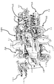
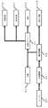
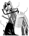
はじめに、図1および2を参照しながら、本実施の形態の田植え機の構成および動作について具体的に説明する。 First, the configuration and operation of the rice transplanter according to the present embodiment will be specifically described with reference to FIGS. 1 and 2.
ここに、図1は本発明における実施の形態の田植え機の斜視図であり、図2は本発明における実施の形態の田植え機の動力伝達系のブロック図である。 Here, FIG. 1 is a perspective view of the rice transplanter according to the embodiment of the present invention, and FIG. 2 is a block diagram of a power transmission system of the rice transplanter according to the embodiment of the present invention.
本実施の形態の田植え機の動作について説明しながら、本発明に関連した発明の自動旋回制御方法についても説明する。 While explaining the operation of the rice transplanter of the present embodiment, the automatic turning control method of the invention related to the present invention will also be described.
本実施の形態の田植え機は8条植えの乗用マット苗田植え機であり、植付け装置100は4個の植付けユニットを有し、各々の植付けユニットは左右一対の2個の植付け具を有する。
The rice transplanter of the present embodiment is a riding mat seedling rice transplanter for eight-row planting, the
もちろん、田植え機は、8条植えの乗用マット苗田植え機に限らず、たとえば、10条植えの乗用ポット苗田植え機であってもよい。 Of course, the rice transplanter is not limited to the 8-row planting riding mat seedling planting machine, and may be, for example, a 10-row planting riding pot seedling planting machine.
最初に説明されるのは、本実施の形態の田植え機の基本的な構成および動作である。したがって、制御装置200の動作などについては、後に詳細に説明する。 First, the basic configuration and operation of the rice transplanter of the present embodiment will be described. Therefore, the operation of the control device 200 and the like will be described in detail later.
運転ユニット50は、エンジンカバーの上方に設けられた座席51を有する。
The
座席51の前方には、前輪31を操作するためのステアリングハンドル52が設けられている。そして、エンジンカバーの左右両側には、水平なステップフロアが設けられている。さらに、ステアリングハンドル52の左右両側には、予備苗載せ台101が設けられている。
A steering handle 52 for operating the
走行装置30は、前輪31および後輪32で車体10を走行させる装置である。
The traveling
整地装置60は、整地ローター機構61および整地フロート機構62で圃場を整地する装置である。
The ground leveling device 60 is a device for leveling a field with a ground leveling rotor mechanism 61 and a ground
線引きマーカー80は、つぎの植付け走行経路の目安となる直線のマーキングを圃場へ形成する、車体10へ収納可能に取付けられたマーカーである。 The line drawing marker 80 is a marker that is storably attached to the vehicle body 10 to form a straight line marking that serves as a guideline for the next planting travel path in the field.
植付け装置100は、植付け装置昇降装置90を介して車体10の後側へ取付けられている。
The
メインフレームへ取付けられたエンジン20の回転動力は、HST(Hydro Static Transmission)機構である主変速機構41などへ伝達される。主変速機構41および副変速機構42において変速された回転動力は、走行装置30などにおいて利用される走行動力と、植付け装置100などにおいて利用される外部取出動力と、に分離される。
The rotational power of the
走行動力の一部は左右の前輪ファイナルケースへ伝達されて左右一対の前輪31を駆動し、走行動力の残りが左右の後輪ギヤケース43へ伝達されて左右一対の後輪32を駆動する。そして、後輪ギヤケース43へ伝達された走行動力の一部は、整地装置60および施肥装置70へ伝達される。
A part of the running power is transmitted to the left and right front wheel final cases to drive the pair of left and right
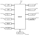
つぎに、図3および4を主として参照しながら、本実施の形態の田植え機の構成および動作についてより具体的に説明する。 Next, the configuration and operation of the rice transplanter according to the present embodiment will be described more specifically with reference to FIGS. 3 and 4.
ここに、図3は本発明における実施の形態の田植え機の制御系のブロック図であり、図4は本発明における実施の形態の田植え機の自動旋回制御の説明図である。 Here, FIG. 3 is a block diagram of the control system of the rice transplanter according to the embodiment of the present invention, and FIG. 4 is an explanatory diagram of automatic turning control of the rice transplanter according to the embodiment of the present invention.
制御装置200は、主変速レバー53、副変速レバー54または直進アシストレバー55によるレバー操作、およびアシストモードスイッチ56によるスイッチ操作のみならず、後輪回転数センサー210または植付け装置昇降センサー220による検出結果なども利用してさまざまな制御を行う装置である。
The control device 200 includes not only lever operation by the main shift lever 53, auxiliary shift lever 54 or straight-
測位システム300は、たとえば、典型的なGNSS(Global Navigation Satellite System)であるGPS(Global Positioning System)を利用する、DGPS(Differential Global Positioning System)技術により測位を行うシステムである。
The
直進アシスト制御においては、車体10の現在の方位情報を取得する測位システム300を利用して、植付け作業を行う直進走行の開始点に対応するA点、および直進走行の終了点に対応するB点の座標があらかじめ登録される。そして、A点とB点とを結ぶ仮想線に基づいた直進走行が行われるように、ステアリングモーター45を駆動してステアリングを行うことにより、直進アシスト制御が実現される。
In straight-ahead assist control, point A corresponding to the start point of straight-ahead running for planting work and point B corresponding to the end point of straight-ahead running using the
しかしながら、手動ステアリングを必要とする旋回のたびに、直進アシスト制御のオンオフ操作が行われなければならないので、作業者の負担が少なくはなく、操作性および作業性が必ずしも十分ではない。 However, since the straight-ahead assist control must be turned on and off every time a turn requires manual steering, the burden on the operator is not small, and the operability and workability are not always sufficient.
したがって、直進アシスト制御のみならず、たとえば、2400ミリメートルの植付け条間距離による条合わせが自動的に行われる自動旋回制御も実現されることが望ましく、つぎのような基本的な自動旋回制御が考えられる。 Therefore, it is desirable to realize not only straight-ahead assist control but also automatic turning control in which stitching is automatically performed based on a distance between planted rows of 2400 mm, and the following basic automatic turning control can be considered. Be done.
制御装置200は、ステアリングハンドル52を駆動するステアリングモーター45にステアリングハンドル52を駆動させることにより、車体10の自動旋回制御を行う。 The control device 200 controls the automatic turning of the vehicle body 10 by driving the steering handle 52 to the steering motor 45 that drives the steering handle 52.
車体10へ昇降可能に取付けられた植付け装置100が上昇された後に行われる自動旋回制御においては、ステアリングハンドル52の状態は、直進状態から旋回状態へ変化させられ、旋回状態から直進状態へ変化させられ、直進状態から旋回状態へ再び変化させられ、旋回状態から直進状態へ再び変化させられる。
In the automatic turning control performed after the
図4を主として参照しながら、より具体的に説明するとつぎの通りである。 A more specific description will be made with reference to FIG. 4 as follows.
(自動旋回制御における第一の段階)
植付け装置100は必要に応じた補助的な手動操作で直進アシスト制御の終了点において上昇され、線引きマーカー80が振出されている向きへの旋回が行われるように、ステアリングモーター45が駆動される。
(First stage in automatic turning control)
The
(自動旋回制御における第二の段階)
ステアリングモーター45の駆動にともない、あらかじめ定められた標準方位角度である、たとえば、60度の目標方位角度θ1を目指す旋回動作が行われる(第一の旋回動作)。このような旋回動作の指令は通常はフルレフトターンまたはフルライトターンの指令であり、フルレフトターンまたはフルライトターンの指令実行に必要とされる時間はおよそ4から5秒である。
(Second stage in automatic turning control)
Along with the drive of the steering motor 45, a turning motion aiming at a predetermined standard azimuth angle, for example, a target azimuth angle θ1 of 60 degrees is performed (first turning motion). Such a turning motion command is usually a full left turn or full right turn command, and the time required to execute the full left turn or full right turn command is approximately 4 to 5 seconds.
(自動旋回制御における第三の段階)
目標方位角度θ1への到達にともない、ステアリングモーター45が駆動され、ステアリングハンドル52の位置が中立位置に戻されるとともに、後輪回転数センサー210による走行車輪回転数のカウントが開始される(旋回途中直進動作)。このようなステアリングハンドル52の中立位置への戻しは、ゆっくりと行われてもよいし、素早く行われてもよい。
(Third stage in automatic turning control)
When the target azimuth angle θ1 is reached, the steering motor 45 is driven, the position of the steering handle 52 is returned to the neutral position, and the number of running wheel rotations is counted by the rear wheel rotation speed sensor 210 (during turning). Straight-ahead operation). Such a return of the steering handle 52 to the neutral position may be performed slowly or quickly.
(自動旋回制御における第四の段階)
走行車輪回転数が旋回途中直進距離Δに対応する所定のカウント数へ到達すると、ステアリングモーター45が駆動され、あらかじめ定められた標準方位角度である、たとえば、30度の目標方位角度θ2を目指す旋回動作が行われる(第二の旋回動作)。このような旋回動作の指令も通常はフルレフトターンまたはフルライトターンの指令であり、フルレフトターンまたはフルライトターンの指令実行に必要とされる時間はおよそ4から5秒である。
(Fourth stage in automatic turning control)
When the number of rotations of the traveling wheel reaches a predetermined count number corresponding to the straight-ahead distance Δ during turning, the steering motor 45 is driven to turn aiming at a predetermined standard azimuth angle, for example, a target azimuth angle θ2 of 30 degrees. The operation is performed (second turning operation). Such a turning motion command is also usually a full left turn or full right turn command, and the time required to execute the full left turn or full right turn command is approximately 4 to 5 seconds.
(自動旋回制御における第五の段階)
目標方位角度θ2への到達にともない、ステアリングモーター45が駆動され、ステアリングハンドル52の位置が中立位置に戻されるとともに、直進アシスト制御が開始される。
(Fifth stage in automatic turning control)
Upon reaching the target azimuth angle θ2, the steering motor 45 is driven, the position of the steering handle 52 is returned to the neutral position, and the straight-ahead assist control is started.
このような自動旋回制御においては、車体10の旋回経路の設定は不要であり、自動旋回制御の後の直進アシスト制御の開始点へ向かうためのステアリング精度が目標方位角度の設定により向上されるので、優れた旋回性および安全性が実現される。そして、旋回は必要に応じた補助的な手動操作で速やかに開始され、直進アシスト制御への移行は自動的に行われるので、優れた操作性および作業性が実現される。 In such automatic turning control, it is not necessary to set the turning path of the vehicle body 10, and the steering accuracy for heading to the starting point of the straight-ahead assist control after the automatic turning control is improved by setting the target azimuth angle. , Excellent turning performance and safety are realized. Then, the turning is promptly started by an auxiliary manual operation as needed, and the transition to the straight-ahead assist control is automatically performed, so that excellent operability and workability are realized.
上述された五つの段階を有する自動旋回制御は車体10の方位角度を利用して行われるので、確実な自動旋回が実現される。 Since the automatic turning control having the above-mentioned five stages is performed using the azimuth angle of the vehicle body 10, reliable automatic turning is realized.
そして、本発明者は、自動旋回精度を向上させるために、旋回動作における目標方位角度が標準方位角度として必ずしもあらかじめ定められていない自動旋回制御を研究している。 Then, in order to improve the automatic turning accuracy, the present inventor is studying automatic turning control in which the target azimuth in the turning motion is not necessarily predetermined as the standard azimuth.
ステアリングハンドル52の状態が旋回状態から直進状態へ変化させられるタイミング、およびステアリングハンドル52の状態が旋回状態から直進状態へ再び変化させられるタイミングは、車体10の方位角度が所定の方位角度に到達したタイミングとして決定される。 The azimuth angle of the vehicle body 10 reaches a predetermined azimuth at the timing when the state of the steering handle 52 is changed from the turning state to the straight running state and the timing when the state of the steering handle 52 is changed again from the turning state to the straight running state. Determined as the timing.
車体10の方位角度の時間的な変化を示す、車体10の方位角速度が、取得される。 The azimuth angular velocity of the vehicle body 10, which indicates the temporal change of the azimuth angle of the vehicle body 10, is acquired.
たとえば、ステアリングハンドル52の状態を旋回状態から直進状態へ変化させるときのステアリング応答性は土質のような圃場の条件などにも影響されるので、このような車体10の方位角度が所定の方位角度に到達したタイミングの把握は重要であると考えられる。 For example, the steering responsiveness when changing the state of the steering handle 52 from the turning state to the straight traveling state is affected by the conditions of the field such as soil, so that the azimuth angle of the vehicle body 10 is a predetermined azimuth angle. It is considered important to understand the timing of reaching.
図4を主として参照しながら、より具体的に説明するとつぎの通りである。 A more specific description will be made with reference to FIG. 4 as follows.
自動旋回制御における第一の段階においては、旋回制御が開始されたとき、ステアリング回転角度を規定されたステアリング回転角度と一致させる指令を出力する制御が行われる。このような制御は、単純であり、田植え機の規格に依らないで、利用可能である。 In the first stage of the automatic turning control, when the turning control is started, control is performed to output a command for matching the steering rotation angle with the specified steering rotation angle. Such control is simple and can be used regardless of the rice transplanter standard.
自動旋回制御における第二の段階においては、車体10の方位角速度α1[rad/s]およびステアリング回転角速度β1[rad/s]が測定される。二つの角速度の何れも、旋回が開始された後に定常的な状態がまもなく達成されるので、一定値であると見なされる。このような角速度の測定により、車体走行速度、トレッド、ホイールベース、および車輪スリップなどのようなさまざまな車体10の条件に影響されないのみならず、圃場の条件にも影響されないで、旋回状態は正確に把握される。 In the second stage of the automatic turning control, the directional angular velocity α1 [rad / s] and the steering rotational angular velocity β1 [rad / s] of the vehicle body 10 are measured. Both of the two angular velocities are considered constant because a steady state is achieved shortly after the turn is initiated. By measuring such angular velocity, not only is it unaffected by various vehicle body 10 conditions such as vehicle running speed, tread, wheelbase, and wheel slip, but it is also unaffected by field conditions, and the turning state is accurate. Is grasped by.
自動旋回制御における第三の段階においては、測定された車体10の方位角速度α1に依る車体10の方位角度d1[rad]への到達タイミングで、ステアリングハンドル52の位置が中立位置に戻される。たとえば、ステアリング回転角度c1[rad]への到達タイミングで、ステアリングハンドル52の位置を中立位置に戻す指令を出力する制御が行われる場合においては、所定の方位角度である、ステアリングハンドル52の位置が中立位置に戻されるタイミングでの車体10の方位角度 In the third stage of the automatic turning control, the position of the steering handle 52 is returned to the neutral position at the timing of reaching the azimuth angle d1 [rad] of the vehicle body 10 according to the measured azimuth angular velocity α1 of the vehicle body 10. For example, when control is performed to output a command to return the position of the steering handle 52 to the neutral position at the timing of reaching the steering rotation angle c1 [rad], the position of the steering handle 52, which is a predetermined azimuth angle, is set. Orientation angle of the vehicle body 10 at the timing of returning to the neutral position
(数1)
d1=α1×(c1/β1)[rad]
はあらかじめ定められた標準方位角度である目標方位角度θ1と必ずしも一致しない。しかしながら、車体10の方位角度d1が一定値としてあらかじめ定められていると、後に続く自動旋回途中の直進動作における車体10の方位角度が上述された車体10および圃場の条件の影響などでばらつき安定しないことがあるので、ステアリングハンドル52の位置が中立位置に戻されるタイミングは、たとえば、車体10の方位角速度α1に依る車体10の方位角度d1を利用して調節されることがしばしば望ましい。このような車体10の方位角度d1は、直接的な測定で得られてもよいし、直接的な測定で得られなくてもよい。
(Number 1)
d1 = α1 × (c1 / β1) [rad]
Does not always match the target azimuth angle θ1, which is a predetermined standard azimuth angle. However, if the azimuth angle d1 of the vehicle body 10 is predetermined as a constant value, the azimuth angle of the vehicle body 10 in the straight-ahead operation during the subsequent automatic turning varies due to the influence of the vehicle body 10 and the field conditions described above and is not stable. Therefore, it is often desirable that the timing at which the position of the steering handle 52 is returned to the neutral position is adjusted by using, for example, the azimuth angle d1 of the vehicle body 10 depending on the azimuth angular velocity α1 of the vehicle body 10. Such an azimuth angle d1 of the vehicle body 10 may or may not be obtained by direct measurement.
自動旋回制御における第四の段階においては、車体10の方位角速度α2[rad/s]およびステアリング回転角速度β2[rad/s]が測定される。二つの角速度の何れも、旋回が開始された後に定常的な状態がまもなく達成されるので、一定値であると見なされる。このような角速度の測定により、車体走行速度、トレッド、ホイールベース、および車輪スリップなどのようなさまざまな車体10の条件に影響されないのみならず、圃場の条件にも影響されないで、旋回状態は正確に把握される。 In the fourth stage of the automatic turning control, the directional angular velocity α2 [rad / s] and the steering rotational angular velocity β2 [rad / s] of the vehicle body 10 are measured. Both of the two angular velocities are considered constant because a steady state is achieved shortly after the turn is initiated. By measuring such angular velocity, not only is it unaffected by various vehicle body 10 conditions such as vehicle running speed, tread, wheelbase, and wheel slip, but it is also unaffected by field conditions, and the turning state is accurate. Is grasped by.
自動旋回制御における第五の段階においては、測定された車体10の方位角速度α2に依る車体10の方位角度d2[rad]への到達タイミングで、ステアリングハンドル52の位置が中立位置に戻される。たとえば、ステアリング回転角度c2[rad]への到達タイミングで、ステアリングハンドル52の位置を中立位置に戻す指令を出力する制御が行われる場合においては、所定の方位角度である、ステアリングハンドル52の位置が中立位置に戻されるタイミングでの車体10の方位角度 In the fifth stage of the automatic turning control, the position of the steering handle 52 is returned to the neutral position at the timing of reaching the azimuth angle d2 [rad] of the vehicle body 10 according to the measured azimuth angular velocity α2 of the vehicle body 10. For example, when control is performed to output a command to return the position of the steering handle 52 to the neutral position at the timing of reaching the steering rotation angle c2 [rad], the position of the steering handle 52, which is a predetermined azimuth angle, is set. Orientation angle of the vehicle body 10 at the timing of returning to the neutral position
(数2)
d2=α2×(c2/β2)[rad]
はあらかじめ定められた標準方位角度である目標方位角度θ2と必ずしも一致しない。しかしながら、車体10の方位角度d2が一定値としてあらかじめ定められていると、後に続く自動旋回後の直進動作における車体10の方位角度が上述された車体10および圃場の条件の影響などでばらつき安定しないことがあるので、ステアリングハンドル52の位置が中立位置に戻されるタイミングは、たとえば、車体10の方位角速度α2に依る車体10の方位角度d2を利用して調節されることがしばしば望ましい。このような車体10の方位角度d2は、直接的な測定で得られてもよいし、直接的な測定で得られなくてもよい。
(Number 2)
d2 = α2 × (c2 / β2) [rad]
Does not always match the target azimuth angle θ2, which is a predetermined standard azimuth angle. However, if the azimuth angle d2 of the vehicle body 10 is predetermined as a constant value, the azimuth angle of the vehicle body 10 in the subsequent straight-ahead operation after automatic turning varies and is not stable due to the influence of the vehicle body 10 and the field conditions described above. Therefore, it is often desirable that the timing at which the position of the steering handle 52 is returned to the neutral position is adjusted by using, for example, the azimuth angle d2 of the vehicle body 10 depending on the azimuth angle velocity α2 of the vehicle body 10. Such an azimuth angle d2 of the vehicle body 10 may or may not be obtained by direct measurement.
なお、所定の方位角度は、あらかじめ定められた標準方位角速度と取得された車体10の方位角速度との比較に基づいて、あらかじめ定められた標準方位角度を調節することにより得られてもよい。 The predetermined azimuth angle may be obtained by adjusting the predetermined standard azimuth angle based on the comparison between the predetermined standard azimuth angular velocity and the acquired azimuth angular velocity of the vehicle body 10.
あらかじめ定められた標準方位角度に拘束されずに、簡素なアルゴリズムを利用することにより自動旋回精度を向上させることができる。 The automatic turning accuracy can be improved by using a simple algorithm without being constrained by a predetermined standard azimuth.
また、所定の方位角度はあらかじめ定められた標準方位角度であってもよく、ステアリングハンドル52の状態は、あらかじめ定められた標準方位角速度と取得された車体10の方位角速度との比較に基づいて、旋回状態から直進状態へ変化させられ、旋回状態から直進状態へ再び変化させられてもよい。 Further, the predetermined azimuth angle may be a predetermined standard azimuth angle, and the state of the steering handle 52 is based on a comparison between the predetermined standard azimuth angular velocity and the acquired azimuth angular velocity of the vehicle body 10. The turning state may be changed to the straight running state, and the turning state may be changed to the straight running state again.
あらかじめ定められた標準方位角度を尊重しながら、簡素なアルゴリズムを利用することにより自動旋回精度を向上させることができる。 The automatic turning accuracy can be improved by using a simple algorithm while respecting a predetermined standard azimuth.
上述された自動旋回制御における第二および第四の段階において車体10の方位角速度α[rad/s]およびステアリング回転角速度β[rad/s]が測定され、自動旋回制御における第三および第五の段階において、たとえば、ステアリング回転角度c[rad]への到達タイミングで、ステアリングハンドル52の位置が中立位置に戻される場合においては、所定の方位角度である、車体10の方位角度 In the second and fourth stages of the automatic turning control described above, the azimuth angular velocity α [rad / s] and the steering rotational angular velocity β [rad / s] of the vehicle body 10 are measured, and the third and fifth steps in the automatic turning control In the stage, for example, when the position of the steering handle 52 is returned to the neutral position at the timing of reaching the steering rotation angle c [rad], the orientation angle of the vehicle body 10 is a predetermined orientation angle.
(数3)
d=α×(c/β)[rad]
はさまざまな手法を利用して補正されてもよい。
(Number 3)
d = α × (c / β) [rad]
May be corrected using various methods.
たとえば、車体10の方位角度dは、作業者が好む旋回終了状態などに応じた容易なダイヤル手動操作などで調節可能である調節角度h[rad]を導入することにより、 For example, the azimuth angle d of the vehicle body 10 can be adjusted by introducing an adjustment angle h [rad] that can be adjusted by a simple manual dial operation or the like according to the turning end state preferred by the operator.
(数4)
d=(α×(c/β)+h)[rad]
が満足されるように決定されてもよい。
(Number 4)
d = (α × (c / β) + h) [rad]
May be determined to be satisfactory.
調節角度hは、調節角度パラメーターk[rad]を導入することにより、0以上100以下であるトラニオン開度gに応じて比例的に大きくなるように、 By introducing the adjustment angle parameter k [rad], the adjustment angle h is proportionally increased according to the trunnion opening degree g which is 0 or more and 100 or less.
(数5)
h=g×k[rad]
が満足されるように決定されてもよい。自動旋回精度は、車体走行速度、トレッド、ホイールベース、および車輪スリップなどのようなさまざまな車体10の条件に影響されるのみならず、圃場の条件にも影響されるので、調節角度hをトラニオン開度gに応じて決定することにより、自動旋回精度へのこれらの条件の影響を低減することができる。
(Number 5)
h = g × k [rad]
May be determined to be satisfactory. The automatic turning accuracy is not only affected by various vehicle body 10 conditions such as vehicle speed, tread, wheelbase, and wheel slip, but also by field conditions, so the adjustment angle h is trunnioned. By determining according to the opening degree g, the influence of these conditions on the automatic turning accuracy can be reduced.
もちろん、車体10の方位角度dは、実際の方位角度測定結果に基づいて決定されてもよい。さまざまな田植え機の規格について、上述されたさまざまな条件のもとで方位角度測定をあらかじめ実際に行ってデータを収集することにより、高い自動旋回精度が実現される。 Of course, the azimuth angle d of the vehicle body 10 may be determined based on the actual azimuth angle measurement result. High automatic turning accuracy is realized by actually performing azimuth angle measurement in advance and collecting data under various conditions described above for various rice transplanter standards.
たとえば、車体走行速度が0.5[m/s]である場合においては、実際に測定された車体10の方位角速度αが15[deg/s]であり、車体10の方位角度dが25[deg]であるときに理想的な自動旋回精度が実現されるのであれば、フルレフトターンまたはフルライトターンの指令実行に必要とされる時間はおよそ1.7(=25/15)秒であると理解される。したがって、車体10の方位角度dは、容易なダイヤル手動操作などで調節可能である調節角度パラメーターp[s]を導入することにより、 For example, when the vehicle body traveling speed is 0.5 [m / s], the actually measured azimuth angular velocity α of the vehicle body 10 is 15 [deg / s], and the azimuth angle d of the vehicle body 10 is 25 [d]. If ideal automatic turning accuracy is achieved when [deg], the time required to execute a full left turn or full right turn command is approximately 1.7 (= 25/15) seconds. Is understood. Therefore, the azimuth angle d of the vehicle body 10 can be adjusted by introducing an adjustment angle parameter p [s] that can be adjusted by a simple manual dial operation or the like.
(数6)
d=α×p[rad]
が満足されるように決定されてもよい。たとえば、このような調節角度パラメーターpの基準値は1.5[s]であり、ダイヤル手動操作は調節角度パラメーターpの微小な増加および減少を0.1[s]刻みで行うための操作である。
(Number 6)
d = α × p [rad]
May be determined to be satisfactory. For example, the reference value of such an adjustment angle parameter p is 1.5 [s], and the manual dial operation is an operation for slightly increasing or decreasing the adjustment angle parameter p in 0.1 [s] increments. is there.
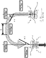
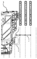
つぎに、図3から7を主として参照しながら、本実施の形態の田植え機の構成および動作についてさらにより具体的に説明する。 Next, the configuration and operation of the rice transplanter according to the present embodiment will be described more specifically with reference to FIGS. 3 to 7.
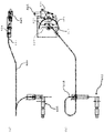
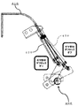
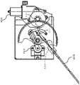
ここに、図5(a)は本発明における実施の形態の田植え機のデフロックシャフト400近傍の部分平面図であり、図5(b)は本発明における実施の形態の田植え機のデフロックシャフト400近傍の部分背面図であり、図6(a)および(b)は本発明における実施の形態の田植え機のモーター装置姿勢切換え機構440近傍の部分背面図(その一および二)であり、図7は本発明における実施の形態の田植え機のスプリング部材450近傍の部分左側面図である。
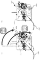
Here, FIG. 5 (a) is a partial plan view of the vicinity of the
図6(a)にはモーター装置姿勢切換え機構440のソレノイドへの電源供給が行われている状態が示されており、図6(b)にはモーター装置姿勢切換え機構440のソレノイドへの電源供給が行われていない状態が示されている。図7には、ケーブル部材410が牽引されている状態と、ケーブル部材410が牽引されていない状態と、が両方とも示されている。 FIG. 6A shows a state in which power is being supplied to the solenoid of the motor device posture switching mechanism 440, and FIG. 6B shows a state in which power is supplied to the solenoid of the motor device posture switching mechanism 440. Is not shown. FIG. 7 shows both a state in which the cable member 410 is towed and a state in which the cable member 410 is not towed.
ギヤ部材420は、デフロックがオンされるように牽引されるケーブル部材410の一端411が連結されている部材である。 The gear member 420 is a member to which one end 411 of the cable member 410 towed so that the diff lock is turned on is connected.
ケーブル部材410がモーター装置430のモーターにより牽引されたとき、デフロックはオンされる。したがって、デフロックシャフト400の回動アーム部材へ接続されたデフロックペダルの踏込み操作なしに、デフロックはオンされる。
The diff lock is turned on when the cable member 410 is towed by the motor of the motor device 430. Therefore, the diff lock is turned on without depressing the diff lock pedal connected to the rotating arm member of the diff lock
もちろん、手動操作のためのデフロックペダルが併せて設けられていてもよいが、デフロックシャフト400の回動アーム部材はケーブル部材410によりギヤ部材420と連結されているので、左右一対の後輪32を連動させるためのデフロックを自動的にまたは半自動的にオンオフすることができる。
Of course, a diff lock pedal for manual operation may also be provided, but since the rotating arm member of the diff lock
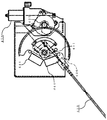
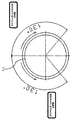
モーター装置430のモータースイッチの状態に応じて左右方向に回転させられるギヤ部材420の形状は略半月形状であり、回転ストッパー421が何れの回転向きについても所定のギヤ部材回転角度位置に設けられており、モーター装置430のモーター回転は回転ストッパー421への当接にともなう電流値上昇の検出により停止される。 The shape of the gear member 420 that is rotated in the left-right direction according to the state of the motor switch of the motor device 430 is substantially a half-moon shape, and the rotation stopper 421 is provided at a predetermined gear member rotation angle position in any rotation direction. The motor rotation of the motor device 430 is stopped by detecting an increase in the current value due to contact with the rotation stopper 421.
デフロックペダルの接続部であるギヤ部材420の側面孔と、ケーブル部材410の一端411は接続されており、孔位置はギヤ部材420の回転にともない移動する。ギヤ部材デフロックオン回転角度は60度であり、ギヤ部材デフロックオフ回転角度は120度である。 The side hole of the gear member 420, which is the connection portion of the diff lock pedal, and one end 411 of the cable member 410 are connected, and the hole position moves with the rotation of the gear member 420. The gear member diff lock-on rotation angle is 60 degrees, and the gear member diff lock-off rotation angle is 120 degrees.
このようなギヤ部材回転角度は、角度センサーとして機能する、図8に示されているような一対の2個のリミットスイッチ441、または図9に示されているようなポテンショメーター442により検出され、モーター回転制御に利用されてもよい。 Such a gear member rotation angle is detected by a pair of two limit switches 441 as shown in FIG. 8 or a potentiometer 442 as shown in FIG. 9, which functions as an angle sensor, and is detected by a motor. It may be used for rotation control.
ここに、図8および9は、本発明における変形例の実施の形態の田植え機のモーター装置姿勢切換え機構440近傍の部分背面図(その一および二)である。 Here, FIGS. 8 and 9 are partial rear views (Nos. 1 and 2) of the vicinity of the motor device posture switching mechanism 440 of the rice transplanter according to the embodiment of the modified example of the present invention.
モーター装置姿勢切換え機構440は、モーター装置430の噛合部431がギヤ部材420と噛合するモーター装置噛合姿勢と、噛合部431がギヤ部材420と噛合しないモーター装置非噛合姿勢と、の間のモーター装置姿勢切換えを行う機構である。 The motor device posture switching mechanism 440 is a motor device between a motor device meshing posture in which the meshing portion 431 of the motor device 430 meshes with the gear member 420 and a motor device non-meshing posture in which the meshing portion 431 does not mesh with the gear member 420. It is a mechanism for switching posture.
スプリング部材450は、デフロックがオンされるように牽引されたケーブル部材410を引戻す付勢力を印加する部材である。
The
モーター装置430は、噛合部431がギヤ部材420と噛合しているとき、ケーブル部材410が牽引されてデフロックがオンされるようにギヤ部材420を駆動する。 The motor device 430 drives the gear member 420 so that the cable member 410 is towed and the diff lock is turned on when the meshing portion 431 is engaged with the gear member 420.
制御装置200は、自動旋回制御を開始するとき、モーター装置姿勢切換え機構440にモーター装置非噛合姿勢からモーター装置噛合姿勢へのモーター装置姿勢切換えを行わせるとともに、モーター装置430にケーブル部材410が牽引されてデフロックがオンされるようにギヤ部材420を駆動させる。 When the control device 200 starts the automatic turning control, the motor device posture switching mechanism 440 causes the motor device posture switching mechanism 440 to switch the motor device posture from the motor device non-meshing posture to the motor device meshing posture, and the motor device 430 pulls the cable member 410. The gear member 420 is driven so that the differential lock is turned on.
モーター装置430の噛合部431は、モーター装置姿勢切換え機構440のソレノイドへの電源供給が行われていればソレノイドによりギヤ部材420へ押付けられるが、電源供給が行われていなければギヤ部材420から離れる。 The meshing portion 431 of the motor device 430 is pressed against the gear member 420 by the solenoid if power is supplied to the solenoid of the motor device posture switching mechanism 440, but is separated from the gear member 420 if power is not supplied. ..
枕地などにおける自動旋回制御においては、大きい負荷に起因するスリップが発生しやすいので、旋回動作が安定するように、ステアリングハンドル52がステアリングモーター45により駆動されるのみならず、デフロックもオンされる。デフロックオンが、たとえば、旋回目標設定が行われた、直進状態から旋回状態への変化の前に実行されると、旋回動作が安定しないことがあるので、デフロックはステアリングハンドル52の左回転または右回転が検出された後にオンされることがしばしば望ましい。 In automatic turning control on a headland or the like, slippage due to a large load is likely to occur. Therefore, not only the steering handle 52 is driven by the steering motor 45 but also the diff lock is turned on so that the turning operation is stable. .. If the diff lock-on is performed, for example, before the change from the straight-ahead state to the turning state in which the turning target is set, the turning operation may not be stable, so that the diff lock turns the steering handle 52 counterclockwise or to the right. It is often desirable to turn it on after rotation is detected.
モーター装置430のモーターへの電源供給のみならず、モーター装置姿勢切換え機構440のソレノイドへの電源供給も、ステアリング回転角度が所定のステアリング回転角度範囲内にあるときのみ行われる。したがって、モーター装置430のモーターが常にはギヤ部材420へ押付けられず、モーター故障が発生しても、自動旋回制御を終了したときデフロックはオフされるので、直進状態における旋回径が不要なデフロックオンの継続に起因して大きくなってしまうことはほとんどなく、旋回性のみならず安全性も向上される。 Not only the power supply to the motor of the motor device 430 but also the power supply to the solenoid of the motor device attitude switching mechanism 440 is performed only when the steering rotation angle is within a predetermined steering rotation angle range. Therefore, the motor of the motor device 430 is not always pressed against the gear member 420, and even if a motor failure occurs, the diff lock is turned off when the automatic turning control is finished, so that the diff lock on does not require a turning diameter in the straight running state. It hardly becomes large due to the continuation of the above, and not only the turning performance but also the safety is improved.
このようなステアリング回転角度は、図10(a)および10(b)に示されているように、図11に示されているような130度のステアリングハンドル52の左回転および右回転についてのモーター装置430のモーター駆動開始角度位置に応じた、ステアリングハンドル52のステアリング回転角度部材に設けられた直進機ステアリング回転角度センサーアセンブリ443により検出されてもよい。 Such a steering rotation angle is a motor for left and right rotation of the 130 degree steering handle 52 as shown in FIG. 11, as shown in FIGS. 10 (a) and 10 (b). It may be detected by the straight-moving machine steering rotation angle sensor assembly 443 provided on the steering rotation angle member of the steering handle 52 according to the motor drive start angle position of the device 430.
ここに、図10(a)は本発明における変形例の実施の形態の田植え機の直進機ステアリング回転角度センサーアセンブリ443近傍の部分右側面図であり、図10(b)は本発明における変形例の実施の形態の田植え機の直進機ステアリング回転角度センサーアセンブリ443近傍の部分正面図であり、図11は本発明における変形例の実施の形態の田植え機のモーター装置430のモーター駆動開始角度位置の説明図である。 Here, FIG. 10 (a) is a partial right side view of the vicinity of the straight-moving machine steering rotation angle sensor assembly 443 of the rice transplanter according to the embodiment of the modified example of the present invention, and FIG. 10 (b) is a modified example of the present invention. FIG. 11 is a partial front view of the vicinity of the straight-moving machine steering rotation angle sensor assembly 443 of the rice transplanter according to the embodiment, and FIG. 11 shows the motor drive start angle position of the motor device 430 of the rice transplanter according to the embodiment of the present invention. It is explanatory drawing.
制御装置200は、自動旋回制御を終了したとき、モーター装置姿勢切換え機構440にモーター装置噛合姿勢からモーター装置非噛合姿勢へのモーター装置姿勢切換えを行わせ、スプリング部材450はデフロックがオンされるように牽引されたケーブル部材410を引戻す付勢力を印加することにより、デフロックはオフされる。
When the control device 200 ends the automatic turning control, the motor device posture switching mechanism 440 is made to switch the motor device posture from the motor device meshing posture to the motor device non-meshing posture, and the
デフロックシャフト400の回動アーム部材にはケーブル部材410を引戻すための圧縮スプリングであるスプリング部材450部材が嵌込まれているので、ケーブル部材410が牽引されてデフロックがオンされるとき、ケーブル部材410の弛みはほとんど存在しない。したがって、デフロックシャフト400の回動アーム部材角度に関わらず、モーター回転誤差を考慮したいわゆる余分ケーブル引きしろはほとんどないので、モーター装置430の確実なモーター回転精度が実現されるのみならず、モーター耐久性もモーター負荷の低減にともない実現される。
Since a
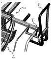
(A)つぎに、小型手摺り部材510について具体的に説明する。 (A) Next, the small handrail member 510 will be specifically described.
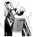
図12に示されているような小型手摺り部材510は、図13および14に示されているような大型手摺り部材520と比べて廉価である。
The small handrail member 510 as shown in FIG. 12 is cheaper than the
ここに、図12は本発明における変形例の実施の形態の田植え機の小型手摺り部材510近傍の部分斜視図であり、図13および14は本発明における変形例の実施の形態の田植え機の大型手摺り部材520近傍の部分斜視図(その一および二)である。
Here, FIG. 12 is a partial perspective view of the vicinity of the small handrail member 510 of the rice transplanter according to the embodiment of the modified example of the present invention, and FIGS. 13 and 14 show the rice transplanter of the embodiment of the modified example of the present invention. It is a partial perspective view (No. 1 and 2) in the vicinity of a
小型手摺り部材510は、乗降を補助する目的に特化した簡素な手摺り部材であり、作業者転落を防止して安全性を向上することもできる大型手摺り部材520のように高いコストを必要としない。
The small handrail member 510 is a simple handrail member specialized for the purpose of assisting getting on and off, and has a high cost like the
しかしながら、車体10への小型手摺り部材取付け構成は、車体10への大型手摺り部材取付け構成と同じであり、大型手摺り部材520の代わりに小型手摺り部材510を取付けるための専用部材は不要である。車体10の側の共通な手摺り部材取付けフレーム530が利用されるので、小型手摺り部材510の代わりにオプショナルに大型手摺り部材520を取付けることもでき、コストの増加が招来されない。
However, the configuration for attaching the small handrail member to the vehicle body 10 is the same as the configuration for attaching the large handrail member to the vehicle body 10, and a dedicated member for attaching the small handrail member 510 instead of the
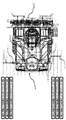
(B)つぎに、サイドマーカー610について具体的に説明する。
(B) Next, the
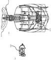
左のサイドマーカー610のサイドマーカーステー611は、図15および16に示されているように、バッテリーケース620の後方に取付けられている。
The side marker stay 611 of the
ここに、図15は本発明における変形例の実施の形態の田植え機の部分平面図であり、図16は本発明における変形例の実施の形態の田植え機のサイドマーカー610近傍の部分平面図である。
Here, FIG. 15 is a partial plan view of the rice transplanter according to the embodiment of the modified example of the present invention, and FIG. 16 is a partial plan view of the vicinity of the
もちろん、左のサイドマーカー610のサイドマーカーステー611、および右のサイドマーカー610のサイドマーカーステー611の内の少なくとも一方が、バッテリーケース620の後方に取付けられていてもよい。
Of course, at least one of the side marker stay 611 of the
サイドマーカーステー611がいわゆる苗枠支柱に取付けられる場合においては、バッテリーケース620が存在するので、バッテリー回避のための曲がったサイドマーカー形状が必要とされ、サイドマーカー形状などが互いに異なる、左のサイドマーカー610および右のサイドマーカー610がしばしば利用されなければならない。
When the side marker stay 611 is attached to the so-called seedling frame support, the
サイドマーカーステー611がバッテリーケース620の後方に取付けられる場合においては、バッテリー回避のための曲がったサイドマーカー形状は必要とされず、サイドマーカー形状が両方ともまっすぐで同じである、左のサイドマーカー610および右のサイドマーカー610が共通に利用可能であるので、部品点数が削減される。
When the side marker stay 611 is mounted behind the
サイドマーカーステー611の配置は、サイドマーカー長さが同じである左右のサイドマーカー610が利用可能であるように行われる。
The arrangement of the side marker stays 611 is performed so that the left and
各々の植付け条数についてのサイドマーカー長さは、サイドマーカー位置が植付け条数に対応するように調節されるが、5から7の植付け条数に関わらず、基本的なサイドマーカー構成は共通であるので、サイドマーカーの種類が削減され、コストの増加が招来されない。 The side marker length for each number of planted rows is adjusted so that the side marker position corresponds to the number of planted rows, but the basic side marker configuration is the same regardless of the number of planted rows of 5 to 7. As such, the types of side markers are reduced and no cost increase is incurred.
サイドマーカーステー611の配置は、優れたサイドマーカー視認性が植付け条数に応じたサイドマーカー長さで実現されるように行われる。 The arrangement of the side marker stays 611 is performed so that excellent side marker visibility is realized with a side marker length corresponding to the number of planting rows.
たとえば、植付け条数が5である場合においては、隣接する植付け条のサイドマーカー視認性が近年のワイドステップ化にともない低下しやすいので、二つの植付け条の幅だけ離れた植付け軌跡に対応するサイドマーカー長さが採用されてもよい。二つの植付け条の幅だけ離れた植付け軌跡は、一つの植付け条の幅だけ離れた隣接する植付け条の植付け軌跡と比べて、ワイドステップの陰に隠れないで容易に視認され、このような場合におけるサイドマーカー長さは植付け条数が7である場合における通常のサイドマーカー長さと一致するので、サイドマーカーの種類が削減され、コストの増加が招来されない。 For example, when the number of planting rows is 5, the visibility of the side markers of the adjacent planting strips tends to decrease with the recent wide step, so the side corresponding to the planting locus separated by the width of the two planting strips. The marker length may be adopted. Planting loci separated by the width of two planting strips are more easily visible without being hidden behind wide steps compared to planting loci of adjacent planting strips separated by the width of one planting strip. Since the side marker length in the above matches the normal side marker length when the number of planting rows is 7, the types of side markers are reduced and the cost is not increased.
(C)つぎに、ロボット田植え機の作業ルート記憶について具体的に説明する。 (C) Next, the work route memory of the robot rice transplanter will be specifically described.
ロボット田植え機の作業ルート記憶に関しては、部分植付け条クラッチとも呼ばれる、いわゆる畦クラッチのオンオフ情報を位置情報とリンクさせる情報リンク記録機能が実装されていることが望ましい。 Regarding the work route memory of the robot rice transplanter, it is desirable that an information link recording function, which is also called a partial planting strip clutch, is implemented to link the on / off information of the so-called ridge clutch with the position information.
これは、田植え作業の省力化を促進することができるからである。 This is because labor saving in rice planting work can be promoted.
(D)つぎに、ロボット田植え機の自動旋回位置の切換えについて具体的に説明する。 (D) Next, switching of the automatic turning position of the robot rice transplanter will be specifically described.
ロボット田植え機の自動旋回位置の切換えに関しては、旋回開始タイミングを決定する後輪駆動軸パルス値が操作パネルで調節可能であることが望ましい。 Regarding the switching of the automatic turning position of the robot rice transplanter, it is desirable that the rear wheel drive shaft pulse value that determines the turning start timing can be adjusted on the operation panel.
これは、自動旋回位置は畦からの距離に対応するが、旋回方法は地域、圃場、およびユーザーの好みなどに依り異なるので、畦からの距離に応じたさまざまな旋回位置が選択可能であることが望ましいからである。 This is because the automatic turning position corresponds to the distance from the ridge, but the turning method differs depending on the area, field, user preference, etc., so various turning positions can be selected according to the distance from the ridge. Is desirable.
旋回開始タイミングは、たとえば、操作パネルのダイヤルスイッチで調節可能であってもよい。 The turning start timing may be adjusted by, for example, a dial switch on the operation panel.
(E)つぎに、乗用田植え機の畦からの苗補給の前の自動旋回について具体的に説明する。 (E) Next, the automatic turning before replenishing seedlings from the ridges of the passenger rice transplanter will be specifically described.
乗用田植え機の畦からの苗補給の前の自動旋回に関しては、車体10が畦と平行になって停止するように自動旋回制御が行われることが望ましい。 Regarding the automatic turning before replenishing the seedlings from the ridges of the passenger rice transplanter, it is desirable that the automatic turning control is performed so that the vehicle body 10 stops in parallel with the ridges.
これは、畦からの苗補給作業の省力化を促進することができるからである。 This is because it is possible to promote labor saving in the work of supplying seedlings from the ridges.
自動旋回は、苗タンクとも呼ばれる、苗載せ台の欠株センサーによる欠株検出に基づいて開始されるが、植付けのための前進動作は畦の直前まで行われるので、旋回動作は所定の距離の後進動作が行われた後に行われる。このような後進動作は、GPS位置情報を利用して行われてもよい。ステアリング回転角度が所定の角度に到達し、旋回外側の後輪回転数センサー210の後輪駆動軸パルス値が所定の値に到達すると、HST機構である主変速機構41は中立状態で停止する。主変速機構41の停止後の再発進は、リモートコントロール操作により行われてもよい。 The automatic turning is started based on the stock shortage detection by the stock shortage sensor of the seedling stand, which is also called a seedling tank, but since the forward movement for planting is performed until just before the ridge, the turning movement is a predetermined distance. It is performed after the reverse operation is performed. Such a reverse operation may be performed using GPS position information. When the steering rotation angle reaches a predetermined angle and the rear wheel drive shaft pulse value of the rear wheel rotation speed sensor 210 on the outside of turning reaches a predetermined value, the main transmission mechanism 41, which is an HST mechanism, stops in a neutral state. The restart after the main transmission mechanism 41 is stopped may be performed by a remote control operation.
なお、本発明に関連した発明のプログラムは、上述された本発明に関連した発明の自動旋回制御方法の全部または一部のステップ(または工程、動作および作用など)の動作をコンピュータに実行させるためのプログラムであって、コンピュータと協働して動作するプログラムである。 The program of the invention related to the present invention is for causing the computer to perform the operation of all or a part of the automatic turning control method of the invention related to the present invention described above (or steps, operations, actions, etc.). It is a program that operates in cooperation with a computer.
また、本発明に関連した発明の記録媒体は、上述された本発明に関連した発明の自動旋回制御方法の全部または一部のステップ(または工程、動作および作用など)の全部または一部の動作をコンピュータに実行させるためのプログラムを記録した記録媒体であり、読取られたプログラムがコンピュータと協働して利用されるコンピュータ読取り可能な記録媒体である。 In addition, the recording medium of the invention related to the present invention is an operation of all or a part of all or a part of the steps (or steps, operations, actions, etc.) of the automatic turning control method of the invention related to the present invention described above. Is a recording medium on which a program for causing a computer to execute a program is recorded, and is a computer-readable recording medium in which the read program is used in cooperation with a computer.
なお、上述された「一部のステップ(または工程、動作および作用など)」は、それらの複数のステップの内の一つまたはいくつかのステップを意味する。 The above-mentioned "partial step (or process, operation, action, etc.)" means one or several steps among the plurality of steps.
また、上述された「ステップ(または工程、動作および作用など)の動作」は、上述されたステップの全部または一部の動作を意味する。 Further, the above-mentioned "operation of a step (or process, operation, action, etc.)" means an operation of all or a part of the above-mentioned steps.
また、本発明に関連した発明のプログラムの一利用形態は、インターネット、光、電波または音波などのような伝送媒体の中を伝送され、コンピュータにより読取られ、コンピュータと協働して動作するという形態であってもよい。 Further, one usage form of the program of the invention related to the present invention is a form in which the program is transmitted in a transmission medium such as the Internet, light, radio waves, sound waves, etc., read by a computer, and operates in cooperation with the computer. It may be.
また、記録媒体としては、ROM(Read Only Memory)などが含まれる。 Further, the recording medium includes a ROM (Read Only Memory) and the like.
また、コンピュータは、CPU(Central Processing Unit)などのような純然たるハードウェアに限らず、ファームウェア、OS(Operating System)、そしてさらに周辺機器を含んでもよい。 Further, the computer is not limited to pure hardware such as a CPU (Central Processing Unit), but may include a firmware, an OS (Operating System), and further peripheral devices.
なお、上述されたように、本発明の構成は、ソフトウェア的に実現されてもよいし、ハードウェア的に実現されてもよい。 As described above, the configuration of the present invention may be realized by software or hardware.
本発明における移植機は、車体の自動旋回制御を行うことができ、田植え機などのような移植機に利用する目的に有用である。 The transplanter in the present invention can perform automatic turning control of the vehicle body, and is useful for the purpose of using it for a transplanter such as a rice transplanter.
10 車体
20 エンジン
30 走行装置
31 前輪
32 後輪
41 主変速機構
42 副変速機構
43 後輪ギヤケース
45 ステアリングモーター
50 運転ユニット
51 座席
52 ステアリングハンドル
53 主変速レバー
54 副変速レバー
55 直進アシストレバー
56 アシストモードスイッチ
60 整地装置
61 整地ローター機構
62 整地フロート機構
70 施肥装置
80 線引きマーカー
90 植付け装置昇降装置
100 植付け装置
101 予備苗載せ台
200 制御装置
210 後輪回転数センサー
220 植付け装置昇降センサー
300 測位システム
400 デフロックシャフト
410 ケーブル部材
411 一端
420 ギヤ部材
421 回転ストッパー
430 モーター装置
431 噛合部
440 モーター装置姿勢切換え機構
441 リミットスイッチ
442 ポテンショメーター
443 直進機ステアリング回転角度センサーアセンブリ
450 スプリング部材
510 小型手摺り部材
520 大型手摺り部材
530 手摺り部材取付けフレーム
610 サイドマーカー
611 サイドマーカーステー
620 バッテリーケース
10
Claims (4)
操舵部材(52)を駆動する操舵部材駆動装置(45)と、
前記操舵部材駆動装置(45)に前記操舵部材(52)を駆動させることにより、前記車体(10)の自動旋回制御を行う制御装置(200)と、
を備え、
前記作業装置(100)が上昇された後に行われる前記自動旋回制御においては、前記操舵部材(52)の状態は、直進状態から旋回状態へ変化させられ、前記旋回状態から前記直進状態へ変化させられ、前記直進状態から前記旋回状態へ再び変化させられ、前記旋回状態から前記直進状態へ再び変化させられ、
前記操舵部材(52)の前記状態が前記旋回状態から前記直進状態へ変化させられるタイミング、および前記操舵部材(52)の前記状態が前記旋回状態から前記直進状態へ再び変化させられるタイミングは、前記車体(10)の方位角度が所定の方位角度に到達したタイミングとして決定されることを特徴とする移植機。 A work device (100) attached to the vehicle body (10) so as to be able to move up and down,
A steering member driving device (45) that drives the steering member (52), and
A control device (200) that automatically turns the vehicle body (10) by driving the steering member (52) on the steering member driving device (45).
With
In the automatic turning control performed after the working device (100) is raised, the state of the steering member (52) is changed from the straight traveling state to the turning state, and is changed from the turning state to the straight traveling state. , The straight state is changed again to the turning state, and the turning state is changed again to the straight state.
The timing at which the state of the steering member (52) is changed from the turning state to the straight traveling state and the timing at which the state of the steering member (52) is changed again from the turning state to the straight traveling state are described above. A transplanter characterized in that the azimuth angle of the vehicle body (10) is determined as the timing at which a predetermined azimuth angle is reached.
前記所定の方位角度は、あらかじめ定められた標準方位角速度と前記取得された前記車体(10)の方位角速度との比較に基づいて、あらかじめ定められた標準方位角度を調節することにより得られることを特徴とする請求項1に記載の移植機。 The azimuth angular velocity of the vehicle body (10), which indicates the temporal change of the azimuth angle of the vehicle body (10), is acquired.
The predetermined azimuth angle can be obtained by adjusting the predetermined standard azimuth angle based on the comparison between the predetermined standard azimuth angular velocity and the acquired azimuth angular velocity of the vehicle body (10). The transplanting machine according to claim 1, wherein the transplanting machine is characterized.
前記所定の方位角度は、あらかじめ定められた標準方位角度であり、
前記操舵部材(52)の前記状態は、あらかじめ定められた標準方位角速度と前記取得された前記車体(10)の方位角速度との比較に基づいて、前記旋回状態から前記直進状態へ変化させられ、前記旋回状態から前記直進状態へ再び変化させられることを特徴とする請求項1に記載の移植機。 The azimuth angular velocity of the vehicle body (10), which indicates the temporal change of the azimuth angle of the vehicle body (10), is acquired.
The predetermined azimuth is a predetermined standard azimuth.
The state of the steering member (52) is changed from the turning state to the straight traveling state based on a comparison between a predetermined standard directional angular velocity and the acquired directional angular velocity of the vehicle body (10). The transplanter according to claim 1, wherein the transplanter can be changed from the turning state to the straight traveling state again.
モーター装置(430)の噛合部(431)が前記ギヤ部材(420)と噛合するモーター装置噛合姿勢と、前記噛合部(431)が前記ギヤ部材(420)と噛合しないモーター装置非噛合姿勢と、の間のモーター装置姿勢切換えを行うモーター装置姿勢切換え機構(440)と、
前記デフロックがオンされるように前記牽引されたケーブル部材(410)を引戻す付勢力を印加するスプリング部材(450)と、
を備え、
前記モーター装置(430)は、前記噛合部(431)が前記ギヤ部材(420)と噛合しているとき、前記ケーブル部材(410)が牽引されて前記デフロックがオンされるように前記ギヤ部材(420)を駆動し、
前記制御装置(200)は、前記自動旋回制御を開始するとき、前記モーター装置姿勢切換え機構(440)に前記モーター装置非噛合姿勢から前記モーター装置噛合姿勢への前記モーター装置姿勢切換えを行わせるとともに、前記モーター装置(430)に前記ケーブル部材(410)が牽引されて前記デフロックがオンされるように前記ギヤ部材(420)を駆動させ、
前記制御装置(200)は、前記自動旋回制御を終了したとき、前記モーター装置姿勢切換え機構(440)に前記モーター装置噛合姿勢から前記モーター装置非噛合姿勢への前記モーター装置姿勢切換えを行わせ、前記スプリング部材(450)は前記デフロックがオンされるように前記牽引されたケーブル部材(410)を引戻す前記付勢力を印加することにより、前記デフロックはオフされることを特徴とする請求項1に記載の移植機。 A gear member (420) to which one end (411) of a cable member (410) towed so that a diff lock is turned on is connected.
A motor device meshing posture in which the meshing portion (431) of the motor device (430) meshes with the gear member (420), and a non-meshing posture of the motor device in which the meshing portion (431) does not mesh with the gear member (420). Motor device posture switching mechanism (440) that switches the posture of the motor device between
A spring member (450) that applies an urging force to pull back the towed cable member (410) so that the diff lock is turned on.
With
The motor device (430) has the gear member (430) so that when the meshing portion (431) is engaged with the gear member (420), the cable member (410) is towed and the diff lock is turned on. 420) drive and
When the automatic turning control is started, the control device (200) causes the motor device posture switching mechanism (440) to switch the motor device posture from the motor device non-meshing posture to the motor device meshing posture. , The gear member (420) is driven so that the cable member (410) is pulled by the motor device (430) and the differential lock is turned on.
When the automatic turning control is completed, the control device (200) causes the motor device posture switching mechanism (440) to switch the motor device posture from the motor device meshing posture to the motor device non-meshing posture. The spring member (450) is characterized in that the differential lock is turned off by applying the urging force that pulls back the towed cable member (410) so that the differential lock is turned on. The transplant machine described in.
Priority Applications (1)
| Application Number | Priority Date | Filing Date | Title |
|---|---|---|---|
| JP2019196593A JP6977753B2 (en) | 2019-10-29 | 2019-10-29 | Porting machine |
Applications Claiming Priority (1)
| Application Number | Priority Date | Filing Date | Title |
|---|---|---|---|
| JP2019196593A JP6977753B2 (en) | 2019-10-29 | 2019-10-29 | Porting machine |
Publications (2)
| Publication Number | Publication Date |
|---|---|
| JP2021069293A true JP2021069293A (en) | 2021-05-06 |
| JP6977753B2 JP6977753B2 (en) | 2021-12-08 |
Family
ID=75711627
Family Applications (1)
| Application Number | Title | Priority Date | Filing Date |
|---|---|---|---|
| JP2019196593A Active JP6977753B2 (en) | 2019-10-29 | 2019-10-29 | Porting machine |
Country Status (1)
| Country | Link |
|---|---|
| JP (1) | JP6977753B2 (en) |
Cited By (4)
| Publication number | Priority date | Publication date | Assignee | Title |
|---|---|---|---|---|
| JP2023049711A (en) * | 2021-09-29 | 2023-04-10 | 井関農機株式会社 | work vehicle |
| KR20230057278A (en) | 2021-10-21 | 2023-04-28 | 이세키노우키가부시키가이샤 | Working vehicle |
| JP2023077649A (en) * | 2021-11-25 | 2023-06-06 | 井関農機株式会社 | work vehicle |
| JP2023118607A (en) * | 2022-02-15 | 2023-08-25 | 井関農機株式会社 | work vehicle |
Citations (6)
| Publication number | Priority date | Publication date | Assignee | Title |
|---|---|---|---|---|
| JP2008290511A (en) * | 2007-05-23 | 2008-12-04 | Fujii Corporation Kk | Mower |
| US20170202131A1 (en) * | 2016-01-14 | 2017-07-20 | Cnh Industrial America Llc | System and method for generating and implementing an end-of-row turn path |
| JP2018117558A (en) * | 2017-01-24 | 2018-08-02 | 株式会社クボタ | Work vehicle |
| JP2018185671A (en) * | 2017-04-26 | 2018-11-22 | 株式会社クボタ | Automatic steering system |
| JP2019113960A (en) * | 2017-12-21 | 2019-07-11 | 株式会社クボタ | Automatic steering system |
| JP2019115299A (en) * | 2017-12-27 | 2019-07-18 | 井関農機株式会社 | Work vehicle |
-
2019
- 2019-10-29 JP JP2019196593A patent/JP6977753B2/en active Active
Patent Citations (6)
| Publication number | Priority date | Publication date | Assignee | Title |
|---|---|---|---|---|
| JP2008290511A (en) * | 2007-05-23 | 2008-12-04 | Fujii Corporation Kk | Mower |
| US20170202131A1 (en) * | 2016-01-14 | 2017-07-20 | Cnh Industrial America Llc | System and method for generating and implementing an end-of-row turn path |
| JP2018117558A (en) * | 2017-01-24 | 2018-08-02 | 株式会社クボタ | Work vehicle |
| JP2018185671A (en) * | 2017-04-26 | 2018-11-22 | 株式会社クボタ | Automatic steering system |
| JP2019113960A (en) * | 2017-12-21 | 2019-07-11 | 株式会社クボタ | Automatic steering system |
| JP2019115299A (en) * | 2017-12-27 | 2019-07-18 | 井関農機株式会社 | Work vehicle |
Cited By (7)
| Publication number | Priority date | Publication date | Assignee | Title |
|---|---|---|---|---|
| JP2023049711A (en) * | 2021-09-29 | 2023-04-10 | 井関農機株式会社 | work vehicle |
| JP7447881B2 (en) | 2021-09-29 | 2024-03-12 | 井関農機株式会社 | work vehicle |
| KR20230057278A (en) | 2021-10-21 | 2023-04-28 | 이세키노우키가부시키가이샤 | Working vehicle |
| JP2023077649A (en) * | 2021-11-25 | 2023-06-06 | 井関農機株式会社 | work vehicle |
| JP7476870B2 (en) | 2021-11-25 | 2024-05-01 | 井関農機株式会社 | Work vehicles |
| JP2023118607A (en) * | 2022-02-15 | 2023-08-25 | 井関農機株式会社 | work vehicle |
| JP7528967B2 (en) | 2022-02-15 | 2024-08-06 | 井関農機株式会社 | Work vehicles |
Also Published As
| Publication number | Publication date |
|---|---|
| JP6977753B2 (en) | 2021-12-08 |
Similar Documents
| Publication | Publication Date | Title |
|---|---|---|
| JP7543382B2 (en) | Work vehicle | |
| JP6977753B2 (en) | Porting machine | |
| JP6643091B2 (en) | Farm work machine | |
| JP7433352B2 (en) | work vehicle | |
| JP6991050B2 (en) | Traveling work machine | |
| JP6908508B2 (en) | Traveling work machine | |
| EP3811750B1 (en) | Work vehicle | |
| JP2021048827A (en) | Work vehicle | |
| JP6811655B2 (en) | Work platform | |
| JP2024040453A (en) | work vehicle | |
| JP7668392B2 (en) | Work vehicles | |
| JP2021153455A (en) | Porting machine | |
| JP2020000066A (en) | Traveling work machine | |
| JP2019041590A (en) | Work vehicle | |
| JP7013170B2 (en) | Working machine | |
| JP2022170850A (en) | work vehicle | |
| JP7712905B2 (en) | Work vehicles | |
| JP2021049952A (en) | Work vehicle | |
| JP7476870B2 (en) | Work vehicles | |
| JP7205559B2 (en) | work vehicle | |
| JP7094326B2 (en) | Work vehicle control system | |
| JP6934510B2 (en) | Agricultural work machine | |
| JP2021175405A (en) | Agricultural implement | |
| JP2020162519A (en) | Field work vehicle | |
| JP7548361B2 (en) | Work vehicles |
Legal Events
| Date | Code | Title | Description |
|---|---|---|---|
| RD02 | Notification of acceptance of power of attorney |
Free format text: JAPANESE INTERMEDIATE CODE: A7422 Effective date: 20201111 |
|
| A621 | Written request for application examination |
Free format text: JAPANESE INTERMEDIATE CODE: A621 Effective date: 20210517 |
|
| A871 | Explanation of circumstances concerning accelerated examination |
Free format text: JAPANESE INTERMEDIATE CODE: A871 Effective date: 20210517 |
|
| A131 | Notification of reasons for refusal |
Free format text: JAPANESE INTERMEDIATE CODE: A131 Effective date: 20210803 |
|
| A521 | Request for written amendment filed |
Free format text: JAPANESE INTERMEDIATE CODE: A523 Effective date: 20210819 |
|
| TRDD | Decision of grant or rejection written | ||
| A01 | Written decision to grant a patent or to grant a registration (utility model) |
Free format text: JAPANESE INTERMEDIATE CODE: A01 Effective date: 20211012 |
|
| A61 | First payment of annual fees (during grant procedure) |
Free format text: JAPANESE INTERMEDIATE CODE: A61 Effective date: 20211025 |
|
| R150 | Certificate of patent or registration of utility model |
Ref document number: 6977753 Country of ref document: JP Free format text: JAPANESE INTERMEDIATE CODE: R150 |