JP2021069094A - Image encoding apparatus, control method thereof and program - Google Patents
Image encoding apparatus, control method thereof and program Download PDFInfo
- Publication number
- JP2021069094A JP2021069094A JP2019195527A JP2019195527A JP2021069094A JP 2021069094 A JP2021069094 A JP 2021069094A JP 2019195527 A JP2019195527 A JP 2019195527A JP 2019195527 A JP2019195527 A JP 2019195527A JP 2021069094 A JP2021069094 A JP 2021069094A
- Authority
- JP
- Japan
- Prior art keywords
- plane
- code amount
- buffer
- ratio
- planes
- Prior art date
- Legal status (The legal status is an assumption and is not a legal conclusion. Google has not performed a legal analysis and makes no representation as to the accuracy of the status listed.)
- Granted
Links
- 238000000034 method Methods 0.000 title claims description 41
- 239000000872 buffer Substances 0.000 claims abstract description 138
- 230000006835 compression Effects 0.000 claims abstract description 62
- 238000007906 compression Methods 0.000 claims abstract description 62
- 238000006243 chemical reaction Methods 0.000 claims abstract description 32
- 238000004364 calculation method Methods 0.000 claims description 43
- 230000001131 transforming effect Effects 0.000 claims description 6
- 238000013139 quantization Methods 0.000 description 45
- 238000012545 processing Methods 0.000 description 18
- 238000003384 imaging method Methods 0.000 description 9
- 238000000354 decomposition reaction Methods 0.000 description 6
- 230000006866 deterioration Effects 0.000 description 3
- 238000010586 diagram Methods 0.000 description 3
- 239000011159 matrix material Substances 0.000 description 3
- 230000035945 sensitivity Effects 0.000 description 3
- 238000012360 testing method Methods 0.000 description 3
- 238000009825 accumulation Methods 0.000 description 2
- 238000005516 engineering process Methods 0.000 description 2
- 230000006870 function Effects 0.000 description 2
- 238000012986 modification Methods 0.000 description 2
- 230000004048 modification Effects 0.000 description 2
- 230000015556 catabolic process Effects 0.000 description 1
- 238000012937 correction Methods 0.000 description 1
- 238000001514 detection method Methods 0.000 description 1
- 238000001914 filtration Methods 0.000 description 1
- 230000003287 optical effect Effects 0.000 description 1
- 238000000926 separation method Methods 0.000 description 1
- 230000000007 visual effect Effects 0.000 description 1
Images


Abstract
Description
本発明は、画像データの符号化技術に関するものである。 The present invention relates to an image data coding technique.
現在、デジタルビデオカメラ等、動画像を記録するデジタルの撮像装置が普及しており、近年では、RAW画像を記録する方式が、静止画のみならず動画にも適用されている。RAW(生)画像は記録に必要なデータ量が膨大になるものの、オリジナル画像に対する補正や劣化を最低限に抑えることができ、撮影後の画像編集の自由度が高い。そのため、RAW画像記録は、撮像装置を使用する者の中でも特に上級者によって好んで使われている。 Currently, digital imaging devices for recording moving images such as digital video cameras have become widespread, and in recent years, a method for recording RAW images has been applied not only to still images but also to moving images. Although the amount of data required for recording a RAW image is enormous, correction and deterioration of the original image can be minimized, and the degree of freedom in image editing after shooting is high. Therefore, RAW image recording is preferably used by advanced users among those who use the image pickup apparatus.
RAW画像の動画記録時は、所定の記録媒体に一定時間の動画像が記録できるよう、データ量を圧縮する圧縮符号化が必要となる。RAW画像は、R,G,B各色成分の画素がモザイク状に配置されたベイヤ配列の画像である。ベイヤ配列における隣接する画素は、異なる色成分となっているので、隣接画素間の相関が低い。故に、そのまま符号化しても高い圧縮効率を得ることは難しい。そこで、RAW画像から同じ色成分の画素のみを抜き出して複数のプレーンを生成する。そして、プレーンごとに符号化を行うことで、プレーン内の画素間の相関を高めて圧縮効率を向上させる、プレーン変換技術が圧縮符号化の手法の一つとして一般的に利用される。 When recording a moving image of a RAW image, compression coding that compresses the amount of data is required so that a moving image for a certain period of time can be recorded on a predetermined recording medium. The RAW image is an image of a Bayer array in which pixels of each of the R, G, and B color components are arranged in a mosaic pattern. Since the adjacent pixels in the Bayer array have different color components, the correlation between the adjacent pixels is low. Therefore, it is difficult to obtain high compression efficiency even if the encoding is performed as it is. Therefore, only pixels having the same color component are extracted from the RAW image to generate a plurality of planes. Then, a plane conversion technique that enhances the correlation between pixels in the plane and improves the compression efficiency by performing coding for each plane is generally used as one of the compression coding methods.
また、従来の代表的な圧縮符号化方式として、H.264(H.264/MPEG-4 Part10:Advanced Video Coding)が知られている。この圧縮符号化方式では、1フレーム内の所定画素数からなるブロック毎に、動画像が有する時間冗長性と空間冗長性を利用したデータ量の圧縮が行われる。 Further, as a conventional typical compression coding method, H.I. 264 (H.264 / MPEG-4 Part10: Advanced Video Coding) is known. In this compression coding method, the amount of data is compressed by utilizing the time redundancy and spatial redundancy of the moving image for each block consisting of a predetermined number of pixels in one frame.
上記H.264では、時間冗長性に対する動き検出及び動き補償、空間冗長性に対する周波数変換として離散コサイン変換(Discrete Cosine Transform:DCT)、更に量子化やエントロピー符号化といった技術を組み合わせることで圧縮符号化を実現している。ただし、ある程度以上へ圧縮率を上げると、DCT変換特有のブロック歪みが顕著になり、主観的に画像劣化が目立つようになる。 The above H. In 264, compression coding is realized by combining motion detection and motion compensation for time redundancy, discrete cosine transform (DCT) as frequency conversion for spatial redundancy, and technologies such as quantization and entropy coding. ing. However, if the compression ratio is increased to a certain extent or more, the block distortion peculiar to the DCT transform becomes remarkable, and the image deterioration becomes subjectively noticeable.
そこで、水平及び垂直方向に低域と高域フィルタリングをそれぞれ適用し、サブバンドと呼ばれる周波数帯に分解する離散ウェーブレット変換(Discrete Wavelet Transform:DWT)を用いるサブバンド符号化技術がJPEG2000方式等で採用されている。このサブバンド符号化は、DCTを用いた符号化技術に比べ、ブロック歪みが生じにくく、高圧縮時の圧縮特性が良いといった特徴を有する。 Therefore, a subband coding technology that uses the Discrete Wavelet Transform (DWT), which applies low-frequency and high-frequency filtering in the horizontal and vertical directions and decomposes into frequency bands called subbands, has been adopted in the JPEG2000 system and the like. Has been done. Compared with the coding technique using DCT, this subband coding is characterized in that block distortion is less likely to occur and the compression characteristics at the time of high compression are good.
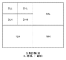
例えば、特許文献1に記載の技術は、RAW画像データから輝度成分で構成される輝度プレーンと、輝度以外の3プレーンに変換する。その後、各プレーンの信号を更にDWT変換を用いて周波数成分を分離し、図1に示すような複数のサブバンドを生成した後、サブバンドごとに符号化をすることで、効率的にRAW画像データを圧縮している。
For example, the technique described in
図1は、ウェーブレット変換を2回実行した場合に生成されるサブバンドを示している。ウェーブレット変換を1回行うと、{LL,HL,LH,HH}の4つのサブバンドが生成される。ここで、Lが低域、Hが高域を表す。また、アルファベット2文字の1つ目は水平方向、2つ目は垂直方向の帯域に対応する。そして、サブバンドの先頭の数字は分解レベルを表す。例えば、1HLは、水平方向が高域成分、垂直方向が低域成分の分解レベル“1”のサブバンド(の変換係数)を表す。なお、ウェーブレット変換の回数に制限はない。また、2回目以降のウェーブレット変換は、直前のウェーブレット変換で得られたサブバンドLLに対して再帰的に行うことになる。それ故、設定した回数のウェーブレット変換を行った際のサブバンドLLは一つしか存在しない。図1は、ウェーブレット変換を2回行った例であるので、7つのサブバンドが生成されることになる。 FIG. 1 shows the subbands generated when the wavelet transform is executed twice. When the wavelet transform is performed once, four subbands {LL, HL, LH, HH} are generated. Here, L represents a low frequency band and H represents a high frequency band. The first of the two letters of the alphabet corresponds to the horizontal band, and the second corresponds to the vertical band. And the number at the beginning of the subband represents the decomposition level. For example, 1HL represents (conversion coefficient) of the decomposition level “1” of the high frequency component in the horizontal direction and the low frequency component in the vertical direction. There is no limit to the number of wavelet transforms. Further, the second and subsequent wavelet transforms are recursively performed with respect to the subband LL obtained by the immediately preceding wavelet transform. Therefore, there is only one subband LL when the wavelet transform is performed a set number of times. Since FIG. 1 is an example in which the wavelet transform is performed twice, seven subbands are generated.
上記の技術などを用いてRAW画像データを圧縮してデータサイズを小さくすることで、動画記録時にはより長い時間記録することが可能になる。 By compressing the RAW image data and reducing the data size by using the above technique or the like, it becomes possible to record for a longer time at the time of moving image recording.
しかしながら、特許文献1に記載されるようにRAW画像データから輝度プレーンと輝度以外のプレーンとを生成してサブバンド符号化を利用した圧縮の場合、各プレーンへの符号化バッファの割り当てに留意する必要がある。
However, in the case of compression using subband coding by generating a luminance plane and a plane other than the luminance plane from the RAW image data as described in
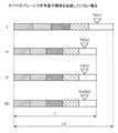
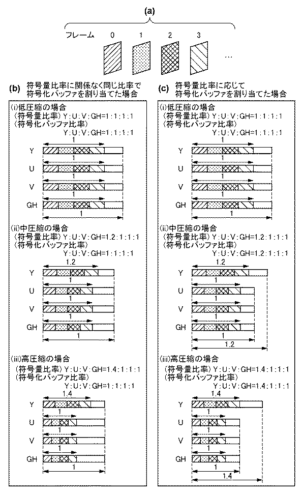
ここで、動画記録時の符号化データのバッファメモリへの格納について、図2(a)〜’c)を参照して説明する。図2(a)は、動画記録時に4フレーム分のベイヤ配列のRAW画像データを取得し、プレーン変換、ウェーブレット変換、エントロピー符号化して生成した符号化データをバッファメモリ上に確保されたプレーン毎の符号化バッファに格納する例を示している。 Here, the storage of the coded data in the buffer memory at the time of moving image recording will be described with reference to FIGS. 2 (a) to 2'c). In FIG. 2A, RAW image data of a bayer array for 4 frames is acquired at the time of moving image recording, and the coded data generated by plane conversion, wavelet transform, and entropy coding is secured for each plane in the buffer memory. An example of storing in the encoding buffer is shown.
図2(b)はRAW画像データから、R,G1,G2,Bプレーンを分離した場合を示し、図2(c)はRAW画像データを、Y(輝度)と輝度以外の3色差であるU,V,GHへの変換処理を介在させて得た、Y、U,V,GHプレーンの場合を示している。また、図2(b)(i)、図2(c)(i)それぞれは低圧縮時のプレーン毎の符号化バッファを、図2(b)(ii)、図2(c)(ii)は中圧縮時のプレーン毎の符号化バッファを、図2(b)(iii)、図2(c)(iii)は高圧縮時のプレーン毎の符号化バッファを示している。ここでバッファに格納されているデータの模様は、同図(a)のプレーンの模様に応じたものであると理解されたい。 FIG. 2 (b) shows a case where the R, G1, G2, and B planes are separated from the RAW image data, and FIG. 2 (c) shows the RAW image data as U, which is a three-color difference other than Y (luminance) and brightness. , V, GH The case of the Y, U, V, GH plane obtained by interposing the conversion process to GH is shown. Further, FIGS. 2 (b) (i) and 2 (c) (i) show the coding buffer for each plane at the time of low compression, respectively, as shown in FIGS. 2 (b) (ii) and 2 (c) (ii). Shows the coding buffer for each plane at the time of medium compression, and FIGS. 2 (b) (iii) and 2 (c) (iii) show the coding buffer for each plane at the time of high compression. It should be understood that the pattern of the data stored in the buffer here corresponds to the pattern of the plane shown in FIG.
図2(b)に示すR,G1,G2,Bプレーンの場合は、圧縮率に依らず、同じ比率の符号化バッファにすることで効率良く符号化バッファを使用することができる。一方で、図2(c)に示す後述するY,U,V,GHプレーンの場合は、輝度のYプレーンが他の色差プレーンよりも画質に支配的であるので、圧縮率が高いほど輝度プレーンは輝度以外のプレーンと比べて符号量を多く割り当てて符号化が行われる。このため、圧縮率依らず各プレーンで同じ比率の符号化バッファを割り当てると、輝度プレーン以外のプレーンには冗長の符号化バッファを与えることになり、バッファメモリが増大することで回路規模が大きくなってしまう。 In the case of the R, G1, G2, and B planes shown in FIG. 2B, the coding buffer can be efficiently used by using the coding buffer having the same ratio regardless of the compression ratio. On the other hand, in the case of the Y, U, V, and GH planes shown in FIG. 2C, which will be described later, the luminance Y plane is more dominant in image quality than the other color difference planes. Is coded by allocating a larger amount of code than a plane other than luminance. Therefore, if the same ratio of coding buffers is assigned to each plane regardless of the compression rate, redundant coding buffers are given to the planes other than the luminance plane, and the circuit scale increases due to the increase in buffer memory. It ends up.
本発明は上記の問題点に鑑み、圧縮率に応じた効率的な符号化バッファの使用を行い、回路規模を削減することを可能とする画像符号化装置の提供を目的とする。 In view of the above problems, an object of the present invention is to provide an image coding apparatus capable of efficiently using a coding buffer according to a compression ratio and reducing the circuit scale.
この課題を解決するため、例えば本発明の画像符号化装置は以下の構成を備える。すなわち、
RAW画像データを符号化する画像符号化装置であって、
符号化データを一時的に記憶するためのバッファメモリと、
RAW画像データを輝度成分で構成される輝度プレーンと、輝度以外の複数の種類の色差成分のプレーンに変換するプレーン変換手段と、
前記プレーン変換手段で得られた各プレーンに対してウェーブレット変換するウェーブレット変換手段と、
前記ウェーブレット変換手段で生成された各サブバンドの係数を量子化、符号化し、得られた符号化データを前記バッファメモリに格納する符号化手段と、
前記バッファメモリに格納された符号化データを記録媒体に記録する記録手段と、
前記バッファメモリに確保するプレーン毎のバッファサイズの比率を、前記RAW画像データの圧縮率に応じて制御する制御手段とを有する。
In order to solve this problem, for example, the image coding apparatus of the present invention has the following configuration. That is,
An image coding device that encodes RAW image data.
A buffer memory for temporarily storing encoded data, and
A luminance plane composed of luminance components and a plane conversion means for converting RAW image data into planes of multiple types of color difference components other than luminance, and
A wavelet transforming means that performs wavelet transforming on each plane obtained by the plane transforming means,
A coding means that quantizes and encodes the coefficient of each subband generated by the wavelet transform means and stores the obtained coded data in the buffer memory.
A recording means for recording the coded data stored in the buffer memory on a recording medium, and
It has a control means for controlling the ratio of the buffer size for each plane secured in the buffer memory according to the compression rate of the RAW image data.
本発明によれば、冗長な符号化バッファを減らし、回路規模の増大を抑えることができる。 According to the present invention, redundant coding buffers can be reduced and an increase in circuit scale can be suppressed.
以下、添付図面を参照して実施形態を詳しく説明する。尚、以下の実施形態は特許請求の範囲に係る発明を限定するものでない。実施形態には複数の特徴が記載されているが、これらの複数の特徴の全てが発明に必須のものとは限らず、また、複数の特徴は任意に組み合わせられてもよい。さらに、添付図面においては、同一若しくは同様の構成に同一の参照番号を付し、重複した説明は省略する。 Hereinafter, embodiments will be described in detail with reference to the accompanying drawings. The following embodiments do not limit the invention according to the claims. Although a plurality of features are described in the embodiment, not all of the plurality of features are essential to the invention, and the plurality of features may be arbitrarily combined. Further, in the attached drawings, the same or similar configurations are designated by the same reference numbers, and duplicate explanations are omitted.
[第1の実施形態]
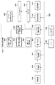
図3は、第1の実施形態の画像符号化装置を、撮像装置300に適用した場合の構成を示している。
[First Embodiment]
FIG. 3 shows a configuration when the image coding device of the first embodiment is applied to the
撮像装置300は、CPU301、撮像部302、プレーン変換部303、ウェーブレット変換部304、量子化部305、エントロピー符号化部306、メモリI/F 307、バッファメモリ308、記録処理部309、記録媒体310、及び、ユーザインタフェース350を有する。ユーザインタフェース350は、ユーザに撮像画像や各種メニューを表示するための表示デバイス、並びに、ユーザからの各種指示入力(圧縮率の設定も含まれる)を受け付けるスイッチやボタン、タッチパネル等の操作部で構成される。
The
CPU301は、当該CPUが実行する制御プログラムを格納したり、ワークエリアとして使用するためのメモリを持ち、撮像装置300の全体の処理を制御する。
The
撮像部302は、光情報を電気信号に変換するCCDイメージセンサ又は、CMOSイメージセンサなどの撮像素子を含む。撮像素子の並びはベイヤ配列となっているものとする。撮像部302は、イメージセンサで得た電気信号をデジタル信号に変換して得たベイヤ配列の画像データを、RAW画像データとして、プレーン変換部303に送る。
The
なお、ベイヤ配列の画像における、隣接する2×2画素に着目したとき、その内訳は、1個のR(赤)成分の画素、1個のB(青)成分の画素、そして対角位置関係にある2個のG(緑)成分の画素で構成される。G成分の画素は2つあるので、便宜的に一方をG1画素,他方をG2画素と表現している。ベイヤ配列とは、この2×2画素のパターンが、繰り返し並んだ配列を言う。 When focusing on adjacent 2 × 2 pixels in the Bayer array image, the breakdown is one R (red) component pixel, one B (blue) component pixel, and a diagonal positional relationship. It is composed of two G (green) component pixels in. Since there are two pixels of the G component, one is expressed as a G1 pixel and the other as a G2 pixel for convenience. The Bayer array is an array in which these 2 × 2 pixel patterns are repeatedly arranged.
プレーン変換部303は、撮像部302から送られたRAW画像データから、それぞれが単一成分で構成される4つのプレーンを分離し、それらを予め設定された順番にウェーブレット変換部304に送る。例えば、4つのプレーンは、R成分の画素のみで構成されるRプレーン、G1成分の画素のみで構成されるG1プレーン、G2成分の画素のみで構成されるG2プレーン、および、B成分のみの画素で構成されるBプレーンである。また、プレーン変換部303は、例えば以下の式(1)〜(4)を用いて、RAW画像データから、1つのY(輝度成分)プレーンと、3つの色差成分のプレーン(Uプレーン、Vプレーン、及びGHプレーン)を導出しても良い。
Y=(R+B+G1+G2)/4 …(1)
U=B-(G1+G2)/2 …(2)
V=R-(G1+G2)/2 …(3)
GH=G1-G2 …(4)
実施形態におけるプレーン変換部303が、RAW画像データをY,U,V,GHプレーンに変換するものとして説明を続ける。なお、プレーン変換部303は、複数の計算式を実装しておき、CPU301で使用する計算式を選択するようにしても良い。また、実施形態では、色差の種類として、U,V,GHを例にするが、これに限らず、他の色差を用いても良い。
The
Y = (R + B + G1 + G2) / 4… (1)
U = B- (G1 + G2) / 2… (2)
V = R- (G1 + G2) / 2… (3)
GH = G1-G2… (4)
The description continues assuming that the
ウェーブレット変換部304は、プレーン変換部303により入力した各プレーン(それぞれを単一成分の画像データと見ることができる)をウェーブレット変換し、複数のサブバンドを生成する。ウェーブレット変換部304が行うウェーブレット変換の回数(分解数)は、CPU301によって設定されるものとする。また、ウェーブレット変換部304は、各サブバンドで1ライン分の変換係数が生成される度に、各サブバンドの1ライン分の変換係数を量子化部305へ出力する。
The
量子化部305は、量子化パラメータQpを利用し、ウェーブレット変換部304より入力した各プレーンの変換係数に対して、1係数単位に量子化する。なお、量子化パラメータQpは、その値が大きいほど、量子化後の値が小さくなって符号量の削減が可能になるものの、画質劣化が顕著になるパラメータである。また、各プレーンの変換係数の量子化はプレーン毎に行っても、全プレーンについて並列して行っても良い。
The
エントロピー符号化部306は、量子化部305で量子化された各サブバンドに対してハフマン符号や算術符号等を用いたエントロピー符号化を行い、各サブバンドの符号化データを生成する。また、エントロピー符号化部306は、CPU301によって指定されたアドレスに基づき、各サブバンドの符号化データをバッファメモリ308に一時的に記憶する。なお、プレーンまたはサブバンド毎の符号化バッファの大きさはCPU301によって設定される。
The
メモリI/F307は、エントロピー符号化部306を含めた、各処理部からのバッファメモリ・アクセス要求を調停し、バッファメモリ308に対する読み出し、並びに、書き込みの制御を行う。
The memory I /
バッファメモリ308は、エントロピー符号化部306から送られた各サブバンドの符号化データを含めた、各種データを格納するための揮発性メモリで構成される記憶領域である。
The
記録処理部309は、CPU301からの記録命令に従い、バッファメモリ308へ格納された符号化データを記録媒体310へファイルとして記録する。記録媒体310は、不揮発性メモリで構成される記録メディアである。なお、記録媒体310は、典型的には、SDカードに代表される脱着可能な記録媒体とする。
The
続いて、CPU301による、圧縮率に応じたバッファメモリ308上の符号化バッファの割り当てについて図4を参照して説明する。
Subsequently, the allocation of the coded buffer on the
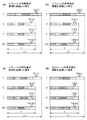
図4(a)は、連続する4つのRAW画像のフレームを示している。同図(b)はRAW画像からY,U,V,GHプレーンを分離し、それぞれについて同じ比率でバッファサイズを割り当てた際の符号化データの蓄積状態を示している。同図(c)はRAW画像からY,U,V,GHプレーンを分離し、それぞれについて符号量に応じた比率でバッファサイズを割り当てた際の符号化データの蓄積状態を示している。なお、バッファに格納される符号化データと、4つのRAW画像との対応を分かり易くするため、それぞれを対応する模様で表現している。 FIG. 4A shows frames of four consecutive RAW images. FIG. 3B shows the accumulation state of coded data when the Y, U, V, and GH planes are separated from the RAW image and the buffer sizes are assigned to each of them at the same ratio. FIG. 3C shows the accumulation state of coded data when the Y, U, V, and GH planes are separated from the RAW image and the buffer size is assigned to each of them at a ratio according to the code amount. In order to make it easy to understand the correspondence between the coded data stored in the buffer and the four RAW images, each is represented by a corresponding pattern.
また、実施形態では、バッファに連続する4プレーン分の符号化データが格納された場合、もしくは、符号化データのバッファへの格納された割合が設定された閾値に到達したプレーンが1つでもあれば、全プレーンの符号化データのファイルへの記録処理を行うものとして説明する。 Further, in the embodiment, when the encoded data for four consecutive planes is stored in the buffer, or even if there is only one plane in which the ratio of the encoded data stored in the buffer reaches the set threshold value. For example, it will be described as assuming that the coded data of all planes is recorded in a file.
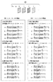
本実施形態では、予め大量の画像データから圧縮率毎に統計的に各プレーンの符号量比率を求めておき、以下の符号量比率が取得できたと仮定する。なお、圧縮率に応じた各プレーンの符号量比率はこれに限るものではないが、ユーザはユーザインタフェース150を操作して、3段階の圧縮率(符号量比率)の中の1つを選択するものとする。なお、圧縮率が高いほど、符号量が少なくなることを意味することに注意されたい。 In the present embodiment, it is assumed that the code amount ratio of each plane is statistically obtained for each compression rate from a large amount of image data in advance, and the following code amount ratio can be obtained. The code amount ratio of each plane according to the compression rate is not limited to this, but the user operates the user interface 150 to select one of the three levels of compression rate (code amount ratio). It shall be. It should be noted that the higher the compression ratio, the smaller the code amount.
<統計的に求めた圧縮率毎の各プレーンの符号量比率>
・低圧縮時の場合
Y:U:V:GH = 1:1:1:1 …(5)
・中圧縮時の場合
Y:U:V:GH = 1.2:1:1:1 …(6)
・高圧縮時の場合
Y:U:V:GH = 1.4:1:1:1 …(7)
図4(b)は、圧縮率に依らずプレーン間の符号化バッファのサイズ比率を同一として符号化を行い、そのときの符号量が統計データに基づくプレーン毎の符号量比率になったと仮定した場合を示している。このとき、図4(b)で示すように圧縮率が高くなるほどY(輝度)プレーンの符号化バッファ使用率が、輝度以外の色差プレーンと比較して高くなり、輝度以外のプレーンでは符号化バッファを冗長に確保してしまっていることを示している。
<Statistically determined code amount ratio of each plane for each compression rate>
・ For low compression
Y: U: V: GH = 1: 1: 1: 1… (5)
・ For medium compression
Y: U: V: GH = 1.2: 1: 1: 1… (6)
・ For high compression
Y: U: V: GH = 1.4: 1: 1: 1… (7)
In FIG. 4B, it is assumed that the size ratio of the coding buffer between the planes is the same regardless of the compression rate and the coding is performed, and the coding amount at that time is the coding amount ratio for each plane based on the statistical data. Shows the case. At this time, as shown in FIG. 4B, the higher the compression ratio, the higher the coding buffer usage rate of the Y (luminance) plane as compared with the color difference plane other than the luminance plane, and the coding buffer in the plane other than the luminance plane. It shows that it has been secured redundantly.
そこで、本実施形態では図4(c)に示すように圧縮率に応じて、バッファメモリ308に確保する各プレーンの符号化バッファ、サイズの比率を変更する。ここでは、以下のように符号化バッファ比率を割り当てるとする。
Therefore, in the present embodiment, as shown in FIG. 4C, the ratio of the coded buffer and the size of each plane secured in the
<圧縮率に応じた各プレーンの符号化バッファ比率の割り当て>
・低圧縮時の場合
Y:U:V:GH = 1:1:1:1 …(8)
・中圧縮時の場合
Y:U:V:GH = 1.2:1:1:1 …(9)
・高圧縮時の場合
Y:U:V:GH = 1.4:1:1:1 …(10)
上記のように各圧縮率で統計に基づいた符号化バッファ比率にすることによって、図4(b)のときと比較して、図4(c)の場合、輝度以外のプレーンで冗長となっていた符号化バッファのサイズを削減することが可能となる。
<Assignment of coding buffer ratio of each plane according to compression rate>
・ For low compression
Y: U: V: GH = 1: 1: 1: 1… (8)
・ For medium compression
Y: U: V: GH = 1.2: 1: 1: 1… (9)
・ For high compression
Y: U: V: GH = 1.4: 1: 1: 1… (10)
By setting the coding buffer ratio based on statistics at each compression rate as described above, in the case of FIG. 4 (c), the planes other than the luminance are redundant as compared with the case of FIG. 4 (b). It is possible to reduce the size of the coded buffer.
ここまでは各プレーンの符号化バッファの割り当てを説明した。次に、プレーン分離後の4プレーン中の1プレーンに着目し、その着目プレーンから得た各サブバンドへの割り当て比率について説明する。 So far, the allocation of the coding buffer for each plane has been described. Next, focusing on one of the four planes after plane separation, the allocation ratio to each subband obtained from the plane of interest will be described.
本実施形態においてサブバンドごとの符号化バッファは、各サブバンドの面積比に基づいて割り当てるものとする。 In the present embodiment, the coding buffer for each subband shall be allocated based on the area ratio of each subband.
離散ウェーブレット変換によるサブバンド分割は、分解レベルが1レベル上がるごとに水平および垂直の係数の個数が半分になるため、面積としては4分の1となる。 Subband division by the discrete wavelet transform halves the number of horizontal and vertical coefficients each time the decomposition level increases by one level, resulting in a quarter of the area.
そのため、サブバンド{1HL,1LH,1HH}の各々のサイズに対し、サブバンド{2LL、2HL,2LH,2HH}の各々のサイズは4分の1の関係となる。以上より、各サブバンドへの符号化バッファの割り当ては、下記のように行われる。 Therefore, each size of the subband {2LL, 2HL, 2LH, 2HH} has a one-fourth relationship with each size of the subband {1HL, 1LH, 1HH}. From the above, the coding buffer is assigned to each subband as follows.
<各サブバンドの符号化バッファ比率>
2LL:2HL:2LH:2HH:1HL:1LH:1HH =1:1:1:1:4:4:4 …(11)
なお、各サブバンドのバッファメモリの割り当ては、圧縮率に依らず一定とする。また、ここでは4プレーン中の1プレーンについて説明したが、他のプレーンに関しても同様な割り当てを行う。
<Code-coded buffer ratio for each subband>
2LL: 2HL: 2LH: 2HH: 1HL: 1LH: 1HH = 1: 1: 1: 1: 1: 4: 4: 4… (11)
The allocation of the buffer memory of each subband is constant regardless of the compression rate. Further, although one of the four planes has been described here, the same allocation is made for the other planes.
続いて、本第1の実施形態である画像符号化装置の動作の詳細を図5に示すフローチャートを基づき説明する。なお、ここでの動作として、符号化したRAW画像データのバッファメモリ308上のバッファメモリへの格納と、すでに符号化バッファに格納されている符号化されたRAW画像データの記録媒体310への記録が同時に実行されているものとする。
Subsequently, the details of the operation of the image coding apparatus according to the first embodiment will be described with reference to the flowchart shown in FIG. As the operation here, the encoded RAW image data is stored in the
まず、S501にて、CPU301は、ユーザインタフェース350により設定された、撮影に係る圧縮率のモードを判定する。続いて、S502にて、CPU301は、判定した圧縮率の設定に基づき、バッファメモリ308における、プレーン毎の符号化バッファの割り当てを決定する。
First, in S501, the
次に、S503にて、CPU301は、プレーン毎に割り当てられた符号化バッファサイズを各サブバンドの面積比に基づいて、各サブバンドのバッファサイズを割り当て、これらを、エントロピー符号化部306の出力先として設定する。
Next, in S503, the
次に、S504にて、CPU301は、撮像部302の駆動を開始する。そして、CPU301は、プレーン変換部303、ウェーブレット変換部304、量子化部305、エントロピー符号化部306の駆動も開始し、複数のサブバンドごとの符号化データを生成し、バッファメモリ308に書き込みを行わせる。
Next, in S504, the
次に、S505にて、CPU301は、1フレームの符号化を完了させる。
Next, in S505, the
そして、S506にて、CPU301は、ユーザから記録の停止指示を受けたか否か、受けていれば最終フレームのバッファメモリ内の符号化データの記録媒体310への記録が完了しているか否かを判定し、最終フレームの記録が完了していれば本処理を終了する。また、記録が継続している場合、CPU301は、処理をS504に戻し、のフレームの符号化を行う。
Then, in S506, the
以上、本第1の実施形態によれば、圧縮率に起因するプレーン間における発生符号量の偏りに対応でき、効率良くバッファメモリを使用することで、回路規模を増加させることなく符号化が可能となる。 As described above, according to the first embodiment, it is possible to deal with the bias of the generated code amount between the planes due to the compression rate, and by efficiently using the buffer memory, coding can be performed without increasing the circuit scale. It becomes.
なお、上記第1の実施形態の画像符号化装置において、圧縮率毎に各プレーンの符号化比率を変更したが、圧縮率に限らずフレームレートに応じて符号化バッファの比率を変更してもよい。つまり、フレームレートが高くなるほど、圧縮率を高くするという関係を用いて、符号化バッファ比率を決定する。また、上記では、ユーザが選択できる圧縮率の段数を“3”として説明したが、この数に特に制限はない。 In the image coding apparatus of the first embodiment, the coding ratio of each plane is changed for each compression rate, but the ratio of the coding buffer may be changed according to the frame rate as well as the compression rate. Good. That is, the coding buffer ratio is determined by using the relationship that the compression rate increases as the frame rate increases. Further, in the above description, the number of stages of the compression rate that can be selected by the user is described as "3", but this number is not particularly limited.
また、実際に発生する符号化データサイズに基づいて各サブバンドへの割り当てを実施していないため、バッファメモリのサイズとしてはマージンを持つことが望ましい。このときのマージンに関しても各プレーンで符号化バッファ比率に応じた領域を確保する。 Further, since the allocation to each subband is not performed based on the actually generated coded data size, it is desirable to have a margin as the size of the buffer memory. Regarding the margin at this time, an area corresponding to the coding buffer ratio is secured in each plane.
[第2の実施形態]
上記第1の実施形態では、圧縮率に応じてプレーン間の符号量比率が異なることを鑑みて、圧縮率に応じてプレーン間の符号化バッファ比率を変更した。本第2の実施形態では、上記第1の実施形態と比較して、圧縮率に応じて各プレーンの符号化バッファ比率を変更してもなおプレーン間で符号量に偏りが生じる場合に対処する、符号量制御に関して説明する。
[Second Embodiment]
In the first embodiment, the coding buffer ratio between the planes is changed according to the compression rate in view of the fact that the code amount ratio between the planes differs depending on the compression rate. In the second embodiment, as compared with the first embodiment, the case where the code amount is still biased between the planes even if the coding buffer ratio of each plane is changed according to the compression rate is dealt with. , Code amount control will be described.
本第2の実施形態でも、画像符号化装置として、撮像装置に適用した例を説明する。図6は、第2の実施形態における撮像装置600のブロック構成図である。
Also in the second embodiment, an example applied to an image pickup device as an image coding device will be described. FIG. 6 is a block configuration diagram of the
撮像装置600は、CPU 601、撮像部602、プレーン変換部603、ウェーブレット変換部604、量子化部605、エントロピー符号化部606、バッファ使用率算出部607、メモリI/F 608、バッファメモリ609、記録処理部610、記録媒体611、符号量制御部612、発生符号量保持部613、差分算出部614、目標符号量算出部615、量子化制御部616、及び、ユーザインタフェース650を有する。
The
ここで、本第2の実施形態の装置構成における第1の実施形態と異なる点を説明する。バッファ使用率算出部607は、1フレームの符号化完了後、バッファメモリ609における各プレーンの符号化バッファの使用率を算出する。その際、算出した各プレーンの符号化バッファ使用率が、予め設定した閾値(TH(Y)、TH(U)、TH(V)、TH(GH))に対して、図7で示すように全てのプレーンで超過しない場合と、図8(a)〜(d)で示すように一つのプレーンでも符号量が超過してしまう場合がある。図8(a)は輝度Yプレーンにおいて、図8(b)は色差Uプレーンにおいて、図8(c)は色差Vプレーンにおいて、そして、図8(d)は色差GHプレーンにおいて符号量が閾値を超過した場合を示している。なお、閾値の設定方法として、例えば、本来のバッファ比率に対して20%の符号化バッファのマージンを取ったとすると、このときの符号化バッファ量はマージン分を含めて120%となる。そこで、各プレーンで設定する閾値はその内の9割よりも多くの符号量を使用した場合と定義し、120%×0.9=108%を閾値として定義するものとした。
Here, the points different from the first embodiment in the apparatus configuration of the second embodiment will be described. The buffer usage
本実施形態では、バッファ使用率算出部607で算出した各プレーンの符号化バッファの使用率が閾値を超過するか否かで符号量制御部612の制御方法を変更するが、詳細な制御方法に関する説明は後述する。なお、各プレーンで設定する閾値は任意である。このときの各プレーンの符号化バッファの割り当ては以下に示すものであるとする。
In the present embodiment, the control method of the code
<各プレーンの符号化バッファ比率の割り当て>
Y:U:V:GH = 1.2:1:1:1 …(12)
<Assignment of coding buffer ratio for each plane>
Y: U: V: GH = 1.2: 1: 1: 1… (12)
まず、はじめに全てのプレーンの符号量が閾値を超過しない場合の符号量制御部612の制御方法について説明する。
First, a control method of the code
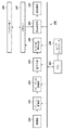
<制御単位>
前述のように符号化単位をサブバンド毎のラインとしているが、量子化制御単位は、同一画素位置の各サブバンドの符号化結果の集合体とする。すなわち、図9に示すように、分解レベル2のサブバンド{2LL,2LL,2HL,2HH}の1ライン、分解レベル1のサブバンド{1LH,1HL,1HH}の2ラインを、一回のQpによる制御単位とする。以降、この制御単位をブロックラインと呼ぶ。また、iをブロックライン番号とする。なお、1ブロックラインは、入力したRAW画像データの16ラインに相当する。
<Control unit>
As described above, the coding unit is a line for each subband, but the quantization control unit is a set of coding results of each subband at the same pixel position. That is, as shown in FIG. 9, one line of the
発生符号量保持部613は、エントロピー符号化部606から通知される符号化データの発生符号量を保持する。目標符号量算出部615は、各フレームの先頭ブロックラインのQpを制御するタイミングと判断した場合にフレームの目標符号量を算出する。その際の目標符号量算出方法の詳細は後述する。差分算出部614は、ブロックライン毎の発生符号量とブロックライン毎の目標符号量の差分を算出し、差分の積算値である積算差分量を更に算出する。また、フレームの先頭ブロックラインのQpを制御するタイミングで、積算差分量は“0”に初期化されるものとする。
The generated code
量子化制御部616は、差分算出部614から通知される積算差分量に基づき、Qpを算出(更新)する(詳細は後述)。以上により符号量制御する。
The
<量子化値算出>
量子化パラメータ算出方法の一つに、MPEG2 Test Model 5に示された公知技術がある。このTest Model 5によれば、着目ブロックラインがi番目とし、差分算出部614で算出した着目ブロックラインの直前までの積算差分量をΣE[i−1]、基準量子化パラメータQp_ref、制御感度“r”と定義したとき、着目ブロックラインの量子化パラメータQp[i]を以下のように算出することができる。
Qp[i] = Qp_ref+r× ΣE[i-1] …(13)
なお、Qp_refは、フレームの先頭では初期量子化パラメータQp_iniであり、それ以外の領域では、直前フレームの最終ブロックラインのQpである。これは、ΣE[i−1]はQpの連続性を確保するために行う処理であり、フレームの先頭で初期化する。また、制御感度“r”は、大きいほど急峻にQpを変動させる一方、符号量の制御性が向上するパラメータである。
<Quantization value calculation>
As one of the quantization parameter calculation methods, there is a known technique shown in
Qp [i] = Qp_ref + r × ΣE [i-1]… (13)
Note that Qp_ref is the initial quantization parameter Qp_ini at the beginning of the frame, and is the Qp of the final block line of the immediately preceding frame in other regions. This is a process performed by ΣE [i-1] to ensure the continuity of Qp, and is initialized at the beginning of the frame. Further, the control sensitivity "r" is a parameter that sharply fluctuates Qp as it is larger, while improving the controllability of the code amount.
Test Model5を利用することで、目標符号量に対して発生符号量が大きければ量子化パラメータを大きく、小さければ量子化パラメータを小さく設定し、符号量を制御することが可能である。
By using
量子化制御部616は、式(13)を用いて決定した着目ブロックラインの量子化パラメータQp[i]を、各サブバンドで実際に量子化へ利用するサブバンドQp(=Qp[pl][sb])に更に変換し、量子化部605に通知する。なお、pl,sbはそれぞれ、該当プレーン、該当サブバンドを示す。量子化制御部616は、式(13)で決定した着目ブロックラインの量子化パラメータQp[i]を、式(14)に示すように、予め設定したプレーンやサブバンド毎に有するマトリクスmtxに適用することで、サブバンド毎のQpを算出する。
Qp[pl][sb] = Qp[i]×mtx[pl][sb] …(14)
一般的に、高域のサブバンドほどQpを大きく、低域のサブバンドほどQpを小さく設定し符号量制御を行うことで、人間の視覚特性上視認しづらい、画像データの高域成分ほど発生符号量を圧縮し、符号化効率を向上させる。そのため、マトリクスは、高域サブバンドほどQpが大きく、低域サブバンドほどQpが小さくなるように設定する。
The
Qp [pl] [sb] = Qp [i] × mtx [pl] [sb]… (14)
In general, by setting the Qp larger for the high-frequency subband and the Qp smaller for the low-frequency subband and controlling the code amount, it is difficult to visually recognize due to human visual characteristics, and the high-frequency component of the image data is generated. The amount of code is compressed to improve the coding efficiency. Therefore, the matrix is set so that the higher the subband, the larger the Qp, and the lower the subband, the smaller the Qp.
<目標符号量算出>
<処理フロー>
目標符号量算出部615は、フレームの先頭のQpを決定する場合に駆動され、1フレームの目標符号量を算出する。各フレームの目標符号量の算出方法として、設定されたビットレートから1フレーム当たりの目標符号量を算出したものと、前フレームにおける目標符号量から発生符号量を引いた差分値の和を各フレームの目標符号量とする。
<Calculation of target code amount>
<Processing flow>
The target code amount calculation unit 615 is driven when determining the Qp at the beginning of the frame, and calculates the target code amount of one frame. As a method of calculating the target code amount of each frame, the sum of the value obtained by calculating the target code amount per frame from the set bit rate and the difference value obtained by subtracting the generated code amount from the target code amount in the previous frame is added to each frame. Let it be the target code amount of.
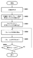
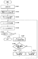
図10は、目標符号量算出部615の処理手順を示すフローチャートである。以下、同図を参照して、目標符号量算出部615によるブロックライン毎の目標符号量の算出方法について説明する。 FIG. 10 is a flowchart showing a processing procedure of the target code amount calculation unit 615. Hereinafter, a method of calculating the target code amount for each block line by the target code amount calculation unit 615 will be described with reference to the figure.
S1001にて、目標符号量算出部615は、符号量残量を算出する。符号量残量とは、着目フレームの目標符号量から符号化済みブロックラインの発生符号量の総和を減じた値である。 In S1001, the target code amount calculation unit 615 calculates the remaining amount of code amount. The remaining code amount is a value obtained by subtracting the sum of the generated code amounts of the coded block lines from the target code amount of the frame of interest.
S1002にて、目標符号量算出部615は、符号量残量が0以下であれば、符号量残量を0にクリップして以降の処理を実施する。この処理は、目標符号量が負になることを避けるために実施する。 In S1002, if the remaining amount of code is 0 or less, the target code amount calculation unit 615 clips the remaining amount of code to 0 and performs the subsequent processing. This process is carried out in order to prevent the target code amount from becoming negative.
S1003にて、目標符号量算出部615は、ブロックライン毎の目標符号量を算出する。ブロックライン毎の目標符号量は、符号量残量/未符号化ブロックライン数により算出する。 以上によりブロックライン毎の目標符号量が決定する。 In S1003, the target code amount calculation unit 615 calculates the target code amount for each block line. The target code amount for each block line is calculated by the remaining amount of code / the number of uncoded block lines. From the above, the target code amount for each block line is determined.
次に、予め設定した閾値に対して符号量が超過するプレーンが一つでも存在する場合の符号量制御部612の制御方法について説明する。
Next, a control method of the code
この場合の符号量制御部612の制御方法は、閾値を超過したプレーンに対する符号化バッファの符号量をこれ以上増加させないようにするため、フレーム単位の符号量制御ではなく、各プレーンで独立して符号量制御する。
In this case, the control method of the code
<制御単位>
制御単位に関しては、前述したブロックライン単位で行う。発生符号量保持部613は、プレーン毎にエントロピー符号化部606から通知される符号化データである発生符号量を保持する。目標符号量算出部615は、先頭ブロックラインのQpを制御するタイミングと判断した場合に各プレーンの目標符号量を算出する。その際の各プレーンにおける目標符号量算出方法の詳細は後述する。差分算出部614は、各プレーンのブロックライン毎の発生符号量と各プレーンのブロックライン毎の目標符号量との差分を算出し、差分の積算値である積算差分量を更に算出する。また、各プレーンの先頭ブロックラインのQpを制御するタイミングで、積算差分量は0に初期化する。量子化制御部616は、差分算出部614から通知される積算差分量に基づき、Qpを算出する(詳細後述)。以上により符号量制御する。
<Control unit>
The control unit is the block line unit described above. The generated code
<量子化値算出>
量子化制御部616は、各プレーンのブロックライン毎に差分算出部614で算出した積算差分量ΣE[i−1]と、各プレーンの基準量子化パラメータQYini、QUini、QVini、QGHiniと、各プレーンの制御感度rY、rU、rV、rGHを用いて、プレーン毎の着目ブロックラインの量子化パラメータQY [i]、QU[i]、QV[i]、QGH[i]を以下のように算出する。
QY[i] =QYini + rY×ΣE[i-1] …(15)
QU[i] =QUini + rU×ΣE[i-1] …(16)
QV[i] =QVini + rV×ΣE[i-1] …(17)
QGH[i] =QGHini + rGH×ΣE[i-1] …(18)
ただし、UプレーンとVプレーンの量子化パラメータは色のバランスを鑑み、QU[i]とQV[i]との大小比較を行い、大きい方の量子化パラメータを共通の量子化パラメータとして使用する。
<Quantization value calculation>
The
Q Y [i] = Q Yini + r Y × ΣE [i-1]… (15)
Q U [i] = Q Uini + r U × ΣE [i-1]… (16)
Q V [i] = Q Vini + r V × ΣE [i-1]… (17)
Q GH [i] = Q GHini + r GH × ΣE [i-1]… (18)
However, in consideration of the color balance, the quantization parameters of the U plane and V plane are compared in magnitude between Q U [i] and Q V [i], and the larger quantization parameter is used as a common quantization parameter. To do.
量子化制御部616は、式(15)から(18)に従って決定した各プレーンの着目ブロックラインの量子化パラメータQpを、各サブバンドで実際に量子化へ利用するサブバンドのパラメータQp{Qp[Y][sb]、Qp[U][sb]、Qp[V][sb]、Qp[GH][sb])に更に変換し、量子化部605に通知する。なお、ここで“sb”は該当サブバンドを示す。量子化制御部616は、式(15)~(18)で決定したブロックラインの量子化パラメータを、各プレーンで予め設定したサブバンド毎に有するマトリクスmtxを用いて、式(19)〜(22)に適用して、サブバンドの量子化パラメータQpを算出する。
Qp[Y][sb] = QY[i] ×mtx[sb] …(19)
Qp[U][sb] = QU[i] ×mtx[sb] …(20)
Qp[V][sb] = QV[i] ×mtx[sb] …(21)
Qp[GH][sb] = QGH[i] ×mtx[sb] …(22)
The
Qp [Y] [sb] = Q Y [i] × mtx [sb]… (19)
Qp [U] [sb] = Q U [i] × mtx [sb]… (20)
Qp [V] [sb] = Q V [i] × mtx [sb]… (21)
Qp [GH] [sb] = Q GH [i] × mtx [sb]… (22)
<目標符号量算出>
<処理フロー>
目標符号量算出部615は、フレームの先頭のQpを決定する場合に駆動され、各プレーンの目標符号量を算出する。ここで、プレーン毎の目標符号量の算出方法として、例えば、図8(a)で示したYプレーンの符号量が予め設定していた閾値(TH(Y))を超過した場合に関する各プレーンの目標符号量算出について説明する。
<Calculation of target code amount>
<Processing flow>
The target code amount calculation unit 615 is driven when determining the Qp at the beginning of the frame, and calculates the target code amount of each plane. Here, as a method of calculating the target code amount for each plane, for example, for each plane regarding the case where the code amount of the Y plane shown in FIG. 8A exceeds a preset threshold value (TH (Y)). The calculation of the target code amount will be described.
ここで、着目フレームのYプレーンの発生符号量をY(Sn)、Uプレーンの発生符号量をU(Sn)、Vプレーンの発生符号量をV(Sn)、GHプレーンの発生符号量をGH(Sn)とし、着目フレームの目標符号量をTnとする。このとき、以下の関係が成り立つ。
Tn=Y(Tn)+V(Tn)+U(Tn)+GH(Tn) …(23)
Here, the generated code amount of the Y plane of the frame of interest is Y (S n ), the generated code amount of the U plane is U (S n ), the generated code amount of the V plane is V (S n ), and the generated code of the GH plane. Let the quantity be GH (S n) and the target code quantity of the frame of interest be T n . At this time, the following relationship holds.
T n = Y (T n ) + V (T n ) + U (T n ) + GH (T n )… (23)
また、上記着目フレームに対し前フレームにおけるYプレーンの発生符号量をY(Sn-1)、同Uプレーンの発生符号量をU(Sn-1)、同Vプレーンの発生符号量をV(Sn-1)、同GHプレーンの発生符号量をGH(Sn-1)とし、前フレームの目標符号量をTn-1とする。 Further, with respect to the frame of interest, the generated code amount of the Y plane in the previous frame is Y (S n-1 ), the generated code amount of the U plane is U (S n-1 ), and the generated code amount of the V plane is V. (S n-1 ), the generated code amount of the same GH plane is GH (S n-1 ), and the target code amount of the previous frame is T n-1 .
まず、着目フレームにおけるYプレーンの目標符号量Y(Tn)は、これ以上のYプレーンの符号化バッファを増加さないで、且つ、その中でも最大限の符号量が割り当てられるよう式(12)で示すプレーン毎の符号化バッファ比率を鑑みて以下のように設定する。
Y(Tn)=Tn×1.2/(1.2+1+1+1) …(24)
First, the target code amount Y (T n ) of the Y plane in the frame of interest does not increase the coding buffer of the Y plane any more, and the maximum code amount is allocated among them (Equation (12)). Set as follows in consideration of the coding buffer ratio for each plane indicated by.
Y (T n ) = T n × 1.2 / (1.2 + 1 + 1 + 1)… (24)
同様にして、Yプレーン以外のプレーンに対する目標符号量の設定についても式(12)を用いて設定することが可能であるが、符号化バッファ比率で符号量を割り当てるよりもそれまでフレーム単位で符号量制御していたときの符号量を踏襲した方が画質的に安定をする。そのため、Yプレーン以外では、着目フレームに対し前フレームの符号量を鑑みた目標符号量の設定を行うこととする。 Similarly, it is possible to set the target code amount for planes other than the Y plane by using Eq. (12), but the code is coded in frame units until then, rather than allocating the code amount by the coded buffer ratio. The image quality is more stable if the code amount is followed when the amount is controlled. Therefore, in addition to the Y plane, the target code amount is set for the frame of interest in consideration of the code amount of the previous frame.
ここで、上記着目フレームに対し前フレームのYプレーンの発生符号量Y(Sn-1)と、Yプレーンに符号化バッファ比率通りに割り当られた場合の符号量との差分をYプレーンの余剰符号量ΔYnと定義すると、ΔYnは以下のように定義できる。
ΔYn=Y(Sn-1)-Tn-1×1.2/(1.2+1+1+1) …(25)
Here, the difference between the generated code amount Y (S n-1 ) of the Y plane of the previous frame and the code amount when the Y plane is assigned to the Y plane according to the coding buffer ratio with respect to the frame of interest is the difference between the Y planes. If the surplus code amount ΔY n is defined, ΔY n can be defined as follows.
ΔY n = Y (S n-1 ) -T n-1 × 1.2 / (1.2 + 1 + 1 + 1)… (25)
Yプレーンの余剰符号量ΔYnを着目フレームにおけるYプレーン以外のプレーンであるUプレーン、Vプレーン及びGHプレーンの目標符号量に割り当てるように目標符号量を設定する。余剰符号量分の符号量を割り当てる優先順位としては、Yプレーン>Uプレーン=Vプレーン>GHプレーンの順で割り当てる。例えば、通常であればY:U:V:GH=1:1:1:1で割り当てるところを、Y:U:V:GH=3:2:2:1のように余剰符号量分の割り当て比率を変更する。ただし、プレーン毎の割り当て比率はこれに限るものではない。ここでは、Yプレーン以外のプレーンが対象となるため、本実施形態ではYプレーンの余剰符号量ΔYnをU:V:GH=2:2:1の関係で符号量の割り当て比率を変更する。 The target code amount is set so that the surplus code amount ΔY n of the Y plane is assigned to the target code amounts of the U plane, the V plane, and the GH plane, which are planes other than the Y plane in the frame of interest. The order of priority for allocating the code amount for the surplus code amount is Y plane> U plane = V plane> GH plane. For example, what is normally assigned as Y: U: V: GH = 1: 1: 1: 1, is assigned as much as the surplus code amount as Y: U: V: GH = 3: 2: 2: 1. Change the ratio. However, the allocation ratio for each plane is not limited to this. Here, since planes other than the Y plane are targeted, in the present embodiment, the code amount allocation ratio is changed in the relationship of U: V: GH = 2: 2: 1 for the surplus code amount ΔY n of the Y plane.
以上を踏まえ、着目フレームにおけるUプレーンの目標符号量U(Tn)は、U(Sn-1)、ΔYn、Tn、Tn-1に基づき以下の式(26)のようになる。このとき、着目フレーム目標符号量Tnと前フレームの目標符号量Tn-1は、符号量制御を行っているため必ずしも同じとは限らない。このため、着目フレームにスケーリングを行って以下のように算出する。 Based on the above, the target code amount U (T n ) of the U plane in the frame of interest is given by the following equation (26) based on U (S n-1 ), ΔY n, T n , and T n-1. .. At this time, the target code amount T n of the frame of interest and the target code amount T n-1 of the previous frame are not necessarily the same because the code amount is controlled. Therefore, the frame of interest is scaled and calculated as follows.
また、着目フレームにおけるVプレーンの目標符号量V(Tn)は、V(Sn-1)、ΔYn、Tn、Tn-1に基づき以下の式(27)のように算出される。このとき、Uプレーンと同様にスケーリングが行われる。 Further, the target code amount V (T n ) of the V plane in the frame of interest is calculated by the following equation (27) based on V (S n-1 ), ΔY n , T n , and T n-1. .. At this time, scaling is performed in the same manner as the U plane.
さらに、着目フレームにおけるGHプレーンの目標符号量GH(Tn)は、GH(Sn-1)、ΔYn、Tn、Tn-1に基づき、以下の式(28)のように算出される。このとき、UプレーンとVプレーンと同様にスケーリングが行われる。 Further, the target code amount GH (T n ) of the GH plane in the frame of interest is calculated by the following equation (28) based on GH (S n-1 ), ΔY n , T n , and T n-1. To. At this time, scaling is performed in the same manner as the U plane and the V plane.
![]()
![]()
なお、ここでは、Yプレーンの符号量が予め設定した閾値に対して超過する場合を説明したが、他のプレーンが超過する場合や複数のプレーンにおいて超過する場合も同様の考え方で目標符号量を決定する。 Here, the case where the code amount of the Y plane exceeds the preset threshold value has been described, but the target code amount is set in the same way when the code amount of the Y plane exceeds the threshold value set in advance or when the code amount of the Y plane exceeds the threshold value. decide.
図11は目標符号量算出部615の処理手順を示すフローチャートである。以下、同図を参照して、目標符号量算出部615のブロックライン毎の目標符号量の算出方法について説明する。 FIG. 11 is a flowchart showing a processing procedure of the target code amount calculation unit 615. Hereinafter, a method of calculating the target code amount for each block line of the target code amount calculation unit 615 will be described with reference to the figure.
S1101にて、目標符号量算出部615は、符号量残量を算出する。符号量残量とは、着目フレームのプレーン毎の目標符号量からプレーン毎の符号化済みブロックラインの発生符号量の総和を減じた値である。 In S1101, the target code amount calculation unit 615 calculates the remaining amount of code amount. The code amount remaining amount is a value obtained by subtracting the sum of the generated code amounts of the coded block lines for each plane from the target code amount for each plane of the frame of interest.
S1102にて、目標符号量算出部615は、符号量残量が0以下であれば、符号量残量を0にクリップして以降の処理を実施する。この処理は、目標符号量が負になることを避けるために実施する。 In S1102, if the remaining amount of code is 0 or less, the target code amount calculation unit 615 clips the remaining amount of code to 0 and performs the subsequent processing. This process is carried out in order to prevent the target code amount from becoming negative.
S1103にて、目標符号量算出部615は、ブロックライン毎のプレーン毎の目標符号量を算出する。各プレーンのブロックライン毎の目標符号量は、各プレーンの符号量残量/未符号化ブロックライン数により算出する。以上によりブロックライン毎の目標符号量が決定する。 In S1103, the target code amount calculation unit 615 calculates the target code amount for each plane for each block line. The target code amount for each block line of each plane is calculated by the remaining amount of code amount of each plane / the number of uncoded block lines. From the above, the target code amount for each block line is determined.
続いて、本第2の実施形態である撮像装置における画像符号化に係る動作の詳細を図12に示すフローチャートを基づき説明する。なお、ここでの動作として、符号化したRAW画像データのバッファメモリ609上への格納と、すでに符号化バッファに格納されている符号化データの記録媒体611への記録が同時に実行されているものとする。
Subsequently, the details of the operation related to the image coding in the image pickup apparatus according to the second embodiment will be described with reference to the flowchart shown in FIG. As the operation here, the storage of the encoded RAW image data in the
まず、S1201にて、CPU601は、ユーザインタフェース650により設定された、撮影に係る圧縮率のモードを判定する。続いて、S1202にて、CPU601は、判定した圧縮率の設定に基づき、プレーン毎の符号化バッファの割り当てを決定する。次に、S1203にて、CPU601は、プレーン毎に割り当てられた符号化バッファサイズを各サブバンドの面積比に基づいて割り当て、エントロピー符号化部606の出力先として設定する。
First, in S1201, the
次に、S1204にて、CPU601は、撮像部602の駆動を開始する。そしてCPU601は、プレーン変換部603、ウェーブレット変換部604、量子化部605、エントロピー符号化部606の駆動も開始することで、複数のサブバンド毎の符号化データを生成させ、バッファメモリ308に書き込みを行わせる。
Next, in S1204, the
次に、S1205にて、CPU601は、1フレームの符号化を完了させる。そして、S1206にて、CPU601は、ユーザから記録の停止指示を受けたか否か、受けていれば最終フレームのバッファメモリ内の符号化データの記録媒体611への記録が完了しているか否かを判定する。最終フレームの記録が完了している場合、CPU601は本処理を終了する。また、記録が継続している場合、CPU601は処理をS1207に進める。
Next, in S1205, the
S1207にて、CPU601は、バッファ使用率算出部607に各プレーンの符号化バッファ使用率を算出させる。次に、S1208には、CPU601は、各プレーンにおいて、符号量が閾値を超過して否かを判定する。符号化バッファ使用率が予め設定した閾値を超過している場合、CPU601は、処理をS1209に進める。このS1209にて、CPU601は、符号量が閾値を超過しているプレーンの符号化バッファをこれ以上増やさないように符号量制御するため、プレーン単位で目標符号量を定め、プレーン単位に符号量制御を行わせる。このとき、符号量が超過しているプレーンの目標符号量を減らし、それ以外のプレーンにその分の符号量を割り当てる。減じた分の符号量を割り当てる優先順位としては、Yプレーン>Uプレーン=Vプレーン>GHプレーンとする。
In S1207, the
また、S1208にて、CPU601が、全てのプレーンの符号量が閾値よりも少ないと判定した場合、処理をS1210に進める。このS1210にて、CPU601は、フレーム単位で目標符号量を定めて、フレーム単位に符号量制御する。
If the
上記のごとく、本第2の実施形態の処理を行うことで、プレーン間で符号量に偏りが生じ符号量が符号化バッファを超過しそうな場合に関しても符号化バッファを増やさずに回路規模を抑えて符号化することが可能となる。 As described above, by performing the processing of the second embodiment, the circuit scale can be suppressed without increasing the coding buffer even when the coding amount is biased between the planes and the coding amount is likely to exceed the coding buffer. Can be encoded.
[第3の実施形態]
続いて、第3の実施形態を説明する。上記第2の実施形態では、各プレーンの符号化バッファ使用率が予め設定した閾値に対して、符号量が超過する場合に符号量制御を変更することについて説明した。本第3の実施形態では、式(12)で示すように予め設定したバッファ比率に対して、プレーン毎の符号化比率が所定値以上超過する場合について説明する。装置構成は第2の実施形態の図6と同じとし、その説明は省略する。
本第3の実施形態である画像符号化に係る処理内容を図13に示すフローチャートを基づき説明する。なお、ここでの動作として、符号化したRAW画像データのバッファメモリ609上への格納と、すでに符号化バッファに格納されている符号化したRAWデータの記録媒体611への記録が同時に実行されているものとする。
[Third Embodiment]
Subsequently, the third embodiment will be described. In the second embodiment, it has been described that the code amount control is changed when the code amount exceeds the preset threshold value of the coded buffer usage rate of each plane. In the third embodiment, a case where the coding ratio for each plane exceeds a predetermined value or more with respect to the buffer ratio set in advance as shown in the equation (12) will be described. The apparatus configuration is the same as that of FIG. 6 of the second embodiment, and the description thereof will be omitted.
The processing content related to image coding according to the third embodiment will be described with reference to the flowchart shown in FIG. As the operation here, the storage of the encoded RAW image data in the
まず、S1301にて、CPU601は、ユーザインタフェース650により設定された、撮影に係る圧縮率のモードを判定する。続いて、S1302にて、CPU601は、判定した圧縮率の設定に基づき、プレーン毎の符号化バッファの割り当てを決定する。次に、S1303にて、CPU601は、プレーン毎に割り当てられた符号化バッファサイズを各サブバンドの面積比に基づいて割り当て、エントロピー符号化部606の出力先として設定する。なお、サブバンド間のバッファサイズは、その面積比としているので固定比でもある。
First, in S1301, the
次に、S1304にて、CPU601は、撮像部602の駆動を開始する。そしてCPU601は、プレーン変換部603、ウェーブレット変換部604、量子化部605、エントロピー符号化部606の駆動も開始することで、複数のサブバンド毎の符号化データを生成させ、バッファメモリ308に書き込みを行わせる。
Next, in S1304, the
次に、S1305にて、CPU601は、1フレームの符号化を完了させる。そして、S1306にて、CPU601は、ユーザから記録の停止指示を受けたか否か、受けていれば最終フレームのバッファメモリ内の符号化データの記録媒体611への記録が完了しているか否かを判定する。最終フレームの記録が完了している場合、CPU601は本処理を終了する。また、記録が継続している場合、CPU601は処理をS1307に進める。
Next, in S1305, the
S1307にて、CPU601は、バッファ使用率算出部607で各プレーンの符号化バッファ使用率を算出させる。
In S1307, the
次にS1308にて、CPU601は、発生符号量保持部613から目標符号量算出部615に入力された各プレーンの発生符号量より各プレーンの符号量比率を算出する。また、目標符号量算出部615に予め記憶された着目フレームにおける各プレーンの目標符号量比率と上記発生符号量による各プレーンの符号量比率を比較し、1プレーンでも所定値以上超過しているか否かを判定する。なお、ここでの所定値は任意とする。また、所定値以上超過した場合に次のフレームから、フレーム単位の符号量制御からプレーン毎の符号量制御に変更するのではなく、n回連続して超過した場合に変更するものでも良い。なお、nは任意の設定とする。
Next, in S1308, the
バッファ使用率におけるプレーン毎の符号化比率が所定値以上ある場合は、CPU601は処理をS1309に進める。このS1309にて、CPU601は、予め設定したバッファ比率に対して大きく符号量が発生しないように第2の実施形態のときと同様に、プレーン単位で目標符号量を定め、プレーン単位の符号量制御を行う。
If the coding ratio for each plane in the buffer usage rate is equal to or higher than a predetermined value, the
一方、全てのプレーンのバッファ使用率の比率が所定値未満であると判定した場合、CPU601は処理をS1310に進める。このS1310にて、CPU601は、第2の実施形態と同様に、フレーム単位で目標符号量を定めて、フレーム単位の符号量制御を行う。
On the other hand, when it is determined that the ratio of the buffer usage rates of all planes is less than a predetermined value, the
上記第3の実施形態の画像符号化手順により、符号化バッファ比率に対して発生符号量比率に偏りが生じる場合に関しても符号化バッファを増やさずに回路規模を抑えて符号化することが可能となる。 According to the image coding procedure of the third embodiment, it is possible to reduce the circuit scale without increasing the coding buffer even when the generated code amount ratio is biased with respect to the coding buffer ratio. Become.
(その他の実施例)
本発明は、上述の実施形態の1以上の機能を実現するプログラムを、ネットワーク又は記憶媒体を介してシステム又は装置に供給し、そのシステム又は装置のコンピュータにおける1つ以上のプロセッサーがプログラムを読出し実行する処理でも実現可能である。また、1以上の機能を実現する回路(例えば、ASIC)によっても実現可能である。
(Other Examples)
The present invention supplies a program that realizes one or more functions of the above-described embodiment to a system or device via a network or storage medium, and one or more processors in the computer of the system or device reads and executes the program. It can also be realized by the processing to be performed. It can also be realized by a circuit (for example, ASIC) that realizes one or more functions.
発明は上記実施形態に制限されるものではなく、発明の精神及び範囲から離脱することなく、様々な変更及び変形が可能である。従って、発明の範囲を公にするために請求項を添付する。 The invention is not limited to the above embodiments, and various modifications and modifications can be made without departing from the spirit and scope of the invention. Therefore, a claim is attached to make the scope of the invention public.
300…撮像装置、301…CPU、302…撮像部、303…プレーン変換部、304…ウェーブレット変換部、305…量子化部、306…エントロピー符号化部、307…メモリI/F、308…バッファメモリ、309…記録処理部、310…記録媒体 300 ... Imaging device, 301 ... CPU, 302 ... Imaging unit, 303 ... Plain converter, 304 ... Wavelet transform, 305 ... Quantization unit, 306 ... Entropy encoding unit, 307 ... Memory I / F, 308 ... Buffer memory , 309 ... Recording processing unit, 310 ... Recording medium
Claims (14)
符号化データを一時的に記憶するためのバッファメモリと、
RAW画像データを輝度成分で構成される輝度プレーンと、輝度以外の複数の種類の色差成分のプレーンに変換するプレーン変換手段と、
前記プレーン変換手段で得られた各プレーンに対してウェーブレット変換するウェーブレット変換手段と、
前記ウェーブレット変換手段で生成された各サブバンドの係数を量子化、符号化し、得られた符号化データを前記バッファメモリに格納する符号化手段と、
前記バッファメモリに格納された符号化データを記録媒体に記録する記録手段と、
前記バッファメモリに確保するプレーン毎のバッファサイズの比率を、前記RAW画像データの圧縮率に応じて制御する制御手段と
を有することを特徴とする画像符号化装置。 An image coding device that encodes RAW image data.
A buffer memory for temporarily storing encoded data, and
A luminance plane composed of luminance components and a plane conversion means for converting RAW image data into planes of multiple types of color difference components other than luminance, and
A wavelet transforming means that performs wavelet transforming on each plane obtained by the plane transforming means,
A coding means that quantizes and encodes the coefficient of each subband generated by the wavelet transform means and stores the obtained coded data in the buffer memory.
A recording means for recording the coded data stored in the buffer memory on a recording medium, and
An image coding apparatus comprising: a control means for controlling the ratio of the buffer size for each plane secured in the buffer memory according to the compression rate of the RAW image data.
算出して得た着目フレームの前フレームにおける各プレーンのバッファ使用率に応じて、着目フレームの符号量制御する単位を変更することを特徴とする請求項1に記載の画像符号化装置。 The control means includes a usage rate calculation means for calculating the usage rate of each plane in the buffer memory.
The image coding apparatus according to claim 1, wherein the unit for controlling the code amount of the frame of interest is changed according to the buffer usage rate of each plane in the frame preceding the frame of interest obtained by calculation.
前フレームにおける全てのプレーンにおいてバッファの使用率が所定値未満の場合、前記着目フレームの目標符号量を定めてフレーム単位に符号量制御を行い、
前フレームにおける一つ以上のプレーンのバッファの使用率が所定値以上になった場合、プレーン単位の目標符号量を定めてプレーン単位に符号量制御を行う
ことを特徴とする請求項5に記載の画像符号化装置。 The control means
When the buffer usage rate is less than a predetermined value in all planes in the previous frame, the target code amount of the frame of interest is determined and the code amount is controlled in frame units.
The fifth aspect of claim 5, wherein when the usage rate of the buffers of one or more planes in the previous frame exceeds a predetermined value, the target code amount in the plane unit is determined and the code amount is controlled in the plane unit. Image encoding device.
前フレームにおける全てのプレーンのバッファの使用率に対するプレーン毎の符号化比率が所定値未満の場合、着目フレームの目標符号量を定めてフレーム単位に符号量制御を行い、
前フレームにおける一つ以上のプレーンのバッファ比率に対するプレーン毎の符号化比率が所定値以上の場合、プレーン単位の目標符号量を定めてプレーン単位に符号量制御を行う
ことを特徴とする請求項5に記載の画像符号化装置。 The control means
When the coding ratio for each plane to the buffer usage of all planes in the previous frame is less than a predetermined value, the target code amount of the frame of interest is determined and the code amount is controlled for each frame.
Claim 5 is characterized in that when the coding ratio for each plane to the buffer ratio of one or more planes in the previous frame is equal to or more than a predetermined value, the target code amount for each plane is determined and the code amount is controlled for each plane. The image encoding device according to.
前記所定の比率は、3つの色差プレーンのうち2つについて同一の比率である
ことを特徴とする請求項8に記載の画像符号化装置。 The plane conversion means converts the RAW image data of the Bayer array into one luminance plane and three color difference planes.
The image coding apparatus according to claim 8, wherein the predetermined ratio is the same ratio for two of the three color difference planes.
RAW画像データを輝度成分で構成される輝度プレーンと、輝度以外の複数の種類の色差成分のプレーンに変換するプレーン変換工程と、
前記プレーン変換工程で得られた各プレーンに対してウェーブレット変換するウェーブレット変換工程と、
前記ウェーブレット変換工程で生成された各サブバンドの係数を量子化、符号化し、得られた符号化データを前記バッファメモリに格納する符号化工程と、
前記バッファメモリに格納された符号化データを記録媒体に記録する記録工程と、
前記バッファメモリに確保するプレーン毎のバッファサイズの比率を、前記RAW画像データの圧縮率に応じて制御する制御工程と
を有することを特徴とする画像符号化装置の制御方法。 It is a control method of an image coding device that has a buffer memory for temporarily storing coded data and encodes RAW image data.
A luminance plane composed of luminance components and a plane conversion process for converting RAW image data into planes of multiple types of color difference components other than luminance components.
A wavelet transform step of performing wavelet transform on each plane obtained in the plane transform step, and a wavelet transform step.
A coding step in which the coefficients of each subband generated in the wavelet transform step are quantized and encoded, and the obtained coded data is stored in the buffer memory.
A recording step of recording the coded data stored in the buffer memory on a recording medium, and
A control method for an image coding apparatus, comprising a control step of controlling the ratio of the buffer size for each plane secured in the buffer memory according to the compression rate of the RAW image data.
Priority Applications (1)
| Application Number | Priority Date | Filing Date | Title |
|---|---|---|---|
| JP2019195527A JP7465073B2 (en) | 2019-10-28 | 2019-10-28 | Image encoding device, control method and program thereof |
Applications Claiming Priority (1)
| Application Number | Priority Date | Filing Date | Title |
|---|---|---|---|
| JP2019195527A JP7465073B2 (en) | 2019-10-28 | 2019-10-28 | Image encoding device, control method and program thereof |
Publications (2)
| Publication Number | Publication Date |
|---|---|
| JP2021069094A true JP2021069094A (en) | 2021-04-30 |
| JP7465073B2 JP7465073B2 (en) | 2024-04-10 |
Family
ID=75638656
Family Applications (1)
| Application Number | Title | Priority Date | Filing Date |
|---|---|---|---|
| JP2019195527A Active JP7465073B2 (en) | 2019-10-28 | 2019-10-28 | Image encoding device, control method and program thereof |
Country Status (1)
| Country | Link |
|---|---|
| JP (1) | JP7465073B2 (en) |
Family Cites Families (4)
| Publication number | Priority date | Publication date | Assignee | Title |
|---|---|---|---|---|
| JP4721262B2 (en) | 2005-03-31 | 2011-07-13 | 株式会社リコー | Image processing apparatus, image processing method, program, and information recording medium |
| US8831108B2 (en) | 2011-05-04 | 2014-09-09 | Cavium, Inc. | Low latency rate control system and method |
| AU2012201684A1 (en) | 2012-03-21 | 2013-10-10 | Canon Kabushiki Kaisha | Image compression |
| JP6857970B2 (en) | 2016-06-01 | 2021-04-14 | キヤノン株式会社 | Image coding device and its control method |
-
2019
- 2019-10-28 JP JP2019195527A patent/JP7465073B2/en active Active
Also Published As
| Publication number | Publication date |
|---|---|
| JP7465073B2 (en) | 2024-04-10 |
Similar Documents
| Publication | Publication Date | Title |
|---|---|---|
| JP4177583B2 (en) | Wavelet processing system, method and computer program | |
| US7352908B2 (en) | Image compression device, image decompression device, image compression/decompression device, program for executing on a computer to perform functions of such devices, and recording medium storing such a program | |
| TWI436287B (en) | Method and apparatus for coding image | |
| JP4594688B2 (en) | Image encoding processing method, image decoding processing method, moving image compression processing method, moving image expansion processing method, image encoding processing program, image encoding device, image decoding device, image encoding / decoding system, extended image compression / decompression Processing system | |
| KR100904797B1 (en) | Methods and systems for compressing image data | |
| JPH09130802A (en) | Image compressing method | |
| US7903734B2 (en) | Moving image decoding apparatus, moving image decoding method, image decoding method, and image decoding apparatus | |
| JP6857973B2 (en) | Image coding device and its control method | |
| JP6986868B2 (en) | Image coding device, image decoding device, image coding method, image decoding method, program | |
| JP2004153751A (en) | Image processing apparatus and image processing method | |
| JP6857970B2 (en) | Image coding device and its control method | |
| WO2006046550A1 (en) | Image encoding method and device, image decoding method, and device | |
| JP2004186871A (en) | Image processing apparatus, imaging apparatus, program, and storage medium | |
| JP6792370B2 (en) | Image processing equipment, its control method, and computer programs | |
| US11140392B2 (en) | Image encoding apparatus, image decoding apparatus, control methods thereof, and non- transitory computer-readable storage medium | |
| US8873878B2 (en) | Image processing apparatus and method with reduced processing load | |
| US20230133895A1 (en) | Image encoding apparatus and method for controlling the same and non-transitory computer-readable storage medium | |
| JP7465073B2 (en) | Image encoding device, control method and program thereof | |
| JP2002135593A (en) | Image processing apparatus and image processing method, and storage medium | |
| JP6775339B2 (en) | Image coding device and its control method | |
| JP2004214985A (en) | Image processor and image reproducing device | |
| JP2001231009A (en) | Image data storage device ad method | |
| Kim et al. | Implementation of DWT-based adaptive mode selection for LCD overdrive | |
| JP2023070055A (en) | Image encoding device, control method thereof, and program | |
| JP2004056264A (en) | Image decoder, image prcoessor, moving picture display system, program, recording medium and image decoding method |
Legal Events
| Date | Code | Title | Description |
|---|---|---|---|
| RD01 | Notification of change of attorney |
Free format text: JAPANESE INTERMEDIATE CODE: A7421 Effective date: 20210103 |
|
| A521 | Request for written amendment filed |
Free format text: JAPANESE INTERMEDIATE CODE: A523 Effective date: 20210113 |
|
| A621 | Written request for application examination |
Free format text: JAPANESE INTERMEDIATE CODE: A621 Effective date: 20221017 |
|
| A977 | Report on retrieval |
Free format text: JAPANESE INTERMEDIATE CODE: A971007 Effective date: 20231106 |
|
| A131 | Notification of reasons for refusal |
Free format text: JAPANESE INTERMEDIATE CODE: A131 Effective date: 20240105 |
|
| A521 | Request for written amendment filed |
Free format text: JAPANESE INTERMEDIATE CODE: A523 Effective date: 20240208 |
|
| TRDD | Decision of grant or rejection written | ||
| A01 | Written decision to grant a patent or to grant a registration (utility model) |
Free format text: JAPANESE INTERMEDIATE CODE: A01 Effective date: 20240301 |
|
| A61 | First payment of annual fees (during grant procedure) |
Free format text: JAPANESE INTERMEDIATE CODE: A61 Effective date: 20240329 |
|
| R150 | Certificate of patent or registration of utility model |
Ref document number: 7465073 Country of ref document: JP Free format text: JAPANESE INTERMEDIATE CODE: R150 |