JP2021053436A - Game machine - Google Patents
Game machine Download PDFInfo
- Publication number
- JP2021053436A JP2021053436A JP2020210408A JP2020210408A JP2021053436A JP 2021053436 A JP2021053436 A JP 2021053436A JP 2020210408 A JP2020210408 A JP 2020210408A JP 2020210408 A JP2020210408 A JP 2020210408A JP 2021053436 A JP2021053436 A JP 2021053436A
- Authority
- JP
- Japan
- Prior art keywords
- bell
- stopped
- winning combination
- won
- replay
- Prior art date
- Legal status (The legal status is an assumption and is not a legal conclusion. Google has not performed a legal analysis and makes no representation as to the accuracy of the status listed.)
- Pending
Links
Images


Landscapes
- Slot Machines And Peripheral Devices (AREA)
Abstract
Description
本発明は、所定時間が経過したか否かを判断するためのカウント値を更新する遊技機に関するものである。 The present invention relates to a gaming machine that updates a count value for determining whether or not a predetermined time has elapsed.
従来の遊技機において、演出を実行することになったときに、遅延時間抽選を行い、この抽選で得られた遅延時間を減算タイマで計測し、当該遅延時間の経過後に、演出実行回路に信号を送信して、演出を開始する技術が知られている(たとえば、特許文献1参照)。 In a conventional game machine, when it is decided to execute an effect, a delay time lottery is performed, the delay time obtained by this lottery is measured by a subtraction timer, and after the delay time elapses, a signal is sent to the effect execution circuit. Is known to start the production (see, for example, Patent Document 1).
前述の従来の遊技機において、2バイト(上位1バイト、下位1バイト)からなるカウント値が「0」であるか否かを判断するときは、上位バイト及び下位バイトの双方の値を判断する必要があり、その分、プログラム処理が必要となるという問題があった。
本発明が解決しようとする課題は、2バイトの記憶領域のカウント値を更新する場合において、2バイトの記憶領域の本来のカウント値が「0」であるか否かを、上位バイト及び下位バイトの双方の値を判断することなく実行可能とすることである。
In the above-mentioned conventional game machine, when determining whether or not the count value consisting of 2 bytes (upper 1 byte, lower 1 byte) is "0", the values of both the upper byte and the lower byte are determined. There was a problem that it was necessary and program processing was required accordingly.
The problem to be solved by the present invention is to determine whether or not the original count value of the 2-byte storage area is "0" when updating the count value of the 2-byte storage area. It is to be feasible without judging both values of.
本発明は、以下の解決手段によって上述の課題を解決する(かっこ書きで、対応する実施形態の構成を示す。)。なお、本願の当初請求項に係る発明は、後述する当初発明1〜8のうち、当初発明5に相当する。
本発明は、
所定の条件を満たしたとき(たとえば、図46のステップS255に進んだとき)に、所定時間(メダル払出し装置制御時間)が経過したか否かを判断するための2バイトのカウント値(0B7D(H))を記憶する2バイトの記憶領域(F028(H)及びF029(H))を備え、
カウント値を更新するタイミング(図54のステップS605)となったときに、前記記憶領域のカウント値を「1」減算し(図55中、ステップS637)、
2バイトのカウント値のうち、上位バイトの値が「0」になったときは、前記所定時間が経過したと判断する
ことを特徴とする。
The present invention solves the above-mentioned problems by the following means (in parentheses, the configuration of the corresponding embodiment is shown). The invention according to the initial claim of the present application corresponds to the
The present invention
A 2-byte count value (0B7D (0B7D) for determining whether or not a predetermined time (medal payout device control time) has elapsed when a predetermined condition is satisfied (for example, when the process proceeds to step S255 of FIG. 46). It is provided with a 2-byte storage area (F028 (H) and F029 (H)) for storing H)).
When it is time to update the count value (step S605 in FIG. 54), the count value in the storage area is subtracted by "1" (step S637 in FIG. 55).
When the value of the upper byte of the 2-byte count value becomes "0", it is determined that the predetermined time has elapsed.
本発明によれば、所定時間が経過したか否かを判断するときは、上位バイトの値が「0」であるか否かを判断するだけでよいので(下位バイトの値を読み込み、判断する必要がないので)、プログラム容量を削減し、処理速度を高めることができる。 According to the present invention, when determining whether or not a predetermined time has elapsed, it is only necessary to determine whether or not the value of the high-order byte is "0" (the value of the low-order byte is read and determined). (Because it is not necessary), the program capacity can be reduced and the processing speed can be increased.
本明細書において、用語の意味は、以下の通りである。
「RT」とは、抽選対象となる条件装置(1BB、リプレイ、小役)の種類(数)及びその当選確率が特有の抽選状態であることを意味し、「RT移行」とは、一のRTから他の一のRTに移行することによって、抽選対象となる少なくとも1つの条件装置(たとえば、リプレイ)の当選確率が変動することを意味する。したがって、一のRTにおけるリプレイの種類ごとの当選確率は、そのRT特有の値であり、一のRTと、他の一のRTとで、リプレイの種類ごとの当選確率がすべて同一になることはない。ただし、一のRTと、他の一のRTとで、リプレイの当選確率の合算値が同一になることは、差し支えない。
In the present specification, the meanings of the terms are as follows.
"RT" means that the type (number) of the condition devices (1BB, replay, small winning combination) to be drawn and the winning probability thereof are in a unique lottery state, and "RT transition" is one. By shifting from RT to another RT, it means that the winning probability of at least one conditional device (for example, replay) to be a lottery target fluctuates. Therefore, the winning probability for each type of replay in one RT is a value peculiar to that RT, and the winning probability for each type of replay is the same for one RT and the other RT. Absent. However, it is permissible that the total value of the winning probabilities of the replay is the same for one RT and the other RT.
RTは、本実施形態では、非RT、RT1、RT2、RT3、及びRT4を備える(後述する図14及び図15)。
なお、「非RT」とは、RTの概念に含まれないという意味ではなく、「RT0」と等価である。したがって、本明細書において「RT」というときは、非RTを含む。
本実施形態では、非内部中を非RT、RT1、RT2、又はRT3とし、内部中をRT4としている。非内部中と内部中とで抽選対象となるリプレイの種類(数)及びその当選確率が異なる。
In this embodiment, the RT includes non-RT, RT1, RT2, RT3, and RT4 (FIGS. 14 and 15 described later).
Note that "non-RT" does not mean that it is not included in the concept of RT, but is equivalent to "RT0". Therefore, the term "RT" as used herein includes non-RT.
In the present embodiment, the non-internal part is non-RT, RT1, RT2, or RT3, and the internal part is RT4. The type (number) of replays to be drawn and the winning probability are different between non-internal and internal.
さらにまた、本実施形態では、特別遊技中のRTとして1BBA作動及び1BBB作動を備えている。本実施形態では、1BBA作動及び1BBB作動のいずれも、少なくとも1つのリプレイの抽選を行う。 「役」とは、抽選の対象となるものをいい、本実施形態では、条件装置を抽選し、その条件装置には、少なくとも1つの役を含むように設定されている。したがって、いずれかの条件装置の当選となったときは、少なくとも1つの役の当選となる(少なくとも1つの当選役を有する)。 Furthermore, in the present embodiment, 1BBA operation and 1BBB operation are provided as RTs during the special game. In this embodiment, at least one replay lottery is performed for both the 1BBA operation and the 1BBB operation. The “combination” refers to a lottery target, and in the present embodiment, a condition device is drawn by lottery, and the condition device is set to include at least one combination. Therefore, when any of the conditional devices is won, at least one winning combination is won (having at least one winning combination).
抽選される条件装置には、「特別役(役物)」のいずれかが含まれる「役物条件装置」と、小役又はリプレイのいずれかが含まれる「入賞及びリプレイ条件装置」とを有する。
「役物条件装置」には、特別役のいずれかが含まれる。特別役が入賞すると、小役の入賞を容易にする装置であるSB(シングルボーナス)、RB(第一種特別役物;レギュラーボーナス)、CB(第二種特別役物;チャレンジボーナス)や、1BB(第一種役物連続作動装置;第一種ビッグボーナス)、2BB(第二種役物連続作動装置;第二種ビッグボーナス)が作動する。
The condition device to be drawn includes a "character condition device" including one of "special roles (roles)" and a "winning and replay condition device" including either a small role or a replay. ..
The "feature condition device" includes any of the special roles. When a special role wins, SB (single bonus), RB (
ここで、第一種役物連続作動装置(1BB)とは、第一種特別役物(RB)を連続して作動させることができる装置をいう。
同様に、第二種役物連続作動装置(2BB)とは、第二種特別役物(CB)を連続して作動させることができる装置をいう。
本実施形態では、特別役として、1BBのみが設けられ、後述する2種類(1BBA及び1BBB)を有する。
1BBの作動中において、RBは、2回の役の入賞又は2遊技のいずれかを満たすときに終了し、その終了後、1BB作動の終了条件を満たさないことを条件に、再度RBを作動させる。
また、本実施形態では、SB、CB、2BBは設けられていない。
Here, the first-class accessory continuous operation device (1BB) means a device capable of continuously operating the first-class special accessory (RB).
Similarly, the
In this embodiment, only 1BB is provided as a special role, and has two types (1BBA and 1BBB) described later.
During the operation of 1BB, the RB ends when either the winning of two wins or the two games is satisfied, and after the end, the RB is operated again on condition that the end condition of the 1BB operation is not satisfied. ..
Further, in this embodiment, SB, CB, and 2BB are not provided.
一方、「入賞及びリプレイ条件装置」には、当選情報を次回遊技以降に持ち越さない小役又はリプレイのいずれかが含まれる。
本実施形態では、入賞及びリプレイ条件装置番号「0」〜「30」を備える。
これに対し、「役物条件装置」には、当選情報を次回遊技以降に持越し可能なRB、1BB及び2BBと、当選情報を次回遊技以降に持ち越さないSB及びCBのいずれかが含まれるが、本実施形態では、当選情報を次回遊技以降に持越し可能な1BB(1BBA及び1BBB)のみが設けられている。
On the other hand, the "winning and replay condition device" includes either a small winning combination or a replay in which the winning information is not carried over to the next game or later.
In the present embodiment, the winning and replay condition device numbers "0" to "30" are provided.
On the other hand, the "feature condition device" includes either RB, 1BB and 2BB in which the winning information can be carried over to the next game, and SB and CB in which the winning information is not carried over to the next game. In this embodiment, only 1BB (1BBA and 1BBB) that can carry over the winning information to the next game or later are provided.
当選情報を次回遊技以降に持越し可能な特別役のいずれかが含まれる役物条件装置に当選したときは、その特別役に対応する図柄の組合せが有効ラインに停止するまで、特別役の当選情報を次回遊技に持ち越す。
そして、当選情報を次回遊技以降に持越し可能な特別役のいずれかが含まれる役物条件装置に当選していない遊技を、「非内部中」という。これに対し、役物条件装置に当選したが、当選した特別役に対応する図柄の組合せが未だ有効ラインに停止していないとき、すなわち特別役の当選情報を持ち越している遊技を「内部中」という。本実施形態では、役物条件装置に当選した遊技については「非内部中」に含めるが、役物条件装置に当選した遊技を「内部中」に含めてもよい。
When the winning information is won in the character condition device that includes any of the special roles that can be carried over to the next game or later, the winning information of the special role is until the combination of symbols corresponding to the special role stops at the valid line. Will be carried over to the next game.
A game in which the winning information is not won in the character condition device including any of the special roles that can be carried over to the next game or later is referred to as "non-internal". On the other hand, when the winning character condition device is won, but the combination of symbols corresponding to the winning special role is not yet stopped at the effective line, that is, the game in which the winning information of the special role is carried over is "inside". That is. In the present embodiment, the game won by the bonus condition device is included in "non-internal", but the game won by the bonus condition device may be included in "internal".
ストップスイッチの「有利な操作態様」とは、ストップスイッチの操作態様によって遊技結果(有効ラインに停止する図柄の組合せ)に有利/不利が生じる遊技において、払出し枚数の多い役が入賞する操作態様、又は有利なRTに移行(昇格)する若しくは不利なRTに移行(転落)しない役が入賞する操作態様を指す。「有利な操作態様」は、正解操作態様とも称される。 The "advantageous operation mode" of the stop switch is an operation mode in which a winning combination with a large number of payouts wins in a game in which the game result (combination of symbols that stop at the effective line) is advantageous / disadvantageous depending on the operation mode of the stop switch. Alternatively, it refers to an operation mode in which a winning combination that does not shift (promote) to an advantageous RT or shift (fall) to an unfavorable RT wins a prize. The "advantageous operation mode" is also referred to as a correct operation mode.
なお、「操作態様」とは、ストップスイッチの押し順、及び/又は操作タイミング(対象図柄が有効ラインに停止するためのストップスイッチの押すタイミング)を指す概念である。
そして、「ストップスイッチの有利な操作態様を有する遊技」は、本実施形態では、押し順ベル(小役B群、小役C群)当選時の遊技、重複リプレイ(リプレイB群、リプレイC群)当選時の遊技に相当する。
The "operation mode" is a concept that refers to the pressing order of the stop switch and / or the operation timing (the timing of pressing the stop switch for the target symbol to stop at the effective line).
Then, in the present embodiment, the "game having an advantageous operation mode of the stop switch" is a game at the time of winning the push order bell (small winning combination B group, small winning combination C group), and duplicate replays (replay B group, replay C group). ) Corresponds to the game at the time of winning.
さらに、押し順ベル当選時に、正解押し順でストップスイッチを操作されたときに入賞するベル(小役)を高目ベル(重複当選しているベル群(小役群)のうち、払出し枚数が最も多い小役等、その図柄の組合せが表示されることが遊技者にとって最も有利となるベル(小役))と称する場合がある。
一方、押し順ベル当選時に、不正解押し順でストップスイッチを操作したときは、ストップスイッチの操作タイミングに応じて、安目ベルが入賞する場合と、役のとりこぼしとなる場合とを有する。役のとりこぼし時に表示される停止出目(有効ライン上の図柄の組合せ。「こぼし目」ともいう。)を、本実施形態では「パターン図柄」と称し、パターン図柄01〜03を有する。
Furthermore, when the push order bell is won, the number of bells (small winning combination) that wins when the stop switch is operated in the correct pressing order is the higher bell (out of the duplicate winning bell group (small winning combination), the number of payouts is It may be referred to as a bell (small role) in which it is most advantageous for the player to display the combination of the symbols such as the most small combination.
On the other hand, when the stop switch is operated in the wrong pressing order when the push order bell is won, the cheap bell may win a prize or the role may be missed depending on the operation timing of the stop switch. The stop rolls (combination of symbols on the effective line, also referred to as "spilled stitches") displayed when the winning combination is missed are referred to as "pattern symbols" in the present embodiment, and have pattern symbols 01 to 03.
一方、リプレイ重複当選(リプレイB群、リプレイC群の当選)時には、ストップスイッチの押し順に応じて異なる図柄の組合せが停止表示するが、リプレイ当選時にはとりこぼしは発生しない(後述する「PB=1」)。
この場合、遊技者に有利な図柄の組合せ、たとえばリプレイ当選確率がより高いRTに移行する図柄の組合せや、リプレイ当選確率が高いRTを維持する図柄の組合せを停止表示させる押し順を、「正解押し順」又は「昇格押し順」と称する。
これに対し、遊技者にとって有利なRT(たとえばリプレイ当選確率の高いRT)から不利なRT(たとえばリプレイ当選確率の低いRT)に移行する図柄の組合せが停止表示される押し順を、「不正解押し順」又は「転落(降格)押し順」と称する。
On the other hand, when the replay is duplicated (winning of the replay B group and the replay C group), the combination of different symbols is stopped and displayed according to the order in which the stop switch is pressed, but when the replay is won, no omission occurs (“PB = 1” described later). ").
In this case, the push order for stopping and displaying the combination of symbols that is advantageous to the player, for example, the combination of symbols that shifts to the RT with a higher replay winning probability, or the combination of symbols that maintains the RT with a high replay winning probability is "correct answer". It is called "push order" or "promotion push order".
On the other hand, the push order in which the combination of symbols that shift from the RT that is advantageous to the player (for example, the RT with a high probability of winning a replay) to the RT that is unfavorable (for example, the RT with a low probability of winning a replay) is stopped and displayed is "incorrect". It is called "push order" or "fall (demotion) push order".
「指示機能」とは、上述した「有利な操作態様」を遊技者に表示(報知)する機能を意味する。
いいかえれば、「指示機能」は、入賞を容易にする装置を指す。一方、「指示機能」が小役の入賞を容易にする装置である場合、「指示機能」は、押し順ベル当選時に正解押し順(高目ベル)を入賞させるための正解押し順を表示することを指し、リプレイ重複当選時に有利なリプレイ(有利なRTに移行するためのリプレイ、又は有利なRTを維持するためのリプレイ)を入賞させるための正解押し順を表示することは含まない。
The "instruction function" means a function of displaying (notifying) the above-mentioned "advantageous operation mode" to the player.
In other words, the "instruction function" refers to a device that facilitates winning. On the other hand, when the "instruction function" is a device that facilitates the winning of small wins, the "instruction function" displays the correct answer pressing order for winning the correct answer pressing order (higher bell) when the pressing order bell is won. This does not include displaying the correct push order for winning a favorable replay (a replay for shifting to a favorable RT or a replay for maintaining a favorable RT) when a duplicate replay is won.
以下の実施形態では、「指示機能」は、「有利な操作態様」を遊技者に表示する機能を指すものとし、「指示機能の作動」は、押し順ベル当選時に正解押し順を表示すること、及びリプレイ重複当選時に有利なリプレイを入賞させる正解押し順を表示することの双方を含む意味で使用する。
なお、「指示」内容を遊技者に見せることが「表示」であり、指示内容を遊技者に知らせることが「報知」である。よって、「指示機能」は、「表示機能」でもあり、「報知機能」でもある。
また、「指示」とは、「命令」の意味合いを有する概念であるが、「指示」に従わなかったからといって、遊技者に何らかのペナルティが課されることはない。ただし、指示機能の作動により表示された正解押し順に従わなければ、押し順ベル当選時に高目ベルが入賞しないことや、リプレイ重複当選時に不利なリプレイが入賞する場合がある。
In the following embodiments, the "instruction function" refers to a function of displaying the "advantageous operation mode" to the player, and the "operation of the instruction function" indicates the correct answer pressing order when the pressing order bell is won. , And to display the correct answer push order to win a favorable replay at the time of duplicate replay winning.
It should be noted that showing the content of the "instruction" to the player is "display", and notifying the player of the content of the instruction is "notification". Therefore, the "instruction function" is both a "display function" and a "notification function".
Further, the "instruction" is a concept having the meaning of "instruction", but the player is not penalized for not following the "instruction". However, if the correct answer push order displayed by the operation of the instruction function is not followed, the higher bell may not win when the push order bell is won, or the unfavorable replay may win when the replay duplicate win is won.
また、「指示機能作動遊技」とは、ストップスイッチの有利な操作態様を有する遊技(ストップスイッチの有利な操作態様を有する条件装置(小役B群、小役C群、リプレイB群、リプレイC群)に当選した遊技)において、指示機能を作動させる遊技を意味する。このため、指示機能作動遊技は、一遊技である。指示機能作動遊技は、報知遊技とも称することがある。 また、ストップスイッチの有利な操作態様を有する遊技であっても、指示機能を作動させないときは、当該遊技は、指示機能作動遊技ではない。 Further, the "instruction function operating game" is a game having an advantageous operation mode of the stop switch (condition device having an advantageous operation mode of the stop switch (small combination B group, small combination C group, replay B group, replay C). In the game) won in the group), it means a game in which the instruction function is activated. Therefore, the instruction function operating game is one game. The instruction function operating game may also be referred to as a notification game. Further, even if the game has an advantageous operation mode of the stop switch, when the instruction function is not activated, the game is not an instruction function operation game.
本実施形態において、「遊技区間」には、「通常区間」、「待機区間」、及び「有利区間」を備える。
まず、「通常区間」とは、指示機能に係る信号、具体的には後述する押し順指示番号や入賞及びリプレイ条件装置番号(正解押し順を判別可能な情報)を周辺基板(たとえば、サブ制御基板)に送信することを禁止する遊技区間であり、かつ、指示機能に係る性能に一切影響を及ぼさない(指示機能を作動させない)遊技区間を指す。換言すれば、通常区間は、指示機能の作動ができない遊技区間、有利な操作態様の表示ができない遊技区間である。ただし、条件装置(役)の抽選に加え、有利区間に移行するか否かの決定(抽選等)を行うことができる。
通常区間では、指示機能を作動させてはならないため、メイン制御基板と電気的に接続された所定の表示装置(LED等)での押し順指示情報の表示を行うことができないし、指示機能に係る信号を周辺基板に送信しないので、後述するサブ制御基板に電気的に接続された画像表示装置による有利な操作態様の表示(報知)を行うこともできない。
In the present embodiment, the "game section" includes a "normal section", a "standby section", and an "advantageous section".
First, the "normal section" refers to a signal related to an instruction function, specifically, a push order instruction number and a winning and replay condition device number (information capable of determining the correct push order) described later, which are peripheral boards (for example, sub-control). It refers to a game section that is prohibited from being transmitted to the board) and that does not affect the performance related to the instruction function at all (does not activate the instruction function). In other words, the normal section is a game section in which the instruction function cannot be operated and a game section in which an advantageous operation mode cannot be displayed. However, in addition to the lottery of the conditional device (combination), it is possible to determine whether or not to shift to the advantageous section (lottery, etc.).
In the normal section, since the instruction function must not be activated, it is not possible to display the push order instruction information on a predetermined display device (LED, etc.) electrically connected to the main control board, and the instruction function can be used. Since such a signal is not transmitted to the peripheral board, it is not possible to display (notify) an advantageous operation mode by an image display device electrically connected to the sub-control board described later.
なお、本実施形態の「通常区間」は、有利区間に移行するか否かの決定(抽選等)を行うことができる遊技区間である。しかし、これに限らず、有利区間に移行するか否かの決定(抽選等)を行うことができる第1通常区間(有利区間抽選可能区間)と、有利区間に移行するか否かの決定(抽選等)を行うことができない第2通常区間(有利区間抽選不可期間)とを設けることも可能である。
たとえば、第1通常区間において第2通常区間への移行条件を満たしたとき(たとえば特定の条件装置に当選したとき)に、第2通常区間に移行することが挙げられる。あるいは、特別役(たとえば1BB)作動終了後(特別遊技終了後)、一律に又は所定の条件下で、第2通常区間に移行することが挙げられる。
また、第2通常区間から第1通常区間への移行は、所定遊技回数の消化、所定の条件装置の当選、所定の図柄の組合せの表示、所定のRT(たとえば、複数のRTの中で滞在比率の最も高いRT)への移行等を条件にすることが挙げられる。
The "normal section" of the present embodiment is a game section in which it is possible to determine whether or not to shift to an advantageous section (lottery, etc.). However, not limited to this, the first normal section (section where lottery is possible for the advantageous section) where it is possible to determine whether or not to shift to the advantageous section (lottery, etc.) and the decision whether or not to shift to the advantageous section (lottery, etc.) It is also possible to provide a second normal section (advantageous section lottery impossible period) in which lottery etc. cannot be performed.
For example, when the transition condition to the second normal section is satisfied in the first normal section (for example, when a specific condition device is won), the transition to the second normal section can be mentioned. Alternatively, after the end of the special combination (for example, 1BB) operation (after the end of the special game), the transition to the second normal section may be made uniformly or under predetermined conditions.
In addition, the transition from the second normal section to the first normal section includes digestion of a predetermined number of games, winning of a predetermined condition device, display of a combination of predetermined symbols, and stay in a predetermined RT (for example, staying in a plurality of RTs). The condition is to shift to RT), which has the highest ratio.
また、「有利区間」とは、指示機能に係る性能を有する(指示機能を作動させてよい)遊技区間であり、具体的には、指示機能を作動させる場合には、メイン制御基板において指示内容(有利な操作態様)が識別できるように押し順指示情報を表示する場合に限り、指示機能に係る信号をサブ制御基板に送信することができる遊技区間を指す。換言すれば、有利区間は、指示機能の作動ができる(指示機能を作動させてもよい)遊技区間、有利な操作態様の表示ができる(表示してもよい)遊技区間である。有利区間中の遊技は、報知可能遊技とも称することがある。逆に、通常区間中の遊技や待機区間中の遊技は、報知不可能遊技と称することがある。
ただし、サブ制御基板は、メイン制御基板が行う指示内容や、受信した指示機能に係る信号に反する演出を出力することはできない。
Further, the "advantageous section" is a game section having performance related to the instruction function (the instruction function may be activated), and specifically, when the instruction function is activated, the instruction content on the main control board. It refers to a game section in which a signal related to the instruction function can be transmitted to the sub-control board only when the push order instruction information is displayed so that (advantageous operation mode) can be identified. In other words, the advantageous section is a game section in which the instruction function can be operated (the instruction function may be activated) and a game section in which the advantageous operation mode can be displayed (may be displayed). The game in the advantageous section may also be referred to as a noticeable game. On the contrary, the game in the normal section and the game in the waiting section may be referred to as a non-notifying game.
However, the sub control board cannot output an effect contrary to the instruction content given by the main control board or the signal related to the received instruction function.
そして、本実施形態の有利区間では、指示機能作動遊技を実行可能な遊技(役物非作動時)における規定数(「3」枚)に対応する最大払出し枚数(「9」枚)を獲得できる有利な操作態様を有する条件装置(小役B群)に当選した遊技において、最大払出し枚数に係る役(小役01)が入賞するストップスイッチの操作態様を指示することを、少なくとも1遊技以上行うことが必要である。 Then, in the advantageous section of the present embodiment, the maximum payout number (“9”) corresponding to the specified number (“3”) in the game (when the accessory is not activated) in which the instruction function operating game can be executed can be obtained. In a game in which a conditional device (small winning combination B group) having an advantageous operating mode is won, at least one game is instructed to indicate the operating mode of the stop switch in which the winning combination (small winning combination 01) related to the maximum number of payouts is awarded. It is necessary.
具体的には、本実施形態では、いわゆる押し順ベルの条件装置として、小役B群と、小役C群とを備える。
小役B群は、押し順正解時には9枚役である小役01が常に入賞し、押し順不正解時には1枚役が入賞可能(とりこぼす場合あり)となる。
一方、小役C群は、押し順正解時時には3枚役である小役02が常に入賞し、押し順不正解時には1枚役が常に入賞する。
Specifically, in the present embodiment, the small combination B group and the small combination C group are provided as the so-called push order bell condition device.
In the small winning combination B group, when the pushing order is correct, the small winning combination 01, which is a 9-card winning combination, always wins, and when the pushing order is incorrect, a 1-card winning combination can be won (may be missed).
On the other hand, in the small winning combination C group, the small winning combination 02, which is a three-card combination, always wins when the pushing order is correct, and the one-card winning combination always wins when the pushing order is incorrect.
そして、指示機能作動遊技を実行するときの遊技は、役物非作動時(通常遊技)であり、この通常遊技での規定数(投入すべきメダル枚数)は、「3」枚である。
さらに、規定数が「3」枚であるときの最大払出し枚数は、「9」枚(小役01入賞時)である。
このため、本実施形態の有利区間では、小役01が入賞可能となる条件装置(小役B群)の当選時に指示機能を作動させることにより、小役01を入賞させるための正解押し順を表示する遊技を、少なくとも1遊技実行することが必要である。
The game when the instruction function activated game is executed is when the accessory is not activated (normal game), and the specified number (the number of medals to be inserted) in this normal game is "3".
Further, when the specified number is "3", the maximum number of payouts is "9" (at the time of winning the small winning combination 01).
Therefore, in the advantageous section of the present embodiment, the correct answer pressing order for winning the small winning combination 01 is determined by activating the instruction function at the time of winning the condition device (small winning combination B group) in which the small winning combination 01 can be won. It is necessary to execute at least one game to be displayed.
また、有利区間中は、有利な操作態様を有する条件装置に当選した遊技では、常に指示機能を作動させてストップスイッチの有利な操作態様を表示してもよい。
一方、有利区間中に、有利な操作態様を有する条件装置に当選した遊技であっても、指示機能を作動させなくても差し支えない。
Further, during the advantageous section, in the game in which the condition device having the advantageous operation mode is won, the instruction function may be always activated to display the advantageous operation mode of the stop switch.
On the other hand, even if the game is won by a condition device having an advantageous operation mode during the advantageous section, the instruction function may not be activated.
さらにまた、「待機区間」とは、有利区間に移行することに決定した後、未だ有利区間に移行していないときの遊技区間を指す。待機区間は、設けてもよく、設けなくてもよい。すなわち、通常区間から有利区間に移行してもよく、通常区間から待機区間に移行し、さらにこの待機区間から有利区間に移行してもよい。なお、有利区間から待機区間に移行することはできず、有利区間の終了後は常に通常区間に移行する。待機区間は、当選情報を次回遊技以降に持越し可能な特別役が含まれる条件装置の当選に基づき有利区間に移行することに決定したときに限り、移行することができ、当該特別役に対応する図柄の組合せが表示された遊技では必ず終了しなければならない。もちろん、当該特別役に対応する図柄の組合せが表示される遊技よりも前に終了してもよい。
また、待機区間では、メイン制御基板において指示機能を作動させることや、指示機能に係る信号をサブ制御基板に送信することはできない。メイン制御基板において指示機能を作動させ、指示機能に係る信号をサブ制御基板に送信する場合には、有利区間中であることが条件となる。
Furthermore, the "waiting section" refers to a game section when the transition to the advantageous section has not yet been made after the decision to shift to the advantageous section. The waiting section may or may not be provided. That is, the normal section may be shifted to the advantageous section, the normal section may be shifted to the standby section, and the standby section may be further shifted to the advantageous section. It is not possible to shift from the advantageous section to the standby section, and after the end of the advantageous section, it always shifts to the normal section. The waiting section can be shifted only when it is decided to shift to the advantageous section based on the winning of the conditional device including the special combination that can be carried over to the next game or later, and corresponds to the special combination. A game in which a combination of symbols is displayed must be completed. Of course, the game may end before the game in which the combination of symbols corresponding to the special combination is displayed.
Further, in the standby section, it is not possible to operate the instruction function on the main control board or transmit a signal related to the instruction function to the sub control board. When the instruction function is operated on the main control board and the signal related to the instruction function is transmitted to the sub control board, it is a condition that the section is in an advantageous section.
本実施形態の有利区間では、1回の指示機能作動遊技(小役C群、リプレイB群、リプレイC群に当選した遊技を除く)を実行する場合と、所定回数の遊技を実行する場合とを有する。
所定回数の遊技を実行する有利区間では、ストップスイッチの有利な操作態様を有する条件装置に当選したときは、基本的に、指示機能を作動させる。
なお、有利区間の終了条件は、上述した遊技回数を定めるのではなく、たとえば、所定のタイミングで終了(パンク)抽選を行い、この抽選に当選したときに、有利区間を終了させること等であってもよい。
In the advantageous section of the present embodiment, there are cases where one instruction function operating game (excluding games won in the small winning combination C group, replay B group, and replay C group) is executed, and cases where a predetermined number of games are executed. Have.
In the advantageous section in which the game is executed a predetermined number of times, when the condition device having the advantageous operation mode of the stop switch is won, the instruction function is basically activated.
The end condition of the advantageous section is not to determine the number of games described above, but for example, to perform an end (puncture) lottery at a predetermined timing, and to end the advantageous section when the lottery is won. You may.
あるいは、有利区間に移行しただけでは、指示機能作動遊技の実行条件を満たさないようにし、有利区間中であることを条件に、指示機能作動遊技を実行するか否かを抽選等で決定し、指示機能作動遊技を実行することに決定したときは、所定の終了条件を満たすまで指示機能作動遊技を実行することが挙げられる。
また、有利区間中は、有利区間の(残り)遊技回数を上乗せ(加算)するか否かの決定(抽選等)を行う。
また、有利区間には、上限遊技回数が定められており、上限遊技回数に到達したときは、有利区間の残り遊技回数を有する場合であっても、その時点で常に有利区間を終了し(リミッターの作動)、通常区間に移行する。
Alternatively, the execution condition of the instruction function operating game is not satisfied only by shifting to the advantageous section, and whether or not to execute the instruction function operating game is determined by lottery or the like on the condition that the instruction function operating game is in the advantageous section. When it is decided to execute the instruction function operation game, the instruction function operation game may be executed until a predetermined end condition is satisfied.
In addition, during the advantageous section, it is determined (lottery, etc.) whether or not to add (add) the number of (remaining) games in the advantageous section.
In addition, the maximum number of games is set for the advantageous section, and when the maximum number of games is reached, the advantageous section is always terminated at that point even if the number of remaining games in the advantageous section is reached (limiter). Operation), shift to the normal section.
さらに、上限遊技回数に到達したときは、最大払出し枚数(「9」枚)を獲得できる有利な操作態様を有する条件装置(小役B群)に1度も当選していなくても又は当選はしていたが最大払出し枚数に係る役(小役01)が入賞するストップスイッチの操作態様を1度も指示していなくても、その時点で常に有利区間を終了し(リミッターの作動)、通常区間に移行する。 Further, when the maximum number of games is reached, even if the condition device (small winning combination B group) having an advantageous operation mode capable of obtaining the maximum number of payouts (“9”) has never been won, or the winning is won. However, even if the winning combination (small combination 01) related to the maximum number of payouts has never instructed the operation mode of the stop switch, the advantageous section is always ended at that point (limiter operation), and it is normal. Move to the section.
なお、以下の実施形態では、AT(指示機能作動区間、報知遊技区間)についての詳細な説明は省略する。ATは、ストップスイッチの有利な操作態様を有する条件装置に当選したときは、常に指示機能を作動させるか、又は指示機能を作動させる頻度を高くした遊技区間である。
有利区間とATとの関係については任意に設定することができる。ただし、AT中は必ず有利区間中であることが必要である。たとえば、「有利区間=AT」に設定してもよい。この場合には、有利区間中はずっとATを継続する。
また、有利区間中に非ATとATとを繰り返す(少なくとも1回のATを実行する)ものであってもよい。
In the following embodiments, detailed description of AT (instruction function operating section, notification game section) will be omitted. The AT is a game section in which the instruction function is always activated or the instruction function is activated more frequently when the condition device having an advantageous operation mode of the stop switch is won.
The relationship between the advantageous section and AT can be set arbitrarily. However, it is necessary to be in the advantageous section during AT. For example, it may be set to "advantageous section = AT". In this case, the AT is continued throughout the advantageous section.
Further, the non-AT and the AT may be repeated (execution of at least one AT) during the advantageous section.
さらにまた、有利区間をチャンスゾーン(CZ)とし、有利区間(CZ)中にATの実行条件を満たしたときはATを実行するが、ATの実行条件を満たさなかったときはATを実行することなく有利区間を終了することも可能である。ただし、上述したように、有利区間に移行したときは、少なくとも1回、最大払出し枚数(下記実施形態では「9」枚)を獲得できる有利な操作態様を有する条件装置(小役B群)に当選したときに、指示機能を作動させることが必要である。ただし、有利区間の遊技回数の継続上限である所定の遊技回数(たとえば1500遊技)で、小役B群に1回も当選しなかったときは、指示機能を1回も作動させることなく有利区間を終了してもよい。 Furthermore, the advantageous section is set as a chance zone (CZ), and AT is executed when the AT execution condition is satisfied during the advantageous section (CZ), but AT is executed when the AT execution condition is not satisfied. It is also possible to end the advantageous section without. However, as described above, when the section shifts to the advantageous section, the condition device (small combination B group) having an advantageous operation mode capable of obtaining the maximum number of payouts (“9” in the following embodiment) at least once is used. It is necessary to activate the instruction function when winning. However, if the player does not win the small winning combination B group even once within the predetermined number of games (for example, 1500 games), which is the upper limit of the number of games in the advantageous section, the instruction function is not activated even once in the advantageous section. May be terminated.
引込み率(PB)とは、ストップスイッチを操作した瞬間からリールが停止するまでの間(最大移動コマ数)に、有効ラインに停止させたい所望の図柄を有効ラインに停止させることができる確率を示す。
そして、適切なリールの位置で(対象図柄を最大移動コマ数の範囲内において有効ラインに停止可能な操作タイミングで)ストップスイッチを操作しなければ、対象図柄を有効ラインに停止させる(有効ラインまで引き込む)ことができないことを、「PB(引込み率)≠1」と称する。
これに対し、ストップスイッチが操作された瞬間のリールがどの位置であっても(ストップスイッチの操作タイミングにかかわらず)、対象図柄を常に有効ラインに停止させる(引き込む)ことができることを、「PB=1」と称する。
The pull-in rate (PB) is the probability that the desired symbol to be stopped on the effective line can be stopped on the effective line from the moment the stop switch is operated until the reel stops (maximum number of moving frames). Shown.
Then, if the stop switch is not operated at an appropriate reel position (at an operation timing at which the target symbol can be stopped at the effective line within the range of the maximum number of moving frames), the target symbol is stopped at the effective line (up to the effective line). The inability to pull in) is referred to as "PB (pull-in rate) ≠ 1".
On the other hand, "PB" indicates that the target symbol can always be stopped (pulled in) to the effective line regardless of the position of the reel at the moment when the stop switch is operated (regardless of the operation timing of the stop switch). = 1 ".
そして、「PB=1」は、その役について、全リールがそのようになっている場合と、特定の(一部の)リールについてのみそのようになっている場合とを有する。
本実施形態では、最大移動コマ数は「4」に設定され、5図柄以内の間隔で対象図柄が配列されているときは、「PB=1」となり、5図柄を超える(6図柄以上の)間隔で配列されているときは、「PB≠1」となる。特に、本実施形態のリールの図柄数は「20」に設定されており、5図柄間隔で4個配置とすれば、その図柄は、「PB=1」となる。
Then, "PB = 1" has a case where all reels are so and a case where only a specific (some) reel is so for the combination.
In the present embodiment, the maximum number of moving frames is set to "4", and when the target symbols are arranged at intervals of 5 symbols or less, "PB = 1" and exceeds 5 symbols (6 symbols or more). When arranged at intervals, "PB ≠ 1". In particular, the number of symbols on the reels of the present embodiment is set to "20", and if four symbols are arranged at intervals of five symbols, the symbols are "PB = 1".
「N−1」遊技目、「N」遊技目、「N+1」遊技目、・・・(「N」は、2以上の整数)と遊技が進行する場合において、現在の遊技が「N」遊技目であるとき、「N」遊技目の遊技を「今回遊技」と称する。また、「N−1」遊技目の遊技を「前回遊技」と称する。
一方、「N+1」遊技目の遊技を「次回遊技」と称する。
When the game progresses with "N-1" game, "N" game, "N + 1" game, ... ("N" is an integer of 2 or more), the current game is "N" game. When it is an eye, the game of the "N" game is referred to as "this time game". Further, the game of the "N-1" game is referred to as a "previous game".
On the other hand, the game of the "N + 1" game is referred to as the "next game".
「出玉率」とは、メダル払出し枚数期待値/メダル投入枚数により算出される値であって、「1」であるときは現状維持状態であり、「1」を超えるときはメダルが増加する状態であり、「1」未満であるときはメダルが減少する状態である。
また、「メダル払出し枚数期待値」とは、その遊技で抽選対象となるすべての役について、「役の当選確率×払出し枚数」の総和により算出される。
The "ball payout rate" is a value calculated by the expected number of medals to be paid out / the number of medals to be inserted. When it is "1", the status quo is maintained, and when it exceeds "1", the number of medals increases. It is a state, and when it is less than "1", the number of medals is reduced.
Further, the "expected value of the number of medals to be paid out" is calculated by the sum of "probability of winning the winning number x number of payouts" for all the winning combinations to be drawn in the game.
さらにまた、「差枚数」とは、「メダル払出し枚数(実際に払い出されたメダル枚数又はメダル払出し枚数期待値)−メダル投入枚数」により算出される値である。メダル投入枚数が「3」であるとき、メダル払出し枚数(期待値)が「3」であれば、差枚数は「±0」、メダル払出し枚数(期待値)が「3」を超えるときは、差枚数は「0」を超え、メダル払出し枚数(期待値)が「3」未満であるときは、差枚数は「0」未満となる。 Furthermore, the "difference number" is a value calculated by "the number of medals paid out (the number of medals actually paid out or the expected value of the number of medals paid out) -the number of medals inserted". When the number of medals inserted is "3", if the number of medals paid out (expected value) is "3", the difference number is "± 0", and if the number of medals paid out (expected value) exceeds "3", When the difference number exceeds "0" and the medal payout number (expected value) is less than "3", the difference number is less than "0".
「ベット」とは、遊技を行うためにメダル(遊技媒体)を賭けることをいう。本実施形態において、役物非作動時(通常遊技中)において、遊技可能なベット枚数(規定数)は、3枚に設定されている。一方、役物(1BB)作動中は、遊技可能なベット枚数(規定数)は、2枚に設定されている。メダルをベットするには、メダル投入口から実際のメダルを手入れ投入するか、又は貯留されているメダルをベットするためにベットスイッチを操作する。
一方、「貯留」とは、上記「ベット」とは異なり、スロットマシン10内部にメダルをクレジットすることをいう。「貯留」は、ベットを含む意味で用いられる場合もあるが、本明細書では、「貯留」というときは、「ベット」を含まない意味で使用する。本実施形態において、貯留可能な最大(限界)枚数は、遊技状態等にかかわらず、「50」枚に設定されている。
"Bet" means betting a medal (game medium) in order to play a game. In the present embodiment, the number of bets (specified number) that can be played is set to 3 when the accessory is not operating (during a normal game). On the other hand, while the accessory (1BB) is operating, the number of bets (specified number) that can be played is set to two. To bet a medal, the actual medal is groomed and inserted from the medal slot, or the bet switch is operated to bet the stored medal.
On the other hand, "storage" means crediting medals inside the
「手入れ」とは、遊技者が、後述するメダル投入口43からメダルを直接投入することをいう。
「手入れベット」とは、遊技者が、メダル投入口43からメダルを手入れすることにより、メダルをベットすることをいう。
「手入れ貯留」とは、遊技者が、メダル投入口43からメダルを手入れすることにより、メダルを貯留する(クレジットを加算する)ことをいう。
「ベットメダル」とは、ベットされているメダルをいう。
「貯留メダル」とは、クレジットとして貯留されているメダルをいう。
“Maintenance” means that the player directly inserts medals from the
The “care bet” means that the player bets a medal by caring for the medal from the
“Maintenance storage” means that the player stores medals (adds credits) by caring for medals from the
"Bet medal" means a medal that has been bet.
"Reservoir medal" means a medal stored as a credit.
「貯留ベット」とは、遊技者が後述するベットスイッチ40を操作することにより、当該遊技でベット可能な範囲内において、クレジットとして貯留されているメダルの一部又は全部を、遊技を行うためにベットすることをいう。
「自動ベット」とは、リプレイが入賞したときに、スロットマシン10の制御処理により、前回遊技でベットされていた数のメダルを自動でベットすることをいう。なお、上記の手入れベットしたメダル、貯留ベットしたメダル、及び貯留メダルは、その後に精算可能であるが、リプレイの入賞により自動ベットされたメダルは精算を行うことができないように設定されている。
「投入」とは、上記の手入れベット、手入れ貯留、貯留ベット、及び自動ベットを含み、メダルをベット又は貯留することをいう。
「精算」とは、ベットメダル及び/又は貯留メダルを遊技者に対して払い出すことをいう。
The "storage bet" is to allow the player to operate a
The "automatic bet" means that when the replay wins, the number of medals bet in the previous game is automatically bet by the control process of the
"Injection" means betting or storing medals, including the above-mentioned care bets, care storage, storage bets, and automatic bets.
"Payment" means paying out bet medals and / or stored medals to the player.
「払出し」とは、役の入賞に基づきメダルを遊技者に払い出すこと、又は上記精算によりメダルを払い出すことをいう。役の入賞に基づきメダルを遊技者に払い出すときは、クレジットとして貯留すること、及び払出し口(図示せず)から実際のメダルを払い出すことの双方を含む。本実施形態における払出しは、「50」枚を限界枚数としてクレジットに貯留し、貯留数が「50」を超えた分のメダルは、遊技者に対して実際に払い出すように制御する。 "Payout" means paying out medals to the player based on the winning of the role, or paying out the medals by the above settlement. When a medal is paid out to a player based on a winning combination, it includes both storing it as a credit and paying out the actual medal from the payout slot (not shown). In the payout in the present embodiment, "50" medals are stored in the credit as the limit number, and the medals for which the number of stored medals exceeds "50" are controlled to be actually paid out to the player.
なお、本実施形態のスロットマシン10が遊技者に対してメダルを「払い出す」ことと、遊技者がメダルを「獲得する」こととは、等価である。したがって、スロットマシン10側の視点では「メダルの払出し」となり、遊技者側の視点では「メダルの獲得」となる。このため、たとえば「払出し(数)」と称する場合と、「獲得(数)」と称する場合とを有するが、いずれも同じ意味合いである。
また、「遊技媒体」は、本実施形態ではメダルであるが、たとえば封入式遊技機のような場合には、遊技媒体として電子情報が用いられる。なお、「電子情報」とは、たとえば貸出し機に金銭(紙幣)を投入すると、その金銭に対応する分の電子情報に変換されるとともに、その電子情報の一部又は全部を、遊技機で遊技を行うための遊技媒体として遊技機に貯留可能となるものである。
It should be noted that the
Further, the "game medium" is a medal in the present embodiment, but in the case of, for example, an enclosed game machine, electronic information is used as the game medium. The "electronic information" means, for example, that when money (banknotes) is inserted into a lending machine, it is converted into electronic information corresponding to the money, and a part or all of the electronic information is played on the game machine. It can be stored in a game machine as a game medium for performing the above.
本実施形態のMPU(1チップマイクロプロセッサ)では、演算時に、A、B、C、D、E、H、Lレジスタ(7個のレジスタ)が使用可能である。
さらに、本実施形態で用いられるレジスタ(Aレジスタ、Hレジスタ等)の1つとして、F(フラグ)レジスタが設けられている。Fレジスタは、他のレジスタと同様に、D0〜D7ビットから構成されている。そして、D0ビットにキャリーフラグが割り当てられており、D6ビットにゼロフラグが割り当てられている。
「キャリーフラグ」は、演算処理(たとえば、加算処理、減算処理、論理積演算処理、論理和演算処理、排他的論理和等。以下同じ。)を実行し、演算結果により桁あふれや桁下がりが発生したときに「1」となる。一方、演算処理を実行し、演算結果により桁あふれや桁下がりが発生しなかったときに「0」となる。
また、「ゼロフラグ」は、演算処理を実行し、演算結果が「0」となったときに「1」となる。一方、演算処理を実行し、演算結果が「0」とならなかったときに「0」となる。
In the MPU (1 chip microprocessor) of the present embodiment, A, B, C, D, E, H, and L registers (7 registers) can be used at the time of calculation.
Further, an F (flag) register is provided as one of the registers (A register, H register, etc.) used in the present embodiment. The F register, like the other registers, is composed of D0 to D7 bits. A carry flag is assigned to the D0 bit, and a zero flag is assigned to the D6 bit.
The "carry flag" executes arithmetic processing (for example, addition processing, subtraction processing, logical product operation processing, logical sum operation processing, exclusive OR operation, etc., the same applies hereinafter), and the result of the operation causes overflow or carry. When it occurs, it becomes "1". On the other hand, when the calculation process is executed and no digit overflow or carry occurs due to the calculation result, the value becomes "0".
Further, the "zero flag" becomes "1" when the calculation process is executed and the calculation result becomes "0". On the other hand, when the arithmetic processing is executed and the arithmetic result is not "0", it becomes "0".
本明細書において、末尾(特に、8ビット)に「B」を付した数値は、2進数を意味する。同様に、末尾に「H」を付した数値は、16進数を意味する。具体的には、たとえば10進数で「16」を示す数値は、2進数では「00010000(B)」と表記し、16進数では「10(H)」と表記する。また、10進数を意味する数値については、必要に応じて「16(D)」と表記する。
ただし、2進数、10進数、及び16進数のいずれであるかが明確であるときは、それぞれ「B」、「D」、「H」の末尾記号を省略する場合がある。
In the present specification, a numerical value having a "B" at the end (particularly, 8 bits) means a binary number. Similarly, a number with an "H" at the end means a hexadecimal number. Specifically, for example, a numerical value indicating "16" in a decimal number is expressed as "00010000 (B)" in a binary number and "10 (H)" in a hexadecimal number. Further, a numerical value meaning a decimal number is expressed as "16 (D)" as necessary.
However, when it is clear which of the binary number, the decimal number, and the hexadecimal number is, the suffixes of "B", "D", and "H" may be omitted, respectively.
以下、図面等を参照して、本発明の一実施形態について説明する。
<第1実施形態>
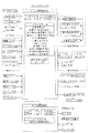
図1は、本実施形態におけるスロットマシン10の制御の概略を示すブロック図である。
スロットマシン10に設けられた代表的な制御基板として、メイン制御基板50とサブ制御基板80とを備える。
メイン制御基板50は、入力ポート51及び出力ポート52を有し、RWM53、ROM54、メインCPU55等を備える(図1で図示したもののみを備える意味ではない)。
Hereinafter, an embodiment of the present invention will be described with reference to the drawings and the like.
<First Embodiment>
FIG. 1 is a block diagram showing an outline of control of the
As a typical control board provided in the
The
図1において、メイン制御基板50と、ベットスイッチ40等の操作スイッチを含む遊技進行用の周辺機器とは、入力ポート51(後述する入力ポート0〜2等)又は出力ポート52(後述する出力ポート0〜7等)を介して電気的に接続されている。入力ポート51は、操作スイッチ等の信号が入力される接続部であり、出力ポート52は、モータ32等の周辺機器に対して信号を送信する接続部である。
図1中、入力用の周辺機器は、その周辺機器からの信号がメイン制御基板50に向かう矢印で表示しており、出力用の周辺機器は、メイン制御基板50からその周辺機器に向かう矢印で示している(サブ制御基板80も同様である)。
In FIG. 1, the
In FIG. 1, the input peripheral device is indicated by an arrow pointing from the
RWM53は、遊技の進行等に基づいた各種データ(変数)を記憶(更新)可能な記憶媒体である。後述する管理情報を表示するために必要なデータ(総遊技回数等)は、RWM53に記憶される。
ROM54は、遊技の進行に必要なプログラムや各種データ(たとえば、データテーブル)等を記憶しておく記憶媒体である。
The
The ROM 54 is a storage medium for storing programs and various data (for example, a data table) necessary for the progress of the game.
メインCPU55は、メイン制御基板50上に設けられたCPUを指し、遊技の進行に必要なプログラムの実行、演算等を行い、具体的には、役の抽選、リール31の駆動制御、及び入賞時の払出し等を実行する。
メインCPU55は、レジスタを内蔵する。特に本実施形態では、複数(たとえばAレジスタ〜Lレジスタ、及び送信用レジスタ等)設けられている。
The
The
また、メイン制御基板50上には、RWM53、ROM54、メインCPU55及びレジスタを含むMPUが搭載される。なお、RWM53及びROM54は、MPU内部に搭載されるもの以外に、外部に備えていてもよい。
後述するサブ制御基板80上には、RWM83、ROM84、及びサブCPU85を含むMPUが搭載される。なお、RWM83及びROM84は、MPU内部に搭載されるもの以外に、外部に備えてもよい。
Further, on the
An MPU including an RWM83, a ROM84, and a subCPU85 is mounted on the
図1において、メダル投入口43から投入されたメダルは、メダルセレクタ内部に送られる。
メダルセレクタは、図1に示すように、通路センサ43a、ブロッカ45、投入センサ44を備え(ただし、これらに限定されるものではない)、メイン制御基板50と電気的に接続されている。
メダル投入口43からメダルが投入されると、最初に、通路センサ43aにより検知されるように構成されている。
In FIG. 1, the medals inserted from the
As shown in FIG. 1, the medal selector includes a passage sensor 43a, a
When a medal is inserted from the
さらに、通路センサ43aの下流側には、ブロッカ45が設けられている。ブロッカ45は、メダルの投入を許可/不許可にするためのものであり、メダルの投入が不許可状態のときは、メダル投入口43から投入されたメダルを払出し口から返却するメダル通路を形成する。これに対し、メダルの投入が許可状態のときは、メダル投入口43から投入されたメダルをホッパー35に案内するメダル通路を形成する。
Further, a
ここで、ブロッカ45は、遊技中(リール31の回転開始時から、全リール31が停止し、役の入賞時には入賞役に対応する払出しの終了時まで)は、メダルの投入を不許可状態とする。すなわち、ブロッカ45がメダルの投入を許可するのは、少なくとも遊技が行われていないときである。
Here, the
ブロッカ45のさらに下流側には、投入センサ(光学センサ)44が設けられている。投入センサ44は、本実施形態では所定距離を隔てて配置された一対の投入センサ44a及び44bからなり、メダルが一方の投入センサ44aにより検知されてから所定時間を経過した後に他方の投入センサ44bにより検知されるように構成されている。そして、一対の投入センサ44がそれぞれオン/オフとなるタイミングに基づいて、正しいメダルが投入されたか否かを判断する。
なお、以降において、投入センサ44全体を指すときは、「投入センサ44」と称する。また、後述するフローチャート等において、投入センサ44aを「投入センサ1」と略称し、投入センサ44bを「投入センサ2」と略称する場合がある。
An input sensor (optical sensor) 44 is provided further downstream of the
In the following, when referring to the
また、図1に示すように、メイン制御基板50には、遊技者が操作する操作スイッチとして、ベットスイッチ40、スタートスイッチ41、(左、中、右)ストップスイッチ42、及び精算スイッチ46が電気的に接続されている。
ベットスイッチ40(40a又は40b)は、貯留されたメダルを今回遊技のためにベットするときに遊技者が操作するスイッチである。本実施形態では、1枚のメダルを投入するための1ベットスイッチ40aと、3枚(最大数ないし規定数)のメダルを投入するための3ベットスイッチ40bとを備える。
なお、これに限らず、2枚ベット用のベットスイッチを設けてもよい。
Further, as shown in FIG. 1, on the
The bet switch 40 (40a or 40b) is a switch operated by the player when betting the stored medals for the game this time. In the present embodiment, a 1-bet switch 40a for inserting one medal and a 3-bet switch 40b for inserting three (maximum number or a specified number) medals are provided.
Not limited to this, a bet switch for two bets may be provided.
また、本実施形態の規定数は、役物非作動時は3枚、役物作動時は2枚に設定されているが、1ベットスイッチ40aを2回操作する(押す)と2枚のメダルを投入可能であり、3回操作する(押す)と3枚のメダルを投入可能である。また、役物作動中は、3ベットスイッチ40bを操作すれば、一時に2枚(規定数)のメダルを投入可能である。 Further, the specified number of the present embodiment is set to 3 when the accessory is not activated and 2 when the accessory is activated, but when the 1-bet switch 40a is operated (pressed) twice, 2 medals are used. Can be inserted, and three medals can be inserted by operating (pressing) three times. Further, while the accessory is operating, two medals (specified number) can be inserted at one time by operating the 3-bet switch 40b.
また、スタートスイッチ41は、(左、中、右のすべての)リール31を始動させるときに遊技者が操作するスイッチである。
さらにまた、ストップスイッチ42は、3つ(左、中、右)のリール31に対応して3つ設けられ、対応するリール31を停止させるときに遊技者が操作するスイッチである。
さらに、精算スイッチ46は、スロットマシン10内部にベット及び/又は貯留(クレジット)されたメダルを払い戻す(ペイアウトする)ときに遊技者が操作するスイッチである。
Further, the
Furthermore, the
Further, the
また、図1に示すように、メイン制御基板50には、表示基板75が電気的に接続されている。なお、実際には、メイン制御基板50と表示基板75との間には、中継基板が設けられ、メイン制御基板50と中継基板、及び中継基板と表示基板75とが接続されているが、図1では中継基板の図示を省略している。このように、メイン制御基板50と表示基板75とは、直接ハーネス等で接続されていてもよいが、両者間に別の基板が介在してもよい。
さらに、制御基板同士が直接ハーネス等で接続されていることに限らず、他の別基板(中継基板等)を介して接続されていてもよい。たとえば、メイン制御基板50とサブ制御基板80との間に1つ以上の他の別基板(中継基板等)が介在してもよい。
Further, as shown in FIG. 1, a
Further, the control boards are not limited to being directly connected by a harness or the like, and may be connected via another board (relay board or the like). For example, one or more other separate boards (relay board, etc.) may be interposed between the
表示基板75には、貯留数表示LED76、獲得数表示LED78、及び状態表示LED79が搭載されている。これらのLED76、78、及び79は、遊技者が操作する操作スイッチの近傍に設けられ、遊技者が常に視認できる位置に設けられている。なお、1つの表示基板75上にLED76、78、及び79が設けられている必要はなく、たとえば表示基板75A及び75Bのように複数の表示基板75を備え、いずれかの表示基板75にいずれかのLED76、78、及び79が設けられていればよい。
以上の貯留数表示LED76、獲得数表示LED78、及び状態表示LED79についての詳細は、後述する(図16)。
The
Details of the stored number display LED76, the acquired number display LED78, and the status display LED79 will be described later (FIG. 16).
図1において、メイン制御基板50には、図柄表示装置のモータ32等が電気的に接続されている。
図柄表示装置は、図柄を表示する(本実施形態では3つの)リール31と、各リール31をそれぞれ駆動するモータ32と、リール31の位置を検出するためのリールセンサ33とを含む。
In FIG. 1, a
The symbol display device includes a
モータ32は、リール31を回転させるためのものであり、各リール31の回転中心部に連結され、後述するリール制御手段65によって制御される。ここで、リール31は、左リール31、中リール31、右リール31からなり、左リール31を停止させるときに操作するストップスイッチ42が左ストップスイッチ42であり、中リール31を停止させるときに操作するストップスイッチ42が中ストップスイッチ42であり、右リール31を停止させるときに操作するストップスイッチ42が右ストップスイッチ42である。
The
リール31は、リング状のものであって、その外周面には複数種類の図柄(役に対応する図柄の組合せを構成している図柄)を印刷したリールテープを貼付したものである。なお、リール31上の図柄の具体的配列は、後述する。
また、各リール31には、1個(2個以上であってもよい)のインデックスが設けられている。インデックスは、リール31のたとえば周側面に凸状に設けられており、リール31が所定位置を通過したか否かや、1回転したか否か等を検出するときに用いられる。そして、各インデックスは、リールセンサ33により検知される。リールセンサ33の信号は、メイン制御基板50に電気的に接続されている。そして、インデックスがリールセンサ33を検知する(切る)と、その入力信号がメイン制御基板50に入力され、そのリール31が所定位置を通過したことが検知される。
The
Further, each
また、リールセンサ33がリール31のインデックスを検知した瞬間の基準位置上の図柄を予めROM54に記憶している。これにより、インデックスを検知した瞬間の基準位置上の図柄を検知することができる。
Further, the symbol on the reference position at the moment when the
また、メイン制御基板50には、メダル払出し装置が電気的に接続されている。メダル払出し装置は、メダルを溜めておくためのホッパー35と、ホッパー35のメダルを払出し口から払い出すときに駆動するホッパーモータ36と、ホッパーモータ36から払い出されたメダルを検出するための払出しセンサ37を備える。
Further, a medal payout device is electrically connected to the
メダル投入口43から手入れされ、受け付けられたメダルは、所定の通路(「シュート部」とも称する。)を通してホッパー35内に収容されるように形成されている。
払出しセンサ(光学センサ)37は、本実施形態では、所定距離を隔てて配置された一対の払出しセンサ37a及び37bからなり、メダルが一方の払出しセンサ37aにより検知されてから所定時間を経過した後に他方の払出しセンサ37bにより検知されるように構成されている。そして、一対の払出しセンサ37がそれぞれオン/オフとなるタイミングに基づいて、メダルが正しく払い出されたか否かを判断する。
なお、以降において、払出しセンサ37全体を指すときは、「払出しセンサ37」と称する。また、後述するフローチャート等において、払出しセンサ37aを「払出しセンサ1」と略称し、払出しセンサ37bを「払出しセンサ2」と略称する場合がある。
The medals that have been cared for and received from the
In the present embodiment, the payout sensor (optical sensor) 37 includes a pair of payout sensors 37a and 37b arranged at a predetermined distance, and after a predetermined time has elapsed after the medal is detected by one payout sensor 37a. It is configured to be detected by the other payout sensor 37b. Then, based on the timing at which the pair of
In the following, when referring to the
たとえば、ホッパーモータ36が駆動しているにもかかわらず、払出しセンサ37a及び37bの信号がいずれもオフであるときは、メダルが払い出されていないと判断し、ホッパーエラー(メダルなし)と検知される。
一方、払出しセンサ37の信号の少なくとも1つがオンのままとなったときは、メダル詰まりが生じたと検知する。
For example, when the signals of the payout sensors 37a and 37b are both off even though the
On the other hand, when at least one of the signals of the
また、電源スイッチ11は、スロットマシン10の電源のオン/オフを行うスイッチである。
設定キースイッチ12は、設定キー挿入口から設定キーが挿入され、右90度(時計回り)に回転しているときにオンとなるスイッチであり、設定確認時や設定変更時にオンとされる。
Further, the
The setting
設定スイッチ13は、設定値を変更するときに操作されるスイッチである。たとえば設定変更中に1回操作されるごとに、設定値が「1」ずつ加算される。設定値は本実施形態では設定1から設定6まで有し、設定変更中は、設定スイッチ13を操作するごとに、設定値が、「1」→「2」→・・・→「6」→「1」→・・・と切り替わる。なお、設定変更中にはいずれかの設定値が表示されており、スタートスイッチ41を操作すると、表示されている設定値が確定する。
The setting
また、リセットスイッチ14は、このスイッチをオンにしつつ電源スイッチ11がオンにされると、リセットすなわち初期化処理が行われ、RWM53に記憶されている所定のデータがクリアされる。
また、ドアスイッチ15は、スロットマシン10のフロントドア(図示せず)を開けたときにオンとなるスイッチであり、フロントドアの開閉状態を検知するためのものである。
Further, when the
Further, the
さらにまた、出力ポート52の一部(後述する図20の出力ポート4)からは、外部集中端子板100への外部信号(外端信号)が出力される。
ここで、「外部信号」とは、外部集中端子板100を介してスロットマシン10の外部(ホールコンピュータ200や、ホールに設置されているデータカウンタ等)に出力するための信号である。本実施形態では、外部信号として、AT(有利区間)や特別遊技に関する信号、スロットマシン10で生じたエラーや電源断から復帰したこと(電源がオンとなったこと)等を示す信号、スロットマシン10のフロントドアの開放を示す信号、メダルベット信号、メダル払出し信号等を設けている。
Furthermore, an external signal (outer end signal) to the external centralized
Here, the "external signal" is a signal to be output to the outside of the slot machine 10 (such as a
図1において、サブ制御基板80は、遊技中及び遊技待機中における演出(情報)の選択や出力等を制御するものである。
ここで、メイン制御基板50とサブ制御基板80とは、電気的に接続されており、メイン制御基板50(後述する制御コマンド送信手段71)は、パラレル通信によってサブ制御基板80に一方向で、演出の出力に必要な情報(制御コマンド)を送信する。
なお、メイン制御基板50とサブ制御基板80とは、電気的に接続されることに限らず、光通信手段を用いた接続であってもよい。さらに、電気的接続及び光通信接続のいずれも、パラレル通信に限らず、シリアル通信であってもよく、シリアル通信とパラレル通信とを併用してもよい。
In FIG. 1, the
Here, the
The
サブ制御基板80は、メイン制御基板50と同様に、入力ポート81、出力ポート82、RWM83、ROM84、及びサブCPU85等を備える。
サブ制御基板80には、入力ポート81又は出力ポート82を介して、図1に示すような以下の演出ランプ21等の演出用周辺機器が電気的に接続されている。ただし、演出用の周辺機器は、これらに限られるものではない。
RWM83は、サブCPU85が演出を制御するときに取り込んだデータ等を一時的に記憶可能な記憶媒体である。
また、ROM84は、演出用データとして、演出に係る抽選を行うとき等のプログラムや各種データ等を記憶しておく記憶媒体である。
Like the
The following peripheral devices for effect such as the
The RWM 83 is a storage medium that can temporarily store data or the like captured when the
Further, the ROM 84 is a storage medium for storing various data and the like when a lottery related to the production is performed as the production data.
演出ランプ21は、たとえばLED等からなり、所定の条件を満たしたときに、それぞれ所定のパターンで点灯する。なお、演出ランプ21には、各リール31の内周側に配置され、リール31に表示された図柄(表示窓17から見える上下に連続する3図柄)を背後から照らすためのバックランプ、リール31の上部からリール31上の図柄を照光する蛍光灯、スロットマシン10のフロントドア前面に配置され、役の入賞時等に点滅する枠ランプ等が含まれる。
The
また、スピーカ22は、遊技中に各種の演出を行うべく、所定の条件を満たしたときに、所定のサウンドを出力するものである。
さらにまた、画像表示装置23は、液晶ディスプレイ、有機ELディスプレイ、ドットディスプレイ等からなるものであり、遊技中に各種の演出画像(正解押し順、条件装置の抽選結果に対応する演出等)や、遊技情報(役物作動時や有利区間中の遊技回数や獲得枚数等)等を表示するものである。
また、十字キー24及びメニューボタン25は、遊技者が意図する情報(遊技者の遊技履歴である二次元コードを含む)を表示させるときや、ホール管理者(店長等)が各種の設定を変更するとき等に用いられる。
Further, the
Furthermore, the
Further, the cross key 24 and the
続いて、本実施形態の役、図柄の組合せ等について説明する。
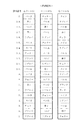
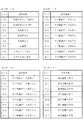
図2は、本実施形態におけるリール31の図柄配列を示す図である。図2では、図柄番号を併せて図示している。たとえば、左リール31において、図柄番号0番の図柄は、「ベルA」である。
図2に示すように、本実施形態では、各リール31は、20コマに等分割され、各コマに所定の図柄が表示されている。
なお、図中、「ブランク」は、図柄が全く表示されていないことを意味するものではなく、「ブランク」に対応する所定の図柄が表示されている。
なお、「ベルA」、「ベルB」、「ベルC」は、外観が類似する図柄であるが、それぞれ異なる図柄である。
Subsequently, the roles of the present embodiment, the combination of symbols, and the like will be described.
FIG. 2 is a diagram showing a symbol arrangement of the
As shown in FIG. 2, in the present embodiment, each
In the figure, "blank" does not mean that the symbol is not displayed at all, and a predetermined symbol corresponding to the "blank" is displayed.
The "bell A", "bell B", and "bell C" are symbols having similar appearances, but different symbols.
また、図3(A)は、スロットマシン10のフロントドア(前面扉。図示せず。)に設けられた表示窓(透明窓)17と、各リール31の位置関係と、有効ライン(図柄の組合せを表示する表示ライン)とを示す図である。
各リール31は、本実施形態では横方向に並列に3つ(左リール31、中リール31、及び右リール31)設けられている。さらに、各リール31は、表示窓17から、上下に連続する3図柄が見えるように配置されている。よって、スロットマシン10の表示窓17から、合計9個の図柄(コマ)が見えるように配置されている。なお、各図柄の右下の数字は図柄番号を示している。
Further, FIG. 3A shows the positional relationship between the display window (transparent window) 17 provided on the front door (front door, not shown) of the
In this embodiment, three
また、図3(B)は、本明細書における図柄位置の称呼を図示している。本明細書では、リール31ごとに、表示窓17から見える停止時の図柄位置を、上から順に「上段」、「中段」、「下段」と称し、左リール31であれば、それぞれ「左上段」、「左中段」、「左下段」と称するものとする。
さらにまた、図3(A)に示すように、表示窓17から見える9個の図柄に対し、有効ラインが設定されている。
Further, FIG. 3B illustrates the designation of the symbol position in the present specification. In the present specification, the symbol positions at the time of stop that can be seen from the
Furthermore, as shown in FIG. 3A, effective lines are set for the nine symbols that can be seen from the
ここで、「有効ライン」とは、リール31の停止時における図柄の並びラインであって図柄の組合せを形成させる図柄組合せライン(表示ライン)であり、かつ、いずれかの役に対応する図柄の組合せがそのラインに停止したときに、その役の入賞となるラインである。本実施形態では、1本有効ライン(「左下段」−「中中段」−「右上段」を通る一直線状のライン)が定められており、他の図柄組合せラインは、全て無効ラインとなっている。
Here, the "effective line" is a symbol combination line (display line) that is an arrangement line of symbols when the
無効ラインは、図柄組合せラインのうち、有効ラインとして設定されないラインであって、いずれかの役に対応する図柄の組合せがそのラインに停止した場合であっても、その役に応じた利益の付与(メダルの払出し等)を行わないラインである。すなわち、無効ラインは、そもそも図柄の組合せの成立対象となっていないラインである。 The invalid line is a line that is not set as a valid line among the symbol combination lines, and even if the combination of symbols corresponding to any combination stops at that line, the profit is given according to the combination. This is a line that does not pay out medals. That is, the invalid line is a line that is not the target of establishing the combination of symbols in the first place.
また、従来より、メダルの投入枚数に応じて有効ライン数が異なるスロットマシンが知られている。たとえば、メダル投入枚数が1枚のときは有効ラインは1本、メダル投入枚数が2枚のときは有効ライン数は3本、メダル投入枚数が3枚のときは有効ライン数は5本に設定すること等が挙げられる。これに対し、本実施形態では、上述したように、3枚又は2枚のメダルを投入して遊技を行うとともに、すべての遊技において、図3(A)に示した1本が有効ラインとなり、メダル投入枚数による有効ライン数の変動はない。よって、本明細書では、「有効ライン」というときは、図3(A)に示すラインを指すものである。 Further, conventionally, slot machines in which the number of effective lines differs depending on the number of medals inserted have been known. For example, when the number of medals inserted is 1, the number of effective lines is 1, when the number of medals inserted is 2, the number of effective lines is set to 3, and when the number of medals inserted is 3, the number of effective lines is set to 5. And so on. On the other hand, in the present embodiment, as described above, three or two medals are inserted to play the game, and in all the games, one line shown in FIG. 3 (A) becomes an effective line. There is no change in the number of effective lines depending on the number of medals inserted. Therefore, in the present specification, the term "effective line" refers to the line shown in FIG. 3 (A).
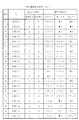
図4〜図9は、本実施形態における役(後述する役抽選手段61で抽選される条件装置に含まれる役等)の種類、払出し枚数等、及び図柄の組合せを示す図である。なお、図9には、役ではないが、特定の条件装置に当選した場合において当選役のとりこぼし時に表示される図柄の組合せとして、パターン図柄01〜03を示している(番号「101」〜「120」)。 4 to 9 are diagrams showing the types of combinations (combinations included in the condition device drawn by the combination lottery means 61 described later), the number of payouts, and the combination of symbols in the present embodiment. In addition, although it is not a combination, FIG. 9 shows pattern symbols 01 to 03 as a combination of symbols displayed when the winning combination is missed when a specific condition device is won (numbers "101" to "101" to "120").
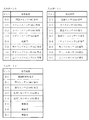
本実施形態の役は、大別して、特別役、リプレイ(再遊技役)、及び小役を有する。
そして、各役に対応する図柄の組合せ及び入賞時の払出し枚数等が定められている。すべてのリール31の停止時に、いずれかの役に対応する図柄の組合せが有効ラインに停止する(役が入賞する。以下同じ。)と、その役に対応する枚数のメダルが払い出される。
ただし、特別役の入賞時の払出し枚数は0枚に設定されている。また、リプレイは、メダルが自動投入される(再遊技)。
The roles of the present embodiment are roughly classified into a special role, a replay (replaying role), and a small role.
Then, the combination of symbols corresponding to each combination and the number of payouts at the time of winning are determined. When all
However, the number of payouts at the time of winning a special role is set to 0. In the replay, medals are automatically inserted (replay).
図4〜図9において、払出し枚数等に表示された「規定数3」は、規定数が3枚(役物非作動時、すなわち通常遊技中の投入枚数)であるときの払出し枚数等を示し、「規定数2」は、規定数が2枚(役物作動時、すなわち特別遊技中の投入枚数)であるときの払出し枚数等を示している。たとえば、番号「3」のリプレイ01は、規定数3枚では再遊技となることを示し、規定数2枚の「−」は、抽選されないことを示している。
In FIGS. 4 to 9, the "specified
図4中、番号「1」及び「2」は、特別役(役物)に相当する。本実施形態では、特別役として1BBのみが設けられ、さらに、1BBは、2種類(1BBA及び1BBB)有する。
特別役は、通常遊技から特別遊技に移行させる役である。
1BBに入賞すると、今回遊技におけるメダルの払い出しはないが、次回遊技から、特別遊技に相当する1BB遊技に移行する(役物の作動)。
1BB遊技中(役物作動時)は、出玉率が「1」を超えるように設定されていることで、役物非作動時以上にメダル獲得が期待できる、遊技者にとって有利な遊技である。
In FIG. 4, the numbers "1" and "2" correspond to special roles (roles). In the present embodiment, only 1BB is provided as a special role, and 1BB has two types (1BBA and 1BBB).
The special role is a role that shifts from a normal game to a special game.
If you win 1BB, you will not be paid out medals in this game, but from the next game, you will shift to the 1BB game, which is equivalent to a special game (operation of the character).
During the 1BB game (when the character is activated), the ball output rate is set to exceed "1", so that medals can be expected to be obtained more than when the character is not activated, which is an advantageous game for the player. ..
また、リプレイ(再遊技役)とは、今回遊技で投入したメダル枚数を維持した(メダルを自動ベットする)再遊技が行えるようにした役である。なお、たとえば、今回遊技の規定数が「3」のときにリプレイが入賞し、次回遊技の規定数が「2」のような場合には、今回遊技で投入したメダル枚数を維持せず、次回遊技の規定数である「2」が自動ベットされるようにしてもよい。
本実施形態のリプレイは、図4に示すように、リプレイ01〜06(番号「3」〜「13」)を備える。
リプレイ02及び03は、特定のRTにおいて入賞すると、他のRTに移行させることとなるリプレイである。したがって、これらのリプレイは、移行リプレイとも称される。
In addition, the replay (replay role) is a role that enables the replay to maintain the number of medals inserted in this game (automatically bet the medals). For example, if the replay wins when the specified number of games is "3" this time and the specified number of next games is "2", the number of medals inserted in this game is not maintained and the next time. The specified number of games, "2", may be automatically bet.
As shown in FIG. 4, the replay of the present embodiment includes replays 01 to 06 (numbers "3" to "13").
Replays 02 and 03 are replays that, if a prize is won in a specific RT, will be transferred to another RT. Therefore, these replays are also referred to as transitional replays.
より具体的には、RT2においてリプレイ02が入賞すると、次回遊技から、RT3(遊技者に有利なRT)に移行させる。このため、リプレイ02は、昇格リプレイとも称される。
また、RT3においてリプレイ03が入賞すると、次回遊技から、RT2(それまでのRTよりも遊技者に不利なRT)に移行させる。このため、リプレイ03は、転落(降格)リプレイとも称される。
More specifically, when the replay 02 wins in RT2, the game shifts to RT3 (RT advantageous to the player) from the next game. Therefore, the replay 02 is also referred to as a promotion replay.
Further, when the replay 03 wins in RT3, the game shifts to RT2 (RT which is more disadvantageous to the player than the previous RT) from the next game. Therefore, the replay 03 is also referred to as a fall (demotion) replay.
また、リプレイ04及び05は、第1に、複数のリプレイを重複当選させて条件装置の種類を増加させることを目的とした制御用リプレイとして用いられ、本実施形態では、後述する条件装置中、リプレイB2、B3、C2、C3、又はEに含まれるリプレイである。リプレイB2、B3、C2、又はC3に当選したときは、制御用リプレイとしてのリプレイ04又は05は有効ラインに停止することはない。 Further, the replays 04 and 05 are firstly used as control replays for the purpose of increasing the types of condition devices by winning a plurality of replays in duplicate. Replay A replay included in B2, B3, C2, C3, or E. When the replays B2, B3, C2, or C3 are won, the replay 04 or 05 as the control replay does not stop at the effective line.
さらに、リプレイ04及び05は、第2に、レアリプレイとして用いられ、後述する条件装置のリプレイEに含まれる。有利区間中のリプレイE当選時には、有利区間の上乗せが実行される。なお、必ず、上乗せが実行されるのではなく、上乗せ抽選が行われるようにしてもよい。
また、リプレイ06は、1BB作動中に抽選されるリプレイであり、後述する条件装置のリプレイDに含まれる。有利区間中のリプレイD当選時には、有利区間の上乗せが実行される。なお、必ず、上乗せが実行されるのではなく、上乗せ抽選が行われるようにしてもよい。
Further, the replays 04 and 05 are secondly used as a rare replay and are included in the replay E of the condition device described later. When Replay E is won during the advantageous section, the addition of the advantageous section is executed. It should be noted that the addition may not always be executed, but the addition lottery may be performed.
Further, the replay 06 is a replay drawn by lottery during the operation of 1BB, and is included in the replay D of the condition device described later. When Replay D is won during the advantageous section, the addition of the advantageous section is executed. It should be noted that the addition may not always be executed, but the addition lottery may be performed.
また、小役は、図4〜図8に示すように、小役01〜40(番号「14」〜「100」)を備える。小役01及び02は、後述する押し順ベル当選時の正解押し順時に入賞する小役(高目ベルに対応する小役)である。また、小役03〜34は、押し順ベル当選時の不正解押し順時に入賞可能(PB≠1)となる小役(安目ベルに対応する小役)である。
さらにまた、小役35〜38は、レア小役(スイカ又はチェリーに対応する小役)である。
さらに、小役39及び40は、規定数が2枚、すなわち役物作動時にのみ入賞可能となる小役である。
Further, as shown in FIGS. 4 to 8, the small combination includes small combinations 01 to 40 (numbers “14” to “100”). Small wins 01 and 02 are small wins (small wins corresponding to higher bells) that win a prize in the correct push order when the push order bell is won, which will be described later. In addition, the small wins 03 to 34 are small wins (small wins corresponding to the cheap bells) that can be won (PB ≠ 1) in the incorrect push order when the push order bell is won.
Furthermore, the
Further, the small winning
パターン図柄01〜03は、上述したように、役自体ではないが、押し順ベル当選時の押し順不正解時に、当選役を取りこぼしたとき(当選役の非入賞となったとき)に出現する図柄の組合せである。さらに、パターン図柄は、特定のRT(本実施形態では非RT、RT1、又はRT3)においてその図柄の組合せが有効ラインに停止すると、RTを移行させる(本実施形態ではRT2に移行させる)図柄の組合せである。本実施形態では、小役B群当選時の押し順不正解時に、当選役を取りこぼしたとき(当選役の非入賞となったとき)に、必ずパターン図柄01〜03が出現するようにしているが、その他の図柄の組合せ(役自体ではない)が出現するようにしてもよい。 As described above, the pattern symbols 01 to 03 are not the winning combination itself, but appear when the winning combination is missed (when the winning combination is not won) when the pressing order is incorrect when the push order bell is won. It is a combination of symbols. Further, the pattern symbol is a symbol that shifts RT (shifts to RT2 in this embodiment) when the combination of the symbols stops at the effective line at a specific RT (non-RT, RT1, or RT3 in this embodiment). It is a combination. In the present embodiment, the pattern symbols 01 to 03 are made to appear without fail when the winning combination is missed (when the winning combination is not won) when the push order is incorrect when the small combination B group is won. However, other combinations of symbols (not the combination itself) may appear.
上述した各役において、役に当選した遊技でその役に対応する図柄の組合せが有効ラインに停止しなかったときは、次回遊技以降に持ち越される役と、持ち越されない役とが定められている。
持ち越される役は、本実施形態では1BBである。1BBに当選したときは、1BBが入賞するまでの遊技において、その1BBの当選情報を次回遊技以降に持ち越すように制御される。
In each of the above-mentioned combinations, if the combination of symbols corresponding to the winning combination does not stop at the effective line in the winning game, the combination that is carried over to the next game and the combination that is not carried over is defined. ..
The carry-over role is 1BB in this embodiment. When 1BB is won, the winning information of the 1BB is controlled to be carried over to the next game or later in the game until the 1BB wins.
一方、1BBの当選は持ち越されるのに対し、1BB以外の小役及びリプレイは、持ち越されない。条件装置の抽選において、小役又はリプレイに当選したときは、今回遊技でのみその当選役が有効となり、その当選は次回遊技以降に持ち越されない。すなわち、これらの役に当選した遊技では、その当選した役に対応する図柄の組合せが入賞可能にリール31が停止制御されるが、その当選役の入賞の有無にかかわらず、その遊技の終了時に、その当選役に係る権利は消滅する。
On the other hand, the winning of 1BB is carried over, while the small roles and replays other than 1BB are not carried over. When a small winning combination or replay is won in the lottery of the conditional device, the winning combination is valid only in this game, and the winning is not carried over to the next game or later. That is, in the game in which these winning combinations are won, the
遊技を開始するときは、遊技者は、ベットスイッチ40の操作により予め貯留されたメダルを投入するか(貯留ベット)、又はメダル投入口43からメダルを手入れ投入する(手入れベット)。規定数のメダルがベットされた状態でスタートスイッチ41が操作されると、そのときに発生する信号がメイン制御基板50に入力される。メイン制御基板50(具体的には、後述するリール制御手段65)は、この信号を受信すると、役抽選手段61による役の抽選を行うとともに、すべてのモータ32を駆動制御して、すべてのリール31を回転させるように制御する。このようにしてリール31がモータ32によって回転されることで、リール31上の図柄は、所定の速度で表示窓17内で上下方向に移動表示される。
When starting the game, the player inserts the medals stored in advance by operating the bet switch 40 (storage bet), or takes care of the medals from the medal insertion slot 43 (care bet). When the
そして、遊技者は、ストップスイッチ42を押すことで、そのストップスイッチ42に対応するリール31(たとえば、左ストップスイッチ42に対応する左リール31)の回転を停止させる。ストップスイッチ42が操作されると、そのときに発生する信号がメイン制御基板50に入力される。メイン制御基板50(具体的には、後述するリール制御手段65)は、この信号を受信すると、そのストップスイッチ42に対応するモータ32を駆動制御して、役抽選手段61の役抽選結果に対応するように、そのモータ32に係るリール31の停止制御を行う。
Then, by pressing the
そして、すべてのリール31の停止時における図柄の組合せにより、今回遊技の遊技結果を表示する。さらに、いずれかの役に対応する図柄の組合せが有効ラインに停止したとき(その役の入賞となったとき)は、入賞した役に対応するメダルの払出し等が行われる。
Then, the game result of this game is displayed by the combination of the symbols when all the
次に、メイン制御基板50の具体的構成について説明する。
図1に示すように、メイン制御基板50のメインCPU55は、以下の役抽選手段61等を備える。本実施形態における以下の各手段は例示であり、本実施形態で示した手段に限定されるものではない。
Next, a specific configuration of the
As shown in FIG. 1, the
役抽選手段61は、条件装置(当選役)の抽選(決定、選択)を行う。したがって、役抽選手段61は、条件装置決定(抽選又は選択)手段、当選役決定(抽選又は選択)手段、等とも称される。
また、「条件装置の当選」は、役抽選結果、抽選結果、当選番号、当選結果、等とも称される。
The combination lottery means 61 draws (determines, selects) a condition device (winning combination). Therefore, the winning combination lottery means 61 is also referred to as a condition device determination (lottery or selection) means, a winning combination determination (lottery or selection) means, and the like.
Further, "winning of the condition device" is also referred to as a winning combination lottery result, a lottery result, a winning number, a winning result, and the like.
役抽選手段61は、たとえば、抽選用の乱数発生手段(ハードウェア乱数等)と、この乱数発生手段が発生する乱数を抽出する乱数抽出手段と、乱数抽出手段が抽出した乱数値に基づいて、条件装置の当選の有無及び当選した条件装置を判定する判定手段とを備えている。 The combination lottery means 61 is based on, for example, a random number generating means (hardware random number or the like) for lottery, a random number extracting means for extracting random numbers generated by the random number generating means, and a random number value extracted by the random number extracting means. It is provided with a determination means for determining whether or not the condition device has been won and the winning condition device.
乱数発生手段は、所定の領域(たとえば10進数で「0」〜「65535」)の乱数を発生させる。乱数は、たとえば200n(ナノ)secで1カウントを行うカウンターが「0」〜「65535」の範囲を1サイクルとしてカウントし続ける乱数であり、スロットマシン10の電源が投入されている間は、乱数をカウントし続ける。
The random number generation means generates random numbers in a predetermined region (for example, "0" to "65535" in decimal numbers). The random number is, for example, a random number that the counter that counts 1 in 200 n (nano) sec keeps counting in the range of "0" to "65535" as one cycle, and is a random number while the power of the
乱数抽出手段は、乱数発生手段によって発生した乱数を、所定の時、本実施形態では遊技者によりスタートスイッチ41が操作(オン)された時に抽出する。判定手段は、乱数抽出手段により抽出された乱数値を、後述する条件装置抽選テーブルと照合することにより、その乱数値が属する領域に対応する条件装置を決定する。たとえば、抽出した乱数値が入賞及びリプレイ条件装置番号「1」(リプレイA)の領域に属する場合は、リプレイAの当選と判定する。
The random number extraction means extracts the random numbers generated by the random number generation means at a predetermined time, in the present embodiment, when the
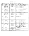
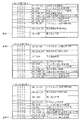
図10〜図13は、役抽選手段61によって抽選される条件装置の種類と、各条件装置に含まれる当選役の内容を示す図である。
なお、以下の説明においては、条件装置の説明を主とし、それぞれの条件装置当選時におけるストップスイッチ42の押し順や操作タイミングに基づくリール31の停止制御の詳細については、リール制御手段65で説明する。
10 to 13 are diagrams showing the types of condition devices drawn by the combination lottery means 61 and the contents of the winning combination included in each condition device.
In the following description, the condition device will be mainly described, and the details of the stop control of the
本実施形態の条件装置は、上述したように、当選情報を次回遊技に持ち越し可能な特別役のいずれかが含まれる条件装置である「役物条件装置」と、当選情報を次回遊技に持ち越さない小役又はリプレイのいずれかが含まれる条件装置である「入賞及びリプレイ条件装置」とからなる。
役物条件装置の当選は、本実施形態では1BBの当選に相当する。
役物条件装置番号「0」は、特別役の非当選に相当し、役物条件装置番号「1」は、1BBAの当選に相当し、役物条件装置番号「2」は、1BBBの当選に相当する。
As described above, the condition device of the present embodiment is a "character condition device" which is a condition device including any of the special roles that can carry over the winning information to the next game, and the winning information is not carried over to the next game. It consists of a "winning and replay condition device" which is a condition device including either a small win or a replay.
Winning of the accessory condition device corresponds to winning of 1BB in this embodiment.
The character condition device number "0" corresponds to the non-winning of the special role, the character condition device number "1" corresponds to the winning of 1 BBA, and the character condition device number "2" corresponds to the winning of 1 BBB. Equivalent to.
また、たとえばリプレイA当選時は、役物条件装置番号は「0」、入賞及びリプレイ条件装置番号は「1」となる。
一方、1BBA単独当選時は、役物条件装置番号は「1」、入賞及びリプレイ条件装置番号は「0」となる。
Further, for example, when the replay A is won, the accessory condition device number is "0", and the winning and replay condition device numbers are "1".
On the other hand, when 1BBA is won alone, the accessory condition device number is "1", and the winning and replay condition device number is "0".
さらにまた、本実施形態では、1BB及び小役の重複当選となる場合を有し、たとえば1BBAと小役Dの重複当選時は、役物条件装置番号は「1」、入賞及びリプレイ条件装置番号は「26」となる。
なお、1BBと小役又はリプレイが重複当選したときは、今回遊技では小役又はリプレイの入賞が優先される(なお、優先順位は任意に設定可能である)。また、小役又はリプレイの当選は、今回遊技でのみ有効であるのでその当選を次回遊技に持ち越さないが、1BBの当選情報は、入賞しない限り次回遊技に持ち越す。
Furthermore, in the present embodiment, there is a case where 1BB and the small winning combination are duplicated. For example, when 1BBA and the small winning combination D are duplicated, the accessory condition device number is "1", and the winning and replay condition device number. Is "26".
If 1BB and a small win or replay are won in duplicate, the prize for the small win or replay is prioritized in this game (the priority can be set arbitrarily). In addition, since the winning of a small role or replay is valid only in this game, the winning is not carried over to the next game, but the winning information of 1BB is carried over to the next game unless a prize is won.
以下、入賞及びリプレイ条件装置について説明する。
条件装置番号「0」は、役の非当選(いわゆるハズレ)に相当する。
また、条件装置番号「1」のリプレイAは、リプレイ01の単独当選である。リプレイA当選時は、押し順不問で(いずれの押し順でも)リプレイ01が入賞する。
Hereinafter, the winning and replay condition devices will be described.
The condition device number "0" corresponds to a non-winning combination (so-called loss).
Further, the replay A of the condition device number "1" is a single winning of the replay 01. When Replay A is won, Replay 01 wins regardless of the push order (in any push order).
条件装置番号「2」〜「4」のリプレイB1〜B3(以下、総称して「リプレイB群」と称する。)、条件装置番号「5」〜「7」のリプレイC1〜C3(以下、総称して「リプレイC群」と称する。)は、いずれも、複数種類のリプレイの重複当選であり、少なくともリプレイ01又は02の少なくとも1つを含む重複当選である。そして、ストップスイッチ42の押し順に応じて、入賞するリプレイの種類が異なるように設定されている。
たとえば条件装置番号「2」のリプレイB1では、左第一停止の押し順ではリプレイ02が入賞し、左第一停止以外(中又は右第一停止)時には、リプレイ01が入賞する。
Replays B1 to B3 of condition device numbers "2" to "4" (hereinafter collectively referred to as "replay B group"), replays C1 to C3 of condition device numbers "5" to "7" (hereinafter collectively referred to as "replay B group"). Each of the above (referred to as "replay C group") is a duplicate winning of a plurality of types of replays, and is a duplicate winning including at least one of the replays 01 or 02. Then, the type of replay to be won is set to be different according to the pressing order of the
For example, in the replay B1 of the condition device number "2", the replay 02 wins in the push order of the left first stop, and the replay 01 wins in the case other than the left first stop (middle or right first stop).
なお、リプレイ重複当選の場合、いずれの押し順であってもリプレイ(再遊技役)が入賞するので、メダルの払出し等についての高目/安目の概念はない。しかし、たとえばRT2においてリプレイB1に当選したときは、左第一停止ではリプレイ02を入賞させることによりRTを昇格(RT2からRT3に移行)させる。一方、左第一停止以外では、リプレイ01を入賞させることによりRT2を維持する。
また、RT3においてリプレイC1に当選したときは、左第一停止ではリプレイ01を入賞させることによりRT3を維持する。一方、左第一停止以外では、リプレイ03を入賞させることによりRTを転落(降格)(RT3からRT2に移行)させる。
In the case of duplicate replay winning, the replay (replaying role) wins regardless of the push order, so there is no concept of high / low medals. However, for example, when the replay B1 is won in RT2, the RT is promoted (shifted from RT2 to RT3) by winning the replay 02 in the first left stop. On the other hand, except for the first stop on the left, RT2 is maintained by winning the replay 01.
Further, when the replay C1 is won in the RT3, the RT3 is maintained by winning the replay 01 at the first left stop. On the other hand, except for the first stop on the left, RT is dropped (demoted) (shifted from RT3 to RT2) by winning Replay 03.
条件装置番号「8」のリプレイDは、リプレイ06の単独当選である。リプレイD当選時は、押し順不問でリプレイ06が入賞する。
同様に、条件装置番号「9」のリプレイEは、リプレイ04及び05の重複当選である。リプレイE当選時は、押し順不問でリプレイ04又は05が入賞する。これらのリプレイ04及び05は、レアリプレイとしての役割を有する。特に本実施形態では、RT1において抽選され、RT1かつ有利区間中にリプレイEに当選すると、有利区間が上乗せされる。なお、必ず、上乗せが実行されるのではなく、上乗せ抽選が行われるようにしてもよい。
The replay D of the condition device number "8" is a single win of the replay 06. When Replay D is won, Replay 06 wins regardless of the push order.
Similarly, the replay E of the condition device number "9" is a duplicate winning of the replays 04 and 05. When Replay E is won, Replay 04 or 05 wins regardless of the push order. These replays 04 and 05 have a role as rare replays. In particular, in the present embodiment, if a lottery is drawn at RT1 and Replay E is won during RT1 and the advantageous section, the advantageous section is added. It should be noted that the addition may not always be executed, but the addition lottery may be performed.
図11において、条件装置番号「10」の小役Aは、いわゆる共通ベルに装置し、小役01の単独当選である。そして、小役A当選時は、ストップスイッチ42の押し順にかかわらず、常に、小役01が入賞する(PB=1)。
また、図11〜図12において、条件装置番号「11」〜「22」の小役B1〜B12(以下、総称して「小役B群」と称する。)は、いわゆる押し順ベルに相当し、小役01(9枚ベル、9枚役)と、小役03〜34(1枚役)のうちの少なくとも1つを含む重複当選である。
In FIG. 11, the small winning combination A of the condition device number “10” is attached to a so-called common bell, and the small winning combination 01 is independently elected. Then, when the small winning combination A is won, the small winning combination 01 always wins regardless of the order in which the
Further, in FIGS. 11 to 12, the small combinations B1 to B12 (hereinafter collectively referred to as "small combination B group") of the condition device numbers "11" to "22" correspond to so-called push order bells. , Small win 01 (9 bells, 9 wins) and at least one of small wins 03-34 (1 win).
これらの条件装置当選時には、ストップスイッチ42の押し順に応じて、正解押し順であるときは「PB=1」で高目ベル(9枚ベル、9枚役)である小役01が入賞する。これに対し、不正解押し順であるときは、ストップスイッチ42の操作タイミング(ストップスイッチ42を操作した瞬間のリール31の位置)に応じて、安目ベル(1枚役)である小役03〜34が入賞する場合と、いずれの小役も入賞しない場合(とりこぼしによりパターン図柄が表示される場合)とを有する。
When these conditional devices are won, a small winning combination 01, which is a high bell (9 bells, 9 winning combination), is awarded with "PB = 1" in the correct pressing order according to the pressing order of the
図13において、条件装置番号「23」〜「25」の小役C1〜C3(以下、総称して「小役C群」と称する。)は、上記の小役B群と同様に、いわゆる押し順ベルに相当し、小役02(3枚ベル、3枚役)と、小役03〜10(1枚役)とを含む重複当選である。
これらの条件装置当選時には、ストップスイッチ42の押し順に応じて、正解押し順であるときは「PB=1」で高目ベル(3枚ベル、3枚役)である小役02が入賞する。これに対し、不正解押し順であるときは、「PB=1」で、安目ベル(1枚役)である小役03〜10のいずれかが入賞する。よって、小役C群の当選時は、小役B群の当選時と異なり、パターン図柄が表示される場合(とりこぼし)はない。なお、これに限らず、いずれの小役も入賞しない場合を有していてもよい。
In FIG. 13, the small combinations C1 to C3 (hereinafter collectively referred to as “small combination C group”) of the condition device numbers “23” to “25” are so-called pushes, as in the above small combination B group. It corresponds to a forward bell, and is a duplicate winning including a small winning combination 02 (3 bells, 3 playing cards) and a small winning combination 03-10 (1 card winning combination).
When these conditional devices are won, a small winning combination 02, which is a high bell (3 bells, 3 bindings), wins a prize according to the pressing order of the
小役B群の当選時に、高目ベルの入賞時は9枚の払出しとなるので、押し順正解時には、イン(投入枚数)3枚、アウト(払出し枚数)9枚となり、今回遊技での差枚数は「+6枚」となる。したがって、押し順正解時には、メダル枚数が増加し、押し順不正解時(払出し枚数は1枚又は0枚)にはメダル枚数が減少する条件装置となる。
これに対し、小役C群は、高目ベルの入賞時は3枚の払出しとなるので、押し順正解時には、イン(投入枚数)3枚、アウト(払出し枚数)3枚となり、今回遊技での差枚数は「±0枚」となる。したがって、押し順正解時には、メダル枚数は現状維持となり、押し順不正解時(払出し枚数は1枚)にはメダル枚数が減少する条件装置となる。
When the small role B group is won, 9 cards will be paid out when the high bell is won, so when the push order is correct, 3 cards will be put in and 9 cards will be paid out. The number of sheets is "+6". Therefore, the condition device is such that the number of medals increases when the push order is correct, and the number of medals decreases when the push order is incorrect (the number of payouts is 1 or 0).
On the other hand, in the small role C group, 3 cards will be paid out when the high bell is won, so when the push order is correct, 3 cards will be paid out (number of input) and 3 cards will be paid out (number of payouts). The difference in the number of sheets is "± 0 sheets". Therefore, when the push order is correct, the number of medals is maintained as it is, and when the push order is incorrect (the number of payouts is one), the number of medals is reduced.
なお、このように、正解押し順時に9枚の払出しとなる押し順ベルと、3枚の払出しとなる押し順ベルとの双方を設けているのは、出玉率の調整のためである。特に、本実施形態では、図11及び図12に示すように、小役B群当選時の押し順不正解時には、1枚役が入賞する確率を25%とし、それ以外の75%はパターン図柄が表示されるように設定している(パターン図柄表示時は払出しなし)。これに対し、図13に示すように、小役C群当選時の押し順不正解時には、「PB=1」で1枚役が入賞するようにしている。このようにして、押し順正解時と不正解時とで払出し枚数が異なる2種類の押し順ベルを設け、その当選確率を適切に設定することで、出玉率を適切な範囲に設定できるようになる。 It should be noted that the reason why both the push order bells for paying out 9 pieces and the push order bells for paying out 3 pieces in the correct push order are provided in order to adjust the payout rate. In particular, in the present embodiment, as shown in FIGS. 11 and 12, the probability that one winning combination will be won is 25% when the push order is incorrect when the small winning combination B is won, and the other 75% is a pattern symbol. Is set to be displayed (no payout when the pattern pattern is displayed). On the other hand, as shown in FIG. 13, when the push order is incorrect when the small winning combination C group is won, one winning combination is won with "PB = 1". In this way, by providing two types of push order bells with different numbers of payouts depending on whether the answer is correct or incorrect, and setting the winning probability appropriately, the payout rate can be set in an appropriate range. become.
条件装置番号「26」の小役Dは、レア小役(スイカ)に相当する。小役Dは、小役35の単独当選であり、「PB≠1」に設定されている。
また、条件装置番号「27」の小役E1、及び条件装置番号「28」の小役E2は、上記小役D1と同様に、レア小役(チェリー)に相当する。小役E1は、小役36及び38の重複当選であり、小役E2は、上記小役36及び38に加え、小役37を含む重複当選である。小役E1又はE2当選時は、押し順不問で2枚役(小役36又は38)が入賞する。
The small winning combination D of the condition device number "26" corresponds to a rare small winning combination (watermelon). The small winning combination D is a single winning of the small winning
Further, the small winning combination E1 of the condition device number "27" and the small winning combination E2 of the conditional device number "28" correspond to the rare small winning combination (cherry) as in the above small winning combination D1. The small winning combination E1 is a duplicate winning of the small winning
条件装置番号「29」の小役Fは、1BB作動中(1BB遊技中)にのみ抽選される役であり、小役01〜39の重複当選である。小役F当選時は、10枚役である小役39が「PB=1」で入賞する。
条件装置番号「30」の小役Gは、1BB作動中(1BB遊技中)にのみ抽選される役であり、小役40の単独当選である。小役G当選時は、9枚役である小役40が「PB=1」で入賞する。
The small winning combination F of the condition device number "29" is a winning combination that is drawn only during 1BB operation (during 1BB game), and is a duplicate winning of small winning combination 01 to 39. When the small role F is won, the
The small winning combination G of the condition device number "30" is a winning combination that is drawn only during 1BB operation (during 1BB game), and is a single winning of the small winning
図14及び図15は、役抽選手段61により条件装置の抽選が行われるときの抽選テーブルにより定められる当選確率であって、RTごとの役物条件装置並びに入賞及びリプレイ条件装置の置数を示す図である。図14及び図15で示す数値を「65536」で割ると、当選確率となる。たとえば、1BBAの単独当選となる置数は、非RT、RT1〜RT3のいずれにおいても、「20」及び「10」(合計で「30」)に設定されている。したがって、1BBAの単独当選確率は、「30/65536」である。 14 and 15 are winning probabilities determined by the lottery table when the condition device is drawn by the combination lottery means 61, and show the number of the accessory condition devices and the winning and replay condition devices for each RT. It is a figure. Dividing the numerical values shown in FIGS. 14 and 15 by "65536" gives the winning probability. For example, the number of units for which 1 BBA is independently won is set to "20" and "10" ("30" in total) in both non-RT and RT1 to RT3. Therefore, the single winning probability of 1BBA is "30/65536".
図14は、設定共通、かつ有利区間に移行することに決定可能な、又は有利区間の上乗せを実行可能な(又は上乗せ抽選を行うことが可能な)条件装置の置数表である。
ここで、「設定共通」とは、設定差を有さない、すなわち設定1〜設定6で同一値の置数を有することを指す。
そして、設定共通の条件装置に当選したときは、常に、有利区間に移行することに決定(有利区間中は上乗せすることに決定)してもよく、又は、有利区間に移行するか否か(有利区間中は上乗せするか否か)を抽選で決定してもよい。あるいは、有利区間に移行することに決定(有利区間中は上乗せすることに決定)する条件装置と、有利区間に移行しないことに決定(有利区間中は上乗せしないことに決定)する条件装置とを設けてもよい。
FIG. 14 is a table of number of condition devices that are common in settings and that can be determined to shift to an advantageous section, or that an additional advantageous section can be added (or an additional lottery can be performed).
Here, "common setting" means that there is no setting difference, that is, the setting 1 to the setting 6 have the same numerical value.
Then, when the condition device common to the settings is won, it may always be decided to shift to the advantageous section (decision to add during the advantageous section), or whether or not to shift to the advantageous section ( Whether or not to add during the advantageous section) may be decided by lottery. Alternatively, a conditional device that decides to shift to the advantageous section (decides to add during the advantageous section) and a conditional device that decides not to shift to the advantageous section (decides not to add during the advantageous section). It may be provided.
本実施形態では、図14に示す設定共通の条件装置には、有利区間に移行することに決定する条件装置と、有利区間に移行しないことに決定する条件装置とを設けている。さらに、有利区間中は、常に、有利区間を上乗せすることに決定する条件装置に設定している。
図14中、通常区間において、「○」は、有利区間に移行することに決定することを意味し、「×」は、有利区間に移行しないことに決定することを意味する。また、有利区間において、「△」は、有利区間を上乗せすることに決定することを意味し、「×」は、有利区間を上乗せしないことに決定することを意味する。
なお、図14では、「○」は、有利区間に移行することに決定し、「△」は、有利区間を上乗せすることに決定するものであるが、これに限らず、「○」は、有利区間に移行するか否かを抽選することを意味し、「△」は有利区間を上乗せするか否かを抽選することを意味してもよい。
In the present embodiment, the condition device common to the settings shown in FIG. 14 is provided with a condition device that determines to shift to the advantageous section and a condition device that determines not to shift to the advantageous section. Further, during the advantageous section, the condition device is always set to determine to add the advantageous section.
In FIG. 14, in the normal section, "◯" means that it is decided to shift to the advantageous section, and "x" means that it is decided not to shift to the advantageous section. Further, in the advantageous section, "Δ" means that the advantageous section is decided to be added, and "x" means that the advantageous section is not added.
In FIG. 14, "○" determines to shift to the advantageous section, and "Δ" determines to add the advantageous section, but the present invention is not limited to this, and "○" indicates It may mean that a lottery is performed whether or not to shift to an advantageous section, and “Δ” may mean a lottery whether or not to add an advantageous section.
また、図15は、有利区間に移行することに決定せず、かつ有利区間を上乗せすることに決定しない条件装置とその置数を示している。
本実施形態においては、有利区間に移行することに決定したり、有利区間を上乗せすることに決定する条件装置は、図14に示す条件装置の当選時に限るようにし、図15に示す条件装置の当選では、いずれも、有利区間に移行することに決定せず、かつ有利区間を上乗せすることに決定しない。
なお、図15では、設定1及び設定6の置数を代表的に図示しているが、実際には、上述したように、設定値は、設定1〜設定6の6段階を有し、設定値ごとの置数が定められている。
Further, FIG. 15 shows a conditional device and a number thereof that are not determined to shift to the advantageous section and are not determined to add the advantageous section.
In the present embodiment, the condition device that decides to shift to the advantageous section or decides to add the advantageous section is limited to the time when the condition device shown in FIG. 14 is won, and the condition device shown in FIG. 15 In the winning, neither of them decides to shift to the advantageous section and does not decide to add the advantageous section.
Although the number of
図14及び図15において、1BBA又は1BBBを含む条件装置は、非内部中でのみ抽選されるので、非RT、RT1〜RT3で抽選される。また、1BBA及び1BBBは、単独当選する場合と、小役D、E1又はE2と重複当選する場合とを有する。一方、小役D、E1又はE2は、単独当選する場合を有する。RT4で抽選されている1BBA又は1BBBを含む条件装置は、小役D、E1又はE2の単独当選として扱う。そのため、RT4における小役Dの単独当選となる置数は、合算で「580」〜「585」であり、RT4における小役E1の単独当選となる置数は、合算で「1030」であり、RT4における小役E2の単独当選となる置数は、合算で「310」〜「370」である。
また、1BBBは、設定差を有する条件装置が当選したときの当選役に設定されており、1BBBの当選に基づいて有利区間に移行することに決定したり、有利区間を上乗せすることに決定されることはない。
In FIGS. 14 and 15, since the condition device including 1BBA or 1BBB is drawn only in the non-internal part, it is drawn in the non-RT, RT1 to RT3. Further, 1BBA and 1BBB have a case of winning alone and a case of winning multiple times with the small winning combination D, E1 or E2. On the other hand, the small winning combination D, E1 or E2 may be elected independently. The condition device including 1BBA or 1BBB drawn by RT4 is treated as a single winning of the small winning combination D, E1 or E2. Therefore, the total number of small wins D in RT4 is "580" to "585", and the total number of small wins E1 in RT4 is "1030". The total number of small winning combinations E2 in RT4 is "310" to "370".
Further, 1BBB is set as a winning combination when a condition device having a setting difference is won, and it is decided to shift to an advantageous section or add an advantageous section based on the winning of 1BBB. There is nothing.
また、リプレイDは、1BB作動中でのみ抽選される。さらにまた、リプレイEは、RT1でのみ抽選される。詳細は後述するが、本実施形態では、1BBBの作動終了後には、RT1に移行する。そして、このRT1においてリプレイEに当選すると、有利区間を上乗せする(有利区間中に限る)。したがって、他のRTでは出現しないように設定するため、RT1でのみリプレイEを抽選する。
さらに、小役D及びE1は、役物非作動時でのみ抽選され、役物作動時には抽選されない。
一方、小役F及びGは、役物非作動時では抽選されず、役物作動時でのみ抽選される。
In addition, Replay D is drawn only while 1BB is in operation. Furthermore, Replay E is drawn only at RT1. Details will be described later, but in the present embodiment, after the operation of 1BBB is completed, the process shifts to RT1. Then, if Replay E is won in this RT1, an advantageous section is added (limited to the advantageous section). Therefore, in order to set it so that it does not appear in other RTs, the replay E is drawn only in RT1.
Further, the small winning combination D and E1 are drawn only when the accessory is not activated, and are not drawn when the accessory is activated.
On the other hand, the small winning combination F and G are not drawn when the accessory is not activated, and are drawn only when the accessory is activated.
また、図14において、1BBAの単独当選の置数の合計は「30」であるが、本実施形態では、通常区間において有利区間に移行することに決定する置数「20」と、有利区間に移行しないことに決定する置数「10」とに分けられている。すなわち、1BBAの単独当選となった場合において、置数「20」の方に当選すると、当該遊技が通常区間であるときは、同時に有利区間の当選となる。これに対し、1BBAの単独当選となった場合において、置数「10」の方に当選すると、有利区間の非当選となる。 Further, in FIG. 14, the total number of single winnings of 1BBA is "30", but in the present embodiment, the number of placements "20" determined to shift to the advantageous section in the normal section and the advantageous section It is divided into an interval "10" that decides not to shift. That is, in the case of a single winning of 1BBA, if the number "20" is won, when the game is a normal section, the advantageous section is also won at the same time. On the other hand, in the case of a single winning of 1BBA, if the number "10" is won, the advantageous section will not be won.
また、有利区間中に1BBAに単独当選したときは、置数「20」の方でも「10」の方でも、有利区間を上乗せすることに決定する。
同様に、小役E1の単独当選となる置数は、合算で「1000」であるが、本実施形態では、通常区間において有利区間に移行することに決定する置数「250」と、有利区間に移行しないことに決定する置数「750」とに分けられている。
In addition, when 1BBA is won alone during the advantageous section, it is decided that the advantageous section will be added regardless of whether the number is "20" or "10".
Similarly, the number of single winnings of the small winning combination E1 is "1000" in total, but in the present embodiment, the number "250" determined to shift to the advantageous section in the normal section and the advantageous section It is divided into an interval "750" that decides not to shift to.
なお、これに限らず、小役E1の単独当選置数を1個の置数「1000」(置数「250」と置数「750」とに分けない)とし、小役E1に当選したときに、別途抽選により、有利区間に移行するか否かを決定してもよい。たとえば、25%の確率で有利区間に移行することに決定し、75%の確率で有利区間に移行することに決定しないことが挙げられる。このように、最初から有利区間に当選する置数と有利区間に当選しない置数とを設けてもよいが、置数自体は1つの値とし、その置数に当選したときには、有利区間に移行するか否かの抽選(2段階抽選)を行うようにしてもよい。 また、上述したように、本実施形態では、RT4(内部中)のときは、有利区間に移行することに決定する場合はなく、有利区間を上乗せすることもない。したがって、小役D又はE1当選時であっても、RT4であるときは、有利区間に移行することに決定せず、かつ有利区間を上乗せすることもない(図14中、「*3」)。 Not limited to this, when the single winning number of the small winning combination E1 is set to one placement number "1000" (not divided into the placement number "250" and the placement number "750") and the small winning combination E1 is won. In addition, it may be decided whether or not to shift to the advantageous section by a separate lottery. For example, there is a 25% chance of deciding to move to an advantageous section and a 75% chance of not deciding to move to an advantageous section. In this way, a number that wins the advantageous section and a number that does not win the advantageous section may be provided from the beginning, but the number itself is set to one value, and when the number is won, the section shifts to the advantageous section. A lottery (two-stage lottery) may be held to decide whether or not to do so. Further, as described above, in the present embodiment, in the case of RT4 (inside the inside), it is not determined to shift to the advantageous section, and the advantageous section is not added. Therefore, even when the small winning combination D or E1 is won, when it is RT4, it is not decided to shift to the advantageous section and the advantageous section is not added (“* 3” in FIG. 14). ..
図15において、1BBBの単独当選、及び1BBB及び小役Dの重複当選となったときは、いずれも、有利区間に関する決定を行わない。ただし、後述するように、1BBBの作動終了後(RT1移行後)に、有利区間の上乗せの機会が設けられる。
小役E2は、1BBBと重複当選する場合と、単独当選する場合とを有するが、いずれも、有利区間に関する決定を行わない。これに対し、図14に示すように、小役E1当選時には、小役E1の単独当選及び1BBAとの重複当選のいずれも、有利区間に関する決定が行われる場合がある。
In FIG. 15, when 1 BBB is won alone or when 1 BBB and small winning combination D are won in duplicate, no decision is made regarding the advantageous section. However, as will be described later, an opportunity to add an advantageous section is provided after the operation of 1BBB is completed (after the transition to RT1).
The small winning combination E2 has a case where the winning is duplicated with 1BBB and a case where the winning is single, but neither of them makes a decision regarding the advantageous section. On the other hand, as shown in FIG. 14, when the small winning combination E1 is won, a decision regarding the advantageous section may be made for both the single winning of the small winning combination E1 and the overlapping winning with 1BBA.
また、図15に示すように、リプレイA、リプレイB群、及びリプレイC群の各条件装置は、設定共通であるが、有利区間に移行することに決定せず、かつ有利区間中において上乗せすることに決定しない。
ただし、図14及び図15の例に限らず、これらリプレイの条件装置の当選時に、有利区間に移行することに決定(抽選を含む)したり、有利区間を上乗せすることに決定(抽選を含む)する場合を設けてもよい。あるいは、図15中、リプレイA、リプレイB群、及びリプレイC群において、設定1と設定6とで置数をわずかに異ならせ(たとえば「1」異なるようにし)、リプレイA、リプレイB群、及びリプレイC群については設定別としてもよい。
Further, as shown in FIG. 15, the condition devices of the replay A, the replay B group, and the replay C group have the same settings, but they are not determined to shift to the advantageous section and are added in the advantageous section. I don't decide.
However, not limited to the examples of FIGS. 14 and 15, when the condition devices for these replays are won, it is decided to shift to an advantageous section (including a lottery) or to add an advantageous section (including a lottery). ) May be provided. Alternatively, in FIG. 15, in the replay A, the replay B group, and the replay C group, the number of settings is slightly different between the setting 1 and the setting 6 (for example, "1" is different), and the replay A, the replay B group, And the replay C group may be set separately.
図15において、リプレイAは、役物非作動時には、すべてのRTにおいて抽選される。また、リプレイB1群は、RT2でのみ抽選される。さらにまた、リプレイC群は、RT3でのみ抽選される。小役A、小役B群、小役C群は、いずれも、設定1と設定6とで設定差を有するものの、すべてのRTにおいて置数は同一である。
In FIG. 15, the replay A is drawn at all RTs when the accessory is not activated. In addition, the replay B1 group is drawn only at RT2. Furthermore, the replay group C is drawn only at RT3. The small winning combination A, the small winning combination B group, and the small winning combination C group all have a setting difference between the setting 1 and the
また、図15中、「特別役と小役」の表に示すように、設定1と設定6とでは、設定6の方が1BB及び小役の当選確率が高く設定されている。したがって、この点において、設定6の方が設定1よりも有利となる。
さらにまた、「リプレイ」の表に示すように、リプレイの当選確率は、RT3が最も高くなる。そして、有利区間では、基本的にRT3に滞在するように設定するので、押し順ベル当選時の指示機能の作動によりメダルを増加させるだけでなく、リプレイ入賞によりメダルの減りも少ない遊技状態となる。
Further, as shown in the table of "special combination and small combination" in FIG. 15, in setting 1 and setting 6, the winning probability of 1BB and small combination is set higher in setting 6. Therefore, in this respect, setting 6 is more advantageous than setting 1.
Furthermore, as shown in the "Replay" table, RT3 has the highest probability of winning a replay. Then, in the advantageous section, since it is basically set to stay at RT3, not only the number of medals is increased by the operation of the instruction function when the push order bell is won, but also the number of medals is small due to the replay winning. ..
また、小役A、小役B群、及び小役C群は、いずれも設定差を有する条件装置に設定されている。ここで、小役Aの設定1と設定6との置数差は「250」であり、小役B群(全体)の設定1と設定6との置数差は「240(20×12)」である。したがって、小役Aの方が小役B群よりも置数差が大きい。これにより、押し順に応じて入賞差を有さない小役Aの置数の方をより大きな値とすることで、設定値に応じた出玉率の差を確実に設けることができる。
また、小役A当選時に入賞可能となる図柄の組合せと、小役B群当選時の押し順正解時に入賞可能となる図柄の組合せを、同一に設定しているので(後述)、小役Aの当選(入賞)回数をカウントすることで設定値を推測することはできない。
Further, the small winning combination A, the small winning combination B group, and the small winning combination C group are all set in the condition device having a setting difference. Here, the difference in the number of the small winning combination A between the setting 1 and the
Further, since the combination of the symbols that can be won when the small winning combination A is won and the combination of the symbols that can be won when the push order is correct when the small winning combination B is won are set to be the same (described later), the small winning combination A is set. The set value cannot be estimated by counting the number of winnings (winnings).
さらに、図15に示すように、小役B群に当選する確率の方が、小役C群に当選する確率よりも高く設定している。ここで、規定数3枚であるときの最大払出し枚数は9枚であり、有利区間中は、払出し枚数が9枚(規定数3枚での最大払出し数)となる指示機能作動遊技を少なくとも1回実行する必要がある。したがって、有利区間では、少なくとも1回、小役B群の当選時に指示機能作動遊技を実行する必要がある。そこで、小役B群の当選確率を、小役C群の当選確率よりも高く設定しておくことで、1回の指示機能作動遊技(小役C群、リプレイB群、リプレイC群に当選した遊技を除く)のみで終了する有利区間の遊技回数期待値を少なくすることができる。さらに、所定回数の遊技を実行したことで終了する有利区間であるにもかかわらず、所定回数の間に1度も小役B群に当選しなかったため、有利区間を終了できないといったことを少なくすることができる。 Further, as shown in FIG. 15, the probability of winning the small winning combination B group is set higher than the probability of winning the small winning combination C group. Here, the maximum number of payouts is 9 when the specified number is 3, and at least 1 instruction function operating game in which the number of payouts is 9 (maximum number of payouts with the specified number of 3) during the advantageous section. Need to run twice. Therefore, in the advantageous section, it is necessary to execute the instruction function operating game at least once when the small winning combination B group is won. Therefore, by setting the winning probability of the small winning combination B group higher than the winning probability of the small winning combination C group, one instruction function operating game (small winning combination C group, replay B group, and replay C group is won). It is possible to reduce the expected number of games in the advantageous section that ends only with (excluding the games played). Furthermore, even though it is an advantageous section that ends after executing a predetermined number of games, it is less likely that the advantageous section cannot be ended because the small winning combination B group has never been won during the predetermined number of times. be able to.
説明を図1に戻す。
当選フラグ制御手段62は、役抽選手段61による抽選結果に基づいて、各役に対応する当選フラグのオン/オフを制御するものである。本実施形態では、すべての役について、役ごとに当選フラグを備える。そして、役抽選手段61による抽選においていずれかの条件装置の当選となったときは、その条件装置に含まれる役の当選フラグをオンにする(当選フラグを立てる)。
The explanation is returned to FIG.
The winning flag control means 62 controls on / off of the winning flag corresponding to each winning combination based on the lottery result by the winning combination lottery means 61. In the present embodiment, a winning flag is provided for each combination for all the combinations. Then, when any of the conditional devices is won in the lottery by the winning combination lottery means 61, the winning flag of the winning combination included in the conditional device is turned on (the winning flag is set).
たとえば、非内部中遊技において、リプレイB1に当選したときは、当該条件装置に含まれるリプレイ01及びリプレイ02の2つの当選フラグがオンとなり、それ以外の役の当選フラグはオフとなる。
同様に、非内部中遊技において、小役B1に当選したときは、当該条件装置に含まれる小役01、小役03、小役10、小役11、小役18、小役19、及び小役26の7つの当選フラグがオンとなり、それ以外の役の当選フラグはオフとなる。
For example, in the non-internal middle game, when the replay B1 is won, the two winning flags of the replay 01 and the replay 02 included in the condition device are turned on, and the winning flags of the other combinations are turned off.
Similarly, in the non-internal medium game, when the small winning combination B1 is won, the small winning combination 01, the small winning combination 03, the small winning
さらに、上述したように、1BB以外の小役及びリプレイの当選は持ち越されないので、今回遊技で小役又はリプレイに当選し、これらの役の当選フラグがオンにされても、今回遊技の終了時にその当選フラグがオフにされる。
これに対し、1BBの当選は持ち越されるので、今回遊技で1BBに当選し、当選した1BBに係る当選フラグが一旦オンになったときは、その1BBが入賞するまでオンの状態が維持され、その1BBが入賞した時点でオフにされる。
Furthermore, as described above, the winning of small roles and replays other than 1BB is not carried over, so even if the small role or replay is won in this game and the winning flag of these roles is turned on, the game ends this time. Sometimes the winning flag is turned off.
On the other hand, since the winning of 1BB is carried over, when the winning flag of 1BB is won in this game and the winning flag related to the winning 1BB is turned on once, the on state is maintained until the 1BB is won, and the winning state is maintained. It will be turned off when 1BB wins.
また、たとえば役抽選手段61で1BBA及び小役Dに重複当選したときは、1BBA及び小役Dに対応する小役35の当選フラグがオンとなり、当該遊技で双方の役が入賞する場合はないので、たとえば1BBAが入賞しなかったときは、小役35が入賞したか入賞しなかったかにかかわらず、1BBAの当選フラグのオンは維持され、小役35の当選フラグはオフとなる。
Further, for example, when the winning combination lottery means 61 wins 1BBA and the small winning combination D more than once, the winning flag of the small winning
さらにまた、たとえば役抽選手段61で、1BBAに単独当選したときは、今回遊技では、1BBAの当選フラグがオンとなり、今回遊技で1BBAが入賞しないときは、1BBAの当選フラグのオンは維持される。
さらに、次回遊技で、小役A1に当選したときは、当選を持ち越している1BBAに加え、小役01の当選フラグがオンとなり、今回遊技の終了時に、1BBAが入賞しなかったときは、1BBAの当選フラグのオンは維持され、小役01の当選フラグはオフとなる。
Furthermore, for example, when 1BBA is won alone by the role lottery means 61, the 1BBA winning flag is turned on in this game, and when 1BBA is not won in this game, the 1BBA winning flag is kept on. ..
Furthermore, when the small role A1 is won in the next game, in addition to the 1BBA that has carried over the winning, the winning flag of the small role 01 is turned on, and if 1BBA does not win at the end of this game, 1BBA The winning flag of is kept on, and the winning flag of the small winning combination 01 is turned off.
押し順指示番号選択手段63は、役抽選手段61による条件装置の抽選結果に基づいて、押し順指示番号の選択を行うものである。
ここで選択される押し順指示番号の「押し順」とは、遊技者にとって有利な押し順を意味する。たとえば小役B群及び小役C群の当選時には、高目ベルを入賞させる押し順を指す。また、リプレイ重複当選時は、有利なRTに昇格させる押し順又は不利なRTに転落させない押し順を指す。
なお、有利区間及び通常区間のいずれであっても、押し順指示番号選択手段63は、押し順指示番号の選択を行うようにしてもよいが、これに限らず、たとえば有利区間中に限り、押し順指示番号の選択を行うようにしてもよい。
また、選択した押し順指示番号をサブ制御基板80に送信することができるのは、有利区間中に限られる。したがって、通常区間において押し順指示番号選択手段63により押し順指示番号が選択されたとしても(なお、通常区間では選択しても選択しなくてもよい)、その押し順指示番号がサブ制御基板80に送信されることはない。
本実施形態では、条件装置ごとに、それぞれ固有の押し順指示番号を備える。
The push order instruction number selection means 63 selects the push order instruction number based on the lottery result of the condition device by the combination lottery means 61.
The "push order" of the push order instruction number selected here means a push order that is advantageous to the player. For example, when the small winning combination B group and the small winning combination C group are won, it refers to the pushing order in which the high-ranking bell is won. In addition, when a replay duplicate is won, it refers to a push order that promotes to an advantageous RT or a push order that does not cause a fall to an unfavorable RT.
In either the advantageous section or the normal section, the push order instruction number selection means 63 may select the push order instruction number, but the present invention is not limited to this, and only during the advantageous section, for example. The push order instruction number may be selected.
Further, the selected push order instruction number can be transmitted to the
In the present embodiment, each condition device is provided with a unique push order instruction number.
演出グループ番号選択手段64は、当選した条件装置に対応する演出グループ番号であって、サブ制御基板80に送信するための番号を選択するものである。
条件装置の抽選を行った結果、当選した入賞及びリプレイ条件装置番号そのものをサブ制御基板80に送信することも考えられる。しかし、本実施形態では、当選した入賞及びリプレイ条件装置番号そのものをサブ制御基板80には送信しない。これにより、サブ制御基板80側では、今回遊技で当選した入賞及びリプレイ条件装置番号(ひいては、正解押し順の情報)を知ることができない。
The effect group number selection means 64 is an effect group number corresponding to the winning condition device, and selects a number to be transmitted to the
As a result of drawing the condition device, it is also conceivable to transmit the winning prize and the replay condition device number itself to the
一方、メイン制御基板50側では、当選した条件装置に対応する演出グループ番号を予め定めておく。そして、条件装置の抽選後、当選した条件装置に対応する演出グループ番号を選択し、その演出グループ番号をサブ制御基板80に送信する。サブ制御基板80は、今回遊技で選択された演出グループ番号を受信すると、その演出グループ番号に対応する演出を選択し、出力することが可能となる。
On the other hand, on the
リール制御手段65は、リール31の回転開始命令を受けたとき、特に本実施形態ではスタートスイッチ41が操作されたときに、すべて(3つ)のリール31の回転を開始するように制御する。さらに、リール制御手段65は、役抽選手段61により条件装置の抽選が行われた後、今回遊技における当選フラグのオン/オフを参照して、当選フラグのオン/オフに対応する停止位置決定テーブルを選択するとともに、ストップスイッチ42が操作されたときに、ストップスイッチ42が操作されたときのタイミングに基づいて、そのストップスイッチ42に対応するリール31の停止位置を決定するとともに、モータ32を駆動制御して、その決定した位置にそのリール31を停止させるように制御する。
The reel control means 65 controls to start the rotation of all (three)
たとえば、リール制御手段65は、少なくとも1つの当選フラグがオンである遊技では、リール31の停止制御の範囲内において、当選役(当選フラグがオンになっている役)に対応する図柄の組合せを有効ラインに停止可能にリール31を停止制御するとともに、当選役以外の役(当選フラグがオフになっている役)に対応する図柄の組合せを有効ラインに停止させないようにリール31を停止制御する。
For example, in the game in which at least one winning flag is turned on, the reel control means 65 sets a combination of symbols corresponding to the winning combination (the combination in which the winning flag is turned on) within the range of the stop control of the
ここで、「リール31の停止制御の範囲内」とは、ストップスイッチ42が操作された瞬間からリール31が実際に停止するまでの時間又はリール31の回転量(移動コマ(図柄)数)の範囲内を意味する。
本実施形態では、リール31は、定速時は1分間で約80回転する速度で回転される。
そして、ストップスイッチ42が操作されたときは、ストップスイッチ42が操作された瞬間からリール31を停止させるまでの時間が190ms以内に設定されている。これにより、本実施形態では、ストップスイッチ42が操作された瞬間の図柄からリール31が停止するまでの最大移動コマ数が4コマに設定されている。
Here, "within the range of stop control of the
In the present embodiment, the
When the
たとえば図2において、左リール31の1番の「リプレイ」が左下段(有効ライン上)に位置する瞬間に左ストップスイッチ42が操作されたときは、その4コマ先、すなわち5番の「ベルB」までが左下段に停止可能な図柄となる。よって、上記の操作タイミングでは、1番(ビタ止め)〜5番(4コマスベリ)の図柄が左下段に停止可能な図柄となる。
For example, in FIG. 2, when the
ただし、上記に限らず、ストップスイッチ42が操作された瞬間に有効ライン上に位置する図柄の次の図柄から、最大移動コマ数を4コマに設定することも可能である。この場合には、たとえば、左リール31の1番の「リプレイ」が左下段に位置する瞬間に左ストップスイッチ42が操作されたときは、その次の図柄、すなわち2番の「ブランク」から、その4コマ先の図柄である6番の「リプレイ」までが左下段に停止可能な図柄となる。よって、上記の操作タイミングでは、2番〜6番の図柄が左下段に停止可能な図柄となる。
なお、以下の説明では、ストップスイッチ42が操作された瞬間に有効ライン上に位置する図柄から最大移動コマ数を4コマとして説明する。
However, not limited to the above, it is also possible to set the maximum number of moving frames to 4 from the next symbol of the symbol located on the effective line at the moment when the
In the following description, the maximum number of moving frames from the symbol located on the effective line at the moment when the
まず、ストップスイッチ42の操作を検知した瞬間に、リール31の停止制御の範囲内にある図柄のいずれかが所定の有効ラインに停止させるべき図柄であるときは、ストップスイッチ42が操作されたときに、その図柄が所定の有効ラインに停止するように制御される。
First, at the moment when the operation of the
すなわち、ストップスイッチ42が操作された瞬間に直ちにリール31を停止させると、当選役に係るその図柄が所定の有効ラインに停止しないときには、リール31を停止させるまでの間に、リール31の停止制御の範囲内においてリール31を回転移動制御することで、当選役に係る図柄をできる限り所定の有効ラインに停止させるように制御する(引込み停止制御)。
That is, if the
また逆に、ストップスイッチ42が操作された瞬間に直ちにリール31を停止させると、当選していない役に対応する図柄の組合せが有効ラインに停止してしまうときは、リール31の停止時に、リール31の停止制御の範囲内においてリール31を回転移動制御することで、当選していない役に対応する図柄の組合せを有効ラインに停止させないように制御する(蹴飛ばし停止制御)。
さらに、複数の役に当選している遊技では、ストップスイッチ42の押し順や、ストップスイッチ42の操作タイミングに応じて、入賞させる役の優先順位が予め定められており、所定の優先順位によって、最も優先する図柄の引込み停止制御を行う。
On the contrary, if the
Further, in the game in which a plurality of winning combinations are won, the priority order of the winning combination is predetermined according to the pressing order of the
さらに、リール制御手段65は、ストップスイッチ42の押し順(操作順番)を検出する。リール制御手段65は、遊技者によりストップスイッチ42が操作されたときに、左、中、及び右ストップスイッチ42のうち、いずれが操作されたかを検出する。
ストップスイッチ42が操作されると、そのストップスイッチ42が操作された旨の信号がリール制御手段65に入力される。この信号を判別することで、リール制御手段65は、どのストップスイッチ42が操作されたかを検出する。そして、操作されたストップスイッチ42に対応するリール31の停止制御を実行する。
Further, the reel control means 65 detects the pressing order (operation order) of the
When the
さらに、リール制御手段65は、条件装置ごとに停止位置決定テーブルを備える。停止位置決定テーブルは、ストップスイッチ42が操作された瞬間のリール31の位置に対する、リール31の停止位置を定めたものである。そして、各停止位置決定テーブルには、たとえば1番の図柄(左リール31であれば「リプレイ」)が左下段(有効ライン上)を通過する瞬間にストップスイッチ42が操作されたときは、何図柄だけ移動制御して(何コマスベリで)、何番の図柄を左下段に停止させる、というように停止位置が事前に定められている。
Further, the reel control means 65 includes a stop position determination table for each condition device. The stop position determination table defines the stop position of the
ここで、本実施形態における図柄配列について説明する。
まず、図2に示すように、すべてのリール31において、「リプレイ」は、5図柄間隔で4個配置されている。これにより、すべてのリール31の「リプレイ」は、「PB=1」配置である。
同様に、左リール31では、「ベルA」又は「ベルB」のいずれか一方が5図柄間隔で4個配置されている。これにより、これら2図柄合算で「PB=1」配置である。
また、中リール31では、「ベルC」は、5図柄間隔で4個配置されている。これにより、中リール31の「ベルC」は「PB=1」配置である。
さらにまた、右リール31では、「ベルA」又は「ベルB」いずれか一方が5図柄間隔で4個配置されている。これにより、これら2図柄合算で「PB=1」配置である。
Here, the symbol arrangement in the present embodiment will be described.
First, as shown in FIG. 2, four "replays" are arranged at intervals of five symbols on all
Similarly, in the
Further, in the
Furthermore, on the
さらに、右リール31において、「チェリー」は、5図柄間隔で4個配置されている。これにより、右リール31の「チェリー」は、「PB=1」配置である。
また、左リール31には、「黒7」又は「スイカ」のいずれか一方が5図柄間隔で4個配置されている。これにより、これら2図柄合算で「PB=1」配置である。
同様に、中リール31には、「青7」又は「チェリー」のいずれか一方が5図柄間隔で4個配置されている。これにより、これら2図柄合算で「PB=1」配置である。
さらに同様に、右リール31には、「黒7」、「青7」、「ブランク」、又は「赤7」のいずれか1つが5図柄間隔で4個配置されている。これにより、これら4図柄合算で「PB=1」配置である。
Further, in the
Further, on the
Similarly, on the
Similarly, on the
これに対し、左リール31において、「チェリー」は、3番、8番、13番に配置されているので、「PB=1」配置ではない。
同様に、「スイカ」については、左及び中リール31は「PB≠1」配置であり、右リール31は「PB=1」配置である。
On the other hand, in the
Similarly, for the "watermelon", the left and
以下、各条件装置に対応する停止位置決定テーブルについて、上述した図10〜図13に基づき、説明する。
最初に、入賞及びリプレイ条件装置当選時の停止位置決定テーブルについて説明する。
非当選テーブルは、役の非当選時の遊技で用いられ、いずれの役に対応する図柄の組合せも有効ラインに停止しないように、リール31の停止時の図柄の組合せを定めたものである。
Hereinafter, the stop position determination table corresponding to each condition device will be described with reference to FIGS. 10 to 13 described above.
First, the stop position determination table at the time of winning and winning the replay condition device will be described.
The non-winning table is used in a game when a winning combination is not won, and defines a combination of symbols when the
リプレイAテーブルは、リプレイA当選(リプレイ01の単独当選)時に用いられ、リール31の停止制御の範囲内において、ストップスイッチ42の押し順にかかわらず、リプレイ01を有効ラインに停止させるように、リール31の停止位置を定めたものである。リプレイ01、及び後述するリプレイ02〜06に係る各リール31の図柄は、すべてのリール31において、「PB=1」配置である。したがって、リプレイの当選時には常に当選したリプレイ(複数のリプレイが重複当選しているときは、重複当選しているいずれかのリプレイ)が常に入賞する。
The replay A table is used at the time of replay A winning (single winning of replay 01), and the reel is used so that the replay 01 is stopped at the effective line within the range of the stop control of the
リプレイB1テーブルは、リプレイB1当選時の遊技で用いられ、リール31の停止制御の範囲内において、左第一停止時(押し順正解時)はリプレイ02を有効ラインに停止させ、左第一停止時以外(押し順不正解時)は、リプレイ01を有効ラインに停止させるように(図10参照)、リール31の停止位置を定めたものである。
The replay B1 table is used in the game when the replay B1 is won, and within the range of the stop control of the
まず、リプレイB1テーブルが用いられた遊技において、左第一停止時には、左下段に「黒7」又は「スイカ」を停止させる(上述したように「PB=1」)。この場合、左上段には「リプレイ」が停止する。
次に、中第二停止時には、中中段に「リプレイ」を停止させる。そして、右第三停止時には「チェリー」を右上段に停止させる。この場合、右下段には「リプレイ」が停止する。これにより、有効ライン上に「黒7/スイカ」−「リプレイ」−「チェリー」が停止して、リプレイ02の入賞となる。さらに、「左上段」−「中中段」−「右下段」には、「リプレイ」−「リプレイ」−「リプレイ」が停止する。
First, in a game in which the replay B1 table is used, "
Next, at the time of the second middle stop, the "replay" is stopped in the middle middle stage. Then, at the time of the third stop on the right, "cherry" is stopped in the upper right row. In this case, "replay" stops at the lower right. As a result, "
これに対し、リプレイB1テーブルが用いられた遊技において、中第一停止時には、「青7」又は「チェリー」を中中段に停止させる(「PB=1」)。この場合、中上段には「リプレイ」が停止する。その後、左リール31の停止時には左下段に「黒7」又は「スイカ」を停止させる(「PB=1」)。このときは、上述したように、左上段には「リプレイ」が停止する。
また、右リール31の停止時には、右上段に「リプレイ」を停止させる(「PB=1」)。これにより、有効ライン上に「黒7/スイカ」−「青7/チェリー」−「リプレイ」が停止して、リプレイ01の入賞となる。さらに、「左上段」−「中上段」−「右上段」には、「リプレイ」−「リプレイ」−「リプレイ」が停止する。
On the other hand, in the game in which the replay B1 table is used, "blue 7" or "cherry" is stopped in the middle middle stage at the time of the first middle stop ("PB = 1"). In this case, "replay" stops in the upper middle row. After that, when the
When the
リプレイB1テーブルが用いられた遊技において、右第一停止時にも、中第一停止時と同様の制御となる。
さらに、リプレイB2当選時のリプレイB2テーブル、リプレイB3当選時のリプレイB3テーブルについても、上記と同様の制御により、押し順正解時にはリプレイ02を入賞させ、押し順不正解時にはリプレイ01を入賞させる。
In the game in which the replay B1 table is used, the control is the same at the time of the first right stop as at the time of the first stop at the middle.
Further, with respect to the replay B2 table when the replay B2 is won and the replay B3 table when the replay B3 is won, the replay 02 is won when the push order is correct and the replay 01 is won when the push order is incorrect by the same control as described above.
リプレイC1テーブルは、リプレイC1当選時の遊技で用いられ、リール31の停止制御の範囲内において、左第一停止時(押し順正解時)はリプレイ01を有効ラインに停止させ、左第一停止時以外(押し順不正解時)は、リプレイ03を有効ラインに停止させるように(図10参照)、リール31の停止位置を定めたものである。
The replay C1 table is used in the game when the replay C1 is won, and within the range of the stop control of the
まず、リプレイC1テーブルが用いられた遊技において、左第一停止時にリプレイ01を有効ラインに停止させる制御については、上記リプレイB1テーブルと同様であるので、説明を割愛する。
また、リプレイC1テーブルが用いられた遊技において、中第一停止時には、「リプレイ」を中中段に停止させる(「PB=1」)。その後、左リール31の停止時には左下段に「ベルA」又は「ベルB」を停止させる(「PB=1」)。この場合、左中段には「リプレイ」が停止する。また、右リール31の停止時には、右上段に「スイカ」を停止させる(「PB=1」)。この場合、右中段には「リプレイ」が停止する。これにより、有効ライン上に「ベルA/ベルB」−「リプレイ」−「スイカ」が停止して、リプレイ03の入賞となる。さらに、「左中段」−「中中段」−「右中段」には、「リプレイ」−「リプレイ」−「リプレイ」が停止する。
First, in the game in which the replay C1 table is used, the control of stopping the replay 01 at the effective line at the time of the first left stop is the same as that of the replay B1 table, so the description thereof will be omitted.
Further, in the game in which the replay C1 table is used, the "replay" is stopped in the middle middle stage at the time of the first middle stop ("PB = 1"). After that, when the
リプレイC1テーブルが用いられた遊技において、右第一停止時にも、中第一停止時と同様の制御となる。
さらにまた、リプレイC2当選時のリプレイC2テーブル、リプレイC3当選時のリプレイC3テーブルについても、上記と同様の制御により、押し順正解時にはリプレイ01を入賞させ、押し順不正解時にはリプレイ03を入賞させる。
In the game in which the replay C1 table is used, the control is the same at the time of the first right stop as at the time of the first stop at the middle.
Furthermore, for the replay C2 table when the replay C2 is won and the replay C3 table when the replay C3 is won, the replay 01 is won when the push order is correct and the replay 03 is won when the push order is incorrect by the same control as above. ..
リプレイDテーブルは、リプレイD当選時の遊技で用いられ、リール31の停止制御の範囲内において、ストップスイッチ42の押し順にかかわらず、リプレイ06を有効ラインに停止させるようにリール31の停止位置を定めたものである。リプレイ06は、「PB=1」である。
また、リプレイEテーブルは、リプレイE当選時の遊技で用いられ、リール31の停止制御の範囲内において、ストップスイッチ42の押し順にかかわらず、リプレイ04又は05を有効ラインに停止させるように、リール31の停止位置を定めたものである。この場合には、「PB=1」で、リプレイ04又は05のいずれかを停止させることができる。
The replay D table is used in the game when the replay D is won, and the stop position of the
Further, the replay E table is used in the game at the time of winning the replay E, and the reel is used so that the replay 04 or 05 is stopped at the effective line within the range of the stop control of the
小役Aテーブルは、小役A当選時の遊技で用いられ、リール31の停止制御の範囲内において、ストップスイッチ42の押し順にかかわらず、小役01を有効ラインに停止させるようにリール31の停止位置を定めたものである。小役01の図柄の組合せは、「黒7/スイカ」−「ベルC」−「リプレイ」であり、全リール31において「PB=1」である。また、左下段に「黒7/スイカ」が停止すると、左中段には「ベルA/ベルB」が停止する。さらにまた右上段に「リプレイ」が停止すると、右中段には「ベルA/ベルB」が停止する。よって、小役01の入賞時は、「左中段」−「中中段」−「右中段」に、「ベルA/ベルB」−「ベルC」−「ベルA/ベルB」が停止する。
The small winning combination A table is used in the game when the small winning combination A is won, and the small winning combination 01 is stopped at the effective line within the range of the stop control of the
小役B1テーブルは、小役B1当選時の遊技で用いられ、リール31の停止制御の範囲内において、左第一停止時(押し順正解時)は小役01を有効ラインに停止させ、左第一停止時以外(押し順不正解時)は、当選役に含まれる1枚役(小役B1当選時のときは、小役03、10、11、18、19、26のいずれか)を有効ラインに停止させるか、又はパターン図柄01〜03のいずれかを停止させるように、リール31の停止位置を定めたものである。
The small winning combination B1 table is used in the game when the small winning combination B1 is won, and within the range of the stop control of the
小役B1テーブルが用いられた遊技における左第一停止時(押し順正解時)は、小役Aテーブルと同様であるので、説明を割愛する。
なお、以下の小役B2テーブル〜小役B12テーブルが用いられたときも、押し順正解時には、小役Aテーブルと同様の停止制御を行う。
これにより、小役A当選時、及び小役B群当選時における押し順正解時は、常に、小役01が入賞し、かつ、「左中段」−「中中段」−「右中段」に、「ベルA/ベルB」−「ベルC」−「ベルA/ベルB」が停止する。よって、指示機能を作動させない遊技において小役01が入賞しても、小役Aの当選であるのか、又は小役B群当選時の押し順正解時であるのかは、遊技者にはわからない。
In the game in which the small winning combination B1 table is used, the left first stop (when the push order is correct) is the same as that of the small winning combination A table, so the explanation is omitted.
Even when the following small winning combination B2 table to small winning combination B12 table are used, the same stop control as the small winning combination A table is performed when the push order is correct.
As a result, when the small winning combination A is won and when the small winning combination B is won, the small winning combination 01 always wins, and the "left middle row"-"middle middle row"-"right middle row" is displayed. "Bell A / Bell B"-"Bell C"-"Bell A / Bell B" stops. Therefore, even if the small winning combination 01 wins in a game in which the instruction function is not activated, the player does not know whether the small winning combination A is won or the push order is correct when the small winning combination B group is won.
また、有利区間中においても、小役A当選時には、上述したようにダミーで指示機能を作動させれば、小役Aの当選であるのか、小役B群の当選であるのかは、遊技者にはわからない。
上述したように、本実施形態では、小役Aの当選置数には設定差を有することから、小役Aの入賞回数をカウントすることにより、設定値を推測することが可能となる。しかし、小役A当選時と小役B群当選時の押し順正解時とで、停止出目を同一にしておけば、小役Aの入賞回数のみをカウントすることはできなくなるので、設定値を推測することができなくなる。
Further, even during the advantageous section, when the small winning combination A is won, if the instruction function is activated by the dummy as described above, the player can determine whether the small winning combination A is won or the small winning combination B group is won. I don't know.
As described above, in the present embodiment, since there is a setting difference in the number of winnings of the small winning combination A, it is possible to estimate the set value by counting the number of winnings of the small winning combination A. However, if the stop rolls are the same when the small role A is won and when the push order is correct when the small role B group is won, it is not possible to count only the number of winnings of the small role A, so the set value. Can no longer be guessed.
また、小役B1テーブルが用いられた遊技において、より具体的には、以下のような停止制御を実行する。
まず、小役B1当選時は、図11に示すように、小役01、03、10、11、18、19、26の7個の当選となり、その図柄の組合せは、以下の通りである。
小役01:「黒7/スイカ」−「ベルC」−「リプレイ」(9枚)
小役03:「ベルA」−「ベルA」−「ベルA」(1枚)
小役10:「ベルB」−「ベルB」−「ベルB」(1枚)
小役11:「ベルC」−「ベルA」−「青7」(1枚)
小役18:「赤7」−「ベルB」−「赤7」(1枚)
小役19:「ベルC」−「青7」−「ベルA」(1枚)
小役26:「赤7」−「赤7」−「ベルB」(1枚)
Further, more specifically, in the game in which the small winning combination B1 table is used, the following stop control is executed.
First, when the small winning combination B1 is won, as shown in FIG. 11, seven small winning
Small role 01: "
Small role 03: "Bell A"-"Bell A"-"Bell A" (1 sheet)
Small role 10: "Bell B"-"Bell B"-"Bell B" (1 sheet)
Small role 11: "Bell C"-"Bell A"-"
Small role 18: "
Small role 19: "Bell C"-"
Small role 26: "
そして、払出し枚数が異なる複数の小役が重複当選したときのリール31の停止制御として、以下の方法が挙げられる。 第1優先として、当選している図柄の組合せを構成する(当該リール31の)図柄のすべてを有効ラインに停止可能であるときは、その位置でリール31を停止させる。
Then, the following method can be mentioned as the stop control of the
次に、「当選している図柄の組合せを構成する図柄のすべてを有効ラインに停止させる」ことができないとき(第1優先を採用することができないとき)は、第2優先として、「枚数優先」又は「個数優先」のいずれかによりリール31を停止制御する。
ここで、「枚数優先」とは、重複当選している図柄の組合せのうち、払出し枚数の最も多い図柄の組合せを構成する当該リール31の図柄を優先して有効ラインに停止させる(引き込む)ことをいう。このため、小役B群当選時においては、小役01が払出し枚数の最も多い(9枚の)図柄の組合せに相当する。
一方、「個数優先」とは、有効ラインに停止可能となる図柄の組合せ数が最も多くなるように、当該リール31の図柄を有効ラインに停止させることをいう。
Next, when it is not possible to "stop all the symbols that make up the winning combination of symbols on the effective line" (when the first priority cannot be adopted), the second priority is "number of sheets priority". , Or "number priority" to stop and control the
Here, "number priority" means that among the combinations of symbols that have been won in duplicate, the symbols of the
On the other hand, "number priority" means stopping the symbols of the
たとえば、小役B1に当選し、中第一停止であるとき、当選している役に係る中リール31のすべてを同時に有効ラインに停止させることはできない。当選している小役の中リール31の図柄は、複数種類あるのに対し、有効ラインは1本であるので、1種類の図柄しか有効ラインに停止させることができないからである。
For example, when the small winning combination B1 is won and the middle first stop is made, all the
したがって、小役B群当選時には、個数優先又は枚数優先のいずれかにより、リール31を停止制御する。そして本実施形態では、押し順正解時には枚数優先によりリールを停止制御し、押し順不正解時には、個数優先によりリール31を停止制御する。個数優先によりリールを停止制御すると、小役01(9枚役)は入賞せずに1枚役が入賞可能となるように(取りこぼす場合を有するように)構成されている。
このように、特定の押し順(本実施形態における正解押し順)では枚数優先を行い、他の押し順(本実施形態における不正解押し順)では個数優先を行う等、ストップスイッチ42の操作態様に応じて枚数優先又は個数優先を行う。
Therefore, when the small winning combination B group is won, the
In this way, the operation mode of the
上記の例において、中第一停止時(押し順不正解時)に個数優先を行うときは、「ベルA」又は「ベルB」のいずれかを有効ラインに停止させれば、有効ラインに停止可能となる図柄の組合せ数は、それぞれ2個となって最大となる。たとえば中リール31の停止時に「ベルA」を有効ラインに停止させれば、小役03又は11が入賞可能となる。中リール31の「ベルA」又は「ベルB」は、2図柄合算で「PB=1」であるので、中リール31の停止時には、常に「ベルA」又は「ベルB」のいずれかを停止させることができる。
ここで、中リール31の停止時に、「ベルA」を停止させたと仮定する。この場合、この時点で、小役03又は11が入賞可能となる。
In the above example, when the number is prioritized at the time of the middle first stop (when the push order is incorrect), if either "Bell A" or "Bell B" is stopped at the effective line, the number is stopped at the effective line. The maximum number of possible combinations of symbols is two each. For example, if "Bell A" is stopped at the effective line when the
Here, it is assumed that the "bell A" is stopped when the
次に、左リール31を停止させるときは、「ベルA」又は「ベルC」を有効ラインに停止させることを優先する。図2に示すように、左リール31において、「ベルA」は15番及び0番に配置されており、「ベルC」は、18番に配置されている。このため、ストップスイッチ42が操作された瞬間の左リール31の図柄が11番〜19番及び0番であるときは、「ベルA」又は「ベルC」を有効ラインに停止させることができ、1番〜10番であるときは、「ベルA」又は「ベルC」を有効ラインに停止させることができない。
Next, when stopping the
よって、無作為に(特定の図柄を狙わずに)左リール31を停止させたときは、「1/2」の確率で、「ベルA」又は「ベルC」が有効ラインに停止する。特に本実施形態では、「ベルC」を停止させることなく「ベルA」を停止させることができるため、ストップスイッチ42が操作された瞬間の左リール31の図柄が11番〜19番及び0番であるときは、常に「ベルA」を有効ラインに停止させる。
なお、このように、「ベルC」を停止させずに「ベルA」を停止させるのは、第三停止時に当選役のとりこぼしとなったときは、後述するパターン図柄を表示できるようにするためである(左リール31の停止時に「ベルC」を停止させるとパターン図柄を表示できないためである)。
Therefore, when the
In this way, stopping "Bell A" without stopping "Bell C" makes it possible to display the pattern symbol described later when the winning combination is missed at the time of the third stop. This is because the pattern symbol cannot be displayed if "Bell C" is stopped when the
一方、左リール31の停止時に「ベルA」を有効ラインに停止させることができないときは、いずれかのパターン図柄を有効ラインに停止させるように制御する。図9に示すように、中リール31の図柄が「ベルA」であるパターン図柄のうち、左リール31の図柄は、「黒7」又は「スイカ」である。左リール31の「黒7」又は「スイカ」は、2図柄合算で「PB=1」であるので、常にこれらのいずれかの図柄を停止させることができる。
On the other hand, when the "bell A" cannot be stopped at the effective line when the
よって、中第一停止、左第二停止時には、「ベルA」−「ベルA」−「回転中」となるか、又は「黒7/スイカ」−「ベルA」−「回転中」となる。
さらに、右第三停止前に、「ベルA」−「ベルA」−「回転中」であるときは、右リール31の停止時に、有効ラインに「ベルA」を停止可能であるときは「ベルA」を停止させる。図2に示すように、「ベルA」を有効ラインに停止させるためには、ストップスイッチ42を操作した瞬間の有効ラインの図柄が4番〜13番の範囲であれば「ベルA」を停止させることができ、それ以外の範囲であれば「ベルA」を停止させることができない。よって、無作為に右リール31を停止させたときは、「1/2」の確率で、「ベルA」が有効ラインに停止する。右リール31の停止時に有効ラインに「ベルA」を停止させたときは、「ベルA」−「ベルA」−「ベルA」となり、小役03の入賞となる。
Therefore, at the time of the middle first stop and the left second stop, it becomes "bell A"-"bell A"-"rotating", or "black 7 / watermelon"-"bell A"-"rotating". ..
Further, when "Bell A"-"Bell A"-"Rotating" is set before the third stop on the right, "Bell A" can be stopped on the effective line when the
一方、「ベルA」−「ベルA」−「回転中」である場合において、右リール31の停止時に有効ラインに「ベルA」を停止させることができないときは、「チェリー」を有効ラインに停止させる(「PB=1」)。これにより、有効ライン上の図柄の組合せは、「ベルA」−「ベルA」−「チェリー」となり、パターン図柄03が停止する。
また、「黒7/スイカ」−「ベルA」−「回転中」の場合において、右リール31の停止時には、有効ラインに「ベルA」又は「ベルB」を停止させる(「PB=1」)。これにより、有効ライン上の図柄の組合せは、「黒7/スイカ」−「ベルA」−「ベルA/ベルB」となり、パターン図柄01が停止する。
On the other hand, in the case of "Bell A"-"Bell A"-"Rotating", if "Bell A" cannot be stopped on the effective line when the
Further, in the case of "
次に、小役B1当選時の中第一停止時(押し順不正解時)に、有効ラインに「ベルB」を停止させたと仮定する。この場合、この時点で、小役10又は18が入賞可能となる。
次に、左リール31を停止させるときは、小役10又は18に係る図柄である「ベルB」又は「赤7」を有効ラインに停止させることを優先する。図2に示すように、左リール31において、「ベルB」は5番及び10番に配置されており、「赤7」は、7番に配置されている。このため、ストップスイッチ42が操作された瞬間の左リール31の図柄が1番〜10番であるときは、「ベルB」又は「赤7」を有効ラインに停止させることができ、それ以外であるときは、「ベルB」又は「赤7」を有効ラインに停止させることができない。
Next, it is assumed that "Bell B" is stopped on the effective line at the time of the first stop (when the push order is incorrect) when the small winning combination B1 is won. In this case, at this point, the small winning
Next, when stopping the
よって、無作為に(特定の図柄を狙わずに)に左リール31を停止させたときは、「1/2」の確率で、「ベルB」又は「赤7」が有効ラインに停止する。特に本実施形態では、「赤7」を停止させることなく「ベルB」を停止させることができるため、ストップスイッチ42が操作された瞬間の左リール31の図柄が1番〜10番であるときは、常に「ベルB」を有効ラインに停止させる。
Therefore, when the
一方、左リール31の停止時に「ベルB」を有効ラインに停止させることができないときは、いずれかのパターン図柄を有効ラインに停止させるように制御する。図9に示すように、中リール31の図柄が「ベルB」であるパターン図柄は、「黒7」又は「スイカ」である。左リール31の「黒7」又は「スイカ」は、2図柄合算で「PB=1」であるので、常にこれらのいずれかの図柄を停止させることができる。
On the other hand, when the "bell B" cannot be stopped at the effective line when the
よって、中第一停止、左第二停止時には、「ベルB」−「ベルB」−「回転中」となるか、又は「黒7/スイカ」−「ベルB」−「回転中」となる。
さらに、右第三停止前に、「ベルB」−「ベルB」−「回転中」であるときは、右リール31の停止時に、有効ラインに「ベルB」を停止可能であるときは「ベルB」を停止させる。図2に示すように、「ベルB」を有効ラインに停止させるためには、ストップスイッチ42を操作した瞬間の有効ラインの図柄が14番〜18番、又は19番〜3番の範囲であれば「ベルB」を停止させることができ、それ以外の範囲であれば「ベルB」を停止させることができない。よって、無作為に右リール31を停止させたときは、「1/2」の確率で、「ベルB」が有効ラインに停止する。右リール31の停止時に有効ラインに「ベルB」を停止させたときは、「ベルB」−「ベルB」−「ベルB」となり、小役10の入賞となる。
Therefore, at the time of the middle first stop and the left second stop, it becomes "bell B"-"bell B"-"rotating", or "black 7 / watermelon"-"bell B"-"rotating". ..
Further, when "Bell B"-"Bell B"-"Rotating" is set before the third stop on the right, "Bell B" can be stopped on the effective line when the
一方、「ベルB」−「ベルB」−「回転中」である場合において、右リール31の停止時に有効ラインに「ベルB」を停止させることができないときは、「チェリー」を有効ラインに停止させる(「PB=1」)。これにより、有効ライン上の図柄の組合せは、「ベルB」−「ベルB」−「チェリー」となり、パターン図柄03が停止する。
また、「黒7/スイカ」−「ベルB」−「回転中」の場合において、右リール31の停止時には、有効ラインに「ベルA」又は「ベルB」を停止させる(「PB=1」)。これにより、有効ライン上の図柄の組合せは、「黒7/スイカ」−「ベルB」−「ベルA/ベルB」となり、パターン図柄01が停止する。
On the other hand, in the case of "Bell B"-"Bell B"-"Rotating", if "Bell B" cannot be stopped on the effective line when the
Further, in the case of "
以上より、小役B1当選時における中第一停止時に、中リール31は、「PB=1」で1枚役に係る図柄を停止させることができ、左及び右リール31は、いずれも「1/2」の確率で1枚役に係る図柄を停止させることができる。さらに、1枚役に係る図柄を停止させることができないときは、常に、パターン図柄を停止させることができる。よって、小役B1当選時における中第一停止時(押し順不正解時)は、
1枚役:1/4の確率で入賞
パターン図柄:3/4の確率で停止
となる。
さらに、1枚役の入賞時には、
「ベルA」−「ベルA」−「ベルA」(小役03)
「ベルB」−「ベルB」−「ベルB」(小役10)
のいずれかとなる。
From the above, at the time of the first stop in the middle when the small winning combination B1 is won, the
1-card combination: Winning with a probability of 1/4 Pattern pattern: Stops with a probability of 3/4.
Furthermore, when winning a single role,
"Bell A"-"Bell A"-"Bell A" (small role 03)
"Bell B"-"Bell B"-"Bell B" (small role 10)
Will be one of.
次に、小役B1当選時において、右第一停止時の場合について説明する。右リール31の停止時に個数優先を行うときは、「ベルA」又は「ベルB」のいずれかを有効ラインに停止させれば、有効ラインに停止可能となる図柄の組合せ数は、それぞれ2個となって最大となる。たとえば右リール31の停止時に「ベルA」を有効ラインに停止させれば、小役03又は19が入賞可能となる。右リール31の「ベルA」又は「ベルB」は、2図柄合算で「PB=1」であるので、右リール31の停止時には、常に「ベルA」又は「ベルB」を停止させることができる。
まず、右リール31の停止時に、有効ラインに「ベルA」を停止させたと仮定する。この場合、この時点で、小役03又は19が入賞可能となる。
Next, the case where the small winning combination B1 is won and the right first stop is described will be described. When giving priority to the number when the
First, it is assumed that "Bell A" is stopped on the effective line when the
次に、左リール31を停止させるときは、小役03又は19に係る図柄である「ベルA」又は「ベルC」を有効ラインに停止させることを優先する。ここでは、上記と同様に、「ベルA」の停止を優先する。「ベルA」は、「1/2」の確率で停止させることができる。また、「ベルA」を停止させることができないときは、「黒7」又は「スイカ」を停止させる(2図柄合算で「PB=1」)。
Next, when stopping the
よって、右第一停止、左第二停止時には、「ベルA」−「回転中」−「ベルA」であるか、又は「黒7/スイカ」−「回転中」−「ベルA」となる。
さらに、中第三停止前に、「ベルA」−「回転中」−「ベルA」である場合において、中リール31の停止時に、有効ラインに「ベルA」を停止可能であるときは「ベルA」を停止させる。図2に示すように、「ベルA」を有効ラインに停止させるためには、ストップスイッチ42を操作した瞬間の有効ラインの図柄が5番〜14番の範囲であれば「ベルA」を停止させることができ、それ以外の範囲であれば「ベルA」を停止させることができない。よって、無作為に中リール31を停止させたときは、「1/2」の確率で、「ベルA」が有効ラインに停止する。中リール31の停止時に有効ラインに「ベルA」を停止させたときは、「ベルA」−「ベルA」−「ベルA」となり、小役03の入賞となる。
Therefore, at the time of the first right stop and the second left stop, it is either "Bell A"-"Rotating"-"Bell A", or "
Further, when "Bell A"-"Rotating"-"Bell A" is set before the middle third stop, when "Bell A" can be stopped on the effective line when the
一方、「ベルA」−「回転中」−「ベルA」である場合において、中リール31の停止時に有効ラインに「ベルA」を停止させることができないときは、「青7」又は「チェリー」を有効ラインに停止させる(2図柄合算で「PB=1」)。これにより、有効ラインには、パターン図柄02が停止する。
また、「黒7/スイカ」−「回転中」−「ベルA」の場合において、中リール31の停止時には、有効ラインに「ベルA」又は「ベルB」を停止させる(「PB=1」)。これにより、有効ラインには、パターン図柄01が停止する。
On the other hand, in the case of "Bell A"-"Rotating"-"Bell A", if "Bell A" cannot be stopped on the effective line when the
Further, in the case of "black 7 / watermelon"-"rotating"-"bell A", when the
また、右リール31の第一停止時に、有効ラインに「ベルB」を停止させたと仮定する。この場合、この時点で、小役10又は26が入賞可能となる。
次に、左リール31を停止させるときは、小役10又は26に係る図柄である「ベルB」又は「赤7」を有効ラインに停止させることを優先する。ここでは、「ベルB」の停止を優先する。「ベルB」は、「1/2」の確率で停止させることができる。また、「ベルB」を停止させることができないときは、「黒7」又は「スイカ」を停止させる(2図柄合算で「PB=1」)。
Further, it is assumed that "Bell B" is stopped at the effective line at the first stop of the
Next, when stopping the
よって、右第一停止、左第二停止時には、「ベルB」−「回転中」−「ベルB」であるか、又は「黒7/スイカ」−「回転中」−「ベルB」となる。
さらに、中第三停止前に、「ベルB」−「回転中」−「ベルB」である場合において、中リール31の停止時に、有効ラインに「ベルB」を停止可能であるときは「ベルB」を停止させる。ここで、無作為に中リール31を停止させたときは、「1/2」の確率で、「ベルB」が有効ラインに停止する。中リール31の停止時に有効ラインに「ベルB」を停止させたときは、「ベルB」−「ベルB」−「ベルB」となり、小役10の入賞となる。
Therefore, at the time of the first right stop and the second left stop, it is either "bell B"-"rotating"-"bell B" or "black 7 / watermelon"-"rotating"-"bell B". ..
Further, when "Bell B"-"Rotating"-"Bell B" is set before the middle third stop, when "Bell B" can be stopped on the effective line when the
一方、「ベルB」−「回転中」−「ベルB」である場合において、中リール31の停止時に有効ラインに「ベルB」を停止させることができないときは、「青7」又は「チェリー」を有効ラインに停止させる(2図柄合算で「PB=1」)。これにより、有効ラインには、パターン図柄02が停止する。
また、「黒7/スイカ」−「回転中」−「ベルB」の場合において、中リール31の停止時には、有効ラインに「ベルA」又は「ベルB」を停止させる(「PB=1」)。これにより、有効ラインには、パターン図柄01が停止する。
On the other hand, in the case of "Bell B"-"Rotating"-"Bell B", if "Bell B" cannot be stopped on the effective line when the
Further, in the case of "black 7 / watermelon"-"rotating"-"bell B", when the
以上より、小役B1当選時における右第一停止時に、右リール31は、「PB=1」で1枚役に係る図柄を停止させることができ、左及び右リール31は、いずれも「1/2」の確率で1枚役に係る図柄を停止させることができる。さらに、1枚役に係る図柄を停止させることができないときは、常に、パターン図柄を停止させることができる。よって、小役B1当選時における右第一停止時(押し順不正解時)は、
1枚役:1/4の確率で入賞
パターン図柄:3/4の確率で停止
となる。
さらに、1枚役の入賞時には、
「ベルA」−「ベルA」−「ベルA」(小役03)
「ベルB」−「ベルB」−「ベルB」(小役10)
のいずれかとなる。
この入賞率及びパターン図柄の停止率は、中第一停止時と同様である。
よって、小役B1当選時に、左第一停止時(押し順正解時)には、「PB=1」で小役01が入賞する。一方、中又は右第一停止時(押し順不正解時)には、いずれも、「1/4」の確率で1枚役が入賞し、「3/4」の確率でパターン図柄が停止する。
From the above, at the time of the first right stop when the small winning combination B1 is won, the
1-card combination: Winning with a probability of 1/4 Pattern pattern: Stops with a probability of 3/4.
Furthermore, when winning a single role,
"Bell A"-"Bell A"-"Bell A" (small role 03)
"Bell B"-"Bell B"-"Bell B" (small role 10)
Will be one of.
The winning rate and the stop rate of the pattern symbol are the same as those at the time of the first stop.
Therefore, when the small winning combination B1 is won, when the left first stop (when the push order is correct), the small winning combination 01 wins with "PB = 1". On the other hand, at the time of the first stop in the middle or right (when the push order is incorrect), one card wins with a probability of "1/4", and the pattern symbol stops with a probability of "3/4". ..
小役B2当選時についても、小役B1当選時と同様に、小役B2テーブルが設けられている。小役B2当選時に含まれる当選役は、
小役01:「黒7/スイカ」−「ベルC」−「リプレイ」(9枚)
小役04:「ベルA」−「ベルA」−「ベルB」(1枚)
小役09:「ベルB」−「ベルB」−「ベルA」(1枚)
小役12:「ベルC」−「ベルA」−「赤7」(1枚)
小役17:「赤7」−「ベルB」−「青7」(1枚)
小役20:「ベルC」−「青7」−「ベルB」(1枚)
小役25:「赤7」−「赤7」−「ベルA」(1枚)
である。
When the small winning combination B2 is won, the small winning combination B2 table is provided as in the case where the small winning combination B1 is won. The winning roles included when the small role B2 is won are
Small role 01: "
Small role 04: "Bell A"-"Bell A"-"Bell B" (1 sheet)
Small role 09: "Bell B"-"Bell B"-"Bell A" (1 sheet)
Small role 12: "Bell C"-"Bell A"-"
Small role 17: "
Small role 20: "Bell C"-"
Small role 25: "
Is.
そして、左第一停止時(押し順正解時)には、小役01を入賞させる。
次に、中第一停止時(押し順不正解時)には、個数優先により、「ベルA」又は「ベルB」を有効ラインに停止させる。
まず、中第一停止時に「ベルA」を停止させたとき、左停止時は、「ベルA」又は「ベルC」のいずれかを停止させることを優先する。ここで、「ベルC」を停止可能であるときは「ベルA」を停止可能であるので、「ベルC」を停止させずに「ベルA」を停止させる。また、「ベルA」を停止させることができないときは、「黒7/スイカ」を停止させる。よって、「ベルA」−「ベルA」−「回転中」又は「黒7/スイカ」−「ベルA」−「回転中」のいずれかとなる。
Then, at the time of the first left stop (when the push order is correct), the small winning combination 01 is awarded.
Next, at the time of the middle first stop (when the push order is incorrect), "Bell A" or "Bell B" is stopped at the effective line by giving priority to the number.
First, when "Bell A" is stopped at the first middle stop, priority is given to stopping either "Bell A" or "Bell C" at the time of left stop. Here, when the "bell C" can be stopped, the "bell A" can be stopped, so the "bell A" is stopped without stopping the "bell C". If "Bell A" cannot be stopped, "
「ベルA」−「ベルA」−「回転中」であるときは、右停止時には「ベルB」を停止可能であるときは「ベルB」を停止させる。これにより、小役04の入賞となる。また、右停止時に「ベルB」を停止させることができないときは、「チェリー」を停止させる。これにより、パターン図柄03が停止する。
一方、「黒7/スイカ」−「ベルA」−「回転中」となったときに、右停止時に、「ベルA」又は「ベルB」を停止させる。これにより、パターン図柄01が停止する。
When "Bell A"-"Bell A"-"Rotating", "Bell B" is stopped when it is possible to stop "Bell B" when it is stopped to the right. As a result, the small role 04 will be won. If "Bell B" cannot be stopped when stopped to the right, "Cherry" is stopped. As a result, the pattern symbol 03 is stopped.
On the other hand, when "
次に、中第一停止時に「ベルB」を停止させたとする。この場合、左停止時は、「ベルB」又は「赤7」のいずれかを停止させることを優先する。ここで、「赤7」を停止可能であるときは「ベルB」を停止可能であるので、「赤7」を停止させずに「ベルB」を停止させる。また、「ベルB」を停止させることができないときは、「黒7/スイカ」を停止させる。よって、「ベルB」−「ベルB」−「回転中」、又は「黒7/スイカ」−「ベルB」−「回転中」のいずれかとなる。
Next, it is assumed that "Bell B" is stopped at the time of the first middle stop. In this case, when stopping to the left, priority is given to stopping either "Bell B" or "
「ベルB」−「ベルB」−「回転中」であるときは、右停止時には「ベルA」を停止可能であるときは「ベルA」を停止させる。これにより、小役09の入賞となる。また、右停止時に「ベルA」を停止させることができないときは、「チェリー」を停止させる。これにより、パターン図柄03が停止する。
一方、「黒7/スイカ」−「ベルB」−「回転中」となったときに、右停止時に、「ベルA」又は「ベルB」を停止させる。これにより、パターン図柄01が停止する。
When "Bell B"-"Bell B"-"Rotating", "Bell A" is stopped when it is stopped to the right, and "Bell A" is stopped when it is possible to stop. As a result, the small role 09 will be won. If "Bell A" cannot be stopped when stopping to the right, "Cherry" is stopped. As a result, the pattern symbol 03 is stopped.
On the other hand, when "
次に、小役B2当選時の右第一停止時(押し順不正解時)には、個数優先により、「ベルA」又は「ベルB」を有効ラインに停止させる。
まず、右第一停止時に「ベルA」を停止させたとき、左停止時は、「ベルB」又は「赤7」のいずれかを停止させることを優先する。ここで、「赤7」を停止可能であるときは「ベルB」を停止可能であるので、「赤7」を停止させずに「ベルB」を停止させる。また、「ベルB」を停止させることができないときは、「黒7/スイカ」を停止させる。よって、「ベルB」−「回転中」−「ベルA」、又は「黒7/スイカ」−「回転中」−「ベルA」のいずれかとなる。
Next, at the time of the first right stop when the small winning combination B2 is won (when the push order is incorrect), "Bell A" or "Bell B" is stopped at the effective line by giving priority to the number.
First, when "Bell A" is stopped at the first right stop, priority is given to stopping either "Bell B" or "
「ベルB」−「回転中」−「ベルA」であるときは、中停止時には「ベルB」を停止可能であるときは「ベルB」を停止させる。これにより、小役09の入賞となる。また、中停止時に「ベルB」を停止させることができないときは、「青7/チェリー」を停止させる。これにより、パターン図柄02が停止する。
一方、「黒7/スイカ」−「回転中」−「ベルA」となったときに、中停止時に、「ベルA」又は「ベルB」を停止させる。これにより、パターン図柄01が停止する。
When "Bell B"-"Rotating"-"Bell A", "Bell B" is stopped when "Bell B" can be stopped at the middle stop. As a result, the small role 09 will be won. If "Bell B" cannot be stopped during the middle stop, "
On the other hand, when "
次に、右第一停止時に「ベルB」を停止させたとする。この場合、左停止時は、「ベルA」又は「ベルC」のいずれかを停止させることを優先する。ここで、「ベルC」を停止可能であるときは「ベルA」を停止可能であるので、「ベルC」を停止させずに「ベルA」を停止させる。また、「ベルA」を停止させることができないときは、「黒7/スイカ」を停止させる。よって、「ベルA」−「回転中」−「ベルB」、又は「黒7/スイカ」−「回転中」−「ベルB」のいずれかとなる。
Next, it is assumed that "Bell B" is stopped at the first right stop. In this case, when stopping to the left, priority is given to stopping either "Bell A" or "Bell C". Here, when the "bell C" can be stopped, the "bell A" can be stopped, so the "bell A" is stopped without stopping the "bell C". If "Bell A" cannot be stopped, "
「ベルA」−「回転中」−「ベルB」であるときは、中停止時には「ベルA」を停止可能であるときは「ベルA」を停止させる。これにより、小役04の入賞となる。また、中停止時に「ベルA」を停止させることができないときは、「青7/チェリー」を停止させる。これにより、パターン図柄02が停止する。
一方、「黒7/スイカ」−「回転中」−「ベルB」となったときは、中停止時に「ベルA」又は「ベルB」を停止させる。これにより、パターン図柄01が停止する。
When "Bell A"-"Rotating"-"Bell B", "Bell A" is stopped when "Bell A" can be stopped at the middle stop. As a result, the small role 04 will be won. If "Bell A" cannot be stopped during the middle stop, "
On the other hand, when "
以上より、小役B2当選時において、押し順不正解時には、
1枚役:1/4の確率で入賞
パターン図柄:3/4の確率で停止
となる。
さらに、1枚役の入賞時には、
「ベルA」−「ベルA」−「ベルB」(小役04)
「ベルB」−「ベルB」−「ベルA」(小役09)
のいずれかとなる。
From the above, when the small role B2 is won, when the push order is incorrect,
1-card combination: Winning with a probability of 1/4 Pattern pattern: Stops with a probability of 3/4.
Furthermore, when winning a single role,
"Bell A"-"Bell A"-"Bell B" (small role 04)
"Bell B"-"Bell B"-"Bell A" (small role 09)
Will be one of.
小役B3当選時についても、小役B1当選時と同様に、小役B3テーブルが設けられている。小役B3当選時に含まれる当選役は、
小役01:「黒7/スイカ」−「ベルC」−「リプレイ」(9枚)
小役05:「ベルA」−「ベルB」−「ベルA」(1枚)
小役08:「ベルB」−「ベルA」−「ベルB」(1枚) 小役13:「ベルC」−「ベルB」−「青7」(1枚)
小役16:「赤7」−「ベルA」−「赤7」(1枚)
小役21:「ベルC」−「赤7」−「ベルA」(1枚)
小役24:「赤7」−「青7」−「ベルB」(1枚)
である。
When the small winning combination B3 is won, the small winning combination B3 table is provided as in the case where the small winning combination B1 is won. The winning roles included when the small role B3 is won are
Small role 01: "
Small role 05: "Bell A"-"Bell B"-"Bell A" (1 sheet)
Small role 08: "Bell B"-"Bell A"-"Bell B" (1 sheet) Small role 13: "Bell C"-"Bell B"-"
Small role 16: "
Small role 21: "Bell C"-"
Small role 24: "
Is.
そして、左第一停止時(押し順正解時)には、小役01を入賞させる。
次に、中第一停止時(押し順不正解時)には、個数優先により、「ベルA」又は「ベルB」を有効ラインに停止させる。
まず、中第一停止時に「ベルA」を停止させたとき、左停止時は、「ベルB」又は「赤7」のいずれかを停止させることを優先する。ここで、上記と同様に「赤7」を停止させずに「ベルB」を停止させる。また、「ベルB」を停止させることができないときは、「黒7/スイカ」を停止させる。よって、「ベルB」−「ベルA」−「回転中」又は「黒7/スイカ」−「ベルA」−「回転中」のいずれかとなる。
Then, at the time of the first left stop (when the push order is correct), the small winning combination 01 is awarded.
Next, at the time of the middle first stop (when the push order is incorrect), "Bell A" or "Bell B" is stopped at the effective line by giving priority to the number.
First, when "Bell A" is stopped at the first middle stop, priority is given to stopping either "Bell B" or "
「ベルB」−「ベルA」−「回転中」であるときは、右停止時には「ベルB」を停止可能であるときは「ベルB」を停止させる。これにより、小役08の入賞となる。また、右停止時に「ベルB」を停止させることができないときは、「チェリー」を停止させる。これにより、パターン図柄03が停止する。
一方、「黒7/スイカ」−「ベルA」−「回転中」となったときに、右停止時に、「ベルA」又は「ベルB」を停止させる。これにより、パターン図柄01が停止する。
When "Bell B"-"Bell A"-"Rotating", "Bell B" is stopped when "Bell B" can be stopped when stopped to the right. As a result, the small role 08 will be won. If "Bell B" cannot be stopped when stopped to the right, "Cherry" is stopped. As a result, the pattern symbol 03 is stopped.
On the other hand, when "
次に、中第一停止時に「ベルB」を停止させたとする。この場合、左停止時は、「ベルA」又は「ベルC」のいずれかを停止させることを優先する。ここで、上記と同様に「ベルC」を停止させずに「ベルA」を停止させる。また、「ベルA」を停止させることができないときは、「黒7/スイカ」を停止させる。よって、「ベルA」−「ベルB」−「回転中」、又は「黒7/スイカ」−「ベルB」−「回転中」のいずれかとなる。
Next, it is assumed that "Bell B" is stopped at the time of the first middle stop. In this case, when stopping to the left, priority is given to stopping either "Bell A" or "Bell C". Here, the "bell A" is stopped without stopping the "bell C" in the same manner as described above. If "Bell A" cannot be stopped, "
「ベルA」−「ベルB」−「回転中」であるときは、右停止時には「ベルA」を停止可能であるときは「ベルA」を停止させる。これにより、小役05の入賞となる。また、右停止時に「ベルA」を停止させることができないときは、「チェリー」を停止させる。これにより、パターン図柄03が停止する。
一方、「黒7/スイカ」−「ベルB」−「回転中」となったときに、右停止時に、「ベルA」又は「ベルB」を停止させる。これにより、パターン図柄01が停止する。
When "Bell A"-"Bell B"-"Rotating", "Bell A" is stopped when it is possible to stop "Bell A" when it is stopped to the right. As a result, the small role 05 will be awarded. If "Bell A" cannot be stopped when stopping to the right, "Cherry" is stopped. As a result, the pattern symbol 03 is stopped.
On the other hand, when "
次に、小役B2当選時の右第一停止時(押し順不正解時)には、個数優先により、「ベルA」又は「ベルB」を有効ラインに停止させる。
まず、右第一停止時に「ベルA」を停止させたとき、左停止時は、「ベルA」又は「ベルC」のいずれかを停止させることを優先する。ここで、上記と同様に「ベルA」を停止させる。また、「ベルA」を停止させることができないときは、「黒7/スイカ」を停止させる。よって、「ベルA」−「回転中」−「ベルA」、又は「黒7/スイカ」−「回転中」−「ベルA」のいずれかとなる。
Next, at the time of the first right stop when the small winning combination B2 is won (when the push order is incorrect), "Bell A" or "Bell B" is stopped at the effective line by giving priority to the number.
First, when "Bell A" is stopped at the first right stop, priority is given to stopping either "Bell A" or "Bell C" at the time of left stop. Here, the "bell A" is stopped in the same manner as described above. If "Bell A" cannot be stopped, "
「ベルA」−「回転中」−「ベルA」であるときは、中停止時には「ベルB」を停止可能であるときは「ベルB」を停止させる。これにより、小役05の入賞となる。また、中停止時に「ベルB」を停止させることができないときは、「青7/チェリー」を停止させる。これにより、パターン図柄02が停止する。
一方、「黒7/スイカ」−「回転中」−「ベルA」となったときに、中停止時に、「ベルA」又は「ベルB」を停止させる。これにより、パターン図柄01が停止する。
When "Bell A"-"Rotating"-"Bell A", "Bell B" is stopped when "Bell B" can be stopped at the middle stop. As a result, the small role 05 will be awarded. If "Bell B" cannot be stopped during the middle stop, "
On the other hand, when "
次に、右第一停止時に「ベルB」を停止させたとする。この場合、左停止時は、「ベルB」又は「赤7」のいずれかを停止させることを優先する。ここで、上記と同様に「ベルB」を停止させる。また、「ベルB」を停止させることができないときは、「黒7/スイカ」を停止させる。よって、「ベルB」−「回転中」−「ベルB」、又は「黒7/スイカ」−「回転中」−「ベルB」のいずれかとなる。
Next, it is assumed that "Bell B" is stopped at the first right stop. In this case, when stopping to the left, priority is given to stopping either "Bell B" or "
「ベルB」−「回転中」−「ベルB」であるときは、中停止時には「ベルA」を停止可能であるときは「ベルA」を停止させる。これにより、小役08の入賞となる。また、中停止時に「ベルB」を停止させることができないときは、「青7/チェリー」を停止させる。これにより、パターン図柄02が停止する。
一方、「黒7/スイカ」−「回転中」−「ベルB」となったときは、中停止時に「ベルA」又は「ベルB」を停止させる。これにより、パターン図柄01が停止する。
When "Bell B"-"Rotating"-"Bell B", "Bell A" is stopped when "Bell A" can be stopped at the middle stop. As a result, the small role 08 will be won. If "Bell B" cannot be stopped during the middle stop, "
On the other hand, when "
以上より、小役B3当選時において、押し順不正解時には、
1枚役:1/4の確率で入賞
パターン図柄:3/4の確率で停止
となる。
さらに、1枚役の入賞時には、
「ベルA」−「ベルB」−「ベルA」(小役05)
「ベルB」−「ベルA」−「ベルB」(小役08)
のいずれかとなる。
From the above, when the small role B3 is won, when the push order is incorrect,
1-card combination: Winning with a probability of 1/4 Pattern pattern: Stops with a probability of 3/4.
Furthermore, when winning a single role,
"Bell A"-"Bell B"-"Bell A" (small role 05)
"Bell B"-"Bell A"-"Bell B" (small role 08)
Will be one of.
小役B4当選時についても、小役B1当選時と同様に、小役B4テーブルが設けられている。小役B4当選時に含まれる当選役は、
小役01:「黒7/スイカ」−「ベルC」−「リプレイ」(9枚)
小役06:「ベルA」−「ベルB」−「ベルB」(1枚)
小役07:「ベルB」−「ベルA」−「ベルA」(1枚)
小役14:「ベルC」−「ベルB」−「赤7」(1枚)
小役15:「赤7」−「ベルA」−「青7」(1枚)
小役22:「ベルC」−「赤7」−「ベルB」(1枚)
小役23:「赤7」−「青7」−「ベルA」(1枚)
である。
When the small winning combination B4 is won, the small winning combination B4 table is provided as in the case where the small winning combination B1 is won. The winning roles included when the small role B4 is won are
Small role 01: "
Small role 06: "Bell A"-"Bell B"-"Bell B" (1 sheet)
Small role 07: "Bell B"-"Bell A"-"Bell A" (1 sheet)
Small role 14: "Bell C"-"Bell B"-"
Small role 15: "
Small role 22: "Bell C"-"
Small role 23: "
Is.
そして、左第一停止時(押し順正解時)には、小役01を入賞させる。
次に、中第一停止時(押し順不正解時)には、個数優先により、「ベルA」又は「ベルB」を有効ラインに停止させる。
まず、中第一停止時に「ベルA」を停止させたとき、左停止時は、「ベルB」又は「赤7」のいずれかを停止させることを優先するが、ここでは、上記と同様に「ベルB」を停止させる。また、「ベルB」を停止させることができないときは、「黒7/スイカ」を停止させる。よって、「ベルB」−「ベルA」−「回転中」又は「黒7/スイカ」−「ベルA」−「回転中」のいずれかとなる。
Then, at the time of the first left stop (when the push order is correct), the small winning combination 01 is awarded.
Next, at the time of the middle first stop (when the push order is incorrect), "Bell A" or "Bell B" is stopped at the effective line by giving priority to the number.
First, when "Bell A" is stopped at the middle first stop, priority is given to stopping either "Bell B" or "
「ベルB」−「ベルA」−「回転中」であるときは、右停止時には「ベルA」を停止可能であるときは「ベルA」を停止させる。これにより、小役07の入賞となる。また、右停止時に「ベルB」を停止させることができないときは、「チェリー」を停止させる。これにより、パターン図柄03が停止する。
一方、「黒7/スイカ」−「ベルA」−「回転中」となったときに、右停止時に、「ベルA」又は「ベルB」を停止させる。これにより、パターン図柄01が停止する。
When "Bell B"-"Bell A"-"Rotating", "Bell A" is stopped when it is possible to stop "Bell A" when it is stopped to the right. As a result, the small role 07 will be won. If "Bell B" cannot be stopped when stopped to the right, "Cherry" is stopped. As a result, the pattern symbol 03 is stopped.
On the other hand, when "
次に、中第一停止時に「ベルB」を停止させたとする。この場合、左停止時は、「ベルA」又は「ベルC」のいずれかを停止させることを優先する。ここで、上記と同様に「ベルA」を停止させる。また、「ベルA」を停止させることができないときは、「黒7/スイカ」を停止させる。よって、「ベルA」−「ベルB」−「回転中」、又は「黒7/スイカ」−「ベルB」−「回転中」のいずれかとなる。
Next, it is assumed that "Bell B" is stopped at the time of the first middle stop. In this case, when stopping to the left, priority is given to stopping either "Bell A" or "Bell C". Here, the "bell A" is stopped in the same manner as described above. If "Bell A" cannot be stopped, "
「ベルA」−「ベルB」−「回転中」であるときは、右停止時には「ベルB」を停止可能であるときは「ベルB」を停止させる。これにより、小役06の入賞となる。また、右停止時に「ベルB」を停止させることができないときは、「チェリー」を停止させる。これにより、パターン図柄03が停止する。
一方、「黒7/スイカ」−「ベルB」−「回転中」となったときに、右停止時に、「ベルA」又は「ベルB」を停止させる。これにより、パターン図柄01が停止する。
When "Bell A"-"Bell B"-"Rotating", "Bell B" is stopped when it is possible to stop "Bell B" when it is stopped to the right. As a result, the small role 06 will be won. If "Bell B" cannot be stopped when stopped to the right, "Cherry" is stopped. As a result, the pattern symbol 03 is stopped.
On the other hand, when "
次に、小役B4当選時の右第一停止時(押し順不正解時)には、個数優先により、「ベルA」又は「ベルB」を有効ラインに停止させる。
まず、右第一停止時に「ベルA」を停止させたとき、左停止時は、「ベルB」又は「赤7」のいずれかを停止させることを優先する。ここで、上記と同様に「ベルB」を停止させる。また、「ベルB」を停止させることができないときは、「黒7/スイカ」を停止させる。よって、「ベルB」−「回転中」−「ベルA」、又は「黒7/スイカ」−「回転中」−「ベルA」のいずれかとなる。
Next, at the time of the first right stop when the small winning combination B4 is won (when the push order is incorrect), "Bell A" or "Bell B" is stopped at the effective line by giving priority to the number.
First, when "Bell A" is stopped at the first right stop, priority is given to stopping either "Bell B" or "
「ベルB」−「回転中」−「ベルA」であるときは、中停止時には「ベルA」を停止可能であるときは「ベルA」を停止させる。これにより、小役07の入賞となる。また、中停止時に「ベルA」を停止させることができないときは、「青7/チェリー」を停止させる。これにより、パターン図柄02が停止する。
一方、「黒7/スイカ」−「回転中」−「ベルA」となったときに、中停止時に、「ベルA」又は「ベルB」を停止させる。これにより、パターン図柄01が停止する。
When "Bell B"-"Rotating"-"Bell A", "Bell A" is stopped when "Bell A" can be stopped at the middle stop. As a result, the small role 07 will be won. If "Bell A" cannot be stopped during the middle stop, "
On the other hand, when "
次に、右第一停止時に「ベルB」を停止させたとする。この場合、左停止時は、「ベルA」又は「ベルC」のいずれかを停止させることを優先する。ここで、上記と同様に「ベルA」を停止させる。また、「ベルA」を停止させることができないときは、「黒7/スイカ」を停止させる。よって、「ベルA」−「回転中」−「ベルB」、又は「黒7/スイカ」−「回転中」−「ベルB」のいずれかとなる。
Next, it is assumed that "Bell B" is stopped at the first right stop. In this case, when stopping to the left, priority is given to stopping either "Bell A" or "Bell C". Here, the "bell A" is stopped in the same manner as described above. If "Bell A" cannot be stopped, "
「ベルA」−「回転中」−「ベルB」であるときは、中停止時には「ベルB」を停止可能であるときは「ベルB」を停止させる。これにより、小役06の入賞となる。また、中停止時に「ベルB」を停止させることができないときは、「青7/チェリー」を停止させる。これにより、パターン図柄02が停止する。
一方、「黒7/スイカ」−「回転中」−「ベルB」となったときは、中停止時に「ベルA」又は「ベルB」を停止させる。これにより、パターン図柄01が停止する。
When "Bell A"-"Rotating"-"Bell B", "Bell B" is stopped when "Bell B" can be stopped at the middle stop. As a result, the small role 06 will be won. If "Bell B" cannot be stopped during the middle stop, "
On the other hand, when "
以上より、小役B4当選時において、押し順不正解時には、
1枚役:1/4の確率で入賞
パターン図柄:3/4の確率で停止
となる。
さらに、1枚役の入賞時には、
「ベルA」−「ベルB」−「ベルB」(小役06)
「ベルB」−「ベルA」−「ベルA」(小役07)
のいずれかとなる。
From the above, when the small role B4 is won, when the push order is incorrect,
1-card combination: Winning with a probability of 1/4 Pattern pattern: Stops with a probability of 3/4.
Furthermore, when winning a single role,
"Bell A"-"Bell B"-"Bell B" (small role 06)
"Bell B"-"Bell A"-"Bell A" (small role 07)
Will be one of.
以下、小役B5〜B12当選時におけるそれぞれの小役B5テーブル〜小役B12テーブルについては、詳細な説明を割愛し、その概要のみを説明する。
小役B5当選時に用いられる小役B5テーブルにおいては、押し順正解時である中第一停止時には小役01が入賞し、押し順不正解時には「1/4」の確率で小役03又は小役10が入賞し、「3/4」の確率でパターン図柄が停止する。すなわち、押し順不正解時に入賞可能となる小役は、小役B1当選時と同様である。
また、小役B6当選時に用いられる小役B6テーブルにおいては、押し順正解時である中第一停止時には小役01が入賞し、押し順不正解時には「1/4」の確率で小役04又は小役09が入賞し、「3/4」の確率でパターン図柄が停止する。すなわち、押し順不正解時に入賞可能となる小役は、小役B2当選時と同様である。
Hereinafter, detailed description of each of the small winning combination B5 table to the small winning combination B12 table at the time of winning the small winning combination B5 to B12 will be omitted, and only the outline thereof will be described.
In the small winning combination B5 table used when the small winning combination B5 is won, the small winning combination 01 wins at the middle first stop, which is the correct answer in the pushing order, and the small winning combination 03 or the small winning combination has a probability of "1/4" when the pushing order is incorrect. The winning
Further, in the small winning combination B6 table used when the small winning combination B6 is won, the small winning combination 01 wins at the first stop in the middle when the pushing order is correct, and the small winning combination 04 has a probability of "1/4" when the pushing order is incorrect. Alternatively, the small winning combination 09 wins, and the pattern symbol stops with a probability of "3/4". That is, the small winning combination that can be won when the push order is incorrect is the same as when the small winning combination B2 is won.
さらにまた、小役B7当選時に用いられる小役B7テーブルにおいては、押し順正解時である中第一停止時には小役01が入賞し、押し順不正解時には「1/4」の確率で小役05又は小役08が入賞し、「3/4」の確率でパターン図柄が停止する。すなわち、押し順不正解時に入賞可能となる小役は、小役B3当選時と同様である。
さらに、小役B8当選時に用いられる小役B8テーブルにおいては、押し順正解時である中第一停止時には小役01が入賞し、押し順不正解時には「1/4」の確率で小役06又は小役07が入賞し、「3/4」の確率でパターン図柄が停止する。すなわち、押し順不正解時に入賞可能となる小役は、小役B4当選時と同様である。
Furthermore, in the small winning combination B7 table used when the small winning combination B7 is won, the small winning combination 01 wins at the first stop in the middle when the push order is correct, and there is a probability of "1/4" when the push order is incorrect. 05 or small winning combination 08 wins, and the pattern symbol stops with a probability of "3/4". That is, the small winning combination that can be won when the push order is incorrect is the same as when the small winning combination B3 is won.
Furthermore, in the small winning combination B8 table used when the small winning combination B8 is won, the small winning combination 01 wins at the first stop in the middle when the pushing order is correct, and the small winning combination 06 has a probability of "1/4" when the pushing order is incorrect. Alternatively, the small winning combination 07 wins, and the pattern symbol stops with a probability of "3/4". That is, the small winning combination that can be won when the push order is incorrect is the same as when the small winning combination B4 is won.
小役B9当選時に用いられる小役B9テーブルにおいては、押し順正解時である右第一停止時には小役01が入賞し、押し順不正解時には「1/4」の確率で小役03又は小役10が入賞し、「3/4」の確率でパターン図柄が停止する。すなわち、押し順不正解時に入賞可能となる小役は、小役B1当選時と同様である。
また、小役B10当選時に用いられる小役B10テーブルにおいては、押し順正解時である右第一停止時には小役01が入賞し、押し順不正解時には「1/4」の確率で小役04又は小役09が入賞し、「3/4」の確率でパターン図柄が停止する。すなわち、押し順不正解時に入賞可能となる小役は、小役B2当選時と同様である。
In the small winning combination B9 table used when the small winning combination B9 is won, the small winning combination 01 wins when the right first stop is when the push order is correct, and when the push order is incorrect, there is a probability of "1/4" for the small win 03 or small win. The winning
Further, in the small winning combination B10 table used when the small winning combination B10 is won, the small winning combination 01 wins at the first right stop when the pushing order is correct, and the small winning combination 04 has a probability of "1/4" when the pushing order is incorrect. Alternatively, the small winning combination 09 wins, and the pattern symbol stops with a probability of "3/4". That is, the small winning combination that can be won when the push order is incorrect is the same as when the small winning combination B2 is won.
さらにまた、小役B11当選時に用いられる小役B11テーブルにおいては、押し順正解時である右第一停止時には小役01が入賞し、押し順不正解時には「1/4」の確率で小役05又は小役08が入賞し、「3/4」の確率でパターン図柄が停止する。すなわち、押し順不正解時に入賞可能となる小役は、小役B3当選時と同様である。
さらに、小役B12当選時に用いられる小役B12テーブルにおいては、押し順正解時である右第一停止時には小役01が入賞し、押し順不正解時には「1/4」の確率で小役06又は小役07が入賞し、「3/4」の確率でパターン図柄が停止する。すなわち、押し順不正解時に入賞可能となる小役は、小役B4当選時と同様である。
Furthermore, in the small winning combination B11 table used when the small winning combination B11 is won, the small winning combination 01 wins at the first right stop when the push order is correct, and there is a probability of "1/4" when the push order is incorrect. 05 or small winning combination 08 wins, and the pattern symbol stops with a probability of "3/4". That is, the small winning combination that can be won when the push order is incorrect is the same as when the small winning combination B3 is won.
Furthermore, in the small winning combination B12 table used when the small winning combination B12 is won, the small winning combination 01 wins at the first right stop, which is the correct answer in the push order, and the small win 06 has a probability of "1/4" when the push order is incorrect. Alternatively, the small winning combination 07 wins, and the pattern symbol stops with a probability of "3/4". That is, the small winning combination that can be won when the push order is incorrect is the same as when the small winning combination B4 is won.
以上より明らかであるが、小役B群の当選時における押し順不正解時において、入賞可能となる1枚役は、小役03〜小役10である。したがって、各条件装置に含まれる上記以外の小役は入賞しない。このように設定したのは、後述する小役C群当選時に入賞可能となる1枚役と関係する。
As is clear from the above, the one-card winning combination that can be won when the push order is incorrect at the time of winning the small winning combination B group is the small winning combination 03 to the small winning
小役C1テーブルは、小役C1当選時の遊技で用いられ、リール31の停止制御の範囲内において、左第一停止時(押し順正解時)は小役02を有効ラインに停止させ、左第一停止時以外(押し順不正解時)は、当選役に含まれる1枚役(小役C1当選時のときは、小役03〜10のいずれか)を有効ラインに停止させるように、リール31の停止位置を定めたものである。
The small winning combination C1 table is used in the game when the small winning combination C1 is won, and within the range of the stop control of the
小役C1(後述する小役C2及びC3も同様)当選時において、押し順正解時には、小役B群当選時と同様に、枚数優先により、小役02(3枚役)を入賞させるように制御する。小役02に対応する図柄の組合せは、図4に示すように、「ベルA/ベルB」−「青7/チェリー」−「スイカ」であり、全リール31で「PB=1」である。よって、押し順正解時には常に小役02を入賞させることができる。
Small win C1 (same for small wins C2 and C3, which will be described later) When the push order is correct, the small win 02 (3 wins) will be won by prioritizing the number of coins, as in the case of winning the small win B group. Control. As shown in FIG. 4, the combination of symbols corresponding to the small winning combination 02 is "bell A / bell B"-"blue 7 / cherry"-"watermelon", and "PB = 1" on all
また、小役C1当選時において、押し順不正解時(中又は右第一停止時)には、個数優先により、1枚役(小役03〜10)を入賞させるように制御する。ここで、小役03〜10の図柄の組合せは、図5に示すように、各リール31ともに、「ベルA」又は「ベルB」の図柄の組合せである。さらに、小役03〜10の図柄の組合せのうち、いずれのリール31でも、「ベルA」が4個、「ベルB」が4個であり、「ベルA」又は「ベルB」のいずれを停止させても個数優先の条件を満たす。特に、小役C2及び小役C3当選時には、それぞれ小役21及び小役22を含むが、これらの小役が当選役に含まれても、個数優先となる図柄の種類に変化はない。また、すべてのリール31において、「ベルA」又は「ベルB」は、2図柄合算で「PB=1」である。よって、常に、小役03〜10のいずれかを入賞させることができる。
In addition, when the small winning combination C1 is won, when the pushing order is incorrect (at the time of the first stop in the middle or the right), the number of winning winning combination (small winning combination 03 to 10) is controlled by giving priority to the number of pieces. Here, as shown in FIG. 5, the combination of the symbols of the small combinations 03 to 10 is a combination of the symbols of "bell A" or "bell B" for each
以上より、小役C1当選時において、押し順正解時は小役02(3枚役)が入賞し(「PB=1」)、押し順不正解時は小役03〜10のいずれか(1枚役)が入賞し(「PB=1」)、小役B群当選時のようなとりこぼし(パターン図柄の停止)は発生しない。 From the above, when the small winning combination C1 is won, the small winning combination 02 (3 cards) wins when the pushing order is correct (“PB = 1”), and when the pushing order is incorrect, either small winning combination 03 to 10 (1). The card combination) wins (“PB = 1”), and there is no omission (stopping of the pattern pattern) as in the case of winning the small combination B group.
小役C2当選時及び小役C3当選時にそれぞれ用いられる小役C2テーブル、及び小役C3テーブルについても、小役C1テーブルと同様である。図13に示すように、小役C2当選時は中第一停止が正解押し順となり、小役C3当選時は右第一停止が正解押し順となる。小役02、又は小役03〜10を入賞させる停止制御については小役C1当選時と同様であるので、説明を割愛する。 The small winning combination C2 table and the small winning combination C3 table used at the time of winning the small winning combination C2 and the small winning combination C3 are the same as those of the small winning combination C1 table. As shown in FIG. 13, when the small winning combination C2 is won, the middle first stop is in the correct answer pushing order, and when the small winning combination C3 is won, the right first stop is in the correct answer pushing order. Since the stop control for winning the small winning combination 02 or the small winning combination 03 to 10 is the same as when the small winning combination C1 is won, the explanation is omitted.
よって、小役B群当選時の押し順不正解時に停止可能となる1枚役(小役03〜10)と、小役C群当選時の押し順不正解時に停止可能となる1枚役(小役03〜10)は、同一となる。これにより、小役03〜10の入賞を見ただけでは、当該遊技で小役B群又は小役C群のいずれに当選したかを判断することができないようになっている。 Therefore, a 1-card combination (small combination 03 to 10) that can be stopped when the push order is incorrect when the small combination B group is won, and a 1-card combination (small combination 03 to 10) that can be stopped when the push order is incorrect when the small combination C group is won. Small roles 03 to 10) are the same. As a result, it is not possible to determine whether the small winning combination B group or the small winning combination C group has been won in the game just by looking at the winning of the small winning combination 03-10.
小役Dテーブルは、小役D当選時の遊技で用いられ、リール31の停止制御の範囲内において小役35を有効ラインに停止させるように、リール31の停止位置を定めたものである。小役Dテーブルでは、ストップスイッチ42の押し順は関係しない。小役35の図柄の組合せは、図6に示すように、「スイカ」揃いである。「スイカ」は、左及び中リール31では「PB≠1」配置、右リール31では「PB=1」配置である。したがって、小役Dテーブルが用いられた遊技において、左及び中リール31では、「スイカ」が有効ラインに停止するタイミングでストップスイッチ42を操作すれば「スイカ」が有効ラインに停止するが、「スイカ」が有効ラインに停止しないタイミングでストップスイッチ42を操作したときは「スイカ」は有効ラインに停止せず、小役35のとりこぼしとなる。
The small winning combination D table is used in the game when the small winning combination D is won, and the stop position of the
小役E1テーブルは、小役E1当選時の遊技で用いられ、リール31の停止制御の範囲内において、小役36又は38を有効ラインに停止させるように、リール31の停止位置を定めたものである。ここで、図13に示すように、左又は中第一停止でストップスイッチ42が操作されたときは、いわゆる中段チェリーの停止形となるように(左中段に「チェリー」が停止するように)リール31の停止位置を定めている。これに対し、右第一停止でストップスイッチ42が操作されたときは、中段チェリーが停止しないように、リール31の停止位置を定めている。
The small winning combination E1 table is used in the game when the small winning combination E1 is won, and the stop position of the
なお、小役E1の当選には、小役36及び38を含む(さらに、後述する小役E2当選時には小役37を含む)が、これらの小役はいずれも2枚役であるので、上述した個数/枚数優先は適用されず、予め定めた任意の停止制御によってリール31を停止させることができる。このため、左又は中第一停止時には小役36の入賞を優先するように制御し、右第一停止時には小役38の入賞を優先するように制御する。
It should be noted that the winning of the small winning combination E1 includes the small winning
図2において、左リール31の「チェリー」は、3番、8番、13番である(「PB≠1」)。そして、左中段に「チェリー」を停止させたとき、左下段である有効ラインには、「ブランク」又は「赤7」が停止する。よって、この場合には、左リール31については小役36に係る図柄を停止させたこととなる。
In FIG. 2, the “cherries” on the
たとえば、左第一停止時に7番の「赤7」を左下段に停止させたとき(左中段に「チェリー」停止)は、中リール31の停止時は「青7」又は「チェリー」を有効ラインに停止させ(「PB=1」)、右リール31の停止時は、「黒7」、「青7」、「赤7」、又は「ブランク」のいずれか(4図柄合算で「PB=1」)を有効ラインに停止させる。これにより、小役36の入賞となる。
また、左リール31の停止時に2番又は12番の「ブランク」を左下段に停止させたとき(左中段に「チェリー」停止)についても、上記と同様に、中リール31の停止時は「青7」又は「チェリー」を有効ラインに停止させ、右リール31の停止時は、「黒7」、「青7」、「赤7」、又は「ブランク」のいずれかを有効ラインに停止させる。これにより、小役36の入賞となる。
For example, when the 7th "
Further, when the 2nd or 12th "blank" is stopped in the lower left stage when the
中第一停止時についても上記と同様に停止制御する。したがって、中及び右リール31は「PB=1」で小役36に係る図柄が停止し、左リール31については、「赤7」又は「ブランク」が停止する場合と停止しない場合とを有する(「PB≠1」)。
ただし、左又は中第一停止時に、左下段に「赤7」又は「ブランク」を停止させることができないときは、「ベルA」又は「ベルB」を停止させる。「ベルA」又は「ベルB」については「PB=1」で停止させることができる。この場合の停止形は、「ベルA/ベルB」−「青7/チェリー」−「黒7/青7/赤7/ブランク」となり、小役38が入賞する。
Stop control is performed in the same manner as above when the middle first stop is performed. Therefore, the middle and
However, if "
一方、小役E1テーブルが用いられた遊技において、右第一停止時は、小役38の入賞を優先させる。したがって、この場合には、「ベルA/ベルB」−「青7/チェリー」−「黒7/青7/赤7/ブランク」が停止し、小役38が「PB=1」で入賞する。
さらに、右第一停止時には、左リール31の停止時に左中段に「チェリー」が停止可能であっても、左中段に「チェリー」を停止させずに、左下段に「ベルA」又は「ベルB」(この場合には左中段に「チェリー」非停止)を停止させる。
On the other hand, in the game in which the small winning combination E1 table is used, the winning of the small winning
Further, at the time of the first right stop, even if the "cherry" can be stopped at the left middle stage when the
小役E2テーブルは、小役E1当選時の遊技で用いられ、リール31の停止制御の範囲内において、小役36又は38(あるいは、小役37)を有効ラインに停止させるように、リール31の停止位置を定めたものである。
したがって、小役E2テーブルは、小役E1テーブルと同一の停止制御を行うことが可能であるので、同一の停止位置決定テーブルを用いることが可能である。
The small winning combination E2 table is used in the game when the small winning combination E1 is won, and the
Therefore, since the small winning combination E2 table can perform the same stop control as the small winning combination E1 table, it is possible to use the same stop position determination table.
あるいは、左第一停止の場合において、左下段に「赤7」又は「ブランク」を停止させることができたとき(中段チェリー停止時)に限り、中リール31については「リプレイ」を有効ラインに停止させ(「PB=1」)、右リール31については「黒7」、「青7」、「赤7」、又は「ブランク」のいずれかを停止させるようにしてもよい。これにより、小役37が入賞する。仮に、このように停止制御すれば、中段チェリー停止時に、小役E1当選時であるか、小役E2当選時であるかを判別することが可能な停止制御となる。
Alternatively, in the case of the first left stop, only when "
小役Fテーブルは、小役F当選時の遊技で用いられ、リール31の停止制御の範囲内において、小役01〜39のいずれかを有効ラインに停止させるように、リール31の停止位置を定めたものである。
本実施形態では、小役Fは、1BB作動中にのみ抽選される。
また、小役Fテーブルは、ストップスイッチ42の押し順にかかわらず、枚数優先により停止制御を行う。これにより、常に小役39を入賞させる。なお、左リール31では、「チェリー」又は「ベルC」の2図柄合算で「PB=1」配置であるので、小役39は「PB=1」で入賞する。
The small winning combination F table is used in the game when the small winning combination F is won, and the stop position of the
In the present embodiment, the small winning combination F is drawn only during 1BB operation.
Further, the small winning combination F table performs stop control by giving priority to the number of sheets regardless of the pressing order of the
小役Gテーブルは、小役G当選時の遊技で用いられ、リール31の停止制御の範囲内において、小役40を有効ラインに停止させるように、リール31の停止位置を定めたものである。小役40は、全リール31について「PB=1」配置の図柄の組合せからなるので、当該遊技では常に小役40を入賞させることができる。
The small winning combination G table is used in the game when the small winning combination G is won, and the stop position of the
1BBAテーブルは、役物条件装置番号「1」当選(1BBA単独当選)時の遊技、又は前回遊技以前に1BBAに当選し、かつ今回遊技で非当選であるときに用いられ、リール31の停止制御の範囲内において、1BBAに対応する図柄の組合せを有効ラインに停止させるとともに、1BBA以外の役に対応する図柄の組合せを有効ラインに停止させないように、リール31の停止時の図柄の組合せを定めたものである。
1BBAの図柄は、すべてのリール31で「赤7」であるので(PB≠1)、目押しをしないと「赤7」を有効ラインに停止させることができない。
The 1BBA table is used when the game when the accessory condition device number "1" is won (1BBA alone is won), or when the 1BBA is won before the previous game and is not won in the game this time, and the stop control of the
Since the symbol of 1BBA is "
同様に、1BBBテーブルは、役物条件装置番号「2」当選(1BBB単独当選)時の遊技、又は前回遊技以前に1BBBに当選し、かつ今回遊技で非当選であるときに用いられ、リール31の停止制御の範囲内において、1BBBに対応する図柄の組合せを有効ラインに停止させるとともに、1BBB以外の役に対応する図柄の組合せを有効ラインに停止させないように、リール31の停止時の図柄の組合せを定めたものである。
1BBBの図柄は、1BBAと同様に全リール31ともに「PB≠1」であるので、目押しをしないと「赤7」及び「黒7」を有効ラインに停止させることができない。
Similarly, the 1BBB table is used when the game is won when the accessory condition device number "2" is won (1BBB is won alone), or when the 1BBB is won before the previous game and is not won in the game this time, and the
Since the symbol of 1BBB is "PB ≠ 1" for all
なお、詳細な説明は割愛するが、1BBと小役又はリプレイが重複当選した遊技、あるいは、前回遊技以前に1BBに当選し、今回遊技で小役又はリプレイに当選した遊技では、以下の停止制御が挙げられる。 Although detailed explanation is omitted, in a game in which 1BB and a small role or replay are duplicated, or in a game in which 1BB is won before the previous game and the small role or replay is won in this game, the following stop control is performed. Can be mentioned.
たとえば第1に、当選している1BB及び小役又はリプレイの双方の図柄を有効ラインに停止させることを優先し、双方の図柄を有効ラインに停止させることができないときは、当選している小役又はリプレイの図柄を有効ラインに停止させることを優先する停止制御が挙げられる。なお、1BB及び小役又はリプレイの双方の図柄を有効ラインに停止させる停止制御は、第二停止までであり、第三停止時には、1BB、又は小役若しくはリプレイを入賞させるように制御し、複数の役が重複入賞することはない。
また第2に、当選している1BB及び小役又はリプレイの双方の図柄を有効ラインに停止させることを優先し、双方の図柄を有効ラインに停止させることができないときは、当選している1BBの図柄を有効ラインに停止させることを優先する(上記とは逆の)停止制御が挙げられる。
For example, first, priority is given to stopping both the winning 1BB and the small winning combination or replay symbol on the effective line, and when both symbols cannot be stopped on the effective line, the winning small symbol. A stop control that gives priority to stopping the combination or replay symbol on the effective line can be mentioned. Note that the stop control for stopping both the 1BB and the small win or replay symbol on the effective line is up to the second stop, and at the time of the third stop, 1BB or the small win or replay is controlled to win a prize, and a plurality of The role of is not duplicated.
Secondly, priority is given to stopping both the winning 1BB and the small winning combination or replay symbol on the effective line, and when both symbols cannot be stopped on the effective line, the winning 1BB There is a stop control (opposite to the above) that gives priority to stopping the symbol of.
さらにまた第3に、当選している小役又はリプレイの図柄を有効ラインに停止させることを優先するものの、当選している小役又はリプレイの図柄を有効ラインに停止させる際に、併せて、当選している1BBの図柄を同時に有効ラインに停止可能であるときは、その位置で停止させる停止制御が挙げられる。 Thirdly, although priority is given to stopping the winning small winning combination or replay symbol on the effective line, when stopping the winning small winning combination or replay symbol on the effective line, When the winning 1BB symbol can be stopped at the effective line at the same time, stop control for stopping at that position can be mentioned.
なお、1BB(「PB≠1」)と、「PB=1」の小役又はリプレイとが重複当選したとき(同時に当選しているとき)は、当選した1BBの図柄と、小役又はリプレイの図柄との双方を有効ラインに停止させる制御を行う必要はなく、「PB=1」の小役又はリプレイの図柄のみを有効ラインに停止させるように制御することも可能である。したがって、小役E1及びE2は、「PB=1」であるので、本実施形態の1BBA及び小役E1の重複当選時や、1BBB及び小役E2重複当選時は、それぞれ小役E1又はE2のみを入賞させる停止制御を実行することも可能である。 When 1BB (“PB ≠ 1”) and the small winning combination or replay of “PB = 1” are won in duplicate (when they are winning at the same time), the winning 1BB symbol and the small winning combination or replay It is not necessary to control to stop both the symbol and the symbol on the effective line, and it is also possible to control so that only the small winning combination of "PB = 1" or the symbol of the replay is stopped on the effective line. Therefore, since the small winning combination E1 and E2 are "PB = 1", only the small winning combination E1 or E2 is obtained when the 1BBA and the small winning combination E1 of the present embodiment are duplicated or when the 1BBB and the small winning combination E2 are duplicated. It is also possible to execute stop control to win a prize.
説明を図1に戻す。
入賞判定手段66は、リール31の停止時に、有効ラインに停止したリール31の図柄の組合せが、いずれかの役に対応する図柄の組合せと一致するか否か(いずれかの役が入賞したか否か)を判断するものである。入賞判定手段66は、たとえばモータ32の停止時の角度やステップ数等を検知することにより、有効ライン上の図柄を判断する。
The explanation is returned to FIG.
When the
払出し手段67は、入賞判定手段66により、リール31の停止時に有効ラインに停止した図柄の組合せがいずれかの役に対応する図柄の組合せと一致すると判断され、その役の入賞となったときに、その入賞役に応じて所定枚数のメダルを遊技者に対して払い出すか、又はクレジットの加算等の処理を行うものである。また、リプレイの入賞時には、メダルを払い出すことなく、今回遊技で投入されたメダル枚数を自動投入するように制御する。
When the winning determination means 66 determines that the combination of symbols stopped on the effective line when the
RT制御手段68は、毎遊技、全リール31の停止時に、RTの移行条件を満たすか否かを判断し、RTの移行条件を満たすと判断したときは、RTの移行を行うように制御するものである。
本実施形態のRTは、上述したように、非RT、RT1〜RT4、1BBA作動(1BBA遊技)、1BBB作動(1BBB遊技)を備える。そして、図14及び図15で示したように、RTごとに、抽選される条件装置の種類(数)やその当選確率が異なっている。
The RT control means 68 determines whether or not the RT transition condition is satisfied at each game and when all
As described above, the RT of the present embodiment includes non-RT, RT1 to RT4, 1BBA operation (1BBA game), and 1BBB operation (1BBB game). Then, as shown in FIGS. 14 and 15, the type (number) of the condition devices to be drawn and the winning probability thereof are different for each RT.
本実施形態において、RTの移行タイミングは、図柄の組合せの停止表示時又はRT移行役の入賞時、すなわち全停時(すべてのリール31の停止時)に設定されている。したがって、たとえばRT1中に、全リール31の停止時にパターン図柄が停止したときは、当該全停時にRTがRT1からRT2に移行する。なお、非RT、RT1〜RT3からRT4への移行は、1BBの当選に基づいて行うようにしてもよく、あるいは、1BBに当選した遊技において1BBが入賞しなかったことに基づいて行うようにしてもよい。本実施形態では、1BBに当選した遊技において1BBが入賞しなかったことに基づいてRT4に移行する。
In the present embodiment, the RT transition timing is set when the stop display of the symbol combination or when the RT transition combination is won, that is, when all the reels are stopped (when all
非内部中遊技は、非RT、RT1、RT2、RT3に相当する。また、内部中遊技は、RT4に相当する。
また、有利区間かつAT中は、スロットマシン10側の制御として基本的にRT3に滞在させるように制御するが、遊技者のストップスイッチ42の押し順ミス等が発生したときは、RT2に滞在する場合もある。1回の指示機能作動遊技(小役C群、リプレイB群、リプレイC群に当選した遊技を除く)のみで終了する有利区間の場合は、RT3に滞在させなくてもよい。すなわち、RT2において、1回の指示機能作動遊技(小役C群、リプレイB群、リプレイC群に当選した遊技を除く)を行い、有利区間を終了してもよい。もちろん、有利区間中は基本的にRT3に滞在させるようにしてもよい。また、有利区間かつ非AT中は、原則としてRT3に滞在するようにしてもよく、あるいは、特定のRTに滞在させてもよく、滞在するRTは限定されないようにしてもよい。
Non-internal medium games correspond to non-RT, RT1, RT2, RT3. In addition, the internal medium game corresponds to RT4.
Further, during the advantageous section and AT, the
なお、有利区間の移行条件を満たしたことに基づいて特定のRT(例えばRT3)に移行可能としてもよく、有利区間の終了条件を満たしたことに基づいて所定のRT(たとえば非RT)に移行可能としてもよい。このように構成した場合において、有利区間の移行条件を満たし、かつ、次回遊技から内部中に移行するときは、特定のRTではなく、内部中のRT(たとえばRT4)に移行するようにしてもよい。そして当該ボーナスが終了した後も有利区間が継続する場合には、ボーナス終了後のRTがRT3となるようにしてもよい。 In addition, it may be possible to shift to a specific RT (for example, RT3) based on satisfying the transition condition of the advantageous section, and shift to a predetermined RT (for example, non-RT) based on satisfying the end condition of the advantageous section. It may be possible. In the case of such a configuration, when the transition condition of the advantageous section is satisfied and the transition from the next game to the inside is performed, the transition to the internal RT (for example, RT4) is performed instead of the specific RT. Good. Then, if the advantageous section continues even after the bonus ends, the RT after the bonus ends may be RT3.
非RT、RT1〜RT3の非内部中遊技では、役物条件装置の抽選が行われる。そして、これらのRTにおいて1BBに当選し、1BBが入賞しなかったときは、RT制御手段68は、RTの移行条件を満たすと判断し、内部中遊技に相当するRT4に移行する。
また、1BBに当選した遊技で1BBが入賞したときは、今回遊技の全停時に1BBA又は1BBBの作動を開始するため、この場合にはRT4(内部中遊技)を経由しない。
In the non-RT, RT1 to RT3 non-internal middle games, a lottery of the character condition device is performed. Then, when 1BB is won in these RTs and 1BB is not won, the RT control means 68 determines that the transition condition of RT is satisfied, and shifts to RT4 corresponding to the internal middle game.
In addition, when 1BB wins in a game that wins 1BB, the operation of 1BBA or 1BBB starts when the game is completely stopped this time, so in this case, RT4 (internal middle game) is not used.
RT4は、当選した1BBが入賞するまで継続される。RT制御手段68は、RT4において1BBA又は1BBBが入賞したと判断したときは、RTの移行条件を満たすと判断し、それぞれ1BBA作動(1BBA遊技)又は1BBB作動(1BBB遊技)に移行する。
1BBA作動中になると、1BBAの作動終了条件を満たすまで継続される。本実施形態では、1BBAの作動終了条件は、払出し枚数が150枚を超えたことに設定されている。
RT4 will continue until the winning 1BB wins. When the RT control means 68 determines that 1BBA or 1BBB has won a prize in RT4, it determines that the transition condition of RT is satisfied, and shifts to 1BBA operation (1BBA game) or 1BBB operation (1BBB game), respectively.
When 1BBA is in operation, it is continued until the operation end condition of 1BBA is satisfied. In the present embodiment, the operation end condition of 1BBA is set so that the number of payouts exceeds 150.
RT制御手段68は、毎遊技、1BBA作動中には、150枚を超えるメダルの払出しがあったか否かを判断し、150枚を超えるメダルの払出しがあったと判断したときは、1BBA作動の終了条件を満たすと判断し、次回遊技から、非RTに移行するように制御する。 The RT control means 68 determines whether or not more than 150 medals have been paid out during each game and 1BBA operation, and when it is determined that more than 150 medals have been paid out, the termination condition of the 1BBA operation It is determined that the condition is satisfied, and control is performed so that the game shifts to non-RT from the next game.
1BBB作動についても上記と同様である。1BBB作動中に移行すると、1BBBの作動終了条件を満たすまで継続される。本実施形態では、1BBB作動の終了条件は、200枚を超えるメダルの払出しに設定されている。
RT制御手段68は、毎遊技、200枚を超えるメダルの払出しがあったか否かを判断し、200枚を超えるメダルの払出しがあったと判断したときは、1BBBの作動終了条件を満たすと判断し、次回遊技から、RT1に移行するように制御する。
The same applies to 1BBB operation. If the transition is made during the operation of 1BBB, it is continued until the operation end condition of 1BBB is satisfied. In the present embodiment, the termination condition of the 1BBB operation is set to pay out more than 200 medals.
The RT control means 68 determines whether or not more than 200 medals have been paid out for each game, and if it determines that more than 200 medals have been paid out, it determines that the operation termination condition of 1BBB is satisfied. From the next game, it is controlled to shift to RT1.
なお、1BB作動中の150枚や200枚のカウントには、リプレイは含まれない。図14に示すように、1BB作動中は、リプレイDに当選する場合があるが、リプレイの入賞時における自動ベットは、払出し枚数にはカウントしない。このため、リプレイDに当選するほど、1BB作動中の遊技回数は増加する。特に本実施形態では、図14に示すように、1BBA作動中のリプレイDの当選確率は、1BBB作動中の10倍に設定されているので、1BBA作動中の遊技回数の期待値は、1BBB作動中の遊技回数の期待値よりも多くなる。 Replay is not included in the count of 150 or 200 sheets during 1BB operation. As shown in FIG. 14, while 1BB is in operation, the replay D may be won, but the automatic bet at the time of winning the replay is not counted in the number of payouts. Therefore, the more the replay D is won, the more the number of games during 1BB operation increases. In particular, in the present embodiment, as shown in FIG. 14, the winning probability of the replay D during 1BBA operation is set to 10 times that during 1BBB operation, so that the expected value of the number of games during 1BBA operation is 1BBB operation. It will be more than the expected value of the number of games in.
1BBA及び1BBBの作動中は、上述したように、RBの連続作動となる。RBは、2回の役の入賞又は2遊技のいずれかを満たすときに終了し、その終了後、1BB作動の終了条件を満たさないことを条件に、再度、RBを作動させる。
また、図15に示すように、1BBA作動中における小役E2の当選確率は、設定1よりも設定6の方が高く設定されている。小役E2に当選し、小役36又は38が入賞したときの払出し枚数は、2枚である。これにより、設定6の方が、設定1よりも、1BBA作動中に終了条件(150枚を超えること)に到達するまでの遊技回数が多くなる。よって、有利区間中の1BBA作動中は、設定6の方が設定1よりもリプレイDに当選する期待値が高くなるので、有利区間が上乗せされる確率が高くなる。この点についての詳細は、後述する有利区間の制御において説明する。
During the operation of 1BBA and 1BBB, as described above, the RB is continuously operated. The RB ends when either the winning of two wins or the two games is satisfied, and after the end, the RB is operated again on condition that the end condition of the 1BB operation is not satisfied.
Further, as shown in FIG. 15, the winning probability of the small winning combination E2 during the operation of 1BBA is set higher in the setting 6 than in the
RWM53の初期化時は、非RTから遊技を開始する。ただし、これに限らず、RWM53を初期化した場合であっても、RTを維持するようにしてもよい。ここで、たとえば1BBの当選を持ち越しているときにRWM53を初期化したときは、1BBの当選についても維持される(持ち越される)。 When the RWM53 is initialized, the game is started from non-RT. However, the present invention is not limited to this, and RT may be maintained even when the RWM53 is initialized. Here, for example, when the RWM53 is initialized while the 1BB winning is carried over, the 1BB winning is also maintained (carried over).
RT制御手段68は、非RTでは、パターン図柄が表示されるまで非RTを継続する。非RTでは、小役B群が抽選され、小役B群のいずれかに当選し、当選小役を取りこぼすと、パターン図柄が表示される。RT制御手段68は、非RTにおいてパターン図柄が表示されたときは、RTの移行条件を満たすと判断し、次回遊技からRT2に移行する。
RT1では、非RTと同様に、パターン図柄が表示されるまでRT1を維持する。そして、RT1においてパターン図柄が表示されると、RT2に移行する。
In non-RT, the RT control means 68 continues non-RT until the pattern symbol is displayed. In the non-RT, the small winning combination B group is drawn, and if any of the small winning combination B groups is won and the winning small winning combination is missed, the pattern pattern is displayed. When the pattern symbol is displayed in the non-RT, the RT control means 68 determines that the RT transition condition is satisfied, and shifts to RT2 from the next game.
In RT1, as in the case of non-RT, RT1 is maintained until the pattern symbol is displayed. Then, when the pattern symbol is displayed in RT1, the process shifts to RT2.
RT2は、通常区間では最も滞在率が高くなるRTである。RT2では、リプレイB群に当選し、リプレイ02が入賞したときは、RTの移行条件を満たすと判断し、次回遊技からRT3に移行する。
一方、RT3では、パターン図柄が表示されるか、又はリプレイC群に当選し、リプレイ03が入賞するまで継続される。RT3において、パターン図柄が表示されたとき又はリプレイ03が入賞したときは、RTの移行条件を満たすと判断し、次回遊技からRT2に移行する。
RT2 is the RT with the highest stay rate in the normal section. In RT2, when the replay B group is won and the replay 02 wins, it is judged that the RT transition condition is satisfied, and the game shifts to RT3 from the next game.
On the other hand, in RT3, it continues until the pattern symbol is displayed or the replay C group is won and the replay 03 wins. When the pattern symbol is displayed or the replay 03 wins in RT3, it is determined that the RT transition condition is satisfied, and the game shifts to RT2 from the next game.
以上のようにして、通常区間(かつ非内部中)では、おおかたが、RT2とRT3との間を行き来するが、確率上は、RT2の滞在率が最も高くなる。RT2やRT3(非RT及びRT1も含む)において1BBに当選したときは、次回遊技から、RT4(内部中)に移行することは、上述した通りである。 As described above, in the normal section (and non-internal), most of them go back and forth between RT2 and RT3, but the probability of staying at RT2 is the highest. When 1BB is won in RT2 and RT3 (including non-RT and RT1), the transition to RT4 (internal) from the next game is as described above.
また、通常区間中に、有利区間に移行することに決定した場合において、有利区間に移行することに決定した遊技がRT3であるときは、RT3を維持するため(有利区間中は原則としてRT3に滞在させる場合)、リプレイC群の当選時に指示機能を作動させ、リプレイ01を入賞させるための正解押し順を表示する。これにより、RT2への転落を防止する。また、小役B群当選時には、指示機能を作動させることで、小役01を入賞させるための正解押し順を表示する。同様に、小役C群当選時には、指示機能を作動させることにより、小役02を入賞させるための正解押し順を表示する。 In addition, in the case where it is decided to shift to the advantageous section during the normal section, if the game decided to shift to the advantageous section is RT3, in order to maintain RT3 (in principle, to RT3 during the advantageous section). (When staying), the instruction function is activated when the replay C group is won, and the correct answer pressing order for winning the replay 01 is displayed. This prevents the vehicle from falling to RT2. In addition, when the small winning combination B group is won, the correct answer pressing order for winning the small winning combination 01 is displayed by activating the instruction function. Similarly, when the small winning combination C group is won, the correct answer pressing order for winning the small winning combination 02 is displayed by activating the instruction function.
一方、有利区間に移行することに決定した遊技がRT2であるときは、上記のような指示機能を作動させつつ、リプレイB群当選時に、指示機能を作動させることにより、リプレイ02を入賞させる正解押し順を表示し、RT3に移行するように制御する(有利区間中は原則としてRT3に滞在させる場合)。
また、非RT又はRT1であるときに有利区間に移行することに決定したときは、非RTやRT1中であっても有利区間には移行するが、パターン図柄が表示されるまでは、指示機能を作動可能な遊技(たとえば小役B群当選時)において指示機能を作動させず、パターン図柄が表示されるまで待つ。そして、非RTやRT1においてパターン図柄が表示され、RT2に移行したときは、上述と同様に指示機能を作動させる(有利区間中は原則としてRT3に滞在させる場合)。
On the other hand, when the game decided to shift to the advantageous section is RT2, the correct answer is to activate the instruction function at the time of winning the replay B group while activating the instruction function as described above to win the replay 02. The push order is displayed and controlled to shift to RT3 (when staying at RT3 in principle during the advantageous section).
Further, when it is decided to shift to the advantageous section when it is non-RT or RT1, it shifts to the advantageous section even during non-RT or RT1, but the instruction function is displayed until the pattern symbol is displayed. In a game in which the operation is possible (for example, when the small winning combination B group is won), the instruction function is not activated and the pattern symbol is displayed. Then, when the pattern symbol is displayed in non-RT or RT1 and the pattern shifts to RT2, the instruction function is operated in the same manner as described above (when staying in RT3 in principle during the advantageous section).
有利区間制御手段69は、通常区間から有利区間への移行(待機区間を含む)、有利区間を終了するか否かの判断、有利区間中の上乗せ、指示機能の作動制御等を実行する手段である。
まず、有利区間制御手段69は、通常区間かつ非内部中遊技では、有利区間に移行するか否かを決定する。
また、有利区間制御手段69は、有利区間かつ非内部中遊技では、有利区間の遊技回数を上乗せするか否かを決定する。
The advantageous section control means 69 is a means for executing transition from a normal section to an advantageous section (including a standby section), determination of whether or not to end the advantageous section, addition in the advantageous section, operation control of an instruction function, and the like. is there.
First, the advantageous section control means 69 determines whether or not to shift to the advantageous section in the normal section and the non-internal middle game.
Further, the advantageous section control means 69 determines whether or not to add the number of games in the advantageous section in the advantageous section and the non-internal middle game.
通常区間中に有利区間に移行するか否かは、本実施形態では、図14に示したように、役抽選手段61による抽選において、特定の条件装置に当選したときは、同時に、有利区間に移行することに決定する。また、有利区間に移行することに決定する場合は、非内部中であることに限られ、内部中に通常区間から有利区間に移行することに決定することはない。 Whether or not to shift to the advantageous section during the normal section is determined in the present embodiment, as shown in FIG. 14, when the specific condition device is won in the lottery by the winning combination lottery means 61, at the same time, the advantageous section is selected. Decide to migrate. Further, when deciding to shift to the advantageous section, it is limited to being in the non-internal section, and it is not decided to shift from the normal section to the advantageous section in the internal section.
また、上述したように、役抽選結果(当選した条件装置)に応じて有利区間への移行を決定する場合、設定差を有する条件装置の当選を条件にすることはできない。
そこで、本実施形態では、図14で示したように、設定共通の条件装置の当選時を条件として、通常区間から有利区間に移行する場合がある。
Further, as described above, when the transition to the advantageous section is determined according to the winning combination lottery result (winning conditional device), the winning of the conditional device having a setting difference cannot be a condition.
Therefore, in the present embodiment, as shown in FIG. 14, there is a case where the normal section shifts to the advantageous section on condition that the condition device having common settings is won.
図14に示すように、たとえば1BBAの単独当選時には、有利区間に移行することに決定する場合と、移行することに決定しない場合とを有する。1BBAの単独当選に割り当てられている置数「30」のうち、置数「20」の範囲に含まれる乱数値を抽出したときは、有利区間に移行することに決定し、置数「10」の範囲に含まれる乱数値を抽出したときは、有利区間に移行しないことに決定する。「1BBA+小役D」、「1BBA+小役E1」、小役E1の単独当選についても上記と同様である。 As shown in FIG. 14, for example, when a single BBA is won, there are cases where it is decided to shift to an advantageous section and cases where it is not decided to shift. When a random number value included in the range of the number "20" is extracted from the number "30" assigned to the single winning of 1BBA, it is decided to shift to the advantageous section and the number "10". When the random number value included in the range of is extracted, it is decided not to shift to the advantageous interval. The same applies to the single winning of "1BBA + small winning combination D", "1BBA + small winning combination E1", and small winning combination E1.
また、有利区間中に図14で示した条件装置の当選となったときは、いずれも、有利区間を上乗せする。なお、これらの条件装置に当選したときに、一律に有利区間を上乗せするのではなく、上乗せ抽選を行うようにしたり、あるいは、上乗せ抽選を行うか否かを抽選したりすることも可能であるが、本実施形態では、説明の簡素化のため、有利区間の上乗せを一律に行うようにする。 Further, when the condition device shown in FIG. 14 is won during the advantageous section, the advantageous section is added in each case. In addition, when these condition devices are won, it is possible to perform an additional lottery instead of uniformly adding an advantageous section, or to draw a lottery as to whether or not to perform an additional lottery. However, in the present embodiment, in order to simplify the explanation, the advantageous sections are uniformly added.
通常区間において有利区間に移行することに決定したときは、予め定めた遊技回数の有利区間を設定してもよく、あるいは、有利区間の遊技回数を抽選等で決定してもよい。あるいは、遊技回数で有利区間の終了条件を定めるのではなく、遊技回数以外の終了条件(たとえば、払出し枚数、差枚数、小役B群の当選回数、指示機能の作動回数等)を定めてもよい。本実施形態では、通常区間において図14に示す条件装置に当選したときは、それぞれ下記ように終了条件が設定された有利区間に移行する。
具体的には、たとえば以下のように定めることが挙げられる。
1BBA単独当選時(置数「20」):初期値が1BB遊技の終了後からカウントして100遊技の有利区間に移行
1BBA+小役D重複当選時(置数「5」):初期値が1BB遊技の終了後からカウントして250遊技の有利区間に移行
1BBA+小役E1重複当選時(置数「20」):初期値が1BB遊技の終了後からカウントして200遊技の有利区間に移行
小役D単独当選時(置数「50」):初期値が150遊技の有利区間
小役E1単独当選時(置数「250」):初期値が100遊技の有利区間、又は1回の小役B群当選時の指示機能の作動で終了する有利区間のいずれか(いずれにするかを抽選で決定してもよい。あるいは、置数「250」のうち、置数「120」の範囲に含まれる乱数値を抽出したときは、初期値が100遊技の有利区間とし、置数「130」の範囲に含まれる乱数値を抽出したときは、1回の小役B群当選時の指示機能の作動で終了する有利区間としてもよい)
When it is decided to shift to the advantageous section in the normal section, the advantageous section with a predetermined number of games may be set, or the number of games in the advantageous section may be determined by lottery or the like. Alternatively, instead of determining the end condition of the advantageous section by the number of games, the end conditions other than the number of games (for example, the number of payouts, the difference number, the number of winnings of the small winning combination B group, the number of times the instruction function is operated, etc.) may be set. Good. In the present embodiment, when the condition device shown in FIG. 14 is won in the normal section, the section shifts to the advantageous section in which the end conditions are set as described below.
Specifically, for example, the following can be defined.
When 1BBA alone is won (number of positions "20"): Initial value is counted after the end of 1BB game and shifts to the advantageous section of 100 games. Counting after the end of the game and shifting to the advantageous section of 250 games 1BBA + small winning combination E1 duplicate winning (number "20"): Initial value counts after the end of 1BB game and shifts to the advantageous section of 200 games Small When the combination D is won alone (number of placements "50"): Advantageous section of 150 games with an initial value Small role E1 When the single winning combination is won (number of placements "250"): Advantageous section of 100 games with an initial value, or one small combination Any of the advantageous sections ending by the operation of the instruction function at the time of winning the group B (which may be decided by lottery, or included in the range of the number "120" out of the number "250" When the random value is extracted, the initial value is set to the advantageous section of 100 games, and when the random value included in the range of the number "130" is extracted, the instruction function at the time of winning the small winning combination B once. It may be an advantageous section that ends with operation)
なお、小役Dの当選確率は、小役E1の当選確率よりも低いため、小役Dに当選したときのプレミア感を出すために、小役D当選時における有利区間の遊技回数を、小役E1当選時よりも多く設定している。小役E1当選時における有利区間の遊技回数を、小役D当選時よりも多く設定してもよい。
また、有利区間中に図14に示す条件装置に当選したときについても、たとえば、1BBA単独当選時は、有利区間の遊技回数を「30」上乗せ、小役E1単独当選時(置数「250」)は遊技回数を「50」上乗せ、小役E1単独当選時(置数「750」)は遊技回数を「20」上乗せ、・・・等のように定める。
Since the winning probability of the small role D is lower than the winning probability of the small role E1, in order to give a premier feeling when the small role D is won, the number of games in the advantageous section when the small role D is won is set to a small number. It is set more than when the role E1 is won. The number of games in the advantageous section when the small winning combination E1 is won may be set to be larger than that when the small winning combination D is won.
Also, when the condition device shown in FIG. 14 is won during the advantageous section, for example, when 1BBA alone is won, the number of games played in the advantageous section is added by "30", and when the small winning combination E1 is won alone (number of positions "250"). ) Adds "50" to the number of games, and "20" is added to the number of games when the small winning combination E1 is won alone (number of places "750"), and so on.
さらにまた、図14に示すように、通常区間では、小役E1単独当選時には、「1/4」の確率(全置数「1000」中、「250」)で有利区間に移行することに決定する。
一方、図15に示すように、小役E2の単独当選確率は、設定6の方が設定1よりも高く設定されている。
Furthermore, as shown in FIG. 14, in the normal section, when the small winning combination E1 is won alone, it is decided to shift to the advantageous section with a probability of "1/4"("250" out of the total number of "1000"). To do.
On the other hand, as shown in FIG. 15, the single winning probability of the small winning combination E2 is set higher in the setting 6 than in the
したがって、高設定ほど中段チェリーの出現割合は高くなるが、中段チェリー出現時に有利区間に移行することに決定される確率は、設定1の方が設定6よりも高くなる。
すなわち、有利区間に移行することに決定する確率には設定差がないにもかかわらず、遊技者には、設定差があるような印象を与えることができる。
なお、本実施形態とは逆に、図15における小役E2の単独当選確率について、設定1の方を設定6よりも高くしてもよい。
このようにすれば、低設定ほど、中段チェリーの出現確率は高くなるが、中段チェリー出現時の有利区間に移行することに決定される確率は低くなる。
また、有利区間中は、小役E1単独当選時には、常に有利区間の上乗せとなる。これに対し、有利区間中の小役E2単独当選時には、有利区間が上乗せされることはない。よって、高設定ほど中段チェリーの出現割合は高くなるが、中段チェリー出現時に有利区間が上乗せされる確率は、設定1の方が設定6よりも高くなる。そのため、有利区間の上乗せが行われる確率には設定差がないにもかかわらず、遊技者には、設定差があるような印象を与えることができる。
Therefore, the higher the setting, the higher the appearance ratio of the middle cherry, but the probability that the middle cherry will be determined to shift to the advantageous section when the middle cherry appears is higher in the setting 1 than in the
That is, although there is no setting difference in the probability of deciding to shift to the advantageous section, it is possible to give the player the impression that there is a setting difference.
Contrary to the present embodiment, the setting 1 may be higher than the setting 6 for the single winning probability of the small winning combination E2 in FIG.
In this way, the lower the setting, the higher the probability of appearance of the middle cherry, but the lower the probability of being determined to shift to the advantageous section when the middle cherry appears.
In addition, during the advantageous section, when the small winning combination E1 is won alone, the advantageous section is always added. On the other hand, when the small winning combination E2 alone is won in the advantageous section, the advantageous section is not added. Therefore, the higher the setting, the higher the appearance ratio of the middle cherry, but the probability that the advantageous section is added when the middle cherry appears is higher in the setting 1 than in the
また、1BBAは、当選置数が設定共通の特別役(1BBA及び小役Dの重複当選時を除く)であり、1BBBは、当選置数に設定差を有する特別役である。
この場合、有利区間中に設定共通の1BBAに当選し、1BBAの作動中となったときは、1BBAの作動中に有利区間の上乗せが可能となる。これに対し、有利区間中に設定差を有する1BBBに当選し、1BBBの作動中となったときは、1BBBの作動中に有利区間の上乗せを行うことはできないことと定めている。有利区間中に設定差を有する1BBA及び小役Dに重複当選し、1BBAの作動中となったときは、1BBAの作動中に有利区間の上乗せを行うことはできないことと定めている。
Further, 1BBA is a special combination in which the number of winnings is common to the setting (excluding the case where 1BBA and the small combination D are duplicated), and 1BBB is a special combination having a setting difference in the number of winnings.
In this case, when the 1BBA common to the setting is won during the advantageous section and the 1BBA is in operation, the advantageous section can be added during the operation of the 1BBA. On the other hand, when 1BBB having a setting difference during the advantageous section is won and 1BBB is in operation, it is stipulated that the advantageous section cannot be added during the operation of 1BBB. It is stipulated that when 1BBA and small winning combination D, which have a setting difference in the advantageous section, are elected in duplicate and 1BBA is in operation, the advantageous section cannot be added during the operation of 1BBA.
一方、1BBA作動中において、設定1と設定6とを対比すると、小役Aの当選確率は設定6の方が設定1よりも低く、小役E2の当選確率は、設定6の方が設定1よりも高い。このため、1BBAの作動終了条件は、150枚を超える払出しに設定しているため、設定6の方が設定1よりも1BBA作動中の遊技回数(期待値)が多くなる。
そこで、たとえばリプレイD当選時には有利区間の上乗せをするように設定すると、1BBA作動中にリプレイDに当選する回数の期待値は、設定6の方が設定1よりもが高くなるので、高設定ほど有利区間が上乗せされやすくすることができる。
On the other hand, when setting 1 and setting 6 are compared while 1BBA is operating, the winning probability of the small winning combination A is lower in the setting 6 than in the
Therefore, for example, if it is set to add an advantageous section when the replay D is won, the expected value of the number of times the replay D is won during the operation of 1BBA is higher in the setting 6 than in the
さらに、1BBA作動中において、遊技回数が所定回数に到達したときに、有利区間の上乗せを行うように設定してもよい。
上述したように、1BBA作動中は、設定6の方が設定1よりも1BBA作動中の遊技回数の期待値が多くなる。
上記のように、1BBAの作動終了条件は、150枚を超える払出しがあったことに設定されている。一方、1BBA作動中における1遊技あたりの払出し枚数期待値は、設定1で約「8.664」枚、設定6で約「8.557」枚である。よって、払出し枚数が150枚に到達する遊技回数の期待値は、設定1で約「17.3」、設定6で約「17.5」となる。
そこで、1BBA作動中に、遊技回数がたとえば18遊技目となったときは、無条件で有利区間の上乗せを行うことに決定すれば、設定値が高いほど、有利区間の上乗せが行われやすくすることができる。
さらに、1BBA作動中において、一定の遊技回数が経過するごとに有利区間の上乗せを行うように設定してもよい。このようにすることでも、設定値が高いほど、有利区間の上乗せが行われやすくすることができる。
Further, during the operation of 1BBA, when the number of games reaches a predetermined number, the advantageous section may be added.
As described above, during 1BBA operation, the expected value of the number of games during 1BBA operation is higher in setting 6 than in setting 1.
As described above, the operation termination condition of 1BBA is set that more than 150 sheets have been paid out. On the other hand, the expected value of the number of payouts per game during 1BBA operation is about "8.664" in setting 1 and about "8.557" in setting 6. Therefore, the expected value of the number of games in which the number of payouts reaches 150 is about "17.3" in setting 1 and about "17.5" in setting 6.
Therefore, when the number of games reaches, for example, the 18th game during 1BBA operation, if it is decided to unconditionally add the advantageous section, the higher the set value, the easier it is to add the advantageous section. be able to.
Further, during the operation of 1BBA, it may be set to add an advantageous section every time a certain number of games have elapsed. Even in this way, the higher the set value, the easier it is to add the advantageous section.
一方、1BBBは、設定差を有する特別役であるので、1BBB作動中は、有利区間の上乗せを行うことができない。
また、1BBAの作動終了後は非RTに移行し、非RTに移行したときは、パターン図柄が表示されるまで非RTに滞在し、パターン図柄が表示されたときはRT2に移行する。すなわち、1BBAの作動終了後はRT1を経由しない。
On the other hand, since 1BBB is a special role having a setting difference, it is not possible to add an advantageous section while 1BBB is operating.
Further, after the operation of 1BBA is completed, it shifts to non-RT, when it shifts to non-RT, it stays in non-RT until the pattern symbol is displayed, and when the pattern symbol is displayed, it shifts to RT2. That is, it does not go through RT1 after the operation of 1BBA is completed.
これに対し、1BBBの作動終了後はRT1に移行し、パターン図柄が表示されるまでRT1に滞在する。RT1では、リプレイEが抽選され、図14に示すように、有利区間中のRT1であれば、リプレイE当選時に、有利区間が上乗せされる。これにより、1BBB作動終了後は、1BBA作動終了後よりも、有利区間の上乗せ確率が高くなる。そして、リプレイE当選時における有利区間の上乗せ遊技回数を適切な値に設定すれば、1BBA作動終了後と1BBB作動終了後とのバランスをとることができる。 On the other hand, after the operation of 1BBB is completed, the process shifts to RT1 and stays in RT1 until the pattern symbol is displayed. In RT1, the replay E is drawn by lottery, and as shown in FIG. 14, if the RT1 is in the advantageous section, the advantageous section is added when the replay E is won. As a result, after the end of the 1BBB operation, the probability of adding the advantageous section is higher than that after the end of the 1BBA operation. Then, if the number of additional games in the advantageous section at the time of winning the replay E is set to an appropriate value, it is possible to balance after the end of the 1BBA operation and after the end of the 1BBB operation.
そして、有利区間を維持してRT1に移行したときは、パターン図柄が表示されるまでは、指示機能を作動可能な遊技(たとえば小役B群当選時)において指示機能を作動させず、パターン図柄が表示されるまで待つ。そして、RT1においてパターン図柄が表示され、RT2に移行したときは、指示機能を作動させる。有利区間を維持してRT1に移行したときは、その有利区間中は、小役B群当選時に指示機能を作動させることで、小役01が入賞し、(押し順ミスがない限りは)パターン図柄が表示されることはない。このため、有利区間中にRT1に移行したときは、有利区間が終了するまでRT1に滞在し続けさせることもできる。有利区間が終了するまでではなく、所定遊技回数までは、小役B群当選時に指示機能を作動させ、所定遊技回数後は、パターン図柄が表示されるまでは、指示機能を作動可能な遊技(たとえば小役B群当選時)において指示機能を作動させず、パターン図柄が表示されるまで待つようにしてもよい。 Then, when the advantageous section is maintained and the transition to RT1 is performed, the instruction function is not activated in a game in which the instruction function can be activated (for example, when the small winning combination B group is won) until the pattern symbol is displayed, and the pattern symbol is not activated. Wait until is displayed. Then, when the pattern symbol is displayed in RT1 and the pattern shifts to RT2, the instruction function is activated. When the advantageous section is maintained and the transition to RT1 is performed, the small winning combination 01 wins a prize by activating the instruction function when the small winning combination B group is won, and the pattern (unless there is a mistake in the pushing order). No design is displayed. Therefore, when the user shifts to RT1 during the advantageous section, he / she can continue to stay at RT1 until the advantageous section ends. Not until the end of the advantageous section, but until the predetermined number of games, the instruction function is activated when the small winning combination B group is won, and after the predetermined number of games, the instruction function can be activated until the pattern symbol is displayed. For example, when the small winning combination B group is won), the instruction function may not be activated and the pattern may be waited until the pattern is displayed.
また、有利区間制御手段69は、通常区間から有利区間に移行することに決定したときに、所定のタイミングが到来するまでに、有利区間表示LED(図1では図示せず)を点灯するように制御し、有利区間以外(通常区間又は待機区間)であるときは、有利区間表示LEDを消灯するように制御する。
有利区間制御手段69は、第1に、有利区間に移行することに決定したときは、有利区間に移行することに決定した遊技の終了後(全リール31が停止し、払出しがあるときはメダル払出し後)の次回遊技のメダル投入(ベット)が可能になるまで、及び貯留メダルを有するときは精算スイッチ46の操作(精算処理操作)が可能となるまでに、有利区間表示LEDを点灯するように制御する。
Further, when the advantageous section control means 69 decides to shift from the normal section to the advantageous section, the advantageous section display LED (not shown in FIG. 1) is turned on by the time when a predetermined timing arrives. Control is performed so that the advantageous section display LED is turned off when the section is other than the advantageous section (normal section or standby section).
First, when the advantageous section control means 69 decides to shift to the advantageous section, after the end of the game determined to shift to the advantageous section (when all
また、第2に、当選情報を次回遊技以降に持越し可能な1BBが含まれる条件装置の当選に基づき有利区間への移行を決定したときは、1BBに対応する図柄の組合せが停止するまでに、有利区間表示LEDを点灯するように制御する。
したがって、特別役が含まれる条件装置の当選に基づき有利区間への移行を決定した場合であれば、たとえばその特別役が1BB、2BB、及びRBのように当選情報を次回遊技に持ち越す特別役であるときは、その特別役に対応する図柄の組合せが停止するまでに、有利区間表示LEDを点灯すればよい(待機区間を設ける場合に限る)。
Secondly, when it is decided to shift to the advantageous section based on the winning of the conditional device including the 1BB that can carry over the winning information after the next game, the combination of the symbols corresponding to the 1BB is stopped. The advantageous section display LED is controlled to be turned on.
Therefore, if the transition to the advantageous section is decided based on the winning of the conditional device including the special role, the special role is a special role that carries the winning information to the next game, for example, 1BB, 2BB, and RB. In some cases, the advantageous section display LED may be turned on before the combination of symbols corresponding to the special combination is stopped (only when a standby section is provided).
一方、その特別役がSB、CBのように当選した遊技でのみ当選が有効となり、当選情報を次回遊技に持ち越さない特別役であるときは、小役やリプレイのみが含まれる条件装置の当選に基づき有利区間への移行を決定したときと同様に、次回遊技のメダル投入(ベット)が可能になるまで、及び精算スイッチ46の操作が可能となるまでに、有利区間表示LED77を点灯する必要がある。
On the other hand, if the special role is a special role such as SB or CB that is valid only in the winning game and the winning information is not carried over to the next game, the winning condition device that includes only the small role or replay is selected. Similar to when the transition to the advantageous section is decided based on the above, it is necessary to turn on the advantageous
また、有利区間制御手段69は、有利区間において、指示機能を作動させるべき遊技では、後述するサブ制御基板80による正解押し順の報知とは別個に、指示機能を作動させることにより、獲得数表示LED78に押し順指示情報を表示する。たとえば、小役B1に当選したときは、押し順指示番号に対応する押し順指示情報を、獲得数表示LED78に表示する。この制御が、本実施形態における「指示機能の作動」に相当するものとなる。
Further, in the game in which the instruction function should be activated in the advantageous section, the advantageous section control means 69 displays the number of acquisitions by operating the instruction function separately from the notification of the correct answer pressing order by the
有利区間中に指示機能を作動させることが可能となる遊技となるのは、
1)非RT及びRT1:小役C群当選時(小役B群当選時は、パターン図柄を表示させたいので、指示機能の作動なし。)
2)RT2:リプレイB群当選時、小役B群当選時、及び小役C群当選時
3)RT3:リプレイC群当選時、小役B群当選時、及び小役C群当選時
である。
It is a game that makes it possible to activate the instruction function during the advantageous section.
1) Non-RT and RT1: When the small winning combination C group is won (When the small winning combination B group is won, the pattern pattern is displayed, so the instruction function does not operate.)
2) RT2: When the replay B group is won, when the small role B group is won, and when the small role C group is won 3) RT3: When the replay C group is won, when the small role B group is won, and when the small role C group is won. ..
図1において、外部信号送信手段70は、外部集中端子板100に、外部信号を送信する。この外部信号は、有利区間の開始及び終了、ATの開始及び終了、1BBの作動開始及び作動終了を示す信号等である。
In FIG. 1, the external signal transmitting means 70 transmits an external signal to the external centralized
制御コマンド送信手段71は、サブ制御基板80に対し、サブ制御基板80で出力する演出に必要な情報(制御コマンド)を送信する。
制御コマンドは、たとえば、第1制御コマンドと第2制御コマンドとからなる。第1制御コマンド及び第2制御コマンドは、いずれも、たとえば8ビットの1バイトデータである。そして、1つの制御コマンドは、第1制御コマンドと第2制御コマンドとを対にしたものである。たとえば、第1制御コマンドを、制御コマンドの種別を示すデータに設定し、第2制御コマンドを、パラメータ(変数)を示すデータに設定することが挙げられる。
The control command transmitting means 71 transmits information (control command) necessary for the effect output by the
The control command includes, for example, a first control command and a second control command. Both the first control command and the second control command are, for example, 8-bit 1-byte data. One control command is a pair of a first control command and a second control command. For example, the first control command may be set in the data indicating the type of the control command, and the second control command may be set in the data indicating the parameter (variable).
たとえば、RTを示す制御コマンドである場合、第1制御コマンドは、本実施形態では「33(H)」(00110011(B))となる。また、RTのパラメータは、たとえばRT1であるときは、本実施形態では「00000001(B)」となる。よって、これらを結合した2バイトデータ、「00110011/00000001」(「/」は、第1制御コマンドと第2制御コマンドとの間を示すものであり、実際にはない。)がRTの制御コマンドとして、メイン制御基板50からサブ制御基板80に送信される。
押し順指示番号(指示機能作動遊技のみ)、演出グループ番号、役物条件装置番号についても、上記RTと同様に、第1制御コマンドは、種別データであり、第2制御コマンドは、いずれも、RWM53に記憶されているデータである。
For example, in the case of a control command indicating RT, the first control command is "33 (H)" (00110011 (B)) in this embodiment. Further, when the RT parameter is, for example, RT1, it is "00000001 (B)" in the present embodiment. Therefore, the 2-byte data "0010011/00000001"("/" indicates between the first control command and the second control command, which is not actually present), which is a combination of these, is the RT control command. Is transmitted from the
As for the push order instruction number (only for the instruction function operation game), the effect group number, and the accessory condition device number, the first control command is the type data and the second control command is all the same as in the above RT. This is the data stored in the
なお、制御コマンド送信手段71は、入賞及びリプレイ条件装置番号についてはサブ制御基板80に送信しない。たとえば押し順ベル当選時には、不正行為により、入賞及びリプレイ条件装置番号に基づいて正解押し順を知られてしまうおそれがあるためである。これに対し、役物条件装置番号については、上記のような不正行為のおそれがない。したがって、たとえば1BBAに当選しているときは、役物条件装置番号「1」をサブ制御基板80に送信する。
The control command transmitting means 71 does not transmit the winning and replay condition device numbers to the
図1において、サブ制御基板80のサブCPU85は、演出出力制御手段91を備える。
演出出力制御手段91は、上述したように、メイン制御基板50から送信されてくる制御コマンド、具体的には、押し順指示番号、演出グループ番号、役物条件装置番号等の各制御コマンドに基づいて、どのようなタイミングで(スタートスイッチ41の操作時や各ストップスイッチ42の操作時等)、どのような演出を出力するか(ランプ21をどのように点灯、点滅又は消灯させるか、スピーカ22からどのようなサウンドを出力するか、及び画像表示装置23にどのような画像を表示させるか等)等の、具体的な演出内容を抽選によって決定する。
In FIG. 1, the
As described above, the effect output control means 91 is based on the control commands transmitted from the
そして、演出出力制御手段91は、その決定に従い、演出ランプ21、スピーカ22、画像表示装置23の出力を制御する。また、1BB作動中や有利区間中は、獲得枚数、及び遊技回数(残り遊技回数又は消化遊技回数)等を画像表示する。さらに、有利区間中において、指示機能の作動時は、正解押し順を報知(画像表示)する。たとえば、有利区間中の遊技で小役B1に当選し、押し順指示番号に対応する制御コマンドを受信したときは、正解押し順である「左第一停止」、あるいは「1−○−○」等のように、遊技者が正解押し順を容易に知り得る内容を報知する。
Then, the effect output control means 91 controls the output of the
さらにまた、演出グループ番号の制御コマンドは、実際にどの条件装置に当選したかの情報は含まれないが、大まかな当選情報が含まれているといえる。たとえば、小役A、小役B群、又は小役C群のいずれかに当選したことを示す演出グループ番号に対応する制御コマンドを受信したとき、小役A、小役B群、又は小役C群のいずれに当選したかまではサブ制御基板80側で知ることはできない。しかし、小役A、小役B群、又は小役C群のいずれかに当選したかについては知ることができる。よって、「ベル」の図柄を表示したり、「ベル」の対応色である「黄色」で枠ランプを点灯させる等の演出を出力することは可能となる。
Furthermore, it can be said that the control command of the effect group number does not include information on which condition device was actually won, but includes rough winning information. For example, when a control command corresponding to an effect group number indicating that one of the small winning combination A, the small winning combination B group, or the small winning combination C group has been won is received, the small winning combination A, the small winning combination B group, or the small winning combination It is not possible for the
続いて、本実施形態のLEDについて説明する。
図16は、貯留数表示LED76、獲得数表示LED78、及び状態表示LED79をより詳細に示す平面図である。
また、図16において、これら貯留数表示LED76、獲得数表示LED78、及び状態表示LED79の下側であってスロットマシン10内部に表示基板75(図3中、点線で示す)が配置されている。
Subsequently, the LED of this embodiment will be described.
FIG. 16 is a plan view showing the stored number display LED76, the acquired number display LED78, and the status display LED79 in more detail.
Further, in FIG. 16, a display board 75 (indicated by a dotted line in FIG. 3) is arranged inside the
貯留数表示LED76は、スロットマシン10内部に貯留されたメダル枚数を表示するLEDであり、上位桁を表示するデジット1と、下位桁を表示するデジット2とから構成されている。すなわち、貯留数表示LED76は、2桁を表示する。
ここで、「デジット」とは、表示部(ディスプレイ)を意味し、特に本実施形態では、セブンセグメントディスプレイ(セブンセグメント表示部、いわゆる7セグ)から構成されている。
なお、図16に示すように、表示基板75上に実装されたデジットはデジット1〜4の4個であるが、本実施形態では5個のデジットを有し、もう1つのデジット5は、メイン制御基板50上に設けられた設定値表示LED73(図1)に相当する。
The stored
Here, the "digit" means a display unit (display), and in particular, in the present embodiment, it is composed of a seven-segment display (seven-segment display unit, so-called 7-segment display).
As shown in FIG. 16, the number of digits mounted on the
貯留数表示LED76は、貯留されているメダル枚数を表示するものであり、本実施形態では、「00」〜「50」(整数)の間の数字を表示する。
たとえば、メダルが全くベット及び貯留されていない状態では、貯留数表示LED76の表示は、「00」となっている。なお、この場合には、「00」の表示に限らず、「*0」や「**」(ここで、「*」は消灯を示す。)であってもよい。
ここで、1枚のメダルが手入れされると、当該遊技のためにその1枚のメダルがベットされる。さらに2枚を追加投入すると、当該遊技のために3枚のメダルがベットされる(ベット限界枚数が3枚の場合)。したがって、手入れされたメダルが3枚までのときは、そのメダルはベットされ、貯留されない。さらにメダルが手入れされ続けると、スロットマシン10内部にメダルが貯留されるとともに、その貯留枚数が貯留数表示LED76によって表示される。
The stored
For example, in a state where no medals are bet and stored, the display of the stored number display LED76 is "00". In this case, the display is not limited to "00", and may be "* 0" or "**" (where "*" indicates extinguishing).
Here, when one medal is cared for, the one medal is bet for the game. If two more medals are added, three medals will be bet for the game (when the bet limit is three). Therefore, when the number of medals maintained is up to three, the medals are bet and are not stored. When the medals are further maintained, the medals are stored inside the
本実施形態では、最大で50枚までのメダルを貯留可能となっている。したがって、貯留枚数が50枚となったとき(貯留数表示LED76に「50」と表示されたとき)は、それ以上、メダルは貯留されない。この状態で、仮に、メダル投入口43からメダルが手入れされると、ブロッカ45により、手入れされたメダルは、払出し口から返却される。
In this embodiment, up to 50 medals can be stored. Therefore, when the number of stored medals reaches 50 (when "50" is displayed on the stored number display LED 76), no more medals are stored. In this state, if a medal is maintained from the
ここで、メダル払出しのある役(リプレイを除く)が入賞してその役に対応するメダルが払い出されるときは、払出し口から実際にメダルが払い出されることよりも優先して、スロットマシン10内部にメダルが貯留される。たとえば、役入賞前の貯留枚数が「10」である場合において、9枚役が入賞すると、貯留数表示LED76の表示が「10」から「19」に更新される。
Here, when a winning combination (excluding replay) with a medal payout wins and a medal corresponding to that role is paid out, priority is given to the actual payout of the medal from the payout port, and the inside of the
さらにまた、役の入賞時に、貯留枚数が「50」を超えるときは、「50」を超えた分については払出し口から実際に払い出さされる。たとえば、役の入賞前に貯留枚数が「47」であり、9枚役の入賞によって9枚のメダルが払い出されるとき、3枚は貯留されて貯留枚数が「50」となり、「50」を超える6枚については払出し口から払い出される。 Furthermore, when the number of stored cards exceeds "50" at the time of winning the winning combination, the amount exceeding "50" is actually paid out from the payout slot. For example, when the number of medals stored is "47" before the winning combination and 9 medals are paid out by winning the winning combination of 9 medals, 3 medals are stored and the number of stored medals becomes "50", which exceeds "50". Six cards will be paid out from the payout slot.
さらに、リプレイの入賞時は、メダルの貯留及び払出しは行われず、当該遊技でベットされていた枚数のメダルが再遊技のために自動ベットされる。たとえば、当該遊技を3ベット(3枚)で行い、リプレイが入賞したときは、3枚のメダルが自動ベットされる。そして、リプレイの入賞に基づく自動ベットは、再遊技を行うためのメダルの投入であるので、その後に精算(返却)操作を行っても、当該メダルを精算することはできない。 Further, when the replay is won, the medals are not stored or paid out, and the number of medals bet in the game is automatically bet for the replay. For example, when the game is played with 3 bets (3 cards) and the replay wins, 3 medals are automatically bet. Then, since the automatic bet based on the winning of the replay is the insertion of a medal for performing the replay, the medal cannot be settled even if the settlement (return) operation is performed after that.
なお、「遊技機の認定及び型式の検定等に関する規則」では、リプレイに対応する図柄の組合せが有効ラインに停止したときは、再遊技に係る条件装置の作動であって「入賞」ではないと解釈されている。しかし、本願(本明細書等)では、リプレイについても役の1つとして扱い(再遊技役)、リプレイに対応する図柄の組合せが有効ラインに停止したことを「リプレイの入賞」と称する。 In addition, according to the "Rules for Approval of Game Machines and Type Approval, etc.", when the combination of symbols corresponding to the replay stops at the effective line, it is the operation of the condition device related to the replay, not the "winning". It has been interpreted. However, in the present application (the present specification, etc.), the replay is also treated as one of the roles (replay role), and the combination of the symbols corresponding to the replay stops at the effective line, which is referred to as "replay winning".
また、獲得数表示LED78は、役の入賞時に、払出し数(遊技者の獲得数)を表示するLEDであり、上位桁を表示するデジット3と、下位桁を表示するデジット4とから構成されている。したがって、獲得数表示LED78は、貯留数表示LED76と同様に、2桁を表示する。
獲得数表示LED78は、払い出されるメダルがないときは、表示は「00」であるが、たとえば後述する9枚役が入賞して9枚のメダルが払い出されると、獲得数表示LED78の表示は、「00」から「09」となる。
なお、獲得数表示LED78は、払い出されるメダルがないときは、消灯するように制御してもよい。あるいは、上位桁(デジット3)を消灯し、下位桁(デジット4)のみを「0」表示してもよい。
Further, the acquisition
The display of the acquired number display LED78 is "00" when there are no medals to be paid out, but for example, when the 9-card combination described later wins and 9 medals are paid out, the display of the acquired number display LED78 is It changes from "00" to "09".
The acquired
また、獲得数表示LED78は、通常は獲得数を表示するが、エラー発生時にはエラーの内容(種類)を表示するLEDとして機能する。
さらにまた、獲得数表示LED78は、指示機能作動遊技において、押し順指示情報を表示するLEDとして機能する。よって、本実施形態における獲得数表示LED78は、獲得数、エラー内容、及び押し順指示情報の表示を兼ねるLEDである。なお、有利な押し順の報知は、サブ制御基板80に接続された画像表示装置23によっても実行される。
また、図16では図示していないが、デジット1〜4を、ドット(DP;デシマルポイント)付きの7セグメントディスプレイとし、デジット2(貯留数表示LED76の下位桁)又はデジット4(獲得数表示LED78)のドットを、上述した有利区間表示LEDとして使用することも可能である。
Further, the acquired
Furthermore, the acquired number display LED 78 functions as an LED for displaying push order instruction information in the instruction function operation game. Therefore, the acquired
Further, although not shown in FIG. 16,
図16において、状態表示LED79は、7個のLED(79a〜79g)から構成されている。
1ベット、2ベット、及び3ベット表示LED79a〜79cは、それぞれ、ベットされているメダル枚数を表示するLEDであり、1枚のメダルがベットされたときは1ベット表示LED79aが点灯し、2枚のメダルがベットされたときは、1ベット表示LED79a及び2ベット表示LED79bが点灯する。さらに、3枚のメダルがベットされたときは、1ベット表示LED79a、2ベット表示LED79b及び3ベット表示LED79cが点灯する。
In FIG. 16, the status display LED 79 is composed of seven LEDs (79a to 79 g).
The 1-bet, 2-bet, and 3-bet display LEDs 79a to 79c are LEDs that display the number of medals bet, respectively, and when one medal is bet, the 1-bet display LED 79a lights up and two are bet. When the medal is bet, the 1-bet display LED 79a and the 2-bet display LED 79b are lit. Further, when three medals are bet, the 1-bet display LED 79a, the 2-bet display LED 79b and the 3-bet display LED 79c are lit.
遊技開始LED79dは、メダルが投入され、スタートスイッチ41を操作可能な状態となったときに点灯するLEDである。したがって、メダルがベットされていない(又はリプレイの自動投入がされていない)状態では点灯しない。
投入表示LED79eは、メダルを投入可能な状態のときに点灯するLEDである。すなわち、遊技が終了し、次遊技に移行するためのメダルが投入される前に点灯し、いわゆるベット待ち状態を示す。なお、本実施形態ではリプレイが作動した後であっても貯留枚数に応じてベット可能なとき(たとえば、貯留数が「50」未満のとき)には点灯する。
The game start LED 79d is an LED that lights up when a medal is inserted and the
The insertion display LED 79e is an LED that lights up when a medal can be inserted. That is, it lights up before the game is completed and the medal for shifting to the next game is inserted, indicating a so-called bet waiting state. In this embodiment, even after the replay is activated, the light is turned on when betting is possible according to the number of stored sheets (for example, when the number of stored numbers is less than "50").
リプレイ表示LED79fは、リプレイの入賞時に点灯するLEDであり、リプレイが入賞した後の所定のタイミング(たとえば、リプレイの入賞に基づく自動ベットが行われる前、又はリプレイの入賞に基づく自動ベットが行われ後)に、リプレイ表示LED79fが点灯し、自動ベット状態であることを遊技者に知らせる。
演出表示LED79gは、本実施形態では、精算処理中に点灯するLEDである。貯留メダル及び/又はベットメダル(リプレイ入賞時の自動ベットを除く)を有する状態で、精算スイッチ46がオンされたときに、メダルを実際に払い出している最中に点灯する。
The replay display LED 79f is an LED that lights up when the replay wins, and a predetermined timing after the replay wins (for example, before the automatic bet based on the replay winning or the automatic betting based on the replay winning is performed). Later), the replay display LED 79f lights up to notify the player that the automatic betting state is in effect.
In the present embodiment, the effect display LED 79g is an LED that lights up during the settlement process. When the
図17は、デジット及びセグメントの詳細を説明する図である。
各デジットは、セグメントA〜P(合計8個)から構成され、そのうちのセグメントA〜G(7個)により、いわゆる7セグを構成している。さらに、セグメントPは、状態表示LED79のいずれか1つ(ただし、デジット2を除く)を構成している。
図17に示すように、たとえばデジット1のセグメントPは、遊技開始LED79dを構成している。また、デジット3のセグメントPは、投入表示LED79eを構成している。さらにまた、デジット4のセグメントPは、リプレイ表示LED79fを構成している。
FIG. 17 is a diagram illustrating details of digits and segments.
Each digit is composed of segments A to P (8 in total), and segments A to G (7) of them constitute a so-called 7-segment display. Further, the segment P constitutes any one of the status display LEDs 79 (however, the
As shown in FIG. 17, for example, the segment P of the
なお、詳細な説明は省略するが、デジット1〜5は、割込み処理ごとにダイナミック点灯される。たとえば、ある割込み処理ではデジット1のみが点灯可能となり、デジット2〜5は消灯となる。そして、その次の割込み処理ではデジット2のみが点灯可能となり、デジット1、3〜5は消灯となる。したがって、各デジットは、5割込みに1回の割合で点灯可能となる。
Although detailed description is omitted,
図18は、メイン制御基板60に設けられた入力ポート0〜2を示す図である。また、図19及び図20は、メイン制御基板60に設けられた出力ポート0〜3、及び4〜7を示す図である。なお、実際には、スロットマシン10には、他の入力ポート及び出力ポートも設けられているが、本実施形態には直接関係しないので、図示を省略している。
本実施形態の入力ポート0〜2及び出力ポート0〜7は、D0〜D7の8ビットが入力又は出力可能な1バイトのポートである。なお、図示しない他の入力ポート及び出力ポートも同様に、D0〜D7の8ビットデータを出力可能な1バイトのポートである。
FIG. 18 is a diagram showing
The
また、図18〜図20中、未使用と表示したポートは、実際に使用されていないか、又は本実施形態において説明を省略する信号の入出力ポートを意味する(信号の入出力がないポートは、すべて未使用という意味ではない)。 Further, in FIGS. 18 to 20, the port indicated as unused means a signal input / output port that is not actually used or whose description is omitted in the present embodiment (port without signal input / output). Does not mean that they are all unused).
図18において、入力ポート0は、操作スイッチである精算スイッチ46、ベットスイッチ40(1ベットスイッチ40a及び3ベットスイッチ40b)、スタートスイッチ41、及びストップスイッチ42の各信号が入力される。なお、図18の例では、1ベットスイッチ信号(D1ビット)と3ベットスイッチ信号(D2ビット)とを分けているが、3ベットスイッチ40のみが設けられる仕様のスロットマシン10であるときは、入力ポート0のD1ビットは未使用となる。
In FIG. 18, each signal of the
また、入力ポート1には、通路センサ43a、ドアスイッチ15、設定スイッチ13、設定キースイッチ12、リセットスイッチ14、(左、中、右)リールセンサ33の各信号が入力される。
さらにまた、入力ポート2には、電断信号(電断が発生したときに出力される信号)、投入センサ1(44a)及び2(44b)の信号、払出しセンサ1(37a)及び2(37b)の信号が入力される。
Further, signals of the passage sensor 43a, the
Furthermore, the
そして、後述するように、遊技を進行する情報処理として、1遊技あたり1回行うメイン処理(メインループともいう。)が設けられている。メイン処理では、投入されたメダルの検知や、全リール31が停止した後の入賞処理等が行われる処理である。なお、後述する、プログラム開始処理(図32)、及び電源復帰処理(図33)も含めて、メイン処理と称することもある。
Then, as will be described later, as information processing for advancing the game, a main process (also referred to as a main loop) performed once per game is provided. In the main process, the inserted medals are detected, and the winning process after all
このメイン処理中に、メイン処理を一旦抜けて、後述する割込み処理(タイマ割込み処理)を実行する。そして、割込み処理では、入力ポート0〜2を検知する処理等を実行し、これらの処理の実行後、再度、メイン処理に戻る処理を定期的に行っている。その割込み時間の間隔は、本実施形態では2.235msである。すなわち、2.235ms間隔の割込み処理ごとに、入力ポート0〜2のデータを取得する。
During this main process, the main process is temporarily exited, and the interrupt process (timer interrupt process) described later is executed. Then, in the interrupt processing, processing for detecting
そして、取得したデータに基づいて、入力ポート0〜2のそれぞれについて、レベルデータ(各ビットのオン/オフを示すデータ)、入力ポートの立ち上がりデータ(前回割込み時がオフで、今回割込み時がオンになったデータがどのビットであるかを示すデータ)、入力ポートの立ち下がりデータ(前回割込み時がオンで、今回割込み時がオフになったデータがどのビットであるかを示すデータ)を生成し、記憶する。したがって、これらのデータは、2.235msごとに更新されていく。
Then, based on the acquired data, for each of the
また、割込み処理がいつ行われたかにかかわらず、入力ポート0〜2のD0〜D7ビットのすべてを検知する。たとえば、リール31の回転中(ストップスイッチ42が操作される前)は、遊技者によってベットスイッチ40が操作されることはあり得ないので、必ずしも入力ポート0のD1及びD2ビットのデータを取得する必要はないが、本発明では、すべてのビットのデータを取得する。そして、全ビットのデータを取得すれば、エラー判定を行うことも可能となる。たとえばリール31の回転中にベットスイッチ40の立ち上がりデータがオンになった場合が挙げられる。
また、たとえば入力ポート0の1バイトデータ(8ビット)を取得すれば、すべての操作スイッチのオン/オフの状況を知ることができる。
Further, all of the D0 to D7 bits of the
Further, for example, by acquiring 1-byte data (8 bits) of the
図19において、出力ポート0では、D0〜D3ビットからは、左リール31のモータ32の各φ0〜φ3信号が出力される。本実施形態のモータ32は、1−2相励磁によりリール31を回転するように構成されており、φ0〜φ3の4相の励磁の組合せでリール31を駆動するようにしているため、各相の信号がそれぞれ所定のビットから出力される。
In FIG. 19, at the
また、D6ビットからは、ブロッカ45の信号が出力される。さらにまた、D7ビットからは、ホッパーモータ36の駆動信号が出力される。
ここで、ブロッカ45は、ブロッカの信号が「1」(オン)であるときは、メダル投入口43とホッパー35とを連結するメダル通路を形成し、「0」(オフ)であるときは、メダル投入口43と払出し口とを連結する通路(返却通路)を形成する。
そして、たとえばブロッカ45の駆動時には、割込み処理によって、出力ポート0のD6ビットからブロッカ信号を出力する。
Further, the signal of the
Here, the
Then, for example, when the
出力ポート1のD0〜D3ビットからは、中リール31のモータ32の各φ0〜φ3信号が出力される。同様に、D4〜D7ビットからは、右リール31のモータ32の各φ0〜φ3信号が出力される。
また、出力ポート2のD0〜D2ビットからは、それぞれ、状態表示LED79中、1ベット表示LED79a、2ベット表示LED79b、及び2ベット表示LED79cを点灯させるための信号が出力される。さらに、D3〜D7ビットからは、それぞれデジット1信号〜デジット5信号が出力される。これらのデジット信号は、貯留数表示LED76、獲得数表示LED78、状態表示LED79、設定値表示LED73を点灯/消灯させるための信号である。
From the D0 to D3 bits of the
Further, signals for lighting the 1-bet display LED 79a, the 2-bet display LED 79b, and the 2-bet display LED 79c in the status display LED 79 are output from the D0 to D2 bits of the
また、出力ポート3のD0〜D7ビットからは、それぞれセグメントA信号〜セグメントP信号が出力される。これらのセグメント信号は、図17に示す各セグメント(素子)を点灯させるための信号である。
デジット信号及びセグメント信号を具体的に説明すると、たとえば出力ポート2のデータが「10000000(B)」であるときは、デジット5のみがオンとなるので、設定値表示LED73のみがオンとなる。さらに、出力ポート3のデータが「00111111(B)」であるとき、セグメントA〜Fの信号がオン(セグメントGの信号はオフ)となるので、デジット5には「0」と表示される。
以上のように、出力ポート2のD3〜D7でどのデジットを点灯させるかを定め、出力ポート3でどのセグメントを点灯させるかを定める。
Further, the segment A signal to the segment P signal are output from the D0 to D7 bits of the
To specifically explain the digit signal and the segment signal, for example, when the data of the
As described above, D3 to D7 of the
図20において、出力ポート4からは、外部集中端子板100への外部(外端)信号が出力され、本実施形態では、外部信号1〜5、メダル投入信号、及びメダル払出し信号が出力される。
ここで、「外部信号」とは、上述したように、外部集中端子板100を介してスロットマシン10の外部(ホールコンピュータや、ホールに設置されているデータカウンタ等)に出力するための信号である。本実施形態では、スロットマシン10のドアスイッチ15のオン(フロントドアの開放)を示す外部信号5、スロットマシン10で生じたエラーや電源断が発生したこと等を示す外部信号4、有利区間の開始及び終了、ATの開始及び終了、1BB作動開始及び終了を示す外部信号1〜3を設けている。なお、外部信号1〜3をどのように定めるかは任意である。たとえば、外部信号1を、特定のRTの滞在時の信号と定めること等が可能である。
さらにまた、D6ビットからはメダルベット信号が出力され、D7ビットからはメダル払出し信号が出力される。
In FIG. 20, an external (outer end) signal is output from the
Here, the "external signal" is a signal to be output to the outside of the slot machine 10 (such as a hall computer or a data counter installed in the hall) via the external centralized
Furthermore, a medal bet signal is output from the D6 bit, and a medal payout signal is output from the D7 bit.
出力ポート5及び6は、サブ制御データ信号(サブ制御基板80に送信する制御コマンド)を出力するポートである。出力ポート5はサブ制御データ信号1〜8を出力し、出力ポート6はサブ制御データ信号9〜16を出力する。
また、出力ポート7は、試験機に対して試験信号を送信するポートに設定されている。ここで、「試験信号」とは、スロットマシン10(遊技機)と試験機とを接続し、スロットマシン10から試験機に対して所定の信号を送信することで、スロットマシン10が「遊技機の認定及び型式の検定等に関する規則」に則って設計されているかを確認するために用いられる信号である。なお、スロットマシン10と試験機との接続は、直接接続されるものだけでなく、中継するためのインターフェイスボードを介して接続してもよい。
Further, the
そして、出力ポート7には、条件装置1〜8信号が割り当てられている。ここで、「条件装置」とは、いわゆる当選番号(当選の種類)を示すものであり、本実施形態では、D6及びD7ビットでボーナス(特別役)当選の有無を示し、D0〜D5ビットで当選の種類を示している。D0〜D5ビットを用いることにより、64種類の当選パターンを出力可能となる。出力ポート7から信号を出力することにより、当該遊技ではどの条件装置がオンであるか(どの当選となったか)を外部に知らせることができる。
なお、出力ポート7から試験信号を出力するための電子部品(IC)は、スロットマシン10が遊技店(市場)に設置されるときには未実装とすることが望ましい。ただし、メイン制御基板50に実装されたROM54には出力ポート7から試験信号を出力するためのプログラムが記憶された状態で、スロットマシン10が遊技店に設置される。換言すると、市場に設置されたスロットマシン10は、試験信号を送信するためのプログラム処理は実行されるものの、当該プログラム処理による試験信号は出力されないように構成されている。
Then, the
It is desirable that the electronic component (IC) for outputting the test signal from the
図21〜図31は、RWM53に記憶されるデータのアドレス(格納番地)とその内容を示す図である。なお、図21〜図31で示したデータは、本実施形態の説明で用いるためのデータであり、RWM53に記憶されるデータは、これらのデータに限られるものではない。
図21において、アドレス「F008(H)」の入力ポートレベルデータ(_PT_IN0_OLD )は、入力ポート0のレベルデータを記憶するための領域である。一割込み処理ごとに、入力ポート0からの入力信号が読み込まれ、所定の演算が実行された後、当該記憶領域にそのデータが記憶(更新)される。
アドレス「F009(H)」の入力ポート0立ち上がりデータ(_PT_IN0_UP)は、入力ポート0の立ち上がりデータを記憶するための領域である。入力ポート0レベルデータの更新ごとに演算され、入力ポート0立ち上がりデータも更新されていく。
なお、「立ち上がり」とは、前回割込み時がオフ(「0」)であり、かつ今回割込み時がオン(「1」)になったことを示す信号である。よって、前回割込み時がオン(「1」)であり、かつ今回割込み時もオン(「1」)であるときは、立ち上がりデータは「0」である。
21 to 31 are diagrams showing the addresses (storage addresses) of the data stored in the
In FIG. 21, the input port level data (_PT_IN0_OLD) of the address “F008 (H)” is an area for storing the level data of the
The
The “rising” is a signal indicating that the previous interrupt was off (“0”) and the current interrupt was on (“1”). Therefore, when the previous interrupt is on (“1”) and the current interrupt is also on (“1”), the rising data is “0”.
図22において、アドレス「F00A(H)」の入力ポート1レベルデータ(_PT_IN1_OLD )は、入力ポート1のレベルデータを記憶するための領域である。一割込み処理ごとに、入力ポート1からの入力信号が読み込まれ、所定の演算が実行された後、当該記憶領域にそのデータが記憶(更新)される。
また、アドレス「F00B(H)」の入力ポート1立ち上がりデータ(_PT_IN1_UP)は、入力ポート1の立ち上がりデータを記憶するための領域である。入力ポート1レベルデータの更新ごとに演算され、入力ポート1立ち上がりデータも更新されていく。
In FIG. 22, the
The
図23において、アドレス「F00C(H)」の入力ポート1立ち下がりデータ(_PT_IN1_DOWN)は、入力ポート1の立ち下がりデータを記憶するための領域である。入力ポート1レベルデータの更新ごとに演算され、入力ポート1立ち下がりデータも更新されていく。
なお、「立ち下がり」とは、前回割込み時がオン(「1」)であり、かつ今回割込み時がオフ(「0」)になったことを示す信号である。よって、前回割込み時がオフ(「0」)であり、かつ今回割込み時もオフ(「0」)であるときは、立ち下がりデータは「0」である。
また、アドレス「F00D(H)」の入力ポート2レベルデータ(_PT_IN2_OLD )は、入力ポート2のレベルデータを記憶するための領域である。一割込み処理ごとに、入力ポート2からの入力信号が読み込まれ、上述したように演算された後、データが更新されていく。
In FIG. 23, the
The "falling edge" is a signal indicating that the previous interrupt was on ("1") and the current interrupt was off ("0"). Therefore, when the previous interrupt is off (“0”) and the current interrupt is also off (“0”), the falling data is “0”.
The
図24において、アドレス「F00F(H)」の特定情報フラグ(_FL_ERROR_INF )は、特定情報フラグのデータを記憶するための領域である。ここで、特定情報フラグは、本実施形態では、ドアスイッチ情報(D1)、設定スイッチ情報(D2)、設定キースイッチ情報(D3)、リセットスイッチ情報(D4)、電源断復帰時送信ビット(D6)から構成されている。
ドアスイッチ(15)情報(D1)、設定スイッチ(13)情報(D2)、設定キースイッチ(12)情報(D3)、及びリセットスイッチ(14)情報(D4)は、入力ポート1レベルデータの各ビットと対応している。そして、たとえばドアスイッチ15のオンが検知されると、入力ポート1レベルデータのD1ビットがオン(「1」)となるが、これに併せて、特定情報フラグのD1ビットがオン(「1」)となる。設定キースイッチ情報(D3)、及びリセットスイッチ情報(D4)についても同様である。
In FIG. 24, the specific information flag (_FL_ERROR_INF) of the address “F00F (H)” is an area for storing the data of the specific information flag. Here, in the present embodiment, the specific information flags are the door switch information (D1), the setting switch information (D2), the setting key switch information (D3), the reset switch information (D4), and the transmission bit (D6) when the power is turned off and restored. ).
The door switch (15) information (D1), setting switch (13) information (D2), setting key switch (12) information (D3), and reset switch (14) information (D4) are
また、D6ビットの「電源復帰時送信ビット」は、電源断からの復帰を検知した後、所定時間を経過するまでの間、オン(「1」)となるフラグである。特定情報フラグは、電源断からの復帰時から所定時間を経過したか否かと、上述の設定変更に関するスイッチのオン/オフの状況とを同時に判断するために、1フラグ内(1バイトデータ内)に、これらの情報を記憶している。したがって、特定情報フラグにアクセスして各ビットのオン/オフを判断すれば、設定変更に係るスイッチのオン/オフと、電源断からの復帰後所定時間を経過したか否かを同時に判断可能となる。 Further, the D6 bit "transmission bit when the power is restored" is a flag that is turned on ("1") until a predetermined time elapses after detecting the restoration from the power failure. The specific information flag is in one flag (in one byte data) in order to simultaneously determine whether or not a predetermined time has passed since the power was turned off and the switch on / off status related to the above setting change. I remember this information. Therefore, by accessing the specific information flag and determining the on / off of each bit, it is possible to simultaneously determine the on / off of the switch related to the setting change and whether or not a predetermined time has elapsed after returning from the power failure. Become.
また、アドレス「F010(H)」の異常入力フラグ(_FL_IN_ABNML)は、異常入力フラグのデータを記憶するための領域である。本実施形態では、D4〜D6ビットのデータは、それぞれ通路センサ43aの滞留異常が生じたとき、投入センサ2(44b)の異常入力が生じたとき、及び払出しセンサ37の異常入力が生じたときにオンとなる。
The abnormal input flag (_FL_IN_ABNML) of the address "F010 (H)" is an area for storing the data of the abnormal input flag. In the present embodiment, the data of the D4 to D6 bits are the data when the passage sensor 43a has an abnormal stay, when the input sensor 2 (44b) has an abnormal input, and when the
図25において、アドレス「F011(H)」のメダル管理フラグ(_FL_MEDAL_STS )は、主として状態表示LED79の点灯/消灯を制御するためのフラグを記憶するための領域である。メダル管理フラグにおいて、D0ビットは、スタートスイッチ41受付け状態を示し、スタートスイッチ41の操作を受け付けているとき、すなわちスタートスイッチ41が操作可能であるとき(たとえばメダルがベットされ、遊技開始前の状態)に「1」となり、スタートスイッチ41の操作受付けが不可能状態であるとき(たとえばリール31の回転中)は「0」にされる。
In FIG. 25, the medal management flag (_FL_MEDAL_STS) of the address “F011 (H)” is mainly an area for storing a flag for controlling lighting / extinguishing of the status display LED 79. In the medal management flag, the D0 bit indicates the
D2ビットのブロッカ状態は、ブロッカ45がオンであるときは「1」となり、オフであるときは「0」にされるデータである。このD2ビットの値を判断することにより、現在のブロッカ45がどのような状態であるか(オンかオフか)を判断可能となる。
D3ビットのリプレイ表示LED(79f)は、リプレイが表示され、再遊技としてメダルが自動投入されるときに「1」にされるデータである。このデータが「1」のときに、上述した状態表示LED79のうちのリプレイ表示LED79fが点灯する。また、再遊技による遊技が終了したときに、「0」にされるデータである。このデータが「0」のとき、リプレイ表示LED79fが消灯する。
The blocker state of the D2 bit is data that is set to "1" when the
The D3-bit replay display LED (79f) is data that is set to "1" when the replay is displayed and medals are automatically inserted as a replay. When this data is "1", the replay display LED 79f of the above-mentioned status display LEDs 79 lights up. Further, it is the data to be set to "0" when the game by the re-game is completed. When this data is "0", the replay display LED 79f is turned off.
D4ビットの演出表示LED(79g)は、精算スイッチ46が操作され、ベットメダル及び/又は貯留メダルを精算するときに「1」にされるデータである。このデータが「1」のとき、上述した状態表示LED79のうちの演出表示LED79gが点灯する。また、精算対象であるメダルの精算が終了したときに「0」にされるデータである。
The D4 bit effect display LED (79 g) is data that is set to "1" when the
本実施形態では、たとえばリプレイが入賞しなかった場合において、ベットメダルを有し(「1」以上)、かつ、貯留メダルを有する(「1」以上)状況下で精算スイッチが操作されたときは、ベットメダルを精算対象とし、当該ベットメダルの精算を実行しているときに演出表示LED79gが点灯するように形成されているが、一度にベットメダルと貯留メダルとを精算対象とするように形成されている場合には、ベットメダル又は貯留メダルを精算するときに「1」にされるように(演出表示LED79gが点灯するように)形成されていることが好ましい。なお、上述したように、リプレイによる自動ベット処理によりベットメダルを有するときは、当該ベットメダルは精算対象としない。換言すると、リプレイが入賞した後に、ベットメダルを有し、かつ、貯留メダルを有さない状況下で精算スイッチが操作されたときは、メダルの精算は実行されない。 In the present embodiment, for example, when the checkout switch is operated in a situation where a bet medal is held (“1” or more) and a stored medal is held (“1” or more) when the replay does not win a prize. , The bet medal is set as the settlement target, and the effect display LED 79g is formed to light up when the bet medal is being settled, but the bet medal and the stored medal are formed to be settled at once. If so, it is preferable that the bet medal or the stored medal is formed so as to be set to "1" (so that the effect display LED 79 g is lit) when the settlement is made. As described above, when a bet medal is held by automatic bet processing by replay, the bet medal is not subject to settlement. In other words, after the replay wins, if the checkout switch is operated in a situation where the bet medal is held and the stored medal is not held, the checkout of the medal is not executed.
D6ビットの設定変更不可フラグは、設定変更が可能な状態であるときに「0」となり、それ以外は「1」となるデータである。本実施形態では、スタートスイッチ41が操作されて遊技が進行されたときに「1」にされるデータであり、次遊技のメダル受付けが開始されたときに、「0」にされるデータである。設定変更に際しては、設定変更許可フラグの値が参照され、設定変更不可フラグが「1」であるときは設定変更は許可されない。ただし、設定変更不可フラグが「1」のときであっても復帰不可能エラー(たとえば、割込み処理ごとに判定される乱数の更新異常)と判断されたときは設定変更が許可され、設定変更に基づいて復帰不可能エラーを解除することが可能となる。
The D6 bit setting non-changeable flag is data that becomes "0" when the setting can be changed, and becomes "1" in other cases. In the present embodiment, the data is set to "1" when the
D7ビットのメダル限界設定判定は、ベットメダル枚数がメダル限界枚数(規定数)に達しているときは「1」となり、メダル限界枚数に達していないときは「0」となるデータである。本実施形態では、限界枚数(規定数)は、通常遊技中は3枚、1BB遊技中は2枚に設定されている。したがって、たとえば通常遊技中において、ベットメダル枚数が0、1、又は2枚であるときはメダル限界枚数に達していないので「0」となり、3枚であるときはメダル限界枚数に達しているので「1」となる。 The D7-bit medal limit setting determination is data that is "1" when the number of bet medals has reached the medal limit number (specified number) and is "0" when the number of bet medals has not reached the medal limit number. In the present embodiment, the limit number (specified number) is set to 3 during the normal game and 2 during the 1BB game. Therefore, for example, in a normal game, when the number of bet medals is 0, 1, or 2, the number of medals has not reached the limit number of medals, so it becomes "0", and when the number of medals is 3, the number of medals has reached the limit number. It becomes "1".
アドレス「F012(H)」のベット枚数表示LEDデータ(_PT_MEDAL_LED )は、ベット枚数表示LEDデータを記憶するための領域であり、D0〜D2ビットにそれぞれ1ベット〜3ベット表示LED79a〜79cが割り当てられている。たとえば、D0ビットのみが「1」であるときは、1ベット表示LED79aのみが点灯するように制御される。また、D1及びD2ビットが「1」であるときは、1ベット表示LED79a及び2ベット表示LED79bが点灯するように制御される。 The bet number display LED data (_PT_MEDAL_LED) of the address "F012 (H)" is an area for storing the bet number display LED data, and 1 bet to 3 bet display LEDs 79a to 79c are assigned to the D0 to D2 bits, respectively. ing. For example, when only the D0 bit is "1", only the 1-bet display LED 79a is controlled to light up. Further, when the D1 and D2 bits are "1", the 1-bet display LED 79a and the 2-bet display LED 79b are controlled to light up.
図26において、アドレス「F014(H)」の作動状態フラグ(_FL_ACTION)は、作動状態フラグのデータを記憶するための領域であり、本実施形態では、D0ビットにリプレイ、D3ビットに1BB、D4ビットにRBが割り当てられている。
たとえばリプレイが入賞したときは、リプレイの作動状態となり、遊技状態をセットするとき(たとえば、後述する図35のステップS91で「Yes」となったとき)に、D0ビットが「1」にされる。このD0ビットが「1」から「0」にされるのは、再遊技による遊技が終了したときである。
また、1BBA又は1BBBが入賞したときは、1BBの作動状態になるとともに、RBの作動状態となり、遊技状態をセットするとき(たとえば、後述する図35のステップS88)に、D3ビット及びD4ビットが「1」となる。そして、1BBA又は1BBBの終了条件を満たしたときは、D3ビット及びD4ビットが「0」となる。
なお、本実施形態では設けていないが、たとえば2BBやCBを設けたときは、作動状態フラグの空きビットに割り当てる(たとえばD1ビットに2BB、D2ビットにCB)を割り当てることが挙げられる。
In FIG. 26, the operating state flag (_FL_ACTION) of the address “F014 (H)” is an area for storing the data of the operating state flag. In the present embodiment, the D0 bit is replayed, the D3 bit is 1BB, and D4. RB is assigned to the bit.
For example, when the replay wins a prize, the replay is in the operating state, and when the game state is set (for example, when “Yes” is set in step S91 of FIG. 35 described later), the D0 bit is set to “1”. .. The D0 bit is changed from "1" to "0" when the replay game is completed.
Further, when 1BBA or 1BBB wins, the 1BB is in the operating state and the RB is in the operating state, and when the gaming state is set (for example, step S88 in FIG. 35 described later), the D3 bit and the D4 bit are set. It becomes "1". Then, when the end condition of 1BBA or 1BBB is satisfied, the D3 bit and the D4 bit become "0".
Although not provided in the present embodiment, for example, when 2BB or CB is provided, it may be assigned to an empty bit of the operating state flag (for example, 2BB to the D1 bit and CB to the D2 bit).
アドレス「F015(H)」の図柄組合せ表示フラグ(_FL_WIN )は、図柄組合せ表示フラグを記憶するための領域であり、本実施形態では、D0ビットにリプレイ、D3ビットに1BBが割り当てられている。たとえばリプレイ図柄が停止したと判断したとき(入賞したとき)は、D0ビットが「1」にされる。そして、このビットが「1」から「0」にされるのは、次遊技のスタートスイッチ41の操作時である。
また、本実施形態では設けていないが、2BB、CB、(単独当選する)RBを設けたときは、作動状態フラグに対応するように、たとえばD1ビットに2BB、D2ビットにCB、D4ビットにRBを割り当てることが挙げられる。
The symbol combination display flag (_FL_WIN) of the address "F015 (H)" is an area for storing the symbol combination display flag, and in the present embodiment, replay is assigned to the D0 bit and 1BB is assigned to the D3 bit. For example, when it is determined that the replay symbol has stopped (when a prize is won), the D0 bit is set to "1". Then, this bit is changed from "1" to "0" when the
Further, although not provided in this embodiment, when 2BB, CB, and (single winning) RB are provided, for example, D1 bit is set to 2BB, D2 bit is set to CB, D4 bit so as to correspond to the operating state flag. Allocating RB can be mentioned.
図27において、アドレス「F06A(H)」の自動ベット(投入)枚数データ(_NB_REP_MEDAL )は、自動投入枚数データ(リプレイ入賞時に自動ベットするメダル枚数を示すデータ)を記憶するための領域であり、本実施形態では「2」又は「3」が記憶される。
アドレス「F06B(H)」のメダルベット(投入)枚数データ(_NB_PLAY_MEDAL)は、メダルベット枚数のデータを記憶するための領域であり、本実施形態では、「0」〜「3」のいずれかが記憶される。
アドレス「F06C(H)」のメダル払出し枚数データ(_NB_PAY_MEDAL )は、メダル払出し枚数データを記憶するための領域であり、本実施形態では、「0」〜「10」の値のいずれかが記憶される。なお、本実施形態では、1遊技におけるメダルの最大払出し枚数が10枚であるため、メダル払出し枚数データの最大値は「10」である。ただし、たとえば15枚払出し役を設けたときは、メダル払出し枚数データは、「0」〜「15」となる。
In FIG. 27, the automatic bet (insertion) number data (_NB_REP_MEDAL) of the address “F06A (H)” is an area for storing the automatic bet (insertion) number data (data indicating the number of medals to be automatically bet at the time of replay winning). In this embodiment, "2" or "3" is stored.
The medal bet (insertion) number data (_NB_PLAY_MEDAL) of the address "F06B (H)" is an area for storing the medal bet number data, and in the present embodiment, any one of "0" to "3" is used. It will be remembered.
The medal payout number data (_NB_PAY_MEDAL) of the address “F06C (H)” is an area for storing the medal payout number data, and in the present embodiment, any of the values “0” to “10” is stored. To. In the present embodiment, since the maximum number of medals to be paid out in one game is 10, the maximum value of the medal payout number data is "10". However, for example, when a 15-card payout combination is provided, the medal payout number data is "0" to "15".
アドレス「F06D(H)」のメダル払出し枚数データバッファ(_BF_PAY_MEDAL )は、メダル払出し枚数データを記憶するための領域であり、本実施形態では、アドレス「F06C(H)」のメダル払出し枚数データと同様に、「0」〜「10」の値のいずれかが記憶される。
本実施形態では、入賞役の判定が行われると、アドレス「F06C(H)」のメダル払出し枚数データと、アドレス「F06D(H)」のメダル払出し枚数データバッファとの双方の値が更新される。この更新時には、双方のアドレスに同一値が記憶される。そして、アドレス「F06C(H)」のメダル払出し枚数データは、メダルの1枚払出しごとに減算され、メダル払出し終了時には「0」となる。これに対し、アドレス「F06D(H)」のメダル払出し枚数データバッファは、メダル払出しによっては値が更新されずに維持される。次回遊技の終了時に値が更新されるまで、記憶された値を維持する。
The medal payout number data buffer (_BF_PAY_MEDAL) of the address "F06D (H)" is an area for storing the medal payout number data, and in the present embodiment, it is the same as the medal payout number data of the address "F06C (H)". , Any of the values "0" to "10" is stored.
In the present embodiment, when the winning combination is determined, the values of both the medal payout number data of the address "F06C (H)" and the medal payout number data buffer of the address "F06D (H)" are updated. .. At the time of this update, the same value is stored in both addresses. Then, the medal payout number data of the address "F06C (H)" is subtracted for each medal payout, and becomes "0" at the end of the medal payout. On the other hand, the value of the medal payout number data buffer at the address "F06D (H)" is maintained without being updated depending on the medal payout. The stored value is maintained until the value is updated at the end of the next game.
なお、このメダル払出し枚数データバッファは、1BBの遊技中に小役が入賞したか否かを判断するために設けられている。たとえば、1BBの遊技ではRBが連続作動するが、当該RBの終了条件として2回の遊技、又は2回の小役の入賞と定めている。このとき、RBの終了条件である2回の小役の入賞を判断する際、小役が入賞したか否かを判断する必要がある。ここで、アドレス「F06C(H)」のメダル払出し枚数データを参照した場合には、小役が入賞した場合であっても払い出しが終了してしまい当該アドレスに「0」が記憶されている可能性があるが、払出しが終了したか否かにかかわらず、小役の入賞が発生したことが把握できるようにアドレス「F06D(H)」を設けている。本実施形態では、メダル払出し枚数データを記憶するが、小役が入賞しなかったときには「0」、小役が入賞したときには「1」が記憶されるようにしてもよい。 The medal payout number data buffer is provided to determine whether or not a small winning combination has won a prize during the 1BB game. For example, in a 1BB game, the RB operates continuously, but as a condition for ending the RB, it is defined as two games or two small wins. At this time, when determining the winning of two small wins, which is the end condition of RB, it is necessary to judge whether or not the small win has won. Here, when the medal payout number data of the address "F06C (H)" is referred to, the payout is completed even if the small winning combination is won, and "0" may be stored in the address. Although there is a possibility, the address "F06D (H)" is provided so that it can be grasped that a small winning combination has occurred regardless of whether or not the payout has been completed. In the present embodiment, the medal payout number data is stored, but "0" may be stored when the small winning combination does not win, and "1" may be stored when the small winning combination wins.
アドレス「F06E(H)」の獲得枚数データ(_NB_PAYOUT)は、獲得枚数データを記憶するための領域である。小役が入賞してメダルが払い出されると、この獲得枚数データに払出し枚数が記憶される。そして、このデータに基づいて、獲得数表示LED78の表示が制御される。たとえば、獲得枚数データが「1」であるとき、このデータ「1」が読み込まれ、獲得数表示LED78(デジット3及び4)に「01」と表示される。
The acquired number data (_NB_PAYOUT) of the address "F06E (H)" is an area for storing the acquired number data. When a small win is won and a medal is paid out, the number of medals to be paid out is stored in this acquired number data. Then, based on this data, the display of the acquired
ここで、上述したアドレス「F06C(H)」のメダル払出し枚数データは、たとえば9枚役が入賞したときに、「9」が記憶され、メダル払出し時(貯留枚数への加算を含む)に、「9」→「8」→「7」→・・・→「0」のように、払出し枚数に応じてデクリメントされるカウンタである。
これに対し、アドレス「F06E(H)」の獲得枚数データは、たとえば9枚役が入賞したときに、「1」→「2」→「3」→・・・→「9」のように、メダル払出しに応じて加算されるカウンタである。
よって、獲得数表示LED78による表示は、獲得枚数データを用いて行われる。
Here, in the medal payout number data of the above-mentioned address "F06C (H)", for example, "9" is stored when the 9-card combination wins, and when the medal is paid out (including addition to the stored number), It is a counter that is decremented according to the number of payouts, such as "9"->"8"->"7"->...->"0".
On the other hand, the acquired number data of the address "F06E (H)" is, for example, "1"->"2"->"3"->...->"9" when the 9-card combination wins. It is a counter that is added according to the payout of medals.
Therefore, the display by the acquired
アドレス「F06F(H)」の貯留枚数表示データ(_NB_CREDIT)は、貯留枚数表示データを記憶するための領域であり、上述した貯留数表示LED76にその時点での貯留枚数を表示するためのデータを記憶している。
ここで、本実施形態では、データそのものは16進数の値(H)であるが、貯留枚数を10進数に換算した値を記憶する。たとえば、表示すべき貯留枚数が「29」であるとき、「29(H)」という値を記憶する。換言すると、アドレス「F06F(H)」には、「00101001(B)」を記憶する。これにより、アドレス「F06F(H)」のD0〜D3の下位4ビットは、貯留枚数の下位桁(本例では「9」)を表示するために使用し、D4〜D7の上位4ビットは、貯留枚数の上位桁(本例では「2」)を表示するためのデータとして記憶している。なお、本実施形態では、貯留枚数の上限値は「50」であるので、記憶されるデータ値は、「0」〜「50」の範囲となる。
The stored number display data (_NB_CREDIT) of the address "F06F (H)" is an area for storing the stored number display data, and the data for displaying the stored number at that time is displayed on the above-mentioned stored
Here, in the present embodiment, the data itself is a decimal number value (H), but a value obtained by converting the number of stored sheets into a decimal number is stored. For example, when the number of stored sheets to be displayed is "29", the value "29 (H)" is stored. In other words, "00101001 (B)" is stored in the address "F06F (H)". As a result, the lower 4 bits of D0 to D3 of the address "F06F (H)" are used to display the lower digit of the number of stored sheets ("9" in this example), and the upper 4 bits of D4 to D7 are used. It is stored as data for displaying the upper digit (“2” in this example) of the number of stored sheets. In this embodiment, the upper limit of the number of stored sheets is "50", so the stored data value is in the range of "0" to "50".
そして、本実施形態では、貯留枚数データそのものを記憶するRWM53のアドレスは設けておらず、貯留数表示LED76の表示データとして貯留枚数表示データを設けている。ただし、貯留枚数表示データは、貯留枚数データそのものである。
In the present embodiment, the address of the
アドレス「F070(H)」のメダルベット(投入)信号出力回数(メダルベット(投入)信号切換回数とも称する)(_CT_MEDAL_IN)は、メダルベット(投入)信号出力回数を記憶領域であり、「0」〜「6」の値が記憶される。本実施形態では、このメダルベット信号出力回数は、メダルのベット枚数を信号として外部に出力する回数を示し、ベット枚数を2倍にした回数を出力する。したがって、本実施形態では、ベット枚数の最大値は「3」であるので、メダルベット信号出力回数の最大値は「6」となる。たとえばベット枚数「3」を出力するときは、「オン(1回目)→オフ(2回目)→オン(3回目)→オフ(4回目)→オン(5回目)→オフ(6回目)」となる。 The medal bet (insertion) signal output count (also referred to as the medal bet (insertion) signal switching count) (_CT_MEDAL_IN) of the address "F070 (H)" is a storage area for the medal bet (insertion) signal output count, and is "0". ~ The value of "6" is stored. In the present embodiment, the number of times the medal bet signal is output indicates the number of times the medal bet number is output to the outside as a signal, and the number of times the bet number is doubled is output. Therefore, in the present embodiment, the maximum number of bets is "3", so the maximum number of medal bet signal outputs is "6". For example, when outputting the number of bets "3", "on (1st time)-> off (2nd time)-> on (3rd time)-> off (4th time)-> on (5th time)-> off (6th time)" Become.
アドレス「F071(H)」のメダル払出し信号出力回数(メダル払出し信号切換回数とも称する)(_CT_MEDAL_OUT )は、メダル払出し信号出力回数のデータを記憶するための領域であり、「0」〜「20」の値が記憶される。このメダル払出し信号出力回数は、メダル払出し枚数を信号として外部に出力する回数を示し、払出し枚数を2倍にした回数を出力する。この点は、上記のメダルベット信号出力回数と同様である。したがって、本実施形態では、払出し枚数の最大値は「10」であるので、メダル払出し信号出力回数の最大値は「20」となる。上述したように、払出し枚数の最大値をたとえば「15」に設定した場合には、メダル払出し信号出力回数の最大値は「30」となる。 The medal payout signal output count (also referred to as the medal payout signal switching count) (_CT_MEDAL_OUT) of the address "F071 (H)" is an area for storing data of the medal payout signal output count, and is "0" to "20". The value of is stored. The number of times the medal payout signal is output indicates the number of times the medal payout number is output to the outside as a signal, and the number of times the number of payouts is doubled is output. This point is the same as the number of times the medal bet signal is output. Therefore, in the present embodiment, the maximum value of the number of payouts is "10", so the maximum value of the number of medal payout signal outputs is "20". As described above, when the maximum value of the number of payouts is set to, for example, "15", the maximum value of the number of times the medal payout signal is output is "30".
図28において、アドレス「F081(H)」及び「F082(H)」の割込みカウンタ(_CT_INTR)は、割込みカウンタを記憶するための領域である。割込みカウンタの値は、「0」〜「65535(D)」の範囲を有するインクリメントカウンタであり、一割込みごとに値が更新(「+1」)される。本実施形態では、割込みカウンタの値として「0」〜「65535(D)」を採用しているので、2バイトのアドレス「F081(H)」(下位8ビット)と「F082(H)」(上位8ビット)とを用いているが、たとえば「0」〜「255(D)」の範囲を採用する場合には、1バイトのアドレス「F081(H)」のみを用いる。 In FIG. 28, the interrupt counter (_CT_INTR) of the addresses “F081 (H)” and “F082 (H)” is an area for storing the interrupt counter. The value of the interrupt counter is an increment counter having a range of "0" to "65535 (D)", and the value is updated ("+1") for each interrupt. In this embodiment, since "0" to "65535 (D)" are adopted as the values of the interrupt counter, the 2-byte addresses "F081 (H)" (lower 8 bits) and "F082 (H)" ( The upper 8 bits) are used. For example, when the range of "0" to "255 (D)" is adopted, only the 1-byte address "F081 (H)" is used.
アドレス「F083(H)」の入賞及びリプレイ条件装置番号(_NB_CND_NOR )は、入賞及びリプレイ条件装置番号を記憶するための領域であり、条件装置の抽選が行われた後、この記憶領域に、当選した入賞及びリプレイ条件装置に対応する値が記憶される。ここで記憶される値は、リール31の停止制御に用いる停止位置決定テーブルの選択、有利区間やAT抽選(及び上乗せ)、演出グループ番号の選択等に用いられる。
本実施形態では、当選情報を次回遊技に持ち越さない条件装置である入賞(小役)及びリプレイ条件装置番号「0」〜「30(D)」と、当選情報を次回遊技に持越し可能な条件装置である役物条件装置番号「1」及び「2(D)」とを備える。アドレス「F083(H)」の入賞及びリプレイ条件装置番号の記憶領域は、当選情報を次回遊技に持ち越さない条件装置の記憶領域である。
The winning and replay condition device number (_NB_CND_NOR) of the address "F083 (H)" is an area for storing the winning and replay condition device number, and after the lottery of the condition device is performed, the storage area is won. The value corresponding to the winning and replay condition device is stored. The value stored here is used for selection of a stop position determination table used for stop control of the
In the present embodiment, the winning (small winning combination) and replay condition device numbers "0" to "30 (D)", which are condition devices that do not carry over the winning information to the next game, and the condition device that allows the winning information to be carried over to the next game. The accessory condition device numbers "1" and "2 (D)" are provided. The storage area of the winning and replay condition device number of the address "F083 (H)" is the storage area of the condition device that does not carry over the winning information to the next game.
これに対し、アドレス「F040(H)」の役物条件装置番号(_NB_CND_BNS )は、当選情報を持越し可能な役物条件装置番号を記憶するための領域であり、本実施形態では役物非当選時は「0」、1BBA当選時は「1」、1BBB当選時は「2(D)」が記憶される。
この値も上記と同様に、リール31の停止制御に用いる停止位置決定テーブルの選択、有利区間やAT抽選(上乗せ)、演出グループ番号の選択等に用いられる。
なお、上述した条件装置番号は、当選番号とも称される。
On the other hand, the accessory condition device number (_NB_CND_BNS) of the address "F040 (H)" is an area for storing the accessory condition device number that can carry over the winning information, and in the present embodiment, the accessory condition device number is not won. "0" is stored when the time is won, "1" is stored when the 1BBA is won, and "2 (D)" is stored when the 1BBB is won.
Similar to the above, this value is also used for selecting the stop position determination table used for the stop control of the
The above-mentioned conditional device number is also referred to as a winning number.
アドレス「F085(H)」の押し順指示番号(_NB_ORD_INF )は、押し順指示番号を記憶するための領域である。本実施形態では、当選した(入賞及びリプレイ)条件装置ごとに、遊技者に有利な押し順が割り当てられており(遊技者に有利な押し順を有する場合と有さない場合との双方を含む)、所定の条件を満たしたときに、当選した条件装置に対応する押し順指示番号が取得され、このアドレスに記憶される。
なお、「所定の条件を満たしたとき」とは、押し順指示状態のとき(指示機能作動遊技のとき)である。したがって、押し順指示状態のときは押し順指示番号が取得されてRWM53に記憶されるが、押し順指示状態でないときは、押し順指示番号の取得やRWM53への記憶は実行されない。
The push order instruction number (_NB_ORD_INF) of the address "F085 (H)" is an area for storing the push order instruction number. In the present embodiment, a push order favorable to the player is assigned to each winning (winning and replay) condition device (including both a case where the push order is favorable to the player and a case where the push order is not favorable to the player). ), When the predetermined condition is satisfied, the push order instruction number corresponding to the winning condition device is acquired and stored in this address.
It should be noted that "when a predetermined condition is satisfied" is when the push order is instructed (in the instruction function operating game). Therefore, in the push order instruction state, the push order instruction number is acquired and stored in the
アドレス「F086(H)」の演出グループ番号(_NB_ACT_GRP )は、演出グループ番号を記憶するための領域である。本実施形態では、条件装置の抽選が行われると、当選した条件装置に対応する演出グループ番号を選択し、このアドレスに記憶する。
アドレス「F08A(H)」の左リール図柄番号(通過位置用)(_NB_RL1_PASPIC)は、中段(図3参照)を通過している図柄番号を記憶するための領域であり、リール31の回転に伴って、中段を通過する図柄番号が更新されるごとに、この記憶領域のデータも更新される。たとえば、左リール31の中段に、図2中、10番の「ベルB」が位置するときは、この記憶領域には、「10(D)」が記憶される。また、この記憶領域に実際の図柄番号が記憶されるのは、リール31の回転が開始した後(リール31の回転速度が一定速度に達した後)、リールセンサ33による検知後である。リールセンサ33によりリール31が検知される前は、初期値として「FF(H)」が記憶される。
The effect group number (_NB_ACT_GRP) of the address "F086 (H)" is an area for storing the effect group number. In the present embodiment, when the lottery of the conditional device is performed, the effect group number corresponding to the winning conditional device is selected and stored in this address.
The left reel symbol number (for passing position) (_NB_RL1_PASPIC) of the address "F08A (H)" is an area for storing the symbol number passing through the middle stage (see FIG. 3), and is accompanied by rotation of the
アドレス「F08B(H)」の左リール図柄番号(停止位置用)(_NB_RL1_STPPIC)は、中段に停止させる図柄番号を記憶するための領域である。ストップスイッチ42が操作され、当該遊技で当選している条件装置とリール31の位置とから停止位置が決定されると、この記憶領域に、中段に停止させる図柄番号が記憶される。また、停止させる図柄番号が未だ決まっていないときは、「FF(H)」が記憶される。
The left reel symbol number (for stop position) (_NB_RL1_STPPIC) of the address "F08B (H)" is an area for storing the symbol number to be stopped in the middle stage. When the
アドレス「F08C(H)」の中リール図柄番号(通過位置用)、及び「F08D(H)」の中リール図柄番号(停止位置用)は、それぞれ、左リール31用であるアドレス「F08A(H)」の左リール図柄番号(通過位置用)、及び「F08B(H)」の左リール図柄番号(停止位置用)に対応するもの(中リール31用)である。これらの記憶領域に記憶するデータは、中リール31についてのデータであること以外は、それぞれ、アドレス「F08A(H)」及び「F08B(H)」と同一である。
また、アドレス「F08E(H)」の右リール図柄番号(通過位置用)、及び「F08F(H)」の右リール図柄番号(停止位置用)は、それぞれ、左リール31用であるアドレス「F08A(H)」の左リール図柄番号(通過位置用)、及び「F08B(H)」の左リール図柄番号(停止位置用)に対応するもの(右リール31用)である。これらの記憶領域に記憶するデータは、右リール31についてのデータであること以外は、それぞれ、アドレス「F08A(H)」及び「F08B(H)」と同一である。
The middle reel symbol number (for the passing position) of the address "F08C (H)" and the middle reel symbol number (for the stop position) of the "F08D (H)" are the addresses "F08A (H)" for the
Further, the right reel symbol number (for the passing position) of the address "F08E (H)" and the right reel symbol number (for the stop position) of the "F08F (H)" are the addresses "F08A" for the
図29において、アドレス「F091(H)」の入賞及びリプレイ条件装置情報(_NB_CNDINF_N)は、入賞及びリプレイ条件装置情報を記憶するための領域である。本アドレスのデータは、アドレス「F083(H)」の入賞及びリプレイ条件装置番号に基づいて生成され、試験機に送信するための情報を格納するための記憶領域である。この入賞及びリプレイ条件装置情報では、D6ビットは常に「1」となるように情報を生成し、さらに、D0〜D5ビットには、当選した条件装置に対応する値(本実施形態では「0」〜「30(D)」のいずれか)が記憶される。たとえばアドレス「F083(H)」に「00000001(B)」が記憶されているとき(本実施形態ではリプレイA当選時)には、アドレス「F091(H)」には「01000001(B)」が記憶されることになる。また、アドレス「F083(H)」に「00000000(B)」が記憶されているとき(当選した条件装置番号「0」時、すなわち非当選時)にはアドレス「F091(H)」には「01000000(B)」が記憶される。 In FIG. 29, the winning and replay condition device information (_NB_CNDINF_N) at the address “F091 (H)” is an area for storing the winning and replay condition device information. The data of this address is a storage area for storing information to be generated based on the winning and replay condition device number of the address "F083 (H)" and transmitted to the testing machine. In this winning and replay condition device information, the information is generated so that the D6 bit is always "1", and the D0 to D5 bits are values corresponding to the winning condition device ("0" in this embodiment). ~ "Any of" 30 (D) ") is stored. For example, when "00000001 (B)" is stored in the address "F083 (H)" (when Replay A is won in this embodiment), "01000001 (B)" is stored in the address "F091 (H)". It will be remembered. Further, when "00000000 (B)" is stored in the address "F083 (H)" (when the winning condition device number "0", that is, when not winning), the address "F091 (H)" is " 01000000 (B) ”is stored.
また、アドレス「F092(H)」の役物条件装置情報(_NB_CNDINF_B)は、役物条件装置情報を記憶するための領域であり、1BBA、1BBBの当選の有無に応じて、当選した条件装置に対応する番号が記憶される。本アドレスのデータは、アドレス「F084(H)」の役物条件装置番号の値に基づいて生成され、試験機に送信するための情報を格納するための記憶領域である。この役物条件装置情報では、D7ビットは常に「1」となるように情報を生成し、さらに、1BB非当選時はD0ビットが「0」とされ、1BBA当選時又は1BBA内部中時はD0ビットが「1」とされる。たとえばアドレス「F084(H)」に「00000001(B)」が記憶されているとき(本実施形態では、1BBAの当選時)は、アドレス「F092(H)」には「10000001(B)」が記憶される。
同様に、アドレス「F084(H)」に「00000010(B)」が記憶されているとき(1BBBの当選時)は、アドレス「F092(H)」には「10000010(B)」が記憶される。
さらにまた、アドレス「F084(H)」に「00000000(B)」が記憶されているとき(1BBの非当選時)にはアドレス「F092(H)」には「10000000(B)」が記憶される。
なお、上述した条件装置情報は、当選情報とも称される。
Further, the accessory condition device information (_NB_CNDINF_B) at the address "F092 (H)" is an area for storing the accessory condition device information, and the winning condition device can be used depending on whether or not 1BBA and 1BBB are won. The corresponding number is stored. The data of this address is a storage area for storing information to be transmitted to the testing machine, which is generated based on the value of the accessory condition device number of the address "F084 (H)". In this accessory condition device information, the information is generated so that the D7 bit is always "1", and the D0 bit is set to "0" when 1BB is not won, and D0 when 1BBA is won or when 1BBA is inside. The bit is set to "1". For example, when "00000001 (B)" is stored in the address "F084 (H)" (in this embodiment, when 1BBA is won), "10000001 (B)" is stored in the address "F092 (H)". Be remembered.
Similarly, when "00000010 (B)" is stored in the address "F084 (H)" (when 1BBB is won), "10000010 (B)" is stored in the address "F092 (H)". ..
Furthermore, when "0000000 (B)" is stored in the address "F084 (H)" (when 1BB is not won), "10000000 (B)" is stored in the address "F092 (H)". To.
The above-mentioned conditional device information is also referred to as winning information.
図30において、アドレス「F093(H)」のブロッカ信号及びホッパーモータ駆動信号データ(_PT_BLK_HPM )は、ブロッカ信号及びホッパーモータ駆動信号のデータを記憶するための領域であり、ブロッカ信号としてD6ビット、及びホッパーモータ駆動信号としてD7ビットが用いられる(D0〜D5ビットは未使用)。ブロッカ45をオンにするときは、D6ビットが「1」となり、ホッパーモータ36をオンにするときはD7ビットが「1」にされる。より具体的には、メイン処理内でアドレス「F093(H)」を更新し、割込み処理内でアドレス「F093(H)」のデータに基づいて出力ポート0のデータを生成し、ブロッカ45及びホッパーモータ36を制御している。
In FIG. 30, the blocker signal and hopper motor drive signal data (_PT_BLK_HPM) at the address “F093 (H)” are areas for storing the data of the blocker signal and the hopper motor drive signal, and are D6 bits as the blocker signal and D7 bits are used as the hopper motor drive signal (D0 to D5 bits are unused). When the
アドレス「F094(H)」のメダル信号データ(_PT_MEDAL_IO)は、メダル信号データを記憶するための領域であり、D6ビットにメダルベット信号、D7ビットにメダル払出し信号が割り当てられている。このビットの割り当ては、出力ポート4(図20)のメダルベット信号及びメダル払出し信号の割り当てビットと同一になるように設定されている。メダルベット信号は、外部にメダルベット信号を出力するときにオンとなる。同様に、メダル払出し信号は、外部にメダル払出し信号を出力するとき(送信しているとき)にオンとなる。
なお、本実施形態において、メダルベット信号は、ベットメダル枚数データ(何枚ベットされて遊技が開始されたか)を外部に送信するものであり、貯留枚数データは含まれない。
The medal signal data (_PT_MEDAL_IO) of the address “F094 (H)” is an area for storing the medal signal data, and a medal bet signal is assigned to the D6 bit and a medal payout signal is assigned to the D7 bit. The allocation of this bit is set to be the same as the allocation bit of the medal bet signal and the medal payout signal of the output port 4 (FIG. 20). The medal bet signal is turned on when the medal bet signal is output to the outside. Similarly, the medal payout signal is turned on when the medal payout signal is output (transmitted) to the outside.
In the present embodiment, the medal bet signal transmits the bet medal number data (how many bets are bet and the game is started) to the outside, and does not include the stored number data.
アドレス「F095(H)」の外部信号出力フラグ(_FL_INF_OUT )は、外部信号出力フラグを記憶するための領域であり、外部信号1〜3を出力するときに、それぞれ該当するビットが「1」となるデータである。これらの外部信号1〜3は、出力ポート4(図20)の外部信号1〜3と同一であり、これらの外部信号1〜3のビットの割り当ては、出力ポート4の外部信号1〜3のビットの割り当てと一致するように設定されている。
The external signal output flag (_FL_INF_OUT) of the address "F095 (H)" is an area for storing the external signal output flag, and when the
図31は、本実施形態のRWM53の記憶領域のうち、タイマ値を記憶する記憶領域を示すものである。
本実施形態のタイマ値の記憶領域は、1バイトタイマ記憶領域と2バイトタイマ記憶領域とを有する。すべての1バイトタイマ記憶領域のアドレスは、連続するように配置される。同様に、すべての2バイトタイマ記憶領域のアドレスは、連続するように配置される。さらに、2バイトタイマ記憶領域は、上位桁を記憶するための1バイト記憶領域と下位桁を記憶するための1バイト記憶領域とを有し、これら2つの1バイト記憶領域のアドレスは連続している。
FIG. 31 shows a storage area for storing the timer value in the storage area of the
The timer value storage area of the present embodiment has a 1-byte timer storage area and a 2-byte timer storage area. The addresses of all 1-byte timer storage areas are arranged so as to be contiguous. Similarly, the addresses of all 2-byte timer storage areas are arranged contiguously. Further, the 2-byte timer storage area has a 1-byte storage area for storing the upper digit and a 1-byte storage area for storing the lower digit, and the addresses of these two 1-byte storage areas are consecutive. There is.
以上より、2つの1バイトタイマ記憶領域の間に2バイトタイマ記憶領域が配置されることはない。同様に、2つの2バイトタイマ記憶領域の間に1バイトタイマ記憶領域が配置されることはない。
なお、本実施形態における2バイトタイマ記憶領域のアドレスは、アドレス値の小さい方が下位桁のアドレスを示し、下位桁のアドレス値に「1」を加算したアドレスが上位桁のアドレスを示す。たとえば図31において、メダル払出し装置制御時間の2バイトタイマのうち、アドレス「F028(H)」が下位桁の記憶領域であり、アドレス「F029(H)」が上位桁の記憶領域である。
From the above, the 2-byte timer storage area is not arranged between the two 1-byte timer storage areas. Similarly, the 1-byte timer storage area is not arranged between the two 2-byte timer storage areas.
As for the address of the 2-byte timer storage area in the present embodiment, the smaller address value indicates the lower digit address, and the address obtained by adding "1" to the lower digit address value indicates the upper digit address. For example, in FIG. 31, in the 2-byte timer of the medal payout device control time, the address “F028 (H)” is the lower digit storage area, and the address “F029 (H)” is the upper digit storage area.
図31に示すように、タイマ値を記憶する記憶領域のアドレスは、「F021(H)」から「F02D(H)」まで連続して(連番となるように)配置されている。また、第1実施形態では、先頭アドレスである「F021(H)」が基準アドレスとなる。なお、「基準アドレス」の意味については後述する。 As shown in FIG. 31, the addresses of the storage areas for storing the timer values are arranged consecutively (in a serial number) from "F021 (H)" to "F02D (H)". Further, in the first embodiment, the start address "F021 (H)" is used as the reference address. The meaning of the "reference address" will be described later.
図31の第1実施形態では、基準アドレスは、1バイトタイマ記憶領域から始まり、7個の1バイトタイマ記憶領域が連続して配置された後、3個の2バイトタイマ記憶領域が連続して配置されている。
また、図31に示すすべてのタイマ値は、後述する割込み処理のタイマ計測時に減算(更新)される。すなわち、一割込みごとに「1」減算する。
ここで、後述する図54において、割込み処理が実行されたときであっても、ステップS603で電源断を検知したときは、ステップS605のタイマ計測には進まないので、割込み処理時にタイマ値が常に「1」減算(更新)されるとは限らない。したがって、本明細書では、図31に示す各タイマ値を「減算する」と記載するが、実際には、「減算可能とする」ことを意味するものであり、いかなる場合においても常に「減算する」ことを意味するものではない。
以上のように、タイマ値を記憶する記憶領域を連続配置することにより、後述するタイマ計測(図55)で、簡素な方法で、すべてのタイマ値を順次更新することが可能となる。
In the first embodiment of FIG. 31, the reference address starts from the 1-byte timer storage area, 7 1-byte timer storage areas are continuously arranged, and then 3 2-byte timer storage areas are continuously arranged. Have been placed.
Further, all timer values shown in FIG. 31 are subtracted (updated) at the time of timer measurement of interrupt processing described later. That is, "1" is subtracted for each interrupt.
Here, in FIG. 54, which will be described later, even when interrupt processing is executed, when a power failure is detected in step S603, the timer measurement in step S605 does not proceed, so that the timer value is always set during interrupt processing. It is not always subtracted (updated) by "1". Therefore, in the present specification, each timer value shown in FIG. 31 is described as "subtracting", but in reality, it means "subtracting", and in any case, it is always "subtracted". It does not mean that.
As described above, by continuously arranging the storage areas for storing the timer values, it is possible to sequentially update all the timer values by a simple method in the timer measurement (FIG. 55) described later.
また、本実施形態のMPU(1チップマイクロプロセッサ)の命令では、2バイトタイマであっても一命令で減算処理が可能となっている。なお、2バイトタイマの減算処理は、以下のようになるようにプログラムされている。
「0100(H)」→「1」減算→「00FF(H)」
「0001(H)」→「1」減算→「0000(H)」
「0000(H)」→「1」減算→「0000(H)」
なお、1バイトタイマも同様に、
「10(H)」→「1」減算→「0F(H)」
「01(H)」→「1」減算→「00(H)」
「00(H)」→「1」減算→「00(H)」
となる。
Further, in the instruction of the MPU (1 chip microprocessor) of the present embodiment, even if it is a 2-byte timer, the subtraction process can be performed with one instruction. The subtraction process of the 2-byte timer is programmed as follows.
"0100 (H)" → "1" subtraction → "00FF (H)"
"0001 (H)" → "1" subtraction → "0000 (H)"
"0000 (H)"->"1"subtraction->"0000(H)"
Similarly, the 1-byte timer is also used.
"10 (H)" → "1" subtraction → "0F (H)"
"01 (H)" → "1" subtraction → "00 (H)"
"00 (H)" → "1" subtraction → "00 (H)"
Will be.
換言すると、減算処理によって桁下がりが発生する(した)場合には、「0000(H)」(2バイトの場合)又は「00(H)」(1バイトの場合)となる。
ここで、減算対象となるアドレスに記憶されている値が「0000(H)」又は「00(H)」か否かを判断し、「0000(H)」又は「00(H)」であるときは、減算処理を実行しないようにするプログラムとすることが考えられる。この場合には、「0000(H)」又は「00(H)」であるか否かの判断と、その判断結果に応じて、減算処理を実行するか否かの判断とを行う必要がある。
これに対し、本実施形態のように、桁下がりが発生する(した)ときは、「0000(H)」又は「00(H)」にすれば、演算前の値が「0000(H)」又は「00(H)」であるか否かにかかわらず、同一の減算処理によってタイマ値を更新することができるため、プログラム容量を簡素化することができる。
In other words, when a carry occurs (in the case of 1 byte) due to the subtraction process, it becomes "0000 (H)" (in the case of 2 bytes) or "00 (H)" (in the case of 1 byte).
Here, it is determined whether or not the value stored in the address to be subtracted is "0000 (H)" or "00 (H)", and it is "0000 (H)" or "00 (H)". In some cases, it is conceivable to use a program that prevents the subtraction process from being executed. In this case, it is necessary to determine whether or not the value is "0000 (H)" or "00 (H)" and whether or not to execute the subtraction process according to the determination result. ..
On the other hand, as in the present embodiment, when a carry occurs (or is), if it is set to "0000 (H)" or "00 (H)", the value before the calculation is "0000 (H)". Alternatively, the timer value can be updated by the same subtraction process regardless of whether or not it is "00 (H)", so that the program capacity can be simplified.
図31において、アドレス「F021(H)」の外部信号出力時間(_TM1_OUT_CNT)は、メダルベット信号及びメダル払出し信号の出力時間を計測するためのタイマ値の記憶領域である。本実施形態では、タイマ値が「0」になったと判断したときは、再度、タイマ値「46(D)」(16進数で「2E(H)」)をセットし(図58のステップS742)、一割込みごとに「1」減算するカウントを実行する。 In FIG. 31, the external signal output time (_TM1_OUT_CNT) of the address “F021 (H)” is a timer value storage area for measuring the output time of the medal bet signal and the medal payout signal. In the present embodiment, when it is determined that the timer value has reached "0", the timer value "46 (D)" ("2E (H)" in hexadecimal number) is set again (step S742 in FIG. 58). , Executes a count that subtracts "1" for each interrupt.
なお、本実施形態では、外部信号出力時間の初期値を「46(D)」とし、メダルベット信号及びメダル払出し信号を、実際のベット数及び払出し数を2倍にした値としている。
しかし、これに限らず、外部信号出力時間の初期値を、「46(D)」の2倍である「92(D)」とし、このタイマ値が「92〜47(D)」のときはオン信号を出力可能とし、タイマ値が「46〜1(D)」のときはオフ信号を出力可能とするように構成してもよい。
この場合、図27中、アドレス「F070(H)」のメダルベット信号出力回数、及びアドレス「F071(H)」のメダル払出し信号出力回数は、いずれも、2倍にした値を記憶する必要はなく、それぞれ、ベット数及び払出し数そのものを記憶すればよい。したがって、この場合には、アドレス「F070(H)」のメダルベット信号出力回数には、「0〜3(D)」が記憶され、アドレス「F071(H)」のメダル払出し信号出力回数には、「0〜10(D)」が記憶される。
In the present embodiment, the initial value of the external signal output time is set to "46 (D)", and the medal bet signal and the medal payout signal are set to double the actual number of bets and the number of payouts.
However, not limited to this, when the initial value of the external signal output time is set to "92 (D)", which is twice "46 (D)", and this timer value is "92 to 47 (D)", The on signal may be output, and the off signal may be output when the timer value is "46 to 1 (D)".
In this case, in FIG. 27, the number of times the medal bet signal is output at the address “F070 (H)” and the number of times the medal payout signal is output at the address “F071 (H)” need to be doubled. Instead, the number of bets and the number of payouts themselves may be stored, respectively. Therefore, in this case, "0 to 3 (D)" is stored in the medal bet signal output count of the address "F070 (H)", and the medal payout signal output count of the address "F071 (H)" is set. , "0 to 10 (D)" are stored.
たとえば、アドレス「F070(H)」のメダルベット信号出力回数に「3」が記憶されている状況下において、タイマ値が「92〜47(D)」のときにはオン信号を出力し、タイマ値が「46〜1(D)」のときにはオフ信号を出力するよう制御する。そしてタイマ値が「0」となったときは、メダルベット信号出力回数を「1」減算する処理(本例では、「3(D)」から「2(D)」に更新する処理)と、タイマ値「92(D)」を再セットする処理とを実行する。
このような処理を、メダルベット信号出力回数が「0」になるまで繰り返すことによって、アドレス「F070(H)」のメダルベット信号出力回数に「3(D)」が記憶されたときは、メダルベット信号としてオン信号を出力する処理とオフ信号を出力する処理とを3回実行することになる。また、アドレス「F070(H)」のメダルベット信号出力回数に「0」が記憶されている状況下においては、タイマ値を一割込みごとに「1」減算するカウント処理(タイマ値が「92〜0(D)」を循環させる処理)は行われるものの、タイマ値にかかわらず、オフ信号が出力されるように制御する。
なお、上記は、メダルベット信号を例に挙げて説明したが、メダル払出し信号のオン信号の出力及びオフ信号の出力も同様の処理で(アドレス「F071(H)」のデータとアドレス「F021(H)」のタイマ値に基づいて)制御することができる。
For example, in a situation where "3" is stored in the number of times the medal bet signal is output at the address "F070 (H)", when the timer value is "92 to 47 (D)", an on signal is output and the timer value is set. When it is "46 to 1 (D)", it is controlled to output an off signal. Then, when the timer value becomes "0", the process of subtracting "1" from the number of times the medal bet signal is output (in this example, the process of updating from "3 (D)" to "2 (D)") The process of resetting the timer value "92 (D)" is executed.
By repeating such processing until the number of times the medal bet signal is output becomes "0", when "3 (D)" is stored in the number of times the medal bet signal is output at the address "F070 (H)", the medal The process of outputting the on signal as the bet signal and the process of outputting the off signal are executed three times. Further, in a situation where "0" is stored in the number of times the medal bet signal is output at the address "F070 (H)", the timer value is subtracted by "1" for each interrupt (timer value is "92 to"). Although the process of circulating "0 (D)") is performed, the off signal is controlled to be output regardless of the timer value.
Although the above description has been given by taking the medal bet signal as an example, the on-signal output and the off-signal output of the medal payout signal are processed in the same manner (the data of the address "F071 (H)" and the address "F021 (" It can be controlled (based on the timer value of "H)".
アドレス「F022(H)」のリール停止受付待機時間(_TM1_STOP )は、ストップスイッチ42が操作された後、次のストップスイッチ42の操作を受けるまでの待機時間を計測するタイマ値の記憶領域である。第1又は第2ストップスイッチ42が操作されたときにタイマ値「7(D)」(16進数で「7(H)」)をセットし(図51のステップS326)、一割込みごとに「1」減算するカウントを実行する。
The reel stop reception waiting time (_TM1_STOP) at the address "F022 (H)" is a timer value storage area for measuring the waiting time from the operation of the
アドレス「F023(H)」の払出しセンサチェック時間(_TM1_PAY)は、ホッパーモータ36の駆動停止後の払出し検出を監視するためのタイマ値、及びメダル詰まりを検出するためのタイマ値を記憶する領域である。本実施形態では、後述するメダル1枚払出し(M_1MEDAL_PAY)において、所定のタイミングとなったときに、検出時間としてタイマ値「46(D)」(16進数で「2E(H)」)をセットし、一割込みごとに「1」減算するカウントを実行する。
具体的には、第1に、払出しセンサ1の信号を検出したときに、払出しセンサ1検出時間としてタイマ値「46(D)」をセットし(図46のステップS259)、タイマ値が「0」となったときでも払出しセンサ1の信号がオンであるとき等の場合には、メダル詰まりであると判断する。
The payout sensor check time (_TM1_PAY) of the address "F023 (H)" is an area for storing a timer value for monitoring payout detection after the drive of the
Specifically, first, when the signal of the
また第2に、ホッパーモータ36の駆動信号をオフにしたときに払出しセンサ1検出時間としてタイマ値「46(D)」をセットし(図46のステップS261)、タイマ値が「0」となったときでも払出しセンサ1の信号がオンにならないときは、メダル空エラー(ホッパーエンプティ)と判断する。
さらにまた第3に、払出しセンサ1信号がオンになり、その後、払出しセンサ1及び2信号がオンになったときに、払出しセンサ2検出時間としてタイマ値「46(D)」をセットする(図46のステップS268)。そして、タイマ値が「0」となったときでも払出しセンサ2の信号がオフにならないときは、メダル詰まりであると判断する。
Secondly, when the drive signal of the
Thirdly, when the
アドレス「F024(H)」の条件装置出力時間(_TM1_COND_OUT )は、条件装置信号(入賞及びリプレイ条件装置情報、並びに役物条件装置情報)の出力時間を計測するためのタイマ値を記憶する領域である。本実施形態では、最小遊技時間経過後に「25(D)」(16進数で「19(H)」)がセットされるとともに(図50のステップS316)、一割込みごとに「1」ずつ減算される。
本実施形態では、24割込みにより、約53.64msがカウントされ、この53.64msが条件装置信号の出力時間となる。詳細は後述するが、本実施形態では、最小遊技時間経過後にタイマ値「25(D)」がセットされた後、最初の割込み処理でそのタイマ値が「24(D)」(16進数で「18(H)」)に更新される。そして、タイマ値が「24(D)〜13(D)」(16進数で、「18(H)〜D(H)」)である間は、役物条件装置情報を出力し、タイマ値が「12(D)〜1(D)」(16進数で、「C(H)〜1(H)」)である間は入賞及びリプレイ条件装置情報を出力する。さらに、タイマ値が「0」である間は、条件装置情報として「0」の値を出力する。
The condition device output time (_TM1_COND_OUT) of the address "F024 (H)" is an area for storing a timer value for measuring the output time of the condition device signal (winning and replay condition device information, and accessory condition device information). is there. In the present embodiment, "25 (D)"("19(H)" in hexadecimal number) is set after the minimum game time has elapsed (step S316 in FIG. 50), and "1" is subtracted for each interrupt. To.
In the present embodiment, about 53.64 ms is counted by 24 interrupts, and this 53.64 ms is the output time of the condition device signal. Details will be described later, but in the present embodiment, after the timer value "25 (D)" is set after the minimum game time has elapsed, the timer value is set to "24 (D)" (hexa-dichlorophenoic number "24 (D)" in the first interrupt processing. It will be updated to 18 (H) "). Then, while the timer value is "24 (D) to 13 (D)" (hexadecimal, "18 (H) to D (H)"), the accessory condition device information is output and the timer value is set. While it is "12 (D) to 1 (D)" (hexadecimal, "C (H) to 1 (H)"), the winning and replay condition device information is output. Further, while the timer value is "0", the value of "0" is output as the condition device information.
アドレス「F025(H)」の電源断復帰時外部信号4出力時間(_TM1_POWER_ON )は、電断復帰時に外部信号4(出力ポート4のD1ビット)を出力する時間をカウントするタイマ値の記憶領域である。本実施形態では、電源断からの復帰を検知すると、この値の初期値として「136(D)」(16進数で「88(H)」)をセットし(図33のステップS39)、一割込みごとに「1」ずつ減算する。そして、この値が「0」になるまで、外部信号4を出力すると判断する。
The
アドレス「F026(H)」のブロッカオフ時監視時間(_TM1_BLOFF_CHK)は、通路センサ43aの立ち上がり時にセットされ(図56のステップS702)、ブロッカ45をオンからオフにするときの待機用のタイマ値を記憶する領域である。通路センサ43aの立ち上がりデータを検知したときに、初期値として「144(D)」(16進数で「90(H)」)をセットし、一割込みごとに「1」ずつ減算する。そして、この値が「0」となる前まではブロッカ45をオンからオフにしない。このように、通路センサ43aがメダルを検知してから一定時間はブロッカ45をオンからオフにしないのは、メダルセレクタとブロッカ45との間でメダルの挟み込みを防止する(ひいては、メダル滞留エラー等を防止する)ためである。
The blocker-off monitoring time (_TM1_BLOFF_CHK) of the address "F026 (H)" is set when the passage sensor 43a rises (step S702 in FIG. 56), and stores the standby timer value when the
アドレス「F027(H)」のブロッカオン時監視時間(_TM1_BLON_CHK )は、通路センサ43aの立ち上がり時にセットされ(図56のステップS703)、ブロッカ45をオフからオンにするときの待機用のタイマ値を記憶する領域である。通路センサ43aの立ち上がりデータを検知したときに、初期値として「45(D)」(16進数で「2D(H)」)をセットし、一割込みごとに「1」ずつ減算する。そして、この値が「0」となる前まではブロッカ45をオフからオンにしない。このように、通路センサ43aがメダルを検知してから一定時間はブロッカ45をオフからオンにしないのは、上記と同様に、メダルセレクタとブロッカ45との間でメダルの挟み込みを防止するためである。
The blocker-on monitoring time (_TM1_BLON_CHK) of the address "F027 (H)" is set when the passage sensor 43a rises (step S703 in FIG. 56), and stores the standby timer value when the
さらに、ブロッカ45をオンからオフにするときの待機時間(「145」割込み)と、オフからオンにするときの待機時間(「46」割込み)とで差を有するのは、ブロッカ45がオンからオフになるまでに要する時間の方が、ブロッカ45がオフからオンになるまでに要する時間よりも長いためである。
本実施形態では図示しないが、ブロッカ45をオフからオンにするときは、磁石の磁力で引きつけることにより行う。一方、ブロッカ45をオンからオフにするときは、ばねで離す動作による。このように、使用する動力の差により、オフからオンにする時間と、オンからオフにする時間とが相違することに基づくものである。
Further, the difference between the waiting time when the
Although not shown in this embodiment, the
アドレス「F028(H)」及び「F029(H)」のメダル払出し装置制御時間(_TM2_HE_CHK )は、メダル払出し装置、すなわちホッパーモータ36の制御時間を計測するためのタイマ値を記憶する領域であり、ホッパーモータ36の駆動を開始するときに割込み回数「2686」をカウントするために初期値をセットする(図46のステップS255)。そして、一割込みごとに「1」ずつ減算する。
ここで、当該タイマ値の初期値としては、「2686(D)」(16進数で「0A7E(H)」)をセットするか、又は、「0A7E(H)」に「FF(H)」を加算した「0B7D(H)」をセットする。どの値をセットするかで、割込み回数「2686」をカウントしたか否かの判断方法が異なる。この点については後述する。
そして、初期値「0A7E(H)」をセットしたときは、当該タイマ値が「0」であるときは、メダル払出し装置制御時間を経過したと判断する。
これに対し、初期値「0B7D(H)」をセットしたときは、当該タイマ値が「00FF(H)」以下であるときは、メダル払出し装置制御時間を経過したと判断する。
The medal payout device control time (_TM2_HE_CHK) of the addresses "F028 (H)" and "F029 (H)" is an area for storing a timer value for measuring the control time of the medal payout device, that is, the
Here, as the initial value of the timer value, "2686 (D)"("0A7E(H)" in hexadecimal number) is set, or "FF (H)" is set to "0A7E (H)". Set the added "0B7D (H)". Depending on which value is set, the method of determining whether or not the number of interrupts "2686" is counted differs. This point will be described later.
Then, when the initial value "0A7E (H)" is set and the timer value is "0", it is determined that the medal payout device control time has elapsed.
On the other hand, when the initial value "0B7D (H)" is set and the timer value is "00FF (H)" or less, it is determined that the medal payout device control time has elapsed.
アドレス「F02A(H)」及び「F02B(H)」の遊技待機表示開始時間(_TM2_BACK_OFF )は、遊技待機表示を行うまでの待機時間を計測するタイマ値を記憶する領域である。遊技開始セット(MS_GAME_SET )時に、割込み回数「26846」をカウントするために、初期値をセットする(図35のステップS81)。なお、本実施形態の遊技待機表示開始時間は、「約60秒」(26846×2.235ms≒60秒)に設定されている。
ここで、当該タイマ値の初期値としては、「26846(D)」(16進数で「68DE(H)」)をセットするか、又は上記と同様に「68DE(H)」に「FF(H)」を加算した「69DD(H)」をセットする。そして、一割込みごとに「1」ずつ減算する。
そして、初期値「68DE(H)」)をセットしたときは、当該タイマ値が「0」であるときは、遊技待機表示開始時間を経過したと判断する。
これに対し、初期値「69DD(H)」をセットしたときは、当該タイマ値が「00FF(H)」以下であるときは、遊技待機表示開始時間を経過したと判断する。
The game standby display start time (_TM2_BACK_OFF) of the addresses "F02A (H)" and "F02B (H)" is an area for storing a timer value for measuring the waiting time until the game standby display is performed. At the game start set (MS_GAME_SET), an initial value is set in order to count the number of interrupts "26846" (step S81 in FIG. 35). The game standby display start time of the present embodiment is set to "about 60 seconds" (26846 × 2.235 ms ≈ 60 seconds).
Here, as the initial value of the timer value, "26846 (D)"("68DE(H)" in hexadecimal number) is set, or "FF (H)" is set to "68DE (H)" in the same manner as above. ) ”Is added to“ 69DD (H) ”. Then, "1" is subtracted for each interrupt.
Then, when the initial value "68DE (H)") is set, when the timer value is "0", it is determined that the game standby display start time has elapsed.
On the other hand, when the initial value "69DD (H)" is set and the timer value is "00FF (H)" or less, it is determined that the game standby display start time has elapsed.
アドレス「F02C(H)」及び「F02D(H)」の最小遊技時間(_TM2_GAME )は、1回の最小遊技時間を監視するタイマであり、最小遊技時間を経過したと判断したときに、割込み回数「1836」をカウントするために、初期値をセットする(図50のステップS312)。なお、本実施形態の最小遊技時間は、「約4.1秒」に設定されている(2.235ms×1836≒4100ms)。
ここで、当該タイマ値の初期値としては、「1836(D)」(16進数で「072C(H)」)をセットするか、又は「072C(H)」に「FF(H)」を加算した「082B(H)」をセットする。そして、一割込みごとに「1」ずつ減算する。
そして、初期値「072C(H)」)をセットしたときは、当該タイマ値が「0」であるときは、最小遊技時間を経過したと判断する。
これに対し、初期値「082B(H)」をセットしたときは、当該タイマ値が「00FF(H)」以下であるときは、最小遊技時間を経過したと判断する。
The minimum game time (_TM2_GAME) of the addresses "F02C (H)" and "F02D (H)" is a timer that monitors one minimum game time, and is the number of interrupts when it is determined that the minimum game time has passed. An initial value is set in order to count "1836" (step S312 in FIG. 50). The minimum game time of this embodiment is set to "about 4.1 seconds" (2.235 ms × 1836 ≈ 4100 ms).
Here, as the initial value of the timer value, "1836 (D)"("072C(H)" in hexadecimal number) is set, or "FF (H)" is added to "072C (H)". Set the "082B (H)". Then, "1" is subtracted for each interrupt.
Then, when the initial value "072C (H)") is set, when the timer value is "0", it is determined that the minimum game time has elapsed.
On the other hand, when the initial value "082B (H)" is set and the timer value is "00FF (H)" or less, it is determined that the minimum game time has elapsed.
なお、以上の図31に示すタイマは、RWM53の所定アドレスに記憶されるカウント値であって、所定値をセットした後も遊技の進行は可能である。この点で、後述する2バイト時間待ち処理(図39)とは異なる。2バイト待ち処理では、割込み待ち処理(図40)が実行され、その間は、遊技の進行が待機(ウェイト処理)状態となる。
The timer shown in FIG. 31 is a count value stored in a predetermined address of the
続いて、メイン制御基板50(メインCPU55)による情報処理について、フローチャートに基づき説明する。
図32は、メイン制御基板50によるプログラムを開始するときの処理(M_PRG_START )を示すフローチャートである。
図39において、ステップS11でプログラムが開始されると、次のステップS12において、メイン制御基板50は、レジスタを初期化する。具体的処理としては、たとえば、QレジスタにRWM53の上位アドレス(本実施形態ではF0(H))を記憶する処理等が挙げられる。この処理により、たとえばRWM53のアドレスを指定する際に、下位アドレス(たとえば、アドレス「F021(H)」指定時に、「21(H)」)のみを指定することにより、Qレジスタで指定しているデータ(F0(H))と組み合わせることで、RWM53のアドレス「F021(H)」を指定することが可能となり、ブログラム容量の削減につながる。
Subsequently, the information processing by the main control board 50 (main CPU 55) will be described based on the flowchart.
FIG. 32 is a flowchart showing a process (M_PRG_START) when starting a program by the
In FIG. 39, when the program is started in step S11, the
次にステップS13に進み、メイン制御基板50は、電源断処理済フラグが正常値であるか否かを判断する。本実施形態では、電源断時(図54中、ステップS619)に、電源断処理済みフラグをRWM53の所定アドレス(図示せず)に記憶する。この電源断処理済みフラグは、電源オン時に、前回の電源断が正常に行われたか否かを判断するためのフラグである。そして、ステップS13において、電源断処理済みフラグが正常値(本実施形態では、「01(H)」)であると判断したときは、ステップS14に進み、正常値でない(本実施形態では、「01(H)」以外)と判断したときは、ステップS14及びS15のチェックサムデータの算出を行うことなくステップS16に進む。
Next, the process proceeds to step S13, and the
ステップS14では、RWM53のチェックサムの算出を実行する。具体的には、電源断処理時に実行したRWM53のチェックサムと同範囲(たとえば、プログラムで使用する作業領域、未使用領域、スタックエリア)のチェックサム算出(対象となるアドレスのデータ値の加算)を実行する。
本実施形態では、RWM53の所定範囲のチェックサムを行うとともに、チェックサムによってデータが「0」となるように、RWM53のチェックサムデータが設定されている。
In step S14, the checksum of the
In the present embodiment, the checksum data of the
ステップS15では、チェックサムを算出するRWM53の範囲が完了したか否かを判定する。具体的には、現時点でのチェックサムを算出したRWM53のアドレスから次のアドレスを指定し、次のアドレスがチェックサムを算出するアドレスであるか否かを判断する。チェックサムの算出が終了していないと判断したときはステップS14に進む。一方、チェックサムを算出するRWM53の範囲が完了したと判断したときはステップS16に進む。
なお、以降の処理においてもRWM53の複数範囲(アドレス)に記憶されたデータを初期化する場合には、本実施形態では指定されたRWM53の範囲で同様の処理を実行するものとする。
In step S15, it is determined whether or not the range of RWM53 for calculating the checksum is completed. Specifically, the next address is specified from the address of the RWM53 for which the checksum is calculated at the present time, and it is determined whether or not the next address is the address for which the checksum is calculated. When it is determined that the checksum calculation has not been completed, the process proceeds to step S14. On the other hand, when it is determined that the range of RWM53 for calculating the checksum is completed, the process proceeds to step S16.
In the subsequent processing as well, when the data stored in the plurality of ranges (addresses) of the RWM53 is initialized, the same processing is executed in the range of the designated RWM53 in the present embodiment.
ステップS16では、メイン制御基板50は、電源断復帰データを所定のレジスタ(たとえば、Bレジスタ)に記憶する。ここで、電源断処理済みフラグが正常値であり、かつRWM53のチェックサムデータが正常値であると判断したときは、電源断復帰データとして正常値を記憶する。一方、電源断処理済みフラグが異常値であったとき(ステップS13で「No」のとき)、及び/又はRWM53のチェックサムデータが異常値である(ステップS14で算出された、全範囲のチェックサムデータ値が「0」でない)と判断したときは、電源断復帰データとして異常値を記憶する。
In step S16, the
次のステップS17では、入力ポート1(図18)のレベルデータを所定のレジスタ(たとえば、Aレジスタ)に記憶する。次にステップS18に進み、入力ポート1のレベルデータに基づいて、指定スイッチがオンであるか否かを判断する。ここで「指定スイッチ」とは、本実施形態では、入力ポート1のうち、ドアスイッチ15の信号(D1)、及び設定キースイッチ12の信号(D3)の2つである。
In the next step S17, the level data of the input port 1 (FIG. 18) is stored in a predetermined register (for example, the A register). Next, the process proceeds to step S18, and it is determined whether or not the designated switch is on based on the level data of the
そして、ドアスイッチ15の信号がオンであり(フロントカバー(筐体)が開けられており)、かつ、設定キースイッチ12の信号がオンであるとき(設定キーが挿入されているとき)に限り設定変更を許可する。2つ全ての指定スイッチがオンであるときは、ステップS22の設定変更処理に移行可能となるが、少なくとも1つの指定スイッチがオンでないときは、ステップS22の設定変更処理に移行することを許可しない。
つまり、ドアスイッチ15の信号がオフのとき(フロントカバーが閉じられているとき)に、設定キースイッチ12の信号がオンになることはあり得ず、不正の可能性が高いことから、設定変更処理への移行を許可しない。
Then, only when the signal of the
That is, when the signal of the
したがって、ステップS18で全指定スイッチがオンであると判断したときはステップS19に進み、オンでないと判断したときはステップS21に進む。
ステップS19では、メイン制御基板50は、電源断復帰データが異常値であるか否かを判断する。この電源断復帰データは、ステップS16でレジスタに記憶したデータである。
Therefore, when it is determined in step S18 that all the designated switches are on, the process proceeds to step S19, and when it is determined that the switches are not on, the process proceeds to step S21.
In step S19, the
そして、電源断復帰データが異常値であると判断したときは、電源断復帰データが異常値である旨(ステップS16で記憶したデータ)を保持しつつステップS22の設定変更処理に進み、異常値でないと判断したときはステップS20に進む。ステップS20では、設定変更不可フラグがオンであるか否かを判断する。ここで、設定変更不可フラグは、上述したメダル管理フラグ(図25)のD6ビット値であって、図34中、役抽選処理(ステップS60)〜遊技終了チェック処理(ステップS69)までの間は不可にされるフラグである。そして、設定変更不可フラグがオンであるときはステップS21に進み、オンでないときは電源断復帰データが正常値である旨(ステップS16で記憶したデータ)を保持しつつステップS22の設定変更処理に進む。このようにして、本実施形態では、電源断復帰データが異常値であるときの設定変更処理と、電源断復帰データが正常値であるときの設定変更処理とを有する。
なお、本実施形態では、設定変更不可フラグを設けたが、常時設定変更が可能に構成されている場合には、設定変更不可フラグを設けなくてもよい。その場合、ステップS19及びS20に相当する処理は不要となり、電源断復帰が異常であるか否かにかかわらず、ステップS22の設定変更処理に進む。
Then, when it is determined that the power-off / recovery data is an abnormal value, the process proceeds to the setting change process in step S22 while maintaining the fact that the power-off / recovery data is an abnormal value (data stored in step S16), and the abnormal value is obtained. If it is determined that this is not the case, the process proceeds to step S20. In step S20, it is determined whether or not the setting change impossible flag is on. Here, the setting non-changeable flag is the D6 bit value of the above-mentioned medal management flag (FIG. 25), and in FIG. 34, from the combination lottery process (step S60) to the game end check process (step S69). It is a flag that is disabled. Then, when the setting change impossibility flag is on, the process proceeds to step S21, and when it is not on, the setting change process in step S22 is performed while maintaining the fact that the power off / returning data is a normal value (data stored in step S16). move on. In this way, the present embodiment has a setting change process when the power supply cutoff / recovery data is an abnormal value and a setting change process when the power supply cutoff / recovery data is a normal value.
In the present embodiment, the setting change impossible flag is provided, but if the setting can be changed at all times, the setting change impossible flag may not be provided. In that case, the processing corresponding to steps S19 and S20 becomes unnecessary, and the process proceeds to the setting change processing in step S22 regardless of whether or not the power off / returning is abnormal.
ステップS21では、メイン制御基板50は、電源断復帰データが正常値であるか否かを判断する。この処理は、ステップS19と同等の処理であり、ステップS16でレジスタに記憶したデータを参照する。そして、電源断復帰データが正常値であると判断したときはステップS23に進んで電源復帰処理(図33)を行う。これに対し、電源断復帰データが正常値でないと判断したときはステップS24に進んで復帰不可能エラー処理を行う。ステップS21において電源断復帰データが正常値でないと判断されたときのエラーは、本実施形態では「E1」エラーと称し、「E1」である旨をデジット3及び4(獲得数表示LED78)に表示する。復帰不可能エラーは、設定変更処理(設定変更モード)が実行されないと解除されないエラーである。具体的には、設定変更処理におけるRWMクリアによってRWM53の所定範囲(本実施形態では、F000(H)〜F1FF(H))をクリアすることによって解除可能となる。
In step S21, the
以上のように、プログラム開始処理では、電源断復帰データが正常値である場合及び異常値である場合のいずれも、設定変更が可能なときは設定変更処理に進む。
また、指定スイッチがオンでない場合(ステップS18で「No」)又は設定変更が不可である場合において、電源断復帰データが異常値であるとき(ステップS21で「No」)は復帰不可能エラー処理に進み、電源断復帰データが正常値であるとき(ステップS21で「Yes」)は電源復帰処理(図33)に進む。
As described above, in the program start process, when the setting can be changed, the process proceeds to the setting change process in both the case where the power off / returning data is a normal value and the case where the setting is an abnormal value.
Further, when the designated switch is not turned on (“No” in step S18) or the setting cannot be changed and the power off / returning data is an abnormal value (“No” in step S21), an unrecoverable error process is performed. When the power supply cutoff / recovery data is a normal value (“Yes” in step S21), the process proceeds to the power supply recovery process (FIG. 33).
図33は、図32中、ステップS23の電源復帰処理(M_POWER_ON)を示すフローチャートである。
先ず、ステップS31では、スタックポインタを復帰させる。ここで、スタックポインタとは、電断が生じた場合に、電断発生時のデータ(例えば、レジスタ値、割込み処理前のメイン処理の命令処理のプログラムアドレス等)を保存するRWM53の領域(スタック領域と称し、本実施形態では、F1E0(H)〜F1FF(H)とする)のうち、どこの領域(アドレス)まで保存されていたかを示すレジスタの一つを指す(SPレジスタとも称する)。具体的には、ステップS619の電源断処理の中でスタックポインタの値をRWM53の所定のアドレスに記憶しており、ステップS31で当該アドレスに記憶されている値をスタックポインタに記憶する。
次のステップS32では、RWM53に記憶されている設定値を読み込み、設定値の範囲が正常範囲であるか(「1」〜「6」であるか)否かを判断する。設定値が正常範囲であると判断したときはステップS33に進み、設定値が正常範囲でないと判断したときはステップS42に進み、復帰不可能エラー処理に移行する。この場合のエラーは、本実施形態では「E6」エラーと称し、「E6」である旨をデジット3及び4(獲得数表示LED78)に表示する。
FIG. 33 is a flowchart showing the power recovery process (M_POWER_ON) in step S23 in FIG. 32.
First, in step S31, the stack pointer is returned. Here, the stack pointer is an area (stack) of RWM53 that stores data at the time of power failure (for example, register value, program address of instruction processing of main processing before interrupt processing, etc.) when power failure occurs. It is referred to as an area, and in the present embodiment, it refers to one of the registers indicating which area (address) of F1E0 (H) to F1FF (H)) has been stored (also referred to as SP register). Specifically, the value of the stack pointer is stored in the predetermined address of the
In the next step S32, the set value stored in the
ステップS33に進むと、RWM53の未使用領域の初期化範囲をレジスタにセットする。そして次のステップS34において、ステップS33でセットした範囲のRWM53の初期化を実行する。ここで、未使用領域であってもノイズ等によりRWM53に値が記憶されてしまうことが考えられる。万が一、未使用領域に値が記憶されると、不正等のゴトにつながる可能性があるため、未使用領域は電源の投入時に(通常であれば1日に1回)初期化するようにしている。
次のステップS35では、RWM53の初期化を終了したか否かを判断し、終了したと判断したときはステップS36に進む。ステップS36では、入力ポート0〜2のデータ(図21〜図23)をセットし、次のステップS37で入力ポート0〜2の読み込みを行う。この処理は、電源断前の入力ポートの各データ(レベルデータ、立ち上がりデータ、立ち下がりデータ)を最新のデータに更新するための処理である。
Proceeding to step S33, the initialization range of the unused area of the
In the next step S35, it is determined whether or not the initialization of the
次にステップS38に進み、電源投入時の特定情報データをセットする。この処理は、特定情報フラグ(図24)のD6ビット(電断復帰時送信ビット)を「1」にする処理である。次のステップS39では、電源断復帰時外部信号4出力時間のセットを行う。この処理は、図31中、アドレス「F025(H)」の電源断復帰時外部信号4出力時間として「136(D)」をセットする。これにより、一割込みごとに、この値が減算されていく。
次のステップS40では、割込みを起動させる。この処理は、たとえばタイマ割込みの周期を設定する処理等であり、当該処理以降からタイマ割込み処理(図54)が実行されるようになる。
次にステップS41に進み、電源断処理済フラグをクリア、すなわち「0」にする。そして本フローチャートによる処理を終了する。なお、本フローチャートによる処理の終了後は、図34のメイン処理中、電源断直前のステップに戻るように構成されている。
Next, the process proceeds to step S38, and the specific information data at the time of turning on the power is set. This process is a process of setting the D6 bit (transmission bit at the time of power failure recovery) of the specific information flag (FIG. 24) to “1”. In the next step S39, the
In the next step S40, an interrupt is activated. This process is, for example, a process of setting the timer interrupt cycle, and the timer interrupt process (FIG. 54) is executed after the process.
Next, the process proceeds to step S41, and the power off processing flag is cleared, that is, set to "0". Then, the process according to this flowchart is completed. After the processing according to this flowchart is completed, the process returns to the step immediately before the power is turned off during the main processing of FIG. 34.
上記の電源復帰処理においては、入力ポート0〜2の読み込みを実行した(ステップS37)後に、割込み処理を起動(ステップS40)させている。その理由は、以下の通りである。
後述するように、遊技待機中に、設定キーを挿入して、設定値の確認ができるように構成されている。ここで、設定キースイッチ12の立ち下がり信号が「1」になったときに、設定値の確認を終了したと判断している。
しかし、たとえば設定確認中に電源断が生じ、この電源断中に設定キースイッチ12をオフにして(設定キーを抜いて)電源を立ち上げたと仮定する。
In the power recovery process, the interrupt process is activated (step S40) after the
As will be described later, it is configured so that the setting value can be confirmed by inserting the setting key during the game standby. Here, when the falling signal of the setting
However, for example, it is assumed that the power is cut off during the setting confirmation, and the setting
この場合、電源断復帰後の割込み処理により、設定キースイッチ12がオフであることに基づいて、設定キースイッチ12の立ち下がり信号が「1」になるので、設定キースイッチの立ち下がりが検知される。
その結果、電源断復帰時の状態と、電源断前の状態とで、異なる状態となってしまう。具体的には、電源断前の状態では、設定キースイッチ12の立ち下がり信号が「0」であるのに対し、電源断復帰時に、設定キースイッチ12の立ち下がり信号が「1」となる。
よって、このように、電源断前後で異なる状態となってしまうことを回避するため、電源断復帰時には、入力ポート0〜2のRWM53の値を最新の状態に更新するため、入力ポート0〜2読み込み処理を実行した後、割込み処理を起動させている。
In this case, the fall signal of the setting
As a result, the state at the time of power off and recovery and the state before the power off are different. Specifically, the fall signal of the setting
Therefore, in order to avoid such a different state before and after the power is turned off, when the power is turned off and restored, the values of RWM53 of the
図34は、本実施形態におけるメイン処理(M_MAIN)処理を示すフローチャートである。そして、このメイン処理中に、2.235msごとに、後述する割込み処理(図54)を行う。
また、図35〜図53は、メイン処理中のサブルーチンを示す処理である。
FIG. 34 is a flowchart showing the main process (M_MAIN) process in the present embodiment. Then, during this main process, interrupt processing (FIG. 54), which will be described later, is performed every 2.235 ms.
Further, FIGS. 35 to 53 are processes showing subroutines during the main process.
図34において、ステップS51では、スタックポインタをセットする。具体的には、スタックポインタとして「F200(H)」を初期値にセットする処理である。たとえば、スタックポインタとして「F200(H)」が指定されている場合には、レジスタ等の情報がスタック領域に記憶されるアドレスは、スタック領域(F1E0(H)〜F1FF(H))のうち、「F1FF(H)」となる。
次のステップS52では、遊技開始セット処理(MS_GAME_SET )を行う。ステップS52に進むと、後述する図35の処理に移行する。
In FIG. 34, in step S51, the stack pointer is set. Specifically, it is a process of setting "F200 (H)" as an initial value as a stack pointer. For example, when "F200 (H)" is specified as the stack pointer, the address where information such as registers is stored in the stack area is the stack area (F1E0 (H) to F1FF (H)). It becomes "F1FF (H)".
In the next step S52, the game start set process (MS_GAME_SET) is performed. Proceeding to step S52, the process proceeds to the process of FIG. 35, which will be described later.
次のステップS53ではベットメダルの読み込みを行う。この処理は、現時点においてベットされているメダル枚数が何枚であるかを読み込む処理である(貯留枚数の読み込みとは異なる)。
次のステップS54では、ステップS53で読み込んだベット枚数に基づき、ベットメダルの有無を判断する。
In the next step S53, the bet medal is read. This process is a process of reading how many medals are bet at the present time (different from reading the number of stored medals).
In the next step S54, the presence or absence of a bet medal is determined based on the number of bets read in step S53.
ステップS54でベットメダルありと判断したときはステップS56に進み、ベットメダルなしと判断したときはステップS55に進んでメダル投入待ち(MS_STANDBY_DSP;図42)を行い、ステップS56に進む。メダル投入待ち処理は、設定キースイッチ信号の検知や、遊技待機表示開始時間を経過したか否かを判断等する処理である。 If it is determined in step S54 that there is a bet medal, the process proceeds to step S56, and if it is determined that there is no bet medal, the process proceeds to step S55 to wait for medal insertion (MS_STANDBY_DSP; FIG. 42), and then proceed to step S56. The medal insertion waiting process is a process of detecting a setting key switch signal and determining whether or not the game standby display start time has elapsed.
ステップS56では、メダル管理処理(MS_MEDAL_CHK;図43)を行う。この処理は、メダルが投入されたか否かや、精算スイッチ46が操作されたか否かの判断等を行う処理である。
次のステップS57では、ソフト乱数の更新処理を行う。この処理は、役抽選手段61で使用する乱数(ハード乱数、又は内蔵乱数)に加工(演算処理)するための加工用乱数を更新(たとえば「1」ずつ加算)する処理である。ソフト乱数は、0〜65535(D)の範囲を有する16ビット乱数である。なお、更新方法として、更新前の値に、割込みカウント値(割込み時にインクリメントされるカウント値(変数))を加算する処理を実行してもよい。
In step S56, the medal management process (MS_MEDAL_CHK; FIG. 43) is performed. This process is a process of determining whether or not a medal has been inserted, whether or not the
In the next step S57, the soft random number is updated. This process is a process of updating (for example, adding "1" at a time) a processing random number for processing (calculation processing) into a random number (hard random number or built-in random number) used in the winning combination lottery means 61. The soft random number is a 16-bit random number having a range of 0 to 65535 (D). As an update method, a process of adding an interrupt count value (count value (variable) incremented at the time of interrupt) to the value before update may be executed.
次のステップS58では、メイン制御基板50は、スタートスイッチチェック処理(M_START_CHK ;図48)を行う。この処理は、スタートスイッチ41が操作されたか否かを判断等する処理である。ステップS58のスタートスイッチチェックにおいて、スタートスイッチ41が操作されたと判断したときはステップS59に進み、スタートスイッチ41が操作されていないと判断したときはステップS53に戻る。
ステップS59では、スタートスイッチ受付け処理(MS_START_CTL;図49)を行う。この処理は、各種フラグのセット、メダルベット信号の出力回数セット等を行う。
In the next step S58, the
In step S59, the start switch acceptance process (MS_START_CTL; FIG. 49) is performed. This process sets various flags, sets the number of times the medal bet signal is output, and the like.
次にステップS60に進み、メイン制御基板50(役抽選手段61)は、役(条件装置)の抽選を行う。ここで、スタートスイッチ41が操作されたタイミングで、すなわちスタートスイッチ41の操作信号の受信時に、役の抽選を実行する。つまり、役抽選時の乱数値はステップS59のスタートスイッチ受付けで取得する。そして、ステップS60において、取得した乱数値が、いずれかの条件装置に該当する乱数値であるか否かを抽選テーブルを用いて判定する処理を行う。ここで当選した条件装置番号は、上述した図28の入賞及びリプレイ条件装置番号や、役物条件装置番号に記憶される。
Next, the process proceeds to step S60, and the main control board 50 (combination lottery means 61) draws a combination (condition device). Here, the lottery of the winning combination is executed at the timing when the
次のステップS61では、メイン制御基板50(押し順指示番号選択手段63)は、押し順指示番号セット処理を実行する。この処理は、当選した条件装置に応じて、押し順指示情報を表示する遊技(指示機能作動遊技)では、押し順指示番号を選択し、図28中、RWM53の押し順指示番号に記憶する処理を行う。この処理により、獲得数表示LED78に、押し順指示情報が表示される。
次にステップS62に進み、メイン制御基板50(演出グループ番号選択手段64)は、演出グループ番号セット処理を実行する。この処理は、当選した条件装置に対応する演出グループ番号を選択し、選択した番号を、図28中、RWM53の演出グループ番号に記憶する処理や、サブ制御基板80に演出グループ番号を送信するために制御コマンドバッファに演出グループ番号を記憶する処理である。
In the next step S61, the main control board 50 (push order instruction number selection means 63) executes the push order instruction number setting process. In this process, in the game (instruction function operating game) in which the push order instruction information is displayed according to the winning condition device, the push order instruction number is selected and stored in the push order instruction number of RWM53 in FIG. 28. I do. By this process, the push order instruction information is displayed on the acquired
Next, the process proceeds to step S62, and the main control board 50 (effect group number selection means 64) executes the effect group number setting process. This process is for selecting an effect group number corresponding to the winning condition device, storing the selected number in the effect group number of RWM53 in FIG. 28, and transmitting the effect group number to the
次のステップS63では、リール回転開始準備処理(M_REEL_READY;図50)を実行する。この処理は、最小遊技時間を経過したか否かの判断や、当選した条件装置番号に対応する条件装置情報を保存する処理等を実行する。
次にステップS64に進み、リール制御手段65は、リール31の回転を開始する。次のステップS65では、メイン制御基板50は、リール31の停止制御(M_REEL_STOP ;図51)を行う。この処理は、ストップスイッチ42の操作を検知したときに、そのストップスイッチ42に対応するリール31を停止制御等する処理である。
In the next step S63, the reel rotation start preparation process (M_REEL_READY; FIG. 50) is executed. This process executes a process of determining whether or not the minimum game time has elapsed, a process of saving the condition device information corresponding to the winning condition device number, and the like.
Next, the process proceeds to step S64, and the reel control means 65 starts the rotation of the
ステップS65において全てのリール31が停止したと判断されると、ステップS66に進む。
ステップS66では、第1に、図柄の表示判定を行う。ここでは、入賞判定手段66により、有効ラインに、役に対応する図柄の組合せが停止したか否かを判断する。そして、停止した図柄の組合せに応じて、図26中、図柄組合せフラグを更新する。たとえばリプレイの図柄組合せが有効ラインに停止したと判断したときは、図柄組合せフラグのD0ビットを「1」にする。
If it is determined in step S65 that all
In step S66, first, the display determination of the symbol is performed. Here, the winning determination means 66 determines whether or not the combination of symbols corresponding to the winning combination has stopped on the effective line. Then, the symbol combination flag is updated in FIG. 26 according to the combination of the stopped symbols. For example, when it is determined that the symbol combination of the replay has stopped at the effective line, the D0 bit of the symbol combination flag is set to "1".
また、ステップS66では、第2に、図27中、メダル払出し枚数データの値を更新する。たとえば1枚役が入賞し、それまでのメダル払出し枚数データが「0」であるとき、「0」から「1」に更新する。さらに、図27中、メダル払出し枚数データバッファの値も同じように更新する。
次にステップS67に進み、図柄の表示エラーが発生したか否かを判断する。図柄の表示エラーが発生したと判断したときはステップS72に進み、表示エラーが発生していないと判断したときはステップS68に進む。
Further, in step S66, secondly, in FIG. 27, the value of the medal payout number data is updated. For example, when one medal combination wins and the medal payout number data up to that point is "0", it is updated from "0" to "1". Further, in FIG. 27, the value of the medal payout number data buffer is also updated in the same manner.
Next, the process proceeds to step S67, and it is determined whether or not a symbol display error has occurred. When it is determined that a symbol display error has occurred, the process proceeds to step S72, and when it is determined that no display error has occurred, the process proceeds to step S68.
ここで、リール31の停止は、停止位置決定テーブルに基づき実行されるので、通常は、停止位置決定テーブルで定められた位置以外の位置でリール31が停止する場合はない。しかし、図柄の表示判定の結果、有効ライン上に、本来表示されてはいけない図柄(蹴飛ばし図柄)が表示されたときは、異常であると判定し、ステップS72に進んだときは、復帰不可能エラー処理を実行する。この図柄組合せ異常エラーは、「E5」エラーと称し、デジット3及び4(獲得数表示LED78)に「E5」と表示し、メイン処理を停止する。
Here, since the
次のステップS68では、払出し手段67は、入賞役に対応するメダルの払出し処理(MS_WIN_PAY;図52)を実行する。この処理は、実際のメダルの払出し処理や、払出し信号出力回数をセットする処理等である。次のステップS69では、メイン制御基板50は、遊技終了チェック処理(M_GAME_CHK;図53)を実行する。この処理は、各種フラグのクリア処理等である。
次のステップS70では、遊技終了時の出力要求をセットする。この処理は、1遊技が終了した旨をサブ制御基板80に送信するために、Dレジスタ及びEレジスタに制御コマンドとして送信する情報を記憶する処理である。具体的には、Dレジスタに「3F(H)」、Eレジスタに「FF(H)」を記憶する処理である。
In the next step S68, the payout means 67 executes a medal payout process (MS_WIN_PAY; FIG. 52) corresponding to the winning combination. This process includes an actual medal payout process, a process of setting the number of payout signal outputs, and the like. In the next step S69, the
In the next step S70, an output request at the end of the game is set. This process is a process of storing information to be transmitted as a control command in the D register and the E register in order to transmit the fact that one game is completed to the
次にステップS71に進み、メイン制御基板50は、制御コマンドセット1(R_CMD_SET ;図36)を実行する。この処理は、RWM53に設けられた制御コマンドバッファ(図示せず)に、サブ制御基板80に送信する制御コマンドデータを記憶する処理である。
そして、ステップS71の処理を終了すると、再度、ステップS50に戻る。
Next, the process proceeds to step S71, and the
Then, when the process of step S71 is completed, the process returns to step S50 again.
図35は、図34のステップS52における遊技開始セット(MS_GAME_SET )を示すフローチャートである。
まず、ステップS81では、遊技待機表示開始時間をセットする。この処理は、図31中、アドレス「F02A(H)」の遊技待機表示開始時間に、「26846(D)」又は「27101(D)」をセットする処理である。ここで遊技待機表示開始時間がセットされると、この時点から、一割込み処理ごとに、「1」ずつ減算される。
FIG. 35 is a flowchart showing the game start set (MS_GAME_SET) in step S52 of FIG. 34.
First, in step S81, the game standby display start time is set. This process is a process of setting "26846 (D)" or "27101 (D)" to the game standby display start time of the address "F02A (H)" in FIG. If the game standby display start time is set here, "1" is subtracted for each interrupt process from this point.
遊技待機表示開始時間が「0」となると、図42のメダル投入待ち中、ステップS162において、獲得枚数データ(図27のアドレス「F06E(H)」)をクリアする。これにより、獲得数表示LED78には「00」が表示される。たとえば、前回遊技に払い出されたメダル枚数が「9」枚であり、かつ、遊技者が精算スイッチ46の操作により精算し、遊技を終了したとしても、約1分後には「00」が表示される。これにより、ホールの店員や別の遊技者が空き台として認識できることにより空き台を減少させることができるという効果を有する。
When the game standby display start time becomes “0”, the acquired number data (address “F06E (H)” in FIG. 27) is cleared in step S162 while waiting for the medal insertion in FIG. 42. As a result, "00" is displayed on the acquired
なお、遊技待機表示開始時間経過後の獲得数表示LED78には、「00」の表示に限らず、「*0」や「**」であってもよい。ここで、「*」は、消灯を示す。
なお、「*0」と表示するときは、遊技待機表示開始時間が「0」であるときに、デジット3のLED表示要求フラグ(後述)を「0」にすることが挙げられる。これにより、割込み処理がデジット3の点灯時であっても、デジット3のセグメントA〜Gを点灯させないように制御する。
同様に、「**」と表示するときは、遊技待機表示開始時間が「0」であるときに、デジット3及び4のLED表示要求フラグを「0」にすることが挙げられる。これにより、割込み処理がデジット3又はデジット4の点灯時であっても、デジット3又はデジット4のセグメントA〜Gを点灯させないように制御する。
The acquired
When displaying "* 0", the LED display request flag (described later) of the
Similarly, when displaying "**", the LED display request flag of the
次にステップS82に進み、押し順指示番号の初期化処理を実行する。この処理は、図28中、アドレス「F085(H)」に記憶された押し順指示番号をクリアする処理である。
次のステップS83では、図柄組合せ表示フラグのデータを取得する。この処理は、前遊技でのリール31の停止後における有効ライン上の図柄組合せ、すなわち図柄組合せ表示フラグ(図26中、「F015(H)」)のデータをAレジスタに記憶する処理である。
次のステップS84では、1BB作動図柄が表示されたか否かを判断する。この処理では、Aレジスタ値に記憶されているD3ビットが「1」であるか否かを判断し、「1」であるときは「Yes」と判断し、「0」であるときは「No」と判断する。1BB作動図柄が表示されたと判断したときはステップS85に進み、表示されていないと判断したときはステップS86に進む。
Next, the process proceeds to step S82, and the push order instruction number initialization process is executed. This process is a process of clearing the push order instruction number stored in the address “F085 (H)” in FIG. 28.
In the next step S83, the data of the symbol combination display flag is acquired. This process is a process of storing the data of the symbol combination on the effective line after the
In the next step S84, it is determined whether or not the 1BB operation symbol is displayed. In this process, it is determined whether or not the D3 bit stored in the A register value is "1", if it is "1", it is determined as "Yes", and if it is "0", it is determined as "No". ". When it is determined that the 1BB operation symbol is displayed, the process proceeds to step S85, and when it is determined that the 1BB operation symbol is not displayed, the process proceeds to step S86.
ステップS85では、1BB作動時(1BB遊技時)の獲得可能枚数を保存する。この処理は、RWM53に設けられた1BB遊技時の獲得可能枚数を記憶する領域(図示せず)に、所定値、たとえば1BBAであれば「150」(図10)の値を保存(記憶)する処理である。そしてステップS86に進む。 In step S85, the number of sheets that can be acquired when 1BB is operated (during 1BB game) is saved. In this process, a predetermined value, for example, a value of "150" (FIG. 10) in the case of 1BBA is stored (stored) in an area (not shown) for storing the number of sheets that can be acquired during a 1BB game provided in the RWM53. It is a process. Then, the process proceeds to step S86.
次のステップS86では、作動状態フラグを生成する。このステップS86では、以下の(1)〜(5)の処理を実行する。
(1)HLレジスタに、作動状態フラグのアドレスを記憶する。図26に示すように、作動状態フラグのアドレスは「F014(H)」であるので、Hレジスタ値=「F0(H)」、及びLレジスタ値=「14(H)」とする。
(2)次に、Aレジスタ値と、HLレジスタ値が示すアドレス(換言すれば、HLレジスタ値によって指定されるアドレス。以下同じ。)に記憶された情報とをOR演算し、演算結果をAレジスタに記憶する。ここで、Aレジスタには、ステップS83において図柄組合せ表示フラグのデータが記憶されており、HLレジスタ値が示すアドレスに記憶された情報は、作動状態フラグの情報である。
In the next step S86, the operating state flag is generated. In this step S86, the following processes (1) to (5) are executed.
(1) The address of the operating state flag is stored in the HL register. As shown in FIG. 26, since the address of the operating state flag is "F014 (H)", the H register value = "F0 (H)" and the L register value = "14 (H)".
(2) Next, the A register value and the information stored in the address indicated by the HL register value (in other words, the address specified by the HL register value; the same applies hereinafter) are OR-operated, and the operation result is A. Store in the register. Here, the data of the symbol combination display flag is stored in the A register in step S83, and the information stored in the address indicated by the HL register value is the information of the operating state flag.
具体的に説明すると、たとえば以下の通りである。
例1)
1BBの図柄の組合せが表示されたときは、
Aレジスタ値:00001000(B)
HLレジスタ値が示すアドレスに記憶された情報:00000000(B)
OR演算後のAレジスタ値:00001000(B)
となる。
例2)
1BBの図柄の組合せが既に表示され、かつ、1BB及びRBが作動中であるときは、
Aレジスタ値:00000000(B)
HLレジスタ値が示すアドレスに記憶された情報:00011000(B)
OR演算後のAレジスタ値:00011000(B)
となる。
Specifically, for example, it is as follows.
Example 1)
When a combination of 1BB symbols is displayed,
A register value: 00001000 (B)
Information stored in the address indicated by the HL register value: 00000000 (B)
A register value after OR operation: 00001000 (B)
Will be.
Example 2)
When the combination of 1BB symbols is already displayed and 1BB and RB are in operation,
A register value: 00000000 (B)
Information stored in the address indicated by the HL register value: 00011000 (B)
A register value after OR operation: 00011000 (B)
Will be.
例3)
1BBの図柄の組合せが既に表示され、かつ、1BBの作動中であるが、RBの非作動であるときは、
Aレジスタ値:00000000(B)
HLレジスタ値が示すアドレスに記憶された情報:00001000(B) OR演算後のAレジスタ値:00001000(B)
となる。
Example 3)
When the combination of 1BB symbols is already displayed and 1BB is operating but RB is not operating,
A register value: 00000000 (B)
Information stored in the address indicated by the HL register value: 00001000 (B) A register value after OR operation: 00001000 (B)
Will be.
(3)Aレジスタ値をCレジスタに記憶する。
たとえば上記の例1)〜例3)を例に挙げると、以下のようになる。
例1)及び例3)
Aレジスタ値:00001000(B)
Cレジスタ値:00001000(B)
例2)
Aレジスタ値:00011000(B)
Cレジスタ値:00011000(B)
(3) The A register value is stored in the C register.
For example, taking the above Examples 1) to 3) as an example, it is as follows.
Example 1) and Example 3)
A register value: 00001000 (B)
C register value: 00001000 (B)
Example 2)
A register value: 00011000 (B)
C register value: 00011000 (B)
(4)Aレジスタに記憶されている情報と、1BBに対応するビットを「1」にした情報とをAND演算し、演算結果をAレジスタに記憶する。
たとえば上記の例1)〜例3)を例に挙げると、以下のようになる。
例1)及び例3)
Aレジスタ値:00001000(B)
1BBに対応するビットを「1」にした情報:00001000(B)
AND演算後のAレジスタ値:00001000(B)
例2)
Aレジスタ値:00011000(B)
1BBに対応するビットを「1」にした情報:00001000(B)
AND演算後のAレジスタ値:00001000(B)
(4) The information stored in the A register and the information in which the bit corresponding to 1BB is set to "1" are ANDed, and the calculation result is stored in the A register.
For example, taking the above Examples 1) to 3) as an example, it is as follows.
Example 1) and Example 3)
A register value: 00001000 (B)
Information in which the bit corresponding to 1BB is set to "1": 00001000 (B)
A register value after AND operation: 00001000 (B)
Example 2)
A register value: 00011000 (B)
Information in which the bit corresponding to 1BB is set to "1": 00001000 (B)
A register value after AND operation: 00001000 (B)
(5)Aレジスタ値を左にローテーシフトする演算を行い、演算結果をAレジスタに記憶する。
たとえば上記の例1)〜例3)を例に挙げると、以下のようになる。
Aレジスタ値(演算前):00001000(B)
Aレジスタ値(演算後):00010000(B)
(5) The operation of rotating the A register value to the left is performed, and the operation result is stored in the A register.
For example, taking the above Examples 1) to 3) as an example, it is as follows.
A register value (before calculation): 00001000 (B)
A register value (after calculation): 00010000 (B)
次のステップS87では、作動状態フラグを更新する。この処理は、Aレジスタ値とCレジスタ値とをOR演算し、演算結果をAレジスタに記憶する処理である。
たとえば上記の例1)〜例3)を例に挙げると、以下のようになる。
例1)
Aレジスタ値:00010000(B)
Cレジスタ値:00001000(B)
Aレジスタ値(OR演算後):00011000(B)
例2)
Aレジスタ値:00010000(B)
Cレジスタ値:00011000(B)
Aレジスタ値(OR演算後):00011000(B)
例3)
Aレジスタ値:00010000(B)
Cレジスタ値:00001000(B)
Aレジスタ値(OR演算後):00011000(B)
In the next step S87, the operating state flag is updated. This process is a process of ORing the A register value and the C register value and storing the operation result in the A register.
For example, taking the above Examples 1) to 3) as an example, it is as follows.
Example 1)
A register value: 00010000 (B)
C register value: 00001000 (B)
A register value (after OR calculation): 00011000 (B)
Example 2)
A register value: 00010000 (B)
C register value: 00011000 (B)
A register value (after OR calculation): 00011000 (B)
Example 3)
A register value: 00010000 (B)
C register value: 00001000 (B)
A register value (after OR calculation): 00011000 (B)
さらに次のステップS88では、作動状態フラグを保存(記憶)する。この処理は、Aレジスタに記憶された値を、HLレジスタ値が示すRWM53のアドレス(すなわち作動状態フラグ)に記憶する処理である。これにより、それまでの作動状態フラグの情報から、ステップS87で更新した作動状態フラグの情報に置き換わる。 たとえば、例1)のように、1BBの図柄の組合せが表示されたとき(1BB入賞時)は、作動状態フラグの1BBに対応するD3ビットが「0」から「1」となる。
また、例2)のように、1BB及びRBが作動中であるときは、その状態が維持される(作動状態フラグの1BBに対応するD3ビット及びRBに対応するD4ビットが「1」)。
Further, in the next step S88, the operating state flag is saved (stored). This process is a process of storing the value stored in the A register at the address of the
Further, as in Example 2), when 1BB and RB are in operation, the state is maintained (the D3 bit corresponding to 1BB of the operating state flag and the D4 bit corresponding to RB are “1”).
さらにまた、例3)のように、1BBの作動中であるが、RBの非作動であるときは、作動状態フラグのRBに対応するD4ビットが「0」から「1」になる。本実施形態では、1BB遊技において、RB作動フラグは、2遊技(又は2回入賞時)の終了時にオフ(「0」)とされるが、1BB遊技の終了条件を満たしていないとき(作動状態フラグの1BBに対応するD3ビットが「1」であるとき)は、このステップS88において「1」にされる。 Furthermore, as in Example 3), when 1BB is operating but RB is not operating, the D4 bit corresponding to the RB of the operating state flag changes from “0” to “1”. In the present embodiment, in the 1BB game, the RB operation flag is turned off (“0”) at the end of the two games (or when winning twice), but when the end condition of the 1BB game is not satisfied (operating state). (When the D3 bit corresponding to 1BB of the flag is "1") is set to "1" in this step S88.
次のステップS89では、RB作動が開始したか否かを判断する。この処理は、Aレジスタに記憶された情報とCレジスタに記憶された情報とをXOR演算し、演算結果をAレジスタに記憶し、ゼロフラグが「1」であるか否かを判断する処理である。
上記の例1)〜例3)を例に挙げると、以下のようになる。
例1)及び例3)
Aレジスタ値:00011000(B)
Cレジスタ値:00001000(B)
Aレジスタ値(XOR演算後):00010000(B)(ゼロフラグ≠1)
例2)
Aレジスタ値:00011000(B)
Cレジスタ値:00011000(B)
Aレジスタ値(XOR演算後):00000000(B)(ゼロフラグ=1)
In the next step S89, it is determined whether or not the RB operation has started. This process is a process of performing an XOR operation on the information stored in the A register and the information stored in the C register, storing the operation result in the A register, and determining whether or not the zero flag is "1". ..
Taking Examples 1) to 3) above as an example, it is as follows.
Example 1) and Example 3)
A register value: 00011000 (B)
C register value: 00001000 (B)
A register value (after XOR operation): 00010000 (B) (zero flag ≠ 1)
Example 2)
A register value: 00011000 (B)
C register value: 00011000 (B)
A register value (after XOR operation): 00000000 (B) (zero flag = 1)
そして、ゼロフラグ=「1」のときは、「No」と判断しステップS91に進み、ゼロフラグ≠「1」のときは「Yes」と判断してステップS90に進む。以上のようにして、ステップS89では、
a)1BB遊技の開始時
b)RB作動終了後、1BB遊技の終了条件を満たしていないとき
は、「Yes」と判断される。
次のステップS90では、RB作動時の遊技回数及び入賞回数を保存する。この処理は、RWM53に設けられたRB作動時の遊技回数カウンタの記憶領域(図示せず)に「2」を保存(記憶)するとともに、RB作動時の入賞回数カウンタの記憶領域(図示せず)に「2」を保存(記憶)する処理である。そしてステップS91に進む。
Then, when the zero flag = "1", it is determined as "No" and the process proceeds to step S91, and when the zero flag ≠ "1", it is determined as "Yes" and the process proceeds to step S90. As described above, in step S89,
a) At the start of the 1BB game b) After the RB operation is completed, if the end condition of the 1BB game is not satisfied, it is judged as "Yes".
In the next step S90, the number of games played and the number of winnings when the RB is activated are saved. This process saves (stores) "2" in the storage area (not shown) of the game count counter during RB operation provided in the RWM53, and also stores (stores) the winning count counter during RB operation (not shown). ) Is a process of saving (memorizing) "2". Then, the process proceeds to step S91.
なお、これらのRB作動時の遊技回数カウンタ及びRB作動時の入賞回数カウンタは、いずれも、初期値として「2」が設定され、それぞれ遊技回数又は入賞回数が「1」増加するごとに「1」ずつデクリメントされるカウンタである。ただし、これに限らず、これらのカウンタ値の初期値を「0」に設定し、遊技回数又は入賞回数が「1」増加するごとに「1」ずつインクリメントし、これらのカウンタ値が「2」に到達したか否かを判断してもよい。 Both the game count counter when the RB is activated and the winning counter when the RB is activated are set to "2" as initial values, and each time the number of games or the number of winnings increases by "1", "1" is set. It is a counter that is decremented one by one. However, not limited to this, the initial values of these counter values are set to "0", and each time the number of games or winnings increases by "1", they are incremented by "1", and these counter values become "2". You may decide whether or not you have reached.
ステップS91では、ステップS83で取得した図柄組合せ表示フラグのデータに基づいて、リプレイの図柄の組合せが表示されたか(リプレイが入賞したか)否かを判断する。リプレイの図柄の組合せが表示されたと判断したときはステップS92に進み、表示されていないと判断したときはステップS94に進む。 In step S91, it is determined whether or not the combination of symbols of the replay is displayed (whether the replay has won a prize) based on the data of the symbol combination display flag acquired in step S83. When it is determined that the combination of the symbols of the replay is displayed, the process proceeds to step S92, and when it is determined that the combination of the symbols of the replay is not displayed, the process proceeds to step S94.
ステップS92では、メイン制御基板50は、ベットメダルの読み込みを行う。この処理は、前回遊技でベットされていたメダル枚数(図27中、アドレス「F06B(H)」)を読み込む処理である。次にステップS93に進み、自動ベット数データをセットする。この処理は、図27中、アドレス「F06A(H)」の自動ベット数データを更新する(たとえば通常遊技では「3(D)」を記憶する)処理である。
In step S92, the
次にステップS94に進み、作動状態の出力要求をセットする。次のステップS95では、制御コマンドセット1を実行する。具体的には、リプレイが作動したことや1BB等が作動したことを示す情報をサブ制御基板80に送信するための制御コマンドを制御コマンドバッファに記憶する。なお、図示していないが、今回遊技の設定値に関する情報や、今回遊技のRTに関する情報等も送信するため、制御コマンドを制御コマンドバッファに記憶している。そして、ステップS96に進み、メダル受付け開始処理(MS_MEDAL_START;図38)に移行する。
Next, the process proceeds to step S94, and the output request of the operating state is set. In the next step S95, the control command set 1 is executed. Specifically, a control command for transmitting information indicating that the replay has been activated or that 1BB or the like has been activated to the
図36は、たとえば図34のステップS71等における制御コマンドセット1(R_CMD_SET )の処理を示すフローチャートである。この処理は、具体的には、送信するための制御コマンドをメイン処理で制御コマンドバッファに記憶する際に実行される処理である。換言すると、送信するための制御コマンドを割込み処理で制御コマンドバッファに記憶する場合には、制御コマンドセット1は実行されず、後述する制御コマンドセット2が直接実行される。 FIG. 36 is a flowchart showing the processing of the control command set 1 (R_CMD_SET) in step S71 of FIG. 34, for example. Specifically, this process is a process executed when a control command for transmission is stored in the control command buffer in the main process. In other words, when the control command for transmission is stored in the control command buffer by interrupt processing, the control command set 1 is not executed, and the control command set 2 described later is directly executed.
まず、ステップS501では、割込み禁止処理を実行する。次のステップS502では、制御コマンドセット2(C_CMD_SET ;図37)を実行する。そしてステップS503に進み、ステップS501で禁止した割込み処理を解除(すなわち割込み許可)を実行する。以上の処理により、制御コマンドセット2の実行中は、割込み処理が禁止される。
そして、制御コマンドセット2では、以下に示すように、制御コマンドの書き込みを行うが、制御コマンドセット2の実行中は、上述したように割込み処理が禁止されている。したがって、制御コマンドの書き込み処理中に割込み処理が実行されることによる誤作動(正常の書き込みアドレスとは異なるアドレスに書き込んでしまうこと等)を防止することができる。
First, in step S501, interrupt prohibition processing is executed. In the next step S502, the control command set 2 (C_CMD_SET; FIG. 37) is executed. Then, the process proceeds to step S503, and the interrupt processing prohibited in step S501 is canceled (that is, interrupt is enabled). By the above processing, interrupt processing is prohibited during execution of the control command set 2.
Then, in the control command set 2, the control command is written as shown below, but the interrupt processing is prohibited as described above during the execution of the control command set 2. Therefore, it is possible to prevent a malfunction (such as writing to an address different from the normal write address) due to the interrupt processing being executed during the write processing of the control command.
ここで、割込みの禁止/解除を記憶するための割込みフラグが設けられている。割込みフラグは、ステップS501で割込み処理を禁止した後、次の割込み処理を実行するタイミング(割込み処理を禁止した時から2.235ms以内)が到来したときにオンにされる。そして、メインCPU55は、禁止した割込み処理を解除するときは、その後、割込みフラグをクリアする。
メイン制御基板50は、割込み処理を実行するタイミングが到来したときは、割込みフラグのオン/オフを判断し、割込み処理の禁止/許可を判断する。
Here, an interrupt flag is provided to store the prohibition / cancellation of the interrupt. The interrupt flag is turned on when the timing for executing the next interrupt processing (within 2.235 ms from the time when the interrupt processing is prohibited) arrives after the interrupt processing is prohibited in step S501. Then, when canceling the prohibited interrupt processing, the
When the timing to execute the interrupt processing comes, the
図37は、図36のステップS502における制御コマンドセット2(C_CMD_SET )を示すフローチャートである。なお、上述したように、割込み処理によって1つの制御コマンドを制御コマンドバッファに記憶するときは、制御コマンドセット1(R_CMD_SET )は実行されない。また、制御コマンドセット2(C_CMD_SET )を実行するときは、Dレジスタ及びEレジスタに1つの制御コマンドを構成する情報が記憶されている。
まず、ステップS511では、制御コマンドバッファのアドレス(図示せず)をセットする。この処理は、制御コマンドバッファの先頭アドレスをHLレジスタに記憶する処理である。なお、上述した図21〜図31では図示していないが、RWM53には、制御コマンドバッファを記憶するための記憶領域が複数設けられている。
次のステップS512では、制御コマンド書き込みポインタ値の取得を行う。制御コマンド書き込みポインタは、制御コマンドのデータを、RWM53のどのアドレスに書き込むかを指定するためのものであり、現時点での書き込みポインタがRWM53の所定アドレス(図示せず)に記憶されているので、その書き込みポインタを読み込む処理を行う。
ここでの処理は、制御コマンド書き込みポインタ値をAレジスタ値に記憶する。たとえば、制御コマンド書き込みポインタ値に記憶されている値)が「1」であるときは、Aレジスタ値=「1」とする。
FIG. 37 is a flowchart showing the control command set 2 (C_CMD_SET) in step S502 of FIG. 36. As described above, when one control command is stored in the control command buffer by interrupt processing, the control command set 1 (R_CMD_SET) is not executed. Further, when the control command set 2 (C_CMD_SET) is executed, the information constituting one control command is stored in the D register and the E register.
First, in step S511, the address (not shown) of the control command buffer is set. This process is a process of storing the start address of the control command buffer in the HL register. Although not shown in FIGS. 21 to 31 described above, the
In the next step S512, the control command write pointer value is acquired. The control command write pointer is for specifying to which address of the RWM53 the control command data is written, and the write pointer at the present time is stored at a predetermined address (not shown) of the RWM53. The process of reading the write pointer is performed.
In the processing here, the control command write pointer value is stored in the A register value. For example, when the value stored in the control command write pointer value) is "1", the A register value = "1".
次のステップS513では、指定アドレスを取得する。この処理は、制御コマンドバッファの先頭アドレスと、書き込みポインタの現在位置を示すデータとから、書き込む(RWM53の)アドレスを求めるものである。
次にステップS514に進み、指定アドレスのデータを取得する。この処理は、前処理のステップS513で求めたアドレスのRWM53の記憶領域に保存されているデータを読み込む処理である。
In the next step S513, the designated address is acquired. In this process, the address to be written (of RWM53) is obtained from the start address of the control command buffer and the data indicating the current position of the write pointer.
Next, the process proceeds to step S514 to acquire the data of the designated address. This process is a process of reading the data stored in the storage area of the RWM53 of the address obtained in step S513 of the preprocessing.
次のステップS515における「制御コマンド<64?」では、指定アドレスのデータ(ステップS514で記憶したAレジスタ値)の値が「0」であるか否かを判断し、「0」であるときは、「Yes」と判断する処理である。
ここで、ステップS515で「No」と判断されるのは、Aレジスタ値が「0」でないときである。Aレジスタ値が「0」でないときは、制御コマンド書き込みポインタ値が示すアドレスの制御コマンドバッファにはデータが既に書き込まれており、当該アドレスにはデータを書き込めないことを意味する。このようにして、指定アドレスにデータがあるときは、データの書き込み処理を実行しないので、指定アドレスにデータがあるときの上書きが防止される。
ステップS515で「Yes」と判断されたときはステップS516に進み、「No」と判断されたときは本フローチャートによる処理を終了する。
In the "control command <64?" In the next step S515, it is determined whether or not the value of the data at the specified address (A register value stored in step S514) is "0", and if it is "0", it is determined. , It is a process of determining "Yes".
Here, "No" is determined in step S515 when the A register value is not "0". When the A register value is not "0", it means that the data has already been written to the control command buffer at the address indicated by the control command write pointer value, and the data cannot be written to the address. In this way, when there is data at the designated address, the data writing process is not executed, so that overwriting when there is data at the designated address is prevented.
If "Yes" is determined in step S515, the process proceeds to step S516, and if "No" is determined, the process according to this flowchart is terminated.
次のステップS516における「制御コマンドをRWMに記憶」では、HLレジスタ値を「1」減算する。そして、HLレジスタ値が示すアドレスに、Eレジスタ値を記憶するとともに、「HL+1」レジスタ値が示すアドレスにDレジスタ値を記憶する。
これにより、2つの連続するRWM53のアドレス(制御コマンドバッファ)に、Eレジスタ値とDレジスタ値とを記憶可能とする。
In the next step S516, "store the control command in the RWM", the HL register value is subtracted by "1". Then, the E register value is stored in the address indicated by the HL register value, and the D register value is stored in the address indicated by the "HL + 1" register value.
As a result, the E register value and the D register value can be stored in the addresses (control command buffers) of the two consecutive RWM53s.
次のステップS517では、制御コマンド書き込みポインタ値の更新処理を行う。
この処理では、まず、HLレジスタに、RWM53の所定アドレス(図示せず)に記憶されている制御コマンド書き込みポインタ値を記憶する。
次に、HLレジスタに記憶した値に「1」を加算する。ここで、「1」を加算した結果、「64(D)」を超えているときは、「0」にする。
そして、加算後の値(HLレジスタに記憶した値)を、制御コマンド書き込みポインタ値に記憶する。そして本フローチャートによる処理を終了する。
In the next step S517, the control command write pointer value is updated.
In this process, first, the control command write pointer value stored in the predetermined address (not shown) of the
Next, "1" is added to the value stored in the HL register. Here, when the result of adding "1" exceeds "64 (D)", it is set to "0".
Then, the added value (value stored in the HL register) is stored in the control command write pointer value. Then, the process according to this flowchart is completed.
図38は、図35のステップS96におけるメダル受付け開始(MS_MEDAL_START)を示すフローチャートである。
まず、ステップS101では、ベットメダル枚数のデータをクリアする。すなわち、前回遊技におけるベット枚数をクリアする処理であり、具体的には、図27中、アドレス「F06B(H)」のメダルベット枚数データの値を「0」にする処理を行う。
次にステップS102に進み、ベット表示LED(79a〜79c)を消灯する処理を行う。具体的には、図25中、アドレス「F012(H)」のベット枚数表示LED信号データのD0〜D2ビットを「0」にする処理を行う。なお、ステップS102を実行せずに、前回遊技のベット数をベット表示LED(79a〜79c)で表示するようにしていてもよい。これにより、前回遊技で何枚のメダルをベットして遊技したかを確認することが可能となる。そして、実際に今回遊技のメダルがベットされたときに初めて、ベット表示LED(79a〜79c)の表示を更新してもよい。 次のステップS103では、メダル管理フラグの初期化を行う。具体的には、図25中、アドレス「F011(H)」のメダル管理フラグのD0、D2〜D4、D6、及びD7ビットを「0」にする処理を行う。
FIG. 38 is a flowchart showing the start of medal acceptance (MS_MEDAL_START) in step S96 of FIG. 35.
First, in step S101, the data on the number of bet medals is cleared. That is, it is a process of clearing the number of bets in the previous game. Specifically, in FIG. 27, a process of setting the value of the medal bet number data of the address “F06B (H)” to “0” is performed.
Next, the process proceeds to step S102 to turn off the bet display LEDs (79a to 79c). Specifically, in FIG. 25, the process of setting the D0 to D2 bits of the bet number display LED signal data of the address “F012 (H)” to “0” is performed. The number of bets in the previous game may be displayed by the bet display LEDs (79a to 79c) without executing step S102. This makes it possible to check how many medals were bet and played in the previous game. Then, the display of the bet display LEDs (79a to 79c) may be updated only when the medal of the game is actually bet this time. In the next step S103, the medal management flag is initialized. Specifically, in FIG. 25, the process of setting the D0, D2 to D4, D6, and D7 bits of the medal management flag of the address “F011 (H)” to “0” is performed.
次のステップS104では、メイン制御基板50は、作動状態フラグをチェックする。ここで作動状態フラグをチェックするのは、次のステップS105において、リプレイ作動時であるか否かを判断するためである。本実施形態では、ステップS104では、作動状態フラグ(図26)のD0ビット(リプレイ)の値を読み込む。
In the next step S104, the
次にステップS105に進み、ステップS104における読み込みに基づいて、リプレイ作動時であるか否か、すなわちD0ビットが「1」であるか否かを判断する。D0ビットが「1」、すなわちリプレイ作動時であると判断したときはステップS106に進み、リプレイ作動時でないと判断したときはステップS118に進む。
リプレイ作動時でないと判断され、ステップS118に進むと、ブロッカ45をオンにする処理(MS_BLOCKER_ON ;図41)を実行し、本フローチャートによる処理を終了する。すなわち、リプレイ非作動時には、一律に、メダルの手入れ投入を許可する。
したがって、本フローチャートのメダル受け付け開始処理において、ステップS106以降の処理は、リプレイ作動時の自動ベット処理に相当する。
Next, the process proceeds to step S105, and based on the reading in step S104, it is determined whether or not the replay is in operation, that is, whether or not the D0 bit is “1”. When it is determined that the D0 bit is “1”, that is, when the replay is in operation, the process proceeds to step S106, and when it is determined that the replay is not in operation, the process proceeds to step S118.
When it is determined that the replay is not in operation and the process proceeds to step S118, the process of turning on the blocker 45 (MS_BLOCKER_ON; FIG. 41) is executed, and the process according to this flowchart is completed. That is, when the replay is not activated, the medals are uniformly allowed to be taken care of.
Therefore, in the medal acceptance start processing of this flowchart, the processing after step S106 corresponds to the automatic betting processing at the time of replay operation.
ステップS106では、リプレイ作動時の待機時間をセットする。本実施形態では、ウェイト時間として、約500msを設定するために、割込み数のカウント値「237」(237×2.235ms=約529.7ms)を設定する。このため、Bレジスタ値として「00000000(B)」、及びCレジスタ値として「11101101(B)」をセットする。すなわち、ステップS108における2バイト時間待ち処理を実行するために、待ち時間の上位バイト値をBレジスタに記憶し、下位バイト値をCレジスタに記憶する。 In step S106, the waiting time at the time of replay operation is set. In the present embodiment, in order to set the wait time to about 500 ms, the count value “237” (237 × 2.235 ms = about 529.7 ms) of the number of interrupts is set. Therefore, "00000000000 (B)" is set as the B register value, and "11101101 (B)" is set as the C register value. That is, in order to execute the 2-byte time waiting process in step S108, the upper byte value of the waiting time is stored in the B register and the lower byte value is stored in the C register.
次にステップS108に進み、2バイト時間待ち処理(R_2BYTE_WAIT;図39)を実行する。この処理は、一割込みごとにBCレジスタ値を減算していき、「0」になるまで待機する処理である。この待機処理を設けるのは、遊技終了直後にリプレイ表示LED79fが点灯してしまう(ステップS111)ことや、遊技終了直後に自動ベットされてしまう(ステップS114)ことを防止するためである(見た目上、この好ましくないからである)。これにより、自動ベットのタイミングを適切なものにすることができる。
さらに、たとえばリプレイの入賞時に、2バイト時間待ち処理を利用してリプレイ入賞時の演出(リプレイ入賞時の効果音等も含む)を遊技者に提供することも可能となる(2バイト時間待ち処理中は、遊技進行を待機する(ウェイト処理を実行する)ので、演出キャンセルができないため)。
また、自動ベット時のベット音は、ステップS112及びステップS113で記憶されるコマンドに基づいて出力される。
Next, the process proceeds to step S108, and the 2-byte time wait process (R_2BYTE_WAIT; FIG. 39) is executed. This process is a process of subtracting the BC register value for each interrupt and waiting until it becomes "0". This standby process is provided in order to prevent the replay display LED 79f from lighting immediately after the end of the game (step S111) and automatically betting immediately after the end of the game (step S114) (appearingly). , Because this is not desirable). As a result, the timing of automatic betting can be made appropriate.
Further, for example, at the time of winning a replay, it is possible to provide the player with the effect of winning the replay (including the sound effect at the time of winning the replay) by using the 2-byte time waiting process (2-byte time waiting process). During the game, the game progress is waited for (wait processing is executed), so the effect cannot be canceled).
Further, the bet sound at the time of automatic betting is output based on the commands stored in steps S112 and S113.
2バイト待ち処理が終了すると、ステップS108に進み、貯留枚数の読み込みを行う。ここで、上述したように、貯留枚数データは、図27中、アドレス「F06F(H)」の貯留枚数表示データを読み取ることにより行う。次のステップS109では、貯留枚数が限界枚数(本実施形態では、50枚)であるか否かを判断する。限界枚数であると判断したときはステップS111に進み、限界枚数でないと判断したときはステップS110に進む。 When the 2-byte waiting process is completed, the process proceeds to step S108 to read the number of stored sheets. Here, as described above, the stored number data is performed by reading the stored number display data at the address “F06F (H)” in FIG. 27. In the next step S109, it is determined whether or not the number of stored sheets is the limit number (50 sheets in the present embodiment). When it is determined that the number of sheets is the limit, the process proceeds to step S111, and when it is determined that the number of sheets is not the limit, the process proceeds to step S110.
ステップS110では、ブロッカをオン、すなわちメダルの受付けを許可するように制御する。そしてステップS111に進む。
以上より、第1に、リプレイ作動時でないときは、常にブロッカ45をオンにし、メダルの受付けを許可する。リプレイ作動時でないときは、前回遊技で貯留枚数が上限枚数(50枚)であったとしても、ベットメダル(通常遊技では3枚)については消費しており、その分についてはベット可能だからである。
In step S110, the blocker is controlled to be turned on, that is, to allow the acceptance of medals. Then, the process proceeds to step S111.
From the above, first, when the replay is not activated, the
また第2に、リプレイ作動時において、貯留メダル枚数が限界枚数でないときは、ブロッカ45をオンにし、メダルの受付けを許可する。貯留メダル枚数が限界枚数でないときは、メダルの手入れにより、少なくとも貯留枚数の追加が可能だからである。
さらにまた第3に、リプレイ作動時において、貯留メダル枚数が限界枚数であるときは、ブロッカ45をオンにしない(それまでのブロッカ45のオフ状態を維持する)。リプレイ作動時かつ貯留メダル枚数が上限枚数であるときは、メダルをベットできず、かつ貯留メダル枚数の追加ができないので、メダルの受付けを行わないためである。
Secondly, when the number of stored medals is not the limit during the replay operation, the
Thirdly, when the number of stored medals is the limit number during the replay operation, the
ステップS111では、リプレイ表示LEDの点灯処理を行う。この処理は、メダル管理フラグ(図25)のD3ビットをオン(「1」)にする処理である。
なお、リプレイ表示LED79fを実際に点灯させる処理は、後述する割込み処理(図54)におけるステップS606のLED表示制御にて行う。
このように、ステップS107において2バイト時間待ち処理の実行後にリプレイ表示LED79fの点灯処理を実行するので、リプレイが表示された瞬間にリプレイ表示LED79fが点灯するのではなく、リプレイが表示された後、約0.5秒の間をおいてから点灯することになる。
In step S111, the replay display LED is turned on. This process is a process of turning on (“1”) the D3 bit of the medal management flag (FIG. 25).
The process of actually turning on the replay display LED 79f is performed by the LED display control in step S606 in the interrupt process (FIG. 54) described later.
In this way, since the replay display LED 79f is lit after the 2-byte time wait process is executed in step S107, the replay display LED 79f is not lit at the moment the replay is displayed, but after the replay is displayed, the replay display LED 79f is lit. It will turn on after about 0.5 seconds.
そして、次のステップS112では、サブ制御基板80に対し、自動ベットが行われたことを示すコマンドを送信するための出力要求セット処理を行い、次のステップS113で制御コマンドセット1処理を実行する。
次のステップS114では、メダルを1枚加算する処理(ここでは、自動ベット処理を意味する)、すなわち、リプレイの入賞に基づき、自動ベットを行うために、1枚ずつメダルの自動ベット(加算)処理を行う。なお、ステップS114のメダル1枚加算が実行されることに基づいて、図25中、アドレス「F012(H)」のベット枚数表示LED信号データのD0〜D2ビットを更新する。これにより、後述する割込み処理により、ベット数表示LED79a〜79cの点灯態様が更新される。
Then, in the next step S112, an output request set process for transmitting a command indicating that the automatic bet has been made is performed on the
In the next step S114, a process of adding one medal (here, an automatic bet process), that is, an automatic bet (addition) of medals one by one in order to make an automatic bet based on the winning of the replay. Perform processing. In addition, based on the execution of the addition of one medal in step S114, the D0 to D2 bits of the bet number display LED signal data of the address "F012 (H)" are updated in FIG. 25. As a result, the lighting mode of the bet number display LEDs 79a to 79c is updated by the interrupt processing described later.
次に、ステップS115に進み、リプレイに基づく自動ベット時の待機時間をセットする。本実施形態では、ウェイト時間として、約100msを設定するために、割込み数のカウント値「46」(46×2.235ms=約103ms)を設定する。このため、Bレジスタ値として「00000000(B)」、及びCレジスタ値として「00101110(B)」をセットする。次にステップS116に進み、2バイト時間待ち処理を実行する。この処理は、上記と同様に、一割込みごとにBCレジスタ値を減算していき、「0」になるまで待機する処理である。ステップS116の2バイト時間待ち処理が終了すると、ステップS117に進み、メダル限界枚数(通常遊技では3枚)になったか否かを判断し、メダル限界枚数となったと判断したときは、本フローチャートによる処理を終了する。
一方、メダル限界枚数になっていないと判断したときはステップS114に戻り、メダル1枚加算(自動ベット)処理を再度実行する。
Next, the process proceeds to step S115, and the waiting time at the time of automatic betting based on the replay is set. In the present embodiment, in order to set the wait time of about 100 ms, the count value “46” (46 × 2.235 ms = about 103 ms) of the number of interrupts is set. Therefore, "00000000000 (B)" is set as the B register value, and "00101110 (B)" is set as the C register value. Next, the process proceeds to step S116, and the 2-byte time wait process is executed. This process is the process of subtracting the BC register value for each interrupt and waiting until it becomes "0" in the same manner as described above. When the 2-byte time waiting process of step S116 is completed, the process proceeds to step S117 to determine whether or not the medal limit number (3 in normal games) has been reached, and when it is determined that the medal limit number has been reached, this flowchart is used. End the process.
On the other hand, when it is determined that the number of medals has not reached the limit, the process returns to step S114, and the one medal addition (automatic bet) process is executed again.
上記のように、リプレイ入賞時の自動ベットにおいて、メダルを1枚ずつ自動ベットすることに合わせてステップS115及びS116の2バイト時間待ち処理が実行されるので、ステップS114のメダル1枚加算処理は、約100ms経過するごとに実行される。これにより、ベット枚数表示LED信号データも約100ms経過するごとに更新される。よって、ベット表示LED79a〜79cが順次(約100ms経過ごとに)点灯するように遊技者に見せることができる。さらに、サブ制御基板80側において、スピーカ22から自動ベット音(「プルル」等の音)を出力するときには、ベット表示LED79a〜79cの点灯の変化と、自動ベット音とを同調させることができる。なお、ステップS115及びS116の処理を行わない場合には、すべてのベット数表示LED79a〜79cが一遍に点灯するように遊技者に見せることができる。
As described above, in the automatic betting at the time of winning the replay, the 2-byte time waiting process of steps S115 and S116 is executed in accordance with the automatic betting of medals one by one. , Is executed every 100 ms. As a result, the bet number display LED signal data is also updated every time about 100 ms elapses. Therefore, it is possible to show the player that the bet display LEDs 79a to 79c are turned on sequentially (every time about 100 ms elapses). Further, when the automatic bet sound (sound such as “pullle”) is output from the
図39は、2バイト時間待ち処理(R_2BYTE_WAIT)を示すフローチャートである。
まず、ステップS521では、2バイトの待機時間が経過したか否かを判断する。この処理は、BCレジスタの値を判断し、「0」であるか否か(Bレジスタ値が「0」、かつCレジスタ値が「0」であるか否か)を判断する。具体的には、たとえばBレジスタ値=「1」、Cレジスタ値=「0」であるときは、「0」でないと判断する。あるいは、Bレジスタ値=「0」、Cレジスタ値=「0」であるときは、「0」であると判断する。
ステップS521において「0」であると判断したときは本フローチャートによる処理を終了し、「0」でないと判断したときはステップS522に進む。
FIG. 39 is a flowchart showing a 2-byte time wait process (R_2BYTE_WAIT).
First, in step S521, it is determined whether or not the waiting time of 2 bytes has elapsed. This process determines the value of the BC register and determines whether or not it is "0" (whether or not the B register value is "0" and the C register value is "0"). Specifically, for example, when the B register value = "1" and the C register value = "0", it is determined that the value is not "0". Alternatively, when the B register value = "0" and the C register value = "0", it is determined that the value is "0".
When it is determined in step S521 that it is "0", the process according to this flowchart is terminated, and when it is determined that it is not "0", the process proceeds to step S522.
ステップS522では、割込み待ち処理(C_INTR_WAIT ;図40)を実行する。この処理は、一割込み時間(2.235ms)を経過するまで待機する処理である。そして、割込み待ち処理が終了するとステップS523に進み、待機時間の更新処理を実行し、ステップS521に戻る。この処理は、BCレジスタ値から「1」を減算する処理である。具体的には、たとえばBレジスタ値=「1」、Cレジスタ値=「0」であるとき、「1」を減算すると、Bレジスタ値=「0」、Cレジスタ値=「255(D)」となる。あるいは、たとえばBレジスタ値=「0」、Cレジスタ値=「1」であるとき、「1」を減算すると、Bレジスタ値=「0」、Cレジスタ値=「0」となる。 In step S522, interrupt wait processing (C_INTR_WAIT; FIG. 40) is executed. This process is a process of waiting until one interrupt time (2.235 ms) elapses. Then, when the interrupt wait processing is completed, the process proceeds to step S523, the standby time update process is executed, and the process returns to step S521. This process is a process of subtracting "1" from the BC register value. Specifically, for example, when the B register value = "1" and the C register value = "0", when "1" is subtracted, the B register value = "0" and the C register value = "255 (D)". It becomes. Alternatively, for example, when the B register value = "0" and the C register value = "1", subtracting "1" results in the B register value = "0" and the C register value = "0".
図40は、割込み待ち処理(C_INTR_WAIT )を示すフローチャートである。
まず、ステップS531の割込みカウンタ値取得では、割込みカウンタ値をAレジスタに記憶する。ここで、本実施形態では、図28中、「F081(H)」及び「F082(H)」の2アドレスに16ビット(2バイトカウンタ)として割込みカウンタ値を記憶しているが、ステップS531では、下位8ビットのアドレス「F081(H)」に記憶されている値をAレジスタに記憶する。
FIG. 40 is a flowchart showing interrupt wait processing (C_INTR_WAIT).
First, in the interrupt counter value acquisition in step S531, the interrupt counter value is stored in the A register. Here, in the present embodiment, the interrupt counter value is stored as 16 bits (2-byte counter) at the two addresses "F081 (H)" and "F082 (H)" in FIG. 28, but in step S531 , The value stored in the address "F081 (H)" of the lower 8 bits is stored in the A register.
次に、ステップS532に進み、図28中、割込みカウンタ値(アドレス「F081(H)」に記憶されている下位8ビットの値)が変化したか否かを判断する。具体的には、Aレジスタ値から、アドレス「F081(H)」に記憶されている割込みカウンタ値を減算する処理を実行し、演算結果が「0」(ゼロフラグ=「1」)であるときは、「No」と判断する。そして、変化したと判断したときは本フローチャートによる処理を終了し、変化していないと判断したときはステップS532の処理を継続する。 Next, the process proceeds to step S532, and it is determined whether or not the interrupt counter value (the value of the lower 8 bits stored in the address “F081 (H)”) has changed in FIG. 28. Specifically, when the process of subtracting the interrupt counter value stored in the address "F081 (H)" from the A register value is executed and the calculation result is "0" (zero flag = "1"), , Judge as "No". Then, when it is determined that the change has occurred, the process according to this flowchart is terminated, and when it is determined that the change has not occurred, the process of step S532 is continued.
また、上述したように、割込みカウンタ値として8ビット値(1バイトカウンタ)を用いる場合には、アドレス「F081(H)」のみに割込みカウンタ値を記憶するので、ステップS531ではアドレス「F081(H)」の値をAレジスタに記憶し、ステップS532では、アドレス「F081(H)」に記憶されている値が変化したか否かを判断する。 Further, as described above, when an 8-bit value (1-byte counter) is used as the interrupt counter value, the interrupt counter value is stored only in the address "F081 (H)". Therefore, in step S531, the address "F081 (H)" is stored. ) ”Is stored in the A register, and in step S532, it is determined whether or not the value stored in the address“ F081 (H) ”has changed.
図41は、図38のステップS110等におけるブロッカオン(MS_BLOCKER_ON )を示すフローチャートである。
先ず、ステップS131において、メイン制御基板50は、ブロッカオン時監視時間の経過をチェックする。ここでは、図31中、アドレス「F027(H)」のブロッカオン時監視時間を読み込む。なお、このブロッカオン時監視時間は、通路センサ43aがオンとなったとき(メダルを検知したとき)にタイマ値「45」をセットし、割込み処理ごとにこのタイマ値を減算している。そして、次のステップS132で、ブロッカオン時監視時間が経過したか否かを判断する。ここでは、図31中、アドレス「F027(H)」のタイマ値が「0」であるときはブロッカオン時監視時間が経過したと判断し、「0」でないときはブロッカオン時監視時間が経過していないと判断する。
FIG. 41 is a flowchart showing the blocker-on (MS_BLOCKER_ON) in step S110 and the like in FIG. 38.
First, in step S131, the
ブロッカオン時監視時間が経過したと判断したときはステップS133に進み、経過していないと判断したときはステップS131に戻り、経過するまで待機する処理を行う。
このように制御するのは、ブロッカ45によりメダルを挟み込んでしまうことを防止するためである。具体的には、通路センサ43aによりメダルを検知してから約100ms経過していれば、通路センサ43aにより検知されたメダルはブロッカ45を既に通り過ぎている(メダル返却側の通路をメダルが通過している)と判断できるからである。換言すれば、通路センサ43aがオンとなってから約100ms以内にブロッカ45を駆動すると、通路センサ43aにより検知したメダルをブロッカ45が挟み込んでしまうおそれがあるためである。
When it is determined that the blocker-on monitoring time has elapsed, the process proceeds to step S133, and when it is determined that the blocker-on monitoring time has not elapsed, the process returns to step S131 and waits until it elapses.
The reason for controlling in this way is to prevent the medal from being pinched by the
ステップS133では、メイン制御基板50は、この時点からの割込みを禁止する。上述したように、メイン処理の実行中には、2.235msごとに1回のタイマ割込み処理を実行するが、ステップS133における「割込み禁止」の処理の実行後は、当該割込み禁止が解除されるまで、割込みを許可しないように制御する。
In step S133, the
次のステップS134では、メイン制御基板50は、ブロッカ信号をオンにする処理を行う。この処理は、出力ポート0のD6ビットの信号を「1」にするためのデータを記憶する処理である。具体的には、図30の「ブロッカ信号及びホッパーモータ駆動信号データ」中、D6ビット(ブロッカ信号)を「1」にする処理である。
なお、本実施形態では、割込み処理により出力ポートから情報を出力している(後述する図54のステップS611)。すなわち、ステップS134のタイミングで出力ポート0のD6ビットをオンにするのではなく、メイン処理であるステップS134において、「ブロッカ信号及びホッパーモータ駆動信号データ」にブロッカ信号「1」を記憶し、割込み処理において出力ポート0を出力する処理時(ステップS611)に、RWM53に記憶されたデータに基づいて出力している。
In the next step S134, the
In this embodiment, information is output from the output port by interrupt processing (step S611 in FIG. 54, which will be described later). That is, instead of turning on the D6 bit of the
次のステップS135では、ブロッカ状態のフラグをオンにする。ここでは、図25中、メダル管理フラグのD2ビットをオン(「1」)にする処理を行う。そしてステップS136に進み、ステップS133で設定した割込み禁止の解除、すなわち割込みを許可する。そして、本フローチャートによる処理を終了する。 In the next step S135, the blocker state flag is turned on. Here, in FIG. 25, the process of turning on (“1”) the D2 bit of the medal management flag is performed. Then, the process proceeds to step S136, and the interrupt prohibition set in step S133 is canceled, that is, interrupts are permitted. Then, the process according to this flowchart is completed.
上記において、ステップS134及びS135の処理間に割込みを発生させないのは、以下の理由による。
本実施形態では、ステップS134において、ブロッカ信号をオンにし、ステップS135において、ブロッカ状態をオンにする処理を行う。この場合、ステップS134とステップS135との間に割込みが入ると、一方がオン、他方がオフの状態になってしまう。具体的には、途中で入った割込み処理により、ブロッカ45に対してはオンを出力するにもかかわらず、投入表示LED79eにはオンを出力しない(非点灯)という不整合が生じることとなる。つまり、そのような状態を避け、双方の値を一気に更新するために、割込み処理を禁止することにより、遊技者に混乱を与えないように制御することを可能としている。なお、本実施形態では、ステップS134、S135の順で処理を実行しているが、これとは逆に、ステップS135、S134の順でもよい。
In the above, the reason why an interrupt is not generated between the processes of steps S134 and S135 is as follows.
In the present embodiment, the blocker signal is turned on in step S134, and the blocker state is turned on in step S135. In this case, if an interrupt is inserted between step S134 and step S135, one is turned on and the other is turned off. Specifically, due to the interrupt processing entered in the middle, an inconsistency occurs in which the ON is output to the
また、本実施形態では、通路センサ43aがメダルを検知してから約102ms(「46」割込み)経過後にブロッカ45がオンとなり、メダル通路を形成する。このように設定したのは、投入されたメダル(通路センサ43aにより検知されたメダル)がブロッカ45に到達した瞬間にブロッカ45がオンとなり、メダルがブロッカ45に挟まることを防止するためである。よって、通路センサ43aがメダルを検知した後、所定時間(メダルが挟まる可能性のある時間)を経過するまで、ブロッカ45をオンにしないように制御している。
Further, in the present embodiment, the
図42は、図34のステップS55におけるメダル投入待ち(MS_STANDBY_DSP)を示すフローチャートである。
先ず、ステップS151では、メイン制御基板50は、設定キースイッチ12の信号がオンであるか否かを判断する。ここでは、入力ポート1の立ち上がりデータにおいて、設定キースイッチ12の立ち上がりデータがオン(「1」)であるか否かを判断する。オンであるときはステップS152に進み、オンでないと判断したときはステップS161に進む。すなわち、メダル投入待ち状態において、設定キースイッチ12がオンにされると(設定キー挿入口から設定キーが挿入されると)、設定確認モードとなり、ステップS152〜ステップS160の処理が実行される。設定確認モードは、現設定値を確認(管理者が目視にて確認)するモードであり、設定値の変更はできない。
FIG. 42 is a flowchart showing the waiting for medal insertion (MS_STANDBY_DSP) in step S55 of FIG. 34.
First, in step S151, the
次のステップS152では、ブロッカ45をオフにする(MS_BLOCKER_OFF;図44)。これにより、メダルがメダル投入口43から投入されても払出し口から返却される。
なお、ステップS152の処理を実行するときには、図31中、ブロッカオフ時監視時間が経過しているか否かを判断しない。これは、メダルを投入しつつ設定確認を行うということが行われる可能性が低いためである。
次のステップS153では、メイン制御基板50は、設定値表示開始時の出力要求をセットする。そして、次のステップS154で、制御コマンドセット1を実行する(設定値表示開始時の制御コマンドデータをセットする)。
In the next step S152, the
When executing the process of step S152, it is not determined in FIG. 31 whether or not the monitoring time at the time of blocker off has elapsed. This is because it is unlikely that the setting will be confirmed while inserting medals.
In the next step S153, the
次にステップS155に進み、メイン制御基板50は、設定値表示LED73(デジット5)を点灯させる処理を行う。ここで、本実施形態では、どのデジットを点灯可能とするかを定めるLED表示要求フラグ(図示せず)が設けられており、このLED表示要求フラグのうちのデジット5に対応するビットをオン(「1」)にする処理を実行する。これにより、設定値表示LED73を点灯可能とし、現在の設定値を表示することができる。なお、設定値表示LED73を実際に点灯/消灯する処理は、割込み処理におけるLED表示制御(ステップS606)にて行われる。
Next, the process proceeds to step S155, and the
次にステップS156に進み、設定キースイッチ12の信号がオフになったか否かを判断し続ける。この処理は、ステップS151とは反対に、入力ポート1のD3ビットの立ち下がりデータが「1」になったか否かを判断する。設定キースイッチ12の信号がオフになったと判断されたときはステップS157に進み、メイン制御基板50は、設定値表示LED73を消灯させる処理を実行する。
Next, the process proceeds to step S156, and it continues to determine whether or not the signal of the setting
次に、ステップS158に進み、メイン制御基板50は、設定値表示終了時時の出力要求をセットする。そして、次のステップS159で、制御コマンドセット1を実行する(設定値表示終了時の制御コマンドデータをセットする)。
次のステップS160では、メイン制御基板50は、ブロッカをオンにする処理(図41)を行う。次にステップS161に進み、メイン制御基板50は、遊技待機表示開始時間が、図35のステップS81でセットした「26846」割込み(約60秒)を経過したか否かを判断する。ここでは、図31中、アドレス「F02A(H)」及び「F02B(H)」のタイマ値が「0」であるか否かを判断する(ここでは、初期値として「072C(H)」を記憶したものとする。)。「0」であると判断したときは遊技待機表示開始時間が経過したと判断し、「0」でないときは遊技待機表示開始時間が経過していないと判断する。 なお、遊技待機表示開始時間のタイマ値として、「072C(H)」に「FF(H)」を加算した「082B(H)」を記憶したときは、当該タイマ値が「00FF(H)」以下であるときは、遊技待機表示開始時間が経過したと判断する。
Next, the process proceeds to step S158, and the
In the next step S160, the
遊技待機表示開始時間を経過したと判断したときは、ステップS162に進み、獲得数表示LED78の表示をクリアする処理を実行する。この処理は、図27中、獲得枚数データの値を「0」に更新する処理である。そして、本フローチャートによる処理を終了する。一方、ステップS161において、遊技待機表示開始時間を経過していないと判断したときは、本フローチャートによる処理を終了する。
以上より、本実施形態では、所定時間、遊技が行われなかった場合には、獲得数表示LED78の表示をクリアするが、貯留数表示LED76、ベット表示LED79a〜79c、及びリプレイ表示LED79fはクリアしないように構成している。これにより、精算可能な貯留枚数を有すること、ベットされていること、及び再遊技が可能なことは、表示され続けているため、遊技者が一旦離席しようとしたときに、他の遊技者やホール関係者に対してその遊技者が遊技を終了したとは感じさせないことが可能となる。これにより、遊技者が不利益を被ることを少なくすることができる。
When it is determined that the game standby display start time has elapsed, the process proceeds to step S162, and a process of clearing the display of the acquired
From the above, in the present embodiment, when the game is not played for a predetermined time, the display of the acquired number display LED78 is cleared, but the stored number display LED76, the bet display LEDs 79a to 79c, and the replay display LED79f are not cleared. It is configured as follows. As a result, it is continuously displayed that the number of stored sheets that can be settled, that the bet is placed, and that the game can be replayed. Therefore, when the player tries to leave the seat, another player It is possible to prevent the player from feeling that the player has finished the game. As a result, it is possible to reduce the disadvantage of the player.
また、遊技者が遊技を終了(精算処理等を行って離席)した後も獲得枚数が表示され続けることによって、他の遊技者やホール関係者に対してその遊技者が遊技を終了していないと感じさせないこと(まだ遊技者が遊技をしようとしているかもしれない)と混同してしまうため、獲得枚数はクリアしている。 In addition, even after the player finishes the game (leaves the seat after performing settlement processing, etc.), the number of acquired sheets continues to be displayed, so that the player has finished the game to other players and hall related persons. The number of acquisitions has been cleared because it is confused with not making you feel that it is not (the player may still be trying to play the game).
以上のように、図35のステップS81、及び図42のステップS161及びS162の処理により、遊技開始時には、約60秒のタイマがセットされ、遊技開始時から約60秒を経過すると、獲得数表示LED78の表示内容をクリアする(「00」にする)。
これにより、たとえば、リール31の回転中や、全リール31の停止時における役の非入賞時(役の当選を有無を問わない)には、獲得数表示LED78には「00」が表示された状態である。また、たとえば全リール31の停止時に小役01が入賞したときは、獲得数表示LED78の表示が「00」から「09」となる。
As described above, by the processing of step S81 of FIG. 35 and steps S161 and S162 of FIG. 42, a timer of about 60 seconds is set at the start of the game, and when about 60 seconds have passed from the start of the game, the number of acquisitions is displayed. Clear the display contents of LED78 (set to "00").
As a result, for example, when the
また、詳細な処理については省略するが、メダル投入があったとき(メダルの手入れベット、リプレイ入賞時のメダルの自動投入時)は、獲得枚数の表示がクリアされる。
なお、上記の制御は一例であるので、たとえば、リール31の回転中、全リール31の停止時における役の非入賞時、メダル投入時には、獲得数表示LED78には何も表示しないように制御してもよい。
In addition, although detailed processing is omitted, when a medal is inserted (when a medal maintenance bet or when a medal is automatically inserted at the time of replay winning), the display of the number of acquired medals is cleared.
Since the above control is an example, for example, when the
なお、「獲得数表示LED78の表示をクリアする」とは、獲得数表示LED78の表示を「00」になることだけでなく、「*0」にすることや、「**」にすること(「*」は消灯を示す)等が挙げられる。換言すると、前回遊技で遊技者が獲得した獲得枚数の表示から、他の所定の表示に変更することを意味する。
また、前回遊技のベット数を示すベット表示LED79a〜79cを消灯させるための処理(図35のステップS102)を実行しない仕様の場合においては、遊技待機表示開始時間を経過したと判断したときに、ベット表示LED79a〜79cを消灯するためのクリア処理(具体的にはアドレス「F012(H)」のベット枚数表示LEDデータ(_PT_MEDAL_LED )のD0〜D2ビットをクリアする処理、又はこのベット枚数表示LEDデータをすべてクリアする処理)を実行してもよい。
Note that "clearing the display of the acquired number display LED78" means not only setting the display of the acquired number display LED78 to "00", but also setting it to "* 0" or "**" ( "*" Indicates that the light is off). In other words, it means that the display of the number of acquired sheets acquired by the player in the previous game is changed to another predetermined display.
Further, in the case of the specification in which the process for turning off the bet display LEDs 79a to 79c indicating the number of bets of the previous game (step S102 in FIG. 35) is not executed, when it is determined that the game standby display start time has elapsed, Clear processing for turning off the bet display LEDs 79a to 79c (specifically, processing for clearing the D0 to D2 bits of the bet number display LED data (_PT_MEDAL_LED) of the address "F012 (H)", or the bet number display LED data The process of clearing all of) may be executed.
図43は、図34のステップS56におけるメダル管理処理(MS_MEDAL_CHK)を示すフローチャートである。
図43において、ステップS171では、メイン制御基板50は、ブロッカ信号がオンであるか否かを検知する。ブロッカ信号がオンであるときはステップS172に進み、ブロッカ信号がオンでないときはステップS173に進む。ここで、「ブロッカ信号がオン」であるというのは、ブロッカ45によりメダル通路が形成されている場合に相当する。ここでは、図25中、メダル管理フラグのD2ビットのデータがオンであるか否かを検知する。
FIG. 43 is a flowchart showing the medal management process (MS_MEDAL_CHK) in step S56 of FIG. 34.
In FIG. 43, in step S171, the
ステップS172では、メイン制御基板50は、投入センサ信号のデータがオンであるか否かを検知する。ここでは、入力ポート2のレベルデータのD1又はD2ビットのいずれかが「1」であるか否かを判断する。投入センサ信号のデータがオンであると判断したときは、メダルの手入れ投入があったことを意味するので、ステップS182に進み、メダルの手入れ時のチェック処理を実行する。これに対し、オンでないと判断したときは、ステップS173に進む。
なお、ステップS182の手入れメダルチェック処理の詳細については図示を省略するが、この処理は、投入センサ1及び2がメダルの通過を正しく検知したか否かを判断し、メダルを正しく検知したと判断したときは、ベットメダル又は貯留メダルに「1」を加算する。これに対し、投入センサ1及び2がメダルの通過を正しく検知しなかったときは、所定のエラー表示処理を実行する。また、手入れメダルチェック処理を実行するときには、メダル管理フラグ(アドレス「F011(H)」)のD0ビットを「0」にする。これにより、スタートスイッチ41の操作が受付可能ではないことを報知することができる。
In step S172, the
Although the details of the maintenance medal check process in step S182 are not shown, this process determines whether or not the
ステップS173では、1ベットスイッチ40a、3ベットスイッチ40bのベット操作、精算操作の受付けが可能であるか否かをチェックする要求をセットする。そして、次のステップS174において、これらの操作受付けが可能であるか否かをチェックする。
次にステップS175に進み、メイン制御基板50は、操作受付けが可能であるか否かを判断する。操作受付けが可能であると判断したときはステップS176に進み、操作受付けが可能でないと判断したときは本フローチャートによる処理を終了し、メイン処理に戻る。
In step S173, a request for checking whether or not the betting operation and the settlement operation of the 1-bet switch 40a and the 3-bet switch 40b can be accepted is set. Then, in the next step S174, it is checked whether or not these operations can be accepted.
Next, the process proceeds to step S175, and the
上記のステップS173〜S175の処理により、ベット処理又は精算処理を行う前に、1ベットスイッチ40a、3ベットスイッチ40b及び精算スイッチ46の操作受付けが可能な状態であるか否かを判断し、可能な状態である場合のみ、ベット処理又は精算処理に移行するようにしている。たとえば、ステップS173〜S175の処理により、入力ポート0のレベルデータ及び立ち上がりデータを読み込み、入力ポート0のレベルデータと立ち上がりデータとが一致していないときに、操作受付可能ではないと判断している。
ステップS176では、ベットスイッチ信号及び精算スイッチ信号の確認要求をセットする。ここでは、入力ポート0の立ち上がりデータを読み込む。
By the processing of steps S173 to S175 above, it is possible to determine whether or not the operation of the 1-bet switch 40a, the 3-bet switch 40b and the
In step S176, a confirmation request for the bet switch signal and the checkout switch signal is set. Here, the rising data of the
次のステップS177では、ステップS176での読み込みに基づき、1ベットスイッチ40a、3ベットスイッチ40b又は精算スイッチ46のうち、いずれかの信号の立ち上がりがあるか否かを判断する。この処理は、ステップS173で読み込んだ入力ポート0の立ち上がりデータのうち、D0、D1、D2ビットが「1」であるか否かを判断する処理である。
具体的には、たとえば読み込んだ入力ポート0の立ち上がりデータと、「00000111(B)」(定義データ)とをAND演算し、D3〜D7ビットをクリアする。そして、演算結果が「0」であるか否かを判断する。
演算結果が「0」であるときは、いずれの信号の立ち上がりもないと判断し(すなわち、1ベットスイッチ40a、3ベットスイッチ40b及び精算スイッチ46のいずれも操作の変化がないと判断し)、本フローチャートによる処理を終了してメイン処理に戻る。
In the next step S177, based on the reading in step S176, it is determined whether or not any of the signals of the 1-bet switch 40a, the 3-bet switch 40b, and the
Specifically, for example, the read rising data of the
When the calculation result is "0", it is determined that none of the signals rises (that is, it is determined that none of the 1-bet switch 40a, the 3-bet switch 40b and the
ステップS177で、演算結果が「0」でないと判断したとき、すなわちいずれかの信号の立ち上がりがあると判断されたときはステップS178に進む。ステップS178では、スタートスイッチ41の受付け許可フラグをクリアする。この処理は、図25のメダル管理フラグのD0ビットを「0」にする処理である。メダル管理フラグのD0ビットが「0」のときは、スタートスイッチ41は有効にはならない(操作されても無効となる)ことを示すために、遊技開始表示LED79dを消灯する。一方、メダル管理フラグのD0ビットが「1」のときは、スタートスイッチ41が有効となっていることを示すために、遊技開始表示LED79dを点灯する。なお、遊技開始表示LED79dの点灯/消灯の実際の出力は、割込み処理(図54のステップS606)で実行される。
When it is determined in step S177 that the calculation result is not "0", that is, when it is determined that there is a rise of any signal, the process proceeds to step S178. In step S178, the acceptance permission flag of the
したがって、1ベットスイッチ40a、3ベットスイッチ40b又は精算スイッチ46のうち、いずれかの信号に変化があったときは、スタートスイッチ41の受付けを許可しないことを報知するために、メダル管理フラグのデータを更新してから、1ベットスイッチ40a、3ベットスイッチ40b又は精算スイッチ46の操作に基づく処理(図43中、ステップS181の精算処理(MS_MEDAL_RET)、又はステップS183の貯留ベット処理)を実行する。
なお、スタートスイッチ41に基づく処理(たとえば役抽選処理等)は、メイン処理で実行され、精算処理や貯留ベット処理もメイン処理で実行されることから、たとえば精算処理中にスタートスイッチ41に基づく処理が実行されないように構成されている。
Therefore, when there is a change in any of the signals of the 1-bet switch 40a, the 3-bet switch 40b, or the
Note that the process based on the start switch 41 (for example, the winning combination lottery process) is executed in the main process, and the settlement process and the storage bet process are also executed in the main process. Therefore, for example, the process based on the
次にステップS179に進み、メイン制御基板50は、精算スイッチ信号に係るデータの確認要求をセットする。ここでの処理は、入力ポート0の立ち上がりデータのD0ビットが「0」か「1」かを確認する処理である。
そして、次のステップS180で、メイン制御基板50は、ステップS179での読み込みに基づき、精算スイッチ信号の立ち上がりがあるか否かを判断する。この処理は、入力ポート0の立ち上がりデータにおいて、D0ビットが「0」であるときは精算スイッチ信号の立ち上がりがないと判断し、D0ビットが「1」であるときは、精算スイッチ信号の立ち上がりがあると判断する。
Next, the process proceeds to step S179, and the
Then, in the next step S180, the
精算スイッチ信号の立ち上がりがあると判断したときはステップS181に進み、精算処理(M_MEDAL_RET :図45)を実行する。一方、精算スイッチ信号の立ち上がりがないと判断したときは、ベットスイッチ信号の立ち上がりがあることを意味するので、ステップS183に進み、貯留ベット処理を実行する。
なお、貯留ベット処理の詳細なフローチャートについては図示を省略する。貯留ベット処理は、貯留メダルを有するか否かを判断し、貯留メダルを有する場合において、ベット可能であるときは、ベット処理を実行するものである。
When it is determined that the settlement switch signal rises, the process proceeds to step S181, and the settlement process (M_MEDAL_RET: FIG. 45) is executed. On the other hand, when it is determined that the settlement switch signal does not rise, it means that the bet switch signal rises, so the process proceeds to step S183 to execute the storage bet process.
The detailed flowchart of the storage bet processing will be omitted. The storage bet processing determines whether or not a storage medal is held, and if a storage medal is available and a bet is possible, the storage bet processing is executed.
以上のメダル管理処理において、ステップS172で投入センサ信号に係るデータがオンであるか否かを判断し、オンであるときは手入れメダルチェックに進み、オンでないと判断したときは、ベットスイッチ信号又は精算スイッチ信号に係るデータがオンであるか否かを判断する。
したがって、ベットスイッチ40や精算スイッチ46よりも、物理的なメダルの投入を優先的にチェックするので、メダルの飲み込みを防止することができる。
In the above medal management process, it is determined in step S172 whether or not the data related to the input sensor signal is on, if it is on, the maintenance medal check proceeds, and if it is determined that it is not on, the bet switch signal or It is determined whether or not the data related to the settlement switch signal is on.
Therefore, since the physical medal insertion is checked with priority over the
ここで、「ベットスイッチ40や精算スイッチ46よりも、物理的なメダルの投入を優先的にチェックする」とは、図34のステップS53〜S58をループしているときであって、かつブロッカ信号がオンの状況下において、割込み処理によって各入力ポートに係るRWM53のデータが更新され、入力ポート2のD1又はD2ビットのレベルデータのいずれかが「1」、及び入力ポート0のD0、D1又はD2ビットの立ち上がりデータのいずれかが「1」のときに、「手入れメダルチェック(ステップS182)」が「精算処理(ステップS181)」や「貯留ベット処理(ステップS183)」よりも実行されやすいプログラム順序やプログラム処理を指す。
Here, "checking the insertion of physical medals with priority over the
また、ステップS180では、精算スイッチ46の立ち上がりデータを確認し、続く処理の実行(精算処理又は貯留ベット処理)を判断している。
この理由の1つとして、本実施形態では貯留ベット処理を実行するためのスイッチとして1ベットスイッチ40a、3ベットスイッチ40bの2つのスイッチを備えているのに対し、精算処理を実行するためのスイッチとしては精算スイッチ46の1つしか備えていない。そのため、入力ポート0のD0ビット(特定ビット)の立ち上がりデータがオンか否かを判断するだけで、精算処理又は貯留ベット処理の判断が可能となる。換言すると、「D1ビット又はD2ビットがオン?」と判定するより処理が簡素化され、プログラム容量が削減される。
Further, in step S180, the rising data of the
One of the reasons for this is that in the present embodiment, two switches, a 1-bet switch 40a and a 3-bet switch 40b, are provided as switches for executing the storage bet process, whereas the switch for executing the settlement process is provided. It has only one of the checkout switches 46. Therefore, it is possible to determine the settlement process or the storage bet process simply by determining whether or not the rising data of the D0 bit (specific bit) of the
図44は、図42のステップS152等のブロッカオフ処理(MS_BLOCKER_OFF)を示すフローチャートである。上述したように、メダルの手入れが有効になった後、メダルの手入れが不可能(受付け不可能)となったときは、ブロッカ45をオフにし、メダル投入口43から手入れされたメダルを払出し口から返却するメダル通路を形成するように制御する。
FIG. 44 is a flowchart showing the blocker-off process (MS_BLOCKER_OFF) of step S152 and the like in FIG. 42. As described above, when the medal maintenance becomes impossible (acceptable) after the medal maintenance becomes effective, the
先ず、ステップS191において、メイン制御基板50は、ブロッカ信号の確認処理を行う。ここでは、図30中、ブロッカ信号及びホッパーモータ駆動信号データのD6ビットを確認する。
First, in step S191, the
次にステップS192に進み、メイン制御基板50は、ブロッカ信号がオフ(上記のブロッカ信号データが「0」)であるか否かを判断する。オフでないと判断したときはステップS193に進み、オフであると判断したときは本フローチャートによる処理を終了する。すなわち、既にブロッカ45がオフであるときは、ブロッカ45をオフにする本処理を進めることなく本フローチャートによる処理を終了する。
Next, the process proceeds to step S192, and the
ステップS192においてブロッカ信号がオフでないと判断し、ステップS193に進むと、メイン制御基板50は、この時点からの割込みを禁止する。
次のステップS194では、メイン制御基板50は、ブロッカ信号をオフにする処理を行う。この処理は、出力ポート0のD6ビットを「0」にするための処理である。具体的には、上記のブロッカ信号及びホッパーモータ駆動信号データ中、D6ビットを「0」にする。これにより、次の割込み処理時に出力ポート0のD6ビットが「0」となる。さらに次のステップS195では、ブロッカ状態をオフにする処理を行う。この処理は、図25中、メダル管理フラグのD2ビットを「0」にする処理である。
そしてステップS196に進み、ステップS193で設定した割込み禁止の解除、すなわち割込みを許可する。そして、本フローチャートによる処理を終了する。
When it is determined in step S192 that the blocker signal is not off and the process proceeds to step S193, the
In the next step S194, the
Then, the process proceeds to step S196, and the interrupt prohibition set in step S193 is canceled, that is, interrupts are permitted. Then, the process according to this flowchart is completed.
上記処理において、ステップS194〜ステップS195の処理間に割込みを発生させないのは、ブロッカオンの処理時と同様である。
すなわち、ブロッカ信号をオフにする処理、及びブロッカ状態をオフにする処理との間に割込みが入ると、一方がオフ、他方がオンの状態になってしまうが、そのような状態を避け、双方の値を一気に更新するために、割込み処理を禁止している。
In the above processing, interrupts are not generated between the processing of steps S194 to S195, which is the same as in the blocker-on processing.
That is, if an interrupt is inserted between the process of turning off the blocker signal and the process of turning off the blocker state, one is turned off and the other is turned on. Interrupt processing is prohibited in order to update the value of.
図45は、図43のステップS181における精算処理(M_MEDAL_RET )を示すフローチャートである。
先ず、ステップS211では、ブロッカオフ時監視時間が経過したかを判断する。この判断は、図31中、「F026(H)」のタイマ値が「0」であるか否かを判断し、「0」であると判断したときは、監視時間を経過したと判断する。監視時間を経過したと判断したときはステップS211に進み、経過していないと判断したときは本フローチャートによる処理を終了する。したがって、ブロッカオフ時監視時間が経過するまでは、精算処理を実行しない。なお、ブロッカオフ時監視時間が経過していないと判断したときには、図34のステップS57から処理を実行する。
ステップS211では、精算開始時の出力要求をセットする。この処理は、図34のステップS70等と同様に、精算を開始する旨の制御コマンドをサブ制御基板80に送信するために、Dレジスタ及びEレジスタに制御コマンドとして送信する情報を記憶する処理である。具体的には、Dレジスタに「21(H)」、Eレジスタに「55(H)」を記憶する。
FIG. 45 is a flowchart showing the settlement process (M_MEDAL_RET) in step S181 of FIG. 43.
First, in step S211 it is determined whether the monitoring time at the time of blocker off has elapsed. This determination determines whether or not the timer value of "F026 (H)" in FIG. 31 is "0", and when it is determined to be "0", it is determined that the monitoring time has elapsed. When it is determined that the monitoring time has elapsed, the process proceeds to step S211. Therefore, the settlement process is not executed until the monitoring time at the time of blocker off has elapsed. When it is determined that the monitoring time at the time of blocker off has not elapsed, the process is executed from step S57 in FIG.
In step S211 the output request at the start of settlement is set. Similar to step S70 of FIG. 34, this process is a process of storing information to be transmitted as a control command in the D register and the E register in order to transmit a control command to start settlement to the
次にステップS213に進み、リプレイ作動時であるか否かを判断する。この処理は、図26中、作動状態フラグのD0ビットが「1」であるか否かを判断し、「1」であるときは、リプレイ作動時であると判断する。リプレイ作動時であると判断したときはステップS224に進み、リプレイ作動時でないと判断したときはステップS214に進む。
この処理により、リプレイ作動時でないと判断したときは、ステップS214以降の処理に進み、ベットメダルの精算処理を可能とする。これに対し、リプレイ作動時は、精算可能なベットメダルを有さないので、貯留メダルの精算を可能とするためにステップS224以降の処理に進む。
Next, the process proceeds to step S213, and it is determined whether or not the replay is in operation. In FIG. 26, this process determines whether or not the D0 bit of the operating state flag is "1", and if it is "1", it is determined that the replay is in operation. When it is determined that the replay is in operation, the process proceeds to step S224, and when it is determined that the replay is not in operation, the process proceeds to step S214.
By this process, when it is determined that the replay operation is not in progress, the process proceeds to the process of step S214 and thereafter, and the bet medal settlement process is enabled. On the other hand, since there are no bet medals that can be settled during the replay operation, the process proceeds to step S224 and subsequent steps in order to enable the settlement of the stored medals.
ステップS214では、ベットメダルの読み込みを行う。この処理は、HLレジスタに、図27中、メダルベット枚数データのアドレス「F06B(H)」を記憶し、さらに、Aレジスタに、HLレジスタ値が示すアドレスのデータ、すなわちメダルベット枚数データを記憶する処理を実行する。
次のステップS215では、ベットメダルを有するか否かを判断する。この処理は、Aレジスタ値が「0」でないときはベットメダルありと判断し、「0」であるときはベットメダルなしと判断する。ベットメダルありと判断されたときはステップS216に進み、ベットメダルなしと判断されたときはステップS224(貯留メダルの精算処理)に進む。
In step S214, the bet medal is read. In this process, the address "F06B (H)" of the medal bet number data in FIG. 27 is stored in the HL register, and the address data indicated by the HL register value, that is, the medal bet number data is stored in the A register. Execute the process to be performed.
In the next step S215, it is determined whether or not the player has a bet medal. In this process, when the A register value is not "0", it is determined that there is a bet medal, and when it is "0", it is determined that there is no bet medal. If it is determined that there is a bet medal, the process proceeds to step S216, and if it is determined that there is no bet medal, the process proceeds to step S224 (payment process of stored medals).
ステップS216では、ブロッカオフ処理(図44)を実行する。すなわち、精算処理中は、メダル投入を受け付けないようにするため、ブロッカ45をオフにする。ここで、ステップS211でブロッカオフ時監視時間を経過したと判断されたことを条件として、ステップS216に進む。したがって、ステップS216のブロッカオフが実行されるときは、ブロッカオフ時監視時間は必ず経過している。
次のステップS217では、制御コマンドセット1(図36)を実行する。これにより、ベットメダルの精算を開始する旨の制御コマンドが制御コマンドバッファに記憶される。また、この制御コマンドセット1を実行することにより、Aレジスタ値及びHLレジスタ値は、制御コマンドセット2(図37)で使用されるため、ステップS214でセットした値とは異なるようになる。
In step S216, the blocker off process (FIG. 44) is executed. That is, during the settlement process, the
In the next step S217, the control command set 1 (FIG. 36) is executed. As a result, the control command to start the settlement of the bet medal is stored in the control command buffer. Further, by executing this control command set 1, the A register value and the HL register value are used in the control command set 2 (FIG. 37), so that the values are different from the values set in step S214.
次のステップS218では、ベットメダルの読み込みを行う。この処理は、ステップS214と同様の処理である。ステップS217の処理により、Aレジスタ値及びHLレジスタ値がステップS214の処理時と異なっているため、再度、ステップS214の処理時と同様に、HLレジスタにベット枚数データのアドレスを記憶し、Aレジスタに、HLレジスタ値が示すアドレスのデータを記憶する。 In the next step S218, the bet medal is read. This process is the same as step S214. Since the A register value and the HL register value are different from those in the processing in step S214 due to the processing in step S217, the address of the bet number data is stored in the HL register again as in the processing in step S214, and the A register is stored. The data of the address indicated by the HL register value is stored in.
次にステップS219に進み、メダル1枚払出し処理(M_1MEDAL_PAY;図46〜図47)を実行する。この処理は、払出しセンサ1及び2の検出を行いつつ、ホッパーモータ36を駆動して、実際のメダルをホッパー35から1枚払い出す処理である。 次にステップS220に進み、ベットメダルの読み込みを行う。この処理は、ステップS214と同様である。ステップS219のメダル1枚払出し処理でHLレジスタを使用するので、ステップS219の終了後は、ステップS218でセットしたHLレジスタ値とは値が異なってしまうので、ステップS220において、再度、ベットメダルの読み込み(HLレジスタにベット枚数データのアドレスを記憶し、Aレジスタに、HLレジスタ値が示すアドレスのデータを記憶する処理)を実行する。
Next, the process proceeds to step S219, and one medal payout process (M_1MEDAL_PAY; FIGS. 46 to 47) is executed. This process is a process of driving the
次のステップS221では、ベットメダル枚数を「1」減算する。すなわち、Aレジスタ値を「1」減算し、そのAレジスタ値を、HLレジスタ値が示すアドレス(F06B(H))に記憶する。これにより、メダルベット枚数データが更新される。次のステップS222では、ベット枚数表示データを生成する。この処理は、図25中、ベット枚数表示LED信号データを更新する処理である。ベット枚数表示LED信号データは、ベット数に応じて、
ベット枚数表示LED信号データ(1枚投入時):00000001(B)
ベット枚数表示LED信号データ(2枚投入時):00000011(B)
ベット枚数表示LED信号データ(3枚投入時):00000111(B)
となっている。
したがって、ステップS222の直前で、ベット枚数表示LED信号データが3枚ベット時の「00000111(B)」であるときは、2枚ベット時のベット枚数表示LED信号データとなるように、演算を行って「00000011(B)」とする。ここでは、右に1シフトする命令(ローテートではない命令)を出すことで、「00000111(B)」→「00000011(B)」とする。
In the next step S221, the number of bet medals is subtracted by "1". That is, the A register value is subtracted by "1", and the A register value is stored in the address (F06B (H)) indicated by the HL register value. As a result, the medal bet number data is updated. In the next step S222, the bet number display data is generated. This process is a process of updating the bet number display LED signal data in FIG. 25. The bet number display LED signal data is based on the number of bets.
Bet number display LED signal data (when one bet is inserted): 00000001 (B)
Bet number display LED signal data (when two bets are inserted): 000000111 (B)
Bet number display LED signal data (when 3 bets are inserted): 00000111 (B)
It has become.
Therefore, immediately before step S222, when the bet number display LED signal data is "00000011 (B)" at the time of betting three bets, the calculation is performed so as to be the bet number display LED signal data at the time of betting two bets. It is set to "00000011 (B)". Here, by issuing an instruction to shift one to the right (an instruction that is not rotate), "00000011 (B)" → "00000011 (B)".
次にステップS223に進み、ベットメダルの精算が終了したか否かを判断する。この処理は、ベットメダル枚数データがこの時点で記憶されているAレジスタ値が「0」であるか否かを判断し、「0」でないときはベットメダルの精算が終了していないと判断し、「0」であるときはベットメダルの精算が終了したと判断する。ベットメダルの精算が終了していないと判断したときはステップS218に戻り、さらにベットメダルの精算を継続する。これに対し、ベットメダルの精算が終了したと判断したときはステップS234に進む。 Next, the process proceeds to step S223 to determine whether or not the bet medal has been settled. This process determines whether or not the A register value stored in the bet medal number data at this point is "0", and if it is not "0", it is determined that the bet medal settlement has not been completed. , If it is "0", it is judged that the settlement of the bet medal is completed. When it is determined that the bet medal settlement has not been completed, the process returns to step S218, and the bet medal settlement is continued. On the other hand, when it is determined that the settlement of the bet medal is completed, the process proceeds to step S234.
なお、ステップS234に進むと、その後は、貯留メダルの精算を行うことなく精算処理を終了する。したがって、貯留メダルを有するときは、再度、精算スイッチ46を操作して精算処理を行わせる。
すなわち、図45の例では、精算スイッチ46が操作された場合において、ベットメダルを有するときはベットメダルの精算のみを実行し、貯留メダルを有する場合であっても貯留メダルの精算を実行しない。この場合には、再度、精算スイッチ46が操作されると、貯留メダルの精算処理が実行される。
なお、このような2段階の精算処理に限らず、ステップS223においてベットメダルの精算が終了したと判断したときはステップS224に進んで、貯留メダルの精算を開始してもよい。すなわち、精算スイッチ46が操作された場合において、ベットメダル及び貯留メダルの双方を有するときは、すべてのメダルの精算処理を実行してもよい。
When the process proceeds to step S234, the settlement process ends without the settlement of the stored medals thereafter. Therefore, when holding the stored medal, the
That is, in the example of FIG. 45, when the
Not limited to such a two-step settlement process, when it is determined in step S223 that the settlement of bet medals has been completed, the process may proceed to step S224 and the settlement of stored medals may be started. That is, when the
ステップS213でリプレイ作動時でないと判断されたとき、又はステップS215でベットメダルがないと判断されたときは、ステップS224に進む。
ステップS224では、貯留枚数データを取得する。この処理は、図27中、貯留枚数表示データを記憶しているアドレス「F06F(H)」の値をHLレジスタに記憶し、かつ、HLレジスタ値が示すアドレスのデータ、すなわち貯留枚数表示データをAレジスタに記憶する処理である。次のステップS225では、貯留メダルを有するか否かを判断する。この判断は、Aレジスタ値が「0」であるか否かを判断する。貯留メダルありと判断したときはステップS226に進み、貯留メダルなしと判断したときは本フローチャートによる処理を終了する。
If it is determined in step S213 that the replay is not in operation, or if it is determined in step S215 that there is no bet medal, the process proceeds to step S224.
In step S224, the stored number data is acquired. In FIG. 27, this process stores the value of the address "F06F (H)" that stores the stored number display data in the HL register, and stores the data of the address indicated by the HL register value, that is, the stored number display data. This is a process of storing in the A register. In the next step S225, it is determined whether or not the player has a stored medal. This determination determines whether or not the A register value is "0". When it is determined that there is a stored medal, the process proceeds to step S226, and when it is determined that there is no stored medal, the process according to this flowchart ends.
ステップS226では、ステップS216と同様に、ブロッカ45をオフにする。そして、次のステップS227では、ステップS217と同様に制御コマンドセット1を実行する。この処理は、貯留メダル精算の制御コマンドをサブ制御基板80に送信するため、制御コマンドバッファに当該制御コマンドを記憶する処理である。
次にステップS228に進み、演出表示LED79gを点灯する処理を行う。この処理は、図25中、メダル管理フラグのD4ビットを「1」にする処理である。なお、メダル管理フラグのD4ビットが「1」になった後、割込み処理(図54)が実行され、デジット5の点灯タイミングであるときは、ステップS606で演出表示LED79gが点灯する。
In step S226, the
Next, the process proceeds to step S228, and a process of turning on the effect display LED 79 g is performed. This process is a process of setting the D4 bit of the medal management flag to “1” in FIG. 25. After the D4 bit of the medal management flag becomes "1", the interrupt process (FIG. 54) is executed, and when it is the lighting timing of the
次にステップS229に進み、再度、貯留枚数表示データを取得する。この処理は、ステップS224と同様に、HLレジスタに貯留枚数表示データのアドレス「F06F(H)」を記憶し、HLレジスタ値が示すアドレスのデータ(貯留枚数表示データ)をAレジスタに記憶する処理である。上記と同様に、ステップS227において制御コマンドセット1が実行されているために、HLレジスタ値及びAレジスタ値がステップS224の時点から異なっているためである。 Next, the process proceeds to step S229, and the stored number display data is acquired again. In this process, as in step S224, the address "F06F (H)" of the stored number display data is stored in the HL register, and the data of the address indicated by the HL register value (stored number display data) is stored in the A register. Is. This is because, similarly to the above, since the control command set 1 is executed in step S227, the HL register value and the A register value are different from the time point in step S224.
次にステップS230に進み、ステップS219と同様に、メダル1枚払出し処理(M_1MEDAL_PAY;図46〜図47)を実行する。そして、次のステップS231では、貯留枚数表示データから「1」を減算する。この処理は、Aレジスタ値から「1」を減算し、減算後のAレジスタ値を、HLレジスタ値が示すアドレス(F06F(H))に記憶する処理である。この処理により、貯留枚数表示データが更新される。
次のステップS232では、貯留メダルの精算が終了したか否かを判断する。この処理気は、ステップS231で減算後のAレジスタ値が「0」であるか否かを判断し、「0」であるときは貯留メダルの精算が終了したと判断し、「0」でないときは貯留メダルの精算が終了していないと判断する。貯留メダルの精算が終了していないときはステップS229に戻って貯留メダル精算を継続する。これに対し、貯留メダルの精算が終了したと判断したときはステップS233に進む。
Next, the process proceeds to step S230, and the one medal payout process (M_1MEDAL_PAY; FIGS. 46 to 47) is executed in the same manner as in step S219. Then, in the next step S231, "1" is subtracted from the stored number display data. This process is a process of subtracting "1" from the A register value and storing the subtracted A register value at the address (F06F (H)) indicated by the HL register value. By this process, the stored number display data is updated.
In the next step S232, it is determined whether or not the settlement of the stored medals has been completed. This processing energy determines whether or not the A register value after subtraction is "0" in step S231, and if it is "0", it is determined that the settlement of the stored medals is completed, and if it is not "0". Judges that the settlement of the stored medals has not been completed. If the settlement of the stored medals has not been completed, the process returns to step S229 to continue the settlement of the stored medals. On the other hand, when it is determined that the settlement of the stored medals is completed, the process proceeds to step S233.
ステップS233では、演出表示LEDの消灯処理を行う。この処理は、ステップS28と逆の処理である。すなわち、図25中、メダル管理フラグのD4ビットを「0」にする処理を実行する。
次のステップS234では、メイン制御基板50は、精算終了時の出力要求をセットする。具体的には、Dレジスタに「21(H)」、Eレジスタに「71(H)」を記憶する。そして、次のステップS235では、制御コマンドセット1を実行する。さらに次のステップS236に進み、ブロッカ45をオンにする処理(図41)を実行する。したがって、精算処理の終了後は、ブロッカ45がオンになり、メダルが投入可能となる。なお、ここで、ブロッカ45をオンにする処理の終了後は、図34のステップS57から処理を実行する。
In step S233, the effect display LED is turned off. This process is the reverse of step S28. That is, in FIG. 25, the process of setting the D4 bit of the medal management flag to “0” is executed.
In the next step S234, the
図46及び図47は、図45中、ステップS219及びステップS230等におけるメダル1枚払出し処理(M_1MEDAL_PAY)を示すフローチャートである。図47は、図46に続くフローチャートである。
このメダル1枚払出し処理の開始であるステップS251を実行する前に、フローチャートでは図示しないが、AFレジスタ(Aレジスタ及びFレジスタ)をスタック領域(RWM53の一部の記憶領域)に退避させる。そして、後述するステップS273の前に、スタック領域に退避していたAFレジスタを復帰させる。 図46のステップS251では、メイン制御基板50は、エラー未検出をセットする。すなわち、初期状態ではエラーを検出していない状態をセットする。次のステップS252では、メイン制御基板50は、メダル詰まりエラー表示要求をセットする。
なお、メダル詰まりエラーは、本実施形態では「HPエラー」と称し、このメダル詰まりエラーが発生したときは、獲得数表示LED78に「HP」と表示する処理を実行する。
なお、ここでの「エラー」は、復帰可能エラーを意味する。復帰可能エラーの発生時は、エラー内容を表示して処理を停止するが、ホール店員がエラー解除操作を実行し(エラー要因を除去し)、リセットスイッチ14を操作すると、エラーが解除されたか否かを判断して、エラーが解除されたと判断したときは、処理を再開する。
46 and 47 are flowcharts showing the one medal payout process (M_1MEDAL_PAY) in steps S219 and S230 in FIG. 45. FIG. 47 is a flowchart following FIG. 46.
Before executing step S251, which is the start of the one medal payout process, the AF registers (A register and F register) are saved in the stack area (a part of the storage area of the RWM 53), although not shown in the flowchart. Then, before step S273, which will be described later, the AF register saved in the stack area is restored. In step S251 of FIG. 46, the
The medal jam error is referred to as an "HP error" in the present embodiment, and when this medal jam error occurs, a process of displaying "HP" on the acquired
The "error" here means a recoverable error. When a recoverable error occurs, the error content is displayed and the process is stopped. However, when the hall clerk executes the error canceling operation (removes the error cause) and operates the
次にステップS253に進み、メイン制御基板50は、エラーを検出したか否かを判断する。エラーを検出したと判断したときはステップS254に進んでエラー表示を行う。そしてステップS255に進む。一方、ステップS253でエラーを検出していないと判断したときはステップS255に進む。
Next, the process proceeds to step S253, and the
ステップS255では、メイン制御基板50は、メダル払出し装置35の制御時間をセットする。この処理は、図31中、アドレス「F028(H)」及び「F029(H)」のメダル払出し装置制御時間に、「2686(D)」(又は「255(D)」加算時は「2941(D)」)をセットする処理である。ここでメダル払出し装置制御時間がセットされると、以後、一割込みごとに「1」ずつ減算される。
次にステップS256に進み、ホッパーモータ36を駆動するための処理を行う。具体的には、図30中、ブロッカ信号及びホッパーモータ駆動信号データのD7ビットを「1」にする処理である。これにより、次の割込み処理時に出力ポート0のD7ビットが「1」となる。
そして、次のステップS257において、メイン制御基板50は、メダル払出し装置制御時間が所定時間を経過したか否かを判断する。この処理は、メダル払出し装置制御時間のタイマ値が「0」であるか否か(「FF(H)」を加算していないとき)、又は「00FF(H)」以下であるか否か(「FF(H)」加算時)を判断し、それぞれ「0」である又は「00FF(H)」以下であるときは、メダル払出し装置制御時間を経過したと判断する。メダル払出し装置制御時間を経過したと判断したときはステップS260に進み、経過していないと判断したときはステップS258に進む。
In step S255, the
Next, the process proceeds to step S256 to perform a process for driving the
Then, in the next step S257, the
ステップS260では、ホッパーモータ36の駆動信号をオフにするための処理を行う。具体的には、図30中、ブロッカ信号及びホッパモータ駆動信号データのD7ビットを「0」にする。これにより、次の割込み処理時には、出力ポート0のD7ビットが「0」となる。そして、次のステップS261では、払出しセンサ1の検出時間をセットする。この処理は、図31中、アドレス「F023(H)」の払出しセンサチェック時間にタイマ値「46」をセットする処理である。次にステップS262に進み、払出しセンサ1信号がオンとなったか否かを判断する。ここでは、図23中、入力ポート2レベルデータのD3ビットが「1」となったか否かを判断する。払出しセンサ1信号がオンとなったと判断したときはステップS255に進み、オンとなっていないと判断したときはステップS263に進む。
In step S260, a process for turning off the drive signal of the
ステップS263では、メイン制御基板50は、払出しセンサ1の検出時間が所定時間を経過したか否かを判断する。この処理は、ステップS261でセットしたタイマ値(アドレス「F023(H)」の払出しセンサチェック時間)が「0」となったか否かを判断し、「0」となったと判断したときは、払出しセンサ1時間を経過したと判断し、ステップS264に進む。一方、払出しセンサ1時間が「0」となっていないと判断したときは、ステップS262に戻る。 ステップS264では、メイン制御基板50は、メダル空エラーの表示要求をセットする。メダル空エラーは、本実施形態では「HEエラー」と称し、このメダル空エラーが発生したときは、獲得数表示LED78に「HE」と表示する処理を実行する。そしてステップS253からステップS254に進み、エラー表示を実行する。
すなわち、ホッパーモータ36を駆動しても、払出しセンサ1がメダルを検出しないときは、ホッパー35にメダルがないと判断する。
In step S263, the
That is, if the
ステップS257においてメダル払出し制御時間が経過したと判断され、ステップS258に進むと、払出しセンサ1信号がオンとなったか否かを判断する。ここでは、図23中、入力ポート2レベルデータのD3ビットが「1」となったか否かを判断する。払出しセンサ1信号がオンとなったと判断したときはステップS259に進み、オンとなっていないと判断したときはステップS257に戻る。
ステップS259では、払出しセンサ1の検出時間をセットする。この処理は、図31中、アドレス「F023(H)」の払出しセンサチェック時間にタイマ値「46」をセットする処理である。そしてステップS265に進む。
In step S257, it is determined that the medal payout control time has elapsed, and when the process proceeds to step S258, it is determined whether or not the
In step S259, the detection time of the
ステップS265では、メイン制御基板50は、メダル詰まりを検出したか否かを判断する。この処理は、後述するステップS267において払出しセンサ1及び2の信号のオンが検出される前にステップS259でセットした払出しセンサ1検出時間のタイマ値が「0」となったときに、メダル詰まりを検出したと判断するものである。メダル詰まりを検出したと判断したときはステップS252に進み、検出していないと判断したときはステップS266に進む。
ステップS266では、メイン制御基板50は、払出しセンサ1信号がオンであるか否かを判断する。この処理は、ステップS258と同様に、図23中、入力ポート2レベルデータのD3ビットが「1」であるか否かを判断する。払出しセンサ1信号がオンとなったと判断したときはステップS267に進み、オンとなっていないと判断したときはステップS257に進む。
In step S265, the
In step S266, the
ステップS267では、メイン制御基板50は、払出しセンサ1及び2信号がオンであるか否かを判断する。この処理は、図23中、入力ポート2レベルデータのD3ビット及びD4ビットの双方が「1」であるか否かを判断する。払出しセンサ1及び2信号がオンである(双方のビットが「1」である)と判断したときはステップS268に進み、払出しセンサ1及び2信号がオンでないと判断したときはステップS265に戻る。
ステップS268では、払出しセンサ2の検出時間をセットする。この処理は、図31中、アドレス「F023(H)」の払出しセンサチェック時間にタイマ値「46」をセットする処理である。そしてステップS269(図47)に進む。
In step S267, the
In step S268, the detection time of the
ステップS269では、メイン制御基板50は、メダル詰まりを検出したか否かを判断する。この処理は、ステップS270において払出しセンサ2信号のオフを検出する前に上記タイマ値が「0」になったとき、又はステップS272において払出しセンサ1信号のオフを検出する前に上記タイマ値が「0」になったときに、メダル詰まりを検出したと判断する。メダル詰まりを検出したと判断したときはステップS252に進み、検出していないと判断したときはステップS270に進む。
In step S269, the
ステップS270では、払出しセンサ2信号がオフになったか否かを判断する。この処理は、図23中、入力ポート2レベルデータのD4ビットが「0」であるか否かを判断する。払出しセンサ2信号がオフであると判断したときはステップS271に進み、払出しセンサ2信号がオフでないと判断したときはステップS269に戻る。
ステップS271では、メイン制御基板50は、メダル払出しが無効であるか否かを判断する。無効であると判断したときはステップS257に進み、無効でないと判断したときはステップS272に進む。ステップS272では、メイン制御基板50は、払出しセンサ1信号がオフであるか否かを判断する。この処理は、図23中、入力ポート2レベルデータのD3ビットが「0」であるか否かを判断する。払出しセンサ1信号がオフであると判断したときはステップS273に進み、払出しセンサ1信号がオフでないと判断したときはステップS269に戻る。
In step S270, it is determined whether or not the
In step S271, the
ステップS273では、残り払出し数(カウント値)を「1」減算する。なお、上述したように、ステップS273の前に、スタック領域に退避していたAFレジスタを復帰させる。そして、ステップS273では、Aレジスタに記憶されているデータを「1」減算する処理を実行する。
次にステップS274に進み、メイン制御基板50は、メダル払出しを終了したか否かを判断する。この処理は、「1」減算後のAレジスタ値が「0」であるか否かを判断し、「0」であるときはメダル払出しを終了したと判断する。
In step S273, the remaining payout number (count value) is subtracted by "1". As described above, the AF register saved in the stack area is restored before step S273. Then, in step S273, the process of subtracting "1" from the data stored in the A register is executed.
Next, the process proceeds to step S274, and the
メダル払出しを終了したと判断したときはステップS275に進み、終了していないと判断したときは本フローチャートを終了する。ステップS275では、メイン制御基板50は、ホッパーモータ36の駆動信号をオフにするための処理を行う。具体的には、図30中、ブロッカ信号及びホッパモータ駆動信号データのD7ビットを「0」にする。これにより、次の割込み処理時に出力ポート0のD7ビットが「0」となる(ホッパー駆動信としてオフ信号が出力される)。そして本フローチャートによる処理を終了する。
When it is determined that the medal payout has been completed, the process proceeds to step S275, and when it is determined that the medal payout has not been completed, the present flowchart is terminated. In step S275, the
なお、図46の例では、ステップS257においてメダル払出し装置制御時間が経過したと判断されたときはステップS260に進んでホッパーモータ駆動信号をオフにした後、ステップS261において払出しセンサ1検出時間をセットした。そして、払出しセンサ1信号のオンを検出する前に払出しセンサ1検出時間が経過したとき(ステップS263で「Yes」)は、ステップS264に進んでHEエラーをセットした。
しかし、上記処理に限らず、ステップS257においてメダル払出し装置制御時間が経過したと判断されたときはステップS260に進んでホッパーモータ駆動信号をオフにした後、次にステップS264に進んでHEエラーをセットしてもよい。すなわち、メダル払出し装置制御時間が経過するまで払出しセンサ1信号を検出しなかったときは、すぐにHEエラーとしてもよい。
In the example of FIG. 46, when it is determined in step S257 that the medal payout device control time has elapsed, the process proceeds to step S260 to turn off the hopper motor drive signal, and then the
However, not limited to the above processing, when it is determined in step S257 that the medal payout device control time has elapsed, the process proceeds to step S260 to turn off the hopper motor drive signal, and then proceeds to step S264 to cause an HE error. You may set it. That is, if the
図48は、図34のステップS58におけるスタートスイッチチェック処理(M_START_CHK )を示すフローチャートである。
まず、ステップS281では、規定数が一致しているか否かを判断する。この処理は、この時点でベットされているメダル枚数を、図27中、メダルベット枚数データから読み込み、たとえば通常遊技中であれば「3」であるか否かを判断する。ベット枚数と規定数とが一致すると判断したときはステップS282に進み、一致しないと判断したときはステップS53(図34)に戻る。この処理により、規定数のメダルがベットされていなければ、スタートスイッチ41が操作されてもスタートスイッチチェック処理を進行しない(遊技を開始しない)。
FIG. 48 is a flowchart showing the start switch check process (M_START_CHK) in step S58 of FIG. 34.
First, in step S281, it is determined whether or not the specified numbers match. This process reads the number of medals bet at this point from the medal bet number data in FIG. 27, and determines whether or not the number is "3" during a normal game, for example. When it is determined that the number of bets and the specified number match, the process proceeds to step S282, and when it is determined that they do not match, the process returns to step S53 (FIG. 34). By this process, if the specified number of medals are not bet, the start switch check process does not proceed even if the
ステップS282では、ブロッカオフ時監視時間を経過したか否かを判断する。ここでは、以下の処理を実行する。
(1)HLレジスタに、図25中、メダル管理フラグのアドレス「F011(H)」を記憶する。
(2)図31中、アドレス「F026(H)」のブロッカオフ時監視時間のタイマ値が「0」であるか否かを判断し、「0」であるときはブロッカオフ時監視時間を経過したと判断する。
ブロッカオフ時監視時間を経過したと判断したときはステップS284に進み、ブロッカオフ時監視時間を経過していないと判断したときはステップS283に進む。
ステップS283では、遊技開始表示LED信号をオフにする。この処理は、HLレジスタ値が示すアドレス、すなわち図25中、「F011(H)」のD0ビットを「0」にする処理である。そしてステップS53(図34)に戻る。
In step S282, it is determined whether or not the monitoring time at the time of blocker off has elapsed. Here, the following processing is executed.
(1) In FIG. 25, the address “F011 (H)” of the medal management flag is stored in the HL register.
(2) In FIG. 31, it is determined whether or not the timer value of the blocker-off monitoring time at the address “F026 (H)” is “0”, and if it is “0”, the blocker-off monitoring time has elapsed. to decide.
When it is determined that the blocker-off monitoring time has elapsed, the process proceeds to step S284, and when it is determined that the blocker-off monitoring time has not elapsed, the process proceeds to step S283.
In step S283, the game start display LED signal is turned off. This process is a process of setting the address indicated by the HL register value, that is, the D0 bit of “F011 (H)” in FIG. 25 to “0”. Then, the process returns to step S53 (FIG. 34).
一方、ステップS282においてブロッカオフ時監視時間を経過したと判断し、ステップS284に進むと、遊技開始表示LED信号をオンにする。この処理は、HLレジスタ値が示すアドレス、すなわち「F011(H)」のD0ビットを「1」にする処理である。そしてステップS53(図34)に戻る。
次にステップS285に進み、メイン制御基板50は、スタートスイッチ41が操作されたか否かを判断する。この処理は、図21中、入力ポート0立ち上がりデータのD3ビットが「1」であるか否かを判断し、「1」であるときはスタートスイッチ41が操作されたと判断する。スタートスイッチ41が操作されたと判断したときはステップS59のスタートスイッチ受付け(MS_START_CTL;図49)に進む。これに対し、スタートスイッチ41が操作されていないと判断したときはステップS53に戻る。
On the other hand, when it is determined in step S282 that the monitoring time at the time of blocker off has elapsed and the process proceeds to step S284, the game start display LED signal is turned on. This process is a process of setting the address indicated by the HL register value, that is, the D0 bit of "F011 (H)" to "1". Then, the process returns to step S53 (FIG. 34).
Next, the process proceeds to step S285, and the
なお、ステップS59のスタートスイッチ受付けに進むと、図49のステップS294でブロッカ45がオフにされる。よって、ステップS282において、ブロッカオフ時監視時間を経過したと判断されたことを条件に、ブロッカ45がオフにされる。このため、図49のフローでは、ステップS294のブロッカオフを実行する直前にブロッカオフ時監視時間を経過したか否かの判断は行わない。
When the process proceeds to accept the start switch in step S59, the
図49は、図34及び図48中、ステップS59におけるスタートスイッチ受付け(MS_START_CTL)を示すフローチャートである。
ステップS291では、内蔵乱数をMPUのレジスタ(乱数ソフトラッチレジスタ)に記憶する。ここでは、乱数のラッチ(取得)を行うものであり、取得した乱数が当選役に相当する乱数であるか否かを判定するのは、図34のステップS60である。
次のステップS292では、スタートスイッチ受付け許可フラグをクリアする。すなわち、図25中、メダル管理フラグのD0ビットをクリアする(「0」にする)。
次にステップS293に進み、設定変更許可フラグをクリアする。この処理では、図25中、メダル管理フラグのD6ビットを「1」にする。これにより、設定変更が不可となる。
FIG. 49 is a flowchart showing the start switch acceptance (MS_START_CTL) in step S59 in FIGS. 34 and 48.
In step S291, the built-in random number is stored in the MPU register (random number soft latch register). Here, the random number is latched (acquired), and it is in step S60 of FIG. 34 to determine whether or not the acquired random number is a random number corresponding to the winning combination.
In the next step S292, the start switch acceptance permission flag is cleared. That is, in FIG. 25, the D0 bit of the medal management flag is cleared (set to "0").
Next, the process proceeds to step S293, and the setting change permission flag is cleared. In this process, the D6 bit of the medal management flag is set to "1" in FIG. 25. This makes it impossible to change the settings.
次のステップS294では、ブロッカ45をオフにする(図44)。すなわち、スタートスイッチ41の操作後は、メダルが投入されても受け付けないように制御する。次のステップS295では、ベットメダルの読み込みを実行する。ここで読み込んだベットメダル枚数をAレジスタに記憶する。次のステップS296では、メイン制御基板50は、リール回転開示の出力要求をセットする。ここでは、Dレジスタに「13(H)」をセットする。
次にステップS297に進み、ステップS295で読み込んだベットメダル枚数(Aレジスタ値)をEレジスタにセットする。
In the next step S294, the
Next, the process proceeds to step S297, and the number of bet medals (A register value) read in step S295 is set in the E register.
次のステップS298では、制御コマンドセット1を実行する。この処理は、ステップS296及びS297でセットしたDレジスタ及びEレジスタの情報を制御コマンドバッファに記憶する処理である。
次にステップS299に進み、メイン制御基板50は、RWM53の所定アドレス(図示せず)に記憶されている設定値が正常範囲(1〜6)であるか否かを判断する。正常範囲であると判断したときはステップS300に進み、正常範囲でないと判断したときはステップS305に進んで復帰不可能エラー処理(E6エラー)を実行する。
In the next step S298, the control command set 1 is executed. This process is a process of storing the information of the D register and the E register set in steps S296 and S297 in the control command buffer.
Next, the process proceeds to step S299, and the
ステップS300では、ベットメダルの読み込みを実行する。そして、読み込んだベットメダル枚数をAレジスタに記憶する。なお、ステップS295においてベットメダルを読み込んでいるが、ステップS298の制御コマンドセット1によりAレジスタ値が変わるので、改めてベットメダルを読み込む。
なお、リプレイの入賞時には、自動ベットされたメダル枚数がベットメダル枚数に設定される。次にステップS301に進み、読み込んだベットメダル枚数を2倍にする。この処理は、Aレジスタ値とAレジスタ値とを加算し、加算後の値をAレジスタに記憶する処理である。さらに、HLレジスタに、図27中、メダルベット信号出力回数のアドレス(F070(H))を記憶する。
In step S300, the bet medal is read. Then, the read number of bet medals is stored in the A register. Although the bet medal is read in step S295, the A register value changes depending on the control command set 1 in step S298, so the bet medal is read again.
At the time of winning the replay, the number of automatically bet medals is set as the number of bet medals. Next, the process proceeds to step S301, and the number of read bet medals is doubled. This process is a process of adding the A register value and the A register value and storing the added value in the A register. Further, in FIG. 27, the address (F070 (H)) of the number of times the medal bet signal is output is stored in the HL register.
次のステップS302では、割込み処理を禁止する。次にステップS303に進み、メダルベット信号出力回数をセットする。この処理は、HLレジスタ値が示すアドレスに記憶されている値(メダルベット信号出力回数)とAレジスタ(2倍後のベットメダル枚数)とを加算し、その加算後の値をAレジスタに記憶する処理である。さらに、Aレジスタの値を、HLレジスタ値が示すアドレス(F070(H))に記憶する。これにより、メダルベット信号出力回数が更新される。そして、ステップS304に進み、割込み処理を許可し、本フローチャートによる処理を終了する。 In the next step S302, interrupt processing is prohibited. Next, the process proceeds to step S303, and the number of times the medal bet signal is output is set. In this process, the value stored in the address indicated by the HL register value (the number of medal bet signal outputs) and the A register (the number of bet medals after doubling) are added, and the added value is stored in the A register. It is a process to do. Further, the value of the A register is stored in the address (F070 (H)) indicated by the HL register value. As a result, the number of times the medal bet signal is output is updated. Then, the process proceeds to step S304, the interrupt processing is permitted, and the processing according to this flowchart is terminated.
以上のステップS302〜ステップS304の処理は、メダルベット信号出力回数の更新前後で割込みを禁止するものである。この割込み禁止により、メダルベット信号の更新途中に割込み処理が実行され、メダルベット信号出力回数を更新する処理が実行されてしまうことを防止することができる。すなわち、メダルベット信号出力回数を更新する処理の終了後、割込み処理を許可してメダルベット信号の更新を許可するものである。 The above steps S302 to S304 prohibit interrupts before and after updating the number of times the medal bet signal is output. By disabling the interrupt, it is possible to prevent the interrupt process from being executed during the update of the medal bet signal and the process of updating the number of times the medal bet signal is output from being executed. That is, after the process of updating the number of times the medal bet signal is output is completed, the interrupt process is permitted and the medal bet signal is updated.
また、上記のように、本実施形態では、メダルベット信号を出力するときは、実際のメダルベット枚数を2倍に演算し、その値を出力回数としてセットする。このように制御するのは、上述したように、メダルベット信号を、オンとオフとを繰り返すパルス信号として外部に出力するときに、オンとオフの2回で1枚のメダルベット枚数を表すように制御するためである。このことは、メダル払出し時も同様である。メダル払出し信号を外部に出力するときは、メダル払出し枚数を2倍に演算し、その値をメダル払出し信号出力回数に設定し、オンとオフの2回で1枚のメダル払出し枚数を表すように制御する。 Further, as described above, in the present embodiment, when the medal bet signal is output, the actual number of medal bets is doubled and the value is set as the number of outputs. In this way, as described above, when the medal bet signal is output to the outside as a pulse signal that repeats on and off, the number of medal bets is represented by two times of on and off. This is to control. This also applies when paying out medals. When outputting the medal payout signal to the outside, the number of medal payouts is doubled, the value is set to the number of medal payout signal output times, and one medal payout number is represented by turning on and off twice. Control.
図50は、図34中、ステップS63におけるリール回転開始準備(M_REEL_READY)を示すフローチャートである。
ステップS311では、最小遊技期間が経過したか否かを判断する。この処理は、図31中、アドレス「F02C(H)」及び「F02D(H)」の最小遊技時間のタイマ値が「0」であるか否か(「FF(H)」を加算していないとき)、又は「00FF(H)」以下であるか否か(「FF(H)」加算時)を判断する処理である。なお、本実施形態では、最小遊技時間(リール31の回転開始時から、次回遊技でリール31の回転を開始するまでの最小時間)として、約4.1秒に設定されている。
FIG. 50 is a flowchart showing the reel rotation start preparation (M_REEL_READY) in step S63 in FIG. 34.
In step S311 it is determined whether or not the minimum gaming period has elapsed. In this process, whether or not the timer value of the minimum game time of the addresses "F02C (H)" and "F02D (H)" in FIG. 31 is "0"("FF(H)" is not added). When) or whether or not it is "00FF (H)" or less (when "FF (H)" is added). In the present embodiment, the minimum game time (the minimum time from the start of rotation of the
最小遊技時間を経過したと判断されると、ステップS312に進み、最小遊技時間をセットする。この処理は、図31中、アドレス「F02C(H)」及び「F02D(H)」に、最小遊技時間のタイマ値をセットする処理である。なお、上述したように、セットするタイマ値は、「1836(D)」に相当する「072C(H)」、又はこの値に「FF(H)」を加算した「082B(H)」(2091(D)に相当)である。したがって、ステップS312で最小遊技時間がセットされると、この時点から、一割込みごとにタイマ値が「1」減算され、次回遊技におけるステップS311において、タイマ値が「0」であるか否か(「FF(H)」を加算していないとき)、又は「00FF(H)」以下であるか否か(「FF(H)」加算時)が判断される。 When it is determined that the minimum game time has elapsed, the process proceeds to step S312, and the minimum game time is set. This process is a process of setting the timer value of the minimum game time to the addresses "F02C (H)" and "F02D (H)" in FIG. As described above, the timer value to be set is "072C (H)" corresponding to "1836 (D)", or "082B (H)" (2091) obtained by adding "FF (H)" to this value. (Equivalent to (D)). Therefore, when the minimum game time is set in step S312, the timer value is subtracted by "1" for each interrupt from this point, and whether or not the timer value is "0" in step S311 in the next game ( Whether or not "FF (H)" is not added) or "00FF (H)" or less (when "FF (H)" is added) is determined.
次のステップS313では、条件装置番号を取得する。この処理は、Hレジスタに、図28中、アドレス「F084(H)」の役物条件装置番号を記憶し、Lレジスタに、アドレス「F083(H)」の入賞及びリプレイ条件装置番号を記憶する処理である。
次のステップS314における条件装置情報出力ビットセットでは、HレジスタのD7ビットを「1」に設定し、LレジスタのD6ビットを「1」に設定する処理を行う。この処理は、役物条件装置番号から役物条件装置情報を作成し、入賞及びリプレイ条件装置番号から入賞及びリプレイ条件装置情報を作成する処理である。
本実施形態では、条件装置情報の上位2ビット中、D7ビットが「1」であるときは、役物条件装置情報であることを指し、D6ビットが「1」であるときは、入賞及びリプレイ条件装置情報を指すように設定している(図29参照)。
In the next step S313, the condition device number is acquired. In this process, the accessory condition device number of the address “F084 (H)” in FIG. 28 is stored in the H register, and the winning and replay condition device number of the address “F083 (H)” is stored in the L register. It is a process.
In the condition device information output bit set in the next step S314, the process of setting the D7 bit of the H register to “1” and the D6 bit of the L register to “1” is performed. This process is a process of creating the bonus condition device information from the bonus condition device number and creating the winning and replay condition device information from the winning and replay condition device numbers.
In the present embodiment, among the upper two bits of the condition device information, when the D7 bit is "1", it means that it is the accessory condition device information, and when the D6 bit is "1", it means winning and replaying. It is set to point to the condition device information (see FIG. 29).
次にステップS315に進み、条件装置情報の保存処理を行う。この処理は、Hレジスタ値を、図29中、アドレス「F092(H)」の役物条件装置情報に記憶し、Lレジスタ値を、アドレス「F091(H)」の入賞及びリプレイ条件装置情報に記憶する処理である。
次にステップS316に進み、条件装置情報出力時間を保存する。この処理は、図31中、アドレス「F024(H)」の条件装置出力時間にタイマ値「25」を記憶する処理である。詳細は後述するが、本実施形態では、「24×2.235ms=53.64ms」の間、役物条件装置情報と入賞及びリプレイ条件装置情報とを外部(試験機)に出力する。ここでセットした条件装置出力時間は、次回割込み処理(図54)から、後述するステップS605において「1」ずつ減算される。
なお、条件装置情報は、試験機に出力するための情報であり、市場では実際には出力されない。ただし、出力するために必要なプログラム処理を記憶したROM54や条件装置情報の元となる情報及び条件装置情報の出力時間を記憶可能なRWM53(記憶領域)は、市場におけるスロットマシン10においても備えられている。換言すると、市場におけるスロットマシン10が備えているROM54及びRWM53によって条件装置情報を出力するための処理は実行されるが、条件装置情報は出力されない。
Next, the process proceeds to step S315 to save the condition device information. In this process, the H register value is stored in the accessory condition device information of the address "F092 (H)" in FIG. 29, and the L register value is stored in the winning and replay condition device information of the address "F091 (H)". It is a process to memorize.
Next, the process proceeds to step S316, and the condition device information output time is saved. This process is a process of storing the timer value “25” in the conditional device output time of the address “F024 (H)” in FIG. 31. Although the details will be described later, in the present embodiment, the accessory condition device information and the winning and replay condition device information are output to the outside (testing machine) during “24 × 2.235 ms = 53.64 ms”. The condition device output time set here is subtracted by "1" from the next interrupt process (FIG. 54) in step S605 described later.
The condition device information is information to be output to the testing machine, and is not actually output in the market. However, the ROM 54 that stores the program processing required for output and the RWM53 (storage area) that can store the information that is the source of the condition device information and the output time of the condition device information are also provided in the
図51は、図34中、ステップS65におけるリール停止制御(M_REEL_STOP )を示すフローチャートである。
まず、ステップS321では、ずらしコマ数を作成する。なお、ずらしコマ数とは、すべりコマ数と同義である。この処理は、役抽選手段61による役(条件装置)の抽選結果(当選番号)に基づいて、停止受付が実行される前に作成される。また、停止受付される可能性のある停止図柄番号すべてに対して作成する。
FIG. 51 is a flowchart showing the reel stop control (M_REEL_STOP) in step S65 in FIG. 34.
First, in step S321, the number of shifted frames is created. The number of staggered frames is synonymous with the number of slipped frames. This process is created before the stop reception is executed, based on the lottery result (winning number) of the combination (condition device) by the combination lottery means 61. In addition, it is created for all the stop symbol numbers that may be stopped.
図示しないが、RWM53には、3個のリール31に対して、全図柄番号20個(0〜19)分の合計60個(60バイト)のずらしコマ数の記憶領域を有している。
そして、原則として、停止受付図柄番号にずらしコマ数を加算した値が、停止図柄番号となる。
また、たとえば、左リールが停止操作された後、左リールの停止受付図柄番号又は停止図柄番号に基づいて、中リール及び右リールのずらしコマ数を作成し直す。
Although not shown, the
Then, as a general rule, the value obtained by adding the number of shifted frames to the stop reception symbol number becomes the stop symbol number.
Further, for example, after the left reel is stopped, the number of shifted frames of the middle reel and the right reel is recreated based on the stop reception symbol number or the stop symbol number of the left reel.
次のステップS322では、停止受付が可能であるか否かを判断する。この処理は、全リール31について、図28中、左リール図柄番号(通過位置用)、中リール図柄番号(通過位置用)、及び右リール図柄番号(通過位置用)に、「0」〜「19(D)」の図柄番号が記憶されているか否かを確認し、「0」〜「19(D)」の図柄番号が記憶されているときは「Yes」と判断し、「FF(H)」が記憶されているときは「No」と判断する。なお、上述したように、リール図柄番号(通過位置用)では、リールセンサ未通過時には、「FF(H)」が記憶されている。 ステップS322で停止受付可能であると判断したときはステップS323に進み、停止受付が可能でないと判断したときはステップS328に進む。
ステップS323では、リール停止受付待機時間を経過したか否かを判断する。この処理は、図31中、アドレス「F022(H)」のリール停止受付待機時間を読み込み、そのタイマ値が「0」であるときは、待機時間を経過したと判断する。待機時間を経過したと判断したときはステップS324に進み、待機時間を経過していないと判断したときはして328に進む。なお、この待機時間の間に、新たなずらしコマ数等を算出し、算出したずらしコマ数をRWM53に保存可能としている。
In the next step S322, it is determined whether or not the stop reception is possible. In this process, for all
In step S323, it is determined whether or not the reel stop reception waiting time has elapsed. In this process, the reel stop reception waiting time at the address “F022 (H)” is read in FIG. 31, and when the timer value is “0”, it is determined that the waiting time has elapsed. When it is determined that the waiting time has elapsed, the process proceeds to step S324, and when it is determined that the waiting time has not elapsed, the process proceeds to 328. During this waiting time, a new number of shifted frames and the like are calculated, and the calculated number of shifted frames can be saved in the
ステップS324では、ストップスイッチ信号の立ち上がりが検出されたか否かを判断する。この処理は、図21中、入力ポート0立ち上がりデータのD5〜D7ビットが「1」であるか否かを判断し、いずれかが「1」であると判断したときは、そのストップスイッチ42が操作されたと判断する。ストップスイッチ信号の立ち上がりが検出されたと判断したときはステップS326に進み、検出されていないと判断したときはステップS325に進む。
ステップS325では、全リール31の停止操作が行われたか否かを判断する。全リール31の停止操作が行われたと判断したときはステップS328に進み、全リール31の停止操作が行われていないと判断したときはステップS324に戻る。
In step S324, it is determined whether or not the rise of the stop switch signal is detected. In this process, in FIG. 21, it is determined whether or not the D5 to D7 bits of the
In step S325, it is determined whether or not the stop operation of all
ステップS324からステップS326に進むと、リール停止受付開始時間をセットする。この処理は、図31中、アドレス「F022(H)」のリール停止受付待機時間に「7」をセットする処理である。よって、この時点でリール停止受付待機時間に「7」がセットされたときは、それ以降の割込み処理において、一割込みごとに「1」ずつ減算される。そして、リール停止受付待機時間が「0」になるまでは、ステップS323で「No」と判断され、「0」になった以降は、ステップS323で「Yes」と判断される。 Proceeding from step S324 to step S326, the reel stop acceptance start time is set. This process is a process of setting "7" in the reel stop reception waiting time of the address "F022 (H)" in FIG. 31. Therefore, when "7" is set in the reel stop reception standby time at this point, "1" is subtracted for each interrupt in the subsequent interrupt processing. Then, until the reel stop reception waiting time becomes "0", it is determined as "No" in step S323, and after it becomes "0", it is determined as "Yes" in step S323.
ステップS326の後、ステップS327に進み、停止位置を保存する。この処理は、操作されたストップスイッチ42に対応するリール31について、図28中、リール図柄番号(停止位置用)を保存する処理である。上述したように、停止受付図柄番号にずらしコマ数を加算した値を停止図柄番号とする。よって、このステップS327は、左、中、及び右リール31のすべてについて行われるものであり、左、中、右ストップスイッチ42が操作されるごとに、それぞれ、図28中、左リール図柄番号(停止位置用)、中リール図柄番号(停止位置用)、及び右リール図柄番号(停止位置用)が記憶される。
After step S326, the process proceeds to step S327 to save the stop position. This process is a process of saving the reel symbol number (for the stop position) in FIG. 28 for the
次にステップS328に進み、全てのリールの停止状態がチェックされる。この処理は、全リール31のステータスが停止状態であるか否かが判断される。ストップスイッチ42が操作されると、回転中のリール31は、その瞬間に停止するのではなく、モータ32の減速処理を経て停止する。このため、ステップS328では、全リール31について、実際に停止したか否かにかかわらず、停止状態となったか否かを判断する。実際に全リール31が停止したか否かは、次のステップS329で判断される。
Next, the process proceeds to step S328, and the stopped states of all reels are checked. In this process, it is determined whether or not the status of all
次のステップS329では、全リール31が停止したか否かをチェックする。全リール31が停止した(全リールのステータスが停止状態)と判断したときは本フローチャートによる処理を終了し、全リール31が停止していないと判断されたときはステップS321に戻る。
ここで、上述したように、一番最初のステップS321におけるずらしコマ数作成では、左、中、及び右リール31の全図柄番号について作成されるが、いずれか1つのストップスイッチ42が操作され、そのストップスイッチ42に対応するリール31が停止すると、ステップS329からステップS321に戻ったときに、再度、残りのリールの全図柄番号について、ずらしコマ数が新たに作成される。
In the next step S329, it is checked whether or not all the
Here, as described above, in the creation of the number of shifted frames in the first step S321, all the symbol numbers of the left, middle, and
図52は、図34のステップS68における入賞によるメダル払出し処理(MS_WIN_PAY)を示すフローチャートである。
まず、ステップS341では、メダル払出し開始時の出力要求をセットする。この処理は、獲得(払出し)枚数を示す情報を所定のレジスタに記憶する処理である。具体的には、Dレジスタに「22(H)」、Eレジスタに獲得(払出し)枚数を記憶する処理である。次のステップS342では、制御コマンドセット1を実行する。この処理は、RWM53の制御コマンドバッファに制御コマンドを記憶する処理である。
次にステップS343に進み、メダル枚数セット処理を実行する。この処理は、以下の処理を実行する。
(1)Dレジスタに、図27中、アドレス「F06C(H)」のメダル払出し枚数データを記憶する。
(2)Eレジスタに、図27中、アドレス「F06B(H)」のメダルベット枚数データを記憶する。
次のステップS344では、作動フラグをチェックする。この処理は、図26中、作動状態フラグの各ビットのオン/オフを判断する処理である。
FIG. 52 is a flowchart showing a medal payout process (MS_WIN_PAY) by winning a prize in step S68 of FIG. 34.
First, in step S341, an output request at the start of medal payout is set. This process is a process of storing information indicating the number of acquired (paid out) sheets in a predetermined register. Specifically, it is a process of storing "22 (H)" in the D register and the number of acquired (paid out) sheets in the E register. In the next step S342, the control command set 1 is executed. This process is a process of storing control commands in the control command buffer of RWM53.
Next, the process proceeds to step S343, and the medal number setting process is executed. This process executes the following process.
(1) In the D register, the medal payout number data of the address “F06C (H)” in FIG. 27 is stored.
(2) The medal bet number data of the address "F06B (H)" in FIG. 27 is stored in the E register.
In the next step S344, the operation flag is checked. This process is a process of determining on / off of each bit of the operating state flag in FIG. 26.
次にステップS345に進み、1BB作動時であるか否かを判断する。本実施形態では、作動状態フラグのD3ビットが「1」であるか否かにより、1BBの作動状態フラグを判断する。そして、1BBの作動状態フラグが「1」であると判断したときはステップS346に進み、1BBの作動状態フラグが「1」でないと判断したときはステップS350に進む。
ステップS346では、1BB作動時の獲得可能枚数データを取得する。この処理は、RWM53の所定アドレス(図示せず)に記憶された1BB作動時の獲得可能枚数のデータをAレジスタに記憶する処理である。そして、次のステップS347では、1BB作動時の獲得枚数上限値に到達したか否かを判断する。ここでは、Aレジスタに記憶した値から、Dレジスタの情報(メダル払出し枚数データ)を減算し、その演算結果をAレジスタに記憶し、Aレジスタに記憶した値がマイナスでない(キャリーフラグ≠「1」)か否かを判断する。マイナスでないと判断したときは、「No」(1BB作動時の獲得枚数上限値に到達していない)と判断される。
Next, the process proceeds to step S345, and it is determined whether or not 1BB is in operation. In the present embodiment, the operating state flag of 1BB is determined depending on whether or not the D3 bit of the operating state flag is "1". Then, when it is determined that the operating state flag of 1BB is "1", the process proceeds to step S346, and when it is determined that the operating state flag of 1BB is not "1", the process proceeds to step S350.
In step S346, the data on the number of sheets that can be acquired when 1BB is operated is acquired. This process is a process of storing the data of the number of sheets that can be acquired at the time of 1BB operation stored in the predetermined address (not shown) of the RWM53 in the A register. Then, in the next step S347, it is determined whether or not the acquisition number upper limit value at the time of 1BB operation has been reached. Here, the information in the D register (data on the number of medals paid out) is subtracted from the value stored in the A register, the calculation result is stored in the A register, and the value stored in the A register is not negative (carry flag ≠ "1". ") Judge whether or not. When it is determined that it is not negative, it is determined as "No" (the upper limit of the number of acquired sheets at the time of 1BB operation has not been reached).
1BB作動時の獲得枚数上限値に到達したと判断されたときはステップS348に進み、到達していないと判断されたときはステップS349に進む。
ステップS348では、1BB作動時の獲得可能枚数をクリアする。この処理は、Aレジスタ値とAレジスタ値とを「XOR」演算し、その演算結果をAレジスタに記憶する処理である。この演算処理により、Aレジスタ値は必ず「0」となる。そしてステップS349に進む。
ステップS349では、1BB作動時の獲得可能枚数を更新する。具体的には、Aレジスタ値を、RWM53の1BB作動時の獲得可能枚数に記憶する。そして、ステップS350に進む。
When it is determined that the upper limit of the number of acquired sheets at the time of 1BB operation has been reached, the process proceeds to step S348, and when it is determined that the value has not been reached, the process proceeds to step S349.
In step S348, the number of sheets that can be obtained when 1BB is operated is cleared. This process is a process of performing an "XOR" operation on the A register value and the A register value, and storing the operation result in the A register. By this arithmetic processing, the A register value is always "0". Then, the process proceeds to step S349.
In step S349, the number of sheets that can be acquired when 1BB is operated is updated. Specifically, the A register value is stored in the number of sheets that can be acquired when 1BB of the RWM53 is operated. Then, the process proceeds to step S350.
ステップS350では、メダル払出し枚数のセット処理を行う。この処理は、Eレジスタ値(メダルベット枚数データ)をAレジスタに記憶する処理である。これにより、Aレジスタにはメダルベット枚数データが記憶される。
次のステップS251では、リプレイが表示されたか否かを判断する。この処理は、図26中、図柄組合せ表示フラグのD0ビット(リプレイ)が「1」であるか否かを判断する処理である。そして、図柄組合せ表示フラグのD0ビットが「1」であるとき(リプリプレイ表示時であるとき)はステップS353に進み、リプレイ表示時でないと判断したときはステップS352に進む。
In step S350, the number of medals to be paid out is set. This process is a process of storing the E register value (medal bet number data) in the A register. As a result, the medal bet number data is stored in the A register.
In the next step S251, it is determined whether or not the replay is displayed. This process is a process of determining whether or not the D0 bit (replay) of the symbol combination display flag is "1" in FIG. 26. Then, when the D0 bit of the symbol combination display flag is "1" (when the replay is displayed), the process proceeds to step S353, and when it is determined that the replay is not displayed, the process proceeds to step S352.
ステップS352では、メダル払出し枚数のセット処理を行う。この処理は、Dレジスタ値(メダル払出し枚数データ)をAレジスタに記憶する処理である。これにより、Aレジスタにはメダル払出し枚数データが記憶される。
以上の処理により、リプレイ入賞時には、Aレジスタ値は、ステップS343でセットしたメダルベット枚数データ値となり、リプレイの入賞時でないとき(すなわち小役入賞時)には、Aレジスタ値は、ステップS352でセットしたメダル払出し枚数データ値となる。
次にステップS353に進み、Aレジスタに記憶されたメダル枚数を2倍にする処理を実行する。2倍にする理由は、上述したように、2倍にした払出し信号を送信するためである。この処理は、Aレジスタ値とAレジスタ値とを加算し、加算後の値をAレジスタに記憶する処理である。また、HLレジスタに、メダル払出し信号出力回数のアドレス、すなわち、図27に示す「F071(H)」を記憶する。
In step S352, the number of medals to be paid out is set. This process is a process of storing the D register value (medal payout number data) in the A register. As a result, the medal payout number data is stored in the A register.
By the above processing, at the time of replay winning, the A register value becomes the medal bet number data value set in step S343, and when it is not at the time of replay winning (that is, at the time of small winning combination winning), the A register value is set at step S352. It is the data value of the number of medals to be paid out.
Next, the process proceeds to step S353, and a process of doubling the number of medals stored in the A register is executed. The reason for doubling is to transmit the doubling payout signal as described above. This process is a process of adding the A register value and the A register value and storing the added value in the A register. Further, the address of the number of times the medal payout signal is output, that is, "F071 (H)" shown in FIG. 27 is stored in the HL register.
次にステップS354に進み、割込み処理を禁止する。次のステップS355では、メダル払出し信号出力回数をセットする。この処理は、HLレジスタ値が示すアドレスに記憶されている値とAレジスタ値とを加算し、加算後の値をAレジスタに記憶する処理である。この処理により、メダル払出し信号出力回数の値が更新される。次のステップS356では、割込み処理を許可する。
以上の処理により、メダル払出し信号出力回数の値の更新前後で割込み処理が禁止される。
この割込み禁止により、メダル払出し信号の更新途中に割込み処理が実行され、メダル払出し信号出力回数を更新する処理が実行されてしまうことを防止することができる。すなわち、メダル払出し信号出力回数を更新する処理の終了後、割込み処理を許可してメダル払出し信号の更新を許可するものである。
Next, the process proceeds to step S354 to disable interrupt processing. In the next step S355, the number of times the medal payout signal is output is set. This process is a process of adding the value stored in the address indicated by the HL register value and the A register value, and storing the added value in the A register. By this process, the value of the number of times the medal payout signal is output is updated. In the next step S356, interrupt processing is permitted.
By the above processing, interrupt processing is prohibited before and after updating the value of the medal payout signal output count.
By disabling the interrupt, it is possible to prevent the interrupt process from being executed during the update of the medal payout signal and the process of updating the medal payout signal output number of times from being executed. That is, after the process of updating the medal payout signal output number of times is completed, the interrupt process is permitted and the medal payout signal is allowed to be updated.
さらに、本実施形態では、メダルの払出し枚数は最大で10枚に設定しているが、10枚の払出しに伴うメダル払出し信号の出力中に次の遊技による払出し枚数の更新が行われる可能性は低い。しかし、開発過程においてメダル払出し枚数の変更(たとえば、最大払出し枚数を10枚から15枚に変更する等)した場合に、メダル払出し信号が出力されている最中に払出し枚数が更新される可能性がある。ここで、本実施形態のように、割込み禁止処理を設ければ、開発途中でメダル払出し枚数が(たとえば最大15枚に)変更されたとしても、プログラムの変更を少なくすることができる。 Further, in the present embodiment, the maximum number of medals to be paid out is set to 10, but there is a possibility that the number of medals to be paid out will be updated by the next game during the output of the medal payout signal accompanying the payout of 10 medals. Low. However, if the number of medals to be paid out is changed during the development process (for example, the maximum number of medals to be paid out is changed from 10 to 15), the number of medals to be paid out may be updated while the medal payout signal is being output. There is. Here, if interrupt prohibition processing is provided as in the present embodiment, even if the number of medals paid out is changed (for example, up to 15) during development, the change in the program can be reduced.
また、ステップS355では、実際のメダルの払出し処理前に、メダル払出し信号出力回数をセットすることに意味がある。具体的には、メダル払出し信号出力回数は、リプレイ入賞時以外は、メダル払出し枚数データから作成する。このとき、メダル払出し信号出力回数をセットする前に、払出し処理(図52中、ステップS357以降)を行うと、メダル払出し枚数データが更新されてしまい、正しい回数分のメダル払出し信号が出力されなくなってしまうおそれがあるからである。 Further, in step S355, it is meaningful to set the number of times the medal payout signal is output before the actual medal payout process. Specifically, the number of times the medal payout signal is output is created from the medal payout number data except when the replay is won. At this time, if the payout process (step S357 or later in FIG. 52) is performed before setting the medal payout signal output number of times, the medal payout number data is updated and the correct number of medal payout signals are not output. This is because there is a risk that it will end up.
次のステップS357では、メダル払出しがあるか否かを判断する。ここでの処理は、Dレジスタ値(メダル払出し枚数データ)から「1」を減算し、減算後の値が「0」であるか否かを判断する。「0」であるときは、メダル払出しがないと判断する。メダル払出しがあると判断したときはステップS358に進み、メダル払出しがないと判断したときは本フローチャートによる処理を終了する。
ステップS358では、貯留枚数の読み込みを行う。この処理は、図27中、アドレス「F06F(H)」の貯留枚数表示データの値を読み込む処理である。次にステップS359に進み、メダル貯留枚数が限界値となっているか否かを判断する。読み込んだ貯留枚数表示データの値が「50」であるときは貯留枚数が限界値になっていると判断してステップS363に進み、貯留枚数が限界になっていないと判断したときはステップS360に進む。
In the next step S357, it is determined whether or not there is a medal payout. In the process here, "1" is subtracted from the D register value (medal payout number data), and it is determined whether or not the value after the subtraction is "0". When it is "0", it is determined that there is no medal payout. When it is determined that there is a medal payout, the process proceeds to step S358, and when it is determined that there is no medal payout, the process according to this flowchart ends.
In step S358, the number of stored sheets is read. This process is a process of reading the value of the stored number display data of the address “F06F (H)” in FIG. 27. Next, the process proceeds to step S359, and it is determined whether or not the number of medals stored has reached the limit value. When the value of the read stored number display data is "50", it is determined that the stored number has reached the limit value, and the process proceeds to step S363. When it is determined that the stored number has not reached the limit, step S360 is performed. move on.
ステップS360では、貯留メダル加算時の待機時間をセットする。本実施形態では、図38のステップS115と同様に、ウェイト時間として、約100msを設定するために、割込み数のカウント値「46」(46×2.235ms=約100ms)を設定する。このため、Bレジスタに「00000000(B)」、及びCレジスタに「00101110(B)」をセットする。次にステップS361に進み、2バイト時間待ち処理(図39)を実行する。この処理は、上述したように、一割込みごとにBCレジスタ値を減算していき、「0」になるまで待機する処理である。ステップS361の2バイト時間待ち処理が終了すると、ステップS362に進み、貯留枚数1枚加算を実行する。この処理は、図27中、アドレス「F06F(H)」の貯留枚数表示データに「1」を加算する処理である。そして、ステップS364に進む。
一方、ステップS359からステップS363に進むと、メダル1枚払出し処理(図46)を実行する。以上の処理により、貯留枚数が限界値になるまでは貯留枚数(貯留枚数表示データ)を加算し、貯留枚数が限界値となっているときは、実際のメダルをホッパー35から払い出す処理(メダル1枚払出し処理)を実行する。
In step S360, the waiting time at the time of adding the stored medals is set. In the present embodiment, similarly to step S115 of FIG. 38, in order to set the wait time of about 100 ms, the count value “46” (46 × 2.235 ms = about 100 ms) of the number of interrupts is set. Therefore, "00000000000 (B)" is set in the B register and "00101110 (B)" is set in the C register. Next, the process proceeds to step S361, and the 2-byte time wait process (FIG. 39) is executed. As described above, this process is a process of subtracting the BC register value for each interrupt and waiting until it becomes “0”. When the 2-byte time waiting process of step S361 is completed, the process proceeds to step S362 to execute the addition of one stored sheet. This process is a process of adding "1" to the stored number display data of the address "F06F (H)" in FIG. 27. Then, the process proceeds to step S364.
On the other hand, when the process proceeds from step S359 to step S363, one medal payout process (FIG. 46) is executed. By the above processing, the number of stored sheets (stored number display data) is added until the number of stored sheets reaches the limit value, and when the number of stored sheets reaches the limit value, the actual medal is paid out from the hopper 35 (medals). Execute the one-sheet payout process).
ステップS364では、獲得数表示を「+1」にする。この処理は、図27中、獲得枚数データに「1」を加算する処理である。これにより、たとえばそれまでの表示が「02」であるときは、表示が「03」に更新される。
次のステップS365では、図27中、メダル払出し枚数データから「1」を減算する処理を行う。次にステップS366に進み、メダル払出しが終了したか否かを判断する。この処理は、更新後のメダル払出し枚数データが「0」となったか否かを判断する。メダル払出し枚数データが「0」であると判断したときはステップS367に進み、メダル払出し枚数データが「0」でないと判断したときはステップS358に戻る。
In step S364, the number of acquisitions is displayed as "+1". This process is a process of adding "1" to the acquired number of sheets data in FIG. 27. As a result, for example, when the previous display is "02", the display is updated to "03".
In the next step S365, in FIG. 27, a process of subtracting "1" from the medal payout number data is performed. Next, the process proceeds to step S366, and it is determined whether or not the medal payout is completed. This process determines whether or not the updated medal payout number data is "0". When it is determined that the medal payout number data is "0", the process proceeds to step S367, and when it is determined that the medal payout number data is not "0", the process returns to step S358.
ステップS367では、メダル払出し終了時の出力要求をセットする。この処理は、メダル払出しの終了を示すコマンドをレジスタに記憶する処理である。次のステップS368では、制御コマンドセット1を実行する。この処理は、RWM53の制御コマンドバッファに制御コマンドを記憶する処理である。そして本フローチャートによる処理を終了する。 In step S367, an output request at the end of medal payout is set. This process is a process of storing a command indicating the end of medal payout in a register. In the next step S368, the control command set 1 is executed. This process is a process of storing control commands in the control command buffer of RWM53. Then, the process according to this flowchart is completed.
以上の払出し処理において、貯留枚数を1枚加算する払出しを行うときは、ステップS361及びS362の処理により、約100ms間の待機時間が設定される。これにより、貯留数表示LED76がカウントアップするように遊技者に見せることができる。たとえば、貯留加算前の貯留数表示LED76の表示が「08」であり、これに9枚のメダルが貯留加算されるときは、「表示「08」→100msのウェイト処理→表示「09」→100msのウェイト処理→・・・→100msのウェイト処理→表示「17」」となる。これに対し、貯留枚数1枚加算時に待機時間を設けないと、表示「08」から瞬時に表示「17」に変化する。
そして、本実施形態のように、貯留枚数を加算するときに、1枚加算ごとに2バイト時間待ち処理を実行することで、サブ制御基板80側から出力する払出し音(「プルルル・・・」)と、貯留枚数のカウントアップとを同調させることが可能となる。
In the above payout process, when payout is performed by adding one stored sheet, the waiting time of about 100 ms is set by the process of steps S361 and S362. As a result, it is possible to show the player that the stored number display LED 76 counts up. For example, when the display of the storage number display LED76 before the storage addition is "08" and nine medals are stored and added to this, "display" 08 "-> 100 ms weight processing->display" 09 "-> 100 ms. Wait processing → ... → 100ms weight processing → display “17”. On the other hand, if no waiting time is provided when adding one stored sheet, the display instantly changes from "08" to "17".
Then, as in the present embodiment, when the number of stored sheets is added, the payout sound output from the
これに対し、貯留枚数が最大数の「50」を超え、ステップS363以降の処理において実際にメダルを払い出すときは、ステップS360及びS371の2バイト時間待ち処理を設けていない。
これは、実際のメダルを1枚払い出すためには、ホッパーモータ36を駆動して払い出すため、上述したように、1枚の払出しに約100msの時間を要するためである。これにより、メダル1枚あたりの払出し時間が約100msとなるので、実際のメダルを払い出すときには、2バイト時間待ち処理を設けていない。よって、実際にメダルを払い出すときには、2バイト時間待ち処理を設けることなく、サブ制御基板80側から出力する払出し音と同調させることができる。
On the other hand, when the number of stored sheets exceeds the maximum number "50" and the medals are actually paid out in the processing after step S363, the 2-byte time waiting processing of steps S360 and S371 is not provided.
This is because, in order to pay out one actual medal, the
図53は、図34のステップS69における遊技終了チェック処理(M_GAME_CHK)を示すフローチャートである。
ステップS381では、条件装置のフラグ(当選情報とも称する)をクリアする処理を行う。この処理は、特別役の条件装置以外をクリアする処理であり、特別役に対応する図柄の組合せが有効ラインに停止したと判断したときは特別役の条件装置についてもクリアする処理を実行する。次のステップS382では、リプレイ表示LEDの消灯処理を行う。この処理は、図25中、メダル管理フラグのD3ビットを「0」にする処理に相当する。次にステップS383に進み、リプレイ作動フラグをクリアする。この処理は、図26中、作動状態フラグのD0ビットを「0」にする処理である。そして本フローチャートによる処理を終了する。
FIG. 53 is a flowchart showing the game end check process (M_GAME_CHK) in step S69 of FIG. 34.
In step S381, a process of clearing a flag (also referred to as winning information) of the condition device is performed. This process is a process of clearing other than the special combination condition device, and when it is determined that the combination of symbols corresponding to the special combination has stopped at the effective line, the process of clearing the special combination condition device is also executed. In the next step S382, the replay display LED is turned off. This process corresponds to the process of setting the D3 bit of the medal management flag to “0” in FIG. 25. Next, the process proceeds to step S383, and the replay operation flag is cleared. This process is a process of setting the D0 bit of the operating state flag to “0” in FIG. 26. Then, the process according to this flowchart is completed.
図54は、メイン制御基板50(メインCPU55)による割込み処理(I_INTR)を示すフローチャートである。上述したように、メイン制御基板50は、図34のメイン処理と並行して、2.235ms周期で、図54に示す割込み処理を行う。換言すると、所定の周期で図54の割込み処理を実行可能としている。なお、本実施形態では割込み周期を2.235msとしているが、この周期に限られるものではない。
先ず、ステップS601の割込み処理に移行すると、ステップS602では、初期処理として、レジスタ値の退避及び重複割込みの禁止処理を行う。ここでは、メイン処理で使用しているメインCPU55のレジスタを割込み処理で使用するため、現在のレジスタ値をRWM53のスタック領域に退避する。さらに、割込み処理中に次の割込み処理が開始されないように、割込み禁止フラグをオンにする。このようにするのは、たとえば電源断処理の実行中に割込み処理の実行要求が行われるときがあるからである。
FIG. 54 is a flowchart showing interrupt processing (I_INTR) by the main control board 50 (main CPU 55). As described above, the
First, when the process shifts to the interrupt process of step S601, in step S602, the register value is saved and the duplicate interrupt is prohibited as the initial process. Here, since the register of the
次のステップS603では、電源断を検知したか否かを判断する。ここでは、(図示しない)メイン制御基板50上に設けられた電圧監視装置(電源断検出回路)により、電源電圧が所定値以下になったときには、図18中、入力ポート2のD0ビットに電源断検知信号が入力されるので、その信号の入力があったか否かを検知する。
そして、電源断を検知したときはステップS619の電源断処理に進み、電源断を検知していないと判断したときはステップS604に進む。
In the next step S603, it is determined whether or not a power failure is detected. Here, when the power supply voltage becomes equal to or less than a predetermined value by the voltage monitoring device (power supply disconnection detection circuit) provided on the main control board 50 (not shown), the power is supplied to the D0 bit of the
Then, when the power off is detected, the process proceeds to the power off process in step S619, and when it is determined that the power off is not detected, the process proceeds to step S604.
ステップS604では、割込みカウンタ値の更新を行う。この処理は、図28中、割込みカウンタ値を「1」減算する処理である。
次のステップS605では、タイマ計測(I_TIME_CNT;図55)を行う。この処理は、図31で示したすべてのタイマ値を更新(減算等)する処理である。
次に、ステップS606に進み、LED表示制御を行う。この処理は、スロットマシン10の状態に応じて、設定値、貯留枚数、獲得枚数、エラー表示内容(エラーコード)等を7セグLED(デジット1〜5)を用いて点灯する処理である。
In step S604, the interrupt counter value is updated. This process is a process of subtracting the interrupt counter value by "1" in FIG. 28.
In the next step S605, timer measurement (I_TIME_CNT; FIG. 55) is performed. This process is a process of updating (subtracting, etc.) all the timer values shown in FIG.
Next, the process proceeds to step S606 to control the LED display. This process is a process of lighting a set value, a stored number of sheets, an acquired number of sheets, an error display content (error code), and the like by using a 7-segment LED (
なお、図34のステップS72や、この図54中、ステップS620に示す復帰不可能エラーでは、メイン処理によりエラー表示を出力するが、設定変更や設定確認中の設定値、貯留枚数、獲得枚数、復帰可能なエラーの表示は、割込み処理時ごとに、このステップS606におけるLED表示制御にて行う。 In step S72 of FIG. 34 and the unrecoverable error shown in step S620 in FIG. 54, an error display is output by the main process, but the set value, the number of stored sheets, and the number of acquired sheets during setting change or setting confirmation are output. The recoverable error is displayed by the LED display control in step S606 for each interrupt process.
次にステップS607に進み、入力ポート0〜2(図18)の読み込み処理を行う。これにより、ベットスイッチ40、スタートスイッチ41、ストップスイッチ42等の操作が行われたか否かや、スイッチ信号、各種センサの入力信号が読み込まれ、入力ポート0〜2に基づくデータ(レベルデータ、立ち上がりデータ、立ち下がりデータ;図21〜図23)を生成し、RWM53の所定アドレスに記憶する。次のステップS608では、内蔵乱数のチェック処理を行う。本実施形態では、内蔵乱数にエラーが発生するとオンになるフラグが設けられており、このフラグがオンであるか否かが判断される。
Next, the process proceeds to step S607 to read
具体的には、たとえば役抽選用の乱数のクロック周波数異常(乱数更新が遅い場合等)を検知したときは、当該エラーフラグがオンにされる。より具体的には、MPUに入力されるSCLK(発振源:12MHz)とRCK(発振源:9MHZ)を備え、RCKに基づいて内蔵乱数を更新するものとする。このとき、「RCK<SCLK/2」を満たした場合にエラーフラグがオンになる。 Specifically, for example, when a clock frequency abnormality of a random number for a winning combination lottery (when the random number update is slow, etc.) is detected, the error flag is turned on. More specifically, it is provided with SCLK (oscillation source: 12 MHz) and RCK (oscillation source: 9 MHZ) input to the MPU, and the built-in random number is updated based on the RCK. At this time, the error flag is turned on when "RCK <SCLK / 2" is satisfied.
そして、ステップS609に進み、内蔵乱数にエラーが発生しているか否か(エラーフラグがオンか否か)を判断し、エラーが発生していないと判断されたときはステップS610に進み、エラーが発生していると判断したときは、ステップS620に進んで、復帰不可能エラー処理に移行する。このときのエラー表示内容は、「E7」となる。 Then, the process proceeds to step S609 to determine whether or not an error has occurred in the built-in random number (whether or not the error flag is on), and when it is determined that no error has occurred, the process proceeds to step S610 and an error occurs. When it is determined that the occurrence has occurred, the process proceeds to step S620, and the process proceeds to the non-recoverable error processing. The error display content at this time is "E7".
ステップS610では、リール31の駆動制御を行う。この制御は、リール31単位(左、中、右)で行われるとともに、それぞれ動作状態に応じて、停止中、定速、加速、減速、減速開始、待機が挙げられる。リール31の駆動制御が終了するとステップS611に進み、ポート出力処理を行う。この処理は、モータ32、ホッパーモータ36の励磁出力や、ブロッカ45の励磁出力を行う。
In step S610, the drive control of the
次のステップS612では、通路センサチェック(PATHSEN_CHK ;図56)を行う。この処理は、通路センサ43aの立ち上がりがあったか否かを検出し、その検出結果に基づいて、ブロッカ45関連のタイマ値をセットする処理である。
次のステップS613では、制御コマンド送信を行う。この処理は、たとえば出力要求セット及び制御コマンドセット1でセットされた制御コマンド(RWM53の制御コマンドバッファに記憶されている未送信の制御コマンド)を出力ポート5及び6から出力し、たとえば出力ポート8(図示せず)のデータストローブ信号に対応するビット(たとえばD4ビット)を「1」にしたデータを、出力ポート8から出力することにより、サブ制御基板80に送信する処理である。
In the next step S612, a passage sensor check (PATHSEN_CHK; FIG. 56) is performed. This process is a process of detecting whether or not the passage sensor 43a has risen and setting a timer value related to the
In the next step S613, a control command is transmitted. This process outputs, for example, the control commands set in the output request set and the control command set 1 (untransmitted control commands stored in the control command buffer of the RWM53) from the
ここで、「データストローブ信号」とは、サブ制御データ信号1〜16とともにサブ制御基板80に送信する信号である。サブ制御基板80は、データストローブ信号を受信すると、このデータストローブ信号の立ち上がりに基づいて、サブ制御データ信号1〜16のデータをサブ制御基板80に設けられたバッファから取得するように制御する。
出力要求セット及び制御コマンドセット1において制御コマンドが制御コマンドバッファにセットされると、その時点以降の割込み処理(制御コマンドバッファが空の場合は、原則としては、その時点の次に到来する割込み処理)において、このステップS613によって制御コマンドがサブ制御基板80に送信される。そして出力ポート5及び6からの出力処理が実行されたのち、出力ポート8のデータトローブ信号(たとえばD4ビット)を「0」にする。
Here, the "data strobe signal" is a signal transmitted to the
When a control command is set in the control command buffer in the output request set and control command set 1, interrupt processing after that point (if the control command buffer is empty, in principle, interrupt processing that comes after that point in time. ), The control command is transmitted to the
次のステップS614では、外部信号出力データ管理(IS_INF_CTL;図57)を行い、次のステップS615では、外部信号出力(IS_COUNTER_OUT;図58)を行う。これらの処理は、出力ポート4から出力する外部信号の出力データをセット(レジスタに記憶)し、図1に示す外部集中端子板100に対して信号を送信する処理である。
In the next step S614, external signal output data management (IS_INF_CTL; FIG. 57) is performed, and in the next step S615, external signal output (IS_COUNTER_OUT; FIG. 58) is performed. These processes are processes in which the output data of the external signal output from the
次のステップS616では、条件装置情報出力(I_CNDINF_OUT;図59)を行う。この処理は、RWM53に記憶されているデータに基づいて出力ポート7にデータを書き込む(セットする)ことにより、スロットマシン10が法律に従って適切に設計されているか否かを判断するための試験機に対して、試験信号としての条件装置信号を送信する処理である。
次にステップS617に進み、乱数更新処理を行う。次のステップS618では、ステップS602で退避したレジスタ値を復帰させ、次回割込みの許可を行う。具体的には、割込み処理開始時に記憶していたレジスタデータを復帰するとともに、次回の割込み処理を開始できるように、割込禁止フラグをオフにする。そして本フローチャートによる処理を終了する。
In the next step S616, the condition device information output (I_CNDINF_OUT; FIG. 59) is performed. This process is a tester for determining whether the
Next, the process proceeds to step S617 to perform random number update processing. In the next step S618, the register value saved in step S602 is restored to allow the next interrupt. Specifically, the register data stored at the start of interrupt processing is restored, and the interrupt prohibition flag is turned off so that the next interrupt processing can be started. Then, the process according to this flowchart is completed.
以上の処理に示すように、2.235msごとの割込み処理により、貯留数表示LED76、獲得数表示LED78、状態表示LED79(79a〜79g)、設定値表示LED73の点灯/消灯が制御される。なお、デジット1〜5に対してダイナミック点灯が実行されるので、ステップS606のLED表示制御では、いずれか1つのデジットに対して点灯処理が行われる。このため、5割込みごとに1回、当該デジットの点灯タイミングが到来する。
さらに、割込み処理ごとに、サブ制御基板80に未送信の制御コマンドが制御コマンドバッファに記憶されているときは、その送信処理が行われる。
As shown in the above processing, the on / off of the stored number display LED76, the acquired number display LED78, the status display LED79 (79a to 79g), and the set value display LED73 is controlled by the interrupt processing every 2.235 ms. Since the dynamic lighting is executed for the
Further, for each interrupt process, when a control command that has not been transmitted to the
なお、復帰不可能エラー処理時には、割込み処理を行わない。
復帰不可能エラーは、通常では起こり得ない重大なエラーであり、異常データに基づく処理(入力ポートからのデータに基づくRWM53のデータ更新や、サブ制御基板80への制御コマンドの送信)等を実行させないようにするために、割込み自体を禁止している。
いいかえれば、復帰不可能エラー時には、メイン制御基板50からサブ制御基板80への制御コマンドの送信が行われないので、制御コマンドセット1を実行しても意味がない。
さらに、復帰不可能エラーの発生時に、制御コマンドのバッファに未送信の制御コマンドが格納されていた場合は、当該制御コマンドをサブ制御基板80に送信しない。制御バッファに格納されている制御コマンドが正しくないおそれがあるからである。
Note that interrupt processing is not performed during unrecoverable error processing.
An unrecoverable error is a serious error that cannot normally occur, and processing based on abnormal data (data update of RWM53 based on data from an input port, transmission of a control command to the
In other words, it is meaningless to execute the control command set 1 because the control command is not transmitted from the
Further, when an unrecoverable error occurs and an untransmitted control command is stored in the control command buffer, the control command is not transmitted to the
図55は、図54中、ステップS605に示すタイマ計測(I_TIME_CNT)を示すフローチャートである。
ステップS631では、計測開始タイマアドレスをセットする。ここで、計測開始タイマアドレスは、基準アドレスを指す。第1実施形態では、図31に示すように、「F021(H)」が基準アドレスとなる。したがって、ステップS631では、HLレジスタに「F021(H)」をセットする。
FIG. 55 is a flowchart showing the timer measurement (I_TIME_CNT) shown in step S605 in FIG. 54.
In step S631, the measurement start timer address is set. Here, the measurement start timer address refers to the reference address. In the first embodiment, as shown in FIG. 31, "F021 (H)" is the reference address. Therefore, in step S631, "F021 (H)" is set in the HL register.
次にステップS632に進み、1バイトタイマ数をBレジスタにセットする。1バイトタイマ数とは、図31において、1バイトタイマの個数を示す。図31に示すように、1バイトタイマは、「F021(H)」〜「F027(H)」の合計7個である。したがって、ここでは、Bレジスタに「7」をセットする。 Next, the process proceeds to step S632, and the number of 1-byte timers is set in the B register. The number of 1-byte timers indicates the number of 1-byte timers in FIG. 31. As shown in FIG. 31, there are a total of seven 1-byte timers, "F021 (H)" to "F027 (H)". Therefore, here, "7" is set in the B register.
次のステップS633では、1バイトタイマ値を更新する。ここでの処理は、HLレジスタ値が示すアドレスに記憶されている値を「1」減算する。たとえば、「F021(H)」に「46(D)」が記憶されているときは、「45(D)」となる。また、「1」減算した結果、桁下がりが発生したとき(すなわち、減算前の値が「0」であるとき)は、「0」を記憶する。 In the next step S633, the 1-byte timer value is updated. In the processing here, the value stored in the address indicated by the HL register value is subtracted by "1". For example, when "46 (D)" is stored in "F021 (H)", it becomes "45 (D)". Further, when a carry occurs as a result of subtracting "1" (that is, when the value before subtraction is "0"), "0" is stored.
次にステップS634に進み、次のタイマアドレスをセットする。この処理は、HLレジスタ値に「1」を加算する処理である。 次のステップS635では、1バイトタイマ計測が終了したか否かを判断する。この処理は、Bレジスタ値から「1」を減算し、減算後のBレジスタ値が「0」であるか否かを判断する処理である。減算後のBレジスタ値が「0」でないときは、1バイトタイマ計測が終了していないと判断する。
1バイトタイマ計測を終了したと判断したときはステップS636に進み、1バイトタイマ計測を終了していないと判断したときはステップS633に進む。
以上のステップS633〜635を繰り返すことにより、7個の1バイトタイマすべてが「1」減算される(ただし、上述したように、1バイトタイマ値として「0」が記憶されている場合には「0」が維持される。)。
Next, the process proceeds to step S634, and the next timer address is set. This process is a process of adding "1" to the HL register value. In the next step S635, it is determined whether or not the 1-byte timer measurement is completed. This process is a process of subtracting "1" from the B register value and determining whether or not the subtracted B register value is "0". If the B register value after subtraction is not "0", it is determined that the 1-byte timer measurement has not been completed.
When it is determined that the 1-byte timer measurement has been completed, the process proceeds to step S636, and when it is determined that the 1-byte timer measurement has not been completed, the process proceeds to step S633.
By repeating the above steps S633 to 635, all seven 1-byte timers are subtracted by "1" (however, as described above, when "0" is stored as the 1-byte timer value, "0" is stored. 0 ”is maintained.).
ステップS636では、2バイトタイマ数をBレジスタにセットする。この処理は、図31中、2バイトタイマの個数をセットする処理である。第1実施形態では、図31に示すように、2バイトタイマは3個であるので、Bレジスタに「3」を記憶する。
次のステップS637では、2バイトタイマ値を更新する。この処理は、HLレジスタ値が示すアドレスに記憶されている値を下位桁とし、「HLレジスタ値+1」が示すアドレス値を上位桁とした2バイトのデータから「1」を減算する。
具体例を示すと、以下の通りである。
(1)例1
HLレジスタ値=F028(H)であって(以下同じ)、
F028(H)=05(H)
F029(H)=01(H)
であるとき、「1」を減算すると、
F028(H)=04(H)
F029(H)=01(H)
となる。
In step S636, the number of 2-byte timers is set in the B register. This process is a process of setting the number of 2-byte timers in FIG. 31. In the first embodiment, as shown in FIG. 31, since there are three 2-byte timers, "3" is stored in the B register.
In the next step S637, the 2-byte timer value is updated. In this process, "1" is subtracted from the 2-byte data in which the value stored in the address indicated by the HL register value is the lower digit and the address value indicated by "HL register value + 1" is the upper digit.
A specific example is as follows.
(1) Example 1
HL register value = F028 (H) (the same applies hereinafter),
F028 (H) = 05 (H)
F029 (H) = 01 (H)
When, when "1" is subtracted,
F028 (H) = 04 (H)
F029 (H) = 01 (H)
Will be.
(2)例2
F028(H)=00(H)
F029(H)=01(H)
であるとき、「1」を減算すると、
F028(H)=FF(H)
F029(H)=00(H)
となる。
(3)例3
F028(H)=50(H)
F029(H)=00(H)
であるとき、「1」を減算すると、
F028(H)=4F(H)
F029(H)=00(H)
となる。
(2) Example 2
F028 (H) = 00 (H)
F029 (H) = 01 (H)
When, when "1" is subtracted,
F028 (H) = FF (H)
F029 (H) = 00 (H)
Will be.
(3) Example 3
F028 (H) = 50 (H)
F029 (H) = 00 (H)
When, when "1" is subtracted,
F028 (H) = 4F (H)
F029 (H) = 00 (H)
Will be.
(4)例4
F028(H)=01(H)
F029(H)=00(H)
であるとき、「1」を減算すると、
F028(H)=00(H)
F029(H)=00(H)
となる。
(5)例5
F028(H)=00(H) F029(H)=00(H)
であるとき、「1」を減算すると、
F028(H)=00(H)
F029(H)=00(H)
となる。
(4) Example 4
F028 (H) = 01 (H)
F029 (H) = 00 (H)
When, when "1" is subtracted,
F028 (H) = 00 (H)
F029 (H) = 00 (H)
Will be.
(5) Example 5
F028 (H) = 00 (H) F029 (H) = 00 (H)
When, when "1" is subtracted,
F028 (H) = 00 (H)
F029 (H) = 00 (H)
Will be.
次のステップS638では、次のタイマアドレスをセットする。この処理は、HLレジスタ値に「1」を加算し、さらにそのHLレジスタ値に「1」を加算する処理を実行する。これにより、HLレジスタ値が「2」加算される。換言すると、HLレジスタ値が示すアドレスが2つ分ずれるので、たとえばそれまで「F028(H)」を指定していたときは、当該演算により、「F02A(H)」を指定することとなる。
次のステップS639では、2バイトタイマ計測を終了したか否かを判断する。この処理は、Bレジスタ値を「1」減算し、減算後のBレジスタ値が「0」でないときは、2バイトタイマ計測を終了していないと判断する。2バイトタイマ計測を終了していないと判断したときはステップS637に戻り、2バイトタイマ計測を終了したと判断したときは本フローチャートによる処理を終了する。
以上のステップS637〜639を繰り返すことにより、3個の2バイトタイマすべてが「1」減算される(ただし、上述したように、2バイトタイマ値として「0」が記憶されている場合には「0」が維持される。)。
In the next step S638, the next timer address is set. This process executes a process of adding "1" to the HL register value and further adding "1" to the HL register value. As a result, the HL register value is added by "2". In other words, since the address indicated by the HL register value is shifted by two, for example, when "F028 (H)" has been specified until then, "F02A (H)" is specified by the operation.
In the next step S639, it is determined whether or not the 2-byte timer measurement has been completed. This process subtracts the B register value by "1", and when the subtracted B register value is not "0", it is determined that the 2-byte timer measurement has not been completed. When it is determined that the 2-byte timer measurement has not been completed, the process returns to step S637, and when it is determined that the 2-byte timer measurement has been completed, the process according to this flowchart is terminated.
By repeating the above steps S637 to 639, all three 2-byte timers are subtracted by "1" (however, as described above, when "0" is stored as the 2-byte timer value, "0" is stored. 0 ”is maintained.).
以上の通り、1バイトタイマのアドレスを連続して配置することにより、ステップS633〜S635の処理をループするだけで、各1バイトタイマのアドレスに記憶されたタイマ値を順次更新することができる。
同様に、2バイトタイマのアドレスを連続して配置することにより、ステップS637〜S639の処理をループするだけで、各2バイトタイマのアドレスに記憶されたタイマ値を順次更新することができる。これにより、タイマの更新処理においてプログラム容量を削減することができる。
また、1バイトタイマの記憶領域(F021(H)〜F027(H))と2バイトタイマの記憶領域(F028(H)〜F02D(H))とが連続することにより、HLレジスタにアドレスを記憶する処理は1度(図55中、ステップS631)だけで済み、それ以降は、HLレジスタ値を「+1」又は「+2」する(HLレジスタ値を「+1」する処理を2回繰り返す)だけでタイマ値の更新対象となるアドレスを指定することができるため、タイマの更新処理においてプログラム容量を削減することができる。
具体的には、HLレジスタにアドレスを記憶するプログラムは、ROM54の記憶領域として3バイト要する命令であるが、HLレジスタ値を「+1」するプログラムは、ROM54の記憶領域として1バイトで済む命令であり、HLレジスタ値を「+2」するプログラムは、ROM54の記憶領域として2バイトで済む命令である。なお、これらの効果は、後述する第2実施形態(変形例)においても当てはまる。
As described above, by arranging the addresses of the 1-byte timers in succession, the timer values stored in the addresses of the 1-byte timers can be sequentially updated only by looping the processes of steps S633 to S635.
Similarly, by arranging the addresses of the 2-byte timers in succession, the timer values stored in the addresses of the 2-byte timers can be sequentially updated only by looping the processes of steps S637 to S639. As a result, the program capacity can be reduced in the timer update process.
Further, the storage area of the 1-byte timer (F021 (H) to F027 (H)) and the storage area of the 2-byte timer (F028 (H) to F02D (H)) are continuous, so that the address is stored in the HL register. The process of performing the operation only needs to be performed once (step S631 in FIG. 55), and thereafter, the HL register value is set to "+1" or "+2" (the process of setting the HL register value to "+1" is repeated twice). Since the address to be updated of the timer value can be specified, the program capacity can be reduced in the timer update process.
Specifically, a program that stores an address in the HL register is an instruction that requires 3 bytes as the storage area of the ROM 54, but a program that "+1" the HL register value is an instruction that requires only 1 byte as the storage area of the ROM 54. A program that sets the HL register value to "+2" is an instruction that requires only 2 bytes as the storage area of the ROM 54. It should be noted that these effects also apply to the second embodiment (modification example) described later.
図31で説明したように、1バイトタイマについては、予め定められた所定値、たとえば「F022(H)」のリール停止受付待機時間の場合には、図51中、ステップS326で「7(H)」をセットする。
これに対し、2バイトタイマについては、たとえば最小遊技時間の場合には、図50中、ステップS312において、「1836(D)」に相当する「072C(H)」をセットする場合と、「072C(H)」に「FF(H)」を加算した「082B(H)」をセットする場合とがある。
そして、前者の場合、タイマ値が「0」となったときは、図50中、ステップS311で最小遊技時間を経過したと判断する。この点については、1バイトタイマと同様である。
As described with reference to FIG. 31, for the 1-byte timer, in the case of a predetermined predetermined value, for example, the reel stop reception waiting time of “F022 (H)”, “7 (H)” in step S326 in FIG. ) ”Is set.
On the other hand, regarding the 2-byte timer, for example, in the case of the minimum game time, in step S312 in FIG. 50, "072C (H)" corresponding to "1836 (D)" is set and "072C" is set. In some cases, "082B (H)" is set by adding "FF (H)" to "(H)".
Then, in the former case, when the timer value becomes "0", it is determined in FIG. 50 that the minimum game time has passed in step S311. This point is the same as that of the 1-byte timer.
ここで、最小遊技時間として「072C(H)」をセットするときは、「2C(H)」を「F02C(H)」(下位桁)に記憶し、「7(H)」を「F02D(H)」(上位桁)に記憶する。
そして、最小遊技時間を更新するときは、毎割込みごと(タイマ計測処理を実行するごと)に、「F02C(H)」(下位桁)及び「F02D(H)」(上位桁)からなる2バイトのデータから「1」を減算する。
また、最小遊技時間を経過したか否かを判断するときは、2バイトのデータが「0」のとき(具体的には、「F02C(H)」(下位桁)に記憶されたデータをLレジスタに記憶し、「F02D(H)」(上位桁)に記憶されたデータをHレジスタに記憶し、HLレジスタ値が「0」である(ゼロフラグ=「1」)とき)、最小遊技時間を経過したと判断する。
Here, when "072C (H)" is set as the minimum game time, "2C (H)" is stored in "F02C (H)" (lower digit), and "7 (H)" is stored in "F02D (lower digit)". Store in "H)" (upper digit).
Then, when updating the minimum game time, 2 bytes consisting of "F02C (H)" (lower digit) and "F02D (H)" (upper digit) for each interrupt (every time the timer measurement process is executed). Subtract "1" from the data of.
Further, when determining whether or not the minimum game time has elapsed, when the 2-byte data is "0" (specifically, the data stored in "F02C (H)" (lower digit) is L. When the data stored in the register and stored in "F02D (H)" (upper digit) is stored in the H register and the HL register value is "0" (zero flag = "1"), the minimum game time is set. Judge that it has passed.
これに対し、最小遊技時間として「072C(H)」に「FF(H)」を加算した「082B(H)」をセットするときは、「2B(H)」を「F02C(H)」(下位桁)に記憶し、「8(H)」を「F02D(H)」(上位桁)に記憶する。
そして、最小遊技時間を更新するときは、毎割込みごと(タイマ計測処理を実行するごと)に、「F02C(H)」(下位桁)及び「F02D(H)」(上位桁)からなる2バイトのデータから「1」を減算する。
また、最小遊技時間を経過したか判断するときは、上位桁の1バイトのデータが「0」のとき(具体的には、「F02D(H)」(上位桁)に記憶されたデータが「0」である(ゼロフラグ=「1」)とき)、最小遊技時間を経過したと判断する。
On the other hand, when setting "082B (H)" which is obtained by adding "FF (H)" to "072C (H)" as the minimum game time, "2B (H)" is changed to "F02C (H)" ( It is stored in the lower digit), and "8 (H)" is stored in the "F02D (H)" (upper digit).
Then, when updating the minimum game time, 2 bytes consisting of "F02C (H)" (lower digit) and "F02D (H)" (upper digit) for each interrupt (every time the timer measurement process is executed). Subtract "1" from the data of.
Further, when determining whether or not the minimum game time has elapsed, the data stored in the high-order digit 1-byte data when the data is "0" (specifically, "F02D (H)" (high-order digit) is ". When it is "0" (zero flag = "1"), it is determined that the minimum game time has passed.
他の2バイトタイマについても、上記と同様である。
図31中、アドレス「F028(H)」及び「F029(H)」のメダル払出し装置制御時間について、「FF(H)」を加算しない「0A7E(H)」をセットするときは、「7E(H)」を「F028(H)」(下位桁)に記憶し、「A(H)」を「F029(H)」(上位桁)に記憶する。
そして、メダル払出し装置制御時間を更新するときは、毎割込みごと(タイマ計測処理を実行するごと)に、「F028(H)」(下位桁)及び「F029(H)」(上位桁)からなる2バイトのデータから「1」を減算する。
また、メダル払出し装置制御時間を経過したか否かを判断するときは、2バイトのデータが「0」のとき(具体的には、「F028(H)」(下位桁)に記憶されたデータをLレジスタに記憶し、「F029(H)」(上位桁)に記憶されたデータをHレジスタに記憶し、HLレジスタ値が「0」である(ゼロフラグ=「1」)とき)、メダル払出し装置制御時間を経過したと判断する。
The same applies to the other 2-byte timers.
In FIG. 31, when setting "0A7E (H)" in which "FF (H)" is not added to the medal payout device control time of the addresses "F028 (H)" and "F029 (H)", "7E ( "H)" is stored in "F028 (H)" (lower digit), and "A (H)" is stored in "F029 (H)" (upper digit).
Then, when updating the medal payout device control time, each interrupt (every time the timer measurement process is executed) is composed of "F028 (H)" (lower digit) and "F029 (H)" (upper digit). Subtract "1" from the 2-byte data.
Further, when determining whether or not the medal payout device control time has elapsed, the data stored in the 2-byte data when the data is "0" (specifically, "F028 (H)" (lower digit)). Is stored in the L register, the data stored in "F029 (H)" (upper digit) is stored in the H register, and when the HL register value is "0" (zero flag = "1"), the medal is paid out. It is determined that the device control time has passed.
これに対し、メダル払出し装置制御時間として「0A7E(H)」に「FF(H)」を加算した「0B7D(H)」をセットするときは、「7D(H)」を「F028(H)」(下位桁)に記憶し、「B(H)」を「F029(H)」(上位桁)に記憶する。
そして、メダル払出し装置制御時間を更新するときは、毎割込みごと(タイマ計測処理を実行するごと)に、「F028(H)」(下位桁)及び「F029(H)」(上位桁)からなる2バイトのデータから「1」を減算する。
また、メダル払出し装置制御時間を経過したか判断するときは、上位桁の1バイトのデータが「0」のとき(具体的には、「F029(H)」(上位桁)に記憶されたデータが「0」である(ゼロフラグ=「1」)とき)、メダル払出し装置制御時間を経過したと判断する。
On the other hand, when setting "0B7D (H)" which is obtained by adding "FF (H)" to "0A7E (H)" as the medal payout device control time, "7D (H)" is changed to "F028 (H)". "(Lower digit), and" B (H) "is stored in" F029 (H) "(upper digit).
Then, when updating the medal payout device control time, each interrupt (every time the timer measurement process is executed) is composed of "F028 (H)" (lower digit) and "F029 (H)" (upper digit). Subtract "1" from the 2-byte data.
Further, when determining whether the medal payout device control time has elapsed, the data stored in the high-
同様に、図31中、アドレス「F02A(H)」及び「F02B(H)」の遊技待機表示開始時間について、「FF(H)」を加算しない「68DE(H)」をセットするときは、「DE(H)」を「F02A(H)」(下位桁)に記憶し、「68(H)」を「F02B(H)」(上位桁)に記憶する。
そして、遊技待機表示開始時間を更新するときは、毎割込みごと(タイマ計測処理を実行するごと)に、「F02A(H)」(下位桁)及び「F02B(H)」(上位桁)からなる2バイトのデータから「1」を減算する。
また、遊技待機表示開始時間を経過したか否かを判断するときは、2バイトのデータが「0」のとき(具体的には、「F02A(H)」(下位桁)に記憶されたデータをLレジスタに記憶し、「F02B(H)」(上位桁)に記憶されたデータをHレジスタに記憶し、HLレジスタ値が「0」である(ゼロフラグ=「1」)とき)、遊技待機表示開始時間を経過したと判断する。
Similarly, in FIG. 31, when setting "68DE (H)" without adding "FF (H)" to the game standby display start time of the addresses "F02A (H)" and "F02B (H)", "DE (H)" is stored in "F02A (H)" (lower digit), and "68 (H)" is stored in "F02B (H)" (upper digit).
Then, when updating the game standby display start time, each interrupt (every time the timer measurement process is executed) is composed of "F02A (H)" (lower digit) and "F02B (H)" (upper digit). Subtract "1" from the 2-byte data.
Further, when determining whether or not the game standby display start time has elapsed, the data stored in the 2-byte data when the data is "0" (specifically, "F02A (H)" (lower digit)). Is stored in the L register, the data stored in "F02B (H)" (upper digit) is stored in the H register, and when the HL register value is "0" (zero flag = "1"), the game is on standby. It is judged that the display start time has passed.
これに対し、遊技待機表示開始時間として「68DE(H)」に「FF(H)」を加算した「69DD(H)」をセットするときは、「DD(H)」を「F02A(H)」(下位桁)に記憶し、「69(H)」を「F02B(H)」(上位桁)に記憶する。
そして、遊技待機表示開始時間を更新するときは、毎割込みごと(タイマ計測処理を実行するごと)に、「F02A(H)」(下位桁)及び「F02B(H)」(上位桁)からなる2バイトのデータから「1」を減算する。
また、遊技待機表示開始時間を経過したか判断するときは、上位桁の1バイトのデータが「0」のとき(具体的には、「F02B(H)」(上位桁)に記憶されたデータが「0」である(ゼロフラグ=「1」)とき)、遊技待機表示開始時間を経過したと判断する。
On the other hand, when setting "69DD (H)" which is obtained by adding "FF (H)" to "68DE (H)" as the game standby display start time, "DD (H)" is changed to "F02A (H)". "(Lower digit), and" 69 (H) "is stored in" F02B (H) "(upper digit).
Then, when updating the game standby display start time, each interrupt (every time the timer measurement process is executed) is composed of "F02A (H)" (lower digit) and "F02B (H)" (upper digit). Subtract "1" from the 2-byte data.
Further, when determining whether the game standby display start time has elapsed, the data stored in the high-
以上のように、「FF(H)」を加算したときは、上位バイト(上位桁)が「0」となったか否かを判断するだけで、タイマ値が「0」になったと判断できる理由について、以下に説明する。なお、以下の説明では、理解の容易化のため、10進数を例に挙げる。
たとえば、タイマ値が「1956」である場合において、上記の「FF(H)」を加算しない方法のときは、この「1956」をRWM53に記憶する。ここで、下位桁は「56」、上位桁は「19」であるので、それぞれRWMの記憶領域に記憶される。
そして、「1956」が経過したか否かを判断するとき、RWMの記憶領域のうち、上位桁の記憶領域と、下位桁の記憶領域の双方が「0」となったか否かを判断する必要がある。
As described above, when "FF (H)" is added, it can be determined that the timer value has become "0" simply by determining whether or not the high-order byte (high-order digit) has become "0". Will be described below. In the following description, a decimal number will be given as an example for ease of understanding.
For example, when the timer value is "1956" and the above "FF (H)" is not added, this "1956" is stored in the RWM53. Here, since the lower digit is "56" and the upper digit is "19", they are stored in the storage area of the RWM.
Then, when determining whether or not "1956" has elapsed, it is necessary to determine whether or not both the upper digit storage area and the lower digit storage area of the RWM storage area have become "0". There is.
これに対し、タイマ値が「1956」である場合において、上記の「FF(H)」を加算する方法のときは、この「1956」に「99」を加算した「2055」をRWM53に記憶する。
この場合には、下位桁として「55」が記憶され、上位桁として「20」が記憶される。
このように設定すると、「1956」が経過したかを判断するとき、上位桁が「0」となったか否かを判断するだけで、「1956」が経過したかを判断可能となる。
具体的には、「2055」を記憶した後、「1」ずつ減算していくと、
2055→2054→・・・→0101→0100→0099→・・・→0000
となる。そして、タイマ値が「0099」となったときに、「1856」を経過したと判断することができる。
On the other hand, when the timer value is "1956" and the above method of adding "FF (H)" is used, "2055" obtained by adding "99" to this "1956" is stored in the RWM53. ..
In this case, "55" is stored as the lower digit and "20" is stored as the upper digit.
With this setting, when determining whether or not "1956" has passed, it is possible to determine whether or not "1956" has passed by simply determining whether or not the high-order digit has become "0".
Specifically, after memorizing "2055", subtracting "1" at a time,
2055 → 2054 → ・ ・ ・ → 0101 → 0100 → 0099 → ・ ・ ・ → 0000
Will be. Then, when the timer value becomes "00099", it can be determined that "1856" has passed.
上記のように、10進数で考えるときは下位桁の最大値である「99」を加算したが、16進数では、1バイトの記憶領域に記憶可能な最大値である「FF(H)」を加算する。
そして、タイマ値が「00FF(H)」(上位桁が「0」)となったときに、「FF(H)」を加算する前のタイマ値が「0」になったと判断することができる。
As described above, when considering in decimal numbers, the maximum value of the lower digits "99" is added, but in hexadecimal numbers, the maximum value "FF (H)" that can be stored in the 1-byte storage area is added. to add.
Then, when the timer value becomes "00FF (H)" (the upper digit is "0"), it can be determined that the timer value before adding "FF (H)" has become "0". ..
上記について、たとえば最小遊技時間(1837割込み)を例に挙げて説明すると、
072C(H)→072B(H)→・・・→0700(H)→06FF(H)→・・・→0100(H)→00FF(H)→・・・→0001(H)→0000(H)
となる。
ここで、「072C(H)」から「0000(H)」になるまでの割込み回数は、「1837」である。
これに対し、「072C(H)」に「FF(H)」を加算した「082B(H)」では、
082B(H)→082A(H)→・・・→0800(H)→07FF(H)→・・・→0100(H)→00FF(H)→・・・→0000(H)
となる。
ここで、「082B(H)」から「00FF(H)」になるまでの割込み回数は、「1837」である。すなわち、上位桁が「08(H)」から「00(H)」になったときに、最小遊技時間が経過することとなる。
このように、一割込みごとに、下位桁から「1」を減算するが、下位桁の値にかかわわらず、上位桁が「0」になったか否かを判断するだけで、最小遊技時間を経過したか否かを判断することができる。
The above will be described by taking, for example, the minimum game time (1837 interrupts) as an example.
072C (H) → 072B (H) → ・ ・ ・ → 0700 (H) → 06FF (H) → ・ ・ ・ → 0100 (H) → 00FF (H) → ・ ・ ・ → 0001 (H) → 0000 (H) )
Will be.
Here, the number of interrupts from "072C (H)" to "0000 (H)" is "1837".
On the other hand, in "082B (H)", which is "072C (H)" plus "FF (H)",
082B (H) → 082A (H) → ・ ・ ・ → 0800 (H) → 07FF (H) → ・ ・ ・ → 0100 (H) → 00FF (H) → ・ ・ ・ → 0000 (H)
Will be.
Here, the number of interrupts from "082B (H)" to "00FF (H)" is "1837". That is, when the upper digit changes from "08 (H)" to "00 (H)", the minimum game time elapses.
In this way, "1" is subtracted from the lower digit for each interrupt, but the minimum game time can be determined simply by determining whether or not the upper digit has become "0" regardless of the value of the lower digit. It is possible to judge whether or not it has passed.
なお、「FF(H)」を加算したタイマ値をセットした場合において、当該タイマ値が「00FF(H)」となったときは、所定時間を経過したと判断されるが、その後も、下位バイトのタイマ値は、一割込みごとに「1」ずつ減算される。したがって、当該タイマ値が再セットされなければ、最終的には、当該タイマ値は「0000(H)」となる。さらに、「0000(H)」となった後も、一割込みごとに「1」ずつ減算され(更新され)、「0000(H)」が維持される。
ここで、所定時間を経過したと判断されたとき(「00FF(H)」となったとき)に、下位バイトを「0」にする処理を実行することも考えられる。
しかし、当該タイマ値にかかわらず、一割込みごとに「1」ずつ減算する処理を継続すれば、所定時間を経過したか否かの判断処理を行う必要がないので、処理の簡素化(プログラム容量の削減)を図ることができる。
In addition, when the timer value to which "FF (H)" is added is set and the timer value becomes "00FF (H)", it is judged that the predetermined time has passed, but it is still lower. The byte timer value is decremented by "1" for each interrupt. Therefore, if the timer value is not reset, the timer value will eventually become "0000 (H)". Further, even after the value becomes "0000 (H)", "1" is subtracted (updated) for each interrupt, and "0000 (H)" is maintained.
Here, when it is determined that the predetermined time has elapsed (when it becomes "00FF (H)"), it is conceivable to execute the process of setting the lower byte to "0".
However, regardless of the timer value, if the process of subtracting "1" for each interrupt is continued, it is not necessary to perform the process of determining whether or not the predetermined time has elapsed, so that the process is simplified (program capacity). Can be reduced).
図56は、図54中、ステップS612における通路センサチェック(PAHTSEN_CHK )を示すフローチャートである。
まず、ステップS701では、通路センサの立ち上がりがあるか否かを判断する。この処理は、図22中、入力ポート1立ち上がりデータのD0ビットが「1」であるときに、通路センサの立ち上がりありと判断する。通路センサの立ち上がりありと判断したときはステップS702に進み、立ち上がりなしと判断したときは本フローチャートによる処理を終了する。
ステップS702では、ブロッカオフ時監視時間をセットする。この処理は、図31中、アドレス「F026(H)」にタイマ値「144(D)」をセットする処理である。
次にステップS703に進み、ブロッカオン時監視時間をセットする。この処理は、図31中、アドレス「F027(H)」にタイマ値「45(D)」をセットする処理である。そして本フローチャートによる処理を終了する。
FIG. 56 is a flowchart showing the passage sensor check (PAHTSEN_CHK) in step S612 in FIG. 54.
First, in step S701, it is determined whether or not the passage sensor rises. In FIG. 22, this process determines that the passage sensor has risen when the D0 bit of the
In step S702, the monitoring time when the blocker is off is set. This process is a process of setting the timer value “144 (D)” to the address “F026 (H)” in FIG. 31.
Next, the process proceeds to step S703, and the monitoring time when the blocker is turned on is set. This process is a process of setting the timer value “45 (D)” to the address “F027 (H)” in FIG. 31. Then, the process according to this flowchart is completed.
ここで、ブロッカオフ時監視時間、及びブロッカオン時監視時間がセットされると、次回割込み処理から、図54中、ステップS605においてそれぞれ「1」ずつ減算される。
ブロッカオン時監視時間が経過したか否かは、たとえば図41中、ステップS132において判断される。
また、ブロッカオフ時監視時間が経過したか否かは、たとえば図45中、ステップS211において判断される。
Here, when the blocker-off monitoring time and the blocker-on monitoring time are set, "1" is subtracted from the next interrupt process in step S605 in FIG. 54, respectively.
Whether or not the blocker-on monitoring time has elapsed is determined in step S132, for example, in FIG. 41.
Further, it is determined in step S211 in FIG. 45, for example, whether or not the monitoring time at the time of blocker off has elapsed.
図57は、図54のステップS614における外部信号出力データ管理(IS_INF_CTL)を示すフローチャートである。
まず、ステップS731では、図30中、外部信号出力フラグを取得する。ここで取得した値をBレジスタに記憶する。ここで取得されるビットは、8ビットのうち、D2〜D4ビット(外部信号1〜3)である。これらのD2〜D4ビット(外部信号1〜3)は、出力ポート4(図20)に対応している。
また、この処理において、Bレジスタは、外部信号出力データを記憶するレジスタに用いている。
FIG. 57 is a flowchart showing the external signal output data management (IS_INF_CTL) in step S614 of FIG. 54.
First, in step S731, the external signal output flag is acquired in FIG. 30. The value acquired here is stored in the B register. The bits acquired here are D2 to D4 bits (
Further, in this process, the B register is used as a register for storing external signal output data.
次にステップS732に進み、ドアスイッチ信号がオンであるか否かを判断する。ここでの処理は、図22中、入力ポート1レベルデータのアドレス「F00A(H)」をHLレジスタに記憶する。次に、HLレジスタ値が示すアドレスのデータをAレジスタに記憶する。そして、Aレジスタ値と「00000010」とをAND演算し、演算結果が「0」でないとき(ゼロフラグ≠「1」のとき)、「Yes」と判断する。
ドアスイッチ信号がオンであると判断したときはステップS733に進み、オンでないと判断したときはステップS734に進む。
ステップS733では、外部信号5出力データのセット処理を行う。この処理は、Bレジスタ値に「1」を加算する。ここで、それまでのBレジスタ値のD0ビットは「0」であるが、この処理によりBレジスタのD0ビットが「1」にされる。そしてステップS734に進む。このD0ビットは、図20中、出力ポート4のD0ビットに対応している。なお、Bレジスタ値に「1」を加算する方法に限られるものではなく、BレジスタのD0ビットが「1」になる演算であればよい。
Next, the process proceeds to step S732 to determine whether or not the door switch signal is on. In the process here, the address "F00A (H)" of the input port 1-level data is stored in the HL register in FIG. 22. Next, the data of the address indicated by the HL register value is stored in the A register. Then, the A register value and "00000010" are ANDed, and when the calculation result is not "0" (when the zero flag ≠ "1"), it is determined as "Yes".
When it is determined that the door switch signal is on, the process proceeds to step S733, and when it is determined that the door switch signal is not on, the process proceeds to step S734.
In step S733, the
ステップS734では、設定キースイッチ信号がオンであるか否かを判断する。この処理は、HLレジスタ値が示すアドレス「F00A(H)」のデータ(入力ポート1レベルデータ;図22)において、D3ビットが「1」であるか否かを判断する。設定キースイッチ信号がオンであると判断したときはステップS737に進み、オンでないと判断したときはステップS735に進む。
次のステップS735では、図24中、異常入力フラグのデータをAレジスタに記憶する。なお、異常入力フラグは、図54では図示を省略しているが、割込み処理時に生成されている。さらに、図31中、アドレス「F025(H)」の電源断復帰時外部信号4出力時間の値とAレジスタ値とをOR演算し、その演算結果をAレジスタに記憶する。
In step S734, it is determined whether or not the setting key switch signal is on. This process determines whether or not the D3 bit is "1" in the data (
In the next step S735, the data of the abnormal input flag is stored in the A register in FIG. 24. Although not shown in FIG. 54, the abnormal input flag is generated during interrupt processing. Further, in FIG. 31, the value of the
そして、次のステップS736では、Aレジスタ値(ステップS735で演算した値)が「0」であるか否かを判断する。Aレジスタ値が「0」であるとき(ゼロフラグ=「1」)は、全データなしと判断し、本フローチャートによる処理を終了する。
これに対し、ステップS736で「No」と判断されたときはステップS737に進み、BレジスタのD1ビットを「1」にする。換言すると、復帰可能エラーが発生しているか、又は電源断復帰時外部信号4出力時間が経過していないときに、BレジスタのD1ビットを「1」にする。このD1ビットは、図20中、出力ポート4のD1ビットに対応している。そして本フローチャートによる処理を終了する。
以上の外部信号出力データ管理により、BレジスタのD0〜D4ビットが所定値に設定される。
Then, in the next step S736, it is determined whether or not the A register value (the value calculated in step S735) is "0". When the A register value is "0" (zero flag = "1"), it is determined that there is no data, and the process according to this flowchart is terminated.
On the other hand, when it is determined as "No" in step S736, the process proceeds to step S737, and the D1 bit of the B register is set to "1". In other words, the D1 bit of the B register is set to "1" when a recoverable error has occurred or the output time of the
By the above external signal output data management, the D0 to D4 bits of the B register are set to predetermined values.
図58は、図54のステップS615における外部信号出力(I_COUNTER_OUT )を示すフローチャートである。
まず、ステップS741では、以下の処理を実行する。
(1)図30中、メダル信号データを記憶しているRWM53のアドレス(F094(H))を、DEレジスタに記憶する。
(2)図31中、アドレス「F021(H)」外部信号出力時間値をAレジスタに記憶する。 (3)Aレジスタ値が「0」であるとき(ゼロフラグ=「1」のとき)、外部信号出力時間が終了したと判断する。外部信号出力時間を終了したと判断したときはステップS742に進み、終了していないと判断したときはステップSステップS751に進む。
FIG. 58 is a flowchart showing the external signal output (I_COUNTER_OUT) in step S615 of FIG. 54.
First, in step S741, the following processing is executed.
(1) In FIG. 30, the address (F094 (H)) of the RWM53 storing the medal signal data is stored in the DE register.
(2) In FIG. 31, the address “F021 (H)” external signal output time value is stored in the A register. (3) When the A register value is "0" (when the zero flag = "1"), it is determined that the external signal output time has ended. When it is determined that the external signal output time has ended, the process proceeds to step S742, and when it is determined that the external signal output time has not ended, the process proceeds to step S step S751.
ステップS742では、図31中、外部信号出力時間に、タイマ値「46(D)」をセットする。以上の処理により、外部信号出力時間が「0」であるときは「46(D)」をセットし、「0」でないときは、当該セットを行わない。
次のステップS743では、以下の処理を実行する。
(1)図27中、メダルベット信号出力回数を記憶しているRWM53のアドレス(F070(H))を、HLレジスタに記憶する。
(2)HLレジスタ値が示すアドレスに記憶された値をAレジスタに記憶する。
(3)Aレジスタ値が「0」であるとき、メダルベット信号出力回数がないと判断する。ステップS743でメダルベット信号出力回数ありと判断されたときはステップS744に進み、メダルベット信号出力回数なしと判断されたときはステップS746に進む。
In step S742, the timer value “46 (D)” is set in the external signal output time in FIG. 31. By the above processing, when the external signal output time is "0", "46 (D)" is set, and when it is not "0", the set is not performed.
In the next step S743, the following processing is executed.
(1) In FIG. 27, the address (F070 (H)) of the RWM53 that stores the number of times the medal bet signal is output is stored in the HL register.
(2) The value stored in the address indicated by the HL register value is stored in the A register.
(3) When the A register value is "0", it is determined that there is no medal bet signal output count. If it is determined in step S743 that there is a medal bet signal output count, the process proceeds to step S744, and if it is determined that there is no medal bet signal output count, the process proceeds to step S746.
次のステップS744では、HLレジスタ値が示すアドレス(F070(H))に記憶された値(メダルベット信号出力回数)から「1」を減算する。
次のステップS745では、CレジスタのD6ビットを「1」にする。なお、このD6ビットは、図20中、出力ポート4のD6ビット(メダルベット信号)に対応している。
In the next step S744, "1" is subtracted from the value (the number of times the medal bet signal is output) stored in the address (F070 (H)) indicated by the HL register value.
In the next step S745, the D6 bit of the C register is set to "1". The D6 bit corresponds to the D6 bit (medal bet signal) of the
次のステップS746では、以下の処理を実行する。
(1)HLレジスタ値が示すアドレス値を「+1」にする。これにより、HLレジスタ値は、図27に示すように、メダルベット信号出力回数を示すアドレス「F070(H)」から、メダル払出し信号出力回数を示すアドレス「F071(H)」となる。
(2)HLレジスタ値が示すアドレスに記憶された値(メダル払出し信号出力回数)をAレジスタに記憶する。
(3)Aレジスタ値が「0」でないとき、メダル払出し信号出力回数ありと判断する。ステップS746でメダル払出し信号出力回数ありと判断したときはステップS747に進み、メダル払出し信号出力回数なしと判断したときはステップS749に進む。
In the next step S746, the following processing is executed.
(1) Set the address value indicated by the HL register value to "+1". As a result, as shown in FIG. 27, the HL register value changes from the address “F070 (H)” indicating the number of times the medal bet signal is output to the address “F071 (H)” indicating the number of times the medal payout signal is output.
(2) The value (the number of times the medal payout signal is output) stored in the address indicated by the HL register value is stored in the A register.
(3) When the A register value is not "0", it is determined that the medal payout signal has been output a number of times. If it is determined in step S746 that the medal payout signal has been output, the process proceeds to step S747, and if it is determined that the medal payout signal has not been output, the process proceeds to step S749.
ステップS747では、メダル払出し出力回数から「1」を減算する。具体的には、HLレジスタ値が示すアドレス(F071(H))に記憶された値を「1」減算する。
次のステップS748では、CレジスタのD7ビットを「1」にする。なお、このD7ビットは、図20中、出力ポート4のD7ビット(メダル払出し信号)に対応している。そしてステップS749に進む。
In step S747, "1" is subtracted from the number of medal payout outputs. Specifically, the value stored in the address (F071 (H)) indicated by the HL register value is subtracted by "1".
In the next step S748, the D7 bit of the C register is set to "1". Note that this D7 bit corresponds to the D7 bit (medal payout signal) of the
ステップS749では、出力ビットのオン/オフ反転を行う。ここでは、以下の処理を実行する。
(1)DEレジスタ値が示すアドレス(F094(H))に記憶された値(メダル信号データ)をAレジスタに記憶する。
(2)Aレジスタ値とCレジスタ値とをXOR演算し、演算結果をAレジスタに記憶する。
(3)Aレジスタ値を、DEレジスタ値が示すアドレス(F094(H);メダル信号データ)に記憶する。
In step S749, the output bit is inverted on / off. Here, the following processing is executed.
(1) The value (medal signal data) stored in the address (F094 (H)) indicated by the DE register value is stored in the A register.
(2) The A register value and the C register value are XOR-operated, and the operation result is stored in the A register.
(3) The A register value is stored in the address (F094 (H); medal signal data) indicated by the DE register value.
ここで、Cレジスタ値は、メダル払出し信号出力回数が「0」でないときは、D7ビットが常に「1」となる。また、メダルベット信号出力回数が「0」でないときは、D6ビットが常に「1」となる。
一方、Aレジスタ値であるメダル信号データ(F094(H))では、メダル払出し信号がオンのときはD7ビットが「1」であり、オフのときはD7ビットは「0」である。同様に、メダル信号データでは、メダルベット信号がオンのときはD6ビットが「1」であり、オフのときはD6ビットは「0」である。
Here, the C register value is always "1" in the D7 bit when the number of times the medal payout signal is output is not "0". When the number of times the medal bet signal is output is not "0", the D6 bit is always "1".
On the other hand, in the medal signal data (F094 (H)) which is the A register value, the D7 bit is “1” when the medal payout signal is on, and the D7 bit is “0” when the medal payout signal is off. Similarly, in the medal signal data, the D6 bit is "1" when the medal bet signal is on, and the D6 bit is "0" when the medal bet signal is off.
よって、たとえば、メダル払出し信号が「1」であり、メダル払出し信号出力回数が「0」でないときは、
Aレジスタ値:10000000
Cレジスタ値:10000000
XOR演算後:00000000(更新後のAレジスタ値)
となり、更新後のメダル払出し信号は「0」となる。
また、メダル払出し信号が「0」であり、メダル払出し信号出力回数が「0」でないときは、
Aレジスタ値:00000000
Cレジスタ値:10000000
XOR演算後:10000000(更新後のAレジスタ値)
となり、更新後のメダル払出し信号は「1」となる。
Therefore, for example, when the medal payout signal is "1" and the medal payout signal output count is not "0",
A register value: 10000000
C register value: 10000000
After XOR operation: 00000000000 (A register value after update)
Then, the updated medal payout signal becomes "0".
When the medal payout signal is "0" and the medal payout signal output count is not "0",
A register value: 00000000
C register value: 10000000
After XOR operation: 10000000 (A register value after update)
The updated medal payout signal will be "1".
メダルベット信号についても同様である。たとえばメダル払出し信号が「0」、メダルベット信号が「1」、メダル払出し信号出力回数が「0」でなく、メダルベット信号出力回数が「0」でないときは、
Aレジスタ値:01000000
Cレジスタ値:11000000
XOR演算後:10000000(更新後のAレジスタ値)
となり、更新後のメダル払出し信号は「1」、メダルベット信号は「0」となる。
同様に、たとえばメダル払出し信号が「1」、メダルベット信号が「0」、メダル払出し信号出力回数が「0」でなく、メダルベット信号出力回数が「0」でないときは、
Aレジスタ値:100000000
Cレジスタ値:11000000
XOR演算後:01000000(更新後のAレジスタ値)
となり、更新後のメダル払出し信号は「0」、メダルベット信号は「1」となる。
The same applies to the medal bet signal. For example, when the medal payout signal is "0", the medal bet signal is "1", the medal payout signal output count is not "0", and the medal bet signal output count is not "0",
A register value: 01000000
C register value: 11000000
After XOR operation: 10000000 (A register value after update)
The updated medal payout signal is "1" and the medal bet signal is "0".
Similarly, for example, when the medal payout signal is "1", the medal bet signal is "0", the medal payout signal output count is not "0", and the medal bet signal output count is not "0",
A register value: 100000000
C register value: 11000000
After XOR operation: 01000000 (A register value after update)
The updated medal payout signal is "0" and the medal bet signal is "1".
次にステップS750に進み、メダルベット信号及びメダル払出し信号の出力データをセットする。この処理は、DEレジスタ値が示すアドレス(F094(H);メダル信号データ)に記憶された値をAレジスタに記憶する処理である。
この処理により、メダル払出し信号がオンであるときは、AレジスタのD7ビットが「1」となり、メダルベット信号がオンであるときは、AレジスタのD6ビットが「1」となる。
Next, the process proceeds to step S750, and the output data of the medal bet signal and the medal payout signal are set. This process is a process of storing the value stored in the address (F094 (H); medal signal data) indicated by the DE register value in the A register.
By this process, when the medal payout signal is on, the D7 bit of the A register becomes “1”, and when the medal bet signal is on, the D6 bit of the A register becomes “1”.
次にステップS751に進み、Bレジスタ値とAレジスタ値とをOR演算し、演算結果をAレジスタに記憶する。ここで、Bレジスタ値は、図57の外部信号出力データ管理により記憶された値であり、D0〜D4ビット(外部信号1〜5)が定められている。
また、Aレジスタには、本フローチャートにより、メダルベット信号及びメダル払出し信号データが記憶されている。したがって、Bレジスタ値とAレジスタ値とをOR演算することにより、外部信号1〜5のデータと、メダルベット信号及びメダル払出し信号データがAレジスタ(1バイト)に合成される。さらに、Aレジスタ値を、図20中、出力ポート4に記憶する。これにより、出力ポート4から外部信号が送信される。そして本フローチャートによる処理を終了する。
Next, the process proceeds to step S751, the B register value and the A register value are ORed, and the calculation result is stored in the A register. Here, the B register value is a value stored by the external signal output data management of FIG. 57, and D0 to D4 bits (
Further, the medal bet signal and the medal payout signal data are stored in the A register according to this flowchart. Therefore, by performing an OR operation on the B register value and the A register value, the data of the
図59は、図54のステップS616における条件装置情報出力(I_CNDINF_OUT)を示すフローチャートである。
ステップS761では、条件装置情報のクリアデータをセットする。この処理は、図31中、アドレス「F024(H)」の条件装置出力時間に記憶されている値をAレジスタに記憶する処理である。
上述したように、図50中、ステップS311で最小遊技時間(約4.1秒)を経過したと判断されると、ステップS316において、条件装置出力時間に、「25(D)」の値が記憶される。そして、この値は、一割込みごと(具体的には、図54のステップS605のタイマ計測時)に「1」ずつ減算されていく。したがって、「25(D)」の値が記憶された後、「25」割込み後は、「0」となる。
FIG. 59 is a flowchart showing the condition device information output (I_CNDINF_OUT) in step S616 of FIG. 54.
In step S761, the clear data of the condition device information is set. This process is a process of storing the value stored in the condition device output time of the address “F024 (H)” in the A register in FIG. 31.
As described above, in FIG. 50, when it is determined that the minimum game time (about 4.1 seconds) has elapsed in step S311, the value of “25 (D)” is set in the condition device output time in step S316. Be remembered. Then, this value is subtracted by "1" for each interrupt (specifically, when the timer is measured in step S605 of FIG. 54). Therefore, after the value of "25 (D)" is stored, it becomes "0" after the interruption of "25".
次のステップS762では、条件装置情報の出力時であるか否かを判断する。この処理は、Aレジスタに記憶した値が「0」(ゼロフラグ=「1」)であるか否かを判断し、「0」のときは条件装置情報の出力時でないと判断し、「0」でないときは条件装置情報の出力時であると判断する。条件装置情報の出力時であると判断したときはステップS763に進み、条件装置情報の出力時でないと判断したときはステップS767に進む。 In the next step S762, it is determined whether or not it is time to output the condition device information. This process determines whether or not the value stored in the A register is "0" (zero flag = "1"), and if it is "0", it is determined that the condition device information is not output, and "0". If not, it is determined that the condition device information is being output. When it is determined that the condition device information is being output, the process proceeds to step S763, and when it is determined that the condition device information is not being output, the process proceeds to step S767.
ステップS763では、役物条件装置情報のRWM53のアドレスをセットする。具体的には、HLレジスタに、図29中、役物条件装置情報のアドレス「F092(H)」を記憶する。これにより、Hレジスタ値=「F0(H)」、及びLレジスタ値=「92(H)」となる。次のステップS764では、役物条件装置情報出力時であるか否かを判断する。この処理は、Aレジスタに記憶された値(Aレジスタには、ステップS761において、条件装置出力時間が記憶されている)から、「12.5(25/2)」を減算する演算を行い、演算結果が「0」より大きい(キャリーフラグ≠「1」)と判断した場合には、「Yes」と判断する。すなわち、条件装置出力時間の初期値である「24」から、半分の時間を経過したか否かを判断している。役物条件装置情報出力時であると判断したときはステップS766に進み、役物条件装置情報出力時でないと判断したときはステップS765に進む。 In step S763, the address of RWM53 of the accessory condition device information is set. Specifically, in FIG. 29, the address "F092 (H)" of the accessory condition device information is stored in the HL register. As a result, the H register value = "F0 (H)" and the L register value = "92 (H)". In the next step S764, it is determined whether or not it is time to output the accessory condition device information. This process performs an operation of subtracting "12.5 (25/2)" from the value stored in the A register (the condition device output time is stored in the A register in step S761). When it is determined that the calculation result is larger than "0" (carry flag ≠ "1"), it is determined to be "Yes". That is, it is determined whether or not half the time has passed from the initial value "24" of the condition device output time. If it is determined that it is time to output the accessory condition device information, the process proceeds to step S766, and if it is determined that it is not the time to output the accessory condition device information, the process proceeds to step S765.
ステップS765では、入賞及びリプレイ条件装置情報のRWM53のアドレスをセットする。この処理は、HLレジスタに、図29中、入賞及びリプレイ条件装置情報のアドレス、すなわち「F091(H)」を記憶するため、HLレジスタ値から「1」を減算する。これにより、HLレジスタ値=「F091(H)」(Hレジスタ値=「F0(H)」、及びLレジスタ値=「91(H)」)となる。 In step S765, the address of the RWM53 of the winning and replay condition device information is set. In this process, "1" is subtracted from the HL register value in order to store the address of the winning and replay condition device information in FIG. 29, that is, "F091 (H)" in the HL register. As a result, the HL register value = "F091 (H)" (H register value = "F0 (H)" and the L register value = "91 (H)").
次にステップS766に進み、条件装置情報を取得する。この処理は、HLレジスタ値が示すアドレスに記憶されているデータ(役物条件装置情報、又は入賞及びリプレイ条件装置情報)をAレジスタに記憶する処理である。したがって、HLレジスタ値=「F091(H)」の場合には、入賞及びリプレイ条件装置情報の値が記憶され、HLレジスタ値=「F092(H)」の場合には、役物条件装置情報の値が記憶される。
次にステップS767に進み、Aレジスタに記憶されている情報を、図20中、出力ポート7に出力する。これにより、出力ポート7から、条件装置情報が試験機に対して出力(送信)可能となる(市場のスロットマシン10においては、出力処理を実行するものの、実際には出力されない。)。そして本フローチャートによる処理を終了する。
Next, the process proceeds to step S766 to acquire the condition device information. This process is a process of storing the data (character condition device information or winning and replay condition device information) stored in the address indicated by the HL register value in the A register. Therefore, when the HL register value = "F091 (H)", the value of the winning and replay condition device information is stored, and when the HL register value = "F092 (H)", the accessory condition device information is stored. The value is stored.
Next, the process proceeds to step S767, and the information stored in the A register is output to the
以上の条件装置情報出力処理では、ステップS762において、条件装置出力時間のタイマ値が「0」であるときは、「No」と判断され、ステップS767に進む。この場合、Aレジスタ値は「0」であるので、条件装置情報として、「0」(00000000(B))を出力することとなる。 In the above condition device information output process, in step S762, when the timer value of the condition device output time is "0", it is determined as "No", and the process proceeds to step S767. In this case, since the A register value is "0", "0" (0000000000 (B)) is output as the condition device information.
また、条件装置出力時間の値が「0」でないとき(「1」〜「24」のとき)は、割込み処理ごとに、条件装置情報を出力することとなる。
なお、条件装置出力時間の初期値としては、図50のステップS316において「25(D)」がセットされるが、図54の割込み処理中、ステップS605において「1」が減算されてからステップS616の条件装置情報出力処理に進む。したがって、図50中、ステップS316において「25」がセットされた後、最初に図59のステップS762に進んだときは、条件装置出力時間値は「24」となっている。
When the value of the condition device output time is not "0" (when it is "1" to "24"), the condition device information is output for each interrupt process.
As the initial value of the conditional device output time, "25 (D)" is set in step S316 of FIG. 50, but "1" is subtracted in step S605 during the interrupt processing of FIG. 54, and then step S616. Proceed to the condition device information output processing of. Therefore, in FIG. 50, when “25” is set in step S316 and then the first step S762 in FIG. 59 is performed, the condition device output time value is “24”.
さらに、条件装置情報を出力する場合において、ステップS764の判断で、条件装置出力時間が「13」〜「24」(第1の期間)であるときは、ステップS765を実行しないので、出力する条件装置情報は、役物条件装置情報となる。これに対し、ステップS764の判断で、条件装置出力時間が「1」〜「12」(第2の期間)であるときは、ステップS765の処理を実行するので、出力する条件装置情報は、入賞及びリプレイ情報装置情報となる。 Further, when the condition device information is output, if the condition device output time is "13" to "24" (first period) at the judgment of step S764, step S765 is not executed. The device information becomes the accessory condition device information. On the other hand, if the condition device output time is "1" to "12" (second period) in the judgment of step S764, the process of step S765 is executed, so that the condition device information to be output wins a prize. And replay information device information.
図60は、図59のステップS767における条件装置情報の出力例を示す図である。
図60の例では、1BBA内部中に、「N」遊技目で、入賞及びリプレイ条件装置番号「23」(小役C1)に当選し、次の「N+1」遊技目では、入賞及びリプレイ条件装置番号「1」(リプレイA)に当選したときの条件装置情報の出力例を示す。なお、「N」遊技目では1BBAは入賞しないものとする。
まず、1BBA内部中であるときは、役物条件装置情報のD0ビットは「1」となる。したがって、役物条件装置情報は、「10000001(B)」となる。
また、「N」遊技目で条件装置番号「23」に当選したときは、入賞及びリプレイ条件装置情報のD0〜D5ビットは、「010111」(=「23(D)」)であるので、入賞及びリプレイ条件装置情報は、「01010111(B)」となる。
FIG. 60 is a diagram showing an output example of condition device information in step S767 of FIG. 59.
In the example of FIG. 60, in the 1BBA game, the winning and replay condition device number "23" (small winning combination C1) is won in the "N" game, and in the next "N + 1" game, the winning and replay condition device. An output example of the condition device information when the number "1" (replay A) is won is shown. In addition, 1 BBA shall not be won in the "N" game.
First, when the inside of 1BBA is inside, the D0 bit of the accessory condition device information is "1". Therefore, the accessory condition device information is "10000001 (B)".
Further, when the condition device number "23" is won in the "N" game, the D0 to D5 bits of the prize and replay condition device information are "010111" (= "23 (D)"), so that the prize is won. And the replay condition device information is "01010111 (B)".
そして、「N」遊技目において、条件装置出力時間値が「24(D)」〜「13(D)」である間は、図59のステップS764で「Yes」となり、ステップS763でセットした役物条件装置情報を出力する。次に、条件装置出力時間値が「12(D)」〜「1(D)」である間は、図59のステップS764で「No」となり、ステップS765でセットした入賞及びリプレイ条件装置情報を出力する。さらに次に、条件装置出力時間値が「0」になると、図59のステップS762で「No」となるので、ステップS761でクリアした条件装置情報(「00000000(B)」)を出力する。 Then, in the "N" game, while the condition device output time value is "24 (D)" to "13 (D)", it becomes "Yes" in step S764 of FIG. 59, and the winning combination set in step S763. Physical condition device information is output. Next, while the condition device output time value is "12 (D)" to "1 (D)", the result is "No" in step S764 of FIG. 59, and the winning and replay condition device information set in step S765 is displayed. Output. Next, when the condition device output time value becomes “0”, it becomes “No” in step S762 of FIG. 59, so that the condition device information (“00000000000 (B)”) cleared in step S761 is output.
次に、「N+1」遊技目で役の抽選が行われ、入賞及びリプレイ条件装置番号「1」に当選した場合において、条件装置出力時間値が「24(D)」〜「13(D)」である間は、「N」遊技目と同様に、「10000001(B)」を出力し、条件装置出力時間値が「12(D)」〜「1(D)」である間は、「01000001(B)」を出力する。これにより、図60に示す信号波形となる。 Next, when a lottery for the winning combination is performed in the "N + 1" game and the winning and replay condition device number "1" is won, the condition device output time values are "24 (D)" to "13 (D)". While, "10000001 (B)" is output as in the "N" game, and while the condition device output time value is "12 (D)" to "1 (D)", "0100001" is output. (B) ”is output. As a result, the signal waveform shown in FIG. 60 is obtained.
<第2実施形態>
図61は、第2実施形態のタイマ値のアドレス配置を示す図であり、第1実施形態の図31に対応する図である。
図61の第2実施形態は、A〜Cの3種類を例示している。
第2実施形態Aでは、アドレスの配置、及び各アドレスの内容は、第1実施形態(図31)と同一である。ただし、基準アドレスが第1実施形態と異なる。第1実施形態では、基準アドレスを「F021(H)」に設定したが、第2実施形態Aでは、基準アドレスは「F02C(H)」である。
<Second Embodiment>
FIG. 61 is a diagram showing address arrangement of timer values of the second embodiment, and is a diagram corresponding to FIG. 31 of the first embodiment.
The second embodiment of FIG. 61 illustrates three types A to C.
In the second embodiment A, the arrangement of the addresses and the contents of each address are the same as those in the first embodiment (FIG. 31). However, the reference address is different from that of the first embodiment. In the first embodiment, the reference address is set to "F021 (H)", but in the second embodiment A, the reference address is "F02C (H)".
第1実施形態では、図55のタイマ計測のフローチャートで示したように、基準アドレス「F021(H)」(最初)から開始して、最後に「F02C(H)」のタイマ値を「1」減算した。
これに対し、第2実施形態Aでは、基準アドレス「F02C(H)」(最初)から開始して、最後に「F021(H)」のタイマ値を「1」減算する。
In the first embodiment, as shown in the timer measurement flowchart of FIG. 55, the timer value of the reference address “F021 (H)” (first) is started and finally the timer value of “F02C (H)” is set to “1”. Subtracted.
On the other hand, in the second embodiment A, the timer value of "F021 (H)" is subtracted by "1" at the end, starting from the reference address "F02C (H)" (first).
また、図61において、第2実施形態Bでは、2バイトタイマから順にアドレスを割り当てたものである。したがって、第1実施形態におけるアドレス「F028(H)」〜「F02D(H)」が、第2実施形態Bでは、アドレス「F021(H)」〜「F026(H)」となっている。
たとえば、アドレス「F021(H)」及び「F022(H)」は、メダル払出し装置制御時間のアドレスとなる。さらに、このアドレスが基準アドレスとなる。また、1バイトタイマのアドレスは、2バイトタイマの後に配置され、「F027(H)」から「F02D(H)」までである。
さらにまた、図61において、第2実施形態Cでは、アドレスの配置及び内容は、第2実施形態Bと同一であるが、基準アドレスが、「F02D(H)」となっている点で第2実施形態Bと異なる。
Further, in FIG. 61, in the second embodiment B, addresses are assigned in order from the 2-byte timer. Therefore, the addresses "F028 (H)" to "F02D (H)" in the first embodiment are the addresses "F021 (H)" to "F026 (H)" in the second embodiment B.
For example, the addresses "F021 (H)" and "F022 (H)" are addresses for the medal payout device control time. Further, this address becomes a reference address. The address of the 1-byte timer is arranged after the 2-byte timer and ranges from "F027 (H)" to "F02D (H)".
Furthermore, in FIG. 61, in the second embodiment C, the arrangement and contents of the addresses are the same as those in the second embodiment B, but the reference address is "F02D (H)". Different from embodiment B.
図62は、図61中、第2実施形態Aのアドレス配置及び基準アドレスによるタイマ計測(例1)を示すフローチャートである。
まず、ステップS771では、計測開始タイマアドレスをセットする。この処理は、HLレジスタに、「F02E(H)」を記憶する処理である。なお、図61に示すように、タイマ値のアドレス範囲は、「F021(H)」〜「F02D(H)」である。したがって、「F02E(H)」は、タイマ値のアドレス範囲ではない。しかし、ステップS771では、基準アドレスの下位桁アドレスである「F02C(H)」に「2」を加算した値をHLレジスタに記憶する。
次にステップS772に進み、2バイトタイマ数をセットする。2バイトタイマ数は、第1実施形態と同様に「3」であるので、Bレジスタに「3」を記憶する。
FIG. 62 is a flowchart showing a timer measurement (Example 1) based on the address arrangement and the reference address of the second embodiment A in FIG. 61.
First, in step S771, the measurement start timer address is set. This process is a process of storing "F02E (H)" in the HL register. As shown in FIG. 61, the address range of the timer value is "F021 (H)" to "F02D (H)". Therefore, "F02E (H)" is not the address range of the timer value. However, in step S771, the value obtained by adding "2" to "F02C (H)", which is the lower digit address of the reference address, is stored in the HL register.
Next, the process proceeds to step S772, and the number of 2-byte timers is set. Since the number of 2-byte timers is "3" as in the first embodiment, "3" is stored in the B register.
次のステップS773では、次のタイマアドレスをセットする。この処理は、HLレジスタに記憶された値から「1」を減算し、さらにそのHLレジスタに記憶された値から「1」減算する処理である。換言すると、HLレジスタに記憶された値から「2」を減算する処理である。
この処理により、HLレジスタに最初は「F02E(H)」が記憶されているが、ステップS773により、HLレジスタには「F02C(H)」(最小遊技時間のアドレス)が記憶される。
また、ステップS773の処理前にHLレジスタに「F02C(H)」が記憶されているときは、ステップS773の処理により、HLレジスタには「F02A(H)」(遊技待機表示開始時間のアドレス)が記憶される。
さらにまた、ステップS773の処理前にHLレジスタに「F02A(H)」が記憶されているときは、ステップS773の処理により、HLレジスタに「F028(H)」(メダル払出し装置制御時間のアドレス)が記憶される。
In the next step S773, the next timer address is set. This process is a process of subtracting "1" from the value stored in the HL register and further subtracting "1" from the value stored in the HL register. In other words, it is a process of subtracting "2" from the value stored in the HL register.
By this process, "F02E (H)" is initially stored in the HL register, but in step S773, "F02C (H)" (the address of the minimum game time) is stored in the HL register.
If "F02C (H)" is stored in the HL register before the processing of step S773, "F02A (H)" (address of the game standby display start time) is stored in the HL register by the processing of step S773. Is memorized.
Furthermore, when "F02A (H)" is stored in the HL register before the processing of step S773, "F028 (H)" (address of the medal payout device control time) is stored in the HL register by the processing of step S773. Is memorized.
次のステップS774では、2バイトタイマ値を更新する。この処理は、HLレジスタ値が示すアドレスに記憶されている値、及びHLレジスタ値が示すアドレスに「1」を加算したアドレスに記憶されている値からなる2バイト値から、「1」を減算する処理を実行する。この処理は、図55のステップS637と同一である。なお、第2実施形態において、「2バイトタイマ値更新」は、すべてこの処理と同一である。
次にステップS775に進み、2バイトタイマの計測を終了したか否かを判断する。ここでは、Bレジスタ値を「1」減算し、減算後のBレジスタ値が「0」であるときは、2バイトタイマの計測を終了したと判断する。
2バイトタイマの計測を終了したと判断したときはステップS776に進み、終了していないと判断したときはステップS773に戻る。
In the next step S774, the 2-byte timer value is updated. In this process, "1" is subtracted from the 2-byte value consisting of the value stored in the address indicated by the HL register value and the value stored in the address obtained by adding "1" to the address indicated by the HL register value. Execute the process to be performed. This process is the same as step S637 in FIG. In the second embodiment, the "2-byte timer value update" is the same as this process.
Next, the process proceeds to step S775, and it is determined whether or not the measurement of the 2-byte timer is completed. Here, the B register value is subtracted by "1", and when the B register value after the subtraction is "0", it is determined that the measurement of the 2-byte timer is completed.
When it is determined that the measurement of the 2-byte timer has been completed, the process proceeds to step S776, and when it is determined that the measurement has not been completed, the process returns to step S773.
ステップS776では、1バイトタイマ数をセットする。この処理は、Bレジスタに、1バイトタイマであって、更新するタイマ値の数に相当する「7」を記憶する。
次のステップS777では、次のタイマアドレスをセットする。この処理は、HLレジスタ値から「1」を減算する処理である。
ここで、ステップS775からステップS776に進んだときは、HLレジスタ値は、「F028(H)」となっている。よって、HLレジスタ値を「1」減算することで、HLレジスタ値は「F027(H)」となり、ブロッカオン時監視時間のアドレスが記憶される。
In step S776, the number of 1-byte timers is set. In this process, "7", which is a 1-byte timer and corresponds to the number of timer values to be updated, is stored in the B register.
In the next step S777, the next timer address is set. This process is a process of subtracting "1" from the HL register value.
Here, when the process proceeds from step S775 to step S776, the HL register value is "F028 (H)". Therefore, by subtracting the HL register value by "1", the HL register value becomes "F027 (H)", and the address of the monitoring time at the time of blocker on is stored.
次にステップS778に進み、1バイトタイマ値を更新する。この処理は、HLレジスタ値が示すアドレスに記憶されている値を「1」減算する処理である。この処理は、図55中、ステップS633と同一である。なお、第2実施形態において、「1バイトタイマ値更新」は、すべてこの処理と同一である。
そして、次のステップS779では、1バイトタイマの計測を終了したか否かを判断する。ここでは、Bレジスタ値を「1」減算し、減算後のBレジスタ値が「0」であるときは、1バイトタイマの計測を終了したと判断する。
1バイトタイマの計測を終了したと判断したときは本フローチャートによる処理を終了する。これに対し、計測を終了していないと判断したときはステップS777に戻る。
Next, the process proceeds to step S778 to update the 1-byte timer value. This process is a process of subtracting "1" from the value stored in the address indicated by the HL register value. This process is the same as step S633 in FIG. 55. In the second embodiment, "1 byte timer value update" is the same as this process.
Then, in the next step S779, it is determined whether or not the measurement of the 1-byte timer is completed. Here, the B register value is subtracted by "1", and when the B register value after the subtraction is "0", it is determined that the measurement of the 1-byte timer is completed.
When it is determined that the measurement of the 1-byte timer is completed, the process according to this flowchart is terminated. On the other hand, when it is determined that the measurement has not been completed, the process returns to step S777.
図63は、第2実施形態Aのアドレス配置及び基準アドレスによるタイマ計測(例2)を示すフローチャートである。
まず、ステップS791では、計測開始タイマアドレスをセットする。この処理は、HLレジスタに、「F02C(H)」を記憶する処理である。
この処理は、第2実施形態Aの例1と異なり、2バイトタイマの基準アドレス(下位桁アドレス)値をHLレジスタに記憶する。
次のステップS792では、2バイトタイマ数をセットする。この処理は、Bレジスタに「3」を記憶する処理である。
次のステップS793では、2バイトタイマ値を更新する。この処理は、HLレジスタ値が示すアドレスに記憶されている値、及びHLレジスタ値が示すアドレスに「1」を加算したアドレスに記憶されている値からなる2バイト値から「1」を減算する処理である。換言すると、HLレジスタに記憶された値から「2」を減算する処理である。
FIG. 63 is a flowchart showing a timer measurement (Example 2) based on the address arrangement and the reference address of the second embodiment A.
First, in step S791, the measurement start timer address is set. This process is a process of storing "F02C (H)" in the HL register.
In this process, unlike Example 1 of the second embodiment A, the reference address (lower digit address) value of the 2-byte timer is stored in the HL register.
In the next step S792, the number of 2-byte timers is set. This process is a process of storing "3" in the B register.
In the next step S793, the 2-byte timer value is updated. This process subtracts "1" from the 2-byte value consisting of the value stored in the address indicated by the HL register value and the value stored in the address obtained by adding "1" to the address indicated by the HL register value. It is a process. In other words, it is a process of subtracting "2" from the value stored in the HL register.
次にステップS794に進み、次のタイマアドレスをセットする。この処理は、HLレジスタに記憶された値から「1」を減算し、さらにそのHLレジスタに記憶された値から「1」減算する処理である。
この処理により、HLレジスタには最初は「F02C(H)」が記憶されているが、ステップS794により、HLレジスタには「F02A(H)」(遊技待機表示開始時間のアドレス)が記憶される。
また、ステップS794の処理前にHLレジスタに「F02A(H)」が記憶されているときは、ステップS794の処理により、HLレジスタには「F028(H)」(メダル払出し装置制御時間のアドレス)が記憶される。
さらにまた、ステップS794の処理前にHLレジスタに「F028(H)」が記憶されているときは、ステップS794の処理により、HLレジスタには「F026(H)」(ブロッカオフ時監視時間のアドレス)が記憶される。
Next, the process proceeds to step S794, and the next timer address is set. This process is a process of subtracting "1" from the value stored in the HL register and further subtracting "1" from the value stored in the HL register.
By this process, "F02C (H)" is initially stored in the HL register, but in step S794, "F02A (H)" (address of the game standby display start time) is stored in the HL register. ..
Further, when "F02A (H)" is stored in the HL register before the processing of step S794, "F028 (H)" (address of the medal payout device control time) is stored in the HL register by the processing of step S794. Is memorized.
Furthermore, when "F028 (H)" is stored in the HL register before the processing of step S794, "F026 (H)" (address of the monitoring time when the blocker is off) is stored in the HL register by the processing of step S794. Is memorized.
次のステップS795では、2バイトタイマの計測を終了したか否かを判断する。ここでは、Bレジスタ値を「1」減算し、減算後のBレジスタ値が「0」であるときは、2バイトタイマの計測を終了したと判断する。
2バイトタイマの計測を終了したと判断したときはステップS796に進む。これに対し、計測を終了していないと判断したときはステップS793に戻る。 ステップS796に進むと、アドレス補正を実行する。この処理は、HLレジスタ値に「1」を加算する処理である。
ここで、ステップS795からステップS796に進んだときは、上述したように、HLレジスタ値は、「F026(H)」となっている。これに対し、1バイトタイマ値の最初に減算を行うアドレスは、図61に示すように、アドレス「F027(H)」のブロッカオン時監視時間である。そこで、HLレジスタ値に「1」を加算し、1バイトタイマ値の最初に減算を行うアドレスとなるようにする。
In the next step S795, it is determined whether or not the measurement of the 2-byte timer is completed. Here, the B register value is subtracted by "1", and when the B register value after the subtraction is "0", it is determined that the measurement of the 2-byte timer is completed.
When it is determined that the measurement of the 2-byte timer is completed, the process proceeds to step S796. On the other hand, when it is determined that the measurement has not been completed, the process returns to step S793. Proceeding to step S796, address correction is executed. This process is a process of adding "1" to the HL register value.
Here, when the process proceeds from step S795 to step S796, the HL register value is "F026 (H)" as described above. On the other hand, as shown in FIG. 61, the address at which the 1-byte timer value is first subtracted is the blocker-on monitoring time of the address “F027 (H)”. Therefore, "1" is added to the HL register value so that it becomes the address to be subtracted at the beginning of the 1-byte timer value.
次のステップS797では、1バイトタイマ数をセットする。この処理は、Bレジスタに「7」を記憶する処理である。
次にステップS798に進み、1バイトタイマ値を更新する。この処理は、HLレジスタ値が示すアドレスに記憶されているデータから「1」を減算する処理である。
次のステップS799では、次のタイマアドレスをセットする。この処理は、HLレジスタ値が示すアドレスに記憶されたデータから「1」を減算する処理である。
そして、ステップS800に進み、1バイトタイマの計測を終了したか否かを判断する。ここでは、Bレジスタ値を「1」減算し、減算後のBレジスタ値が「0」であるときは、1バイトタイマの計測を終了したと判断する。
1バイトタイマの計測を終了したと判断したときは本フローチャートによる処理を終了する。これに対し、計測を終了していないと判断したときはステップS798に戻る。
In the next step S797, the number of 1-byte timers is set. This process is a process of storing "7" in the B register.
Next, the process proceeds to step S798 to update the 1-byte timer value. This process is a process of subtracting "1" from the data stored in the address indicated by the HL register value.
In the next step S799, the next timer address is set. This process is a process of subtracting "1" from the data stored in the address indicated by the HL register value.
Then, the process proceeds to step S800, and it is determined whether or not the measurement of the 1-byte timer is completed. Here, the B register value is subtracted by "1", and when the B register value after the subtraction is "0", it is determined that the measurement of the 1-byte timer is completed.
When it is determined that the measurement of the 1-byte timer is completed, the process according to this flowchart is terminated. On the other hand, when it is determined that the measurement has not been completed, the process returns to step S798.
なお、第2実施形態Aの例1(図62)と例2(図63)とを対比すると、例1(図62)では、例2(図63)のステップS796(アドレス補正)の処理を要しないので、その分、プログラム容量を削減することができる。換言すると、プログラム容量削減の観点からは、例1(図62)のように、ステップS771で、本来のタイマ値のアドレス以外のアドレスを記憶(セット)する方法の方が好ましい。 Comparing Example 1 (FIG. 62) and Example 2 (FIG. 63) of the second embodiment A, in Example 1 (FIG. 62), the process of step S796 (address correction) of Example 2 (FIG. 63) is performed. Since it is not required, the program capacity can be reduced accordingly. In other words, from the viewpoint of reducing the program capacity, the method of storing (setting) an address other than the original timer value address in step S771 is preferable as in Example 1 (FIG. 62).
図64は、図61中、第2実施形態Bのアドレス配置及び基準アドレス時のタイマ計測を示すフローチャートである。
まず、ステップS811では、計測開始タイマアドレスをセットする。この処理は、HLレジスタに、基準アドレス値である「F021(H)」(メダル払出し装置制御時間のアドレス)を記憶する処理である。
次のステップS812では、2バイトタイマ数をセットする。この処理は、Bレジスタに、2バイトタイマ数に相当する「3」を記憶する処理である。
次にステップS813に進み、2バイトタイマ値を更新する。この処理は、HLレジスタ値が示すアドレスに記憶されているデータ、及びHLレジスタ値が示すアドレスに「1」を加算したアドレスに記憶されているデータからなる2バイト値から「1」を減算する処理である。
FIG. 64 is a flowchart showing the address arrangement of the second embodiment B and the timer measurement at the reference address in FIG. 61.
First, in step S811, the measurement start timer address is set. This process is a process of storing the reference address value “F021 (H)” (address of the medal payout device control time) in the HL register.
In the next step S812, the number of 2-byte timers is set. This process is a process of storing "3" corresponding to the number of 2-byte timers in the B register.
Next, the process proceeds to step S813 to update the 2-byte timer value. This process subtracts "1" from the 2-byte value consisting of the data stored in the address indicated by the HL register value and the data stored in the address obtained by adding "1" to the address indicated by the HL register value. It is a process.
そして、ステップS814に進み、次のタイマアドレスをセットする。この処理は、HLレジスタに記憶された値に「1」加算し、さらに、そのHLレジスタに記憶された値に「1」を加算する処理である。換言すると、HLレジスタに記憶された値に「2」を加算する処理である。
この処理により、HLレジスタには、最初は「F021(H)」が記憶されているが、ステップS814の処理により、HLレジスタには「F023(H)」(遊技待機表示開始時間のアドレス)が記憶される。
また、ステップS814の処理前にHLレジスタに「F023(H)」が記憶されているときは、ステップS814の処理により、HLレジスタには「F025(H)」(最小遊技時間のアドレス)が記憶される。
さらにまた、ステップS814の処理前にHLレジスタに「F025(H)」が記憶されているときは、ステップS814の処理により、HLレジスタには「F027(H)」(外部信号出力時間のアドレス)が記憶される。
Then, the process proceeds to step S814, and the next timer address is set. This process is a process of adding "1" to the value stored in the HL register and further adding "1" to the value stored in the HL register. In other words, it is a process of adding "2" to the value stored in the HL register.
By this process, "F021 (H)" is initially stored in the HL register, but by the process of step S814, "F023 (H)" (address of the game standby display start time) is stored in the HL register. Be remembered.
If "F023 (H)" is stored in the HL register before the processing of step S814, "F025 (H)" (address of the minimum game time) is stored in the HL register by the processing of step S814. Will be done.
Furthermore, when "F025 (H)" is stored in the HL register before the processing of step S814, "F027 (H)" (address of the external signal output time) is stored in the HL register by the processing of step S814. Is memorized.
次のステップS815では、2バイトタイマの計測を終了したか否かを判断する。ここでは、Bレジスタ値を「1」減算し、減算後のBレジスタ値が「0」であるときは、2バイトタイマの計測を終了したと判断する。
2バイトタイマの計測を終了したと判断したときはステップS816に進み、終了していないと判断したときはステップS813に戻る。
In the next step S815, it is determined whether or not the measurement of the 2-byte timer is completed. Here, the B register value is subtracted by "1", and when the B register value after the subtraction is "0", it is determined that the measurement of the 2-byte timer is completed.
When it is determined that the measurement of the 2-byte timer has been completed, the process proceeds to step S816, and when it is determined that the measurement has not been completed, the process returns to step S813.
ステップS816では、1バイトタイマ数をセットする。この処理は、Bレジスタに、1バイトタイマであって、更新するタイマ値の数に相当する「7」を記憶する。
次のステップS817では、1バイトタイマ値を更新する。この処理は、HLレジスタ値が示すアドレスに記憶されている値を「1」減算する処理である。ここで、ステップS815からステップS816に進んだときは、HLレジスタ値は、「F027(H)」(外部信号出力時間のアドレス)となっており、1バイトタイマのうち最初に更新されるタイ値のアドレスとなっている。
そして、次のステップS818では、次のタイマアドレスをセットする。この処理は、HLレジスタ値が示すアドレスに記憶されているデータに「1」を加算する処理である。
In step S816, the number of 1-byte timers is set. In this process, "7", which is a 1-byte timer and corresponds to the number of timer values to be updated, is stored in the B register.
In the next step S817, the 1-byte timer value is updated. This process is a process of subtracting "1" from the value stored in the address indicated by the HL register value. Here, when the process proceeds from step S815 to step S816, the HL register value is "F027 (H)" (address of the external signal output time), and the tie value to be updated first among the 1-byte timers. It is the address of.
Then, in the next step S818, the next timer address is set. This process is a process of adding "1" to the data stored in the address indicated by the HL register value.
次にステップS819に進み、1バイトタイマの計測を終了したか否かを判断する。ここでは、Bレジスタ値を「1」減算し、減算後のBレジスタ値が「0」であるときは、1バイトタイマの計測を終了したと判断する。
1バイトタイマの計測を終了したと判断したときは本フローチャートによる処理を終了する。これに対し、計測を終了していないと判断したときはステップS817に戻る。
Next, the process proceeds to step S819, and it is determined whether or not the measurement of the 1-byte timer is completed. Here, the B register value is subtracted by "1", and when the B register value after the subtraction is "0", it is determined that the measurement of the 1-byte timer is completed.
When it is determined that the measurement of the 1-byte timer is completed, the process according to this flowchart is terminated. On the other hand, when it is determined that the measurement has not been completed, the process returns to step S817.
図65は、図61中、第2実施形態Cのアドレス配置及び基準アドレス時のタイマ計測(例1)を示すフローチャートである。
まず、ステップS831では、計測開始タイマアドレスをセットする。ここで、計測開始タイマアドレスは、第2実施形態Aの例1と同様に、HLレジスタに、「F02E(H)」を記憶する。このアドレスは、1バイトタイマの最後のタイマを格納するブロッカオン時監視時間のアドレスに「1」を加算したアドレスとなる。
FIG. 65 is a flowchart showing the address arrangement of the second embodiment C and the timer measurement (example 1) at the reference address in FIG. 61.
First, in step S831, the measurement start timer address is set. Here, the measurement start timer address stores "F02E (H)" in the HL register as in Example 1 of the second embodiment A. This address is the address of the monitoring time at the time of blocker on, which stores the last timer of the 1-byte timer, plus "1".
次にステップS832に進み、1バイトタイマ数をセットする。ここでは、Bレジスタに「7」をセットする。 Next, the process proceeds to step S832, and the number of 1-byte timers is set. Here, "7" is set in the B register.
次のステップS833では、次のタイマアドレスをセットする。この処理は、HLレジスタ値から「1」を減算する処理である。この処理により、たとえばHLレジスタに「F02E(H)」が記憶されている場合には、HLレジスタには「F02D(H)」(ブロッカオン時監視時間のアドレス)が記憶される。
また、ステップS833の処理前にHLレジスタに「F02D(H)」が記憶されているときは、ステップS833の処理により、HLレジスタには「F02C(H)」(ブロッカオフ時監視時間のアドレス)が記憶される。
In the next step S833, the next timer address is set. This process is a process of subtracting "1" from the HL register value. By this processing, for example, when "F02E (H)" is stored in the HL register, "F02D (H)" (address of the monitoring time at the time of blocker on) is stored in the HL register.
If "F02D (H)" is stored in the HL register before the processing of step S833, "F02C (H)" (address of the monitoring time when the blocker is off) is stored in the HL register by the processing of step S833. Be remembered.
さらにまた、ステップS833の処理前にHLレジスタに「F028(H)」が記憶されているときは、ステップS833の処理により、HLレジスタには「F027(H)」(外部信号出力時間のアドレス)が記憶される。
次にステップS834に進み、1バイトタイマ値を更新する。ここでの処理は、HLレジスタ値が示すアドレスに記憶されている値を「1」減算する。
Furthermore, when "F028 (H)" is stored in the HL register before the processing of step S833, "F027 (H)" (address of the external signal output time) is stored in the HL register by the processing of step S833. Is memorized.
Next, the process proceeds to step S834 to update the 1-byte timer value. In the processing here, the value stored in the address indicated by the HL register value is subtracted by "1".
次にステップS835に進み、1バイトタイマ計測が終了したか否かを判断する。この処理は、Bレジスタ値から「1」を減算する。そして、減算後のBレジスタ値が「0」でないときは、1バイトタイマ計測が終了していないと判断する。
1バイトタイマ計測を終了したと判断したときはステップS836に進み、1バイトタイマ計測を終了していないと判断したときはステップS833に進む。
Next, the process proceeds to step S835, and it is determined whether or not the 1-byte timer measurement is completed. This process subtracts "1" from the B register value. Then, when the B register value after subtraction is not "0", it is determined that the 1-byte timer measurement has not been completed.
When it is determined that the 1-byte timer measurement has been completed, the process proceeds to step S836, and when it is determined that the 1-byte timer measurement has not been completed, the process proceeds to step S833.
ステップS836では、2バイトタイマ数をセットする。この処理は、2バイトタイマの個数「3」をBレジスタに記憶する処理である。
次のステップS837では、次のタイマアドレスをセットする。この処理は、HLレジスタ値を「1」減算し、さらに、そのHLレジスタ値を「1」減算する処理を実行する。換言すると、HLレジスタに記憶された値から「2」を減算する処理である。
これにより、ステップS837に進んだ時点でのHLレジスタ値は「F027(H)」であるので、ステップS837の処理により、HLレジスタ値は、「F025(H)」となる。
次にステップS838に進み、2バイトタイマ値を更新する。この処理は、HLレジスタ値が示すアドレスに記憶されている値を下位桁とし、「HLレジスタ値+1」が示すアドレス値を上位桁とした2バイト値から「1」を減算する処理である。
In step S836, the number of 2-byte timers is set. This process is a process of storing the number "3" of 2-byte timers in the B register.
In the next step S837, the next timer address is set. This process executes a process of subtracting the HL register value by "1" and further subtracting the HL register value by "1". In other words, it is a process of subtracting "2" from the value stored in the HL register.
As a result, since the HL register value at the time of proceeding to step S837 is "F027 (H)", the HL register value becomes "F025 (H)" by the processing of step S837.
Next, the process proceeds to step S838 to update the 2-byte timer value. This process is a process of subtracting "1" from a 2-byte value in which the value stored in the address indicated by the HL register value is the lower digit and the address value indicated by "HL register value + 1" is the upper digit.
次のステップS839では、2バイトタイマ計測を終了したか否かを判断する。この処理は、Bレジスタから「1」を減算し、減算後のBレジスタ値が「0」でないときは、2バイトタイマ計測を終了していないと判断する。2バイトタイマ計測を終了していないと判断したときはステップS837に戻り、2バイトタイマ計測を終了したと判断したときは本フローチャートによる処理を終了する。 In the next step S839, it is determined whether or not the 2-byte timer measurement has been completed. This process subtracts "1" from the B register, and if the subtracted B register value is not "0", it is determined that the 2-byte timer measurement has not been completed. When it is determined that the 2-byte timer measurement has not been completed, the process returns to step S837, and when it is determined that the 2-byte timer measurement has been completed, the process according to this flowchart is terminated.
図66は、図61中、第2実施形態Cのアドレス配置及び基準アドレス時のタイマ計測(例2)を示すフローチャートである。
まず、ステップS851では、計測開始タイマアドレスをセットする。この処理は、HLレジスタに、基準アドレスである「F02D(H)」を記憶する処理である。
次にステップS852に進み、1バイトタイマ数をセットする。この処理は、1バイトタイマ数である「7」をBレジスタに記憶する処理である。
FIG. 66 is a flowchart showing the address arrangement of the second embodiment C and the timer measurement (example 2) at the time of the reference address in FIG. 61.
First, in step S851, the measurement start timer address is set. This process is a process of storing the reference address "F02D (H)" in the HL register.
Next, the process proceeds to step S852, and the number of 1-byte timers is set. This process is a process of storing "7", which is the number of 1-byte timers, in the B register.
次のステップS853では、1バイトタイマ値を更新する。この処理は、HLレジスタ値が示すアドレスに記憶されているデータから「1」を減算する処理である。
そしてステップS854に進み、次のタイマアドレスをセットする。この処理は、HLレジスタ値を「1」減算する処理である。この処理により、HLレジスタに「F02D(H)」が記憶されているときは、HLレジスタには「F02C(H)」(ブロッカオフ時監視時間のアドレス)が記憶される。
また、ステップS854の処理前にHLレジスタに「F027(H)」が記憶されているときは、ステップS854の処理により、HLレジスタには「F026(H)」(最小遊技時間の上位アドレス)が記憶される。
In the next step S853, the 1-byte timer value is updated. This process is a process of subtracting "1" from the data stored in the address indicated by the HL register value.
Then, the process proceeds to step S854, and the next timer address is set. This process is a process of subtracting "1" from the HL register value. By this process, when "F02D (H)" is stored in the HL register, "F02C (H)" (address of the monitoring time when the blocker is off) is stored in the HL register.
Further, when "F027 (H)" is stored in the HL register before the processing of step S854, "F026 (H)" (upper address of the minimum game time) is stored in the HL register by the processing of step S854. Be remembered.
次にステップS855に進み、1バイトタイマの計測を終了したか否かを判断する。ここでは、Bレジスタ値を「1」減算し、減算後のBレジスタ値が「0」であるときは、1バイトタイマの計測を終了したと判断する。
1バイトタイマの計測を終了したと判断したときはステップS856に進み、計測を終了していないと判断したときはステップS853に戻る。
Next, the process proceeds to step S855, and it is determined whether or not the measurement of the 1-byte timer is completed. Here, the B register value is subtracted by "1", and when the B register value after the subtraction is "0", it is determined that the measurement of the 1-byte timer is completed.
When it is determined that the measurement of the 1-byte timer has been completed, the process proceeds to step S856, and when it is determined that the measurement has not been completed, the process returns to step S853.
ステップS856では、アドレス補正を行う。この処理は、HLレジスタ値から「1」を減算する処理である。ここで、ステップS855からステップS856に進んだときは、HLレジスタ値は「F026(H)」となっている。このアドレス値は、1バイトタイマ値の減算を開始する最初のアドレス(下位桁)である「F025(H)」ではない。そこで、HLレジスタ値から「1」を減算し、HLレジスタ値を、1バイトタイマ値の減算を開始する最初のアドレス(下位桁)となるように補正する。
次にステップS857に進み、2バイトタイマ数をセットする。この処理は、2バイトタイマ数である「3」をBレジスタに記憶する処理である。
次のステップS858では、次のタイマアドレスをセットする。この処理は、HLレジスタ値から「1」を減算し、さらにそのHLレジスタ値から「1」を減算する処理である。
In step S856, address correction is performed. This process is a process of subtracting "1" from the HL register value. Here, when the process proceeds from step S855 to step S856, the HL register value is "F026 (H)". This address value is not "F025 (H)" which is the first address (lower digit) for starting the subtraction of the 1-byte timer value. Therefore, "1" is subtracted from the HL register value, and the HL register value is corrected so that it becomes the first address (lower digit) at which the subtraction of the 1-byte timer value is started.
Next, the process proceeds to step S857, and the number of 2-byte timers is set. This process is a process of storing "3", which is the number of 2-byte timers, in the B register.
In the next step S858, the next timer address is set. This process is a process of subtracting "1" from the HL register value and further subtracting "1" from the HL register value.
次にステップS859に進み、2バイトタイマ値を更新する。この処理は、HLレジスタ値が示すアドレスに記憶されているデータ、及びHLレジスタ値が示すアドレスに「1」を加算したアドレスに記憶されているデータからなる2バイト値から、「1」を減算する処理である。
次にステップS860に進み、2バイトタイマの計測を終了したか否かを判断する。ここでは、Bレジスタ値から「1」を減算し、減算後のBレジスタ値が「0」であるときは、2バイトタイマの計測を終了したと判断する。
そして、2バイトタイマの計測を終了したと判断したときは本フローチャートによる処理を終了し、計測を終了していないと判断したときはステップS858に戻る。
Next, the process proceeds to step S859 to update the 2-byte timer value. In this process, "1" is subtracted from the 2-byte value consisting of the data stored in the address indicated by the HL register value and the data stored in the address obtained by adding "1" to the address indicated by the HL register value. It is a process to do.
Next, the process proceeds to step S860, and it is determined whether or not the measurement of the 2-byte timer is completed. Here, "1" is subtracted from the B register value, and when the subtracted B register value is "0", it is determined that the measurement of the 2-byte timer has been completed.
Then, when it is determined that the measurement of the 2-byte timer is completed, the process according to this flowchart is terminated, and when it is determined that the measurement is not completed, the process returns to step S858.
なお、第2実施形態Cの例1(図65)と例2(図66)とを対比すると、例1(図65)では、例2(図66)のステップS856(アドレス補正)の処理を要しないので、その分、プログラム容量を削減することができる。換言すると、プログラム容量削減の観点からは、例1(図65)のように、ステップS831で、本来のタイマ値のアドレス以外のアドレスを記憶(セット)する方法の方が好ましい。 Comparing Example 1 (FIG. 65) and Example 2 (FIG. 66) of the second embodiment C, in Example 1 (FIG. 65), the process of step S856 (address correction) of Example 2 (FIG. 66) is performed. Since it is not required, the program capacity can be reduced accordingly. In other words, from the viewpoint of reducing the program capacity, the method of storing (setting) an address other than the original timer value address in step S831 is preferable as in Example 1 (FIG. 65).
以上、本発明の実施形態について説明したが、本発明は、上述した内容に限定されるものではなく、たとえば以下のような種々の変形が可能である。
(1)本実施形態のタイマの種類は、図31に示したものに限定されるものではなく、遊技機には、その他の種々のタイマが設けられている。図31で示したタイマは、例示であって、これらに限定される意味ではない。
たとえば、図43中、ステップS182の手入れメダルチェックに進んだときは、以下のように制御される。
投入センサ1の立ち上がり信号を検出したときは、投入センサ1通過チェック時間というタイマ値がセットされ、割込み処理ごとに「1」減算される。そして、投入センサ1通過チェック時間のタイマ値が「0」になっても投入センサ1がメダルを検知し続けたときは、メダル滞留エラー(CEエラー)とする。
同様に、投入センサ2の立ち上がり信号を検出したときは、投入センサ2通過チェック時間というタイマ値がセットされ、割込み処理ごとに「1」減算される。そして、投入センサ2通過チェック時間のタイマ値が「0」になっても投入センサ2がメダルを検知し続けたときは、メダル滞留エラー(CEエラー)とする。
Although the embodiments of the present invention have been described above, the present invention is not limited to the above-mentioned contents, and various modifications such as the following are possible.
(1) The type of timer of the present embodiment is not limited to that shown in FIG. 31, and various other timers are provided in the game machine. The timer shown in FIG. 31 is an example and does not mean that the timer is limited thereto.
For example, in FIG. 43, when the maintenance medal check in step S182 is performed, the control is as follows.
When the rising signal of the
Similarly, when the rising signal of the
また、図31の例では、1バイトタイマ数を7個、2バイトタイマ数を3個としたが、1バイトタイマや2バイトタイマの数が何個であっても、図31で説明した規則に従ってアドレスを配置すればよい。
ここで、1バイトタイマの個数を「N1」、2バイトタイマの個数を「N2」としたとき、「N1>N2」、「N1=N2」、「N1<N2」のいずれであってもよい。
また、「N1≧2」であるときは「N2=0」でもよい。同様に、「N2≧2」であるときは、「N1=0」でもよい。
さらにまた、「N1≧1、かつ、N2≧1」でもよい。
Further, in the example of FIG. 31, the number of 1-byte timers is 7 and the number of 2-byte timers is 3. However, regardless of the number of 1-byte timers and 2-byte timers, the rule described with reference to FIG. 31 The addresses may be arranged according to the above.
Here, when the number of 1-byte timers is "N1" and the number of 2-byte timers is "N2", it may be any of "N1>N2","N1 = N2", and "N1 <N2". ..
Further, when "N1 ≥ 2", "N2 = 0" may be used. Similarly, when "N2 ≥ 2", "N1 = 0" may be used.
Furthermore, "N1 ≧ 1 and N2 ≧ 1" may be used.
(2)本実施形態では、一割込みごとにタイマ値を「1」減算したが、これに限らず、他の所定の周期でタイマ値を更新することも可能である。また、複数回の割込みで、タイマ値を「1」減算するものでもよい。たとえば、5割込みに1回の割合でタイマ計測処理が実行されるようにしてもよい。さらにまた、タイマ値の減算値は、「1」に限られるものではない。さらに、たとえば5割込みに1回の割合でタイマ計測処理を実行し、かつタイマ値を「2」減算するようなものでもよい。
(3)本実施形態では、更新前のタイマ値が「0」であるときは、更新後もタイマ値も「0」とした。しかし、これに限らず、更新前にタイマ値が「0」であるか否かを判断し、更新前のタイマ値が「0」であると判断したときは、当該タイマ値を更新処理対象から除外するプログラムとすることも可能である。ただし、本実施形態のように、更新前のタイマ値が「0」であるか否かにかかわらず(「0」であるか否かを判断することなく)、一律に更新すれば、プログラムを簡素化する(プログラム容量を削減する)ことができる。
(4)図31で示した各タイマ値は、例示であり、図31で示した値に限定されるものではない。たとえば、図31で示した1バイトタイマ値は、スロットマシン10の仕様によっては2バイトタイマ値となる場合もあり、図31で示した2バイトタイマ値は、スロットマシン10の仕様によっては1バイトタイマ値となる場合もあり得る。
(2) In the present embodiment, the timer value is subtracted by "1" for each interrupt, but the timer value is not limited to this, and the timer value can be updated at another predetermined cycle. Further, the timer value may be subtracted by "1" by a plurality of interrupts. For example, the timer measurement process may be executed once every five interrupts. Furthermore, the subtraction value of the timer value is not limited to "1". Further, for example, the timer measurement process may be executed once every five interrupts, and the timer value may be subtracted by "2".
(3) In the present embodiment, when the timer value before the update is "0", the timer value is also set to "0" even after the update. However, not limited to this, it is determined whether or not the timer value is "0" before the update, and when it is determined that the timer value before the update is "0", the timer value is transferred from the update processing target. It is also possible to exclude the program. However, as in the present embodiment, regardless of whether the timer value before the update is "0" (without determining whether or not it is "0"), if the program is updated uniformly, the program can be updated. It can be simplified (reduces program capacity).
(4) Each timer value shown in FIG. 31 is an example, and is not limited to the value shown in FIG. 31. For example, the 1-byte timer value shown in FIG. 31 may be a 2-byte timer value depending on the specifications of the
(5)本実施形態では、1バイトタイマ及び2バイトタイマの例を挙げたが、3バイトタイマを設けることも可能である。2バイトタイマの初期値を「FFFF(H)」とし、「2.235ms」ごとの割込み処理で「1」ずつ減算する場合、約146秒をカウントすることが可能となる。したがって、たとえば3分をカウントするときは、3バイトタイマが必要となる。3バイトタイマを設けたときは、その3バイトタイマの次のアドレスをセットするときに、HLレジスタ値に「3」を加算する処理を実行すればよい。 (5) In the present embodiment, examples of a 1-byte timer and a 2-byte timer are given, but a 3-byte timer can also be provided. When the initial value of the 2-byte timer is set to "FFFF (H)" and "1" is subtracted by interrupt processing every "2.235 ms", about 146 seconds can be counted. Therefore, for example, when counting 3 minutes, a 3-byte timer is required. When the 3-byte timer is provided, the process of adding "3" to the HL register value may be executed when setting the next address of the 3-byte timer.
(6)本実施形態では、割込み処理の周期を「2.235ms」としたが、この値に限られるものではなく、1ms、3.5ms等、種々設定することができる。
また、図31に示す各種のタイマ値をセットするタイミングは、上記実施形態で例示したものに限定されるものではなく、適切なタイミングであれば、いかなるタイミングであってもよい。
(7)図21〜図31に示したRWM53のアドレス、及びアドレスに対応した内容は、一例であって、適宜設定することが可能である。
(6) In the present embodiment, the interrupt processing cycle is set to "2.235 ms", but the period is not limited to this value, and various settings such as 1 ms and 3.5 ms can be set.
Further, the timing for setting the various timer values shown in FIG. 31 is not limited to the one illustrated in the above embodiment, and may be any timing as long as it is an appropriate timing.
(7) The address of the
<付記>
本願の当初明細書等に記載した発明(当初発明)は、たとえば以下の当初発明1〜8を挙げることができ、それぞれ、各当初発明が解決しようとする課題、当初発明に係る課題を解決するための手段及び当初発明の効果は、以下の通りである。ただし、本明細書に記載した発明は、当初発明1〜8に限ることを意味するものではない。
<Additional notes>
Examples of the inventions (initial inventions) described in the initial specification of the present application include the following
1.当初発明1
(a)当初発明1が解決しようとする課題
従来の遊技機において、たとえば複数の計測対象を有するとき(複数のタイマ値を更新するとき)は、プログラムが複雑化し、プログラム容量が増大するおそれがある。
当初発明が解決しようとする課題は、所定時間が経過したか否かを判断するためのカウント値を複数有する場合において、簡素なプログラムで各カウント値を更新可能とすることである。
(b)当初発明1の課題を解決するための手段(なお、かっこ書きで、対応する実施形態を記載する。)
(b1)第1実施形態(図55)に対応する第1の解決手段は、
所定時間を経過したか否かを判断するための1バイトのカウント値を記憶する複数種類の1バイトの記憶領域(図31中、「F021(H)」〜「F027(H)」の7つ)と、 所定の周期(2.235msごとの割込み周期)で各記憶領域のカウント値を更新可能なカウント値更新手段(図55のタイマ計測(I_TIME_CNT))と
を備え、
前記カウント値更新手段は、
所定のアドレス(F021(H))を特定する値を第1レジスタ(HLレジスタ)に記憶する処理(ステップS631)と、所定値(タイマ数である「7」)を第2レジスタ(Bレジスタ)に記憶する処理(ステップS632)とを実行し、
a)第1レジスタの値に基づいて記憶領域のカウント値を「1」減算する処理(ステップS633)と、
b)第1レジスタの値を更新する処理(ステップS634)と、
c)第2レジスタの値を更新する処理(ステップS635)と
を、第2レジスタの値が特定値(「0」)になるまで繰り返し実行することにより、記憶領域のカウント値を更新可能とする
ことを特徴とする。
1. 1.
(A) Problem to be Solved by
The problem to be solved by the initial invention is to make it possible to update each count value with a simple program when there are a plurality of count values for determining whether or not a predetermined time has elapsed.
(B) Means for Solving the Problems of Initial Invention 1 (Note that the corresponding embodiments are described in parentheses.)
(B1) The first solution corresponding to the first embodiment (FIG. 55) is
A plurality of types of 1-byte storage areas for storing 1-byte count values for determining whether or not a predetermined time has elapsed (7 of "F021 (H)" to "F027 (H)" in FIG. 31). ) And a count value updating means (timer measurement (I_TIME_CNT) in FIG. 55) capable of updating the count value of each storage area in a predetermined cycle (interrupt cycle every 2.235 ms).
The count value updating means is
A process (step S631) of storing a value specifying a predetermined address (F021 (H)) in the first register (HL register) and a predetermined value (“7” which is the number of timers) are stored in the second register (B register). (Step S632) and the process of storing in
a) The process of subtracting "1" from the count value of the storage area based on the value of the first register (step S633).
b) The process of updating the value of the first register (step S634) and
c) The count value of the storage area can be updated by repeatedly executing the process of updating the value of the second register (step S635) until the value of the second register reaches a specific value (“0”). It is characterized by that.
(b2)第2実施形態C(例2)(図66)に対応する第1の解決手段は、
所定時間を経過したか否かを判断するための1バイトのカウント値を記憶する複数種類の1バイトの記憶領域(図61の第2実施形態C中、「F027(H)」〜「F02D(H)」の7つ)と、
所定の周期(2.235msごとの割込み周期)で各記憶領域のカウント値を更新可能なカウント値更新手段(図66のタイマ計測(I_TIME_CNT))と
を備え、
前記カウント値更新手段は、
所定のアドレス(F02D(H))を特定する値を第1レジスタ(HLレジスタ)に記憶する処理(ステップS851)と、所定値(タイマ数である「7」)を第2レジスタ(Bレジスタ)に記憶する処理(ステップS852)とを実行し、
a)第1レジスタの値に基づいて記憶領域のカウント値を「1」減算する処理(ステップS853)と、
b)第1レジスタの値を更新する処理(ステップS854)と、
c)第2レジスタの値を更新する処理(ステップS855)と
を、第2レジスタの値が特定値(「0」)になるまで繰り返し実行することにより、記憶領域のカウント値を更新可能とする
ことを特徴とする。
(B2) The first solution corresponding to the second embodiment C (Example 2) (FIG. 66) is
A plurality of types of 1-byte storage areas for storing 1-byte count values for determining whether or not a predetermined time has elapsed (in the second embodiment C of FIG. 61, "F027 (H)" to "F02D (" H) ”7) and
It is provided with a count value updating means (timer measurement (I_TIME_CNT) in FIG. 66) capable of updating the count value of each storage area in a predetermined cycle (interrupt cycle every 2.235 ms).
The count value updating means is
A process (step S851) of storing a value specifying a predetermined address (F02D (H)) in the first register (HL register) and a predetermined value (“7” which is the number of timers) are stored in the second register (B register). (Step S852) and the process of storing in
a) The process of subtracting "1" from the count value of the storage area based on the value of the first register (step S853).
b) The process of updating the value of the first register (step S854) and
c) The count value of the storage area can be updated by repeatedly executing the process of updating the value of the second register (step S855) until the value of the second register reaches a specific value (“0”). It is characterized by that.
(b3)第2の解決手段(図65に示す第2実施形態C(例1))は、
所定時間を経過したか否かを判断するための1バイトのカウント値を記憶する複数種類の1バイトの記憶領域(図61の第2実施形態B中、「F027(H)」〜「F02D(H)」の7つ)と、
所定の周期(2.235msごとの割込み周期)で各記憶領域のカウント値を更新可能なカウント値更新手段(図65のタイマ計測(I_TIME_CNT))と
を備え、
前記カウント値更新手段は、
所定のアドレス(F02E(H))を特定する値を第1レジスタ(HLレジスタ)に記憶する処理(ステップS831)と、所定値(タイマ数である「7」)を第2レジスタ(Bレジスタ)に記憶する処理(ステップS832)とを実行し、
a)第1レジスタの値を更新する処理(ステップS833)と、
b)第1レジスタの値に基づいて記憶領域のカウント値を「1」減算する処理(ステップS834)と、
c)第2レジスタの値を更新する処理(ステップS835)と
を、第2レジスタの値が特定値になるまで繰り返し実行することにより、記憶領域のカウント値を更新可能とする
ことを特徴とする。
(B3) The second solution (second embodiment C (Example 1) shown in FIG. 65) is
A plurality of types of 1-byte storage areas for storing 1-byte count values for determining whether or not a predetermined time has elapsed (in the second embodiment B of FIG. 61, "F027 (H)" to "F02D (" H) ”7) and
It is equipped with a count value updating means (timer measurement (I_TIME_CNT) in FIG. 65) capable of updating the count value of each storage area in a predetermined cycle (interrupt cycle every 2.235 ms).
The count value updating means is
A process (step S831) of storing a value specifying a predetermined address (F02E (H)) in the first register (HL register) and a predetermined value (“7” which is the number of timers) are stored in the second register (B register). (Step S832) and the process of storing in
a) The process of updating the value of the first register (step S833) and
b) The process of subtracting "1" from the count value of the storage area based on the value of the first register (step S834).
c) The storage area count value can be updated by repeatedly executing the process of updating the value of the second register (step S835) until the value of the second register reaches a specific value. ..
(b4)第2実施形態A(例2)(図63)に対応する第3の解決手段は、
所定時間を経過したか否かを判断するための2バイトのカウント値を記憶する複数種類の2バイトの記憶領域(図61の第2実施形態A中、「F028(H)」〜「F02D(H)」の3つ)と、
所定の周期(2.235msごとの割込み周期)で各記憶領域のカウント値を更新可能なカウント値更新手段(図63のタイマ計測(I_TIME_CNT))と
を備え、
前記カウント値更新手段は、
所定のアドレス(F02C(H))を特定する値を第1レジスタ(HLレジスタ)に記憶する処理(ステップS791)と、所定値(タイマ数である「3」)を第2レジスタ(Bレジスタ)に記憶する処理(ステップS792)とを実行し、
a)第1レジスタの値に基づいて記憶領域のカウント値を「1」減算する処理(ステップS793)と、
b)第1レジスタの値を更新する処理(ステップS794)と、
c)第2レジスタの値を更新する処理(ステップS795)と
を、第2レジスタの値が特定値になるまで繰り返し実行することにより、記憶領域のカウント値を更新可能とする
ことを特徴とする。
(B4) The third solution corresponding to the second embodiment A (Example 2) (FIG. 63) is
A plurality of types of 2-byte storage areas for storing 2-byte count values for determining whether or not a predetermined time has elapsed (in the second embodiment A of FIG. 61, "F028 (H)" to "F02D (" H) ”3) and
It is equipped with a count value updating means (timer measurement (I_TIME_CNT) in FIG. 63) capable of updating the count value of each storage area in a predetermined cycle (interrupt cycle every 2.235 ms).
The count value updating means is
A process (step S791) of storing a value specifying a predetermined address (F02C (H)) in the first register (HL register) and a predetermined value (“3” which is the number of timers) are stored in the second register (B register). (Step S792) and the process of storing in
a) The process of subtracting "1" from the count value of the storage area based on the value of the first register (step S793).
b) The process of updating the value of the first register (step S794) and
c) The storage area count value can be updated by repeatedly executing the process of updating the value of the second register (step S795) until the value of the second register reaches a specific value. ..
(b5)第2実施形態B(図64)に対応する第3の解決手段は、
所定時間を経過したか否かを判断するための2バイトのカウント値を記憶する複数種類の2バイトの記憶領域(図61の第2実施形態B中、「F021(H)」〜「F026(H)」の3つ)と、
所定の周期(2.235msごとの割込み周期)で各記憶領域のカウント値を更新可能なカウント値更新手段(図64のタイマ計測(I_TIME_CNT))と
を備え、
前記カウント値更新手段は、
所定のアドレス(F021(H))を特定する値を第1レジスタ(HLレジスタ)に記憶する処理(ステップS811)と、所定値(タイマ数である「3」)を第2レジスタ(Bレジスタ)に記憶する処理(ステップS812)とを実行し、
a)第1レジスタの値に基づいて記憶領域のカウント値を「1」減算する処理(ステップS813)と、
b)第1レジスタの値を更新する処理(ステップS814)と、
c)第2レジスタの値を更新する処理(ステップS815)と
を、第2レジスタの値が特定値になるまで繰り返し実行することにより、記憶領域のカウント値を更新可能とする
ことを特徴とする。
(B5) The third solution corresponding to the second embodiment B (FIG. 64) is
A plurality of types of 2-byte storage areas for storing 2-byte count values for determining whether or not a predetermined time has elapsed (in the second embodiment B of FIG. 61, "F021 (H)" to "F026 (" H) ”3) and
It is equipped with a count value updating means (timer measurement (I_TIME_CNT) in FIG. 64) capable of updating the count value of each storage area in a predetermined cycle (interrupt cycle every 2.235 ms).
The count value updating means is
A process (step S811) of storing a value specifying a predetermined address (F021 (H)) in the first register (HL register) and a predetermined value (“3” which is the number of timers) are stored in the second register (B register). (Step S812) and the process of storing in
a) The process of subtracting "1" from the count value of the storage area based on the value of the first register (step S813).
b) The process of updating the value of the first register (step S814) and
c) The storage area count value can be updated by repeatedly executing the process of updating the value of the second register (step S815) until the value of the second register reaches a specific value. ..
(b6)第4の解決手段(図62に示す第2実施形態A(例1))は、
所定時間を経過したか否かを判断するための2バイトのカウント値を記憶する複数種類の2バイトの記憶領域(図61の第2実施形態A中、「F028(H)」〜「F02D(H)」の3つ)と、
所定の周期(2.235msごとの割込み周期)で各記憶領域のカウント値を更新可能なカウント値更新手段(図62のタイマ計測(I_TIME_CNT))と
を備え、
前記カウント値更新手段は、
所定のアドレス(F02E(H))を特定する値を第1レジスタに記憶する処理(ステップS771)と、所定値(タイマ数である「3」)を第2レジスタ(Bレジスタ)に記憶する処理(ステップS772)とを実行し、
a)第1レジスタの値を更新する処理(ステップS773)と、
b)第1レジスタの値に基づいて記憶領域のカウント値を「1」減算する処理(ステップS774)と、
c)第2レジスタの値を更新する処理(ステップS775)と
を、第2レジスタの値が特定値になるまで繰り返し実行することにより、記憶領域のカウント値を更新可能とする
ことを特徴とする。
(c)当初発明1の効果
当初発明によれば、第1レジスタ及び第2レジスタの更新処理と、カウント値の減算処理とを実行するだけで、複数種類の記憶領域を更新し続けることが可能となる。
(B6) The fourth solution (second embodiment A (Example 1) shown in FIG. 62) is
A plurality of types of 2-byte storage areas for storing 2-byte count values for determining whether or not a predetermined time has elapsed (in the second embodiment A of FIG. 61, "F028 (H)" to "F02D (" H) ”3) and
It is equipped with a count value updating means (timer measurement (I_TIME_CNT) in FIG. 62) capable of updating the count value of each storage area in a predetermined cycle (interrupt cycle every 2.235 ms).
The count value updating means is
A process of storing a value for specifying a predetermined address (F02E (H)) in the first register (step S771) and a process of storing a predetermined value (“3” which is the number of timers) in the second register (B register). (Step S772) and
a) The process of updating the value of the first register (step S773) and
b) The process of subtracting "1" from the count value of the storage area based on the value of the first register (step S774).
c) The storage area count value can be updated by repeatedly executing the process of updating the value of the second register (step S775) until the value of the second register reaches a specific value. ..
(C) Effect of
2.当初発明2
(a)当初発明1が解決しようとする課題
当初発明1と同じ。
(b)当初発明2の課題を解決するための手段(なお、かっこ書きで、対応する実施形態を記載する。)
当初発明は、
第1の条件を満たしたとき(たとえば図58中、ステップS742に進んだとき)に、第1の時間(外部信号出力時間)が経過したか否かを判断するためのカウント値を記憶する第1記憶領域(F021(H))と、
第2の条件を満たしたとき(たとえば図51中、ステップS326に進んだとき)に、第2の時間(リール停止受付待機時間)が経過したか否かを判断するためのカウント値を記憶する第2記憶領域(F022(H))と
を備え、
カウント値を更新するタイミング(図54のステップS605)となったときに、少なくとも第1記憶領域及び第2記憶領域に記憶されているカウント値を更新する更新処理(図55中、ステップS633)を実行し、
前記更新処理では、
更新前のカウント値が「N(N≧1)」であるときは、減算によってカウント値を「N−1」に更新し、
更新前のカウント値が「0」であるときは、カウント値を「0」のままとする
ことを特徴とする。
2.
(A) Problems to be solved by the
(B) Means for Solving the Problems of Initial Invention 2 (Note that the corresponding embodiments are described in parentheses.)
The original invention was
When the first condition is satisfied (for example, when the process proceeds to step S742 in FIG. 58), the count value for determining whether or not the first time (external signal output time) has elapsed is stored. 1 storage area (F021 (H)) and
When the second condition is satisfied (for example, when the process proceeds to step S326 in FIG. 51), the count value for determining whether or not the second time (reel stop reception waiting time) has elapsed is stored. With a second storage area (F022 (H))
When the timing for updating the count value (step S605 in FIG. 54) comes, at least the update process for updating the count value stored in the first storage area and the second storage area (step S633 in FIG. 55) is performed. Run and
In the update process,
When the count value before the update is "N (N ≧ 1)", the count value is updated to "N-1" by subtraction.
When the count value before the update is "0", the count value is left as "0".
(c)当初発明2の効果
当初発明によれば、更新前のカウント値が「0」であるか否かの判断処理を行うことなく、一律に、カウント値を更新する処理を実行できるので、カウント値の更新処理のプログラムを簡素化することができる。
(C) Effect of
3.当初発明3
(a)当初発明3が解決しようとする課題
当初発明1と同じ。
(b)当初発明3の課題を解決するための手段(なお、かっこ書きで、対応する実施形態を記載する。)
当初発明は、
第1の条件を満たしたとき(たとえば図58中、ステップS742に進んだとき)に、第1の時間(外部信号出力時間)が経過したか否かを判断するためのカウント値を記憶する第1記憶領域(F021(H))と、
第2の条件を満たしたとき(たとえば図51中、ステップS326に進んだとき)に、第2の時間(リール停止受付待機時間)が経過したか否かを判断するためのカウント値を記憶する第2記憶領域(F022(H))と
を備え、
第1記憶領域のアドレスと第2記憶領域のアドレスとを連続して配置し、
カウント値を更新するタイミングとなったときに、
a)第1記憶領域のアドレス値を特定する値(F021(H))をレジスタ(HLレジスタ)に記憶し(図55中、ステップS631)、
b)前記レジスタの値に基づいて、第1記憶領域のカウント値を「1」減算し(ステップS633)、
c)前記レジスタの値に所定値を加算又は減算(第1実施形態では加算。ただし、たとえば第2実施形態Cでは減算。)することにより、前記レジスタの値を第2記憶領域のアドレスを特定する値に更新し(ステップS634)、
d)前記レジスタの値に基づいて、第2記憶領域のカウント値を「1」減算する(ステップS633)
ことにより、カウント値を更新するタイミング(図54のステップS605)となるごとに、第1記憶領域及び第2記憶領域のカウント値を更新可能とする
ことを特徴とする。
3. 3.
(A) Problems to be solved by the
(B) Means for Solving the Problems of Initial Invention 3 (Note that the corresponding embodiments are described in parentheses.)
The original invention was
When the first condition is satisfied (for example, when the process proceeds to step S742 in FIG. 58), the count value for determining whether or not the first time (external signal output time) has elapsed is stored. 1 storage area (F021 (H)) and
When the second condition is satisfied (for example, when the process proceeds to step S326 in FIG. 51), the count value for determining whether or not the second time (reel stop reception waiting time) has elapsed is stored. With a second storage area (F022 (H))
The address of the first storage area and the address of the second storage area are arranged consecutively,
When it is time to update the count value
a) A value (F021 (H)) for specifying the address value of the first storage area is stored in a register (HL register) (step S631 in FIG. 55).
b) The count value of the first storage area is subtracted by "1" based on the value of the register (step S633).
c) The address of the second storage area is specified by adding or subtracting a predetermined value to the value of the register (addition in the first embodiment, but subtraction in, for example, second embodiment C). Update to the value to be (step S634),
d) The count value of the second storage area is subtracted by "1" based on the value of the register (step S633).
As a result, the count values in the first storage area and the second storage area can be updated each time the count value is updated (step S605 in FIG. 54).
(c)当初発明3の効果
当初発明によれば、レジスタの更新処理と、カウント値の減算処理とを実行するだけで、複数種類の記憶領域を更新し続けることが可能となる。
(C) Effect of
4.当初発明4
(a)当初発明4が解決しようとする課題
当初発明1と同じ。
(b)当初発明4の課題を解決するための手段(なお、かっこ書きで、対応する実施形態を記載する。)
第1の解決手段(第1実施形態;図31、図55)は、
所定時間を経過したか否かを判断するためのカウント値を記憶する複数の記憶領域(F021(H)〜F02D(H))と、
所定の周期(2.235msごとの割込み周期)で各記憶領域のカウント値を更新可能なカウント値更新手段(図55のタイマ計測(I_TIME_CNT))と
を備え、
記憶領域は、
1バイトからなるカウント値を記憶可能なM個(M≧1)(7個)の記憶領域X(F021(H)〜F027(H))と、
M個の記憶領域Xに連続して配置され、2バイトからなるカウント値を記憶可能なN個(N≧1)(3個)の記憶領域Y(F028(H)〜F02D(H))と
を有し、
前記カウント値更新手段は、
所定のアドレス(F021(H))を特定する値をレジスタ(HLレジスタ)に記憶し(ステップS631)、
前記レジスタの値に基づいて記憶領域Xのカウント値を「1」減算する処理(ステップS633)と、前記レジスタの値を更新する処理(ステップS634)とを少なくとも含む1バイトタイマ減算処理(ステップS633〜S635)を実行し、
前記1バイトタイマ減算処理を終了した後、前記レジスタの値に基づいて、記憶領域Yのカウント値を「1」減算する処理(ステップS637)を少なくとも含む2バイトタイマ減算処理(ステップS637〜S639)を実行する
ことを特徴とする。
4.
(A) Problems to be solved by the
(B) Means for Solving the Problem of Initial Invention 4 (Note that the corresponding embodiment is described in parentheses.)
The first solution (first embodiment; FIGS. 31, 55) is
A plurality of storage areas (F021 (H) to F02D (H)) for storing count values for determining whether or not a predetermined time has elapsed, and
It is equipped with a count value updating means (timer measurement (I_TIME_CNT) in FIG. 55) capable of updating the count value of each storage area in a predetermined cycle (interrupt cycle every 2.235 ms).
The storage area is
M (M ≧ 1) (7) storage areas X (F021 (H) to F027 (H)) that can store count values consisting of 1 byte,
N (N ≧ 1) (3) storage areas Y (F028 (H) to F02D (H)) that are continuously arranged in M storage areas X and can store count values consisting of 2 bytes. Have,
The count value updating means is
A value for specifying a predetermined address (F021 (H)) is stored in a register (HL register) (step S631).
A 1-byte timer subtraction process (step S633) including at least a process of subtracting the count value of the storage area X by "1" based on the value of the register (step S633) and a process of updating the value of the register (step S634). ~ S635) is executed,
A 2-byte timer subtraction process (steps S637 to S639) including at least a process (step S637) of subtracting the count value of the storage area Y by "1" based on the value of the register after the 1-byte timer subtraction process is completed. It is characterized by executing.
第2の解決手段(たとえば第2実施形態A、図61、図62)は、
所定時間を経過したか否かを判断するためのカウント値を記憶する複数の記憶領域(F021(H)〜F02D(H))と、
所定の周期(2.235msごとの割込み周期)で各記憶領域のカウント値を更新可能なカウント値更新手段(図62のタイマ計測(I_TIME_CNT))と
を備え、
記憶領域は、
2バイトからなるカウント値を記憶可能なM個(M≧1)(3個)の記憶領域X(F028(H)〜F02D(H))と、
M個の記憶領域Xに連続して配置され、1バイトからなるカウント値を記憶可能なN個(N≧1)(7個)の記憶領域Y(F021(H)〜F027(H))と
を有し、
前記カウント値更新手段は、
所定のアドレスを特定する値をレジスタに記憶し(ステップS771)、
前記レジスタの値に基づいて記憶領域Xのカウント値を「1」減算する処理(ステップS774)と、前記レジスタの値を更新する処理(ステップS773)とを少なくとも含む2バイトタイマ減算処理(ステップS773〜S775)を実行し、
前記2バイトタイマ減算処理を終了した後、前記レジスタの値に基づいて、記憶領域Yのカウント値を「1」減算する処理(ステップS778)を少なくとも含む1バイトタイマ減算処理(ステップS777〜S779)を実行する
ことを特徴とする。
The second solution (for example, second embodiment A, FIG. 61, FIG. 62) is
A plurality of storage areas (F021 (H) to F02D (H)) for storing count values for determining whether or not a predetermined time has elapsed, and
It is equipped with a count value updating means (timer measurement (I_TIME_CNT) in FIG. 62) capable of updating the count value of each storage area in a predetermined cycle (interrupt cycle every 2.235 ms).
The storage area is
M (M ≧ 1) (3) storage areas X (F028 (H) to F02D (H)) that can store count values consisting of 2 bytes,
N (7) storage areas Y (F021 (H) to F027 (H)) that are continuously arranged in M storage areas X and can store count values consisting of 1 byte. Have,
The count value updating means is
A value that identifies a predetermined address is stored in a register (step S771), and the value is stored.
A 2-byte timer subtraction process (step S773) including at least a process of subtracting the count value of the storage area X by "1" based on the value of the register (step S774) and a process of updating the value of the register (step S773). ~ S775),
1-byte timer subtraction processing (steps S777 to S779) including at least a processing (step S778) of subtracting "1" from the count value of the storage area Y based on the value of the register after the 2-byte timer subtraction processing is completed. It is characterized by executing.
(c)当初発明4の効果
当初発明によれば、1バイトからなる記憶領域と2バイトからなる記憶領域とを有する複数の記憶領域のカウント値を、簡素な方法で更新することができる。
(C) Effect of
5.当初発明5
(a)当初発明5が解決しようとする課題
従来の遊技機において、2バイト(上位1バイト、下位1バイト)からなるカウント値が「0」であるか否かを判断するときは、上位バイト及び下位バイトの双方の値を判断する必要があり、その分、プログラム処理が必要となるという問題があった。
当初発明が解決しようとする課題は、2バイトの記憶領域のカウント値を更新する場合において、2バイトの記憶領域の本来のカウント値が「0」であるか否かを、上位バイト及び下位バイトの双方の値を判断することなく実行可能とすることである。
5.
(A) Problem to be Solved by
The problem to be solved by the original invention is that when updating the count value of the 2-byte storage area, whether or not the original count value of the 2-byte storage area is "0" is determined by the upper byte and the lower byte. It is to be feasible without judging both values of.
(b)当初発明5の課題を解決するための手段(なお、かっこ書きで、対応する実施形態を記載する。)
第1の解決手段は、
所定の条件を満たしたとき(たとえば、図46のステップS255に進んだとき)に、所定時間(メダル払出し装置制御時間)が経過したか否かを判断するための2バイトのカウント値(0B7D(H))を記憶する2バイトの記憶領域(F028(H)及びF029(H))を備え、
カウント値を更新するタイミング(図54のステップS605)となったときに、前記記憶領域のカウント値を「1」減算し(図55中、ステップS637)、
2バイトのカウント値のうち、上位バイトの値が「0」になったときは、前記所定時間が経過したと判断する
ことを特徴とする。
第2の解決手段は、第1の解決手段において、
カウント値として初期値「x(H)」(0A7E(H))が「0」になったときに前記所定時間が経過したと判断されると仮定したとき、上位バイトの値が「0」になったときに前記所定時間が経過したと判断される初期値「x+y(H)」(y=FF(H)、x+y=0B7D(H))を、前記所定の条件を満たしたときに前記記憶領域に記憶する
ことを特徴とする。
(B) Means for Solving the Problem of Initial Invention 5 (Note that the corresponding embodiments are described in parentheses.)
The first solution is
A 2-byte count value (0B7D (0B7D) for determining whether or not a predetermined time (medal payout device control time) has elapsed when a predetermined condition is satisfied (for example, when the process proceeds to step S255 of FIG. 46). It is provided with a 2-byte storage area (F028 (H) and F029 (H)) for storing H)).
When it is time to update the count value (step S605 in FIG. 54), the count value in the storage area is subtracted by "1" (step S637 in FIG. 55).
When the value of the upper byte of the 2-byte count value becomes "0", it is determined that the predetermined time has elapsed.
The second solution is in the first solution.
Assuming that the predetermined time has elapsed when the initial value "x (H)" (0A7E (H)) becomes "0" as the count value, the value of the high-order byte becomes "0". The initial value "x + y (H)" (y = FF (H), x + y = 0B7D (H)), which is determined to have passed the predetermined time when the predetermined time is satisfied, is stored in the memory when the predetermined condition is satisfied. It is characterized by storing in an area.
(c)当初発明5の効果
当初発明によれば、所定時間が経過したか否かを判断するときは、上位バイトの値が「0」であるか否かを判断するだけでよいので(下位バイトの値を読み込み、判断する必要がないので)、プログラム容量を削減し、処理速度を高めることができる。
(C) Effect of
6.当初発明6
(a)当初発明6が解決しようとする課題
当初発明5と同じ。
(b)当初発明6の課題を解決するための手段(なお、かっこ書きで、対応する実施形態を記載する。)
当初発明は、
所定の時点(図50のステップS312)から所定時間(最小遊技時間;1837割込み)が経過したことを条件に、遊技を進行可能(図50中、ステップS312以降の処理に進行可能)とし、
前記所定時間が経過したか否かを判断するための2バイトのカウント値を記憶する2バイトの記憶領域(F02C(H)及びF02D(H))を備え、
カウント値を更新するタイミング(図54のステップS605)となったときに、前記記憶領域のカウント値を「1」減算し(図55のステップS637)、
2バイトのカウント値のうち、上位バイトの値が「0」になったことを条件に、前記所定時間が経過したと判断し(図50のステップS311で「Yes」)、遊技を進行可能とする
ことを特徴とする。
なお、実施形態では、最小遊技時間(1837割込み)に対応するタイマ値「072C(H)」に「FF(H)」を加算した「082B(H)」を、2バイトの記憶領域(F02C(H)及びF02D(H))に記憶する。
(c)当初発明6の効果
当初発明5と同じ。
6.
(A) Problems to be solved by the
(B) Means for Solving the Problem of Initial Invention 6 (Note that the corresponding embodiments are described in parentheses.)
The original invention was
On condition that a predetermined time (minimum game time; 1837 interrupt) has elapsed from a predetermined time point (step S312 in FIG. 50), the game can proceed (in FIG. 50, the process after step S312 can proceed).
A 2-byte storage area (F02C (H) and F02D (H)) for storing a 2-byte count value for determining whether or not the predetermined time has elapsed is provided.
When it is time to update the count value (step S605 in FIG. 54), the count value in the storage area is subtracted by "1" (step S637 in FIG. 55).
On condition that the value of the upper byte among the count values of 2 bytes becomes "0", it is determined that the predetermined time has passed ("Yes" in step S311 of FIG. 50), and the game can proceed. It is characterized by doing.
In the embodiment, the timer value "072C (H)" corresponding to the minimum game time (1837 interrupt) plus "FF (H)" is added to "082B (H)" to store a 2-byte storage area (F02C (F02C (F02C)). Store in H) and F02D (H)).
(C) Effect of the
7.当初発明7
(a)当初発明7が解決しようとする課題
当初発明5と同じ。
(b)当初発明7の課題を解決するための手段(なお、かっこ書きで、対応する実施形態を記載する。)
当初発明は、
遊技媒体(メダル)を払い出すための駆動部(ホッパーモータ36)を有する遊技媒体払出し装置(メダル払出し装置)を備え、
前記駆動部の作動を開始したとき(図46中、ステップS256)は、所定時間(メダル払出し装置制御時間;2687割込み)が経過するまで、前記駆動部を作動させ、
前記所定時間が経過したか否かを判断するための2バイトのカウント値を記憶する2バイトの記憶領域(F028(H)及びF029(H))を備え、
カウント値を更新するタイミング(図54のステップS605)となったときに、前記記憶領域のカウント値を「1」減算し(図55のステップS637)、
2バイトのカウント値のうち、上位バイトの値が「0」になったときは、前記所定時間が経過したと判断し(ステップS257で「Yes」)、前記駆動部の作動を停止する(ステップS260)
ことを特徴とする。 なお、実施形態では、メダル払出し装置制御時間(2687割込み)に対応するタイマ値「0A7E(H)」に「FF(H)」を加算した「0B7D(H)」を、2バイトの記憶領域(F028(H)及びF029(H))に記憶する。
(c)当初発明7の効果
当初発明5と同じ。
7.
(A) Problems to be solved by the
(B) Means for Solving the Problem of Initial Invention 7 (Note that the corresponding embodiment is described in parentheses.)
The original invention was
A game medium payout device (medal payout device) having a drive unit (hopper motor 36) for paying out the game medium (medal) is provided.
When the operation of the drive unit is started (step S256 in FIG. 46), the drive unit is operated until a predetermined time (medal payout device control time; 2687 interrupt) elapses.
A 2-byte storage area (F028 (H) and F029 (H)) for storing a 2-byte count value for determining whether or not the predetermined time has elapsed is provided.
When it is time to update the count value (step S605 in FIG. 54), the count value in the storage area is subtracted by "1" (step S637 in FIG. 55).
When the value of the upper byte among the 2-byte count values becomes "0", it is determined that the predetermined time has elapsed ("Yes" in step S257), and the operation of the drive unit is stopped (step). S260)
It is characterized by that. In the embodiment, the timer value "0A7E (H)" corresponding to the medal payout device control time (2687 interrupt) plus "FF (H)" is added to "0B7D (H)" to store a 2-byte storage area (2 bytes). It is stored in F028 (H) and F029 (H)).
(C) Effect of the
8.当初発明8
(a)当初発明8が解決しようとする課題
当初発明5と同じ。
(b)当初発明8の課題を解決するための手段(なお、かっこ書きで、対応する実施形態を記載する。)
当初発明は、
払い出された遊技媒体数を表示する払出し数表示部(獲得数表示LED78)を備え、
前記払出し数表示部に遊技媒体数を表示した後、一定条件下で所定時間(遊技待機表示開始時間;26847割込み)が経過したか否かを判断するための2バイトのカウント値を記憶する2バイトの記憶領域(F02A(H)及びF02B(H))を備え、
カウント値を更新するタイミング(図54のステップS605)となったときに、前記記憶領域のカウント値を「1」減算し(図55のステップS637)、
2バイトのカウント値のうち、上位バイトの値が「0」になったときは、前記所定時間が経過したと判断し(図42のステップS161で「Yes」)、前記払出し数表示部の表示態様を所定態様(「00」、「*0」、又は「**」(ただし、「*」は、消灯を示す))に切替え可能とする
ことを特徴とする。
なお、実施形態では、遊技待機表示開始時間(26847割込み)に対応するタイマ値「68DE(H)」に「FF(H)」を加算した「69DD(H)」を、2バイトの記憶領域(F02A(H)及びF02B(H))に記憶する。
(c)当初発明8の効果
当初発明5と同じ。
8.
(A) Problems to be solved by the
(B) Means for Solving the Problems of the Initial Invention 8 (Note that the corresponding embodiments are described in parentheses).
The original invention was
Equipped with a payout number display unit (acquired number display LED78) that displays the number of game media paid out.
After displaying the number of game media on the payout number display unit, a 2-byte count value for determining whether or not a predetermined time (game standby display start time; 26847 interrupts) has elapsed under certain conditions is stored. It has a byte storage area (F02A (H) and F02B (H)).
When it is time to update the count value (step S605 in FIG. 54), the count value in the storage area is subtracted by "1" (step S637 in FIG. 55).
When the value of the upper byte among the 2-byte count values becomes "0", it is determined that the predetermined time has elapsed ("Yes" in step S161 of FIG. 42), and the payout number display unit is displayed. It is characterized in that the mode can be switched to a predetermined mode (“00”, “* 0”, or “**” (where “*” indicates extinguishing)).
In the embodiment, the timer value "68DE (H)" corresponding to the game standby display start time (26847 interrupts) plus "FF (H)" is added to "69DD (H)" in a 2-byte storage area (2 bytes). It is stored in F02A (H) and F02B (H)).
(C) Effect of the
10 スロットマシン
11 電源スイッチ
12 設定キースイッチ
13 設定スイッチ
14 リセットスイッチ
15 ドアスイッチ
17 表示窓
21 演出ランプ
22 スピーカ
23 画像表示装置
24 十字キー
25 メニューボタン
31 リール
32 モータ
33 リールセンサ
35 ホッパー
36 ホッパーモータ
37(37a、37b) 払出しセンサ
40a 1ベットスイッチ
40b 3ベットスイッチ 41 スタートスイッチ
42 ストップスイッチ
43 メダル投入口
43a 通路センサ
44(44a、44b) 投入センサ
45 ブロッカ
46 精算スイッチ
50 メイン制御基板(メイン制御手段)
51 入力ポート
52 出力ポート
53 RWM
54 ROM
55 メインCPU
61 役抽選手段
62 当選フラグ制御手段
63 押し順指示番号選択手段
64 演出グループ番号選択手段
65 リール制御手段
66 入賞判定手段
67 払出し手段
68 RT制御手段
69 有利区間制御手段
70 外部信号送信手段
71 制御コマンド送信手段
73 設定値表示LED(デジット5)
75 表示基板
76 貯留数表示LED(デジット1、2)
78 獲得数表示LED(デジット3、4)
79 状態表示LED
79a 1ベット表示LED
79b 2ベット表示LED
79c 3ベット表示LED
79d 遊技開始表示LED
79e 投入表示LED
79f リプレイ表示LED
79g 演出表示LED
80 サブ制御基板(サブ制御手段)
81 入力ポート(入力ポート0〜2)
82 出力ポート(出力ポート0〜7)
83 RWM
84 ROM
85 サブCPU
91 演出出力制御手段
100 外部集中端子板
200 ホールコンピュータ
10
51 Input port 52
54 ROM
55 Main CPU
61 Winning flag control means 62 Winning flag control means 63 Push order instruction number selection means 64 Production group number selection means 65 Reel control means 66 Winning judgment means 67 Payout means 68 RT control means 69 Advantageous section control means 70 External signal transmission means 71 Control command Transmission means 73 Set value display LED (digit 5)
75
78 Number of acquisitions display LED (
79 Status display LED
79a 1-bet display LED
79b 2-bet display LED
79c 3-bet display LED
79d Game start display LED
79e input display LED
79f replay display LED
79g production display LED
80 Sub control board (sub control means)
81 Input port (input
82 Output port (output port 0-7)
83 RWM
84 ROM
85 sub CPU
91 Production output control means 100 External centralized
Claims (1)
カウント値を更新するタイミングとなったときに、前記記憶領域のカウント値を「1」減算し、
2バイトのカウント値のうち、上位バイトの値が「0」になったときは、前記所定時間が経過したと判断する
ことを特徴とする遊技機。 It is provided with a 2-byte storage area for storing a 2-byte count value for determining whether or not a predetermined time has elapsed when a predetermined condition is satisfied.
When it is time to update the count value, the count value in the storage area is subtracted by "1".
A gaming machine characterized in that when the value of the upper byte among the count values of 2 bytes becomes "0", it is determined that the predetermined time has elapsed.
Priority Applications (1)
| Application Number | Priority Date | Filing Date | Title |
|---|---|---|---|
| JP2020210408A JP2021053436A (en) | 2020-12-18 | 2020-12-18 | Game machine |
Applications Claiming Priority (1)
| Application Number | Priority Date | Filing Date | Title |
|---|---|---|---|
| JP2020210408A JP2021053436A (en) | 2020-12-18 | 2020-12-18 | Game machine |
Related Parent Applications (1)
| Application Number | Title | Priority Date | Filing Date |
|---|---|---|---|
| JP2017051436A Division JP2018153337A (en) | 2017-03-16 | 2017-03-16 | Game machine |
Publications (2)
| Publication Number | Publication Date |
|---|---|
| JP2021053436A true JP2021053436A (en) | 2021-04-08 |
| JP2021053436A5 JP2021053436A5 (en) | 2021-09-30 |
Family
ID=75272307
Family Applications (1)
| Application Number | Title | Priority Date | Filing Date |
|---|---|---|---|
| JP2020210408A Pending JP2021053436A (en) | 2020-12-18 | 2020-12-18 | Game machine |
Country Status (1)
| Country | Link |
|---|---|
| JP (1) | JP2021053436A (en) |
Citations (5)
| Publication number | Priority date | Publication date | Assignee | Title |
|---|---|---|---|---|
| JP2011087809A (en) * | 2009-10-23 | 2011-05-06 | Sanyo Product Co Ltd | Game machine |
| JP2013180074A (en) * | 2012-03-02 | 2013-09-12 | Daito Giken:Kk | Game machine |
| JP2014230748A (en) * | 2014-04-24 | 2014-12-11 | 株式会社大都技研 | Game stand |
| JP2017000490A (en) * | 2015-06-11 | 2017-01-05 | 株式会社三共 | Game machine |
| JP2018027116A (en) * | 2016-08-15 | 2018-02-22 | 株式会社ユニバーサルエンターテインメント | Game machine |
-
2020
- 2020-12-18 JP JP2020210408A patent/JP2021053436A/en active Pending
Patent Citations (5)
| Publication number | Priority date | Publication date | Assignee | Title |
|---|---|---|---|---|
| JP2011087809A (en) * | 2009-10-23 | 2011-05-06 | Sanyo Product Co Ltd | Game machine |
| JP2013180074A (en) * | 2012-03-02 | 2013-09-12 | Daito Giken:Kk | Game machine |
| JP2014230748A (en) * | 2014-04-24 | 2014-12-11 | 株式会社大都技研 | Game stand |
| JP2017000490A (en) * | 2015-06-11 | 2017-01-05 | 株式会社三共 | Game machine |
| JP2018027116A (en) * | 2016-08-15 | 2018-02-22 | 株式会社ユニバーサルエンターテインメント | Game machine |
Similar Documents
| Publication | Publication Date | Title |
|---|---|---|
| JP2017113249A (en) | Slot machine | |
| JP6547257B2 (en) | Gaming machine | |
| JP6120285B2 (en) | Game machine | |
| JP6307644B1 (en) | Game machine | |
| JP2021041280A (en) | Game machine | |
| JP2018153335A (en) | Game machine | |
| JP6540500B2 (en) | Slot machine | |
| JP6307645B1 (en) | Game machine | |
| JP5911031B2 (en) | Game machine | |
| JP2021053436A (en) | Game machine | |
| JP2018153339A (en) | Game machine | |
| JP6307646B1 (en) | Game machine | |
| JP6213431B2 (en) | Game machine | |
| JP2018153338A (en) | Game machine | |
| JP2018153340A (en) | Game machine | |
| JP2018153337A (en) | Game machine | |
| JP6597288B2 (en) | Slot machine | |
| JP6270949B1 (en) | Game machine | |
| JP6679099B2 (en) | Slot machine | |
| JP6547256B2 (en) | Gaming machine | |
| JP6307392B2 (en) | Game machine | |
| JP6770239B2 (en) | Game machine | |
| JP2019013356A (en) | Game machine | |
| JP2017113242A (en) | Slot machine | |
| JP2017113244A (en) | Slot machine |
Legal Events
| Date | Code | Title | Description |
|---|---|---|---|
| A621 | Written request for application examination |
Free format text: JAPANESE INTERMEDIATE CODE: A621 Effective date: 20210114 |
|
| A521 | Request for written amendment filed |
Free format text: JAPANESE INTERMEDIATE CODE: A523 Effective date: 20210823 |
|
| A131 | Notification of reasons for refusal |
Free format text: JAPANESE INTERMEDIATE CODE: A131 Effective date: 20211007 |
|
| A871 | Explanation of circumstances concerning accelerated examination |
Free format text: JAPANESE INTERMEDIATE CODE: A871 Effective date: 20211008 |
|
| A02 | Decision of refusal |
Free format text: JAPANESE INTERMEDIATE CODE: A02 Effective date: 20220401 |