JP2021045592A - Game machine - Google Patents
Game machine Download PDFInfo
- Publication number
- JP2021045592A JP2021045592A JP2020201552A JP2020201552A JP2021045592A JP 2021045592 A JP2021045592 A JP 2021045592A JP 2020201552 A JP2020201552 A JP 2020201552A JP 2020201552 A JP2020201552 A JP 2020201552A JP 2021045592 A JP2021045592 A JP 2021045592A
- Authority
- JP
- Japan
- Prior art keywords
- display
- gear
- ball
- state
- view
- Prior art date
- Legal status (The legal status is an assumption and is not a legal conclusion. Google has not performed a legal analysis and makes no representation as to the accuracy of the status listed.)
- Pending
Links
Images


Classifications
-
- Y—GENERAL TAGGING OF NEW TECHNOLOGICAL DEVELOPMENTS; GENERAL TAGGING OF CROSS-SECTIONAL TECHNOLOGIES SPANNING OVER SEVERAL SECTIONS OF THE IPC; TECHNICAL SUBJECTS COVERED BY FORMER USPC CROSS-REFERENCE ART COLLECTIONS [XRACs] AND DIGESTS
- Y02—TECHNOLOGIES OR APPLICATIONS FOR MITIGATION OR ADAPTATION AGAINST CLIMATE CHANGE
- Y02E—REDUCTION OF GREENHOUSE GAS [GHG] EMISSIONS, RELATED TO ENERGY GENERATION, TRANSMISSION OR DISTRIBUTION
- Y02E60/00—Enabling technologies; Technologies with a potential or indirect contribution to GHG emissions mitigation
- Y02E60/10—Energy storage using batteries
Landscapes
- Display Devices Of Pinball Game Machines (AREA)
- Pinball Game Machines (AREA)
Abstract
Description
本発明は、パチンコ機に代表される遊技機に関するものである。 The present invention relates to a gaming machine represented by a pachinko machine.
従来より、特別図柄の抽選結果を表示手段に表示される識別情報を用いて遊技者に報知するパチンコ機が提案されている。 Conventionally, a pachinko machine has been proposed in which a player is notified of a lottery result of a special symbol by using identification information displayed on a display means.
この場合、ドットLEDにより表示手段が構成されているため、表示手段に表示される識別情報の表示位置を変更することができず、遊技者の興趣を向上させることができないという問題点があった。 In this case, since the display means is configured by the dot LED, there is a problem that the display position of the identification information displayed on the display means cannot be changed and the player's interest cannot be improved. ..
本発明は、上記例示した問題点等を解決するためになされたものであり、遊技者の興趣を向上できる遊技機を提供することを目的とする。 The present invention has been made to solve the above-exemplified problems and the like, and an object of the present invention is to provide a game machine capable of improving the interest of a player.
この目的を達成するために請求項1記載の遊技機は、判別条件の成立に基づいて、判別を実行する判別手段と、その判別手段による判別結果に基づいた識別情報が表示される表示手段と、その表示手段に表示される前記識別情報を動的表示する動的表示手段と、演出を実行する演出実行手段と、その演出実行手段により特定の演出が実行された後に、遊技者に有利な特典を付与する特典付与手段と、前記識別情報を前記表示手段に表示する位置を前記判別手段により判別が実行される毎に決定する表示位置決定手段と、を有するものである。
In order to achieve this object, the gaming machine according to
請求項2記載の遊技機は、請求項1記載の遊技機において、前記演出実行手段は、前記表示手段に前記演出の一部として演出態様を表示させるものであり、前記識別情報は、前記演出態様が表示される表示領域よりも小さい表示領域に表示されるものである。
The gaming machine according to
請求項3記載の遊技機は、請求項1記載の遊技機において、前記演出実行手段は、前記演出の一部として演出態様を前記表示手段とは異なる演出表示手段に表示するものであり、前記演出表示手段は、前記表示手段よりも大きい表示領域で構成されているものである。
The gaming machine according to
請求項4記載の遊技機は、請求項1から3のいずれかに記載の遊技機において、前記表示位置決定手段により決定された前記識別情報の表示位置を、前記識別情報の動的表示中に表示位置を可変させる表示位置可変手段を有するものである。
The gaming machine according to
請求項5記載の遊技機は、請求項1から4のいずれかに記載の遊技機において、前記演出実行手段は、前記判別手段による複数回の判別が可能な予め定められた演出期間で前記演出を実行するものであり、前記表示手段に表示される前記識別情報の動的表示期間を決定する動的表示期間決定手段を有し、前記動的表示期間決定手段は、前記演出実行手段により前記演出が実行されている状態で、前記判別手段により特定の判別結果が判別された場合に、前記演出の残り期間以上の期間を動的表示期間として決定し易く設定されているものである。
The gaming machine according to
請求項1記載の遊技機によれば、判別条件の成立に基づいて、判別を実行する判別手段と、その判別手段による判別結果に基づいた識別情報が表示される表示手段と、その表示手段に表示される前記識別情報を動的表示する動的表示手段と、演出を実行する演出実行手段と、その演出実行手段により特定の演出が実行された後に、遊技者に有利な特典を付与する特典付与手段と、前記識別情報を前記表示手段に表示する位置を前記判別手段により判別が実行される毎に決定する表示位置決定手段と、を有するものである。
According to the gaming machine according to
これにより、遊技者の興趣を向上できるという効果がある。 This has the effect of improving the interest of the player.
請求項2記載の遊技機によれば、請求項1記載の遊技機の奏する効果に加え、次の効果を奏する。即ち、前記演出実行手段は、前記表示手段に前記演出の一部として演出態様を表示させるものであり、前記識別情報は、前記演出態様が表示される表示領域よりも小さい表示領域に表示されるものである。
According to the gaming machine according to
これにより、遊技者の興趣を向上できるという効果がある。 This has the effect of improving the interest of the player.
請求項3記載の遊技機は、請求項1記載の遊技機の奏する効果に加え、次の効果を奏する。即ち、前記演出実行手段は、前記演出の一部として演出態様を前記表示手段とは異なる演出表示手段に表示するものであり、前記演出表示手段は、前記表示手段よりも大きい表示領域で構成されているものである。
The gaming machine according to
これにより、遊技者の興趣を向上できるという効果がある。 This has the effect of improving the interest of the player.
請求項4記載の遊技機は、請求項1から3のいずれかに記載の遊技機の奏する効果に加え、前記表示位置決定手段により決定された前記識別情報の表示位置を、前記識別情報の動的表示中に表示位置を可変させる表示位置可変手段を有するものである。これにより、遊技者の興趣を向上できるという効果がある。
The gaming machine according to
請求項5記載の遊技機は、請求項1から4のいずれかに記載の遊技機の奏する効果に加え、次の効果を奏する。即ち、前記演出実行手段は、前記判別手段による複数回の判別が可能な予め定められた演出期間で前記演出を実行するものであり、前記表示手段に表示される前記識別情報の動的表示期間を決定する動的表示期間決定手段を有し、前記動的表示期間決定手段は、前記演出実行手段により前記演出が実行されている状態で、前記判別手段により特定の判別結果が判別された場合に、前記演出の残り期間以上の期間を動的表示期間として決定し易く設定されているものである。これにより、遊技者の興趣を向上できるという効果がある。
The gaming machine according to
<第1実施形態>
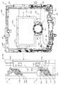
以下、本発明の実施形態について、添付図面を参照して説明する。まず、図1から図88を参照し、第1実施形態として、本発明をパチンコ遊技機(以下、単に「パチンコ機」という)10に適用した場合の一実施形態について説明する。図1は、第1実施形態におけるパチンコ機10の正面図であり、図2はパチンコ機10の遊技盤13の正面図であり、図3はパチンコ機10の背面図である。
<First Embodiment>
Hereinafter, embodiments of the present invention will be described with reference to the accompanying drawings. First, with reference to FIGS. 1 to 88, as a first embodiment, an embodiment when the present invention is applied to a pachinko gaming machine (hereinafter, simply referred to as “pachinko machine”) 10 will be described. FIG. 1 is a front view of the
図1に示すように、パチンコ機10は、略矩形状に組み合わせた木枠により外殻が形成される外枠11と、その外枠11と略同一の外形形状に形成され外枠11に対して開閉可能に支持された内枠12とを備えている。外枠11には、内枠12を支持するために正面視(図1参照)左側の上下2カ所に金属製のヒンジ18が取り付けられ、そのヒンジ18が設けられた側を開閉の軸として内枠12が正面手前側へ開閉可能に支持されている。
As shown in FIG. 1, the
内枠12には、多数の釘や入賞口63,64等を有する遊技盤13(図2参照)が裏面側から着脱可能に装着される。この遊技盤13の前面を球(遊技球)が流下することにより弾球遊技が行われる。なお、内枠12には、球を遊技盤13の前面領域に発射する球発射ユニット112a(図4参照)やその球発射ユニット112aから発射された球を遊技盤13の前面領域まで誘導する発射レール(図示せず)等が取り付けられている。
A game board 13 (see FIG. 2) having a large number of nails, winning
内枠12の前面側には、その前面上側を覆う前面枠14と、その下側を覆う下皿ユニット15とが設けられている。前面枠14及び下皿ユニット15を支持するために正面視(図1参照)左側の上下2カ所に金属製のヒンジ19が取り付けられ、そのヒンジ19が設けられた側を開閉の軸として前面枠14及び下皿ユニット15が正面手前側へ開閉可能に支持されている。なお、内枠12の施錠と前面枠14の施錠とは、シリンダ錠20の鍵穴21に専用の鍵を差し込んで所定の操作を行うことでそれぞれ解除される。
On the front side of the
前面枠14は、装飾用の樹脂部品や電気部品等を組み付けたものであり、その略中央部には略楕円形状に開口形成された窓部14cが設けられている。前面枠14の裏面側には2枚の板ガラスを有するガラスユニット16が配設され、そのガラスユニット16を介して遊技盤13の前面がパチンコ機10の正面側に視認可能となっている。
The
前面枠14には、球を貯留する上皿17が前方へ張り出して上面を開放した略箱状に形成されており、この上皿17に賞球や貸出球などが排出される。上皿17の底面は正面視(図1参照)右側に下降傾斜して形成され、その傾斜により上皿17に投入された球が球発射ユニット112a(図4参照)へと案内される。また、上皿17の上面には、枠ボタン22が設けられている。この枠ボタン22は、例えば、第3図柄表示装置81(図2参照)で表示される演出のステージを変更したり、スーパーリーチの演出内容を変更したりする場合などに、遊技者により操作される。
On the
前面枠14には、その周囲(例えばコーナー部分)に各種ランプ等の発光手段が設けられている。これら発光手段は、大当たり時や所定のリーチ時等における遊技状態の変化に応じて、点灯又は点滅することにより発光態様が変更制御され、遊技中の演出効果を高める役割を果たす。窓部14cの周縁には、LED等の発光手段を内蔵した電飾部29〜33が設けられている。パチンコ機10においては、これら電飾部29〜33が大当たりランプ等の演出ランプとして機能し、大当たり時やリーチ演出時等には内蔵するLEDの点灯や点滅によって各電飾部29〜33が点灯または点滅して、大当たり中である旨、或いは大当たり一歩手前のリーチ中である旨が報知される。また、前面枠14の正面視(図1参照)左上部には、LED等の発光手段が内蔵され賞球の払い出し中とエラー発生時とを表示可能な表示ランプ34が設けられている。
The
また、右側の電飾部32下側には、前面枠14の裏面側を視認できるように裏面側より透明樹脂を取り付けて小窓35が形成され、遊技盤13前面の貼着スペースK1(図2参照)に貼付される証紙等がパチンコ機10の前面から視認可能とされている。また、パチンコ機10においては、より煌びやかさを醸し出すために、電飾部29〜33の周りの領域にクロムメッキを施したABS樹脂製のメッキ部材36が取り付けられている。
Further, on the lower side of the illuminated
窓部14cの下方には、貸球操作部40が配設されている。貸球操作部40には、度数表示部41と、球貸しボタン42と、返却ボタン43とが設けられている。パチンコ機10の側方に配置されるカードユニット(球貸しユニット)(図示せず)に紙幣やカード等を投入した状態で貸球操作部40が操作されると、その操作に応じて球の貸出が行われる。具体的には、度数表示部41はカード等の残額情報が表示される領域であり、内蔵されたLEDが点灯して残額情報として残額が数字で表示される。球貸しボタン42は、カード等(記録媒体)に記録された情報に基づいて貸出球を得るために操作されるものであり、カード等に残額が存在する限りにおいて貸出球が上皿17に供給される。返却ボタン43は、カードユニットに挿入されたカード等の返却を求める際に操作される。なお、カードユニットを介さずに球貸し装置等から上皿17に球が直接貸し出されるパチンコ機、いわゆる現金機では貸球操作部40が不要となるが、この場合には、貸球操作部40の設置部分に飾りシール等を付加して部品構成は共通のものとしても良い。カードユニットを用いたパチンコ機と現金機との共通化を図ることができる。
A ball
上皿17の下側に位置する下皿ユニット15には、その左側に上皿17に貯留しきれなかった球を貯留するための下皿50が上面を開放した略箱状に形成されている。下皿50の右側には、球を遊技盤13の前面へ打ち込むために遊技者によって操作される操作ハンドル51が配設される。
In the
操作ハンドル51の内部には、球発射ユニット112aの駆動を許可するためのタッチセンサ51aと、押下操作している期間中には球の発射を停止する発射停止スイッチ51bと、操作ハンドル51の回動操作量(回動位置)を電気抵抗の変化により検出する可変抵抗器(図示せず)などが内蔵されている。操作ハンドル51が遊技者によって右回りに回動操作されると、タッチセンサ51aがオンされると共に可変抵抗器の抵抗値が回動操作量に対応して変化し、その可変抵抗器の抵抗値に対応した強さ(発射強度)で球が発射され、これにより遊技者の操作に対応した飛び量で遊技盤13の前面へ球が打ち込まれる。また、操作ハンドル51が遊技者により操作されていない状態においては、タッチセンサ51aおよび発射停止スイッチ51bがオフとなっている。
Inside the
下皿50の正面下方部には、下皿50に貯留された球を下方へ排出する際に操作するための球抜きレバー52が設けられている。この球抜きレバー52は、常時、正面方向に付勢されており、その付勢に抗して背面方向へスライドさせることにより、下皿50の底面に形成された底面口が開口して、その底面口から球が自然落下して排出される。この球抜きレバー54bの操作は、通常、下皿50の下方に下皿50から排出された球を受け取る箱(一般に「千両箱」と称される)を置いた状態で行われる。
A
図2に示すように、遊技盤13は、正面視略正方形状に切削加工したベース板60に、球案内用の多数の釘(図示せず)や風車の他、レール61,62、一般入賞口63、第1入球口64、第2入球口640a、第2可変入賞装置65、スルーゲート67、可変表示装置ユニット80等を組み付けて構成され、その周縁部が内枠12(図1参照)の裏面側に取り付けられる。ベース板60は光透過性の樹脂材料からなり、その正面側からベース板60の背面側に配設された各種構造体を遊技者に視認させることが可能に形成される。一般入賞口63、第1入球口64、第2入球口640a、第2可変入賞装置65、可変表示装置ユニット80は、ルータ加工によってベース板60に形成された貫通穴に配設され、遊技盤13の前面側からタッピングネジ等により固定されている。
As shown in FIG. 2, the
遊技盤13の前面中央部分は、前面枠14の窓部14c(図1参照)を通じて内枠12の前面側から視認することができる。以下に、主に図2を参照して、遊技盤13の構成について説明する。
The front central portion of the
遊技盤13の前面には、帯状の金属板を略円弧状に屈曲加工して形成した外レール62が植立され、その外レール62の内側位置には外レール62と同様に帯状の金属板で形成した円弧状の内レール61が植立される。この内レール61と外レール62とにより遊技盤13の前面外周が囲まれ、遊技盤13とガラスユニット16(図1参照)とにより前後が囲まれることにより、遊技盤13の前面には、球の挙動により遊技が行われる遊技領域が形成される。遊技領域は、遊技盤13の前面であって2本のレール61,62とレール間を繋ぐ樹脂製の外縁部材73とにより区画して形成される領域(入賞口等が配設され、発射された球が流下する領域)である。
An
2本のレール61,62は、球発射ユニット112a(図4参照)から発射された球を遊技盤13上部へ案内するために設けられたものである。内レール61の先端部分(図2の左上部)には戻り球防止部材68が取り付けられ、一旦、遊技盤13の上部へ案内された球が再度球案内通路内に戻ってしまうといった事態が防止される。外レール62の先端部(図2の右上部)には、球の最大飛翔部分に対応する位置に返しゴム69が取り付けられ、所定以上の勢いで発射された球は、返しゴム69に当たって、勢いが減衰されつつ中央部側へ跳ね返される。
The two
遊技領域の正面視左側下部(図2の左側下部)には、発光手段である複数のLED及び7セグメント表示器を備える第1図柄表示装置37A,37Bが配設されている。第1図柄表示装置37A,37Bは、主制御装置110(図4参照)で行われる各制御に応じた表示がなされるものであり、主にパチンコ機10の遊技状態の表示が行われる。本実施形態では、第1図柄表示装置37A,37Bは、球が、第1入球口64へ入賞したか、第2入球口640aへ入賞したかに応じて使い分けられるように構成されている。具体的には、球が、第1入球口64へ入賞した場合には、第1図柄表示装置37Aが作動し、一方で、球が、第2入球口640aへ入賞した場合には、第1図柄表示装置37Bが作動するように構成されている。
In the lower left side of the front view (lower left side of FIG. 2) of the game area, first
また、第1図柄表示装置37A,37Bは、LEDにより、パチンコ機10が確変中か時短中か通常中であるかを点灯状態により示したり、変動中であるか否かを点灯状態により示したり、停止図柄が確変大当たりに対応した図柄か通常大当たりに対応した図柄か外れ図柄であるかを点灯状態により示したり、保留球数を点灯状態により示すと共に、7セグメント表示装置により、大当たり中のラウンド数やエラー表示を行う。なお、複数のLEDは、それぞれのLEDの発光色(例えば、赤、緑、青)が異なるよう構成され、その発光色の組み合わせにより、少ないLEDでパチンコ機10の各種遊技状態を示唆することができる。
Further, the first
尚、本パチンコ機10では、第1入球口64及び第2入球口640aへ入賞があったことを契機として抽選が行われる。パチンコ機10は、その抽選において、大当たりか否かの当否判定(大当たり抽選)を行うと共に、大当たりと判定した場合はその大当たり種別の判定も行う。ここで判定される大当たり種別としては、確変大当たりA〜K、通常大当たりA,Bが用意されている。第1図柄表示装置37A,37Bには、変動終了後の停止図柄として抽選の結果が大当たりであるか否かが示されるだけでなく、大当たりである場合はその大当たり種別に応じた図柄が示される。
In the
ここで、「確変大当たりA〜K」は、いずれも最大ラウンド数が2ラウンドの大当たりであり、大当たりの終了後に特別図柄の高確率状態へと移行する。一方、「通常大当たりA,B」になると、最大ラウンド数が2ラウンドの大当たりの後に特別図柄の低確率状態へ移行する。 Here, the "probability variation jackpots AK" are jackpots with a maximum number of rounds of 2 rounds, and after the jackpot ends, the game shifts to a high probability state of a special symbol. On the other hand, when it becomes "normal jackpot A, B", the maximum number of rounds shifts to the low probability state of the special symbol after the jackpot of 2 rounds.
また、「高確率状態」とは、大当たり終了後に付加価値としてその後の大当たり確率がアップした状態、いわゆる確率変動中(確変中)の時をいい、換言すれば、特別遊技状態へ移行し易い遊技の状態のことである。本実施形態における高確率状態(確変中)は、後述する第2図柄の当たり確率がアップして第2入球口640aへ球が入賞し易い遊技の状態を含む。「低確率状態」とは、確変中でない時をいい、大当たり確率が通常の状態、即ち、確変の時より大当たり確率が低い状態をいう。また、「低確率状態」のうちの時短状態(時短中)とは、大当たり確率が通常の状態であると共に、大当たり確率がそのままで第2図柄の当たり確率のみがアップして第2入球口640aへ球が入賞し易い遊技の状態のことをいう。一方、パチンコ機10が通常中とは、確変中でも時短中でもない遊技の状態(大当たり確率も第2図柄の当たり確率もアップしていない状態)である。
In addition, the "high probability state" refers to a state in which the subsequent jackpot probability increases as an added value after the end of the jackpot, that is, during so-called probability fluctuation (probability change), in other words, a game in which it is easy to shift to a special gaming state. It is the state of. The high-probability state (during probabilistic change) in the present embodiment includes a game state in which the hit probability of the second symbol, which will be described later, is increased and the ball is likely to win a prize in the
確変中や時短中は、第2図柄の当たり確率がアップするだけではなく、第2入球口640aに付随する電動役物640bが開放される時間も変更され、通常中と比して長い時間が設定される。電動役物640bが開放された状態(開放状態)にある場合は、その電動役物640bが閉鎖された状態(閉鎖状態)にある場合と比して、第2入球口640aへ球が入賞しやすい状態となる。よって、確変中や時短中は、第2入球口640aへ球が入賞し易い状態となり、大当たり抽選が行われる回数を増やすことができる。
During the probability change and the time reduction, not only the hit probability of the second symbol increases, but also the time when the
なお、確変中や時短中において、第2入球口640aに付随する電動役物640bの開放時間を変更するのではなく、または、その開放時間を変更することに加えて、1回の当たりで電動役物640bが開放する回数を通常中よりも増やす変更を行うものとしてもよい。また、確変中や時短中において、第2図柄の当たり確率は変更せず、第2入球口640aに付随する電動役物640bが開放される時間および1回の当たりで電動役物640bが開放する回数の少なくとも一方を変更するものとしてもよい。また、確変中や時短中において、第2入球口640aに付随する電動役物640bが開放される時間や、1回の当たりで電動役物640bを開放する回数はせず、第2図柄の当たり確率だけを、通常中と比してアップするよう変更するものであってもよい。
In addition, during the probability change or the time reduction, the opening time of the
遊技領域には、球が入賞することにより5個から15個の球が賞球として払い出される複数の一般入賞口63が配設されている。また、遊技領域の中央部分には、可変表示装置ユニット80が配設されている。可変表示装置ユニット80には、第1入球口64及び第2入球口640aへの入賞(始動入賞)をトリガとして、第1図柄表示装置37A,37Bにおける変動表示と同期させながら、第3図柄の変動表示を行う液晶ディスプレイ(以下単に「表示装置」と略す)で構成された第3図柄表示装置81と、スルーゲート67の球の通過をトリガとして第2図柄を変動表示するLEDで構成される第2図柄表示装置83(図示せず)とが設けられている。
In the game area, a plurality of general winning
また、可変表示装置ユニット80には、第3図柄表示装置81の外周を囲むようにして、センターフレーム86が配設されている。このセンターフレーム86の中央に開口される開口部から第3図柄表示装置81が視認可能とされる。
Further, in the variable
第3図柄表示装置81は9インチサイズの大型の液晶ディスプレイで構成されるものであり、表示制御装置114(図4参照)によって表示内容が制御されることにより、例えば上、中及び下の3つの図柄列が表示される。各図柄列は複数の図柄(第3図柄)によって構成され、これらの第3図柄が図柄列毎に横スクロールして第3図柄表示装置81の表示画面上にて第3図柄が可変表示されるようになっている。本実施形態の第3図柄表示装置81は、主制御装置110(図4参照)の制御に伴った遊技状態の表示が第1図柄表示装置37A,37Bで行われるのに対して、その第1図柄表示装置37A,37Bの表示に応じた装飾的な表示を行うものである。なお、表示装置に代えて、例えばリール等を用いて第3図柄表示装置81を構成するようにしても良い。
The third
第2図柄表示装置83は、球がスルーゲート67を通過する毎に表示図柄(第2図柄(図示せず))としての「○」の図柄と「×」の図柄とを所定時間交互に点灯させる変動表示を行うものである。パチンコ機10では、球がスルーゲート67を通過したことが検出されると、当たり抽選が行われる。その当たり抽選の結果、当たりであれば、第2図柄表示装置83において、普通図柄(第2図柄)の変動表示後に「○」の図柄が停止表示される。また、当たり抽選の結果、外れであれば、第2図柄表示装置83において、第3図柄の変動表示後に「×」の図柄が停止表示される。
The second symbol display device 83 alternately lights the “○” symbol and the “×” symbol as the display symbol (second symbol (not shown)) each time the sphere passes through the through
パチンコ機10は、第2図柄表示装置83における変動表示が所定図柄(本実施形態においては「○」の図柄)で停止した場合に、第2入球口640aに付随された電動役物640bが所定時間だけ作動状態となる(開放される)よう構成されている。
In the
第2図柄の変動表示にかかる時間は、遊技状態が通常中の場合よりも、確変中または時短中の方が短くなるように設定される。これにより、確変中および時短中は、第2図柄の変動表示が短い時間で行われるので、当たり抽選を通常中よりも多く行うことができる。よって、当たり抽選において当たりとなる機会が増えるので、第2入球口640aの電動役物640bが開放状態となる機会を遊技者に多く与えることができる。よって、確変中および時短中は、第2入球口640aへ球が入賞しやすい状態とすることができる。
The time required for the variation display of the second symbol is set to be shorter during the probability change or the time reduction than when the game state is normal. As a result, during the probability change and the time reduction, the variation display of the second symbol is performed in a short time, so that the winning lottery can be performed more than during the normal time. Therefore, since the chances of winning in the winning lottery increase, it is possible to give the player many opportunities to open the
なお、確変中または時短中において、当たり確率を高める、1回に当たりに対する電動役物640bの開放時間や開放回数を増やすなど、その他の方法によっても、確変中または時短中に第2入球口640aへ球が入賞しやすい状態としている場合は、第2図柄の変動表示にかかる時間を遊技状態にかかわらず一定としてもよい。一方、第2図柄の変動表示にかかる時間を、確変中または時短中において通常中よりも短く設定する場合は、当たり確率を遊技状態にかかわらず一定にしてもよいし、また、1回の当たりに対する電動役物640bの開放時間や開放回数を遊技状態にかかわらず一定にしてもよい。
In addition, during the probability change or the time reduction, the
スルーゲート67は、可変表示装置ユニット80の下側の領域における右方において遊技盤に組み付けられ、遊技盤に発射された球のうち、遊技盤の右方を流下する球の一部が通過可能に構成されている。スルーゲート67を球が通過すると、第2図柄の当たり抽選が行われる。当たり抽選の後、第2図柄表示装置83にて変動表示を行い、当たり抽選の結果が当たりであれば、変動表示の停止図柄として「○」の図柄を表示し、当たり抽選の結果が外れであれば、変動表示の停止図柄として「×」の図柄を表示する。
The through
球のスルーゲート67の通過回数は、合計で最大4回まで保留され、その保留球数が上述した第1図柄表示装置37A,37Bにより表示されると共に第2図柄保留ランプ(図示せず)においても点灯表示される。第2図柄保留ランプは、最大保留数分の4つ設けられ、第3図柄表示装置81の下方に左右対称に配設されている。
The number of times the ball has passed through the through
なお、第2図柄の変動表示は、本実施形態のように、第2図柄表示装置83において複数のランプの点灯と非点灯を切り換えることにより行うものの他、第1図柄表示装置37A,37B及び第3図柄表示装置81の一部を使用して行うようにしても良い。同様に、第2図柄保留ランプの点灯を第3図柄表示装置81の一部で行うようにしても良い。また、スルーゲート67の球の通過に対する最大保留球数は4回に限定されるものでなく、3回以下、又は、5回以上の回数(例えば、8回)に設定しても良い。また、スルーゲート67の組み付け数は1つに限定されるものではなく、複数(例えば、2つ)であっても良い。また、スルーゲート67の組み付け位置は可変表示装置ユニット80の右方に限定されるものではなく、例えば、可変表示装置ユニット80の左方でも良い。また、第1図柄表示装置37A,37Bにより保留球数が示されるので、第2図柄保留ランプにより点灯表示を行わないものとしてもよい。
The variation display of the second symbol is performed by switching the lighting and non-lighting of a plurality of lamps in the second symbol display device 83 as in the present embodiment, as well as the first
可変表示装置ユニット80の下方には、球が入賞し得る第1入球口64が配設されている。この第1入球口64へ球が入賞すると遊技盤13の裏面側に設けられる第1入賞口スイッチ(図示せず)がオンとなり、その第1入賞口スイッチのオンに起因して主制御装置110(図4参照)で大当たりの抽選がなされ、その抽選結果に応じた表示が第1図柄表示装置37Aで示される。
Below the variable
一方、第1入球口64の正面視右方には、球が入賞し得る第2入球口640aが配設されている。この第2入球口640aへ球が入賞すると遊技盤13の裏面側に設けられる第2入球口スイッチ(図示せず)がオンとなり、その第2入球口スイッチのオンに起因して主制御装置110(図4参照)で大当たりの抽選がなされ、その抽選結果に応じた表示が第1図柄表示装置37Bで示される。
On the other hand, on the right side of the
また、第1入球口64および第2入球口640aは、それぞれ、球が入賞すると5個の球が賞球として払い出される入賞口の1つにもなっている。なお、本実施形態においては、第1入球口64へ球が入賞した場合に払い出される賞球数と第2入球口640aへ球が入賞した場合に払い出される賞球数とを同じに構成したが、第1入球口64へ球が入賞した場合に払い出される賞球数と第2入球口640aへ球が入賞した場合に払い出される賞球数とを異なる数、例えば、第1入球口64へ球が入賞した場合に払い出される賞球数を3個とし、第2入球口640aへ球が入賞した場合に払い出される賞球数を5個として構成してもよい。
Further, each of the first ball opening 64 and the second ball opening 640a is also one of the winning holes in which five balls are paid out as prize balls when the balls win a prize. In the present embodiment, the number of prize balls paid out when a ball wins in the
第2入球口640aには電動役物640bが付随されている。この電動役物640bは開閉可能に構成されており、通常は電動役物640bが閉鎖状態(張出し状態)となって、球が第2入球口640aへ入賞しにくい状態となっている。一方、スルーゲート67への球の通過を契機として行われる第2図柄の変動表示の結果、「○」の図柄が第2図柄表示装置83に表示された場合、電動役物640bが開放状態(引込み状態)となり、球が第2入球口640aへ入賞しやすい状態となる。
An
上述した通り、確変中および時短中は、通常中と比して第2図柄の当たり確率が高く、また、第2図柄の変動表示にかかる時間も短いので、第2図柄の変動表示において「○」の図柄が表示され易くなって、電動役物640bが開放状態(引込み状態)となる回数が増える。更に、確変中および時短中は、電動役物640bが開放される時間も、通常中より長くなる。よって、確変中および時短中は、通常時と比して、第2入球口640aへ球が入賞しやすい状態を作ることができる。
As described above, during the probability change and the time reduction, the probability of hitting the second symbol is higher than during the normal time, and the time required for the variation display of the second symbol is short. ”Is easy to display, and the number of times that the
ここで、第1入球口64に球が入賞した場合と第2入球口640aへ球が入賞した場合とで、大当たりとなる確率は、低確率状態であっても高確率状態でも同一である。しかしながら、大当たりとなった場合に選定される大当たりの種別として、第2入球口640aへ球が入賞した場合の方が、比較的多量の賞球を獲得可能な大当たり種別の選択割合が高く設定されている。一方、第1入球口64は、第2入球口640aにあるような電動役物は有しておらず、球が常時入賞可能な状態となっている。
Here, the probability of winning a jackpot is the same in both the low probability state and the high probability state depending on whether the ball wins the first ball opening 64 or the second ball opening 640a. is there. However, as the type of jackpot selected in the case of a jackpot, the selection ratio of the jackpot type that can obtain a relatively large amount of prize balls is set higher when the ball wins in the
よって、通常中においては、第2入球口640aに付随する電動役物が閉鎖状態にある場合が多く、第2入球口640aに入賞し難いので、電動役物のない第1入球口64へ向けて、可変表示装置ユニット80の左方を球が通過するように球を発射し(所謂「左打ち」)、第1入球口64への入賞によって大当たり抽選の機会を多く得て、大当たりとなることを狙った方が、遊技者にとって有利となる。
Therefore, in normal times, the electric accessory attached to the
一方、確変中や時短中は、スルーゲート67に球を通過させることで、第2入球口640aに付随する電動役物640bが開放状態となりやすく、第2入球口640aに入賞しやすい状態であるので、第2入球口640aへ向けて、可変表示装置80の右方を球が通過するように球を発射し(所謂「右打ち」)、スルーゲート67を通過させて電動役物を開放状態にすると共に、第2入球口640aへの入賞によって大当たりとなることを狙った方が、遊技者にとって有利となる。
On the other hand, during the probability change or the time reduction, by passing the ball through the through
このように、本実施形態のパチンコ機10は、パチンコ機10の遊技状態(確変中であるか、時短中であるか、通常中であるか)に応じて、遊技者に対し、球の発射の仕方を「左打ち」と「右打ち」とに変えさせることができる。よって、遊技者に対して、球の打ち方に変化をもたらすことができるので、遊技を楽しませることができる。
As described above, the
第1入球口64の左上には第1可変入賞装置82aが配設され、その近傍に第1特定入賞口82が設けられている。通常は第1可変入賞装置82aが閉鎖状態(縮小状態)となって、球が第1特定入賞口82へと入賞できないようになっている。一方、特定の大当たり(例えば、確変大当たりA)の際に第1可変入賞装置82aが、大当たり種別に応じた所定の開放パターンに従って開閉される。所定の開放パターンとして、0.6秒間の開放と0.9秒間の閉鎖とを20回繰り返す開放パターン(開放パターンA)と、0.052秒間の開放を1回のみ行う開放パターン(開放パターンB)とが設けられている。
A first variable winning
この第1可変入賞装置82aによる所定の開放パターンに従った開閉動作は、最高で例えば2回(2ラウンド)繰り返し可能にされている。この開閉動作が行われている状態が、遊技者にとって有利な特別遊技状態の一形態であり、遊技者には、遊技上の価値(遊技価値)の付与として通常時より多量の賞球の払い出しが行われる。なお、各ラウンドでは、開放パターンが完了していなくても、所定個数(例えば、10個)以上の球が第1特定入賞口82へと入賞したことを検出した場合に、強制的に第1可変入賞装置82aが閉鎖されてラウンドの終了が設定される。
The opening / closing operation according to a predetermined opening pattern by the first variable winning
第1入球口64の右側には第2可変入賞装置65が配設されており、その略中央部分に横長矩形状の第2特定入賞口(大開放口)65aが設けられている。パチンコ機10においては、第1入球口64又は第2入球口640aへの入賞に起因して行われた大当たり抽選が大当たりとなると、所定時間(変動時間)が経過した後に、大当たりの停止図柄となるよう第1図柄表示装置37A又は第1図柄表示装置37Bを点灯させると共に、その大当たりに対応した停止図柄を第3図柄表示装置81に表示させて、大当たりの発生が示される。その大当たり種別が第2特定入賞口65aに対応する種別の場合には、球が第2特定入賞口65aへと入賞し易い特別遊技状態(大当たり)に遊技状態が遷移する。この特別遊技状態として、通常時には閉鎖されている第2特定入賞口65aが、所定時間(例えば、30秒経過するまで、或いは、球が10個入賞するまで)開放される。即ち、第1可変入賞装置82aが開放される大当たり種別に比較して、長い開放時間が設定される。よって、第2特定入賞口65aが開放される大当たり種別では、多くの場合、第2特定入賞口65aに対して上限個数(例えば、10個)の球を入賞させることができるので、遊技者に対してより多くの賞球を獲得させることができる。従って、大当たりとなった場合に、第2特定入賞口65aが開放される大当たり種別であることを願わせることができるので、大当たりとなった場合において第2特定入賞口65aに注目させることができる。
A second variable winning
この第2特定入賞口65aは、所定時間が経過すると閉鎖され、その閉鎖後、再度、その第2特定入賞口65aが所定時間開放される。この第2特定入賞口65aの開閉動作は、最高で例えば2回(2ラウンド)繰り返し可能にされている。この開閉動作が行われている状態が、遊技者にとって有利な特別遊技状態の一形態であり、遊技者には、遊技上の価値(遊技価値)の付与として通常時より多量の賞球の払い出しが行われる。
The second specific winning
第2可変入賞装置65は、具体的には、第2特定入賞口65aを覆う横長矩形状の開閉板と、その開閉板の下辺を軸として前方側に開閉駆動するための大開放口ソレノイド(図示せず)とを備えている。第2特定入賞口65aは、通常時は、球が入賞できないか又は入賞し難い閉状態になっている。大当たりの際には大開放口ソレノイドを駆動して開閉板を前面下側に傾倒し、球が第2特定入賞口65aに入賞しやすい開状態を一時的に形成し、その開状態と通常時の閉状態との状態を交互に繰り返すように作動する。
Specifically, the second variable winning
遊技盤13の下側における右隅部には、証紙や識別ラベル等を貼着するための貼着スペースK1が設けられ、貼着スペースK1に貼られた証紙等は、前面枠14の小窓35(図1参照)を通じて視認することができる。
A sticking space K1 for sticking a certificate stamp, an identification label, or the like is provided in the right corner on the lower side of the
遊技盤13には、第1アウト口71が設けられている。遊技領域を流下する球であって、いずれの入賞口63,64,65a,640,にも入賞しなかった球は、第1アウト口71を通って図示しない球排出路へと案内される。第1アウト口71は、第1入球口64の下方に配設される。
The
遊技盤13には、球の落下方向を適宜分散、調整等するために多数の釘が植設されているとともに、風車等の各種部材(役物)とが配設されている。
A large number of nails are planted on the
図3に示すように、パチンコ機10の背面側には、制御基板ユニット90,91と、裏パックユニット94とが主に備えられている。制御基板ユニット90は、主基板(主制御装置110)と音声ランプ制御基板(音声ランプ制御装置113)と表示制御基板(表示制御装置114)とが搭載されてユニット化されている。制御基板ユニット91は、払出制御基板(払出制御装置111)と発射制御基板(発射制御装置112)と電源基板(電源装置115)とカードユニット接続基板116とが搭載されてユニット化されている。
As shown in FIG. 3, the
裏パックユニット94は、保護カバー部を形成する裏パック92と払出ユニット93とがユニット化されている。また、各制御基板には、各制御を司る1チップマイコンとしてのMPU、各種機器との連絡をとるポート、各種抽選の際に用いられる乱数発生器、時間計数や同期を図る場合などに使用されるクロックパルス発生回路等が、必要に応じて搭載されている。
In the
なお、主制御装置110、音声ランプ制御装置113及び表示制御装置114、払出制御装置111及び発射制御装置112、電源装置115、カードユニット接続基板116は、それぞれ基板ボックス100〜104に収納されている。基板ボックス100〜104は、ボックスベースと該ボックスベースの開口部を覆うボックスカバーとを備えており、そのボックスベースとボックスカバーとが互いに連結されて、各制御装置や各基板が収納される。
The
また、基板ボックス100(主制御装置110)及び基板ボックス102(払出制御装置111及び発射制御装置112)は、ボックスベースとボックスカバーとを封印ユニット(図示せず)によって開封不能に連結(かしめ構造による連結)している。また、ボックスベースとボックスカバーとの連結部には、ボックスベースとボックスカバーとに亘って封印シール(図示せず)が貼着されている。この封印シールは、脆性な素材で構成されており、基板ボックス100,102を開封するために封印シールを剥がそうとしたり、基板ボックス100,102を無理に開封しようとすると、ボックスベース側とボックスカバー側とに切断される。よって、封印ユニット又は封印シールを確認することで、基板ボックス100,102が開封されたかどうかを知ることができる。
Further, in the board box 100 (main control device 110) and the board box 102 (
払出ユニット93は、裏パックユニット94の最上部に位置して上方に開口したタンク130と、タンク130の下方に連結され下流側に向けて緩やかに傾斜するタンクレール131と、タンクレール131の下流側に縦向きに連結されるケースレール132と、ケースレール132の最下流部に設けられ、払出モータ216(図4参照)の所定の電気的構成により球の払出を行う払出装置133とを備えている。タンク130には、遊技ホールの島設備から供給される球が逐次補給され、払出装置133により必要個数の球の払い出しが適宜行われる。タンクレール131には、当該タンクレール131に振動を付加するためのバイブレータ134が取り付けられている。
The
また、払出制御装置111には状態復帰スイッチ120が設けられ、発射制御装置112には可変抵抗器の操作つまみ121が設けられ、電源装置115にはRAM消去スイッチ122が設けられている。状態復帰スイッチ120は、例えば、払出モータ216(図4参照)部の球詰まり等、払出エラーの発生時に球詰まりを解消(正常状態への復帰)するために操作される。操作つまみ121は、発射ソレノイドの発射力を調整するために操作される。RAM消去スイッチ122は、パチンコ機10を初期状態に戻したい場合に電源投入時に操作される。
Further, the
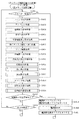
次に、図4を参照して、本パチンコ機10の電気的構成について説明する。図4は、パチンコ機10の電気的構成を示すブロック図である。
Next, the electrical configuration of the
主制御装置110には、演算装置である1チップマイコンとしてのMPU201が搭載されている。MPU201には、該MPU201により実行される各種の制御プログラムや固定値データを記憶したROM202と、そのROM202内に記憶される制御プログラムの実行に際して各種のデータ等を一時的に記憶するためのメモリであるRAM203と、そのほか、割込回路やタイマ回路、データ送受信回路などの各種回路が内蔵されている。主制御装置110では、MPU201によって、大当たり抽選や第1図柄表示装置37A,37B及び第3図柄表示装置81における表示の設定、第2図柄表示装置83における表示結果の抽選といったパチンコ機10の主要な処理を実行する。
The
なお、払出制御装置111や音声ランプ制御装置113などのサブ制御装置に対して動作を指示するために、主制御装置110から該サブ制御装置へ各種のコマンドがデータ送受信回路によって送信されるが、かかるコマンドは、主制御装置110からサブ制御装置へ一方向にのみ送信される。
In order to instruct the operation of the sub control device such as the
RAM203は、各種エリア、カウンタ、フラグのほか、MPU201の内部レジスタの内容やMPU201により実行される制御プログラムの戻り先番地などが記憶されるスタックエリアと、各種のフラグおよびカウンタ、I/O等の値が記憶される作業エリア(作業領域)とを有している。なお、RAM203は、パチンコ機10の電源の遮断後においても電源装置115からバックアップ電圧が供給されてデータを保持(バックアップ)できる構成となっており、RAM203に記憶されるデータは、すべてバックアップされる。
The
停電などの発生により電源が遮断されると、その電源遮断時(停電発生時を含む。以下同様)のスタックポインタや、各レジスタの値がRAM203に記憶される。一方、電源投入時(停電解消による電源投入を含む。以下同様)には、RAM203に記憶される情報に基づいて、パチンコ機10の状態が電源遮断前の状態に復帰される。RAM203への書き込みはメイン処理(図示せず)によって電源遮断時に実行され、RAM203に書き込まれた各値の復帰は電源投入時の立ち上げ処理(図示せず)において実行される。なお、MPU201のNMI端子(ノンマスカブル割込端子)には、停電等の発生による電源遮断時に、停電監視回路252からの停電信号SG1が入力されるように構成されており、その停電信号SG1がMPU201へ入力されると、停電時処理としてのNMI割込処理(図示せず)が即座に実行される。
When the power supply is cut off due to the occurrence of a power failure or the like, the stack pointer at the time of the power failure (including the time when the power failure occurs; the same applies hereinafter) and the value of each register are stored in the
主制御装置110のMPU201には、アドレスバス及びデータバスで構成されるバスライン204を介して入出力ポート205が接続されている。入出力ポート205には、払出制御装置111、音声ランプ制御装置113、第1図柄表示装置37A,37B、第2図柄表示装置83、第2図柄保留ランプ、第2特定入賞口65aの開閉板の下辺を軸として前方側に開閉駆動するための大開放口ソレノイドや電動役物を駆動するためのソレノイドなどからなるソレノイド209が接続され、MPU201は、入出力ポート205を介してこれらに対し各種コマンドや制御信号を送信する。
An input /
また、入出力ポート205には、図示しないスイッチ群およびスライド位置検出センサSや回転位置検出センサRを含むセンサ群などからなる各種スイッチ208、電源装置115に設けられた後述のRAM消去スイッチ回路253が接続され、MPU201は各種スイッチ208から出力される信号や、RAM消去スイッチ回路253より出力されるRAM消去信号SG2に基づいて各種処理を実行する。
Further, the input /
払出制御装置111は、払出モータ216を駆動させて賞球や貸出球の払出制御を行うものである。演算装置であるMPU211は、そのMPU211により実行される制御プログラムや固定値データ等を記憶したROM212と、ワークメモリ等として使用されるRAM213とを有している。
The
払出制御装置111のRAM213は、主制御装置110のRAM203と同様に、MPU211の内部レジスタの内容やMPU211により実行される制御プログラムの戻り先番地などが記憶されるスタックエリアと、各種のフラグおよびカウンタ、I/O等の値が記憶される作業エリア(作業領域)とを有している。RAM213は、パチンコ機10の電源の遮断後においても電源装置115からバックアップ電圧が供給されてデータを保持(バックアップ)できる構成となっており、RAM213に記憶されるデータは、すべてバックアップされる。なお、主制御装置110のMPU201と同様、MPU211のNMI端子にも、停電等の発生による電源遮断時に停電監視回路252から停電信号SG1が入力されるように構成されており、その停電信号SG1がMPU211へ入力されると、停電時処理としてのNMI割込処理(図示せず)が即座に実行される。
The
払出制御装置111のMPU211には、アドレスバス及びデータバスで構成されるバスライン214を介して入出力ポート215が接続されている。入出力ポート215には、主制御装置110や払出モータ216、発射制御装置112などがそれぞれ接続されている。また、図示はしないが、払出制御装置111には、払い出された賞球を検出するための賞球検出スイッチが接続されている。なお、該賞球検出スイッチは、払出制御装置111に接続されるが、主制御装置110には接続されていない。
An input /
発射制御装置112は、主制御装置110により球の発射の指示がなされた場合に、操作ハンドル51の回動操作量に応じた球の打ち出し強さとなるよう球発射ユニット112aを制御するものである。球発射ユニット112aは、図示しない発射ソレノイドおよび電磁石を備えており、その発射ソレノイドおよび電磁石は、所定条件が整っている場合に駆動が許可される。具体的には、遊技者が操作ハンドル51に触れていることをタッチセンサ51aにより検出し、球の発射を停止させるための発射停止スイッチ51bがオフ(操作されていないこと)を条件に、操作ハンドル51の回動操作量(回動位置)に対応して発射ソレノイドが励磁され、操作ハンドル51の操作量に応じた強さで球が発射される。
The
音声ランプ制御装置113は、音声出力装置(図示しないスピーカなど)226における音声の出力、ランプ表示装置(電飾部29〜33、表示ランプ34など)227における点灯および消灯の出力、変動演出(変動表示)や予告演出といった表示制御装置114で行われる第3図柄表示装置81の表示態様の設定などを制御するものである。演算装置であるMPU221は、そのMPU221により実行される制御プログラムや固定値データ等を記憶したROM222と、ワークメモリ等として使用されるRAM223とを有している。
The audio
音声ランプ制御装置113のMPU221には、アドレスバス及びデータバスで構成されるバスライン224を介して入出力ポート225が接続されている。入出力ポート225には、主制御装置110、表示制御装置114、音声出力装置226、ランプ表示装置227、その他装置228、各種センサ230、枠ボタン22などがそれぞれ接続されている。
An input /
音声ランプ制御装置113は、主制御装置110から受信した各種のコマンド(変動パターンコマンド、停止種別コマンド等)に基づいて、第3図柄表示装置81の表示態様を決定し、決定した表示態様をコマンド(表示用変動パターンコマンド、表示用停止種別コマンド等)によって表示制御装置114へ通知する。また、音声ランプ制御装置113は、枠ボタン22からの入力を監視し、遊技者によって枠ボタン22が操作された場合は、第3図柄表示装置81で表示されるステージを変更したり、スーパーリーチ時の演出内容を変更したりするように、表示制御装置114へ指示する。ステージが変更される場合は、変更後のステージに応じた背面画像を第3図柄表示装置81に表示させるべく、変更後のステージに関する情報を含めた背面画像変更コマンドを表示制御装置114へ送信する。ここで、背面画像とは、第3図柄表示装置81に表示させる主要な画像である第3図柄の背面側に表示される画像のことである。表示制御装置114は、この音声ランプ制御装置113から送信されるコマンドに従って、第3図柄表示装置81に各種の画像を表示する。
The voice
また、音声ランプ制御装置113は、表示制御装置114から第3図柄表示装置81の表示内容を表すコマンド(表示コマンド)を受信する。音声ランプ制御装置113では、表示制御装置114から受信した表示コマンドに基づき、第3図柄表示装置81の表示内容に合わせて、その表示内容に対応する音声を音声出力装置226から出力し、また、その表示内容に対応させてランプ表示装置227の点灯および消灯を制御する。
Further, the voice
表示制御装置114は、音声ランプ制御装置113及び第3図柄表示装置81が接続され、音声ランプ制御装置113より受信したコマンドに基づいて、第3図柄表示装置81における第3図柄の変動演出などの表示を制御するものである。また、表示制御装置114は、第3図柄表示装置81の表示内容を通知する表示コマンドを適宜音声ランプ制御装置113へ送信する。音声ランプ制御装置113は、この表示コマンドによって示される表示内容にあわせて音声出力装置226から音声を出力することで、第3図柄表示装置81の表示と音声出力装置226からの音声出力とをあわせることができる。
In the
電源装置115は、パチンコ機10の各部に電源を供給するための電源部251と、停電等による電源遮断を監視する停電監視回路252と、RAM消去スイッチ122(図3参照)が設けられたRAM消去スイッチ回路253とを有している。電源部251は、図示しない電源経路を通じて、各制御装置110〜114等に対して各々に必要な動作電圧を供給する装置である。その概要としては、電源部251は、外部より供給される交流24ボルトの電圧を取り込み、各種スイッチ208などの各種スイッチや、ソレノイド209などのソレノイド、モータ等を駆動するための12ボルトの電圧、ロジック用の5ボルトの電圧、RAMバックアップ用のバックアップ電圧などを生成し、これら12ボルトの電圧、5ボルトの電圧及びバックアップ電圧を各制御装置110〜114等に対して必要な電圧を供給する。
The
停電監視回路252は、停電等の発生による電源遮断時に、主制御装置110のMPU201及び払出制御装置111のMPU211の各NMI端子へ停電信号SG1を出力するための回路である。停電監視回路252は、電源部251から出力される最大電圧である直流安定24ボルトの電圧を監視し、この電圧が22ボルト未満になった場合に停電(電源断、電源遮断)の発生と判断して、停電信号SG1を主制御装置110及び払出制御装置111へ出力する。停電信号SG1の出力によって、主制御装置110及び払出制御装置111は、停電の発生を認識し、NMI割込処理を実行する。なお、電源部251は、直流安定24ボルトの電圧が22ボルト未満になった後においても、NMI割込処理の実行に充分な時間の間、制御系の駆動電圧である5ボルトの電圧の出力を正常値に維持するように構成されている。よって、主制御装置110及び払出制御装置111は、NMI割込処理(図示せず)を正常に実行し完了することができる。
The power
RAM消去スイッチ回路253は、RAM消去スイッチ122(図3参照)が押下された場合に、主制御装置110へ、バックアップデータをクリアさせるためのRAM消去信号SG2を出力するための回路である。主制御装置110は、パチンコ機10の電源投入時に、RAM消去信号SG2を入力した場合に、バックアップデータをクリアすると共に、払出制御装置111においてバックアップデータをクリアさせるための払出初期化コマンドを払出制御装置111に対して送信する。
The RAM erase
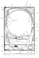
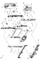
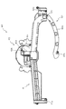
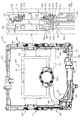
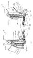
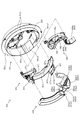
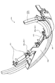
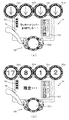
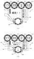
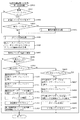
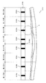
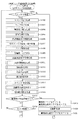
次いで、図5から図10を参照して、動作ユニット200の概略構成について説明する。図5は、動作ユニット200の分解正面斜視図であり、図6は、遊技盤13及び動作ユニット200の正面斜視図である。また、図7は、動作ユニット200の正面斜視図であり、図8から図10は、動作ユニット200の正面図である。
Next, a schematic configuration of the
なお、図6及び図7では、液晶昇降ユニット400が下降位置に配置された状態が、図9では、液晶昇降ユニット400の第2通路形成部材422と左揺動ユニット500の第1通路形成部材520とが連結された状態が、図10では、液晶昇降ユニット400が上昇位置に配置された状態が、それぞれ図示される。また、図6から図10では、上部昇降ユニット300が上昇位置に配置された状態が図示される。
In addition, in FIGS. 6 and 7, the state in which the liquid
図5から図10に示すように、動作ユニット200は、箱状に形成される背面ケース210を備え、その背面ケース210の内部空間に、上部昇降ユニット300、液晶昇降ユニット400、左揺動ユニット500、回転ユニット600及び発光装飾部材700がそれぞれ収容される。
As shown in FIGS. 5 to 10, the
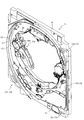
背面ケース210は、正面視略矩形の底壁部211と、その底壁部211の4辺の外縁から正面へ向けて立設される外壁部212とを備え、これら各壁部211,212により一面側が開放された箱状に形成される。背面ケース210の底壁部211には、その中央に正面性略円形の凹部が凹設され、その凹部に回転ユニット600が収納される。液晶昇降ユニット400は、回転ユニット600の正面側に配設され、上部昇降ユニット300、左揺動ユニット500及び装飾発光部材700は、液晶昇降ユニット400の上側縁部、左側縁部および下側縁部にそれぞれ配設される。
The
上部昇降ユニット300は、複数(本実施形態では4個)が幅方向(図8左右方向)に並設される昇降体330を備え、それら昇降体330がそれぞれ独立して高さ方向(図8上下方向)に昇降可能に形成される(図12及び図13参照)。液晶昇降ユニット400が下降位置に配置された状態では、昇降体330が上昇位置に配置されると、第3図柄表示装置81のほぼ全面が視認可能とされる一方(図8参照)、昇降体330が下降位置に配置されると(図12参照)、かかる昇降体330により第3図柄表示装置81の一部が視認不能とされる。
The upper elevating
液晶昇降ユニット400は、軸を上下方向に沿わせた縦姿勢で配設されると共に幅方向に所定間隔を隔てて配設される一対の案内棒451と、その案内棒451に幅方向両端がスライド変位可能に支持される駆動側スライド部材420及び従動側スライド部材430と、駆動側スライド部材420を昇降駆動する駆動モータ441とを備え、その駆動モータ441により駆動側スライド部材420が昇降駆動されることで、従動側スライド部材430が従動して昇降される。
The liquid
即ち、駆動側スライド部材420が上昇される際には、かかる駆動側スライド部材420が従動側スライド部材430を重力の作用に抗しつつ上方へ押し上げる一方、駆動側スライド部材420が下降される際には、その駆動側スライド部材420の下降に伴い、従動側スライド部材430が自重により下降される。
That is, when the drive-
なお、駆動側スライド部材420には、第2通路形成部材422が配設され、従動側スライド部材430には、第3図側表示装置81が配設される。駆動側スライド部材420が、上昇位置および下降位置の間の連結位置に配置されると、第2通路形成部材422が左揺動ユニット500の第1通路形成部材520と連結可能とされる(図9参照)。また、駆動側スライド部材420が、上昇位置に配置されると、第3図柄表示装置81の上方領域が上部昇降ユニット300の背面側に配置される(図10参照)。
The drive
左揺動ユニット500は、基端側を中心として先端側を上下させる方向へ揺動される第1通路形成部材520を備える。第1通路形成部材520は、先端側を持ち上げる方向へ揺動されると、連結位置に配置され(図9参照)、先端側が液晶昇降ユニット400の第2通路形成部材422に連結される一方、先端側を振り下げる方向へ揺動されると、解除位置に配置され(図10参照)、液晶昇降ユニット400の第2通路形成部材422との連結が解除される。
The
遊技領域を流下する球は、左揺動ユニット500内へ流入可能とされ、左揺動ユニット500は、第1通路形成部材520が連結位置に配置された状態では(図9参照)、流入された球を、第1通路形成部材520を介して、液晶昇降ユニット400の第2通路形成部材422へ送球する一方、第1通路形成部材520が解除位置に配置された状態では(図10参照)、流入された球を、第1通路形成部材520とは別に設けられた後述する通路を介して、遊技領域へ送球する。
The ball flowing down the game area can flow into the
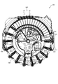
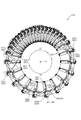
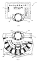
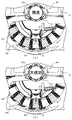
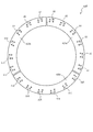
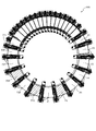
回転ユニット600は、ルーレットを模して構成される演出装置である。即ち、回転可能に形成されるホイール(回転盤)に相当する部材(回転部材640)と、そのホイールを周方向に区画して形成され赤または黒の色が付されると共にそれぞれ異なる数字が表示されるポケットに相当する部分(表示板646及び区画板647)とを備え、ホイールの内周側の装置(投球装置650)から投球された球Bが、複数のポケットに相当する部分のうちのいずれかに落下するように形成される。
The
液晶昇降ユニット400が下降位置に配置された状態では(図8参照)、回転ユニット600のほぼ全体が液晶昇降ユニット400によって遊技者から視認不能に遮蔽される一方、液晶昇降ユニット400が連結位置に配置された状態では(図9参照)、ホイールに相当する部材の一部(下方部分)が露出されると共に、液晶昇降ユニット400が上昇位置に配置された状態では(図10参照)、ホイールに相当する部材の一部(下方部分)に加え、ホイールに相当する部材の内周側に保持されている球B及びその球Bが投球されてからポケットに相当する部分に落下するまでの経路が露出され、これらが遊技者から視認可能とされる。
In the state where the liquid
発光装飾部材700は、光透過性の材料から形成されるケース体と、そのケース体の内部に配設される複数のLEDとを備え、LEDから発光する光の態様(例えば、発光するLEDの数や発光時間)を変更することで、発光による演出を行う。
The light emitting
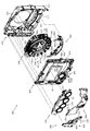
次いで、図11から図20を参照して、上部昇降ユニット300、液晶昇降ユニット400、左揺動ユニット500、回転ユニット600及び発光装飾部材700の詳細構成を説明する。まず、図11から図20を参照して、上部昇降ユニット300について説明する。
Next, with reference to FIGS. 11 to 20, detailed configurations of the upper elevating
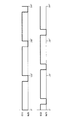
図11は、上部昇降ユニット300の正面斜視図であり、図12及び図13は、上部昇降ユニット300の正面図である。なお、図11及び図12では、幅方向(図12左右方向)に並設される全ての昇降体330が上昇位置に配置された状態が図示され、図13では、全ての昇降体330が下降位置に配置された状態が図示される。
FIG. 11 is a front perspective view of the upper elevating
図11から図13に示すように、上部昇降ユニット300は、横長矩形板形状のベース部材310の幅方向に昇降体330が複数(本実施形態では4個)配設され、各昇降体330が上昇位置(図12参照)と下降位置(図13参照)との間を昇降移動可能に構成される。次いで、図14及び図15を参照して、各昇降体330の駆動機構の構成について説明する。
As shown in FIGS. 11 to 13, in the upper elevating
図14は、上部昇降ユニット300の正面分解斜視図であり、図15は、上部昇降ユニット300の背面分解斜視図である。
FIG. 14 is a front exploded perspective view of the upper elevating
図14及び図15に図示されるように、上部昇降ユニット300は、横長矩形板形状のベース部材310と、そのベース部材310との間に伝達装置350を収容する空間を設けながらベース部材310の背面側に締結固定される背面カバー320と、ベース部材310及び背面カバー320の間にラック332が収容されると共に円形の演出部331がベース部材310の正面側に配置される昇降体330と、背面カバー部材320に締結固定され昇降体の昇降動作に必要な駆動力を発生させる駆動装置340と、その駆動装置340が発生する駆動力を昇降体330に伝達させる伝達装置350と、を主に備える。
As shown in FIGS. 14 and 15, in the upper elevating
カバー部材310は、下端に円の中心が配置される半円形状で正面側側面から背面側へ向けて凹設される半円凹設部311と、背面側側面から昇降体330のラック332の左右方向に若干隙間を空けた位置へ向かってリブ状に凸設される案内リブ312と、を備える。
The
半円凹設部311は、昇降体330の演出部331の外径よりも若干大きな半径で構成され、その半円凹設部311の円の中心と、演出部331の中心とが鉛直線状で一致する位置に配置される。これにより、演出部331が上昇移動する際に、ベース部材310の正面側において半円凹設部311と干渉する位置の手前まで移動することが可能となり、ベース部材310の上下幅は確保しつつ、演出部331の上昇移動幅も大きく確保することができる。
The semicircular recessed
案内リブ部312は、鉛直方向に延びるリブ状の部分であって、組立状態(図11参照)において、昇降体330のラック332の左右側面と当接可能な位置まで凸設される。これにより、昇降体330が昇降移動中に左右方向に移動する(並行移動や傾斜動作する)ことを抑制することができる。
The
また、半円凹設部311を正面側から背面側へ凹設される凹部として構成することで、前後方向に貫通する空間とする場合に比較して、背面側を視認不能とできる面積を広げることができる。従って、機構部分(ギアやモータ等の、遊技者に視認させることを目的としない部分)を配設する面積を大きく確保できる。
Further, by configuring the semicircular recessed
背面カバー320は、正面側および下方が開放されたケース状に構成される本体部321と、その本体部321から正面側に凸設される円柱形状の軸支部322と、その軸支部322から正面視左右方向に位置ずれした位置において延設方向を鉛直方向と一致させた状態で穿設される長孔である案内孔323と、上側の軸支部322が凸設される周囲の底部から軸支部322の径方向に沿設されるリブ状に形成される係止部324と、を備える。
The
軸支部322は、伝達装置350の一対のギア部材351,352をそれぞれ軸支する部分であり、案内孔323は、昇降体330の昇降動作を案内する孔である。
The
係止部324は、上側の軸支部322の軸に対して、鉛直方向上側と鉛直方向下側とに配設され、それぞれ昇降体330が上昇位置または下降位置に配置された状態において、第1ギア351の係止円弧部351cの端部が回転方向で当接可能とされる部分である。
The locking
昇降体330は、円形板形状に構成される演出部331と、その演出部331の背面に固定され演出部331の背面側側面から隙間を空けた位置において鉛直方向に延設されるラック332と、を備える。
The elevating
演出部331は、円形の外枠の内側に円形の液晶パネルが配設され、液晶パネルに模様や図形を表示することにより演出を行う部分である。
The
ラック332は、背面側に凸設されると共に背面カバー320の案内孔323に挿通される位置まで凸設されるスライド軸332aを備える。
The
スライド軸332aは、複数が凸設される態様ではなく、一つが凸設される態様とされる。そのため、案内孔323の配設個数を1つにでき(低減でき)るので、鉛直方向における案内孔323の配設スペースを抑制しながら、ラック332の移動距離を大きく確保することができる。一方で、本実施形態では、ラック332が左右方向で案内リブ部312と当接可能とされるので、ラック332の案内孔323との連結位置が一箇所であっても、ラック332が左右方向に傾くことを防止することができる。これにより、昇降体330が上下移動する際に演出部331が左右方向に振れることを防止できると共に、第2ギア352とラック332との間隔が変動して歯合関係が悪化することを防止することができる。
The
駆動装置340は、背面カバー320に締結固定される駆動源である駆動モータ341と、その駆動モータ341の駆動軸の回転により回転され伝達装置350に駆動力を伝達する駆動ギア342と、を備える。
The
伝達装置350は、軸支部322に軸支されると共に駆動ギア342に歯合される第1ギア351と、その第1ギア351及びラック332に歯合されると共に軸支部322に軸支される第2ギア352と、を備える。
The
このように、複数(本実施形態では4個)の昇降体330は、それぞれ独立の駆動モータ341を備えるので、全ての昇降体330が連動して昇降動作する動作に加え、各昇降体330を個別に昇降動作させることができる。なお、各昇降体330の技術的思想は共通するので、以下では、図11の左端に配設される昇降体330について説明し、その他の昇降体330についての説明を省略する。
As described above, since the plurality of (four in the present embodiment) elevating
次いで、図16を参照して、第1ギア351及び第2ギア352について説明する。図16(a)は、第1ギア351の正面図であり、図16(b)は、第1ギア351の背面図であり、図16(c)は、第2ギア352の正面図であり、図16(d)は、第2ギア352の背面図である。
Next, the
図16(a)及び図16(b)に示すように、第1ギア351は、軸支部322(図14参照)が挿通される貫通孔を備え外周面にギア歯が形成される本体部351aと、その本体部351aの外周面においてギア歯の形成が省略される部分にギア歯の歯丈の約半分の張出長さ(歯合する歯同士の接点を連結したピッチ円C1まで張り出す張出長さ)で径方向に張出形成される当接部351bと、本体部351aの背面側側面から軸と平行な方向に沿って軸を中心とした円弧形状で凸設される係止円弧部351cと、を備える。
As shown in FIGS. 16A and 16B, the
当接部351bは、径方向の先端面が本体部351aの中心軸を中心として半径rの円弧形状とされ、およそ本体部351aに形成されるギア歯の2から3つ分の歯厚(円弧の中心の成す角度がおよそ45度から60度の範囲の歯厚)で構成される。即ち、ギア歯一つ分の歯厚よりも本体部351a周方向の形成長さが長くされるので、本体部351aのギア歯に比較して、周方向の強度を確保することができる。
The
係止円弧部351cは、周方向の先端が背面カバー320の係止部324(図14参照)と周方向で当接可能とされる部分であって、第1ギア351の回転角度を規制する役割がある。
The locking
図16(c)及び図16(d)に示すように、第2ギア352は、正面側と背面側とで歯形の異なる2層のギアから構成され、ドーナツ板形状に構成される中間板353と、その中間板353の正面側に形成され歯形が一部異形とされる異形ギア部354と、中間板353の背面側に平歯車形状に形成されラック332(図15参照)と歯合される伝達ギア部355と、を備える。
As shown in FIGS. 16 (c) and 16 (d), the
中間板352は、異形ギア部354及び伝達ギア部355のギア歯の先端よりも径方向外側まで張り出して形成される。そのため、歯合される相手部材(第1ギア351又はラック332(図15参照))と歯面と平行な方向で重なることで当接可能とされ(図17参照)、その相手部材が昇降体330の昇降動作時に歯面と平行な方向へ移動することを抑制することができる。
The
異形ギア部354は、組立状態(図11参照)において第1ギア351と歯合される部分であって、軸支部322(図14参照)が挿通される貫通孔を備え外周面にギア歯が形成される本体部354aと、その本体部354aの外周面においてギア歯の形成が省略される部分に張出形成される受け部354bと、その受け部354bの一端(図16(c)右側の端部)に隣設される隣設ギア歯354cと、を備える。
The
受け部354bは、本体部354aの外周面に沿って隣設ギア歯354cから正面視反時計回り側(昇降体330を上昇移動させる際に第1ギア351が隣設ギア部354cに噛み込む側)にギア歯2個分ほどの配設角度(約30度から50度)で形成される部分であって、伝達装置350が軸支部322に軸支された状態において当接部351bの先端面が形成する半径rの円弧形状に沿って湾曲形成される湾曲壁部354b1と、その湾曲壁部354b1と隣設ギア歯354cの周方向の歯面との間に隣設ギア歯354cの歯丈の約半分の歯丈(歯合する歯同士の接点を連結したピッチ円C2まで張り出される歯丈)で形成される連結壁部354b2と、を備える。従って、隣設ギア歯354cの連結壁部354b2側の側面は、隣設ギア歯354cの連結壁部354b2の反対側の側面の径方向の張出長さの約半分の張出長さで、連結壁部354b2と一体形成される状態で連結壁部354b2から径方向に張り出して構成される。
The receiving
図16(c)に示すように、伝達装置350が軸支部322に軸支された状態において、第2ギア352が当接部351bの先端面が形成する半径rの円弧形状に沿って湾曲壁部354b1が配置される姿勢とされる場合に、隣設ギア歯354cは半径rの円弧の外側(第2ギア352側)に配置される態様とされる(隣設ギア歯354cが半径rの円と干渉しない位置での形成に留められる)。
As shown in FIG. 16C, in a state where the
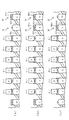
次いで、図17から図20を参照して、昇降体330の昇降動作について説明する。なお、上昇動作と下降動作との動作経路は共通であるので、ここでは上昇動作について説明し、下降動作の説明を省略する。
Next, the elevating operation of the elevating
図17から図20は、昇降体330の上昇動作が時系列で図示される昇降体330及び伝達装置350の正面図である。なお、図17では、昇降体330が下降位置に配置された状態が図示され、図18では、図17に図示される状態から第2ギア352が正面視時計回りに回転され昇降体330が所定距離上昇動作し第1ギア351の当接部351bの周方向の端部が第2ギア352の隣設ギア歯354cに噛み合い始めた状態が図示され、図19では、図18に図示される状態から第1ギア351が正面視反時計回り及び第2ギア352が正面視時計回りに回転され当接部351bの周方向の端面と隣設ギア歯354cとの当接が外れた直後の状態が図示され、図20では、図19に図示される状態から第1ギア351のみが正面視時計回りに所定量回転された状態が図示される。
17 to 20 are front views of the elevating
図17から図20に図示されるように、昇降体330は、ラック332に駆動モータ341(図14参照)の駆動力が駆動ギア342及び伝達装置350を介して伝達されることにより昇降動作される。詳述すると、駆動ギア342の駆動力は、その駆動ギア342と歯合される第1ギア351から、その第1ギア351に歯合される第2ギア352の異形ギア部354に伝達され、第2ギア352の回転が、その第2ギア352の伝達ギア部355(図16(d)参照)と歯合されるラックに伝達されることにより、昇降体330が昇降動作する。
As shown in FIGS. 17 to 20, the elevating
図17に図示される下降位置では、ラック332のスライド軸332a(図15参照)が背面カバー320の案内孔323(図15参照)の下端に配置される。そのため、ラック332がそれ以上下方に移動することを機械的に防止できる。
In the lowered position shown in FIG. 17, the
また、図17に図示される状態において、第1ギア351の係止円弧部351cの周方向の端部と背面カバー320の下側の係止部324とが当接することで、第1ギア351の正面視時計回り方向(ラック332を下降動作させる方向)への回転が機械的に防止される。
Further, in the state shown in FIG. 17, the
これにより、駆動モータ341の制御不良などにより駆動ギア342が過回転して第1ギア351を図17に図示される状態から更に正面視時計間回りに回転させようとする負荷が生じたとしても、第1ギア351の回転が機械的に防止されることにより、その負荷が第2ギア352に伝達されることを防止でき、ラック332が下降動作する事態を回避できるので、スライド軸322a(図15参照)が案内孔323(図15参照)の下側面に押し当てられスライド軸322a又は案内孔323が破損することを防止することができる。
As a result, even if the
図18に図示されるように、昇降体330が上昇動作する過程において、周方向の歯厚が他のギア歯よりも大きくされる当接部351bの周方向端面が隣設ギア歯354cと噛み合うので、第2ギア352から第1ギア351へ逆方向に伝達される負荷(昇降体330の重さによる負荷)を他のギア歯に比較して強度の大きい当接部351bで受けることができ、第1ギア351の耐久性を向上させることができる。
As shown in FIG. 18, in the process of ascending the elevating
第1ギア351の当接部351bがピッチ円C1まで張り出されると共に、第2ギア352の連結壁部354b2がピッチ円C2まで張り出されるので、図18の状態において、当接部351bが連結壁部354b2と擦れる位置まで近接される。そのため、隣設ギア歯354cの歯元に近い部分で当接部351bと隣設ギア歯354cとを当接させることができ、隣設ギア歯354cの耐久性を向上させることができる。
The
また、隣設ギア歯354cは、連結壁部354b2に周方向の一方の側面を連結されるので、他のギア歯に比較して、周方向から受ける負荷に対する強度が向上される。換言すれば、連結壁部354b2側の側面の径方向の張出長さが短くされるため、隣設ギア歯354cの歯丈方向と垂直な方向への変形に対する抵抗が増加すると共に、連結壁部354b2が隣設ギア歯354cと一体で形成されることで隣設ギア歯354cに負荷される力を受ける部分としての隣設ギア歯354c及び連結壁部354b2の合計の歯厚が大きくされるため、隣設ギア歯354cの周方向への変形に対する抵抗が増加する。これにより、隣設ギア歯354cが第1ギア351の当接部351bを受け止める際に破損することを抑制することができる。
Further, since one side surface of the
図19に示すように、昇降体330が上昇位置に配置された直後の状態において、当接部351bの円弧状の先端部と隣設ギア歯354cとが当接する。この状態において、第1ギア351の周方向で第1ギア351と第2ギア352とが当接していないので、第1ギア351の回転方向の駆動力の第2ギア352への伝達が解除される。
As shown in FIG. 19, immediately after the elevating
そのため、第2ギア352に歯合される昇降体330の重さを支える力が第1ギア351から伝達されなくなり、昇降体330が落下する方向に移動しかけるので、第2ギア352がラック332を下降動作させる方向(図19反時計回り)に回転しかける。
Therefore, the force supporting the weight of the elevating
一方で、図19に示すように、隣設ギア歯354cが回転する方向の範囲(隣設ギア歯354cの先端が形成する円の内側)に当接部351bが配置されるので、第2ギア352を回転させる際には、隣設ギア歯354cにより当接部351bを隣設ギア歯354cの移動軌跡の外側に押しやる必要がある。
On the other hand, as shown in FIG. 19, since the
当接部351bの外周形状が本体部351aの中心軸を中心とした円弧形状とされるので、当接部351bの外周面に与えられる荷重は、第1ギア351の軸側へ向かう軸方向成分Faと、第1ギア351の当接部351bの接線方向に沿う周方向成分Fbとに分解される。
Since the outer peripheral shape of the
軸方向成分Faは、第1ギア351を回転可能な方向では無く、また、第1ギア351の剛性が確保される状態では(径方向に伸縮しない構造では)、軸方向成分Faにより当接部351bを隣設ギア歯354cの移動軌跡の外側に押しやることは困難である。
The axial component Fa is not in a direction in which the
周方向成分Fbは、第1ギア351の回転方向を向くが、隣設ギア歯354cと当接部351bとが点で接触するため、隣設ギア歯354cと当接部351bとの間で滑りが生じ、第1ギア351が回転されにくいため、周方向成分Fbにより当接部351bを隣設ギア歯354cの移動軌跡の外側に押しやることは困難である。
The circumferential component Fb faces the rotation direction of the
従って、隣設ギア歯354cにより当接部351bを隣設ギア歯354cの移動軌跡の外側に押しやることが防止されることから、第2ギア352が回転することが防止され、第2ギア352及び昇降体330の状態が保持される。
Therefore, since the
当接部351bと受け部354bの湾曲壁部354b1とが、共に第1ギア351を中心とした半径rの円弧形状から形成され、図19に図示されるように、第1回転ギア351の周方向に沿って面当たりで当接されるので、第1ギア351の回転を湾曲壁部354b1全体の面積を利用して強固に受け止めることができる。これにより、昇降体330が上昇位置に到達した後に駆動モータ341(図14参照)の停止が遅れたとしても、第1ギア351が過回転することを防止することができ、駆動モータ341の停止の遅れが昇降体330の動作態様に影響することを防止することができる。
Both the abutting
図20に示すように、第1ギア351は、係止円弧部351cが上側の係止部324に当接する状態まで回転し、停止する。図18から図20までの間、第1ギア351の当接部351bの周方向端面が隣設ギア歯354cの側面を押進することにより第2ギア352が回転されるので、隣設ギア歯354cが第2ギア352に対して位置合わせされ、図20に図示される状態において隣設ギア歯354cが当接部351bの歯先面に当接する状態を確実に形成することができる。
As shown in FIG. 20, the
図19に示す状態から図20に示す状態までにおいて、昇降体330は上昇位置に配置されるので、第2ギア352がラック332を上昇移動させる方向(図20時計回り)に回転することが規制される。そのため、第1ギア351が第2ギア352に対して図19反時計回りに回転しても、第2ギア352が連れ回りすることが無い。従って、当接部351bの歯先面が隣設ギア歯354cに対面する状態を確実に形成することができる。
From the state shown in FIG. 19 to the state shown in FIG. 20, since the elevating
図20に図示されるように、昇降体330が上昇位置に配置された状態において、第2ギア352が当接部351bの先端面が形成する半径rの円弧形状に沿って湾曲壁部354b1が配置される姿勢とされ隣設ギア歯354cが半径rの円弧の外側(第2ギア352側)に配置されるので、図19に図示される状態から、第1ギア351のみを同一回転方向(図19反時計回り方向)に回転させることができる。
As shown in FIG. 20, in a state where the elevating
このとき、当接部351bの歯厚が他のギア歯に比較して厚く(およそギア歯2個分から3個分の厚さ)されるので、第1ギア351の停止位置の精度を緩やかにすることができる。即ち、例えば、図19に示す状態から図20に示す状態の中間の位相に第1ギア351が停止したとしても、隣設ギア歯354cと当接部351bとの当接位置での関係は同様に確保され、第2ギア352の回転を規制することができる。
At this time, the tooth thickness of the
また、第1ギア351の停止位置の精度を緩やかにしたまま、第2ギア352の両方向への回転を規制することができる。即ち、第2ギア352が図20時計回りに回転しかけたとしても、受け部354bの湾曲壁部354b1が当接部351bの歯先面と当接することで、荷重の方向を詳細に上述した隣設ギア歯354cと当接部351bとの当接時と同様に第2ギア352の回転が規制される。従って、昇降体330が上昇位置に配置された状態においてラック332が上下両方向に移動する事が規制されるので、昇降体330にがたつきが発生することを抑制することができる。上下両方向の規制(特に、上昇方向の規制)は、従来のクランク機構で行うことは困難であり、本実施形態のように第1ギア351と第2ギア352のギア形状により、初めて達成されるものである。
Further, it is possible to regulate the rotation of the
このように、第1ギア351及び第2ギア352の形状の関係により、昇降体330が上昇位置に配置された状態において第2ギア352が回転することを防止することができるので、昇降体330を上昇位置に維持するために駆動モータ341(図14参照)の駆動力を自重以上の大きさで付与し続けることを不要とでき、消費エネルギーを抑制することができる。
As described above, due to the relationship between the shapes of the
また、クランク機構の死点を利用して昇降体330を上昇位置に維持することも可能ではあるが、その場合、昇降体330の移動距離に対応してクランク機構が大型化するという問題点があった。本実施形態では、クランク機構を不要とし、第1ギア351及び第2ギア352の形状の関係により第2ギア352の回転を規制できるので、伝達部分の小型化を図ることができる。
Further, it is possible to maintain the elevating
第2ギア352の回転の規制を解除する方法について説明する。図19及び図20に示す状態において、第1ギア351の当接部351bを逆方向へ回転させる場合の回転方向(図20時計回り方向)に当接部351bと干渉する別部材が配設されないので、第1ギア351の昇降体330を下降動作させる方向(図20時計回り方向)への回転動作が許容される。
A method of releasing the restriction on the rotation of the
第1ギア351を図20に図示される状態から図19に図示される状態まで回転させ、更に同一方向に回転させると第2ギア352の回転方向への規制が解除され(当接部351bの先端面が隣設ギア歯354cから離間して)、昇降体330が下降動作可能となる。即ち、第1ギア351の回転動作により、第2ギア352の回転規制の解除を行うことができ、第2ギア352の回転規制の解除のために第1ギア351に別動作を行わせることが不要であるので、第1ギア351の構造を簡素化することができる。
When the
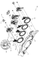
次いで、図21から図33を参照して、液晶昇降ユニット400について説明する。図21は、液晶昇降ユニット400の正面斜視図である。図21に示すように、液晶昇降ユニット400は、円形の液晶部分を有する演出部422aを有し昇降動作する駆動側スライド部材420と、その駆動側スライド部材420に従動して上昇動作する部材であって第3図柄表示装置81を備える従動側スライド部材430と、を備え、それら駆動側スライド部材420及び従動側スライド部材430が共通の案内棒451に連通され、同一方向に動作する態様で構成される。
Next, the liquid
図22は、液晶昇降ユニット400の正面分解斜視図である。図22に図示されるように、液晶昇降ユニット400は、一対の長尺板状部材から構成されるベース部材410と、上下方向に昇降動作可能に構成される駆動側スライド部材420と、その駆動側スライド部材420の上方に配置され上下方向に動作可能に構成される従動側スライド部材430と、駆動側スライド部材420が昇降動作する駆動力を発生させる駆動装置440と、その駆動装置440から発生した駆動力を駆動側スライド部材420に伝達すると共に駆動側スライド部材420及び従動側スライド部材430の動作を案内する一対の案内棒451を有する伝達装置450と、一対のベース部材410の下端部同士を連結すると共に駆動側スライド部材420と連結される下側前板部材460と、液晶昇降ユニット400の左右および上部の正面側に配設されるカバー部材470と、を主に備えて構成される。
FIG. 22 is a front exploded perspective view of the liquid
ベース部材410は、縦長の長尺板状部材として構成される本体部材411と、その本体部材411の上下両端部に互いに鉛直方向で一致する位置に配置され正面に開放するコ字形状の凹部として構成される案内棒支持部412と、その案内棒支持部412から引かれる鉛直線よりも内側(他方のベース部材410に近接する側)に配置され本体部材411の正面側に延設される係止部413と、案内棒支持部412から引かれる鉛直線を挟んで係止部413の反対側において本体部材411の正面側に円柱形状に凸設される第1軸支部414と、その第1軸支部414に軸支されると共に駆動側スライド部材420の下降動作を規制する下降規制部材415と、第1軸支部414の下方に配置され本体部材411の正面側に円柱形状に凸設される第2軸支部416と、その第2軸支部416に軸支されると共に従動側スライド部材430の上昇動作を規制する上昇規制部材417と、を主に備える。
The
案内棒支持部412は、伝達装置450の案内棒451の両端を支持する部分であって、案内棒451を収容可能な開口幅で形成される。本実施形態では、カバー部材470がベース部材410に締結固定されることにより、案内棒支持部412の正面側の開口が塞がれ、案内棒451が案内棒支持部412に固定される。
The guide
係止部413は、従動側スライド部材430の落下防止部435の下側側面に上下方向で当接する部分であって、その当接状態から、それ以上、従動側スライド部材430が下降動作することを規制する。
The locking
下降規制部材415及び上昇規制部材417は、駆動側スライド部材420の昇降動作に伴って回転動作し、従動側スライド部材430の移動を規制する役割をもつ部材であるが、詳細は後述する。
The lowering restricting
駆動側スライド部材420は、左右両端部を伝達装置450のラック452に締結固定され、ラック452のスライド動作により昇降動作される部材である。
The drive-
従動側スライド部材430は、独立の駆動装置を持たず、左右両端を案内棒451にスライド動作可能に支持されると共に、駆動側スライド部材420の昇降動作に従動して昇降動作する。従動側スライド部材430は、第3図柄表示装置81を有し左右方向に長尺に構成される本体部材431と、その本体部材431の左右方向両端に配置される機能部432と、その機能部432に鉛直方向に穿設される孔であって案内棒451が挿通される案内孔433と、機能部432の下端部において左右外側方向に上昇傾斜して延設される鉤状部434と、機能部432の上端部の案内孔433の内側(他方の案内孔433に近接する側)において背面側に延設される落下防止部435と、を主に備える。
The driven
鉤状部434は、上昇規制部材417に引っ掛けられる部分である。従動側スライド部材430が下降位置に配置される状態において、上昇規制部材417が鉤状部434の上側面である係合面434aに回り込んで引っ掛けられることで(図29参照)、従動側スライド部材430が上昇方向に動作することを防止することができる(例えば、落下の反動で跳ねることを防止することができる)。また、鉤状部434が上昇傾斜し、その傾斜と平行に上昇規制部材417の係合爪部417eが構成されるので、鉤状部434と上昇規制部材417との係合により、左右方向のぐらつきも抑制することができる。
The hook-shaped
なお、鉤状部434の先端部(図29に図示される状態において係合爪部417eの先端部よりも外側(図29右側の部分))の形状は、係合爪部417eの移動軌跡よりも下方に収まる形状とされる。そのため、係合爪部417eと鉤状部434とが係合し、互いに負荷を掛け合う状態においても、上昇規制部材417の回転動作を行うことができる。
The shape of the tip of the hook-shaped portion 434 (outside the tip of the engaging
駆動装置440は、ベース部材410の本体部材411に締結固定される駆動モータ441と、その駆動モータの駆動力で回転される駆動ギア442と、を備える。
The
伝達装置450は、ベース部材410の案内棒支持部412に固定される一対の案内棒451と、その案内棒451にスライド動作可能に支持され駆動側スライド部材420が締結固定されると共に駆動ギア442に内側(一対の駆動ギア442の内側)から歯合されるラック452とそのラック452の歯元付近から正面側に延設される縦長板状の当接壁453と、を主に備える。
The
当接壁453は、上昇規制部材417を解除側に回転させる役割と、上昇規制部材417の付勢力を受けてラック452を駆動ギア442から離反する方向に寄せる役割とを備えるが、詳細は後述する。
The
下側前板部材460は、左右端部はベース部材410の本体部材411の正面側に締結固定され中央部は左右端部に比較して背面側に所定量オフセットされる態様で折曲される形状の本体部材461と、その本体部材461の左半部において左右方向に沿って(外側に近接するほど上昇傾斜する態様で)穿設される案内孔462と、本体部材461の上方に延設される筒状部材であって上端部が正面側に開口される筒状通路部463と、を主に備える。
The lower
案内孔462は、配線収納部材423のスライド軸423bがスライド可能に案内される長孔である。
The
筒状通路部463は、球が通過可能な筒状の部材であって、駆動側スライド部材420が連結位置に配置される状態(図31参照)において、駆動側スライド部材420の第2通路形成部材422を通過して流下する球が通過する部材である。
The
図23から図25を参照して、駆動側スライド部材420の詳細構成について説明する。図23は、駆動側スライド部材420の分解正面斜視図であり、図24は、駆動側スライド部材420の分解背面斜視図であり、図25は、駆動側スライド部材420の背面図である。
The detailed configuration of the drive-
図23から図25に図示されるように、駆動側スライド部材420は、左右方向に長尺な板状部材として構成される本体部材421と、円形の液晶から構成される演出部422aを有する円盤部分が本体部材421の中心部に正面側から締結固定されると共にその円盤部分から正面視左方に球が通過可能な溝が延設される第2通路形成部材422と、その第2流路形成部材422の正面視左下端部に一方の端部が軸支され他方の端部が下側前板部材460の案内孔462に支持される配線収納部材423と、第2流路形成部材422に軸支されると共に軸の周方向に沿って貫通する通路部を有し第2流路形成部材422の溝部422bへ球を導入する部分としてはたらく接続部材424と、を主に備える。
As shown in FIGS. 23 to 25, the drive-
本体部材421は、案内棒451(図22参照)が挿通される筒状部の一部を構成する案内部421aと、中央部から正面視左方に延設される部分に正面側に開放する態様で左方に下降傾斜して配設される溝部421bと、その溝部421bの左下端部において球の直径以上の大きさで前後方向に貫通形成される排出開口部421cと、を主に備える。
The
案内部421aは、背面側に開放され鉛直方向に延設される断面円弧形状の溝部分であって、その開放部分を伝達装置450のラック452(図22参照)で閉鎖することにより、案内棒451(図22参照)が挿通される筒状部が構成される。
The
溝部421bは、第2通路形成部材422と共同で球の通路を形成する部材であって、溝部421bに沿って流下した球は、排出開口部421cを通って本体部材421の背面側へ排出される。
The
第2通路形成部材422は、円形の液晶から構成される演出部422aと、その円形の液晶の背面側に配設される円盤部分から背面側へ円柱形状で凸設される軸支部422bと、その軸支部422bの下方に配設され球の通過を検出するセンサ部材422cと、そのセンサ部材422cを通過した球が流下可能な幅で背面側へ開放される溝であり溝部421bと前後方向で形状が一致する溝部422dと、案内棒451(図22参照)が挿通される筒状部を構成する案内部422eと、軸支部422bとセンサ部材422cとの間で接続部材424を収容可能な形状で凹設される収容凹部422fと、を主に備える。
The second
軸支部422bは、接続部材424が軸支される部分である。連結位置に液晶昇降ユニット400が配置される状態において、左揺動ユニット500を流下した球が接続部材424を介してセンサ部材422cを通過したあと、溝部422d,421bの形成する通路を球が通過する。
The
配線収納部材423は、下側前側部材460等から延長され演出部422a等に接続される配線を収容する部材であって、第2通路形成部材422の正面視左下端部に軸支される長尺断面コ字状の棒状部分である本体部423aと、その本体部423aの下端部から背面側に凸設される円柱形状のスライド軸423bと、を主に備える。
The
本体部423aは、断面コ字状に形成される内側部分に配線を収納する部材であって、長手方向に第2通路形成部材422から離反する方向に凸となる態様で湾曲した形状で構成される。これにより、第2通路形成部材422との軸支位置付近において、湾曲形状に沿って配線を弛ませることができ、配線が折れ曲げられて断線することを抑制することができる。
The
スライド軸423bは、下側前板部材460の案内孔462に挿通される棒状部分である。
The
次いで、図26を参照して、接続部材424の構成について説明する。図26(a)は、接続部材424の正面斜視図であり、図26(b)は、図26(a)の矢印XXVIb方向視における接続部材424の正面図であり、図26(c)は、図26(a)の矢印XXVIc方向視における接続部材424の背面図である。
Next, the configuration of the connecting
図26(a)から図26(c)に示すように、接続部材424は、筒状に形成され軸支部422bに軸支される筒状部424aと、その筒状部424aの径方向に延設される板状の上側壁部424bと、その上側壁部424bの正面視下方に球の直径以上の長さを空けて上側壁部424bと対向配置される湾曲した板状の下側壁部424cと、それら上側壁部424b及び下側壁部424cの背面側端部を連結すると共に上側壁部424b及び下側壁部424cの間に覆設される連結カバー424dと、筒状部424aに巻き付けられ接続部材424に下向き(図25(b)反時計回り)の付勢力を与えるねじりバネ424eと、を主に備える。
As shown in FIGS. 26A to 26C, the connecting
上側壁部424bは、筒状部424aの径方向の端部から筒状部424aの軸へ近接する程幅が大きくなる態様で形成され側面が図25(b)において直線に沿って形成される板状部である。
The upper
下側壁部424cは、筒状部424aの軸を中心とした円弧に沿って湾曲形成される板状部であり、上側壁部424bとの間に球が通過可能な長さの空間を空けて配設される。
The lower
連結カバー424dは、接続部材424を通過する球が背面側にこぼれることを抑制する板部材である。なお、連結カバー424dの反対側(正面側)に構成される接続部材424の開放部は、第2通路形成部材422の収容凹部422fの底部が正面側から当接されることで塞がれる。これにより、球が接続部材424の開放部からこぼれることを抑制することができる。
The connecting
図27及び図28を参照して、第2通路形成部材422に対する接続部材424の動作について説明する。図27及び図28は、第2通路形成部材422及び接続部材424の背面図である。なお、図27では、接続部材424の上側壁部424b及び下側壁部424cにより構成される開放部が左右方向を向く下傾斜状態が図示され、図28では、図27の状態に比較して接続部材424の上側壁部424b及び下側壁部424cにより構成される開放部が斜め上方向を向く上傾斜状態が図示され、図27が後述する離間状態(図41参照)に対応し、図28が後述する連通状態(図42参照)に対応する。
The operation of the connecting
図27及び図28に示すように、接続部材424は、第2通路形成部材422の収容凹部422fに収容された状態で軸支部422bを中心に回転動作可能とされ、第2通路形成部材422の収容凹部422fの底部に上側壁部424b及び下側壁部424cの正面側端面が当接される。
As shown in FIGS. 27 and 28, the connecting
収容凹部422fは、図27に図示される状態で接続部材424の下側壁部424cと対向配置される部分に、下側壁部424cの外径に沿って軸支部422bを中心とした円弧形状に形成される湾曲壁部422f1と、その湾曲壁部422f1と対向配置される面が湾曲壁部422f1から遠ざかる方向に凹み上傾斜状態(図42参照)において接続部材424の上側壁部424bと滑らかに連結される湾曲面を有する対向壁部422f2と、を備える。
The
湾曲壁部422f1は、接続部材424の下傾斜状態において下側壁部424cと径方向で面当たりされるので、接続部材424の軸径方向の位置ずれを抑制することができる。
Since the curved wall portion 422f1 is in surface contact with the lower
従って、軸支部422bと接続部材424の筒状部424aとの嵌合を緩め(隙間の大きい状態、例えば、寸法が0.5mmから1mmの間の隙間を有する状態)としたとしても、接続部材424が下傾斜状態とされる場合には下側壁部424cと湾曲壁部422f1との当接により、接続部材424の姿勢を高精度に維持することができる。
Therefore, even if the fitting between the
一方で、軸支部422bと接続部材424の筒状部424aとの嵌合を緩めとする場合、軸支部分に生じる動作抵抗が低減されるので、他の部材からの負荷が生じない限り、接続部材424を重力の作用およびねじりバネ424eの付勢力で確実に下傾斜状態に維持することができる。従って、他の部材からの負荷が生じていないのに、接続部材424が上傾斜状態に維持される事態を抑制する事ができる。
On the other hand, when the fitting of the
対向壁部422f2は、接続部材424からセンサ部材422cへ球を案内する部分である。本実施形態では、湾曲壁部422f1と対向配置する面が湾曲することにより、球を滑らかにセンサ部材422cへ案内することができる。
The facing wall portion 422f2 is a portion that guides the sphere from the connecting
上傾斜状態は、左揺動ユニット500の第1通路形成部材520と接続部材424とが連通される連通状態において形成される。この状態では、下側壁部424cがセンサ部材422cの開口から離間されるので、接続部材424の下側壁部424cを転動して通過した球は湾曲壁部422f1を転動し、センサ部材422cの開口を通過して溝部422dを流下する。
The upward tilted state is formed in a communicating state in which the first
一方、下傾斜状態は、左揺動ユニット500の第1通路形成部材520と接続部材424とが離間される離間状態において形成される。この状態では、下側壁部424cが、センサ部材422cの開口の内側まで張り出し、下側壁部422cの下側端部と、その下側端部と対向配置される収容凹部422fの壁面(センサ部材422cから鉛直上方に延びる壁面)との間の寸法が球の直径以下とされることで、球が接続部材424を通過する(球が下端部から排出される)ことが防止される。
On the other hand, the downward tilting state is formed in a separated state in which the first
そのため、後述するように、離間状態において球が接続部材424に到達したとしても、その球の流れを接続部材424で停滞させることができる。
Therefore, as will be described later, even if the sphere reaches the connecting
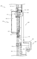
次いで、図29から図33を参照して、駆動側スライド部材420及び従動側スライド部材430の昇降動作について説明する。まず、図29及び図30を参照して駆動側スライド部材420、従動側スライド部材430及びベース部材410の位置関係を説明する。
Next, the elevating operation of the driving
図29は、液晶昇降ユニット400の正面図であり、図30は、図29の矢印XXX方向視における液晶昇降ユニット400の側面図である。なお、図29及び図30では、駆動側スライド部材420及び従動側スライド部材430が下降位置に配置された状態が図示されると共に、カバー部材470の内で左右一対のカバー部材の図示が省略され伝達部材450が視認可能とされる。また、図29では、正面視右側の下降規制部材415及び上昇規制部材417が部分的に拡大視されると共に、当接壁453と上昇規制部材417の解除凸部417cとが当接する直前のラック452の外形が想像線で図示される。
29 is a front view of the liquid
図29及び図30に示すように、従動側スライド部材430は、下降位置において、落下防止部435がベース部材410の係止部413に下側から当接されると共に、鉤状部434が上昇規制部材417に上側から当接される。このように、従動側スライド部材430は上下両方向から移動を規制される態様とされるので、下降位置において従動側スライド部材430が上下方向にがたつくことを抑制することができる。
As shown in FIGS. 29 and 30, in the driven
また、案内孔433に挿通される案内棒451を挟んで上昇規制部材417及び係止部413が配設され、それらが従動側スライド部材430の機能部432と当接可能とされるので、機能部432が案内棒451の軸直角方向(図29左右方向)にがたつくことを抑制できる。従って、下降位置に配置された瞬間や、パチンコ機10(図1参照)が遊技者から叩かれた場合等、従動側スライド部材430に外乱が生じたとしても、従動側スライド部材430ががたつくことを抑制でき、第3図柄表示装置81の演出効果を向上させることができる。
Further, the
更に、上昇規制部材417と、係止部413の上下方向の位置がずれて配設されるので、機能部432が斜め方向(例えば係止部413と上昇規制部材417とを結ぶ方向)にがたつくことを抑制することができる。そのため、下降位置に配置された瞬間や、パチンコ機10(図1参照)が遊技者から叩かれた場合等、従動側スライド部材430に外乱が生じたとしても、従動側スライド部材430ががたつくことを抑制でき、第3図柄表示装置81の演出効果を向上させることができる。
Further, since the
なお、上昇規制部材417と比較して、係止部413が上方に位置ずれしているので、係止部413が駆動側スライド部材420から遠い位置に配置され、係止部413が駆動側スライド部材420の昇降動作を阻害しにくくできる。従って、駆動側スライド部材420の設計自由度を向上させることができる。
Since the locking
図30に示すように、下降規制部材415の方が上昇規制部材417の前方に配置され、伝達装置450の当接壁453の形成高さ(ラック452の歯元付近からの張出長さ)が下降規制部材415に到達する手前までの高さとされるので、下降規制部材415の回転方向において下降規制部材415と当接壁453とは当接しない。また、鉤状部434が上昇規制部材417と前後方向で同等の位置に配置されることから、鉤状部434と下降規制部材415とは上下方向で当接しない。
As shown in FIG. 30, the lowering restricting
一方、ラック452は、当接壁453の上端部から正面側へ凸設される凸設板453aを備え、その凸設板453aが下降規制部材415と回転方向で当接可能とされる。
On the other hand, the
図31は、液晶昇降ユニット400の正面図である。なお、図31では、駆動側スライド部材420が下降位置から上昇移動され、連結位置に配置された状態が図示されると共に、カバー部材470の内で左右一対のカバー部材の図示が省略される。また、図31では、正面視右側の下降規制部材415及び上昇規制部材417が部分的に拡大視される。
FIG. 31 is a front view of the liquid
駆動側スライド部材420が連結位置に配置される状態において、左揺動ユニット500(図42参照)を介して接続部材424に球を導入可能とされる。
In a state where the drive-
図29及び図31に示すように、上昇規制部材417は、当接壁453の上端部が上昇規制部材417に当接される前の状態において鉤状部434に上側から被さる部材であって、図29に示す係合状態と、図31に示す解除状態との間を回転動作可能とされる。なお、解除状態とは、図31の状態に限定されず、鉤状部434の鉛直上方から上昇規制部材417が退避される姿勢まで上昇規制部材417が回転された状態を意味する。
As shown in FIGS. 29 and 31, the
上昇規制部材417は、第2軸支部416に軸支される円筒部417aと、その円筒部417aの接線方向に直線上に延設される延設板417bと、その延設板417bの一方の端部(下側の端部)から垂直に凸設される解除凸部417cと、延設板417bの他方の端部から垂直に凸設される係合凸部417dと、その係合凸部417dの凸設端部において係合状態で鉤状部434の延設方向と平行に延びると共に鉤状部434の先端部よりも上内方(図29拡大図左上方)に配設される係合爪部417eと、係合凸部417dの凸設端部の上側側面において下降傾斜される離間傾斜部417fと、円筒部417aに巻き付け形成され一方の端部がベース部材410の本体部材411に係止されることにより上昇規制部材417を内巻き方向(図29拡大図反時計回り方向)に付勢するねじりバネ417gと、を主に備える。
The
延設板417bは、円筒部417aの軸よりも上方に延設される。これにより、解除凸部417cが押し上げられた際に、延設板417bの他方の端部を従動側スライド部材430から離反する方向に移動させることができ、解除動作を行うことができる。
The
係合爪部417eは、係合状態において、従動側スライド部材430が上方に移動しかけても、鉤状部434と噛み合うことにより(鉤状部434と機能部432との間に係合爪部417eが入り込むことにより)、従動側スライド部材430の移動を強固に抑制する。
Even if the driven
上昇規制部材417の解除動作について説明する。まず、図29に示す状態では、当接壁453の上端が解除凸部417cに当接される一方、上昇規制部材417は係合状態に維持される。この状態から、ラック452が図31の状態まで上昇動作されると、当接壁453の端部が解除凸部413cを押し上げることにより上昇規制部材417が外巻き方向(図31拡大図時計回り方向)に回転され、係合凸部417dが鉤状部434の上方から退避される(解除状態)。
The release operation of the
即ち、上昇規制部材417の解除動作を、ラック452の上昇動作のみにより行うことができる。そのため、例えば、上昇規制部材417の解除動作を行うソレノイド部材を別で配設する場合に比較して、上昇規制部材417の解除動作を行う駆動装置を駆動モータ441(図22参照)で兼用することができ、駆動装置の配設個数を低減する事ができる(製品コストを低減することができる)。また、不用意に上昇規制部材417が動作されることを抑制することができる。
That is, the release operation of the
換言すれば、本実施形態によれば、ラック452の配置に応じて上昇規制部材417が動作されるので、上昇規制部材417を別の駆動源(ソレノイド等)で動作させる場合に比較して、ラック452と上昇規制部材417との動作タイミングが合わずに動作不良を起こすことを抑制することができ、従動側スライド部材430が上昇動作する場合には上昇規制部材417を確実に解除状態へ移行させることができる。例えば、上昇規制部材417が係合状態のままラック452が上昇動作され、鉤状部434及び上昇規制部材417の係合凸部417dに過度な負荷がかけられることを抑制することができる。
In other words, according to the present embodiment, since the
更に、ラック452が上昇動作され、ラック452の上端と従動側スライド部材430の下端とが当接される直前に上昇規制部材417が解除状態に移行されるので、ラック452が上昇動作を継続するだけで、従動側スライド部材430及び駆動側スライド部材420が離間している状態では係合状態(図29参照)を構成し従動側スライド部材430のがたつきを防止する一方で、従動側スライド部材430及び駆動側スライド部材420が当接している状態では解除状態(図31参照)を構成し従動側スライド部材430を上昇動作させる際に必要な駆動力を抑制することができる。
Further, the
ここで、本実施形態のように、駆動側スライド部材420の上昇動作の途中で駆動側スライド部材420が従動側スライド部材430を押し上げる構成の場合、従動側スライド部材430と係合部との解除は、従動側スライド部材430を押し上げる動作により行うことも可能であるが、この場合、従動側スライド部材430の押し上げ力により解除できる程度の係合状態とする必要があり、強固な係合が困難となる。また、この場合、従動側スライド部材430と係合部との解除時に生じる反動により従動側スライド部材430が振動して姿勢が不安定となるという問題があった。
Here, in the case of the configuration in which the drive
一方、本実施形態では、上昇規制部材417を回転動作させ、従動側スライド部材430の鉤状部434の上方から上昇規制部材417を退避させることにより係合の解除を行うので、係合状態において従動側スライド部材430に負荷可能な力と上昇規制部材417を回転動作させる力とを異ならせることができる。従って、解除に必要な力は抑制しながら、係合状態において従動側スライド部材430の上昇動作を抑制する力を増加させることができる。
On the other hand, in the present embodiment, the
また、上昇規制部材417の解除動作を行う際に駆動側スライド部材420及び従動側スライド部材430が当接しないので、従動側スライド部材430に反動が生じにくくなり、解除時の従動側スライド部材430の姿勢を安定させることができる。
Further, since the drive
なお、図31に示す連結状態において、駆動側スライド部材420の排出開口部421cと、下側前板部材460の筒状通路部463とが連通される。これにより、第2通路形成部材422を流下した球を筒状通路部463に排出することが可能となる。
In the connected state shown in FIG. 31, the
図32及び図33は、液晶昇降ユニット400の正面図である。なお、図32では、図31に図示される状態から駆動側スライド部材420が上昇動作し、伝達装置450の凸設板453aが下降規制部材415に当接しかけた状態が図示され、図33では、図32に図示される状態から駆動側スライド部材420が上昇動作し、凸設板453aが下降規制部材415の上側に乗り上げた上昇位置に配置された状態が図示される。また、図33では、下降規制部材415付近が部分的に拡大視される。
32 and 33 are front views of the liquid
図32に図示される状態において、上昇規制部材417の解除凸部417cが伝達装置450の当接壁453に当接される。本実施形態では、一対の伝達装置450が左右対称に配設され、解除凸部417cが当接壁453に当接する向きも左右対称とされる。そのため、解除凸部417cが駆動側スライド部材420を案内するガイドとして働き、駆動側スライド部材420が昇降動作中に左右方向にがたつくことを抑制することができる。
In the state shown in FIG. 32, the release
上昇規制部材417は、ねじりバネ417gにより液晶昇降ユニット400の左右内向き方向に付勢されるので、解除凸部417cから当接壁453に対して液晶昇降ユニット400の左右内向き方向の負荷がかけられる。これにより、駆動側スライド部材420が左右方向に沿って一定の方向に付勢されるので、駆動側スライド部材420の昇降動作中の姿勢を安定させることができる。
Since the
更に、左右方向に駆動側スライド部材420が位置ずれした場合に解除凸部417cから当接壁453にかけられる弾性的な力は、駆動側スライド部材420を中心位置に復帰させる態様で、左右一対の上昇規制部材417において左右非対称となる。
Further, when the drive
即ち、当接壁453が解除凸部417cに近接する方向に移動する側では上昇規制部材417が解除側に更に回転されることにより、ねじりバネ417gの変形量が増加し付勢力が増大され当接壁453を押し戻す力が増大する一方、当接壁453が解除凸部417cから離反する方向に移動する側では上昇規制部材417が解除側とは逆方向に回転されることにより、ねじりバネ417gの変形量が減少し付勢力が低減され当接壁453を押しやる力が低減される。これにより、駆動側スライド部材420が昇降動作される際に左右方向にがたつくことを抑制することができる。
That is, on the side where the
ラック452に対して駆動ギア442及び上昇規制部材417が同じ側に配設されるので、ねじりバネ417gの付勢力がラック452を駆動ギア442から離反させる方向に働くので、駆動側スライド部材420が左右方向にがたついてラック452と駆動ギア442とが近接し、駆動抵抗が上昇することを抑制することができる(ラック452及び駆動ギア442の歯面の間隔を安定化することができる)。
Since the
即ち、駆動側スライド部材420が左右方向にがたついてラック452が駆動ギア442に近接する向きに移動する場合、上昇規制部材417が外巻き(係合凸部417dが液晶昇降ユニット400の左右外側方向に移動する回転方向)に回転されることで、ねじりバネ417gの変形量が増大し、付勢力が増大することで駆動側スライド部材420を押し戻す付勢力が増大される一方、ラック452が駆動ギア442から離反する向きに移動する場合、案内棒451がラック452を支持する事により、案内棒451とラック452との間の支持構造に設けられる隙間以上にラック452が駆動ギア442から離反することが規制される。これにより、ラック452及び駆動ギア422の歯面の間隔が狭くなり、歯合抵抗が過大となることを抑制できると共に、ラック452及び駆動ギア422の歯面の間隔が広くなり、歯ずれが生じることを抑制することができる。
That is, when the drive
図33に示すように、駆動側スライド部材420及び従動側スライド部材430が上昇位置に配置された状態において、伝達装置450の凸設板453aの下側面が下降規制部材415の解除凸部415cの上側面と当接する(係止状態)。
As shown in FIG. 33, in a state where the drive
凸設板453aは、下側面に左右外側へ向かうほど上昇傾斜する態様の傾斜側面453a1を備える。
The
下降傾斜部材415は、第1軸支部414に軸支される円筒部415aと、その円筒部415aの接線方向に直線上に延設される延設板415bと、その延設板415bの一方の端部(上側の端部)から垂直に凸設され先端が半円状に形成される解除凸部415cと、円筒部415aに巻き付け形成され一方の端部がベース部材410の本体部材411に係止されることにより下降規制部材415を内巻き方向(図33の拡大視において反時計回り方向)に付勢するねじりバネ415dと、を主に備える。
The descending
図33に図示されるように、伝達装置450のラック452が下降規制部材415により係止される。そのため、ラック452を上昇位置に保持したまま、駆動モータ441(図22参照)の駆動力の供給を停止することができ、駆動モータ441の消費電力を低減することができる。
As shown in FIG. 33, the
また、図33に図示される係止状態への下降規制部材415の回転動作は、ラック452が上昇動作され凸設板453aが下降規制部材415の解除凸部415cを乗り越えることにより行われる。そのため、ラック452を上昇動作させるための駆動力および下降規制部材415の係止状態を形成するための駆動力を共に駆動モータ441(図2参照)により発生させることができる。即ち、駆動モータ441を兼用することができ、その分だけ製品コストを低減することができる。
Further, the rotation operation of the
図30に戻って下降規制部材415、上昇規制部材417及び当接壁453の前後方向に位置関係について説明する。図30に示すように、下降規制部材415は上昇規制部材417に比較して正面側(図30左側)に配置され、当接壁453が上昇規制部材417に図30紙面垂直方向で当接可能な位置に配置されると共に、下降規制部材415の背面側側面が当接壁453の正面側側面と面当たり可能な態様とされる。
Returning to FIG. 30, the positional relationship between the descending
図33に戻って説明する。下降規制部材415と当接壁453とが、前後方向で当接される。即ち、図33に示す状態において、当接壁453と上昇規制部材417とが左右方向(図33左右方向)で当接され、当接壁453と下降規制部材415とが前後方向(図33紙面垂直方向)で当接される。これにより、上昇規制部材417によって駆動側スライド部材420の左右方向のがたつきを抑制できると共に、下降規制部材415によって、前後方向(ラック452及び駆動ギア442の歯面に平行な方向)のがたつきを抑制することができる。
It will be described back to FIG. 33. The lowering restricting
従って、ラック452及び駆動ギア442が歯面と平行な方向に相対移動することにより歯合面の面積が低下することを抑制できると共に、ラック452が上昇位置に配置された状態において前倒れすることを防止することができる。
Therefore, it is possible to prevent the area of the tooth contact surface from being reduced due to the relative movement of the
図33に示す状態から、ラック452を下降させる方向に駆動ギア442を回転させることにより、ラック452が下降しかけると、凸設板453aが解除凸部415cに対し負荷を与えることで、下降規制部材415が外側(図33拡大視において時計回り方向)へ回転される。これにより、下降規制部材415による係止が解除され、駆動側スライド部材420を下降動作できるようになる。即ち、下降規制部材415による係止の解除を駆動モータ441の駆動力により行うことができる(駆動源を兼用できる)ので、製品コストを削減することができる。
By rotating the
また、駆動側スライド部材420の下降動作により下降規制部材415の係止の解除を行うので、別の駆動源により下降規制部材415の回転動作をさせるときのように、動作タイミングがずれて下降規制部材415の規制が解除される前に駆動側スライド部材420を下降させてしまい、駆動源や下降規制部材415に過負荷が生じることを防止することができる。
Further, since the lowering
なお、本実施形態のように、上昇位置では駆動側スライド部材420及び従動側スライド部材430の両方が上昇位置に維持される構造では、各部材の上昇位置での係止を従動側スライド部材430の係止により行うことも可能であるが、その場合、従動側スライド部材430と駆動側スライド部材420との連結および分離を行う構造が複雑化し、コストが嵩む。
In the structure in which both the driving
一方、本実施形態では、駆動側スライド部材420を係止することで従動側スライド部材430の上昇位置での維持を行うので、従動側スライド部材430及び駆動側スライド部材420を上昇位置で維持するために必要な構成を減らすことができる(駆動装置450と駆動側スライド部材420だけにすることができる)。また、従動側スライド部材430の駆動側スライド部材420との連動は専ら重力の作用によるものとすることで、従動側スライド部材430と駆動側スライド部材420との間の構造を簡素化することができる。
On the other hand, in the present embodiment, since the driven
ラック452を図33に示す状態から下降させると、従動側スライド部材430はラック452に乗って下降するが、例えば、案内棒451が汚れる等して、案内棒451と案内孔433(図22参照)との間の抵抗が大きい場合、従動側スライド部材430の下降速度がラック452の下降速度に比較して小さくなる恐れがある。この場合でも、従動側スライド部材430が上昇規制部材417と当接する際に、鉤状部434が上昇規制部材417の離間傾斜部417fに作用して、上昇規制部材417を回転させる事ができるので、従動側スライド部材430の自重により、上昇規制部材417と鉤状部434とを係合させることができる。
When the
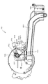
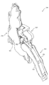
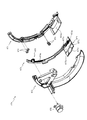
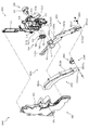
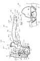
次いで、図34から図42を参照して、左揺動ユニット500について説明する。図34は、遊技盤13及び左揺動ユニット500の正面斜視図である。図34に示すように、左揺動ユニット500は、遊技盤13の第1可変入賞装置82a及び第1特定入賞口82の背面側に配設され、第1特定入賞口82に入賞した球を通過させる流路を内側に備える。本実施形態では、第1可変入賞装置82aと第1特定入賞口82との間に球が通過したことを検出するセンサ部材82bが配設される。なお、センサ部材82bは、各種スイッチ208(図4参照)の一部である。
Next, the
図35は、左揺動ユニット500の正面斜視図である。図35に示すように、左揺動ユニット500は、第1通路形成部材520を正面視右下方に垂らす態様で構成され、この第1通路形成部材520を揺動させることにより演出を行うユニットである。
FIG. 35 is a front perspective view of the
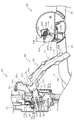
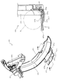
図36は、左揺動ユニット500の分解正面斜視図であり、図37は、左揺動ユニット500の分解背面斜視図である。図36及び図37に図示されるように、左揺動ユニット500は、骨格を形成するベース部材510と、そのベース部材510に軸支され揺動動作される第1通路形成部材520と、ベース部材510に締結固定され第1通路形成部材520の駆動力を発生させる駆動装置530と、その駆動装置530の駆動力を第1通路形成部材520に伝達する伝達装置540と、正面側に覆設されベース部材510に締結固定されると共に遊技盤13の第1特定入賞口82に連結される導入円筒部552を有するカバー部材550と、を主に備える。
FIG. 36 is an exploded front perspective view of the
ベース部材510は、正面視L字の板状体から構成される本体部材511と、その本体部材の正面視右端部に前後方向に円形状で穿設される軸支孔512と、その軸支孔512の鉛直上方に配設され面を前後方向へ向ける平面板状に構成される第1壁部513と、その第1壁部513の左下端部から正面視左方に球一つ分以上の間隔を空けて配設され面を左右方向に向ける湾曲板状に構成される第2壁部514と、第2壁部514の背面側に配設され第2壁部514に到達した球が流下される流下通路515と、軸支孔512の正面視左下方に配設され正面側に円柱状に凸設される軸支部516と、その軸支部516の軸周りに配設される係止壁部517と、軸支部516の上方に配置され伝達装置の位相を検出する検出センサ518と、を主に備える。
The
軸支孔512は、第1通路形成部材520の軸支部521cが挿通される孔であり、第1通路形成部材520は軸支孔512を中心に揺動動作される。
The
第1壁部513は、左右方向両端部から正面側へ延設される一対の案内壁部513aを備える。
The
係止壁部517は、軸支部516の上方においてその軸支部516を中心とした円弧形状で構成される円弧壁部517aと、正面視右下方へ延設される傾斜壁部517bと、を備える。
The locking
円弧壁部517aは、検出センサ518の端面であり軸支部516の周方向端面まで延設される。
The
第1通路形成部材520は、軸支孔512に軸支される部材である長尺棒状の振分ベース部材521と、その振分ベース部材521の正面側に配設され振分ベース部材521に締結固定されると共に振分ベース部材521との間に球が流下可能な通路を形成する通路カバー部材522と、を主に備える。
The first
振分ベース部材521は、球の流下通路の一辺を構成する長尺板形状の垂下板部521aと、その垂下板部521aの上端部から垂下板部521aの延設方向に沿って球一つ分の隙間V1だけ離間した位置に配設される中間板部521bと、垂下板部521aの上端部付近において背面側に円柱状に凸設されると共に軸支孔512に挿通される軸支部521cと、その軸支部521cの径方向に延設される板状部にその延設方向に沿って穿設される長孔521dと、中間板部521bの垂下板部521a側の端部から背面側に凸設されると共に軸支部521cの径方向外側に向かうほど幅が短縮される態様で構成される振分凸部521eと、その振分凸部521eの背面視左側面に沿って隙間V1の正面側に延設され垂下板部521aの上端部に中心を有する円弧形状に沿って湾曲する湾曲壁部521fと、を主に備える。
The
垂下板部521aは、中間部から下側が中間部から上側に比較して下方へ折れ曲げられる形状から構成され、その下端部に正面側の板厚部分が削られて薄板化される球送り部521a1を備える。
The hanging
隙間V1は、振分凸部521eの正面視右側に到達した球を正面方向に通過させる空間である。
The gap V1 is a space through which the sphere that has reached the right side of the front view of the distribution
通路カバー部材522は、振分ベース部材521の正面側に覆設される板状の板状部522aと、その板状部522aの短手方向両端部から背面側に向けて板状に延設される上下壁部522bと、を主に備える。
The
板状部522aは、光透過生の樹脂材料から形成され、その下端部の振分ベース部材521の球送り部521a1の正面側に配置される部分において背面側に屈曲される球受け部522a1を備える。
The plate-shaped
上下壁部522bは、隙間V1を通過した球を転動させる部分であり、垂下板部521a同様に中間部を境に傾斜角度が変化するので、球の流下速度を中間部で変化させることができる。
The upper and
上下壁部522bの内、下側の壁部には、先端部分の内側に段差が設けられる。その段差は、転動する球を上下壁部522bの対向方向(一方の壁部から他方の壁部へ向かう方向)に変位させ、球を減速させる役割を備える。
Of the upper and
また、第1通路形成部材520の下端部まで到達した球は、球送り部521a1及び球受け部522a1により背面側に速度を向けられる。これにより、排出前の球の速度を減速させることができ、球の排出を安定させることができる。
Further, the ball that has reached the lower end of the first
駆動装置530は、駆動モータ531と、その駆動モータ531の回転軸に軸支回転される駆動ギア532と、を備え、駆動ギア532が伝達装置540の本体ギア部541に歯合される。
The
伝達装置540は、軸支部516に軸支され駆動ギア532に歯合される本体ギア部541と、その本体ギア部541の偏心した位置から正面側に円柱状に凸設され第1通路形成部材520の長孔521dに挿通される偏心凸部542と、本体ギア部541から径方向に延設され係止壁部517と当接可能に構成されると共に検出センサ518の隙間を通過可能とされる延設部543と、を主に備える。
The
カバー部材550は、ベース部材510に覆設される板状の本体部材551と、その本体部材551の正面視右側端部において第1特定入賞口82に連結されると共に背面側端部が第1壁部513に当接される円筒形状の導入円筒部552と、本体部材551の背面側側面において導入円筒部552の左右方向端部から下方へ延設される一対の案内壁部553と、を主に備える。
The
案内壁部553は、ベース部材510の案内壁部513aと前後方向で重なる部分である。導入円筒部552を通過した球は、案内壁部513a,553の間を通って下方へ流下される。
The
図38から図40を参照して、第1通路形成部材520の揺動動作について説明する。図38から図40は、揺動動作ユニット500の正面図である。なお、図38から図40では、カバー部材550の図示が省略されると共に第1通路形成部材520が垂下板部521aの前後方向中間位置で断面視された外形が図示されると共に通路カバー部材の外形形状が想像線で図示される。
The swinging operation of the first
また、図38では、第1通路形成部材520が解除位置に配置された状態が、図39(a)では、第1通路形成部材520が図38に図示される状態から所定量揺動され振分凸部521eが一対の案内壁部513aの中間位置に配置された状態が、図39(b)では、第1通路形成部材520が図39(a)に図示される状態から所定量揺動され接続部材424に当接する直前の状態が、図40では、第1通路形成部材520が図39(b)に図示される状態から所定量揺動され連結位置に配置された状態がそれぞれ図示される。
Further, in FIG. 38, the state in which the first
図38から図40に示すように、第1通路形成部材520の揺動動作は、伝達装置540が回転され、偏心凸部542の移動に伴い長孔521dの位置が移動されることで生じる。
As shown in FIGS. 38 to 40, the swinging operation of the first
図38に示すように、解除位置では、軸支部516及び偏心凸部542を結ぶ方向X1と、長孔521dの延設方向(軸支部521cの径方向)と一致する方向X2とが垂直に交差する。そのため、第1通路形成部材520が回転動作しかけることにより偏心凸部542に与えられる負荷は軸支部516へ向けられるので、伝達装置540を回転させる負荷が生じることを抑制することができる。これにより、駆動ギア532に駆動力をかけ続けなくとも、伝達装置540の姿勢を維持する事ができ、駆動モータ531(図36参照)の消費電力を低減することができる。
As shown in FIG. 38, at the release position, the direction X1 connecting the
また、解除位置において、伝達装置540の延設部543が、検出センサ518の隙間に配置されると共に円弧壁部517aの端部に当接される。即ち、延設部543は、伝達装置540の位相の検出に利用される部分としての役割と、回り止め部材としての役割とを共に有する。
Further, at the release position, the
図38に示すように、解除位置において、振分凸部521eがベース部材510の正面視右側の案内壁部513aと対向配置される。そのため、第1壁部513に到達し案内壁部513a,553の間を通過した球は、振分凸部521eにより正面視左側の経路に振り分けられ、流下通路515を通って遊技領域外に排出される。
As shown in FIG. 38, at the release position, the distribution
図39(a)に示すように、解除位置と連結位置との間の中間位置において、振分凸部521eがベース部材510の一対の案内壁部513aの中間位置に配置される。そのため、第1壁部513に到達し案内壁部513a,553の間を通過した球は、振分凸部521eにより流下を停止される(振分凸部521eの先端部に乗ったまま、留まる)。
As shown in FIG. 39A, the distribution
図39(b)に示すように、第1通路形成部材520が接続部材424に当接する直前の状態において、振分凸部521eがベース部材510の一対の案内壁部513aの間に配置される、そのため、第1壁部513に到達し案内壁部513a,553の間を通過した球は、振分凸部521eにより流下を停止される(振分凸部521eの先端部に乗ったまま、留まる)。これにより、図39(b)の状態において球が第1通路形成部材520を通過し、接続部材424に送球され、対向壁部422f2に球が到達することが防止される。
As shown in FIG. 39B, in a state immediately before the first
ここで、対向壁部422f2は、上傾斜状態(図42参照)において接続部材424の上側壁部424bと滑らかに連結されるので、下傾斜状態(図41参照)では、上端部が接続部材424の上側壁部424bの下端部から正面視左方に張り出す態様とされる。そのため、下傾斜状態で接続部材424に球が送球され、対向壁部422f2の上端部に球が衝突すると、対向壁部422f2が破損する恐れがある。
Here, since the facing wall portion 422f2 is smoothly connected to the upper
これに対し、本実施形態では、図39(b)に示す状態において、第1通路形成部材520への球の導入が防止されるので、対向壁部422f2に球が衝突することを防止でき、対向壁部422f2が破損することを防止することができる。
On the other hand, in the present embodiment, in the state shown in FIG. 39B, the introduction of the sphere into the first
図40に示すように、連結位置では、軸支部516及び偏心凸部542を結ぶ方向X1と、長孔521dの延設方向(軸支部521cの径方向)と一致する方向X2とが垂直に交差する。そのため、第1通路形成部材520が回転動作しかけることにより偏心凸部542に与えられる負荷は軸支部516へ向けられるので、伝達装置540を回転させる負荷が生じることを抑制することができる。これにより、駆動ギア532に駆動力をかけ続けなくとも、伝達装置540の姿勢を維持する事ができ、駆動モータ531(図36参照)の消費電力を低減することができる。
As shown in FIG. 40, at the connecting position, the direction X1 connecting the
また、連結位置において、伝達装置540の延設部543が、傾斜壁部517bに面当たりされる。これにより、延設部543を傾斜壁部517bに突き当てることで伝達装置540を停止させる位相を安定させながら、延設部543に局部的に荷重が負荷される場合に比較して延設部543の耐久性を向上させることができる。
Further, at the connection position, the
図40に示すように、連結状態において、振分凸部521eがベース部材510の正面視左側の案内壁部513aと対向配置される。そのため、第1壁部513に到達し案内壁部513a,553の間を通過した球は、振分凸部521eにより正面視右側の経路に振り分けられ、隙間V1を通って正面側に移動してから通路カバー部材522の上下壁部522b(図37参照)の下側の壁部に沿って転動する。
As shown in FIG. 40, in the connected state, the distribution
連結状態での球の流れについて説明する。まず、遊技領域から第1可変入賞装置82aを通って第1特定入賞口82に入賞した球は導入円筒部552(図36参照)を通って背面側へ向けて前後移動し、第1壁部513に当接されると案内壁部513a,553の形成する通路を流下し、第1通路形成部材520の隙間V1を通って正面側へ向けて前後移動し、通路カバー部材522の上下壁部522bの下側の壁部の上を転動する。
The flow of spheres in the connected state will be described. First, the ball that has won the first specific winning
即ち、球が第1通路形成部材520の内部を流下する前に、球が前後方向に送られる。そのため、第1特定入賞口82に球が数珠つなぎで供給されても、球の跳ね等を抑制して、第1通路形成部材520にスムーズに球を流入させることができる。また、前後方向に送られた球を湾曲壁部521f(図37参照)に沿って流下させることにより、球の速度の向きを変えることができ、第1通路形成部材520に球をスムーズに流入させることができる。
That is, the sphere is fed in the front-rear direction before the sphere flows down the inside of the first
第1通路形成部材520は、振分ベース部材521及び通路カバー部材522が、中間部を境に延設方向が変化する。即ち、振分ベース部材521及び通路カバー部材522が、中間部から基端側(軸支部521c側)までは直線Y1に沿って延設され、中間部から先端側(基端側の逆側)までは直線Y1よりも下方へ傾斜される直線Y2に沿って延設される。
In the first
そのため、第1通路形成部材520の内部を転動する球の速度が、基端側から中間部へ到達するまでの間の方が、中間部から先端部へ向かうまでの間に比較して遅くなる。そのため、第1通路形成部材520へ球が導入した直後に遊技者に球を視認させやすくすることができる。
Therefore, the speed of the sphere rolling inside the first
また、直線Y1に沿った真っ直ぐな形状で第1通路形成部材520が構成される場合に比較して、連結位置(図42参照)において、第1通路形成部材520から球が送球される方向と、センサ部材422cに球が導入される方向(鉛直方向)との角度を小さくすることができる。これにより、第1通路形成部材520から第2通路形成部材422への球の送球を安定させることができる。
Further, as compared with the case where the first
図38から図40に図示されるように、伝達装置540の回転により第1通路形成部材520が揺動され、振分凸部521eの配置によって球が流下される経路が切り替えられる。
As shown in FIGS. 38 to 40, the rotation of the
ここで、振分凸部521eの回転方向において振分凸部521eと対向配置される壁部材が配置される場合に、その壁部材に対して振分凸部521eが球の直径以下にまで近づける構成を採用すると、球が振分凸部521eの回転方向に滞留した場合に振分凸部521eと壁部材との間に球が噛み込まれ、動作不良を起こす恐れがある。
Here, when a wall member arranged to face the distribution
これに対し、本実施形態では、図40に図示される連結位置において、振分凸部521eと第2壁部514との間には、球の直径以上の間隔が空けられ、振分凸部521eを挟んで第2壁部514の反対側には壁部材は配置されず開放される。従って、振分凸部521eの回転方向で球を噛み込むという事態を生じることが無く、動作不良を防止することができる。
On the other hand, in the present embodiment, at the connection position shown in FIG. 40, a space equal to or larger than the diameter of the sphere is provided between the distribution
図41及び図42を参照して、液晶昇降ユニット400と左揺動ユニット500との流路の接続について説明する。図41及び図42は、液晶昇降ユニット400及び左揺動ユニット500の部分正面図である。なお、図41及び図42では、第2通路形成部材422が断面視され接続部材424が視認可能とされると共に、第1通路形成部材520が垂下板部521aの前後方向中間位置における外形形状で図示され振分凸部521eが視認可能とされる。
The connection of the flow path between the liquid
また、図41及び図42では、液晶昇降ユニット400が連結位置(図31参照)に配置された状態が図示され、図41では、左揺動ユニット500が解除位置(図38参照)に配置された状態が図示され、図42では、左揺動ユニット500が連結位置(図40参照)に配置された状態が図示される。
Further, in FIGS. 41 and 42, the state in which the liquid
図41に示す状態から図42に示す状態に第1通路形成部材520が揺動動作されると、その先端部が接続部材424の上側壁部424bの下側側面に当接し、接続部材424を揺動させる。即ち、接続部材424が第1通路形成部材520の移動方向に連れ立って移動されるので、例えば、駆動側スライド部材420の停止位置が理想的な位置から若干ずれた場合であっても、第1通路形成部材520の先端と接続部材424との間に隙間が生じることを抑制することができる。これにより、球が第1通路形成部材520の先端と接続部材424との間に落下することを抑制し、第1通路形成部材520から第2通路形成部材422への球の送球を安定させることができる。
When the first
接続部材424が揺動されることにより、第1通路形成部材520から流下された球が転動する下側壁部424cが第1通路形成部材520の先端へ近接する方向へ移動されるので、第1通路形成部材520と接続部材424との転動面間の隙間を狭めることができ、球が第1通路形成部材520と接続部材424との転動面間の隙間から落下することを抑制することができるので、球の送球を安定させることができる。
When the connecting
また、図42に示す状態において、下側壁部424cが溝部422d(図27参照)に連通されるセンサ部材422cへ向けて下降傾斜される。これにより、球をその下降傾斜に沿って転動させることができ、第2通路形成部材422への球の送球を安定させることができる。
Further, in the state shown in FIG. 42, the lower
なお、第1通路形成部材520の揺動動作は、センサ部材82b(図34参照)やセンサ部材422cの球の通過を検出して、行われる。例えば、図42に示す連結位置に第1通路形成部材520が配置された状態において、センサ部材82bとセンサ部材422cとの球の検出個数が合致する(第1通路形成部材520に球が残留していない)タイミングで第1通路形成部材520を解除位置(図41参照)へ向けて揺動開始させることで、第1通路形成部材520の先端から遊技領域外に球が排出されることを防止することができる。
The swinging motion of the first
図41及び図42に図示されるように、振分凸部521eの移動による球の振り分けと、第1通路形成部材520を揺動させることにより第1通路形成部材520と接続部材424とを当接させて球の流下経路を形成する動作とに必要な駆動力が兼用される(第1通路形成部材520を動作させる駆動モータ531(図36参照)の駆動力でまかなわれる)また、両者の状態が同期されるので、例えば、第1通路形成部材520が解除位置に配置される状態において球が第1通路形成部材520に導入される事態を回避することができる。その結果、第1通路形成部材520の先端から球が遊技領域外に排出されることを確実に防止することができる。
As shown in FIGS. 41 and 42, the spheres are distributed by moving the distribution
また、振分凸部521eは振分ベース部材521の上端部に配設され、垂下板部521a(図36参照)の正面側を流下する球の通路を区画する(上端を形成する)壁部を兼ねる。これにより、他の部品で振分を行う場合に比較して部品コストの削減を図ることができると共に、第1通路形成部材520側に振り分けられた球を確実に垂下板部521aと通路カバー部材522との間の通路に導入させることができる。
Further, the distribution
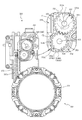
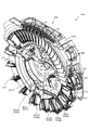
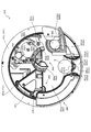
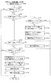
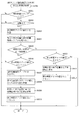
次いで、図43から図77を参照して、回転ユニット600について説明する。図43は、回転ユニット600の正面図であり、図44は、回転ユニット600の正面斜視図である。図45は、ガイド部材680が取り外された状態における回転ユニット600の正面図であり、図46は、ガイド部材680が取り外された状態における回転ユニット600の正面斜視図である。また、図47は、回転ユニット600の分解正面斜視図であり、図48は、回転ユニット600の分解背面斜視図である。
Next, the
図43から図48に示すように、回転ユニット600は、一面側が開放された容器状に形成されるケース部材610と、そのケース部材610の一面側に覆設される案内部材620と、それらケース部材610及び案内部材620の対向間に配設される駆動機構630と、その駆動機構630の駆動力により回転駆動される回転部材640と、その回転部材640の内周側に配設される投球装置650と、回転部材640の外周側に配設されるガイド部材680と、を主に備える。
As shown in FIGS. 43 to 48, the
ケース部材610は、正面視略円形の底壁部611と、その底壁部611から正面へ向けて立設される略円筒状の外壁部612とを備え、これら各壁部611,612により一面側が開放された容器状に形成される。案内部材620は、正面視円環の円板状に形成され、ケース部材610の外壁部612の立設先端に配設(固着)される。これにより、ケース部材610の底壁部611と案内部材620との間に内部空間が形成され、その内部空間に駆動機構630が配設される。
The
案内部材620は、回転部材640を変位可能に保持するための部材であり、その正面に連結リンク作用溝621及び起伏リンク作用溝622が凹設される。これら連結リンク作用溝621及び起伏リンク作用溝622は、案内部材620の周方向に沿って延設される断面コ字状の凹溝であり、回転部材640の後述する連結リンク部材644及び起伏リンク部材648の挿通部644a,648aがそれぞれ挿通される。
The
なお、連結リンク作用溝621及び起伏リンク作用溝622の溝幅は、連結リンク部材644及び起伏リンク部材648の挿通部644a,648aの直径と同等または若干大きな寸法に設定される。よって、連結リンク部材644及び起伏リンク部材648の挿通部644a,648aは、連結リンク作用溝621及び起伏リンク作用溝622の延設方向に沿って摺動(案内)可能とされる。
The groove widths of the connecting
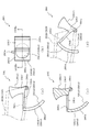
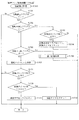
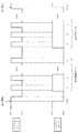
回転部材640が回転駆動される際に、連結リンク作用溝621は、連結リンク部材644に作用して、分割部材DVどうしの間隔を増減させる一方(図73参照)、起伏リンク作用溝622は、起伏リンク部材648に作用して、表示板646及び区画板647を起伏させる(図59及び図60参照)。ここで、図49及び図50を参照して、案内部材620の連結リンク作用溝621及び起伏リンク作用溝622について説明する。
When the rotating
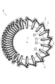
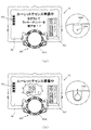
図49は、回転部材640、投球装置650の一部およびガイド部材680が取り外された状態における回転ユニット600の正面図であり、図50は、案内部材620の正面模式図である。なお、図50では、連結リンク作用溝621及び起伏リンク作用溝622の形状が二点鎖線を用いて模式的に図示される。かかる二点鎖線は、各作用溝621,622の溝幅の中央を通る線として図示される。
FIG. 49 is a front view of the
図49及び図50に示すように、連結リンク作用溝621は、軸心Oを中心として半径R1で円弧状に湾曲する大径部621aと、軸心Oを中心として半径R2で円弧状に湾曲する小径部621bと、それら大径部621a及び小径部621bの間を接続する一対の接続部621cとからなる。なお、大径部621aの半径R1は、小径部621bの半径R2よりも大きな寸法に設定される(R2<R1)。
As shown in FIGS. 49 and 50, the connecting
起伏リンク作用溝622は、軸心Oを中心として半径R3で円弧状に湾曲する大径部622aと、軸心Oを中心として半径R4で円弧状に湾曲する小径部622bと、それら大径部622a及び小径部622bの間を接続する一対の接続部622cとからなる。なお、大径部622aの半径R3は、小径部622bの半径R4よりも大きな寸法に設定される(R4<R3)。
The undulating
本実施形態では、連結リンク作用溝621の大径部621a及び小径部621bと、起伏リンク作用溝622の大径部622a及び小径部622bとが、軸心Oを中心として同心に配置される。この場合、軸心Oは、回転部材640が回転される際の回転中心に一致される。よって、回転部材640が回転される際に、連結リンク作用溝621及び起伏リンク作用溝622の大径部621a,622a及び小径部622a,622bから連結リンク部材644及び起伏リンク部材648へそれぞれ作用する力を抑制して、駆動機構630の駆動モータ631に必要とされる出力を小さくできる。
In the present embodiment, the large-
また、連結リンク作用溝621の一対の接続部621cは、180度位相を異ならせた位置に配置される。同様に、起伏リンク作用溝622の一対の接続部622cは、180度位相を異ならせた位置に配置される。よって、回転部材640が回転駆動される際に、連結リンク作用溝621の一方の接続部621cから連結リンク部材644へ作用される力と他方の接続部621cから連結リンク部材644へ作用される力とを相殺させることができる。同様に、起伏リンク作用溝622の一方の接続部622cから起伏リンク部材648へ作用される力と他方の接続部622cから起伏リンク部材648へ作用される力とを相殺させることができる。これにより、回転部材640に作用される力を全体として均一化できるので、その回転部材640の回転を安定化させることができると共に、駆動機構630の駆動モータ631に必要とされる出力を小さくできる。
Further, the pair of connecting
なお、本実施形態では、連結リンク作用溝621の接続部621cと起伏リンク作用溝622の接続部622cとが異なる位相となるように形成される。即ち、連結リンク作用溝621の接続部621cに連結リンク部材644の挿通部644aが挿通されている状態では、起伏リンク部材648の挿通部648aは、起伏リンク作用溝622の大径部622a又は小径部622bのいずれか一方に挿通されると共に、起伏リンク作用溝622の接続部622cに起伏リンク部材648の挿通部648aが挿通されている状態では、連結リンク部材644の挿通部644aは、連結リンク作用溝621の大径部621a又は小径部621bのいずれか一方に挿通される。
In the present embodiment, the connecting
接続部621c,622cは分割部材DVの間隔を変更する又は表示板646及び区画板647を変位させるための部位であるため、かかる接続部621c,622cから比較的大きな反力を受けるところ、挿通部644a,648aが接続部621c,622cに同時に挿通されないようにすることで、必要な駆動力を分散させることができる。その結果、駆動機構630の駆動モータ631に必要とされる出力を小さくできる。
Since the connecting
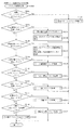
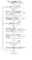
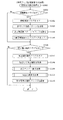
図43から図48に戻って、駆動機構630について説明する。駆動機構630は、回転部材640を回転駆動するための機構であり、駆動モータ631と、その駆動モータ631の駆動軸に固着されるピニオンギア632と、そのピニオンギア632に先頭のギア(第1伝達ギア633a)が歯合される伝達ギア列と、その伝達ギア列の末尾のギア(第2伝達ギア633b)に歯合されるギア634aを有する中央伝達体634と、その中央伝達部材634のギア634aに先頭のギア(第1分配ギア635a,636a)が歯合される一側分配ギア列および他側分配ギア列と、それら一側分配ギア列および他側ギア列の末尾のギア(第3分配ギア635c,636c)に歯合されるギア637a,638aを有する一側回転駆動部材637及び他側回転駆動部材638と、を主に備える。なお、第1分配ギア635a,636aと第3分配ギア635c,636cの間には第2分配ギア635b,636bがそれぞれ介在される。
Returning from FIG. 43 to FIG. 48, the drive mechanism 630 will be described. The drive mechanism 630 is a mechanism for rotationally driving the rotating
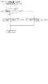
一側回転駆動部材637及び他側回転駆動部材638は、駆動モータ631から発生された回転駆動力を伝達する伝達経路の末尾(駆動機構630における出力端)となる部材であり、駆動モータ631の回転駆動力により自身が回転されると共に、その回転により回転部材640を回転させる。ここで、一側回転駆動部材637及び他側回転駆動部材638について、図51を参照して説明する。
The one-side
図51(a)は、一側回転駆動部材637及び他側回転部材638の正面図であり、図51(b)は、図51(a)のLIb−LIb線における一側回転部材637及び他側回転部材638の断面図である。
51 (a) is a front view of the one-side
なお、一側回転駆動部材637及び他側回転駆動部材638は、互いに同一の形状に形成される部材であるので、一側回転駆動部材637のみについて説明し、他側回転駆動部材638については、図51の図中に符号のみを付し、その説明を省略する。
Since the one-side
図47に示すように、一側回転駆動部材637は、円板状に形成され、その外縁部の周方向等間隔となる複数箇所(本実施形態では3カ所)に係合部637bが凹欠形成される。
As shown in FIG. 47, the one-side
係合部637bは、回転部材640の分割部材DVにおける被係合部641(図56参照)と係合する部位であり、その開放側から凹欠奥側へ向かうに従って幅(対向面どうしの間隔)が狭くされる正面視(軸方向視)略V字状に形成される。後述するように、一側回転駆動部材637を回転させることで、その回転を、係合部637b及び被係合部641の係合を介して、回転部材640へ伝達して、回転部材640を回転させることができる。
The engaging
一側回転駆動部材637には、係合部637bの対向する内面どうしを部分的に連結する連結壁637cが形成される。連結壁637cは、一側回転駆動部材637の軸心を中心として正面視(軸方向視)円弧状に湾曲する形状に形成されると共に、係合部637bの開放側(一側回転駆動部材637の外縁側)の内面どうしのみを連結し、係合部637bの凹欠奥側の内面どうしは非連結とする。
The one-side
ここで、一側回転駆動部材637による回転部材640の駆動時には、係合部637bと被係合部641との係合と解除とが断続的に繰り返される(図74参照)。そのため、係合部637bに被係合部641が係合し始める際に、衝撃荷重が入力され、一側回転駆動部材637が破損する恐れがある。一方で、一側回転駆動部材637の重量が嵩むと、駆動機構630の駆動モータ631に大きな出力が必要とされる。
Here, when the
この場合、本実施形態によれば、連結壁637cが係合部637bの開放側のみに形成されるので、係合部637bと被係合部641とが係合し始める際の衝撃荷重に対する補強と軽量化とを効果的に両立させることができる。その結果、一側駆動部材637の耐久性の向上を図りつつ、駆動機構630の駆動モータ631に必要とされる出力を小さくできる。
In this case, according to the present embodiment, since the connecting
図43から図48に戻って説明する。駆動機構630の各構成部品は、中央伝達部材634を除き、ケース部材610に配設される(図53参照)。一方、中央伝達部材634は、案内部材620の背面側に回転可能に保持される。ここで、案内部材620への中央伝達部材634の保持構造について、図52を参照して説明する。
It will be described back from FIG. 43 to FIG. 48. Each component of the drive mechanism 630 is disposed on the
図52は、中央伝達部材634の回転軸を含む平面で切断した回転ユニット600の断面図である。図52に示すように、中央伝達体634は、正面視円形であって中央部分が窪んだハット状に形成され、中央の窪んだ部分の外周面にギア634aが刻設されると共に、最外縁部から張出部634bが径方向外方へ向けてフランジ状に張り出して形成される。
FIG. 52 is a cross-sectional view of the
案内部材620の背面側には、周方向等間隔となる3カ所(即ち、120度間隔となる位置)に一対の保持カラー623,624(図47及び図48参照)が重ね合わされた状態でそれぞれ配設され、かかる一対の保持カラー623,624の対向間に中央伝達部材634の張出部634bが摺動可能に挿通される。これにより、一対の保持カラー623,624を介して、中央伝達部材634を案内部材620に回転可能に保持できる。
On the back side of the
即ち、案内部材620に対する中央伝達部材634の径方向(図52上下方向)への変位は、中央伝達部材634の外周面に一対の保持カラー623,624の外周面を当接させることで規制でき、案内部材620に対する中央伝達部材634の軸方向(図52左右方向)への変位は、一対の保持カラー623,624の対向面に中央伝達部材634の張出部634bを当接させることで規制できる。
That is, the displacement of the
この場合、一対の保持カラー623,624は、正面視(中央伝達部材634の回転軸方向視)形状が円形に形成される。よって、一対の保持カラー623,624の外周面と中央伝達部材634の外周面とを互いの円弧形状が外接する(即ち、点接触する)関係とすることができるので、それらの接触面積を小さくして、中央伝達部材634が回転する際の摩擦抵抗を低減できる。その結果、駆動機構630の駆動モータ631に必要とされる出力を小さくできる。
In this case, the pair of holding
更に、このように、中央伝達部材634の外縁側(張出部634b)を保持する構造とすることで、かかる中央伝達部材634の中央の窪んだ部分をケース部材610の底壁部611に軸支させる必要がなく、その軸支のための部品を配設するスペースが不要となるので、その分、後述する投球装置650の配設スペースを確保できる。
Further, by adopting a structure for holding the outer edge side (overhanging
次いで、駆動機構630の動作について、図53を参照して、説明する。図53は、ケース部材610及び駆動機構630の正面図であり、中央伝達部材634が断面視された状態が図示される。
Next, the operation of the drive mechanism 630 will be described with reference to FIG. 53. FIG. 53 is a front view of the
図53に示すように、駆動機構630は、回転部材640の回転中心である軸心Oと同心となる位置に中央伝達部材634が配設され、その中央伝達部材634のギア634aに第2伝達ギア633bと第3分配ギア635c,636cとが歯合された状態で配設される。なお、第3分配ギア635c,636cは、180度位相を異ならせた位置(即ち、軸心Oを挟んで対向する位置)に配設される。
As shown in FIG. 53, in the drive mechanism 630, the
よって、駆動モータ631が回転駆動されると、その回転が、ピニオンギア632及び第1伝達ギア633aを介して、第2伝達ギア633bに伝達され、その第2伝達ギア633bの回転に伴って、中央伝達部材634が回転される。
Therefore, when the
中央伝達部材634が回転されると、その中央伝達部材634の回転に伴って、一対の第1分配ギア635a,636aがそれぞれ回転され、その回転が、第2分配ギア635b,636b及び第3分配ギア635c,636cを介して、一側回転駆動部材637及び他側回転駆動部材638のギア637a,638a(図48参照)に伝達され、一側回転駆動部材637及び他側回転駆動部材638が回転される。
When the
このように、第1分配ギア635a及び第2分配ギア636aに中央伝達ギア634が歯合されるので、駆動モータ631の回転駆動力で中央伝達ギア634を回転させることで、一側回転駆動部材637及び他側回転駆動部材638を同期された状態で回転させることができる。その結果、回転部材640の駆動を安定化させることができる。
In this way, the
この場合、中央伝達ギア634は、回転部材640の軸心Oと同心に配設されるので、かかる中央伝達ギア634と一側及び他側回転駆動部材637,638とを、軸心O方向視において、回転部材640の外縁部よりも内方(軸心O方向側)に配設できる。即ち、中央伝達ギア634と一側及び他側回転駆動部材637,638が回転部材640の外形よりも外方に突出されないため、その分、小型化を図ることができる。
In this case, since the
なお、ケース部材610に案内部材620が配設された状態では、その案内部材620の外縁部分よりも径方向外方に一側回転駆動部材637及び他側回転駆動部材638の係合部637b,638bが露出され(図49参照)、かかる係合部637b,638bに回転部材640の分割部材DVにおける被係合部641が係合可能とされる。よって、一側回転駆動部材637及び他側回転駆動部材638を回転させることで、その回転を、係合部637b,638b及び被係合部641の係合を介して、回転部材640に伝達して、回転部材640を回転させることができる。
In the state where the
この場合、一側回転駆動部材637及び他側回転駆動部材638は、180度位相を異ならせた位置(即ち、軸心Oを挟んで対向する位置)に配設される。よって、後述するように、回転部材640へ駆動力を付与する位置(係合する位置)を最大限に離間させて、その回転部材640の回転を安定化できる。
In this case, the one-side
また、一側回転駆動部材637及び他側回転駆動部材638は、それらの係合部637b及び係合部638bの位相が互いに異なる姿勢(回転位置)で配設される。即ち、係合部637b又は係合部638bの一方が被係合部641と非係合とされている状態では、係合部637b又は係合部638bの他方が被係合部641と係合される(一方と他方とが同時に非係合とされることが回避される)ように配設される。よって、後述するように、一側回転駆動部材637及び他側回転駆動部材638から回転部材640への駆動力の伝達が断続的となることを抑制でき、回転部材640の回転を安定化できる。
Further, the one-side
図43から図48に戻って説明する。回転部材640は、上述したように、回転機構630の駆動力を受けて回転される正面視円環形状の部材であり、中央伝達部材634及び案内部材620と同心となる姿勢で、案内部材620の正面側に配設される。なお、本実施形態では、回転部材640は、正面視反時計回り(左回り)に回転される。ここで、回転部材640について、図54から図60を参照して説明する。
It will be described back from FIG. 43 to FIG. 48. As described above, the rotating
図54(a)は、回転部材640の正面図であり、図54(b)は、図54(a)の矢印LIVb方向視における回転部材640の側面図である。また、図55は、図54(b)の矢印LV方向視における回転部材640の背面図である。
54 (a) is a front view of the rotating
図54及び図55に示すように、回転部材640は、複数(本実施形態では30個)の分割部材DVを備えると共に、それら複数の分割部材DVが周方向に沿って互いに無端状に連結されることで、正面視円環状に形成される。
As shown in FIGS. 54 and 55, the rotating
この場合、複数の分割部材DVは、隣接する分割部材DVとの間の間隔を変更可能に形成される。即ち、回転部材640には、分割部材DVどうしが第1の間隔で周方向に連結される第1区間S1と、分割部材DVどうしが第1の間隔よりも狭い間隔とされる第2の間隔で周方向に連結される第2区間S2とが形成される。なお、第1区間S1及び第2区間S2の間には、それら第1区間S1における第1の間隔から第2区間S2における第2の間隔(又はその逆)へ分割部材DVどうしの間隔が遷移する区間が形成される。
In this case, the plurality of split member DVs are formed so that the distance between the plurality of split member DVs can be changed. That is, in the rotating
図56(a)は、分割部材DVの正面斜視図であり、図56(b)は、分割部材DVの背面斜視図である。また、図57は、分割部材DVの分解正面斜視図であり、図58は、分割部材DVの分解背面斜視図である。なお、図56から図58では、分割部材DVどうしの連結構造の理解のために、隣接する分割部材DVの連結リンク部材644が二点鎖線を用いて模式的に図示される。
FIG. 56A is a front perspective view of the split member DV, and FIG. 56B is a rear perspective view of the split member DV. Further, FIG. 57 is an exploded front perspective view of the split member DV, and FIG. 58 is an exploded rear perspective view of the split member DV. In addition, in FIGS. 56 to 58, in order to understand the connecting structure of the dividing member DVs, the connecting
ここで、本実施形態では、複数の分割部材DVのうちの一部(本実施形態では15個)の分割部材DVには、被検出部641cが形成される一方、残りの分割部材DVでは、被検出部641cの形成が省略される。これら被検出部641cが形成される分割部材DVと、被検出部641cの形成が省略される分割部材DVとは、被検出部641cの有無を除き、他の構成は同一である。よって、以下においては、被検出部641cが形成される分割部材DVについて説明し、被検出部641cの形成が省略される分割部材DVについての説明は省略する。
Here, in the present embodiment, the detected
図56から図58に示すように、分割部材DVは、被係合部641と、その被係合部641が背面側に配設される背面側本体642と、その背面側本体642の正面側に配設される正面側本体643と、それら背面側本体642及び正面側本体643の間に基端側が回転可能に軸支される連結リンク部材644と、正面側本体643の正面側に配設される板保持部材645と、その板保持部材645に変位可能に保持される表示板646及び区画板647と、正面側本体643及び板保持部材645との間にスライド変位可能に配設される起伏リンク部材648と、を主に備えて構成される。
As shown in FIGS. 56 to 58, the split member DV includes an engaged
被係合部641は、上述したように、駆動機構630の各回転駆動部材637,638の係合部637b,638bに係合される部位であり、正面視略二等辺三角形状に形成され、背面側本体642の長手方向一側(図56(b)下側)の背面から突設される姿勢で配設される。
As described above, the engaged
被係合部641の背面側本体642への取り付け面側には、背面側本体642の背面との間に所定間隔を隔てて対向する対向部641aが形成され、その対向部641aと背面側本体642との対向面間に、案内部材620の外縁部が摺動可能に挟み込まれる。これにより、案内部材620の正面からの分割部材DV(背面側本体642の長手方向一側)の浮き上がりを抑制できる。
On the mounting surface side of the engaged
また、被係合部641の背面側本体642への取り付け面側には、円柱状に形成される一対の摺動ローラ641bが回転可能に軸支される。摺動ローラ641bは、その回転軸を背面側本体642の背面(即ち、分割部材DVの移動平面)に対して直交させると共にその外周面を案内部材620の外縁部の外周面に当接可能な姿勢で配設される。これにより、案内部材620の周方向に沿って分割部材DVが変位される際の摺動抵抗を低減できる。
Further, a pair of sliding
一方、被係合部641の背面側本体642への取り付け面と反対側には、板状の被検出部641cが張り出し形成される。被検出部641cは、ガイド部材680に配設された検出センサ684により検出される板状の部位であり、背面側本体642の背面(即ち、分割部材DVの移動平面)に水平な姿勢とされる。
On the other hand, a plate-shaped detected
背面側本体642は、その背面が案内部材620の正面に載置され、回転部材640の回転時に案内部材620の正面を摺動する部位であり、正面視長方形の板状に形成される。案内部材620に回転部材640が配設された状態では、背面側本体642は、その長手方向を案内部材620の径方向に沿わせた姿勢で配設される。即ち、各背面側本体部642が軸心Oを中心とする放射直線状に配設される(図54参照)。
The back surface of the back surface side
背面側本体642は、長手方向に沿って直線状に延設される溝状の開口である連結リンク用開口642a及び起伏リンク用開口642bと、長手方向一側(図57下側)の正面に形成され正面側本体643(軸支部643b)との間で連結リンク部材644の基端側を軸支する軸支部642cと、長手方向他側(図58上側)の背面から突設される屈曲部642dと、を備える。
The back side
連結リンク用開口642aは、隣接する分割部材DVの連結リンク部材644における挿通部644aが摺動可能に挿通される開口であり、この連結リンク用開口642aへの挿通部644aの挿通により、分割部材DVを、連結リンク部材644を介して、隣接する分割部材DVと連結させることができる。また、連結リンク部材644は、連結リンク用開口642aに挿通された挿通部644aの先端を案内部材620の連結リンク作用溝621に挿通させる。
The connecting
なお、連結リンク用開口642aの開口幅は、連結リンク部材644の挿通部644aの直径と同等または若干大きな寸法に設定される。よって、連結リンク644の挿通部644aは、連結リンク用開口642aの延設方向に沿って摺動(案内)可能とされる。
The opening width of the connecting
分割部材DVが案内部材620の周方向へ変位される際に、連結リンク部材644の挿通部644aが案内部材620の連結リンク作用溝621から作用を受けると、挿通部644aが連結リンク用開口642aに沿って摺動することで、連結リンク作用溝621からの作用に伴って連結リンク部材644の姿勢が変化することを許容することができる。その結果、背面側本体642に対する連結リンク部材644の姿勢を生じさせ、分割部材DVどうしの間隔を増減させることができる。
When the dividing member DV is displaced in the circumferential direction of the
起伏リンク用開口642bは、起伏リンク部材648の挿通部648aが摺動可能に挿通される開口であり、起伏リンク部材648は、起伏リンク用開口642bに挿通された挿通部648aの先端を案内部材620の起伏リンク作用溝622に挿通させる。
The undulating
なお、起伏リンク用開口642bの開口幅は、起伏リンク部材648の挿通部648aの直径と同等または若干大きな寸法に設定される。よって、起伏リンク648の挿通部648aは、起伏リンク用開口642bの延設方向に沿って摺動(案内)可能とされる。
The opening width of the undulating
分割部材DVが案内部材620の周方向へ変位される際に、起伏リンク部材648の挿通部648aが案内部材620の起伏リンク作用溝622から作用を受けると、挿通部648aが起伏リンク用開口642bに沿って摺動されることで、表示板646及び区画板647を起伏させることができる。
When the dividing member DV is displaced in the circumferential direction of the
軸支部642cは、上述したように、背面側本体642の長手方向一側(図57下側)に形成されるので、連結リンク部材644の基端側を、被係合部641と正面視において重なる位置で軸支することができる。よって、被係合部641が各回転駆動部材637,638の係合部637b,638bによって駆動され、分割部材DVが案内部材620の周方向に沿って変位される際には、その変位を隣接する分割部材DVへ連結リンク部材644を介して伝達しやすくできる。
As described above, the
屈曲部642dは、背面側本体642の長手方向他側(図58上側)の背面から突設されると共にその突設先端が背面側本体642の背面との間に所定間隔を隔てて対向されるように屈曲される部位であり、その突設先端の屈曲される部分と背面側本体642との対向面間に、案内部材620の内縁部が摺動可能に挟み込まれる。これにより、案内部材620の正面からの分割部材DV(背面側本体642の長手方向他側)の浮き上がりを抑制できる。
The
また、屈曲部642dは、その基部を案内部材620の内縁部の内周面に当接可能な姿勢で配設され、かかる屈曲部642dの基部と上述した摺動ローラ641bとの対向間隔が、案内部材620の径方向の幅と同等または若干大きな寸法に設定される。これにより、案内部材620の径方向への分割部材DVの変位を規制できるので、かかる本体部材DV(背面側本体642)を、その長手方向を案内部材620の径方向に沿わせた姿勢のままで、案内部材620の周方向へ変位させることができる。
Further, the
正面側本体643は、背面側本体642と略同一の大きさの正面視長方形の板状に形成される部材であり、長手方向に沿って直線状に延設される溝状の開口である起伏リンクスライド溝643aと、長手方向一側(図58下側)の背面に形成され背面側本体642(軸支部642c)との間で連結リンク部材644の基端側を軸支する軸支部643bと、正面から突設され区画板647を回転可能に支持する支持板643cと、を備える。
The front side
起伏リンクスライド溝643aは、起伏リンク部材648がスライド可能に配設される直線上の溝であり、起伏リンク用開口642bと平行に延設される。即ち、起伏リンク部材648は、起伏リンクスライド溝643aに沿ってスライドされることで、その挿通部648aを起伏リンク用開口642bに沿って摺動させる。
The undulating
背面側本体642及び正面側本体643は、正面視において、長手方向他側の幅寸法が長手方向一側の幅寸法がよりも小さくされる。即ち、回転部材640の外周側に位置する部分の幅寸法よりも内周側に位置する部分の幅寸法の方が小さい正面視楔状に形成される。よって、第2区間S2における第2の間隔をより小さくして、分割部材DVどうしを近接させることができ、回転部材640の配設に要するスペースを抑制できる。なお、本実施形態では、第2区間S2において、背面側本体642及び正面側本体643が隣接する背面側本体642及び正面側本体643と周方向に当接される(図54及び図73参照)。
The width dimension of the back side
連結リンク部材644は、長尺状の部材であり、基端側が背面側本体642及び正面側本体643の軸支部642c,643bによって回転可能に軸支されると共に、先端側に円柱状の挿通部644aが形成される。挿通部644aは、連結リンク部材644の回転軸と平行な姿勢で突出され、上述したように、隣接する分割部材DVにおける背面側本体642の連結リンク用開口642aを介して案内部材620の連結リンク用作用溝621に挿通される。
The connecting
挿通部644aは、その直径が、連結リンク用開口642a及び連結リンク用作用溝621の溝幅と略同一または若干小さい寸法に設定される。よって、回転部材640の回転中において、連結リンク644の挿通部644aに対する分割部材DVの位置ずれを最小限に抑制でき、分割部材DVどうしの間隔を一定に維持しやすくできる。これにより、被検出部641cの位置ばらつきを抑制することができるので、検出センサ684(図71参照)による検出精度の向上を図ることができる。
The diameter of the
なお、連結リンク部材644の背面側本体642及び正面側本体643に回転可能に軸支される基端側(即ち、各本体642,643の軸支部642c,643b)は、連結リンク用開口642aよりも被係合部641に近接する位置に配設される。本実施形態では、連結リンク部材644の基端側は、正面視(回転部材640の軸心O方向視)において、被係合部641に重なる位置に配設される。
The base end side (that is, the
これにより、分割部材DVの被係合部641に一側および他側回転駆動部材637,638の係合部637b,638bが係合され、一側および他側回転駆動部材637,638の回転によって、分割部材DVが案内部材620の周方向に沿って移動される際に、その分割部材DVの変位を連結リンク部材644を介して隣接する分割部材DVへ伝達しやすくできる。その結果、回転部材640の変位(回転)の安定化を図ることができる。
As a result, the engaging
起伏リンク部材648は、正面側本体643の起伏リンクスライド溝643aにスライド変位可能に保持される部材であり、背面側に円柱状の挿通部648aが形成されると共に、正面側に作用溝648bが形成される。挿通部648aは、連結リンク部材644の挿通部644aと平行な姿勢で突出され、上述したように、背面側本体642の起伏リンク用開口642bを介して案内部材620の起伏リンク用作用溝622に挿通される。
The undulating
作用溝648bは、起伏リンク部材648がスライド変位されることで表示板646の被作用部646dに作用して、表示板646及び区画板647を起伏させるための部位であり、起伏リンク部材648のスライド方向に沿って直線状に延設される溝状に形成されると共に、その溝状部分の対向面間に表示板646の被作用部646dが摺動可能に挿通される。
The
表示板646は、正面視矩形の板状に形成される板部646aと、その板部646aの一辺側に形成される軸部646b及び連結軸646cと、起伏リンク部材648の作用溝648bの対向面間に挿通される板状の被作用部646dとを備える。被作用部646dは、正面視略S字状に屈曲して形成されるため、起伏リンク部材648がスライド変位されると、そのスライド変位の方向と直交する方向に被作用部646dを変位させ、軸部646bを回転中心として表示板646を回転させることができる。
The
区画板647は、正面視台形状に形成される板状の板部647aと、その板部647aの一辺側に形成される一対の軸部647bと、それら一対の軸部647bと同じ一辺側に形成されると共に表示板646の連結軸646cを回転可能に軸支する軸支部647cとを備える。
The
ここで、上述したように、回転ユニット600は、複数のポケットが周方向に連設されたホイールを回転させると共に投球した球をいずれかのポケットに落下させるルーレットを模して構成される演出装置であり、1の分割部材DVの表示板646及び区画板647と隣接する分割部材DVの区画板647とで囲まれる空間がポケットとされると共に、表示板646(板部646a)には、赤または黒の色が付されると共にそれぞれに異なる数字(1〜29)が表示される。
Here, as described above, the
なお、本実施形態では、1の表示板646には、緑の色が付されると共に、所定のマーク(星形状)が表示される。また、回転部材640は、第1区間S1に位置する表示板646のみが遊技者から視認される。即ち、第2区間S2に位置する表示板646は、その正面側に配設された他の部材により遮蔽され、遊技者から視認不能とされる。
In the present embodiment, the
板保持部材645は、表示板646の軸部646bを回転可能に軸支する軸支部645aと、区画板647の軸部647bを回転可能に軸支する軸支部645bとを備え、これら各軸支部645a,645bによる軸支により、正面側本体643の上面側(正面側)において、表示板646及び区画板647をそれぞれ回転可能に支持する。
The
この場合、表示板646と区画板647とは、連結軸646c及び軸支部647cにより連結されるため、起伏リンク部材648のスライド変位に伴って表示板646が軸部646bを回転中心として回転されると、その回転が連結軸646c及び軸支部647cを介して、区画板647へ伝達され、かかる区画板647が軸部647bを回転中心として回転される。この表示板646及び区画板647の回転について、図59及び図60を参照して説明する。
In this case, since the
図59(a)及び図59(b)は、第1区間S1に配置された状態における分割部材DVの上面斜視図および下面斜視図であり、図60(a)及び図60(b)は、第2区間S2に配置された状態における分割部材DVの上面斜視図および下面斜視図である。なお、図59及び図60は、理解を容易とするために、一部の構成を透視した状態が図示されると共に、連結リンク部材644や被検出部641c、屈曲部642dの図示が省略される。
59 (a) and 59 (b) are a top perspective view and a bottom perspective view of the dividing member DV in a state of being arranged in the first section S1, and FIGS. 60 (a) and 60 (b) are views. It is a top perspective view and the bottom perspective view of the split member DV in the state of being arranged in the second section S2. In addition, in FIGS. 59 and 60, in order to facilitate understanding, a state in which a part of the configuration is seen through is shown, and the connecting
図59に示すように、分割部材DVが第1区間S1に配置された状態では、起伏リンク部材648の挿通部648aが案内部材620の起伏リンク作用溝622における小径部622b(図50参照)に挿通される。そのため、起伏リンク部材648が背面側本体642及び正面側本体643の長手方向他側(即ち、案内部材620及び回転部材640の内周側、軸心O側)にスライド変位された状態とされ、これにより、表示板646の板部646aが水平姿勢に配置とされる一方、区画板647の板部647aが起立姿勢に配置される。
As shown in FIG. 59, when the dividing member DV is arranged in the first section S1, the
なお、水平姿勢とは、表示板646の板部646aが、背面側本体642の背面(即ち、分割部材DVの移動平面)に平行となる姿勢であり、起立姿勢とは、区画板647の板部647aが、背面側本体642の背面(即ち、分割部材DVの移動平面)に直交平行となる姿勢である。
The horizontal posture is a posture in which the
図60に示すように、分割部材DVが第2区間S2に配置された状態では、起伏リンク部材648の挿通部648aが案内部材620の起伏リンク作用溝622における大径部622a(図50参照)に挿通される。そのため、起伏リンク部材648が背面側本体642及び正面側本体643の長手方向一側(即ち、案内部材620及び回転部材640の外周側、軸心Oと反対側)にスライド変位された状態とされ、これにより、表示板646の板部646aが、水平姿勢から区画板647の板部647a側へ持ち上げられて、傾斜姿勢に配置とされると共に、区画板647の板部647aが、起立姿勢から表示板646の板部646a側へ傾倒されて、傾斜姿勢に配置される。
As shown in FIG. 60, when the dividing member DV is arranged in the second section S2, the
このように、本実施形態では、表示板646と区画板647とを、連結軸646c及び軸支部647cにより連結するので、起伏リンク部材648のスライド変位に伴い、表示板646を回転させることで、連結軸646c及び軸支部647cを介して、区画板647も回転させることができる。
As described above, in the present embodiment, the
これにより、表示板646を回転させるための機構と、区画板647を回転させるための機構とのそれぞれに対して、起伏リンク作用溝および起伏リンク部材を別々に設ける必要がなく、両機構において起伏リンク作用溝および起伏リンク部材を共通化することができる。その結果、部品点数を削減できると共に、構造を簡素化でき、製品コストの削減を図ることができる。
As a result, it is not necessary to separately provide the undulating link action groove and the undulating link member for each of the mechanism for rotating the
ここで、本実施形態では、表示板646の板部646aは、区画板647の板部647aよりも重量が重くされる。そのため、図60に示す状態(即ち、表示板646の板部646aが上方へ持ち上げられると共に、区画板647の板部647aが下方へ傾倒された状態)から、図59に示す状態(即ち、表示板646の板部646aが水平姿勢とされると共に、区画板647の板部647aが起立姿勢とされた状態)とする場合には、表示板646(板部646a)の自重による回転作用を利用して、図59に示す状態を確実かつ速やかに形成することができる。
Here, in the present embodiment, the
即ち、表示板646の板部646aは、上方へ持ち上げられているので、下方へ傾倒される方向へ自重で回転されることで、水平姿勢を形成できると共に、その表示板646の回転(自重)が連結軸646c及び軸支部647cを介して区画板647へ伝達されることで、区画板647を持ち上げて起立姿勢を形成できる。よって、汚れや埃などの付着により回転が阻害されている場合であっても、図59に示す状態を確実かつ速やかに形成することができる。
That is, since the
特に、本実施形態では、表示板646は、板部646aの軸部646bからの張り出し長さが、区画板647における板部647aの軸部647bからの張り出し長さよりも大きな寸法に設定される。そのため、表示板646の板部646aにおける重心を軸部646bから離間させると共に、区画板647の板部647aにおける重心を軸部647bに近接させることができ、その結果、図59に示す状態の形成を、表示板646の自重を利用して、より確実かつ速やかに行うことができる。
In particular, in the present embodiment, the
図43から図48に戻って説明する。投球装置650は、球Bを回転部材640へ投球するための装置であり、駆動機構630の中央伝達部材634における中央の窪みに収納され、回転部材640の内周側に配設される。ここで、投球装置650について、図61から図69を参照して説明する。
It will be described back from FIG. 43 to FIG. 48. The
図61及び図62は、投球装置650の分解正面斜視図である。なお、図62では、保持片出没機構670がケース体651に取り付けられた状態が図示されると共に、通路部材655の図示が省略される。
61 and 62 are exploded front perspective views of the
図61及び図62に示すように、投球装置650は、正面側が開放された容器状に形成されるケース体651と、そのケース体651の内部に配設されるアーム回転機構660及び保持片出没機構670と、ケース体651の正面側に配設される通路部材655と、透光性材料から球形に形成される球Bと、を主に備える。
As shown in FIGS. 61 and 62, the
ケース体651は、正面視略円形の底壁部651aと、その底壁部651aから正面へ向けて立設される略円筒状の外壁部651bと、その外壁部651bの外周面から径方向外方へフランジ状に張り出して形成される張出壁部651cとを備え、張出壁部651cが案内部材620の背面側に締結固定されることで、外壁部651bの立設先端(開口部分)を回転部材640(表示板646の板部646a)の正面に略一致させた位置に配設される。
The
底壁部651aの正面には、球保持部652が配設される。球保持部652には、球Bの外径に対応した大きさの球面状の窪みが正面に形成され、その窪みが球Bの保持位置(初期位置)とされる。即ち、球保持部652に球Bが配置されると、その球Bは、外壁部651bの内周面とアーム回転機構660のアーム部材664との間に保持される(図44参照)。
A
この場合、投球装置650は、保持片出没機構670の保持片677が最下方に位置する姿勢で配設されており、アーム回転機構660のアーム部材664が回転されると、球Bが外壁部651bの内周面(内周通路651c1)を転動して、保持片出没機構670の突出位置にある保持片677上に保持される(図68参照)。ここで、アーム回転機構660について、図63から図65を参照して説明する。
In this case, the
図63は、アーム回転機構660の分解正面斜視図である。また、図64は、アーム回転機構660のアーム部材664が保持位置に配置された状態における投球装置660の正面図であり、図65は、アーム回転機構660のアーム部材664が離間位置に配置された状態における投球装置660の正面図である。なお、図64及び図65では、理解を容易とするために、アーム回転機構660の正面ケース662が取り外された状態が図示される。
FIG. 63 is an exploded front perspective view of the
図63から図65に示すように、アーム回転機構660は、ケース体651の底壁部651aに配設される背面ケース661と、その背面ケース661の正面に配設される正面ケース662と、それら背面ケース661及び正面ケース662の対向面間に回転可能に保持されるクランク部材663及びアーム部材664と、それらクランク部材663及びアーム部材664を駆動するための駆動モータ665及びピニオンギア666とを備える。
As shown in FIGS. 63 to 65, the
背面ケース661には、軸661a,661bが突設され、軸661aにクランク部材663が、軸661bにアーム部材664が、それぞれ回転可能に軸支される。クランク部材663には、ピニオンギア676が歯合されるギア663aが外周面に刻設されると共に、回転中心(軸661a)から偏心した位置にピン部663bが突設される。また、アーム部材664には、クランク部材663のピン部663bが摺動可能に挿通される摺動溝664aが直線状に延設されると共に、その摺動溝664aに対して回転中心(軸661b)を挟んで反対側となる位置には、円環形状を半分に分割した正面視形状の湾曲部664bが形成される。
よって、駆動モータ665を正方向または逆方向に回転駆動し、その駆動モータ655の駆動軸に固着されたピニオンギア666の回転を介してクランク部材663を回転させ、そのクランク部材663のピン部663bをアーム部材664の摺動溝664aへ作用させることで、アーム部材664を軸661bを回転中心として一方向または他方向へ回転させることができる。
Therefore, the
即ち、アーム部材664は、湾曲部664bの湾曲形状を球保持部652の外周部分に沿わせて球Bを球保持部652に保持する保持位置(図64参照)と、湾曲部664bを球保持部652から離間させて球Bを球保持部652から内周通路651c1へ落下させる離間位置(図65参照)との間で回転(揺動)可能とされる。
That is, the
本実施形態では、湾曲部664bの内周面の一部(軸661bから離間される側(下方側)の中心角略90度の範囲)が片持ち板664cにより形成される。片持ち板664cは、湾曲部664bの内周面に沿って湾曲する板状体であり、その基端側に設けられた軸664c1が湾曲部664bに回転可能に軸支されると共に、先端側の背面側(外周面側)に配設されたリミットスイッチ667の板ばね667aの弾性力により上方(径方向内方側)へ持ち上げられた姿勢に維持される。
In the present embodiment, a part of the inner peripheral surface of the
よって、アーム部材664が保持位置に配置された状態において、球保持部652に球Bが保持される場合には、その球Bの重量により片持ち板664cが軸664c1を回転中心として押し下げられ、リミットスイッチ667をオンさせる一方、球保持部652に球Bが保持されていない場合には、片持ち板664cが上述したように持ち上げられた姿勢とされ、リミットスイッチ667をオフさせる。その結果、球保持部652における球Bの有無を検出できる。
Therefore, when the ball B is held by the
この場合、アーム部材664の湾曲部664bおよび球保持部652の窪みは、アーム部材664が保持位置に配置された状態において、球Bが変位可能な大きさに形成される。即ち、湾曲部664bの内径および球保持部652の窪みの内径が、球の直径よりも大きくされる。よって、パチンコ機10が遊技者により叩かれたり揺らされたりして外力(振動)が入力された場合には、その振動の入力に伴って、球Bを変位させることができる。即ち、球Bが変位(振動)されることで、その振動に伴って、片持ち板664cを変位させることができ、リミットスイッチ667をオン・オフさせることができる。その結果、リミットスイッチ667の状態を監視することで、アーム回転機構660を利用して、パチンコ機10への外力の入力を検出することができる。
In this case, the
図61及び図62へ戻って説明する。上述したように、アーム回転機構660のアーム部材664が離間位置へ回転されると、球Bは、外壁部651bの内周面(内周通路651c1)を転動され、保持片出没機構670の突出位置にある保持片677上に保持される(図68参照)。保持片出没機構670は、保持片677が突出位置と没入位置との間で出没可能に形成されており、かかる保持片677が没入位置に没入されることで、球Bが回転部材640の複数の分割部材DVのうちのいずれかの分割部材DV(表示板646)上に投球される。ここで、保持片出没機構670について、図66から図69を参照して説明する。
A description will be given by returning to FIGS. 61 and 62. As described above, when the
図66は、保持片677が突出位置に配置された状態における保持片出没機構670の分解正面斜視図であり、図67は、保持片677が没入位置に配置された状態における保持片出没機構670の分解正面斜視図である。
FIG. 66 is an exploded front perspective view of the holding
図68(a)は、保持片677が突出位置に配置された状態における保持片出没機構670の正面斜視図であり、図68(b)は、図68(a)のLXVIIIb−LXVIIIb線における保持片出没機構670の部分拡大断面図である。また、図69(a)は、保持片677が没入位置に配置された状態における保持片出没機構670の正面斜視図であり、図69(b)は、図69(a)のLXIXb−LXIXb線における保持片出没機構670の部分拡大断面図である。
FIG. 68 (a) is a front perspective view of the holding
図66から図69に示すように、保持片出没機構670は、ケース体651の外壁部651bの内周面に沿う円弧状に湾曲して形成されケース体651の底壁部651aに配設される背面ケース671と、その背面ケース671の正面に配設される正面ケース672と、それら背面ケース671及び正面ケース672の対向面間にスライド変位可能に保持されるスライド部材673と、そのスライド部材673を駆動するための駆動モータ675及びピニオンギア676と、スライド部材673のスライド変位に伴って出没される保持片677と、を備える。
As shown in FIGS. 66 to 69, the holding
背面ケース671は、所定間隔を隔てて対向配置一対一組のローラ部材674を二組備え、それら各組のローラ部材674の対向間にスライド部材673をスライド変位可能に保持する。また、背面ケース671は、その周方向一端側(下方部分)から正面側へ向けて張り出し形成される上面視矩形板状の摺動ベース671aを備え、その摺動ベース671aの上面と正面ベース672の下面(外周面)との間で保持片677のスライド変位(正面側への突出および背面側への没入)を案内する。
The
スライド部材673には、その周方向一端側(下方部分)からピン部673aが突出されると共に、周方向他端側(情報部分)には、ピニオンギア676が歯合されるラックギア673bが内周面に沿って刻設される。また、保持片677には、スライド部材673のピン部673aが摺動可能に挿通される摺動溝677aが略Z字状に屈曲して延設される。即ち、摺動溝677aは、その一端側(図66右側)が他端側(図66左側)よりも正面側にオフセットされる。
A
よって、駆動モータ675を正方向または逆方向に回転駆動し、その駆動モータ675の駆動軸に固着されたピニオンギア676を回転させることで、ラックギア673bを介してスライド部材673をスライド変位させ、そのスライド部材673のピン部673aを保持片677の摺動溝677aへ作用させることで、保持片677を正面側へ突出または背面側へ没入させることができる。即ち、保持片677は、正面側へ突出される突出位置(図68参照)と、背面側へ没入される没入位置(図69参照)との間でスライド変位可能とされる。
Therefore, the
ここで、保持片677の上面には、背面側(図68(b)及び図69(b)右側)に位置すると共にケース体651の外壁部651bの内周面(即ち、内周通路651c1)と同心状に湾曲し内周通路651c1と周方向に滑らかに連なる湾曲面677bと、その湾曲面677bの縁部に連なると共に正面側(図68(b)及び図69(b)左側)へ向かうに従って上昇傾斜される上昇傾斜面677cと、その上昇傾斜面677cの縁部に連なると共に正面側へ向かうに従って下降傾斜される下降傾斜面677dとが形成される。
Here, on the upper surface of the holding
よって、保持片677が突出位置に配置された状態では(図68(a)及び図68(b)参照)、球保持部652から落下され内周通路651c1を転動して保持片677の湾曲面677b上に達した球Bが正面側(図68(b)左側)へ転動することを上昇傾斜面677cの上昇傾斜によって規制して、保持片677(湾曲面677b)上に保持することができる。
Therefore, in the state where the holding
一方、この突出位置から保持片677が背面側へ没入され没入位置に配置されると(図69(a)及び図69(b)参照)、正面ケース672の正面によって背面側(図69(b)右側)への移動が規制されている球Bが、保持片677の没入方向(背面側)への変位に伴って、上昇傾斜面677cを乗り越えて、下降傾斜面677d上に位置される。これにより、かかる下降傾斜面677dの下降傾斜に沿って球Bを転動させ、かかる球Bを正面側(回転部材640の分割部材DV)へ投球することができる。
On the other hand, when the holding
なお、湾曲面677bは、その周方向両側が内周通路651c1に滑らかに連なるので、球保持部652から落下され、一方の内周通路651c1を転動してきた球Bを、保持片677の湾曲面677b上を通過させて、他方の内周通路651c1まで転動させることができる。即ち、湾曲面677bを介して、球Bを周方向一方側の内周通路651c1及び周方向他方側の内周通路651c1の間で往復させることができる。また、保持片677の湾曲面677bは、内周通路651c1よりも下方に位置するので、球Bの勢いが無くなりその転動が収束された際には、その球Bを湾曲面677b上に位置させることができる。
Since both sides of the
図61へ戻って説明する。上述したように、ケース体651の正面側には、通路部材655が配設される。通路部材655は、保持片出没機構670の保持片677の正面側に位置しその保持片677の没入動作(没入位置への没入)により投球された球Bを回転部材640の分割部材DV(表示板646)上へ送球する際の通路となる送球通路655aと、回転部材640の分割部材DVから送球された球Bを球保持部652へ返送する際の通路となる返送通路655bとを備える。
It returns to FIG. 61 and will be described. As described above, the
送球通路655aは、保持片出没機構670の保持片677における下降傾斜面677dと略同一の幅寸法を有し正面側へ延設される断面略コ字状の溝部655a1と、その溝部655a1から正面側縁部に連なると共に回転部材640の分割部材DVにおける表示板646と略面一に連なる正面部655a2と、その正面部655a2の幅方向両側から立設されると共に回転部材640の分割部材DVにおける区画板647の対向間隔と略同一の間隔で対向する一対の対向部655a3とを備える。
The
よって、保持片出没機構670の保持片677が没入位置へ没入されると、その保持片677の下降傾斜面677dを転動される球Bを、溝部655a1で受け取り、その溝部655a1の延設方向に沿って転動させることで、がたつきを抑制しつつ球Bを投球することができる。
Therefore, when the holding
また、正面部655a2が分割部材DVの表示板646と面一に連なると共に、一対の対向部655a3の対向間隔が分割部材DVの区画板647の対向間隔と略同一の間隔とされるので、投球された球Bを分割部材DVの表示板646上にスムーズに配置できる。なお、回転部材640は、球Bの投球時には、後述する検出センサ684による検出結果に基づいて、分割部材DVの区画板647が対向部655a3と一致する位相(回転位置)で停止される。
Further, since the front portion 655a2 is flush with the
返送通路655bは、回転部材640の分割部材DVから送球された球Bを上流側で受け止めると下流側へ転動させる転動面としての転動部655b1と、その転動部655b1の下流側に立設されると共に球Bの転動方向を背面側へ向かせるために湾曲して形成される立設部655b2とを備える。
The
転動部655b1は、投球装置650の正面視において、上流側が回転部材640の内周側縁部に配置されると共に、下流側が球保持部652bの正面側に配置される。また、転動部655b1は、上流側から下流側へ向けて下降傾斜されると共に、下流側が球保持部652へ向けて下降傾斜して形成される。
The rolling portion 655b1 is arranged on the inner peripheral side edge portion of the rotating
回転部材640の分割部材DV上に載置され回転部材640の回転に伴って周方向に搬送された球Bが、区画板647と後述するガイド部材680の返送ガイド681bとの作用により径方向内方へ押し出され、返送通路655bの上流側へ送球されると、その球Bは、転動部655b1を下流側へ転動され、立設部655b2に案内されつつ、球保持部652へ落下される。
The sphere B placed on the dividing member DV of the rotating
図43から図48に戻って説明する。上述したように、回転部材640の外周側にはガイド部材680が配設される。ガイド部材680は、回転部材640の下方部分に沿って配設される部材であり、回転部材640の分割部材DV上の球Bを、その回転部材640の回転に伴う搬送時にガイドする(即ち、球Bを下方から支持する)と共に、回転部材640の位相(回転位置)を検出するための検出センサ684を保持する。ここで、ガイド部材680について、図70及び図71を参照して説明する。
It will be described back from FIG. 43 to FIG. 48. As described above, the
図70は、ガイド部材680の正面斜視図であり、図71は、ガイド部材680の背面斜視図である。図70に示すように、ガイド部材680は、ケース部材610に配設される基部681と、その基部681の正面側に配設される板状の透過板682と、その透過板682の背面側に配設される片持ち板683と、基部681に配設される複数(本実施形態では6個)の検出センサ684とを主に備える。
FIG. 70 is a front perspective view of the
基部681は、円環形状を中心角略120度で分断した形状(即ち、正面視円弧状に湾曲する形状)に形成される部材であり、その内周面側にガイド面681aが形成される。ガイド面681aは、回転部材640の外周面側に配置され、分割部材DV上(即ち、表示板646及び区画板647で囲まれる空間)に配置された球Bに対面される。即ち、回転部材640の分割部材DV上に配置され、回転部材640の回転に伴って搬送される球Bを下方から支持する。
The
また、基部681の内周面側には、ガイド面681aの下流側(図70右側)に連なる返送ガイド681bが形成される。返送ガイド681bは、回転部材640の回転に伴い搬送される球Bを通路部材655の返送通路655bへ送球させるための部位であり、ガイド面681aよりも幅寸法が小さく形成されると共に、径方向内方へ向けて突出された形状に形成されることで、回転部材640の分割部材DV(表示板646)に対面して配設される(図43及び図44参照)。
Further, on the inner peripheral surface side of the
よって、回転部材640の分割部材DV上に載置され球Bが、回転部材640の回転に伴って周方向に搬送されると、その分割部材DVの区画板647(板部647a)によって返送ガイド681bの内周面に球Bが押し付けられる。よって、回転部材640が更に回転されると、球Bが、区画板647と返送ガイド681bとの作用により径方向内方へ押し出され、返送通路655bの上流側へ搬送される。
Therefore, when the ball B placed on the dividing member DV of the rotating
ここで、返送ガイド681bの形成を省略した場合であっても、返送通路655bへ向けて区画板647(板部647a)が下降傾斜される位置まで回転部材640が回転されれば、その区画板647の下降傾斜に沿って球Bを返送通路655bへ落下させることができる。しかしながら、この場合には、球Bが自重で転動を開始するまでにその球Bが上方へ搬送されてしまうため、球Bが落下される際の落下位置が高くなると共に、区画板647の下降傾斜に沿って球Bが転動された後に落下されるため、球Bの落下の際の勢いが大きい。そのため、返送通路655bの破損を招く恐れがある。
Here, even if the formation of the
これに対し、本実施形態では、上述の通り、返送ガイド681bが設けられることで、球Bが返送通路655bへ落下される際の落下位置を低くできると共に、球Bが返送ガイド681bで摺動されつつ返送通路655bへ送球されるので、その送球速度を弱めることができる。その結果、返送通路655bの破損を抑制できる。
On the other hand, in the present embodiment, as described above, by providing the
透過板682は、回転部材640の分割部材DV(表示板646)に所定間隔(球Bを保持可能な間隔)を隔てて対面される部位であり、幅方向中央の上縁側部分の一部が通路部材655の送球通路655a(正面部655a2)に対面する位置まで上方へ延設される。これにより、投球装置650からの回転部材640の分割部材DVへ投球された球Bが外部へ飛び出すことを抑制できる。
The
また、透過板682は、球Bが投球される分割部材DV(即ち、送球通路655aの正面部655a2と同位相となる分割部材DV)だけでなく、その分割部材DVの下流側(球Bの搬送方向下流側)に隣接される分割部材DVにも部分的に対面可能な大きさ(幅寸法)で形成されるので、送球通路655aから投球された球Bの暴れを、透過板682との間で収束させやすくでき、かかる球Bを返送ガイド681bまで安定して搬送させることができる。
Further, the
一方、透過板682は、球Bが投球される分割部材DVおよびその分割部材DVの下流側に隣接する分割部材DVに対面可能な大きさ(幅寸法)とされ、それら投球される分割部材DV及び隣接する分割部材DVよりも下流側に位置する分割部材DVに対しては対面されない。即ち、透過板682における球Bの搬送方向下流側(図70右側)の縁部と返送ガイド681bとの間では、球Bを露出させることができ、かかる球Bの搬送を遊技者に視認させやすくできる。
On the other hand, the
なお、透過板682は、全体が光透過性材料から形成されるので、その背面側に位置する部材や球Bを遊技者に透視させることができる。よって、投球された球Bが、送球通路655aを通過して、分割部材DVの表示板647及び透過板682の対向間に落下されると共に、ガイド面681aに支持されつつ回転部材640の回転により搬送される一連の態様を、遊技者に視認させることができる。
Since the
片持ち板683は、ガイド面681aと共に基部681の内周面を形成する部材であり、ガイド面681a(即ち、基部681の内周面)に沿って湾曲する板状体として形成される。片持ち板683は、その周方向一端側が軸685により基部681に回転可能に軸支されると共に、基部681に配設された図示しないリミットスイッチの板ばねの弾性力により周方向他端側を上方(径方向内方側)へ持ち上げた姿勢に維持される。
The
片持ち板683の周方向他端側が上方へ持ち上げられた姿勢では、リミットスイッチはオフされており、投球装置650から回転部材640の分割部材DVへ球Bが投球されると、その球Bの重量により片持ち板683が軸685を回転中心として押し下げられ、リミットスイッチをオンさせる。これにより、投球装置650から投球された球Bが適正な位置(回転部材640の分割部材DV)に配置されたことを検出できる。
In the posture in which the other end side of the
一方、回転部材640の回転に伴って球Bが搬送され、片持ち板683に作用する球Bの重量が所定の値以下とされると、片持ち板683が上述したように持ち上げられた姿勢に復帰され、リミットスイッチをオフさせる。
On the other hand, when the sphere B is conveyed with the rotation of the rotating
検出センサ684は、回転部材640の位相(回転位置)を検出するためのセンサ装置であり、発光部および受光部が対向配置された非接触式センサとして形成され、その検出領域(発光部および受光部の対向空間)を、第1区間S1(図54参照)における分割部材DVの被検出部641cの移動軌跡上に位置させつつ、周方向等間隔に配設される。なお、検出センサ684どうしの間隔は、第1区間S1における分割部材DV(被検出部641c)どうしの間隔(第1の間隔)と同一に設定される。
The
よって、周方向に隣接する複数(本実施形態では6個)の分割部材DVをそれぞれ検出センサ684に対応する位置に配置できると共に、回転部材640を所定量(即ち、第1の間隔に対応する回転量)だけ回転させるごとに、各検出センサ684に検出される分割部材DVを周方向にずらしていくことができる。
Therefore, a plurality of (six in this embodiment) dividing member DVs adjacent to each other in the circumferential direction can be arranged at positions corresponding to the
この場合、上述したように、複数の分割部材DVのうちの一部(本実施形態では15個)の分割部材DVには、被検出部641cが形成される一方、残りの分割部材DVでは、被検出部641cの形成が省略される。よって、被検出部641cが形成される分割部材DVが配置された検出センサ684は、発光部から照射された光の受光部による受光が被検出部641cに遮られ、検出信号がオンされる一方、被検出部641cが形成されていない分割部材DVが配置された検出センサ684は、発光部から照射された光の受光部による受光が可能となり、検出信号がオフされる(図76参照)。その結果、後述するように、各検出センサ684の検出結果の組み合わせに基づいて、回転部材640の位相(回転位置)を検出することができる。
In this case, as described above, the detected
なお、本実施形態では、分割部材DVの被検出部641cの有無に基づく2通り(オン・オフ)の検出結果が6個の検出センサ684でそれぞれ行われるので、64(=2の6乗)通りの組み合わせを形成することができる。この場合、分割部材DVの配設数は30個であるので、後述するように、これら複数の分割部材DVのうちのいずれの分割部材DVが基準位置に位置するかを、検出センサ684の検出結果に基づいて常に判別することができる。
In the present embodiment, two detection results (on / off) based on the presence / absence of the detected
次いで、図72から図77を参照して、回転ユニット200の動作について説明する。まず、回転部材640が回転される際の分割部材DVどうしの間隔が変更される動作について、図72及び図73を参照して説明する。
Next, the operation of the
図72は、案内部材620及び回転部材640の正面図である。また、図73(a)は、第1区間S1における案内部材620及び回転部材640の部分拡大正面図であり、図73(b)は、第2区間S2における案内部材620及び回転部材640の部分拡大正面図である。
FIG. 72 is a front view of the
なお、図面を簡素化して、理解を容易とするために、図72及び図73では、分割部材DVの構成要素のうちの背面側本体642、連結リンク部材644及び起伏リンク部材648のみが図示されると共に、図73では、連結リンク作用溝621及び起伏リンク作用溝622にハッチングが付された状態が図示される。
In addition, in order to simplify the drawing and facilitate understanding, only the back side
図72に示すように、回転部材640は、軸心Oを回転中心として(即ち、案内部材620の周方向に沿って)回転可能に形成される部材であり、複数の分割部材DVを周方向に連結した無端状に形成される。即ち、各分割部材DVは、連結リンク部材644の基端側が背面側本体642に回転可能に軸支される一方、連結リンク部材644の先端側の挿通部644aが隣接する分割部材DVの背面側本体642における連結リンク用開口642aを介して連結リンク作用溝621に挿通される。
As shown in FIG. 72, the rotating
上述したように、分割部材DVの背面側本体642は、長手方向一側の摺動ローラ641b及び長手方向他側の屈曲部642が案内部材620の外周面および内周面に当接されるため、案内部材620の周方向に移動される際には、案内部材620に対する姿勢が、背面側本体642の長手方向の延長線上に軸心Oが位置する姿勢(即ち、軸心Oを中心として放射直線状となる姿勢)に維持される。即ち、その姿勢を維持した状態での移動のみが許容される。
As described above, in the back side
この場合、連結リンク作用溝621の大径部621aは、小径部621bよりも連結リンク部材644の基端側(回転可能に軸支される側)に近い位置に形成されるため、かかる連結リンク作用溝621の大径部621aに連結リンク部材644の挿通部644aが挿通された状態では(図73(a)参照)、連結リンク部材644を背面側本体642の長手方向に対して傾倒した姿勢として、背面側本体642どうしを離間させることができる。即ち、第1区間S1における分割部材DV(背面側本体642)どうしの間隔を大きな間隔(第1の間隔)とできる。
In this case, the large-
一方、連結リンク作用溝621の小径部621bは、大径部621aよりも連結リンク部材644の基端側(回転可能に軸支される側)から遠い位置に形成されるため、かかる連結リンク作用溝621の小径部621bに連結リンク部材644の挿通部644aが挿通された状態では(図73(b)参照)、連結リンク部材644を背面側本体642の長手方向に沿わせた姿勢として、背面側本体642どうしを近接させることができる。即ち、第2区間S2における分割部材DV(背面側本体642)どうしの間隔を小さな間隔(第2の間隔)とできる。
On the other hand, since the
ここで、回転部材640は、上述したように、ルーレットを模して形成される演出装置であり、表示板646(板部646a)に数字やマークなどの識別情報が表示される。即ち、表示板646に表示させる識別情報を遊技者に視認させることで、演出が行われる。よって、遊技者の視認性を考慮すると、表示板646(識別情報の表示)は大型であることが好ましく、また、演出効果のバリエーションを確保するためには、表示板646の枚数(識別情報の種類)は多いことが好ましい。
Here, as described above, the rotating
この場合、遊技者の視認性を考慮すると、識別情報の表示(即ち、表示板646の板部646a)は一定以上の大きさが確保されていることが必要となるところ、その大きさを維持しつつ、識別情報の表示数(表示板646の枚数)を多くすると、回転部材640が大径化して、所定の配設スペースに収まらなくなる一方、所定のスペースに収まるように、回転部材640を小径化すると、識別情報の表示数(表示板646の枚数)が減少して、演出効果のバリエーションを確保できなくなる。
In this case, in consideration of the visibility of the player, the display of the identification information (that is, the
これに対し、本実施形態によれば、分割部材DVが第1の間隔で周方向に連結される第1区間S1と、その第1区間S1における第1の間隔よりも狭い間隔とされる第2の間隔で分割部材DVが周方向に連結される第2区間S2とを回転部材640に形成可能としつつ、上述したように、第1区間S1に位置する表示板646(板部646a)を遊技者に視認させる(第2区間S2に位置する表示板646は他の部材により遮蔽する)。
On the other hand, according to the present embodiment, the first section S1 in which the dividing member DVs are connected in the circumferential direction at the first interval and the interval narrower than the first interval in the first section S1 are set. As described above, the display plate 646 (
よって、複数の分割部材DVを全て第1の間隔で連結させる場合と比較して、回転部材640の周方向の長さを短くでき、その回転部材640の配設に必要なスペースを抑制することができると共に、識別情報の表示(即ち、表示板646)は一定以上の大きさを確保しつつ、その識別情報の表示数(表示板646の枚数)を多くすることができる。その結果、遊技者の視認性と演出効果のバリエーションとを確保できなくなる。
Therefore, as compared with the case where the plurality of divided member DVs are all connected at the first interval, the length of the rotating
ここで、分割部材DVは、第1区間S1では、上述したように、表示板646の板部646aが水平姿勢(分割部材DVの移動平面に平行な姿勢)に配置されるので、かかる表示板646に表示される識別情報を遊技者から視認しやすくすることができる。
Here, in the first section S1, the split member DV is such a display board because the
一方、分割部材DVは、第2区間S2では、上述したように、表示板646の板部646aが第1区間S1における水平姿勢よりも先端側を持ち上げた姿勢とされるので、隣接する分割部材DVとの干渉を抑制でき、その分、分割部材DVどうしを近づけることができる。即ち、第2区間S2における分割部材DVどうしの間隔(第2の間隔)を狭くすることができる。その結果、回転部材640の周方向の長さを短くして、その配設に必要なスペースを抑制できる。
On the other hand, in the second section S2, the split member DV is in a posture in which the
特に、本実施形態によれば、表示板646は、正面側本体643の上面に変位(回転)可能に配設され、第2区間S2では、板部646aを、隣接する分割部材DV(板保持部材645)の上面よりも上方(即ち、干渉しない位置)へ持ち上げることができる(図54参照)。よって、分割部材DVを互いに背面側本体642及び正面側本体643どうしが当接する位置まで近づけることができる。即ち、第2区間S2における第2の間隔をより狭くすることができる。その結果、回転部材640の周方向の長さを短くして、回転部材の配設に必要なスペースを抑制できる。
In particular, according to the present embodiment, the
次いで、駆動機構630による回転部材640の駆動動作について、図74及び図75を参照して説明する。図74(a)から図74(d)は、一側回転駆動部材637が30度回転される毎の状態遷移図であり、正面視した一側回転駆動部材637が図示される。
Next, the driving operation of the rotating
なお、図74(b)、図74(c)及び図74(d)は、それぞれ図74(a)から30度、60度および90度回転された状態に対応する。また、図74(a)から図74(d)では、分割部材DVの被係合部641が断面視された状態で図示されると共に、その被係合部641の移動軌跡が二点鎖線を用いて図示される。
Note that FIGS. 74 (b), 74 (c) and 74 (d) correspond to states rotated by 30, 60 and 90 degrees from FIG. 74 (a), respectively. Further, in FIGS. 74 (a) to 74 (d), the engaged
ここで、一側回転駆動部材637及び他側回転駆動部材638は、上述したように、互いに同一の形状に形成される。これらによる回転部材640の駆動動作において、同一の駆動動作は、一側回転駆動部材637による駆動動作のみを説明し、他側回転駆動部材638による駆動動作の説明は省略する。
Here, the one-side
図74(a)から図74(d)に示すように、一側回転駆動部材637は、その係合部637bの移動軌跡が、分割部材DVの被係合部641の移動軌跡と部分的に重なる位置に配設され、その重なる部分において、係合部637bを被係合部641に係合させた状態で、回転可能とされる。なお、係合部637bの移動軌跡の円形は、被係合部641の移動軌跡の円形よりも小径の内接円となる。
As shown in FIGS. 74 (a) to 74 (d), the movement locus of the engaging
駆動モータ631(図53参照)の駆動力により一側回転駆動部材637が回転されると、その回転が、係合部637b及び被係合部641の係合を介して、分割部材DVへ伝達され、かかる分割部材DVが案内部材620の周方向に沿って移動され、その移動が、各連結リンク部材644を介して隣接する分割部材DVにそれぞれ伝達されていくことで、回転部材640が周方向に回転される。
When the one-side
この場合、上述したように、分割部材DVの被係合部641は、背面側本体642の長手方向一側に形成される(図57及び図58参照)。即ち、円環状に形成される回転部材640の外周側に被係合部641が配設される。よって、一側回転駆動部材637の単位回転量に対する回転部材640の回転量を小さくできる(回転部材640を単位回転量だけ回転させるのに必要となる一側回転駆動部材637の回転量を大きくできる)。従って、その分、見かけの減速比を小さくできる。言い換えると、回転部材640の軸心Oから遠い位置に駆動力を付与するので、その回転部材640に作用される回転トルクを大きくできる。その結果、回転部材640の回転駆動(特に、停止状態からの回転駆動)を安定化できると共に、駆動機構630の駆動モータ631に必要とされる出力を小さくできる。
In this case, as described above, the engaged
ここで、駆動機構630は、一側回転駆動部材637及び他側回転駆動部材638を備え、それらが回転部材640の周方向に沿って異なる位置に配設されるので(図53参照)、駆動機構630から回転部材640へ付与される駆動力をその回転部材640の周方向の異なる位置に分散させることができ、複数の分割部材DVの一部に駆動力の付与が偏ることを抑制できる。即ち、回転部材640が、上述したように、複数の分割部材DVを周方向に無端状に連結して形成される場合であっても、かかる回転部材640の変位(回転)を安定化できる。
Here, the drive mechanism 630 includes a one-side
特に、本実施形態によれば、一側回転駆動部材637及び他側回転駆動部材638が回転部材640の周方向において位相を180度異ならせた位置に配設されるので(図53参照)、回転部材640(複数の分割部材DV)のうちの最も離間された2カ所へ各回転駆動部材637,638からの駆動力を付与することができ、その結果、回転部材640の変位(回転)を安定化できる。
In particular, according to the present embodiment, the one-side
この場合、分割部材DVの状態には、その分割部材DVに軸支される連結リンク部材644の挿通部644aが、案内部材620の連結リンク作用溝621における大径部621aに挿通された第1の状態、小径部621bに挿通された第2の状態、及び、接続部621cに挿通された第3の状態の3種類が存在するところ、本実施形態では、一側回転駆動部材637及び他側回転駆動部材638が、第3の状態にある分割部材DVに駆動力を付与可能(即ち、第3の状態にある分割部材DVの被係合部641に係合部637b,638bを係合可能)な位置に配設される。
In this case, in the state of the dividing member DV, the
これにより、隣接する分割部材DVとの間隔を第1の間隔から第2の間隔(又はその逆)へ遷移させる状態にある分割部材DVに駆動力を付与できる。かかる分割部材DVは、接続部621cから比較的大きな反力を受けるため、複数の分割部材DVが無端状に連結された回転部材640全体の回転(各分割部材DVの周方向への移動)を阻害する部分となりやすいところ、接続部621cから比較的大きな反力を受ける分割部材DVを一側回転駆動部材637及び他側回転駆動部材638により直接駆動することで、複数の分割部材DVが無端状に連結された回転部材640全体を安定して変位(回転)させることができる。
As a result, a driving force can be applied to the dividing member DV in a state where the interval between the adjacent dividing member DV is changed from the first interval to the second interval (or vice versa). Since the split member DV receives a relatively large reaction force from the connecting
なお、一側回転駆動部材637及び他側回転駆動部材638から分割部材DVへ駆動力が伝達される期間は、かかる分割部材DVが上述した第3の状態にある期間と完全に一致している必要はなく、前者の駆動力が伝達される期間と後者の第3の状態にある期間とが少なくとも一部で重複されていれば足りる。
The period in which the driving force is transmitted from the one-side
本実施形態では、上述したように、連結リンク作用溝621の接続部621cと起伏リンク作用溝622の接続部622cとが異なる位相となる位置に形成される。即ち、分割部材DVが上述した第3の状態にある場合、その分割部材DVに配設される起伏リンク部材648の挿通部648aは、起伏リンク作用溝622の大径部622a又は小径部622bに挿通される。
In the present embodiment, as described above, the connecting
よって、分割部材DVが案内部材620の周方向へ移動される際には、その分割部材DVに軸支される連結リンク部材644の挿通部644aが連結リンク作用溝621の接続部621cを通過した後、起伏リンク部材648の挿通部648aが起伏リンク作用溝622の接続部622cを通過する(又は、その逆となる)。
Therefore, when the dividing member DV is moved in the circumferential direction of the guiding
これにより、連結リンク作用溝621の接続部621cと起伏リンク作用溝622の接続部622cとの両者から同時期に反力を受けることがなく、その反力を受ける時期を異ならせることができる。その結果、必要な駆動力を分散させることができ、その分、駆動機構630の駆動モータ631に必要とされる出力を小さくできる。
As a result, the reaction force is not received from both the connecting
ここで、一側回転駆動部材637及び他側回転駆動部材638は、その位相(係合部637b,638bの回転位置)を互いに異ならせて配設されるので、回転部材640の変位(回転)を安定化できる。ここで、かかる一側回転駆動部材637及び他側回転駆動部材638の位相関係について、図75を参照して説明する。
Here, since the one-side
図75は、分割部材DVに対する一側回転駆動部材637及び他側回転駆動部材638の係合または解除の状態と位相との関係を示す状態関係図である。なお、図75では、上段の状態関係図が一側回転駆動部材637に、下段の状態関係図が他側回転駆動部材638に、それぞれ対応する。また、図75において、横軸が位相を、縦軸が係合または解除の状態を、それぞれ示す。
FIG. 75 is a state relationship diagram showing the relationship between the phase and the engagement or disengagement state of the one-side
図75の上段に示すように、一側回転駆動部材637の3カ所に形成される係合部637bのうちの第1の係合部637bが分割部材DVの被係合部641との係合を開始した時点の位相を0°(基準位置)と規定すると、一側回転駆動部材637は、その位相が略100°に達するまで(即ち、基準位置から100°回転するまで)の間、第1の係合部637bが分割部材DVの被係合部641に係合され、分割部材DVへ駆動力が伝達される一方、位相が略100°から120°までの間は、係合が解除された状態とされ、分割部材DVへの駆動力の伝達が解除される。
As shown in the upper part of FIG. 75, the first engaging
その後は、一側回転駆動部材637の3カ所に形成される係合部637bのうちの第2の係合部637b及び第3の係合部637bが、第1の係合部637bの場合と同一の係合および解除の状態(即ち、回転角度略100°の間の係合および回転角度略20°の間の解除)をそれぞれ繰り返す。
After that, the second
図75の下段に示すように、他側回転駆動部材638についても、その3カ所に形成される係合部638bのそれぞれが、上述した一側回転駆動部材637の場合と同一の係合および解除の状態(即ち、回転角度略100°の間の係合および回転角度略20°の間の解除)を繰り返す。
As shown in the lower part of FIG. 75, with respect to the other side
この場合、本実施形態では、上述したように、一側回転駆動部材637及び他側回転駆動部材638が互いの位相(互いの係合部637b,638bの回転位置)を異ならせて配設される。即ち、他側回転駆動部材638は、その3カ所に形成される係合部638bのうちの第1の係合部638bが分割部材DVの被係合部641と係合を開始する位相が、一側回転駆動部材637の第1の係合部637bが係合を開始する位相(基準位置)から略40°遅れた位相に設定される。
In this case, in this embodiment, as described above, the one-side
これにより、一側回転駆動部材637又は他側回転駆動部材638の一方において、分割部材DVとの係合が解除されている(即ち、駆動力の伝達が解除されている)間は、一側回転駆動部材637又は他側回転駆動部材638の他方が、分割部材DVと係合するように、互いの係合部637b,638bの位相(回転位置)が設定される。これにより、一側回転駆動部材637及び他側回転駆動部材638の両者において、同時に、分割部材DVとの係合が解除された状態が形成されることを回避できる。その結果、駆動機構630から回転部材640への駆動力の伝達が断続的となることを抑制して、回転部材640の変位を安定化できる。
As a result, while one of the one-side
即ち、上述したように、複数の分割部材DVが無端状に連結されることで回転部材640が形成される構成では、駆動機構630から回転部材640への駆動力の伝達が断続的となると、その駆動力の伝達および解除に起因して、分割部材DVどうしの間隔が増減されやすくなる。そのため、回転部材640全体としての姿勢が不安定となり、その変位(回転)が不安定となる。
That is, as described above, in the configuration in which the rotating
これに対し、本実施形態によれば、一側回転駆動部材637又は他側回転駆動部材638のいずれか一方が解除状態にあっても他方が係合した状態とされ、回転部材640へ駆動力が常に伝達されている状態を形成できるので、分割部材DVどうしの間隔を一定に保ちやすくできる。その結果、複数の分割部材DVが無端状に連結されて形成される回転部材640に対し、その姿勢を安定化でき、その変位(回転)を安定化できる。
On the other hand, according to the present embodiment, even if either one of the one-side
次いで、回転部材640の回転位置の検出動作について、図76及び図77を参照して説明する。図76は、回転部材640の単位回転量毎の状態遷移図であり、検出センサ684及び分割部材DVの配置が一直線上に展開された状態が図示される。
Next, the operation of detecting the rotation position of the rotating
なお、図76では、説明の便宜上、検出センサ684には「A〜F」の符号が、分割部材DVには「1〜10、30」の符号が、それぞれ図示されると共に、検出センサ684の検出状態が「オン、オフ」の符号により図示される。また、図76では、理解の容易のために、被検出部641cにハッチングが付される。
In FIG. 76, for convenience of explanation, the reference numerals “A to F” are shown on the
ここで、図76の説明においては、図中に付された符号「A〜F」「1〜10、30」を用いて、各検出センサ684を、検出センサA、検出センサB、・・・、検出センサFと称すると共に、各分割部材DVを、第1の分割部材DV、第2の分割部材DV、・・・、第30の分割部材DVと称し、それぞれを区別する。 Here, in the description of FIG. 76, the detection sensors A, the detection sensors B, ... , The detection sensor F, and each division member DV is referred to as a first division member DV, a second division member DV, ..., A thirty division member DV, and distinguish between them.
図76(a)に示すように、回転部材640が回転され、第1の分割部材DVが検出センサAによって検出可能な位相(回転位置)に達すると、第2の分割部材DVから第6の分割部材DVが検出センサB〜Fによりそれぞれ検出可能な位相に配置される。
As shown in FIG. 76A, when the rotating
よって、検出センサA,C〜Fでは、発光部から照射された光の受光部による受光が、第1の分割部材DV及び第3〜第6の分割部材DVの被検出部641cにより遮られることで、被検出部641cを検出して検出状態がオンとされる一方、検出センサBでは、発光部から照射された光の受光部による受光が可能となり、被検出部641cを検出していない状態となるため検出状態がオフとされる。
Therefore, in the detection sensors A, C to F, the light received by the light receiving portion of the light emitted from the light emitting portion is blocked by the detected
図76(b)に示すように、図76(a)に示す状態から回転部材640が単位回転量だけ回転されると、分割部材DVが周方向(図76(a)及び図76(b)の左方向)へ移動されることで、各検出センサA〜Fの検出対象となる分割部材DVが変更される(1個ずれる)。よって、検出センサB〜Eでは、第3〜第7の分割部材DV(被検出部641c)の遮光により、検出状態がオンとされる一方、検出センサA,Fでは、検出状態がオフとされる。
As shown in FIG. 76 (b), when the rotating
図76(c)に示すように、図76(b)に示す状態から回転部材640が単位回転量だけ回転されると、各検出センサA〜Fの検出対象となる分割部材DVが変更され(1個ずれる)、検出センサA〜D,Fでは、第3〜第6の分割部材DV及び第8の分割部材DV(被検出部641c)の遮光により、検出状態がオンとされる一方、検出センサEでは、検出状態がオフとされる。
As shown in FIG. 76 (c), when the rotating
その後も、回転部材640が単位回転量だけ回転される毎に、各検出センサA〜Fの検出対象となる分割部材DVが変更され(1個ずれる)、これを分割部材DVの数(本実施形態では30個)だけ繰り返す(即ち、回転部材640が1回転される)と、図76(a)に示す状態へ復帰される。
After that, every time the rotating
この場合、回転部材640には、上述したように、被検出部641cが形成されるものと被検出部641cの形成が省略されるものとの2種類が存在する。これら2種類の分割部材DVが周方向に連結されることで、被検出部641cが周方向に不等間隔となる所定の間隔で配列される。所定の配列とは、周方向に連結された30個の分割部材DVのうちからいずれの隣接する6個の分割部材DVを取り出しても、被検出部641cの有無の組み合わせ(即ち、検出センサA〜Fの検出状態)がいずれも異なる組み合わせとなる配列を意味する。
In this case, as described above, there are two types of the rotating
よって、かかる組み合わせのテーブル(検出センサA〜Fの検出状態とその検出時の検出対象となる分割部材DVとを対応付けた表)を予め作成し、音声ランプ制御装置113のROM222に記憶させておくことで、検出センサA〜Fが検出を行う度に、テーブルを参照することで、回転部材640の位相(回転位置)を把握することができる。即ち、複数(本実施形態では30個)の分割部材DVのうちのいずれの分割部材DVが基準位置に位置するかを判別することができる。
Therefore, a table of such a combination (a table in which the detection states of the detection sensors A to F and the dividing member DV to be detected at the time of detection are associated with each other) is created in advance and stored in the
ここで、回転部材640に周方向に連続するスリットを設けると共に、そのスリットを検出センサ684で検出し、パルス状の信号のパルス数を累積加算することで、その累積加算したパルス数に基づいて、基準位置からの回転部材640の回転量(位相)を検出することもできる。しかしながら、この場合には、検出センサ684の受光部の受光不良などによる検出不良が発生すると、回転部材640の回転量とパルス数の累積加算数とにずれが生じ、回転部材640の位相を正確に検出することができなくなる。即ち、一度でも検出不良が発生すると、その後の検出結果に影響を与えると共に、検出不良が発生する度に、検出結果への影響が累積される。
Here, the rotating
これに対し、本実施形態によれば、回転部材640の周方向に沿って不等間隔(所定の配列)で配設される複数の被検出部641cと、それら複数の被検出部641cの移動軌跡上に配設される複数の検出センサ684(検出センサA〜F)とを備えるので、検出センサA〜Fの検出結果の組み合わせに基づいて、回転部材640の位相(回転位置)を検出することができる。即ち、検出センサA〜Fが検出している現在の検出結果のみに基づいて、回転部材640の位相を検出することができ、かかる回転部材640の位相の検出に、検出センサA〜Fの過去の検出結果を必要としないので、過去に検出不良が発生したとしても、その検出不良の影響を受けることがなく、よって、回転部材640の位相を正確に検出することができる。
On the other hand, according to the present embodiment, the plurality of detected
検出センサA〜Fの間隔は、上述したように、第1区間S1(図54参照)における分割部材DV(被検出部641c)どうしの間隔(第1の間隔)と同一に設定される。
As described above, the interval between the detection sensors A to F is set to be the same as the interval (first interval) between the dividing members DV (detected
よって、分割部材DVどうしの間隔に相当する回転角度だけ回転部材640が回転される毎に、検出センサA〜Fの検出結果の組み合わせを異ならせることができる。即ち、第1区間S1における分割部材DVどうしの間隔に相当する回転角度を最少単位として、回転部材640の位相(回転位置)を検出することができる。その結果、周方向に連結される複数の分割部材DVのうちのいずれの分割部材DV(即ち、ルーレットを模した回転部材640のいずれのポケット)に対しても球Bを投球装置650から投球することができる。
Therefore, each time the rotating
また、このように、検出センサA〜Fの配設間隔が、第1区間S1における分割部材DVの間隔を基準として設定される(即ち、検出センサA〜Fが第1区間S1における分割部材DVの被検出部641cを検出可能な位置に配置される)ことで、第2区間S2における分割部材DVの間隔を基準とする場合と比較して、検出センサA〜Fの配設に必要なスペースを確保しやすくでき、設計の自由度を高めることができる。
Further, in this way, the arrangement interval of the detection sensors A to F is set with reference to the interval of the dividing member DV in the first section S1 (that is, the detection sensors A to F are set by the dividing member DV in the first section S1). By arranging the detected
言い換えると、第2区間S2における分割部材DVの被検出部641cを検出可能な位置に検出センサA〜Fを配設する場合には、これら検出センサA〜Fを配設するためのスペースを確保する必要があることから、分割部材DVどうしの間隔(第2の間隔)を狭くすることに制限が発生する。これに対し、検出センサA〜Fが第1区間S1側に配設されることで、第2区間S2における分割部材DVの間隔(第2の間隔)の設定に制限が発生せず、かかる第2の間隔をより狭い間隔とすることができる。その結果、回転部材640の配設に必要なスペースを抑制できる。
In other words, when the detection sensors A to F are arranged at positions where the detected
なお、上述したように、本実施形態では、分割部材DVの被検出部641cの有無に基づく2通り(オン・オフ)の検出結果が6個の検出センサ684でそれぞれ行われるので、64(=2の6乗)通りの組み合わせを形成することができる。
As described above, in the present embodiment, two detection results (on / off) based on the presence / absence of the detected
この場合、分割部材DVの配設数は30個であるので、5個の検出センサ684があれば足りる(即ち、32(=2の5乗)の組み合わせが形成できる)。しかしながら、この場合には、5個の検出センサ684の全ての検出結果がオフとなる(被検出部641cにより遮光されない)状態が発生するため、その状態に対応する所定の位相(回転位置)において、検出センサ684の検出結果を取得するタイミングが得られない。
In this case, since the number of the divided member DVs is 30, it is sufficient to have 5 detection sensors 684 (that is, a combination of 32 (= 2 to the 5th power) can be formed). However, in this case, a state occurs in which all the detection results of the five
これに対し、本実施形態のように6個の検出センサ684を用いることで、6個の検出センサ684の全て検出センサ684においてその検出結果がオフ(被検出部641cによる遮光がなされていない状態)となることを回避できる。即ち、6個の検出センサ684のうちの少なくとも1個の検出センサ684においては、その検出結果をオンとなる(被検出部641による遮光がなされている)状態とできるので、全ての位相(回転位置)において、検出センサ684の検出結果を取得するタイミングを得ることができる。
On the other hand, by using the six
図77は、回転部材640の第1区間S1における部分を拡大した部分拡大側面図である。図77に示すように、第1区間S1では、分割部材DVの表示板646は、その板部646aが水平姿勢に配置とされると共に、その板部646aの軸部646b(図57及び図58参照)と反対側の側面(図77左側)が、隣接する分割部材DVの板保持部材645の側面に対面される。
FIG. 77 is a partially enlarged side view of the rotating
なお、本実施形態では、表示板646は、その板部646aの軸部646bと反対側の側面が円弧状に湾曲して形成される(図77中の拡大部分を参照)。よって、表示板646は、その板部646aが軸部646bを中心として回転され水平姿勢に配置される際に、板部646aの軸部646bと反対側が、隣接する分割部材DVの板保持部材645の側面に干渉することを抑制でき、その結果、板部646aの軸部646bと反対側(円弧状の側面)と板保持部材645の側面との間隔をより狭くすることができる。
In the present embodiment, the
これにより、第1区間S1では、分割部材DVと隣接する分割部材DVとがそれらの間の間隔(第1の間隔)を狭くする方向へ相対変位しようとすると、表示板646の板部646aの側面が板保持部材645の側面に当接されることで、かかる相対変位を規制することができる。よって、これら分割部材DVの被検出部641cがそれらの間隔を狭くする方向へ位置ずれすることを抑制でき、その結果、検出センサ684による検出精度の向上を図ることができる。
As a result, in the first section S1, when the dividing member DV and the adjacent dividing member DV try to relatively displace in the direction of narrowing the interval (first interval) between them, the
一方、第1区間S1では、連結リンク部材644の挿通部644aが、隣接する分割部材DVの背面側本体642における連結リンク用開口642aの終端(延設方向一側の端部、図73(a)下側)に位置されているので(図73(a)参照)、分割部材DVと隣接する分割部材DVとがそれらの間隔(第1の間隔)を広くする方向へ相対変位しようとすると、連結リンク部材644の挿通部644aが連結リンク用開口642aの終端に当接されることで、かかる相変位を規制することができる。よって、これら分割部材DVの被検出部641cがそれらの間隔を広くする方向へ位置ずれすることを抑制でき、その結果、検出センサ684による検出精度の向上を図ることができる。
On the other hand, in the first section S1, the
<第2実施形態>
次いで、図78から図83を参照して、第2実施形態について説明する。上述した各実施形態では、第1通路形成部材520の先端が常時開放される場合を説明したが、第2実施形態における左揺動ユニット2500は、第1通路形成部材2520の先端に配設され、通路を開閉する先端壁部材2560を備える。なお、上述した各実施形態と同一の部分には同一の符号を付して、その説明は省略する。
<Second Embodiment>
Next, the second embodiment will be described with reference to FIGS. 78 to 83. In each of the above-described embodiments, the case where the tip of the first
図78は、第2実施形態における左揺動ユニット2500の分解正面斜視図である。なお、図78では、第1通路形成部材2520が解除位置に配置された状態が図示される。
FIG. 78 is an exploded front perspective view of the
図78に図示されるように、左揺動ユニット2500は、第1壁部513の正面視右側後方へ球を排出するベース部材2510と、振分ベース部材2521の延設方向と長孔2521dの延設方向とが略一直線に構成される第1通路形成部材2520と、第1通路形成部材2520の先端を開閉する先端壁部材2560と、を主に備えて構成される。
As shown in FIG. 78, the
ベース部材2510は、案内壁部513aの右側方から後方へ延びる側方流下通路2515を備える。なお、導入円筒部552の外形が第1実施形態における導入円筒部552の外形と異なるが、その技術的思想は同一なので、本実施形態では説明を省略する。
The
側方流下通路2515は、第1通路形成部材2520が解除位置に配置される状態において、第1壁部513に到達した球を排出する通路である。
The
第1通路形成部材2520は、振分ベース部材2521と通路カバー部材2522とを備える。振分ベース部材2521は、球の流下通路の一辺を構成する長尺板形状の垂下板部2521aと、その垂下板部2521aの延設方向に沿って延設される長孔2521dと、隙間V1の正面視右方において振分凸部521eと対向配置される第2振分凸部2521gと、その第2振分凸部2521gの正面視右方において垂下板部の正面側へ向けて背面側側面から凹設される排出凹部2521hと、を備える。
The first
垂下板部2521aは、その下端部において、下側壁面の通路カバー部材2522と面する側(図78左側)の部分が削られ凹設される凹設部2521a2と、下端部において、通路カバー部材2522とは反対側に通路カバー部材と対向する方向に円形に穿設される軸支孔2521a3と、を備える。
The hanging
凹設部2521a2は、通路カバー部材2522の凹設部2522b1と共同で第1通路形成部材2520の下側面に開口部を構成する凹設部である。凹設部2521aにより構成される開口部を先端壁部材2560が回転動作により通過する。
The recessed portion 2521a2 is a recessed portion that forms an opening on the lower side surface of the first
軸支孔2521a3は、先端壁部材2560の本体部2561aが棒上のピン部材で軸支される孔であり、通路カバー部材2522の軸支孔2522a2と対応する位置(同軸の位置)に配置される。
The shaft support hole 2521a3 is a hole in which the
第2振分凸部2521gは、振分凸部521eと略同形状で構成される部分であって、第1壁部513へ到達した球を左右に振り分ける部分である。排出凹部2521hが、第1壁部513との間に球の直径以上の空間を設けで配設されており、第1壁部513へ到達して第2振分凸部2521gの正面視右側へ振り分けられた球は排出凹部2521hから側方流下通路2515へ導入後、遊技領域外に排出される。
The second distribution
通路カバー部材2522は、振分ベース部材2521の正面側に覆設される板状の板状部2522aと、その板状部2522aの短手方向両端部から背面側に向けて板状に延設される上下壁部2522bと、を主に備える。
The
板状部2522aは、第1実施形態で上記した球受け部522a1と、下側先端部に振分ベース部材2521の軸支孔2521a3と同軸で円形に穿設される軸支孔2522a2と、を備える。軸支孔2521a3,2522a2は、先端壁部材2560を回転可能に軸支する孔である。
The plate-shaped
上下壁部2522bは、凹設部2521a2と対向する位置において凹設され、凹設部2521a2と共同で球が通過可能な開口を構成する凹設部2522b1を備える。
The upper and
先端壁部材2560は、第1通路形成部材2520の先端部において、振分ベース部材2521及び通路カバー部材2522の間に配設されると共に軸支孔2521a3,2522a2と同軸で棒状のピン部材に回転可能に軸支される正面視略Z字形状の本体部材2561と、その本体部材2561を正面視時計回りに付勢するねじりバネ2562と、を主に備える。
The
ねじりバネ2562は、一方の腕が通路カバー部材2522の先端に固着され、他方の腕が、先端壁部材2560から背面側に凸設される係止ピン2561eに当接する態様で構成される。
The
図79を参照して、先端壁部材2560の本体部材2561について説明する。図79(a)及び図79(d)は、先端壁部材2560の本体部材2561の正面図であり、図79(b)は、先端壁部材2560の本体部材2561の上面図であり、図79(c)は、図79(b)のLXXIXc−LXXIXc線における先端壁部材2560の本体部材2561の断面図である。なお、図79(a)及び図79(d)では、第1通路形成部材2520の先端部分の形状が想像線で図示され、図79(a)では、第1通路形成部材2520が解除位置(図80参照)に配置された状態が図示され、図79(d)では、第1通路形成部材2520が連結位置(図81参照)に配置された状態が図示される。
The
図79に示すように、先端壁部材2560の本体部材2561は、軸支孔2521a3,2522a2(図78参照)と同軸で軸支される筒状の本体部2561aと、その本体部2561aから径方向に直線状に形成される板状の板部2561bと、その板部2561bの厚み方向に球の直径以上の径で穿設される流下孔2561cと、板部2561bの本体部2561aとは反対側の端部から本体部2561aを中心とした円弧に沿って延設される湾曲壁部2561dと、その湾曲壁部2561dの先端部において本体部2561aの軸方向と平行に凸設される係止ピン2561eと、本体部材2561aを境に湾曲壁部2561dの反対側に配設される部分であって第1通路形成部材2520の先端部の開口よりも小さな形状で構成される押し込み部2561fと、を主に備える。
As shown in FIG. 79, the
板部2561bは、本体部2561aの径方向の長さ(延設方向の長さ)が第1通路形成部材2520の先端の開口の短手方向(図80縦方向)の寸法よりも長く形成される。これにより、ねじりバネ2562(図78参照)の付勢方向の先端壁部材2560の回転停止位置を、板部2561bと上下壁部2522bの上側壁部とが当接する位置とすることができる(図79(d)参照)。
The
湾曲壁部2561dは、解除状態(図79(d)参照)では、第1通路形成部材2520を流下してきた球と対向配置される当接壁2561d1に球を衝突させることで、その流下を停止させる一方、連結状態では、第1通路形成部材2520の下方に移動することで球の通過を許容すると共に、流下孔2561cを通過した球を当接壁2561d1の裏側に配設される転動壁2561d2の上に転動させることで、その後の流下をスムーズにさせるという役割を備える。
In the released state (see FIG. 79 (d)), the
次いで、図80から図82を参照して、左揺動ユニット2500の動作について説明する。図80から図82は、左揺動ユニット2500の正面図である。なお、図80から図82では、カバー部材550の図示が省略されると共に、図80では、第1通路形成部材2520が解除位置に配置された状態が図示され、図81では、図80から第1通路形成部材2520が正面視時計回りに所定量回転された状態が図示され、図82では、第1通路形成部材2520が連結位置に配置された状態が図示される。また、図80から図82では、第1通路形成部材2520が、垂下板部2521aの前後方向中間位置における外形線で図示されると共に、第2振分凸部2521gが図示される。
Next, the operation of the
図80に示すように、第1通路形成部材2520が解除位置とされる場合、遊技領域から流下され、第1壁部513に到達した球は、第2振分凸部2521gの正面視右方に振り分けられ、排出凹部2521hと第1壁部513との間に滞留し、第1通路形成部材2520が正面視時計回りに回転され排出凹部2521hが側方流下通路2515の正面側に配置されることにより、球が側方流下通路2515を流下可能となり、球が遊技領域外に排出される。これにより、第1通路形成部材2520が解除位置に配置された状態において、球が通路カバー部材2522の上下壁部2522b(図78参照)の間に供給されることを防止することができる。
As shown in FIG. 80, when the first
また、図80に示す状態において、排出凹部2521hに導入された球は、第1通路形成部材2520が回転するまでは排出凹部2521hに滞留するので、次に来る球が排出凹部2521hに入ることを防止でき、次に来る球を第2振分凸部2521gの先端の回転軌跡の外側(図80上側)に留めることができる。
Further, in the state shown in FIG. 80, the ball introduced into the
第2振分凸部2521gの先端の回転軌跡の外側(図80上側)に留められた球は、第1通路形成部材2520が正面視時計回りに回転し、第2振分凸部2521gが案内壁部513aの右側の壁部に沿う位置に配置されることにより、第2振分凸部2521gの左側に導入され、通路カバー部材2522の上下壁部2522b(図78参照)の間に供給される。これにより、図80に示す状態において第1壁部513に複数の球が到達しても、排出凹部2521hに導入される球を一つに留めることができる。
In the sphere fastened to the outside of the rotation locus of the tip of the second distribution
図80に示すように、第1通路形成部材2520が解除位置に配置される状態では、基端部(図80左側端部)から先端部(図80右側端部)に向かうにつれて第1通路形成部材2520が上昇傾斜する態様で構成される。そのため、通路カバー部材2522の上下壁部2522b(図78参照)の間に供給された球が残留した状態で第1通路形成部材2520が回転され、図80に示す状態に至ったとしても、球は重力の作用で基端部へ向けて流れるので、球が先端部から落下することを防止することができる。
As shown in FIG. 80, in a state where the first
図81に示すように、第1通路形成部材2520が解除位置および連結位置の間の状態とされる場合、遊技領域から流下され、第1壁部513に到達した球は、第2振分凸部2521gの先端に乗り、流下を停止される。これにより、第1通路形成部材2520が解除位置および連結位置の間の状態に配置された場合において、球が通路カバー部材2522の上下壁部2522b(図78参照)の間に供給されることを防止することができる。
As shown in FIG. 81, when the first
また、図81に示す状態では、第1通路形成部材2520の先端部へ向かうにつれて下降傾斜される。そのため、先端部の開口が常時開放されていると、球が通路カバー部材2522の上下壁部2522b(図78参照)の間に残留した状態で図81に図示される状態にされると、球が第1通路形成部材2520の先端部から落下する恐れが有り、その球が他のユニット(回転ユニット600等(図5参照))に噛み込まれ、動作不良を起こす恐れがある。
Further, in the state shown in FIG. 81, the first
これに対し、本実施形態では、図81に示す状態において、第1通路形成部材2520の先端部の開口に先端壁部材2560が配置され、湾曲壁部2561dが開口の蓋として機能するので、球が第1通路形成部材2520の先端から落下することを確実に防止することができる。
On the other hand, in the present embodiment, in the state shown in FIG. 81, the
図82に示すように、第1通路形成部材2520が連結位置に配置される場合、遊技領域から流下され、第1壁部513に到達した球は、第2振分凸部2521gの正面視左方に振り分けられ、隙間V1(図78参照)を通り正面側へ移動され、通路カバー部材2522の上下壁部2522b(図78参照)の間に供給され、第1通路形成部材2520の延設方向に沿って流下する。
As shown in FIG. 82, when the first
連結位置では、先端壁部材2560の押し込み部2561fと駆動側スライド部材420の収容凹部422fの壁面とが当接し(押し込み部2561fの変位軌跡上に収容凹部422fの壁面が配設される)、先端壁部材2560の湾曲壁部2561dが第1通路形成部材2520の外側に張り出される方向(図82反時計回り)に回転される。即ち、先端壁部材2560の回転は、第1通路形成部材2520の位置の変化により生じるので、先端壁部材2560の駆動力を第1通路形成部材2520の駆動力と兼用できる。これにより、製品コストの削減を図ることができる。
At the connecting position, the pushing
このとき、連結位置において、板部2561bが上下壁部2522bに対して面位置となる姿勢まで先端壁部材2560が回転されることにより、第1通路形成部材2520の先端部まで到達した球をスムーズに(上下壁部2522bと板部2561bとの間に段差が生じる場合のように跳ねること無く)流下孔2561cに送球することができる。
At this time, at the connecting position, the
流下孔2561cを通過した球は湾曲壁部2561dの転動壁2561d2を転動することにより、駆動側スライド部材420のセンサ部材422cへ案内される。即ち、湾曲壁部2561dは、第1通路形成部材2520の先端部まで到達した球を停止させる役割と、流下孔2561cを通過して第1通路形成部材2520から送球された球を案内する役割と、に兼用される。
The sphere that has passed through the flow-
なお、連結位置(図82参照)において、板部2561bが通路カバー部材2522の上下壁部2522b(図78参照)の下側の壁部と面位置とされるので、連結位置に到達する手前では、板部2561bが上下壁部2522bの下側の壁部よりも内側(図82上側)に入り込んだ状態とされる。即ち、連結位置に到達して初めて球が流下孔2561cを通過可能となる(連結位置に到達するまでは球が湾曲壁部2561dに停止される状態が確保される)。
At the connecting position (see FIG. 82), the
これにより、球が第1通路形成部材2520の内側に残留した状態において、第1通路形成部材2520が連結位置から解除位置へ向けて回転動作しかけても、球が第1通路形成部材2520の先端から落下することを確実に防止することができる。これは、球が複数個連なって送球される場合にも維持される。
As a result, even if the first
図83を参照して、第1通路形成部材2520に球が複数個連なって送球された場合について説明する。図83(a)から図83(c)は、左揺動ユニット2500及び液晶昇降ユニット400の部分正面図である。なお、図83(a)から図83(c)では、第1通路形成部材2520及び第2通路形成部材422の球の通路が部分的に断面視され、図83(a)では、第1通路形成部材2520が連結位置に配置された状態が図示され、図83(b)では、図83(a)に示す状態から第1通路形成部材2520が図83(b)反時計回りに所定量回転された状態が図示され、図83(c)では、図83(b)に示す状態から第1通路形成部材2520が図83(b)反時計回りに所定量回転され先端壁部材2560が回転仕切った状態が図示される。
A case where a plurality of balls are continuously thrown to the first
また、図83(a)から図83(c)では、第1通路形成部材2520の先端に連なって流下する球が例示として図示される。
Further, in FIGS. 83 (a) to 83 (c), a sphere flowing down in a row at the tip of the first
図83(a)に示すように、押し込み部2561fは、連結状態において収容凹部422fと当接され、その当接される位置を起点として図83(a)下側に凹設部2561f1を備える。その凹設部2561f1は、軸支部516(図37参照)を中心とする円弧C21よりも軸支部516側に凹設される。そのため、図83(a)から第1通路形成部材2520が回転することに伴い先端壁部材2560がねじりバネ2562の付勢力により回転し始める。図83(a)において、湾曲壁部2561dを挟んで右側に配置される球を送り球P21とし、左側に配置される球を残留球P22とする。
As shown in FIG. 83 (a), the push-in
図83(b)に示すように、第1通路形成部材2520が回転しかけると、先端壁部材2560が回転することにより、湾曲壁部2561dが上下壁部2522bの内側に入り込む。これにより残留球P22は当接壁2561dに当接され、残留球P22の流下が停止する。
As shown in FIG. 83 (b), when the first
一方で、送り球P21は、湾曲壁部2561dの右側に配置されるので、当接壁2561dにより流下を停止されることはなく、流下孔2561cを通過して第1通路形成部材2520の外側へ送球可能とされる。
On the other hand, since the feed ball P21 is arranged on the right side of the
この場合に、湾曲壁部2561dの上端部に送り球P21が持ち上げられる場合があるが(図83(b)参照)湾曲壁部2561dの移動方向に上下壁部2522bの上側の壁部が対向配置されるので、送り球P21がその壁部で押し込まれることで、送り球P21が流下孔2561cを通過することを確実にすることができる。これにより、流下孔2561cの開口の直径を球の直径と同等程度に抑制することができ、流下孔2561cを流下する球の流下経路を安定させることができる。
In this case, the feed ball P21 may be lifted to the upper end of the
図83(c)に示すように、図83(b)に示す状態から、第1通路形成部材2520が図83(c)反時計回りに回転され、湾曲壁部2561dが駆動側スライド部材420の湾曲壁部422f1の上方に移動された場合に送り球P21が湾曲壁部2561d側に残留していたとしても、転動壁2561d2が送り球P21の転動させる部分として機能し、その転動壁2561d2の下側端部と湾曲壁部422f1の上側端部との間の距離が球の直径以下である内に送り球P21を流下させる(送り球P21が流下仕切るまでの期間、第1通路形成部材2520を図83(c)の位置で停止させる又は図83(c)付近で速度を緩める)ことで、球が第1通路形成部材2520から第2通路形成部材422に流下することを確実とすることができる。
As shown in FIG. 83 (c), from the state shown in FIG. 83 (b), the first
<第3実施形態>
次いで、図84から図88を参照して、第3実施形態について説明する。上述した各実施形態では、従動側スライド部材430の左右方向中心位置に第3図柄表示装置81が配設される場合を説明したが、第3実施形態における液晶昇降ユニット3400は、第3図柄表示装置81が従動側スライド部材3430の左右方向左寄りに配設される。なお、上述した各実施形態と同一の部分には同一の符号を付して、その説明は省略する。
<Third Embodiment>
Next, a third embodiment will be described with reference to FIGS. 84 to 88. In each of the above-described embodiments, the case where the third
図84から図88は、駆動側スライド部材420及び従動側スライド部材3430の昇降動作を時系列に沿って図示する第3実施形態における液晶昇降ユニット3400の正面図である。なお、図84から図88では、カバー部材470の部材の内で左右の部材の図示が省略されると共に、下降規制部材415及び上昇規制部材417の付近が部分的に拡大視される。
84 to 88 are front views of the liquid
また、図84では、伝達装置450のラック452が従動側スライド部材3430に当接した直後が図示され、図85では、図84に図示される状態からラック452が上昇動作され駆動側スライド部材420及び従動側スライド部材3430が上昇位置に配置された状態が図示され、図86では、図85の状態から駆動側スライド部材420のみが下降動作され下降位置に配置された状態が図示され、図87では、図86に示す状態から従動側スライド部材3430が落下され鉤状部434の下側側面である離間作用面434bと上昇規制部材417の離間傾斜部417fとが当接されると共に上昇規制部材417が所定量回転された状態が図示され、図88では、図87に図示される状態から従動側スライド部材3430が更に落下され従動側スライド部材3430が下降位置に配置された状態が図示される。
Further, in FIG. 84, immediately after the
図84から図88に図示されるように、液晶昇降ユニット3400は、ベース部材410と、駆動側スライド部材420と、従動側スライド部材3430と、駆動装置440と、伝達装置450と、下側前板部剤460と、カバー部材470と、そのカバー部材470の正面側に配設され、従動側スライド部材3430の落下を防止する態様で動作するソレノイド3480と、を主に備える。
As illustrated in FIGS. 84 to 88, the liquid
ベース部材410は、下降規制部材415及び上昇規制部材417が、正面視左側の部分にのみ配設され、正面視右側の部分の配設は省略される。
In the
従動側スライド部材3430は、第3図柄表示装置81を左右中心位置から正面視左方に偏心した位置に有し左右方向に長尺に構成される本体部材3431と、その本体部材3431の左右方向両端に配置される機能部432と、その機能部432に鉛直方向に穿設される孔であって案内棒451が挿通される案内孔433と、機能部432の下端部において左右外側方向に上昇傾斜して延設される鉤状部434と、機能部432の上端部の案内孔433の内側(他方の案内孔433に近接する側)において背面側に延設される落下防止部435と、を主に備える。
The driven
本体部材3431は、その上端部において正面視左方に凸設される係止凸部3431aを備える。係止凸部3431aは、カバー部材470の正面側に配設されるソレノイド3480に係止され落下を防止される部分である。係止凸部3431aは、その上面が凸設方向先端へ向かうにつれて下降傾斜される。
The
ソレノイド3480は、正面視右方に出没可能な棒部材3481を備え、その棒部材3481の下面が、張り出し方向先端へ向かうにつれて上昇傾斜される。なお、ソレノイド3480は、通電時に没入状態とされ、非通電時に張出状態とされ、その張出状態において、棒部材3481の先端が係止凸部3431aの先端よりも左右中央側へ張り出す態様で構成される。
The
図84に示すように、第3図柄表示装置81が正面視左側に寄って配置される。これにより、第3図柄表示装置81の大きさは確保しながら、第3図柄表示装置81の左右に分かれていた領域を一箇所(図84において第3図柄表示装置81の右方)に集め、大きな領域として構成することで、その空いた領域に配設可能な可動部材の大きさの自由度を向上させることができる。
As shown in FIG. 84, the third
第3図柄表示装置81が正面視左側に寄って配置されるので、従動側スライド部材420からラック452に与えられる負荷が左右非対称となる(左側の方が大きくなる)。左右のラック452は駆動側スライド部材420により連結されているので、ラック452への負荷の非対称さが、駆動側スライド部材420及びラック452の姿勢を正面視反時計回りに傾斜させようとする。
Since the third
また、図84に示すように、第2通路形成部材422の正面視左側下端部に配線収納部材423が配設される。このとき、配線収納部材423の重心位置G31が、駆動側スライド部材420の中心位置から左寄りに配置されるので、配線収納部材423及びその配線収納部材423に収容される配線の重みにより、駆動側スライド部材420が負荷を受け、正面視反時計回りに傾斜する恐れがある。
Further, as shown in FIG. 84, the
このように、駆動側スライド部材420及びラック452が正面視反時計回りに傾斜し易くされるので、駆動側スライド部材420及びラック452の昇降動作中のがたつきを、駆動側スライド部材420及びラック452が水平姿勢(図87参照)を保つ状態と、駆動側スライド部材420及びラック452が正面視反時計回りに傾斜した状態との間でのがたつきに限定することができる(駆動側スライド部材420及びラック452が水平姿勢から正面視時計回りに傾斜することを抑制することができる。
In this way, the drive-
よって、正面視左側に配設された下降規制部材415及び上昇規制部材417が駆動側スライド部材420及びラック452の傾斜を有効に抑制しながら、駆動側スライド部材420及びラック452の昇降動作を案内する。一方で、正面視右側に駆動側スライド部材420及びラック452が傾斜されないことから、正面視右側の機能部432の外側に下降規制部材415及び上昇規制部材417の配設することが不要となり、製品コスト(材料費用や組立工数)を削減することができる。
Therefore, the lowering restricting
図85に示すように、駆動側スライド部材420が上昇位置に配置されると、図84に示す状態に比較して配線収納部材423が立ち上がり、その重心位置G31が図84に示す状態に比較して正面視左方に移動される。
As shown in FIG. 85, when the drive-
そのため、駆動側スライド部材420及びラック452を正面視反時計回りに傾斜させる方向の負荷が大きくなり、ラック452及び駆動ギア442の間の歯合関係が悪化する恐れがある。
Therefore, the load in the direction in which the drive-
これに対し、駆動側スライド部材420が上昇位置に配置された状態において、凸設板453aが下降規制部材415に当接され支えられる。これにより、駆動側スライド部材420及びラック452の姿勢が正面視反時計回りに傾斜することを抑制することができる。
On the other hand, in a state where the drive-
図85に示すように、従動側スライド部材3430が上昇位置に配置されると、係止凸部3431がソレノイド3480の棒部材3481を乗り越え、係止凸部3431が棒部材3481に載置される。
As shown in FIG. 85, when the driven
このとき、係止凸部3431の上面の傾斜に沿って棒部材3481が左右方向に押されることで、係止凸部3431が棒部材3481を乗り越えられる。これにより、ソレノイド3480に電気を通さないままで、係止凸部3431をソレノイド3480の棒部材3481に載置することができる。
At this time, the
図86に示すように、従動側スライド部材3430が上昇位置に配置された状態で駆動側スライド部材420が下降しても、ソレノイド3480の棒部材3481が従動側スライド部材3430の係止凸部3431aを支えることにより、従動側スライド部材3430が駆動側スライド部材420に連動して下降動作することが防止され、従動側スライド部材3430が上昇位置に維持される。
As shown in FIG. 86, even if the drive
このとき、従動側スライド部材3430は、第3図柄表示装置81が中心位置から正面視左側に寄った位置に配置され、重心位置が左側に寄っているので、ソレノイド3480が左側にしか無い状態においても、従動側スライド部材3430が落下することを抑制することができる。
At this time, the driven
即ち、従動側スライド部材3430の重心位置が左右方向中央にある場合、振動等により、従動側スライド部材3430は正面視時計回りにも反時計回りにもぐらつく恐れがある。ソレノイド3480が左側にしか無い状態において、従動側スライド部材3430が正面視時計回りに傾斜すると、係止凸部3431aが棒部材3481からずれ落ちる恐れがある。
That is, when the position of the center of gravity of the driven
これに対し、本実施形態では、従動側スライド部材3430の重心位置が正面視左側に寄っているため、振動等により従動側スライド部材3430が水平姿勢(図87参照)から正面視時計回りに傾斜することが抑制される。
On the other hand, in the present embodiment, since the position of the center of gravity of the driven
よって、係止凸部3431aがソレノイド3480の棒部材3481に近接する方向に傾斜し易く、係止凸部3431a及び棒部材3481の当接が維持されるので、係止凸部3431aが棒部材3481からずれ落ちることが抑制される。
Therefore, the locking
従って、従動側スライド部材3430の左右方向両側にソレノイド3480を配設すること無く、従動側スライド部材3430を上昇位置に安定して維持することができるので、ソレノイド3480の配設個数を低減しながら、従動側スライド部材3430の動作を良好とすることができる。
Therefore, the driven
図87に示すように、ソレノイド3480が通電され、棒部材3481が没入状態とされると、従動側スライド部材3430が落下する。従動側スライド部材3430が落下する過程において、鉤状部434と下降規制部材415との位置が前後方向でずれていることから、鉤状部434が下降規制部材415に引っ掛かり動作不良を起こすことを抑制することができる。
As shown in FIG. 87, when the
図87に示すように、鉤状部434が上昇規制部材417の離間傾斜部417fと当接した状態で落下することにより、上昇規制部材417を外巻き(図87反時計回り)に回転させる(解除状態)。
As shown in FIG. 87, the hook-shaped
図88に示すように、従動側スライド部材3430が下降位置に配置されると、上昇規制部材417が内巻き(図88時計回り)に回転され、上昇規制部材417の係合爪部417eと、鉤状部434とが上下方向で対向配置される(係合状態)。
As shown in FIG. 88, when the driven
図87及び図88に示すように、上昇規制部材417が従動側スライド部材3430の鉤状部434に対して回転されることで解除状態から係合状態へ状態が変化するので、姿勢の変化無しで係合させる場合(部材の弾性で解除状態と係合状態とを変化させる場合等)に比較して、解除状態と係合状態とを変化させるために必要な荷重や姿勢変化量を大きくすることができる。これにより、従動側スライド部材3430の鉤状部434と上昇規制部材417とが係合する係合状態を維持し易くすることができる。
As shown in FIGS. 87 and 88, since the
また、図87及び図88に示すように、従動側スライド部材3430の落下により上昇規制部材417が回転動作される。即ち、上昇規制部材417の係合状態を形成するために駆動装置を別途設ける必要が無い。よって、部品点数を削減して、製品コストを低減することができる。
Further, as shown in FIGS. 87 and 88, the
<第4実施形態>
次いで、図89を参照して、第4実施形態について説明する。上述した各実施形態では、下傾斜位置において接続部材424の上側壁部424bの下端部から対向壁部422f2が張り出される場合を説明したが、第4実施形態における駆動側スライド部材4420は、湾曲壁部422f1に対向配置される対向壁部4422f2が、上下方向に延設される平面上の壁部として構成される。なお、上述した各実施形態と同一の部分には同一の符号を付して、その説明は省略する。
<Fourth Embodiment>
Next, a fourth embodiment will be described with reference to FIG. 89. In each of the above-described embodiments, the case where the facing wall portion 422f2 projects from the lower end portion of the upper
図89(a)は、第4実施形態における駆動側スライド部材4420の部分正面図であり、図89(b)は、図89(a)の矢印LXXXIXb方向視における駆動側スライド部材4420の側面図であり、図89(c)は、駆動側スライド部材4420の部分正面図である。なお、図89(a)及び図89(c)では、接続部材4424の前後方向(図89(a)紙面垂直方向)中心位置において、駆動側スライド部材4420が断面視される。また、図89(a)及び図89(b)では、接続部材4424の下傾斜状態が図示され、図89(c)では、接続部材4424の上傾斜状態が図示される。
89 (a) is a partial front view of the drive-
接続部材4424は、上側壁部424bの下端部から正面視右方へ延設される延設爪部4424fを備える。
The connecting
延設爪部4424fは、上傾斜状態において湾曲壁部422f1と対向配置され、湾曲壁部422f1から遠ざかる方向へ凹んで湾曲されると共に、図89(b)に示すように、前後方向(図89(b)左右方向)中間部分に一対の凹設部を備える。
The
第2通路形成部材4422は、湾曲壁部422f1に対向配置される対向壁部4422f2を備える。対向壁部4422f2は、センサ部材422cの開口に沿って鉛直方向に延設される板部分であり、延設爪部4424fと干渉しない態様で凹設部が配置されると共に図89(a)の状態において延設爪部4424fと重なる位置まで延設される。
The second
本実施形態によれば、図89(a)に示す下傾斜状態において、球の経路に球が衝突することで破損する部分(突起部分等)が配設されていないので、第1通路形成部材520から接続部材4424に球が送球された場合に球と衝突することにより部材が破損することを抑制することができる。
According to the present embodiment, in the downward tilted state shown in FIG. 89 (a), a portion (protrusion portion or the like) that is damaged by the collision of the sphere with the sphere is not arranged, so that the first passage forming member When a ball is thrown from 520 to the connecting
図89(b)に示す上傾斜状態において、延設爪部4424fと対向壁部4422f2とが球を案内するので、球がセンサ部材422c付近で詰まることを抑制することができる。
Since the extending
<第1制御例>
次いで、上述した各実施形態における第1制御例について、図90〜図179を参照して説明する。本制御例では、特別図柄の確変状態であるか否かに拘わらず、普通図柄の時短状態の方が、普通図柄の通常状態(低確率状態)よりも遊技者にとって有利となるように構成している。より具体的には、第1入球口64へと球が入球することに基づいて実行される特別図柄の抽選(以下、特別図柄1の抽選と称す)により大当たりとなった場合に比較して、第2入球口640aへと球が入球することに基づいて実行される特別図柄の抽選(以下、特別図柄2の抽選と称す)により大当たりとなった方が、多量の賞球を獲得可能な大当たり種別(第2特定入賞口65aが開放される大当たり種別)が選択され易くなるように構成されている。つまり、普通図柄の時短状態では、第2入球口640aに付随する電動役物640bが開放され易くなり、特別図柄2の抽選が実行され易くなるので、大当たりとなった場合に遊技者が多量の賞球を獲得し易くなる。よって、普通図柄の時短状態では遊技者にとって有利となる。一方、普通図柄の通常状態(低確率状態)では、第2入球口640aに付随する電動役物640bが開放され難くなり、特別図柄2の抽選が実行され難くなる(特別図柄1の抽選が実行され易くなる)ので、大当たりとなっても多量の賞球を獲得することが困難となる。よって、普通図柄の時短状態に比較して、普通図柄の通常状態は遊技者に不利となる。
<First control example>
Next, the first control example in each of the above-described embodiments will be described with reference to FIGS. 90 to 179. In this control example, regardless of whether or not the special symbol is in the probabilistic state, the time-saving state of the normal symbol is configured to be more advantageous to the player than the normal state (low probability state) of the normal symbol. ing. More specifically, it is compared with the case where a big hit is obtained by a special symbol lottery (hereinafter referred to as a
また、詳細については後述するが、本制御例では、普通図柄の時短状態において大当たりになると、その大当たりの終了後に高確率(例えば、97.5%)で普通図柄の時短状態が設定される。この普通図柄の時短状態は、次に大当たりとなるまで継続する。即ち、普通図柄の時短状態において1度大当たりになると、大当たりと普通図柄の時短状態とが高確率(97.5%)で繰り返される。よって、大当たり後に時短状態が設定され続ける限り、持ち球を減らすことなく大当たりに繰り返し当選させることができるので、多量の賞球の獲得が見込まれる有利な状態となる。以下、次に大当たりとなるまで継続する普通図柄の時短状態が設定されている状態のことを、「連荘モード」と称する。 Further, as will be described in detail later, in this control example, when a big hit occurs in the time saving state of the normal symbol, the time saving state of the normal symbol is set with a high probability (for example, 97.5%) after the end of the big hit. The time saving state of this normal symbol continues until the next big hit. That is, once a big hit occurs in the time saving state of the normal symbol, the big hit and the time saving state of the normal symbol are repeated with a high probability (97.5%). Therefore, as long as the time saving state is continuously set after the big hit, the big hit can be repeatedly won without reducing the number of balls held, which is an advantageous state in which a large number of prize balls are expected to be won. Hereinafter, the state in which the time saving state of the normal symbol that continues until the next big hit is set is referred to as "ream villa mode".
一方、普通図柄の通常状態(低確率状態)においては、大当たりになったとしても、その大当たりの終了後に普通図柄の時短状態が設定され難く構成されている。また、仮に普通図柄の時短状態が付与されたとしても、その設定された時短状態の大半が、特別図柄の抽選が7回実行されるまでに終了する。即ち、大当たり後に設定される普通図柄の時短期間は、大半が7回以下(1回、または7回)である。上述した通り、この時短状態中に大当たりに当選すれば、高確率(97.5%)で「連荘モード」へと移行するものの、大当たりの終了後の限られた回数の抽選で再度大当たりとなるのは困難なので、多くの場合、大当たりにならずに普通図柄の通常状態へと戻ってしまう。つまり、持ち球が減り易い普通図柄の通常状態(低確率状態)と、賞球を得難い大当たり(第1可変入賞装置82aが開放される大当たり)とが繰り返され易くなる。よって、普通図柄の通常状態は、遊技者にとって不利な状態となる。以下、説明の便宜上、普通図柄の通常状態(低確率状態)のことを、「通常モード」と称する。また、大当たり終了後に移行する可能性がある、回数の限られた(大当たり終了後、所定回数の特別図柄の抽選が実行されると終了する)時短状態のことを、「準備モード」と称する。
On the other hand, in the normal state (low probability state) of the normal symbol, even if it becomes a big hit, it is difficult to set the time saving state of the normal symbol after the end of the big hit. Further, even if the time saving state of the normal symbol is given, most of the set time saving state is completed by the time when the lottery of the special symbol is executed seven times. That is, most of the time saving periods of ordinary symbols set after the big hit are 7 times or less (1 time or 7 times). As mentioned above, if you win the jackpot during this time saving state, there is a high probability (97.5%) that you will shift to the "renso mode", but after the jackpot ends, you will win the jackpot again in a limited number of lottery. Since it is difficult to become, in many cases, it returns to the normal state of the normal symbol without becoming a big hit. That is, the normal state (low probability state) of the normal symbol in which the number of balls to be held tends to decrease and the jackpot in which it is difficult to obtain the prize ball (the jackpot in which the first variable winning
遊技者にとって有利な「連荘モード」と、遊技者にとって不利な「通常モード」とを設ける構成にすることで、遊技にメリハリをつけることができる。よって、遊技が単調となってしまうことを抑制(防止)することができる。 By providing a "renso mode" that is advantageous for the player and a "normal mode" that is disadvantageous for the player, the game can be sharpened. Therefore, it is possible to suppress (prevent) the game from becoming monotonous.
まず、図90〜図96を参照して、パチンコ機10において実行される各種演出の態様について説明する。図90、および図91(a)は、「通常モード」(普通図柄の通常状態)において特別図柄の抽選が実行された場合に実行される変動表示(変動パターン演出)の一例を示した図であり、図91(b)、および図92は、「通常モード」において大当たりとなった場合に、その大当たりにおいて実行される演出態様の一例を示した図であり、図93〜図96は、大当たり終了後に「準備モード」へと移行した(1回又は7回の時短期間が付与された)場合において、「準備モード」から「連荘モード」へと移行するか否かを示唆する演出態様の一例を示した図である。
First, with reference to FIGS. 90 to 96, various modes of production performed in the
まず、図90、図91(a)を参照して、「通常モード」において変動表示が実行された場合の演出態様について説明する。「通常モード」では、上部昇降ユニット300の演出部331に対して表示される数字(ナンバー)により、今回の特別図柄の抽選結果が大当たりであるかの報知を行う。より具体的には、遊技者によって予め選択された(予め定められた)5種類の数字のうち、いずれかの4種類が演出部331を構成する各表示部331a〜331dに1種類ずつ表示されることにより、大当たりが報知される。一方、各表示部331a〜331dのうち少なくとも1つに、予め定められた5種類の数字のいずれとも異なる数字が表示されることにより、特別図柄の外れが報知される。
First, with reference to FIGS. 90 and 91 (a), an effect mode when the variable display is executed in the "normal mode" will be described. In the "normal mode", the number (number) displayed on the
特別図柄の抽選結果を示す5種類の数字の組み合わせは、第3図柄表示装置81に表示される。具体的には、図90(a)に示した通り、第3図柄表示装置81の表示画面中において正面視右側に形成された縦長略長方形形状の小領域Ds2の内側に5種類の数字の組み合わせ(ラッキーナンバー)が表示される。図90(a)の例では、予め定められた5種類の数字の組み合せ(ラッキーナンバー)として、「2」,「7」,「13」,「17」,「25」の5種類が表示されている。また、第3図柄表示装置81の表示画面のうち、大領域Dmには、「ラッキーナンバーをGETしろ!!」という文字が表示される。これらの表示内容により、ラッキーナンバーとして表示されている5種類の数字(「2」,「7」,「13」,「17」,「25」)が演出部331に表示されることで特別図柄の大当たりになることを、遊技者に対して容易に認識させることができる。なお、小領域Ds2に表示される5種類のラッキーナンバーは、例えば、遊技メニュー画面から遊技者が選択することができる。この遊技メニュー画面は、例えば遊技停止状態において枠ボタン22を操作することによって表示される画面である。ラッキーナンバーを遊技者が選択可能な構成とすることによって、特別図柄の当たりとなる場合に演出部331に表示される数字(図柄)の組み合わせを遊技者の好みの数字(図柄)に設定することができる。即ち、当たり図柄を各遊技者の趣向に合わせて変更することができる。
The combination of five kinds of numbers indicating the lottery result of the special symbol is displayed on the third
また、第3図柄表示装置81の表示画面中において、正面視左側に形成された縦長略長方形形状の小領域Ds1の内側には、現在の保留球数を示す保留図柄が表示される。図90(a)の例では、保留球数が4個の場合を示しているので、黒丸で表示された保留図柄が小領域Ds1に4個表示されている。この保留図柄の個数を視認することによって、遊技者は容易に保留球数を認識することができる。
Further, in the display screen of the third
図90(a)に示した通り、特別図柄の抽選が開始されると、演出部331の各表示部331a〜331dにおいて図柄の変動表示が実行される。特別図柄の抽選結果が外れの場合には、少なくとも1の表示部に対してラッキーナンバーとは異なる数字が表示される(図90(b)参照)。図90(b)は、外れの変動表示において、表示部331b、および表示部331cに対してラッキーナンバーとは異なる数字(「8」、および「1」)が表示され、表示部331a、および表示部331dにはラッキーナンバー(「17」、および「2」)が表示される例を示している。
As shown in FIG. 90A, when the lottery of the special symbol is started, the variable display of the symbol is executed in each
図90(b)に示した通り、演出部331に対して外れの組み合わせが停止表示されると、第3図柄表示装置81の表示画面のうち、大領域Dmに「残念・・・」という文字が表示される。これにより、遊技者に対して今回の特別図柄の抽選結果が外れであったことを容易に理解させることができる。
As shown in FIG. 90 (b), when the combination of deviations is stopped and displayed on the
なお、演出部331の各表示部331a〜331dに表示される数字は、ラッキーナンバーであるか否かによって異なる態様に設定される。より具体的には、図90(b)に示した通り、ラッキーナンバーとして規定されたいずれかの数字が表示される場合には、白抜きの数字が表示される(表示部331a,331d)。一方、ラッキーナンバーとは異なる数字が表示される場合には、数字が黒文字で表示される(表示部331b,331c)。ラッキーナンバーであるか否かに応じて数字の表示態様を異ならせることで、各表示部331a〜331dに表示された数字がラッキーナンバーであるか否かを遊技者に対してより容易に認識させることができる。
The numbers displayed on the
本制御例では、ラッキーナンバーを白抜きの数字、ラッキーナンバー以外の数字を黒文字で表示しているが、これに限られるものではない。例えば、ラッキーナンバーを赤文字で表示することによりラッキーナンバーであるか否かを容易に区別可能に構成してもよいし、ラッキーナンバーの背景を赤色、ラッキーナンバー以外の数字の背景を白色に設定することでラッキーナンバーか否かを容易に区別可能に構成してもうよいし、ラッキーナンバーの文字サイズを大きくすることによりラッキーナンバーか否かを容易に区別可能に構成してもよい。 In this control example, the lucky number is displayed in white and the numbers other than the lucky number are displayed in black, but the present invention is not limited to this. For example, by displaying the lucky number in red letters, it may be configured so that it can be easily distinguished whether or not it is a lucky number, or the background of the lucky number is set to red and the background of the numbers other than the lucky number is set to white. By doing so, it may be configured so that it can be easily distinguished whether it is a lucky number or not, or it may be configured so that it can be easily distinguished whether it is a lucky number or not by increasing the character size of the lucky number.
図91(a)に示した通り、特別図柄の抽選結果が大当たりであった場合は、各表示部331a〜331dに対して5種類のラッキーナンバーのいずれかが1種類ずつ表示される。図91(a)の例では、ラッキーナンバーである5種類の数字(「2」,「7」,「13」,「17」,「25」)のうち、「17」,「25」,「2」,「13」がそれぞれ白抜きの数字で表示されている。また、各表示部331a〜331dにラッキーナンバーが表示されると共に、第3図柄表示装置81の大領域Dmに対して「成功!!」という文字が表示される。これらの表示内容によって、遊技者に対して大当たりとなったことを容易に認識させることができる。
As shown in FIG. 91 (a), when the lottery result of the special symbol is a big hit, one of the five types of lucky numbers is displayed for each of the
本制御例では、第3図柄表示装置81に表示された5種類のラッキーナンバーのうち4種類が各表示部331a〜331dに対して1種類ずつ表示されることにより大当たりを報知する構成としているが、これに限られるものではない。例えば、ラッキーナンバーを規定せず、単に同一の数字が各表示部331a〜331dに表示されることで大当たりを報知する構成としてもよい。これにより、同じ数字が揃ったか否かのみに着目すればよく、ラッキーナンバーと各表示部331a〜331dに表示された数字とを照らし合わせる必要が無くなるため、大当たりとなるか否かをより理解し易くすることができる。また、例えば、図柄の変動表示は、必ずしも各表示部331a〜331dで実行しなくてもよく、第3図柄表示装置81において図柄の変動表示を実行する構成としてもよい。これにより、各表示部331a〜331dを省略することができるので、パチンコ機10の部品点数を削減することができる。よって、パチンコ機10の原価を削減することができる。また、部品点数削減により、生産時の歩留まり率を向上することができる。また、故障率を低下させることができる。
In this control example, four of the five types of lucky numbers displayed on the third
次に、「通常モード」中の大当たりにおいて実行される演出について、図91(b)、および図92を参照して説明する。ここで、上述した通り、本制御例におけるパチンコ機10では、第1可変入賞装置82aが0.6秒間の開放と0.9秒間の閉鎖とを1ラウンドあたり20回繰り返す開放パターン(開放パターンA)と、1ラウンド当たり0.052秒間の開放を1回のみ行う開放パターン(開放パターンB)とが設けられている。図91(b)、および図92では、開放パターンAが設定された場合の大当たり演出について説明する。
Next, the effect executed in the jackpot in the "normal mode" will be described with reference to FIGS. 91 (b) and 92. Here, as described above, in the
図92(b)は、開放パターンAが設定されている大当たりにおける表示内容の一例を示した図である。ここで、「通常モード」において開放パターンAが設定される大当たり種別に当選すると、まず、液晶昇降ユニット400の駆動側スライド部材420と、左揺動ユニット500の第1通路形成部材520とが連結位置に配置される。その後、開放パターンAに従って第1可変入賞装置82aが開閉される。開放パターンAを設定する前に駆動側スライド部材420と、第1通路形成部材520とを連結しておくことで、第1可変入賞装置82aへと入賞した全ての球を、第1通路形成部材520を介して液晶昇降ユニット400へと流下させることができる。本制御例では、第1可変入賞装置82aへと入球した球が液晶昇降ユニット400へと到達する度に(第2通路形成部材422のセンサ部材422cにより球の通過が検出される毎に)、普通図柄の時短状態が設定されるか否かを示唆する時短示唆演出が実行される。
FIG. 92B is a diagram showing an example of the display contents in the jackpot in which the opening pattern A is set. Here, when the jackpot type in which the opening pattern A is set in the "normal mode" is won, first, the drive
より具体的には、図91(b)に示した通り、第3図柄表示装置81の大領域Dmに、「ラッキーナンバーを揃えろ!!」という文字が表示される。また、各表示部331a〜331dには、大当たりを報知する際に表示されたラッキーナンバーが大当たり中も表示され続ける。更に、液晶昇降ユニット400の演出部422aにおいて、図柄の変動表示が実行される。これらの表示内容により、5種類のラッキーナンバー(小領域Ds2参照)のうち、各表示部331a〜331dに表示された数字と異なる残り1種類の数字が演出部422aに表示されることで遊技者に有利な時短状態が設定されることを遊技者に対して容易に認識させることができる。なお、演出部422aにおいて実行される図柄の変動表示は、液晶昇降ユニット400へと球が到達する(センサ部材422cにより球の通過が検出される)毎に停止表示が実行される。
More specifically, as shown in FIG. 91 (b), the characters "Align lucky numbers !!" are displayed in the large area Dm of the third
図92(a)は、第1可変入賞装置82aへと入球した球が液晶昇降ユニット400へと到達し、外れが報知された場合を示した図である。図92(a)に示した通り、外れが報知される場合は、演出部422aに対して、第3図柄表示装置81に表示されたラッキーナンバー(小領域Ds2参照)とは異なる数字である「3」が停止表示される。また、第3図柄表示装置81の大領域Dmに対して、「失敗・・・」という文字が表示される。これにより、大当たりの終了後に時短状態が付与されるか否かが未確定であることを遊技者に認識させることができる。なお、外れが報知されても、開放パターンAの開放期間が残っていれば、演出部422aにおいて再度図柄の変動表示(図91(b)参照)が再開される。即ち、球を第1可変入賞装置82aへと入球(入賞)させるほど変動表示が多く実行されるので、積極的に球を第1可変入賞装置82aへと入賞させたいと思わせることができる。よって、遊技者の大当たり遊技に対する参加意欲を向上させることができる。
FIG. 92A is a diagram showing a case where a ball that has entered the first variable winning
図92(b)は、第1可変入賞装置82aへと入球した球が液晶昇降ユニット400へと到達し、普通図柄の時短状態が報知された場合を示した図である。この場合は、図92(b)に示した通り、球が液晶昇降ユニット400のセンサ部材422cを通過したと判別されると、演出部422aに対してラッキーナンバーの1種類である「7」が停止表示される。即ち、5種類のラッキーナンバーのうち、大当たりを報知するために各表示部331a〜331dに停止表示された4種類のラッキーナンバーとは異なる数字が停止表示される。また、第3図柄表示装置81の大領域Dmに対して、「大成功!!ルーレットチャンスGET!!」という文字が表示される。これらの表示により、大当たりが終了した後で「準備モード」(普通図柄の時短状態)へと移行することを遊技者に対して容易に認識させることができる。
FIG. 92B is a diagram showing a case where the ball that has entered the first variable winning
なお、本制御例では、「準備モード」へと移行しない場合にラッキーナンバーとは異なる数字(図柄)が演出部422aに表示され、「準備モード」へと移行する場合にラッキーナンバーとして規定された数字(図柄)の1つが演出部422aに表示されるように構成しているが、これに限られるものではない。例えば、大当たり開始時において演出部422aに壁の画像が表示され、センサ部材422cにより球の通過が検出される毎に表示された壁が少しずつ崩れていく演出を実行してもよい。そして、壁が崩れる程に、その壁の背後に表示されたラッキーナンバーが露出していき、壁が完全に崩れることによりラッキーナンバーを獲得できる(「準備モード」が報知される)ように構成してもよい。このように、第1可変入賞装置82aへと入賞した球が、センサ部材422cによって検出される毎に、ラッキーナンバーの獲得が近付いているかのような態様の演出を実行することで、遊技者に対して大当たり中により積極的に球を打ち出させることができる。よって、遊技者の大当たり遊技に対する参加意欲を高めることができる。
In this control example, a number (design) different from the lucky number is displayed on the
本制御例では、「準備モード」を報知する場合に、演出部422aに対してラッキーナンバーが表示されるように構成したが、演出部422aに対して表示される数字(図柄)は、必ずしもラッキーナンバーに限られるものではない。ラッキーナンバーとは無関係な図柄を表示させてもよく、例えば、「V」という文字が付された図柄を表示することにより「準備モード」への移行を報知してもよい。
In this control example, the lucky number is displayed to the
本制御例では、「開放パターンA」が設定される大当たりにおいて、球がセンサ部材422cによって検出される毎に、変動表示を実行する構成としていたが、必ずしも球を検出する毎に変動表示(「準備モード」へと移行するか否かの報知)を行わなくてもよい。例えば、大当たり中に1回のみ変動表示を行う構成としてもよい。具体的には、例えば、予め定められた数(例えば、10個)の球がセンサ部材422cを通過したことを契機にラッキーナンバーが表示されるか否かの演出(変動表示)を実行してもよい。このように構成することで、「準備モード」へと移行するか否かをいち早く知るために、球をより積極的に打ち出させることができる。よって、遊技者の大当たり遊技に対する参加意欲を向上させることができる。この場合において、大当たりの最終ラウンドが終了するまでにセンサ部材422cを通過した球の個数が予め定められた数(例えば、10個)に満たなかった場合は、エンディング期間において「準備モード」へと移行するか否かを報知してもよいし、大当たりが終了して最初の変動表示が実行された場合に「準備モード」へと移行したか否かを報知する構成としてもよい。これにより、大当たり中に第1可変入賞装置82aへと予め定められた個数の球を入球させることができなかった場合にも、「準備モード」へと移行するか否かを報知することができるので、遊技者に対して大当たり後の遊技状態を正確に把握させることができる。また、ラッキーナンバーが表示されるか否かの演出(変動表示)が行われるまでに第1可変入賞装置82aへと入賞させる球の個数は、毎回固定にする必要はなく、「開放パターンA」が設定される大当たりとなる毎に抽選等によって可変させてもよい。
In this control example, in the jackpot where the "opening pattern A" is set, the variation display is executed every time the sphere is detected by the
本制御例では、「開放パターンA」が設定される大当たりにおいて、球がセンサ部材422cによって検出される毎に、変動表示を実行する構成としていたが、これに限られるものではない。センサ部材422cによって球の通過を所定回数(例えば、2回や5回等)検出する毎に、変動表示を実行する構成としてもよい。このように構成することで、球が連続して第1可変入賞装置82aへと入賞したとしても、各変動を完了させてから次の変動を開始させるまでに十分な時間間隔を空けることができる(変動中に次の変動の開始条件が成立してしまうことを防止できる)。よって、各変動表示の結果をより確実に遊技者に確認させることができる。
In this control example, in the jackpot where the "opening pattern A" is set, the variation display is executed every time the sphere is detected by the
なお、図示については省略したが、1ラウンド当たり0.052秒間の開放を1回のみ行う開放パターン(開放パターンB)の大当たりでは、「準備モード」へと移行するか否かが即座に報知される。即ち、大当たり後に「準備モード」へと移行する場合には、球が入賞したか否かに拘わらず、第1可変入賞装置82aの開放時に演出部422aに対してラッキーナンバーが表示される。一方、「準備モード」へと移行しない場合は、第1可変入賞装置82aの開放時にラッキーナンバーとは異なる数字(図柄)が表示される。
Although not shown, in the jackpot of the opening pattern (opening pattern B) in which the opening is performed only once for 0.052 seconds per round, whether or not to shift to the "preparation mode" is immediately notified. To. That is, when the mode shifts to the "preparation mode" after the big hit, the lucky number is displayed to the
この「開放パターンB」が設定される大当たりについて詳述する。「開放パターンB」が設定される大当たりは、3秒間のオープニング期間と、0.052秒間のラウンド期間(2ラウンド分)と、0.5秒間のインターバル期間と、3秒間のエンディング期間とで構成されている。即ち、約6.6秒間で大当たりが終了する。この6.6秒間を用いて、演出部422aにおいて図柄の変動表示が実行される。そして、大当たり後に「準備モード」へと移行する場合には、5.6秒経過時に演出部422aに対してラッキーナンバーが停止表示され、大当たりの残りの約1秒間、ラッキーナンバーが表示され続ける。これにより、遊技者に対して「準備モード」へと移行したことを容易に認識させることができる。一方、大当たり後に「通常モード」へと移行する場合は、演出部422aに対してラッキーナンバーとは異なる数字が停止表示される。これにより、「通常モード」へと移行することを容易に認識させることができる。「開放パターンB」が設定される大当たり中に、「準備モード」へと移行するか否かの演出を実行することにより、大当たりの期間中に演出部422aへと注目させることができる。即ち、僅かな時間(0.052秒)しか第1可変入賞装置82aが開放されない(即ち、賞球を獲得することが極めて困難な)「開放パターンB」が設定されたとしても、その僅かな開放期間に遊技者の注意を第1可変入賞装置82aから逸らすことができる。よって、「開放パターンB」が設定された大当たりとなったこと自体を認識し難くすることができるので、「通常モード」において選択される変動演出の1態様かのように認識させることができる。つまり、「通常モード」から直接「準備モード」へと移行するかのように遊技者に認識させることができる。よって、「開放パターンA」が設定される大当たりになり、且つ、その大当たり中に第1可変入賞装置82aへと球を入賞させることによって実行される時短示唆演出によって演出部422aに対してラッキーナンバーが表示されるという複数の段階を経なくても、「準備モード」へと移行する場合があると認識させることができるので、遊技者に対して「準備モード」へとより移行し易いかのように感じさせることができる。よって、遊技者の遊技に対するモチベーションをより向上させることができる。
The jackpot on which this "opening pattern B" is set will be described in detail. The jackpot for which "open pattern B" is set consists of an opening period of 3 seconds, a round period of 0.052 seconds (for 2 rounds), an interval period of 0.5 seconds, and an ending period of 3 seconds. Has been done. That is, the jackpot ends in about 6.6 seconds. Using this 6.6 seconds, the
次に、図93〜図96を参照して、大当たり終了後に「準備モード」へと移行した(1回又は7回の時短期間が付与された)場合における演出の一例について説明する。上述した通り、本制御例では、普通図柄の時短状態において大当たりになると、その大当たりの終了後に高確率(例えば、97.5%)で遊技者にとって有利な「連荘モード」(次に大当たりとなるまで継続する普通図柄の時短状態)へと移行する。「連荘モード」では、特別図柄2の抽選が実行されやすくなる。特別図柄2の抽選により大当たりになると、第2特定入賞口65aが開放される大当たり種別(確変大当たりH〜K、通常大当たりB)が選択されるので、遊技者に対してより多くの賞球を獲得させることができる。よって、有利な「連荘モード」へと移行することを一つの目標に遊技者に遊技を行わせることができる。
Next, with reference to FIGS. 93 to 96, an example of the effect in the case of shifting to the “preparation mode” (given one or seven time saving periods) after the end of the big hit will be described. As described above, in this control example, when a big hit is made in the time saving state of a normal symbol, there is a high probability (for example, 97.5%) after the end of the big hit, which is advantageous for the player. It shifts to the time saving state of the normal symbol that continues until it becomes. In the "renso mode", the lottery for the
「通常モード」から「連荘モード」へと移行させるためには、基本的に「準備モード」へと移行させ、その「準備モード」中に大当たりに当選する必要がある。このため、「準備モード」において大当たりとなるか否かは、本パチンコ機10において遊技を行う遊技者の有利度合いを左右することとなるので、遊技において最も重要な場面の一つである。このため、本制御例では、この「準備モード」において、回転部材640(図45参照)の回転動作を伴う比較的大がかり(派手)な「連荘モード示唆演出」(図94、図95参照)を実行するように構成されている。
In order to shift from the "normal mode" to the "renso mode", it is basically necessary to shift to the "preparation mode" and win a big hit during the "preparation mode". Therefore, whether or not a big hit is achieved in the "preparation mode" affects the degree of advantage of the player who plays the game in the
詳細については後述するが、この「連荘モード示唆演出」では、ルーレットを模して構成される回転部材640(図45参照)の回転動作中に、投球装置650により球Bを投球し、その球Bが落下するポケット(表示板646及び区画板647)の種別によって、「連荘モード」へと移行したか否かを報知する演出が実行される。より具体的には、回転部材640に設けられた30箇所のポケット(ポケットP1〜P30)を、当たりポケットと外れポケットとに区分し、投球装置650から投球された球Bが当たりポケットへと落下することにより「連荘モード」へと移行したことが報知される。なお、回転部材640の背面側には背面LED625が設けられている(図97参照)。この背面LED625は、当たりポケットの背面側が点灯状態、外れポケットの背面側が消灯状態となるように点灯制御される。よって、点灯状態のポケットを視認することにより、遊技者が当たりポケットの位置を容易に認識することができる。
The details will be described later, but in this "ream villa mode suggestion effect", the ball B is thrown by the
「連荘モード示唆演出」は、具体的には、当たりポケットを設定(点灯)する演出(ラッキーナンバー増加演出)と、球Bを回転部材640のいずれかのポケットへと投球する演出(ルーレットチャンス演出)と、エンディング演出とで構成されている。ラッキーナンバー増加演出では、第2入球口640aへと球が入球する毎に、当たりポケット(ラッキーナンバー)を増加させるか否かの抽選が行われる。当たりポケットが増加することで、遊技者に対して、より「連荘モード」へと移行しやすくなったかのように思わせることができるので、遊技者の遊技に対する興趣を向上させることができる。
Specifically, the "renso mode suggestion effect" is an effect of setting (lighting up) a hit pocket (an effect of increasing the lucky number) and an effect of throwing the ball B into one of the pockets of the rotating member 640 (roulette chance). It consists of a production) and an ending production. In the lucky number increase effect, a lottery is performed every time a ball enters the
また、当たりポケットを増加させるか否かの抽選では、「連荘モード」への移行が確定しているか(確変大当たりの当たり変動中であるか、若しくは、保留球の中に「連荘モード」中の確変大当たりが存在しているか)否かに応じて、当たりポケットを増加させるか否かの抽選確率を異ならせている。具体的には、「連荘モード」への移行が確定している場合には、高確率(第2入球口640aへと球が入球する毎に25%の割合)で当たりポケットの増加が決定される。一方、「連荘モード」への移行が未確定か、または「連荘モード」へと移行せずに「通常モード」へと戻ることが確定している場合(設定された時短期間内の最後の特別図柄の抽選が外れの場合)には、低確率(第2入球口640aへと球が入球する毎に5%の割合)で当たりポケットの増加が決定される。「連荘モード」への移行が確定している場合に、より当たりポケットが増加され易くなるため、当たりポケットが増加されることにより、遊技者の「連荘モード」に対する期待感を向上させることができる。
Also, in the lottery to decide whether to increase the winning pocket, whether the transition to the "renso mode" is confirmed (whether the hit of the probability change jackpot is changing, or the "renso mode" is in the reserved ball. Depending on whether or not there is a probabilistic jackpot inside), the lottery probability of whether or not to increase the winning pocket is different. Specifically, if the transition to the "renso mode" is confirmed, there is a high probability that the number of hit pockets will increase (25% for each ball entering the
なお、当たりポケットを増加させる前は、第3図柄表示装置81に表示されたラッキーナンバーと同じ数字が付されたポケットが当たりポケットに設定される。即ち、第3図柄表示装置81に表示されたラッキーナンバーは、「通常モード」において特別図柄の大当たりを報知するための役割(図91(a)参照)と、大当たり終了後に「準備モード」へと移行するか否かを報知するための役割(図92(b)参照)とに加え、「連荘モード」へと移行するか否かを報知する役割も兼ねている。遊技者にとって有利となる種々の報知にラッキーナンバーが用いられるので、ラッキーナンバーを把握しておくことにより、各演出の結果を遊技者に対して容易に理解させることができる。よって、より分かり易い演出を提供できる。また、「通常モード」における特別図柄の大当たりの報知と、その大当たりにおいて実行される「準備モード」(普通図柄の時短状態)の報知と、その「準備モード」において実行される「連荘モード」の報知とで、全てラッキーナンバーを獲得することを目的とした演出が実行される。よって、これらの3種類の異なる報知を、遊技者に対して1の演出であるかのように感じさせることができる。よって、統一感のある演出を実行することができる。
Before increasing the number of hit pockets, a pocket with the same number as the lucky number displayed on the third
図93を参照して、ラッキーナンバー増加演出の詳細について説明する。図93(a)は、ラッキーナンバー増加演出における第3図柄表示装置81の表示内容を示した図である。図93(a)に示した通り、ラッキーナンバー増加演出中は、第3図柄表示装置81の大領域Dmに対して、「ルーレットチャンス準備中」という文字が表示される。これにより、ルーレットを模して構成された回転部材640によりルーレットチャンス演出が実行されることを遊技者に対して容易に理解させることができる。
The details of the lucky number increase effect will be described with reference to FIG. 93. FIG. 93A is a diagram showing the display contents of the third
また、「ルーレットチャンス準備中」という文字の下方には、「右打ちしてラッキーナンバーを増やせ!!」という文字が表示される。この文字が表示されることで、ラッキーナンバー増加演出の実行中は球を遊技盤13の右側に向けて打ち出す(右打ちする)ことにより、当たりポケットが増加する可能性があることを遊技者に報知することができる。よって、ラッキーナンバー増加演出が設定される「準備モード」において、遊技者に対して右打ちを行わせることができるので、普通図柄の時短状態において遊技者にとって有利な特別図柄2の抽選が実行され易くなる。よって、遊技者の有利な条件で遊技を行わせることができるので、遊技者の遊技に対する興趣を向上させることができる。
In addition, below the words "Preparing for roulette chance", the words "Right-handed to increase your lucky number !!" are displayed. By displaying this character, the player is informed that the hit pocket may increase by launching (striking right) the ball toward the right side of the
図93(b)は、ラッキーナンバー増加演出において、当たりポケット(ラッキーナンバー)が増加した場合の表示内容について示した図である。図93に示した通り、ラッキーナンバー増加演出の実行中において第2入球口640aへの入賞(入球)が検出され、当たりポケットの増加抽選に当選すると、第3図柄表示装置81において追加の当たりポケット(ラッキーナンバー)が報知される。即ち、大領域Dmにおいて、「10GET!!」という文字が表示される。これにより、遊技者に対して当たりポケットが1箇所増加したことを報知できるので、遊技者を喜ばせることができる。当たりポケットの増加が報知されると、その当たりポケットの背面側が点灯状態に設定される。これにより、回転部材640における当たりポケットの位置を容易に判別することができる。
FIG. 93B is a diagram showing the display contents when the winning pocket (lucky number) is increased in the lucky number increase effect. As shown in FIG. 93, when a winning (winning ball) in the
なお、本第1制御例では、第2入球口640aへと球が入球したことを契機として、当たりポケット(ラッキーナンバー)を増加させるか否かの抽選が行われる構成としていたが、当たりポケット(ラッキーナンバー)を増加させる契機はこれに限られるものではない。例えば、普通入球口(スルーゲート)67を通過したことを契機として当たりポケット(ラッキーナンバー)を増加させるか否かの抽選を行う構成としてもよいし、経過時間に応じて(例えば、大当たり終了から3秒経過毎に)当たりポケット(ラッキーナンバー)を増加させるか否かの抽選を行う構成としてもよいし、射出された球の個数に応じて(例えば、5個の球が発射される毎に)当たりポケット(ラッキーナンバー)を増加させるか否かの抽選を行う構成としてもよい。
In this first control example, when the ball enters the
本第1制御例では、ラッキーナンバー増加演出の実行中において、当たりポケットを増加させるか否かの抽選確率を、「連荘モード」への移行が確定しているか否かに応じて異ならせるように構成していたが、抽選確率のバリエーションをより増加させてもよい。例えば、「連荘モード」への移行が確定している場合と、「連荘モード」へと移行するか否かが未定の場合(時短状態中の始動入賞の回数が、設定された時短期間に満たない場合)と、「連荘モード」へ移行しないことが確定している場合とで、当たりポケットの増加が決定される確率(割合)を異ならせる構成としてもよい。具体的には、例えば、抽選の時点で「連荘モード」への移行が確定している場合には、比較的高確率(例えば、第2入球口640aへと入球した場合の25%の割合)で当たりポケット(ラッキーナンバー)が増加されるように構成し、「連荘モード」へ移行しないことが確定している場合には、比較的高確率(例えば、第2入球口640aへと入球した場合の5%の割合)で当たりポケットが増加されるように構成してもよい。また、「連荘モード」へと移行するか否かが未定の場合には、上記2つのケースの間の確率(例えば、第2入球口640aへと入球した場合の10%の割合)で当たりポケットが増加されるように構成してもよい。このように構成することで、当たりポケットの増え方にバリエーションを持たせることができるので、ラッキーナンバー増加演出における興趣をより向上更に、例えば、「連荘モード」へと移行するか否かが未定の場合において、「準備モード」として設定された時短回数に応じて当たりポケットが増加される確率を異ならせてもよい。即ち、時短期間が1回の「準備モード」が設定されている場合には、時短期間が7回の「準備モード」が設定されている場合に比較して当たりポケットが増加される確率を低くしてもよい。より具体的には、例えば、時短期間が1回の場合には8%、時短期間が7回の場合には12%の割合で当たりポケット(ラッキーナンバー)が増加される構成としてもよい。これにより、当たりポケット(ラッキーナンバー)の増加具合から時短期間を予測させることができるので、当たりポケットが増加されることにより、「連荘モード」へと移行することを期待させることができるのに加え、遊技者にとって有利な(「連荘モード」へと移行するチャンスが多い)7回の時短期間を期待させることができる。
In this first control example, the lottery probability of whether or not to increase the winning pocket is made different depending on whether or not the transition to the "renso mode" is confirmed during the execution of the lucky number increase effect. However, the variation of the lottery probability may be further increased. For example, when the transition to the "renso mode" is confirmed and when it is undecided whether or not to shift to the "renso mode" (the number of start prizes during the time saving state is the set time saving period. The probability (ratio) of determining the increase in the winning pocket may be different depending on whether the mode is less than the above) and the case where it is confirmed that the mode does not shift to the "renso mode". Specifically, for example, when the transition to the "renso mode" is confirmed at the time of the lottery, there is a relatively high probability (for example, 25% of the case where the ball enters the
次に、図94および図95を参照して、「連荘モード示唆演出」を構成する演出の一つであるルーレットチャンス演出について説明する。このルーレットチャンス演出では、上述した通り、球Bが当たりポケットへと落下するか否かによって、「連荘モード」へと移行するか否かを報知するための演出である。 Next, with reference to FIGS. 94 and 95, a roulette chance production, which is one of the productions constituting the “renso mode suggestion production”, will be described. In this roulette chance production, as described above, it is a production for notifying whether or not to shift to the "renso mode" depending on whether or not the ball B falls into the hit pocket.
ルーレットチャンス演出が実行されると、まず、第3図柄表示装置81の大領域Dmに対して、「ルーレットチャンス!!」という文字が表示されると共に、その文字の下方に「光るポケットに球が落ちたら連荘モード」という文字が表示される。これにより、回転部材640の各ポケットのうち、背面側が点灯状態に設定されたポケットに球Bが落下することで「連荘モード」へと移行することを遊技者に対して理解させることができる。
When the roulette chance effect is executed, first, the characters "Roulette chance !!" are displayed for the large area Dm of the third
図94(b)は、投球装置650のアーム部材664が回転され(図65参照)、球Bが突出位置にある保持片677上において揺動動作を行っている状態を示した図である。この図94(b)において、回転部材640の当たりポケットをハッチング表示し、外れポケットを白抜き表示している。
FIG. 94 (b) is a diagram showing a state in which the
ルーレットチャンス演出では、球Bの揺動動作の周期が所定周期(例えば、1秒)以下となった場合に、狙いのポケット(外れポケット、又は当たりポケットの何れか)へと球Bを落下させる(保持片677を没入位置へと没入させる)。球Bを保持片677上で一旦揺動動作させ、揺動の周期が小さくなってから球Bを落下させることにより、球Bが自然に落下しているかのように思わせることができる。即ち、球Bが保持片677上で揺動動作を行っている際に、球Bの動作に対してより注目させることができるので、遊技者のルーレットチャンス演出に対する興趣を向上させることができる。なお、以降の説明では、ルーレットチャンス演出のうち、球Bが保持片677に向けて投球されてからいずれかのポケットへと落下するまでの一連の演出のことを揺動演出と称する。
In the roulette chance production, when the swinging motion cycle of the ball B is less than a predetermined cycle (for example, 1 second), the ball B is dropped into the target pocket (either the detached pocket or the hit pocket). (The holding
図95(a)は、球Bが外れポケットへと落下した場合を示した図である。ここで、球Bが外れポケットに落下する場合とは、具体的には、「準備モード」中に特別図柄の抽選で大当たりにならずに揺動演出が実行された場合(揺動演出の開始時点において、外れ変動の実行中、若しくは、変動停止状態中の場合)である。この場合には、揺動演出の開始時点において「連荘モード」への移行が確定していないため、外れポケットへと球Bが落下するように制御を行う。 FIG. 95A is a diagram showing a case where the sphere B comes off and falls into the pocket. Here, the case where the ball B comes off and falls into the pocket is specifically a case where the swing effect is executed without a big hit by a lottery of a special symbol during the "preparation mode" (start of the swing effect). At the time point, the deviation fluctuation is being executed or the fluctuation is stopped). In this case, since the transition to the "renso mode" is not confirmed at the start of the swinging effect, the ball B is controlled to fall into the out-of-pocket.
特別図柄の大当たりにならずに揺動演出が開始された場合は、図95(a)に示した通り、回転部材640の回転により保持片677の直下に外れポケット(白抜き表示のポケット)が配置されるのに合わせて球Bが保持片677から落下するように制御される。また、液晶昇降ユニット400の演出部422aに対して、「残念」という文字が表示される。これにより、「準備モード」から「連荘モード」へと移行させることができなかったことを遊技者に対して容易に理解させることができる。
When the swinging effect is started without becoming a big hit of the special symbol, as shown in FIG. 95 (a), the rotation of the rotating
一方で、揺動演出の開始時点において、「連荘モード」へと移行することが確定している場合には、図95(b)に示した通り、保持片677の直下に当たりポケット(ハッチング表示のポケット)が配置されるのに合わせて球Bが保持片677から落下するように制御される。また、液晶昇降ユニット400の演出部422aに対して、「大成功」という文字が表示される。これにより、「連荘モード」へと移行することを遊技者に対して容易に認識させることができる。
On the other hand, when it is confirmed that the mode shifts to the "renso mode" at the start of the rocking effect, as shown in FIG. 95 (b), it hits directly under the holding
なお、球Bが外れポケット、または当たりポケットへと落下すると、上述した通り、ガイド部材680の片持ち板683が球Bの重みにより押し下げられることにより、リミットスイッチがオンの状態となる。リミットスイッチのオン状態を検出することで、球Bが正常に落下しことを容易に判別することができる。球Bの落下を検出すると、回転部材640の回転動作が停止される。言い換えると、今回の「連荘モード示唆演出」における演出結果を示す数字(識別情報)が付されたポケット(球Bが落下したポケット)が、球Bの落下と共に保持片677の直下で停止される。よって、遊技者は毎回の「連荘モード示唆演出」において、同じ位置(保持片677の直下)を観察することで演出の結果を容易に認識することができる。従って、演出の結果がより判り易い演出を提供することができる。
When the ball B falls into the detached pocket or the hit pocket, the
なお、回転部材640が回転している間の各ポケットの配置は、上述した通り、ガイド部材680に配設されている各検出センサA〜F(図76参照)の出力を監視し、その出力の組み合わせによって判別される。即ち、検出センサA〜F(回転位置検出センサ684)の出力(H出力、またはL出力)の組み合わせによって、保持片677の直下に配置されたポケットの種別が判別される。以降の説明では、保持片677の直下の位置のことを落下位置と称する。
As for the arrangement of the pockets while the rotating
本制御例では、球Bが保持片677上で揺動している状態において、検出センサA〜Fの出力の組み合わせから落下位置のポケット種別が特定(判別)される。そして、その判別結果に応じて、現在落下位置に配置されているポケットの次に落下位置へと配置されるポケット(落下位置に現在配置されているポケットに隣接しているポケット)の種別が判別される。次に落下位置へと配置されるポケット種別が、今回の揺動演出において球Bを落下させるポケット種別(当たりポケットであるか、外れポケットであるか)に一致し、且つ、球Bの揺動動作の周期が所定周期(例えば、1秒)以下となっている場合に、次に落下位置へと配置されるポケットに対して球Bを落下させる。
In this control example, in a state where the sphere B is swinging on the holding
ここで、落下位置のポケットの種別ではなく、回転部材640の回転動作によって次に落下位置に配置されるポケットの種別を判別しているのは、球Bを落下させると判断されてから、実際に球が落下位置のポケットへと到達するまでには時間を要するためである。即ち、駆動モータ(保持片用モータ)675を駆動させることで保持片677を没入位置へと動作開始させてから、実際に球Bが落下するまでにタイムラグが生じるためである。仮に、落下位置のポケット種別を判別して球Bの落下制御(保持片677の没入位置への動作)を実行する構成にすると、球Bが実際に落下するまでの時間が長くなってしまい、例えば、狙いのポケットが通り過ぎてから球Bが落下してしまう虞がある。また、例えば、球Bが送球通路655aを落下している最中に、落下位置に配置されたポケットの正面視右側に設けられた区画板647が回転動作によって移動することにより、球Bが送球通路655aと区画板647とによって挟み込まれてしまい、回転部材640の回転動作を妨げてしまう虞がある。
Here, the type of the pocket to be arranged at the next drop position is determined not by the type of the pocket at the drop position but by the rotational operation of the rotating
これに対して本制御例では、次に落下位置に配置されるポケットの種別の判別と、判別結果に基づく球Bの落下制御とを、当該ポケットが落下位置に配置されるよりも前に実行するように構成している。即ち、球Bを落下させる場合に、十分に次のポケットへと落下させることができるタイミング(例えば、次のポケットが落下位置に配置される0.2秒前)で保持片677を没入位置へと没入させることができる。よって、より確実に狙いの種別のポケットへと球Bを落下させることができる。従って、「連荘モード」へと移行しないにも拘わらず、球Bが当たりポケットへと落下してしまったり、逆に、「連荘モード」への移行が確定しているにも拘わらず、球Bが外れポケットへと落下してしまったりすることを防止(抑制)できる。
On the other hand, in this control example, the type of the pocket to be placed in the drop position is determined next, and the drop control of the ball B based on the determination result is executed before the pocket is placed in the drop position. It is configured to do. That is, when the ball B is dropped, the holding
なお、本制御例では、現在、落下位置に配置されているポケットの次に落下位置に配置されるポケットの種別を判別して、球Bの落下制御を実行するように構成していたが、これに限られるものではない。例えば、現在の落下位置から2個先のポケットや、3個先のポケットの種別を予め判別しておき、その判別したポケットに対する球Bの落下制御を実行するように構成してもよい。このように構成することで、落下制御をより余裕を持って実行することができるので、確実に狙いの種別のポケットに対して球Bを落下させることができる。 In this control example, the type of the pocket currently arranged in the drop position next to the pocket arranged in the drop position is determined, and the drop control of the ball B is executed. It is not limited to this. For example, the type of the pocket two or three ahead of the current drop position may be determined in advance, and the drop control of the sphere B may be executed for the determined pocket. With this configuration, the fall control can be executed with a greater margin, so that the ball B can be reliably dropped into the target type of pocket.
球Bが外れポケット、または当たりポケットへと落下したことが検出されたことに基づいて回転部材640の回転動作が停止され、その停止から所定期間(例えば、3秒間)が経過すると、「連荘モード示唆演出」の終了を示すエンディングが開始される。エンディングでは、演出の結果を第3図柄表示装置81において改めて報知すると共に、回転部材640を、「連荘モード示唆演出」における回転動作の方向(即ち、正面視時計回り方向)とは逆方向に回転動作させる。この回転動作は、保持片677から落下させた球Bを返送通路655bへと転動させることが可能な位置(例えば、反時計回り方向にポケット5個分)に回転部材640が配置されるまで継続する。回転部材640の回転動作の過程で、返送通路655bに対して正面視右上方向に球Bが落下したポケットが配置される状態になると、球Bがポケットの開口部より返送通路655bへと落下する。球Bが返送通路655bへと落下すると、球Bは転動部655b1の傾斜に沿って転動し、球保持部652へと配置される。このように、エンディング中に、球Bを投球装置650によって投球できる状態に復帰させておくことで、毎回の「連荘モード示唆演出」において球Bを何れかのポケットへと落下させる演出を実行することができる。
The rotation operation of the rotating
なお、エンディング中に実行された球Bを球保持部652へと戻すための回転動作が終了すると、次に「連荘モード示唆演出」が実行されるまで、回転部材640は停止状態のまま保たれる。即ち、「連荘モード示唆演出」が終了した後における回転部材640の配置は、球Bが落下したポケットによって異なる。回転部材640の配置を決まった位置へと戻さず、単に球Bを落下させた位置からポケット5個分回転動作させる構成とすることで、回転動作の終了までの時間を短くすることができる。よって、「連荘モード示唆演出」のエンディング中に確実に回転部材640の動作を終了させることができる。
When the rotation operation for returning the ball B executed during the ending to the
次に、図96を参照して、「通常モード」において、「準備モード」や「連荘モード」へと移行することを遊技者に対して期待させるために実行される上乗せ演出について説明する。ここで言う「上乗せ」とは、「連荘モード示唆演出」のルーレットチャンス演出における当たりポケットの個数(ラッキーナンバーの個数)を上乗せ(追加)することを意味し、保留球を全て消化するまでの間に「連荘モード示唆演出」が実行されると、上乗せ演出で上乗せされた個数分だけ当たりポケットが増やされる。当たりポケット(ラッキーナンバー)が上乗せされることにより、ルーレットチャンス演出でより当たり易くなるかのように思わせることができるので、遊技者のルーレットチャンス演出に対する期待感を高めることができる。 Next, with reference to FIG. 96, an additional effect executed in order to expect the player to shift to the “preparation mode” or the “renso mode” in the “normal mode” will be described. "Addition" here means to add (add) the number of winning pockets (the number of lucky numbers) in the roulette chance production of "Renso mode suggestion production", until all the reserved balls are exhausted. If the "Roulette mode suggestion effect" is executed in the meantime, the number of pockets added by the additional effect will be increased. By adding a winning pocket (lucky number), it is possible to make the player feel that it is easier to hit the roulette chance production, so that the player's expectation for the roulette chance production can be increased.
上乗せ演出を実行するか否かは、「通常モード」において第1入球口64への入賞が保留されたことを契機に実行される抽選(上乗せ抽選)により決定される。この上乗せ抽選では、各保留球の内容に応じて上乗せ演出の決定される割合が異なっている。具体的には、保留球の中に、「準備モード」への移行に対応する抽選結果(普通図柄の時短状態が設定される大当たり)と、「連荘モード」への移行に対応する抽選結果(普通図柄の時短状態中の確変大当たり)とが存在する場合(ルーレットチャンス演出で成功することが確定している場合)に最も高い割合(25%)で上乗せ演出の実行が決定される。一方、保留球の中に、「連荘モード」への移行に対応する抽選結果も、「準備モード」への移行に対応する抽選結果も含まれていない場合(ルーレットチャンス演出が実行されない場合)には、最も低い割合(5%)で上乗せ演出の実行が決定される。更に、保留球の中に「連荘モード」への移行に対応する抽選結果が含まれず、「準備モード」への移行に対応する抽選結果のみが含まれている場合(ルーレットチャンス演出の実行のみが確定し、演出結果が未確定の場合)は、上述した2つのケースの中間の割合(15%)で上乗せ演出の実行が決定される。
Whether or not to execute the additional effect is determined by a lottery (additional lottery) executed when the winning of the
このように、保留球の中に含まれている抽選結果が遊技者にとって有利である程、上乗せ演出の実行が決定され易くなるように構成されているので、上乗せ演出が実行された場合に、保留球を消化することで遊技者にとって有利な状態となることを期待させることができる。よって、遊技者の遊技意欲を向上させることができる。 In this way, the more advantageous the lottery result contained in the reserved ball is to the player, the easier it is to determine the execution of the additional effect. Therefore, when the additional effect is executed, the additional effect is easily determined. By digesting the reserved ball, it can be expected that the player will be in an advantageous state. Therefore, it is possible to improve the player's willingness to play.
次いで、上乗せ演出の具体的な態様について、図96(a)を参照して説明する。図96(a)に示した通り、「通常モード」において保留球が増加すると、第3図柄表示装置81の小領域Ds1に表示される保留図柄(黒丸で表示された図柄)が1つ増加して3個になる。また、保留球が増加したことを契機に実行される上乗せ抽選により上乗せ演出の実行が決定されると、第3図柄表示装置81の大領域Dmに対して「上乗せ!!+1」という文字が表示されると共に、小領域Ds2に表示されているラッキーナンバーの下方に、累計の上乗せ数を示す「+1」が表示される。この小領域Ds2に対する上乗せ数の表示は、「連荘モード示唆演出」が実行される場合には、「連荘モード示唆演出」において上乗せされた個数分の当たりポケットが増やされる演出を実行するまで表示され続ける。一方、上乗せ演出が実行されたものの、「連荘モード示唆演出」が実行されない場合(保留球の中に時短状態が設定される大当たりが含まれていない場合)には、上乗せ演出の実行が決定される契機となった保留球を消化する(保留球に基づく特別図柄の抽選が終了する)まで累計の上乗せ数が表示され続ける。
Next, a specific mode of the addition effect will be described with reference to FIG. 96 (a). As shown in FIG. 96A, when the number of reserved balls increases in the "normal mode", the number of reserved symbols (symbols displayed by black circles) displayed in the small area Ds1 of the third
図96(b)は、上乗せ演出により当たりポケット(ラッキーナンバー)が1つ上乗せされ、その後、保留球の消化中に「連荘モード示唆演出」が開始された場合の表示内容を示した図である。上述した通り、「連荘モード示唆演出」が実行されるのは、「通常モード」において特別図柄の大当たりとなり、且つ、その大当たりの終了後に普通図柄の時短状態が設定された場合である。よって、「連荘モード示唆演出」の開始時には、各表示部331a〜331dに対して大当たりの報知時に表示されたラッキーナンバー(即ち、「17」,「25」,「2」,「13」の図柄)が表示され続け、更に、演出部422aに対して「準備モード」の報知時に表示されたラッキーナンバー(即ち、「7」の図柄)が表示され続ける(図96(b)参照)。
FIG. 96 (b) is a diagram showing the display contents when one hit pocket (lucky number) is added by the additional effect and then the "ream villa mode suggestion effect" is started during the digestion of the reserved ball. is there. As described above, the "renso mode suggestion effect" is executed when the special symbol is a jackpot in the "normal mode" and the time saving state of the normal symbol is set after the jackpot ends. Therefore, at the start of the "ream villa mode suggestion effect", the lucky numbers (that is, "17", "25", "2", "13" displayed at the time of the jackpot notification to each
また、上乗せされた状態で「連荘モード示唆演出」が開始されると、ラッキーナンバー増加演出の一部として、「通常モード」中の上乗せ演出において上乗せされたラッキーナンバーを報知する演出が実行される。具体的には、図96(b)に示した通り、大領域Dmに対して、「上乗せしたラッキーナンバーは」という文字が表示される。そして、その文字の下方に「5GET!!」という文字が表示される。この文字は、累計の上乗せ数が表示されている箇所から発生する吹き出しの内部に表示されるため、遊技者は、大当たりとなる前に上乗せ演出によって上乗せされたラッキーナンバーが「5」であったことを認識することができる。また、この演出によって報知されたラッキーナンバーに対応する回転部材640のポケットが、新たに当たりポケットとして設定される。即ち、「5」の数字が付されたポケットが点灯状態に設定される。当たりポケット(ラッキーナンバー)が増加する演出を実行することにより、その後に実行されるルーレットチャンス演出において当たり(「連荘モード」への移行)が報知される可能性が高くなったかのように感じさせることができる。よって、遊技者のルーレットチャンス演出に対する期待感を高めることができる。
In addition, when the "renso mode suggestion effect" is started in the added state, an effect of notifying the added lucky number in the added effect in the "normal mode" is executed as a part of the lucky number increase effect. To. Specifically, as shown in FIG. 96 (b), the characters "the added lucky number" are displayed for the large area Dm. Then, the characters "5GET !!" are displayed below the characters. Since this character is displayed inside the balloon generated from the place where the cumulative number of additions is displayed, the player had a lucky number of "5" added by the addition effect before becoming a big hit. You can recognize that. Further, the pocket of the rotating
このように、本制御例では、「通常モード」において、遊技者にとって有利な抽選結果が保留されている程に実行され易い上乗せ演出を設ける構成としている。これにより、上乗せ演出が実行されるだけで、各種の有利な状態へと移行することを遊技者に対して期待させることができる。例えば、上乗せ演出は、大当たり後に「準備モード」が設定される大当たり種別が保留されている場合に実行される割合が高くなるので、大当たりとなることを通常(上乗せ演出が実行されなかった場合)よりも強く期待して遊技を行わせることができる。大当たりになれば、「準備モード」へと移行する期待度も高まるためである。 As described above, in this control example, in the "normal mode", an additional effect that is so easy to be executed that the lottery result advantageous to the player is reserved is provided. As a result, it is possible to expect the player to shift to various advantageous states only by executing the additional effect. For example, the extra effect is usually executed when the jackpot type for which the "preparation mode" is set is held after the jackpot, so it is usually a jackpot (when the extra effect is not executed). You can have them play the game with a stronger expectation. This is because if it becomes a big hit, the expectation for shifting to the "preparation mode" will increase.
また、遊技者の期待通り大当たりとなった場合には、通常(上乗せ演出が実行されなかった場合)よりも「準備モード」へと移行する期待度が高いと遊技者に認識させることができるので、大当たり遊技中に演出部422aに対してラッキーナンバーが表示されることをより強く期待させることができる。更に、上乗せ演出の実行時点において、「連荘モード」への移行に対応する抽選結果が保留されている場合の方が、「連荘モード」への移行が確定していない場合に比較して上乗せ演出の実行割合が高く構成されているので、遊技者の期待通りに「準備モード」が報知された段階で、通常よりも「連荘モード」へと移行する期待度が高いと遊技者に認識させることができる。よって、「連荘モード」へと移行することに対する期待感をより強く遊技者に抱かせることができる。従って、上乗せ演出が実行されることにより、遊技者に対して段階的に期待感を抱かせることができるので、遊技者の遊技に対する興趣を向上させることができる。
In addition, if the jackpot is as expected by the player, the player can be made to recognize that the expectation for shifting to the "preparation mode" is higher than usual (when the additional effect is not executed). , It is possible to expect the
本制御例では、保留球の範囲内で「連荘モード」へと移行することが確定している場合と、保留球の範囲内で「準備モード」への移行のみが確定している場合と、「準備モード」にすら移行しない場合との3つの場合で上乗せ演出が実行される割合(確率)を異ならせていた(それぞれ25%,10%,5%)が、上乗せ演出が実行されるか否かの抽選確率は、より細かく場合分けしてもよい。より具体的には、例えば、保留球が全て外れの場合に3%の割合(確率)で上乗せ演出が実行され、保留球の中に大当たりに対応する抽選結果が含まれ、且つ、大当たり種別として大当たり後に「通常モード」へと移行する大当たり種別のみが含まれている場合に5%の割合(確率)で上乗せ演出が実行されるように構成してもよい。また、保留球の中に「準備モード」へと移行する大当たり種別が含まれており、且つ、上乗せ抽選の時点で「連荘モード」へと移行しないことが確定している場合には7%の割合(確率)で上乗せ演出が実行されるように構成してもよい。ここで、「連荘モード」へと移行しないことが確定している場合とは、例えば、1回の時短期間が付与される大当たり種別に対応する抽選結果のみが保留された状態で、外れの抽選結果に対応する保留球が新たに保留されたことにより上乗せ抽選が実行される場合等である。更に、上乗せ抽選の時点で「準備モード」への移行のみが確定している場合には、10%の割合(確率)で上乗せ演出が決定されるように構成し、「連荘モード」への移行が確定している場合には、25%の割合(確率)で上乗せ演出が実行されるように構成してもよい。 In this control example, there are cases where it is confirmed that the transition to the "ream villa mode" is made within the range of the reserved ball, and cases where only the transition to the "preparation mode" is confirmed within the range of the reserved ball. , The ratio (probability) of executing the additional effect was different in the three cases of not even shifting to the "preparation mode" (25%, 10%, 5%, respectively), but the additional effect is executed. The lottery probability of whether or not it may be divided into more detailed cases. More specifically, for example, when all the reserved balls are out, the additional effect is executed at a rate (probability) of 3%, the reserved balls include the lottery result corresponding to the jackpot, and as the jackpot type. If only the jackpot type that shifts to the "normal mode" after the jackpot is included, the additional effect may be executed at a rate (probability) of 5%. In addition, 7% if the reserved ball includes a jackpot type that shifts to "preparation mode" and it is confirmed that it will not shift to "renso mode" at the time of the additional lottery. It may be configured so that the additional effect is executed at the ratio (probability) of. Here, when it is confirmed that the mode does not shift to the "renso mode", for example, only the lottery result corresponding to the jackpot type to which one time saving period is given is held, and the result is out of order. This is a case where an additional lottery is executed because a reserved ball corresponding to the lottery result is newly held. Furthermore, if only the transition to the "preparation mode" is confirmed at the time of the additional lottery, the additional production is determined at a rate (probability) of 10%, and the "ream villa mode" is entered. If the transition is confirmed, the additional effect may be executed at a rate (probability) of 25%.
このように構成することで、より細かい段階に区分して、各種の有利な状態に対する期待感を抱かせることができる。即ち、上乗せ演出が実行された時点において、大当たりとなることを通常(上乗せ演出が実行されていない場合)よりも強く期待させることができる。大当たりとなれば、「準備モード」への移行や、「連荘モード」への移行に対する期待度が高くなるためである。そして、遊技者の期待通りに大当たりとなった場合には、その大当たりにおいて「準備モード」への移行が報知されることを通常よりも強く期待させることができる。上乗せ演出後に「準備モード」へと移行すれば、「連荘モード」への移行に対する期待度が高くなるためである。更に、遊技者の期待通りに大当たりとなった場合には、「準備モード」において実行されるルーレットチャンス演出により当たり(即ち、「連荘モード」への移行)が報知されることをより強く期待させることができる。 With such a configuration, it is possible to divide into finer stages and have a sense of expectation for various advantageous states. That is, at the time when the additional effect is executed, it is possible to expect a big hit more strongly than usual (when the additional effect is not executed). This is because if it becomes a big hit, expectations for the transition to the "preparation mode" and the transition to the "renso mode" will increase. Then, when the jackpot is as expected by the player, it is possible to expect the jackpot to be notified of the transition to the "preparation mode" more strongly than usual. This is because if the shift to the "preparation mode" is performed after the additional production, the degree of expectation for the shift to the "renso mode" will increase. Furthermore, if the jackpot is as expected by the player, it is more strongly expected that the hit (that is, the transition to the "renso mode") will be notified by the roulette chance effect executed in the "preparation mode". Can be made to.
次に、図97〜図102を参照して、背面LED625の点灯制御について説明する。上述した通り、背面LED625は、回転部材640の当たりポケットを背面側から光らせるために設けられている。図97に示した通り、背面LED625は、円弧状の3つのLEDバー625a,625b,625cで構成されており、これらが複合することで正面視円環状に形成される。また、図97に示した通り、各LEDバー625a,625b,625cには、4つのLEDチップが密集した点灯領域が等間隔に6箇所ずつ設けられている(点灯領域A1〜A18)。各点灯領域A1〜A18のそれぞれを点灯させることで、回転部材640のポケット1個分と略同一面積の領域を発光させることができる。よって、当たりポケットの背面側に配置された点灯領域を点灯することで、当たりポケットが光った見た目とすることができる。
Next, the lighting control of the
ここで、背面LED625に含まれる各LEDチップは、公知のLEDドライバによって点灯制御される。このLEDドライバは、音声ランプ制御装置113から受信した点灯制御コマンドに基づいて、LEDのオン期間とオフ期間との比率(DUTY比)を切り替えたり、点灯周波数を可変させたりすることができる。例えば、オン期間が80%(DUTY比80%)、周波数が320Hzを示す点灯制御コマンドがLEDドライバに対して出力された場合、LEDドライバによって、一周期(1/320秒)の80%の時間幅のオン期間と、20%の時間幅のオフ期間とが繰り返し設定される。この動作は新たな点灯制御コマンドを受信するまで継続される。
Here, each LED chip included in the
LEDドライバに出力する点灯制御コマンドによりオン期間を指定する方法について、より具体的に説明する。上述した、オン期間の長さ(点灯率)を示すデータ(点灯率データ)は、複数ビット(例えば、8ビット)のデータで構成される。点灯率データが00H(十進数表記で0)であれば、点灯率(DUTY比)0%を意味し、点灯率データがFFH(十進数表記で255)であれば、点灯率(DUTY比)100%を意味する。また、点灯率データが00HからFFHへ向かうにつれて、等間隔で点灯率が高くなっていくように設定されている。例えば、点灯率データとして80H(十進数表記で128)を設定した場合は、点灯率が50%(つまり、128/255)の点灯状態となる。 A method of specifying the on period by a lighting control command output to the LED driver will be described more specifically. The above-mentioned data (lighting rate data) indicating the length of the on period (lighting rate) is composed of data of a plurality of bits (for example, 8 bits). If the lighting rate data is 00H (decimal notation 0), it means the lighting rate (DUTY ratio) 0%, and if the lighting rate data is FFH (decimal notation 255), the lighting rate (DUTY ratio). It means 100%. Further, as the lighting rate data goes from 00H to FFH, the lighting rate is set to increase at equal intervals. For example, when 80H (128 in decimal notation) is set as the lighting rate data, the lighting rate is 50% (that is, 128/255).
LEDの点灯周波数の基準となる基準信号(同期信号)は、点灯制御コマンドにより指定された周波数をLEDドライバ自身で生成する(フリーランに設定する)こともできるし、LEDドライバの外部から入力される同期信号(外部同期信号)を用いることもできるように構成されている。また、フリーランとするか、外部同期信号を用いるかは点灯制御コマンドによって指定でき、LEDドライバに対して外部同期信号を入力する場合は、点灯制御コマンドにより点灯周波数を設定する必要がない。 The reference signal (synchronous signal), which is the reference of the LED lighting frequency, can be generated by the LED driver itself (set to free run) at the frequency specified by the lighting control command, or is input from the outside of the LED driver. The synchronization signal (external synchronization signal) can also be used. Further, whether to use the free run or the external synchronization signal can be specified by the lighting control command, and when the external synchronization signal is input to the LED driver, it is not necessary to set the lighting frequency by the lighting control command.
また、LEDをオン、およびオフする一周期において、オン期間の位置を点灯制御コマンドにより可変させることができる。つまり、同期信号の検出と同時にLEDのオン期間を設定し、オン期間の終了後にLEDのオフ期間を設定することもできるし、例えば、同期信号の検出と同時にLEDのオフ期間を設定し、オフ期間の終了後にオン期間を設定することもできる。 In addition, the position of the ON period can be changed by the lighting control command in one cycle of turning the LED on and off. That is, the LED on period can be set at the same time as the synchronization signal is detected, and the LED off period can be set after the end of the on period. For example, the LED off period can be set at the same time as the synchronization signal is detected and turned off. You can also set the on period after the period ends.
このオン期間の位置を設定する点灯制御コマンドの具体例について、詳しく説明する。オン期間の設定開始位置は、例えば、8ビットのデータで指定される。具体的には、一周期を255等分し、8ビットのデータによりどの区間からオン期間を開始させるかを指定可能に構成されている。オン期間の位置を指定するデータが00Hであれば、一周期を255等分したうちの最初の区間から(つまり、一周期の開始と同時に)オン期間が開始される。また、オン期間の位置を指定するデータが1EH(即ち、十進数表記で30)であれば、一周期を255等分したうちの31番目の区間からオン期間が開始される。 A specific example of the lighting control command for setting the position of this on-period will be described in detail. The setting start position of the on period is specified by, for example, 8-bit data. Specifically, one cycle is divided into 255 equal parts, and it is possible to specify from which section the on period is started by 8-bit data. If the data specifying the position of the on period is 00H, the on period is started from the first section of the 255 equal divisions of one cycle (that is, at the same time as the start of one cycle). If the data that specifies the position of the on period is 1 EH (that is, 30 in decimal notation), the on period is started from the 31st section of the 255 equal divisions of one cycle.
また、点灯制御コマンドには、点灯領域を指定するデータが含まれる。即ち、点灯領域A1〜A18の一部または全部を指定して、上述した点灯率や点灯周波数や点灯位相等を設定することができる。この点灯領域の設定は、例えば3バイト(24ビット)のデータで指定される。具体的には、点灯領域A1〜A18のそれぞれに対応するビットを設定しておき(例えば、下位ビットから順に点灯領域A1〜A18を対応付けておき)、オンのビットに対応する点灯領域に対して、点灯制御コマンドによって指定された点灯状態がLEDドライバによって反映される。 In addition, the lighting control command includes data for designating the lighting area. That is, it is possible to specify a part or all of the lighting areas A1 to A18 and set the above-mentioned lighting rate, lighting frequency, lighting phase, and the like. The setting of this lighting area is specified by, for example, 3 bytes (24 bits) of data. Specifically, bits corresponding to each of the lighting areas A1 to A18 are set (for example, the lighting areas A1 to A18 are associated in order from the lower bits), and the lighting area corresponding to the on bit is set. Then, the lighting state specified by the lighting control command is reflected by the LED driver.
このように、本実施形態のLEDを制御するためのLEDドライバは、複数のデータを含んだ点灯制御コマンドを受け付け可能に構成されている。この複数のデータは、例えば、I2C(Inter−Integrated Circuit)方式等のシリアル転送方式で出力される。即ち、音声ランプ制御装置113から、点灯率等の各種点灯制御データ(シリアルデータ)に対応する信号と、現在出力中のシリアルデータが何のデータ(データの何ビット目であるか)であるかを示す信号(シリアルクロック)とを出力するように構成されている。
As described above, the LED driver for controlling the LED of the present embodiment is configured to be able to accept a lighting control command including a plurality of data. The plurality of data are output by a serial transfer method such as an I2C (Inter-Integrated Circuit) method. That is, from the voice
より具体的には、例えば、音声ランプ制御装置113から、シリアルデータとして、点灯領域に対応する24ビットのデータや、指定した点灯領域の点灯率に対応する8ビットのデータや、点灯周波数に対応する8ビットのデータや、オン期間の設定開始位置を示す8ビットのデータ等が出力される。LEDドライバは、例えば8ビット分のデータ毎を受信する毎に、データを正常に受信したことを示す信号(所謂、ACK)を音声ランプ制御装置113へと出力する。音声ランプ制御装置113は、ACKを受信するまで待機し、ACKが受信された場合に、次の8ビット分のデータを出力する。これにより、データの受信漏れを防止することができる。また、音声ランプ制御装置113が出力する各種別のデータの出力順は毎回固定となっており、且つ、LEDドライバにも音声ランプ制御装置113から出力されるデータ種別の順番が記憶されているため、何のデータを受信したのかを容易に把握することができる。各データは、所定周波数(例えば、100kHz)でオン(1)とオフ(0)とを繰り返すシリアルクロックに同期させて出力される。即ち、シリアルクロックがオン(1)の状態におけるシリアルデータの状態がオン(1)であるか、オフ(0)であるかによって、出力されたデータのうち、シリアルクロックが示すビットがオンであるかオフであるかを判別する。
More specifically, for example, from the voice
ここで、シリアルクロックとシリアルデータの態様の具体例について、図234を参照して説明する。図234は、シリアルクロックとシリアルデータとで構成される点灯制御コマンドの一例を示した図である。シリアルクロックとシリアルデータとは、それぞれオンまたはオフの何れかの値に設定可能である。シリアルクロックがオン(1)の状態におけるシリアルデータの状態によって、点灯制御コマンドを構成する各ビットのデータを通知することができる。なお、この例では、点灯領域A1、およびA2に対して点灯率100%の点灯状態を設定するためのコマンドについて説明する。 Here, a specific example of the mode of the serial clock and the serial data will be described with reference to FIG. 234. FIG. 234 is a diagram showing an example of a lighting control command composed of a serial clock and serial data. The serial clock and serial data can be set to either on or off values, respectively. Depending on the state of the serial data when the serial clock is on (1), the data of each bit constituting the lighting control command can be notified. In this example, a command for setting a lighting state with a lighting rate of 100% for the lighting areas A1 and A2 will be described.
図234に示した通り、シリアルクロック、およびシリアルデータは、データの出力がされていない場合は、オン(1)に設定される。そして、点灯制御コマンドを出力する場合は、シリアルクロックがオン(1)の状態で、シリアルデータがオン(1)からオフ(0)に変位する。この変位により、LEDドライバは、これから点灯制御コマンドが通知されることを容易に認識することができる。 As shown in FIG. 234, the serial clock and the serial data are set to on (1) when no data is output. Then, when the lighting control command is output, the serial data is displaced from on (1) to off (0) while the serial clock is on (1). Due to this displacement, the LED driver can easily recognize that the lighting control command will be notified from now on.
シリアルデータがオン(1)からオフ(0)に変位し、点灯制御コマンドの出力開始を通知すると、まず、点灯領域データ(点灯領域A1〜A18の何れに対するデータを出力するかを指定するデータ)が出力される。このデータは、24ビットで構成され、8ビット分ずつ3回に分けて出力される。図に示した通り、点灯制御コマンドの出力開始を通知してから、シリアルクロックが2回オンとオフとを繰り返す間、シリアルデータがオンに設定される。即ち、点灯領域データの0ビット目、および1ビット目がオンであることが通知される。そして、図示については省略したが、その後、シリアルクロックが22回オンとオフとを繰り返す間、シリアルデータがオフに設定される。即ち、点灯領域データの3ビット目〜24ビット目が全てオフであることが通知される。これにより、今回の点灯制御コマンドが、点灯領域データの0ビット目、および1ビット目に対応する点灯領域A1,A2に対する点灯状態を通知するコマンドであるとLEDドライバに対して容易に認識させることができる。 When the serial data is displaced from on (1) to off (0) and the output start of the lighting control command is notified, first, the lighting area data (data for specifying which of the lighting areas A1 to A18 is to be output). Is output. This data is composed of 24 bits and is output in 3 batches of 8 bits each. As shown in the figure, the serial data is set to on while the serial clock repeats on and off twice after notifying the output start of the lighting control command. That is, it is notified that the 0th bit and the 1st bit of the lighting area data are on. Then, although not shown, the serial data is set to off while the serial clock repeats on and off 22 times thereafter. That is, it is notified that all the 3rd to 24th bits of the lighting area data are off. As a result, the LED driver can easily recognize that the lighting control command this time is a command for notifying the lighting state for the lighting areas A1 and A2 corresponding to the 0th bit and the 1st bit of the lighting area data. Can be done.
なお、シリアルデータのオン期間は、その始期が、シリアルクロックがオフからオンに立ち上がるタイミングよりも早くなるように構成され、且つ、その終期が、シリアルクロックがオンからオフに立ち下がるタイミングよりも遅くなるように構成されている。これにより、シリアルクロックがオンの期間において、より確実にシリアルデータをオンの状態に保つことができる。即ち、オンのデータを出力したにも拘らず、LEDドライバ側でオフのデータを受信したと判別されてしまうことを防止(抑制)し、各種データをより正確に通知することができる。なお、同様の理由により、シリアルデータのオフ期間の始期は、シリアルクロックがオフからオンに立ち上がるタイミングよりも早くなるように構成され、且つ、終期はシリアルクロックがオンからオフに立ち下がるタイミングよりも遅くなるように構成されている。 The serial data on period is configured so that the start period is earlier than the timing at which the serial clock rises from off to on, and the end period is later than the timing at which the serial clock falls from on to off. It is configured to be. This makes it possible to more reliably keep the serial data on while the serial clock is on. That is, it is possible to prevent (suppress) the LED driver from determining that the off data has been received even though the on data has been output, and to notify various data more accurately. For the same reason, the beginning of the serial data off period is configured to be earlier than the timing at which the serial clock rises from off to on, and the end is configured to be earlier than the timing at which the serial clock falls from on to off. It is configured to be slow.
点灯領域データを8ビットずつ3回に分けて出力し、3回分の出力に対して、LEDドライバからそれぞれACKが返ってきた(8ビット分の各データをLEDドライバが正常に受信したことが通知された)場合は、次に、点灯率データとして8ビット分のデータを出力する。上述した通り、本具体例では、点灯率100%(2進数表記で11111111B)を通知するので、シリアルクロックが8回オンに設定される間、シリアルデータがオンに設定される。これにより、点灯率データとして「11111111B」をLEDドライバに対して通知することができる。図示については省略したが、その他のデータ(点灯周波数に対応する8ビットのデータや、オン期間の設定開始位置を示す8ビットのデータ等)も同様の規則に従って出力される。そして、点灯制御コマンドを構成する全てのデータを出力し終えると、まず、シリアルクロックがオン(1)状態に設定され、次に、シリアルデータがオフ(0)状態からオン(1)状態に立ち上がる。シリアルクロックのオン(1)状態中にシリアルデータがオフ(0)状態からオン(1)状態に立ち上がることで、LEDドライバに対してデータを全て出力し終えたことを通知することができる。 The lighting area data is output in 3 batches of 8 bits each, and ACK is returned from the LED driver for each of the 3 outputs (notifying that the LED driver has normally received each 8-bit data). If so, then 8 bits of data are output as lighting rate data. As described above, in this specific example, since the lighting rate of 100% (11111111B in binary notation) is notified, the serial data is set to be on while the serial clock is set to be on eight times. As a result, "11111111B" can be notified to the LED driver as the lighting rate data. Although not shown, other data (8-bit data corresponding to the lighting frequency, 8-bit data indicating the setting start position of the on period, etc.) are also output according to the same rule. Then, when all the data constituting the lighting control command is output, the serial clock is first set to the on (1) state, and then the serial data rises from the off (0) state to the on (1) state. .. By raising the serial data from the off (0) state to the on (1) state during the on (1) state of the serial clock, it is possible to notify the LED driver that all the data has been output.
このように、本制御例では、シリアルクロック、およびシリアルデータの2種類の信号を用いることで、点灯状態を正確に通知することができる。データの種別毎に異なる配線を用いる必要が無いので、配線数を節約することができる。よって、配線数の削減によりパチンコ機10の単価の削減を図ることができる。
As described above, in this control example, the lighting state can be accurately notified by using two types of signals, the serial clock and the serial data. Since it is not necessary to use different wiring for each data type, the number of wirings can be saved. Therefore, the unit price of the
なお、LEDドライバは、上述した態様の点灯制御コマンドを受け付けるものには限られない。例えば、オン期間の位置と長さの指定をより簡素な点灯制御コマンドで指定できるドライバを採用してもよい。例えば、8ビットのデータの各ビットに対して、一周期を8等分した場合の各区間の点灯状態を対応付けた点灯制御コマンドを受け付け可能なLEDドライバを用いてもよい。具体的には、下位ビットから順に、時間的に早い区間を対応付け、データが1のビットに対応する区間を点灯状態とし、データが0のビットに対応する区間を消灯状態とする。例えば、制御データが07H(即ち、2進数表記で00000111B)であれば、一周期を8等分した各区間のうち、前半の3区間を点灯状態とし、後半の5区間を消灯状態とする。これにより、MPU221からLEDドライバに対して出力する点灯制御コマンドを簡素化できるので、MPU221の処理負荷を軽減することができる。また、LEDドライバとして、各点灯領域A1〜A18のLED電流値(アノード電圧値)を可変可能なものを採用してもよい。
The LED driver is not limited to the one that accepts the lighting control command of the above-described embodiment. For example, a driver that can specify the position and length of the on period with a simpler lighting control command may be adopted. For example, an LED driver that can accept a lighting control command associated with the lighting state of each section when one cycle is divided into eight equal parts may be used for each bit of 8-bit data. Specifically, in order from the lower bits, the sections corresponding to the earlier bits in time are associated, the section corresponding to the bit with
図98は、点灯領域A13,A15、およびA17が点灯状態(点灯率100%)に設定され、その他の点灯領域が消灯状態(点灯率0%)に設定されている状態を示した図である。なお、図98において点線で示しているのは、背面LED625の前面に配設される回転部材640の外形である。図98に示した通り、分割部材DV(各ポケット)どうしが第1の間隔で周方向に連結される第1区間S1(図54参照)に配置されている各分割部材DV(各ポケット)の配置と、点灯領域A1,A2,A12〜A18の配置とが一致する。
FIG. 98 is a diagram showing a state in which the lighting areas A13, A15, and A17 are set to the lighting state (
そして、図99は、図98に示した点灯状態に設定された場合における回転部材640の見た目を示した図である。図99に示した通り、点灯領域A13,A15、およびA17が点灯率100%の点灯状態に設定されると、その前面側に配設されたポケットP2,P28、およびP30が光った見た目となる(図99のハッチング表示箇所)。このように、当たりポケットの背面側に配置された点灯領域を点灯率100%の点灯状態に設定することで、当たりポケットを光った見た目とすることができる。よって、当たりポケットと外れポケットとを見た目から遊技者が容易に判別できる。
FIG. 99 is a diagram showing the appearance of the rotating
なお、背面LED625は、回転部材640に追従して、回転部材640の回転動作の回転軸Oを中心として、回転部材640と同一の回転速度で回転動作するように制御される。よって、回転部材640の回転動作中において、当たりポケットに点灯率100%の点灯領域を追従させることができるので、ルーレットチャンス演出において、当たりポケットを光った見た目のままに保つことができる。従って、点灯位置と当たりポケットとの対応関係が崩れ、遊技者が当たりポケットと外れポケットとを誤認してしまうことを防止(抑制)することができる。
The
なお、上述した通り、回転部材640には、分割部材DVどうしが第1の間隔で周方向に連結される第1区間S1と、分割部材DVどうしが第1の間隔よりも狭い第2の間隔で周方向に連結される第2区間S2とが形成されており、周方向に合計30個の分割部材DVが正面視円環状に形成されている。これに対して背面LED625は、18箇所の点灯領域が等間隔に配置されている。つまり、背面LED625が一周する間に、回転部材640は18/30周しかできないため、各分割部材DV(ポケット)の種別と、その分割部材DV(ポケット)の背面側に配置される点灯領域の種別とが、回転動作の進行具合に応じてずれてしまう。例えば、図98、および図99の例において、点灯領域A17が点灯率100%に設定されていることにより、ポケットP2が光った見た目となっているが、この状態のまま回転部材640、および背面LED625を背面LED625が一周するまで回転させると、点灯領域A17の前面側に配設されるポケットが変わってしまう。即ち、背面LED625が一周する間に、回転部材640はポケット数として18個分だけ移動するので、点灯領域A17の前面側配置されるポケットの種別がポケットP20に変わってしまう。よって、単純に同じ位置を点灯させ続けると、背面LEDが一周する毎に光った見た目のポケットが変わってしまい、遊技者を混乱させてしまう虞がある。そこで、本制御例では、背面LEDが1/3周する毎に(つまり、LEDバー1個分単位で)、各点灯領域A1〜A18の点灯状態を補正するように構成し、当たりポケットが常に光った見た目となるように制御している。より具体的には、何れかのLEDバーが図98に示した補正区間RAに一致する毎に、その補正区間RAに一致したLEDバーの点灯状態を、回転部材640の配置とのずれに合わせて補正する(切り替える)構成としている。
As described above, the rotating
ここで、補正区間RAは、上昇位置に配置された液晶昇降ユニット400によって遊技者から視認不能に遮蔽されている区間である。このため、補正区間RAに配置された各点灯領域の点灯状態を切り替えたとしても、その切り替わりを遊技者が視認することが不可能(困難)となる。即ち、遊技者の見た目上は、当たりポケットが常に光った見た目に保たれる。よって、ポケットの見た目から、当たりポケットと外れポケットとを遊技者に対してより確実に見分けさせることができる。
Here, the correction section RA is a section that is invisible to the player by the liquid
次に、図100〜図102を参照して、点灯状態の補正(切り替え)について、具体例を示して説明する。図100は、ポケットP3,P9〜P11,P15,P16,P20,P28〜P30が当たりポケットに設定された場合の例を示した図である。なお、本制御例では、「連荘モード示唆演出」が開始されると、回転部材640が回転動作されてから最初にLEDバー625aの配置と補正区間RAとが一致したことを契機に、各点灯領域の点灯制御が開始される。ここで、補正区間RAとLEDバー625aとが一致した状態の配置となっているか否かは、背面LED625の回転位置を検出するための回転位置検出センサ684(図示なし)によって検出される。
Next, with reference to FIGS. 100 to 102, the correction (switching) of the lighting state will be described with reference to specific examples. FIG. 100 is a diagram showing an example in which pockets P3, P9 to P11, P15, P16, P20, and P28 to P30 are set as hit pockets. In this control example, when the "ream villa mode suggestion effect" is started, the arrangement of the
図100の例では、回転部材640が回転動作を開始してから最初にLEDバー625aが補正区間RAに一致する配置となった場合に、落下位置に配置されたポケットがポケットP1であった場合を示している(図100(b)参照)。この場合、ポケットP1から回転の回転動作の進行方向に6個分のポケット(ポケットP25〜P30)の種別(当たりポケットであるか、外れポケットであるか)と、回転動作の進行方向とは逆方向に12個分のポケット(ポケットP1〜P12)の種別とを読み出して、各ポケットの種別に対応する点灯状態を、各点灯領域A1〜A18に対して設定する。即ち、ポケットP25〜P30の種別を読み出して、点灯領域A7〜A12にそれぞれ対応する点灯状態を反映させる。また、ポケットP1〜P12の種別を読み出して、点灯領域A6〜A13にそれぞれ対応する点灯状態を反映させる。
In the example of FIG. 100, when the
より具体的には、ポケットP25〜P30のうち、ポケットP28〜P30が当たりポケットであるので、対応する点灯領域A10〜A12をそれぞれ点灯率100%の点灯状態に設定する。また、ポケットP1〜P12のうち、ポケットP3、およびポケットP9〜P11が当たりポケットであるので、ポケットP3に対応する点灯領域A15と、ポケットP9〜P11に対応する点灯領域A3〜A5とが点灯率100%の点灯状態に設定される(図100(a)参照)。これにより、回転部材640の下半分(遊技者に視認可能となる配置)のうち、ポケットP3、およびポケットP28〜P30が光った見た目となる(図100(b)参照)。よって、遊技者に対してこれらの光った見た目のポケットが当たりポケットであることを容易に認識させることができる。なお、各ポケットP1〜P30の種別(当たりポケットであるか、外れポケットであるか)は、RAM223に設けられた当たり位置格納エリア223kに記憶されている。
More specifically, since the pockets P28 to P30 are the hit pockets among the pockets P25 to P30, the corresponding lighting areas A10 to A12 are each set to a lighting state with a lighting rate of 100%. Further, among the pockets P1 to P12, since the pockets P3 and the pockets P9 to P11 are the hit pockets, the lighting areas A15 corresponding to the pockets P3 and the lighting areas A3 to A5 corresponding to the pockets P9 to P11 have lighting rates. It is set to a 100% lighting state (see FIG. 100 (a)). As a result, of the lower half of the rotating member 640 (arrangement that is visible to the player), the pockets P3 and the pockets P28 to P30 have a shining appearance (see FIG. 100 (b)). Therefore, it is possible to easily make the player recognize that these shining appearance pockets are hit pockets. The type of each pocket P1 to P30 (whether it is a hit pocket or a detached pocket) is stored in the hit
図101は、図100の状態から背面LED625が1/3周した時点における背面LED625、および回転部材640の配置をそれぞれ示した図である。図に示した通り、1/3周するまでの間、背面LED625の各点灯領域A1〜A18は、図100において設定された状態が保たれる。即ち、点灯領域A3〜A5,A10〜A12、および点灯領域A15が、点灯率100%の点灯状態に保たれたまま、回転部材640と同じ回転速度で1/3周する。これにより、LEDバー625bが補正区間RAに一致する配置となる。図100で説明した状態のまま背面LED625が回転するので、LEDバー625bを構成する各点灯領域A7〜A12は、ポケットP25〜P30の種別(当たりポケットであるか否か)に応じた点灯状態のままとなっている。しかしながら、図101(b)に示した通り、補正区間RAにおけるポケットの並び順は、ポケットP13〜ポケットP30の並びとなっている。即ち、仮にLEDバー625bの各点灯領域A7〜A12の状態を保ったまま、更に回転動作を継続してしまうと、ポケットP13〜P18の6つのポケットに対して、ポケットP25〜P30に対応する点灯状態が適用されてしまう。よって、当たりポケットと外れポケットとの対応関係が崩れてしまい、遊技者を混乱させてしまう虞がある。
FIG. 101 is a diagram showing the arrangement of the
そこで、本制御例では、補正区間RAにいずれかのLEDバー625a〜625cが配置された場合に、その補正区間RAに含まれたLEDバーを構成する点灯領域の点灯状態を補正する(切り替える)ように構成している。より具体的には、補正区間RAに配置されるポケットの種別を区間の先頭から(即ち、回転動作により非補正区間NAへと配置されるのが早い順に)6個分読み出して、その読み出した種別に応じた点灯状態を補正区間RAに含まれる各点灯領域に反映させるように制御する。これにより、非補正区間NAに配置されている全てのポケットの種別と、各ポケットの背面側に配置される点灯領域の点灯状態とがずれてしまうことを防止(抑制)できる。
Therefore, in this control example, when any of the
図102は、LEDバー625bを構成する各点灯領域A7〜A12の状態を、ポケットP13〜P18の種別に合わせて補正した場合を示した図である。上述した通り、ポケットP13〜P18のうち、当たりポケットはP15,P16の2つである。即ち、回転動作により、非補正区間NAに今後配置される6個のポケットのうち、3個目、および4個目に配置されるポケットが当たりポケットとなる。よって、3個目、および4個目のポケットが光った見た目となるように、LEDバー625bを構成する各点灯領域A7〜A12のうち、3番目、および4番目に配置されている点灯領域A9,A10がそれぞれ点灯率100%の点灯状態に設定される(図102参照)。これにより、今後回転部材640の回転により非補正区間NAへと配置されるポケットP13〜P18の見た目を、予め各ポケットの種別に対応する見た目(点灯率100%の点灯状態、または点灯率0%の消灯状態)に設定しておくことができる。
FIG. 102 is a diagram showing a case where the states of the lighting areas A7 to A12 constituting the
これ以降も、回転部材640の回転動作中は、何れかのLEDバー625a〜625cが補正区間RAに配置される毎に、その補正区間RAに配置されたLEDバーを構成する点灯領域の点灯状態が補正される。これにより、非補正区間NAに配置されたポケットを、常にポケットの種別に対応した見た目(当たりポケットが光り、外れポケットが暗くなる見た目)に保つことができる。遊技者は、非補正区間の一部のみを視認可能となるため、遊技者が当たりポケットと外れポケットとを誤認してしまうことを防止(抑制)することができる。
Even after that, during the rotation operation of the rotating
次に、図103を参照して、球Bが保持片677上で揺動動作を行っている場合において、揺動動作の周期を判別するための構成について説明する。図103(a)に示した通り、可動片677、およびその可動片677の上部において揺動動作を行う球Bに対して奥側に配置されている正面ケース672には、横長略長方形形状の開口部678が設けられている。この開口部678の内側には、球Bが手前側に配置されているか否かを判別するための球検出センサ679が設けられている。この球検出センサ679に対して正面視手前側に球Bが配置されていない状態では(図103(a)参照)、球検出センサ679の出力がL(ロー)となる。一方、球Bが揺動動作を行うことにより、球検出センサ679の手前側に球Bが配置されると(図103(b)参照)、球Bを検出し、球検出センサ679の出力がH(ハイ)になる。本制御例では、この球Bが揺動動作を行っている場合において、球検出センサ679の出力がHとなる間隔(期間)によって球Bの揺動動作の周期を判別している。例えば、球検出センサ679のH出力を検出してから(図103(b)参照)、次にH出力を検出するまでの期間が1秒であった場合には、現在、球Bが行っている揺動動作の周期の半分が1秒であることを意味するため、揺動動作の周期が2秒と判別する。
Next, with reference to FIG. 103, when the sphere B is swinging on the holding
上述した通り、本制御例では、球Bが揺動動作を行っている状態において、その揺動動作の周期を判別し、所定周期(1秒)以下となった場合に球Bの落下を許容するように構成されている。即ち、揺動動作の周期が十分短くなり、球Bを落下させたとしても遊技者に対して不自然さを抱かせることが無いタイミングで球Bを落下させるように構成されている。このように構成することで、ルーレットチャンス演出において球Bが落下するポケットの種別を意図的に操作されているという印象を遊技者に抱かせてしまうことを防止(抑制)することができる。よって、ルーレットチャンス演出の結果に疑念を抱かせることなく、最後まで演出を楽しませることができる。 As described above, in this control example, in the state where the sphere B is swinging, the cycle of the swinging motion is determined, and when the cycle is less than a predetermined cycle (1 second), the ball B is allowed to fall. It is configured to do. That is, the period of the swinging motion is sufficiently shortened, and even if the ball B is dropped, the ball B is dropped at a timing that does not cause the player to feel unnatural. With this configuration, it is possible to prevent (suppress) the player from giving the impression that the type of pocket into which the ball B falls is intentionally manipulated in the roulette chance production. Therefore, it is possible to entertain the production to the end without making doubts about the result of the roulette chance production.
なお、本制御例における保持片677は、球Bの揺動動作の振幅が所定周期(1秒)以下の場合に、十分球Bをその上部に保持しておける幅で構成されている。このため、球Bの揺動動作の振幅が所定周期(1秒)以下となった状態で保持片677を没入位置へと没入させることにより、確実に球Bを落下させることができる。
The holding
次に、各種駆動モータ(上部昇降用モータ341、液晶昇降用モータ441、左揺動用モータ531、回転用モータ631、投球用モータ665、保持片用モータ675)の駆動方法について説明する。これらの各種駆動モータは、例えば、公知のステッピングモータで構成され、パチンコ機10に搭載されている各役物を動作させるために、各役物に対応付けて複数設けられている。この各種駆動モータは、対応するモータ制御用IC(モータドライバ)によって駆動される。具体的には、音声ランプ制御装置113のMPU221からモータ制御用IC(モータドライバ)に対して、回転のステップ数と、回転方向(正方向、または負方向)と、回転速度とを少なくとも含むコマンドを出力する。制御用IC(モータドライバ)は、出力されたコマンドに基づいて、対応する各種駆動モータを駆動する。なお、モータ制御用IC(モータドライバ)は、単一のICで複数の駆動モータに対して動作を設定可能なものを採用してもよいし、複数のモータ制御用IC(モータドライバ)を設けて別々の役物に対応する駆動モータをそれぞれ動作させるように構成してもよい。複数の駆動モータに対して動作を設定可能なモータ制御用IC(モータドライバ)を採用する場合は、回転ステップ数等を送信するためのコマンドに、駆動モータの種別を特定するための情報を含ませて出力すればよい。
Next, various drive motors (upper elevating
ここで、上部昇降用モータ341を例に挙げて、駆動モータの動作について説明する。設定されたコマンドに基づいて、制御用IC(モータドライバ)が上部昇降用モータ341を動作させる場合は、1ステップの動作を実行させる毎に、音声ランプ制御装置113のMPU221に対して動作を実行させたことを通知するための信号(実行信号)が出力される。この実行信号により、MPU221は、設定した動作の進捗を把握することができる。なお、音声ランプ制御装置113のRAM223には、図示しないステップカウンタが設けられている。このステップカウンタは、役物毎に設けられており、各役物が原点(退避)位置から何ステップ分動作したのかをカウントするカウンタである。即ち、原点(退避)位置を0ステップの位置として、制御用ICからの実行信号を受信する度にその値が1ずつ更新される。より具体的には、役物が原点(退避)位置から終点(張出)位置へと向かう方向(正方向)へ1ステップ動作する毎にその値が1ずつ加算される。また、終点(張出)位置から原点(退避)位置へと向かう方向(負方向)へ1ステップ動作する毎にその値が1ずつ減算される。よって、ステップカウンタの値に基づいて各役物の動作位置を容易に把握することができる。
Here, the operation of the drive motor will be described by taking the upper elevating
ここで、原点位置とは、役物毎に設定されている特定の配置を指し、電源投入に基づく原点復帰において移行する位置のことである。具体的には、各役物には、原点位置か否かを検出するための原点センサ(図示せず)が設けられており、電源投入時に原点センサがオンでなければ、原点センサがオンを検出するまで役物を可変させる(即ち、各種駆動モータを駆動する)。この原点位置が、各役物の動作の基準位置となる。なお、上述したステップカウンタは、原点復帰により役物が原点位置となった場合(即ち、原点センサがオンを検出した場合)に、0にリセットされる。そして、上述した通り、モータ制御用ICより出力される実行信号に基づいて、ステップカウンタの値が1ずつ更新される。 Here, the origin position refers to a specific arrangement set for each accessory, and is a position where the origin shifts when the power is turned on. Specifically, each accessory is provided with an origin sensor (not shown) for detecting whether or not it is at the origin position, and if the origin sensor is not turned on when the power is turned on, the origin sensor is turned on. The accessory is changed until it is detected (that is, various drive motors are driven). This origin position serves as a reference position for the operation of each accessory. The above-mentioned step counter is reset to 0 when the accessory reaches the origin position by returning to the origin (that is, when the origin sensor detects on). Then, as described above, the value of the step counter is updated by 1 based on the execution signal output from the motor control IC.
次いで、モータ制御用IC(モータドライバ)による各種駆動モータ(ここでは上部昇降用モータ341)の制御の一例について、図104を参照して説明する。なお、説明を分かり易くするために、1ステップで90度回転する(即ち、4ステップで1周する)ステッピングモータを例に取って説明するが、実際の上部昇降用モータ341は、1ステップの回転角度をより細かく設定できるように構成されている。具体的には、1ステップで1度回転するように構成されている。
Next, an example of control of various drive motors (here, the upper elevating motor 341) by the motor control IC (motor driver) will be described with reference to FIG. 104. In order to make the explanation easier to understand, a stepping motor that rotates 90 degrees in one step (that is, makes one revolution in four steps) will be described as an example, but the actual
まず、図104(a)は、ステッピングモータで構成される上部昇降用モータ341の概要を示す図である。この上部昇降用モータ341は、対応するモータ制御用ICに対して音声ランプ制御装置113から励磁制御データを送ることにより、その励磁制御データに対応した部位が励磁されるように構成されている。具体的には、図104(a)に示す「A,B,C,D」に対応した4桁の2進数で構成された励磁制御データによって、モータ制御用ICにより励磁される。具体的には、上部昇降用モータ341の各部位(即ち、A,B,C,Dのいずれか)に対応する励磁制御データが「1」であれば励磁され、励磁制御データが「0」であれば励磁されない。例えば、励磁制御のデータが「1100」であれば、A及びBが励磁され、CおよびDは励磁されない。この励磁制御データは、音声ランプ制御装置113のROM222に設けられている励磁テーブル(図104(b)参照)に規定されている。
First, FIG. 104 (a) is a diagram showing an outline of an upper elevating
また、音声ランプ制御装置113には、励磁テーブル(図104(b)参照)に規定された複数の励磁制御データの中から1の励磁制御データを選択して設定するために用いられる励磁カウンタが設けられている。この励磁カウンタは、「0」を起点として正方向に1ずつ更新することができ、励磁カウンタの値が「3」となってから値が更新されると値が「0」に戻るループカウンタとなっている。この励磁カウンタ値が更新される度に、対応する励磁制御データが読み出されて設定される。励磁制御データが設定されると、励磁制御データに基づく各部位の励磁が即座に行われる(即ち、励磁制御データの設定からタイムラグなく上部昇降用モータ341が動作する)。更に、励磁カウンタは、負の方向にも更新することができる。つまり、値が「0」を起点として、「0」→「3」→「2」→「1」→「0」の順番に更新することができる。負方向に更新する場合は、正方向に更新した場合と上部昇降用モータ341の回転方向が逆向きになる。励磁カウンタを更新する方向(正方向であるか、負方向であるか)と、励磁カウンタの更新頻度とは、動作を設定する役物の種別毎に予め定められている。なお、この励磁カウンタの最大値は、駆動モータのステップ数に応じて変化する。具体的には、例えば、1ステップで1度回転する(即ち、モータが1回転するのに360ステップを要する)駆動モータの場合、励磁カウンタは「0」〜「359」の範囲で更新されるループカウンタとなる。
Further, the voice
次いで、上部昇降用モータ341の各部位を励磁するための励磁制御データの具体例について、図104(b)を参照して説明する。図104(b)は、励磁制御データを規定した励磁テーブルと、その励磁テーブルに規定された励磁制御データに基づいて励磁された上部昇降用モータ341の状態との対応関係を示した図である。なお、図104(b)に示した通り、励磁テーブルには、励磁カウンタの値毎に励磁制御データが規定されている。
Next, a specific example of excitation control data for exciting each part of the upper elevating
具体的には、図104(b)に示した通り、上部昇降用モータ341に対応するシーケンスデータとして、励磁カウンタ「0」〜「3」の順に「1100,0110,0011,1001」の励磁制御データがそれぞれ規定されている。また、励磁カウンタ値「0」に対応するシーケンスデータである「1100」が設定されると、上部昇降用モータ341のA、およびBの各位置が励磁される。また、励磁カウンタ値「1」に対応するシーケンスデータである「0110」が設定されると、上部昇降用モータ341のB、およびCの各位置が励磁されるので、励磁カウンタ値が「0」の状態から時計回りに90度回転する。また、励磁カウンタ値「2」に対応するシーケンスデータである「0011」が設定されると、上部昇降用モータ341のC、およびDの各位置が励磁され、励磁カウンタ値が「1」の状態から時計回りに90度回転する。また、励磁カウンタ値「3」に対応するシーケンスデータである「1001」が設定されると、上部昇降用モータ341のA、およびDの各位置が励磁されるので、励磁カウンタ値が「2」の状態から時計回りに90度回転する。このように、図104に示した例では、励磁カウンタの値が正方向に1更新される毎に、上部昇降用モータ341が時計回りに90度ずつ回転する。なお、上述した通り、励磁カウンタの値が負方向に更新される場合は、上部昇降用モータ341が反時計回りに90度ずつ回転する。
Specifically, as shown in FIG. 104 (b), as sequence data corresponding to the upper elevating
以上のように、上部昇降用モータ341の制御を、簡略化した動作モデルで説明したが、本実施形態で実際に用いられる上部昇降用モータ341では、1ステップ毎に(即ち、励磁カウンタを1更新する毎に)1度ずつ回転させることができる。即ち、各役物を可変させる場合は、可変させるステップ数に応じた回数だけ励磁カウンタの値を1ずつ更新し、励磁カウンタの更新毎に励磁カウンタに対応する励磁制御データを設定することで、正確に各役物を可変させることができる。
As described above, the control of the upper elevating
このように、本制御例では、モータドライバに対してコマンドを設定することにより、コマンドで指定した回転速度、回転方向、および回転ステップ数で各種駆動モータを駆動させることができる。よって、役物を用いた多彩な演出動作を実現することができる。 As described above, in this control example, by setting a command for the motor driver, various drive motors can be driven at the rotation speed, the rotation direction, and the number of rotation steps specified by the command. Therefore, it is possible to realize a variety of production operations using the accessory.
なお、各役物には、演出に応じた固有の動作パターン(動作シナリオ)が設定されている。詳細については後述するが、この動作パターン(動作シナリオ)は、上述したモータ制御用IC(モータドライバ)に対して設定するコマンドを、経過時間毎に規定したものである。 In addition, each accessory has a unique operation pattern (operation scenario) set according to the effect. Although the details will be described later, this operation pattern (operation scenario) defines the command to be set for the motor control IC (motor driver) described above for each elapsed time.
また、本制御例では、モータドライバに対して設定したコマンドに基づいて各種駆動モータが動作完了したか否かを、各種駆動モータが動作したステップ数に基づいて判断している。即ち、コマンドにより設定したステップ数と、モータドライバにより1ステップの動作が設定される度にモータドライバから出力される実行信号の受信回数とに基づいて、各種駆動モータに設定した動作が完了したか否かを判断しているが、これに限られるものではない。例えば、各種駆動モータを動作させるためのコマンドを設定してからの経過時間を計測し、その経過時間に基づいて各種駆動モータの動作が完了したか否かを判別するように構成してもよい。 Further, in this control example, whether or not the operation of the various drive motors is completed based on the command set for the motor driver is determined based on the number of steps in which the various drive motors are operated. That is, has the operation set for each drive motor completed based on the number of steps set by the command and the number of times the execution signal output from the motor driver is received each time the operation of one step is set by the motor driver? It is judged whether or not, but it is not limited to this. For example, it may be configured to measure the elapsed time from setting a command for operating various drive motors and determine whether or not the operation of various drive motors is completed based on the elapsed time. ..
<第1制御例における電気的構成について>
次に、主制御装置110に設けられているRAM203について説明する。主制御装置110では、特別図柄の抽選、普通図柄の抽選、第1図柄表示装置37A,37Bにおける表示の設定、第2図柄表示装置83における表示の設定、および、第3図柄表示装置81における表示の設定といったパチンコ機10の主要な処理を実行する。そして、RAM203には、これらの処理を制御するための各種カウンタが設けられている。
<About the electrical configuration in the first control example>
Next, the
ここで、図105を参照して、主制御装置110のRAM203内に設けられるカウンタ等について説明する。これらのカウンタ等は、特別図柄の抽選、普通図柄の抽選、第1図柄表示装置37A,37Bにおける表示の設定、第2図柄表示装置83における表示の設定、および、第3図柄表示装置81における表示の設定などを行うために、主制御装置110のMPU201で使用される。
Here, with reference to FIG. 105, a counter and the like provided in the
特別図柄の抽選や、第1図柄表示装置37A,37Bおよび第3図柄表示装置81の表示の設定には、特別図柄の抽選に使用する第1当たり乱数カウンタC1と、特別図柄の大当たり種別を選択するために使用する第1当たり種別カウンタC2と、特別図柄における外れの停止種別を選択するために使用する停止種別選択カウンタC3と、第1当たり乱数カウンタC1の初期値設定に使用する第1初期値乱数カウンタCINI1と、変動パターン選択に使用する変動種別カウンタCS1とが用いられる。また、普通図柄の抽選には、第2当たり乱数カウンタC4が用いられ、第2当たり乱数カウンタC4の初期値設定には第2初期値乱数カウンタCINI2が用いられる。これら各カウンタは、更新の都度、前回値に1が加算され、最大値に達した後0に戻るループカウンタとなっている。
For the special symbol lottery and the display settings of the first
各カウンタは、例えば、タイマ割込処理(図130参照)の実行間隔である2ミリ秒間隔で更新され、また、一部のカウンタは、メイン処理(図139参照)の中で不定期に更新されて、その更新値がRAM203のカウンタ用バッファ203yに適宜格納される。RAM203には、共通実行エリアと、4つの保留エリア(保留第1〜第4エリア)からなる特別図柄1保留球格納エリア203aとがそれぞれ設けられており、これらの各エリアには、第1入賞口64と第2入球口640aとへの入球タイミングに合わせて、第1当たり乱数カウンタC1、第1当たり種別カウンタC2及び停止種別選択カウンタC3の各値がそれぞれ格納される。共通実行エリアに格納される各種カウンタ値に基づいて特別図柄の抽選が実行される。一方、特別図柄1保留球格納エリア203aの各保留エリアに格納された各種カウンタ値は、特別図柄の抽選条件が成立するまで抽選の実行が保留される。なお、本制御例では、特別図柄1の抽選のみが保留され、特別図柄2の抽選は保留されないように構成されている。このため、第2入球口640aへの入球が検出された場合には、特別図柄1の抽選が保留されていなく、図柄変動中でない場合に各種カウンタ値が共通実行エリアに格納されて特別図柄2の抽選が実行される。
Each counter is updated, for example, at intervals of 2 milliseconds, which is the execution interval of the timer interrupt process (see FIG. 130), and some counters are updated irregularly in the main process (see FIG. 139). Then, the updated value is appropriately stored in the
また、RAM203には、1つの実行エリアと4つの保留エリア(保留第1〜第4エリア)とからなる普通図柄保留球格納エリア203bが設けられており、これらの各エリアには、球が普通入球口(スルーゲート)67を通過したタイミングに合わせて、第2当たり乱数カウンタC4の値が格納される。
Further, the
各カウンタについて詳しく説明する。第1当たり乱数カウンタC1は、所定の範囲(例えば、0〜999)内で順に1ずつ加算され、最大値(例えば、0〜999の値を取り得るカウンタの場合は999)に達した後0に戻る構成となっている。特に、第1当たり乱数カウンタC1が1周した場合、その時点の第1初期値乱数カウンタCINI1の値が当該第1当たり乱数カウンタC1の初期値として読み込まれる。 Each counter will be described in detail. The first random number counter C1 is incremented by 1 in order within a predetermined range (for example, 0 to 999), and after reaching the maximum value (for example, 999 in the case of a counter capable of taking a value of 0 to 999), it is 0. It is configured to return to. In particular, when the first random number counter C1 makes one round, the value of the first initial value random number counter CINI1 at that time is read as the initial value of the first random number counter C1.
また、第1初期値乱数カウンタCINI1は、第1当たり乱数カウンタC1と同一範囲で更新されるループカウンタとして構成される。即ち、例えば、第1当たり乱数カウンタC1が0〜999の値を取り得るループカウンタである場合には、第1初期値乱数カウンタCINI1もまた、0〜999の範囲のループカウンタである。この第1初期値乱数カウンタCINI1は、タイマ割込処理(図130参照)の実行毎に1回更新されると共に、メイン処理(図139参照)の残余時間内で繰り返し更新される。 Further, the first initial value random number counter CINI1 is configured as a loop counter that is updated in the same range as the first random number counter C1. That is, for example, when the first random number counter C1 is a loop counter capable of taking a value of 0 to 999, the first initial value random number counter CINI1 is also a loop counter in the range of 0 to 999. The first initial value random number counter CINI1 is updated once for each execution of the timer interrupt process (see FIG. 130), and is repeatedly updated within the remaining time of the main process (see FIG. 139).
第1当たり乱数カウンタC1の値は、例えば定期的に(本制御例ではタイマ割込処理毎に1回)更新され、球が第1入賞口64または第2入球口640aに入賞したタイミングでRAM203の共通実行エリア、または特別図柄1保留球格納エリア203aに格納される。そして、特別図柄の大当たりとなる乱数の値は、主制御装置110のROM202に格納される第1当たり乱数テーブル202a(図106(b)参照)によって設定されており、第1当たり乱数カウンタC1の値が、第1当たり乱数テーブル202aによって設定された大当たりとなる乱数の値と一致する場合に、特別図柄の大当たりと判定する。また、この第1当たり乱数テーブル202aは、特別図柄の低確率時(特別図柄の低確率状態である期間)用と、その低確率時より特別図柄の大当たりとなる確率の高い高確率時(特別図柄の高確率状態である期間)用との2種類に分けられる。即ち、第1当たり乱数テーブル202a(図106(b)参照)は、低確率時用の第1当たり乱数テーブルと、高確率時用の第1当たり乱数テーブルとで構成され、それぞれのテーブルに含まれる大当たりとなる乱数の個数が異なっている。このように、大当たりとなる乱数の個数を異ならせることにより、特別図柄の低確率時と特別図柄の高確率時とで、大当たりとなる確率が変更される。
The value of the first random number counter C1 is updated periodically (once for each timer interrupt process in this control example), for example, at the timing when the ball wins the first winning
第1当たり種別カウンタC2は、特別図柄の大当たりとなった場合に、第1図柄表示装置37A,37Bの表示態様を決定するものであり、所定の範囲(例えば、0〜999)内で順に1ずつ加算され、最大値(例えば、0〜999の値を取り得るカウンタの場合は999)に達した後0に戻る構成となっている。第1当たり種別カウンタC2の値は、例えば、定期的に(本制御例ではタイマ割込処理毎に1回)更新され、球が第1入賞口64または第2入球口640aに入賞したタイミングでRAM203の共通実行エリア、または特別図柄1保留球格納エリア203aに格納される。
The first hit type counter C2 determines the display mode of the first
ここで、共通実行エリア、または特別図柄1保留球格納エリア203aに格納された第1当たり乱数カウンタC1の値が、特別図柄の大当たりとなる乱数でなければ、即ち、特別図柄の外れとなる乱数であれば、第1図柄表示装置37A,37Bに表示される停止図柄に対応した表示態様は、特別図柄の外れ時のものとなる。
Here, the value of the first hit random number counter C1 stored in the common execution area or the
一方で、共通実行エリア、または特別図柄1保留球格納エリア203aに格納された第1当たり乱数カウンタC1の値が、特別図柄の大当たりとなる乱数であれば、第1図柄表示装置37A,37Bに表示される停止図柄に対応した表示態様は、特別図柄の大当たり時のものとなる。この場合、その大当たり時の具体的な表示態様は、同じ共通実行エリア、または特別図柄1保留球格納エリア203aに格納されている第1当たり種別カウンタC2の値が示す表示態様となる。
On the other hand, if the value of the first random number counter C1 stored in the common execution area or the
本実施形態のパチンコ機10における第1当たり乱数カウンタC1は、0〜999の範囲の2バイトのループカウンタとして構成されている。この第1当たり乱数カウンタC1において、特別図柄の低確率時に、特別図柄の大当たりとなる乱数値は40個あり、その乱数値である「0〜39」は、低確率時用の第1当たり乱数テーブル202a(図106(b)参照)に格納されている。このように特別図柄の低確率時には、乱数値の総数が1000ある中で、大当たりとなる乱数値の総数が40なので、特別図柄の大当たりとなる確率は、「1/25」となる。
The first random number counter C1 in the
一方で、特別図柄の高確率時に、特別図柄の大当たりとなる乱数値は41個あり、その値である「500〜540」は、高確率時用の第1当たり乱数テーブル202a(図106(b)参照)に格納されている。このように特別図柄の高確率時には、乱数値の総数が1000ある中で、大当たりとなる乱数値の総数が41なので、特別図柄の大当たりとなる確率は、「1/24.4」となる。即ち、特別図柄の高確率時(特別図柄の確変状態)と、特別図柄の低確率時とで特別図柄の大当たりとなる確率がほぼ同等となっている。これは、本制御例におけるパチンコ機10は、「通常モード」において大当たりになっただけでは遊技者にとっての恩恵が少ないためである。即ち、上述した通り、「通常モード」では、第1可変入賞装置82aが開放される(つまり、獲得できる賞球が比較的少ない)大当たりになり易く、且つ、大当たりとなった場合の多くは、その後に「連荘モード」へと移行せずに、再度「通常モード」へと移行する。よって、獲得できる賞球が比較的少ない大当たりと、通常モードとが繰り返され易くなるので、「通常モード」に滞在している間は、遊技者にとって不利となる。
On the other hand, when the special symbol has a high probability, there are 41 random number values that are big hits of the special symbol, and the values "500 to 540" are the first random number table 202a for high probability (FIG. 106 (b). ) Is stored in). As described above, when the special symbol has a high probability, the total number of random numbers that will be a big hit is 41 while the total number of random numbers is 1000, so the probability that the special symbol will be a big hit is "1 / 2.4". That is, the probability of becoming a big hit of a special symbol is almost the same when the probability of the special symbol is high (probability change state of the special symbol) and when the probability of the special symbol is low. This is because the
また、上述した通り、本制御例におけるパチンコ機10では、「連荘モード」へと移行することによって遊技者にとって非常に有利となる。そして、「連荘モード」へと移行するためには、主として「準備モード」中に大当たりとなる必要があり、その準備モードへ移行させるには、「通常モード」において時短状態が付与される大当たり種別を引き当てる必要がある。よって、「通常モード」における大当たりは、単に「準備モード」へと移行させるという役割を担っているに過ぎず、遊技者は大当たりとなること自体を主目的として「通常モード」における遊技を行うわけではない。この状況下において、特別図柄の低確率状態における大当たり確率を、特別図柄の高確率状態に比較して極端に低くしてしまうと、「連荘モード」や「準備モード」へと移行させるどころか、これらの前段階である大当たりにすら当選しないという状況が長く続いてしまう場合があるので、遊技者の遊技に対するモチベーションを著しく損なってしまう虞がある。そこで、本制御例では、特別図柄の高確率状態と、特別図柄の低確率状態とで、大当たりとなる確率をほぼ共通とし、どちらの場合でも大当たりに比較的当選し易くなるように構成している。これにより、「連荘モード」や「準備モード」の前段階である大当たりにすらならないという状況が長く続くことを防止(抑制)できるので、遊技者の遊技に対するモチベーションを高く保つことができる。
Further, as described above, in the
また、本実施形態のパチンコ機10における第1当たり種別カウンタC2の値は、0〜999の範囲のループカウンタとして構成されており、この第1当たり種別カウンタC2の値と、ROM202内に設けられている第1当たり種別選択テーブル202b(図106(c)参照)とに基づいて大当たり種別が決定される。第1当たり種別カウンタC2の値と、決定される大当たり種別との対応関係は、図106(c)〜図108を参照して後述する。
Further, the value of the first hit type counter C2 in the
停止種別選択カウンタC3は、例えば0〜99の範囲内で順に1ずつ加算され、最大値(つまり99)に達した後0に戻る構成となっている。本制御例では、停止種別選択カウンタC3によって、第3図柄表示装置81で表示される外れ時の停止種別が選択され、リーチが発生した後、最終停止図柄がリーチ図柄以外で停止する「外れリーチ」(例えば90〜99の範囲)と、リーチ発生しない「完全外れ」(例えば0〜89の範囲)との2つの停止(演出)パターンが選択される。停止種別選択カウンタC3の値は、例えば定期的に(本制御例ではタイマ割込処理毎に1回)更新され、球が第1入賞口64または第2入球口640aに入賞したタイミングでRAM203の共通実行エリア、または特別図柄1保留球格納エリア203aに格納される。
The stop type selection counter C3 is configured to be incremented by 1 in order within the range of 0 to 99, and return to 0 after reaching the maximum value (that is, 99). In this control example, the stop type selection counter C3 selects the stop type at the time of disconnection displayed on the third
尚、停止種別選択カウンタC3の値(乱数値)から、特別図柄の停止種別を決定するための乱数値は、停止種別選択テーブル(図示せず)により設定されており、このテーブルは、主制御装置110のROM202内に設けられている。
From the value (random value) of the stop type selection counter C3, the random number value for determining the stop type of the special symbol is set by the stop type selection table (not shown), and this table is the main control. It is provided in the
変動種別カウンタCS1は、例えば0〜198の範囲内で順に1ずつ加算され、最大値(つまり198)に達した後0に戻る構成となっている。変動種別カウンタCS1によって、図柄変動の変動時間が決定される。変動種別カウンタCS1により決定された変動時間に基づいて、音声ランプ制御装置113や表示制御装置114により第3図柄表示装置81で表示される細かな変動態様が決定される。変動種別カウンタCS1の値は、後述するメイン処理(図139参照)が1回実行される毎に1回更新され、当該メイン処理内の残余時間内でも繰り返し更新される。なお、変動種別カウンタCS1の値(乱数値)から、図柄変動の変動時間を一つ決定する乱数値を格納した変動パターン選択テーブル(図110(b)参照)は、主制御装置110のROM202内に設けられている。
The variation type counter CS1 is configured to be incremented by 1 in order within the range of 0 to 198, and return to 0 after reaching the maximum value (that is, 198). The fluctuation type counter CS1 determines the fluctuation time of the symbol fluctuation. Based on the fluctuation time determined by the variation type counter CS1, the fine variation mode displayed by the third
第2当たり乱数カウンタC4は、例えば0〜239の範囲内で順に1ずつ加算され、最大値(つまり239)に達した後0に戻るループカウンタとして構成されている。また、第2当たり乱数カウンタC4が1周した場合、その時点の第2初期値乱数カウンタCINI2の値が当該第2当たり乱数カウンタC4の初期値として読み込まれる。第2当たり乱数カウンタC4の値は、本制御例ではタイマ割込処理毎に、例えば定期的に更新され、球が普通入球口(スルーゲート)67を通過したことが検知された時に取得され、RAM203の普通図柄保留球格納エリア203bに格納される。
The second random number counter C4 is configured as a loop counter in which, for example, 1 is added in order in the range of 0 to 239, the maximum value (that is, 239) is reached, and then the counter returns to 0. Further, when the second hit random number counter C4 makes one round, the value of the second initial value random number counter CINI2 at that time is read as the initial value of the second hit random number counter C4. In this control example, the value of the second random number counter C4 is updated periodically, for example, for each timer interrupt process, and is acquired when it is detected that the ball has passed through the normal entry port (through gate) 67. , It is stored in the normal symbol holding
そして、普通図柄の当たりとなる乱数の値は、主制御装置のROM202に格納される第2当たり乱数テーブル(図110(a)参照)によって設定されており、第2当たり乱数カウンタC4の値が、第2当たり乱数テーブル(図110(a)参照)によって設定された当たりとなる乱数の値と一致する場合に、普通図柄の当たりと判定する。また、この第2当たり乱数テーブルは、普通図柄の低確率時(普通図柄の通常状態である期間)用と、その低確率時より普通図柄の当たりとなる確率の高い高確率時(普通図柄の時短状態である期間)用との2種類に分けられ、それぞれに含まれる大当たりとなる乱数の個数が異なって設定されている。このように、当たりとなる乱数の個数を異ならせることにより、普通図柄の低確率時と普通図柄の高確率時とで、当たりとなる確率が変更される。
The value of the random number that normally hits the symbol is set by the second hit random number table (see FIG. 110 (a)) stored in the
図110(a)に示すように、普通図柄の低確率時に、普通図柄の当たりとなる乱数値は1個あり、その値は「5」となっている。この乱数値は、低確率時用の第2当たり乱数テーブルに格納されている。このように普通図柄の低確率時には、乱数値の総数が240ある中で、大当たりとなる乱数値の総数が1なので、特別図柄の大当たりとなる確率は、「1/240」となる。 As shown in FIG. 110A, there is one random value that is a hit of the normal symbol at a low probability of the normal symbol, and the value is "5". This random number value is stored in the second random number table for low probability. As described above, when the probability of a normal symbol is low, the total number of random numbers that become a jackpot is 1 while the total number of random numbers is 240, so the probability of a jackpot of a special symbol is "1/240".
パチンコ機10が普通図柄の低確率時である場合に、球が普通入球口(スルーゲート)67を通過すると、第2当たり乱数カウンタC4の値が取得されると共に、第2図柄表示装置83において普通図柄の変動表示が30秒間実行される。そして、取得された第2当たり乱数カウンタC4の値が「5」であれば当選と判定されて、第2図柄表示装置83における変動表示が終了した後に、停止図柄(第2図柄)として「○」の図柄が点灯表示されると共に、第2入球口640aに付随する電動役物640bが「0.2秒間×1回」だけ開放される。なお、本制御例では、パチンコ機10が普通図柄の低確率時である場合に、普通図柄の当たりとなったら第2入球口640aが「0.2秒間×1回」だけ開放されるが、開放時間や回数は任意に設定すれば良い。例えば、「0.5秒間×2回」開放しても良い。
When the
一方で、普通図柄の高確率時に、普通図柄の大当たりとなる乱数値は200個あり、その範囲は「5〜204」となっている。これらの乱数値は、高確率時用の第2当たり乱数テーブルに格納されている。このように特別図柄の低確率時には、乱数値の総数が240ある中で、大当たりとなる乱数値の総数が200なので、特別図柄の大当たりとなる確率は、「1/1.2」となる。 On the other hand, when there is a high probability of a normal symbol, there are 200 random values that are big hits of the normal symbol, and the range is "5 to 204". These random number values are stored in the second random number table for high probability. As described above, when the probability of the special symbol is low, the total number of random numbers is 200 while the total number of random numbers is 240, so the probability of the special symbol being a jackpot is "1 / 1.2".
パチンコ機10が普通図柄の高確率時である場合に、球が普通入球口(スルーゲート)67を通過すると、第2当たり乱数カウンタC4の値が取得されると共に、第2図柄表示装置83において普通図柄の変動表示が3秒間実行される。そして、取得された第2当たり乱数カウンタC4の値が「5〜204」の範囲であれば当選と判定されて、第2図柄表示装置83における変動表示が終了した後に、停止図柄(普通図柄)として「○」の図柄が点灯表示されると共に、第2入球口640aが「1秒間×2回」開放される。このように、普通図柄の高確率時には、普通図柄の低確率時と比較して、変動表示の時間が「30秒→3秒」と非常に短くなり、更に、第2入球口640aの開放期間が「0.2秒×1回→1秒間×2回」と非常に長くなるので、第1入賞口64へ球が入球し易い状態となる。なお、本制御例では、パチンコ機10が普通図柄の高確率時である場合に、普通図柄の当たりとなったら第2入球口640aが「1秒間×2回」だけ開放されるが、開放時間や回数は任意に設定すれば良い。例えば、「3秒間×3回」開放してもよい。
When the
このように、本制御例では、普通図柄の低確率時に普通図柄の当たりとなる確率を、普通図柄の高確率時よりも大幅に低くし、普通図柄の当たりとなった場合に第2入球口640aが開放される回数を少なくし、且つ、第2入球口640aの1回の開放期間を少なくすることにより、普通図柄の低確率時(即ち、「通常モード」)において球が第2入球口640aへと入球し難くなるように構成している。これにより、普通図柄の低確率時(即ち、「通常モード」)において第2入球口640aへと入球させることにより、獲得できる賞球が比較的多い大当たり(第2特定入賞口65aが開放される大当たり種別)を狙うという変則的な遊技方法に対する抑制を図ることができる。仮に、変則的な遊技方法が行われ、第2特定入賞口65aが開放される大当たりに連続して当選されてしまうと、パチンコ機10の設計上出玉率を大きく上回る出玉率となってしまい、ホールに不測の不利益を与えてしまう虞がある。これに対し、本制御例では、普通図柄の低確率時(即ち、「通常モード」)において、第2入球口640aへと球を入球させることが極めて困難となる構成としているので、遊技者が「通常モード」において第2入球口640を狙って球を打ち出す変則的な遊技方法を実行することを防止(抑制)することができる。よって、設計通りの出玉率を実現することができる。
As described above, in this control example, the probability of hitting the normal symbol when the probability of hitting the normal symbol is significantly lower than that of hitting the normal symbol when the probability of hitting the normal symbol is significantly lower than that when the probability of hitting the normal symbol is high. By reducing the number of times the
第2初期値乱数カウンタCINI2は、第2当たり乱数カウンタC4と同一範囲で更新されるループカウンタとして構成され(値=0〜239)、タイマ割込処理(図130参照)毎に1回更新されると共に、メイン処理(図139参照)の残余時間内で繰り返し更新される。 The second initial value random number counter CINI2 is configured as a loop counter that is updated in the same range as the second random number counter C4 (value = 0 to 239), and is updated once for each timer interrupt process (see FIG. 130). At the same time, it is repeatedly updated within the remaining time of the main process (see FIG. 139).
このように、RAM203には種々のカウンタ等が設けられており、主制御装置110では、このカウンタ等の値に応じて大当たり抽選や第1図柄表示装置37A,37Bおよび第3図柄表示装置81における表示の設定、第2図柄表示装置83における表示結果の抽選といったパチンコ機10の主要な処理を実行することができる。
As described above, the
次いで、図106〜図116を参照して、主制御装置110に設けられているROM202の構成について説明する。上述した通り、ROM202には、主制御装置110のMPU201により実行される各種の制御プログラムや固定値データが記憶されている。
Next, the configuration of the
図106(a)は、ROM202の構成を示したブロック図である。図106aに示した通り、ROM202には、第1当たり乱数テーブル202a、第1当たり種別選択テーブル202b、第2当たり乱数テーブル202c、変動パターン選択テーブル202d、遊技結果設定テーブル202e、および状態設定テーブル202fが少なくとも設けられている。
FIG. 106 (a) is a block diagram showing the configuration of
第1当たり乱数テーブル202a(図106(b)参照)は、上述した通り、第1当たり乱数カウンタC1の大当たり判定値が記憶されているデータテーブルである。具体的には、特別図柄の低確率状態における大当たり判定値として、「0〜39」の40個の判定値が規定され、特別図柄の高確率状態(確変状態)における大当たり判定値として、「500〜540」の41個の判定値が規定されている。始動入賞に基づいて取得した第1当たり乱数カウンタC1の値が、この第1当たり乱数テーブル202a(図106(b)参照)に規定されているいずれかの判定値と一致した場合に、特別図柄の大当たりであると判別される。 As described above, the first hit random number table 202a (see FIG. 106 (b)) is a data table in which the jackpot determination value of the first hit random number counter C1 is stored. Specifically, 40 judgment values of "0 to 39" are defined as jackpot judgment values in the low probability state of the special symbol, and "500" as the jackpot judgment value in the high probability state (probability variation state) of the special symbol. Forty-one determination values of "~ 540" are specified. When the value of the first random number counter C1 acquired based on the starting prize matches any of the determination values specified in the first random number table 202a (see FIG. 106 (b)), a special symbol is used. It is determined that it is a big hit.
第1当たり種別選択テーブル202b(図106(c))は、大当たり種別を決定するための判定値が記憶されているデータテーブルであり、第1当たり種別カウンタC2の判定値が、各大当たり種別に対応付けて規定されている。ここで、図106(c)〜図108を参照して、この第1当たり種別選択テーブル202bの詳細について説明する。 The first hit type selection table 202b (FIG. 106 (c)) is a data table in which judgment values for determining the jackpot type are stored, and the judgment value of the first hit type counter C2 is set to each jackpot type. It is specified in association with each other. Here, the details of the first type selection table 202b will be described with reference to FIGS. 106 (c) to 108.
図106(c)は、上述した第1当たり種別選択テーブル202bの構成を示したブロック図である。図106(c)に示した通り、第1当たり種別選択テーブル202bは、特別図柄1の抽選により大当たりとなった場合に、大当たり種別を決定するために用いられる特図1用当たり種別選択テーブル202b1と、特別図柄2の抽選により大当たりとなった場合に、大当たり種別を決定するために用いられる特図2用当たり種別選択テーブル202b2とで構成されている。まず、特図1当たり種別選択テーブル202b1の詳細について、図107を参照して説明する。
FIG. 106 (c) is a block diagram showing the configuration of the first type selection table 202b described above. As shown in FIG. 106 (c), the first hit type selection table 202b is a special figure 1 hit type selection table 202b1 used to determine the jackpot type when a big hit is obtained by the lottery of the
図107は、特図1当たり種別選択テーブル202b1の規定内容を示した図である。この特図1当たり種別選択テーブル202b1には、第1当たり種別カウンタC2の取り得る値に対応付けて、「確変大当たりA」〜「確変大当たりG」、および「通常大当たりA」の8種類の大当たり種別が規定されている。 FIG. 107 is a diagram showing the specified contents of the type selection table 202b1 per special figure 1. In this special figure 1 per type selection table 202b1, eight types of jackpots of "probability variation jackpot A" to "probability variation jackpot G" and "normal jackpot A" are associated with possible values of the first hit type counter C2. The type is specified.
より具体的には、第1当たり種別カウンタC2が「0〜4」の範囲には、「確変大当たりA」が対応付けられている。上述した通り、第1当たり種別カウンタC2は、「0〜999」の1000個の値を取り得るカウンタである。このうち、「確変大当たりA」となる判定値の個数が「0〜4」の5個なので、特別図柄1の抽選で大当たりとなった場合に「確変大当たりA」となる確率は0.5%(5/1000)である。
More specifically, "probability variation jackpot A" is associated with the range in which the first hit type counter C2 is "0 to 4". As described above, the first type counter C2 is a counter capable of taking 1000 values of "0 to 999". Of these, the number of judgment values that are "probability variation jackpot A" is 5 of "0-4", so if a jackpot is achieved in the
「確変大当たりA」は、ラウンド数が2ラウンドであり、各ラウンドにおいて第2特定入賞口65aが所定時間(30秒が経過するまで、或いは、球が10個入賞するまで)開放される大当たりである。遊技者が連続して球を打ち出し続ければ、30秒が経過するよりも前に第2特定入賞口65aへと10個の球を十分に入賞させることができるので、多くの場合、遊技者は比較的多量(300個)の賞球を獲得することができる。また、「確変大当たりA」の終了後には特別図柄の確変状態へと移行し、且つ、普通図柄の時短状態へと移行する。なお、「確変大当たりA」の終了後に付与される普通図柄の時短状態は、当選時の状態(「通常モード」、「準備モード」、または「連荘モード」の何れであるか)に拘わらず、次に大当たりとなるまで継続する。即ち、「確変大当たりA」の終了後は「準備モード」を介さずに直接「連荘モード」へと移行する。比較的多量の賞球を獲得可能な上、遊技者にとって最も有利な「連荘モード」へと直接移行するので、「確変大当たりA」は、特別図柄1の抽選において選択され得る大当たり種別のうち、最も遊技者に有利な大当たり種別である。よって、特に「通常モード」では、大当たりが報知された(各演出部331a〜331dの全てにラッキーナンバーが表示された)場合に、遊技者に対して「確変大当たりA」になることを強く期待させることができる。
"Probability change jackpot A" is a jackpot in which the number of rounds is two, and the second specific winning
第1当たり種別カウンタC2が「5〜84」の範囲には、「確変大当たりB」が対応付けられている。第1当たり種別カウンタC2が取り得る1000個の判定値(乱数値)のうち、「確変大当たりB」となる判定値の個数が「5〜84」の80個なので、特別図柄1の抽選で大当たりとなった場合に「確変大当たりB」となる確率(割合)は8%(80/1000)である。 A "probability variation jackpot B" is associated with the range in which the first hit type counter C2 is "5 to 84". Of the 1000 judgment values (random values) that the first hit type counter C2 can take, the number of judgment values that are "probability variation jackpot B" is 80, which is "5 to 84". The probability (ratio) of becoming a "probability change jackpot B" is 8% (80/1000).
「確変大当たりB」は、ラウンド数が2ラウンドであり、各ラウンドにおいて第1可変入賞装置82aが開放パターンA(0.6秒間の開放と0.9秒間の閉鎖とを20回繰り返す開放パターン)に従って開閉される大当たりである。1ラウンドあたりの開放時間が最大で合計12秒(0.6秒×20回)と、第2特定入賞口65aの最大の開放時間(30秒)よりも短い上に、1回の開放期間が0.6秒と短いため、球を連続して入賞させることが困難となる。よって、第2特定入賞口65aが開放される大当たり種別に比較して、1回の大当たりにおいて獲得できる賞球数が少なくなるので、第2特定入賞口65aが開放される大当たり種別に比較して賞球数の面で遊技者に不利となる。
"Probability change jackpot B" has two rounds, and in each round, the first variable winning
また、「確変大当たりB」の終了後には特別図柄の確変状態へと移行する。なお、「確変大当たりB」の終了後に付与される普通図柄の時短状態の種別は、「確変大当たりB」となった時点における遊技状態(普通図柄の時短状態であるか、普通図柄の低確率状態であるか)によって異なる。より具体的には、図107に示した通り、普通図柄の時短状態において「確変大当たりB」となった場合には、次に大当たりとなるまで継続する普通図柄の時短状態へと移行する。即ち、「連荘モード」へと移行する。上述した通り、「連荘モード」は、遊技者にとって最も有利な状態であるので、普通図柄の時短状態において「確変大当たりB」となることにより、遊技者を喜ばせることができる。 In addition, after the end of "Probability change jackpot B", the state shifts to the probability change state of the special symbol. In addition, the type of the time saving state of the normal symbol given after the end of the "probability variation jackpot B" is the gaming state at the time of becoming the "probability variation jackpot B" (the time saving state of the normal symbol or the low probability state of the normal symbol). Is it). More specifically, as shown in FIG. 107, when the "probability variation jackpot B" is obtained in the time saving state of the normal symbol, the process shifts to the time saving state of the normal symbol that continues until the next big hit. That is, the mode shifts to the "renso mode". As described above, since the "renso mode" is the most advantageous state for the player, the player can be pleased by becoming the "probability change jackpot B" in the time saving state of the normal symbol.
一方で、普通図柄の低確率状態(非時短状態)において「確変大当たりB」となった場合は、大当たり終了後、特別図柄の抽選が7回終了するまで継続する普通図柄の時短状態へと移行する。即ち、「準備モード」へと移行する。上述した通り、「準備モード」において特別図柄の大当たりとなれば、高確率(97.5%)で遊技者にとって最も有利な「連荘モード」へと移行する。よって、「確変大当たりB」の終了後に移行する「準備モード」において、大当たりとなることを期待して遊技を行わせることができる。また、限られた抽選回数(7回)で大当たりとならなければ、「連荘モード」へと移行しないので、大当たりとならずに「通常モード」へと戻ってしまうことに対する不安感と、「連荘モード」へと移行することに対する期待感とを遊技者に抱かせることができる。よって、「準備モード」における遊技者の遊技に対する興趣を向上させることができる。 On the other hand, if the probability change jackpot B is reached in the low probability state (non-time saving state) of the normal symbol, the time saving state of the normal symbol that continues until the lottery of the special symbol is completed 7 times after the jackpot ends. To do. That is, the mode shifts to the "preparation mode". As described above, if a special symbol is a big hit in the "preparation mode", there is a high probability (97.5%) of the transition to the "renso mode", which is the most advantageous for the player. Therefore, in the "preparation mode" that shifts after the end of the "probability change jackpot B", it is possible to play the game with the expectation that it will be a jackpot. Also, if you do not win a big hit with a limited number of lottery (7 times), you will not shift to the "renso mode", so you will feel anxious about returning to the "normal mode" without a big hit. It is possible to give the player a sense of expectation for shifting to the "renso mode". Therefore, it is possible to improve the interest of the player in the game in the "preparation mode".
なお、上述した通り、普通図柄の時短状態においては、第2入球口640aへと球が入球し易くなるため、基本的に特別図柄2の抽選が実行される。逆に言うと、特別図柄1の抽選が「通常モード」において実行される可能性は低い。しかしながら、特別図柄1の抽選は最大4回まで保留されるため、「準備モード」へと移行した時点で、保留球の中に「準備モード」中の「確変大当たりB」が含まれている可能性がある。この場合に「連荘モード」へと移行させない(「準備モード」へ移行させる)のは遊技者にとって酷となる。よって、本制御例では、「準備モード」中に消化される特別図柄1の保留球や、「連荘モード」において誤って第1入球口64の方向へと球を打ち出してしまった場合における救済を図るため、普通図柄の時短状態(「準備モード」や「連荘モード」)において「確変大当たりB」となった場合に、「連荘モード」へと移行する構成としている。これにより、遊技者に対して遊技への不満感を抱かせてしまうことを防止(抑制)し、より楽しんで遊技を行わせることができる。なお、特図1用当たり種別選択テーブル202b1に規定されている他の確変大当たり(即ち、「確変大当たりC〜G」)についても同様に、普通図柄の時短状態において当選した場合には、「連荘モード」へと移行するように構成されている。
As described above, in the time saving state of the normal symbol, the ball can easily enter the
第1当たり種別カウンタC2が「85〜274」の範囲には、「確変大当たりC」が対応付けられている。第1当たり種別カウンタC2が取り得る1000個の判定値(乱数値)のうち、「確変大当たりC」となる判定値の個数が「85〜274」の190個なので、特別図柄1の抽選で大当たりとなった場合に「確変大当たりC」となる確率(割合)は19%(190/1000)である。 "Probability variation jackpot C" is associated with the range in which the first hit type counter C2 is "85-274". Of the 1000 judgment values (random values) that the first hit type counter C2 can take, the number of judgment values that are "probability variation jackpot C" is 190, which is "85-274". The probability (ratio) of becoming a "probability change jackpot C" is 19% (190/1000).
「確変大当たりC」は、ラウンド数が2ラウンドであり、各ラウンドにおいて第1可変入賞装置82aが開放パターンA(0.6秒間の開放と0.9秒間の閉鎖とを20回繰り返す開放パターン)に従って開閉される大当たりである。よって、「確変大当たりB」と同様に、1回の大当たりにおいて獲得できる賞球数が少なくなるので、第2特定入賞口65aが開放される大当たり種別に比較して賞球数の面で遊技者に不利となる。
"Probability change jackpot C" has two rounds, and in each round, the first variable winning
また、図107に示した通り、普通図柄の時短状態において「確変大当たりC」となった場合には、特別図柄の確変状態へと移行するとともに、次に大当たりとなるまで継続する普通図柄の時短状態へと移行する。即ち、「連荘モード」へと移行する。一方で、普通図柄の低確率状態(非時短状態)において「確変大当たりC」となった場合は、特別図柄の確変状態へと移行するとともに、大当たり終了後、特別図柄の抽選が1回終了するまで継続する普通図柄の時短状態へと移行する。即ち、「準備モード」へと移行する。「確変大当たりC」の終了後に設定される「準備モード」は、「確変大当たりB」の終了後に設定される「準備モード」よりも特別図柄の抽選回数が少ないので、「通常モード」(非確変状態)において、「確変大当たりC」は、「確変大当たりB」よりも不利となる。 Further, as shown in FIG. 107, when the time saving state of the normal symbol becomes "probability variation jackpot C", the time shortening of the normal symbol continues until the next jackpot while shifting to the probability variation state of the special symbol. Move to the state. That is, the mode shifts to the "renso mode". On the other hand, if the probability of a normal symbol is low (non-time saving state) and the probability is changed to "probability change jackpot C", the probability of the special symbol is changed to the probability variation state, and the lottery of the special symbol is completed once after the jackpot is completed. It shifts to the time saving state of the normal symbol that continues until. That is, the mode shifts to the "preparation mode". The "preparation mode" set after the end of the "probability change jackpot C" has a smaller number of lottery of special symbols than the "preparation mode" set after the end of the "probability change jackpot B", so the "normal mode" (non-probability change) In the state), the "probability change jackpot C" is more disadvantageous than the "probability change jackpot B".
第1当たり種別カウンタC2が「275〜774」の範囲には、「確変大当たりD」が対応付けられている。第1当たり種別カウンタC2が取り得る1000個の判定値(乱数値)のうち、「確変大当たりD」となる判定値の個数が「275〜774」の500個なので、特別図柄1の抽選で大当たりとなった場合に「確変大当たりD」となる確率(割合)は50%(500/1000)である。 A "probability variation jackpot D" is associated with the range in which the first hit type counter C2 is "275-774". Of the 1000 judgment values (random values) that the first hit type counter C2 can take, the number of judgment values that are "probability variation jackpot D" is 500, which is "275-774". The probability (ratio) of becoming a "probability change jackpot D" is 50% (500/1000).
「確変大当たりD」は、ラウンド数が2ラウンドであり、各ラウンドにおいて第1可変入賞装置82aが開放パターンA(0.6秒間の開放と0.9秒間の閉鎖とを20回繰り返す開放パターン)に従って開閉される大当たりである。よって、「確変大当たりB」や「確変大当たりC」と同様に、1回の大当たりにおいて獲得できる賞球数が少なくなるので、第2特定入賞口65aが開放される大当たり種別に比較して賞球数の面で遊技者に不利となる。
"Probability change jackpot D" has two rounds, and in each round, the first variable winning
また、図107に示した通り、普通図柄の時短状態において「確変大当たりD」となった場合には、特別図柄の確変状態へと移行するとともに、次に大当たりとなるまで継続する普通図柄の時短状態へと移行する。即ち、「連荘モード」へと移行する。一方で、普通図柄の低確率状態(非時短状態)において「確変大当たりD」となった場合は、特別図柄の確変状態へと移行するものの、普通図柄の時短状態は設定されない。即ち、「準備モード」へと移行しないため、「連荘モード」へと移行するチャンスが与えられない。よって、「通常モード」(非確変状態)で「確変大当たりD」になると、直接「連荘モード」へと移行する「確変大当たりA」や、大当たり後に「準備モード」へと移行する「確変大当たりB」や「確変大当たりC」になった場合に比較して、遊技者にとって不利になる。 Further, as shown in FIG. 107, when the time saving state of the normal symbol becomes "probability change jackpot D", the time saving of the normal symbol continues until the next big hit while shifting to the probability variation state of the special symbol. Move to the state. That is, the mode shifts to the "renso mode". On the other hand, when the "probability change jackpot D" is obtained in the low probability state (non-time saving state) of the normal symbol, the time saving state of the normal symbol is not set although it shifts to the probability change state of the special symbol. That is, since the mode does not shift to the "preparation mode", there is no chance to shift to the "renso mode". Therefore, when the "probability change jackpot D" is reached in the "normal mode" (non-probability change state), the "probability change jackpot A" that directly shifts to the "renso mode" and the "probability change jackpot A" that shifts to the "preparation mode" after the jackpot It is disadvantageous for the player as compared with the case of "B" or "probability change jackpot C".
第1当たり種別カウンタC2が「775〜804」の範囲には、「確変大当たりE」が対応付けられている。第1当たり種別カウンタC2が取り得る1000個の判定値(乱数値)のうち、「確変大当たりE」となる判定値の個数が「775〜804」の30個なので、特別図柄1の抽選で大当たりとなった場合に「確変大当たりE」となる確率(割合)は3%(30/1000)である。
A "probability variation jackpot E" is associated with the range in which the first hit type counter C2 is "775-804". Of the 1000 judgment values (random values) that the first hit type counter C2 can take, the number of judgment values that are "probability variation jackpot E" is 30 of "775-804", so the jackpot in the
「確変大当たりE」は、ラウンド数が2ラウンドであり、各ラウンドにおいて第1可変入賞装置82aが開放パターンB(0.052秒間の開放が1回のみ行われる開放パターン)に従って開閉される大当たりである。1ラウンドあたりの開放時間が最大で0.052秒と、第2特定入賞口65aが開放される場合や、開放パターンAが設定される場合に比較して大幅に短い開放期間となるため、大当たり中に第1可変入賞装置82aに対して球を入賞させることが困難となり、多くの場合、1球も入賞させることができないまま大当たりが終了されてしまう。よって、「確変大当たりE」は、賞球の面で最も不利な大当たり種別の1種である。
"Probability change jackpot E" is a jackpot in which the number of rounds is two, and the first variable winning
また、図107に示した通り、普通図柄の時短状態において「確変大当たりE」となった場合には、特別図柄の確変状態へと移行するとともに、次に大当たりとなるまで継続する普通図柄の時短状態へと移行する。即ち、「連荘モード」へと移行する。一方で、普通図柄の低確率状態(非時短状態)において「確変大当たりE」となった場合は、「確変大当たりB」と同様に、特別図柄の確変状態へと移行するとともに、大当たり終了後、特別図柄の抽選が7回終了するまで継続する普通図柄の時短状態へと移行する。即ち、「準備モード」へと移行する。直接「連荘モード」へと移行する「確変大当たりA」を除き、最も長い抽選回数の間「準備モード」(普通図柄の時短状態)が継続する大当たり種別の一種であるため、「通常モード」において「確変大当たりE」になると、「準備モード」となる抽選回数が少ない「確変大当たりC」や、「準備モード」に移行しない「確変大当たりD」に比較して遊技者に有利となる。 Further, as shown in FIG. 107, when the time saving state of the normal symbol becomes "probability variation jackpot E", the time shortening of the normal symbol continues until the next jackpot while shifting to the probability variation state of the special symbol. Move to the state. That is, the mode shifts to the "renso mode". On the other hand, if the "probability change jackpot E" is reached in the low probability state (non-time saving state) of the normal symbol, it shifts to the probability variation state of the special symbol as in the "probability variation jackpot B", and after the jackpot ends, It shifts to the time saving state of the normal symbol that continues until the lottery of the special symbol is completed 7 times. That is, the mode shifts to the "preparation mode". Except for "Probability change jackpot A" which directly shifts to "Renso mode", "Preparation mode" (time saving state of normal symbol) continues for the longest number of lottery, so it is a kind of jackpot type, so "Normal mode" In the case of "probability change jackpot E", the player is more advantageous than "probability change jackpot C" in which the number of lottery is small in the "preparation mode" and "probability change jackpot D" in which the game does not shift to the "preparation mode".
第1当たり種別カウンタC2が「805〜874」の範囲には、「確変大当たりF」が対応付けられている。第1当たり種別カウンタC2が取り得る1000個の判定値(乱数値)のうち、「確変大当たりF」となる判定値の個数が「805〜874」の70個なので、特別図柄1の抽選で大当たりとなった場合に「確変大当たりF」となる確率(割合)は7%(70/1000)である。 A "probability variation jackpot F" is associated with the range in which the first hit type counter C2 is "805-874". Of the 1000 judgment values (random values) that the first hit type counter C2 can take, the number of judgment values that are "probability variation jackpot F" is 70, which is "805-874". The probability (ratio) of becoming a "probability change jackpot F" is 7% (70/1000).
「確変大当たりF」は、ラウンド数が2ラウンドであり、第1可変入賞装置82aが開放パターンB(0.052秒間の開放が1回のみ行われる開放パターン)に従って開閉される大当たりである。よって、「確変大当たりE」と同様に、賞球数の面で遊技者にとって最も不利な大当たり種別の一つである。
The "probability variation jackpot F" is a jackpot in which the number of rounds is two and the first variable winning
また、図107に示した通り、普通図柄の時短状態において「確変大当たりF」となった場合には、特別図柄の確変状態へと移行するとともに、次に大当たりとなるまで継続する普通図柄の時短状態へと移行する。即ち、「連荘モード」へと移行する。一方で、普通図柄の低確率状態(非時短状態)において「確変大当たりF」となった場合は、特別図柄の確変状態へと移行するとともに、大当たり終了後、特別図柄の抽選が1回終了するまで継続する普通図柄の時短状態へと移行する。即ち、「準備モード」へと移行する。「確変大当たりF」の終了後に設定される「準備モード」は、「確変大当たりB」や「確変大当たりE」の終了後に設定される「準備モード」よりも特別図柄の抽選回数が少ないので、「通常モード」(非確変状態)において、「確変大当たりF」は、「確変大当たりB」や「確変大当たりE」よりも不利となる。一方、「準備モード」が設定されない「確変大当たりD」に比べると、1回限りとは言え「連荘モード」へと移行するチャンスが与えられるため、遊技者にとって有利となる。 Further, as shown in FIG. 107, when the "probability change jackpot F" is obtained in the time saving state of the normal symbol, the time shortening of the normal symbol continues until the next big hit while shifting to the probability variation state of the special symbol. Move to the state. That is, the mode shifts to the "renso mode". On the other hand, if the probability of a normal symbol is low (non-time saving state) and the probability changes to the jackpot F, the probability of the special symbol changes to the probability variation state, and after the jackpot ends, the special symbol lottery ends once. It shifts to the time saving state of the normal symbol that continues until. That is, the mode shifts to the "preparation mode". The "preparation mode" set after the end of the "probability change jackpot F" has a smaller number of special symbol lottery than the "preparation mode" set after the end of the "probability change jackpot B" or "probability change jackpot E". In the "normal mode" (non-probability change state), the "probability change jackpot F" is more disadvantageous than the "probability change jackpot B" and the "probability change jackpot E". On the other hand, as compared with the "probability change jackpot D" in which the "preparation mode" is not set, the player is given a chance to shift to the "ream villa mode" even if it is only once, which is advantageous for the player.
第1当たり種別カウンタC2が「875〜974」の範囲には、「確変大当たりG」が対応付けられている。第1当たり種別カウンタC2が取り得る1000個の判定値(乱数値)のうち、「確変大当たりG」となる判定値の個数が「875〜974」の100個なので、特別図柄1の抽選で大当たりとなった場合に「確変大当たりG」となる確率(割合)は10%(100/1000)である。 A "probability variation jackpot G" is associated with the range in which the first hit type counter C2 is "875-974". Of the 1000 judgment values (random values) that the first hit type counter C2 can take, the number of judgment values that are "probability variation jackpot G" is 100, which is "875-974". The probability (ratio) of becoming a "probability change jackpot G" is 10% (100/1000).
「確変大当たりG」は、ラウンド数が2ラウンドであり、各ラウンドにおいて第1可変入賞装置82aが開放パターンB(0.052秒間の開放が1回のみ行われる開放パターン)に従って開閉される大当たりである。よって、「確変大当たりE」や「確変大当たりF」と同様に、賞球数の面で遊技者にとって最も不利な大当たり種別の一つである。
The "probability change jackpot G" is a jackpot in which the number of rounds is two, and the first variable winning
また、図107に示した通り、普通図柄の時短状態において「確変大当たりG」となった場合には、特別図柄の確変状態へと移行するとともに、次に大当たりとなるまで継続する普通図柄の時短状態へと移行する。即ち、「連荘モード」へと移行する。一方で、普通図柄の低確率状態(非時短状態)において「確変大当たりG」となった場合は、特別図柄の確変状態へと移行するものの、「確変大当たりD」と同様に普通図柄の時短状態は設定されない。即ち、「準備モード」へと移行しないため、「連荘モード」へと移行するチャンスが与えられない。よって、「通常モード」(非確変状態)で「確変大当たりD」になると、直接「連荘モード」へと移行する「確変大当たりA」や、大当たり後に「準備モード」へと移行する「確変大当たりB」、「確変大当たりC」、「確変大当たりE」、および「確変大当たりF」になった場合に比較して、遊技者にとって不利になる。 Further, as shown in FIG. 107, when the time saving state of the normal symbol becomes "probability change jackpot G", the time shortening of the normal symbol continues until the next big hit while shifting to the probability variation state of the special symbol. Move to the state. That is, the mode shifts to the "renso mode". On the other hand, if the "probability change jackpot G" is obtained in the low probability state (non-time saving state) of the normal symbol, it shifts to the probability change state of the special symbol, but the time saving state of the normal symbol is the same as the "probability change jackpot D". Is not set. That is, since the mode does not shift to the "preparation mode", there is no chance to shift to the "renso mode". Therefore, when the "probability change jackpot D" is reached in the "normal mode" (non-probability change state), the "probability change jackpot A" that directly shifts to the "renso mode" and the "probability change jackpot A" that shifts to the "preparation mode" after the jackpot It is disadvantageous for the player as compared with the case of "B", "probability change jackpot C", "probability change jackpot E", and "probability change jackpot F".
第1当たり種別カウンタC2が「975〜999」の範囲には、「通常大当たりA」が対応付けられている。第1当たり種別カウンタC2が取り得る1000個の判定値(乱数値)のうち、「通常大当たりA」となる判定値の個数が「975〜999」の25個なので、特別図柄1の抽選で大当たりとなった場合に「通常大当たりA」となる確率(割合)は2.5%(25/1000)である。 A "normal jackpot A" is associated with the range in which the first hit type counter C2 is "975-999". Of the 1000 judgment values (random values) that the first hit type counter C2 can take, the number of judgment values that are "normal jackpot A" is 25, which is "975-999". The probability (ratio) of becoming a "normal jackpot A" is 2.5% (25/1000).
「通常大当たりA」は、ラウンド数が2ラウンドであり、各ラウンドにおいて第1可変入賞装置82aが開放パターンA(0.6秒間の開放と0.9秒間の閉鎖とを20回繰り返す開放パターン)に従って開閉される大当たりである。よって、「確変大当たりB」〜「確変大当たりD」と同様に、第2特定入賞口65aが開放される大当たり種別に比較して獲得できる賞球数が少なくなる。一方、開放パターンBが設定される大当たり種別に比較すると、獲得できる賞球数が多くなる。よって、賞球数の面で、「通常大当たりA」は、「確変大当たりA」よりも不利となるが、「確変大当たりE」〜「確変大当たりG」よりも有利となる。
"Normal jackpot A" has two rounds, and in each round, the first variable winning
また、図107に示した通り、普通図柄の時短状態において「通常大当たりA」となった場合には、特別図柄の低確率状態へと移行するが、普通図柄の時短状態へ移行することはない。即ち、「通常モード」へと移行する。このため、「準備モード」において「通常大当たりA」になると、残りの時短回数に拘わらず「通常モード」へと移行してしまうため、他の大当たり種別に比較して遊技者に不利となる。また、「連荘モード」において「通常大当たりA」になった場合も、大当たり後に「通常モード」へと移行するため、遊技者にとって最も有利な「連荘モード」が終了してしまう。このため、「準備モード」、および「連荘モード」では、「通常大当たりA」になることで、遊技者にとって不利な結果となる。 Further, as shown in FIG. 107, when "normal jackpot A" is obtained in the time saving state of the normal symbol, it shifts to the low probability state of the special symbol, but does not shift to the time saving state of the normal symbol. .. That is, the mode shifts to the "normal mode". Therefore, when the "normal jackpot A" is set in the "preparation mode", the mode shifts to the "normal mode" regardless of the remaining number of time reductions, which is disadvantageous to the player as compared with other jackpot types. Further, even when the "normal jackpot A" is set in the "consecutive villa mode", the mode shifts to the "normal mode" after the jackpot, so that the "rensou mode", which is the most advantageous for the player, ends. Therefore, in the "preparation mode" and the "renso mode", the "normal jackpot A" is a disadvantageous result for the player.
一方で、普通図柄の低確率状態(非時短状態)において「通常大当たりA」となった場合は、特別図柄の低確率状態へと移行するとともに、大当たり終了後、特別図柄の抽選が1回終了するまで継続する普通図柄の時短状態へと移行する。即ち、「準備モード」へと移行する。「通常大当たりA」の終了後に設定される「準備モード」は、「確変大当たりB」や「確変大当たりE」の終了後に設定される「準備モード」よりも特別図柄の抽選回数が少ないので、「通常モード」(非確変状態)において、「通常大当たりA」は、「確変大当たりB」や「確変大当たりE」よりも不利となる。一方、「準備モード」が設定されない「確変大当たりD」や「確変大当たりG」に比べると、1回限りとは言え「連荘モード」へと移行するチャンスが与えられるため、遊技者にとって有利となる。 On the other hand, if it becomes "normal jackpot A" in the low probability state (non-time saving state) of the normal symbol, it shifts to the low probability state of the special symbol, and after the jackpot ends, the lottery of the special symbol ends once. It shifts to the time saving state of the normal symbol that continues until it is done. That is, the mode shifts to the "preparation mode". The "preparation mode" set after the end of "normal jackpot A" has a smaller number of special symbol lottery than the "preparation mode" set after the end of "probability change jackpot B" or "probability change jackpot E". In the "normal mode" (non-probability change state), the "normal jackpot A" is more disadvantageous than the "probability change jackpot B" and the "probability change jackpot E". On the other hand, compared to "Probability change jackpot D" and "Probability change jackpot G" where "Preparation mode" is not set, it is advantageous for the player because it gives a chance to shift to "Renso mode" even if it is only once. Become.
次に、図108を参照して、特別図柄2の抽選により大当たりとなった場合に大当たり種別を決定するために参照される特図2用当たり種別選択テーブル202b2の詳細について説明する。図108は、特図2用当たり種別選択テーブル202b2の規定内容を示した図である。この特図2当たり種別選択テーブル202b2には、第1当たり種別カウンタC2の取り得る値に対応付けて、「確変大当たりH」〜「確変大当たりK」、および「通常大当たりB」の5種類の大当たり種別が規定されている。
Next, with reference to FIG. 108, the details of the special figure 2 hit type selection table 202b2, which is referred to for determining the big hit type when a big hit is obtained by the lottery of the
第1当たり種別カウンタC2が「0〜4」の範囲には、「確変大当たりH」が対応付けられている。第1当たり種別カウンタC2が取り得る1000個の判定値(乱数値)のうち、「確変大当たりH」となる判定値の個数が「0〜4」の5個なので、特別図柄2の抽選で大当たりとなった場合に「確変大当たりH」となる確率(割合)は0.5%(5/1000)である。
A "probability variation jackpot H" is associated with the range in which the first hit type counter C2 is "0 to 4". Of the 1000 judgment values (random values) that the first hit type counter C2 can take, the number of judgment values that are "probability variation jackpot H" is 5 of "0-4", so a jackpot in the
「確変大当たりH」は、ラウンド数が2ラウンドであり、第2特定入賞口65aが所定時間(30秒が経過するまで、或いは、球が10個入賞するまで)開放される大当たりである。よって、「確変大当たりA」と同様に、第1可変入賞装置82aが開放される大当たり種別(「確変大当たりB〜G」、「通常大当たりA」)に比較して、遊技者が多量の賞球を獲得することができる。なお、特別図柄2の抽選で大当たりになった場合に決定され得る全ての大当たり種別は、この「確変大当たりH」や、上述した「確変大当たりA」と同様に第2特定入賞口65aが開放される。よって、特別図柄2の抽選により大当たりになった場合は、獲得できる賞球数の面で、特別図柄1の抽選による大当たりよりも有利となる(「確変大当たりA」を除く)。
The "probability change jackpot H" is a jackpot in which the number of rounds is two and the second specific winning
また、図108に示した通り、「確変大当たりH」となった場合には、当選時の状態(普通図柄の時短状態であるか否か)に拘わらず、特別図柄の確変状態へ移行すると共に、次の大当たりまで継続する普通図柄の時短状態へと移行する。即ち、「連荘モード」へと直接移行する。よって、特に「通常モード」(非時短状態)において「確変大当たりH」になると、「準備モード」へと移行する大当たり種別や、「通常モード」へと移行する大当たり種別に比較して遊技者に有利となる。 In addition, as shown in FIG. 108, when the "probability change jackpot H" is obtained, the state shifts to the probabilistic state of the special symbol regardless of the state at the time of winning (whether or not the time is shortened for the normal symbol). , It shifts to the time saving state of the normal symbol that continues until the next big hit. That is, it directly shifts to the "renso mode". Therefore, especially in the "normal mode" (non-time saving state), when the "probability change jackpot H" is reached, the player is compared with the jackpot type that shifts to the "preparation mode" and the jackpot type that shifts to the "normal mode". It will be advantageous.
第1当たり種別カウンタC2の値「5」には、「確変大当たりI」が対応付けられている。第1当たり種別カウンタC2が取り得る1000個の判定値(乱数値)のうち、「確変大当たりI」となる判定値の個数が1個なので、特別図柄2の抽選で大当たりとなった場合に「確変大当たりI」となる確率(割合)は0.1%(1/1000)である。
A "probability variation jackpot I" is associated with the value "5" of the first hit type counter C2. Of the 1000 judgment values (random values) that the first hit type counter C2 can take, the number of judgment values that will be "probability variation jackpot I" is one, so if a jackpot is achieved in the
図108に示した通り、普通図柄の時短状態において「確変大当たりI」となった場合には、特別図柄の確変状態へと移行するとともに、次に大当たりとなるまで継続する普通図柄の時短状態へと移行する。即ち、「連荘モード」へと移行する。一方で、普通図柄の低確率状態(非時短状態)において「確変大当たりI」となった場合は、「確変大当たりB」、および「確変大当たりE」と同様に、特別図柄の確変状態へと移行するとともに、大当たり終了後、特別図柄の抽選が7回終了するまで継続する普通図柄の時短状態へと移行する。即ち、「準備モード」へと移行する。直接「連荘モード」へと移行する「確変大当たりA」や「確変大当たりH」を除き、最も長い抽選回数の間「準備モード」(普通図柄の時短状態)が継続する大当たり種別の一種であるため、「通常モード」において「確変大当たりI」になると、「準備モード」となる抽選回数が少ない「確変大当たりC」、「確変大当たりF」、および「通常大当たりA」や、「準備モード」に移行しない「確変大当たりD」、および「確変大当たりG」に比較して遊技者に有利となる。 As shown in FIG. 108, when the "probability change jackpot I" is obtained in the time saving state of the normal symbol, the state shifts to the probability variation state of the special symbol and the time saving state of the normal symbol that continues until the next big hit. And migrate. That is, the mode shifts to the "renso mode". On the other hand, when the "probability change jackpot I" is obtained in the low probability state (non-time saving state) of the normal symbol, the transition to the probability variation state of the special symbol is performed in the same manner as the "probability variation jackpot B" and the "probability variation jackpot E". At the same time, after the big hit is completed, the time is reduced to the normal symbol, which continues until the lottery of the special symbol is completed 7 times. That is, the mode shifts to the "preparation mode". Except for "Probability change jackpot A" and "Probability change jackpot H" that directly shift to "Renso mode", it is a kind of jackpot type in which "preparation mode" (normal symbol time saving state) continues for the longest number of lottery. Therefore, when "Probability change jackpot I" is set in "Normal mode", "Probability change jackpot C", "Probability change jackpot F", "Normal jackpot A", and "Preparation mode" are set to "Preparation mode". It is advantageous to the player as compared with the "probability change jackpot D" and the "probability change jackpot G" that do not shift.
なお、上述した通り、普通図柄の通常状態(低確率状態)において「確変大当たりI」となった場合に、時短期間が7回の「準備モード」へと移行させるのは、「通常モード」において第2入球口640aを狙って球を打ち出す変則的な遊技方法を防止(抑制)するためである。より詳述すると、仮に、「通常モード」において特別図柄2の抽選により何れかの確変大当たり(即ち、「確変大当たりH〜K」)となった場合にも、「連荘モード」へと移行させる構成とした場合、「連荘モード」へと移行させることを目的として、「通常モード」においても第2入球口640aを狙って球を打ち出す(所謂、右打ちを行う)遊技者が現れる可能性がある。変則的な遊技方法により、「通常モード」から直接「連荘モード」へと移行されてしまうと、設計上の出玉率を大きく上回る個数の賞球が払い出される可能性があり、ホールに対して不測の不利益を与えてしまう虞がある。そこで、本制御例では、特別図柄2の抽選により大当たりとなった場合には、その大当たりとなった時点が普通図柄の時短状態であるか否かに応じて、大当たり後の遊技状態を異ならせる構成としている。このように構成することで、普通図柄の通常状態(即ち、「通常モード」)において特別図柄2の抽選を実行させた場合の遊技者にとってのメリットを無くすことができるので、変則的な遊技方法を防止(抑制)することができる。これにより、ホールに設置された各パチンコ機10の出玉率を、設計の範囲内により確実に収めることができるので、ホールの売り上げ予測等を立て易くすることができる。
As described above, when the "probability variation jackpot I" is reached in the normal state (low probability state) of the normal symbol, it is in the "normal mode" that the time saving period is shifted to the "preparation mode" of 7 times. This is to prevent (suppress) an irregular game method of launching a ball aiming at the
第1当たり種別カウンタC2の値「6」には、「確変大当たりJ」が対応付けられている。第1当たり種別カウンタC2が取り得る1000個の判定値(乱数値)のうち、「確変大当たりJ」となる判定値の個数が1個なので、特別図柄2の抽選で大当たりとなった場合に「確変大当たりJ」となる確率(割合)は0.1%(1/1000)である。
A "probability variation jackpot J" is associated with the value "6" of the first hit type counter C2. Of the 1000 judgment values (random values) that the first hit type counter C2 can take, the number of judgment values that will be "probability variation jackpot J" is one, so if a jackpot is achieved in the
また、図108に示した通り、普通図柄の時短状態において「確変大当たりJ」となった場合には、特別図柄の確変状態へと移行するとともに、次に大当たりとなるまで継続する普通図柄の時短状態へと移行する。即ち、「連荘モード」へと移行する。一方で、普通図柄の低確率状態(非時短状態)において「確変大当たりJ」となった場合は、特別図柄の確変状態へと移行するとともに、大当たり終了後、特別図柄の抽選が1回終了するまで継続する普通図柄の時短状態へと移行する。即ち、「準備モード」へと移行する。「確変大当たりJ」の終了後に設定される「準備モード」は、「確変大当たりB」、「確変大当たりE」、および「確変大当たりI」の終了後に設定される「準備モード」よりも特別図柄の抽選回数が少ないので、「通常モード」(非確変状態)において、「確変大当たりJ」は、「確変大当たりB」、「確変大当たりE」、および「確変大当たりI」よりも不利となる。一方、「準備モード」が設定されない「確変大当たりD」や「確変大当たりG」に比べると、1回限りとは言え「連荘モード」へと移行するチャンスが与えられるため、遊技者にとって有利となる。 Further, as shown in FIG. 108, when the time saving state of the normal symbol becomes "probability change jackpot J", the time saving of the normal symbol continues until the next big hit while shifting to the probability variation state of the special symbol. Move to the state. That is, the mode shifts to the "renso mode". On the other hand, if the probability of a normal symbol is low (non-time saving state) and the probability changes to the jackpot J, the probability of the special symbol changes to the probability variation state, and after the jackpot ends, the special symbol lottery ends once. It shifts to the time saving state of the normal symbol that continues until. That is, the mode shifts to the "preparation mode". The "preparation mode" set after the end of "probability jackpot J" has a special symbol than the "preparation mode" set after the end of "probability change jackpot B", "probability change jackpot E", and "probability change jackpot I". Since the number of lottery is small, in the "normal mode" (non-probability change state), the "probability change jackpot J" is more disadvantageous than the "probability change jackpot B", the "probability change jackpot E", and the "probability change jackpot I". On the other hand, compared to "Probability change jackpot D" and "Probability change jackpot G" where "Preparation mode" is not set, it is advantageous for the player because it gives a chance to shift to "Renso mode" even if it is only once. Become.
第1当たり種別カウンタC2が「7〜974」の範囲には、「確変大当たりK」が対応付けられている。第1当たり種別カウンタC2が取り得る1000個の判定値(乱数値)のうち、「確変大当たりK」となる判定値の個数が「7〜974」の968個なので、特別図柄2の抽選で大当たりとなった場合に「確変大当たりK」となる確率(割合)は96.8%(968/1000)である。 A "probability variation jackpot K" is associated with the range in which the first hit type counter C2 is "7 to 974". Of the 1000 judgment values (random values) that the first hit type counter C2 can take, the number of judgment values that are "probability variation jackpot K" is 968, which is "7 to 974". The probability (ratio) of becoming a "probability change jackpot K" is 96.8% (968/1000).
図108に示した通り、普通図柄の時短状態において「確変大当たりK」となった場合には、特別図柄の確変状態へと移行するとともに、次に大当たりとなるまで継続する普通図柄の時短状態へと移行する。即ち、「連荘モード」へと移行する。一方で、普通図柄の低確率状態(非時短状態)において「確変大当たりK」となった場合は、特別図柄の確変状態へと移行するものの、「確変大当たりD」や「確変大当たりG」と同様に普通図柄の時短状態は設定されない。即ち、「準備モード」へと移行しないため、「連荘モード」へと移行するチャンスが与えられない。よって、「通常モード」(非確変状態)で「確変大当たりD」になると、遊技者にとって最も不利となる。 As shown in FIG. 108, when the "probability change jackpot K" is obtained in the time saving state of the normal symbol, the state shifts to the probability variation state of the special symbol and the time saving state of the normal symbol that continues until the next big hit And migrate. That is, the mode shifts to the "renso mode". On the other hand, when the probability change state (non-time saving state) of the normal symbol becomes "probability change jackpot K", it shifts to the probability change state of the special symbol, but it is the same as "probability change jackpot D" and "probability change jackpot G". The time saving state of the normal symbol is not set. That is, since the mode does not shift to the "preparation mode", there is no chance to shift to the "renso mode". Therefore, when the "probability change jackpot D" is set in the "normal mode" (non-probability change state), it is the most disadvantageous for the player.
第1当たり種別カウンタC2が「975〜999」の範囲には、「通常大当たりB」が対応付けられている。第1当たり種別カウンタC2が取り得る1000個の判定値(乱数値)のうち、「通常大当たりB」となる判定値の個数が「975〜999」の25個なので、特別図柄1の抽選で大当たりとなった場合に「通常大当たりB」となる確率(割合)は2.5%(25/1000)である。 A "normal jackpot B" is associated with the range in which the first hit type counter C2 is "975-999". Of the 1000 judgment values (random values) that the first hit type counter C2 can take, the number of judgment values that are "normal jackpot B" is 25, which is "975-999". The probability (ratio) of becoming a "normal jackpot B" is 2.5% (25/1000).
図108に示した通り、普通図柄の時短状態において「通常大当たりB」となった場合には、特別図柄の低確率状態へと移行するが、普通図柄の時短状態へ移行しない。即ち、「通常モード」へと移行する。このため、「通常大当たりA」と同様に、「準備モード」において「通常大当たりB」になると、残りの時短回数に拘わらず「通常モード」へと移行してしまうため、他の大当たり種別に比較して遊技者に不利となる。また、「連荘モード」において「通常大当たりB」になった場合も、大当たり後に「通常モード」へと移行するため、遊技者にとって最も有利な「連荘モード」が終了してしまう。このため、「準備モード」、および「連荘モード」では、「通常大当たりB」になることで、遊技者にとって不利な結果となる。 As shown in FIG. 108, when "normal jackpot B" is obtained in the time saving state of the normal symbol, it shifts to the low probability state of the special symbol, but does not shift to the time saving state of the normal symbol. That is, the mode shifts to the "normal mode". For this reason, as with "normal jackpot A", when "normal jackpot B" is set in "preparation mode", it shifts to "normal mode" regardless of the remaining number of time reductions, so it is compared with other jackpot types. Therefore, it becomes disadvantageous to the player. Further, even when the "normal jackpot B" is set in the "consecutive villa mode", the mode shifts to the "normal mode" after the jackpot, so that the "rensou mode", which is the most advantageous for the player, ends. Therefore, in the "preparation mode" and the "ream villa mode", the "normal jackpot B" is a disadvantageous result for the player.
一方で、普通図柄の低確率状態(非時短状態)において「通常大当たりB」となった場合は、特別図柄の低確率状態へと移行するとともに、大当たり終了後、特別図柄の抽選が1回終了するまで継続する普通図柄の時短状態へと移行する。即ち、「準備モード」へと移行する。「通常大当たりB」の終了後に設定される「準備モード」は、「確変大当たりB」や「確変大当たりE」や「確変大当たりI」の終了後に設定される「準備モード」よりも特別図柄の抽選回数が少ないので、「通常モード」(非確変状態)において、「通常大当たりB」は、「確変大当たりB」や「確変大当たりE」や「確変大当たりI」よりも不利となる。一方、「準備モード」が設定されない「確変大当たりD」や「確変大当たりG」や「確変大当たりK」に比べると、1回限りとは言え「連荘モード」へと移行するチャンスが与えられるため、遊技者にとって有利となる。 On the other hand, if it becomes "normal jackpot B" in the low probability state (non-time saving state) of the normal symbol, it shifts to the low probability state of the special symbol, and after the jackpot ends, the lottery of the special symbol ends once. It shifts to the time saving state of the normal symbol that continues until it is done. That is, the mode shifts to the "preparation mode". The "preparation mode" set after the end of "normal jackpot B" is a lottery of special symbols than the "preparation mode" set after the end of "probability change jackpot B", "probability change jackpot E", and "probability change jackpot I". Since the number of times is small, in the "normal mode" (non-probability change state), the "normal jackpot B" is more disadvantageous than the "probability change jackpot B", the "probability change jackpot E", and the "probability change jackpot I". On the other hand, compared to "Probability change jackpot D", "Probability change jackpot G", and "Probability change jackpot K" for which "Preparation mode" is not set, there is a chance to shift to "Renso mode" even if it is only once. , It will be advantageous for the player.
このように、本制御例では、獲得できる賞球数や、大当たり後の状態(「通常モード」、「準備モード」、または「連荘モード」)が異なる複数の大当たり種別が設けられている。多種多様な大当たり種別を設けることで、大当たりとなった場合に何れの大当たり種別となるかについて、遊技者に対してより興味を抱かせることができる。よって、遊技者の遊技に対する興趣を向上させることができる。 As described above, in this control example, a plurality of jackpot types having different numbers of prize balls that can be acquired and the state after the jackpot (“normal mode”, “preparation mode”, or “renso mode”) are provided. By providing a wide variety of jackpot types, it is possible to make the player more interested in which jackpot type will be used in the event of a jackpot. Therefore, it is possible to improve the interest of the player in the game.
なお、本制御例では、「通常モード」において特別図柄2の大当たりとなった場合にも、「連荘モード」へと移行する大当たり(即ち、「確変大当たりH」)や、「準備モード」へと移行する大当たり(即ち、「確変大当たりI」、および「確変大当たりJ」)を設ける構成としているが、必ずしもこれらを全て設けておく必要はない。例えば、特別図柄2の抽選により大当たりとなった場合には、97.5%の確率で「確変大当たりK」が決定され、2.5%の確率で「通常大当たりB」が決定される構成としてもよい。即ち、「通常モード」において特別図柄2の抽選によって大当たりとなった場合は、大当たり後に再度「通常モード」へと移行する(「確変大当たりK」の場合)か、または、大当たり後に時短期間が1回の「準備モード」へと移行する(「通常大当たりB」の場合)ように構成してもよい。このように構成することで、「通常モード」において第2入球口640aを狙って球を打ち出すことに対するデメリットをより大きくすることができるので、より確実に変則的な遊技方法(「通常モード」において第2入球口640aを狙って球を打ち出す遊技方法)を防止することができる。
In this control example, even if the
次に、特別図柄1用当たり種別選択テーブル202b1(図107参照)、および、特別図柄2用当たり種別選択テーブル202b2(図108参照)に基づいて大当たり種別が決定されることにより行われる状態移行について、図109を参照して説明する。 Next, about the state transition performed by determining the jackpot type based on the hit type selection table 202b1 for special symbol 1 (see FIG. 107) and the hit type selection table 202b2 for special symbol 2 (see FIG. 108). , FIG. 109 will be described.
図109は、本制御例における3種類の状態(「通常モード」、「準備モード」、または「連荘モード」)を行き来する条件を示した図である。まず、遊技者にとって最も不利な「通常モード」(非時短状態)における状態移行について説明する。この「通常モード」は、図109の上側に示している。図109に示した通り、「通常モード」では大当たりになった場合に、他の遊技状態へと移行する。なお、上述した通り、本制御例における大当たり確率は、特別図柄の低確率状態で1/24.4、特別図柄の高確率状態で1/25とほぼ同等になる。簡略化のため、図109では大当たり確率を1/25と表記する。上述した通り、この「通常モード」は、普通図柄の低確率状態(非時短状態)であるので、第2入球口640aに付随する電動役物640bが開放され難くなるので、遊技者は基本的に第1入球口64を狙って球を打ち出す。よって、特別図柄1の抽選が実行されるので、大当たり種別は基本的に特図1当たり種別選択テーブル202b1から決定される。
FIG. 109 is a diagram showing conditions for switching between three types of states (“normal mode”, “preparation mode”, or “renso mode”) in this control example. First, the state transition in the "normal mode" (non-time saving state), which is the most disadvantageous for the player, will be described. This "normal mode" is shown on the upper side of FIG. 109. As shown in FIG. 109, in the "normal mode", when a big hit occurs, the game shifts to another gaming state. As described above, the jackpot probability in this control example is approximately equal to 1 / 2.4 in the low probability state of the special symbol and 1/25 in the high probability state of the special symbol. For the sake of simplicity, the jackpot probability is expressed as 1/25 in FIG. 109. As described above, since this "normal mode" is a low probability state (non-time saving state) of the normal symbol, it is difficult for the
「通常モード」(確変非時短状態、および非確変非時短状態)において、特別図柄1の抽選で大当たりになると、60%の割合で「確変大当たりD」(50%)、または「確変大当たりG」(10%)が決定される(図107参照)。「通常モード」においてこれらの大当たり種別になると、大当たり終了後に再度「通常モード」へと移行する(図109の上部左側参照)。即ち、「通常モード」をループする。「確変大当たりD」や「確変大当たりG」に当選したとしても、獲得できる賞球は比較的少ないため、「確変大当たりD」、および「確変大当たりG」に当選し続ける(「通常モード」をループし続ける)と、多くの場合、大当たりで得られる賞球よりも「通常モード」において消費される持ち球の方が多くなる。よって、遊技者にとって不利となる。
In the "normal mode" (probability change non-time saving state and non-probability change non-time saving state), if a big hit is obtained by lottery of
また、特別図柄1の抽選で大当たりとなった場合、39.5%の割合で「確変大当たりB,C,E,F」、および「通常大当たりA」の何れかとなる。この場合、大当たりの終了後に「準備モード」(非確変非時短状態)へと移行する(図109の上部中央部分参照)。即ち、比較的「連荘モード」へと移行し易い状態へと移行するので、「確変大当たりD」や「確変大当たりG」よりも遊技者に有利となる。
In addition, if a big hit is obtained in the
そして、特別図柄1の抽選で大当たりとなった場合の0.5%で当選する「確変大当たりA」となった場合は、大当たりの終了後に直接「連荘モード」へと移行する(図109の上部右側参照)。この「連荘モード」では、上述した通り、次の大当たりまで継続する時短状態と、比較的多量の賞球を得易い大当たり(「確変大当たりH」〜「確変大当たりK」、「通常大当たりB」)とが繰り返され易いので、遊技者にとって最も有利となる。
Then, in the case of "probability change jackpot A", which is won at 0.5% of the jackpot in the
このように、「通常モード」(確変非時短状態、非確変非時短状態)では、大当たりになった場合の、60%の割合で同じ状態(即ち、「通常モード」)をループする一方、40%の割合で、現在の状態よりも有利な「準備モード」、または「連荘モード」へと移行するように構成されている。よって、大当たり後の状態にも注目して遊技者に遊技を行わせることができる。 In this way, in the "normal mode" (probability change non-time saving state, non-probability change non-time saving state), the same state (that is, "normal mode") is looped at a rate of 60% when a big hit is made, while 40 At a rate of%, it is configured to shift to "preparation mode" or "ream mode", which is more advantageous than the current state. Therefore, the player can be made to play the game by paying attention to the state after the big hit.
次に、上記した「通常モード」よりも遊技者にとって有利な(「連荘モード」に移行し易い)「準備モード」における状態移行について説明する。この「準備モード」は、図109の中央部分に示している。この「準備モード」は、普通図柄の時短状態であるため、第2入球口640aに付随する電動役物640bが開放され易くなる。よって、遊技者は基本的に第2入球口640aを狙って遊技を行うため、特別図柄2の抽選が行われ易くなる。しかしながら、大当たりとなる前や、大当たり中において特別図柄1の抽選が保留されていた場合は、「準備モード」が開始後に、保留されていた特別図柄1の抽選から実行される。このため、「準備モード」では、遊技者が通常通り遊技を行っている場合に、特別図柄1の抽選で大当たりとなる場合も、特別図柄2の抽選で大当たりになる場合も起こり得る。
Next, the state transition in the "preparation mode", which is more advantageous for the player than the above-mentioned "normal mode" (easy to shift to the "renso mode"), will be described. This "preparation mode" is shown in the central portion of FIG. 109. Since this "preparation mode" is a time-saving state of a normal symbol, the
図109に示した通り、「準備モード」では、大当たりになるか、前回の大当たり後に付与された普通図柄の時短期間が経過することにより、他の状態へと移行する。より具体的には、図109に示した通り、「準備モード」において、2.5%の割合で当選する通常大当たりになった場合(特別図柄1の抽選で「通常大当たりA」になった場合、および特別図柄2の抽選で「通常大当たりB」になった場合)には、大当たりの終了後に「通常モード」へと移行する(図109の中央部左下参照)。即ち、不利な状態に転落してしまうので、「準備モード」において、遊技者に対して通常大当たりとならないことを願って遊技を行わせることができる。
As shown in FIG. 109, in the "preparation mode", the state shifts to another state when the jackpot is reached or the time saving period of the normal symbol given after the previous jackpot elapses. More specifically, as shown in FIG. 109, in the "preparation mode", when a normal jackpot is won at a rate of 2.5% (when a "normal jackpot A" is obtained in the lottery of special symbol 1). , And when the lottery for the
一方、「準備モード」において97.5%の割合で当選する確変大当たり(特別図柄1の抽選で「確変大当たりA」〜「確変大当たりG」のいずれかになった場合、および特別図柄2の抽選で「確変大当たりH」〜「確変大当たりK」のいずれかになった場合)は、「連荘モード」へと移行する(図109の中央部分参照)。このため、「連荘モード」により賞球の大量獲得を遊技者に期待させることができるので、遊技者の遊技に対する興趣を向上させることができる。
On the other hand, in the "preparation mode", the probability variation jackpot that is won at a rate of 97.5% (when the lottery of the
また、図109に示した通り、「準備モード」において、設定された時短回数(特別図柄の抽選回数1回又は7回)が経過すると、通常大当たりになった場合と同様に、現状よりも不利な「通常モード」へと移行(転落)する。このため、時短回数が経過するよりも前にいずれかの確変大当たりになることを期待して「準備モード」における遊技を行わせることができる。一般的な遊技機では、普通図柄の時短状態は単に持ち球が減り難くなるという程度であり、時短状態において大当たりとなるか、非時短状態で大当たりとなるかによって、大当たりによる恩恵は変わらない場合がほとんどである。これに対して本制御例では、「準備モード」(時短状態)中に確変大当たりになることで遊技者にとって最も有利な「連荘モード」へと移行するが、「通常モード」(非時短状態)中に大当たりになっても過半数が最も不利な「通常モード」をループしてしまう。よって、時短状態中に確変大当たりに当選できるか否かが、その後の展開に大きく影響を与えるという斬新な遊技性を提供することができる。よって、遊技者の遊技に対する興趣を向上させることができる。 In addition, as shown in FIG. 109, when the set number of time reductions (1 or 7 lottery times for special symbols) has elapsed in the "preparation mode", it is more disadvantageous than the current situation, as in the case of a normal jackpot. Shift (fall) to the "normal mode". Therefore, it is possible to play the game in the "preparation mode" with the expectation that one of the probabilistic jackpots will be achieved before the number of time reductions elapses. In a general game machine, the time saving state of a normal symbol is just that it is difficult to reduce the number of balls held, and the benefit of the big hit does not change depending on whether it is a big hit in the time saving state or a big hit in the non-time saving state. Is most of the time. On the other hand, in this control example, the player shifts to the most advantageous "ream villa mode" by becoming a probabilistic jackpot during the "preparation mode" (time saving state), but the "normal mode" (non-time saving state) ) Even if it becomes a big hit, the majority will loop the most disadvantageous "normal mode". Therefore, it is possible to provide a novel playability in which whether or not the probability change jackpot can be won during the time saving state has a great influence on the subsequent development. Therefore, it is possible to improve the interest of the player in the game.
次に、図109の下部に示した「連荘モード」について説明する。なお、上述した通り、「連荘モード」は普通図柄の時短状態であるため、第2入球口640aに付随する電動役物640bが開放され易くなる。よって、遊技者は基本的に第2入球口640aを狙って遊技を行うため、特別図柄2の抽選が行われ易くなる。また、「連荘モード」へは、多くの場合、特別図柄2の抽選が行われ易い「準備モード」から移行するため、特別図柄1の抽選が保留された状態で「連荘モード」となることは稀である。よって、「連荘モード」では基本的に特別図柄2の抽選が実行される。
Next, the "ream villa mode" shown at the bottom of FIG. 109 will be described. As described above, since the "ream villa mode" is in the time saving state of the normal symbol, the
図109の下部に示した通り、「連荘モード」では、特別図柄の大当たりとなった場合にのみ、他の状態へと移行する可能性がある。具体的には、「連荘モード」において、特別図柄2の抽選により大当たりとなった場合の2.5%の割合で決定される「通常大当たりB」になると、その大当たりの終了後に「通常モード」へと移行する(図109の下部左側参照)。即ち、最も有利な状態から、最も不利な状態に転落してしまうため、遊技者にとって不利となる。
As shown in the lower part of FIG. 109, in the "renso mode", there is a possibility of shifting to another state only when the special symbol is a big hit. Specifically, in the "renso mode", when the "normal jackpot B" is determined at a rate of 2.5% when the jackpot is won by the lottery of the
一方、特別図柄2の抽選により大当たりとなった場合の97.5%の割合で決定される「確変大当たりH」〜「確変大当たりK」になると、その大当たり終了後に再度「連荘モード」へと移行する(「連荘モード」をループする)。このため、「連荘モード」においては、いずれかの確変大当たりに当選し続ける限り、比較的多量の賞球を獲得可能な大当たり(第2特定入賞口65aが開放される大当たり)と、次の大当たりまで継続する普通図柄の時短状態とが繰り返されるので、遊技者にとって極めて有利となる。従って、「連荘モード」において、遊技者に対して確変大当たりに当選し続けることを期待して遊技を行わせることができるので、遊技者の「連荘モード」における遊技に対する興趣を向上させることができる。
On the other hand, when the "probability change jackpot H" to "probability change jackpot K", which are determined at a rate of 97.5% when the jackpot is won by the
このように、本実施形態のパチンコ機10では、「通常モード」における大当たりの一部で、「連荘モード」に移行しやすい「準備モード」へ移行するように構成されている。そして、「準備モード」においていずれかの確変大当たりに当選することにより、その大当たりの終了後に「連荘モード」へと移行する。この「連荘モード」では、多量の賞球を獲得可能な大当たりとなり易い上に、大当たりになった場合の97.5%の割合で決定される確変大当たりになると、その大当たり後に再度「連荘モード」が設定される。よって、確変大当たりに当選し続けることにより、多量の賞球を連続して獲得することができるので、遊技者にとって非常に有利な状態となる。従って、遊技者に対して、この「連荘モード」に移行させること、および、「連荘モード」をより多くの回数ループさせることを期待させて遊技を行わせることができるので、遊技者の遊技に対する興趣を向上させることができる。
As described above, the
図106に戻って説明を続ける。第2当たり乱数テーブル202c(図110(a)参照)は、普通図柄の当たり判定値が記憶されているデータテーブルである。具体的には、上述した通り、普通図柄の低確率状態(通常状態)において、普通図柄の当たりとなる判定値として、「5」が規定されている(図110(a)参照)。また、普通図柄の高確率状態(時短状態)において、普通図柄の当たりとなる判定値として、「5〜204」が規定されている(図110(a)参照)。本制御例のパチンコ機10では、スルーゲート67を球が通過することに基づいて取得される第2当たり乱数カウンタC4の値と、第2当たり乱数テーブル202cとを参照し、普通図柄の当たりであるか否かを判定している。
Returning to FIG. 106, the description will continue. The second hit random number table 202c (see FIG. 110 (a)) is a data table in which hit determination values of ordinary symbols are stored. Specifically, as described above, "5" is defined as a determination value for hitting the normal symbol in the low probability state (normal state) of the normal symbol (see FIG. 110 (a)). Further, in the high probability state (time saving state) of the normal symbol, "5-204" is defined as a determination value for hitting the normal symbol (see FIG. 110 (a)). In the
変動パターン選択テーブル202dは、変動種別カウンタCS1の値(乱数値)に対応付けて、今回の特別図柄の抽選結果を示す図柄変動の変動時間を規定したデータテーブルである。この変動パターン選択テーブル202dの詳細について、図110(b)〜図113を参照して説明する。 The variation pattern selection table 202d is a data table that defines the variation time of the symbol variation indicating the lottery result of the special symbol this time in association with the value (random value) of the variation type counter CS1. The details of the fluctuation pattern selection table 202d will be described with reference to FIGS. 110 (b) to 113.
図110(b)は、本制御例における変動パターン選択テーブル202dの構成を示したブロック図である。図110(b)に示したように、変動パターン選択テーブル202dは、普通図柄の通常状態(即ち、「通常モード」)において特別図柄の抽選結果が大当たりだった場合に変動時間を決定するための通常中大当たりテーブル202d1と、普通図柄の通常状態において特別図柄の抽選結果が外れだった場合に変動時間を決定するための通常中外れテーブル202d2と、普通図柄の時短状態(即ち、「準備モード」、または「連荘モード」)において特別図柄の抽選結果が大当たりだった場合に変動時間を決定するための時短中大当たりテーブル202d3と、普通図柄の時短状態において特別図柄の抽選結果が外れだった場合に変動時間を決定するための時短中外れテーブル202d4とが設けられている。これらの各テーブルについて、図111〜図113を参照してより詳細に説明する。 FIG. 110B is a block diagram showing the configuration of the variation pattern selection table 202d in this control example. As shown in FIG. 110 (b), the variation pattern selection table 202d is for determining the variation time when the lottery result of the special symbol is a big hit in the normal state of the normal symbol (that is, "normal mode"). The normal medium jackpot table 202d1 and the normal mid-out table 202d2 for determining the fluctuation time when the lottery result of the special symbol is out of order in the normal state of the normal symbol, and the time saving state of the normal symbol (that is, "preparation mode"). , Or when the lottery result of the special symbol is a big hit in the "Renso mode"), the time saving medium big hit table 202d3 for determining the fluctuation time and the lottery result of the special symbol in the time saving state of the normal symbol are out of order. Is provided with a time saving table 202d4 for determining the fluctuation time. Each of these tables will be described in more detail with reference to FIGS. 111-113.
まず、図111(a)を参照して、通常中大当たりテーブル202d1について説明する。図111(a)は、この通常中大当たりテーブル202d1の内容を模式的に示した模式図である。この通常中大当たりテーブル202d1は、上述した通り、普通図柄の通常状態において特別図柄の抽選結果が大当たりである場合に、変動時間(変動パターン)を決定するために用いられるデータテーブルである。大当たりの変動パターンとしては、当たりノーマル変動(7秒)、および当たりロング変動(10秒)の2種類が設けられており、各変動パターンに対して、それぞれ変動種別カウンタCS1の値が判定値として設定されている。 First, the normal medium-sized jackpot table 202d1 will be described with reference to FIG. 111 (a). FIG. 111A is a schematic diagram schematically showing the contents of the normal medium-sized jackpot table 202d1. As described above, the normal medium jackpot table 202d1 is a data table used to determine the fluctuation time (fluctuation pattern) when the lottery result of the special symbol is a jackpot in the normal state of the normal symbol. There are two types of jackpot fluctuation patterns, a hit normal fluctuation (7 seconds) and a hit long fluctuation (10 seconds), and the value of the fluctuation type counter CS1 is used as a determination value for each fluctuation pattern. It is set.
具体的には、図111(a)に示した通り、当たりノーマル変動(7秒)については、「0〜99」が、当たりロング変動(10秒)については、「100〜198」がそれぞれ変動種別カウンタCS1の判定値として規定されている。普通図柄の通常状態において特別図柄の抽選結果が大当たりとなった場合は、変動種別カウンタCS1の値に対応する変動パターンが、この通常中大当たりテーブル202d1より選択される。 Specifically, as shown in FIG. 111 (a), “0 to 99” fluctuates for the hit normal fluctuation (7 seconds), and “100 to 198” fluctuates for the hit long fluctuation (10 seconds). It is defined as a determination value of the type counter CS1. When the lottery result of the special symbol is a big hit in the normal state of the normal symbol, the fluctuation pattern corresponding to the value of the fluctuation type counter CS1 is selected from the normal medium jackpot table 202d1.
図111(b)は、通常中外れテーブル202d2の内容を模式的に示した模式図である。通常中外れテーブル202d2は、上述した通り、普通図柄の通常状態において特別図柄の抽選結果が外れである場合に、変動時間(変動パターン)を決定するために用いられるデータテーブルである。外れの変動パターンとしては、外れノーマル変動(7秒)、および外れロング変動(10秒)の2種類が設けられており、各変動パターンに対して、それぞれ変動種別カウンタCS1の値が判定値として設定されている。 FIG. 111B is a schematic view schematically showing the contents of the normal center deviation table 202d2. As described above, the normal center deviation table 202d2 is a data table used to determine the fluctuation time (variation pattern) when the lottery result of the special symbol is out of alignment in the normal state of the normal symbol. There are two types of deviation patterns, the deviation normal fluctuation (7 seconds) and the deviation long fluctuation (10 seconds), and the value of the fluctuation type counter CS1 is used as the determination value for each fluctuation pattern. It is set.
具体的には、図111(b)に示した通り、外れノーマル変動(7秒)については、「0〜150」が、外れロング変動(10秒)については、「151〜198」がそれぞれ変動種別カウンタCS1の判定値として規定されている。普通図柄の通常状態において特別図柄の抽選結果が外れとなった場合は、変動種別カウンタCS1の値に対応する変動パターンが、この通常中大当たりテーブル202d1より選択される。 Specifically, as shown in FIG. 111 (b), “0 to 150” fluctuates for the off-normal fluctuation (7 seconds), and “151 to 198” fluctuates for the off-long fluctuation (10 seconds). It is defined as a determination value of the type counter CS1. When the lottery result of the special symbol is out of the normal state of the normal symbol, the fluctuation pattern corresponding to the value of the fluctuation type counter CS1 is selected from the normal medium jackpot table 202d1.
図112は、時短中大当たりテーブル202d3の内容を示した図である。この時短中大当たりテーブル202d3は、上述した通り、普通図柄の時短状態(即ち、「準備モード」、または「連荘モード」)において特別図柄の抽選結果が大当たりである場合に、変動時間を決定するために用いられるデータテーブルである。時短状態中に大当たりとなった場合の変動パターンとしては、ショート変動(0.2秒)、ミドル変動(3秒)、およびロング変動A(90秒)〜ロング変動G(72秒)の9種類が設けられている。 FIG. 112 is a diagram showing the contents of the time saving medium jackpot table 202d3. As described above, the time saving medium jackpot table 202d3 determines the fluctuation time when the lottery result of the special symbol is a jackpot in the time saving state of the normal symbol (that is, "preparation mode" or "ream villa mode"). It is a data table used for. There are nine types of fluctuation patterns when a big hit occurs during a short time state: short fluctuation (0.2 seconds), middle fluctuation (3 seconds), and long fluctuation A (90 seconds) to long fluctuation G (72 seconds). Is provided.
図112に示した通り、普通図柄の時短状態においては前回の大当たり種別、および前回の大当たりが終了してから実行された特別図柄の抽選回数(変動回数)に応じて異なる変動パターン(変動時間)が選択されるように構成されている。これは、「準備モード」において、「連荘モード示唆演出」(図93〜図95参照)を実行するための十分な演出期間を確保するためである。なお、「準備モード」において実行される「連荘モード示唆演出」は、演出時間が90秒間の固定演出となっている。しかしながら、「準備モード」における最大の変動回数は、上述した通り、1回、若しくは7回の2種類存在する(図107、図108参照)。更に、7回の時短期間が設定された「準備モード」であっても、7回の変動が終了する前に大当たりとなれば、7回の変動表示を全て実行する前に他の状態へと移行する。このため、設定された時短回数や、時短状態中の抽選結果等に応じて、「準備モード」が継続する特別図柄の抽選回数が毎回異なってしまう。 As shown in FIG. 112, in the time saving state of the normal symbol, the fluctuation pattern (variation time) differs depending on the previous jackpot type and the number of lottery (variation count) of the special symbol executed after the previous jackpot is completed. Is configured to be selected. This is to secure a sufficient production period for executing the "ream villa mode suggestion effect" (see FIGS. 93 to 95) in the "preparation mode". It should be noted that the "ream villa mode suggestion effect" executed in the "preparation mode" has a fixed effect time of 90 seconds. However, as described above, there are two types of maximum fluctuations in the "preparation mode", one or seven (see FIGS. 107 and 108). Furthermore, even in the "preparation mode" in which the time reduction period of 7 times is set, if a big hit is made before the end of the 7 fluctuations, the state will be changed to another state before all the 7 fluctuations are displayed. Transition. Therefore, the number of times the special symbol lottery in which the "preparation mode" continues is different each time depending on the set number of time reductions and the lottery result during the time reduction state.
そこで、本制御例では、設定された時短回数や時短状態中の抽選結果に拘わらず、同じタイミングで「準備モード」から他のモードへと移行できるようにすべく、前回の大当たり種別と、その大当たりが終了してからの変動回数(特別図柄の抽選回数)とに応じて変動パターン(変動時間)が選択されるように構成している。そして、選択される変動時間は、設定された時短回数(1回、または7回)、および時短中の抽選結果によらず、同じ時間(「連荘モード示唆演出」の演出時間である90秒)で全ての変動表示が終了するように構成されている。このように構成することで、「準備モード」において実行される「連荘モード示唆演出」の演出期間を十分に確保することができる。また、「連荘モード示唆演出」の演出時間を統一することができるので、演出時間の異なる複数パターンの演出態様を用意する必要が無くなる。よって、処理負荷の削減や、記憶容量の削減を図ることができる。 Therefore, in this control example, regardless of the set number of time reductions and the lottery result during the time reduction state, the previous jackpot type and its The fluctuation pattern (variation time) is selected according to the number of fluctuations (the number of lottery of special symbols) after the jackpot is completed. The selected variable time is the same time (90 seconds, which is the production time of the "renso mode suggestion production", regardless of the set number of time reductions (1 time or 7 times) and the lottery result during the time reduction. ) Is configured to end all variable displays. With this configuration, it is possible to sufficiently secure the production period of the "ream villa mode suggestion production" executed in the "preparation mode". Further, since the production time of the "renso mode suggestion production" can be unified, it is not necessary to prepare a production mode of a plurality of patterns having different production times. Therefore, it is possible to reduce the processing load and the storage capacity.
時短中大当たりテーブル202d3の規定内容について、より具体的に説明する。図112に示した通り、前回の大当たり種別が「確変大当たりA,D,G,H,K」の何れかであった場合は、その大当たりが終了してからの変動回数(特別図柄の抽選回数)に拘わらず、図112の下方に示した連荘用テーブル(大当たり時)を参照して変動パターン(変動時間)が選択される。この連荘用テーブル(大当たり時)は、「連荘モード」における変動パターン(変動時間)を決定するために用いられる。なお、変動回数(特別図柄の抽選回数)に関係なく「連荘モード」として変動時間を決定するのは、「確変大当たりA,D,G,H,K」後に「準備モード」へと移行することがないためである。即ち、上記各大当たりの終了後に普通図柄の時短状態となった場合は、必ず「連荘モード」となるため、「連荘モード示唆演出」の演出期間を確保する必要が無いためである。 The specified contents of the time saving medium jackpot table 202d3 will be described more specifically. As shown in FIG. 112, when the previous jackpot type was any of "probability variation jackpot A, D, G, H, K", the number of fluctuations since the jackpot was completed (the number of lottery of special symbols). ), The fluctuation pattern (variation time) is selected with reference to the table for consecutive villas (at the time of jackpot) shown at the bottom of FIG. 112. This table for consecutive villas (at the time of big hit) is used to determine the fluctuation pattern (variation time) in the "continuous villa mode". In addition, regardless of the number of fluctuations (the number of lottery of special symbols), determining the fluctuation time as the "consecutive villa mode" shifts to the "preparation mode" after the "probability variation jackpot A, D, G, H, K". This is because there is no such thing. That is, when the time is shortened for the normal symbol after the end of each of the above jackpots, the "renso mode" is always set, and it is not necessary to secure the production period of the "renso mode suggestion effect".
図112の下方に示した通り、連荘用テーブル(大当たり時)において、変動種別カウンタCS1が「0〜99」の範囲には、変動種別としてショート変動(0.2秒)が対応付けられている。一方、変動種別カウンタCS1が「100〜198」の範囲には、変動種別としてミドル変動3秒が対応付けられている。このように、「連荘モード」では、「通常モード」において決定される変動時間(7秒、または10秒)に比較して短い変動時間が決定されるので、「連荘モード」中において遊技をスピーディーに実行させることができる。また、次に大当たりとなるまでの期間を短くすることができるので、「連荘モード」における遊技が単調となってしまうことを防止(抑制)することができる。 As shown at the bottom of FIG. 112, in the table for consecutive villas (at the time of big hit), a short variation (0.2 seconds) is associated with the variation type counter CS1 in the range of "0 to 99" as the variation type. There is. On the other hand, in the range of the fluctuation type counter CS1 of "100 to 198", a middle fluctuation of 3 seconds is associated with the fluctuation type. In this way, in the "renso mode", a shorter fluctuation time is determined as compared with the fluctuation time (7 seconds or 10 seconds) determined in the "normal mode", so that the game is played in the "renso mode". Can be executed speedily. In addition, since the period until the next big hit can be shortened, it is possible to prevent (suppress) the game in the "renso mode" from becoming monotonous.
図112に示した通り、前回の大当たり種別が「確変大当たりB,E,I」の何れかであった場合は、その大当たり後の変動回数(特別図柄の抽選回数)に応じて異なる変動時間(変動パターン)が決定される。より具体的には、「確変大当たりB,E,I」の後、1回目の特別図柄の抽選で大当たりとなった場合には、変動種別カウンタCS1の値とは無関係に変動パターンとしてロング変動A(90秒)が決定される。これにより、ロング変動A(90秒)の変動時間と、「連荘モード示唆演出」の演出時間とを合わせることができるので、準備モードが終了して大当たりとなるタイミングと、「連荘モード示唆演出」が終了するタイミングとを一致させることができる。 As shown in FIG. 112, when the previous jackpot type was any of "probability variation jackpot B, E, I", the fluctuation time (the number of fluctuations after the jackpot (the number of lottery of special symbols)) differs Fluctuation pattern) is determined. More specifically, if a big hit is obtained in the first special symbol lottery after "probability change jackpot B, E, I", long fluctuation A as a fluctuation pattern regardless of the value of the fluctuation type counter CS1. (90 seconds) is determined. As a result, the fluctuation time of the long fluctuation A (90 seconds) can be matched with the production time of the "ream villa mode suggestion effect", so that the timing when the preparation mode ends and a big hit is obtained and the "ream villa mode suggestion effect" It is possible to match the timing at which the "directing" ends.
また、「確変大当たりB,E,I」の後、2回目の特別図柄の抽選で大当たりとなった場合には、変動種別カウンタCS1の値とは無関係に変動パターンとしてロング変動B(87秒)が決定される。ここで、詳細については図113を参照して後述するが、本制御例では、「準備モード」において特別図柄の抽選が外れとなった場合は、変動種別カウンタCS1の値とは無関係に変動時間が3秒のミドル変動が決定される。このため、「確変大当たりB,E,I」の後、1回目の特別図柄の抽選が外れとなり、2回目の抽選で大当たりになった場合は、ミドル変動の3秒と、ロング変動Bの87秒との合計90秒の変動時間を経て「準備モード」が終了し、大当たりとなる。即ち、「確変大当たりB,E,I」の後、2回目に実行された特別図柄の抽選により大当たりとなった場合も、「準備モード」が終了するまでの変動時間を「連荘モード示唆演出」の演出時間である90秒に合わせ込むことができる。 In addition, if a big hit is obtained in the second special symbol lottery after "probability change jackpot B, E, I", long fluctuation B (87 seconds) is used as a fluctuation pattern regardless of the value of the fluctuation type counter CS1. Is determined. Here, the details will be described later with reference to FIG. 113, but in this control example, when the lottery of the special symbol is missed in the "preparation mode", the fluctuation time is irrespective of the value of the fluctuation type counter CS1. However, the middle fluctuation of 3 seconds is determined. For this reason, after the "probability change jackpot B, E, I", if the first special symbol lottery is missed and the second lottery wins a jackpot, the middle fluctuation is 3 seconds and the long fluctuation B is 87. After a total fluctuation time of 90 seconds with seconds, the "preparation mode" ends, and a big hit is obtained. That is, even if a big hit is obtained by the second special symbol lottery executed after the "probability change jackpot B, E, I", the fluctuation time until the end of the "preparation mode" is the "consecutive villa mode suggestion effect". It can be adjusted to the production time of 90 seconds.
同様に、「確変大当たりB,E,I」の後、3回目〜7回目に特別図柄の抽選で大当たりとなった場合にも、その大当たりとなるまでに実行された特別図柄の外れを示す変動表示(ミドル変動)の変動時間(3秒×外れの回数)と、大当たりを示す変動表示(ロング変動C〜Gのいずれか)の変動時間との合計が90秒となるように、ロング変動C〜Gの変動時間が設定されている。例えば、大当たり終了後、5回目に大当たりとなった場合は、1〜4回目の外れの変動表示の変動時間が各3秒(ミドル変動)となり、5回目の変動表示の変動時間として78秒(ロング変動E)が決定されるので、計90秒(3秒×4+78秒)の変動時間となる。よって、7回の時短期間が設定された「準備モード」のうち、1回目〜7回目のいずれの変動回数(特別図柄の抽選回数)で大当たりになった場合も、その大当たりになるまでに実行された特別図柄の外れに対応する変動表示(ミドル変動)の変動時間と、大当たりに対応する変動表示(ロング変動A〜ロング変動G)の変動時間との合計を、「連荘モード示唆演出」の演出時間である90秒に合わせ込むことができる。よって、「準備モード」において実行される「連荘モード示唆演出」の演出期間を十分に確保することができる。また、「連荘モード示唆演出」の演出時間を統一することができるので、演出時間の異なる複数パターンの演出態様を用意する必要が無くなる。よって、処理負荷の削減や、記憶容量の削減を図ることができる。 Similarly, even if a big hit is obtained in the 3rd to 7th special symbol lottery after the "probability change jackpot B, E, I", the fluctuation indicating the deviation of the special symbol executed until the jackpot is reached. Long fluctuation C so that the total of the fluctuation time of the display (middle fluctuation) (3 seconds x number of deviations) and the fluctuation time of the fluctuation display (any of long fluctuations C to G) indicating the jackpot is 90 seconds. The fluctuation time of ~ G is set. For example, in the case of the 5th big hit after the end of the big hit, the fluctuation time of the 1st to 4th deviation display is 3 seconds each (middle fluctuation), and the fluctuation time of the 5th fluctuation display is 78 seconds (78 seconds). Since the long fluctuation E) is determined, the fluctuation time is 90 seconds (3 seconds x 4 + 78 seconds) in total. Therefore, even if a big hit is made in any of the 1st to 7th fluctuations (the number of lottery of special symbols) in the "preparation mode" in which the time saving period of 7 times is set, it is executed until the big hit. The total of the fluctuation time of the fluctuation display (middle fluctuation) corresponding to the deviation of the special symbol and the fluctuation time of the fluctuation display (long fluctuation A to long fluctuation G) corresponding to the jackpot is calculated as "Continuous villa mode suggestion production". It can be adjusted to 90 seconds, which is the production time of. Therefore, it is possible to sufficiently secure the production period of the "ream villa mode suggestion production" executed in the "preparation mode". Further, since the production time of the "renso mode suggestion production" can be unified, it is not necessary to prepare a production mode of a plurality of patterns having different production times. Therefore, it is possible to reduce the processing load and the storage capacity.
なお、「確変大当たりB,E,I」が終了してからの変動回数(特別図柄の抽選回数)が7回を超えている場合には、図112の下方に示した連荘用テーブル(大当たり時)を参照して変動パターン(変動時間)が選択される。「確変大当たりB,E,I」の終了後に「準備モード」へと移行した場合には、必ず7回の時短期間が設定されるので、「確変大当たりB,E,I」の終了後、7回を超えて普通図柄の時短状態が継続している場合は、「連荘モード」であることを意味するためである。 If the number of fluctuations (the number of lottery of special symbols) since the end of "probability change jackpot B, E, I" exceeds 7, the table for consecutive villas (big hit) shown at the bottom of FIG. 112. The fluctuation pattern (variation time) is selected with reference to (hours). When the mode is changed to the "preparation mode" after the "probability change jackpot B, E, I" is completed, the time saving period of 7 times is always set. This is because if the time saving state of the normal symbol continues beyond the number of times, it means that it is in the "renso mode".
ここで、「確変大当たりB,E,I」の終了後に「連荘モード」へと移行した場合にも、時短中大当たりテーブル202d3が参照されるため、「連荘モード」になってから7回以内に大当たりになると、長い変動時間(72秒〜90秒)が設定される。「連荘モード」において長い変動時間が設定されると、大当たりとなるまでの期間が長くなってしまい、遊技が間延びしてしまう虞がある。この点、本制御例では、特別図柄2の抽選により大当たりとなった場合に、「確変大当たりI」が決定される確率(割合)が0.1%と極めて低確率になるように構成している(図108参照)。また、「連荘モード」においては、第2入球口640aを狙って球を打ち出すので、特別図柄1の抽選が行われ難くなる。即ち、「連荘モード」と特別図柄の大当たりとが繰り返されている(「連荘モード」がループしている)間において、「確変大当たりB」や「確変大当たりE」にはならない。よって、実際の遊技において、「連荘モード」において実行される変動表示の変動時間が長くなってしまう不具合を抑制することができる。
Here, even if the player shifts to the "renso mode" after the end of the "probability change jackpot B, E, I", the time saving medium jackpot table 202d3 is referred to, so seven times after the "renso mode" is entered. If it becomes a big hit within, a long fluctuation time (72 seconds to 90 seconds) is set. If a long fluctuation time is set in the "ream villa mode", the period until the jackpot is reached becomes long, and there is a risk that the game will be delayed. In this regard, in this control example, when a big hit is obtained by the lottery of the
図112に示した通り「確変大当たりC,F,J」の後、1回目の特別図柄の抽選で大当たりとなった場合には、変動種別カウンタCS1の値とは無関係に変動パターンとしてロング変動A(90秒)が決定される。これにより、ロング変動A(90秒)の変動時間と、「連荘モード示唆演出」の演出時間とを合わせることができるので、準備モードが終了して大当たりとなるタイミングと、「連荘モード示唆演出」が終了するタイミングとを一致させることができる。 As shown in FIG. 112, when a jackpot is obtained in the first special symbol lottery after "probability variation jackpot C, F, J", long fluctuation A is used as a fluctuation pattern regardless of the value of the fluctuation type counter CS1. (90 seconds) is determined. As a result, the fluctuation time of the long fluctuation A (90 seconds) can be matched with the production time of the "ream villa mode suggestion effect", so that the timing when the preparation mode ends and a big hit is obtained and the "ream villa mode suggestion effect" It is possible to match the timing at which the "directing" ends.
また、「確変大当たりC,F,J」が終了してからの変動回数(特別図柄の抽選回数)が2回以上の場合には、図112の下方に示した連荘用テーブル(大当たり時)を参照して変動パターン(変動時間)が選択される。「確変大当たりC,F,J」の終了後に「準備モード」へと移行した場合には、必ず時短期間が1回のみ設定されるので、「確変大当たりC,F,J」の終了後、2回を超えて普通図柄の時短状態が継続している場合は、「連荘モード」であることを意味するためである。 If the number of fluctuations (the number of lottery of special symbols) since the end of "probability change jackpot C, F, J" is 2 or more, the table for consecutive villas shown at the bottom of FIG. 112 (at the time of jackpot). The fluctuation pattern (fluctuation time) is selected with reference to. When the mode is changed to the "preparation mode" after the "probability change jackpot C, F, J" is completed, the time saving period is always set only once, so after the end of the "probability change jackpot C, F, J", 2 This is because if the time saving state of the normal symbol continues beyond the number of times, it means that it is in the "renso mode".
図112に示した通り、前回の大当たり種別が「通常大当たりA,B」の後、1回目の特別図柄の抽選で大当たりになった場合は、前回の大当たり種別が「確変大当たりC,F,J」の場合と同様に、変動種別カウンタCS1の値とは無関係に変動パターンとしてロング変動A(90秒)が決定される。これにより、ロング変動A(90秒)の変動時間と、「連荘モード示唆演出」の演出時間とを合わせることができるので、準備モードが終了して大当たりとなるタイミングと、「連荘モード示唆演出」が終了するタイミングとを一致させることができる。 As shown in FIG. 112, if the previous jackpot type is "normal jackpot A, B" and then a jackpot is obtained in the first special symbol lottery, the previous jackpot type is "probability variable jackpot C, F, J". , The long fluctuation A (90 seconds) is determined as the fluctuation pattern regardless of the value of the fluctuation type counter CS1. As a result, the fluctuation time of the long fluctuation A (90 seconds) can be matched with the production time of the "ream villa mode suggestion effect", so that the timing when the preparation mode ends and a big hit is obtained and the "ream villa mode suggestion effect" It is possible to match the timing at which the "directing" ends.
一方、変動回数(特別図柄の抽選回数)が2回以上の場合の変動時間は規定されていない。「通常大当たりA,B」の終了後に「連荘モード」へと移行する場合はなく(図107、図108参照)、「通常大当たりA,B」の終了後に時短状態が設定されるのは、必ず時短期間が1回の「準備モード」だからである。 On the other hand, the fluctuation time when the number of fluctuations (the number of lottery of special symbols) is 2 or more is not specified. There is no case of shifting to the "renso mode" after the end of "normal jackpots A and B" (see FIGS. 107 and 108), and the time saving state is set after the end of "normal jackpots A and B". This is because the "preparation mode" always has one time saving period.
このように、時短中大当たりテーブル202d3は、「準備モード」の時短回数や、「準備モード」中における特別図柄の抽選結果に拘わらず、大当たりとなるまでのトータルの変動時間が、「連荘モード示唆演出」の演出時間である90秒に一致するように構成されている。よって、「準備モード」において実行される「連荘モード示唆演出」の演出期間を十分に確保することができる。また、「連荘モード示唆演出」の演出時間を統一できるので、演出時間の異なる複数パターンの演出態様を用意する必要が無くなる。従って、処理負荷の削減や、記憶容量の削減を図ることができる。 In this way, regardless of the number of time reductions in the "preparation mode" and the lottery result of the special symbol in the "preparation mode", the time saving medium jackpot table 202d3 shows the total fluctuation time until the jackpot is reached in the "ream villa mode". It is configured to match the production time of "suggestion effect" of 90 seconds. Therefore, it is possible to sufficiently secure the production period of the "ream villa mode suggestion production" executed in the "preparation mode". In addition, since the production time of the "renso mode suggestion production" can be unified, it is not necessary to prepare a production mode of a plurality of patterns having different production times. Therefore, it is possible to reduce the processing load and the storage capacity.
また、時短中大当たりテーブル202d3は、「連荘モード」における変動時間が「通常モード」に比較して短くなるように構成されている。これにより、「連荘モード」中において遊技をスピーディーに実行させることができる。また、次に大当たりとなるまでの期間を短くすることができるので、「連荘モード」における遊技が単調となってしまうことを防止(抑制)することができる。 Further, the time saving medium jackpot table 202d3 is configured so that the fluctuation time in the "renso mode" is shorter than that in the "normal mode". As a result, the game can be executed speedily in the "renso mode". In addition, since the period until the next big hit can be shortened, it is possible to prevent (suppress) the game in the "renso mode" from becoming monotonous.
ここで、「確変大当たりC,F,J」の終了後に「連荘モード」へと移行した場合にも、時短中大当たりテーブル202d3が参照されるため、「連荘モード」になってから1回目に大当たりになると、長い変動時間(90秒)が設定される。「連荘モード」において長い変動時間が設定されると、大当たりとなるまでの期間が長くなってしまい、遊技が間延びしてしまう虞がある。この点、本制御例では、特別図柄2の抽選により大当たりとなった場合に、「確変大当たりJ」が決定される確率(割合)が0.1%と極めて低確率になるように構成している(図108参照)。また、「連荘モード」においては、第2入球口640aを狙って球を打ち出すので、特別図柄1の抽選が行われ難くなる。即ち、「連荘モード」と特別図柄の大当たりとが繰り返されている(「連荘モード」がループしている)間において、「確変大当たりC」や「確変大当たりF」にはならない。よって、実際の遊技において、「連荘モード」において実行される変動表示の変動時間が長くなってしまう不具合を抑制することができる。
Here, even when the mode is changed to the "renso mode" after the end of the "probability change jackpot C, F, J", the time saving medium jackpot table 202d3 is referred to, so that it is the first time since the "renso mode" is entered. When it becomes a big hit, a long fluctuation time (90 seconds) is set. If a long fluctuation time is set in the "ream villa mode", the period until the jackpot is reached becomes long, and there is a risk that the game will be delayed. In this regard, in this control example, when a big hit is obtained by the lottery of the
次に、図113を参照して時短中外れテーブル202d4について説明する。この時短中外れテーブル202d4は、上述した通り、普通図柄の時短状態(即ち、「準備モード」、または「連荘モード」)において特別図柄の抽選結果が外れである場合に、変動時間を決定するために用いられるデータテーブルである。時短状態中に外れとなった場合の変動パターンとしては、ショート変動(0.2秒)、ミドル変動(3秒)、ロング変動A(90秒)、およびロング変動G(72秒)の4種類が設けられている。 Next, the time saving middle deviation table 202d4 will be described with reference to FIG. 113. As described above, the time saving middle deviation table 202d4 determines the fluctuation time when the lottery result of the special symbol is out of the time saving state of the normal symbol (that is, "preparation mode" or "ream villa mode"). It is a data table used for. There are four types of fluctuation patterns when the time is reduced during the time reduction state: short fluctuation (0.2 seconds), middle fluctuation (3 seconds), long fluctuation A (90 seconds), and long fluctuation G (72 seconds). Is provided.
図113に示した通り、普通図柄の時短状態においては前回の大当たり種別、および前回の大当たりが終了してから実行された特別図柄の抽選回数(変動回数)に応じて異なる変動パターン(変動時間)が選択されるように構成されている。これは、時短中大当たりテーブル202d3と同様に、「準備モード」において、「連荘モード示唆演出」(図93〜図95参照)を実行するための十分な演出期間(90秒)を確保するためである。 As shown in FIG. 113, in the time saving state of the normal symbol, the fluctuation pattern (variation time) differs depending on the previous jackpot type and the number of lottery (variation count) of the special symbol executed after the previous jackpot is completed. Is configured to be selected. This is to secure a sufficient production period (90 seconds) for executing the "ream villa mode suggestion effect" (see FIGS. 93 to 95) in the "preparation mode" as in the time saving medium jackpot table 202d3. Is.
図113に示した通り、前回の大当たり種別が「確変大当たりA,D,G,H,K」の何れかであった場合は、その大当たりが終了してからの変動回数(特別図柄の抽選回数)に拘わらず、図113の下方に示した連荘用テーブル(外れ時)を参照して変動パターン(変動時間)が選択される。この連荘用テーブル(外れ時)は、「連荘モード」における変動パターン(変動時間)を決定するために用いられる。なお、変動回数(特別図柄の抽選回数)に関係なく「連荘モード」として変動時間を決定するのは、「確変大当たりA,D,G,H,K」後に「準備モード」へと移行することがないためである。即ち、上記各大当たりの終了後に普通図柄の時短状態となった場合は、必ず「連荘モード」となるため、「連荘モード示唆演出」の演出期間(90秒)を確保する必要が無いためである。 As shown in FIG. 113, when the previous jackpot type was any of "probability variation jackpot A, D, G, H, K", the number of fluctuations since the jackpot was completed (the number of lottery of special symbols). ), The fluctuation pattern (variation time) is selected with reference to the table for consecutive villas (at the time of disconnection) shown at the bottom of FIG. 113. This table for consecutive villas (when off) is used to determine the fluctuation pattern (variation time) in the "continuous villa mode". In addition, regardless of the number of fluctuations (the number of lottery of special symbols), determining the fluctuation time as the "consecutive villa mode" shifts to the "preparation mode" after the "probability variation jackpot A, D, G, H, K". This is because there is no such thing. That is, if the time is shortened for the normal symbol after the end of each of the above jackpots, the "renso mode" is always set, so it is not necessary to secure the production period (90 seconds) of the "renso mode suggestion effect". Is.
図113の下方に示した通り、連荘用テーブル(外れ時)において、変動種別カウンタCS1が「0〜160」の範囲には、変動種別としてショート変動(0.2秒)が対応付けられている。一方、変動種別カウンタCS1が「161〜198」の範囲には、変動種別としてミドル変動3秒が対応付けられている。このように、「連荘モード」では、「通常モード」において決定される変動時間(7秒、または10秒)に比較して短い変動時間が決定されるので、「連荘モード」中において遊技をスピーディーに実行させることができる。また、次に大当たりとなるまでの期間を短くすることができるので、「連荘モード」における遊技が単調となってしまうことを防止(抑制)することができる。また、「連荘モード」において特別図柄の抽選が外れの場合には、当たりの場合に比較してミドル変動(0.2秒)が選択され難くなるように構成されている。これにより、連荘モード」において、比較的長い(3秒)変動時間が決定されることで、特別図柄の大当たりに対する期待感を高めることができる。よって、変動時間に注目して遊技を行わせることができるので、「連荘モード」における遊技が単調となってしまうことを防止し、遊技に対する興趣を向上させることができる。 As shown in the lower part of FIG. 113, in the table for consecutive villas (when off), a short variation (0.2 seconds) is associated with the variation type counter CS1 in the range of "0 to 160" as the variation type. There is. On the other hand, in the range of the fluctuation type counter CS1 of "161 to 198", a middle fluctuation of 3 seconds is associated with the fluctuation type. In this way, in the "renso mode", a shorter fluctuation time is determined as compared with the fluctuation time (7 seconds or 10 seconds) determined in the "normal mode", so that the game is played in the "renso mode". Can be executed speedily. In addition, since the period until the next big hit can be shortened, it is possible to prevent (suppress) the game in the "renso mode" from becoming monotonous. In addition, when the lottery of the special symbol is missed in the "renso mode", the middle fluctuation (0.2 seconds) is less likely to be selected than in the case of winning. As a result, in the "renso mode", a relatively long (3 seconds) fluctuation time is determined, so that the expectation for the jackpot of the special symbol can be increased. Therefore, since the game can be performed by paying attention to the fluctuation time, it is possible to prevent the game in the "renso mode" from becoming monotonous and to improve the interest in the game.
図113に示した通り、前回の大当たり種別が「確変大当たりB,E,I」の何れかであった場合は、その大当たり後の変動回数(特別図柄の抽選回数)に応じて異なる変動時間(変動パターン)が決定される。より具体的には、「確変大当たりB,E,I」の後、1回目〜6回目の特別図柄の抽選が外れとなった場合には、変動種別カウンタCS1の値とは無関係に変動パターンとしてミドル変動(3秒)が決定される。一方、「確変大当たりB,E,I」の後、7回目の特別図柄の抽選が外れとなった場合には、変動種別カウンタCS1の値とは無関係に変動パターンとしてロング変動G(72秒)が決定される。これにより、「確変大当たりB,E,I」の終了後、「準備モード」(7回の時短期間)へと移行し、7回の特別図柄の抽選が全て外れだった場合に、変動時間の合計を90秒(3秒×6+72秒)にすることができる。即ち、「準備モード」が終了して「通常モード」へと移行するまでのトータルの変動時間を、「連荘モード示唆演出」の演出時間に一致させることができる。 As shown in FIG. 113, when the previous jackpot type was any of "probability variation jackpot B, E, I", the fluctuation time (the number of fluctuations after the jackpot (the number of lottery of special symbols)) differs depending on the number of fluctuations. Fluctuation pattern) is determined. More specifically, if the 1st to 6th special symbol lottery is missed after "Probability change jackpot B, E, I", it will be treated as a fluctuation pattern regardless of the value of the fluctuation type counter CS1. Middle fluctuation (3 seconds) is determined. On the other hand, if the 7th special symbol lottery is missed after the "probability change jackpot B, E, I", the long fluctuation G (72 seconds) is used as the fluctuation pattern regardless of the value of the fluctuation type counter CS1. Is determined. As a result, after the end of the "probability change jackpot B, E, I", the mode shifts to the "preparation mode" (7 times shortened period), and when all 7 special symbol lottery is missed, the fluctuation time The total can be 90 seconds (3 seconds x 6 + 72 seconds). That is, the total fluctuation time from the end of the "preparation mode" to the transition to the "normal mode" can be matched with the production time of the "renso mode suggestion production".
なお、「確変大当たりB,E,I」が終了してからの変動回数(特別図柄の抽選回数)が7回を超えている場合には、図112の下方に示した連荘用テーブル(大当たり時)を参照して変動パターン(変動時間)が選択される。「確変大当たりB,E,I」の終了後に「準備モード」へと移行した場合には、必ず7回の時短期間が設定されるので、「確変大当たりB,E,I」の終了後、7回を超えて普通図柄の時短状態が継続している場合は、「連荘モード」であることを意味するためである。 If the number of fluctuations (the number of lottery of special symbols) since the end of "probability change jackpot B, E, I" exceeds 7, the table for consecutive villas (big hit) shown at the bottom of FIG. 112. The fluctuation pattern (variation time) is selected with reference to (hours). When the mode is changed to the "preparation mode" after the "probability change jackpot B, E, I" is completed, the time saving period of 7 times is always set. This is because if the time saving state of the normal symbol continues beyond the number of times, it means that it is in the "renso mode".
ここで、「確変大当たりB,E,I」の終了後に「連荘モード」へと移行した場合にも、時短中外れテーブル202d4が参照されるため、「連荘モード」になってから7回連続で外れになると、長い変動時間(72秒)が設定される。「連荘モード」において長い変動時間が設定されると、大当たりとなるまでの期間が長くなってしまい、遊技が間延びしてしまう虞がある。この点、本制御例では、特別図柄2の抽選により大当たりとなった場合に、「確変大当たりI」が決定される確率(割合)が0.1%と極めて低確率になるように構成している(図108参照)。また、「連荘モード」においては、第2入球口640aを狙って球を打ち出すので、特別図柄1の抽選が行われ難くなる。即ち、「連荘モード」と特別図柄の大当たりとが繰り返されている(「連荘モード」がループしている)間において、「確変大当たりB」や「確変大当たりE」にはならない。よって、実際の遊技において、「連荘モード」において実行される変動表示の変動時間が長くなってしまう不具合を抑制することができる。
Here, even when the mode is changed to the "ream villa mode" after the end of the "probability change jackpot B, E, I", the time saving middle-out table 202d4 is referred to, so seven times after the "ream villa mode" is set. If it is continuously deviated, a long fluctuation time (72 seconds) is set. If a long fluctuation time is set in the "ream villa mode", the period until the jackpot is reached becomes long, and there is a risk that the game will be delayed. In this regard, in this control example, when a big hit is obtained by the lottery of the
図113に示した通り「確変大当たりC,F,J」の後、1回目の特別図柄の抽選で外れとなった場合には、変動種別カウンタCS1の値とは無関係に変動パターンとしてロング変動A(90秒)が決定される。これにより、ロング変動A(90秒)の変動時間と、「連荘モード示唆演出」の演出時間とを合わせることができるので、時短期間が1回の「準備モード」が終了して「通常モード」へと移行するタイミングと、「連荘モード示唆演出」が終了するタイミングとを一致させることができる。 As shown in FIG. 113, if the player loses the lottery for the first special symbol after the "probability variation jackpot C, F, J", the long variation A is used as the variation pattern regardless of the value of the variation type counter CS1. (90 seconds) is determined. As a result, the fluctuation time of the long fluctuation A (90 seconds) can be matched with the production time of the "renso mode suggestion production", so that the "preparation mode" with one time saving period ends and the "normal mode" is completed. It is possible to match the timing of transitioning to "" and the timing of ending "Renso mode suggestion effect".
また、「確変大当たりC,F,J」が終了してからの変動回数(特別図柄の抽選回数)が2回以上の場合には、図113の下方に示した連荘用テーブル(外れ時)を参照して変動パターン(変動時間)が選択される。「確変大当たりC,F,J」の終了後に「準備モード」へと移行した場合には、必ず時短期間が1回のみ設定されるので、「確変大当たりC,F,J」の終了後、2回を超えて普通図柄の時短状態が継続している場合は、「連荘モード」であることを意味するためである。 If the number of fluctuations (the number of lottery of special symbols) since the end of "probability change jackpot C, F, J" is 2 or more, the table for consecutive villas shown at the bottom of FIG. 113 (when off). The fluctuation pattern (fluctuation time) is selected with reference to. When the mode is changed to the "preparation mode" after the "probability change jackpot C, F, J" is completed, the time saving period is always set only once, so after the end of the "probability change jackpot C, F, J", 2 This is because if the time saving state of the normal symbol continues beyond the number of times, it means that it is in the "renso mode".
ここで、「確変大当たりC,F,J」の終了後に「連荘モード」へと移行した場合にも、時短中外れテーブル202d4が参照されるため、「連荘モード」になってから1回目の特別図柄の抽選が外れになると、長い変動時間(90秒)が設定される。「連荘モード」において長い変動時間が設定されると、大当たりとなるまでの期間が長くなってしまい、遊技が間延びしてしまう虞がある。この点、本制御例では、特別図柄2の抽選により大当たりとなった場合に、「確変大当たりC」が決定される確率(割合)が0.1%と極めて低確率になるように構成している(図108参照)。また、「連荘モード」においては、第2入球口640aを狙って球を打ち出すので、特別図柄1の抽選が行われ難くなる。即ち、「連荘モード」と特別図柄の大当たりとが繰り返されている(「連荘モード」がループしている)間において、「確変大当たりC」や「確変大当たりF」にはならない。よって、実際の遊技において、「連荘モード」において実行される変動表示の変動時間が長くなってしまう不具合を抑制することができる。
Here, even when the mode is changed to the "renso mode" after the "probability change jackpot C, F, J" is completed, the time saving middle-out table 202d4 is referred to, so that it is the first time since the "renso mode" is set. If the lottery for the special symbol is missed, a long fluctuation time (90 seconds) is set. If a long fluctuation time is set in the "ream villa mode", the period until the jackpot is reached becomes long, and there is a risk that the game will be delayed. In this regard, in this control example, when a jackpot is obtained by the lottery of the
図113に示した通り、前回の大当たり種別が「通常大当たりA,B」の後、1回目の特別図柄の抽選で外れになった場合は、前回の大当たり種別が「確変大当たりC,F,J」の場合と同様に、変動種別カウンタCS1の値とは無関係に変動パターンとしてロング変動A(90秒)が決定される。これにより、ロング変動A(90秒)の変動時間と、「連荘モード示唆演出」の演出時間とを合わせることができるので、「準備モード」が終了して「通常モード」へと移行するタイミングと、「連荘モード示唆演出」が終了するタイミングとを一致させることができる。 As shown in FIG. 113, if the previous jackpot type is "normal jackpot A, B" and then the first special symbol lottery is missed, the previous jackpot type is "probability variable jackpot C, F, J". , The long fluctuation A (90 seconds) is determined as the fluctuation pattern regardless of the value of the fluctuation type counter CS1. As a result, the fluctuation time of the long fluctuation A (90 seconds) can be matched with the production time of the "renso mode suggestion production", so that the timing when the "preparation mode" ends and the mode shifts to the "normal mode" And the timing at which the "ream villa mode suggestion effect" ends can be matched.
一方、変動回数(特別図柄の抽選回数)が2回以上の場合の変動時間は規定されていない。「通常大当たりA,B」の終了後に「連荘モード」へと移行する場合はなく(図107、図108参照)、「通常大当たりA,B」の終了後に時短状態が設定されるのは、必ず時短期間が1回の「準備モード」だからである。 On the other hand, the fluctuation time when the number of fluctuations (the number of lottery of special symbols) is 2 or more is not specified. There is no case of shifting to the "renso mode" after the end of "normal jackpots A and B" (see FIGS. 107 and 108), and the time saving state is set after the end of "normal jackpots A and B". This is because the "preparation mode" always has one time saving period.
このように、時短中外れテーブル202d4は、「準備モード」の時短回数に拘わらず、準備モードが終了するまでのトータルの変動時間が、「連荘モード示唆演出」の演出時間である90秒に一致するように構成されている。よって、「準備モード」において実行される「連荘モード示唆演出」の演出期間を十分に確保することができる。また、「連荘モード示唆演出」の演出時間を統一できるので、演出時間の異なる複数パターンの演出態様を用意する必要が無くなる。従って、処理負荷の削減や、記憶容量の削減を図ることができる。 In this way, regardless of the number of time reductions in the "preparation mode", the total fluctuation time until the end of the preparation mode is 90 seconds, which is the production time of the "ream villa mode suggestion production". It is configured to match. Therefore, it is possible to sufficiently secure the production period of the "ream villa mode suggestion production" executed in the "preparation mode". In addition, since the production time of the "renso mode suggestion production" can be unified, it is not necessary to prepare a production mode of a plurality of patterns having different production times. Therefore, it is possible to reduce the processing load and the storage capacity.
また、時短中外れテーブル202d4は、「連荘モード」における変動時間が「通常モード」に比較して短くなるように構成されている。これにより、「連荘モード」中において遊技をスピーディーに実行させることができる。また、次に大当たりとなるまでの期間を短くすることができるので、「連荘モード」における遊技が単調となってしまうことを防止(抑制)することができる。 Further, the time saving middle-out table 202d4 is configured so that the fluctuation time in the "renso mode" is shorter than that in the "normal mode". As a result, the game can be executed speedily in the "renso mode". In addition, since the period until the next big hit can be shortened, it is possible to prevent (suppress) the game in the "renso mode" from becoming monotonous.
次に、図114、および図115を参照して、「準備モード」において7回の普通図柄の時短回数が設定された場合の、変動時間と演出態様との対応関係について説明する。図114(a)は、普通図柄の時短回数が7回設定され、全ての特別図柄の抽選で外れとなった場合を示した図である。即ち、ルーレットチャンス演出で外れが報知される場合を示した図である。 Next, with reference to FIGS. 114 and 115, the correspondence between the fluctuation time and the effect mode when the time reduction number of 7 times of the normal symbol is set in the “preparation mode” will be described. FIG. 114 (a) is a diagram showing a case where the number of time reductions of the normal symbol is set to 7 times and all the special symbols are drawn out. That is, it is a figure which showed the case where the deviation is notified by the roulette chance production.
図114(a)に示した通り、「準備モード」において外れに対応する変動演出が7回実行されると、1回目(時短1)〜6回目(時短6)の変動表示は3秒の変動時間が設定される。一方、7回目(時短7)の変動表示は、72秒の変動時間が設定される。そして、7回目の特別図柄の抽選が終了すると、時短回数が経過したことにより普通図柄の時短状態が終了して、「通常モード」へと移行する。このトータル90秒間において、「連荘モード示唆演出」が実行される。 As shown in FIG. 114 (a), when the variation effect corresponding to the deviation is executed 7 times in the "preparation mode", the variation display of the 1st (time reduction 1) to the 6th (time reduction 6) is a variation of 3 seconds. The time is set. On the other hand, in the 7th fluctuation display (time reduction 7), a fluctuation time of 72 seconds is set. Then, when the 7th special symbol lottery is completed, the time reduction state of the normal symbol ends due to the passage of the time reduction number, and the mode shifts to the "normal mode". In this total of 90 seconds, the "ream villa mode suggestion effect" is executed.
より具体的には、図114(a)に示した通り、大当たりが終了して「準備モード」へと移行すると、まず、ラッキーナンバー増加演出(図93(a),(b)参照)が実行される。このラッキーナンバー増加演出は、上述した通り、第2入球口640aへと球が入球する毎に抽選を実行し、その抽選に当選した場合にラッキーナンバー(当たりポケット)を増加させる演出である。このラッキーナンバー増加演出は演出時間が20秒間固定の演出である。
More specifically, as shown in FIG. 114 (a), when the jackpot ends and the mode shifts to the "preparation mode", the lucky number increase effect (see FIGS. 93 (a) and 93 (b)) is first executed. Will be done. As described above, this lucky number increase effect is an effect of executing a lottery every time a ball enters the
ラッキーナンバー増加演出が終了すると、ルーレットチャンス演出(図94、図95参照)が開始される。このルーレットチャンス演出は、上述した通り、球Bが落下するポケットの種別によって、「連荘モード」へと移行するか否かを報知する演出である。このルーレットチャンス演出は、演出時間が65秒間固定の演出である。ルーレットチャンス演出の終了後は、「連荘モード示唆演出」の終了を報知する5秒間のエンディング演出が設定される。このエンディング演出の演出時間は、「準備モード」における遊技の状況に応じて伸びる場合がある。 When the lucky number increase effect is completed, the roulette chance effect (see FIGS. 94 and 95) is started. As described above, this roulette chance effect is an effect of notifying whether or not to shift to the "renso mode" depending on the type of pocket in which the ball B falls. This roulette chance production is a production in which the production time is fixed for 65 seconds. After the end of the roulette chance effect, a 5-second ending effect is set to notify the end of the "renso mode suggestion effect". The production time of this ending effect may be extended depending on the situation of the game in the "preparation mode".
このように、本制御例の「連荘モード示唆演出」は、基本的に20秒のラッキーナンバー増加演出と、65秒のルーレットチャンス演出と、5秒のエンディング演出との合計90秒間の演出が、この順番に実行される。この90秒間の演出時間に合わせて、「準備モード」において実行される各変動表示(変動演出)の変動時間が設定されており、7回の変動表示が間隔無く実行され、全ての変動表示が終了した場合に、丁度「連荘モード示唆演出」が終了するように構成されている。これにより、「準備モード」が終了していないにも拘らず「連荘モード示唆演出」が終了してしまったり、逆に、「準備モード」が終了したにも拘らず延々と「連荘モード示唆」演出が実行され続けてしまうことを防止(抑制)し、遊技状態と実行される演出とをリンクさせることができる。よって、実行される演出によって、現在が「準備モード」であるか否かを遊技者に対して認識させることができる。 In this way, the "renso mode suggestion effect" of this control example basically consists of a 20-second lucky number increase effect, a 65-second roulette chance effect, and a 5-second ending effect for a total of 90 seconds. , Executed in this order. According to this 90-second effect time, the variation time of each variation display (variation effect) executed in the "preparation mode" is set, seven variation displays are executed without intervals, and all variation displays are displayed. When it is finished, it is configured so that the "ream villa mode suggestion effect" is just finished. As a result, the "Renso mode suggestion production" ends even though the "Preparation mode" has not ended, or conversely, the "Renso mode" ends endlessly even though the "Preparation mode" has ended. It is possible to prevent (suppress) the "suggestion" effect from being continuously executed, and to link the gaming state and the effect to be executed. Therefore, it is possible to make the player recognize whether or not the current state is the "preparation mode" by the effect to be executed.
なお、ラッキーナンバー増加演出を20秒としておくことにより、「準備モード」において実行される全ての特別図柄の抽選結果を加味して、ルーレットチャンス演出を実行することができる。即ち、特別図柄の抽選が中断無く実行された場合には、最長でも18秒後に7回目の抽選が実行されるので、7回目に実行される特別図柄の抽選結果が当たりであるか否かを判定し、その判定結果に応じて「連荘モード」へと移行するのか否かを判別した上で、ルーレットチャンス演出を開始させることができる。よって、ルーレットチャンス演出の途中で「連荘モード」へと移行するか否かを判定し、演出の途中で結果を書き換える等の処理を実行する必要がなく、ルーレットチャンス演出の開始時に演出の結果まで含めて設定することができるので、ルーレットチャンス演出を実行している間の処理負荷を軽減することができる。 By setting the lucky number increase effect to 20 seconds, the roulette chance effect can be executed in consideration of the lottery results of all the special symbols executed in the "preparation mode". That is, when the lottery of the special symbol is executed without interruption, the seventh lottery is executed after 18 seconds at the longest, so whether or not the lottery result of the special symbol executed the seventh time is a hit is determined. It is possible to start the roulette chance production after making a determination and determining whether or not to shift to the "renso mode" according to the determination result. Therefore, it is not necessary to determine whether or not to shift to the "renso mode" in the middle of the roulette chance production, and to rewrite the result in the middle of the production, and the result of the production at the start of the roulette chance production. Since it can be set including up to, the processing load can be reduced while the roulette chance effect is being executed.
次に、図114(b)を参照して、普通図柄の時短回数が7回設定され、全ての特別図柄の抽選で外れとなる場合において、外れに対応する7回の変動表示の途中で特別図柄の抽選が中断した場合の演出態様について説明する。即ち、「準備モード」の途中において第2入球口640aへと球が入球しない期間が生じた場合について説明する。なお、図114(b)は、2回目の変動表示が終了してから5秒間、第2入球口640aへと球が入球しなかったため、2回目の変動表示と3回目の変動表示との間で5秒間の変動停止状態が発生した場合を示している。
Next, with reference to FIG. 114 (b), when the number of time reductions of the normal symbol is set to 7 times and all the special symbols are missed in the lottery, the special symbol is displayed in the middle of the 7 fluctuation displays corresponding to the miss. An effect mode when the lottery of symbols is interrupted will be described. That is, a case where a period during which the ball does not enter the
図114(b)に示した通り、「準備モード」の途中で変動停止状態が発生したとしても、ラッキーナンバー増加演出、およびルーレットチャンス演出の演出時間は変更されない。即ち、「準備モード」が開始されると、20秒間のラッキーナンバー増加演出が実行され、その後、65秒のルーレットチャンス演出が実行される。一方で、エンディング演出の実行期間は、変動停止期間に合わせて5秒間延長される。即ち、図114(b)に示した通り、エンディング演出が10秒間実行される。このように、本制御例では、「準備モード」において変動停止状態が発生し、「準備モード」となっている期間が90秒からずれてしまった場合に、エンディング演出の演出時間を可変させることによってずれを吸収可能に構成している。これにより、変動停止状態が発生してしまったとしても、「準備モード」となっている期間と、「連荘モード示唆演出」の演出期間とを一致させることができる。 As shown in FIG. 114 (b), even if the fluctuation stop state occurs in the middle of the "preparation mode", the effect time of the lucky number increase effect and the roulette chance effect is not changed. That is, when the "preparation mode" is started, the lucky number increase effect for 20 seconds is executed, and then the roulette chance effect for 65 seconds is executed. On the other hand, the execution period of the ending effect is extended by 5 seconds in accordance with the fluctuation stop period. That is, as shown in FIG. 114 (b), the ending effect is executed for 10 seconds. In this way, in this control example, when a variable stop state occurs in the "preparation mode" and the period in the "preparation mode" deviates from 90 seconds, the production time of the ending effect is changed. It is configured to be able to absorb the deviation. As a result, even if the fluctuation stop state occurs, the period in which the "preparation mode" is set and the production period in the "renso mode suggestion effect" can be matched.
なお、本制御例では、エンディング演出の演出期間を可変させることによって変動停止期間を吸収し、「準備モード」となっている期間と、「連荘モード示唆演出」の演出期間とを一致させるように構成しているが、これに限られるものではない。例えば、ラッキーナンバー増加演出の演出時間を可変させてもよいし、ルーレットチャンス演出の演出期間を可変させてもよい。また、変動停止を検出した時点で、「連荘モード示唆演出」を中断するように構成し、その後に変動開始を検出した場合に演出を再開するように構成してもよい。 In this control example, the variable stop period is absorbed by changing the effect period of the ending effect, so that the period of the "preparation mode" and the effect period of the "renso mode suggestion effect" are matched. However, it is not limited to this. For example, the effect time of the lucky number increase effect may be changed, or the effect period of the roulette chance effect may be changed. Further, it may be configured to interrupt the "consecutive villa mode suggestion effect" when the fluctuation stop is detected, and then restart the effect when the fluctuation start is detected.
次に、図115(a)を参照して、「準備モード」において特別図柄の抽選により大当たりとなる場合の演出態様と変動時間との関係について説明する。図115(a)は、普通図柄の時短回数が7回設定されたうちの、4回目の特別図柄の抽選で大当たりとなった場合の例を示した図である。図115(a)に示した通り、「準備モード」において実行される特別図柄の抽選において、1回目(時短1)〜3回目(時短3)が外れとなり、4回目(時短4)が大当たりになると、1回目(時短1)〜3回目(時短3)の変動表示の変動時間として3秒間が設定され、4回目(時短4)の変動表示の変動時間として81秒間(ロング変動D)が設定される。これにより、変動時間のトータルを「連荘モード示唆演出」の演出期間である90秒に一致させることができる。よって、図115(a)に示した通り、20秒間のラッキーナンバー増加演出と、65秒間のルーレットチャンス演出と、5秒間のエンディング演出との合計90秒の「連荘モード示唆演出」が終了するタイミングで、「準備モード」を終了させることができる。よって、遊技状態と実行される演出とをリンクさせることができるので、実行される演出によって、現在が「準備モード」であるか否かを遊技者に対して認識させることができる。 Next, with reference to FIG. 115 (a), the relationship between the effect mode and the fluctuation time when a big hit is obtained by lottery of a special symbol in the “preparation mode” will be described. FIG. 115 (a) is a diagram showing an example in which a big hit is obtained in the fourth special symbol lottery out of the time reduction times of the normal symbol set to 7 times. As shown in FIG. 115 (a), in the special symbol lottery executed in the "preparation mode", the first (time reduction 1) to the third (time reduction 3) are missed, and the fourth (time reduction 4) is a big hit. Then, 3 seconds is set as the fluctuation time of the fluctuation display of the first time (time reduction 1) to the third time (time reduction 3), and 81 seconds (long fluctuation D) is set as the fluctuation time of the fluctuation display of the fourth time (time reduction 4). Will be done. As a result, the total fluctuation time can be matched with the production period of 90 seconds of the "renso mode suggestion production". Therefore, as shown in FIG. 115 (a), a total of 90 seconds of "Roulette mode suggestion effect", which is a 20-second lucky number increase effect, a 65-second roulette chance effect, and a 5-second ending effect, ends. The "preparation mode" can be terminated at the timing. Therefore, since the gaming state and the effect to be executed can be linked, the player can be made to recognize whether or not the current state is the "preparation mode" by the effect to be executed.
次に、図115(b)を参照して、普通図柄の時短回数が7回設定され、4回目の特別図柄の抽選で大当たりとなる場合において、4回の変動表示の途中で特別図柄の抽選が中断した場合の演出態様について説明する。即ち、「準備モード」の途中において第2入球口640aへと球が入球しない期間が生じた場合について説明する。なお、図115(b)は、3回目の変動表示(時短3)が終了してから40秒間、第2入球口640aへと球が入球しなかったため、3回目の変動表示と4回目の変動表示との間で40秒間の変動停止状態が発生した場合を示している。
Next, referring to FIG. 115 (b), when the number of time reductions of the normal symbol is set to 7 times and a big hit is obtained in the 4th special symbol lottery, the special symbol lottery is performed in the middle of the 4 fluctuation displays. The effect mode when is interrupted will be described. That is, a case where a period during which the ball does not enter the
図115(b)に示した通り、「準備モード」の途中で変動停止状態が発生したとしても、ラッキーナンバー増加演出、およびルーレットチャンス演出の演出時間は変更されない。即ち、「準備モード」が開始されると、20秒間のラッキーナンバー増加演出が実行され、その後、65秒のルーレットチャンス演出が実行される。なお、このルーレットチャンス演出の実行開始時点では、「連荘モード」へと移行するか否かが未確定であるため、このルーレットチャンス演出では外れが報知される(外れポケットに球Bが落下する)。そして、図115(b)の例では、外れを報知するルーレットチャンス演出の途中で第2入球口640aへと入球し、特別図柄の抽選により大当たりとなる。このため、本制御例では、「連荘モード」へと移行することを報知するために、一旦実行中のルーレットチャンス演出で外れを報知し、通常通り5秒のエンディング演出を設定した後で、再度ルーレットチャンス演出を実行する(復活ルーレットチャンス演出を実行する)ように構成されている。この復活ルーレットチャンス演出は、30秒間実行され、最終的に当たりポケットに球が落下して「連荘モード」への移行が報知される。そして、復活ルーレットチャンス演出の終了後は、10秒間のエンディング演出が設定される。このエンディング演出は、変動停止期間が生じたことによる演出期間と「準備モード」の期間とのずれを吸収するために設定され、その演出期間は、ずれに合わせて可変することができる。
As shown in FIG. 115 (b), even if the fluctuation stop state occurs in the middle of the "preparation mode", the effect time of the lucky number increase effect and the roulette chance effect is not changed. That is, when the "preparation mode" is started, the lucky number increase effect for 20 seconds is executed, and then the roulette chance effect for 65 seconds is executed. At the start of execution of this roulette chance production, it is undecided whether or not to shift to the "renso mode", so in this roulette chance production, a miss is notified (ball B falls into the miss pocket). ). Then, in the example of FIG. 115 (b), the ball enters the
このように、外れを報知するルーレットチャンス演出の途中で「連荘モード」への移行が確定した場合に、復活ルーレットチャンスを実行することで、遊技者を喜ばせることができる。また、変動停止期間が発生したとしても、その変動停止期間に応じた長さの演出を実行することができるので、演出期間と「準備モード」の期間とがずれてしまうことを防止(抑制)することができる。なお、変動停止期間が30秒よりも短く、復活ルーレットチャンスが実行できない場合には、回転部材640の回転動作を伴わない、比較的短時間(例えば、5秒間)で終了する短表示演出が実行される。変動停止期間が30秒よりも短い場合は、この短表示演出によって、「連荘モード」へと移行するか否かが報知されるので、「連荘モード」へと移行したか否かを遊技者に対して確実に把握させることができる。
In this way, when the transition to the "renso mode" is confirmed in the middle of the roulette chance production to notify the deviation, the player can be pleased by executing the revival roulette chance. In addition, even if a fluctuation stop period occurs, it is possible to execute an effect of a length corresponding to the fluctuation stop period, so that the effect period and the "preparation mode" period are prevented (suppressed) from being deviated from each other. can do. If the fluctuation stop period is shorter than 30 seconds and the revival roulette chance cannot be executed, a short display effect that ends in a relatively short time (for example, 5 seconds) without rotating the rotating
図106(a)に戻って説明を続ける。遊技結果設定テーブル202eは、特別図柄の抽選により大当たりが終了した後の遊技状態を決定するための情報(状態設定情報)を規定したデータテーブルである。また、状態設定テーブル202fは、遊技結果設定テーブル202eから選択された状態設定情報に基づいて大当たり終了後の遊技状態に関する各種設定値(確変フラグ203f、時短フラグ203g、および時短中カウンタ203h)を決定するために用いられるデータテーブルである。
The explanation will be continued by returning to FIG. 106 (a). The game result setting table 202e is a data table that defines information (state setting information) for determining the game state after the jackpot is completed by the lottery of the special symbol. Further, the state setting table 202f determines various setting values (
本パチンコ機10では、大当たりに当選することに基づいて、遊技結果設定テーブル202e(図116(a)参照)から、当選した大当たり種別に応じた状態設定情報を、RAM203に設けられた状態設定情報格納エリア203j(図117参照)に格納する。この状態設定情報格納エリア203jに格納された状態設定情報は、大当たりの間保持され、大当たりの終了タイミングにおいて、大当たり終了後の遊技状態に関する各種設定値(確変フラグ203f、時短フラグ203g、および時短中カウンタ203h)を状態設定テーブル202f(図116(b)参照)から読み出して設定するために用いられる。より具体的には、状態設定情報の値毎に、遊技状態に関する各種設定値(確変フラグ203f、時短フラグ203g、および時短中カウンタ203h)を規定した状態設定テーブル202f(図116(b)参照)から各種設定値の組み合わせを選択して設定するために用いられる。即ち、本実施形態のパチンコ機10では、第1入球口64、または第2入球口640aへの入球(始動入賞)に伴って取得される乱数値(カウンタ値)そのものを大当たりの終了時点まで保持し続け、その乱数値(カウンタ値)に基づいて大当たり終了後の遊技状態を決定しているわけではなく、第1入球口64、または第2入球口640aへの入球(始動入賞)に伴って取得される乱数値(カウンタ値)に基づいて遊技結果設定テーブル202eから選択される状態設定情報値のみを大当たり中に保持する構成としている。
In the
ここで、大当たりとなる乱数値を大当たり当選の際の変動パターン演出中や、その後の大当たり状態中に保持しておく構成とした場合、不正遊技者によって大当たり乱数が読み出されることにより、大当たりとなる乱数値が特定される可能性がある。よって、その特定された乱数値が出現するタイミングが解析され、その解析されたタイミングに基づいて不正に大当たりを引き当てられやすくなる虞がある。これに対して、本制御例では、取得した乱数値(カウンタ値)を、状態設定情報値に変換して大当たり終了時点まで保持し、その状態設定情報値に基づいて大当たり終了後の遊技状態を設定するように構成しているので、特別図柄の大当たりとなる乱数値自体が保持されている期間を短期間に限ることができる。よって、特別図柄の大当たりとなる乱数値を外部から不正に取得され難くすることができるので、大当たりとなる乱数値が出現するタイミングを解析し、その解析したタイミングに基づいて大当たりを引き当てる不正行為を抑制することができる。具体的には、解析したタイミングを、所謂ぶらさげ基板に設定して、大当たりとなる乱数値が出現するタイミングで乱数を取得し、大当たりの当否を判定させるように制御を行う不正行為を抑制することができる。 Here, if the random number value that becomes the jackpot is held during the fluctuation pattern production at the time of winning the jackpot or during the subsequent jackpot state, the jackpot random number is read by the fraudulent player, and the jackpot becomes a jackpot. Random number values may be identified. Therefore, the timing at which the specified random number value appears is analyzed, and there is a risk that a jackpot may be liable to be illegally assigned based on the analyzed timing. On the other hand, in this control example, the acquired random number value (counter value) is converted into a state setting information value and held until the end of the jackpot, and the gaming state after the end of the jackpot is determined based on the state setting information value. Since it is configured to be set, it is possible to limit the period in which the random number value itself, which is the jackpot of the special symbol, is held for a short period of time. Therefore, it is possible to make it difficult for the random value that becomes the jackpot of the special symbol to be illegally obtained from the outside. Therefore, the timing at which the random value that becomes the jackpot appears is analyzed, and the fraudulent act of assigning the jackpot based on the analyzed timing is performed. It can be suppressed. Specifically, the analysis timing is set on the so-called hanging board, the random number is acquired at the timing when the random number value that becomes the jackpot appears, and the fraudulent act of controlling so as to judge the success or failure of the jackpot is suppressed. Can be done.
また、本制御例のパチンコ機10では、大当たり終了後の遊技状態に関する各種設定値(確変フラグ203f、時短フラグ203g、および時短中カウンタ203h)を、大当たりを報知するための図柄の変動表示中や、その後の大当たり(特典遊技状態)中に保持しておくのではなく、状態設定情報のみを保持しておく構成としている。RAM203に各種設定値の全てを一時的に記憶しておく記憶エリアを設けておくのではなく、状態設定情報値を保持する領域を設けておくだけで足りるので、RAM203の記憶領域を効率良く使用することができる。
Further, in the
遊技結果設定テーブル202e、および状態設定テーブル202fについて、図116(a),(b)をそれぞれ参照して説明する。図116(a)に示した通り、遊技結果設定テーブル202eには、特別図柄の抽選が実行された時点における遊技状態、およびその特別図柄の抽選により当選した大当たりの種別毎に、その大当たりが終了した後の遊技状態を設定するための情報である状態設定情報の値が規定されている。また、図116(b)に示した通り、状態設定テーブル202fには、状態設定情報の値毎に、大当たり終了後の遊技状態に関する設定値が規定されている。 The game result setting table 202e and the state setting table 202f will be described with reference to FIGS. 116 (a) and 116 (b), respectively. As shown in FIG. 116 (a), in the game result setting table 202e, the jackpot ends for each game state at the time when the special symbol lottery is executed and the type of jackpot won by the special symbol lottery. The value of the state setting information, which is the information for setting the game state after the game is played, is specified. Further, as shown in FIG. 116 (b), in the state setting table 202f, set values related to the game state after the end of the big hit are defined for each value of the state setting information.
より具体的には、遊技結果設定テーブル202eにおいて、普通図柄の時短状態における「確変大当たりA〜K」に対しては、状態設定情報の値として「00H」が対応付けられ、普通図柄の時短状態における「通常大当たりA,B」に対しては、状態設定情報の値として「05H」が対応付けられている。同様に、普通図柄の通常状態(非時短状態)における「確変大当たりA,H」に対しては、状態設定情報の値として「00H」が対応付けられ、普通図柄の通常状態(非時短状態)における「確変大当たりB,E,H」に対しては、状態設定情報の値として「01H」が対応付けられている。更に、普通図柄の通常状態(非時短状態)における「確変大当たりC,F,J」に対しては、状態設定情報の値として「02H」が対応付けられ、普通図柄の通常状態(非時短状態)における「確変大当たりD,G,K」に対しては、状態設定情報の値として「03H」が対応付けられ、普通図柄の通常状態(非時短状態)における「通常大当たりA,B」に対しては、状態設定情報の値として「04H」が対応付けられている。 More specifically, in the game result setting table 202e, "00H" is associated with the "probability variation jackpot A to K" in the time saving state of the normal symbol as the value of the state setting information, and the time saving state of the normal symbol is associated. "05H" is associated with the "normal jackpots A and B" in the above as the value of the state setting information. Similarly, "00H" is associated with the "probability variation jackpot A, H" in the normal state (non-time saving state) of the normal symbol as the value of the state setting information, and the normal state (non-time saving state) of the normal symbol is associated. "01H" is associated with the "probability variation jackpot B, E, H" in the above as the value of the state setting information. Further, "02H" is associated with the "probability variation jackpot C, F, J" in the normal state (non-time saving state) of the normal symbol as the value of the state setting information, and the normal state (non-time saving state) of the normal symbol is associated. ), "03H" is associated with the value of the state setting information for "probability variation jackpot D, G, K", and for "normal jackpot A, B" in the normal state (non-time saving state) of the normal symbol. Therefore, "04H" is associated with the value of the state setting information.
そして、図116(b)に示した通り、状態設定テーブル202fにおいて、状態設定情報の値「00H」に対しては、確変フラグ203f、時短フラグ203g、および時短中カウンタ203hとして、それぞれ「オン」、「オン」、「0」がそれぞれ対応付けられている。なお、詳細については後述するが、確変フラグ203fは、特別図柄の確変状態であるか否かを示すフラグであり、時短フラグ203gは、次の大当たりまで継続する普通図柄の時短状態(即ち、「連荘モード」)であるか否かを示すフラグであり、時短中カウンタ203hは、普通図柄の時短回数(即ち、「準備モード」における残りの時短回数)をカウントするためのカウンタである。よって、確変フラグ203fが「オン」、時短フラグ203gが「オン」、時短中カウンタ203hの値が「0」であれば、大当たり終了後に特別図柄の確変状態、且つ、次の大当たりまで継続する普通図柄の時短状態(即ち、「連荘モード」)へと移行する。上述した通り、普通図柄の時短状態において確変大当たり(確変大当たりA〜K)になった場合や、普通図柄の通常状態において「確変大当たりA,H」になった場合は、直接「連荘モード」へと移行するので(図107、図108参照)、遊技結果設定テーブル202e、および状態設定テーブル202fを参照することで大当たり終了後に正しい遊技状態に設定することができる。
Then, as shown in FIG. 116 (b), in the state setting table 202f, the
また、状態設定テーブル202fにおいて、状態設定情報の値「01H」に対しては、確変フラグ203f、時短フラグ203g、および時短中カウンタ203hとして、それぞれ「オン」、「オフ」、「7」がそれぞれ対応付けられている。よって、普通図柄の通常状態(即ち、「通常モード」)において「確変大当たりB,E,I」になり、状態設定情報格納エリア203jに対して「01H」が格納された場合は(図116(a)参照)、その大当たり後に時短回数が7回の「準備モード」へと移行させることができる。
Further, in the state setting table 202f, for the value "01H" of the state setting information, "on", "off", and "7" are set as the
状態設定テーブル202fにおいて、状態設定情報の値「02H」に対しては、確変フラグ203f、時短フラグ203g、および時短中カウンタ203hとして、それぞれ「オン」、「オフ」、「1」がそれぞれ対応付けられている。よって、普通図柄の通常状態(即ち、「通常モード」)において「確変大当たりC,F,J」になり、状態設定情報格納エリア203jに対して「02H」が格納された場合は(図116(a)参照)、その大当たり後に時短回数が1回の「準備モード」へと移行させることができる。
In the state setting table 202f, "on", "off", and "1" are associated with the value "02H" of the state setting information as the
状態設定テーブル202fにおいて、状態設定情報の値「03H」に対しては、確変フラグ203f、時短フラグ203g、および時短中カウンタ203hとして、それぞれ「オン」、「オフ」、「0」がそれぞれ対応付けられている。よって、普通図柄の通常状態(即ち、「通常モード」)において「確変大当たりD,G,K」になり、状態設定情報格納エリア203jに対して「03H」が格納された場合は(図116(a)参照)、その大当たり後に「通常モード」へと移行させることができる。
In the state setting table 202f, "on", "off", and "0" are associated with the value "03H" of the state setting information as the
状態設定テーブル202fにおいて、状態設定情報の値「04H」に対しては、確変フラグ203f、時短フラグ203g、および時短中カウンタ203hとして、それぞれ「オフ」、「オフ」、「1」がそれぞれ対応付けられている。よって、普通図柄の通常状態(即ち、「通常モード」)において「通常大当たりA,B」になり、状態設定情報格納エリア203jに対して「04H」が格納された場合は(図116(a)参照)、その大当たり後に特別図柄の低確率状態へと移行させるとともに、普通図柄の時短回数が1回の「準備モード」へと移行させることができる。
In the state setting table 202f, "off", "off", and "1" are associated with the value "04H" of the state setting information as the
状態設定テーブル202fにおいて、状態設定情報の値「05H」に対しては、確変フラグ203f、時短フラグ203g、および時短中カウンタ203hとして、それぞれ「オフ」、「オフ」、「0」がそれぞれ対応付けられている。よって、普通図柄の時短状態(即ち、「準備モード」、または「連荘モード」)において「通常大当たりA,B」になり、状態設定情報格納エリア203jに対して「05H」が格納された場合は(図116(a)参照)、その大当たり後に特別図柄の低確率状態へと移行させるとともに、普通図柄の通常状態(即ち、「通常モード」)へと移行させることができる。
In the state setting table 202f, "off", "off", and "0" are associated with the value "05H" of the state setting information as the
このように、特別図柄の抽選結果が大当たりとなった場合に、遊技結果設定テーブル202eから大当たり種別に応じた状態設定情報の値を読み出して状態設定情報格納エリア203jに記憶しておき、その大当たりの終了時に、状態設定情報に対応する各種設定値を状態設定テーブル202fから読み出して設定することにより、図109に示した通りの状態移行を実現することができる。即ち、「通常モード」、「準備モード」、および「連荘モード」の3種類の状態を行き来する遊技性を実現することができる。
In this way, when the lottery result of the special symbol becomes a big hit, the value of the state setting information corresponding to the big hit type is read from the game result setting table 202e and stored in the state setting
また、本制御例では、取得した乱数値(カウンタ値)を、状態設定情報値に変換して大当たり終了時点まで保持し、その状態設定情報値に基づいて大当たり終了後の遊技状態を設定するように構成しているので、特別図柄の大当たりとなる乱数値自体が保持されている期間を短期間に限ることができる。よって、特別図柄の大当たりとなる乱数値を外部から不正に取得され難くすることができるので、大当たりとなる乱数値が出現するタイミングを解析し、その解析したタイミングに基づいて大当たりを引き当てる不正行為を抑制することができる。具体的には、解析したタイミングを、所謂ぶらさげ基板に設定して、大当たりとなる乱数値が出現するタイミングで乱数を取得し、大当たりの当否を判定させるように制御を行う不正行為を抑制することができる。 Further, in this control example, the acquired random number value (counter value) is converted into a state setting information value and held until the end of the jackpot, and the gaming state after the end of the jackpot is set based on the state setting information value. Therefore, it is possible to limit the period in which the random number value itself, which is the jackpot of the special symbol, is held for a short period of time. Therefore, it is possible to make it difficult for the random value that becomes the jackpot of the special symbol to be illegally obtained from the outside. Therefore, the timing at which the random value that becomes the jackpot appears is analyzed, and the fraudulent act of assigning the jackpot based on the analyzed timing is performed. It can be suppressed. Specifically, the analysis timing is set on the so-called hanging board, the random number is acquired at the timing when the random number value that becomes the jackpot appears, and the fraudulent act of controlling so as to judge the success or failure of the jackpot is suppressed. Can be done.
また、本制御例のパチンコ機10では、大当たり終了後の遊技状態に関する各種設定値(確変フラグ203f、時短フラグ203g、および時短中カウンタ203h)を、大当たりを報知するための図柄の変動表示中や、その後の大当たり(特典遊技状態)中に保持しておくのではなく、状態設定情報のみを保持しておく構成としている。RAM203に各種設定値の全てを一時的に記憶しておく記憶エリアを設けておくのではなく、状態設定情報値を保持する領域を設けておくだけで足りるので、RAM203の記憶領域を効率良く使用することができる。
Further, in the
次に、図117を参照して、本制御例における主制御装置110に設けられたRAM203の構成について説明する。図117に示すように、本制御例のRAM203は、特別図柄1保留球格納エリア203aと、普通図柄保留球格納エリア203bと、特別図柄1保留球数カウンタ203cと、普通図柄保留球数カウンタ203dと、入賞情報格納エリア203eと、確変フラグ203fと、時短フラグ203gと、時短中カウンタ203hと、入賞個数カウンタ203iと、状態設定情報格納エリア203jと、状態格納エリア203kと、先読み確変中フラグ203mと、カウンタ用バッファ203yと、その他メモリエリア203zとを少なくとも有している。
Next, the configuration of the
特別図柄1保留球格納エリア203aは、第1入賞口64への入賞を記憶するための記憶エリアであり、4つの保留エリア(保留第1エリア〜保留第4エリア)を有している。これらの各エリアには、第1当たり乱数カウンタC1、第1当たり種別カウンタC2、及び停止種別選択カウンタC3の各値がそれぞれ格納される。
The
より具体的には、球が第1入賞口64へ入賞(始動入賞)したタイミングで、各カウンタC1〜C3の各値が取得され、その取得されたデータが、4つの保留エリア(保留第1エリア〜保留第4エリア)の空いているエリアの中で、エリア番号(第1〜第4)の小さいエリアから順番に記憶される。つまり、エリア番号の小さいエリアほど、時間的に古い入賞に対応するデータが記憶され、保留第1エリアには、時間的に最も古い入賞に対応するデータが記憶される。なお、4つの保留エリアの全てにデータが記憶されている場合には、新たに何も記憶されない。 More specifically, at the timing when the ball wins the first winning opening 64 (starting winning), each value of each counter C1 to C3 is acquired, and the acquired data is stored in four holding areas (holding first). Among the vacant areas (area to reserved 4th area), the areas with the smallest area numbers (1st to 4th) are stored in order. That is, the smaller the area number, the data corresponding to the time-old winning prize is stored, and the data corresponding to the time-oldest winning prize is stored in the reserved first area. If data is stored in all four holding areas, nothing is newly stored.
その後、主制御装置110において、特別図柄の抽選が行われる場合には、特別図柄1保留球格納エリア203aの保留第1エリアに記憶されている各カウンタC1〜C3の各値が、共通実行エリアへシフトされ(移動させられ)、その共通実行エリアに記憶された各カウンタC1〜C3の各値に基づいて、特別図柄の抽選などの判定が行われる。
After that, when the special symbol lottery is performed in the
なお、保留第1エリアから実行エリアへデータをシフトすると、保留第1エリアが空き状態となる。そこで、他の保留エリア(保留第2エリア〜保留第4エリア)に記憶されている入賞のデータを、エリア番号の1小さい保留エリア(保留第1エリア〜保留第3エリア)に詰めるシフト処理が行われる。本制御例では、特別図柄1保留球格納エリア203aにおいて、入賞のデータが記憶されている保留エリア(第2保留エリア〜第4保留エリア)についてのみデータのシフトが行われる。
When the data is shifted from the hold 1st area to the execution area, the hold 1st area becomes empty. Therefore, a shift process is performed in which the winning data stored in the other holding areas (holding 2nd area to holding 4th area) is packed into the holding area (holding 1st area to holding 3rd area) whose area number is 1 smaller. Will be done. In this control example, in the
本パチンコ機10では、球が第1入賞口64へ入賞(始動入賞)し、その始動入賞に応じて各カウンタC1〜C3の各値が取得されると直ちに、本来の特別図柄の大当たり抽選とは別に、その取得された各カウンタC1〜C3の各値から、本来の抽選が行われた場合に得られる各種情報が予測(推定)される。このように、本来の特別図柄の抽選が行われる前に、始動入賞に対応するデータ(各カウンタC1〜C3の各値)に基づいて、本来の抽選が行われた場合に得られる各種情報を予測することを、以後、特別図柄の抽選結果を先読みすると記載する。なお、各種情報としては、当否、停止種別、変動パターンなどが該当する。
In this
そして、先読みが終了すると、先読みにより得られた各種情報(当否、変動パターン等)を含む入賞情報コマンドが音声ランプ制御装置113へ送信される。入賞情報コマンドが音声ランプ制御装置113によって受信されると、音声ランプ制御装置113は、入賞情報コマンドから、当否、停止種別、および変動パターンを抽出し、それらを入賞情報としてRAM223の入賞情報格納エリア223aに格納する。
Then, when the look-ahead is completed, a winning information command including various information (whether or not, fluctuation pattern, etc.) obtained by the look-ahead is transmitted to the voice
本パチンコ機10では、主制御装置110において始動入賞となった場合に、その始動入賞に応じて取得された第1当たり乱数カウンタC1、第1当たり種別カウンタC2及び停止種別選択カウンタC3の各値から、その始動入賞に対応する特別図柄の抽選により得られる各種情報(当否、停止種別、変動パターン)を予測する。なお、この予測(先読み)は、当該始動入賞に対応する変動が開始される時点での、遊技状態(通常遊技状態または確変遊技状態)に応じた大当たり判定値を参照するように構成している。これにより、その始動入賞に対応する特別図柄の抽選結果を正確に予測することができる。
In the
普通図柄保留球格納エリア203bは、1つの実行エリアと、4つの保留エリア(保留第1エリア〜保留第4エリア)とを有している。これらの各エリアには、第2当たり乱数カウンタC4が格納される。
The normal symbol holding
より具体的には、球が普通入球口(スルーゲート)67を通過したタイミングで、カウンタC4の値が取得され、その取得されたデータが、4つの保留エリア(保留第1エリア〜保留第4エリア)の空いているエリアの中で、エリア番号(第1〜第4)の小さいエリアから順番に記憶される。つまり、特別図柄1保留球格納エリア203aと同様に、入賞した順序が保持されつつ、入賞に対応するデータが格納される。なお、4つの保留エリアの全てにデータが記憶されている場合には、新たに何も記憶されない。
More specifically, the value of the counter C4 is acquired at the timing when the ball passes through the normal entry port (through gate) 67, and the acquired data is the four reserved areas (holding first area to holding first area). Among the vacant areas (4 areas), the areas with the smallest area numbers (1st to 4th) are stored in order. That is, similarly to the
その後、主制御装置110において、普通図柄の当たりの抽選が行われる場合には、普通図柄保留球格納エリア203bの保留第1エリアに記憶されているカウンタC4の値が、実行エリアへシフトされ(移動させられ)、その実行エリアに記憶されたカウンタC4の値に基づいて、普通図柄の当たりの抽選などの判定が行われる。
After that, when the lottery for winning the normal symbol is performed in the
なお、保留第1エリアから実行エリアへデータをシフトすると、保留第1エリアが空き状態となるので、特別図柄1保留球格納エリア203aの場合と同様に、他の保留エリアに記憶されている入賞のデータを、エリア番号の1小さい保留エリアに詰めるシフト処理が行われる。また、データのシフトも、入賞のデータが記憶されている保留エリアについてのみ行われる。
When the data is shifted from the hold 1st area to the execution area, the hold 1st area becomes empty. Therefore, as in the case of the
特別図柄1保留球数カウンタ203cは、第1入賞口64への入球(始動入賞)に基づいて第1図柄表示装置37A,37Bで行われる特別図柄(第1図柄)の変動表示の保留球数(待機回数)を最大4回まで計数するカウンタである。この特別図柄1保留球数カウンタ203cは、初期値がゼロに設定されており、第1入賞口64へ球が入球して変動表示の保留球数が増加する毎に、最大値4まで1ずつ加算される(図133のS404参照)。一方、特別図柄1保留球数カウンタ203cは、新たに特別図柄の変動表示が実行される毎に、1減算される(図131のS205参照)。
The
この特別図柄1保留球数カウンタ203cの値(特別図柄1における変動表示の保留回数N)は、保留球数コマンドによって音声ランプ制御装置113に通知される(図131のS206、図133のS405参照)。保留球数コマンドは、特別図柄1保留球数カウンタ203cの値が変更される度に、主制御装置110から音声ランプ制御装置113に対して送信されるコマンドである。
The value of the
音声ランプ制御装置113は、特別図柄1保留球数カウンタ203cの値が変更される度に、主制御装置110より送信される保留球数コマンドによって、主制御装置110に保留された変動表示の保留球数そのものの値を取得することができる。これにより、音声ランプ制御装置113の特別図柄1保留球数カウンタ223bによって管理される変動表示の保留球数が、ノイズ等の影響によって、主制御装置110に保留された実際の変動表示の保留球数からずれてしまった場合であっても、次に受信する保留球数コマンドによって、そのずれを修正することができる。
The voice
なお、音声ランプ制御装置113は、保留球数コマンドに基づいて保留球数を管理し、保留球数が変化する度に表示制御装置114に対して、保留球数を通知するための表示用保留球数コマンドを送信する。表示制御装置114は、この表示用保留球数コマンドによって通知された保留球数を基に、第3図柄表示装置81に保留球数図柄を表示する。
The voice
普通図柄保留球数カウンタ203dは、普通入球口(スルーゲート)67における球の通過に基づいて第2図柄表示装置83で行われる普通図柄(第2図柄)の変動表示の保留球数(待機回数)を最大4回まで計数するカウンタである。この普通図柄保留球数カウンタ203dは、初期値がゼロに設定されており、球が普通入球口(スルーゲート)67を通過して変動表示の保留球数が増加する毎に、最大値4まで1加算される(図136のS704参照)。一方、普通図柄保留球数カウンタ203dは、新たに普通図柄(第2図柄)の変動表示が実行される毎に、1減算される(図135のS605参照)。
The normal symbol reserved
球が普通入球口(スルーゲート)67を通過した場合に、この普通図柄保留球数カウンタ203dの値(普通図柄における変動表示の保留回数M)が4未満であれば、第2当たり乱数カウンタC4の値が取得され、その取得されたデータが、普通図柄保留球格納エリア203bに記憶される(図136のS705)。一方、球が普通入球口(スルーゲート)67を通過した場合に、この普通図柄保留球数カウンタ203dの値が4であれば、普通図柄保留球格納エリア203bには新たに何も記憶されない(図136のS703:No)。
When a ball passes through the normal entrance (through gate) 67, if the value of the normal symbol hold
確変フラグ203fは、パチンコ機10が特別図柄の確変状態(特別図柄の高確率状態)であるか否かを示すフラグである。この確変フラグ203fの値がオンであれば、パチンコ機10が特別図柄の確変状態であることを示し、オフであれば、パチンコ機10が特別図柄の通常状態(特別図柄の低確率状態)であることを示す。確変フラグ203fは、初期値がオフに設定されており、大当たりが終了する毎に、状態設定テーブル202fから、状態設定情報格納エリア203jに格納された状態設定情報値に対応する状態が読み出され、確変フラグ203fに設定される。即ち、状態設定テーブル202fから「オン」が読み出された場合は、確変フラグ203fが「オン」に設定され、「オフ」が読み出された場合は、確変フラグ203fが「オフ」に設定される。そして、特別図柄1変動開始処理(図132参照)や特別図柄2入賞処理(図134参照)において遊技状態が確変状態であるか否かを判別するために参照され(図132のS302、図134のS505参照)、次の大当たり遊技が開始される場合にオフに設定される(図131のS213参照)。
The
具体的には、特別図柄1変動開始処理(図132参照)、または特別図柄2入賞処理(図134参照)が実行されると、特別図柄の抽選が行われる。特別図柄1変動開始処理(図132参照)または特別図柄2入賞処理(図134)では、確変フラグ203fの値が参照され、その値がオンであれば、高確率時用の第1当たり乱数テーブル202aに基づいて、特別図柄の抽選が行われる一方、確変フラグ203fの値がオフであれば、低確率時用の第1当たり乱数テーブル202aに基づいて、特別図柄の抽選が行われる。
Specifically, when the
時短フラグ203gは、パチンコ機10が次の大当たりまで継続する普通図柄の時短状態であるか(即ち、「連荘モード」であるか)否かを示すフラグである。この時短フラグ203gの値がオンであれば、パチンコ機10が次の大当たりまで継続する普通図柄の時短状態であることを示し、オフであれば、パチンコ機10が「連荘モード」でないことを示す。なお、上述した通り、本制御例では、「連荘モード」に加え、「準備モード」においても普通図柄の時短状態となる。「準備モード」における残りの時短回数は、時短中カウンタ203hによってカウントされる。即ち、本制御例では、時短フラグ203gがオフであり、且つ、時短中カウンタ203hの値が0である場合にのみ普通図柄の通常状態(即ち、「通常モード」)となる。
The time saving flag 203g is a flag indicating whether or not the
時短フラグ203gは、初期値がオフに設定されており、大当たりが終了する毎に、状態設定テーブル202fから、状態設定情報格納エリア203jに格納された状態設定情報値に対応する状態が読み出され、時短フラグ203gに設定される。即ち、状態設定テーブル202fから「オン」が読み出された場合は、時短フラグ203gが「オン」に設定され、「オフ」が読み出された場合は、時短フラグ203gが「オフ」に設定される。そして、普通図柄変動処理(図135参照)において遊技状態が時短状態であるか否かを判別するために参照され(図135のS608,S614,619参照)、次の大当たり遊技が開始される場合にオフに設定される(図131のS213参照)。
The initial value of the time saving flag 203g is set to off, and each time the jackpot ends, the state corresponding to the state setting information value stored in the state setting
時短中カウンタ203hは、普通図柄の時短回数(即ち、「準備モード」における残りの時短回数)をカウントするためのカウンタである。この時短中カウンタ203hの値が0より大きい場合は、パチンコ機10が普通図柄の時短回数が残っている(即ち、「準備モード」である)ことを示し、時短中カウンタ203hの値が0であれば、パチンコ機10が「準備モード」でないことを示す。なお、上述した通り、時短中カウンタ203hの値が0であっても、時短フラグ203gがオンであれば、普通図柄の時短状態であることを意味する。即ち、本制御例では、時短フラグ203gがオフであり、且つ、時短中カウンタ203hの値が0である場合にのみ普通図柄の通常状態(即ち、「通常モード」)となる。
The time reduction /
時短中カウンタ203hは、初期値が0に設定されており、大当たりが終了する毎に、状態設定テーブル202fから、状態設定情報格納エリア203jに格納された状態設定情報値に対応する値が読み出され、時短中カウンタ203hの値として設定される。即ち、状態設定テーブル202fから「0」が読み出された場合は、時短中カウンタ203hの値が「0」に設定され、「1」が読み出された場合は、時短中カウンタ203hの値が「1」に設定され、「7」が読み出された場合は、時短中カウンタ203hの値が「7」に設定される。そして、普通図柄変動処理(図135参照)において遊技状態が時短状態であるか否かを判別するために参照され(図135のS608,S614,619参照)、次の大当たり遊技が開始される場合に値が0に初期化される(図131のS213参照)。
The initial value of the time saving /
入賞個数カウンタ203iは、大当たりの各ラウンドにおいて第1可変入賞装置82a、または第2可変入賞装置65へと入賞した球の累計個数をカウントするためのカウンタである。大当たりの各ラウンドでは、この入賞個数カウンタ203iの値に応じて、各ラウンドの終了条件が成立したか否か判別される。この入賞個数カウンタ203iは、大当たりにおいて第1可変入賞装置82a、または第2可変入賞装置65への入賞を検出する毎に値が1ずつ加算される(図141のS1203参照)。そして、大当たりにおいて、この入賞個数カウンタ203iが10以上になったことを検出した場合に、実行中のラウンドが終了される(図141のS1207参照)。入賞個数カウンタ203iは初期値が0に設定されており、各ラウンドを終了する際は、入賞個数カウンタ203iの値が0に初期化される。入賞個数カウンタ203iの値は、パチンコ機10の電源が遮断されてもバックアップされる。
The winning number counter 203i is a counter for counting the cumulative number of balls that have won the first variable winning
状態設定情報格納エリア203jは、特別図柄の抽選で大当たりとなった場合に、大当たり種別に応じて遊技結果設定テーブル202eから読み出された状態設定情報を、大当たりが終了するまで記憶(保持)しておくための記憶領域である。上述した通り、状態設定情報格納エリア203jに格納された状態設定情報に基づいて、大当たり終了後の遊技状態に対応する各種設定値が状態設定テーブル202fから読み出されて設定される(図140のS1115参照)。
The state setting
状態格納エリア203kは、現在が大当たり中における何れの期間であるかを示す情報が格納される記憶領域である。ここで、大当たりは、大当たりの開始を報知するためのオープニング期間と、第1可変入賞装置82a、または第2特定入賞口65aが開閉されるラウンド期間と、大当たりの終了を報知するためのエンディング期間とで少なくとも構成される。状態格納エリア203kには、これらの複数種類の期間のうち、現在の期間が何れであるかを区別するための情報が格納される。より具体的には、大当たりが開始され、オープニング期間では、状態格納エリア203kに対して「01H」が格納され、1ラウンド目では、状態格納エリア203kに対して「02H」が格納され、2ラウンド目では、状態格納エリア203kに対して「03H」が格納され、エンディング期間では、状態格納エリア203kに対して「04H」が格納される。一方、大当たり中以外の状態では、状態格納エリア203kに「00H」が格納される。
The
状態格納エリア203kは、初期値が「00H」に設定されており、パチンコ機10の電源が遮断されても、格納された値はバックアップされる。この状態格納エリア203kに格納された値は、パチンコ機10に対する電源投入時に参照され、この状態格納エリア203kに格納された値等に基づいて音声ランプ制御装置113に対して現在の遊技状態を通知するための状態コマンドが設定される。これにより、遊技中に電源が遮断されたとしても、電源復帰時に主制御装置110が把握する遊技状態と、音声ランプ制御装置113が把握する遊技状態とを一致させることができる。よって、実際の遊技状態と、演出との間に齟齬が生じてしまうことを防止(抑制)することができる。
The initial value of the
先読み確変中フラグ203mは、始動入賞に応じて取得される乱数値(カウンタ値)に基づいて、特別図柄の抽選結果を先読みする場合に、パチンコ機10が特別図柄の確変状態(特別図柄の高確率状態)であるものとして入賞のデータを解析すれば良いのか、パチンコ機10が特別図柄の通常状態(特別図柄の低確率状態)であるものとして入賞のデータを解析すれば良いのかを示すフラグである。
The look-ahead
先読み確変中フラグ203mがオンの場合には、パチンコ機10が特別図柄の確変状態であるものとして入賞のデータが解析されて、特別図柄の抽選結果が先読みされる。一方、先読み確変中フラグ203mがオフの場合には、パチンコ機10が特別図柄の通常状態であるものとして入賞のデータが解析されて、特別図柄の抽選結果が先読みされる。この先読み確変中フラグ203mは、RAMの初期設定(図138のS916参照)時にオフに初期化され、先読みされた抽選結果が確変大当たりであると判定される度に、オンに設定される(図133のS410、図134のS514)。一方、先読みされた抽選結果が通常大当たりであると判定される度に、オフに設定される(図133のS412、図134のS515参照)。
When the pre-reading
カウンタ用バッファ203yは、上述した各カウンタ(第1当たり乱数カウンタC1、第1当たり種別カウンタC2、停止種別選択カウンタC3、第1初期値乱数カウンタCINI1、変動種別カウンタCS1、第2当たり乱数カウンタC4、第2初期値乱数カウンタCINI2)の値を格納するための記憶領域である。このカウンタ用バッファ203yに格納されたカウンタ値が、特別図柄1保留球格納エリア203aや普通図柄保留球格納エリア203bに格納される。
The
その他メモリエリアは203z、は上述したデータ以外のデータを格納する領域として設けられており、主制御装置110のMPU201が使用するその他カウンタ値などを一時的に記憶しておくための領域や、MPU201の内部レジスタの内容やMPU201により実行される制御プログラムの戻り先番地などが記憶されるスタックエリアと、各種のフラグおよびカウンタ、I/O等の値が記憶される作業エリア(作業領域)などを有している。
The other memory area, 203z, is provided as an area for storing data other than the above-mentioned data, and is an area for temporarily storing other counter values and the like used by the
なお、RAM203は、パチンコ機10の電源の遮断後においても電源装置115からバックアップ電圧が供給されてデータを保持(バックアップ)できる構成となっており、RAM203に記憶されるデータは、すべてバックアップされる。
The
停電などの発生により電源が遮断されると、その電源遮断時(停電発生時を含む。以下同様)のスタックポインタや、各レジスタの値がRAM203に記憶される。一方、電源投入時(停電解消による電源投入を含む。以下同様)には、RAM203に記憶される情報に基づいて、パチンコ機10の状態が電源遮断前の状態に復帰される。RAM203への書き込みはメイン処理(図139参照)によって電源遮断時に実行され、RAM203に書き込まれた各値の復帰は電源投入時の立ち上げ処理(図138参照)において実行される。なお、MPU201のNMI端子(ノンマスカブル割込端子)には、停電等の発生による電源遮断時に、停電監視回路252からの停電信号SG1が入力されるように構成されており、その停電信号SG1がMPU201へ入力されると、停電時処理としてのNMI割込処理(図137参照)が即座に実行される。
When the power supply is cut off due to the occurrence of a power failure or the like, the stack pointer at the time of the power failure (including the time when the power failure occurs; the same applies hereinafter) and the value of each register are stored in the
次に、図118(a),(b)を参照して、音声ランプ制御装置113のROM222、およびRAM223について説明を行う。音声ランプ制御装置113のROM222には、変動パターン選択テーブル222aと、動作シナリオテーブル222bと、回転位置判別テーブル222cと、上乗せ判別テーブル222dとが少なくとも規定されている。
Next, the
変動パターン選択テーブル222aは、既に公知のものであるため簡単に説明するが、音声ランプ制御装置113は主制御装置110から出力された変動パターンコマンドに基づいて、その変動パターンコマンドが示す大まかな変動内容(変動時間)から更に詳細な変動内容を変動パターン選択テーブル222aより決定する。これにより、さらに多様な変動態様を決定することができる。ここでは、主制御装置110から指示された大まかな変動内容に対して、抽選により複数種類の中より1の変動態様が決定される。
Since the variation pattern selection table 222a is already known, it will be briefly described. However, the voice
動作シナリオテーブル222bは、各役物(上部昇降ユニット300、液晶昇降ユニット400、左揺動ユニット500、回転ユニット600等)のうち少なくとも1種類が可動する可動演出を実行する場合における役物の動作内容(動作シナリオ)を規定したデータテーブルである。より具体的には、各役物に対応する各種駆動モータに対して設定する設定値(動作速度、動作ステップ数、動作方向等)が規定されているデータテーブルである。この動作シナリオテーブル222bの詳細について、図119、および図120を参照して説明する。
The operation scenario table 222b is an operation of the accessory when at least one of the accessory (upper elevating
図119(a)は、動作シナリオテーブル222bを示すブロック図である。この動作シナリオテーブル222bには、駆動(可変)可能な役物の種別毎にデータが格納されている。より具体的には、図119(a)に示した通り、上部昇降ユニット300を駆動する演出が設定された場合に参照される上部昇降ユニットテーブル222b1と、液晶昇降ユニット400を駆動する演出が設定された場合に参照される液晶昇降ユニットテーブル222b2と、左揺動ユニット500を駆動する演出が設定された場合に参照される左揺動ユニットテーブル222b3と、回転ユニット600を駆動する演出が設定された場合に参照される回転ユニットテーブル222b4とが規定されている。加えて、液晶昇降ユニット400と左揺動ユニット500とが連結される大当たり種別(特定の大当たり種別)となった場合に、その大当たりのオープニング期間における各役物の動作内容が規定された特定オープニング用テーブル222b5と、特定の大当たり種別のエンディング期間における各役物の動作内容が規定された特定エンディング用テーブル222b6と、パチンコ機10に対する電源投入時に実行される各役物の初期動作の動作内容を役物毎に規定した初期動作テーブル222b7とが規定されている。
FIG. 119 (a) is a block diagram showing an operation scenario table 222b. In this operation scenario table 222b, data is stored for each type of accessory that can be driven (variable). More specifically, as shown in FIG. 119 (a), the upper elevating unit table 222b1 referred to when the effect of driving the upper elevating
これらの各テーブルについて、図119(b)〜図120を参照してより具体的に説明する。図119(b)は、上述した上部昇降ユニットテーブル222b1の規定内容を示した図である。図119(b)に示した通り、上部昇降ユニットテーブル222b1には、動作シナリオに基づく設定の進捗状況を示す動作ポインタ223gの値毎に、モータ制御用IC(モータドライバ)に対して設定する設定値(動作速度、動作ステップ数、および動作方向)が規定されている。
Each of these tables will be described in more detail with reference to FIGS. 119 (b) to 120. FIG. 119 (b) is a diagram showing the specified contents of the above-mentioned upper elevating unit table 222b1. As shown in FIG. 119 (b), the upper elevating unit table 222b1 is set for each value of the
ここで、動作速度とは、モータドライバが1ステップの動作を設定するための信号(パルス)を対応する駆動モータ(上部昇降用モータ341)に対して出力する頻度を示しており、1秒間あたりに出力される信号(パルス)の数(pps,puls per second)により表す。例えば、動作速度が333ppsであれば、モータドライバから上部昇降用モータ341に対して1秒間に333回信号(パルス)を出力することを意味する。即ち、1秒間に333ステップの速度で上部昇降用モータ341を駆動させることを意味している。また、動作ステップ数とは、上部昇降用モータ341により実行される動作の回数を示し、換言すれば、モータドライバから上部昇降用モータ341に対して1ステップの動作を設定するための信号(パルス)を出力する回数を示す。例えば、動作ステップ数127とは、上部昇降用モータ341に対して1ステップの動作を127回設定することを意味する。更に、動作方向とは、上部昇降用モータ341の駆動方向(モータの回転方向)を意味しており、正方向、および負方向の2種類の方向を設定することができる。なお、上部昇降用モータ341においては、上昇位置(原点位置)から下降位置へと向かう方向を正方向、下降位置から上昇位置(原点位置)へと向かう方向を負方向としている。これらの設定値を、上部昇降用モータ341を駆動するためのモータドライバに対して設定することにより、対応する動作を正確に実行させることができる。
Here, the operating speed indicates the frequency with which the motor driver outputs a signal (pulse) for setting the operation of one step to the corresponding drive motor (upper elevating motor 341), and per second. It is represented by the number of signals (pulses) output to (pps, pulses per second). For example, if the operating speed is 333 pps, it means that the motor driver outputs a signal (pulse) 333 times per second to the upper elevating
図119(b)に示した通り、動作ポインタ223gの値「01H」には、上部昇降ユニット300の昇降体330を上昇位置(原点位置)から下降位置まで下降させるための動作(往路の動作)が対応付けられている。具体的には、動作速度として333ppsが規定され、動作ステップ数として127が規定され、動作方向として正方向が規定されている。この設定内容は、演出において上部昇降ユニット300が駆動されるタイミングとなった場合にモータドライバに対して出力(設定)される。なお、127ステップは、下降位置までのステップ数を意味している。
As shown in FIG. 119 (b), the value "01H" of the
動作ポインタ223gの値「02H」には、上部昇降ユニット300の昇降体330を下降位置で停止(静止)させるための動作が対応付けられている。具体的には、動作速度として333ppsが規定され、動作ステップとして1000が規定され、動作方向として「停止」が規定されている。即ち、333ppsの動作速度で停止命令を1000回連続で出し続けることが規定されている。これにより、上部昇降ユニット300の昇降体330を下降位置で約3秒間(1000回/333pps)停止させることができる。
The value "02H" of the
動作ポインタ223gの値「03H」には、上部昇降ユニット300の昇降体330を下降位置からから上昇位置(原点位置)まで上昇させるための動作(復路の動作)が対応付けられている。具体的には、動作速度として333ppsが規定され、動作ステップ数として127が規定され、動作方向として負方向が規定されている。また、動作ポインタ223gの値「04H」には、ENDデータが対応付けられている。このENDデータが読み出されることにより、動作シナリオに規定された全ての動作を実行完了したと判別される。
The value "03H" of the
液晶昇降ユニットテーブル222b2、左揺動ユニットテーブル222b3、および回転ユニットテーブル222b4についても同様に、各役物に対応する動作ポインタ223gの値毎に、各役物を駆動する駆動モータに対応するモータドライバに設定する設定内容が規定されている。
Similarly, for the liquid crystal elevating unit table 222b2, the left swing unit table 222b3, and the rotating unit table 222b4, the motor driver corresponding to the drive motor for driving each accessory is set for each value of the
また、図119(c)は、上述した特定オープニング用テーブル222b5の規定内容を示した図である。この特定オープニング用テーブル222b5は、上述した通り、液晶昇降ユニット400と左揺動ユニット500とが連結される大当たり種別(特定の大当たり種別)となった場合に、その大当たりのオープニング期間における各役物の動作内容が規定されたデータテーブルである。なお、特定の大当たり種別とは、具体的には、大当たりの各ラウンドにおいて、第1可変入賞装置82aに対して開放パターンA(0.6秒間の開放と0.9秒間の閉鎖とを20回繰り返す開放パターン)が設定される大当たり種別である。
Further, FIG. 119 (c) is a diagram showing the specified contents of the above-mentioned specific opening table 222b5. As described above, the specific opening table 222b5 has a jackpot type (specific jackpot type) in which the liquid
上述した通り、「通常モード」において開放パターンAが設定される大当たり種別に当選すると、液晶昇降ユニット400の駆動側スライド部材420と、左揺動ユニット500の第1通路形成部材520とを連結位置に配置することにより、第1可変入賞装置82aへと入賞した全ての球を、第1通路形成部材520を介して液晶昇降ユニット400へと流下させるように構成されている。そして、第1可変入賞装置82aへと入球した球が液晶昇降ユニット400へと到達する度に(第2通路形成部材422のセンサ部材422cにより球の通過が検出される毎に)、普通図柄の時短状態が設定されるか否かを示唆する時短示唆演出が実行される。
As described above, when the jackpot type in which the opening pattern A is set in the "normal mode" is won, the drive
この時短示唆演出を実行するために、本制御例では、開放パターンAが設定される大当たりのオープニング期間において、左揺動ユニット500の第1通路形成部材520と、液晶昇降ユニット400とを駆動させ、大当たりの1ラウンド目が開始される前に(即ち、球が第1可変入賞装置82aへと入球可能な状態になる前に)、これらの役物を連結位置へと可動させるように構成されている。このオープニング期間における各役物の動作内容が、特定オープニング用テーブル222b5に規定されている。
In order to execute this time saving suggestion effect, in this control example, the first
図119(c)に示した通り、特定オープニング用テーブル222b5において、動作ポインタ223gの値「01H」に対しては、液晶昇降ユニット400を下降位置から連結位置(図9参照)へと駆動させるための動作が対応付けられている。具体的には、動作速度として500ppsが規定され、動作ステップとして250が規定され、動作方向として正方向が規定されている。この動作内容を設定することで、液晶昇降ユニット400を連結位置に配置させることができる。
As shown in FIG. 119 (c), in order to drive the liquid
また、動作ポインタ223gの値「02H」に対しては、左揺動ユニット500の第1通路形成部材520を解除位置(原点位置)から連結位置へと揺動動作させるための動作内容が規定されている。具体的には、動作速度として200ppsが規定され、動作ステップ数として200が規定され、動作方向として正方向が規定されている。この動作内容を設定することで、第1通路形成部材520を連結位置へと配置させることができる。よって、先に連結位置へと配置された液晶昇降ユニット400と、第1通路形成部材520とを連結させることができるので、第1可変入賞装置82aへと入賞した球を、第1通路形成部材520を介して液晶昇降ユニット400の第2通路形成部材422へと誘導する(流下させる)ことができる。
Further, with respect to the value "02H" of the
また、動作ポインタ223gの値「03H」には、動作終了を示すENDデータが対応付けられている。このENDデータが読み出されることにより、動作シナリオに規定された全ての動作を実行完了したと判別される。
Further, the value "03H" of the
なお、特定エンディング用テーブル222b6についても、特定オープニング用テーブル222b5と同様に、左揺動ユニット500の動作内容と、液晶昇降ユニット400の動作内容とが規定されている。具体的には、左揺動ユニット500の第1通路形成部材520を連結位置から解除位置へと駆動させるための設定内容と、液晶昇降ユニット400を連結位置から下降位置へと駆動させるための設定内容とが規定されている。この特定エンディング用テーブル222b6は、動作方向、および役物の動作順序が特定オープニング用テーブル222b5(図119(c)参照)と逆になっているだけなので、図示については省略する。
As for the specific ending table 222b6, the operation content of the
次に、上述した初期動作テーブル222b7の詳細について、図120を参照して説明する。図120は、初期動作テーブル222b7の規定内容を示した図である。図120に示した通り、この初期動作テーブル222b7は、動作ポインタ223gの値に対応付けて、動作を設定する役物の種別と、その役物に対応するモータドライバに設定するための設定値とが規定されている。
Next, the details of the above-mentioned initial operation table 222b7 will be described with reference to FIG. 120. FIG. 120 is a diagram showing the specified contents of the initial operation table 222b7. As shown in FIG. 120, in the initial operation table 222b7, the type of the accessory for which the operation is set and the set value for setting in the motor driver corresponding to the accessory are associated with the value of the
この初期動作テーブル222b7は、動作シナリオテーブル222bに規定された他のテーブルと異なり、動作ステップ数が規定されていない代わりに、動作終了条件、および異常と判別するステップ数が規定されている。即ち、本制御例における初期動作では、各役物に対応して設けられている各種センサへの到達を検出するまで、初期動作テーブル222b7に規定された動作速度、および動作方向で1ステップ動作を繰り返し実行するように構成されている。例えば、液晶昇降ユニット400には、昇降位置を判別するための複数のセンサが設けられている。即ち、液晶昇降ユニット400が下降位置(原点位置)に配置されている場合に出力がH(ハイ)となる液晶用原点センサ418と、連結位置に配置されている場合に出力がH(ハイ)となる液晶用中間センサ419とが少なくとも設けられている。動作ポインタ223gの値「01H」に対応する液晶昇降ユニット400の初期動作では、連結位置へと到達したことが液晶用中間センサ419によって検出される(液晶用中間センサ419の出力がHになる)まで、動作速度500ppsで正方向(上昇方向)に1ステップずつ駆動される。
Unlike the other tables specified in the operation scenario table 222b, the initial operation table 222b7 does not specify the number of operation steps, but defines the operation end condition and the number of steps to be determined as abnormal. That is, in the initial operation in this control example, one-step operation is performed in the operation speed and the operation direction specified in the initial operation table 222b7 until the arrival at various sensors provided corresponding to each accessory is detected. It is configured to run repeatedly. For example, the liquid
また、初期動作の実行中において、液晶用中間センサ419により連結位置への到達が検出されないまま、初期動作テーブル222b7に規定された異常判別ステップ値に到達したと判別された場合は、連結位置へ十分到達可能なステップ数の動作を設定したにも拘らず、連結位置へと到達していないことを意味する。よって、この場合には、液晶昇降ユニット400を駆動するための液晶昇降用モータ441が故障してモータドライバの指示に対応する動作が実行できていなかったり、ギアとモータとがずれてしまい、液晶昇降用モータ441が空転している等の不具合が発生している可能性がある。このため、初期動作において液晶昇降ユニット400の動作終了条件が成立する前に異常判別ステップ値(1050ステップ)に到達した場合には、エラーが報知される。このエラーの報知により、ホールの店員に対して即座に不具合の発生を認識させることができるので、修理等の適切な対応を実行させることができる。
If it is determined that the abnormality determination step value specified in the initial operation table 222b7 has been reached without detecting the arrival at the connection position by the liquid crystal
動作ポインタ「01H」の場合の動作を例にとって説明したが、他の動作ポインタ値に対しても、図120に示した通り、各役物の動作速度、動作終了条件、異常判定ステップ数、および動作方向が同様に規定されている。この初期動作テーブル222b7に従って初期動作を実行することにより、全ての役物が正常に動作しているか否かを、パチンコ機10に対して電源が投入される毎に確認することができる。よって、初期動作が完了してから遊技を行わせることにより、遊技者に対して常に各役物が正常に動作する状態で遊技を行わせることができる。
The operation in the case of the operation pointer "01H" has been described as an example, but for other operation pointer values, as shown in FIG. 120, the operation speed of each accessory, the operation end condition, the number of abnormality determination steps, and the number of abnormality determination steps, and The operating direction is specified in the same way. By executing the initial operation according to the initial operation table 222b7, it is possible to confirm whether or not all the accessories are operating normally every time the power is turned on to the
図118(a)に戻って説明を続ける。回転位置判別テーブル222cは、回転位置検出センサ684の出力から現在の回転部材640の配置を特定するための情報が規定されたデータテーブルである。この回転位置判別テーブル222cの詳細について、図121を参照して説明する。
The explanation will be continued by returning to FIG. 118 (a). The rotation position determination table 222c is a data table in which information for specifying the current arrangement of the
図121は、回転位置判別テーブル222cの規定内容を示した図である。図121に示した通り、回転位置検出センサ684を構成する6つの検出センサ(検出センサA〜F)は、回転部材640の位相(配置)によって異なるように、被検出部641cが設けられたポケット(分割部材DV)、設けられていないポケット(分割部材DV)が設定されている。本制御例における回転位置判別テーブル222cは、被検出部641cの有無から特定される検出センサA〜検出センサFの出力の組み合わせを、落下位置に配置されるポケット毎に規定したデータテーブルである。なお、ポケットP1〜P30は、この順に反時計回りに配置されているので、落下位置のポケットが特定できれば全てのポケットの配置を特定することができる。
FIG. 121 is a diagram showing the specified contents of the rotation position determination table 222c. As shown in FIG. 121, the six detection sensors (detection sensors A to F) constituting the rotation
図121に示した通り、検出センサA〜検出センサFの出力の組み合わせ「L,L,H,H,L,H」に対しては、落下位置のポケットとしてポケットP1が規定されている。このため、回転部材640の回転動作中において、検出センサA〜検出センサFの出力の組み合わせがそれぞれL,L,H,H,L,Hとなっていることを検出した場合には、現在の回転部材640が、落下位置にポケットP1が配置される回転位置であると判別される。
As shown in FIG. 121, for the combination “L, L, H, H, L, H” of the outputs of the detection sensor A to the detection sensor F, the pocket P1 is defined as the pocket at the drop position. Therefore, when it is detected that the combination of the outputs of the detection sensor A to the detection sensor F is L, L, H, H, L, H, respectively, during the rotation operation of the rotating
同様に、検出センサA〜検出センサFの出力の組み合わせ「L,L,L,H,H,L」に対しては、落下位置のポケットとしてP2が規定されている。このため、回転部材640の回転動作中において、検出センサA〜検出センサFの出力の組み合わせがそれぞれL,L,L,H,H,Lとなっていることを検出した場合には、現在の回転部材640が、落下位置にポケットP2が配置される回転位置であると判別される。
Similarly, for the combination "L, L, L, H, H, L" of the outputs of the detection sensor A to the detection sensor F, P2 is defined as a pocket at the drop position. Therefore, when it is detected that the combination of the outputs of the detection sensor A to the detection sensor F is L, L, L, H, H, L, respectively, during the rotation operation of the rotating
ポケットP3〜P30についても同様に、回転位置判別テーブル222cに対して、対応する検出センサA〜検出センサFの出力の組み合わせが規定されている(図121参照)。このように、ポケットP1〜P30に対して異なる検出センサの出力の組み合わせが対応付けられているので、いずれかのポケットが落下位置へと配置される毎に、回転部材640の位相(配置)を正確に特定することができる。
Similarly, for the pockets P3 to P30, the combination of the outputs of the corresponding detection sensors A to F is specified for the rotation position determination table 222c (see FIG. 121). In this way, since different combinations of detection sensor outputs are associated with the pockets P1 to P30, the phase (arrangement) of the rotating
図118(a)に戻って説明を続ける。上乗せ判別テーブル222dは、ラッキーナンバー増加演出(図93(a),(b)参照)の実行中において、第2入球口640aへの入球を検出した場合、および、「通常モード」において特別図柄1の抽選が新たに保留された場合に、当たりポケット(ラッキーナンバー)を増加させるか否か決定するために用いられるデータテーブルである。なお、図示については省略したが、この上乗せ判別テーブル222dには、比較的高確率(25%)でラッキーナンバーの増加が決定される上乗せ高確率テーブルと、比較的低確率(5%)でラッキーナンバーの増加が決定される上乗せ低確率テーブルと、両者の中間の確率(10%)でラッキーナンバーの増加が決定される上乗せ中確率テーブルとが設けられている。ラッキーナンバーを増加させるか否かの判別を行う判別条件が成立した場合は、状況(例えば、「連荘モード」への移行が確定しているか否か)に応じて上述した3種類のテーブルのうち何れか1つが選択されて、ラッキーナンバーを増加させるか否かの判別に用いられる。ここで、ラッキーナンバー(当たりポケット)を増加させるか否かの判別(決定)に用いる乱数値(カウンタ)は、例えばRAM223に設けられており、音声ランプ制御装置113のメイン処理(図145参照)の実行毎に値が更新される。
The explanation will be continued by returning to FIG. 118 (a). The addition determination table 222d is special when it detects that the ball has entered the
次に、音声ランプ制御装置113のRAM223の構成について説明する。図118(b)は、RAM223の構成を示すブロック図である。このRAM223には、入賞情報格納エリア223aと、特別図柄1保留球数カウンタ223bと、変動開始フラグ223cと、停止種別選択フラグ223dと、ステップカウンタ223eと、動作シナリオフラグ223fと、動作ポインタ223gと、原点復帰中フラグ223iと、初期動作中フラグ223jと、当たり位置格納エリア223kと、点灯位置格納エリア223mと、確変状態フラグ223nと、時短状態フラグ223oと、時短状態カウンタ223pと、当たり中状態格納エリア223qと、動作可能種別格納エリア223rと、補正位置カウンタ223sと、初回設定済フラグ223tと、回転位置格納エリア223uと、揺動未検出フラグ223vと、揺動タイマ223wと、指定ポケット格納エリア223xと、上乗せカウンタ223avと、演出用タイマ223bvと、増加演出中フラグ223cvと、ルーレットフラグ223dvと、揺動演出フラグ223evと、球落下可能フラグ223fvと、入賞カウンタ223gvと、排出カウンタ223hvと、電源断フラグ223yと、その他メモリエリア223zとが少なくとも設けられている。
Next, the configuration of the
入賞情報格納エリア223aは、1つの実行エリアと、4つのエリア(特別図柄1用の第1エリア〜第4エリア)とを有しており、これらの各エリアには、入賞情報がそれぞれ格納される。本パチンコ機10では、主制御装置110において始動入賞となった場合に、その始動入賞に応じて取得された第1当たり乱数カウンタC1、第1当たり種別カウンタC2及び停止種別選択カウンタC3の各値から、その始動入賞に対応する特別図柄の抽選が行われた場合に得られる各種情報(当否、変動パターン等)が主制御装置110において予測(推定)され、その予測された各種情報が、主制御装置110から音声ランプ制御装置113へ入賞情報コマンドによって通知される。
The prize
音声ランプ制御装置113では、入賞情報コマンドが受信されると、その入賞情報コマンドにより通知された各種情報(当否、変動パターン等)が入賞情報として抽出されて、その入賞情報が、入賞情報格納エリア223aに記憶される。より具体的には、抽出された入賞情報が、特別図柄の4つのエリア(第1エリア〜第4エリア)の空きエリアの中で、エリア番号(第1〜第4)の小さいエリアから順番に記憶される。つまり、エリア番号の小さいエリアほど、時間的に古い入賞に対応するデータが記憶され、第1エリアには、時間的に最も古い入賞に対応するデータが記憶される。
When the winning information command is received in the voice
特別図柄1保留球数カウンタ223bは、主制御装置110の特別図柄1保留球数カウンタ203cと同様に、第1図柄表示装置37A,37B(および第3図柄表示装置81)で行われる変動演出(変動表示)であって、主制御装置110において保留されている特別図柄1の変動演出の保留球数(待機回数)を最大4回まで計数するカウンタである。
The
上述したように、音声ランプ制御装置113は、主制御装置110に直接アクセスして、主制御装置110のRAM203に格納されている特別図柄1保留球数カウンタ203cの値を取得することができない。よって、音声ランプ制御装置113では、主制御装置110から送信される保留球数コマンドに基づいて保留球数をカウントし、特別図柄1保留球数カウンタ223bにて、その保留球数を管理するようになっている。
As described above, the voice
具体的には、主制御装置110では、第1入賞口64への入球によって変動表示の保留球数が加算された場合、又は、主制御装置110において特別図柄における変動表示が実行されて保留球数が減算された場合に、加算後または減算後の特別図柄1保留球数カウンタ203cの値を示す保留球数コマンドを、音声ランプ制御装置113へ送信する。
Specifically, in the
音声ランプ制御装置113は、主制御装置110より送信される保留球数コマンドを受信すると、その保留球数コマンドから、主制御装置110の特別図柄1保留球数カウンタ203cの値を取得して、特別図柄1保留球数カウンタ223bに格納する(図150のS2107参照)。このように、音声ランプ制御装置113では、主制御装置110より送信される保留球数コマンドに従って、特別図柄1保留球数カウンタ223bの値を更新するので、主制御装置110の特別図柄1保留球数カウンタ203cと同期させながら、その値を更新することができる。
When the voice
特別図柄1保留球数カウンタ223bの値は、第3図柄表示装置81における保留球数図柄の表示に用いられる。即ち、音声ランプ制御装置113は、保留球数コマンドの受信に応じて、そのコマンドにより示される保留球数を特別図柄1保留球数カウンタ223bに格納すると共に、格納後の特別図柄1保留球数カウンタ223bの値を表示制御装置114に通知するべく、表示用保留球数コマンドを表示制御装置114に対して送信する。
The value of the
変動開始フラグ223cは、主制御装置110から送信される変動パターンコマンドを受信した場合に実行される変動パターン受信処理においてオンされ(図151のS2202参照)、変動表示の設定がなされるときにオフされる(図162のS3302参照)。変動開始フラグ223cがオンになると、受信した変動パターンコマンドから抽出された変動パターンに基づいて、表示用変動パターンコマンドが設定される。
The
ここで設定された表示用変動パターンコマンドは、RAM223に設けられたコマンド送信用のリングバッファに記憶され、MPU221により実行されるメイン処理(図145参照)のコマンド出力処理(S1602)の中で、表示制御装置114に向けて送信される。表示制御装置114では、この表示用変動パターンコマンドを受信することによって、この表示用変動パターンコマンドによって示される変動パターンで、第3図柄表示装置81等(第3図柄表示装置81、および演出部331)において第3図柄の変動表示が行われるように、その変動演出の表示制御が開始される。
The display variation pattern command set here is stored in the command transmission ring buffer provided in the
停止種別選択フラグ223dは、主制御装置110から送信される停止種別コマンドを受信した場合にオンされ(図150のS2104参照)、第3図柄表示装置81における停止種別の設定がなされるときにオフされる(図162のS3307参照)。停止種別選択フラグ223dがオンになると、受信した停止種別コマンドから抽出された停止種別が設定される。また、設定された停止種別は、表示用停止種別コマンドによって、表示制御装置114に通知される。表示制御装置114では、音声ランプ制御装置113より受信した表示用停止種別コマンドによって示される停止種別に応じた停止図柄が、第3図柄表示装置81で停止表示されるように、変動演出の停止表示が制御される。
The stop
ステップカウンタ223eは、駆動モータで駆動される各役物の動作ステップ数をカウントするためのカウンタである。なお、カウントの基準(動作ステップ数が0の位置)は、各役物の原点位置に設定されている。このステップカウンタ223eは、役物の種別毎の動作ステップ数を別個にカウントできるように構成されている。即ち、ステップカウンタ223eは、上部昇降ユニット300における昇降体330の昇降動作の動作ステップ数をカウントするためのカウンタや、左揺動部材500における第1通路形成部材520の揺動動作の動作ステップ数をカウントするためのカウンタ等、役物を駆動するための駆動モータの個数分だけ別々のカウンタが設けられている。
The
ステップカウンタ223eは、パチンコ機10に設けられている各種駆動モータのいずれかから、1ステップの動作を実行したことを示す実行信号を受信する毎に、その実行信号(実行コマンド)を出力した駆動モータの種別に対応するカウンタ値が1ずつ更新される(図155のS2601参照)。また、パチンコ機10の電源が投入されると、各種役物を原点位置に戻すための原点復帰動作が実行されるが、その原点復帰動作により各種役物が原点に復帰すると、ステップカウンタ223eの値に対して0が設定される。この原点復帰動作によって、ステップカウンタ223eの値が0となる位置を確実に各役物の原点位置に設定することができるので、各役物の動作状況(駆動位置)を正確に把握することができる。
The
動作シナリオフラグ223fは、動作シナリオテーブル222bに規定された、各役物の演出動作に対応する動作シナリオのうち、いずれの動作シナリオが設定されているかを示すフラグである。この動作シナリオフラグ223fは、例えば1バイト(8ビット)で構成され、各ビットに動作シナリオの種別が対応付けられている。例えば、動作シナリオフラグ223fの第0ビットは、上部昇降ユニットテーブル222b1に対応しており、この第0ビットが1(オン)であれば、上部昇降ユニットテーブル222b1が動作シナリオとして設定されていることを意味し、0(オフ)であれば、上部昇降ユニットテーブル222b1が設定されていないことを意味する。他のビットについても同様に、各ビットに対応する動作シナリオが設定されていれば、対応するビットが1(オン)に設定され、対応する動作シナリオが設定されていなければ、対応するビットが0(オフ)に設定される。
The
この動作シナリオフラグ223fは、変動パターンコマンド処理(図151参照)の中で、変動パターンコマンドに基づいて動作シナリオを設定した場合に(図151のS2204参照)、そのシナリオに対応するビットが1(オン)に設定される。また、動作シナリオが設定された変動演出が終了する毎に、設定されていたシナリオに対応するビットが0(オフ)に設定される。この動作シナリオフラグ223fにより、現在設定されている動作シナリオの種別を容易に判別することができる。
When an operation scenario is set based on the fluctuation pattern command in the fluctuation pattern command processing (see FIG. 151) (see S2204 in FIG. 151), the
動作ポインタ223gは、設定されている動作シナリオの進捗状況を識別するために用いられるポインタである。上述した通り、動作シナリオテーブル222bを構成する各データテーブルは、この動作ポインタ223gの値と、設定する動作内容(動作速度、動作ステップ数、動作方向)とが対応付けられて規定されている。本制御例では、1の設定内容の動作を駆動モータに設定し、設定内容に応じた動作が完了すると、動作ポインタ223gの値が更新される。
The
また、動作ポインタ223gは、設定されている動作シナリオ毎にポインタ値を別個に更新していくことができる。即ち、動作ポインタ223gは、動作シナリオ毎に設けられた異なるポインタの総称である。動作ポインタ223gを構成する各ポインタは、対応する動作シナリオが新たに設定されることにより、その値に「01H」が設定される。そして、以降はポインタ値に対応する動作内容が完了する度に、ポインタ値が更新され(図155のS2612、図156のS2706参照)、更新後のポインタ値に対応する動作内容が設定される。また、対応する動作シナリオが設定された変動演出が終了すると、ポインタ値は「00H」にリセットされる。この動作ポインタ223gを用いることにより、設定されている動作シナリオを正確に把握することができる。
Further, the
原点復帰中フラグ223iは、パチンコ機10に対して電源が投入された場合に実行される原点復帰動作(原点位置からずれている役物を原点位置へ復帰させるための動作)の実行中であるか否かを示すフラグである。この原点復帰中フラグ223iがオンであれば、原点復帰動作の実行中であることを示し、オフであれば、原点復帰動作の実行中でないことを示す。この原点復帰中フラグ223iは、原点復帰処理(図144参照)の中で、原点復帰動作が設定された場合にオンに設定される(図144のS1505参照)。一方、原点復帰動作において、全ての役物が原点位置に復帰したと判別された場合にオフに設定される(図155のS2605参照)。この原点復帰中フラグ223iを用いることにより、原点復帰動作中であるか否かを容易に判別することができる。
The home-returning
初期動作中フラグ223jは、原点復帰動作が終了した後で、各役物が正常に動作するか否かを判別するために実行される初期動作の実行中であるか否かを示すフラグである。この初期動作中フラグ223jがオンであれば、初期動作の実行中であることを示し、オフであれば、初期動作の実行中でないことを示す。この初期動作中フラグ223jは、電源投入時に全ての役物が原点位置に配置されていると判別された場合(図144のS1507)、または電源投入後に実行される原点復帰動作が終了した後でオンに設定され(図155のS2605参照)、初期動作テーブル222b7に規定されている全ての動作が終了した場合にオフに設定される(図156のS2709参照)。この初期動作中フラグ223jを用いることにより、初期動作の実行中であるか否かを容易に判別することができる。
The
当たり位置格納エリア223kは、「連荘モード示唆演出」において、回転部材640の各ポケットP1〜P30の種別(当たりポケットであるか、外れポケットであるか)を格納するための記憶領域である。本制御例では、この当たり位置格納エリア223kを参照して、背面LED625の各点灯領域A1〜A18の点灯状態を設定する。即ち、当たりポケットの背面側に配置された点灯領域を点灯率100%の点灯状態に設定し、外れポケットの背面側に配置された点灯領域を消灯状態に設定する。また、球Bを保持片677から何れかのポケットへと落下させる際に、当たり位置格納エリア223kに格納された各ポケットの種別と、落下位置に配置されたポケットとを比較して、球Bを落下位置に配置されたポケットの次のポケットへと落下させることができるか否かを判別する。
The hit
当たりポケット格納エリア223kの詳細について、図122を参照して説明する。図122に示した通り、当たりポケット格納エリア223kは、各ポケットに対応する記憶領域が設けられており、各記憶領域には当否(当たりポケットであるか、外れポケットであるか)に対応する情報を格納することができる。各ポケットに対応する記憶領域は、それぞれ1ビットが割り当てられており、各ビットがH(1)である場合に、対応するポケットが当たりポケットであることを意味し、L(0)であれば、対応するポケットが外れポケットであることを意味する。
The details of the hit
ここで、上述した通り、ルーレットチャンス演出の開始時に「連荘モード」への移行が確定している場合(「準備モード」中である「連荘モード示唆演出」において、特別図柄の抽選により確変大当たりになった場合)は、何れかの当たりポケットへと球Bを落下させることが許容され、外れポケットへと球Bを落下させることが規制される。一方、ルーレットチャンス演出の開始時に「連荘モード」への移行が確定していない(演出開始時までに実行された特別図柄の抽選が全て外れの場合)は、何れかの外れポケットへと球Bを落下させることが許容され、当たりポケットへと球Bを落下させることが規制される。本制御例では、球Bを落下させる条件が成立した場合(球Bの揺動動作の周期が1秒以下となった場合)に、当たり位置格納エリア223kを参照して各ポケットの種別を判別し、現在落下位置に配置されているポケットの次に落下位置へと配置されるポケットが、今回のルーレットチャンス演出において球Bの落下を許容されているポケットであるか否かを判別する。そして、次のポケットが、落下が許容されているポケットの場合には、そのポケットに対して球Bを落下させるように制御する。これにより、狙いの種別のポケットと異なるポケットに球Bが落下してしまうことを防止(抑制)できるので、遊技者に対して「連荘モード」へと移行したか否かを、球Bが落下したポケットの種別によって正確に報知することができる。
Here, as described above, when the transition to the "ream villa mode" is confirmed at the start of the roulette chance production (in the "ream villa mode suggestion production" in the "preparation mode", the probability changes by lottery of special symbols. In the case of a big hit), it is allowed to drop the ball B into one of the hit pockets, and it is restricted to drop the ball B into the out-of-pocket. On the other hand, if the transition to "Renso mode" is not confirmed at the start of the roulette chance production (when all the lottery of special symbols executed by the start of the production is out), the ball goes to one of the out pockets. It is allowed to drop B, and it is restricted to drop the ball B into the hit pocket. In this control example, when the condition for dropping the ball B is satisfied (when the period of the swinging motion of the ball B is 1 second or less), the type of each pocket is determined by referring to the hit
図122は、ポケットP3,P9〜P11,P15,P16,P20,P28〜P30が当たりポケットに設定され、残りの他のポケットが外れポケットに設定された場合に、当たり位置格納エリア223kに格納されるデータを示した図である。この場合、図122に示した通り、ポケットP3,P9〜P11,P15,P16,P20,P28〜P30に対応する記憶領域に対して、当たりポケットを示すH(1)が格納され、その他のポケットに対応する記憶領域に対して外れポケットを示すL(0)が格納される。
FIG. 122 is stored in the hit
点灯位置格納エリア223mは、背面LED625の各点灯領域A1〜A18の状態(点灯率100%の点灯状態、または点灯率0%の消灯状態)に対応する情報を格納するための記憶領域である。この点灯位置格納エリア223mに格納された情報に応じて、背面LED625の各LEDの点灯が制御される。
The lighting
この点灯位置格納エリア223mの詳細について、図123を参照して説明する。図123(a)は、点灯位置格納エリア223mの構成を示したブロック図である。図123(a)に示した通り、この点灯位置格納エリア223mは、背面LED625を構成する3つのLEDバー625a〜625cのそれぞれの点灯位置を示す第1格納エリア223m1〜第3格納エリア223m3の3つの記憶領域で構成されている。
The details of the lighting
第1格納エリア223m1は、LEDバー625aの各点灯領域A1〜A6の状態を格納するための記憶領域である。図123(b)に示した通り、点灯領域A1〜A6のうち、点灯率100%の点灯領域に対応する記憶領域には、H(1)が格納され、消灯状態の点灯領域に対応する記憶領域には、L(0)が格納される。図123(b)の例では、点灯領域A3〜A5に対応する記憶領域には、点灯率100%の点灯状態を示すH(1)が設定される。一方、点灯領域A1,A2,A6に対応する記憶領域には、点灯率0%の消灯状態を示すL(0)が設定される。
The first storage area 223m1 is a storage area for storing the states of the lighting areas A1 to A6 of the
LEDバー625bに対応する第2格納エリア223m2や、LEDバー625cに対応する第3格納エリア223m3についても第1格納エリア223m1と同様の構成となっている。具体的には、図123(c),(d)に示した通り、第2格納エリア223m2には、点灯領域A7〜A12の点灯状態に対応するデータ(H、またはL)を設定するための記憶領域が設けられており、第3格納エリア223m3には、点灯領域A13〜A18の点灯状態に対応するデータ(H、またはL)を設定するための記憶領域が設けられている。
The second storage area 223m2 corresponding to the
これら3つの格納エリアを当たりポケットの配置に応じて順次更新し、各格納エリアに格納された情報に応じて各点灯領域A1〜A18の状態を制御することにより、当たりポケットのみを光った見た目にすることができる。なお、上述した通り、背面LED625が一周する間に、回転部材640は18/30周しかできないため、各ポケットの種別と、そのポケットの背面側に配置される点灯領域の種別とが、回転動作の進行具合に応じてずれてしまう。そこで、本制御例では、背面LEDが1/3周する毎に(つまり、LEDバー1個分単位で)、各点灯領域A1〜A18の点灯状態を補正するように構成し、当たりポケットが常に光った見た目となるように制御している。即ち、背面LEDが1/3周する毎に、補正区間RA(図98参照)に配置されたLEDバーに対応する格納エリアの情報を、回転動作によって生じるずれに合わせて補正するように構成されている。これにより、非補正区間NAに配置されたポケットを、常にポケットの種別に対応した見た目(当たりポケットが光り、外れポケットが暗くなる見た目)に保つことができる。遊技者は、非補正区間の一部のみを視認可能となるため、遊技者が当たりポケットと外れポケットとを誤認してしまうことを防止(抑制)することができる。
By sequentially updating these three storage areas according to the arrangement of the hit pockets and controlling the state of each lighting area A1 to A18 according to the information stored in each storage area, only the hit pockets appear to shine. can do. As described above, since the rotating
図118(b)に戻って説明を続ける。確変状態フラグ223nは、特別図柄の高確率状態であるか否かを判別するためのフラグである。この確変状態フラグ223nがオンであれば、特別図柄の確変状態であることを示し、オフであれば、確変状態でないことを示す。この確変状態フラグ223nは、主制御装置110において遊技状態が変更される毎に音声ランプ制御装置113に対して出力される状態コマンドに応じて更新される。即ち、状態コマンドにより特別図柄の確変状態が通知された場合には、この確変状態フラグ223nがオンに設定(更新)され、特別図柄の低確率状態が通知された場合には、この確変状態フラグ223nがオフに設定(更新)される(図159のS3001参照)。
The explanation will be continued by returning to FIG. 118 (b). The probability
時短状態フラグ223oは、次の大当たりまで継続する普通図柄の時短状態(即ち、「連荘モード」)であるか否かを示すフラグである。この時短状態フラグ223oがオンであれば、「連荘モード」であることを示し、オフであれば、「連荘モード」でない(即ち、「通常モード」、または「準備モード」である)ことを示す。この時短状態フラグ223oは、確変状態フラグ223nと同様に、主制御装置110において遊技状態が変更される毎に音声ランプ制御装置113に対して出力される状態コマンドに応じて更新される。即ち、状態コマンドにより「連荘モード」が通知された場合には、この時短状態フラグ223oがオンに設定(更新)され、「通常モード」や「準備モード」が通知された場合には、この時短状態フラグ223oがオフに設定(更新)される(図159のS3001参照)。
The time saving state flag 223o is a flag indicating whether or not it is a time saving state (that is, "ream villa mode") of a normal symbol that continues until the next big hit. If the time saving state flag 223o is on, it indicates that it is in "ream villa mode", and if it is off, it means that it is not in "ream villa mode" (that is, it is in "normal mode" or "preparation mode"). Is shown. This time saving state flag 223o is updated according to the state command output to the voice
時短状態カウンタ223pは、「準備モード」における残りの時短回数をカウントするためのカウンタである。この時短回数カウンタの値が1以上であれば、カウンタ値に応じた回数、特別図柄の抽選が実行されるまで「準備モード」(即ち、普通図柄の時短状態)が継続することを示す。一方、カウンタ値が0であれば、「準備モード」でないことを示す。この時短状態カウンタ223pは、確変状態フラグ223nや、時短状態フラグ223oと同様に、主制御装置110において遊技状態が変更される毎に音声ランプ制御装置113に対して出力される状態コマンドに応じて更新される。即ち、状態コマンドにより「準備モード」の時短回数(1回、または7回)が通知された場合には、通知された回数に応じて時短状態カウンタ223pの値が1、または7に更新される。一方、状態コマンドにより「通常モード」や「連荘モード」が通知された場合には、この時短状態カウンタ223pの値が0に設定(更新)される(図159のS3001参照)。
The time
当たり中状態格納エリア223qは、現在が大当たり中における何れの期間であるかを示す情報が格納される記憶領域であり、主制御装置110の状態格納エリア203kと同一の構成となっている。即ち、大当たりのオープニング期間では、当たり中状態格納エリア223qに対して「01H」が格納され、1ラウンド目では「02H」が格納され、2ラウンド目では「03H」が格納され、エンディング期間では「04H」が格納される。一方、大当たり中以外の状態では、この当たり中状態格納エリア223qに「00H」が格納される。この時短状態カウンタ223pは、主制御装置110から音声ランプ制御装置113に対して出力される状態コマンドに応じて更新される(図159のS3001参照)。
The hit-middle
動作可能種別格納エリア223rは、パチンコ機10に対する電源投入時に、各役物に対して実行される原点復帰動作や、初期動作において各役物を動作させることが許容されるか否かを示す情報が格納される記憶領域である。この動作可能種別格納エリア223rは、例えば1バイトで構成され、1バイトの各ビットに対してパチンコ機10の各役物(上部昇降ユニット300、左揺動ユニット500等)がそれぞれ対応付けられている。そして、各ビットに0が格納された(Hに設定された)場合は、そのビットに対応する役物を動作させることが制限される状態である(その役物に対して原点復帰動作や初期動作を実行できない)ことを意味し、1が格納された(Lに設定された)場合は、そのビットに対応する役物を動作させることが許容される状態であることを意味する。
The operable
なお、役物の動作(原点復帰動作や初期動作)が制限される状態とは、例えば、第1可変入賞装置82aに対して開放パターンAが設定される大当たり中に電源が遮断された場合等である。上述した通り、開放パターンAが設定されると、左揺動ユニット500の第1通路形成部材520と、液晶昇降ユニット400の第2通路形成部材422とが連結され、第1可変入賞装置82aへと入賞した球が、第1通路形成部材520、および第2通路形成部材422を介してパチンコ機10の外部へと排出可能とされる。このため、仮に電源遮断時の状態に関係なく全ての役物に対して原点復帰動作、および初期動作を実行する構成にすると、液晶昇降ユニット400や左揺動ユニット500が電源遮断時に接続されていた場合であっても、原点復帰動作や初期動作によって、その接続が解除されてしまう。このため、例えば、第1通路形成部材520へと球が進入した状態で、瞬間的にパチンコ機10の電源が遮断され、即座に電源が復帰してしまうと、第1通路形成部材520を通過中に原点復帰動作や初期動作が開始され、第1通路形成部材520と第2通路形成部材422との接続が解除されてしまう虞がある。即ち、第1通路形成部材520を通過中の球が、第2通路形成部材422へと入球せずに、パチンコ機10の裏側等に入り込んでしまう場合がある。これにより、配線や回路のショート等の不具合が生じてしまう虞がある。
The state in which the operation of the accessory (origin return operation or initial operation) is restricted is, for example, when the power is cut off during the jackpot in which the opening pattern A is set for the first variable winning
これに対して本制御例では、主制御装置110から電源投入時に出力される状態コマンドによって音声ランプ制御装置113側でも電源投入時におけるパチンコ機10の状態を正確に把握できる構成としている。そして、状態コマンドから把握される遊技状態が、開放パターンAに設定される大当たりの途中であった場合には、動作可能種別格納エリア223rにおける液晶昇降ユニット400と、左揺動ユニット500に対応するビットに対し、動作が制限されることを意味する1が格納される(Lに設定される)。よって、第1通路形成部材520と第2通路形成部材422とが連結された状態でパチンコ機10の電源が遮断されたとしても、電源復帰時に連結が解除されてしまうことを防止(抑制)することができる。よって、仮に第1通路形成部材520を球が通過している最中に電源が復帰したとしても、第1通路形成部材520から第2通路形成部材422へと球を確実に流下させることができる。よって、球がパチンコ機10の裏側の基盤部分や配線部分に入り込んでしまい、配線や回路がショートしてしまう等の不具合が生じることを防止(抑制)することができる。
On the other hand, in this control example, the state command output from the
補正位置カウンタ223sは、背面LED625に設けられた点灯領域の状態と、回転部材640のポケットとの対応関係のずれを補正するために点灯位置格納エリア223mのデータを書き換える場合に、何れの格納エリア(第1格納エリア223m1〜第3格納エリア223m3)に格納されたデータを書き換えればよいかを示すカウンタである。上述した通り、回転部材640には、ポケットP1〜P30の30個が設けられている。これに対し、各ポケットを点灯または消灯させるための点灯領域は、点灯領域A1〜A18の18個が設けられている。また、第1区間S1(図54参照)に配置された(即ち、遊技者が視認可能な)ポケットに、その背面側に配置された点灯領域を追従させて動作させるために、回転部材640と背面LED625とを同一の回転速度で回転動作させるように構成されている。このため、背面LED625が一周する間に、回転部材640が18/30周しかしないので、第2区間S2に突入する毎に、ポケットと点灯領域との対応関係がずれてしまう。そこで、本制御例では、遊技者が視認不可能(困難)な補正区間RA(図98参照)に対して何れかのLEDバー625a〜625cが配置された場合に、そのLEDバーを構成する各点灯領域の状態を切り替えることにより、ポケットと点灯領域との対応関係のずれを補正するように構成されている。補正を実行する際には、補正位置カウンタ223sの値から、補正するLEDバー625の種別を特定するように構成されている。これにより、背面LED625がどれだけ回転動作を行ったとしても、遊技者に視認可能な第1区間における各ポケットの種別と、各ポケットの背面側に配置された点灯領域の点灯状態との対応関係を固定化することができる。よって、遊技者に対して、各ポケットの見た目から容易に当たりポケットの位置を認識させることができる。
When the
この補正位置カウンタ223sは、「0」〜「2」の範囲で1ずつカウントアップされ、値が「2」の状態で更新された場合に「0」に戻るループカウンタとして構成されている。補正位置カウンタ223sの値が「0」であれば、LEDバー625aを構成する各点灯領域A1〜A6に対して補正を行うことを示し、値が「1」であれば、LEDバー625bを構成する各点灯領域A7〜A12に対して補正を行うことを示し、値が「2」であれば、LEDバー625cを構成する各点灯領域A13〜A18に対して補正を行うことを示す。この補正位置カウンタ223sは、各点灯領域A1〜A18の点灯状態を設定、および補正するための点灯設定処理の中で1ずつ更新される(図158のS2912参照)。
The
初回設定済フラグ223tは、「連荘モード示唆演出」において、ルーレットを模して構成された回転部材640(および背面LED625)が回転動作を開始してから最初の各点灯領域A1〜A18の点灯状態の設定が実行済みであるかを示すフラグである。この初回設定済みフラグ223tがオンであれば、回転動作の開始後、最初の点灯状態の設定を実行済みであることを意味し、オフであれば、最初の点灯状態の設定が未実行であることを意味する。回転部材640、および背面LED625の回転動作中は、この初回設定済フラグ223tが参照され、初回設定済フラグ223tがオフの場合には、背面LED625の回転の原点位置となった場合に全ての点灯領域A1〜A18の点灯状態を設定する。一方、初回設定済フラグ223tがオンの場合には、既に最初の点灯状態の設定が実行済みであることを意味するため、背面LED625が1/3周し、いずれかのLEDバーの配置が補正区間RAに一致する毎に、補正区間RAに配置されたLEDバーの点灯状態を補正するように構成されている。この初回設定済フラグ223tは、「連荘モード示唆演出」の開始後、最初に背面LED625の配置が原点位置となった(原点センサの出力がHとなった)ことが検出され、各点灯領域A1〜A18の点灯状態が設定された場合にオンに設定される(図158のS2908参照)。一方、「連荘モード示唆演出」の終了時にオフに設定される。
The
回転位置格納エリア223uは、回転部材640の現在の配置を記憶しておくための記憶領域である。この回転位置格納エリア223uには、回転部材640の回転中において、回転位置検出センサ684を構成する各検出センサA〜Fに基づいて落下位置に何れかのポケットが配置されたことを検出する毎に、その落下位置に配置されたポケットに応じた情報が格納される(図157のS2803)。この回転位置格納エリア223uに格納された情報に基づいて、回転部材640が回転中において現在の回転部材640の配置を特定することができる。
The rotation
揺動未検出フラグ223vは、揺動演出が開始後、球Bが球検出センサ679によって少なくとも1回検出されたかを示すフラグである。この揺動未検出フラグ223vがオンであれば、球検出センサ679によって1回も球Bが検出されていないことを意味する。一方、揺動未検出フラグ223vがオフであれば、揺動演出の実行中において球Bが球検出センサ679によって少なくとも1回検出されたことを意味する。
The swing
上述した通り、本制御例では、揺動演出の実行中において球検出センサ679が球Bを検出する時間間隔に基づいて球Bの揺動動作の周期(振幅)を判別し、十分に周期が短くなった(周期が1秒以下になった)場合に球Bの落下を許容するように構成されている。しかしながら、球検出センサ679により最初に球Bが検出された場合には、前回の検出結果が存在せず、時間間隔を算出することができない。よって、本制御例では、この揺動未検出フラグ223vを設け、球検出センサ679によって球Bの通過を既に1回以上検出しているか(前回の検出結果から周期を判別できる状態か)否かを判別し、球検出センサ679がオフの場合にのみ球Bの揺動動作の周期を判別する構成としている。これにより、球Bの揺動動作の周期より正確に判別することができる。
As described above, in this control example, the cycle (amplitude) of the swing operation of the sphere B is determined based on the time interval in which the
揺動未検出フラグ223vは、「連荘モード示唆演出」の実行中において、投球装置650の投球動作により球Bが投球されたことに基づいてオンに設定される(図164のS3507参照)。一方、揺動未検出フラグ223vがオンの状態で球検出センサ679によって球Bの通過が検出されたことに基づいてオフに設定される(図146のS1704参照)。
The swing
揺動タイマ223wは、球Bが保持片677上で揺動動作を行っている場合に、球検出センサ679によって球Bが検出される時間間隔を計測するために用いられる。この揺動タイマ223wは、初期値が0に設定されており、揺動演出中の各種設定を実行する揺動演出処理の実行毎に1ずつ値がカウントアップされる(図146のS1707参照)。この揺動演出処理(図146参照)は、音声ランプ制御装置113のMPU221によって実行されるメイン処理(図145参照)の中で、1ミリ秒経過毎に実行される処理なので、揺動タイマ223wの更新も1ミリ秒単位で実行される。一方、球検出センサ679によって球Bの通過が検出される(即ち、球検出センサ679の出力がHになる)毎に値がリセットされる(図146のS1704,S1710参照)。この揺動タイマ223wによって揺動動作の周期(振幅)を判別し、周期が十分に小さくなってから(周期が1秒以下となってから)球Bを落下させることにより、球Bが自然に落下しているかのように思わせることができる。よって、球Bの揺動動作が制御されているとの疑念を抱かせ難くすることができるので、遊技者に対して球Bの揺動動作をより楽しませることができる。
The
指定ポケット格納エリア223xは、「通常モード」における当たり図柄(図91(a)参照)、大当たりにおける「準備モード」報知図柄(図92(b)参照)、およびルーレットチャンス演出における当たりポケット位置(図95(b)参照)として用いられるラッキーナンバー(当たりポケット)に対応する情報が格納される記憶領域である。この指定ポケット格納エリア223xに格納された情報に応じて、「通常モード」におけるラッキーナンバーの表示(図90(a)のDs2参照)や、当たりポケットの点灯制御等に用いられる。なお、5種類のラッキーナンバーは、遊技者が選択することができる。
The designated
ここで、ラッキーナンバーは、例えば、変動停止時において枠ボタン22を押下することにより、表示される遊技メニュー画面から遊技者が選択することができる。具体的には、遊技メニュー画面の項目の1つに、ラッキーナンバーの選択が設けられている。そして、ラッキーナンバーの選択画面において、各ポケット(分割部材DV)に示された30種類の数字の中から5つの数字を選択することができるように構成されている。指定ポケット格納エリア223xには、このラッキーナンバー選択画面において選択された5種類の数字に対応する情報が格納される。
Here, the lucky number can be selected by the player from the displayed game menu screen by pressing the
指定ポケット格納エリア223xの記憶内容に基づいて、「通常モード」における特別図柄の抽選結果を演出部331の各表示部331a〜331dに対して表示させる場合には、指定ポケット格納エリア223xに格納されたラッキーナンバーに応じて表示内容が決定される。即ち、特別図柄の抽選結果が大当たりであれば、5種類のラッキーナンバーのうち4種類が選択されて各表示部331a〜331dに対して1種類ずつ表示されるように制御される(図163のS3408参照)。一方、特別図柄の抽選結果が外れであれば、各表示部331a〜331dのうち、少なくとも1つにラッキーナンバー以外の外れナンバーが表示されるように制御される(図163のS3407参照)。
When the lottery result of the special symbol in the "normal mode" is displayed on the
また、大当たり後に「準備モード」へと移行する大当たり種別になった場合は、大当たりの報知時に各表示部331a〜331dに対して表示されなかった1種類のラッキーナンバーが、「準備モード」の報知ナンバーとして設定され、大当たり中に演出部aに対して表示されるように制御される。更に、「準備モード」へ移行した場合に実行される「連荘モード示唆演出」では、最初に指定ポケット格納エリア223xの記憶内容に基づき、遊技者が選択したラッキーナンバーに対応するポケットを当たりポケットとして設定される(図160のS3102)。
In addition, when the jackpot type shifts to the "preparation mode" after the jackpot, one type of lucky number that was not displayed for each
このように、遊技者が指定(選択)したラッキーナンバーが、「通常モード」における大当たりの報知や、大当たり中における「準備モード」の報知、「連荘モード示唆演出」における「連荘モード」の報知という3種類の遊技者にとって有利となる報知に対して共通して用いられる。これにより、ラッキーナンバーを選択する楽しみを遊技者に与えることができるので、遊技者の遊技に対する興趣を向上させることができる。 In this way, the lucky number specified (selected) by the player is the notification of the jackpot in the "normal mode", the notification of the "preparation mode" during the jackpot, and the "renso mode" in the "renso mode suggestion production". It is commonly used for notifications, which are advantageous for three types of players. As a result, the player can be given the pleasure of selecting the lucky number, so that the player's interest in the game can be improved.
上乗せカウンタ223avは、通常モードにおいて実行される「上乗せ演出」(図96(a)参照)において、上乗せされたトータルの当たりポケット数をカウントするためのカウンタである。この上乗せカウンタ223avは、「上乗せ演出」の設定時に1ずつ加算される(図152のS2312参照)。「連荘モード示唆演出」の開始時には、この上乗せカウンタ223avのカウント値に基づいて、当たりポケット振り分け処理(図160参照)により当たりポケットが上乗せされる。 The addition counter 223av is a counter for counting the total number of additional winning pockets in the "addition effect" (see FIG. 96A) executed in the normal mode. The addition counter 223av is added one by one when the "addition effect" is set (see S2312 in FIG. 152). At the start of the "ream villa mode suggestion effect", the hit pocket is added by the hit pocket distribution process (see FIG. 160) based on the count value of the addition counter 223av.
演出用タイマ223bvは、「連荘モード示唆演出」が開始されてからの経過時間を計測するタイマである。この演出用タイマ223bvの値は、初期値が0に設定されており、「連荘モード示唆演出」の実行中において演出設定処理(図149参照)が実行される度に1ずつカウントアップされる(図149のS2007参照)。なお、演出設定処理(図149参照)は、1ミリ秒毎に実行されるので、演出用タイマ223bvは1ミリ秒単位でカウントアップされる。例えば、演出用タイマ223bvの値が1000であれば、「連荘モード示唆演出」が開始されてから1秒(1000ミリ秒)が経過したことを意味する。演出用タイマ223bvの値に応じて演出時間が終了したか否かが判別され、演出態様の切り替えが行われる。即ち、「連荘モード示唆演出」におけるラッキーナンバー増加演出からルーレットチャンス演出への切り替えや、ルーレットチャンス演出からエンディング演出への切り替えが行われる(図149のS2004,S2008:Yes)。なお、説明の簡略化のため、以降の説明では、ラッキーナンバー増加演出のことを単に「増加演出」と呼称する。
The effect timer 223bv is a timer that measures the elapsed time from the start of the “renso mode suggestion effect”. The initial value of the effect timer 223bv is set to 0, and the value is counted up by 1 each time the effect setting process (see FIG. 149) is executed during the execution of the "renso mode suggestion effect". (See S2007 in FIG. 149). Since the effect setting process (see FIG. 149) is executed every 1 millisecond, the effect timer 223bv is counted up in 1 millisecond units. For example, if the value of the effect timer 223bv is 1000, it means that 1 second (1000 milliseconds) has elapsed from the start of the "ream villa mode suggestion effect". Whether or not the effect time has ended is determined according to the value of the
増加演出中フラグ223cvは、増加演出の実行中であるかを示すフラグである。この増加演出中フラグ223cvがオンであれば、増加演出の実行中であることを示し、オフであれば増加演出の実行中でないことを示す。この増加演出中フラグ223cvは、大当たり終了後に主制御装置110から出力された状態コマンドにおいて、「準備モード」への移行が通知された(状態コマンドによって時短状態カウンタの値に1または7が設定された)場合にオンに設定される(図159のS3006参照)。一方、演出用タイマ223bvの値が、増加演出の終了(ルーレットチャンス演出の開始)タイミングを示す値(即ち、「連荘モード示唆演出」の開始から20秒後を示すカウンタ値)であると判別された場合にオフに設定される。
The increase effect in progress flag 223cv is a flag indicating whether or not the increase effect is being executed. If the increase effect flag 223cv is on, it indicates that the increase effect is being executed, and if it is off, it indicates that the increase effect is not being executed. The flag 223cv during the increase effect is notified of the transition to the "preparation mode" in the state command output from the
ルーレットフラグ223dvは、ルーレットチャンス演出の実行中であるかを示すフラグである。このルーレット223dvがオンであれば、ルーレットチャンス演出の実行中であることを示し、オフであればルーレットチャンス演出の実行中でないことを示す。このルーレットフラグ223dvは、演出用タイマ223bvの値が、ルーレットチャンス演出の開始(増加演出の終了)タイミングを示す値(即ち、「連荘モード示唆演出」の開始から20秒後を示すカウンタ値)であると判別された場合にオンに設定される(図149のS2005参照)。一方、演出用タイマ223bvの値が、ルーレットチャンス演出の終了(エンディング演出の開始)タイミングを示す値(即ち、「連荘モード示唆演出」の開始から85秒後を示すカウンタ値)であると判別された場合にオフに設定される(図149のS2009参照)。 The roulette flag 223dv is a flag indicating whether or not the roulette chance effect is being executed. If this roulette 223dv is on, it indicates that the roulette chance effect is being executed, and if it is off, it indicates that the roulette chance effect is not being executed. The roulette flag 223dv is a value at which the value of the effect timer 223bv indicates the start timing (end of the increase effect) of the roulette chance effect (that is, the counter value indicating 20 seconds after the start of the "renso mode suggestion effect"). When it is determined that the value is (see S2005 in FIG. 149). On the other hand, it is determined that the value of the effect timer 223bv is a value indicating the end timing (start of the ending effect) of the roulette chance effect (that is, a counter value indicating 85 seconds after the start of the "renso mode suggestion effect"). If so, it is set to off (see S2009 in FIG. 149).
揺動演出フラグ223evは、揺動演出の実行中であるかを示すフラグである。この揺動演出フラグ223evがオンであれば、揺動演出の実行中であることを示し、オフであれば揺動演出の実行中でないことを示す。この揺動演出フラグ223evは、ルーレットチャンス演出の実行中において、投球装置650の駆動タイミングとなり、球Bが投球される場合にオンに設定される(図164のs3505参照)。なお、本制御例では、「ルーレットチャンス演出」が開始されてから50秒経過時を投球装置650の駆動タイミングと設定している。一方、演出用タイマ223bvの値が、ルーレットチャンス演出の終了(エンディング演出の開始)タイミングを示す値(即ち、「連荘モード示唆演出」の開始から85秒後を示すカウンタ値)であると判別された場合にオフに設定される(図149のS2009参照)。
The rocking effect flag 223ev is a flag indicating whether or not the rocking effect is being executed. When the rocking effect flag 223ev is on, it indicates that the rocking effect is being executed, and when it is off, it indicates that the rocking effect is not being executed. This swing effect flag 223ev is the drive timing of the
球落下可能フラグ223fvは、球Bが保持片677の上部で揺動動作を行っている場合において、球Bを何れかのポケットへと落下させることが可能な状態か否かを示すフラグである。この球落下可能フラグ223fvがオンであれば、球Bを落下させることが可能な状態であることを意味し、オフであれば、球Bを落下させることが規制される状態であることを意味する。本制御例では、揺動動作を行っている球Bの勢いが弱まり、揺動動作の周期(振幅)が所定周期(1秒)以下となった場合に、球Bの落下を落下させることが可能な状態であると判別し、この球落下可能フラグ223fvがオンに設定される(図146のS1711参照)。また、球Bの落下を設定した場合にオフに設定される(図147のS1807参照)。
The ball dropable flag 223fv is a flag indicating whether or not the ball B can be dropped into any pocket when the ball B is swinging on the upper part of the holding
入賞カウンタ223gvは、大当たりにおいて第1可変入賞装置(第1大開放口)82a、および第2特定入賞口(第2大開放口)65aに対する球の入賞個数をカウントするカウンタである。左揺動ユニット500の第1通路形成部材520と、液晶昇降ユニット400の第2通路形成部材422とが連結される大当たり(確変大当たりB〜D、通常大当たりA)において、この入賞カウンタ223gvの値に基づいて第1可変入賞装置82aへと入賞した球の個数がカウントされ、第2通路形成部材422を介して排出された球の個数との一致が判定される。そして、入賞個数と排出個数とが一致した場合に、第1通路形成部材520と第2通路形成部材422との連結を解除するように構成されている。これにより、第1通路形成部材520の通過中に連結が解除されてしまうことを防止(抑制)できるので、第1可変入賞装置82aへと入所した球を第2通路形成部材422へと確実に流下させることができる。よって、球がパチンコ機10の裏側の基盤部分や配線部分に入り込んでしまい、配線や回路がショートしてしまう等の不具合が生じることを防止(抑制)することができる。この入賞カウンタ223gvは、初期値が0に設定されており、球の入賞を通知する大開放口入賞コマンドを受信する毎に値に1ずつ加算される(図153のS2413参照)。一方、入賞個数と排出個数とが一致したと判別され、第1通路形成部材520と第2通路形成部材422との連結の解除が設定された場合に0に初期化される(図154のS2505参照)。
The winning counter 223gv is a counter that counts the number of winning balls for the first variable winning device (first large opening) 82a and the second specific winning opening (second large opening) 65a in the jackpot. The value of the winning
排出カウンタ223hvは、左揺動ユニット500の第1通路形成部材520と、液晶昇降ユニット400の第2通路形成部材422とが連結される大当たり(確変大当たりB〜D、通常大当たりA)において、第2通路形成部材422から排出された球の個数をカウントするためのカウンタである。この排出カウンタ223hvの値は、大当たりのエンディング期間において、上述した入賞カウンタ223gvの値と比較される。そして、値が一致した場合に第1通路形成部材520と第2通路形成部材422との連結の解除が設定される。この排出カウンタ223hvは、初期値が0に設定されており、球の排出を検出する(センサ部材422cの通過を検出する)毎に1ずつ値が加算される(図148のS1902参照)。一方、入賞個数と排出個数とが一致したと判別され、第1通路形成部材520と第2通路形成部材422との連結の解除が設定された場合に0に初期化される(図154のS2505参照)。
The discharge counter 223hv is used at the jackpot (probability variation jackpot B to D, normal jackpot A) in which the first
電源断フラグ223yは、瞬間的な停電があったか否かを判別するために用いられるフラグである。この電源断フラグ223yは、主制御装置110から電源断コマンドを受信し、電源断処理が実行される前にオンに設定される(図145のS1619参照)。なお、RAM223は揮発性メモリであるため、RAM223の情報は一定時間(例えば、100ミリ秒)経過後に全て消えてしまう。よって、音声ランプ制御装置113の立ち上げ処理(図142参照)において、電源断フラグ223yがオンである場合は(図142の1308:Yes参照)、電源断フラグ223yがオンに設定されてから一定時間(例えば、100ミリ秒)経過前に音声ランプ制御装置113が立ち上がった場合、即ち、瞬間的な停電があった場合である。この場合には、RAM223の情報は全て消えておらず、RAM223の作業領域に不要な情報(または、一部の情報のみが消えてしまったことで不完全となった情報など)が残っている場合があるので、RAM223の作業領域の情報をクリアする(図142のS1309参照)。これにより、不要(または、不完全)な情報に基づいて処理が実行されることがなくなるので、音声ランプ制御装置113の各処理を正常に動作させることができる。
The power off
その他メモリエリア223zは上述したデータ以外のデータを格納する領域として設けられており、音声ランプ制御装置113のMPU221が使用するその他カウンタ値などを一時的に記憶しておくための領域である。
The
RAM223は、その他、主制御装置110より受信したコマンドを、そのコマンドに対応した処理が行われるまで一時的に記憶するコマンド記憶領域(図示せず)などを有している。なお、コマンド記憶領域はリングバッファで構成され、FIFO(First In First Out)方式によってデータの読み書きが行われる。音声ランプ処理装置113のコマンド判定処理(図150参照)が実行されると、コマンド記憶領域に記憶された未処理のコマンドのうち、最初に格納されたコマンドが読み出され、コマンド判定処理によって、そのコマンドが解析されて、そのコマンドに応じた処理が行われる。
The
次に、図124を参照して、表示制御装置114の電気的構成について説明する。図124は、表示制御装置114の電気的構成を示すブロック図である。表示制御装置114は、MPU231と、ワークRAM233と、キャラクタROM234と、常駐用ビデオRAM235と、通常用ビデオRAM236と、画像コントローラ237と、入力ポート238と、出力ポート239と、バスライン240,241とを有している。
Next, the electrical configuration of the
入力ポート238の入力側には音声ランプ制御装置113の出力側が接続され、入力ポート238の出力側には、MPU231、ワークRAM233、キャラクタROM234、画像コントローラ237がバスライン240を介して接続されている。画像コントローラ237には、常駐用ビデオRAM235及び通常用ビデオRAM236が接続されると共に、バスライン241を介して出力ポート239が接続されている。また、出力ポート239の出力側には、第3図柄表示装置81と、上部昇降ユニット300の演出部331と、液晶昇降ユニット400の演出部422aとが接続されている。
The output side of the voice
なお、パチンコ機10は、特別図柄の大当たりとなる抽選確率や、1回の特別図柄の大当たりで払い出される賞球数が異なる別機種であっても、第3図柄表示装置81で表示される図柄構成が全く同じ仕様の機種があるので、表示制御装置114は共通部品化されコスト低減が図られている。
Even if the
以下では、先にMPU231、キャラクタROM234、画像コントローラ237、常駐用ビデオRAM235、通常用ビデオRAM236について説明し、次いで、ワークRAM233について説明する。
In the following, the
まず、MPU231は、主制御装置110の変動パターンコマンドに基づく音声ランプ制御装置113から出力された表示用変動パターンコマンドに基づいて、第3図柄表示装置81等(第3図柄表示装置81、演出部331、および演出部422a)の表示内容を制御するものである。MPU231は、命令ポインタ231aを内蔵しており、命令ポインタ231aで示されるアドレスに格納された命令コードを読み出してフェッチし、その命令コードに従って各種処理を実行する。MPU231には、電源投入(停電からの復電を含む。以下、同じ。)直後に、電源装置115からシステムリセットがかけられるようになっており、そのシステムリセットが解除されると、命令ポインタ231aは、MPU231のハードウェアによって自動的に「0000H」に設定される。そして、命令コードがフェッチされる度に、命令ポインタ231aは、その値が1ずつ加算される。また、MPU231が命令ポインタ231aの設定命令を実行した場合は、その設定命令により指示されたポインタの値が命令ポインタ231aにセットされる。
First, the
なお、詳細については後述するが、本制御例において、MPU231によって実行される制御プログラムや、その制御プログラムで使用される各種の固定値データは、従来の遊技機のように専用のプログラムROMを設けて記憶させるのではなく、第3図柄表示装置81等(第3図柄表示装置81、演出部331、および演出部422a)に表示させる画像のデータを記憶させるために設けられたキャラクタROM234に記憶させている。
Although details will be described later, in this control example, the control program executed by the
詳細については後述するが、キャラクタROM234は、小面積で大容量化を図ることが可能なNAND型フラッシュメモリ234aによって構成されている。これにより、画像データだけでなく制御プログラム等を十分に記憶させておくことができる。そして、キャラクタROM234に制御プログラム等を記憶させておけば、制御プログラム等を記憶する専用のプログラムROMを設ける必要がない。よって、表示制御装置114における部品点数を削減することができ、製造コストを削減できるほか、部品数増加による故障発生率の増加を抑制することができる。
Although details will be described later, the
一方で、NAND型フラッシュメモリ234aは、特にランダムアクセスを行う場合において読み出し速度が遅くなるという問題点がある。例えば、複数のページに連続して並んだデータの読み出しを行う場合において、2ページ目以降のデータは高速読み出しが可能であるが、最初の1ページ目のデータの読み出しには、アドレスが指定されてからデータが出力されるまでに大きな時間を要する。また、連続していないデータを読み出す場合は、そのデータを読み出す度に大きな時間を要する。このように、NAND型フラッシュメモリ234aは、その読み出しに係る速度が遅いため、MPU231が直接キャラクタROM234から制御プログラムを読み出して各種処理を実行するように構成すると、制御プログラムを構成する命令の読み出しに時間がかかる場合が発生し、MPU231として高性能のプロセッサを用いても、表示制御装置114の処理性能を悪化させてしまうおそれがある。
On the other hand, the
そこで、本制御例では、MPU231のシステムリセットが解除されると、まず、キャラクタROM234のNAND型フラッシュメモリ234aに記憶されている制御プログラムを、各種データの一時記憶用に設けたワークRAM233に転送して格納する。そして、MPU231はワークRAM233に格納された制御プログラムに従って、各種処理を実行する。ワークRAM233は、後述するようにDRAM(Dynamic RAM)によって構成され、高速でデータの読み書きが行われるので、MPU231は遅滞なく制御プログラムを構成する命令の読み出しを行うことができる。よって、表示制御装置114において高い処理性能を保つことができ、第3図柄表示装置81等(第3図柄表示装置81、演出部331、および演出部422a)を用いて、多様化、複雑化させた演出を容易に実行することができる。
Therefore, in this control example, when the system reset of the
キャラクタROM234は、MPU231において実行される制御プログラムや、第3図柄表示装置81等(第3図柄表示装置81、演出部331、および演出部422a)に表示される画像のデータを記憶したメモリであり、MPU231とバスライン240を介して接続されている。MPU231は、バスライン240を介してシステムリセット解除後にキャラクタROM234に直接アクセスし、そのキャラクタROM234の後述する第2プログラム記憶エリア234a1に記憶された制御プログラムを、ワークRAM233のプログラム格納エリア233aへ転送する。また、バスライン240には画像コントローラ237も接続されており、画像コントローラ237はキャラクタROM234のキャラクタ記憶エリア234a2に格納された画像データを、画像コントローラ237に接続されている常駐用ビデオRAM235や通常用ビデオRAM236へ転送する。
The
このキャラクタROM234は、NAND型フラッシュメモリ234a、ROMコントローラ234b、バッファRAM234c、NOR型ROM234dをモジュール化して構成されている。
The
NAND型フラッシュメモリ234aは、キャラクタROM234におけるメインの記憶部として設けられる不揮発性のメモリであり、MPU231によって実行される制御プログラムの大部分や第3図柄表示装置81等(第3図柄表示装置81、演出部331、および演出部422a)を駆動させるための固定値データを記憶する第2プログラム記憶エリア234a1と、第3図柄表示装置81等(第3図柄表示装置81、演出部331、および演出部422a)に表示させる画像(キャラクタ等)のデータを格納するキャラクタ記憶エリア234a2とを少なくとも有する。
The NAND
ここで、NAND型フラッシュメモリ234aは、小さな面積で大きな記憶容量が得られる特徴を有しており、キャラクタROM234を容易に大容量化することができる。これにより、本パチンコ機において、例えば2ギガバイトの容量を持つNAND型フラッシュメモリ234aを用いることにより、第3図柄表示装置81に表示させる画像として、多くの画像をキャラクタ記憶エリア234a2に記憶させることができる。よって、遊技者の興趣をより高めるために、第3図柄表示装置81等(第3図柄表示装置81、演出部331、および演出部422a)に表示される画像を多様化、複雑化することができる。
Here, the
また、NAND型フラッシュメモリ234aは、多くの画像データをキャラクタ記憶エリア234a2に記憶させた状態で、更に、制御プログラムや固定値データも第2プログラム記憶エリア234a1に記憶させることができる。このように、制御プログラムや固定値データを、従来の遊技機のように専用のプログラムROMを設けて記憶させることなく、第3図柄表示装置81等(第3図柄表示装置81、演出部331、および演出部422a)に表示させる画像のデータを記憶させるために設けられたキャラクタROM234に記憶させることができるので、表示制御装置114における部品点数を削減することができ、製造コストを削減できるほか、部品数増加による故障発生率の増加を抑制することができる。
Further, the
ROMコントローラ234bは、キャラクタROM234の動作を制御するためのコントローラであり、例えば、バスライン240を介してMPU231や画像コントローラ237から伝達されたアドレスに基づいて、NAND型フラッシュメモリ234a等から該当するデータを読み出し、バスライン240を介してMPU231又は画像コントローラ237へ出力する。
The
ここで、NAND型フラッシュメモリ234aは、その性質上、データの書き込み時にエラービット(誤ったデータが書き込まれたビット)が比較的多く発生したり、データを書き込むことができない不良データブロックが発生したりする。そこで、ROMコントローラ234bは、NAND型フラッシュメモリ234aから読み出したデータに対して公知の誤り訂正を施し、また、不良データブロックを避けてNAND型フラッシュメモリ234aへのデータの読み書きが行われるように公知のデータアドレスの変換を実行する。
Here, due to the nature of the
このROMコントローラ234bにより、エラービットを含むNAND型フラッシュメモリ234aから読み出されたデータに対して誤り訂正が行われるので、キャラクタROM234としてNAND型フラッシュメモリ234aを用いたとしても、誤ったデータに基づいてMPU231が処理を行ったり、画像コントローラ237が各種画像を生成したりすることを抑制することができる。
Since the
また、ROMコントローラ234bによってNAND型フラッシュメモリ234aの不良データブロックが解析され、その不良データブロックへのアクセスが回避されるので、MPU231や画像コントローラ237は、個々のNAND型フラッシュメモリ234aで異なる不良データブロックのアドレス位置を考慮することなく、キャラクタROM234へのアクセスを容易に行うことができる。よって、キャラクタROM234にNAND型フラッシュメモリ234aを用いても、キャラクタROM234へのアクセス制御が複雑化することを抑制することができる。
Further, since the defective data block of the
バッファRAM234cは、NAND型フラッシュメモリ234aから読み出したデータを一時的に記憶するバッファとして用いられるメモリである。MPU231や画像コントローラ237からバスライン240を介してキャラクタROM234に割り振られたアドレスが指定されると、ROMコントローラ234bは、その指定されたアドレスに対応するデータを含む1ページ分(例えば、2キロバイト)のデータがバッファRAM234cにセットされているか否かを判断する。そして、セットされていなければ、その指定されたアドレスに対応するデータを含む1ページ分(例えば、2キロバイト)のデータをNAND型フラッシュメモリ234a(またはNOR型ROM234d)より読み出してバッファRAM234cに一旦セットする。そして、ROMコントローラ234bは、公知の誤り訂正処理を施した上で、指定されたアドレスに対応するデータを、バスライン240を介してMPU231や画像コントローラ237に出力する。
The
このバッファRAM234cは、2バンクで構成されており、1バンク当たりNAND型フラッシュメモリ234aの1ページ分のデータがセットできるようになっている。これにより、ROMコントローラ234bは、例えば、一方のバンクにデータをセットした状態のまま他方のバンクを使用して、NAND型フラッシュメモリ234aのデータを外部に出力したり、MPU231や画像コントローラ237より指定されたアドレスに対応するデータを含む1ページ分のデータをNAND型フラッシュメモリ234aから一方のバンクに転送してセットする処理と、MPU231や画像コントローラ237によって指定されたアドレスに対応するデータを他方のバンクから読み出してMPU231や画像コントローラ237に対して出力する処理とを並列して処理したりすることができる。よって、キャラクタROM234の読み出しにおける応答性を向上させることができる。
The
NOR型ROM234dは、キャラクタROM234におけるサブの記憶部として設けられる不揮発性のメモリであり、NAND型フラッシュメモリ234aを補完することを目的にそのNAND型フラッシュメモリ234aよりも極めて小容量(例えば、2キロバイト)に構成されている。このNOR型ROM234dには、キャラクタROM234に記憶される制御プログラムのうち、NAND型フラッシュメモリ234aの第2プログラム記憶エリア234a1に記憶されていないプログラム、具体的には、MPU231においてシステムリセット解除後に最初に実行されるブートプログラムの一部を格納する第1プログラム記憶エリア234d1が少なくとも設けられている。
The NOR
ブートプログラムは、第3図柄表示装置81等(第3図柄表示装置81、演出部331、および演出部422a)に対する各種制御が実行可能となるように表示制御装置114を起動するための制御プログラムであり、システムリセット解除後にMPU231が先ずこのブートプログラムを実行する。これにより、表示制御装置114において各種制御が実行可能な状態とすることができる。第1プログラム記憶エリア234d1は、このブートプログラムのうち、バッファRAM234cの1バンク分(即ち、NAND型フラッシュメモリ234aの1ページ分)の容量の範囲で、システムリセット解除後にMPU231によって最初に処理すべき命令から所定数の命令(例えば、1ページの容量が2キロバイトであれば、1024ワード(1ワード=2バイト)分の命令)を格納する。なお、第1プログラム記憶エリア234d1に格納されるブートプログラムの命令数は、バッファRAM234cの1バンク分の容量以下に収まっていればよく、表示制御装置114の仕様に合わせて適宜設定されるものであってもよい。
The boot program is a control program for starting the
MPU231は、システムリセットが解除されると、ハードウェアによって命令ポインタ231aの値を「0000H」に設定すると共に、バスライン240に対して命令ポインタ231aにて示されるアドレス「0000H」を指定するように構成されている。一方、キャラクタROM234のROMコントローラ234bは、バスライン240にアドレス「0000H」が指定されたことを検知すると、NOR型ROM234dの第1プログラム記憶エリア234d1に記憶されたブートプログラムをバッファRAM234cの一方のバンクにセットして、対応するデータ(命令コード)をMPU231へ出力する。
When the system reset is released, the
MPU231は、キャラクタROM234から受け取った命令コードをフェッチすると、そのフェッチした命令コードに従って各種処理を実行するとともに、命令ポインタ231aを1だけ加算し、命令ポインタ231aにて示されるアドレスをバスライン240に対して指定する。そして、キャラクタROM234のROMコントローラ234bは、バスライン240によって指定されたアドレスがNOR型ROM234dに記憶されたプログラムを指し示すアドレスである間、先にNOR型ROM234dからバッファRAM234cにセットされたプログラムの中から、対応するアドレスの命令コードをバッファRAM234cより読み出して、MPU231に対して出力する。
When the
ここで、本制御例において、制御プログラムを全てNAND型フラッシュメモリ234aに格納するのではなく、ブートプログラムのうち、システムリセット解除後にMPU231によって最初に処理すべき命令から所定数の命令をNOR型ROM234dに格納するのは、次の理由による。即ち、NAND型フラッシュメモリ234aは、上述したように、最初の1ページ目のデータの読み出しにおいて、アドレスを指定してからデータが出力されるまでに大きな時間を要する、というNAND型フラッシュメモリ234a特有の問題がある。
Here, in this control example, instead of storing all the control programs in the
このようなNAND型フラッシュメモリ234aに対して制御プログラムを全て格納すると、システムリセット解除後にMPU231が最初に実行すべき命令コードをフェッチするためにMPU231からバスライン240を介してアドレス「0000H」が指定された場合、キャラクタROM234はアドレス「0000H」に対応するデータ(命令コード)を含む1ページ分のデータをNAND型フラッシュメモリ234aから読み出してバッファRAM234cにセットしなければならない。そして、NAND型フラッシュメモリ234aの性質上、その読み出しからバッファRAM234cへのセットに多大な時間を要することになるので、MPU231は、アドレス「0000H」を指定してからアドレス「0000H」に対応する命令コードを受け取るまでに多くの待ち時間を消費する。よって、MPU231の起動にかかる時間が長くなるので、結果として、表示制御装置114における第3図柄表示装置81等(第3図柄表示装置81、演出部331、および演出部422a)の制御が即座に開始されないおそれがあるという問題点が生じる。
When all the control programs are stored in such a
これに対し、NOR型ROM234dは高速にデータを読み出すことが可能なメモリであるので、ブートプログラムのうち、システムリセット解除後にMPU231によって最初に処理すべき命令から所定数の命令をNOR型ROM234dに格納することによって、システムリセット解除後にMPU231からバスライン240を介してアドレス「0000H」が指定されると、キャラクタROM234は即座にNOR型ROM234dの第1プログラム記憶エリア234d1に記憶されたブートプログラムをバッファRAM234cにセットして、対応するデータ(命令コード)をMPU231へ出力することができる。よって、MPU231は、アドレス「0000H」を指定してから短い時間でアドレス「0000H」に対応する命令コードを受け取ることができ、MPU231の起動を短時間で行うことができる。従って、読み出し速度の遅いNAND型フラッシュメモリ234aで構成されたキャラクタROM234に制御プログラムを格納しても、表示制御装置114における第3図柄表示装置81等(第3図柄表示装置81、演出部331、および演出部422a)の制御を即座に開始することができる。
On the other hand, since the NOR
さて、ブートプログラムは、NAND型フラッシュメモリ234aの第2プログラム記憶エリア234a1に記憶されている制御プログラム、即ち、NOR型ROM234dの第1プログラム記憶エリア234d1に記憶されているブートプログラムを除く制御プログラムや、その制御プログラムで用いられる固定値データ(例えば、後述する表示データテーブル、転送データテーブルなど)を、所定量(例えば、NAND型フラッシュメモリ234aの1ページ分の容量)ずつワークRAM233のプログラム格納エリア233aやデータテーブル格納エリア233bへ転送するようにプログラミングされている。そして、MPU231は、まず、システムリセット解除後に第1プログラム記憶エリア234d1から読み出したブートプログラムに従って、第2プログラム記憶エリア234a1に記憶されている制御プログラムを、第1プログラム記憶エリア234d1のブートプログラムがセットされているバッファRAM234cのバンクとは異なるバンクを使用しながら、所定量だけプログラム格納エリア233aに転送し、格納する。
The boot program includes a control program stored in the second program storage area 234a1 of the
ここで、第1プログラム記憶エリア234d1に記憶されているブートプログラムは、上述したように、バッファRAM234cの1バンク分に相当する容量で構成されているので、内部バスのアドレスが「0000H」に指定されたことを受けて第1プログラム記憶エリア234d1のブートプログラムがバッファRAM234cにセットされる場合、そのブートプログラムはバッファRAM234cの一方のバンクにのみセットされる。よって、第1プログラム記憶エリア234d1のブートプログラムに従って、第2プログラム記憶エリア234a1に記憶されている制御プログラムをプログラム格納エリア233aに転送する場合は、バッファRAM234cの一方のバンクにセットされた第1プログラム記憶エリア234d1のブートプログラムを残したまま、他方のバンクを使用してその転送処理を実行することができる。従って、その転送処理後に、第1プログラム記憶エリア234d1のブートプログラムを再度バッファRAM234cにセットし直すといった処理が不要であるので、ブート処理に係る時間を短くすることができる。
Here, since the boot program stored in the first program storage area 234d1 has a capacity corresponding to one bank of the
第1プログラム記憶エリア234d1に記憶されているブートプログラムは、第2プログラム記憶エリア234a1に記憶されている制御プログラムを所定量だけプログラム格納エリア233aに転送すると、命令ポインタ231aをプログラム格納エリア233a内の第1の所定番地に設定するようにプログラミングされている。これにより、システムリセット解除後、MPU231によって第2プログラム記憶エリア234a1に記憶されている制御プログラムが所定量だけプログラム格納エリア233aに転送されると、命令ポインタ231aがプログラム格納エリア233aの第1の所定番地に設定される。
When the boot program stored in the first program storage area 234d1 transfers the control program stored in the second program storage area 234a1 to the
よって、第2プログラム記憶エリア234a1に記憶されている制御プログラムのうち所定量のプログラムがプログラム格納エリア233aに格納されると、MPU231は、そのプログラム格納エリア233aに格納された制御プログラムを読み出して、各種処理を実行することができる。即ち、MPU231は、第2プログラム記憶エリア234a1を有するNAND型フラッシュメモリ234aから制御プログラムを読み出して命令フェッチするのではなく、プログラム格納エリア233aを有するワークRAM233に転送された制御プログラムを読み出して命令フェッチし、各種処理を実行することになる。後述するように、ワークRAM233はDRAMによって構成されるため、高速に読み出し動作が行われる。よって、制御プログラムの殆どを読み出し速度の遅いNAND型フラッシュメモリ234aに記憶させた場合であっても、MPU231は高速に命令をフェッチし、その命令に対する処理を実行することができる。
Therefore, when a predetermined amount of the control programs stored in the second program storage area 234a1 are stored in the
ここで、第2プログラム記憶エリア234a1に記憶されている制御プログラムには、第1プログラム記憶エリア234d1に記憶されていない残りのブートプログラムが含まれている。一方、第1プログラム記憶エリア234d1に記憶されているブートプログラムは、ワークRAM233のプログラム格納エリア233aに所定量だけ第2プログラム記憶エリア234a1から転送される制御プログラムの中に、その残りのブートプログラムが含まれるようにプログラミングされていると共に、プログラム格納エリア233aに格納されたその残りのブートプログラムの先頭アドレスを第1の所定番地として命令ポインタ231aを設定するようにプログラミングされている。
Here, the control program stored in the second program storage area 234a1 includes the remaining boot programs that are not stored in the first program storage area 234d1. On the other hand, the boot program stored in the first program storage area 234d1 has the remaining boot programs in the control program transferred from the second program storage area 234a1 by a predetermined amount to the
これにより、MPU231は、第1プログラム記憶エリア234d1に記憶されているブートプログラムによって、第2プログラム記憶エリア234a1に記憶されている制御プログラムを所定量だけプログラム格納エリア233aに転送した後、その転送した制御プログラムに含まれる残りのブートプログラムを実行する。
As a result, the
この残りのブートプログラムでは、プログラム格納エリア233aに転送されていない残りの制御プログラムやその制御プログラムで用いられる固定値データ(例えば、後述する表示データテーブル、転送データテーブルなど)を全て第2プログラム記憶エリア234a1から所定量ずつプログラム格納エリア233a又はデータテーブル格納エリア233bに転送する処理を実行する。また、ブートプログラムの最後で、命令ポインタ231aをプログラム格納エリア233a内の第2の所定番地に設定する。具体的には、この第2の所定番地として、プログラム格納エリア233aに格納された、ブートプログラムによるブート処理(図165のS3601参照)の終了後に実行される初期化処理(図165のS3602参照)に対応するプログラムの先頭アドレスを設定する。
In this remaining boot program, the remaining control program that has not been transferred to the
MPU231は、この残りのブートプログラムを実行することによって、第2プログラム記憶エリア234a1に記憶されている制御プログラムや固定値データが全てプログラム格納エリア233a又はデータテーブル格納エリア233bに転送される。そして、ブートプログラムがMPU231により最後まで実行されると、命令ポインタ231aが第2の所定番地に設定され、以後、MPU231は、NAND型フラッシュメモリ234aを参照することなく、プログラム格納エリア233aに転送された制御プログラムを用いて各種処理を実行する。
By executing the remaining boot program, the
よって、制御プログラムの殆どを読み出し速度の遅いNAND型フラッシュメモリ234aによって構成されるキャラクタROM234に記憶させた場合であっても、システムリセット解除後にその制御プログラムをワークRAM233のプログラム格納エリア233aに転送することで、MPU231は、読み出し速度が高速なDRAMによって構成されるワークRAM233から制御プログラムを読み出して各種制御を行うことができる。従って、表示制御装置114において高い処理性能を保つことができ、第3図柄表示装置81を用いて、多様化、複雑化させた演出を容易に実行することができる。
Therefore, even when most of the control programs are stored in the
また、上述したように、NOR型ROM234dにブートプログラムを全て格納せずに、システムリセット解除後にMPU231によって最初に処理すべき命令から所定数の命令を格納しておき、残りのブートプログラムについては、NAND型フラッシュメモリ234aの第2プログラム記憶エリア234a1に記憶させても、第2プログラム記憶エリア234a1に記憶されている制御プログラムを確実にプログラム格納エリア233aに転送することができる。よって、キャラクタROM234は、極めて小容量のNOR型ROM234dを追加するだけで、MPU231の起動を短時間で行うことができるようになるので、その短時間化に伴うキャラクタROM234のコスト増加を抑制することができる。
Further, as described above, instead of storing all the boot programs in the NOR
画像コントローラ237は、画像を描画し、その描画した画像を所定のタイミングで第3図柄表示装置81等(第3図柄表示装置81、演出部331、および演出部422a)に表示させるデジタル信号プロセッサ(DSP)である。画像コントローラ237は、MPU231から送信される後述の描画リスト(図129参照)に基づき1フレーム分の画像を描画して、後述する第1フレームバッファ236bおよび第2フレームバッファ236cのいずれか一方のフレームバッファに描画した画像を展開すると共に、他方のフレームバッファにおいて先に展開された1フレーム分の画像情報を第3図柄表示装置81へ出力することによって、第3図柄表示装置81等(第3図柄表示装置81、演出部331、および演出部422a)に画像を表示させる。画像コントローラ237は、この1フレーム分の画像の描画処理と1フレーム分の画像の表示処理とを、第3図柄表示装置81等(第3図柄表示装置81、演出部331、および演出部422a)における1フレーム分の画像表示時間(本制御例では、20ミリ秒)の中で並列処理する。
The
画像コントローラ237は、1フレーム分の画像の描画処理が完了する20ミリ秒毎に、MPU231に対して垂直同期割込信号(以下、「V割込信号」と称す)を送信する。MPU231は、このV割込信号を検出する度に、V割込処理(図167(b)参照)を実行し、画像コントローラ237に対して、次の1フレーム分の画像の描画を指示する。この指示により、画像コントローラ237は、次の1フレーム分の画像の描画処理を実行すると共に、先に描画によって展開された画像を第3図柄表示装置81等(第3図柄表示装置81、演出部331、および演出部422a)に表示させる処理を実行する。
The
このように、MPU231は、画像コントローラ237からのV割込信号に伴ってV割込処理を実行し、画像コントローラ237に対して描画指示を行うので、画像コントローラ237は、画像の描画処理および表示処理間隔(20ミリ秒)毎に、画像の描画指示をMPU231より受け取ることができる。よって、画像コントローラ237では、画像の描画処理や表示処理が終了していない段階で、次の画像の描画指示を受け取ることがないので、画像の描画途中で新たな画像の描画を開始したり、表示中の画像情報が格納されているフレームバッファに、新たな描画指示に伴って画像が展開されたりすることを防止することができる。
In this way, the
画像コントローラ237は、また、MPU231からの転送指示や、描画リストに含まれる転送データ情報に基づいて、画像データをキャラクタROM234から常駐用ビデオRAM235や通常用ビデオRAM236に転送する処理も実行する。
The
なお、画像の描画は、常駐用ビデオRAM235および通常用ビデオRAM236に格納された画像データを用いて行われる。即ち、描画の際に必要となる画像データは、その描画が行われる前に、MPU231からの指示に基づき、キャラクタROM234から常駐用ビデオRAM235または通常用ビデオRAM236へ転送される。
The drawing of the image is performed using the image data stored in the
ここで、NAND型フラッシュメモリ234aは、ROMの大容量化を容易にする一方、読み出し速度がその他のROM(マスクROMやEEPROMなど)と比して遅い。これに対し、表示制御装置114では、MPU231が、キャラクタROM234に格納されている画像データのうち一部の画像データを電源投入後に常駐用ビデオRAM235に転送するように、画像コントローラ237に対して指示するよう構成されている。そして、後述するように、常駐用ビデオRAM235に格納された画像データは、上書きされることなく常駐されるように制御される。
Here, the
これにより、電源が投入されてから常駐用ビデオRAM235に常駐すべき画像データの転送が終了した後は、常駐用ビデオRAM235に常駐された画像データを使用しながら、画像コントローラ237にて画像の描画処理を行うことができる。よって、描画処理に使用する画像データが常駐用ビデオRAM235に常駐されていれば、画像描画時に読み出し速度の遅いNAND型フラッシュメモリ234aで構成されたキャラクタROM234から対応する画像データを読み出す必要がないため、その読み出しにかかる時間を省略でき、画像の描画を即座に行って第3図柄表示装置81等(第3図柄表示装置81、演出部331、および演出部422a)に描画した画像を表示することができる。
As a result, after the transfer of the image data to be resident in the
特に、常駐用ビデオRAM235には、頻繁に表示される画像の画像データや、主制御装置110または表示制御装置114によって表示が決定された後、即座に表示すべき画像の画像データを常駐させるので、キャラクタROM234をNAND型フラッシュメモリ234aで構成しても、第3図柄表示装置81等(第3図柄表示装置81、演出部331、および演出部422a)に何らかの画像を表示させるまでの応答性を高く保つことができる。
In particular, since the
また、表示制御装置114は、常駐用ビデオRAM235に非常駐の画像データを用いて画像の描画を行う場合は、その描画が行われる前に、キャラクタROM234から通常用ビデオRAM236に対して描画に必要な画像データを転送するように、MPU231が画像コントローラ237に対して指示するよう構成されている。後述するように、通常用ビデオRAM236に転送された画像データは、画像の描画に用いられた後、上書きによって削除される可能性はあるものの、画像描画時には、読み出し速度の遅いNAND型フラッシュメモリ234aで構成されたキャラクタROM234から対応する画像データを読み出す必要がなく、その読み出しにかかる時間を省略できるので、画像の描画を即座に行って第3図柄表示装置81等(第3図柄表示装置81、演出部331、および演出部422a)に描画した画像を表示することができる。
Further, when drawing an image using non-resident image data in the
また、通常用ビデオRAM236にも画像データを格納することによって、全ての画像データを常駐用ビデオRAM235に常駐させておく必要がないため、大容量の常駐用ビデオRAM235を用意する必要がない。よって、常駐用ビデオRAM235を設けたことによるコスト増大を抑えることができる。
Further, by storing the image data in the
画像コントローラ237は、NAND型フラッシュメモリ234aの1ブロック分の容量である132キロバイトのSRAMによって構成されたバッファRAM237aを有している。
The
MPU231が、転送指示や描画リストの転送データ情報によって画像コントローラ237に対して行う画像データの転送指示には、転送すべき画像データが格納されているキャラクタROM234の先頭アドレス(格納元先頭アドレス)と最終アドレス(格納元最終アドレス)、転送先の情報(常駐用ビデオRAM235及び通常用ビデオRAM236のいずれに転送するかを示す情報)、及び転送先(常駐用ビデオRAM235又は通常用ビデオRAM236)の先頭アドレスが含まれる。なお、格納元最終アドレスに代えて、転送すべき画像データのデータサイズを含めてもよい。
The image data transfer instruction given by the
画像コントローラ237は、この転送指示の各種情報に従って、キャラクタROM234の所定アドレスから1ブロック分のデータを読み出して一旦バッファRAM237aに格納し、常駐用ビデオRAM235または通常用ビデオRAM236の未使用時に、バッファRAM237aに格納された画像データを常駐用ビデオRAM235または通常用ビデオRAM236に転送する。そして、転送指示により示された格納元先頭アドレスから格納元最終アドレスに格納された画像データが全て転送されるまで、その処理を繰り返し実行する。
The
これにより、キャラクタROM234から時間をかけて読み出された画像データを一旦そのバッファRAM237aに格納し、その後、その画像データをバッファRAM237aから常駐用ビデオRAM235又は通常用ビデオRAM236へ短時間で転送することができる。よって、キャラクタROM234から画像データが常駐用ビデオRAM235又は通常用ビデオRAM236へ転送される間に、常駐用ビデオRAM235又は通常用ビデオRAM236が、その画像データの転送で長時間占有されるのを防止することができる。従って、画像データの転送により常駐用ビデオRAM235や通常用ビデオRAM236が占有されることで、画像の描画処理にそれらのビデオRAM235,236が使用できず、結果として必要な時間までに画像の描画や、第3図柄表示装置81等(第3図柄表示装置81、演出部331、および演出部422a)への表示が間に合わないことを防止することができる。
As a result, the image data read from the
また、バッファRAM234cから常駐用ビデオRAM235又は通常用ビデオRAM236への画像データへの転送は、画像コントローラ237によって行われるので、常駐用ビデオRAM235及び通常用ビデオRAM236が画像の描画処理や第3図柄表示装置81等(第3図柄表示装置81、演出部331、および演出部422a)への表示処理に未使用である期間を容易に判定することができ、処理の単純化を図ることができる。
Further, since the transfer of the image data from the
常駐用ビデオRAM235は、キャラクタROM234より転送された画像データが、電源投入中、上書きされることがなく保持され続けるように用いられ、電源投入時主画像エリア235a、背面画像エリア235c、キャラクタ図柄エリア235e、エラーメッセージ画像エリア235fが設けられているほか、電源投入時変動画像エリア235b、第3図柄エリア235dが少なくとも設けられている。
The
電源投入時主画像エリア235aは、電源が投入されてから常駐用ビデオRAM235に常駐すべき全ての画像データが格納されるまでの間に第3図柄表示装置81に表示する電源投入時主画像に対応するデータを格納する領域である。また、電源投入時変動画像エリア235bは、第3図柄表示装置81に電源投入時主画像が表示されている間に遊技者によって遊技が開始され、第1入球口64、または第2入球口640aへの入球が検出された場合に、主制御装置110において行われた抽選結果を変動演出によって表示する電源投入時変動画像に対応する画像データを格納する領域である。この、電源投入時変動画像に基づく変動表示(変動演出)は、電源投入時の遊技状態(「通常モード」であるか、「準備モード」であるか、「連荘モード」であるか)に関係なく、第3図柄表示装置81において実行される。電源投入時主画像、および電源投入時変動画像を共に第3図柄表示装置81にて表示させる構成とすることにより、画像の種別に応じて表示される箇所(第3図柄表示装置81、演出部331、および演出部422aの何れか)を判別する必要が無くなるので、処理を高速化することができる。よって、電源が投入されてから電源投入時主画像、および電源投入時変動画像が表示されるまでの期間をより短縮することができる。
The
MPU231は、電源部251から電源供給が開始されたときに、キャラクタROM234から電源投入時主画像および電源投入時変動画像に対応する画像データを電源投入時主画像エリア235aへ転送するように、画像コントローラ237へ転送指示を送信する(図165のS3603,S3604参照)。
When the power supply is started from the power supply unit 251 of the
ここで、図125を参照して、電源投入時変動画像について説明する。図125は、表示制御装置114が電源投入直後において、常駐用ビデオRAM235に対して格納すべき画像データをキャラクタROM234から転送している間に、第3図柄表示装置81にて表示される電源投入時画像を説明する説明図である。
Here, a variation image when the power is turned on will be described with reference to FIG. 125. FIG. 125 shows the power-on displayed by the third
表示制御装置114は、電源投入直後に、キャラクタROM234から電源投入時主画像および電源投入時変動画像に対応する画像データを、電源投入時主画像エリア235aおよび電源投入時変動画像エリア235bへ転送すると、続いて、常駐用ビデオRAM235に格納すべき残りの画像データを、キャラクタROM234から常駐用ビデオRAM235に対して転送する。この残りの画像データの転送が行われている間、表示制御装置114は、先に電源投入時主画像エリア235aに格納された画像データを用いて、図125(a)に示す電源投入時主画像を第3図柄表示装置81等(第3図柄表示装置81、演出部331、および演出部422a)に表示させる。
Immediately after the power is turned on, the
このとき、変動開始の指示コマンドである主制御装置110からの変動パターンコマンドに基づき音声ランプ制御装置113から送信される表示用変動パターンコマンドを受信すると、表示制御装置114は、図125(b)に示すように、電源投入時主画像の表示画面上に、画面に向かって右下の位置に「○」図柄の電源投入時変動画像と、図125(c)に示すように、「○」図柄と同位置に「×」図柄の電源投入時変動画像とを、変動期間中、交互に繰り返して表示する。そして、主制御装置110からの変動パターンコマンドや停止種別コマンドに基づき音声ランプ制御装置113から送信される表示用変動パターンコマンドおよび表示用停止種別コマンドから、主制御装置110にて行われた抽選の結果を判断し、「特別図柄の大当たり」である場合は図125(b)に示す画像を変動演出の停止後に一定期間表示させ、「特別図柄の外れ」である場合は図125(c)に示す画像を変動演出の停止後に一定期間表示させる。
At this time, when the display fluctuation pattern command transmitted from the voice
MPU231は、常駐用ビデオRAM235に常駐すべき全ての画像データが常駐用ビデオRAM235に対して転送されるまで、画像コントローラ237に対し、電源投入時主画像エリア235aに格納された画像データを用いて電源投入時主画像の描画を行うよう指示する。これにより、残りの常駐すべき画像データが常駐用ビデオRAM235に転送されている間、遊技者やホール関係者は、第3図柄表示装置81に表示された電源投入時主画像を確認することができる。よって、表示制御装置114は、電源投入時主画像を第3図柄表示装置81に表示させている間に、時間をかけて残りの常駐すべき画像データをキャラクタROM234から常駐用ビデオRAM235に転送することができる。また、遊技者等は、電源投入時主画像が第3図柄表示装置81に表示されている間、何らかの処理が行われていることを認識できるので、残りの常駐用ビデオRAM235に常駐すべき画像データが、キャラクタROM234から常駐用ビデオRAM235に転送されるまでの間、動作が停止していないか、といった不安を持つことなく、常駐用ビデオRAM235への画像データの転送が完了するまで待機することができる。
The
また、製造時の工場等における動作チェックにおいても、電源投入時主画像がすぐに第3図柄表示装置81に表示されることによって、第3図柄表示装置81が電源投入によって問題なく動作が開始されていることをすぐに確認することができ、更に、キャラクタROM234に読み出し速度の遅いNAND型フラッシュメモリ234aを用いることにより動作チェックの効率が悪化することを抑制できる。
Further, even in the operation check in a factory or the like at the time of manufacturing, the main image at the time of power-on is immediately displayed on the third
また、電源投入時主画像が第3図柄表示装置81に表示されている間に遊技者が遊技を開始し、第1入球口64、または第2入球口640aに対する入球が検出された場合は、電源投入時変動画像エリア235bに常駐された電源投入時変動画像に対応する画像データを用いて電源投入時変動画像が描画され、図125(b)及び(c)に示す画像が交互に第3図柄表示装置81に表示されるように、MPU231から画像コントローラ237に対して指示される。これにより、電源投入時変動画像を用いて簡単な変動演出を行うことができる。よって、遊技者は、電源投入時主画像が第3図柄表示装置81に表示されている間であっても、その簡単な変動演出によって確実に抽選が行われたことを確認することができる。
Further, when the power is turned on, the player starts the game while the main image is displayed on the third
また、電源投入時主画像が第3図柄表示装置81に表示される段階で、すでに電源投入時変動演出画像に対応する画像データが電源投入時変動画像エリア235bに常駐されているので、電源投入時主画像が第3図柄表示装置81に表示されている間に第1入球口64に入球が検出された場合は、対応する変動演出を第3図柄表示装置81に即座に表示させることができる。
Further, since the image data corresponding to the power-on fluctuation effect image is already resident in the power-on
図124に戻って、説明を続ける。背面画像エリア235cは、第3図柄表示装置81に表示される背面画像に対応する画像データを格納する領域である。ここで、図14を参照して、背面画像と、その背面画像のうち、背面画像エリア235cに格納される背面画像の範囲について説明する。図126は、2種類の背面画像と、各背面画像に対して常駐用ビデオRAM235の背面画像エリア235cに格納される背面画像の範囲を説明する説明図であり、図126(a)は、「街中ステージ」に対応する背面Aに対して、図126(b)は、「空ステージ」に対応する背面Bに対してそれぞれ示したものである。
Returning to FIG. 124, the description will be continued. The
各背面A,Bに対応する背面画像は、図126に示すように、いずれも第3図柄表示装置81において表示される表示領域よりも水平方向に長い画像が、キャラクタROM234に用意されている。画像コントローラ237は、その画像を水平方向に左から右へスクロールさせながら背面画像が第3図柄表示装置81に表示されるように、画像の描画をおこなう。
As shown in FIG. 126, as the rear image corresponding to each of the rear surfaces A and B, an image longer in the horizontal direction than the display area displayed on the third
各背面A及びBに用意された画像(以下、「スクロール用画像」と称す。)は、いずれも位置aおよび位置cのところで背面画像が連続するように画像が構成されている。そして、位置cから位置dの間の画像および位置aから位置a’の間の画像は、表示領域の水平方向の幅分の画像によって構成されており、位置cから位置dの間にある画像が表示領域として第3図柄表示装置81に表示された後に、位置aから位置a’の間にある画像を表示領域として第3図柄表示装置81に表示させると、第3図柄表示装置81にスムーズなつながりで背面画像がスクロール表示されるようになっている。
The images prepared on the back surfaces A and B (hereinafter, referred to as "scrolling images") are configured so that the back image is continuous at the positions a and c. The image between the position c and the position d and the image between the position a and the position a'are composed of an image corresponding to the width of the display area in the horizontal direction, and the image between the position c and the position d. Is displayed on the third
遊技者によって枠ボタン22が操作されてステージが「街中ステージ」または「空ステージ」に変更されると、MPU231は、対応する背面画像のまず位置aから位置a’の間を表示領域の初期位置として設定し、その初期位置の画像が第3図柄表示装置81に表示されるように、画像コントローラ237を制御する。そして、時間の経過とともに、表示領域をスクロール用画像に対して左から右に移動させ、順次その表示領域が第3図柄表示装置81に表示されるように画像コントローラ237を制御し、更に、表示領域が位置cから位置dの間の画像に到達した場合、再び表示領域を位置aから位置a’の画像として第3図柄表示装置81に表示されるように画像コントローラ237を制御する。よって、第3図柄表示装置81には、位置a〜位置cの間の画像を、左方向に向かって流れるように、スムーズなつながりで繰り返しスクロールされて表示させることができる。
When the
次いで、各背面画像において、背面画像エリア235cに格納される背面画像の範囲について説明する。初期ステージである街中ステージに対応する背面Aは、図126(a)に示すように、その背面Aの全範囲、即ち、位置aから位置dに対応する画像データが全て常駐用ビデオRAM235の背面画像エリア235cに格納される。通常、初期ステージである街中ステージを表示させたまま、ステージを変更せずに遊技が行われる場合が多いので、多頻度で表示される街中ステージに対応する背面Aの画像データを全て背面画像エリア235cに常駐させておくことで、キャラクタROM234へのデータアクセス回数を減らすことができ、表示制御装置114にかかる負荷を軽減することができる。
Next, in each back image, the range of the back image stored in the
一方、空ステージに対応する背面Bは、図126(b)に示すように、その背面の一部領域、即ち、位置aから位置bの間の画像に対応する画像データだけを常駐用ビデオRAM235の背面画像エリア235cに格納する。
On the other hand, as shown in FIG. 126 (b), the back surface B corresponding to the empty stage contains only a part of the back surface area, that is, the image data corresponding to the image between the position a and the position b, for the
ここで、ステージを変更するために遊技者により行われる枠ボタン22の操作は、遊技者の意思に基づき任意のタイミングで行われるものであるので、任意のタイミングで枠ボタン22が操作されても即座に背面画像を変更するためには、全ての背面画像について全範囲の画像データを常駐用ビデオRAM235に常駐させておくことが理想的であるが、そのようにすると常駐用ビデオRAM235として非常に大きな容量のRAMを用いなければならず、コストの増大につながるおそれがある。
Here, since the operation of the
これに対し、本パチンコ機10では、ステージが変更された場合に最初に表示される背面画像の初期位置を、位置aから位置a’の範囲(または図125(a)〜(b)の範囲)に固定し、その初期位置を含む位置aから位置bの間の画像(または図125(a)〜(b)の間の画像)に対応する画像データを常駐用ビデオRAM235の背面画像エリア235cに格納しておくので、キャラクタROM234を読み出し速度の遅いNAND型フラッシュメモリ234aで構成しても、遊技者による枠ボタン22の操作によって任意のタイミングでステージが変更された場合に、常駐用ビデオRAM235の背面画像エリア235cに常駐されている画像データを用いることによって、即座にその背面Bの初期位置を第3図柄表示装置81に表示させることができ、また、時間経過とともにスクロール表示または色調を変化させながら表示させることができる。また、背面Bについては、一部範囲の画像に対応する画像データだけを格納するので、常駐用ビデオRAM235の記憶容量の増大を抑制でき、コストの増大を抑えることができる。
On the other hand, in the
また、背面Bは、初期位置の画像が表示された後、常駐用ビデオRAM235の背面画像エリア235cに常駐された画像データを用いて位置aから位置bの範囲を左から右に向けてスクロールさせている間に、位置b’から位置dの画像に対応する画像データをキャラクタROM234から通常用RAM236へ転送完了できるように、その位置aから位置bの範囲が設定されている。これにより、位置aから位置bの範囲をスクロールさせる間に位置b’から位置dの画像データを通常用ビデオRAM236へ転送できるので、常駐用ビデオRAM235の背面画像エリア235cに格納された画像データを用いて位置aから位置bの範囲をスクロールさせた後、遅滞なく通常用ビデオRAM236に格納された背面画像に対応する画像データを用いて、位置b’から位置dの範囲をスクロールさせて第3図柄表示装置81に表示させることができる。
Further, on the back surface B, after the image at the initial position is displayed, the range from the position a to the position b is scrolled from left to right using the image data resident in the
なお、背面Bにおいて、通常用ビデオRAM236に格納される画像データは、通常用ビデオRAM236の画像格納エリア236a(図124参照)に設けられた背面画像専用のサブエリアに格納される。これにより、背面画像専用のサブエリアに格納された背面画像データが、他の画像データによって上書きされることがないので、背面画像を確実に表示させることができる。また、常駐用ビデオRAM235の背面画像エリア235cに格納される画像データと、通常用ビデオRAM236に格納される画像データとでは、位置b’から位置bの間の画像に対応する画像データが重複して格納される。そして、MPU231による画像コントローラ237の制御により、常駐用ビデオRAM235の背面画像エリア235cに格納された画像データを用いて位置bまでの画像を第3図柄表示装置81に表示させ、次いで、通常用ビデオRAM236に格納された画像データを用いて位置b’からの画像を第3図柄表示装置81に表示させることで、第3図柄表示装置81にスムーズなつながりで背面画像がスクロール表示されるようになっている。
On the back surface B, the image data stored in the
更に、MPU231は、通常用ビデオRAM236の画像データを用いて、位置cから位置dの間の画像を表示領域として第3図柄表示装置81に表示されるように画像コントローラ237を制御すると、次いで、MPU231は、常駐用ビデオRAM235の背面画像エリア235cの画像データを用いて、位置aから位置a’の間の画像を表示領域として第3図柄表示装置81に表示されるように画像コントローラ237を制御する。これにより、第3図柄表示装置81には、位置a〜位置cの間の画像が、左方向に向かって流れるように、スムーズなつながりで繰り返しスクロールされて表示させることができる。
Further, the
図124に戻って、説明を続ける。第3図柄エリア235dは、演出部331に表示される変動演出において使用される第3図柄を常駐するためのエリアである。即ち、第3図柄エリア235dには、第3図柄である「1」から「30」の数字を付した上述の30種類のナンバー(主図柄)に対応する画像データが常駐される。これにより、演出部331にて変動演出を行う場合、逐一キャラクタROM234から画像データを読み出す必要がないので、キャラクタROM234にNAND型フラッシュメモリ234aを用いても、演出部331において素早く変動演出を開始することができる。よって、第1入球口64、または第2入球口640aへの入球が発生してから、第1図柄表示装置37A,37Bでは変動演出が開始されているにも関わらず、演出部331において変動演出が即座に開始されないような状態が発生するのを抑制することができる。
Returning to FIG. 124, the description will be continued. The third symbol area 235d is an area for resident the third symbol used in the variable effect displayed on the
また、第3図柄エリア235dには、「1」から「30」の数字が付されていない主図柄として、木箱といった後方図柄からなる主図柄や、後方図柄とかんな,風呂敷,ヘルメット等のキャラクタを模した付属図柄とからなる主図柄に対応する画像データも常駐される。これらの画像データは、一の変動演出が停止してから所定時間経過しても、始動入賞に伴う次の変動演出が開始されない場合に、演出部331に表示されるデモ演出に用いられる。これにより、デモ演出が演出部331に表示されると、そのデモ演出において、第3図柄として数字の付されていない主図柄が表示される。よって、遊技者は、数字の付されていない演出部331の表示画像から視認することによって、当該パチンコ機10がデモ状態にあることを容易に認識することができる。
Further, in the third symbol area 235d, as the main symbols without the numbers "1" to "30", the main symbol consisting of the rear symbol such as a wooden box, the rear symbol and the character such as the furoshiki, the helmet, etc. Image data corresponding to the main symbol consisting of the attached symbol imitating the above is also resident. These image data are used for the demonstration effect displayed on the
キャラクタ図柄エリア235eは、第3図柄表示装置81に表示される各種演出で使用されるキャラクタ図柄に対応する画像データを格納する領域である。本パチンコ機10では、「少年」や「老人」、「少女」をはじめとする様々なキャラクタが各種演出にあわせて表示されるようになっており、これらに対応するデータがキャラクタ図柄エリア235eに常駐されることにより、表示制御装置114は、音声ランプ制御装置113より受信したコマンドの内容に基づいてキャラクタ図柄を変更する場合、キャラクタROM234から対応の画像データを新たに読み出すのではなく、常駐用ビデオRAM235のキャラクタ図柄エリア235eに予め常駐されている画像データを読み出すことによって、画像コントローラ237にて所定の画像を描画できるようになっている。これにより、キャラクタROM234から対応の画像データを読み出す必要がないので、キャラクタROM234に読み出し速度の遅いNAND型フラッシュメモリ234aを用いても、キャラクタ図柄を即座に変更することができる。
The character symbol area 235e is an area for storing image data corresponding to the character symbols used in various effects displayed on the third
エラーメッセージ画像エリア235fは、パチンコ機10内にエラーが発生した場合に表示されるエラーメッセージに対応する画像データを格納する領域である。本パチンコ機10では、例えば、遊技盤13の裏面に取り付けられた振動センサ(図示せず)の出力から、音声ランプ制御装置113によって振動を検出すると、音声ランプ制御装置113は振動エラーの発生をエラーコマンドによって表示制御装置114に通知する。また、音声ランプ制御装置113により、その他のエラーの発生が検出された場合にも、音声ランプ制御装置113は、エラーコマンドによって、そのエラーの発生をそのエラー種別と共に表示制御装置114へ通知する。表示制御装置114では、エラーコマンドを受信すると、その受信したエラーに対応するエラーメッセージを第3図柄表示装置81に表示させるように構成されている。
The error
ここで、エラーメッセージは、遊技者の不正防止やエラーに対する遊技者の保護の観点から、エラーの発生とほぼ同時に表示されることが求められる。本パチンコ機10では、エラーメッセージ画像エリア235fに、各種エラーメッセージに対応する画像データが予め常駐されているので、表示制御装置114は、受信したエラーコマンドに基づいて、常駐用ビデオRAM235のエラーメッセージ画像エリア235fに予め常駐されている画像データを読み出すことによって、画像コントローラ237にて各エラーメッセージ画像を即座に描画できるようになっている。これにより、キャラクタROM234から逐次エラーメッセージに対応する画像データを読み出す必要がないので、キャラクタROM234に読み出し速度の遅いNAND型フラッシュメモリ234aを用いても、エラーコマンドを受信してから対応するエラーメッセージを即座に表示させることができる。
Here, from the viewpoint of preventing fraud of the player and protecting the player against the error, the error message is required to be displayed almost at the same time as the occurrence of the error. In the
通常用ビデオRAM236は、データが随時上書きされ更新されるように用いられるもので、画像格納エリア236a、第1フレームバッファ236b、第2フレームバッファ236cが少なくとも設けられている。
The
画像格納エリア236aは、第3図柄表示装置81等(第3図柄表示装置81、演出部331、および演出部422a)に表示させる画像の描画に必要な画像データのうち、常駐用ビデオRAM235に常駐されていない画像データを格納するためのエリアである。画像格納エリア236aは、複数のサブエリアに分割されており、サブエリア毎に、そのサブエリアに格納される画像データの種別が予め定められている。
The
MPU231は、常駐用ビデオRAM235に常駐されていない画像データのうち、その後の画像の描画で必要となる画像データを、キャラクタROM234から通常用ビデオRAM236の画像格納エリア236aに設けられたサブエリアのうち、その画像データの種別を格納すべき所定のサブエリアに転送するように、画像コントローラ237に対して指示をする。これにより画像コントローラ237は、MPU231により指示された画像データをキャラクタROM234から読み出し、バッファRAM237aを介して、画像格納エリア236aの指定された所定のサブエリアにその読み出した画像データを転送する。
Of the image data that is not resident in the
なお、画像データの転送指示は、MPU231が画像コントローラ237に対して画像の描画を指示する後述の描画リストの中に、転送データ情報を含めることによって行われる。これにより、MPU231は、画像の描画指示と、画像データの転送指示とを、描画リストを画像コントローラ237に送信するだけで行うことができるので、処理負荷を低減することができる。
The image data transfer instruction is given by including the transfer data information in the drawing list described later in which the
第1フレームバッファ236bおよび第2フレームバッファ236cは、第3図柄表示装置81に表示すべき画像を展開するためのバッファである。画像コントローラ237は、MPU231からの指示に従って描画した1フレーム分の画像を、第1フレームバッファ236bおよび第2フレームバッファ236cのいずれか一方のフレームバッファに書き込むことによって、そのフレームバッファに1フレーム分の画像を展開すると共に、その一方のフレームバッファに画像を展開している間、他方のフレームバッファから先に展開された1フレーム分の画像情報を読み出し、駆動信号と共に第3図柄表示装置81等(第3図柄表示装置81、演出部331、および演出部422a)に対してその画像情報を送信することによって、第3図柄表示装置81等(第3図柄表示装置81、演出部331、および演出部422a)に、その1フレーム分の画像を表示させる処理を実行する。
The
このように、フレームバッファとして、第1フレームバッファ236bおよび第2フレームバッファ236cの2つを設けることによって、画像コントローラ237は、一方のフレームバッファに描画した1フレーム分の画像を展開しながら、同時に、他方のフレームバッファから先に展開された1フレーム分の画像を読み出して、第3図柄表示装置81等(第3図柄表示装置81、演出部331、および演出部422a)にその読み出した1フレーム分の画像を表示させることができる。
In this way, by providing two frame buffers, the
そして、1フレーム分の画像を展開するフレームバッファと、第3図柄表示装置81等(第3図柄表示装置81、演出部331、および演出部422a)に画像を表示させるために1フレーム分の画像情報が読み出されるフレームバッファとは、1フレーム分の画像の描画処理が完了する20ミリ秒毎に、MPU231によって、それぞれ第1フレームバッファ236bおよび第2フレームバッファ236cのいずれかが交互に入れ替えて指定される。
Then, an image for one frame is displayed in order to display the image on the frame buffer that develops the image for one frame and the third
即ち、あるタイミングで、1フレーム分の画像を展開するフレームバッファとして第1フレームバッファ236bが指定され、1フレーム分の画像情報が読み出されるフレームバッファとして第2フレームバッファ236cが指定されて、画像の描画処理および表示処理が実行されると、1フレーム分の画像の描画処理が完了する20ミリ秒後に、1フレーム分の画像を展開するフレームバッファとして第2フレームバッファ236cが指定され、1フレーム分の画像情報が読み出されるフレームバッファとして第1フレームバッファ236bが指定される。これにより、先に第1フレームバッファ236bに展開された画像の画像情報が読み出されて第3図柄表示装置81等(第3図柄表示装置81、演出部331、および演出部422a)に表示させることができると同時に、第2フレームバッファ236cに新たな画像が展開される。
That is, at a certain timing, the
そして、更に次の20ミリ秒後には、1フレーム分の画像を展開するフレームバッファとして第1フレームバッファ236bが指定され、1フレーム分の画像情報が読み出されるフレームバッファとして第2フレームバッファ236cが指定される。これにより、先に第2フレームバッファ236cに展開された画像の画像情報が読み出されて第3図柄表示装置81等(第3図柄表示装置81、演出部331、および演出部422a)に表示させることができると同時に、第1フレームバッファ236bに新たな画像が展開される。以後、1フレーム分の画像を展開するフレームバッファと、1フレーム分の画像情報が読み出されるフレームバッファとを、20ミリ秒毎に、それぞれ第1フレームバッファ236bおよび第2フレームバッファ236cのいずれかを交互に入れ替えて指定することによって、1フレーム分の画像の描画処理を行いながら、1フレーム分の画像の表示処理を20ミリ秒単位で連続的に行わせることができる。
Then, after the next 20 milliseconds, the
ワークRAM233は、キャラクタROM234に記憶された制御プログラムや固定値データを格納したり、MPU231による各種制御プログラムの実行時に使用されるワークデータやフラグを一時的に記憶するためのメモリであり、DRAMによって構成される。このワークRAM233は、プログラム格納エリア233a、データテーブル格納エリア233b、簡易画像表示フラグ233c、表示データテーブルバッファ233d、転送データテーブルバッファ233e、ポインタ233f、描画リストエリア233g、計時カウンタ233h、格納画像データ判別フラグ233i、描画対象バッファフラグ233j、背面画像変更フラグ233w、背面画像判別フラグ233x、デモ表示フラグ233y、確定表示フラグ233zを少なくとも有している。
The
プログラム格納エリア233aは、MPU231によって実行される制御プログラムを格納するためのエリアである。MPU231は、システムリセットが解除されると、キャラクタROM234から制御プログラムを読み出してワークRAM233へ転送し、このプログラム格納エリア233aに格納する。そして、全ての制御プログラムをプログラム格納エリア233aに格納すると、以後、MPU231はプログラム格納エリア233aに格納された制御プログラムを用いて各種制御を実行する。上述したように、ワークRAM233はDRAMによって構成されるため、高速に読み出し動作が行われる。よって、制御プログラムを読み出し速度の遅いNAND型フラッシュメモリ234aによって構成されるキャラクタROM234に記憶させた場合であっても、表示制御装置114において高い処理性能を保つことができ、第3図柄表示装置81を用いて、多様化、複雑化させた演出を容易に実行することができる。
The
データテーブル格納エリア233bは、主制御装置110からのコマンドに基づき表示させる一の演出に対し、時間経過に伴い第3図柄表示装置81等(第3図柄表示装置81、演出部331、および演出部422a)に表示すべき表示内容を記載した表示データテーブルと、表示データテーブルにより表示される一の演出において使用される画像データのうち常駐用ビデオRAM235に常駐されていない画像データの転送データ情報ならびに転送タイミングを規定した転送データテーブルとが格納される領域である。
The data
これらのデータテーブルは、通常、キャラクタROM234のNAND型フラッシュメモリ234aに設けられた第2プログラム記憶エリア234a1に固定値データの一種として記憶されており、システムリセット解除後にMPU231によって実行されるブートプログラムに従って、これらのデータテーブルがキャラクタROM234からワークRAM233へ転送され、このデータテーブル格納エリア233bに格納される。そして、全てのデータテーブルがデータテーブル格納エリア233bに格納されると、以後、MPU231は、データテーブル格納エリア233bに格納されたデータテーブルを用いて第3図柄表示装置81等(第3図柄表示装置81、演出部331、および演出部422a)の表示を制御する。上述したように、ワークRAM233はDRAMによって構成されるため、高速に読み出し動作が行われる。よって、各種データテーブルを読み出し速度の遅いNAND型フラッシュメモリ234aによって構成されるキャラクタROM234に記憶させた場合であっても、表示制御装置114において高い処理性能を保つことができ、第3図柄表示装置81等(第3図柄表示装置81、演出部331、および演出部422a)を用いて、多様化、複雑化させた演出を容易に実行することができる。
These data tables are usually stored as a kind of fixed value data in the second program storage area 234a1 provided in the
ここで、各種データテーブルの詳細について説明する。まず、表示データテーブルは、主制御装置110からのコマンドに基づいて第3図柄表示装置81等(第3図柄表示装置81、演出部331、および演出部422a)に表示される各演出の演出態様毎に1つずつ用意されるもので、例えば、変動演出、オープニング演出、ラウンド演出、エンディング演出、デモ演出に対応する表示データテーブルが用意されている。
Here, the details of various data tables will be described. First, the display data table is displayed on the third
変動演出は、音声ランプ制御装置113からの表示用変動パターンコマンドを受信した場合に、第3図柄表示装置81等(第3図柄表示装置81、演出部331、および演出部422a)において開始される演出である。なお、表示用変動パターンコマンドが受信される場合には、変動演出の停止種別を示す表示用停止種別コマンドも受信される。例えば、変動演出が開始された場合に、その変動演出の停止種別が外れであれば、外れを示す停止図柄が最終的に停止表示される一方、その変動演出の停止種別が大当たりA、大当たりBのいずれかであれば、それぞれの大当たり示す停止図柄が最終的に停止表示される。遊技者は、この変動演出における停止図柄を視認することで大当たり種別を認識でき、大当たり種別に応じて付与される遊技価値を容易に判断することができる。
The variation effect is started by the third
オープニング演出は、これからパチンコ機10が特別遊技状態へ移行して、通常時には閉鎖されている第1可変入賞装置82a、または第2特定入賞口65aが繰り返し開放されることを遊技者に報知するための演出であり、ラウンド演出は、これから開始されるラウンド数を遊技者に報知するための演出である。エンディング演出は、特別遊技状態の終了を遊技者に報知するための演出である。
The opening effect is to notify the player that the
なお、デモ演出は、上述したように、一の変動演出が停止してから所定時間経過しても、始動入賞に伴う次の変動演出が開始されない場合に、演出部331に対して、「0」から「9」の数字が付されていない主図柄からなる第3図柄が停止表示されると共に、第3図柄表示装置81における背面画像がデモ用の背面画像に変化する。演出部331、および第3図柄表示装置81にデモ演出が表示されていれば、遊技者やホール関係者が、当該パチンコ機10において遊技が行われていないことを認識することができる。
As described above, the demo effect is set to "0" for the
データテーブル格納エリア233bには、オープニング演出、ラウンド演出、エンディング演出およびデモ演出に対応する表示データテーブルをそれぞれ1つずつ格納する。また、変動演出用の表示データテーブルである変動表示データテーブルは、設定される変動演出パターンが32パターンあれば、1変動演出パターンに1テーブル、合計で32テーブルが用意される。
In the data
ここで、図127を参照して、表示データテーブルの詳細について説明する。図127は、表示データテーブルのうち、変動表示データテーブルの一例を模式的に示した模式図である。表示データテーブルは、第3図柄表示装置81等(第3図柄表示装置81、演出部331、および演出部422a)において1フレーム分の画像が表示される時間(本制御例では、20ミリ秒)を1単位として表したアドレスに対応させて、その時間に表示すべき1フレーム分の画像の内容(描画内容)を詳細に規定したものである。
Here, the details of the display data table will be described with reference to FIG. 127. FIG. 127 is a schematic diagram schematically showing an example of a variable display data table among the display data tables. The display data table is the time for displaying an image for one frame on the third
描画内容には、1フレーム分の画像を構成する表示物であるスプライト毎に、そのスプライトの種別を規定すると共に、そのスプライトの種別に応じて、表示位置座標、拡大率、回転角度、半透明値、αブレンディング情報、色情報、フィルタ指定情報といった、スプライトを第3図柄表示装置81等(第3図柄表示装置81、演出部331、および演出部422a)に描画させるための描画情報が規定されている。
In the drawing content, the type of sprite is specified for each sprite that is a display object that constitutes an image for one frame, and the display position coordinates, enlargement ratio, rotation angle, and translucency are specified according to the type of sprite. Drawing information for causing the third
スプライトの種別は、表示すべきスプライトを特定するための情報である。表示位置座標は、そのスプライトを表示すべき第3図柄表示装置81等(第3図柄表示装置81、演出部331、および演出部422a)の座標を特定するための情報である。拡大率は、そのスプライトに対して予め設定された標準的な表示サイズに対する拡大率を指定するための情報で、その拡大率に従って表示されるスプライトの大きさが特定される。なお、拡大率が100%より大きい場合は、そのスプライトが標準的な大きさよりも拡大されて表示され、拡大率が100%未満の場合は、そのスプライトが標準的な大きさもよりも縮小されて表示される。
The sprite type is information for identifying the sprite to be displayed. The display position coordinates are information for specifying the coordinates of the third
回転角度は、スプライトを回転させて表示させる場合の回転角度を特定するための情報である。半透明値は、スプライト全体の透明度を特定するためのものであり、半透明値が高いほど、スプライトの背面側に表示される画像が透けて見えるように画像が表示される。αブレンディング情報は、他のスプライトとの重ね合わせ処理を行う場合に用いられる既知のαブレンディング係数を特定するための情報である。色情報は、表示すべきスプライトの色調を指定するための情報である。そして、フィルタ指定情報は、指定されたスプライトを描画する場合に、そのスプライトに対して施すべき画像フィルタを指定するための情報である。 The rotation angle is information for specifying the rotation angle when the sprite is rotated and displayed. The translucency value is for specifying the transparency of the entire sprite, and the higher the translucency value, the more the image displayed on the back side of the sprite can be seen through. The α-blending information is information for identifying a known α-blending coefficient used when performing a superposition process with another sprite. The color information is information for designating the color tone of the sprite to be displayed. Then, the filter designation information is information for designating an image filter to be applied to the sprite when drawing the designated sprite.
変動表示データテーブルでは、各アドレスに対応して規定される1フレーム分の描画内容として、1つの背面画像、4個の第3図柄(図柄1,図柄2,・・・)、その画像において光の差し込みなどを表現するエフェクト、少年画像や文字などの各種演出に用いられるキャラクタといった各スプライトに対する描画情報が、アドレス毎に規定されている。なお、エフェクトやキャラクタに関する情報は、そのフレームに表示すべき内容に合わせて、1つ又は複数規定される。
In the variable display data table, as the drawing contents for one frame defined corresponding to each address, one back image, four third symbols (
ここで、背面画像は、表示位置は第3図柄表示装置81の画面全体に固定され、拡大率、回転角度、半透明値、αブレンディング情報、色情報およびフィルタ指定情報は、時間経過に対して一定とされるので、変動表示データテーブルでは、背面画像の種別を特定するための情報である背面種別のみが規定されている。この背面種別は、遊技者によって選択されているステージ(「街中ステージ」、「空ステージ」のいずれか)に対応する背面A,Bのいずれかを表示させるか、背面A,Bとは異なる背面画像を表示させるかを特定する情報が記載されている。また、背面種別は、背面A,Bとは異なる背面画像を表示させることを特定する場合、どの背面画像を表示させるかを特定する情報も合わせて記載されている。
Here, the display position of the rear image is fixed to the entire screen of the third
MPU231は、この背面種別によって、背面A,Bのいずれかを表示させることが特定される場合は、背面A,Bのうち遊技者によって指定されたステージに対応する背面画像を描画対象として特定し、また、そのフレームに対して表示すべき背面画像の範囲を時間経過に合わせて特定する。一方、背面A,Bとは異なる背面画像を表示させることが特定される場合は、背面種別から表示させるべき背面画像を特定する。
When it is specified that either the back surface A or the back surface A or B is to be displayed by the back surface type, the
なお、本制御例では、表示データテーブルにおいて、背面画像の描画内容として背面種別のみを規定する場合について説明するが、これに代えて、背面種別と、その背面種別に対応する背面画像のどの範囲を表示すべきかを示す位置情報とを規定するようにしてもよい。この位置情報は、例えば、初期位置に対応する範囲の背面画像が表示されてからの経過時間を示す情報であってもよい。この場合、MPU231は、そのフレームに対して表示すべき背面画像の範囲を、位置情報により示される初期位置に対応する範囲の背面画像が表示されてからの経過時間に基づいて特定する。
In this control example, a case where only the back type is specified as the drawing content of the back image in the display data table will be described. Instead, the back type and the range of the back image corresponding to the back type will be described. It may be specified as the position information indicating whether or not to be displayed. This position information may be, for example, information indicating the elapsed time since the back image of the range corresponding to the initial position is displayed. In this case, the
また、位置情報は、この表示データテーブルに基づく画像の描画(もしくは、第3図柄表示装置81等の表示)が開始されてからの経過時間を示す情報であってもよい。この場合、MPU231は、そのフレームに対して表示すべき背面画像の範囲を、表示用データベースに基づき画像の描画(もしくは、第3図柄表示装置81等の表示)が開始された段階で表示されていた背面画像の位置と、位置情報により示される該画像の描画(もしくは、第3図柄表示装置81等の表示)が開始されてからの経過時間とに基づいて特定する。
Further, the position information may be information indicating an elapsed time from the start of drawing an image based on this display data table (or display of the third
更に、位置情報は、背面種別に応じて、初期位置に対応する範囲の背面画像が表示されてからの経過時間を示す情報および表示データテーブルに基づく画像の描画(もしくは、第3図柄表示装置81等の表示)が開始されてからの経過時間を示す情報のいずれかを示すものであってもよいし、背面種別および位置情報とともに、その位置情報の種別情報(例えば、初期位置に対応する範囲の背面画像が表示されてからの経過時間を示す情報であるか、表示用データベースに基づく画像の描画(もしくは、第3図柄表示装置81等の表示)が開始されてからの経過時間を示す情報であるかを示す情報)を、背面画像の描画内容として規定してもよい。その他、位置情報は、経過時間を示す情報ではなく、表示すべき背面画像の範囲が格納されたアドレスを示す情報であってもよい。
Further, the position information is information indicating the elapsed time from the display of the rear image in the range corresponding to the initial position and the drawing of the image based on the display data table (or the third symbol display device 81) according to the rear type. Etc.) may indicate any of the information indicating the elapsed time since the start of the display, and the type information of the position information (for example, the range corresponding to the initial position) together with the back type and the position information. Information indicating the elapsed time since the back image of the above is displayed, or information indicating the elapsed time since the drawing of the image based on the display database (or the display of the third
第3図柄(図柄1,図柄2,・・・)は、表示すべき第3図柄を特定するための図柄種別情報として、図柄種別オフセット情報が記載されている。このオフセット情報は、各第3図柄に付された数字の差分を表す情報である。第3図柄の種別を直接特定するのではなく、オフセット情報を特定するのは、変動演出における第3図柄の表示は、1つ前に行われた変動演出の停止図柄および今回行われる変動演出の停止図柄に応じて変わるためであり、変動が開始されてから所定時間経過するまでの図柄オフセット情報では、1つ前に行われた変動演出の停止図柄からのオフセット情報を記載する。これにより、1つ前の変動演出における停止図柄から変動演出が開始される。
In the third symbol (
一方、変動が開始されてから所定時間経過後は、音声ランプ制御装置113を介して主制御装置110より受信した停止種別コマンド(表示用停止種別コマンド)に応じて設定される停止図柄からのオフセット情報を記載する。これにより、変動演出を、主制御装置110より指定された停止種別に応じた停止図柄で停止させることができる。
On the other hand, after a predetermined time has elapsed from the start of the fluctuation, the offset from the stop symbol set according to the stop type command (display stop type command) received from the
なお、各第3図柄には固有の数字が付されているので、1つ前の変動演出における変動図柄や、主制御装置110より指定された停止種別に応じた停止図柄を、その第3図柄に付された数字で管理し、また、オフセット情報を、各第3図柄に付された数字の差分で表すことにより、そのオフセット情報から容易に表示すべき第3図柄を特定することができる。
Since each third symbol has a unique number, the fluctuation symbol in the previous variation effect and the stop symbol according to the stop type specified by the
また、図柄オフセット情報において、1つ前に行われた変動演出の停止図柄のオフセット情報から今回行われている変動演出の停止図柄のオフセット情報に切り替えられる所定時間は、第3図柄が高速に変動表示されている時間となるように設定されている。第3図柄が高速に変動表示されている間は、その第3図柄が遊技者に視認不能な状態であるので、その間に、図柄オフセット情報を1つ前に行われた変動演出の停止図柄のオフセット情報から今回行われている変動演出の停止図柄のオフセット情報に切り替えることによって、第3図柄の数字の連続性が途切れても、その数字の連続性の途切れを遊技者に認識させないようにすることができる。 Further, in the symbol offset information, the third symbol fluctuates at high speed for a predetermined time during which the offset information of the stop symbol of the fluctuation effect performed immediately before is switched to the offset information of the stop symbol of the fluctuation effect performed this time. It is set to be the displayed time. While the third symbol is fluctuating at high speed, the third symbol is invisible to the player. Therefore, during that time, the stop symbol of the fluctuation effect performed immediately before the symbol offset information is displayed. By switching from the offset information to the offset information of the stop symbol of the fluctuation effect that is being performed this time, even if the continuity of the numbers of the third symbol is interrupted, the player is prevented from recognizing the interruption of the continuity of the numbers. be able to.
表示データテーブルの先頭アドレスである「0000H」には、データテーブルの開始を示す「Start」情報が記載され、表示データテーブルの最終アドレス(図127の例では、「02F0H」)には、データテーブルの終了を示す「End」情報が記載されている。そして、「Start」情報が記載されたアドレス「0000H」と「End」情報が記載されたアドレスとの間の各アドレスに対して、その表示データテーブルで規定すべき演出態様に対応させた描画内容が記載されている。 "Start" information indicating the start of the data table is described in the start address "0000H" of the display data table, and the data table is described in the final address of the display data table ("02F0H" in the example of FIG. 127). "End" information indicating the end of is described. Then, for each address between the address "0000H" in which the "Start" information is described and the address in which the "End" information is described, the drawing content corresponding to the effect mode to be specified in the display data table is obtained. Is described.
MPU231は、主制御装置110からのコマンド等に基づき音声ランプ制御装置113から送信されるコマンド(例えば、表示用変動パターンコマンド)等に応じて、使用する表示データテーブルを選定し、その選定した表示データテーブルをデータテーブル格納エリア233bから読み出して、表示データテーブルバッファ233dに格納すると共に、ポインタ233fを初期化する。そして、1フレーム分の描画処理が完了する度にポインタ233fを1加算し、表示データテーブルバッファ233dに格納された表示データテーブルにおいて、ポインタ233fが示すアドレスに規定された描画内容に基づき、次に描画すべき画像内容を特定して後述する描画リスト(図129参照)を作成する。この描画リストを画像コントローラ237に送信することで、その画像の描画指示を行う。これにより、ポインタ233fの更新に従って、表示データテーブルで規定された順に描画内容が特定されるので、その表示データテーブルで規定された通りの画像が第3図柄表示装置81等(第3図柄表示装置81、演出部331、および演出部422a)に表示される。
The
このように、本パチンコ機10では、表示制御装置114において、主制御装置110からのコマンド等に基づき音声ランプ制御装置113から送信されるコマンド(例えば、表示用変動パターンコマンド)等に応じて、MPU231により実行すべきプログラムを変更するのではなく、表示データテーブルを表示データテーブルバッファ233dに適宜置き換えるという単純な操作だけで、第3図柄表示装置81等(第3図柄表示装置81、演出部331、および演出部422a)に表示すべき演出画像を変更することができる。
As described above, in the
ここで、従来のパチンコ機のように、第3図柄表示装置81等(第3図柄表示装置81、演出部331、および演出部422a)に表示させる演出画像を変更する度にMPU231で実行されるプログラムを起動するように構成した場合、演出画像の多種多様化に伴って複雑かつ膨大化するプログラムの起動や実行の処理に多大な負荷がかかるため、表示制御装置114における処理能力が制限となって、制御可能な演出画像の多様化に限界が生じてしまうおそれがあった。これに対し、本パチンコ機10では、表示データテーブルを表示データテーブルバッファ233dに適宜置き換えるという単純な操作だけで、第3図柄表示装置81に表示すべき演出画像を変更することができるので、表示制御装置114の処理能力に関係なく、多種態様な演出画像を第3図柄表示81等(第3図柄表示装置81、演出部331、および演出部422a)に表示させることができる。
Here, like a conventional pachinko machine, every time the effect image to be displayed on the third
また、このように各演出態様に対応して表示データテーブルを用意し、表示すべき演出態様に応じた表示データテーブルバッファ233dを設定して、その設定されたデータテーブルに従い、1フレームずつ描画リストを作成することができるのは、パチンコ機10では、始動入賞に基づいて行われる抽選の結果に基づいて、予め第3図柄表示装置81等(第3図柄表示装置81、演出部331、および演出部422a)に表示させる演出が決定されるためである。これに対し、パチンコ機といった遊技機を除くゲーム機などでは、ユーザの操作に基づいてその場その場で表示内容が変わるため、表示内容を予測することができず、よって、上述したような各演出態様に対応する表示データテーブルを持たせることはできない。このように、各演出態様に対応して表示データテーブルを用意し、表示すべき演出態様に応じた表示データテーブルバッファ233dを設定して、その設定されたデータテーブルに従い、1フレームずつ描画リストを作成する構成は、パチンコ機10が、始動入賞に基づいて行われる抽選の結果に基づき予め第3図柄表示装置81等(第3図柄表示装置81、演出部331、および演出部422a)に表示させる演出態様を決定する構成であることに基づいて初めて実現できるものである。
Further, in this way, a display data table is prepared corresponding to each effect mode, a display
次いで、図128を参照して、転送データテーブルの詳細について説明する。図128は、転送データテーブルの一例を模式的に示した模式図である。転送データテーブルは、演出毎に用意された表示データテーブルに対応して用意されるもので、上述したように、表示データテーブルで規定されている演出において使用されるスプライトの画像データのうち、常駐用ビデオRAM235に常駐されていない画像データをキャラクタROM234から通常用ビデオRAM236の画像格納エリア236aに転送するための転送データ情報ならびにその転送タイミングが規定されている。
Next, the details of the transfer data table will be described with reference to FIG. 128. FIG. 128 is a schematic diagram schematically showing an example of a transfer data table. The transfer data table is prepared corresponding to the display data table prepared for each effect, and as described above, among the sprite image data used in the effect specified by the display data table, it is resident. The transfer data information for transferring the image data not resident in the
なお、表示データテーブルに規定された演出において使用されるスプライトの画像データが、全て常駐用ビデオRAM235に格納されていれば、その表示データテーブルに対応する転送データテーブルは用意されていない。これにより、データテーブル格納エリア233bの容量増大を抑制することができる。
If all the sprite image data used in the effect specified in the display data table is stored in the
転送データテーブルは、表示データテーブルにおいて規定されるアドレスに対応させて、そのアドレスで示される時間に転送を開始すべきスプライトの画像データ(以下、「転送対象画像データ」と称す)の転送データ情報が記載されている(図128のアドレス「0001H」及び「0097H」が該当)。ここで、表示データテーブルに従って所定のスプライトの描画が開始されるまでに、その所定のスプライトに対応する画像データが画像格納エリア236aに格納されるように、その転送対象画像データの転送開始タイミングが設定されており、転送データテーブルでは、その転送開始タイミングに対応するアドレスに対応させて、転送対象画像データの転送データ情報が規定される。
The transfer data table corresponds to the address specified in the display data table, and the transfer data information of the sprite image data (hereinafter referred to as "transfer target image data") for which transfer should be started at the time indicated by the address. (Corresponding to the addresses "0001H" and "097H" in FIG. 128). Here, the transfer start timing of the transfer target image data is set so that the image data corresponding to the predetermined sprite is stored in the
一方、表示データテーブルにおいて規定されるアドレスで示される時間に、転送を開始すべき転送対象画像データが存在しない場合は、そのアドレスに対応して転送を開始すべき転送対象画像データが存在しないことを意味するNullデータが規定される(図128のアドレス「0002H」が該当)。 On the other hand, if there is no transfer target image data to start transfer at the time indicated by the address specified in the display data table, there is no transfer target image data to start transfer corresponding to that address. Null data is defined (corresponding to the address "0002H" in FIG. 128).
転送データ情報としては、その転送対象画像データが格納されているキャラクタROM234の先頭アドレス(格納元先頭アドレス)と最終アドレス(格納元最終アドレス)、及び、転送先(通常用ビデオRAM236)の先頭アドレスが含まれる。
The transfer data information includes the start address (storage source start address) and end address (storage source final address) of the
なお、転送データテーブルの先頭アドレスである「0000H」には、表示データテーブルと同様に、データテーブルの開始を示す「Start」情報が記載され、転送データテーブルの最終アドレス(図128の例では、「02F0H」)には、データテーブルの終了を示す「End」情報が記載されている。そして、「Start」情報が記載されたアドレス「0000H」と「End」情報が記載されたアドレスとの間の各アドレスに対して、その転送データテーブルで規定すべき転送対象画像データの転送データ情報が記載されている。 As with the display data table, "Start" information indicating the start of the data table is described in "0000H", which is the start address of the transfer data table, and the final address of the transfer data table (in the example of FIG. 128, in the example of FIG. 128). In "02F0H"), "End" information indicating the end of the data table is described. Then, for each address between the address "0000H" in which the "Start" information is described and the address in which the "End" information is described, the transfer data information of the image data to be transferred that should be specified in the transfer data table. Is described.
MPU231は、主制御装置110からのコマンド等に基づき音声ランプ制御装置113から送信されるコマンド(例えば、表示用変動パターンコマンド)等に応じて、使用する表示データテーブルを選定すると、その表示データテーブルに対応する転送データテーブルが存在する場合は、その転送データテーブルをデータテーブル格納エリア233bから読み出して、後述するワークRAM233の転送データテーブルバッファ233eに格納する。そして、ポインタ233fの更新毎に、表示データテーブルバッファ233dに格納された表示データテーブルから、ポインタ233fが示すアドレスに規定された描画内容を特定して、後述する描画リスト(図129参照)を作成すると共に、転送データテーブルバッファ233eに格納された転送データテーブルから、その時点において転送を開始すべき所定のスプライトの画像データの転送データ情報を取得して、その転送データ情報を作成した描画リストに追加する。
When the
例えば、図128の例では、ポインタ233fが「0001H」や「0097H」となった場合に、MPU231は、転送データテーブルの当該アドレスに規定された転送データ情報を、表示データテーブルに基づいて作成した描画リストに追加して、その追加後の描画リストを画像コントローラ237へ送信する。一方、ポインタ233fが「0002H」である場合、転送データテーブルのアドレス「0002H」には、Nullデータが規定されているので、転送を開始すべき転送対象画像データが存在しないと判断し、生成した描画リストに転送データ情報を追加せずに、描画リストを画像コントローラ237へ送信する。
For example, in the example of FIG. 128, when the
そして、画像コントローラ237は、MPU231より受信した描画リストに転送データ情報が記載されていた場合、その転送データ情報に従って、転送対象画像データを、キャラクタROM234から画像格納エリア236aの所定のサブエリアに転送する処理を実行する。
Then, when the transfer data information is described in the drawing list received from the
ここで、上述したように、表示データテーブルに従って所定のスプライトの描画が開始されるまでに、その所定のスプライトに対応する画像データが画像格納エリア236aに格納されるように、転送データテーブルでは、転送対象画像データの転送データ情報が所定のアドレスに対して規定されているので、この転送データテーブルに規定された転送データ情報に従って、画像データをキャラクタROM234から画像格納エリア236aに転送することにより、表示データテーブルに従って所定のスプライトを描画する場合に、そのスプライトの描画に必要な常駐用ビデオRAM235に常駐されていない画像データを、必ず画像格納エリア236aに格納させておくことができる。そして、その画像格納エリア236aに格納された画像データを用いて、表示データテーブルに基づき、所定のスプライトの描画を行うことができる。
Here, as described above, in the transfer data table, the image data corresponding to the predetermined sprite is stored in the
これにより、読み出し速度の遅いNAND型フラッシュメモリ234aによってキャラクタROM234を構成しても、遅滞なく表示に必要な画像を予めキャラクタROM234から読み出し、通常用ビデオRAM236へ転送しておくことができるので、表示データテーブルで指定された各スプライトの画像を描画しながら、対応する演出を第3図柄表示装置81に表示させることができる。また、転送データテーブルの記載によって、常駐用ビデオRAM235に非常駐の画像データだけを容易に且つ確実にキャラクタROM234から通常用ビデオRAM236へ転送することができる。
As a result, even if the
また、本パチンコ機10では、表示制御装置114において、主制御装置110からのコマンド等に基づき音声ランプ制御装置113から送信されるコマンド(例えば、表示用変動パターンコマンド)等に応じて、表示データテーブルを表示データテーブルバッファ233dに設定するのに合わせて、その表示データテーブルに対応する転送データテーブルが転送データテーブルバッファ233eに設定されるので、その表示データテーブルで用いられるスプライトの画像データを、所望のタイミングで確実にキャラクタROM234から通常用ビデオRAM236へ転送することができる。
Further, in the
また、転送データテーブルでは、スプライトに対応する画像データ毎にキャラクタROM234から通常用ビデオRAM236へ画像データが転送されるように、その転送データ情報を規定する。これにより、その画像データの転送をスプライト毎に管理し、また、制御することができるので、その転送に係る処理を容易に行うことができる。そして、スプライト単位でキャラクタROM234から通常用ビデオRAM236への画像データの転送を制御することにより、その処理を容易にしつつ、詳細に画像データの転送を制御できる。よって、転送にかかる負荷の増大を効率よく抑制することができる。
Further, in the transfer data table, the transfer data information is defined so that the image data is transferred from the
また、転送データテーブルは、表示データテーブルと同様のデータ構造を有し、表示データテーブルにおいて規定されるアドレスに対応させて、そのアドレスで示される時間に転送を開始すべき転送対象画像データの転送データ情報が規定されているので、表示データテーブルバッファ233dに設定された表示データテーブルに基づいて所定のスプライトの画像データが用いられる前に、確実にその画像データが通常用ビデオRAM236へ格納されるように、転送開始のタイミングを指示することができるので、読み出し速度の遅いNAND型フラッシュメモリ234aによってキャラクタROM234を構成しても、多種多様な演出画像を容易に第3図柄表示装置81等(第3図柄表示装置81、演出部331、および演出部422a)に表示させることができる。
Further, the transfer data table has the same data structure as the display data table, and is associated with the address specified in the display data table, and the transfer of the transfer target image data to be started at the time indicated by the address is transferred. Since the data information is specified, the image data of a predetermined sprite is surely stored in the
簡易画像表示フラグ233cは、第3図柄表示装置81に、図125(a)〜(c)に示す電源投入時画像(電源投入時主画像および電源投入時変動画像)を表示するか否かを示すフラグである。この簡易画像表示フラグ233cは、電源投入時主画像および電源投入時変動画像に対応する画像データが常駐用ビデオRAM235の電源投入時主画像エリア235a又は電源投入時変動画像エリア235bに転送された後に、MPU231により実行されるメイン処理(図165参照)の中でオンに設定される(図165のS3605参照)。そして、画像転送処理の常駐画像転送設定処理によって、全ての常駐対象画像データが常駐用ビデオRAM235に格納された段階で、第3図柄表示装置81に電源投入時画像以外の画像を表示させるために、オフに設定される(図176(b)のS5205参照)。
The simple
この簡易画像表示フラグ233cは、画像コントローラ237から送信されるV割込信号を検出する毎にMPU231によって実行されるV割込処理の中で参照され(図167(b)のS3901参照)、簡易画像表示フラグ233cがオンである場合は、電源投入時画像が第3図柄表示装置81に表示されるように、簡易コマンド判定処理(図167(b)のS3908参照)および簡易表示設定処理(図167(b)のS3909参照)が実行される。一方、簡易画像表示フラグ233cがオフである場合は、主制御装置110からのコマンド等に基づき音声ランプ制御装置113から送信されるコマンドに応じて、種々の画像が表示されるように、コマンド判定処理(図168〜図172参照)および表示設定処理(図173〜図175参照)が実行される。
This simple
また、簡易画像表示フラグ233cは、V割込処理の中でMPU231により実行される転送設定処理の中で参照され(図176(a)のS5101参照)、簡易画像表示フラグ233cがオンである場合は、常駐用ビデオRAM235に格納されていない常駐対象画像データが存在するため、常駐対象画像データをキャラクタROM234から常駐用ビデオRAM235へ転送する常駐画像転送設定処理(図176(b)参照)を実行し、簡易画像表示フラグ233cがオフである場合は、描画処理に必要な画像データをキャラクタROM234から通常用ビデオRAM236へ転送する通常画像転送設定処理(図177参照)を実行する。
Further, the simple
表示データテーブルバッファ233dは、主制御装置110からのコマンド等に基づき音声ランプ制御装置113から送信されるコマンド等に応じて第3図柄表示装置81等(第3図柄表示装置81、演出部331、および演出部422a)に表示させる演出態様に対応する表示データテーブルを格納するためのバッファである。MPU231は、その音声ランプ制御装置113から送信されるコマンド等に基づいて、第3図柄表示装置81等(第3図柄表示装置81、演出部331、および演出部422a)に表示させる演出態様を判断し、その演出態様に対応する表示データテーブルをデータテーブル格納エリア233bから選定して、その選定された表示データテーブルを表示データテーブルバッファ233dに格納する。そして、MPU231は、ポインタ233fを1ずつ加算しながら、表示データテーブルバッファ233dに格納された表示データテーブルにおいてそのポインタ233fで示されるアドレスに規定された描画内容に基づき、1フレーム毎に画像コントローラ237に対する画像描画の指示内容を記載した後述の描画リスト(図129参照)を生成する。これにより、第3図柄表示装置81等(第3図柄表示装置81、演出部331、および演出部422a)には、表示データテーブルバッファ233dに格納された表示データテーブルに対応する演出が表示される。
The display
MPU231は、ポインタ233fを1ずつ加算しながら、表示データテーブルバッファ233dに格納された表示データテーブルにおいてそのポインタ233fで示されるアドレスに規定された描画内容に基づき、1フレーム毎に画像コントローラ237に対する画像描画の指示内容を記載した後述の描画リスト(図129参照)を生成する。これにより、第3図柄表示装置81等(第3図柄表示装置81、演出部331、および演出部422a)には、表示データテーブルに対応する演出が表示される。
The
転送データテーブルバッファ233eは、主制御装置110からのコマンド等に基づき音声ランプ制御装置113から送信されるコマンド等に応じて、表示データテーブルバッファ233dに格納された表示データテーブルに対応する転送データテーブルを格納するためのバッファである。MPU231は、表示データテーブルバッファ233dに表示データテーブルを格納するのに合わせて、その表示データテーブルに対応する転送データテーブルをデータテーブル格納エリア233bから選定して、その選定された転送データテーブルを転送データテーブルバッファ233eに格納する。なお、表示データテーブルバッファ233dに格納される表示データテーブルにおいて用いられるスプライトの画像データが全て常駐用ビデオRAM235に格納されている場合は、その表示データテーブルに対応する転送データテーブルが用意されていないので、MPU231は、転送データテーブルバッファ233eに転送対象画像データが存在しないことを意味するNullデータを書き込むことで、その内容をクリアする。
The transfer
そして、MPU231は、ポインタ233fを1ずつ加算しながら、転送データテーブルバッファ233eに格納された転送データテーブルにおいてそのポインタ233fで示されるアドレスに規定された転送対象画像データの転送データ情報が規定されていれば(即ち、Nullデータが記載されていなければ)、1フレーム毎に生成される画像コントローラ237に対する画像描画の指示内容を記載した後述の描画リスト(図129参照)に、その転送データ情報を追加する。
Then, the
これにより、画像コントローラ237は、MPU231より受信した描画リストに転送データ情報が記載されていた場合、その転送データ情報に従って、転送対象画像データを、キャラクタROM234から画像格納エリア236aの所定のサブエリアに転送する処理を実行する。ここで、上述したように、表示データテーブルに従って所定のスプライトの描画が開始されるまでに、その所定のスプライトに対応する画像データが画像格納エリア236aに格納されるように、転送データテーブルでは、転送対象画像データの転送データ情報が所定のアドレスに対して規定されている。よって、この転送データテーブルに規定された転送データ情報に従って、画像データをキャラクタROM234から画像格納エリア236aに転送することにより、表示データテーブルに従って所定のスプライトを描画する場合に、そのスプライトの描画に必要な常駐用ビデオRAM235に常駐されていない画像データを、必ず画像格納エリア236aに格納させておくことができる。
As a result, when the transfer data information is described in the drawing list received from the
これにより、読み出し速度の遅いNAND型フラッシュメモリ234aによってキャラクタROM234を構成しても、遅滞なく表示に必要な画像を予めキャラクタROM234から読み出し、通常用ビデオRAM236へ転送しておくことができるので、表示データテーブルで指定された各スプライトの画像を描画しながら、対応する演出を第3図柄表示装置81等(第3図柄表示装置81、演出部331、および演出部422a)に表示させることができる。また、転送データテーブルの記載によって、常駐用ビデオRAM235に非常駐の画像データだけを容易に且つ確実にキャラクタROM234から通常用ビデオRAM236へ転送することができる。
As a result, even if the
ポインタ233fは、表示データテーブルバッファ233dおよび転送データテーブルバッファ233eの各バッファにそれぞれ格納された表示データテーブルおよび転送データテーブルから、対応する描画内容もしくは転送対象画像データの転送データ情報を取得すべきアドレスを指定するためのものである。MPU231は、表示データテーブルバッファ233dに表示データテーブルが格納されるのに合わせて、ポインタ233fを一旦0に初期化する。そして、画像コントローラ237から1フレーム分の画像の描画処理が完了する20ミリ秒ごとに送信されるV割込信号に基づいてMPU231により実行されるV割込処理の表示設定処理(図167(b)のS3903参照)の中で、ポインタ更新処理(図167(b)のS4805参照)が実行され、ポインタ233fの値が1ずつ加算される(図175のS5001参照)。
The
MPU231は、このようなポインタ233fの更新が行われる毎に、表示データテーブルバッファ233dに格納された表示データテーブルから、ポインタ233fが示すアドレスに規定された描画内容を特定して、後述する描画リスト(図129参照)を作成すると共に、転送データテーブルバッファ233eに格納された転送データテーブルから、その時点において転送を開始すべき所定のスプライトの画像データの転送データ情報を取得して、その転送データ情報を作成した描画リストに追加する。
Each time the
これにより、表示データテーブルバッファ233dに格納された表示データテーブルに対応する演出が第3図柄表示装置81等(第3図柄表示装置81、演出部331、および演出部422a)に表示される。よって、表示データテーブルバッファ233dに格納する表示データテーブルを変更するだけで、容易に第3図柄表示装置81等(第3図柄表示装置81、演出部331、および演出部422a)に表示させる演出を変更することができる。従って、表示制御装置114の処理能力に関わらず、多種多様な演出を表示させることができる。
As a result, the effect corresponding to the display data table stored in the display
また、転送データテーブルバッファ233eに格納された転送データテーブルが格納されている場合は、その転送データテーブルに基づいて、対応する表示データテーブルによって所定のスプライトの描画が開始されるまでに、そのスプライトの描画で用いられる常駐用ビデオRAM235に常駐されていない画像データを、必ず画像格納エリア236aに格納させておくことができる。これにより、読み出し速度の遅いNAND型フラッシュメモリ234aによってキャラクタROM234を構成しても、遅滞なく表示に必要な画像を予めキャラクタROM234から読み出し、通常用ビデオRAM236へ転送しておくことができるので、表示データテーブルで指定された各スプライトの画像を描画しながら、対応する演出を第3図柄表示装置81等(第3図柄表示装置81、演出部331、および演出部422a)に表示させることができる。また、転送データテーブルの記載によって、常駐用ビデオRAM235に非常駐の画像データだけを容易に且つ確実にキャラクタROM234から通常用ビデオRAM236へ転送することができる。
If the transfer data table stored in the transfer
描画リストエリア233gは、表示データテーブルバッファ233dに格納された表示データテーブル、及び、転送データテーブルバッファ233eに格納された転送データテーブルに基づいて生成される、1フレーム分の画像の描画を画像コントローラ237に指示する描画リストを格納するためのエリアである。
The
ここで、図129を参照して、描画リストの詳細について説明する。図129は、描画リストの内容を模式的に示した模式図である。この描画リストは、画像コントローラ237に対して、1フレーム分の画像の描画を指示する指示表であり、図127に示すように、1フレームの画像で使用する背面画像、第3図柄(図柄1,図柄2,・・・)、エフェクト(エフェクト1,エフェクト2,・・・)、キャラクタ(キャラクタ1,キャラクタ2,・・・,保留球数図柄1,保留球数図柄2,・・・,エラー図柄)といったスプライト毎に、そのスプライトの詳細な描画情報(詳細情報)を記述したものである。また、描画リストには、画像コントローラ237に対して所定の画像データをキャラクタROM234から通常用ビデオRAM236へ転送させるための転送データ情報もあわせて記述される。
Here, the details of the drawing list will be described with reference to FIG. 129. FIG. 129 is a schematic diagram schematically showing the contents of the drawing list. This drawing list is an instruction table for instructing the
各スプライトの詳細な描画情報(詳細情報)には、対応するスプライト(表示物)の画像データが格納されているRAM種別(常駐用ビデオRAM235か、通常用ビデオRAM236か)を示す情報と、そのアドレスとが記述されており、画像コントローラ237は、そのRAM種別およびアドレスによって指定されるメモリ領域から、当該スプライトの画像データを取得する。また、その詳細な描画情報(詳細情報)には、表示位置座標、拡大率、回転角度、半透明値、αブレンディング情報、色情報およびフィルタ指定情報が含まれており、画像コントローラ237は、各種ビデオRAMより読み出した当該スプライトの画像データにより生成される標準的な画像に対し、拡大率に応じて拡大縮小処理を施し、回転角度に応じて回転処理を施し、半透明値に応じて半透明化処理を施し、αブレンディング情報に応じて他のスプライトとの合成処理を施し、色情報に応じて色調補正処理を施し、フィルタ指定情報に応じてその情報により指定された方法でフィルタリング処理を施した上で、表示位置座標に示される表示位置に各種処理を施して得られた画像を描画する。そして、描画した画像は、画像コントローラ237によって、描画対象バッファフラグ233jで指定される第1フレームバッファ236b又は第2フレームバッファ236cのいずれかに展開される。
The detailed drawing information (detailed information) of each sprite includes information indicating the RAM type (
MPU231は、表示データテーブルバッファ233dに格納された表示データテーブルにおいて、ポインタ233fによって示されるアドレスに規定された描画内容と、その他の描画すべき画像の内容(例えば、保留球数図柄を表示する保留画像や、エラーの発生を通知する警告画像など)とに基づき、1フレーム分の画像の描画に用いられる全スプライトに対する詳細な描画情報(詳細情報)を生成すると共に、その詳細情報をスプライト毎に並び替えることによって描画リストを作成する。
In the display data table stored in the display
ここで、各スプライトの詳細情報のうち、スプライト(表示物)のデータの格納RAM種別とアドレスとは、表示データテーブルに規定されるスプライト種別や、その他の画像の内容から特定されるスプライト種別に応じて生成される。即ち、スプライト毎に、そのスプライトの画像データが格納される常駐用ビデオRAM235のエリア、又は、通常用ビデオRAM236の画像格納エリア236aのサブエリアが固定されているので、MPU231は、スプライト種別に応じて、そのスプライトの画像データが格納されている格納RAM種別とアドレスとを即座に特定し、それらの情報を描画リストの詳細情報に容易に含めることができる。
Here, among the detailed information of each sprite, the storage RAM type and address of the sprite (display object) data are the sprite type specified in the display data table and the sprite type specified from the contents of other images. Generated accordingly. That is, for each sprite, the area of the
また、MPU231は、各スプライトの詳細情報のうち、その他の情報(表示位置座標、拡大率、回転角度、半透明値、αブレンディング情報、色情報およびフィルタ指定情報)について、表示データテーブルに規定されるそれらの情報をそのままコピーする。
Further, the
また、MPU231は、描画リストを生成するにあたり、1フレーム分の画像の中で、最も背面側に配置すべきスプライトから前面側に配置すべきスプライト順に並び替えて、それぞれのスプライトに対する詳細な描画情報(詳細情報)を記述する。即ち、描画リストでは、最初に背面画像に対応する詳細情報が記述され、次いで、第3図柄(図柄1,図柄2,・・・)、エフェクト(エフェクト1,エフェクト2,・・・)、キャラクタ(キャラクタ1,キャラクタ2,・・・,保留球数図柄1,保留球数図柄2,・・・,エラー図柄)の順に、それぞれのスプライトに対応する詳細情報が記述される。
Further, when generating the drawing list, the
画像コントローラ237では、描画リストに記述された順番に従って、各スプライトの描画処理を実行し、フレームバッファにその描画されたスプライトを上書きによって展開していく。従って、描画リストによって生成した1フレーム分の画像において、最初に描画したスプライトが最も背面側に配置させ、最後に描画したスプライトが最も前面側に配置させることができるのである。
The
また、MPU231は、転送データテーブルバッファ233eに格納された転送データテーブルにおいて、ポインタ233fによって示されるアドレスに転送データ情報が記載されている場合、その転送データ情報(転送対象画像データが格納されたキャラクタROM234における格納元先頭アドレスおよび格納元最終アドレスと、その転送対象画像データを格納すべき画像格納エリア236aに設けられたサブエリアの格納先先頭アドレス)を、描画リストの最後に追加する。画像コントローラ237は、描画リストにこの転送データ情報が含まれていれば、その転送データ情報に基づいて、キャラクタROM234の所定の領域(格納元先頭アドレスおよび格納元最終アドレスによって示される領域)から画像データを読み出して、通常用ビデオRAM236の画像格納エリア236aに設けられた所定のサブエリア(格納先アドレス)に、転送対象となる画像データを転送する。
Further, when the transfer data information is described in the transfer data table stored in the transfer
計時カウンタ233hは、表示データテーブルバッファ233dに格納された表示データテーブルにより第3図柄表示装置81等(第3図柄表示装置81、演出部331、および演出部422a)にて表示される演出の演出時間をカウントするカウンタである。MPU231は、表示データテーブルバッファ233dに一の表示データテーブルを格納するのに合わせて、その表示データテーブルに基づいて表示される演出の演出時間を示す時間データを設定する。この時間データは、演出時間を第3図柄表示装置81等(第3図柄表示装置81、演出部331、および演出部422a)における1フレーム分の画像表示時間(本制御例では、20ミリ秒)で割った値である。
The
そして、1フレーム分の画像の描画処理および表示処理が完了する20ミリ秒毎に画像コントローラ237から送信されるV割込信号に基づいて、MPU231により実行されるV割込処理(図167(b)参照)の表示設定処理が実行される度に、計時カウンタ233hが1ずつ減算される(図173のS4807参照)。その結果、計時カウンタ233hの値が0以下となった場合、MPU231は、表示データテーブルバッファ233dに格納された表示データテーブルにより表示される演出が終了したことを判断し、演出終了に合わせて行うべき種々の処理を実行する。
Then, the V interrupt process executed by the
描画対象バッファフラグ233jは、2つのフレームバッファ(第1フレームバッファ236bおよび第2フレームバッファ236c)の中から、画像コントローラ237によって描画された画像を展開するフレームバッファ(以下、「描画対象バッファ」と称す)を指定するためのフラグで、描画対象バッファフラグ233jが0である場合は描画対象バッファとして第1フレームバッファ236bを指定し、1である場合は第2フレームバッファ236cを指定する。そして、この指定された描画対象バッファの情報は、描画リストと共に画像コントローラ237に送信される(図178のS5402参照)。
The drawing
これにより、画像コントローラ237は、描画リストに基づいて描画した画像を、指定された描画対象バッファ上に展開する描画処理を実行する。また、画像コントローラ237は、描画処理と同時並列的に、描画対象バッファとは異なるフレームバッファから先に展開済みの描画画像情報を読み出し、駆動信号と共に第3図柄表示装置81等(第3図柄表示装置81、演出部331、および演出部422a)に対して、その画像情報を転送することで、第3図柄表示装置81等(第3図柄表示装置81、演出部331、および演出部422a)に画像を表示させる表示処理を実行する。
As a result, the
この描画対象バッファフラグ233jは、描画対象バッファ情報が描画リストと共に画像コントローラ237に対して送信されるのに合わせて、更新される。この更新は、描画対象バッファフラグ233jの値を反転させることにより、即ち、その値が「0」であった場合は「1」に、「1」であった場合は「0」に設定することによって行われる。これにより、描画対象バッファは、描画リストが送信される度に、第1フレームバッファ236bと第2フレームバッファ236cとの間で交互に設定される。また、描画リストの送信は、1フレーム分の画像の描画処理および表示処理が完了する20ミリ秒毎に画像コントローラ237から送信されるV割込信号に基づいて、MPU231により実行されるV割込処理の描画処理(図167(b)のS3906参照)が実行される度に行われる。
The drawing
即ち、あるタイミングで、1フレーム分の画像を展開するフレームバッファとして第1フレームバッファ236bが指定され、1フレーム分の画像情報が読み出されるフレームバッファとして第2フレームバッファ236cが指定されて、画像の描画処理および表示処理が実行されると、1フレーム分の画像の描画処理が完了する20ミリ秒後に、1フレーム分の画像を展開するフレームバッファとして第2フレームバッファ236cが指定され、1フレーム分の画像情報が読み出されるフレームバッファとして第1フレームバッファ236bが指定される。これにより、先に第1フレームバッファ236bに展開された画像の画像情報が読み出されて第3図柄表示装置81等(第3図柄表示装置81、演出部331、および演出部422a)に対してに表示させることができると同時に、第2フレームバッファ236cに対して新たな画像が展開される。
That is, at a certain timing, the
そして、更に次の20ミリ秒後には、1フレーム分の画像を展開するフレームバッファとして第1フレームバッファ236bが指定され、1フレーム分の画像情報が読み出されるフレームバッファとして第2フレームバッファ236cが指定される。これにより、先に第2フレームバッファ236cに展開された画像の画像情報が読み出されて第3図柄表示装置81等(第3図柄表示装置81、演出部331、および演出部422a)に表示させることができると同時に、第1フレームバッファ236bに新たな画像が展開される。以後、1フレーム分の画像を展開するフレームバッファと、1フレーム分の画像情報が読み出されるフレームバッファとを、20ミリ秒毎に、それぞれ第1フレームバッファ236bおよび第2フレームバッファ236cのいずれかを交互に入れ替えて指定することによって、1フレーム分の画像の描画処理を行いながら、1フレーム分の画像の表示処理を20ミリ秒単位で連続的に行わせることができる。
Then, after the next 20 milliseconds, the
背面画像変更フラグ233wは、第3図柄表示装置81等(第3図柄表示装置81、演出部331、および演出部422a)に表示される背面画像の種別を変更するか否かを判別するためのフラグである。この背面画像変更フラグ233wがオンであれば、背面画像の種別を変更することを意味し、オフであれば変更を行わないことを意味する。背面画像変更フラグ233wは、音声ランプ制御装置113から送信される背面画像変更コマンドを受信した場合にオンに設定される(図172(a)のS4601参照)。また、この背面画像変更フラグ233wは、通常画像転送設定処理において参照され(図177のS5309参照)、背面画像の変更処理が実行される際にオフに設定される(図177のS5310参照)。これにより、音声ランプ制御装置113から受信した背面画像変更コマンドや演出モード変更コマンドに対応した背面画像を表示することができる。
The rear image change flag 233w is for determining whether or not to change the type of the rear image displayed on the third
背面画像判別フラグ233xは、設定されている背面画像種別を示すフラグである。このフラグは、例えば1バイトで構成されており、各ビットに対して各背面種別が対応付けられている。この背面画像判別フラグ233xのうち、いずれかのビットがオンであれば、そのオンのビットに対応する背面種別が現在の背面種別として設定されていることを意味する。例えば、背面画像判別フラグ233xの0ビット目がオンであれば、背面Aが設定されていることを意味する。この背面画像判別フラグ233xは、音声ランプ制御装置113から送信される背面画像変更コマンドを受信した場合に、そのコマンドにより通知された背面画像に対応するビットがオンに設定される(図172(a)のS4602参照)。この際、他のビットは全てオフに設定される。この背面画像判別フラグ233xにより、容易に現在設定されている背面種別を特定することができる。
The rear image discrimination flag 233x is a flag indicating the set rear image type. This flag is composed of, for example, 1 byte, and each back type is associated with each bit. If any bit of the back image discrimination flag 233x is on, it means that the back type corresponding to the on bit is set as the current back type. For example, if the 0th bit of the rear image discrimination flag 233x is on, it means that the rear surface A is set. When the rear image change command transmitted from the voice
デモ表示フラグ233yは、デモ演出中であるか否かを示すフラグである。このデモ表示フラグ233yがオンであればデモ演出中であることを意味し、オフであればデモ演出中でないことを意味する。このデモ表示フラグ233yは、表示設定処理(図173参照)において、デモ表示データテーブルを表示データテーブルバッファ233dに設定した場合にオンに設定され(図173のS4821参照)、デモ表示データテーブル以外の他の表示データテーブルが表示データテーブルバッファ233dに対して設定された場合にオフに設定される(図169(a)のS4106、図170(a)のS4305、図170(b)のS4405、図171のS4506参照)。このデモ表示フラグ233yにより、現在がデモ演出中であるか否かを容易に判別することができる。
The
確定表示フラグ233zは、確定表示演出の実行中であるか否かを示すフラグである。ここで、確定表示演出とは、変動パターン後に停止図柄を所定期間(例えば、1秒)停止表示(確定表示)する演出を示す。この確定表示フラグ233zがオンであれば、確定表示演出中であることを意味し、オフであれば、確定表示演出中でないことを意味する。確定表示フラグ233zは、表示設定処理(図173参照)の中で、確定表示データテーブルを表示データテーブルバッファ233dに設定した場合にオンに設定され(図173のS4814)、確定表示データテーブル以外の他の表示データテーブルが表示データテーブルバッファ233dに対して設定された場合にオフに設定される(図169(a)のS4106、図170(a)のS4305、図170(b)のS4405、図171のS4506参照)。この確定表示フラグ233zにより、現在が確定表示演出中であるか否かを容易に判別することができる。
The
<第1制御例における主制御装置の制御処理について>
次に、図130から図141のフローチャートを参照して、第1制御例におけるパチンコ機10において、主制御装置110内のMPU201により実行される各制御処理について説明する。かかるMPU201の処理としては大別して、電源投入に伴い起動される立ち上げ処理と、その立ち上げ処理後に実行されるメイン処理と、定期的に(本実施形態では2ミリ秒間隔で)起動されるタイマ割込処理と、NMI端子への停電信号SG1の入力により起動されるNMI割込処理とがあり、説明の便宜上、はじめにタイマ割込処理とNMI割込処理とを説明し、その後、立ち上げ処理とメイン処理とを説明する。
<Regarding the control processing of the main control device in the first control example>
Next, in the
図130は、主制御装置110内のMPU201により実行されるタイマ割込処理を示すフローチャートである。タイマ割込処理は、例えば2ミリ秒毎に実行される定期処理である。タイマ割込処理では、まず各種入賞スイッチの読み込み処理を実行する(S101)。即ち、主制御装置110に接続されている各種スイッチの状態を読み込むと共に、当該スイッチの状態を判定して検出情報(入賞検知情報)を保存する。
FIG. 130 is a flowchart showing a timer interrupt process executed by the
次に、第1初期値乱数カウンタCINI1と第2初期値乱数カウンタCINI2の更新を実行する(S102)。具体的には、第1初期値乱数カウンタCINI1を1加算し、そのカウンタ値が最大値(本実施形態では999)に達した際に0にクリアする。そして、第1初期値乱数カウンタCINI1の更新値を、RAM203の該当するバッファ領域に格納する。同様に、第2初期値乱数カウンタCINI2を1加算すると共に、そのカウンタ値が最大値(本実施形態では239)に達した際、0にクリアし、その第2初期値乱数カウンタCINI2の更新値をRAM203の該当するバッファ領域に格納する。
Next, the first initial value random number counter CINI1 and the second initial value random number counter CINI2 are updated (S102). Specifically, the first initial value random number counter CINI1 is added by 1, and when the counter value reaches the maximum value (999 in this embodiment), it is cleared to 0. Then, the updated value of the first initial value random number counter CINI1 is stored in the corresponding buffer area of the
更に、第1当たり乱数カウンタC1、第1当たり種別カウンタC2、停止種別選択カウンタC3及び第2当たり乱数カウンタC4の更新を実行する(S103)。具体的には、第1当たり乱数カウンタC1、第1当たり種別カウンタC2、停止種別選択カウンタC3及び第2当たり乱数カウンタC4をそれぞれ1加算すると共に、それらのカウンタ値が最大値(本実施形態ではそれぞれ、999,999,99,239)に達した際、それぞれ0にクリアする。そして、各カウンタC1〜C4の更新値を、RAM203の該当するバッファ領域に格納する。
Further, the first hit random number counter C1, the first hit type counter C2, the stop type selection counter C3, and the second hit random number counter C4 are updated (S103). Specifically, the first per random number counter C1, the first per type counter C2, the stop type selection counter C3, and the second per random number counter C4 are each added by 1, and their counter values are the maximum values (in the present embodiment). When they reach 999,999,99,239, respectively, they clear to 0, respectively. Then, the updated values of the counters C1 to C4 are stored in the corresponding buffer area of the
次に、第1図柄表示装置37A,37Bにおいて表示を行うための処理であると共に、第3図柄表示装置81による第3図柄の変動パターンなどを設定する特別図柄変動処理を実行する(S104)。尚、この特別図柄変動処理(S104)の詳細については、図131及び図132を参照して後述する。
Next, in addition to the process for displaying on the first
特別図柄変動処理(S104)を実行した後は、第1入球口64及び第2入球口640aにおける球の通過に伴う始動入賞処理(S105)を実行する。尚、この始動入賞処理(S105)の詳細については、図133及び図134を参照して後述する。
After executing the special symbol variation process (S104), the start winning process (S105) accompanying the passage of the ball at the first
始動入賞処理(S105)を実行した後は、第2図柄表示装置83において表示を行うための処理を行う普通図柄変動処理を実行する(S106)。尚、普通図柄変動処理(S106)の詳細については、図135を参照して後述する。 After the start winning process (S105) is executed, the normal symbol variation process that performs the process for displaying on the second symbol display device 83 is executed (S106). The details of the normal symbol variation processing (S106) will be described later with reference to FIG. 135.
普通図柄変動処理を実行した後は、普通図柄始動口(スルーゲート)67における球の通過に伴う処理を行うスルーゲート通過処理(S107)を実行する。尚、このスルーゲート通過処理(S107)の詳細については、図136を参照して後述する。スルーゲート通過処理(S107)を実行した後は、発射制御処理を実行し(S108)、更に、定期的に実行すべきその他の処理を実行して(S109)、タイマ割込処理を終了する。なお、発射制御処理は、遊技者が操作ハンドル51に触れていることをタッチセンサ51aにより検出し、且つ、発射を停止させるための打ち止めスイッチ51bが操作されていないことを条件に、球の発射のオン/オフを決定する処理である。主制御装置110は、球の発射がオンである場合に、発射制御装置112に対して球の発射指示をする。
After the normal symbol variation process is executed, the through gate passage process (S107), which performs the process associated with the passage of the sphere at the normal symbol start port (through gate) 67, is executed. The details of this through-gate passing process (S107) will be described later with reference to FIG. 136. After executing the through-gate passage process (S107), the launch control process is executed (S108), and other processes to be executed periodically are executed (S109) to end the timer interrupt process. In the launch control process, the ball is launched on the condition that the
次に、図131を参照して、主制御装置110内のMPU201により実行されるタイマ割込処理の一処理である特別図柄変動処理(S104)を説明する。図131は、この特別図柄変動処理(S104)を示すフローチャートである。この特別図柄変動処理(S104)は、タイマ割込処理(図130参照)の中で実行され、第1図柄表示装置37A,37Bにおいて行う特別図柄(特別図柄1、または特別図柄2)の変動表示や、演出表示部331a〜331dにおいて行う図柄の変動表示などを制御するための処理である。
Next, with reference to FIG. 131, a special symbol variation process (S104), which is one process of the timer interrupt process executed by the
この特別図柄変動処理(図131、S104)では、まず、現在が特別図柄の大当たり遊技中であるか否かが判定される(S201)。特別図柄の大当たり中としては、第1図柄表示装置37A,37B及び演出表示部331a〜331dにおいて第1特別図柄の大当たり(特別図柄の大当たり遊技中も含む)を示す表示がなされている最中と、第1特別図柄の大当たり遊技終了後の所定時間の最中とが含まれる。現在が第1特別図柄の大当たり中であると判定された場合には(S201:Yes)、そのまま本処理を終了する。一方、第1特別図柄の大当たり中でないと判定された場合には(S201:No)、第1特別図柄の変動表示中であるかが判定される(S202)。
In this special symbol variation processing (FIGS. 131, S104), first, it is determined whether or not the special symbol is currently in the jackpot game (S201). As for the jackpot of the special symbol, the first
S202の処理において第1特別図柄の変動表示中でないと判定された場合には(S202:No)、特別図柄1保留球数カウンタ203cの値(特別図柄1の保留球数N)を取得し(S203)、特別図柄1保留球数カウンタ203cの値(N)が0より大きいかを判定する(S204)。特別図柄1保留球数カウンタ203cの値(N)が0であれば(S204:No)、そのまま本処理を終了する。
If it is determined in the processing of S202 that the fluctuation display of the first special symbol is not being performed (S202: No), the value of the
一方、S204の処理において、特別図柄1保留球数カウンタ203cの値(N)が0より大きければ(S204:Yes)、特別図柄1保留球数カウンタ203cの値(N)から1を減算し(S205)、減算により変更された特別図柄1保留球数カウンタ203cの値を示す保留球数コマンドを設定する(S206)。ここで設定された保留球数コマンドは、RAM203に設けられたコマンド送信用のリングバッファに記憶され、MPU201により実行される後述のメイン処理(図139参照)の外部出力処理(S1001)の中で、音声ランプ制御装置113に向けて送信される。音声ランプ制御装置113は、保留球数コマンドを受信すると、その保留球数コマンドから特別図柄1保留球数カウンタ203cの値を抽出し、抽出した値をRAM223の特別図柄1保留球数カウンタ223bに格納する。
On the other hand, in the processing of S204, if the value (N) of the
S206の処理により保留球数コマンドを設定した後は、特別図柄1保留球格納エリア203aに格納されたデータをシフトする(S207)。S207の処理では、特別図柄1保留球格納エリア203aの保留第1エリア〜保留第4エリアに格納されているデータを、実行エリア側に順にシフトさせる処理を行う。より具体的には、保留第1エリア→実行エリア、保留第2エリア→保留第1エリア、保留第3エリア→保留第2エリア、保留第4エリア→保留第3エリアといった具合に各エリア内のデータをシフトする。データをシフトした後は、第1図柄表示装置37A,37Bにおいて変動表示を開始するための特別図柄1変動開始処理を実行する(S208)。なお、特別図柄1変動開始処理については、図132を参照して後述する。
After setting the hold ball number command by the process of S206, the data stored in the
第1図柄表示装置37A,37Bの表示態様が変動中であれば(S202:Yes)、第1図柄表示装置37A,37Bにおいて実行している変動表示の変動時間が経過したか否かを判別する(S209)。第1図柄表示装置37A,37Bにおいて実行される変動表示の変動時間は、変動種別カウンタCS1により選択された変動パターンに応じて決められており(変動パターンコマンドに応じて決められており)、この変動時間が経過していなければ(S209:No)、第1図柄表示装置37A,37Bの表示を更新して(S210)、本処理を終了する。
If the display mode of the first
S209の処理において、第1図柄表示装置37A,37Bにおいて実行される変動表示の変動時間が経過していると判定された場合は(S209:Yes)、第1図柄表示装置37A,37Bの停止図柄に対応した表示態様を設定する(S211)。停止図柄の設定は、図132を参照して後述する特別図柄1変動開始処理(S208)によって予め行われる。この特別図柄1変動開始処理が実行されると、共通実行エリアに格納された各種カウンタの値に基づいて、特別図柄の抽選が行われる。より具体的には、第1当たり乱数カウンタC1の値に応じて特別図柄の大当たりか否かが決定されると共に、特別図柄の大当たりである場合には、第1当たり種別カウンタC2の値に応じて大当たり種別(図107、図108参照)が決定される。
If it is determined in the processing of S209 that the fluctuation time of the fluctuation display executed by the first
S211の処理が終了した後は、第1図柄表示装置37A,37Bにおいて実行中の変動表示が開始されたときに、特別図柄1変動開始処理によって行われた特別図柄の抽選結果(今回の抽選結果)が、特別図柄の大当たりであるかを判定する(S212)。今回の抽選結果が第1特別図柄の大当たりであれば(S212:Yes)、確変フラグ203fと時短フラグ203gとをオフに設定し、時短中カウンタ203hの値を0に初期化する(S213)。そして、特別図柄の大当たりの開始を設定して(S214)、S218の処理へと移行する。S214の処理によって、第1特別図柄の大当たりの開始が設定されると、メイン処理(図139参照)の大当たり制御処理(S1004)が実行された場合に、S1101:Yesへ分岐して、オープニングコマンドが設定される。その結果、第3図柄表示装置81において、大当たり演出が開始される。
After the processing of S211 is completed, when the variation display being executed by the first
S212の処理において、今回の抽選結果が特別図柄の外れであれば(S212:No)、時短中カウンタ203hの値が0より大きいかを判定し(S215)、時短中カウンタ203hの値が0より大きければ(S215:Yes)、時短中カウンタ203hの値を1減算し(S216)、減算後の時短中カウンタ203hの値を通知するための状態コマンドを設定し(S217)、S218の処理へ移行する。ここで設定された状態コマンドは、RAM203に設けられたコマンド送信用のリングバッファに記憶され、MPU201により実行される後述のメイン処理(図139参照)の外部出力処理(S1001)の中で、音声ランプ制御装置113に向けて送信される。音声ランプ制御装置113は、状態コマンドを受信すると、その状態コマンドによって通知された遊技状態に応じて確変状態フラグ223n、時短状態フラグ223o、時短状態カウンタ223p、当たり中状態格納エリア223qの値を更新する。
In the processing of S212, if the result of the lottery this time is out of the special symbol (S212: No), it is determined whether the value of the time saving
一方、S215の処理において、時短中カウンタ203hの値が0であると判定した場合は(S215:No)、S216、およびS217の処理をスキップして、S218の処理へ移行する。S218の処理では、停止コマンドを設定し(S218)、その後、本処理を終了する。
On the other hand, in the process of S215, when it is determined that the value of the time saving /
次に、図132を参照して、主制御装置110内のMPU201により実行される特別図柄1変動開始処理(図132、S208)について説明する。図132は、この特別図柄1変動開始処理(S208)を示すフローチャートである。この特別図柄1変動開始処理(S208)は、タイマ割込処理(図130参照)の特別図柄1変動処理(図131参照)の中で実行される処理であり、特別図柄1保留球格納エリア203aの実行エリアに格納された各種カウンタの値に基づいて、「特別図柄の大当たり」又は「特別図柄の外れ」の抽選(当否判定)を行うと共に、第1図柄表示装置37A,37Bおよび第3図柄表示装置81で行われる変動演出の演出パターン(変動パターン)を決定するための処理である。
Next, with reference to FIG. 132, the
特別図柄1変動開始処理では、まず、特別図柄1保留球格納エリア203aの実行エリアに格納されている第1当たり乱数カウンタC1、第1当たり種別カウンタC2、及び、停止種別選択カウンタC3の各値を取得する(S301)。
In the
次に、確変フラグ203fの状態を参照して、パチンコ機10が特別図柄の確変中であるか否かを判定する(S302)。S302の処理において、パチンコ機10が特別図柄の確変中である(即ち、確変フラグ203fがオンである)と判別した場合は(S302:Yes)、S301の処理で取得した第1当たり乱数カウンタC1の値と、高確率時用の第1当たり乱数テーブル202aとに基づいて、特別図柄の大当たりか否かの抽選結果を取得する(S303)。具体的には、第1当たり乱数カウンタC1の値を、高確率時用の第1当たり乱数テーブル202aに格納されている41の乱数値と1つ1つ比較する。上述したように、特別図柄の大当たりとなる乱数値としては、「500〜540」の41個が設定されており、第1当たり乱数カウンタC1の値と、これらの当たりとなる乱数値とが一致する場合に、特別図柄の大当たりであると判定する。特別図柄の抽選結果を取得したら、S305の処理へ移行する。
Next, with reference to the state of the
一方、S302の処理において、パチンコ機10が確変中でない(即ち、確変フラグ203fがオフである)と判別した場合は(S302:No)、パチンコ機10が特別図柄の低確率状態であるので、S301の処理で取得した第1当たり乱数カウンタC1の値と、低確率時用の第1当たり乱数テーブル202aとに基づいて、第1特別図柄の大当たりか否かの抽選結果を取得する(S304)。具体的には、第1当たり乱数カウンタC1の値を、低確率時用の第1大当たり乱数テーブル202aに格納されている40の乱数値と1つ1つ比較する。上述したように、第1特別図柄の大当たりとなる乱数値としては、「0〜39」の40個が設定されており、第1当たり乱数カウンタC1の値と、これらの当たりとなる乱数値とが一致する場合に、特別図柄の大当たりであると判定する。特別図柄1の抽選結果を取得したら、S305の処理へ移行する。
On the other hand, in the processing of S302, when it is determined that the
そして、S303またはS304の処理によって取得した特別図柄の抽選結果が、特別図柄の大当たりであるかを判定し(S305)、特別図柄の大当たりであると判定された場合には(S305:Yes)、S301の処理で取得した第1当たり種別カウンタC2の値に基づいて、今回の大当たり種別を特定する(S306)。より具体的には、S301の処理で取得した第1当たり種別カウンタC2の値と、特図1用当たり種別選択テーブル202b1に格納されている乱数値とを比較し、8種類ある特別図柄の大当たり(確変大当たりA〜確変大当たりG、通常大当たりA)のうち、大当たり種別が何であるかを判定する。上述したように、第1当たり種別カウンタC2の値が「0〜4」の範囲にあれば、確変大当たりA(2R確変大当たり)であると判定し、「5〜84」の範囲にあれば、確変大当たりB(2R確変大当たり)であると判定し、「85〜274」の範囲にあれば、確変大当たりC(2R確変大当たり)であると判定し、「275〜774」の範囲にあれば、確変大当たりD(2R確変大当たり)であると判定し、「775〜804」の範囲にあれば、確変大当たりE(2R確変大当たり)であると判定し、「805〜874」の範囲にあれば、確変大当たりF(2R確変大当たり)であると判定し、「875〜974」の範囲にあれば、確変大当たりG(2R確変大当たり)であると判定し、「975〜999」の範囲にあれば、通常大当たりA(2R通常大当たり)であると判定する(図107参照)。 Then, it is determined whether the lottery result of the special symbol acquired by the processing of S303 or S304 is a jackpot of the special symbol (S305), and if it is determined to be a jackpot of the special symbol (S305: Yes). Based on the value of the first hit type counter C2 acquired in the process of S301, the current jackpot type is specified (S306). More specifically, the value of the first hit type counter C2 acquired in the process of S301 is compared with the random number value stored in the hit type selection table 202b1 for special figure 1, and the jackpot of eight kinds of special symbols is compared. It is determined what type of jackpot is among (probability variation jackpot A to probability variation jackpot G, normal jackpot A). As described above, if the value of the first hit type counter C2 is in the range of "0-4", it is determined that it is the probability variation jackpot A (2R probability variation jackpot), and if it is in the range of "5 to 84", it is determined. It is determined that the probability variation jackpot is B (2R probability variation jackpot), and if it is in the range of "85-274", it is determined that it is the probability variation jackpot C (2R probability variation jackpot), and if it is in the range of "275-774", it is determined. It is determined that the probability variation jackpot is D (2R probability variation jackpot), and if it is in the range of "775-804", it is determined that it is the probability variation jackpot E (2R probability variation jackpot), and if it is in the range of "805-874", it is determined. It is determined that the probability variation jackpot is F (2R probability variation jackpot), and if it is in the range of "875-974", it is determined that it is the probability variation jackpot G (2R probability variation jackpot), and if it is in the range of "975-999", it is determined. It is determined that it is a normal jackpot A (2R normal jackpot) (see FIG. 107).
このS306の処理では、判定された大当たり種別(確変大当たりA〜確変大当たりG、および通常大当たりAのいずれか)に応じて、第1図柄表示装置37A,37Bの表示態様(LED37aの点灯状態)が設定される。また、大当たり種別に対応した停止図柄を、第3図柄表示装置81において停止表示させるべく、大当たり種別(確変大当たりA〜確変大当たりG、通常大当たりA)が停止種別として設定される。
In the processing of S306, the display mode (lighting state of the LED 37a) of the first
次に、特定した大当たり種別に対応する状態設定情報を遊技結果設定テーブル202eから読み出して(S307)、その読み出した状態設定情報の値を状態設定情報格納エリア203jに記憶する(S308)。その後、大当たり時の表示態様を設定し(S309)、大当たり時の変動パターンを決定する(S310)。S310の処理で変動パターンが設定されると、第1図柄表示装置37A,37Bにおける変動演出の変動時間(表示時間)が設定されると共に、第3図柄表示装置81において大当たり図柄で停止するまでの第3図柄の変動時間が決定される。このとき、RAM203のカウンタ用バッファに格納されている変動種別カウンタCS1の値と、変動パターン選択テーブル202d(図110(b)参照)とを比較し、変動種別カウンタCS1の値に対応する変動パターン(変動時間)を決定する。
Next, the state setting information corresponding to the specified jackpot type is read from the game result setting table 202e (S307), and the value of the read state setting information is stored in the state setting
一方、S305の処理において、特別図柄1の抽選が外れであると判定された場合には(S305:No)、外れ時の表示態様を設定する(S311)。S311の処理では、第1図柄表示装置37A,37Bの表示態様を外れ図柄に対応した表示態様に設定すると共に、特別図柄1保留球格納エリア203aの実行エリアに格納されている停止種別選択カウンタC3の値に基づいて、演出部331において表示させる停止種別を設定する。
On the other hand, in the process of S305, when it is determined that the lottery of the
ここでは、パチンコ機10が特別図柄の確変状態であれば、S301の処理で取得した停止種別選択カウンタC3の値と、高確率時用の停止種別選択テーブルに格納されている乱数値とを比較して、停止種別を設定する。
Here, if the
次に、外れ時の変動パターンを決定する(S312)。ここでは、第1図柄表示装置37A,37Bの表示時間が設定されると共に、演出部331において外れ図柄で停止するまでの第3図柄の変動時間が決定される。このとき、S310の処理と同様に、RAM203のカウンタ用バッファに格納されている変動種別カウンタCS1の値と、変動パターン選択テーブル202dとを比較し、変動種別カウンタCS1の値に対応する変動パターン(変動時間)を決定する。
Next, the fluctuation pattern at the time of disconnection is determined (S312). Here, the display times of the first
S310の処理またはS312の処理が終わると、次に、S310の処理またはS312の処理で決定した変動パターンを表示制御装置114へ通知するための変動パターンコマンドを設定する(S313)。次いで、S309又はS311の処理で設定された停止種別を表示制御装置114へ通知するための停止種別コマンドを設定する(S314)。これらの変動パターンコマンドおよび停止種別コマンドは、RAM203に設けられたコマンド送信用のリングバッファに記憶され、メイン処理(図139参照)のS1001の処理で、これらのコマンドが音声ランプ制御装置113に送信される。音声ランプ制御装置113は、停止種別コマンドをそのまま表示制御装置114へ送信する(S315)。S315の処理が終わると、特別図柄1変動処理へ戻る。
When the processing of S310 or the processing of S312 is completed, next, a variation pattern command for notifying the
次に、図133のフローチャートを参照して、主制御装置110内のMPU201により実行される始動入賞処理(S105)について説明する。図133は、この始動入賞処理(S105)を示すフローチャートである。この始動入賞処理(S105)は、タイマ割込処理(図130参照)の中で実行され、第1入球口64、および第2入球口640aへの入賞(始動入賞)の有無を判断し、始動入賞があった場合に、各種乱数カウンタが示す値の保留処理や、その保留された各種乱数カウンタが示す値から、特別図柄における抽選結果の先読み等を実行するための処理である。
Next, the start winning process (S105) executed by the
始動入賞処理が実行されると、まず、球が第1入球口64に入賞(始動入賞)したか否かを判定する(S401)。ここでは、第1入球口64への入球を3回のタイマ割込処理にわたって検出する。そして、球が第1入球口64に入賞したと判別されると(S401:Yes)、特別図柄1保留球数カウンタ203cの値(特別図柄における変動表示の保留回数N)を取得する(S402)。そして、特別図柄1保留球数カウンタ203cの値(N)が上限値(本実施形態では4)未満であるか否かを判定する(S403)。
When the start winning process is executed, first, it is determined whether or not the ball has won a prize (starting prize) in the first ball opening 64 (S401). Here, the ball entering the first
そして、第1入球口64への入賞がないか(S401:No)、或いは、第1入球口64への入賞があっても特別図柄1保留球数カウンタ203cの値(N)が4未満でなければ(S403:No)、S413の処理へ移行する。一方、第1入球口64への入賞があり(S401:Yes)、且つ、特別図柄1保留球数カウンタ203cの値(N)が4未満であれば(S403:Yes)、特別図柄1保留球数カウンタ203cの値(N)を1加算する(S404)。そして、加算後の特別図柄1保留球数カウンタ203cの値を示す保留球数コマンドを設定する(S405)。
Then, whether or not there is a prize in the first ball slot 64 (S401: No), or even if there is a prize in the
ここで設定された保留球数コマンドは、RAM203に設けられたコマンド送信用のリングバッファに記憶され、MPU201により実行される後述のメイン処理(図139参照)の外部出力処理(S1001)の中で、音声ランプ制御装置113に向けて送信される。音声ランプ制御装置113は、保留球数コマンドを受信すると、その保留球数コマンドから特別図柄1保留球数カウンタ203cの値を抽出し、抽出した値をRAM223の特別図柄1保留球数カウンタ223bに格納する。
The reserved ball count command set here is stored in the ring buffer for command transmission provided in the
S405の処理により保留球数コマンドを設定した後は、上述したタイマ割込処理のS103で更新した第1当たり乱数カウンタC1、第1当たり種別カウンタC2及び停止種別選択カウンタC3の各値を、RAM203の特別図柄1保留球格納エリア203aの空き保留エリア(保留第1エリア〜保留第4エリア)のうち最初のエリアに格納する(S406)。尚、S406の処理では、特別図柄1保留球数カウンタ203cの値を参照し、その値が0であれば、保留第1エリアを最初のエリアとする。同様に、その値が1であれば保留第2エリアを、その値が2であれば保留第3エリアを、その値が3であれば保留第4エリアを、それぞれ最初のエリアとする。
After setting the hold ball number command by the processing of S405, the values of the first random number counter C1, the first hit type counter C2, and the stop type selection counter C3 updated in S103 of the timer interrupt processing described above are set to RAM 203.
S406の処理の後は、先読み確変中フラグ203mと、RAM203の特別図柄1保留球格納エリア203aに格納された第1当たり乱数カウンタC1、第1当たり種別カウンタC2及び停止種別選択カウンタC3の各値とに基づいて、特別図柄の抽選の当否、停止種別および変動パターンを予測(先読み)し(S407)、予測した特別図柄の抽選の当否、停止種別および変動パターンを含む入賞情報コマンドを設定する(S408)。次に、S408の処理において予測(先読み)した特別図柄の抽選の当否が確変大当たりであるかを判定し(S409)、予測(先読み)した特別図柄の抽選の当否が確変大当たりであれば(S409:Yes)、先読み確変中フラグ203mをオンに設定し(S410)、S413の処理へ移行する。
After the processing of S406, each value of the look-ahead
一方、S409の処理において、予測した特別図柄の抽選の当否が確変大当たりでなければ(S409:No)、次いで、予測した特別図柄の抽選の当否が通常大当たりであるかを判定する(S411)。予測した特別図柄の抽選の当否が通常大当たりであれば(S411:Yes)、先読み確変中フラグ203mをオフに設定し(S412)、S413の処理へ移行する。また、S411の処理において、予測した特別図柄の抽選の当否が通常大当たりでない場合は(S411:No)、S412の処理をスキップし、S413の処理へ移行する。
On the other hand, in the processing of S409, if the winning or failing of the predicted special symbol lottery is not a probabilistic jackpot (S409: No), then it is determined whether or not the predicted special symbol lottery is a normal jackpot (S411). If the predicted success or failure of the special symbol lottery is a normal jackpot (S411: Yes), the pre-reading
S413の処理では、球が第2入球口640aへ入賞(始動入賞)したかを判定する(S413)。第2入球口640aへの入賞がなければ(S413:No)、そのまま本処理を終了する。一方、第2入球口640aへの入賞があれば(S413:Yes)、第2入球口640aへの入賞(入球)を検出したことを音声ランプ制御装置113に対して通知するための特図2入賞コマンドを設定する(S414)。ここで設定された特図2入賞コマンドは、RAM203に設けられたコマンド送信用のリングバッファに記憶され、MPU201により実行されるメイン処理(図139参照)の外部出力処理(S1001)の中で、音声ランプ制御装置113に向けて送信される。音声ランプ制御装置113は、増加演出(ラッキーナンバー増加演出)の実行中において特図2入賞コマンドを受信すると、ラッキーナンバー(当たりポケット)を増加させるか否かの判別を行う。
In the process of S413, it is determined whether or not the ball has won a prize (starting prize) in the
S414の処理が終了すると、次いで、第2入球口640aへの始動入賞に基づいて取得された各種カウンタ値(乱数値)に基づいて特別図柄2の抽選を実行するための特別図柄2入賞処理を実行し(S415)、本処理を終了してタイマ割込処理へ戻る。この、特別図柄2入賞処理(S415)の詳細について、図134を参照して説明する。
When the processing of S414 is completed, then, the
図134は、この特別図柄2入賞処理(S415)を示すフローチャートである。特別図柄2入賞処理(図134、S415)は、上述した通り、第2入球口640aへの始動入賞が検出されることで共通実行エリアに格納された各種カウンタの値に基づき、「特別図柄の大当たり」又は「特別図柄の外れ」の抽選(当否判定)を行うと共に、第1図柄表示装置37A,37Bおよび演出部331で行われる変動演出の演出パターン(変動パターン)を決定するための処理である。
FIG. 134 is a flowchart showing this
特別図柄2入賞処理では、まず、現在の表示態様が変動中であるかを判別し(S501)、現在の表示態様が変動中であると判別した場合は(S501:Yes)、そのまま本処理を終了する。一方、現在の表示態様が変動中でなければ(S501:No)、特別図柄1保留球数カウンタ203cの値(N)を取得し(S502)、その値が0であるかを判定する(S503)。特別図柄1保留球数カウンタ203cの値(N)が0でないと判定した場合は(S503:No)、そのまま本処理を終了する。
In the
一方、特別図柄1保留球数カウンタ203cの値(N)が0であると判定した場合は(S503:Yes)、各カウンタ(第1当たり乱数カウンタC1、第1当たり種別カウンタC2、及び、停止種別選択カウンタC3)の値を共通実行エリアに格納する(S504)。次に、確変フラグ203fの状態を参照して、パチンコ機10が特別図柄の確変中であるか否かを判定し(S505)、特別図柄の確変中である(即ち、確変フラグ203fがオンである)と判別した場合は(S505:Yes)、S504の処理で取得した第1当たり乱数カウンタC1の値と、高確率時用の第1当たり乱数テーブル202aとに基づいて、特別図柄の大当たりか否かの抽選結果を取得する(S506)。具体的には、第1当たり乱数カウンタC1の値を、高確率時用の第1当たり乱数テーブル202aに格納されている41の乱数値と1つ1つ比較する。上述したように、第2特別図柄の大当たりとなる乱数値としては、「500〜540」の41個が設定されており、第1当たり乱数カウンタC1の値と、これらの当たりとなる乱数値とが一致する場合に、第2特別図柄の大当たりであると判定する。第2特別図柄の抽選結果を取得したら、S508の処理へ移行する。
On the other hand, when it is determined that the value (N) of the
一方、S505の処理において、パチンコ機10が確変中でない(即ち、確変フラグ203fがオフである)と判別した場合は(S505:No)、パチンコ機10が特別図柄の低確率状態であるので、S504の処理で取得した第1当たり乱数カウンタC1の値と、低確率時用の第1当たり乱数テーブル202aとに基づいて、特別図柄の大当たりか否かの抽選結果を取得する(S507)。具体的には、第1当たり乱数カウンタC1の値を、低確率時用の第1当たり乱数テーブル202aに格納されている40の乱数値と1つ1つ比較する。上述したように、特別図柄の大当たりとなる乱数値としては、「0〜39」の40個が設定されており、第1当たり乱数カウンタC1の値と、これらの当たりとなる乱数値とが一致する場合に、特別図柄の大当たりであると判定する。特別図柄の抽選結果を取得したら、S508の処理へ移行する。
On the other hand, in the process of S505, when it is determined that the
S508の処理では、S506、またはS507の処理によって取得した特別図柄2の抽選結果が、特別図柄の大当たりであるかを判定し(S508)、特別図柄の大当たりであると判定された場合には(S508:Yes)、S504の処理で取得した第1当たり種別カウンタC2の値に基づいて、今回の大当たり種別(図108参照)を特定し、その特定した大当たり種別に対応する状態設定情報を、遊技結果設定テーブル202eから読み出す(S509)。
In the processing of S508, it is determined whether the lottery result of the
次に、読み出した状態設定情報の値を状態設定情報格納エリア203jに記憶する(S510)。その後、大当たり時の表示態様を設定し(S511)、大当たり時の変動パターンを決定する(S512)。S512の処理で変動パターンが設定されると、第1図柄表示装置37A,37Bにおける変動演出の変動時間(表示時間)が設定されると共に、第3図柄表示装置81において大当たり図柄で停止するまでの第3図柄の変動時間が決定される。このとき、RAM203のカウンタ用バッファに格納されている変動種別カウンタCS1の値と、変動パターン選択テーブル202d(図110(b)参照)とを比較し、変動種別カウンタCS1の値に対応する変動パターン(変動時間)を決定する。
Next, the value of the read state setting information is stored in the state setting
次に、S512の処理において決定された大当たりが確変大当たりであるかを判定し(S513)、決定された大当たりが確変大当たりであれば(S513:Yes)、先読み確変中フラグ203mをオンに設定して(S514)、S518の処理へ移行する。一方、決定された大当たりが確変大当たりでなければ(S513:No)、先読み確変中フラグ203mをオフに設定し(S515)、S518の処理へ移行する。
Next, it is determined whether the jackpot determined in the process of S512 is a probability variation jackpot (S513), and if the determined jackpot is a probability variation jackpot (S513: Yes), the look-ahead
S508の処理において、特別図柄の外れであると判定された場合には(S508:No)、外れ時の表示態様を設定する(S516)。S516の処理では、第1図柄表示装置37A,37Bの表示態様を外れ図柄に対応した表示態様に設定すると共に、共通実行エリアに格納されている停止種別選択カウンタC3の値に基づいて、演出部331において表示させる停止種別を設定する。
In the process of S508, when it is determined that the special symbol is out of alignment (S508: No), the display mode at the time of deviation is set (S516). In the process of S516, the display modes of the first
次に、外れ時の変動パターンを決定する(S517)。ここでは、第1図柄表示装置37A,37Bの表示時間が設定されると共に、演出部331において外れ図柄で停止するまでの第3図柄の変動時間が決定される。このとき、S512の処理と同様に、RAM203のカウンタ用バッファに格納されている変動種別カウンタCS1の値と、変動パターン選択テーブル202dとを比較し、変動種別カウンタCS1の値に対応する変動パターン(変動時間)を決定する。
Next, the fluctuation pattern at the time of disconnection is determined (S517). Here, the display times of the first
S517の処理が終わると、次に、S512の処理またはS517の処理で決定した変動パターンを表示制御装置114へ通知するための変動パターンコマンドを設定する(S518)。次いで、S511又はS516の処理で設定された停止種別を表示制御装置114へ通知するための停止種別コマンドを設定する(S519)。これらの変動パターンコマンドおよび停止種別コマンドは、RAM203に設けられたコマンド送信用のリングバッファに記憶され、メイン処理(図139参照)のS1001の処理で、これらのコマンドが音声ランプ制御装置113に送信される。音声ランプ制御装置113は、停止種別コマンドをそのまま表示制御装置114へ送信する。S519の処理が終わると、始動入賞処理へ戻る。
When the process of S517 is completed, next, a variation pattern command for notifying the
次に、図135を参照して、主制御装置110内のMPU201により実行される普通図柄変動処理(S106)について説明する。図135は、この普通図柄変動処理(S106)を示すフローチャートである。この普通図柄変動処理(S106)は、タイマ割込処理(図130参照)の中で実行され、第2図柄表示装置83(図示せず)において行う普通図柄(第2図柄)の変動表示や、第2入球口640aに付随する電動役物640bの開放時間などを制御するための処理である。
Next, the normal symbol variation processing (S106) executed by the
この普通図柄変動処理(図135参照)では、まず、今現在が、普通図柄(第2図柄)の当たり中であるか否かを判定する(S601)。普通図柄(第2図柄)の当たり中としては、第2図柄表示装置83において当たりを示す表示がなされている最中と、第2入球口640aに付随する電動役物640bの開閉制御がなされている最中とが含まれる。判定の結果、普通図柄(第2図柄)の当たり中であれば(S601:Yes)、そのまま本処理を終了する。
In this normal symbol variation processing (see FIG. 135), first, it is determined whether or not the normal symbol (second symbol) is currently being hit (S601). As for the hitting of the normal symbol (second symbol), the opening / closing control of the
一方、普通図柄(第2図柄)の当たり中でないと判別された場合には(S601:No)、第2図柄表示装置83の普通図柄が変動表示中であるか判別され(S602)、普通図柄が変動表示中でないと判別された場合には(S602:No)、普通図柄保留球数カウンタ203dの値(普通図柄における変動表示の保留回数M)を取得する(S603)。次に、普通図柄保留球数カウンタ203dの値(M)が0よりも大きいか否かを判別し(S604)、普通図柄保留球数カウンタ203dの値(M)が0であれば(S604:No)、そのまま本処理を終了する。一方、普通図柄保留球数カウンタ203dの値(M)が1以上であれば(S604:Yes)、普通図柄保留球数カウンタ203dの値(M)を1減算する(S605)。
On the other hand, when it is determined that the normal symbol (second symbol) is not hit (S601: No), it is determined whether the normal symbol of the second symbol display device 83 is in variable display (S602), and the normal symbol is displayed. When it is determined that is not in the variable display (S602: No), the value of the normal symbol reserved
次に、普通図柄保留球格納エリア203bに格納されたデータをシフトする(S606)。S606の処理では、普通図柄保留球格納エリア203bの保留第1エリア〜保留第4エリアに格納されているデータを、実行エリア側に順にシフトさせる処理を行う。より具体的には、保留第1エリア→実行エリア、保留第2エリア→保留第1エリア、保留第3エリア→保留第2エリア、保留第4エリア→保留第3エリアといった具合に各エリア内のデータをシフトする。データをシフトした後は、普通図柄保留球格納エリア203bの実行エリアに格納されている第2当たり乱数カウンタC4の値を取得する(S607)。
Next, the data stored in the normal symbol holding
次に、普通図柄の時短状態であるか否かを判定する(S608)。なお、このS608の処理では、RAM203の時短フラグ203gがオンであるか、または時短中カウンタ203hの値が1以上であれば普通図柄の時短状態であると判定する。
Next, it is determined whether or not the normal symbol is in the time saving state (S608). In the process of S608, if the time saving flag 203g of the
S608の処理において、普通図柄の時短状態であると判定した場合は(S608:Yes)、今現在が、特別図柄の大当たり中であるか否かを判定する(S609)。特別図柄の大当たり中としては、第1図柄表示装置37A,37B及び演出部331において特別図柄の大当たり(特別図柄の大当たり遊技中も含む)を示す表示がなされている最中と、特別図柄の大当たり遊技終了後の所定時間の最中とが含まれる。判定の結果、特別図柄の大当たり中であれば(S609:Yes)、S611の処理に移行する。
In the process of S608, when it is determined that the normal symbol is in the time saving state (S608: Yes), it is determined whether or not the special symbol is currently in the jackpot (S609). Among the special symbol jackpots, the first
S609の処理において、特別図柄の大当たり中でなければ(S609:No)、パチンコ機10が特別図柄の大当たり中でなくて、パチンコ機10が普通図柄の時短状態であるので、S607の処理で取得した第2当たり乱数カウンタC4の値と、高確率時用の第2当たり乱数テーブル202cと基づいて、普通図柄の当たりか否かの抽選結果を取得する(S610)。具体的には、第2当たり乱数カウンタC4の値と、高確率時用の第2当たり乱数テーブルに格納されている乱数値と比較する。上述したように、第2当たり種別カウンタC4の値が「5〜204」の範囲内であれば、普通図柄の当たりであると判定し、「0〜4,205〜239」の範囲にあれば、普通図柄の外れであると判定する(図110(a)参照)。
In the processing of S609, if the special symbol is not in the jackpot (S609: No), the
S608の処理において、普通図柄の時短状態でないと判定した場合は(S608:No)、S611の処理へ移行する。S611の処理では、パチンコ機10が特別図柄の大当たり中であるか、又は、パチンコ機10が普通図柄の通常状態であるので、S607の処理で取得した第2当たり乱数カウンタC4の値と、低確率時用の第2当たり乱数テーブル202cとに基づいて、普通図柄の当たりか否かの抽選結果を取得する(S611)。具体的には、第2当たり乱数カウンタC4の値と、低確率時用の第2当たり乱数テーブル202cに格納されている乱数値と比較する。上述したように、第2当たり種別カウンタC4の値が「5」であれば、普通図柄の当たりであると判定し、「0〜4,6〜239」の範囲にあれば、普通図柄の外れであると判定する(図110(a)参照)。
In the process of S608, when it is determined that the time saving state of the normal symbol is not (S608: No), the process proceeds to the process of S611. In the processing of S611, the
次に、S610またはS611の処理によって取得した普通図柄の抽選結果が、普通図柄の当たりであるかを判定し(S612)、普通図柄の当たりであると判定された場合には(S612:Yes)、当たり時の表示態様を設定する(S613)。このS613の処理では、第2図柄表示装置83における変動表示が終了した後に、停止図柄(第2図柄)として「○」の図柄が点灯表示されるように設定する。 Next, it is determined whether the lottery result of the ordinary symbol acquired by the processing of S610 or S611 is a hit of the ordinary symbol (S612), and if it is determined to be a hit of the ordinary symbol (S612: Yes). , The display mode at the time of hit is set (S613). In the process of S613, after the variation display in the second symbol display device 83 is completed, the symbol “◯” is set to be lit and displayed as the stop symbol (second symbol).
そして、普通図柄の時短状態であるかを判定し(S614)、普通図柄の時短状態である(時短フラグ203gがオンであるか、または時短中カウンタ203hの値が1以上である)と判定した場合は(S614:Yes)、今現在が、特別図柄の大当たり中であるか否かを判定する(S615)。判定の結果、特別図柄の大当たり中であれば(S615:Yes)、S617の処理に移行する。
Then, it was determined whether the normal symbol was in the time saving state (S614), and it was determined that the normal symbol was in the time saving state (the time saving flag 203g was on, or the value of the time saving
S615の処理において、特別図柄の大当たり中でなければ(S615:No)、パチンコ機10が特別図柄の大当たり中でなくて、パチンコ機10が普通図柄の時短状態であるので、第2入球口640aに付随する電動役物640bの開放期間を1秒間に設定すると共に、その開放回数を2回に設定し(S616)、S619の処理へ移行する。
In the processing of S615, if the special symbol is not in the jackpot (S615: No), the
S614の処理において、普通図柄の時短状態でない(即ち、普通図柄の通常状態である)と判定された場合は(S614:No)、処理をS617へと移行する。S617の処理では、パチンコ機10が特別図柄の大当たり中であるか、又は、パチンコ機10が普通図柄の通常状態であるので、第2入球口640aに付随する電動役物640bの開放期間を0.2秒間に設定すると共に、その開放回数を1回に設定し(S617)、S619の処理へ移行する。
In the process of S614, if it is determined that the time saving state of the normal symbol is not (that is, the normal state of the normal symbol) (S614: No), the process shifts to S617. In the processing of S617, since the
S612の処理において、普通図柄の外れであると判定された場合には(S612:No)、外れ時の表示態様を設定する(S618)。このS618の処理では、第2図柄表示装置83における変動表示が終了した後に、停止図柄(第2図柄)として「×」の図柄が点灯表示されるように設定する。外れ時の表示態様の設定が終了したら、S619の処理へ移行する。 In the process of S612, when it is determined that the normal symbol is out of alignment (S612: No), the display mode at the time of deviation is set (S618). In the process of S618, after the variation display in the second symbol display device 83 is completed, the symbol "x" is set to be lit and displayed as the stop symbol (second symbol). When the setting of the display mode at the time of disconnection is completed, the process proceeds to S619.
S619の処理では、普通図柄の時短状態であるかを判定し(S619)、普通図柄の時短状態である(時短フラグ203gがオンであるか、または時短中カウンタ203hの値が1以上である)と判定した場合は(S619:Yes)、第2図柄表示装置83における変動表示の変動時間を3秒間に設定して(S620)、本処理を終了する。一方、S619の処理において、普通図柄の時短状態でない(即ち、普通図柄の通常状態である)と判定した場合は(S619:No)、第2図柄表示装置83における変動表示の変動時間を30秒間に設定して(S621)、本処理を終了する。このように、特別図柄の大当たり中を除き、普通図柄の高確率時には、普通図柄の低確率時と比較して、変動表示の時間が「30秒→3秒」と非常に短くなり、更に、第2入球口640aに付随する電動役物640bの解放期間が「0.2秒×1回→1秒間×2回」と非常に長くなるので、第2入球口640aへ球が入球し易い状態となる。
In the process of S619, it is determined whether or not the normal symbol is in the time saving state (S619), and the normal symbol is in the time saving state (the time saving flag 203g is on, or the value of the time saving
S602の処理において、普通図柄(第2図柄)が変動表示中であると判別された場合には(S602:Yes)、第2図柄表示装置83において実行している普通図柄の変動時間が経過したか判別される(S622)。尚、ここでの変動時間は、第2図柄表示装置83(図示せず)において変動表示が開始される前に、後述する、S620の処理、またはS621の処理によって予め設定された時間である。 In the process of S602, when it is determined that the normal symbol (second symbol) is being displayed in a variable manner (S602: Yes), the fluctuation time of the normal symbol executed in the second symbol display device 83 has elapsed. Is determined (S622). The fluctuation time here is a time preset by the process of S620 or the process of S621, which will be described later, before the variation display is started on the second symbol display device 83 (not shown).
S622の処理において、変動時間が経過していなければ(S622:No)、本処理を終了する。一方、S622の処理において、変動表示している普通図柄の変動時間が経過していると判別された場合には(S622:Yes)、第2図柄表示装置83の停止表示を設定する(S623)。S623の処理では、普通図柄の抽選が当たりとなって、S613の処理により表示態様が設定されていれば、普通図柄(第2図柄)として第2図柄表示装置83(図示せず)には「○」図柄が停止表示(点灯表示)されるように設定される。一方、普通図柄の抽選が外れとなって、S618の処理により外れ時の表示態様が設定されていれば、普通図柄(第2図柄)として第2図柄表示装置83(図示せず)には「×」図柄が、停止表示(点灯表示)されるように設定される。S623の処理により、停止表示が設定されると、第2図柄表示装置83における変動表示が終了し、S613の処理、S618の処理で設定された表示態様で、停止図柄(第2図柄)が第2図柄表示装置83に停止表示(点灯表示)される。 In the process of S622, if the fluctuation time has not elapsed (S622: No), this process ends. On the other hand, in the process of S622, when it is determined that the fluctuation time of the normal symbol to be variablely displayed has elapsed (S622: Yes), the stop display of the second symbol display device 83 is set (S623). .. In the process of S623, if the lottery of the normal symbol is a win and the display mode is set by the process of S613, the second symbol display device 83 (not shown) is displayed as a normal symbol (second symbol). ○ ”The symbol is set to be stopped (lit). On the other hand, if the lottery of the normal symbol is lost and the display mode at the time of the loss is set by the process of S618, the second symbol display device 83 (not shown) is displayed as a normal symbol (second symbol). The "x" symbol is set to be stopped (lit). When the stop display is set by the process of S623, the variation display in the second symbol display device 83 ends, and the stop symbol (second symbol) is the second in the display mode set in the process of S613 and the process of S618. 2 A stop display (lighting display) is displayed on the symbol display device 83.
次に、今回の普通図柄の抽選結果は当たりであるかが判別される(S624)。今回の普通図柄の抽選結果は当たりであると判別された場合には(S624:Yes)、第2入球口640aに付随する電動役物640bの開閉制御の開始が設定される(S625)。S625の処理によって、電動役物の開閉制御開始が設定されると、次にメイン処理(図139参照)の電動役物開閉処理(S1005参照)が実行された場合に、電動役物の開閉制御が開始され、S616の処理またはS617の処理で設定された開放時間および開放回数が終了するまで電動役物の開閉制御が継続される。一方、S624の処理において、今回の抽選結果が普通図柄の外れであれば(S624:No)、S625の処理をスキップして、本処理を終了する。
Next, it is determined whether or not the lottery result of the ordinary symbol this time is a win (S624). When it is determined that the lottery result of the ordinary symbol this time is a hit (S624: Yes), the start of opening / closing control of the
次に、図136のフローチャートを参照して、主制御装置110内のMPU201により実行されるスルーゲート通過処理(S107)を説明する。図136は、このスルーゲート通過処理(S107)を示すフローチャートである。このスルーゲート通過処理(S107)は、タイマ割込処理(図130参照)の中で実行され、普通入球口(スルーゲート)67における球の通過の有無を判断し、球の通過があった場合に、第2当たり乱数カウンタC4が示す値を取得し保留するための処理である。
Next, the through-gate passage process (S107) executed by the
スルーゲート通過処理では、まず、球がスルーゲート67を通過したか否かを判定する(S701)。ここでは、スルーゲート67における球の通過を3回のタイマ割込処理にわたって検出する。そして、球がスルーゲート67を通過したと判定されると(S701:Yes)、普通図柄保留球数カウンタ203dの値(普通図柄における変動表示の保留回数M)を取得する(S702)。そして、普通図柄保留球数カウンタ203dの値(M)が上限値(本実施形態では4)未満であるか否かを判定する(S703)。
In the through gate passing process, first, it is determined whether or not the sphere has passed through the through gate 67 (S701). Here, the passage of the sphere at the through
球がスルーゲート67を通過していないか(S701:No)、或いは、球がスルーゲート67を通過していても普通図柄保留球数カウンタ203dの値(M)が4未満でなければ(S703:No)、本処理を終了する。一方、球がスルーゲート67を通過し(S701:Yes)、且つ、普通図柄保留球数カウンタ203dの値(M)が4未満であれば(S703:Yes)、普通図柄保留球数カウンタ203dの値(M)を1加算する(S704)。そして、上述したタイマ割込処理のS103で更新した第2当たり乱数カウンタC4の値を、RAM203の普通図柄保留球格納エリア203bの空き保留エリア(保留第1エリア〜保留第4エリア)のうち最初のエリアに格納して(S705)、本処理を終了する。尚、S705の処理では、普通図柄保留球数カウンタ203dの値を参照し、その値が0であれば、保留第1エリアを最初のエリアとする。同様に、その値が1であれば保留第2エリアを、その値が2であれば保留第3エリアを、その値が3であれば保留第4エリアを、それぞれ最初のエリアとする。
If the ball has not passed through the through gate 67 (S701: No), or if the value (M) of the normal symbol reserved
図137は、主制御装置110内のMPU201により実行されるNMI割込処理を示すフローチャートである。NMI割込処理は、停電の発生等によるパチンコ機10の電源遮断時に、主制御装置110のMPU201により実行される処理である。このNMI割込処理により、電源断の発生情報がRAM203に記憶される。即ち、停電の発生等によりパチンコ機10の電源が遮断されると、停電信号SG1が停電監視回路252から主制御装置110内のMPU201のNMI端子に出力される。すると、MPU201は、実行中の制御を中断してNMI割込処理を開始し、電源断の発生情報の設定として、電源断の発生情報をRAM203に記憶し(S801)、NMI割込処理を終了する。
FIG. 137 is a flowchart showing an NMI interrupt process executed by the
なお、上記のNMI割込処理は、払出制御装置111でも同様に実行され、かかるNMI割込処理により、電源断の発生情報がRAM213に記憶される。即ち、停電の発生等によりパチンコ機10の電源が遮断されると、停電信号SG1が停電監視回路252から払出制御装置111内のMPU211のNMI端子に出力され、MPU211は実行中の制御を中断して、NMI割込処理を開始するのである。
The above NMI interrupt process is also executed in the
次に、図138を参照して、主制御装置110に電源が投入された場合に主制御装置110内のMPU201により実行される立ち上げ処理について説明する。図138は、この立ち上げ処理を示すフローチャートである。
Next, with reference to FIG. 138, the start-up process executed by the
この立ち上げ処理は、電源投入時のリセットにより起動される。立ち上げ処理(図138)では、まず、電源投入に伴う初期設定処理を実行する(S901)。例えば、スタックポインタに予め決められた所定値を設定する。次いで、サブ側の制御装置(音声ランプ制御装置113、払出制御装置111等の周辺制御装置)が動作可能な状態になるのを待つために、ウエイト処理(本実施形態では1秒)を実行する(S902)。そして、RAM203のアクセスを許可する(S903)。
This start-up process is started by a reset when the power is turned on. In the start-up process (FIG. 138), first, the initial setting process associated with the power-on is executed (S901). For example, a predetermined value is set in the stack pointer. Next, a weight process (1 second in this embodiment) is executed in order to wait for the control device on the sub side (peripheral control device such as the voice
その後は、電源装置115に設けたRAM消去スイッチ122(図3参照)がオンされているか否かを判別し(S904)、オンされていれば(S904:Yes)、処理をS914へ移行する。一方、RAM消去スイッチ122がオンされていなければ(S904:No)、更にRAM203に電源断の発生情報が記憶されているか否かを判別し(S905)、記憶されていなければ(S905:No)、前回の電源遮断時の処理が正常に終了しなかった可能性があるので、この場合も、処理をS914へ移行する。
After that, it is determined whether or not the RAM erase switch 122 (see FIG. 3) provided in the
S905の処理において、RAM203に電源断の発生情報が記憶されていると判別した場合は(S905:Yes)、RAM判定値を算出し(S906)、算出したRAM判定値が正常でなければ(S907:No)、即ち、算出したRAM判定値が電源遮断時に保存したRAM判定値と一致しなければ、バックアップされたデータは破壊されているので、かかる場合にも処理をS914へ移行する。なお、図139のS1014の処理で後述する通り、RAM判定値は、例えばRAM203の作業領域アドレスにおけるチェックサム値である。このRAM判定値に代えて、RAM203の所定のエリアに書き込まれたキーワードが正しく保存されているか否かによりバックアップの有効性を判断するようにしても良い。
In the process of S905, when it is determined that the power failure occurrence information is stored in the RAM 203 (S905: Yes), the RAM determination value is calculated (S906), and if the calculated RAM determination value is not normal (S907). : No), that is, if the calculated RAM determination value does not match the RAM determination value saved when the power is cut off, the backed up data has been destroyed, and the process is shifted to S914 even in such a case. As will be described later in the process of S1014 in FIG. 139, the RAM determination value is, for example, a checksum value at the work area address of the
S914の処理では、サブ側の制御装置(周辺制御装置)となる払出制御装置111を初期化するために払出初期化コマンドを送信する(S914)。払出制御装置111は、この払出初期化コマンドを受信すると、RAM213のスタックエリア以外のエリア(作業領域)をクリアすると共に、初期値を設定して、遊技球の払い出し制御を開始可能な状態となる。主制御装置110は、払出初期化コマンドの送信後は、RAM203の初期化処理(S915,S916)を実行する。
In the process of S914, a payout initialization command is transmitted to initialize the
上述したように、本パチンコ機10では、例えばホールの営業開始時など、電源投入時にRAMデータを初期化する場合にはRAM消去スイッチ122を押しながら電源が投入される。従って、立ち上げ処理の実行時にRAM消去スイッチ122が押されていれば、RAMの初期化処理(S915,S916)を実行する。また、電源断の発生情報が設定されていない場合や、RAM判定値(チェックサム値等)によりバックアップの異常が確認された場合も同様に、RAM203の初期化処理(S915,S916)を実行する。RAMの初期化処理(S915,S916)では、RAM203の使用領域を0クリアし(S915)、その後、RAM203の初期値を設定する(S916)。RAM203の初期化処理の実行後は、S910の処理へ移行する。
As described above, in the
一方、RAM消去スイッチ122がオンされておらず(S904:No)、電源断の発生情報が記憶されており(S905:Yes)、更にRAM判定値(チェックサム値等)が正常であれば(S907:Yes)、RAM203にバックアップされたデータを保持したまま、電源断の発生情報をクリアする(S908)。次に、サブ側の制御装置(周辺制御装置)を駆動電源遮断時の遊技状態に復帰させるための復電時の払出復帰コマンドを送信し(S909)、S910の処理へ移行する。払出制御装置111は、この払出復帰コマンドを受信すると、RAM213に記憶されたデータを保持したまま、遊技球の払い出し制御を開始可能な状態となる。
On the other hand, if the RAM erase
S910の処理では、確変フラグ203f、時短フラグ203g、時短中カウンタ203hおよび状態格納エリア203kの各値を読み出し(S910)、読み出した確変フラグ203f、時短フラグ203g、時短中カウンタ203hおよび状態格納エリア203kの各値に基づいて、状態コマンドを設定する(S911)。ここで設定された状態コマンドは、RAM203に設けられたコマンド送信用のリングバッファに記憶され、MPU201により実行されるメイン処理(図139参照)の外部出力処理(S1001)の中で、音声ランプ制御装置113に向けて送信される。音声ランプ制御装置113は、状態コマンドを受信することにより、電源投入時におけるパチンコ機10の遊技状態(特別図柄の確変状態であるかや、大当たり中であるか等)を把握することができる。これにより、原点復帰動作や初期動作において動作可能な役物の種別を特定したり、状態に対応する演出を実行することができる。
In the processing of S910, each value of the
S911の処理が終了すると、演出許可コマンドを音声ランプ制御装置113へ送信し、音声ランプ制御装置113および表示制御装置114に対して各種演出の実行を許可し(S912)、割込みを許可して(S913)、後述するメイン処理に移行する。
When the processing of S911 is completed, the effect permission command is transmitted to the voice
次に、図139を参照して、上記した立ち上げ処理後に主制御装置110内のMPU201により実行されるメイン処理について説明する。図139は、このメイン処理を示すフローチャートである。このメイン処理では遊技の主要な処理が実行される。その概要として、4m秒周期の定期処理としてS1001〜S1007の各処理が実行され、その残余時間でS1010,S1011のカウンタ更新処理が実行される構成となっている。
Next, with reference to FIG. 139, the main process executed by the
メイン処理においては、まず、タイマ割込処理(図130参照)の実行中に、RAM203に設けられたコマンド送信用のリングバッファに記憶されたコマンド等の出力データをサブ側の各制御装置(周辺制御装置)に送信する外部出力処理を実行する(S1001)。具体的には、タイマ割込処理(図130参照)におけるS101のスイッチ読み込み処理で検出した入賞検知情報の有無を判別し、入賞検知情報があれば払出制御装置111に対して獲得球数に対応する賞球コマンドを送信する。また、特別図柄変動処理(図131参照)や始動入賞処理(図133参照)で設定された保留球数コマンドを音声ランプ制御装置113に送信する。また、始動入賞処理で設定された入賞情報コマンドを音声ランプ制御装置113に送信する。更に、この外部出力処理により、第3図柄表示装置81による第3図柄の変動表示に必要な変動パターンコマンド、停止種別コマンド等を音声ランプ制御装置113に送信する。また、大当たり制御処理(図140参照)で設定されたオープニングコマンド、ラウンド数コマンド、エンディングコマンド等を音声ランプ制御装置113へ送信する。加えて、球の発射を行う場合には、発射制御装置112へ球発射信号を送信する。
In the main process, first, during the execution of the timer interrupt process (see FIG. 130), the output data such as commands stored in the ring buffer for command transmission provided in the
次に、変動種別カウンタCS1の値を更新する(S1002)。具体的には、変動種別カウンタCS1を1加算すると共に、そのカウンタ値が最大値(本実施形態では198)に達した際、0にクリアする。そして、変動種別カウンタCS1の更新値を、RAM203の該当するバッファ領域に格納する。
Next, the value of the fluctuation type counter CS1 is updated (S1002). Specifically, the variation type counter CS1 is added by 1, and when the counter value reaches the maximum value (198 in the present embodiment), it is cleared to 0. Then, the update value of the variation type counter CS1 is stored in the corresponding buffer area of the
変動種別カウンタCS1の更新が終わると、払出制御装置111より受信した賞球計数信号や払出異常信号を読み込み(S1003)、次いで、特別図柄の大当たり状態である場合に、大当たり演出の実行や、第1可変入賞装置82a、および第2特定入賞口(大開放口)65aを開放又は閉鎖するための大当たり制御処理を実行する(S1004)。大当たり制御処理では、大当たり状態のラウンド毎に第1可変入賞装置82a、または第2特定入賞口65aを開放し、最大開放時間が経過したか、又は球が規定数入賞したかを判定する。そして、これら何れかの条件が成立するとラウンドを終了する。尚、本実施形態では、大当たり制御処理(S1004)をメイン処理において実行しているが、タイマ割込処理において実行しても良い。この大当たり制御処理(S1004)の詳細については、図140を参照して後述する。
When the update of the variation type counter CS1 is completed, the prize ball counting signal and the payout abnormality signal received from the
次に、第2入球口640aに付随する電動役物640bの開閉制御を行う電動役物開閉処理を実行する(S1005)。電動役物開閉処理では、普通図柄変動処理(図135参照)のS625の処理によって電動役物の開閉制御開始が設定された場合に、電動役物の開閉制御を開始する。尚、この電動役物の開閉制御は、普通図柄変動処理におけるS616の処理またはS617の処理で設定された開放時間および開放回数が終了するまで継続される。
Next, the electric accessory opening / closing process for controlling the opening / closing of the
次に、第1図柄表示装置37A,37Bの表示を更新する第1図柄表示更新処理を実行する(S1006)。第1図柄表示更新処理では、特別図柄1変動開始処理(図132参照)のS310の処理またはS312の処理と、特別図柄2入賞処理(図134参照)のS512の処理またはS517の処理によって変動パターンが設定された場合に、その変動パターンに応じた変動表示を、第1図柄表示装置37A,37Bにおいて開始する。本実施形態では、第1図柄表示装置37A,37BのLED37aの内、変動が開始されてから変動時間が経過するまでは、例えば、現在点灯しているLEDが赤であれば、その赤のLEDを消灯すると共に緑のLEDを点灯させ、緑のLEDが点灯していれば、その緑のLEDを消灯すると共に青のLEDを点灯させ、青のLEDが点灯していれば、その青のLEDを消灯すると共に赤のLEDを点灯させる。
Next, the first symbol display update process for updating the display of the first
なお、メイン処理は4ミリ秒毎に実行されるが、そのメイン処理の実行毎にLEDの点灯色を変更すると、LEDの点灯色の変化を遊技者が確認することができない。そこで、遊技者がLEDの点灯色の変化を確認することができるように、メイン処理が実行される毎にカウンタ(図示せず)を1カウントし、そのカウンタが100に達した場合に、LEDの点灯色の変更を行う。即ち、0.4s毎にLEDの点灯色の変更を行う。尚、カウンタの値は、LEDの点灯色が変更されたら、0にリセットされる。 The main process is executed every 4 milliseconds, but if the LED lighting color is changed each time the main process is executed, the player cannot confirm the change in the LED lighting color. Therefore, a counter (not shown) is counted by 1 each time the main process is executed so that the player can confirm the change in the lighting color of the LED, and when the counter reaches 100, the LED is displayed. Change the lighting color of. That is, the lighting color of the LED is changed every 0.4 s. The value of the counter is reset to 0 when the lighting color of the LED is changed.
また、第1図柄表示更新処理では、特別図柄1変動開始処理(図132参照)のS310の処理またはS312の処理と、特別図柄2入賞処理(図134参照)のS512の処理またはS517の処理によって設定された変動パターンに対応する変動時間が終了した場合に、第1図柄表示装置37A,37Bにおいて実行されている変動表示を終了し、特別図柄1変動開始処理(図132参照)のS309の処理またはS311の処理と、特別図柄2入賞処理(図134参照)のS511の処理またはS516の処理によって設定された表示態様で、停止図柄(第1図柄)を第1図柄表示装置37A,37Bに停止表示(点灯表示)する。
Further, in the first symbol display update process, the process of S310 or S312 of the
次に、第2図柄表示装置83の表示を更新する第2図柄表示更新処理を実行する(S1007)。第2図柄表示更新処理では、普通図柄変動開始処理(図135参照)のS620の処理またはS621の処理によって第2図柄の変動時間が設定された場合に、第2図柄表示装置83において変動表示を開始する。これにより、第2図柄表示装置83では、第2図柄としての「○」の図柄と「×」の図柄とを交互に点灯させる変動表示が実行される。また、第2図柄表示更新処理では、普通図柄変動処理(図135参照)のS623の処理によって第2図柄表示装置83の停止表示が設定された場合に、第2図柄表示装置83において実行されている変動表示を終了し、普通図柄変動開始処理(図135参照)のS613の処理またはS618の処理によって設定された表示態様で、停止図柄(第2図柄)を第2図柄表示装置83に停止表示(点灯表示)する。 Next, the second symbol display update process for updating the display of the second symbol display device 83 is executed (S1007). In the second symbol display update process, when the variation time of the second symbol is set by the process of S620 or the process of S621 of the normal symbol variation start process (see FIG. 135), the variation display is displayed on the second symbol display device 83. Start. As a result, the second symbol display device 83 executes a variable display in which the “◯” symbol and the “x” symbol as the second symbol are alternately lit. Further, in the second symbol display update process, when the stop display of the second symbol display device 83 is set by the process of S623 of the normal symbol change process (see FIG. 135), the second symbol display device 83 is executed. The stop symbol (second symbol) is stopped and displayed on the second symbol display device 83 in the display mode set by the process of S613 or the process of S618 of the normal symbol variation start process (see FIG. 135) after ending the variable display. (Lighting display).
その後は、RAM203に電源断の発生情報が記憶されているか否かを判別する(S1008)。RAM203に電源断の発生情報が記憶されていなければ(S1008:No)、停電監視回路252から停電信号SG1は出力されておらず、電源は遮断されていないことを意味する。よって、かかる場合には、次のメイン処理の実行タイミングに至ったか否か、即ち今回のメイン処理の開始から所定時間(本実施形態では4ミリ秒)が経過したか否かを判別し(S1009)、既に所定時間が経過していれば(S1009:Yes)、処理をS1001へ移行し、上述したS1001以降の各処理を繰り返し実行する。
After that, it is determined whether or not the power failure occurrence information is stored in the RAM 203 (S1008). If the power failure occurrence information is not stored in the RAM 203 (S1008: No), it means that the power failure signal SG1 is not output from the power
一方、今回のメイン処理の開始から未だ所定時間(4ミリ秒)が経過していなければ(S1009:No)、所定時間に至るまで間、即ち、次のメイン処理の実行タイミングに至るまでの残余時間内において、第1初期値乱数カウンタCINI1、第2初期値乱数カウンタCINI2及び変動種別カウンタCS1の更新を繰り返し実行する(S1010,S1011)。 On the other hand, if a predetermined time (4 milliseconds) has not yet elapsed from the start of the main process this time (S1009: No), the remainder until the predetermined time is reached, that is, until the execution timing of the next main process is reached. Within the time, the first initial value random number counter CINI1, the second initial value random number counter CINI2, and the variation type counter CS1 are repeatedly updated (S1010, S1011).
まず、第1初期値乱数カウンタCINI1と第2初期値乱数カウンタCINI2との更新を実行する(S1010)。具体的には、第1初期値乱数カウンタCINI1と第2初期値乱数カウンタCINI2を1加算すると共に、そのカウンタ値が最大値(本実施形態では共に255)に達した際、0にクリアする。そして、第1初期値乱数カウンタCINI1と第2初期値乱数カウンタCINI2の更新値を、RAM203の該当するバッファ領域にそれぞれ格納する。次に、変動種別カウンタCS1の更新を、S1002の処理と同一の方法によって実行する(S1011)。
First, the first initial value random number counter CINI1 and the second initial value random number counter CINI2 are updated (S1010). Specifically, the first initial value random number counter CINI1 and the second initial value random number counter CINI2 are added by 1, and when the counter value reaches the maximum value (both 255 in this embodiment), it is cleared to 0. Then, the updated values of the first initial value random number counter CINI1 and the second initial value random number counter CINI2 are stored in the corresponding buffer areas of the
ここで、S1001〜S1007の各処理の実行時間は遊技の状態に応じて変化するため、次のメイン処理の実行タイミングに至るまでの残余時間は一定でなく変動する。故に、かかる残余時間を使用して第1初期値乱数カウンタCINI1と第2初期値乱数カウンタCINI2の更新を繰り返し実行することにより、第1初期値乱数カウンタCINI1と第2初期値乱数カウンタCINI2(即ち、第1当たり乱数カウンタC1の初期値、第2当たり乱数カウンタC4の初期値)をランダムに更新することができ、同様に変動種別カウンタCS1についてもランダムに更新することができる。 Here, since the execution time of each process of S1001 to S1007 changes according to the state of the game, the remaining time until the execution timing of the next main process is not constant and fluctuates. Therefore, by repeatedly updating the first initial value random number counter CINI1 and the second initial value random number counter CINI2 using the remaining time, the first initial value random number counter CINI1 and the second initial value random number counter CINI2 (that is, , The initial value of the first random number counter C1 and the initial value of the second random number counter C4) can be updated at random, and similarly, the variation type counter CS1 can also be updated at random.
また、S1008の処理において、RAM203に電源断の発生情報が記憶されていれば(S1008:Yes)、停電の発生または電源のオフにより電源が遮断され、停電監視回路252から停電信号SG1が出力された結果、図137のNMI割込処理が実行されたということなので、S1012以降の電源遮断時の処理が実行される。この電源遮断時の処理では、まず、各割込処理の発生を禁止し(S1012)、電源が遮断されたことを示す電源断コマンドを他の制御装置(払出制御装置111や音声ランプ制御装置113等の周辺制御装置)に対して送信する(S1013)。そして、RAM判定値を算出して、その値を保存し(S1014)、RAM203のアクセスを禁止して(S1015)、電源が完全に遮断して処理が実行できなくなるまで無限ループを継続する。ここで、RAM判定値は、例えば、RAM203のバックアップされるスタックエリア及び作業エリアにおけるチェックサム値である。
Further, in the process of S1008, if the power outage occurrence information is stored in the RAM 203 (S1008: Yes), the power is cut off due to the occurrence of a power failure or the power is turned off, and the power failure signal SG1 is output from the power
なお、S1008の処理は、S1001〜S1007で行われる遊技の状態変化に対応した一連の処理の終了時、又は、残余時間内に行われるS1010とS1011の処理の1サイクルの終了時となるタイミングで実行されている。よって、主制御装置110のメイン処理において、各設定が終わったタイミングで電源断の発生情報を確認しているので、電源遮断の状態から復帰する場合には、立ち上げ処理の終了後、処理をS1001の処理から開始することができる。即ち、立ち上げ処理において初期化された場合と同様に、処理をS1001の処理から開始することができる。よって、電源遮断時の処理において、MPU201が使用している各レジスタの内容をスタックエリアへ退避したり、スタックポインタの値を保存しなくても、初期設定の処理(図138のS901参照)において、スタックポインタが所定値(初期値)に設定されることで、S1001の処理から開始することができる。従って、主制御装置110の制御負担を軽減することができると共に、主制御装置110が誤動作したり暴走したりすることなく正確な制御を行うことができる。
The process of S1008 is performed at the end of a series of processes corresponding to the state change of the game performed in S1001 to S1007, or at the end of one cycle of the processes of S1010 and S1011 performed within the remaining time. It is running. Therefore, in the main process of the
次に、図140のフローチャートを参照して、主制御装置110内のMPU201により実行される大当たり制御処理(S1004)を説明する。図140は、この大当たり制御処理(S1004)を示すフローチャートである。この大当たり制御処理(S1004)は、メイン処理(図139参照)の中で実行され、パチンコ機10が特別図柄の大当たり状態である場合に、大当たりに応じた各種演出の実行や、第1可変入賞装置(第1大開放口)82a、または第2特定入賞口(第2大開放口)65aの開閉制御を実行するための処理である。
Next, the jackpot control process (S1004) executed by the
この大当たり制御処理では、まず、特別図柄の大当たりが開始されるかを判定する(S1101)。具体的には、特別図柄変動処理(図131参照)のS214の処理が実行され、特別図柄の大当たりの開始が設定されていれば、特別図柄の大当たりが開始されると判定する。S1101の処理において、特別図柄の大当たりが開始される場合には(S1101:Yes)、状態格納エリア203kにオープニング期間であることを示す「01H」を格納し(S1102)、オープニングコマンドを設定して(S1103)、本処理を終了する。
In this jackpot control process, first, it is determined whether or not the jackpot of the special symbol is started (S1101). Specifically, if the processing of S214 of the special symbol variation processing (see FIG. 131) is executed and the start of the jackpot of the special symbol is set, it is determined that the jackpot of the special symbol is started. In the process of S1101, when the jackpot of the special symbol is started (S1101: Yes), "01H" indicating that the opening period is set is stored in the
ここで設定されたオープニングコマンドはRAM203に設けられたコマンド送信用のリングバッファに記憶され、MPU201により実行されるメイン処理(図139参照)の外部出力処理(S1001)の中で、音声ランプ制御装置113に向けて送信される。音声ランプ制御装置113は、オープニングコマンドを受信すると、表示用オープニングコマンドを表示制御装置114へ送信する。表示制御装置114によって表示用オープニングコマンドが受信されると、第3図柄表示装置81においてオープニング演出が開始される。
The opening command set here is stored in the ring buffer for command transmission provided in the
一方、S1101の処理において、特別図柄の大当たりが開始されない場合には(S1101:No)、特別図柄の大当たり中であるかを判定する(S1104)。特別図柄の大当たり中としては、第1図柄表示装置37A,37B及び第3図柄表示装置81において特別図柄の大当たり(特別図柄の大当たり遊技中も含む)を示す表示がなされている最中と、特別図柄の大当たり遊技終了後の所定時間の最中とが含まれる。S1104の処理において、特別図柄の大当たり中でなければ(S1104:No)、そのまま本処理を終了する。
On the other hand, in the process of S1101, if the jackpot of the special symbol is not started (S1101: No), it is determined whether the jackpot of the special symbol is in progress (S1104). The special symbol jackpots include those during which the first
一方、S1104の処理において、特別図柄の大当たり中であれば(S1104:Yes)、新たなラウンドの開始タイミングであるかを判定する(S1105)。新たなラウンドの開始タイミングであれば(S1105:Yes)、大当たり種別に応じた第1可変入賞装置(第1大開放口)82a、または第2特定入賞口(第2大開放口)65aの開放パターンを設定する(S1106)。具体的には、上述した通り、大当たり種別が確変大当たりB〜D、通常大当たりAの何れかであれば、第1可変入賞装置(第1大開放口)82aの開放パターンとして開放パターンA(0.6秒間の開放と0.9秒間の閉鎖とを20回繰り返す開放パターン)が設定され、大当たり種別が確変大当たりE〜Gであれば、第1可変入賞装置(第1大開放口)82aの開放パターンとして開放パターンB(0.052秒間の開放を1回のみ行う開放パターン)が設定される。一方、大当たり種別が確変大当たりA、確変大当たりH〜K、または通常大当たりBの何れかである場合は、第2特定入賞口(第2大開放口)65aが所定時間(30秒間経過するまで、或いは球が10個入賞するまで)開放される開放パターンが設定される。
On the other hand, in the processing of S1104, if the special symbol is in the big hit (S1104: Yes), it is determined whether it is the start timing of a new round (S1105). If it is the start timing of a new round (S1105: Yes), the first variable winning device (first large opening) 82a or the second specific winning opening (second large opening) 65a according to the jackpot type is opened. The pattern is set (S1106). Specifically, as described above, if the jackpot type is either a probabilistic jackpot B to D or a normal jackpot A, the opening pattern A (0) is used as the opening pattern of the first variable winning device (first large opening) 82a. If an opening pattern (opening pattern that repeats opening for 6 seconds and closing for 0.9
S1106の処理が終了すると、次に、新たに開始するラウンド数を示すラウンド数コマンドを設定する(S1107)。ここで設定されたラウンド数コマンドは、RAM203に設けられたコマンド送信用のリングバッファに記憶され、MPU201により実行されるメイン処理(図139参照)の外部出力処理(S1001)の中で、音声ランプ制御装置113に向けて送信される。音声ランプ制御装置113は、ラウンド数コマンドを受信すると、そのラウンド数コマンドからラウンド数を抽出する。そして、抽出したラウンド数に応じた表示用ラウンド数コマンドを表示制御装置114へ送信する。表示制御装置114によって表示用ラウンド数コマンドが受信されると、第3図柄表示装置81において新たなラウンド演出が開始される。
When the processing of S1106 is completed, next, a round number command indicating the number of newly started rounds is set (S1107). The round number command set here is stored in the ring buffer for command transmission provided in the
S1107の処理後は、ラウンド数に応じて状態格納エリア203kを更新し(S1108)、本処理を終了する。具体的には、上述した通り、今回のラウンドが大当たりの1ラウンドであれば、状態格納エリア203kに対して「02H」を格納し、2ラウンドであれば、「03H」を格納する。なお、この更新後の値を音声ランプ制御装置113に対して通知していないのは、S1107の処理において設定されるラウンド数コマンドによって音声ランプ制御装置113に対して開始されたラウンド数を把握させることができるためである。コマンドの出力回数を削減することができるので、主制御装置110のMPU201の処理負荷を軽減することができる。
After the processing of S1107, the
一方、S1105の処理において、新たなラウンドの開始タイミングでないと判定された場合は(S1105:No)、エンディング演出の開始タイミングであるかを判定する(S1109)。具体的には、通常時より多量の賞球の払い出しが行われる特別遊技状態(2ラウンド全て)が終了した場合に、エンディング演出の開始タイミングであると判定する。 On the other hand, in the process of S1105, when it is determined that it is not the start timing of a new round (S1105: No), it is determined whether it is the start timing of the ending effect (S1109). Specifically, when the special game state (all two rounds) in which a larger amount of prize balls are paid out than in the normal state is completed, it is determined that the ending effect is started.
S1109の処理において、エンディング演出の開始タイミングであると判定した場合には(S1109:Yes)、エンディングコマンドを設定し(S1110)、状態格納エリア203kに04Hを格納して(S1111)、本処理を終了する。S1110の処理において設定されたエンディングコマンドは、RAM203に設けられたコマンド送信用のリングバッファに記憶され、MPU201により実行されるメイン処理(図139参照)の外部出力処理(S1001)の中で、音声ランプ制御装置113に向けて送信される。音声ランプ制御装置113は、エンディングコマンドを受信すると、RAM223の入賞情報格納エリア223aに格納されている入賞情報に基づいて、エンディング演出の表示態様を選択する。そして、選択したエンディング演出の表示態様に応じた表示用エンディングコマンドを表示制御装置114へ送信する。表示制御装置114によって表示用エンディングコマンドが受信されると、第3図柄表示装置81においてエンディング演出が開始される。
In the process of S1109, when it is determined that it is the start timing of the ending effect (S1109: Yes), the ending command is set (S1110), 04H is stored in the
一方、S1109の処理において、エンディングの開始タイミングでないと判定した場合には(S1109:No)、次に、今回の大当たり(特別遊技状態)の終了タイミングであるかを判定する(S1112)。S1112の処理において、大当たりの終了タイミングであると判定した場合には(S1112:Yes)、主制御装置110のROM202に設けられた状態設定テーブル202fを読み出すと共に(S1113)、今回の大当たりを報知するための変動表示の開始時において、状態設定情報格納エリア203jに格納された状態設定情報を読み出す(S1114)。
On the other hand, in the process of S1109, when it is determined that it is not the start timing of the ending (S1109: No), then it is determined whether it is the end timing of the current jackpot (special game state) (S1112). In the process of S1112, when it is determined that it is the end timing of the jackpot (S1112: Yes), the state setting table 202f provided in the
次いで、読み出した状態設定テーブル202fから、状態設定情報に対応する設定値(確変フラグ203f、時短フラグ203g、および時短中カウンタ203h)の組み合わせを読み出し(S1115)、読み出した設定値を確変フラグ203f、時短フラグ203gおよび時短中カウンタ203hに設定する(S1116)。このように、本制御例では、遊技結果設定テーブル202eから選択される状態設定情報を大当たり中に保持しておき、大当たり終了時には保持された状態設定情報に基づいて遊技状態を設定するように構成している。このように構成しておくことで、始動入賞時に取得した各種カウンタ値(乱数値)から大当たり後の遊技状態を設定する必要が無くなるため、各種カウンタ値が保持された状態を、状態設定情報を状態設定情報格納エリア202jに格納するまでの短時間に限ることができる。よって、特別図柄の大当たりとなる乱数値を外部から不正に取得され難くすることができるので、大当たりとなる乱数値が出現するタイミングを解析し、その解析したタイミングに基づいて大当たりを引き当てる不正行為を抑制することができる。具体的には、解析したタイミングを、所謂ぶらさげ基板に設定して、大当たりとなる乱数値が出現するタイミングで乱数を取得し、大当たりの当否を判定させるように制御を行う不正行為を抑制することができる。
Next, from the read state setting table 202f, a combination of setting values (
また、本制御例のパチンコ機10では、大当たり終了後の遊技状態に関する各種設定値(確変フラグ203f、時短フラグ203g、および時短中カウンタ203h)を、大当たりを報知するための図柄の変動表示中や、その後の大当たり(特典遊技状態)中に保持しておくのではなく、状態設定情報のみを保持しておく構成としている。RAM203に各種設定値の全てを一時的に記憶しておく記憶エリアを設けておくのではなく、状態設定情報値を保持する領域を設けておくだけで足りるので、RAM203の記憶領域を効率良く使用することができる。
Further, in the
S1116の処理後は、状態格納エリア203kに対して大当たり中でないことを意味する「00H」を格納し(S1117)、大当たり後の遊技状態(確変フラグ203f、時短フラグ203g、時短中カウンタ203h、状態格納エリア203k等)を音声ランプ制御装置113に対して通知するための状態コマンドを設定して(S1118)、本処理を終了する。ここで設定された状態コマンドは、RAM203に設けられたコマンド送信用のリングバッファに記憶され、MPU201により実行されるメイン処理(図139参照)の外部出力処理(S1001)の中で、音声ランプ制御装置113に向けて送信される。音声ランプ制御装置113は、状態コマンドを受信すると、その状態コマンドによって通知された遊技状態に応じて確変状態フラグ223n、時短状態フラグ223o、時短状態カウンタ223p、当たり中状態格納エリア223qの値を更新する。
After the processing of S1116, "00H" meaning that the jackpot is not being hit is stored in the
S1112の処理において、大当たり(特別遊技状態)の終了タイミングでないと判定した場合には(S1112:No)、第1可変入賞装置(第1大開放口)82a、または第2特定入賞口(第2大開放口)65aへと球が入賞した場合に対応する制御を実行するための入賞処理を実行し(S1119)、本処理を終了する。この入賞処理(S1119)の詳細について、図141を参照して後述する。 In the processing of S1112, if it is determined that it is not the end timing of the jackpot (special game state) (S1112: No), the first variable winning device (first large opening) 82a, or the second specific winning opening (second) The winning process for executing the control corresponding to the case where the ball wins the large opening) 65a is executed (S1119), and this process is terminated. The details of this winning process (S1119) will be described later with reference to FIG. 141.
図141は、入賞処理(S1119)を示したフローチャートである。この入賞処理(図141、S1119)では、まず、ラウンド有効期間であるかを判定する(S1201)。ラウンド有効期間とは、ラウンド遊技が設定されている期間、即ち、第1可変入賞装置(第1大開放口)82a、または第2特定入賞口(大開放口)65aに対して開放パターンが設定されている期間、およびラウンド終了後のインターバル期間(3秒)の総称である。S1201の処理において、ラウンド有効期間外であると判別した場合には(S1201:No)、そのまま本処理を終了する。 FIG. 141 is a flowchart showing the winning process (S1119). In this winning process (FIG. 141, S1119), first, it is determined whether the round is valid (S1201). The round validity period is a period in which the round game is set, that is, an opening pattern is set for the first variable winning device (first large opening) 82a or the second specific winning opening (large opening) 65a. It is a general term for the period that has been set and the interval period (3 seconds) after the end of the round. If it is determined in the process of S1201 that the round is out of the valid period (S1201: No), this process is terminated as it is.
一方、ラウンド有効期間内であると判別した場合には(S1201:Yes)、第1可変入賞装置(第1大開放口)82a、または第2特定入賞口(第2大開放口)65aへの入賞を検出したかを判別し(S1202)、入賞を検出したと判別した場合は(S1202:Yes)、入賞個数カウンタ203iを1加算して更新し(S1203)、大当たり中の入賞を音声ランプ制御装置113に対して通知するための大開放口入賞コマンドを設定して(S1204)、処理をS1205へと移行する。ここで設定された状態コマンドは、RAM203に設けられたコマンド送信用のリングバッファに記憶され、MPU201により実行されるメイン処理(図139参照)の外部出力処理(S1001)の中で、音声ランプ制御装置113に向けて送信される。音声ランプ制御装置113は、受信した大開放口入賞コマンドに基づいて球の入賞個数を判別することができる。
On the other hand, when it is determined that the round is within the valid period (S1201: Yes), the first variable winning device (first large opening) 82a or the second specific winning opening (second large opening) 65a is entered. It is determined whether or not a winning is detected (S1202), and if it is determined that a winning is detected (S1202: Yes), the winning number counter 203i is added and updated (S1203), and the winning during the jackpot is controlled by the voice lamp. A large open mouth winning command for notifying the
また、左揺動ユニット500の第1通路形成部材520と、液晶昇降ユニット400の第2通路形成部材422とが連結される大当たり(確変大当たりB〜D、通常大当たりA)においては、この大開放口入賞コマンドに基づいて把握される入賞個数(入賞カウンタ223gvの値)に基づいて第1可変入賞装置82aへと入賞した球の個数がカウントされ、第2通路形成部材422を介して排出された球の個数との一致が判定される。そして、入賞個数と排出個数とが一致した場合に、第1通路形成部材520と第2通路形成部材422との連結を解除するように構成されている。これにより、第1通路形成部材520の通過中に連結が解除されてしまうことを防止(抑制)できるので、第1可変入賞装置82aへと入所した球を第2通路形成部材422へと確実に流下させることができる。よって、球がパチンコ機10の裏側の基盤部分や配線部分に入り込んでしまい、配線や回路がショートしてしまう等の不具合が生じることを防止(抑制)することができる。
Further, in the jackpot (probability variation jackpot B to D, normal jackpot A) in which the first
S1202の処理において、第1可変入賞装置(第1大開放口)82a、および第2特定入賞口(第2大開放口)65aへの入賞が検出されていないと判別した場合には(S1202:No)、S1203、およびS1204の処理をスキップして、処理をS1205へと移行する。S1205の処理では、入賞個数カウンタ203iの値が10以上であるか判別し(S1205)、値が10以上であれば(S1205:Yes)、S1207の処理へ移行する。一方、S1205の処理において、入賞個数カウンタ203iの値が10未満であると判別した場合には(S1205:No)、ラウンド時間が経過したかを判別する(S1206)。ここで、ラウンド時間とは、第1可変入賞装置82aに設定された開放パターンの終了時間、若しくは、第2特定入賞口65aに設定された開放時間(30秒)を意味する。
In the process of S1202, when it is determined that the winning of the first variable winning device (first large opening) 82a and the second specific winning opening (second large opening) 65a is not detected (S1202: No), S1203, and S1204 are skipped, and the processing is shifted to S1205. In the process of S1205, it is determined whether the value of the winning number counter 203i is 10 or more (S1205), and if the value is 10 or more (S1205: Yes), the process proceeds to the process of S1207. On the other hand, in the process of S1205, when it is determined that the value of the winning number counter 203i is less than 10 (S1205: No), it is determined whether the round time has elapsed (S1206). Here, the round time means the end time of the opening pattern set in the first variable winning
S1206の処理において、ラウンド時間が経過していないと判別した場合は(S1206:No)、ラウンドの終了条件が成立していないことを意味するため、そのまま本処理を終了する。一方、S1206の処理において、ラウンド時間が経過したと判別した場合には(S1206:Yes)、S1207の処理へ移行する。このS1207の処理が実行されるのは、第1可変入賞装置82a、または第2特定入賞口65aに対して上限個数の球が入賞した場合(S1205:Yes)か、ラウンド時間が経過した場合(S1206:Yes)である。即ち、ラウンドの終了条件が成立した場合である。よって、この場合は、実行中のラウンドの終了を設定し(S1207)、入賞個数カウンタ203iの値を0に初期化して(S1208)、本処理を終了する。
If it is determined in the process of S1206 that the round time has not elapsed (S1206: No), it means that the end condition of the round is not satisfied, so the present process is terminated as it is. On the other hand, in the process of S1206, when it is determined that the round time has elapsed (S1206: Yes), the process proceeds to the process of S1207. This process of S1207 is executed when the upper limit number of balls wins the first
<第1制御例における音声ランプ制御装置の制御処理について>
次に、図142から図164を参照して、音声ランプ制御装置113内のMPU221により実行される各制御処理を説明する。かかるMPU221の処理としては大別して、電源投入に伴い起動される立ち上げ処理と、その立ち上げ処理後に実行されるメイン処理とがある。
<Regarding the control processing of the audio lamp control device in the first control example>
Next, each control process executed by the
まず、図142を参照して、音声ランプ制御装置113内のMPU221により実行される立ち上げ処理を説明する。図142は、この立ち上げ処理を示したフローチャートである。この立ち上げ処理は電源投入時に起動される。
First, the start-up process executed by the MPU 221 in the voice
立ち上げ処理が実行されると、まず、電源投入に伴う初期設定処理を実行する(S1301)。具体的には、スタックポインタに予め決められた所定値を設定する。その後、電源断処理中フラグがオンしているか否かによって、今回の立ち上げ処理が瞬間的な電圧降下(瞬間的な停電、所謂「瞬停」)によって、S1620の電源断処理(図145参照)の実行途中に開始されたものであるか否かが判断される(S1302)。図145を参照して後述する通り、音声ランプ制御装置113は、主制御装置110から電源断コマンドを受信すると(図145のS1617:Yes)、S1620の電源断処理を実行する。かかる電源断処理の実行前に、電源断処理中フラグがオンされ、該電源断処理の終了後に、電源断処理中フラグはオフされる。よって、S1620の電源断処理が実行途中であるか否かは、電源断処理中フラグの状態によって判断できる。
When the start-up process is executed, first, the initial setting process associated with the power-on is executed (S1301). Specifically, a predetermined value is set in the stack pointer. After that, depending on whether or not the power-off processing flag is turned on, the power-off processing of S1620 (see FIG. 145) is caused by a momentary voltage drop (momentary power failure, so-called "instantaneous power failure") in this startup processing. ) Is started in the middle of execution (S1302). As will be described later with reference to FIG. 145, when the voice
電源断処理中フラグがオフであれば(S1302:No)、今回の立ち上げ処理は、電源が完全に遮断された後に開始されたか、瞬間的な停電が生じた後であってS1620の電源断処理の実行を完了した後に開始されたか、或いは、ノイズなどによって音声ランプ制御装置113のMPU221にのみリセットがかかって(主制御装置110からの電源断コマンドを受信することなく)開始されたものである。よって、これらの場合には、RAM223のデータが破壊されているか否かを確認する(S1303)。
If the power off processing flag is off (S1302: No), the start-up process this time is started after the power is completely cut off, or after a momentary power failure occurs and the power of S1620 is turned off. It was started after the execution of the process was completed, or it was started by resetting only the MPU 221 of the voice lamp control device 113 (without receiving the power off command from the main control device 110) due to noise or the like. is there. Therefore, in these cases, it is confirmed whether or not the data in the
RAM223のデータ破壊の確認は、次のように行われる。即ち、RAM223の特定の領域には、S1306の処理によって「55AAh」のキーワードとしてのデータが書き込まれている。よって、その特定領域に記憶されるデータをチェックし、該データが「55AAh」であればRAM223のデータ破壊は無く、逆に「55AAh」でなければRAM223のデータ破壊を確認することができる。RAM223のデータ破壊が確認されれば(S1303:Yes)、S1304へ移行して、RAM223の初期化を開始する。一方、RAM223のデータ破壊が確認されなければ(S1303:No)、S1308の処理へ移行する。
Confirmation of data corruption in
なお、今回の立ち上げ処理が、電源が完全に遮断された後に開始された場合には、RAM223の特定領域に「55AAh」のキーワードは記憶されていないので(電源断によってRAM223の記憶は喪失するから)、RAM223のデータ破壊と判断され(S1303:Yes)、S1304へ移行する。一方、今回の立ち上げ処理が、瞬間的な停電が生じた後であってS1620の電源断処理の実行を完了した後に開始されたか、或いは、ノイズなどによって音声ランプ制御装置113のMPU221にのみリセットがかかって開始された場合には、RAM223の特定領域には「55AAh」のキーワードが記憶されているので、RAM223のデータは正常と判断されて(S1303:No)、S1308の処理へと移行する。
If the start-up process is started after the power is completely cut off, the keyword "55AAh" is not stored in the specific area of the RAM 223 (the memory of the
S1302の処理において、電源断処理中フラグがオンであれば(S1302:Yes)、今回の立ち上げ処理は、瞬間的な停電が生じた後であって、S1620の電源断処理の実行途中に、音声ランプ制御装置113のMPU221にリセットがかかって開始されたものである。かかる場合は電源断処理の実行途中なので、RAM223の記憶状態は必ずしも正しくない。よって、かかる場合には制御を継続することはできないので、処理をS1304へ移行して、RAM223の初期化を開始する。
If the power-off processing flag is on in the processing of S1302 (S1302: Yes), the startup processing this time is after a momentary power failure and during the execution of the power-off processing of S1620. The MPU 221 of the voice
S1304の処理では、RAM223の全範囲の記憶領域をチェックして(S1304)、RAM223の各記憶領域が正常であるか否かを判別する(S1305)。チェック方法としては、まず、1バイト毎に「0FFh」を書き込み、それを1バイト毎に読み出して「0FFh」であるか否かを確認し、「0FFh」であれば正常と判別する。かかる1バイト毎の書き込み及び確認を、「0FFh」に次いで、「55h」、「0AAh」、「00h」の順に行う。このRAM223の読み書きチェックにより、RAM223のすべての記憶領域が0クリアされる。
In the process of S1304, the storage area of the entire range of the
S1305の処理において、RAM223のすべての記憶領域について、読み書きチェックが正常と判別されれば(S1305:Yes)、RAM223の特定領域に「55AAh」のキーワードを書き込んで、RAM破壊チェックデータを設定する(S1306)。この特定領域に書き込まれた「55AAh」のキーワードを確認することにより、RAM223にデータ破壊があるか否かがチェックされる。一方、RAM223のいずれかの記憶領域で読み書きチェックの異常が検出されれば(S1305:No)、RAM223の異常を報知して(S1307)、電源が遮断されるまで無限ループする。RAM223の異常は、表示ランプ34により報知される。なお、音声出力装置226により音声を出力してRAM223の異常報知を行うようにしても良いし、表示制御装置114にエラーコマンドを送信して、第3図柄表示装置81にエラーメッセージを表示させるようにしてもよい。
In the process of S1305, if the read / write check is determined to be normal for all the storage areas of the RAM 223 (S1305: Yes), the keyword "55AAh" is written in the specific area of the
S1306の処理後は、電源断フラグ223yがオンされているか否かを判別する(S1308)。電源断フラグ223yは電源断処理(図145のS1620参照)の実行時にオンされる(図145のS1619参照)。つまり、電源断フラグ223yは、電源断処理(図145のS1620参照)が実行される前にオンされるので、電源断フラグ223yがオンされた状態でS1308の処理に至るのは、今回の立ち上げ処理が、瞬間的な停電が生じた後であって電源断処理(図145のS1620参照)の実行を完了した状態で開始された場合である。従って、かかる場合には(S1308:Yes)、音声ランプ制御装置113の各処理を初期化するためにRAMの作業エリアをクリアし(S1309)、電源断フラグ223yをオフに設定して(S1310)、処理をS1311へと移行する。なお、RAM223の作業エリアとしては、主制御装置110から受信したコマンド等を記憶する領域以外の領域をいう。
After the processing of S1306, it is determined whether or not the
一方、電源断フラグ223yがオフされた状態でS1308の処理に至るのは、今回の立ち上げ処理が、例えば電源が完全に遮断された後に開始されたためにS1304からS1306の処理を経由してS1308の処理へ至ったか、或いは、ノイズなどによって音声ランプ制御装置113のMPU221にのみリセットがかかって(主制御装置110からの電源断コマンドを受信することなく)開始された場合である。よって、かかる場合には(S1308:No)、RAM223の作業領域のクリア処理であるS1309と、電源断フラグ223yをオフに設定する処理であるS1310をスキップして、処理をS1311へ移行する。
On the other hand, the reason why the process of S1308 is reached with the
なお、S1309のクリア処理をスキップするのは、S1304からS1306の処理を経由してS1308の処理へ至った場合には、S1304の処理によって、既にRAM223のすべての記憶領域はクリアされているし、ノイズなどによって音声ランプ制御装置113のMPU221にのみリセットがかかって、立ち上げ処理が開始された場合には、RAM223の作業領域のデータをクリアせず保存しておくことにより、音声ランプ制御装置113の制御を継続できるからである。
The reason for skipping the clearing process of S1309 is that when the processing of S1308 is reached via the processing of S1304 to S1306, all the storage areas of the
S1311の処理では、RAM223の初期値を設定し(S1311)、次いで、割込み許可を設定する(S1312)。その後、主制御装置110から受信した状態コマンドに基づいて電源投入時の遊技状態を識別するための投入時状態設定処理を実行し(S1313)、原点位置から変異している役物を原点位置へと復帰させるための原点復帰処理を実行して(S1314)、メイン処理へ移行する。なお、投入時状態設定処理(S1313)、および原点復帰処理(S1314)の詳細については、それぞれ図143、および図144を参照して後述する。
In the process of S1311, the initial value of the
次に、図143を参照して、音声ランプ制御装置113内のMPU221により実行される投入時状態設定処理(S1313)について説明する。図143は、この投入時状態設定処理(S1313)を示したフローチャートである。この投入時状態設定処理(S1313)は、立ち上げ処理(図142参照)の中で実行され、上述した通り、電源投入時の遊技状態を識別するための処理である。
Next, the on-time state setting process (S1313) executed by the
投入時状態設定処理(S1313)では、まず、主制御装置110から音声ランプ制御装置113に対して出力された状態コマンドに応じて確変状態フラグ223n、時短状態フラグ223o、時短状態カウンタ223pおよび当たり中状態格納エリア223qの値を更新する(S1401)。
In the on-time state setting process (S1313), first, the probability
なお、上述した通り、状態コマンドは、主制御装置110の立ち上げ処理の中で、電源投入時における確変フラグ203f、時短フラグ203g、時短中カウンタ203h、および状態格納エリア203kの各値を通知するために出力される(図138のS911参照)。この状態コマンドに基づいて、S1401の処理では、確変フラグ203fの状態に一致するように確変状態フラグ223nを更新し、時短フラグ203gの状態に一致するように時短状態フラグ223oを更新し、時短中カウンタ203hの値に一致するように時短状態カウンタ223pを更新し、状態格納エリア203kの格納値に一致するように当たり中状態格納エリア223qを更新する。これにより、パチンコ機10の実際の遊技状態と、音声ランプ制御装置113が把握する遊技状態とを、立ち上げ処理の中で一致させることができる。
As described above, the state command notifies each value of the
次いで、更新後の当たり中状態格納エリア223qの格納値が大当たり中を示す値であるかを判別する(S1402)。ここで、上述した通り、当たり中状態格納エリア223qに対して「01H」が格納されていれば、大当たりのオープニング期間であることを示し、「02H」が格納されていれば、1ラウンドのラウンド期間であることを示し、「03H」が格納されていれば、2ラウンドのラウンド期間であることを示し、「04H」が格納されていれば、エンディング期間であることを示す。一方、「00H」が格納されていれば、現在が大当たり中ではないことを示す。
Next, it is determined whether the stored value of the hit
S1402の処理において、当たり中状態格納エリア223qの値が大当たり中を示す値でない(即ち、「00H」が格納されている)と判別した場合は(S1402:No)、S1403の処理へ移行する。一方、当たり中状態格納エリア223qの値が大当たり中を示す値である(即ち、「01H」〜「04H」の何れかである)と判別した場合は(S1402:Yes)、次に、当たり中状態格納エリア223qに対して、エンディング期間中を示す「04H」が格納されているかを判定する(S1404)。
In the process of S1402, when it is determined that the value of the hit
S1404の処理において、現在がエンディング期間中であると判定された場合は(S1404:Yes)、1.5秒のウエイト期間を設定し(S1405)、S1403の処理へ移行する。ここで設定されたウエイト期間は、原点復帰処理(図144参照)の実行を遅延させるために設定される。このウエイト期間を設定することによって、第1通路形成部材520を球が通過中に、原点復帰動作が実行されて第2通路形成部材422との連結が解除されてしまうことを防止できる。よって、第1通路形成部材520を通過中の球が、第2通路形成部材422へと入球せずに、パチンコ機10の裏側等に入り込んでしまう不具合を抑制できる。
In the process of S1404, if it is determined that the current ending period is in progress (S1404: Yes), a weight period of 1.5 seconds is set (S1405), and the process proceeds to the process of S1403. The weight period set here is set to delay the execution of the home return processing (see FIG. 144). By setting this weight period, it is possible to prevent the origin return operation from being executed and the connection with the second
より詳述すると、第1通路形成部材520と第2通路形成部材422とが連結される大当たり(確変大当たりB〜D、および通常大当たりA)では、エンディング期間中に連結を解除し、各役物を原点位置へと駆動させるように構成されている。この原点位置への駆動は、エンディング期間において、入賞カウンタ223gvの値と排出カウンタ223hvの値とが一致し、第1通路形成部材520内に球が残存していないことを確認した後で実行される。しかしながら、エンディング期間中に電源が遮断され、再度電源が投入されると、立ち上げ処理の中でRAM223が初期化されてしまい(図142のS1311参照)、入賞カウンタ223gvの値や排出カウンタ223hvの値もクリアさてしまうため、電源投入時に第1通路形成部材520内に球が残存しているか否かを判別することができなくなってしまう。そこで、本制御例では、大当たりのエンディング期間において電源の遮断、および投入が実行されたと判別した場合は、第1通路形成部材520と第2通路形成部材422とが連結された状態であり、且つ、第1通路形成部材520の内部に球が残存していたとしても、その第1通路形成部材520内の球が第2通路形成部材422へと十分に到達できる期間である1.5秒間は原点復帰動作を待機させる構成としている。これにより、球が第1通路形成部材520を通過している間に原点復帰動作が実行されてしまい、第2通路形成部材422との連結が解除されてしまうことを防止できる。よって、球が第2通路形成部材422へと入球せずに、第1通路形成部材520の開口部から射出されてしまい、パチンコ機10の裏側等に入り込んでしまう不具合を抑制できる。
More specifically, in the jackpot (probability variation jackpots B to D, and normal jackpot A) in which the first
S1402の処理において、大当たり中ではないと判別された場合(S1402:No)、及びS1405の処理後に実行されるS1403の処理では、動作可能種別格納エリア223rの全役物に対応するビットに、動作可能を示す1を設定して(S1403)、本処理を終了し、立ち上げ処理へ戻る。このS1403の処理によって、全ての役物に対して動作可能を示す値(1)を設定しておくことにより、全ての役物に対して原点復帰動作、及び初期動作を実行することができる、よって、全ての役物が正常に動作可能な状態であるかを確認することができる。
In the processing of S1402, when it is determined that the jackpot is not hit (S1402: No), and in the processing of S1403 executed after the processing of S1405, the bits corresponding to all the accessories of the operable
一方、S1404の処理において、現在がエンディング期間中ではない(当たり中状態格納エリア223qに「04H」以外の値が格納されている)と判定した場合は(S1404:No)、次に、現在がオープニング期間中であるか(当たり中状態格納エリア223qに「01H」が格納されているか)を判定する(S1406)。S1406の処理において、オープニング期間中である(当たり中状態格納エリア223qに「01H」が格納されている)と判定した場合は(S1406:Yes)、第1通路形成部材520、第2通路形成部材422をそれぞれ連結位置に設定し(S1407)、S1408の処理へ移行する。一方、S1406の処理において現在がオープニング期間中でなければ(S1406:No)、S1407の処理をスキップし、S1408の処理へ移行する。
On the other hand, in the processing of S1404, if it is determined that the current is not in the ending period (a value other than "04H" is stored in the hit
オープニング期間において立ち上げ処理(図142参照)が実行された場合に、第1通路形成部材520、および第2通路形成部材422を連結位置に設定するのは、立ち上げ処理におけるRAM223の初期化(図142のS1311参照)により、ステップカウンタ223eが初期化されてしまうためである。このため、確変大当たりB〜D、および通常大当たりAのオープニング期間において、第1通路形成部材520と第2通路形成部材422との連結の途中で電源が遮断された場合には、電源の再投入時に各部材の配置が不明となってしまう。そこで、本制御例では、各部材の配置に関係なく、再度連結位置への駆動を設定する構成としている。これにより、第1通路形成部材520と、第2通路形成部材422とをオープニング期間中において確実に連結させることができる。
When the start-up process (see FIG. 142) is executed during the opening period, setting the first
S1408の処理では、動作可能種別格納エリア223rのうち、連結位置に設定した役物(液晶昇降ユニット400、および左揺動ユニット500)に対応するビットを0に設定し、他のビットに1を設定し(S1408)、本処理を終了する。これにより、第1通路形成部材520と、第2通路形成部材422とは原点復帰動作や初期動作の対象から外すことができるので、大当たりにおいて、第1通路形成部材520と第2通路形成部材422とが連結された状態に保つことができる。よって、球が第1通路形成部材520を通過している最中に、第1通路形成部材520と、第2通路形成部材422との連結が解除されてしまうことを防止できるので、球が第1通路形成部材520の開口部から射出され、パチンコ機10の裏側等に入り込んでしまう不具合を抑制することができる。
In the processing of S1408, in the operable
次に、図144を参照して、音声ランプ制御装置113内のMPU221により実行される原点復帰処理(S1314)について説明する。図144は、この原点復帰処理(S1314)を示したフローチャートである。この原点復帰処理(S1314)は、音声ランプ制御装置113内のMPU221により実行される立ち上げ処理(図142参照)の中で実行され、電源投入時に原点位置から変異している役物を、原点位置へと戻すための処理である。
Next, the origin return process (S1314) executed by the
原点復帰処理では、まず、現在がウエイト期間中であるかを判定し(S1501)、ウエイト期間中であれば(S1501:Yes)、そのまま本処理を終了する。なお、このウエイト期間は、上述した通り、大当たりのエンディング期間において投入時状態設定処理が実行された場合に設定され(図143のS1405参照)、球が第1通路形成部材520を通過中に原点復帰動作が実行されることを防止するために設定される。
In the origin return process, first, it is determined whether the current state is in the weight period (S1501), and if it is in the weight period (S1501: Yes), the present process is terminated as it is. As described above, this weight period is set when the throw-in state setting process is executed during the jackpot ending period (see S1405 in FIG. 143), and the origin is while the sphere is passing through the first
一方、S1501の処理において、現在がウエイト期間中でないと判定した場合は(S1501:No)、動作可能種別格納エリア223rの各ビットに格納された値を読み出し(S1502)、値が1のビットに対応する役物の原点センサが全てH出力の状態であるかを判定する(S1503)。値が1のビットに対応する役物のうち、少なくとも1の役物の原点センサの出力がLの状態であると判定した場合は(S1503:No)、出力がLの状態の原点センサに対応する役物に対して、原点方向への動作(原点復帰動作)を設定する(S1504)。そして、原点復帰動作の実行中であることを示すために、原点復帰中フラグ223iをオンに設定し(S1505)、本処理を終了する。
On the other hand, in the processing of S1501, when it is determined that the current time is not in the weight period (S1501: No), the value stored in each bit of the operable
一方、S1503の処理において、動作可能種別格納エリア223rにおける値が1のビットに対応する役物の原点センサの出力が全てHの状態であると判定された場合は(S1503:Yes)、原点復帰動作を実行する必要がないので、初期動作の開始を設定すると共に(S1506)、初期動作の実行中であることを示すために、初期動作中フラグ223jをオンに設定して(S1507)、本処理を終了する。
On the other hand, in the processing of S1503, when it is determined that all the outputs of the origin sensor of the accessory corresponding to the bit whose value in the operable
この原点復帰処理(S1314)を実行することにより、各役物を原点位置へと復帰させることができるので、その後の初期動作を原点位置から開始させることができる。 By executing this origin return process (S1314), each accessory can be returned to the origin position, so that the subsequent initial operation can be started from the origin position.
次に、図145を参照して、音声ランプ制御装置113の立ち上げ処理後に音声ランプ制御装置113内のMPU221により実行されるメイン処理について説明する。図145は、このメイン処理を示したフローチャートである。メイン処理が実行されると、まず、メイン処理が開始されてから、又は、前回のS1601の処理が実行されてから1ミリ秒以上が経過したか否かが判別され(S1601)、1ミリ秒以上経過していなければ(S1601:No)、S1602〜S1613の処理を行わずにS1614の処理へ移行する。S1601の処理で、1ミリ秒経過したか否かを判別するのは、S1602〜S1613が主に表示(演出)に関する処理であり、短い周期(1ミリ秒以内)で編集する必要がないのに対して、S1614のコマンド判定処理や、S1615の変動表示設定処理を短い周期で実行する方が好ましいからである。S1614の処理が短い周期で実行されることにより、主制御装置110から送信されるコマンドの受信洩れを防止でき、S1615の処理が短い周期で実行されることにより、コマンド判定処理によって受信されたコマンドに基づき、変動演出に関する設定を遅滞なく行うことができる。
Next, with reference to FIG. 145, the main process executed by the
S1601の処理で1ミリ秒以上経過していれば(S1601:Yes)、まず、S1603〜S1616の処理によって設定された、表示制御装置114に対する各種コマンドを、表示制御装置114に対して送信する(S1602)。次いで、表示ランプ34の点灯態様の設定や後述するS1608の処理で編集されるランプの点灯態様となるよう各ランプの出力を設定し(S1603)、その後電源投入報知処理を実行する(S1604)。電源投入報知処理は、電源が投入された場合に所定の時間(例えば30秒)電源が投入されたことを知らせる報知を行うものであり、その報知は音声出力装置226やランプ表示装置227により行われる。また、第3図柄表示装置81の画面において電源が供給されたことを報知するようコマンドを表示制御装置114に送信するものとしても良い。なお、電源投入時でなければ、電源投入報知処理による報知は行わずにS1605の処理へ移行する。
If 1 millisecond or more has passed in the process of S1601 (S1601: Yes), first, various commands for the
S1605の処理では客待ち演出処理が実行され、その後、保留個数表示更新処理が実行される(S1606)。客待ち演出処理では、パチンコ機10が遊技者により遊技されない時間が所定時間経過した場合に、第3図柄表示装置81の表示をタイトル画面に切り替える設定などが行われ、その設定がコマンドとして表示制御装置114に送信される。保留個数表示更新処理では、特別図柄1保留球数カウンタ223bの値に応じて保留ランプ(図示せず)を点灯させる処理が行われる。
In the process of S1605, the customer waiting effect process is executed, and then the hold quantity display update process is executed (S1606). In the customer waiting effect processing, when a predetermined time elapses when the
その後、枠ボタン入力監視・演出処理が実行される(S1607)。この枠ボタン入力監視・演出処理では、演出効果を高めるために遊技者に操作される枠ボタン22が押されたか否かの入力を監視し、枠ボタン22の入力が確認された場合に対応した演出を行うよう設定する処理である。この処理では、枠ボタン22の遊技者による操作が検出されると、表示制御装置114に対して枠ボタン22が操作されたことを通知する枠ボタン操作コマンドを設定する。
After that, the frame button input monitoring / effect processing is executed (S1607). In this frame button input monitoring / effect processing, the input of whether or not the
また、変動演出が未実行の期間や、高速変動期間中に枠ボタン22が押された場合は、ステージを変更する処理を行い、表示制御装置114に対する背面画像変更コマンドを設定する。この背面画像変更コマンドに、変更後のステージに対応する背面画像の種別に関する情報を含めることにより、表示制御装置114において、第3図柄表示装置81に表示される背面画像を、ステージに応じた画像に変更する処理が行われる。また、変動表示開始時に予告キャラが出現した場合に枠ボタン22を押すことで今回の変動による大当たりの期待値を表示したり、リーチ演出中に枠ボタン22を押すことで大当たりへの期待感を持てる演出に変更したり、枠ボタン22を複数のリーチ演出のうち1のリーチ演出を選択するための決定ボタンとしても良い。なお、枠ボタン22が配設されていない場合には、S1607の処理は省略される。
Further, when the
枠ボタン入力監視・演出処理が終わると、ランプ編集処理を実行し(S1608)、その後音編集・出力処理を実行する(S1609)。ランプ編集処理では、第3図柄表示装置81で行われる表示に対応するよう電飾部29〜33の点灯パターンなどが設定される。音編集・出力処理では、第3図柄表示装置81で行われる表示に対応するよう音声出力装置226の出力パターンなどが設定され、その設定に応じて音声出力装置226から音が出力される。
When the frame button input monitoring / effect processing is completed, the lamp editing process is executed (S1608), and then the sound editing / output processing is executed (S1609). In the lamp editing process, the lighting patterns of the
S1609の処理後、液晶演出実行管理処理が実行される(S1610)。液晶演出実行管理処理では、主制御装置110から送信される変動パターンコマンドに基づいて演出部331で行われる変動表示に要する時間と同期した時間が設定される。この液晶演出実行監視処理で設定された時間に基づいてS1608のランプ編集処理が実行される。なお、S1609の音編集・出力処理も演出部331で行われる変動表示に要する時間と同期した時間で実行される。
After the process of S1609, the liquid crystal effect execution management process is executed (S1610). In the liquid crystal effect execution management process, a time synchronized with the time required for the variation display performed by the
S1610の処理が終了すると、球Bが保持片677の上部で揺動動作を行う揺動演出中における制御を行う揺動演出処理を実行する(S1611)。次に、第2通路形成部材422を通過した(パチンコ機10から排出される)球を検出し、対応する制御を行うための排出検出処理を実行する(S1612)。次に、「連荘モード示唆演出」の実行中において実行される各種演出を制御するための演出設定処理を実行して(S1613)、S1614の処理へ移行する。なお、これらの揺動演出処理(S1611)、排出検出処理(S1612)、および演出設定処理(S1613)の詳細については、図146〜149を参照して後述する。
When the process of S1610 is completed, the oscillating effect process of controlling the sphere B during the oscillating effect of oscillating the upper part of the holding
S1614の処理では、主制御装置110より受信したコマンドに応じた処理を行うコマンド判定処理を行う(S1614)。このコマンド判定処理の詳細については、図150を参照して後述する。そして、コマンド判定処理の後、変動表示設定処理が実行される(S1615)。変動表示設定処理では、演出部331において変動演出(変動表示)を実行させるために、主制御装置110より受信した変動パターンコマンドに基づいて表示用変動パターンコマンドが生成されて設定される。その結果、そのコマンドが表示制御装置114に送信される。なお、この変動表示設定処理の詳細については、図162および図163を参照して後述する。そして、変動表示設定処理(S1615)の終了後は、各役物の動作を設定するための役物動作設定処理が実行される(S1616)。なお、この役物動作設定処理の詳細については、図164を参照して後述する。
In the process of S1614, a command determination process for performing a process according to a command received from the
S1616の処理が終了すると、ワークRAM233に電源断の発生情報が記憶されているか否かを判別する(S1617)。電源断の発生情報は、主制御装置110から電源断コマンドを受信した場合に記憶される。S1617の処理において、電源断の発生情報が記憶されていると判別された場合は(S1617:Yes)、電源断フラグ223y、及び電源断処理中フラグを共にオンに設定して(S1619)、電源断処理を実行する(S1620)。電源断処理の実行後は、電源断処理中フラグをオフし(S1621)、その後、処理を無限ループする。電源断処理では、割込処理の発生を禁止すると共に、各出力ポートをオフして、音声出力装置226およびランプ表示装置227からの出力をオフする。また、電源断の発生情報の記憶も消去する。
When the processing of S1616 is completed, it is determined whether or not the power failure occurrence information is stored in the work RAM 233 (S1617). The power-off occurrence information is stored when a power-off command is received from the
一方、S1617の処理で電源断の発生情報が記憶されていなければ(S1617:No)、RAM223に記憶されるキーワードに基づき、RAM223が破壊されているか否かが判別され(S1618)、RAM223が破壊されていなければ(S1618:No)、S1601の処理へ戻り、繰り返しメイン処理が実行される。一方、RAM223が破壊されていれば(S1618:Yes)、以降の処理の実行を停止させるために、処理を無限ループする。ここで、RAM破壊と判別されて無限ループするとメイン処理が実行されないので、その後、演出部331や第3図柄表示装置81における表示内容が変化しない。よって、遊技者は、異常が発生したことを知ることができるので、ホールの店員などを呼びパチンコ機10の修復などを頼むことができる。また、RAM223が破壊されていると確認された場合に、音声出力装置226やランプ表示装置227によりRAM破壊の報知を行うものとしても良い。
On the other hand, if the power failure occurrence information is not stored in the process of S1617 (S1617: No), it is determined whether or not the
次に、図146を参照して、音声ランプ制御装置113内のMPU221により実行される揺動演出処理(S1611)について説明する。図146は、この揺動演出処理(S1611)を示したフローチャートである。この揺動演出処理(S1611)は、音声ランプ制御装置113内のMPU221により実行されるメイン処理(図145参照)の中で実行され、上述した通り、揺動演出の実行中における各種制御が行われる。
Next, with reference to FIG. 146, the swing effect process (S1611) executed by the
揺動演出処理では、まず、音声ランプ制御装置113のRAM223に設けられた揺動演出フラグ223evがオンであるかを判定し(S1701)、揺動演出フラグ223evがオフであれば(S1701:No)、揺動演出の実行中ではないため、そのまま本処理を終了する。一方、S1701の処理において、揺動演出フラグ223evがオンであると判別した場合は(S1701:Yes)、次いで、揺動未検出フラグ223vがオンンであるかを判定し(S1702)、揺動未検出フラグ223vがオンであれば(S1702:Yes)、球検出センサ679(図103参照)の出力がHの状態であるかを判定する(S1703)。即ち、保持片677の上部中央部分に設けられた球検出センサ679の手前側を球Bが通過したか否かを判定する。
In the rocking effect processing, first, it is determined whether or not the rocking effect flag 223ev provided in the
S1703の処理において、球検出センサ679の出力がHの状態でない(即ち、出力がLの状態である)と判定した場合は(S1703:No)、球検出センサ679の手前側を球が通過していないことを意味するので、そのまま本処理を終了し、メイン処理へ戻る。一方、S1703の処理において、球検出センサの出力がHの状態であると判定した場合は(S1703:Yes)、投球装置650によって球Bが投球されてから、最初に球Bが球検出センサ679によって検出されたことを意味するので、揺動未検出フラグ223vをオフに設定すると共に、揺動タイマ223wをリセットして(S1704)、本処理を終了する。これにより、以降は球検出センサ679によって球Bの通過が検出される毎に、揺動タイマ223wの計測値から揺動動作の周期を判別することができる。
In the process of S1703, when it is determined that the output of the
S1702の処理において、揺動未検出フラグ223vがオフであると判定した場合は(S1702:No)、次に、球落下可能フラグ223fvがオンであるかを判定する(S1705)。S1705の処理において、球落下可能フラグ223fvがオンであると判定した場合は(S1705:Yes)、球Bが行う揺動動作の周期(振幅)が十分小さくなっており、球Bを落下させる条件が成立していることを意味するため、回転部材640の配置を判別して球Bの落下を制御する落下制御処理(S1706)を実行し、本処理を終了する。なお、落下制御処理(S1706)の詳細については、図147を参照して後述する。
In the process of S1702, when it is determined that the swing
一方、S1705の処理において、球落下可能フラグ223fvがオフであると判定した場合は(S1705:No)、揺動タイマ223wの値に1を加算し(S1707)、次いで、球検出センサ679の出力がHの状態であるかを判定する(S1708)。S1708の処理において、球検出センサ679の出力がHでない(即ち、出力がLの状態である)と判定した場合は(S1708:No)、球Bが保持片677の上部中央へと戻っていないことを示し、周期を判別することができないため、そのまま本処理を終了する。
On the other hand, in the process of S1705, when it is determined that the ball drop enable flag 223fv is off (S1705: No), 1 is added to the value of the
これに対し、S1708の処理において、球検出センサの出力がHの状態であると判定した場合は(S1708:Yes)、次に、揺動タイマ223wの値が500より大きいかを判別する(S1709)。S1709の処理において、揺動タイマ223wの値が500以下であれば(S1709:No)、球Bが前回球検出センサ679によって通過を検出されてから、今回再度通過を検出されるまでの期間が500ミリ秒以下であることを意味する。即ち、揺動の周期が1秒(500ミリ秒×2)以下まで小さくなったことを意味するので、球落下可能フラグ223fvをオンに設定し(S1711)、本処理を終了する。
On the other hand, in the process of S1708, when it is determined that the output of the ball detection sensor is in the H state (S1708: Yes), then it is determined whether the value of the
一方、S1709の処理において、揺動タイマ223wの値が500より大きければ(S1709:Yes)、球Bの行う揺動動作の周期が比較的長い(揺動動作の振幅が大きい)ことを意味し、この状態で球Bを落下させると不自然な見た目になる虞があるため、落下させる条件を成立させずに(球落下可能フラグ223fvをオフに保って)、揺動タイマ223wの値をリセットし(S1710)、その後、メイン処理へ戻る。
On the other hand, in the processing of S1709, if the value of the
次に、図147を参照して、音声ランプ制御装置113内のMPU221により実行される落下制御処理(S1706)について説明する。図147は、この落下制御処理(S1706)を示したフローチャートである。この落下制御処理(S1706)は、音声ランプ制御装置113内のMPU221により実行される揺動演出処理(図146参照)の中で実行される。
Next, the drop control process (S1706) executed by the
落下制御処理(S1706)では、まず、検出センサA〜Fの出力が全てLであるかを判定する(S1801)。検出センサA〜Fの出力が全てLであると判定された場合は(S1801:Yes)、各被検出部641cと、各検出センサA〜Fとの配置がずれている状態であり、回転部材640の配置を特定できない状態なので、そのまま本処理を終了する。
In the drop control process (S1706), first, it is determined whether the outputs of the detection sensors A to F are all L (S1801). When it is determined that all the outputs of the detection sensors A to F are L (S1801: Yes), the positions of the detected
一方、S1801の処理において、検出センサA〜Fのうち、少なくとも1つの出力がLでない(即ち、少なくとも1つの出力がHである)と判定された場合は(S1801:No)、検出センサA〜Fの出力と、回転位置判別テーブル222c(図121参照)とに基づき、落下位置(保持片677の直下)に配置されたポケットを特定する(S1802)。次に、当たり位置格納エリア223k(図122参照)から、現在落下位置に配置されているポケットの次に落下位置に配置されているポケットのポケット種別(当たりポケットであるか、外れポケットであるか)を特定する(S1803)。そして、特定したポケット種別と、今回のルーレットチャンスの当否(「連荘モード」への移行が確定しているか否か)とを比較し(S1804)、比較結果が一致しているかを判定する(S1805)。
On the other hand, in the process of S1801, when it is determined that at least one output of the detection sensors A to F is not L (that is, at least one output is H) (S1801: No), the detection sensors A to A to Based on the output of F and the rotation position determination table 222c (see FIG. 121), the pocket arranged at the drop position (immediately below the holding piece 677) is specified (S1802). Next, from the hit
S1805の処理において、比較結果が不一致であれば(S1805:No)、そのまま本処理を終了する。一方、S1805の処理において、比較結果が一致していれば(S1805:Yes)、100ステップ後に球Bが落下するように(即ち、保持片677が没入位置へと駆動するように)設定すると共に(S1806)、球落下可能フラグ223fvをオフに設定して(S1807)、本処理を終了する。なお、100ステップとは、次のポケットへと到達する0.2秒前に保持片677が没入位置へと駆動するステップ数である。この0.2秒は、保持片677から落下した球Bの落下時間と略同一となるように設定されている。これにより、次のポケットが落下位置へと配置されたタイミングで、丁度球Bを次のポケットへと入球させることができる。
If the comparison results do not match in the process of S1805 (S1805: No), the present process is terminated as it is. On the other hand, in the process of S1805, if the comparison results match (S1805: Yes), the ball B is set to fall after 100 steps (that is, the holding
このように、本制御例における落下制御処理(図147参照)では、次に落下位置に配置されるポケットの種別の判別と、判別結果に基づく球Bの落下制御とを、当該ポケットが落下位置に配置されるよりも前に実行するように構成している。即ち、球Bを落下させる場合に、十分に次のポケットへと落下させることができるタイミング(例えば、次のポケットが落下位置に配置される0.2秒前)で保持片677を没入位置へと駆動(没入)させることができる。よって、より確実に狙いの種別のポケットへと球Bを落下させることができる。従って、「連荘モード」へと移行しないにも拘わらず、球Bが当たりポケットへと落下してしまったり、逆に、「連荘モード」への移行が確定しているにも拘わらず、球Bが外れポケットへと落下してしまったりすることを防止(抑制)できる。
As described above, in the drop control process (see FIG. 147) in this control example, the pocket is determined to determine the type of the pocket to be arranged at the drop position, and the ball B is controlled to drop based on the determination result. It is configured to run before it is placed in. That is, when the ball B is dropped, the holding
なお、本制御例では、次のポケットへと落下させると判別した場合に、球Bの配置とは無関係に回転部材640による100ステップの回転動作後に保持片677を没入位置へと没入させる構成としていたが、これに限られるものではない。例えば、球Bが揺動動作において保持片677の中央部分に到達するタイミングを図って保持片677を没入位置へと没入させてもよい。より具体的には、例えば、落下させるポケットを特定してからも、球Bが保持片677の中央部分に到達する毎に揺動動作の周期(振幅)を判別しておくと共に、その判別した揺動動作の周期をRAM223に対して記憶(更新)可能に構成しておく。そして、100ステップに到達した段階で揺動タイマ223wの値(前回球検出センサ679によって球Bの通過が検出されてからの経過時間)を参照し、例えばRAM223に記憶しておいた直近の揺動動作の周期に近い値(例えば、直近の揺動動作の周期の90%以上の値)であると判別した場合は、そのまま保持片677を没入させるように制御してもよい。一方で、直近の揺動動作の周期に対して所定割合(例えば、直近の揺動動作の周期の90%)未満の値であれば、所定割合となるまで待機してから保持片677を没入位置へと没入させるように制御してもよい。このように構成することで、球Bが保持片677の外側方向(左端または右端方向)へと向かって転動している場合、若しくは保持片677の端部(左端または右端)の近傍に配置されている場合に保持片677が没入位置へと没入することを防止(抑制)することができる。即ち、保持片677が没入された場合に、球Bが他の方向へと進行することなく、確実に落下位置の方向へと落下させることができる。よって、保持片677を没入位置へと没入させてから球Bが落下し始めるまでの時間をより短くすることができるので、より確実に狙いのポケットへと球Bを落下させることができる。
In this control example, when it is determined that the ball B will be dropped into the next pocket, the holding
本制御例では、現在落下位置に配置されているポケットの次に落下位置に配置されるポケットに対して球Bを落下させることができると判別した場合には、100ステップ分の回転動作を実行した後で保持片677を没入位置へと没入させる構成としていたが、これに限られるものではない。球Bが落下位置のポケット、および落下位置の2個隣のポケットに落下せず、確実に落下位置のポケットへと球Bを落下させることができる範囲(例えば、100ステップ後〜120ステップ後の範囲内)で毎回ランダムに落下させる構成としてもよい。このように構成することで、球Bが落下するタイミングをばらつかせることができるので、毎回同じタイミングで球Bを落下させる場合に比較して、より自然な見た目(球Bが重力のみの作用で落下しているかのような見た目)で球Bを落下させることができる。
In this control example, when it is determined that the ball B can be dropped with respect to the pocket arranged at the drop position next to the pocket currently arranged at the drop position, the rotation operation for 100 steps is executed. However, the structure is such that the holding
次に、図148のフローチャートを参照して、排出検出処理(S1612)について説明する。この排出検出処理(S1612)は、音声ランプ制御装置113内のMPU221により実行されるメイン処理(図145参照)の中で実行され、上述した通り、第2通路形成部材422を通過した(パチンコ機10から排出される)球を検出し、対応する制御を行うための処理である。
Next, the emission detection process (S1612) will be described with reference to the flowchart of FIG. 148. This emission detection process (S1612) is executed in the main process (see FIG. 145) executed by the
排出検出処理(図148参照)では、まず、液晶昇降ユニット400の第2通路形成部材422に対する入球を検出したか否か判別し(S1901)、入球が検出されなかった場合は(S1901:No)、そのまま本処理を終了する。一方、S1901の処理において、第2通路形成部材422に対する入球を検出したと判別した場合は(S1901:Yes)、第1可変入賞装置82aに入賞した球が第1通路形成部材520を介して正常に第2通路形成部材422へと到達したことを意味するので、まず、排出カウンタ223hvの値に1を加算する(S1902)。
In the discharge detection process (see FIG. 148), first, it is determined whether or not the ball entering the second
S1902の処理が終了すると、次いで、排出待機フラグ(図示せず)はオンか否かが判別される。この排出待機フラグは、第1可変入賞装置82aへの入賞した全ての球を排出させるために、大当たりの全てのラウンドが終了した後に設定される期間(排出待機期間)であるかを示すフラグである。S1903の処理において、排出待機フラグがオフであると判別した場合は(S1903:No)排出待機期間ではないことを意味し、大当たりのラウンド期間中であることを意味するので、普通図柄の時短状態が設定されるか否かを示唆する時短示唆演出(図92(a),(b)参照)の実行を設定し(S1904)、本処理を終了する。 When the processing of S1902 is completed, it is then determined whether or not the discharge standby flag (not shown) is on. This discharge waiting flag is a flag indicating whether or not it is a period (discharge waiting period) set after all the rounds of the jackpot are completed in order to discharge all the winning balls to the first variable winning device 82a. is there. In the processing of S1903, when it is determined that the discharge waiting flag is off (S1903: No), it means that it is not the discharge waiting period, and it means that it is in the jackpot round period. Is set to execute the time-saving suggestion effect (see FIGS. 92 (a) and 92 (b)) that suggests whether or not is set (S1904), and this process is terminated.
一方で、S1903の処理において、排出待機フラグがオンであると判別された場合は(S1903:Yes)、入賞カウンタ223gvの値を読み出して(S1905)、その読み出した入賞カウンタ223gvの値が排出カウンタ223hvの値に一致するか否かを判別する(S1906)。S1906の処理において、読み出した入賞カウンタ223gvの値が、排出カウンタ223hvの値と不一致の場合には(S1906:No)、引き続き排出待機期間を継続させるために、そのまま本処理を終了する。
On the other hand, in the process of S1903, when it is determined that the discharge standby flag is on (S1903: Yes), the value of the winning counter 223gv is read (S1905), and the read value of the winning counter 223gv is the discharge counter. It is determined whether or not the value matches the value of 223 hv (S1906). In the process of S1906, if the read-out value of the winning
一方、S1906の処理において、読み出した入賞カウンタ223gvの値が排出カウンタ223hvに一致すると判別した場合は(S1906:Yes)、第1可変入賞装置82aへと入賞した全ての球が、正常に第2通路形成部材422から排出されたことを意味する。よって、第1通路形成部材520と、第2通路形成部材422との連結を解除するための処理を実行する。具体的には、特定エンディング用のテーブル222b6に対応する動作ポインタ223gの値に「01H」を設定し(S1907)、動作ポインタ223gの値に応じた動作内容を通知するための動作コマンドを設定する(S1908)。そして、入賞カウンタ223gvの値と排出カウンタ223hvの値を0にリセットし(S1909)、本処理を終了する。
On the other hand, in the process of S1906, when it is determined that the value of the read winning counter 223gv matches the discharge counter 223hv (S1906: Yes), all the balls that have won the first variable winning
この排出検出処理を実行することにより、第1可変入賞装置82aへと入球した全ての球が第2通路形成部材422を介して排出されてから、第1通路形成部材520と第2通路形成部材422との連結(接続)を解除することができる。よって、球がパチンコ機10の裏側の基盤部分や配線部分に入り込んでしまい、配線や回路がショートしてしまう等の不具合が生じることを防止(抑制)することができる。
By executing this discharge detection process, all the balls that have entered the first variable winning
次に図149のフローチャートを参照して、音声ランプ制御装置113における演出設定処理(S1613)について説明する。この演出設定処理(S1613)は、メイン処理(図145参照)の中の1処理であり、上述した通り、「連荘モード示唆演出」の実行中において実行される各種演出を制御するための処理である。
Next, the effect setting process (S1613) in the voice
演出設定処理(図149参照)では、まず、増加演出中フラグ223cvがオンか否か判別し(S2001)、増加演出中フラグ223cvがオンであれば(S2001:Yes)、演出用タイマ223bvに1を加算して(S2002)、加算後の演出用タイマ223bvの値が増加演出(ラッキーナンバー増加演出)の終了を示すタイマ値であるか判別する(S2003)。
In the effect setting process (see FIG. 149), first, it is determined whether or not the
S2003の処理において、演出用タイマ223bvが増加演出の終了を示すタイマ値である場合と判別した場合は(S2003:Yes)、ルーレットチャンス演出を設定し(S2004)、増加演出中フラグ223cvをオフに設定すると共にルーレットフラグ223dvをオンに設定して(S2005)、本処理を終了する。一方、S2003の処理において、演出用タイマ223bvの値が、増加演出の終了を示すタイマ値でないと判別された場合は(S2003:No)、S2004、およびS2005の処理をスキップして、本処理を終了する。 In the processing of S2003, if it is determined that the effect timer 223bv is a timer value indicating the end of the increase effect (S2003: Yes), the roulette chance effect is set (S2004), and the increase effect in-progress flag 223cv is turned off. At the same time as setting, the roulette flag 223dv is set to on (S2005), and this process ends. On the other hand, in the process of S2003, when it is determined that the value of the effect timer 223bv is not the timer value indicating the end of the increase effect (S2003: No), the processes of S2004 and S2005 are skipped, and this process is performed. finish.
一方、S2001の処理において増加演出中フラグ223cvがオンでないと判別した場合は(S2001:No)、次に、ルーレットフラグ223dvがオンであるか否かを判別し(S2006)、オフであると判別した場合は(S2006:No)、「連荘モード示唆演出」の実行中ではないことを意味するため、そのまま本処理を終了する。これに対し、S2006の処理において、ルーレットフラグ223dvがオンであると判別した場合は(S2006:Yes)、現在がルーレットチャンス演出(図95(a),(b)参照)の実行中であることを意味するので、次に、演出用タイマ223bvに1を加算し(S2007)、加算後の演出用タイマ223bvの値がルーレットチャンス演出の終了を示すタイマ値であるか否かを判別する(S2008)。
On the other hand, if it is determined in the processing of S2001 that the increasing effect flag 223cv is not on (S2001: No), then it is determined whether or not the roulette flag 223dv is on (S2006), and it is determined that it is off. If this is done (S2006: No), it means that the "ream villa mode suggestion effect" is not being executed, so this process is terminated as it is. On the other hand, when it is determined that the roulette flag 223dv is on in the processing of S2006 (S2006: Yes), the roulette chance effect (see FIGS. 95 (a) and 95 (b)) is currently being executed. Next, 1 is added to the
S2008の処理において、演出用タイマ223bvがルーレットチャンス演出の終了を示すタイマ値ではないと判別した場合は(S2008:No)、引き続きルーレットチャンス演出を継続させるために、そのまま本処理を終了する。一方、S2008の処理において、演出用タイマ223bvの値がルーレットチャンス演出の終了を示すタイマ値であると判別した場合は(S2008:Yes)、ルーレットチャンス演出を終了して「連荘モード示唆演出」のエンディング演出を設定するために、まず、ルーレットフラグ223dvと揺動演出フラグ223evとをオフに設定する(S2009)。 If it is determined in the process of S2008 that the effect timer 223bv is not a timer value indicating the end of the roulette chance effect (S2008: No), this process is terminated as it is in order to continue the roulette chance effect. On the other hand, in the process of S2008, when it is determined that the value of the effect timer 223bv is the timer value indicating the end of the roulette chance effect (S2008: Yes), the roulette chance effect is ended and the "renso mode suggestion effect" is performed. First, the roulette flag 223dv and the swinging effect flag 223ev are set to off in order to set the ending effect of (S2009).
S2009の処理が終了すると、次に、今回のルーレットチャンス演出において、「連荘モード」への移行を報知した(球Bを当たりポケットへと落下させた)か否かが判別され(S2010)、「連荘モード」への移行(当たりポケットへの落下)が報知された場合は(S2010:Yes)、実行中の大当たり変動が終了するまでエンディング画像が表示され続けるように、エンディング画像の表示時間を設定し(S2011)、本処理を終了する。 When the processing of S2009 is completed, next, in the roulette chance production this time, it is determined whether or not the transition to the "renso mode" is notified (the ball B is hit and dropped into the pocket) (S2010). When the transition to "Roulette mode" (falling into the hit pocket) is notified (S2010: Yes), the display time of the ending image is displayed so that the ending image will continue to be displayed until the running jackpot fluctuation is completed. Is set (S2011), and this process is terminated.
一方、S2010の処理において、今回のルーレットチャンス演出で「連荘モード」への移行を報知していないと判別した場合は(S2010)、次に、今回のルーレットチャンス演出において外れを報知した(外れポケットへと球Bを落下させた)か判別し(S2012)、外れを報知していない(球Bを外れポケットへと落下させていない)と判別した場合は(S2010:No)、ルーレットチャンス演出の終了タイミングに達したにも拘わらず、球Bを落下させていない(ルーレットチャンス演出の結果を報知していない)ことを意味するため、保持片677に動作不良が生じた等の不具合が生じている可能性がある。よって、この場合は、表示用エラーコマンドを設定することによりエラーの表示を設定して(S2013)、本処理を終了する。表示用エラーコマンドによってエラー表示が実行されることで、ホールの店員に対し、パチンコ機10に対して不具合が発生していることを容易に認識させることができる。よって、修理等の適切な対応を迅速に行わせることができる。
On the other hand, in the processing of S2010, if it is determined that the transition to the "renso mode" is not notified in the current roulette chance production (S2010), then the deviation is notified in the current roulette chance production (disengagement). If it is determined whether the ball B has been dropped into the pocket (S2012) and the detachment has not been notified (the ball B has not been dropped into the pocket) (S2010: No), a roulette chance effect is produced. Since it means that the ball B has not been dropped (the result of the roulette chance production has not been notified) even though the end timing of the above has been reached, a problem such as a malfunction of the holding
一方、S2012の処理において、外れを報知した(外れポケットへ球Bを落下させた)と判別した場合は(S2012:Yes)、次に、現在が特別図柄の変動表示中であるか否かを判別し(S2014)、変動中ではない場合は(S2014:No)、エンディング画像の表示を5秒間に設定し(S2015)、本処理を終了する。なお、ルーレットチャンス演出の終了タイミング(「連荘モード示唆演出」の開始から85秒時点)において、変動停止状態となるのは、「準備モード」として設定されている時短回数分の特別図柄の抽選が実行される前に、変動停止した場合である。よって、その後の残りの時短回数内で確変大当たりとなった場合には、その確変大当たりの終了後に「連荘モード」へと移行する。この場合には、復活ルーレットチャンス演出(図115(b)参照)が実行され、当たりポケットへと球Bが落下するように制御される。 On the other hand, in the processing of S2012, if it is determined that the detachment has been notified (the ball B has been dropped into the detached pocket) (S2012: Yes), then whether or not the special symbol is currently being displayed in a variable manner is determined. It is determined (S2014), if it is not changing (S2014: No), the display of the ending image is set to 5 seconds (S2015), and this process is terminated. At the end timing of the roulette chance production (85 seconds after the start of the "Roulette mode suggestion production"), the fluctuation stop state is the lottery of special symbols for the number of time reductions set as the "preparation mode". This is the case when the fluctuation stops before is executed. Therefore, if a probabilistic jackpot is reached within the remaining number of time reductions after that, the mode shifts to the "renso mode" after the probabilistic jackpot ends. In this case, the resurrection roulette chance effect (see FIG. 115 (b)) is executed, and the ball B is controlled to fall into the hit pocket.
S2014の処理において、現在が特別図柄の変動表示中であると判別した場合は(S2014:Yes)、その変動種別が外れ変動であるかを判別し(S2016)、外れ変動の実行中であれば(S2016:Yes)、エンディング画像の表示時間として、実行中の外れ変動が終了するまでの残り時間を設定して(S2018)、本処理を終了する。一方、S2016の処理において、外れ変動でない(即ち、大当たり変動の実行中である)と判別した場合は(S2016:No)、復活ルーレットチャンス演出(図115(b)参照)を設定し(S2017)、本処理を終了する。この演出設定処理(図149参照)を実行することにより、「連荘モード示唆演出」において適切な演出を実行することができる。 In the processing of S2014, if it is determined that the fluctuation display of the special symbol is currently being displayed (S2014: Yes), it is determined whether the fluctuation type is an outlier variation (S2016), and if the outlier variation is being executed. (S2016: Yes), the remaining time until the end of the disengagement fluctuation during execution is set as the display time of the ending image (S2018), and this process is terminated. On the other hand, in the processing of S2016, when it is determined that the fluctuation is not out of alignment (that is, the jackpot fluctuation is being executed) (S2016: No), a revival roulette chance effect (see FIG. 115B) is set (S2017). , End this process. By executing this effect setting process (see FIG. 149), an appropriate effect can be executed in the "renso mode suggestion effect".
次に、図150を参照して、音声ランプ制御装置113内のMPU221により実行されるコマンド判定処理(S1614)について説明する。図150は、このコマンド判定処理(S1614)を示したフローチャートである。このコマンド判定処理(S1614)は、音声ランプ制御装置113内のMPU221により実行されるメイン処理(図145参照)の中で実行され、上述したように、主制御装置110から受信したコマンドを判定するための処理である。
Next, the command determination process (S1614) executed by the
このコマンド判定処理では、まず、RAM223に設けられたコマンド記憶領域から、未処理のコマンドのうち主制御装置110より受信した最初のコマンドを読み出し、解析して、主制御装置110より変動パターンコマンドを受信したか否かを判定する(S2101)。S2101の処理において、変動パターンコマンドを受信したと判別した場合には(S2101:Yes)、変動パターンコマンド処理を実行し(S2102)、メイン処理に戻る。なお、この変動パターンコマンド処理の詳細については、図151を参照して後述する。
In this command determination process, first, the first unprocessed command received from the
一方、変動パターンコマンドを受信していない場合には(S2101:No)、次いで、主制御装置110より停止種別コマンドを受信したか否かを判定する(S2103)。そして、停止種別コマンドを受信した場合には(S2103:Yes)、RAM223の停止種別選択フラグ223dをオンに設定し(S2104)、受信した停止種別コマンドから停止種別を抽出して(S2105)、メイン処理に戻る。ここで抽出された停止種別は、RAM223に記憶され、後述の変動表示設定処理(図162参照)が実行される場合に参照される。そして、表示制御装置114に対して変動演出の停止種別を通知する表示用停止種別コマンドを設定するために用いられる。
On the other hand, if the variation pattern command has not been received (S2101: No), then it is determined whether or not the stop type command has been received from the main controller 110 (S2103). Then, when the stop type command is received (S2103: Yes), the stop
一方、停止種別コマンドを受信していない場合には(S2103:No)、次いで、主制御装置110より保留球数コマンドを受信したか否かを判定する(S2106)。そして、保留球数コマンドを受信したと判定した場合には(S2106:Yes)、受信した保留球数コマンドに含まれている値、即ち、主制御装置110の特別図柄1保留球数カウンタ203cの値(特別図柄における変動表示の保留回数N)を抽出し、これを音声ランプ制御装置113の特別図柄1保留球数カウンタ223bに格納する(S2107)。また、S2107の処理では、更新された特別図柄1保留球数カウンタ223bの値を表示制御装置114へ通知するための表示用保留球数コマンドを設定する。S2107の処理の終了後は、メイン処理に戻る。
On the other hand, if the stop type command has not been received (S2103: No), then it is determined whether or not the hold ball number command has been received from the main control device 110 (S2106). Then, when it is determined that the hold ball number command has been received (S2106: Yes), the value included in the received hold ball number command, that is, the
ここで、保留球数コマンドは、球が第1入球口64に入賞(始動入賞)したとき、又は、特別図柄の抽選が行われたときに主制御装置110から送信されるので、始動入賞が検出される毎に、又は、特別図柄の抽選が行われる毎に、S2107の処理によって音声ランプ制御装置113の特別図柄1保留球数カウンタ223bの値を主制御装置110の特別図柄1保留球数カウンタ203cの値に合わせることができる。よって、ノイズなどの影響により、音声ランプ制御装置113の特別図柄1保留球数カウンタ223bの値が主制御装置110の特別図柄1保留球数カウンタ203cの値とずれても、始動入賞の検出時や特別図柄の抽選時に、音声ランプ制御装置113の特別図柄1保留球数カウンタ223bの値を修正し、主制御装置110の特別図柄1保留球数カウンタ203cの値に合わせることができる。尚、S2107の処理が実行されると、更新された特別図柄1保留球数カウンタ223bの値を表示制御装置114へ通知するための表示用保留球数コマンドが設定される。これにより、表示制御装置114では、保留球数に応じた保留球数図柄が第3図柄表示装置81に表示される。
Here, the hold ball number command is transmitted from the
S2106の処理において、保留球数コマンドを受信していないと判定した場合には(S2106:No)、次いで、入賞情報コマンドを受信したか否かを判定する(S2108)。S2108の処理において、入賞情報コマンドを受信していれば(S2108:Yes)、入賞情報に応じた演出を設定するための入賞情報コマンド処理を実行し(S2109)、本処理を終了する。なお、この入賞情報コマンド処理(S2109)の詳細については、図152を参照して後述する。 In the process of S2106, when it is determined that the reserved ball number command has not been received (S2106: No), then it is determined whether or not the winning information command has been received (S2108). In the process of S2108, if the prize information command is received (S2108: Yes), the prize information command process for setting the effect according to the prize information is executed (S2109), and this process is terminated. The details of the winning information command processing (S2109) will be described later with reference to FIG. 152.
一方、S2108の処理において、入賞情報コマンドを受信していないと判定した場合は(S2108:No)、次いで、大当たりに関するコマンド(即ち、オープニングコマンド、ラウンド数コマンド、大開放口入賞コマンド、エンディングコマンドの何れか)を受信したかを判定する(S2110)。S2110の処理において、大当たりに関するコマンドを受信していると判別した場合は(S2110:Yes)、大当たりに関する各種コマンドに応じた処理を実行するための当たり関連コマンド処理を実行し(S2111)、本処理を終了する。なお、この当たり関連コマンド処理(S2111)の詳細については、図153および図154を参照して後述する。 On the other hand, in the processing of S2108, when it is determined that the winning information command has not been received (S2108: No), then the command related to the jackpot (that is, the opening command, the number of rounds command, the large opening winning command, the ending command) It is determined whether any) has been received (S2110). If it is determined that a command related to a jackpot has been received in the process of S2110 (S2110: Yes), a hit-related command process for executing a process corresponding to various commands related to the jackpot is executed (S2111), and this process is performed. To finish. The details of the hit-related command processing (S2111) will be described later with reference to FIGS. 153 and 154.
一方、S2110の処理において、大当たりに関するコマンドを受信していなければ(S2110:No)、次いで、何れかのモータドライバから実行コマンドを受信したか否かを判定する(S2112)。S2112の処理において、実行コマンドを受信していれば(S2112:Yes)、各種モータドライバから出力された実行コマンドに応じて、そのモータドライバにより駆動される役物の動作の進捗を判別し、進捗に応じた制御を行うための実行コマンド処理を実行し(S2113)、本処理を終了する。なお、実行コマンド処理(S2113)の詳細については、図155を参照して後述する。 On the other hand, in the process of S2110, if the command related to the jackpot has not been received (S2110: No), then it is determined whether or not the execution command has been received from any of the motor drivers (S2112). In the process of S2112, if an execution command is received (S2112: Yes), the progress of the operation of the accessory driven by the motor driver is determined according to the execution command output from various motor drivers, and the progress is made. Execution command processing for performing control according to (S2113) is executed, and this processing is terminated. The details of the execution command processing (S2113) will be described later with reference to FIG. 155.
一方、S2112の処理において、実行コマンドを受信していなければ(S2112:No)、次いで、状態コマンドを受信したかを判定し(S2114)、状態コマンドを受信していれば(S2114:Yes)、その状態コマンドにより通知された遊技状態を判別し、対応する制御を行うための状態コマンド処理を実行し(S2115)、本処理を終了する。なお、この状態コマンド処理(S2115)の詳細については、図159および図160を参照して後述する。 On the other hand, in the process of S2112, if the execution command is not received (S2112: No), then it is determined whether the state command is received (S2114), and if the state command is received (S2114: Yes), The game state notified by the state command is determined, a state command process for performing the corresponding control is executed (S2115), and this process is terminated. The details of this state command processing (S2115) will be described later with reference to FIGS. 159 and 160.
一方、S2114の処理において、状態コマンドを受信していなければ(S2114:No)、次いで、特図2入賞コマンドを受信したかを判定する(S2116)。S2116の処理において、特図2入賞コマンドを受信していれば(S2116:Yes)、第2入球口640aへの入球に応じて対応する演出を設定するための特図2入賞コマンド処理を実行し(S2117)、本処理を終了する。なお、この特図2入賞コマンド処理(S2117)の詳細については、図161を参照して後述する。
On the other hand, in the process of S2114, if the state command has not been received (S2114: No), then it is determined whether or not the special figure 2 winning command has been received (S2116). In the processing of S2116, if the special figure 2 winning command is received (S2116: Yes), the special figure 2 winning command processing for setting the corresponding effect according to the entry into the
一方、S2116の処理において、特図2入賞コマンドを受信していないと判定した場合には(S2116:No)、その他のコマンドを受信したか否かを判定し、その受信したコマンドに応じた処理を実行して(S2118)、メイン処理に戻る。例えば、その他のコマンドが、音声ランプ制御装置113で用いるコマンドであればそのコマンドに対応した処理を行い、処理結果をRAM223に記憶し、表示制御装置114で用いるコマンドであればそのコマンドを表示制御装置114に送信するようにコマンドの設定を行う。
On the other hand, in the processing of S2116, when it is determined that the special figure 2 winning command has not been received (S2116: No), it is determined whether or not another command has been received, and the processing according to the received command. Is executed (S2118), and the process returns to the main process. For example, if the other command is a command used by the voice
次に、図151を参照して、音声ランプ制御装置113内のMPU221により実行される変動パターンコマンド処理(S2102)について説明する。図151は、この変動パターンコマンド処理(S2102)を示したフローチャートである。この変動パターンコマンド処理(S2102)は、コマンド判定処理(図150参照)の中で実行され、変動パターンコマンドから変動パターン(変動時間)を特定すると共に、役物の動作を設定するための処理である。
Next, the variation pattern command processing (S2102) executed by the
変動パターンコマンド処理(図151参照)では、まず、変動開始フラグ223cをオンに設定し(S2201)、受信した変動パターンコマンドから変動パターンを抽出する(S2202)。次に、役物動作シナリオがあるか否かを判別し(S2203)、役物動作シナリオがなければ(S2203:No)そのまま本処理を終了する。
In the variation pattern command processing (see FIG. 151), first, the
一方、S2203の処理において、役物動作シナリオがあると判別された場合は(S2203:Yes)、対応する役物の動作シナリオを設定し(S2204)、その後、本処理を終了する。 On the other hand, in the process of S2203, if it is determined that there is an accessory operation scenario (S2203: Yes), the corresponding accessory operation scenario is set (S2204), and then this process ends.
次に、図152のフローチャートを参照して、入賞情報コマンド処理(S2109)の詳細について説明する。この入賞情報コマンド処理(S2109)は、コマンド判定処理(図150参照)において入賞情報コマンドを受信した場合に実行される処理であり、上述した通り、入賞情報に応じた演出を設定するための処理である。 Next, the details of the winning information command processing (S2109) will be described with reference to the flowchart of FIG. 152. This prize-winning information command process (S2109) is a process executed when a prize-winning information command is received in the command determination process (see FIG. 150), and as described above, a process for setting an effect according to the prize-winning information. Is.
この入賞情報コマンド処理(図152参照)が開始されると、まず、受信した入賞情報コマンドから、当否、停止種別、および変動パターンを抽出し、それらを入賞情報としてRAM233の入賞情報格納エリア223aに格納する(S2301)。次いで、入賞情報格納エリア223aに格納された入賞情報に基づいて上乗せ演出(図96(a)参照)を設定するためのS2302〜S2313の各処理を実行する。この上乗せ演出は、上述した通り、「通常モード」において第1入球口64への入賞が保留されたことを契機に実行され、保留球内で「準備モード」や「連荘モード」へと移行することを遊技者に期待させるための演出である。
When this prize information command processing (see FIG. 152) is started, first, the win / fail, stop type, and fluctuation pattern are extracted from the received prize information command, and these are used as prize information in the prize
上乗せ演出を設定するためのS2302〜S2313の処理について、より具体的に説明する。まず、S2302の処理では、時短状態フラグ223oがオンであるか否かを判別し(S2302)、オンであると判別した場合は(S2302:Yes)、現在が「連荘モード」である(「通常モード」でない)ことを意味し、入賞情報の当否に関係なく、上乗せ演出が実行されないので、そのまま本処理を終了する。一方、S2302の処理において、時短状態フラグ223oがオフであると判別した場合は(S2302:No)、次いで、時短状態カウンタ223pの値が0より大きい値であるかを判別する(S2303)。
The processing of S2302 to S2313 for setting the additional effect will be described more specifically. First, in the processing of S2302, it is determined whether or not the time saving state flag 223o is on (S2302), and if it is determined that it is on (S2302: Yes), the current state is the "consecutive villa mode" ("" It means that it is not "normal mode"), and the additional effect is not executed regardless of whether the winning information is correct or not, so this process is terminated as it is. On the other hand, in the process of S2302, when it is determined that the time saving state flag 223o is off (S2302: No), then it is determined whether the value of the time saving
S2303の処理において、時短状態カウンタ223pの値が0より大きいと判別した場合は(S2303:Yes)、現在が「準備モード」である(「通常モード」でない)ことを意味し、入賞情報の当否に関係なく、上乗せ演出が実行されないので、そのまま本処理を終了する。一方、S2303の処理において、時短状態カウンタ223pの値が0であると判別した場合は(S2303:No)、次に、上乗せカウンタ223avの値(上乗せ個数)が上限値である3であるか否かを判別し(S2304)、上限値であれば、上乗せ演出を設定せず、そのまま本処理を終了する。なお、本制御例では、上乗せ個数の上限値を一律3個に設定しているが、これに限られるものではない。例えば、遊技者に有利な抽選結果が保留されている程、上限個数を増加させてもよい。これにより、遊技者に有利な抽選結果が保留されている程、上乗せ演出の実行回数が多くなり易くなるので、上乗せ演出が実行される程、遊技者の期待感を高めることができる。
In the processing of S2303, when it is determined that the value of the time saving
S2304の処理において、上乗せカウンタ223avの値が上限値未満(3未満)であると判別した場合は(S2304:No)、次いで、入賞情報格納エリア223aの各エリアから、現在保留されている各保留球に対応する入賞情報を読み出して(S2305)、読み出した入賞情報の中に、確変大当たりB,C,E,F、および通常大当たりAの何れかが含まれている(保留されている)か否かを判別する(S2306)。即ち、「準備モード」へと移行する大当たり種別が保留されているかを判別する。
In the processing of S2304, if it is determined that the value of the addition counter 223av is less than the upper limit value (less than 3) (S2304: No), then each hold currently held from each area of the winning
S2306の処理において、「準備モード」へと移行する大当たりが保留されていないと判別された場合は(S2306:No)、保留内に外れ、および「準備モード」が付与されない大当たり種別(大当たり後に「通常モード」)のみが含まれる場合であるので、他の場合に比較して、遊技者にとって不利な抽選結果が保留されている場合である。よって、この場合は、上乗せ判別テーブル222dのうち、上乗せ演出が決定される割合が最も低い(即ち、5%の)上乗せ低確率テーブルに基づいて、上乗せ演出を実行するか否かを判別し(S2310)、処理をS2311へと移行する。 In the process of S2306, if it is determined that the jackpot that shifts to the "preparation mode" is not held (S2306: No), the jackpot type is out of the hold and the "preparation mode" is not given ("preparation mode" is not given after the jackpot. Since this is the case where only the "normal mode") is included, the lottery result which is disadvantageous to the player is reserved as compared with other cases. Therefore, in this case, it is determined whether or not to execute the additional effect based on the additional low probability table in which the ratio of the additional effect is determined is the lowest (that is, 5%) in the additional effect determination table 222d (that is, 5%). S2310), the process shifts to S2311.
一方、S2306の処理において、「準備モード」へと移行する大当たり種別が保留されていると判別された場合は(S2306:Yes)、次いで、「準備モード」へと移行する大当たり種別の終了後に設定される「準備モード」(普通図柄の時短状態)内に確変大当たりが保留されているかを判別し(S2307)、「準備モード」中における確変大当たりが保留されていると判別した場合は(S2307:Yes)、最も有利な「連荘モード」への移行が確定していることを意味するため、上乗せ判別テーブル222dのうち、上乗せ演出が決定される割合が最も低い(即ち、25%の)上乗せ低確率テーブルに基づいて、上乗せ演出を実行するか否かを判別し(S2308)、処理をS2311へと移行する。 On the other hand, in the processing of S2306, if it is determined that the jackpot type that shifts to the "preparation mode" is reserved (S2306: Yes), then it is set after the jackpot type that shifts to the "preparation mode" ends. When it is determined whether the probability variation jackpot is held in the "preparation mode" (time saving state of the normal symbol) to be performed (S2307), and when it is determined that the probability variation jackpot in the "preparation mode" is reserved (S2307: Yes), because it means that the transition to the most advantageous "renso mode" has been confirmed, the ratio of the addition effect to be determined is the lowest (that is, 25%) in the addition determination table 222d. Based on the low-probability table, it is determined whether or not to execute the additional effect (S2308), and the process shifts to S2311.
これに対して、S2307の処理において、「準備モード」(普通図柄の時短状態)内での確変大当たりが保留されていない場合は(S2307)、遊技者にとって比較的有利な「準備モード」のみが確定しているので、上乗せ判別テーブル222dのうち、上乗せ演出が決定される割合が低確率テーブルと高確率テーブルの中間の(即ち、10%の)上乗せ中確率テーブルに基づいて、上乗せ演出を実行するか否かを判別し(S2309)、処理をS2311へと移行する。 On the other hand, in the processing of S2307, when the probability variation jackpot in the "preparation mode" (time saving state of the normal symbol) is not reserved (S2307), only the "preparation mode" which is relatively advantageous for the player is available. Since it is fixed, the addition effect is executed based on the addition medium probability table (that is, 10%) between the low probability table and the high probability table in the ratio of the addition determination table 222d. It is determined whether or not to do so (S2309), and the process shifts to S2311.
S2308〜S2310の何れかが実行された後で実行されるS2311の処理では、S2308〜S2310の処理において上乗せ演出の実行が決定されたかを判別し(S2311)、上乗せ演出の実行が決定されていれば(S2311:Yes)、上乗せカウンタ223avに1を加算し(S2312)、上乗せ演出の実行を設定して(S2313)、本処理を終了する。一方、S2311の処理において、上乗せ演出の実行が決定されなかったと判別した場合は(S2311:No)、S2312、およびS2313の処理をスキップして、そのまま本処理を終了する。 In the process of S2311 executed after any one of S2308 to S2310 is executed, it is determined whether the execution of the additional effect is determined in the processes of S2308 to S2310 (S2311), and the execution of the additional effect is determined. If (S2311: Yes), 1 is added to the addition counter 223av (S2312), execution of the addition effect is set (S2313), and this process is terminated. On the other hand, if it is determined in the process of S2311 that the execution of the additional effect is not determined (S2311: No), the processes of S2312 and S2313 are skipped, and the present process is terminated as it is.
この入賞情報コマンド処理(図152参照)により、保留球の内容に応じて上乗せ演出が決定される割合を可変させることができる。これにより、上乗せ演出が実行されるだけで、各種の有利な状態へと移行することを遊技者に対して期待させることができる。例えば、上乗せ演出は、大当たり後に「準備モード」が設定される大当たり種別が保留されている場合に実行される割合が高くなるので、大当たりとなることを通常(上乗せ演出が実行されなかった場合)よりも強く期待して遊技を行わせることができる。大当たりになれば、「準備モード」へと移行する期待度も高まるためである。 By this winning information command processing (see FIG. 152), it is possible to change the ratio at which the additional effect is determined according to the content of the reserved ball. As a result, it is possible to expect the player to shift to various advantageous states only by executing the additional effect. For example, the extra effect is usually executed when the jackpot type for which the "preparation mode" is set is held after the jackpot, so it is usually a jackpot (when the extra effect is not executed). You can have them play the game with a stronger expectation. This is because if it becomes a big hit, the expectation for shifting to the "preparation mode" will increase.
また、遊技者の期待通り大当たりとなった場合には、通常(上乗せ演出が実行されなかった場合)よりも「準備モード」へと移行する期待度が高いと遊技者に認識させることができるので、大当たり遊技中に演出部422aに対してラッキーナンバーが表示されることをより強く期待させることができる。更に、上乗せ演出の実行時点において、「連荘モード」への移行に対応する抽選結果が保留されている場合の方が、「連荘モード」への移行が確定していない場合に比較して上乗せ演出の実行割合が高く構成されているので、遊技者の期待通りに「準備モード」が報知された段階で、通常よりも「連荘モード」へと移行する期待度が高いと遊技者に認識させることができる。よって、「連荘モード」へと移行することに対する期待感をより強く遊技者に抱かせることができる。従って、上乗せ演出が実行されることにより、遊技者に対して段階的に期待感を抱かせることができるので、遊技者の遊技に対する興趣を向上させることができる。
In addition, if the jackpot is as expected by the player, the player can be made to recognize that the expectation for shifting to the "preparation mode" is higher than usual (when the additional effect is not executed). , It is possible to expect the
次に、図153のフローチャートを参照して、当たり関連コマンド処理(S2111)について説明する。この当たり関連コマンド処理(S2111)は、コマンド判定処理(図150参照)の中の1処理であり、上述した通り、大当たりに関連するコマンドを受信した場合に、対応する制御を行うための処理である。 Next, the hit-related command processing (S2111) will be described with reference to the flowchart of FIG. 153. This hit-related command process (S2111) is one process in the command determination process (see FIG. 150), and as described above, is a process for performing the corresponding control when a command related to the jackpot is received. is there.
この当たり関連コマンド処理(図153参照)が開始されると、まず、オープニングコマンドを受信したか否かを判別し(S2401)、オープニングコマンドを受信していれば(S2401:Yes)、確変大当たりB〜D、および通常大当たりAの何れかの開始を示すオープニングであるかを判別する(S2402)。即ち、第1可変入賞装置82aに対して開放パターンAが設定される大当たりであるかを判別する。
When this hit-related command processing (see FIG. 153) is started, it is first determined whether or not the opening command has been received (S2401), and if the opening command has been received (S2401: Yes), the probability change jackpot B It is determined whether the opening indicates the start of any of ~ D and the normal jackpot A (S2402). That is, it is determined whether or not the opening pattern A is set for the first variable winning
S2402の処理において、確変大当たりB〜D、および通常大当たりAの何れかに対するオープニングコマンドであると判別した場合は(S2402:Yes)、第1通路形成部材520と、第2通路形成部材422とを連結位置へと駆動させるために、特定オープニング用テーブル222b5(図119(c)参照)に対応する動作ポインタ223gに対して「01H」を設定する(S2403)。そして、特定オープニング用テーブル222b5から、動作ポインタ223gの値「01H」に対応する動作内容を読み出して、その読み出した動作内容をモータドライバに設定するための動作コマンドを設定し(S2404)、処理をS2405へと移行する。一方、S2402の処理において、確変大当たりB〜D、および通常大当たりAのいずれとも異なる大当たりに対応するオープニングコマンドを受信したと判別した場合は(S2402:No)、第1通路形成部材520と第2通路形成部材422とを連結させる必要がないため、S2403、およびS2404の処理をスキップし、処理をS2405へと移行する。
In the process of S2402, when it is determined that the opening command is for any of the probabilistic jackpots B to D and the normal jackpot A (S2402: Yes), the first
S2405の処理では、大当たりのオープニング演出を開始させるために、表示用オープニングコマンドを設定して(S2405)、本処理を終了してコマンド判定処理(図150参照)へと戻る。ここで設定された表示用オープニングコマンドは、RAM223に設けられたコマンド送信用のリングバッファに記憶され、MPU221により実行されるメイン処理(図145参照)のコマンド出力処理(S1602)の中で、表示制御装置114に向けて送信される。表示制御装置114では、この表示用オープニングコマンドを受信することによって、第3図柄表示装置81において大当たりのオープニング演出が行われるように、そのオープニング演出の表示制御が開始される。
In the process of S2405, in order to start the opening effect of the jackpot, a display opening command is set (S2405), this process is ended, and the process returns to the command determination process (see FIG. 150). The display opening command set here is stored in the command transmission ring buffer provided in the
また、S2401の処理において、主制御装置110より受信したコマンドの中にオープニングコマンドが含まれていないと判別した場合は(S2401:No)、次いで、ラウンド数コマンドを受信したか否かを判別し(S2406)、ラウンド数コマンドを受信していれば(S2406:Yes)、まず、受信したラウンド数コマンドから、大当たりのラウンド数を抽出する(S2407)。次いで、特定されたラウンド数が1ラウンド目であるかを判別し(S2408)、1ラウンド目であれば(S2408:Yes)、特定オープニングテーブル222b5(図119(c)参照)に対応する動作ポインタ223gの値が「00H」であるか否かを判別する(S2409)。即ち、左揺動ユニット500の第1通路形成部材520と、液晶昇降ユニット400の第2通路形成部材422とが動作中でないかを判別する。そして、動作ポインタ223gの値が「00H」以外の値であると判別した場合は(S2409:No)、オープニング期間が終了したにも拘わらず左揺動ユニット500の第1通路形成部材520と、液晶昇降ユニット400の第2通路形成部材422とが動作中であることを意味する。オープニング期間は、上記各役物を連結位置へと配置させるのに十分な長さの時間が設定されているので、1ラウンドの開始時点において特定オープニングテーブル222b5(図119(c)参照)に規定された動作内容が完了していないということは、何らかの異常によって駆動モータが停止又は空転していたり、モータドライバと駆動モータとの通信に異常が生じている可能性がある。よって、この場合は、エラーを報知するエラー画像を表示させるために、表示用エラーコマンドを設定して(S2410)、本処理を終了する。
Further, in the processing of S2401, if it is determined that the opening command is not included in the commands received from the main control device 110 (S2401: No), then it is determined whether or not the round number command has been received. If the number of rounds command is received (S2406: Yes), first, the number of jackpot rounds is extracted from the received number of rounds command (S2407). Next, it is determined whether the specified number of rounds is the first round (S2408), and if it is the first round (S2408: Yes), the operation pointer corresponding to the specific opening table 222b5 (see FIG. 119 (c)). It is determined whether or not the value of 223 g is "00H" (S2409). That is, it is determined whether or not the first
エラーコマンドによってエラー画像を表示させることにより、ホールの店員に対してパチンコ機10に異常が発生していることを容易に認識させることができる。よって、異常が発生したパチンコ機10に対して、修理等の適切な処置を施させることができる。
By displaying the error image by the error command, the clerk in the hall can easily recognize that the
S2408の処理において、ラウンド数コマンドから抽出したラウンド数が1ラウンド目でない(即ち2ラウンド目である)と判別した場合(S2408:No)、および、S2409の処理において、特定オープニングテーブル222b5(図119(c)参照)に対応する動作ポインタ223gの値が「00H」であると判別した場合は(S2409:Yes)、S2408の処理において抽出したラウンド数を表示させるための、表示用ラウンド数コマンドを設定して(S2411)、本処理を終了する。
In the processing of S2408, when it is determined that the number of rounds extracted from the round number command is not the first round (that is, the second round) (S2408: No), and in the processing of S2409, the specific opening table 222b5 (FIG. 119). When it is determined that the value of the
また、S2406の処理において、ラウンド数コマンドを主制御装置110から受信していないと判別した場合は(S2406:No)、次いで、大開放口入賞コマンドを受信した否かを判別し(S2412)、大開放口入賞コマンドを受信していれば(S2412:Yes)、入賞カウンタ223gvの値に1を加算して(S2413)、本処理を終了する。
Further, in the processing of S2406, when it is determined that the round number command has not been received from the main control device 110 (S2406: No), then it is determined whether or not the large open opening winning command has been received (S2412). If the large open mouth winning command is received (S2412: Yes), 1 is added to the value of the winning
一方、S2412の処理において、大開放口入賞コマンドを受信していないと判別した場合は(S2412:No)、次いで、エンディングコマンドを受信したか判別し(S2414)、エンディングコマンドを受信していれば(S2414:Yes)、確変大当たりB〜D、または通常大当たりAのいずれかのエンディングであるかを判別する(S2415)。即ち、第1通路形成部材520と、第2通路形成部材422とが連結位置へ駆動される大当たり種別のエンディングであるかを判別する。そして、S2415の処理において、確変大当たりB〜D、または通常大当たりAのいずれかのエンディングであると判別した場合は(S2415:Yes)、第1通路形成部材520と、第2通路形成部材422との連結(接続)を解除するための接続解除判定処理を実行して(S2416)、処理をS2417へと移行する。この接続解除判定処理(S2416)の詳細については、図154を参照して後述する。
On the other hand, in the processing of S2412, if it is determined that the large opening winning command has not been received (S2412: No), then it is determined whether the ending command has been received (S2414), and if the ending command has been received. (S2414: Yes), it is determined whether the ending is any of the probabilistic jackpots B to D, or the normal jackpot A (S2415). That is, it is determined whether the first
これに対し、S2415の処理において、確変大当たりB〜D、または通常大当たりAのいずれかのエンディングでないと判別した場合は(S2415:No)、S2416の処理をスキップして、処理をS2417へと移行する。S2417の処理では、表示用エンディングコマンドを設定して(S2417)、本処理を終了する。 On the other hand, in the processing of S2415, if it is determined that the ending is not either the probability variation jackpot B to D or the normal jackpot A (S2415: No), the processing of S2416 is skipped and the processing is shifted to S2417. To do. In the process of S2417, the display ending command is set (S2417), and this process is terminated.
次に、図154のフローチャートを参照して、上述した接続解除判定処理(S2416)の詳細について説明する。この接続解除判定処理(S2416)は、第1通路形成部材520と、第2通路形成部材422との接続(連結)を解除するための処理である。
Next, the details of the connection disconnection determination process (S2416) described above will be described with reference to the flowchart of FIG. 154. This connection disconnection determination process (S2416) is a process for disconnecting (connecting) the first
この接続解除処理(図154参照)では、まず、入賞カウンタ223gvと、排出カウンタ223hvとの値を読み出して(S2501)、これらのカウンタ値が一致するか否か判別する(S2502)。S2502の処理において、読み出したカウンタ値が一致したと判別した場合は(S2502:Yes)、第1可変入賞装置82aへと入賞した球が全て第2通路形成部材422へと到達した(第1通路形成部材520を通過中の球が存在しない)ことを意味するので、第1通路形成部材520と第2通路形成部材422との連結(接続)を解除するためのS2503〜S2505の処理を実行する。
In this connection disconnection process (see FIG. 154), first, the values of the winning
具体的には、特定エンディング用テーブル222b6に対応する動作ポインタ223gの値に「01H」を設定し(S2503)、動作ポインタ223gの値「01H」に応じた動作内容を特定エンディング用テーブル222b6から読み出して、読み出した動作内容をモータドライバに通知するための動作コマンドを設定する(S2504)。そして、入賞カウンタ223gvと、排出カウンタ223hvの値とを共に0にリセットして(S2505)、本処理を終了する。このように、第1可変入賞装置82aへと入賞した球が、第2通路形成部材422へと到達したことを判別してから第1通路形成部材520と第2通路形成部材422との連結(接続)を解除する構成とすることにより、第1通路形成部材520を球が通過している最中に連結が解除されてしまうことを防止できる。よって、第1通路形成部材520の開口部から球が射出され、パチンコ機10の裏側等に入り込んでしまう不具合を抑制できる。
Specifically, "01H" is set to the value of the
一方、S2502の処理において、入賞カウンタ223gvの値と排出カウンタ223hvの値とが不一致の場合は(S2502:No)、入賞カウンタ223gvの値が排出カウンタ223hvの値よりも大きいかを判別し(S2506)、入賞カウンタ223gvの値の方が大きければ(S2506:Yes)、第1可変入賞装置82aへと入球した球の一部が第2通路形成部材422へ未到達であることを意味するため、未到達の球が第2通路形成部材422へと到達するまで待機するために、排出待機フラグをオンに設定して(S2507)、本処理を終了する。この排出待機フラグをオンに設定しておくことにより、上述した排出検出処理(図148参照)が実行される毎に入賞カウンタ223gvの値と排出カウンタ223hvの値との一致が判定され、これらが一致した場合に第1通路形成部材520と第2通路形成部材422との連結(接続)が解除される。
On the other hand, in the processing of S2502, when the value of the winning counter 223gv and the value of the discharging counter 223hv do not match (S2502: No), it is determined whether the value of the winning counter 223gv is larger than the value of the discharging counter 223hv (S2506). ), If the value of the winning counter 223gv is larger (S2506: Yes), it means that a part of the balls that have entered the first variable winning
また、S2506の処理において、入賞カウンタ223gvの値が排出カウンタ223hvの値以下であると判別した場合は(S2506:No)、第1可変入賞装置82aへと入賞した個数以上の球が第2通路形成部材422を介して排出されていることを意味するため、何らかの異常が発生している可能性がある。よって、この場合は、エラーを報知するエラー画像を表示させるために、表示用エラーコマンドを設定して(S2508)、本処理を終了する。エラーコマンドによってエラー画像を表示させることにより、ホールの店員に対してパチンコ機10に異常が発生していることを容易に認識させることができる。よって、異常が発生したパチンコ機10に対して、修理等の適切な処置を施させることができる。
Further, in the processing of S2506, when it is determined that the value of the winning counter 223gv is equal to or less than the value of the discharge counter 223hv (S2506: No), the number or more balls that have won the first variable winning
次に、図155のフローチャートを参照して、実行コマンド処理(S2113)の詳細について説明する。この実行コマンド処理(S2113)は、コマンド判定処理(図150参照)における1処理であり、上述した通り、各役物に対して設定した動作の進捗に応じた制御を実行するための処理である。 Next, the details of the execution command processing (S2113) will be described with reference to the flowchart of FIG. 155. This execution command process (S2113) is one process in the command determination process (see FIG. 150), and as described above, is a process for executing control according to the progress of the operation set for each accessory. ..
実行コマンド処理(図155参照)が開始されると、まず、受信した実行コマンドに対応する役物のステップカウンタ223eの値に1を加算する(S2601)。次いで、原点復帰中フラグ223iがオンであるかを判別し(S2602)、オンであれば(S2603:Yes)、原点復帰動作中であることを意味するので、出力がLの状態の原点センサが存在するか否かを判別する(S2603)。即ち、原点復帰動作によって全ての役物が原点位置へと復帰したかを判別する。S2603の処理において、出力がLの状態の原点センサが存在すると判別した場合は(S2603:Yes)、その原点センサに対応する役物の原点復帰動作が完了していないことを意味するので、引き続き原点復帰動作を実行させるために、そのまま本処理を終了する。
When the execution command process (see FIG. 155) is started, first, 1 is added to the value of the
一方、S2603の処理において、全ての原点センサの出力がHの状態である(全ての役物が原点位置へと復帰した)と判別した場合は(S2603:No)、原点復帰動作が完了したことを意味するので、次いで、初期動作の開始を設定する(S2604)。この初期動作は、各役物に対して予め定められた動作を設定することによって、各役物が正常に動作可能な状態かを判別するために実行される。上述した通り、この初期動作における動作内容は、初期動作テーブル222b7に規定されている。即ち、S2604の処理では、初期動作テーブル222b7に対応する動作ポインタ223gの値に「01H」を設定すると共に、動作ポインタ223gの値「01H」に対応する動作内容を初期動作テーブル222b7から読み出して動作コマンドを設定する。S2604の処理が終了すると、原点復帰中フラグ223iをオフに設定すると共に、初期動作中フラグ223jをオンに設定して(S2605)、本処理を終了する。
On the other hand, in the process of S2603, when it is determined that the outputs of all the origin sensors are in the H state (all the accessories have returned to the origin position) (S2603: No), the origin return operation is completed. Then, the start of the initial operation is set (S2604). This initial operation is executed in order to determine whether or not each accessory can operate normally by setting a predetermined operation for each accessory. As described above, the operation contents in this initial operation are defined in the initial operation table 222b7. That is, in the process of S2604, "01H" is set to the value of the
S2602の処理において、原点復帰中フラグ223iがオフであると判別した場合は(S2602:No)、次いで、初期動作中フラグ223jがオンであるかを判別する(S2606)。即ち、初期動作の実行中であるかを判別し、初期動作中フラグ223jがオンであると判別した場合は(S2606:Yes)、初期動作の進捗に応じた制御を実行するための初期動作処理を実行して(S2607)、本処理を終了する。この初期動作処理の詳細については、図156を参照して後述する。
In the process of S2602, when it is determined that the
S2606の処理において、初期動作中フラグ223jがオフであると判別した場合は(S2606:No)、次いで、今回受信した実行コマンドが、回転ユニット600のモータドライバから出力された実行コマンドであるか否かを判別する(S2608)。即ち、回転部材640の1ステップ分の回転動作が実行されたことを通知するための実行コマンドであるかを判別する。S2608の処理において、回転ユニット600のモータドライバから出力された実行コマンドであると判別した場合は(S2608:Yes)、回転部材640(および背面LED625)の回転動作を制御するための回転設定処理を実行し(S2609)、背面LED625の各点灯領域A1〜A18の点灯状態を制御するための点灯設定処理を実行して(S2610)、本処理を終了する。回転設定処理(S2609)、および点灯設定処理(S2610)の詳細については、それぞれ図157、および図158を参照して後述する。
If it is determined in the processing of S2606 that the
一方、S2608の処理において、今回受信した実行コマンドが、回転ユニット600に対応するコマンドではないと判別した場合は(S2608:No)、次いで、今回受信した実行コマンドにより、その実行コマンドに対応する役物に対して設定された動作ステップ数に到達したかを判別する(S2611)。例えば、上部昇降ユニット300のモータドライバに対応する実行コマンドを受信した場合は、設定されている動作シナリオ(上部昇降ユニットテーブル222b1)と、動作シナリオに対応する動作ポインタ223gの値とから動作ステップ数を読み出す。そして、ステップカウンタ223e値が動作シナリオに規定された動作ステップ以上の値となっていれば、設定したステップ数に到達したと判別する。
On the other hand, in the processing of S2608, when it is determined that the execution command received this time is not the command corresponding to the rotation unit 600 (S2608: No), then the execution command received this time is used to correspond to the execution command. It is determined whether or not the number of operation steps set for the object has been reached (S2611). For example, when an execution command corresponding to the motor driver of the upper elevating
S2611の処理において、設定したステップ数に到達したと判別した場合は(S2611:Yes)、次いで、今回受信した実行コマンドに対応する役物(動作シナリオ)の動作ポインタ223gに1を加算し(S2612)、加算後のポインタ値に対応する動作内容を動作シナリオテーブル222bから読み出す(S2613)。そして、読み出した動作内容を対応するモータドライバへ指示するための動作コマンドを設定して(S2614)、本処理を終了する。
In the process of S2611, when it is determined that the set number of steps has been reached (S2611: Yes), then 1 is added to the
次に、図156のフローチャートを参照して、初期動作処理(S2606)の詳細について説明する。この初期動作処理(S2606)は、実行コマンド処理(図155参照)の中の1処理であり、上述した通り、初期動作の進捗に応じた制御を実行するための処理である。 Next, the details of the initial operation process (S2606) will be described with reference to the flowchart of FIG. 156. This initial operation process (S2606) is one process in the execution command process (see FIG. 155), and as described above, is a process for executing control according to the progress of the initial operation.
この初期動作処理(図156参照)が開始されると、まず、初期動作の動作シナリオに対応する動作ポインタ223gを読み出して(S2701)、ポインタ値に対応する動作の終了条件が成立したかを判別する(S2702)。例えば、現在の動作ポインタ223gの値が「02H」であれば、上部昇降ユニット300が下降位置へと到達し、左揺動ユニット500が連結位置へ到達した場合に終了条件が成立したと判別する(図120参照)。
When this initial operation process (see FIG. 156) is started, first, the
S2702の処理において、現在設定されている動作の終了条件が成立していないと判別した場合は(S2702:No)、次いで、現在の動作ポインタ223gの値と、ステップカウンタ223eの値とから初期動作テーブル222b7(図120参照)に規定された異常判別ステップ数に到達したかを判別する(S2703)。S2703の処理において、異常判別ステップ数に到達していないと判別した場合は(S2703:No)、追加で1ステップ分の動作を設定して(S2704)、本処理を終了する。一方、異常判別ステップ数に到達したと判別した場合は(S2703:Yes)、終了条件を成立させるために十分なステップ数の動作を設定したにも拘らず、終了条件が成立していないことを意味する。このため、駆動モータが正常に動作していなかったり、モータドライバと駆動モータとの通信に異常が発生している等の不具合の可能性がある。よって、この場合は、表示用エラーコマンドを設定することにより、エラー表示の設定を行って(S2705)、本処理を終了する。
In the process of S2702, when it is determined that the end condition of the currently set operation is not satisfied (S2702: No), then the initial operation is performed from the value of the
また、S2702の処理において、現在設定されている動作の終了条件が成立したと判別した場合は(S2702:Yes)、初期動作に対応する動作ポインタ223gの値に1を加算して(S2706)、動作可能種別格納エリア223rの各ビットの値を読み出す(S2707)。そして、加算後の動作ポインタ223gの値に対応する初期動作テーブル222b7のデータがENDデータか(初期動作が完了したか)を判別し(S2708)、ENDデータが読み出された(初期動作が完了した)場合は(S2708:Yes)、初期動作中フラグ223jをオフに設定して、本処理を終了する。
Further, in the process of S2702, when it is determined that the end condition of the currently set operation is satisfied (S2702: Yes), 1 is added to the value of the
一方、S2708の処理において、初期動作が完了していないと判別した場合は(S2708:No)、次に、動作ポインタ223gの値に対応する役物の初期動作が実行可能であるかを判別する(S2710)。つまり、動作可能種別格納エリア223rにおいて値が1に設定されたビットに対応する役物の初期動作であるかを判別する。S2710の処理において、動作ポインタ223gの値に対応する役物の初期動作を実行可能であると判別した場合は(S2710:Yes)、S2706の処理によって1が加算された後の動作ポインタ223gの値に対応する動作内容を初期動作テーブル222b7から読み出して(S2711)、読み出した動作内容に応じた動作コマンドを設定し(S2712)、本処理を終了する。これに対し、S2710の処理において、動作ポインタ223gの値に対応する役物の初期動作が実行不可能(動作可能種別格納エリア223rの対応ビットが0である)と判別した場合は(S2710:No)、処理をS2706へと移行して、初期動作を実行可能な役物に対応する動作ポインタ223gの値となるまでS2706〜S2710の処理を繰り返す。
On the other hand, in the process of S2708, when it is determined that the initial operation is not completed (S2708: No), then it is determined whether the initial operation of the accessory corresponding to the value of the
次に、図157のフローチャートを参照して、回転設定処理(S2609)の詳細について説明する。この回転設定処理(S2609)は、実行コマンド処理(図155参照)の中の1処理であり、上述した通り、回転部材640(および背面LED625)の回転動作を制御するために実行される。 Next, the details of the rotation setting process (S2609) will be described with reference to the flowchart of FIG. 157. This rotation setting process (S2609) is one process in the execution command process (see FIG. 155), and is executed to control the rotation operation of the rotating member 640 (and the rear LED 625) as described above.
この回転設定処理(図157参照)が実行されると、まず、回転位置検出センサ684を構成する各検出センサA〜Fの出力が全てLであるかを判別し(S2801)、全ての検出センサA〜Fの出力がLの状態であれば(S2801:Yes)、回転部材640の配置を特定することができない状態(全ての非検出部641cが回転位置検出センサ684の検出範囲外に配置されている状態)であることを意味するので、そのまま本処理を終了する。
When this rotation setting process (see FIG. 157) is executed, first, it is determined whether the outputs of the detection sensors A to F constituting the rotation
これに対し、S2801の処理において、検出センサA〜Fのうち、いずれかの出力がHの状態であると判別した場合は(S2801:No)、次いで、検出センサA〜Fの出力の組み合わせと、回転位置判別テーブル222c(図121参照)とを比較して、今回の出力の組み合わせに一致する回転部材640の配置(落下位置のポケット)を特定する(S2802)。そして、特定した配置から、回転位置格納エリア223uを更新する(S2803)。
On the other hand, in the processing of S2801, when it is determined that any of the outputs of the detection sensors A to F is in the H state (S2801: No), then the combination of the outputs of the detection sensors A to F is used. , The arrangement of the rotating member 640 (pocket at the falling position) matching the combination of outputs this time is specified by comparing with the rotating position determination table 222c (see FIG. 121) (S2802). Then, the rotation
S2803の処理が終了すると、次いで、球落下可能フラグ223fvがオンであるかを判別し(S2804)、オフであれば(S2804:No)、球Bを落下させる条件が成立していないことを意味するため、そのまま本処理を終了する。一方、S2804の処理において、球落下可能フラグ223fvがオンであると判別した場合は(S2804:Yes)、回転位置格納エリア223uに格納された配置と、当たり位置格納エリア223kの記憶内容とに基づいて、落下位置のポケットから5個分のポケットの種別(当たりポケットであるか、外れポケットであるか)を読み出す(S2805)。そして、読み出した5個分のポケットの種別と、今回のルーレットチャンス演出において球Bを落下させるポケット種別とを比較する(S2806)。
When the processing of S2803 is completed, it is next determined whether the ball drop enable flag 223fv is on (S2804), and if it is off (S2804: No), it means that the condition for dropping the ball B is not satisfied. Therefore, this process is terminated as it is. On the other hand, when it is determined in the processing of S2804 that the ball drop enable flag 223fv is on (S2804: Yes), it is based on the arrangement stored in the rotation
S2806の処理が終了すると、次に、S2806の処理における比較結果が全て不一致であるかを判別し(S2807)、全て不一致であると判別した場合は(S2807:Yes)、球Bを落下させることができるポケットが、少なくとも回転動作によってポケット5つ分回転する間落下位置へと配置されることがないので、回転部材640の回転速度を高速(例えば、300pps)に設定する(S2808)。これにより、狙いのポケット種別が落下位置へと配置されるまでの時間を短縮することができるので、揺動動作の周期が短く(1秒以下)なってから球Bが長い時間落下せずに揺動動作をし続けることを防止できる。よって、自然な見た目で球Bを落下させることができる。
When the processing of S2806 is completed, it is next determined whether the comparison results in the processing of S2806 are all inconsistent (S2807), and if it is determined that they are all inconsistent (S2807: Yes), the ball B is dropped. The rotation speed of the rotating
一方、S2807の処理において、回転動作により5つ分のポケットを通過するまでに狙いの種別のポケットが落下位置に配置されることを意味する。よって、この場合は、回転速度を変えなくても、自然な見た目で球Bを落下させることができるので、S2808の処理をスキップして、そのまま本処理を終了する。 On the other hand, in the process of S2807, it means that the pockets of the target type are arranged at the drop position by the time the pockets of the target type are passed by the rotation operation. Therefore, in this case, since the sphere B can be dropped with a natural appearance without changing the rotation speed, the process of S2808 is skipped and the present process is terminated as it is.
次に、図158のフローチャートを参照して、点灯設定処理(S2610)の詳細について説明する。この点灯設定処理(S2610)は、実行コマンド処理(図155参照)の中の1処理であり、上述した通り、背面LED625の各点灯領域A1〜A18の点灯状態を制御するための処理である。
Next, the details of the lighting setting process (S2610) will be described with reference to the flowchart of FIG. 158. This lighting setting process (S2610) is one process in the execution command process (see FIG. 155), and is a process for controlling the lighting state of each lighting area A1 to A18 of the
この点灯設定処理(図158参照)が実行されると、まず、初回設定済フラグ223tがオンであるか(点灯領域A1〜A18の点灯状態が設定済であるか)を判別し(S2901)、オフであれば(S2901:No)、次いで、背面LED625の原点センサ(図示なし)の出力がオン(H)であるかを判別する(S2902)。即ち、LEDバー625aが補正区間RAに一致する配置(図100(a)参照)になっているかを判別する(S2902)。S2902の処理において、原点センサの出力がオフ(L)であると判別した場合は(S2902:No)、点灯状態を設定するタイミングではないため、そのまま本処理を終了する。
When this lighting setting process (see FIG. 158) is executed, it is first determined whether the initially set
これに対して、S2902の処理において原点センサの出力がオン(H)であると判別した場合は(S2902:Yes)、点灯領域A1〜A18に対してそれぞれ点灯状態を設定するための処理を行う。より具体的には、まず、回転部材640の回転動作に対応するステップカウンタ223eの値をリセットして(S2903)、回転位置判別テーブル222cを読み出す(S2903)。次いで、読み出した回転位置判別テーブル222cと、回転位置検出センサ684を構成する各検出センサA〜Fの出力の組み合わせとに基づいて、現在の回転部材640の配置を特定する(S2905)。
On the other hand, when it is determined in the process of S2902 that the output of the origin sensor is ON (H) (S2902: Yes), a process for setting the lighting state for each of the lighting areas A1 to A18 is performed. .. More specifically, first, the value of the
S2905の処理が終了すると、次に、現在の落下位置のポケットから5個手前のポケット〜12個先のポケットまでの範囲に配置された全てのポケットの種別を当たり位置格納エリア223kから読み出す(S2906)。即ち、各点灯領域A1〜A18の前面側に配置されたポケットの種別を特定する。そして、S2906の処理によって読み出した各ポケットの種別に応じて、点灯位置格納エリア223m(図123参照)を更新する。なお、上述した通り、当たりポケットの背面側に配置された点灯領域に対応する記憶領域にはデータとしてHが格納され、外れポケットの背面側に配置された点灯領域に対応する記憶領域にはデータとしてLが格納される。ここで格納されたデータ(点灯データ)に基づいて、Hが格納された記憶領域に対応する点灯領域のLEDが点灯率100%の点灯状態に設定され(即ち、点灯率100%に対応する点灯制御コマンドが出力され)、Lが格納された記憶領域に対応する点灯領域のLEDが点灯率0%の消灯状態に設定される。S2907の処理が終了すると、補正位置カウンタ223sの値を初期化すると共に、初回設定済フラグ223tをオンに設定して(S2908)、本処理を終了する。
When the processing of S2905 is completed, next, the types of all pockets arranged in the range from the pocket at the current drop position to the
また、S2901の処理において、初回設定済フラグ223tがオンであると判別した場合は(S2901:Yes)、各点灯領域A1〜A18の状態を、回転部材640の回転の進捗に合わせて切り替える(補正する)ための処理を実行する。具体的には、まず、回転部材640の回転動作に対応するステップカウンタ223eの値が864(即ち、原点位置から1/3周分のステップ数)、または1728(即ち、原点位置から2/3周分のステップ数)であるかを判別する(S2909)。S2909の処理において、ステップカウンタ223eの値が864でも1728でもないと判別した場合は(S2909:No)、LEDバー625b,625cが補正区間RAに一致した状態ではないことを意味するので、次いで、背面LED625の原点センサの出力がオンであるかを判別する(S2910)。
Further, in the process of S2901 when it is determined that the
S2910の処理において、背面LED625の原点センサの出力がオフであると判別した場合は(S2910:No)、LEDバー625aも補正区間RAに一致していない(LEDバー625a〜625cのいずれも補正区間RAに一致していない)ことを意味する。よって、この場合は、点灯状態の補正(切り替え)を実行できない配置であるため、そのまま本処理を終了する。一方、S2910の処理において、背面LED625の原点センサの出力がオンであると判別した場合は(S2910:Yes)、回転動作のステップカウンタ223eを0にリセットして、処理をS2912へと移行する。また、S2909の処理においてステップカウンタ223eの値が864、または1728であると判別した場合は(S2909:Yes)、S2910、およびS2911の各処理をスキップして、処理をS2912へと移行する。
In the process of S2910, when it is determined that the output of the origin sensor of the
S2912の処理では、今回点灯状態の補正(切り替え)を行うLEDバーの種別を示す補正位置カウンタ223sの値を1だけ更新する(S2912)。次いで、回転位置判別テーブル222cを読みし(S2913)、読み出した回転位置判別テーブル222cと、回転位置検出センサ684を構成する各検出センサA〜Fの出力の組み合わせとに基づいて、現在の回転部材640の配置を特定する(S2914)。そして、当たり位置格納エリア223kから、補正区間RAに配置された各ポケットの種別(当たりポケットであるか、外れポケットであるか)を読み出し(S2915)、読み出したポケット種別に応じて、点灯位置格納エリア223mのうち、補正位置カウンタ223sの示すLEDバーに対応する記憶領域を更新して(S2916)、本処理を終了する。
In the process of S2912, the value of the
この点灯設定処理(図158参照)を実行することにより、背面LEDが1/3周する毎に(つまり、LEDバー1個分単位で)、各点灯領域A1〜A18の点灯状態を補正することができる。即ち、背面LEDが1/3周する毎に、補正区間RA(図98参照)に配置されたLEDバーに対応する格納エリアの情報を、回転動作によって生じる回転部材640の各ポケットと、点灯領域A1〜A18との対応関係のずれに合わせて補正することができる。これにより、非補正区間NAに配置されたポケットを、常にポケットの種別に対応した見た目(当たりポケットが光り、外れポケットが暗くなる見た目)に保つことができる。遊技者は、非補正区間の一部のみを視認可能となるため、遊技者が当たりポケットと外れポケットとを誤認してしまうことを防止(抑制)することができる。
By executing this lighting setting process (see FIG. 158), the lighting state of each lighting area A1 to A18 is corrected every time the rear LED makes 1/3 turn (that is, in units of one LED bar). Can be done. That is, every time the rear LED makes 1/3 turn, the information of the storage area corresponding to the LED bar arranged in the correction section RA (see FIG. 98) is sent to each pocket of the rotating
次に、図159のフローチャートを参照して、状態コマンド処理(S2115)の詳細について説明する。この状態コマンド処理(S2115)は、コマンド判定処理(図150参照)の1処理であり、主制御装置110から受信した状態コマンドに応じて各種制御を実行するための処理である。
Next, the details of the state command processing (S2115) will be described with reference to the flowchart of FIG. 159. This state command process (S2115) is one process of the command determination process (see FIG. 150), and is a process for executing various controls according to the state command received from the
この状態コマンド処理(図159参照)では、まず、受信した状態コマンドに基づいて、確変状態フラグ223n、時短状態フラグ223o、時短状態カウンタ223p、および当たり中状態格納エリア223qをそれぞれ更新する(S3001)。次に、今回の状態コマンドが、大当たりの終了時に出力されたコマンドであるかを判別し(S3002)、大当たりの終了時に出力されたコマンドでなければ(S3002:No)、そのまま本処理を終了する。なお、大当たりの終了時に出力されたか否かは、例えば、当たり中状態格納エリア223qの格納値によって判別する。具体的には、当たり中状態格納エリア223qに対して、エンディング期間中を示す「04H」が格納された状態で、新たに状態コマンドを受信した場合には、大当たりの終了時に出力された状態コマンドと判別する。大当たりのエンディング期間中は状態が変更されないためである。
In this state command processing (see FIG. 159), first, the probability
一方、S3002の処理において、今回受信した状態コマンドが大当たりの終了時に出力されたコマンドであると判別した場合は(S3002:Yes)、状態コマンドに基づいて更新された後の時短状態カウンタ223pの値が0より大きいかを判別する(S3003)。即ち、大当たり後に時短回数が1回、または7回の「準備モード」へと移行したかを判別し、「準備モード」へと移行していない(時短状態カウンタ223pが0である)と判別した場合は(S3003:No)、そのまま本処理を終了する。これに対し、時短状態カウンタ223pの値が0より大きいと判別した場合は(S3003:Yes)、当たりポケットの配置を決定するための当たりポケット振り分け処理(S3004)を実行する。この当たりポケット振り分け処理(S3004)の詳細については、図160を参照して後述する。
On the other hand, in the processing of S3002, if it is determined that the status command received this time is the command output at the end of the jackpot (S3002: Yes), the value of the time saving
当たりポケット振り分け処理(S3003)によって当たりポケットを設定(決定)した後は、増加演出(図93(a),(b)参照)の開始を設定し(S3005)、増加演出中であることを示すために増加演出中フラグ223cvをオンに設定する(S3006)。そして、演出用タイマ223bvをリセットすることにより、「連荘モード示唆演出」が開始されてからの演出期間の計時を開始させて(S3007)、本処理を終了する。 After the hit pocket is set (determined) by the hit pocket distribution process (S3003), the start of the increase effect (see FIGS. 93 (a) and 93 (b)) is set (S3005), indicating that the increase effect is in progress. Therefore, the flag 223cv during the increase effect is set to ON (S3006). Then, by resetting the effect timer 223bv, the time counting of the effect period after the start of the "ream villa mode suggestion effect" is started (S3007), and this process is terminated.
次に、図160のフローチャートを参照して、当たりポケット振り分け処理(S3004)の詳細について説明する。この当たりポケット振り分け処理(S3004)は、上述した通り、当たりポケットの配置を決定するための処理である。 Next, the details of the hit pocket distribution process (S3004) will be described with reference to the flowchart of FIG. 160. As described above, the hit pocket distribution process (S3004) is a process for determining the arrangement of the hit pockets.
この当たりポケット振り分け処理(図160参照)が開始されると、まず、指定ポケット格納エリア223xに格納された5つのポケットを読み出して(S3101)、読み出したポケットを当たり位置格納エリア22kにおける当たりポケットに設定する(S3102)。即ち、読み出したポケットに対応する記憶領域にHを格納する。
When this hit pocket distribution process (see FIG. 160) is started, first, the five pockets stored in the designated
S3102の処理が終了すると、次いで、上乗せカウンタ223avの値を読み出して(S3103)、その読み出した上乗せカウンタ223avの値が0より大きいかを判別する(S3104)。S3104の処理において、上乗せカウンタ223avの値が0であると判別した場合は(S3104:No)、当たりポケットを増加させる必要がないため、そのまま本処理を終了する。 When the processing of S3102 is completed, the value of the additional counter 223av is then read (S3103), and it is determined whether the read value of the additional counter 223av is larger than 0 (S3104). If it is determined that the value of the addition counter 223av is 0 in the process of S3104 (S3104: No), it is not necessary to increase the hit pocket, so this process is terminated as it is.
一方、S3104の処理において、読み出した上乗せカウンタ223avの値が0より大きい(1以上である)と判別した場合は(S3104:Yes)、上乗せカウンタ223avの値分の当たりポケットを追加で設定する(上乗せする)ために、S3105〜S3110の処理を実行する。具体的には、まず、当たり位置格納エリア223kから当たりポケット(当たり位置)を読み出して(S3105)、当たりポケット(当たり位置)が5個以上連続している箇所が存在するか否かを判別する(S3106)。
On the other hand, in the processing of S3104, when it is determined that the value of the read additional counter 223av is greater than 0 (1 or more) (S3104: Yes), a hit pocket corresponding to the value of the additional counter 223av is additionally set ( In order to add), the processes of S3105 to S3110 are executed. Specifically, first, the hit pocket (hit position) is read out from the hit
S3106の処理において、当たりポケットが5個以上連続している箇所が存在すると判別した場合は(S3106:Yes)、外れポケットのうち、当たり位置が5個以上連続している箇所の前後1箇所以外の外れポケットから上乗せ位置を1箇所選択し(S3108)、処理をS3109へと移行する。5個以上連続している箇所の前後に、更に当たりポケットを追加することを制限しているのは、当たりを連続させすぎると、球Bを自然に落下させ難くなる場合があるためである。即ち、外れを報知するルーレットチャンス演出の実行中において、当たりポケットが連続した箇所に差し掛かったタイミングで球Bの揺動動作の周期が短くなったことを検出した場合に、その当たりポケットが連続した箇所をやり過ごしてから球Bを落下させなくてはならなくなる。よって、揺動動作の周期が短い(揺動動作が弱まった)状態が長く続くため、球Bがなかなか落下しないことに対して遊技者が違和感を抱いてしまう可能性がある。そこで、本制御例では、当たり位置の連続数に制限を設け、球Bを落下させることができない状態が長く続いてしまうことを抑制している。 In the process of S3106, when it is determined that there is a place where 5 or more hit pockets are continuous (S3106: Yes), other than one place before and after the place where 5 or more hit positions are continuous among the detached pockets. Select one additional position from the detached pocket (S3108), and shift the process to S3109. The reason why the addition of the hit pockets is restricted before and after the five or more consecutive points is that if the hits are made too continuous, it may be difficult to drop the ball B naturally. That is, when it is detected that the cycle of the swinging motion of the sphere B is shortened at the timing when the hit pockets reach the continuous points during the execution of the roulette chance effect for notifying the disengagement, the hit pockets are continuous. You have to drop the ball B after passing the spot. Therefore, since the swinging motion cycle is short (the swinging motion is weakened) for a long time, the player may feel uncomfortable when the ball B does not easily fall. Therefore, in this control example, the number of continuous hit positions is limited to prevent the ball B from being unable to drop for a long time.
一方、S3106の処理において、当たりポケットが5個以上連続している箇所が存在しないと判別した場合は(S3106:No)、全ての外れポケットの中から、上乗せ位置を1箇所選択して(S3107)、処理をS3109へと移行する。S3107、またはS3108の処理後に実行されるS3109の処理では、選択した上乗せ位置が当たり位置となるように当たり位置格納エリア223kを更新して(S3109)、上乗せカウンタ223avの値を1減算し(S3110)、処理を再度S3104へと移行する。そして、これ以降、上乗せカウンタ223avの値が0となるまで、S3104〜S3110の各処理を繰り返し実行し、上乗せカウンタavの値が0となった場合に本処理を終了する。
On the other hand, in the process of S3106, when it is determined that there is no place where five or more hit pockets are continuous (S3106: No), one additional position is selected from all the detached pockets (S3107). ), The process shifts to S3109. In the processing of S3109 executed after the processing of S3107 or S3108, the hit
次に、図161のフローチャートを参照して、特図2入賞コマンド処理(S2117)について説明する。この特図2入賞コマンド処理(S2117)は、コマンド判定処理(図150参照)の中の1処理であり、増加演出中に第2入球口640aへと球が入球した場合に、当たりポケットを増加させるか否か判定するための処理である。
Next, the special figure 2 winning command processing (S2117) will be described with reference to the flowchart of FIG. 161. This special figure 2 winning command process (S2117) is one process in the command determination process (see FIG. 150), and is a hit pocket when a ball enters the
この特図2入賞コマンド処理(図161参照)では、まず、増加演出中フラグ223cvがオンであるかを判別し(S3201)、オフであれば(S3201:No)、増加演出中ではないので、そのまま本処理を終了する。一方、S3201の処理において、増加演出中フラグ223cvがオンであると判別した場合は(S3201:Yes)、次いで、入賞情報格納エリア223aのデータを読み出す(S3202)。そして、当たりポケットの個数が上限値である5であるかを判別し(S3203)、上限値であれば(S3203:Yes)、そのまま本処理を終了する。
In this special figure 2 winning command processing (see FIG. 161), first, it is determined whether or not the increase effect flag 223cv is on (S3201), and if it is off (S3201: No), the increase effect is not in progress. This process ends as it is. On the other hand, in the process of S3201, when it is determined that the increase effect flag 223cv is on (S3201: Yes), then the data of the winning
一方、S3203の処理において、当たりポケットの個数が上限値未満であると判別した場合は(S3203:No)、次いで、入賞情報の中に当たりの保留球が存在するか否かを判別し(S3204)、当たりの保留球がなければ(S3204:No)、次いで、大当たり変動の実行中であるかを判別する(S3205)。そして、当たりの保留球が存在せず、大当たり変動の実行中でもない場合は(S3204:No,S3205:No)、上乗せが選択される割合が5%の上乗せ低確率テーブルに基づいて、上乗せを行うかを判別し(S3206)、処理をS3208へと移行する。これに対し、S3204の処理において大当たりの保留球が存在すると判別した場合(S3204:Yes)、および、S3205の処理において大当たり変動の実行中であると判別した場合は(S3205:Yes)、上乗せが選択される割合が25%の上乗せ高確率テーブルに基づいて、上乗せを行うか否か判別し(S3207)、処理をS3208へと移行する。 On the other hand, in the process of S3203, when it is determined that the number of winning pockets is less than the upper limit value (S3203: No), then it is determined whether or not there is a winning reserved ball in the winning information (S3204). If there is no reserved ball for hitting (S3204: No), then it is determined whether or not the jackpot fluctuation is being executed (S3205). Then, when there is no reserved ball for winning and the jackpot fluctuation is not being executed (S3204: No, S3205: No), the addition is performed based on the addition low probability table in which the ratio of selection of the addition is 5%. (S3206), and the process shifts to S3208. On the other hand, when it is determined that the jackpot holding ball exists in the processing of S3204 (S3204: Yes), and when it is determined that the jackpot fluctuation is being executed in the processing of S3205 (S3205: Yes), the addition is added. Based on the addition high probability table in which the selected ratio is 25%, it is determined whether or not to perform the addition (S3207), and the process shifts to S3208.
S3206、又はS3207の処理後に実行されるS3208の処理では、上乗せが決定されたか否かを判別し(S3208)、上乗せが決定されていなければ(S3208:No)、そのまま本処理を終了する。一方、S3208の処理において、上乗せが決定されていれば(S3208:Yes)、当たり位置格納エリア223kから当たりポケット(当たり位置)を読み出して、当たりポケット(当たり位置)が5個以上連続している箇所が存在するか否かを判別する(S3209)。
In the process of S3208 executed after the process of S3206 or S3207, it is determined whether or not the addition is determined (S3208), and if the addition is not determined (S3208: No), the present process is terminated as it is. On the other hand, in the processing of S3208, if the addition is determined (S3208: Yes), the hit pocket (hit position) is read from the hit
S3209の処理において、当たりポケットが5個以上連続している箇所が存在すると判別した場合は(S3209:Yes)、外れポケットのうち、当たり位置が5個以上連続している箇所の前後1箇所以外の外れポケットから上乗せ位置を1箇所選択し(S3211)、処理をS3212と移行する。5個以上連続している箇所の前後に、更に当たりポケットを追加することを制限しているのは、当たりを連続させすぎると、球Bを自然に落下させ難くなる場合があるためである。即ち、外れを報知するルーレットチャンス演出の実行中において、当たりポケットが連続した箇所に差し掛かったタイミングで球Bの揺動動作の周期が短くなったことを検出した場合に、その当たりポケットが連続した箇所をやり過ごしてから球Bを落下させなくてはならなくなる。よって、揺動動作の周期が短い(揺動動作が弱まった)状態が長く続くため、球Bがなかなか落下しないことに対して遊技者が違和感を抱いてしまう可能性がある。そこで、本制御例では、当たり位置の連続数に制限を設け、球Bを落下させることができない状態が長く続いてしまうことを抑制している。 In the process of S3209, when it is determined that there is a place where 5 or more hit pockets are continuous (S3209: Yes), other than one place before and after the place where 5 or more hit positions are continuous among the detached pockets. One additional position is selected from the detached pocket (S3211), and the process shifts to S3212. The reason why the addition of the hit pockets is restricted before and after the five or more consecutive points is that if the hits are made too continuous, it may be difficult to drop the ball B naturally. That is, when it is detected that the cycle of the swinging motion of the sphere B is shortened at the timing when the hit pockets reach the continuous points during the execution of the roulette chance effect for notifying the disengagement, the hit pockets are continuous. You have to drop the ball B after passing the spot. Therefore, since the swinging motion cycle is short (the swinging motion is weakened) for a long time, the player may feel uncomfortable when the ball B does not easily fall. Therefore, in this control example, the number of continuous hit positions is limited to prevent the ball B from being unable to drop for a long time.
一方、S3209の処理において、当たりポケットが5個以上連続している箇所が存在しないと判別した場合は(S3209:No)、全ての外れポケットの中から、上乗せ位置を1箇所選択して(S3210)、処理をS3212へと移行する。S3210、またはS3211の処理後に実行されるS3212の処理では、選択した上乗せ位置が当たり位置となるように当たり位置格納エリア223kを更新して(S3212)、上乗せした当たり位置の報知(図93(b)参照)を設定し、本処理を終了する。
On the other hand, in the processing of S3209, when it is determined that there is no place where five or more hit pockets are continuous (S3209: No), one additional position is selected from all the detached pockets (S3210). ), The process shifts to S3212. In the process of S3212 executed after the process of S3210 or S3211, the hit
この特図2入賞コマンド処理(図161参照)を実行することにより、増加演出の実行中において、第2入球口640aへと球が入球する毎に当たりポケットを増加させるか否か抽選(判別)し、抽選に当選した場合に当たりポケットを増加させることができる。よって、増加演出の実行中において積極的に第2入球口640aを狙って球を打ち出させることができるので、遊技者の遊技に対する参加意欲を向上させることができる。
By executing this special figure 2 winning command process (see FIG. 161), a lottery (determination) is made as to whether or not the pocket is increased each time the ball enters the
なお、本第1制御例の特図2入賞コマンド処理では、当たりポケットを増加させるか否かの抽選確率を、「連荘モード」への移行が確定しているか否かに応じて異ならせるように構成していたが、抽選確率のバリエーションをより増加させてもよい。例えば、「連荘モード」への移行が確定している場合と、「連荘モード」へと移行するか否かが未定の場合(時短状態中の始動入賞の回数が、設定された時短期間に満たない場合)と、「連荘モード」へ移行しないことが確定している場合とで、当たりポケットの増加が決定される確率(割合)を異ならせる構成としてもよい。具体的には、例えば、抽選の時点で「連荘モード」への移行が確定している場合には、比較的高確率(例えば、第2入球口640aへと入球した場合の25%の割合)で当たりポケット(ラッキーナンバー)が増加されるように構成し、「連荘モード」へ移行しないことが確定している場合には、比較的高確率(例えば、第2入球口640aへと入球した場合の5%の割合)で当たりポケットが増加されるように構成してもよい。また、「連荘モード」へと移行するか否かが未定の場合には、上記2つのケースの間の確率(例えば、第2入球口640aへと入球した場合の10%の割合)で当たりポケットが増加されるように構成してもよい。このように構成することで、当たりポケットの増え方にバリエーションを持たせることができるので、ラッキーナンバー増加演出における興趣をより向上更に、例えば、「連荘モード」へと移行するか否かが未定の場合において、「準備モード」として設定された時短回数に応じて当たりポケットが増加される確率を異ならせてもよい。即ち、時短期間が1回の「準備モード」が設定されている場合には、時短期間が7回の「準備モード」が設定されている場合に比較して当たりポケットが増加される確率を低くしてもよい。より具体的には、例えば、時短期間が1回の場合には8%、時短期間が7回の場合には12%の割合で当たりポケット(ラッキーナンバー)が増加される構成としてもよい。これにより、当たりポケット(ラッキーナンバー)の増加具合から時短期間を予測させることができるので、当たりポケットが増加されることにより、「連荘モード」へと移行することを期待させることができるのに加え、遊技者にとって有利な(「連荘モード」へと移行するチャンスが多い)7回の時短期間を期待させることができる。
In the special figure 2 winning command processing of the first control example, the lottery probability of whether or not to increase the winning pocket is made different depending on whether or not the transition to the "renso mode" is confirmed. However, the variation of the lottery probability may be further increased. For example, when the transition to the "renso mode" is confirmed and when it is undecided whether or not to shift to the "renso mode" (the number of start prizes during the time saving state is the set time saving period. The probability (ratio) of determining the increase in the winning pocket may be different depending on whether the mode is less than the above) and the case where it is confirmed that the mode does not shift to the "renso mode". Specifically, for example, when the transition to the "renso mode" is confirmed at the time of the lottery, there is a relatively high probability (for example, 25% of the case where the ball enters the
次に、図162を参照して、音声ランプ制御装置113内のMPU221により実行される変動表示設定処理(S1615)について説明する。図162は、この変動表示設定処理(S1615)を示したフローチャートである。この変動表示設定処理(S1615)は、音声ランプ制御装置113内のMPU221により実行されるメイン処理(図145参照)の中で実行され、演出部331において変動演出を実行させるために、主制御装置110より受信した変動パターンコマンドに基づいて表示用変動パターンコマンドを生成し設定する処理である。
Next, the variation display setting process (S1615) executed by the
変動表示設定処理では、まず、RAM223に設けられた変動開始フラグ223cがオンか否かを判別する(S3301)。そして、変動開始フラグ223cがオンではない(即ち、オフである)と判別された場合(S3301:No)、主制御装置110より変動パターンコマンドを受信していない状態であるので、S3306の処理へ移行する。一方、変動開始フラグ223cがオンであると判別された場合(S3301:Yes)、変動開始フラグ223cをオフし(S3302)、次いで、変動パターンコマンド処理(図151参照)のS2202の処理において、変動パターンコマンドから抽出した変動演出における変動パターン種別を、RAM223より取得する(S3303)。
In the variation display setting process, first, it is determined whether or not the
そして、取得した変動パターン種別に基づいて、表示制御装置114へ通知するための表示用変動パターンコマンドを生成して、そのコマンドを表示制御装置114へ送信するために設定する(S3304)。表示制御装置114では、この表示用変動パターンコマンドを受信することによって、この表示用変動パターンコマンドによって示される変動パターンで、演出部331において図柄の変動表示が行われるように、その変動演出の表示制御が開始される。
Then, based on the acquired variation pattern type, a display variation pattern command for notifying the
次に、入賞情報格納エリア223aに格納されたデータをシフトする(S3305)。S3305の処理では、入賞情報格納エリア223aの第1エリア〜第4エリアに格納されているデータを、実行エリア側に順にシフトさせる処理を行う。より具体的には、第1エリア→実行エリア、第2エリア→第1エリア、第3エリア→第2エリア、第4エリア→第3エリアといった具合に各エリア内のデータをシフトする。データをシフトした後は、S3306の処理へ移行する。
Next, the data stored in the winning
S3306の処理では、RAM233に設けられた停止種別選択フラグ223dがオンか否かを判別する(S3306)。そして、停止種別選択フラグ223dがオンではない(即ち、オフである)と判別された場合(S3306:No)、主制御装置110より停止種別コマンドを受信していない状態であるので、この変動表示設定処理を終了し、メイン処理に戻る。一方、停止種別選択フラグ223dがオンであると判別された場合(S3306:Yes)、停止種別選択フラグ223dをオフし(S3307)、次いで、コマンド判定処理(図150参照)のS2105の処理において、停止種別コマンドから抽出された変動演出における停止種別を、RAM223より取得する(S3308)。
In the process of S3306, it is determined whether or not the stop
次いで、演出部331において表示される表示ナンバーを決定するための表示ナンバー選択処理を実行する(S3309)。この表示ナンバー選択処理の詳細については、図163を参照して後述する。
Next, the display number selection process for determining the display number displayed on the
S3309の処理が終了すると、主制御装置110からの停止種別コマンドによって指示された停止種別を、表示制御装置114へ通知するための表示用停止種別コマンドを生成して、そのコマンドを表示制御装置114へ送信するために設定し(S3310)、本処理を終了する。表示制御装置114では、この表示用停止種別コマンドを受信することによって、この表示用停止種別コマンドによって示される停止種別に応じた停止図柄が、演出部331で停止表示されるように、変動演出の停止表示が制御される。
When the processing of S3309 is completed, a display stop type command for notifying the
次に、図163のフローチャートを参照して、表示ナンバー選択処理(S3409)の詳細について説明する。この表示ナンバー選択処理(S3409)は、変動表示設定処理(図162参照)の中の1処理であり、上述した通り、演出部331において表示される表示ナンバーを決定するための処理である。
Next, the details of the display number selection process (S3409) will be described with reference to the flowchart of FIG. 163. This display number selection process (S3409) is one process in the variable display setting process (see FIG. 162), and is a process for determining the display number displayed in the
この表示ナンバー選択処理(図163参照)が開始されると、まず、現在が普通図柄の時短状態であるか否かを判別する(S3401)。即ち、時短状態フラグ223oがオンであるか、または時短状態カウンタ223pの値が1以上であるかを判別する。そして、普通図柄の時短状態中であると判別した場合は(S3401:Yes)、そのまま本処理を終了する。一方、S3401の処理において、普通図柄の時短状態でない(即ち、「通常モード」である)と判別した場合は(S3401:No)、次いで、指定ポケット格納エリア223xに格納されたラッキーナンバー(大当たり図柄)に対応する情報を読み出して(S3402)、次に、今回の特別図柄の抽選結果が大当たりであるかを判別する(S3403)。
When this display number selection process (see FIG. 163) is started, it is first determined whether or not the current state is the time saving state of the normal symbol (S3401). That is, it is determined whether the time saving state flag 223o is on or the value of the time saving
S3403の処理において、今回の抽選結果が外れであると判別した場合は(S3403:No)、30種類のナンバー(各ポケットP1〜P30にそれぞれ付された数字)の中から互いに異なる3種類をランダムに選択する(S3404)。そして、選択した3種類のナンバーが全て指定ポケット格納エリア223xに規定されたラッキーナンバー(大当たり図柄)であるかを判別し(S3405)、少なくとも3種類のナンバーのうち、少なくとも1種類がラッキーナンバーとは異なる外れナンバーであると判別した場合は(S3405:No)、S3404の処理において選択された3種類を除いた残り27種類のナンバーの中から1種類を停止図柄として選択し(S3406)、本処理を終了する。
In the processing of S3403, if it is determined that the result of this lottery is out of order (S3403: No), three different numbers are randomly selected from 30 types of numbers (numbers assigned to each pocket P1 to P30). (S3404). Then, it is determined whether all the selected three types of numbers are lucky numbers (big hit symbols) defined in the designated
これに対し、S3405の処理において、3種類が全てラッキーナンバー(大当たり図柄)であると判別した場合は(S3405:Yes)、残りの1種類のナンバー(図柄)を、未選択の外れのナンバーの中からランダムに選択して(S3407)、本処理を終了する。S3404〜S3407の処理で選択された4種類のナンバー(図柄)が、演出部331に表示される外れの停止図柄として設定される。
On the other hand, in the processing of S3405, when it is determined that all three types are lucky numbers (big hit symbols) (S3405: Yes), the remaining one type of number (symbol) is selected as an unselected number. Randomly select from among (S3407) to end this process. The four types of numbers (designs) selected in the processes of S3404 to S3407 are set as the out-of-order stop symbols displayed on the
また、S3403において、今回の特別図柄の抽選結果が大当たりであると判別した場合は(S3403:Yes)、指定ポケット格納エリア223xから読み出した5種類のラッキーナンバー(当たりナンバー)の中から4種類をランダムに選択する(S3408)。そして、今回の抽選結果が「準備モード」(普通図柄の時短状態)が付与される大当たりであるかを判別し(S3409)、「準備モード」が付与されない場合は(S3409:No)、大当たりにおける時短示唆演出(図92(a),(b)参照)の中で、演出部422aに表示されるナンバー(報知図柄)を、外れナンバーの中から1種類選択し(S3410)、本処理を終了する。
In addition, in S3403, when it is determined that the lottery result of this special symbol is a big hit (S3403: Yes), four kinds from five kinds of lucky numbers (winning numbers) read from the designated
一方、S3409の処理において、「準備モード」が付与される大当たりであると判別した場合は(S3409:Yes)、大当たりにおける時短示唆演出(図92(a),(b)参照)の中で、演出部422aに表示されるナンバー(報知図柄)を、ラッキーナンバー(当たりナンバー)の中から1種類選択し(S3411)、本処理を終了する。
On the other hand, in the process of S3409, when it is determined that the jackpot is given the "preparation mode" (S3409: Yes), in the time saving suggestion effect in the jackpot (see FIGS. 92 (a) and 92 (b)), One type of number (notification symbol) displayed on the
この表示ナンバー選択処理(図163参照)により、遊技者が予め選択した5種類のラッキーナンバーを大当たり図柄として設定することができる。加えて、遊技者が選択したラッキーナンバーを、「準備モード」の報知図柄としても設定することができる。 By this display number selection process (see FIG. 163), five types of lucky numbers selected in advance by the player can be set as jackpot symbols. In addition, the lucky number selected by the player can be set as the notification symbol of the "preparation mode".
次に、図164のフローチャートを参照して、役物動作設定処理(S1616)の詳細について説明する。この役物動作設定処理(S1616)は、メイン処理(図145参照)の中の1処理であり、上述した通り、各役物の動作を設定するための処理である。 Next, the details of the accessory operation setting process (S1616) will be described with reference to the flowchart of FIG. 164. This accessory operation setting process (S1616) is one process in the main process (see FIG. 145), and is a process for setting the operation of each accessory as described above.
役物動作設定処理(図164参照)が開始されると、まず、ウエイト期間の終了タイミングであるかを判別する(S3501)。このウエイト期間は、電源投入時に設定される可能性があり、上述した通り、電源投入時の遊技状態が大当たりのエンディング期間であると判別された場合に、原点復帰動作の開始を遅延させて第1通路形成部材520内の球を確実に排出させるために設定される。
When the accessory operation setting process (see FIG. 164) is started, it is first determined whether or not it is the end timing of the weight period (S3501). This weight period may be set at the time of turning on the power, and as described above, when it is determined that the gaming state at the time of turning on the power is the ending period of the jackpot, the start of the origin return operation is delayed. 1 It is set to ensure that the ball in the
S3501の処理において、ウエイト期間の終了タイミングであると判別した場合は(S3501:Yes)、次に、原点位置から変異している役物を原点位置へと復帰させるための原点復帰処理を実行して(S3502)、本処理を終了する。なお、この原点復帰処理(S3502)は、図144で説明した原点復帰処理(S1314)と同一の処理が実行されるので、その詳細な説明については省略する。 In the process of S3501, when it is determined that it is the end timing of the weight period (S3501: Yes), next, the origin return process for returning the accessory mutated from the origin position to the origin position is executed. (S3502), this process is terminated. Since the origin return process (S3502) is the same process as the origin return process (S1314) described with reference to FIG. 144, detailed description thereof will be omitted.
一方、S3501の処理において、ウエイト期間の終了タイミングではないと判別した場合は(S3501:No)、次に、いずれかの役物の動作開始タイミングであるかを判別し(S3503)、役物の動作開始タイミングでなければ(S3503:No)、そのまま本処理を終了する。一方、S3502の処理において、役物の動作開始タイミングであると判別した場合は(S3503:Yes)、次いで、動作開始する役物に対応する動作ポインタ223gの値に「01H」を設定し(S3504)、動作ポインタ223gの値「01H」に対応する動作内容を、動作シナリオテーブル222bのうち今回動作を開始する役物に対応するテーブルから読み出す(S3505)。
On the other hand, in the processing of S3501, when it is determined that it is not the end timing of the weight period (S3501: No), then it is determined whether it is the operation start timing of any of the accessories (S3503), and the accessory If it is not the operation start timing (S3503: No), this process ends as it is. On the other hand, in the process of S3502, when it is determined that it is the operation start timing of the accessory (S3503: Yes), then "01H" is set to the value of the
S3505の処理が終了すると、次に、投球装置650の動作を読み出したか判別し(S3506)、投球装置650の動作を読み出した場合は(S3506:Yes)、揺動未検出フラグ223v、および揺動演出フラグ223evをそれぞれオンに設定することにより、球Bが投球済みであることを示して(S3507)、S3508の処理へ移行する。なお、上述した通り、投球装置650は、ルーレットチャンス演出が開始されてから50秒経過時点で動作が設定される。
When the processing of S3505 is completed, it is next determined whether the operation of the
一方、S3506の処理において、読み出したのは投球装置650の動作でないと判別した場合は(S3506:No)、S3507の処理をスキップして、処理をS3508へと移行する。S3508の処理では、S3505の処理において読み出された動作内容に基づいて動作コマンドを設定し、本処理を終了する。
On the other hand, in the process of S3506, if it is determined that the operation of the
<第1制御例における表示制御装置の制御処理について>
次に、図165〜図178を参照して、表示制御装置114のMPU231により実行される各制御について説明する。かかるMPU231の処理としては大別して、電源投入後から繰り返し実行されるメイン処理と、音声ランプ制御装置113よりコマンドを受信した場合に実行されるコマンド割込処理と、画像コントローラ237より1フレーム分の画像の描画処理が完了する20ミリ秒毎に送信されるV割込信号をMPU231が検出した場合に実行されるV割込処理とがある。MPU231は、通常、メイン処理を実行し、コマンドの受信やV割込信号の検出に合わせて、コマンド割込処理やV割込処理を実行する。尚、コマンドの受信とV割込信号の検出とが同時に行われた場合は、コマンド受信処理を優先的に実行する。これにより、音声ランプ制御装置113より受信したコマンドの内容を素早く反映して、V割込処理を実行させることができる。
<Regarding the control processing of the display control device in the first control example>
Next, each control executed by the
まず、図165を参照して、表示制御装置114内のMPU231によって実行されるメイン処理について説明する。図165は、このメイン処理を示したフローチャートである。メイン処理は、電源投入時の初期化処理を実行するものである。
First, with reference to FIG. 165, the main process executed by the
このメイン処理の起動は、具体的には、以下の流れに従って行われる。電源回路115から表示制御装置114に対して電源が投入され、システムリセットが解除されると、MPU231は、そのハードウェア構成によって、MPU231内に設けられた命令ポインタ231aを「0000H」に設定すると共に、命令ポインタ231aにて示されるアドレス「0000H」をバスライン240に対して指定する。キャラクタROM234のROMコントローラ234bは、バスライン240に指定されたアドレスが「0000H」であることを検知すると、NOR型ROM234dの第1プログラム記憶エリア234d1に記憶されたブートプログラムをバッファRAM234cにセットして、対応するデータ(命令コード)をMPU231へ出力する。そして、MPU231は、キャラクタROM234から受け取った命令コードをフェッチし、そのフェッチした命令に応じた処理の実行を開始することで、メイン処理を起動する。
Specifically, the activation of this main process is performed according to the following flow. When the power is turned on from the
ここで、仮にシステムリセット解除後にMPU231によって最初に処理されるブートプログラムを全てNAND型フラッシュメモリ234aに記憶させた場合、キャラクタROM234は、バスライン240に指定されたアドレスが「0000H」であることを検知すると、アドレス「0000H」に対応するデータ(命令コード)を含む1ページ分のデータをNAND型フラッシュメモリ234aから読み出してバッファRAM234cにセットしなければならない。そして、NAND型フラッシュメモリ234aの性質上、その読み出しからバッファRAM234cへのセットに多大な時間を要するので、MPU231は、アドレス「0000H」を指定してからアドレス「0000H」に対応する命令コードを受け取るまでに多くの待ち時間を消費することとなる。よって、MPU231の起動にかかる時間が長くなるので、結果として、表示制御装置114における第3図柄表示装置81等(第3図柄表示装置81、演出部331、および演出部422a)の制御が即座に開始されないおそれがあるという問題点が生じる。
Here, if all the boot programs first processed by the
これに対し、本実施形態のように、ブートプログラムのうち、システムリセット解除後にMPU231によって最初に処理すべき命令から所定数の命令がNOR型ROM234dに格納されることにより、NOR型ROMは高速にデータを読み出すことが可能なメモリであるため、システムリセット解除後にMPU231からバスライン240を介してアドレス「0000H」が指定されると、キャラクタROM234は即座にNOR型ROM234dの第1プログラム記憶エリア234d1に記憶されたブートプログラムをバッファRAM234cにセットして、対応するデータ(命令コード)をMPU231へ出力することができる。よって、MPU231は、アドレス「0000H」を指定してから短い時間でアドレス「0000H」に対応する命令コードを受け取ることができるので、MPU231においてメイン処理の起動を短時間で行うことができる。従って、読み出し速度の遅いNAND型フラッシュメモリ234aで構成されたキャラクタROM234に制御プログラムを格納しても、表示制御装置114における第3図柄表示装置81等(第3図柄表示装置81、演出部331、および演出部422a)の制御を即座に開始することができる。
On the other hand, as in the present embodiment, in the boot program, a predetermined number of instructions from the instruction to be processed first by the
以上のようにしてメイン処理が実行されると、まず、ブートプログラムによって実行されるブート処理を実行し(S3601)、第3図柄表示装置81等(第3図柄表示装置81、演出部331、および演出部422a)に対する各種制御が実行可能となるように表示制御装置114を起動する。
When the main process is executed as described above, first, the boot process executed by the boot program is executed (S3601), and the third
ここで、図166を参照して、ブート処理(S3601)について説明する。図166は、表示制御装置114のMPU231において、メイン処理の中で実行されるブート処理(S3601)を示すフローチャートである。
Here, the boot process (S3601) will be described with reference to FIG. 166. FIG. 166 is a flowchart showing a boot process (S3601) executed in the main process in the
上述したように、本実施形態では、MPU231によって実行される制御プログラムや固定値データは、従来の遊技機のように専用のプログラムROMを設けて記憶させるのではなく、第3図柄表示装置81等(第3図柄表示装置81、演出部331、および演出部422a)に表示させる画像のデータを記憶させるために設けられたキャラクタROM234に記憶させている。そしてキャラクタROM234は、小面積で大容量化を図ることが可能なNAND型フラッシュメモリ234aによって構成されているため、画像データだけでなく制御プログラム等を十分に記憶させておくことができる一方、制御プログラム等を記憶する専用のプログラムROMを設ける必要がない。よって、表示制御装置114における部品点数を削減することができ、製造コストを削減できるほか、部品数増加による故障発生率の増加を抑制することができる。
As described above, in the present embodiment, the control program and the fixed value data executed by the
一方、NAND型フラッシュメモリ234aは、特にランダムアクセスを行う場合において読み出し速度が遅いため、MPU231がNAND型フラッシュメモリ234aに格納された制御プログラムや固定値データを直接読み出して処理していては、MPU231として高性能のプロセッサを用いても、表示制御装置114の処理性能を悪化させてしまうおそれがある。そこで、本ブート処理では、NAND型フラッシュメモリ234aの第2プログラム記憶エリア234a1に記憶されている制御プログラム及び固定値データを、DRAMによって構成されるワークRAM233に設けられたプログラム格納エリア233aやデータテーブル格納エリア233bへ転送し格納する処理を実行する。
On the other hand, since the
具体的には、まず、上述のMPU231及びキャラクタROM234のハードウェアによる動作に基づき、システムリセット解除後にNOR型ROM234dの第1プログラム記憶エリア234d1より読み出されバッファRAM234cにセットされたブートプログラムに従って、第2プログラム記憶エリア234a1に記憶されている制御プログラムのうち、所定量だけプログラム格納エリア233aへ転送する(S3701)。ここで転送される所定量の制御プログラムには、第1プログラム記憶エリア234d1に記憶されていない残りのブートプログラムが含まれる。
Specifically, first, based on the above-mentioned operation by the hardware of the
そして、命令ポインタ231aをプログラム格納エリア233aの第1の所定番地、即ち、プログラム格納エリア233aに格納されたその残りのブートプログラムの先頭アドレスを設定する(S3702)。これにより、MPU231は、S3701の処理によってプログラム格納エリア233aに転送され格納された制御プログラムに含まれる残りのブートプログラムの実行を開始する。
Then, the
また、S3702の処理により命令ポインタ231aをプログラム格納エリア233aの所定番地に設定することで、MPU231は、そのワークRAM233のプログラム格納エリア233aに格納された制御プログラムを読み出しながら、各種処理を実行することになる。即ち、MPU231は、第2プログラム記憶エリア234a1を有するNAND型フラッシュメモリ234aから制御プログラムを読み出して命令フェッチするのではなく、プログラム格納エリア233aを有するワークRAM233に転送された制御プログラムを読み出して命令フェッチし、各種処理を実行する。上述したように、ワークRAM233はDRAMによって構成されるため、高速に読み出し動作が行われる。よって、制御プログラムを読み出し速度の遅いNAND型フラッシュメモリ234aによって構成されるキャラクタROM234に記憶させた場合であっても、MPU231は高速に命令をフェッチし、その命令に対する処理を実行することができる。
Further, by setting the
S3702の処理により命令ポインタ231aが設定されると、続いて、その設定された命令ポインタ231aによって実行が開始される残りのブートプログラムに従って、NAND型フラッシュメモリ234aの第2プログラム記憶エリア234a1に記憶されている制御プログラムのうちプログラム格納エリア233aに未転送である残りの制御プログラムと固定値データとを、所定量ずつプログラム格納エリア233a又はデータテーブル格納エリア233bへ転送する(S3703)。具体的には、制御プログラムおよび一部の固定データを、ワークRAM233のプログラム格納エリア233aに格納し、また、固定値データのうち上述の各種データテーブル(表示データテーブル、転送データテーブル)をデータテーブル格納エリア233bに転送する。
When the
そして、ブート処理に必要なその他の処理を実行(S3704)した後、命令ポインタ231aをプログラム格納エリア233aの第2の所定番地、即ち、このブート処理(図165のS3601参照)の終了後に実行すべき初期化処理(図165のS3602参照)に対応するプログラムの先頭アドレスを設定することで(S3705)、ブートプログラムの実行を終え、本ブート処理を終了する。
Then, after executing other processing necessary for the boot processing (S3704), the
このように、ブート処理(S3601)が実行されることによって、NAND型フラッシュメモリ234aの第2プログラム記憶エリア234a1に記憶されている制御プログラム及び固定値データは、全てDRAMによって構成されたワークRAM233のプログラム格納エリア233a及びデータテーブル格納エリア233bに転送され、格納される。そして、ブート処理の終了時に、命令ポインタ231aが上述の第2の所定番地に設定され、以後、MPU231は、NAND型フラッシュメモリ234aを参照することなく、プログラム格納エリア233aに転送された制御プログラムを用いて各種処理を実行する。
By executing the boot process (S3601) in this way, the control program and the fixed value data stored in the second program storage area 234a1 of the
よって、制御プログラムを読み出し速度の遅いNAND型フラッシュメモリ234aによって構成されるキャラクタROM234に記憶させた場合であっても、システムリセット解除後にその制御プログラムや固定値データをワークRAM233のプログラム格納エリア233a及びデータテーブル格納エリア233bに転送することで、MPU231は、読み出し速度が高速なDRAMによって構成されるワークRAMから制御プログラムや固定値データを読み出して各種制御を行うことができるので、表示制御装置114において高い処理性能を保つことができ、補助演出部を用いて、多様化、複雑化させた演出を容易に実行することができる。
Therefore, even when the control program is stored in the
一方、NOR型ROM234dにブートプログラムを全て格納せずに、システムリセット解除後にMPU231によって最初に処理すべき命令から所定数の命令を格納しておき、残りのブートプログラムについては、NAND型フラッシュメモリ234aの第2プログラム記憶エリア234a1に記憶させても、第2プログラム記憶エリア234a1に記憶されている制御プログラムを確実にプログラム格納エリア233aに転送することができる。よって、キャラクタROM234は、極めて小容量のNOR型ROM234dを追加するだけで、MPU231の起動を短時間で行うことができるようになるので、その短時間化に伴うキャラクタROM234のコスト増加を抑制することができる。
On the other hand, instead of storing all the boot programs in the NOR
尚、図166に示すブート処理では、S3701の処理によってプログラム格納エリア233aに転送される所定量の制御プログラムに、第1プログラム記憶エリア234d1に記憶されていない残りのブートプログラムが全て含まれるように構成されているが、必ずしもこれに限られるものではなく、S3701の処理によってプログラム格納エリア233aに転送される所定量の制御プログラムは、S3702の処理に続いて処理すべきブート処理を実行するブートプログラムの一部としてもよい。ここで転送されるブートプログラムは、残りのブートプログラムを全て含む制御プログラムを所定量だけプログラム格納エリア233aに転送し、更に、これによりプログラム格納エリア233aに格納されたブートプログラムの先頭アドレスを命令ポインタ231aに設定する処理を実行するものであってもよい。そして、プログラム格納エリア233aに格納された残り全てのブートプログラムによって、S3703〜S3705の処理を実行するようにしてもよい。
In the boot process shown in FIG. 166, the predetermined amount of control programs transferred to the
また、S3701の処理によって転送されるブートプログラムは、残りのブートプログラムの一部を更に所定量だけプログラム格納エリア233aに転送し、続いて、これによりプログラム格納エリア233aに格納されたブートプログラムの先頭アドレスを命令ポインタ231aに設定する処理を実行するものであってもよい。また、この処理によってプログラム格納エリア233aに格納された一部のブートプログラムは、更に残りのブートプログラムの一部を所定量だけプログラム格納エリア233aに転送し、続いて、これによりプログラム格納エリア233aに格納されたブートプログラムの先頭アドレスを命令ポインタ231aに設定する処理を実行するものであってもよい。そして、残りのブートプログラムの一部を所定量だけプログラム格納エリア233aに転送し、続いて、これによりプログラム格納エリア233aに格納されたブートプログラムの先頭アドレスを命令ポインタ231aに設定する処理を、S3701及びS3702の処理を含めて複数回繰り返した後、S3703〜S3705の処理を実行するようにしてもよい。
Further, the boot program transferred by the process of S3701 further transfers a part of the remaining boot program to the
これにより、ブートプログラムのプログラムサイズが大きく、第1プログラム記憶エリア234d1に記憶されていない残りのブートプログラムが一度にプログラム格納エリア233aへ転送できなくても、MPU231はプログラム格納エリア233aに既に格納されたブートプログラムを使用して、所定量ずつプログラム格納エリア233aに転送することができる。
As a result, even if the program size of the boot program is large and the remaining boot programs that are not stored in the first program storage area 234d1 cannot be transferred to the
また、本実施形態では、第1プログラム記憶エリア234d1に、ブートプログラムのうち、システムリセット解除時にまずMPU231によって実行されるブートプログラムの一部を記憶させる場合について説明したが、全てのブートプログラムを第1プログラム記憶エリア234d1に記憶させてもよい。この場合、MPU231は、ブート処理を開始すると、S3701及びS3702の処理を行わずに、S3703〜S3705の処理を実行してもよい。これにより、ブートプログラムをプログラム格納エリア233aへ転送する処理が不要となるので、キャラクタROM234かプログラム格納エリア233aへのプログラムの転送処理回数が減るため、ブート処理の処理時間を減らすことができる。よって、ブート処理後に可能となるMPU231における補助演出部の制御の開始をより早く行うことができる。
Further, in the present embodiment, the case where a part of the boot program executed by the
ここで、図165の説明に戻る。ブート処理を終了すると、次いで、ワークRAM233のプログラム格納エリア233aに転送され格納された制御プログラムに従って、初期設定処理を実行する(S3602)。具体的には、スタックポインタの値をMPU231内に設定すると共に、MPU231内のレジスタ群や、I/O装置等に対する各種の設定などを行う。また、ワークRAM233、常駐用ビデオRAM235、通常用ビデオRAM236の記憶をクリアする処理などが行われる。更に、ワークRAM233に各種フラグを設け、それぞれのフラグに初期値を設定する。尚、各フラグの初期値として、特に明示した場合を除き、「オフ」又は「0」が設定される。
Here, the description returns to FIG. 165. When the boot process is completed, the initial setting process is then executed according to the control program transferred and stored in the
更に、初期設定処理では、画像コントローラ237の初期設定を行った後、第3図柄表示装置81等(第3図柄表示装置81、演出部331、および演出部422a)に特定の色の画像が画面全体に表示されるように、画像コントローラ237に対して、画像の描画および表示処理の実行を指示する。これにより、電源投入直後において、第3図柄表示装置81等(第3図柄表示装置81、演出部331、および演出部422a)には、まず、特定の色の画像が画面全体に表示される。ここで、電源投入直後に第3図柄表示装置81等(第3図柄表示装置81、演出部331、および演出部422a)の画面全体に表示される画像の色が、パチンコ機の機種に応じて異なる色となるように設定されている。これにより、製造時の工場等における動作チェックにおいて、電源投入直後に、その機種に応じた色の画像が第3図柄表示装置81等(第3図柄表示装置81、演出部331、および演出部422a)に表示されるか否かを検査することで、パチンコ機10が正常に起動開始できるか否かを簡易かつ即座に判断することができる。
Further, in the initial setting process, after the initial setting of the
次いで、電源投入時主画像に対応する画像データを常駐用ビデオRAM235の電源投入時主画像エリア235aへ転送するように、画像コントローラ237に対して転送指示を送信する(S3603)。この転送指示には、電源投入時主画像に対応する画像データが格納されているキャラクタROM234の先頭アドレスおよび最終アドレスと、転送先の情報(ここでは、常駐用ビデオRAM235)と、転送先である電源投入時主画像エリア235aの先頭アドレスとが含まれており、画像コントローラ237は、この転送指示に従って、電源投入時主画像に対応する画像データがキャラクタROM234から常駐用ビデオRAM235の電源投入時主画像エリア235aに転送される。
Next, a transfer instruction is transmitted to the
そして、転送指示により示された画像データの転送が全て完了すると、画像コントローラ237は、MPU231に対して転送終了を示す転送終了信号を送信する。MPU231はこの転送終了信号を受信することにより、転送指示で指定した画像データの転送が終了したことを把握することができる。なお、画像コントローラ237は、転送指示により示された画像データの転送を全て完了した場合、画像コントローラ237の内部に設けられたレジスタまたは内蔵メモリの一部領域に、転送終了を示す転送終了情報を書き込むようにしてもよい。そして、MPU231は随時このレジスタまたは内蔵メモリの一部領域の情報を読み出し、画像コントローラ237による転送終了情報の書き込みを検出することによって、転送指示で指定した画像データの転送が終了したことを把握するようにしてもよい。
Then, when all the transfer of the image data indicated by the transfer instruction is completed, the
電源投入時主画像エリア235aに転送された画像データは、電源が遮断されるまで上書きされないように保持される。S3603の処理により画像コントローラ237に対して送信された転送指示に基づき、電源投入時主画像に対応する画像データの電源投入時主画像エリア235aへの転送が終了すると、次いで、電源投入時変動画像に対応する画像データを常駐用ビデオRAM235の電源投入時変動画像エリア235bへ転送するように、画像コントローラに対して転送指示を送信する(S3604)。この転送指示には、電源投入時変動画像に対応する画像データが格納されているキャラクタROM234の先頭アドレスと、その画像データのデータサイズと、転送先の情報(ここでは、常駐用ビデオRAM235)と、転送先である電源投入時変動画像エリア235bの先頭アドレスとが含まれており、画像コントローラは、この転送指示に従って、電源投入時変動画像に対応する画像データがキャラクタROM234から常駐用ビデオRAM235の電源投入時変動画像エリア235bに転送される。そして、電源投入時変動画像エリア235bに転送された画像データは、電源が遮断されるまで上書きされないように保持される。
The image data transferred to the
S3604の処理により画像コントローラ237に対して送信された転送指示に基づき、電源投入時変動画像に対応する画像データの電源投入時変動画像エリア235bへの転送が終了すると、次いで、簡易画像表示フラグ233cをオンする(S3605)。これにより、簡易画像表示フラグ233cがオンの間は、後述する転送設定処理(図176(a)参照)において、常駐用ビデオRAM235に常駐すべき全ての画像データをキャラクタROM234から常駐用ビデオRAM235へ転送するように画像コントローラ237へ転送を指示する常駐画像転送設定処理が実行される(図176(a)のS5102参照)。
When the transfer of the image data corresponding to the power-on variable image to the power-on
また、簡易画像表示フラグ233cは、この常駐画像転送設定処理による画像コントローラ237への転送指示に基づき、常駐用ビデオRAM235に常駐すべき全ての画像データのキャラクタROM234から常駐用ビデオRAM235への転送が終了するまでの間、オンに維持される。これにより、その間は、V割込処理(図167(b)参照)において、図125に示す電源投入時画像(電源投入時主画像や電源投入時変動画像)が描画されるように、簡易コマンド判定処理(図167(b)のS3908参照)および簡易表示設定処理(図167(b)のS3909参照)が実行される。
Further, the simple
上述したように、本パチンコ機10では、キャラクタROM234にNAND型フラッシュメモリ234aを用いているため、その読み出し速度が遅いことに起因して、常駐用ビデオRAM235に格納すべき全ての画像データが、キャラクタROM234から常駐用ビデオRAM235に転送されるまでに多くの時間を要する。そこで、本メイン処理のように、電源が投入された後、まず先に電源投入時主画像および電源投入時変動画像をキャラクタROM234から常駐用ビデオRAM235へ転送し、電源投入時主画像を第3図柄表示装置81に表示することで、残りの常駐すべき画像データが常駐用ビデオRAM235に転送されている間、遊技者やホール関係者は、第3図柄表示装置81に表示された電源投入時主画像を確認することができる。よって、表示制御装置114は、電源投入時主画像を第3図柄表示装置81に表示させている間に、時間をかけて残りの常駐すべき画像データをキャラクタROM234から常駐用ビデオRAM235に転送することができる。一方、遊技者等は、電源投入時主画像が第3図柄表示装置81に表示されている間、何らかの初期化処理が行われていることを認識できるので、残りの常駐用ビデオRAM235に常駐すべき画像データがキャラクタROM234から常駐用ビデオRAM235に転送されるまでの間、動作が停止していないか、といった不安を持つことなく、初期化が完了するまで待機することができる。
As described above, in the
また、製造時の工場等における動作チェックにおいても、電源投入時主画像がすぐに第3図柄表示装置81に表示されることによって、第3図柄表示装置81が電源投入によって問題なく動作が開始されていることをすぐに確認することができ、キャラクタROM234に読み出し速度の遅いNAND型フラッシュメモリ234aを用いることにより動作チェックの効率が悪化することを抑制できる。
Further, even in the operation check in a factory or the like at the time of manufacturing, the main image at the time of turning on the power is immediately displayed on the third
また、パチンコ機10の表示制御装置114では、電源投入後に電源投入時主画像とあわせて電源投入時変動画像もキャラクタROM234から常駐用ビデオRAM235へ転送するので、電源投入時主画像が第3図柄表示装置81に表示されている間に遊技者が遊技を開始したことにより、第1入球口64へ入球(始動入賞)があり、変動演出の開始指示が主制御装置110より音声ランプ制御装置113を介してあった場合、即ち、表示用変動パターンコマンドを受信した場合は、図125(b),(c)に示す電源投入時変動画像をその変動演出期間中に即座に表示させ、簡単な変動演出を行うことができる。よって、遊技者は、電源投入時主画像が第3図柄表示装置81に表示されている間であっても、その簡単な変動演出によって確実に抽選が行われたことを確認することができる。
Further, in the
また、上述したように、残りの常駐すべき画像データがキャラクタROM234から常駐用ビデオRAM235に転送されている間は、第3図柄表示装置81に電源投入時主画像が表示され続けるが、キャラクタROM234は読み出し速度の遅いNAND型フラッシュメモリ234aによって構成されているので、その転送に時間がかかるので、電源投入後、電源投入時主画像が表示され続ける時間も長くなる。しかしながら、本パチンコ機10では、電源投入後に常駐用ビデオRAM235に転送された電源投入時変動画像を用いて簡易的な変動演出を行うことができるので、電源が投入された直後、例えば、停電復帰直後などにおいて、電源投入時主画像が表示されている間であっても、遊技者に安心して遊技を行わせることができる。
Further, as described above, while the remaining image data to be resident is transferred from the
S3605の処理の後、割込許可を設定し(S3606)、以後、メイン処理は電源が切断されるまで、無限ループ処理を実行する。これにより、S3606の処理によって割込許可が設定されて以降、コマンドの受信およびV割込信号の検出に従って、コマンド割込処理およびV割込処理を実行する。 After the process of S3605, interrupt permission is set (S3606), and thereafter, the main process executes an infinite loop process until the power is turned off. As a result, after the interrupt permission is set by the process of S3606, the command interrupt process and the V interrupt process are executed according to the reception of the command and the detection of the V interrupt signal.
次いで、図167(a)を参照して、表示制御装置114のMPU231で実行されるコマンド割込処理について説明する。図167(a)は、そのコマンド割込処理を示すフローチャートである。上述したように、音声ランプ制御装置113からコマンドを受信すると、MPU231によってコマンド割込処理が実行される。
Next, the command interrupt process executed by the
このコマンド割込処理では、受信したコマンドデータを抽出し、ワークRAM233に設けられたコマンドバッファ領域に、その抽出したコマンドデータを順次格納して(S3801)、終了する。このコマンド割込処理によってコマンドバッファ領域に格納された各種コマンドは、後述するV割込処理のコマンド判定処理または簡易コマンド判定処理によって読み出され、そのコマンドに応じた処理が行われる。 In this command interrupt process, the received command data is extracted, the extracted command data is sequentially stored in the command buffer area provided in the work RAM 233 (S3801), and the process ends. Various commands stored in the command buffer area by this command interrupt process are read by the command determination process or the simple command determination process of the V interrupt process described later, and the process corresponding to the command is performed.
次いで、図167(b)を参照して、表示制御装置114のMPU231で実行されるV割込処理について説明する。図167(b)は、そのV割込処理を示すフローチャートである。このV割込処理では、コマンド割込処理によってコマンドバッファ領域に格納されたコマンドに対応する各種処理を実行すると共に、第3図柄表示装置81等(第3図柄表示装置81、演出部331、および演出部422a)に表示させる画像を特定した上で、その画像の描画リスト(図129参照)を作成し、その描画リストを画像コントローラ237に送信することで、画像コントローラ237に対し、その画像の描画処理および表示処理の実行を指示するものである。
Next, the V interrupt process executed by the
上述したように、このV割込処理は、画像コントローラ237からのV割込信号が検出されることによって実行が開始される。このV割込信号は、画像コントローラ237において、1フレーム分の画像の描画処理が完了する20ミリ秒毎に生成され、MPU231に対して送信される信号である。よって、このV割込信号に同期させてV割込処理を実行することにより、画像コントローラ237に対して描画指示が、1フレーム分の画像の描画処理が完了する20ミリ秒毎に行われることになる。よって、画像コントローラ237では、画像の描画処理や表示処理が終了していない段階で、次の画像の描画指示を受け取ることがないので、画像の描画途中で新たな画像の描画を開始したり、表示中の画像情報が格納されているフレームバッファに、新たな描画指示に伴って画像が展開されたりすることを防止することができる。
As described above, the execution of this V interrupt process is started when the V interrupt signal from the
ここでは、まず、V割込処理のフローの概略について説明し、次いで、各処理の詳細について他の図面を参照して説明する。このV割込処理では、図167(b)に示すように、まず、簡易画像表示フラグ233cがオンであるか否かを判別し(S3901)、簡易画像表示フラグ233cがオンではない、即ち、オフであれば(S3901:No)、常駐用ビデオRAM235に常駐すべき全ての画像データの転送が完了していることを意味するので、図125に示した電源投入時画像ではなく、通常の演出画像を第3図柄表示装置81等(第3図柄表示装置81、演出部331、および演出部422a)に表示させるべく、コマンド判定処理(S3902)を実行し、次いで、表示設定処理(S3903)を実行する。
Here, first, the outline of the flow of the V interrupt processing will be described, and then the details of each processing will be described with reference to other drawings. In this V interrupt process, as shown in FIG. 167 (b), first, it is determined whether or not the simple
コマンド判定処理(S3902)では、コマンド割込処理によってコマンドバッファ領域に格納された音声ランプ制御装置113からのコマンドの内容を解析し、そのコマンドに応じた処理を実行すると共に、表示用デモコマンドや表示用変動パターンコマンドが格納されていた場合は、デモ用表示データテーブル又は変動パターン種別に応じた変動表示データテーブルを表示データテーブルバッファ233dに設定すると共に、設定された表示データテーブルに対応する転送データテーブルを転送データテーブルバッファ233eに設定する。
In the command determination process (S3902), the content of the command from the voice
このコマンド判定処理では、その時点でコマンドバッファ領域に格納されている全てのコマンドを解析して、処理を実行する。これは、コマンド判定処理が、V割込処理の実行される20ミリ秒間隔で行われるため、その20ミリ秒の間に複数のコマンドがコマンドバッファ領域に格納されている可能性が高いためである。特に、主制御装置110において、変動演出の開始が決定された場合、表示用変動パターンコマンドや表示用停止種別コマンドなどが同時にコマンドバッファ領域に格納されている可能性が高い。従って、これらのコマンドを一度に解析して実行することによって、主制御装置110や音声ランプ制御装置113によって選定された変動演出の態様や停止種別を素早く把握し、その態様に応じた演出画像を第3図柄表示装置81等(第3図柄表示装置81、演出部331、および演出部422a)に表示させるように、画像の描画を制御することができる。尚、このコマンド判定処理の詳細については、図168〜図172を参照して後述する。
In this command determination process, all commands stored in the command buffer area at that time are analyzed and the process is executed. This is because the command determination process is performed at intervals of 20 milliseconds when the V interrupt process is executed, so there is a high possibility that multiple commands are stored in the command buffer area during that 20 milliseconds. is there. In particular, when the start of the variation effect is determined in the
表示設定処理(S3903)では、コマンド判定処理(S3902)などによって表示データテーブルバッファ233dに設定された表示データテーブルの内容に基づき、第3図柄表示装置81等(第3図柄表示装置81、演出部331、および演出部422a)において次に表示すべき1フレーム分の画像の内容を具体的に特定する。また、処理の状況などに応じて、第3図柄表示装置81に表示すべき演出態様を決定し、その決定した演出態様に対応する表示データテーブルを表示データテーブルバッファ233dに設定する。尚、この表示設定処理の詳細については、図173〜図175を参照して後述する。
In the display setting process (S3903), the third
表示設定処理が実行された後、次いで、タスク処理を実行する(S3904)。このタスク処理では、表示設定処理(S3903)もしくは簡易表示設定処理(S3909)によって特定された、第3図柄表示装置81等(第3図柄表示装置81、演出部331、および演出部422a)に表示すべき次の1フレーム分の画像の内容に基づき、その画像を構成するスプライト(表示物)の種別を特定すると共に、スプライト毎に、表示座標位置や拡大率、回転角度といった描画に必要な各種パラメータを決定する。
After the display setting process is executed, the task process is then executed (S3904). In this task process, the image is displayed on the third
次に、転送設定処理を実行する(S3905)。この転送設定処理では、簡易画像表示フラグ233cがオンである間は、画像コントローラ237に対して、常駐用ビデオRAM235に常駐すべき画像データをキャラクタROM234から常駐用ビデオRAM235の所定エリアへ転送させる転送指示を設定する。また、簡易画像表示フラグ233cがオフである間は、転送データテーブルバッファ233eに設定される転送データテーブルの転送データ情報に基づき、画像コントローラ237に対して、所定の画像データをキャラクタROM234から通常用ビデオRAM236の画像格納エリア236aの所定サブエリアへ転送させる転送指示を設定すると共に、音声ランプ制御装置113から連続予告コマンドや背面画像変更コマンドを受信した場合にも、画像コントローラ237に対して、連続予告演出で使用する連続予告画像の画像データや変更後の背面画像の画像データをキャラクタROM234から通常用ビデオRAM236の画像格納エリア236aの所定サブエリアへ転送させる転送指示を設定する。尚、転送設定処理の詳細については、図176および図177を参照して後述する。
Next, the transfer setting process is executed (S3905). In this transfer setting process, while the simple
次いで、描画処理を実行する(S3906)。この描画処理では、タスク処理(S3904)で決定された、1フレームを構成する各種スプライトの種別やそれぞれのスプライトの描画に必要なパラメータと、転送設定処理(S3905)により設定された転送指示とから、図129に示す描画リストを生成し、描画対象バッファ情報と共に、その描画リストを画像コントローラ237に対して送信する。これにより、画像コントローラ237では、描画リストに従って、画像の描画処理を実行する。尚、描画処理の詳細については、図178を参照して後述する。
Next, the drawing process is executed (S3906). In this drawing process, the types of various sprites constituting one frame, the parameters required for drawing each sprite, and the transfer instruction set by the transfer setting process (S3905), which are determined in the task process (S3904), are used. , The drawing list shown in FIG. 129 is generated, and the drawing list is transmitted to the
次いで、表示制御装置114に設けられた各種カウンタの更新処理を実行する(S3907)。そして、V割込処理を終了する。S3907の処理によって更新されるカウンタとしては、例えば、停止図柄を決定するための停止図柄カウンタ(図示せず)がある。この停止図柄カウンタの値は、ワークRAM233に格納され、V割込処理が実行される度に、更新処理が行われる。そして、コマンド判定処理において、表示用停止種別コマンドの受信が検出されると、表示用停止種別コマンドにより示される停止種別に対応する停止種別テーブルと停止図柄カウンタとが比較され、第3図柄表示装置81等(第3図柄表示装置81、演出部331、および演出部422a)に表示される変動演出後の停止図柄が最終的に設定される。
Next, update processing of various counters provided in the
一方、S3901の処理において、簡易画像表示フラグ233cがオンであると判別されると(S3901:Yes)、常駐用ビデオRAM235に常駐すべき全ての画像データの転送が完了していないことを意味するので、図125に示した電源投入時画像を第3図柄表示装置81に表示させるべく、簡易コマンド判定処理(S3908)を実行し、次いで、簡易表示設定処理(S3909)を実行して、S3904の処理へ移行する。
On the other hand, if it is determined in the process of S3901 that the simple
次いで、図168〜図172を参照して、表示制御装置114のMPU231で実行されるV割込処理の一処理である上述のコマンド判定処理(S3902)の詳細について説明する。まず、図168は、このコマンド判定処理を示すフローチャートである。
Next, with reference to FIGS. 168 to 172, the details of the above-mentioned command determination process (S3902), which is one process of the V interrupt process executed by the
このコマンド判定処理では、図168に示すように、まず、コマンドバッファ領域に未処理の新規コマンドがあるか否かを判別し(S4001)、未処理の新規コマンドがなければ(S4001:No)、コマンド判定処理を終了してV割込処理に戻る。一方、未処理の新規コマンドがあれば(S4001:Yes)、オン状態で新規コマンドを処理したことを表示設定処理(S3903)に通知する新規コマンドフラグをオンに設定し(S4002)、次いで、コマンドバッファ領域に格納されている未処理のコマンドすべてについて、そのコマンドの種別を解析する(S4003)。 In this command determination process, as shown in FIG. 168, first, it is determined whether or not there is an unprocessed new command in the command buffer area (S4001), and if there is no unprocessed new command (S4001: No), The command judgment process is terminated and the process returns to the V interrupt process. On the other hand, if there is an unprocessed new command (S4001: Yes), the new command flag that notifies the display setting process (S3903) that the new command has been processed in the ON state is set to ON (S4002), and then the command The type of the unprocessed command stored in the buffer area is analyzed (S4003).
そして、未処理のコマンドの中に、まず、表示用変動パターンコマンドがあるか否かを判別し(S4004)、表示用変動パターンコマンドがあれば(S4004:Yes)、変動パターンコマンド処理を実行して(S4005)、S4001の処理へ戻る。 Then, first, it is determined whether or not there is a display variation pattern command among the unprocessed commands (S4004), and if there is a display variation pattern command (S4004: Yes), the variation pattern command processing is executed. (S4005), the process returns to the process of S4001.
ここで、図169(a)を参照して、変動パターンコマンド処理(S4005)の詳細について説明する。図169(a)は、変動パターンコマンド処理を示すフローチャートである。この変動パターンコマンド処理は、音声ランプ制御装置113より受信した表示用変動パターンコマンドに対応する処理を実行するものである。
Here, the details of the variation pattern command processing (S4005) will be described with reference to FIG. 169 (a). FIG. 169 (a) is a flowchart showing the variation pattern command processing. This fluctuation pattern command processing executes the processing corresponding to the display fluctuation pattern command received from the voice
変動パターンコマンド処理では、まず、表示用変動パターンコマンドによって示される変動演出パターンに対応した変動表示データテーブルを決定し、その決定した変動表示データテーブルをデータテーブル格納エリア233bから読み出して、表示データテーブルバッファ233dに設定する(S4101)。
In the variation pattern command processing, first, a variation display data table corresponding to the variation effect pattern indicated by the display variation pattern command is determined, and the determined variation display data table is read from the data
ここで、主制御装置110において変動の開始の判断は、必ず数秒以上離れて行われるので、20ミリ秒以内に2以上の表示用変動パターンコマンドを受信することはなく、したがって、コマンド判定処理を実行する場合に、コマンドバッファ領域に2以上の表示用変動パターンコマンドが格納されている場合はあり得ないが、ノイズ等の影響によってコマンドの一部が変化し、別のコマンドが誤って表示用変動パターンコマンドとして解釈されるおそれもあり得る。S4101の処理では、このような場合に備え、2以上の表示用変動パターンコマンドがコマンドバッファ領域に格納されていると判断される場合は、変動時間が最も短い変動パターンに対応する変動表示データテーブルを表示データテーブルバッファ233dに設定する。
Here, since the determination of the start of fluctuation is always made at a distance of several seconds or more in the
仮に、変動時間の長い変動パターンに対応する変動表示データテーブルを表示データテーブルバッファ233dに設定してしまうと、実際には、設定した表示データテーブルよりも短い変動時間を有する変動演出が主制御装置110によって指示されていた場合に、設定された変動表示データテーブルに従った変動演出を第3図柄表示装置81等(第3図柄表示装置81、演出部331、および演出部422a)に表示させている最中に主制御装置110から次の表示用変動パターンコマンドを受信することとなり、別の変動表示が急に開始されてしまうので、遊技者に対して違和感を持たせるおそれがあった。
If a variation display data table corresponding to a variation pattern having a long variation time is set in the display
これに対し、本実施形態のように、変動時間が最も短い変動パターンに対応する変動表示データテーブルを表示データテーブルバッファ233dに設定することで、実際には、設定した表示データテーブルよりも長い変動時間を有する変動演出が主制御装置110によって指示されていた場合であっても、後述するように、表示データテーブルバッファ233dに従った変動演出が終了したのち、主制御装置110から次の表示用パターンコマンドを受信するまでの間、デモ演出が表示されるように、表示設定処理によって、第3図柄表示装置81等(第3図柄表示装置81、演出部331、および演出部422a)の表示が制御されるので、遊技者は違和感なく第3図柄表示装置81等(第3図柄表示装置81、演出部331、および演出部422a)における第3図柄の変動を見続けることができる。
On the other hand, as in the present embodiment, by setting the variation display data table corresponding to the variation pattern having the shortest variation time in the display
次いで、S4101で設定された表示データテーブルに対応する転送データテーブルを決定してデータテーブル格納エリア233bから読み出し、それを転送データテーブルバッファ233eに設定する(S4102)。
Next, the transfer data table corresponding to the display data table set in S4101 is determined, read from the data
次いで、データテーブル判別フラグをオンに設定する(S4103)。その後、S4101の処理によって表示データテーブルバッファ233dに設定された変動表示データテーブルに対応する変動パターンの変動時間を基に、その変動時間を表す時間データを計時カウンタ233hに設定し(S4104)、ポインタ233fを0に初期化して(S4105)、デモ表示フラグ233yおよび確定表示フラグ233zをいずれもオフに設定し(S4106)、本処理を終了する。
Next, the data table determination flag is set to on (S4103). After that, based on the fluctuation time of the fluctuation pattern corresponding to the fluctuation display data table set in the display
変動パターンコマンド処理(図169(a)参照)が実行されることにより、表示設定処理では、S4105の処理によって初期化されたポインタ233fを更新しながら、S4101の処理によって表示データテーブルバッファ233dに設定された変動表示データテーブルから、ポインタ233fに示されるアドレスに規定された描画内容を抽出し、第3図柄表示装置81において次に表示すべき1フレーム分の画像の内容を特定すると同時に、S4102の処理によって転送データテーブルバッファ233eに設定された転送データテーブルから、ポインタ233fに示されるアドレスに規定された転送データ情報を抽出し、設定された変動表示データテーブルにおいて必要なスプライトの画像データが、予めキャラクタROM234から通常用ビデオRAM236の画像格納エリア236aに転送されるように、画像コントローラ237を制御する。
By executing the variation pattern command process (see FIG. 169 (a)), in the display setting process, the
また、表示設定処理では、S4104の処理によって時間データが設定された計時カウンタ233hを用いて、変動表示データテーブルで規定された変動演出の時間を計時し、変動表示データテーブルにおける変動演出が終了すると判断された場合、主制御装置110からの表示用停止種別コマンドに応じた停止図柄を第3図柄表示装置81等(第3図柄表示装置81、演出部331、および演出部422a)に表示するように、その停止表示の設定を制御する。
Further, in the display setting process, the time of the variation effect defined in the variation display data table is timed by using the
ここで、図168の説明に戻る。S4004の処理において、表示用変動パターンコマンドがないと判別されると(S4004:No)、次いで、未処理のコマンドの中に、表示用停止種別コマンドがあるか否かを判別し(S4006)、表示用停止種別コマンドがあれば(S4006:Yes)、停止種別コマンド処理を実行して(S4007)、S4001の処理へ戻る。 Here, the description returns to FIG. 168. In the processing of S4004, if it is determined that there is no display variation pattern command (S4004: No), then it is determined whether or not there is a display stop type command among the unprocessed commands (S4006). If there is a stop type command for display (S4006: Yes), the stop type command process is executed (S4007), and the process returns to the process of S4001.
ここで、図169(b)を参照して、停止種別コマンド処理(S4007)の詳細について説明する。図169(b)は、停止種別コマンド処理を示すフローチャートである。この停止種別コマンド処理は、音声ランプ制御装置113より受信した表示用停止種別コマンドに対応する処理を実行するものである。
Here, the details of the stop type command processing (S4007) will be described with reference to FIG. 169 (b). FIG. 169 (b) is a flowchart showing the stop type command processing. This stop type command process executes the process corresponding to the display stop type command received from the voice
停止種別コマンド処理では、まず、表示用停止種別コマンドによって示される停止種別情報に対応する停止種別テーブルを決定し(S4201)、その停止種別テーブルと、V割込処理(図167(b)参照)が実行されるたびに更新される停止図柄カウンタの値とを比較して、第3図柄表示装置81等(第3図柄表示装置81、演出部331、および演出部422a)に表示される変動演出後の停止図柄を最終的に設定する(S4202)。
In the stop type command processing, first, the stop type table corresponding to the stop type information indicated by the display stop type command is determined (S4201), and the stop type table and V interrupt processing (see FIG. 167 (b)). Compared with the value of the stop symbol counter that is updated every time is executed, the variable effect displayed on the third
そして、停止図柄毎に設けられた停止図柄判別フラグのうち、S4202の処理によって設定された停止図柄に対応する停止図柄判別フラグをオンすると共に、その他の停止図柄に対応する停止図柄判別フラグをオフに設定して(S4203)、この停止種別コマンド処理を終了し、コマンド判定処理に戻る。 Then, among the stop symbol discrimination flags provided for each stop symbol, the stop symbol discrimination flag corresponding to the stop symbol set by the processing of S4202 is turned on, and the stop symbol discrimination flag corresponding to other stop symbols is turned off. (S4203), this stop type command processing is terminated, and the process returns to the command determination processing.
ここで、上述したように、変動表示データテーブルでは、そのデータテーブルに基づく変動が開始されてから所定時間経過後において、第3図柄表示装置81等(第3図柄表示装置81、演出部331、および演出部422a)に表示すべき第3図柄を特定する種別情報として、S4202の処理によって設定された停止図柄からのオフセット情報(図柄オフセット情報)が記載されている。上述のタスク処理(S3904)では、変動が開始されてから所定時間が経過した後、S4203によって設定された停止図柄判別フラグからS4202の処理によって設定された停止図柄を特定すると共に、その特定した停止図柄に対して表示設定処理により取得された図柄オフセット情報を加算することによって、実際に表示すべき第3図柄を特定する。そして、この特定された第3図柄に対応する画像データが格納されたアドレスを特定する。尚、第3図柄に対応する画像データは、上述したように、常駐用ビデオRAM235の第3図柄エリア235dに格納されている。
Here, as described above, in the variation display data table, after a predetermined time has elapsed from the start of the variation based on the data table, the third
尚、主制御装置110において変動の開始の判断は、必ず数秒以上離れて行われるので、20ミリ秒以内に2以上の表示用停止種別コマンドを受信することはなく、したがって、コマンド判定処理を実行する場合に、コマンドバッファ領域に2以上の表示用停止種別コマンドが格納されている場合はあり得ないが、ノイズ等の影響によってコマンドの一部が変化し、別のコマンドが誤って表示用停止種別コマンドとして解釈されるおそれもあり得る。S4201の処理では、このような場合に備え、2以上の表示用停止種別コマンドがコマンドバッファ領域に格納されていると判断される場合は、停止種別が完全外れであると仮定して、停止種別テーブルを決定する。これにより、完全外れに対応する停止図柄がS4202の処理によって設定される。
Since the determination of the start of fluctuation is always made at a distance of several seconds or more in the
仮に、「特別図柄の大当たり」に対応する停止図柄が設定されてしまうと、実際には、「特別図柄の外れ」であった場合であっても、第3図柄表示装置81等(第3図柄表示装置81、演出部331、および演出部422a)には「特別図柄の大当たり」に対応する停止図柄が表示されることとなり、遊技者にパチンコ機10が「特別図柄の大当たり」となったと勘違いさせてしまい、パチンコ機10の信頼性を低下させるおそれがあった。これに対し、本実施形態のように、完全外れに対応する停止図柄が設定されることで、実際には、「特別図柄の大当たり」であれば、第3図柄表示装置81等(第3図柄表示装置81、演出部331、および演出部422a)に完全外れの停止図柄が表示されても、パチンコ機10が「特別図柄の大当たり」になるので、遊技者を喜ばせることができる。
If a stop symbol corresponding to the "big hit of the special symbol" is set, the third
図168に戻り、説明を続ける。S4006の処理において、表示用停止種別コマンドがないと判別されると(S4006:No)、次いで、未処理のコマンドの中に、表示用オープニングコマンドがあるか否かを判別し(S4008)、表示用オープニングコマンドコマンドがあれば(S4008:Yes)、オープニングコマンド処理を実行して(S4009)、S4001の処理へ戻る。 Returning to FIG. 168, the description will be continued. In the processing of S4006, if it is determined that there is no display stop type command (S4006: No), then it is determined whether or not there is a display opening command among the unprocessed commands (S4008), and the display is performed. If there is an opening command command (S4008: Yes), the opening command process is executed (S4009), and the process returns to the process of S4001.
ここで、図170(a)を参照して、オープニングコマンド処理(S4009)の詳細について説明する。図170(a)は、オープニングコマンド処理を示すフローチャートである。このオープニングコマンド処理は、音声ランプ制御装置113より受信したオープニングコマンドに対応する処理を実行するものである。
Here, the details of the opening command processing (S4009) will be described with reference to FIG. 170 (a). FIG. 170A is a flowchart showing the opening command processing. This opening command process executes the process corresponding to the opening command received from the voice
オープニングコマンド処理では、まず、オープニング表示データテーブルを表示データテーブルバッファ233dに設定する(S4301)。その後、オープニング表示データテーブルに対応する転送データテーブルを転送データテーブルバッファ233eに設定し(S4302)、設定したオープニング表示データテーブルを基に、時間データを計時カウンタ233hに設定する(S4303)。その後、ポインタ233fを0に初期化する(S4304)。そして、デモ表示フラグ233yおよび確定表示フラグ233zをいずれもオフに設定して(S4305)、オープニングコマンドを終了し、コマンド判定処理に戻る。
In the opening command processing, first, the opening display data table is set in the display
図168に戻り、説明を続ける。S4008の処理において、表示用オープニングコマンドがないと判別されると(S4008:No)、次いで、未処理のコマンドの中に、表示用ラウンド数コマンドがあるか否かを判別し(S4010)、表示用ラウンド数コマンドがあれば(S4010:Yes)、ラウンド数コマンド処理を実行して(S4011)、S4001の処理へ移行する。 Returning to FIG. 168, the description will be continued. In the processing of S4008, if it is determined that there is no display opening command (S4008: No), then it is determined whether or not there is a display round number command among the unprocessed commands (S4010), and the display is performed. If there is a round number command (S4010: Yes), the round number command process is executed (S4011), and the process proceeds to S4001.
ここで、図170(b)を参照して、ラウンド数コマンド処理(S4011)の詳細について説明する。図170(b)は、ラウンド数コマンド処理を示すフローチャートである。このラウンド数コマンド処理は、音声ランプ制御装置113より受信した表示用ラウンド数コマンドに対応する処理を実行するものである。
Here, the details of the round number command processing (S4011) will be described with reference to FIG. 170 (b). FIG. 170B is a flowchart showing the round number command processing. This round number command process executes the process corresponding to the display round number command received from the voice
ラウンド数コマンド処理では、まず、表示用ラウンド数コマンドによって示されるラウンド数に対応したラウンド数表示データテーブルを決定し、その決定したラウンド数表示データテーブルをデータテーブル格納エリア233bから読み出して、表示データテーブルバッファ233dに設定する(S4401)。次いで、転送データテーブルバッファ233eにNullデータを書き込むことで、その内容をクリアする(S4402)。
In the round number command processing, first, the round number display data table corresponding to the round number indicated by the display round number command is determined, and the determined round number display data table is read from the data
そして、S4401の処理によって表示データテーブルバッファ233dに設定されたラウンド数表示データテーブルを基に、その演出時間を表す時間データを計時カウンタ233hに設定し(S4403)、ポインタ233fを0に初期化する(S4404)。そして、デモ表示フラグ233yおよび確定表示フラグ233zをいずれもオフに設定して(S4405)、ラウンド数コマンド処理を終了し、コマンド判定処理に戻る。
Then, based on the round number display data table set in the display
ここで、図168の説明に戻る。S4010の処理において、表示用ラウンド数コマンドがないと判別されると(S4010:No)、次いで、未処理のコマンドの中に、表示用エンディングコマンドがあるか否かを判別し(S4012)、表示用エンディングコマンドがあれば(S4012:Yes)、エンディングコマンド処理を実行して(S4013)、S4001の処理へ戻る。 Here, the description returns to FIG. 168. In the processing of S4010, if it is determined that there is no display round number command (S4010: No), then it is determined whether or not there is a display ending command among the unprocessed commands (S4012), and the display is performed. If there is an ending command for (S4012: Yes), the ending command process is executed (S4013), and the process returns to the process of S4001.
ここで、図171を参照して、エンディングコマンド処理(S4013)の詳細について説明する。図171は、エンディングコマンド処理を示すフローチャートである。このエンディングコマンド処理は、音声ランプ制御装置113より受信した表示用エンディングコマンドに対応する処理を実行するものである。
Here, the details of the ending command processing (S4013) will be described with reference to FIG. 171. FIG. 171 is a flowchart showing the ending command processing. This ending command process executes the process corresponding to the display ending command received from the voice
エンディングコマンド処理では、まず、表示用エンディングコマンドによって示されるエンディング演出の表示態様に対応したエンディング表示データテーブルを決定し、その決定したエンディング表示データテーブルをデータテーブル格納エリア233bから読み出して、表示データテーブルバッファ233dに設定する(S4501)。次いで、転送データテーブルバッファ233eにNullデータを書き込むことで、その内容をクリアする(S4502)。
In the ending command processing, first, an ending display data table corresponding to the display mode of the ending effect indicated by the display ending command is determined, and the determined ending display data table is read from the data
次いで、データテーブル判別フラグをオンに設定する(S4503)。その後、S4501の処理によって表示データテーブルバッファ233dに設定されたエンディング表示データテーブルを基に、その演出時間を表す時間データを計時カウンタ233hに設定し(S4504)、ポインタ233fを0に初期化する(S4505)。そして、デモ表示フラグ233yおよび確定表示フラグ233zをいずれもオフに設定して(S4506)、エンディングコマンド処理を終了し、コマンド判定処理に戻る。
Next, the data table determination flag is set to on (S4503). After that, based on the ending display data table set in the display
ここで、図168の説明に戻る。S4012の処理において、表示用エンディングコマンドがないと判別されると(S4012:No)、次いで、未処理のコマンドの中に、背面画像変更コマンドがあるか否かを判別し(S4014)、背面画像変更コマンドがあれば(S4014:Yes)、背面画像変更コマンド処理を実行して(S4015)、S4001の処理へ戻る。 Here, the description returns to FIG. 168. In the processing of S4012, if it is determined that there is no display ending command (S4012: No), then it is determined whether or not there is a rear image change command among the unprocessed commands (S4014), and the rear image is determined. If there is a change command (S4014: Yes), the rear image change command process is executed (S4015), and the process returns to the process of S4001.
ここで、図172(a)を参照して、背面画像変更コマンド処理(S4015)の詳細について説明する。図172(a)は、背面画像変更コマンド処理を示すフローチャートである。この背面画像変更コマンド処理は、音声ランプ制御装置113より受信した背面画像変更コマンドに対応する処理を実行するものである。
Here, the details of the rear image change command processing (S4015) will be described with reference to FIG. 172 (a). FIG. 172 (a) is a flowchart showing the rear image change command process. This rear image change command process executes the process corresponding to the rear image change command received from the voice
背面画像変更コマンド処理では、まず、オン状態で背面画像変更コマンドを受信したことに伴う背面画像の変更を通常画像転送設定処理(図177参照)に通知する背面画像変更フラグ233wをオンに設定する(S4601)。そして、背面画像種別(背面A〜C)毎に設けられた背面画像判別フラグ233xのうち、背面画像変更コマンドによって示された背面画像種別に対応する背面画像判別フラグ233xをオンすると共に、その他の背面画像種別に対応する背面画像判別フラグ233xをオフに設定して(S4602)、この背面画像変更コマンド処理を終了し、コマンド判定処理に戻る。 In the rear image change command process, first, the rear image change flag 233w that notifies the normal image transfer setting process (see FIG. 177) of the change of the rear image due to the reception of the rear image change command in the on state is set to on. (S4601). Then, among the rear image discrimination flags 233x provided for each rear image type (back A to C), the rear image discrimination flag 233x corresponding to the rear image type indicated by the rear image change command is turned on, and other rear image discrimination flags 233x are turned on. The rear image discrimination flag 233x corresponding to the rear image type is set to off (S4602), the rear image change command process is terminated, and the process returns to the command determination process.
通常画像転送設定処理では、S4601の処理により設定される背面画像変更フラグ233wがオンされていることを検出すると、S4602の処理によって設定される背面画像判別フラグ233xから、変更後の背面画像種別を特定する。そして、その特定された背面画像種別が背面Bである場合は、上述したように、それらの背面画像に対応する画像データの一部が常駐用ビデオRAM235の背面画像エリア235cに常駐されていないので、所定の範囲の背面画像に対応する画像データをキャラクタROM234から通常用ビデオRAM236の画像格納エリア236aの所定のサブエリアに転送するよう、画像コントローラ237に対する転送指示の設定を行う。
In the normal image transfer setting process, when it is detected that the rear image change flag 233w set by the process of S4601 is turned on, the rear image type after the change is changed from the rear image discrimination flag 233x set by the process of S4602. Identify. When the specified back image type is back B, as described above, a part of the image data corresponding to those back images is not resident in the
また、タスク処理(S3904)では、表示データテーブルに規定された背面画像の背面種別によって、背面A,Bのいずれかを表示させることが規定されていた場合、S4602によって設定された背面画像判別フラグ233xから、その時点において表示すべき背面画像種別を特定し、更に、表示すべき背面画像の範囲を時間経過に合わせて特定して、その背面画像の範囲に対応する画像データが格納されているRAM種別(常駐用ビデオRAM235か、通常用ビデオRAM236か)と、そのRAMのアドレスを特定する。
Further, in the task processing (S3904), when it is specified to display either the back surface A or B according to the back surface type of the back image defined in the display data table, the back image discrimination flag set by S4602 From 233x, the type of back image to be displayed at that time is specified, the range of the back image to be displayed is specified according to the passage of time, and the image data corresponding to the range of the back image is stored. The RAM type (
尚、遊技者が枠ボタン22を20ミリ秒以下で連続して操作することはないので、20ミリ秒以内に2以上の背面画像変更コマンドを受信することはなく、したがって、コマンド判定処理を実行する場合に、コマンドバッファ領域に2以上の背面画像変更コマンドが格納されている場合はないはずであるが、ノイズ等の影響によってコマンドの一部が変化し、別のコマンドが誤って背面画像変更コマンドとして解釈されるおそれもあり得る。S4602の処理では、2以上の背面画像コマンドがコマンドバッファ領域に格納されていると判断される場合、先に受信した背面画像コマンドによって示される背面画像種別に対応する背面画像判別フラグ233xをオンしてもよいし、後に受信した背面画像コマンドによって示される背面画像種別に対応する背面画像判別フラグ233xをオンしてもよい。また、任意の1の背面画像変更コマンドを抽出し、そのコマンドによって示される背面画像種別に対応する背面画像判別フラグ233xをオンしてもよい。この背面画像の変更は、パチンコ機10における遊技価値の直接影響を与えるものではないので、パチンコ機10の特性や操作性に応じて、適宜設定するのが好ましい。
Since the player does not continuously operate the
ここで、図168の説明に戻る。S4014の処理において、背面画像変更コマンドがないと判別されると(S4014:No)、次いで、未処理のコマンドの中に、エラーコマンドがあるか否かを判別し(S4016)、エラーコマンドがあれば(S4016:Yes)、エラーコマンド処理を実行して(S4017)、S4001の処理へ戻る。 Here, the description returns to FIG. 168. In the processing of S4014, if it is determined that there is no rear image change command (S4014: No), then it is determined whether or not there is an error command among the unprocessed commands (S4016), and there is an error command. If (S4016: Yes), the error command process is executed (S4017), and the process returns to the process of S4001.
ここで、図172(b)を参照して、エラーコマンド処理(S4017)の詳細について説明する。図172(b)は、エラーコマンド処理を示すフローチャートである。このエラーコマンド処理は、音声ランプ制御装置113より受信したエラーコマンドに対応する処理を実行するものである。
Here, the details of the error command processing (S4017) will be described with reference to FIG. 172 (b). FIG. 172 (b) is a flowchart showing error command processing. This error command processing executes the processing corresponding to the error command received from the voice
エラーコマンド処理では、まず、オン状態でエラーが発生していることを示すエラー発生フラグをオンに設定する(S4701)。そして、エラー種別毎に設けられたエラー判別フラグのうち、エラーコマンドによって示されるエラー種別に対応するエラー判別フラグをオンすると共に、その他のエラー判別フラグをオフに設定して(S4702)、エラーコマンド処理を終了し、コマンド判定処理に戻る。 In the error command processing, first, the error occurrence flag indicating that an error has occurred in the ON state is set to ON (S4701). Then, among the error discrimination flags provided for each error type, the error discrimination flag corresponding to the error type indicated by the error command is turned on, and the other error discrimination flags are set to off (S4702), and the error command The process ends and the process returns to the command judgment process.
表示設定処理では、S4701の処理によって設定されたエラー発生フラグに基づいて、エラーの発生を検出すると、S4702の処理によって設定されたエラー判別フラグから発生したエラー種別を判断し、そのエラー種別に対応する警告画像を第3図柄表示装置81等(第3図柄表示装置81、演出部331、および演出部422a)に表示させるように処理を実行する。
In the display setting process, when an error occurrence is detected based on the error occurrence flag set by the process of S4701, the error type generated from the error discrimination flag set by the process of S4702 is determined, and the error type is dealt with. The processing is executed so that the warning image to be displayed is displayed on the third
尚、2以上のエラーコマンドがコマンドバッファ領域に格納されていると判断される場合、S4702に処理では、それぞれのエラーコマンドによって示される全てのエラー種別に対応するエラー判別フラグをオンに設定する。これにより、全てのエラー種別に対応する警告画像が第3図柄表示装置81に表示されるので、遊技者やホール関係者が、エラーの発生状況を正しく把握することができる。
When it is determined that two or more error commands are stored in the command buffer area, the processing in S4702 sets the error discrimination flags corresponding to all the error types indicated by the respective error commands to ON. As a result, warning images corresponding to all error types are displayed on the third
ここで、図168の説明に戻る。S4016の処理において、エラーコマンドがないと判別されると(S4016:No)、次いで、その他の未処理のコマンドに対応する処理を実行し(S4018)、S4001の処理へ戻る。 Here, the description returns to FIG. 168. If it is determined that there is no error command in the process of S4016 (S4016: No), then the process corresponding to the other unprocessed command is executed (S4018), and the process returns to the process of S4001.
各コマンドの処理が実行された後に再び実行されるS4001の処理では、再度、コマンドバッファ領域に未処理の新規コマンドがあるか否かを判別し、未処理の新規コマンドがあれば(S4001:Yes)、再びS4002〜S4018の処理を実行する。そして、コマンドバッファ領域に未処理の新規コマンドがなくなるまで、S4001〜S4018の処理が繰り返し実行され、S4001の処理で、コマンドバッファ領域に未処理の新規コマンドがないと判別されると、このコマンド判定処理を終了する。 In the processing of S4001 that is executed again after the processing of each command is executed, it is determined again whether or not there is an unprocessed new command in the command buffer area, and if there is an unprocessed new command (S4001: Yes). ), The processing of S4002 to S4018 is executed again. Then, the processes of S4001 to S4018 are repeatedly executed until there are no unprocessed new commands in the command buffer area, and when it is determined in the process of S4001 that there are no unprocessed new commands in the command buffer area, this command determination is made. End the process.
尚、V割込処理(図167(b)参照)において簡易画像表示フラグ233cがオンの場合に実行される簡易コマンド判定処理(S3908)も、コマンド判定処理と同様の処理が行われる。ただし、簡易コマンド判定処理では、コマンドバッファ領域に格納されている未処理のコマンドから、図125に示す電源投入時画像を表示するのに必要なコマンド、即ち、表示用変動パターンコマンドおよび表示用停止種別コマンドだけを抽出して、それぞれのコマンドに対応する処理である、変動パターンコマンド処理(図169(a)参照)および停止種別コマンド処理(図169(b)参照)を実行すると共に、その他のコマンドについては、そのコマンドに対応する処理を実行せずに破棄する処理を行う。
The simple command determination process (S3908) executed when the simple
ここで、この場合に実行される、変動パターンコマンド処理(図169(a)参照)では、S4101の処理で、電源投入時変動画像の表示に対応した表示データテーブルバッファが表示データテーブルバッファ233dに設定され、また、その場合に必要となる電源投入時主画像および電源投入時変動画像の画像データは常駐用ビデオRAM235の電源投入時主動画像エリア235aおよび電源投入時変動動画像エリア235bに格納されているので、S4102の処理では、転送データテーブルバッファ233bにはNullデータを書き込み、その内容をクリアする処理が行われる。
Here, in the fluctuation pattern command processing (see FIG. 169 (a)) executed in this case, in the processing of S4101, the display data table buffer corresponding to the display of the fluctuation image at power-on is changed to the display
次いで、図73〜図75を参照して、表示制御装置114のMPU231で実行されるV割込処理の一処理である上述の表示設定処理(S3903)の詳細について説明する。図173は、この表示設定処理を示すフローチャートである。
Next, with reference to FIGS. 73 to 75, the details of the above-mentioned display setting process (S3903), which is one process of the V interrupt process executed by the
この表示設定処理では、図173に示すように、新規コマンドフラグがオンであるか否かを判別し(S4801)、新規コマンドフラグがオンではない、即ち、オフであれば(S4801:No)、先に実行されるコマンド判定処理おいて新規コマンドが処理されていないと判断して、S4802〜S4804の処理をスキップし、S4805の処理へ移行する。一方、新規フラグがオンであれば(S4801:Yes)、先に実行されるコマンド判定処理おいて新規コマンドが処理されたと判断し、新規コマンドフラグをオフに設定した後(S4802)、S4803〜S4804の処理によって、新規コマンドに対応する処理を実行する。 In this display setting process, as shown in FIG. 173, it is determined whether or not the new command flag is on (S4801), and if the new command flag is not on, that is, it is off (S4801: No). It is determined that the new command has not been processed in the command determination process executed first, the process of S4802 to S4804 is skipped, and the process proceeds to the process of S4805. On the other hand, if the new flag is on (S4801: Yes), it is determined that the new command has been processed in the command determination process executed first, and after the new command flag is set to off (S4802), S4803 to S4804 Executes the process corresponding to the new command by the process of.
S4803の処理では、エラー発生フラグがオンであるか否かを判別する(S4803)。そして、エラー発生フラグがオンであれば(S4803:Yes)、警告画像設定処理を実行する(S4804)。 In the process of S4803, it is determined whether or not the error occurrence flag is on (S4803). Then, if the error occurrence flag is on (S4803: Yes), the warning image setting process is executed (S4804).
ここで、図174を参照して、警告画像設定処理の詳細について説明する。図174は、警告画像設定処理を示すフローチャートである。この処理は、発生したエラーに対応する警告画像を第3図柄表示装置81等(第3図柄表示装置81、演出部331、および演出部422a)に表示させる画像データを展開するための処理で、まず、エラー判別フラグを参照し、オンが設定された全てのエラー判別フラグに対応したエラーの警告画像を第3図柄表示装置81等(第3図柄表示装置81、演出部331、および演出部422a)に表示させる警告画像データを展開する(S4901)。
Here, the details of the warning image setting process will be described with reference to FIG. 174. FIG. 174 is a flowchart showing a warning image setting process. This process is a process for developing image data for displaying a warning image corresponding to the generated error on the third
タスク処理(S3904)では、この展開された警告画像データを元に、その警告画像を構成するスプライト(表示物)の種別を特定すると共に、スプライト毎に、表示座標位置や拡大率、回転角度といった描画に必要な各種パラメータを決定する。 In the task processing (S3904), based on the expanded warning image data, the type of sprite (display object) constituting the warning image is specified, and the display coordinate position, enlargement ratio, rotation angle, etc. are obtained for each sprite. Determine various parameters required for drawing.
そして、警告画像設定処理では、S4901の処理の後、エラー発生フラグをオフに設定して(S4902)、表示設定処理に戻る。 Then, in the warning image setting process, after the process of S4901, the error occurrence flag is set to off (S4902), and the process returns to the display setting process.
ここで、図173の説明に戻る。警告画像設定処理(S4804)の後、又は、S4803の処理において、エラー発生フラグがオンではない、即ち、オフであると判別されると(S4803:No)、次いで、S4805の処理へ移行する。 Here, the description returns to FIG. 173. After the warning image setting process (S4804) or in the process of S4803, when it is determined that the error occurrence flag is not on, that is, it is off (S4803: No), the process proceeds to the process of S4805.
S4805では、ポインタ更新処理を実行する(S4805)。ここで、図175を参照して、ポインタ更新処理の詳細について説明する。図175は、ポインタ更新処理を示すフローチャートである。このポインタ更新処理は、表示データテーブルバッファ233dおよび転送データテーブルバッファ233eの各バッファにそれぞれ格納された表示データテーブルおよび転送データテーブルから、対応する描画内容もしくは転送対象画像データの転送データ情報を取得すべきアドレスを指定するポインタ233fの更新を行う処理である。
In S4805, the pointer update process is executed (S4805). Here, the details of the pointer update process will be described with reference to FIG. 175. FIG. 175 is a flowchart showing the pointer update process. This pointer update process acquires the transfer data information of the corresponding drawing contents or transfer target image data from the display data table and transfer data table stored in the display
このポインタ更新処理では、まず、ポインタ233fに1を加算する(S5001)。即ち、ポインタ233fは、原則、V割込処理が実行される度に1だけ加算されるように更新処理が行われる。また、上述したように、各種データテーブルは、アドレス「0000H」には、Start情報が記載されており、それぞれのデータの実体はアドレス「0001H」以降に規定されているところ、表示データテーブルが表示データテーブルバッファ233dに格納されるのに合わせてポインタ233fの値が0に初期化された場合は、このポインタ更新処理によってその値が1に更新されるので、アドレス「0001H」から順に、それぞれのデータテーブルから実体的なデータを読み出すことができる。
In this pointer update process, first, 1 is added to the
S5001の処理によって、ポインタ233fの値を更新した後、次いで、表示データテーブルバッファ233dに設定された表示データテーブルにおいて、その更新後のポインタ233fで示されるアドレスのデータがEnd情報であるか否かを判別する(S5002)。その結果、End情報であれば(S5002:Yes)、表示データテーブルバッファ233dに設定された表示データテーブルにおいて、その実体データが記載されたアドレスを過ぎてポインタ233fが更新されたことを意味する。
After updating the value of the
そこで、表示データテーブルバッファ233dに格納されている表示データテーブルがデモ用表示データテーブルであるか否かを判別して(S5003)、デモ用表示データテーブルであれば(S5003:Yes)、表示データテーブルバッファ233dに設定されているデモ用表示データテーブルの演出時間に対応する時間データを計時カウンタ233hに設定し(S5004)、ポインタ233fを1に設定して初期化し(S5005)、本処理を終了し、表示設定処理に戻る。これにより、表示設定処理では、デモ用表示データテーブルの先頭から順に描画内容を展開することができるので、第3図柄表示装置81等(第3図柄表示装置81、演出部331、および演出部422a)には、デモ演出を繰り返し表示させることができる。
Therefore, it is determined whether or not the display data table stored in the display
一方、S5003の処理において、表示データテーブルバッファ233dに格納されている表示データテーブルがデモ用表示データテーブルでないと判別された場合は(S5003:No)、ポインタ233fの値を1だけ減算して(S5006)、本処理を終了し、表示設定処理に戻る。これにより、表示設定処理では、表示データテーブルバッファ233dにデモ用表示データテーブル以外の表示データテーブル、例えば、変動表示データテーブルが設定されている場合は、End情報が記載された1つ前のアドレスの描画内容が常に展開されるので、第3図柄表示装置81には、その表示データテーブルで規定される最後の画像を停止させた状態で表示させることができる。一方、S5002の処理において、更新後のポインタ233fで示されるアドレスのデータがEnd情報でなければ(S5002:No)、本処理を終了し、表示設定処理に戻る。
On the other hand, in the processing of S5003, when it is determined that the display data table stored in the display
ここで、図173に戻り説明を続ける。ポインタ更新処理の後、表示データテーブルバッファ233dに設定されている表示データテーブルから、ポインタ更新処理によって更新されたポインタ233fで示されるアドレスの描画内容を展開する(S4806)。タスク処理では、先に展開された警告画像などと共に、S4806の処理で展開された描画内容を元に、画像を構成するスプライト(表示物)の種別を特定すると共に、スプライト毎に、表示座標位置や拡大率、回転角度といった描画に必要な各種パラメータを決定する。
Here, the process returns to FIG. 173 to continue the description. After the pointer update process, the drawing contents of the address indicated by the
次いで、計時カウンタ233hの値を1だけ減算し(S4807)、減算後の計時カウンタ233hの値が0以下であるか否かを判別する(S4808)。そして、計時カウンタ233hの値が1以上である場合は(S4808:No)、そのまま表示設定処理を終了してV割込処理に戻る。一方、計時カウンタ233hの値が0以下である場合は(S4808:Yes)、表示データテーブルバッファ233dに設定されている表示データテーブルに対応する演出の演出時間が経過したことを意味する。このとき、表示データテーブルバッファ233dに変動表示データテーブルが設定されている場合は、その変動表示を終了すると共に停止表示を行うタイミングであるので、確定表示フラグ233zがオンであるか否かを確認する(S4809)。
Next, the value of the
その結果、確定表示フラグ233zがオンであれば(S4809:Yes)、まだ確定表示の演出を行っておらず、確定表示の演出を行うタイミングなので、まず、確定表示データテーブルを表示データテーブルバッファ233dに設定し(S4810)、次いで、転送データテーブルバッファ233eにNullデータを書き込むことで、その内容をクリアする(S4811)。そして、確定表示データテーブルの演出時間に対応する時間データを計時カウンタ233hに設定し(S4812)、更に、ポインタ233fの値を0に初期化する(S4813)。そして、オン状態で確定表示演出中であることを示す確定表示フラグ233zをオンに設定した後(S4814)、停止図柄判別フラグの内容をそのままワークRAM233に設けられた前回停止図柄判別フラグにコピーして(S4815)、V割込処理に戻る。
As a result, if the
これにより、表示データテーブルバッファ233dに変動表示データテーブルが設定されている場合などにおいて、その演出の終了に合わせて、変動演出における停止図柄の確定表示演出が第3図柄表示装置81等(第3図柄表示装置81、演出部331、および演出部422a)に表示されるように、その描画内容を設定することができる。また、表示データテーブルバッファ233dに設定される表示データテーブルを確定表示データテーブルに変更するだけで、容易に、第3図柄表示装置81等(第3図柄表示装置81、演出部331、および演出部422a)に表示させる演出を確定表示演出に変更することができる。そして、従来のように、別のプログラムを起動させることによって表示内容を変更する場合と比較して、プログラムが複雑かつ肥大化することなく、よって、MPU231に多大な負荷がかかることがないので、表示制御装置114の処理能力に関係なく、多種態様な演出画像を第3図柄表示81等(第3図柄表示装置81、演出部331、および演出部422a)に表示させることができる。
As a result, when the variable display data table is set in the display
尚、S4815の処理によって設定された前回停止図柄判別フラグは、次に行われる変動演出において第3図柄表示装置81等(第3図柄表示装置81、演出部331、および演出部422a)に表示すべき第3図柄を特定するために用いられる。即ち、上述したように、変動演出における第3図柄の表示は、1つ前に行われた変動演出の停止図柄に応じて変わるためであり、変動表示データテーブルでは、そのデータテーブルに基づく変動が開始されてから所定時間経過するまでは、1つ前に行われた変動演出の停止図柄からの図柄オフセット情報が記載されている。タスク処理(S3904)では、変動が開始されてから所定時間が経過するまで、S4815によって設定された前回停止図柄判別フラグから、1つ前に行われた変動演出の停止図柄を特定すると共に、その特定した停止図柄に対して表示設定処理により取得された図柄オフセット情報を加算することによって、実際に表示すべき第3図柄を特定する。これにより、1つ前の変動演出における停止図柄から変動演出が開始される。
The previous stop symbol determination flag set by the process of S4815 is displayed on the third
一方、S4809の処理において、確定表示フラグ233zがオフであれば(S4809:No)、デモ表示フラグ233yがオンであるか否かを判別する(S4816)。そして、デモ表示フラグ233yがオフであれば(S4816:No)、確定表示演出の終了に伴って計時カウンタ233hの値が0以下になったことを意味するので、デモ用表示データテーブルを表示データテーブルバッファ233dに設定し(S4817)、次いで、転送データテーブルバッファ233eにNullデータを書き込むことで、その内容をクリアする(S4818)。そして、デモ表示データテーブルの演出時間に対応する時間データを計時カウンタ233hに設定する(S4819)。そして、ポインタ233fを0に初期化し(S4820)、オン状態でデモ演出中であることを示すデモ表示フラグ233yをオンに設定して(S4821)、本処理を終了し、V割込処理に戻る。
On the other hand, in the process of S4809, if the
これにより、確定表示演出が終了した後に、次の変動演出開始を示す表示用変動パターンコマンド、または、オープニングコマンドを受信しなかった場合には、自動的に、第3図柄表示装置81等(第3図柄表示装置81、演出部331、および演出部422a)にデモ演出が表示されるように、描画内容を設定することができる。
As a result, if the display variation pattern command indicating the start of the next variation effect or the opening command is not received after the final display effect is completed, the third
S4816の処理において、デモ表示フラグ233yがオンであれば(S4816:Yes)、確定表示演出が終了した後にデモ演出が行われ、そのデモ演出が終了したことを意味するので、そのまま表示設定処理を終了し、V割込処理に戻る。そして、この場合、次回のV割込処理の中で実行されるポインタ更新処理によって、上述したように、再びデモ演出が開始されるように、各種設定が行われるので、音声ランプ制御装置113より新たな表示用変動パターンコマンドを受信するまでは、デモ演出を繰り返し第3図柄表示装置81等(第3図柄表示装置81、演出部331、および演出部422a)に表示させることができる。
In the process of S4816, if the
尚、V割込処理(図167(b)参照)において簡易画像表示フラグ233cがオンの場合に実行される簡易表示設定処理(S3909)でも、表示設定処理と同様の処理が行われる。ただし、簡易表示設定処理では、電源投入時変動画像による変動演出の演出時間が終了した後、所定時間、表示用停止種別コマンドに基づいて設定された停止図柄に応じた電源投入時変動画像の一方の画像(図125(b)および(c)のいずれか)を停止表示させることを規定した表示データテーブルを、表示データテーブルバッファ233dに設定する処理が行われる。
The simple display setting process (S3909) executed when the simple
次いで、図176及び図177を参照して、表示制御装置114のMPU231で実行されるV割込処理の一処理である上述の転送設定処理(S3905)の詳細について説明する。まず、図176(a)は、この転送設定処理を示すフローチャートである。
Next, with reference to FIGS. 176 and 177, the details of the above-mentioned transfer setting process (S3905), which is one process of the V interrupt process executed by the
この転送設定処理では、まず、簡易画像表示フラグ233cがオンか否かを判別する(S5101)。そして、簡易画像表示フラグ233cがオンであれば(S5101:Yes)、常駐用ビデオRAM235に常駐すべき全ての画像データがキャラクタROM234から常駐用ビデオRAM235に転送されていないので、常駐画像転送設定処理を実行して(S5102)、転送設定処理を終了し、V割込処理へ戻る。これにより、画像コントローラ237に対し、常駐用ビデオRAM235に常駐すべき画像データをキャラクタROM234から常駐用ビデオRAM235へ転送させるための転送指示が設定される。なお、常駐画像転送設定処理の詳細については、図176(b)を参照して後述する。
In this transfer setting process, first, it is determined whether or not the simple
一方、S5101の処理の結果、簡易画像表示フラグ233cがオンではない、即ち、オフであれば(S5101:No)、常駐用ビデオRAM235に常駐すべき全ての画像データがキャラクタROM234から常駐用ビデオRAM235に転送されている。この場合は、通常画像転送設定処理を実行し(S5103)、転送設定処理を終了して、V割込処理へ戻る。これにより、以後のキャラクタROM234からの画像データの転送は、通常用ビデオRAM236に対して行われるように転送指示が設定される。なお、通常画像転送設定処理の詳細については、図177を参照して後述する。
On the other hand, as a result of the processing of S5101, if the simple
次いで、図176(b)を参照して、表示制御装置114のMPU231で実行される転送設定処理(S3905)の一処理である常駐画像転送設定処理(S5102)について説明する。図176(b)は、この常駐画像転送設定処理(S5102)を示すフローチャートである。
Next, the resident image transfer setting process (S5102), which is one of the transfer setting processes (S3905) executed by the
この常駐画像転送設定処理では、まず、画像コントローラ237に対して、未転送の画像データの転送指示をしているか否かを判別し(S5201)、転送指示を送信していれば(S5201:Yes)、更に、その転送指示に基づき画像コントローラ237により行われる画像データの転送処理が終了したか否かを判別する(S5202)。このS5202の処理では、画像コントローラ237に対して画像データの転送指示を行った後、画像コントローラ237から、転送処理の終了を示す転送終了信号を受信した場合に、転送処理が終了したと判断する。そして、S5202の処理により、転送処理が終了していないと判別される場合(S5202:No)、画像コントローラ237において画像の転送処理が継続して行われているので、この常駐画像転送設定処理を終了する。一方、転送処理が終了したと判別される場合(S5202:Yes)、S5203の処理へ移行する。また、S5201の処理の結果、画像コントローラ237に対して、未転送の画像データの転送指示を送信していない場合も(S5201:No)、S5203の処理へ移行する。
In this resident image transfer setting process, first, it is determined whether or not the
S5203の処理では、常駐用ビデオRAM235に常駐すべき全ての常駐対象画像データを転送したか否かを判別し(S5203)、未転送の常駐対象画像データがあれば(S5203:No)、その未転送の常駐対象画像データをキャラクタROM234から常駐用ビデオRAM235へ転送するように、画像コントローラ237に対する転送指示を設定し(S5204)、常駐画像転送設定処理を終了する。
In the process of S5203, it is determined whether or not all the resident target image data to be resident in the
これにより、描画処理において画像コントローラ237に対して送信される描画リストに、未転送の常駐対象画像データに関する転送データ情報が含められることになり、画像コントローラ237は、その描画リストに記載された転送データ情報を基に、常駐対象画像データをキャラクタROM234から常駐用ビデオRAM235へ転送することができる。尚、転送データ情報には、常駐対象画像データが格納されているキャラクタROM234の先頭アドレスと最終アドレス、転送先の情報(この場合は、常駐用ビデオRAM235)、及び転送先(ここで転送される常駐対象画像データを格納すべき常駐用ビデオRAM235に設けられたエリア)の先頭アドレスが含められる。画像コントローラ237は、この転送データ情報に基づいて画像転送処理を実行し、転送処理で指定された画像データをキャラクタROM234から読み出して一旦バッファRAM237aに格納した後、常駐用ビデオRAM235の未使用期間中に、常駐用ビデオRAM235の指定されたアドレスに転送する。そして、転送が完了すると、MPU231に対して、転送終了信号を送信する。
As a result, the drawing list transmitted to the
S5203の処理の結果、全ての常駐対象画像データが転送されていれば(S5203:Yes)、簡易画像表示フラグ233cをオフに設定して(S5205)、常駐画像転送設定処理を終了する。これにより、V割込処理(図167(b)参照)において、簡易コマンド判定処理(図167(b)のS3908参照)および簡易表示設定処理(図167(b)のS3909参照)ではなく、コマンド判定処理(図168〜図172参照)および表示設定処理(図173〜図175参照)が実行されるので、通常時の画像の描画が設定されることになり、第3図柄表示装置81等(第3図柄表示装置81、演出部331、および演出部422a)には通常時の画像が表示される。また、以後のキャラクタROM234からの画像データの転送は、通常画像転送設定処理(図177参照)により、通常用ビデオRAM236に対して行われる(図176(a)のS5101:No参照)。
If all the resident image data has been transferred as a result of the process of S5203 (S5203: Yes), the simple
MPU231は、この常駐画像転送設定処理を実行することにより、既にメイン処理の中で転送されている電源投入時主画像および電源投入時変動画像を除く、常駐用ビデオRAM235に常駐すべき全ての常駐対象画像データをキャラクタROM234から常駐用ビデオRAM235に対して転送することができる。そして、MPU231は、常駐用ビデオRAM235に転送された画像データを、電源投入中、上書きすることなく保持され続けるよう制御する。これにより、常駐画像転送設定処理によって常駐用ビデオRAM235に転送された画像データは、電源投入中、常駐用ビデオRAM235に常駐されることになる。
By executing this resident image transfer setting process, the
よって、常駐用ビデオRAM235に常駐すべき全ての画像データが常駐用ビデオRAM235に転送された後、表示制御装置114は、この常駐用ビデオRAM235に常駐された画像データを使用しながら、画像コントローラ237にて画像の描画処理を行うことができる。これにより、描画処理に使用する画像データが常駐用ビデオRAM235に常駐されていれば、画像描画時に読み出し速度の遅いNAND型フラッシュメモリ234aで構成されたキャラクタROM234から対応する画像データを読み出す必要がないため、その読み出しにかかる時間を省略でき、画像の描画を即座に行って第3図柄表示装置81に描画した画像を表示することができる。
Therefore, after all the image data that should be resident in the
特に、常駐用ビデオRAM235には、背面画像や、第3図柄、キャラクタ図柄、エラーメッセージといった、頻繁に表示される画像の画像データや、主制御装置110、音声ランプ制御装置113や表示制御装置114などによって表示が決定された後、即座に表示すべき画像の画像データを常駐させるので、キャラクタROM234をNAND型フラッシュメモリ234aで構成しても、遊技者によって任意のタイミングで行われる種々の操作から、第3図柄表示装置81等(第3図柄表示装置81、演出部331、および演出部422a)に何らかの画像を表示させるまでの応答性を高く保つことができる。
In particular, the
次いで、図177を参照して、表示制御装置114のMPU231で実行される転送設定処理(S3905)の一処理である通常画像転送設定処理(S5103)について説明する。図177は、この通常画像転送設定処理(S5103)を示すフローチャートである。
Next, with reference to FIG. 177, a normal image transfer setting process (S5103), which is one process of the transfer setting process (S3905) executed by the
この通常画像転送設定処理では、まず、転送データテーブルバッファ233eに設定されている転送データテーブルから、先に実行された表示設定処理(S3903)のポインタ更新処理(S4805)によって更新されたポインタ233fで示されるアドレスに記載された情報を取得する(S5301)。そして、取得した情報が転送データ情報であるか否かを判別し(S5302)、転送データ情報であれば(S5302:Yes)、その転送データ情報から、転送対象画像データが格納されているキャラクタROM234の先頭アドレス(格納元先頭アドレス)と最終アドレス(格納元最終アドレス)、及び、転送先(通常用ビデオRAM236)の先頭アドレスを抽出して、ワークRAM233に設けられた転送データバッファに格納し(S5303)、更に、ワークRAM233に設けられ、オン状態で転送開始すべき画像データが存在することを示す転送開始フラグをオンに設定して(S5304)、S5305の処理へ移行する。
In this normal image transfer setting process, first, from the transfer data table set in the transfer
また、S5302の処理において、取得した情報が転送データ情報ではなく、Nullデータであれば(S5302:No)、S5303及びS5304の処理をスキップして、S5305の処理へ移行する。S5305の処理では、画像コントローラ237に対して、前回行われた画像データの転送が終了した後に、新たに画像データの転送指示を設定したか否かを判別し(S5305)、転送指示を設定していれば(S5305:Yes)、更に、その転送指示に基づき画像コントローラ237により行われる画像データの転送が終了したか否かを判別する(S5306)。
Further, in the process of S5302, if the acquired information is not the transfer data information but the Null data (S5302: No), the processes of S5303 and S5304 are skipped and the process proceeds to the process of S5305. In the process of S5305, it is determined whether or not a new image data transfer instruction has been set for the
このS5306の処理では、画像コントローラ237に対して画像データの転送指示を設定した後、画像コントローラ237から、転送処理の終了を示す転送終了信号を受信した場合に、転送処理が終了したと判断する。そして、S5306の処理により、転送処理が終了していないと判別される場合(S5306:No)、画像コントローラ237において画像の転送処理が継続して行われているので、この通常画像転送設定処理を終了する。一方、転送処理が終了したと判別される場合(S5306:Yes)、S5307の処理へ移行する。また、S5305の処理の結果、前回の転送処理の終了後に、画像コントローラ237に対して画像データの転送指示を設定していない場合も(S5305:No)、S5307の処理へ移行する。
In the process of S5306, after setting the image data transfer instruction to the
S5307の処理では、転送開始フラグがオンか否かを判別し(S5307)、転送開始フラグがオンであれば(S5307:Yes)、転送開始すべき画像データが存在しているので、転送開始フラグをオフにし(S5308)、S5303の処理によって転送データバッファに格納した各種情報によって示されるスプライトの画像データを転送対象画像データに設定した上で、S5313の処理へ移行する。一方、転送開始フラグがオンではなく、オフであれば(S5307:No)、次いで、背面画像変更フラグ233wはオンか否かを判別する(S5309)。 In the process of S5307, it is determined whether or not the transfer start flag is on (S5307), and if the transfer start flag is on (S5307: Yes), the image data to be transferred exists, so that the transfer start flag is present. Is turned off (S5308), the image data of the sprite indicated by various information stored in the transfer data buffer by the process of S5303 is set as the image data to be transferred, and then the process proceeds to the process of S5313. On the other hand, if the transfer start flag is not on but off (S5307: No), then it is determined whether or not the rear image change flag 233w is on (S5309).
そして、背面画像変更フラグ233wがオンであれば(S5309:Yes)、背面画像の変更を意味するので、背面画像変更フラグ233wをオフに設定した後(S5310)、背面画像種別毎に設けられた背面画像判別フラグ233xのうち、オン状態にある背面画像判別フラグ233xに対応する背面画像の画像データを特定し、その画像データを転送対象画像データに設定する(S5311)。更に、オン状態にある背面画像判別フラグ233xに対応する背面画像の画像データが格納されているキャラクタROM234の先頭アドレス(格納元先頭アドレス)と最終アドレス(格納元最終アドレス)、及び、転送先(通常用ビデオRAM236)の先頭アドレスを取得し(S5312)、S5313の処理へ移行する。
If the rear image change flag 233w is on (S5309: Yes), it means that the rear image is changed. Therefore, after the rear image change flag 233w is set to off (S5310), it is provided for each rear image type. Among the rear image discrimination flags 233x, the image data of the rear image corresponding to the rear image discrimination flag 233x in the on state is specified, and the image data is set as the transfer target image data (S5311). Further, the start address (storage source start address) and end address (storage source final address) of the
S5309の処理において、背面画像変更フラグ233wがオンではなく、オフであれば(S5309:No)、転送開始すべき画像データが存在していないので、そのまま通常画像転送設定処理を終了する。 In the process of S5309, if the rear image change flag 233w is not on but off (S5309: No), the image data to be transferred does not exist, so the normal image transfer setting process is terminated as it is.
尚、オン状態にある背面画像判別フラグ233xが背面Aのものである場合、対応する画像データは全て常駐用ビデオRAM235の背面画像エリア235cに常駐されているので、通常用ビデオRAM236に転送すべき画像データが存在しない。よって、S5315の処理では、オン状態にある背面画像判別フラグ233xが背面Aのものであれば、そのまま通常画像転送処理を終了する。
When the rear image discrimination flag 233x in the ON state is that of the rear surface A, all the corresponding image data is resident in the
S5313の処理では、転送対象画像データが通常用ビデオRAM236に既に格納されているか否かを判別する(S5313)。このS5313の処理における判別では、格納画像データ判別フラグ233iを参照することによって行われる。即ち、転送対象画像データとされたスプライトに対応する格納状態を格納画像データ判別フラグ233iより読み出して、その格納状態が「オン」であれば、転送対象となったスプライトの画像データが通常用ビデオRAM236に格納されていると判断し、格納状態が「オフ」であれば、転送対象となったスプライトの画像データが通常用ビデオRAM236に格納されていないと判断する。
In the process of S5313, it is determined whether or not the image data to be transferred is already stored in the normal video RAM 236 (S5313). The discrimination in the process of S5313 is performed by referring to the stored image
そして、S5313の処理の結果、転送対象画像データが通常用ビデオRAM236に格納されていれば(S5313:Yes)、キャラクタROM234から通常用ビデオRAM236に対して、その画像データを転送する必要がないので、そのまま通常画像転送設定処理を終了する。これにより、無駄に画像データがキャラクタROM234から通常用ビデオRAM236に対して転送されるのを抑制することができ、表示制御装置114の各部における処理負担の軽減や、バスライン240におけるトラフィックの軽減を図ることができる。
Then, as a result of the processing of S5313, if the image data to be transferred is stored in the normal video RAM 236 (S5313: Yes), it is not necessary to transfer the image data from the
一方、S5313の処理の結果、転送対象画像データが通常用ビデオRAM236に格納されていなければ(S5313:No)、その転送対象画像データの転送指示を設定する(S5314)。これにより、描画処理において画像コントローラ237に対して送信される描画リストに、転送対象画像データの転送データ情報が含められることになり、画像コントローラ237は、その描画リストに記載された転送データ情報を基に、転送対象画像の画像データをキャラクタROM234から通常用ビデオRAM236へ転送することができる。尚、転送データ情報には、転送対象画像の画像データが格納されているキャラクタROM234の先頭アドレスと最終アドレス、転送先の情報(この場合は、通常用ビデオRAM236)、及び転送先(ここで転送される転送対象画像の画像データを格納すべき通常用ビデオRAM236の画像格納エリア236aに設けられたサブエリア)の先頭アドレスが含められる。画像コントローラ237は、この転送データ情報に基づいて画像転送処理を実行し、転送処理で指定された画像データをキャラクタROM234から読み出して、指定されたビデオRAM(ここでは、通常用ビデオRAM236)の指定されたアドレスに転送する。そして、転送が完了すると、MPU231に対して、転送終了信号を送信する。
On the other hand, if the transfer target image data is not stored in the
S5314の処理の後、格納画像データ判別フラグ233iを更新し(S5315)、この通常用転送設定処理を終了する。格納画像データ判別フラグ233iの更新は、上述したように、転送対象画像データとなったスプライトに対応する格納状態を「オン」に設定し、また、その一のスプライトと同じ画像格納エリア236aのサブエリアに格納されることになっているその他のスプライトに対応する格納状態を「オフ」に設定することによって行われる。
After the process of S5314, the stored image
このように、この通常用画像転送処理を実行することによって、先に実行されたコマンド判定処理の中で、表示用停止種別コマンドに対応する処理が実行され、その結果、表示用停止種別コマンドによって示される停止種別情報が大当たりの停止種別であると判別された場合は、オープニング演出において使用する画像データを遅滞なくキャラクタROM234から通常用ビデオRAM236に転送させることができる。また、先に実行されたコマンド判定処理の中で背面画像変更コマンドの受信に基づいて背面画像の変更が行われた場合は、その背面画像で用いられる画像データのうち、常駐用ビデオRAM235の背面画像エリア235cに格納されていない画像データを、遅滞なく、キャラクタROM234から通常用ビデオRAM236に転送させることができる。
In this way, by executing this normal image transfer process, the process corresponding to the display stop type command is executed in the previously executed command determination process, and as a result, the display stop type command is used. When it is determined that the stop type information shown is the stop type of the jackpot, the image data used in the opening effect can be transferred from the
また、本実施形態では、主制御装置110からのコマンド等に基づき音声ランプ制御装置113から送信されるコマンド(例えば、表示用変動パターンコマンド)等に応じて、表示データテーブルが表示データテーブルバッファ233dに設定されるのに合わせて、その表示データテーブルに対応する転送データテーブルが転送データテーブルバッファ233eに設定される。そして、MPU231は、通常画像転送設定処理を実行することにより、転送データテーブルバッファ233eに設定された転送データテーブルのポインタ233fで示されるエリアに記載されている転送データ情報に従って、画像コントローラ237に対し転送対象画像データの転送指示を設定するので、表示データテーブルバッファ233dに設定された表示データテーブルで用いられるスプライトの画像データを、所望のタイミングで確実にキャラクタROM234から通常用ビデオRAM236へ転送することができる。
Further, in the present embodiment, the display data table is displayed as the display
ここで、表示データテーブルに従って所定のスプライトの描画が開始されるまでに、その所定のスプライトに対応する画像データが画像格納エリア236aに格納されるように、転送データテーブルでは、転送対象画像データの転送データ情報が所定のアドレスに対して規定されているので、この転送データテーブルに規定された転送データ情報に従って、画像データをキャラクタROM234から画像格納エリア236aに転送することにより、表示データテーブルに従って所定のスプライトを描画する場合に、そのスプライトの描画に必要な常駐用ビデオRAM235に常駐されていない画像データを、必ず画像格納エリア236aに格納させておくことができる。
Here, in the transfer data table, the image data to be transferred is stored in the
これにより、読み出し速度の遅いNAND型フラッシュメモリ234aによってキャラクタROM234を構成しても、遅滞なく表示に必要な画像を予めキャラクタROM234から読み出し、通常用ビデオRAM236へ転送しておくことができるので、表示データテーブルで指定された各スプライトの画像を描画しながら、対応する演出を第3図柄表示装置81に表示させることができる。また、転送データテーブルの記載によって、常駐用ビデオRAM235に非常駐の画像データだけを容易に且つ確実にキャラクタROM234から通常用ビデオRAM236へ転送することができる。
As a result, even if the
また、転送データテーブルでは、スプライトに対応する画像データ毎にキャラクタROM234から通常用ビデオRAM236へ画像データが転送されるように、その転送データ情報を規定する。これにより、その画像データの転送をスプライト毎に管理し、また、制御することができるので、その転送に係る処理を容易に行うことができる。そして、スプライト単位でキャラクタROM234から通常用ビデオRAM236への画像データの転送を制御することにより、その処理を容易にしつつ、詳細に画像データの転送を制御できる。よって、転送にかかる負荷の増大を効率よく抑制することができる。
Further, in the transfer data table, the transfer data information is defined so that the image data is transferred from the
次いで、図178を参照して、表示制御装置114のMPU231で実行されるV割込処理の一処理である上述の描画処理(S3906)の詳細について説明する。図178は、この描画処理を示すフローチャートである。
Next, with reference to FIG. 178, the details of the above-mentioned drawing process (S3906), which is one process of the V interrupt process executed by the
描画処理では、タスク処理(S3904)で決定された1フレームを構成する各種スプライトの種別ならびにそれぞれのスプライトの描画に必要なパラメータ(表示位置座標、拡大率、回転角度、半透明値、αブレンディング情報、色情報、フィルタ指定情報)、及び、転送設定処理(S3905)により設定された転送指示から、図129に示す描画リストを生成する(S5401)。即ち、S5401の処理では、タスク処理(S3904)で決定された1フレームを構成する各種スプライトの種別から、スプライト毎に、そのスプライトの画像データが格納されている格納RAM種別とアドレスとを特定し、その特定された格納RAM種別とアドレスとに対して、タスク処理で決定されたそのスプライトに必要なパラメータを対応付ける。そして、各スプライトを、1フレーム分の画像の中で最も背面側に配置すべきスプライトから前面側に配置すべきスプライト順に並び替えた上で、その並び替え後のスプライト順に、それぞれのスプライトに対する詳細な描画情報(詳細情報)として、スプライトの画像データが格納されている格納RAM種別ならびにアドレスおよびそのスプライトの描画に必要なパラメータを記述することで、描画リストを生成する。また、転送設定処理(S3905)により転送指示が設定された場合は、その描画リストの末尾に、転送データ情報として、転送対象画像データが格納されているキャラクタROM234の先頭アドレス(格納元先頭アドレス)と最終アドレス(格納元最終アドレス)、及び、転送先(通常用ビデオRAM236)の先頭アドレスを追記する。
In the drawing process, the types of various sprites constituting one frame determined in the task process (S3904) and the parameters required for drawing each sprite (display position coordinates, enlargement ratio, rotation angle, translucent value, α blending information). , Color information, filter designation information), and the transfer instruction set by the transfer setting process (S3905), the drawing list shown in FIG. 129 is generated (S5401). That is, in the processing of S5401, the storage RAM type and address in which the image data of the sprite is stored are specified for each sprite from the types of various sprites constituting one frame determined in the task processing (S3904). , The specified storage RAM type and address are associated with the parameters required for the sprite determined by the task processing. Then, each sprite is rearranged in the order of the sprites to be arranged on the front side from the sprites to be arranged on the back side in the image for one frame, and the details for each sprite are arranged in the order of the sprites after the rearrangement. A drawing list is generated by describing the storage RAM type and address in which the sprite image data is stored and the parameters required for drawing the sprite as various drawing information (detailed information). When a transfer instruction is set by the transfer setting process (S3905), the start address (storage source start address) of the
尚、上述したように、スプライト毎に、そのスプライトの画像データが格納される常駐用ビデオRAM235のエリア、又は、通常用ビデオRAM236の画像格納エリア236aのサブエリアが固定されているので、MPU231は、スプライト種別に応じて、そのスプライトの画像データが格納されている格納RAM種別とアドレスとを即座に特定し、それらの情報を描画リストの詳細情報に容易に含めることができる。
As described above, for each sprite, the area of the
描画リストを生成すると、その生成した描画リストと、描画対象バッファフラグ233jによって特定される描画対象バッファ情報とを画像コントローラへ送信する(S5402)。ここでは、描画対象バッファフラグ233jが0である場合は、描画対象バッファ情報として第1フレームバッファ236bに描画された画像を展開するよう指示する情報を含め、描画対象バッファフラグ233jが1である場合は、描画対象バッファ情報として第2フレームバッファ236cに描画された画像を展開するよう指示する情報を含める。
When the drawing list is generated, the generated drawing list and the drawing target buffer information specified by the drawing
画像コントローラ237は、MPU231より受信した描画リストに基づいて、その描画リストの先頭に記述されたスプライトから順に画像を描画し、それを描画対象バッファ情報によって指示されたフレームバッファに上書きによって展開する。これにより、描画リストによって生成された1フレーム分の画像において、最初に描画したスプライトが最も背面側に配置させ、最後に描画したスプライトが最も前面側に配置させることができる。
The
また、描画リストに転送データ情報が含まれている場合は、その転送データ情報から、転送対象画像データが格納されているキャラクタROM234の先頭アドレス(格納元先頭アドレス)と最終アドレス(格納元最終アドレス)、及び、転送先(通常用ビデオRAM236)の先頭アドレスを抽出し、その格納元先頭アドレスから格納元最終アドレスまでに格納された画像データを順にキャラクタROM234から読み出してバッファRAM237aに一時的に格納した後、通常用ビデオRAM236が未使用状態にあるときを見計らって、バッファRAM237aに格納した画像データを通常用ビデオRAM236の転送先先頭アドレスによって示されるエリアに順次転送する。そして、この通常用ビデオRAM236に格納された画像データは、その後にMPU231より送信される描画リストに基づいて使用され、描画リストに従った画像の描画が行われる。
If the drawing list contains transfer data information, the transfer data information includes the start address (storage source start address) and the final address (storage source final address) of the
尚、画像コントローラ237は、描画対象バッファ情報によって指示されたフレームバッファとは異なるフレームバッファから、先に展開された画像の画像情報を読み出して、駆動信号と共にその画像情報を第3図柄表示装置81等(第3図柄表示装置81、演出部331、および演出部422a)に送信する。これにより、第3図柄表示装置81等(第3図柄表示装置81、演出部331、および演出部422a)に対して、フレームバッファに展開した画像を表示させることができる。また、一方のフレームバッファに描画した画像を展開しながら、一方のフレームバッファから展開した画像を第3図柄表示81等(第3図柄表示装置81、演出部331、および演出部422a)に表示させることができ、描画処理と表示処理とを同時並列的に処理することができる。
The
描画処理は、S5402の処理の後、描画対象バッファフラグ233jを更新する(S5403)。そして、描画処理を終了して、V割込処理に戻る。描画対象バッファフラグ233jの更新は、その値を反転させることにより、即ち、値が「0」であった場合は「1」に、「1」であった場合は「0」に設定することによって行われる。これにより、描画対象バッファは、描画リストが送信される度に、第1フレームバッファ236bと第2フレームバッファ236cとの間で交互に設定される。
The drawing process updates the drawing
ここで、描画リストの送信は、1フレーム分の画像の描画処理および表示処理が完了する20ミリ秒毎に画像コントローラ237から送信されるV割込信号に基づいて、MPU231により実行されるV割込処理(図167(b)参照)の描画処理が実行される度に、行われることになる。これにより、あるタイミングで、1フレーム分の画像を展開するフレームバッファとして第1フレームバッファ236bが指定され、1フレーム分の画像情報が読み出されるフレームバッファとして第2フレームバッファ236cが指定されて、画像の描画処理および表示処理が実行されると、1フレーム分の画像の描画処理が完了する20ミリ秒後に、1フレーム分の画像を展開するフレームバッファとして第2フレームバッファ236cが指定され、1フレーム分の画像情報が読み出されるフレームバッファとして第1フレームバッファ236bが指定される。よって、先に第1フレームバッファ236bに展開された画像の画像情報が読み出されて第3図柄表示装置81等(第3図柄表示装置81、演出部331、および演出部422a)に表示させることができると同時に、第2フレームバッファ236cに新たな画像が展開される。
Here, the drawing list is transmitted by the
そして、更に次の20ミリ秒後には、1フレーム分の画像を展開するフレームバッファとして第1フレームバッファ236bが指定され、1フレーム分の画像情報が読み出されるフレームバッファとして第2フレームバッファ236cが指定される。よって、先に第2フレームバッファ236cに展開された画像の画像情報が読み出されて第3図柄表示装置81等(第3図柄表示装置81、演出部331、および演出部422a)に表示させることができると同時に、第1フレームバッファ236bに新たな画像が展開される。以後、1フレーム分の画像を展開するフレームバッファと、1フレーム分の画像情報が読み出されるフレームバッファとを、20ミリ秒毎に、それぞれ第1フレームバッファ236bおよび第2フレームバッファ236cのいずれかを交互に指定することによって、1フレーム分の画像の描画処理を行いながら、1フレーム分の画像の表示処理を20ミリ秒単位で連続的に行わせることができる。
Then, after the next 20 milliseconds, the
以上説明した通り、第1制御例におけるパチンコ機10では、「通常モード」、「準備モード」、および「連荘モード」の3種類のモードを設ける構成としている。そして、最も有利な「連荘モード」へと移行させるためには、基本的にまず、「通常モード」から「準備モード」へと移行させる必要がある。即ち、時短期間が1回、または7回の時短状態へと移行させる必要がある。そして、「準備モード」中に確変大当たりとなることにより、遊技者にとって最も有利な「連荘モード」へと移行させることができる。
As described above, the
このため、「準備モード」として設定される限られた時短回数(1回、または7回)の範囲内で、確変大当たりになることを遊技者に対して強く期待させることができる。よって、「準備モード」における遊技に対する興趣を向上させることができる。 Therefore, it is possible to strongly expect the player to become a probabilistic jackpot within the limited number of time reductions (1 time or 7 times) set as the "preparation mode". Therefore, it is possible to improve the interest in the game in the "preparation mode".
また、本制御例では、遊技者にとって有利な状態を報知するために用いられる複数(5種類)の識別情報(ラッキーナンバー)が設定されている。ここで、パチンコ機等の遊技機において、液晶表示装置等の表示装置が設けられた遊技機が知られている。この従来型の遊技機では、表示装置において図柄の変動表示が行われ、図柄が予め定められた組み合わせで停止表示されることで、遊技者に有利な当たり遊技が付与される。しかしながら、この従来型の遊技機では、予め定められた図柄の組み合わせを当たりの報知に用いるのみであり、他の報知(例えば、確変状態の報知等)を行う際には異なる報知態様(例えば、敵と戦う表示演出等)で報知を行う構成とするのが一般的であった。即ち、報知態様に統一性がなかったため、報知の内容が分かり難いという問題があった。また、遊技者にとって有利な結果を報知する場合の報知態様は、予め定められた態様を実行するのが一般的であり、遊技者が介入する余地が少なかった。 Further, in this control example, a plurality of (five types) of identification information (lucky numbers) used for notifying a player's advantageous state are set. Here, in a gaming machine such as a pachinko machine, a gaming machine provided with a display device such as a liquid crystal display device is known. In this conventional game machine, a variable display of symbols is performed on a display device, and the symbols are stopped and displayed in a predetermined combination, so that a winning game advantageous to the player is given. However, in this conventional game machine, only a predetermined combination of symbols is used for the hit notification, and different notification modes (for example, for example, notification of the probability change state) are performed when other notifications (for example, notification of the probability change state) are performed. It was common to use a display effect to fight the enemy). That is, there is a problem that it is difficult to understand the content of the notification because the notification mode is not uniform. In addition, as a notification mode for notifying a result advantageous to the player, a predetermined mode is generally executed, and there is little room for the player to intervene.
これに対して本制御例では、有利な状態を報知するための識別情報(ラッキーナンバー)が、「通常モード」において特別図柄の大当たりを報知するための役割(図91(a)参照)と、大当たり終了後に「準備モード」へと移行するか否かを報知するための役割(図92(b)参照)と、「準備モード」から「連荘モード」へと移行するか否かを報知する役割とを兼ねている。遊技者にとって有利となる種々の報知にラッキーナンバーが用いられるので、ラッキーナンバーを把握しておくだけで、各演出の結果を遊技者に対して容易に理解させることができる。よって、より分かり易い演出を提供できる。また、「通常モード」における特別図柄の大当たりの報知と、その大当たりにおいて実行される「準備モード」の報知と、その「準備モード」において実行される「連荘モード」の報知とで、全てラッキーナンバーを獲得することを目的とした演出が実行される。よって、これらの3種類の異なる報知を、遊技者に対して1の演出であるかのように感じさせることができる。従って、統一感のある演出を実行することができる。また、本制御例では、遊技者にとって有利な状態を報知するための識別情報(ラッキーナンバー)を遊技者が任意に選択(設定)することができる。よって、各遊技者の趣向に合わせた報知態様を実行することができるので、遊技が単調となってしまうことを防止(抑制)することができる。 On the other hand, in this control example, the identification information (lucky number) for notifying the advantageous state has a role for notifying the jackpot of the special symbol in the "normal mode" (see FIG. 91 (a)). The role of notifying whether or not to shift to the "preparation mode" after the jackpot ends (see FIG. 92 (b)), and notifying whether or not to shift from the "preparation mode" to the "ream villa mode". It also serves as a role. Since the lucky number is used for various notifications that are advantageous to the player, the player can easily understand the result of each effect only by grasping the lucky number. Therefore, it is possible to provide a more understandable effect. In addition, the jackpot notification of the special symbol in the "normal mode", the notification of the "preparation mode" executed in the jackpot, and the notification of the "renso mode" executed in the "preparation mode" are all lucky. A production aimed at acquiring a number is performed. Therefore, these three types of different notifications can be made to feel as if the player is one effect. Therefore, it is possible to perform a unified production. Further, in this control example, the player can arbitrarily select (set) the identification information (lucky number) for notifying the player of an advantageous state. Therefore, since it is possible to execute the notification mode according to the taste of each player, it is possible to prevent (suppress) the game from becoming monotonous.
また、本制御例では、「通常モード」において大当たりとなった場合に、「通常モード」よりも有利な「準備モード」へと移行するか否かを報知する興趣演出(時短報知演出)を大当たり中に実行するように構成されている。この時短報知演出は、第1可変入賞装置82aの下流側に設けられた第1通路形成部材520を介して、球が第2通路形成部材422へと到達したことを検出する毎に実行される。よって、遊技者に対して球を積極的に第1可変入賞装置82aへと入球させようとして球を打ち出させることができる。よって、大当たり遊技における遊技者の参加意欲を高めることができる。
In addition, in this control example, when a big hit occurs in the "normal mode", a big hit is performed to notify whether or not to shift to the "preparation mode", which is more advantageous than the "normal mode". It is configured to run inside. This time saving notification effect is executed every time it is detected that the ball has reached the second
また、第1通路形成部材520と、第2通路形成部材422とは、大当たりのオープニング期間中に連結され、大当たりが終了する場合にその連結が解除されるように構成されている。ここで、大当たりの最終ラウンド(2ラウンド)の終了時に、即座に連結を解除してしまうと、最終ラウンドの終了時点において第1通路形成部材520を通過中の球が存在した場合に、その球が第2通路形成部材422へと到達する前に第1通路形成部材520と第2通路形成部材422とが離間してしまう虞がある。即ち、第1通路形成部材520を流下した球が、第2通路形成部材422へと入球せずに、第1通路形成部材520の開口部分から予期せぬ方向へ射出されてしまう場合がある。この場合、射出された球が基板部分や配線部分に入り込んでしまい、ショート等の故障を引き起こしてしまいかねない。
Further, the first
これに対して本制御例では、大当たりのエンディング期間において、第1可変入賞装置82aへの入賞個数と、第2通路形成部材422からの排出個数とが一致した場合に、第1通路形成部材520と第2通路形成部材422との連結を解除するように構成されている。これにより、第1通路形成部材520を球が通過している最中に連結が解除されてしまうことを防止(抑制)できるので、第1可変入賞装置82aへと入所した球を第2通路形成部材422へと確実に流下させることができる。よって、球がパチンコ機10の裏側の基盤部分や配線部分に入り込んでしまい、配線や回路がショートしてしまう等の不具合が生じることを防止(抑制)することができる。
On the other hand, in this control example, when the number of winnings to the first variable winning
また、本制御例では、「準備モード」へと突入した場合に、遊技者にとって最も有利な「連荘モード」へと移行するか否かを示唆するための興趣演出として、「連荘モード示唆演出」を実行するように構成されている。この「連荘モード示唆演出」では、ルーレットを模して構成された回転部材640に設けられた複数のポケットのうち何れのポケットに球Bが落下するかで、「連荘モード」へと移行したかを報知する。より具体的には、複数(30種類)のポケットが当たりポケットと外れポケットとに振り分けられ、当たりポケットへと球Bが落下した場合に、「連荘モード」へと移行したことを示す。よって、球Bが落下するポケットの種別に注目させることができるので、遊技者の「連荘モード示唆演出」に対する興趣を向上させることができる。
In addition, in this control example, when the player enters the "preparation mode", the "ream villa mode suggestion" is used as an interesting effect to suggest whether or not to shift to the "ream villa mode" which is the most advantageous for the player. It is configured to perform "directing". In this "Roulette mode suggestion effect", the mode shifts to the "Roulette mode" depending on which pocket of the plurality of pockets provided on the rotating
回転部材640の背面側には、当たりポケットを目立たせる(光った見た目とする)ために、背面側から当たりポケットを照らす背面LED625が設けられている。この背面LED625は、回転部材640と同一の回転速度で同一方向に回転するように構成されている。この背面LED625には、ポケット1つ分の領域を背面から照らすための複数の点灯領域(点灯領域A1〜A18)が等間隔で配置されている。一方、回転部材640に設けられたポケットは30種類存在し、ポケット同士の間隔が異なる複数の区間を設けることにより、回転部材640の直径と、背面LED625の直径とが略同一となるように構成されている。このため、背面LED625が一周する間に、回転部材640は18/30周しかできないので、回転部材640の回転量に応じて、回転部材640に設けられた各ポケットと、各点灯領域A1〜A18との対応関係がずれてしまう。
On the back side of the rotating
ここで、点灯領域と各ポケットとの対応関係を合わせる方法として、背面LEDの各点灯領域の領域数と、回転部材640に設けられた各ポケットの個数とを一致させる方法が考えられるが、点灯領域の領域数をポケットの個数に合わせて増加させた場合、LEDの個数が増加してしまうため、コストアップを招来てしまうとともに、消費電力が増加してしまうという問題点がある。また、LEDバー(LED基板)のサイズが増大してしまうため、パチンコ機10の限られたスペースを無駄に浪費してしまうという問題点がある。更に、スペースを節約するために、背面LED625の各点灯領域を回転位置に応じて点灯領域どうしの間隔が可変する構成(回転部材640と同様の構成)とした場合、回転部材640の第1区間S1に対応させて、LEDバーが折り畳まれた(即ち、点灯領域どうしの間隔が狭い)状態となる区間を設ける必要がある。よって、各LEDバーを、通常の状態(図97参照)と、折りたたまれた状態とに回転に応じて切り替え可能な構成とする必要がある。しかしながら、ポケットと異なり、LEDバーには、各LEDを点灯させるための回路が設けられているので、折り畳まれたることにより、基板にプリントされた回路パターンや、配線等が断線してしまい、LEDが点灯しなくなってしまう虞がある。一方で、回転部材640のポケット数を減らして18個にし、各ポケットの間隔が常に一定(本制御例における第2区間に配置された場合の間隔)となるように構成した場合(背面LED625に設けられた各点灯領域A1〜A18と、各ポケットとが完全に1対1対応となる構造の場合)、ポケット数の減少により演出のバリエーションが少なくなってしまうという問題がある。
Here, as a method of matching the correspondence between the lighting area and each pocket, a method of matching the number of areas of each lighting area of the rear LED with the number of each pocket provided on the rotating
これに対して本制御例では、互いに回転動作を行う部材(回転部材640、および背面LED625)のうち、一方(即ち、背面LED625)の動作(点灯状態)を、所定条件が成立する毎(背面LED625の回転量が1/3周となる毎)に、他方の動作に合わせて補正する(切り替える)構成としている。この補正によって、回転部材640の各ポケットのうち、当たりポケットの背面側に配置される点灯領域が常に光った見た目となるように制御している。即ち、背面LEDが1/3周する毎に、補正区間RA(図98参照)に配置されたLEDバーに対応する格納エリアの情報を、回転動作によって生じるずれに合わせて補正するように構成されている。これにより、非補正区間NAに配置されたポケットを、常にポケットの種別に対応した見た目(当たりポケットが光り、外れポケットが暗くなる見た目)に保つことができる。遊技者は、非補正区間の一部のみを視認可能となるため、遊技者が当たりポケットと外れポケットとを誤認してしまうことを防止(抑制)することができる。
On the other hand, in this control example, the operation (lighting state) of one of the members (rotating
また、本制御例では、「通常モード」において、遊技者にとって有利な抽選結果が保留されていることを期待させるための「上乗せ演出」を実行可能に構成している。ここで、従来より、保留球が増加する毎に、特定の演出(所謂、保留予告演出)を実行する遊技機が知られている。この保留予告演出は、有利な抽選結果(例えば、当たり等)が保留された場合に実行され易くなるように制御されるのが一般的である。しかしながら、この従来型の遊技機では、単に有利な抽選結果が保留されたかを示唆するに過ぎず、保留予告演出が実行された保留球以外の保留球(例えば、その保留予告が実行された保留球よりも前に保留されていた保留球)に対して期待感を抱かせることができなかった。 Further, in the present control example, in the "normal mode", the "additional effect" for expecting that the lottery result advantageous to the player is reserved can be executed. Here, conventionally, a game machine that executes a specific effect (so-called hold notice effect) every time the number of reserved balls increases has been known. This hold notice effect is generally controlled so as to be easily executed when an advantageous lottery result (for example, winning) is held. However, in this conventional game machine, it merely suggests whether an advantageous lottery result has been held, and a hold ball other than the hold ball on which the hold notice effect has been executed (for example, the hold on which the hold notice has been executed). I couldn't get a sense of expectation for the reserved ball that was held before the ball.
これに対して本制御例では、有利な状態を複数設け、且つ、特別図柄の抽選結果に応じてより有利な状態へと段階的に移行(ランクアップ)していく構成となっている。そして、先読みによってより有利な状態へと移行する保留球が保留されている程に、上乗せ演出が実行され易くなる構成としている。これにより、上乗せ演出が実行されるだけで、各種の有利な状態へと移行することを遊技者に対して期待させることができる。例えば、上乗せ演出は、大当たり後に「準備モード」が設定される大当たり種別が保留されている場合に実行される割合が高くなるので、大当たりとなることを通常(上乗せ演出が実行されなかった場合)よりも強く期待して遊技を行わせることができる。大当たりになれば、「準備モード」へと移行する期待度も高まるためである。また、遊技者の期待通り大当たりとなった場合には、通常(上乗せ演出が実行されなかった場合)よりも「準備モード」へと移行する期待度が高いと遊技者に認識させることができるので、大当たり遊技中に演出部422aに対してラッキーナンバーが表示されることを強く期待させることができる。更に、上乗せ演出の実行時点において、「連荘モード」への移行に対応する抽選結果が保留されている場合の方が、「連荘モード」への移行が確定していない場合に比較して上乗せ演出の実行割合が高く構成されているので、遊技者の期待通りに「準備モード」が報知された段階で、通常よりも「連荘モード」へと移行する期待度が高いと遊技者に認識させることができる。よって、「連荘モード」へと移行することに対する期待感をより強く遊技者に抱かせることができる。このように、本制御例では、1の上乗せ演出が実行されることにより、複数の有利な状態へと段階的に移行していくことを遊技者に対して期待させることができる。よって、上乗せ演出が実行された時点で保留されている保留球に対応する全ての抽選に対して期待感を抱かせることができるので、遊技者の遊技に対する興趣をより向上させることができる。
On the other hand, in this control example, a plurality of advantageous states are provided, and the state is gradually shifted (ranked up) to a more advantageous state according to the lottery result of the special symbol. Then, the more the reserved ball that shifts to a more advantageous state by pre-reading is held, the easier it is to execute the additional effect. As a result, it is possible to expect the player to shift to various advantageous states only by executing the additional effect. For example, the extra effect is usually executed when the jackpot type for which the "preparation mode" is set is held after the jackpot, so it is usually a jackpot (when the extra effect is not executed). You can have them play the game with a stronger expectation. This is because if it becomes a big hit, the expectation for shifting to the "preparation mode" will increase. In addition, if the jackpot is as expected by the player, the player can be made to recognize that the expectation for shifting to the "preparation mode" is higher than usual (when the additional effect is not executed). , It is possible to strongly expect that the lucky number is displayed to the
本制御例では、球Bを回転部材640のポケットへと落下させる場合に、保持片677上で球Bを揺動動作させてから、狙いの種別のポケット(当たりポケット、または外れポケット)へと落下させるように構成している。
In this control example, when the sphere B is dropped into the pocket of the rotating
ここで、球Bが保持片677上を揺動動作している場合において、揺動の状況(周期や振幅等)とは無関係に球Bの落下を許容する構成とした場合、揺動動作の周期(振幅)が大きい状態(球Bの揺動動作がしばらく続きそうな見た目の状態)にも拘わらず、球Bが落下してしまったり、揺動動作の周期(振幅)が極めて小さい状態(球Bが落下しそうな見た目の状態)にも拘らず、球Bが保持片677上に保持され続けてしまう場合がある。即ち、球Bの動作が不自然な見た目(落下しそうもない動作状況で落下したり、落下しそうな動作状況でいつまでも落下しなかったり等)となってしまう虞がある。また、揺動動作が開始されてからの経過時間を計測し、自然な見た目で落下させることができる周期(振幅)となるであろう経過時間に到達した場合に球Bを落下させる方法も考えられるが、球Bの揺動動作は、投球時の角度や初速、保持片677の組み付け方等、様々な条件に左右され得るため、自然な見た目で落下させることができる周期(振幅)となるまでの時間には個体差が生じる虞がある。
Here, when the sphere B is swinging on the holding
これに対して本制御例では、球Bを落下させる場合に、球Bが保持片677の中央部分を通過する時間間隔から揺動動作の周期を判別し、揺動動作の周期が十分に小さくなったと判別してから球Bを落下させるように構成している。これにより、パチンコ機10の個体差や球Bを投球する際の条件(角度や初速)等に左右されず、球Bを自然な見た目で落下させることができる。即ち、球Bが保持片677上で揺動動作を行っている際に、遊技者に対して球Bの動作により注目させることができるので、遊技者のルーレットチャンス演出に対する興趣を向上させることができる。
On the other hand, in this control example, when the sphere B is dropped, the cycle of the swing operation is determined from the time interval at which the ball B passes through the central portion of the holding
また、本制御例では、何れかのポケットが落下位置へと配置される毎に検出センサA〜Fの出力から落下位置に配置されたポケットを特定することができる。ここで、仮に落下位置へとポケットが配置される毎に、そのポケットへと球Bを落下させることができるか判別する構成とした場合、ポケットが落下位置に配置された後で球Bの落下が開始されるので、落下位置のポケットに球Bを落下させることができない(次のポケットに落下してしまう)場合がある。保持片677が突出位置から没入位置へと動作するにはタイムラグが生じる上に、球Bが保持片677の上部から落下するのにもタイムラグが生じるため、条件によっては球Bが落下位置のポケットへと到達する前にその落下位置のポケットが回転動作によって通り過ぎてしまう虞があるためである。
Further, in this control example, each time any pocket is arranged at the drop position, the pocket arranged at the drop position can be specified from the outputs of the detection sensors A to F. Here, if it is configured to determine whether the ball B can be dropped into the pocket each time the pocket is placed in the drop position, the ball B falls after the pocket is placed in the drop position. Is started, so that the ball B cannot be dropped into the pocket at the drop position (it may fall into the next pocket). There is a time lag for the holding
これに対して本制御例では、落下位置に何れかのポケットが配置された場合に、落下位置のポケットから現在の回転部材640の配置を特定し、現在落下位置に配置されているポケットの次に落下位置に配置されるポケットの種別を特定して、そのポケットに球Bを落下させることが可能かを判定する構成としている。そして、現在落下位置に配置されているポケットの次に落下位置に配置されるポケットへと球Bを落下させることが可能と判別した場合には、球Bの落下制御(保持片677の没入位置への動作制御)を、当該ポケットが落下位置に配置されるよりも前に実行するように構成している。即ち、球Bを落下させる場合に、十分に次のポケットへと落下させることができるタイミング(例えば、次のポケットが落下位置に配置される0.2秒前)で保持片677を没入位置へと没入させるように構成している。このように構成することで、より確実に狙いの種別のポケットへと球Bを落下させることができる。従って、「連荘モード」へと移行しないにも拘わらず、球Bが当たりポケットへと落下してしまったり、逆に、「連荘モード」への移行が確定しているにも拘わらず、球Bが外れポケットへと落下してしまったりすることを防止(抑制)できる。
On the other hand, in this control example, when any pocket is arranged at the drop position, the current arrangement of the rotating
また、本制御例では、「準備モード」として設定される1または複数(1回または7回)の時短回数に渡って、特定の演出(即ち、「連荘モード示唆演出」)を実行可能に構成されている。ここで、パチンコ機等の遊技機において、複数の変動表示(例えば、演出開始時点で保留されている保留球数分の変動表示)に渡って同系統の演出を実行可能なものがある(所謂、「連続予告演出」)。かかる従来型の遊技機では、同系統の演出が実行される回数や、演出の内容等に拠って、複数の変動に渡って遊技者に対して期待感を抱かせることができる。しかしながら、かかる従来型の遊技機では、演出の実行回数や演出時間等が保留球に左右されるので、保留球が存在しない、若しくは少ない場合には、十分な演出時間を確保できないため、演出効果が低減してしまうという問題点があった。 Further, in this control example, a specific effect (that is, "ream villa mode suggestion effect") can be executed over one or more (1 or 7 times) time saving times set as the "preparation mode". It is configured. Here, in a gaming machine such as a pachinko machine, there is a game machine capable of executing the same type of production over a plurality of fluctuation displays (for example, fluctuation display for the number of reserved balls held at the start of the production). , "Continuous notice production"). In such a conventional game machine, it is possible to give the player a sense of expectation over a plurality of fluctuations depending on the number of times the production of the same system is executed, the content of the production, and the like. However, in such a conventional game machine, the number of times the effect is executed, the effect time, and the like depend on the reserved ball. Therefore, if the reserved ball does not exist or is small, a sufficient effect time cannot be secured. There was a problem that the amount was reduced.
これに対して本制御例では、変動表示が実行されているか否か、および保留球数等とは無関係に固定時間の演出(即ち、「連荘モード示唆演出」)を実行可能に構成している。そして、固定時間の演出中に「準備モード」が終了しないように、時短回数の途中で大当たりとなった場合にも、時短回数分の特別図柄の抽選が全て外れだった場合も、「準備モード」において実行される変動表示の合計の変動時間が一定(「連荘モード示唆演出」の演出時間以上)となるように変動パターン選択テーブル202dを規定している。このように構成することで、「準備モード示唆演出」の実行時間を十分に確保することができるので、演出効果を高めることができる。また、「連荘モード示唆演出」におけるエンディング演出が開始される時点における遊技の進行状況(実行中の変動表示の残りの変動時間や、残りの時短回数等)に応じて、エンディング演出の期間を可変可能に構成した。このように構成することで、「準備モード示唆演出」の終了タイミングと、実際に「準備モード」が終了するタイミングとを一致させることができるので、遊技者に対して遊技状態をより正確に把握させることができる。また、本制御例では、「準備モード示唆演出」において遊技停止状態となり、「準備モード示唆演出」で外れを報知した後で、遊技者が遊技を再開することによって確変大当たりとなって「連荘モード」への移行が確定した場合に、特別な演出(復活ルーレットチャンス演出)を実行可能に構成している。このように構成することで、遊技停止期間の時間分、延々とエンディング演出が継続してしまうことを防止できるので、遊技者が退屈してしまうことを防止(抑制)できる。また、遊技者に対して「連荘モード」へと移行したか否かを適切に通知することができる。 On the other hand, in this control example, a fixed-time effect (that is, "ream villa mode suggestion effect") can be executed regardless of whether or not the variable display is executed and the number of reserved balls. There is. Then, in order to prevent the "preparation mode" from ending during the fixed time production, even if a big hit is made in the middle of the time saving number of times, or if all the lottery of special symbols for the time saving number of times is missed, the "preparation mode" The variation pattern selection table 202d is defined so that the total variation time of the variation display executed in "" is constant (or more than the effect time of the "ream villa mode suggestion effect"). With such a configuration, it is possible to secure a sufficient execution time of the "preparation mode suggestion effect", so that the effect of the effect can be enhanced. In addition, the period of the ending effect is set according to the progress of the game at the time when the ending effect in the "renso mode suggestion effect" is started (the remaining fluctuation time of the variation display during execution, the remaining number of time reductions, etc.). It is configured to be variable. With this configuration, the end timing of the "preparation mode suggestion effect" can be matched with the timing at which the "preparation mode" actually ends, so that the player can more accurately grasp the game state. Can be made to. Further, in this control example, the game is stopped in the "preparation mode suggestion effect", and after notifying the player of the deviation in the "preparation mode suggestion effect", the player restarts the game to become a probabilistic jackpot and "renso". When the transition to "mode" is confirmed, a special effect (revival roulette chance effect) can be executed. With such a configuration, it is possible to prevent the ending effect from continuing endlessly for the time of the game stop period, so that it is possible to prevent (suppress) the player from getting bored. In addition, it is possible to appropriately notify the player whether or not the mode has been changed to the "renso mode".
なお、本制御例では、識別情報(ラッキーナンバー)を、大当たりの報知と、「準備モード」の報知と、「連荘モード」への移行の報知とに用いる構成としていたが、ラッキーナンバーによって報知される有利な状態は、これに限られるものではない。例えば、上記3つの有利な状態のうち、一部のみをラッキーナンバーを用いて報知する構成としてもよいし、上記3つの状態に追加して、他の有利な状態を報知するものとしてもよい。また、上記3つの状態とは異なる有利な状態を報知するものとしてもよい。なお、他の有利な状態としては、例えば、大当たりのオープニング期間において、多くの賞球を獲得し易い大当たり種別となるかを報知するためにラッキーナンバーを用いてもよい。また、例えば、有利な状態として、特別図柄の確変状態となるかを報知するためにラッキーナンバーを用いてもよい。 In this control example, the identification information (lucky number) is used for the jackpot notification, the "preparation mode" notification, and the transition to the "renso mode", but the lucky number is used for notification. The favorable conditions to be achieved are not limited to this. For example, only a part of the above three advantageous states may be notified by using the lucky number, or the other advantageous states may be notified in addition to the above three states. Further, an advantageous state different from the above three states may be notified. As another advantageous state, for example, in the opening period of the jackpot, a lucky number may be used to notify whether the jackpot type is easy to win many prize balls. Further, for example, as an advantageous state, a lucky number may be used to notify whether or not a special symbol is in a probable change state.
本制御例では、1周期の動作(1回転の回転動作)に要する時間の異なる回転部材640と背面LED625とを同一の回転速度で回転動作させるように構成し、回転動作における一部の区間(遊技者が視認可能な区間)において、ポケット種別と、各ポケットの背面側に配置される点灯領域との対応関係が固定となるように各点灯領域の点灯状態を所定の回転量となる毎(背面LED625が1/3周する毎)に補正する構成としていたが、これに限られるものではなく、異なる動作周期で動作する複数の可動物であれば、任意の構成に対して適用することができる。例えば、回転部材640の背面側に、背面LED625に代えて、背面LED625と同一の周期で回転動作可能な回転体を設けて、その回転体に対して回転部材640のポケットと等間隔で可動物を設ける構成としてもよい。回転体の可動物としては、例えば、正面視奥側の没入位置と、正面視手前側の突出位置との間で可変可能な可動物を設ける構成としてもよい。そして、各ポケットに対して可動物が突出位置へと可変した場合に通過可能な通過孔を設けておき、可動物が通過孔を介して手前側に突出した状態となっているポケットを当たりポケットとして示す構成としてもよい。この場合において、遊技者が視認可能な区間(例えば、第1区間S1、図54参照)において突出位置に可変される可動物と当たりポケットとの対応関係が固定となるように制御すると共に、遊技者が視認困難(不可能)な配置に配置されている可動物を、その後の回転動作によって視認可能な区間へと配置されるポケットのポケット種別に合わせて補正してもよい。これにより、遊技者が視認可能な区間において回転部材640と回転体との対応関係を回転動作の動作量等によらず一定とすることができる。
In this control example, the rotating
本制御例では、互いに回転動作を行う役物(回転部材640、および背面LED625)のうち、一方(即ち、背面LED625)の動作(点灯状態)を所定条件が成立する毎(背面LED625の回転量が1/3周となる毎)に、他方の動作に合わせて補正する(切り替える)構成としていたが、回転動作に限られるものではない。遊技者に視認可能な区間、および遊技者に視認不可能(困難)な区間を動作する複数の役物において、視認不可能(困難)な区間に、一部の役物の動作を他の役物の動作に合わせて補正するものであれば、本思想が適用可能である。例えば、遊技者に視認可能な区間と視認困難な区間とを水平移動によって往復する2種類の役物において、視認困難な区間に配置された役物の動作を他の役物の動作に合わせて補正することで、遊技者に視認可能な区間における2種類の役物の対応関係が一致するように制御してもよい。
In this control example, the operation (lighting state) of one of the accessories (rotating
本制御例では、回転動作を行う回転部材640、および背面LED625において、1の当たりポケットを光らせる点灯領域を、タイミング(背面LED625の回転量)に応じて異ならせることで、当たりポケットを常に光った見た目に保つ構成としていたが、必ずしも回転動作する役物に限定されるものではない。表示内容を可変可能な表示装置と、その表示装置の一部又は全部を背面側から照らすバックライトとに対して本思想を適用してもよい。具体的には、例えば、表示装置に対して回転動作しているルーレットの画像を表示させると共に、当たりポケットの画像が表示されている表示領域の背面側に配置されたバックライトを、外れポケットが表示される表示領域よりも明るい点灯状態に設定する構成としてもよい。そして、当たりポケットの画像の動作に追従させて、バックライトの点灯位置を動的に切り替える構成としてもよい。このように構成することで、当たりポケットを常に明るい見た目とすることができるので、当たりポケットであるか否かをより容易に認識させることができる。
In this control example, in the rotating
本制御例では、5種類の識別情報(ラッキーナンバー)が演出部331の各表示部331a〜331dに対して1種類ずつ表示された場合に、大当たりを報知し、更に、その大当たりにおいて演出部422aに対して残りのラッキーナンバーが表示された場合に「準備モード」を報知する構成としていたが、報知に用いるのはラッキーナンバーに限られるものではない。例えば、有利な状態へと移行するための条件(所謂ミッション)を遊技者に対して複数報知しておき、その報知された条件の一部が達成された場合に大当たりを報知する構成としてもよい。また、大当たり中に未達成の残りの条件のうち、一部または全部を達成することによって、「準備モード」へと移行する構成としてもよい。更に、「準備モード」において、未達成の条件の一部または全部を達成することによって「連荘モード」への移行を報知する構成としてもよい。なお、有利な状態へと移行するための条件としては、例えば、「特定のキャラクタが出現する演出を発生させること」や、「枠ボタン22の押下を促す演出を発生させること」や、「保留球を1個以上貯めること」等が挙げられる。これらの条件は、例えば第3図柄表示装置81において、ラッキーナンバーに代えて表示させておけばよい。また、各条件を表示させる場合は、各条件が達成されたか否かを容易に認識し得る態様(例えば、達成済みの条件に対して二重線を引く等)で表示させればよい。このように、複数の条件を達成していくことで、より有利な状態へとステップアップしていく構成とすることで、各条件が達成されるか否かに対してより注目して遊技を行わせることができる。よって、遊技者の遊技に対する参加意欲を向上させることができる。なお、達成済みの条件の一部または全部を、特定条件下で未達成の状態に復帰させてもよい。特定条件とは、例えば、前回の条件達成から所定回数(例えば、10回)の特別図柄の抽選が行われた場合や、前回の条件達成から所定時間(例えば、5分)が経過した場合等である。また、条件は遊技者が選択できるように構成してもよいし、自動的に(例えば、電源投入時にランダムに)選択されるように構成してもよい。
In this control example, when five types of identification information (lucky numbers) are displayed one by one for each
本制御例では、第2通路形成部材422に設けられているセンサ部材422cを球が通過した場合に、第1可変入賞装置82aへと入賞した球が排出された(第1通路形成部材520を通過した)と判別していた。そして、第1可変入賞装置82aへの入賞個数と、第2通路形成部材422からの排出個数とが一致するまで、第1通路形成部材520と、第2通路形成部材422とが連結された状態を維持する構成としていたが、これに限られるものではない。第1通路形成部材520を球が通過している最中に第1通路形成部材520と、第2通路形成部材422との連結が解除されることを防止できればよく、例えば、単に球の入賞を検出してから所定時間(例えば、1.5秒間)、連結が解除されることを制限する構成としてもよい。なお、1.5秒とは、球が第1通路形成部材520を通過するのに要する時間に対してマージンを加えた値であり、第1可変入賞装置82aへと入賞した球を、余裕を持って第2通路形成部材422まで流下させることができる時間である。これにより、第1通路形成部材520を球が通過している最中に第1通路形成部材520と、第2通路形成部材422との連結が解除されてしまうことを防止(抑制)できるので、第1通路形成部材520を通過中の球が、第1通路形成部材520の開口部から射出されてしまい、パチンコ機10の裏側等に入り込んでしまう不具合の発生を抑制することができる。
In this control example, when the ball passes through the
本制御例では、当たりポケットの背面側の点灯領域を点灯率100%の点灯状態に設定し、外れポケットの背面側を点灯率0%の消灯状態に設定する構成としていたが、これに限られるものではなく、点灯率は任意に定めることができる。例えば、外れポケットの背面側に配置される点灯領域の点灯率を10%に設定してもよい。これにより、当たりポケットに比較して暗い見た目としつつ、ポケットに付された数字をより視認し易くすることができる。また、例えば、当たりポケットの背面側に配置された点灯領域の点灯率を80%に設定してもよい。当たりポケットの背面側に配置された点灯領域の点灯率を低減することにより、LEDの消費電力を削減することができる。 In this control example, the lighting area on the back side of the hit pocket is set to the lighting state with a lighting rate of 100%, and the back side of the detached pocket is set to the lighting state with a lighting rate of 0%, but this is limited to this. The lighting rate can be set arbitrarily. For example, the lighting rate of the lighting area arranged on the back side of the detached pocket may be set to 10%. As a result, the numbers attached to the pockets can be made easier to see while giving a darker appearance than the hit pockets. Further, for example, the lighting rate of the lighting area arranged on the back side of the hit pocket may be set to 80%. By reducing the lighting rate of the lighting area arranged on the back side of the hit pocket, the power consumption of the LED can be reduced.
本制御例では、当たりポケットと外れポケットとの2種類のみを設ける構成としていたが、これに限られるものではない。例えば、ポケット種別として、当たりの可能性も外れの可能性もある(例えば、当たりの期待度が50%の)ポケット種別を設けてもよい。これにより、ルーレットチャンス演出によって球Bが落下したとしても、期待度50%のポケットに落下した場合には「連荘モード」へと移行するか否かが確定しないので、遊技者の期待感をより長く持続させることができる。 In this control example, only two types of pockets, a hit pocket and a miss pocket, are provided, but the present invention is not limited to this. For example, as the pocket type, a pocket type may be provided in which there is a possibility of winning or a possibility of losing (for example, the expectation of winning is 50%). As a result, even if the ball B falls due to the roulette chance effect, if it falls into a pocket with an expectation of 50%, it is not certain whether or not to shift to the "renso mode", so that the player's expectation is raised. Can last longer.
本制御例では、点灯状態として点灯率100%の点灯状態と、点灯率0%の点灯状態との2種類のみを設定する構成としていたが、これに限られず、バリエーションを増やしてもよい。例えば、一部の当たりポケットの背面側に配置された点灯領域を、点灯率100%、点灯周波数320Hzに設定し、その一部の当たりポケットとは異なる当たりポケットの背面側に配置された点灯領域を点灯率80%で点灯させてもよい。異なる点灯率の選び方としては、例えば、両隣が外れポケットとなっている当たりポケットの背面側を点灯率100%で点灯させ、当たりポケットが連続している箇所は比較的暗い80%の点灯率に設定してもよい。当たりポケットが連続している場合は、両隣が外れ(点灯率0%)の場合よりも明るい見た目となるため、点灯率を80%に落としても十分明るい見た目とすることができる。これにより、見た目を大きく変えずにLEDの消費電力を削減することができる。また、例えば、各当たりポケットの背面側に配置された点灯領域を点灯率50%、周波数12Hzで点灯させ、最も近い当たりポケット同士でオン期間を反転させてもよい。周波数を12Hzに引き下げることにより、オン期間・オフ期間を遊技者に知覚可能にすると共に、オン期間(点灯位相)を反転させることで、各当たりポケットをより目立たせることができる。
In this control example, only two types of lighting states, a lighting state with a lighting rate of 100% and a lighting state with a lighting rate of 0%, are set as the lighting state, but the present invention is not limited to this, and variations may be increased. For example, a lighting area arranged on the back side of a part of the hit pocket is set to a lighting rate of 100% and a lighting frequency of 320 Hz, and a lighting area arranged on the back side of the hit pocket different from the part of the hit pocket. May be lit at a lighting rate of 80%. As a method of selecting different lighting rates, for example, the back side of the hit pocket, which has detached pockets on both sides, is lit at a lighting rate of 100%, and the part where the hit pockets are continuous has a relatively dark lighting rate of 80%. It may be set. When the hit pockets are continuous, the appearance is brighter than when both sides are off (
なお、当たりポケットの背面側の点灯領域の点灯状態にバリエーションを持たせる場合には、点灯状態毎に異なるタイミングで点灯制御コマンドを出力する構成としてもよい。上述した通り、本制御例では点灯制御コマンドをシリアル転送方式でLEDドライバへと出力する構成としている。このため、パラレル転送方式に比較してデータ(点灯制御コマンド)の出力を開始してから終了するまでに時間を要する。より具体的には、図234を参照して上述した通り、1の点灯状態を通知するためのコマンドをLEDドライバに対して通知するためには、点灯領域データ、点灯率データ等の複数のデータを順番に出力していく必要がある(図234参照)。また、出力した各データがLEDドライバによって正常に受信されているかを確認するために、データを8ビット分出力する毎に、LEDドライバから8ビット分のデータを受信したことを示す信号を受信するまで待機する構成としている。よって、一部の点灯領域の設定を通知するための点灯制御コマンドを出力した後、続けてその他の点灯領域の設定を通知する点灯制御コマンドを出力する構成とした場合、複数の点灯状態分の点灯制御コマンドを全てLEDドライバに対して出力し終わるまでに、より長い時間を要することとなる。このため、比較的長い時間、他の処理へと移行することができなくなってしまう虞がある。これに対し、点灯状態毎に異なるタイミングで(例えば、1回のメイン処理(図145参照)のループにつき、1つの点灯状態ずつ)点灯制御コマンドを出力する構成としてもよい。このように構成することにより、点灯制御コマンドを設定する処理を複数回のメイン処理(図145参照)のループに分散させることができる。よって、点灯制御コマンドを出力するための1回の処理時間を短縮することができるので、他の処理を正常に実行することができる。また、メイン処理の1回のループ当たりに生成される点灯制御コマンドを少なくすることができるので、点灯制御コマンドを生成する際の処理負荷を低減することができる。なお、点灯制御コマンドの設定タイミングを複数回のメイン処理のループに分散させる方法としては、例えば、点灯設定処理(図158参照)の点灯位置格納エリア223mを更新し、対応する点灯制御コマンドを設定する処理において(図158のS2907,S2916参照)、1の点灯状態に対応する点灯制御コマンドのみを出力すると共に、未設定の他の点灯状態が存在することを示すフラグ(点灯未設定フラグ)をオンに設定しておけばよい。そして、メイン処理(図145参照)の次のループで、若しくは、次に実行コマンドを受信して点灯設定処理(図158参照)が実行された場合に、点灯未設定フラグがオンの状態であれば、未設定の1の点灯状態に対応する点灯制御コマンドを出力するように構成すればよい。
If there are variations in the lighting state of the lighting area on the back side of the hit pocket, a lighting control command may be output at different timings for each lighting state. As described above, in this control example, the lighting control command is output to the LED driver by the serial transfer method. Therefore, compared to the parallel transfer method, it takes time from the start to the end of data (lighting control command) output. More specifically, as described above with reference to FIG. 234, in order to notify the LED driver of the command for notifying the lighting state of 1, a plurality of data such as lighting area data and lighting rate data are used. Need to be output in order (see FIG. 234). Further, in order to confirm whether each output data is normally received by the LED driver, every
本制御例では、「連荘モード示唆演出」において、背面LED625が1/3周する毎に、補正区間RAに配置されたLEDバーの点灯状態を当たりポケットの配置に適合するように補正していたが、必ずしもLEDバー単位で補正を行う必要がない。補正区間RAは、遊技者に視認不可能(困難)な範囲で任意に定めることができる。例えば、落下位置の対称位置に配置された点灯領域を1つずつ補正する構成としてもよいし、背面LED625が半周する毎に、上半分に配置された9箇所の点灯領域の点灯状態を補正する構成としてもよい。
In this control example, in the "ream villa mode suggestion effect", every time the
本制御例では、「連荘モード示唆演出」において、何れかのLEDバーが補正区間RAに配置される毎に、当たりポケットの配置を当たり位置格納エリア223kから読み出して、対応する点灯状態に切り替える構成としていたが、これに限られるものではない。当たりポケットの組み合わせと、各組み合わせにおける各点灯領域の点灯状態の計時変化とを規定したデータテーブル(点灯制御シナリオ)をROM222に予め規定しておいてもよい。即ち、当たりポケットの組み合わせに応じて、背面LED625のうち、遊技者に視認可能な下半分に配置される点灯領域の点灯状態と、各点灯領域の前面に配置されるポケットとの対応関係が回転動作の進捗状況によらず不変となるように点灯状態の計時変化をROM222に規定しておけばよい。この場合、点灯制御の開始時における回転部材640の配置と、各点灯領域A1〜A18の配置とを同じにするために、「連荘モード示唆演出」のエンディング中や、「準備モード」へと移行する前の大当たり遊技中等に、予め定められた特定の配置(例えば、ポケットP1が落下位置となり、且つ、背面LED625が原点位置となる配置)となるまで回転部材640、および背面LED625を回転動作させてもよい。そして、点灯制御シナリオは、その予め定められた特定の配置を起点として点灯状態の計時変化を規定しておいてもよい。このように構成することで、「連荘モード示唆演出」の実行中において、単に点灯制御シナリオに従って各点灯領域の点灯状態を設定すればよく、補正区間RAへと何れかのLEDバーが配置されたかの判別処理や、補正区間RAに配置されたLEDバーに含まれる各点灯領域の点灯状態の判別処理等を省略することができるので、音声ランプ制御装置113のMPU221の処理負荷を低減することができる。また、点灯制御シナリオを予め規定しておくのではなく、「連荘モード示唆演出」の開始時に、回転部材640の配置と背面LED625の配置とから点灯制御シナリオを生成し、RAM223に格納しておく構成としてもよい。このように構成することで、回転部材640や背面LED625の配置に関係なく、点灯制御シナリオを設定することができる。
In this control example, every time any LED bar is arranged in the correction section RA in the "ream villa mode suggestion effect", the arrangement of the hit pocket is read from the hit
本制御例では、「準備モード」において実行された特別図柄の抽選結果から「連荘モード」への移行が確定しているか否かを判別し、球Bを落下させるポケット種別(当たりポケット、または外れポケット)を特定しておくように構成した。そして、球Bの揺動動作の周期(振幅)が1秒以下となってから、最初に球Bを落下可能なポケット種別が落下位置に配置される場合に、そのポケットへと球Bを落下させる構成としていたが、落下させるポケットはこれに限られるものではない。例えば、外れポケットに対して球Bを落下させる(「連荘モード」への移行が確定していない)場合は、当たりポケットに隣接した外れポケットへと球Bを落下させるように制御してもよい。これにより、外れの場合でも球Bが落下する直前まで当たりのポケットへと落下することを期待させることができる。よって、遊技者のルーレットチャンス演出中における興趣を向上させることができる。同様に、当たりポケットへと落下させる場合にも、外れポケットに隣接した当たりポケットへと落下させるように制御してもよい。これにより、当たりポケットへと落下させる場合であっても、何れのポケット種別へと球Bが落下するのかを判別することが困難にできるので、ルーレットチャンス演出を最後まで楽しませることができる。 In this control example, it is determined from the lottery result of the special symbol executed in the "preparation mode" whether or not the transition to the "renso mode" is confirmed, and the pocket type (hit pocket or hit pocket) in which the ball B is dropped is determined. It was configured to identify the out-of-pocket). Then, after the period (amplitude) of the swinging motion of the sphere B becomes 1 second or less, when the pocket type capable of dropping the sphere B is first placed at the drop position, the sphere B is dropped into the pocket. Although it was designed to be dropped, the pocket to be dropped is not limited to this. For example, when the ball B is dropped to the detached pocket (the transition to the "renso mode" is not confirmed), even if the ball B is controlled to be dropped to the detached pocket adjacent to the hit pocket. Good. As a result, even if the ball B comes off, it can be expected that the ball B will fall into the hit pocket until just before it falls. Therefore, it is possible to improve the interest of the player during the production of the roulette chance. Similarly, when it is dropped into the hit pocket, it may be controlled so that it is dropped into the hit pocket adjacent to the detached pocket. As a result, even when the ball B is dropped into the hit pocket, it is possible to make it difficult to determine which pocket type the ball B falls into, so that the roulette chance effect can be enjoyed to the end.
本制御例では、「準備モード」において遊技停止状態となること等により、演出時間が一定(固定)の「連荘モード示唆演出」の演出時間と「準備モード」が終了するまでの時間とがずれた場合に、「連荘モード示唆演出」のエンディング演出の演出時間を可変させることでずれを吸収可能に構成していたが、「準備モード」の終了タイミングと、演出期間とのずれを解消するための構成はこれに限られるものではない。例えば、遊技者が遊技を行っていない技停止状態になったと判別した場合には、遊技が再開されるまで「連荘モード示唆演出」を中断する構成としてもよい。即ち、「連荘モード示唆演出」の実行期間を、特別図柄の変動時間に合わせる構成としてもよい。この場合において、遊技停止状態か否かは、例えば、ハンドル51が操作されているか否かによって判別してもよいし、第2入球口640aへと入球してから所定時間(例えば、10秒)以上が経過したか否かによって判別してもよい。このように構成することで、「連荘モード示唆演出」の演出時間と、「準備モード」が終了するまでの時間とがずれてしまうことを防止(抑制)できる。また、「準備モード」が終了するまでの時間と、「連荘モード示唆演出」の演出時間とを合わせる(ずれを少なくする)ために、「準備モード」へと移行してから最初の特別図柄の変動が実行されるまで「連荘モード示唆演出」の開始を待機させる構成としてもよい。このように構成することで、保留球が0個の状態で「準備モード」へと移行したとしても、「準備モード示唆演出」の開始タイミングと、「準備モード」における1回目の特別図柄の抽選の実行タイミングとを合わせることができるので、「準備モード」が終了するまでの時間と、「連荘モード示唆演出」の演出時間とを合わせる(ずれを少なくする)ことができる。
In this control example, due to the game being stopped in the "preparation mode", the production time of the "ream villa mode suggestion production" with a constant (fixed) production time and the time until the "preparation mode" ends are set. In case of deviation, the deviation can be absorbed by changing the production time of the ending production of "Renso Mode Suggestion Production", but the deviation between the end timing of "Preparation Mode" and the production period has been eliminated. The configuration for doing so is not limited to this. For example, if it is determined that the player has stopped playing the game, the "ream villa mode suggestion effect" may be interrupted until the game is resumed. That is, the execution period of the "renso mode suggestion effect" may be adjusted to the fluctuation time of the special symbol. In this case, whether or not the game is stopped may be determined by, for example, whether or not the
本制御例では、増加演出において当たりポケットを増加させる場合に、当たりポケットの連続数が所定数(5連続)以下となるように制限していたが、連続数を制限するのは当たりポケットに限られるものではない。外れポケットの連続数を所定数(5連続)以下となるように制限してもよい。即ち、増加演出において、外れポケットが6連続以上の区間に対して優先的に当たりポケットを配置する構成としてもよい。このように構成することで、「ルーレットチャンス演出」において当たりポケットへと球Bを落下させる場合に、球Bの揺動動作の周期(振幅)が所定周期(1秒)以下の状態において、落下位置を外れポケットばかりが通過してしまうことを抑制できる。よって、当たりポケットが落下位置へと配置されるよりも前に球Bの揺動動作が停止してしまう等、不自然な見た目となってしまうことを抑制できるので、遊技者に対して不信感を抱かせることをより確実に防止できる。 In this control example, when the number of hit pockets is increased in the increase effect, the number of consecutive hit pockets is limited to a predetermined number (5 consecutive) or less, but the number of consecutive hit pockets is limited to the number of hit pockets. It is not something that can be done. The number of consecutive detached pockets may be limited to a predetermined number (5 consecutive) or less. That is, in the increase effect, the hit pockets may be preferentially arranged in the section where the detached pockets are 6 or more consecutive. With this configuration, when the ball B is dropped into the hit pocket in the "roulette chance effect", the ball B is dropped in a state where the swinging motion cycle (amplitude) of the ball B is a predetermined cycle (1 second) or less. It is possible to prevent the pockets from passing out of position. Therefore, it is possible to prevent an unnatural appearance such as the swinging motion of the ball B being stopped before the hit pocket is arranged at the drop position, which makes the player feel distrustful. Can be more reliably prevented from hugging.
本制御例では、上乗せ演出が実行される毎に、上乗せカウンタ223avの値に1ずつ加算される構成としていた。即ち、1回の上乗せ演出につき、1個分の当たりポケットの上乗せが決定される構成としていたが、1回の上乗せ演出で上乗せされる当たりポケットの個数は1個に限られるものではなく、任意の個数に定めてもよい。また、保留されている抽選結果や、指定ポケット格納エリア223xに格納されている5種類の当たりポケット(ラッキーナンバー)を加味して、球Bを自然に落下させるのに都合が良い個数を設定する構成としてもよい。具体的には、例えば、「準備モード」における確変大当たりに対応する抽選結果が保留されたことに基づいて上乗せ演出を実行する場合(球Bを当たりポケットへと落下させる場合)や、時短期間が7回の準備モードが付与される大当たりが保留されたことに基づいて上乗せ演出を実行する場合(その後の抽選結果によって球Bを当たりポケットへと落下させる可能性がある場合)には、指定ポケット格納エリア223xから、遊技者が予め選択した当たりポケット(ラッキーナンバー)を読み出して、当たりポケット、および外れポケットの初期配置を判別する。そして、外れポケットが6連続以上となっている区間の数を判別し、少なくともその区間の数以上の数値を上乗せカウンタ223avに加算する(判別した区間数以上の個数の当たりポケットを上乗せする)構成としてもよい。そして、「準備モード」において上乗せされた当たりポケットの位置を決定する場合には、外れポケットが6連続以上となっている区間に対して優先的に当たりポケットを配置する構成としてもよい。このように構成することで、球Bの揺動動作の周期(振幅)が所定周期(1秒)以下となり、球Bを当たりポケットへと落下させる場合に、落下位置に外れポケットが連続して配置されてしまうことにより球Bを落下させることができないという事態が発生してしまうことを防止(抑制)することができる。即ち、球Bを落下させる条件が成立してから、今回のルーレットチャンス演出の演出結果に対応する種別のポケット(当たりポケット)が落下位置に配置されるまでの間に、球Bの揺動動作が停止してしまうことを防止(抑制)し、球Bが揺動動作を行っている間に確実に球Bを狙いの種別のポケット(当たりポケット)へと落下させることができる。よって、より自然な見た目で球Bを落下させることができる。また、例えば、当たりポケットへと球Bを落下させることが確定している場合と、当たりポケットへと球Bを落下させる可能性がある場合と、外れポケットへと球Bを落下させることが確定している場合とで、選択される上乗せ個数を異ならせてもよい。つまり、当たりポケットへと球Bを落下させることが確定している場合に、より多くの上乗せ個数が選択され易くなるように構成し、外れポケットへと球Bを落下させることが確定している場合には、少ない上乗せ個数が選択され易くなるように構成してもよい。このように構成することで、報知された上乗せ個数によって、遊技者に「連荘モード」へと移行するか否かの期待度を示唆することができる。
In this control example, each time the addition effect is executed, the value of the addition counter 223av is incremented by one. That is, the configuration is such that the addition of one hit pocket is determined for each additional effect, but the number of hit pockets added in one additional effect is not limited to one, and is arbitrary. It may be determined by the number of. In addition, taking into account the reserved lottery results and the five types of winning pockets (lucky numbers) stored in the designated
本制御例では、球Bが保持片677の上部において揺動動作を行っている場合に、球検出センサ679によって球Bの通過が検出される時間間隔から揺動動作の振幅を判別し、振幅が所定以下となった場合に落下を許容する(球落下可能フラグ223fvをオンに設定する)構成としていたが、球検出センサ679の検出結果に基づいて異なる制御を実行してもよい。例えば、球検出センサ679によって球Bの通過が検出される間隔に応じて、楽曲の態様を変更する構成としてもよい。より具体的には、例えば、球Bが投球装置650から投球された場合に、ドラムロールの音声(楽曲)が流れるように設定し、球Bの揺動動作の周期(振幅)が小さくなる程、ドラムロールのテンポが速くなるように楽曲を制御する構成としてもよい。これにより、楽曲のテンポが速くなるほどに、球Bの落下タイミングが近付いていると感じさせることができるので、遊技者の期待感を楽曲のテンポに合わせて向上させることができる。
In this control example, when the sphere B is oscillating on the upper part of the holding
本制御例では、回転部材640の回転動作中に、各点灯領域の配置(遊技者が視認可能な位置に配置されているか否か)に関係なく、補正区間RAにLEDバーの配置が一致するまで点灯状態の変更(切り替え)が行われない構成としていたが、これに限られるものではない。例えば、遊技者が視認困難な位置(例えば、補正区間RA)に配置された点灯領域を点灯率0%の消灯状態に設定する構成としてもよい。そして、何れかのLEDバーの配置が補正区間RAに一致した場合は、そのLEDバーを構成する各点灯領域に対して設定する新たな(補正用の)点灯状態を(即座に反映させずに)記憶しておき、補正区間RAを抜けた(遊技者に視認される可能性がある配置まで移動した)点灯領域に対して記憶しておいた新たな点灯状態を逐次反映させていく構成としてもよい。このように構成することで、遊技者が視認可能な位置に配置されたポケットの種別(当たりポケット、または外れポケット)と、その背面側に配置された点灯領域との対応関係を保ちつつ、補正区間RA(遊技者が視認困難な位置)に配置された全ての点灯領域を、全て点灯率0%の消灯状態に設定しておくことができる。よって、回転部材640の回転中において背面LED625によって消費される消費電力を低減することができる。
In this control example, during the rotation operation of the rotating
本制御例では、落下制御処理(図147参照)において、現在落下位置に配置されているポケットの次のポケットへと落下させると判別した場合に、球Bの配置とは無関係に、回転部材640による100ステップの回転動作後(次のポケットが落下位置に配置される約0.2秒前)に保持片677を没入位置へと没入させる構成としていたが、これに限られるものではない。例えば、球Bが揺動動作において保持片677の中央部分に到達するタイミングを図って保持片677を没入位置へと没入させてもよい。より具体的には、例えば、落下させるポケットを特定してからも、球Bが保持片677の中央部分に到達する毎に揺動動作の周期(振幅)を判別しておくと共に、その判別した揺動動作の周期をRAM223に対して記憶(更新)可能に構成しておく。そして、100ステップに到達した段階で揺動タイマ223wの値(前回球検出センサ679によって球Bの通過が検出されてからの経過時間)を参照し、タイマ値がRAM223に記憶しておいた直近の揺動動作の周期に近い値(例えば、直近の揺動動作の周期の90%以上の値)であると判別した場合は、そのまま保持片677を没入させるように制御してもよい。一方で、直近の揺動動作の周期に対してタイマ値が所定割合(例えば、直近の揺動動作の周期の90%)未満の値であれば、所定割合となるまで待機してから保持片677を没入位置へと没入させるように制御してもよい。このように構成することで、球Bが保持片677の外側方向(左端または右端方向)へと向かって転動している場合、若しくは保持片677の端部(左端または右端)の近傍に配置されている場合に保持片677が没入位置へと没入することを防止(抑制)することができる。即ち、保持片677が没入された場合に、球Bが他の方向へと進行することなく、確実に落下位置の方向へと落下させることができる。よって、保持片677を没入位置へと没入させてから球Bが落下し始めるまでの時間をより短くすることができるので、より確実に狙いのポケットへと球Bを落下させることができる。
In this control example, when it is determined in the drop control process (see FIG. 147) that the ball is dropped into the pocket next to the pocket currently arranged at the drop position, the rotating
本制御例では、球Bが揺動動作を行っている場合において、現在落下位置に配置されているポケットの次に落下位置に配置されるポケットに対して球Bを落下させることができると判別した場合には、100ステップ分の回転動作を実行した後で保持片677を没入位置へと没入させる構成としていたが、これに限られるものではない。球Bを確実に現在落下位置に配置されているポケットの次に落下位置へと配置されるポケットに落下させることができる範囲(例えば、100ステップ後〜120ステップ後の範囲内)で毎回ランダムに落下させる構成としてもよい。より具体的には、落下制御処理(図147参照)のS1806の処理において、100ステップ後の落下を設定する代わりに、100ステップ〜120ステップの範囲のステップ数をランダムに選択する処理と、その選択したステップ数の経過後に保持片677を没入位置へと没入させる設定を行う処理とを実行すればよい。このように構成することで、球Bが落下するタイミングをばらつかせることができるの。よって、毎回同じタイミングで球Bを落下させる場合に比較して、より自然な見た目(球Bが重力のみの作用で落下しているかのような見た目)で球Bを落下させることができる。
In this control example, when the ball B is swinging, it is determined that the ball B can be dropped with respect to the pocket placed at the drop position next to the pocket currently placed at the drop position. In this case, the holding
本制御例では、現在落下位置に配置されているポケットの次に落下位置に配置されるポケットの種別を判別し、球Bを落下させることができる種別であると判別した場合に、次に落下位置へと配置されるポケットに対して球Bを落下させるように制御する構成としているが、必ずしも次に落下位置へと配置されるポケットへと落下させる必要はない。例えば、新たなポケットが落下位置へと配置される毎に、そのポケットの次に落下位置に配置されるポケットの種別を判別するのに加え、現在落下位置に配置されているポケットの種別を判別する構成としてもより。そして、現在落下位置に配置されているポケット、および次に落下位置に配置されているポケットの両方とも、球Bを落下させることが可能なポケット種別であると判別した場合には、落下位置に配置されているポケットへと落下する可能性があるタイミングでの落下制御(保持片677の没入動作)を設定してもよい。より具体的には、例えば、落下制御のタイミングを、5ステップ後〜120ステップ後の範囲でランダムに定める構成としてもよい。なお、5ステップ後〜99ステップ後の範囲は、現在落下位置に配置されているポケットへと球Bが落下する可能性があるタイミングであり、100ステップ後〜120ステップ後は、次に落下位置に配置されるポケットに球Bが落下するタイミングである。このように構成することで、球Bが落下するタイミングをよりランダムにすることができるので、球Bを意図的に決まったポケットへと落下させているという疑念を遊技者に抱かせ難くすることができる。よって、遊技者のルーレットチャンス演出に対する興趣をより向上させることができる。また、例えば、次に落下位置に配置されるポケットのポケット種別と、次の次に落下位置に配置されるポケットのポケット種別とを判別する構成としてもよい。そして、判別した2種類のポケットが共に球Bを落下可能なポケットであると判別した場合は、その2種類のポケットのどちらかに落下させることができる範囲でランダムに落下制御(保持片677を没入させる)タイミングを設定してもよい。また、落下位置のポケットの種別と、次に落下位置に配置されるポケットの種別と、次の次に落下位置に配置されるポケットの種別とを判別する構成としてもよい。そして、次に落下位置に配置されるポケットが球Bを落下可能な種別であり、且つ、次に落下位置に配置されるポケットに隣り合う何れかのポケットも球Bを落下可能な種別である場合には、球Bを落下させることが可能な隣接する複数のポケットの何れかに落下可能な範囲で、球Bの落下制御(保持片677を没入させる)タイミングをランダムに設定する構成としてもよい。このように構成した場合も、上記同様に球Bをより自然な見た目で落下させることができる。よって、遊技者のルーレットチャンス演出に対する興趣をより向上させることができる。 In this control example, the type of the pocket placed in the drop position next to the pocket currently placed in the drop position is determined, and when it is determined that the ball B can be dropped, the next drop is made. The sphere B is controlled to be dropped with respect to the pocket arranged at the position, but it is not always necessary to drop the ball B into the pocket arranged at the next drop position. For example, each time a new pocket is placed in the drop position, in addition to determining the type of pocket next to the pocket in the drop position, the type of pocket currently placed in the drop position is determined. More than as a configuration to do. Then, when it is determined that both the pocket currently arranged in the drop position and the pocket arranged in the next drop position are pocket types capable of dropping the ball B, the pocket is placed in the drop position. Drop control (immersion operation of the holding piece 677) may be set at a timing at which the pocket may fall into the arranged pocket. More specifically, for example, the drop control timing may be randomly determined in the range of 5 steps to 120 steps. The range from 5 steps to 99 steps is the timing at which the ball B may fall into the pocket currently located at the drop position, and after 100 steps to 120 steps, the next drop position is reached. It is the timing when the ball B falls into the pocket arranged in. With this configuration, the timing at which the ball B falls can be made more random, so it is difficult for the player to have the suspicion that the ball B is intentionally dropped into a fixed pocket. Can be done. Therefore, it is possible to further improve the interest of the player in producing the roulette chance. Further, for example, the pocket type of the pocket to be arranged at the next drop position may be discriminated from the pocket type of the pocket to be arranged at the next drop position. Then, when it is determined that both of the determined two types of pockets are pockets capable of dropping the ball B, the drop control (holding piece 677) is randomly performed within a range in which the ball B can be dropped into either of the two types of pockets. You may set the timing (immersive). Further, the type of the pocket to be arranged at the drop position, the type of the pocket to be arranged at the next drop position, and the type of the pocket to be arranged at the next drop position may be discriminated. Then, the pocket arranged at the next drop position is a type capable of dropping the ball B, and any pocket adjacent to the pocket arranged at the next drop position is also a type capable of dropping the ball B. In this case, the timing of falling control of the ball B (immersing the holding piece 677) may be randomly set within a range in which the ball B can be dropped into any of a plurality of adjacent pockets. Good. Even in this configuration, the sphere B can be dropped with a more natural appearance in the same manner as described above. Therefore, it is possible to further improve the interest of the player in producing the roulette chance.
本制御例では、現在落下位置に配置されているポケットの次に落下位置に配置されるポケットの種別を判別し、球Bを落下させることができるか判別する構成としているが、必ずしも新たなポケットが落下位置に配置される毎に次のポケットの種別を判別する構成とする必要はない。球Bを落下させることが可能な種別のポケットが落下位置に配置される前に、球Bの落下制御を設定できる構成であればよく、例えば、球Bを落下させることが可能なポケットの1つ手前側に配置されているポケットか否かを識別可能に構成してもよい。即ち、各ポケットP1〜P30のそれぞれに対して、球Bを落下させるポケットの1つ手前のポケットであるかを示すフラグをRAM223に設けておいてもよい。そして、ルーレットチャンス演出において球Bを落下させる種別を決定した段階で、その球Bを落下可能な種別のポケットの1つ手前に配置されたポケットに対応するフラグをオンに設定し、その他のポケットに対応するフラグをオフに設定しておく。その後、球Bの揺動動作の周期(振幅)が所定周期(1秒)以下となった後は、新たなポケットが落下位置に配置される毎に、その落下位置のポケットに対応するフラグがオンに設定されているか否かを判別し、オンの場合には、例えば100ステップ後の落下制御を設定する構成としてもよい。このように構成することで、次に落下位置に配置されるポケットのポケット種別を判別し、球Bを落下させることが可能かどうかを判定する必要が無く、単にフラグがオンかどうかのみを判別するだけで球Bを落下させるか否かを判定できるので、球Bの落下可否の判定に要する処理負荷を軽減することができる。
In this control example, the type of the pocket placed in the drop position next to the pocket currently placed in the drop position is determined to determine whether the ball B can be dropped, but it is not necessarily a new pocket. It is not necessary to determine the type of the next pocket each time the pocket is placed at the drop position. The structure may be such that the drop control of the ball B can be set before the pocket of the type capable of dropping the ball B is arranged at the drop position. For example, one of the pockets capable of dropping the ball B can be set. It may be configured so that it can be identified whether or not it is a pocket arranged on the front side. That is, for each of the pockets P1 to P30, a flag indicating whether the pocket is one pocket before the pocket on which the ball B is dropped may be provided in the
本制御例では、音声ランプ制御装置113に設けられたROM222の回転位置判別テーブル222cにおいて、各検出センサA〜Fの出力の組み合わせと、その出力の組み合わせとなる場合に落下位置に配置されるポケットとの対応関係を規定していた。また、回転部材640に設けられているポケットが配置される順序も規定していた。そして、各検出センサA〜Fの出力の組み合わせから特定される落下位置のポケットと、ポケットが配置される順序とから、現在の回転部材640の配置を特定する構成としていたが、回転部材640の配置を特定するための方法はこれに限られるものではない。例えば、回転位置判別テーブル222cに対して、検出センサA〜Fの出力の組み合わせと、その組み合わせの場合における、落下位置を起点としたポケットの並びとを規定しておいてもよい。そして、RAM223に対して、落下位置を起点とした現在のポケットの並びを記憶しておく記憶領域を設けておいてもよい。そして、落下位置に新たなポケットが配置される(即ち、検出センサA〜Fの出力が全てLの状態から、何れかの検出センサの出力がHの状態へと変位する)毎に、検出センサの出力の組み合わせに対応する、落下位置を起点とした現在のポケットの並びをROM222から読み出して、RAM223に格納する構成としてもよい。このように、RAM223に対して、落下位置を起点とした現在のポケットの並びを記憶しておくように構成することで、球Bを落下させることができるか否かを判別するために、落下制御処理(図147参照)において落下位置に配置されているポケットの次に落下位置へと配置されるポケットを特定する場合に、RAM223の決まった記憶領域からポケットを読み出すだけでよく(即ち、落下位置の配置を特定し、落下位置の次のポケットを特定するという2ステップの処理を行う必要が無く)、処理を簡素化することができる。背面LED625の各点灯領域A1〜A18の点灯状態を変更する場合についても同様であり、単にRAM223の決まった記憶領域からポケットを読み出して、読み出した各ポケットの種別を判定すればよいので、処理を簡素化することができる。よって、音声ランプ制御装置113の処理負荷を軽減することができる。
In this control example, in the rotation position determination table 222c of the
<第2制御例>
次に、図179〜図194を参照して、第2制御例におけるパチンコ機10について説明する。上述した第1制御例では、ルーレットチャンス演出において、球Bが保持片677上において揺動動作を行っている場合に、球Bが保持片677の中央(球検出センサ679の手前側)を通過する間隔から、球Bが行っている揺動動作の周期(振幅)を判別するように構成していた。そして、判別した周期が所定周期(即ち、1秒)以下となっている場合に、球Bの落下を許容する構成としていた。これにより、揺動動作の周期(振幅)が十分に狭くなってから球Bを何れかのポケットへと落下させることができる。これにより、投球装置650によって球Bが投球された直後等、球Bの揺動動作の周期が大きい状態で球Bを落下させるのに比べて、自然に落下したような見た目とすることができる。よって、遊技者が球Bの落下位置に対して不自然さを感じ、ルーレットチャンス演出結果に疑念を抱いてしまうことを抑制できるので、よりルーレットチャンス演出を楽しませることができる。
<Second control example>
Next, the
これに対して第2制御例では、第1制御例における保持片677に代えて、左右方向へ傾斜するように駆動可能な保持片6770を設ける構成としている。そして、保持片6770の上部における球Bの配置に応じて保持片6770の傾斜を可変させる構成としている。この傾斜は、球Bが揺動動作によって保持片6770の中心から離れる程、保持片6770の中心へ向かって下る向きの傾斜が大きくなるように構成されている。これにより、球Bが揺動動作を行っている間における保持片6770の傾斜は、常に球Bを保持片6770の中心方向へと流下させる向きとなる。よって、球Bが行う揺動動作の勢いが強すぎることにより、保持片6770の外側へと球Bが射出されてしまうことを防止(抑制)することができるので、球Bを保持片6770の上部に確実に保持し、何れかのポケットへと落下させることができる。
On the other hand, in the second control example, instead of the holding
また、上述した第1制御例では、回転位置検出センサ684の各検出センサA〜Fの出力(H出力、またはL出力)の組み合わせによって、回転部材640の配置(落下位置に配置されたポケット)を特定するように構成されていた。これにより、背面LED625の点灯制御を行う際に、回転部材640の配置に応じて当たりポケットに設定されたポケットの背面側に配置された点灯領域のみを正確に点灯状態に設定することができるので、遊技者に対して見た目から当たりポケットを容易に認識させることができた。また、球Bを落下させる際にも、回転部材640の配置を判別し、「準備モード」において実行された特別図柄の抽選結果(即ち、「連荘モード」へと移行するか否か)に応じて適切な種別のポケットに落下させることができるように構成されていた。
Further, in the first control example described above, the
これに加えて第2制御例では、検出センサA〜Fの出力が変位した(少なくとも1の検出センサの出力がHになった)ことが検出されてから、複数の動作ステップに渡って検出センサA〜Fの出力を監視し、その複数の動作ステップに渡る検出結果に基づいて現在の回転部材640の配置(落下位置に配置されたポケット)を判別するように構成されている。このように構成することで、ノイズ等によって何れかの検出センサの出力が変位してしまったり、回転部材640のがたつき等によって、各ポケットに設けられた被検出部641cが被検出位置へと配置されるタイミングがずれてしまった場合であっても、回転部材640の配置を正確に特定することができる。
In addition to this, in the second control example, after it is detected that the outputs of the detection sensors A to F are displaced (the output of at least one detection sensor becomes H), the detection sensors are spread over a plurality of operation steps. It is configured to monitor the outputs of A to F and determine the current arrangement of the rotating member 640 (pocket arranged at the drop position) based on the detection results over the plurality of operation steps. With this configuration, the output of any of the detection sensors may be displaced due to noise or the like, or the detected
この第2制御例におけるパチンコ機10が、第1制御例におけるパチンコ機10と構成上において相違する点は、保持片677に代えて保持片6770が設けられている点、音声ランプ制御装置113に設けられたROM222およびRAM223の構成が一部変更となっている点、および音声ランプ制御装置113のMPU221により実行される一部処理が第1制御例におけるパチンコ機10から変更されている点である。その他の構成や、主制御装置110のMPU201によって実行される各種処理、音声ランプ制御装置113のMPU221によって実行されるその他の処理、表示制御装置114のMPU231によって実行される各種処理については、第1制御例におけるパチンコ機10と同一である。以下、第1制御例と同一の要素には同一の符号を付し、その図示と説明とを省略する。
The difference in configuration between the
まず、図179(a),(b)を参照して、第2制御例における保持片6770の構造について説明する。上述した通り、保持片6770は、第1制御例における保持片677に代えて設けられており、球Bを何れかのポケットへと落下させる前に、一時的に球Bを揺動動作させるために用いられる。
First, the structure of the
図179(a)は、保持片出没機構6700の正面斜視図である。図179(a)に示した通り、本制御例における保持片出没機構6700は、保持片6770と、その保持片6770の背面側に接続された軸支部6740と、その軸支部に設けられた傾斜用ギア6730a、および出没用ギア6730bと、傾斜用ギア6730aに歯合した駆動ギア6730cと、その駆動ギア6730cに対して駆動力を与えるための傾斜用モータ6750aと、出没用ギア6730bに歯合された駆動ギア6730dと、その駆動ギア6730dに対して駆動力を与えるための出没用モータ6750bとで構成されている。なお、保持片6770よりも奥側に設けられている構成(軸支部6740、傾斜用ギア6730等)は、正面ケース672の背面側に設けられており、遊技者が視認することが不可能となるように構成されている。
FIG. 179 (a) is a front perspective view of the holding
保持片6770は、第1制御例における保持片677と同様に、その上部に投球装置650から投球された球Bを保持可能に構成されている。この保持片6770は、出没用モータ6750bを正方向(時計回り方向)に駆動させることで、駆動ギア6730dと歯合された出没用ギア6730bに対して正面視奥側へと押し込む向きの駆動力が与えられる結果、保持位置から離間位置へと可変する。一方で、出没用モータ6750bを負方向(反時計回り方向)に駆動させることで、駆動ギア6730dと歯合された出没用ギア6730bに対して正面視手前側へと引き出す向きの駆動力が与えられる結果、離間位置から保持位置へと可変する。
The
また、本制御例における保持片6770は、傾斜用モータ6750aを駆動させることによって傾斜させることが可能となっている。具体的には、傾斜用モータ6750aを正方向(時計回り方向)に駆動させることで、駆動ギア6730cも正方向に駆動され、駆動ギア6730cと歯合された傾斜用ギア6730aが反時計回りに駆動される。これにより、傾斜用ギア6730aの回転力が軸支部6740を介して保持片6770へと伝達し、保持片6770が反時計回りに回動する。その結果、保持片6770が、正面視右上方向から左下方向へと下る向きに傾斜する。
Further, the
一方、傾斜用モータ6750aを負方向(反時計回り方向)に駆動させることで、駆動ギア6730cも負方向に駆動され、駆動ギア6730cと歯合された傾斜用ギア6730aが時計回りに駆動される。これにより、傾斜用ギア6730aの回転力が軸支部6740を介して保持片6770へと伝達し、保持片6770が時計回りに回動する。その結果、保持片6770が、正面視左上方向から右下方向へと下る向きに傾斜する。
On the other hand, by driving the tilting
次に、図179(b)を参照して、保持片6770が傾斜した状態について説明する。図179(b)は、保持片6770が左右方向に傾斜した場合の正面図である。図179(b)に示した通り、保持片6770は、軸支部6740を中心として左右に傾斜(回動)可能となっている。球Bが右方向へと揺動したことを検出した場合には、傾斜用モータ6750aによって保持片6770が反時計回りに回動され、正面視右上方向から左下方向へと下る向きの傾斜を形成する(図179(b)の実線部分参照)。その結果、球Bが揺動動作によって正面視右方向へと移動する勢いが、保持片6770の形成する傾斜によって相殺される。これにより、球Bが保持片6770の範囲外へと射出されてしまう(飛び出してしまう)ことを確実に防止することができる。なお、本制御例では、保持片6770を傾斜させる場合の傾斜角度を1度刻みで設定することができる。また、傾斜角度の最大値は、左右方向にそれぞれ6度となっている。この6度は、保持片6770を傾斜させたとしても、その傾斜を遊技者が知覚することができない(困難となる)角度である。傾斜角を遊技者が知覚できない角度としておくことで、球Bが自然に揺動動作を行っているかのように感じさせることができる。
Next, a state in which the
また、球Bが左方向へと揺動したことを検出した場合には、傾斜用モータ6750aによって保持片6770が時計回りに回動され、正面視左上方向から右下方向へと下る向きの傾斜を形成する(図179(b)の点線部分参照)。その結果、球Bが揺動動作によって正面視左方向へと移動する勢いが、保持片6770の形成する傾斜によって相殺されるので、球Bが保持片6770の範囲外へと射出されてしまう(飛び出してしまう)ことを確実に防止することができる。
When it is detected that the sphere B swings to the left, the
このように、本制御例における保持片出没機構670では、2種類の駆動モータ(傾斜用モータ6750a、出没用モータ6750b)が設けられており、保持位置と離間位置との間を突出および没入する動作に加え、左右方向への傾斜動作が可能となるように構成されている。これにより、保持片6770の上部で球Bが揺動動作を行った場合に、揺動動作の勢いが強すぎて球Bが保持片6770の範囲外へと射出されてしまうことを防止(抑制)することができる。よって、揺動演出において確実に球Bを何れかのポケットへと落下させることができる。
As described above, in the holding
次に、図180を参照して、保持片6770上で揺動動作を行う球Bの配置を特定するための構成について説明する。図180は、保持片6770の正面図である。図180に示した通り、保持片6770上で揺動動作を行う球Bの奥側には、第1制御例における正面ケース672に設けられた球検出センサ679に代えて、球検出センサ6790a〜6790iが設けられている。これらの球検出センサ6790a〜6790iは、それぞれ第1制御例における球検出センサ679と同一の機能を有しており、球Bが正面視手前側に配置された(通過した)ことを検出した場合に出力がHとなり、球Bによって手前側が遮られていない場合には出力がLとなる。これらの球検出センサ6790a〜6790iは、第2制御例における正面ケース672に設けられた開口部6780の内側に配設されている。
Next, with reference to FIG. 180, a configuration for specifying the arrangement of the sphere B that swings on the
球検出センサ6790a〜6790iの配置としては、具体的には、保持片6770の中心位置の上方に球検出センサ(揺動中心用センサ)6790eが設けられている。また、保持片6770を水平向に8つの区間(第1区間〜第8区間)に等分した場合における、各区間の中心位置の上方に球検出センサ(第1区間用センサ)6790a〜球検出センサ(第4区間用センサ)6790d,球検出センサ(第5区間用センサ)6790f〜球検出センサ(第8区間用センサ)6790iがそれぞれ設けられている。即ち、球検出センサ6790a〜6790d,6790f〜6790iが、この順に正面視左方向から右方向に向けて等間隔に配置されている。本制御例では、球Bが揺動動作を行っている場合において、各センサの出力情報に基づき保持片6770の上部における球Bの配置を特定可能に構成されている。例えば、球検出センサ6790gがオンであれば、球Bが第6区間に配置されている(通過中である)ことを示す。また、例えば、球検出センサ6790bがオンであれば、球Bが第2区間に配置されている(通過中である)ことを意味する。
As for the arrangement of the
本制御例では、各球検出センサ6790a〜6790iの検出結果から球Bが何れの区間に配置されているか(通過中か)を判別し、区間に応じて保持片6770の傾斜角を可変させるように構成している。即ち、球Bの位置が保持片677の中心から離れるにつれて、保持片6770の中心方向へ向かう傾斜角を大きくしていき、第1区間、および第8区間に到達した場合に最大の傾斜角(即ち、6度)となるように構成されている。これにより、球Bが保持片6770の中心から離れる程、球Bを中心方向へと戻す向きの力(重力)が強くなるため、球Bが保持片6770の範囲外へと射出されてしまうことを防止することができる。よって、揺動演出において確実に球Bを何れかのポケットへと落下させることができる。
In this control example, it is determined in which section the sphere B is arranged (passing) from the detection results of the
<第2制御例における電気的構成について>
次に、図181〜図183を参照して、第2制御例におけるパチンコ機10の電気的構成について説明する。まず、図181および図182を参照して、本制御例における音声ランプ制御装置113に設けられているROM222の構成について説明する。図181(a)は、ROM222の構成を示したブロック図である。
<About the electrical configuration in the second control example>
Next, the electrical configuration of the
本制御例におけるROM222は、第1制御例におけるROM222の構成に加え、振幅判別テーブル222eと、揺動角判別テーブル222fとが設けられている点で相違している。その他の構成については第1制御例におけるROM222と同一なので、その詳細な説明については省略する。
The
振幅判別テーブル222eは、球検出センサ(第1区間用センサ)6790a〜球検出センサ(第8区間用センサ)6790i、および球検出センサ(揺動中心用センサ)6790eの出力に応じて、球Bが行っている揺動動作の振幅を特定するために用いられるデータテーブルである。この振幅判別テーブル222eは、球Bの揺動動作中において、何れかのセンサの出力がLからHに切り替わった場合に参照され、球Bの揺動動作の振幅が判別される。本制御例では、この振幅判別テーブル222eを用いて特定された振幅に基づいて、球Bの揺動動作の振幅(周期)が十分短くなったか否かを判別し、落下条件を成立させる(即ち、球落下可能フラグ223fvがオンに設定される)。なお、ここで言う振幅は、区間(図180参照)の幅を単位としている。即ち、球Bがいくつ分の区間にまたがって揺動動作を行っているかを示す値である。例えば、振幅が「4」の場合は、球Bが保持片6770の中心から左右にそれぞれ4区間分の振幅で揺動動作を行っていることを示している。本制御例では、この振幅が「1」(即ち、左右に1区間分)となった場合に球落下可能フラグ223fvをオンに設定するように構成されている(図187のS5511参照)。
The amplitude discrimination table 222e shows the sphere B according to the outputs of the sphere detection sensor (sensor for the first section) 6790a to the sphere detection sensor (sensor for the eighth section) 6790i and the sphere detection sensor (sensor for the swing center) 6790e. It is a data table used to specify the amplitude of the swinging motion performed by. The amplitude determination table 222e is referred to when the output of any sensor is switched from L to H during the swinging motion of the sphere B, and the amplitude of the swinging motion of the sphere B is discriminated. In this control example, based on the amplitude specified by using the amplitude determination table 222e, it is determined whether or not the amplitude (cycle) of the swinging motion of the sphere B is sufficiently shortened, and the drop condition is satisfied (that is,). , Ball fall enable flag 223fv is set to on). The amplitude referred to here is in units of the width of the section (see FIG. 180). That is, it is a value indicating how many sections the sphere B is swinging over. For example, when the amplitude is "4", it means that the sphere B swings from the center of the
振幅判別テーブル222eの詳細について、図181(b)を参照して説明する。図181(b)に示した通り、振幅判別テーブル222eは、前回出力がHとなったことが検出された球検出センサの種別と、今回出力がHとなったことが検出された球検出センサの種別との組み合わせに対応付けて、球Bが行う揺動動作の振幅が規定されている。より具体的には、前回H出力が検出されたセンサ種別が第1区間用センサ6790a、今回H出力が検出されたセンサ種別が第2区間用センサ6790bという組み合わせに対しては、振幅として「4」が規定されている。このセンサ種別の組み合わせは、球Bが揺動動作において、左方向へと転動することにより第1区間へと到達し、方向転換して左方向へと転動したことにより第2区間へ到達したことを意味する。よって、球Bが保持片6770の中心から4区間分の振幅で揺動動作を行っているため、振幅として「4」が設定されている。
The details of the amplitude discrimination table 222e will be described with reference to FIG. 181 (b). As shown in FIG. 181 (b), the amplitude discrimination table 222e shows the type of the sphere detection sensor in which the previous output was detected as H and the sphere detection sensor in which the output was detected as H this time. The amplitude of the swinging motion performed by the sphere B is defined in association with the combination with the type of. More specifically, for a combination in which the sensor type in which the H output was detected last time is the
また、前回H出力が検出されたセンサ種別が第2区間用センサ6790b、今回H出力が検出されたセンサ種別が第3区間用センサ6790cという組み合わせに対しては、振幅として「3」が規定されている。このセンサ種別の組み合わせが読み出されるのは、球Bが揺動動作において、左方向へと転動することにより第2区間へと到達し、方向転換して左方向へと転動したことにより第3区間へ到達した場合である。よって、球Bが保持片6770の中心から3区間分の振幅で揺動動作を行っているため、振幅として「3」が設定されている。なお、第1区間において方向転換し、第2区間および第3区間を通過した場合(振幅が「4」と判別された場合)には、振幅が上書きされないように構成されている。即ち、本制御例では、振幅判別テーブル222eに基づいて一旦揺動動作の振幅が判別されたら、球Bが揺動中心用センサ6790eによって検出されるまで、振幅が上書きされないように構成されている。これにより、球Bが行う揺動動作の振幅をより正確に判別することができる。
Further, for a combination in which the sensor type in which the H output was detected last time is the
以下同様に、前回H出力が検出されたセンサ種別が第3区間用センサ6790c、今回H出力が検出されたセンサ種別が第4区間用センサ6790dという組み合わせに対しては、振幅として「2」が規定され、前回H出力が検出されたセンサ種別が第4区間用センサ6790d、今回H出力が検出されたセンサ種別が揺動中心用センサ6790eという組み合わせ、および前回H出力が検出されたセンサ種別が第5区間用センサ6790f、今回H出力が検出されたセンサ種別が揺動中心用センサ6790eという組み合わせに対しては、振幅として「1」が規定されている。また、前回H出力が検出されたセンサ種別が第6区間用センサ6790g、今回H出力が検出されたセンサ種別が第5区間用センサ6790fという組み合わせに対しては、振幅として「2」が規定され、前回H出力が検出されたセンサ種別が第7区間用センサ6790h、今回H出力が検出されたセンサ種別が第6区間用センサ6790gという組み合わせに対しては、振幅として「3」が規定され、前回H出力が検出されたセンサ種別が第8区用センサ6790i、今回H出力が検出されたセンサ種別が第7区間用センサ6790hという組み合わせに対しては、振幅として「4」が規定されている。
Similarly, for a combination in which the sensor type in which the H output was detected last time is the
このように、本制御例では、各球検出センサ6790a〜6790iがH出力の状態となる順番に応じて振幅を判別可能に構成している。これにより、球Bの振幅を正確に判別することができるので、より自然なタイミング(揺動動作の振幅が「1」となった後)で球Bを何れかのポケットに対して落下させることができる。
As described above, in this control example, the amplitudes of the
図181(a)に戻って説明を続ける。揺動角判別テーブル222fは、保持片6770上における球Bの配置から、保持片6770に対して設定する傾斜角を設定するために用いられるデータテーブルである。この揺動角判別テーブル222fの詳細について、図182を参照して説明する。
The explanation will be continued by returning to FIG. 181 (a). The swing angle determination table 222f is a data table used for setting the inclination angle to be set for the
図182は、揺動角判別テーブル222fの規定内容を示した図である。図182に示した通り、揺動角判別テーブル222fは、球検出センサ6790a〜6790iのうち何れかの出力がHの状態になった場合に参照され、揺動動作の振幅、および今回Hを検出したセンサの種別(今回種別)に対応付けて、保持片6770に対して設定する傾斜角(揺動角)が規定されている。
FIG. 182 is a diagram showing the specified contents of the swing angle determination table 222f. As shown in FIG. 182, the swing angle determination table 222f is referred to when the output of any of the
より具体的には、振幅が「4」、今回種別が第1区間用センサ6790aという組み合わせに対し、保持片6770に設定する傾斜角(揺動角)として6度が規定されている。このため、球Bが4区間分の振幅で揺動動作を行っている場合において、第1区間用センサ6790aによって検出された場合には、保持片6770の傾斜角が上限値である6度に設定される。これにより、保持片6770が正面視左上方向から右下方向へと下る向きに6度傾斜するため、球Bが行う揺動動作の勢いを相殺し、第1区間において方向転換させて保持片6770の中心方向へと転動させることができる。
More specifically, for a combination in which the amplitude is "4" and the type is the
同様に、振幅が「4」、今回種別が第2区間用センサ6790bという組み合わせに対し、傾斜角(揺動角)として4度が規定され、振幅が「4」、今回種別が第3区間用センサ6790cという組み合わせに対し、傾斜角(揺動角)として2度が規定され、振幅が「4」、今回種別が第6区間用センサ6790gという組み合わせに対し、傾斜角(揺動角)として−2度が規定されている。また、振幅が「4」、今回種別が第7区間用センサ6790hという組み合わせに対し、傾斜角(揺動角)として−4度が規定され、振幅が「4」、今回種別が第8区間用センサ6790iという組み合わせに対し、傾斜角(揺動角)として−6度が規定されている。なお、負の角度は、保持片6770を正面視右上方向から左下方向へと傾斜する向きに傾斜させる角度を意味している。
Similarly, for the combination of the amplitude of "4" and the
また、振幅が「3」、今回種別が第2区間用センサ6790bという組み合わせに対し、傾斜角(揺動角)として5度が規定され、振幅が「3」、今回種別が第3区間用センサ6790cという組み合わせに対し、傾斜角(揺動角)として3度が規定され、振幅が「3」、今回種別が第6区間用センサ6790gという組み合わせに対し、傾斜角(揺動角)として−3度が規定され、振幅が「4」、今回種別が第7区間用センサ6790hという組み合わせに対し、傾斜角(揺動角)として−5度が規定されている。
Further, for the combination of the amplitude of "3" and the sensor for the second section this
更に、振幅が「2」、今回種別が第3区間用センサ6790cという組み合わせに対し、傾斜角(揺動角)として4度が規定され、振幅が「2」、今回種別が第6区間用センサ6790gという組み合わせに対し、傾斜角(揺動角)として−4度が規定されている。 Furthermore, for the combination of the amplitude of "2" and the sensor for the third section this time, 6790c, the inclination angle (swing angle) is defined as 4 degrees, the amplitude is "2", and the sensor of the sixth section this time is the sensor for the sixth section. For the combination of 6790 g, -4 degrees is specified as the inclination angle (swing angle).
このように、球Bの配置、および球Bの揺動動作の振幅に応じて傾斜角(揺動角)を可変させる構成とすることで、球Bが保持片6770の範囲外へと射出されてしまう(飛び出してしまう)ことを抑制することができる。なお、揺動動作の振幅が小さくなるに従って、傾斜角を大きくしているのは、振幅が小さくなった場合に即座に停止してしまうことを防止(抑制)するためである。振幅が小さくなり、球Bを落下させる条件が成立したと判定されてからすぐに球Bの揺動動作が停止するまでの期間が短いと、球Bを落下させることが可能なポケットが落下位置に配置される前に球Bの揺動動作が停止してしまい、遊技者が不信感を抱いてしまう虞がある。これに対して本制御例では、振幅が小さい程傾斜角(揺動角)が大きくなる構成としているため、揺動動作をより長く継続させることができる。よって、揺動動作が行われている間(揺動動作が停止する前)に、確実に球Bを狙いのポケットへと落下させることができる。
In this way, the sphere B is ejected out of the range of the
本制御例では、振幅毎に球Bを検出したセンサの種別と、揺動角とが規定されていたが、揺動動作の振幅に関係なく、単にセンサ種別と傾斜角(揺動角)のみを規定しておいてもよい。具体的には、例えば、本制御例における振幅「4」の場合の対応関係を揺動動作の振幅に関係なく適用してもよい。このように構成することで、球Bが保持片6770の範囲外へと射出されてしまうことを防止しつつ、揺動角判別テーブル222fのデータ量を削減することができる。
In this control example, the type of sensor that detected the sphere B and the swing angle are specified for each amplitude, but only the sensor type and tilt angle (swing angle) are specified regardless of the amplitude of the swing motion. May be specified. Specifically, for example, the correspondence relationship in the case of the amplitude "4" in this control example may be applied regardless of the amplitude of the swing operation. With this configuration, it is possible to reduce the amount of data in the swing angle determination table 222f while preventing the sphere B from being ejected out of the range of the
本制御例では、保持片6770の傾斜角の上限値6度に設定しているが、遊技者が保持片6770の傾きが可変されたことを知覚困難となる範囲で任意に定めてもよい。また、センサ種別と揺動角との対応関係についても、球Bが保持片6770の範囲外へと射出してしまわない範囲で任意に定めることができる。
In this control example, the upper limit value of the inclination angle of the
次に、図183を参照して、本制御例におけるRAM223の構成について説明する。図183に示した通り、本制御例におけるRAM223には、上述した第1制御例におけるRAM223の構成に加え、振幅カウンタ223ivと、前回種別格納エリア223jvと、今回種別格納エリア223kvと、配置特定中フラグ223mvと、配置特定済フラグ223nvと、検出値格納エリア223ovと、振幅確定フラグ223pvとが設けられている。
Next, the configuration of the
振幅カウンタ223ivは、揺動動作の振幅を示すカウンタであり、振幅判別テーブル222eから読み出された振幅(1〜4の何れかの値)が格納される。この振幅カウンタ223ivは、振幅判別処理(図187参照)において、異なる振幅が読み出される毎に、その読み出された振幅に上書きされる(図187のS5509)。一方、揺動動作の振幅が1になったと判別されると、球落下可能フラグ223fvがオンに設定された後で値が0に初期化される(図187のS5512参照)。この振幅カウンタ223ivによって、球Bの落下条件が成立したか否かや、保持片6770の傾斜角(揺動角)が判別される。
The amplitude counter 223iv is a counter indicating the amplitude of the swing operation, and stores the amplitude (value of any of 1 to 4) read from the amplitude determination table 222e. In the amplitude discrimination process (see FIG. 187), the amplitude counter 223iv is overwritten with the read amplitude each time a different amplitude is read (S5509 in FIG. 187). On the other hand, when it is determined that the amplitude of the swinging motion becomes 1, the value is initialized to 0 after the ball drop enable flag 223fv is set to ON (see S5512 in FIG. 187). The amplitude counter 223iv determines whether or not the falling condition of the sphere B is satisfied and the inclination angle (swing angle) of the
前回種別格納エリア223jv、および今回種別格納エリア223kvは、いずれもセンサの種別(球検出センサ6790a〜6790iの何れか)を示す情報を格納しておく記憶領域である。前回種別格納エリア223jvには、前回球Bの通過が検出されたセンサの種別(前回種別)が格納され、今回種別格納エリア223kvには、今回球Bの通過が検出されたセンサの種別(今回種別)が格納される。これらの前回種別格納エリア223jv、および今回種別格納エリア223kvに格納されたセンサ種別に基づいて、球Bが行う揺動動作の振幅が判別される。今回種別格納エリア223kvは、揺動演出処理2(図185参照)の中で、何れかのセンサがH出力の状態になったことを検出した場合に、そのH出力の状態となったセンサの種別が格納される(図185のS1722,S1727参照)。また、前回種別格納エリア223jvは、新たに出力がHとなったセンサが検出されるまで、今回種別格納エリア223kvに格納されていたセンサ種別が転送される(図185のS1726参照)。
The previous type storage area 223jv and the current type storage area 223kv are both storage areas for storing information indicating the type of the sensor (any of the
配置特定中フラグ223mvは、回転部材640の配置を特定中であるかを示すフラグである。この配置特定中フラグ223mvがオンであれば、回転部材640の配置を特定中であることを意味し、オフであれば、回転部材640の配置を特定中ではないことを意味する。この配置特定中フラグ223mvは、回転位置検出センサ684の出力が全てLの状態から、何れかのセンサの出力がHとなった場合にオンに設定される(図193のS5903参照)。一方で、複数ステップに渡る検出結果から回転部材640の回転位置の特定が完了した場合にオフに設定される(図192のS5809、図194のS6009参照)。
The arrangement specifying flag 223mv is a flag indicating whether the arrangement of the rotating
配置特定済フラグ223nvは、回転部材640の配置の特定が終了したかを示すフラグである。この配置特定済フラグ223nvがオンであれば、回転部材640の現在の配置の特定が完了したことを示し、オフであれば、回転部材640の特定が未完了であることを意味する。この配置特定済フラグ223nvは、複数ステップに渡る回転位置検出センサ684の検出結果から回転部材640の回転位置の特定が完了した場合にオンに設定される(図192のS5809、図194のS6009参照)。一方、回転部材640の配置の特定が完了してから、回転位置検出センサ684を構成する各検出センサA〜Fの全ての出力がLに切り替わったことを検出した場合にオフに設定される(図193のS5906参照)。
The arrangement specified flag 223nv is a flag indicating whether or not the arrangement of the rotating
検出値格納エリア223ovは、回転位置検出センサ684を構成する各検出センサA〜Fの検出値を、複数ステップ(15ステップ)分格納可能な記憶領域である。上述した配置特定中フラグ223mjがオンに設定されると、回転部材640が1ステップ回転動作する毎に、検出値格納エリア223ovに対して各検出センサA〜Fの検出値が格納される。そして、15ステップ分の検出値が格納された段階で、格納された値が正常であれば、格納された各値に基づいて回転位部材640が特定される(図192のS5807、図194のS6007参照)。
The detection value storage area 223ov is a storage area that can store the detection values of the detection sensors A to F constituting the rotation
振幅確定フラグ223pvは、球Bが保持片6770の上部において揺動動作を行っている場合に、振幅判別テーブル222eに基づいて振幅が判別されたか否かを示すフラグである。この振幅確定フラグ223pvがオンであれば、振幅が判別済みである(球Bが可動片6770の中心に向かって転動している)ことを意味し、オフであれば、振幅の判別が済んでいない(球Bが可動片6770の中心から離反する向きに転動している)ことを意味する。この振幅確定フラグ223pvは、球Bが揺動動作を実行している場合において、球検出センサの検出結果から振幅が判別された場合にオンに設定される(図187のS5506参照)。一方、揺動中心用センサ6790eによって球Bの通過が検出される毎にオフに設定される。
The amplitude determination flag 223pv is a flag indicating whether or not the amplitude is determined based on the amplitude determination table 222e when the sphere B is swinging in the upper part of the
<第2制御例における音声ランプ制御装置の制御処理について>
次に、図184〜図194を参照して、第2制御例における音声ランプ制御装置113のMPU221により実行される各種制御処理について説明する。まず、図184を参照して、第2制御例における音声ランプ制御装置113内のMPU221により実行されるメイン処理2(図184参照)について説明する。このメイン処理2(図184参照)は、第1制御例における音声ランプ制御装置113のメイン処理(図145参照)に代えて実行される処理である。
<Regarding the control processing of the audio lamp control device in the second control example>
Next, various control processes executed by the
この第2制御例におけるメイン処理2(図184参照)のうち、S1601〜S1610、およびS1612〜S1621の各処理では、それぞれ第1制御例におけるメイン処理(図145参照)のS1601〜S1610、およびS1612〜S1621の各処理と同一の処理が実行される。また、第2制御例におけるメイン処理2(図184参照)では、S1610の処理が終了すると、第1制御例における揺動演出処理(S1611)に代えて、揺動演出処理2(S1631)が実行される。この揺動演出処理2(S1631)は、第1制御例における揺動演出処理(図146参照)と同様に、「連荘モード示唆演出」が実行されている場合において、球Bが投球装置650によって投球されてから、球Bが何れかのポケットに落下するまでの間(揺動演出の間)の各種制御を実行するための処理である。この揺動演出処理2(S1631)の詳細については、図185を参照して後述する。
Of the main processes 2 (see FIG. 184) in the second control example, in each of the processes S1601 to S1610 and S1612 to S1621, the main processes (see FIG. 145) S1601 to S1610 and S1612 in the first control example, respectively, The same process as each process of ~ S1621 is executed. Further, in the main process 2 (see FIG. 184) in the second control example, when the process of S1610 is completed, the swing effect process 2 (S1631) is executed instead of the swing effect process (S1611) in the first control example. Will be done. In the swing effect process 2 (S1631), similarly to the swing effect process (see FIG. 146) in the first control example, the ball B is the
また、本制御例におけるメイン処理2(図184参照)では、演出設定処理(S1613)の終了後に、回転設定処理2(S1632)、および点灯設定処理2(S1633)を実行して、処理をS1614へと移行する。回転設定処理2(S1632)は、第1制御例における実行コマンド処理(図155参照)の中で実行されていた回転設定処理(図155参照)と同様に、回転部材640の回転中において、所定条件下で回転部材640の回転速度を可変させるための処理である。また、点灯設定処理2(S1633)は、第1制御例における点灯設定処理(図158参照)と同様に、背面LED625の点灯制御を行うための処理である。
Further, in the main process 2 (see FIG. 184) in this control example, after the effect setting process (S1613) is completed, the rotation setting process 2 (S1632) and the lighting setting process 2 (S1633) are executed to perform the process S1614. Move to. The rotation setting process 2 (S1632) is predetermined during the rotation of the rotating
次に、図185のフローチャートを参照して、上述した揺動演出処理2(S1631)について説明する。この第2制御例における揺動演出処理2(S1631)のうち、S1701,S1702,S1704、およびS1705の各処理では、それぞれ第1制御例における揺動演出処理(図146参照)のS1701,S1702,S1704、およびS1705の各処理と同一の処理が実行される。 Next, the above-described swing effect process 2 (S1631) will be described with reference to the flowchart of FIG. 185. In each of the swing effect processes 2 (S1631) in the second control example, S1701, S1702, S1704, and S1705, S1701, S1702 of the swing effect process (see FIG. 146) in the first control example, respectively. The same processing as each processing of S1704 and S1705 is executed.
また、第2制御例における揺動演出処理2(図185参照)では、S1701の処理において、揺動未検出フラグ223vがオンであると判別された場合に(S1701:Yes)、球検出センサ6890a〜6890i(図180参照)の出力が全てLの状態であるかを判別し(S1721)、全てLであると判別した場合は(S1721:Yes)、球Bが投球されたが、保持片6770へは未到達であることを意味するため、そのまま本処理を終了する。
Further, in the swing effect processing 2 (see FIG. 185) in the second control example, when it is determined in the process of S1701 that the swing
一方、S1721の処理において、球検出センサ6890a〜6890iの何れかの出力がHの状態であると判別した場合は(S1721:No)、次いで、出力がHの状態となった検出センサの種別に対応する情報を、今回種別格納エリア223kvに格納する(S1722)。次に、振幅カウンタ223ivに対して最大値である4を格納すると共に、振幅確定フラグ223pvをオンに設定する(S1723)。球Bが投球された直後は、球Bの勢いが最も強いため、振幅が最大になっているはずだからである。S1723の処理後は、処理をS1704へと移行する。
On the other hand, in the processing of S1721 when it is determined that the output of any of the ball detection sensors 6890a to 6890i is in the H state (S1721: No), then the type of the detection sensor whose output is in the H state is selected. The corresponding information is stored in the
また、本制御例における揺動演出処理2(図185参照)では、S1705の処理において、球落下可能フラグ223fvがオンであると判別した場合に(S1705:Yes)、第1制御例における落下制御処理(図147参照)に代えて、落下制御処理2を実行し(S1724)、本処理を終了する。詳細については図186を参照して後述するが、この落下制御処理2(S1724)は、第1制御例における落下制御処理(図147参照)と同様に、球Bを何れかのポケットに対して落下させるための処理である。
Further, in the swing effect process 2 (see FIG. 185) in the present control example, when it is determined in the process of S1705 that the ball drop enable flag 223fv is on (S1705: Yes), the drop control in the first control example. Instead of the process (see FIG. 147), the
また、本制御例における揺動演出処理2(図185参照)では、S1705の処理において、球落下可能フラグ223fvがオフであると判別した場合に(S1705:No)、球検出センサ6790a〜6790i(図180参照)の出力が全てLの状態であるかを判別し(S1725)、全ての出力がLであれば(S1725:Yes)、そのまま本処理を終了する。
Further, in the swing effect process 2 (see FIG. 185) in this control example, when it is determined that the ball drop enable flag 223fv is off in the process of S1705 (S1705: No), the
一方、S1725の処理において、何れかのセンサの出力がHの状態であると判別した場合は(S1725:No)、今回種別格納エリア223kvに格納されている情報を、前回種別格納エリア223jvに転送し(S1726)、今回のS1725の処理において出力がHの状態を検出したセンサの種別に応じた情報を、今回種別格納エリア223kvに上書きする(S1727)。これにより、今回Hの出力を検出したセンサの種別を今回種別格納エリア223kvに格納し、前回のS1722、またはS1727の処理においてHの出力を検出したセンサの種別を前回種別格納エリア223jvに格納しておくことができる。 On the other hand, in the process of S1725, when it is determined that the output of any sensor is in the H state (S1725: No), the information stored in the type storage area 223kv this time is transferred to the previous type storage area 223jv. (S1726), the information corresponding to the type of the sensor whose output is H is detected in the processing of this time S1725 is overwritten in the type storage area 223kv this time (S1727). As a result, the type of the sensor that detected the output of H this time is stored in the type storage area 223kv this time, and the type of the sensor that detected the output of H in the previous processing of S1722 or S1727 is stored in the previous type storage area 223jv. Can be kept.
S1727の処理後は、S1726、およびS1727の各処理において更新された前回種別格納エリア223jv、および今回種別格納エリア223kvの記憶内容に基づいて、球Bが行う揺動動作の振幅を判別するための振幅判別処理を行う(S1728)。この振幅判別処理(S1728)の詳細については、図187を参照して後述する。 After the processing of S1727, the amplitude of the swinging motion performed by the sphere B is determined based on the stored contents of the previous type storage area 223jv and the current type storage area 223kv updated in each processing of S1726 and S1727. Amplitude discrimination processing is performed (S1728). The details of this amplitude discrimination process (S1728) will be described later with reference to FIG. 187.
振幅判別処理(S1728)が終了すると、球Bの配置に応じて保持片6770の傾斜角(揺動角)を設定するための揺動角制御処理を実行し(S1729)、本処理を終了する。この揺動角制御処理(S1729)については、図188を参照して後述する。
When the amplitude discrimination process (S1728) is completed, the swing angle control process for setting the tilt angle (swing angle) of the
次に、図186を参照して、上述した落下制御処理2(S1724)の詳細について説明する。この落下制御処理2(S1724)は、上述した通り、球Bを何れかのポケットに対して落下させるために、第1制御例における落下制御処理(図147参照)に代えて実行される処理である。 Next, the details of the above-mentioned drop control process 2 (S1724) will be described with reference to FIG. 186. As described above, the drop control process 2 (S1724) is a process executed in place of the drop control process (see FIG. 147) in the first control example in order to drop the sphere B into any pocket. is there.
この第2制御例における落下制御処理2(図186参照)のうち、S1803〜S1806の各処理では、それぞれ第1制御例における落下制御処理(図147参照)のS1803〜S1806の各処理と同一の処理が実行される。また、本制御例における落下制御処理2(図186参照)が開始されると、まず、配置特定済フラグ223nvがオンであるか否かが判別される(S1811)。この配置特定済フラグ223nvは、上述した通り、回転部材640の配置の特定が終了したかを示すフラグである。この配置特定済フラグ223nvがオンでない(即ち、オフである)あると判別された場合は(S1811:No)、現在の回転部材640の配置が不明であり、球Bを落下させることが可能か否かの判断がつかない状態であることを意味するので、そのまま本処理を終了する。
Of the drop control processes 2 (see FIG. 186) in the second control example, the processes S1803 to S1806 are the same as the processes S1803 to S1806 of the drop control process (see FIG. 147) in the first control example, respectively. The process is executed. Further, when the drop control process 2 (see FIG. 186) in this control example is started, it is first determined whether or not the arrangement specified flag 223nv is on (S1811). As described above, the arrangement-specified flag 223nv is a flag indicating whether or not the arrangement of the rotating
一方、S1811の処理において、配置特定済フラグ223nvがオンであると判別した場合は(S1811:Yes)、次いで、回転位置格納エリア223uから落下位置のポケットを読み出して、現在の回転部材640の配置を特定し(S1812)、処理をS1803へと移行する。
On the other hand, in the process of S1811, when it is determined that the arrangement specified flag 223nv is on (S1811: Yes), then the pocket of the drop position is read out from the rotation
この落下制御処理2(図186参照)により、第1制御例と同様に、「連荘モード」への移行が確定しているか否かに応じて適切な種別のポケットに球Bを落下させることができる。よって、遊技者に対して「連荘モード」へと移行するか否かを正確に報知することができる。 By this drop control process 2 (see FIG. 186), the ball B is dropped into an appropriate type of pocket depending on whether or not the transition to the “renso mode” is confirmed, as in the first control example. Can be done. Therefore, it is possible to accurately notify the player whether or not to shift to the "renso mode".
次に、図187を参照して、振幅判別処理(S1728)の詳細について説明する。この振幅判別処理(S1728)は、揺動演出処理(図185参照)の中の1処理であり、上述した通り、球Bが行う揺動動作の振幅を判別するための処理である。この振幅判別処理(図187参照)では、まず、揺動中心センサ(球検出センサ)6790eの出力がHの状態であるか否かを判別し(S5501)、出力がHの状態であれば(S5501:Yes)、球Bが揺動動作によって保持片6770の上部中央へと到達したことを意味するため、振幅確定フラグ223pvをオンに設定して(S5502)、本処理を終了する。これにより、球Bが保持片6770の上部中央を通過して、逆側へと転動した場合に、その振幅を判別することができる。よって、球Bが保持片6770の上部右側、または左側へと転動(揺動)する毎に、揺動動作の振幅を判別することができるので、より正確に振幅を判別することができる。
Next, the details of the amplitude discrimination process (S1728) will be described with reference to FIG. 187. This amplitude discrimination process (S1728) is one of the swing effect processes (see FIG. 185), and is a process for discriminating the amplitude of the swing motion performed by the sphere B as described above. In this amplitude discrimination process (see FIG. 187), first, it is determined whether or not the output of the swing center sensor (sphere detection sensor) 6790e is in the H state (S5501), and if the output is in the H state (S5501). S5501: Yes), since it means that the sphere B has reached the upper center of the
一方、S5501の処理において、揺動中心センサ(球検出センサ)6790eの出力がHでない(即ち、出力がLである)と判別した場合は(S5501:No)、次いで、振幅確定フラグ223pvがオンであるかを判別する(S5503)。振幅確定フラグ223pvがオンであれば(S5503:Yes)、既に揺動動作の振幅が判別され、保持片6770の中心へ向けて転動している途中であることを意味するので、そのまま本処理を終了する。これに対し、S5503の処理において、振幅確定フラグ223pvがオフであると判別した場合は(S5503:No)、振幅を判別するために振幅判別テーブル222e(図181(b)参照)を読み出す(S5504)。
On the other hand, in the processing of S5501, when it is determined that the output of the swing center sensor (sphere detection sensor) 6790e is not H (that is, the output is L) (S5501: No), then the amplitude confirmation flag 223pv is turned on. (S5503). If the amplitude confirmation flag 223pv is on (S5503: Yes), it means that the amplitude of the swinging motion has already been determined and the
そして、前回種別格納エリア223jv、および今回種別格納エリア223kvに格納されたセンサの種別と、読み出した振幅判別テーブル222eの規定内容とを比較して、センサ種別が振幅判別テーブル222eに規定された組み合わせであるかを判別する(S5505)。S5505の処理において、振幅判別テーブル222eに規定されていない組み合わせが記憶されていると判別された場合は(S5505:No)、球Bが揺動動作の左端、または右端に到達していないことを意味し、現状のセンサ種別の組み合わせ(前回種別格納エリア223jv、および今回種別格納エリア223kvに格納されたセンサ種別の組み合わせ)から振幅を判別することができないので、そのまま本処理を終了して揺動演出処理2(図185参照)へと戻る。 Then, the type of the sensor stored in the previous type storage area 223jv and the current type storage area 223kv is compared with the specified contents of the read amplitude determination table 222e, and the sensor type is a combination defined in the amplitude determination table 222e. (S5505). In the process of S5505, when it is determined that a combination not specified in the amplitude determination table 222e is stored (S5505: No), it is determined that the sphere B has not reached the left end or the right end of the swing operation. This means that the amplitude cannot be determined from the current combination of sensor types (combination of sensor types stored in the previous type storage area 223jv and this time type storage area 223kv). Return to the effect process 2 (see FIG. 185).
一方、S5505の処理において、前回種別格納エリア223jv、および今回種別格納エリア223kvに格納されたセンサ種別の組み合わせが振幅判別テーブル222eに規定されていると判別した場合は(S5505:Yes)、振幅確定フラグ223pvをオンに設定すると共に(S5506)、振幅カウンタ223ivの値を読み出す(S5507)。次いで、読み出した振幅カウンタ223ivの値と、振幅判別テーブル222eに規定されたセンサの組み合わせに対応する振幅とが一致するか否かを判別する(S5508)。 On the other hand, in the processing of S5505, when it is determined that the combination of the sensor types stored in the previous type storage area 223jv and the current type storage area 223kv is specified in the amplitude determination table 222e (S5505: Yes), the amplitude is confirmed. The flag 223pv is set to on (S5506) and the value of the amplitude counter 223iv is read out (S5507). Next, it is determined whether or not the value of the read amplitude counter 223iv and the amplitude corresponding to the combination of sensors specified in the amplitude determination table 222e match (S5508).
S5508の処理において、振幅が一致すると判別された場合は(S5508:Yes)、揺動動作の振幅が変化していないことを意味しているので、振幅カウンタ223ivの値を更新せずに、そのまま本処理を終了する。これに対し、S5508の処理において振幅カウンタ223ivの値が、振幅判別テーブル222eに規定されたセンサの組み合わせに対応する振幅と異なっていると判別した場合は(S5508:No)、振幅判別テーブル222eから読み出された振幅の値を振幅カウンタ223ivに対して上書きすることにより更新し(S5509)、更新後の振幅カウンタ223ivの値が1であるかを判別する(S5510)。そして、振幅カウンタ223ivの値が1であれば(S5510)、球Bが行う揺動動作の振幅が十分に小さくなった(球Bを何れかのポケットへと落下させる条件が成立した)ことを意味するので、球落下可能フラグ223fvをオンに設定し(S5511)、振幅カウンタ223ivを0に初期化すると共に振幅確定フラグ223pvをオフに設定して(S5512)、本処理を終了する。一方、S5510の処理において、更新後の振幅カウンタ223ivの値が1でないと判別した場合は(S5510:No)、球Bが行う揺動動作の振幅が比較的大きく、球Bを落下させてしまうと不自然な見た目となってしまう虞があるため、そのまま本処理を終了する。 In the processing of S5508, when it is determined that the amplitudes match (S5508: Yes), it means that the amplitude of the swing operation has not changed, so the value of the amplitude counter 223iv is not updated and is as it is. This process ends. On the other hand, when it is determined in the processing of S5508 that the value of the amplitude counter 223iv is different from the amplitude corresponding to the combination of sensors specified in the amplitude discrimination table 222e (S5508: No), the amplitude discrimination table 222e is used. The read amplitude value is updated by overwriting the amplitude counter 223iv (S5509), and it is determined whether the updated amplitude counter 223iv has a value of 1 (S5510). Then, when the value of the amplitude counter 223iv is 1 (S5510), the amplitude of the swinging motion performed by the sphere B is sufficiently small (the condition for dropping the sphere B into any pocket is satisfied). Therefore, the ball drop enable flag 223fv is set to on (S5511), the amplitude counter 223iv is initialized to 0, and the amplitude confirmation flag 223pv is set to off (S5512) to end this process. On the other hand, in the processing of S5510, when it is determined that the value of the updated amplitude counter 223iv is not 1 (S5510: No), the amplitude of the swinging motion performed by the sphere B is relatively large, and the sphere B is dropped. Since there is a risk that the appearance will be unnatural, this process is terminated as it is.
この振幅判別処理(図187参照)を行うことにより、正面ケース661に設けられた複数の球検出センサ6790a〜6790iの出力に基づいて揺動動作の振幅を正確に判別することができる。よって、球Bが行う揺動動作の振幅が十分に小さくなってから球Bを落下させることができるので、球Bを保持片6770から自然な見た目で落下させることができる。
By performing this amplitude discrimination process (see FIG. 187), the amplitude of the swing motion can be accurately discriminated based on the outputs of the plurality of
次に、図188のフローチャートを参照して、揺動角制御処理(S1729)の詳細について説明する。この揺動角制御処理(S1729)は、揺動演出処理(図185参照)の中の1処理であり、上述した通り、球Bの配置に応じて保持片6770の傾斜角(揺動角)を設定するための処理である。
Next, the details of the swing angle control process (S1729) will be described with reference to the flowchart of FIG. 188. This swing angle control process (S1729) is one of the swing effect processes (see FIG. 185), and as described above, the tilt angle (swing angle) of the
揺動角制御処理(図188参照)が実行されると、まず、振幅カウンタ223ivの値と、今回種別格納エリア223kvに格納されたセンサ種別とを読み出し(S5601)、更に、揺動角判別テーブル222f(図182参照)を読み出す(S5602)。次いで、S5601の処理において読み出された振幅カウンタ223ivの値と、今回種別格納エリア223kvに記憶されたセンサ種別との組み合わせが、揺動角判別テーブル222fに規定されているか否かを判定し(S5603)、揺動角判別テーブル222fに規定されていない組み合わせであると判定された場合には(S5603)、保持片6770の傾斜角(揺動角)を変更する必要が無いことを意味するため、そのまま本処理を終了する。一方、S5603の処理において、S5601の処理において読み出された組み合わせが、揺動角判別テーブル222fに規定されていると判別した場合には(S5603:Yes)、その組み合わせに対応付けて揺動角判別テーブル222fに規定されている傾斜角(揺動角)を保持片6770の傾斜角(揺動角)に設定し(S5604)、本処理を終了する。
When the swing angle control process (see FIG. 188) is executed, first, the value of the amplitude counter 223iv and the sensor type stored in the
この揺動角制御処理(図188参照)を実行することにより、球Bの配置、および球Bの揺動動作の振幅に応じて傾斜角(揺動角)を可変させることができる(球Bが保持片6770の中心から離れる程、保持片6770の中心へと向かう傾斜を大きくすることができる)ので、球Bが保持片6770の範囲外へと射出されてしまう(飛び出してしまう)ことをより確実に抑制することができる。また、上述した通り、揺動角判別テーブル222fは、揺動動作の振幅が小さくなるに従って、傾斜角が大きくなるように構成されているので、振幅が小さくなった場合に、揺動動作が即座に停止してしまうことを防止(抑制)することができる。よって、揺動動作をより長く継続させることができるので、揺動動作が行われている間(揺動動作が停止する前)に、確実に球Bを狙いのポケットへと落下させることができる。
By executing this swing angle control process (see FIG. 188), the inclination angle (swing angle) can be changed according to the arrangement of the sphere B and the amplitude of the swing operation of the sphere B (sphere B). The farther away from the center of the
次に、図189を参照して、回転設定処理2(S1632)について説明する。この回転設定処理2は、メイン処理2(図184参照)の中の1処理であり、上述した通り、回転部材640の回転中において、所定条件下で回転部材640の回転速度を可変させるための処理である。この第2制御例における回転設定処理2(図189参照)のうち、S2801、およびS2805〜S2808の各処理では、それぞれ第1制御例における回転設定処理(図157参照)のS2801、およびS2805〜S2808の各処理と同一の処理が実行される。
Next, the rotation setting process 2 (S1632) will be described with reference to FIG. 189. This
また、本制御例における回転設定処理2(図189参照)では、S2801の処理において、球落下可能フラグ223fvがオンであると判別された場合に(S2801:Yes)、配置特定済フラグ223nvがオンであるか否かを判別する(S2811)。この配置特定済フラグ223nvがオンでない(即ち、オフである)と判別した場合は(S2811:No)、現在の配置が不明であり、球Bを落下させることができるポケットが落下位置の近傍に配置されているか否かの判断がつかないため、そのまま本処理を終了してメイン処理2(図184参照)に戻る。 Further, in the rotation setting process 2 (see FIG. 189) in this control example, when it is determined that the ball drop enable flag 223fv is on (S2801: Yes) in the process of S2801, the arrangement specified flag 223nv is turned on. It is determined whether or not it is (S2811). When it is determined that the arrangement specified flag 223nv is not on (that is, it is off) (S2811: No), the current arrangement is unknown, and a pocket capable of dropping the sphere B is near the drop position. Since it is not possible to determine whether or not the cells are arranged, the main process is terminated as it is and the process returns to the main process 2 (see FIG. 184).
一方、S2811の処理において、配置特定済フラグ223nvがオンであると判別された場合は(S2811:Yes)、回転位置格納エリア223uから落下位置に配置されているポケットに対応する情報を読み出して(S2812)、処理をS2805へと移行する。
On the other hand, in the process of S2811, when it is determined that the arrangement specified flag 223nv is on (S2811: Yes), the information corresponding to the pocket arranged at the drop position is read from the rotation
この回転設定処理2(図189参照)を実行することにより、現在の落下位置と、球Bを落下させることができる最も近いポケットとの位置関係を把握して、回転部材640の回転速度を位置関係に応じて可変させることができる。これにより、球Bが行う揺動動作の周期(振幅)が小さくなってから長い時間揺動動作が継続されることを防止することができるので、より自然な見た目で何れかのポケットに対して球Bを落下させることができる。
By executing this rotation setting process 2 (see FIG. 189), the positional relationship between the current drop position and the nearest pocket where the ball B can be dropped is grasped, and the rotation speed of the rotating
次に、図190を参照して、コマンド判定処理(図150参照)において、第1制御例における実行コマンド処理(S2113、図155参照)に代えて実行される実行コマンド処理2(S2121)について説明する。この実行コマンド処理2(図190参照)は、第1制御例における実行コマンド処理(図155参照)と同様に、各種モータドライバから出力された実行コマンドに応じて、そのモータドライバにより駆動される役物の動作の進捗を判別し、進捗に応じた制御を行うための処理である。 Next, with reference to FIG. 190, the execution command process 2 (S2121) executed in place of the execution command process (S2113, see FIG. 155) in the first control example in the command determination process (see FIG. 150) will be described. To do. This execution command processing 2 (see FIG. 190) is driven by the motor driver in response to the execution commands output from various motor drivers, as in the execution command processing (see FIG. 155) in the first control example. This is a process for determining the progress of the movement of an object and performing control according to the progress.
この第2制御例における実行コマンド処理2(図190参照)のうち、S2601〜S2608、およびS2611〜S2614の各処理では、それぞれ第1制御例における実行コマンド処理(図155参照)のS2601〜S2608、およびS2611〜S2614の各処理と同一の処理が実行される。また、本制御例における実行コマンド処理2(図190参照)では、S2608の処理が終了すると、回転位置検出センサ684を構成する検出センサA〜Fの出力を複数ステップ(15ステップ)に渡って監視(サンプリング)し、落下位置に配置されたポケットを特定するための配置特定処理を実行して(S2621)、本処理を終了する。この配置特定処理(S2621)の詳細について、図191を参照して説明する。
Of the execution command processes 2 (see FIG. 190) in the second control example, in each of the processes S2601 to S2608 and S2611 to S2614, S2601 to S2608 of the execution command process (see FIG. 155) in the first control example, respectively. And the same processing as each processing of S2611 to S2614 is executed. Further, in the execution command process 2 (see FIG. 190) in this control example, when the process of S2608 is completed, the outputs of the detection sensors A to F constituting the rotation
図191は、上述した配置特定処理(S2621)を示したフローチャートである。この配置特定処理が実行されると、まず、揺動演出フラグ223evがオンであるか否かを判別し(S5701)、オフであると判別した場合は(S5701:No)、球Bが揺動動作を行う前の段階において回転部材640の配置を特定するための回転中特定処理を実行して(S5702)、本処理を終了する。一方、S5701の処理において、揺動演出フラグ223evがオンであると判別した場合は(S5701:Yes)、揺動演出の実行中における回転部材640の配置を特定するための揺動中特定処理を実行して(S5703)、本処理を終了する。これらの回転中特定処理(S5702)、および揺動中特定処理(S5703)の詳細については、図192〜図194を参照して後述する。
FIG. 191 is a flowchart showing the above-mentioned arrangement specifying process (S2621). When this arrangement specifying process is executed, first, it is determined whether or not the swing effect flag 223ev is on (S5701), and if it is determined that it is off (S5701: No), the sphere B swings. In the stage before the operation, the rotation specifying process for specifying the arrangement of the rotating
まず、図192を参照して、回転中特定処理(S5702)の詳細について説明する。この回転中特定処理(図192参照)が開始されると、まず、配置特定中フラグ223mvがオンであるか否かが判別され(S5801)、オンでない(即ち、オフである)と判別された場合は(S5801:No)、回転位置検出センサ684の出力が変位した(検出センサA〜Fの出力が全てLの状態から、何れかのセンサの出力がHの状態に切り替わった)か否かを判別し、出力が変位した場合に回転部材640の配置の特定を開始させるための非特定時処理を実行して(S5802)、本処理を終了する。この非特定時処理(S5802)の詳細については、図193を参照して後述する。
First, the details of the during rotation identification process (S5702) will be described with reference to FIG. 192. When this rotation identification process (see FIG. 192) is started, first, it is determined whether or not the arrangement identification flag 223mv is on (S5801), and it is determined that it is not on (that is, it is off). In the case (S5801: No), whether or not the output of the rotation
一方、S5801の処理において、配置特定中フラグ223mvがオンであると判別した場合は(S5801:Yes)、検出センサA〜Fの検出値(出力)の組み合わせを検出値格納エリア223ovの各記憶領域のうち、データが格納されていない空き領域に格納する(S5803)。そして、検出値格納エリア223ovに対して検出センサA〜Fの出力の組み合わせが上限である15組分格納されたか否かを判別し(S5804)、上限に達していないと判別した場合は(S5804:No)、回転部材640の配置を判別するために必要な検出回数に満たないことを意味するので、そのまま本処理を終了する。
On the other hand, in the processing of S5801, when it is determined that the placement identification flag 223mv is on (S5801: Yes), the combination of the detection values (outputs) of the detection sensors A to F is combined with each storage area of the detection value storage area 223ov. Of these, it is stored in a free area where data is not stored (S5803). Then, it is determined whether or not the combination of the outputs of the detection sensors A to F is stored for the upper limit of 15 sets in the detection value storage area 223ov (S5804), and if it is determined that the upper limit has not been reached (S5804). : No), which means that the number of detections required to determine the arrangement of the rotating
これに対し、S5804の処理において、検出値格納エリア223ovに対して上限数(15組)の検出値の組み合わせが格納されたと判別した場合は(S5804:Yes)、検出値格納エリア223ovに格納された全ての検出値の組み合わせが同一となっているか否かを判別する(S5805)。そして、互いに異なる検出値の組み合わせが検出値格納エリア223ovに格納されていると判別した場合は(S5805:No)、検出値格納エリア223ovに格納されている全てのデータをリセットして(S5806)、本処理を終了する。全てのデータをリセットすることにより、再度、検出値格納エリア223ovに対して動作ステップ毎に検出値の組み合わせを上限(15組)に達するまで格納していくことができる。 On the other hand, in the process of S5804, when it is determined that the upper limit number (15 sets) of the combination of the detected values is stored in the detected value storage area 223ov (S5804: Yes), it is stored in the detected value storage area 223ov. It is determined whether or not all the combinations of the detected values are the same (S5805). Then, when it is determined that a combination of different detection values is stored in the detection value storage area 223ov (S5805: No), all the data stored in the detection value storage area 223ov is reset (S5806). , End this process. By resetting all the data, the combination of detected values can be stored again in the detected value storage area 223ov for each operation step until the upper limit (15 sets) is reached.
一方、S5805の処理において、検出値格納エリア223ovに格納された全ての検出値の組み合わせが同一と判別された場合は(S5805:Yes)、回転位置判別テーブル222cを読み出して、検出センサA〜Fの検出値の組み合わせに対応付けて規定されているポケットを特定し(S5807)、特定したポケットに対応する情報を回転位置格納エリア223uに格納する(S5808)。そして、配置特定中フラグ223mvをオフに設定すると共に、配置特定済フラグ223nvをオンに設定して(S5809)、本処理を終了する。
On the other hand, in the process of S5805, when it is determined that the combinations of all the detected values stored in the detected value storage area 223ov are the same (S5805: Yes), the rotation position determination table 222c is read out and the detection sensors A to F are read. The pocket specified in association with the combination of the detected values of is specified (S5807), and the information corresponding to the specified pocket is stored in the rotation
この回転中特定処理(図192参照)を実行することにより、検出センサA〜Fの出力(検出値)の組み合わせを、15ステップ分の動作ステップに渡って監視(サンプリング)し、検出結果に変化が無いかを判別してから検出結果に対応するポケットを特定することができる。よって、ノイズ等によって何れかの検出センサの出力が変位してしまったり、回転部材640のがたつき等によって、各ポケットに設けられた被検出部641cが被検出位置へと配置されるタイミングがずれてしまった場合であっても、回転部材640の配置を正確に特定することができる。
By executing this specific processing during rotation (see FIG. 192), the combination of the outputs (detection values) of the detection sensors A to F is monitored (sampled) over 15 operation steps, and the detection result is changed. It is possible to identify the pocket corresponding to the detection result after determining whether or not there is. Therefore, the output of any of the detection sensors is displaced due to noise or the like, or the
なお、本制御例では、15ステップ分の検出値の組み合わせのうち、少なくとも1組が異なっていれば、その組み合わせが格納されたタイミングや、異なる組み合わせが格納された回数に関係なく、検出値格納エリア223ovをリセットするように構成していたが、これに限られるものではない。例えば、検出値格納エリア223ovに格納された各組み合わせのうち、異なる組み合わせが格納された記憶領域のみをクリアして、異なる組み合わせが格納された回数分だけ追加で検出値取得してクリアした領域に格納し、全ての組み合わせが一致するかを判別してもよい。これにより、異なる検出値の組み合わせが含まれた場合に、毎回追加で15ステップ分の検出値の組み合わせを取得する必要が無くなるため、落下位置のポケットを特定するまでに要する時間を短縮することができる。 In this control example, if at least one set of the detection value combinations for 15 steps is different, the detection value is stored regardless of the timing at which the combination is stored or the number of times the different combination is stored. It was configured to reset area 223ov, but is not limited to this. For example, of each combination stored in the detection value storage area 223ov, only the storage area in which the different combination is stored is cleared, and the detection value is additionally acquired and cleared for the number of times that the different combination is stored. It may be stored and determined if all combinations match. This eliminates the need to acquire an additional 15 steps of detection value combinations each time when different detection value combinations are included, so that the time required to identify the pocket at the drop position can be shortened. it can.
次に、図193を参照して、非特定時処理(S5802)の詳細について説明する。図193は、この非特定時処理(S5802)を示したフローチャートである。この非特定時処理(S5802)は、上述した通り、回転位置検出センサ684の出力が変位した(検出センサA〜Fの出力が全てLの状態から、何れかのセンサの出力がHの状態に切り替わった)か否かを判別し、出力が変位した場合に回転部材640の配置の特定を開始させるための処理である。
Next, the details of the non-specific time processing (S5802) will be described with reference to FIG. 193. FIG. 193 is a flowchart showing this non-specific time processing (S5802). In this non-specific time processing (S5802), as described above, the output of the rotation
この非特定時処理が実行されると、まず、配置特定済フラグ223nvがオンであるか否かを判別し(S5901)、オフであれば(S5901:No)、検出センサA〜Fの出力が全てLであるかを判別する(S5902)。S5902の処理において、検出センサA〜Fの出力が全てLであると判別した場合は(S5902:Yes)、落下位置にポケットが配置されていないことを意味し、回転部材640の配置を検出することができないので、そのまま本処理を終了する。
When this non-specific time processing is executed, first, it is determined whether or not the arrangement specified flag 223nv is on (S5901), and if it is off (S5901: No), the outputs of the detection sensors A to F are output. It is determined whether all are L (S5902). In the process of S5902, when it is determined that all the outputs of the detection sensors A to F are L (S5902: Yes), it means that the pocket is not arranged at the drop position, and the arrangement of the rotating
一方、S5902の処理において、検出センサA〜Fのうち、何れかの出力がHの状態になったと判別した場合は(S5902:No)、落下位置に何れかのポケットが配置されたことに起因してセンサの出力が変位したことを意味する。よって、この場合は、回転動作における複数の動作ステップに渡って検出センサA〜Fの出力を監視(モニタリング)するために、配置特定中フラグ223mvをオンに設定すると共に(S5903)、回転位置格納エリア223uに格納された、前回落下位置に配置されたポケットに対応する情報をクリアリセットして(S5904)、本処理を終了する。配置特定中フラグ223mvをオンにしておくことにより、以降の回転中特定処理(図192参照)では、S5801の処理において、複数ステップに渡って各検出センサA〜Fの出力の組み合わせを監視するためのS5803〜S5809の各処理を実行することができる。
On the other hand, in the processing of S5902, when it is determined that any of the outputs of the detection sensors A to F is in the H state (S5902: No), it is caused by the fact that one of the pockets is arranged at the drop position. This means that the output of the sensor has been displaced. Therefore, in this case, in order to monitor the outputs of the detection sensors A to F over a plurality of operation steps in the rotation operation, the placement identification flag 223mv is set to ON (S5903) and the rotation position is stored. The information corresponding to the pocket placed in the previously dropped position stored in the
S5901の処理において、配置特定済フラグ223nvがオンであると判別した場合は(S5901:Yes)、次いで、回転位置検出センサ684を構成する各検出センサA〜Fの出力が全てLであるか否かを判別し(S5905)、全てのセンサの出力がLであると判別した場合は(S5905:Yes)、配置特定済フラグ223nvをオフに設定して(S5906)、本処理を終了する。一方、検出センサA〜Fのうち、少なくとも1のセンサの出力がHであると判別した場合は(S5905:No)、そのまま本処理を終了する。このS5905、およびS5906の各処理を実行することにより、配置特定済フラグ223nvがオンとなる期間を、被検出部641cが各検出センサA〜Fの位置を通過している間のみに限ることができる。即ち、回転位置格納エリア223uに格納された回転部材640の配置が参照される期間を、被検出部641cが各検出センサA〜Fの位置を通過している間に限ることができる。よって、被検出部641cが検出センサA〜Fの位置を通過し、例えば、落下位置に2つのポケットがまたがっているような状態で、球Bの落下が設定されてしまう等の不具合を抑制することができる。
If it is determined in the process of S5901 that the arrangement specified flag 223nv is on (S5901: Yes), then whether or not the outputs of the detection sensors A to F constituting the rotation
次に、図194のフローチャートを参照して、揺動中特定処理(S5704)の詳細について説明する。この揺動中特定処理(S5704)は、配置特定処理(図191参照)の中の1処理であり、上述した通り、揺動演出の実行中における回転部材640の配置を特定するための処理である。
Next, the details of the swinging identification process (S5704) will be described with reference to the flowchart of FIG. 194. This swinging identification process (S5704) is one of the arrangement specifying processes (see FIG. 191), and as described above, is a process for specifying the arrangement of the rotating
この揺動中特定処理(図194参照)が開始されると、まず、配置特定中フラグ223mvがオンであるか否かが判別され(S6001)、オンでない(即ち、オフである)と判別された場合は(S6001:No)、上述した非特定時処理を実行して(S6002)、本処理を終了する。この非特定時処理(S6002)は、回転中特定処理(図192参照)の中の1処理である非特定時処理(S5802、図193参照)と同一の処理が実行されるため、その詳細な説明については省略する。 When this swinging identification process (see FIG. 194) is started, first, it is determined whether or not the arrangement specifying flag 223mv is on (S6001), and it is determined that it is not on (that is, it is off). If this is the case (S6001: No), the above-mentioned non-specific time processing is executed (S6002), and this processing is terminated. This non-specific time processing (S6002) is detailed because the same processing as the non-specific time processing (S5802, see FIG. 193), which is one of the rotation specific processing (see FIG. 192), is executed. The description will be omitted.
一方、S6001の処理において、配置特定中フラグ223mvがオンであると判別した場合は(S6001:Yes)、検出センサA〜Fの検出値(出力)の組み合わせを検出値格納エリア223ovの各記憶領域のうち、データが格納されていない空き領域に格納(記憶)する(S6003)。そして、検出値格納エリア223ovに対して検出センサA〜Fの出力の組み合わせが上限である15組分格納(記憶)されたか否かを判別し(S6004)、上限に達していないと判別した場合は(S6004:No)、回転部材640の配置を判別するために必要な検出回数に満たないことを意味するので、そのまま本処理を終了する。
On the other hand, in the process of S6001, when it is determined that the arrangement identification flag 223mv is on (S6001: Yes), the combination of the detection values (outputs) of the detection sensors A to F is combined with each storage area of the detection value storage area 223ov. Of these, it is stored (stored) in a free area where data is not stored (S6003). Then, it is determined whether or not the combination of the outputs of the detection sensors A to F is stored (stored) for 15 sets, which is the upper limit, with respect to the detection value storage area 223ov (S6004), and it is determined that the upper limit has not been reached. (S6004: No) means that the number of detections required for determining the arrangement of the rotating
これに対し、S6004の処理において、検出値格納エリア223ovに対して上限数(15組)の検出値の組み合わせが格納されたと判別した場合は(S6004:Yes)、検出値格納エリア223ovに格納された15個の検出値の組み合わせのうち、8割(2個)以上が同一の検出結果となっているか判別する(S6005)。そして、同一の検出結果の組み合わせが8割未満であると判別した場合は(S6005:No)、検出値格納エリア223ovに格納されている全てのデータをリセットして(S6006)、本処理を終了する。全てのデータをリセットすることにより、再度、検出値格納エリア223ovに対して動作ステップ毎に検出値の組み合わせを上限(15組)に達するまで格納していくことができる。 On the other hand, in the processing of S6004, when it is determined that the upper limit number (15 sets) of the combination of detected values is stored in the detected value storage area 223ov (S6004: Yes), it is stored in the detected value storage area 223ov. It is determined whether or not 80% (2) or more of the 15 combinations of detection values have the same detection result (S6005). Then, when it is determined that the combination of the same detection results is less than 80% (S6005: No), all the data stored in the detection value storage area 223ov is reset (S6006), and this processing is terminated. To do. By resetting all the data, the combination of detected values can be stored again in the detected value storage area 223ov for each operation step until the upper limit (15 sets) is reached.
一方、S6005の処理において、検出値格納エリア223ovに格納された15組の検出値の組み合わせのうち、8割以上の検出値の組み合わせが同一と判別された場合は(S6005:Yes)、回転位置判別テーブル222cを読み出して、検出センサA〜Fの検出値の組み合わせに対応付けて規定されているポケットを特定し(S6007)、特定したポケットに対応する情報を、回転位置格納エリア223uに格納(記憶)する(S6008)。そして、配置特定中フラグ223mvをオフに設定すると共に、配置特定済フラグ223nvをオンに設定して(S6009)、本処理を終了する。
On the other hand, in the processing of S6005, when it is determined that 80% or more of the combinations of the detected values stored in the detected value storage area 223ov are the same (S6005: Yes), the rotation position. The discrimination table 222c is read out, the pocket defined in association with the combination of the detection values of the detection sensors A to F is specified (S6007), and the information corresponding to the specified pocket is stored in the rotation
この揺動中特定処理(図194参照)を実行することにより、検出センサA〜Fの出力(検出値)の組み合わせを、15ステップ分の動作ステップに渡って監視(サンプリング)し、8割以上の割合で一致した検出結果に対応するポケットを特定することができる。即ち、回転中特定処理(図192参照)に比較して、ポケットを特定する条件を甘くしているため、より早く回転部材640の配置(落下位置のポケット)を特定することができる。なお、この揺動中特定処理(図194参照)が実行されるのは、揺動演出の実行中に限られる。揺動演出は、上述した通り、最終的に球Bを何れかのポケットへと落下させる演出である。このため、回転部材640の配置を特定するまでに時間を要してしまうと、球Bを落下させるタイミングも遅れてしまい、狙いのポケットへと球Bを落下させることができない虞がある。これに対して本制御例では、揺動演出の実行中において判定条件が甘い(即ち、配置が特定されるまでの時間が比較的短時間の)揺動中特定処理(図194参照)を実行する構成としている。これにより、回転部材640の配置をより迅速に特定することができるので、より確実に球Bを狙いの種別のポケットへと落下させることができる。
By executing this swinging identification process (see FIG. 194), the combination of the outputs (detection values) of the detection sensors A to F is monitored (sampled) over 15 operation steps, and 80% or more. It is possible to identify the pocket corresponding to the matching detection result in the ratio of. That is, since the condition for specifying the pocket is relaxed as compared with the during rotation identification process (see FIG. 192), the arrangement of the rotating member 640 (pocket at the drop position) can be specified more quickly. It should be noted that the swinging specific process (see FIG. 194) is executed only during the swinging effect. As described above, the rocking effect is an effect of finally dropping the sphere B into any pocket. Therefore, if it takes time to specify the arrangement of the rotating
以上説明した通り、第2制御例におけるパチンコ機10では、傾斜角を可変可能な保持片6770を設ける構成とし、保持片6770の上部における球Bの配置に応じて保持片6770の傾斜角を可変させる構成としている。ここで、仮に球Bを揺動動作させるにあたって、保持片6770の配置を固定にすると、球Bを投球した際の勢いが強すぎた(初速が速すぎた)場合に、球Bが保持片6770の上面を通過して、パチンコ機10の裏側等、予期せぬ位置に入り込んでしまう虞がある。また、球Bの勢いによらず保持片6770の上部で揺動動作を行わせる方法として、保持片6770の幅を広げたり、保持片6770の両側から中央へと向かう傾斜を急にしたりする方法が考えられるが、保持片6770の幅を広げると、その分スペースを確保する必要が生じるため、設計の自由度が低下してしまうという問題がある。また、保持片6770の中央へ向かう傾斜を急にした場合、揺動動作の振幅(周期)が小さくなり易くなるため、球Bが揺動動作を行う時間が短くなってしまい、球Bを落下させる前に球Bが停止してしまう虞がある。即ち、球Bが静止しているにもかかわらず、ポケットへと落下しないという、極めて不自然な見た目となってしまう虞がある。
As described above, the
これに対して本第2制御例では、保持片6770の傾斜角(揺動角)を可変可能に構成している。そして、球Bが揺動動作によって保持片6770の上部中央から離れる程、保持片6770の上部中央へと向かって下る向きの傾斜が大きくなるように傾斜角が制御される。これにより、球Bが揺動動作を行っている間における保持片6770の傾斜角として、常に球Bを保持片6770の中心方向へと流下させる向きに設定することができる。よって、球Bが行う揺動動作の勢いが強すぎることにより、保持片6770の外側へと球Bが射出されてしまうことを防止(抑制)することができるので、球Bを保持片6770の上部に確実に保持し、何れかのポケットへと落下させることができる。また、傾斜角(揺動角)を可変させることによって球Bを保持片6770の上部に保持する構成とすることにより、保持片6770の大型化を抑制することができるので、省スペース化を図ることができる。よって、パチンコ機10の設計の自由度を高めることができる。更に、本第2制御例では、球Bが保持片6770の上部中央へと近づく程に、傾斜角(揺動角)が小さくなるように構成しているので、揺動動作の勢いを削がれ難くすることができる。よって、より長く揺動動作を継続させることができるので、球Bの揺動動作が停止する前に、確実に何れかのポケットへと球Bを落下させることができる。
On the other hand, in the second control example, the inclination angle (swing angle) of the
また、第2制御例では、回転部材640の回転位置を検出するための検出センサA〜Fの出力が変位した(少なくとも1の検出センサの出力がHになった)場合に、複数の動作ステップに渡って検出センサA〜Fの出力を監視(サンプリング)し、その複数の動作ステップに渡る検出結果に基づいて現在の回転部材640の配置(落下位置に配置されたポケット)を判別するように構成されている。このように構成することで、ノイズ等によって何れかの検出センサの出力が変位してしまったり、回転部材640のがたつき等によって、各ポケットに設けられた被検出部641cが被検出位置へと配置されるタイミングがずれてしまった場合であっても、回転部材640の配置を正確に特定することができる。
Further, in the second control example, when the outputs of the detection sensors A to F for detecting the rotation position of the rotating
なお、本制御例では、回転部材640の回転位置の特定方法として、2種類の特定方法が設けられている。第1の方法として、検出センサA〜Fの出力(検出値)の組み合わせを所定ステップ(15ステップ)分の動作ステップに渡って監視(サンプリング)し、所定ステップ(15ステップ)分の全ての検出値の組み合わせが同一であった場合に、その検出結果に対応するポケットを特定する方法が設定されている。なお、この方法では、少なくとも1の検出結果の組み合わせが他の検出結果の組み合わせと異なっていた場合には、再度所定ステップ分の検出結果の組み合わせを取得し直し、全ての検出結果の組み合わせが一致した場合にのみポケットの種別を特定する。この第1の方法によれば、ノイズ等によって何れかの検出センサの出力が変位してしまったり、回転部材640のがたつき等によって、各ポケットに設けられた被検出部641cが被検出位置へと配置されるタイミングがずれてしまった場合であっても、回転部材640の配置を正確に特定することができる。
In this control example, two types of specifying methods are provided as methods for specifying the rotation position of the rotating
一方で、第2の方法として、検出センサA〜Fの出力(検出値)の組み合わせを所定ステップ(15ステップ)分の動作ステップに渡って監視(サンプリング)し、所定ステップ(15ステップ)分の検出値の組み合わせのうち、8割(即ち、12ステップ分)以上の検出値の組み合わせが同一であった場合に、その8割を占める検出結果の組み合わせに対応するポケットを特定する方法が設定されている。この第2の方法は、第1の方法に比較すると、検出結果の変位を最大2割許容する構成としているため、正確性の面で劣る一方、検出のやり直しが少ないため、ポケットを特定するまでに要する時間を短くすることができる。この第2の方法は、球Bをポケットへと落下させる場合に採用される。球Bを落下させるか否かを判別するために、回転部材640の配置を特定する場合において、配置の特定までに時間を要してしまうと、球Bを落下させるタイミングも遅れてしまい、狙いのポケットへと球Bを落下させることができない虞がある。これに対して本制御例では、揺動演出の実行中において判定条件が甘い(即ち、配置が特定されるまでの時間が比較的短時間の)揺動中特定処理(図194参照)を実行する構成としている。これにより、回転部材640の配置をより迅速に特定することができるので、より確実に球Bを狙いの種別のポケットへと落下させることができる。
On the other hand, as a second method, the combination of the outputs (detection values) of the detection sensors A to F is monitored (sampled) over a predetermined step (15 steps) of operation steps, and the predetermined steps (15 steps) are monitored. When 80% (that is, 12 steps) or more of the detection value combinations are the same among the detection value combinations, a method for identifying the pocket corresponding to the detection result combination that occupies 80% is set. ing. Compared to the first method, this second method is configured to allow up to 20% of the displacement of the detection result, so it is inferior in terms of accuracy, but there is less re-detection, so until the pocket is specified. The time required for the displacement can be shortened. This second method is adopted when the ball B is dropped into the pocket. When specifying the arrangement of the rotating
なお、本第2制御例では、第1の方法、および第2の方法において、15ステップ分の回転位置検出センサ684の検出結果を監視(サンプリング)して、その15ステップ分の検出結果に基づいて回転部材640の配置の特定、若しくは再検出の決定を行っていたが、監視(サンプリング)のステップ数は15ステップに限られるものではない。被検出部641cを検出可能なステップ数等に応じて、任意に定めればよい。
In this second control example, in the first method and the second method, the detection result of the rotation
第2制御例では、揺動演出において球Bが8つの区間(第1区間〜第8区間)のうち何れの区間を通過中か判別して、保持片6770の傾斜角(揺動角)を可変させていたが、これに限られるものではない。区間を増加させると共に、球検出センサの個数を増加させてもよいし、区間を減少させると共に、球検出センサの個数を減少させてもよい。区間を増加させた場合には、球Bの配置をより正確に特定することができるので、保持片6770の角度をより細やかに設定することができる。一方、区間を減少させた場合には、センサ数を減少させることができるので、部品点数の減少により原価を低減させることができる。また、故障率を低減させることができる。
In the second control example, it is determined which of the eight sections (first section to eighth section) the sphere B is passing through in the swing effect, and the inclination angle (swing angle) of the
本制御例では、揺動角判別テーブル222f(図182参照)において、球Bの揺動動作の振幅毎に球Bを検出したセンサの種別と、揺動角とが規定されていたが、揺動動作の振幅に関係なく、単にセンサ種別と傾斜角(揺動角)のみを規定しておいてもよい。具体的には、例えば、本制御例における振幅「4」の場合の対応関係(図182の振幅「4」参照)を揺動動作の振幅に関係なく適用してもよい。このように構成することで、球Bが保持片6770の範囲外へと射出されてしまうことを防止しつつ、揺動角判別テーブル222fのデータ量を削減することができる。
In this control example, in the swing angle determination table 222f (see FIG. 182), the type of sensor that detects the ball B and the swing angle are defined for each amplitude of the swing motion of the ball B. Regardless of the amplitude of the dynamic motion, only the sensor type and the tilt angle (swing angle) may be specified. Specifically, for example, the correspondence relationship in the case of the amplitude "4" in this control example (see the amplitude "4" in FIG. 182) may be applied regardless of the amplitude of the swing operation. With this configuration, it is possible to reduce the amount of data in the swing angle determination table 222f while preventing the sphere B from being ejected out of the range of the
本制御例では、保持片6770の傾斜角(揺動角)の上限値6度に設定しているが、遊技者が保持片6770の傾きが可変されたことを知覚困難となる範囲で任意に定めてもよい。また、センサ種別と揺動角との対応関係についても、球Bが保持片6770の範囲外へと射出してしまわない範囲で任意に定めることができる。
In this control example, the upper limit of the tilt angle (swing angle) of the
本第2制御例では、回転部材640が回転動作中で、且つ、球Bが投球される前において何れかのポケットが落下位置へと配置された場合に、15ステップに渡って検出センサA〜Fの出力を監視し、その15ステップ分の出力の組み合わせのうち少なくとも1組が異なっていれば、その組み合わせが格納されたタイミングや、異なる組み合わせが格納された回数に関係なく、検出値格納エリア223ovをリセットするように構成していた(即ち、検出センサA〜Fの出力の監視を追加で15ステップ分実行していた)が、これに限られるものではない。例えば、検出値格納エリア223ovに格納された各組み合わせのうち、異なる組み合わせが格納された記憶領域のみをクリアして、異なる組み合わせが格納された回数分だけ追加で検出値取得してクリアした領域に格納し、全ての組み合わせが一致するかを判別してもよい。これにより、異なる検出値の組み合わせが含まれた場合に、毎回追加で15ステップ分の検出値の組み合わせを取得する必要が無くなるため、落下位置のポケットを特定するまでに要する時間を短縮することができる。
In this second control example, when the rotating
本第2制御例では、回転部材640の何れかのポケットが落下位置へと配置された場合に、各検出センサA〜Fの出力の組み合わせを15ステップ分監視して、全ての組み合わせが一致したと判別した場合(上記第1の方法)、または15ステップ中8割が一致したと判別した場合(上記第2の方法)に、落下位置のポケットを特定する構成としていたが、落下位置のポケット(回転部材640の配置)を特定するためのステップ数はこれに限られるものではなく、任意に定めてもよい。15ステップよりも少ないステップ数(例えば、10ステップ)を採用することによって、より迅速に落下位置のポケット(回転部材640の配置)を特定することができる。また、15ステップよりも多いステップ数(例えば、18ステップ)を採用することによって、より正確に落下位置のポケット(回転部材640の配置)を特定することができる。また、上記第1の方法と、第2の方法とで、落下位置のポケット(回転部材640の配置)を特定するためのステップ数は必ずしも一致させる必要はなく、互いに異なるステップ数を採用してもよい。
In this second control example, when any pocket of the rotating
本第2制御例では、回転部材640の何れかのポケットが落下位置へと配置された場合に、各検出センサA〜Fの出力の組み合わせを15ステップ分監視して、15ステップ分の検出結果の中に異なる検出値の組み合わせが少なくとも1組含まれる場合(上記第1の方法)、または15ステップ中、検出値の組み合わせの一致が8割未満と判別した場合(上記第2の方法)に、追加で15ステップ分の検出値を監視する構成としていたが、必ずしも15ステップ分を監視する必要はない。例えば、上記第1の方法において、15ステップの途中で検出値が変化した場合に、その時点で追加の15ステップの監視を開始させるように構成してもよい。また、例えば、上記第2の方法において、15ステップに満たない場合でも、一致する検出値が15ステップの8割(12ステップ分)に満たないと判別された場合には、その時点で追加の15ステップの監視を開始させるように構成してもよい。このように構成することで、より迅速にポケットを特定することができる。
In this second control example, when any pocket of the rotating
本制御例では、回転部材640が回転動作中において検出センサA〜Fの何れかの出力が変位した(全ての検出センサの出力がLの状態から、センサの出力が変化した)と判別した場合に、出力が変位したセンサの種別とは無関係に、その時点から15ステップ分の回転動作を行う間の各検出センサA〜Fの出力の組み合わせを監視する構成としていたが、これに限られるものではない。例えば、回転部材640のがたつき等を加味して、各検出センサの中で最も遅く被検出部641cを検出する可能性が高いセンサの検出値(例えば、第1区間S1に到達してから最も短い距離を回転動作した位置に配置されている検出センサA)が変位したことを契機として、15ステップ分の検出値の監視を開始する構成としてもよい。このように構成することで、15ステップ分の検出値の中に不一致となる検出値の組み合わせが存在する可能性を低くすることができるので、監視のやり直しを発生し難くすることができる。よって、より早く回転部材640の各ポケットの配置を特定することができる。
In this control example, when it is determined that the output of any of the detection sensors A to F is displaced while the rotating
本制御例では、6つの検出センサの出力の組み合わせから配置を判別する構成について、上記第1の方法(所定ステップ分の出力が全て同一であった場合に、その同一と判別された出力に対応する制御を行う方法)を適用する構成としているが、第1の方法が適用できるのは、6つの検出センサで構成されるものに限られない。センサの個数が多くても(例えば、10個でも)よいし、少なくても(例えば、単独のセンサでも)よい。また、配置を特定するための用途以外に対しても上記第1の方法を適用することができる。例えば、球検出センサ6790a〜6790iの何れかの出力がLの状態からHの状態に切り替わったことを検出した場合に、その検出センサの出力を所定回数(例えば、5回のメイン処理に渡って)監視し、所定回数の監視期間の間、出力が全てHであれば、その検出センサを球Bが通過したと判別する構成としてもよい。このように構成することで、ノイズ等の影響により球Bの通過とは無関係に瞬間的に検出センサの出力がHになっていしまった場合に、そのH出力から球Bが対応するセンサを通過したと誤認してしまうことを防止することができる。よって、球Bが揺動動作を行っている場合において、球Bの配置をより正確に判別することができる。
In this control example, regarding the configuration for determining the arrangement from the combination of the outputs of the six detection sensors, the first method (when the outputs for a predetermined step are all the same, the outputs determined to be the same correspond to the outputs. However, the first method can be applied not only to the one composed of six detection sensors. The number of sensors may be large (for example, 10) or small (for example, a single sensor). In addition, the above-mentioned first method can be applied to applications other than those for specifying the arrangement. For example, when it is detected that the output of any of the
<第3制御例>
次いで、上述した各実施形態における本第3制御例について、図195〜図206を参照して説明する。上述した第1制御例では、「通常モード」や、「準備モード」開始後の所定期間において、当たりポケット(ラッキーナンバー)を増加させる(上乗せする)か否かを判別するように構成されていた。そして、上乗せが決定された場合は、「準備モード」において実行される増加演出において、増加させる(上乗せされる)当たりポケットを、外れポケットの中からランダムに決定するように構成されていた。これにより、その後に実行される「ルーレットチャンス演出」において、球Bが当たりポケットへと落下し易くなるかのように感じさせることができるので、上乗せが行われる程に、遊技者の「連荘モード」に対する期待感を高めることができる。
<Third control example>
Next, the third control example in each of the above-described embodiments will be described with reference to FIGS. 195 to 206. In the first control example described above, it is configured to determine whether or not to increase (add) the winning pocket (lucky number) in a predetermined period after the start of the "normal mode" or the "preparation mode". .. Then, when the addition is decided, in the increase effect executed in the "preparation mode", the pocket to be increased (added) is randomly determined from the out pockets. As a result, in the "roulette chance production" that is executed after that, it is possible to make the ball B feel as if it is easy to hit and fall into the pocket. Expectations for "mode" can be increased.
これに対して第3制御例では、上乗せが決定され、増加演出において当たりポケットを決定する場合に、意図的に当たりポケットの割合が高い区間を設ける構成としている。これにより、当たりポケットの割合が高い区間の配置と、球Bが保持片677の上部で行う揺動動作の勢い(周期)との対応関係を遊技者に対してより注意深く見守らせることができる。よって、「ルーレットチャンス演出」における遊技者の遊技に対する興趣をより向上させることができる。
On the other hand, in the third control example, when the addition is determined and the hit pocket is determined in the increase effect, a section in which the ratio of the hit pocket is intentionally high is provided. As a result, the player can be made to watch more carefully the correspondence between the arrangement of the section having a high ratio of the hit pockets and the momentum (cycle) of the swinging motion performed by the ball B on the upper part of the holding
また、上述した第1制御例では、主として「通常モード」や「準備モード」における制御および演出態様についての説明を行った。 Further, in the above-described first control example, the control and effect modes mainly in the "normal mode" and the "preparation mode" have been described.
これに対して、本第3制御例では、第3図柄表示装置81において「連荘モード」中に実行される興趣演出の一つであるチャンス目連続演出についての説明も行う。なお、詳細については後述するが、チャンス目連続演出とは、「連荘モード」において大当たりか否かを示唆するための興趣演出の一種である。
On the other hand, in the third control example, the chance eye continuous production, which is one of the entertainment effects executed in the "renso mode" in the third
この第3制御例におけるパチンコ機10が、上述した第1制御例におけるパチンコ機10と構成上において相違する点は、「連荘モード」中に実行される演出態様である「チャンス目連続演出」が追加されている点、「準備モード」中に振り分けられる当たりポケットの振り分け方法を変更した点、音声ランプ制御装置113に設けられたROM222、およびRAM223の構成が一部変更されている点、および音声ランプ制御装置113のMPU221により実行される一部処理が上述した第1制御例におけるパチンコ機10から変更されている点である。その他の構成や、主制御装置110のMPU201によって実行される各種処理、音声ランプ制御装置113のMPU221によって実行されるその他の処理、表示制御装置114のMPU231によって実行される各種処理については、上述した第1制御例におけるパチンコ機10と同一である。以下、上述した第1制御例と同一の要素には同一の符号を付し、その図示と説明とを省略する。
The difference in configuration between the
まず、図195から図196を参照して、本第3制御例の「連荘モード」中に実行される「チャンス目連続演出」について説明する。この「チャンス目連続演出」は、チャンス目を所定の間隔(1.2秒間隔)で複数回(3回)停止表示させることで抽選の結果が大当たりであることを報知する演出である。 First, with reference to FIGS. 195 to 196, the “chance eye continuous production” executed during the “renso mode” of the third control example will be described. This "chance eye continuous effect" is an effect of notifying that the result of the lottery is a big hit by stopping and displaying the chance eyes a plurality of times (three times) at a predetermined interval (1.2 second interval).
ここで、本第3制御例における「連荘モード」は、上述した第1制御例と同様に、大当たり時の変動パターンとして当たりショート変動(0.2秒)と当たりミドル変動(3秒)とが約1対1の割合で選択されるように構成されている。また、外れ時の変動パターンとして外れショート変動(0.2秒)と外れミドル変動(3秒)とが約4対1の割合で選択されるように構成されている。 Here, in the "renso mode" in the third control example, as in the first control example described above, the fluctuation patterns at the time of a big hit are a hit short fluctuation (0.2 seconds) and a hit middle fluctuation (3 seconds). Is configured to be selected in a ratio of about 1: 1. Further, as the fluctuation pattern at the time of deviation, the deviation short fluctuation (0.2 seconds) and the deviation middle fluctuation (3 seconds) are selected at a ratio of about 4: 1.
これにより、「連荘モード」では、「通常モード」において決定される変動時間(7秒、または10秒)に比較して短い変動時間が決定されるので、「連荘モード」中において遊技をスピーディーに実行させることができる。また、次に大当たりとなるまでの期間を短くすることができるので、「連荘モード」における遊技が単調となってしまうことを防止(抑制)することができる。 As a result, in the "renso mode", a shorter fluctuation time is determined as compared with the fluctuation time (7 seconds or 10 seconds) determined in the "normal mode", so that the game can be played in the "renso mode". It can be executed speedily. In addition, since the period until the next big hit can be shortened, it is possible to prevent (suppress) the game in the "renso mode" from becoming monotonous.
また、時短中である「連荘モード」は、スルーゲート67に球を通過させることで、第2入球口640aに付随する電動役物640bが開放状態となりやすく、第2入球口640aに入賞しやすい状態であるので、第2入球口640aへ向けて、可変表示装置80の右方を球が通過するように球を発射し(所謂「右打ち」)、スルーゲート67を通過させて電動役物640bを開放状態にすると共に、第2入球口640aへの入賞によって大当たりとなることを狙う遊技(所謂「右打ち遊技」)が実行される。
Further, in the "renso mode" in which the time is shortened, by passing the ball through the through
本第3制御例のパチンコ機10は、上述した第1制御例のパチンコ機10と同様に、第2入球口640aに球が入球したことに基づいて実行される特別図柄2の抽選が保留されないように構成されている。
Similar to the
従来の遊技機では、通常の遊技状態に比べて短い変動時間が決定される所定の遊技状態(時短中等)では、遊技者に対して特別図柄の抽選の結果が大当たりであるか否かを報知する演出を1回の変動時間で実行することが困難であるため、保留記憶されている入賞情報に基づいて複数回の変動時間を用いた演出が行われている(所謂「先読み演出」)。 In a conventional gaming machine, in a predetermined gaming state (time saving, medium, etc.) in which a shorter fluctuation time is determined as compared with the normal gaming state, the player is notified whether or not the result of the special symbol lottery is a big hit. Since it is difficult to execute the effect to be performed in one variable time, the effect using a plurality of variable times is performed based on the winning information stored on hold (so-called "look-ahead effect").
ところが、本第3制御例では、上述したように特別図柄2の抽選が保留されないように構成されており、上述した「先読み演出」を実行することができない。そこで、本第3制御例は、通常の遊技状態に比べて短い変動時間が決定される所定の遊技状態(「連荘モード」)において、「先読み演出」を用いることなく遊技者に対して特別図柄の抽選の結果が大当たりであるか否かを示唆する演出として「チャンス目連続演出」を実行可能に構成している。
However, in the third control example, as described above, the lottery of the
図195(a)は、「連荘モード」中に実行される「チャンス目連続演出」のうち、当たりミドル変動に対応した演出態様の一例をタイミングチャートで示した図である。この当たりミドル変動は大当たりに当選した場合に選択される変動パターンであり、3秒の変動時間と0.5秒の確定時間とから構成される。当たりミドル変動に対応する演出態様は、変動パターン選択処理において連荘中大当たり用テーブル222a3(図198参照)を参照して選択される(図206のS6107)。 FIG. 195 (a) is a timing chart showing an example of an effect mode corresponding to a hit middle fluctuation in the “chance eye continuous effect” executed in the “renso mode”. This hit middle fluctuation is a fluctuation pattern selected when a big hit is won, and is composed of a fluctuation time of 3 seconds and a fixed time of 0.5 seconds. The effect mode corresponding to the hit middle fluctuation is selected by referring to the table 222a3 (see FIG. 198) for the consecutive villa medium jackpot in the fluctuation pattern selection process (S6107 in FIG. 206).
図195(a)を参照して、より具体的な内容について説明をする。この図195(a)は「チャンス目連続演出」のうち、当たりミドル変動に対応した演出態様の一例として「3連続チャンス目演出」が実行された状態を示すタイミングチャートである。この「3連続チャンス目演出」が実行されると、1回の変動時間内に所定の間隔でチャンス目が3回停止表示される。 More specific contents will be described with reference to FIG. 195 (a). FIG. 195 (a) is a timing chart showing a state in which the “third consecutive chance eye effect” is executed as an example of the effect mode corresponding to the hit middle fluctuation in the “chance eye continuous effect”. When this "third consecutive chance-th effect" is executed, the chance-th is stopped and displayed three times at a predetermined interval within one fluctuation time.
まず、図195(a)に示す通り、「3連続チャンス目演出」が設定された当たりミドル変動を開始(実行)すると、まず、擬似変動を開始(実行)する(擬似変動期間は0.2秒)。この擬似変動とは、第3図柄をチャンス目で擬似停止(仮停止)するまでの間の変動疑似的な変動表示であり、ショート変動が実行された場合の変動時間と同一の0.2秒の変動時間が設定されている。 First, as shown in FIG. 195 (a), when the hit middle fluctuation in which the "third consecutive chance effect" is set is started (executed), the pseudo fluctuation is first started (executed) (the pseudo fluctuation period is 0.2). Seconds). This pseudo fluctuation is a fluctuation pseudo fluctuation display until the third symbol is pseudo-stopped (temporarily stopped) at the chance eye, and is 0.2 seconds, which is the same as the fluctuation time when the short fluctuation is executed. Fluctuation time is set.
なお、擬似変動が行われている期間は遊技者に対して第3図柄が特定の図柄で停止していると認識されない表示態様(非停止表示態様)が実行されていればよく、複数の図柄が切り替わるように変動する表示態様でもよいし、特定の図柄のみが回転するような表示態様でもよい。また、遊技者が停止表示される図柄を認識できないように、図柄自体を高速で移動させたり、視認困難な程度に小さくしたりする表示態様でもよい。 It should be noted that during the period in which the pseudo-variation is performed, it is sufficient that the player is executed in a display mode (non-stop display mode) in which the third symbol is not recognized as being stopped at a specific symbol, and a plurality of symbols are required. The display mode may be changed so that is switched, or the display mode may be such that only a specific symbol is rotated. Further, the display mode may be such that the symbol itself is moved at a high speed or the symbol is made small so as to be difficult to see so that the player cannot recognize the symbol to be stopped and displayed.
その後、擬似変動期間(0.2秒)が経過すると、チャンス目(1回目のチャンス目)を停止表示する(チャンス目停止期間は0.5秒)。このチャンス目の停止表示とは、遊技者に対して第3図柄が特定の図柄で停止していると認識させる表示態様(仮停止表示態様)で第3図柄を表示させるものであり、ショート変動が実行された場合における確定時間(0.5秒)と同一の時間が設定されている。 After that, when the pseudo-variation period (0.2 seconds) elapses, the chance th (first chance th) is stopped and displayed (the chance th stop period is 0.5 seconds). The stop display of the chance eye is to display the third symbol in a display mode (temporary stop display mode) that causes the player to recognize that the third symbol is stopped at a specific symbol, and the short variation. Is set to the same time as the fixed time (0.5 seconds) when is executed.
この仮停止表示態様としては、第3図柄が完全に停止する表示態様以外に、特定の図柄を若干揺らす表示態様も含まれる。このようにチャンス目の停止表示を実行することで、特別図柄の変動時間(当たりミドル変動の場合は3秒)が終了する前に、遊技者に1回の変動が終了したと認識させることが可能となる。よって、遊技者に対して特別図柄の1回分の変動が実行されている間に複数回の変動が実行されているように認識させる演出を実行させることが可能となる。 This temporary stop display mode includes a display mode in which a specific symbol is slightly shaken, in addition to a display mode in which the third symbol is completely stopped. By executing the stop display of the chance eye in this way, it is possible to make the player recognize that one fluctuation has been completed before the fluctuation time of the special symbol (3 seconds in the case of a hit middle fluctuation) ends. It will be possible. Therefore, it is possible to make the player perform an effect of recognizing that the variation is executed a plurality of times while the variation of the special symbol is executed once.
上述したように、ミドル変動が実行されると、擬似変動期間(0.2秒)とチャンス目停止期間(0.5秒)とが、ショート変動の変動時間(期間)(0.2秒)と確定時間(期間)(0.5秒)と同一の期間で実行されるよう設定しているため、ミドル変動におけるチャンス目停止表示を遊技者に対して違和感なく表示することができる。 As described above, when the middle fluctuation is executed, the pseudo fluctuation period (0.2 seconds) and the chance stop period (0.5 seconds) are the fluctuation time (period) (0.2 seconds) of the short fluctuation. Since it is set to be executed in the same period as the fixed time (period) (0.5 seconds), the chance eye stop display in the middle fluctuation can be displayed to the player without discomfort.
そして、チャンス目停止期間が経過すると、第3図柄を擬似停止する(擬似停止期間は0.7秒)。この擬似停止とは、次の変動が実行されるまでの間の期間を擬似的に表示するものである。本第3制御例では、上述したように「連荘モード」中に右打ち遊技が実行されるため、特別図柄の変動が停止した後に第2入球口640aに球が入球(始動入賞)し、再度特別図柄の変動が実行されるまでの間に非遊技期間が生じる場合がある。
Then, when the chance th stop period elapses, the third symbol is pseudo-stopped (pseudo-stop period is 0.7 seconds). This pseudo stop is a pseudo display of the period until the next fluctuation is executed. In this third control example, since the right-handed game is executed during the "renso mode" as described above, the ball enters the
具体的には、時短中である「連荘モード」ではスルーゲート67に球を通過させると、普通図柄(第2図柄)が3秒間変動し(図135のS620参照)、その後、今回の普通図柄の抽選結果が当たりの場合は(図135のS615:Yes)、第2入球口640aに付随する電動役物640bが1秒間の開放を2回実行するように可動制御する(図135のS616参照)。よって、特別図柄の変動が停止してから、次に電動役物640bが開放し第2入球口640aに球が入球するまでにタイムラグが発生する場合がある。さらに、本第3制御例のパチンコ機10は第2入球口640aに球が入球したことに基づいて実行される特別図柄2の抽選が保留されないように構成されている。よって、新たな特別図柄の変動が実行されない非遊技期間が生じる場合がある。
Specifically, in the "renso mode" in which the time is shortened, when the ball is passed through the through
図195(a)に戻り、説明を続ける。第3図柄を擬似停止させる期間は、上述した非遊技期間に対応した期間を擬似的に表示するための期間であり、この擬似停止期間を設けることにより、ショート変動が複数回実行される場合の特別図柄の変動態様と同様の変動態様を1回のミドル変動で実行することが可能となる。 Returning to FIG. 195 (a), the description will be continued. The period for pseudo-stopping the third symbol is a period for pseudo-displaying the period corresponding to the above-mentioned non-game period, and by providing this pseudo-stop period, when the short variation is executed a plurality of times. It is possible to execute the same variation mode as the variation mode of the special symbol with one middle variation.
ここで、擬似停止を行う場合の表示態様としては、遊技者に対して非遊技期間であると認識させることが可能な表示態様であればよく、例えば、チャンス目停止期間中の第3図柄の表示態様よりも揺れ幅を小さくする表示態様や、第3図柄表示装置の背景画像を特別図柄の変動に対応する背景画像から非遊技期間に対応する背景画像に切り替える表示態様でもよい。 Here, the display mode in the case of performing the pseudo stop may be any display mode that allows the player to recognize that it is a non-game period, for example, the third symbol during the chance eye stop period. It may be a display mode in which the swing width is smaller than the display mode, or a display mode in which the background image of the third symbol display device is switched from the background image corresponding to the fluctuation of the special symbol to the background image corresponding to the non-gaming period.
なお、本第3制御例では、1回のミドル変動が実行されている間に、複数回の変動が実行されているように演出する擬似変動演出として、遊技者に対して違和感を与えないために、ショート変動の変動期間と同一の時間である擬似変動期間を設定し、ショート変動の図柄確定期間と同一の時間であるチャンス目停止期間を設定し、更に、非遊技期間を擬似的に表示するための擬似停止期間を設けているが、この全ての構成を設ける必要はない。 In this third control example, the player is not given a sense of discomfort as a pseudo-variation effect that produces the appearance that the variation is executed a plurality of times while the middle variation is being executed once. Set a pseudo-variation period that is the same time as the fluctuation period of the short fluctuation, set a chance eye stop period that is the same time as the symbol confirmation period of the short fluctuation, and display the non-game period in a pseudo manner. Although a pseudo stop period is provided for this purpose, it is not necessary to provide all of these configurations.
例えば、擬似停止期間に該当する期間分チャンス目停止期間を延長し、チャンス目停止期間を1.2秒に設定することで擬似停止期間の構成を無くしてもよい。このような構成であったとしても、遊技者に対して違和感を与えることなく擬似変動演出を実行することができるという効果を奏する。 For example, the configuration of the pseudo stop period may be eliminated by extending the chance eye stop period by the period corresponding to the pseudo stop period and setting the chance eye stop period to 1.2 seconds. Even with such a configuration, there is an effect that the pseudo-variation effect can be executed without giving a sense of discomfort to the player.
図195(a)に示す「3連続チャンス目演出」は、上述した擬似変動期間(0.2秒)とチャンス目停止期間(0.5秒)と擬似停止期間(0.7秒)とにより構成される擬似演出(1.4秒)を2回実行し、2回目の擬似演出終了後に3回目の擬似変動(0.2秒)を実行する。この3回目の擬似変動が終了する時点までを特別図柄の変動時間(3秒)の範囲で実行し、3回目のチャンス目の停止表示(0.5秒)を、特別図柄の確定時間(0.5秒)を用いて実行する。そして、3回目のチャンス目の停止表示期間(特別図柄の確定時間)経過後に大当たりを開始(実行)する。 The "third consecutive chance eye effect" shown in FIG. 195 (a) is based on the above-mentioned pseudo fluctuation period (0.2 seconds), chance eye stop period (0.5 seconds), and pseudo stop period (0.7 seconds). The configured pseudo-effect (1.4 seconds) is executed twice, and after the completion of the second pseudo-effect, the third pseudo-variation (0.2 seconds) is executed. The time until the end of the third pseudo-variation is executed within the range of the fluctuation time (3 seconds) of the special symbol, and the stop display (0.5 seconds) of the third chance is displayed as the confirmation time (0) of the special symbol. Execute using (0.5 seconds). Then, the jackpot is started (executed) after the stop display period (time for confirming the special symbol) of the third chance is elapsed.
このように、図195(a)に示す「3連続チャンス目演出」は、変動が開始されてから0.2秒後、1.6秒後、3秒後のタイミング、即ち、1.4秒間隔でチャンス目が3回停止表示されるため、「連荘モード」中において、その1回の変動時間内に所定間隔で複数回チャンス目を停止させる演出態様を実行することが可能に構成されている。これにより、遊技者に対して「先読み演出」を用いなくても複数回の変動を跨いで演出が実行されているように認識させることができる。 As described above, in the "third consecutive chance effect" shown in FIG. 195 (a), the timing 0.2 seconds, 1.6 seconds, and 3 seconds after the fluctuation is started, that is, 1.4 seconds. Since the chance eyes are stopped and displayed three times at intervals, it is possible to execute an effect mode in which the chance eyes are stopped multiple times at predetermined intervals within the one fluctuation time in the "renso mode". ing. As a result, it is possible to make the player recognize that the effect is being executed over a plurality of fluctuations without using the "look-ahead effect".
なお、図195(a)を参照して説明した「3連続チャンス目演出」では、特別図柄の確定時間(0.5秒)を用いて3回目のチャンス目の停止表示を実行しているが、例えば、3回目のチャンス目の停止表示が実行される期間までを特別図柄の変動時間(3秒)の範囲で実行し、特別図柄の確定時間(0.5秒)は、特別図柄の当たりに対応する第3図柄の組み合わせ(例えば、同一の数字図柄が揃う組み合わせ)を停止表示する構成にしてもよい。これにより今回の変動が当たりであることを遊技者に認識させ易くすることができる。 In the "third consecutive chance effect" described with reference to FIG. 195 (a), the stop display of the third chance is executed using the confirmation time (0.5 seconds) of the special symbol. For example, the period until the stop display of the third chance is executed is executed within the range of the fluctuation time of the special symbol (3 seconds), and the confirmation time of the special symbol (0.5 seconds) is the hit of the special symbol. The third symbol combination corresponding to (for example, a combination in which the same numerical symbols are aligned) may be stopped and displayed. This makes it easier for the player to recognize that this fluctuation is a hit.
一方、図195(b)は、「連荘モード」中に実行される「チャンス目連続演出」のうち、外れミドル変動に対応した演出態様の一例をタイミングチャートで示した図である。この外れミドル変動は、大当たりに当選しなかった(特別図柄の抽選で外れとなった)場合に選択される変動パターンであり、3秒の変動時間と0.5秒の確定時間とから構成される。外れミドル変動に対応する演出態様は、変動パターン選択処理において連荘中大当たり用テーブル222a3(図198参照)を参照して選択される(図206のS6107)。 On the other hand, FIG. 195 (b) is a diagram showing an example of an effect mode corresponding to the out-of-middle fluctuation in the “chance eye continuous effect” executed in the “renso mode” with a timing chart. This out-of-middle fluctuation is a fluctuation pattern that is selected when the jackpot is not won (it is out of the lottery of a special symbol), and consists of a fluctuation time of 3 seconds and a fixed time of 0.5 seconds. To. The effect mode corresponding to the deviation middle fluctuation is selected by referring to the table 222a3 (see FIG. 198) for the consecutive villa medium jackpot in the fluctuation pattern selection process (S6107 in FIG. 206).
図195(b)を参照して、より具体的な内容について説明をする。この図195(b)は、「チャンス目連続演出」のうち、外れミドル変動に対応した演出態様の一例として「外れ用2連続チャンス目演出」が実行された状態を示すタイミングチャートである。この「外れ用2連続チャンス目演出」が実行されると、1回の変動時間内に所定の間隔でチャンス目が2回停止表示された後、最終的に完全外れ目で第3図柄が停止表示される。 More specific contents will be described with reference to FIG. 195 (b). FIG. 195 (b) is a timing chart showing a state in which the “second continuous chance effect for disengagement” is executed as an example of the effect mode corresponding to the deviation middle fluctuation in the “consecutive effect of chance eye”. When this "second consecutive chance effect for disengagement" is executed, the chance eye is stopped and displayed twice at a predetermined interval within one fluctuation time, and then the third symbol is finally stopped at the complete disengagement. Is displayed.
まず、図195(b)に示す通り、「外れ用2連続チャンス目演出」が設定された外れミドル変動を開始(実行)すると、図195(a)を参照して上述した「3連続チャンス目演出」と同様に、擬似変動を2回実行する。その後、3回目の擬似変動を実行(0.2秒)し、完全外れ目の停止表示(0.5秒)を、特別図柄の確定時間(0.5秒)を用いて実行する。 First, as shown in FIG. 195 (b), when the disengagement middle fluctuation in which the “second consecutive chance effect for disengagement” is set is started (executed), the above-mentioned “third consecutive chance th effect” is referred to with reference to FIG. 195 (a). Similar to "Direction", the pseudo-variation is executed twice. After that, the third pseudo-variation is executed (0.2 seconds), and the stop display (0.5 seconds) of the complete deviation is executed using the confirmation time (0.5 seconds) of the special symbol.
以上、説明をしたように図195(b)に示す「外れ用2連続チャンス目演出」では、変動が開始されてから0.2秒後、1.6秒後のタイミングでチャンス目が停止表示されるため、「連荘モード」中において、その1回の変動時間内に所定間隔で複数回チャンス目を停止させる演出態様を実行することが可能に構成されている。これにより、遊技者に対して「先読み演出」を用いなくても複数回の変動を跨いで演出が実行されているように認識させることができるという効果がある。 As described above, in the "second consecutive chance production for disconnection" shown in FIG. 195 (b), the chance eye is stopped and displayed at the timing 0.2 seconds and 1.6 seconds after the fluctuation is started. Therefore, in the "ream villa mode", it is possible to execute an effect mode in which the chance eyes are stopped a plurality of times at predetermined intervals within the one fluctuation time. This has the effect of making the player recognize that the effect is being executed across a plurality of fluctuations without using the "look-ahead effect".
また、上述した「3連続チャンス目演出」と同じタイミング(変動が開始されてから0.2秒後、1.6秒後のタイミング)で1回目と2回目のチャンス目を停止表示するよう構成しているため、今回の変動が終了するまで(完全外れ目が停止するまで)、遊技者に対して大当たりへの期待を抱かせることが可能となる。 In addition, the first and second chances are stopped and displayed at the same timing as the above-mentioned "third consecutive chance production" (timing 0.2 seconds and 1.6 seconds after the fluctuation starts). Therefore, it is possible to make the player expect a big hit until the end of this fluctuation (until the complete deviation stops).
次に、図196(a)を参照して、「連荘モード」中に実行される「チャンス目連続演出」のうち、外れショート変動と当たりショート変動とが実行された場合における演出態様について説明する。図196(a)は、「連荘モード」中に実行される「チャンス目連続演出」のうち、外れショート変動に対応する演出態様として「チャンス目演出」が2変動連続で実行され、その後、当たりショート変動に対応する演出態様として「チャンス目演出」が実行された場合におけるタイミングチャートを示した図である。この外れショート変動は、大当たりに当選しなかった(外れに当選した)場合に選択される変動パターンであり、0.2秒の変動時間と0.5秒の確定時間とから構成される。外れショート変動に対応する演出態様は、変動パターン選択処理において連荘中外れ用テーブル222a4(図199参照)を参照して選択される(図206のS6107)。また、当たりショート変動は、大当たりに当選した場合に選択される変動パターンであり、変動時間と確定時間、および演出態様を選択する処理については上述した外れショート変動と同一のため、その説明を省略する。 Next, with reference to FIG. 196 (a), among the “chance eye continuous effects” executed in the “renso mode”, the effect mode when the missed short variation and the hit short variation are executed will be described. To do. In FIG. 196 (a), among the “chance-eye continuous effects” executed during the “renso mode”, the “chance-eye effect” is executed for two consecutive variations as an effect mode corresponding to the out-of-short variation, and then. It is a figure which showed the timing chart at the time of executing "chance eye effect" as an effect mode corresponding to a hit short variation. This out-of-short fluctuation is a fluctuation pattern selected when the jackpot is not won (winning out), and is composed of a fluctuation time of 0.2 seconds and a fixed time of 0.5 seconds. The effect mode corresponding to the deviation short variation is selected in the variation pattern selection process with reference to the table 222a4 (see FIG. 199) for the consecutive villas (see S6107 in FIG. 206). Further, the hit short fluctuation is a fluctuation pattern selected when a big hit is won, and the fluctuation time, the fixed time, and the process of selecting the effect mode are the same as the above-mentioned miss short fluctuation, so the description thereof is omitted. To do.
図196(a)を参照して、より具体的な内容について説明をする。まず、図196(a)に示す通り、「チャンス目演出」が設定された外れショート変動を開始(実行)すると、変動を開始(実行)する(変動期間は0.2秒)。そして、変動期間が経過すると、今回の変動が当たりではない(外れである)ことを示すチャンス目を停止表示し、図柄を確定する(確定期間0.5秒)。 More specific contents will be described with reference to FIG. 196 (a). First, as shown in FIG. 196 (a), when the out-of-short fluctuation in which the "chance eye effect" is set is started (executed), the fluctuation is started (executed) (the fluctuation period is 0.2 seconds). Then, when the fluctuation period elapses, the chance eye indicating that the current fluctuation is not a hit (missing) is stopped and displayed, and the symbol is confirmed (confirmation period 0.5 seconds).
なお、本第3制御例のパチンコ機10は、ショート変動における変動時間(0.2秒)と確定時間(0.5秒)がミドル変動中に実行される擬似変動期間(0.2秒)とチャンス目停止期間(0.5秒)とが同一のタイミングとなるように設定されている。よって、ミドル変動中に実行される擬似演出とショート変動における変動演出と同じのタイミングで実行することが可能となるため、遊技者がミドル変動中に実行した擬似演出に対して違和感を抱くことをなくすることができるという効果がある。
In the
図196(a)に戻り、説明を続ける。チャンス目の停止表示(1回目)が実行された後、次の変動が開始されるまで(第2入球口640aに新たな入球(始動入賞)が発生するまで)、図柄の変動が停止する(変動停止期間)。この変動停止期間中は第3図柄が停止表示され、特別図柄が変動していないことを遊技者に認識させるために第3図柄表示装置81に表示される背景画面が、変動中の背景画面から変動停止中の背景画面へと切り替えて表示される。
Returning to FIG. 196 (a), the description will be continued. After the stop display (first time) of the chance is executed, the fluctuation of the symbol is stopped until the next fluctuation is started (until a new ball is entered (starting prize) at the
そして、新たな始動入賞が発生した場合に、次の変動として「チャンス目演出」が設定された外れ用ショート変動を開始(実行)し、2回目のチャンス目を停止表示する。この外れ用ショート変動については、上述した1回目のチャンス目表示と同一の演出態様に基づく演出が表示される。 Then, when a new start prize is generated, the short variation for disconnection for which "chance eye effect" is set as the next variation is started (executed), and the second chance second is stopped and displayed. As for the short variation for disconnection, an effect based on the same effect mode as the first chance display described above is displayed.
次いで、大当たりに当選した当たり用ショート変動が実行され、3回目のチャンス目を停止表示し、チャンス目停止期間経過後に大当たりが開始(実行)される。 Next, the short variation for winning the jackpot is executed, the third chance is stopped and displayed, and the jackpot is started (executed) after the chance th stop period elapses.
なお、詳細については図198を参照して後述するが、本第3制御例は、所定の間隔(1.4秒の間隔)でチャンス目が3回停止表示されることで大当たりに当選したことを報知する演出を有しているため、「チャンス目演出」が設定された外れ用ショート変動が2回連続で実行された状態では、次のショート変動が当たりショート変動の場合には「チャンス目演出」を設定可能に構成し、次の変動が外れショート変動の場合には「チャンス目演出」が設定されないように構成されている。 The details will be described later with reference to FIG. 198, but in this third control example, the chance eye is stopped and displayed three times at a predetermined interval (interval of 1.4 seconds), and the jackpot is won. Since it has an effect of notifying, in a state where the short variation for disconnection for which the "chance eye effect" is set is executed twice in a row, if the next short variation hits and the short variation occurs, the "chance eye effect" is set. It is configured so that the "effect" can be set, and the "chance eye effect" is not set in the case of a short fluctuation when the next fluctuation is missed.
このようにすることで、ショート変動が複数回連続した場合において、抽選結果が外れであるにも関わらず、複数回の変動を跨いで所定の間隔で複数回のチャンス目を停止表示されてしまうことを防ぐ(抑制)ことができる。よって、遊技者に対して適正な演出を提供することができるという効果がある。 By doing so, when short fluctuations occur multiple times in a row, even though the lottery result is out of order, the multiple chances are stopped and displayed at predetermined intervals across the multiple fluctuations. It can be prevented (suppressed). Therefore, there is an effect that an appropriate effect can be provided to the player.
次に、図196(b)を参照して、「連荘モード中」に実行される「チャンス目連続演出」のうち、3回連続で外れショート変動が実行された場合における演出態様について説明する。図196(b)は、「連荘モード」中に実行される「チャンス目連続演出」のうち、外れショート変動に対応する演出態様として「チャンス目演出」を2変動連続で実行し、その後外れショート変動に対応する演出態様として「通常演出」が実行された場合におけるタイミングチャートを示した図である。この外れショート変動は、大当たりに当選しなかった(外れに当選した)場合に選択される変動パターンであり、0.2秒の変動時間と0.5秒の確定時間とから構成される。外れショート変動に対応する演出態様は、変動パターン選択処理において連荘中外れ用テーブル222a4(図199参照)を参照して選択される(図206のS6107)。 Next, with reference to FIG. 196 (b), among the “chance eye continuous effects” executed in the “during the consecutive villa mode”, the effect mode when the disengagement short variation is executed three times in a row will be described. .. In FIG. 196 (b), among the “chance-eye continuous effects” executed during the “renso mode”, the “chance-eye effect” is executed for two consecutive fluctuations as an effect mode corresponding to the missed short variation, and then the motion is removed. It is a figure which showed the timing chart in the case where the "normal effect" is executed as the effect mode corresponding to a short-circuit fluctuation. This out-of-short fluctuation is a fluctuation pattern selected when the jackpot is not won (winning out), and is composed of a fluctuation time of 0.2 seconds and a fixed time of 0.5 seconds. The effect mode corresponding to the deviation short variation is selected in the variation pattern selection process with reference to the table 222a4 (see FIG. 199) for the consecutive villas (see S6107 in FIG. 206).
まず、図196(b)に示す通り、「チャンス目演出」が設定された外れショート変動が2連続で実行された後に、再度外れショート変動が変動する場合は、その外れショート変動に対応する演出態様として「チャンス目演出」が選択されないように構成されており(図199参照)、図196(b)に示す通り「通常演出」を実行する。 First, as shown in FIG. 196 (b), if the missed short fluctuation changes again after the missed short fluctuation for which the "chance eye effect" is set is executed for two consecutive times, the effect corresponding to the missed short fluctuation is produced. It is configured so that "chance eye effect" is not selected as an embodiment (see FIG. 199), and "normal effect" is executed as shown in FIG. 196 (b).
この外れショート変動に対応する「通常演出」は、チャンス目を停止表示しない演出態様であり、変動表示を0.2秒実行した後に完全外れ目で第3図柄を停止表示するものである。 The "normal effect" corresponding to this deviation short variation is an effect mode in which the chance eye is not stopped and displayed, and after the variation display is executed for 0.2 seconds, the third symbol is stopped and displayed at the complete deviation.
なお、本第3制御例では所定の間隔でチャンス目を複数回停止表示させる演出態様により、抽選の結果を示唆する演出(所謂「チャンス目連続演出」)を実行しているが、所定の間隔で実行される態様としてチャンス目の停止表示以外の態様を用いても良い。例えば、上部昇降ユニット300を所定間隔で可動させるようにしてもよい。これにより、第3図柄表示装置81の表示以外の構成を用いて抽選の結果を示唆することが可能となり、興趣を高めた演出を遊技者に提供することができるという効果がある。
In the third control example, an effect suggesting the result of the lottery (so-called "chance eye continuous effect") is executed by an effect mode in which the chance eyes are stopped and displayed a plurality of times at a predetermined interval. As a mode executed in, a mode other than the stop display of the chance eye may be used. For example, the upper elevating
また、本第3制御例では、所定間隔として1.4秒の間隔を設けているが、遊技者が認識困難な範囲で間隔をずらしてもよく、例えば前後に0.2程度の誤差範囲を含めて所定間隔とすればよい。これにより、特別図柄2の入賞情報が保留記憶されない遊技状態において、特別図柄の変動が直ちに開始されない場合であっても、「チャンス目連続演出」を実行することが可能となる。
Further, in the third control example, an interval of 1.4 seconds is provided as a predetermined interval, but the interval may be shifted within a range that is difficult for the player to recognize, for example, an error range of about 0.2 before and after. It may be included at a predetermined interval. As a result, in the game state in which the winning information of the
更には、所定の間隔でチャンス目を停止させるのではなく、所定期間(変動時間や、変動回数)内でチャンス目が停止表示された回数によって、抽選の結果を示唆可能に構成してもよい。 Furthermore, instead of stopping the chance eyes at predetermined intervals, the result of the lottery may be suggested by the number of times the chance eyes are stopped and displayed within a predetermined period (variation time or number of fluctuations). ..
次に、図197から図199を参照して、音声ランプ制御装置113のROM222の説明をする。図197(a)は、ROM202の構成を示したブロック図である。図197(a)に示した通り、本第3制御例は、上述した各制御例に対して、変動パターン選択テーブル222aの中身を一部変更した点、および、音声ランプ制御装置113のROM222に上乗せ領域選択テーブル222gを追加した点で相違する。
Next, the
ここで、図197(b)を参照して、本第3制御例の変動パターン選択テーブル222aについて説明する。図197(b)は、本第3制御例の変動パターン選択テーブル222aの構成を示したブロック図である。この第3制御例における変動パターン選択テーブル222aは、第1制御例における変動パターン選択テーブル222aと同様に、主制御装置110から出力された変動パターンコマンドに基づいて、その変動パターンコマンドが示す大まかな変動内容(変動時間)から更に詳細な変動内容を決定するために用いられるデータテーブルである。
Here, the variation pattern selection table 222a of the third control example will be described with reference to FIG. 197 (b). FIG. 197 (b) is a block diagram showing the configuration of the variation pattern selection table 222a of the third control example. Similar to the fluctuation pattern selection table 222a in the first control example, the fluctuation pattern selection table 222a in the third control example is roughly indicated by the fluctuation pattern command based on the fluctuation pattern command output from the
変動パターン選択テーブル222aは、通常中大当たり用テーブル222a1と、通常中外れ用テーブル222a2と、連荘中大当たり用テーブル222a3と、連荘中外れ用テーブル222a4とで構成されている。 The variation pattern selection table 222a is composed of a normal medium-sized big hit table 222a1, a normal middle-out table 222a2, a consecutive villa medium-sized big hit table 222a3, and a continuous villa middle-out table 222a4.
通常中大当たり用テーブル222a1には、主制御装置110から出力される変動パターンコマンドに基づいて、変動時間が7秒と10秒の変動種別に対応する詳細な演出態様が規定されている(図示せず)。ここで、通常中大当たり用テーブル222a1に規定されている演出態様について説明する。まず、通常中大当たり用テーブル222a1には、演出部331の各表示部331a〜331dにおいて変動表示される図柄の停止パターンとして7秒停止パターンと10秒停止パターンが規定されている。
Normally, the medium-sized jackpot table 222a1 defines detailed effect modes corresponding to the fluctuation types of the fluctuation time of 7 seconds and 10 seconds based on the fluctuation pattern command output from the main control device 110 (shown). Z). Here, an effect mode defined in the medium-sized jackpot table 222a1 will be described. First, in the normal medium-sized jackpot table 222a1, a 7-second stop pattern and a 10-second stop pattern are defined as stop patterns of symbols that are variably displayed on the
7秒停止パターンは、各表示部331a〜331dにおいて変動表示される各図柄が等間隔で停止表示される停止パターンであり、10秒停止パターンは各表示部331a〜331dのうち、最後に図柄が停止する表示部331d以外の表示部にラッキーナンバーに対応する図柄(例えば、「2」,「7」,「13」)が停止表示されてから表示部331dに図柄が停止するまでの時間が長く設定される停止パターンである。
The 7-second stop pattern is a stop pattern in which each symbol that is variablely displayed on each
また、通常中外れ用テーブル222a2も通常中大当たり用テーブル222a1と同様に主制御装置110から出力される変動パターンコマンドに基づいて、変動時間が7秒と10秒の変動種別に対応する詳細な演出態様が規定されている(図示せず)。
In addition, the normal middle-out table 222a2 also has a detailed effect corresponding to the fluctuation types of 7 seconds and 10 seconds based on the fluctuation pattern command output from the
なお、本第3制御例のパチンコ機10では、通常中大当たりに当選した場合に選択される変動パターンとして、変動時間が7秒の変動パターンと変動時間が10秒の変動パターンとが選択される割合が約1対1となるように規定されており(図111(a)参照)、通常中外れの場合に選択される変動パターンとして、変動時間が7秒の変動パターンと変動時間が10秒の変動パターンとが選択される割合が約3対1となるように規定されている(図111(b))。よって、10秒停止パターンが実行された場合に遊技者に対して大当たりの期待感を持たせることが可能となる。
In the
また、連荘中大当たり用テーブル222a3は、「連荘モード」中に主制御装置110から出力される変動パターンコマンドに対して詳細な演出態様が規定されているテーブルである。この連荘中大当たり用テーブル222a3について、図198を参照して詳細な説明をする。
Further, the consecutive villa middle jackpot table 222a3 is a table in which a detailed effect mode is defined for the fluctuation pattern command output from the
図198は、連荘中大当たり用テーブル222a3の規定内容を示した図である。この連荘中大当たり用テーブル222a3には、主制御装置110から出力された変動パターンコマンドが示す変動種別である「当たりショート変動(0.2秒)」と「当たりミドル変動(3秒)」、チャンス目回数カウンタ223qvの値、演出カウンタ223rvの値に対応付けて、演出態様として「通常大当たり演出」、「当たり用単発チャンス目演出」、「当たり用2連続チャンス目演出」、「3連続チャンス目演出」の4種類の演出態様が規定されている。
FIG. 198 is a diagram showing the specified contents of the table 222a3 for the big hit in the consecutive villas. In the table 222a3 for the big hit in the consecutive villas, the fluctuation types indicated by the fluctuation pattern command output from the
より具体的には、主制御装置110から出力された変動パターンコマンドが示す変動種別が「当たりショート変動」で、チャンス目回数カウンタ223qvの値が「0,1」で、演出カウンタ223rvの値が「0〜99」の場合に、演出態様として「通常大当たり演出」が選択される。
More specifically, the fluctuation type indicated by the fluctuation pattern command output from the
「通常大当たり演出」は、0.2秒の変動時間内に遊技者に対して今回の抽選の結果が大当たりであることを報知する演出として、例えば、第3図柄表示装置81に表示されたキャラクタが、その周囲に出現した各種シンボル(例えば、確変大当たりを示す「V」の文字が付されたシンボルや、通常大当たり(「通常モード」への転落)を示す髑髏マークが付されたシンボル等)を獲得する演出が実行される。また、例えば、演出部331の各表示部331a〜331dに対して確変大当たりを示す態様(例えば、「V」の文字)が同時に表示される演出や、通常大当たり(「通常モード」への転落)を示す態様(例えば、髑髏マーク)が同時に表示される演出が実行される。
The "normal jackpot effect" is, for example, a character displayed on the third
ここで、「通常大当たり演出」の実行が決定されてから、キャラクタや各種シンボル図柄(「V」の文字が付されたシンボル図柄や、髑髏マークが付されたシンボル図柄等)を出現させ、キャラクタがシンボル図柄を獲得する演出を実行する構成とした場合、0.2秒間の間に一連の演出を実行する必要が生じてしまい、演出時間が短すぎて遊技者が演出内容を十分に理解できなくなってしまう虞がある。一方で、仮に長い変動時間が選択(決定)される割合を高めることにより演出時間を確保する構成とすると、1回の特別図柄の抽選が実行されてから、次に特別図柄の抽選が行われるまでに要する時間が長くなってしまい、遊技が間延びしてしまうという問題点がある。また、変動時間が長くなる程、変動中に第2入球口640aへと入球する可能性が高まるが、第2入球口640aへの入球は保留されないため、「連荘モード」において第2入球口640aへと球が入球する程、球を無駄にしたと感じさせてしまう虞がある。即ち、遊技者に対して不満感を抱かせてしまう虞がある。
Here, after the execution of the "normal jackpot effect" is decided, the character and various symbol symbols (symbol symbols with the letter "V", symbol symbols with the skull mark, etc.) are made to appear, and the character is displayed. If is configured to execute the effect of acquiring the symbol symbol, it becomes necessary to execute a series of effects within 0.2 seconds, and the effect time is too short for the player to fully understand the effect contents. There is a risk that it will disappear. On the other hand, if it is configured to secure the production time by increasing the ratio of selecting (determining) a long fluctuation time, one special symbol lottery is executed and then the special symbol lottery is performed. There is a problem that the time required for the game becomes long and the game is delayed. In addition, the longer the fluctuation time, the higher the possibility of entering the
そこで、本制御例における「連荘モード」では、特別図柄の変動中であるか否かに拘わらず、第3図柄表示装置81にキャラクタを常に表示させておく構成としている。即ち、変動演出においてシンボルを獲得するか否かの演出を行うキャラクタを、背面画像の一部として表示させておく構成としている。そして、変動演出では、背面画像として予め表示されていたキャラクタを用いてシンボルを獲得する演出態様の変動演出を実行する構成としている。このように構成することで、変動演出が開始される前の背面画像を、変動演出の一部かのように見せることができるので、変動時間が極めて短い(例えば、0.2秒の)変動パターンが決定された場合にも、演出効果を高めることができる。
Therefore, in the "renso mode" in this control example, the character is always displayed on the third
更に、キャラクタと同様に、各種シンボル図柄(「V」の文字が付されたシンボル図柄や、髑髏マークが付されたシンボル図柄等)の画像も、背面画像の一部としてランダムに出現させ、その表示位置もランダムに切り替える構成としている。即ち、例えば、「V」の文字が付されたシンボル図柄が第3図柄表示装置81の画面外からフレームインしてキャラクタに近づいてきて、キャラクタの付近に所定時間留まってからキャラクタから離れていき、第3図柄表示装置81の画面外へとフレームアウトしていく態様の背面画像のパターンや、髑髏マークが付されたシンボル図柄が、同様にキャラクタに近づいてから離れていく動作を行う態様の背面画像のパターンや、「V」の文字が付されたシンボル図柄と髑髏マークが付されたシンボル図柄の両方が、同様にキャラクタに近づいてから離れていく態様の背面画像のパターンを用意しておき、これらの背面画像をランダムに切り替える構成としている。そして、何れかのシンボル図柄がキャラクタに近接した状態(0.2秒間の変動時間でキャラクタが自然にシンボル図柄を獲得可能な距離)で、そのシンボル図柄に対応する抽選結果の変動演出が開始される場合には、背面画像として表示されていたシンボル図柄を、キャラクタが獲得する態様の変動パターンを設定する構成としている。このように構成することで、変動演出が開始されるよりも前(対応するシンボル図柄が背面画像の一部として第3図柄表示装置81に表示された時点)から演出が始まっているかのように思わせることができる。よって、短い変動時間(例えば、0.2秒)の変動演出が実行される場合でも、演出効果を高めることができる。また、短い変動時間の中で演出を実行する場合に比較して、自然な流れの演出を実行することができる。なお、本制御例では、遊技停止状態を検出した場合に、デモ画面として、各種シンボル図柄がキャラクタに近接した状態(0.2秒間の変動時間でキャラクタが自然にシンボル図柄を獲得可能な距離)で静止する態様の背面画像が設定される。このように構成することで、遊技を再開した後、最初に実行される特別図柄の抽選で変動時間が0.2秒の当たりショート変動が決定された場合に、遊技停止状態中にキャラクタに近接した状態で静止させていたシンボル図柄のうち、今回の当たり種別に対応する図柄を獲得させる演出を実行することができる。よって、変動停止状態を介して短い変動時間(例えば、0.2秒)の変動演出が実行される場合でも、違和感の少ない態様の演出を実行することができる。
Further, like the character, images of various symbol symbols (symbol symbols with the letter "V", symbol symbols with a skull mark, etc.) are also randomly made to appear as a part of the back image, and the images thereof are randomly displayed. The display position is also randomly switched. That is, for example, the symbol symbol with the letter "V" framed in from outside the screen of the third
主制御装置110から出力された変動パターンコマンドが示す変動種別が「当たりショート変動」で、チャンス目回数カウンタ223qvの値が「2」で、且つ、演出カウンタ223rvの値が「0〜49」の場合には、演出態様として「通常大当たり演出」が選択される。この「通常大当たり演出」については、上述した内容と同一であるため、その説明を省略する。
The fluctuation type indicated by the fluctuation pattern command output from the
一方、主制御装置110から出力された変動パターンコマンドが示す変動種別が「当たりショート変動」で、チャンス目回数カウンタ223qvの値が「2」で、演出カウンタ223rvの値が「50〜99」の場合に、演出態様として「当たり用単発チャンス目演出」が選択される。
On the other hand, the fluctuation type indicated by the fluctuation pattern command output from the
この「当たり用単発チャンス目演出」は、チャンス目回数カウンタ223qvの値が「2」の場合、つまり、所定間隔(約1.4秒間隔)でチャンス目が2回停止表示されている状態で実行される演出であり、変動が開始されてから0.2秒後にチャンス目が停止表示される演出である。これにより、「当たり用単発チャンス目演出」が実行される前に停止表示された2回のチャンス目と、今回の「当たり用単発チャンス目演出」において停止表示された1回のチャンス目との計3回のチャンス目が停止表示されたことを遊技者に対して報知することができる。 This "winning single-shot chance eye production" is when the value of the chance eye count counter 223qv is "2", that is, when the chance eye is stopped and displayed twice at a predetermined interval (about 1.4 second interval). It is an effect to be executed, and the chance eye is stopped and displayed 0.2 seconds after the fluctuation is started. As a result, the second chance that was stopped and displayed before the "winning single-shot chance production" was executed, and the first chance that was stopped and displayed in this "winning single-shot chance production". It is possible to notify the player that a total of three chances have been stopped and displayed.
主制御装置110から出力された変動パターンコマンドが示す変動種別が「当たりミドル変動」で、チャンス目回数カウンタ223qvの値が「0」で、演出カウンタ223rvの値が「0〜29」の場合は、演出態様として「通常大当たり演出」が選択される。変動時間が3秒となる当たりミドル変動における「通常大当たり演出」では、3秒の変動時間内に遊技者に対して今回の抽選の結果が大当たりであることを報知する演出として、第3図柄表示装置81にてキャラクタが大当たりを示す態様(例えば、Vマーク)を獲得する演出や、演出部331の各表示部331a〜331dに大当たりを示す態様が順に停止表示される演出が実行される。
When the fluctuation type indicated by the fluctuation pattern command output from the
一方、主制御装置110から出力された変動パターンコマンドが示す変動種別が「当たりミドル変動」で、チャンス目回数カウンタ223qvの値が「0」で、演出カウンタ223rvの値が「30〜99」の場合は、演出態様として「3連続チャンス目演出」が選択される。この「3連続チャンス目演出」は、図195(a)にて説明をした演出態様であり、1回の変動時間内にチャンス目が3回停止表示される演出態様である。
On the other hand, the fluctuation type indicated by the fluctuation pattern command output from the
主制御装置110から出力された変動パターンコマンドが示す変動種別が「当たりミドル変動」で、チャンス目回数カウンタ223qvの値が「1」で、演出カウンタ223rvの値が「0〜49」の場合は、演出態様として「通常大当たり演出」が選択される。この「通常大当たり演出」は、上述した当たりミドル変動時における「通常大当たり演出」と同一の演出態様であるため、その説明を省略する。
When the fluctuation type indicated by the fluctuation pattern command output from the
一方、主制御装置110から出力された変動パターンコマンドが示す変動種別が「当たりミドル変動」で、チャンス目回数カウンタ223qvの値が「1」で、演出カウンタ223rvの値が「50〜99」の場合は、演出態様として「当たり用2連続チャンス目演出」が選択される。この「当たり用2連続チャンス目演出」は、チャンス目回数カウンタ223qvの値が「1」の場合、つまり、チャンス目が1回停止表示されている状態で実行される演出であり、変動が開始されてから0.2秒後および1.6秒後の2回のタイミングでチャンス目が停止表示される演出態様である。これにより、遊技者に対して、前回の変動にて実行された演出態様と併せて、所定間隔でチャンス目が3回停止表示されたことを報知することができる。
On the other hand, the fluctuation type indicated by the fluctuation pattern command output from the
よって、複数回の変動に跨って所定の間隔で3回のチャンス目を停止表示させることが可能となるため、記憶された入賞情報に基づく「先読み演出」を用いることなく、複数回の変動を跨いで、遊技者に対して特別図柄の抽選の結果が大当たりであるか否かを示唆する演出を実行することができる。 Therefore, since it is possible to stop and display the third chance at a predetermined interval over a plurality of fluctuations, the multiple fluctuations can be performed without using the "look-ahead effect" based on the stored winning information. By straddling, it is possible to execute an effect that suggests to the player whether or not the result of the lottery of the special symbol is a big hit.
主制御装置110から出力された変動パターンコマンドが示す変動種別が「当たりミドル変動」で、チャンス目回数カウンタ223qvの値が「2」で、演出カウンタ223rvの値が「0〜9」の場合は、演出態様として「通常大当たり演出」が選択される。この「通常大当たり演出」は、上述した当たりミドル変動時における「通常大当たり演出」と同一の演出態様であるため、その説明を省略する。
When the fluctuation type indicated by the fluctuation pattern command output from the
一方、主制御装置110から出力された変動パターンコマンドが示す変動種別が「当たりミドル変動」で、チャンス目回数カウンタ223qvの値が「2」で、演出カウンタ223rvの値が「10〜99」の場合は、演出態様として「当たり用単発チャンス目演出」が選択される。
On the other hand, the fluctuation type indicated by the fluctuation pattern command output from the
この「当たり用単発チャンス目演出」は、チャンス目回数カウンタ223qvの値が「2」の場合、つまり、チャンス目が所定間隔で2回停止表示されている状態で実行される演出であり、変動が開始されてから0.2秒後にチャンス目が停止表示される演出態様である。これにより、遊技者に対して、前回の変動にて実行された演出態様とあわせて、所定間隔(約1.4秒間隔)でチャンス目が3回停止表示されたことを報知することができる。 This "winning single-shot chance eye effect" is an effect executed when the value of the chance eye count counter 223qv is "2", that is, the chance eyes are stopped and displayed twice at predetermined intervals, and varies. This is an effect mode in which the chance eye is stopped and displayed 0.2 seconds after the start of. As a result, it is possible to notify the player that the chance eye has been stopped and displayed three times at a predetermined interval (approximately 1.4 second interval) in addition to the effect mode executed in the previous variation. ..
なお、当たりミドル変動に対応する演出態様として「当たり用単発チャンス目演出」が実行された場合、変動が開始されてから0.2秒後にチャンス目(以前の変動から併せて所定間隔で3回目のチャンス目)が停止表示されてから、変動が終了するまでの期間(2.8秒)は、遊技者に対して大当たりに当選したことを報知する画像が第3図柄表示装置81に表示されるとともに、大当たりを祝福する音声が音声出力装置(図示しないスピーカなど)226により出力され、ランプ表示装置(電飾部29〜33、表示ランプ34など)227を点灯させる演出が実行される。
In addition, when "single chance eye production for hit" is executed as an effect mode corresponding to the hit middle fluctuation, the chance eye (third time at a predetermined interval from the previous fluctuation) 0.2 seconds after the fluctuation is started. During the period (2.8 seconds) from when the chance eye) is stopped and displayed until the fluctuation ends, an image notifying the player that the jackpot has been won is displayed on the third
このように、本第3制御例では、所定の間隔で複数回のチャンス目が停止表示された場合に抽選の結果が大当たりであることを報知する「チャンス目連続演出」を実現するために、連荘中大当たり用テーブル222a3により、実行される演出態様が選択される。さらに、チャンス目回数カウンタ223qvの値に基づいて今回の変動で停止表示するチャンス目の回数を選択可能に構成しているため、複数回の変動に跨いでチャンス目を所定の間隔で複数回停止表示させることができる。よって、1回の変動時間が短い場合であっても、複数回の変動を用いて抽選の結果を示唆する演出を遊技者に対して容易に認識可能な演出態様で実行することができる。 As described above, in the third control example, in order to realize the "chance eye continuous production" that notifies that the lottery result is a big hit when a plurality of chance eyes are stopped and displayed at predetermined intervals. The effect mode to be executed is selected by the table 222a3 for the big hit in the consecutive villas. Furthermore, since the number of chance eyes to be stopped and displayed due to this fluctuation can be selected based on the value of the chance eye count counter 223qv, the chance eyes are stopped multiple times at predetermined intervals across multiple fluctuations. It can be displayed. Therefore, even when one fluctuation time is short, it is possible to execute an effect suggesting the result of the lottery by using the plurality of fluctuations in an effect mode that can be easily recognized by the player.
図197(b)に戻り説明を続ける。連荘中外れ用テーブル222a4は、「連荘モード」中に主制御装置110から出力される変動パターンコマンドに対して詳細な演出態様が規定されているテーブルである。この連荘中外れ用テーブル222a4について、図199を参照して詳細な説明をする。
Returning to FIG. 197 (b), the description will be continued. The table 222a4 for disconnecting the center of the villa is a table in which a detailed effect mode is defined for the fluctuation pattern command output from the
図199は、連荘中外れ用テーブル222a4の規定内容を示した図である。この連荘中外れ用テーブル222a4には、主制御装置110から出力された変動パターンコマンドが示す変動種別である「外れショート変動(0.2秒)」と「外れ用ミドル変動(3秒)」、チャンス目回数カウンタ223qvの値、演出カウンタ223rvの値に対応付けて、演出態様として「通常演出」、「外れ用単発チャンス目演出」、「外れ用2連続チャンス目演出」の3種類の演出態様が規定されている。
FIG. 199 is a diagram showing the specified contents of the table 222a4 for the center of the consecutive villa. On the table 222a4 for the center of the consecutive villa, the fluctuation types indicated by the fluctuation pattern command output from the
より具体的には、主制御装置110から出力された変動パターンコマンドが示す変動種別が「外れショート変動」で、チャンス目回数カウンタ223qvの値が「0,1」で、演出カウンタ223rvの値が「0〜79」の場合に、演出態様として「通常演出」が選択される。
More specifically, the fluctuation type indicated by the fluctuation pattern command output from the
「通常演出」は、0.2秒の変動時間内に遊技者に対して今回の抽選の結果が外れであることを報知する演出が実行される。具体的には、第3図柄表示装置81にてキャラクタが大当たりを示す態様(例えば、Vマーク)を獲得できない演出(失敗演出)や、演出部331の各表示部331a〜331dに外れを示す態様が同時に表示される演出が実行される。
In the "normal effect", an effect of notifying the player that the result of this lottery is out of order is executed within a fluctuation time of 0.2 seconds. Specifically, an effect (failure effect) in which the character cannot acquire a mode (for example, V mark) indicating a big hit on the third
なお、この「通常演出」は0.2秒という短時間の変動であるため、抽選の結果が外れであることを遊技者に強調して報知することなく次の変動が実行されるような演出を用いてもよい。これにより、「外れショート変動」が連続して実行された場合に、遊技者の遊技意欲が低下してしまう事態を抑制することができる。 Since this "normal effect" is a short-time fluctuation of 0.2 seconds, the next fluctuation is executed without emphasizing and notifying the player that the result of the lottery is out of order. May be used. As a result, it is possible to suppress a situation in which the player's willingness to play is reduced when the "disengagement short variation" is continuously executed.
一方、図199(b)に示す通り、主制御装置110から出力された変動パターンコマンドが示す変動種別が「外れショート変動」で、チャンス目回数カウンタ223qvが「0,1」で、演出カウンタ223rvの値が「80〜99」の場合に、演出態様として「外れ用単発チャンス目演出」が選択される。
On the other hand, as shown in FIG. 199 (b), the variation type indicated by the variation pattern command output from the
この「外れ用単発チャンス目演出」は、チャンス目回数カウンタ223qvの値が「0,1」の場合、つまり、前回の変動でチャンス目の停止が1回以下の場合に実行される演出であり、変動が開始されてから0.2秒後にチャンス目が停止表示される演出である。具体的には、チャンス目回数カウンタ223qvの値が「1」の場合に、「外れ用単発チャンス目演出」が実行されると、前回の変動と今回の変動とで併せてチャンス目が2回停止表示されることになり、チャンス目回数カウンタ223qvの値が加算され「2」となる。よって、例えば、次回の変動として「当たりショート変動」が選択され、演出態様として「当たり用単発チャンス目演出」が実行される場合には、3回の変動を跨いでチャンス目を3回停止表示させた後に大当たりを実行することが可能となる。 This "single chance eye effect for loss" is an effect executed when the value of the chance eye count counter 223qv is "0,1", that is, when the chance eye is stopped once or less due to the previous fluctuation. , It is an effect that the chance eye is stopped and displayed 0.2 seconds after the fluctuation starts. Specifically, when the value of the chance eye count counter 223qv is "1" and the "single chance eye production for disconnection" is executed, the chance eye is twice in combination with the previous fluctuation and the current fluctuation. The stop display will be displayed, and the value of the chance eye count counter 223qv will be added to obtain "2". Therefore, for example, when "hit short variation" is selected as the next variation and "hit single chance eye effect" is executed as the effect mode, the chance eye is stopped and displayed three times across the three fluctuations. It becomes possible to execute a big hit after making it.
次に、主制御装置110から出力された変動パターンコマンドが示す変動種別が「外れショート変動」で、チャンス目回数カウンタ223qvが「2」で、演出カウンタ223rvの値が「0〜99」の場合には、演出態様として「通常演出」が選択される。この「通常演出」は、上述した外れショート変動時における「通常演出」と同一の演出態様であるため、その説明を省略する。
Next, when the fluctuation type indicated by the fluctuation pattern command output from the
上述したように、主制御装置110から出力された変動パターンコマンドが示す変動種別が「外れショート変動」で、チャンス目回数カウンタ223qvが「2」の場合、つまり、チャンス目が所定間隔で2回停止表示されている状態で「外れショート変動」の演出態様を選択する場合は、チャンス目が停止表示される演出態様が選択されないように規定されている。これは、チャンス目が複数回の変動を跨いで所定間隔で3回停止表示されることを防止するためである。これにより、チャンス目が停止表示される演出態様が複数回連続して実行されてしまうことにより、抽選結果が外れであるにも関わらず、チャンス目が複数回の変動を跨いで所定間隔で複数回停止表示されてしまうといった事態を無くすことが可能となる。よって、遊技者に対して信頼度の高い演出態様を提供することができるという効果がある。
As described above, when the fluctuation type indicated by the fluctuation pattern command output from the
一方、主制御装置110から出力された変動パターンコマンドが示す変動種別が「外れショート変動」で、チャンス目回数カウンタ223qvの値が「2」の場合は演出カウンタ223rvの値に関わらず、上述した「通常演出」と同一の演出態様である「通常演出」が選択される。
On the other hand, when the fluctuation type indicated by the fluctuation pattern command output from the
次に、主制御装置110から出力された変動パターンコマンドが示す変動種別が「外れミドル変動」で、チャンス目回数カウンタ223qvの値が「0」の場合は、演出カウンタ223rvの値が「0〜59」の場合は「通常演出」が、「60〜89」に場合は「外れ用単発チャンス目演出」が、「90〜99」の場合は「外れ用2連続チャンス目演出」がそれぞれ選択される。
Next, when the fluctuation type indicated by the fluctuation pattern command output from the
この「外れ用単発チャンス目演出」とは、変動が開始されていから0.2秒後にチャンス目を停止させる演出態様であり、「外れ用2連続チャンス目演出」は、図195(b)に示した通り、変動が開始されてから0.2秒後と1.6秒後にチャンス目を停止させる演出態様である。これにより、外れミドル変動に対応する演出態様を、途中まで当たりミドル変動に対応する演出態様と同様にすることができるため、遊技者に対して、変動の最後まで演出態様に興味を持たせることが可能となり、パチンコ機10の演出効果を高めることができるという効果がある。
This "single chance eye effect for disengagement" is an effect mode in which the chance eye is stopped 0.2 seconds after the fluctuation is started, and the "second consecutive chance eye effect for disengagement" is shown in FIG. 195 (b). As shown, it is an effect mode in which the chance eye is stopped 0.2 seconds and 1.6 seconds after the fluctuation is started. As a result, the production mode corresponding to the out-of-middle fluctuation can be made the same as the production mode corresponding to the middle fluctuation by hitting halfway, so that the player is interested in the production mode until the end of the fluctuation. This has the effect of enhancing the effect of the
主制御装置110から出力された変動パターンコマンドが示す変動種別が「外れミドル変動」で、チャンス目回数カウンタ223qvの値が「1」の場合は、演出カウンタ223rvの値が「0〜59」の場合は「通常演出」が、「60〜99」の場合は「外れ用単発チャンス目演出」がそれぞれ選択される。
When the fluctuation type indicated by the fluctuation pattern command output from the
最後に、主制御装置110から出力された変動パターンコマンドが示す変動種別が「外れミドル変動」で、チャンス目回数カウンタ223qvの値が「2」の場合は、演出カウンタ223rvの値に関わらず「通常演出」が選択される。
Finally, when the fluctuation type indicated by the fluctuation pattern command output from the
図197(a)に戻り、説明を続ける。上乗せ領域選択テーブル222gは、「準備モード」中に実行される回転部材の当たりポケットを増加させる「増加演出」において、増加させる当たりポケットを決定する際に参照される(図203のS6001)。この「増加演出」は、上述した通り、ルーレットチャンス演出における当たりポケットの個数(ラッキーナンバーの個数)を上乗せ(追加)する演出であり、当たりポケット(ラッキーナンバー)が上乗せされることにより、ルーレットチャンス演出でより当たり易くなる(「連荘モード」に移行し易くなる)かのように思わせることができる。よって、遊技者のルーレットチャンス演出に対する期待感を高めることができる演出である。 Returning to FIG. 197 (a), the description will be continued. The additional area selection table 222g is referred to when determining the hit pocket to be increased in the “increase effect” for increasing the hit pocket of the rotating member executed in the “preparation mode” (S6001 in FIG. 203). As described above, this "increase effect" is an effect of adding (adding) the number of winning pockets (the number of lucky numbers) in the roulette chance effect, and by adding the winning pockets (lucky number), the roulette chance is added. You can make it seem as if it will be easier to hit in the production (it will be easier to shift to the "renso mode"). Therefore, it is a production that can raise the player's expectation for the roulette chance production.
本第3制御例では「増加演出」において、上乗せ(追加)される当たりポケット(ラッキーナンバー)を決定する際に、上乗せされ易い領域(易選択領域)と上乗せされ難い領域(難選択領域)とを設定し、「上乗せ演出」によって上乗せ(追加)される当たりポケット(ラッキーナンバー)を意図的に偏らせる(均等にしない)構成を追加した点で上述した第1制御例と相違する。 In this third control example, in the "increase effect", when determining the winning pocket (lucky number) to be added (added), an area that is easy to add (easy selection area) and an area that is difficult to add (difficult selection area) Is set, and a configuration is added in which the hit pockets (lucky numbers) added (added) by the "addition effect" are intentionally biased (not evenly distributed), which is different from the first control example described above.
このように、「増加演出」によって上乗せ(追加)される当たりポケット(ラッキーナンバー)を意図的に偏らせる(均等にしない)構成を設けることで、回転部材640に設けられた30箇所のポケット(ポケットP1〜P30)に対して当たりポケットの設定が多い領域(箇所)と当たりポケットの設定が少ない領域(箇所)とを意図的に設けることができる。よって、ルーレットチャンス演出にて当たり易い領域(当たりポケットの設定が多い領域)と、当たり難い領域(当たりポケットの設定が少ない領域)とが通過することになるため、球Bが落ちるタイミングを遊技者が興味深く見ることになり、演出効果を高めることができる。 In this way, by providing a configuration in which the hit pockets (lucky numbers) added (added) by the "increase effect" are intentionally biased (not evenly distributed), the 30 pockets provided in the rotating member 640 ( Areas (locations) where the number of hit pockets is large and areas (locations) where the number of hit pockets are small can be intentionally provided with respect to the pockets P1 to P30). Therefore, in the roulette chance production, the area where it is easy to hit (the area where there are many hit pockets set) and the area where it is difficult to hit (the area where there are few hit pockets) pass, so the player decides when the ball B falls. Will be interesting to see, and the effect of the production can be enhanced.
次に、図199(b)を参照して、上乗せ領域選択テーブル222gの詳細について説明する。図199(b)は、上乗せ領域選択テーブル222gの規定内容を示した図である。この上乗せ領域選択テーブル222gには、演出カウンタ223rvの取り得る値に対応付けて、「易選択領域」と「難選択領域」とが規定されている。 Next, the details of the additional area selection table 222g will be described with reference to FIG. 199 (b). FIG. 199 (b) is a diagram showing the specified contents of the additional area selection table 222g. In the additional area selection table 222g, an "easy selection area" and a "difficult selection area" are defined in association with possible values of the effect counter 223rv.
より具体的には、演出カウンタ223rvの値が「0〜74」の範囲には、「易選択領域」が対応付けられている。第1制御例にて上述した通り、演出カウンタ223rvは、「0〜99」の100個の値を取り得るループカウンタで構成されている。このうち、「易選択領域」が選択される値が「0〜74」の75個なので、上乗せ領域選択テーブル222gによって「易選択領域」が選択される確率(割合)は75%(75/100)である。 More specifically, the "easy selection area" is associated with the range in which the value of the effect counter 223rv is "0 to 74". As described above in the first control example, the effect counter 223rv is composed of a loop counter that can take 100 values of "0 to 99". Of these, 75 values for selecting the "easy selection area" are "0 to 74", so the probability (ratio) that the "easy selection area" is selected by the additional area selection table 222g is 75% (75/100). ).
演出カウンタ223rvの値が「75〜99」の範囲には、「難選択領域」が対応付けられている。演出カウンタ223rvが取り得る100個の値のうち、「難選択領域」が選択される値が「75〜99」の25個なので、上乗せ領域選択テーブル222gによって「難選択領域」が選択される確立は25%(25/100)である。 A "difficult-to-select area" is associated with the range in which the value of the effect counter 223rv is "75 to 99". Of the 100 values that the effect counter 223rv can take, 25 values for which the "difficult-to-select area" is selected are "75 to 99", so it is established that the "difficult-to-select area" is selected by the additional area selection table 222g. Is 25% (25/100).
つまり、例えば「上乗せ演出」によって4つの当たりポケット(ラッキーナンバー)を上乗せ(増加)させる場合には、「易選択領域」から平均3個、「難選択領域」から平均1個の当たりポケット(ラッキーナンバー)が選択される割合となる。これにより、易選択領域が設定されている領域に当たりポケットを偏らせることが可能となる。なお、回転部材640に設けられた30箇所のポケット(ポケットP1〜P30)を「易選択領域」と「難選択領域」に区分けする構成については、図202を参照して後述する。
That is, for example, when adding (increasing) four hit pockets (lucky numbers) by "additional effect", an average of three hit pockets (lucky) from the "easy selection area" and one hit pocket (lucky) from the "difficult selection area". Number) is the ratio to be selected. As a result, it is possible to bias the pocket to the area where the easy selection area is set. The configuration for dividing the 30 pockets (pockets P1 to P30) provided in the rotating
次に、図200、および図201を参照して、音声ランプ制御装置113のRAM223の説明をする。図200は、音声ランプ制御装置113のRAM223の構成を示したブロック図である。図200に示した通り、本第3制御例は、上述した各制御例に対して、当たり位置格納エリア223kの内容を一部変更した点、および、チャンス目回数カウンタ223qvと演出カウンタ223rvとを追加した点で相違する。その他の内容については、上述した各制御例と同一であるため、同一の要素には同一の符号を付し、その図示と説明とを省略する。
Next, the
まず、本第3制御例で内容を一部変更した当たり位置格納エリア223kについて説明をする。当たり位置格納エリア223kは、上述した通り「連荘モード示唆演出」において、回転部材640の各ポケットP1〜P30の種別(当たりポケットであるか、外れポケットであるか)を格納するための記憶領域である。この当たり位置格納エリア223kは、当たりポケット振り分け処理3にて指定ポケット格納エリア223xに格納されたポケットに基づいて当たり位置が設定される(図202のS3102)。次に、図201を参照して、上述した第1制御例との相違点について詳細に説明する。
First, the hit
図201は当たり位置格納エリア223kの内容を模式的に示した模式図である。本第3制御例では、各ポケットP1〜P30に対応する当否種別が格納されると共に、各ポケットP1〜P30が「第1領域」と「第2領域」とに区分けされるよう構成されている。図201に示す通り、「第1領域」は、ポケットP1〜P15までが含まれる領域となり、「第2領域」は、ポケットP16〜P30までが含まれる領域となる。このように構成された当たり位置格納エリア223kに格納された記憶情報を読み出すことで、各ポケットP1〜P30に設定される種別の他、各領域(第1領域、第2領域)に設定されている当たりポケットの個数を把握することが可能となる。本制御例では、増加演出の開始時(指定ポケット格納エリア223xに格納された当たりポケットのみが当たり位置として反映された状態)において、第1領域、および第2領域に含まれる当たりポケットの個数を判別し、当たりポケットの個数が多く設定されている領域を上述した易選択領域、当たりポケットが少ない領域を難選択領域に設定するように構成されている。これにより、易選択領域に含まれるポケットの個数がより多い状態で増加演出を実行することができるので、当たりポケットの配置をより易選択領域に偏らせることができる。
FIG. 201 is a schematic diagram schematically showing the contents of the hit
図200に戻り、説明を続ける。チャンス目回数カウンタ223qvは、上述した「チャンス目連続演出」にて、複数回の変動を跨いでチャンス目が停止表示された回数をカウントするカウンタである。このチャンス目回数カウンタ223qvの値は、変動パターン選択処理において参照され(図206のS6106)、「チャンス目演出」が決定された場合に、決定された「チャンス目演出」に対応する値、即ち、決定された変動パターンにおいてチャンス目が停止表示される回数に対応した値が加算される(図206のS6109)。そして、「チャンス目演出」が決定されなかった場合、即ち、通常演出が決定された場合に、カウンタの値が初期化される(図206のS6110)。また、図示はしないが、チャンス目回数カウンタ223qvの値が初期化されていない状態で大当たりが実行された場合にも、カウンタの値は初期化される。 Returning to FIG. 200, the description will be continued. The chance eye number counter 223qv is a counter that counts the number of times the chance eye is stopped and displayed across a plurality of fluctuations in the above-mentioned "chance eye continuous production". The value of the chance eye count counter 223qv is referred to in the fluctuation pattern selection process (S6106 in FIG. 206), and when the "chance eye effect" is determined, the value corresponding to the determined "chance eye effect", that is, , A value corresponding to the number of times the chance eye is stopped and displayed in the determined fluctuation pattern is added (S6109 in FIG. 206). Then, when the "chance eye effect" is not determined, that is, when the normal effect is determined, the value of the counter is initialized (S6110 in FIG. 206). Further, although not shown, the value of the counter is also initialized when the jackpot is executed in a state where the value of the chance eye count counter 223qv is not initialized.
なお、本制御例では、チャンス目演出が決定されなかった場合に、チャンス目回数カウンタ223qvの値を初期化する構成としているが、これに限られるものではない。例えば、最後にチャンス目が停止表示されてから所定期間(例えば、5秒)が経過するまでチャンス目回数カウンタ223qvの値が初期化されないように構成してもよい。これにより、チャンス目が途切れる場合は、最低でも5秒間チャンス目が出現しない期間を設定することができるので、チャンス目が連続したのか否かをより明確に認識させることができる。よって、遊技者にチャンス目の連続回数を誤認させてしまうことを防止(抑制)することができるので、より分かりやすい演出を提供することができる。 In this control example, the value of the chance eye count counter 223qv is initialized when the chance eye effect is not determined, but the present invention is not limited to this. For example, the value of the chance eye count counter 223qv may not be initialized until a predetermined period (for example, 5 seconds) elapses after the last chance eye stop display is displayed. As a result, when the chance eyes are interrupted, it is possible to set a period in which the chance eyes do not appear for at least 5 seconds, so that it is possible to more clearly recognize whether or not the chance eyes are continuous. Therefore, it is possible to prevent (suppress) the player from misunderstanding the number of consecutive chances, and it is possible to provide a more understandable effect.
演出カウンタ223rvは、音声ランプ制御装置113において、各種演出(「チャンス目連続演出」、「上乗せ演出」など)の選択や各種抽選等に用いられるカウンタであり、図示は省略したが、音声ランプ制御装置113のメイン処理(図145参照)において0から99の範囲で繰り返し更新されるループカウンタとして構成されている。この演出カウンタ223rvを用いることにより、各種演出の選択時に、ランダム性を担保することができる。
The effect counter 223rv is a counter used in the voice
<第3制御例における音声ランプ制御装置の制御処理について>
次に、図202〜図206を参照して、本第3制御例における音声ランプ制御装置113のMPU221により実行される各種制御処理について説明する。まず、図202は、状態コマンド処理(図159参照)において、第1制御例における当たりポケット振り分け処理(図160参照)に代えて実行される当たりポケット振り分け処理3(S3011)を示すフローチャートである。この当たりポケット振り分け処理3のうち、S3101、およびS3102の各処理では、それぞれ上述した第1制御例における当たりポケット振り分け処理(図160参照)のS3101、およびS3102の各処理と同一の処理が実行される。
<Regarding the control processing of the audio lamp control device in the third control example>
Next, various control processes executed by the
また、本制御例における当たりポケット振り分け処理3(図202参照)では、S3102の処理によって、読み出したポケットを当たり位置格納エリア223kの当たり位置に設定したあと(S3102)、その当たり位置格納エリア223kの第1領域と第2領域とに含まれる当たりポケット数をそれぞれ算出する(S3121)。例えば、指定ポケット格納エリア223xに格納された当たりポケットが、ポケットP9,P10,P11,P20、およびP28であった場合は、第1領域(ポケットP1〜P15)に対して3個のポケットが含まれていると算出され、第2領域(ポケットP16〜P30)に対して2個のポケットが含まれていると算出される。
Further, in the hit pocket distribution process 3 (see FIG. 202) in this control example, after the read pocket is set to the hit position of the hit
S3121の処理が終了すると、次に、S3121の処理において算出した各領域の当たりポケット数に基づいて、第1領域に含まれる当たりポケットの個数が、第2領域よりも多いかを判別する(S3122)。S3122の処理において、第1領域の方が当たりポケット数が多いと判別した場合は(S3122:Yes)、第1領域を易選択領域に設定すると共に、第2領域を難選択領域に設定して(S3123)、処理をS3103へと移行する。 When the processing of S3121 is completed, it is then determined whether the number of hit pockets included in the first region is larger than that of the second region based on the number of hit pockets in each region calculated in the processing of S3121 (S3122). ). In the processing of S3122, when it is determined that the first area has a larger number of hit pockets (S3122: Yes), the first area is set as the easy selection area and the second area is set as the difficult selection area. (S3123), the process shifts to S3103.
一方、S3122の処理において、当たりポケット数が第2領域の方が第1領域より多いと判別された場合は(S3122:No)、第2領域を易選択領域に設定すると共に、第1領域を難選択領域に設定して(S3124)、処理をS3103へと移行する。 On the other hand, in the processing of S3122, when it is determined that the number of hit pockets in the second region is larger than that in the first region (S3122: No), the second region is set as the easy selection region and the first region is set. The difficult-to-select area is set (S3124), and the process shifts to S3103.
つまり、S3122〜S3124の処理において、当たりポケット数が多い領域を「上乗せ演出」にて当たりポケットを上乗せ(追加)しやすい「易選択領域」に設定するための処理が実行される。これにより、回転部材640に設けられた30箇所のポケット(ポケットP1〜P30)に対して当たりポケットが設定される領域をより偏らせることが可能となり、演出効果を高めることができる。
That is, in the processes of S3122 to S3124, the process for setting the area having a large number of hit pockets to the "easy selection area" where the hit pockets can be easily added (added) by the "addition effect" is executed. As a result, the area where the hit pocket is set can be more biased with respect to the 30 pockets (pockets P1 to P30) provided on the rotating
なお、第1領域と第2領域とに設定される当たりポケットの数が同数の場合は、ランダムで「易選択領域」と「難選択領域」とを設定してもよいし、予め定めた領域が「易選択領域」となるように設定してもよい。また、指定ポケット格納エリア223xに格納される当たり位置に対応する種別の数が奇数となるように設定し、第1領域と第2領域とに設定される当たりポケットの数が同数とならないように構成してもよい。
If the number of hit pockets set in the first area and the second area is the same, the "easy selection area" and the "difficult selection area" may be randomly set, or a predetermined area may be set. May be set to be an "easy selection area". In addition, the number of types corresponding to the hit positions stored in the designated
また、本第3制御例では予め規定されている第1領域と第2領域とに設定される当たりポケットの数に基づいて「易選択領域」と「難選択領域」とを設定する構成を用いているが、「上乗せ演出」によって当たりポケットを上乗せ(追加)した場合に、当たりポケットが位置する領域を偏らせる構成であればよく、例えば、当たりポケットが連続して設定されている箇所を中心に「第1領域」を設定するように構成してもよい。 Further, in the third control example, a configuration in which the "easy selection area" and the "difficult selection area" are set based on the number of hit pockets set in the first area and the second area defined in advance is used. However, when the hit pocket is added (added) by the "addition effect", the configuration may be such that the area where the hit pocket is located is biased. For example, the center is where the hit pocket is continuously set. May be configured to set a "first area".
これにより、「第1領域」と「第2領域」とを当たりポケット位置に基づいて設定することが可能となるため、回転部材640に設けられた30箇所のポケット(ポケットP1〜P30)に対して当たりポケットが設定される領域をより偏らせることが可能となり、演出効果を高めることができる。
As a result, the "first region" and the "second region" can be set based on the contact pocket position, so that the 30 pockets (pockets P1 to P30) provided in the rotating
図202に戻り説明を続ける。S3103、およびS3104の各処理では、それぞれ上述した第1制御例におけるS3103、およびS3104の各処理と同一の処理が実行される。そして、S3104の処理にて上乗せカウンタの値が0よりも多いと判別された場合に(S3104:Yes)、増加させる(上乗せする)当たりポケットを決定するための上乗せ位置決定処理を実行する(S3125)。この上乗せ位置決定処理(S3125)の詳細については、図203を参照して後述する。S3125の処理が完了すると、上乗せカウンタ233avの値から1を減算し(S3110)、S3104へ移行する。そして、以降は上乗せカウンタ223avの値が0となるまで、S3104,S3110、およびS3125の各処理が繰り返し実行される。 Returning to FIG. 202, the description will be continued. In each of the processes of S3103 and S3104, the same processes as those of S3103 and S3104 in the above-described first control example are executed. Then, when it is determined in the process of S3104 that the value of the addition counter is more than 0 (S3104: Yes), the addition position determination process for determining the pocket to be increased (additional) is executed (S3125). ). Details of this additional position determination process (S3125) will be described later with reference to FIG. 203. When the processing of S3125 is completed, 1 is subtracted from the value of the addition counter 233av (S3110), and the process proceeds to S3104. After that, each process of S3104, S3110, and S3125 is repeatedly executed until the value of the addition counter 223av becomes 0.
次に、図203を参照して上述した上乗せ位置決定処理の詳細について説明する。図203は上乗せ位置決定処理(S3125)を示すフローチャートである。この上乗せ位置決定処理(S3125)は、「増加演出」において上乗せ(追加)する当たりポケットの位置を決定するための処理である。 Next, the details of the above-mentioned additional position determination process will be described with reference to FIG. 203. FIG. 203 is a flowchart showing the additional position determination process (S3125). This additional position determination process (S3125) is a process for determining the position of the additional (additional) hit pocket in the “increase effect”.
上乗せ位置決定処理(S3125)では、まず、上乗せ領域選択テーブル222gを読み出して(S6001)、演出カウンタ223rvの値に対応する上乗せ領域を決定する(S6002)。具体的には、取得した演出カウンタ223rvの値が「0〜74」の場合は、「易選択領域」に設定されている領域を上乗せ領域に決定し、取得した演出カウンタ223rvの値が「75〜99」の場合は、「難選択領域」に設定されている領域を上乗せ領域に決定する(図199(b)参照)。なお、上述した通り、易選択領域、および難選択領域は、増加演出開始時に指定ポケット格納エリア223xに格納された当たりポケットの配置に応じて設定される。
In the addition position determination process (S3125), first, the addition area selection table 222g is read out (S6001), and the addition area corresponding to the value of the effect counter 223rv is determined (S6002). Specifically, when the value of the acquired effect counter 223rv is "0 to 74", the area set in the "easy selection area" is determined as the additional area, and the value of the acquired effect counter 223rv is "75". In the case of "~ 99", the area set in the "difficult-to-select area" is determined as an additional area (see FIG. 199 (b)). As described above, the easy selection area and the difficult selection area are set according to the arrangement of the hit pockets stored in the designated
S6002の処理を終えると、次に、当たり位置格納エリア223kを読み出して、当たりの連続数が5以上の箇所、つまり、当たりポケットが5個以上連続している箇所があるかを判別する(S6003)。S6003の処理において、当たりの連続数が5以上の箇所がないと判別された場合は(S6003:No)、外れの種別が設定されているポケットの中から上乗せ位置を1箇所選択する(S6004)。
After finishing the processing of S6002, next, the hit
一方、S6002の処理において、当たりの連続数が5以上の箇所があると判別された場合は(S6003:Yes)、外れの種別が設定されているポケットのうち、当たりが5箇所連続している箇所の前後1箇所以外の外れポケットから上乗せ位置を1箇所選択する(S6005)。 On the other hand, in the processing of S6002, when it is determined that there are 5 or more consecutive hits (S6003: Yes), 5 consecutive hits are made among the pockets for which the type of loss is set. Select one additional position from the detached pockets other than the one before and after the location (S6005).
ここで、S6005にて実行される処理について説明をする。本第3制御例では、ルーレットチャンス演出を実行する場合に、遊技者に違和感を与えることなく球Bを指定のポケット(当たりポケットまたは外れポケット)に落下させるために、当たりポケットが連続して設定される数の上限を5個に設定している。当たりポケットを連続させすぎると、ルーレットチャンス演出で外れとなる場合に、当たりポケットが連続する位置を通過するのに時間を要してしまい、通過中に球Bの揺動動作が停止してしまう、または極めて微小な振幅の揺動動作となってしまう虞がある。この場合、球Bが落下せずに保持片677の上部へ留まっているのは極めて不自然な見た目となってしまうため、遊技者に対して不信感を抱かせてしまう虞がある。よって、「増加演出」の実行中において、上乗せによって当たりポケットが6個以上連続しないように制御する必要がある。そこで、既に当たりポケットとして設定されているポケットが連続している状況を把握し、「増加演出」により上乗せ(追加)する当たりポケットの位置を設定している。これにより、遊技者に違和感を与えることなくルーレットチャンス演出を実行することができる。
Here, the process executed in S6005 will be described. In this third control example, when the roulette chance effect is executed, the hit pockets are continuously set in order to drop the ball B into the designated pocket (hit pocket or miss pocket) without giving a sense of discomfort to the player. The upper limit of the number to be played is set to 5. If the hit pockets are made too continuous, it will take time for the hit pockets to pass through the continuous position when the hit pockets come off due to the roulette chance effect, and the swinging motion of the ball B will stop during the passage. Or, there is a risk that the swinging motion will have an extremely small amplitude. In this case, it is extremely unnatural that the ball B stays on the upper part of the holding
S6004またはS6005の処理を終えると、次いで、選択した上乗せ位置が当たり位置となるように当たり位置格納エリア223kを更新し(S6006)、本処理を終了する。なお、この上乗せ位置決定処理は、図204に示す特図2入賞コマンド処理3(S2121)の中でも実行される。
When the processing of S6004 or S6005 is completed, the hit
次に、図204を参照して、本制御例における音声ランプ制御装置113のメイン処理(図145参照)の中で実行される特図2入賞コマンド処理3(S2121)について説明する。この特図2入賞コマンド処理3(S2121)うち、S3201〜S3208の各処理では、それぞれ上述した第1制御例における特図2入賞コマンド処理(図161参照)のS3201〜S3208の各処理と同一の処理が実行される。
Next, with reference to FIG. 204, the special figure 2 winning command process 3 (S2121) executed in the main process (see FIG. 145) of the voice
そして、S3208の処理にて上乗せすると判別された場合に(S3208:Yes)、上乗せ位置決定処理が実行され(S3221)、その後、本処理を終了する。なお、S3221にて実行される上乗せ位置決定処理は上述したS3125にて実行される上乗せ位置決定処理と同一の処理が実行されるため、その詳細な説明を省略する。 Then, when it is determined in the process of S3208 that the addition is to be added (S3208: Yes), the addition position determination process is executed (S3221), and then this process is terminated. Since the additional position determination process executed in S3221 is the same as the additional position determination process executed in S3125 described above, detailed description thereof will be omitted.
上述したように、本第3制御例では、特図2入賞コマンド処理3(S2121)においても、上乗せ位置決定処理が実行されるため、回転部材640に設けられた30箇所のポケット(ポケットP1〜P30)に対して当たりポケットが設定される領域をより偏らせることが可能となり、演出効果を高めることができる。
As described above, in the third control example, since the addition position determination process is also executed in the special figure 2 winning command process 3 (S2121), 30 pockets (pockets P1 to P1) provided on the rotating
なお、上述した特図2入賞コマンド処理3(図204参照)では、S3208の処理にて上乗せすると判別された場合に、上乗せ位置決定処理が実行されるように構成しているが、このタイミングにおいて、再度、「易選択領域」と「難選択領域」とを設定し直してもよい。これにより、回転部材640に設けられた30箇所のポケット(ポケットP1〜P30)に対して当たりポケットが設定される領域をより偏らせることが可能となり、演出効果を高めることができる。
The above-mentioned special figure 2 winning command process 3 (see FIG. 204) is configured to execute the addition position determination process when it is determined in the process of S3208 to add the command. , The "easy selection area" and the "difficult selection area" may be set again. As a result, the area where the hit pocket is set can be more biased with respect to the 30 pockets (pockets P1 to P30) provided on the rotating
次に、図205、および図206を参照して、本第3制御例における音声ランプ制御装置113のMPU221により実行される変動表示設定処理3について説明する。この変動表示設定処理3では、上述した第1制御例の変動表示設定処理に対して、変動パターン選択処理(S3321)を追加した点で相違する。この変動パターン選択処理(S3321)では、上述した「チャンス目連続演出」を実行するための変動パターンを選択する処理が実行される。
Next, with reference to FIGS. 205 and 206, the variation
まず、図205は、本制御例における音声ランプ制御装置113のメイン処理(図145参照)において実行される変動表示設定処理3(S1641)を示すフローチャートである。この変動表示設定処理3のうち、S3301〜S3303の各処理では、それぞれ上述した第1制御例における変動表示設定処理(図162参照)のS3301〜S3303の各処理と同一の処理が実行される。
First, FIG. 205 is a flowchart showing a variation display setting process 3 (S1641) executed in the main process (see FIG. 145) of the voice
S3303の処理が終了すると、次に、今回の変動パターンコマンドに対応する演出態様を選択するための変動パターン選択処理(S3え21)を実行する。変動パターン選択処理(S3321)の詳細については、図206を参照して後述する。この変動パターン選択処理(S3321)を終えると、次いで、S3え05〜S3え10の処理が実行され、本処理を終了する。このS3305〜S3310の各処理は、それぞれ上述した第1制御例におけるS3305〜S3310の各処理と同一の処理が実行される。
When the processing of S3303 is completed, next, the variation pattern selection process (S3E21) for selecting the effect mode corresponding to the variation pattern command of this time is executed. Details of the variation pattern selection process (S3321) will be described later with reference to FIG. 206. When the variation pattern selection process (S3321) is completed, the processes of S3e 05 to
次に、図206を参照して、上述した変動パターン選択処理(S3321)について説明する。図206は変動パターン選択処理を示すフローチャートである。図206に示す通り、変動パターン選択処理が実行されると、まず、時短状態フラグ223oがオンに設定されているか、即ち、「連荘モード」中であるかを判別する(S6101)。 Next, the above-mentioned fluctuation pattern selection process (S3321) will be described with reference to FIG. 206. FIG. 206 is a flowchart showing a variation pattern selection process. As shown in FIG. 206, when the variation pattern selection process is executed, it is first determined whether the time saving state flag 223o is set to ON, that is, whether or not it is in the "consecutive villa mode" (S6101).
時短状態フラグ223oがオンに設定されていると判別した場合は(S6101:Yes)、今回の変動パターンに対応する連荘用のテーブルを変動パターン選択テーブル222aから読み出す(S6105)。具体的には、例えば、主制御装置110から出力される変動パターンコマンドが「当たりミドル変動」に対応する変動種別(変動パターン)を示す場合であれば、変動パターン選択テーブル222aから連荘中大当たり用テーブル222a3を読み出す。
When it is determined that the time saving state flag 223o is set to ON (S6101: Yes), the table for the consecutive villa corresponding to the current fluctuation pattern is read from the fluctuation pattern selection table 222a (S6105). Specifically, for example, if the fluctuation pattern command output from the
次に、演出カウンタ223rvの値とチャンス目回数カウンタ223qvの値を読み出し(S6106)、読み出した各カウンタ(演出カウンタ223rvとチャンス目回数カウンタ223qv)の値に対応する演出態様を決定する(S6107)。具体的には、例えば、連荘中大当たり用テーブル223a3が読み出され、取得した演出カウンタ223rvの値が「60」で、チャンス目回数カウンタ223qvの値が「1」の場合は、「当たり用2連続チャンス目演出」が選択される(図198参照)。
Next, the value of the
上述したS6107の処理を終えると、次いで、今回の演出態様としてチャンス目演出が決定(選択)されたかを判別する(S6108)。S6108の処理にて、チャンス目演出が決定(選択)されたと判別した場合は(S6108:Yes)、チャンス目回数カウンタ223qvに対応値を加算し(S6109)、S6111の処理に移行する。 After completing the process of S6107 described above, it is then determined whether or not the chance eye effect is determined (selected) as the effect mode of this time (S6108). When it is determined in the process of S6108 that the chance eye effect is determined (selected) (S6108: Yes), the corresponding value is added to the chance eye count counter 223qv (S6109), and the process proceeds to the process of S6111.
一方、S6108の処理にて、チャンス目演出が決定(選択)されていないと判別した場合は(S6108:No)、チャンス目回数カウンタ223qvの値を初期化し(S6110)、S6111に移行する。 On the other hand, if it is determined in the process of S6108 that the chance eye effect has not been determined (selected) (S6108: No), the value of the chance eye count counter 223qv is initialized (S6110), and the process proceeds to S6111.
一方、S6101の処理にて、時短状態フラグ223oがオンに設定されていない(オフに設定されている)場合は(S6101:No)、今回の変動パターンに対応する通常用のテーブルを変動パターン選択テーブル222aから読み出す(S6102)。具体的には、例えば、主制御装置110から出力される変動パターンコマンドが「外れミドル変動」に対応する変動種別(変動パターン)を示す場合であれば、変動パターン選択テーブル222aから通常中外れ用テーブル222a2を読み出す。
On the other hand, in the processing of S6101 when the time saving state flag 223o is not set to on (set to off) (S6101: No), the fluctuation pattern is selected for the normal table corresponding to the current fluctuation pattern. Read from table 222a (S6102). Specifically, for example, when the fluctuation pattern command output from the
S6102の処理を終えると、次いで、演出カウンタ223rvの値を読み出し(S6103)、読み出した演出カウンタ223rvの値に対応する演出態様を決定して(S6104)、処理をS6111へと移行する。 When the processing of S6102 is completed, the value of the effect counter 223rv is then read (S6103), the effect mode corresponding to the read value of the effect counter 223rv is determined (S6104), and the process is shifted to S6111.
S6109、S6110、またはS6104の処理が実行された後に、実行されるS6111の処理では、各処理で決定した演出態様を通知するための表示用変動パターンコマンドを設定し(S6111)、本処理を終了する。 In the process of S6111 to be executed after the process of S6109, S6110, or S6104 is executed, a display variation pattern command for notifying the effect mode determined in each process is set (S6111), and this process is terminated. To do.
以上説明したように、本第3制御例では、上乗せが決定され、増加演出において当たりポケットを決定する場合に、意図的に当たりポケットの割合が高い区間を設ける構成としている。ここで、仮に当たりポケットの配置を完全にランダムに定める構成にすると、当たりポケットが回転部材640の全体にまんべんなく振り分けられる可能性がある。この場合、球Bが保持片677からいつ落下したとしても、当たりポケットへと落下する期待度に差が無くなってしまう。即ち、球Bに揺動動作を行わせ、その揺動動作の周期(振幅)から球Bが落下する区間(ポケット)を遊技者に予測させたとしても、期待度に差をつけることができない虞がある。よって、揺動演出の演出効果が低くなってしまうという問題点がある。
As described above, in the third control example, when the addition is determined and the hit pocket is determined in the increase effect, a section in which the ratio of the hit pocket is intentionally high is provided. Here, if the arrangement of the hit pockets is completely randomly determined, the hit pockets may be evenly distributed over the entire rotating
これに対して本制御例では、当たりポケットの割合が高い区間を意図的に設ける構成としているので、当たりポケットの割合が高い区間の配置と、球Bが保持片677の上部で行う揺動動作の勢い(周期)との対応関係を遊技者に対してより注意深く見守らせることができる。即ち、球Bが落下する位置(区間)が、当たりポケットの割合が高い区間となることを期待させて、揺動動作の周期(振幅)から球Bが落下する位置(区間)を予測させることができる。よって、揺動演出の実行中における遊技者の遊技に対する興趣をより向上させることができる。
On the other hand, in this control example, since the section having a high hit pocket ratio is intentionally provided, the section having a high hit pocket ratio is arranged and the sphere B swings on the upper part of the
また、本第3制御例では、主に特別図柄2の抽選が実行される「連荘モード」において、チャンス目が1または複数回停止表示されるチャンス目連続演出を実行可能に構成している。ここで、パチンコ機等の遊技機において、複数の変動表示(例えば、演出開始時点で保留されている保留球数分の変動表示)に渡って同系統の演出を実行可能なものがある(所謂、「連続予告演出」)。かかる従来型の遊技機では、同系統の演出が実行される回数や、演出の内容等に拠って、複数の変動に渡って遊技者に対して期待感を抱かせることができる。しかしながら、従来型の遊技機では、演出の実行回数や演出時間等が保留球に左右されるので、そもそも抽選結果を保留する機能を有していない遊技機に対して連続予告演出を適用することができなかった。また、従来型の遊技機の中には、1の変動表示において疑似的に複数回の変動表示が実行されているかのような態様の演出を実行可能に構成し、その複数回の疑似的な変動表示において同系統の演出を実行することにより、上述した連続予告演出を1の変動表示で実行するものもある。この従来型の遊技機では、保留球数に関係なく連続予告演出を実行できるが、変動表示に設定された変動時間の範囲内で演出を実行する必要があるため、十分な演出期間を確保することが困難な場合があるという問題点があった。
Further, in the third control example, in the "renso mode" in which the lottery of the
これに対して本制御例では、1の変動表示において特定の演出(チャンス目が表示される演出)を1または複数回実行可能に構成している。そして、変動表示を実行する場合には、その変動表示に対して特定の演出を設定するか否か、および特定の演出を実行する場合の実行回数等を、その変動表示よりも前に実行された特定の演出の履歴に基づいて判別する構成としている。そして、当該変動表示の契機となる特別図柄の抽選結果とに基づき、外れの場合と大当たりの場合とで、特定の演出の最大連続回数を異ならせる構成としている。このように構成することにより、特別図柄の抽選結果が保留されない特別図柄2の抽選に基づく変動表示において、複数の変動表示に渡って特定の演出を連続して実行することにより、遊技者に対して大当たりに対する期待感を抱かせることができる。
On the other hand, in this control example, a specific effect (effect in which a chance eye is displayed) can be executed one or more times in one variable display. Then, when the variable display is executed, whether or not to set a specific effect for the variable display, the number of executions when the specific effect is executed, and the like are executed before the variable display. It is configured to make a judgment based on the history of a specific production. Then, based on the lottery result of the special symbol that triggers the variable display, the maximum number of consecutive times of a specific effect is different between the case of a miss and the case of a big hit. With this configuration, in the variable display based on the lottery of the
また、本制御例では、変動時間が0.2秒のショート変動においてチャンス目の表示が決定された場合は、0.2秒の図柄変動が実行された後で、チャンス目が0.5秒間停止表示される。また、変動時間が3秒のミドル変動においてチャンス目連続演出が決定されると、擬似変動期間(0.2秒)とチャンス目仮停止期間(0.5秒)とが、3秒の変動期間中に1または複数回設定される。このように、ミドル変動中の疑似変動期間、および確定時間を、それぞれショート変動の変動時間(期間)(0.2秒)、および確定時間(期間)(0.5秒)と同一になるように構成しているため、ミドル変動におけるチャンス目停止表示を遊技者に対して違和感なく表示することができる。 Further, in this control example, when the display of the chance eye is determined in the short variation of the fluctuation time of 0.2 seconds, the chance eye is 0.5 seconds after the symbol variation of 0.2 seconds is executed. Stop is displayed. In addition, when the chance eye continuous effect is determined in the middle fluctuation with a fluctuation time of 3 seconds, the pseudo fluctuation period (0.2 seconds) and the chance eye temporary stop period (0.5 seconds) are changed to a fluctuation period of 3 seconds. Set once or multiple times inside. In this way, the pseudo fluctuation period and the fixed time during the middle fluctuation are made the same as the fluctuation time (period) (0.2 seconds) and the fixed time (period) (0.5 seconds) of the short fluctuation, respectively. Since it is configured in, the chance eye stop display in the middle fluctuation can be displayed to the player without discomfort.
また、ミドル変動中に実行される擬似演出として、擬似変動期間と仮停止期間に加え、新たな図柄変動が開始されない期間を擬似的に表した擬似停止期間を設けたため、特別図柄の抽選を記憶しない構成(所謂、保留記憶機能を有さず、連続的に球を打ち出しても変動表示が離散的(非連続的)に実行される構成)を用いた場合の変動を、違和感なく擬似的に表現することができる。 In addition, as a pseudo effect executed during the middle fluctuation, in addition to the pseudo fluctuation period and the temporary stop period, a pseudo stop period that simulates the period during which the new symbol fluctuation is not started is provided, so that the lottery of the special symbol is stored. The fluctuations when using a configuration that does not (so-called a configuration that does not have a hold storage function and the fluctuation display is executed discretely (discontinuously) even if the sphere is continuously launched) are simulated without discomfort. Can be expressed.
本第3制御例では、「チャンス目演出」が設定された外れ用ショート変動が2回連続で実行された状態において、次のショート変動が当たりショート変動と判別された場合に、「チャンス目演出」を設定可能に構成し、次の変動が外れショート変動の場合には「チャンス目演出」が設定されないよう制限する構成としている。即ち、特別図柄の大当たりとなる場合にのみ、チャンス目が3回連続で停止表示されることを許容し、特別図柄の抽選が外れの場合にはチャンス目が連続する回数を2回までに制限する構成としている。 In this third control example, in a state where the short variation for disconnection in which the "chance eye effect" is set is executed twice in a row, when the next short variation is determined to be a hit short variation, the "chance eye effect" is produced. Is configured to be configurable, and in the case of a short fluctuation when the next fluctuation is missed, the configuration is such that the "chance eye effect" is not set. That is, only when the special symbol is a big hit, the chance eyes are allowed to be stopped and displayed three times in a row, and when the special symbol lottery is missed, the number of consecutive chance eyes is limited to two times. It is configured to be.
このように構成することで、チャンス目の連続回数に着目して遊技を行わせることができるので、遊技者の遊技に対する参加意欲を向上させることができる。また、ミドル変動においてチャンス目連続演出が設定されたか、チャンス目の停止表示が設定されたショート変動が複数回連続したかによらず、所定の間隔でチャンス目が複数回(3回)停止表示されてしまうことを防止(抑制)することができる。よって、遊技者に対して適正な演出を提供することができる。 With this configuration, it is possible to play the game focusing on the number of consecutive chances, so that the player's willingness to participate in the game can be improved. In addition, regardless of whether the chance eye continuous effect is set in the middle fluctuation or the short fluctuation in which the chance eye stop display is set is set multiple times in a row, the chance eye stop display is displayed multiple times (three times) at a predetermined interval. It can be prevented (suppressed) from being done. Therefore, it is possible to provide an appropriate effect to the player.
なお、本第3制御例では、上述したようにチャンス目が停止表示されることを規制する制御を連続する変動表示に対して実行しているが、それ以外の構成を用いてもよく、例えば、チャンス目が2回連続で表示された後は、所定時間(例えば、10秒)が経過するまで、外れに当選した変動に対応した演出態様としてチャンス目が停止表示される演出態様が選択されないようにするとよい。これにより、遊技者に対して適正な演出を提供することができる。 In the third control example, as described above, the control for restricting the stop display of the chance eye is executed for the continuous variable display, but other configurations may be used, for example. After the chance eyes are displayed twice in a row, the production mode in which the chance eyes are stopped and displayed is not selected as the production mode corresponding to the fluctuation in which the player wins the loss until a predetermined time (for example, 10 seconds) elapses. It is good to do so. As a result, it is possible to provide an appropriate effect to the player.
本第3制御例では、「チャンス目連続演出」として、チャンス目が停止する間隔が所定の間隔となるように設定されているが、それ以外の構成を用いてもよく、例えば、所定期間(ミドル変動が実行される変動時間である3秒)内に、チャンス目が停止されるタイミングを複数設け、その何れかのタイミングで合計して所定回数(3回)チャンス目が停止表示されるように構成してもよい。これにより、特別図柄の変動中において、どのタイミングでチャンス目が表示されるのかを把握することが困難となるため、遊技者が遊技に早期に飽きてしまうことを抑制することができる。 In the third control example, as the "chance eye continuous effect", the interval at which the chance eyes stop is set to be a predetermined interval, but other configurations may be used, for example, a predetermined period ( Within 3 seconds, which is the fluctuation time during which the middle fluctuation is executed, a plurality of timings at which the chance eyes are stopped are provided, and the chance eyes are stopped and displayed a predetermined number of times (3 times) in total at any of the timings. It may be configured as. As a result, it becomes difficult to grasp at what timing the chance eye is displayed during the fluctuation of the special symbol, so that it is possible to prevent the player from getting bored with the game at an early stage.
また、チャンス目が停止表示される場合におけるチャンス目の表示態様として、停止する第3図柄の色や背景の色を予め複数パターン容易しておき、特定の表示態様で表示されるチャンス目が1回停止表示されると、通常のチャンス目が3回停止表示した場合と同等の価値を付与するようにしてもよい。これにより、チャンス目が所定回数停止表示されることが困難となった場合、つまり、変動が開始されてから一定期間の間チャンス目が一度も停止表示されない場合であっても、大当たりに当選したことを報知する演出を実行することが可能となるため、遊技の興趣を向上することができる。 Further, as a display mode of the chance eye when the chance eye is stopped and displayed, a plurality of patterns of the color of the third symbol to be stopped and the color of the background are easily set in advance, and the chance eye displayed in a specific display mode is 1. When the stop display is displayed, the same value as when the normal chance eye is stopped and displayed three times may be given. As a result, even if it becomes difficult for the chance eye to be stopped and displayed a predetermined number of times, that is, even if the chance eye is never stopped and displayed for a certain period of time after the fluctuation starts, the jackpot is won. Since it is possible to execute an effect of notifying that, it is possible to improve the interest of the game.
また、本第3制御例では、所定間隔(1.4秒間隔)で複数回(3回)現出する対象物として第3図柄表示装置81に表示されるチャンス目を用いているが、遊技者が認識できるものであればよく、例えば、上部昇降ユニット300を所定間隔で可動させるようにしてもよい。これにより、第3図柄表示装置81の表示以外の構成を用いて抽選の結果を示唆することが可能となり、興趣を高めた演出を遊技者に提供することができる。
Further, in the third control example, the chance eye displayed on the third
さらに、上部昇降ユニット300といったパチンコ機10に付随する可動役物を可動させる構成を用いた場合は、同じ動作(揺れ動作)が複数回実行される構成以外に、例えば、可動役物を段階的に可動させていき、可動役物が所定回数可動することで、最終段階まで可動するように構成してもよい。このように構成することで、遊技者に対して大当たりが近づいていることを認識させることができるため、演出効果を高めることができる。
Further, when a configuration in which a movable accessory attached to the
なお、本第3制御例のように第3図柄表示装置81にて所定の表示態様(チャンス目等)を複数回停止表示させる構成を用いた場合であっても、所定の表示態様が停止表示された回数を表示する回数表示と、大当たりに当選したことを報知するために必要な所定の表示態様の停止表示回数を表示する目標表示とを第3図柄表示装置81に表示してもよい。これにより、所定の表示態様が停止表示される毎に、遊技者に対して大当たりが近づいていることを認識させることができるため、演出効果を高めることができる。
Even when the third
本第3制御例では、連続して実行される変動に対してチャンス目回数をカウントする処理を実行しているため、チャンス目が停止表示される演出態様が選択された変動が複数回連続した場合において、複数回の変動を跨いでチャンス目を所定回数停止表示させることができるとともに、外れに当選した変動に対応する演出態様によって所定回数目のチャンス目が停止表示されないように演出態様を制御しているため、演出効果を高めている。 In the third control example, since the process of counting the number of chance eyes is executed for the fluctuations executed continuously, the fluctuations in which the effect mode in which the chance eyes are stopped and displayed are selected are continuously performed a plurality of times. In the case, the chance eye can be stopped and displayed a predetermined number of times across a plurality of fluctuations, and the effect mode is controlled so that the predetermined number of chance eyes is not stopped and displayed by the effect mode corresponding to the variation that is won out of the game. Because it is done, the production effect is enhanced.
このように、連続して実行される変動を対象にチャンス目の停止表示演出を実行する構成に変えて、所定期間内に実行される変動を対象にチャンス目の停止表示演出を実行する構成にしてもよい。つまり、本第3制御例のように変動時間が短い変動パターンを選択可能なパチンコ機10では、連続していない変動を用いても所定間隔で所定回数のチャンス目を停止表示させることができるからである。このような構成を用いる場合は、チャンス目を所定期間内に複数回停止表示させる演出態様を予め定めておき、その演出態様にてチャンス目を停止表示するタイミングに対応する変動表示にてチャンス目を停止させるように構成すればよい。
In this way, instead of the configuration in which the stop display effect of the chance eye is executed for the fluctuations executed continuously, the configuration is changed to execute the stop display effect of the chance eye for the fluctuations executed within the predetermined period. You may. That is, in the
このように構成することで、連続していない変動を用いて好適にチャンス目連続演出を実行することが可能となる。なお、この構成を用いる場合は、チャンス目が停止表示されるタイミングに若干の許容範囲を設けると良い。これによりチャンス目連続演出を実行可能とする変動を増やすことができ、遊技の興趣を高めることが可能となる。 With this configuration, it is possible to suitably execute the chance eye continuous effect using the non-continuous variation. When using this configuration, it is advisable to provide a slight allowable range at the timing when the chance eye is stopped and displayed. As a result, it is possible to increase the fluctuations that enable the continuous production of chance eyes, and it is possible to enhance the interest of the game.
また、本第3制御例では、「チャンス目連続演出」において「外れミドル変動」が決定された場合に、1回または2回のチャンス目を1回目(変動が開始されてから0.2秒後)または2回目(変動が開始されてから1.6秒後)の停止表示タイミングで停止表示可能に構成しているが、たとえば、「外れミドル変動」にて、3回目(変動が開始されてから3秒後)の停止表示タイミングでチャンス目を停止表示させるようにしてもよい。このように構成することで、ミドル変動とショート変動とを跨いで複数回のチャンス目を所定間隔で停止表示させることが可能となる。 Further, in the third control example, when the "outside middle fluctuation" is determined in the "chance eye continuous production", the first or second chance th time (0.2 seconds after the fluctuation is started) is performed. It is configured so that the stop display can be performed at the stop display timing of the second time (after) or the second time (1.6 seconds after the change starts). The chance eye may be stopped and displayed at the stop display timing (3 seconds after that). With this configuration, it is possible to stop and display a plurality of chances at predetermined intervals across the middle fluctuation and the short fluctuation.
また、本第3制御例では「上乗せ演出」を実行する場合に、「上乗せ演出」によって上乗せ(追加)される当たりポケット(ラッキーナンバー)を意図的に偏らせる(均等にしない)構成を設けることで、回転部材640に設けられた30箇所のポケット(ポケットP1〜P30)に対して当たりポケットの設定が多い領域(箇所)と当たりポケットの設定が少ない領域(箇所)とを意図的に設けることができる。よって、ルーレットチャンス演出にて当たり易い領域(当たりポケットの設定が多い領域)と、当たり難い領域(当たりポケットの設定が少ない領域)とが通過することになるため、球Bが落ちるタイミングを遊技者が興味深く見ることになり、演出効果を高めることができる。
Further, in the third control example, when the "additional effect" is executed, a configuration is provided in which the hit pockets (lucky numbers) added (added) by the "additional effect" are intentionally biased (not evenly distributed). Therefore, for the 30 pockets (pockets P1 to P30) provided on the rotating
<第4制御例>
次いで、図207〜図214を参照して、第4制御例におけるパチンコ機10について説明する。上述した第1制御例では、主として「通常モード」や「準備モード」における制御および演出態様についての説明を行った。これに対して本第4制御例におけるパチンコ機10では、「連荘モード」における興趣演出の1態様として、役物(上部昇降ユニット300)を用いた演出により遊技者の興趣を向上する方法について説明する。
<Fourth control example>
Next, the
また、上述した第1制御例では、「連荘モード示唆演出」の前半(演出開始から20秒間)に実行される増加演出において当たりポケットの上乗せが決定された場合に、上乗せする当たりポケットの位置を、当たりポケットが6連続以上とならない範囲でランダムに決定する構成としていた。そして、ルーレットチャンス演出において球Bを落下させる場合には、球Bの揺動動作の周期(振幅)が十分小さくなってから、回転部材640の配置を判別して、球Bを落下させることが可能なポケットが落下位置の手前の位置(落下位置へ到達する0.2秒前)となるまで球Bを保持片677上に保持する構成としていた。
Further, in the above-described first control example, when the addition of the hit pocket is determined in the increase effect executed in the first half (20 seconds from the start of the effect) of the "renso mode suggestion effect", the position of the hit pocket to be added is determined. Was randomly determined within a range in which the number of hit pockets did not exceed 6 consecutive times. Then, when the sphere B is dropped in the roulette chance effect, the sphere B may be dropped by determining the arrangement of the rotating
これに対して、本第4制御例では、ルーレットチャンス演出における投球装置650の投球動作タイミングを増加演出の実行中に予め逆算し、当たりポケットの上乗せ位置を決定するように構成した。ここで、逆算方法について詳述すると、「連荘モード示唆演出」の開始から70秒後に投球装置650の投球動作タイミングとなるので、揺動動作を経て、球Bが落下可能となるのは、「連荘モード示唆演出」の開始から約75秒後〜82秒後である。よって、「連荘モード」への移行が確定した状態で当たりポケットの上乗せを行う際は、「連荘モード示唆演出」の開始から約75秒後〜82秒後となった場合に落下位置に配置されるポケット(または落下位置に近いポケット)を、現在の経過時間や、回転部材640の回転速度から予測して、上乗せ位置として決定する。一方、「連荘モード」への移行が確定していない場合は、上述した約75秒後〜82秒後に落下位置へと配置されると予測されるポケットを避けて上乗せ位置を決定する。上述した通り、「連荘モード示唆演出」の開始時点における回転部材640の配置は、前回の「連荘モード示唆演出」において球Bを落下させたポケットに応じて異なる構成となっているが、回転部材640の配置や、経過時間を把握可能に構成することにより、約75秒後〜82秒後に落下位置へと配置されるポケットを容易に予測することができる。これにより、「連荘モード」へと移行するか否かに応じて、精度良く当たりまたは外れのポケットへ球Bを落下させることができる。
On the other hand, in the fourth control example, the pitching operation timing of the
また、上述した第1制御例では、回転位置検出センサ684の各検出センサA〜Fの出力(H出力、またはL出力)の組み合わせによって、回転部材640の配置(落下位置に配置されたポケット)を特定するように構成されていた。これにより、背面LED625の点灯制御を行う際に、回転部材640の配置に応じて当たりポケットに設定されたポケットの背面側に配置された点灯領域のみを正確に点灯状態に設定することができるので、遊技者に対して見た目から当たりポケットを容易に認識させることができた。また、球Bを落下させる際にも、回転部材640の配置を判別し、「準備モード」において実行された特別図柄の抽選結果(即ち、「連荘モード」へと移行するか否か)に応じて適切な種別のポケットに落下させることができるように構成されていた。
Further, in the first control example described above, the
これに加えて本第4制御例では、回転位置検出センサ684を構成する6つの検出センサ(検出センサA〜F)の検出結果を取得した場合に、その検出結果を、次のポケット(現在落下位置に配置されているポケットの次に落下位置に配置されるポケット)が落下位置へと配置されるまで保持するように構成している。そして、その保持された検出結果と、次のポケットが落下位置へと配置されることにより取得された新たな検出結果とを比較して、異常の有無を判別する構成とした。即ち、前回の検出結果と今回の検出結果とが、連続している(隣接している)ポケットの検出結果になっているかを判別することにより異常の有無を判別している。これにより、検出センサA〜Fの破損(または、被検出部641cの破損)を検出することができる。
In addition to this, in the fourth control example, when the detection results of the six detection sensors (detection sensors A to F) constituting the rotation
この第4制御例におけるパチンコ機10が第1制御例におけるパチンコ機10と構成上において相違する点は、音声ランプ制御装置113に設けられたRAM222およびRAM223の構成が一部変更となっている点、音声ランプ制御装置113のMPU221により実行される一部処理が変更されている点である。その他の構成や、主制御装置110のMPU201によって実行される各種処理、音声ランプ制御装置113のMPU221によって実行されるその他の処理、表示制御装置114のMPU231によって実行される各種処理については、第1制御例におけるパチンコ機10と同一である。以下、第1制御例と同一の要素には同一の符号を付し、その図示と説明とを省略する。
The difference in configuration between the
<第4制御例における電気的構成>
まず、図207を参照して、本第4制御例における音声ランプ制御装置113に設けられたROM222について説明する。図207(a)〜図207(d)に示した通り、本制御例のROM222は、第1制御例におけるROM222の構成(図118(a)参照)に対して、変動パターン選択テーブル222aおよび動作シナリオテーブル222bの内容が一部変更されている点で相違する。その他のROM222の内容については、上述した第1制御例におけるパチンコ機10と同一である。以下、第1制御例と同一の部分には同一の符号を付して、その図示と説明とを省略する。
<Electrical configuration in the 4th control example>
First, the
まず、図207(a)を参照して、本第4制御例における変動パターン選択テーブル222aについて説明する。図207(a)は、第4制御例の変動パターン選択テーブル222aの構成を示したブロック図である。この第4制御例における変動パターン選択テーブル222aは、第1制御例における変動パターン選択テーブル222aと同様に、主制御装置110から出力された変動パターンコマンドに基づいて、その変動パターンコマンドが示す大まかな変動内容(変動時間)から更に詳細な変動内容を決定するために用いられるデータテーブルである。
First, the variation pattern selection table 222a in the fourth control example will be described with reference to FIG. 207 (a). FIG. 207 (a) is a block diagram showing the configuration of the variation pattern selection table 222a of the fourth control example. Similar to the fluctuation pattern selection table 222a in the first control example, the fluctuation pattern selection table 222a in the fourth control example is roughly indicated by the fluctuation pattern command based on the fluctuation pattern command output from the
図207(a)に示した通り、本制御例における変動パターン選択テーブル222aは、通常中大当たり用テーブル222a1と、通常中外れ用テーブル222a2と、連荘中変動パターン選択テーブル222a5とで構成されている。 As shown in FIG. 207 (a), the variation pattern selection table 222a in this control example is composed of a normal medium-sized jackpot table 222a1, a normal center-out-out table 222a2, and a continuous villa-in-house variation pattern selection table 222a5. There is.
通常中大当たり用テーブル222a1には、主制御装置110から出力される変動パターンコマンドに基づいて、変動時間が7秒と10秒の変動種別に対応する詳細な演出態様が規定されている(図示せず)。ここで、通常中大当たり用テーブル222a1に規定されている演出態様について説明する。まず、通常中大当たり用テーブル222a1には、演出部331の各表示部331a〜331dにおいて変動表示される図柄の停止パターンとして7秒停止パターンと10秒停止パターンが規定されている。
Normally, the medium-sized jackpot table 222a1 defines detailed effect modes corresponding to the fluctuation types of the fluctuation time of 7 seconds and 10 seconds based on the fluctuation pattern command output from the main control device 110 (shown). Z). Here, an effect mode defined in the medium-sized jackpot table 222a1 will be described. First, in the normal medium-sized jackpot table 222a1, a 7-second stop pattern and a 10-second stop pattern are defined as stop patterns of symbols that are variably displayed on the
7秒停止パターンは、各表示部331a〜331dにて変動表示される図柄が等間隔で停止表示される停止パターンであり、10秒停止パターンは各表示部331a〜331dのうち、最後に図柄が停止する表示部331d以外の表示部にラッキーナンバーに対応する図柄(例えば、「2」,「7」,「13」)が停止表示されてから表示部331dに図柄が停止するまでの時間が長く設定される停止パターンである。
The 7-second stop pattern is a stop pattern in which the symbols that are variablely displayed on the
また、通常中外れ用テーブル222a2も通常中大当たり用テーブル222a1と同様に主制御装置110から出力される変動パターンコマンドに基づいて、変動時間が7秒と10秒の変動種別に対応する詳細な演出態様が規定されている(図示せず)。
In addition, the normal middle-out table 222a2 also has a detailed effect corresponding to the fluctuation types of 7 seconds and 10 seconds based on the fluctuation pattern command output from the
なお、本第4制御例のパチンコ機10では、通常中大当たりに当選した場合に選択される変動パターンとして、変動時間が7秒の変動パターンと変動時間が10秒の変動パターンとが選択される割合が約1対1となるように規定されており(図111(a)参照)、通常中外れの場合に選択される変動パターンとして、変動時間が7秒の変動パターンと変動時間が10秒の変動パターンとが選択される割合が約3対1となるように規定されている(図111(b)参照)。よって、10秒停止パターンが実行された場合に遊技者に対して大当たりの期待感を持たせることが可能となる。
In the
次に、図207(b)を参照して、連荘中変動パターン選択テーブル222a5の詳細について説明する。この連荘中変動パターン選択テーブル222a5は、時短中である「連荘モード」時に参照される変動パターン選択テーブルである。 Next, with reference to FIG. 207 (b), the details of the variation pattern selection table 222a5 during the consecutive villas will be described. The variation pattern selection table 222a5 in the consecutive villas is a variation pattern selection table referred to in the "consecutive villa mode" in which the time is shortened.
図207(b)に示す通り、変動種別が当たりショート変動(0.2秒)である場合には、演出カウンタ223swの値「0〜99」に対して通常大当たり演出が設定されている。変動種別が当たりミドル変動(3秒)である場合には、演出カウンタ223swの値「0〜99」に対して上部揺動演出が設定されている。変動種別が外れショート変動(0.2秒)である場合には、演出カウンタ223swの値「0〜79」に対して通常外れ演出が設定されており、演出カウンタ223swの値「80〜99」に対して、上部用動ユニット300の動作を伴う演出態様である上部揺動演出が設定されている。変動種別が外れミドル変動(3秒)である場合には、演出カウンタ223swの値「0〜89」に対して通常外れ演出が設定され、演出カウンタ223swの値「90〜99」に対して上部揺動演出が設定されている。
As shown in FIG. 207 (b), when the variation type is a hit short variation (0.2 seconds), a normal jackpot effect is set for the value "0 to 99" of the effect counter 223sw. When the fluctuation type is a hit middle fluctuation (3 seconds), the upper swing effect is set for the value "0 to 99" of the effect counter 223sw. When the fluctuation type is a deviated short variation (0.2 seconds), the deviating effect is normally set for the value "0 to 79" of the effect counter 223sw, and the value "80 to 99" of the effect counter 223sw. On the other hand, an upper swinging effect, which is an effect mode involving the operation of the upper moving
ここで、上部揺動演出とは、上部昇降ユニット300の昇降体330が上下に可動する上部揺動動作が所定回数実行される演出である。具体的には、特別図柄の抽選結果が大当たりとなる変動が実行されている場合には、上部揺動動作が3回(変動開始から0秒後、1.4秒後、2.8秒後の計3回)行われる上部揺動演出が実行される。特別図柄の抽選結果が外れとなる場合に実行される上部揺動演出では、上部揺動動作が1回または2回行われる上部揺動演出が実行される。このように、大当たりとなるか否かに応じて、上部揺動演出が設定された場合の上部揺動動作の回数を異ならせているので、上部揺動動作の回数に注目させることができる。即ち、上部揺度動作が3回連続して行われることを願って、上部昇降ユニット300を観察させることができる。よって、遊技者の「連荘モード」における遊技に対する興趣を向上させることができる。
Here, the upper swing effect is an effect in which the upper swing operation in which the elevating
次に、図207(c)を参照して、本第4制御例における動作シナリオテーブル222bの内容について説明する。図207(c)に示した通り、本第4制御例における動作シナリオテーブル222bは、上述した第1制御例における動作シナリオテーブル222bの構成(図119(a)参照)に対して、上部揺動演出テーブル222b8が追加されている点で相違する。この上部揺動演出テーブル222b8は、本制御例において実行される上部揺動演出が設定された場合に参照されるテーブルである。 Next, the contents of the operation scenario table 222b in the fourth control example will be described with reference to FIG. 207 (c). As shown in FIG. 207 (c), the operation scenario table 222b in the fourth control example swings upward with respect to the configuration of the operation scenario table 222b in the first control example described above (see FIG. 119 (a)). The difference is that the production table 222b8 is added. The upper swing effect table 222b8 is a table that is referred to when the upper swing effect to be executed in this control example is set.
ここで、図207(d)を参照して、上部揺動演出テーブル222b8の規定内容について説明する。上部揺動演出テーブル222b8には、動作シナリオテーブル222bとして規定された他のデータテーブルと同様に、動作シナリオに基づく設定の進捗状況を示す動作ポインタ223gの値毎に、モータ制御用IC(モータドライバ)に対して設定する設定値(動作速度(pps)、動作ステップ数、および動作方向)が規定されている。
Here, with reference to FIG. 207 (d), the specified contents of the upper swing effect table 222b8 will be described. Similar to the other data tables defined as the operation scenario table 222b, the upper swing effect table 222b8 has a motor control IC (motor driver) for each value of the
図207(d)に示した通り、動作ポインタ223gの値「01H」には、上部昇降ユニット300の昇降体330を上昇位置(原点位置)から下降位置まで下降させるための動作(往路の動作)が対応付けられている。具体的には、動作速度として635ppsが規定され、動作ステップ数として127が規定され、動作方向として正方向が規定されている。この設定内容は、上部揺動演出において上部昇降ユニット300が駆動されるタイミングとなった場合にモータドライバに対して出力(設定)される。なお、127ステップは、下降位置までのステップ数を意味している。
As shown in FIG. 207 (d), the value "01H" of the
ここで、動作速度635ppsとは、モータドライバから上部昇降用モータ341に対して1ステップ分の駆動を指示する信号を1秒間に635パルス(ステップ)の頻度で出力することを意味するので、上部昇降ユニット300の昇降体330が127ステップ動作する(原点位置から下降位置へ移動する)のに必要な時間は127/635秒(0.2秒)となる。
Here, the operating speed of 635 pps means that the motor driver outputs a signal instructing the upper elevating
動作ポインタ223gの値「02H」には、上部昇降ユニット300の昇降体330を下降位置からから上昇位置(原点位置)まで上昇させるための動作(復路の動作)が対応付けられている。具体的には、動作速度として635ppsが規定され、動作ステップ数として127が規定され、動作方向として負方向が規定されている。よって、上下昇降体ユニット300の昇降体330は0.2秒かけて下降位置から上昇位置へと移動する。また、動作ポインタ223gの値「03H」には、ENDデータが対応付けられている。このENDデータが読み出されることにより、動作シナリオに規定された全ての動作の実行が完了したと判別される。
The value "02H" of the
このように、上部揺動演出は、上部昇降ユニット300の昇降体330が、0.2秒かけて上昇位置から下降位置へと下降し、その後、0.2秒かけて下降位置から上昇位置へと上昇する計0.4秒の揺動動作を所定回数(大当たりの場合は3回、外れの場合は1回または2回)実行する演出である。この上部揺動演出は、上述したように、連荘モード中において大当たりとなる期待度を示唆する演出として実行される。
In this way, in the upper swing effect, the elevating
これにより、特別図柄の変動が実行(開始)されてから所定のタイミング(0秒後(変動開始直後)、1.4秒後、2.8秒後)で揺動動作が実行されるか否かに対して遊技者に興味を持たせることができる。 As a result, whether or not the swing operation is executed at a predetermined timing (0 seconds (immediately after the start of the fluctuation), 1.4 seconds, 2.8 seconds) after the fluctuation of the special symbol is executed (started). It is possible to make the player interested in the crab.
次に、図208を参照して、本制御例における音声ランプ制御装置113のRAM223の内容について説明する。本制御例におけるRAM223は、第1制御例におけるRAM223の構成(図118(b)参照)に対して、上部揺動演出用タイマ223pwと、上部揺動演出フラグ223qwと、センサ情報格納エリア223rwと、演出カウンタ223swとが追加されている点で相違し、その他の構成は同一である。第1制御例と同一の部分には同一の符号を付して、その詳細な説明を省略する。
Next, the contents of the
上部揺動演出用タイマ223pwは、上部揺動演出の演出時間(演出開始からの経過時間)をカウント(計時)するためのタイマカウンタである。この上部揺動演出用タイマは、変動パターン選択処理4(図213参照)において上部揺動演出が決定された場合に0に初期化され(図213のS6135参照)、上部揺動演出が実行されている場合に、上部揺動演出処理(図214参照)が実行される毎に1ずつ加算される(図214のS6204参照)。 The upper swing effect timer 223pw is a timer counter for counting (timekeeping) the effect time (elapsed time from the start of the effect) of the upper swing effect. This upper swing effect timer is initialized to 0 when the upper swing effect is determined in the fluctuation pattern selection process 4 (see FIG. 213) (see S6135 in FIG. 213), and the upper swing effect is executed. If this is the case, 1 is added each time the upper swing effect process (see FIG. 214) is executed (see S6204 in FIG. 214).
上部揺動演出フラグ223qwは、上部揺動演出が実行中であるか否かを判別するためのフラグである、この上部揺動演出フラグ223qwは、変動パターン選択処理4(図213参照)において上部揺動演出が決定された場合にオンに設定され(図213のS6133参照)、上部揺動演出処理(図214参照)において上部揺動演出が終了したと判別された場合(大当たりが開始された場合(S6201:Yes)、3回目の揺動動作タイミング(S6207:Yes))に、オフに設定される(S6202、S6208)。 The upper swing effect flag 223qw is a flag for determining whether or not the upper swing effect is being executed. The upper swing effect flag 223qw is the upper part in the fluctuation pattern selection process 4 (see FIG. 213). It is set to on when the swing effect is determined (see S6133 in FIG. 213), and when it is determined in the upper swing effect process (see FIG. 214) that the upper swing effect has ended (big hit has started). (S6201: Yes), the third rocking operation timing (S6207: Yes)) is set to off (S6202, S6208).
センサ情報格納エリア223rwは、回転位置検出センサ684を構成する6つの検出センサ(検出センサA〜F)の出力値を格納(更新)するための領域であり、検出センサA〜Fの出力値を少なくとも1回分格納(更新)可能に構成されている。このセンサ情報格納エリア223rwは、回転設定処理4(図210参照)において、検出センサA〜Fの出力値が格納(更新)される(図210のS2836参照)。
The sensor information storage area 223rw is an area for storing (updating) the output values of the six detection sensors (detection sensors A to F) constituting the rotation
詳細は後述するが、回転設定処理4(図210参照)では前回格納された検出センサA〜Fの出力値と現在の検出センサA〜Fの出力値とを比較することで(図210のS2833)、検出センサA〜Fの検出値に対する異常の有無を判別する。具体的には、前回の検出センサA〜Fの出力値と、現在の検出センサA〜Fの出力値とが一致するか否かを判別し、一致する場合には異常無し、一致しない場合には異常有りと判別する。 Details will be described later, but in the rotation setting process 4 (see FIG. 210), the output values of the detection sensors A to F stored last time are compared with the output values of the current detection sensors A to F (S2833 in FIG. 210). ), It is determined whether or not there is an abnormality in the detected values of the detection sensors A to F. Specifically, it is determined whether or not the output values of the previous detection sensors A to F and the output values of the current detection sensors A to F match, and if they match, there is no abnormality, and if they do not match, there is no abnormality. Determines that there is an abnormality.
ここで、検出センサA〜Fの出力値は、球Bの落下位置となるポケットとそのポケットの右2つ分のポケットおよび左2つ分のポケットの計5個のポケットに付随する計6個の被検出部641cの有無によって変化する。回転位置判別テーブル222c(図121参照)に示すように、落下位置となるポケットが1個分変化した場合には、検出センサA〜Eで検出されていた被検出部641cが、検出センサB〜Fに検出される位置に移動される。検出センサFで検出されていた被検出部641cは検出センサA〜Fの検出範囲から外れ、新たな被検出部641cが検出センサAに検出される位置に移動される。よって、検出センサA〜Eの出力値が、落下位置となるポケットが1個分変化した後の検出センサB〜Fの出力値と一致しない場合には、被検出部641cが破損した等の不具合が発生したと判別することができる。
Here, the output values of the detection sensors A to F are a total of 6 pockets attached to a pocket at which the ball B falls, two pockets on the right side of the pocket, and two pockets on the left side, for a total of five pockets. It changes depending on the presence or absence of the detected
演出カウンタ223swは、音声ランプ制御装置113において、各種演出(「上部揺動演出」など)の選択や各種抽選等に用いられるカウンタであり、図示は省略したが、音声ランプ制御装置113のメイン処理4(図209参照)において0から99の範囲で繰り返し更新される。
The effect counter 223sw is a counter used in the voice
<第4制御例における音声ランプ制御装置の制御処理について>
次に、図209〜図214のフローチャートを参照して、第4制御例における音声ランプ制御装置113内のMPU201により実行される各制御処理について説明する。まず、図209のフローチャートを参照して、音声ランプ制御装置113内のMPU201により実行されるメイン処理4について説明する。この第4制御例におけるメイン処理4は、第1制御例におけるメイン処理(図145参照)に対して、上部揺動演出処理(S1651)が追加される点と、コマンド判定処理(S1614)内の回転設定処理(図157参照)に代えて回転設定処理4(S2609、図210参照)が実行される点と、コマンド判定処理(S1614)内の特図2入賞コマンド処理(図161参照)に代えて特図2入賞コマンド処理4(S2117、図211参照)が実行される点と、変動表示設定処理(S1615)に代えて変動表示設定処理4(S1652、図212参照)を実行する点で相違し、その他の部分は同一である。同一の部分には、同一の符号を付して、その説明を省略する。
<Regarding the control processing of the audio lamp control device in the fourth control example>
Next, each control process executed by the
この第4制御例におけるメイン処理4では、第1制御例のメイン処理(図145参照)と同様に、S1601〜S1610の処理を実行した後で、「連荘モード」において上部昇降ユニット300を用いた演出を設定するための上部揺動演出処理を実行し(S1651)、処理をS1611へと移行する。なお、上部揺動演出処理(S1651)の詳細については、図214を参照して後述する。
In the
また、本制御例におけるメイン処理4(図209参照)では、S1611〜S1614の処理を実行した後で、第1制御例における変動表示設定処理(図162参照)に代えて変動表示設定処理4を実行し(S1652)、処理をS1616へと移行する。なお、変動表示設定処理4(S1652)の詳細については、図212を参照して後述する。
Further, in the main process 4 (see FIG. 209) in this control example, after the processes S161 to S1614 are executed, the variation
次に、図210のフローチャートを参照して、音声ランプ制御装置113内のMPU221により実行される回転設定処理4(S2609)の詳細について説明する。この第4制御例における回転設定処理4(S2609)は、実行コマンド処理(図155参照)の中で、第1制御例における回転設定処理(図157参照)に代えて実行される処理であり、回転設定処理(図157参照)と同様に、回転部材640(および背面LED625)の回転動作を制御するための処理である。
Next, the details of the rotation setting process 4 (S2609) executed by the
この第4制御例における回転設定処理4(図157参照)は、第1制御例における回転設定処理(図157参照)に対して、S2801の処理に代えてS2831の処理を実行する点と、S2832からS2836の処理が追加される点とが相違し、その他の点は同一である。以下、同一の部分には同一の符号を付して、その詳細な説明を省略する。 The rotation setting process 4 (see FIG. 157) in the fourth control example executes the process of S2831 instead of the process of S2801 for the rotation setting process (see FIG. 157) in the first control example, and S2832. The difference is that the processing of S2836 is added, and the other points are the same. Hereinafter, the same parts will be designated by the same reference numerals, and detailed description thereof will be omitted.
この回転設定処理4(S2609)が開始されると、まず、回転位置検出センサ684を構成する6つの検出センサ(検出センサA〜F)の出力が全てLの状態から変化したか否かを判別する(S2831)。即ち、ポケットに設けられた各被検出部641cが検出センサA〜Fの検出範囲外から検出範囲内に変位したかを判別し、検出センサA〜Fの出力が全てLの状態のままである(各被検出部641cが検出センサA〜Fの検出範囲外に配置されたままである)と判別した場合は(S2831:No)、球Bの落下位置に新たな(次の)ポケットが配置されていない場合(前回センサ情報格納エリア223rwに検出センタA〜Fの出力値が格納された時から回転部材640の回転量(回転角度)が単位回転量(ポケット1つ分移動する回転量)以下の場合)であるため、そのまま本処理を終了する。
When the rotation setting process 4 (S2609) is started, first, it is determined whether or not all the outputs of the six detection sensors (detection sensors A to F) constituting the rotation
一方、S2831の処理において、回転位置検出センサ684を構成する6つの検出センサ(検出センサA〜F)の出力値が全てLの状態から、検出センサA〜Fのうち少なくとも1のセンサの出力がHとなる状態に変位したと判別した場合は(S2831:Yes)、球Bの落下位置に新たな(次の)ポケットが配置された場合(前回センサ情報格納エリア223rwに検出センタA〜Fの出力値が格納された時から回転部材640の回転量(回転角度)が単位回転量となった場合)であるため、この場合には、S2802の処理へ移行する。なお、検出センサA〜Fの出力値が全てLでない場合であっても、いずれかの検出センサA〜Fの出力値がLからHに変化した場合でなければ(S2831:No)、既に、S2802以降の処理を実行した場合であるので、この場合はそのまま本処理を終了する。
On the other hand, in the process of S2831, the output values of the six detection sensors (detection sensors A to F) constituting the rotation
S2802の処理では、第1制御例と同様に球Bの落下位置のポケットを特定し(S2802)、特定したポケットに基づいて、回転位置格納エリア223uを更新する(S2803)。次に、パチンコ機10の電源がオンになってからの検出センサA〜Fによる検出が初回であるか否かを判別する(S2832)。具体的には、センサ情報格納エリア223rwに初期値が格納されているか否かを判別する。なお、センサ情報格納エリア223rwは、電源投入時に初期値として、2バイト分の記憶領域の全ビットにL(0)が設定される。S2832の処理では、センサ情報格納エリア223rwに割り当てられている全てのビットにL(0)が格納されている場合に、初回の検出であると判別する。
In the process of S2802, the pocket of the drop position of the sphere B is specified (S2802) as in the first control example, and the rotation
S2832の処理において、検出センサA〜Fによる検出が電源投入後初めて行われたのではない(即ち、前回の検出センサA〜Fの出力値が格納されている)と判別された場合は(S2832:No)、センサ情報格納エリア223rwに格納されている前回(ポケット位置が1個分変化する前)の検出センサA〜Fの出力値と、今回、新たにいずれかのポケットが落下位置に配置されたことにより変位した検出センサA〜Fの出力値とを比較する(S2833)。具体的には、上述したように、前回の検出センサA〜Fの出力値のうち検出センサA〜Eの5種類の出力値と、現在の検出センサA〜Fの出力値のうち検出センサB〜Fの5種類の出力値とを比較する。センサの検出結果に対する異常の有無を、前回落下位置に配置されたポケットに対する検出センサA〜Fの検出結果と、今回落下位置に配置されたポケットに対する検出結果とのみで判別できるのは、落下位置となるポケットが1個分変化した場合に、検出センサA〜Eで検出されていた被検出部641cが、検出センサB〜Fに検出される位置に移動されるためである。よって、検出センサA〜Eの出力値が、落下位置となるポケットが1個分変化する前の検出センサB〜Fの出力値と一致しない場合には、被検出部641cのうち少なくとも1つが破損して検出センサにより検出できなくなった等の不具合が発生したと判別することができる。
In the process of S2832, when it is determined that the detection by the detection sensors A to F is not performed for the first time after the power is turned on (that is, the output values of the previous detection sensors A to F are stored) (S2832). : No), the output value of the previous detection sensors A to F stored in the sensor information storage area 223rw (before the pocket position changes by one), and this time, one of the pockets is newly placed at the drop position. The output values of the detection sensors A to F displaced due to the displacement are compared (S2833). Specifically, as described above, among the output values of the previous detection sensors A to F, the five types of output values of the detection sensors A to E and the output values of the current detection sensors A to F, the detection sensor B Compare with 5 types of output values of ~ F. The presence or absence of an abnormality in the sensor detection result can be determined only by the detection results of the detection sensors A to F for the pockets placed in the previous drop position and the detection results for the pockets placed in the drop position this time. This is because, when the pocket to be detected changes by one pocket, the detected
S2833の処理が終了すると、次いで、S2833の処理により実行された比較結果が異常であるか否かを判別する(S2834)。具体的には、前回の検出センサA〜Eの出力値と、現在の検出センサB〜Fの出力値とが一致する場合には異常無し、一致しない場合には異常有りと判別する。S2834の処理において、比較結果が異常であると判別された場合は(S2834:Yes)、エラー情報を出力(表示用エラーコマンドを設定)して(S2835)、S2836の処理へ移行する。 When the processing of S2833 is completed, it is then determined whether or not the comparison result executed by the processing of S2833 is abnormal (S2834). Specifically, if the output values of the previous detection sensors A to E and the output values of the current detection sensors B to F match, it is determined that there is no abnormality, and if they do not match, it is determined that there is an abnormality. If it is determined that the comparison result is abnormal in the process of S2834 (S2834: Yes), the error information is output (display error command is set) (S2835), and the process proceeds to the process of S2836.
一方、S2832の処理において、検出センサA〜Fよる検出が初回であると判別された場合は(S2832:Yes)、前回の検出結果と比較することができないので、S2833からS2835の処理をスキップして、S2836の処理へ移行する。また、S2834の処理において、比較結果が正常であると判別された場合は(S2834:No)、S2835の処理をスキップしてS2836の処理へ移行する。 On the other hand, in the processing of S2832, if it is determined that the detection by the detection sensors A to F is the first time (S2832: Yes), it cannot be compared with the previous detection result, so the processing of S2833 to S2835 is skipped. Then, the process proceeds to S2836. If it is determined that the comparison result is normal in the process of S2834 (S2834: No), the process of S2835 is skipped and the process proceeds to the process of S2836.
S2836の処理では、現在の検出センサA〜Fの出力値に基づいてセンサ情報格納エリア223rwの値を更新して、S2804の処理へ移行する。S2804〜S2808の処理では、第1制御例のS2804〜S2808の処理と同一の処理を実行して、本処理を終了する。 In the process of S2836, the value of the sensor information storage area 223rw is updated based on the current output values of the detection sensors A to F, and the process proceeds to the process of S2804. In the processing of S2804 to S2808, the same processing as the processing of S2804 to S2808 of the first control example is executed, and this processing is terminated.
このように、本第4制御例における回転設定処理4では、検出センサA〜Fの検出情報(出力値)をセンサ情報格納エリア223rwに複数格納可能に構成し、所定のタイミング(いずれかのポケットが落下位置に配置されたタイミング)で得た検出情報(前回格納した検出センサA〜Fの検出情報と、今回取得した検出情報)のうち、所定範囲(正常であれば同一の検出情報となる範囲)の検出情報を比較することで、検出センサA〜Fの故障または被検出部641cの破損を検出することができる。
As described above, in the
なお、本第4制御例では、前回の検出情報(前回落下位置に配置されたポケット)と今回の検出情報(今回落下位置に配置されたポケット)とを比較する構成を用いているが、例えば3つ以上のタイミング(例えば、今回、前回、前々回にポケットが落下位置に配置されたタイミング)で取得した検出情報を比較するようにしてもよい、このように構成することで、より精度良く異常の有無を判別することができる。 In this fourth control example, a configuration is used in which the previous detection information (pocket arranged at the previous drop position) and the current detection information (pocket arranged at the current drop position) are compared. It is also possible to compare the detection information acquired at three or more timings (for example, the timing when the pocket is placed at the drop position this time, the previous time, and the time before the previous time). It is possible to determine the presence or absence of.
さらに、本第4制御例では、回転部材640のポケットを特定するために用いる検出センサA〜Fの検出情報(出力値)を用いて、検出センサA〜Fの故障または被検出部641cの破損といった異常検出を実行するよう構成しているため、検出センサA〜Fまたは被検出部641cの異常を検出するための検出情報を別途取得する必要がない。よって、音声ランプ制御装置113のMPU221による処理負荷を軽減することができる。
Further, in the fourth control example, the detection information (output value) of the detection sensors A to F used to identify the pocket of the rotating
なお、検出センサA〜Fの故障または被検出部641cの破損を検出するための構成は、前回、ポケットが落下位置に配置された際に取得された検出結果の組み合わせと、今回、ポケットが落下位置に配置された際に取得された検出結果の組み合わせとを比較して異常の有無を判別する形態に限られるものではない、例えば、被検出部641cの配置パターンを予め記憶(格納)しておき、検出センサA〜Fのうち少なくとも何れかから出力される出力値(検出情報)が、予め記憶されている配置パターンと一致するか否かを判別する構成を用いても良い。このように構成しても本第4制御例と同様の効果を奏することができる。
The configuration for detecting the failure of the detection sensors A to F or the damage of the detected
また、センサ情報格納エリア223rwに格納された検出センサA〜Fの出力値(検出情報)に基づいて、次回格納される検出情報の少なくとも一部を予測した予測検出情報を作成し、その予測検出情報と次回格納される検出情報とが一致するか否かを判別する構成にしてもよい。 Further, based on the output values (detection information) of the detection sensors A to F stored in the sensor information storage area 223rw, the prediction detection information that predicts at least a part of the detection information to be stored next time is created, and the prediction detection is performed. The configuration may be such that it is determined whether or not the information and the detection information to be stored next time match.
次に、図211のフローチャートを参照して、音声ランプ制御装置113内のMPU221により実行される特図2入賞コマンド処理4(S2117)について説明する。この第4制御例における特図2入賞コマンド処理4(S2117)は、第1制御例における特図2入賞コマンド処理(図161参照)に対して、S3209〜S3211の処理に代えてS3231〜S3234の処理を実行する点で相違し、その他の点は同一である。以下、同一の部分には同一の符号を付して、その詳細な説明を省略する。
Next, the special figure 2 winning command process 4 (S2117) executed by the
第4制御例における特図2入賞コマンド処理4(S2117)が開始されると、まず、第1制御例と同様にS3201〜S3208の処理を実行する。そして、S3208の処理において、上乗せすると判別された場合は(S3208:Yes)、投球装置650の投球動作タイミングから落下可能範囲となるポケットを特定する(S3231)。ここで、投球装置650が投球動作を行う(球Bを保持片677へと投球する)タイミングは、ルーレットチャンス演出が開始されてから50秒後(「連荘モード示唆演出」の開始から70秒後)である。そして、球Bが投球されてから、保持片677上での揺動動作を経て球Bを落下させるまでの期間は7秒〜10秒程度となる。このため、例えば、「連荘モード示唆演出」が開始されてから5秒後にS3231の処理が実行された場合には、65秒後に投球装置650が投球動作を行い、72秒後〜75秒後に球Bが落下すると判別できる。そして、回転部材640は、1秒間にポケット1つ分移動可能な回転速度で回転動作する。このため、この具体例では、ポケット72個〜75個分の回転動作を行った後で(即ち、現在落下位置に配置されているポケットから12個〜15個先のポケットに)球Bが落下すると判別される。なお、S3231の処理では、マージンを含めて7個のポケットを落下可能範囲と判別する。例えば、上記具体例では、8個先〜17個先のポケットを落下可能範囲と判別する。即ち、前後に2個分のマージンを取っている。
When the special figure 2 winning command process 4 (S2117) in the fourth control example is started, first, the processes of S3201 to S3208 are executed in the same manner as in the first control example. Then, in the process of S3208, when it is determined to add (S3208: Yes), the pocket within the fallable range is specified from the pitching operation timing of the pitching device 650 (S3231). Here, the timing at which the
S3231の処理が終了すると、「準備モード」(時短状態カウンタが0より大きい場合)において確変大当たりとなる保留球があるか否かを判別する(S3232)。S3232の処理において、「準備モード」において確変大当たりとなる保留球があると判別された場合は(S3232:Yes)、S3231の処理において特定したポケットを上乗せ位置として選択し(S3234)、S3212の処理へ移行する。 When the processing of S3231 is completed, it is determined whether or not there is a reserved ball that becomes a probabilistic jackpot in the "preparation mode" (when the time saving state counter is larger than 0) (S3232). In the process of S3232, when it is determined that there is a reserved ball that becomes a probable change jackpot in the "preparation mode" (S3232: Yes), the pocket specified in the process of S3231 is selected as an additional position (S3234), and the process of S3212. Move to.
一方、S3232の処理において、準備モード中に確変大当たりとなる保留球がないと判別された場合は(S3232:No)、S3231の処理において特定したポケットとは異なるポケットを上乗せ位置として選択し(S3233)、S3212の処理へ移行する。 On the other hand, in the processing of S3232, if it is determined that there is no reserved ball that will be a probable change jackpot during the preparation mode (S3232: No), a pocket different from the pocket specified in the processing of S3231 is selected as the additional position (S3233). ), The process proceeds to S3212.
S3212の処理以降は、第1制御例と同様にS3212の処理およびS3213の処理を実行して、本処理を終了する。 After the processing of S3212, the processing of S3212 and the processing of S3213 are executed in the same manner as in the first control example, and this processing is terminated.
このように、本制御例の特図2入賞コマンド処理4(S2117)では、S3232の処理において、「準備モード」において確変大当たりとなる保留球があると判別された場合(即ち、ルーレットチャンス演出において、球Bを当たりポケットへと落下させる場合)には、S3231の処理において特定した落下可能範囲となるポケットを上乗せ位置として選択する。これにより、落下可能範囲となるポケットを当たり位置として上乗せすることができるので、球Bを落下させる演出(ルーレットチャンス演出)の際に落下可能となる範囲に当たりポケット(点灯しているポケット)が多く配置されることになる。その結果、当たりポケット(点灯しているポケット)に球Bを落下させることが容易となる。 As described above, in the special figure 2 winning command processing 4 (S2117) of this control example, when it is determined in the processing of S3232 that there is a reserved ball that becomes a probable change jackpot in the "preparation mode" (that is, in the roulette chance production). , When the ball B is dropped into the hit pocket), a pocket within the fallable range specified in the process of S3231 is selected as the addition position. As a result, a pocket that can be dropped can be added as a hit position, so that there are many pockets (lighted pockets) that can be dropped when the ball B is dropped (roulette chance effect). It will be placed. As a result, it becomes easy to drop the ball B into the hit pocket (lighting pocket).
一方、S3232の処理において、準備モード中に確変大当たりとなる保留球がないと判別された場合(即ち、ルーレットチャンス演出において、球Bが外れポケットへ落下する場合)には、S3231の処理において特定した落下可能範囲となるポケットとは異なるポケットを上乗せ位置として選択する。これにより、落下可能範囲となるポケットが当たり位置として上乗せされることがないので、球Bを落下させる演出(ルーレットチャンス演出)の際に落下可能となる範囲に外れポケット(消灯しているポケット)が多く配置されることになる。その結果、外れポケット(消灯しているポケット)に球Bを落下させることが容易となる。 On the other hand, in the processing of S3232, when it is determined that there is no reserved ball that will be a probable change jackpot during the preparation mode (that is, when the ball B falls out of the pocket in the roulette chance production), it is specified in the processing of S3231. Select a pocket different from the pocket that can be dropped as the additional position. As a result, the pocket that can be dropped is not added as a hit position, so that the pocket that can be dropped (the pocket that is turned off) is out of the range that can be dropped when the ball B is dropped (roulette chance effect). Will be placed in large numbers. As a result, it becomes easy to drop the ball B into the detached pocket (the pocket that is turned off).
このように、本第4制御例における特図2入賞コマンド処理4(図211参照)では、ルーレットチャンス演出において球Bが落下可能な範囲を投球装置650の投球動作タイミングに基づいて算出することで、回転部材640に設けられた30箇所のポケット(ポケットP1〜P30)を球Bが落下可能な範囲(第1領域)と、球Bが落下しない(困難な)範囲(第2領域)とに分類している。
As described above, in the special figure 2 winning command process 4 (see FIG. 211) in the fourth control example, the range in which the ball B can fall in the roulette chance effect is calculated based on the pitching operation timing of the
そして、準備モード中に確変大当たりとなる保留があるか否かの判別結果、即ち、ルーレットチャンス演出によって球Bを当たりポケットまたは外れポケットの何れに落下させるかの判別結果に基づいて、当たりポケットを上乗せする領域を第1領域または第2領域の何れかに設定しているため、当たりポケットを上乗せ(追加)する演出の頻度を高めたとしても、特別図柄の抽選結果に対して適切に球Bを落下させることが可能となる。 Then, based on the determination result of whether or not there is a hold that becomes a probable change jackpot during the preparation mode, that is, the determination result of whether the ball B is dropped into the hit pocket or the out pocket by the roulette chance effect, the hit pocket is placed. Since the area to be added is set to either the first area or the second area, even if the frequency of the effect of adding (adding) the winning pocket is increased, the ball B is appropriately applied to the lottery result of the special symbol. Can be dropped.
なお、本第4制御例では、球Bの落下可能範囲となる第1領域として、遊技者が指定可能な当たりポケット(ラッキーナンバー)の個数である5個よりも多くの範囲(即ち、ポケット7個分)を設定するように構成されている。これにより、たとえ、遊技者がラッキーナンバーを連続した5個のポケットに設定し、その連続した5個のポケットが全て落下可能範囲(第1領域)に含まれたとしても、落下可能範囲(第1領域)の中に少なくとも1つは外れポケットを設定することが可能となる。よって、特別図柄の抽選結果に対して適切に球Bを落下させることが可能となる。 In the fourth control example, as the first region in which the ball B can fall, a range larger than five, which is the number of hit pockets (lucky numbers) that can be specified by the player (that is, pockets 7). It is configured to set (for each). As a result, even if the player sets the lucky number to five consecutive pockets and all the five consecutive pockets are included in the fallable range (first area), the fallable range (first area). It is possible to set at least one out-of-pocket in one area). Therefore, it is possible to appropriately drop the ball B with respect to the lottery result of the special symbol.
次に、図212のフローチャートを参照して、本制御例における変動表示設定処理4(S1652)の詳細について説明する。この第4制御例における変動表示設定処理4(S1652)は、第1制御例における変動表示設定処理(図162参照)に対して、S3304の処理に代えて変動パターン選択処理4(S3331)を実行する点で相違し、その他の点は同一である。以下、同一の部分には同一の符号を付して、その詳細な説明を省略する。 Next, the details of the variation display setting process 4 (S1652) in this control example will be described with reference to the flowchart of FIG. 212. The variation display setting process 4 (S1652) in the fourth control example executes the variation pattern selection process 4 (S3331) in place of the process of S3304 for the variation display setting process (see FIG. 162) in the first control example. It differs in that it does, and is the same in other respects. Hereinafter, the same parts will be designated by the same reference numerals, and detailed description thereof will be omitted.
本制御例における変動表示設定処理4(S1652)では、上述した第1制御例と同様に、S3301の処理において変動開始フラグ223cがオンであると判別された場合に(S3301:Yes)、S3302からS3303の処理を実行する。そして、変動パターン選択処理4を実行して(S3331)、S3305の処理へ移行し、第1制御例と同様に、S3306〜S3310の処理を実行して、本処理を終了する。なお、変動パターン選択処理4(S3331)は、主制御装置110より受信した変動パターンコマンドに基づいて、詳細な変動パターンを選択するための処理である。この変動パターン選択処理4(図213参照)の詳細について、図213を参照して説明する。
In the variation display setting process 4 (S1652) in this control example, when it is determined that the
図213のフローチャートは、上述した変動パターン選択処理4(S3331)を示すフローチャートである。この変動パターン選択処理4(S3331)は、第3制御例における変動パターン選択処理(図206参照)の一部処理を変更したものである。具体的には、チャンス目演出に関連する処理(S6106,S6108〜S6110)に代えて、上部揺動演出に関連する処理(S6131〜S6135)を実行するように変更した点で相違し、その他の点は同一である。以下、第3制御例と同一の部分には、同一の符号を付して、その詳細な説明を省略する。 The flowchart of FIG. 213 is a flowchart showing the variation pattern selection process 4 (S3331) described above. The variation pattern selection process 4 (S3331) is a modification of a part of the variation pattern selection process (see FIG. 206) in the third control example. Specifically, the difference is that the process related to the upper swing effect (S6131 to S6135) is executed instead of the process related to the chance eye effect (S6106, S6108 to S6110). The points are the same. Hereinafter, the same parts as those in the third control example are designated by the same reference numerals, and detailed description thereof will be omitted.
変動パターン選択処理4(S3331)では、まず、時短状態フラグ223oがオンであるか否かを判別する(S6101)。S6101の処理において、時短状態フラグ223oがオフであると判別された場合は(S6101:No)、第3制御例における変動パターン処理(図206参照)と同様に、通常用の演出態様を決定して(S6102〜S6104)、決定した演出態様を通知するための表示用変動パターンコマンドを設定して(S6111)、本処理を終了する。 In the variation pattern selection process 4 (S3331), first, it is determined whether or not the time saving state flag 223o is on (S6101). When it is determined that the time saving state flag 223o is off in the processing of S6101 (S6101: No), the normal production mode is determined in the same manner as the fluctuation pattern processing (see FIG. 206) in the third control example. (S6102 to S6104), a display variation pattern command for notifying the determined effect mode is set (S6111), and this process is terminated.
一方、S6101の処理において、時短状態フラグ223oがオンであると判別された場合は(S6101:Yes)、連荘用のテーブル(連荘中変動パターン選択テーブル222a5)を変動パターン選択テーブル222aから読み出す(S6105)。そして、演出カウンタ223swの値を読み出して(S6131)、読み出した連荘中変動パターン選択テーブル222a5と、演出カウンタ223swの値とに基づいて演出態様を決定する(S6107)。 On the other hand, in the process of S6101 when it is determined that the time saving state flag 223o is on (S6101: Yes), the table for the consecutive villas (variable pattern selection table 222a5 in the consecutive villas) is read from the variation pattern selection table 222a. (S6105). Then, the value of the effect counter 223sw is read out (S6131), and the effect mode is determined based on the read-out value of the variation pattern selection table 222a5 in the continuous villa and the value of the effect counter 223sw (S6107).
次いで、上部揺動演出フラグ223qwがオフであり、且つ、S6107の処理において決定された演出態様が上部演出態様であるか否かを判別する(S6132)。S6132の処理において、上部揺動演出フラグ223qwがオン(即ち、既に上部揺動演出が実行中)であるか、またはS6107の処理において上部揺動演出が決定されていないと判別された場合は(S6132:No)、演出態様として通常大当たり演出を通知するための表示用変動パターンコマンドを設定して(S6111)、本処理を終了する。 Next, it is determined whether or not the upper swing effect flag 223qw is off and the effect mode determined in the process of S6107 is the upper effect mode (S6132). If it is determined in the process of S6132 that the upper swing effect flag 223qw is on (that is, the upper swing effect is already being executed), or that the upper swing effect has not been determined in the process of S6107 (. S6132: No), a display variation pattern command for notifying a normal jackpot effect is set as an effect mode (S6111), and this process ends.
一方、S6132の処理において、上部揺動演出フラグ223qwがオフであり、且つ、上部揺動演出が決定されていると判別された場合は(S6132:Yes)、上部揺動演出フラグ223qwをオンに設定し(S6133)、上部揺動動作を設定する(S6134)。S6134の処理において上部揺動動作が設定されることで、上述した動作シナリオテーブル222bの上部揺動演出テーブル222b8に基づいて、上部昇降ユニット300の昇降体330が上下に可動される。
On the other hand, in the process of S6132, when it is determined that the upper swing effect flag 223qw is off and the upper swing effect is determined (S6132: Yes), the upper swing effect flag 223qw is turned on. Set (S6133) and set the upper swing operation (S6134). By setting the upper swing operation in the process of S6134, the elevating
その後、上部揺動演出用タイマ223pwを0に初期化して(S6135)、決定した演出態様を通知するための表示用変動パターンコマンドを設定して(S6111)、本処理を終了する。 After that, the upper swing effect timer 223pw is initialized to 0 (S6135), a display variation pattern command for notifying the determined effect mode is set (S6111), and this process ends.
このように、本制御例における変動パターン選択処理4(S3331)では、上部揺動演出が決定された場合に(S6132:Yes)、上部昇降ユニット300の昇降体330が上下に可動するように設定されると共に、上部揺動演出用タイマ223pwが0に初期化される。この上部揺動演出用タイマ223pwを用いて、上部揺動演出の開始からの経過時間を計測し、所定時間(1.4秒または2.8秒)が経過した場合に、再度上部昇降ユニット300の昇降体330を上下に可動させる上部揺動動作を実行することができる。
As described above, in the fluctuation pattern selection process 4 (S3331) in the present control example, the elevating
次に、図214のフローチャートを参照して、本制御例における上部揺動演出処理(S1651)の詳細について説明する。上部揺動演出処理(S1651)は、上述した変動パターン選択処理4(S3331)において上部揺動演出が決定(開始)された場合に、上部揺動演出の開始から所定時間(本制御例では、1.4秒および2.8秒)の経過を計測し、その所定時間経過時に上部揺動動作を実行するための処理である。 Next, the details of the upper swing effect processing (S1651) in this control example will be described with reference to the flowchart of FIG. 214. In the upper swing effect process (S1651), when the upper swing effect is determined (started) in the fluctuation pattern selection process 4 (S3331) described above, a predetermined time from the start of the upper swing effect (in this control example, the upper swing effect process) It is a process for measuring the elapse of 1.4 seconds and 2.8 seconds) and executing the upper swing operation when the predetermined time elapses.
上部揺動演出処理(S1651)では、まず、大当たり遊技が開始されたか否かを判別する(S6201)。S6201の処理において、大当たり遊技が開始されたと判別された場合は(S6201:Yes)、上部揺動演出が開始されたものの、その後、当たりショート変動による大当たりが発生したことにより大当たり遊技が開始された場合であるので、上部揺動演出を終了するために上部揺動演出フラグ223qwをオフに設定して(S6202)、本処理を終了する。 In the upper swing effect processing (S1651), first, it is determined whether or not the jackpot game has been started (S6201). In the process of S6201, when it was determined that the jackpot game was started (S6201: Yes), the upper swing effect was started, but after that, the jackpot game was started due to the occurrence of the jackpot due to the hit short variation. Since this is the case, the upper swing effect flag 223qw is set to off (S6202) in order to end the upper swing effect, and this process is terminated.
一方、S6201の処理において、大当たり遊技が開始されていないと判別された場合は(S6201:No)、次いで、上部揺動演出フラグ223qwがオンであるか否かを判別する(S6203)。 On the other hand, in the process of S6201 when it is determined that the jackpot game has not been started (S6201: No), then it is determined whether or not the upper swing effect flag 223qw is on (S6203).
S6203の処理において、上部揺動演出フラグ223qwがオフであると判別された場合は(S6203:No)、上部揺動演出は開始されていない場合であるので、そのまま本処理を終了する。一方、S6203の処理において、上部揺動演出フラグ223qwがオンであると判別された場合は(S6203:Yes)、上部揺動演出を実行するためにS6204の処理へ移行する。 If it is determined in the process of S6203 that the upper swing effect flag 223qw is off (S6203: No), it means that the upper swing effect has not been started, so this process is terminated as it is. On the other hand, in the process of S6203, when it is determined that the upper swing effect flag 223qw is on (S6203: Yes), the process proceeds to the process of S6204 in order to execute the upper swing effect.
S6204の処理では、上部揺動演出用タイマ223pwの値を1加算する(S6204)。この上部揺動演出処理(S1651)は、上述した音声ランプ制御装置113により実行されるメイン処理4(図209参照)において1ms毎に実行される処理である。よって、S6204の処理により上部揺動演出用タイマ223pwの値が加算されるのは1ms毎となる。
In the process of S6204, the value of the upper swing effect timer 223pw is added by 1 (S6204). This upper swing effect process (S1651) is a process executed every 1 ms in the main process 4 (see FIG. 209) executed by the voice
S6204の処理を終えると、次いで、加算後の上部揺動演出用タイマ223pwの値が1400であるか否かを判別する(S6205)。即ち、上部揺動演出が開始されてから1.4秒が経過したか否かを判別する。 After finishing the processing of S6204, it is then determined whether or not the value of the upper swing effect timer 223pw after addition is 1400 (S6205). That is, it is determined whether or not 1.4 seconds have passed since the upper swing effect was started.
S6205の処理において、加算後の上部揺動演出用タイマ223pwの値が1400であると判別された場合は(S6205:Yes)、上部昇降ユニット300の昇降体330を上下に動作させるために、上部揺動動作を設定して(S6206)、S6207の処理へ移行する。
In the process of S6205, when it is determined that the value of the upper swing effect timer 223pw after addition is 1400 (S6205: Yes), the upper part is used to move the elevating
一方、上部揺動演出用タイマ223pwの値が1400でないと判別された場合は(S6205)、S6206の処理をスキップして、S6207の処理へ移行する。S6207の処理では、上部揺動演出用タイマ223pwの値が2800であるか否かを判別する(S6207)。即ち、上部揺動演出が開始されてから2.8秒が経過したか否かを判別する。 On the other hand, when it is determined that the value of the upper swing effect timer 223pw is not 1400 (S6205), the processing of S6206 is skipped and the process proceeds to S6207. In the process of S6207, it is determined whether or not the value of the upper swing effect timer 223pw is 2800 (S6207). That is, it is determined whether or not 2.8 seconds have passed since the upper swing effect was started.
S6207の処理において、上部揺動演出用タイマ223pwの値が2800であると判別された場合は(S6207:Yes)、上部揺動演出の終了タイミングであるので、上部揺動演出フラグ223qwをオフに設定して(S6208)、S6209の処理へ移行する。 In the process of S6207, when it is determined that the value of the upper swing effect timer 223pw is 2800 (S6207: Yes), it is the end timing of the upper swing effect, so the upper swing effect flag 223qw is turned off. After setting (S6208), the process proceeds to S6209.
S6209の処理では、大当たりとなる変動が実行中であるか否かを判別する(S6209)。S6209の処理において大当たりとなる変動が実行中であると判別された場合は(S6209:Yes)、上部揺動動作を設定する(S6210)。 In the process of S6209, it is determined whether or not the fluctuation that becomes a big hit is being executed (S6209). When it is determined in the process of S6209 that the fluctuation that becomes a big hit is being executed (S6209: Yes), the upper swing operation is set (S6210).
一方、S6209の処理において、大当たりとなる変動が実行されていないと判別された場合は(S6209:No)、S6210の処理をスキップして、本処理を終了する。 On the other hand, in the process of S6209, when it is determined that the fluctuation that becomes a big hit is not executed (S6209: No), the process of S6210 is skipped and the present process is terminated.
ここで、本制御例における上部揺動演出は、上述したように上部昇降ユニット300の昇降体330が上下に可動する上部揺動動作が最大3回実行される演出である。この上部揺動動作が3回実行される場合は、その後大当たりとなる場合に限られており、上部揺動動作が3回実行されることで、遊技者に対して大当たりに当選したことを報知できる。
Here, the upper swing effect in this control example is an effect in which the upper swing operation in which the elevating
S6209の処理が実行されるのは、既に上部揺動演出のうち、1回目(上部揺動演出開始直後)の上部揺動動作と、2回目(上部揺動演出が開始されてから1.4秒後)の上部揺動動作が実行された場合である。この場合において、大当たりとなる変動が実行中であれば、3回目(上部揺動演出が開始されてから2.8秒後)の上部揺動動作を実行するために、上部揺動動作を設定(S6210)する。 The processing of S6209 is already executed for the first (immediately after the start of the upper swing effect) upper swing operation and the second (immediately after the start of the upper swing effect) 1.4 of the upper swing effects. This is the case when the upper swing operation (after seconds) is executed. In this case, if the big hit fluctuation is being executed, the upper swing operation is set in order to execute the third upper swing operation (2.8 seconds after the start of the upper swing effect). (S6210).
一方、大当たりとなる変動が実行されていなければ(S6209:No)、上部揺動演出を設定せず、本処理を終了する。これにより、その後、大当たりとならないにも関わらず、上部揺動動作が3回実行される上部揺動演出が実行されてしまうとの不具合を防止できる。 On the other hand, if the fluctuation that becomes a big hit is not executed (S6209: No), this process is terminated without setting the upper swing effect. As a result, it is possible to prevent a problem that the upper swing effect is executed three times after that, even though it is not a big hit.
このように、本第4制御例の変動パターン選択処理4(図213のS3331)および上部揺動演出処理(図214のS1651)により実行される上部揺動演出は、主制御装置110から出力される変動パターンコマンドに基づいて1回目の上部揺動動作が実行され、上部揺動演出が実行されてから所定時間(1.4秒)が経過したことに基づいて2回目の上部揺動動作が実行される。そして、2回目の上部揺動動作が実行されてから更に所定時間(1.4秒)が経過した時に、大当たりに当選した特別図柄の変動が実行されている場合に3回目の上部揺動動作が実行されるように構成されている。
As described above, the upper swing effect executed by the fluctuation pattern selection process 4 (S3331 in FIG. 213) and the upper swing effect process (S1651 in FIG. 214) of the fourth control example is output from the
これにより、所定の間隔(1.4秒間隔)で複数回(3回)実行される動作態様(上部揺動動作)により構成される上部揺動演出を、特別図柄の変動パターン(変動時間)に影響されることなく実行することができる。 As a result, the upper swing effect composed of the operation mode (upper swing operation) executed a plurality of times (three times) at a predetermined interval (1.4 second interval) is combined with the fluctuation pattern (variation time) of the special symbol. It can be executed without being affected by.
よって、連荘中変動パターン選択テーブル222a5により選択される「当たりミドル変動(変動時間3秒)」のように、上部揺動演出として3回の上部揺動動作を1回の変動中に完了させる場合以外に、「外れショート変動(変動時間0.2秒)」によって上部揺動演出が開始され、その上部揺動演出が開始された変動とは異なる「当たりショート変動(変動時間0.2秒)」が、上部揺動演出が開始されてから2.8秒後に変動している場合であっても3回の上部揺動動作が行われる上部揺動演出を実行することが可能となる。
Therefore, as in the "hit middle fluctuation (
従って、所定の動作態様(上部揺動動作)が所定の間隔(1.4秒間隔)で複数回(3回)実行されることで所定の抽選結果(大当たり)に当選したことを報知する報知演出(上部揺動演出)を、複数回の変動を跨いで実行することができ、遊技の興趣を向上することができる。 Therefore, a notification notifying that a predetermined lottery result (big hit) has been won by executing a predetermined operation mode (upper swing operation) a plurality of times (three times) at a predetermined interval (1.4 second interval). The effect (upper swing effect) can be executed across a plurality of fluctuations, and the interest of the game can be improved.
さらに、本第4制御例のパチンコ機10のように、特別図柄の抽選を記憶しない構成(所謂、保留記憶機能が無い構成)を用いたとしても、複数回の特別図柄の変動を関連付けた演出を実行することができる。
Further, even if a configuration that does not store the lottery of special symbols (so-called configuration that does not have a hold storage function) such as the
なお、特別図柄の抽選(入賞情報)を記憶する構成(保留記憶する構成)を有するパチンコ機10に本第4制御例の構成を用いてもよく、例えば、3回目の上部揺動動作が実行されるタイミングにおいて、保留記憶されている入賞情報の中に大当たりに当選している入賞情報があるかを判別し、大当たりに当選している入賞情報がある場合に3回目の上部揺動動作が実行される構成にしてもよい。これにより、上部揺動動作が3回実行される上部揺動演出が実行される頻度を高めることができ、遊技の興趣を向上することができる。
The
なお、本第4制御例では、上部揺動演出が開始されてから1.4秒後に2回目の上部揺動動作が必ず実行される構成としているが、例えば、上部揺動演出が開始されてから1.4秒経過した時点で特別図柄が変動中であるかを判別し、特別図柄が変動中であると判別された場合に2回目の上部揺動動作が実行されるように構成してもよい。これにより、遊技者に対して上部揺動動作が実行される上部揺動演出が、特別図柄の変動表示に関連している演出であると認識させることができ、演出効果を高めることができるという効果がある。 In the fourth control example, the second upper swing operation is always executed 1.4 seconds after the upper swing effect is started. For example, the upper swing effect is started. It is configured so that it is determined whether the special symbol is fluctuating when 1.4 seconds have passed since then, and if it is determined that the special symbol is fluctuating, the second upper swing operation is executed. May be good. As a result, the player can be made to recognize that the upper swing effect in which the upper swing operation is executed is an effect related to the variation display of the special symbol, and the effect can be enhanced. effective.
以上説明した通り、本第4制御例では、ルーレットチャンス演出における投球装置650の投球動作タイミングを、増加演出中に予め逆算し、当たりポケットの上乗せ位置を決定するように構成した。即ち、球Bが投球されることにより可動片677の上部で行われる揺動動作の周期(振幅)が小さくなり、球Bを落下させた場合に自然な見た目となるタイミング(期間)を逆算し、その逆算した期間と、今回のルーレットチャンス演出の結果(「連荘モード」へと移行するか否か)とから、当たりポケットの上乗せ位置を決定する構成としている。ここで、単に球Bの揺動動作の振幅が小さくなってから、今回の「連荘モード示唆演出」の結果に対応するポケット種別が落下位置に配置されるまで待機し、対応するポケット種別が落下位置に配置されるタイミングで球Bを落下させる構成にした場合、対応するポケット種別が落下位置に配置されない状態が長く続くことにより、球Bを落下させる前に球Bが停止してしまう虞がある。即ち、球Bが静止しているにもかかわらず、ポケットへと落下しないという、極めて不自然な見た目となってしまう虞がある。
As described above, in the fourth control example, the pitching operation timing of the
これに対して本制御例では、球Bを落下させることが可能な区間(球Bの揺動動作の周期が所定周期以下となった場合に落下位置に配置される区間)を、「連荘モード示唆演出」の開始時に予め判別しておき、増加演出により当たりポケットを増加させる場合には、球Bを落下させることが可能な区間における当たりポケットと外れポケットとの配分(上乗せが決定された場合に当該区間に当たりポケットを新たに設定するか否か)を、演出の結果(球Bを当たりポケットへと落下させるか、外れポケットへと落下させるか)に応じて決定する構成としている。このように構成することで、球Bを落下させることが可能な区間において、確実に演出結果に対応する種別のポケットを配置することができる。よって、球Bの揺動動作の周期(振幅)が所定周期(1秒)以下となり、且つ、球Bの揺動動作が停止する前に球Bを狙いのポケットへと確実に落下させることができる。従って、自然な見た目で、且つ、精度良く球Bを落下させることができる。 On the other hand, in this control example, the section in which the sphere B can be dropped (the section in which the sphere B is arranged at the drop position when the swinging motion cycle of the sphere B is equal to or less than a predetermined cycle) is defined as "ream villa". When the hit pocket is increased by the increase effect after determining in advance at the start of the "mode suggestion effect", the distribution (addition) between the hit pocket and the out-of-pocket in the section where the ball B can be dropped is determined. In this case, whether or not to newly set the hit pocket in the section) is determined according to the result of the effect (whether the ball B is dropped into the hit pocket or the out pocket). With this configuration, it is possible to reliably arrange a type of pocket corresponding to the effect result in the section where the ball B can be dropped. Therefore, the period (amplitude) of the swinging motion of the sphere B is equal to or less than the predetermined cycle (1 second), and the sphere B can be reliably dropped into the target pocket before the swinging motion of the sphere B is stopped. it can. Therefore, the sphere B can be dropped with a natural appearance and with high accuracy.
また、第4制御例では、回転位置検出センサ684を構成する6つの検出センサ(検出センサA〜F)の検出結果を取得した場合に、その検出結果を、次のポケット(現在落下位置に配置されているポケットの次に落下位置に配置されるポケット)が落下位置へと配置されるまで保持するように構成している。そして、その保持された検出結果と、次のポケットが落下位置へと配置されることにより取得された新たな検出結果とを比較して、異常の有無を判別する構成とした。即ち、前回の検出結果と今回の検出結果とが、連続している(隣接している)ポケットの検出結果になっているかを判別することにより異常の有無を判別している。これにより、検出センサA〜Fの破損(または、被検出部641cの破損)を検出することができる。
Further, in the fourth control example, when the detection results of the six detection sensors (detection sensors A to F) constituting the rotation
また、本第4制御例におけるパチンコ機10では、「連荘モード」における興趣演出の1態様として、役物(上部昇降ユニット300)を用いた演出により遊技者の興趣向上を図っている。具体的には、上部昇降ユニット300の昇降体330を、所定の時間間隔(1.4秒間隔)で1または複数回昇降動作させる演出を実行可能に構成している。この、昇降体330の動作回数は、大当たりか否かによって異ならせており、外れの場合は動作回数が2回以下となり、大当たりの場合にのみ3回の昇降動作が許容される構成としている。これにより、遊技者に対して、昇降体330の昇降動作の回数に注目して遊技を行わせることができるので、「連荘モード」における遊技が単調となってしまうことを抑制することができる。
Further, in the
昇降体330が昇降動作を行う演出(上部揺動演出)は、大当たりが開始されない限り、特別図柄の変動パターン(変動時間)に関係なく(変動時間が経過しても)、決められた回数の昇降動作を所定の時間間隔(1.4秒間隔)で実行するまで継続する。よって、連荘中変動パターン選択テーブル222a5により選択される「当たりミドル変動(変動時間3秒)」のように、上部揺動演出として3回の上部揺動動作を1回の変動中に完了させる場合以外に、「外れショート変動(変動時間0.2秒)」によって上部揺動演出が開始され、その上部揺動演出が開始された変動とは異なる「当たりショート変動(変動時間0.2秒)」が、上部揺動演出が開始されてから2.8秒後に変動している場合であっても3回の上部揺動動作が行われる上部揺動演出を実行することが可能となる。従って、所定の動作態様(上部揺動動作)が所定の間隔(1.4秒間隔)で複数回(3回)実行されることで所定の抽選結果(大当たり)に当選したことを報知する報知演出(上部揺動演出)を、複数回の変動を跨いで実行することができ、遊技の興趣を向上することができる。
The effect of raising and lowering the elevating body 330 (upper swing effect) is a fixed number of times regardless of the fluctuation pattern (fluctuation time) of the special symbol (even if the fluctuation time elapses) unless the jackpot is started. The ascending / descending operation is continued until the predetermined time interval (1.4 second interval) is executed. Therefore, as in the "hit middle fluctuation (
なお、本第4制御例では、「連荘モード示唆演出」の実行中において、球Bを落下させることが可能となる(球Bの揺動動作の周期が所定周期以下の状態となる)区間を、演出時間から予め予測しておき、当たりポケットを新たに設定する場合は、球Bが落下する区間を加味して、新たな当たりポケットの位置を決定する構成としていたが、これに加えて、「連荘モード示唆」演出における所定のタイミング(例えば、ルーレットチャンス演出の開始時点や、投球装置650による球Bの投球タイミング等)で、球Bが落下するであろう区間に変わりがないかを判別する構成としてもよい。そして、当たりポケットを新たに設定した時点において球Bが落下すると予測された区間と、所定のタイミング(例えば、ルーレットチャンス演出の開始時点や、投球装置650による球Bの投球タイミング等)において予測される、球Bが落下すると予測される区間とがずれている場合は、そのずれを補正する構成としてもよい。ずれを補正する方法としては、例えば、回転部材640の回転速度を可変させることにより、球Bが実際に落下可能となる区間を、当たりポケットが上乗せされた時点において予測された区間に一致させる構成としてもよいし、投球装置650による投球タイミングを、予め定められたタイミング(即ち、「連荘モード示唆演出」の開始後70秒経過時点)からずらすことにより、球Bが実際に落下可能となる区間を、当たりポケットが上乗せされた時点において予測された区間に一致させる構成としてもよい。このように構成することで、より確実に球Bを自然な見た目(球Bの揺動動作の周期が所定周期以下、且つ、球Bが静止していない範囲の見た目)で、狙いの種別のポケットに落下させることができる。
In this fourth control example, the section in which the ball B can be dropped (the cycle of the swinging motion of the ball B is equal to or less than a predetermined cycle) during the execution of the "ream villa mode suggestion effect". Was predicted in advance from the production time, and when a new hit pocket was set, the position of the new hit pocket was determined in consideration of the section where the ball B fell, but in addition to this. , Is there any change in the section where the ball B will fall at a predetermined timing in the "ream villa mode suggestion" production (for example, the start time of the roulette chance production, the pitching timing of the ball B by the
本制御例では、検出センサA〜Fの検出結果を取得した場合に、その検出結果を、次のポケット(現在落下位置に配置されているポケットの次に落下位置に配置されるポケット)が落下位置へと配置されるまで保持しておき、次のポケットが落下位置へと配置されることにより取得された新たな検出結果と比較することで異常の有無を判別する構成としているが、異常の判別方法はこれに限られるものではない。例えば、検出センサA〜Fの検出結果を取得する毎に、その検出結果によって特定される回転部材640の配置から、次に落下位置に配置されるポケットの検出結果の組み合わせを予め予測しておく構成としてもよい。即ち、回転位置判別テーブル222cから、次に落下位置へと配置されるポケットの検出センサの出力の組み合わせを読み出して、RAM223に記憶しておく構成としてもよい。そして、実際に次のポケットが落下位置へと配置された場合には、予め予測(RAM223に記憶)しておいた検出センサの出力の組み合わせと、実際の検出センサの出力の組み合わせとが一致するか否かを判別する構成としてもよい。このように構成することで、本第4制御例におけるパチンコ機10と同様に、各検出センサA〜Fの破損や、被検出部641cの破損等の異常の有無を正確に判別することができる。また、例えば、検出センサA〜Fの出力の組み合わせを、ポケットの並び順で全て記憶しておく構成とし、新たなポケットが落下位置へと配置される毎に、ポケットの並び順に応じた検出結果となっているかを判別する構成としてもよい。このように構成することで、検出センサA〜Fや、被検出部641cにおける異常の有無を容易に判別することができる。更に、例えば、回転部材640が1周した場合において、被検出部641cを検出した回数を判別することにより、被検出部641cの少なくとも一部に破損が生じていないかを判別する構成としてもよい。上述した通り、被検出部641cは、30個のポケットのうち、16個のポケットに設けられている。このため、回転部材640が1周した場合、各検出センサA〜Fは、それぞれ16回ずつ出力がHの状態となるはずである。この状況下において、1周当たりのH出力の回数が16回未満であると判別された場合は、何れかの被検出部641cが破損等によって検出センサA〜Fによって検出不可能な状態となっている可能性が高い。よって、この場合は、異常を報知することで、被検出部641cの破損等の不具合に対して迅速に対処させることができる。更に、1周時点において、各検出センサA〜FがH出力の状態になった回数を比較して、回数が一致するかの判別を行う構成としてもよい。1周の間に出力がHの状態となる回数(各被検出部641cを検出する回数)は、全ての検出センサで共通となるはずなので、検出回数が一致しない場合は、何れかの検出センサに故障等の不具合が生じていると判別することができる。よって、検出センサA〜Fの不具合を容易に判別することができる。
In this control example, when the detection results of the detection sensors A to F are acquired, the next pocket (the pocket arranged at the drop position next to the pocket currently arranged at the drop position) drops the detection result. It is held until it is placed in the position, and the presence or absence of an abnormality is determined by comparing it with the new detection result obtained by arranging the next pocket in the drop position. The discrimination method is not limited to this. For example, each time the detection results of the detection sensors A to F are acquired, the combination of the detection results of the pockets to be arranged at the next drop position is predicted in advance from the arrangement of the rotating
本第4制御例では、演出時間が固定の「連荘モード示唆演出」において、演出開始時に回転部材640を回転させる構成とし、演出時間等から球Bが落下する大まかな区間を予測する構成としていたが、演出時間、および回転部材640の回転動作を開始させるタイミングは固定でなくともよい。例えば、「連荘モード示唆演出」の演出時間にバリエーションを持たせ、抽選で1の演出時間が決定される構成である場合にも、本第4制御例の制御を適用することができる。即ち、演出時間を決定した時点で、その演出時間と、回転部材640の回転速度とに基づいて、球Bを落下させる大まかな区間を予測する構成とすればよい。また、同様に、回転部材640の回転動作を開始させるタイミング、および回転速度の一方又は両方が異なる複数の演出パターンが設けられている場合においても、回転動作を開始させたタイミングで、演出時間から球Bが投球されるまでの時間を逆算して、回転部材640の回転速度から球Bを落下させる大まかな区間を予測する構成としてもよい。このように構成することで、当たりポケットを上乗せする場合に、演出結果を加味して予測した区間に球Bを落下させる種別のポケットが確実に含まれるように新たな当たりポケットを配置することができる。よって、毎回の「連荘モード示唆演出」において、演出結果に対応する種別のポケットに対して球Bを落下させることができる。更に、回転部材640が回転動作を開始するタイミングよりも、「連荘モード示唆演出」における演出時間が決定されるタイミングの方が遅い構成とした場合であっても、本第4制御例の制御を適用することができる。即ち、演出時間が決定されたタイミングで、回転部材640の回転速度から、球Bが落下する可能性がある区間を大まかに予測し、その予測した区間に対して今回の演出結果に対応する種別のポケットが配置されるように当たりポケットの上乗せを行う構成とすればよい。これにより、球Bが完全に揺動動作を停止する前に、確実に演出結果に対応するポケットへと球Bを落下させることができる。
In the fourth control example, in the "renso mode suggestion effect" in which the effect time is fixed, the rotating
<第5制御例>
次いで、図215〜図225を参照して、第5制御例におけるパチンコ機10について説明する。上述した第1制御例では、左揺動ユニット500の第1通路形成部材520を、一部の大当たり(開放パターンAが設定される大当たり)となった場合に連結位置まで可動させ、第1可変入賞装置82aに入賞した球を第2通路形成部材422へと流化させるための流下通路として用いる構成としていた。これに加えて本制御例では、左揺動ユニット500の第1通路形成部材520を特別図柄の抽選結果が大当たりとなる期待度を示唆する演出として可動させるように構成した。これにより、遊技者の興趣を向上できる。
<Fifth control example>
Next, the
また、上述した第1制御例では、「連荘モード示唆演出」において球Bを落下させる場合には、球Bの揺動動作の周期(振幅)が十分小さくなってから、回転部材640の配置を判別して、球Bを落下させることが可能なポケットが落下位置の手前の位置(落下位置へ到達する0.2秒前)となるまで球Bを保持片677上に保持する構成としていた。
Further, in the first control example described above, when the sphere B is dropped in the "ream villa mode suggestion effect", the
これに対して本制御例におけるパチンコ機10では、ルーレットチャンス演出において球Bを落下させる落下位置(ポケット)を予め定めておくように構成した。そして、特別図柄の抽選結果に応じて、予め定められた落下位置を当たり位置として設定するか否か(点灯させるか否か)を決定するように構成した。これにより、予め定められたポケットに対して球Bを落下させるようにすればよいので、制御処理を簡易にすることができる。
On the other hand, in the
また、上述した第1制御例では、球Bが投球装置650によって投球されるタイミングを一定(「連荘モード示唆演出」が開始されてから70秒後)としていた。これに対して本制御例では、ルーレットチャンス演出において、枠ボタン22の操作を受け付ける期間(例えば、1回のルーレットチャンス演出において3秒間)を設ける構成とし、遊技者が枠ボタン22の操作を行ったと検出した場合に投球装置650によって球Bが投球されるように構成した。また、枠ボタン22を受け付け可能な期間において、遊技者に対して枠ボタン22の押下を促すための投球押下演出(図216参照)を実行するように構成している。この投球押下演出によって示唆される期間中に枠ボタン22が押下された場合に、投球装置650によって球Bが投球される。これにより、遊技者が任意のタイミングで球Bを回転部材640へ投球することができるため、遊技者のルーレットチャンス演出に対する参加意欲を向上することができる。
Further, in the first control example described above, the timing at which the ball B is thrown by the
なお、投球押下演出を開始するタイミング(枠ボタン22の操作を受け付ける期間)は、回転部材640の回転位置に基づいて定められる。これにより、投球押下演出において予め定められた落下位置(ポケット)へ落下させ易いタイミングで投球押下演出を開始することができる。また、上述した投球押下演出が開始されてから所定期間以内(例えば、1.5秒間以内)に枠ボタン22が押下された場合は、投球装置650により球Bが投球されるタイミングを遅延するように構成した。これにより、投球押下演出において球Bが投球されるタイミングを限定することができる。その結果、予め定められたポケット以外のポケットに球Bが落下してしまう不具合の発生を防止(抑制)できる。
The timing for starting the pitching pressing effect (the period for accepting the operation of the frame button 22) is determined based on the rotation position of the rotating
この第5制御例におけるパチンコ機10が、第1制御例におけるパチンコ機10と構成上において相違する点は、音声ランプ制御装置113に設けられたRAM222およびRAM223の構成が一部変更となっている点、音声ランプ制御装置113のMPU221により実行される一部処理が変更されている点である。その他の構成や、主制御装置110のMPU201によって実行される各種処理、音声ランプ制御装置113のMPU221によって実行されるその他の処理、表示制御装置114のMPU231によって実行される各種処理については、第1制御例におけるパチンコ機10と同一である。以下、第1制御例と同一の要素には同一の符号を付し、その図示と説明とを省略する。
The difference in configuration between the
まず、図215を参照して、本制御例における左揺動ユニット500による予告演出の演出態様について説明する。第1制御例において上述したように、本パチンコ機10の「通常モード」では、上部昇降ユニット300の演出部331に対して表示される数字(ナンバー)により、今回の特別図柄の抽選結果が大当たりであるかの報知を行う。これに加えて、本制御例では、特別図柄の抽選結果が大当たりとなる期待度を示唆する演出として、左揺動ユニット500が上下に可動される演出(左揺動演出)を実行可能に構成されている。なお、左揺動演出として、大当たりとなる期待度が比較的低い第1左揺動演出と、第1左揺動演出に比較して大当たりとなる期待度が高い第2左揺動演出との2種類が少なくとも設けられている。
First, with reference to FIG. 215, an effect mode of the advance notice effect by the
図215(a)に示すように、第1左揺動演出および第2左揺動演出では、まず、左揺動ユニット500の第1通路形成部材520が、解除位置から、解除位置と連結位置との中間位置まで上昇動作される。その後、第1左揺動演出では、左揺動ユニット500が解除位置と連結位置との中間位置から、解除位置へと下降動作される。
As shown in FIG. 215 (a), in the first left swing effect and the second left swing effect, first, the first
一方、第2左揺動演出では、図215(b)に示すように、解除位置と連結位置との中間位置から、連結位置まで上昇動作される。そして、連結位置から解除位置まで下降動作される。 On the other hand, in the second left swing effect, as shown in FIG. 215 (b), the ascending operation is performed from the intermediate position between the release position and the connection position to the connection position. Then, the lowering operation is performed from the connecting position to the releasing position.
このように、本制御例におけるパチンコ機10では、特別図柄の抽選結果が大当たりとなる期待度に応じて、左揺動ユニット500の第1通路形成部材520が可動する左揺動演出(第1左揺動演出、または第2左揺動演出)が実行される。これにより、遊技者は大当たりとなる期待度の高い第2左揺動演出が実行されるか否かに注目する(左揺動ユニット500が中間位置から上昇するか否かに注目する)ので、遊技者の興趣を向上できる。
As described above, in the
次に、図216を参照して、本第5制御例における投球押下演出について説明する。本制御例におけるルーレットチャンス演出は、投球押下準備演出、投球押下演出、揺動演出の順に実行される。投球押下準備演出は、図216(a)に示す通り、「投球チャンス!」の文字が第3図柄表示装置81に表示される。この投球押下準備演出が表示されることで、枠ボタン22の押下によって球Bを投球する演出(投球押下演出)が実行されることを遊技者に対して認識させることができる。詳細は後述するが、投球押下準備演出から投球押下演出へと移行するタイミング(即ち、投球押下演出が表示されるタイミング)は、回転部材640の位置情報と落下位置格納エリア223exの情報とに基づいて決定される。これにより、計3秒の投球押下演出の実行中(演出中)に落下させるポケットが落下位置に配置されるように、投球押下演出を開始することができる。
Next, with reference to FIG. 216, the pitching pressing effect in the fifth control example will be described. The roulette chance effect in this control example is executed in the order of pitching press preparation effect, pitching pressing effect, and swinging effect. As shown in FIG. 216 (a), the characters “throwing chance!” Are displayed on the third
投球押下演出は、図216(b)に示す通り、遊技者に対して枠ボタン22の押下を促す演出が第3図柄表示装置81に表示される。この投球押下演出の実行中(表示中)に枠ボタン22が押下されると、投球装置650から球Bが投球され、揺動演出へと移行する(図216(c)参照)。一方、投球押下演出の実行中(表示中)に枠ボタン22が押下されない場合は、所定時間(本実施形態では3秒)経過後に投球装置650から球Bが投球され、揺動演出へと移行する(図216(c)参照)。
As shown in FIG. 216 (b), the pitching pressing effect is displayed on the third
なお、投球押下演出が開始されてから1.5秒経過以前に枠ボタン22が押下された場合には、投球押下演出が開始されてから1.5秒経過してから球Bが投球される(即ち、投球が遅延される)。一方で、投球押下演出が開始されてから1.5秒経過してから枠ボタン22が押下された場合には、その押下タイミングで球Bが投球される。これにより、球Bが投球されるタイミングを3秒間のうちの後半1.5秒間に限定することができる。その結果、予め定められたポケット以外のポケットに球Bが落下してしまうとの不具合を抑制(防止)できる。
If the
<第5制御例における電気的構成について>
次に、図217を参照して、第5制御例における音声ランプ制御装置113に設けられたROM222について説明する。本制御例のROM222は、第1制御例におけるROM222の構成(図118参照)に対して、左揺動ユニットテーブル222b3の内容が一部変更されている点で相違する。その他のROM222の内容については、上述した第1制御例におけるパチンコ機10と同一である。以下、第1制御例と同一の部分には同一の符号を付して、その図示と説明とを省略する。
<About the electrical configuration in the 5th control example>
Next, the
図217(a)に示した通り、本制御例における左揺動ユニットテーブル222b3は、第1揺動演出を実行するための第1左揺動ユニットテーブル222b3aと、第2揺動演出を実行するための第2左揺動ユニットテーブル222b3bとが設けられている。左揺動ユニットテーブル222b3には、動作シナリオに基づく設定の進捗状況を示す動作ポインタ223gの値毎に、モータ制御用IC(モータドライバ)に対して設定する設定値(動作速度(pps)、動作ステップ数、および動作方向)が規定されている。
As shown in FIG. 217 (a), the left swing unit table 222b3 in this control example executes the first left swing unit table 222b3a for executing the first swing effect and the second swing effect. A second left swing unit table 222b3b for this purpose is provided. In the left swing unit table 222b3, set values (operating speed (pps), operation) set for the motor control IC (motor driver) are set for each value of the
ここで、図217(b)を参照して、第1左揺動ユニットテーブル222b3aの規定内容について説明する。図217(b)に示した通り、第1左揺動ユニットテーブル222b3aにおいて、動作ポインタ223gの値「01H」には、左揺動ユニット500を解除位置(原点位置)から、解除位置と連結位置との中間まで上昇させるための動作(往路の動作)が対応付けられている。具体的には、動作速度として200ppsが規定され、動作ステップ数として100が規定され、動作方向として正方向が規定されている。この設定内容は、第1左揺動演出において左揺動ユニット500が駆動されるタイミングとなった場合にモータドライバに対して出力(設定)される。なお、100ステップは、解除位置から中間位置までのステップ数を意味している。
Here, with reference to FIG. 217 (b), the specified contents of the first left swing unit table 222b3a will be described. As shown in FIG. 217 (b), in the first left swing unit table 222b3a, the value "01H" of the
ここで、上述した通り、動作速度(pps)とは、モータドライバが1ステップの動作を指示する信号(パルス)を対応する駆動モータに出力する頻度(1秒間あたりの出力回数)を示している。よって、左揺動ユニット500の第1通路形成部材520を動作速度200ppsで100ステップ動作させて解除位置から中間位置まで変位させるのに要する時間は100/200秒(0.5秒)となる。
Here, as described above, the operating speed (pps) indicates the frequency (number of outputs per second) at which the motor driver outputs a signal (pulse) instructing the operation of one step to the corresponding drive motor. .. Therefore, the time required to displace the first
動作ポインタ223gの値「02H」には、左揺動ユニット500を中間位置で停止(静止)させるための動作が対応付けられている。具体的には、動作速度として200ppsが規定され、動作ステップとして1000が規定され、動作方向として「停止」が規定されている。即ち、200ppsの動作速度で停止命令を1000回連続で出し続けることが規定されている。これにより、左揺動ユニット1000を中間位置で5秒間(1000回/200pps)停止させることができる。
The value "02H" of the
動作ポインタ223gの値「03H」には、左揺動ユニット500を中間位置から解除位置(原点位置)まで下降させるための動作(復路の動作)が対応付けられている。具体的には、動作速度として200ppsが規定され、動作ステップ数として100が規定され、動作方向として負方向が規定されている。即ち、左揺動ユニット500が中間位置から解除位置へと0.5秒間かけて下降される。
The value "03H" of the
動作ポインタ223gの値「04H」には、ENDデータが対応付けられている。このENDデータが読み出されることにより、動作シナリオに規定された全ての動作を実行完了したと判別される。
END data is associated with the value "04H" of the
次に、図217(c)を参照して、第2左揺動ユニットテーブル222b3bの内容について説明する。図217(c)に示した通り、第2左揺動ユニットテーブル222b3bにおける、動作ポインタ223gの値「01H」には、第1左揺動ユニットテーブル222b3aと同様に、左揺動ユニット500を解除位置(原点位置)から中間位置まで上昇させるための動作(往路の動作)が対応付けられている。具体的には、動作速度として200ppsが規定され、動作ステップ数として100が規定され、動作方向として正方向が規定されている。即ち、左揺動ユニット500が解除位置から中間位置へと0.5秒(100ステップ/200pps)間かけて上昇される。
Next, the contents of the second left swing unit table 222b3b will be described with reference to FIG. 217 (c). As shown in FIG. 217 (c), at the value "01H" of the
動作ポインタ223gの値「02H」には、左揺動ユニット500を中間位置で停止(静止)させるための動作が対応付けられている。具体的には、動作速度として200ppsが規定され、動作ステップとして500が規定され、動作方向として「停止」が規定されている。即ち、200ppsの動作速度で停止命令を500回連続で出力し続けることが規定されている。これにより、左揺動ユニット500を中間位置で2.5秒間(500回/200pps)停止させることができる。
The value "02H" of the
動作ポインタ223gの値「03H」には、左揺動ユニット500を中間位置から連結位置まで上昇させるための動作(往路の動作)が対応付けられている。具体的には、動作速度として200ppsが規定され、動作ステップ数として100が規定され、動作方向として正方向が規定されている。即ち、左揺動ユニット500が中間位置から連結位置へと0.5秒間かけて上昇される。
The value "03H" of the
動作ポインタ223gの値「04H」には、左揺動ユニット500を連結位置で停止(静止)させるための動作が対応付けられている。具体的には、動作速度として200ppsが規定され、動作ステップとして300が規定され、動作方向として「停止」が規定されている。即ち、200ppsの動作速度で停止命令を300回連続で出し続けることが規定されている。これにより、左揺動ユニット500を中間位置で1.5秒間(300回/200pps)停止させることができる。
The value "04H" of the
動作ポインタ223gの値「05H」には、左揺動ユニット500を連結位置から解除位置(原点位置)まで下降させるための動作(復路の動作)が対応付けられている。具体的には、動作速度として200ppsが規定され、動作ステップ数として200が規定され、動作方向として負方向が規定されている。即ち、左揺動ユニット500が連結位置から解除位置へ1秒間かけて下降される。
The value "05H" of the
動作ポインタ223gの値「06H」には、ENDデータが対応付けられている。このENDデータが読み出されることにより、動作シナリオに規定された全ての動作を実行完了したと判別される。
END data is associated with the value "06H" of the
次に、図218を参照して、第5制御例における音声ランプ制御装置113に設けられたRAM223について説明する。本制御例におけるRAM223は、第1制御例におけるRAM223(図118(b)参照)に対して、演出カウンタ223axと、投球押下演出設定フラグ223bxと、投球押下演出中フラグ223cxと、遅延投球フラグ223dxと、落下位置格納エリア223exとが追加される点で相違し、その他の点は同一である。同一の部分には同一の符号を付して、その詳細な説明を省略する。
Next, the
演出カウンタ223axは、音声ランプ制御装置113において、各種演出(「左揺動演出」など)の選択や各種抽選等に用いられるカウンタであり、図示は省略したが、音声ランプ制御装置113のメイン処理(図145参照)において0から99の範囲で繰り返し更新される。
The effect counter 223ax is a counter used in the voice
投球押下演出設定フラグ223bxは、投球押下演出の設定を実行するか否かを判別するために用いられるフラグである。この投球押下演出設定フラグ223bxは、演出設定処理5(図222参照)において、ルーレット演出における投球押下演出の開始タイミングとなった場合に(図222のS2003:Yes参照)、オンに設定される。投球押下演出設定フラグ223bxは、演出設定処理5(図222参照)において参照され、オンであると判別された場合に(図222のS2023:Yes参照)、投球押下演出設定処理(図223参照)が実行される。そして、投球押下演出設定処理(図223参照)において、球Bが投球装置650から投球された場合に、オフに設定される。
The pitching pressing effect setting flag 223bx is a flag used for determining whether or not to execute the setting of the pitching pressing effect. This pitching pressing effect setting flag 223bx is set to on when the pitching pressing effect setting start timing in the roulette effect is reached in the effect setting process 5 (see FIG. 222) (see S2003: Yes in FIG. 222). The pitching pressing effect setting flag 223bx is referred to in the effect setting process 5 (see FIG. 222), and when it is determined to be on (see S2023: Yes in FIG. 222), the pitching pressing effect setting process (see FIG. 223). Is executed. Then, in the pitching pressing effect setting process (see FIG. 223), when the ball B is pitched from the
投球押下演出中フラグ223cxは、遊技者に対して球Bを投球するために枠ボタン22の押下を促す投球押下演出(図216参照)が表示されているか否かを判別するためのフラグである。この投球押下演出中フラグ223cxは、投球押下演出設定処理(図223参照)において、球Bの投球タイミングであると判別された場合(図223のS6404:Yes参照)に、投球押下演出の表示が設定される(図223のS6406参照)と共に、オンに設定されるものである(図223のS6407参照)。投球押下演出中フラグ223cxは、投球押下演出設定処理(図223参照)において参照され、オンであると判別された場合は(図223のS6408:Yes)、枠ボタン22が押下されたことに基づいて投球装置650の投球動作が設定され(図223のS6414参照)、揺動演出に移行する。枠ボタン22が押下されなかった場合でも(S6408:No)、所定時間(本制御例では3秒)の経過に基づいて投球装置650の投球動作が設定され(図223のS6414参照)、揺動演出へ移行する。なお、詳細は後述するが、投球押下演出が開始されてから一定期間(1.5秒間)は投球が許容されない期間となっており、投球装置650の投球動作が遅延して設定されることとなる。
The pitching pressing effect flag 223cx is a flag for determining whether or not a pitching pressing effect (see FIG. 216) that prompts the player to press the
遅延投球フラグ223dxは、投球押下演出の投球許容期間外(投球が許容されない期間)に枠ボタン22が押下されたか否かを判別するためのフラグである。この遅延投球フラグ223dxは、投球押下演出設定処理(図223参照)において、投球押下演出の投球許容期間外(投球押下演出の開始から1.5秒以内)に枠ボタン22が押下された場合にオンに設定される(図223のS6410参照)。投球押下演出設定処理(図223参照)において、投球押下演出の投球許容期間となった場合に遅延投球フラグ223dxがオンであるか参照され(図223のS6412参照)、遅延投球フラグ223dxがオンであると判別された場合には、投球装置650の投球動作が実行される。即ち、投球許容期間まで投球動作が遅延して実行されることとなる。その後、遅延投球フラグ223dxはオフに設定される(図223のS6415参照)。
The delayed pitching flag 223dx is a flag for determining whether or not the
落下位置格納エリア223exは、ルーレットチャンス演出において球Bを落下させる落下位置(ポケット)の情報を格納するための領域である。この落下位置格納エリア223exは、「連荘モード示唆演出」の開始時に実行される当たりポケット振り分け処理5(図224参照)において、次の保留球(最初に実行される特別図柄の抽選結果)が確変大当たりか否かに基づいて定められる。具体的には、次の保留球が確変大当たりである場合には、指定ポケット格納エリア223avに格納されたポケット(遊技者が指定したポケット)の一つを落下位置として設定し(図224のS3122参照)、次の保留が大当たりとならない場合には、指定ポケット格納エリア223avに格納されたポケット以外のポケットを落下位置として指定する(図224のS3123参照)。落下位置格納エリア223exに格納された落下位置(ポケット)は、上述した投球押下演出の開始タイミングを判別する際(図223のS6404参照)や、増加演出において当たりポケットを増加させる際(図224のS3124および図225のS3221参照)に参照される。 The drop position storage area 223ex is an area for storing information on the drop position (pocket) at which the ball B is dropped in the roulette chance effect. In this drop position storage area 223ex, in the hit pocket distribution process 5 (see FIG. 224) executed at the start of the "ream villa mode suggestion effect", the next reserved ball (the lottery result of the special symbol executed first) is It is determined based on whether it is a probabilistic jackpot or not. Specifically, when the next reserved ball is a probabilistic jackpot, one of the pockets (pockets designated by the player) stored in the designated pocket storage area 223av is set as the drop position (S3122 in FIG. 224). (See), if the next hold is not a big hit, a pocket other than the pocket stored in the designated pocket storage area 223av is designated as the drop position (see S3123 in FIG. 224). The drop position (pocket) stored in the drop position storage area 223ex is used when determining the start timing of the pitching pressing effect described above (see S6404 in FIG. 223) or when increasing the hit pocket in the increase effect (FIG. 224). See S3124 and S3221 in FIG. 225).
<第5制御例における音声ランプ制御装置の制御処理について>
次に、図219〜図225のフローチャートを参照して、第5制御例における音声ランプ制御装置113内のMPU221により実行される各制御処理について説明する。まず、図219のフローチャートを参照して、第5制御例における音声ランプ制御装置113内のMPU221により実行される落下制御処理5を説明する。
<Regarding the control processing of the audio lamp control device in the fifth control example>
Next, each control process executed by the
この第5制御例における落下制御処理5は、音声ランプ制御装置113内のMPU221により実行される処理であり、第1制御例における落下制御処理(図147参照)と同様に、球Bの落下(保持片677の動作)を制御するための処理である。なお、第1制御例における落下制御処理(図147参照)と同一部分については、同一の符号を付しその説明を省略し、異なる部分についてのみ説明する。
The
この第5制御例における落下制御処理5では、まず、第1制御例における落下制御処理(図147参照)と同様に、S1801〜S1802の処理を実行する。そして、S1802の処理において特定されたポケットに基づいて、次のポケットを算出する(S1831)。ここで、次のポケットとは、S1802の処理において特定されたポケットの次に落下位置に配置されるポケットを意味し、例えば、S1802の処理にて特定されたポケットがポケットP1であった場合は、次のポケットとしてポケットP2が特定される。このポケットの算出は、音声ランプ制御装置113のROM222に格納されているポケット配置情報(図示せず)を参照して算出される。
In the
S1831の処理を終えると、次に、落下位置格納エリア223exに格納されているポケット(球Bを落下させるポケット)の情報を取得し(S1832)、その後、落下位置格納エリア223exに格納されているポケットと、S1831の処理により算出されたポケット(次のポケット)とが一致しているか、即ち、次に落下位置に配置されるポケットが、球Bを落下させるポケットであるかを判別する(S1833)。 When the processing of S1831 is completed, next, the information of the pocket (pocket for dropping the ball B) stored in the drop position storage area 223ex is acquired (S1832), and then stored in the drop position storage area 223ex. It is determined whether the pocket and the pocket calculated by the process of S1831 (next pocket) match, that is, whether the pocket arranged at the next drop position is the pocket for dropping the ball B (S1833). ).
S1833の処理において、落下位置格納エリア223exに格納されているポケットと、S1831の処理により算出されたポケットとが一致していると判別した場合は(S1833:Yes)、S1806の処理へ移行する。一方、S1833の処理において、落下位置格納エリア223exに格納されているポケットと、S1831の処理により算出されたポケットとが一致しなければ(S1833:No)、次いで、揺動タイマ223wの値が100(0.1秒に相当)より小さいか否かを判別する(S1834)。このS1834の処理では、球検出センサ679からH(ハイ)が出力される間隔、つまり、球Bが可動片677上を揺動する周期の半分が0.1秒未満であるかを判別している。この0.1秒とは、次に球検出センサ679からH(ハイ)が出力されるまで(次の球Bの落下動作を設定可能タイミングが到来するまで)の間に球Bが可動片677上で停止してしまう虞がある状態を示す値として設定されている。
If it is determined in the process of S1833 that the pocket stored in the drop position storage area 223ex and the pocket calculated by the process of S1831 match (S1833: Yes), the process proceeds to the process of S1806. On the other hand, in the processing of S1833, if the pocket stored in the drop position storage area 223ex and the pocket calculated by the processing of S1831 do not match (S1833: No), then the value of the
S1834の処理において、揺動タイマ223wの値が100以上であると判別した場合は(S1834:No)、そのまま本処理を終了する。一方、揺動タイマ223wの値が100より小さい、即ち、球Bが可動片677上で停止してしまう虞があると判別された場合には(S1834:Yes)、点灯位置格納エリア223mの全ての情報をクリア(全ビットをLに設定)し(S1835)、S1806の処理へ移行する。
If it is determined in the process of S1834 that the value of the
ここで、上述したS1835の処理について具体的に説明をする。点灯位置格納エリア223mは、上述したように背面LED625(図97参照)の各点灯領域A1〜A18の状態(点灯状態、または消灯状態)に対応する情報を格納するための記憶領域であり、この点灯位置格納エリア223mに格納された情報に応じて、背面LED625の各LEDの点灯が制御される。よって、S1835の処理で点灯位置格納エリア223mの全ての情報をクリア(全ビットをLに設定)することにより、背面LED625の各点灯領域A1〜A18の全てが消灯状態となるように制御される。
Here, the above-mentioned processing of S1835 will be specifically described. As described above, the lighting
S1806の処理では、100ステップ後に演出球(球B)が落下される動作設定を行い、その後、球落下可能フラグ223fvをオフに設定し(S1807)、本処理を終了する。 In the process of S1806, the operation setting in which the effect ball (ball B) is dropped is set after 100 steps, and then the ball drop enable flag 223fv is set to off (S1807), and this process is terminated.
このように、本第5制御例の落下制御処理5(図219参照)では、ルーレットチャンス演出において球Bを落下させるポケットを予め落下位置格納エリア223exに格納しておき、次に落下位置に配置されるポケットが落下位置格納エリア223exに格納されているポケットであると判別された場合に球Bを落下させるよう構成している。これにより、予め設定したポケットに対して球Bを適切に落下させることができるため、予め定められたポケット以外のポケットに球Bが落下してしまう不具合を抑制(防止)できる。 As described above, in the drop control process 5 (see FIG. 219) of the fifth control example, the pocket for dropping the ball B in the roulette chance effect is stored in advance in the drop position storage area 223ex, and then arranged at the drop position. The ball B is configured to drop when it is determined that the pocket to be stored is a pocket stored in the drop position storage area 223ex. As a result, the ball B can be appropriately dropped into the preset pocket, so that it is possible to suppress (prevent) the problem that the ball B is dropped into a pocket other than the predetermined pocket.
また、本第5制御例では、揺動演出が実行された後、球Bを落下させる条件を満たすこと無く(落下位置格納エリア223exに格納されているポケットと、S1831の処理により算出されたポケット(次のポケット)とが一致すること無く)、可動片677上を揺動する球Bの振幅が所定の大きさ(本制御例では振幅周期の半分が0.1秒となる振幅の大きさ)より小さくなった場合に、背面LED625の各点灯領域A1〜A18の全てを消灯状態に設定し、その後、球Bを落下させる処理(異常処理)が実行されるよう構成されている。これにより、揺動演出中に狙いのポケット(落下位置格納エリア223exに格納されているポケット)に球Bを落下させられない状況が継続することで、揺動演出中に球Bが可動片677上で停止してしまう事態を防止(抑制)することが可能となるため、遊技者に対して違和感を与えない演出を提供することができる。
Further, in the fifth control example, after the swing effect is executed, the pocket stored in the drop position storage area 223ex and the pocket calculated by the processing of S1831 without satisfying the condition for dropping the ball B (fall position storage area 223ex). The amplitude of the sphere B swinging on the
なお、大当たりに当選したことに基づいて実行される揺動演出において、上述したS1835の処理が実行された(背面LED625の各点灯領域A1〜A18の全てが消灯状態に設定された)場合は、揺動演出が終了した後に大当たりに当選したことを報知する演出を第3図柄表示装置81にて表示するように構成されている。これにより、球Bを落下させることができなかった場合にも、ルーレットチャンス演出における報知の1態様かのように思わせることができる。よって、遊技者に違和感を抱かせてしまうことを防止(抑制)できる。
In addition, in the swing effect executed based on winning the jackpot, when the above-mentioned processing of S1835 is executed (all of the lighting areas A1 to A18 of the
なお、本第5制御例では、次に落下位置に配置されるポケットが落下位置格納エリア222exに格納されているポケットである場合に、球Bの落下動作を設定する構成としているが、例えば、検出センサA〜Fのから出力される値(H(ハイ)またはL(ロー))と回転位置判別テーブル222cとに基づいて特定したポケットと、落下位置格納エリア222exに格納されているポケットとが何ポケット分離間しているのかを算出し、その算出結果に基づいて球Bの落下動作を設定するタイミングを設定してもよい。このように構成することで、音声ランプ制御装置113のMPU221の処理負荷を軽減することができる。
In the fifth control example, when the pocket to be arranged at the next drop position is the pocket stored in the drop position storage area 222ex, the drop operation of the ball B is set. The pocket specified based on the value (H (high) or L (low)) output from the detection sensors A to F and the rotation position determination table 222c, and the pocket stored in the drop position storage area 222ex are The number of pockets separated may be calculated, and the timing for setting the falling motion of the ball B may be set based on the calculation result. With this configuration, the processing load of the
なお、本第5制御例では、回転用モータ631のモータ制御用IC(モータドライバ)が出力するステップ数を用いて球Bの落下動作を実行するタイミングであるかを判別しているが、それ以外の構成を用いてもよく、例えば、音声ランプ制御装置113のメイン処理が実行される毎に更新されるカウンタによって判別するようにしてもよい。
In the fifth control example, the number of steps output by the motor control IC (motor driver) of the
次に、図220のフローチャートを参照して、第5制御例における音声ランプ制御装置113内のMPU221により実行される変動表示設定処理5を説明する。この第5制御例における変動表示設定処理5は、第1制御例における変動表示設定処理(図162参照)と同様に、音声ランプ制御装置113内のMPU221により実行される処理である。なお、第1制御例における変動表示設定処理(図162参照)と同一部分については、同一の符号を付しその説明を省略し、異なる部分についてのみ説明する。
Next, the variation
この第5制御例における変動表示設定処理5では、まず、上述した第1制御例の変動表示設定処理(図162参照)と同様にS3301〜S3305の処理を実行後、予告演出として左揺動ユニット500を可動させる演出を設定するための予告演出設定処理を実行し(S3321)、S3306処理へ移行する。尚、この予告演出設定処理(S3321)の詳細については、図221を参照して後述する。S3301の処理において、変動開始フラグ223dがオフの場合も(S3301:No)、処理をS3306へ移行する。その後、S3306〜S3310の処理を実行し、変動表示設定処理5を終了する。
In the variation
次に、図221のフローチャートを参照して、第5制御例における音声ランプ制御装置113内のMPU221により実行される予告演出設定処理(S3321)を説明する。この第5制御例における予告演出設定処理(S3321)は、第5制御例における、音声ランプ制御装置113内のMPU221により実行される変動表示設定処理5(図220参照)の中の一処理である。
Next, the advance notice effect setting process (S3321) executed by the
この予告演出設定処理(S3321)では、特別図柄の抽選結果および演出カウンタ223axの値に基づいて、左揺動ユニット500を可動させる予告演出を設定する処理が実行される。この予告演出設定処理(S3321)が実行されると、まず、現在の演出カウンタ223axの値を取得し、その演出カウンタ223axの値が0〜9であるかを判別する(S6301)。演出カウンタ223axの値が0〜9でなければ(S6301:No)、そのまま本処理を終了する。一方、S6301の処理において、演出カウンタ223axの値が0〜9であれば(S6301:Yes)、左揺動ユニット500を可動させる予告演出を設定するために、S6302の処理へ移行する。上述したように演出カウンタ223axは0〜198のループカウンタであるため、10/199の確率(約5%の割合)で左揺動ユニット500を可動させる予告演出が設定(実行)される。
In this notice effect setting process (S3321), a process of setting a notice effect for moving the
S6302の処理では、今回の特別図柄の抽選結果が大当たりであるかを判別し(S6302)、今回の特別図柄の抽選結果が外れであれば(S6302:No)、第1左揺動ユニットテーブル222b3a(図217(b)参照)に対応する動作ポインタ223gの値に「01H」を設定し(S6303)、S6307の処理へ移行する。S6303の処理により、左揺動ユニット500が中間位置まで可動される第1左揺動演出が実行される。
In the process of S6302, it is determined whether the lottery result of the special symbol this time is a big hit (S6302), and if the lottery result of the special symbol this time is out of order (S6302: No), the first left swing unit table 222b3a (See FIG. 217 (b)), the value of the
一方、S6302の処理において、今回の抽選結果が大当たりであると判別した場合は(S6302:Yes)、S6301にて取得した演出カウンタ223axの値が4の倍数であるかを判別する(S6304)。S6304の処理において、演出カウンタ223axの値が4の倍数であると判別した場合は(S6304:Yes)、第1左揺動ユニットテーブル222b3a(図217(b)参照)に対応する動作ポインタ223gの値に「01H」を設定し(S6306)、S6307の処理へ移行する。一方、S6304の処理において、演出カウンタaxの値が4の倍数でなければ(S6304:No)、第2左揺動ユニットテーブル222b3b(図217(c)参照)に対応する動作ポインタ223gの値に「01H」を設定し(S6305)、S6307の処理へ移行する。S6303,S6305、およびS6306の何れかの処理が実行された後で移行するS6307の処理では、設定した動作ポインタ223gに対応する動作内容を読み出して、その動作内容をモータドライバに対して通知(指示)するための動作コマンドを設定し(S6307)、その後、本処理を終了する。
On the other hand, in the process of S6302, when it is determined that the lottery result this time is a big hit (S6302: Yes), it is determined whether the value of the effect counter 223ax acquired in S6301 is a multiple of 4 (S6304). In the processing of S6304, when it is determined that the value of the effect counter 223ax is a multiple of 4 (S6304: Yes), the
S6306の処理を経由してS6307の処理が実行されると、左揺動ユニット500が中間位置まで可動される第1左揺動演出が実行され、S6305の処理を経由してS6307の処理が実行されると、左揺動ユニット500が連結位置まで可動される第2左揺動演出が実行される。各揺動演出が設定される比率は、S6304の処理で設定している通り、3/4の確率で第1左揺動演出が設定され、1/4の確率で第2左揺動演出が設定される。即ち、特別図柄の抽選結果が外れで、且つ、予告演出が設定される場合には、高確率(1/4)で第1左揺動演出が設定され、低確率(1/4)で第2左揺動演出が設定される。一方で、特別図柄の抽選で大当たりとなり、且つ、予告演出が設定される場合には、第2左揺動演出のみが設定される。よって、第2左揺動演出は大当たりとなる期待度が高い演出となり、第1左揺動演出は大当たりとなる期待度が低い演出となる)。従って、左揺動ユニット500の第1通路形成部材520が中間位置まで動作した場合には、その中間位置から更に連結位置まで動作することを期待して遊技を行わせることができる。即ち、第1通路形成部材520の動作に注目させることができるので、遊技者の予告演出中における興趣を向上させることができる。
When the process of S6307 is executed via the process of S6306, the first left swing effect in which the
なお、予告演出の選択比率は、本制御例の形態に限られるものではなく、任意に定めてもよい。例えば、特別図柄の抽選結果が当たりの場合にも、第1左揺動演出が所定割合(例えば、1/10)で選択されるように構成してもよいし、特別図柄の外れの場合に第2左揺動演出が選択されないように構成してもよい。 The selection ratio of the advance notice effect is not limited to the form of this control example, and may be arbitrarily determined. For example, even when the lottery result of the special symbol is successful, the first left swing effect may be selected at a predetermined ratio (for example, 1/10), or when the special symbol is out of order. It may be configured so that the second left swing effect is not selected.
また、左揺動ユニット500の動作を伴う予告演出の態様は2種類に限られるものではなく、より多様化させてもよい。予告演出の態様を多様化させることによって、より多彩な演出を実現できるので、遊技者の遊技に対する興趣を向上させることができる。予告演出の異なる態様としては、例えば、中間位置(または連結位置)と解除位置とを複数回往復する態様や、異なる中間位置(例えば、解除位置から50ステップの位置)で停止する態様、中間位置における停止時間が異なる態様等が挙げられる。また、逆に、予告演出の態様を1種類に減らしてもよい。この場合、左揺動ユニットテーブル222b3のデータ量を削減することができる。
Further, the mode of the advance notice effect accompanied by the operation of the
このように、本第5制御例では大当たり中に第1特定入賞口82に入賞した球を通過させる流路を備える左揺動ユニット500を可動させることで、特別図柄の抽選結果が大当たりとなる期待度を示唆する演出を実行可能に構成している。これにより、球を通過させる流路を構成する部材と演出に用いる部材とを共通化することが可能となり、パチンコ機10内の限られたスペースを有効に利用することができる。
In this way, in the fifth control example, the lottery result of the special symbol becomes a big hit by moving the
また、大当たり中に球が入賞可能となる第1特定入賞口82に入賞した球を通過させる流路を備える左揺動ユニット500を、大当たり中以外のタイミング(特別図柄が変動しているタイミング)で可動させるため、左揺動ユニット500を可動させたとしても球流れに影響を与えることがない。つまり、左揺動ユニット500を特典遊技中(大当たり中)は、球を通過させる球通路として、通常遊技中(特別図柄変動中)は、演出用の可動部材として用いることが可能となる。
In addition, the
なお、本第5制御例のパチンコ機10は、左揺動ユニット500を解除位置から連結位置まで上昇させた状態で大当たり遊技が実行されるように構成されている。よって、例えば、図217(a)に示す左揺動ユニットテーブル222b3にて規定される左揺動ユニット500の動作シナリオとして、大当たりに当選している場合のみ連結位置にて停止し続ける動作シナリオを設けてもよい。このように構成することで、左揺動ユニット500を特別図柄の抽選結果が大当たりとなる期待度を示唆する演出だけではなく、特別図柄の抽選結果が大当たりであることを報知する報知手段としても用いることが可能となる。また、左揺動ユニット500が可動する回数を抑制することができるため、可動部材の故障を抑制することができる。
The
また、左揺動ユニット500を演出として可動させた場合に、左揺動ユニット500が正常に可動しているかを判別する判別手段を設けるとよい。これにより、大当たり遊技が開始される前に左揺動ユニット500の異常を判別することが可能となり、大当たり遊技中に左揺動ユニット500が連結位置まで上昇できずに異常となる事態を未然に防止(抑制)することが可能となる。
Further, when the
なお、演出として左揺動ユニット500を可動させた際に左揺動ユニット500が異常であると判別された場合は、その判別結果を報知するとともに、大当たり遊技中において、左揺動ユニット500を可動させない演出が実行されるように構成するとよい。これにより、遊技者に対して大当たり遊技中の演出に違和感を与えることを防止(抑制)することができる。ここで、左揺動ユニット500には流下通路515が設けられており(図36参照)、解除位置に位置している状態で入賞した球を遊技領域外に排出されるよう構成されている。即ち、左揺動ユニット500を可動させなくても、第1可変入賞装置82aへと球が入賞した場合に、その入賞した球を正常に(パチンコ機10の裏側等、予期せぬ位置に入り込んでしまうことなく)排出させることができる。
If it is determined that the
左揺動ユニット500を可動させない演出としては、例えば、左揺動ユニット500を解除位置に位置させた状態で大当たり遊技を開始し、第1特定入賞口82に入賞した球が流下通路515を流下するようにすると共に、左揺動ユニット500とは連結しない状態で液晶昇降ユニット400の演出部422aにて演出を実行するように構成すればよい。この場合、左揺動ユニット500を流下した球が液晶昇降ユニット400に設けられたセンサ部材422cを通過することが無いため、演出部422aにて表示される演出の進行を、第1特定入賞口82に入賞した球に基づいて実行する代わりに、例えば枠ボタン22の操作によって実行するように構成するとよい。即ち、例えば遊技者が枠ボタン22を押下する毎に演出部422aにおいて図柄(ナンバー)が変動表示され、ラッキーナンバーで停止表示された場合に「準備モード」への移行を報知する演出を実行する構成としてもよい。
As an effect of not moving the
さらに、大当たり遊技終了後所定期間(例えば2秒)が経過するまでの間は、左揺動ユニット500を用いた予告演出が選択されないように禁則処理を実行するように構成してもよいし、左揺動ユニット500の予告演出(6秒間(図217(c)参照))が終了してから大当たり遊技が開始されるまでの期間が所定期間(例えば2秒)以内となってしまう変動時間が設定される変動パターンでは、左揺動ユニット500を用いた予告演出が選択されないように禁則処理を実行するように構成してもよい。これにより、大当たり遊技中に実行される左揺動ユニット500の可動動作と、通常遊技中に実行される左揺動ユニット500の可動動作との間に所定の間隔(例えば2秒)を持たせることができる。
Further, until a predetermined period (for example, 2 seconds) elapses after the end of the jackpot game, the prohibition process may be executed so that the advance notice effect using the
この所定の間隔としては、左揺動ユニット500の可動動作に対して不具合が発生した場合に実行されるリトライ期間よりも長い期間となる間隔を設定するとよい。これにより、大当たり遊技中または通常遊技中の左揺動ユニット500の可動動作においてリトライ動作が実行されたとしても、他の条件が成立することにより実行される左揺動ユニット500の可動動作に影響を与えてしまうことを抑制することができ、遊技者に適正な演出を提供することができる。
As the predetermined interval, it is preferable to set an interval that is longer than the retry period that is executed when a problem occurs in the movable operation of the
次に、図222のフローチャートを参照して、第5制御例における音声ランプ制御装置113内のMPU221により実行される演出設定処理5(S1613)を説明する。この第5制御例における演出設定処理5(S1613)は、第1制御例における演出設定処理(図149参照)に代えてメイン処理(図145参照)の中で実行され、ルーレットチャンス演出中に実行される投球押下準備演出(図216(a)参照)および投球押下演出(図216(b)参照)の設定を行うための処理である。なお、第1制御例における演出設定処理(図149参照)と同一部分については、同一の符号を付しその説明を省略し、異なる部分についてのみ説明する。
Next, the effect setting process 5 (S1613) executed by the
演出設定処理5(S1613)が実行されると、まず、上述した第1制御例の演出設定処理(図149参照)と同様にS2001、及びS2002の各処理を実行後、演出用タイマ223bvの値が増加演出の終了を示すタイマ値であるかを判別する(S2003)。S2003の処理において、演出用タイマ223bvの値が増加演出の終了を示すタイマ値であれば(S2003:Yes)、投球押下演出が開始される旨を遊技者に報知する演出である投球押下準備演出(図216(a)参照)を設定し(S2021)、次に、増加演出中フラグ223cvをオフに設定し、投球押下演出設定フラグ223bxをオンに設定し(S2022)、そのまま本処理を終了する。また、S2003の処理において、演出用タイマ223bvの値が増加演出の終了を示すタイマ値でないと判別した場合は(S2003:No)、上述したS2021およびS2022の処理を実行せずにそのまま本処理を終了する。 When the effect setting process 5 (S1613) is executed, first, after executing each process of S2001 and S2002 in the same manner as the effect setting process (see FIG. 149) of the first control example described above, the value of the effect timer 223bv. Is a timer value indicating the end of the increase effect (S2003). In the process of S2003, if the value of the effect timer 223bv is a timer value indicating the end of the increase effect (S2003: Yes), the pitcher press preparation effect is an effect of notifying the player that the pitcher press effect is started. (See FIG. 216 (a)) is set (S2021), then the increase effect in-progress flag 223cv is set to off, the pitching press effect setting flag 223bx is set to on (S2022), and the present process is terminated as it is. .. Further, in the process of S2003, when it is determined that the value of the effect timer 223bv is not the timer value indicating the end of the increase effect (S2003: No), the present process is performed as it is without executing the processes of S2021 and S2022 described above. finish.
S2001の処理において、増加演出中フラグ223cvがオフであると判別した場合は(S2001:No)、次いで、投球押下演出設定フラグ223bxがオンであるか否かを判別する(S2023)。投球押下演出設定フラグ223bxがオンであれば(S2023:Yes)、S2023の処理において、遊技者が球Bを投球するタイミングを決定可能な演出である投球押下演出を設定するための投球押下演出設定処理(S2024)を実行し、S2006の処理へ移行する。尚、この投球押下演出設定処理(S2024)の詳細については図223を参照して後述する。一方、S2023の処理において、投球押下演出設定フラグ223bxがオフである場合は(S2023:No)、S2024の処理をスキップし、S2006の処理へ移行する。次に、上述した第1制御例の演出設定処理(図149参照)と同様にS2006〜S2017の処理を実行し、その後、本処理を終了する。 In the process of S2001, when it is determined that the increase effect in-progress flag 223cv is off (S2001: No), then it is determined whether or not the pitching press effect setting flag 223bx is on (S2023). If the pitching pressing effect setting flag 223bx is on (S2023: Yes), the pitching pressing effect setting for setting the pitching pressing effect, which is an effect that allows the player to determine the timing of throwing the ball B in the process of S2023. The process (S2024) is executed, and the process proceeds to the process of S2006. The details of the pitching pressing effect setting process (S2024) will be described later with reference to FIG. 223. On the other hand, in the process of S2023, if the pitching press effect setting flag 223bx is off (S2023: No), the process of S2024 is skipped and the process proceeds to the process of S2006. Next, the processes S2006 to S2017 are executed in the same manner as the effect setting process (see FIG. 149) of the first control example described above, and then this process is terminated.
次に、図223のフローチャートを参照して、第5制御例における音声ランプ制御装置113内のMPU221により実行される投球押下演出設定処理(S2024)について説明する。この第5制御例における投球押下演出設定処理(S2024)は、第5制御例における、音声ランプ制御装置113内のMPU221により実行される演出設定処理5(図222参照)の一処理である。この投球押下演出設定処理(S2024)は、ルーレットチャンス演出において球Bを投球するタイミングを遊技者が枠ボタン22を操作することで決定可能とする演出である投球押下演出を設定するための処理である。
Next, the pitching pressing effect setting process (S2024) executed by the
投球押下演出設定処理(S2024)が実行されると、まず、投球押下演出中フラグ223cvがオンであるかを判別し(S6401)、投球押下演出中フラグ223cxがオフであれば(S6401:No)、落下位置格納エリア223exの情報を取得し(S6402)、回転位置格納エリア223uの情報を取得する(S6403)。つまり、S6402の処理により予め定めておいた球Bを落下させるポケットの情報を取得し、S6403の処理により現在落下位置に配置されているポケットの情報を取得する。
When the pitching pressing effect setting process (S2024) is executed, first, it is determined whether the pitching pressing effect flag 223cv is on (S6401), and if the pitching pressing effect flag 223cx is off (S6401: No). , The information of the drop position storage area 223ex is acquired (S6402), and the information of the rotation
次に、現在が投球可能タイミングであるかを判別する(S6404)。ここで、本第5制御例のパチンコ機10で実行される「連荘モード示唆演出」について説明をする。本第5制御例のパチンコ機10では上述した第1制御例のパチンコ機10と同様に、「準備モード」へと移行した場合に、合計90秒の演出期間となる「連荘モード示唆演出」が実行されるように構成されており、この「連荘モード示唆演出」は、第2入球口640aへの球の入球に基づいて当たりポケットを増加(追加)させる増加演出(演出時間20秒)と、当たりポケットに球Bが落下するか否かを演出するルーレットチャンス演出(演出期間65秒)と、ルーレットチャンス演出が終了したことを示すエンディング演出(演出期間5秒)とで構成されている。
Next, it is determined whether or not the current pitching is possible timing (S6404). Here, the "ream villa mode suggestion effect" executed by the
さらに、上述したルーレットチャンス演出(演出時間65秒)は、ルーレットチャンス演出が実行されたことを示す報知態様や、ルーレットチャンス演出を説明する報知態様や、賑やかしの報知態様により演出が進行する前半部(演出時間42秒)と、投球押下準備演出(演出時間5秒)と投球押下演出(最大演出時間3秒)とが実行される中盤部(最大演出時間8秒)と、投球装置650により投球された球Bが保持片677の上部で揺動動作を行ってからポケットに落下する揺動演出が実行される後半部(演出時間15秒)とから構成されている。
Further, the above-mentioned roulette chance production (
ここで、投球押下演出(最大演出時間3秒)は、遊技者により枠ボタン22が操作されたとしても投球装置650による球Bの投球を許容しない投球非許容期間(1.5秒)と、枠ボタン22が操作されたことに基づいて投球装置650による球Bの投球を許容する投球許容期間(1.5秒)とから構成されている。つまり、投球押下演出が開始されてから1.5秒の間は枠ボタン22が操作されても投球装置650により球Bが投球されることがなく、投球押下演出が開始されてから1.5秒〜3秒の間は遊技者により枠ボタン22が操作されたタイミングで投球装置650により球Bが投球される期間となる。
Here, the pitching pressing effect (
よって、投球押下演出において球Bが投球され得るタイミングは、最小で投球押下演出の開始から1.5秒後、最長で投球押下演出の開始から3秒後となる(投球押下演出の演出時間は1.5秒〜3秒となる)。なお、投球押下演出の演出時間が3秒に満たない場合、つまり、投球押下演出中に枠ボタン22を操作し、投球装置650により球Bが投球された場合は、ルーレットチャンス演出の後半部にてその差分が吸収されるように構成されている。これにより、遊技者が枠ボタン22を所定期間内(投球押下演出が開始されてから1.5秒〜3秒の期間内)で操作した場合、その枠ボタン22を操作したタイミングに基づいて即座に球Bが投球されるため、球Bが落下するポケットを遊技者が自力で決定できるように見せることができ、演出効果を高めることが可能となる。
Therefore, the timing at which the ball B can be thrown in the pitching pressing effect is 1.5 seconds after the start of the pitching pressing effect at the minimum and 3 seconds after the start of the pitching pressing effect at the longest (the effect time of the pitching pressing effect is It will be 1.5 to 3 seconds). If the production time of the pitching pressing effect is less than 3 seconds, that is, if the
なお、詳細については後述するが、本第5制御例では投球押下演出が実行されてから1.5秒の間に枠ボタン22が操作された場合は、1.5秒が経過したタイミングで投球装置650の投球動作が実行されるように構成されている。これにより、遊技者が枠ボタン22を操作可能な投球押下演出の期間(3秒)に対し、枠ボタン22の操作タイミングによって、投球装置650により球Bが投球されるタイミングが相違する期間(1.5秒)を短くすることができる。
Although the details will be described later, in the fifth control example, if the
また、本第5制御例では、ルーレットチャンス演出の後半部である揺動演出(演出期間15秒)は、投球装置650により投球された球Bが可動片677上を落下不可能な振幅で揺動する期間(揺動タイマ223wの値が500より大きい期間(図146のS1709:Yes参照))である揺動中球落下禁止期間(7秒)と、その後、落下可能な振幅で揺動する期間(揺動タイマ223wの値が500より小さい期間(図146のS1709:No参照))である揺動中球落下可能期間(最大3秒)と、球Bの落下動作を実行する期間である球落下期間(5秒)とから構成されている。
Further, in the fifth control example, in the swing effect (
このうち、揺動中球落下可能期間(最大3秒)は、上述した投球押下演出において投球装置650により球Bが投球されるタイミングの相違する期間(1.5秒)よりも長い期間が設定されているため、投球押下演出中に遊技者がどのタイミングで枠ボタン22を操作したとしても、予め定められたポケットに球Bを落下させることが可能となる。また、揺動中球落下可能期間としてポケットが複数(3つ)移動する期間を設定しているため、予め定められたポケットに球Bを落下させる精度を高めることができる。
Of these, the period during which the ball can be dropped during swinging (maximum 3 seconds) is set to be longer than the period (1.5 seconds) at which the timing at which the ball B is thrown by the
なお、球落下期間(5秒)は、球Bをポケットに落下させた後、落下したポケットの種別(当たりポケットまたは外れポケット)に応じた報知演出が行われる期間であり、上述した投球許容期間または揺動中球落下可能期間において生じたタイムラグ(実際の演出時間と設定されている最大時間との相違)分延長されるように構成されている。これにより、遊技者が枠ボタン22を操作するタイミングや、投球装置650が球Bを投球するタイミングが相違したとしても「連荘モード示唆演出」の演出期間を90秒に一致させることができる。
The ball falling period (5 seconds) is a period in which after the ball B is dropped into the pocket, a notification effect is performed according to the type of the dropped pocket (hit pocket or out-of-pocket), and the above-mentioned pitching allowable period. Alternatively, it is configured to be extended by the time lag (difference between the actual effect time and the set maximum time) that occurs during the swinging mid-ball fallable period. As a result, even if the timing at which the player operates the
また、本第5制御例のパチンコ機10では、回転部材640の回転速度として高速(ポケット1つ分を移動するために要する時間が0.25秒となる動作速度(500pps)を設定)と、低速(ポケット1つ分を移動するために要する時間が1秒となる動作速度(125pps))との2つの回転速度を制御可能に構成されている。この回転速度は、音声ランプ制御装置113からモータドライバに対して動作速度(125ppsまたは500pps)を設定する信号を出力することにより切り替わるよう構成されている。
Further, in the
なお、本第5制御例におけるパチンコ機10では、「連荘モード示唆演出」が実行されてから投球押下演出が実行されるまでの間は回転部材640を高速で回転させ、投球押下演出が実行されると回転部材640が低速で回転するように構成されている。
In the
図223に戻り説明を続ける。上述した第5制御例のパチンコ機10では、投球押下演出が実行されてから10秒〜11.5秒後の範囲で球Bを落下可能に構成されている。具体的には、球Bは、投球押下演出(最大3秒)と揺動中球落下禁止期間(7秒)と、揺動中球落下可能期間(最大3秒)を経てポケットに落下されるが、投球押下演出は最小で1.5秒となる可能性があることから、投球押下演出(3秒)と揺動中球落下禁止期間(7秒)とを合計した10秒を投球押下演出が実行されてから球が落下可能な最短期間し、投球押下演出(1.5秒)と揺動中球落下禁止期間(7秒)と、揺動中球落下可能期間(3秒)とを合計した11.5秒を投球押下演出が実行されてから球が落下可能な最長期間としている。
The explanation will be continued by returning to FIG. 223. The
そして、回転部材640が低速で移動している投球押下演出中において投球押下演出が実行されてから10秒〜11.5秒後の範囲に該当するポケットは、現在落下位置にあるポケットから10および11個先のポケットとなるため、S6402の処理にて取得した落下位置格納エリア223exに格納されているポケットがS6403の処理にて取得した現在のポケットに対して、10及び11個先にあるかを判別することで、現在が投球可能タイミングであるかを判別する(S6404)。
Then, during the pitching pressing effect in which the rotating
現在が投球可能タイミングでなければ(S6404:No)、そのまま本処理を終了する。なお、S6404の処理において投球可能タイミングであると判別されるまでの期間を短縮するために、本第5制御例では、投球押下演出が実行されるまでは回転部材640の回転速度を高速(500pps(ポケット1個分移動させるのに要する時間が0.25秒))に設定している。一方、現在が投球可能タイミングであれば(S6404:Yes)、回転部材の回転速度を低速(125pps(ポケット1個分移動させるのに要する時間が1秒))に設定し(S6405)、投球押下演出の表示を設定し(S6406)、投球押下演出中フラグ223cxをオンに設定した後(S6407)、本処理を終了する。
If the current timing is not the pitching possible timing (S6404: No), this process ends as it is. In addition, in order to shorten the period until it is determined that the pitching possible timing is reached in the processing of S6404, in the fifth control example, the rotation speed of the rotating
一方、S6401の処理において、投球押下演出中フラグ223cxがオンであれば(S6401:Yes)、次いで、ボタン(枠ボタン22)が押下されたかを判別する(S6408)。ボタン(枠ボタン22)が押下されていれば(S6408:Yes)、現在が投球許容期間(投球押下演出が実行されてから1.5秒〜3秒の期間)であるかを判別し(S6409)、投球許容期間でなければ(S6409:No)、遅延投球フラグ223dxをオンに設定し(S6410)、そのまま本処理を終了する。投球許容期間であれば(S6409:Yes)、投球演出コマンドを設定し(S6411)、S6414の処理へ移行する。 On the other hand, in the process of S6401, if the pitching pressing effect flag 223cx is on (S6401: Yes), then it is determined whether the button (frame button 22) is pressed (S6408). If the button (frame button 22) is pressed (S6408: Yes), it is determined whether the current pitching allowable period (a period of 1.5 to 3 seconds after the pitching pressing effect is executed) is determined (S6409). ), If it is not the pitching allowable period (S6409: No), the delayed pitching flag 223dx is set to ON (S6410), and this process is terminated as it is. If it is a pitching allowable period (S6409: Yes), a pitching effect command is set (S6411), and the process proceeds to S6414.
一方、S6408の処理において、ボタンが押下されていなければ(S6408:No)、現在が投球許容期間で、且つ、遅延投球フラグ223dxがオンに設定されているか否かを判別する(S6412)。現在が投球許容期間で、且つ、遅延投球フラグ223dxがオンに設定されていれば(S6412:Yes)、S6411の処理を実行し、S6414の処理へ移行する。一方、現在が投球許容期間ではないか、遅延投球フラグ223dxがオフに設定されていれば(S6412:No)、投球押下演出表示期間が経過したか否かを判別する(S6413)。投球押下演出表示期間が経過していなければ(S6413:No)、そのまま本処理を終了し、投球押下演出表示期間が経過していれば(S6413:Yes)、S6414の処理へ移行する。 On the other hand, in the process of S6408, if the button is not pressed (S6408: No), it is determined whether or not the current pitching allowable period and the delayed pitching flag 223dx are set to ON (S6412). If the current pitching allowance period is set and the delayed pitching flag 223dx is set to ON (S6412: Yes), the process of S6411 is executed and the process shifts to the process of S6414. On the other hand, if the current pitching allowable period is not set or the delayed pitching flag 223dx is set to off (S6412: No), it is determined whether or not the pitching pressing effect display period has elapsed (S6413). If the pitching pressing effect display period has not elapsed (S6413: No), this process ends as it is, and if the pitching pressing effect display period has elapsed (S6413: Yes), the process proceeds to S6414.
S6414の処理では、投球位置の投球動作を設定し(S6414)、投球押下演出中フラグ223cxと、投球押下演出設定フラグ223bxと、遅延投球フラグ223dxとをオフに設定し(S6415)、揺動演出を設定し(S6416)、揺動未検出フラグ223vと、揺動演出フラグ223evをオンに設定した後(S6417)、本処理を終了する。
In the process of S6414, the pitching operation of the pitching position is set (S6414), the pitching pressing effect setting flag 223cx, the pitching pressing effect setting flag 223bx, and the delayed pitching flag 223dx are set to off (S6415), and the swinging effect is performed. (S6416), and after setting the swing
このように、本第5制御例では、遊技者が枠ボタン22を操作に基づいて、投球装置650の動作タイミングを設定することができるように構成している。よって、球Bが落下するポケットを遊技者が自力で決定できるように見せることができ、演出効果を高めることができる。また、本制御例では、枠ボタン22の操作が有効となる期間(3秒間)に対して、球Bの投球が許容される期間(後半1.5秒間)が短くなるように構成している。そして、球Bの投球が許容され合い前半1.5秒間において枠ボタン22が操作された場合には、球Bの投球が許容される期間の開始タイミングまで球Bの投球を遅延させる構成としている。これにより、球Bが落下するポケットを遊技者が自力で決定できるように見せながら、予め定められたポケットに球Bを落下させる制御の処理負担を軽減させることが可能となる。
As described above, in the fifth control example, the player can set the operation timing of the
また、遊技者が枠ボタン22を操作することに基づいて投球装置650により球Bが投球されるタイミングの相違期間(1.5秒)よりも揺動中球落下可能期間(3秒)が長く設定されるように構成しているため、遊技者がどのタイミングで枠ボタン22を操作しても予め定められたポケットに球Bを落下させる精度を高めることができる。
Further, the swinging mid-ball fallable period (3 seconds) is longer than the difference period (1.5 seconds) in which the
本第5制御例では、落下位置格納エリア223exの情報と回転位置格納エリア223uの情報に基づいて投球可能タイミングとなった場合に、投球押下演出が実行されるように構成しているため、ルーレットチャンス演出における球Bの揺動動作に対して遊技者が違和感を覚える事態を防止(抑制)することができると。
In the fifth control example, when the pitching possible timing is reached based on the information of the drop position storage area 223ex and the information of the rotation
さらに、回転部材640の回転速度を高速(500pps(ポケット1個分移動させるのに要する時間が0.25秒))と低速(125pps(ポケット1個分移動させるのに要する時間が1秒))との2つの回転速度を設定可能に構成し、投球可能タイミングであると判別されるまでは、回転部材640の回転速度を高速に設定している。これにより、投球可能タイミングであると判別されるまでの期間を短縮し、ルーレットチャンス演出を円滑に行えるようにすることができる。
Further, the rotation speed of the rotating
また、遊技者が枠ボタン22を操作可能な投球押下演出が実行されてから、投球装置650により球Bが投球される揺動演出が終了するまでの期間は、回転部材640の回転速度を低速に設定している。これにより、遊技者に対してルーレットチャンス演出を注意深く見守らせることができるため、演出効果を高めることができる。
Further, the rotation speed of the rotating
次に、図224のフローチャートを参照して、第5制御例における音声ランプ制御装置113内のMPU221により実行される当たりポケット振り分け処理5を説明する。
Next, the hit
この第5制御例における当たりポケット振り分け処理5は、第1制御例における当たりポケット振り分け処理(図160参照)と同様に、音声ランプ制御装置113内のMPU221により実行される処理である。なお、第1制御例における当たりポケット振り分け処理(図160参照)と同一部分については、同一の符号を付しその説明を省略し、異なる部分についてのみ説明する。
The hit
この第5制御例における当たりポケット振り分け処理5は、ルーレットチャンス演出にて球Bが落下するポケットを予め設定するための処理が実行される。当たりポケット振り分け処理5が実行されると、まず、上述した第1制御例における当たりポケット振り分け処理(図160参照)と同様にS3101の処理を実行後、次の保留が大当たりか否かを判別する(S3121)。次の保留が大当たりであれば(S3121:Yes)、読み出したポケットの一つを落下位置として落下位置格納エリア223exに設定し(S3122)、S3104の処理へ移行する。
In the hit
一方、S3121の処理において、次の保留が大当たりでなければ(S3121:No)、読み出したポケットと異なるポケットを落下位置として落下位置格納エリア223exに設定し(S3123)、上述した第1制御例の当たりポケット振り分け処理(図160参照)と同様にS3104とS3105の処理を実行する。その後、落下位置格納エリア223exから当たり位置を読み出し(S3124)、当たり位置及び落下位置ではない位置を上乗せ位置として選択した後(S3125)、上述した第1制御例の当たりポケット振り分け処理(図160参照)と同様にS3109とS3110の処理を実行する。S3110の処理を実行後は、S3104の処理へ戻り、その後の処理を繰り返す。 On the other hand, in the processing of S3121, if the next hold is not a big hit (S3121: No), a pocket different from the read pocket is set as the drop position in the drop position storage area 223ex (S3123), and the above-described first control example The processes of S3104 and S3105 are executed in the same manner as the hit pocket distribution process (see FIG. 160). After that, the hit position is read out from the drop position storage area 223ex (S3124), the hit position and the position other than the drop position are selected as the additional positions (S3125), and then the hit pocket distribution process of the first control example described above (see FIG. 160). ), The processes of S3109 and S3110 are executed. After executing the process of S3110, the process returns to the process of S3104, and the subsequent processes are repeated.
このように、本第5制御例におけるパチンコ機10では、ルーレットチャンス演出において球Bを落下させる落下位置(ポケット)を予め定めておくように構成している。そして、特別図柄の抽選結果に応じて、予め定められた落下位置を当たり位置として設定するか否か(点灯させるか否か)を決定するように構成している。これにより、予め定められたポケットに対して球Bを落下させるようにすればよいので、制御処理を簡易にすることができる。
As described above, the
なお本第5制御例では、落下位置格納エリア223exに格納するポケットを1つとしているが、連続する複数のポケットを落下位置格納エリア223exに格納するように構成してもよい。 In the fifth control example, one pocket is stored in the drop position storage area 223ex, but a plurality of consecutive pockets may be stored in the drop position storage area 223ex.
次に、図225のフローチャートを参照して、第5制御例における音声ランプ制御装置113内のMPU221により実行される特図2入賞コマンド処理5を説明する。この第5制御例における特図2入賞コマンド処理5は、第1制御例における特図2入賞コマンド処理(図161参照)と同様に、音声ランプ制御装置113内のMPU221により実行される処理である。なお、第1制御例における特図2入賞コマンド処理(図161参照)と同一部分については、同一の符号を付しその説明を省略し、異なる部分についてのみ説明する。
Next, the special figure 2 winning
この第5制御例における特図2入賞コマンド処理5は、「準備モード中」に実行される増加演出において、大当たりに当選した入賞コマンドが出力された場合に、落下位置格納エリア223exに格納されているポケットを当たりポケットに変更するための処理が実行される。
The special figure 2 winning
第5制御例における特図2入賞コマンド処理5が実行されると、まず、上述した第1制御例の特図2入賞コマンド処理(図161参照)と同様にS3201を実行する。S3201の処理において、増加演出中フラグ223cvがオフであれば(S3201:No)、S3213の処理へ移行する。増加演出中フラグ223cvがオンであれば(S3201:Yes)、落下位置格納エリア223exから落下位置を読み出し(S3221)、次いで、時短中(時短状態カウンタが0よりも大きい状態中)に大当たりとなる入賞であるか否かを判別する(S3222)。時短中に大当たりとなる入賞であれば(S3222:Yes)、落下位置を上乗せ位置として選択し(S3223)、S3212の処理へ移行する。
When the special figure 2 winning
一方、S3222の処理において、時短中に大当たりとなる入賞でなければ(S3222:No)、当たり位置格納エリア223kから当たり位置を読み出し(S3224)、当たり位置及び落下位置と異なる位置を上乗せ位置として選択し(S3225)、S3212の処理へ移行する。その後、S3212、S3213の処理を実行し、本処理を終了する。
On the other hand, in the processing of S3222, if the prize is not a big hit during the time saving (S3222: No), the hit position is read out from the hit
以上説明した通り、第5制御例におけるパチンコ機10では、左揺動ユニット500の第1通路形成部材520を特別図柄の抽選結果が大当たりとなる期待度を示唆する演出として可動させるように構成した。ここで、パチンコ機等の遊技機において、モータ等で動作する可変部材を構成に含むものがある。かかる遊技機の中には、複数の可変部材を動作させることによって、多種多様な演出動作を実行することができるものがある。しかしながら、演出効果を向上させるために可変部材の数を増加させると、消費電力の増大や、部品点数の増加による故障率の増加、遊技機の原価の上昇、配線等の引き回しの複雑化等、様々な問題が生じる。
As described above, in the
これに対して本制御例では、大当たり遊技において第1可変入賞装置82aへと入賞した球をパチンコ機10の外部へと排出するための流路(第1通路形成部材520)を、遊技者にとって視認可能な位置(第3図柄表示装置81に対して正面視左側)に配置する構成としている。この流路(第1通路形成部材520)は、大当たりにおいて第1可変入賞装置82aへと入賞した球を排出させるための配置(連結位置)と、原点位置(解除位置)との間で揺動可能に構成されている。そして、通常時(大当たり中でない状態)に実行される興趣演出(大当たりとなる期待度を示唆する演出)の一種として、流路を揺動動作させる可動演出を実行可能に構成した。即ち、賞球を排出させるための流路(第1通路形成部材520)を、興趣演出にも兼用する構成とした。これにより、役物(可変部材)の数が増大し過ぎることを防止(抑制)できるので、パチンコ機10の消費電力の低減や、故障率および原価の削減、配線等の引き回しの単純化等を実現することができる。
On the other hand, in this control example, the player is provided with a flow path (first passage forming member 520) for discharging the ball winning the first variable winning
また、本制御例では、流路(第1通路形成部材520)を用いた興趣演出として、第1通路形成部材520が解除位置から中間位置まで動作(可動)した後、解除位置へと戻る第1左揺動演出と、第1通路形成部材520が解除位置から連結位置まで動作(可動)した後、解除位置へと戻る第2左揺動演出とが設けられている。そして、第2左揺動演出は、第1左揺動演出に比較して特別図柄の抽選結果が大当たりの場合に選択され易く、外れの場合に選択され難く構成されている。即ち、第1通路形成部材520の動作量が多い第2左揺動演出の方が、第1左揺動演出に比較して大当たりとなる期待度が高くなるように構成されている。よって、左揺動ユニット500の第1通路形成部材520が動作を開始した場合に、連結位置まで動作することを期待して動作を観察させることができる。よって、「連荘モード」における遊技者の興趣を向上できる。
Further, in this control example, as an interesting effect using the flow path (first passage forming member 520), the first
また、本制御例におけるパチンコ機10では、ルーレットチャンス演出において球Bを落下させる落下位置(ポケット)を予め1箇所に定めておくように構成した。そして、特別図柄の抽選結果に応じて、予め定められた落下位置を当たり位置として設定するか否か(点灯させるか否か)を決定するように構成した。これにより、予め定められたポケットに対して球Bを落下させるようにすればよいので、制御処理を簡易にすることができる。
Further, in the
また、本制御例では、ルーレットチャンス演出において、枠ボタン22の操作を受け付ける期間(例えば、1回のルーレットチャンス演出において3秒間)を設ける構成とし、遊技者が枠ボタン22の操作を行ったと検出した場合に投球装置650によって球Bが投球されるように構成した。また、枠ボタン22を受け付け可能な期間において、遊技者に対して枠ボタン22の押下を促すための投球押下演出(図216参照)を実行するように構成している。この投球押下演出によって示唆される期間中に枠ボタン22が押下された場合に、投球装置650によって球Bが投球される。これにより、遊技者が任意のタイミングで球Bを回転部材640へ投球することができるため、遊技者のルーレットチャンス演出に対する参加意欲を向上することができる。
Further, in this control example, in the roulette chance production, a period for accepting the operation of the frame button 22 (for example, 3 seconds in one roulette chance production) is provided, and it is detected that the player has operated the
なお、本第5制御例では、球Bを落下させる1つのポケットを予め定めておく構成としたが、必ずしも1つに限定する必要はない。球Bを落下させる位置として、複数のポケットが連続する区間を定めておき、その区間を構成するポケットの何れかに落下させる構成としてもよい。このように構成することで、落下させる位置を1のポケットのみに限定する場合に比較して、球Bを落下させる場合の自由度を高めることができる。即ち、球Bを落下させる区間に突入した段階で、揺動動作の周期(振幅)が比較的大きい(例えば、1秒を超えている)と判別した場合は、区間の後ろ側に配置されているポケットへと落下させることで、周期が小さくなってから球Bを落下させることができる。逆に、球Bを落下させる区間に突入した段階で、揺度動作の周期(振幅)が小さくなりすぎている(例えば、0.5秒以下となっている)と判別した場合には、区間の手前側のポケットに配置されているポケットへと落下させることで、球Bが完全に静止する前に球Bを落下させることができる。 In the fifth control example, one pocket for dropping the sphere B is set in advance, but it is not always limited to one. A section in which a plurality of pockets are continuous may be defined as a position for dropping the ball B, and the ball B may be dropped into any of the pockets constituting the section. With this configuration, the degree of freedom in dropping the ball B can be increased as compared with the case where the dropping position is limited to only one pocket. That is, when it is determined that the period (amplitude) of the swinging motion is relatively large (for example, exceeding 1 second) at the stage of entering the section where the ball B is dropped, it is arranged behind the section. By dropping it into the pocket, the ball B can be dropped after the cycle becomes small. On the contrary, when it is determined that the period (amplitude) of the shaking motion is too small (for example, 0.5 seconds or less) at the stage of entering the section where the ball B is dropped, the section is determined. By dropping the ball B into a pocket arranged in the pocket on the front side of the ball B, the ball B can be dropped before the ball B is completely stationary.
本第5制御例では、落下位置格納エリア223exに格納されている1つのポケットが落下位置に配置されるよりも前に球Bの揺動動作の周期が所定周期(0.2秒)以下となった場合に、特別な演出を実行する構成としているが、所定周期(0.2秒)となる前に落下位置に狙いのポケットが配置されるように制御してもよい。より具体的には、例えば、ルーレットチャンス演出の開始時に、投球押下演出が開始されるまでの時間と、落下位置に現在配置されているポケットとから、球Bを落下させることができるポケットを予測し、落下位置格納エリア223exに格納されているポケットと一致するか判別するかを判別してもよい。そして、落下位置格納エリア223exに格納されたポケットに対して球Bを落下させることができないことが見込まれる場合には、球Bが落下可能となるまでの残り時間と、落下位置格納エリア223exに格納されたポケットの位置とに基づいて、落下可能となるタイミングで落下位置格納エリア223exに格納されたポケットが落下位置へと配置されるように、回転部材640の回転速度を変更する構成としてもよい。また、回転部材640の回転速度を変更するのに代えて、若しくは加えて、例えば、投球押下演出の実行タイミングを変更してもよい。即ち、投球装置650から球Bが投球されるタイミングを可変することにより、落下位置格納エリア223exに格納されたポケットが落下位置に配置されるタイミングで球Bを落下させることができるように合わせ込む構成としてもよい。このように構成することで、より確実に狙いのポケットへと球Bを落下させることができる。
In the fifth control example, the period of the swinging motion of the sphere B is set to a predetermined period (0.2 seconds) or less before one pocket stored in the drop position storage area 223ex is arranged in the drop position. When it becomes, a special effect is executed, but it may be controlled so that the target pocket is arranged at the drop position before the predetermined cycle (0.2 seconds) is reached. More specifically, for example, at the start of the roulette chance effect, the pocket from which the ball B can be dropped is predicted from the time until the pitching press effect is started and the pocket currently arranged at the drop position. Then, it may be determined whether or not it matches the pocket stored in the drop position storage area 223ex. Then, when it is expected that the ball B cannot be dropped into the pocket stored in the drop position storage area 223ex, the remaining time until the ball B can be dropped and the drop position storage area 223ex are used. Based on the position of the stored pocket, the rotation speed of the rotating
<第6制御例>
次に、図226〜図233を参照して、第6制御例におけるパチンコ機10について説明する。上述した第1制御例では、演出部331の各表示部331a〜331dに対して図柄(数字)を表示させることにより、大当たりであるか否かの報知を実行する構成としていた。そして、第3図柄表示装置81は、基本的に興趣演出や保留球数の表示、大当たりになる図柄(ラッキーナンバー)の内訳等を表示するために用いられていた。
<6th control example>
Next, the
これに対して第6制御例では、第3図柄表示装置81においても、特別図柄の抽選結果を示す識別情報の動的表示(装飾図柄の変動表示)を実行可能に構成している。この装飾図柄の変動表示は、モードに関係なく実行され、第1図柄表示装置37A,37Bの変動表示に対応して実行されるので、特別図柄の抽選結果をモードによらず確認することができる。
On the other hand, in the sixth control example, the third
この第6制御例におけるパチンコ機10が、第1制御例におけるパチンコ機10と構成上において相違する点は、第3図柄表示装置81に対して装飾図柄を表示可能に構成した点、音声ランプ制御装置113に設けられたROM222およびRAM223の構成が一部変更となっている点、および音声ランプ制御装置113のMPU221により実行される一部処理が第1制御例におけるパチンコ機10から変更されている点である。その他の構成や、主制御装置110のMPU201によって実行される各種処理、音声ランプ制御装置113のMPU221によって実行されるその他の処理、表示制御装置114のMPU231によって実行される各種処理については、第1制御例におけるパチンコ機10と同一である。以下、第1制御例と同一の要素には同一の符号を付し、その図示と説明とを省略する。
The
まず、図226、および図227を参照して、第6制御例における第3図柄表示装置81の表示内容について説明する。図226(a)は、「通常モード」において特別図柄の抽選が実行され、装飾図柄(第3図柄)が変動表示されている場合の表示内容を示した図である。図226(a)に示した通り、「通常モード」において特別図柄の抽選が実行されると、第1制御例と同様に、表示部331a〜331dにおいて図柄の変動表示が実行される。加えて、第6制御例では、第3図柄表示装置81のうち、正面視右下側に横長略長方形形状で形成された変動表示領域(右下側領域)Dd1において、装飾図柄(第3図柄)の変動表示が行われる。
First, the display contents of the third
より詳述すると、この変動表示領域(右下側領域)Dd1には、左・中・右の3つの図柄列が表示される。各図柄列には、0〜9の何れかの数字が付された装飾図柄(第3図柄)が規定の順序(数字の降順、または昇順)で表示される。これら3つの図柄列は、それぞれ周期性をもって上から下へとスクロールして変動表示が行われる。特に、左図柄列においては主図柄の数字が降順に現れるように配列され、中図柄列及び右図柄列においては主図柄の数字が昇順に現れるように配列されている。この装飾図柄の変動表示において、各図柄列に同一の数字が付された装飾図柄(第3図柄)が停止表示されることにより、大当たりであることを示す。一方、各図柄列に停止表示された装飾図柄(第3図柄)のうち、少なくとも1つが異なる数字の付された装飾図柄(第3図柄)である場合は、今回の特別図柄の抽選が外れであることを示す。なお、変動表示領域(右下側領域)Dd1は、各表示部331a〜331dに比較して面積が小さく構成されている。よって、遊技者に対して各表示部331a〜331dにおいて実行される変動表示によって特別図柄の抽選結果を確認させることができる。
More specifically, in this variable display area (lower right area) Dd1, three symbol sequences of left, middle, and right are displayed. In each symbol row, decorative symbols (third symbol) with any number from 0 to 9 are displayed in a specified order (descending or ascending order of numbers). Each of these three symbol rows is scrolled from top to bottom with periodicity to perform variable display. In particular, in the left symbol row, the numbers of the main symbols appear in descending order, and in the middle symbol row and the right symbol row, the numbers of the main symbols appear in ascending order. In the variable display of the decorative symbol, the decorative symbol (third symbol) with the same number attached to each symbol row is stopped and displayed to indicate that it is a big hit. On the other hand, if at least one of the decorative symbols (third symbol) that is stopped and displayed in each symbol row is a decorative symbol (third symbol) with a different number, the lottery for this special symbol is missed. Indicates that there is. The variable display area (lower right area) Dd1 has a smaller area than the
また、図226(b)は、「通常モード」において特別図柄の外れに対応する変動表示が終了し、装飾図柄(第3図柄)が停止表示された場合の表示内容を示した図である。図226(b)に示した通り、「通常モード」において実行される変動表示の変動時間が経過すると、第1制御例と同様に、表示部331a〜331dにおいて数字(図柄)が1種類ずつ停止表示される。加えて、第6制御例では、第3図柄表示装置81の変動表示領域(右下側領域)Dd1において、外れの組み合わせで装飾図柄(第3図柄)が停止表示される。図226(b)の例では、左図柄列に「6」の数字が付された装飾図柄が停止表示され、中図柄列に「4」の数字が付された図柄列が停止表示され、右図柄列に「3」の数字が付された図柄列が停止表示される。異なる数字が付された装飾図柄(第3図柄)が表示されることにより、特別図柄の抽選結果が外れであったことを示すことができる。
Further, FIG. 226 (b) is a diagram showing the display contents when the variable display corresponding to the deviation of the special symbol is completed in the "normal mode" and the decorative symbol (third symbol) is stopped and displayed. As shown in FIG. 226 (b), when the fluctuation time of the fluctuation display executed in the "normal mode" elapses, the numbers (designs) are stopped one by one on the
次に、図227(a),(b)を参照して、「準備モード」における表示内容について説明する。図227(a)は、装飾図柄(第3図柄)の変動表示中における第3図柄表示装置81の表示内容を示した図である。図227(a)に示した通り、「準備モード」において特別図柄の抽選が実行されると、「通常モード」と同様に、変動表示領域(右下側領域)Dd1において装飾図柄(第3図柄)の変動表示が実行される。これにより、変動中であることを示している。
Next, the display contents in the "preparation mode" will be described with reference to FIGS. 227 (a) and 227 (b). FIG. 227 (a) is a diagram showing the display contents of the third
また、図227(b)は、「準備モード」において変動時間が経過し、装飾図柄(第3図柄)が停止表示された場合の表示態様の一例を示した図である。図227(b)に示した通り、変動表示領域(右下側領域)Dd1とは異なる表示領域に対して装飾図柄(第3図柄)が停止表示される。図227(b)は、第3図柄表示装置81の表示画面において正面視左上に形成される横長略長方形形状の左上側領域Dq1に装飾図柄が停止表示された場合の例である。この例では、左上側領域Dq1において、左図柄列に「1」の数字が付された装飾図柄が停止表示され、中図柄列に「8」の数字が付された装飾図柄が停止表示され、右図柄列に「9」の数字が付された装飾図柄が停止表示される。
Further, FIG. 227 (b) is a diagram showing an example of a display mode when the decorative symbol (third symbol) is stopped and displayed after the fluctuation time has elapsed in the “preparation mode”. As shown in FIG. 227 (b), the decorative symbol (third symbol) is stopped and displayed in a display area different from the variable display area (lower right region) Dd1. FIG. 227 (b) is an example in which the decorative symbol is stopped and displayed in the upper left side region Dq1 of the horizontally long substantially rectangular shape formed in the upper left of the front view on the display screen of the third
このように、「準備モード」において、装飾図柄の停止表示を、変動表示とは異なる表示領域で行うのは、今回の「準備モード」における時短回数を、停止表示された装飾図柄から認識され難くするためである。仮に、「準備モード」中も変動表示領域Dd1において変動表示および停止表示を行う構成とすると、変動表示領域Dd1を観察することにより、「準備モード」において実行される装飾図柄の変動表示時間が容易に認識されてしまう。上述した通り、時短期間が1回の「準備モード」では、特別図柄の抽選結果に関係なく、変動時間が90秒のロング変動Aが選択される(図112、図113参照)。一方で、時短期間が7回の「準備モード」では、特別図柄の大当たりの場合には変動時間が90秒のロング変動Aが選択され(図112参照)、外れの場合には変動時間が3秒のミドル変動が選択される。よって、「連荘モード示唆演出」が開始されてから3秒経過時点で装飾図柄が停止表示されなかった場合(ロング変動Aが選択された場合)は、大当たりであるか、若しくは時短期間が1回のみ設定され、特別図柄の外れとなった場合であると判別される。この場合、特別図柄の抽選が外れとなり、且つ、変動後に「通常モード」へと移行する可能性が高まるので、その後の「連荘モード示唆演出」を遊技者が楽しむことができなくなってしまう虞がある。また、時短期間が7回の「準備モード」における1〜6回目の特別図柄の抽選が外れの場合には、変動時間が3秒のミドル変動が選択される(図113参照)。逆に言えば、2回目〜6回目の変動表示において3秒以上変動が継続した場合は、「連荘モード示唆演出」の演出結果を確認せずとも大当たりである(97.5%の確率で「連荘モード」へ移行する)と認識できてしまう。このため、「連荘モード」へと移行する公算が高く、以降の「連荘モード示唆演出」を確認する必要が無いと遊技者に感じさせてしまう場合がある。 In this way, in the "preparation mode", the stop display of the decorative symbol is performed in a display area different from the variable display, so that it is difficult to recognize the number of time reductions in the "preparation mode" this time from the decorative symbol that is stopped and displayed. To do. Assuming that the variable display and the stop display are performed in the variable display area Dd1 even during the "preparation mode", the variable display time of the decorative symbol executed in the "preparation mode" is easy by observing the variable display area Dd1. Will be recognized by. As described above, in the "preparation mode" in which the time saving period is once, the long variation A having a variation time of 90 seconds is selected regardless of the lottery result of the special symbol (see FIGS. 112 and 113). On the other hand, in the "preparation mode" in which the time reduction period is 7 times, the long fluctuation A with a fluctuation time of 90 seconds is selected in the case of a big hit of a special symbol (see FIG. 112), and the fluctuation time is 3 in the case of a deviation. Middle variation in seconds is selected. Therefore, if the decorative symbol is not stopped and displayed 3 seconds after the start of the "Renso mode suggestion effect" (when long fluctuation A is selected), it is a big hit or the time saving period is 1. It is set only once, and it is determined that the case is out of the special symbol. In this case, the lottery of the special symbol will be missed, and the possibility of shifting to the "normal mode" after the change will increase, so that the player may not be able to enjoy the subsequent "ream villa mode suggestion effect". There is. In addition, when the lottery of the 1st to 6th special symbols in the "preparation mode" in which the time saving period is 7 times is missed, the middle fluctuation with a fluctuation time of 3 seconds is selected (see FIG. 113). Conversely, if the fluctuation continues for 3 seconds or more in the 2nd to 6th fluctuation display, it is a big hit without checking the production result of "Renso mode suggestion production" (97.5% probability). It can be recognized as (shifting to "renso mode"). For this reason, it is highly probable that the mode will shift to the "renso mode", and the player may feel that it is not necessary to confirm the subsequent "renso mode suggestion effect".
これに対して本制御例では、装飾図柄の停止表示を、変動表示とは異なる表示領域において実行するように構成されている。このように構成することで、変動表示領域(右下側領域)Dd1を確認した遊技者に対し、停止表示が実行されたのか否かを認識され難くすることができる。よって、「連荘モード示唆演出」の結果を確認する前に、「連荘モード」へと移行するか否かを予測され難くできるので、「連荘モード示唆演出」の実行中において、最後まで遊技者の期待感を持続させることができる。 On the other hand, in this control example, the stop display of the decorative symbol is configured to be executed in a display area different from the variable display. With this configuration, it is possible to make it difficult for the player who has confirmed the variable display area (lower right area) Dd1 to recognize whether or not the stop display has been executed. Therefore, it is difficult to predict whether or not to shift to the "renso mode" before confirming the result of the "renso mode suggestion effect". Therefore, during the execution of the "renso mode suggestion effect", until the end. The player's expectation can be maintained.
また、本制御例では、停止表示されたタイミングをより判り難くするために、ロング変動A(90秒)〜ロング変動G(72秒)の実行中において、3秒間変動表示を行う毎に装飾図柄の表示位置を、変動表示領域Dd1とは異なる表示領域(例えば、左上側領域Dq1)に切り替えるように構成している。この表示位置が切り替えられた状態は0.5秒間継続し、0.5秒が経過すると、再度、表示位置が変動表示領域Dd1に切り替えられる。即ち、変動表示領域Dd1における3秒間の変動表示と、変動表示領域Dd1とは異なる領域(左上側領域Dq1等)における0.5秒間の変動表示とが繰り替えされる。よって、変動表示領域Dq1における変動表示の切れ目(表示位置の切り替わり)に着目したとしても、その切れ目が停止表示によるものなのか、ロング変動A〜Gにおいて定期的に設定されるものなのかを判別することを困難とすることができる。よって、「準備モード」において装飾図柄が停止表示されたか否かをより判り難くできるので、「連荘モード」へと移行するか否かを遊技者によって予測され難くできる。従って、「連荘モード示唆演出」の実行中において、最後まで遊技者の期待感を持続させることができる。 Further, in this control example, in order to make it more difficult to understand the stop display timing, the decorative symbol is displayed every 3 seconds during the execution of the long fluctuation A (90 seconds) to the long fluctuation G (72 seconds). Is configured to be switched to a display area different from the variable display area Dd1 (for example, the upper left area Dq1). The state in which the display position is switched continues for 0.5 seconds, and when 0.5 seconds have elapsed, the display position is switched to the variable display area Dd1 again. That is, the fluctuation display for 3 seconds in the fluctuation display area Dd1 and the fluctuation display for 0.5 seconds in a region different from the fluctuation display area Dd1 (such as the upper left region Dq1) are repeated. Therefore, even if attention is paid to the fluctuation display break (switching of the display position) in the fluctuation display area Dq1, it is determined whether the break is due to the stop display or is periodically set in the long fluctuations A to G. Can be difficult to do. Therefore, it is possible to make it more difficult to tell whether or not the decorative symbol is stopped and displayed in the "preparation mode", and it is difficult for the player to predict whether or not to shift to the "ream villa mode". Therefore, it is possible to maintain the player's expectation until the end during the execution of the "ream villa mode suggestion effect".
更に、本制御例では、左上側領域Dq1以外にも、停止図柄を表示させるための表示領域が複数設けられている。具体的には、第3図柄表示装置81の右上側に形成される右上側領域Dq2(図227(b)の右上の点線箇所参照)と、第3図柄表示装置81の左下側に形成される左下側領域Dq3(図227(b)の左下の点線箇所参照)とが設けられている。「準備モード」において装飾図柄の停止表示を行う場合(変動時間が経過した場合)、および、ロング変動A〜Gの実行中に変動表示を行う位置を変動表示領域Dd1から切り替える場合は、これらの3種類の表示領域(左上側領域Dq1、右上側領域Dq2、左下側領域Dq3)の中から1の表示領域が抽選により選択される。このように構成することにより、表示位置が変動表示領域Dd1から他の表示領域へと切り替えられた場合の表示内容(停止表示されているか、変動表示されているか)を視認することがより困難とすることができる。よって、「準備モード」において装飾図柄が停止表示されたか否かをより判り難くできるので、「連荘モード」へと移行するか否かを遊技者によって予測され難くできる。従って、「連荘モード示唆演出」の実行中において、最後まで遊技者の期待感を持続させることができる。
Further, in this control example, a plurality of display areas for displaying the stop symbol are provided in addition to the upper left side area Dq1. Specifically, it is formed on the upper right side region Dq2 (see the dotted line on the upper right side of FIG. 227 (b)) formed on the upper right side of the third
なお、本制御例では、変動表示領域Dd1を第3図柄表示装置81の右下に設けたが、これに限られるものではなく、任意の位置に配置することができる。また、本制御例では、「準備モード」において停止表示を行う場合、およびロング変動A〜Gの実行中に変動表示領域Dd1から表示位置を切り替える場合の表示領域として、左上側領域Dq1、右上側領域Dq2、左下側領域Dq3の3種類の表示領域を設けていたが、3種類に限られるものではない。より多くの表示領域を設ける構成としてもよいし、少なくしてもよい。また、各表示領域の配置についても任意に定めてよい。
In this control example, the variable display area Dd1 is provided at the lower right of the third
本制御例では、変動表示領域Dd1以外の領域に停止表示、若しくは変動表示を切り替えた場合は、変動表示領域Dd1に装飾図柄が表示されない(単に表示位置を移動させる)構成としていたが、これに限られるものではない。例えば、表示位置の切り替えを行った後も、変動表示領域Dd1に対して疑似的に変動表示を行ってもよい。これにより、変動表示領域Dd1に注目した場合に、停止表示されたか、変動中であるかに関係なく、「準備モード」の間は常に変動表示が継続しているかのような見た目となるため、「準備モード」において装飾図柄が停止表示されたか否かをより判り難くできる。 In this control example, when the stop display or the fluctuation display is switched to an area other than the fluctuation display area Dd1, the decorative symbol is not displayed in the fluctuation display area Dd1 (the display position is simply moved). It is not limited. For example, even after the display position is switched, the variable display area Dd1 may be subjected to a pseudo variable display. As a result, when paying attention to the variable display area Dd1, it looks as if the variable display is always continued during the "preparation mode" regardless of whether the display is stopped or the variable is in progress. It is possible to make it more difficult to tell whether or not the decorative pattern is stopped and displayed in the "preparation mode".
<第6制御例における電気的構成について>
次いで、図228、および図229を参照して、第6制御例における電気的構成について説明する。図228(a)は、第6制御例における音声ランプ制御装置113のROM222の構成を示したブロック図である。図228(a)に示した通り、第6制御例におけるROM222は、第1制御例におけるROM222(図118(a)参照)の構成に加え、図柄位置選択テーブル222hが設けられている。この図柄位置選択テーブル222hは、「準備モード」において、変動表示領域Dd1以外の領域に停止表示、若しくは変動表示を切り替える場合に、切り替え後の表示領域を選択するために用いられるデータテーブルである。この図柄位置選択テーブル222hの詳細について、図228(b)を参照して説明する。
<About the electrical configuration in the 6th control example>
Next, the electrical configuration in the sixth control example will be described with reference to FIGS. 228 and 229. FIG. 228 (a) is a block diagram showing the configuration of
図228(b)は、図柄位置選択テーブル222hの規定内容を示した図である。図228(b)に示した通り、図柄位置選択テーブル222hには、表示位置選択カウンタ223ayの値毎に、装飾図柄(停止表示、若しくは変動表示)の表示位置が規定されている。なお、表示位置選択カウンタ223ayは、「0〜99」の範囲内で定期的に、または不定期に更新されるループカウンタとして構成される。 FIG. 228 (b) is a diagram showing the specified contents of the symbol position selection table 222h. As shown in FIG. 228 (b), the symbol position selection table 222h defines the display position of the decorative symbol (stop display or variable display) for each value of the display position selection counter 223ay. The display position selection counter 223ay is configured as a loop counter that is updated periodically or irregularly within the range of "0 to 99".
図柄位置選択テーブル222hにおいて、表示位置選択カウンタ223ayの値が「0〜39」の範囲には左上側領域Dq1が対応付けられている。表示位置選択カウンタ223ayが取り得る100個の乱数値(カウンタ値)のうち、「0〜39」の40個が対応付けられているので、装飾図柄を変動表示領域(右下側領域)Dd1から他の領域へと切り替える(移動させる)場合に左上側領域Dq1が選択される確率(割合)は40%(40/100)である。 In the symbol position selection table 222h, the upper left side region Dq1 is associated with the range in which the value of the display position selection counter 223ay is "0 to 39". Of the 100 random values (counter values) that the display position selection counter 223ay can take, 40 of "0 to 39" are associated with each other, so that the decorative symbol can be changed from the variable display area (lower right area) Dd1. The probability (ratio) that the upper left region Dq1 is selected when switching (moving) to another region is 40% (40/100).
また、表示位置選択カウンタ223ayの値が「40〜79」の範囲には右上側領域Dq2が対応付けられている。表示位置選択カウンタ223ayが取り得る100個の乱数値(カウンタ値)のうち、「40〜79」の40個が対応付けられているので、装飾図柄を変動表示領域(右下側領域)Dd1から他の領域へと切り替える(移動させる)場合に右上側領域Dq2が選択される確率(割合)は40%(40/100)である。 Further, the upper right region Dq2 is associated with the range in which the value of the display position selection counter 223ay is "40 to 79". Of the 100 random values (counter values) that the display position selection counter 223ay can take, 40 of "40 to 79" are associated with each other, so that the decorative symbol can be displayed from the variable display area (lower right area) Dd1. The probability (ratio) that the upper right region Dq2 is selected when switching (moving) to another region is 40% (40/100).
更に、表示位置選択カウンタ223ayの値が「80〜99」の範囲には左下側領域Dq3が対応付けられている。表示位置選択カウンタ223ayが取り得る100個の乱数値(カウンタ値)のうち、「80〜99」の20個が対応付けられているので、装飾図柄を変動表示領域(右下側領域)Dd1から他の領域へと切り替える(移動させる)場合に左下側領域Dq3が選択される確率(割合)は20%(20/100)である。左下側領域Dq3のみ選択される確率(割合)が高いのは、この領域のみ遊技者にとって変動表示領域(右下側領域)Dd1と同じ目線の高さとなるので、遊技者が変動表示領域Dd1に着目していた場合に視認される可能性があるためである。よって、比較的視認され易い左下側領域Dq3の選択比率を下げて、装飾図柄の表示位置が切り替えられた場合の表示内容を視認され難くしている。一方で、割合を0にしていないのは、切り替え後の表示位置を予測され難くするためである。即ち、表示位置の候補が多いほど、遊技者が切り替え後の表示位置を予測し難くなり、表示位置を切り替えた後の装飾図柄の態様(停止表示、または変動表示)を視認し難くすることができる。 Further, the lower left region Dq3 is associated with the range in which the value of the display position selection counter 223ay is "80 to 99". Of the 100 random values (counter values) that the display position selection counter 223ay can take, 20 of "80 to 99" are associated with each other, so that the decorative symbol can be displayed from the variable display area (lower right area) Dd1. The probability (ratio) that the lower left region Dq3 is selected when switching (moving) to another region is 20% (20/100). The probability (ratio) that only the lower left area Dq3 is selected is high because only this area has the same line-of-sight height as the variable display area (lower right area) Dd1 for the player. This is because there is a possibility that it will be visually recognized if it is focused. Therefore, the selection ratio of the lower left region Dq3, which is relatively easy to see, is lowered to make it difficult to see the display content when the display position of the decorative symbol is switched. On the other hand, the reason why the ratio is not set to 0 is that it is difficult to predict the display position after switching. That is, the more candidates for the display position, the more difficult it is for the player to predict the display position after switching, and it becomes difficult for the player to visually recognize the mode (stop display or variable display) of the decorative symbol after switching the display position. it can.
このように、図柄位置選択テーブル222hを用いて装飾図柄の表示位置を切り替えることで、「連荘モード示唆演出」の結果報知される前に「連荘モード」へと移行するか否かが予測されてしまうことを防止(抑制)することができる。よって、「連荘モード示唆演出」を最後まで楽しませることができる。 In this way, by switching the display position of the decorative symbol using the symbol position selection table 222h, it is predicted whether or not to shift to the "renso mode" before the result of the "renso mode suggestion effect" is notified. It can be prevented (suppressed) from being done. Therefore, it is possible to entertain the "ream villa mode suggestion production" to the end.
次に、図229を参照して、第6制御例における音声ランプ制御装置113に設けられたRAM223の構成について説明する。図229に示した通り、本制御例におけるRAM223は、第1制御例における音声ランプ制御装置113に設けられたRAM223の構成に加え、表示位置選択カウンタ223ayと、表示時間タイマ223byと、表示位置格納エリア223cyとが設けられている点で相違している。
Next, the configuration of the
表示位置選択カウンタ223ayは、上述した図柄位置選択テーブル222hから装飾図柄を表示させる表示領域を選択するために用いられる。この表示位置選択カウンタ223ayは、「0〜99」の範囲で更新されるループカウンタとして構成され、例えば、メイン処理のS1616の処理とS1617の処理の間で1ずつ更新される。上述した通り、装飾図柄を変動表示領域(右下側領域)Dd1から他の領域へと切り替える(移動させる)場合に、この表示位置選択カウンタ223ayの値が「0〜39」の範囲であれば、装飾図柄を表示させる領域として、左上側領域Dq1が選択される。また、表示位置選択カウンタ223ayの値が「40〜79」の範囲であれば、装飾図柄を表示させる領域として、右上側領域Dq2が選択され、「80〜99」の範囲であれば、装飾図柄を表示させる領域として、左下側領域Dq3が選択される。 The display position selection counter 223ay is used to select a display area for displaying a decorative symbol from the symbol position selection table 222h described above. The display position selection counter 223ay is configured as a loop counter that is updated in the range of "0 to 99", and is updated one by one between the processing of S1616 and the processing of S1617 of the main processing, for example. As described above, when the decorative symbol is switched (moved) from the variable display area (lower right area) Dd1 to another area, if the value of the display position selection counter 223ay is in the range of "0 to 39". , The upper left side area Dq1 is selected as the area for displaying the decorative pattern. If the value of the display position selection counter 223ay is in the range of "40 to 79", the upper right area Dq2 is selected as the area for displaying the decorative symbol, and if it is in the range of "80 to 99", the decorative symbol is displayed. The lower left area Dq3 is selected as the area for displaying.
表示時間タイマ223byは、「準備モード」において装飾図柄(第3図柄)を1の領域(変動表示領域Dd1、左上側領域Dq1、右上側領域Dq2、または左下側領域Dq3)へと表示させてからの経過時間を計時するタイマである。この表示時間タイマ223byは、初期値が0に設定されており、「準備モード」における装飾図柄の変動中に、表示位置選択処理(図231参照)の中で1ずつ値が加算される(図231のS6503参照)。表示位置選択処理(図231参照)は、メイン処理6(図230参照)において1ミリ秒経過毎に実行されるので、表示時間タイマ223byは、1ミリ秒毎にカウントアップされる。また、この表示時間タイマ223byは、装飾図柄が表示される領域(表示位置)を切り替える毎に、0にリセットされる(図231のS6510,S6513参照)。この表示時間タイマ223byの値に基づいて、変動表示領域Dd1に装飾図柄が表示されてから3秒が経過した場合に装飾図柄が他の表示位置(表示領域)に切り替えられる。また、左上側領域Dq1、右上側領域Dq2、または左下側領域Dq3に装飾図柄が表示されてから0.5秒が経過した場合に、装飾図柄の表示位置(表示領域)が変動表示領域Dd1へと切り替えられる。 The display time timer 223by displays the decorative symbol (third symbol) in the area 1 (variable display area Dd1, upper left area Dq1, upper right area Dq2, or lower left area Dq3) in the "preparation mode". It is a timer that measures the elapsed time of. The initial value of this display time timer 223by is set to 0, and the value is added one by one in the display position selection process (see FIG. 231) while the decorative symbol in the "preparation mode" is fluctuating (see FIG. 231). See S6503 of 231). Since the display position selection process (see FIG. 231) is executed every 1 millisecond in the main process 6 (see FIG. 230), the display time timer 223by is counted up every 1 millisecond. Further, the display time timer 223by is reset to 0 every time the area (display position) where the decorative symbol is displayed is switched (see S6510 and S6513 in FIG. 231). Based on the value of the display time timer 223by, the decorative symbol is switched to another display position (display area) when 3 seconds have passed since the decorative symbol was displayed in the variable display area Dd1. Further, when 0.5 seconds have passed since the decorative symbol was displayed in the upper left area Dq1, the upper right region Dq2, or the lower left region Dq3, the display position (display area) of the decorative symbol fluctuates to the display area Dd1. Can be switched to.
表示位置格納エリア223cyは、現在の装飾図柄の表示位置(領域)が変動表示領域Dd1、左上側領域Dq1、右上側領域Dq2、または左下側領域Dq3の何れであるかを示すフラグである。この表示位置格納エリア223cyには、「00H」〜「03H」の4種類の値のいずれかが格納され、「00H」が格納されていれば変動表示領域(右下側領域)Dd1を示し、「01H」が格納されていれば左上側領域Dq1を示し、「02H」が格納されていれば右上側領域Dq2を示し、「03H」が格納されていれば左下側領域Dq3を示す。装飾図柄の表示位置を変更するか否かは、上述した表示時間タイマ223byの値(経過時間)と、この表示位置格納エリア223cyに格納された値とに基づいて判断される。即ち、この表示位置格納エリア223cyに「00H」が格納された状態で3秒が経過した場合に、装飾図柄が他の表示位置(表示領域)に切り替えられる。また、表示位置格納エリア223cyに「01H」〜「03H」のいずれかが格納された状態で0.5秒が経過した場合に、装飾図柄の表示位置(表示領域)が変動表示領域Dd1へと切り替えられる。 The display position storage area 223cy is a flag indicating whether the current display position (area) of the decorative symbol is the variable display area Dd1, the upper left side area Dq1, the upper right side area Dq2, or the lower left side area Dq3. In this display position storage area 223cy, any of four types of values "00H" to "03H" is stored, and if "00H" is stored, the variable display area (lower right area) Dd1 is indicated. When "01H" is stored, the upper left region Dq1 is indicated, when "02H" is stored, the upper right region Dq2 is indicated, and when "03H" is stored, the lower left region Dq3 is indicated. Whether or not to change the display position of the decorative symbol is determined based on the value (elapsed time) of the display time timer 223by described above and the value stored in the display position storage area 223cy. That is, when 3 seconds elapse in the state where "00H" is stored in the display position storage area 223cy, the decorative symbol is switched to another display position (display area). Further, when 0.5 seconds elapse in a state where any of "01H" to "03H" is stored in the display position storage area 223cy, the display position (display area) of the decorative symbol changes to the variable display area Dd1. Can be switched.
<第6制御例における音声ランプ制御装置の制御処理について>
次に、図230〜図233を参照して、第6制御例における音声ランプ制御装置113のMPU221により実行される各種制御処理について説明する。まず、図230を参照して、第6制御例における音声ランプ制御装置113内のMPU221により実行されるメイン処理6(図230参照)について説明する。このメイン処理6(図230参照)は、第1制御例における音声ランプ制御装置113のメイン処理(図145参照)に代えて実行される処理である。
<Regarding the control processing of the audio lamp control device in the sixth control example>
Next, various control processes executed by the
この第6制御例におけるメイン処理6(図230参照)のうち、S1601〜S1614、およびS1616〜S1621の各処理では、それぞれ第1制御例におけるメイン処理(図145参照)におけるS1601〜S1614、およびS1616〜S1621の各処理と同一の処理が実行される。また、第2制御例におけるメイン処理6(図230参照)では、S1613の処理が終了すると、「準備モード」における装飾図柄の変動表示中において、経過時間に応じて装飾図柄の表示位置を選択するための表示位置選択処理を実行し(S1661)、処理をS1614へと移行する。この表示位置選択処理(S1661)の詳細については、図231を参照して後述する。 Of the main processes 6 (see FIG. 230) in the sixth control example, in each of the processes S1601 to S1614 and S1616 to S1621, S1601 to S1614 and S1616 in the main process (see FIG. 145) in the first control example, respectively. The same process as each process of ~ S1621 is executed. Further, in the main process 6 (see FIG. 230) in the second control example, when the process of S1613 is completed, the display position of the decorative symbol is selected according to the elapsed time during the variable display of the decorative symbol in the "preparation mode". The display position selection process for this is executed (S1661), and the process shifts to S1614. Details of this display position selection process (S1661) will be described later with reference to FIG. 231.
また、本制御例におけるメイン処理6(図230参照)では、S1614の処理が終了すると、第1制御例における変動表示設定処理(図162参照)に代えて、変動表示設定処理6が実行される(S1662)。この変動表示設定処理6は、演出部331、および第3図柄表示装置81において識別情報(図柄)の変動表示を実行させるために、主制御装置110より受信した変動パターンコマンドに基づいて表示用変動パターンコマンドを生成し設定する処理である。この変動表示設定処理6(S1662)の詳細については、図232を参照して後述する。変動表示設定処理6が終了すると、処理をS1616へと移行し、以降は第1制御例におけるメイン処理(図145参照)と同一の処理が実行される。
Further, in the main process 6 (see FIG. 230) in the present control example, when the process of S1614 is completed, the variable
次に、図231のフローチャートを参照して、上述した表示位置選択処理(S1661)の詳細について説明する。この表示位置選択処理(S1661)は、上述した通り、「準備モード」における装飾図柄の変動表示中において、経過時間に応じて装飾図柄の表示位置を選択するための処理である。 Next, the details of the display position selection process (S1661) described above will be described with reference to the flowchart of FIG. 231. As described above, this display position selection process (S1661) is a process for selecting the display position of the decorative symbol according to the elapsed time during the variable display of the decorative symbol in the "preparation mode".
表示位置選択処理(図231参照)が開始されると、まず、時短状態カウンタ223pの値が0よりも大きいか否かを判別し(S6501)、0であると判別した場合は(S6501:No)、現在が「準備モード」ではない(「通常モード」、または「連荘モード」である)ことを意味し、装飾図柄の表示位置(表示領域)を変更する必要が無いため、そのまま本処理を終了する。
When the display position selection process (see FIG. 231) is started, first, it is determined whether or not the value of the time saving
一方、S6501の処理において、時短状態カウンタ223pの値が0よりも大きいと判別した場合は(S6501:Yes)、現在が「準備モード」であることを意味し、装飾図柄の表示位置を変更する可能性があるため、次に、現在が装飾図柄の変動表示中であるかを判別する(S6502)。S6502の処理において、変動表示中でないと判別した場合は(S6502:No)、そのまま本処理を終了する。一方、S6502の処理において、変動表示中であると判別した場合は(S6502:Yes)、次に、表示時間タイマ223byの値に1を加算して(S6503)、現在の表示位置(表示領域)を示す情報を表示位置格納エリア223cyから読み出す(S6504)。
On the other hand, in the processing of S6501, when it is determined that the value of the time saving
次いで、S6504の処理で読み出した情報に基づいて、現在の装飾図柄の表示位置(表示領域)が変動表示領域(右下側領域)Dd1であるか(読み出した値が「00H」か)を判別し(S6505)、装飾図柄の表示位置が変動表示領域(右下側領域)Dd1であれば(S6505:Yes)、表示時間タイマ223byの値が3000であるかを判別する(S6506)。即ち、装飾図柄の表示位置が変動表示領域(右下側領域)Dd1になってから3秒が経過したかを判別する。S6506の処理において、表示時間タイマ223byの値が3000になったと判別した場合は(S6506:Yes)、図柄位置選択テーブル222hを読み出して(S6507)、表示位置選択カウンタ223ayの値に対応する装飾図柄の表示位置を特定する(S6508)。具体的には、上述した通り、表示位置選択カウンタ223ayの値が「0〜39」の範囲であれば、装飾図柄を表示させる領域として、左上側領域Dq1が特定され、「40〜79」の範囲であれば、装飾図柄を表示させる領域として、右上側領域Dq2が選択され、「80〜99」の範囲であれば、装飾図柄を表示させる領域として、左下側領域Dq3が選択される(図228(b)参照)。 Next, based on the information read in the process of S6504, it is determined whether the current display position (display area) of the decorative symbol is the variable display area (lower right area) Dd1 (whether the read value is "00H"). If the display position of the decorative symbol is the variable display area (lower right area) Dd1 (S6505: Yes), it is determined whether the value of the display time timer 223by is 3000 (S6506). That is, it is determined whether 3 seconds have passed since the display position of the decorative symbol became the variable display area (lower right area) Dd1. In the process of S6506, when it is determined that the value of the display time timer 223by has reached 3000 (S6506: Yes), the symbol position selection table 222h is read out (S6507), and the decorative symbol corresponding to the value of the display position selection counter 223ay is read. The display position of is specified (S6508). Specifically, as described above, if the value of the display position selection counter 223ay is in the range of "0 to 39", the upper left side area Dq1 is specified as the area for displaying the decorative pattern, and "40 to 79". If it is a range, the upper right area Dq2 is selected as the area for displaying the decorative symbol, and if it is in the range of "80 to 99", the lower left area Dq3 is selected as the area for displaying the decorative symbol (FIG. 228 (b)).
S6508の処理が終了すると、次いで、装飾図柄の表示位置を、S6508の処理で特定した表示位置に切り替える(S6509)。また、この切り替えに合わせて、表示位置格納エリア223cyに記憶された値も更新される。即ち、左上側領域Dq1に切り替えられた場合は「01H」に更新され、右上側領域Dq2に切り替えられれば「02H」に更新され、左下側領域Dq3に切り替えられた場合は「03H」に更新される。S6509の処理後は、表示時間タイマ223byの値を0にリセットして(S6510)、本処理を終了する。表示時間タイマ223byをリセットしておくことで、装飾図柄の表示位置を変更してからの経過時間を新たに計測し、0.5秒経過時に変動表示領域Dd1へと装飾図柄の表示位置を切り替えることができる。 When the process of S6508 is completed, the display position of the decorative symbol is then switched to the display position specified by the process of S6508 (S6509). In addition, the value stored in the display position storage area 223cy is also updated in accordance with this switching. That is, when it is switched to the upper left area Dq1, it is updated to "01H", when it is switched to the upper right area Dq2, it is updated to "02H", and when it is switched to the lower left area Dq3, it is updated to "03H". To. After the processing of S6509, the value of the display time timer 223by is reset to 0 (S6510), and this processing is terminated. By resetting the display time timer 223by, the elapsed time after changing the display position of the decorative symbol is newly measured, and the display position of the decorative symbol is switched to the variable display area Dd1 when 0.5 seconds have elapsed. be able to.
一方、S6506の処理において、表示時間タイマ223byの値が3000ではないと判別した場合は(S6506:No)、表示位置を切り替える必要が無いため、S6507〜S6510の各処理をスキップして、そのまま本処理を終了する。 On the other hand, in the processing of S6506, when it is determined that the value of the display time timer 223by is not 3000 (S6506: No), it is not necessary to switch the display position. End the process.
また、S6505の処理において、現在の装飾図柄の表示位置が変動表示領域Dd1ではない(表示位置格納エリア223cyに格納されていたのが「01H」〜「03H」のいずれかである)と判別した場合は(S6505:No)、次いで、表示時間タイマ223byの値が500であるかを判別する(S6511)。即ち、装飾図柄の表示位置が変左上側領域Dq1、右上側領域Dq2、および左下側領域Dq3の何れかに切り替わってから0.5秒が経過したかを判別する。 Further, in the processing of S6505, it was determined that the current display position of the decorative symbol is not the variable display area Dd1 (the one stored in the display position storage area 223cy is any of "01H" to "03H"). In the case (S6505: No), then it is determined whether the value of the display time timer 223by is 500 (S6511). That is, it is determined whether 0.5 seconds have passed since the display position of the decorative symbol was switched to any of the variable upper left side region Dq1, the upper right side region Dq2, and the lower left side region Dq3.
S6511の処理において、表示時間タイマ223byの値が500であると判別した場合は(S6511:Yes)、装飾図柄の表示位置を変動表示領域(右下側領域)Dd1に切り替えると共に(S6512)、表示位置格納エリア223cyに変動表示領域Dd1を示す「00H」を格納する。そして、表示時間タイマ223byの値を0にリセットして(S6513)、本処理を終了する。一方、S6511の処理において、表示時間タイマ223byの値が500でないと判別した場合は(S6511)、装飾図柄の表示位置を変動表示領域Dd1に切り替える必要が無いため、S6512、およびS6513の処理をスキップして、そのまま本処理を終了する。 In the process of S6511, when it is determined that the value of the display time timer 223by is 500 (S6511: Yes), the display position of the decorative symbol is switched to the variable display area (lower right area) Dd1 (S6512) and displayed. “00H” indicating the variable display area Dd1 is stored in the position storage area 223cy. Then, the value of the display time timer 223by is reset to 0 (S6513), and this process is terminated. On the other hand, in the processing of S6511, when it is determined that the value of the display time timer 223by is not 500 (S6511), it is not necessary to switch the display position of the decorative symbol to the variable display area Dd1, so the processing of S6512 and S6513 is skipped. Then, this process ends as it is.
この表示位置選択処理(図231参照)を実行することにより、「準備モード」においてロング変動A〜Gのいずれかが実行された場合に、変動表示領域Dd1における3秒間の変動表示と、変動表示領域Dd1とは異なる領域(左上側領域Dq1、右上側領域Dq2、または左下側領域Dq3のいずれか)における0.5秒間の変動表示とが繰り替えされる。よって、変動表示領域Dq1における変動表示の切れ目(表示位置の切り替わり)に着目したとしても、その切れ目が停止表示によるものなのか、ロング変動A〜Gにおいて定期的に設定されるものなのかを判別することを困難とすることができる。よって、「準備モード」において装飾図柄が停止表示されたか否かをより判り難くできるので、「連荘モード」へと移行するか否かを遊技者によって予測され難くできる。従って、「連荘モード示唆演出」の実行中において、最後まで遊技者の期待感を持続させることができる。 By executing this display position selection process (see FIG. 231), when any of the long fluctuations A to G is executed in the "preparation mode", the fluctuation display and the fluctuation display for 3 seconds in the fluctuation display area Dd1 are performed. The fluctuation display for 0.5 seconds in a region different from the region Dd1 (either the upper left region Dq1, the upper right region Dq2, or the lower left region Dq3) is repeated. Therefore, even if attention is paid to the fluctuation display break (switching of the display position) in the fluctuation display area Dq1, it is determined whether the break is due to the stop display or is periodically set in the long fluctuations A to G. Can be difficult to do. Therefore, it is possible to make it more difficult to tell whether or not the decorative symbol is stopped and displayed in the "preparation mode", and it is difficult for the player to predict whether or not to shift to the "ream villa mode". Therefore, it is possible to maintain the player's expectation until the end during the execution of the "ream villa mode suggestion effect".
次に、図232のフローチャートを参照して、変動表示設定処理6(S1662)の詳細について説明する。この変動表示設定処理6(S1662)は、メイン処理6(図230参照)の中の1処理であり、上述した通り、演出部331、および第3図柄表示装置81において識別情報(図柄)の変動表示を実行させるために、主制御装置110より受信した変動パターンコマンドに基づいて表示用変動パターンコマンドを生成し設定するために、第1制御例における変動表示処理(図162参照)に代えて実行される。
Next, the details of the variable display setting process 6 (S1662) will be described with reference to the flowchart of FIG. 232. This variation display setting process 6 (S1662) is one process in the main process 6 (see FIG. 230), and as described above, the variation of the identification information (symbol) in the
この変動表示設定処理6(図232参照)のうち、S3301〜S3310の各処理では、それぞれ第1制御例における変動表示設定処理(図162参照)のS3301〜S3310の各処理と同一の処理が実行される。また、本制御例における変動表示設定処理6(図232参照)では、S3309の処理が終了すると、「準備モード」において装飾図柄を停止表示する表示位置を選択するための停止位置選択処理を実行して(S3331)、処理をS3310へと移行する。この停止位置選択処理(S3331)の詳細について、図233を参照して説明する。 Of the variation display setting process 6 (see FIG. 232), in each process of S3301 to S3310, the same process as each process of S3301 to S3310 of the variation display setting process (see FIG. 162) in the first control example is executed. Will be done. Further, in the variable display setting process 6 (see FIG. 232) in this control example, when the process of S3309 is completed, a stop position selection process for selecting a display position for stopping and displaying the decorative symbol is executed in the "preparation mode". (S3331), the process shifts to S3310. The details of this stop position selection process (S3331) will be described with reference to FIG. 233.
図233は、この停止位置選択処理(S3331)の詳細を示したフローチャートである。この停止位置選択処理(図233参照)が開始されると、まず、時短状態カウンタ223pの値が0よりも大きい値であるか判別し(S6601)、値が0であれば(S6601)、現在が「準備モード」ではないことを意味し、装飾図柄を停止表示する位置を変動表示領域Dd1から他の表示位置へ変更する必要が無いため、そのまま本処理を終了する。
FIG. 233 is a flowchart showing the details of the stop position selection process (S3331). When this stop position selection process (see FIG. 233) is started, first, it is determined whether the value of the time saving
一方、S6601の処理において、時短状態カウンタ223pの値が0より大きいと判別した場合は(S6601:Yes)、現在が「準備モード」であることを意味するので、次に、図柄位置選択テーブル222hを読み出して(S6602)、表示位置選択カウンタ223ayの値に対応する装飾図柄の表示位置を特定する(S6603)。具体的には、上述した通り、表示位置選択カウンタ223ayの値が「0〜39」の範囲であれば、装飾図柄を表示させる領域として、左上側領域Dq1が特定され、「40〜79」の範囲であれば、装飾図柄を表示させる領域として、右上側領域Dq2が選択され、「80〜99」の範囲であれば、装飾図柄を表示させる領域として、左下側領域Dq3が選択される(図228(b)参照)。S6603の処理が終了すると、次いで、装飾図柄の表示位置を、S6603の処理で特定した表示位置に切り替えて(S6604)、本処理を終了する。
On the other hand, in the processing of S6601, when it is determined that the value of the time saving
この停止位置選択処理(図233参照)を実行することにより、装飾図柄の停止表示を、変動表示とは異なる表示位置(表示領域)において実行することができるので、変動表示領域(右下側領域)Dd1を確認した遊技者に対し、停止表示が実行されたのか否かを認識され難くすることができる。よって、「連荘モード示唆演出」の結果を確認する前に、「連荘モード」へと移行するか否かを予測され難くできるので、「連荘モード示唆演出」の実行中において、最後まで遊技者の期待感を持続させることができる。 By executing this stop position selection process (see FIG. 233), the stop display of the decorative symbol can be executed in a display position (display area) different from the variable display, so that the variable display area (lower right area) can be executed. ) It is possible to make it difficult for the player who has confirmed Dd1 to recognize whether or not the stop display has been executed. Therefore, it is difficult to predict whether or not to shift to the "renso mode" before confirming the result of the "renso mode suggestion effect". Therefore, during the execution of the "renso mode suggestion effect", until the end. The player's expectation can be maintained.
以上説明した通り、第6制御例におけるパチンコ機10では、特別図柄の抽選結果を示す表示(装飾図柄の変動表示)を第3図柄表示装置81の変動表示領域Dd1において実行するように構成している。これにより、モードに関係なく、変動表示の結果を停止図柄に基づいて判別することができる。
As described above, the
また、本制御例では、「準備モード」において、装飾図柄の停止表示を、変動表示領域Dd1とは異なる表示位置で行うように構成している。ここで、仮に、「準備モード」中も変動表示領域Dd1において変動表示および停止表示を行う構成とすると、変動表示領域Dd1を観察することにより、「準備モード」において実行される装飾図柄の変動表示時間が容易に認識されてしまう。上述した通り、時短期間が1回の「準備モード」では、特別図柄の抽選結果に関係なく、変動時間が90秒のロング変動Aが選択される(図112、図113参照)。一方で、時短期間が7回の「準備モード」では、特別図柄の大当たりの場合には変動時間が90秒のロング変動Aが選択され(図112参照)、外れの場合には変動時間が3秒のミドル変動が選択される。よって、「連荘モード示唆演出」が開始されてから3秒経過時点で装飾図柄が停止表示されなかった場合(ロング変動Aが選択された場合)は、大当たりであるか、若しくは時短期間が1回のみ設定され、特別図柄の外れとなった場合であると判別される。この場合、特別図柄の抽選が外れとなり、且つ、変動後に「通常モード」へと移行する可能性が高まるので、その後の「連荘モード示唆演出」を遊技者が楽しむことができなくなってしまう虞がある。また、時短期間が7回の「準備モード」における1〜6回目の特別図柄の抽選が外れの場合には、変動時間が3秒のミドル変動が選択される(図113参照)。逆に言えば、2回目〜6回目の変動表示において3秒以上変動が継続した場合は、「連荘モード示唆演出」の演出結果を確認せずとも大当たりである(97.5%の確率で「連荘モード」へ移行する)と認識できてしまう。このため、「連荘モード」へと移行する公算が高く、以降の「連荘モード示唆演出」を確認する必要が無いと遊技者に感じさせてしまう場合がある。 Further, in this control example, in the "preparation mode", the stop display of the decorative symbol is configured to be performed at a display position different from the variable display area Dd1. Here, assuming that the variable display and the stop display are performed in the variable display area Dd1 even during the "preparation mode", the variable display of the decorative symbol executed in the "preparation mode" is performed by observing the variable display area Dd1. Time is easily recognized. As described above, in the "preparation mode" in which the time saving period is once, the long variation A having a variation time of 90 seconds is selected regardless of the lottery result of the special symbol (see FIGS. 112 and 113). On the other hand, in the "preparation mode" in which the time reduction period is 7 times, the long fluctuation A with a fluctuation time of 90 seconds is selected in the case of a big hit of a special symbol (see FIG. 112), and the fluctuation time is 3 in the case of a deviation. Middle variation in seconds is selected. Therefore, if the decorative symbol is not stopped and displayed 3 seconds after the start of the "Renso mode suggestion effect" (when long fluctuation A is selected), it is a big hit or the time saving period is 1. It is set only once, and it is determined that the case is out of the special symbol. In this case, the lottery of the special symbol will be missed, and the possibility of shifting to the "normal mode" after the change will increase, so that the player may not be able to enjoy the subsequent "ream villa mode suggestion effect". There is. In addition, when the lottery of the 1st to 6th special symbols in the "preparation mode" in which the time saving period is 7 times is missed, the middle fluctuation with a fluctuation time of 3 seconds is selected (see FIG. 113). Conversely, if the fluctuation continues for 3 seconds or more in the 2nd to 6th fluctuation display, it is a big hit without checking the production result of "Renso mode suggestion production" (97.5% probability). It can be recognized as (shifting to "renso mode"). For this reason, it is highly probable that the mode will shift to the "renso mode", and the player may feel that it is not necessary to confirm the subsequent "renso mode suggestion effect".
これに対して本制御例では、装飾図柄の停止表示を、変動表示とは異なる表示領域において実行するように構成されている。このように構成することで、変動表示領域(右下側領域)Dd1を確認した遊技者に対し、停止表示が実行されたのか否かを認識され難くすることができる。よって、「連荘モード示唆演出」の結果を確認する前に、「連荘モード」へと移行するか否かを予測され難くできるので、「連荘モード示唆演出」の実行中において、最後まで遊技者の期待感を持続させることができる。 On the other hand, in this control example, the stop display of the decorative symbol is configured to be executed in a display area different from the variable display. With this configuration, it is possible to make it difficult for the player who has confirmed the variable display area (lower right area) Dd1 to recognize whether or not the stop display has been executed. Therefore, it is difficult to predict whether or not to shift to the "renso mode" before confirming the result of the "renso mode suggestion effect". Therefore, during the execution of the "renso mode suggestion effect", until the end. The player's expectation can be maintained.
また、本制御例では、停止表示されたタイミングをより判り難くするために、ロング変動A〜Gの実行中において、変動表示領域Dd1における3秒間の変動表示と、変動表示領域Dd1とは異なる領域(左上側領域Dq1等)における0.5秒間の変動表示とが繰り替えされるように構成されている。よって、変動表示領域Dq1における変動表示の切れ目(表示位置の切り替わり)に着目したとしても、その切れ目が停止表示によるものなのか、ロング変動A〜Gにおいて定期的に設定されるものなのかを判別することを困難とすることができる。よって、「準備モード」において装飾図柄が停止表示されたか否かをより判り難くできるので、「連荘モード」へと移行するか否かを遊技者によって予測され難くできる。従って、「連荘モード示唆演出」の実行中において、最後まで遊技者の期待感を持続させることができる。 Further, in this control example, in order to make it more difficult to understand the stop display timing, during the execution of the long fluctuations A to G, the fluctuation display for 3 seconds in the fluctuation display area Dd1 and the region different from the fluctuation display area Dd1. It is configured so that the fluctuation display for 0.5 seconds in (upper left region Dq1 etc.) is repeated. Therefore, even if attention is paid to the fluctuation display break (switching of the display position) in the fluctuation display area Dq1, it is determined whether the break is due to the stop display or is periodically set in the long fluctuations A to G. Can be difficult to do. Therefore, it is possible to make it more difficult to tell whether or not the decorative symbol is stopped and displayed in the "preparation mode", and it is difficult for the player to predict whether or not to shift to the "ream villa mode". Therefore, it is possible to maintain the player's expectation until the end during the execution of the "ream villa mode suggestion effect".
なお、本第6制御例では、「準備モード」において、変動表示領域Dd1に装飾図柄の変動表示が実行されてから3秒経過したと判別された場合に、装飾図柄の表示位置を何れの表示位置(左上側領域Dq1、右上側領域Dq2、および左下側領域Dq3のいずれか)に切り替えるか抽選(判別)する構成としていたが、これに限られるものではない。例えば、時間経過毎の表示位置まで含めた形で、装飾図柄の変動表示の表示態様を変動パターン(変動時間)毎に規定しておいてもよい。具体的には、例えば、主制御装置110からロング変動A(90秒)に対応する変動パターンコマンドが通知された場合に、変動表示領域Dd1から切り替えられる表示位置が左上側領域Dq1→右上側領域Dq2→左下側領域Dq3→左上側領域Dq1→・・・という順番になる態様と、表示領域が左下側領域Dq3→右上側領域Dq2→左上側領域Dq1→左下側領域Dq3→・・・という順番になる態様とのうちから今回の変動表示の表示態様を選択可能に構成してもよい。即ち、表示制御装置114のキャラクタROM234において、装飾図柄の変動表示の態様として、装飾図柄の表示位置が異なる複数のバリエーションの表示態様を規定しておけばよい。このように構成することで、音声ランプ制御装置113により時間経過毎に表示位置を抽選(判別)するための処理を実行する必要が無くなるため、音声ランプ制御装置113のMPU221の処理負荷を軽減することができる。
In the sixth control example, when it is determined that 3 seconds have passed since the variable display of the decorative symbol was executed in the variable display area Dd1 in the "preparation mode", any display of the decorative symbol display position is displayed. The configuration is such that the position (any of the upper left region Dq1, the upper right region Dq2, and the lower left region Dq3) is switched or lottery (discrimination) is performed, but the present invention is not limited to this. For example, the display mode of the variable display of the decorative symbol may be defined for each variable pattern (variable time), including the display position for each passage of time. Specifically, for example, when the
本制御例では、変動表示領域Dd1を第3図柄表示装置81の右下に設けたが、これに限られるものではなく、任意の位置に配置することができる。また、本制御例では、「準備モード」において停止表示を行う場合、およびロング変動A〜Gの実行中に変動表示領域Dd1から表示位置を切り替える場合の表示領域として、左上側領域Dq1、右上側領域Dq2、左下側領域Dq3の3種類の表示領域を設けていたが、3種類に限られるものではない。より多くの表示領域を設ける構成としてもよいし、少なくしてもよい。また、各表示領域の配置についても任意に定めてよい。
In this control example, the variable display area Dd1 is provided at the lower right of the third
本制御例では、変動表示領域Dd1に対して装飾図柄が表示されてから3秒経過時(停止表示のタイミング、または変動表示中)に、装飾図柄の表示位置を切り替える構成としているが、これに限られるものではない。表示位置を切り替えるのに代えて、変動表示領域Dd1の表示態様を変更する構成としてもよい。例えば、変動表示領域Dd1を、3秒経過する毎に0.5秒間縮小表示し、3秒間の通常サイズの表示態様と、0.5秒間の縮小表示の表示態様とを繰り返す構成としてもよい。縮小表示を行う際は、遊技者にとって視認困難な大きさ(例えば、縦1ミリメートル×横1ミリメートル)に縮小表示する構成としてもよい。このように構成することで、縮小表示されている間は、装飾図柄が停止表示されているのか、変動表示されているのかを遊技者が視認困難とすることができるので、装飾図柄の表示位置を可変させる場合と同一の効果を奏することができる。また、表示位置を切り替えるための抽選(判別)処理を省略することができるので、音声ランプ制御装置113の処理負荷を軽減することができる。
In this control example, the display position of the decorative symbol is switched when 3 seconds have passed after the decorative symbol is displayed in the variable display area Dd1 (at the timing of stop display or during variable display). It is not limited. Instead of switching the display position, the display mode of the variable display area Dd1 may be changed. For example, the variable display area Dd1 may be reduced for 0.5 seconds every 3 seconds, and the normal size display mode for 3 seconds and the reduced display mode for 0.5 seconds may be repeated. When the reduced display is performed, the reduced display may be performed in a size that is difficult for the player to see (for example, 1 mm in length × 1 mm in width). With this configuration, it is possible for the player to make it difficult for the player to see whether the decorative symbol is stopped or variable while it is displayed in a reduced size. Therefore, the display position of the decorative symbol is displayed. Can produce the same effect as when changing. Further, since the lottery (discrimination) process for switching the display position can be omitted, the processing load of the voice
本制御例では、変動表示領域Dd1以外の領域に停止表示、若しくは変動表示を切り替えた場合は、変動表示領域Dd1に装飾図柄が表示されない(単に表示位置を移動させる)構成としていたが、これに限られるものではない。例えば、表示位置の切り替えを行った後も、変動表示領域Dd1に対して疑似的に変動表示を行ってもよい。これにより、変動表示領域Dd1に注目した場合に、停止表示されたか、変動中であるかに関係なく、「準備モード」の間は常に変動表示が継続しているかのような見た目となるため、「準備モード」において装飾図柄が停止表示されたか否かをより判り難くできる。 In this control example, when the stop display or the fluctuation display is switched to an area other than the fluctuation display area Dd1, the decorative symbol is not displayed in the fluctuation display area Dd1 (the display position is simply moved). It is not limited. For example, even after the display position is switched, the variable display area Dd1 may be subjected to a pseudo variable display. As a result, when paying attention to the variable display area Dd1, it looks as if the variable display is always continued during the "preparation mode" regardless of whether the display is stopped or the variable is in progress. It is possible to make it more difficult to tell whether or not the decorative pattern is stopped and displayed in the "preparation mode".
本制御例では、変動表示領域Dd1に対して装飾図柄の変動表示が表示されてから3秒が経過した場合に、他の表示位置(表示領域)へと装飾図柄を移動させるように構成しているが、変動表示領域Dq1に対する装飾図柄の表示時間は3秒間に限られるものではなく、任意に定めてもよい。 In this control example, the decorative symbol is configured to move to another display position (display area) when 3 seconds have passed since the variable display of the decorative symbol was displayed on the variable display area Dd1. However, the display time of the decorative symbol with respect to the variable display area Dq1 is not limited to 3 seconds, and may be arbitrarily set.
本制御例では、装飾図柄を4つの表示位置のうち何れかに対して3秒間、または0.5秒間表示されるように構成しているが、これに限られるものではない。例えば、「準備モード」における装飾図柄の表示位置(変動表示、または停止表示)を常に高速で移動させてもよい。また、移動方向もランダムな見た目となるように構成してもよい。このように構成することで、装飾図柄を視認し難くすることができるので、「連荘モード示唆演出」の結果が遊技者に予測されてしまうことを防止(抑制)することができる。よって、「連荘モード示唆演出」を最後まで期待感を持って確認させることができる。 In this control example, the decorative symbol is configured to be displayed for 3 seconds or 0.5 seconds at any of the four display positions, but the present invention is not limited to this. For example, the display position (variable display or stop display) of the decorative symbol in the "preparation mode" may always be moved at high speed. Further, the moving direction may be configured to have a random appearance. With such a configuration, it is possible to make it difficult to visually recognize the decorative pattern, so that it is possible to prevent (suppress) the result of the "ream villa mode suggestion effect" from being predicted by the player. Therefore, it is possible to confirm the "ream villa mode suggestion effect" with a sense of expectation until the end.
上記各制御例では、「連荘モード示唆演出」において、球Bを保持片677(又は保持片6770)の上部で揺動動作を行わせた後、今回の演出結果に対応する種別のポケットへと落下させる構成としていたが、演出結果を示すポケットを識別させるための構成は、球体で構成された球Bに限られるものではない。例えば、パチンコ機10の一部の演出に出現するキャラクタを模した人形を、演出結果に対応するポケットへと落下させる構成としてもよい。この場合において、保持片677(保持片6770)の上部で揺動動作を行わせるのに代えて、キャラクタを模した人形を落下位置の上方に紐等で吊り下げて振り子状の揺動動作を行わせてもよい。そして、揺動動作の周期(振幅)が所定周期(例えば、1秒)以下となった場合に、今回の演出結果に対応する種別のポケットへと人形を落下させる構成としてもよい。このように構成することで、球体でない人形を用いたとしても、球Bを用いた場合と同様に演出結果を明確に報知することができる。なお、演出終了後は、球Bと同様にキャラクタを模した人形を回収し、再度吊り下げられた状態に戻すことで毎回の「連荘モード示唆演出」において人形を落下させる演出を実行可能に構成してもよい。
In each of the above control examples, in the "ream villa mode suggestion effect", after the ball B is made to swing on the upper part of the holding piece 677 (or holding piece 6770), it is moved to the pocket of the type corresponding to the current effect result. However, the configuration for identifying the pocket showing the effect result is not limited to the sphere B composed of spheres. For example, a doll imitating a character appearing in a part of the
上記各制御例では、各ポケットP1〜P30として、それぞれ数字が付された板状の部材を採用していたが、これに限られるものではない。例えば、回転部材640を、液晶表示装置等による映像で代替してもよい。即ち、例えば、第3図柄表示装置81を大型化すると共に、第3図柄表示装置81に対してルーレットの画像を表示させることにより、「連荘モード示唆演出」を実行する構成としてもよい。この場合において、球Bも映像で代替する構成としてもよい。即ち、「連荘モード示唆演出」において球Bが投球されてから、保持片677上で揺動動作をした後、何れかのポケットへと落下するという一連の演出を、全て第3図柄表示装置81に対して表示される映像(画像)によって実行する構成としてもよい。このように構成することで、回転部材640や保持片677、球Bや投球装置650等を削減することができる。よって、部品点数の削減により、パチンコ機10の原価を低減することができる。
In each of the above control examples, plate-shaped members with numbers are used as the pockets P1 to P30, but the present invention is not limited to this. For example, the rotating
以上、上記実施形態に基づき本発明を説明したが、本発明は上記形態に何ら限定されるものではなく、本発明の趣旨を逸脱しない範囲内で種々の変形改良が可能であることは容易に推察できるものである。 Although the present invention has been described above based on the above-described embodiment, the present invention is not limited to the above-described embodiment, and it is easy to make various modifications and improvements within a range that does not deviate from the gist of the present invention. It can be inferred.
上記各実施形態において、1の実施形態の一部または全部を他の1又は複数の実施形態の一部または全部と入れ替えて又は組み合わせて、遊技機を構成しても良い。 In each of the above embodiments, a game machine may be configured by replacing or combining a part or all of one embodiment with a part or all of another one or a plurality of other embodiments.
上記各実施形態では、左揺動ユニット500の第1通路形成部材520の上端部(振分凸部521eの径方向外側部分)が開放される場合を説明したが、必ずしもこれに限られるものではない。例えば、第1通路形成部材520の上端部の開放部分に蓋をするカバー部材が、振分凸部521eの左右の領域において、球が供給される側は開放し、球が供給される側の反対側は蓋をする態様で動作しても良い。この場合、振分凸部521eの左右の領域に球以外の異物が混入することを防止することができる。
In each of the above embodiments, the case where the upper end portion (the radial outer portion of the distribution
上記各実施形態では、接続部材424が第1通路形成部材520と当接し回転される場合を説明したが、必ずしもこれに限られるものではない。例えば、接続部材424の配設を省略してもいい。この場合、第1通路形成部材520と第2通路形成部材422との連結に必要な部材の部品点数を減らすことで、製品コストを低減することができる。また、接続部材424の代わりに、内部通路を有するゴム状弾性体を配設しても良い。この場合、第1通路形成部材520がゴム状弾性体に当接することによるゴム状弾性体の形状の変形により第1通路形成部材520と第2通路形成部材422との間の位置ずれを吸収することができる。
In each of the above embodiments, the case where the connecting
上記各実施形態では、駆動側スライド部材420が一層のラック452で駆動される場合を説明したが、必ずしもこれに限られるものではない。例えば、駆動側スライド部材420を駆動するラックが前後2層で構成され、前側のラックで駆動側スライド部材420を上下動作させる場合と、後側のラックで駆動側スライド部材420を上下動作させる場合とを構成可能としても良い。この場合、2層のラックのいずれかのみが従動側スライド部材430と上下で当接する態様とすることで、駆動側スライド部材420と従動側スライド部材430とが連動して上下動作する場合と、駆動側スライド部材420が従動側スライド部材430を通過して、単独で上下動作する場合とを切り替えることができる。
In each of the above embodiments, the case where the drive-
上記各実施形態では、当接部351bと受け部354bとが他のギア歯の歯元が形成する円よりも外側に張り出される場合を説明したが、必ずしもこれに限られるものではない。例えば、当接部351b又は受け部354bの一方が他のギア歯の歯元が形成する円よりも中心側へ凹み、他方がその分長く張り出される態様で構成されても良い。
In each of the above embodiments, the case where the
上記各実施形態では、当接部351bと当接する部分が、ギア歯形状の隣設ギア歯354cとされたが、必ずしもこれに限られるものではない。例えば、ギア歯形状とは異なる形状の部分が形成され、その部分と当接部351bとが当接する態様で構成されても良い。
In each of the above embodiments, the portion that comes into contact with the
上記各実施形態では、当接部351bと面当たりする部分が、歯形状が形成されない受け部354bとされたが、必ずしもこれに限られるものではない。例えば、歯形状で構成される部分のギア歯が部分的に削られることで、当接部351bと面当たりする面を形成しても良い。
In each of the above embodiments, the portion that comes into contact with the
上記各実施形態では、当接部351b及び受け部354bの重なっている部分の全体が面当たりする場合を説明したが、必ずしもこれに限られるものではない。例えば、当接部351b又は受け部354bの中間位置に回転軸へ向けて凹設される凹設部を備えることで、面当たりする面積が低減されても良い。
In each of the above embodiments, the case where the entire overlapping portion of the
上記第1実施形態では、左右の上昇規制部材417が駆動側スライド部材420と同じタイミングで当接する場合を説明したが、必ずしもこれに限られるものではない。例えば、左右の一方の上昇規制部材417を駆動側スライド部材420と当接させても良い。この場合、駆動側スライド部材420に左右非対称の負荷を与えることができ、駆動側スライド部材420の重心が左右どちらか(左右の一方)に寄っている場合でも駆動側スライド部材420が傾くことを抑制することができる。
In the first embodiment, the case where the left and right ascending
上記第2実施形態では、第1通路形成部材2520の先端に先端壁部材2560が配設される場合を説明したが、必ずしもこれに限られるものではない。例えば、第1通路形成部材2520の先端から基端側へ向けて風を送る送風装置を配設する態様や、第1通路形成部材2520の先端に磁力発生装置を設け磁力で球を吸着する態様や、第1通路形成部材2520の先端を回転方向に振動させる態様でも良い。この場合、球が第1通路形成部材2520の先端から落下することを抑制することができる。
In the second embodiment, the case where the
上記第2実施形態では、解除状態において、第1通路形成部材2520が先端側へ向かうほど上昇傾斜する場合を説明したが、必ずしもこれに限られるものではない。例えば、第1通路形成部材2520の基端部と先端部との間に沈み込む中間部分を備えても良い(U字形状に構成されても良い)。この場合、解除状態において第1通路形成部材2520の内部に球が残留している場合、中間部分(基端部よりも先端部側の位置)に球を留めることができるので、連通状態に変化した際に、第1通路形成部材2520の先端から球が送球されるまでの期間を短縮することができる。
In the second embodiment, the case where the first
上記第3実施形態では、下降規制部材415及び上昇規制部材417が片側に配設される場合を説明したが、必ずしもこれに限られるものではない。例えば、下降規制部材415及び上昇規制部材417をベース部材410の左右にそれぞれ一対で配設し、下降規制部材415及び上昇規制部材417を付勢するねじりバネ415d,417gの弾性係数を、左側に配設されるねじりバネ415d,417gと右側に配設されるねじりバネ415d,417gとで差を持たせても良い。このとき、正面視左側(従動側スライド部材3430の重心が寄っている側)に配設されるねじりバネ415d,417gに比較して、正面視右側に配設されるねじりバネ415d,417gの弾性係数を小さくすることが好ましい。この場合、右側に配設される下降規制部材415及び上昇規制部材417により従動側スライド部材3430を正面視反時計回り(重心の偏りにより従動側スライド部材3430が傾く方向)に姿勢変化させる負荷は抑制しながら、従動側スライド部材3430の急激な上下動作により従動側スライド部材3430が正面視時計回りに姿勢変化した場合に、その姿勢変化を抑制することができる。
In the third embodiment, the case where the
上記第3実施形態では、駆動側スライド部材420が下降位置に配置されてから従動側スライド部材430が落下する場合を説明したが、必ずしもこれに限られるものではない。例えば、駆動側スライド部材420が中間位置に配置される状態で従動側スライド部材430を落下させても良い。この状態において、駆動側スライド部材420を従動側スライド部材430の動作方向と逆方向に動作させる態様で制御(上昇動作と下降動作とを繰り返し切り替える制御)をしても良い。この場合、駆動側スライド部材420で従動側スライド部材430を跳ね返らせる(繰り返し跳ね返らせる等)演出を行うことができる。
In the third embodiment, the case where the driven
上記各実施形態では、連結リンク部材644の挿通部644aが連結リンク作用溝621の接続部621cに挿通された状態にある分割部材DVを、一側回転駆動部材637及び他側回転駆動部材638により駆動する場合を説明したが、必ずしもこれに限られるものではなく、連結リンク部材644の挿通部644aが連結リンク作用溝621の大径部621aに挿通された状態にある分割部材DVを、一側回転駆動部材637及び他側回転駆動部材638により駆動しても良い。この場合には、駆動力を付与する分割部材DV及び隣接する分割部材DVとの間の間隔が広くされるので、隣接する分割部材DVと一側回転駆動部材637及び他側回転駆動部材638との干渉を抑制でき、その分、これら一側回転駆動部材および他側回転駆動部材の直径を大きくすることができる。その結果、一側回転駆動部材および他側回転駆動部材から分割部材DV(回転部材640)へ付与される駆動トルクを大きくできる。
In each of the above embodiments, the split member DV in which the
上記各実施形態では、一側回転駆動部材637の係合部637bが分割部材DVの被係合部641に係合されている期間と、他側回転駆動部材638の係合部638bが分割部材DVの被駆動部641に係合されている期間とが重複する場合を説明したが(図75参照)、必ずしもこれに限られるものではなく、一側回転駆動部材637の係合部637b又は他側回転駆動部材638の係合部638bの一方が分割部材DVの被係合部641に係合されている期間は他方が非係合とされると共に、一側回転駆動部材637の係合部637b又は他側回転駆動部材638の係合部638bの他方が分割部材DVの被係合部641に係合されている期間は一方が非係合とされるようにしても良い。
In each of the above embodiments, the period during which the engaging
この場合には、一側回転駆動部材637の係合部637bと他側回転駆動部材638の係合部638bとが同時にそれぞれ分割部材DVの被係合部641に係合されることを回避できる。即ち、一側回転駆動部材637の係合部637b又は他側回転駆動部材638の係合部638bを被係合部641に交互に係合させることができる。これにより、回転部材640の変位を安定化できる。
In this case, it is possible to prevent the
即ち、一側回転駆動部材637と他側回転駆動部材638との間には、寸法公差や組立公差、駆動モータ631の駆動公差などに起因して、位相ずれが発生するところ、複数の分割部材DVが無端状に連結されて形成される回転部材640では、一側回転駆動部材637の係合部637bと他側回転駆動部材638の係合部638bとが同時にそれぞれ分割部材DVの被係合部641に係合された状態で位相ずれが発生すると、回転部材640の周方向における一方の区間が圧縮状態になると共に他方の区間が引っ張り状態となるため、かかる回転部材640の変位が不安定となる。
That is, where a phase shift occurs between the one-side
これに対し、上述のように一側回転駆動部材637の係合部637bと他側回転駆動部材638の係合部638bとが交互に分割部材DVの被係合部641に係合される構成とすることで、位相ずれが発生したとしても、その影響を回転部材640が受けることを回避できる。その結果、複数の分割部材DVが無端状に連結されて形成される回転部材640であっても、その変位を安定化できる。
On the other hand, as described above, the engaging
上記各実施形態では、回転ユニット600において、分割部材DVを無端状に連結する場合を説明したが、必ずしもこれに限られるものではなく、分割部材DVを有端状に連結する(一端から他端までの間で分割部材DVを連結し、一端および他端を非連結とする)ことは当然可能である。この場合、例えば、上記各実施形態における無端状の軌道に沿って、有端状に連結された分割部材DVを変位(移動)させても良く、或いは、有端状の軌道に沿って、有端状に連結された分割部材DVを往復変位(往復移動)させても良い。
In each of the above embodiments, the case where the split member DV is connected in an endless manner in the
本発明を上記各実施形態とは異なるタイプのパチンコ機等に実施してもよい。例えば、一度大当たりすると、それを含めて複数回(例えば2回、3回)大当たり状態が発生するまで、大当たり期待値が高められるようなパチンコ機(通称、2回権利物、3回権利物と称される)として実施してもよい。また、大当たり図柄が表示された後に、所定の領域に球を入賞させることを必要条件として遊技者に所定の遊技価値を付与する特別遊技を発生させるパチンコ機として実施してもよい。また、Vゾーン等の特別領域を有する入賞装置を有し、その特別領域に球を入賞させることを必要条件として特別遊技状態となるパチンコ機に実施してもよい。更に、パチンコ機以外にも、アレパチ、雀球、スロットマシン、いわゆるパチンコ機とスロットマシンとが融合した遊技機などの各種遊技機として実施するようにしても良い。 The present invention may be implemented in a pachinko machine or the like of a type different from each of the above embodiments. For example, once a jackpot is hit, a pachinko machine (commonly known as a two-time right item, a three-time right item) that raises the expected value of the jackpot until multiple times (for example, two or three times) a big hit state occurs. It may be carried out as). Further, after the jackpot symbol is displayed, it may be implemented as a pachinko machine that generates a special game that gives a player a predetermined game value on the condition that a ball is won in a predetermined area. Further, it may be carried out on a pachinko machine that has a winning device having a special area such as a V zone and is in a special gaming state on the condition that a ball is won in the special area. Further, in addition to the pachinko machine, it may be implemented as various game machines such as a pachinko machine, a sparrow ball, a slot machine, a so-called pachinko machine and a slot machine.
なお、スロットマシンは、例えばコインを投入して図柄有効ラインを決定させた状態で操作レバーを操作することにより図柄が変動され、ストップボタンを操作することにより図柄が停止されて確定される周知のものである。従って、スロットマシンの基本概念としては、「複数の識別情報からなる識別情報列を変動表示した後に識別情報を確定表示する表示装置を備え、始動用操作手段(例えば操作レバー)の操作に起因して識別情報の変動表示が開始され、停止用操作手段(例えばストップボタン)の操作に起因して、或いは、所定時間経過することにより、識別情報の変動表示が停止して確定表示され、その停止時の識別情報の組合せが特定のものであることを必要条件として、遊技者に所定の遊技価値を付与する特別遊技を発生させるスロットマシン」となり、この場合、遊技媒体はコイン、メダル等が代表例として挙げられる。 It should be noted that, for example, in a slot machine, the symbol is changed by operating the operation lever in a state where a coin is inserted and the symbol effective line is determined, and the symbol is stopped and confirmed by operating the stop button. It is a thing. Therefore, the basic concept of the slot machine is "provided with a display device that displays the identification information in a variable manner after displaying the identification information string composed of a plurality of identification information in a variable manner, and is caused by the operation of the starting operation means (for example, the operation lever). The variable display of the identification information is started, and the variable display of the identification information is stopped and confirmed and displayed due to the operation of the stop operation means (for example, the stop button) or after a predetermined time has elapsed, and the stop is stopped. It becomes a "slot machine that generates a special game that gives a player a predetermined game value on the condition that the combination of time identification information is specific". In this case, the game medium is represented by coins, medals, etc. Take as an example.
また、パチンコ機とスロットマシンとが融合した遊技機の具体例としては、複数の図柄からなる図柄列を変動表示した後に図柄を確定表示する表示装置を備えており、球打出用のハンドルを備えていないものが挙げられる。この場合、所定の操作(ボタン操作)に基づく所定量の球の投入の後、例えば操作レバーの操作に起因して図柄の変動が開始され、例えばストップボタンの操作に起因して、或いは、所定時間経過することにより、図柄の変動が停止され、その停止時の確定図柄がいわゆる大当たり図柄であることを必要条件として遊技者に所定の遊技価値を付与する特別遊技が発生させられ、遊技者には、下部の受皿に多量の球が払い出されるものである。かかる遊技機をスロットマシンに代えて使用すれば、遊技ホールでは球のみを遊技価値として取り扱うことができるため、パチンコ機とスロットマシンとが混在している現在の遊技ホールにおいてみられる、遊技価値たるメダルと球との別個の取扱による設備上の負担や遊技機設置箇所の制約といった問題を解消し得る。 Further, as a specific example of a gaming machine in which a pachinko machine and a slot machine are fused, a display device for variably displaying a symbol sequence consisting of a plurality of symbols and then confirming the symbol is provided, and a handle for launching a ball is provided. Some are not. In this case, after a predetermined amount of balls are thrown in based on a predetermined operation (button operation), the symbol variation is started due to, for example, the operation of the operation lever, and for example, due to the operation of the stop button or a predetermined amount. As time elapses, the fluctuation of the symbol is stopped, and a special game is generated that gives the player a predetermined game value on the condition that the confirmed symbol at the time of the stop is a so-called jackpot symbol, and the player is given a predetermined game value. Is for paying out a large amount of balls to the lower saucer. If such a game machine is used instead of a slot machine, only the ball can be treated as a game value in the game hall, which is a game value seen in the current game hall where pachinko machines and slot machines are mixed. It is possible to solve problems such as the burden on equipment and restrictions on the location of game machines due to the separate handling of medals and balls.
以下に、本発明の遊技機に加えて上述した実施形態に含まれる各種発明の概念を示す。 The concepts of various inventions included in the above-described embodiments in addition to the gaming machine of the present invention are shown below.
<係止円弧部351cで第2ギア352の回転を規制する構造を一例とする発明の概念について>
駆動手段と、その駆動手段の駆動力を伝達する伝達部材と、その伝達部材により伝達された駆動力により上昇位置および下降位置の間で変位される変位部材とを備えた遊技機において、前記伝達部材は、第1歯車と、その第1歯車に歯合されると共に前記第1歯車よりも前記駆動力の伝達経路における前記変位部材側に配設される第2歯車とを備え、前記第1歯車は、その歯形の一部に形成される当接部を備え、前記変位部材が上昇位置に配設された状態では、前記第1歯車の当接部に前記第2歯車の所定の歯が当接されることで、前記変位部材が下降する方向への前記第2歯車の回転が規制されることを特徴とする遊技機A1。
<About the concept of the invention as an example of a structure in which the rotation of the
The transmission in a gaming machine including a driving means, a transmission member that transmits the driving force of the driving means, and a displacement member that is displaced between an ascending position and a descending position by the driving force transmitted by the transmitting member. The member includes a first gear and a second gear that is meshed with the first gear and is arranged on the displacement member side of the driving force transmission path with respect to the first gear. The gear includes an abutting portion formed in a part of the tooth profile, and in a state where the displacement member is arranged at an elevated position, a predetermined tooth of the second gear is attached to the abutting portion of the first gear. The gaming machine A1 is characterized in that the rotation of the second gear in the direction in which the displacement member descends is restricted by being brought into contact with the gear.
ここで、駆動手段と、その駆動手段の駆動力を伝達する伝達部材と、その伝達部材により伝達された駆動力により上昇位置および下降位置の間で変位される変位部材とを備えた遊技機が知られている。例えば、伝達部材をラックアンドピニオン機構で形成し、駆動手段により駆動されるピニオンの回転をラックの直線運動に変換し、そのラックの直線運動より変位部材を下降位置および上昇位置の間で昇降させるものがある(特許文献1:例えば、特開2012−80941号公報)。この場合、変位部材が上昇位置に配置された状態で、駆動手段の駆動力が解除されると、変位部材が自重で下降される。そのため、駆動手段の駆動力を付与し続ける必要があり、変位部材を上昇位置に保持する際の消費エネルギーが嵩むという問題点があった。一方、駆動手段の一部にクランク機構を介設し、かかるクランク機構の死点を利用することで、駆動手段の駆動力が解除されても、変位部材が自重で上昇位置から下降されないようにする構造も知られているが(特開2014−140602号公報)、この場合には、クランク機構を介設する分、伝達部材全体が大型化するという問題点があった。 Here, a gaming machine including a driving means, a transmission member that transmits the driving force of the driving means, and a displacement member that is displaced between an ascending position and a descending position by the driving force transmitted by the transmitting member. Are known. For example, the transmission member is formed by a rack and pinion mechanism, the rotation of the pinion driven by the driving means is converted into the linear motion of the rack, and the displacement member is moved up and down between the descending position and the ascending position by the linear motion of the rack. (Patent Document 1: For example, Japanese Patent Application Laid-Open No. 2012-80941). In this case, when the driving force of the driving means is released while the displacement member is arranged in the ascending position, the displacement member is lowered by its own weight. Therefore, it is necessary to continuously apply the driving force of the driving means, and there is a problem that the energy consumption when holding the displacement member in the raised position increases. On the other hand, by providing a crank mechanism as a part of the driving means and utilizing the dead center of the crank mechanism, the displacement member is prevented from being lowered from the ascending position by its own weight even if the driving force of the driving means is released. However, in this case, there is a problem that the entire transmission member becomes large due to the presence of the crank mechanism.
これに対し、遊技機A1によれば、第1歯車は、その歯形の一部に形成される当接部を備え、変位部材が上昇位置に配設された状態では、第1歯車の当接部に第2歯車の所定の歯が当接されることで、変位部材が下降する方向への第2歯車の回転が規制されるので、駆動手段の駆動力を解除しても、変位部材が自重で下降されることを抑制できる。よって、変位部材を上昇位置に保持する際の消費エネルギーを抑制できる。また、変位部材を上昇位置に保持するための構造を、第1歯車および第2歯車により形成することができ、クランク機構を別途介設する必要がないので、伝達部材の小型化を図ることができる。 On the other hand, according to the game machine A1, the first gear includes a contact portion formed in a part of the tooth profile thereof, and when the displacement member is arranged in the raised position, the first gear contacts the first gear. When the predetermined teeth of the second gear are brought into contact with the portion, the rotation of the second gear in the descending direction of the displacement member is restricted, so that the displacement member is still present even if the driving force of the driving means is released. It is possible to suppress the descent by its own weight. Therefore, the energy consumption when holding the displacement member in the raised position can be suppressed. Further, since the structure for holding the displacement member in the raised position can be formed by the first gear and the second gear, and it is not necessary to separately interpose the crank mechanism, the transmission member can be miniaturized. it can.
遊技機A1において、前記第2歯車は、その歯形の一部に形成される受け部を備え、前記変位部材が上昇位置に配設された状態では、前記第1歯車の当接部に前記第2歯車の受け部が当接されることで、前記変位部材が上昇する方向への前記第2歯車の回転が規制されることを特徴とする遊技機A2。 In the game machine A1, the second gear includes a receiving portion formed in a part of the tooth profile thereof, and in a state where the displacement member is arranged in the raised position, the second gear is in contact with the first gear. The gaming machine A2, characterized in that the rotation of the second gear in the direction in which the displacement member rises is restricted by abutting the receiving portion of the two gears.
遊技機A2によれば、遊技機A1の奏する効果に加え、第1歯車の当接部に第2歯車の受け部が当接されると、変位部材が上昇する方向への第2歯車の回転が規制される、即ち、変位部材が上昇位置に配設された状態では、第2歯車の回転が正逆の両方向で規制されるので、上昇位置に保持された変位部材にがたつきが発生することを抑制できる。 According to the game machine A2, in addition to the effect of the game machine A1, when the receiving part of the second gear comes into contact with the contact part of the first gear, the displacement member rotates in the rising direction of the second gear. Is regulated, that is, when the displacement member is arranged in the raised position, the rotation of the second gear is regulated in both forward and reverse directions, so that the displacement member held in the raised position rattles. Can be suppressed.
遊技機A1又はA2において、前記変位部材が上昇位置に配設された状態では、前記変位部材を下降させる方向への前記第1歯車の回転が許容されることを特徴とする遊技機A3。 In the game machine A1 or A2, the game machine A3 is characterized in that, in a state where the displacement member is arranged in an ascending position, rotation of the first gear in a direction in which the displacement member is lowered is allowed.
遊技機A3によれば、遊技機A1又はA2の奏する効果に加え、変位部材が上昇位置に配設された状態では、変位部材を下降させる方向への第1歯車の回転が許容されるので、第1歯車の当接部と第2歯車の所定の歯との当接を解除するための動作を別途行う必要がなく、駆動手段の駆動力で第1歯車を回転させることで、上昇位置に保持された変位部材を下降させることができる。即ち、変位部材を下降させる方向への第2歯車の回転は規制される一方、変位部材を下降させる方向への第1歯車の回転は許容される。よって、変位部材が上昇位置から自重で下降しようとすると、第1歯車の当接部に第2歯車の所定の歯が当接されることで、第2歯車の回転を規制して、変位部材を上昇位置に保持できる。一方、第1歯車が回転される場合には、その回転に伴い、第2歯車が回転され、変位部材を下降させることができる。 According to the game machine A3, in addition to the effect of the game machine A1 or A2, in the state where the displacement member is arranged in the ascending position, the rotation of the first gear in the direction of lowering the displacement member is allowed. It is not necessary to separately perform an operation for releasing the contact between the contact portion of the first gear and the predetermined tooth of the second gear, and the first gear is rotated by the driving force of the driving means to move to the ascending position. The held displacement member can be lowered. That is, the rotation of the second gear in the direction of lowering the displacement member is restricted, while the rotation of the first gear in the direction of lowering the displacement member is allowed. Therefore, when the displacement member tries to descend from the ascending position by its own weight, the predetermined teeth of the second gear come into contact with the contact portion of the first gear, thereby restricting the rotation of the second gear and restricting the rotation of the displacement member. Can be held in the ascending position. On the other hand, when the first gear is rotated, the second gear is rotated along with the rotation, and the displacement member can be lowered.
遊技機A1からA3のいずれかにおいて、前記第1歯車の当接部は、前記変位部材を上昇させる方向への回転時に前記第2歯車の所定の歯と歯合可能に形成されると共に、前記第1歯車の歯よりも歯たけが低くされその歯先面に前記第2歯車の所定の歯が当接可能とされることを特徴とする遊技機A4。 In any of the game machines A1 to A3, the contact portion of the first gear is formed so as to be meshable with a predetermined tooth of the second gear when rotating in a direction for raising the displacement member. The gaming machine A4 is characterized in that the tooth depth is lower than the teeth of the first gear so that the predetermined teeth of the second gear can come into contact with the tooth tip surface thereof.
遊技機A4によれば、遊技機A1からA3のいずれかの奏する効果に加え、第1歯車の当接部は、変位部材を上昇させる方向への回転時に第2歯車の所定の歯と歯合可能に形成されると共に、第1歯車の歯よりも歯たけが低くされその歯先面に第2歯車の所定の歯が当接可能とされるので、変位部材を上昇させる方向へ第1歯車が回転され、変位部材が上昇位置に配設される際には、当接部および所定の歯の歯合を介して、変位部材を上昇させる方向へ第2歯車を回転させることができ、その結果、第2歯車の所定の歯が第1歯車の当接部に当接可能な状態(第1歯車の当接部(歯先面)が第2歯車の所定の歯に対面する状態)を確実に形成できる。 According to the game machine A4, in addition to the effect of any of the game machines A1 to A3, the contact portion of the first gear meshes with a predetermined tooth of the second gear when rotating in the direction of raising the displacement member. It is possible to form the gear, and the tooth depth is lower than that of the first gear so that the predetermined tooth of the second gear can come into contact with the tooth tip surface of the first gear. Therefore, the first gear is raised in the direction of raising the displacement member. Is rotated, and when the displacement member is arranged in the ascending position, the second gear can be rotated in the direction of ascending the displacement member through the contact portion and the tooth engagement of the predetermined teeth. As a result, a state in which the predetermined tooth of the second gear can be brought into contact with the contact portion of the first gear (a state in which the contact portion (tooth tip surface) of the first gear faces the predetermined tooth of the second gear). It can be formed reliably.
遊技機A4において、前記第1歯車の当接部は、前記第1歯車の歯よりも歯厚が大きくされることを特徴とする遊技機A5。 A5 of the game machine A4, wherein the contact portion of the first gear has a tooth thickness larger than that of the teeth of the first gear.
遊技機A5によれば、遊技機A4の奏する効果に加え、第1歯車の当接部は、第1歯車の歯よりも歯厚が大きくされるので、第2歯車の所定の歯が当接可能な領域を確保することができる。よって、変位部材が上昇位置に配設された状態における第1歯車の停止位置の精度を緩やかとする(許容量を大きくする)ことができる。その結果、第2歯車の所定の歯が第1歯車の当接部に当接可能な状態を確実に形成できる。 According to the game machine A5, in addition to the effect of the game machine A4, the contact portion of the first gear has a larger tooth thickness than the teeth of the first gear, so that the predetermined teeth of the second gear come into contact with each other. A possible area can be secured. Therefore, the accuracy of the stop position of the first gear in the state where the displacement member is arranged in the ascending position can be relaxed (the allowable amount can be increased). As a result, it is possible to reliably form a state in which the predetermined teeth of the second gear can come into contact with the contact portion of the first gear.
また、第1歯車の当接部は、第2歯車の所定の歯を受け止めて、その第2歯車の回転を規制する(即ち、変位部材の重量を支える)部位であるところ、その歯厚が大きくされるので、強度を確保できる。 Further, the contact portion of the first gear is a portion that receives a predetermined tooth of the second gear and regulates the rotation of the second gear (that is, supports the weight of the displacement member), and the tooth thickness is Since it is enlarged, strength can be secured.
遊技機A4又はA5において、前記第1歯車の当接部は、前記歯先面が前記第1歯車の回転軸を中心とする円弧状に湾曲して形成されることを特徴とする遊技機A6。 In the game machine A4 or A5, the contact portion of the first gear is formed by bending the tooth tip surface into an arc shape centered on the rotation axis of the first gear. ..
遊技機A6によれば、遊技機A4又はA5の奏する効果に加え、第1歯車の当接部は、その歯先面が第1歯車の回転中心を中心とする円弧状に湾曲して形成されるので、第2歯車の所定の歯が第1歯車の当接部(歯先面)に当接可能な状態となるまで第1歯車を回転可能としつつ、かかる第1歯車の強度の向上を図ることができる。 According to the game machine A6, in addition to the effect of the game machine A4 or A5, the contact portion of the first gear is formed with its tooth tip surface curved in an arc shape centered on the rotation center of the first gear. Therefore, the strength of the first gear can be improved while allowing the first gear to rotate until the predetermined teeth of the second gear can come into contact with the contact portion (tooth tip surface) of the first gear. Can be planned.
また、変位部材を下降させる方向へ第2歯車が回転されその第2歯車の所定の歯が第1歯車の当接部(歯先面)に当接された際には、第2歯車の所定の歯から第1歯車の当接部へ作用する力の方向を第1歯車の回転軸へ向かう方向として、第1歯車が回転されることを抑制しやすくできる。その結果、変位部材が下降する方向への第2歯車の回転を規制しやすくでき、駆動手段の駆動力を解除しても、変位部材が自重で下降されることを確実に抑制できる。 Further, when the second gear is rotated in the direction of lowering the displacement member and the predetermined tooth of the second gear is brought into contact with the contact portion (tooth tip surface) of the first gear, the predetermined tooth of the second gear is determined. The direction of the force acting on the contact portion of the first gear from the tooth is set to the direction toward the rotation axis of the first gear, and it is possible to easily suppress the rotation of the first gear. As a result, the rotation of the second gear in the descending direction of the displacement member can be easily regulated, and even if the driving force of the driving means is released, the displacement member can be reliably suppressed from being lowered by its own weight.
遊技機A6において、前記第2歯車は、その歯形の一部に形成される受け部を備え、前記変位部材が上昇位置に配設された状態では、前記第2歯車の受け部に前記第1歯車の当接部が当接されることで、前記変位部材が上昇する方向への前記第1歯車の回転が規制されることを特徴とする遊技機A7。 In the game machine A6, the second gear includes a receiving portion formed in a part of the tooth profile, and in a state where the displacement member is arranged in the raised position, the first gear receives the second gear. The gaming machine A7 is characterized in that the rotation of the first gear in the direction in which the displacement member rises is restricted by abutting the contact portion of the gear.
遊技機A7によれば、遊技機A6の奏する効果に加え、第2歯車が、その歯形の一部に形成される受け部を備え、変位部材が上昇位置に配設された状態では、第1歯車の当接部が第2歯車の受け部に当接されることで、変位部材が上昇する方向への第1歯車の回転が規制されるので、第2歯車の受け部を、変位部材を上昇位置に配置させた後の第1歯車の回転を停止させるストッパとして機能させることができる。 According to the game machine A7, in addition to the effect of the game machine A6, the second gear is provided with a receiving portion formed in a part of the tooth profile thereof, and the first gear is in a state where the displacement member is arranged in the raised position. Since the contact portion of the gear is brought into contact with the receiving portion of the second gear, the rotation of the first gear in the direction in which the displacement member rises is restricted. It can function as a stopper for stopping the rotation of the first gear after being placed in the raised position.
遊技機A7において、前記第2歯車の受け部は、前記第1歯車の当接部に対面する側が前記第2歯車の回転軸へ向けて凹となると共に前記第1歯車の当接部の円弧形状と略同等の径の円弧状に湾曲して形成されることを特徴とする遊技機A8。 In the game machine A7, the receiving portion of the second gear has a concave portion on the side facing the contact portion of the first gear toward the rotation axis of the second gear, and the arc of the contact portion of the first gear. A game machine A8 characterized in that it is formed by being curved in an arc shape having a diameter substantially equal to that of the shape.
遊技機A8によれば、遊技機A7の奏する効果に加え、第2歯車の受け部は、第1歯車の当接部に対面する側が第2歯車の回転軸へ向けて凹となると共に第1歯車の当接部の円弧形状と略同等の径の円弧状に湾曲して形成されるので、第1歯車の当接部が第2歯車の受け部に当接される際に、両者を面当たりで当接させ、第1歯車の当接部を第2歯車の受け部で強固に受け止めることができる。その結果、変位部材を上昇位置に配置させた後の第1歯車の回転を停止させるストッパとして機能を第2歯車の受け部に確実に発揮させることができる。 According to the game machine A8, in addition to the effect of the game machine A7, the receiving portion of the second gear has a concave portion on the side facing the contact portion of the first gear toward the rotation axis of the second gear, and the first Since it is formed by being curved in an arc shape having a diameter substantially equal to the arc shape of the contact portion of the gear, when the contact portion of the first gear is in contact with the receiving portion of the second gear, both surfaces are surfaced. The contact portion of the first gear can be abutted by hitting, and the contact portion of the first gear can be firmly received by the receiving portion of the second gear. As a result, the receiving portion of the second gear can be reliably exerted its function as a stopper for stopping the rotation of the first gear after the displacement member is arranged in the raised position.
また、第2歯車の受け部は、その第2歯車の回転軸へ向けて凹となる円弧状に湾曲されるので、歯厚方向両側における歯丈を高くすることができ、かかる受け部の強度を高めることができる。これにより、第1歯車の当接部を受け止める際の第2歯車の受け部の破損を抑制できる。 Further, since the receiving portion of the second gear is curved in an arc shape that is concave toward the rotation axis of the second gear, the tooth height on both sides in the tooth thickness direction can be increased, and the strength of the receiving portion can be increased. Can be enhanced. As a result, damage to the receiving portion of the second gear when receiving the contact portion of the first gear can be suppressed.
遊技機A4〜A8のいずれかにおいて、前記変位部材が上昇位置に配設された状態では、前記第1歯車の当接部と前記第2歯車の所定の歯との歯合が解除され、かつ、前記変位部材が上昇方向への可動範囲の終端に位置されることを特徴とする遊技機A9。 In any of the game machines A4 to A8, when the displacement member is arranged in the raised position, the engagement between the contact portion of the first gear and the predetermined tooth of the second gear is released, and The gaming machine A9, wherein the displacement member is located at the end of a movable range in the ascending direction.
遊技機A9によれば、遊技機A4からA8のいずれかの奏する効果に加え、変位部材が上昇位置に配設された状態では、第1歯車の当接部と第2歯車の所定の歯との歯合が解除され、かつ、変位部材が上昇方向への可動範囲の終端に位置されるので、変位部材を上昇させる方向への第1歯車の回転により変位部材が上昇位置に配設された後に、第2歯車を停止させつつ、第1歯車のみを、変位部材が上昇する方向へ回転させることができる。これにより、第2歯車の所定の歯が第1歯車の当接部に当接可能な状態(第1歯車の当接部(歯先面)が第2歯車の所定の歯に対面する状態)を確実に形成できる。 According to the game machine A9, in addition to the effect of any of the game machines A4 to A8, when the displacement member is arranged in the raised position, the contact portion of the first gear and the predetermined tooth of the second gear Since the meshing of the displacement member is released and the displacement member is located at the end of the movable range in the ascending direction, the displacement member is arranged in the ascending position by the rotation of the first gear in the direction of raising the displacement member. Later, while stopping the second gear, only the first gear can be rotated in the direction in which the displacement member rises. As a result, a predetermined tooth of the second gear can be brought into contact with the contact portion of the first gear (a state in which the contact portion (tooth tip surface) of the first gear faces the predetermined tooth of the second gear). Can be reliably formed.
<第1通路形成部材520と第2通路形成部材422とを連結する構造を一例とする発明の概念について>
球が通過可能に形成される第1通路部材および第2通路部材を備え、少なくとも前記第1通路部材が変位されることで、前記第1通路部材および第2通路部材の一端どうしが連通され前記第1通路部材から第2通路部材への球の送球が可能とされる連通状態と、前記第1通路部材の一端が前記第2通路部材の一端から離間され第1通路部材および第2通路部材が非連通とされる離間状態とが形成可能とされる遊技機において、前記第1通路部材または第2通路部材の一方の一端に変位可能に配設されると共に、前記第1通路部材または第2通路部材の他方に当接して変位された状態では前記第1通路部材および第2通路部材の一端どうしの間を連通させる接続部材を備えることを特徴とする遊技機B1。
<About the concept of the invention in which the structure connecting the first
The first passage member and the second passage member formed so that the sphere can pass through are provided, and at least the first passage member is displaced so that one ends of the first passage member and the second passage member are communicated with each other. A communication state in which a ball can be thrown from the first passage member to the second passage member, and one end of the first passage member is separated from one end of the second passage member, and the first passage member and the second passage member. In a gaming machine capable of forming a separated state in which is non-communication, the first passage member or the first passage member or the first passage member is displaceably arranged at one end of one end of the first passage member or the second passage member. 2. The gaming machine B1 is provided with a connecting member that communicates between one end of the first passage member and one end of the second passage member in a state of being displaced by being in contact with the other of the two passage members.
ここで、球が通過可能に形成される第1通路部材および第2通路部材を備え、少なくとも第1通路部材が変位されることで、第1通路部材および第2通路部材の一端どうしが連通され第1通路部材から第2通路部材への球の送球が可能とされる連通状態と、第1通路部材の一端が第2通路部材の一端から離間され第1通路部材および第2通路部材が非連通とされる離間状態とが形成可能とされる遊技機が知られている(特開2014−171636号公報)。この場合、各部品の寸法公差や組み付け公差に起因して、第1通路部材が変位される際の停止位置や第2通路部材の配設位置にばらつきが生じることが避けられない。そのため、連通状態では、第1通路部材および第2通路部材の一端どうしの位置に位置ずれが生じるため、第1通路部材から第2通路部材への安定した球の送球が困難であるという問題点があった。 Here, the first passage member and the second passage member formed so that the sphere can pass through are provided, and at least one end of the first passage member and the second passage member are communicated with each other by being displaced. A communication state in which a ball can be thrown from the first passage member to the second passage member, and one end of the first passage member is separated from one end of the second passage member so that the first passage member and the second passage member are not. There is known a gaming machine capable of forming a separated state that is considered to be communicative (Japanese Unexamined Patent Publication No. 2014-171636). In this case, it is inevitable that the stop position when the first passage member is displaced and the arrangement position of the second passage member vary due to the dimensional tolerance and the assembly tolerance of each part. Therefore, in the communicating state, the positions of one ends of the first passage member and the second passage member are displaced from each other, which makes it difficult to stably throw the ball from the first passage member to the second passage member. was there.
これに対し、遊技機B1によれば、第1通路部材または第2通路部材の一方の一端に配設されると共に、第1通路部材または第2通路部材の他方に当接して変位された状態では第1通路部材および第2通路部材の一端どうしの間を連通させる接続部材を備えるので、第1通路部材および第2通路部材の一端どうしの位置が位置ずれしている場合でも、それらの一端どうしの間に介在する接続部分の変位により、位置ずれを吸収することができる。これにより、第1通路部材から第2通路部材への球の送球を安定化させることができる。また、第1通路部材の変位に伴い、その第1通路部材が接続部材に当接して接続部材を変位させるので、第1通路部材を変位させる駆動力を兼用することができ、接続部材を変位させる駆動力を別途設けることを不要とできる。 On the other hand, according to the game machine B1, it is disposed at one end of the first passage member or the second passage member, and is displaced by being in contact with the other of the first passage member or the second passage member. In the case, since the connecting member for communicating between the one ends of the first passage member and the second passage member is provided, even if the positions of the ends of the first passage member and the second passage member are misaligned, one end of each of them is provided. The displacement of the connecting portion between them can absorb the misalignment. Thereby, the throwing of the ball from the first passage member to the second passage member can be stabilized. Further, as the first passage member is displaced, the first passage member abuts on the connecting member to displace the connecting member, so that the driving force for displaceing the first passage member can also be used and the connecting member is displaced. It is not necessary to separately provide a driving force for causing the displacement.
遊技機B1において、前記接続部材は、前記第1通路部材または第2通路部材の一方の一端の開口を挟んで対向配置される一側壁部および他側壁部を備えると共に、前記一側壁部が、前記第1通路部材の変位軌跡上に位置し、前記第1通路部材が変位され、前記第1通路部材または第2通路部材の他方の一端が前記接続部材の一側壁部に当接されると、前記接続部材が変位されて、前記接続部材の他側壁部が前記第1通路部材または第2通路部材の他方の一端に近接されることを特徴とする遊技機B2。 In the game machine B1, the connecting member includes one side wall portion and the other side wall portion that are arranged so as to face each other with an opening at one end of the first passage member or the second passage member. When it is located on the displacement locus of the first passage member, the first passage member is displaced, and the other end of the first passage member or the second passage member is brought into contact with one side wall portion of the connecting member. 2. The gaming machine B2, wherein the connecting member is displaced so that the other side wall portion of the connecting member is brought close to the other end of the first passage member or the second passage member.
遊技機B2によれば、遊技機B1の奏する効果に加え、第1通路部材が変位され、第1通路部材または第2通路部材の他方の一端が接続部材の一側壁部に当接されると、接続部材が変位されて、その接続部材の他側壁部が第1通路部材または第2通路部材の他方の一端に近接されるので、連通状態において、接続部材の一側壁部および他側壁部を、第1通路部材および第2通路部材の一端へより近接させることができ、これら第1通路部材および第2通路部材の一端どうしの位置ずれを吸収しやすくできる。その結果、第1通路部材から第2通路部材への球の送球を安定化させることができる。 According to the game machine B2, in addition to the effect of the game machine B1, when the first passage member is displaced and the other end of the first passage member or the second passage member is brought into contact with one side wall portion of the connecting member. , Since the connecting member is displaced and the other side wall portion of the connecting member is brought close to the other end of the first passage member or the second passage member, one side wall portion and the other side wall portion of the connecting member are placed in the communicating state. , The first passage member and the second passage member can be brought closer to one end, and the misalignment between one ends of the first passage member and the second passage member can be easily absorbed. As a result, it is possible to stabilize the throwing of the ball from the first passage member to the second passage member.
遊技機B1又はB2において、前記第1通路部材がその一端を回転先端側として回転されることで前記連通状態が形成され、前記接続部材は、前記第1通路部材の回転軸と平行な回転軸を備え、前記第1通路部材が回転され、前記第1通路部材または第2通路部材の他方の一端が前記接続部材の一側壁部に当接されると、前記接続部材が回転されて、前記接続部材の他側壁部が前記第1通路部材または第2通路部材の他方の一端に近接されることを特徴とする遊技機B3。 In the game machine B1 or B2, the communication state is formed by rotating the first passage member with one end thereof as the rotation tip side, and the connecting member is a rotation shaft parallel to the rotation axis of the first passage member. When the first passage member is rotated and the other end of the first passage member or the second passage member is brought into contact with one side wall portion of the connecting member, the connecting member is rotated and said. The gaming machine B3, wherein the other side wall portion of the connecting member is close to the other end of the first passage member or the second passage member.
遊技機B3によれば、遊技機B1又はB2の奏する効果に加え、第1通路部材がその一端を回転先端側として回転されることで連通状態が形成されると共に、接続部材は、第1通路部材の回転軸と平行な回転軸を備えるので、第1通路部材の変位(回転)に伴う接続部材の変位(回転)をスムーズに行わせることができる。また、両者の回転動作を利用することで、第1通路部材または第2通路部材の他方の一端へ接続部材の他側壁部をより近接させることができる。 According to the game machine B3, in addition to the effect of the game machine B1 or B2, a communication state is formed by rotating the first passage member with one end thereof as the rotation tip side, and the connecting member is the first passage. Since the rotation axis parallel to the rotation axis of the member is provided, the displacement (rotation) of the connecting member due to the displacement (rotation) of the first passage member can be smoothly performed. Further, by utilizing the rotational motion of both, the other side wall portion of the connecting member can be brought closer to the other end of the first passage member or the second passage member.
遊技機B2又はB3において、前記接続部材は、前記連通状態において、前記一側壁部および他側壁部の対向面のうちの一方の対向面が、前記第1通路部材から第2通路部材へ球が送球される際の転動面とされ、前記連通状態では、前記一方の対向面が前記第1通路部材から第2通路部材へ向けて下降傾斜されることを特徴とする遊技機B4。 In the game machine B2 or B3, in the communication state, one of the facing surfaces of the one side wall portion and the other side wall portion has a ball from the first passage member to the second passage member. The gaming machine B4 is a rolling surface when a ball is thrown, and in the communicating state, one of the facing surfaces is inclined downward from the first passage member to the second passage member.
遊技機B4によれば、遊技機B2又はB3の奏する効果に加え、第1通路部材および第2通路部材の一端どうしの連通部分における球の送球を安定化させることができる。即ち、第1通路部材および第2通路部材の一端どうしの連通部分は位置ずれが大きくなる部分であるため、球の送球が不安定となるところ、かかる連通部分における球の転動面を形成する一方の対向面は、第1通路部材から第2通路部材へ向けて下降傾斜されるので、球を転動させて、その送球を安定化させることができる。 According to the game machine B4, in addition to the effect of the game machine B2 or B3, it is possible to stabilize the throwing of the ball at the communicating portion between the first passage member and one end of the second passage member. That is, since the communicating portion between the ends of the first passage member and the second passage member is a portion where the positional deviation becomes large, the ball throwing becomes unstable, and a rolling surface of the ball is formed in the communicating portion. Since one of the facing surfaces is inclined downward from the first passage member to the second passage member, the ball can be rolled and the thrown ball can be stabilized.
遊技機B1からB4のいずれかにおいて、前記連通状態では前記第1通路部材内の球が前記第1通路部材の一端から送球されることを許容すると共に前記解除状態では前記第1通路部材内の球が前記第1通路部材の一端から送球されることを規制する送球規制手段を備えることを特徴とする遊技機B5。 In any of the game machines B1 to B4, the ball in the first passage member is allowed to be thrown from one end of the first passage member in the communication state, and the ball in the first passage member is allowed in the release state. A game machine B5 comprising a ball throwing regulating means for restricting a ball from being thrown from one end of the first passage member.
ここで、解除状態では、第1通路部材の一端が第2通路部材の一端から離間され第1通路部材および第2通路部材が非連通とされるので、かかる状態において、何らかの理由により、第1通路部材に球が供給されると、第1通路部材を通過した球が遊技領域外へ落下する恐れがある。また、連通状態において、第1通路部材に供給された球であっても、その球が何らかの理由により第1通路部材に留まり、その状態のまま解除状態に移行した場合には、第1通路部材に留まっていた球が、遊技領域へ落下する恐れがある。遊技領域外へ球が落下すると、歯車やクランク機構などの可動部材の動きを妨げる恐れや、球が挟み込まれることで、可動部材の破損を招く恐れがある。 Here, in the released state, one end of the first passage member is separated from one end of the second passage member, and the first passage member and the second passage member are not communicated with each other. When a ball is supplied to the passage member, the ball that has passed through the first passage member may fall out of the game area. Further, even if the sphere is supplied to the first passage member in the communicating state, if the sphere stays in the first passage member for some reason and shifts to the released state in that state, the first passage member There is a risk that the ball that stayed in the game will fall into the game area. If the ball falls out of the game area, it may hinder the movement of movable members such as gears and crank mechanisms, and the ball may be pinched, resulting in damage to the movable members.
これに対し、遊技機B5によれば、遊技機B1からB4のいずれかの奏する効果に加え、連通状態では第1通路部材内の球が第1通路部材の一端から送球されることを許容すると共に解除状態では第1通路部材内の球が第1通路部材の一端から送球されることを規制する送球規制手段を備えるので、例えば、解除状態において第1通路部材に球が供給された場合や、第1通路部材に球が留まったまま連通状態から解除状態へ移行した場合でも、第1通路部材の一端から球が遊技領域外へ落下することを抑制できる。 On the other hand, according to the game machine B5, in addition to the effect of any of the game machines B1 to B4, the ball in the first passage member is allowed to be thrown from one end of the first passage member in the communicating state. In addition, in the released state, a ball throwing regulating means for restricting the ball in the first passage member from being thrown from one end of the first passage member is provided. Therefore, for example, when the ball is supplied to the first passage member in the released state, Even when the ball stays in the first passage member and shifts from the communication state to the release state, it is possible to prevent the ball from falling out of the game area from one end of the first passage member.
遊技機B5において、前記第1通路部材の一端に配設され、前記連通状態では球の通過を許容すると共に前記解除状態では球の通過を規制するカバー体を備え、前記カバー体が前記送球規制手段を形成することを特徴とする遊技機B6。 In the game machine B5, a cover body is provided at one end of the first passage member, which allows the passage of a ball in the communicating state and restricts the passage of the ball in the released state, and the cover body regulates the throwing of the ball. A game machine B6 characterized by forming means.
遊技機B6によれば、遊技機B5の奏する効果に加え、第1通路部材の一端には、連通状態では球の通過を許容すると共に解除状態では球の通過を規制する送球規制手段としてのカバー体が配設されるので、例えば、解除状態において第1通路部材に球が供給された場合や、第1通路部材に球が留まったまま連通状態から解除状態へ移行した場合でも、第1通路部材の一端から球が遊技領域外へ落下することを抑制できる。 According to the game machine B6, in addition to the effect of the game machine B5, one end of the first passage member is covered as a ball throwing regulation means that allows the ball to pass in the communicating state and regulates the ball in the released state. Since the body is arranged, for example, even when a ball is supplied to the first passage member in the released state, or when the ball stays in the first passage member and shifts from the communication state to the released state, the first passage It is possible to prevent the ball from falling out of the game area from one end of the member.
遊技機B5において、前記カバー体に付勢力を付与して前記カバー体を前記球の通過を規制する位置に維持する付勢部材と、前記第1通路部材の変位に伴い前記カバー体に作用して少なくとも前記連通状態が形成される際に前記球の通過を許容する方向へ前記カバー体を変位させる作用部材と、を備えることを特徴とする遊技機B7。 In the game machine B5, the urging member that applies an urging force to the cover body to maintain the cover body at a position that restricts the passage of the ball and acts on the cover body with the displacement of the first passage member. The gaming machine B7 is characterized by comprising, at least, an action member that displaces the cover body in a direction that allows the ball to pass through when the communication state is formed.
遊技機B7によれば、遊技機B5の奏する効果に加え、カバー体に付勢力を付与してそのカバー体を球の通過を規制する位置に維持する付勢部材を備えるので、解除状態においてカバー体が不用意に変位することを抑制でき、その結果、第1通路部材の一端から球が遊技領域外へ落下することをより確実に抑制できる。一方、連通状態が形成されると、カバー体が球の通過を許容する方向へ変位されるので、第1通路部材から第2通路部材への球の送球を行うことができる。 According to the game machine B7, in addition to the effect of the game machine B5, an urging member that applies urging force to the cover body to maintain the cover body at a position that restricts the passage of the ball is provided, so that the cover body is covered in the released state. It is possible to prevent the body from being inadvertently displaced, and as a result, it is possible to more reliably prevent the ball from falling out of the game area from one end of the first passage member. On the other hand, when the communication state is formed, the cover body is displaced in a direction that allows the ball to pass through, so that the ball can be thrown from the first passage member to the second passage member.
この場合、カバー体の球の通過を許容する方向への変位は、作用部材の作用により第1通路部材の変位に伴い行われるので、第1通路部材を変位させる駆動手段を、カバー体を変位させるための駆動手段として兼用させることができ、その分、製品コストの削減を図ることができる。 In this case, the displacement of the cover body in the direction allowing the passage of the sphere is performed along with the displacement of the first passage member by the action of the acting member. Therefore, the driving means for displacement of the first passage member is used to displace the cover body. It can also be used as a driving means for the displacement, and the product cost can be reduced accordingly.
なお、作用部材としては、第1通路部材の変位に伴うカバー体の変位軌跡上に位置し、その変位軌跡に沿って変位されるカバー体に当接することで、付勢部材の付勢力に抗してカバー体を球の通過を許容する方向へ変位させるもの(例えば、第2通路部材、接続部材、遊技盤に固定される部材など)や、第1通路部材を変位させる駆動手段の駆動力をカバー体へ伝達して、第1通路部材の変位と共にカバー体も変位させるもの(例えば、駆動手段と駆動力を回転運動または直線運動に変換してカバー体へ伝達する歯車やラック・ピニオンなど)が例示される。 The working member is located on the displacement locus of the cover body due to the displacement of the first passage member, and abuts on the cover body displaced along the displacement locus to resist the urging force of the urging member. To displace the cover body in a direction that allows the passage of the ball (for example, a second passage member, a connecting member, a member fixed to the game board, etc.), or a driving force of a driving means that displaces the first passage member. Is transmitted to the cover body, and the cover body is also displaced together with the displacement of the first passage member (for example, a gear or a rack pinion that converts the driving means and the driving force into a rotary motion or a linear motion and transmits the displacement to the cover body, etc. ) Is illustrated.
遊技機B5において、前記送球規制手段は、前記解除状態において前記第1通路部材をその第1通路部材の一端が最上方となる姿勢に配設するものであることを特徴とする遊技機B8。 In the game machine B5, the ball throwing regulating means arranges the first passage member in a posture in which one end of the first passage member is at the uppermost position in the released state.
遊技機B8によれば、遊技機B5の奏する効果に加え、送球規制手段は、解除状態において第1通路部材をその第1通路部材の一端が最上方となる姿勢に配設するので、例えば、解除状態において第1通路部材に球が供給された場合や、第1通路部材に球が留まったまま連通状態から解除状態へ移行した場合でも、第1通路部材の一端から球が遊技領域外へ落下することを抑制できる。 According to the game machine B8, in addition to the effect of the game machine B5, the throwing regulating means arranges the first passage member in a posture in which one end of the first passage member is at the top in the released state, so that, for example, Even when the ball is supplied to the first passage member in the released state, or when the ball stays in the first passage member and shifts from the communication state to the released state, the ball moves out of the game area from one end of the first passage member. It can be suppressed from falling.
なお、解除状態において第1通路部材の一端が最上方となる姿勢に配設された第1通路部材は、その第1通路部材の全体が上昇傾斜している必要はなく、第1通路部材の一部に水平または下降傾斜となる領域が存在しても良い。 It should be noted that the first passage member arranged in a posture in which one end of the first passage member is at the uppermost position in the released state does not need to have the entire first passage member ascending and inclined, and the first passage member of the first passage member. There may be a part of the area that is horizontal or has a downward slope.
遊技機B5において、前記送球規制手段は、前記解除状態において前記第1通路部材をその第1通路部材の他端から一端へ向けて上昇傾斜する姿勢に配設するものであることを特徴とする遊技機B9。 The game machine B5 is characterized in that the throwing regulating means is arranged in a posture in which the first passage member is ascended from the other end to one end of the first passage member in the released state. Game machine B9.
遊技機B9によれば、遊技機B5の奏する効果に加え、送球規制手段は、解除状態において前記第1通路部材をその第1通路部材の他端から一端へ向けて上昇傾斜する姿勢に配設するので、例えば、解除状態において第1通路部材に球が供給された場合や、第1通路部材に球が留まったまま連通状態から解除状態へ移行した場合でも、第1通路部材の一端から球が遊技領域外へ落下することを抑制しやすくできる。 According to the game machine B9, in addition to the effect of the game machine B5, the ball throwing regulating means arranges the first passage member in a posture of ascending and tilting from the other end to one end of the first passage member in the released state. Therefore, for example, even when a ball is supplied to the first passage member in the released state, or when the ball stays in the first passage member and shifts from the communication state to the released state, the ball is transmitted from one end of the first passage member. Can be easily suppressed from falling out of the game area.
また、連通状態を形成する場合には、第1通路部材の全体を他端から一端へ向けて下降傾斜した状態を形成できるので、第1通路部材から第2通路部材へ球を送球しやすくでき、途中に球が留まることを抑制できる。よって、解除状態に移行した場合には、第1通路部材に留まっていた球が遊技領域へ落下することを抑制できる。 Further, when the communication state is formed, the entire first passage member can be formed in a downwardly inclined state from the other end toward one end, so that the ball can be easily thrown from the first passage member to the second passage member. , It is possible to prevent the ball from staying in the middle. Therefore, when the state shifts to the released state, it is possible to prevent the ball remaining in the first passage member from falling into the game area.
遊技機B1からB9のいずれかにおいて、球が通過可能に形成される上流通路および下流通路を有するケース体と、前記上流通路から流下される球を前記第1通路へ振り分ける一側位置および前記上流通路から流下される球を前記下流通路へ振り分ける他側位置の間で変位する振分部材とを備え、前記ケース体は、前記振分部材の変位方向の両側が開放して形成されることを特徴とする遊技機B10。 In any of the game machines B1 to B9, a case body having an upstream passage and a downstream passage formed so that the ball can pass through, and a one-sided position for distributing the ball flowing down from the upstream passage to the first passage and The case body is formed with both sides in the displacement direction of the distribution member open so as to include a distribution member that displaces a ball flowing down from the upstream passage between other side positions that distribute the ball to the downstream passage. A game machine B10 characterized by the fact that.
遊技機B10によれば、遊技機B1からB9のいずれかの奏する効果に加え、ケース体は、振分部材の変位方向の両側が開放して形成されるので、一側位置または他側位置へ向けて変位される振分部材とケース体との間へ球が流下した場合でも、その流下した球が振分部材とケース体との間に挟み込まれることを抑制できる。 According to the game machine B10, in addition to the effect of any of the game machines B1 to B9, the case body is formed so that both sides in the displacement direction of the distribution member are open, so that the case body can be moved to one side position or the other side position. Even when a sphere flows down between the distribution member and the case body that are displaced toward the direction, it is possible to prevent the flowing sphere from being sandwiched between the distribution member and the case body.
遊技機B10において、前記振分部材は、前記第1通路部材に形成され、前記第1通路部材の変位により前記連通状態が形成されると前記振分部材が前記一側位置に配設され、前記第1通路部材の変位により前記解除状態が形成されると前記振分部材が前記他側位置に配設されることを特徴とする遊技機B11。 In the game machine B10, the distribution member is formed in the first passage member, and when the communication state is formed by the displacement of the first passage member, the distribution member is arranged at the one side position. The gaming machine B11 is characterized in that when the released state is formed by the displacement of the first passage member, the distribution member is arranged at the other side position.
遊技機B11によれば、遊技機B10の奏する効果に加え、振分部材が第1通路部材に形成され、第1通路部材の変位に伴って変位部材を一側位置および他側位置に配設することができるので、第1通路部材を変位させる駆動手段を、振分部材を変位させるための駆動手段として兼用させることができ、その分、製品コストの削減を図ることができる。 According to the game machine B11, in addition to the effect of the game machine B10, a distribution member is formed in the first passage member, and the displacement member is arranged at one side position and the other side position according to the displacement of the first passage member. Therefore, the driving means for displacing the first passage member can also be used as the driving means for displacing the distribution member, and the product cost can be reduced accordingly.
ここで、振分部材が第1通路部材とは独立して変位される構造では、例えば、制御不良の発生により、振分部材と第1通路部材との変位状態にずれが生じると、解除状態にある第1通路部材に対して球が振り分けられ(即ち、振分部材が一側位置に配設され)、第1通路部材の一端から遊技領域外へ球が落下する恐れがある。これに対し、遊技機B10では、振分部材が第1通路部材に形成されるので、振分部材と第1通路部材との変位状態を常に同期させることができる。よって、制御不良が発生したとしても、解除状態にある第1通路部材に対して球が振り分けられることを回避でき(即ち、解除状態が形成されている場合には振分部材は常に他側位置に配設される)、その結果、第1通路部材の一端から遊技領域外へ球が落下することを確実に抑制できる。 Here, in the structure in which the distribution member is displaced independently of the first passage member, for example, when the displacement state of the distribution member and the first passage member is deviated due to the occurrence of control failure, the release state is released. The ball is distributed to the first aisle member (that is, the distribution member is arranged at one side position), and the ball may fall out of the game area from one end of the first aisle member. On the other hand, in the game machine B10, since the distribution member is formed in the first passage member, the displacement states of the distribution member and the first passage member can always be synchronized. Therefore, even if a control failure occurs, it is possible to prevent the ball from being distributed to the first passage member in the released state (that is, when the released state is formed, the distribution member is always in the other side position. As a result, it is possible to reliably prevent the ball from falling out of the game area from one end of the first passage member.
遊技機B11において、前記第1通路部材は、球が通過する通路を区画する壁部を備え、前記第1通路部材の壁部が前記振分部材とされることを特徴とする遊技機B12。 In the game machine B11, the first passage member includes a wall portion for partitioning a passage through which a ball passes, and the wall portion of the first passage member is used as the distribution member.
遊技機B12によれば、遊技機B11の奏する効果に加え、第1通路部材は、球が通過する通路を区画する壁部を備え、第1通路部材の壁部が振分部材とされるので、部品を共通化して、部品コストの削減を図ることができる。また、球が通過する通路を区画する壁部を振分部材とすることで、振り分けられた球を確実に通路へ流下させることができる。 According to the game machine B12, in addition to the effect of the game machine B11, the first passage member includes a wall portion for partitioning the passage through which the ball passes, and the wall portion of the first passage member is used as a distribution member. , Parts can be standardized to reduce the cost of parts. Further, by using the wall portion that divides the passage through which the spheres pass as a distribution member, the distributed spheres can be surely flowed down into the passage.
<従動側スライド部材430の跳ね返りを規制する構造を一例とする発明の概念について>
上下方向に延設される案内部材と、その案内部材に案内され上昇位置および下降位置の間を前記案内部材に沿って変位可能とされる変位部材と、その変位部材を前記下降位置に支持する支持部材と、前記案内部材に沿って昇降可能に形成される昇降部材とを備え、前記昇降部材の上昇に伴いその昇降部材に押し上げられることで前記変位部材が前記下降位置から上昇位置まで上昇されると共に、前記昇降部材の下降に伴い前記変位部材が自重により前記上昇位置から下降位置まで下降される遊技機において、前記変位部材が前記下降位置まで下降されると前記変位部材の上昇方向への変位を規制する上昇規制部材を備えることを特徴とする遊技機C1。
<About the concept of the invention as an example of a structure that regulates the bounce of the driven
A guide member extending in the vertical direction, a displacement member guided by the guide member and displaceable along the guide member between the ascending position and the descending position, and the displacement member are supported at the descending position. A support member and an elevating member formed so as to be able to elevate along the guide member are provided, and the displacement member is raised from the descending position to the ascending position by being pushed up by the elevating member as the elevating member rises. At the same time, in a gaming machine in which the displacement member is lowered from the ascending position to the lowering position by its own weight as the elevating member is lowered, when the displacement member is lowered to the lowering position, the displacement member is moved in the ascending direction. A game machine C1 characterized by including a rise regulating member that regulates displacement.
ここで、上下方向に延設される案内部材と、その案内部材に案内され上昇位置および下降位置の間を案内部材に沿って変位可能とされる変位部材と、その変位部材を下降位置に支持する支持部材と、案内部材に沿って昇降可能に形成される昇降部材とを備え、昇降部材の上昇に伴いその昇降部材に押し上げられることで変位部材が下降位置から上昇位置まで上昇されると共に、昇降部材の下降に伴い変位部材が自重により上昇位置から下降位置まで下降される遊技機が知られている(特開2014−233494号公報)。この場合、案内部材に沿って自重で下降された変位部材は、支持部材上に載置されその支持部材に支持されることで、下降位置に維持される。しかしながら、変位部材は、支持部材に載置された状態であり、案内部材に沿って上昇方向へ変位可能であるため、外乱に起因してがたつきが生じやすく、下降位置における変位部材の姿勢が不安定であるという問題点があった。 Here, a guide member extending in the vertical direction, a displacement member guided by the guide member and capable of being displaced along the guide member between the ascending position and the descending position, and the displacement member being supported at the descending position. The support member and the elevating member formed so as to be able to elevate along the guide member are provided, and the displacement member is raised from the descending position to the ascending position by being pushed up by the elevating member as the elevating member rises. There is known a gaming machine in which a displacement member is lowered from an ascending position to a descending position by its own weight as the elevating member is lowered (Japanese Unexamined Patent Publication No. 2014-233494). In this case, the displacement member lowered by its own weight along the guide member is maintained in the lowered position by being placed on the support member and supported by the support member. However, since the displacement member is mounted on the support member and can be displaced in the ascending direction along the guide member, rattling is likely to occur due to disturbance, and the posture of the displacement member in the descending position is likely to occur. There was a problem that it was unstable.
これに対し、遊技機C1によれば、変位部材が下降位置まで下降されると変位部材の上昇方向への変位を規制する上昇規制部材を備えるので、下降位置において変位部材が案内部材に沿って上昇方向へ変位することを規制でき、外乱に起因するがたつきを抑制できる。その結果、下降位置における変位部材の姿勢を安定化できる。 On the other hand, according to the game machine C1, since the ascending regulating member that regulates the displacement of the displacement member in the ascending direction when the displacement member is lowered to the descending position is provided, the displacement member is along the guide member at the descending position. Displacement in the ascending direction can be regulated, and rattling caused by disturbance can be suppressed. As a result, the posture of the displacement member in the descending position can be stabilized.
遊技機C1において、前記上昇規制部材を前記変位部材へ近接する方向へ付勢する付勢手段を備え、前記変位部材は、その変位部材が自重で下降される際に前記上昇規制部材に当接してその上昇規制部材を前記変位部材から離間する方向へ変位させる離間作用部と、前記下降位置において前記上昇規制部材が前記変位部材へ近接する方向へ変位することを許容し且つ前記上昇規制部材に係合する係合部とを備えることを特徴とする遊技機C2。 The game machine C1 includes an urging means for urging the ascending restricting member in a direction close to the displacement member, and the displacement member comes into contact with the ascending restricting member when the displacement member is lowered by its own weight. A separating action portion that displaces the ascending restricting member in a direction away from the displacement member, and the ascending restricting member that allows the ascending restricting member to be displaced in a direction closer to the displacement member at the descending position. A gaming machine C2 comprising an engaging portion to be engaged.
遊技機C2によれば、遊技機C1の奏する効果に加え、変位部材は、変位部材が自重で下降される際に上昇規制部材を変位部材から離間する方向へ変位させる離間作用部と、下降位置において上昇規制部材と係合する係合部とを備えるので、変位部材を下降位置まで自重で下降させる動作のみで上昇規制部材による規制状態を形成することができ、上昇規制部材による規制状態を形成するための駆動源を別途設ける必要がない。よって、部品点数を削減して、製品コストの削減を図ることができる。 According to the game machine C2, in addition to the effect of the game machine C1, the displacement member includes a separation action portion that displaces the ascending regulating member in a direction away from the displacement member when the displacement member is lowered by its own weight, and a lowering position. Since it is provided with an engaging portion that engages with the ascending regulating member in It is not necessary to separately provide a drive source for this purpose. Therefore, the number of parts can be reduced and the product cost can be reduced.
また、上昇規制部材と係合部との係合は、上昇規制部材が変位部材へ近接する方向へ変位することを許容した上で行われるので、その分、上昇規制部材と係合部との係合を解除するために必要な力および上昇規制部材の変位を大きくできる。その結果、外乱が入力された場合でも、上昇規制部材と係合部との係合を維持しやすくできる。 Further, the engagement between the ascending regulating member and the engaging portion is performed after allowing the ascending regulating member to be displaced in the direction closer to the displacement member, so that the ascending regulating member and the engaging portion are engaged accordingly. The force required to disengage and the displacement of the ascent restricting member can be increased. As a result, even when a disturbance is input, it is possible to easily maintain the engagement between the ascending restricting member and the engaging portion.
遊技機C2において、前記上昇規制部材と前記変位部材の係合部との係合の解除は、前記昇降部材が上昇されることで行われることを特徴とする遊技機C3。 In the game machine C2, the game machine C3 is characterized in that the disengagement between the ascending regulating member and the engaging portion of the displacement member is performed by raising the elevating member.
遊技機C3によれば、遊技機C2の奏する効果に加え、上昇規制部材と変位部材の係合部との係合の解除は、昇降部材が上昇されることで行われるので、変位部材に外乱が入力されてがたつこうとした場合であっても、上昇規制部材と変位部材の係合部との係合が不用意に解除されることを抑制できる。 According to the game machine C3, in addition to the effect of the game machine C2, the disengagement between the ascending regulating member and the engaging portion of the displacement member is performed by raising the elevating member, so that the displacement member is disturbed. Is input, and even if it tries to rattle, it is possible to prevent the engagement portion between the ascending restricting member and the displacement member from being inadvertently disengaged.
また、上昇規制部材と変位部材の係合部との係合の解除が、昇降部材が上昇されることで行われるので、かかる係合を解除するための駆動源を別途設ける必要がなく、昇降部材を昇降させるための駆動源を、上昇規制部材と変位部材の係合部との係合を解除するための駆動源として兼用させることができ、その分、製品コストの削減を図ることができる。 Further, since the engagement between the ascending restricting member and the engaging portion of the displacement member is released by raising the elevating member, it is not necessary to separately provide a drive source for disengaging the ascending / descending member. The drive source for raising and lowering the member can also be used as the drive source for disengaging the engaging portion between the ascending regulating member and the displacement member, and the product cost can be reduced accordingly. ..
更に、上昇規制部材と変位部材の係合部との係合の解除を行うための駆動源を別途設ける場合には、例えば、制御不良の発生により、上昇規制部材と変位部材の係合部との係合が解除されていない状態で、昇降部材が上昇して変位部材を押し上げる恐れがあるところ、遊技機C3によれば、上昇規制部材と変位部材の係合部との係合の解除を、昇降部材の上昇に伴いその昇降部材で変位部材を押し上げる動作に合せて行うことができるので、昇降部材により変位部材を押し上げる際には、上昇規制部材と変位部材の係合部との係合が確実に解除された状態を形成できる。 Further, when a drive source for disengaging the engagement portion between the ascending restricting member and the displacement member is separately provided, for example, due to the occurrence of poor control, the engaging portion between the ascending restricting member and the displacement member There is a risk that the elevating member will rise and push up the displacement member in the state where the engagement of the member is not disengaged. Since it can be performed according to the operation of pushing up the displacement member with the elevating member as the elevating member rises, when the displacement member is pushed up by the elevating member, the engagement portion between the ascending regulating member and the engaging portion of the displacement member is engaged. Can form a state in which is surely released.
遊技機C3において、前記昇降部材は、その昇降部材が上昇される際に前記上昇規制部材に当接して前記上昇規制部材を変位させることで前記上昇規制部材と前記変位部材の係合部との係合を解除させる解除作用部を備えることを特徴とする遊技機C4。 In the game machine C3, when the elevating member is lifted, the elevating member comes into contact with the ascending regulating member and displaces the ascending regulating member so that the ascending regulating member and the engaging portion of the displacement member are engaged with each other. A game machine C4 comprising a disengaging action portion for disengaging.
ここで、上昇規制部材と変位部材の係合部との係合の解除は、昇降部材の昇降に伴い変位部材を押し上げる際の押し上げ力により行うこともできるが、この場合には、その押し上げ力により解除できる程度の係合状態とする必要があり、強固な係合が困難となる。また、この場合には、係合が解除される際にその反動で振動が発生して、変位部材の姿勢が不安定となる。 Here, the engagement between the ascending restricting member and the engaging portion of the displacement member can be disengaged by the pushing force when pushing up the displacement member as the elevating member moves up and down. In this case, the pushing force is used. It is necessary to make the engagement state to the extent that it can be disengaged, which makes strong engagement difficult. Further, in this case, when the engagement is released, vibration is generated due to the reaction, and the posture of the displacement member becomes unstable.
これに対し、遊技機C4によれば、遊技機C3の奏する効果に加え、昇降部材は、その昇降部材が上昇される際に上昇規制部材に当接して上昇規制部材を変位させることで上昇規制部材と変位部材の係合部との係合を解除させる解除作用部を備えるので、上昇規制部材と変位部材の係合部とが強固に係合されている場合でも、その解除を確実に行うことができる。言い換えれば、強固な係合状態を形成しておけるので、外乱に起因する変位部材のがたつきを抑制して、下降位置における変位部材の姿勢を安定化できる。また、係合が解除される際の反動による振動を抑制して、変位部材の姿勢を安定化できる。 On the other hand, according to the game machine C4, in addition to the effect of the game machine C3, the elevating member abuts on the ascending regulating member and displaces the ascending regulating member when the elevating member is ascended. Since it is provided with a disengaging action portion that disengages the engaging portion between the member and the displacement member, the disengagement is reliably performed even when the ascending restricting member and the engaging portion of the displacement member are firmly engaged. be able to. In other words, since a strong engaging state can be formed, rattling of the displacement member due to disturbance can be suppressed, and the posture of the displacement member in the descending position can be stabilized. Further, the posture of the displacement member can be stabilized by suppressing the vibration due to the reaction when the engagement is released.
遊技機C3又はC4において、前記上昇規制部材は、前記変位部材の係合部との係合が解除された状態では、前記下降位置および上昇位置の間で前記変位部材を昇降させる前記昇降部材に当接されることを特徴とする遊技機C5。 In the game machine C3 or C4, the ascending restricting member is attached to the elevating member that elevates and elevates the displacement member between the descending position and the ascending position in a state where the engagement portion of the displacement member is disengaged. A game machine C5 characterized by being brought into contact with each other.
遊技機C5によれば、遊技機C3又はC4の効果に加え、上昇規制部材は、変位部材の係合部との係合が解除された状態では、下降位置および上昇位置の間で変位部材を昇降させる昇降部材に当接されるので、案内ガイドとして機能して、昇降部材が昇降される際のがたつきを抑制することができる。その結果、その昇降部材に伴って昇降する変位部材の姿勢を安定化できる。 According to the game machine C5, in addition to the effect of the game machine C3 or C4, the ascending restricting member moves the displacement member between the descending position and the ascending position in the state where the engagement portion of the displacement member is disengaged. Since it comes into contact with the elevating member for elevating and lowering, it functions as a guide guide and can suppress rattling when the elevating member is moved up and down. As a result, the posture of the displacement member that moves up and down with the lifting member can be stabilized.
遊技機C5において、前記昇降部材に当接される上昇規制部材は、前記昇降部材へ近接する方向へ前記付勢手段により付勢されることを特徴とする遊技機C6。 The game machine C6 is characterized in that, in the game machine C5, the ascending restricting member abutting on the elevating member is urged by the urging means in a direction close to the elevating member.
遊技機C6によれば、遊技機C5の奏する効果に加え、昇降部材に当接される上昇規制部材は、昇降部材へ近接する方向へ付勢手段により付勢されるので、昇降部材を一定方向へ付勢して、その姿勢を安定化させることができる。また、昇降部材ががたつくことを、付勢手段の弾性的な緩衝作用により抑制することができる。 According to the game machine C6, in addition to the effect of the game machine C5, the ascending regulating member abutting on the elevating member is urged by the urging means in the direction close to the elevating member, so that the elevating member is urged in a certain direction. It can be urged to stabilize its posture. Further, the rattling of the elevating member can be suppressed by the elastic buffering action of the urging means.
遊技機C6において、駆動手段と、その駆動手段により回転駆動されるピニオンと、そのピニオンが歯合されるラックとを備えると共に、前記ラックが前記昇降部材に配設され、前記昇降部材は、前記上昇規制部材を介して、前記ラックが前記ピニオンから離間される方向へ前記付勢手段により付勢されることを特徴とする遊技機C7。 The game machine C6 includes a driving means, a pinion that is rotationally driven by the driving means, and a rack to which the pinions are engaged, and the rack is arranged on the elevating member, and the elevating member is the elevating member. The gaming machine C7 is characterized in that the rack is urged by the urging means in a direction away from the pinion via an ascending restricting member.
遊技機C7によれば、遊技機C6の奏する効果に加え、駆動手段により回転駆動されたピニオンの回転運動がラックの直線運動に変換され、その直線運動により昇降部材が案内部材に沿って昇降される。この場合、昇降部材は、上昇規制部材を介して、ラックがピニオンから離間される方向へ付勢されるので、ラックおよびピニオンの歯面の間隔を安定化させることができる。即ち、ラックおよびピニオンの歯面の間隔が狭まる方向へ昇降部材ががたつく場合には、その間隔を広げる方向へ付勢手段の付勢力が作用する一方、ラックおよびピニオンの歯面の間隔が広がる方向へ昇降部材ががたつく場合には、その間隔が一定以上に広がることを案内部材による案内構造により規制できる。よって、ラックおよびピニオンの歯面の間隔が狭くなり、歯合抵抗が過大となることを抑制できる。 According to the game machine C7, in addition to the effect of the game machine C6, the rotary motion of the pinion rotationally driven by the driving means is converted into the linear motion of the rack, and the elevating member is moved up and down along the guide member by the linear motion. To. In this case, since the elevating member is urged in the direction in which the rack is separated from the pinion via the ascending regulating member, the distance between the rack and the tooth surface of the pinion can be stabilized. That is, when the elevating member rattles in the direction in which the distance between the tooth surfaces of the rack and the pinion is narrowed, the urging force of the urging means acts in the direction in which the distance is widened, while the distance between the tooth surfaces of the rack and the pinion is widened. When the elevating member rattles, it can be regulated by the guide structure by the guide member that the interval spreads beyond a certain level. Therefore, the distance between the tooth surfaces of the rack and the pinion becomes narrow, and it is possible to prevent the tooth engagement resistance from becoming excessive.
遊技機C1からC7のいずれかにおいて、前記昇降部材が前記変位部材を前記上昇位置まで押し上げると前記昇降部材の下降方向への変位を規制する下降規制部材を備えることを特徴とする遊技機C8。 A gaming machine C8, wherein any of the gaming machines C1 to C7 includes a lowering regulating member that regulates the displacement of the elevating member in the descending direction when the elevating member pushes the displacement member up to the ascending position.
遊技機C8によれば、遊技機C1からC7のいずれかにおいて、昇降部材が変位部材を上昇位置まで押し上げると昇降部材の下降方向への変位を規制する下降規制部材を備えるので、上昇位置に配設された変位部材および昇降部材を下降規制部材により支持することができる。その結果、変位部材を上昇位置に保持するための駆動力を不要とできるので、昇降部材を駆動する駆動手段の消費エネルギーを抑制できる。 According to the game machine C8, in any of the game machines C1 to C7, since the elevating member is provided with a descent restricting member that regulates the displacement of the elevating member in the descending direction when the displacement member is pushed up to the ascending position, the elevating member is arranged at the ascending position. The provided displacement member and elevating member can be supported by the descent restricting member. As a result, it is possible to eliminate the need for a driving force for holding the displacement member in the ascending position, so that the energy consumption of the driving means for driving the elevating member can be suppressed.
また、下降規制部材による規制が、昇降部材が上昇されることで行われるので、かかる下降規制部材による規制を形成するための駆動源を別途設ける必要がなく、昇降部材を昇降させるための駆動源を、下降規制部材による規制を形成するための駆動源として兼用させることができ、その分、製品コストの削減を図ることができる。 Further, since the regulation by the lowering regulation member is performed by raising the elevating member, it is not necessary to separately provide a drive source for forming the regulation by the lowering regulation member, and the drive source for raising and lowering the elevating member is not required. Can also be used as a drive source for forming the regulation by the descending regulation member, and the product cost can be reduced accordingly.
遊技機C8において、前記下降規制部材による規制の解除は、前記昇降部材が下降されることで行われることを特徴とする遊技機C9。 In the game machine C8, the release of the regulation by the lowering regulation member is performed by lowering the lowering member.
遊技機C9によれば、遊技機C8の奏する効果に加え、下降規制部材による規制の解除は、昇降部材が下降されることで行われるので、かかる規制を解除するための駆動源を別途設ける必要がなく、昇降部材を昇降させるための駆動源を、下降規制部材の規制を解除するための駆動源として兼用させることができ、その分、製品コストの削減を図ることができる。 According to the game machine C9, in addition to the effect of the game machine C8, the release of the regulation by the lowering regulation member is performed by lowering the elevating member, so that it is necessary to separately provide a drive source for releasing the regulation. Therefore, the drive source for raising and lowering the elevating member can also be used as the drive source for releasing the regulation of the descent restricting member, and the product cost can be reduced accordingly.
また、下降規制部材による規制の解除を行うための駆動源を別途設ける場合には、例えば、制御不良の発生により、下降規制部材による規制が解除されていない状態で、昇降部材が下降して駆動源に過負荷が作用する或いは下降規制部材などが破損するおそれがあるところ、遊技機C9によれば、下降規制部材による規制の解除を、昇降部材の下降動作に合せて行うことができるので、昇降部材を下降させる際には、下降規制部材による規制が確実に解除された状態を形成できる。 Further, when a drive source for releasing the regulation by the lowering regulation member is separately provided, for example, the elevating member is lowered and driven in a state where the regulation by the lowering regulation member is not released due to the occurrence of control failure. Where there is a risk of overload acting on the source or damage to the descent restricting member, etc., according to the game machine C9, the regulation by the descent restricting member can be released in accordance with the descent operation of the elevating member. When lowering the elevating member, it is possible to form a state in which the regulation by the lowering regulating member is surely released.
なお、下降規制部材が、昇降部材ではなく、変位部材の下降方向への変位を規制する構造の場合には、かかる下降規制部材による規制の解除を、昇降部材の下降に伴って行う構造が複雑化するところ、遊技機C8及びC9によれば、下降規制部材が、昇降部材の下降方向への変位を規制する構造であるため、かかる下降規制部材による規制の解除を昇降部材の下降に伴って行う構造を簡素化できる。 If the lowering regulating member is not an elevating member but a structure that regulates the displacement of the displacement member in the descending direction, the structure in which the regulation is released by the descending regulating member as the elevating member descends is complicated. However, according to the gaming machines C8 and C9, since the descent regulating member has a structure that regulates the displacement of the elevating member in the descending direction, the release of the regulation by the descent regulating member is accompanied by the descent of the elevating member. The structure to be performed can be simplified.
遊技機C8又はC9において、前記下降規制部材により前記昇降部材の下降方向への変位が規制される状態では、前記上昇規制部材が前記昇降部材に当接され、前記下降規制部材が前記昇降部材に当接される方向と前記上昇規制部材が前記昇降部材に当接される方向とが異なる方向とされることを特徴とする遊技機C10。 In the game machine C8 or C9, in a state where the displacement of the elevating member in the descending direction is restricted by the descending regulating member, the ascending regulating member is brought into contact with the elevating member, and the descending regulating member is attached to the elevating member. The gaming machine C10 is characterized in that the abutting direction and the direction in which the ascending restricting member is abutted on the elevating member are different directions.
遊技機C10によれば、遊技機C8又はC9において、下降規制部材が昇降部材に当接される方向と上昇規制部材が昇降部材に当接される方向とが異なる方向とされるので、これら下降規制部材および上昇規制部材により昇降部材の異なる方向へのがたつきをそれぞれ抑制させることができる。その結果、昇降部材の姿勢を効果的に安定させることができる。 According to the game machine C10, in the game machine C8 or C9, the direction in which the lowering regulating member is in contact with the elevating member is different from the direction in which the ascending regulating member is in contact with the elevating member. It is possible to suppress rattling of the elevating member in different directions by the regulating member and the ascending regulating member. As a result, the posture of the elevating member can be effectively stabilized.
遊技機C10において、駆動手段と、その駆動手段により回転駆動されるピニオンと、そのピニオンが歯合されるラックとを備えると共に、前記ラックが前記昇降部材に配設され、前記下降規制部材は、前記ラックの歯面に平行な方向から前記昇降部材に当接されることを特徴とする遊技機C11。 In the game machine C10, a driving means, a pinion rotationally driven by the driving means, and a rack to which the pinions are meshed are provided, and the rack is arranged on the elevating member, and the lowering restricting member is provided. The gaming machine C11 is characterized in that it comes into contact with the elevating member from a direction parallel to the tooth surface of the rack.
遊技機C11によれば、駆動手段により回転駆動されたピニオンの回転運動がラックの直線運動に変換され、その直線運動により昇降部材が案内部材に沿って昇降される。この場合、ラック(昇降部材)はピニオンに対して歯面に平行な方向への変位が可能とされるところ、下降規制部材は、ラックの歯面に平行な方向から昇降部材に当接されるので、ラック(昇降部材)がピニオンに対してラックの歯面に平行な方向へ変位されることを規制できる。 According to the game machine C11, the rotational motion of the pinion rotationally driven by the driving means is converted into the linear motion of the rack, and the elevating member is moved up and down along the guide member by the linear motion. In this case, the rack (elevating member) can be displaced in the direction parallel to the tooth surface with respect to the pinion, and the lowering restricting member is brought into contact with the elevating member from the direction parallel to the tooth surface of the rack. Therefore, it is possible to regulate that the rack (elevating member) is displaced with respect to the pinion in the direction parallel to the tooth surface of the rack.
遊技機C1からC11のいずれかにおいて、前記変位部材が下降位置に配置された状態では、前記上昇規制部材および支持部材が前記案内部材を挟んだ一側および他側から前記変位部材に当接可能にそれぞれ配設されることを特徴とする遊技機C12。 In any of the game machines C1 to C11, when the displacement member is arranged in the descending position, the ascending restricting member and the supporting member can come into contact with the displacement member from one side and the other side sandwiching the guide member. A game machine C12, which is characterized in that it is arranged in each of the above.
遊技機C12によれば、遊技機C1からC11のいずれかの奏する効果に加え、変位部材が下降位置に配置された状態では、上昇規制部材および支持部材が案内部材を挟んだ一側および他側から変位部材に当接可能にそれぞれ配設されるので、案内部材に対する変位部材の一側または他側へのいずれの方向へのがたつきも上昇規制部材または支持部材が当接することでそれぞれ規制できる。よって、下降位置に配設された変位部材が外乱に起因してがたつくことを効果的に抑制できる。 According to the game machine C12, in addition to the effect of any of the game machines C1 to C11, when the displacement member is arranged in the descending position, the ascending regulating member and the supporting member sandwich the guide member on one side and the other side. Since they are arranged so as to be able to come into contact with the displacement members, rattling in either direction of the displacement member with respect to the guide member is regulated by the abutment of the ascending regulating member or the supporting member. it can. Therefore, it is possible to effectively suppress the displacement member arranged at the descending position from rattling due to the disturbance.
遊技機C1からC12のいずれかにおいて、前記変位部材が下降位置に配置された状態では、前記支持部材および上昇規制部材が案内部材の延設方向に沿って位置を違えつつ前記変位部材に当接可能に配設されると共に、前記支持部材が前記上昇規制部材よりも上方に配設されることを特徴とする遊技機C13。 In any of the game machines C1 to C12, when the displacement member is arranged in the descending position, the support member and the ascending restricting member come into contact with the displacement member while changing their positions along the extending direction of the guide member. The gaming machine C13 is characterized in that the support member is arranged so as to be possible and the support member is arranged above the ascending restricting member.
遊技機C13によれば、遊技機C1からC11のいずれかの奏する効果に加え、変位部材が下降位置に配置された状態では、支持部材および上昇規制部材が案内部材の延設方向に沿って位置を違えつつ変位部材に当接可能に配設されるので、変位部材の斜め方向へのがたつきを上昇規制部材および支持部材との当接により規制できる。よって、下降位置に配設された変位部材が外乱に起因してがたつくことを効果的に抑制できる。 According to the game machine C13, in addition to the effect of any of the game machines C1 to C11, when the displacement member is arranged in the descending position, the support member and the ascending regulating member are positioned along the extending direction of the guide member. Since the displacement members are arranged so as to be able to come into contact with the displacement members, the rattling of the displacement members in the oblique direction can be regulated by the contact with the ascending restricting member and the supporting member. Therefore, it is possible to effectively suppress the displacement member arranged at the descending position from rattling due to the disturbance.
また、支持部材が上昇規制部材よりも上方に配設されるので、支持部材が昇降部材の昇降を阻害せず、昇降部材が昇降するためのスペースを確保することができる。よって、設計の自由度を確保できる。 Further, since the support member is arranged above the ascending regulating member, the supporting member does not hinder the elevating and lowering of the elevating member, and a space for the elevating member to ascend and descend can be secured. Therefore, the degree of freedom in design can be ensured.
<回転部材640の被検出部641を検出センサ684により検出する構造を一例とする発明の概念について>
移動可能に形成される移動部材と、その移動部材の移動位置を検出する検出手段とを備えた遊技機において、前記検出手段は、前記移動部材にその移動の方向に沿って不等間隔で配設される複数の被検出部と、その被検出部の移動軌跡上に配設される複数の検出センサとを備えることを特徴とする遊技機D1。
<About the concept of the invention in which the structure in which the detected
In a gaming machine provided with a movable member formed movably and a detecting means for detecting a moving position of the moving member, the detecting means is arranged on the moving member at unequal intervals along the direction of movement. The gaming machine D1 includes a plurality of detected units to be provided and a plurality of detection sensors arranged on the movement locus of the detected units.
ここで、回転可能に形成される移動部材と、その移動部材の回転位置を検出する検出手段とを備えた遊技機が知られている(特開2005−46467号公報)。この遊技機によれば、検出手段が、移動部材の外周に等間隔に形成される複数のスリットと、そのスリットを挟んで対向配置される発光部および受光部とを備え、受光部が受光するパルス状の信号のパルス数を累積加算し、その累積加算したパルス数に基づいて、基準位置からの移動部材の回転量(即ち、回転位置)を検出する。しかしながら、この場合には、受光部の受光不良などによる検出不良が発生すると、移動部材の回転位置と累積加算数とにずれが生じ、移動部材の回転位置を正確に検出することができなくなるという問題点があった。即ち、検出不良が発生すると、その後の検出結果に影響を与えると共に、検出不良が発生する度に、検出結果への影響が累積される。 Here, a gaming machine including a moving member rotatably formed and a detecting means for detecting a rotational position of the moving member is known (Japanese Patent Laid-Open No. 2005-46667). According to this gaming machine, the detecting means includes a plurality of slits formed at equal intervals on the outer periphery of the moving member, and a light emitting portion and a light receiving portion arranged to face each other with the slits interposed therebetween, and the light receiving portion receives light. The number of pulses of the pulsed signal is cumulatively added, and the amount of rotation (that is, the rotation position) of the moving member from the reference position is detected based on the cumulatively added number of pulses. However, in this case, if a detection failure occurs due to a light reception failure of the light receiving portion or the like, the rotation position of the moving member and the cumulative addition number are deviated, and the rotation position of the moving member cannot be accurately detected. There was a problem. That is, when a detection failure occurs, the subsequent detection result is affected, and each time a detection failure occurs, the influence on the detection result is accumulated.
これに対し、遊技機D1によれば、検出手段は、移動部材にその移動の方向に沿って不等間隔で配設される複数の被検出部と、その被検出部の移動軌跡上に配設される複数の検出センサとを備えるので、複数の検出センサの検出結果の組み合わせに基づいて、移動部材の移動位置を検出することができる。即ち、複数の検出センサが検出している現在の検出結果のみに基づいて、移動部材の移動位置を検出することができ、かかる移動部材の移動位置の検出に検出センサの過去の検出結果を必要としないので、移動部材の移動位置を正確に検出することができる。 On the other hand, according to the game machine D1, the detecting means is arranged on a plurality of detected portions arranged on the moving member at unequal intervals along the moving direction, and on the moving locus of the detected portions. Since the plurality of detection sensors provided are provided, the moving position of the moving member can be detected based on the combination of the detection results of the plurality of detection sensors. That is, the moving position of the moving member can be detected based only on the current detection results detected by the plurality of detection sensors, and the past detection result of the detection sensor is required to detect the moving position of the moving member. Therefore, the moving position of the moving member can be accurately detected.
遊技機D1において、前記移動部材は、複数の分割部材を備えると共に、それら複数の分割部材が移動方向に沿って連結されることで形成され、前記被検出部は、前記複数の分割部材のうちの一部の分割部材に配設されると共に残りの分割部材には配設されず、前記複数の検出センサは、前記分割部材の配設間隔を基準とする間隔で配設されることを特徴とする遊技機D2。 In the game machine D1, the moving member includes a plurality of divided members and is formed by connecting the plurality of divided members along the moving direction, and the detected portion is among the plurality of divided members. The plurality of detection sensors are arranged at intervals based on the arrangement intervals of the divided members, and are not arranged on the remaining divided members. Game machine D2.
遊技機D2によれば、遊技機D1の奏する効果に加え、移動部材は、複数の分割部材を備えると共に、それら複数の分割部材が移動方向に沿って連結されることで形成され、被検出部は、複数の分割部材のうちの一部の分割部材に配設されると共に残りの分割部材には配設されず、複数の検出センサは、分割部材の配設間隔を基準として配設されるので、分割部材の配設間隔に相当する分だけ移動部材が変位される毎に、複数の検出センサの検出結果の組み合わせを異ならせることができる。即ち、分割部材の配設間隔に相当する移動量を最少単位として、移動部材の移動位置を検出することができる。 According to the game machine D2, in addition to the effect of the game machine D1, the moving member includes a plurality of dividing members and is formed by connecting the plurality of dividing members along the moving direction to be detected. Is arranged on a part of the divided members and not on the remaining divided members, and the plurality of detection sensors are arranged based on the arrangement interval of the divided members. Therefore, each time the moving member is displaced by the amount corresponding to the arrangement interval of the divided members, the combination of the detection results of the plurality of detection sensors can be changed. That is, the moving position of the moving member can be detected with the moving amount corresponding to the arrangement interval of the dividing member as the minimum unit.
なお、分割部材の配設間隔を基準とする間隔で複数の検出センサが配設されるとは、複数の検出センサがそれぞれ複数の分割部材のうちのいずれかに対応する位置に配設されることを意味する。即ち、複数の検出センサのそれぞれが対応する分割部材の被検出部の有無を検出可能となる位置に配設されることを意味する。 When a plurality of detection sensors are arranged at intervals based on the arrangement interval of the dividing members, the plurality of detection sensors are arranged at positions corresponding to any of the plurality of dividing members. Means that. That is, it means that each of the plurality of detection sensors is arranged at a position where the presence / absence of the detected portion of the corresponding dividing member can be detected.
遊技機D2において、前記移動部材には、前記複数の分割部材が第1の間隔で連結される第1区間と、前記複数の分割部材が前記第1の間隔よりも狭い間隔とされる第2の間隔で連結される第2区間とが形成され、前記複数の検出センサは、前記第1区間における分割部材の配設間隔を基準とする間隔で、前記第1区間における被検出部の移動軌跡上に配設されることを特徴とする遊技機D3。 In the game machine D2, the moving member has a first section in which the plurality of dividing members are connected at a first interval, and a second section in which the plurality of divided members are connected at a narrower interval than the first interval. A second section is formed, and the plurality of detection sensors have an interval based on the arrangement interval of the dividing members in the first section, and the movement locus of the detected portion in the first section. A game machine D3 characterized by being arranged on the top.
遊技機D3によれば、遊技機D2の奏する効果に加え、移動部材には、複数の分割部材が第1の間隔で連結される第1区間と、複数の分割部材が第1の間隔よりも狭い間隔とされる第2の間隔で連結される第2区間とが形成されるので、全体を第1の間隔で連結させる場合と比較して、移動部材の長さを短くできる。その結果、移動部材の配設に必要なスペースを抑制できる。 According to the game machine D3, in addition to the effect of the game machine D2, the moving member includes a first section in which a plurality of divided members are connected at a first interval, and a plurality of divided members are more than the first interval. Since the second section connected at the second interval, which is a narrow interval, is formed, the length of the moving member can be shortened as compared with the case where the whole is connected at the first interval. As a result, the space required for arranging the moving member can be suppressed.
この場合、複数の検出センサは、第1区間における分割部材の配設間隔(第1の間隔)を基準とする間隔で、第1区間における被検出部の移動軌跡上に配設されるので、検出センサの配設に必要なスペースを確保しやすくできる。言い換えると、第2区間における分割部材の配設間隔(第2の間隔)を設定する際には、検出センサの配設のためのスペースを考慮する必要がなく、よって、第2の間隔をより狭い間隔に設定できる。その結果、この点からも移動部材の配設に必要なスペースを抑制できる。 In this case, the plurality of detection sensors are arranged on the movement locus of the detected portion in the first section at intervals based on the arrangement interval (first interval) of the dividing members in the first section. It is possible to easily secure the space required for arranging the detection sensor. In other words, when setting the arrangement interval (second interval) of the dividing members in the second section, it is not necessary to consider the space for the arrangement of the detection sensor, and therefore, the second interval is set more. Can be set at narrow intervals. As a result, the space required for arranging the moving member can be suppressed from this point as well.
遊技機D3において、前記分割部材は、前記被検出部材が配設される本体部材と、その本体部材および隣接する分割部材の本体部のそれぞれに両端が変位可能に連結されるリンク部材とを備え、前記リンク部材が前記本体部材および隣接する分割部材の本体部に対して変位されることで、前記分割部材および隣接する分割部材の間隔が増減され、前記第1区間では、前記リンク部材が変位終端に達し、前記分割部材が隣接する分割部材との間隔を広くする方向へ変位することが規制されることを特徴とする遊技機D4。 In the game machine D3, the split member includes a main body member on which the detected member is arranged, and a link member whose both ends are displaceably connected to each of the main body member and the main body portion of the adjacent split member. By displacement of the link member with respect to the main body portion of the main body member and the adjacent split member, the distance between the split member and the adjacent split member is increased or decreased, and the link member is displaced in the first section. The gaming machine D4, characterized in that it reaches the end and is restricted from being displaced in a direction in which the dividing member is displaced in a direction to widen the distance from the adjacent dividing member.
遊技機D4によれば、遊技機D3の奏する効果に加え、分割部材は、被検出部材が配設される本体部材と、その本体部材および隣接する分割部材の本体部のそれぞれに両端が変位可能に連結されるリンク部材とを備え、リンク部材が本体部材および隣接する分割部材の本体部に対して変位されることで、分割部材および隣接する分割部材の間隔が増減されるので、第1区間および第2区間を形成するための構造を簡素化できる。 According to the game machine D4, in addition to the effect of the game machine D3, both ends of the split member can be displaced to each of the main body member on which the detected member is arranged and the main body member of the main body member and the main body portion of the adjacent split member. By providing a link member connected to the main body member and the link member being displaced with respect to the main body portion of the main body member and the adjacent split member, the distance between the split member and the adjacent split member is increased or decreased. And the structure for forming the second section can be simplified.
この場合、第1区間では、リンク部材が変位終端に達し、分割部材が隣接する分割部材との間隔を広くする方向へ変位することが規制されるので、かかる間隔を広くする方向への被検出部の位置ばらつきを抑制することができる。その結果、検出センサによる検出精度の向上を図ることができる。 In this case, in the first section, since the link member reaches the displacement end and the dividing member is restricted from being displaced in the direction of widening the distance from the adjacent dividing member, the detection is performed in the direction of widening the distance. It is possible to suppress the displacement of the position of the portion. As a result, the detection accuracy of the detection sensor can be improved.
遊技機D4において、前記分割部材が変位可能に配設されるベース部材を備え、前記ベース部材は、前記分割部材が変位される際に前記本体部材を案内する本体案内部と前記リンク部材を案内するリンク案内部とを備え、前記リンク案内部は、前記本体部材が前記ベース部材の本体案内部に案内されて変位される際に、前記リンク部材に作用して、前記本体部材および前記隣接する分割部材の本体部材に対する前記リンク部材の姿勢を変化させることを特徴とする遊技機D5。 The game machine D4 includes a base member in which the split member is displaceably arranged, and the base member guides the main body guide portion and the link member that guide the main body member when the split member is displaced. The link guide portion acts on the link member when the main body member is guided by the main body guide portion of the base member and is displaced, and the link guide portion acts on the main body member and the adjacent main body member. The gaming machine D5, characterized in that the posture of the link member with respect to the main body member of the dividing member is changed.
遊技機D5によれば、遊技機D4の奏する効果に加え、ベース部材は、分割部材が変位される際に本体部材を案内する本体案内部とリンク部材を案内するリンク案内部とを備え、リンク案内部は、本体部材がベース部材の本体案内部に案内されて変位される際に、リンク部材に作用して、本体部材および隣接する分割部材の本体部材に対するリンク部材の姿勢を変化させるので、かかるリンク部材の姿勢の変化に伴って、分割部材どうしの間隔を増減させることができる。即ち、移動部材を移動させつつ、分割部材どうしの間隔を増減させ、第1区間および第2区間を形成することができる。 According to the game machine D5, in addition to the effect of the game machine D4, the base member includes a main body guide portion for guiding the main body member and a link guide portion for guiding the link member when the split member is displaced, and links. When the main body member is guided by the main body guide portion of the base member and displaced, the guide portion acts on the link member to change the posture of the link member with respect to the main body member and the main body member of the adjacent split member. The distance between the divided members can be increased or decreased as the posture of the link member changes. That is, it is possible to form the first section and the second section by increasing or decreasing the distance between the dividing members while moving the moving member.
遊技機D5において、前記リンク部材は、前記ベース部材のリンク案内部に案内される被案内部を備え、前記ベース部材のリンク案内部は、前記リンク部材の被案内部が摺動可能に挿通される溝状に形成されると共に、その溝幅が前記リンク部材の外形に対応する寸法に設定されることを特徴とする遊技機D6。 In the game machine D5, the link member includes a guided portion guided by the link guide portion of the base member, and the guided portion of the link member is slidably inserted through the link guide portion of the base member. The gaming machine D6 is characterized in that it is formed in a groove shape and the groove width is set to a dimension corresponding to the outer shape of the link member.
遊技機D6によれば、遊技機D5の奏する効果に加え、リンク部材は、ベース部材のリンク案内部に案内される被案内部を備えると共に、ベース部材のリンク案内部は、リンク部材の被案内部が摺動可能に挿通される溝状に形成されると共に、その溝幅がリンク部材の外形に対応する寸法に設定されるので、第1区間においてリンク部材を変位終端に維持しやすくできる。これにより、分割部材が隣接する分割部材との間隔を広くする方向へ変位することを確実に規制して、かかる間隔を広くする方向への被検出部の位置ばらつきを抑制することができるので、検出センサによる検出精度の向上を図ることができる。 According to the game machine D6, in addition to the effect of the game machine D5, the link member includes a guided portion guided by the link guide portion of the base member, and the link guide portion of the base member is guided by the link member. Since the portion is formed in a groove shape to be slidably inserted and the groove width is set to a dimension corresponding to the outer shape of the link member, the link member can be easily maintained at the displacement end in the first section. As a result, it is possible to reliably regulate the displacement of the dividing member in the direction of widening the distance from the adjacent dividing member, and suppress the positional variation of the detected portion in the direction of widening the distance. It is possible to improve the detection accuracy by the detection sensor.
遊技機D4からD6のいずれかにおいて、前記分割部材は、前記本体部材に変位可能に配設される変位部材を備え、前記第1区間では、前記隣接する分割部材の本体部材に当接される位置に前記変位部材が変位され、前記分割部材が隣接する分割部材との間隔を狭くする方向へ変位することが規制されることを特徴とする遊技機D7。 In any of the game machines D4 to D6, the split member includes a displacement member displaceably arranged on the main body member, and in the first section, the split member is brought into contact with the main body member of the adjacent split member. The gaming machine D7 is characterized in that the displacement member is displaced to a position, and the displacement member is restricted from being displaced in a direction in which the distance between the split member and the adjacent split member is narrowed.
遊技機D7によれば、遊技機D4からD6のいずれかの奏する効果に加え、分割部材は、本体部材に変位可能に配設される変位部材を備え、第1区間では、隣接する分割部材の本体部材に当接される位置に変位部材が変位され、分割部材が隣接する分割部材との間隔を狭くする方向へ変位することが規制されるので、かかる間隔を狭くする方向への被検出部の位置ばらつきを抑制することができる。その結果、検出センサによる検出精度の向上を図ることができる。 According to the game machine D7, in addition to the effect of any of the game machines D4 to D6, the dividing member includes a displacement member displaceable on the main body member, and in the first section, the adjacent dividing member Since the displacement member is displaced to the position where it comes into contact with the main body member, and the displacement member is restricted from being displaced in the direction of narrowing the distance between the split member and the adjacent split member, the detected portion in the direction of narrowing the distance. It is possible to suppress the positional variation of. As a result, the detection accuracy of the detection sensor can be improved.
<移動部材640における分割部材DVどうしの間隔を調整する構造を一例とする発明の概念について>
移動可能に形成される移動部材を備えた遊技機において、前記移動部材は、複数の分割部材を備える共に、それら複数の分割部材が移動方向に沿って連結されることで形成され、その移動部材には、前記複数の分割部材が第1の間隔で連結される第1区間と、前記複数の分割部材が前記第1の間隔よりも狭い間隔とされる第2の間隔で連結される第2区間とが形成されることを特徴とする遊技機E1。
<About the concept of the invention as an example of a structure for adjusting the distance between the divided members DV in the moving
In a game machine provided with a movable member formed so as to be movable, the moving member is formed by having a plurality of divided members and connecting the plurality of divided members along a moving direction, and the moving member is formed. Is a second section in which the plurality of dividing members are connected at a first interval and a second section in which the plurality of dividing members are connected at a second interval which is narrower than the first interval. A game machine E1 characterized in that a section is formed.
ここで、回転可能に形成される移動部材を備えた遊技機が知られている(特開2010−115426号公報)。この場合、例えば、移動部材の正面に複数の識別情報を周方向に沿って表示し、所定位置に配設された識別情報を遊技者に視認させることで、演出を行うことができる。しかしながら、遊技者の視認性を考慮して、識別情報は一定以上の大きさを確保する必要があるため、識別情報の表示数を多くすると、移動部材が大径化して、配設に必要なスペースが嵩む一方、移動部材を小径化すると、識別情報の表示数が減少する。 Here, a game machine including a moving member formed so as to be rotatable is known (Japanese Unexamined Patent Publication No. 2010-115426). In this case, for example, the effect can be performed by displaying a plurality of identification information along the circumferential direction on the front surface of the moving member and allowing the player to visually recognize the identification information arranged at a predetermined position. However, in consideration of the visibility of the player, it is necessary to secure a certain size or more of the identification information. Therefore, if the number of displayed identification information is increased, the diameter of the moving member becomes large, which is necessary for the arrangement. While the space is increased, if the diameter of the moving member is reduced, the number of identification information displayed is reduced.
これに対し、遊技機E1によれば、移動部材には、複数の分割部材が第1の間隔で連結される第1区間と、複数の分割部材が第1の間隔よりも狭い間隔とされる第2の間隔で連結される第2区間とが形成されるので、全体を第1の間隔で連結させる場合と比較して、移動部材の長さを短くできる。その結果、移動部材の配設に必要なスペースを抑制できる。即ち、分割部材の数は確保しつつ、それら複数の分割部材の配設に必要なスペースは抑制できる。よって、例えば、各分割部材に識別情報を表示する場合には、識別情報の表示数を確保しつつ、移動部材の配設に必要なスペースを抑制できる。 On the other hand, according to the game machine E1, the moving member has a first section in which a plurality of divided members are connected at a first interval and a plurality of divided members at an interval narrower than the first interval. Since the second section connected at the second interval is formed, the length of the moving member can be shortened as compared with the case where the whole is connected at the first interval. As a result, the space required for arranging the moving member can be suppressed. That is, while securing the number of the dividing members, the space required for arranging the plurality of dividing members can be suppressed. Therefore, for example, when the identification information is displayed on each divided member, the space required for arranging the moving member can be suppressed while securing the number of displayed identification information.
遊技機E1において、前記分割部材は、本体部材と、その本体部材および隣接する分割部材の本体部のそれぞれに両端が変位可能に連結されるリンク部材とを備え、前記リンク部材が前記本体部材および隣接する分割部材の本体部に対して変位されることで、前記分割部材および隣接する分割部材の間隔が増減されることを特徴とする遊技機E2。 In the game machine E1, the split member includes a main body member and a link member whose both ends are displaceably connected to each of the main body member and the main body portion of the adjacent split member, and the link member is the main body member and The gaming machine E2 is characterized in that the distance between the divided member and the adjacent divided member is increased or decreased by being displaced with respect to the main body portion of the adjacent divided member.
遊技機E2によれば、遊技機E1の奏する効果に加え、分割部材は、本体部材と、その本体部材および隣接する分割部材の本体部のそれぞれに両端が変位可能に連結されるリンク部材とを備え、リンク部材が本体部材および隣接する分割部材の本体部に対して変位されることで、分割部材および隣接する分割部材の間隔が増減されるので、第1区間および第2区間を形成するための構造を簡素化できる。 According to the game machine E2, in addition to the effect of the game machine E1, the split member includes a main body member and a link member whose both ends are displaceably connected to each of the main body member and the main body portion of the adjacent split member. Since the link member is displaced with respect to the main body portion of the main body member and the adjacent split member, the distance between the split member and the adjacent split member is increased or decreased, so that the first section and the second section are formed. The structure of can be simplified.
遊技機E2において、前記分割部材が変位可能に配設されるベース部材を備え、前記ベース部材は、前記分割部材が変位される際に前記本体部材を案内する本体案内部と前記リンク部材を案内するリンク案内部とを備え、前記リンク案内部は、前記本体部材が前記ベース部材の本体案内部に案内されて変位される際に、前記リンク部材に作用して、前記本体部材および前記隣接する分割部材の本体部材に対する前記リンク部材の姿勢を変化させることを特徴とする遊技機E3。 The game machine E2 includes a base member in which the split member is displaceably arranged, and the base member guides the main body guide portion and the link member that guide the main body member when the split member is displaced. The link guide portion acts on the link member when the main body member is guided by the main body guide portion of the base member and is displaced, and the link guide portion acts on the main body member and the adjacent main body member. The gaming machine E3, characterized in that the posture of the link member with respect to the main body member of the dividing member is changed.
遊技機E3によれば、遊技機E2の奏する効果に加え、ベース部材は、分割部材が変位される際に本体部材を案内する本体案内部とリンク部材を案内するリンク案内部とを備え、リンク案内部は、本体部材がベース部材の本体案内部に案内されて変位される際に、リンク部材に作用して、本体部材および隣接する分割部材の本体部材に対するリンク部材の姿勢を変化させるので、かかるリンク部材の姿勢の変化に伴って、分割部材どうしの間隔を増減させることができる。即ち、移動部材を移動させつつ、分割部材どうしの間隔を増減させ、第1区間および第2区間を形成することができる。 According to the game machine E3, in addition to the effect of the game machine E2, the base member includes a main body guide portion for guiding the main body member and a link guide portion for guiding the link member when the split member is displaced, and links. When the main body member is guided by the main body guide portion of the base member and displaced, the guide portion acts on the link member to change the posture of the link member with respect to the main body member and the main body member of the adjacent split member. The distance between the divided members can be increased or decreased as the posture of the link member changes. That is, it is possible to form the first section and the second section by increasing or decreasing the distance between the dividing members while moving the moving member.
遊技機E2又はE3において、前記分割部材は、前記本体部材に変位可能に配設される変位部材を備え、前記変位部材は、前記第1区間では、隣接する分割部材の側へ傾倒した姿勢とされると共に、前記第2区間では、第1区間における姿勢よりも起立された姿勢とされることを特徴とする遊技機E4。 In the game machine E2 or E3, the dividing member includes a displacement member displaceable on the main body member, and the displacement member has a posture of being tilted toward an adjacent dividing member in the first section. At the same time, the gaming machine E4 is characterized in that, in the second section, the posture is more upright than the posture in the first section.
遊技機E4によれば、遊技機E2又はE3の奏する効果に加え、変位部材は、第1区間では、隣接する分割部材の側へ傾倒した姿勢とされるので、変位部材を遊技者から視認しやすくすることができる。よって、例えば、変位部材に識別情報を表示する場合には、その識別情報の遊技者への視認性を高めることができる。また、第1区間では、分割部材どうしの間隔が広くされるので、変位部材が傾倒するためのスペースを確保でき、その分、変位部材を大型化できる。よって、この点からも、変位部材の視認性、即ち、識別情報の視認性の向上を図ることができる。 According to the game machine E4, in addition to the effect of the game machine E2 or E3, the displacement member is in a posture of being tilted toward the adjacent split member in the first section, so that the displacement member is visually recognized by the player. It can be made easier. Therefore, for example, when the identification information is displayed on the displacement member, the visibility of the identification information to the player can be improved. Further, in the first section, since the distance between the dividing members is widened, it is possible to secure a space for the displacement member to tilt, and the displacement member can be increased in size accordingly. Therefore, from this point as well, the visibility of the displacement member, that is, the visibility of the identification information can be improved.
一方、変位部材は、第2区間では、第1区間における姿勢よりも起立された姿勢とされるので、変位部材を隣接する分割部材の本体部材から離間させることができ、その分、本体部材どうしを近づけて、それらの間隔を狭くすることができる。即ち、第2区間における第2の間隔を狭くすることができる。その結果、移動部材の長さを短くして、移動部材の配設に必要なスペースを抑制できる。 On the other hand, in the second section, the displacement member is in an upright posture rather than the posture in the first section, so that the displacement member can be separated from the main body member of the adjacent split member, and the main body members can be separated by that amount. Can be brought closer and their spacing narrowed. That is, the second interval in the second section can be narrowed. As a result, the length of the moving member can be shortened, and the space required for arranging the moving member can be suppressed.
遊技機E4において、前記変位部材は、前記本体部材の上面に変位可能に配設され、前記第2区間では、前記隣接する分割部材の本体部材の上面よりも上方に配設されることを特徴とする遊技機E5。 In the game machine E4, the displacement member is displaceably disposed on the upper surface of the main body member, and in the second section, the displacement member is disposed above the upper surface of the main body member of the adjacent split member. The game machine E5.
遊技機E5によれば、遊技機E4の奏する効果に加え、変位部材は、本体部材の上面に変位可能に配設され、第2区間では、隣接する分割部材の本体部材の上面よりも上方に配設されるので、変位部材との干渉を抑制できる。よって、例えば、本体部材どうしを当接するまで近づけることができ、それらの間隔をより狭くすることができる。即ち、第2区間における第2の間隔をより狭くすることができる。その結果、移動部材の長さを短くして、移動部材の配設に必要なスペースを抑制できる。 According to the game machine E5, in addition to the effect of the game machine E4, the displacement member is displaceably arranged on the upper surface of the main body member, and in the second section, above the upper surface of the main body member of the adjacent split member. Since it is arranged, interference with the displacement member can be suppressed. Therefore, for example, the main body members can be brought close to each other until they come into contact with each other, and the distance between them can be made narrower. That is, the second interval in the second section can be made narrower. As a result, the length of the moving member can be shortened, and the space required for arranging the moving member can be suppressed.
遊技機E3において、前記ベース部材の本体案内部は、その軌道が円形に形成されることを特徴とする遊技機E6。 In the game machine E3, the main body guide portion of the base member is characterized in that its trajectory is formed in a circular shape.
遊技機E6によれば、遊技機E3の奏する効果に加え、ベース部材の本体案内部の軌道が円形に形成されるので、ベース部材の本体案内部に案内されて本体部材が変位するための構造を簡素化できる。 According to the game machine E6, in addition to the effect of the game machine E3, the trajectory of the main body guide portion of the base member is formed in a circular shape, so that the main body member is displaced by being guided by the main body guide portion of the base member. Can be simplified.
遊技機E3において、前記第1区間における前記分割部材の軌道が円弧形状に形成されると共に、その円弧形状の半径が、前記複数の分割部材を全て前記第1の間隔で周方向に連結して円形に配設する場合の半径と同等とされることを特徴とする遊技機E7。 In the game machine E3, the trajectory of the dividing member in the first section is formed in an arc shape, and the radius of the arc shape connects all the plurality of dividing members in the circumferential direction at the first interval. The gaming machine E7 is characterized in that it has the same radius as when it is arranged in a circular shape.
ここで、複数の分割部材が第1の間隔で周方向に連結される第1区間と、複数の分割部材が第1の間隔よりも狭い間隔とされる第2の間隔で周方向に連結される第2区間とが移動部材に形成される場合(以下「前者の場合」と称す)は、全体を第1の間隔で連結させる場合(以下「後者」と称す)と比較して、移動部材の周方向の長さを短くできるので、分割部材の数は確保しつつ、それら複数の分割部材の配設に必要なスペースは抑制できる。しかしながら、複数の分割部材の軌道を円形に形成する場合、前者の場合の半径は、後者の場合の半径よりも小さくされる。そのため、前者の場合における第1区間の分割部材を視認する遊技者に対して、その第1区間における分割部材の数と半径とに基づいて、移動部材を形成する分割部材の全数として実際の数よりも少ない数を想起させる。 Here, the first section in which the plurality of dividing members are connected in the circumferential direction at the first interval and the plurality of dividing members are connected in the circumferential direction at the second interval which is narrower than the first interval. When the second section is formed on the moving member (hereinafter referred to as "the former case"), the moving member is compared with the case where the whole is connected at the first interval (hereinafter referred to as "the latter"). Since the length in the circumferential direction of the above can be shortened, the space required for arranging the plurality of divided members can be suppressed while securing the number of the divided members. However, when the trajectories of the plurality of partitioning members are formed in a circular shape, the radius in the former case is smaller than the radius in the latter case. Therefore, for the player who visually recognizes the dividing member of the first section in the former case, the actual number as the total number of the dividing members forming the moving member based on the number and the radius of the dividing member in the first section. Reminiscent of fewer numbers.
これに対し、遊技機E7によれば、遊技機E3の奏する効果に加え、第1区間における分割部材の軌道が円弧形状に形成されると共に、その円弧形状の半径が、複数の分割部材を全て第1の間隔で周方向に連結して円形に配設する場合の半径と同等とされるので、複数の分割部材の数を確保すると共にそれら複数の分割部材の配設に必要なスペースを抑制しつつ、移動部材を形成する分割部材の全数として実際の数に相当する数を遊技者に想起させることができる。 On the other hand, according to the game machine E7, in addition to the effect of the game machine E3, the trajectory of the dividing member in the first section is formed in an arc shape, and the radius of the arc shape covers all the plurality of dividing members. Since it is equivalent to the radius when connected in the circumferential direction at the first interval and arranged in a circle, the number of a plurality of divided members is secured and the space required for arranging the plurality of divided members is suppressed. At the same time, the player can be reminded of a number corresponding to the actual number as the total number of the divided members forming the moving member.
<駆動機構630を一例とする発明の概念について>
案内部が延設されるベース部材と、そのベース部材の案内部に沿って変位される複数の分割部材がそれぞれ連結されることで形成される移動部材と、その移動部材に駆動力を付与する駆動手段とを備え、前記ベース部材の案内部は、前記分割部材に作用することで、前記分割部材どうしの間隔を第1の間隔に設定する第1案内部と、前記第1の間隔よりも狭い第2の間隔に前記分割部材どうしの間隔を設定する第2案内部とを備え、前記駆動手段は、前記分割部材に係合可能な係合部を有する回転駆動部材を備え、その回転駆動部材が前記係合部を前記分割部材に係合させつつ回転されることで、前記複数の分割部材が前記ベース部材の案内部に沿って変位されることを特徴とする遊技機F1。
<Concept of the invention using the drive mechanism 630 as an example>
A moving member formed by connecting a base member on which a guide portion is extended and a plurality of divided members displaced along the guide portion of the base member, and a driving force are applied to the moving member. The guide portion of the base member is provided with a driving means, and the guide portion of the base member acts on the split member to set the distance between the divided members to the first distance, and the guide portion is more than the first guide portion. The driving means includes a rotary driving member having an engaging portion that can engage with the split member, and the driving means is provided with a second guide portion that sets a gap between the split members in a narrow second gap. The gaming machine F1 is characterized in that the plurality of divided members are displaced along the guide portion of the base member by rotating the member while engaging the engaging portion with the divided member.
ここで、回転可能に形成される移動部材を備えた遊技機が知られている(特開2010−115426号公報)。この場合、例えば、移動部材の正面に複数の識別情報を周方向に沿って表示し、所定位置に配設された識別情報を遊技者に視認させることで、演出を行うことができる。しかしながら、遊技者の視認性を考慮して、識別情報は一定以上の大きさを確保する必要があるため、識別情報の表示数を多くすると、移動部材が大径化して、配設に必要なスペースが嵩む一方、移動部材を小径化すると、識別情報の表示数が減少する。 Here, a game machine including a moving member formed so as to be rotatable is known (Japanese Unexamined Patent Publication No. 2010-115426). In this case, for example, the effect can be performed by displaying a plurality of identification information along the circumferential direction on the front surface of the moving member and allowing the player to visually recognize the identification information arranged at a predetermined position. However, in consideration of the visibility of the player, it is necessary to secure a certain size or more of the identification information. Therefore, if the number of displayed identification information is increased, the diameter of the moving member becomes large, which is necessary for the arrangement. While the space is increased, if the diameter of the moving member is reduced, the number of identification information displayed is reduced.
そこで、本願出願人は、複数の分割部材を連結することで移動部材を形成し、その移動部材に、複数の分割部材が第1の間隔で連結される区間と、第1の間隔よりも狭い間隔の第2の間隔で複数の分割部材が連結される区間とを形成することで、全体を第1の間隔で連結させる場合と比較して、分割部材の数は確保しつつ、それら複数の分割部材の配設に必要なスペースは抑制できる、即ち、各分割部材に識別情報を表示する場合には、識別情報の表示数を確保しつつ、移動部材の配設に必要なスペースを抑制できることに想到した。 Therefore, the applicant of the present application forms a moving member by connecting a plurality of divided members, and the section in which the plurality of divided members are connected to the moving member at the first interval is narrower than the first interval. By forming a section in which a plurality of dividing members are connected at the second interval of the interval, as compared with the case where the whole is connected at the first interval, the number of the dividing members is secured and the plurality of the dividing members are connected. The space required for arranging the dividing members can be suppressed, that is, when the identification information is displayed on each dividing member, the space required for arranging the moving members can be suppressed while securing the number of displayed identification information. I came up with.
しかしながら、複数の分割部材が連結された移動部材に、複数の分割部材が第1の間隔で連結される区間と、第1の間隔よりも狭い間隔の第2の間隔で複数の分割部材が連結される区間とを形成しつつ、かかる移動部材をベース部材に対して変位させることが困難であるという問題点があった。 However, a moving member to which a plurality of dividing members are connected is connected to a section in which the plurality of dividing members are connected at a first interval and a plurality of dividing members at a second interval narrower than the first interval. There is a problem that it is difficult to displace the moving member with respect to the base member while forming the section to be formed.
これに対し、遊技機F1では、ベース部材の案内部は、分割部材に作用することで、分割部材どうしの間隔を第1の間隔に設定する第1案内部と、第1の間隔よりも狭い第2の間隔に分割部材どうしの間隔を設定する第2案内部とを備え、駆動手段は、分割部材に係合可能な係合部を有する回転駆動部材を備え、その回転駆動部材が係合部を分割部材に係合させつつ回転されることで、複数の分割部材がベース部材の案内部に沿って変位されるので、分割部材どうしの間隔が広い区間および狭い区間(第1の間隔の区間および第2の間隔の区間)を移動部材に形成しつつ、かかる移動部材をベース部材に対して変位させることができる。 On the other hand, in the game machine F1, the guide portion of the base member is narrower than the first guide portion that sets the distance between the divided members to the first distance by acting on the divided member and the first distance. The second guide portion for setting the distance between the divided members is provided at the second interval, and the drive means includes a rotary drive member having an engaging portion that can be engaged with the split member, and the rotary drive member engages with the rotary drive member. By rotating the portions while engaging them with the dividing members, the plurality of dividing members are displaced along the guide portions of the base members, so that the intervals between the dividing members are wide and narrow (the first interval). The moving member can be displaced with respect to the base member while forming the section (the section and the section of the second interval) in the moving member.
遊技機F1において、前記回転駆動部材には、前記係合部が複数形成されることを特徴とする遊技機F2。 In the game machine F1, the game machine F2 is characterized in that a plurality of the engaging portions are formed on the rotation drive member.
遊技機F2によれば、遊技機F1の奏する効果に加え、回転駆動部材には、係合部が複数形成されるので、回転駆動部材から移動部材への駆動力の伝達効率の向上を図ることができる。 According to the game machine F2, in addition to the effect of the game machine F1, a plurality of engaging portions are formed on the rotation drive member, so that the efficiency of transmitting the driving force from the rotation drive member to the moving member can be improved. Can be done.
遊技機F1又はF2において、前記複数の分割体部材が周方向に無端状に連結されることで前記移動部材が形成され、前記駆動手段は、2の前記回転駆動部材を備え、それら2の回転駆動部材が前記移動部材の周方向に沿って異なる位置に配設されることを特徴とする遊技機F3。 In the game machine F1 or F2, the moving member is formed by connecting the plurality of divided body members in an endless manner in the circumferential direction, and the driving means includes two rotating driving members, and the rotation of the two. The gaming machine F3, wherein the driving member is arranged at different positions along the circumferential direction of the moving member.
遊技機F3によれば、遊技機F1又はF2の奏する効果に加え、2の回転駆動部材が移動部材の周方向に沿って異なる位置に配設されるので、回転駆動部材から移動部材へ付与される駆動力をその移動部材の周方向の異なる位置に分散させることができる。これにより、複数の分割部材の一部に駆動力の付与が偏ることを抑制して、移動部材の変位を安定化できる。
According to the game machine F3, in addition to the effect of the game machine F1 or F2, the
遊技機F3において、前記ベース部材の案内部に沿って変位される前記複数の分割部材の軌道が円形とされると共に、前記2の回転駆動部材が、前記円形の軌道において位相を180度異ならせた位置に配設されることを特徴とする遊技機F4。 In the game machine F3, the trajectories of the plurality of divided members displaced along the guide portion of the base member are circular, and the rotation driving members of the second are 180 degrees out of phase with each other in the circular orbits. A game machine F4 characterized in that it is arranged at a vertical position.
遊技機F4によれば、遊技機F3の奏する効果に加え、ベース部材の案内部に沿って変位される複数の分割部材の軌道が円形とされると共に、2の回転駆動部材が、円形の軌道において位相を180度異ならせた位置に配設されるので、移動部材(複数の分割部材)のうちの最も離間された2カ所へ回転駆動部材からの駆動力を付与することができ、その結果、移動部材の変位を安定化できる。
According to the game machine F4, in addition to the effect of the game machine F3, the trajectories of the plurality of divided members displaced along the guide portion of the base member are circular, and the
遊技機F3又はF4において、前記2の回転駆動部材は、一方の回転駆動部材の前記係合部が前記分割部材に非係合とされている間は、他方の回転駆動部材の前記係合部が前記分割部材に係合されるように、前記係合部の位相を互いに異ならせて配設されることを特徴とする遊技機F5。 In the game machine F3 or F4, the rotation drive member of the second is the engaging portion of the other rotation drive member while the engagement portion of one rotation drive member is not engaged with the division member. The gaming machine F5 is characterized in that the engaging portions are arranged in different phases so as to be engaged with the dividing member.
遊技機F5によれば、遊技機F3又はF4の奏する効果に加え、2の回転駆動部材は、一方の回転駆動部材の係合部が分割部材に非係合とされている間は、他方の回転駆動部材の係合部が分割部材に係合されるように、係合部の位相を互いに異ならせて配設されるので、一方の回転駆動部材の係合部と他方の回転駆動部材の係合部とが同時にそれぞれ分割部材に非係合されることを回避でき、回転駆動部材から移動部材への駆動力の伝達が断続的となることを抑制できる。これにより、移動部材の変位を安定化できる。 According to the game machine F5, in addition to the effect of the game machine F3 or F4, the rotation drive member of 2 is the other while the engaging portion of one rotation drive member is not engaged with the split member. Since the engaging portions of the rotary drive member are arranged so as to be engaged with the split member so that the phases of the engaging portions are different from each other, the engaging portion of one rotary drive member and the other rotary drive member It is possible to prevent the engaging portions from being disengaged from the split members at the same time, and it is possible to prevent the transmission of the driving force from the rotational driving member to the moving member to be intermittent. Thereby, the displacement of the moving member can be stabilized.
即ち、本発明のように複数の分割部材が無端状に連結される構成では、回転駆動部材から移動部材への駆動力の伝達が断続的となると、駆動力の伝達および解除に伴って、分割部材どうしの間隔が増減されるため、移動部材全体としての姿勢が不安定となる。 That is, in the configuration in which a plurality of dividing members are connected in an endless manner as in the present invention, when the driving force is intermittently transmitted from the rotary driving member to the moving member, the split members are divided as the driving force is transmitted and released. Since the distance between the members is increased or decreased, the posture of the moving member as a whole becomes unstable.
これに対し、遊技機F5によれば、一方の回転駆動部材の係合部と他方の回転駆動部材の係合部とのいずれか一方が常に分割部材に係合され、移動部材に常に駆動力が伝達された状態を形成できるので、分割部材どうしの間の間隔を一定に保ちやすくできる。その結果、複数の分割部材が無端状に連結されて形成される移動部材であっても、その姿勢を安定化できる。即ち、その変位を安定化できる。 On the other hand, according to the game machine F5, either one of the engaging portion of one rotation driving member and the engaging portion of the other rotation driving member is always engaged with the split member, and the moving member is always driven by the driving force. Can form a transmitted state, so that the distance between the dividing members can be easily kept constant. As a result, even a moving member formed by connecting a plurality of divided members in an endless manner can stabilize the posture. That is, the displacement can be stabilized.
遊技機F1からF5のいずれかにおいて、前記複数の分割部材は、前記回転駆動手段の係合部が係合される被係合部を備え、その被係合部が前記複数の分割部材の軌道における外周側に配設されることを特徴とする遊技機F6。 In any of the game machines F1 to F5, the plurality of dividing members include an engaged portion to which the engaging portion of the rotation driving means is engaged, and the engaged portion is a trajectory of the plurality of divided members. The gaming machine F6, which is arranged on the outer peripheral side of the above.
遊技機F6によれば、遊技機F1からF5のいずれかの奏する効果に加え、複数の分割部材は、回転駆動手段の係合部が係合される被係合部を備え、その被係合部が複数の分割部材の軌道における外周側に配設されるので、回転駆動部材の回転量に対する移動部材(複数の分割部材)の回転量を小さくできる。即ち、減速比を小さくできるので、その分、回転駆動部材から移動部材へ付与される駆動トルクを大きくできる。 According to the game machine F6, in addition to the effect of any one of the game machines F1 to F5, the plurality of divided members include an engaged portion to which the engaging portion of the rotation driving means is engaged, and the engaged portion thereof is provided. Since the portions are arranged on the outer peripheral side of the track of the plurality of divided members, the amount of rotation of the moving member (plurality of divided members) with respect to the amount of rotation of the rotation driving member can be reduced. That is, since the reduction ratio can be reduced, the drive torque applied from the rotary drive member to the moving member can be increased accordingly.
遊技機F1からF6のいずれかにおいて、前記回転駆動部材は、前記案内部のうちの第1案内部に沿って案内される前記分割部材に前記係合部を係合可能な位置に配設されることを特徴とする遊技機F7。 In any of the game machines F1 to F6, the rotation driving member is arranged at a position where the engaging portion can be engaged with the dividing member guided along the first guide portion of the guide portions. A game machine F7 characterized by the fact that.
遊技機F7によれば、遊技機F3からF6のいずれかの奏する効果に加え、回転駆動部材は、案内部のうちの第1案内部に沿って案内される分割部材、即ち、分割部材どうしの間隔が広くされた状態で案内される分割部材に係合部を係合可能な位置に配設されるので、隣接する分割部材と回転駆動部材との干渉を抑制でき、その分、回転駆動部材の直径を大きくすることができる。その結果、回転駆動部材から移動部材へ付与される駆動トルクを大きくできる。 According to the game machine F7, in addition to the effect of any of the game machines F3 to F6, the rotation drive member is a split member guided along the first guide portion of the guide portions, that is, between the split members. Since the engaging portion is arranged at a position where it can be engaged with the split member guided in a state where the interval is widened, interference between the adjacent split member and the rotation drive member can be suppressed, and the rotation drive member can be suppressed accordingly. The diameter of the can be increased. As a result, the drive torque applied from the rotary drive member to the moving member can be increased.
遊技機F3からF7のいずれかにおいて、前記ベース部材の案内部は、その案内部に沿って変位される分割部材に作用することで、前記分割部材どうしの間隔を前記第1の間隔または第2の間隔から前記第2の間隔または第1の間隔へ遷移させる第3案内部を備え、前記回転駆動部材は、前記案内部のうちの第3案内部に沿って案内される前記分割部材に前記係合部を係合可能な位置に配設されることを特徴とする遊技機F8。 In any of the game machines F3 to F7, the guide portion of the base member acts on the split member displaced along the guide portion, so that the distance between the divided members is set to the first distance or the second. The rotation driving member is provided with a third guide portion for transitioning from the interval of the above to the second interval or the first interval, and the rotation driving member is attached to the dividing member guided along the third guide portion of the guide portions. The gaming machine F8, characterized in that the engaging portion is arranged at a position where it can be engaged.
遊技機F8によれば、遊技機F1からF7のいずれかに記載の遊技機において、回転駆動部材は、案内部のうちの第3案内部に沿って案内される分割部材、即ち、隣接する分割部材との間隔が第1の間隔または第2の間隔から第2の間隔または第1の間隔へ遷移されている分割部材に係合部を係合可能な位置に配設されるので、案内部(第3案内部)から比較的大きな反力を受ける分割部材を回転駆動部材により直接駆動することができる。その結果、複数の分割部材が連結されることで形成される移動部材が途中で屈曲することを抑制して、その移動部材の変位の安定化を図ることができる。 According to the game machine F8, in the game machine according to any one of the game machines F1 to F7, the rotation drive member is a split member guided along the third guide portion of the guide portions, that is, an adjacent split member. Since the engaging portion is arranged at a position where the engaging portion can be engaged with the divided member whose distance from the member is changed from the first interval or the second interval to the second interval or the first interval, the guide portion is provided. The split member that receives a relatively large reaction force from the (third guide portion) can be directly driven by the rotation drive member. As a result, it is possible to prevent the moving member formed by connecting the plurality of divided members from bending in the middle, and to stabilize the displacement of the moving member.
遊技機F1からF8のいずれかにおいて、前記分割部材は、前記案内部に沿って変位される本体部材と、その本体部材に一端が回転可能に連結されると共に隣接する分割部材の本体部材に他端がスライド可能に連結されるリンク部材とを備え、前記リンク部材の一端および他端が前記本体部材および隣接する分割部材の本体部材に対してそれぞれ回転およびスライドされることで、前記分割部材および隣接する分割部材の間隔が増減され、前記回転駆動部材の係合部は、前記分割部材の本体部材であって、前記隣接する分割部材のリンク部材の他端がスライド可能に連結される部位よりも前記リンク部材の一端が回転可能に連結される部位に近い位置に係合されることを特徴とする遊技機F9。 In any of the game machines F1 to F8, the dividing member is a main body member displaced along the guide portion, one end of which is rotatably connected to the main body member, and the main body member of an adjacent split member. The split member and the other end are provided with a link member whose ends are slidably connected, and one end and the other end of the link member are rotated and slid with respect to the main body member and the main body member of the adjacent split member, respectively. The distance between the adjacent dividing members is increased or decreased, and the engaging portion of the rotation driving member is the main body member of the dividing member, and the other end of the link member of the adjacent dividing member is slidably connected to the portion. The gaming machine F9 is also characterized in that one end of the link member is engaged at a position close to a portion rotatably connected.
遊技機F9によれば、遊技機F1からF8のいずれかの奏する効果に加え、分割部材が、案内部に沿って変位される本体部材と、その本体部材に一端が回転可能に連結されると共に隣接する分割部材の本体部材に他端がスライド可能に連結されるリンク部材とを備え、リンク部材の一端および他端が本体部材および隣接する分割部材の本体部材に対してそれぞれ回転およびスライドされることで、分割部材および隣接する分割部材の間隔が増減され、回転駆動部材の係合部は、分割部材の本体部材であって、隣接する分割部材のリンク部材の他端がスライド可能に連結される部位よりもリンク部材の一端が回転可能に連結される部位に近い位置に係合されるので、分割部材の本体部材が回転駆動部材によって駆動され、案内部に沿って変位される際に、その本体部材の変位を隣接する分割部材の本体部材へリンク部材を介して伝達しやすくすることができる。その結果、移動部材の変位の安定化を図ることができる。 According to the game machine F9, in addition to the effect of any of the game machines F1 to F8, the dividing member is rotatably connected to the main body member displaced along the guide portion and one end to the main body member. A link member whose other end is slidably connected to the main body member of the adjacent split member is provided, and one end and the other end of the link member are rotated and slid with respect to the main body member and the main body member of the adjacent split member, respectively. As a result, the distance between the split member and the adjacent split member is increased or decreased, and the engaging portion of the rotation drive member is the main body member of the split member, and the other end of the link member of the adjacent split member is slidably connected. Since one end of the link member is engaged at a position closer to the rotatably connected portion than the portion to be connected, when the main body member of the split member is driven by the rotation drive member and displaced along the guide portion, The displacement of the main body member can be easily transmitted to the main body member of the adjacent split member via the link member. As a result, the displacement of the moving member can be stabilized.
遊技機F4又はF5において、前記複数の分割部材の軌道である円形と同心に配設されると共に前記2の回転駆動部材にそれぞれ歯合される駆動歯車を備えることを特徴とする遊技機F10。 The game machine F4 or F5 is characterized in that the game machine F4 or F5 is provided with a drive gear that is arranged concentrically with a circle that is a trajectory of the plurality of divided members and is meshed with each of the rotational drive members.
遊技機F10によれば、遊技機F4又はF5の奏する効果に加え、2の回転駆動部材にそれぞれ歯合される駆動歯車を備えるので、駆動歯車を回転させることで、2の回転駆動部材を同期された状態で回転させることができる。その結果、移動部材の回転を安定化させることができる。この場合、駆動歯車は、複数の分割部材の軌道である円形と同心に配設されるので、駆動歯車および2の回転駆動部材を、ベース部材の正面視において、移動部材(複数の分割部材)の移動軌跡の外周よりも内方に配設できる。即ち、駆動歯車および2の回転駆動部材が移動部材の外形よりも外方に突出されないので、その分、小型化を図ることができる。
According to the game machine F10, in addition to the effect of the game machine F4 or F5, the two rotation drive members are provided with drive gears that are meshed with each other. Therefore, by rotating the drive gears, the two rotation drive members are synchronized. It can be rotated in the state where it is turned on. As a result, the rotation of the moving member can be stabilized. In this case, since the drive gear is arranged concentrically with the circle which is the trajectory of the plurality of division members, the drive gear and the
<特徴G群>(バニーの足制御)
遊技球が流下可能な第1流路と、遊技球が流下可能に構成され、前記第1流路とは異なる第2流路と、前記第1流路に遊技球が入球したことを判別可能な第1判別手段と、前記第1流路と前記第2流路とが連通して、遊技球が流下可能な連通状態に前記第1流路と前記第2流路との少なくとも一方を可動させることが可能な可動手段と、前記第1判別手段の判別結果に基づいて、前記連通状態を解除することが可能な解除条件の成立を判別する解除判別手段と、その解除判別手段により解除可能と判別されるまで、前記連通状態を維持する維持手段と、を有するものであることを特徴とする遊技機G1。
<Characteristic G group> (Bunny foot control)
It is determined that the first flow path through which the game ball can flow down, the second flow path in which the game ball can flow down and different from the first flow path, and the game ball has entered the first flow path. At least one of the first flow path and the second flow path is connected to the possible first discriminating means and the first flow path and the second flow path so that the game ball can flow down. Based on the determination result of the movable means that can be moved and the first determination means, the release determination means that determines the establishment of the release condition that can release the communication state, and the release determination means thereof. The gaming machine G1 is characterized by having a maintenance means for maintaining the communication state until it is determined to be possible.
ここで、始動入賞を契機として抽選を実行し、その抽選により特定の抽選結果となった場合に遊技者にとって有利な当たり状態を付与する遊技機が知られている。この従来型の遊技機では、当たり状態となった場合に開放(又は拡大)される特定の入球領域へと遊技球を入球させることにより、遊技者に対して特典が付与される。また、かかる従来型の遊技機では、入球領域の内部に複数の流路が設けられ、通過する流路に応じて付与される特典を異ならせることで当たり状態中における興趣の向上を図っているものがある(例えば、特開2013−59445号公報)。なお、複数の流路のうち、遊技球が進行する流路は、例えば、当たりの種別や経過時間等に応じて切り替えられる。 Here, there is known a gaming machine that executes a lottery triggered by a starting prize and gives a winning state advantageous to the player when a specific lottery result is obtained by the lottery. In this conventional game machine, a privilege is given to the player by entering the game ball into a specific ball entry area that is opened (or expanded) when a hit state is reached. Further, in such a conventional game machine, a plurality of flow paths are provided inside the ball entry area, and the privilege given is different depending on the flow path through which the ball enters to improve the interest in the hit state. (For example, Japanese Patent Application Laid-Open No. 2013-59445). Of the plurality of flow paths, the flow path in which the game ball advances can be switched according to, for example, the type of hit, the elapsed time, and the like.
しかしながら、上述した従来の遊技機では、遊技球の進行方向を完全に制御することができない場合があり、遊技球を好適に流下させることができなくなってしまう虞があった。 However, in the above-mentioned conventional game machine, the traveling direction of the game ball may not be completely controlled, and there is a possibility that the game ball cannot be flowed down appropriately.
これに対して遊技機G1では、第1流路に対する遊技球の入球が第1判別手段によって判別される。第1流路と第2流路との少なくとも一方が、可動手段によって第1流路と第2流路とが連通して遊技球が流下可能な連通状態に可動される。第1判別手段による判別結果に基づいて、連通状態を解除することが可能な解除条件の成立が解除判別手段によって判別され、その解除判別手段により解除可能と判別されるまで、維持手段によって連通状態が維持される。 On the other hand, in the game machine G1, the entry of the game ball into the first flow path is determined by the first discriminating means. At least one of the first flow path and the second flow path is moved by a movable means so that the first flow path and the second flow path communicate with each other so that the game ball can flow down. Based on the determination result by the first determination means, the establishment of the release condition capable of canceling the communication state is determined by the release determination means, and the communication state is determined by the maintenance means until the release determination means determines that the release is possible. Is maintained.
これにより、解除条件が成立するまで連通状態が維持されるので、遊技球を好適に流下させることができるという効果がある。 As a result, the communication state is maintained until the release condition is satisfied, so that there is an effect that the game ball can be suitably flowed down.
遊技機G1において、遊技球が前記第2流路に入球したことに基づいて、所定の判別を実行する第2判別手段を有し、前記解除条件は、前記第1判別手段により判別された遊技球の数と、前記第2判別手段により判別された遊技球の数とが一致した場合に成立するものであることを特徴とする遊技機G2。 The game machine G1 has a second discriminating means for executing a predetermined determination based on the game ball entering the second flow path, and the release condition is discriminated by the first discriminating means. The game machine G2 is characterized in that it is established when the number of game balls and the number of game balls determined by the second discriminating means match.
遊技機G2によれば、遊技機G1の奏する効果に加え、次の効果を奏する。即ち、遊技球が第2流路に入球したことに基づいて、第2判別手段により所定の判別が実行される。第1判別手段により判別された遊技球の数と、第2判別手段により判別された遊技球の数とが一致した場合に解除条件が成立する。 According to the game machine G2, in addition to the effect played by the game machine G1, the following effects are played. That is, a predetermined determination is executed by the second determination means based on the fact that the game ball has entered the second flow path. The release condition is satisfied when the number of game balls determined by the first determination means and the number of game balls determined by the second determination means match.
これにより、連通状態となった第1流路と第2流路との一方から他方へと遊技球が流下するまで連通状態を維持することができる。即ち、一方の流路から他方の流路へと流下する最中に連通状態が解除されてしまうことを抑制し、確実に他方の流路へと遊技球を流下させることができる。よって、遊技球の流下先を好適に制御することができるという効果がある。 As a result, the communication state can be maintained until the game ball flows down from one of the first flow path and the second flow path in the communication state to the other. That is, it is possible to prevent the communication state from being released during the flow from one flow path to the other flow path, and to ensure that the game ball flows down to the other flow path. Therefore, there is an effect that the flow destination of the game ball can be preferably controlled.
遊技機G1において、前記解除条件は、前記第1判別手段により遊技球の入球が判別されてから所定期間が経過した場合に成立するものであることを特徴とする遊技機G3。 The game machine G1 is characterized in that the release condition is satisfied when a predetermined period has elapsed after the entry of the game ball is determined by the first determination means.
遊技機G3によれば、遊技機G1の奏する効果に加え、第1判別手段により遊技球の入球が判別されてから所定期間が経過した場合に解除条件が成立するので、その所定期間の間に連通状態の第1流路と第2流路とを通過させることができる。よって、いずれかの流路を遊技球が流下している最中に連通状態が解除されてしまうことを抑制し、遊技球を好適に流下させることができるという効果がある。 According to the game machine G3, in addition to the effect of the game machine G1, the cancellation condition is satisfied when a predetermined period has elapsed from the determination of the entry of the game ball by the first determination means. It is possible to pass through the first flow path and the second flow path in a communicated state. Therefore, there is an effect that the communication state is suppressed from being released while the game ball is flowing down any of the flow paths, and the game ball can be suitably flowed down.
遊技機G1において、前記解除条件は、1の前記連通状態中において前記第1判別手段により最後に遊技球の入球が判別されてから所定期間が経過した場合に成立するものであることを特徴とする遊技機G4。 In the game machine G1, the release condition is satisfied when a predetermined period has elapsed since the last determination of the entry of the game ball by the first determination means in the communication state of 1. The game machine G4.
遊技機G4によれば、遊技機G1の奏する効果に加え、1の連通状態中において第1判別手段により最後に遊技球の入球が判別されてから所定時間が経過した場合に解除条件が成立するので、連通状態において第1流路へと入球した全ての遊技球を所定時間の間に通過させてから連通状態を解除することができる。よって、いずれかの流路を遊技球が流下している最中に連通状態が解除されてしまうことを抑制し、遊技球を好適に流下させることができるという効果がある。 According to the game machine G4, in addition to the effect of the game machine G1, the cancellation condition is satisfied when a predetermined time has elapsed since the last determination of the entry of the game ball by the first determination means in the communication state of 1. Therefore, it is possible to release the communication state after passing all the game balls that have entered the first flow path in the communication state within a predetermined time. Therefore, there is an effect that the communication state is suppressed from being released while the game ball is flowing down any of the flow paths, and the game ball can be suitably flowed down.
遊技機G1からG4のいずれかにおいて、遊技球が入球可能な入球手段と、その入球手段に遊技球が入球可能となる開放状態とその開放状態よりも入球が困難となる閉鎖状態とに可変可能な可変部材と、特定条件が成立した場合に、所定条件が成立するまで、前記可変部材を前記閉鎖状態から前記開放状態に可変させる可変手段と、を有し、前記第1流路は、前記入球手段に入球した遊技球が入球する位置に配置されているものであることを特徴とする遊技機G5。 In any of the game machines G1 to G4, an entry means capable of entering a game ball, an open state in which the game ball can enter the entry means, and a closure in which entry is more difficult than in the open state. It has a variable member that can be changed to a state, and, when a specific condition is satisfied, a variable means that changes the variable member from the closed state to the open state until a predetermined condition is satisfied. The game machine G5 is characterized in that the flow path is arranged at a position where the game ball that has entered the ball entry means enters the ball.
遊技機G5によれば、遊技機G1からG4のいずれかが奏する効果に加え、次の効果を奏する。即ち、入球手段に遊技球が入球可能となる開放状態と、その開放状態よりも入球が困難となる閉鎖状態とに可変部材が可変される。特定条件が成立した場合に、可変部材が可変手段により閉鎖状態から開放状態に可変される。ここで、入球手段に入球した遊技球が入球する位置に第1流路が配置されている。 According to the game machine G5, in addition to the effect played by any of the game machines G1 to G4, the following effects are played. That is, the variable member is variable between an open state in which the game ball can enter the ball entering means and a closed state in which the ball is more difficult to enter than the open state. When a specific condition is satisfied, the variable member is changed from the closed state to the open state by the variable means. Here, the first flow path is arranged at a position where the game ball that has entered the ball entry means enters.
これにより、入球手段へと入球した遊技球が第2流路へと到達するよりも前に連通状態が解除されてしまうことを抑制することができる。よって、入球手段が開放状態となっている場合において、入球手段へと入球した遊技球を好適に流下させることができるという効果がある。 As a result, it is possible to prevent the game ball that has entered the ball entry means from being released from the communication state before it reaches the second flow path. Therefore, when the ball entry means is in the open state, there is an effect that the game ball that has entered the ball entry means can be suitably flowed down.
遊技機G1からG5のいずれかにおいて、演出が実行される演出手段と、前記第1判別手段により遊技球の入球が判別されてから所定の経過期間が経過したことに基づいて、前記演出手段に実行される演出態様を可変させる演出可変手段を有しているものであることを特徴とする遊技機G6。 In any of the game machines G1 to G5, the effect means for executing the effect and the effect means based on the elapse of a predetermined elapsed period from the determination of the entry of the game ball by the first determination means. The gaming machine G6 is characterized in that it has an effect variable means for changing an effect mode to be executed.
遊技機G6によれば、遊技機G1からG5のいずれかが奏する効果に加え、第1判別手段により遊技球の入球が判別されてから所定の経過期間が経過したことに基づいて、演出手段によって実行される演出態様が演出可変手段によって可変される。 According to the game machine G6, in addition to the effect produced by any of the game machines G1 to G5, the effect means based on the elapse of a predetermined elapsed period from the determination of the entry of the game ball by the first determination means. The effect mode executed by is changed by the effect variable means.
これにより、演出手段によって実行される演出態様を可変させることを一つの楽しみとして、遊技者に対して第1路を狙って遊技球を打ち出させることができる。よって、遊技者の遊技に対する参加意欲を向上させることができるという効果がある。 As a result, it is possible to make the player launch the game ball aiming at the first path, with the pleasure of changing the effect mode executed by the effect means. Therefore, there is an effect that the player's willingness to participate in the game can be improved.
遊技機G6において、前記演出手段は、前記第2流路の前面側に配置されており、前記所定の経過期間は、前記第1流路に入球した遊技球が前記第2流路に到達するまでに要する期間以上で構成されているものであることを特徴とする遊技機G7。 In the game machine G6, the effect means is arranged on the front side of the second flow path, and the game ball that has entered the first flow path reaches the second flow path during the predetermined elapsed period. The gaming machine G7, which is characterized in that it is composed of more than the period required for the game.
遊技機G7によれば、遊技機G6の奏する効果に加え、次の効果を奏する。即ち、演出手段が第2流路の前面側に配置されている。そして、第1入球手段に入球した遊技球が第2流路に到達するまでに要する期間以上の期間が所定の経過期間として設定される。 According to the gaming machine G7, in addition to the effects played by the gaming machine G6, the following effects are played. That is, the effect means is arranged on the front side of the second flow path. Then, a period equal to or longer than the period required for the game ball that has entered the first ball entry means to reach the second flow path is set as a predetermined elapsed period.
これにより、演出手段の背面側に設けられた第2流路へと遊技球が到達してから演出手段によって実行される演出態様が可変されるので、遊技者にとって、演出手段に遊技球が到達したことを契機に演出態様が可変されたかのような見た目の演出を実行することができる。よって、斬新な演出を実現できるので、遊技者の遊技に対する興趣を向上させることができるという効果がある。また、所定の経過期間が経過したか否かによって第2流路へと遊技球が入球したか否かを判別できるので、第2流路への入球を判別するためのセンサ等の構成を省略することができる。よって、遊技機の部品点数の削減により遊技機の原価を削減することができるという効果がある。 As a result, the effect mode executed by the effect means after the game ball reaches the second flow path provided on the back side of the effect means is changed, so that the player can reach the effect means. It is possible to perform an effect that looks as if the effect mode has been changed. Therefore, since it is possible to realize a novel production, there is an effect that the player's interest in the game can be improved. Further, since it is possible to determine whether or not the game ball has entered the second flow path depending on whether or not a predetermined elapsed period has elapsed, a configuration of a sensor or the like for determining whether or not the ball has entered the second flow path. Can be omitted. Therefore, there is an effect that the cost price of the game machine can be reduced by reducing the number of parts of the game machine.
遊技機G7において、前記第2流路は、少なくとも一部が前記演出手段の内部に形成されているものであることを特徴とする遊技機G8。 In the game machine G7, the game machine G8 is characterized in that at least a part of the second flow path is formed inside the effect means.
遊技機G8によれば、遊技機G7の奏する効果に加え、第2流路の少なくとも一部が演出手段の内部に形成されているので、遊技球が第2流路を通過する過程で、演出手段の内部へと遊技球を入球させることができる。よって、演出手段の内部へと遊技球が入球したことを契機として演出手段により実行される演出態様が可変される斬新な演出を実現することができる。従って、遊技者の遊技に対する興趣を向上させることができるという効果がある。 According to the game machine G8, in addition to the effect of the game machine G7, at least a part of the second flow path is formed inside the effect means, so that the game ball is produced in the process of passing through the second flow path. A game ball can be put into the inside of the means. Therefore, it is possible to realize a novel effect in which the effect mode executed by the effect means is changed when the game ball enters the inside of the effect means. Therefore, there is an effect that the player's interest in the game can be improved.
遊技機G1において、前記第2流路に入球した遊技球に基づいて、所定の判別を実行する第2判別手段と、演出が実行される演出手段と、前記第2判別手段による判別結果に基づいて、前記演出手段に実行される演出態様を可変させる演出可変手段と、を有するものであることを特徴とする遊技機G9。 In the game machine G1, based on the game ball that has entered the second flow path, the second determination means that executes a predetermined determination, the effect means that the effect is executed, and the determination result by the second determination means Based on this, the gaming machine G9 is characterized by having an effect variable means for changing an effect mode executed by the effect means.
遊技機G9によれば、遊技機G1の奏する効果に加え、次の効果を奏する。即ち、第2流路に入球した遊技球に基づいて、第2判別手段によって所定の判別が実行される。そして、第2判別手段による判別結果に基づいて、演出手段に実行される演出態様が演出可変手段によって可変される。 According to the game machine G9, in addition to the effect played by the game machine G1, the following effects are played. That is, a predetermined determination is executed by the second determination means based on the game ball that has entered the second flow path. Then, based on the determination result by the second determination means, the effect mode executed by the effect means is changed by the effect variable means.
これにより、演出態様を可変させるために、遊技者に対して第2流路へと遊技球が入球するように遊技球を打ち出させることができる。よって、遊技者の遊技に対する参加意欲を向上させることができるという効果がある。 As a result, in order to change the effect mode, the player can launch the game ball so that the game ball enters the second flow path. Therefore, there is an effect that the player's willingness to participate in the game can be improved.
遊技機G9において、前記演出手段は、前記第2流路の前面側に配置されており、前記第2判別手段は、遊技球が前記第2流路に到達したことを判別するものであることを特徴とする遊技機G10。 In the game machine G9, the effect means is arranged on the front side of the second flow path, and the second determination means determines that the game ball has reached the second flow path. A game machine G10 characterized by.
遊技機G10によれば、遊技機G9の奏する効果に加え、次の効果を奏する。即ち、演出手段が第2流路の前面側に配置されている。そして、遊技球が第2流路に到達したことが第2判別手段によって判別される。 According to the game machine G10, in addition to the effect played by the game machine G9, the following effects are played. That is, the effect means is arranged on the front side of the second flow path. Then, it is determined by the second discriminating means that the game ball has reached the second flow path.
これにより、演出手段の背面側に設けられた第2流路へと遊技球が到達してから演出手段によって実行される演出態様が可変されるので、遊技者にとって、演出手段に遊技球が到達したことを契機に演出態様が可変されたかのような見た目の演出を実行することができる。よって、斬新な演出を実現できるので、遊技者の遊技に対する興趣を向上させることができるという効果がある。 As a result, the effect mode executed by the effect means after the game ball reaches the second flow path provided on the back side of the effect means is changed, so that the player can reach the effect means. It is possible to perform an effect that looks as if the effect mode has been changed. Therefore, since it is possible to realize a novel production, there is an effect that the player's interest in the game can be improved.
遊技機G10において、前記第2流路は、少なくとも一部が前記演出手段の内部に形成されているものであり、前記第2判別手段は、前記第2流路のうち前記演出手段の内部に形成された部分を遊技球が流下したか否かを判別するものであることを特徴とする遊技機G11。 In the game machine G10, at least a part of the second flow path is formed inside the effect means, and the second discriminating means is inside the effect means in the second flow path. The game machine G11 is characterized in that it determines whether or not the game ball has flowed down the formed portion.
遊技機G11によれば、遊技機G10の奏する効果に加え、次の効果を奏する。即ち、演出手段の内部に第2流路の少なくとも一部が形成されている。そして、第2流路のうち演出手段の内部に形成された部分を遊技球が流下したか否かが第2判別手段によって判別される。 According to the game machine G11, in addition to the effect played by the game machine G10, the following effects are played. That is, at least a part of the second flow path is formed inside the effect means. Then, the second discriminating means determines whether or not the game ball has flowed down the portion of the second flow path formed inside the effect means.
これにより、演出手段の内部へと遊技球が入球したことを契機として演出手段により実行される演出態様が可変される斬新な演出を実現することができる。従って、遊技者の遊技に対する興趣を向上させることができるという効果がある。 As a result, it is possible to realize a novel effect in which the effect mode executed by the effect means is changed when the game ball enters the inside of the effect means. Therefore, there is an effect that the player's interest in the game can be improved.
遊技機G1からG11において、前記可動手段により前記第1流路と前記第2流路との少なくとも一方が前記連通状態に可動された後に、前記連通状態を解除する解除タイミングであるかを判定する判定手段を有し、前記可動手段は、判定手段により前記解除タイミングであると判定されている場合に、前記解除判別手段により前記解除条件が成立していると判別されたことに基づいて、前記第1流路と前記第2流路との少なくとも一方を可動させて前記連通状態を解除するものであることを特徴とする遊技機G12。 In the game machines G1 to G11, after at least one of the first flow path and the second flow path is moved to the communication state by the movable means, it is determined whether it is the release timing for releasing the communication state. The movable means has a determination means, and when the determination means determines that the release timing is reached, the release determination means determines that the release condition is satisfied. The gaming machine G12 is characterized in that at least one of the first flow path and the second flow path is moved to release the communication state.
遊技機G12によれば、遊技機G1からG11の奏する効果に加え、次の効果を奏する。即ち、可動手段により第1流路と第2流路との少なくとも一方が連通状態に可動された後で、連通状態を解除する解除タイミングであるかが判定手段によって判定される。判定手段により解除タイミングであると判定されている場合に、解除判別手段により解除条件が成立していると判別されたことに基づいて、第1流路と第2流路との少なくとも一方が可動手段により可動され、連通状態が解除される。 According to the game machine G12, in addition to the effects played by the game machines G1 to G11, the following effects are played. That is, after at least one of the first flow path and the second flow path is moved to the communicative state by the movable means, the determination means determines whether it is the release timing for releasing the communicative state. When the release timing is determined by the determination means, at least one of the first flow path and the second flow path is movable based on the determination that the release condition is satisfied by the release determination means. It is moved by means and the communication state is released.
これにより、解除タイミングになったとしても、解除条件が成立するまで連通状態を維持することができるので、解除タイミングの直前等に第1流路へと遊技球が進行した場合にも、その遊技球を好適に流下させることができるという効果がある。 As a result, even if the release timing is reached, the communication state can be maintained until the release condition is satisfied. Therefore, even if the game ball advances to the first flow path immediately before the release timing, the game is played. There is an effect that the sphere can be suitably flowed down.
遊技機G12において、前記解除判定手段は、前記判定手段により前記解除タイミングであると判定されてから特定期間が経過したことに基づいて、前記解除条件が成立したと判別するものであることを特徴とする遊技機G13。 The game machine G12 is characterized in that the release determination means determines that the release condition is satisfied based on the elapse of a specific period after the determination means determines that the release timing is reached. The game machine G13.
遊技機G13によれば、遊技機G12の奏する効果に加え、判定手段により解除タイミングであると判定されてから特定期間が経過したことに基づいて、解除判別手段により解除条件が成立したと判別されるので、解除判別手段によって解除条件が成立したと判別されるまでの特定期間の間に、第1流路を流下した遊技球を確実に第1通路および第2流路から排出することができる。よって、遊技球を好適に流下させることができるという効果がある。 According to the game machine G13, in addition to the effect of the game machine G12, it is determined that the release condition is satisfied by the release determination means based on the elapse of a specific period after the determination means determines that the release timing is reached. Therefore, the game ball that has flowed down the first passage can be reliably discharged from the first passage and the second passage during a specific period until it is determined that the release condition is satisfied by the release determination means. .. Therefore, there is an effect that the game ball can be suitably flowed down.
遊技機G13において、前記特定期間は、前記第1流路に入球した遊技球が排出される期間以上であることを特徴とする遊技機G14。 In the game machine G13, the specific period is equal to or longer than a period in which the game ball that has entered the first flow path is discharged.
遊技機G14によれば、遊技機G13の奏する効果に加え、特定期間が第2流路に入球した遊技球が排出される期間以上の期間で構成されるので、解除タイミングであると判定される直前等に第1流路へと入球した遊技球を、連通状態が維持されている間により確実に排出させることができるという効果がある。 According to the game machine G14, in addition to the effect of the game machine G13, the specific period is composed of a period equal to or longer than the period in which the game ball that has entered the second flow path is discharged, so that it is determined that the release timing is reached. There is an effect that the game ball that has entered the first flow path immediately before the ball can be more reliably discharged while the communication state is maintained.
<特徴H群>(動作状況によって制御対象が可変(ポケットのLED制御))
複数の装飾部が配置された可動体と、その可動体を可動させる可動手段と、前記可動体に配置された前記装飾部の位置を前記可動体の可動に対応して可変させることが可能な可変手段と、前記可動体に対して追従することが可能であり、前記装飾部よりも少ない複数の作動部が配置された作動体と、その作動体に配置された前記複数の作動部を所定数毎にそれぞれ作動させることが可能な作動制御手段と、前記複数の装飾部より特定の装飾部を決定する決定手段と、その決定手段により決定された前記特定の装飾部に対応する位置の前記作動部を判別する判別手段と、を備え、前記作動制御手段は、前記判別手段による判別情報に基づいて、前記作動部を作動させるものであることを特徴とする遊技機H1。
<Characteristic H group> (Control target is variable depending on operating conditions (LED control of pocket))
It is possible to change the position of the movable body in which a plurality of decorative portions are arranged, the movable means for moving the movable body, and the decorative portion arranged on the movable body in accordance with the movement of the movable body. A variable means, an actuating body capable of following the movable body and having a plurality of actuating portions arranged on the actuating body, and the plurality of actuating portions arranged on the actuating body are predetermined. The operation control means that can be operated for each number, the determining means for determining a specific decorative portion from the plurality of decorative portions, and the position corresponding to the specific decorative portion determined by the determining means. The gaming machine H1 includes a discriminating means for discriminating an operating portion, and the operation controlling means operates the operating portion based on the discriminating information by the discriminating means.
ここで、各種役物や表示手段等の複数の演出用部材を用いて興趣演出を実行する遊技機が知られている。かかる遊技機の中には、一の演出において複数の演出用部材を動作させることにより多種多様な興趣演出を実行可能なものがある。しかしながら、かかる従来型の遊技機では、異なる演出用部材を用いて統一感のある演出を実行することが困難となってしまう場合があったため、遊技者の興趣を十分に向上させることができない虞があった。また、従来型の遊技機の中には、遊技盤の左右に設けられた液晶表示装置からなる演出用部材を、互いに近接する向き、および遠ざかる向きにスライド移動させることができるものがある。この従来型の遊技機では、左右の演出用部材の距離に応じて、各演出用部材の表示画面に表示される表示態様を可変させ、興趣の向上を図っているものがある(例えば、特開2014−239965号公報)。しかしながら、かかる従来型の遊技機では、単に2つの演出用部材を互いに対象動作させているに過ぎなかった。このため、演出用部材を増加させ、対称動作が不可能な場合に、演出用部材の動作を好適に設定することができなくなってしまう虞があった。 Here, there is known a game machine that executes a hobby effect by using a plurality of effect members such as various accessories and display means. Some of such game machines can perform a wide variety of entertainment effects by operating a plurality of effect members in one effect. However, in such a conventional game machine, it may be difficult to perform a unified production by using different production members, so that it may not be possible to sufficiently improve the interest of the player. was there. Further, in some conventional game machines, the effect members composed of liquid crystal display devices provided on the left and right sides of the game board can be slid and moved in directions close to and away from each other. In this conventional game machine, the display mode displayed on the display screen of each production member is changed according to the distance between the left and right production members to improve the interest (for example, special feature). Open 2014-239965). However, in such a conventional game machine, the two production members are merely operated symmetrically with each other. Therefore, when the number of the effect member is increased and the symmetrical operation is impossible, there is a possibility that the operation of the effect member cannot be set appropriately.
これに対して遊技機H1によれば、複数の装飾部が可動体に配置され、その可動体が可動手段によって可動される。可動体に配置された装飾部の位置が可変手段によって可動体の可動に対応して可変される。可動体に追従して作動体が可動する。その作動体には、装飾部よりも少ない複数の作動部が配置され、その複数の作動部が作動制御手段によって所定数毎にそれぞれ作動される。複数の装飾部より特定の装飾部が決定手段によって決定され、その決定手段により決定された特定の装飾部に対応する位置の作動部が判別手段によって判別される。そして、判別手段による判別情報に基づいて、作動制御手段により作動部が作動される。 On the other hand, according to the game machine H1, a plurality of decorative portions are arranged on the movable body, and the movable body is moved by the movable means. The position of the decorative portion arranged on the movable body is changed by the variable means according to the movement of the movable body. The operating body moves following the moving body. A plurality of operating portions, which are smaller than the decorative portions, are arranged in the operating body, and the plurality of operating portions are respectively actuated by a predetermined number by the actuation control means. A specific decorative portion is determined by the determining means from the plurality of decorative portions, and the operating portion at a position corresponding to the specific decorative portion determined by the determining means is determined by the determining means. Then, the operation unit is operated by the operation control means based on the determination information by the determination means.
これにより、装飾部の配置に対応する作動部を作動させることができるので、装飾部と作動部とによって統一感のある動作を実行させることができる。よって、遊技者の遊技に対する興趣を向上させることができるという効果がある。 As a result, the operating portion corresponding to the arrangement of the decorative portion can be operated, so that the decorative portion and the operating portion can perform a unified operation. Therefore, there is an effect that the player's interest in the game can be improved.
遊技機H1において、前記作動体は、前記可動体に対して固定されているものであることを特徴とする遊技機H2。 In the game machine H1, the operating body is fixed to the movable body.
遊技機H2によれば、遊技機H1の奏する効果に加え、作動体が可動体に対して固定されているので、可動体の装飾部と作動対の作動部とによって一体感のある動作を実現することができるという効果がある。 According to the game machine H2, in addition to the effect of the game machine H1, since the operating body is fixed to the movable body, a unified operation is realized by the decorative part of the movable body and the operating part of the operating pair. It has the effect of being able to.
遊技機H1またはH2において、前記作動制御手段は、前記特定の装飾部が少なくとも第1位置からその第1位置とは異なる第2位置まで可動する間に、前記判別手段により判別された前記作動部を実行させるものであることを特徴とする遊技機H3。 In the game machine H1 or H2, the operation control means is the actuating portion determined by the discriminating means while the specific decorative portion moves from at least a first position to a second position different from the first position. The gaming machine H3, which is characterized in that it executes the above.
遊技機H3によれば、遊技機H1またはH2の奏する効果に加え、特定の装飾部が少なくとも第1位置からその第1位置とは異なる第2位置まで可動する間に、判別手段により判別された作動部が作動制御手段によって作動されるので、少なくとも第2位置以降において、特定の装飾部に対応する位置の作動部が作動した状態に制御することができる。よって、装飾部と作動部とにより統一感のある動作を実現することができるので、互いに個数の異なる装飾部と作動部との動作を好適に設定することができるという効果がある。 According to the game machine H3, in addition to the effect of the game machine H1 or H2, it is determined by the discriminating means while the specific decorative portion moves from at least the first position to the second position different from the first position. Since the actuating portion is actuated by the actuation control means, it is possible to control the actuating portion at a position corresponding to the specific decorative portion to be actuated at least in the second and subsequent positions. Therefore, since it is possible to realize a unified operation between the decorative portion and the operating portion, there is an effect that the operations of the decorative portions and the operating portions, which are different in number from each other, can be preferably set.
遊技機H1からH3のいずれかにおいて、前記複数の装飾部の位置をそれぞれ判別することが可能な位置判別手段を有し、前記判別手段は、位置判別手段により判別された位置判別情報に基づいて、前記特定の装飾部に対応する位置の前記作動部を判別するものであることを特徴とする遊技機H4。 In any of the game machines H1 to H3, the position determining means capable of discriminating the positions of the plurality of decorative portions is provided, and the discriminating means is based on the position discriminating information determined by the position discriminating means. The gaming machine H4, which determines the operating portion at a position corresponding to the specific decorative portion.
遊技機H4によれば、遊技機H1からH3の奏する効果に加え、次の効果を奏する。即ち、複数の装飾部の位置が位置判別手段によってそれぞれ判別される。そして、位置判別手段によって判別された位置判別情報に基づいて、特定の装飾部に対応する位置の作動部が判別手段によって判別される。 According to the game machine H4, in addition to the effects played by the game machines H1 to H3, the following effects are played. That is, the positions of the plurality of decorative portions are determined by the position determining means. Then, based on the position determination information determined by the position determination means, the operating portion at the position corresponding to the specific decorative portion is determined by the determination means.
これにより、複数の装飾部の位置に対応させて作動部を作動させることができるので、装飾部と作動部とで統一感のある動作を実行することができるという効果がある。 As a result, since the operating portion can be operated corresponding to the positions of the plurality of decorative portions, there is an effect that the decorative portion and the operating portion can perform a unified operation.
遊技機H4において、前記可動体には、所定位置に複数の突出片が配置されており、予め定められた複数の可動位置に前記可動体が可動する毎に、前記複数の突出片のうち、それぞれの前記可動位置に対応して設定された前記1または複数の突出片を検出することが可能な検出手段を有し、前記位置判別手段は、前記検出手段の検出結果に基づいて、前記複数の装飾部の位置を判別するものであることを特徴とする遊技機H5。 In the game machine H4, a plurality of projecting pieces are arranged at predetermined positions on the movable body, and each time the movable body moves to a plurality of predetermined movable positions, among the plurality of projecting pieces, The position determining means has a detecting means capable of detecting the one or a plurality of protruding pieces set corresponding to each of the movable positions, and the position determining means has the plurality of detecting means based on the detection result of the detecting means. The gaming machine H5, which is characterized in that it determines the position of the decorative portion of the above.
遊技機H5によれば、遊技機H4の奏する効果に加え、次の効果を奏する。即ち、可動体の所定位置に複数の突出片が配置されている。予め定められた複数の可動位置に可動体が可動する毎に、複数の突出片のうち、それぞれの可動位置に対応して設定された1または複数の突出片が検出手段によって検出され、その検出手段による検出結果に基づいて、位置判別手段により複数の装飾部の位置が判別される。 According to the game machine H5, in addition to the effect played by the game machine H4, the following effects are played. That is, a plurality of projecting pieces are arranged at predetermined positions of the movable body. Each time the movable body moves to a plurality of predetermined movable positions, one or a plurality of protruding pieces set corresponding to the respective movable positions are detected by the detection means among the plurality of protruding pieces, and the detection thereof is performed. Based on the detection result by the means, the position determination means determines the positions of the plurality of decorative portions.
これにより、突出片を検出手段によってメカニカルに検出することで装飾部の配置を判別できるので、判別をより正確に実行できるという効果がある。 As a result, the arrangement of the decorative portion can be determined by mechanically detecting the protruding piece by the detecting means, so that there is an effect that the determination can be performed more accurately.
遊技機H5において、前記複数の装飾部には、それぞれ異なる識別情報が予め設定され、予め定められた順序で前記識別情報に対応する前記装飾部が前記可動体に配置されているものであり、前記位置判別手段は、前記検出手段の検出結果に基づいて、予め定められた所定位置に位置する前記装飾部の識別情報を判定する識別情報判定手段を有し、その識別情報判定手段により判定された前記識別情報に基づいて、残りの前記装飾部の位置を判別するものであることを特徴とする遊技機H6。 In the game machine H5, different identification information is preset in each of the plurality of decorative portions, and the decorative portions corresponding to the identification information are arranged on the movable body in a predetermined order. The position determining means has an identification information determining means for determining the identification information of the decorative portion located at a predetermined predetermined position based on the detection result of the detecting means, and is determined by the identification information determining means. The gaming machine H6 is characterized in that the positions of the remaining decorative portions are determined based on the identification information.
遊技機H6によれば、遊技機H5の奏する効果に加え、次の効果を奏する。即ち、複数の装飾部には、それぞれ異なる識別情報が予め設定され、予め定められた順序で識別情報に対応する装飾部が可動体に配置されている。また、位置判別手段において、検出手段の検出結果に基づいて、予め定められた所定位置に位置する装飾部の識別情報が識別情報判定手段によって判定され、その識別情報判定手段により判定された識別情報に基づいて、残りの装飾部の位置が判別される。 According to the game machine H6, in addition to the effect played by the game machine H5, the following effects are played. That is, different identification information is preset in each of the plurality of decorative portions, and the decorative portions corresponding to the identification information are arranged on the movable body in a predetermined order. Further, in the position determination means, the identification information of the decorative portion located at a predetermined predetermined position is determined by the identification information determination means based on the detection result of the detection means, and the identification information determined by the identification information determination means. The position of the remaining decorative portion is determined based on.
これにより、所定位置の識別情報を判定するだけで全ての装飾部の位置を判別することができるので、所定位置に配置される装飾部を検出する分の検出手段のみを設ければよく、検出手段の個数を低減できる。よって、部品点数を削減できるので、遊技機の原価を低減することができるという効果がある。 As a result, the positions of all the decorative portions can be determined only by determining the identification information of the predetermined position. Therefore, it is sufficient to provide only the detection means for detecting the decorative portion arranged at the predetermined position. The number of means can be reduced. Therefore, since the number of parts can be reduced, there is an effect that the cost price of the game machine can be reduced.
遊技機H4において、前記可動手段は、前記可動体を予め定められた可動パターンで可動させるものであり、前記可動パターンに対応して、前記複数の装飾部の位置情報が記憶された位置情報記憶手段を有し、前記位置判別手段は、前記可動体が可動されている前記可動パターンの情報に基づいて前記位置情報記憶手段に記憶された前記位置情報より前記複数の装飾部の位置をそれぞれ判別するものであることを特徴とする遊技機H7。 In the game machine H4, the movable means moves the movable body in a predetermined movable pattern, and the position information storage in which the position information of the plurality of decorative portions is stored corresponding to the movable pattern. The position determination means determines the positions of the plurality of decorative portions from the position information stored in the position information storage means based on the information of the movable pattern in which the movable body is moved. A game machine H7 characterized by being a game machine.
遊技機H7によれば、遊技機H4の奏する効果に加え、次の効果を奏する。即ち、可動体が予め定められた可動パターンで可動手段によって可動される。可動パターンに対応して、複数の装飾部の位置情報が位置情報記憶手段に記憶されている。可動体が可動されている可動パターンの情報に基づいて位置情報記憶手段に記憶された位置情報から位置判別手段によって複数の装飾部の位置がそれぞれ判別される。 According to the game machine H7, in addition to the effect played by the game machine H4, the following effects are played. That is, the movable body is moved by the movable means in a predetermined movable pattern. The position information of the plurality of decorative portions is stored in the position information storage means corresponding to the movable pattern. Based on the information of the movable pattern in which the movable body is moved, the positions of the plurality of decorative portions are determined by the position determining means from the position information stored in the position information storage means.
これにより、単に位置情報記憶手段に記憶されている位置情報を読み出すという簡素な制御によって装飾部の位置を判別することができるので、装飾部の位置を判別する際の処理負荷を軽減することができるという効果がある。また、センサ等の検出手段を設ける必要がないため、遊技機の部品点数を削減することができる。よって、遊技機の原価を低減することができるという効果がある。 As a result, the position of the decorative portion can be determined by a simple control of simply reading out the position information stored in the position information storage means, so that the processing load when determining the position of the decorative portion can be reduced. It has the effect of being able to do it. Further, since it is not necessary to provide a detection means such as a sensor, the number of parts of the game machine can be reduced. Therefore, there is an effect that the cost price of the game machine can be reduced.
遊技機H1からH7のいずれかにおいて、前記可動体は、前記作動体の前面側に配置されており、前記作動部は、前面側に位置する前記装飾部に対して発光する発光手段で構成されているものであることを特徴とする遊技機H8。 In any of the game machines H1 to H7, the movable body is arranged on the front side of the operating body, and the operating portion is composed of light emitting means that emits light to the decorative portion located on the front side. The gaming machine H8, which is characterized by being a game machine.
遊技機H8によれば、遊技機H1からH7のいずれかが奏する効果に加え、作動体の前面側に可動体が配置され、作動部が、前面側に位置する装飾部に対して発光する発光手段で構成されているので、作動部によって特定の装飾部を光った見た目とすることができる。よって、特定の装飾部を目立たせることができるという効果がある。 According to the game machine H8, in addition to the effect of any of the game machines H1 to H7, the movable body is arranged on the front side of the operating body, and the operating portion emits light to the decorative portion located on the front side. Since it is composed of means, it is possible to give a specific decorative portion a shining appearance by the operating portion. Therefore, there is an effect that a specific decorative portion can be made to stand out.
遊技機H1からH8のいずれかにおいて、前記可動手段は、前記可動体を回動させるものであり、前記可動パターンは、前記可動体を回動させるための予め定められた回動パターンであることを特徴とする遊技機H9。 In any of the game machines H1 to H8, the movable means rotates the movable body, and the movable pattern is a predetermined rotation pattern for rotating the movable body. A game machine H9 characterized by.
遊技機H9によれば、遊技機H1からH8のいずれかが奏する効果に加え、可動体が可動手段によって、可動パターンとして規定された予め定められた回動パターンに基づいて回動されるので、回転させながら、特定の装飾部に対応する作動部を作動させることができる。よって、回転動作の動作品位を向上させることができるという効果がある。 According to the game machine H9, in addition to the effect of any of the game machines H1 to H8, the movable body is rotated by the movable means based on a predetermined rotation pattern defined as a movable pattern. While rotating, the actuating portion corresponding to a specific decorative portion can be actuated. Therefore, there is an effect that the operation quality of the rotation operation can be improved.
<特徴I群>(ポケット位置制御)
所定の可動範囲で可動可能な可動体と、その可動体を前記可動範囲で可動させる可動手段と、前記可動手段を可動制御する可動制御手段と、を有した遊技機において、前記可動体は、予め定められた複数の所定位置に配置された複数の検出部を有し、前記遊技機は、前記予め定められた複数の所定位置に前記可動体が可動された場合に、前記複数の検出部のうち、前記所定位置毎に対応する予め定められた組み合わせで構成された1以上の前記検出部を検出することが可能な検出手段と、その検出手段により所定数の前記検出部が検出された場合に、前記可動体が予め定められた所定量可動される間、前記検出手段に検出される前記検出部が一定であることを条件に前記検出手段に検出された検出結果に基づいて、位置情報を判別する判別手段と、を有するものであることを特徴とする遊技機I1。
<Feature I group> (Pocket position control)
In a gaming machine having a movable body that can be moved within a predetermined movable range, a movable means that moves the movable body within the movable range, and a movable control means that controls the movable means, the movable body is The game machine has a plurality of detection units arranged at a plurality of predetermined predetermined positions, and the game machine has the plurality of detection units when the movable body is moved to the plurality of predetermined predetermined positions. Among them, a detection means capable of detecting one or more of the detection units composed of a predetermined combination corresponding to each predetermined position, and a predetermined number of the detection units detected by the detection means. In this case, the position is based on the detection result detected by the detection means on the condition that the detection unit detected by the detection means is constant while the movable body is moved by a predetermined amount. A game machine I1 characterized by having a discriminating means for discriminating information.
ここで、役物等の可動手段を用いた可動演出を実行可能な遊技機が知られている。この従来型の遊技機では、センサ等の検出手段を用いて可動手段の配置を検出することにより、正確な演出動作を実現していた(例えば、特開2010−213755)。しかしながら、かかる従来型の遊技機では、検出手段によって誤検出が発生した場合に、可動手段の可動位置を誤認してしまう虞があった。 Here, a game machine capable of performing a movable effect using a movable means such as an accessory is known. In this conventional game machine, an accurate effect operation is realized by detecting the arrangement of the movable means by using a detection means such as a sensor (for example, Japanese Patent Application Laid-Open No. 2010-213755). However, in such a conventional gaming machine, when an erroneous detection occurs by the detecting means, there is a risk that the movable position of the movable means may be erroneously recognized.
これに対して遊技機I1によれば、予め定められた複数の所定位置に配置された複数の検出部が可動体に設けられている。予め定められた複数の所定位置に可動体が可動された場合に、複数の検出部のうち、所定位置毎に対応する予め定められた組み合わせで構成された1以上の検出部が検出手段によって検出される。検出手段により所定数の検出部が検出された場合に、可動体が予め定められた所定量可動される間、検出手段に検出される検出部が一定であることを条件に検出手段に検出された検出結果に基づいて、判別手段により位置情報が判別される。 On the other hand, according to the game machine I1, a plurality of detection units arranged at a plurality of predetermined predetermined positions are provided on the movable body. When the movable body is moved to a plurality of predetermined predetermined positions, one or more detection units composed of a predetermined combination corresponding to each predetermined position among the plurality of detection units are detected by the detection means. Will be done. When a predetermined number of detection units are detected by the detection means, the detection means detects the movable body on the condition that the detection units detected by the detection means are constant while the movable body is moved by a predetermined predetermined amount. The position information is discriminated by the discriminating means based on the detection result.
これにより、検出部をより確実に判別することができるので、可動手段の位置情報を正確に判別することができるという効果がある。 As a result, the detection unit can be discriminated more reliably, so that there is an effect that the position information of the movable means can be accurately discriminated.
遊技機I1において、所定条件の成立に基づいて、前記複数の所定位置より特定の前記所定位置を決定する決定手段と、その決定手段により決定された前記特定の所定位置に前記可動体が可動されていると前記判別手段に判別された場合に、前記可動体が前記特定の所定位置であることを示す報知処理を実行する報知手段と、を有するものであることを特徴とする遊技機I2。 In the game machine I1, the movable body is moved to a determination means for determining a specific predetermined position from the plurality of predetermined positions and the specific predetermined position determined by the determination means based on the establishment of the predetermined conditions. The gaming machine I2 is characterized by having a notification means for executing a notification process indicating that the movable body is at the specific predetermined position when the determination means determines that the movable body is.
遊技機I2によれば、遊技機I1の奏する効果に加え、次の効果を奏する。即ち、所定条件の成立に基づいて、決定手段により複数の所定位置から特定の所定位置が決定される。決定手段により決定された特定の所定位置に可動体が可動されていると判別手段に判別された場合に、可動体が特定の所定位置であることを示す報知処理が報知手段によって実行される。 According to the game machine I2, in addition to the effect played by the game machine I1, the following effects are played. That is, a specific predetermined position is determined from a plurality of predetermined positions by the determination means based on the establishment of the predetermined condition. When the determining means determines that the movable body is moved to a specific predetermined position determined by the determining means, the notification process executes a notification process indicating that the movable body is in a specific predetermined position.
これにより、可動体が特定の所定位置となったことを、遊技者に対して明確に認識させることができるという効果がある。 This has the effect of making the player clearly recognize that the movable body has reached a specific predetermined position.
遊技機I1またはI2において、前記検出手段の数に対する2の乗数は、前記複数の所定位置よりも大きい数となるように、前記検出手段が配置されているものであることを特徴とする遊技機I3。 In the game machine I1 or I2, the game machine is characterized in that the detection means are arranged so that the multiplier of 2 with respect to the number of the detection means is a number larger than the plurality of predetermined positions. I3.
遊技機I3によれば、遊技機I1またはI2の奏する効果に加え、検出手段の数に対する2の乗数は、複数の所定位置よりも大きい数となるように、検出手段が配置されているので、検出手段が配置されている位置における検出部の有無の組み合わせを、全ての所定位置で異ならせることができる。即ち、検出手段による検出結果の組み合わせと、各所定位置とを1対1対応にできるので、検出手段による検出結果から、可動手段の位置をより正確に判別できるという効果がある。 According to the game machine I3, in addition to the effect of the game machine I1 or I2, the detection means are arranged so that the multiplier of 2 with respect to the number of detection means is a number larger than a plurality of predetermined positions. The combination of the presence or absence of the detection unit at the position where the detection means is arranged can be made different at all the predetermined positions. That is, since the combination of the detection results by the detection means and each predetermined position can be made to have a one-to-one correspondence, there is an effect that the position of the movable means can be more accurately determined from the detection result by the detection means.
遊技機I1からI3のいずれかにおいて、前記可動体は、複数の装飾部が配置されており、前記複数の所定位置に対応して前記装飾部がそれぞれ前記可動体に配置されているものであることを特徴とする遊技機I4。 In any of the game machines I1 to I3, the movable body has a plurality of decorative portions arranged, and the decorative portions are respectively arranged on the movable body corresponding to the plurality of predetermined positions. A game machine I4 characterized by this.
遊技機I4によれば、遊技機I1からI3のいずれかが奏する効果に加え、複数の所定位置に対応して装飾部がそれぞれ可動体に配置されているので、可動体を装飾された見た目とすることができる。よって、可動体に注目させることができるので、遊技者の興趣を向上させることができるとい効果がある。 According to the game machine I4, in addition to the effect of any of the game machines I1 to I3, the decorative portions are arranged on the movable body corresponding to a plurality of predetermined positions, so that the movable body has a decorated appearance. can do. Therefore, since the movable body can be focused on, there is an effect that the interest of the player can be improved.
遊技機I1からI4のいずれかにおいて、前記可動手段は、前記可動体を回動させるものであり、前記複数の所定位置は、前記可動体が所定角度毎に回動された位置であることを特徴とする遊技機I5。 In any of the game machines I1 to I4, the movable means rotates the movable body, and the plurality of predetermined positions are positions in which the movable body is rotated by a predetermined angle. Characteristic gaming machine I5.
遊技機I5によれば、遊技機I1からI4のいずれかが奏する効果に加え、次の効果を奏する。即ち、可動手段により可動体が回動される。可動体が所定角度毎に回動された位置に複数の所定位置が配置されている。 According to the game machine I5, in addition to the effect played by any of the game machines I1 to I4, the following effects are played. That is, the movable body is rotated by the movable means. A plurality of predetermined positions are arranged at positions where the movable body is rotated at predetermined angles.
これにより、可動体が回動している場合において、所定角度毎に可動体の配置を判別することができるので、より正確に回転動作を実行させることができるという効果がある。 As a result, when the movable body is rotating, the arrangement of the movable body can be determined for each predetermined angle, so that there is an effect that the rotation operation can be executed more accurately.
遊技機I1からI5のいずれかにおいて、所定条件の成立に基づいて、前記複数の所定位置より特定の前記所定位置を決定する決定手段と、その決定手段により決定された前記特定の所定位置に前記可動体が可動されていると前記判別手段に判別された場合に、前記可動体が前記特定の所定位置であることを示す報知処理を実行する報知手段と、判定条件の成立に基づいて、判定を実行する判定手段と、その判定手段の判定結果が特定の判定結果となったことに基づいて、遊技者に有利な特典を付与する特典付与手段と、を有し、前記決定手段は、前記判定手段の判定結果に基づいて前記特定の所定位置を決定するものであることを特徴とする遊技機I6。 In any of the game machines I1 to I5, the determination means for determining the specific predetermined position from the plurality of predetermined positions based on the establishment of the predetermined conditions, and the specific predetermined position determined by the determination means. When the determination means determines that the movable body is movable, the determination is made based on the notification means that executes the notification process indicating that the movable body is in the specific predetermined position and the establishment of the determination condition. The determination means includes a determination means for executing the above, and a privilege granting means for granting a privilege advantageous to the player based on the determination result of the determination means becoming a specific determination result. The gaming machine I6 is characterized in that the specific predetermined position is determined based on the determination result of the determination means.
遊技機I6によれば、遊技機I1からI5のいずれかが奏する効果に加え、次の効果を奏する。即ち、所定条件の成立に基づいて、複数の所定位置より特定の所定位置が決定手段によって決定され、その決定手段により決定された特定の所定位置に可動体が可動されていると判別手段に判別された場合に、可動体が特定の所定位置であることを示す報知処理が報知手段によって実行される。判定条件の成立に基づいて、判定手段により判定が実行され、その判定手段の判定結果が特定の判定結果となったことに基づいて、遊技者に有利な特典が特典付与手段によって付与される。また、判定手段の判定結果に基づいて決定手段により特定の所定位置が決定される。 According to the game machine I6, in addition to the effect produced by any of the game machines I1 to I5, the following effects are produced. That is, based on the establishment of the predetermined conditions, the determining means determines a specific predetermined position from a plurality of predetermined positions, and the determining means determines that the movable body is moved to the specific predetermined position determined by the determining means. When this is done, the notification process is executed by the notification means to indicate that the movable body is in a specific predetermined position. Based on the establishment of the determination condition, the determination means executes the determination, and based on the determination result of the determination means becoming a specific determination result, a privilege advantageous to the player is given by the privilege granting means. Further, a specific predetermined position is determined by the determination means based on the determination result of the determination means.
これにより、判定手段の判定結果に応じた特定の所定位置を報知処理によって報知することができるので、判定手段による判定結果を遊技者により明確に理解させることができるという効果がある。 As a result, a specific predetermined position according to the determination result of the determination means can be notified by the notification process, so that there is an effect that the determination result by the determination means can be clearly understood by the player.
遊技機I6において、前記複数の所定位置のうち、前記可動体が停止することで前記判定手段の判定結果が特定の判定結果であることを示す前記所定位置を選択する選択手段を有し、前記決定手段は、前記判定手段の判定結果が前記特定の判定結果である場合には、前記選択手段により選択された前記所定位置より前記特定の所定位置を決定し、前記判定手段の判定結果が前記特定の判定結果以外である場合には、前記選択手段により選択された前記所定位置以外から前記特定の所定位置を決定するものであることを特徴とする遊技機I7。 The game machine I6 has a selection means for selecting the predetermined position among the plurality of predetermined positions, which indicates that the determination result of the determination means is a specific determination result when the movable body is stopped. When the determination result of the determination means is the specific determination result, the determination means determines the specific predetermined position from the predetermined position selected by the selection means, and the determination result of the determination means is the said. The gaming machine I7 is characterized in that the specific predetermined position is determined from other than the predetermined position selected by the selection means when the determination result is other than the specific determination result.
遊技機I7によれば、遊技機I6の奏する効果に加え、次の効果を奏する。即ち、複数の所定位置のうち、可動体が停止することで判定手段の判定結果が特定の判定結果であることを示す所定位置が選択手段によって選択される。判定手段の判定結果が特定の判定結果である場合には、選択手段により選択された所定位置より特定の所定位置が決定手段により決定される。また、判定手段による判定結果が特定の判定結果以外である場合には、選択手段により選択された所定位置以外から特定の所定位置が決定手段により決定される。 According to the game machine I7, in addition to the effect played by the game machine I6, the following effects are played. That is, among the plurality of predetermined positions, the selection means selects a predetermined position indicating that the determination result of the determination means is a specific determination result when the movable body stops. When the determination result of the determination means is a specific determination result, the determination means determines a specific predetermined position from the predetermined position selected by the selection means. When the determination result by the determination means is other than the specific determination result, the determination means determines a specific predetermined position from other than the predetermined position selected by the selection means.
これにより、選択手段により選択された所定位置が特定の所定位置として報知されることを期待させることができるので、可動体の動作により注目させることができる。よって、遊技者の遊技に対する興趣を向上させることができるという効果がある。 As a result, it can be expected that the predetermined position selected by the selection means is notified as a specific predetermined position, so that the movement of the movable body can be more noticeable. Therefore, there is an effect that the player's interest in the game can be improved.
遊技機I7において、前記可動体は、前記複数の所定位置に対応して複数の前記装飾部がそれぞれ配置されているものであり、前記報知手段は、前記特定の所定位置まで前記可動体が可動したことに基づいて、その特定の所定位置に対応する前記装飾部に対して報知部材を移動させて遊技者に報知するように制御するものであることを特徴とする遊技機I8。 In the game machine I7, the movable body is one in which a plurality of the decorative portions are arranged corresponding to the plurality of predetermined positions, and the notification means can move the movable body to the specific predetermined position. The gaming machine I8 is characterized in that the notification member is moved to the decorative portion corresponding to the specific predetermined position to notify the player based on the above.
遊技機I8によれば、遊技機I7の奏する効果に加え、次の効果を奏する。即ち、複数の所定位置に対応して複数の装飾部がそれぞれ可動体に配置されている。また、特定の所定位置まで可動体が可動したことに基づいて、その特定の所定位置に対応する装飾部に対して報知部材を移動させて遊技者に報知するように報知手段によって制御される。 According to the game machine I8, in addition to the effect played by the game machine I7, the following effects are played. That is, a plurality of decorative portions are arranged on the movable body corresponding to the plurality of predetermined positions. Further, based on the movement of the movable body to a specific predetermined position, the notification means is controlled to move the notification member to the decorative portion corresponding to the specific predetermined position to notify the player.
これにより、可動体の動作と、報知部材の動作とに遊技者を注目させることができる。よって、遊技者の遊技に対する興趣を向上させることができるという効果がある。 As a result, the player can pay attention to the movement of the movable body and the movement of the notification member. Therefore, there is an effect that the player's interest in the game can be improved.
<特徴J群>(ネクストポケット制御)
所定の可動範囲で可動可能であり複数の装飾部がそれぞれ異なる位置に配置された可動体と、その可動体を前記可動範囲で可動させる可動手段と、所定の演出情報を決定する演出情報決定手段と、その演出情報決定手段により決定された前記演出情報に基づいて、前記可動体の前記複数の装飾部のうち、特定の前記装飾部を予め定められた演出位置まで前記可動手段に可動させる可動制御手段と、を有した遊技機において、前記可動体に配置された前記装飾部の配置情報が記憶された記憶手段と、前記可動体が前記可動手段によって可動される場合に、前記演出位置にある前記装飾部について判別する判別手段と、その判別手段による判別結果に基づいて、前記判別手段により判別された前記装飾部の次以降に前記演出位置に可動される前記装飾部を前記記憶手段に記憶された前記配置情報より識別する識別手段と、を有するものであることを特徴とする遊技機J1。
<Characteristic J group> (Next pocket control)
A movable body that is movable within a predetermined movable range and has a plurality of decorative portions arranged at different positions, a movable means for moving the movable body within the movable range, and an effect information determining means for determining predetermined effect information. And, based on the effect information determined by the effect information determining means, the movable means is movable to move a specific decorative part among the plurality of decorative parts of the movable body to a predetermined effect position. In a gaming machine having a control means, when the storage means for storing the arrangement information of the decorative portion arranged on the movable body and the movable body are moved by the movable means, the effect position is set to the effect position. Based on the discriminating means for discriminating the decorative portion and the discriminating result by the discriminating means, the decorative portion that is moved to the effect position after the decorative portion determined by the discriminating means is used as the storage means. The gaming machine J1 having an identification means for identifying from the stored arrangement information.
ここで、役物等の可動手段を用いた可動演出を実行可能な遊技機が知られている。この従来型の遊技機では、センサ等の検出手段を用いて可動手段の配置を検出することにより、正確な演出動作を実現していた(例えば、特開2010−213755)。しかしながら、かかる従来型の遊技機では、センサにより可動手段の配置が検出されるまで、可動手段の配置を正確に特定することができないため、演出動作の自由度が少なくなってしまう場合があった。即ち、遊技者の遊技に対する興趣を十分に向上させることができないという問題点があった。 Here, a game machine capable of performing a movable effect using a movable means such as an accessory is known. In this conventional game machine, an accurate effect operation is realized by detecting the arrangement of the movable means by using a detection means such as a sensor (for example, Japanese Patent Application Laid-Open No. 2010-213755). However, in such a conventional gaming machine, since the arrangement of the movable means cannot be accurately specified until the arrangement of the movable means is detected by the sensor, the degree of freedom of the effect operation may be reduced. .. That is, there is a problem that the player's interest in the game cannot be sufficiently improved.
これに対して遊技機J1によれば、可動体に配置された装飾部の配置情報が記憶手段に記憶されている。可動体が可動手段によって可動される場合に、演出位置にある装飾部が判別手段によって判別され、その判別手段による判別結果に基づいて、判別手段により判別された装飾部の次以降に演出位置に可動される装飾部が、識別手段によって記憶手段に記憶された配置情報から識別される。 On the other hand, according to the game machine J1, the arrangement information of the decorative portion arranged on the movable body is stored in the storage means. When the movable body is moved by the movable means, the decorative portion in the effect position is determined by the discriminating means, and based on the discriminating result by the discriminating means, the decorative portion determined by the discriminating means is placed in the effect position after the decorative portion. The movable decorative portion is identified by the identification means from the arrangement information stored in the storage means.
これにより、特定の装飾部が演出位置へと配置されるよりも前に、特定の装飾部が演出位置へと配置されることを予め識別しておくことができるので、演出情報に基づく演出動作の自由度を高めることができる。よって、遊技者の遊技に対する興趣を向上させることができるという効果がある。 As a result, it is possible to identify in advance that the specific decorative portion is arranged at the effect position before the specific decorative portion is arranged at the effect position, so that the effect operation based on the effect information can be performed. The degree of freedom can be increased. Therefore, there is an effect that the player's interest in the game can be improved.
遊技機J1において、前記複数の装飾部には、それぞれの装飾部を識別するための識別情報が設定されており、前記演出決定手段により決定される前記特定の装飾部は、特定の前記識別情報が設定されているものであることを特徴とする遊技機J2。 In the game machine J1, the plurality of decorative parts are set with identification information for identifying each of the decorative parts, and the specific decorative part determined by the effect determining means is the specific identification information. A game machine J2 characterized in that is set.
遊技機J2によれば、遊技機J1の奏する効果に加え、次の効果を奏する。即ち、複数の装飾部には、それぞれの装飾部を識別するための識別情報が設定されている。演出決定手段により決定される特定の装飾部には、特定の識別情報が設定されている。 According to the game machine J2, in addition to the effect played by the game machine J1, the following effects are played. That is, identification information for identifying each decorative portion is set in the plurality of decorative portions. Specific identification information is set in a specific decorative portion determined by the effect determining means.
これにより、複数の装飾部に対して特定の識別情報が設定されている場合には、いずれかの特定の装飾部を演出位置へと可動させればよいので、演出の自由度を高めることができるという効果がある。 As a result, when specific identification information is set for a plurality of decorative parts, one of the specific decorative parts may be moved to the effect position, so that the degree of freedom of the effect can be increased. It has the effect of being able to do it.
遊技機J1またはJ2において、前記演出情報決定手段により決定された前記特定の装飾部であることを、前記演出位置まで前記特定の装飾部が可動された場合に、その特定の装飾部に報知部材を移動させることで遊技者に報知する報知手段を有するものであることを特徴とする遊技機J3。 In the game machine J1 or J2, when the specific decorative portion is moved to the effect position, the specific decorative portion is notified to the specific decorative portion that the specific decorative portion is determined by the effect information determining means. The game machine J3 is characterized by having a notification means for notifying the player by moving the player.
遊技機J3によれば、遊技機J1またはJ2のいずれかが奏する効果に加え、特定の装飾部が演出位置まで可動された場合に、その特定の装飾部に報知部材を移動させることで特定の装飾部材であることが報知手段により遊技者に報知されるので、遊技者を報知部材の動作に注目させることができる。よって、遊技者の遊技に対する興趣を向上させることができる。また、特定の装飾部材が演出位置に配置されるよりも前に特定の装飾部材が演出位置に配置されることを予め識別することができるので、装飾部材が演出位置に配置されるよりも前に、特定の装飾部材へと報知部材を移動させ始めることができる。従って、より確実に特定の装飾部材へと報知部材を移動させることができるという効果がある。 According to the game machine J3, in addition to the effect produced by either the game machine J1 or J2, when a specific decorative part is moved to the effect position, the notification member is moved to the specific decorative part to be specific. Since the player is notified by the notification means that it is a decorative member, the player can pay attention to the operation of the notification member. Therefore, it is possible to improve the interest of the player in the game. Further, since it is possible to identify in advance that the specific decorative member is arranged at the effect position before the specific decorative member is arranged at the effect position, it is possible to identify before the decorative member is arranged at the effect position. In addition, the notification member can be started to move to a specific decorative member. Therefore, there is an effect that the notification member can be moved to a specific decorative member more reliably.
遊技機J3において、前記報知手段は、前記報知部材として球状で構成された球体を有し、前記球体を保持位置で保持可能な保持手段と、その保持手段による前記球体の保持が解除された場合に、前記球体を前記演出位置へと移動させることが可能な位置で揺動させて所定期間待機させることが可能な待機揺動路と、その待機揺動路から前記演出位置へと前記球体の進行方向を可変させる可変手段と、を少なくとも有するものであることを特徴とする遊技機J4。 In the game machine J3, when the notification means has a sphere configured as a sphere as the notification member, the holding means capable of holding the sphere at the holding position, and the holding of the sphere by the holding means are released. In addition, a standby rocking path capable of swinging the sphere at a position where it can be moved to the effect position and waiting for a predetermined period of time, and a standby rocking path of the sphere from the standby rocking path to the effect position. The gaming machine J4 is characterized by having at least a variable means for changing the traveling direction.
遊技機J4によれば、遊技機J3の奏する効果に加え、次の効果を奏する。即ち、報知手段において、報知部材が球状の球対で構成され、その球体が保持手段により保持位置で保持される。保持手段による球体の保持が解除された場合に、待機揺動路において、球体が演出位置へと移動させることが可能な位置で揺動され、所定時間待機される。待機揺動路から演出位置へと球体の進行方向が可変手段によって可変される。 According to the game machine J4, in addition to the effect played by the game machine J3, the following effects are played. That is, in the notification means, the notification member is composed of a pair of spherical spheres, and the spheres are held at the holding position by the holding means. When the holding of the sphere by the holding means is released, the sphere is oscillated at a position where it can be moved to the effect position on the standby oscillating path, and the sphere is waited for a predetermined time. The traveling direction of the sphere is changed by the variable means from the standby rocking path to the effect position.
これにより、待機揺動路から演出位置へと球体の進行方向が可変されるタイミングに遊技者を注目させることができる。よって、遊技者の遊技に対する興趣を向上させることができるという効果がある。 As a result, the player can pay attention to the timing at which the traveling direction of the sphere is changed from the standby rocking path to the effect position. Therefore, there is an effect that the player's interest in the game can be improved.
遊技機J4において、前記報知手段は、前記可変手段を可変させる可変制御手段を有し、前記可変制御手段は、前記識別手段による識別結果に基づいて、前記可変手段を可変させるタイミングを決定して可変させるものであることを特徴とする遊技機J5。 In the game machine J4, the notification means has a variable control means for varying the variable means, and the variable control means determines a timing for changing the variable means based on the identification result by the identification means. A game machine J5 characterized by being variable.
遊技機J5によれば、遊技機J4の奏する効果に加え、次の効果を奏する。即ち、報知手段において、可変手段が可変制御手段により可変される。識別手段による識別結果に基づいて可変手段を可変させるタイミングが可変制御手段によって決定され、可変される。 According to the game machine J5, in addition to the effect played by the game machine J4, the following effects are played. That is, in the notification means, the variable means is changed by the variable control means. The timing for varying the variable means is determined and variable by the variable control means based on the identification result by the identifying means.
これにより、特定の装飾部が演出位置まで可変するよりも前に可変手段を可変させるタイミングを決定することができるので、球体が可変手段から演出位置へと移動する移動時間を加味し、特定の装飾部が演出位置に配置された状態で確実に球体を演出位置に移動させることができるという効果がある。 As a result, it is possible to determine the timing at which the variable means is changed before the specific decorative portion is changed to the effect position. Therefore, the movement time for the sphere to move from the variable means to the effect position is taken into consideration, and a specific There is an effect that the sphere can be reliably moved to the effect position while the decorative portion is arranged at the effect position.
遊技機J1からJ5のいずれかにおいて、前記可動体には、複数の位置に検出部が配置されており、所定数の予め定められた位置にそれぞれ配置された、前記検出部を検出することが可能な検出手段を有し、前記判別手段は、前記検出手段により検出された前記検出部の組み合わせに基づいて、前記演出位置に位置する前記装飾部を判別するものであることを特徴とする遊技機J6。 In any of the game machines J1 to J5, the movable body has detection units arranged at a plurality of positions, and it is possible to detect the detection units arranged at a predetermined number of predetermined positions. A game characterized in that the discriminating means has a possible detecting means, and the discriminating means discriminates the decorative portion located at the effect position based on the combination of the detecting portions detected by the detecting means. Machine J6.
遊技機J6によれば、遊技機J1からJ5のいずれかにおいて、可動体の複数の位置に検出部が配置されている。検出部を検出することが可能な検出手段が所定数の予め定められた位置にそれぞれ配置されている。検出手段により検出された検出部の組み合わせに基づいて、演出位置に位置する装飾部が判別手段によって判別される。 According to the game machine J6, in any of the game machines J1 to J5, detection units are arranged at a plurality of positions of the movable body. A predetermined number of detection means capable of detecting the detection unit are arranged at predetermined positions. Based on the combination of the detection units detected by the detection means, the decoration unit located at the effect position is determined by the determination means.
これにより、検出手段によりメカニカルに検出部を検出することができるので、より正確に演出位置に配置された装飾部を判別することができるという効果がある。 As a result, the detection unit can be mechanically detected by the detection means, so that there is an effect that the decorative portion arranged at the effect position can be determined more accurately.
遊技機J1からJ6のいずれかにおいて、前記識別手段は、前記判別手段に判別された前記装飾部の次に前記演出位置に可動される前記装飾部の種別を判別するものであることを特徴とする遊技機J7。 In any of the game machines J1 to J6, the identification means discriminates the type of the decorative portion that is moved to the effect position next to the decorative portion determined by the discriminating means. Game machine J7 to play.
遊技機J7によれば、遊技機J1からJ6の奏する効果に加え、判別手段により判別された装飾部の次に演出位置に可動される装飾部の種別が識別手段により識別されるので、特定の装飾部の手前の装飾部が演出位置へと配置された段階で、特定の装飾部が演出位置へと配置されることを予め識別しておくことができる。よって、演出情報に基づく演出動作の自由度を高めることができるので、遊技者の遊技に対する興趣を向上させることができるという効果がある。 According to the game machine J7, in addition to the effects of the game machines J1 to J6, the type of the decorative part that is moved to the effect position next to the decorative part determined by the discriminating means is identified by the discriminating means, so that it is specific. At the stage when the decorative portion in front of the decorative portion is arranged at the effect position, it is possible to identify in advance that the specific decorative portion is arranged at the effect position. Therefore, since the degree of freedom of the production operation based on the production information can be increased, there is an effect that the player's interest in the game can be improved.
<特徴K群>(複数のステップの出力に基づいてポケットを特定)
所定位置に複数の検出部を有する可動体と、その可動体を可動させる可動手段と、その可動手段により可動される前記可動体に対して、所定の検出位置における前記複数の検出部のうち所定範囲に配置された前記検出部を所定期間に跨って同時に検出することが可能な検出手段と、その検出手段による検出結果を所定期間に複数回判別する判別手段と、その判別手段による前記複数回の判別結果を識別し、予め定められた所定条件を満たすと識別した判別結果を正規の判別結果として識別する識別手段と、を有するものであることを特徴とする遊技機K1。
<Characteristic K group> (Identifies the pocket based on the output of multiple steps)
A movable body having a plurality of detection units at a predetermined position, a movable means for moving the movable body, and the movable body moved by the movable means, a predetermined of the plurality of detection units at a predetermined detection position. A detection means capable of simultaneously detecting the detection units arranged in a range over a predetermined period, a discrimination means for discriminating the detection result by the detection means a plurality of times in a predetermined period, and the plurality of times by the discriminating means. The gaming machine K1 is characterized by having an identification means for identifying the determination result of the above and identifying the identification result when the predetermined determination condition is satisfied as a normal determination result.
ここで、役物等の可動手段を用いた可動演出を実行可能な遊技機が知られている。この従来型の遊技機では、センサ等の検出手段を用いて可動手段の配置を検出することにより、正確な演出動作を実現していた(例えば、特開2010−213755)。しかしながら、かかる従来型の遊技機では、検出手段によって誤検出が発生した場合に、可動手段の可動位置を誤認してしまい、可動手段を好適に制御できなくなってしまうという問題点があった。 Here, a game machine capable of performing a movable effect using a movable means such as an accessory is known. In this conventional game machine, an accurate effect operation is realized by detecting the arrangement of the movable means by using a detection means such as a sensor (for example, Japanese Patent Application Laid-Open No. 2010-213755). However, in such a conventional gaming machine, when an erroneous detection occurs by the detecting means, there is a problem that the movable position of the movable means is erroneously recognized and the movable means cannot be controlled appropriately.
これに対して遊技機K1によれば、所定位置に複数の検出部が設けられている可動体が可動手段によって可動される。可動手段により可動される可動体に対して、所定の検出位置における複数の検出部のうち所定範囲に配置された検出部が所定期間に跨って、検出手段によって同時に検出される。検出手段による検出結果が判別手段によって所定期間に複数回判別され、その判別手段による複数回の判別結果のうち、予め定められた所定条件を満たした判別結果が識別手段により正規の判別結果として識別される。 On the other hand, according to the game machine K1, a movable body provided with a plurality of detection units at a predetermined position is moved by the movable means. With respect to the movable body moved by the movable means, the detection units arranged in the predetermined range among the plurality of detection units at the predetermined detection positions are simultaneously detected by the detection means over a predetermined period. The detection result by the detection means is discriminated a plurality of times in a predetermined period by the discriminating means, and among the multiple discriminant results by the discriminating means, the discriminant result satisfying a predetermined predetermined condition is identified as a regular discriminant result by the discriminating means. Will be done.
これにより、可動体の検出部を検出する場合に、予め定められた条件を満たした判別結果に基づいて検出を行うことができるので、正確に検出部を検出することができる。よって、可動体を好適に制御することができるという効果がある。 As a result, when detecting the detection unit of the movable body, the detection can be performed based on the determination result satisfying the predetermined conditions, so that the detection unit can be detected accurately. Therefore, there is an effect that the movable body can be suitably controlled.
遊技機K1において、前記可動体には、複数の異なる装飾部が配置されており、前記検出手段は、所定数で構成され、前記装飾部の配置間隔に対応して配置されており、前記検出部は、前記複数の装飾部のうち、特定の前記装飾部の位置に対応して配置されているものであることを特徴とする遊技機K2。 In the game machine K1, a plurality of different decorative portions are arranged on the movable body, and the detection means are configured by a predetermined number and arranged corresponding to the arrangement interval of the decorative portions, and the detection means. The gaming machine K2 is characterized in that the unit is arranged corresponding to the position of a specific decorative portion among the plurality of decorative portions.
遊技機K2によれば、遊技機K1の奏する効果に加え、次の効果を奏する。即ち、可動体に複数の異なる装飾部が配置されている。所定数の検出手段が装飾部の配置間隔に対応して配置されている。複数の装飾部のうち、特定の装飾部の位置に対応して検出部が配置されている。 According to the game machine K2, in addition to the effect played by the game machine K1, the following effects are played. That is, a plurality of different decorative portions are arranged on the movable body. A predetermined number of detection means are arranged corresponding to the arrangement interval of the decorative portion. Among the plurality of decorative parts, the detection part is arranged corresponding to the position of a specific decorative part.
これにより、検出手段の配置間隔を可動体が可動する毎に、検出部を検出させることができる。よって、可動体の可動中に定期的に検出部を検出することができるという効果がある。 As a result, the detection unit can be detected each time the movable body moves at the arrangement interval of the detection means. Therefore, there is an effect that the detection unit can be periodically detected while the movable body is moving.
遊技機K2において、前記複数の装飾部は、所定間隔毎にそれぞれ前記可動体に配置されており、前記検出部は、前記複数の装飾部を前記所定数に対応した単位で分けた複数の装飾部に対して、それぞれ同一の配置関係とならないように前記装飾部に配置されているものであることを特徴とする遊技機K3。 In the game machine K2, the plurality of decorative portions are arranged on the movable body at predetermined intervals, and the detection unit is a plurality of decorations in which the plurality of decorative portions are divided into units corresponding to the predetermined number. The gaming machine K3 is characterized in that it is arranged in the decorative portion so that the portions do not have the same arrangement relationship.
遊技機K3によれば、遊技機K2の奏する効果に加え、次の効果を奏する。即ち、複数の装飾部が所定間隔毎にそれぞれ可動体に配置されている。複数の装飾部を所定数に対応した単位で分けた複数の装飾部に対して、それぞれ同一の配置関係とならないように、検出部が配置されている。 According to the game machine K3, in addition to the effect played by the game machine K2, the following effects are played. That is, a plurality of decorative portions are arranged on the movable body at predetermined intervals. The detection unit is arranged so that the plurality of decorative parts are not arranged in the same arrangement with respect to the plurality of decorative parts in which the plurality of decorative parts are divided into units corresponding to a predetermined number.
これにより、検出手段によって検出される検出部の配置と、可動体の配置とを1対1対応にできるので、検出手段による検出結果から可動体の配置を正確に判別することができるという効果がある。 As a result, the arrangement of the detection unit detected by the detection means and the arrangement of the movable body can be made one-to-one, so that the arrangement of the movable body can be accurately determined from the detection result by the detection means. is there.
遊技機K1からK3のいずれかにおいて、前記検出手段は、前記可動体が所定可動量ずつ可動されることに基づいて、予め定められた順で、前記検出部を検出するものであることを特徴とする遊技機K4。 In any of the game machines K1 to K3, the detection means detects the detection unit in a predetermined order based on the movable body being moved by a predetermined movable amount. The game machine K4.
遊技機K4によれば、遊技機K1からK3のいずれかが奏する効果に加え、可動体が所定可動量ずつ可動されることに基づいて、予め定められた順で、検出部が検出手段によって検出されるので、検出部が検出される順番に基づいて、可動体の配置を正確に判別することができるという効果がある。 According to the game machine K4, in addition to the effect of any of the game machines K1 to K3, the detection unit detects by the detection means in a predetermined order based on the fact that the movable body is moved by a predetermined movable amount. Therefore, there is an effect that the arrangement of the movable body can be accurately determined based on the order in which the detection unit is detected.
遊技機K1からK4のいずれかにおいて、前記識別手段は、前記判別手段による前記複数回の判別結果の中に、互いに同一の判別結果が予め定められた特定割合以上含まれている場合に、その同一の判別結果を正規の判別結果として識別するものであることを特徴とする遊技機K5。 In any of the game machines K1 to K4, when the identification means includes the same determination results in a predetermined ratio or more in the plurality of determination results by the determination means. The gaming machine K5, characterized in that the same discrimination result is identified as a regular discrimination result.
遊技機K5によれば、遊技機K1からK4のいずれかが奏する効果に加え、判別手段による複数回の判別結果の中に、互いに同一の判別結果が予め定められた特定割合以上含まれている場合に、その同一の判別結果が識別手段によって正規の判別結果として識別されるので、ノイズ等の影響によって複数回の判別結果のうち一部が誤った判別結果になってしまったとしても、その誤った判別結果が正規の判別結果として識別されてしまうことを抑制することができる。よって、より正確な判別を実行することができるという効果がある。 According to the gaming machine K5, in addition to the effect produced by any of the gaming machines K1 to K4, the discrimination results of a plurality of times by the discrimination means include the same discrimination results of each other in a predetermined specific ratio or more. In this case, since the same discrimination result is identified as a normal discrimination result by the discrimination means, even if a part of the discrimination results of a plurality of times becomes an erroneous discrimination result due to the influence of noise or the like, the discrimination result is not found. It is possible to prevent an erroneous discrimination result from being identified as a normal discrimination result. Therefore, there is an effect that more accurate determination can be performed.
遊技機K5において、前記識別手段により、前記判別手段による前記複数回の判別結果の中に含まれる互いに同一の判別結果が、予め定められた特定割合未満であると識別された場合に、その複数回の判別結果の中から正規の判別結果が識別されることを回避する回避手段と、その回避手段によって正規の判別結果が識別されることが回避された場合に、前記検出手段により前記検出部を前記所定期間に跨って追加で検出させるように制御する検出制御手段と、を備えることを特徴とする遊技機K6。 In the game machine K5, when the identification means identifies that the same discrimination results included in the plurality of discrimination results by the discrimination means are less than a predetermined specific ratio, the plurality of discrimination results. When the avoidance means for avoiding the identification of the normal discrimination result from the discrimination results of the times and the avoidance means for identifying the normal discrimination result are avoided, the detection unit is said to be the detection unit. The gaming machine K6 is provided with a detection control means for controlling the number of characters to be additionally detected over a predetermined period of time.
遊技機K6によれば、遊技機K5の奏する効果に加え、次の効果を奏する。即ち、判別手段による複数回の判別結果の中に含まれる互いに同一の判別結果が、予め定められた特定割合未満であると識別された場合に、その複数回の判別結果の中から正規の判別結果が識別されることが回避手段によって回避される。そして、回避手段によって正規の判別結果が識別されることが回避された場合に、検出手段により検出部が所定期間に跨って追加で検出されるように検出制御手段によって制御される。 According to the game machine K6, in addition to the effect of the game machine K5, the following effects are played. That is, when it is identified that the same discrimination results included in the multiple discrimination results by the discrimination means are less than a predetermined specific ratio, the normal discrimination is made from the multiple discrimination results. The identification of the result is avoided by the workaround. Then, when it is avoided that the avoidance means identifies the normal determination result, the detection control means controls the detection unit so that the detection unit is additionally detected over a predetermined period.
これにより、検出手段による追加の検出結果をもとに、識別手段により改めて正規の判別結果を識別することができる。よって、より確実に正規の判別結果を判別することができるという効果がある。 As a result, the normal discrimination result can be identified again by the identification means based on the additional detection result by the detection means. Therefore, there is an effect that the normal discrimination result can be discriminated more reliably.
<特徴L群>(狙いのポケットへ球を落とす制御)
複数の異なる識別部が配置された可動体と、その可動体を可動させる可動手段と、その可動手段により前記可動体が可動されている場合に、所定の演出位置に可動される前記識別部の情報を判別する判別手段と、所定の演出に用いる演出体を、少なくともその所定の演出が開始されるまで保持可能な保持手段と、その保持手段による前記演出体の保持が解除された場合に、前記演出位置に前記演出体を移動させることが可能な位置で揺動させることが可能な揺動手段と、その揺動手段により揺動される前記演出体の揺動状態を検出することが可能な検出手段と、所定条件の成立に基づいて、前記演出体を移動させる前記識別部を前記複数の識別部より決定する決定手段と、前記検出手段により前記演出体の揺動状態が所定の揺動状態であると検出された場合に、前記判別手段による判別結果に基づいて、前記決定手段に決定された前記識別部に前記演出体を移動させる移動手段と、を有するものであることを特徴とする遊技機L1。
<Characteristic L group> (Control to drop the ball into the target pocket)
A movable body in which a plurality of different identification units are arranged, a movable means for moving the movable body, and the identification unit that is moved to a predetermined effect position when the movable body is moved by the movable means. When the discriminating means for discriminating information, the holding means capable of holding the effect body used for the predetermined effect at least until the predetermined effect is started, and the holding means of the effect body by the holding means are released. It is possible to detect a swinging means capable of swinging the effect body at a position where the effect body can be moved to the effect position and a swing state of the effect body swinging by the swing means. A detection means, a determination means for determining the identification unit for moving the effect body from the plurality of identification units based on the establishment of a predetermined condition, and a detection means for determining the swing state of the effect body. It is characterized by having a moving means for moving the effect body to the identifying unit determined by the determining means based on the discrimination result by the determining means when it is detected to be in a moving state. The game machine L1.
ここで、複数の流路が設けられている遊技機が知られている。かかる従来型の遊技機の中には、遊技球等の球体が進行する流路によって、遊技者にとって有利となったり、不利となったりするものがある。また、各流路の分岐位置の上流側に、球体を揺動動作させることが可能な揺動通路が設ける構成とし、その揺動通路状で球体が揺動動作を行っている間、遊技者に対して有利な流路へと球体が流下することに対する期待感を高めることができるものがある(例えば、特開2010−179166号公報)。しかしながら、かかる従来型の遊技機では、球体が揺動通路へと入球する際の勢いによって、揺動動作の態様が可変するため、遊技者の期待感が十分に高まるよりも前に揺動流路からいずれかの流路へと球体が流下してしまう場合があった。よって、遊技者の遊技に対する興趣を十分に向上させることができない虞があるという問題点があった。 Here, a game machine provided with a plurality of flow paths is known. Among such conventional game machines, there are some that are advantageous or disadvantageous to the player depending on the flow path through which the sphere such as the game ball travels. Further, a swing passage capable of swinging the sphere is provided on the upstream side of the branch position of each flow path, and the player can swing the sphere while the sphere swings in the swing passage shape. (For example, Japanese Patent Application Laid-Open No. 2010-179166), there are some that can increase the expectation that the sphere will flow down into a flow path that is advantageous to the above. However, in such a conventional game machine, since the mode of the swinging motion changes depending on the momentum when the sphere enters the swinging passage, the swinging motion is performed before the player's expectation is sufficiently increased. In some cases, the sphere flowed down from the flow path to one of the flow paths. Therefore, there is a problem that there is a possibility that the player's interest in the game cannot be sufficiently improved.
これに対して遊技機L1によれば、可動体に複数の異なる識別部が配置され、その可動体が可動手段によって可動される。可動手段により可動体が可動され、所定の演出位置に可動される識別部の情報が判別手段によって判別される。所定の演出に用いる演出体が保持手段によって、少なくとも所定の演出が開始されるまで保持され、その保持手段による演出体の保持が解除された場合に、演出位置に演出体を移動させることが可能な位置で揺動手段により演出体が揺動される。揺動手段によって揺動される演出体の揺動状態が検出手段によって検出される。所定条件の成立に基づいて、演出体を移動させる識別部が複数の識別部より決定手段によって決定される。検出手段により演出体の揺動状態が所定の揺動状態であると検出された場合に、判別手段による判別結果に基づいて、移動手段によって決定手段に決定された識別部に演出体が移動される。 On the other hand, according to the game machine L1, a plurality of different identification portions are arranged on the movable body, and the movable body is moved by the movable means. The movable body is moved by the movable means, and the information of the identification unit that is moved to a predetermined effect position is discriminated by the discriminating means. The effect body used for the predetermined effect is held by the holding means at least until the predetermined effect is started, and when the holding of the effect body by the holding means is released, the effect body can be moved to the effect position. The effect body is oscillated by the oscillating means at various positions. The oscillating state of the effect body oscillated by the oscillating means is detected by the detecting means. Based on the establishment of the predetermined condition, the identification unit for moving the effect body is determined by the determination means from the plurality of identification units. When the detecting means detects that the rocking state of the effect body is a predetermined rocking state, the effect body is moved to the identification unit determined by the moving means as the determining means based on the discrimination result by the discriminating means. To.
これにより、毎回の所定の演出において、演出体を所定の揺動状態となってから識別部に移動させることができるので、所定の演出における演出体の動作品位を向上させることができる。よって、遊技者の揺動動作に対する興趣を向上させることができるという効果がある。 As a result, in each predetermined effect, the effect body can be moved to the identification unit after being in a predetermined rocking state, so that the operation quality of the effect body in the predetermined effect can be improved. Therefore, there is an effect that the player's interest in swinging motion can be improved.
遊技機L1において、前記演出体は、球体で構成され、前記揺動手段は、前記演出体を揺動させることが可能な揺動路を有しているものであることを特徴とする遊技機L2。 In the game machine L1, the effect body is composed of a sphere, and the swing means has a swing path capable of swinging the effect body. L2.
遊技機L2によれば、遊技機L1の奏する効果に加え、次の効果を奏する。即ち、演出体が球体で構成されている。そして、揺動手段において、演出体を揺動させることが可能な揺動路が設けられている。 According to the game machine L2, in addition to the effect played by the game machine L1, the following effects are played. That is, the effect body is composed of a sphere. The swinging means is provided with a swing path capable of swinging the effect body.
これにより、揺動路上で演出体を転動によって往復させることにより揺動させることができるので、単に揺動路方向への初速を与えるだけで演出体を揺動させることができる。よって、演出体に揺動動作を行わせるための特別な構成を設ける必要が無いため、部品点数を削減することができるという効果がある。 As a result, the effect body can be swung by rolling back and forth on the swing path, so that the effect body can be swung simply by giving the initial velocity in the swing path direction. Therefore, it is not necessary to provide the effector with a special configuration for swinging, which has the effect of reducing the number of parts.
遊技機L2において、前記検出手段は、前記揺動路上で揺動する前記演出体を所定位置で検出する演出体検出手段と、その演出体検出手段により前記演出体の揺動幅が所定幅以下であるかを判別する揺動幅検出手段と、を有するものであることを特徴とする遊技機L3。 In the game machine L2, the detecting means includes an effect body detecting means for detecting the effect body swinging on the rocking path at a predetermined position, and the effect body detecting means, the swing width of the effect body is equal to or less than a predetermined width. The gaming machine L3 is characterized by having a swing width detecting means for determining whether or not the machine is.
遊技機L3によれば、遊技機L2の奏する効果に加え、次の効果を奏する。即ち、検出手段において、揺動路上で揺動する演出体が、演出体検出手段により所定位置で検出され、その演出体検出手段により演出体の揺動幅が所定幅以下であるかが揺動幅検出手段によって判別される。 According to the game machine L3, in addition to the effect played by the game machine L2, the following effects are played. That is, in the detecting means, the effect body swinging on the swing path is detected at a predetermined position by the effect body detecting means, and the effect body detecting means swings whether or not the swing width of the effect body is equal to or less than the predetermined width. It is determined by the width detecting means.
これにより、毎回の所定の演出において、揺動体の揺動幅が所定幅以下となってから演出体を演出位置へと移動させることができる。よって、遊技者に対して、演出体の動作に違和感を抱かせてしまうことを抑制することができるという効果がある。 As a result, in each predetermined effect, the effect body can be moved to the effect position after the swing width of the rocking body becomes equal to or less than the predetermined width. Therefore, there is an effect that it is possible to prevent the player from feeling uncomfortable with the movement of the effector.
遊技機L2またはL3のいずれかにおいて、前記移動手段は、前記揺動路の一部で構成され、前記演出体を揺動させるための揺動溝と、その揺動溝の前方に形成され、前記演出位置へと前記演出体を流下させるための流下溝とが少なくとも形成された揺動片と、その揺動片を前記揺動溝と前記揺動路とが連通する第1位置から、前記流下溝が前記揺動路上に配置される第2位置へと移動させる揺動片移動手段と、を有するものであることを特徴とする遊技機L4。 In either the game machine L2 or L3, the moving means is composed of a part of the swing path, and is formed in a swing groove for swinging the effect body and in front of the swing groove. The rocking piece in which at least a flow groove for allowing the effect body to flow down to the effect position is formed, and the rocking piece is communicated with the rocking groove and the rocking path from the first position. The gaming machine L4 is characterized by having a swing piece moving means for moving the flow groove to a second position arranged on the swing path.
遊技機L4によれば、遊技機L2またはL3のいずれかが奏する効果に加え、次の効果を奏する。即ち、移動手段において、揺動路の一部で構成され、演出体を揺動させるための揺動溝と、その揺動溝の前方に形成され、演出位置へと演出体を流下させるための流下溝とが少なくとも形成された揺動片が設けられている。揺動片移動手段により、揺動溝と揺動路とが連通する第1位置から、流下溝が揺動路上に配置される第2位置へと揺動片が移動される。 According to the game machine L4, in addition to the effect played by either the game machine L2 or L3, the following effects are played. That is, in the moving means, a swing groove for swinging the effect body, which is composed of a part of the swing path, and a swing groove formed in front of the swing groove to allow the effect body to flow down to the effect position. A swing piece is provided in which at least a flow groove is formed. The oscillating piece moving means moves the oscillating piece from the first position where the oscillating groove and the oscillating path communicate with each other to the second position where the flow-down groove is arranged on the oscillating path.
これにより、単に揺動片移動手段を第2位置へと移動させるだけで、流下溝から演出体を演出位置へと流下させることができるので、演出体を演出位置へと移動させるための構成を簡素化することができるという効果がある。 As a result, the effect body can be caused to flow down from the flow groove to the effect position by simply moving the swing piece moving means to the second position. It has the effect of being able to be simplified.
遊技機L2またはL3において、前記移動手段は、前記揺動路の一部で構成された揺動片と、その揺動片を前記演出位置方向に傾斜させる揺動片傾斜手段と、を有するものであることを特徴とする遊技機L5。 In the game machine L2 or L3, the moving means includes a swing piece formed of a part of the swing path and a swing piece tilting means for tilting the swing piece in the effect position direction. A game machine L5 characterized by being.
遊技機L5によれば、遊技機L2またはL3の奏する効果に加え、次の効果を奏する。即ち、移動手段において、揺動路の一部で構成された揺動片が設けられ、その揺動片が演出位置方向へと揺動片傾斜手段によって傾斜される。 According to the game machine L5, in addition to the effect played by the game machine L2 or L3, the following effects are played. That is, in the moving means, a swinging piece formed of a part of the swinging path is provided, and the swinging piece is tilted by the swinging piece tilting means in the direction of the effect position.
これにより、傾斜された揺動片から演出体を落下させるだけで演出体を演出位置へと移動させることができるので、演出体を演出位置へと移動させるための構成を簡素化することができるという効果がある。 As a result, the effector can be moved to the effect position simply by dropping the effector from the inclined rocking piece, so that the configuration for moving the effector to the effect position can be simplified. There is an effect.
<特徴M群>(ルーレットで濃いゾーン)
判別条件の成立に基づいて、判別を実行する判別手段と、その判別手段による判別結果が特定の判別結果であることに基づいて、遊技者に有利な特典を付与する特典付与手段と、複数の異なる識別部が配置された識別体と、その識別体における前記識別部のうち、特定の前記識別部を決定する決定手段と、前記判別手段による判別結果が前記特定の判別結果である場合に、前記特定の識別部を報知状態に設定する報知状態設定手段と、特定条件の成立に基づいて、前記識別体の前記識別部により前記判別手段による判別結果を遊技者に報知する特定演出を実行する特定演出実行手段と、を有し、前記決定手段は、前記識別体を複数の領域に分割して、その領域のうち、前記特定の識別部に決定される割合が高い高決定領域と前記特定の識別部に決定される割合が低い低決定領域とが形成されるように、前記特定の識別部を決定するものであることを特徴とする遊技機M1。
<Characteristic M group> (Roulette and dark zone)
A plurality of discrimination means for executing discrimination based on the establishment of the discrimination condition, and a privilege granting means for granting a privilege advantageous to the player based on the discrimination result by the discrimination means being a specific discrimination result. When the discriminator in which the different discriminating portions are arranged, the determining means for determining the specific discriminating unit among the discriminating portions in the discriminating body, and the discriminating result by the discriminating means are the specific discriminating results. Based on the notification state setting means for setting the specific identification unit to the notification state and the establishment of the specific condition, the identification unit of the identification body executes a specific effect of notifying the player of the discrimination result by the discrimination means. The determination unit has a specific effect executing means, and the determination unit divides the discriminator into a plurality of regions, and among the regions, a high determination region having a high ratio of being determined by the specific identification unit and the identification. The gaming machine M1 is characterized in that the specific identification unit is determined so that a low determination region having a low determination ratio is formed in the identification unit.
ここでパチンコ機等の遊技機には、当たり等の判定を実行して、その判定結果を前面側に複数の異なる図柄が配置された回転体を複数並べて回転させて、所定位置で停止した図柄の組み合わせにより報知される。その報知結果として、同じ図柄が所定数(例えば、3つ)揃って停止した場合に、遊技球の入球が可能となるように可変入賞装置を可変させる遊技が実行される遊技機が提案されている(例えば、特開平7―204318号公報)。この場合には、遊技者は、同じ図柄が所定数揃って停止するかに期待を持って遊技をするが、回転する回転体に対しては、当たり図柄の組み合わせ数がそれぞれ配置されている図柄の種別となり、いつも一定であるので、遊技が単調となってしまい、遊技者が早期に飽きてしまうという問題点があった。本発明は上記例示した問題点等を解決するためになされたものであり、遊技者が早期に飽きてしまう不具合を抑制できる遊技機を提供することを目的とする。 Here, in a gaming machine such as a pachinko machine, a hit or the like is determined, and the determination result is obtained by arranging and rotating a plurality of rotating bodies in which a plurality of different symbols are arranged on the front side, and stopping at a predetermined position. It is notified by the combination of. As a result of the notification, a gaming machine is proposed in which a game in which a variable winning device is changed so that a game ball can be entered when a predetermined number (for example, three) of the same symbols are stopped together is executed. (For example, Japanese Patent Application Laid-Open No. 7-20431). In this case, the player plays the game with the expectation that the same symbols will stop in a predetermined number, but the number of combinations of the winning symbols is arranged for the rotating rotating body. Since it is a type of game and is always constant, there is a problem that the game becomes monotonous and the player gets bored early. The present invention has been made to solve the above-exemplified problems and the like, and an object of the present invention is to provide a gaming machine capable of suppressing a problem that a player gets bored at an early stage.
遊技機M1によれば、複数の異なる識別部が配置され、その識別部のうち、特定の識別部に決定された識別部が報知状態となると遊技者に特典が付与されるので、すべての識別部が特定の識別部となる可能性があり、特定の識別部に決定される識別部により期待度を可変させることができる。さらに、識別体が複数の領域に分割され、特定の識別部に決定される割合が高い高決定領域と特定の識別部に決定される割合が低い低決定領域とが形成されるように特定の識別部が決定されるので、識別体の領域により特定の識別部の割合が可変し、特定の識別部への期待度が識別体の中でも可変するように構成できる。よって、遊技者の期待度に変化を持たせることができ、遊技が単調になることを抑制して遊技者が早期に遊技に飽きてしまうのを抑制できるという効果がある。 According to the game machine M1, a plurality of different identification units are arranged, and among the identification units, when the identification unit determined as the specific identification unit is in the notification state, the player is given a privilege, so that all the identification units are identified. The unit may be a specific identification unit, and the degree of expectation can be varied by the identification unit determined by the specific identification unit. Further, the discriminator is divided into a plurality of regions, and a specific region is formed so that a high determination region having a high rate of determination by a specific identification unit and a low determination region having a low rate of determination by a specific identification unit are formed. Since the identification unit is determined, the ratio of the specific identification unit can be changed depending on the region of the identification body, and the degree of expectation for the specific identification unit can be changed in the identification body. Therefore, it is possible to change the degree of expectation of the player, and it is possible to suppress the game from becoming monotonous and to prevent the player from getting bored with the game at an early stage.
遊技機M1において、前記識別体を可動させる可動手段を有し、前記報知状態設定手段は、前記識別体を前記可動手段により可動させて、予め定められた所定の位置で前記特定の識別部に決定された識別部を停止させることで前記報知状態に設定するものであることを特徴とする遊技機M2。 The game machine M1 has a movable means for moving the identification body, and the notification state setting means moves the identification body by the movable means and moves the identification body to the specific identification unit at a predetermined position. The gaming machine M2 is characterized in that the notification state is set by stopping the determined identification unit.
遊技機M2によれば、遊技機M1の奏する効果に加え、前記識別体が可動されて、予め定められた所定の位置に特定の識別部が停止される報知状態となることで、判別結果が特定の判別結果であることが遊技者に報知されるので、遊技者は、識別体がどの位置で停止されるかに興味を持つことができ、遊技の興趣を向上できるという効果がある。 According to the game machine M2, in addition to the effect of the game machine M1, the discriminating body is moved to be in a notification state in which a specific identification unit is stopped at a predetermined predetermined position, so that the discrimination result is obtained. Since the player is notified of the specific determination result, the player can be interested in the position at which the discriminator is stopped, which has the effect of improving the interest of the game.
遊技機M2において、演出体と、前記演出体を前記所定の位置に移動させることが可能な移動手段と、前記識別体が停止するタイミングに合わせて前記演出体を前記移動手段により前記所定の位置に移動させる移動制御手段と、を有するものであることを特徴とする遊技機M3。 In the game machine M2, the effect body, the moving means capable of moving the effect body to the predetermined position, and the effect body are moved to the predetermined position by the moving means at the timing when the discriminating body stops. The gaming machine M3, characterized in that it has a movement control means for moving the player.
遊技機M3によれば、遊技機M2の奏する効果に加え、演出体が識別体の停止タイミングに合わせて所定の位置に移動されるので、所定の位置に停止した識別部を分かり易く遊技者に報知できるという効果がある。 According to the game machine M3, in addition to the effect of the game machine M2, the effect body is moved to a predetermined position according to the stop timing of the identification body, so that the identification unit stopped at the predetermined position can be easily understood by the player. It has the effect of being able to notify.
遊技機M3において、前記演出体は、回動部を有し、前記演出体を保持可能な保持手段と、その保持手段による保持が解除された場合に、前記回動部により前記演出体が揺動可能な揺動路と、を有し、前記移動手段は、前記揺動路から前記演出体を前記所定の位置へと移動させるものであることを特徴とする遊技機M4。 In the game machine M3, the effect body has a rotating portion, and when the holding means capable of holding the effect body and the holding by the holding means are released, the effect body is shaken by the rotating portion. The gaming machine M4 having a movable swing path, and the moving means is for moving the effect body from the swing path to the predetermined position.
遊技機M4によれば、遊技機M3の奏する効果に加え、演出体が回動部により揺動路上を揺動した後に、移動手段により所定の位置へと移動されるので、演出体がどの識別部に移動するかに興味を持たせることで、分かり易く所定の位置に停止した識別部を遊技者に認識させることができるという効果がある。 According to the game machine M4, in addition to the effect of the game machine M3, after the effect body swings on the swing path by the rotating portion, the effect body is moved to a predetermined position by the moving means, so that the effect body can be identified. By making the player interested in moving to the unit, there is an effect that the player can recognize the identification unit stopped at a predetermined position in an easy-to-understand manner.
なお、回動部は、球体や、円筒形、円弧形状等で構成された部材が考えられる。 The rotating portion may be a sphere, a member having a cylindrical shape, an arc shape, or the like.
遊技機M1からM4のいずれかにおいて、前記報知状態設定手段は、前記判別結果が特定の判別結果でない場合には、前記特定の識別部に決定されている隣に位置する前記特定の識別部に決定されていない識別部を前記報知状態に設定するものであることを特徴とする遊技機M5。 In any of the game machines M1 to M4, when the determination result is not a specific determination result, the notification state setting means is assigned to the specific identification unit located next to the specific identification unit. The gaming machine M5, characterized in that the identification unit that has not been determined is set to the notification state.
遊技機M5によれば、遊技機M1からM4のいずれかの奏する効果に加え、特定の判別結果でない場合には、特定の識別部に決定された隣に位置する特定の識別部に決定されていない識別部が報知状態となるので、遊技者に特定の識別部があと少しで報知状態となったと思わせることができ、遊技の興趣を向上できるという効果がある。 According to the game machine M5, in addition to the effect of any of the game machines M1 to M4, if it is not a specific discrimination result, it is determined to be a specific identification unit located next to the specific identification unit. Since the non-identifying unit is in the notification state, it is possible to make the player think that the specific identification unit is in the notification state soon, and there is an effect that the interest of the game can be improved.
<特徴N群>(球の揺れ幅を安定させる制御)
所定の演出を実行する演出実行手段と、その演出実行手段により実行される演出の一部で使用される演出体と、その演出体を所定範囲内で揺動させることが可能な揺動手段と、前記演出体が前記揺動手段により揺動された場合に、その揺動状態を判別する判別手段と、その判別手段による判別結果に基づいて、前記演出体に対して加わる揺動力を調整する調整手段と、を有するものであることを特徴とする遊技機N1。
<Characteristic N group> (Control to stabilize the swing width of the sphere)
An effect executing means for executing a predetermined effect, an effect body used in a part of the effect executed by the effect executing means, and a swinging means capable of swinging the effect within a predetermined range. When the effect body is rocked by the swing means, the swing force applied to the effect body is adjusted based on the discriminating means for discriminating the swing state and the discrimination result by the discriminating means. A game machine N1 characterized by having an adjusting means.
ここでパチンコ機等の遊技機には、遊技球が流下可能な遊技領域の前面側に複数の入賞口を配置して、そのうちの一つである当否判定の開始契機となる始動入賞口に遊技球が入球することで、所定の抽選が実行される。その抽選結果が当たりである場合に、可変入賞装置が開放状態となる遊技が実行され、遊技者が賞球等を多く得られる。そのような遊技機において、始動入賞口等の入賞口への入賞が容易となる流路が形成されており、その流路に入球した遊技球は始動入賞口の真上から遊技球が落下するように誘導される。さらに、入賞が容易になる流路を流下する遊技球にも、始動入賞口への入球し易さが変わるように、流路の傾斜角度を可変させて、遊技球の転動速度にばらつきがでるように構成することで、遊技が単調とならないように構成されている遊技機が提案されている(例えば、特開2015−65977号公報)。さらに、興趣を向上させることにより、遊技が単調となることを抑制する遊技機が求められていた。本発明は上記例示した問題点等を解決するためになされたものであり、遊技の興趣を向上できる遊技機を提供することを目的とする。 Here, in a gaming machine such as a pachinko machine, a plurality of winning openings are arranged on the front side of the gaming area where the gaming ball can flow down, and the game is played at the starting winning opening that triggers the start of one of the winning / failing judgments. When the ball enters, a predetermined lottery is executed. When the lottery result is a win, a game in which the variable winning device is opened is executed, and the player can obtain a large number of prize balls and the like. In such a game machine, a flow path is formed that facilitates winning into a winning opening such as a starting winning opening, and the game ball that has entered the flow path falls from directly above the starting winning opening. You will be guided to do so. Furthermore, even for a game ball that flows down a flow path that facilitates winning, the inclination angle of the flow path is changed so that the ease of entering the starting winning opening changes, and the rolling speed of the game ball varies. There has been proposed a game machine configured so that the game is not monotonous by being configured so as to appear (for example, Japanese Patent Application Laid-Open No. 2015-65977). Further, there has been a demand for a game machine that suppresses the game from becoming monotonous by improving the interest. The present invention has been made to solve the above-exemplified problems and the like, and an object of the present invention is to provide a game machine capable of improving the interest of a game.
遊技機N1によれば、判別手段により判別された演出体の揺動状態に基づいて、演出体に対して加える揺動力が調整手段により調整されるので、遊技者に対して興趣を向上できる揺動状態で演出体を揺動させることができ、遊技が単調となる不具合を抑制でき、遊技の興趣を向上できるという効果がある。 According to the game machine N1, the swinging force applied to the effector is adjusted by the adjusting means based on the swinging state of the effector determined by the discriminating means, so that the player can improve the interest of the player. There is an effect that the effect body can be swung in the moving state, the trouble that the game becomes monotonous can be suppressed, and the interest of the game can be improved.
なお、演出体は、支持体(糸、ピアノ線等の細線等や細軸部材等)により回動可能に軸支され揺動される構成や、円弧形状等の揺動路の上部から揺動路上を転動または滑走することにより揺動されることが考えられる。ここで、調整手段は、支持体により揺動される場合には、演出体に対して力を加えたり、支持体に対して力を加えることが考えられ、揺動路により揺動する場合には、揺動路の傾斜を可変させたり、演出体に外部より力を加えることが考えられる。 The effect body is rotatably supported by a support (thin wire such as thread, piano wire, thin shaft member, etc.) and swings, or swings from the upper part of a swing path such as an arc shape. It is conceivable that it will be rocked by rolling or sliding on the road. Here, when the adjusting means is swung by the support, it is conceivable to apply a force to the effect body or a force to the support, and when the adjusting means is swung by the swing path. It is conceivable to change the inclination of the swing path or to apply an external force to the effect body.
遊技機N1において、前記判別手段は、前記演出体の少なくとも揺動幅を判別するものであり、前記調整手段は、揺動幅が所定揺動幅以下であると前記判別手段により判別された場合に、前記演出体に対する揺動力を増加させるものであることを特徴とする遊技機N2。 In the game machine N1, the discriminating means discriminates at least the swing width of the effect body, and the adjusting means determines that the swing width is equal to or less than a predetermined swing width by the discriminating means. In addition, the gaming machine N2 is characterized in that it increases the swinging force with respect to the effect body.
遊技機N2によれば、遊技機N1の奏する効果に加え、判別手段により揺動幅が判別され、その揺動幅が所定揺動幅以下である場合に、演出体に対する揺動力が増加されるので、演出体の揺動状態が長く継続されることとなり、遊技者の興趣を向上できるという効果がある。 According to the game machine N2, in addition to the effect of the game machine N1, the swing width is determined by the discriminating means, and when the swing width is equal to or less than the predetermined swing width, the swing force with respect to the effect body is increased. Therefore, the swinging state of the effector is continued for a long time, which has the effect of improving the interest of the player.
遊技機N1またはN2において、前記調整手段は、前記演出体に対する揺動力を増加させる場合に、前記判別手段による判別結果が前記所定揺動幅よりも大きくなったと判別されたことに基づいて、前記演出体に対する揺動力の増加を停止させるものであることを特徴とする遊技機N3。 In the game machine N1 or N2, when the adjusting means increases the swinging force with respect to the effect body, it is determined that the discrimination result by the discriminating means is larger than the predetermined swing width. The gaming machine N3, characterized in that the increase in the swinging force with respect to the effect body is stopped.
遊技機N3によれば、遊技機N1またはN2の奏する効果に加え、演出体の揺動幅が所定揺動幅よりも大きくなったことに基づいて、調整手段による揺動力の増加も停止されるので、演出体の揺動幅が過剰に大きくなるのを抑制でき、揺動幅を所定範囲で調整することができ、遊技者に安定した演出を提供できるという効果がある。 According to the game machine N3, in addition to the effect played by the game machine N1 or N2, the increase in the swing force by the adjusting means is also stopped based on the swing width of the effect body becoming larger than the predetermined swing width. Therefore, it is possible to suppress the swing width of the effect body from becoming excessively large, the swing width can be adjusted within a predetermined range, and there is an effect that a stable effect can be provided to the player.
遊技機N1からN3のいずれかにおいて、前記調整手段は、前記演出体に対する位置エネルギーが大きくなるように前記演出体の位置を移動させるものであることを特徴とする遊技機N4。 In any of the game machines N1 to N3, the adjusting means moves the position of the effect body so that the potential energy with respect to the effect body becomes large.
遊技機N4によれば、遊技機N1からN3のいずれかの奏する効果に加え、調整手段は、演出体に対する位置エネルギーが大きくなるように演出体の位置を移動させるので、位置エネルギーを運動エネルギーに可変させることで、演出体の揺動幅を増加させることができるという効果がある。 According to the game machine N4, in addition to the effect of any of the game machines N1 to N3, the adjusting means moves the position of the effect body so that the potential energy with respect to the effect body becomes large, so that the potential energy is used as the kinetic energy. By making it variable, there is an effect that the swing width of the effect body can be increased.
遊技機N1からN4のいずれかにおいて、前記演出体は、回動して転動することが可能な回動部を有し、前記揺動手段は、前記回動部が繰り返し回動方向を変えて回動することが可能な揺動路を有するものであることを特徴とする遊技機N5。 In any of the game machines N1 to N4, the effect body has a rotating portion capable of rotating and rolling, and in the swinging means, the rotating portion repeatedly changes the rotation direction. A game machine N5 having a swing path capable of rotating.
遊技機N5によれば、遊技機N1からN4の奏する効果に加え、演出体の回動部が揺動路を転動することで揺動するので、容易な構成で演出体を揺動させることができるという効果がある。 According to the game machine N5, in addition to the effects of the game machines N1 to N4, the rotating portion of the effect body swings by rolling the swing path, so that the effect body can be swung with a simple configuration. It has the effect of being able to.
遊技機N5において、前記揺動路は、円弧形状で構成されているものであることを特徴とする遊技機N6。 The game machine N6 is characterized in that the swing path is formed in an arc shape in the game machine N5.
遊技機N6によれば、遊技機N5の奏する効果に加え、揺動路は円弧形状で構成されているので、演出体の回動部が揺動を容易にすることができるという効果がある。 According to the game machine N6, in addition to the effect of the game machine N5, since the swing path is formed in an arc shape, there is an effect that the rotating portion of the effect body can easily swing.
遊技機N5またはN6において、前記調整手段は、前記演出体が揺動する方向の前記揺動路の傾斜を可変させて揺動力を増加させるものであることを特徴とする遊技機N7。 In the game machine N5 or N6, the adjusting means changes the inclination of the swing path in the direction in which the effect body swings to increase the swing force.
遊技機N7によれば、遊技機N5またはN6の奏する効果に加え、調整手段は、揺動路の傾斜を可変させることで、揺動力を増加させるので、遊技者に演出体が自然に揺動力を保って揺動しているように見せることができるという効果がある。 According to the game machine N7, in addition to the effect of the game machine N5 or N6, the adjusting means increases the swing force by varying the inclination of the swing path, so that the player naturally swings the effect body. It has the effect of making it look like it is swinging.
遊技機N1からN7のいずれかにおいて、前記揺動手段は、前記演出体を揺動される場合の最下端位置よりも高い位置で保持することが可能な保持手段と、その保持手段の保持を解除させることが可能な解除手段と、を有するものであることを特徴とする遊技機N8。 In any of the game machines N1 to N7, the swinging means holds a holding means capable of holding the effect body at a position higher than the lowermost position when the effect body is rocked, and holding the holding means. The gaming machine N8, which comprises a releasing means capable of releasing.
遊技機N8によれば、遊技機N1からからN7のいずれかの奏する効果に加え、揺動手段が保持手段により揺動される場合の最下端位置よりも高い位置に保持され、解除手段によりその保持が解除されるので、位置エネルギーを利用して演出体の揺動を開始させることができるという効果がある。 According to the game machine N8, in addition to the effect of any of the game machines N1 to N7, the swinging means is held at a position higher than the lowermost position when the swinging means is rocked by the holding means, and the swinging means is held at a position higher than the lowermost position. Since the holding is released, there is an effect that the swinging of the effect body can be started by using the potential energy.
遊技機N8において、前記保持手段は、前記解除手段により前記演出体の保持が解除された場合に、前記揺動路へと前記演出体を誘導可能な位置で前記演出体を保持するものであることを特徴とする遊技機N9。 In the game machine N8, the holding means holds the effect body at a position where the effect body can be guided to the swing path when the holding of the effect body is released by the release means. A game machine N9 characterized by this.
遊技機N9によれば、遊技機N8の奏する効果に加え、保持手段により保持が解除手段により解除されると揺動路へ演出体が誘導されるので、駆動力を電機等で演出体に与えなくても自重により演出体をスムーズに揺動させることができるという効果がある。 According to the game machine N9, in addition to the effect of the game machine N8, when the holding is released by the holding means, the effector is guided to the swing path, so that the driving force is applied to the effector by an electric machine or the like. There is an effect that the effect body can be swung smoothly by its own weight without it.
遊技機N1からN9において、前記調整手段は、特定条件が成立している場合に、前記演出体の揺動幅を特定の揺動幅以下となるように調整する揺動減衰手段を有しているものであることを特徴とする遊技機N10。 In the game machines N1 to N9, the adjusting means has a swing damping means for adjusting the swing width of the effect body to be equal to or less than the specific swing width when a specific condition is satisfied. A game machine N10 characterized by being a game machine.
遊技機N10によれば、遊技機N1からN9の奏する効果に加え、特定条件が成立している場合には、調整手段の揺動減衰手段により演出体の揺動幅が特定の揺動幅以下となるように調整されるので、揺動幅を意図的に可変させることができ、演出を多様にすることで、遊技者の興趣を向上できるという効果がある。 According to the game machine N10, in addition to the effects of the game machines N1 to N9, when the specific conditions are satisfied, the swing damping means of the adjusting means causes the swing width of the effect body to be equal to or less than the specific swing width. Since it is adjusted so as to be, the swing width can be intentionally changed, and by diversifying the production, there is an effect that the player's interest can be improved.
<特徴O群>(落とすポケット位置を事前に判別)
複数の異なる識別部が配置された可動体と、その可動体を可動させる可動手段と、その可動手段により前記可動体を可動させる可動制御手段と、可動条件の成立に基づいて、前記可動体を停止させることが可能な停止可能範囲が予め設定された前記可動体を可動させる可動パターンを決定する決定手段と、前記可動パターンで可動された後に所定の演出位置に特定の前記識別部が停止された場合に、遊技者に有利となる特典を付与する特典付与手段と、前記可動パターンで前記可動体が可動されている場合に、特定条件の成立に基づいて、前記停止可能範囲に設定されている前記識別部より1の前記識別部を決定する識別部決定手段と、その識別部決定手段により決定された前記識別部を特定の停止タイミングで前記演出位置に停止させる停止制御手段と、を有するものであることを特徴とする遊技機O1。
<Characteristic O group> (Pocket position to drop is determined in advance)
A movable body in which a plurality of different identification portions are arranged, a movable means for moving the movable body, a movable control means for moving the movable body by the movable means, and the movable body based on the establishment of movable conditions. A determination means for determining a movable pattern for moving the movable body, which has a preset stoptable range, and a specific identification unit are stopped at a predetermined effect position after being moved by the movable pattern. In that case, the privilege granting means for granting a privilege that is advantageous to the player and the stoptable range are set based on the establishment of a specific condition when the movable body is movable in the movable pattern. It has an identification unit determining means for determining the
ここでパチンコ機等の遊技機には、当たり等の判定を実行して、前面側に複数の異なる図柄が配置された回転体を複数並べ、所定位置で停止する図柄の組み合わせを予め判定結果に基づいて決定して、回転制御することにより報知される。その報知結果として、同じ図柄が所定数(例えば、3つ)揃って停止した場合に、遊技球の入球が可能となるように可変入賞装置を可変させる遊技が実行される遊技機が提案されている(例えば、特開平7―204318号公報)。回転体の停止位置は、予め回転前に決定されているので、演出等の状態により停止させる図柄の組み合わせを変更する等の斬新な演出ができず、遊技が単調となる不具合により、遊技者が早期に飽きてしまうという問題点があった。本発明は上記例示した問題点等を解決するためになされたものであり、さらに斬新な遊技機を提供することで、遊技が単調となることを抑制して、遊技者が早期に飽きてしまう不具合を抑制できる遊技機を提供することを目的とする。 Here, in a gaming machine such as a pachinko machine, a determination such as a hit is executed, a plurality of rotating bodies in which a plurality of different symbols are arranged on the front side are arranged, and a combination of symbols that stop at a predetermined position is used as a determination result in advance. It is determined based on this and notified by controlling the rotation. As a result of the notification, a gaming machine is proposed in which a game in which a variable winning device is changed so that a game ball can be entered when a predetermined number (for example, three) of the same symbols are stopped together is executed. (For example, Japanese Patent Application Laid-Open No. 7-20431). Since the stop position of the rotating body is determined in advance before rotation, it is not possible to perform a novel effect such as changing the combination of symbols to be stopped depending on the state of the effect, and the player has a problem that the game becomes monotonous. There was a problem that I got bored early. The present invention has been made to solve the above-exemplified problems and the like, and by providing a novel game machine, it is possible to suppress the game from becoming monotonous, and the player gets bored early. The purpose is to provide a game machine capable of suppressing defects.
遊技機O1によれば、可動体の停止可能範囲が予め設定された可動パターンにより可動体が可動されて、特定条件が成立したことに基づいて、識別部決定手段により決定された停止可能範囲に設定されている識別部より1の識別部が決定され、その識別部が演出位置で停止するように停止制御手段により可動体が停止されるので、特定条件が成立するまで、可動体の停止位置が特定されず、遊技者にリアルタイムな演出を提供することで、遊技が単調となることを抑制し、遊技者が早期に飽きてしまう不具合を抑制できるという効果がある。
According to the game machine O1, the movable body is moved by a movable pattern in which the movable body is set in advance, and the movable body is moved to the stoptable range determined by the identification unit determining means based on the fact that a specific condition is satisfied. Since the
遊技機O1において、判別条件の成立に基づいて、判別を実行する判別手段を有し、前記停止制御手段は、判別手段による判別結果が特定の判別結果である場合に、前記特定の識別部を前記演出位置に停止させるものであることを特徴とする遊技機O2。 The game machine O1 has a discriminating means for executing the discriminating based on the establishment of the discriminating condition, and the stop control means uses the specific discriminating unit when the discriminating result by the discriminating means is a specific discriminant result. A game machine O2 characterized in that it is stopped at the effect position.
遊技機O2によれば、遊技機O1の奏する効果に加え、判別手段による判別結果が特定の判別結果である場合に、特定の識別部が演出位置に停止されるので、判別手段による判別結果を演出位置に停止する識別部により報知することができるという効果がある。 According to the game machine O2, in addition to the effect of the game machine O1, when the discrimination result by the discriminating means is a specific discriminating result, the specific discriminating unit is stopped at the effect position, so that the discriminating result by the discriminating means can be obtained. There is an effect that the identification unit that stops at the effect position can notify the notification.
遊技機O1またはO2において、設定条件の成立に基づいて、前記複数の異なる識別部より前記特定の識別部に設定する設定手段を有するものであることを特徴とする遊技機O3。 The game machine O3 is characterized in that the game machine O1 or O2 has a setting means for setting the specific identification unit from the plurality of different identification units based on the establishment of the setting condition.
遊技機O3によれば、遊技機O1またはO2の奏する効果に加え、設定手段により特定の識別部が複数の異なる識別部より設定されるので、どの識別部が特定の識別部に設定されるかを遊技者に興味を持たせることができ、遊技の興趣を向上できるという効果がある。 According to the game machine O3, in addition to the effect of the game machine O1 or O2, a specific identification unit is set by a plurality of different identification units by the setting means, so which identification unit is set as the specific identification unit. It has the effect of making the player interested in the game and improving the interest of the game.
遊技機O3において、前記設定手段は、遊技者の選択に基づいて、前記特定の識別部のうち、少なくとも一つを設定するものであることを特徴とする遊技機O4。 In the game machine O3, the setting means sets at least one of the specific identification units based on the player's selection.
遊技機O4によれば、遊技機O3の奏する効果に加え、遊技者の選択に基づいて、特定の識別部のうち、少なくとも一つが設定手段により設定されるので、遊技者の任意の識別部を特定の識別部とすることができ、遊技者が遊技により参加でき、遊技者の興趣を向上できるという効果がある。 According to the game machine O4, in addition to the effect of the game machine O3, at least one of the specific identification units is set by the setting means based on the player's selection, so that any identification unit of the player can be used. It can be a specific identification unit, and there is an effect that the player can participate in the game and the interest of the player can be improved.
遊技機O3またはO4において、前記設定手段は、前記判別手段による判別結果に基づいて、前記特定の識別部を設定するものであることを特徴とする遊技機O5。 In the game machine O3 or O4, the game machine O5 is characterized in that the setting means sets the specific identification unit based on the discrimination result by the discrimination means.
遊技機O5によれば、遊技機O3またはO4の奏する効果に加え、特定の識別部が判別手段の判別結果に基づいて設定手段により設定されるので、設定された特定の識別部により判別手段の判別結果を遊技者に予測させることができるという効果がある。 According to the game machine O5, in addition to the effect of the game machine O3 or O4, a specific identification unit is set by the setting means based on the determination result of the determination means. There is an effect that the determination result can be predicted by the player.
遊技機O2からO5のいずれかにおいて、前記決定手段は、前記判別手段の判別結果に基づいて、前記可動パターンを決定するものであることを特徴とする遊技機O6。 In any of the game machines O2 to O5, the game machine O6 is characterized in that the determination means determines the movable pattern based on the determination result of the determination means.
遊技機O6によれば、遊技機O2からO5のいずれかの奏する効果に加え、可動パターンが判別手段に判別結果に基づいて決定されるので、判別結果により可動パターンを可変することができるという効果がある。 According to the game machine O6, in addition to the effect of any of the game machines O2 to O5, the movable pattern is determined by the discrimination means based on the discrimination result, so that the movable pattern can be changed according to the discrimination result. There is.
遊技機O1からO6のいずれかにおいて、前記演出位置に停止された前記識別部であることを示すための報知体と、その報知体を前記演出位置に停止された前記識別部へと誘導する誘導手段と、を有するものであることを特徴とする遊技機O7。 In any of the game machines O1 to O6, a notification body for indicating that the identification unit is stopped at the effect position, and a guide for guiding the notification body to the identification unit stopped at the effect position. A game machine O7 characterized by having means and means.
遊技機O7によれば、遊技機O1からO6のいずれかの奏する効果に加え、演出位置に停止された識別部に報知体が誘導手段により誘導されるので、より演出位置に停止した識別部を分かり易く遊技者に報知できるという効果がある。 According to the game machine O7, in addition to the effect of any one of the game machines O1 to O6, the notification body is guided by the guiding means to the identification unit stopped at the effect position, so that the identification unit stopped at the effect position can be displayed. It has the effect of being able to notify the player in an easy-to-understand manner.
遊技機O1からO7のいずれかにおいて、前記可動パターンには、前記識別部決定手段により決定される識別部を可変させることが可能な可変設定期間が設定されているものであることを特徴とする遊技機O8。 In any of the game machines O1 to O7, the movable pattern is characterized in that a variable setting period in which the identification unit determined by the identification unit determining means can be changed is set. Game machine O8.
遊技機O8によれば、遊技機O1からO7のいずれかの奏する効果に加え、可動パターンには、識別部決定手段により決定される識別部を可変させることが可能な可変期間が設定されているので、識別部を可変させることができ、遊技の興趣を向上できるという効果がある。 According to the game machine O8, in addition to the effect of any of the game machines O1 to O7, the movable pattern is set with a variable period in which the identification unit determined by the identification unit determining means can be changed. Therefore, the identification unit can be changed, which has the effect of improving the interest of the game.
遊技機O8において、遊技者が操作可能な操作手段を有し、前記可変設定期間では、前記操作手段が操作されたタイミングにより前記識別決定手段により決定される前記識別部が可変するものであることを特徴とする遊技機O9。 The game machine O8 has an operating means that can be operated by the player, and during the variable setting period, the identification unit determined by the identification determining means is variable depending on the timing at which the operating means is operated. A game machine O9 characterized by.
遊技機O9によれば、遊技機O8の奏する効果に加え、遊技者が操作手段を操作したタイミングにより識別部決定手段により決定される識別部が可変されるので、遊技者が特定の識別部が演出位置で停止するように狙って操作手段を操作する遊技を行うことができ、遊技の興趣を向上できる。さらに、遊技者の操作したタイミングにより決定される識別部が可変することで、判別結果に対応した識別部を演出位置で停止させる制御を容易に行うことができるという効果がある。 According to the game machine O9, in addition to the effect of the game machine O8, the identification unit determined by the identification unit determining means is changed according to the timing when the player operates the operation means, so that the player can specify the identification unit. It is possible to perform a game in which the operating means is operated with the aim of stopping at the production position, and the interest of the game can be improved. Further, since the identification unit determined by the timing operated by the player is variable, there is an effect that the identification unit corresponding to the discrimination result can be easily controlled to be stopped at the effect position.
<特徴P群>(爪折れ判別)
所定の可動範囲で可動可能な可動体と、その可動体を前記可動範囲で可動させる可動手段と、前記可動手段を可動制御する可動制御手段と、を有した遊技機において、前記可動体は、予め定められた複数の所定位置に配置された複数の検出部を有し、前記遊技機は、前記予め定められた複数の所定位置に前記可動体が可動された場合に、前記複数の検出部のうち、前記所定位置毎に対応する予め定められた組み合わせで構成された1以上の前記検出部を検出することが可能な検出手段と、その検出手段により検出された検出結果に基づいて、前記可動体の可動位置情報を判別する判別手段と、前記所定条件の成立に基づいて、前記検出手段により検出された検出結果が予め設定された異常条件に一致するかを判定する異常判定手段と、を有するものであることを特徴とする遊技機P1。
<Characteristic P group> (Nail breakage discrimination)
In a gaming machine having a movable body that can be moved within a predetermined movable range, a movable means that moves the movable body within the movable range, and a movable control means that controls the movable means, the movable body is The game machine has a plurality of detection units arranged at a plurality of predetermined predetermined positions, and the game machine has the plurality of detection units when the movable body is moved to the plurality of predetermined predetermined positions. Among the above, based on the detection means capable of detecting one or more of the detection units composed of a predetermined combination corresponding to each predetermined position and the detection result detected by the detection means. A discriminating means for discriminating the movable position information of the movable body, and an abnormality determining means for determining whether the detection result detected by the detecting means matches a preset abnormal condition based on the establishment of the predetermined condition. A game machine P1 characterized by having the above.
ここでパチンコ機等の遊技機には、当たり等の判定を実行して、前面側に複数の異なる図柄が配置された回転体を複数並べ、所定位置で停止する図柄の組み合わせを予め判定結果に基づいて決定して、回転制御することにより報知される。その報知結果として、同じ図柄が所定数(例えば、3つ)揃って停止した場合に、遊技球の入球が可能となるように可変入賞装置を可変させる遊技が実行される遊技機が提案されている(例えば、特開平7―204318号公報)。回転体の停止位置は、複数のセンサ等で回転体の位置を検出する方法が一般的であるが、センサの故障等が発生した場合には、回転体が誤った位置で停止されることが考えられ、遊技者に誤った報知を行ってしまう等の問題点があった。本発明は上記例示した問題点等を解決するためになされたものであり、不具合を早期に検出することができる遊技機を提供することを目的とする。 Here, in a gaming machine such as a pachinko machine, a determination such as a hit is executed, a plurality of rotating bodies in which a plurality of different symbols are arranged on the front side are arranged, and a combination of symbols that stop at a predetermined position is used as a determination result in advance. It is determined based on this and notified by controlling the rotation. As a result of the notification, a gaming machine is proposed in which a game in which a variable winning device is changed so that a game ball can be entered when a predetermined number (for example, three) of the same symbols are stopped together is executed. (For example, Japanese Patent Application Laid-Open No. 7-20431). The stop position of the rotating body is generally a method of detecting the position of the rotating body with a plurality of sensors or the like, but when a sensor failure or the like occurs, the rotating body may be stopped at an incorrect position. It is conceivable that there is a problem that the player is erroneously notified. The present invention has been made to solve the above-exemplified problems and the like, and an object of the present invention is to provide a gaming machine capable of detecting defects at an early stage.
遊技機P1によれば、予め定められた複数の所定位置に可動体が可動された場合に、複数の検出部のうち、所定位置毎に予め定められた組み合わせで構成された1以上の検出部が検出手段により検出される。検出手段により検出された検出結果により可動体の可動位置情報が判別される。よって、正確に可動体がどの所定位置に可動されたかを可動位置情報により識別することができる。また、所定条件の成立に基づいて、検出手段により検出された検出結果が異常条件に一致するか異常判定手段により判定されるので、検出手段や検出部に異常が発生しても早期に異常を検出することができ、誤った可動体の可動を抑制できるという効果がある。 According to the game machine P1, when the movable body is moved to a plurality of predetermined predetermined positions, one or more detection units composed of a predetermined combination for each predetermined position among the plurality of detection units. Is detected by the detection means. The movable position information of the movable body is determined from the detection result detected by the detecting means. Therefore, it is possible to accurately identify to which predetermined position the movable body has been moved by the movable position information. Further, based on the establishment of the predetermined condition, the abnormality determination means determines whether the detection result detected by the detection means matches the abnormality condition. Therefore, even if an abnormality occurs in the detection means or the detection unit, the abnormality is detected at an early stage. It can be detected and has the effect of suppressing the movement of an erroneous moving body.
遊技機P1において、前記判別手段により前記可動位置情報が判別されることに基づいて、判別された可動位置情報が記憶される可動位置情報記憶手段と、それぞれの前記複数の所定位置で前記検出部が前記検出手段により正常に検出された場合における検出されるはずの検出結果が照合データとして予め設定された照合データ設定手段と、を有し、前記異常判定手段は、前記判別手段により前記可動位置情報が判別されることを前記所定条件の成立として、前記判別手段により前回判別されて前記記憶手段に記憶された前記可動位置情報と前記照合データとより前記異常条件に一致するかを判定するものであることを特徴とする遊技機P2。 In the game machine P1, the movable position information storage means for storing the determined movable position information based on the determination of the movable position information by the determination means, and the detection unit at each of the plurality of predetermined positions. Has a collation data setting means in which the detection result that should be detected when normally detected by the detection means is set as collation data, and the abnormality determination means is the movable position by the determination means. Assuming that the predetermined condition is satisfied, it is determined whether or not the movable position information previously determined by the determination means and stored in the storage means and the collation data match the abnormal condition. A game machine P2 characterized by being.
遊技機P2によれば、遊技機P1の奏する効果に加え、前回判別手段により判別された可動位置情報と、照合データとにより異常条件に一致するかが異常判定手段により判定されるので、可動体が正常に可動された場合の可動位置情報を常に監視することができ、早期に不具合を検出することができるという効果がある。 According to the game machine P2, in addition to the effect of the game machine P1, it is determined by the abnormality determination means whether or not the movable position information determined by the previous determination means and the collation data match the abnormality condition. It is possible to constantly monitor the movable position information when the vehicle is normally moved, and there is an effect that a defect can be detected at an early stage.
遊技機P2において、前記異常判定手段は、前記判別手段により判別された可動位置情報が前記可動位置情報記憶手段に記憶されている前回の前記可動位置情報の次の可動位置情報と一致するかを、前記照合データより判定することで異常を判定するものであることを特徴とする遊技機P3。 In the game machine P2, the abnormality determination means determines whether the movable position information determined by the determination means matches the next movable position information of the previous movable position information stored in the movable position information storage means. , A game machine P3 characterized in that an abnormality is determined by determining from the collation data.
遊技機P3によれば、遊技機P1またはP2の奏する効果に加え、判別手段により判別された可動位置情報が前回の可動位置情報の次の可動位置情報と一致するかが照合データより判定することにより異常判定手段により異常が判定されるので、所定位置に可動される毎に異常を判定することができ、より早期な異常検出を行うことができるという効果がある。 According to the game machine P3, in addition to the effect of the game machine P1 or P2, it is determined from the collation data whether the movable position information determined by the determination means matches the next movable position information of the previous movable position information. Since the abnormality is determined by the abnormality determination means, the abnormality can be determined each time the abnormality is moved to a predetermined position, and there is an effect that the abnormality can be detected earlier.
遊技機P1において、前記異常判定手段は、前記可動体が所定量可動したことを前記所定条件の成立として、前記検出手段の検出結果より前記検出部の数に基づいて前記異常条件に一致するかを判定するものであることを特徴とする遊技機P4。 In the game machine P1, whether the abnormality determination means matches the abnormality condition based on the number of detection units based on the detection result of the detection means, assuming that the predetermined condition is satisfied that the movable body has moved by a predetermined amount. The gaming machine P4, which is characterized in that it determines.
遊技機P4によれば、遊技機P1の奏する効果に加え、可動体が所定量可動した場合に、検出手段により検出された検出部の数に基づいて異常条件に一致するか判定されるので、可動体が所定量可動する毎に異常検出を行うことができ、早期に異常を検出できるという効果がある。 According to the game machine P4, in addition to the effect of the game machine P1, when the movable body moves by a predetermined amount, it is determined whether or not the abnormal condition is matched based on the number of detection units detected by the detection means. It is possible to detect an abnormality every time the movable body moves a predetermined amount, and there is an effect that the abnormality can be detected at an early stage.
遊技機P4において、前記可動体が所定量可動した場合に、正常に前記検出手段により検出される前記検出部の検出数が予め記憶された検出数記憶手段を有し、前記異常判定手段は、前記検出手段により検出された前記検出部の数と、前記検出数記憶手段に記憶されている前記検出数とが一致するかを判定するものであることを特徴とする遊技機P5。 In the game machine P4, when the movable body moves by a predetermined amount, the game machine P4 has a detection number storage means in which the number of detections of the detection unit normally detected by the detection means is stored in advance, and the abnormality determination means The gaming machine P5 is characterized in that it determines whether or not the number of the detection units detected by the detection means and the number of detections stored in the detection number storage means match.
遊技機P5によれば、遊技機P4の奏する効果に加え、検出数記憶手段に予め記憶された検出数と一致するか異常判定手段により判定されるので、より正確に異常を判定することができるという効果がある。 According to the game machine P5, in addition to the effect of the game machine P4, it is determined by the abnormality determination means whether or not the number matches the detection number stored in advance in the detection number storage means, so that the abnormality can be determined more accurately. There is an effect.
<特徴Q群>(LEDの点灯データを分割)
複数の作動部と、その作動部を作動させるための作動データに基づいて、それぞれの前記作動部を作動させる作動手段と、それぞれの前記作動部を作動させる作動パターンを所定条件の成立に基づいて決定する作動パターン決定手段と、その作動パターン決定手段により決定された前記作動パターンに基づいて、それぞれの前記作動部の作動データを取得する取得手段と、その取得手段により取得された前記作動データを分割して設定する設定手段と、を有するものであることを特徴とする遊技機Q1。
<Characteristic Q group> (LED lighting data is divided)
Based on a plurality of operating parts and operation data for operating the operating parts, an operating means for operating each of the operating parts and an operating pattern for operating each of the operating parts are determined based on the establishment of predetermined conditions. Based on the operation pattern determining means to be determined and the operation pattern determined by the operation pattern determining means, the acquisition means for acquiring the operation data of each of the operation units, and the operation data acquired by the acquisition means are obtained. A game machine Q1 characterized by having a setting means for dividing and setting.
ここで、LED等の発光手段や、役物等の可動手段等の演出用部材を構成に含む遊技機が知られている。かかる従来型の遊技機では、複数の演出用部材を用いて多彩な演出動作を実行することにより、遊技者の興趣向上を図っている。また、この従来型の遊技機の中には、予めROM等の記憶手段に対して、発光手段の発光パターンや可動手段の可動パターン等の、演出用部材の演出パターンを記憶しておき、実行する演出に応じた演出パターンを読み出して対応する演出用部材の演出動作を実行する遊技機が知られている(例えば、特開2014−18495号公報)。しかしながら、演出用部材を増加させると、演出動作を設定するための設定データのデータ量が増大してしまい、処理負荷が増大してしまうという問題点があった。 Here, a game machine including a light emitting means such as an LED and a production member such as a movable means such as an accessory is known. In such a conventional game machine, a player's interest is improved by executing various production operations using a plurality of production members. Further, in this conventional game machine, the effect pattern of the effect member such as the light emission pattern of the light emitting means and the movable pattern of the movable means is stored in advance in the storage means such as ROM and executed. There is known a game machine that reads out an effect pattern corresponding to the effect to be performed and executes an effect operation of the corresponding effect member (for example, Japanese Patent Application Laid-Open No. 2014-18495). However, if the number of effect members is increased, the amount of setting data for setting the effect operation increases, and there is a problem that the processing load increases.
これに対して遊技機Q1によれば、複数の作動部を作動させるための作動データに基づいて、それぞれの作動部が作動手段によって作動される。それぞれの作動部を作動させる作動パターンが、作動パターン決定手段によって所定条件の成立に基づいて決定され、その作動パターン決定手段により決定された作動パターンに基づいて、それぞれの作動部の作動データが取得手段によって取得される。取得手段により取得された作動データが設定手段によって分割して設定される。 On the other hand, according to the game machine Q1, each operating unit is operated by the operating means based on the operating data for operating the plurality of operating units. The operation pattern for operating each operating unit is determined by the operating pattern determining means based on the establishment of a predetermined condition, and the operating data of each operating unit is acquired based on the operating pattern determined by the operating pattern determining means. Obtained by means. The operation data acquired by the acquisition means is divided and set by the setting means.
これにより、設定手段により一括して作動データを設定する場合に比較して、分割して設定する各回のデータ量を削減することができる。つまり、作動データを設定するための処理負荷を分散させることができるので、処理負荷を軽減することができるという効果がある。 As a result, it is possible to reduce the amount of data each time the operation data is divided and set, as compared with the case where the operation data is set collectively by the setting means. That is, since the processing load for setting the operation data can be distributed, there is an effect that the processing load can be reduced.
遊技機Q1において、前記設定手段は、前記作動データを前記作動部単位で分割して設定することが可能なものであることを特徴とする遊技機Q2。 In the game machine Q1, the setting means is capable of dividing the operation data into the operation unit and setting the game machine Q2.
遊技機Q2によれば、遊技機Q1の奏する効果に加え、作動データが設定手段により作動部単位で分割して設定されるので、処理負荷をより細かく分散させることができるという効果がある。 According to the game machine Q2, in addition to the effect of the game machine Q1, the operation data is divided and set for each operation unit by the setting means, so that there is an effect that the processing load can be more finely distributed.
遊技機Q1またはQ2において、前記作動データは、前記作動部を作動させる場合の作動態様を指定するデータと、その作動態様で動作させる前記作動部を指定するデータとを少なくとも含むものであることを特徴とする遊技機Q3。 In the game machine Q1 or Q2, the operation data is characterized in that it includes at least data that specifies an operation mode when operating the operation unit and data that specifies the operation unit that operates in the operation mode. Game machine Q3 to play.
遊技機Q3によれば、遊技機Q1またはQ2の奏する効果に加え、作動データには、作動部を作動させる場合の作動態様を指定するデータと、その作動態様で動作させる作動部を指定するデータとが少なくとも含まれるので、複数の作動部に対して異なる作動態様を設定することができる。よって、作動態様を多様化させることができるので、遊技者の遊技に対する興趣を向上させることができるという効果がある。 According to the game machine Q3, in addition to the effect of the game machine Q1 or Q2, the operation data includes data that specifies the operation mode when the operation unit is operated and data that specifies the operation unit that operates in the operation mode. And at least are included, so that different operating modes can be set for a plurality of operating portions. Therefore, since the operation mode can be diversified, there is an effect that the player's interest in the game can be improved.
遊技機Q3において、前記取得手段は、複数の異なる作動態様を指定するデータが、それぞれ異なる作動部を指定するデータに対応付けられた前記作動データを取得可能なものであることを特徴とする遊技機Q4。 In the game machine Q3, the acquisition means is capable of acquiring the operation data in which data designating a plurality of different operation modes are associated with data designating different operation units. Machine Q4.
遊技機Q4によれば、遊技機Q3の奏する効果に加え、取得手段により複数の異なる作動態様を指定するデータが、それぞれ異なる作動部を指定するデータに対応付けられた作動データが取得されるので、取得手段により取得される作動データによって、異なる作動部に異なる作動態様を設定することができる。よって、複数の作動部の作動態様をより多様化させることができるという効果がある。 According to the game machine Q4, in addition to the effect of the game machine Q3, the data for designating a plurality of different operation modes is acquired by the acquisition means, and the operation data associated with the data for designating the different operation units is acquired. , Different operation modes can be set for different operation units depending on the operation data acquired by the acquisition means. Therefore, there is an effect that the operating modes of the plurality of operating portions can be further diversified.
遊技機Q4において、前記設定手段は、前記作動データを、同一の作動態様が設定される前記作動部毎に分割して設定するものであることを特徴とする遊技機Q5。 In the game machine Q4, the setting means divides and sets the operation data for each operation unit in which the same operation mode is set.
遊技機Q5によれば、遊技機Q4の奏する効果に加え、同一の作動態様を同一のタイミングで作動部に対して設定することができるので、同じ作動態様を同じタイミングで反映させることができる。よって、作動データを設定した直後における各作動部の見た目の品位を向上させることができるという効果がある。 According to the game machine Q5, in addition to the effect of the game machine Q4, the same operation mode can be set for the operation unit at the same timing, so that the same operation mode can be reflected at the same timing. Therefore, there is an effect that the appearance quality of each operating portion can be improved immediately after the operation data is set.
遊技機Q1からQ5のいずれかにおいて、前記作動部は、発光する発光手段で構成されているものであり、前記作動データは、発光手段による発光パターンを設定するためのデータで構成されていることを特徴とする遊技機Q6。 In any of the game machines Q1 to Q5, the operating unit is composed of light emitting means that emits light, and the operating data is composed of data for setting a light emitting pattern by the light emitting means. A game machine Q6 characterized by.
遊技機Q6によれば、遊技機Q1からQ5のいずれかが奏する効果に加え、次の効果を奏する。即ち、作動部が、発光する発光手段によって構成されている。そして、作動データは、発光手段による発光パターンを設定するためのデータで構成されている。 According to the game machine Q6, in addition to the effect played by any of the game machines Q1 to Q5, the following effects are played. That is, the operating portion is composed of light emitting means that emits light. The operation data is composed of data for setting a light emission pattern by the light emitting means.
これにより、発光手段による発光パターンを設定する際の処理負荷を軽減することができるという効果がある。 This has the effect of reducing the processing load when setting the light emission pattern by the light emitting means.
遊技機Q1からQ6のいずれかにおいて、前記作動データはシリアル通信方式で設定手段により設定されるものであることを特徴とする遊技機Q7。 In any of the game machines Q1 to Q6, the game machine Q7 is characterized in that the operation data is set by a setting means in a serial communication method.
遊技機Q7によれば、遊技機Q1からQ6のいずれかが奏する効果に加え、作動データがシリアル通信方式で設定手段により設定されるので、パラレル通信方式に比較して少ない配線数でデータを設定することができる。よって、配線数の削減により遊技機の原価を低減することができるという効果がある。 According to the game machine Q7, in addition to the effect of any of the game machines Q1 to Q6, the operation data is set by the setting means in the serial communication method, so that the data can be set with a smaller number of wirings as compared with the parallel communication method. can do. Therefore, there is an effect that the cost price of the game machine can be reduced by reducing the number of wirings.
<特徴R群>(遊技者が設定したミッション(当たり図柄の組み合わせを選択)が大当たり中まで継続する)
判別条件の成立に基づいて、判別を実行する判別手段と、その判別手段による判別結果に基づいた識別情報が表示される表示手段と、その表示手段に、特定の判別結果に基づいた識別情報が表示された場合に、遊技者に有利となる特典遊技を実行する特典遊技実行手段と、を有した遊技機において、特定条件が成立した場合に、遊技者に有利な特典が付与されることを通知する特定演出を実行する特定演出実行手段を備え、前記特定演出実行手段は、前記判別手段による判別結果に基づいた前記識別情報が表示される期間から前記特典遊技実行手段により前記特典遊技が実行される期間に跨って少なくとも前記特定演出を継続して実行するものであることを特徴とする遊技機R1。
<Characteristic R group> (Mission set by the player (select a combination of winning symbols) continues until the big hit)
Discrimination means that executes discrimination based on the establishment of the discrimination condition, display means that displays identification information based on the discrimination result by the discrimination means, and identification information based on the specific discrimination result is displayed on the display means. When a specific condition is satisfied in a gaming machine having a privilege game execution means for executing a privilege game that is advantageous to the player when displayed, the privilege that is advantageous to the player is given. The specific effect executing means for executing the specific effect to be notified is provided, and the specific effect executing means executes the privilege game by the privilege game executing means from a period in which the identification information based on the discrimination result by the discrimination means is displayed. The gaming machine R1 is characterized in that at least the specific effect is continuously executed over a period of time.
ここで、大当たりに当選したか否かを通知する演出を通常遊技状態中に実行し、大当たり終了後に付与される特典(例えば、確変遊技状態)が付与されるか否かを通知する演出を特典遊技中(大当たり遊技中)に実行するパチンコ機が提案されている(例えば、特開2009−178292号公報)。この場合、各遊技状態に応じてそれぞれ独立した演出が実行されることから、大当たりに当選したことを通知する演出と、特典が付与されることを通知する演出とを一連の演出で実行することができず、遊技者の遊技意欲が低下してしまうという問題点があった。 Here, an effect of notifying whether or not a jackpot has been won is executed during the normal gaming state, and an effect of notifying whether or not a privilege (for example, a probabilistic gaming state) given after the end of the jackpot is given is a privilege. A pachinko machine that is executed during a game (during a jackpot game) has been proposed (for example, Japanese Patent Application Laid-Open No. 2009-178292). In this case, since independent effects are executed according to each game state, the effect of notifying that the jackpot has been won and the effect of notifying that the privilege will be given are executed in a series of effects. There was a problem that the player's motivation to play was reduced.
これに対して、遊技機R1では、判別手段による判別結果に基づいた識別情報が表示される期間から、特典遊技実行手段により特典遊技が実行される期間に跨って遊技者に有利な特典が付与されることを通知するための特定演出が継続して実行される。これにより、特典遊技が実行されている期間において、次の特典が付与されるか否かを継続して実行される特定演出によって判別することが可能となる。よって、遊技者は特典遊技において継続して実行される特定演出に注目することになるので、遊技者の興趣を向上できるという効果がある。 On the other hand, in the game machine R1, a privilege advantageous to the player is given from the period in which the identification information based on the discrimination result by the discrimination means is displayed to the period in which the privilege game is executed by the privilege game execution means. A specific effect for notifying that the item is to be performed is continuously executed. As a result, during the period in which the privilege game is being executed, it is possible to determine whether or not the next privilege is granted by the specific effect that is continuously executed. Therefore, since the player pays attention to the specific effect continuously executed in the privilege game, there is an effect that the player's interest can be improved.
遊技機R1において、前記特定条件は、複数の異なる小条件が成立することで成立するものであり、前記特定演出実行手段は、前記判別手段の判別結果が前記特定の判別結果であることに基づいて、所定数の前記小条件が成立したことを示す前記特定演出を実行するものであることを特徴とする遊技機R2。 In the game machine R1, the specific condition is satisfied when a plurality of different small conditions are satisfied, and the specific effect executing means is based on the determination result of the determination means being the specific determination result. The gaming machine R2 is characterized in that the specific effect indicating that a predetermined number of the small conditions are satisfied is executed.
遊技機R2によれば、遊技機R1の奏する効果に加え、複数の異なる小条件が成立することで特定条件が成立し、所定数の小条件が成立した場合には特定演出が実行される。よって、遊技者は所定数の小条件が成立したことを特定演出によって認識することができるので、遊技者に対してわかりやすい遊技機を提供することができるという効果がある。 According to the game machine R2, in addition to the effect played by the game machine R1, a specific condition is satisfied by satisfying a plurality of different subconditions, and when a predetermined number of subconditions are satisfied, a specific effect is executed. Therefore, since the player can recognize that a predetermined number of small conditions have been satisfied by the specific effect, it is possible to provide the player with an easy-to-understand game machine.
遊技機R2において、前記特定演出実行手段は、前記特典遊技実行手段により前記特典遊技が実行される期間に前記複数の異なる小条件のうち、残りの小条件が成立したかを示す残特定演出を前記特定演出として実行するものであることを特徴とする遊技機R3。 In the game machine R2, the specific effect executing means performs a residual specific effect indicating whether or not the remaining sub-conditions among the plurality of different sub-conditions are satisfied during the period in which the privilege game is executed by the privilege game executing means. A game machine R3 characterized in that it is executed as the specific effect.
遊技機R3によれば、遊技機R2の奏する効果に加え、複数の異なる小条件のうち残りの小条件が成立したかを示す残特定演出が、特定演出として実行される。よって、遊技者は残特定演出が実行されることで、残りの小条件の個数を認識することができるので、遊技者に対して特定条件が成立することを期待させることができ、遊技者の興趣を向上できるという効果がある。 According to the game machine R3, in addition to the effect played by the game machine R2, a residual specific effect indicating whether the remaining small conditions among the plurality of different small conditions are satisfied is executed as the specific effect. Therefore, the player can recognize the number of the remaining small conditions by executing the remaining specific effect, so that the player can expect the specific condition to be satisfied, and the player can expect the specific condition to be satisfied. It has the effect of improving the interest.
遊技機R1からR3のいずれかにおいて、前記特典遊技実行手段により特典遊技として、遊技者に有利な通常特典遊技と、その通常特典遊技よりも遊技者に有利な特別特典遊技とが少なくとも設定されており、前記特典遊技実行手段により実行される特典遊技の種別を決定する特典遊技種別決定手段を有するものであることを特徴とする遊技機R4。 In any of the game machines R1 to R3, at least a normal privilege game that is advantageous to the player and a special privilege game that is more advantageous to the player than the normal privilege game are set as the privilege game by the privilege game execution means. The gaming machine R4 is characterized by having a privilege game type determining means for determining the type of the privilege game executed by the privilege game executing means.
遊技機R4によれば、遊技機R1からR3のいずれかの奏する効果に加え、特典遊技として設定されている通常特典遊技と、その通常特典遊技よりも遊技者に有利な特別特典遊技とのいずれかが特典遊技種別決定手段によって決定される。よって、遊技者に有利となる特典遊技のバリエーションが増えるので、遊技者が早期に飽きてしまう不具合を抑制(防止)できるという効果がある。 According to the game machine R4, in addition to the effect of any of the game machines R1 to R3, either the normal privilege game set as the privilege game or the special privilege game that is more advantageous to the player than the normal privilege game. It is determined by the privilege game type determination means. Therefore, since the variation of the privileged game that is advantageous to the player increases, there is an effect that the problem that the player gets bored at an early stage can be suppressed (prevented).
遊技機R4において、前記特典遊技中に前記残りの小条件が成立したことを示す前記残特定演出が実行されることにより、前記特別特典遊技が特典遊技実行手段により実行されていることを示すものであることを特徴とする遊技機R5。 In the game machine R4, the special privilege game is executed by the privilege game execution means by executing the residual specific effect indicating that the remaining small conditions are satisfied during the privilege game. A game machine R5 characterized by being.
遊技機R5によれば、遊技機R4の奏する効果に加え、残特典演出が実行されることを契機として、特別特典遊技が実行されていることが示されるので、遊技者に対してわかりやすい遊技機を提供することができるという効果がある。 According to the game machine R5, in addition to the effect played by the game machine R4, it is shown that the special privilege game is being executed when the remaining privilege production is executed, so that the game machine is easy for the player to understand. Has the effect of being able to provide.
遊技機R4またはR5において、前記特別特典遊技は、特典遊技の後に、遊技者に有利となる特別遊技状態が、所定条件が成立するまで付与されるものであることを特徴とする遊技機R6。 In the game machine R4 or R5, the special privilege game is characterized in that, after the privilege game, a special game state that is advantageous to the player is given until a predetermined condition is satisfied.
遊技機R6によれば、遊技機R4またはR5の奏する効果に加え、遊技者に有利となる特別遊技状態が、特典遊技の後に所定条件が成立するまで付与される。よって、遊技者に対してより有利な状態を付与することができるので、遊技者の興趣を向上できるという効果がある。 According to the game machine R6, in addition to the effect played by the game machine R4 or R5, a special game state that is advantageous to the player is given until a predetermined condition is satisfied after the privilege game. Therefore, it is possible to give the player a more advantageous state, which has the effect of improving the interest of the player.
遊技機R2からR6のいずれかにおいて、前記小条件を遊技者が選択することが可能な選択手段を有するものであることを特徴とする遊技機R7。 A game machine R7, wherein any of the game machines R2 to R6 has a selection means capable of selecting the small condition by the player.
遊技機R7によれば、遊技機R2からR6のいずれかの奏する効果に加え、選択手段により小条件を遊技者が選択することが可能となる。よって、遊技者の参加意欲を高めることができるという効果がある。 According to the game machine R7, in addition to the effect of any of the game machines R2 to R6, the player can select a small condition by the selection means. Therefore, there is an effect that the player's willingness to participate can be increased.
<特徴S群>(ルーレットの当たりポケット増加)
判別条件の成立に基づいて、判別を実行する判別手段と、その判別手段の判別結果が特定の判別結果であることに基づいて、遊技者に有利となる特典を付与する特典付与手段と、を有した遊技機において、複数の異なる識別情報が表示される表示手段と、その表示手段に表示される前記複数の異なる識別情報のうち、所定の停止位置で停止表示された場合に、遊技者に前記判別結果が特定の判別結果であることを報知する特定の前記識別情報を決定する識別情報決定手段と、所定条件が成立した場合に、前記表示手段に表示されている前記識別情報を動的に変位させた後、前記停止位置で1の前記識別情報を停止させる演出を実行する演出実行手段と、その演出実行手段により前記演出が実行される場合に、前記判別手段により判別が実行される状態によって、前記識別情報決定手段により前記特定の識別情報として決定される前記識別情報を可変して設定する可変設定手段と、を有するものであることを特徴とする遊技機S1。
<Characteristic S group> (Increased roulette pocket)
A discrimination means that executes discrimination based on the establishment of the discrimination condition, and a privilege granting means that grants a privilege that is advantageous to the player based on the discrimination result of the discrimination means being a specific discrimination result. In the game machine, when a display means for displaying a plurality of different identification information and a plurality of different identification information displayed on the display means are stopped and displayed at a predetermined stop position, the player is informed of the display means. The identification information determining means for determining the specific identification information for notifying that the discrimination result is a specific discrimination result, and the identification information displayed on the display means when a predetermined condition is satisfied are dynamically generated. After being displaced to, the effect executing means for executing the effect of stopping the
ここで、ルーレット盤に表示される複数のキャラクタのうち所定のキャラクタが特定の停止位置に停止した場合に特典遊技(例えば、大当たり遊技)を付与するゲーム性を有するパチンコ機が提案されている(例えば、特開2004−73580号公報)。この場合、特別図柄の抽選結果に基づいてルーレットの停止位置を制御する必要があり、例えば、特別図柄の抽選結果が大当たりである場合に、複数のキャラクタの中から所定のキャラクタを特定の停止位置に停止させなければならず、ルーレットの回転動作が不自然な動きになり、遊技者に対して好適な演出を提供することができず、遊技者の遊技意欲が低下してしまうという問題があった。 Here, there has been proposed a pachinko machine having a game property in which a privilege game (for example, a jackpot game) is given when a predetermined character stops at a specific stop position among a plurality of characters displayed on the roulette board (for example, a jackpot game). For example, Japanese Patent Application Laid-Open No. 2004-73580). In this case, it is necessary to control the stop position of the roulette wheel based on the lottery result of the special symbol. For example, when the lottery result of the special symbol is a big hit, a predetermined character is selected from a plurality of characters at a specific stop position. There is a problem that the rotation motion of the roulette becomes an unnatural movement, it is not possible to provide a suitable effect to the player, and the player's motivation to play is reduced. It was.
これに対して、遊技機S1によれば、判別手段による判別が実行される状態に応じて、演出実行手段により実行される演出において、表示手段に表示される複数の識別情報のうちのいずれかが、可変設定手段によって判別結果が特定の判別結果であること(即ち、遊技者に有利となる特典が付与されること)を報知する特定の識別情報に可変される。これにより、演出実行手段により実行される演出において、特定の識別情報を可変させることができる。よって、遊技者に対して好適な演出を提供することが可能となり、遊技者の興趣を向上できるという効果がある。 On the other hand, according to the game machine S1, one of a plurality of identification information displayed on the display means in the effect executed by the effect executing means according to the state in which the determination by the discriminating means is executed. However, the variable setting means changes the determination result to specific identification information for notifying that the determination result is a specific determination result (that is, a privilege that is advantageous to the player is given). Thereby, the specific identification information can be changed in the effect executed by the effect executing means. Therefore, it is possible to provide a suitable effect to the player, and there is an effect that the player's interest can be improved.
遊技機S1において、前記演出実行手段により実行される演出は、予め所定の期間が設定されており、前記所定の期間のうち、第1期間が経過したことに基づいて前記識別情報決定手段により前記特定の識別情報が決定されるものであることを特徴とする遊技機S2。 In the game machine S1, a predetermined period is set in advance for the effect executed by the effect executing means, and the identification information determining means is used based on the elapse of the first period of the predetermined period. The gaming machine S2, characterized in that specific identification information is determined.
遊技機S2によれば、遊技機S1の奏する効果に加え、次の効果を奏する。即ち、予め設定されている所定の期間で演出実行手段による演出が実行される。その演出が実行される所定の期間のうち第1期間が経過したことに基づいて特定の識別情報が識別情報決定手段により決定される。これにより、第1期間が経過した時点で特定の識別情報が決定されるため、演出実行手段により実行される演出において違和感なく識別情報を動的に変位させることができる。よって、遊技者に対して好適な演出を提供することができ、遊技意欲が低下することを抑制することができるという効果がある。 According to the game machine S2, in addition to the effect played by the game machine S1, the following effects are played. That is, the effect by the effect executing means is executed in a predetermined period set in advance. Specific identification information is determined by the identification information determining means based on the elapse of the first period of the predetermined period in which the effect is executed. As a result, since the specific identification information is determined when the first period elapses, the identification information can be dynamically displaced without discomfort in the effect executed by the effect executing means. Therefore, it is possible to provide a suitable effect to the player, and it is possible to suppress a decrease in the motivation to play.
遊技機S1またはS2において、取得条件の成立に基づいて、前記判別手段により判別される判別情報を取得する取得手段を有するものであることを特徴とする遊技機S3。 The game machine S3 is characterized in that the game machine S1 or S2 has an acquisition means for acquiring the discrimination information determined by the discrimination means based on the establishment of the acquisition condition.
遊技機S3によれば、遊技機S1またはS2の奏する効果に加え、取得条件の成立に基づいて、判別手段により判別される判別情報が取得手段により取得されるため、確実に判別情報を取得することができる。よって、判別条件が成立したにも関わらず演出実行手段により演出が実行されないという不具合が発生することを抑制することができるという効果がある。 According to the game machine S3, in addition to the effect of the game machine S1 or S2, the discrimination information discriminated by the discriminating means is acquired by the discriminating means based on the establishment of the acquisition condition, so that the discriminating information is surely acquired. be able to. Therefore, there is an effect that it is possible to suppress the occurrence of a problem that the effect is not executed by the effect execution means even though the determination condition is satisfied.
遊技機S3において、前記取得手段により取得された前記判別情報を前記判別条件が成立するまで少なくとも記憶する記憶手段と、その記憶手段に記憶された前記判別情報をその判別情報に対応する前記判別条件が成立するよりも前に判別を実行する事前判別手段と、を有し、前記可変設定手段は、前記事前判別手段の判別結果に基づいて、前記識別情報を可変して設定するものであることを特徴とする遊技機S4。 In the game machine S3, a storage means that stores at least the discrimination information acquired by the acquisition means until the discrimination condition is satisfied, and the discrimination condition that stores the discrimination information stored in the storage means corresponding to the discrimination information. The variable setting means has a pre-determination means for executing the determination before the determination is established, and the variable setting means variably sets the identification information based on the determination result of the pre-determination means. A game machine S4 characterized by this.
遊技機S4によれば、遊技機S3の奏する効果に加え、次の効果を奏する。即ち、取得手段が取得した判別情報が記憶手段により少なくとも判別条件が成立するまで記憶される。その記憶手段に記憶された判別情報を事前判別手段により判別条件が成立するよりも前に判別し、その事前判別手段の判別結果に基づいて、識別情報が可変して設定される。これにより、識別情報が可変する対象となった判別情報に基づく演出が実行される前に、識別情報を可変することが可能となるため、演出実行手段により実行される演出にて違和感なく識別情報を動的に変位させることができる。よって、遊技者に対して好適な演出を提供することができ、遊技意欲が低下することを抑制することができるという効果がある。 According to the game machine S4, in addition to the effect played by the game machine S3, the following effects are played. That is, the discrimination information acquired by the acquisition means is stored by the storage means until at least the discrimination condition is satisfied. The discrimination information stored in the storage means is discriminated before the discrimination condition is satisfied by the pre-discrimination means, and the discrimination information is variably set based on the discrimination result of the pre-discrimination means. As a result, the identification information can be changed before the effect based on the discriminant information for which the identification information is variable is executed. Therefore, the identification information is not uncomfortable in the effect executed by the effect execution means. Can be dynamically displaced. Therefore, it is possible to provide a suitable effect to the player, and it is possible to suppress a decrease in the motivation to play.
<特徴T群>(バニーの足演出)
遊技球が入球可能な開口部を有した入球手段と、その入球手段の開口部を遊技球が入球可能な開放状態と、その開放状態よりも遊技球が入球困難となる閉鎖状態とに可変される可変部材と、その可変部材を前記開放状態と前記閉鎖状態とに可変可能な可変手段と、前記開口部に入球した遊技球を流下させ、遊技者に視認可能な位置に配置された第1流路と、その第1流路を、前記開口部に入球した遊技球を流下させることが可能な第1位置と、流下させることが困難となる第2位置とに変位させる変位手段と、その変位手段を前記可変部材が前記開放状態となる期間少なくとも前記第1位置に可動させる変位制御手段と、を有するものであることを特徴とする遊技機T1。
<Characteristic T group>(Bunny's foot production)
An entry means having an opening through which the game ball can enter, an open state in which the game ball can enter through the opening of the entry means, and a closure in which the game ball is more difficult to enter than in the open state. A variable member that can be changed to a state, a variable means that can change the variable member to the open state and the closed state, and a position that allows the game ball that has entered the opening to flow down so that the player can see it. The first flow path arranged in the above, the first flow path, the first position where the game ball which has entered the opening can flow down, and the second position where it is difficult to flow down. The gaming machine T1 is characterized by having a displacement means for displacement and a displacement control means for moving the displacement means to at least the first position during a period in which the variable member is in the open state.
ここで、遊技機では、遊技者の興趣を向上させるための演出として、遊技盤上に演出役物と呼ばれる可動部材を可動させる演出を行う遊技機が知られている(例えば、特開2004−121464号公報)。この場合、演出役物を設けることで、遊技機の遊技に必要な入賞口などの設置スペースが失われてしまうという問題点があった。 Here, as a game machine, as an effect for improving a player's interest, a game machine that performs an effect of moving a movable member called a director on a game board is known (for example, Japanese Patent Application Laid-Open No. 2004-). No. 121464). In this case, there is a problem that the installation space such as the winning opening required for the game of the game machine is lost by providing the production accessory.
遊技機T1によれば、可変部材が入球手段の開放部に遊技球が入球可能となる開放状態に可変されている期間は、遊技者に視認可能な位置に配置された第1流路が、開口部に入球した遊技球が流下するように第1位置へと可変される。また、第1流路は第1位置と第2位置とに変位させることが可能である。これにより、入球手段の開口部へ遊技球が入球する場合には、第1流路が第1位置に可変されるため遊技球を流下させることが可能となり、入球手段の開口部へ遊技球が入球しない場合には、第1流路を第1位置と第2位置とに変位させ、演出等に流用することができる。よって、第1流路を演出に流用することができるので、遊技者の興趣を向上させることができ、さらに、遊技盤上の設置スペースを確保できるという効果がある。 According to the game machine T1, the first flow path is arranged at a position visible to the player during the period in which the variable member is changed to the open state in which the game ball can enter the open portion of the ball entry means. However, it is changed to the first position so that the game ball that has entered the opening flows down. Further, the first flow path can be displaced to the first position and the second position. As a result, when the game ball enters the opening of the ball entry means, the first flow path is changed to the first position, so that the game ball can flow down to the opening of the ball entry means. When the game ball does not enter, the first flow path can be displaced to the first position and the second position and diverted to the production or the like. Therefore, since the first flow path can be diverted to the production, it is possible to improve the interest of the player, and further, there is an effect that the installation space on the game board can be secured.
遊技機T1において、特定条件が成立した場合に、前記可変部材が前記可変手段により所定条件が成立するまで、複数回前記開放状態に可変される特典遊技が実行される特典遊技実行手段を有し、前記変位制御手段は、特典遊技実行手段による特典遊技の実行が終了してから所定期間が経過するまで前記第1流路を前記第1位置に変位させるものであることを特徴とする遊技機T2。 The game machine T1 has a privilege game execution means for executing a privilege game in which the variable member is changed to the open state a plurality of times until the predetermined condition is satisfied by the variable means when a specific condition is satisfied. The displacement control means is a gaming machine that displaces the first flow path to the first position from the end of execution of the privilege game by the privilege game execution means until a predetermined period elapses. T2.
遊技機T2によれば、遊技機T1に奏する効果に加え、所定条件が成立するまで複数回、可変部材が開放状態に可変される特典遊技が実行され、その特典遊技の実行が終了してから所定期間が経過するまで第1流路が第1位置に変位される。よって、入球手段の開口部に入球した遊技球が流下し終えていないにも関わらず、第1流路が第2位置へ変位されることがないので、入球手段の開口部へ入球した遊技球を詰まらせることなく流下させることができるという効果がある。 According to the game machine T2, in addition to the effect played on the game machine T1, the privilege game in which the variable member is changed to the open state is executed a plurality of times until a predetermined condition is satisfied, and after the execution of the privilege game is completed. The first flow path is displaced to the first position until a predetermined period elapses. Therefore, even though the game ball that has entered the opening of the ball entry means has not finished flowing down, the first flow path is not displaced to the second position, so that the ball enters the opening of the ball entry means. It has the effect of allowing the ball to flow down without clogging it.
遊技機T1またはT2において、演出を実行する演出実行手段を有し、前記演出実行手段は、前記演出の一つとして、前記第1流路を前記特典遊技が実行される期間以外において前記変位制御手段により変位させるものであることを特徴とする遊技機T3。 The game machine T1 or T2 has an effect executing means for executing the effect, and the effect executing means controls the displacement of the first flow path as one of the effects except for the period during which the privilege game is executed. A game machine T3 characterized in that it is displaced by means.
遊技機T3によれば、遊技機T1またはT2の奏する効果に加え、特典遊技が実行される期間以外において、第1流路を演出の一つとして変位させる。よって、演出のバリエーションを増やすことができるので、遊技者の興趣を向上させることができるという効果がある。 According to the game machine T3, in addition to the effect played by the game machine T1 or T2, the first flow path is displaced as one of the effects except during the period when the privilege game is executed. Therefore, since the variation of the production can be increased, there is an effect that the player's interest can be improved.
遊技機T3において、判別条件の成立に基づいて所定の判別を実行する判別手段を備え、前記特典遊技実行手段は、前記判別手段による判別結果が特定の判別結果となったことに基づいて、前記特典遊技を実行するものであり、前記演出実行手段は、前記判別手段による判別結果を示す演出の一つとして、前記第1流路を前記変位制御手段により変位させるものであることを特徴とする遊技機T4。 The game machine T3 includes a discrimination means for executing a predetermined discrimination based on the establishment of the discrimination condition, and the privilege game execution means is said to be based on the fact that the discrimination result by the discrimination means becomes a specific discrimination result. The privilege game is executed, and the effect executing means is characterized in that the first flow path is displaced by the displacement control means as one of the effects showing the discrimination result by the discriminating means. Game machine T4.
遊技機T4によれば、遊技機T3の奏する効果に加え、次の効果を奏する。即ち、判別結果が特定の判別結果となった場合に特典遊技が実行され、判別結果を示す演出の一つとして第1流路の変位が実行される。よって、判別結果が特定の判別結果であるかを、第1流路が変位される演出によって判別することができるので、遊技者は第1流路が変位される演出に着目することとなり、遊技者の興趣を向上できるという効果がある。 According to the game machine T4, in addition to the effect of the game machine T3, the following effects are played. That is, when the discrimination result becomes a specific discrimination result, the privilege game is executed, and the displacement of the first flow path is executed as one of the effects showing the discrimination result. Therefore, whether or not the discrimination result is a specific discrimination result can be discriminated by the effect that the first flow path is displaced, so that the player pays attention to the effect that the first flow path is displaced. It has the effect of improving the interest of the person.
<特徴U群>(時間切れ演出)
判別条件の成立に基づいて、判別を実行する判別手段と、その判別手段による判別結果が特定の判別結果であることに基づいて遊技者に有利となる特典を付与する特典付与手段と、所定条件が成立するまで、前記判別条件が成立され易くなる特別遊技状態を設定する状態設定手段と、前記状態設定手段により前記特別遊技状態が設定される場合に、予め定められた期間で演出を実行する演出実行手段と、その演出実行手段による前記演出が実行される期間内に前記所定条件が成立しなかった場合に、前記演出実行手段により実行される前記演出に付随する付随演出を実行する付随演出実行手段と、を有するものであることを特徴とする遊技機U1。
<Characteristic U group> (time-out production)
A discriminating means for executing the discriminating based on the establishment of the discriminating condition, a privilege granting means for granting a privilege advantageous to the player based on the discriminating result by the discriminating means being a specific discriminant result, and a predetermined condition Is established, the state setting means for setting the special game state in which the determination condition is likely to be satisfied, and the effect is executed in a predetermined period when the special game state is set by the state setting means. Ancillary effect that executes an incidental effect accompanying the effect executed by the effect executing means when the predetermined condition is not satisfied within the period in which the effect is executed by the effect executing means and the effect executing means. A game machine U1 characterized by having an execution means.
ここで、所定期間の間、通常の遊技状態とは異なる特別遊技状態(例えば、確変遊技状態)が実行されるパチンコ機があった。そのようなパチンコ機において、現在の遊技状態が特別遊技状態であることを予め定められた期間で実行される演出を用いて遊技者に報知する技術として、予め定められた期間で実行される演出が終了するタイミングと特別遊技状態が終了するタイミングとが相違すると判別された場合に、予め定められた期間で実行される演出の進行具合を変更するパチンコ機が提案されている(特開2008−173320号公報)。この場合、予め定められた期間で実行される演出が終了するタイミングと特別遊技状態が終了するタイミングとが相違する場合に、予め定められた期間で実行される演出の進行具合を変更する制御を行わなければならず、処理負荷が大きくなるという問題点があった。 Here, there is a pachinko machine that executes a special gaming state (for example, a probabilistic gaming state) different from the normal gaming state for a predetermined period. In such a pachinko machine, as a technique for notifying the player of the fact that the current gaming state is a special gaming state by using an effect executed in a predetermined period, an effect executed in a predetermined period. A pachinko machine has been proposed that changes the progress of an effect executed in a predetermined period when it is determined that the timing at which the game ends and the timing at which the special game state ends are different (Japanese Patent Laid-Open No. 2008-). No. 173320). In this case, when the timing at which the effect executed in the predetermined period ends and the timing at which the special gaming state ends differ, control for changing the progress of the effect executed in the predetermined period is controlled. There is a problem that the processing load becomes large because it has to be performed.
遊技機U1によれば、所定条件が成立するまで判別条件が設定され易くなる特別遊技状態が設定され、その特別遊技状態が設定される場合に、予め定められた期間で演出が実行される。その演出が実行される期間において、所定条件が成立しなかった場合には、その演出に付随する付随演出が実行される。ここで、演出が実行される期間において所定条件が成立しなかった場合は、特別遊技状態が継続されるにも関わらず演出の表示期間が終了する場合である。この場合には、付随演出実行手段によって演出に付随する付随演出が実行される。よって、特別遊技状態が継続されていることを、遊技者に対して容易に認識させることができるとの効果がある。また、予め定められた期間で演出が実行される。その演出が実行される期間において、所定条件が成立しなかった場合には、その演出に付随する付随演出が実行されるので、予め定められた期間で実行される演出の内容を変更する制御を行う必要が無くなる。よって、演出を実行する際の処理負荷を軽減することができるという効果がある。 According to the game machine U1, a special game state is set in which the determination condition is easily set until the predetermined condition is satisfied, and when the special game state is set, the effect is executed in a predetermined period. If the predetermined condition is not satisfied during the period in which the effect is executed, the accompanying effect accompanying the effect is executed. Here, if the predetermined condition is not satisfied during the period in which the effect is executed, the display period of the effect ends even though the special gaming state is continued. In this case, the accompanying effect accompanying the effect is executed by the accompanying effect executing means. Therefore, there is an effect that the player can easily recognize that the special gaming state is continued. In addition, the production is executed in a predetermined period. If a predetermined condition is not satisfied during the period in which the effect is executed, the accompanying effect accompanying the effect is executed. Therefore, control for changing the content of the effect executed in the predetermined period is controlled. You don't have to do it. Therefore, there is an effect that the processing load when executing the effect can be reduced.
遊技機U1において、遊技球が入球可能な入球手段と、その入球手段に遊技球が入球することで、前記判別手段により判別される判別情報を取得する取得手段と、その取得手段に取得された前記判別情報を前記判別条件が成立するまで少なくとも記憶される記憶手段と、を有するものであることを特徴とする遊技機U2。 In the game machine U1, a ball entry means capable of entering a game ball, an acquisition means for acquiring discrimination information determined by the discrimination means by the game ball entering the ball entry means, and the acquisition means thereof. The gaming machine U2 is characterized by having at least a storage means for storing the discriminant information acquired in the above until the discriminating condition is satisfied.
遊技機U2によれば、遊技機U1の奏する効果に加え、次の効果を奏する。即ち、入球手段に遊技球が入球することにより判別情報が取得され、その取得された判別情報は判別条件が成立するまで記憶される。これにより、入球手段に遊技球が入球し、判別情報が取得された時点において、判別条件が成立していない場合であっても、その判別情報を記憶手段に記憶しておくことができる。よって、入球手段に遊技球が入球したにも関わらず、判別手段による判別が実行されない場合を抑制(防止)することができるので、遊技者に対して過剰に不利益となることを抑制(防止)できるという効果がある。 According to the game machine U2, in addition to the effect played by the game machine U1, the following effects are played. That is, the discrimination information is acquired when the game ball enters the ball entry means, and the acquired discrimination information is stored until the discrimination condition is satisfied. As a result, even if the discrimination condition is not satisfied at the time when the game ball enters the ball entry means and the discrimination information is acquired, the discrimination information can be stored in the storage means. .. Therefore, it is possible to suppress (prevent) the case where the discrimination by the discrimination means is not executed even though the game ball has entered the ball entry means, so that it is possible to suppress excessive disadvantage to the player. It has the effect of being able to (prevent).
遊技機U1またはU2において、前記演出実行手段は、前記演出を実行する期間に前記判別手段により前記特定の判別結果と判別されたことに基づいて、前記特定の判別結果であることを示す特定演出を残りの前記期間で実行するものであることを特徴とする遊技機U3。 In the game machine U1 or U2, the effect executing means is a specific effect indicating that the effect is the specific determination result based on the determination of the effect by the determination means during the period of executing the effect. The gaming machine U3, characterized in that the above-mentioned period is executed.
遊技機U3によれば、遊技機U1または遊技機U2の奏する効果に加え、演出を実行する期間において特定の判別結果と判別された場合に、残りの期間において特定演出が実行される。よって、演出を実行する期間において特定の判別結果となったことを、遊技者に対して容易に認識させることができるという効果がある。 According to the game machine U3, in addition to the effect of the game machine U1 or the game machine U2, when it is determined as a specific determination result in the period for executing the effect, the specific effect is executed in the remaining period. Therefore, there is an effect that the player can easily recognize that a specific determination result has been obtained during the period in which the effect is executed.
遊技機U1からU3のいずれかにおいて、前記判別手段の判別結果に基づく識別情報が表示される表示手段と、その表示手段に表示される前記識別情報の動的表示期間を決定する動的表示期間決定手段と、を有し、前記所定条件は、所定回数目の前記判別手段による判別に基づく前記動的表示期間が経過したことに基づいて成立するものであることを特徴とする遊技機U4。 In any of the game machines U1 to U3, a display means for displaying identification information based on the discrimination result of the discrimination means and a dynamic display period for determining the dynamic display period of the identification information displayed on the display means. The gaming machine U4 having a determination means, and the predetermined condition is satisfied based on the elapse of the dynamic display period based on the determination by the determination means at a predetermined number of times.
遊技機U4によれば、遊技機U1からU3のいずれかの奏する効果に加え、次の効果を奏する。即ち、判別手段の判別結果に基づく識別情報が表示手段に表示され、その表示手段に表示される識別情報の動的表示期間が動的表示期間決定手段により決定される。そして、所定条件は、所定回数目の判別手段による判別に基づく動的表示期間が経過することに基づいて成立する。これにより、特別遊技状態が設定されている期間(即ち、所定条件が成立するまでの演出が実行される期間、または、その演出に付随する付随演出が実行される期間)において、判別結果に基づく識別情報の動的表示が所定回数表示される。よって、特別遊技状態が設定されている期間において、判別結果に基づく識別情報の動的表示に注目させることができるので、遊技者の興趣を向上できるという効果がある。 According to the game machine U4, in addition to the effect of any of the game machines U1 to U3, the following effect is played. That is, the identification information based on the discrimination result of the discriminating means is displayed on the display means, and the dynamic display period of the identification information displayed on the display means is determined by the dynamic display period determining means. Then, the predetermined condition is satisfied based on the elapse of the dynamic display period based on the determination by the determination means at the predetermined number of times. As a result, based on the determination result in the period in which the special gaming state is set (that is, the period in which the effect until the predetermined condition is satisfied or the period in which the accompanying effect accompanying the effect is executed). The dynamic display of the identification information is displayed a predetermined number of times. Therefore, during the period in which the special gaming state is set, it is possible to pay attention to the dynamic display of the identification information based on the discrimination result, which has the effect of improving the interest of the player.
<特徴V群>(RUSH中の先読み)
遊技球が入球可能な入球手段と、その入球手段に遊技球が入球したことに基づいて情報を取得する取得手段と、その取得手段により取得された前記情報を判別条件の成立に基づいて判別する判別手段と、少なくとも前記判別条件が成立するまで、前記取得手段に取得された前記情報が記憶される記憶手段と、前記判別手段の判別結果に基づく識別情報が表示される表示手段と、その表示手段に特定の前記判別結果に基づく前記識別情報が表示された場合に遊技者に有利な特典を付与する特典付与手段と、その表示手段に表示される識別情報を動的表示する動的表示手段と、その動的表示手段により動的表示される前記識別情報の動的表示期間を決定する動的表示期間決定手段と、その動的表示期間決定手段により決定される前記動的表示期間として、第1動的表示期間と、前記第1動的表示期間よりも所定倍数以上長い第2動的表示期間とが少なくとも記憶された動的表示期間記憶手段と、前記動的表示期間決定手段により前記第1動的表示期間が決定された場合に、その第1動的表示期間の開始から第1期間が経過したタイミングで第1演出を実行する第1演出実行手段と、前記判別手段による判別結果が前記特定の判別結果であることに基づいて、前記動的表示期間決定手段により前記第2動的表示期間が決定された場合に、その第2動的表示期間の開始から前記第1期間が経過したタイミングで前記第1演出を実行し、前記第1動的表示期間が経過する毎に同じタイミングで前記第1演出の実行を所定回数まで繰り返し実行することが可能な第2演出実行手段と、前記判別手段による判別結果が前記特定の判別結果でない場合に、前記第1演出が連続で実行される回数を前記所定回数未満に制限する制限手段と、を有するものであることを特徴とする遊技機V1。
<Characteristic V group> (look-ahead during RUSH)
The discriminating condition is satisfied with the entry means capable of entering the game ball, the acquisition means for acquiring information based on the entry of the game ball into the entry means, and the information acquired by the acquisition means. Discrimination means for discriminating based on, storage means for storing the information acquired in the acquisition means until at least the discrimination condition is satisfied, and display means for displaying identification information based on the discrimination result of the discrimination means. And, when the identification information based on the specific determination result is displayed on the display means, the privilege giving means for giving a privilege advantageous to the player and the identification information displayed on the display means are dynamically displayed. The dynamic display means, the dynamic display period determining means for determining the dynamic display period of the identification information dynamically displayed by the dynamic display means, and the dynamic determined by the dynamic display period determining means. As the display period, a dynamic display period storage means in which at least a first dynamic display period and a second dynamic display period longer than the first dynamic display period by a predetermined multiple or more are stored, and the dynamic display period. When the first dynamic display period is determined by the determining means, the first effect executing means for executing the first effect at the timing when the first period elapses from the start of the first dynamic display period, and the determination. When the second dynamic display period is determined by the dynamic display period determining means based on the determination result by the means, the second dynamic display period starts from the start. A second effect capable of executing the first effect at the timing when the first period elapses, and repeatedly executing the first effect up to a predetermined number of times at the same timing each time the first dynamic display period elapses. It has an effect executing means and a limiting means for limiting the number of times the first effect is continuously executed to less than the predetermined number of times when the determination result by the determination means is not the specific determination result. A game machine V1 characterized by.
ここで、1回の特別図柄変動表示において所定の表示態様を複数回停止表示することで遊技者に大当たりの当選期待度を示唆する演出(所謂、擬似連続予告演出)が提案されている(例えば、特開2008−161390号公報)。この、擬似連続予告演出を実行するには、1回の特別図柄変動の変動時間を所定の表示態様を複数回停止表示可能な時間に設定しなければならず、単位時間当たりの特別図柄変動回数が少なくなるという問題があった。また、特別図柄の入賞情報を複数回記憶可能な機能(保留記憶機能)を有したパチンコ機では、保留記憶されている複数の入賞情報に対応する特別図柄の変動表示を用いて所定の表示態様を複数回停止表示させることで遊技者に大当たりの当選期待度を示唆する演出(所謂、連続予告演出)も提案されている(例えば、特開2010−207261号公報)。この連続予告演出を実行するには特別図柄の入賞情報を複数記憶させる必要があるため、特別図柄の入賞情報を複数記憶させることが困難なパチンコ機や、保留記憶機能を備えないパチンコ機では連続予告演出を実行することができないという問題があった。 Here, there has been proposed an effect (so-called pseudo-continuous notice effect) that suggests the player is expected to win a big hit by stopping and displaying a predetermined display mode a plurality of times in one special symbol variation display (for example). , JP-A-2008-161390). In order to execute this pseudo continuous advance notice effect, it is necessary to set the fluctuation time of one special symbol fluctuation to a time during which a predetermined display mode can be stopped and displayed multiple times, and the number of special symbol fluctuations per unit time. There was a problem that the number was reduced. Further, in a pachinko machine having a function (holding storage function) capable of storing the winning information of a special symbol a plurality of times, a predetermined display mode is used by using a variable display of the special symbol corresponding to the plurality of winning information stored on hold. There has also been proposed an effect (so-called continuous advance notice effect) that suggests the player is expected to win a big hit by stopping and displaying the game a plurality of times (for example, Japanese Patent Application Laid-Open No. 2010-207261). Since it is necessary to store a plurality of prize information of a special symbol in order to execute this continuous advance notice effect, it is continuous on a pachinko machine in which it is difficult to store a plurality of prize information of a special symbol or a pachinko machine that does not have a hold storage function. There was a problem that the advance notice production could not be executed.
これに対して、遊技機V1によれば、識別情報の動的表示期間として決定される第1動的表示期間と、その第1動的表示期間の所定倍数以上長い第2動的表示期間とにおいて、動的表示期間の開始から第1期間が経過したタイミングで第1演出が実行される。第2動的表示期間では、第1演出が表示された後に、第1動的表示期間が経過する毎に同じタイミングで第1演出が所定回数実行される。 On the other hand, according to the game machine V1, the first dynamic display period determined as the dynamic display period of the identification information and the second dynamic display period longer than a predetermined multiple of the first dynamic display period. In, the first effect is executed at the timing when the first period elapses from the start of the dynamic display period. In the second dynamic display period, after the first effect is displayed, the first effect is executed a predetermined number of times at the same timing each time the first dynamic display period elapses.
これにより、第1動的表示期間と、第2動的表示期間との異なる動的表示期間を有しながら、その第1動的表示期間と、第2動的表示期間とで実行される第1演出の実行タイミングを一致させることができる。よって、動的表示期間のバリエーションを増やしつつ、第2動的表示期間が設定された(即ち、判別結果が特定の判別結果となった)ことに基づいて、第1演出が実行されていると遊技者に対して認識させることができるので、遊技者の興趣を向上できるという効果がある。 As a result, the first dynamic display period and the second dynamic display period are executed while having different dynamic display periods from the first dynamic display period and the second dynamic display period. It is possible to match the execution timing of one effect. Therefore, it is said that the first effect is executed based on the fact that the second dynamic display period is set (that is, the discrimination result becomes a specific discrimination result) while increasing the variation of the dynamic display period. Since the player can be made aware of it, there is an effect that the player's interest can be improved.
さらに、判別結果が特定の判別結果であることに基づいて第1演出が所定回数実行され、判別結果が特定の判別結果でない場合には第1演出が連続で実行される回数が制限される。これにより、第2動的表示期間でない(即ち、判別結果が特定の判別結果でない)にも関わらず、第1演出が所定回数実行されることがないので、遊技者に対してわかりやすい遊技機を提供できるという効果がある。 Further, the first effect is executed a predetermined number of times based on the determination result being a specific determination result, and when the determination result is not a specific determination result, the number of times the first effect is continuously executed is limited. As a result, even though it is not the second dynamic display period (that is, the discrimination result is not a specific discrimination result), the first effect is not executed a predetermined number of times, so that the gaming machine that is easy for the player to understand can be obtained. It has the effect of being able to provide it.
遊技機V1において、前記動的表示期間決定手段は、前記第2動的表示期間よりも前記第1動的表示期間を決定し易く構成されているものであることを特徴とする遊技機V2。 The game machine V1 is characterized in that the dynamic display period determining means is configured to easily determine the first dynamic display period than the second dynamic display period.
遊技機V2によれば、遊技機V1の奏する効果に加え、第2動的表示期間よりも、表示期間の短い第1動的表示期間を決定しやすく構成されている。これにより、動的表示期間が長期間となってしまうことを防止できる。よって、遊技時間を間延びさせることがなく、遊技者を飽きさせないようにすることができるという効果がある。 According to the game machine V2, in addition to the effect of the game machine V1, it is easy to determine the first dynamic display period whose display period is shorter than that of the second dynamic display period. As a result, it is possible to prevent the dynamic display period from becoming long. Therefore, there is an effect that the game time is not extended and the player is not bored.
遊技機V1またはV2において、前記第1演出実行手段は、前記第1動的表示期間の開始タイミングに基づいて、前記第1演出を実行するものであることを特徴とする遊技機V3。 In the game machine V1 or V2, the game machine V3 is characterized in that the first effect execution means executes the first effect based on the start timing of the first dynamic display period.
遊技機V3によれば、遊技機V1またはV2の奏する効果に加え、第1演出が第1動的表示期間の開始タイミングに基づいて実行される。これにより、第1動的表示期間が特定の開始タイミングで開始される場合にのみ第1演出を実行することができ、第1動的表示期間において表示される第1演出を、第2動的表示期間において第1演出が表示されるタイミングと一致させることができる。よって、第1動的表示期間において第1演出が表示されているか、第2動的表示期間において第1演出が表示されているのかを、遊技者に対して判別し難くすることができるので、遊技者の興趣を向上させることができるという効果がある。 According to the game machine V3, in addition to the effect played by the game machine V1 or V2, the first effect is executed based on the start timing of the first dynamic display period. As a result, the first effect can be executed only when the first dynamic display period is started at a specific start timing, and the first effect displayed in the first dynamic display period can be changed to the second dynamic. It is possible to match the timing at which the first effect is displayed during the display period. Therefore, it is difficult for the player to determine whether the first effect is displayed in the first dynamic display period or the first effect is displayed in the second dynamic display period. It has the effect of improving the interest of the player.
遊技機V1からV3のいずれかにおいて、前記第1動的表示期間は、前記第1演出の演出期間の2倍よりも短い期間で構成されているものであることを特徴とする遊技機V4。 A game machine V4 in any of the game machines V1 to V3, wherein the first dynamic display period is shorter than twice the effect period of the first effect.
遊技機V4によれば、遊技機V1からV3のいずれかの奏する効果に加え、第1動的表示期間が、第1演出の演出期間の2倍よりも短い期間で構成されている。これにより、第1動的表示期間において複数回の第1演出を実行することがなく、第1動的表示期間では第1演出をするか否かの制御を行うのみで良い。よって、第1動的表示期間において、第1演出を実行する制御処理を簡易なものにできるという効果がある。 According to the game machine V4, in addition to the effect of any of the game machines V1 to V3, the first dynamic display period is shorter than twice the effect period of the first effect. As a result, it is not necessary to execute the first effect a plurality of times in the first dynamic display period, and it is only necessary to control whether or not to perform the first effect in the first dynamic display period. Therefore, there is an effect that the control process for executing the first effect can be simplified in the first dynamic display period.
また、第1動的表示期間が第1演出の演出期間の2倍よりも短い期間である、即ち、第1演出の演出期間が第1動的表示期間の半分よりも長い期間である。これにより、第1動的表示期間が短い期間であったとしても、第1演出の演出期間を十分に確保することができる。よって、第1演出を遊技者に対して容易に認識させることができるという効果がある。 Further, the first dynamic display period is a period shorter than twice the effect period of the first effect, that is, the effect period of the first effect is longer than half of the first dynamic display period. As a result, even if the first dynamic display period is a short period, it is possible to sufficiently secure the effect period of the first effect. Therefore, there is an effect that the player can easily recognize the first effect.
<特徴W群>(飾り図柄のランダム表示)
判別条件の成立に基づいて、判別を実行する判別手段と、その判別手段による判別結果に基づいた識別情報が表示される表示手段と、その表示手段に表示される前記識別情報を動的表示する動的表示手段と、演出を実行する演出実行手段と、その演出実行手段により特定の演出が実行された後に、遊技者に有利な特典を付与する特典付与手段と、前記識別情報を前記表示手段に表示する位置を前記判別手段により判別が実行される毎に決定する表示位置決定手段と、を有するものであることを特徴とする遊技機W1。
<Characteristic W group> (Random display of decorative patterns)
The discrimination means that executes the discrimination based on the establishment of the discrimination condition, the display means that displays the identification information based on the discrimination result by the discrimination means, and the identification information displayed on the display means are dynamically displayed. The dynamic display means, the effect executing means for executing the effect, the privilege giving means for giving a privilege advantageous to the player after the specific effect is executed by the effect executing means, and the display means for displaying the identification information. The gaming machine W1 is characterized by having a display position determining means for determining a position to be displayed on each time the determination is executed by the determining means.
ここで、特別図柄の抽選結果を表示手段に表示される識別情報を用いて遊技者に報知するパチンコ機が提案されている(例えば、特開平6−134105)。この場合、ドットLEDにより表示手段が構成されているため、表示手段に表示される識別情報の表示位置を変更することができず、遊技者の興趣を向上させることができないという問題点があった。 Here, a pachinko machine has been proposed that notifies a player of a lottery result of a special symbol using identification information displayed on a display means (for example, JP-A-6-134105). In this case, since the display means is configured by the dot LED, there is a problem that the display position of the identification information displayed on the display means cannot be changed and the player's interest cannot be improved. ..
また、表示手段に特別図柄の抽選に基づいて変動する装飾図柄を表示するパチンコ機において、装飾図柄の表示態様を変更するパチンコ機が提案されている(例えば、特開2012−2358336)。この場合、特別図柄が変動されている間は装飾図柄の表示態様を様々な態様に変更し遊技の興趣性を高めることができるが、特別図柄が停止表示されるタイミングに併せて装飾図柄も所定位置で停止表示されるため、遊技者は所定位置を確認するだけで特別図柄が停止したか否か(特別図柄の変動が終了したか否か)を容易に把握することができてしまうことから、例えば、複数の特別図柄変動を用いた一連の演出を実行する際に、表示手段にて表示される装飾図柄の停止表示が一連の演出の演出効果を低下させてしまうという問題があった。 Further, in a pachinko machine that displays a decorative symbol that fluctuates based on a special symbol lottery as a display means, a pachinko machine that changes the display mode of the decorative symbol has been proposed (for example, Japanese Patent Application Laid-Open No. 2012-2358336). In this case, while the special symbol is changed, the display mode of the decorative symbol can be changed to various modes to enhance the interest of the game, but the decorative symbol is also specified at the timing when the special symbol is stopped and displayed. Since the stop display is displayed at the position, the player can easily grasp whether or not the special symbol has stopped (whether or not the change of the special symbol has ended) simply by checking the predetermined position. For example, when executing a series of effects using a plurality of special symbol variations, there is a problem that the stop display of the decorative symbols displayed by the display means reduces the effect of the series of effects.
これに対して、遊技機W1によれば、演出実行手段により特定の演出が実行された場合に、遊技者に有利な特典が付与される。そして、判別手段によって判別が実行される毎に、その判別結果に基づいた識別情報の動的表示される位置が表示位置決定手段によって決定される。これにより、識別情報の動的表示される位置が動的表示される毎に変化させることができる。よって、遊技者は識別情報に対して注目するので、遊技者の興趣を向上させることができるという効果がある。 On the other hand, according to the game machine W1, when a specific effect is executed by the effect executing means, a privilege advantageous to the player is given. Then, each time the discrimination is executed by the discrimination means, the display position determining means determines the position where the identification information is dynamically displayed based on the discrimination result. As a result, the position where the identification information is dynamically displayed can be changed each time the identification information is dynamically displayed. Therefore, since the player pays attention to the identification information, there is an effect that the player's interest can be improved.
また、表示位置決定手段により識別情報の表示位置を所定の間隔で複数箇所に移動するように決定することで、識別情報が停止表示するタイミング(特別図柄が停止するタイミング)にて、どの表示位置に識別情報が表示されているのかを遊技者が把握することを困難にすることができる。よって、例えば、複数の特別図柄を用いた一連の演出を実行する際に、表示手段にて表示される識別情報の表示内容(停止したか否か)を遊技者が容易に把握してしまうことを抑制し、一連の演出の演出効果を高めることができるという効果がある。 In addition, by determining that the display position of the identification information is moved to a plurality of places at predetermined intervals by the display position determining means, which display position is displayed at the timing when the identification information is stopped and displayed (the timing when the special symbol is stopped). It can be difficult for the player to grasp whether the identification information is displayed on the. Therefore, for example, when executing a series of effects using a plurality of special symbols, the player can easily grasp the display content (whether or not it has stopped) of the identification information displayed by the display means. There is an effect that the effect of a series of effects can be enhanced.
遊技機W1において、前記演出実行手段は、前記表示手段に前記演出の一部として演出態様を表示させるものであり、前記識別情報は、前記演出態様が表示される表示領域よりも小さい表示領域に表示されるものであることを特徴とする遊技機W2。 In the game machine W1, the effect executing means causes the display means to display the effect mode as a part of the effect, and the identification information is displayed in a display area smaller than the display area where the effect mode is displayed. A game machine W2 characterized by being displayed.
遊技機W2によれば、遊技機W1の奏する効果に加え、次の効果を奏する。即ち、演出実行手段により、演出の一部として表示手段に演出態様が表示される。さらに、演出態様が表示される表示領域よりも小さい表示領域に識別情報が表示される。これにより、遊技者が識別情報の表示内容(停止しているか否か)を容易に把握してしまうことを抑制することができる。よって、演出効果を高めることができるという効果がある。 According to the game machine W2, in addition to the effect played by the game machine W1, the following effects are played. That is, the effect execution means displays the effect mode on the display means as a part of the effect. Further, the identification information is displayed in a display area smaller than the display area in which the effect mode is displayed. As a result, it is possible to prevent the player from easily grasping the display content (whether or not the identification information is stopped) of the identification information. Therefore, there is an effect that the effect of production can be enhanced.
遊技機W1において、前記演出実行手段は、前記演出の一部として演出態様を前記表示手段とは異なる演出表示手段に表示するものであり、前記演出表示手段は、前記表示手段よりも大きい表示領域で構成されているものであることを特徴とする遊技機W3。 In the game machine W1, the effect executing means displays an effect mode on an effect display means different from the display means as a part of the effect, and the effect display means has a larger display area than the display means. A game machine W3 characterized in that it is composed of.
遊技機W3によれば、遊技機W1の奏する効果に加え、次の効果を奏する。即ち、表示手段よりも大きい表示領域で演出表示手段が構成され、演出実行手段により演出の一部として演出表示手段に演出の一部である演出態様が表示される。これにより、識別情報が表示される表示手段よりも表示領域が大きい演出表示手段によって演出の一部である演出態様を表示することができる。よって、遊技者に演出表示手段に表示される演出態様に注視させることが可能となり、遊技者が識別情報の表示内容(停止しているか否か)を容易に把握してしまうことを抑制することができる。よって、演出効果を高めることができるという効果がある。 According to the game machine W3, in addition to the effect played by the game machine W1, the following effects are played. That is, the effect display means is configured in a display area larger than the display means, and the effect display means displays the effect mode that is a part of the effect as a part of the effect by the effect execution means. As a result, it is possible to display the effect mode that is a part of the effect by the effect display means having a larger display area than the display means on which the identification information is displayed. Therefore, it is possible to make the player pay attention to the effect mode displayed on the effect display means, and prevent the player from easily grasping the display content (whether or not the identification information is stopped) of the identification information. Can be done. Therefore, there is an effect that the effect of production can be enhanced.
遊技機W1からW3のいずれかにおいて、前記表示位置決定手段により決定された前記識別情報の表示位置を、前記識別情報の動的表示中に表示位置を可変させる表示位置可変手段を有するものであることを特徴とする遊技機W4。 In any of the game machines W1 to W3, the display position variable means for changing the display position of the identification information determined by the display position determining means during the dynamic display of the identification information is provided. A game machine W4 characterized by this.
遊技機W4によれば、遊技機W1からW3のいずれかの奏する効果に加え、表示位置決定手段により決定された識別情報の表示位置が、表示位置可変手段により識別情報の動的表示中に可変されるため、遊技者が識別情報の表示内容(停止しているか否か)を容易に把握してしまうことを抑制することができる。よって、演出効果を高めることができるという効果がある。 According to the game machine W4, in addition to the effect of any of the game machines W1 to W3, the display position of the identification information determined by the display position determining means is changed during the dynamic display of the identification information by the display position changing means. Therefore, it is possible to prevent the player from easily grasping the display content (whether or not the identification information is stopped) of the identification information. Therefore, there is an effect that the effect of production can be enhanced.
遊技機W1からW4のいずれかにおいて、前記演出実行手段は、前記判別手段による複数回の判別が可能な予め定められた演出期間で前記演出を実行するものであり、前記表示手段に表示される前記識別情報の動的表示期間を決定する動的表示期間決定手段を有し、前記動的表示期間決定手段は、前記演出実行手段により前記演出が実行されている状態で、前記判別手段により特定の判別結果が判別された場合に、前記演出の残り期間以上の期間を動的表示期間として決定し易く設定されているものであることを特徴とする遊技機W5。 In any of the game machines W1 to W4, the effect executing means executes the effect in a predetermined effect period during which the determination means can determine a plurality of times, and is displayed on the display means. The dynamic display period determining means for determining the dynamic display period of the identification information is provided, and the dynamic display period determining means is specified by the determining means in a state where the effect is executed by the effect executing means. The gaming machine W5 is characterized in that, when the determination result is determined, a period equal to or longer than the remaining period of the effect is easily determined as a dynamic display period.
遊技機W5によれば、遊技機W1からW4のいずれかの奏する効果に加え、次の効果を奏する。即ち、演出実行手段により、判別手段による複数回の判別が可能な予め定められた演出期間で演出が実行される。動的表示期間決定手段により表示手段に表示される識別情報の動的表示期間が決定される。そして、動的表示期間決定手段は、演出実行手段により演出が実行されている状態で、判別手段により特定の判別結果が判別された場合に、演出の残り期間以上の期間を動的表示期間として決定し易く設定される。これにより、判別手段により特定の判別結果が判別された場合に、その判別結果に基づいた識別情報の動的表示期間として演出実行手段により実行されている演出の残り期間以上の期間が決定され易くなるため、演出の途中で特定の判別結果に基づく識別情報が表示されてしまい演出効果が低下してしまうことを抑制することができるという効果がある。 According to the game machine W5, in addition to the effect of any of the game machines W1 to W4, the following effect is played. That is, the effect execution means executes the effect in a predetermined effect period during which the determination means can determine a plurality of times. The dynamic display period determining means determines the dynamic display period of the identification information displayed on the display means. Then, the dynamic display period determining means sets a period equal to or longer than the remaining period of the effect as the dynamic display period when a specific determination result is determined by the determination means while the effect is being executed by the effect execution means. It is set so that it is easy to determine. As a result, when a specific determination result is determined by the determination means, it is easy to determine a period equal to or longer than the remaining period of the effect executed by the effect execution means as the dynamic display period of the identification information based on the determination result. Therefore, there is an effect that it is possible to suppress that the identification information based on the specific determination result is displayed in the middle of the effect and the effect of the effect is lowered.
遊技機W5において、前記動的表示期間決定手段は、前記判別手段の判別結果が前記特定の判別結果以外の判別結果であることに基づいて、第1期間となる動的表示期間を決定するものであり、前記演出実行手段により実行される前記演出期間は、前記第1期間の所定倍以上の期間で構成されているものであることを特徴とする遊技機W6。 In the game machine W5, the dynamic display period determining means determines the dynamic display period to be the first period based on the discrimination result of the discrimination means other than the specific discrimination result. The gaming machine W6 is characterized in that the effect period executed by the effect executing means is composed of a predetermined time or more of the first period.
遊技機W6によれば、遊技機W5の奏する効果に加え、次の効果を奏する。即ち、動的表示期間決定手段により、判別手段の判別結果が特定の判別結果以外の判別結果であることに基づいて、第1期間となる動的表示期間が決定され、演出実行手段により実行される演出期間が、第1期間の所定倍以上の期間で構成される。これにより、特定の判別結果以外の判別結果の場合は、単位時間当たりにおける判別手段による判別の回数を増加させることができ、判別効率を向上させることができるという効果がある。 According to the game machine W6, in addition to the effect of the game machine W5, the following effects are played. That is, the dynamic display period determination means determines the dynamic display period to be the first period based on the determination result of the determination means other than the specific determination result, and the effect execution means executes the determination result. The production period is composed of a predetermined time or more of the first period. As a result, in the case of a discrimination result other than the specific discrimination result, the number of discriminations by the discrimination means per unit time can be increased, and there is an effect that the discrimination efficiency can be improved.
さらに、演出実行手段により実行される演出の期間中に判別手段の判別結果に基づく識別情報が表示手段に表示されることになるが、表示位置決定手段により識別情報の表示位置を決定するため、遊技者に演出表示手段に表示される演出態様に注視させることが可能となり、遊技者が識別情報の表示内容(停止しているか否か)を容易に把握してしまうことを抑制することができる。よって、演出効果を高めることができるという効果がある。 Further, the identification information based on the determination result of the determination means is displayed on the display means during the period of the effect executed by the effect execution means, but the display position of the identification information is determined by the display position determining means. It is possible to make the player pay attention to the effect mode displayed on the effect display means, and it is possible to prevent the player from easily grasping the display content (whether or not the identification information is stopped) of the identification information. .. Therefore, there is an effect that the effect of production can be enhanced.
なお、遊技機W1から遊技機W4の何れかに記載の構成を選択的に採用することで、上述した効果をより高めることが可能となる。 By selectively adopting the configuration described in any of the game machines W1 to the game machine W4, the above-mentioned effect can be further enhanced.
遊技機W5またはW6において、前記判別条件の成立が容易となる特別状態を終了条件の成立まで設定する状態設定手段を有し、前記演出実行手段は、前記状態設定手段により前記特別状態が設定されたことに基づいて、前記演出の実行を開始するものであることを特徴とする遊技機W7。 The game machine W5 or W6 has a state setting means for setting a special state in which the determination condition is easily satisfied until the end condition is satisfied, and the effect executing means is set with the special state by the state setting means. The gaming machine W7, characterized in that the execution of the effect is started based on the above.
遊技機W7によれば、遊技機W5またはW6の奏する効果に加え、状態設定手段により判別手段の成立が容易となる特別状態が終了条件の成立まで設定される。演出実行手段により、特別状態が設定されたことに基づいて演出の実行が開始される。これにより、特別状態にて所定期間実行される演出の演出効果を高めることができるという効果がある。 According to the game machine W7, in addition to the effect of the game machine W5 or W6, a special state in which the determination means is easily established by the state setting means is set until the end condition is satisfied. The effect execution means starts execution of the effect based on the setting of the special state. This has the effect of enhancing the effect of the effect that is executed for a predetermined period in a special state.
<特徴X群>(時短期間に応じてルーレット上乗せを可変)
判別条件の成立に基づいて、判別を実行する判別手段と、その判別手段の判別結果に基づく識別情報が表示される表示手段と、その表示手段に特定の前記判別結果を示す前記識別情報が表示された場合に、遊技者に有利となる特典を付与する特典付与手段と、複数の異なる識別部が配置された識別体と、その識別体における前記識別部のうち、特定の前記識別部を決定する決定手段と、前記判別手段による判別結果が前記特定の判別結果である場合に、特定の前記識別部を通常とは異なる特別状態に設定する特別状態設定手段と、特定条件の成立に基づいて、前記識別体の前記識別部により前記判別結果を遊技者に報知する特定演出を実行する特定演出実行手段と、前記特定演出の実行中に、所定条件の成立に基づいて前記特定の識別部を追加して設定する追加設定手段と、前記所定条件が成立する確率を可変させる確率可変手段と、を有するものであることを特徴とする遊技機X1。
<Characteristic X group> (Roulette addition can be changed according to the short period of time)
A discrimination means that executes discrimination based on the establishment of a discrimination condition, a display means that displays identification information based on the discrimination result of the discrimination means, and the identification information that indicates the specific discrimination result are displayed on the display means. When this is done, a privilege granting means for granting a privilege that is advantageous to the player, an discriminator in which a plurality of different discriminators are arranged, and a specific discriminator among the discriminators in the discriminator are determined. Based on the determination means to be performed, the special state setting means for setting the specific identification unit to a special state different from the normal state when the determination result by the determination means is the specific determination result, and the establishment of the specific condition. , The specific effect executing means for executing the specific effect of notifying the player of the determination result by the identification unit of the identification body, and the specific identification unit based on the establishment of a predetermined condition during the execution of the specific effect. The gaming machine X1 is characterized by having an additional setting means for additionally setting and a probability variable means for varying the probability that the predetermined condition is satisfied.
ここで、ルーレット盤に表示される複数のキャラクタのうち所定のキャラクタが特定の停止位置に停止した場合に特典遊技(例えば、大当たり遊技)を付与するゲーム性を有するパチンコ機が提案されている(例えば、特開2004−73580号公報)。しかしながら、所定のキャラクタの数がルーレットゲーム実行中に変更(追加)されることが無いため、ルーレットゲームが進行している間において、遊技者に対して大当たりの期待度を示す報知態様が変わらず、ルーレットゲーム実行中に遊技者の遊技意欲が低下してしまい、遊技者が早期に飽きてしまう虞があった。 Here, there has been proposed a pachinko machine having a game property in which a privilege game (for example, a jackpot game) is given when a predetermined character stops at a specific stop position among a plurality of characters displayed on the roulette board (for example, a jackpot game). For example, Japanese Patent Application Laid-Open No. 2004-73580). However, since the predetermined number of characters is not changed (added) during the execution of the roulette game, the notification mode indicating the expectation of the jackpot to the player does not change while the roulette game is in progress. , There is a risk that the player's willingness to play will decrease during the execution of the roulette game, and the player will get bored early.
これに対して、遊技機X1によれば、識別体に配置されている複数の識別部のうちの特定の識別部が、判別手段による判別結果が特定の判別結果である場合(即ち、遊技者に有利となる特典が付与される場合)に、通常とは異なる特別状態に設定される。つまり、特定の識別部のうちいずれかが通常とは異なる特別状態に設定されると、遊技者に有利となる特典が付与される。そして、特定演出が実行されている場合に所定条件が成立すると、特定の識別部が追加して設定される。これにより、特定演出において特定の識別部が追加して設定されると、遊技者は有利となる特典が付与される可能性が高くなったと感じるので、遊技者の興趣を向上できるという効果がある。 On the other hand, according to the game machine X1, when the specific identification unit among the plurality of identification units arranged in the identification body has the determination result by the determination means (that is, the player). When a privilege that is advantageous to the player is granted), a special state different from the normal state is set. That is, when any of the specific identification units is set to a special state different from the usual one, a privilege that is advantageous to the player is given. Then, when a predetermined condition is satisfied when the specific effect is executed, a specific identification unit is additionally set. As a result, if a specific identification unit is additionally set in the specific effect, the player feels that there is a high possibility that an advantageous privilege will be given, so that there is an effect that the player's interest can be improved. ..
さらに、所定条件が成立する確率が確率可変手段によって可変される。即ち、特定の識別部が追加される確率を可変できる。よって、特定の識別部が追加される確率に変化が生まれるので、遊技者が早期に飽きてしまう不具合を抑制(防止)できるという効果がある。 Further, the probability that the predetermined condition is satisfied is changed by the probability changing means. That is, the probability that a specific identification unit is added can be changed. Therefore, since the probability that a specific identification unit is added changes, there is an effect that the problem that the player gets bored at an early stage can be suppressed (prevented).
遊技機X1において、前記特典付与手段は、遊技者に有利な遊技状態である第1遊技状態と前記第1遊技状態よりも遊技者に有利となる第2遊技状態との少なくとも一方が設定されるものであり、前記確率可変手段は、前記第2遊技状態が設定されている場合には、前記第1遊技状態が設定されている場合よりも前記所定条件の成立する確率を高く設定するものであることを特徴とする遊技機X2。 In the game machine X1, at least one of a first gaming state, which is a gaming state that is advantageous to the player, and a second gaming state, which is more advantageous to the player than the first gaming state, is set as the privilege granting means. The probability variable means sets the probability that the predetermined condition is satisfied higher when the second gaming state is set than when the first gaming state is set. A game machine X2 characterized by being there.
遊技機X2によれば、遊技機X1の奏する効果に加え、遊技者に有利な第1遊技状態と、その第1遊技状態よりも有利となる第2遊技状態とのいずれかのうち、第2遊技状態が設定されている場合に、所定条件の成立する確率が高く設定される。これにより、所定条件が成立し易い場合は、特定の識別部を追加され易い場合となる。よって、遊技者は特定の識別部が追加されることにより、第2遊技状態が設定されていることを期待するので、遊技の興趣を向上できるという効果がある。 According to the game machine X2, in addition to the effect of the game machine X1, the second of the first game state which is advantageous to the player and the second game state which is more advantageous than the first game state. When the game state is set, the probability that the predetermined condition is satisfied is set high. As a result, when a predetermined condition is easily satisfied, a specific identification unit is easily added. Therefore, since the player expects that the second game state is set by adding the specific identification unit, there is an effect that the interest of the game can be improved.
遊技機X1またはX2において、遊技球が入球可能な入球手段と、その入球手段に遊技球が入球することに基づいて、前記判別手段により判別される判別情報を取得する取得手段と、を有し、前記追加設定手段は、前記入球手段に遊技球が入球したことを契機に、前記所定条件が成立しているかを判定するものであることを特徴とする遊技機X3。 In the game machine X1 or X2, an entry means capable of entering a game ball and an acquisition means for acquiring discrimination information determined by the discrimination means based on the entry of the game ball into the entry means. X3, wherein the additional setting means determines whether or not the predetermined condition is satisfied when the game ball enters the ball entry means.
遊技機X3によれば、入球手段に遊技球が入球することに基づいて、判別手段により判別される情報が取得され(即ち、特典付与手段を付与するための情報が取得され)、入球手段に遊技球が入球したことを契機として、所定条件が成立しているかが判定される(即ち、特定の識別部を追加するかが判定される)。よって、遊技者に対して入球手段へ遊技球を入球させることを促すことができ、遊技への参加意欲を向上できるという効果がある。 According to the game machine X3, the information determined by the discriminating means is acquired (that is, the information for granting the privilege granting means is acquired) based on the game ball entering the ball entering means, and the information is entered. When a game ball enters the ball means, it is determined whether or not a predetermined condition is satisfied (that is, whether or not a specific identification unit is added). Therefore, it is possible to encourage the player to enter the game ball into the ball entry means, and there is an effect that the motivation to participate in the game can be improved.
遊技機X3において、前記追加設定手段は、前記入球手段に遊技球が入球したことを契機に、所定の抽選を実行して、その抽選結果が特定の抽選結果である場合に、前記所定条件の成立と判定するものであることを特徴とする遊技機X4。 In the game machine X3, the additional setting means executes a predetermined lottery when the game ball enters the ball entry means, and when the lottery result is a specific lottery result, the predetermined lottery result. A game machine X4 characterized in that it is determined that the conditions are satisfied.
遊技機X4によれば、遊技機X3の奏する効果に加え、入球手段に遊技球が入球したことに基づいて所定の抽選が実行され、その抽選結果が特定の抽選結果となった場合に所定条件が成立される(即ち、特定の識別部が追加される)。よって、所定の抽選の抽選結果に基づいて特定の識別部が追加されるので、遊技者に対して特定の識別部の追加が公平に行われている印象を与えることができるという効果がある。 According to the game machine X4, in addition to the effect played by the game machine X3, a predetermined lottery is executed based on the game ball entering the ball entry means, and the lottery result becomes a specific lottery result. A predetermined condition is satisfied (that is, a specific identification unit is added). Therefore, since the specific identification unit is added based on the lottery result of the predetermined lottery, there is an effect that it is possible to give the player the impression that the specific identification unit is added fairly.
遊技機X4において、前記確率可変手段は、前記追加設定手段による抽選の抽選確率を可変させるものであることを特徴とする遊技機X5。 In the game machine X4, the game machine X5 is characterized in that the probability changing means changes the lottery probability of a lottery by the additional setting means.
遊技機X5によれば、遊技機X4の奏する効果に加え、追加設定手段による抽選の抽選確率が確率可変手段によって可変することが可能となる。よって、特定の識別部が追加される確率に変化が生まれるので、遊技者が早期に飽きてしまう不具合を抑制(防止)できるという効果がある。 According to the game machine X5, in addition to the effect of the game machine X4, the lottery probability of the lottery by the additional setting means can be changed by the probability changing means. Therefore, since the probability that a specific identification unit is added changes, there is an effect that the problem that the player gets bored at an early stage can be suppressed (prevented).
遊技機X4において、前記確率可変手段は、前記追加設定手段による抽選の抽選確率が遊技球の入球数毎に設定された確率テーブルを設定するものであることを特徴とする遊技機X6。 In the game machine X4, the probability variable means sets a probability table in which the lottery probability of the lottery by the additional setting means is set for each number of balls entered.
遊技機X6によれば、遊技機X4の奏する効果に加え、追加設定手段による抽選の抽選確率が遊技球の入球数毎に設定された確率テーブルを設定することにより可変される。よって、追加設定手段による抽選の抽選確率を容易に変更することができるので、遊技機の制御負荷を軽減することができるという効果がある。 According to the game machine X6, in addition to the effect played by the game machine X4, the lottery probability of the lottery by the additional setting means is changed by setting the probability table set for each number of balls entered. Therefore, since the lottery probability of the lottery by the additional setting means can be easily changed, there is an effect that the control load of the game machine can be reduced.
遊技機X6において、前記確率可変手段は、前記第1遊技状態が設定されることに基づいて、前記確率テーブルとして、第1確率テーブルを設定し、前記第2遊技状態が設定されることに基づいて、前記第1確率設定テーブルよりも比較的に抽選確率が高く設定された第2確率設定テーブルを設定するものであることを特徴とする遊技機X7。 In the game machine X6, the probability variable means sets a first probability table as the probability table based on the setting of the first game state, and is based on the setting of the second game state. The gaming machine X7 is characterized in that it sets a second probability setting table in which the lottery probability is set to be relatively higher than that of the first probability setting table.
遊技機X7によれば、遊技機X6の奏する効果に加え、第1遊技状態が設定されることに基づいて、第1確率テーブルが設定され、第2遊技状態が設定されることに基づいて、第1確率設定テーブルよりも抽選確率が高く設定された第2確率設定テーブルが設定される。よって、遊技状態に応じた確率テーブルを設定することにより、追加設定手段による抽選の抽選確率を容易に変更することができるので、遊技機の制御負荷を軽減することができるという効果がある。 According to the game machine X7, in addition to the effect played by the game machine X6, the first probability table is set based on the setting of the first game state, and the second game state is set based on the setting. A second probability setting table in which the lottery probability is set higher than that of the first probability setting table is set. Therefore, by setting the probability table according to the game state, the lottery probability of the lottery by the additional setting means can be easily changed, so that there is an effect that the control load of the game machine can be reduced.
<特徴Y群>(背景演出で当たり予告する場合に、一時停止する場合に0.2Y以内に当たり演出できる位置で停止させておく)
判別条件の成立に基づいて、判別を実行する判別手段と、その判別手段による判別結果に基づく識別情報が表示される表示手段と、その表示手段に表示される前記識別情報を動的表示する動的表示手段と、その動的表示手段により動的表示される前記識別情報の動的表示期間を前記判別結果に基づいて決定する動的表示期間決定手段と、前記表示手段に特定の前記判別結果を示す前記識別情報が表示された場合に、遊技者に有利となる特典を付与する特典付与手段と、前記表示手段に演出を動的表示させる演出動的表示手段と、前記動的表示手段により前記識別情報の動的表示が実行されない期間が所定期間以上継続した場合に、前記演出動的表示手段による前記演出の動的表示を停止させる停止制御手段と、前記特定の判別結果に基づく識別情報が動的表示される場合に、前記演出動的表示手段により動的表示される前記演出の態様として特定の演出態様を決定する演出態様決定手段と、を有し、前記停止制御手段は、前記特定の演出態様に切り替えて表示可能な状態で前記演出の動的表示を停止させるものであることを特徴とする遊技機Y1。
<Characteristic Y group> (If you give a notice of hitting in the background effect, stop it at a position where you can hit it within 0.2Y when you pause)
A discrimination means that executes discrimination based on the establishment of a discrimination condition, a display means that displays identification information based on the discrimination result by the discrimination means, and an operation that dynamically displays the identification information displayed on the display means. The target display means, the dynamic display period determining means for determining the dynamic display period of the identification information dynamically displayed by the dynamic display means based on the discrimination result, and the discrimination result specific to the display means. When the identification information indicating the above is displayed, the privilege giving means for giving a privilege advantageous to the player, the effect dynamic display means for causing the display means to dynamically display the effect, and the dynamic display means. When the period during which the dynamic display of the identification information is not executed continues for a predetermined period or longer, the stop control means for stopping the dynamic display of the effect by the effect dynamic display means and the identification information based on the specific determination result. Is dynamically displayed, the effect mode determining means for determining a specific effect mode as the effect mode dynamically displayed by the effect dynamic display means, and the stop control means said. The gaming machine Y1 is characterized in that the dynamic display of the effect is stopped in a state where the effect can be displayed by switching to a specific effect mode.
ここで、パチンコ機などの遊技機では、特定の判別結果に基づく識別情報が動的表示される場合に、特定の演出態様で演出が動的表示されるものが知られている。また、識別情報の動的表示が所定期間以上継続して実行されない場合には、例えば、デモ画面などの演出が表示されるものが知られている。このような遊技機では、デモ画面などが表示されている場合に、判別結果が特定の判別結果となると、デモ画面から特定の演出態様に演出を切り替える必要があり、演出の切り替えに時間がかかってしまうと、遊技者に対して違和感を与えてしまうという問題点があった。 Here, in a gaming machine such as a pachinko machine, when identification information based on a specific determination result is dynamically displayed, it is known that the effect is dynamically displayed in a specific effect mode. Further, when the dynamic display of the identification information is not continuously executed for a predetermined period or more, it is known that an effect such as a demo screen is displayed. In such a game machine, when a demo screen or the like is displayed and the discrimination result becomes a specific discrimination result, it is necessary to switch the production from the demo screen to a specific production mode, and it takes time to switch the production. If this happens, there is a problem that the player feels uncomfortable.
また、表示手段の表示画面に遊技者に付与される特典(大当たり等)を象徴したキャラクタ(アイコン)を表示させ、そのキャラクタを獲得することにより特典が付与されることを報知する演出が提案されている(例えば、特開2013−236851号公報)。この場合、特別図柄の変動が開始されてから、つまり、今回の特別図柄の抽選結果が確定してから、特典を象徴したキャラクタ(アイコン)を表示画面に表示し、特別図柄の抽選結果に対応する演出(キャラクタを獲得するか否かの演出)が実行されるため、1回の特別図柄の変動時間中に、キャラクタ(アイコン)を表示画面に表示させてから、そのキャラクタを獲得するか否かの結果までを演出表示しなければならず、特別図柄の変動時間を長く設定しなければならないという問題があった。 In addition, it is proposed to display a character (icon) symbolizing the privilege (big hit, etc.) given to the player on the display screen of the display means, and to notify that the privilege is given by acquiring the character. (For example, Japanese Patent Application Laid-Open No. 2013-236851). In this case, after the change of the special symbol is started, that is, after the lottery result of the special symbol is confirmed, the character (icon) symbolizing the privilege is displayed on the display screen to correspond to the lottery result of the special symbol. Since the effect to be performed (effect of whether or not to acquire a character) is executed, whether or not to acquire the character after displaying the character (icon) on the display screen during one special symbol fluctuation time. There is a problem that it is necessary to display the effect up to the result, and it is necessary to set a long fluctuation time of the special symbol.
遊技機Y1によれば、特定の判別結果に基づく識別情報が動的表示される場合に、特定の演出態様で演出が動的表示され、識別情報の動的表示が所定期間以上継続して実行されない場合は、特定の演出態様に切り替えて表示可能な状態で演出の動的表示が停止される。これにより、識別情報の動的表示が所定期間以上継続して実行されなかった場合において、判別条件が成立し、特定の判別結果に基づく動的表示が実行されるとしても、演出の動的表示を特定の演出態様に切り替えて表示することができる。よって、遅滞なく特定の演出態様で演出を行うことができるため、遊技者に対して違和感を与えることがないという効果がある。 According to the game machine Y1, when the identification information based on the specific determination result is dynamically displayed, the effect is dynamically displayed in a specific effect mode, and the dynamic display of the identification information is continuously executed for a predetermined period or longer. If not, the dynamic display of the effect is stopped in a state where it can be displayed by switching to a specific effect mode. As a result, when the dynamic display of the identification information is not continuously executed for a predetermined period or longer, even if the discrimination condition is satisfied and the dynamic display based on the specific discrimination result is executed, the dynamic display of the effect is performed. Can be displayed by switching to a specific production mode. Therefore, since the production can be performed in a specific production mode without delay, there is an effect that the player does not feel uncomfortable.
遊技機Y1において、前記特定の演出態様は、開始から第1演出期間までの期間で前記判別結果が特定の判別結果であることを示す報知態様が含まれて構成されており、前記特定の判別結果であることに基づいて、前記動的表示期間決定手段により決定される動的表示期間は、前記第1演出期間以上で構成されているものであることを特徴とする遊技機Y2。 In the game machine Y1, the specific effect mode includes a notification mode indicating that the determination result is a specific determination result in the period from the start to the first effect period, and the specific determination mode is included. The gaming machine Y2, characterized in that the dynamic display period determined by the dynamic display period determining means is composed of the first effect period or more based on the result.
遊技機Y2によれば、遊技機Y1の奏する効果に加え、次の効果を奏する。即ち、特定の演出態様には、開始から第1演出期間までの期間で判別結果が特定の判別結果であることを示す報知態様が含まれており、判別結果が特定の判別結果である場合には、動的表示期間決定手段により決定される動的表示期間は、第1演出期間以上で構成されている。これにより、特定の判別結果であることを示す報知態様による演出を行う場合には、第1演出期間以上の動的表示期間が決定される。よって、特定の判別結果であることを示す報知態様による演出を確実に表示させることができ、遊技者の興趣を向上できるという効果がある。 According to the game machine Y2, in addition to the effect of the game machine Y1, the following effects are played. That is, when the specific effect mode includes a notification mode indicating that the determination result is a specific determination result in the period from the start to the first effect period, and the determination result is a specific determination result. The dynamic display period determined by the dynamic display period determining means is composed of the first effect period or more. As a result, when performing an effect in a notification mode indicating that the determination result is specific, a dynamic display period equal to or longer than the first effect period is determined. Therefore, it is possible to reliably display the effect of the notification mode indicating that it is a specific determination result, and there is an effect that the player's interest can be improved.
遊技機Y1またはY2において、前記演出動的表示手段は、前記演出を複数回の識別情報の動的表示に跨って動的表示することが可能に構成されており、前記識別情報の動的表示開始タイミングに合わせて、前記特定の演出態様に切り替え可能な演出態様を動的表示するものであることを特徴とする遊技機Y3。 In the game machine Y1 or Y2, the effect dynamic display means is configured to be capable of dynamically displaying the effect over a plurality of times of dynamic display of the identification information, and the effect is dynamically displayed. The gaming machine Y3 is characterized in that it dynamically displays an effect mode that can be switched to the specific effect mode according to the start timing.
遊技機Y3によれば、演出を複数回の識別情報の動的表示に跨って動的表示することが可能であり、識別情報の動的表示開始タイミングに合わせて、特定の演出態様に切り替え可能な演出態様が動的表示される。これにより、識別情報の動的表示が開始される場合には、特定の演出態様に切り替え可能な演出態様が動的表示されていることになる。よって、識別情報の動的表示期間が短い場合であっても、動的表示が開始されてから遅滞なく特定の演出態様に切り替えることが可能となるので、遊技者に対して違和感を与えることがないという効果がある。 According to the game machine Y3, it is possible to dynamically display the effect over a plurality of times of dynamic display of the identification information, and it is possible to switch to a specific effect mode according to the dynamic display start timing of the identification information. The effect mode is dynamically displayed. As a result, when the dynamic display of the identification information is started, the effect mode that can be switched to a specific effect mode is dynamically displayed. Therefore, even if the dynamic display period of the identification information is short, it is possible to switch to a specific production mode without delay after the dynamic display is started, which may give the player a sense of discomfort. There is an effect that there is no.
遊技機Y1からY3のいずれかにおいて、前記演出は、第1演出図柄と第2演出図柄とが少なくとも同時に動的表示されるものであり、前記特定の演出態様は、前記第1演出図柄と前記第2演出図柄とが接触して表示されるものであることを特徴とする遊技機Y4。 In any of the game machines Y1 to Y3, in the effect, the first effect symbol and the second effect symbol are dynamically displayed at least at the same time, and the specific effect mode is the first effect symbol and the above. A game machine Y4 characterized in that it is displayed in contact with a second production symbol.
遊技機Y4によれば、特定の演出態様では、同時に動的表示されている第1演出図柄と第2演出図柄とが接触して表示される。よって、遊技者は第1演出図柄と第2演出図柄との接触を視認することで、特定の演出態様が実行されていることを認識できるので、遊技者に対してわかりやすい遊技機を提供できるという効果がある。 According to the game machine Y4, in a specific effect mode, the first effect symbol and the second effect symbol, which are dynamically displayed at the same time, are displayed in contact with each other. Therefore, the player can recognize that a specific effect mode is being executed by visually recognizing the contact between the first effect symbol and the second effect symbol, so that the player can be provided with an easy-to-understand game machine. effective.
<特徴AA群>(ルーレット中断制御)
遊技球が入球可能な入球手段と、その入球手段に遊技球が入球したことに基づいて、判別を実行する判別手段と、その判別手段による判別結果に基づいて、その判別結果を確定するまでの期間を決定する確定期間決定手段と、前記判別手段の判別結果が特定の判別結果で確定されたことに基づいて、遊技者に有利となる特典を付与する特典付与手段と、を有した遊技機において、複数の異なる識別情報が設定された識別手段と、その識別手段に設定された前記複数の異なる識別情報のうち、遊技者に前記判別結果が特定の判別結果であることを報知する特定の前記識別情報を決定する識別情報決定手段と、所定条件が成立した場合に、予め定められた演出期間で、前記識別手段の前記識別情報より1の前記識別情報が選択され、その選択された識別情報を示す報知態様が報知される特定演出を実行する特定演出実行手段と、その特定演出実行手段により前記特定演出が実行されている場合に、前記判別手段により前記特定の判別結果が判別されたことに基づいて、前記特定演出で選択される前記識別情報として、前記識別情報決定手段により決定される前記特定の識別情報を設定する設定手段と、前記演出期間中に、所定期間、前記判別手段により判別が実行されない場合が継続した場合に、前記演出期間を中断させる中断手段と、を有するものであることを特徴とする遊技機AA1。
<Characteristic AA group> (Roulette interruption control)
Based on the ball-entry means on which the game ball can enter, the discrimination means for executing the discrimination based on the ball entering the ball-entry means, and the discrimination result by the discrimination means, the discrimination result is determined. A fixing period determining means for determining a period until the determination is made, and a privilege giving means for giving a privilege advantageous to the player based on the determination result of the determining means being determined by the specific determination result. In the game machine, the identification means in which a plurality of different identification information is set and the plurality of different identification information set in the identification means, the player is informed that the determination result is a specific determination result. The identification information determining means for determining the specific identification information to be notified, and when a predetermined condition is satisfied, one of the identification information is selected from the identification information of the identification means in a predetermined effect period, and the identification information thereof is selected. When the specific effect is executed by the specific effect executing means for executing the specific effect in which the notification mode indicating the selected identification information is notified and the specific effect executing means, the specific determination result is obtained by the determination means. As the identification information selected in the specific effect based on the determination of, the setting means for setting the specific identification information determined by the identification information determining means, and a predetermined period during the effect period. The gaming machine AA1 is characterized by having an interruption means for interrupting the effect period when the determination is not executed by the determination means for a long time.
ここで、時短遊技状態が開始されてから時短遊技状態が終了するまでの期間中に特別図柄の変動の有無に関わらず特定の演出を実行するパチンコ機が提案されている(例えば、特開2013−236851号公報)。この場合、時短遊技中に特別図柄が変動されていなくても特定の演出が開始されるので、時短遊技状態中という特定の期間内のみで実行される特定の演出を、特別図柄を変動させないことで長期間見ることができてしまう。よって、特定の演出に対する期待感が低くなってしまうという問題があった。 Here, there has been proposed a pachinko machine that executes a specific effect regardless of the presence or absence of fluctuations in a special symbol during the period from the start of the time-saving game state to the end of the time-saving game state (for example, Japanese Patent Application Laid-Open No. 2013). -236851 (Ab.). In this case, since the specific effect is started even if the special symbol is not changed during the time-saving game, the special effect should not be changed for the specific effect executed only within the specific period during the time-saving game state. You can see it for a long time. Therefore, there is a problem that the expectation for a specific production is lowered.
これに対して、遊技機AA1によれば、入球手段に遊技球が入球することに基づいて判別手段により判別が実行され、その判別結果に基づいて確定期間決定手段により判別結果を確定するまでの期間が決定される。判別結果が特定の判別結果で確定したことに基づいて特典付与手段により特典が付与される。そして、識別手段により設定される複数の異なる識別情報のうち、識別情報決定手段により特定の判別結果であることを報知する特定の識別情報が決定され、その特定の識別情報が遊技者に報知される。所定条件が成立した場合には、特定演出実行手段により、予め定められた演出期間で、識別手段に設定された識別情報のうち、選択された1の識別情報を示す報知態様を報知する特定演出が実行される。特定演出実行手段により特定演出が実行されている場合に、判別手段により特定の判別結果が判別されたことに基づいて、特定演出で選択される識別情報として、識別情報決定手段により決定される特定の識別情報が設定手段により設定される。さらに、演出期間中に所定期間判別手段により判別が実行されない場合が継続した場合に、中断手段により演出期間が中断される。よって、予め定められた演出期間を用いて実行される特定演出が判別手段により判別が実行されない間に進行してしまう事態を防ぐことが可能となるため、演出期間に実行される特定演出に対する期待感が損なわれてしまうことを抑制することができるという効果がある。 On the other hand, according to the game machine AA1, the discrimination is executed by the discriminating means based on the ball entering the ball entering means, and the discriminating result is determined by the definite period determining means based on the discriminating result. The period until is decided. The privilege is given by the privilege giving means based on the fact that the determination result is confirmed by the specific determination result. Then, among a plurality of different identification information set by the identification means, the identification information determining means determines specific identification information for notifying that it is a specific determination result, and the specific identification information is notified to the player. To. When a predetermined condition is satisfied, the specific effect executing means notifies a notification mode indicating one selected identification information among the identification information set in the identification means in a predetermined effect period. Is executed. Identification determined by the identification information determining means as the identification information selected in the specific effect based on the determination of the specific determination result by the determination means when the specific effect is executed by the specific effect execution means. Identification information is set by the setting means. Further, if the determination is not executed by the predetermined period determination means during the effect period, the effect period is interrupted by the interruption means. Therefore, it is possible to prevent a situation in which a specific effect executed using a predetermined effect period progresses before the determination is executed by the determination means. Therefore, expectations for the specific effect executed during the effect period are expected. It has the effect of suppressing the loss of sensation.
また、演出期間を中断させることにより、特定演出に対する期待感が損なわれないように演出期間に実行される特定演出の内容を変更(延長)する制御を実行するよりも、演出を制御するための処理を軽減することができるという効果がある。 In addition, by interrupting the production period, the production is controlled rather than the control of changing (extending) the content of the specific production executed during the production period so that the expectation for the specific production is not impaired. It has the effect of reducing processing.
遊技機AA1において、前記演出期間は、開始から第1期間が経過するまでが第1演出期間として設定されており、前記中断手段は、前記第1演出期間において、前記所定期間、判別が実行されない場合が継続したことに基づいて、中断を実行するものであることを特徴とする遊技機AA2。 In the game machine AA1, the effect period is set as the first effect period from the start to the elapse of the first period, and the interruption means does not execute the determination for the predetermined period in the first effect period. The gaming machine AA2, characterized in that the interruption is executed based on the continuation of the case.
遊技機AA2によれば、遊技機AA2の奏する効果に加え、次の効果を奏する。即ち、演出期間が開始されてから第1期間が経過するまでを第1演出期間として設定し、その第1演出期間において所定期間判別が実行されない場合が継続したことに基づいて中断手段により演出期間の中断が実行される。これにより、演出期間を中断するか否かを判別する期間を演出期間の一部(第1演出期間)とすることができる。よって、演出期間が再開した場合において、所定の演出期間を確保することが可能となり、遊技者の期待感を損なうことが無い特定演出を実行することができるという効果がある。 According to the game machine AA2, in addition to the effect of the game machine AA2, the following effects are played. That is, the period from the start of the effect period to the elapse of the first period is set as the first effect period, and the effect period is continued by the interruption means based on the fact that the predetermined period determination is not executed in the first effect period. Suspension is executed. As a result, the period for determining whether or not to interrupt the production period can be a part of the production period (first production period). Therefore, when the production period is resumed, it is possible to secure a predetermined production period, and there is an effect that a specific production can be executed without impairing the expectation of the player.
遊技機AA2において、前記中断手段は、前記第1演出期間が経過するまでの前記所定期間で、前記判別手段の判別が実行されているか判別し、判別が実行されていない場合に、前記第1演出期間が経過したことに基づいて、前記演出期間を中断させるものであることを特徴とする遊技機AA3。 In the game machine AA2, the interruption means determines whether or not the determination of the determination means is executed in the predetermined period until the first effect period elapses, and when the determination is not executed, the first The gaming machine AA3, characterized in that the production period is interrupted based on the elapse of the production period.
遊技機AA3によれば、遊技機AA1の奏する効果に加え、次の効果を奏する。即ち、第1演出期間が経過するまでの所定期間で判別手段の判別が実行されていないと判別された場合に、中断手段により第1演出期間が経過したことに基づいて演出期間が中断される。これにより、演出期間が中断されるタイミングを一定にすることが可能となる。これにより、演出期間が再開した場合における残りの演出期間を一定にすることができるため、再開後の特定演出を実行するための処理負荷を軽減することができるという効果がある。 According to the game machine AA3, in addition to the effect of the game machine AA1, the following effects are played. That is, when it is determined that the determination of the discriminating means has not been executed in the predetermined period until the first effect period elapses, the effect period is interrupted based on the elapse of the first effect period by the interruption means. .. This makes it possible to keep the timing at which the production period is interrupted constant. As a result, when the effect period is resumed, the remaining effect period can be made constant, so that there is an effect that the processing load for executing the specific effect after the resumption can be reduced.
なお、演出期間のうち、第1演出期間は判別手段による判別結果に関わらず所定の演出を実行するようにし、第1演出期間が経過後に特定演出が実行されるように構成するとよい。これにより、演出期間が中断したとしても遊技者に違和感を与えること無く特定演出を実行することが可能となる。 It is preferable that the first effect period of the effect period is such that a predetermined effect is executed regardless of the determination result by the discriminating means, and the specific effect is executed after the first effect period elapses. As a result, even if the production period is interrupted, it is possible to execute the specific production without giving the player a sense of discomfort.
遊技機AA1からAA3の何れかにおいて、前記確定期間決定手段は、前記判別手段により判別される判別結果を確定させるまでの期間として、前記演出期間内で所定回数の判別結果が確定するように前記期間を決定するものであることを特徴とする遊技機AA4。 In any of the game machines AA1 to AA3, the determination period determining means determines the determination result a predetermined number of times within the effect period as a period until the determination result determined by the determination means is determined. A game machine AA4 characterized in that it determines a period.
遊技機AA4によれば、遊技機AA1からAA3の何れかの奏する効果に加え、次の効果を奏する。即ち、判別手段により判別される判別結果を確定させるまでの期間として、演出期間内で所定回数の判別結果が確定するように確定期間決定手段により期間が決定される。これにより、判別手段による判別を演出期間内で複数回実行することができ、遊技の効率を向上することができる。さらに、演出期間内において判別手段による判別が実行されない事態が発生したとしても、つまり、判別手段による1の判別が実行された後に、入球手段に遊技球が入球せず、次の判別が実行されない事態が発生したとしても、中断手段により演出期間が中断されるため、演出期間における特定演出に対する期待感が損なわれることが無いという効果がある。 According to the game machine AA4, in addition to the effect of any of the game machines AA1 to AA3, the following effects are produced. That is, as a period until the determination result determined by the determination means is determined, the period is determined by the determination period determining means so that the determination result of a predetermined number of times is determined within the effect period. As a result, the discrimination by the discrimination means can be executed a plurality of times within the effect period, and the efficiency of the game can be improved. Further, even if a situation occurs in which the determination by the determination means is not executed within the effect period, that is, after the determination of 1 by the determination means is executed, the game ball does not enter the ball entry means, and the next determination is made. Even if a situation occurs in which the execution is not performed, the production period is interrupted by the interruption means, so that there is an effect that the expectation for the specific production during the production period is not impaired.
<特徴AB群>(ボタンPUSHの受付可能期間を報知と異ならせる)
判別条件の成立に基づいて、判別を実行する判別手段と、その判別手段による判別結果が特定の判別結果であることに基づいて、遊技者に有利となる特典を付与する特典付与手段と、遊技者が操作可能な操作手段と、その操作手段による操作が有効となる有効期間を設定する有効期間設定手段と、その有効期間設定手段により前記有効期間が設定されている場合に、前記操作手段が操作されたことに基づいて、演出を実行する演出実行手段と、前記有効期間設定手段により有効期間内に、第1期間を設定する第1期間設定手段と、前記第1期間に前記操作手段が操作された場合に、前記第1期間が経過するまで、前記演出実行手段による前記演出の実行を遅延させる遅延手段と、を有するものであることを特徴とする遊技機AB1。
<Characteristic AB group> (The acceptance period of the button PUSH is different from the notification)
A discrimination means that executes discrimination based on the establishment of the discrimination condition, a privilege granting means that grants a privilege that is advantageous to the player based on the discrimination result by the discrimination means being a specific discrimination result, and a game. When the validity period is set by the operation means that can be operated by a person, the validity period setting means that sets the validity period in which the operation by the operation means is effective, and the validity period setting means, the operation means The effect executing means for executing the effect based on the operation, the first period setting means for setting the first period within the valid period by the valid period setting means, and the operating means for the first period. The gaming machine AB1 is characterized by having, when operated, a delay means for delaying the execution of the effect by the effect executing means until the first period elapses.
ここで、パチンコ機などの遊技機では、表示装置に判別図柄を所定期間動的表示させた後に、判定結果に基づく図柄で停止表示させる。その判定図柄を動的表示させる期間に、様々な演出として、遊技者が操作可能な操作手段(例えば、ボタン)を押下することに基づいて、演出態様が可変して、判定結果を事前に遊技者に予告する予告表示等が表示されることで、遊技者の興趣を向上させる遊技機が提案されている(例えば、特開2007−185224号公報)。この場合、遊技者が操作手段を操作可能な期間は、演出態様が可変して表示できる期間に限られており、遊技者に操作可能な期間を報知した場合に、その期間が短く、有効期間内に操作手段を操作できない等の不具合があり、遊技が難しくなるという問題点があった。本発明は上記例示した問題点等を解決するためになされたものであり、容易な遊技を行うことができる遊技機を提供することを目的とする。 Here, in a gaming machine such as a pachinko machine, after the discriminant symbol is dynamically displayed on the display device for a predetermined period, the discriminant symbol is stopped and displayed with the symbol based on the determination result. During the period in which the determination symbol is dynamically displayed, as various effects, the effect mode is variable based on pressing an operation means (for example, a button) that can be operated by the player, and the determination result is played in advance. A gaming machine has been proposed that improves the interest of a player by displaying a notice display or the like that gives a notice to the person (for example, Japanese Patent Application Laid-Open No. 2007-185224). In this case, the period during which the player can operate the operating means is limited to the period during which the effect mode can be variably displayed, and when the player is notified of the operable period, the period is short and the valid period. There was a problem that the operation means could not be operated inside, which made the game difficult. The present invention has been made to solve the above-exemplified problems and the like, and an object of the present invention is to provide a game machine capable of performing easy games.
遊技機AB1によれば、操作手段による操作が有効となる有効期間が設定されている場合に、その有効期間のうち第1期間が経過した後の有効期間内に操作手段が操作されると演出が実行される。一方、有効期間のうち第1期間が経過する前に操作手段が操作されると、演出の実行が遅延される。よって、操作手段に基づいて実行される演出の開始タイミングと異なる期間であっても有効期間を設定することができ、有効期間をより長く設定することが可能となり、遊技者が操作手段を操作できる期間が長いので、遊技者に容易な遊技を行わせることができるという効果がある。 According to the game machine AB1, when the valid period in which the operation by the operating means is valid is set, the operation means is operated within the valid period after the first period of the valid period has elapsed. Is executed. On the other hand, if the operating means is operated before the first period of the valid period elapses, the execution of the effect is delayed. Therefore, the valid period can be set even if the period is different from the start timing of the effect executed based on the operating means, the valid period can be set longer, and the player can operate the operating means. Since the period is long, there is an effect that the player can easily play the game.
遊技機AB1において、前記演出実行手段により実行される演出は、前記判別手段による判別結果に基づいて演出態様が決定されるものであることを特徴とする遊技機AB2。 In the game machine AB1, the effect executed by the effect executing means is characterized in that the effect mode is determined based on the determination result by the determination means.
遊技機AB2によれば、遊技機AB1の奏する効果に加え、判別手段による判別結果に基づいて演出実行手段により実行される演出の演出態様が決定される。つまり、遊技者は演出の演出態様を視認することで、判別手段による判別結果を把握することが可能となる。よって、遊技者に対して演出の演出態様に興味を抱かせることができるので、演出を表示するための操作手段の操作を意欲的に実行させることができ、遊技者の参加意欲を向上できるという効果がある。 According to the game machine AB2, in addition to the effect played by the game machine AB1, the production mode of the effect executed by the effect execution means is determined based on the determination result by the determination means. That is, the player can grasp the discrimination result by the discrimination means by visually recognizing the production mode of the production. Therefore, since the player can be interested in the production mode of the production, the operation of the operation means for displaying the production can be enthusiastically executed, and the player's willingness to participate can be improved. effective.
遊技機AB1またはAB2において、複数の異なる識別情報が設定された識別手段と、その識別手段に設定された前記複数の異なる識別情報のうち、遊技者に前記判別結果が特定の判別結果であることを報知する特定の前記識別情報を決定する識別情報決定手段と、所定条件が成立した場合に、予め定められた実行期間で、前記識別手段の前記識別情報より1の前記識別情報が選択され、その選択された識別情報を示す報知態様が報知される特定演出を実行する特定演出実行手段と、その特定演出実行手段により前記特定演出が実行されている場合に、前記判別手段により前記特定の判別結果が判別されたことに基づいて、前記特定演出で選択される前記識別情報として、前記識別情報決定手段により決定される前記特定の識別情報を設定する設定手段と、を有し、前記演出実行手段は、前記特定演出で前記選択された識別情報を示す報知演出を実行するものであることを特徴とする遊技機AB3。 In the game machine AB1 or AB2, among the identification means in which a plurality of different identification information is set and the plurality of different identification information set in the identification means, the discrimination result is a specific discrimination result for the player. The identification information determining means for determining the specific identification information for notifying the above, and when a predetermined condition is satisfied, one of the identification information is selected from the identification information of the identification means in a predetermined execution period. When the specific effect is executed by the specific effect executing means for executing the specific effect in which the notification mode indicating the selected identification information is notified and the specific effect executing means, the specific determination is performed by the discriminating means. Based on the determination of the result, the identification information selected in the specific effect includes a setting means for setting the specific identification information determined by the identification information determining means, and the effect is executed. The gaming machine AB3 is characterized in that the means is to execute a notification effect indicating the selected identification information in the specific effect.
遊技機AB3によれば、遊技機AB1またはAB2の奏する効果に加え、次の効果を奏する。即ち、特定演出が実行されている場合に、判別手段により特定の判別結果が判別されると、演出実行手段により判別結果が特定の判別結果であることを報知する特定の識別情報に基づく報知演出が実行される。これにより、特定演出の実行中に判別結果が特定の判別結果となった場合には、演出実行手段による演出(即ち、操作手段が操作されたことに基づく演出)において、判別結果が特定の判別結果であることを遊技者が認識可能となる報知演出が実行される。よって、遊技者に対して、操作手段が操作されたことに基づく演出に興味を抱かせることができ、遊技者の参加意欲を向上できるという効果がある。 According to the game machine AB3, in addition to the effects of the game machines AB1 or AB2, the following effects are produced. That is, when a specific effect is executed and a specific determination result is determined by the determination means, the effect execution means notifies that the determination result is a specific determination result, and the notification effect is based on the specific identification information. Is executed. As a result, when the discrimination result becomes a specific discrimination result during the execution of the specific effect, the discrimination result is the specific determination in the effect by the effect executing means (that is, the effect based on the operation of the operating means). A notification effect is executed so that the player can recognize that it is the result. Therefore, there is an effect that the player can be interested in the production based on the operation of the operating means, and the player's willingness to participate can be improved.
<特徴AC群>(ルーレットを前回の停止位置に基づいて、次のルーレット演出を設定する)
複数の異なる識別部が配置された可動体と、その可動体を可動させる可動手段と、その可動手段により前記可動体を可動させる可動制御手段と、可動条件の成立に基づいて、前記可動体を停止させることが可能な停止可能範囲が予め設定された可動パターンを決定する決定手段と、その決定手段により決定された前記可動パターンで可動された後に、所定の演出位置に特定の前記識別部が停止された場合に、遊技者に有利となる特典を付与する特典付与手段と、前記可動パターンで前記可動体が可動されている場合に、特定条件の成立に基づいて、前記停止可能範囲に設定されている前記識別部より1の前記識別部を決定する識別部決定手段と、その識別部決定手段により決定された前記識別部を特定の停止タイミングで前記演出位置に停止させる停止制御手段と、を有し、前記決定手段は、前記停止制御手段により停止された前記識別部に対応して、次に停止させる前記停止可能範囲が予め設定された可動パターンを決定するものであることを特徴とする遊技機AC1。
<Characteristic AC group> (Set the next roulette effect based on the previous stop position of the roulette)
A movable body in which a plurality of different identification portions are arranged, a movable means for moving the movable body, a movable control means for moving the movable body by the movable means, and the movable body based on the establishment of movable conditions. A determination means for determining a movable pattern in which a stoptable range that can be stopped is preset, and a specific identification unit at a predetermined effect position after being moved by the movable pattern determined by the determination means. The stoptable range is set based on the privilege giving means for giving a privilege that is advantageous to the player when stopped and the establishment of a specific condition when the movable body is moved in the movable pattern. An identification unit determining means for determining the
ここでパチンコ機等の遊技機には、当たり等の判定を実行して、前面側に複数の異なる図柄が配置された回転体を複数並べ、所定位置で停止する図柄の組み合わせを予め判定結果に基づいて決定して、回転制御することにより報知される。その報知結果として、同じ図柄が所定数(例えば、3つ)揃って停止した場合に、遊技球の入球が可能となるように可変入賞装置を可変させる遊技が実行される遊技機が提案されている(例えば、特開平7―204318号公報)。1の回転演出により回転体が停止されても、その停止位置により次の回転演出に対する期待度を異ならせることができず、遊技が単調となる不具合により、遊技者が早期に飽きてしまうという問題点があった。本発明は上記例示した問題点等を解決するためになされたものであり、さらに斬新な遊技機を提供することで、遊技が単調となることを抑制して、遊技者が早期に飽きてしまう不具合を抑制できる遊技機を提供することを目的とする。 Here, in a gaming machine such as a pachinko machine, a determination such as a hit is executed, a plurality of rotating bodies in which a plurality of different symbols are arranged on the front side are arranged, and a combination of symbols that stop at a predetermined position is used as a determination result in advance. It is determined based on this and notified by controlling the rotation. As a result of the notification, a gaming machine is proposed in which a game in which a variable winning device is changed so that a game ball can be entered when a predetermined number (for example, three) of the same symbols are stopped together is executed. (For example, Japanese Patent Application Laid-Open No. 7-20431). Even if the rotating body is stopped by the rotation effect of 1, the degree of expectation for the next rotation effect cannot be changed depending on the stop position, and the problem that the game becomes monotonous causes the player to get bored early. There was a point. The present invention has been made to solve the above-exemplified problems and the like, and by providing a novel game machine, it is possible to suppress the game from becoming monotonous, and the player gets bored early. The purpose is to provide a game machine capable of suppressing defects.
遊技機AC1によれば、可動体における複数の識別部のうち、決定された可動パターンに設定されている停止可能範囲に該当する識別部が所定の演出位置に停止される。可動パターンは、可動体が停止された場合に、次に停止させる停止可能範囲が予め設定された可動パターンが決定される。つまり、可動体を停止した状態において次の停止可能範囲を定めることになる。よって、次の停止可能範囲に合わせて可動体の位置を停止した位置から、特定の識別部が演出位置で停止するかの期待度を変えることができ、特定の識別部が演出位置で停止しない場合にも、その停止位置に興味を持たせることができる。よって、遊技が単調になることを抑制でき、遊技者が遊技に早期に飽きてしまう不具合を抑制できるという効果がある。 According to the game machine AC1, among a plurality of identification units in the movable body, the identification unit corresponding to the stoptable range set in the determined movable pattern is stopped at a predetermined effect position. As the movable pattern, when the movable body is stopped, the movable pattern in which the stoptable range to be stopped next is set in advance is determined. That is, the next stoptable range is determined when the movable body is stopped. Therefore, it is possible to change the degree of expectation of whether a specific identification unit stops at the effect position from the position where the position of the movable body is stopped according to the next stoptable range, and the specific identification unit does not stop at the effect position. In some cases, the stop position can be of interest. Therefore, it is possible to suppress the game from becoming monotonous, and it is possible to suppress the problem that the player gets tired of the game at an early stage.
遊技機AC1において、前記可動パターンは、予め設定された実行期間が設定されているものであることを特徴とする遊技機AC2。 In the game machine AC1, the movable pattern is characterized in that a preset execution period is set.
遊技機AC2によれば、遊技機AC1の奏する効果に加え、可動体の可動パターンには予め設定された実行期間が設定されている。よって、可動体の可動が間延びしてしまうことで、遊技者が早期に飽きてしまうという不具合を抑制(防止)できるという効果がある。 According to the game machine AC2, in addition to the effect of the game machine AC1, a preset execution period is set for the movable pattern of the movable body. Therefore, there is an effect that the problem that the player gets bored at an early stage can be suppressed (prevented) by extending the movement of the movable body.
また、上記遊技機AC1を備えた構成によれば、可動体が停止した状態において次の停止可能範囲を定めるので、可動体の可動される期間が予め設定された実行期間であっても、その実行期間に基づいて停止可能範囲を定めることができる。つまり、可動体の可動される期間(可動パターン)に適した停止可能範囲を定めることができ、例えば、設定された期間(可動パターン)において演出位置に到達しない識別部が停止可能範囲として定められることがない。よって、可動体の可動動作が不自然となることがなく、遊技者に対して違和感を与えることなく好適な演出を提供できるという効果がある。 Further, according to the configuration provided with the game machine AC1, the next stoptable range is determined when the movable body is stopped, so that even if the movable period of the movable body is a preset execution period, the next stoptable range is determined. The range that can be stopped can be determined based on the execution period. That is, the stoptable range suitable for the movable period (movable pattern) of the movable body can be determined. For example, the identification unit that does not reach the effect position in the set period (movable pattern) is defined as the stoptable range. Never. Therefore, there is an effect that the movable movement of the movable body does not become unnatural, and a suitable effect can be provided without giving a sense of discomfort to the player.
遊技機AC1またはAC2において、判別条件の成立に基づいて、判別を実行する判別手段を有し、前記停止制御手段は、判別手段による判別結果が特定の判別結果である場合に、前記特定の識別部を前記演出位置に停止させるものであることを特徴とする遊技機AC3。 The game machine AC1 or AC2 has a discriminating means for executing the discriminating based on the establishment of the discriminating condition, and the stop control means said the specific discriminating when the discriminating result by the discriminating means is a specific discriminant result. The gaming machine AC3, characterized in that the unit is stopped at the effect position.
遊技機AC3によれば、遊技機AC1またはAC2の奏する効果に加え、判別手段による判別結果が特定の判別結果である場合に、特定の識別部が演出位置に停止されるので、判別手段による判別結果を演出位置に停止する識別部により報知することができるという効果がある。 According to the game machine AC3, in addition to the effect of the game machine AC1 or AC2, when the discrimination result by the discrimination means is a specific discrimination result, the specific discrimination unit is stopped at the effect position, so that the discrimination by the discrimination means There is an effect that the result can be notified by the identification unit that stops at the effect position.
遊技機AC1からAC3のいずれかにおいて、設定条件の成立に基づいて、前記複数の異なる識別部より前記特定の識別部に設定する設定手段を有するものであることを特徴とする遊技機AC4。 The game machine AC4 is characterized in that any one of the game machines AC1 to AC3 has a setting means for setting the specific identification unit from the plurality of different identification units based on the establishment of the setting condition.
遊技機AC4によれば、遊技機AC1からAC3のいずれかの奏する効果に加え、設定手段により特定の識別部が複数の異なる識別部より設定されるので、どの識別部が特定の識別部に設定されるかを遊技者に興味を持たせることができ、遊技の興趣を向上できるという効果がある。 According to the game machine AC4, in addition to the effect of any of the game machines AC1 to AC3, a specific identification unit is set by a plurality of different identification units by the setting means, so which identification unit is set as the specific identification unit. It has the effect of making the player interested in what is done and improving the interest of the game.
遊技機AC4において、前記設定手段は、遊技者の選択に基づいて、前記特定の識別部のうち、少なくとも一つを設定するものであることを特徴とする遊技機AC5。 In the game machine AC4, the game machine AC5 is characterized in that the setting means sets at least one of the specific identification units based on the player's selection.
遊技機AC5によれば、遊技機AC4の奏する効果に加え、遊技者の選択に基づいて、特定の識別部のうち、少なくとも一つが設定手段により設定されるので、遊技者の任意の識別部を特定の識別部とすることができ、遊技者が遊技により参加でき、遊技者の興趣を向上できるという効果がある。 According to the game machine AC5, in addition to the effect of the game machine AC4, at least one of the specific identification units is set by the setting means based on the player's selection, so that any identification unit of the player can be used. It can be a specific identification unit, and there is an effect that the player can participate in the game and the interest of the player can be improved.
遊技機AC4またはAC5において、前記設定手段は、前記判別手段による判別結果に基づいて、前記特定の識別部を設定するものであることを特徴とする遊技機AC6。 In the game machine AC4 or AC5, the game machine AC6 is characterized in that the setting means sets the specific identification unit based on the determination result by the determination means.
遊技機AC6によれば、遊技機AC4またはAC6の奏する効果に加え、特定の識別部が判別手段の判別結果に基づいて設定手段により設定されるので、設定された特定の識別部により判別手段の判別結果を遊技者に予測させることができるという効果がある。 According to the game machine AC6, in addition to the effect of the game machine AC4 or AC6, a specific identification unit is set by the setting means based on the determination result of the determination means. There is an effect that the determination result can be predicted by the player.
<特徴AD群>(バニーの足演出を入球してから実行)
遊技球が入球可能な開口部を有した入球手段と、その入球手段の開口部を遊技球が入球可能な開放状態と、その開放状態よりも遊技球が入球困難となる閉鎖状態とに可変される可変部材と、その可変部材を前記開放状態と前記閉鎖状態とに可変可能な可変手段と、前記開口部を通過した遊技球を検出する検出手段と、前記開口部を通過した遊技球を所定期間流下させ、演出が実行される演出体へと誘導する誘導路と、前記検出手段に遊技球が検出されてから、前記所定期間経過したことに基づいて、前記演出体の演出を可変させる演出可変手段と、を有するものであることを特徴とする遊技機AD1。
<Characteristic AD group> (executed after entering the bunny's foot production)
An entry means having an opening through which the game ball can enter, an open state in which the game ball can enter through the opening of the entry means, and a closure in which the game ball is more difficult to enter than in the open state. A variable member that can be changed to a state, a variable means that can change the variable member to the open state and the closed state, a detection means that detects a game ball that has passed through the opening, and a means that passes through the opening. Based on the taxiway that causes the game ball to flow down for a predetermined period and guides the game ball to the effect body on which the effect is executed, and the predetermined period after the game ball is detected by the detection means, the effect body The gaming machine AD1 characterized by having a production variable means for varying the production.
ここでパチンコ機等の遊技機には、遊技球が流下可能な遊技領域の前面側に複数の入賞口を配置して、そのうちの一つである当否判定の開始契機となる始動入賞口に遊技球が入球することで、所定の抽選が実行される。その抽選結果が当たりである場合に、可変入賞装置が開放状態となる遊技が実行され、遊技者が賞球等を多く得られる。そのような遊技機において、複数の遊技球が通過可能な通過口を遊技球が流下可能な流路部材で接続することで、遊技球を所定の位置へと流下させる遊技機が提案されている(特開2014−133036号公報)。さらに、興趣を向上させることにより、遊技が単調となることを抑制する遊技機が求められていた。本発明は上記例示した問題点等を解決するためになされたものであり、遊技の興趣を向上できる遊技機を提供することを目的とする。 Here, in a gaming machine such as a pachinko machine, a plurality of winning openings are arranged on the front side of the gaming area where the gaming ball can flow down, and the game is played at the starting winning opening that triggers the start of one of the winning / failing judgments. When the ball enters, a predetermined lottery is executed. When the lottery result is a win, a game in which the variable winning device is opened is executed, and the player can obtain a large number of prize balls and the like. In such a game machine, a game machine has been proposed in which a game ball is allowed to flow down to a predetermined position by connecting a passage port through which a plurality of game balls can pass with a flow path member through which the game ball can flow down. (Japanese Unexamined Patent Publication No. 2014-1333036). Further, there has been a demand for a game machine that suppresses the game from becoming monotonous by improving the interest. The present invention has been made to solve the above-exemplified problems and the like, and an object of the present invention is to provide a game machine capable of improving the interest of a game.
遊技機AD1によれば、開口部を通過した遊技球が検出されてから演出体へ到達するまでの所定期間経過したことに基づいて、演出体の演出が演出可変手段により可変されるので、遊技球が演出体に誘導することにより演出体の演出が可変されるように演出できる。よって、演出体の演出が可変されるタイミングが分かり易くなり、遊技の興趣を向上できるという効果がある。 According to the game machine AD1, the effect of the effect body is changed by the effect variable means based on the elapse of a predetermined period from the detection of the game ball passing through the opening to the arrival at the effect body. By guiding the ball to the effect body, the effect of the effect body can be changed. Therefore, it becomes easy to understand the timing when the effect of the effector is changed, and there is an effect that the interest of the game can be improved.
遊技機AD1において、前記誘導路は、遊技者に内部を流下する遊技球が視認可能な視認部材で構成されているものであることを特徴とする遊技機AD2。 In the game machine AD1, the taxiway is the game machine AD2 characterized in that the taxiway is composed of a visible member in which a game ball flowing down inside is visible to the player.
遊技機AD2によれば、遊技機AD1の奏する効果に加え、誘導路が遊技者に内部を流下する遊技球が視認可能に構成されているので、演出体へ遊技球が誘導されるのを視認でき、演出体の演出が可変されるタイミングをより分かり易くできるという効果がある。 According to the game machine AD2, in addition to the effect of the game machine AD1, the taxiway is configured so that the player can see the game ball flowing down inside, so that the game ball is visually guided to the director. This has the effect of making it easier to understand when the effect of the effector is variable.
遊技機AD1またはAD2において、前記誘導路は、前記演出体に遊技球を誘導可能な第1位置と前記演出体に遊技球を誘導困難とする第2位置とに少なくとも可動可能に構成され、前記誘導路を前記第1位置と前記第2位置とにそれぞれ可動する可動手段と、前記可変手段が前記可動部材を前記開放状態に可変させる場合には、前記誘導路が前記第2位置から前記第1位置へと可動されるものであることを特徴とする遊技機AD3。 In the game machine AD1 or AD2, the taxiway is configured to be at least movable at a first position where the game ball can be guided to the effect body and a second position where it is difficult to guide the game ball to the effect body. When the movable means that moves the taxiway to the first position and the second position, respectively, and the variable means change the movable member to the open state, the taxiway moves from the second position to the second position. A game machine AD3 characterized in that it can be moved to one position.
遊技機AD3によれば、遊技機AD1またはAD2の奏する効果に加え、可変部材が開放状態となる場合には、誘導路が第1位置へと可動されるので、可変部材が開放状態となることをより分かり易く遊技者に報知できるという効果がある。 According to the game machine AD3, in addition to the effect of the game machine AD1 or AD2, when the variable member is in the open state, the taxiway is moved to the first position, so that the variable member is in the open state. Has the effect of being able to notify the player in an easy-to-understand manner.
遊技機AD2またはAD3において、前記誘導路が前記第1位置に可動されていない場合に、前記開口部に入球した遊技球を排出する排出流路を有しているものであることを特徴とする遊技機AD4。 The game machine AD2 or AD3 is characterized by having a discharge flow path for discharging the game ball that has entered the opening when the taxiway is not moved to the first position. Game machine AD4 to play.
遊技機AD4によれば、遊技機AD2またはAD3の奏する効果に加え、誘導路が第1位置に不具合等で可動されない場合にも、開口部に入球した遊技球を排出通路より排出することができるという効果がある。 According to the game machine AD4, in addition to the effect of the game machine AD2 or AD3, even if the taxiway is not moved to the first position due to a defect or the like, the game ball that has entered the opening can be discharged from the discharge passage. It has the effect of being able to do it.
遊技機AD1からAD4のいずれかにおいて、判別条件の成立に基づいて、判別を実行する判別手段と、その判別手段による判別結果が特定の判別結果である場合に、所定条件の成立まで、前記可変部材を前記可変手段により前記開放状態に可変させる特典遊技を実行する特典遊技実行手段と、を有するものであることを特徴とする遊技機AD5。 In any of the game machines AD1 to AD4, the discriminating means that executes the discriminating based on the establishment of the discriminating condition, and when the discriminating result by the discriminating means is a specific discriminant result, the variable until the predetermined condition is satisfied. The game machine AD5, characterized in that it includes a privilege game execution means for executing a privilege game in which a member is changed to the open state by the variable means.
遊技機AD5によれば、遊技機AD4の奏する効果に加え、判別結果が特定の判別結果となると、特典遊技が特典遊技実行手段により実行されるので遊技者の興趣をより向上できるという効果がある。 According to the game machine AD5, in addition to the effect played by the game machine AD4, when the discrimination result becomes a specific discrimination result, the privilege game is executed by the privilege game execution means, so that there is an effect that the interest of the player can be further improved. ..
遊技機AD5において、前記判別結果が前記特定の判別結果である場合に、前記特典遊技実行手段による前記特典遊技の後に、遊技者に有利となる特別遊技状態を設定するか決定する決定手段を有し、前記演出体は、前記決定手段による決定結果を前記演出による報知するものであることを特徴とする遊技機AD6。 In the game machine AD5, when the determination result is the specific determination result, there is a determination means for determining whether to set a special game state advantageous to the player after the privilege game by the privilege game execution means. However, the game machine AD6 is characterized in that the effect body notifies the determination result by the determination means by the effect.
遊技機AD6によれば、遊技機AD5の奏する効果に加え、演出体により特別遊技状態が設定されるかが報知されるので、特典遊技中にも遊技が単調となる不具合を抑制できるという効果がある。 According to the game machine AD6, in addition to the effect played by the game machine AD5, it is notified whether the special game state is set by the directing body, so that the effect that the game becomes monotonous even during the privilege game can be suppressed. is there.
上記各遊技機のいずれかにおいて、前記遊技機はスロットマシンであることを特徴とする遊技機Z1。中でも、スロットマシンの基本構成としては、「複数の識別情報からなる識別情報列を動的表示した後に識別情報を確定表示する可変表示手段を備え、始動用操作手段(例えば操作レバー)の操作に起因して識別情報の動的表示が開始され、停止用操作手段(ストップボタン)の操作に起因して、或いは、所定時間経過することにより、識別情報の動的表示が停止され、その停止時の確定識別情報が特定識別情報であることを必要条件として、遊技者に有利な特別遊技状態を発生させる特別遊技状態発生手段とを備えた遊技機」となる。この場合、遊技媒体はコイン、メダル等が代表例として挙げられる。 In any of the above-mentioned game machines, the game machine Z1 is characterized in that the game machine is a slot machine. Among them, the basic configuration of the slot machine is "provided with a variable display means for dynamically displaying an identification information string composed of a plurality of identification information and then confirming the identification information, and for operating a starting operation means (for example, an operation lever). Due to this, the dynamic display of the identification information is started, and the dynamic display of the identification information is stopped due to the operation of the stop operation means (stop button) or after a predetermined time has elapsed, and at the time of the stop. A gaming machine provided with a special gaming state generating means for generating a special gaming state advantageous to the player, provided that the definite identification information of the above is the specific identification information. In this case, coins, medals, and the like are typical examples of the game medium.
上記各遊技機のいずれかにおいて、前記遊技機はパチンコ遊技機であることを特徴とする遊技機Z2。中でも、パチンコ遊技機の基本構成としては操作ハンドルを備え、その操作ハンドルの操作に応じて球を所定の遊技領域へ発射し、球が遊技領域内の所定の位置に配設された作動口に入賞(又は作動口を通過)することを必要条件として、表示手段において動的表示されている識別情報が所定時間後に確定停止されるものが挙げられる。また、特別遊技状態の発生時には、遊技領域内の所定の位置に配設された可変入賞装置(特定入賞口)が所定の態様で開放されて球を入賞可能とし、その入賞個数に応じた有価価値(景品球のみならず、磁気カードへ書き込まれるデータ等も含む)が付与されるものが挙げられる。 In any of the above-mentioned game machines, the game machine Z2 is characterized in that the game machine is a pachinko game machine. Among them, the basic configuration of the pachinko gaming machine is provided with an operation handle, and the ball is launched into a predetermined game area in response to the operation of the operation handle, and the ball is placed in a predetermined position in the game area. As a prerequisite for winning a prize (or passing through the operating port), the identification information dynamically displayed by the display means is fixedly stopped after a predetermined time. In addition, when a special gaming state occurs, a variable winning device (specific winning opening) arranged at a predetermined position in the gaming area is opened in a predetermined manner to enable a ball to be won, and is valuable according to the number of winnings. Some are given value (including not only prize balls but also data written on a magnetic card).
上記各遊技機のいずれかにおいて、前記遊技機はパチンコ遊技機とスロットマシンとを融合させたものであることを特徴とする遊技機Z3。中でも、融合させた遊技機の基本構成としては、「複数の識別情報からなる識別情報列を動的表示した後に識別情報を確定表示する可変表示手段を備え、始動用操作手段(例えば操作レバー)の操作に起因して識別情報の変動が開始され、停止用操作手段(例えばストップボタン)の操作に起因して、或いは、所定時間経過することにより、識別情報の動的表示が停止され、その停止時の確定識別情報が特定識別情報であることを必要条件として、遊技者に有利な特別遊技状態を発生させる特別遊技状態発生手段とを備え、遊技媒体として球を使用すると共に、前記識別情報の動的表示の開始に際しては所定数の球を必要とし、特別遊技状態の発生に際しては多くの球が払い出されるように構成されている遊技機」となる。 In any of the above-mentioned game machines, the game machine Z3 is characterized in that the game machine is a fusion of a pachinko game machine and a slot machine. Among them, as a basic configuration of the fused gaming machine, "a variable display means for dynamically displaying an identification information string composed of a plurality of identification information and then confirming and displaying the identification information is provided, and a starting operation means (for example, an operation lever). The variation of the identification information is started due to the operation of, and the dynamic display of the identification information is stopped due to the operation of the stop operation means (for example, the stop button) or after a predetermined time elapses. A special game state generating means for generating a special game state advantageous to the player is provided on the condition that the definite identification information at the time of stopping is the specific identification information, the ball is used as the game medium, and the identification information is described. A game machine that requires a predetermined number of balls to start the dynamic display of the game, and is configured to pay out a large number of balls when a special game state occurs. "
10 パチンコ機(遊技機)
81 第3図柄表示装置(表示手段)
114 表示制御装置(動的表示手段、演出実行手段)
S305,S508 判別手段
S1102 特典付与手段
S1661 表示位置決定手段
10 Pachinko machine (game machine)
81 Third symbol display device (display means)
114 Display control device (dynamic display means, effect execution means)
S305, S508 Discrimination means S1102 Bonus granting means S1661 Display position determining means
パチンコ機等の遊技機において、当たりに当選した場合に、当たり終了後に有利度合いが高い遊技状態へと移行可能に構成されているものがある。 In the gaming machine of the pachinko machine or the like, when the player wins per, Ru Monogaa advantageously degree after completion per are transferable configured to higher gaming state.
しかしながら、更なる興趣向上が求められていた。 However, there was a need for further improvement in interest.
本発明は、上記例示した問題点等を解決するためになされたものであり、遊技者の遊技に対する興趣を向上できる遊技機を提供することを目的とする。 The present invention has been made to solve the above-exemplified problems and the like, and an object of the present invention is to provide a gaming machine capable of improving a player's interest in playing a game.
この目的を達成するために請求項1記載の遊技機は、遊技球が入球可能な第1状態と、その第1状態よりも遊技球が入球困難になる第2状態と、に可変可能な可変入球手段と、判別条件の成立に基づいて、判別を実行する判別手段と、その判別手段による判別結果を示す識別情報が表示される表示手段と、その表示手段に、特定の判別結果を示す識別情報が表示された場合に、前記可変入球手段が所定期間、前記第2状態から前記第1状態に可変される可変遊技を実行する可変遊技実行手段と、を有し、前記可変遊技が終了した後の遊技状態として、第1遊技状態と、その第1遊技状態よりも遊技者に有利な第2遊技状態と、を少なくとも含む複数の中から1の遊技状態を設定する遊技状態設定手段と、その遊技状態設定手段により前記第2遊技状態が設定されるかを示唆することが可能な特定演出を実行する特定演出実行手段と、を備え、前記特定演出実行手段は、前記特定の判別結果を示す前記識別情報が表示される期間のうち少なくとも一部と、当該特定の判別結果に基づく前記可変遊技が実行される期間のうち少なくとも一部と、において所定の前記特定演出を実行することが可能であり、前記遊技機は、前記第2遊技状態が設定される場合に、前記特定演出の実行中に所定の表示領域に特定の表示態様を表示させる手段と、前記特定演出の演出期間に含まれる期間であって前記特定の判別結果を示す前記識別情報が表示される期間のうち少なくとも一部である第1期間において、前記所定の表示領域に対して前記特定の判別結果に対応する所定図柄を表示させる手段と、を有し、前記所定の表示領域とは少なくとも異なる所定位置において前記特定の判別結果となったことを示すための所定演出を実行可能な構成であり、前記所定の表示領域を用いて、前記所定図柄の表示とは少なくとも異なる所定の報知を行うことが可能な構成である。
In order to achieve this object, the gaming machine according to
請求項2記載の遊技機は、請求項1記載の遊技機において、遊技球を発射可能な発射手段を備える。
Gaming machine of
本発明の遊技機によれば、遊技球が入球可能な第1状態と、その第1状態よりも遊技球が入球困難になる第2状態と、に可変可能な可変入球手段と、判別条件の成立に基づいて、判別を実行する判別手段と、その判別手段による判別結果を示す識別情報が表示される表示手段と、その表示手段に、特定の判別結果を示す識別情報が表示された場合に、前記可変入球手段が所定期間、前記第2状態から前記第1状態に可変される可変遊技を実行する可変遊技実行手段と、を有し、前記可変遊技が終了した後の遊技状態として、第1遊技状態と、その第1遊技状態よりも遊技者に有利な第2遊技状態と、を少なくとも含む複数の中から1の遊技状態を設定する遊技状態設定手段と、その遊技状態設定手段により前記第2遊技状態が設定されるかを示唆することが可能な特定演出を実行する特定演出実行手段と、を備え、前記特定演出実行手段は、前記特定の判別結果を示す前記識別情報が表示される期間のうち少なくとも一部と、当該特定の判別結果に基づく前記可変遊技が実行される期間のうち少なくとも一部と、において所定の前記特定演出を実行することが可能であり、前記遊技機は、前記第2遊技状態が設定される場合に、前記特定演出の実行中に所定の表示領域に特定の表示態様を表示させる手段と、前記特定演出の演出期間に含まれる期間であって前記特定の判別結果を示す前記識別情報が表示される期間のうち少なくとも一部である第1期間において、前記所定の表示領域に対して前記特定の判別結果に対応する所定図柄を表示させる手段と、を有し、前記所定の表示領域とは少なくとも異なる所定位置において前記特定の判別結果となったことを示すための所定演出を実行可能な構成であり、前記所定の表示領域を用いて、前記所定図柄の表示とは少なくとも異なる所定の報知を行うことが可能な構成である。 According to the game machine of the present invention , a variable ball entry means that can be changed into a first state in which the game ball can enter and a second state in which the game ball is more difficult to enter than the first state. Based on the establishment of the discrimination condition, the discrimination means for executing the discrimination, the display means for displaying the identification information indicating the discrimination result by the discrimination means, and the display means display the identification information indicating the specific discrimination result. In this case, the variable ball-entry means has a variable game executing means for executing a variable game that is variable from the second state to the first state for a predetermined period, and the game after the variable game is completed. A game state setting means for setting one game state from a plurality of states including at least a first game state and a second game state that is more advantageous to the player than the first game state, and the game state. The specific effect executing means for executing the specific effect capable of suggesting whether the second game state is set by the setting means, and the specific effect executing means indicates the identification indicating the specific determination result. It is possible to execute the predetermined specific effect in at least a part of the period in which the information is displayed and in at least a part of the period in which the variable game is executed based on the specific determination result. When the second gaming state is set, the gaming machine is a means for displaying a specific display mode in a predetermined display area during execution of the specific effect, and a period included in the effect period of the specific effect. In the first period, which is at least a part of the period in which the identification information indicating the specific determination result is displayed, a predetermined symbol corresponding to the specific determination result is displayed in the predetermined display area. and means, possess, the predetermined display area and is a configuration capable of executing a predetermined effect to indicate that it is now to the specific determination result at least different predetermined positions, using the predetermined display area , It is a configuration capable of performing a predetermined notification at least different from the display of the predetermined symbol .
これにより、遊技者の遊技に対する興趣を向上できるという効果がある。 This has the effect of improving the interest of the player in the game.
上記各遊技機のいずれかにおいて、前記遊技機はパチンコ遊技機とスロットマシンとを融合させたものであることを特徴とする遊技機Z3。中でも、融合させた遊技機の基本構成としては、「複数の識別情報からなる識別情報列を動的表示した後に識別情報を確定表示する可変表示手段を備え、始動用操作手段(例えば操作レバー)の操作に起因して識別情報の変動が開始され、停止用操作手段(例えばストップボタン)の操作に起因して、或いは、所定時間経過することにより、識別情報の動的表示が停止され、その停止時の確定識別情報が特定識別情報であることを必要条件として、遊技者に有利な特別遊技状態を発生させる特別遊技状態発生手段とを備え、遊技媒体として球を使用すると共に、前記識別情報の動的表示の開始に際しては所定数の球を必要とし、特別遊技状態の発生に際しては多くの球が払い出されるように構成されている遊技機」となる。
<その他>
従来より、特別図柄の抽選結果を表示手段に表示される識別情報を用いて遊技者に報知するパチンコ機が提案されている(例えば、特許文献1:特開平6−134105号公報)。
この場合、ドットLEDにより表示手段が構成されているため、表示手段に表示される識別情報の表示位置を変更することができず、遊技者の興趣を向上させることができないという問題点があった。
本技術的思想は、上記例示した問題点等を解決するためになされたものであり、遊技者の興趣を向上できる遊技機を提供することを目的とする。
<手段>
この目的を達成するために技術的思想1の遊技機は、判別条件の成立に基づいて、判別を実行する判別手段と、その判別手段による判別結果に基づいた識別情報が表示される表示手段と、その表示手段に表示される前記識別情報を動的表示する動的表示手段と、演出を実行する演出実行手段と、その演出実行手段により特定の演出が実行された後に、遊技者に有利な特典を付与する特典付与手段と、前記識別情報を前記表示手段に表示する位置を前記判別手段により判別が実行される毎に決定する表示位置決定手段と、を有するものである。
技術的思想2の遊技機は、技術的思想1記載の遊技機において、前記演出実行手段は、前記表示手段に前記演出の一部として演出態様を表示させるものであり、前記識別情報は、前記演出態様が表示される表示領域よりも小さい表示領域に表示されるものである。
技術的思想3の遊技機は、技術的思想1記載の遊技機において、前記演出実行手段は、前記演出の一部として演出態様を前記表示手段とは異なる演出表示手段に表示するものであり、前記演出表示手段は、前記表示手段よりも大きい表示領域で構成されているものである。
技術的思想4の遊技機は、技術的思想1から3のいずれかに記載の遊技機において、前記表示位置決定手段により決定された前記識別情報の表示位置を、前記識別情報の動的表示中に表示位置を可変させる表示位置可変手段を有するものである。
技術的思想5の遊技機は、技術的思想1から4のいずれかに記載の遊技機において、前記演出実行手段は、前記判別手段による複数回の判別が可能な予め定められた演出期間で前記演出を実行するものであり、前記表示手段に表示される前記識別情報の動的表示期間を決定する動的表示期間決定手段を有し、前記動的表示期間決定手段は、前記演出実行手段により前記演出が実行されている状態で、前記判別手段により特定の判別結果が判別された場合に、前記演出の残り期間以上の期間を動的表示期間として決定し易く設定されているものである。
<効果>
技術的思想1記載の遊技機によれば、判別条件の成立に基づいて、判別を実行する判別手段と、その判別手段による判別結果に基づいた識別情報が表示される表示手段と、その表示手段に表示される前記識別情報を動的表示する動的表示手段と、演出を実行する演出実行手段と、その演出実行手段により特定の演出が実行された後に、遊技者に有利な特典を付与する特典付与手段と、前記識別情報を前記表示手段に表示する位置を前記判別手段により判別が実行される毎に決定する表示位置決定手段と、を有するものである。
これにより、遊技者の興趣を向上できるという効果がある。
技術的思想2記載の遊技機によれば、技術的思想1記載の遊技機の奏する効果に加え、次の効果を奏する。即ち、前記演出実行手段は、前記表示手段に前記演出の一部として演出態様を表示させるものであり、前記識別情報は、前記演出態様が表示される表示領域よりも小さい表示領域に表示されるものである。
これにより、遊技者の興趣を向上できるという効果がある。
技術的思想3記載の遊技機は、技術的思想1記載の遊技機の奏する効果に加え、次の効果を奏する。即ち、前記演出実行手段は、前記演出の一部として演出態様を前記表示手段とは異なる演出表示手段に表示するものであり、前記演出表示手段は、前記表示手段よりも大きい表示領域で構成されているものである。
これにより、遊技者の興趣を向上できるという効果がある。
技術的思想4記載の遊技機は、技術的思想1から3のいずれかに記載の遊技機の奏する効果に加え、前記表示位置決定手段により決定された前記識別情報の表示位置を、前記識別情報の動的表示中に表示位置を可変させる表示位置可変手段を有するものである。これにより、遊技者の興趣を向上できるという効果がある。
技術的思想5記載の遊技機は、技術的思想1から4のいずれかに記載の遊技機の奏する効果に加え、次の効果を奏する。即ち、前記演出実行手段は、前記判別手段による複数回の判別が可能な予め定められた演出期間で前記演出を実行するものであり、前記表示手段に表示される前記識別情報の動的表示期間を決定する動的表示期間決定手段を有し、前記動的表示期間決定手段は、前記演出実行手段により前記演出が実行されている状態で、前記判別手段により特定の判別結果が判別された場合に、前記演出の残り期間以上の期間を動的表示期間として決定し易く設定されているものである。これにより、遊技者の興趣を向上できるという効果がある。
In any of the above-mentioned game machines, the game machine Z3 is characterized in that the game machine is a fusion of a pachinko game machine and a slot machine. Among them, as a basic configuration of the fused gaming machine, "a variable display means for dynamically displaying an identification information string composed of a plurality of identification information and then confirming and displaying the identification information is provided, and a starting operation means (for example, an operation lever). The variation of the identification information is started due to the operation of, and the dynamic display of the identification information is stopped due to the operation of the stop operation means (for example, the stop button) or after a predetermined time elapses. A special game state generating means for generating a special game state advantageous to the player is provided on the condition that the definite identification information at the time of stopping is the specific identification information, the ball is used as the game medium, and the identification information is described. A game machine that requires a predetermined number of balls to start the dynamic display of the game, and is configured to pay out a large number of balls when a special game state occurs. "
<Others>
Conventionally, a pachinko machine that notifies a player of a lottery result of a special symbol using identification information displayed on a display means has been proposed (for example, Patent Document 1: Japanese Patent Application Laid-Open No. 6-134105).
In this case, since the display means is configured by the dot LED, there is a problem that the display position of the identification information displayed on the display means cannot be changed and the player's interest cannot be improved. ..
This technical idea is made to solve the above-exemplified problems and the like, and aims to provide a game machine capable of improving the interest of the player.
<Means>
In order to achieve this purpose, the gaming machine of the
The gaming machine of the
The gaming machine of the
The game machine of the
The gaming machine according to the
<Effect>
According to the gaming machine described in
This has the effect of improving the interest of the player.
According to the gaming machine described in
This has the effect of improving the interest of the player.
The gaming machine described in
This has the effect of improving the interest of the player.
The gaming machine according to the
The gaming machine described in
10 パチンコ機(遊技機)
37A,37B 第1図柄表示装置(表示手段)
81 第3図柄表示装置(表示手段)
114 表示制御装置(動的表示手段、演出実行手段)
331a〜331d 表示部(所定の表示領域)
422a 演出部(所定の表示領域)
S214 可変遊技実行手段
S305,S508 判別手段
S1102 特典付与手段
S1126 遊技状態設定手段
S1661 表示位置決定手段
10 Pachinko machine (game machine)
37A, 37B 1st symbol display device (display means)
81 Third symbol display device (display means)
114 Display control device (dynamic display means, effect execution means)
331a to 331d display unit (predetermined display area)
422a Director (predetermined display area)
S214 Variable game execution means S305, S508 Discrimination means S1102 Benefit granting means
S1126 gaming state setting means S1661 display position determining means
Claims (5)
その判別手段による判別結果に基づいた識別情報が表示される表示手段と、
その表示手段に表示される前記識別情報を動的表示する動的表示手段と、
演出を実行する演出実行手段と、
その演出実行手段により特定の演出が実行された後に、遊技者に有利な特典を付与する特典付与手段と、
前記識別情報を前記表示手段に表示する位置を前記判別手段により判別が実行される毎に決定する表示位置決定手段と、を有するものであることを特徴とする遊技機。 A discrimination means that executes discrimination based on the establishment of the discrimination condition, and
A display means that displays identification information based on the discrimination result by the discrimination means, and a display means.
A dynamic display means for dynamically displaying the identification information displayed on the display means, and
The production execution means to execute the production and
After a specific effect is executed by the effect execution means, a privilege granting means for giving a privilege advantageous to the player, and a privilege granting means.
A gaming machine comprising: a display position determining means for determining a position for displaying the identification information on the display means each time the discrimination is executed by the discriminating means.
前記識別情報は、前記演出態様が表示される表示領域よりも小さい表示領域に表示されるものであることを特徴とする請求項1記載の遊技機。 The effect executing means causes the display means to display an effect mode as a part of the effect.
The gaming machine according to claim 1, wherein the identification information is displayed in a display area smaller than the display area in which the effect mode is displayed.
前記演出表示手段は、前記表示手段よりも大きい表示領域で構成されているものであることを特徴とする請求項1記載の遊技機。 The effect executing means displays the effect mode on an effect display means different from the display means as a part of the effect.
The gaming machine according to claim 1, wherein the effect display means is composed of a display area larger than that of the display means.
前記表示手段に表示される前記識別情報の動的表示期間を決定する動的表示期間決定手段を有し、
前記動的表示期間決定手段は、前記演出実行手段により前記演出が実行されている状態で、前記判別手段により特定の判別結果が判別された場合に、前記演出の残り期間以上の期間を動的表示期間として決定し易く設定されているものであることを特徴とする請求項1から4のいずれかに記載の遊技機。 The effect executing means executes the effect in a predetermined effect period during which the determination means can determine a plurality of times.
It has a dynamic display period determining means for determining the dynamic display period of the identification information displayed on the display means.
The dynamic display period determining means dynamically sets a period equal to or longer than the remaining period of the effect when a specific determination result is determined by the determination means while the effect is being executed by the effect execution means. The gaming machine according to any one of claims 1 to 4, wherein the display period is set so as to be easy to determine.
Priority Applications (2)
| Application Number | Priority Date | Filing Date | Title |
|---|---|---|---|
| JP2020201552A JP2021045592A (en) | 2020-12-04 | 2020-12-04 | Game machine |
| JP2022107462A JP2022121702A (en) | 2020-12-04 | 2022-07-04 | game machine |
Applications Claiming Priority (1)
| Application Number | Priority Date | Filing Date | Title |
|---|---|---|---|
| JP2020201552A JP2021045592A (en) | 2020-12-04 | 2020-12-04 | Game machine |
Related Parent Applications (1)
| Application Number | Title | Priority Date | Filing Date |
|---|---|---|---|
| JP2019200694A Division JP6900990B2 (en) | 2015-07-31 | 2019-11-05 | Pachinko machine |
Related Child Applications (1)
| Application Number | Title | Priority Date | Filing Date |
|---|---|---|---|
| JP2022107462A Division JP2022121702A (en) | 2020-12-04 | 2022-07-04 | game machine |
Publications (2)
| Publication Number | Publication Date |
|---|---|
| JP2021045592A true JP2021045592A (en) | 2021-03-25 |
| JP2021045592A5 JP2021045592A5 (en) | 2021-05-06 |
Family
ID=74877128
Family Applications (2)
| Application Number | Title | Priority Date | Filing Date |
|---|---|---|---|
| JP2020201552A Pending JP2021045592A (en) | 2020-12-04 | 2020-12-04 | Game machine |
| JP2022107462A Pending JP2022121702A (en) | 2020-12-04 | 2022-07-04 | game machine |
Family Applications After (1)
| Application Number | Title | Priority Date | Filing Date |
|---|---|---|---|
| JP2022107462A Pending JP2022121702A (en) | 2020-12-04 | 2022-07-04 | game machine |
Country Status (1)
| Country | Link |
|---|---|
| JP (2) | JP2021045592A (en) |
Citations (8)
| Publication number | Priority date | Publication date | Assignee | Title |
|---|---|---|---|---|
| JP2003093616A (en) * | 2001-09-27 | 2003-04-02 | Sankyo Kk | Game machine |
| JP2005185680A (en) * | 2003-12-26 | 2005-07-14 | Sophia Co Ltd | Game machine |
| JP2011115467A (en) * | 2009-12-04 | 2011-06-16 | Sammy Corp | Pinball game machine |
| JP2013116389A (en) * | 2013-03-18 | 2013-06-13 | Sankyo Co Ltd | Game machine |
| JP2014144092A (en) * | 2013-01-29 | 2014-08-14 | Maruhon Industry Co Ltd | Pachinko machine |
| JP2015164555A (en) * | 2015-05-14 | 2015-09-17 | 株式会社三共 | Game machine |
| JP2016005716A (en) * | 2015-09-11 | 2016-01-14 | 株式会社ニューギン | Game machine |
| JP6226045B2 (en) * | 2016-08-30 | 2017-11-08 | 株式会社三洋物産 | Game machine |
Family Cites Families (4)
| Publication number | Priority date | Publication date | Assignee | Title |
|---|---|---|---|---|
| JP5323597B2 (en) * | 2009-07-10 | 2013-10-23 | 株式会社三共 | Game machine |
| JP6246609B2 (en) * | 2014-02-12 | 2017-12-13 | 株式会社デンソーアイティーラボラトリ | Self-position estimation apparatus and self-position estimation method |
| JP6042488B1 (en) * | 2015-06-07 | 2016-12-14 | 京楽産業.株式会社 | Game machine |
| JP7444378B2 (en) * | 2021-01-08 | 2024-03-06 | 日本電信電話株式会社 | Key exchange system, communication terminal, information processing device, key exchange method, and program |
-
2020
- 2020-12-04 JP JP2020201552A patent/JP2021045592A/en active Pending
-
2022
- 2022-07-04 JP JP2022107462A patent/JP2022121702A/en active Pending
Patent Citations (8)
| Publication number | Priority date | Publication date | Assignee | Title |
|---|---|---|---|---|
| JP2003093616A (en) * | 2001-09-27 | 2003-04-02 | Sankyo Kk | Game machine |
| JP2005185680A (en) * | 2003-12-26 | 2005-07-14 | Sophia Co Ltd | Game machine |
| JP2011115467A (en) * | 2009-12-04 | 2011-06-16 | Sammy Corp | Pinball game machine |
| JP2014144092A (en) * | 2013-01-29 | 2014-08-14 | Maruhon Industry Co Ltd | Pachinko machine |
| JP2013116389A (en) * | 2013-03-18 | 2013-06-13 | Sankyo Co Ltd | Game machine |
| JP2015164555A (en) * | 2015-05-14 | 2015-09-17 | 株式会社三共 | Game machine |
| JP2016005716A (en) * | 2015-09-11 | 2016-01-14 | 株式会社ニューギン | Game machine |
| JP6226045B2 (en) * | 2016-08-30 | 2017-11-08 | 株式会社三洋物産 | Game machine |
Also Published As
| Publication number | Publication date |
|---|---|
| JP2022121702A (en) | 2022-08-19 |
Similar Documents
| Publication | Publication Date | Title |
|---|---|---|
| JP6841057B2 (en) | Game machine | |
| JP2021037408A (en) | Game machine | |
| JP2021037414A (en) | Game machine | |
| JP2021035642A (en) | Game machine | |
| JP2021035639A (en) | Game machine | |
| JP6862865B2 (en) | Game machine | |
| JP6862862B2 (en) | Game machine | |
| JP6862864B2 (en) | Game machine | |
| JP6862861B2 (en) | Game machine | |
| JP6954433B2 (en) | Pachinko machine | |
| JP6862863B2 (en) | Game machine | |
| JP6841059B2 (en) | Game machine | |
| JP6841058B2 (en) | Game machine | |
| JP2021045592A (en) | Game machine | |
| JP2021045593A (en) | Game machine | |
| JP2021045591A (en) | Game machine | |
| JP2021045622A (en) | Game machine | |
| JP2021045621A (en) | Game machine | |
| JP2021037406A (en) | Game machine | |
| JP2021049394A (en) | Game machine | |
| JP2021035612A (en) | Game machine | |
| JP2021035643A (en) | Game machine | |
| JP2021049395A (en) | Game machine | |
| JP2021037407A (en) | Game machine | |
| JP2021035641A (en) | Game machine |
Legal Events
| Date | Code | Title | Description |
|---|---|---|---|
| A521 | Request for written amendment filed |
Free format text: JAPANESE INTERMEDIATE CODE: A523 Effective date: 20201228 |
|
| A621 | Written request for application examination |
Free format text: JAPANESE INTERMEDIATE CODE: A621 Effective date: 20201228 |
|
| A521 | Request for written amendment filed |
Free format text: JAPANESE INTERMEDIATE CODE: A523 Effective date: 20210312 |
|
| A131 | Notification of reasons for refusal |
Free format text: JAPANESE INTERMEDIATE CODE: A131 Effective date: 20211005 |
|
| A02 | Decision of refusal |
Free format text: JAPANESE INTERMEDIATE CODE: A02 Effective date: 20220405 |
|
| RD02 | Notification of acceptance of power of attorney |
Free format text: JAPANESE INTERMEDIATE CODE: A7422 Effective date: 20220613 |